measurements of radioactivity - Govinfo.gov
92
Measurements of Radioactivity United States Department of Commerce National Bureau of Standards Circular 476
-
Upload
khangminh22 -
Category
Documents
-
view
0 -
download
0
Transcript of measurements of radioactivity - Govinfo.gov
Measurements of
Radioactivity
United States Department of CommerceNational Bureau of Standards
Circular 476

UNITED STATES DEPARTMENT OF COMMERCE • Charles Sawyer, Secretary
NATIONAL BUREAU OF STANDARDS • E. U. Condon, Director
Measurements of
Radioactivityby Leon F. Curtiss
National Bureau of Standards Circular 476Issued October 15, 1949
For sale by the Superintendent of Documents, U. S. Government Printing Office, Washington 25, D. C.
Price .Q^
PrefaceThis publication is a compilation of information intended to be useful
to those starting out in research on problems in radioactivity and nuclear
physics. An effort has been made to provide, in brief form, most of the
essential background for all phases of experimental investigations in this
general field. The number of topics involved limits the space that could
be given to each, and the author is aware that for many items this has
resulted in the elimination of important information. This defect may be
corrected in future revisions, when criticisms and suggestions have indi-
cated the direction of most useful expansion. This Circular is issued in its
present form to provide a convenient source of the information contained
and to provide an opportunity for those interested in this field to offer
critical comments that can serve as the basis of an improved compilation.
E. U. Condon, Director.

Conlents
Preface 11
I. Introduction 1
1. Discovery 1
2 . Statistical nature 1
3. Radioactive radiations 5
4. Artificial radioactivity 6
II. Detection and measurement of radioactiveradiations 8
1. Photographic emulsions 8
2. Crystals 9
3. Ionization of gases 10
4. Measurement of charge transported byalpha and beta rays 12
5. Counting methods 12
6. Ionization chambers 12
7. Proportional counters 14
8. Geiger-Muller counters 15
9. Electron multiplier 18
10. Wilson cloud chamber 18
11. Calorimetric methods of measuringradioactive radiations 19
III. Measurement of ionization currents 20
1. Electroscopes 20
2. Quartz fiber electroscopes 21
3. Electrometers 21
4. String electrometers 23
5. Portable electrometers 23
6. Electrometer tubes 24
7. Vibrating reed electrometers 24
8. Ionization chambers 25
IV. Radioactive substances 26
1. Natural radioactivity 26
2. Artificial radioactivity 28
3. Disintegration by protons 294. Disintegration by deuterons 305. Disintegration by alpha particles 306. Distintegration by neutrons 307. Disintegration by photons 30
8. Alternate methods for producing a givenradioisotope 31
9. Decay of artificially radioactive sub-stances 31
10. Positron emission 3111. Electron capture 31
12. Isomeric transitions 31
V. Equipment for producing artificially radio-active isotopes 32
1. Voltage multiplier 322. Cascade transformers 333. Van de Graaf generator 344. Linear accelerator 345. Cyclotron 356. Betatron 357. Synchrotron 368. Uranium reactors 369. Fission products 36
VI. Radioactive radiations 37
1. Neutrons — 37
2. Production of neutrons 37
3. Mass of the neutron 37
4. Measurements of neutrons 38
5. Fast neutrons 38
6. Slow neutrons 38
7. Counting alpha particles produced byneutron-induced distintegration 38
8. Counting gamma rays resulting fromneutron capture 38
9. Induced activities 39
10. Cross sections for reactions withneutrons 39
11. Radioactivity produced by neutrons 40
12. Proton 41
13. Production of protons 41
14. Detection and measurement of protons 41
15. Radioactivity produced by protonbombardment 42
16. Deuterons 43
17. Deuteron reactions 43
18. Alpha particles 44
19. Range of alpha particles 44
20. Bragg curve 45
21. Stopping power 46
22. Geiger-Nuttall law 46
23. Scattering of alpha particles 47
24. Emission of alpha particles from thenucleus 47
25. Beta particles 48
26. Measurement of beta rays 49
27. Measurements of beta rays with endwindow counters 49
28. Beta-ray standards 50
29. Electroscopes 50
30. Ionization chambers 51
31. Beta-ray spectra 51
32. Magnets for semicircular beta-rayspectrographs 52
33. Magnetic electron lens spectrometer 53
34. Continuous beta-ray spectra 53
35. Neutrino 55
36. Fermi theory of beta-ray decay 55
37. Absorption of beta particles 56
38. Scattering of beta particles 56
39. Range of beta particles 56
40. Absorption method for determiningenergies of beta rays 57
41. Beta-ray energies by magnetic deflec-
tion 57
42. Positron 58
43. Annihilation radiation and pair pro-duction 58
44. Mesotrons 59
45. Artificial production of mesotrons 59
46. Gamma rays 59
47. Disintegration schemes 61
48. Coincidence measurements 62
49. Absolute calibration of gamma-raysources by coincidence 63
iii
50. Measurement of gamma radiation..... 64
51. Counting gamma rays 65
52. Fission particles 65
53. Measurement of half-value periods 67
54. Counter measurement of short half-
value periods 68
55. Measurement of half-value periods withcounters 69
56. Determination of very long half-periods 70
57. Half-periods from true coincidencemeasurements 71
58. Statistical error in measurement ofhalf-value periods with counters 71
VII. Radioactive tracers 72
1. Preparation and measurement of tracersamples 73
2. Absolute measurements of tracersamples 73
VIII. Radioactive standards and units 74
1. Alpha-ray standards 74
2. Beta-ray standards 74
3. Gamma-ray standards 75
4. Neutron standards 76
5. Units used in radioactive measurements 76
IX. Radioactivity in geology 79
1. Uranium lead ratio 79
2. Helium content 79
3. Age of terrestial matter 79
4. Determination of radium and thorium in
rocks 80
5. Pleochroic halves 80
6. Generation of heat in the earth 80
X. Health protection 81
1. Nature of radiation injuries 81
2. Genetic effects of radiation 81
3. Visible evidence of injury from radiation 82
4. Tolerance limits 82
5. Measurements of tolerance levels 82
6. Alpha radiation 82
7. Protective precautions for substancesemitting alpha rays 83
8. Protection from gamma rays 83
XI. References 84
IV
MEASUREMENTS OF RADIOACTIVITY
I. INTRODUCTION
1. Discovery
The discovery of radioactivity illustrates howan incorrect hypothesis may stimulate experi-
ments that lead to the discovery of new phenom-ena. After Roentgen had announced the dis-
covery of X-rays in 1895, a search was insti-
tuted by other physicists for substances that
might emit naturally a similar radiation. Bec-
querel concluded that since X-rays stimulated
certain substances to a strong phosphorescence,
such substances would be likely to emit a radia-
tion having the properties of X-radiation. Ac-cordingly, he exposed photographic plates,
wrapped in black paper, to a number of phos-
phorescent substances with uniformly negative
results until he tried salts of uranium. The suc-
cess of this trial, announced in 1896, marks the
discovery of radioactivity.
2. Statistical Nature
The fundamental nature of radioactivity canbe described as a probability that the atoms of
a substance will undergo a transmutation spon-taneously into atoms of another element with arelease of energy in the form of various typesof radiation. If this probability is very small
the substance is either stable or weakly radio-
active. If it is large it is strongly radioactive.
To test this view, let us assume that the prob-ability that an atom of a given substance will
disintegrate in an interval of time A is p, whichis the same for all atoms of the substance andindependent of their age. For very small valuesof A the probability, p, will be proportional to
the length of the interval so that p=AA, whereA is a constant representing the probability thatan atom will disintegrate in unit time. Now theprobability, q, that an atom will not disinte-
grate in an interval A is q'=1-p=1-AA. For afinite time t=/cA, the probability that an atomwill not be transformed is g'=(l-AA)*'=( 1-AA ) which may be written
q'=[(l-AA)
Now let A become infinitely small while keep-ing the product A:A constant, that is t constant.
We note that
(1-AA) has the form (l+ ir)
the limit of which, as x approaches zero, is e.
Therefore
q'=e-^K ( 1 )
If at the time t—0 there is a large number Noof radioactive atoms present, the number N,at any subsequent time t, is given by
N=No (2)
This relation expresses the law of exponentialdecay so widely established experimentally in
the study of radioactivity, where A is the dis-
integration constant.Differentiating eq. 2 with respect to t, we ob-
tain for the rate of disintegration
dN=aNo e-^*=-AN, (3)
dt
the negative sign indicating that the numberof unchanged atoms is decreasing.
It has become customary to identify the ratesof disintegrations of radioactivity atoms byspecifying the time required to decay to one-half the initial activity. This time is known asthe half-value period, T. This period is the time,T, required for A/’/N(,=l/2=e“^^; or loge 2=-\T, from which r=0.693/a.
Another constant that may be derived fromthe fundamental equation is the mean life, L, ofthe whole group of atoms. The number of atomstransformed in time dt is given by \Ndt=xNq 6“^* dt. Each atom has a life t, hence theaverage life of all of them is
t\N(, dt
L=of oo =0/ 00 t\e-\* dt=l/\.No
(a) . Successive transformations .—It is of in-
terest to determine the relative amounts of
radioactive substances when atoms of one typedisintegrate successively into other types. Thesecan be determined from the relation N=Nofor a number of conditions that are importantin practice. To derive these relations we will
assume that we have a radioactive chain con-
sisting of three types of atoms. A, B, and C, in
which A disintegrates to form B, which in turndisintegrates into C with the respective disin-
tegration constants A^, A2 ,and Ag. Let the respec-
tive number of atoms at time t be P, Q, and R,and Pq, Qq, and at time t—Q. The relations
1
can be extended to a chain of any number ofmembers, but for simplicity three will be con-sidered here. The mathematical analysis wasdeveloped by Rutherford [1]^ and is given herefor a few typical cases.
Consider first that all atoms are initially oftype A. Hence at t=0, P—Po, Q=0, and R=0.From the fundamental expression for radio-active decay, at any time t
A second case is that in which atoms of Ahave been produced at a constant rate and theprocess continued until the atoms of A, B, andC have reached a steady limiting value. Thenthe production of A is stopped abruptly. Let %orepresent the number of atoms of A producedper unit time. Then at equilibrium
Wo^A.iF
P—P^ (4)
The rate of change of atoms of A into those ofB is dP/dt=—AjP, and the rate of increase of
atoms of B is this rate decreased by that at
which atoms of B change into those of C, whichis +A.2Q.
Therefore
dQ
dt
--X,P~x,Q,
and similarly,
where the subscript E indicates the steady state
value. At the moment when the production ofA is stopped, t=0.Then
P—Pe—^o/Xi,
Q—Qe—'^0/X2,
A.3 ,
Therefore, from the fundamental relationN—N„ e-'^‘ and the initial conditions.
noP=— (7)
AidB
—
A
2Q—
A
3P. tlo Ai §dt Q— (
—
( 8)fNow
dQzX^Po e-\'-A2Q,
B=na
dt
from which
[Joo dt],\
K PoQ=
^>2
The value of Q has a maximum when
[
A2
A2 A,-X t
(A2-AJ(A3-Ai) (X^-X^) (A3_A2)
Ai A2
^3 (^1 ^3) (^2 ^3)
-X t
(9)f
(5)
tz
InAi-lnAo
Ai—
A
2
A third case, a modification of the precedingexample, is the condition that atoms of A havebeen produced at a constant rate for a time Tand then the process interrupted. If no is therate of production of atoms of A it is requiredto find the number of atoms of A, B, and C at
^any time subsequent to T. MThe number of atoms of A at time T, A=Pt
Substituting the value of Q in the expressionfor dB/dt and solving for B, B=P„
[
Ai A2.g-Xit_|-.
Ai X2
is given by Pr^n^ dtz
At any time t subsequent to T,
n„
no.(l_e-XiT).
(10)
y— X t P=Pt e-V= -(1-e-V) e-\K ( 11 )
(A2-A1) (A3-A,) (A,_A2) (A3_A2)
Aj A2
+-(A1-A3 ) (A2-A3 )
y— \. ( 6 )
To determine Qt, we note that in time dt
there are n^ dt atoms of A produced. Thereforethe number of atoms dQ of B resulting from thechange in A is obtained from eq. 5 as §
2
^0 >^1
dQ= dt—n^ f (t) dt.
Ai-Ag
After a time of exposure T, the number of
particles Qt of type B present is given by
\_f{T)dt+f{T-dt)dt+ . . . +/(0)d^](12a)
0/^/ {t)dt, (12b)
(12c)
l_g-X2T l_g-Xir
.(12d)
In the same way the number Q at any time t
subsequent to T is given by
f{t)dt, (13a)
Uo >^1
Aj Ag I-
T
I.
K ]e-Ai^ .(13b)
A final example is represented by the growthof the atoms of A, B, and C from zero activity
where A is produced at a constant rate and it
is desired to know the numbers of the variousatoms at some time t. These values can be de-duced from the second case where production ofactive atoms has reached a limiting value, in
which the numbers of atoms are representedby Pe, Qe, and Re- Equilibrium having beenestablished, assume that all radioactive atomsare removed and a new supply continues to
build up at the same constant rate. For theatoms that have been removed we have as be-fore,
P=Pe e t
1 >
Q= (Aj/Ag
A-i-Ag
In the new group being formed there will beamounts present represented by P^, Q^, and R-^.
However, it is obvious that the removal of theequilibrium group does not change the total
number of each kind of atoms present, sincethis would imply that the disintegration rateor the rate of production would depend on thepresence of the parent atom, which is not thecase. Therefore
:
Hi+H=He or P^—Pe-P
From 12d and 13b we get —Qe Qi—Qb~Q
l_g— Xair — e~^.^
Q A,'
Ai
Qt 1—e \ 1-e-V
Ai
(14)
The corresponding ratio for atoms of R comesout
(15)
where
(Ag-Aj (Aa-A,)
(1-e-V),
R-^-\-R—Re R^^Re—R
Substituting in eq. 7, 8, and 9 we have
P^=P^ (1-e-^iO, (16)
(A, e-V-Ag e-\^)
Q,=Qb| 1I . (17)
[ —
A
2 ]
R^=Re\
1-A.
Ai
(Ag-Ai) (Aa-Aa) (A -Ag) (Aa-Ag)
A, Ao
(18)A3 (A-A3 )(Ag-Aa)
X t
3
]
A.
b= (1-e-V),(A -Ag) (Aa-Ag)
c= (1-e-V),(Ai—
A
3 ) (Ag—Ag)
We note that Pj, Q^, and R-, represent the growthof activity from zero and therefore are the val-
ues required for this situation.
On comparison it will be found that the curvesshowing the growth of activity from zero andthose showing the decay for the same initial
and final activities are complementary. For the
3
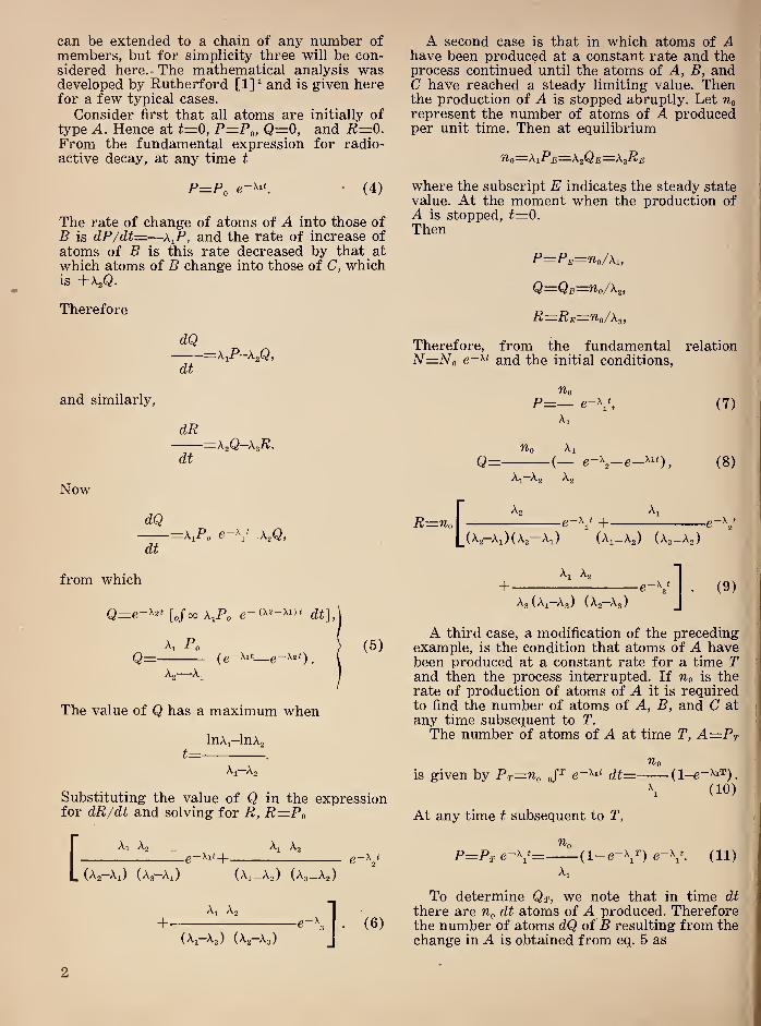
simple case of atoms of one kind this is illus-
trated in figure 1, which shows the curve for6“^* and in relation to the half periodT for any radioactive element.
Figure 1. Exponential growth and decay of radio-
active atoms.
In general, since the parent atoms of anyradioactive chain are undergoing disintegra-
tion, it is never strictly possible to establish
complete equilibrium. Wherever the disintegra-
tion constant of the parent is very small corn-
pared with those of succeeding members, equi-
librium will be practically complete. This situa-
tion is described as secular equilibrium. In thosecases where the disintregration constants aremore nearly comparable, a transient equilibriumis established.
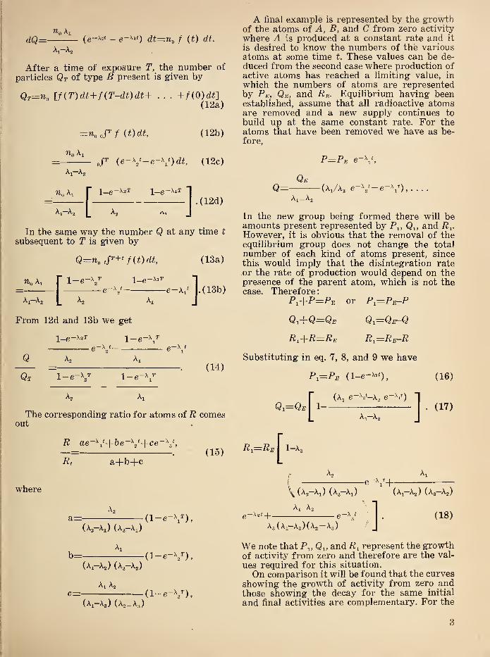
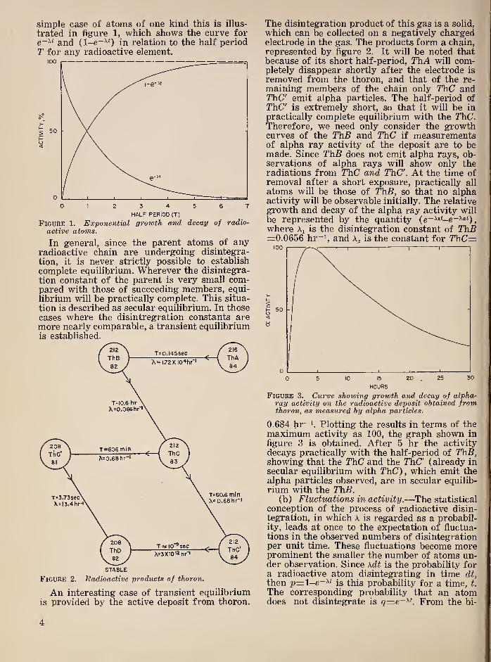
An interesting case of transient equilibriumis provided by the active deposit from thoron.
The disintegration product of this gas is a solid,
which can be collected on a negatively chargedelectrode in the gas. The products form a chain,
represented by figure 2. It will be noted thatbecause of its short half-period, ThA will com-pletely disappear shortly after the electrode is
removed from the thoron, and that of the re-
maining members of the chain only ThC andThC' emit alpha particles. The half-period ofThC is extremely short, so that it will be in
practically complete equilibrium with the ThC.Therefore, we need only consider the growthcurves of the ThB and ThC if measurementsof alpha ray activity of the deposit are to bemade. Since ThB does not emit alpha rays, ob-servations of alpha rays will show only theradiations from ThC and ThC. At the time ofremoval after a short exposure, practically all
atoms will be those of ThB, so that no alphaactivity will be observable initially. The relativegrowth and decay of the alpha ray activity will
be represented by the quantitywhere is the disintegration constant of ThB=0.0656 hr~h and Ag is the constant for TTiC=
Figure 3. Curve showing growth and decay of alpha-ray activity on the radioactive deposit obtained fromthoron, as measured by alpha particles.
0.684 hr^k Plotting the results in terms of themaximum activity as 100, the graph shown in
figure 3 is obtained. After 5 hr the activity
decays practically with the half-period of ThB,showing that the ThC and the ThC (already in
secular equilibrium with ThC), which emit thealpha particles observed, are in secular equilib-
rium with the ThB.(b) Fluctuations in activity .—The statistical
conception of the process of radioactive disin-
tegration, in which A is regarded as a probabil-ity, leads at once to the expectation of fluctua-tions in the observed numbers of disintegrationper unit time. These fluctuations become moreprominent the smaller the number of atoms un-der observation. Since \dt is the probability fora radioactive atom disintegrating in time dt,
then p=l-e-^* is this probability for a time, t.
The corresponding probability that an atomdoes not disintegrate is q=e-^K From the bi-
4
nominal law of probabilities the probability ofan event occurring r times in N independenttrials is
NlPr=V" 9^“% ( 19 )
r!(A^-r) !
which can be written in the approximate form,known as the Poisson formula
(Np)’'
Pr= e-^p, (20 )
f
which gives a good approximation when r is
small compared with N, and p represents theprobability of a rare event in a single trial.
Since Np is the expected number of successes,it can be put equal to e giving
Pr=—e-\ ( 21 )
r.^
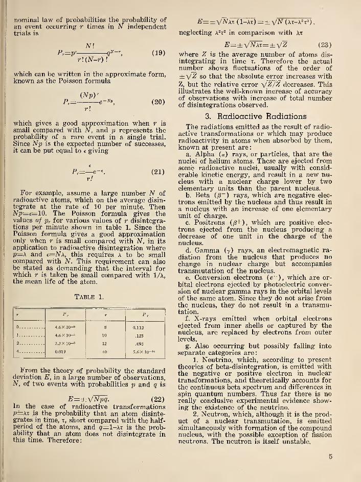
For example, assume a large number N ofradioactive atoms, which on the average disin-tegrate at the rate of 10 per minute. Then^"^=£==10. The Poisson formula gives thevalues of pr for various values of r disintegra-tions per minute shown in table 1. Since thePoisson formula gives a good approximationonly when r is small compared with N, in its
application to radioactive disintegration whereP—X and e=Nx, this requires A to be smallcompared with N. This requirement can alsobe stated as demanding that the interval forwhich r is taken be small compared with 1/a,the mean life of the atom.
Table 1.
r F, r Pr
0 4.6 X 10⁻⁵ 8 0.112
1 4.6X 10-* 10 .125
2 2.3 X 10⁻³ 12 .095
4 0.019 40 5.6 X 10⁻¹*
From the theory of probability the standarddeviation E, in a large number of observations,N, of two events with probabilities p and q is
E=±x/Npq. (22)In the case of radioactive transformationsp=Xx is the probability that an atom disinte-grates in time, t, short compared with the half-period of the atoms, and q=l-AT is the prob-ability that an atom does not disintegrate inthis time. Therefore
;
E=±\/NXx (1—At) =±^/N (At—A^t^),
neglecting a^t^ in comparison with At
E—±'\/Nxx—±^Z (23)
where Z is the average number of atoms dis-
integrating in time x. Therefore the actualnumber shows fluctuations of the order of
so that the absolute error increases with
Z, but the relative error x/Z/Z decreases. Thisillustrates the well-known increase of accuracyof observations with increase of total numberof disintegrations observed.
3. Radioactive Radiations
The radiations emitted as the result of radio-
active transformations or which may produceradioactivity in atoms when absorbed by them,known at present are:
a. Alpha (a) rays, or particles, that are thenuclei of helium atoms. These are ejected fromsome radioactive nuclei, usually with consid-
erable kinetic energy, and result in a new nu-cleus with a nuclear charge lower by twoelementary units than the parent nucleus.
b. Beta i^~) rays, which are negative elec-
trons emitted by the nucleus and thus result in
a nucleus with an increase of one elementaryunit of charge.
c. Positrons (l3+), which are positive elec-
trons ejected from the nucleus producing adecrease of one unit in the charge of thenucleus.
d. Gamma (y) rays, an electromagnetic ra-
diation from the nucleus that produces nochange in nuclear charge but accompaniestransmutation of the nucleus.
e. Conversion electrons {e~), which are or-
bital electrons ejected by photoelectric conver-sion of nuclear gamma rays in the orbital levels
of the same atom. Since they do not arise fromthe nucleus, they do not result in a transmu-tation.
f. X-rays emitted when orbital electrons
ejected from inner shells or captured by thenucleus, are replaced by electrons from outerlevels.
g. Also occurring but possibly falling into
separate categories are:
1. Neutrino, which, according to presenttheories of beta-disintegration, is emitted withthe negative or positive electron in nucleartransformations, and theoretically accounts forthe continuous beta spectrum and differences in
spin quantum numbers. Thus far there is noreally conclusive experimental evidence show-ing the existence of the neutrino.
2. Neutron, which, although it is the prod-uct of a nuclear transmutation, is emittedsimultaneously with formation of the compoundnucleus, with the possible exception of fission
neutrons. The neutron is itself unstable.
5

3.
Meson, which occurs only in nuclear
processes involving tremendously high energies,
as in cosmic ray phenomena. These have also
been produced artificially in the University of
California cyclotron, and are also unstable.
h. The following particles are of importancein radioactivity since when they are capturedby a stable nucleus they may render it radio-
active and are also emitted during the processof forming the new nucleus, although they arenot associated with the subsequent radioactive
disintegration of the newly formed nuclei.
1. Neutron {n) of unit atomic mass andno charge.
2. Proton (p) with two units of mass andone positive charge.
3. Deuteron (d) with two units of massand one positive charge.
4. Triton (t) with three units of mass andone positive charge.
5. Alpha particle (a) with four units of
mass and two of positive charge.6. Electron (e) with zero units of mass
and one of negative charge.7. Gamma ray (y) with zero units of mass
and no charge.
4. Artificial Radioactivity
Although radioactivity was originally dis-
covered and investigated in connection with ele-
ments existing in nature that were undergoingtransmutations, it has now become recognizedas a general property of atomic nuclei. Joliot
and Curie discovered that stable substancesmay be made radioactive in 1934, while study-ing the effect of bombardment of nuclei of lowatomic number by alpha particles. Since thattime it has been found possible to produceradioactive isotopes of practically every atomicspecies. Furthermore, these artificially inducedradioactivities conform to the general laws es-
tablished for radioactivity previously knownto occur in nature. Since radioactivity is aproperty of the nucleus it must be explained in
terms of hypotheses and experiments that in-
volve the structure of the nucleus.(a) Structure of the atomic nucleus .—Ideas
regarding the components of the nucleus andtheir interaction have undergone many modifi-cations since the initial discovery of radio-activity. Some of the difficulties in interpretingradioactive processes in terms of nuclear struc-ture have been removed by the present hypothe-sis on this subject. Since the discovery of theneutron in 1932 by Chadwick, the nucleus hascome to be regarded as made up of protons andneutrons. The number of protons determinesthe nuclear charge Z, and therefore the chemi-cal behavior of the nucleus and its position in
the periodic table. The sum of the number ofprotons and neutrons determines the atomic
mass number of the nucleus, A.Any combination of protons and neutrons
which, when associated in a nucleus, has a lowprobability of disintegration into some other
combination is stable. Ultimately all unstable
forms tend to transform until a stable arrange-ment is reached, and therefore are radioactive.
Instability appears in the very simplest of the
structural elements of the nucleus. The neutronitself, when produced in the free state, quickly
transforms, presumably into a proton. Themechanism of this transformation has not beendefinitely established but it may be assumed, in
absence of evidence to the contrary, that the
neutron emits a beta particle that converts it
into a proton. The proton in turn quickly picks
up an orbital electron to form hydrogen, the
first stable chemical element in the periodic
table. We know now that hydrogen can exist in
three forms. Adding one neutron to the nucleusof a hydrogen atom produces a deuteron, a nu-cleus with two atomic mass units and one nu-clear charge. Chemically indistinguishable fromthe more common variety of hydrogen, this ele-
ment is stable. However, when a second neutronis added to the hydrogen nucleus the combina-tion becomes unstable. A radioactive elementresults that behaves chemically as hydrogen butcan be distinguished from the common variety
by its radioactivity as well as by the difference
in mass. In disintegrating it emits a beta par-ticle that can be interpreted as the transforma-tion of one of the nuclear neutrons into a pro-
ton. When this occurs the nucleus has twopositive charges, its atomic number is 2, and it
behaves chemically as helium. This element is
stable and differs from the common variety ofhelium in that the nuclear mass is 3 instead of
4.
Likewise, when two neutrons are added to
the common helium nucleus the configurationis again unstable, a neutron transforms into aproton with the emission of a beta particle,
thus producing a lithium nucleus of atomic num-ber 3 and atomic mass 6, which is stable. Thisseries of transformations is illustrated in fig-
ure 4.
(b) Types of disintegration .—It is to benoted that in each case mentioned the trans-formation occurs with the emission of a betaparticle, which results in a negligible changein the mass of the nucleus but which increasesthe nuclear charge by one unit. This process is
typical of all beta-ray transformations. Al-though this process was discovered among ele-
ments of high atomic number occurring in
nature, it is now known to occur throughoutthe periodic table. It is associated with thepostulated property of the neutron by whichit has a probability of transforming into aproton. This probability varies with the condi-tions under which the neutron exists, beingvery high for free neutrons and relatively lowfor those in the nuclei of stable atoms.
6

UCLEARCHARGE
0NEUTRON
KHYDROGEN DEUTERIUM
ELEMENT
TRITIUM
HYDROGEN
3 LITHIUM
BERYLLIUM
Figure 4. Chart showing the role of the neutron in
artificial radioactivity.
Radioactive nuclei may also emit alpha par-ticles in their transformation. When this occursthe nuclear charge decreases by 2 units and theatomic mass by 4 units. Alpha particle emissionin connection with radioactive transformationis limited almost exclusively to elements of highatomic number. The emission of alpha particles
can be explained qualitatively by assuming thatin the heavier nuclei there is a tendency fortwo protons and two neutrons to become asso-ciated to form alpha particles as structuralunits of the nucleus. It is assumed that thesealpha particles are held in the nucleus by strongforces of attraction for small internuclear dis-
tances. For greater distances the coulomb lawof repulsion between electric charges of thesame sign produces a repulsive force betweenthe alpha particle and the rest of the nucleus.Under these conditions it has been shown froman application of the principles of wave me-chanics that there is always a finite probabilitythat the alpha particle will escape from the nu-cleus. Therefore, this representation results ina radioactive nucleus that will disintegrate bythe emission of an alpha particle.A considerable number of radioactive atoms
disintegrate by emitting a positron. The nu-clear process by which this occurs may be thetransformation of a nuclear proton into a neu-tron. The new nucleus thus has the same massas the parent but one less unit of charge. Thesame final result is obtained if a nuclear proton
captures an orbital electron from the innershell of the atom, assuming this process results
also in the formation of a neutron. However,the only characteristic radiations emitted bythe atom in this transformation are X-rays re-
sulting from an outer orbital electron droppingin to fill the place of the one captured. A num-ber of transformations by electron capture areknown. They are usually associated with thosewhich go partly by the emission of positronsand partly by orbital electron capture. The proc-
ess is sometimes called X-capture, but it is
not infrequent that an L-electron is capturedinstead.
In this introductory qualitative survey wemust now consider the role of gamma rays andconversion electrons in the process of disinte-
gration. The emission of gamma rays by thenucleus does not change either the mass sig-
nificantly or the atomic number. Therefore, it
can be regarded as a result of the reorganiza-tion of the newly formed nucleus. As can be ex-
pected from this view, gamma rays may accom-pany any type of nuclear disintegration, whichis verified experimentally. However, not all
types of disintegrating atoms emit gamma raysand the intensity and energy of the gammarays vary widely from one type of atom to
another. The intensity and energy of the gammarays may be taken as a measure of the reor-
ganization that takes place.
The conversion electrons have been identified
as orbital electrons ejected by nuclear gammarays and thus are distinguished from nuclearbeta rays, although they have the same physicalproperties otherwise. If a gamma ray of energyE is converted, it is to be expected that groupsof electrons should be found with energiesEy—Ej^, Ey—E]j, Ey—Ei[, where Ej^, Ejj, and Ejj
are the binding energies of the electrons in theK, L, and M levels. The experimental confir-
mation of this relation identifies the conversionelectrons.
(c) Role of gamma rays .—In the process offormation of radioactive nuclei from stable
forms, energy is added to the target nucleus.This may be accomplished by the capture in
the stable nucleus of a neutron, deuteron, oralpha particle, or by the absorption of radia-tion. This process forms an intermediate nu-clear form with a high degree of excitation,
which frequently proceeds to radiate this en-ergy in a number of gamma-ray quanta. Thisis the gamma radiation of the n, y process.Even when most of the energy of excitation is
removed by the emission of another particle,
the part remaining may be radiated as gammarays. Another example is provided by those na-turally radioactive isotopes that disintegrate bythe emission of alpha particles. Frequently theproduct nucleus is left in an excited state thatreturns to the ground level by the emission ofgamma rays. In such cases of nuclear excita-
7
tion the time required for the excited nucleus to
reach the ground state has been estimated to be
of the order of 10“^* second. This reaction
therefore has a very high probability of occur-
rence as contrasted with the probability of the
disintegration of the unstable nucleus in the
ground state formed by the process of excita-
tion and emission of gamma rays.
11. DETECTION AND MEASUREMENT OF RADIOACTIVE RADIATIONS
The principal general methods by whichradioactive radiations can be detected andmeasured depend on their ability to ionize
atoms either directly or by means of secondaryradiations. The radiation from uranium wasdetected by Becquerel by use of photographic
plates. Here the ionizing effects of the radia-
tion render the compound of silver in the emul-
sion developable by chemical treatment, in muchthe same way that light reacts with the silver
in ordinary photography. All types of radio-
active radiation can be detected by this method,either directly or by means of secondary ra-
diations.
When the ionization is produced in a gas, the
electrical conductivity of the gas is increasedin proportion to the degree of ionization. Thusby applying an electric field to the ionized vol-
ume of gas, a current is obtained proportionalto the ionization, which in turn is proportionalto the intensity of the radiation. This methodmay be used with modifications to measure all
types of radioactive radiation. For example,although neutrons produce no ionization di-
rectly, they do eject protons from materialsrich in hydrogen. The protons ionize the gasin proportion to the number of neutrons thatproduced them.The various methods of counting radioactive
radiations are also based chiefly on the ioniza-
tion property of the radiations. In general,counting is accomplished by amplifying thepulse of ionization resulting from the passageof a single ionizing particle through the gas.
This ionizing particle may be a constituent ofthe primary radiation, as an alpha or beta par-ticle, or a secondary ionizing particle such as aphotoelectron produced by a gamma ray, or aproton produced by a neutron. The amplifica-tion may be accomplished by electronic circuits
where the initial ionization is sufficient to pro-duce a pulse that can be amplified convenientlyin this manner, or the amplification may takeplace largely in the ionized gas itself as in theGeiger-Muller tube counter.Examples of methods occasionally employed
that do not depend on ionization are; (1) themeasurement of the charge transported by thoseradioactive radiations that consist of chargedparticles, and (2) the electron multiplier tubein which electrons are released from the elec-
trodes by impact of the radiation.
1. Pholographic Emulsions
For the quantitative measurement of radia-
tion, photographic emulsions must be used un-der carefully controlled conditions such as arerequired for photometric measurements byphotographic methods. The blackening of aphotographic plate by light is given by theSchwarzschild formula
(24)
where I is the intensity of the light and t the
time of exposure. The logarithm form is
D—f{q log /+log t). (25)
The exponent q is obtained by using two in-tensities Ii and /a in exposure times G andso that the same blackening is produced. Then
log ^ 2—log Gq= . (26)
log h—log h
It is found that q is very close to unity for
most intensities of light and times of expos-
ure. For q=l the Schwarzschild law becomesthe Bunsen-Roscoe law
D=.fUt),
so that for a given density the product Ixt is
a constant. In this relation D is determinedphotometrically and is defined by the relation
D—\og iji, (27)
where io is the intensity of the light incident
on the developed photographic plate, and i is
the intensity of the light transmitted throughthe plate.
The Bunsen-Roscoe law is valid for exposure
to alpha rays, at least for intensities of the
ratio of 10 :1. It also holds for both heterogene-
ous and homogeneous beta rays. Ellis andWooster [2] have shown that the relation
H=C' log (E/t+1), (28)
may be applied to exposures of beta rays, whereE is the energy of the incident beta rays, C is
a constant dependent on conditions of photo-
graphic development, and t is a constant re-
8
lated to the energy of the particles. This cor-
rection for the energy is not well known buthas been assumed proportional to where^z=v/c, the ratio of the velocity of the beta
particle to that of light.
Investigations of the blackening produced bygamma rays show that the Bunsen-Roscoe lawapplies for intensities of the ratio of 100:1.
Another interesting application of photo-
graphic plates is the recording of the tracks
of ionizing particles of considerable ener^such as alpha particles, protons, and co'smic
ray mesons. This method is successful only in
special emulsions where chemical fog and otherdisturbing photographic effects are reduced to
a minimum. Since the length of these tracks is
very short, microscopic examination of theemulsion is required to measure them. Fromsuch measurements the energy of the radiation
can be determined if the energy-range relation
is known for the type of particle under ob-
servation.
2. Crystals
A few crystals have properties that makethem suitable for detecting radiations fromradioactive substances. Under appropriate con-
ditions these crystals can be used for quantita-
tive measurements. The classic example of theuse of crystals is the visual scintillation counterdeveloped by Rutherford and used in many im-portant experiments in regard to the nature ofthe nucleus. This method depends on the ability
of specially prepared zinc sulphide crystals to
produce a small flash of light for each alphaparticle that strikes it. A low-power microscopeis required for visual observation and countingof the particles. This procedure has several
obvious disadvantages, which include the vari-
ations of natural visual acuity of the observers,fatigue of the eye, limitation to low rates ofcounting resulting in long periods of observa-tion for reasonable statistical accuracy. Hence,this laborious method has been replaced byelectrical methods, such as electronic amplifica-
tion of the ions produced by alpha particles.
In recent years crystals have assumed a re-
vived importance in the field of radioactivemeasurements. This has come about in twodistinctly different ways, one of which involvesthe counting of scintillations by means ofphoto-tubes and the other the detection of theelectrical pulse produced within the crystalwhen radiation stimulates the crystal to releaseelectrons in the conduction bands of thecrystals.
Photo-electric scintillation counters are obvi-ous extensions of the earlier visual scintilla-
tion counters. The introduction of the multiplierphoto-tube and development of special lumines-cent substances have resulted in a revolutionary
improvement in speed and sensitivity of count-
ing. The photo-tube counters can be used forcounting beta and gamma rays as well as alphaparticles. The pulses produced are fast, so thathigh counting rates may be used without serious
statistical losses. The most serious complica-tion in their use is the natural “noise” in mostphoto-tubes, which may mask or interfere withthe pulses produced by the scintillations. Thisnoise can be reduced by refrigerating the photo-tube or by constructing photo-tubes of special
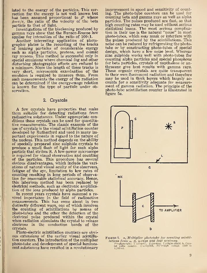
design, which have a low noise level. Whereaszinc sulphide works well with photo-tubes forcounting alpha particles and special phosphousfor beta particles, crystals of napthalene or an-thracene give best results with gamma rays.These organic crystals are quite transparentto their own fiuorescent radiation and thereforemay be used in thick layers which largely ac-counts for a sensitivity adequate for measure-ment of gamma radiation. The principle of thephoto-tube scintillation counter is illustrated infigure 5a.
’
H.V.
Figure 5. a, Multiplier phototube for counting scintil-
lations from a, X-rays and fast neutrons.P=photo-tube; C=:crystal, 5=:source, L=light shield, b, Crys-tal pulse counter. C=crystal, /iF=high voltage (600 to
1 ,500 v).
9
The pulse crystal counter was first developed
by Van Heerden in a dissertation published in
1945 [3] . His successful experiments were madewith crystals of silver chloride at liquid air
temperatures. A number of other crystals havebeen found to possess the same properties. Oneof these, the diamond, can be operated at roomtemperature. The pulses produced by these
crystals arise when an electron receives suffi-
cient energy from the radiation to place it in
the conduction band of the crystal. If an elec-
tric field is generated between two opposite
faces of the crystal, the electrons thus released
produce a displacement current. Consequentlythe counting property is based on phenomenaessentially different from the photoelectric con-
duction observed in many crystals. Actually, to
operate as a counter the crystal must be highly
nonconductive in the ordinary sense, since con-
duction current will tend to interfere with, or
mask the pulses. The size of the pulses dependson the number of electrons released and the
distance that they travel in the crystal for the
absorption of a single particle or quantum of
radiation. These factors in turn depend on thenature and purity of the crystal, the energy of
the incident radiation, and, to a lesser extent,
upon the magnitude of the electrical field
across the crystal. Due to the nature of thedisplacement current, intimate contact with thesurfaces of the crystal are not required. Forexample, clamping a diamond between brasselectrodes yields as good results as are obtainedby depositing silver electrodes on the faces.
Figure 5b shows the essential arrangementsfor counting pulses from crystals. The pulsesdeveloped by most crystals are small and havea considerable range of 'magnitude. Thereforea relatively high gain amplifier is required witha discriminator to reject all pulses below acertain level to eliminate the effects of back-ground noise.
3. lonizalion of Gases
Radioactive radiations may produce ions in
gases in a variety of ways such as by impactof charged particles on the atoms of the gas orby the photoelectric removal of electrons fromthe atoms of the gas by electromagnetic radia-tion. Although the fundamental process consists
in the removal of one or more electrons fromatoms or molecules of the gas, electrons rarelypersist unattached long enough to play an im-portant role. They are taken up by neutralatoms in most gases to form negative ions of amass comparable to that of the positive ions
formed in the ionization process. Pure nitrogenand the noble gases are exceptions to this rule.
The tendency for electrons to form negativeions in these gases is sufficiently small thatnegative ions consisting predominantly of elec-
trons may be collected by an electric field.
Although the charge carried by an ion is oneor more elementary units, equal to the chargeof an electron, the masses of ions may varygreatly depending on the gas or vapor in whichthey are formed, the way in which they are
produced, and the rapidity with which theyare collected.
a. Recombination.—Ions tend to return to
the neutral state by recombination in whichnegative and positive ions share their differ-
ence'in charge to produce neutral atoms, so thatin the absence of an electric field an equilibriumis soon established where the rate of recombi-nation is equal to the rate at which ions areformed. The coefficient of recombination, a, is
defined by the relation
dn/dt=zanji^ (29)
where rii is the concentration of positive ionsand m of negative ions and dn/dt is the rate at
which ion pairs disappear per unit volume.When, as is usual, n^=n^=n this relation be-comes dn/dt—-an"^. Experimentally a has avalue of 1.6x10“® cm® sec~^ for air at atmos-pheric pressure and room temperature.
b. Mobility of ions .—The mobility of an ionis defined as its velocity in centimeters per sec-
Vond in an electric field of 1 . This motion of
cmthe ions constitutes an electrical current and,as in all cases, it represents the average rate
of displacement of the carriers of charge dueto the electric field. The mobility is characteris-tic of a definite type of ion but also depends onthe nature, density, and temperature of the gas.
c. Electrical conductivity of a gas.—The spe-cific conductivity, L, of a gas is given by
L—ne (M1+ M2 ), (30)
where n is the concentration of ion pairs, e is
the ionic charge, and and u^ the mobilities
of the positive and negative ions. The quantityn is determined by the number of ions gener-ated per unit time and volume, q, decreased bythe loss of ions due to recombination.
In the absence of an electric field the con-ductivity attains a maximum value, Lo, wherean equilibrium condition is set up such thatthe number of ions generated equals those lost
by recombination so that
q—ahl or no='\/q/a. (31)
Therefore
Lo=e{Ui+u./) y/q/a. (32)
10
On the application of an electric field the chargeproduced by ionization, qe, is balanced by loss
due to recombination and to the current, i,
which is set up. Hence
qe—aul e+i or i—qe {l-au^/q),
where qe represents the maximum current fora given q and is obtained when the ions arecollected so rapidly that recombination maybe neglected. Noting that
L neiui+u^) n
Lo e(tti=M2) VO'/a VO'/a
we can write
= =an^/q=l-l+ an-/q^l-{\-an^/q)Ll q/ oc
qe{l-an^/q)=1 .
qe
Therefore
A — /i_ gg(l-a^V9)
Lo qe
But
qe{l-an^/q)—i,
so that
^ =yi-i/qe= (33)-^0
if we replace qe, which represents the satura-
tion current, by S.
The voltage V, required for a current i perunit volume is proportional to i/L, or to
i
L^yi-i/S
Therefore
i
V=k . (34)
For values of i small compared with iS this
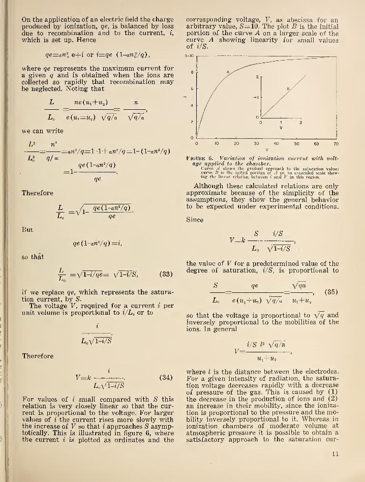
relation is very closely linear so that the cur-rent is proportional to the voltage. For largervalues of i the current rises more slowly withthe increase of V so that i approaches S asymp-totically. This is illustrated in figure 6, wherethe current i is plotted as ordinates and the
corresponding voltage, V, as abscissa for anarbitrary value, 5'= 10. The plot B is the initial
portion of the curve A on a larger scale of thecurve A showing linearity for small valuesof i/s.
Figure 6. Variation of ionization current with volt-age applied to the chamber.
Curve /I shows the gradual approach to the saturation value;curve B is the initial portion of A on an expanded scale show-ing the linear relation between i and V in this region.
Although these calculated relations are onlyapproximate because of the simplicity of theassumptions, they show the general behaviorto be expected under experimental conditions.
Since
S i/sV^k —
Z/Q V \-n/
S
the value of V for a predetermined value of thedegree of saturation, i/S, is proportional to
S qe=
, (35)
Lo e(tq+'M-2 ) Vq/a M1+M2
so that the voltage is proportional to £ind
inversely proportional to the mobilities of theions. In general
i/s L ^/q/Si
U-,^-/U2
where I is the distance between the electrodes.
For a given intensity of radiation, the satura-
tion voltage decreases rapidly with a decrease
of pressure of the gas. This is caused by (1)
the decrease in the production of ions and (2)
an increase in their mobility, since the ioniza-
tion is proportional to the pressure and the mo-bility inversely proportional to it. Whereas in
ionization chambers of moderate volume at
atmospheric pressure it is possible to obtain asatisfactory approach to the saturation cur-
11
rent for a moderate ionization by beta andgamma rays, this is comparatively difficult forionization produced by alpha rays. This arises
from the dense local ionization produced byalpha rays and the resultant rapid recombi-nation.
4.
Measurement of Charge Transportedby Alpha and Beta Rays
The intensity of alpha and beta rays can bemeasured under suitable conditions by deter-
mining the rate at which an insulated receiver
accumulates charge, or the potential developedacross a high resistance connected to the re-
ceiver. Such measurements require that thespace between the sources and receiver be evac-uated to eliminate ionization. The method is
practicable only for relatively strong sources,
since 10® beta particles per second is equivalentto 1.6x10“^^ amp. To secure a measurementof the total number of particles emitted by asource, it is more convenient to connect thesource through a high resistance to ground,with the source located at the center of a wellevacuated chamber of considerable volume. Thesteady potential, in volts, of the source meas-ured under these conditions will be
T=i?(1.6xl0-i®) N,
where N is the number of particles emitted persecond. From this relation we have
VN= .
72(1.6x10-^®)
5.
Counting Methods
The rate at which individual particles or
photons, which constitute the various types of
radioactive radiations, are emitted may be de-
termined by counting the individual constitu-
ents, such as alpha particles, beta particles,
protons, positrons, or neutrons. The variousmethods for doing this all depend on the ioniz-
ing properties of the particles themselves, or ofthe secondary radiations produced by them. Inthe practical applications of all of these methodsonly some fraction of the total radiation is
counted. This fraction is determined by thegeometrical arrangement and, in some cases,
by absorption of windows or walls of the de-tecting chamber, as well as the intrinsic effi-
ciency of the detector. For absolute quantitativemeasurements, therefore, a correction factormust be ascertained for each counting device.Three general types of counting methods canbe distinguished, depending on the method ofamplification of the ionization produced by theprimary event in the detector.
6.
Ionization Chambers
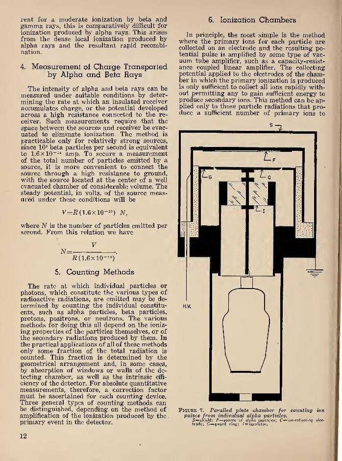
In principle, the most simple is the methodwhere the primary ions for each particle arecollected on an electrode and the resulting po-tential pulse is amplified by some type of vac-uum tube amplifier, such as a capacity-resist-ance coupled linear amplifier. The collectingpotential applied to the electrodes of the cham-ber in which the primary ionization is producedis only sufficient to collect all ions rapidly with-out permitting any to gain sufficient energy toproduce secondary ions. This method can be ap-plied only to those particle radiations that pro-duce a sufficient number of primary ions to
Figure 7. Paralled plate chamber for counting ionpulses from individual alpha particles.
5'=shield; F=source of alpha particles; C=ion-colIecting elec-
trode; G=guard ring; /= insulator.
12
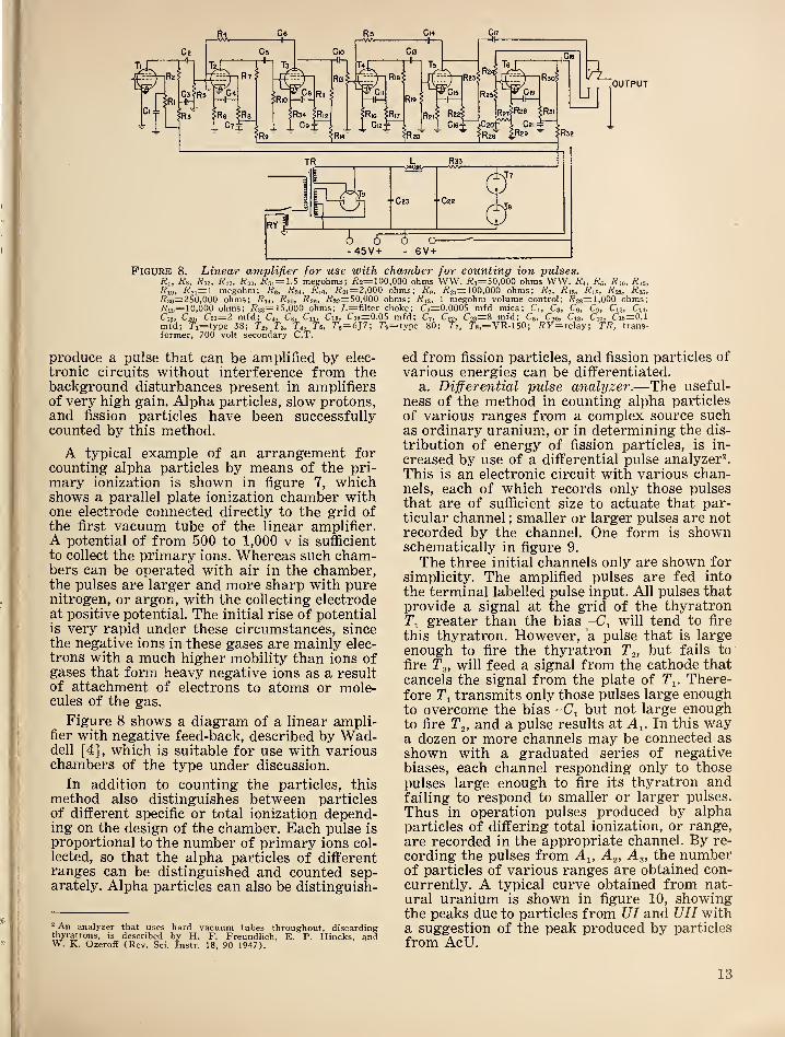
Figure 8. Linear amplifier for use with chamber for counting ion pulses.Ri, Rs, i?i2, i?i7, R22 , ^31=1.5 megohms; I?2=100,000 ohms WW. i?3=50,000 ohms WW. i?4, i?6, Rio, Rio,
Rio, •^24=1 megohm; ^0, i?3i, i?i0, i?2i=2,000 ohms; Ro, i?»;=100,000 ohms; Ri, Ris, Ris, Rzt, Ros,i?3n=2SO,000 ohms; Rn, R 20 , R20 ,
i?32=SO,000 ohms; R13 , 1 megohm volume control; J?28=1.000 ohms;•I'l2s=10i000 ohms; i?33=15,000 ohms; Z-=filter choke; C2=0.0005 mfd mica; Ci, C3, Co, Co, C12, Cu,Cie, C20 , C2i~2 mfd; Ci, Cs, Cu, C15, U19— 0.05 mfd; C7, C'22> U23—8 mfd; Co, Cio, C13 , Cn, Cis— 0.1
mfd; T'i=type 38; To, To, Tt, To, To= 6J7; 7’e=type 80; Ti, 7'8,=VR-150; f?F=relay; TR, trans-former, 700 volt secondary C.T.
produce a pulse that can be amplified by elec-
tronic circuits without interference from thebackground disturbances present in amplifiersof very high gain. Alpha particles, slow protons,and fission particles have been successfullycounted by this method.
A typical example of an arrangement forcounting alpha particles by means of the pri-
mary ionization is shown in figure 7, whichshows a parallel plate ionization chamber withone electrode connected directly to the grid ofthe first vacuum tube of the linear amplifier.A potential of from 500 to 1,000 v is sufficient
to collect the primary ions. Whereas such cham-bers can be operated with air in the chamber,the pulses are larger and more sharp with purenitrogen, or argon, with the collecting electrodeat positive potential. The initial rise of potentialis very rapid under these circumstances, sincethe negative ions in these gases are mainly elec-
trons with a much higher mobility than ions ofgases that form heavy negative ions as a resultof attachment of electrons to atoms or mole-cules of the gas.
Figure 8 shows a diagram of a linear ampli-fier with negative feed-back, described by Wad-dell [4], which is suitable for use with variouschambers of the type under discussion.
In addition to counting the particles, this
method also distinguishes between particlesof different specific or total ionization depend-ing on the design of the chamber. Each pulse is
proportional to the number of primary ions col-
lected, so that the alpha particles of differentranges can be distinguished and counted sep-arately. Alpha particles can also be distinguish-
“ An analyzer that uses hard vacuum tubes throughout, discardingthyratrons, is described by H. F. Freundlich, E. P. Hincks, andW. K. Ozeroff (Rev. Sci. Instr. 18, 90 1947).
ed from fission particles, and fission particles of
various energies can be differentiated.
a. Differential pulse analyzer .—The useful-
ness of the method in counting alpha particles
of various ranges from a complex source suchas ordinary uranium, or in determining the dis-
tribution of energy of fission particles, is in-
creased by use of a differential pulse analyzer^This is an electronic circuit with various chan-nels, each of which records only those pulsesthat are of sufficient size to actuate that par-ticular channel
;smaller or larger pulses are not
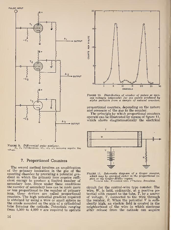
recorded by the channel. One form is shownschematically in figure 9.
The three initial channels only are shown forsimplicity. The amplified pulses are fed into
the terminal labelled pulse input. All pulses thatprovide a signal at the grid of the thyratronTi greater than the bias will tend to fire
this thyratron. However, a pulse that is largeenough to fire the thyratron T^, but fails to
fire Tg, will feed a signal from the cathode thatcancels the signal from the plate of Ti. There-fore Ti transmits only those pulses large enoughto overcome the bias -Cj but not large enoughto fire Tg, and a pulse results at A^. In this waya dozen or more channels may be connected as
shown with a graduated series of negativebiases, each channel responding only to those
pulses large enough to fire its thyratron andfailing to respond to smaller or larger pulses.
Thus in operation pulses produced by alphaparticles of differing total ionization, or range,
are recorded in the appropriate channel. By re-
cording the pulses from A^, Ag, Ag, the numberof particles of various ranges are obtained con-
currently. A typical curve obtained from nat-
ural uranium is shown in figure 10, showingthe peaks due to particles from TJI and UII witha suggestion of the peak produced by particles
from AcU.
13
PULSE INPUT
Figure 9. Differential pulse analyzer.Tii 7'2, 7'3=thyratrons, —Ci, -C2, -C3 increasing negative bias
voltage.
7. Proportional Counters
The second method involves an amplificationof the primary ionization in the gas of thecounting chamber by providing a potential gra-dient in which the primary ions acquire suffi-
cient energy to produce a limited number ofsecondary ions. Since under these conditionsthe number of secondary ions can be made moreor less proportional to the number of primaryions, these devices are called proportionalcounters. The high potential gradient requiredis obtained by using a wire or small sphere asthe anode mounted on the axis of a cylindricaltube forming the cathode. Potentials rangingfrom 1,500 to 4,000 v are required to operate
CHANNELS
Figure 10. Distribution of number of pulses at vari-
ous voltages {channels) for ion pulses produced byalpha particles from a sample of natural uranium.
proportional counters, depending on the natureand pressure of the gas in the counter.The principle by which proportional counters
operate can be illustrated by means of figure 11,
which shows diagrammatically the electrical
T
Figure 11. Schematic diagram of a Geiger counter,
which may be operated either in the proportional re-
gion or the Geiger-Miiller region.r=metal tube; ir=central wire; F=battery; i?=resistor.
circuit for the central-wire type counter. Thewire, W, is held, ordinarily, at a positive po-
tential with respect to the tube, T, by a sourceof voltage, V, connected to the wire throughthe resistor, R. When the potential V is suffi-
ciently high, an electric field is created in theneighborhood of the wire in which electrons
after release from the cathode can acquire
14

energy sufficient to ionize neutral atoms on their
first impact. At this point the phenomenon of
gas amplification of the ionization current be-
gins to appear. As the potential V is increased,
the volume about the wire, where additional
ions are produced, and the number of such ions
per primary electron also increase. The instan-
taneous pulse produced on the wire, dV, is
given by A mc/{C), where n is the number of
primary electrons, A is the number of ion pairs
produced by each on its path to the central
wire, e is the elementary charge, and C the total
capacity of the circuit connected to the wire.
Thus A represents the amplification in the gas,
and a counter is strictly a proportional counteronly when A is constant. The relation betweenionization chambers, proportional counters, andGeiger-Miiller counters is illustrated by the dia-
gram in figure 12, where the pulse size is plotted
ION COLLECTING PROPORTIONAL GEIGER CONTINUOUSRANGE RANGE RANGE DISCHARGE
Figure 12. Diagram showing variation of pulse size
with voltage applied to a counter of the general de-sign shown in figure 11.
against the voltage applied to the counter. Inthe range from 0 to Fj the counter tube behavesas an ionization chamber. There is an initial
short range where the number of ions collected
is proportional to the voltage, followed by aregion where the pulse size is constant as thevoltage increases. This is the saturation regionof an ionization chamber. Beyond the pri-
mary ions produced by the radiation enteringthe counter tube acquire sufficient energy fromthe electron field to produce secondary impactionization of the gas, which also contributesto the size of the pulse. For voltages betweenFj and V^, the number of secondary ions is pro-portional to the number of primary ions mak-ing this the true proportional region. In goingfrom 1^2 to Fg, a transition occurs from the pro-portional range to the Geiger-Miiller range inwhich any primary ionization tends to pro-duce a pulse of the same size, regardless of thenumber of primary ions. Finally, at V^, a condi-tion is reached where all pulses at a given volt-age are of the same size. This condition is main-
tained until Fg is reached. Here the counterbreaks into continuous discharge.To operate as a counter, that is produce one
electrical pulse on the wire for each primaryionizing particle entering the counter, thecumulative ionization must cease when thenegative ions resulting from the primary ioni-
zation all reach the wire. The abrupt cessationof this process is brought about by three prin-cipal factors
;the geometrical form of the
counter, the low mobility of the positive ionsproduced, and the direction in which the nega-tive ions, principally electrons, travel.
The high electric field, as well as the natureof the gas in some cases, reduces the recombina-tion of ions in the counter to a low value. There-fore, as a result of their low mobility, the heavypositive ions remain in the gas of the countervery near the position where they were formed,during the short time in which the electronsreach the wire. Most of these positive ions arein a narrow sheath very near the wire becauseof the form of the field. This produces an almostfield-free space between this sheath and thecounter tube, representing the major volumeof the counter. Therefore, the first avalancheis interrupted since no electrons in this volumeof low potential gradient can acquire energyto produce ionization, and consequently no elec-
trons are released in the region. Not only hasthe counting action been interrupted to give anabrupt pulse but the counter is insensitive tothe arrival of another particle during the shortinterval required for this ion sheath to travel
to the tube and thus restore the electric field
to its original state. This interval of the orderof 10“* second has been called the “deadtime”of the counter.
Proportional counters have been used to
count alpha particles, protons, beta particles,
fission particles, and neutrons by using either
a gas that reacts with neutrons to emit alphaparticles, such as BF^, or by coating the walls
of the counter with boron. The resolving timeof these counters can be decreased by use of
special gases, such as methane. The amplifiers
required need only have a moderate gain;two
stages of pulse amplification with feedback plusa coupling stage to a scaler, or differential pulseanalyzer, are usually adequate.
8. Geiger-Miiller Counters
The Geiger-Miiller counter, although similarin construction to the wire-type proportionalcounter, (figure 11) ,
operates at lower gas pres-sures. For best operation it requires special
gases or mixtures of gases and vapors, and it
delivers pulses of uniform size regardless ofthe number of primary ions formed by theradiation entering it. The lower pressure in-
creases the mobility of the electrons, so that
15

much more gas amplification is produced. As aresult of the higher mobilities these counters
do not produce sharply defined pulses by meansof the space charge action of the positive ion
sheath alone. Additional quenching action is
required. Since in the early development of
these counters this was accomplished by theuse of a high value of the resistor, R, in figure
11, this resulted in the counter becoming in-
operative for the relatively long periods re-
quired for the electric field to be reestablished,
corresponding to the long-time constant repre-
sented by RC. Electronic devices to accomplishthe quenching by suddenly removing the po'ten-
tial for a short interval to allow recombina-tion to remove all ions have been developed.However the commonly preferred solution to
this problem is the self-quenching counter de-
veloped by Trost [5].
Selfquenching is obtained by filling the coun-ter with a mixture of organic vapor, such as
alcohol, with a gas of low electron attachment,such as argon. The function of the organicvapor or gas is mainly to absorb photons thathave sufficient energy to release electrons in
the gas and from the walls of the counter. It
also reduces secondary emission of electronsfrom the walls of the tube produced by thearrival of the positive ions.
Therefore, in the Geiger-Muller counter theprimary ions produced by the penetration of
an ionizing particle, or photon, or other radia-
tion into the effective volume of the countergenerates a saturation amount of ionization
by impact, so that all pulses are uniform re-
gardless of the number of ion pairs producedby the primary agent. By the combination ofthe effects of the ion sheath and the quenchingmixture the counting process is abruptly ter-
minated. Finally, the positive ion sheath movesout to the walls of the tube and its ions arecollected, which restores the counter to a con-dition where it will respond to the entry of anionizing agent.
The characteristics of a good Geiger-Mullercounter include a reasonably low and stable
threshold, (that is the voltage at which count-ing begins) and a rapid rise in sensitivity asthe voltage is increased above the threshold toa plateau where the counting rate of the counterfor a steady source of radiation rises veryslowly. This plateau may extend to several hun-dred volts and have a slope of the order of0.01 percent/v. The flatness and length of thisplateau principally determine the excellence ofthe counter. A typical characteristic curve is
shown in figure 13, where the counting rate is
plotted against the voltage applied to thecounter for a constant source of radiation.is the threshold, V is the operating voltage. Thedifference between these voltages is the overvoltage, which is equal to the voltage of the
pulse on the wire for each count. Beyond theplateau, the counting rate begins to rise rathersharply. Self-quenching counters should neverbe operated in this region since they rapidlydeteriorate under such treatment and may notrecover their original characteristics. It hasbeen found that the threshold voltage of vaportype counters tends to shift with temperatureand operating conditions. The whole plateauthen shifts with the threshold voltage. Conse-quently, it is customary to check the thresholdvoltage at frequent intervals and change theoperating voltage by an amount correspondingto the change in the threshold. This precautionis particularly important for counters withshort or comparatively steep plateaus.
Figure 13. Curve showing plateau of Geiger-Mullercounter.
F= operating’ voltage, Fo=threshold voltage.
The plateau of a Geiger-Muller counter at
the low-voltage end actually merges into a re-
gion where it behaves somewhat as a propor-tional counter. Therefore with sufficient ampli-fication, pulses can be detected below asindicated by the dotted curve in figure 13.
However, it is customary to define by extra-polating the steep rise of the characteristic backto zero count. This gives a value scarcely dis-
tinguishable from that determined by ascer-taining the voltage at which pulses are detectedby an amplifier of moderate sensitivity.
The Geiger-Muller counter is sensitive to asingle ion pair produced in the effective volume.Therefore it may be used to detect and measureany radiation that produces, directly or indi-
rectly, such an effect.
It is used principally for measurement ofbeta and gamma rays and with appropriatemodifications for the measurement of neutrons.The intrinsic efficiency of a Geiger-Mullercounter, that is the proportion of the quantatraversing the effective volume that is de-tected, depends on the nature of the radiation.Practically every beta ray is detected, but onlya small percentage of the gamma-ray photonsare counted.
a. Gamma-ray counters .—For measurementsof gamma rays the tube is made of moderately
16

thick metal to increase the number of photo or
compton electrons that are released from the
tube and produce the primary ionization. Theintrinsic efficiency of gamma counters for
gamma rays below about 1.5 Mev can be in-
creased considerably by using tubes of heavymetals that increase the probability of photo-electric conversion of the gamma rays. A typi-
cal gamma-ray counter consists of a metal tubesealed in a glass envelope with the central wiresupported by wire electrodes sealed through theends of the glass tube. When evacuated andfilled at the proper pressure with a self-
quenching mixture, the filled tube is sealed off.
Since the absorption of gamma rays by theglass wall is small, this arrangement is satis-
factory.*
Figure 14. Beta-ray counters.a, Beta-ray Geiger-Muller counter constructed with a thin-walled metal tube. r=metal tube; 5=insulating bead; K—Kovar seal, b, Bell-type beta-ray counter with thin circularmica window. 11’= Window; /C=Kovar seal.
b. Beta-ray counters .—The walls of Geiger-Miiller counters used for measuring beta raysmust either be very thin, or special windowsmust be provided to permit this easily absorbedradiation to enter. For beta rays of very lowenergy, the counter must be directly open to thesource. There are three common types of betaray counters
: ( 1 ) a thin glass envelope with athin metallic coating forming the tube de-posited on the inside
; (2) aluminum tubes withwall thickness of 0.004 to 0.006 in., with thecentral wire supported by insulators, so that
the aluminum tube forms both the envelopeand the tube of the counter, shown in figure
14, a; (3) mica-window counters most com-monly of the bell type, as shown in figure 14, b.
Mica-window or bell-type counters having awindow thickness corresponding to 4.5 mg/cm^are used successfully on apertures approxi-mately 1 in. in diameter. Where larger aperturesor thinner windows are required, special de-
signs and considerable skill are required in ob-taining windows that will withstand evacuationrequired in the process of filling. The impor-tance of counters of this type has stimulatedconsiderable effort to produce more satisfactorycounters.
c. Correction for recovery time in counters.—It has been demonstrated that all types ofGeiger-Muller counters have a definite interval,
following each response to radiation, in whichthe counter is insensitive. This effect has beeninvestigated by Stever, who calls the insensitiveinterval the “dead time.”
_ For random pulses, as occur in a counter, if
t is the average time between particles, the
average number per second n is equal to 1/t. If
the dead time is ta, then for each second the
counter is dead for n ta part of the time, or the
counter is sensitive for 1-n ta fraction of thetime. The true counting rate m, which wouldbe obtained if the counter were continuouslysensitive is related to the observed countingrate, Wg as follows
n,
nt=—. (36)
1-n ta
When the deadtime is relatively short n maybe assumed equal to n^ in the above relation.
To illustrate the importance of this correctionto counting rates and therefore the necessity ofknowing at least the approximate value of thedeadtime of a counter, let us assume that theobserved average counting rate is 200/sec for
a counter with a deadtime of 1.5xl0~* sec. Thetrue number is obtained from
200 200nt= = =206.
1-200 (1.5X10-G 0.97
If the counter had a deadtime of 5X10“^ sec,
we would have
200 200nt= = =222 .
1-200(5x10-") 0.90
Statistical errors in counting are evaluatedin terms of the fluctuations in the average num-ber of random events per unit time. We haveseen from eq. 24 that the standard deviation E,
is given by ±yZ, where Z is the total numberof events observed. Similarly here the standard
deviation is given by where N repre-
sents the total number of particles or pulses
recorded in a particular set of observations.
This standard deviation means that the true
total number Nt is approximately _twice as
likely to lie within the value Nt±VN as out-
side of it.
In the case of rate meter circuits the stand-
ard deviation of a particular observation de-
pends on the time constant of the condenser C,
and resistor R, used to accumulate the rectified
pulses, sometimes called the “tank” circuit.
Schiff and Evans [6] have shown that it is
given by {2n RC) where n is the averagecounting rate.
The standard deviation when a backgroundis present is determined from the backgroundcount and from the count obtained from asource plus the background. The standard de-
viation for the combination is ±; (7^l+7^2)^/^where is the background count alone, and riz
is the observed count with a source. As ap-proaches Ui, the relative uncertainty in thevalue of n.-n^, the effect of the radiation, in-
creases. Therefore it is desirable to reduce thebackground effect in counters when radiationsof low intensity are to be measured.
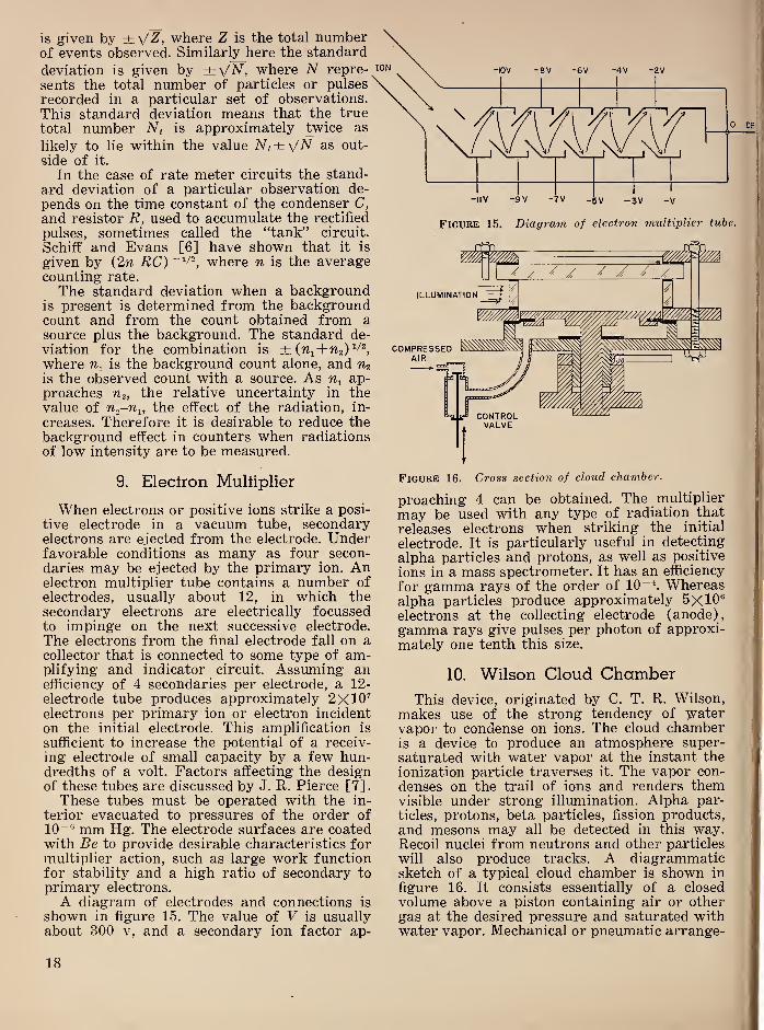
9. Eleclron Mulliplier
When electrons or positive ions strike a posi-
tive electrode in a vacuum tube, secondaryelectrons are ejected from the electrode. Underfavorable conditions as many as four secon-
daries may be ejected by the primary ion. Anelectron multiplier tube contains a number of
electrodes, usually about 12, in which thesecondary electrons are electrically focussedto impinge on the next successive electrode.
The electrons from the final electrode fall on acollector that is connected to some type of am-plifying and indicator circuit. Assuming anefficiency of 4 secondaries per electrode, a 12-
electrode tube produces approximately 2X10^electrons per primary ion or electron incidenton the initial electrode. This amplification is
sufficient to increase the potential of a receiv-
ing electrode of small capacity by a few hun-dredths of a volt. Factors affecting the designof these tubes are discussed by J. R. Pierce [7]
.
These tubes must be operated with the in-
terior evacuated to pressures of the order of10““ mm Hg. The electrode surfaces are coatedwith Be to provide desirable characteristics formultiplier action, such as large work functionfor stability and a high ratio of secondary to
primary electrons.
A diagram of electrodes and connections is
shown in figure 15. The value of V is usuallyabout 300 V, and a secondary ion factor ap-
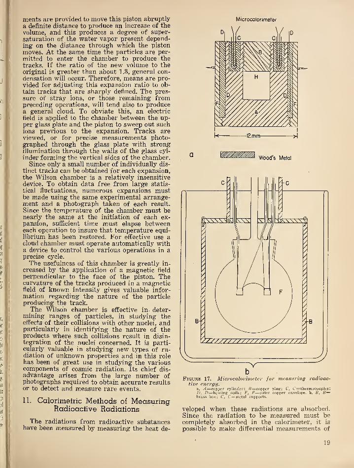
Figure 16. Cross section of cloud chamber.
proaching 4 can be obtained. The multiplier
may be used with any type of radiation that
releases electrons when striking the initial
electrode. It is particularly useful in detecting
alpha particles and protons, as well as positive
ions in a mass spectrometer. It has an efficiency
for gamma rays of the order of 10“^. Whereasalpha particles produce approximately 5x10®electrons at the collecting electrode (anode),
gamma rays give pulses per photon of approxi-
mately one tenth this size.
10. Wilson Cloud Chamber ^
This device, originated by C. T. R. Wilson,
makes use of the strong tendency of y^ater
vapor to condense on ions. The cloud chamberis a device to produce an atmosphere super-
saturated with water vapor at the instant the
ionization particle traverses it. The vapor con-
denses on the trail of ions and renders themvisible under strong illumination. Alpha par-
ticles, protons, beta particles, fission products,
and mesons may all be detected in this way.Recoil nuclei from neutrons and other particles
will also produce tracks. A diagrammaticsketch of a typical cloud chamber is shown in
figure 16. It consists essentially of a closed
volume above a piston containing air or othergas at the desired pressure and saturated withwater vapor. Mechanical or pneumatic arrange-
18
merits are provided to move this piston abruptly
a definite distance to produce an increase of thevolume, and this produces a degree of super-
saturation of the water vapor present depend-ing on the distance through which the piston
moves. At the same time the particles are per-
mitted to enter the chamber to produce the
tracks. If the ratio of the new volume to theoriginal is greater than about 1.3, general con-densation will occur. Therefore, means are pro-
vided for adjusting this expansion ratio to ob-
tain tracks that are sharply defined. The pres-sure of stray ions, or those remaining frompreceding operations, will tend also to producea general cloud. To obviate this, an electric
field is applied to the chamber between the up-per glass plate and the piston to sweep out suchions previous to the expansion. Tracks areviewed, or for precise measurements photo-graphed through the glass plate with strongillumination through the walls of the glass cyl-
inder forming the vertical sides of the chamber.Since only a small number of individually dis-
tinct tracks can be obtained for each expansion,the Wilson chamber is a relatively insensitivedevice. To obtain data free from large statis-
tical fluctuations, numerous expansions mustbe made using the same experimental arrange-ment and a photograph taken of each result.
Since the temperature of the chamber must benearly the same at the initiation of each ex-pansion, sufficient time must elapse betweeneach operation to insure that temperature equi-librium has been restored. For effective use acloud chamber must operate automatically witha device to control the various operations in aprecise cycle.
The usefulness of this chamber is greatly in-
creased by the application of a magnetic field
perpendicular to the face of the piston. Thecurvature of the tracks produced in a magneticfield of known intensity gives valuable infor-mation regarding the nature of the particleproducing the track.
The Wilson chamber is effective in deter-mining ranges of particles, in studying theeffects of their collisions with other nuclei, andparticularly in identifying the nature of theproducts where such collisions result in disin-tegration of the nuclei concerned. It is parti-cularly valuable in studying new types of ra-diation of unknown properties and in this rolehas been of great use in studying the variouscomponents of cosmic radiation. Its chief dis-advantage arises from the large number ofphotographs required to obtain accurate resultsor to detect and measure rare events.
11. Calorimelric Methods of MeasuringRadioaclive Radiations
The radiations from radioactive substanceshave been measured by measuring the heat de-
Microcalorlmeter
Wood’s Metal
bFigure 17. Microcalorimeter for measuring radioac-
tive energy,a, .<4=copper cylinder; .S=copper plug; C, C—thermocouples
;
D, Z)=heating coils; F, i^=outer copper envelope, b, B, B=brass box; C, C= metal supports.
veloped when these radiations are absorbed.Since the radiation to be measured must becompletely absorbed in the calorimeter, it is
possible to make differential measurements of
19
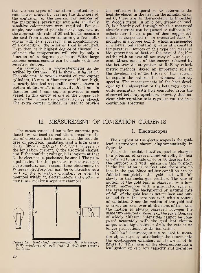
the various types of radiation emitted by aradioactive source by varying the thickness of
the container for the source. For sources of
the magnitude previously available relatively
sensitive calorimeters were required. For ex-
ample, one curie of polonium develops heat at
the approximate rate of 25 cal/hr. To measurethe heat from a source containing a few milli-
curies with fair accuracy, a microcalorimeterof a capacity of the order of 1 cal is required.Even then, with highest degree of thermal in-
sulation the temperature will rise by only afraction of a degree per hour. With largesources measurements can be made with less
sensitive devices.
An example of a microcalorimeter as de-scribed by Orthman [8] is shown in figure 17.
The calorimetric vessels consist of two coppercylinders, 12 mm in diameter and 12 mm high,as nearly identical as possible. One is shown in
section at figure 17, a. A cavity, H, 4 mm in
diameter and 4 mm high is provided in eachvessel. In this cavity of one of the copper cyl-
inders the radioactive preparation is placed.The extra copper cylinder is used to provide
III. MEASUREMENT OF
The measurement of ionization currents pro-duced by radioactive radiations requires theuse of electrical instruments with the best de-gree of electrical insulation and a high sensi-
tivity. Since i=AQ/At=CAV/At, where i is
the ionization current, Q the electrical charge,and V the resulting voltage, it is important thatC, the electrical capacitance, be small. The prin-cipal devices for this purpose are electroscopes,electrometers, and vacuum-tube electrometers.Whereas electroscopes may be constructed as apart of the ionization chamber, or even bemounted within it, electrometers and electrom-eter tubes require a separate chamber.
Figure 18. Gold-leaf electroscope; M—microscope;WW=^windows; G=gold leaf; S=diffusing screen;L=lamp.
the reference temperature to determine the
heat developed in the first. In the annular chan-nel C, there are 15 thermoelements imbeddedin Wood’s metal. In an outer, deeper channel.D, is a heating coil through which a measuredelectric current can be passed to calibrate thecalorimeter. In use a pair of these copper cyl-
inders is suspended in an evacuated flask, F,
mounted in a copper box, B, which is suspendedin a Dewar bulb containing water at a constanttemperature. Devices of this type can measurethe generation of heat at the rate of 5x10“®cal/hr with an over-all accuracy of 2 or 3 per-
cent. Measurement of the energy released bythe beta-ray disintegration of RaE by calori-
metric methods played an important role in
the development of the theory of the neutrino
to explain the nature of continuous beta-ray
spectra. The measurements of the heat devel-
oped by the absorption of the beta rays agreedquite accurately with that computed from the
observed beta ray spectrum, showing that nu-
clear disintegration beta rays are emitted in a
continuous spectrum.
IONIZATION CURRENTS
1. Eleclroscopes
The simplest of the electroscopes is the gold-
leaf electroscope shown diagrammatically in
figure 18.
When the insulated leaf support is chargedto a potential of several hundred volts, the leaf
is repelled to an angle of 40 or 50 degrees fromthe support and will remain in this positionif the insulation is perfect and there are noions in the gas. Since neither condition can befulfilled completely, the gold leaf will fall
slowly to the uncharged position. The rate ofmotion of the gold leaf is observed by a low-power microscope with a graduated scale in
the eyepiece. The background or natural rateof fall, of the gold leaf is determined and sub-tracted from the rate observed with a sourceof radiation. Since the motion of the gold leaf
is rarely uniform over all divisions of the scale,
the motion is always observed between thesame two selected divisions of the scale. Sourcesof widely different intensities cannot be com-pared accurately with the gold leaf electro-
scope, as at high rates of drift the rate is nolonger proportional to the ionization.
Gold leaf electroscopes can be used to meas-ure alpha rays by introducing the source intothe electroscope chamber, as shown at A infigure 19. This form of the electroscope has aleaf system of very low capacity and therefore
20
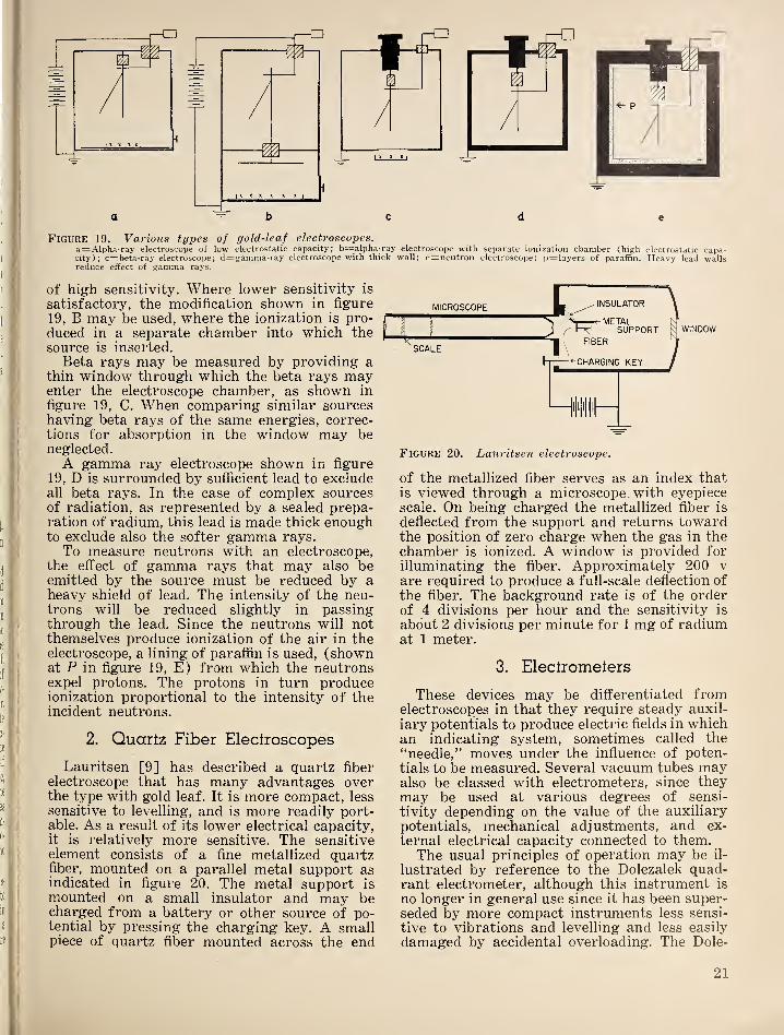
Figure 19. Various types of gold-leaf electroscopes.a=Alpha-ray electroscope of low electrostatic capacity; b=alpha-ray electroscope with separate ionization chamber (high electrostatic capa-city); c=beta-ray electroscope; d=gamma-ray electroscope with thick wall; e=neutron electroscope; p=layers of paraffin. Heavy lead wallsreduce effect of gamma rays.
of high sensitivity. Where lower sensitivity is
satisfactory, the modification shown in figure
19, B may be used, where the ionization is pro-
duced in a separate chamber into which thesource is inserted.
Beta rays may be measured by providing athin window through which the beta rays mayenter the electroscope chamber, as shown in
figure 19, C. When comparing similar sourceshaving beta rays of the same energies, correc-tions for absorption in the window may beneglected.
A gamma ray electroscope shown in figure
19, D is surrounded by sufficient lead to excludeall beta rays. In the case of complex sourcesof radiation, as represented by a sealed prepa-ration of raclium, this lead is made thick enoughto exclude also the softer gamma rays.
To measure neutrons with an electroscope,the effect of gamma rays that may also beemitted by the source must be reduced by aheavy shield of lead. The intensity of the neu-trons will be reduced slightly in passingthrough the lead. Since the neutrons will notthemselves produce ionization of the air in theelectroscope, a lining of paraffin is used, (shownat P in figure 19, E) from which the neutronsexpel protons. The protons in turn produceionization proportional to the intensity of theincident neutrons.
2. Quartz Fiber Electroscopes
Lauritsen [9] has described a quartz fiber
electroscope that has many advantages overthe type with gold leaf. It is more compact, less
sensitive to levelling, and is more readily port-able. As a result of its lower electrical capacity,it is relatively more sensitive. The sensitiveelement consists of a fine metallized quartzfiber, mounted on a parallel metal support asindicated in figure 20. The metal support is
mounted on a small insulator and may becharged from a battery or other source of po-tential by pressing the charging key. A smallpiece of quartz fiber mounted across the end
Figure 20. Lauritsen electroscope.
of the metallized fiber serves as an index thatis viewed through a microscope with eyepiecescale. On being charged the metallized fiber is
deflected from the support and returns towardthe position of zero charge when the gas in thechamber is ionized. A window is provided forilluminating the fiber. Approximately 200 v
are required to produce a full-scale deflection of
the fiber. The background rate is of the orderof 4 divisions per hour and the sensitivity is
about 2 divisions per minute for 1 mg of radiumat 1 meter.
3. Eleclromelers
These devices may be differentiated fromelectroscopes in that they require steady auxil-
iary potentials to produce electric fields in whichan indicating system, sometimes called the
“needle,” moves under the influence of poten-
tials to be measured. Several vacuum tubes mayalso be classed with electrometers, since theymay be used at various degrees of sensi-
tivity depending on the value of the auxiliary
potentials, mechanical adjustments, and ex-
ternal electrical capacity connected to them.The usual principles of operation may be il-
lustrated by reference to the Dolezalek quad-rant electrometer, although this instrument is
no longer in general use since it has been super-seded by more compact instruments less sensi-
tive to vibrations and levelling and less easily
damaged by accidental overloading. The Dole-
21
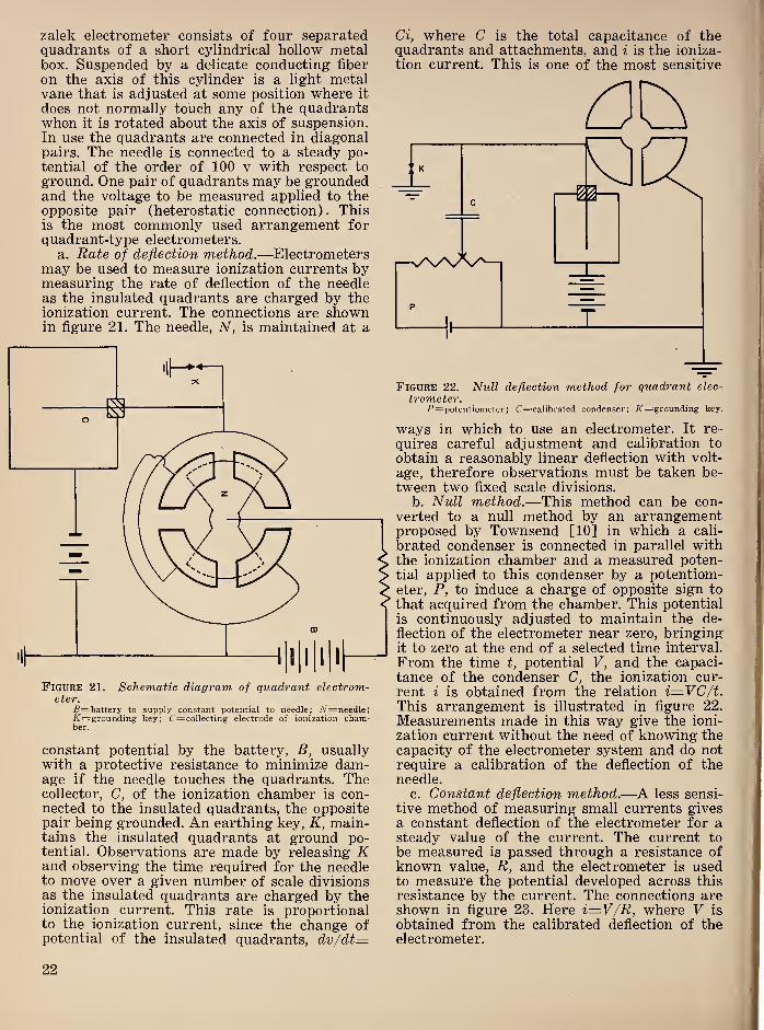
zalek electrometer consists of four separatedquadrants of a short cylindrical hollow metalbox. Suspended by a delicate conducting fiber
on the axis of this cylinder is a light metalvane that is adjusted at some position where it
does not normally touch any of the quadrantswhen it is rotated about the axis of suspension.In use the quadrants are connected in diagonalpairs. The needle is connected to a steady po-tential of the order of 100 v with respect to
ground. One pair of quadrants may be groundedand the voltage to be measured applied to theopposite pair (heterostatic connection). Thisis the most commonly used arrangement forquadrant-type electrometers.
a. Rate of deflection method .—Electrometersmay be used to measure ionization currents bymeasuring the rate of deflection of the needleas the insulated quadrants are charged by theionization current. The connections are shownin figure 21. The needle, N, is maintained at a
Figure 21. Schematic diagram of quadrant electrom-eter.
B=-battery to supply constant potential to needle; A^=needle;/C— grounding key; C=collecting electrode of ionization cham-ber.
constant potential by the battery, B, usuallywith a protective resistance to minimize dam-age if the needle touches the quadrants. Thecollector, C, of the ionization chamber is con-nected to the insulated quadrants, the oppositepair being grounded. An earthing key, K, main-tains the insulated quadrants at ground po-tential. Observations are made by releasing Kand observing the time required for the needleto move over a given number of scale divisionsas the insulated quadrants are charged by theionization current. This rate is proportionalto the ionization current, since the change ofpotential of the insulated quadrants, dv/dt—
a, where C is the total capacitance of thequadrants and attachments, and i is the ioniza-
tion current. This is one of the most sensitive
Figure 22. Null deflection method for quadrant elec-
trometer.P= potentiometer; recalibrated condenser; X=grounding key.
ways in which to use an electrometer. It re-
quires careful adjustment and calibration to
obtain a reasonably linear deflection with volt-
age, therefore observations must be taken be-
tween two fixed scale divisions.
b. Null method .—This method can be con-
verted to a null method by an arrangementproposed by Townsend [10] in which a cali-
brated condenser is connected in parallel withthe ionization chamber and a measured poten-tial applied to this condenser by a potentiom-eter, P, to induce a charge of opposite sign to
that acquired from the chamber. This potential
is continuously adjusted to maintain the de-
flection of the electrometer near zero, bringingit to zero at the end of a selected time interval.
From the time t, potential V, and the capaci-
tance of the condenser C, the ionization cur-
rent i is obtained from the relation i=VC/t.This arrangement is illustrated in figure 22.
Measurements made in this way give the ioni-
zation current without the need of knowing thecapacity of the electrometer system and do notrequire a calibration of the deflection of theneedle.
c. Constant deflection method .—A less sensi-
tive method of measuring small currents givesa constant deflection of the electrometer for asteady value of the current. The current to
be measured is passed through a resistance ofknown value, R, and the electrometer is usedto measure the potential developed across this
resistance by the current. The connections areshown in figure 23. Here i—V/R, where V is
obtained from the calibrated deflection of theelectrometer.
22

This method may also be converted to a null
deflection method by connecting a small cali-
brated auxiliary resistor between the lower endof R and ground and developing a potential
across it equal and opposite to that developed
ro IONIZATION CHAMBER
Figure 24. Schematic diagram of string electrometer.E, £=knife edges; F=quartz fiber; X=grounding key.
in R by the ionization current. This potential
may be determined by measuring the currentthrough the auxiliary resistor. When the elec-
trometer reading is zero, iR=Ir, where r is the
value of the auxiliary resistance and I the cur-
rent through it. It is assumed that the value ofr may be neglected in comparison with R, whichis usually the case.
4. Siring Eleciromeiers
Numerous types of string electrometers havebeen developed, but one of the most satisfac-
tory is due to Lutz in which a fine metal, ormetallized quartz fiber is stretched by a fine
quartz spring between two triangular metalknife edges. These knife edges are maintainedat steady equal positive and negative potentials.
The voltage to be measured is applied to thefiber. This causes it to move from the unchargedposition to a new position of equilibrium in
the plane of the knife edges. A diagram of theinstrument is shown in figure 24. It has a rela-tively low electrical capacity, is only moderatelysensitive to vibration and levelling, and is adapt-able to automatic photographic recording ofthe position of the fiber. The insulators for thefiber system must be of highest quality. It
shares with most electrometers the difficulty ofsecuring and maintaining a uniformly high de-gree of insulation of the moving system. Thesensitivity is adjusted by altering the separa-tion of the knife edges or changing the poten-
Figure 23. Constant deflection method for quadrantelectrometer.
i^=calibrated resistor.
tial applied to them and by altering the tension
of the fiber.
5. Portable Eleciromeiers
Lindemann has devised a portable elec-
trometer of compact arrangement that is based
on the quadrant principle. However, since the
needle is a metallized quartz fiber mounted on a
taut metallized quartz suspension, this instru-
ment is not unduly sensitive to vibration andcan be operated in any position. The electric
field in which the needle moves is provided byapplying opposite potentials to each pair of
four metal plates mounted symmetrically aboutthe needle. It has a sensitivity of about 500
divisions per volt and an electrical capacity of
the order of 2 esu.
In a further modification by Dershem the
sensitivity of the taut fiber electrometer hasbeen increased to several times that of the
Lindemann electrometer. Part of this increase
is obtained by mounting a mirror at the sus-
pension point of the needle and using optical
magnification of the motion. The needle in this
instrument is free to rotate completely aboutits mounting without touching the quadrants.This protects it from damage resulting fromshort circuiting the quadrant voltage. Recentimprovements in methods for producing uni-
form quartz fibers for use in the Lindemann-type electrometers have resulted in the develop-ment of instruments superior to any previously
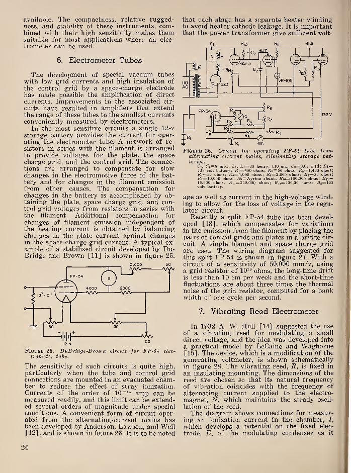
available. The compactness, relative rugged-ness, and stability of these instruments, com-bined with their high sensitivity makes themsuitable for most applications where an elec-
trometer can be used.
6. Electrometer Tubes
The development of special vacuum tubeswith low grid currents and high insulation of
the control grid by a space-charge electrode
has made possible the amplification of direct
currents. Improvements in the associated cir-
cuits have resulted in amplifiers that extendthe range of these tubes to the smallest currentsconveniently measured by electrometers.
In the most sensitive circuits a single 12-v
storage battery provides the current for oper-
ating the electrometer tube. A network of re-
sistors in series with the filament is arrangedto provide voltages for the plate, the spacecharge grid, and the control grid. The connec-tions are arranged to compensate for slowchanges in the electromotive force of the bat-tery and for changes in the filament emissionfrom other causes. The compensation forchanges in the battery is accomplished by ob-taining the plate, space charge grid, and con-trol grid voltages from resistors in series withthe filament. Additional compensation forchanges of filament emission independent of
the heating current is obtained by balancingchanges in the plate current against changesin the space charge grid current. A typical ex-
ample of a stabilized circuit developed by Du-Bridge and Brown [11] is shown in figure 25.
10,000 50
Figure 25. DuBridge-Brown circuit for FP-5i elec-
trometer tube.
The sensitivity of such circuits is quite high,particularly when the tube and control gridconnections are mounted in an evacuated cham-ber to reduce the effect of stray ionization.
Currents of the order of 10“^* amp can bemeasured readily, and this limit can be extend-ed several orders of magnitude under specialconditions. A convenient form of circuit oper-ated from the alternating-current mains hasbeen developed by Anderson, Lawson, and Weil[12] ,
and is shown in figure 26. It is to be noted
that each stage has a separate heater windingto avoid heater cathode leakage. It is importantthat the power transformer give sufficient volt-
Figure 26. Circuit for operating FP-5^ tube fromalternating current mains, eliminating storage bat-teries.
Cl, Ci= 8 mfd; L\, Li=30 henry, 110 ma; C2=0.05 mfd; B\=135 volt battery; Ri—400 ohms; i?2= 50 ohms; i?3=l,400 ohms;/?4=50 ohms; i^5=4,000 ohms; i?6=2,000 ohms; jR7=50 ohms;/^s=l0,000 ohms; i?9= Ayrton shunt; i?io=l00,000 ohms; Rii=15,000 ohms; i^3o=200,000 ohms; .Ri3=l00,00 ohms; B2=135volt battery.
age as well as current in the high-voltage wind-ing to allow for the loss of voltage in the regu-lator circuit.
Recently a split FP-54 tube has been devel-oped [13], which compensates for variationsin the emission from the filament by placing thepairs of control grids and plates in a bridge cir-
cuit. A single filament and space charge gridare used. The wiring diagram suggested forthis split FP-54 is shown in figure 27. With a
circuit of a sensitivity of 50,000 mm/v, usinga grid resistor of 10^® ohms, the long-time drift
is less than 10 cm per week and the short-timefluctuations are about three times the thermalnoise of the grid resistor, computed for a bankwidth of one cycle per second.
7. Vibrating Reed Electrometer
In 1932 A. W. Hull [14] suggested the use
of a vibrating reed for modulating a smalldirect voltage, and the idea was developed into
a practical model by LeCaine and Waghorne[15]. The device, which is a modification of thegenerating voltmeter, is shown schematicallyin figure 28. The vibrating reed, R, is fixed in
an insulating mounting. The dimensions of thereed are chosen so that its natural frequencyof vibration coincides with the frequency of
alternating current supplied to the electro-
magnet, N, which maintains the steady oscil-
lation of the reed.
The diagram shows connections for measur-ing an ionization current in the chamber, I,
which develops a potential on the fixed elec-
trode, E, of the modulating condenser as it
24
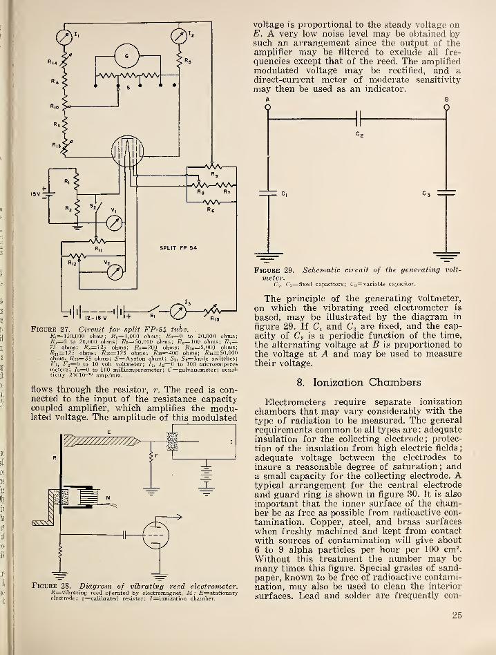
Figure 27. Circuit for split FP-54. tube. .
/?ij=150,000 ohms; i?2= 1.000 ohms; i?3=0 to 20,000 ohms;R4=0 to 20,000 ohms; i?5=50,000 ohms; ^^^=100 ohms; R'j=75 ohms; i?s=125 ohms; i?n=200 ohms; j??io=5,000 ohms;7^11=125 ohms; Ri2~12S ohms; i^i3=400 ohms; i?i4=50,000ohms; i^ir.= 35 ohms; 5'=Ayrton shunt; Si, S2=hmfe switches;
Fo— 0 to 10 volt voltmeter; li, l2=0 to 100 microamperesmeters; /3=0 to 100 milliamperemeter; C=galvanometer
;sensi-
tivity 2X10“^'^ amp/mm.
flows through the resistor, r. The reed is con-nected to the input of the resistance capacitycoupled amplifier, which amplifies the modu-lated voltage. The amplitude of this modulated
voltage is proportional to the steady voltage onE. A very low noise level may be obtained bysuch an arrangement since the output of theamplifier may be filtered to exclude all fre-
quencies except that of the reed. The amplifiedmodulated voltage may be rectified, and adirect-current meter of moderate sensitivity
may then be used as an indicator.
A 8
Figure 29. Schematic circuit of the generating volt-
meter.Cl, C 2==fixed capacitors; C3= variable capacitor.
The principle of the generating voltmeter,
on which the vibrating reed electrometer is
based, may be illustrated by the diagram in
figure 29. If Ci and Cg are fixed, and the cap-
acity of C2 is a periodic function of the time,
the alternating voltage at B is proportioned to
the voltage at A and may be used to measuretheir voltage.
8. Ionization Chambers
Electrometers require separate ionization
chambers that may vary considerably with the
type of radiation to be measured. The generalrequirements common to all types are : adequateinsulation for the collecting electrode; protec-
tion of the insulation from high electric fields
;
adequate voltage between the electrodes to
insure a reasonable degree of saturation; anda small capacity for the collecting electrode. Atypical arrangement for the central electrode
and guard ring is shown in figure 30. It is also
important that the inner surface of the cham-ber be as free as possible from radioactive con-
tamination. Copper, steel, and brass surfaces
when freshly machined and kept from contact
with sources of contamination will give about6 to 9 alpha particles per hour per 100 cm^Without this treatment the number may be
many times this figure. Special grades of sand-
paper, known to be free of radioactive contami-nation, may also be used to clean the interior
surfaces. Lead and solder are frequently con-
25
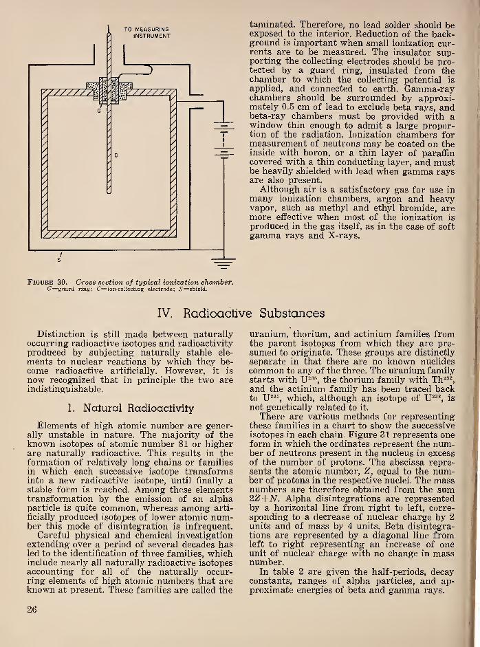
Figure 30. Cross section of typical ionization chamber.G=guard ring; C=ion-collecting electrode; i'=shield.
taminated. Therefore, no lead solder should beexposed to the interior. Reduction of the back-ground is important when small ionization cur-rents are to be measured. The insulator sup-porting the collecting electrodes should be pro-tected by a guard ring, insulated from thechamber to which the collecting potential is
applied, and connected to earth. Gamma-raychambers should be surrounded by approxi-mately 0.5 cm of lead to exclude beta rays, andbeta-ray chambers must be provided with awindow thin enough to admit a large propor-tion of the radiation. Ionization chambers formeasurement of neutrons may be coated on theinside with boron, or a thin layer of paraffincovered with a thin conducting layer, and mustbe heavily shielded with lead when gamma raysare also present.
Although air is a satisfactory gas for use inmany ionization chambers, argon and heavyvapor, such as methyl and ethyl bromide, aremore effective when most of the ionization is
produced in the gas itself, as in the case of softgamma rays and X-rays.
IV. Radioactive Substances
Distinction is still made between naturallyoccurring radioactive isotopes and radioactivityproduced by subjecting naturally stable ele-
ments to nuclear reactions by which they be-come radioactive artificially. However, it is
now recognized that in principle the two areindistinguishable.
1. Natural Radioactivity
Elements of high atomic number are gener-ally unstable in nature. The majority of theknown isotopes of atomic number 81 or higherare naturally radioactive. This results in theformation of relatively long chains or familiesin which each successive isotope transformsinto a new radioactive isotope, until finally astable form is reached. Among these elementstransformation by the emission of an alphaparticle is quite common, whereas among arti-
ficially produced isotopes of lower atomic num-ber this mode of disintegration is infrequent.
Careful physical and chemical investigationextending over a period of several decades hasled to the identification of three families, whichinclude nearly all naturally radioactive isotopesaccounting for all of the naturally occur-ring elements of high atomic numbers that areknown at present. These families are called the
uranium, thorium, and actinium families fromthe parent isotopes from which they are pre-sumed to originate. These groups are distinctly
separate in that there are no known nuclidescommon to any of the three. The uranium familystarts with the thorium family with Th^®^and the actinium family has been traced backto which, although an isotope of is
not genetically related to it.
There are various methods for representingthese families in a chart to show the successiveisotopes in each chain. Figure 31 represents oneform in which the ordinates represent the num-ber of neutrons present in the nucleus in excessof the number of protons. The abscissa repre-sents the atomic number, Z, equal to the num-ber of protons in the respective nuclei. The massnumbers are therefore obtained from the sum2.Z+N. Alpha disintegrations are representedby a horizontal line from right to left, corre-sponding to a decrease of nuclear charge by 2units and of mass by 4 units. Beta disintegra-tions are represented by a diagonal line fromleft to right representing an increase of oneunit of nuclear charge with no change in massnumber.
In table 2 are given the half-periods, decayconstants, ranges of alpha particles, and ap-proximate energies of beta and gamma rays.
26

Figure 31. Chart showing genetic relationship of the uranium, thorium, and actinium families.Abscissa are atomic numbers, ordinates=M’-2Z, where M is the mass number.
The practical usefulness of naturally radio-active isotopes depends on the half-life, thenature and energy of the radiations emitted aswell as an abundance in nature and ease ofchemical separation. Those emitting stronggamma radiation are particularly useful. Apreparation of such isotopes may be sealed in aglass or metal container and used with verylittle loss of radiation by adsorption in thewalls. Gamma radiation has found considerableuse in medical treatments of malignancies andin the radiography of thick metals. In the ura-nium family, radium has been found to fill therequirement of a suitable half-life, and the iso-
topes in equilibrium with it provide a strongsource of gamma radiation. A preparation ofradium is about 2.8x10® times as active as anequal weight of uranium, since the half-periodshave this ratio. Furthermore, the half-periodof radium, 1630 years, is still sufficiently long
to provide a practically constant source. Wheregamma-ray preparations of small volume arerequired for short periods, radon is more satis-
factory than radium. The radon in equilibriumwith 1 g of radium has a volume of only 0.65
mm®, and yet has all the products of the radiumfamily in equilibrium with it that emit stronggamma radiation.
From 5 to 50 tons of uranium ore are re-
quired to produce 1 g of radium. The elaborate
chemical operations required account for the
relatively high cost of radium. Radon is re-
leased freely into the water of a solution of
radium. The radon is separated by pumping off
the gases and vapors from an enclosed solu-
tion of radium, the equilibrium amount beingavailable every 30 days.Radium is also used commercially in the
preparation of a self-luminous compound con-
sisting of a mixture of radium and zinc sul-
27
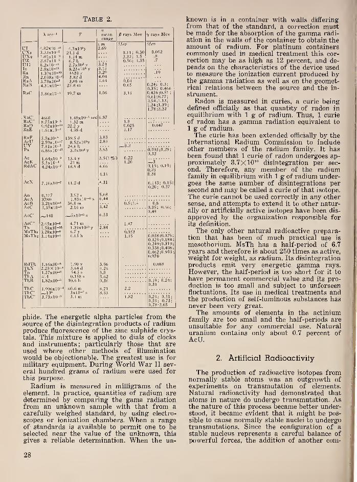
Table 2.
\ sec-^ Tameanrange
rays Mev 7 rays Mev
^ m Mev MevUI 4.82x10-“ 4.5xl0''y 2.69UXi 3.33x10-" 24.1 d 0.11; 0.30 0.092
UXz 1.01x10⁻² 1.14 m 2.32; 1.5 .8
uz 2.87x10-’ 6.7 h 0.56; 1.55 .7
un 8.2x10-“ 2.7x10= y 3.24
To 2.8x10-“ 8.23x10* y 3.15Ra 1.30x10-“ 1630 y 3.29 .19
Rn 2.098x1 O-' 3.82 d 4.04RaA 3.78x10-’ 3.05 m 4.64 0.04RaB 4.31x10-* 25.8 in 0.65 0.24; 0.3;
0.35; 0.466
RaC .3.86x10-* 19.7 m 4.06 3.15 0.426 ;0.51 ;
0.61 ;0.77;0.94;1.13;1.24;1.39 ;
1.78;2.22
RaC 6 87RaC” 8.75x10⁻² 1 .32 m 1.8RaU 9.92x10-“ 22.2 y 0.025 0.047RaE 1.61x10-'* 4.98 d 1.17
RaF 3.83
AcU 2.59x10-*’ 8.52xl02y 2.85
UY 7.81x10— 24.6 h ^0.2Pa 6.86x10-**' 3.2x10* y 3.63 0.095 ;0.29;
0.32
Ac 1.64x10-*' 13.4 y 3.5(1%) 0.22AcK 21 m 1.20 ~-3RdAC 4.24x10-’ 18.9 d 4.66 0.15; 0.19;
0.25
4.34 0.30
AcX 7.16x10“' 11.2 d 4.31 0.143; 0.150.20; 0.27
n 1 77 3 92 s 5.68
AcA •?7«n 1 83x10— ^ s 6.44
AcB 3.21x10-' 36.0 m 0.5;1.4 0.8AcC 5.35x10-' 2.16 ni .5.42 0.35; 0.46;
0.48,1 -5x10--* s 6.53
AcC" 2.45x10⁻² 4.71 m 1.47Th 1 ‘rSvin-l* 1.39x10^^ y 2.84MsThi 3.28x10⁻² 6.7 y 0.053MsTh 2 3.14x10⁻⁴ 6.13 h 1.55 0.058 ;0. 079
0.129;0.1840.249;0.3190.338;0.4080.462 ;0.915
0.970
RdTh 1.16x10^ 1.90 y 3.96 0.088ThX 2 20 X 1
0—' 3.64 d 4 26Tn 1 27x10-2 54.5 s S 0ThA 414 0.158 s 5 62ThB 1.82x10— 10.6 h 0.36 0.19; 0.24;
0.30ThC 1.906x10-* 60.6 m 4.71 2.2Tl-iT' •1 nt» 8.53ThC" 3.73x10— 3.1 m 1.82 0.29; 0.51;
0.59; 0.73;0.78-2.65
phide. The energetic alpha particles from the
source of the disintegration products of radiumproduce fluorescence of the zinc sulphide crys-
tals. This mixture is applied to dials of clocks
and instruments; particularly those that areused where other methods of illumination
would be objectionable. The greatest use is formilitary equipment. During World War II sev-
eral hundred grams of radium were used forthis purpose.
Radium is measured in milligrams of theelement. In practice, quantities of radium aredetermined by comparing the gama radiationfrom an unknown sample with that from acarefully weighed standard, by using electro-
scopes or ionization chambers. When a rangeof standards is available to permit one to beselected near the value of the unknown, this
gives a reliable determination. When the un-
known is in a container with walls differingfrom that of the standard, a correction mustbe made for the absorption of the gamma radi-ation in the walls of the container to obtain theamount of radium. For platinum containerscommonly used in medical treatment this cor-rection may be as high as 12 percent, and de-pends on the characteristics of the device usedto measure the ionization current produced bythe gamma radiation as well as on the geomet-rical relations between the source and the in-
strument.Radon is measured in curies, a curie being
defined officially as that quantity of radon inequilibrium with 1 g of radium. Thus, 1 curieof radon has a gamma radiation equivalent to
1 g of radium.The curie has been extended officially by the
International Radium Commission to includeother members of the radium family. It hasbeen found that 1 curie of radon undergoes ap-proximately 3.7x10^“ disintegration per sec-
ond. Therefore, any member of the radiumfamily in equilibrium with 1 g of radium under-goes the same number of disintegrations persecond and may be called a curie of that isotope.
The curie cannot be used correctly in any othersense, and attempts to extend it to other natur-ally or artificially active isotopes have been dis-
approved by the organization responsible forits definition.
The only other natural radioactive prepara-tion that has been of much practical use is
mesothorium. MsTh has a half-period of 6.7
years and therefore is about 250 times as active,
weight for weight, as radium. Its disintegrationproducts emit very energetic gamma rays.
However, the half-period is too short for it tohave permanent commercial value and its pro-duction is too small and subject to unforseenfluctuations. Its use in medical treatments andthe production of self-luminous substances hasnever been very great.
The amounts of elements in the actiniumfamily are too small and the half-periods areunsuitable for any commercial use. Naturaluranium contains only about 0.7 percent ofAcU.
2. Artificial Radioactivity
The production of radioactive isotopes fromnormally stable atoms was an outgrowth ofexperiments on transmutation of elements.Natural radioactivity had demonstrated thatatoms in nature do undergo transmutation. Asthe nature of this process became better under-stood, it became evident that it might be pos-sible to cause normally stable nuclei to undergotransmutations. Since the configuration of astable nucleus represents a careful balance of
powerful forces, the addition of another com-
•I:
1
28

poneiit with appropriate energy should upset
this balance.This view led to attempts to disrupt the nuclei
of atoms by the use of alpha particles, the onlyparticles available at the time with sufficient
energy and in sufficient numbers to producea detectable effect. Rutherford first succeededin demonstrating the transmutation of a stable
nucleus by bombarding nitrogen with these par-ticles. Protons with energies much greater thanthose of the bombarding alpha particles wereobtained by him, showing clearly that the bom-barded nucleus had contributed some of its
energy to these expelled protons.
The success of this experiment led many ex-
perimenters to investigate methods of produc-ing bombarding particles in greater numbersthan were available from naturally radioactive
sources. Since it was presumed that any particle
with sufficient energy to penetrate the nucleusmight be able to cause disintegration, Cockcroftand Walton [16] undertook to accelerate pro-
tons, produced by ionizing hydrogen, througha potential difference of several hundred thou-sand volts. They found that when these protonsimpinged on a piece of lithium, alpha particles
were released. By photographing the tracks of
these particles in a Wilson chamber they dem-onstrated the nature of the particles and foundthat 2 alpha particles were ejected simulta-neously in opposite directions in each disinte-
gration.
Following the now common method of rep-
resentation this reaction can be written
(37)
where the subscripts refer to the nuclear charge(:=number of protons=atomic number of thenucleus). The superscripts refer to the massnumber ( =the sum of protons and neutrons in
the nucleus) . It is obvious from the results of
this bombardment that the impinging protonwas captured in the lithium nucleus and the re-
sulting compound nucleus split into two alphaparticles which, the experiment revealed, wereejected with considerable velocities, represent-
ing a correspondingly large amount of energy,
Q, approximately 17 Mev.It is of interest to inquire where this energy
came from. Since it is much greater than thatof the bombarding protons', it must have comefrom the nucleus. To understand this we mustrefer to the principle put forward by Einsteinthat energy and mass are equivalent, in accord-ance with the relation
E—mc\ (38)
where E is energy in ergs, m, the mass in
grams, and c, the velocity of light. Therefore,to balance the masses in the equation represent-ing this disintegration, the mass equivalent to
the energy, Q, of the two alpha particles shouldbe added. The masses of the nuclei entering into
the reaction are known from the atomic weightand are given by IF(1.66x 10“-'*) where TF=atomic weight, since the mass of an atomicweight of unity has been determined as1.66 X 10 g. The atomic weight for lithium is
7.01784, and for hydrogen is 1.00813. The sumgives a total nuclear mass of (7.01818+1.00813) 1.66xl0-=^"=1.33231xl0--3 g. Theatomic weight of helium is 4.00386 so that thenuclear mass of two alpha particles is
:
2(4.00389) X 1.66x10-2*= 1.32928x10⁻²² g.
Therefore there are (1.3323-1.32928) Xl0-22z=0.00303x10⁻²³ g missing on the right-handside of the equation. This mass represents(0.00303 X 10⁻²²) c2 erg= (0.00303 x IO- 22
)
8.9864xl02®=2.75xl0-® erg. Now, 1 erg=6.24x10® Mev. Therefore, (2.75x10-®) 6.24
xl0®=17.2 Mev. Careful measurements of thetotal energies of the alpha particles emergingfrom this reaction gave 17.13dz0.06 Mev and17.28 ±0.03 Mev. This experiment gives a com-plete verification of Einstein’s postulate of theequivalence of mass and energy. This relation
between mass and energy may be used to deter-
mine the change of mass involved in a disinte-
gration from the measured release of energyor conversely to determine the release of energyto be expected when the masses are known.Whereas in most readily producible nuclear re-
actions energy is liberated, that is the particle
or photon emitted has an energy greater thanthat of the incident particle, a few reactions
have been observed in which energy is absorbedin the reaction. A typical example is
,N**+,He*^,0*'+,Hh (39)
where the energy of the emergent proton is con-
siderably less than that of the incident alpha
particle.
3. Disintegration by Protons
The reaction of protons with lithium is one of
a great number of disintegi’ations that havebeen observed when using protons as bombard-ing particles. Many of these produce a radio-
active product such as
53p2v + ^H*-»g,Xe*2^+X, (40)
which yields a xenon isotope with a 34-day
half-value period, with the liberation of a neu-
tron. A type of proton reaction is represented
by
,,Fe®^+,H*^3,Co®« + y, (41)
resulting in a radioactive isotope of cobalt withhalf-period of 72 days and the liberation of a
gamma ray.
29
4. Disinlegralion by Deuterons
Bombardment of nuclei with deuterons also
produces disintegrations. In many cases thesereactions result in radioactive isotopes. Thefirst result
sented byobtained with deuterons is repre-
gLi®+ ^gHe* (42)
which is similar to that obtained with JJi'’ andprotons.When deuterons are used to bombard heavy
hydrogen two different reactions are known:
aHe® -1- 0%^, (43)
and
(44)
The product of the first is a stable isotope ofhelium plus a neutron. The second gives a radio-active isotope of hydrogen, known as tritium,plus a proton.Another type of reaction is represented by
2iSc^®+,H^-^,,Ti« + 2oW\ (45)
where two neutrons are released and a radio-active isotope of titanium of 3 hr half-period is
produced.
5.
Disinlegralion by Alpha Parlicles
The development of the cyclotron in whichvery energetic alpha particles can be producedby accelerating helium nuclei to high velocities,has provided a much more abundant source ofthese particles than was available from natur-ally radioactive sources. Therefore a numberof reactions that were uncertain or unknownbefore this method of acceleration was devel-oped have been observed by the use of theseparticles.
A typical reaction is represented by
sBio+ .He^^.N^^-t-oWS (46)
which produces radioactive nitrogen with therelease of a neutron. One other type of reactionusing alpha particles is represented by
,ePd^«^+ ,He^^,,Agiii+ ,H% (47)
producing radioactive silver with the release ofa proton.
6.
Disinlegralion by Neulrons
Neutrons can be used to produce many moredisintegrations than any other type of particle.
This can be ascribed to the absence of electrical
charge, which makes it relatively easy for this
particle to penetrate the strong electrical fields
of the nucleus. In fact, neutrons with energiesvery near that of thermal agitation, 0.04 ev,
are very effective in producing nuclear disinte-
gration. Other reactions require neutrons withrelatively high energies. One of the most com-mon type of reactions with slow neutrons is
represented by
,gAui®^ + o%i-^,gAu^®«+y. (48)
The radioactive product of this reaction is anisotope of the stable gold nucleus with the massnumber increased by unity. A gamma ray is
released in the process. This type of reaction is
very common and is the predominant type oc-
curring in uranium piles, which are essentially
sources of thermal neutrons.Another interaction of neutrons with nuclei
is represented by the typical reaction
,8Ni®*+oWi^,28Ni=^-t-2oWh (49)
This reaction in general requires neutrons offairly high energy. This is also true of reactionsrepresented by
+ (50)
and the somewhat rare reaction represented by
^,2Mo®2-f-(,w^->4oZr®®+2He^. (51)
7.
Disinlegralion by Pholons
Gamma rays of high energy are also capableof producing disintegration of the nucleus.
When by absorption they give up energy to a
nucleus the components become unstable, anddisintegration results. This type of reaction
was discovered by Chadwick and Goldhaber[17] in an experiment that can be represented
by
(52)
Thus the incident gamma ray causes the deu-
teron to split into a proton and a neutron. Re-actions of this kind have been found to be endo-
thermic ;that is, they proceed at the expense of
the energy possessed by the incident gammaray, and the mass of the end products is greater
than that of the target nucleus. Consequentlythere is a threshold value for the energy of the
photon below which the reaction cannot occur,
which is set by the increase of mass. It is note-
worthy that reactions of this type involve the
transformation of the energy of electromagnetic
radiation into matter, another example of the
interchangeability of mass and energy. An ex-
30
ample of the production of a radioisotope bythis process is
+ (53)
The radioisotope 47Ag^““ emits a positron anddecays to stable 46Pd^°® with a half-period of
24.5 min.
8.
Alternate Methods for Producing aGiven Radioisotope
From the numerous ways in which radioiso-
topes can be produced, it is possible to select
several nuclear reactions that give the sameradioisotope. When the radioactive substance to
be produced is required in a pure form, that is
“carrier free,” it is necessary to select a methodof preparation that involves a transmutation;that is the atomic number of the target mate-rial differs from that of the radioisotope pro-duced. The radioisotope then may be separatedchemically from the target material in thosecases where the yield is sufficient to permit sucha procedure.To illustrate the numerous ways for produc-
ing a single radioisotope, the known reactionsfor making gF^®, which has a half-period of112 min are
gFi®+ y -»gF^®+ gyih \
gFl® + 4H2-»gFl®+ 4H®, I
+ -»gFl®+2oWh(
) (54)
,0^^ + 4H^^gF^®+gtlS I
4oNe2°+ 4H2^gF^®+ 2Heh /
All six reactions yield the same radioisotope offluorine with the same period, decaying by posi-tron emission to gO^®, one of the stable isotopesof oxygen.
9.
Decay of Artificially RadioactiveSubstances
Whereas the radioactive decay of artificially
active isotopes obeys the same exponential lawsdiscovered in connection with natural radioac-tivity the predominant modes of decay showsome noticeable differences; very few of theartificial isotopes decay by alpha-ray emission,and the majority undergo a beta-ray type ofdecay, characterized by the emission of a con-tinuous spectrum of beta-ray energies with adefinite upper limit. Long chains of radioactiveelements are absent among these isotopes, ex-cept in the case of a number of fission products.
10. Positron Emission
The radioactive decay of the silver isotope,
47Ag^®® illustrates a type of activity not knownamong natural radioactive substances that is
fairly common among the artificially inducedactivities. This nucleus decays by emitting posi-
trons in a continuous spectrum similar to thatof beta-ray emitters. Therefore it goes over to
4gPd^°®. These positrons are assumed to be cre-
ated in the nucleus at the time of emission muchin the same way that beta particles are pro-duced. Neither are now regarded as constitu-ents of the nucleus. Wherever positrons arepresent, annihilation radiation is produced asthese particles combine with electrons to pro-duce photons. This gamma radiation has anenergy corresponding to the amount of massthat has disappeared, twice the rest mass of theelectron. Since two photons of equal energy areproduced for each electron and positron anni-hilation, the energy of each photon is 0.51 Mev.
11. Electron Capture
Artificial isotopes also decay by capturingan orbital electron, usually from the X-level,
and so this process is commonly called A-cap-ture. The net result is similar to that producedby positron emission, the product nucleus hav-ing one less unit of nuclear charge. However, noannihilation radiation is present. Instead, X-ra-diation, corresponding to the level from whichthe electron was captured, appears. This radi-
ation is characteristic of the product atom. It
frequently happens that a radioisotope decayspartly by electron capture and partly by posi-
tron emission, both processes yielding the sameproduct.
12.
Isomeric Transilions
Among artificial radioisotopes, frequent ex-
amples occur in which an isotope, consisting of
nuclei of the same mass and the same charge,decays with two different periods. This situa-
tion is prevalent among isotopes that emit posi-
trons. Many decay partly by positron emissionand partly by electron capture. It may also
occur in a different way, represented by theonly example among the natural radioelementsin the case of UXg and UZ. This anomaly is
now explained by assuming that UXj is anexcited metastable state and UZ the groundstate of the giPa^®^ nucleus. The greater num-ber (99.85%) of these nuclei assumed to havebeen left in the excited state (UXj) decay di-
rectly to the ground state of (UII) emit-
ting a beta ray of approximately 2.3 Mev. Theremaining fraction emit a gamma ray,
brings them to the ground state of 94Pa^®^(UZ),
31

which then decays by emitting a beta ray andone or more gamma rays to the ground state of
The period for the first mode is 1.14 min
Figure 32. Disintegration scheme showing isomerictransition in disintegration of 9iPa“*.
(Bradt, et al. Helv. Phys. Acta, 18, 259 (1945).
and for the second 6.7 hrs. Considerable experi-mental evidence is available to support thispoint of view, which represents an entirelylogical explanation. An approximate represen-tation of this disintegration is shown in fig-
ure 32.
A summary of some of the more commonnuclear reactions is given in the chart in fig-
ure 33, where the nuclear charge is representedby Z and the mass number by A. Thus
represents any isotope. In addition to those re-
actions listed in figure 33, there are a few less
common ones. For example, for some of thelighter atoms, deuteron bombardment results
under favorable conditions in the capture of thedeuteron and the ejection of a tritium nucleus,t. Alpha particle bombardment in rare in-
stances results in the capture of the alpha par-ticle and the simultaneous release of a protonand a neutron.
INITIAL
NUCLEUS
PARTICLE
ORRADIATION RESULTANT
NUCLEUSINITIAL
NUCLEUS
PARTICLE
ORRADIATION RESULTANT
NUCLEUS
IN OUT IN OUT
zX* y n zX" d 2n x""z+l
n y zX" d O'XA-2
Z-l
zX“n 2n zX" P y
wA+l
Z+l^
NX>
n P V*Z-|A zX'
P n X>
zX' n or
Z-2^ zX“P ot
yA“3z-i-^
zX" d nXA+I
Z+lzX‘
or nyA+3
Z+2'^
zX^ d p zX'^ct P
yA+3
Z+l^
Figure 33. Chart showing some typical nuclear re-
actions for producing artificial radioisotopes.
These reactions are represented by the sym-bols (d, t) and (a, np), respectively. Evidencealso exists of (a, a), {n, n) and {e~, n) reac-
tions, the latter representing the release of anuclear neutron by electron bombardment.
V. Equipment for Producing Artificially Radioactive Isotopes
The rapid progress in extending the numberand increasing the quantity of artificial radio-active isotopes has been the result of the devel-opment of means of accelerating particles.
Most nuclear reactions produce greater yields,
and some reactions only occur, when the bom-barding particles have high energies. WhereasJoliot and Curie discovered artificial radio-activity with relatively simple equipment inwhich neutrons were produced by bombardingberyllium with alpha particles, the amounts ofradioactive substances produced were verysmall and just barely detectable by the radia-tion that they emitted. For production on alarger scale, several types of very elaborateequipment have been devised.
1. Voltage Mulliplier
On the first successful equipment for accel-
erating particles and producing nuclear trans-
mutation was developed by Cockcroft and Wal-ton [16]. They used an electron voltage multi-
plier for this work. The operation of such acircuit can be explained by reference to figure
34. Condenser Cj is charged to the potential, V,
of the battery permanently connected across it.
When the switch is in the position shown bysolid lines, C.^ is also charged to this potential.
When the switch is thrown to the dotted posi-
tion, Cg is in parallel with Cg, and they cometo the common potential of F/2, assuming theyhave equal capacitance. Repeating the switching
32
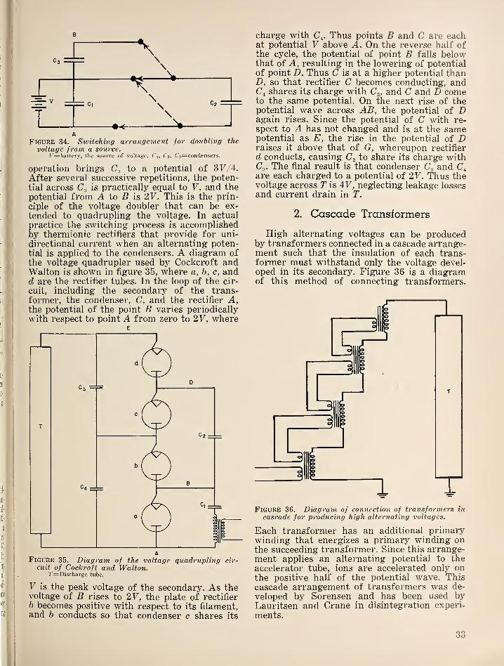
B
A
Figure 34. Switching arrangement for doubling the
voltage from a source./ ’^battery, the source of voltage, Ci, C2 , C3=condensers.
operation brings C,^ to a potential of 31^/4.
After several successive repetitions, the poten-
tial across is practically equal to V, and thepotential from A to 5 is 2V. This is the prin-
ciple of the voltage doubler that can be ex-
tended to quadrupling the voltage. In actual
practice the switching process is accomplishedby thermionic rectifiers that provide for uni-
directional current when an alternating poten-tial is applied to the condensers. A diagram of
the voltage quadrupler used by Cockcroft andWalton is shown in figure 35, where a, b, c, andd are the rectifier tubes. In the loop of the cir-
cuit, including the secondary of the trans-former, the condenser, C, and the rectifier A,the potential of the point B varies periodically
with respect to point A from zero to 2V, where
AFigure 35. Diagram of the voltage quadrupling cir-
cuit of Cockroft and Walton.7'=Discharge tube.
V is the peak voltage of the secondary. As thevoltage of B rises to 2V, the plate of rectifierh becomes positive with respect to its filament,and h conducts so that condenser c shares its
charge with C^. Thus points B and C are eachat potential V above A. On the reverse half ofthe cycle, the potential of point B falls belowthat of A, resulting in the lowering of potentialof point D. Thus C is at a higher potential thanD, so that rectifier C becomes conducting, andC4 shares its charge with C^, and C and D cometo the same potential. On the next rise of thepotential wave across AB, the potential of Dagain rises. Since the potential of C with re-spect to A has not changed and is at the samepotential as E, the rise in the potential of Draises it above that of G, whereupon rectifier
d conducts, causing to share its charge withC3 . The final result is that condenser andare each charged to a potential of 2V. Thus thevoltage across T is AV, neglecting leakage lossesand current drain in T.
2. Cascade Transformers
High alternating voltages can be producedby transformers connected in a cascade arrange-ment such that the insulation of each trans-former must withstand only the voltage devel-oped in its secondary. Figure 36 is a diagramof this method of connecting transformers.
Figure 36. Diagram of connection of transformers incascade for producing high alternating voltages.
Each transformer has an additional primarywinding that energizes a primary winding onthe succeeding transformer. Since this arrange-ment applies an alternating potential to theaccelerator tube, ions are accelerated only onthe positive half of the potential wave. Thiscascade arrangement of transformers was de-
veloped by Sorensen and has been used byLauritsen and Crane in disintegration experi-
ments.
33
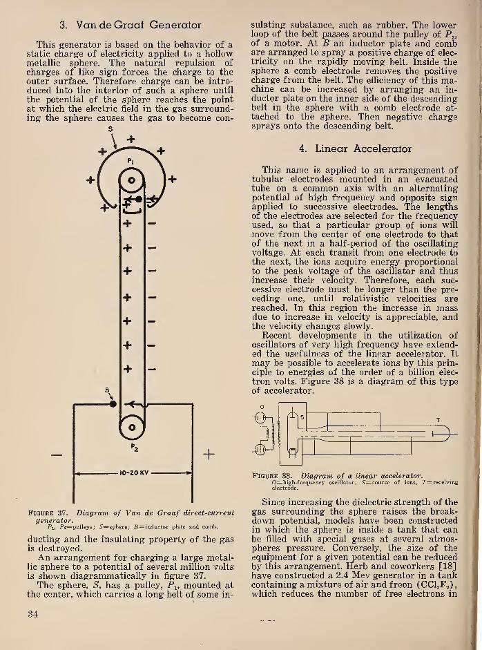
3. VandeGraaf Generalor
This generator is based on the behavior of astatic charge of electricity applied to a hollowmetallic sphere. The natural repulsion ofcharges of like sign forces the charge to theouter surface. Therefore charge can be intro-
duced into the interior of such a sphere until
the potential of the sphere reaches the pointat which the electric field in the gas surround-ing the sphere causes the gas to become con-
s
Figure 37. Diagram of Van de Graaf direct-currentgenerator.
Pi, P2=pulleys; 6'=sphere; B= inductor plate and comb.
ducting and the insulating property of the gasis destroyed.An arrangement for charging a large metal-
lic sphere to a potential of several million volts
is shown diagrammatically in figure 37.
The sphere, S, has a pulley, P^, mounted atthe center, which carries a long belt of some in-
sulating substance, such as rubber. The lowerloop of the belt passes around the pulley of P^,of a motor. At B an inductor plate and combare arranged to spray a positive charge of elec-
tricity on the rapidly moving belt. Inside thesphere a comb electrode removes the positivecharge from the belt. The efficiency of this ma-chine can be increased by arranging an in-
ductor plate on the inner side of the descendingbelt in the sphere with a comb electrode at-
tached to the sphere. Then negative chargesprays onto the descending belt.
4. Linear Accelerator
This name is applied to an arrangement oftubular electrodes mounted in an evacuatedtube on a common axis with an alternatingpotential of high frequency and opposite signapplied to successive electrodes. The lengthsof the electrodes are selected for the frequencyused, so that a particular group of ions will
move from the center of one electrode to thatof the next in a half-period of the oscillating
voltage. At each transit from one electrode tothe next, the ions acquire energy proportionalto the peak voltage of the oscillator and thusincrease their velocity. Therefore, each suc-
cessive electrode must be longer than the pre-ceding one, until relativistic velocities arereached. In this region the increase in massdue to increase in velocity is appreciable, andthe velocity changes slowly.
Recent developments in the utilization ofoscillators of very high frequency have extend-ed the usefulness of the linear accelerator. It
may be possible to accelerate ions by this prin-ciple to energies of the order of a billion elec-
tron volts. Figure 38 is a diagram of this typeof accelerator.
Figure 38. Diagram of a linear accelerator.0=high-frequency oscillator; i'=source of ions, 7'=receivingelectrode.
Since increasing the dielectric strength of thegas surrounding the sphere raises the break-down potential, models have been constructedin which the sphere is inside a tank that canbe filled with special gases at several atmos-pheres pressure. Conversely, the size of theequipment for a given potential can be reducedby this arrangement. Herb and coworkers [18]have constructed a 2.4 Mev generator in a tankcontaining a mixture of air and freon (CCI 2F2 )
,
which reduces the number of free electrons in
34

the gas. By using three concentric electrodes
and reducing the separation, he was able to
increase the voltage to 4.5 Mev in the same size
of equipment. This improvement is based onthe fact that at high pressure the dielectric
strength of air is greater in a short path thanover a long one.
5. Cyclotron
The cyclotron was developed by Lawrence[19] and consists of a vertical magnetic field
to cause ions to travel in horizontal circular
paths inside hollow circular electrodes that al-
ternate in potential, thus acquiring additional
velocity in each half-circle. As the velocity of
the ions increases, the diameter of the circle in
which they travel increases so that the time oftransit remains constant. The ultimate energyacquired depends on the strength of the mag-netic field and the diameter of the chamber in
which the ions circulate, as well as on the mag-nitude of the oscillating potential. Figure 39 is
Figure 39. Diagram of the cyclotron dees.D, Z)=dees; 6'=ion source; F=deflecting plate.
a diagram of the cyclotron showing the twohollow electrodes, or “dees”, and the generalmethod for applying the oscillating potential.
This device is particularly suited to the acceler-
ation of deuterons. Heavy hydrogen is admittedto the evacuated chamber containing the deesand ionized at the center. The beam of deuter-ons emerges tangentially at the periphery. Al-though targets may be bombarded to producetransmutations inside the low-pressure cham-ber, for many purposes it is desirable that thetai’get be outside the chamber to reduce loss
of products through evaporation.
6. Betatron
Electrons may be accelerated to energiescoi’responding to 100 Mev by using the prin-ciple on which the induction of currents by analternating magnetic field is based. A deviceoperating on this principle was first describedby Kerst [20]. If we consider an annular vol-
ume that is evacuated and contains electronsand apply a rapidly increasing magnetic field
perpendicular to the plane of the annulus over
an area entirely within the annulus, the elec-
trons tend to rotate about the annulus on arapidly expanding circle as they increased invelocity and escape tangentially. However, if
the electrons are subjected to a magnetic field
in the same direction over the entire area of theannulus, they will be deflected toward thecenter. If this field is of exactly the right mag-nitude the electrons will then travel in a cir-
cular orbit within the annulus. This requiresthat the magnetic induction, B, over the an-nulus increase at the same rate as the changeof momentum of the electron due to the changeof flux within the annulus. This will give anorbit of constant radius r. The average electro-
magnetic force on the electrons, E, is equal towhere 4>x-^4>2 represents the change
of flux in time t. The tangential electrical field
on the electron in orbit of radius r is cE/^nrand the force on the electron is ee. Therefore,the acceleration a is given by
eC cE 6 'p2~4‘i
a= = = . (55)m m 27rr t
If /t=10Vsec for a radius of 10 cm, ahas a value of 2.8x10’^^ cm/sec/sec. This corre-
sponds to </)2-</>i=l,000,000 maxwells in 1/1,000sec. The distance traveled by the electron in
1,000 sec is then 1.4x10^ cm, or 2.24x10® revo-lutions. Since S' is 10 v in this case, the energygained would be 2.24 Mev neglecting the rela-
tivistic increase in mass of the electron.
The condition for an orbit of constant radiusis /2Tr7’- where is thechange of magnitude of induction. In practice
the saturation of the iron used in producingthe magnetic induction produces a condition
within the quarter cycle of the oscillating mag-netic field, during which electrons are acceler-
ated, where the change in B does not satisfy
the condition for a constant radius of orbit. Theorbit begins to decrease in size. A target is
mounted just inside the constant orbit, so that
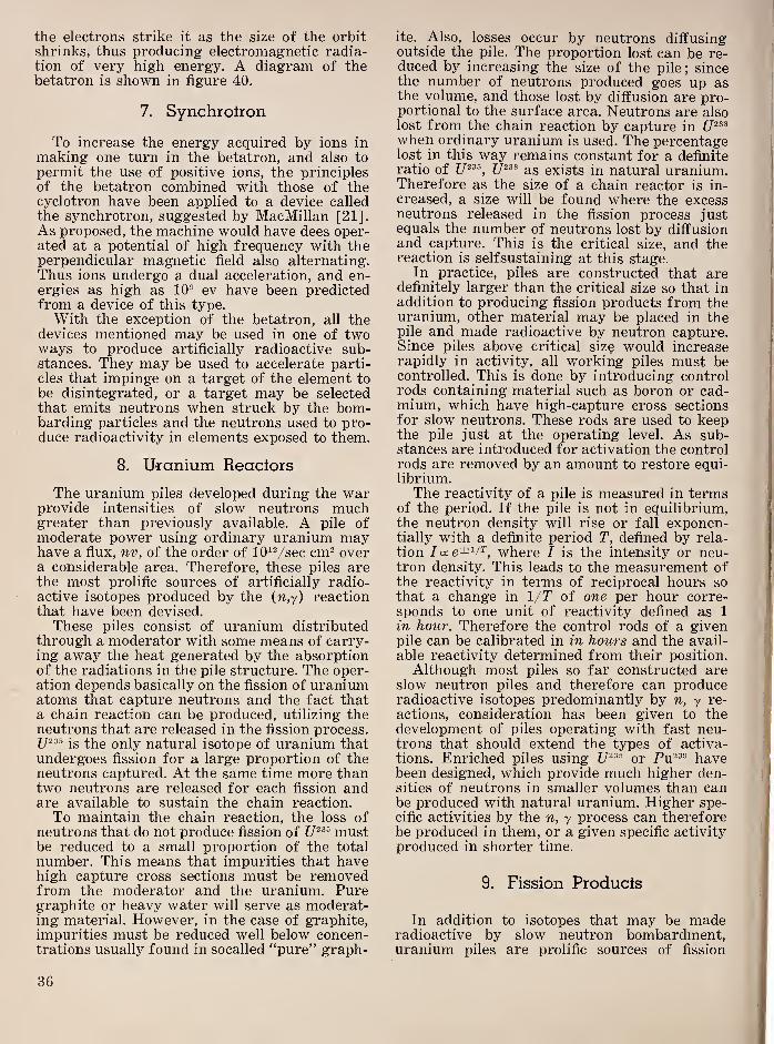
the electrons strike it as the size of the orbitshrinks, thus producing electromagnetic radia-tion of very high energy. A diagram of thebetatron is shown in figure 40.
7.
Synchrotron
To increase the energy acquired by ions in
making one turn in the betatron, and also to
permit the use of positive ions, the principlesof the betatron combined with those of thecyclotron have been applied to a device calledthe synchrotron, suggested by MacMillan [21].As proposed, the machine would have dees oper-ated at a potential of high frequency with theperpendicular magnetic field also alternating.Thus ions undergo a dual acceleration, and en-ergies as high as 10® ev have been predictedfrom a device of this type.
With the exception of the betatron, all thedevices mentioned may be used in one of twoways to produce artificially radioactive sub-stances. They may be used to accelerate parti-cles that impinge on a target of the element to
be disintegrated, or a target may be selectedthat emits neutrons when struck by the bom-barding particles and the neutrons used to pro-duce radioactivity in elements exposed to them.
8.
Uranium Reactors
The uranium piles developed during the warprovide intensities of slow neutrons muchgreater than previously available. A pile ofmoderate power using ordinary uranium mayhave a flux, nv, of the order of lO^Vsec cm^ overa considerable area. Therefore, these piles arethe most prolific sources of artificially radio-active isotopes produced by the (w,y) reactionthat have been devised.
These piles consist of uranium distributedthrough a moderator with some means of carry-ing away the heat generated by the absorptionof the radiations in the pile structure. The oper-ation depends basically on the fission of uraniumatoms that capture neutrons and the fact thata chain reaction can be produced, utilizing theneutrons that are released in the fission process.
is the only natural isotope of uranium thatundergoes fission for a large proportion of theneutrons captured. At the same time more thantwo neutrons are released for each fission andare available to sustain the chain reaction.
To maintain the chain reaction, the loss ofneutrons that do not produce fission of mustbe reduced to a small proportion of the total
number. This means that impurities that havehigh capture cross sections must be removedfrom the moderator and the uranium. Puregraphite or heavy water will serve as moderat-ing material. However, in the case of graphite,impurities must be reduced well below concen-trations usually found in socalled “pure” graph-
ite. Also, losses occur by neutrons diffusingoutside the pile. The proportion lost can be re-duced by increasing the size of the pile; sincethe number of neutrons produced goes up asthe volume, and those lost by diffusion are pro-portional to the surface area. Neutrons are alsolost from the chain reaction by capture inwhen ordinary uranium is used. The percentagelost in this way remains constant for a definiteratio of as exists in natural uranium.Therefore as the size of a chain reactor is in-
creased, a size will be found where the excessneutrons released in the fission process justequals the number of neutrons lost by diffusionand capture. This is the critical size, and thereaction is selfsustaining at this stage.
In practice, piles are constructed that aredefinitely larger than the critical size so that inaddition to producing fission products from theuranium, other material may be placed in thepile and made radioactive by neutron capture.Since piles above critical size would increaserapidly in activity, all working piles must becontrolled. This is done by introducing controlrods containing material such as boron or cad-mium, which have high-capture cross sectionsfor slow neutrons. These rods are used to keepthe pile just at the operating level. As sub-stances are introduced for activation the controlrods are removed by an amount to restore equi-librium.The reactivity of a pile is measured in terms
of the period. If the pile is not in equilibrium,the neutron density will rise or fall exponen-tially with a definite period T, defined by rela-
tion /cce±v2', where I is the intensity or neu-
tron density. This leads to the measurement ofthe reactivity in terms of reciprocal hours sothat a change in 1/T of one per hour corre-sponds to one unit of reactivity defined as 1
in hour. Therefore the control rods of a givenpile can be calibrated in in hours and the avail-
able reactivity determined from their position.
Although most piles so far constructed areslow neutron piles and therefore can produceradioactive isotopes predominantly by n, y re-
actions, consideration has been given to thedevelopment of piles operating with fast neu-trons that should extend the types of activa-tions. Enriched piles using C7®®® or Pu®®® havebeen designed, which provide much higher den-sities of neutrons in smaller volumes than canbe produced with natural uranium. Higher spe-
cific activities by the n, y process can thereforebe produced in them, or a given specific activity
produced in shorter time.
9.
Fission Products
In addition to isotopes that may be maderadioactive by slow neutron bombardment,uranium piles are prolific sources of fission
36
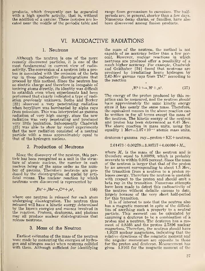
products, which frequently can be separatedwith a high specific activity, that is, withoutthe addition of a carrier. These isotopes are lo-
cated near the middle of the periodic table and
range from germanium to europium. The half-
periods are, in general, shorter than a few days.Numerous decay chains, or families, have also
been discovered among fission products.
VI. RADIOACTIVE RADIATIONS
1.
Neutrons
Although the neutron is one of the morerecently discovered particles, it is one of themost fundamental in current view of radio-activity. The conversion of a neutron into a pro-ton is associated with the emission of the betaray in those radioactive disintegrations thatproceed by this method. Since the neutron hasno electric charge and therefore is incapable ofionizing atoms directly, its identity was difficult
to establish even when experiments had beenperformed that clearly indicated a type of radi-
ation previously unknown. Bothe and Becker[22] observed a very penetrating radiationwhen beryllium was bombarded by alpha raysfrom polonium. This was interpreted as gammaradiation of very high energy, since the newradiation was very penetrating and producedvery little ionization. Subsequently Chadwick[23] was able to show by recoil experimentsthat the new radiation consisted of a neutralparticle with a mass approximately equal tothat of the hydrogen nucleus.
2.
Produclion of Neutrons
Since the discovery of the neutron, this par-ticle has been recognized as a unit in the struc-ture of atomic nucleus, the number in eachnucleus being of the same order as the num-ber of protons. Therefore neutrons are pro-duced by the disintegration of nuclei by arti-
ficial means. The nuclear reaction by whichneutrons were discovered is represented by
,Be'’ + 2He^^eC'"+o'^% (56)
where one neutron is released for each atomundergoing disintegration. The neutron thusreleased will have a kinetic energy determinedby the known energies and masses involved inthe reaction. Protons, deuterons, and photonsmay all produce nuclear disintegrations thatrelease neutrons.
3.
Mass of the Neutron
Elarliest estimates of the mass of the neutronwere made by measuring the energies of hydro-gen and nitrogen nuclei when neutrons collidedwith them. Although sufficient for identifying
the mass of the neutron, the method is notcapable of an accuracy better than a few per-cent. However, nuclear reactions in whichneutrons are produced offer a possibility of amuch higher accuracy. For example, Chadwickand Goldhaber [24] found that neutrons areproduced by irradiating heavy hydrogen by2.62-Mev gamma rays from ThC" according to
the reaction
+ + (57)
The energy of the proton produced by this re-
action can be measured, and the neutron shouldhave approximately the same kinetic energysince it has nearly the same mass. Therefore,the equivalent masses in the above reaction canbe written in for all terms except the mass ofthe neutron. The kinetic energy of the neutronand proton has been determined as 0.45 Mev.Ttie above reaction in mass units, using theequality 1 Mev=1.07xl0~® atomic mass units,
de uteron+ gamma ray=:proton+KE+ neutron,
2.01473+ 0.00279=1.00757+ 0.00096+
where is the mass of the neutron and is
therefore equal to 1.00899, which is probablyaccurate to within 0.005 percent. Since the massof the neutron is larger that that of the protonby an amount corresponding to about 1.3 Mev,the transition from a neutron to a proton re-
leases energy. Therefore the neutron is unstablewith respect to the proton and should emit abeta ray in the transition. Numerous attemptshave been made to detect this radioactivity ofthe neutron without definite success to date,
largely because of the very short half-period
for this transition.
It is of interest to note that the neutron also
has a magnetic moment in spite of the difficul-
ties of ascribing such a property to a neutralparticle. This moment can be calculated byassuming a deuteron to be a combination of aproton and a neutron. The deuteron has a mo-ment of 0.8565 and the proton 2.7896 nuclearmagnetons. Therefore, the neutron should have-1.9331 nuclear magnetons, indicating that the
relative directions of the magnetic moment andthe angular momentum are opposite to thosefor the proton and deuteron. Measurement hasgiven -1.9103 for the magnetic moment of the
37
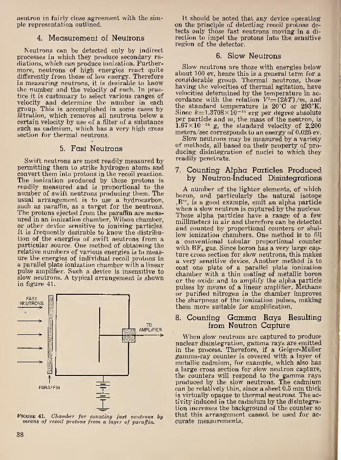
neutron in fairly close agreement with the sim-ple representation outlined.4.
Measurement of Neutrons
Neutrons can be detected only by indirect
processes in which they produce secondary ra-
diations, which can produce ionization. Further-more, neutrons of high energies react quite
differently from those of low energy. Thereforein measuring neutrons, it is desirable to knowthe number and the velocity of each. In prac-tice it is customary to select various ranges ofvelocity and determine the number in eachgroup. This is accomplished in some cases byfiltration, which removes all neutrons below acertain velocity by use of a filter of a substancesuch as cadmium, which has a very high crosssection for thermal neutrons.
5.
Fasl Neulrons
Swift neutrons are most readily measured bypermitting them to strike hydrogen atoms andconvert them into protons in the recoil reaction.The ionization produced by these protons is
readily measured and is proportional to thenumber of swift neutrons producing them. Theusual arrangement is to use a hydrocarbon,such as paraffin, as a target for the neutrons.The protons ejected from the paraffin are meas-ured in an ionization chamber, Wilson chamber,or other device sensitive to ionizing particles.
It is frequently desirable to know the distribu-tion of the energies of swift neutrons from aparticular source. One method of obtaining therelative numbers of various energies is to meas-ure the energies of individual recoil protons ina parallel plate ionization chamber with a linearpulse amplifier. Such a device is insensitive toslow neutrons. A typical arrangement is shownin figure 41.
FASTNEUTRONS
t
^
PARAFFIN
XFigure 41. Chamber for counting fast neutrons bymeans of recoil protons from a layer of paraffin.
It should be noted that any device operatingon the principle of detecting recoil protons de-tects only those fast neutrons moving in a di-
rection to impel the protons into the sensitiveregion of the detector.
6.
Slow Neulrons
Slow neutrons are those with energies belowabout 100 ev, hence this is a general term for aconsiderable group. Thermal neutrons, thosehaving the velocities of thermal agitation, havevelocities determined by the temperature in ac-cordance with the relation V^={2kT) /m, andthe standard temperature is 20°C or 293°K.Since fc=1.3708xl0“^® erg per degree absoluteper particle and m, the mass of the neutron, is
1.67x10“^^ g, the standard velocity of 2,200meters/sec corresponds to an energy of 0.025 ev.
Slow neutrons may be measured by a varietyof methods, all based on their property of pro-ducing disintegration of nuclei to which theyreadily penetrate.
7. Counting Alpha Particles Producedby Neutron-Induced Disintegrations
A number of the lighter elements, of whichboron, and particularly the natural isotopejB’®, is a good example, emit an alpha particle
when a slow neutron is captured by the nucleus.These alpha particles have a range of a fewmillimeters in air and therefore can be detectedand counted by proportional counters or shal-
low ionization chambers. One method is to fill
a conventional tubular proportional counterwith BFg gas. Since boron has a very large cap-ture cross section for slow neutrons, this makesa very sensitive device. Another method is to
coat one plate of a parallel plate ionization
chamber with a thin coating of metallic boronor the oxide and to amplify the alpha particle
pulses by means of a linear amplifier. Methaneor purified nitrogen in the chamber improvesthe sharpness of the ionization pulses, makingthem more suitable for amplification.
8. Counling Gamma Rays Resultingfrom Neutron Capture
When slow neutrons are captured to producenuclear disintegration, gamma rays are emittedin the process. Therefore, if a Geiger-Miiller
gamma-ray counter is covered with a layer of
metallic cadmium, for example, which also hasa large cross section for slow neutron capture,
the counters will respond to the gamma raysproduced by the slow neutrons. The cadmiumcan be relatively thin, since a sheet 0.5 mm thick
is virtually opaque to thermal neutrons. The ac-
tivity induced in the cadmium by the disintegra-
tion increases the background of the counter so
that this arrangement cannot be used for ac-
curate measurements.
38

9. Induced Activities
The amount of the radioactive isotope pro-duced by bombardment with slow neutrons is
proportional to the number of neutrons thatstrike the sample. Therefore, by exposing a foil
to the neutrons to be measured for a definite
time and measuring the activity—counting therate of emission of beta rays, for example—at adefinite time subsequent to the exposure, thenumber of neutrons that were captured in theexposure interval can be determined. The half-
period of the induced activity must be knownas well as the capture cross section of the iso-
tope from which the foil is made. The relationfor this computation is given by eq 11, wherenvNo is sustituted for n^, w=number of neu-trons per cubic centimeter, 'y=their velocity,
N'=number of atoms in foil, and o=their crosssection. P, the number of radioactive atomspresent in the foil at time, t, subsequent to ex-posure to a neutron flux of nv for a time T is
given by
nvNaP= (1-e-^^) e-^*,
A
where A is the decay constant of the radioactiveisotope formed by neutron capture. In practicetwo activities may be induced in the same foil,
as, for example, when the element from whichthe foil is made consists of two isotopes innature. If one of the activities has a muchshorter period than the other, its effect can beeliminated experimentally by waiting a shorttime for the short activity to decay before meas-using the radioactivity of the foil. In attemptingabsolute measurements of nv by this method,it must be noted that the cross section usedmust correspond to the energies of the neutronsthat are being measured.
Frequently it may be desirable to use a num-ber of different foils with resonances for neu-trons of different energies to determine therelative number of neutrons at correspondingenergies.
10. Cross Sections for Reactions withNeutrons
When neutrons impinge on a group of atomicnuclei, the number of those that react is ex-pressed in terms of the cross section of the par-ticular nuclei for the neutrons in question. Thecross section of a nucleus is expressed in squarecentimeters, representing the effective targetarea of the nucleus for the neutron. The symbolo is used to denote this quantity. When there aren neutrons per cubic centimeter with velocity v,
the number striking a square centimeter per
second is nv, the neutron flux. If there are Natoms per square centimeter of the target ele-
ment, then the number of reactions per secondis given by nvNo. A convenient unit for thecross section is 10“^* cm^ A specific cross sec-
tion may be assigned to each type of interactionfor a given nucleus. For example, a neutron mayreact with a nucleus by undergoing (1) scatter-
ing, either elastic or inelastic, or by (2) beingcaptured or absorbed. Further distinction maybe made by specifying the angle of scatteringor the specific results of the capture that mayresult in emission of radiation of particles fromthe bombarded nucleus. Therefore, a number ofsubscripts may be applied to distinguish theprocess to which it applies. For example Oa is
usually used to designate the total cross sectionof a nucleus for neutron capture and Oe for thecross section that leads to a radioactive product.Similarly, Os is used to denote the total scatter-
ing cross section. Fundamentally a refers to asingle nucleus so that a distinction must also
be made between isotopic cross section and theatomic cross section per atom of the naturalelement for those elements that are composedof more than one isotope in nature.
The cross section not only depends on thenucleus but also on the energy of the neutron.In the region of slow neutrons the cross sectionmay vary very markedly with the change in
energy of the neutrons.
The measurement of cross sections undervarious conditions requires the selection of neu-trons with energies distributed over a narrowregion, since no sources of monoenergetic neu-trons are available. Various methods have beenused to obtain such segregation of neutronswith respect to their energies. The velocity se-
lector in which the detector is placed at a defi-
nite distance from the source is one example.The detector and source are modulated at aknown frequency so that the detector is sensi-
tive for a definite interval after the release ofneutrons from the source. The neutrons de-
tected are then those that have velocities equalto d/t, where d is the separation between sourceand detector, and t is the time between release
and detection of the neutrons. This method is
limited to relatively slow neutrons. (£'<10^ ev)
.
A more common method for separating neu-trons according to velocity, is by filtration. Byproper selection of filters, various velocities
of neutrons that correspond to resonance levels
in the filters may be removed. When only oneresonance level is present, the cross section o
(E) as a function of the energy of the neutron,E is given by the Breit-Wigner formula [25]
Er Oo
a(E)= , (58)£1/2 / E-Er W
+l
r/2 )
39
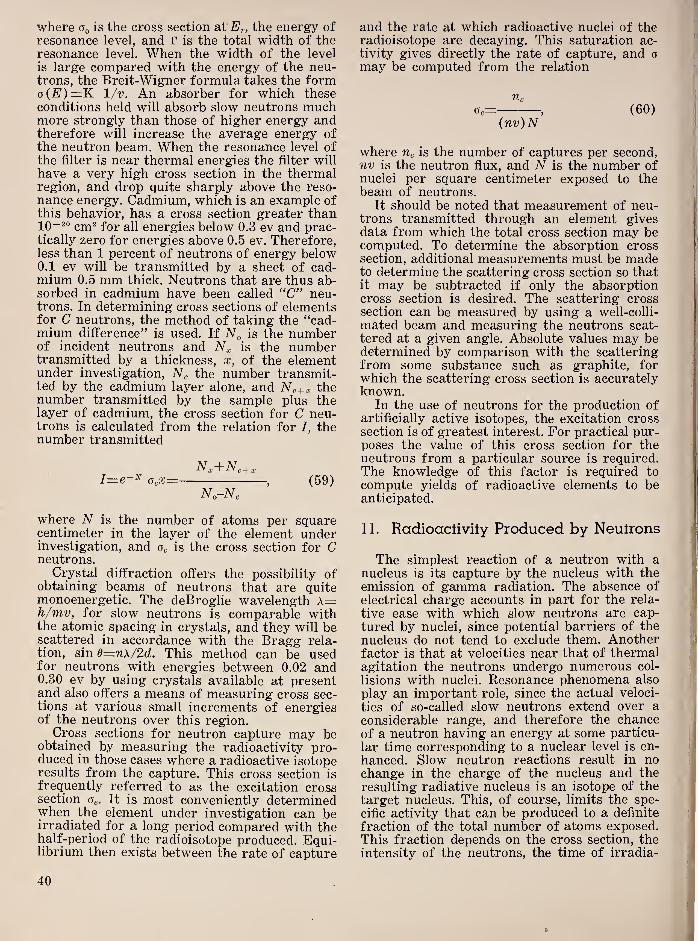
I
where is the cross section at Er, the energy ofresonance level, and r is the total width of theresonance level. When the width of the level
is large compared with the energy of the neu-trons, the Breit-Wigner formula takes the formo{E)=K \/v. An absorber for which theseconditions held will absorb slow neutrons muchmore strongly than those of higher energy andtherefore will increase the average energy ofthe neutron beam. When the resonance level ofthe filter is near thermal energies the filter will
have a very high cross section in the thermalregion, and drop quite sharply above the reso-
nance energy. Cadmium, which is an example ofthis behavior, has a cross section greater than
cm^ for all energies below 0.3 ev and prac-tically zero for energies above 0.5 ev. Therefore,less than 1 percent of neutrons of energy below0.1 ev will be transmitted by a sheet of cad-mium 0.5 mm thick. Neutrons that are thus ab-sorbed in cadmium have been called “C” neu-trons. In determining cross sections of elementsfor C neutrons, the method of taking the “cad-mium difference” is used. If Nq is the numberof incident neutrons and E
^
is the numbertransmitted by a thickness, x, of the elementunder investigation, Ng the number transmit-ted by the cadmium layer alone, and Ng+a, thenumber transmitted by the sample plus thelayer of cadmium, the cross section for C neu-trons is calculated from the relation for I, thenumber transmitted
N:^+ Nc+ x
I=e-^ OcX= , (59)Ng-Ng
where N is the number of atoms per squarecentimeter in the layer of the element underinvestigation, and Og is the cross section for Cneutrons.
Crystal diffraction offers the possibility ofobtaining beams of neutrons that are quitemonoenergetic. The deBroglie wavelength A=h/mv, for slow neutrons is comparable withthe atomic spacing in crystals, and they will bescattered in accordance with the Bragg rela-tion, sin d=nx/2d. This method can be usedfor neutrons with energies between 0.02 and0.30 ev by using crystals available at presentand also offers a means of measuring cross sec-tions at various small increments of energiesof the neutrons over this region.
Cross sections for neutron capture may beobtained by measuring the radioactivity pro-duced in those cases where a radioactive isotoperesults from the capture. This cross section is
frequently referred to as the excitation crosssection Og. It is most conveniently determinedwhen the element under investigation can beirradiated for a long period compared with thehalf-period of the radioisotope produced. Equi-librium then exists between the rate of capture
and the rate at which radioactive nuclei of theradioisotope are decaying. This saturation ac-tivity gives directly the rate of capture, and a
may be computed from the relation
Oe=^^, (60)inv)N
where Uc is the number of captures per second,nv is the neutron flux, and N is the number ofnuclei per square centimeter exposed to thebeam of neutrons.
It should be noted that measurement of neu-trons transmitted through an element givesdata from which the total cross section may becomputed. To determine the absorption crosssection, additional measurements must be madeto determine the scattering cross section so thatit may be subtracted if only the absorptioncross section is desired. The scattering crosssection can be measured by using a well-colli-
mated beam and measuring the neutrons scat-
tered at a given angle. Absolute values may bedetermined by comparison with the scatteringfrom some substance such as graphite, forwhich the scattering cross section is accuratelyknown.
In the use of neutrons for the production ofartificially active isotopes, the excitation crosssection is of greatest interest. For practical pur-poses the value of this cross section for theneutrons from a particular source is required.The knowledge of this factor is required to
compute yields of radioactive elements to beanticipated.
11. Radioactivity Produced by Neutrons
The simplest reaction of a neutron with anucleus is its capture by the nucleus with theemission of gamma radiation. The absence of
electrical charge accounts in part for the rela-
tive ease with which slow neutrons are cap-
tured by nuclei, since potential barriers of the
nucleus do not tend to exclude them. Anotherfactor is that at velocities near that of thermalagitation the neutrons undergo numerous col-
lisions with nuclei. Resonance phenomena also
play an important role, since the actual veloci-
ties of so-called slow neutrons extend over aconsiderable range, and therefore the chanceof a neutron having an energy at some particu-
lar time corresponding to a nuclear level is en-
hanced. Slow neutron reactions result in nochange in the charge of the nucleus and the
resulting radiative nucleus is an isotope of the
target nucleus. This, of course, limits the spe-
cific activity that can be produced to a definite
fraction of the total number of atoms exposed.This fraction depends on the cross section, theintensity of the neutrons, the time of irradia-
40

tion, and the half-value period of the radio-active product.
Neutrons can also produce reactions in whichthe composite nucleus formed by the captureof a neutron ejects a particle, such as a proton,alpha particle, or a pair of neutrons. Thesereactions, with rare exception, require neutronsof relatively high energies for much the samereasons given in the similar case for protons.When charged particles are emitted, the effect
of neutron bombardment resonance appears to
be less important than the delivery of sufficient
energy by the incident particle to permit theejected particle to escape through the nuclearpotential barrier.
12.
Protons
The proton is the nucleus of the hydrogenatom and therefore has one elementary unit ofpositive charge. The mass number of the proton(oxygen= 16.000) is 1.0076, corresponding to
1.6725x10“^* g, and it has a magnetic momentof 2.7896 nuclear magnetrons. It is regardedat present as one of the fundamental units ofnuclear structure, with all nuclei made up ofone or more protons corresponding to the nu-clear charge and sufficient neutrons to accountfor the mass. Protons have never been observedas a product of radioactive disintegration ex-cept as constituents of alpha particles. On theother hand, they frequently are expelled fromthe compound nucleus formed by bombardmentof stable nuclei resulting in nuclear disintegra-tion and the production of artificially radio-active isotopes.
13.
Production of Protons
Protons are produced as the result ofnuclear integrations. A typical reaction is rep-resented by
+ (61)
By varying the number and energy of the in-
cident alpha particles, protons of different en-ergies can be produced in varying numbers.However, the intensities of proton beams avail-
able by this means are very weak, and measure-ments can be made only under favorable experi-mental conditions with sensitive detectors. Forinvestigations of protons where larger intensi-ties are required and for their use in nucleardisintegrations, these particles are produced byionizing hydrogen and accelerating the hydro-gen nuclei in one of the several devices foraccelerating positive ions, for example, a high-voltage accelerator.
Figure 42 is a diagram of a typical low-voltage arc arranged to produce protons fromhydrogen. This gas is introduced into the bulbsurrounding the cylinder at a pressure of 0.1
to 0.5 mm Hg pressure. The filament serves asa source of electrons that are accelerated by apotential difference of 30 to 40 v between thefilament and the anode. The ion gun is severalhundred volts negative with respect to theanode. Protons are admitted to the acceleratingtube through a capillary that permits the arcto operate at a considerably higher pressurethan that of the accelerating tube. Proton cur-rents of the order of milliamperes can be ob-tained by such methods.
Figure 42. Positive ion source for producing protons.
14.
Deleclion and Measurement of
Protons
Relatively intense beams of protons may bemeasured in terms of ionization produced in
any of the conventional types of ionization
chambers. The windows of such chambers mustbe thin enough to admit a relatively large frac-
tion of the protons. Protons of 0.5 Mev arecompletely absorbed in aluminum 0.006 mmthick, and 1.0-Mev protons are absorbed in
0.015 mm. Individual protons of moderate en-
ergy may be detected in any of the devices thatwill respond to ionizing particles. As their
energy increases, ionization per centimeter of
path decreases to the extent that single protonshaving energies greater than 2 Mev are diffi-
cult to detect. The average number of ions pro-
duced per centimeter in air at atmospheric pres-
sure at 2 Mev is about 8,000, whereas at 7 Mevthis number has decreased to about 3,000. Thismay be compared with the ionization producedby an alpha particle that is of the order of
50,000 ion nairs per centimeter under similar
conditions. The relatively low penetrating powerof these particles does not permit the use of
Geiger-Miiller counters, since windows thin
enough to permit them to enter will not with-
stand the required difference in pressure. Thedevice most successful in detecting these par-
ticles is some form of proportional counter, in
which the ionization produced by each is multi-
plied by impact ionization in the gas of the
counter. The decrease of ion pairs per centi-
meter with increasing energy complicates the
problem of estimating the energy from the size
of pulse produced in a proportional counter.
This estimate can only be made when the full
41
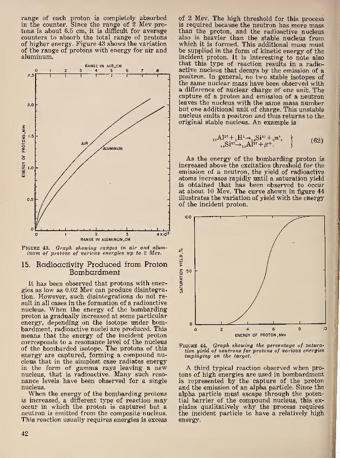
range of each proton is completely absorbedin the counter. Since the range of 2 Mev pro-tons is about 6.5 cm, it is difficult for averagecounters to absorb the total range of protonsof higher energy. Figure 43 shows the variationof the range of protons with energy for air andaluminum.
RANGE IN AIR, CM012345678
Figure 43. Graph showing ranges in air and alum-inum of protons of various energies up to 2 Mev.
15. Radioaclivily Produced from ProtonBombardment
It has been observed that protons with ener-
gies as low as 0.02 Mev can produce disintegra-
tion. However, such disintegrations do not re-
sult in all cases in the formation of a radioactive
nucleus. When the energy of the bombardingproton is gradually increased at some particularenergy, depending on the isotope under bom-bardment, radioactive nuclei are produced. Thismeans that the energy of the incident protoncorresponds to a resonance level of the nucleusof the bombarded isotope. The protons of this
energy are captured, forming a compound nu-cleus that in the simplest case radiates energyin the form of gamma rays leaving a newnucleus, that is radioactive. Many such reso-
nance levels have been observed for a single
nucleus.When the energy of the bombarding protons
is increased, a different type of reaction mayoccur in which the proton is captured but aneutron is emitted from the composite nucleus.This reaction usually requires energies is excess
of 2 Mev. The high threshold for this processis required because the neutron has more massthan the proton, and the radioactive nucleusalso is heavier than the stable nucleus fromwhich it is formed. This additional mass mustbe supplied in the form of kinetic energy of theincident proton. It is interesting to note alsothat this type of reaction results in a radio-active nucleus that decays by the emission of apositron. In general, no two stable isotopes ofthe same nuclear mass have been observed witha difference of nuclear charge of one unit. Thecapture of a proton and emission of a neutronleaves the nucleus with the same mass numberbut one additional unit of charge. This unstablenucleus emits a positron and thus returns to theoriginal stable nucleus. An example is
13 (62)
As the energy of the bombarding proton is
increased above the excitation threshold for theemission of a neutron, the yield of radioactiveatoms increases rapidly until a saturation yieldis obtained that has been observed to occurat about 10 Mev. The curve shown in figure 44illustrates the variation of yield with the energyof the incident proton.
Figure 44. Graph showing the percentage of satura-tion yield of neutrons for protons of various energiesimpinging on the target.
A third typical reaction observed when pro-
tons of high energies are used in bombardmentis represented by the capture of the protonand the emission of an alpha particle. Since the
alpha particle must escape through the poten-tial barrier of the compound nucleus, this ex-
plains qualitatively why the process requiresthe incident particle to have a relatively highenergy.
42
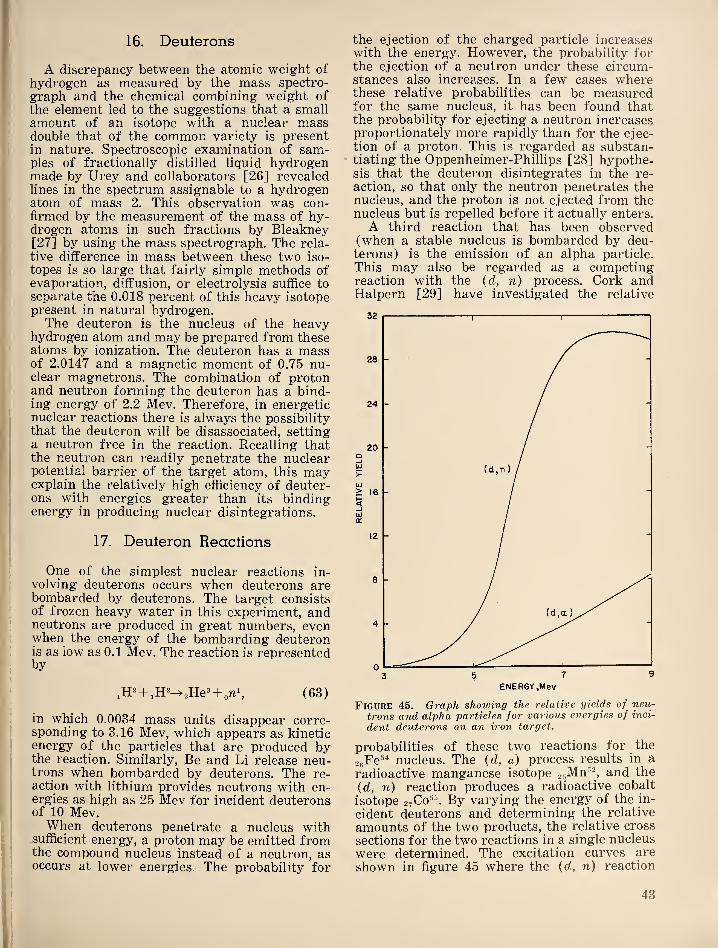
16. Deulerons
A discrepancy between the atomic weight of
hydrogen as measured by the mass spectro-
graph and the chemical combining weight of
the element led to the suggestions that a smallamount of an isotope with a nuclear massdouble that of the common variety is presentin nature. Spectroscopic examination of sam-ples of fractionally distilled liquid hydrogenmade by Urey and collaborators [26] revealedlines in the spectrum assignable to a hydrogenatom of mass 2. This observation was con-firmed by the measurement of the mass of hy-drogen atoms in such fractions by Bleakney[27] by using the mass spectrograph. The rela-
tive difference in mass between these two iso-
topes is so large that fairly simple methods ofevaporation, diffusion, or electrolysis suffice to
separate the 0.018 percent of this heavy isotopepresent in natural hydrogen.The deuteron is the nucleus of the heavy
hydrogen atom and may be prepared from theseatoms by ionization. The deuteron has a massof 2.0147 and a magnetic moment of 0.75 nu-clear magnetrons. The combination of protonand neutron forming the deuteron has a bind-ing energy of 2.2 Mev. Therefore, in energeticnuclear reactions there is always the possibilitythat the deuteron will be disassociated, settinga neutron free in the reaction. Recalling thatthe neutron can readily penetrate the nuclearpotential barrier of the target atom, this mayexplain the relatively high efficiency of deuter-ons with energies greater than its bindingenergy in producing nuclear disintegrations.
17. Deuferon Reactions
One of the simplest nuclear reactions in-volving deuterons occurs when deuterons arebombarded by deuterons. The target consistsof frozen heavy water in this experiment, andneutrons are produced in great numbers, evenwhen the energy of the bombarding deuteronis as low as 0.1 Mev. The reaction is representedby
(63)
in which 0.0034 mass units disappear corre-sponding to 3.16 Mev, which appears as kineticenergy of the particles that are produced bythe reaction. Similarly, Be and Li release neu-trons when bombarded by deuterons. The re-action with lithium provides neutrons with en-ergies as high as 25 Mev for incident deuteronsof 10 Mev.When deuterons penetrate a nucleus with
sufficient energy, a proton may be emitted fromthe compound nucleus instead of a neutron, asoccurs at lower energies. The probability for
the ejection of the charged particle increaseswith the energy. However, the probability forthe ejection of a neutron under these circum-stances also increases. In a few cases wherethese relative probabilities can be measuredfor the same nucleus, it has been found thatthe probability for ejecting a neutron increasesproportionately more rapidly than for the ejec-
tion of a proton. This is regarded as substan-tiating the Oppenheimer-Phillips [28] hypothe-sis that the deuteron disintegrates in the re-
action, so that only the neutron penetrates thenucleus, and the proton is not ejected from thenucleus but is repelled before it actually enters.
A third reaction that has been observed(when a stable nucleus is bombarded by deu-terons) is the emission of an alpha particle.
This may also be regarded as a competingreaction with the {d, n) process. Cork andHalpern [29] have investigated the relative
Figure 45. Graph showing the relative yields of neu-
trons and alpha particles for various energies of inci-
dent deuterons on an iron target.
probabilities of these two reactions for the
soFe^* nucleus. The {d, a) process results in a
radioactive manganese isotope gsMn®^, and the
{d, n) reaction produces a radioactive cobalt
isotope 2700 ^^®. By varying the energy of the in-
cident deuterons and determining the relative
amounts of the two products, the relative cross
sections for the two reactions in a single nucleus
were determined. The excitation curves are
shown in figure 45 where the {d, n) reaction
43

begins at about 3 Mev and the {d, a) at slightly
less than 5 Mev, with the {d, n) reaching asaturation value at about 7.5 Mev, whereas theyield from the {d, a) reaction continues to rise
steadily up to the maximum energy of deuteronsavailable, 9 Mev.A fourth process observed in deuteron bom-
bardment is the emission of two neutrons. Thisreaction, {d, 2n) may be regarded as compa-rable with the emission of two neutrons underneutron bombardment {n, 2n). Both constitu-
ents of the deuteron penetrate the nucleus in
this reaction however, since the proton of thecombination is captured yielding a product withone unit greater atomic number than that ofthe target nucleus. The reaction has been ob-served only in connection with energetic deu-terons.
18. Alpha Particles
Rutherford and Royds [30] proved that alphaparticles are the nuclei of atoms of helium byexamining the optical spectrum of the gasformed when alpha particles are trapped in anevacuated tube. The doubly ionized heliumatoms recapture their orbital electrons whentheir velocities have been reduced to values nearthose of thermal agitation, resulting in atomsof helium. These particles, therefore, have themass of the helium nucleus and carry two ele-
mentary positive charges. The value of e/m foralpha particles was determined by applicationof electric and magnetic fields simultaneouslyto produce deflections in opposite directions, ad-justing these fields to produce a net deflection
of zero. Under these conditions Hev=£'e, whereH is the magnetic field and E the electric field, e
the charge and v the velocity of the particles.
This gives the velocity as v—E/H, which canbe used in the relation for the magnetic deflec-
tion alone, Hev=mr^/r, to determine e/m—E/Wr. The early measurements of this quan-tity were difficult to interpret since velocities,
charge, and mass were initially unknown. Whenparticles of single velocity were used, a valueof 4,300 emu per gram was obtained, which is
quite close to the most accurate value to date of
4,813 [31]. The value of e/m for helium deter-mined by the mass spectrograph is within afraction of a percent of the same value, givenby Birge [32] as 4822.3 ±.05.
19. Range of Alpha Particles
Since alpha particles are emitted in groupswith all particles in the group having the sameinitial energy, the distance that the particlesin a particular group travel before losing suffi-
cient kinetic energy that they no longer pro-duce ionization is approximately the same. This
distance measured in centimeters is the rangeand is usually specified for air at normal pres-sure and temperature. The ranges of alphaparticles are most readily determined by ioni-
zation methods. The procedures and precautionsrequired in such measurements are illustrated
by the measurements of Holloway and Living-ston [33] by using a shallow ionization cham-ber. A differential chamber was used by Lewis
H.V.
Figure 46. Diagrams of ionization chambers for study-ing the variation of ionization of alpha particles withrange.
/^ = shallow chamber; F=thin metal foil; HF—high voltage;
^^differential chamber; Fi, F2 =thin metal foils, used as
windows.
and Wynn-Williams [34] for the same purpose.These two types of ionization chambers are il-
lustrated in figure 46. Figure 46, B representsthe shallow chamber. Particles that passthrough the grid and penetrate the gas in theshallow volume between the grid and collector
plate produce pulses that can be detected by alinear amplifier. There is a minimum height of
pulse, which can be differentiated from thebackground “noise” of the amplifying system,which is represented by a certain minimumdepth of penetration of the particle into the
44
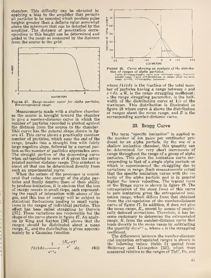
chamber. This difficulty can be obviated byapplying a bias to the amplifier that permits
all particles to be recorded -which produce pulse
heights greater than a definite value somewhatabove the minimum that can be detected by the
amplifier. The distance of penetration corre-
sponding to this height can be determined andadded to the range as measured by the distance
from the source to the grid.
Figure 47. Range-number curve for alpha particles,
R=extrapolated range.
Measurements made with a shallow chamberas the source is brought toward the chamberto give a number-distance curve in which the
number of particles recorded is plotted againstthe distance from the source to the chamber.This curve has the general shape shown in fig-
ure 47. This curve shows a practically constantnumber of particles, which near the end of therange, breaks into a straight line with fairly
large negative slope, followed by a curved por-tion as the number of particles approaches zero.
The straight portion of the descending curvewhen extrapolated to zero at R gives the extra-polated number distance range. This constant is
about all that can be determined directly fromsuch an experimental curve.When the nature of the processes is consid-
ered that reduce the energy of the alpha par-ticles and finally deprive them of their ability
to produce ionization, it is obvious that the loss
of energy occurs in small steps, each represent-ing the result of interaction with atoms of thegas, and this loss of energy will be subject tostatistical fluctuations leading to small varia-tions in the ranges of individual particles. Thiseffect has been called straggling by Darwin[35]. These variations are responsible for theshape of the curve shown in figure 47. An analy-sis by King and Rayton [36] shows that theranges should be distributed about a meanrange, R^, and the distribution is given approxi-mately by a Gaussian function
f{x)dx— e dx, (64)
CENTIMETERS
Figure 48. Curve showing an analysis of the distribu-
tion of ranges of alpha particles.Cvrve S=range-number curve near maximum range; /?=extra-polated range. Curve /4 = distribution of ranges about the meanrange (x=0), a=straggling parameter.
where f(x)dx is the fraction of the total num-ber of particles having a range between x andx + dx. a/Rf, is the range straggling coefficient;
a the range straggling parameter, is the half-
width of the distribution curve at 1/e of themaximum. This distribution is illustrated in
figure 48 where curve A shows the distribution
of ranges about the mean range, and B is thecorresponding number-distance curve.
20. Bragg Curve
The term “specific ionization" is applied to
the number of ion pairs per centimeter pro-duced by an alpha particle. By the use of a
shallow ionization chamber, this quantity canbe determined for very short increments of
range throughout the range of a group of alphaparticles. This gives the ionization curve cor-
responding to that of a single alpha particle onwhich is superimposed the straggling due to
variations in range. Such measurements reveal
that the specific ionization varies with the ve-
locity of the alpha particle and is in general
higher for lower velocities. The typical formof the Bragg curve is shown in figure 49. Theextrapolation of the steep front of this curveto zero ionization gives the extrapolated ioni-
zation range, which differs from that obtainedfrom the extrapolation of the number-distancecurve of figure 47. In addition, it does not give
the mean range, R^, except by means of empiri-cally deduced corrections. Therefore, it has be-
come customary to determine the extrapolatedrange, R, from the number-distance curve that
leads directly to the mean range by subtractingthe quantity d=A''^ a, where a is the straggling
coefficient.
The differences between the number-distanceand ionization extrapolated ranges is shown in
the following values (table 3) quoted fromHolloway and Livingston [33] ,
which weremeasured relative to the ranges of ThC', Po, and
45
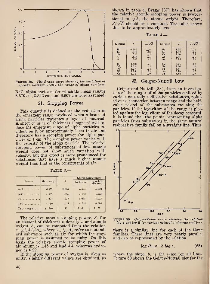
CENTIMETERS FROM SOURCE
Figure 49. The Bragg curve showing the variation of
specific ionization with the range of alpha particles.
RaC' alpha particles for which the mean ranges
8.570 cm, 3.842 cm, and 6.907 cm were assumed.
21. Slopping Power
This quantity is defined as the reduction in
the emergent range produced when a beam of
alpha particles traverses a layer of material.
A sheet of mica of thickness 1 mg/cm^ will re-
duce the emergent range of alpha particles in-
cident on it by approximately 1 cm in air andtherefore has a stopping power for alpha par-
ticles of 1 cm. The stopping power varies with
the velocity of the alpha particle. The relative
stopping power of substances of low atomic
weight does not show much variation withvelocity, but this effect is more pronounced for
substances that have a much higher atomic
weight than that of the constituents of air.
Table 3.
—
Source Mean range a
Extrapola
Ionization
ted ranges
Number-distance
AcA 6.457 0.096 6.496 6.542
AcC 5.429 .083 5.462 5.503
Tn 5.004 .078 5.035 5.073
ThC 4.730 .074 4.718 4.796
ThC' (long) 11.580 .15 11.64 11.71
The relative atomic stopping power, S, for
an element of thickness t, density p, and atomicweight A, can be computed from the relation
s—p^t^A/ptA^, where po, A^ refer to a stand-
ard substance such as air for which the stop-
ping power is assumed to be unity. On this
basis the relative atomic stopping power of
aluminum is 1.45 and lead 4.4, whereas hydro-gen is 0.22.
If the stopping power of oxygen- is taken asunity, slightly different values are obtained, as
shown in table 4. Bragg [37] has shown thatthe relative ^atomic stopping power is propor-
tion^ to A, the atomic weight. Therefore,
S/yA should be a constant. The table showsthis to be approximately true.
Table 4.
—
Element V S/VA Element 5 S/VA
H 0.200 0.20 Fe 1.96 0.26Li .519 .20 Ni 1.89 .25
Be .750 .25 Cu 2.00 .25
C .814 .25 Zn 2.05 .25N .939 .25 Ag 2.74 .26
0 1.000 .25 Cd 2.75 .26Mg 1.23 .25 Sn 2.86 .26A1 1.27 .24 pt 3.64 .26Si 1.23 .23 Au 3.73 .27Cl 1.76 .29 Pb 3.86 .27
22. Geiger-Nutlall Law
Geiger and Nuttall [38], from an investiga-
tion of the ranges of alpha particles emitted byvarious naturally radioactive substances, point-
ed out a connection between range and the half-
value period of the substances emitting theparticles. If the logarithm of the range is plot-
ted against the logarithm of the decay constant,it is found that the points representing alphaparticles from substances in the same naturalradioactive family fall on a straight line. Thus,
Figure 50. Geiger-Nutall curve showing the relation
log \ and log R for various natural alpha-ray emitters.
there is a similar line for each of the threefamilies. These lines are very nearly parallel
and can be represented by the relation
log R=a+b log A, (65)
where the slope, b, is the same for all lines.
Figure 50 shows the Geiger-Nuttall plot for the
46
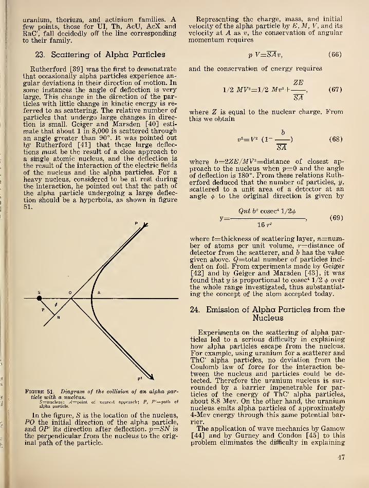
uranium, thorium, and actinium families. Afew points, those for UI, Th, AcU, AcX andRaC', fall decidedly off the line correspondingto their family.
23. Scattering of Alpha Particles
Rutherford [39] was the first to demonstratethat occasionally alpha particles experience an-
gular deviations in their direction of motion. In
some instances the angle of deflection is verylarge. This change in the direction of the par-
ticles with little change in kinetic energy is re-
ferred to as scattering. The relative number of
particles that undergo large changes in direc-
tion is small. Geiger and Marsden [40] esti-
mate that about 1 in 8,000 is scattered throughan angle greater than 90°. It was pointed out
by Rutherford [41] that these large deflec-
tions must be the result of a close approach to
a single atomic nucleus, and the deflection is
the result of the interaction of the electric fields
of the nucleus and the alpha particles. For aheavy nucleus, considered to be at rest duringthe interaction, he pointed out that the path of
the alpha particle undergoing a large deflec-
tion should be a hyperbola, as shown in figure
Figure 51. Diagram of the collision of an alpha par-ticle with a nucleus.
5'=nucleus; yI=point of nearest approach; P, F'=path of
alpha particle.
In the figure, S is the location of the nucleus,
PO the initial direction of the alpha particle,
and OP' its direction after deflection. Tp—SN is
the perpendicular from the nucleus to the orig-
inal path of the particle.
Representing the charge, mass, and initial
velocity of the alpha particle by E, M, V, and its
velocity at A as v, the conservation of angularmomentum requires
p V=SAv, (66)
and the conservation of energy requires
ZE1/2 MV^=l/2 Mv^+ , (67)
SA
where Z is equal to the nuclear charge. Fromthis we obtain
b
SA
where b=2ZE/MV^=distsince of closest ap-
proach to the nucleus when p=0 and the angle
of deflection is 180°. From these relations Ruth-erford deduced that the number of particles, y,
scattered to a unit area of a detector at anangle
<f)to the original direction is given by
Qnt b^ cosec^ l/2c/)
y=, (69)
16
where t=thickness of scattering layer, w=num-ber of atoms per unit volume, r=distance of
detector from the scatterer, and b has the valuegiven above. Q=total number of particles inci-
dent on foil. From experiments made by Geiger[42] and by Geiger and Marsden [43], it wasfound that y is proportional to cosec^ 1/2 (j) overthe whole range investigated, thus substantiat-
ing the concept of the atom accepted today.
24. Emission of Alpha Parlicles from the
Nucleus
Experiments on the scattering of alpha par-ticles led to a serious difficulty in explaininghow alpha particles escape from the nucleus.
For example, using uranium for a scatterer andThC' alpha particles, no deviation from theCoulomb law of force for the interaction be-
tween the nucleus and particles could be de-
tected. Therefore the uranium nucleus is sur-
rounded by a barrier impenetrable for par-ticles of the energy of ThC' alpha particles,
about 8.8 Mev. On the other hand, the uraniumnucleus emits alpha particles of approximately4-Mev energy through this same potential bar-rier.
The application of wave mechanics by Gamow[44] and by Gurney and Condon [45] to this
problem eliminates the difficulty in explaining
47
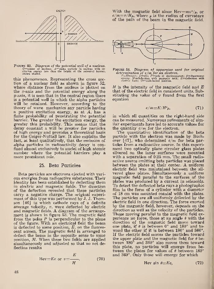
ENERGY
Figure 52. Diagram of the potential well of a nucleus.0—center of nucleus; y4=alpha particle in nucleus with ex-citation energy less than the height of the potential barrier,shown shaded.
this phenomenon. Representing the cross sec-
tion of a nuclear field as shown in figure 52,where distance from the nucleus is plotted onthe a;-axis and the potential energy along they-axis, it is seen that in the central region thereis a potential well in which the alpha particleswill be retained. However, according to thetheory of wave mechanics any particle havinga positive excitation energy, as at A, has afinite probability of penetrating the potentialbarrier. The greater the excitation energy, thegreater this probability. This means that thedecay constant A will be greater for particles
of high energy and provides a theoretical basisfor the Geiger-Nuttall law. It also explains thefact, at least qualitatively, that the emission ofalpha particles in radioactivity decay is con-fined almost exclusively to nuclei of high atomicnumber where the potential barriers play amore prominent role.
25. Bela Particles
Beta particles are electrons ejected with vari-
ous energies from radioactive substances. Theiridentity has been established by deflecting themin electric and magnetic fields. The directionof the deflection revealed that these particles
carry a negative charge. The original experi-ment of this type was performed by J. J. Thom-son [46] in which cathode rays of a definite
average velocity, v, were deflected by electric
and magnetic fields. A diagram of the arrange-ment is shown in figure 53. The magnetic field
from the poles P is perpendicular to the planeof the figure. With an electrical field the beamis deflected to some position, E, on the fluores-
cent screen. The magnetic field is arranged to
deflect the beam in the opposite sense to someposition, M. When these two fields are appliedsimultaneously and adjusted so that no net de-
flection results
EHev=£'e or v= . (70)
H
With the magnetic field alone Hev=m'y^/p, ore/m=.v/Hp, where p is the radius of curvatureof the path of the beam in the magnetic field.
determination of e/m for an electron,F=filairient; S—s\it; P=poIe of electromagnet; B=fluorescentscreen; M=deflection with magnetic field; £‘=deflection withelectric field; 0=undeflected position.
H is the intensity of the magnetic field and Ethat of the electric field in consistent units. Sub-stituting the value of v found from the first
equation
e/m—E/H^p, (71)
in which all quantities on the right-hand sidecan be measured. Numerous refinements of sim-ilar experiments have led to accurate values forthe quantity e/m for the electron.
The quantitative identification of the betaparticle with the electron was made by Buch-erer [47], who determined e/m for beta par-ticles from a radioactive source. In this experi-ment two optically plane circular glass platessilvered on the inner surfaces were mountedwith a separation of 0.25 mm. The small radio-
active source emitting beta particles was placedbetween the plates at their center. A uniformelectric field was maintained between the sil-
vered glass plates. Simultaneously a uniformmagnetic field parallel to the surfaces of theplates was produced by a current in solenoids.
To detect the deflected beta rays a photographicfilm in the form of a cylinder with a diameterof 18 cm was mounted coaxial with the plates.
The particles are all uniformly deflected by theelectric field in one direction. The force exertedby the magnetic field, however, depends on thedirection as well as the velocity of the particles.
Those moving parallel to the magnetic field ex-perience no force, those at an angle 6 with thedirection of the magnetic field move towardone plate, if 6 is between 0° and 180° and to-
ward the other if it is between 180° and 360°.
If the electric field moves the particles towardthe upper plate and the magnetic field for 0 be-
tween 180° and 360° also moves them towardthis plate, no particles will emerge from be-
tween the plates for values of 6 between 180°
and 360°. Only those will emerge for which
Hev sin 6=Ee, (72)
48
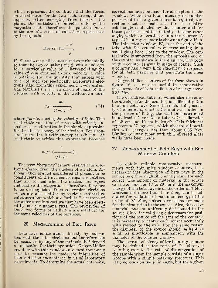
which represents the condition that the forceson the electron for the two fields are equal andopposite. After emerging from between theplates, the particles are affected only by themagnetic field. Therefore, the particles movein the arc of a circle of curvature representedby the equation
mv'^
Hev sin 0=, (73)
p
H, E, and p may all be measured experimentallyso that the two equations yield both v and e/mfor a particular value of 0. Extrapolating thevalue of e/m obtained to zero velocity, a valueis obtained for this quantity that agrees withthat obtained for electrically accelerated elec-
trons. Also, from this experiment, a verificationwas obtained for the variation of mass of theelectron with velocity in the well-known form
mom=
, (74)
( 1_^2)
1/2
where p=v/c, c being the velocity of light. Thisrelativistic variation of mass with velocity in-
troduces a modification in the simple expressionfor the kinetic energy of the electron. For a con-stant mass the kinetic energy is 1/2 mv‘\ Atrelativistic velocities this expression becomes
1
( 1 ).
The term “beta ray” is now reserved for elec-
trons ejected from the nucleus of an atom. Al-though they are not considered at present to beconstituents of the nucleus as separate entities,
they are formed when the nucleus undergoesradioactive disintegration. Therefore, they areto be distinguished from conversion electronswhich are also emitted by various radioactivesubstances but which are “orbital” electrons ofthe outer atomic structure that have been eject-ed by nuclear gamma rays. The properties ofthese two forms of radiation are identical forthe same velocities of the particles.
26. Measurement of Beta Rays
Beta rays ionize atoms directly by interac-tion with the outer electrons and therefore canbe measured by any of the methods that dependon ionization for their operation. Geiger-Milllercounters with thin windows are most commonlyused to measure the moderate intensities ofbeta radiation encountered in usual laboratoryexperiments. To determine the actual intensity.
corrections must be made for absorption in thewindow. Where the total intensity or numberper second from a given source is required, cor-
rection must be made also for the relative
solid angle subtended by the counter and forthose particles emitted initially at some otherangle, which are scattered into the counter. Atypical beta-ray counter is shown in figure 16, b.
The thin mica window, W, is at the end of thetube with the central wire terminating in asmall glass bead close to the window. The cen-tral wire is supported from the opposite end ofthe counter, as shown in the diagram. The bodyof this counter is usually made of copper. Sucha counter has a very high efficiency of responsefor all beta particles that penetrate the micawindow.
Geiger-Miiller counters of the form shown in
figure 16, a are also useful in comparativemeasurements of beta radiation of energy above0.35 Mev.The cylindrical tube, T, which also serves as
the envelope for the counter, is sufficiently thinto admit beta rays. Since the metal tube, usual-ly of aluminum, must withstand evacuation in
the process of filling, the wall thickness mustbe at least 0.1 mm for a tube with a diameterof 1.5 cm and 10 cm in length. This thicknessrepresents 27 mg/cm^, which absorbs all parti-
cles with energies less than about 0.35 Mev.Similar counter tubes with thin silvered glasswalls have been made.
27. Measurement of Beta Rays wifh EndWindow Counters
To obtain reliable comparative measure-ments with thin mica window counters, it is
necessary that absorption of beta rays in thesource be either negligible or the same for eachsource. The amount of material in the sourcecan be as much as 10 to 20 mg if the maximumenergy of the beta rays is of the order of 1 Mev,whereas not more than 1 or 2 mg can be tol-
erated for radiation of maximum energy of theorder of 0.1 Mev, unless corrections are madefor the absorption in the source. Also, the active
material must be uniformly distributed in thesource. Since the solid angle decreases for posi-
tions of the source off the axis of the counter,it is necessary to center each source accuratelywith respect to the axis. For the same reasonthe diameter of the source should be kept assmall as practicable in comparison with thediameter of the counter window.The over-all efficiency of the beta-ray counter
may be defined as the ratio of the observedcounting rate to the rate of disintegration of
the sample when the sample consists of a single
isotope with a simple beta-ray spectrum. Thisratio depends on the solid angle, but for a given
49
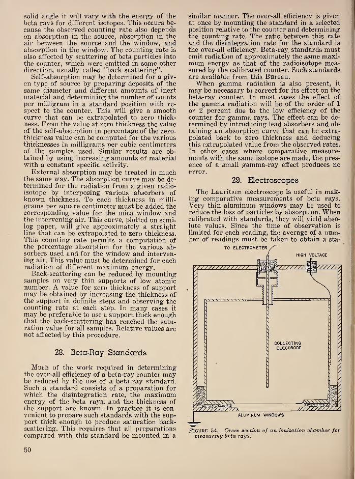
solid angle it will vary with the energy of thebeta rays for different isotopes. This occurs be-
cause the observed counting rate also dependson absorption in the source, absorption in theair between the source and the window, andabsorption in the window. The counting rate is
also affected by scattering of beta particles into
the counter, which were emitted in some otherdirection, usually called “back scattering”.
Self-absorption may be determined for a giv-
en type of source by preparing deposits of thesame diameter and different amounts of inertmaterial and determining the number of countsper milligram in a standard position with re-
spect to the counter. This will give a smoothcurve that can be extrapolated to zero thick-ness. From the value at zero thickness the valueof the self-absorption in percentage of the zero-thickness value can be computed for the variousthicknesses in milligrams per cubic centimetersof the samples used. Similar results are ob-tained by using increasing amounts of materialwith a constant specific activity.
External absorption may be treated in muchthe same way. The absorption curve may be de-termined for the radiation from a given radio-isotope by interposing various absorbers ofknown thickness. To each thickness in milli-
grams per square centimeter must be added thecorresponding value for the mica window andthe intervening air. This curve, plotted on semi-log paper, will give approximately a straightline that can be extrapolated to zero thickness.This counting rate permits a computation ofthe percentage absorption for the various ab-sorbers used and for the window and interven-ing air. This value must be determined for eachradiation of different maximum energy.
Back-scattering can be reduced by mountingsamples on very thin supports of low atomicnumber. A value for zero thickness of supportmay be obtained by increasing the thickness ofthe support in definite steps and observing thecounting rate at each step. In many cases it
may be preferable to use a support thick enoughthat the back-scattering has reached the satu-ration value for all samples. Relative values arenot affected by this procedure.
28. Beta-Ray Standards
Much of the work required in determiningthe over-all efficiency of a beta-ray counter maybe reduced by the use of a beta-ray standard.Such a standard consists of a preparation forwhich the disintegration rate, the maximumenergy of the beta rays, and the thickness ofthe support are known. In practice it is con-venient to prepare such standards with the sup-port thick enough to produce saturation back-scattering. This requires that all preparationscompared with this standard be mounted in a
similar manner. The over-all efficiency is given <
at once by mounting the standard in a selected if
position relative to the counter and determining;
the counting rate. The ratio between this rateand the disintegration rate for the standard is
the over-all efficiency. Beta-ray. standards mustemit radiation of approximately the same maxi-
;
mum energy as that of the radioisotope mea-sured by the calibrated counter. Such standards i
are available from this Bureau. '
When gamma radiation is also present, it
may be necessary to correct for its effect on thebeta-ray counter. In most cases the effect ofthe gamma radiation will be of the order of 1
or 2 percent due to the low efficiency of thecounter for gamma rays. The effect can be de-
termined by introducing lead absorbers and ob-taining an absorption curve that can be extra-polated back to zero thickness and deducingthis extrapolated value from the observed rates.
In other cases where comparative measure-ments with the same isotope are made, the pres-ence of a small gamma-ray effect produces noerror.
29. Eleclroscopes
The Lauritsen electroscope is useful in mak-ing comparative measurements of beta rays.
Very thin aluminum windows may be used to
reduce the loss of particles by absorption. Whencalibrated with standards, they will yield abso-lute values. Since the time of observation is
limited for each reading, the average of a num-ber of readings must be taken to obtain a sta-
Figure 54. Cross section of an ionization chamber formeasuring beta rays.
50
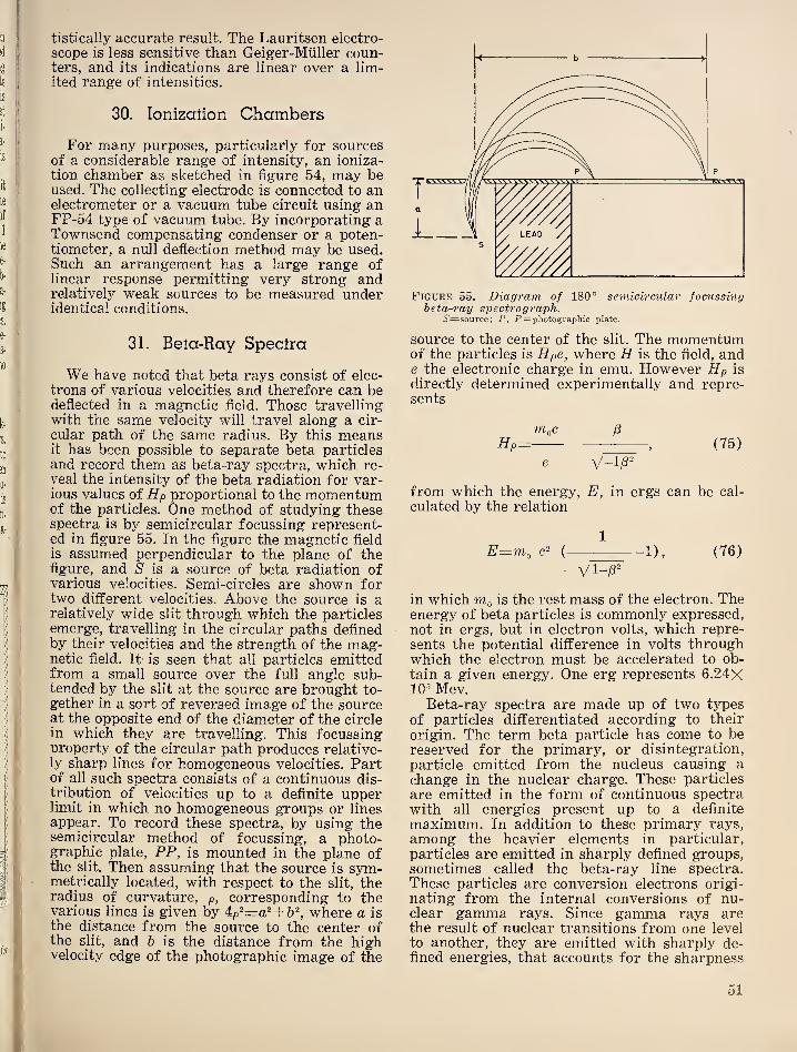
tistically accurate result. The Lauritsen electro-
scope is less sensitive than Geiger-Miiller coun-ters, and its indications are linear over a lim-ited range of intensities.
30. Ionization Chambers
For many purposes, particularly for sourcesof a considerable range of intensity, an ioniza-
tion chamber as sketched in figure 54, may beused. The collecting electrode is connected to anelectrometer or a vacuum tube circuit using anFP-54 type of vacuum tube. By incorporating aTownsend compensating condenser or a poten-tiometer, a null deflection method may be used.Such an arrangement has a large range oflinear response permitting very strong andrelatively weak sources to be measured underidentical conditions.
31. Bela-Ray Spectra
We have noted that beta rays consist of elec-
trons of various velocities and therefore can bedeflected in a magnetic field. Those travellingwith the same velocity will travel along a cir-
cular path of the same radius. By this meansit has been possible to separate beta particlesand record them as beta-ray spectra, which re-
veal the intensity of the beta radiation for var-ious values of Hp proportional to the momentumof the particles. One method of studying thesespectra is by semicircular focussing represent-ed in figure 55. In the figure the magnetic field
is assumed perpendicular to the plane of thefigure, and 5 is a source of beta radiation ofvarious velocities. Semi-circles are shown fortwo different velocities. Above the source is arelatively wide slit through which the particlesemerge, travelling in the circular paths definedby their velocities and the strength of the mag-netic field. It is seen that all particles emittedfrom a small source over the full angle sub-tended by the slit at the source are brought to-
gether in a sort of reversed image of the sourceat the opposite end of the diameter of the circlein which they are travelling. This focussingnroperty of the circular path produces relative-ly sharp lines for homogeneous velocities. Partof all such spectra consists of a continuous dis-
tribution of velocities up to a definite upperlimit in which no homogeneous groups or linesappear. To record these spectra, by using thesemicircular method of focussing, a photo-graphic plate, PP, is mounted in the plane ofthe slit. Then assuming that the source is sym-metrically located, with respect to the slit, theradius of curvature, p, corresponding to thevarious lines is given by 4:p'^=a^+ h'^, where a is
the distance from the source to the center ofthe slit, and 6 is the distance from the highvelocity edge of the photographic image of the
beta-ray spectrograph.5'=source; P, P= photographic plate.
source to the center of the slit. The momentumof the particles is Hpe, where H is the field, ande the electronic charge in emu. However Hp is
directly determined experimentally and repre-sents
m,c fi
Hp= , (75)
from which the energy, E, in ergs can be cal-
culated by the relation
1
E=m, ( 1), (76)
in which ttIq is the rest mass of the electron. Theenergy of beta particles is commonly expressed,not in ergs, but in electron volts, which repre-
sents the potential difference in volts throughwhich the electron must be accelerated to ob-
tain a given energy. One erg represents 6.24X10’ Mev.
Beta-ray spectra are made up of two typesof particles differentiated according to their
origin. The term beta particle has come to bereserved for the primary, or disintegration,
particle emitted from the nucleus causing a
change in the nuclear charge. These particles
are emitted in the form of continuous spectrawith all energies present up to a definite
maximum. In addition to these primary rays,
among the heavier elements in particular,
particles are emitted in sharply defined groups,sometimes called the beta-ray line spectra.These particles are conversion electrons origi-
nating from the internal conversions of nu-clear gamma rays. Since gamma rays arethe result of nuclear transitions from one level
to another, they are emitted with sharply de-fined energies, that accounts for the sharpness
51

of the lines in the conversion electron spectra.If represents the energy of the ejected con-version electron, Ey the energy of the gammaray, and the Ek the binding energy of orbitalelectrons in the X-shell, these quantities arerelated according to the equation
E,=Ey-Ej,. (77)
Since conversion may occur for other than theif-level, several similar equations may be set upfor a single gamma ray, as E.2=Ey-EL andE^=Ey~E^u, where El and Em represent thebinding energies of L and M shell electrons. Theobservation of conversion electrons with ener-gies corresponding to E^, E^, and E^ forms oneof the strongest experimental proofs of thecorrectness of the conversion hypothesis. Thesemicircular focussing beta-ray spectrographhas been used mainly for the study of line spec-
Figure 56. Cross section of an electromagnet for 180°beta-ray spectrograph.
tra of conversion electrons by using a photo-graphic plate for recording. Continuous spectrado not lend themselves to photographic record-ing, since it is difficult to distinguish the maxi-mum end point.
The use of a Geiger-Miiller counter to detectthe beta particles is required to convert this in-
strument for the study of continuous spectra.Since the counter is operated in a fixed positionthe magnetic field must be varied in small accu-rate steps to obtain a spectrum. Magnets withiron cores, either electromagnets or semiper-manent magnets, have been used with the semi-circular spectrograph, but it is difficult tochange the magnetic field with such magnets in
the way desired. On the other hand, these mag-nets are entirely satisfactory for photographicrecording of line spectra.
32. Magnets for Semicircular Beta-RaySpectrographs
The simplest magnet for this purpose con-sists of an electromagnet of yoke design usinglow-carbon steel for the yoke and core. Figure56 is a cross section of a magnet of this type.
An air gap of approximately 5 cm is adequate
Figure 57. Cross section of typical 180° beta-ray spec-
trograph.0=pump connection; Cri=source holder; 6'=source; G2==shutter
holder; ^=shutter; C=cover; F= photographic plate.
52

for the spectrometer. A typical spectrographis shown in section in figure 57. The magneticfield is adjusted by selecting the value of the
current desired and reversing this current sev-
eral times. In this way a definite point is select-
ed on the hysteresis curve of the iron that is
quite accurately reproducible. The desired cur-
rent is selected from a curve showing the mag-netic field for various values of the current ob-
tained by the same method of reversing thecurrent.
33. Magnetic Electron LensSpectrometer
Klemperer [48] proposed in 1935 the use of
a short magnetic lens to focus beta rays. Theprinciples involved are described by Deutsch,Elliott, and Evans [49]. Figure 58 shows adiagram used by Bouwers [50] to explain theaction of a thin magnetic lens on the trajectory
of a beta particle. If we consider a particle en-
tering the magnetic coil from the left withvelocity (v) parallel to the axis and a small
radial velocity v sin a, the electron is first de-
flected sidewise by the Lorentz force due to the
radial component of the magnetic field at the
entrance to the coil, and then moves along ahelical line with slightly varying radius. Theinward movement is produced by the force dueto the axial magnetic field and the lateral veloc-
ity. The lateral speed decreases when the elec-
tron leaves the coil, since the radial componentof the magnetic field is reversed, and the axial
speed of the electron has been maintained. Therotation has ceased when the electron has left
the magnetic field. It is under these conditionsthat the beta particle will intersect the axis onits continued path. It is seen that the radial com-ponent of the short magnetic coil is essential
for the formation of an electron image.The electron lens yields an image of high in-
tensity, since it focusses all electrons of a givenvelocity in a fairly large solid angle in an imageof the source at the focal point. It also possessesthe advantage that no iron need be included in
the coil, so that the magnetic field is always di-
rectly proportional to the current in the coil.
Figure 59 shows a section of a spectrometeradapted for convenient use. The cylindrical
symmetry leads to the use of annular dia-
phragms, that define circular slits, which in
turn determine the angle, X, between the initial
direction of the particle and the axis of the lens.
A central lead baffle is introduced to shield thecounter from gamma radiation from the source.
One of the annular baffles is adjustable fromthe outside through a Wilson seal so that theresolution of the instrument can be varied.Provision is made for introduction of the sourcethrough a Wilson seal and a gate valve withrubber gasket. This permits the source to bechanged while maintaining the vacuum in thespectrometer chamber. Thus the window of theGeiger-Miiller counter is only required to with-stand a pressure difference equal to the pres-
sure inside the counter, usually 8 to 10 cm Hg.Although such an instrument could be cali-
brated from its dimensions, it is simpler to usethe conversion electrons from natural radio-active sources for which the values of Hp havebeen accurately determined. The linearity ofthe calibration curve makes such a calibrationrelatively simple, since two or three pointsdefinitely determine the complete calibration.
Figure 60 shows a typical conversion electronspectrum obtained with this instrument. Thepeaks are produced by the electrons releasedfrom a uranium radiator irradiated by gammarays from Sc^e-
34. Continuous Bela-Ray Spectra
The continuous beta-ray spectra have beenidentified as the disintegration beta rays emittedby the nucleus. The form of these spectra, asshown in figure 61, indicates that these betarays are ejected with all velocities from zeroto a definite maximum, with the greatest num-ber having an energy of approximately one-third of the maximum value. This type of spec-
trum is very difficult to reconcile with a nuclearstructure in sharply quantized energy states.
Consequently, this continuous spectrum was at
first interpreted as representing the resultantof multiple absorption and scattering processessuffered by initially monoenergetic radiation.
This view was forced into the discard by calori-
metric measurements by Ellis and Wooster[51]. They measured the total energy of the
Figure 58. Diagram of the trajectory of an electron in a thin magnetic lens spectrometer.Pi= source; P2=image. The diagram in dotted circle shows an end view of the trajectory. a=Source to center of lens distance; h= centerof lens to image distance.
53
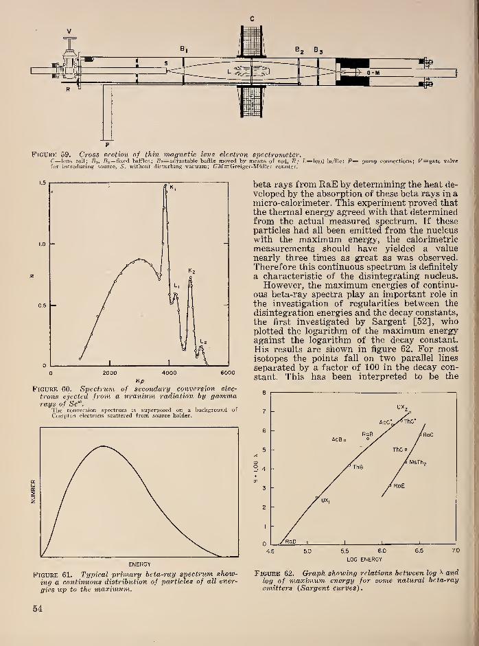
NUMBER
Figure 59. C7'oss section of thin magnetic lens electron spectrometer.C=lens coil; Bi, Bs^fixed baffles; S 2=adjustable baffle moved by means of rod, R; L=lead baffle: P— pump connections; U=gate valvefor introducing source, 5, without disturbing vacuum; GM=Greiger-Muller counter.
Figure 60. Spectrum of secoiidary conversion elec-
trons ejected from a uranium radiation by gammarays of Sc"^.
The conversion spectrum is superposed on a background of
Compton electrons scattered from source holder.
Figure 61. Typical primary beta-ray spectrum show-ing a continuous distribution of particles of all ener-
gies up to the maxhnum.
beta rays from RaE by determining the heat de-
veloped by the absorption of these beta rays in amicro-calorimeter. This experiment proved thatthe thermal energy agreed with that determinedfrom the actual measured spectrum. If theseparticles had all been emitted from the nucleuswith the maximum energy, the calorimetricmeasurements should have yielded a valuenearly three times as great as was observed.Therefore this continuous spectrum is definitely
a characteristic of the disintegrating nucleus.
However, the maximum energies of continu-ous beta-ray spectra play an important role in
the investigation of regularities between thedisintegration energies and the decay constants,
the first investigated by Sargent [52], whoplotted the logarithm of the maximum energyagainst the logarithm of the decay constant.
His results are shown in figure 62. For mostisotopes the points fall on two parallel lines
separated by a factor of 100 in the decay con-
stant. This has been interpreted to be the
Figure 62. Graph showing relations between log ^ andlog of maximum energy for some natural beta-ray
emitters {Sargent curves).
54
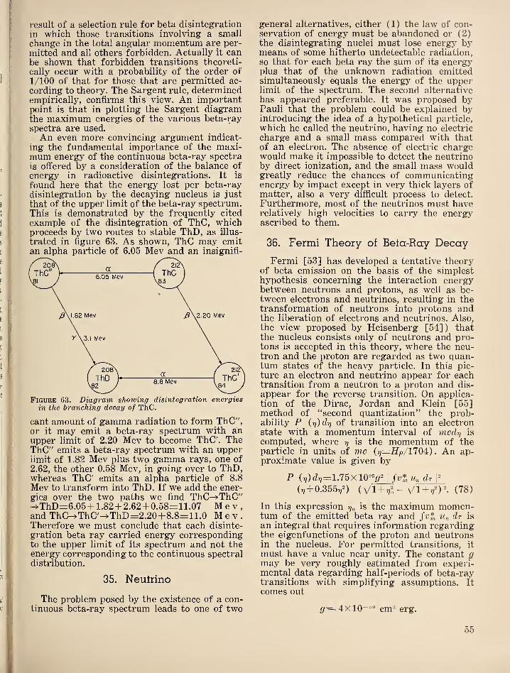
result of a selection rule for beta disintegration
in which those transitions involving a smallchange in the total angular momentum are per-
mitted and all others forbidden. Actually it canbe shown that forbidden transitions theoreti-
cally occur with a probability of the order of
1/100 of that for those that are permitted ac-
cording to theory. The Sargent rule, determinedempirically, confirms this view. An importantpoint is that in plotting the Sargent diagramthe maximum energies of the various beta-rayspectra are used.
An even more convincing argument indicat-
ing the fundamental importance of the maxi-mum energy of the continuous beta-ray spectrais offered by a consideration of the balance of
energy in radioactive disintegrations. It is
found here that the energy lost per beta-raydisintegration by the decaying nucleus is just
that of the upper limit of the beta-ray spectrum.This is demonstrated by the frequently cited
example of the disintegration of ThC, whichproceeds by two routes to stable ThD, as illus-
trated in figure 63. As shown, ThC may emitan alpha particle of 6.05 Mev and an insignifi-
Figure 63. Diagram showing disintegration energiesin the branching decay of ThC.
cant amount of gamma radiation to form ThC",or it may emit a beta-ray spectrum with anupper limit of 2.20 Mev to become ThC'. TheThC" emits a beta-ray spectrum with an upperlimit of 1.82 Mev plus two gamma rays, one of
2.62, the other 0.58 Mev, in going over to ThD,whereas ThC' emits an alpha particle of 8.8
Mev to transform into ThD. If we add the ener-gies over the two paths we find ThC^ThC"^ThD=6.05 + 1.82 + 2.62+ 0.58=11.07 Mev,and ThC^ThC'^ThD=2.20+8.8=11.0 Mev.Therefore we must conclude that each disinte-
gration beta ray carried energy correspondingto the upper limit of its spectrum and not theenergy corresponding to the continuous spectraldistribution.
35. Neutrino
The problem posed by the existence of a con-tinuous beta-ray spectrum leads to one of two
general alternatives, either (1) the law of con-servation of energy must be abandoned or (2)the disintegrating nuclei must lose energy bymeans of some hitherto undetectable radiation,so that for each beta ray the sum of its energyplus that of the unknown radiation emittedsimultaneously equals the energy of the upperlimit of the spectrum. The second alternativehas appeared preferable. It was proposed byPauli that the problem could be explained byintroducing the idea of a hypothetical particle,
which he called the neutrino, having no electric
charge and a small mass compared with thatof an electron. The absence of electric chargewould make it impossible to detect the neutrinoby direct ionization, and the small mass wouldgreatly reduce the chances of communicatingenergy by impact except in very thick layers ofmatter, also a very difficult process to detect.
Furthermore, most of the neutrinos must haverelatively high velocities to carry the energyascribed to them.
36. Fermi Theory of Bela-Ray Decay
Fermi [53] has developed a tentative theoryof beta emission on the basis of the simplesthypothesis concerning the interaction energybetween neutrons and protons, as well as be-tween electrons and neutrinos, resulting in thetransformation of neutrons into protons andthe liberation of electrons and neutrinos. Also,the view proposed by Heisenberg [54]) thatthe nucleus consists only of neutrons and pro-tons is accepted in this theory, where the neu-tron and the proton are regarded as two quan-tum states of the heavy particle. In this pic-
ture an electron and neutrino appear for eachtransition from a neutron to a proton and dis-
appear for the reverse transition. On applica-tion of the Dirac, Jordan and Klein [55]method of “second quantization” the prob-ability P iri)clr] of transition into an electronstate with a momentum interval of mcdrj is
computed, where y is the momentum of theparticle in units of me (y—Hp/1104)
.
An ap-proximate value is given by
P iy) dy=1.75x10^^ I
Un dr 1^
(^+ 0.355,,D iVl + yl - + (78)
In this expression y^ is the maximum momen-tum of the emitted beta ray and Un dr is
an integral that requires information regardingthe eigenfunctions of the proton and neutronsin the nucleus. For permitted transitions, it
must have a value near unity. The constant gmay be very roughly estimated from experi-mental data regarding half-periods of beta-raytransitions with simplifying assumptions. It
comes out
^'^4x10“^® cm® erg.
55
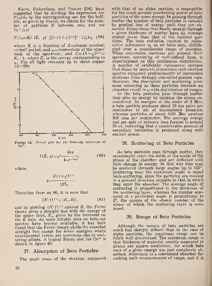
Kurie, Richardson, and Paxton [56] havesuggested that by dividing the expression for
P{r))drj by the corresponding one for the half-
lift!, as given by Fermi, we obtain for the num-ber of particles N between mc-q and me(rj- t At?)
NAv=Kf (Z, r,) [C-(1+T?^)V^]^ {A)v, (79)
where if is a function of Z=atomic number,r=half-period, and 7?o=niomentum at the upperlimit of the spectrum; and C= (1 + t?J)^''"=
Eo+l, where is the energy corresponding to
7?o. For all light elements up to about copper
(Z=29)
Figure 64. Fermi plot for the beta-ray spectrum of
Co“.
2ny, (80)
where
V=137,?
Therefore from eq 80, it is seen that
{N/f)y^a iE„-E), (81)
and by plotting against E, the Fermitheory gives a straight line with the energy of
the upper limit, E^, given by the intercept on
the E axis. As more reliable data on beta-ray
spectra have become available, it has been
found that the Fermi theory yields the expected
straight line except for lower energies whereexperimental errors are numerous due to scat-
tering effects. A typical Fermi plot for Co®° is
shown in figure 64.
37.
Absorption of Beta Particles
The small mass of the electron, compared
with that of an alpha particle, is responsiblefor the much greater penetrating power of betaparticles of the same energy. In passing throughmatter the number of beta particles is reducedby gradual loss of energy until they are ab-sorbed. Hence those that finally emerge througha given thickness of matter have an averageenergy lower than that of the incident par-ticles. The beta radiation emitted by radio-active substances is, as we have seen, distrib-
uted over a considerable range of energies.When conversion electrons are present theirspectrum, consisting of well-defined lines, is
superimposed on this continuous distribution.
A number of artificially radioactive isotopesthat decay by isomeric transitions emit electronspectra composed predominantly of conversionelectrons from strongly converted gamma rays.
However, the absorption and scattering proc-esses occurring as these particles traverse anabsorber result in a wide distribution of ranges.As the beta particles pass through matter
they give up energy by ionizing the atoms en-countered. At energies of the order of 2 Mev,a beta particle produces about 25 ion pairs percentimeter of air at atmospheric pressure,whereas particles of about 0.05 Mev produce200 ions per centimeter. The average energylost per pair of primary ions formed is around35 ev, indicating that a considerable amount of
secondary ionization is produced along withexcited atoms.
38.
Scattering of Beta Particles
As beta particles pass through matter, they
occasionally enter the fields of the nuclei of the
atoms of the absorber and are deflected withlittle change in energy. In this way they maybe scattered through large angles up to 150°,
Scattering near the maximum angle is called
back-scattering, since the particles are movingin a general direction opposite to that in whichthey enter the absorber. The average angle of
scattering is proportional to the thickness of
the scattering layer, whereas the number scat-
tered at a particular angle is proportional to
Z'^, the square of the atomic number of the
atoms of which the scattering layer is com-posed.
39.
Range of Bela Pariicles
Although the ranges of beta particles are
much less sharply defined than in the case of
alpha particles, the maximum range can be
fairly well determined. The maximum range is
that thickness of material, usually measured in
grams per square centimeter, for which betarays of a given energy are just completely ab-
,
sorbed. Aluminum is a convenient absorber fori
making such measurements of range, and it is'

customary to express ranges in grams persquare centimeter of aluminum.
ENERGY OF BETA RAYS.Mev
Figure 65. Graph showing the ranges in air and alum-inum of beta rays of various energies.
The ranges of beta particles for energiesgreater than 0.5 Mev are merely linearly pro-portional to the energy as, shown in figure 65,
where the range in aluminum and air areshown for energies up to 3 Mev.
40. Absorption Method for DeterminingEnergies of Beta Rays
Feather [57] has shown that the maximumenergy of a beta-ray spectrum can be deter-mined approximately from the range in alumi-num by use of the equation
i?=0.543 £'-0.16, (82)
where R is expressed in milligrams per squarecentimeter and E in microelectron volts, whichgives the maximum energy of the beta rays as
R£Max= +0.294 (83)
0.543
The range is determined by measuring thetransmitted intensity through progressively in-
creasing thicknesses of aluminum. If the in-
tensity is plotted on semilog paper with thelogarithmic scale along the ?/-axis and the cor-responding thickness on the x-axis, an approxi-mately straight line of negative slope is ob-tained. If, as is usual, gamma radiation is alsoemitted by the source, a point is found wherethe slope rapidly becomes much smaller, indi-cating that all beta rays have been absorbed,the residual effect arising from the gamma ra-
diation. The thickness of absorber at which this
change occurs is the value of R to be used in eq84. Figure 66 shows a typical absorption curvefor beta rays in aluminum. By using the rangeof 0.4 g/cm^ the energy comes out 1.02 Mev.The figure illustrates the uncertainty in this
method, since it is difficult to select definitely
the point at which beta rays are no longer de-
ALUMINUM, 6RAMS/CM‘
Figure 66. Graph showing the decrease in relative in-
tensity of beta rays from Zn*” on passing throughsuccessive thicknesses of aluminum.
tected as the line representing the beta-ray ab-sorption curves gradually merges into thatrepresenting the absorption of the gamma rays.
41. Befa-Ray Energies by MagneticDeflection
For low-energy beta rays the maximum en-
ergies of the continuous spectra may be deter-
mined by the combination of a screen-wall
Geiger-Miiller counter and a solenoid arrangedto produce a magnetic field, along the axis of
the counter. This procedure has been described
by Libby and Lee [58]. The arrangement is
illustrated in figure 67. As the magnetic field
is increased, the rate of counting decreases
until finally, if gamma rays are also present,
a minimum counting rate is observed wherefurther increase in the magnetic field producesno additional effect. Plotting the counting rate
for various currents in the solenoid yields
curves similar to that shown in figure 68, which
-
57
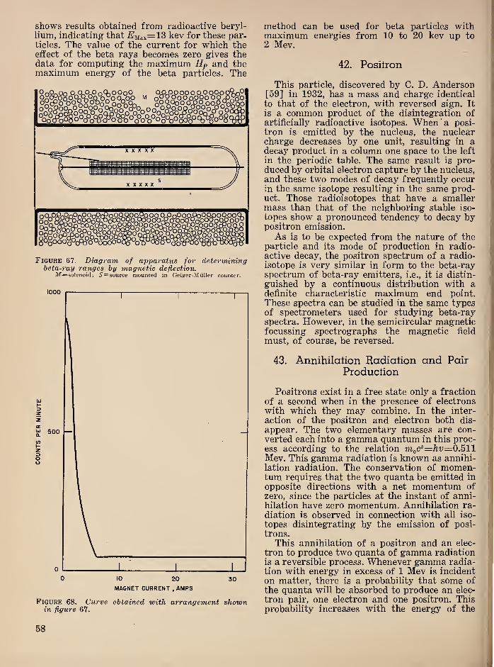
shows results obtained from radioactive beryl-lium, indicating that £'Max=13 kev for these par-ticles. The value of the current for which theeffect of the beta rays becomes zero gives thedata for computing the maximum Hp and themaximum energy of the beta particles. The
Figure 67. Diagram of apparatus for determiningheta-ray ranges by magnetic deflection.
Af=solenoid; 5'=source mounted in Geiger-Miiller counter.
Figure 68. Curve obtained with arrangement shownin figure 67.
method can be used for beta particles withmaximum energies from 10 to 20 kev up to2 Mev.
42. Positron %
I';
This particle, discovered by C. D. Anderson^
[59] in 1932, has a mass and charge identical
to that of the electron, with reversed sign. It
is a common product of the disintegration of^
artificially radioactive isotopes. When 'a posi- |
tron is emitted by the nucleus, the nuclearcharge decreases by one unit, resulting in adecay product in a column one space to the left
in the periodic table. The same result is pro-duced by orbital electron capture by the nucleus,and these two modes of decay frequently occurin the same isotope resulting in the same prod- !
uct. Those radioisotopes that have a smaller ja
mass than that of the neighboring stable iso-||
topes show a pronounced tendency to decay by|
positron emission.
As is to be expected from the nature of the i“
particle and its mode of production in radio- 1
active decay, the positron spectrum of a radio-isotope is very similar in form to the beta-ray
j
spectrum of beta-ray emitters, i.e., it is distin-|
guished by a continuous distribution with adefinite characteristic maximum end point.
These spectra can be studied in the same typesof spectrometers used for studying beta-ray i
spectra. However, in the semicircular magneticfocussing spectrographs the magnetic field
must, of course, be reversed.
43. Annihilation Radiation and Pair
Production]
Positrons exist in a free state only a fraction
of a second when in the presence of electrons
with which they may combine. In the inter-
action of the positron and electron both dis- '
appear. The two elementary masses are con-;
verted each into a gamma quantum in this proc-|
ess according to the relation moC®=^'y=0.511Mev. This gamma radiation is known as annihi-
\
lation radiation. The conservation of momen- i
turn requires that the two quanta be emitted in| j
opposite directions with a net momentum of il
zero, since the particles at the instant of anni- ’
hilation have zero momentum. Annihilation ra- !
diation is observed in connection with all iso-
topes disintegrating by the emission of posi-i
trons.j
This annihilation of a positron and an elec-
tron to produce two quanta of gamma radiation, ,
is a reversible process. Whenever gamma radia-i
'
tion with energy in excess of 1 Mev is incident
on matter, there is a probability that some of;
the quanta will be absorbed to produce an elec-|
tron pair, one electron and one positron. This ;
probability increases with the energy of the
58

gamma-ray quanta. When gamma rays withenergies above 3 Mev are absorbed approxi-mately one-half the energy is given up to pro-duce electron pairs.44.
Mesotrons
These particles, discovered by Anderson [60]in cosmic-ray studies with a cloud chamber, arenow preferably called mesons. The designationof mesotron arose from the fact that theirproperties are closely related to those of theelectron. In the original observations, Andersonnoted particles that had a high specific ioniza-tion, revealed by dense tracks in the cloudchamber. However these particles were of suchhigh energy that the magnetic field used forthe observation produced only a slight curva-ture. By using cloud chambers controlled byGeiger-Miiller counters. Street and Stevenson[61] were able to photograph these particlesnear the end of their range where measureablecurvature in a strong magnetic field was ob-tained. They estimated the mass of these par-ticles as about 200 times that of an electron,assuming that they carry the same charge asthe electron. LePrince-Ringuet [62] and co-workers have measured this mass as 240 ±20times that of the electron.
It has been shown from cosmic-ray investiga-tions of the absorption of mesotrons in theatmosphere and in lead that this particle is
radioactive. In passing through matter, a frac-tion of the particles disappear by other proc-esses than absorption and this fraction in-creases with the time required to pass throughan absorber of given total density per unitarea. In this respect air absorbs mesotrons morereadily than lead. This has been interpreted asmeaning that the mesotrons are unstable andundergo spontaneous disintegration. On thisbasis the mean life has been computed as of theorder of 2x10“® sec. The mean free path in airis of the order of 10,000 m.There is evidence that both positively and
negatively charged mesotrons exist, the relativenumbers of each being approximately equal atsea level. Rasetti [63] has observed that thereis about one disintegration electron for everytwo mesotrons absorbed. This can be inter-preted theoretically on the basis that negativemesotrons have a high probability of nuclearabsorption and that only the positive mesotronsdisintegrate by ejecting an electron. Much ofthe information regarding the properties of themesotron is still in the speculative stage.
These particles have also been called “vario-trons” because of their variable mass and insta-bility. Masses ranging 100 to 3,000 times thoseof the electrons have been reported from ob-servations of cosmic-ray mesotrons. It has be-come customary to refer to the heavier primary
mesons as ‘V-mesons” and the secondary par-ticles of lower mass as ‘V^nesons.” Recently“(j mesons” of masses of the order of 7 to 20electronic charges have been reported [64].Some of the most recent measurements haveused the photographic emulsion technique fordetermining the range and specific ionizationof these particles, giving information regardingtheir initial energies and masses.
45.
Artificial Production of Mesotrons
The rest energy of the mesotron can becomputed from the estimated mass. Assumingthat this mass is 240 times that of an electron,
which has a rest energy of 0.511 Mev, the rest
energy of the mesotron is about 120 Mev. There-fore, accelerators that can produce radiation oraccelerate particles with this or greater energycan be expected to generate mesotrons. Thisexpectation has been confirmed by use of the184-in. cyclotron at Berkeley, in 1948 [65]. Theobservations were made with photographicplates placed near a target bombarded withalpha particles with an energy of 384 Mev. Thetracks obtained revealed the same type of scat-
tering and variation of grain density withresidual range found in cosmic-ray mesontracks with the frequent appearance of char-acteristic stars at the end of the range. Byusing magnetic deflections, an estimate of themass was determined as roughly 315 electron
masses.
46.
Gamma Rays
Gamma rays are emitted with sharply de-
fined energy, which is analogous to the lines of
optical spectra. Therefore the nucleus must beregarded as a quantized system that can exist
in a number of states of energy with definite
probabilities of transitions to states of lowerenergy, the difference in energy being emittedas electromagnetic radiation. This type of nu-clear radiation is known as gamma radiation.
These radiations are emitted in general when anucleus undergoes a radioactive transformationinto a new nucleus by the emission of beta rays,
positrons, or alpha particles. The new nucleususually is left in an excited state, that is withan excess of energy above the normal or groundstate, and the excitation energy is radiated byone or more transitions within the nucleus until
the ground state is reached.Since the differences in energy between the
various levels of the nucleus are much greaterthan those of the electron levels of the atom,responsible for optical and X-ray spectra, theenergies of gamma rays are much higher andtheir wavelengths much shorter. Therefore, theusual methods of spectroscopy cannot be usedto measure the wavelengths of gamma rays,
59
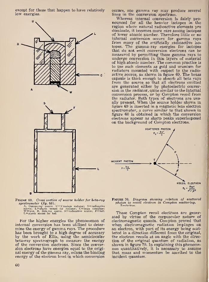
except for those that happen to have relativelylow energies.
occurs, one gamma ray may produce severallines in the conversion spectrum.Whereas internal conversion is fairly pro-
nounced for all the heavier isotopes in theregion where natural radioactive elements predominate, it becomes more rare among isotopesof lower atomic number. Therefore little or nointernal conversion occurs for gamma raysfrom many of the artificially radioactive iso-
topes. The gamma-ray energies for isotopesthat do not emit conversion electrons can bemeasured by permitting these gamma rays toundergo conversion in thin layers of materialof high atomic number. The common practice is
to use such elements as gold and uranium forradiators mounted with respect to the radio-active source, as shown in figure 69. The brasscapsule is thick enough to absorb all beta raysfrom the source so that all electrons emittedare generated either by photoelectric conver-sion in the radiator, quite similar to the internalconversion process, or by Compton recoil fromthe radiator. Both types of electrons are usu-ally present. When the source holder shown in
figure 69 is inserted in a magnetic lens electron
spectrometer, a curve similar to that shown in
figure 60 is obtained in which the conversionelectrons appear as sharp peaks superimposedon the background of Compton electrons.
Figure 69 . Cross section of source holder for beta-rayspectrometer (fig. 59 ).
A, Gamma-ray source. U=Uranium radiator; S=radioactivesource; L= plastic mount for radiator; C=brass container;W=wax. B, Beta-ray source. S=radioactive source; F=foil;L= plastic mount for foil.
For the higher energies the phenomenon ofinternal conversion has been utilized to deter-
mine the energy of gamma rays. The procedurehas been brought to a high degree of accuracyby the work of Ellis, using the semicircularbeta-ray spectrograph to measure the energyof the conversion electrons. Since the conver-sion electrons have energies equal to the origi-
nal energy of the gamma ray, minus the bindingenergy of the electron level in which conversion
Figure 70 . Diagram showing relation of scatteredphoton to recoil electron in Compton scattering.
E=electron.
These Compton recoil electrons are gener-ated by virtue of the corpuscular nature of
electromagnetic quanta. Compton proved that
when electromagnetic radiation impinges onan electron, with part of its energy being scat-
tered in a direction different from the original,
the electron recoils at an angle with the direc-
tion of the original quantum of radiation, as
shown in figure 70. In explaining this phenome-non quantitatively, it is necessary to assumethat mass and momentum be ascribed to theincident quantum.
60
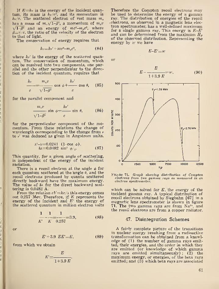
If E—hv is the energy of the incident quan-tum, its mass is hv/c'\ and its momentum is
hv/c. The scattered electron of rest mass m„has a mass of a momentum of nioV
VI-/?" and an energy of mc'--moC^ whereI3=v/c, the ratio of the velocity of the electron
to that of light.
The conservation of energy requires that
hv=hv'
+
(84)
where hv’ is the energy of the scattered quan-tum. The conservation of momentum, whichcan be resolved into two components, one par-allel and the other perpendicular to the direc-
tion of the incident quantum, requires that
hr m„v hv'
= cos(f>+ cos 0, (85)
c V 1-/8" c
for the parallel component and
m-^v hv'
sin <j>= sin 6, (86)
Vl-i8" c
for the perpendicular component of the mo-mentum. From these relations the change of
wavelength corresponding to the change from v
to v' was deduced as given in Angstrom units.
A’-A=0.0241 (1-cos </)),
SA=0.0482 sin- (p/^. (87)
This quantity, for a given angle of scattering,
is independent of the energy of the incidentradiation.
There is a recoil electron at the angle 4> for
each quantum scattered at the angle 0, and therecoil electrons produced by quanta scattereddirectly backward have the maximum energJ^The value of 8A for the direct backward scat-
tering is 0.0482 A.From the relation eV=hc/\ this energy comes
out 0.257 Mev. Therefore, if E represents theenergy of the incident and E' the energy of
the scattered quantum in million electron volts
111= =3.9, (88)
E' E 0.257
or
E' + Z.^ EE'=E, (89)
from which we obtain
E^ ~
1 + 3.9
Therefore the Compton recoil electrons maybe used to determine the energy of a gammaray. The distribution of energies of the recoil
electrons, as observed in a magnetic lens elec-
tron spectrometer, has a well-defined maximumfor a single gamma ray. This energy is E-E'and can be determined from the maximum Hpof the observed distribution. Representing theenergy by 7V we have
E—E'—w
or
EE =ic, (90)
1 + 3.9
Figuke 71. Graph showing distribution of Comptonelectrons from two gamma rays as measured in anelectron spectrometer.
which can be solved for E, the energy of theincident gamma ray. A typical distribution ofrecoil electrons obtained by Siegbahn [67] in amagnetic lens spectrometer is shown in figure71. The two gamma rays are from Na^"*, andthe recoil electrons are from a copper radiator.
47. Disintegration Schemes
A fairly complete picture of the transitionsin nuclear energy resulting from a radioactivetransformation can be obtained from a knowl-edge of (1) the number of gamma rays emit-ted, their energies, and the order in which theyare emitted (or knowledge of which gammarays are emitted simultaneously)
; (2) themaximum energy, or energies, of the beta raysemitted
; and (3) which beta rays are associated
61
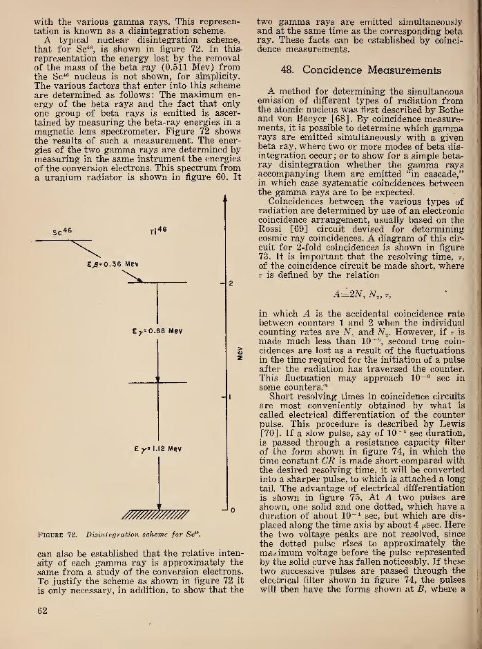
with the various gamma rays. This represen-tation is known as a disintegration scheme.A typical nuclear disintegration scheme,
that for Sc^®, is shown in figure 72. In this-
representation the energy lost by the removalof the mass of the beta ray (0.511 Mev) fromthe Sc*® nucleus is not shown, for simplicity.
The various factors that enter into this schemeare determined as follows: The maximum en-
ergy of the beta rays and the fact that onlyone group of beta rays is emitted is ascer-
tained by measuring the beta-ray energies in amagnetic lens spectrometer. Figure 72 showsthe results of such a measurement. The ener-
gies of the two gamma rays are determined bymeasuring in the same instrument the energies
of the conversion electrons. This spectrum froma uranium radiator is shown in figure 60. It
sc^s Ti46
E jr=0.88 Mev
E 1.12 Mev
0
Figure 72. Disintegration scheme for Se“.
can also be established that the relative inten-
sity of each gamma ray is approximately the
same from a study of the conversion electrons.
To justify the scheme as shown in figure 72 it
is only necessary, in addition, to show that the
two gamma rays are emitted simultaneouslyand at the same time as the corresponding betaray. These facts can be established by coinci-dence measurements.
48. Concidence Measuremenfs
A method for determining the simultaneousemission of different types of radiation fromthe atomic nucleus was first described by Botheand von Baeyer [68]. By coincidence measure-ments, it is possible to determine which gammarays are emitted simultaneously with a givenbeta ray, where two or more modes of beta dis-
integration occur; or to show for a simple beta-
ray disintegration whether the gamma raysaccompanying them are emitted “in cascade,”in which case systematic coincidences between
|
the gamma rays are to be expected.|
Coincidences between the various types ofradiation are determined by use of an electronic i
coincidence arrangement, usually based on thej
Rossi [69] circuit devised for determiningcosmic ray coincidences. A diagram of this cir-
^
cuit for 2-fold coincidences is shown in figurej
73. It is important that the resolving time, r,
of the coincidence circuit be made short, whereT is defined by the relation
A=2N^ N„ T, •j
in which A is the accidental coincidence ratebetween counters 1 and 2 when the individualcounting rates are and N.^. However, if t is :
made much less than 10^®, second true coin-
cidences are lost as a result of the fluctuations
in the time required for the initiation of a pulseafter the radiation has traversed the counter.This fluctuation may approach 10 “® sec in ;
some counters.'^
Short resolving times in coincidence circuits
are most conveniently obtained by what isj
called electrical differentiation of the counter '
;
pulse. This procedure is described by Lewis[70]. If a slow pulse, say of 10~* sec duration, ,
is passed through a resistance capacity filterI
of the form shown in figure 74, in which thetime constant CR is made short compared withthe desired resolving time, it will be convertedinto a sharper pulse, to which is attached a longtail, The advantage of electrical differentiation
is shown in figure 75. At A two pulses are
shown, one solid and one dotted, which have a
duration of about 10“* sec, but which are dis-
placed along the time axis by about 4 /xsec. Herethe two voltage peaks are not resolved, since
j
the dotted pulse rises to approximately the [
maximum voltage before the pulse represented
by the solid curve has fallen noticeably. If these
two successive pulses are passed through thep
electrical filter shown in figure 74, the pulses; i
will then have the forms shown at B, where a ” [I
62
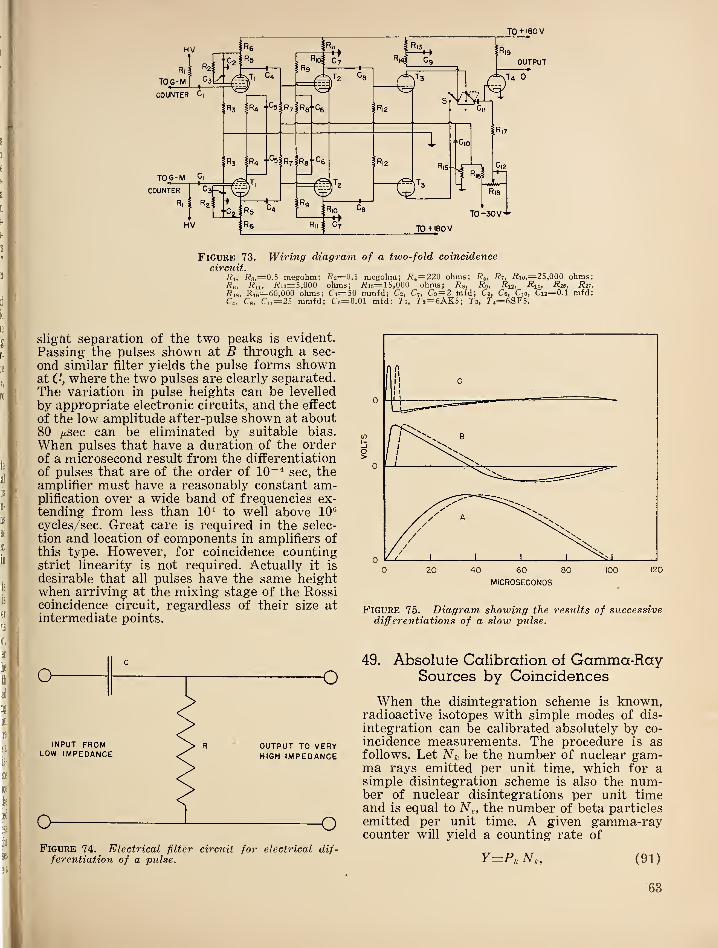
TO + 180 V
Figure 73. Wiring diagram of a two-fold coincidenceC'lT'CUZi*
7?^, i?3,=0.5 megohm; 7^2=0.! megohm; 7?4= 220 ohms; R5 ,Ri, i?io,=25,000 ohms;
Rh^ 7?u» 7^13=5,000 ohms; 7?i6=15,000 ohms; 7?s, Rq, Rh, 7?i4 , Ri«t Rn,R\Si Ri9
— 60,000 ohms; Ci=50 mmfd; C2 , C7 , C9=2 mfd; C3 , Ce, Cio, Ci3= 0.1 mfd;C4 , Cg, Cii—25 mmfd; C5=0.01 mfd: Ti, 7'2= 6AK5; T5 , ^4—6SF5.
sligftt separation of the two peaks is evident.
Passing the pulses shown at B through a sec-
ond similar filter yields the pulse forms shownat (•’, where the two pulses are clearly separated.
The variation in pulse heights can be levelled
by appropriate electronic circuits, and the effect
of the low amplitude after-pulse shown at about80 gsec can be eliminated by suitable bias.
When pulses that have a duration of the orderof a microsecond result from the differentiation
of pulses that are of the order of 10“^ sec, theamplifier must have a reasonably constant am-plification over a wide band of frequencies ex-tending from less than 10^ to well above 10®
cycles/sec. Great care is required in the selec-
tion and location of components in amplifiers ofthis type. However, for coincidence countingstrict linearity is not required. Actually it is
j . desirable that all pulses have the same heightwhen arriving at the mixing stage of the Rossi
^ coincidence circuit, regardless of their size atintermediate points.
Figure 74. Electrical filter circuit for electrical dif-ferentiation of a pulse.
A'.-'
Figure 75. Diagram showing the results of successivedifferentiations of a slow pulse.
49. Absolute Calibration of Gamma-RaySources by Coincidences
When the disintegration scheme is known,radioactive isotopes with simple modes of dis-
integration can be calibrated absolutely by co-
incidence measurements. The procedure is asfollows. Let Nk be the number of nuclear gam-ma rays emitted per unit time, which for asimple disintegration scheme is also the num-ber of nuclear disintegrations per unit timeand is equal to N^, the number of beta particles
emitted per unit time. A given gamma-raycounter will yield a counting rate of
Y=P,N,, (91)
63
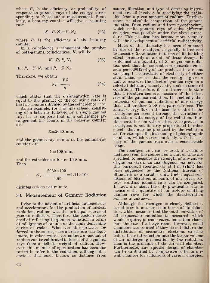
where Pu is the efficiency, or probability, of
response to gamma rays of the energy corre-
sponding to those under measurement. Simi-larly, a beta-ray counter will give a countingrate
Z=P,Ne=PeN,^ (92)
where Pr is the efficiency of the beta-ray
counter.In a coincidence arrangement the number
of beta-gamma coincidences, K, will be
K^P,P,N,. (93)
But P,,= y N,, and Pe=Z/N„.
Therefore, we obtainyz
N,= , (94)K
which states that the disintegration rate is
equal to the product of the counting rates of
the two counters divided by the coincidence rate.
As an example, for a simple scheme consist-
ing of a beta ray followed by a single gammaray, let us suppose that in a coincidence ar-
rangement the counts in the beta-ray counter
are
Z=2030/min,
and the gamma-ray counts in the gamma-raycounter are
y=109/min,
and the coincidences K are 1.99/min.
Then
2030X109N,.= =1.11x10=
1.99
disintegrations per minute.
50. Measuremenl of Gamma Radiation
Prior to the advent of artificial radioactivity
and accelerators for the production of nuclear
radiation, radium was the principal source of
gamma radiation. Therefore, the custom devel-
oped of referring to gamma radiation in termsof milligrams of radium or the equivalent milli-
curies of radon. Whenever this practice re-
ferred to the source, such a procedure was legit-
imate, in other words, an unknown amount of
radium can be calibrated in terms of the gammarays from a definite weight of radium. How-ever, this manner of specification has been dis-
torted to refer to the radiation, although it is
obvious that such factors as distance from
source, filtration, and type of detecting instru-ment are all involved in specifying the radia-tion from a given amount of radium. Further-more, no absolute comparison of the gammaradiation from radium and from mesothorium,which emits gamma rays of quite differentenergies, was possible under the above proce-dure. This problem has become more complexwith the development of artificial radioactivity.
Much of this difficulty has been eliminatedby use of the roentgen, originally introducedto measure X-radiation in terms of its ionizingeffect, primarily as a unit of tissue dosage. It
is defined as a quantity of X- or gamma-radia-tion such that the associated corpuscular emis-sion per 0.001293 g of air produces in air ionscarrying 1 electrostatic of electricity of eithersign. Thus, we see that the roentgen gives aunit to measure the effect of gamma rays on aselected detector, namely, air, under standardconditions. Therefore, it is not correct to statethat 1 roentgen/sec is a measure of the inten-sity of the gamma radiation. It is actually thatintensity of gamma radiation, of any energythat will produce 2.09 ion pairs/cmVsec. Theactual energy flux in the beam is related to theroentgens per second through the variation ofionization with energy of the radiation. Fur-thermore, the ionization effect as expressed in
roentgens is not linearly proportional to othereffects that may be produced by the radiationas, for example, the blackening of photographicemulsion, which varies markedly with the en-ergy of the gamma rays over a considerablerange.
The roentgen unit can be used, if a definite
distance from the source and a unit of time arespecified, to measure the strength of any sourceof gamma rays in an unambiguous manner. Forthis purpose,! roentgen/hr at 1 m (rhm) hasbeen suggested by the National Bureau ofStandards as a suitable unit. Under equal con-ditions of filtration, amounts of any given iso-
tope emitting gamma rays can be compared.In fact, it is about the only practicable way to
measure the quantity of an isotope emittinggamma rays for which the disintegrationscheme is unknown.
Although the roentgen is clearly defined it
is not easy to measure it in terms of its defini-
tion, which assumes that the total ionization of
all corpuscular radiation is measured, whichwould require, jn some cases, ionization cham-bers the size of a large room. However, smallchambers can be used if they do not disturb thedistribution of secondary electrons existingbefore their introduction into the larger volumeof air undergoing ionization by the radiation.
This is the principle of the air-wall chamber^Furthermore, any specific design of chambercan be calibrated by comparison with an air-
wall chamber for radiations of various energies.
64
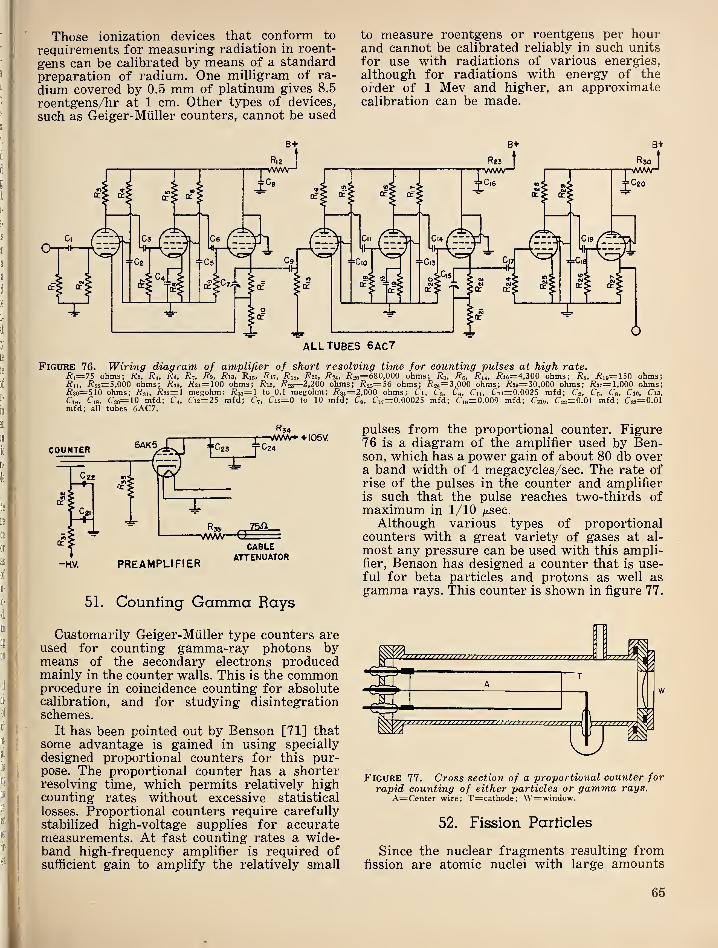
Those ionization devices that conform to
requirements for measuring radiation in roent-
gens can be calibrated by means of a standardpreparation of radium. One milligram of ra-
dium covered by 0.5 mm of platinum gives 8.5
roentgens/hr at 1 cm. Other types of devices,
such as Geiger-Miiller counters, cannot be used
to measure roentgens or roentgens per hourand cannot be calibrated reliably in such units
for use with radiations of various energies,
although for radiations with energy of theorder of 1 Mev and higher, an approximatecalibration can be made.
B+ B* B+
Figure 76. Wiring diagram of amplifier of short resolving time for counting pulses at high rate.i?i=75 ohms; R 2 , Ri, Re, R7 ,
R9 , i?i3, Ri6» Rn, Ri8t Rot, i?20=68O,OOO ohms; Rq, R^, Ru, /?i6=4,300 ohms; i?8» -Rie=150 ohms;Riif i^22=5,000 ohms; i?2i=100 ohms; Rvi, R^s—2,200 ohms; i?25=56 ohms; i?28“3,000 ohms; i?29=30,000 ohms; i?27=l,000 ohms;i?30=5l0 ohms; Rsi, Rs2~\ megohm; i?33=l to 0.1 megohm; i?34=2,000 ohms; Ci, C3, Cq, Cn, Ci4=0.0025 mfd; C2, C5 , Ca, Cio, C13,
Cie, Cis, C2o=10 mfd; C4, Ci2=25 mfd; C?, Ci6=0 to 10 mfd; Cq, Ci7=0. 00025 mfd; Ci9=:0.009 mfd; C219, C22=0.01 mfd; C23“0.01mfd; all tubes 6AC7.
R34
51. Counting Gamma Rays
Customarily Geiger-Miiller type counters areused for counting gamma-ray photons bymeans of the secondary electrons producedmainly in the counter walls. This is the commonprocedure in coincidence counting for absolutecalibration, and for studying disintegrationschemes.
It has been pointed out by Benson [71] thatsome advantage is gained in using specially
designed proportional counters for this pur-pose. The proportional counter has a shorterresolving time, which permits relatively highcounting rates without excessive statistical
losses. Proportional counters require carefullystabilized high-voltage supplies for accuratemeasurements. At fast counting rates a wide-band high-frequency amplifier is required ofsufficient gain to amplify the relatively small
pulses from the proportional counter. Figure76 is a diagram of the amplifier used by Ben-son, which has a power gain of about 80 db overa band width of 4 megacycles/sec. The rate ofrise of the pulses in the counter and amplifieris such that the pulse reaches two-thirds ofmaximum in 1/10 /xsec.
Although various types of proportionalcounters with a great variety of gases at al-
most any pressure can be used with this ampli-fier, Benson has designed a counter that is use-ful for beta particles and protons as well asgamma rays. This counter is shown in figure 77.
Figure 77. Cross section of a proportional counter forrapid counting of either particles or gamma rays.
A=Center wire; T—cathode; \V=window.
52. Fission Particles
Since the nuclear fragments resulting fromfission are atomic nuclei with large amounts
65
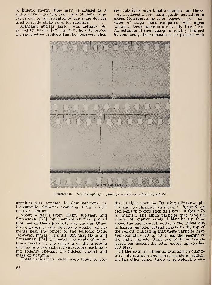
of kinetic energy, they may be classed as aradioactive radiation, and many of their prop-erties can be investigated by the same devicesused to study alpha rays, for example.
Although nuclear fission was actually ob-served by Fermi [72] in 1934, he interpretedthe radioactive products that he observed, when
uranium was exposed to slow neutrons, astransuranic elements resulting from simpleneutron capture.About 3 years later, Hahn, Meitner, and
Strassman [73] by chemical studies, provedthat one of these products was barium. Otherinvestigators rapidly detected a number of ele-
ments near the center of the periodic table.
However, it was not until 1939 that Hahn andStrassman [74] proposed the explanation ofthese results as the splitting of the uraniumnucleus into two radioactive isotopes, each hav-ing roughly one-half the nuclear charge andmass of uranium.
These radioactive nuclei were found to pos-
sess relatively high kinetic energies and there-fore produced a very high specific ionization ingases. However, as is to be expected from par-ticles of large mass compared with alphaparticles, their range in air is only 1 or 2 cm.An estimate of their energy is readily obtainedby comparing their ionization per particle with
that of alpha particles. By using a linear ampli-
fier and ion chamber, as shown in figure 7, anoscillograph record such as shown in figure 78is obtained. The alpha particles that have anenergy of approximately 4 Mev barely showabove the background, whereas the pulses dueto fission particles extend nearly to the top of
the record, indicating that these particles haveapproximately 20 to 30 times the energy of
the alpha particle. Since two particles are re-
leased per fission, the total energy approaches200 Mev.Of the natural elements, available in quanti-
ties, only uranium and thorium undergo fission.
On the other hand, there is considerable evi-
Figure 78 . Oscillograph of a pulse produced by a fission particle.
66
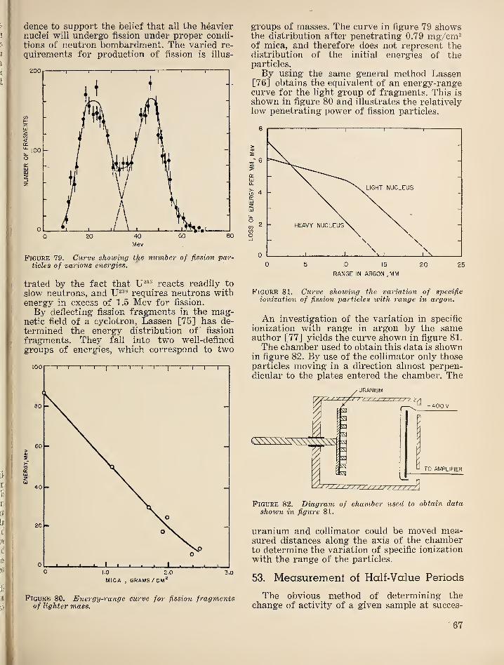
dence to support the belief that all the heaviernuclei will undergo fission under proper condi-tions of neutron bombardment. The varied re-
quirements for production of fission is illus-
Figure 79. Curve showing the number of fission par-ticles of various energies.
trated by the fact that reacts readily to
slow neutrons, and requires neutrons withenergy in excess of 1.5 Mev for fission.
By deflecting fission fragments in the mag-netic field of a cyclotron, Lassen [75] has de-
termined the energy distribution of fission
fragments. They fall into two well-defined
groups of energies, which correspond to two
Figure 80. Energy-range curve for fission fragmentsof lighter mass.
groups of masses. The curve in figure 79 showsthe distribution after penetrating 0.79 mg/cm^of mica, and therefore does not represent thedistribution of the initial energies of theparticles.
By using the same general method Lassen[76] obtains the equivalent of an energy-rangecurve for the light group of fragments. This is
shown in figure 80 and illustrates the relativelylow penetrating power of fission particles.
Figure 81. Curve showing the variation of specific
ionization of fission particles with range in argon.
An investigation of the variation in specific
ionization with range in argon by the sameauthor [77] yields the curve shown in figure 81.
The chamber used to obtain this data is shownin figure 82. By use of the collimator only thoseparticles moving in a direction almost perpen-dicular to the plates entered the chamber. The
Figure 82. Diagram of chamber used to obtain datashown in figure 81.
uranium and collimator could be moved mea-sured distances along the axis of the chamberto determine the variation of specific ionization
with the range of the particles.
53. Measurement of Half-Value Periods
The obvious method of determining thechange of activity of a given sample at succes-
J
67
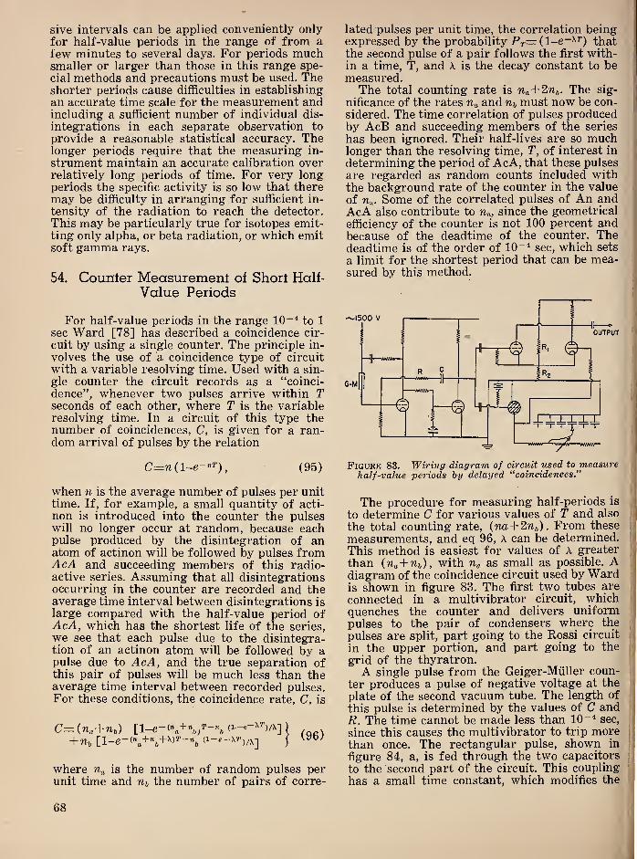
sive intervals can be applied conveniently onlyfor half-value periods in the range of from afew minutes to several days. For periods muchsmaller or larger than those in this range spe-
cial methods and precautions must be used. Theshorter periods cause difficulties in establishingan accurate time scale for the measurement andincluding a sufficient number of individual dis-
integrations in each separate observation to
provide a reasonable statistical accuracy. Thelonger periods require that the measuring in-
strument maintain an accurate calibration overrelatively long periods of time. For very longperiods the specific activity is so low that theremay be difficulty in arranging for sufficient in-
tensity of the radiation to reach the detector.
This may be particularly true for isotopes emit-ting only alpha, or beta radiation, or which emitsoft gamma rays.
54. Counter Measurement of Short Half-
Value Periods
For half-value periods in the range lO""* to 1
sec Ward [78] has described a coincidence cir-
cuit by using a single counter. The principle in-
volves the use of a coincidence type of circuit
with a variable resolving time. Used with a sin-
gle counter the circuit records as a “coinci-
dence”, whenever two pulses arrive within Tseconds of each other, where T is the variableresolving time. In a circuit of this type thenumber of coincidences, C, is given for a ran-dom arrival of pulses by the relation
C=w(l-e-”^), (95)
when n is the average number of pulses per unittime. If, for example, a small quantity of acti-
non is introduced into the counter the pulseswill no longer occur at random, because eachpulse produced by the disintegration of anatom of actinon will be followed by pulses fromAcA and succeeding members of this radio-active series. Assuming that all disintegrationsoccurring in the counter are recorded and theaverage time interval between disintegrations is
large compared with the half-value period ofAcA, which has the shortest life of the series,
we see that each pulse due to the disintegra-tion of an actinon atom will be followed by apulse due to AcA, and the true separation ofthis pair of pulses will be much less than theaverage time interval between recorded pulses.For these conditions, the coincidence rate, C, is
C—(na+nA . .
where n-a is the number of random pulses perunit time and n-i, the number of pairs of corre-
lated pulses per unit time, the correlation beingexpressed by the probability Pr=(l-e-^^) thatthe second pulse of a pair follows the first with-in a time, T, and A. is the decay constant to bemeasured.The total counting rate is na+2nf,. The sig-
nificance of the rates Ua and must now be con-
sidered. The time correlation of pulses producedby AcB and succeeding members of the series
has been ignored. Their half-lives are so muchlonger than the resolving time, T, of interest in
determining the period of AcA, that these pulses
are regarded as random counts included withthe background rate of the counter in the value
of Un. Some of the correlated pulses of An andAcA also contribute to Ua, since the geometrical
efficiency of the counter is not 100 percent andbecause of the deadtime of the counter. Thedeadtime is of the order of 10“^ sec, which sets
a limit for the shortest period that can be mea-sured by this method.
Figure 83. Wirinff diagram of circuit used to measurehalf-value periods by delayed “coincidences."
The procedure for measuring half-periods is
to determine C for various values of T and also
the total counting rate, (na+2nb). From these
measurements, and eq 96, A can be determined.
This method is easiest for values of A greater
than (Wa+Wft), with Tia as small as possible. Adiagram of the coincidence circuit used by Wardis shown in figure 83. The first two tubes are
connected in a multivibrator circuit, whichquenches the counter and delivers uniformpulses to the pair of condensers where the
pulses are split, part going to the Rossi circuit
in the upper portion, and part going to the
grid of the thyratron.A single pulse from the Geiger-Miiller coun-
ter produces a pulse of negative voltage at the
plate of the second vacuum tube. The length of
this pulse is determined by the values of C andR. The time cannot be made less than 10“^ sec,
since this causes the multivibrator to trip morethan once. The rectangular pulse, shown in
figure 84, a, is fed through the two capacitors
to the second part of the circuit. This coupling
has a small time constant, which modifies the
68
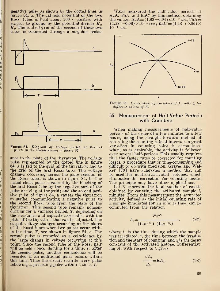
negative pulse as shown by the dotted lines in
figure 84, a. The cathode potential of the twoRossi tubes is held about 100 v positive withrespect to ground by the potential divider R^,R^. The control grid of the second of these twotubes is connected through a megohm resist-
\ Q
/f
Figure 84. Diagram of voltage pulses at variouspoints in the circuit shown in figure 83.
ance to the plate of the thyratron. The voltagepulse represented by the dotted line in figure
84, a is fed to the grid of the thyratron and tothe grid of the first Rossi tube. The voltagechanges occurring across the plate resistor ofthe Rossi tubes is shown in figure 84, b. Theinitial short pulse is caused by the blocking ofthe first Rossi tube by the negative part of thepulse arriving at the grid
; and the second posi-
tive pulse of figure 84, a causes the thyratronto strike, communicating a negative pulse tothe second Rossi tube from the plate of thethyratron. This second tube remains noncon-ducting for a variable period, T, depending onthe resistance and capacity associated with theplate of the thyratron that can be adjusted. Theoutput voltage changes occurring at the platesof the Rossi tubes when two pulses occur with-in the time, T, are shown in figure 84, c. Thesecond pulse is recorded as a coincidence bythe large change in voltage occurring at this
point. Since the second tube of the Rossi pairwill be held nonconducting for a time, T, afterthe second pulse, another coincidence will berecorded if an additional pulse occurs withinthis time. Thus the circuit records every pulsefollowing a preceding pulse within a time, T.
Ward measured the half-value periods ofAcA, ThA, and RaC' by this method, obtainingthe values : AcA= (1.83±:0.04)xl0“® sec;ThA=z;(1.58 ±0.08) xlO-i sec; RaC'=(1.48 ±0.06) x10“* sec.
Figure 85. Curve shounng variation of ivith \ fordifferent values of K.
55. Measurement of Half-Value Periodswith Counters
Vi 'hen making measurements of half-valueperiods of the order of a few minutes to a fewhou;rs, using the straight-forward method ofreccrding the counting rate at intervals, a greatvariation in counting rates is encounteredwh^n, as is desirable, the activity is followedovei’ several half-periods. This usually requiresthat the faster rates be corrected for countinglosses, a procedure that is time-consuming anddifficult to do with precision. Graves and Wal-ker [79] have suggested a method that canbe used for neutron-activated isotopes, whicheliminates the correction for counting losses.
The principle may have other applications.
Let N represent the total number of countsobtained by counting the activated sampleminutes. From this measurement the saturatedactivity, defined as the initial counting rate of
a sample irradiated for an infinite time, can becomputed from the relation
, (97)(l_e-^^) (l_e-x^=)
where G is the time during which the samplewas irradiated, the time between the irradia-
tion and the start of counting, and A is the decayconstant of the activated isotope. Differentiat-
ing As with respect to A gives
dAs=F:As, (98)
dk
69
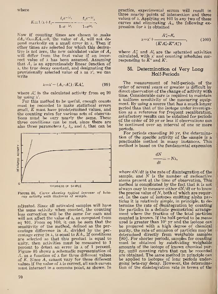
where
K—\/x-\- .
l_g-xtj 1—
Now if counting times are chosen to makeclAs/dx=KAs—0, the value of Ag will not de-pend markedly on a small error in A. Then if
other times are selected for which this deriva-tive is not zero, the new calculated value of Agwill differ from the first value if an incor-
rect value of A has been assumed. Assumingthat Ag is an approximately linear function ofA, the true decay constant, and designating theprovisionally selected value of A as A', we canwrite
x=x'+{Ag-A’g)/KA^, (99)
where Ag is the calculated activity from eq 20by using A'.
For this method to be useful, enough countsmust be recorded to make statistical errors
small, K must have predetermined values, andthe counting rates for various sets of observa-tions must be very nearly the same. Thesethree conditions can be met, since there arealso three parameters and that can be
Figure 86. Curve showing typical increase of beta-
ray activity with thickness of sample.
adjusted. Since all activated samples will havethe same activity when counted, the counting
loss correction will be the same for each andwill not affect the value of A, as computed fromeq 101. From eq 100, it can be seen that the
sensitivity of the method, defined as the per-
centage difference in Ag divided by the per-
centage error in A, is equal to KAg. If conditions
are selected so that this product is equal to
unity, then activities must be measured to 1
percent to detect an error in A of 1 percent.
Figure 85 shows a schematic representation of
Ag as a function of A for three different values
of K. Since Ag cannot vary for these different
values if the value of A is correct, all such curves
must intersect in a common point, as shown. In
practice, experimental errors will result inthree nearby points of intersection and threevalues of A. Applying eq 101 to any two of thesecurves and eliminating Ag, the following ex-pression for A is obtained
A'i-A'gi'
A=A'+, (100)
(A'A'-A"A") i
where A" and Ag are the saturated activities
calculated, with A' and counting schedules cor-responding to K" and K'.
56. Determination of Very LongHalf-Periods
The measurement of half-periods of theorder of several years or greater is difficult bydirect observation of the change of activity withtime. Considerable -care is required to maintaina uniform sensitivity of the measuring equip-ment. By using a source that has a much longer >
period than that of the isotope under investiga-tion as a reference for frequent recalibration,satisfactory results can be obtained for periodsof the order of 10 yr or less if observations canbe continued over an interval of one or moreperiods.
For periods exceeding 10 yr, the determina-j
tion of the specific activity of the sample is a'
practicable method in many instances. Thismethod is based on the fundamental expression
|
dN= - NX,
i
dt !
where dN/dt is the rate of disintegration of thei
sample, and N is the number of radioactive[
atoms present at the time of observation. Thismethod is complicated by the fact that it is notalways easy to measure either dN/dt or to know !-
the precise value of N, both of which are requir-
ed. In the case of isotopes emitting alpha par-ticles it is relatively simple, in principle, to de-
termine the rate of disintegration by counting|
the particles in a definite geometrical arrange- '
j
ment where the fraction of the total particles|
counted is known. If the half-period to be meas-'
ured is greater than 10® yr and the isotope can|
be prepared with a high degree of chemicali
purity, the rate of emission of particles may be i
determined directly from weighable samples[80] . For shorter periods, samples for counting ;
must be obtained by subdividing weighable !
amounts of the isotope of known chemical pur- i
ity, until counting rates that can be recordedj
are obtained. The same method in principle canbe applied to isotopes of long periods under-going beta-ray decay. However, the determina-
''
tion of the disintegration rate in terms of the ^
70
specific activity is much more difficult for sub-
stances of long life emitting beta rays. Moresensitive detectors must be used than for alphaparticles, and the effects of variation of the solid
angle and of back scattering are less easily
evaluated. The energies of the disintegration
beta rays are spread over a continuous spec-
trum, and the interpretation of the results maybe complicated by the presence of conversionelectrons. Finally, the disintegration schememust be known in order to apply this method.
57. Half-Periods from True CoincidenceMeasurements
A method has been suggested by Riedhammer[81] for using the conventional coincidence ar-
rangement for the determination of half-value
periods. When two counters (1 and 2) are con-
nected in a coincidence arrangement the acci-
dental coincidence rate, C, is given by the usualrelation
where r is the resolving time, and arethe individual counting rates of the two count-ers considered constant when averaged over asufficiently long time, and the source for eachcounter is independent of the other.
If the sources irradiating the counters 1 and2 are not constant but are two different sam-ples of the same radioisotope, the values ofand are no longer constant but are repre-sented by ^1=^0 and N^=NI^ where
and N'^ are the initial intensities at t=0.Introducing these expressions into the equationfor C, we obtain
C=2t a; N, e-^^^=Co (101)
For the half-period of the accidental coinci-
dences, Tc, that is the period required for C tobecome Co/2
C=Co/2=Co (102)
or
To=l /2(ln2/y)=l/2 T*,
where T* represents the half-period of theradioisotope.
This method provides a very rapid methodfor determining half-value periods, since thedecay curve for Tc much steeper than for T*,which has particular advantages for the meas-urement of long periods. Ordinarily these re-quire long periods of observation during whichexperimental conditions must be maintainedconstant.
58. Statislical Error in Measurement of
Half-Value Periods with Counters
The limitations in accuracy imposed by thestatistical fluctuations become important in de-termining the half-value periods of beta-rayemitters of relatively short period. A compro-mise between the desired number of counts fora particular point on the decay curve and thechange of average activity during the observa-tion must be made. Peierls [82] has indicateda method for obtaining an improvement in thestatistical accuracy of such measurements withan economy in number of observations requiredcompared with the usual simple methods.The following simple methods for determin-
ing T, are frequently used:
(1) The number of particles are countedduring short periods, and their logarithm is
plotted against the time. These observationsshould fall on a straight line with a slope equalto A. This method is open to the objection thatit is difficult to estimate graphically the error,and the slope of the line obtained in this wayis strongly influenced by the observations takennear the end where the counting rate is low.
(2) The total number of counts, Uo, takenafter a chosen time, t, is compared with thetotal number of counts, N, taken from t=0.
Then
no t
r=—z=e-V'r^ or T= . (103)N In r
The relative error is a minimum for
n^/N=e-*/'r =0,2. (104)
(3) Another method is to observe counts forequal intervals of length, t. Representing thesecounts as %i, n,, W3 . .
.
,
the following expressionis evaluated
...r= . (105)
n^~\-n^-\- . . .
The statistical average of r is or approxi-mately
t
In r
This method can be shown to give a somewhathigher minimum relative error and is thereforeless efficient than method (2), although morecomplicated.
In a rigorous mathematical treatment Peierlsshows that the best approximation to the meanlife T is the arithmetic mean of the individualtimes at which particles have been observed.
71

This may be written s=%tv/m, where m is thetotal number of particles, tv is the midpoint ofthe vth interval, and s—r for an infinite time ofobservation, T. When T is finite
T-s= , (106)
eT/r-i
from which a correction a to the computed t
may be calculated for various values of T/t.
Assuming that values of T/r, T/s, t/s, anda are available, the procedure for determiningT is to divide the total time available, T, into
intervals of length cKO.St. In practical caseswhere this results in a small number of counts,
larger intervals may be taken. The number ofcounts for each interval is determined, repre-sented by Ui, . and their sum by m. Theexpression
d
5o= ( 'M'l+ 37^2+ 5%3+ . . . ),
2m
is taken as a first approximation for s. Fromthe corresponding values of T/s, the value of
r/Sg can be ascertained, which gives an approxi-mate value for t. For a more accurate value, asecond approximation for s can be obtainedfrom the relation
s,=-l/12—, (107)
T ,1
and the corresponding correction for T(tau)will give
Ti=oSi. (108)
The most efficient value for T is computed asapproximately 4t.
Table 15.—Values of T/s, t/s, and ° as computed byPeierls for various values of T/t.
T/t T/s T/S <r
1.0 2.39 2.392 12.51.2 2.48 2.071 9.091.4 2.58 1.846 6.711.6 2.69 1.680 5.291.8 2.80 1.554 4.31
2.0 2.91 1.456 3.632.2 3.03 1.378 3.122.4 3.16 1.315 2.722.6 3.29 1.263 2.412.8 3.42 1.221 2.17
3.0 3.56 1.186 1.983.5 3.93 1.122 1.654.0 4.32 1.081 1.444.5 4.74 1.053 1.305.0 5.18 1.035 1.21
6 6.09 1.015 1.107 7.04 1.006 1.058 8.02 1.003 1.02
VII. RADIOACTIVE TRACERS
The use of radioactivity to identify indi-
vidual atoms in a chemical compound is rela-
tively old. For example, v. Hevesy and Paneth[83] investigated the solubility of lead sul-
phides and lead chromates using RaD as atracer, in a paper published in 1913. In this
case the tracer was used merely to extend thesensitivity of existing methods of measurement.At that time the lower limit for a qualitative
test for the presence of lead using the mostsensitive microchemical reaction was 3x10“® g,
and the quantitative limit was considerablyhigher. By using RaD as an indicator they wereeasily able to measure 10“^® g of lead. If timeis given for the RaE to come into equilibriumthis measurement could be carried to 10“^^ g ofRaD.An example of a typical tracer problem in
which the identification of particular groups of
atoms is used is provided by the investigation
by V. Hevesy [84] of the exchange of atomsbetween liquid and solid phases. Since onlynaturally radioactive isotopes were available
the method was limited to a few cases where
radioactive isotopes of common stable elementswere available. Thus v. Hevesy investigated
I
the exchange of atoms between metallic leadand a solution of lead nitrate using ThB mixedwith the lead in one phase. He was able to showthat the exchange of lead atoms between themetal and solution was very rapid, arisingchiefly from local action and that the lead atoms ^
entered the solution at individual points on themetal and were redeposited at other points. The
,
j
tracer method is practically the only way to '
j
obtain this type of information reliably andj
i
accurately., ;
Now that more than 400 radioactive isotopes i
i
are available, the tracer method can be extended ^
to a great variety of problems, in physics,
chemistry, biology, and industrial applications, i
In practice the number of radioisotopes thati
can be used for tracer methods is limited bythe individual characteristics of these isotopes.
For example, a reasonably long half-period,j
radiation of sufficient energy to be readily J
measured, and a convenient supply of the iso-|
tope in suitable form are obviously desirable, i
72
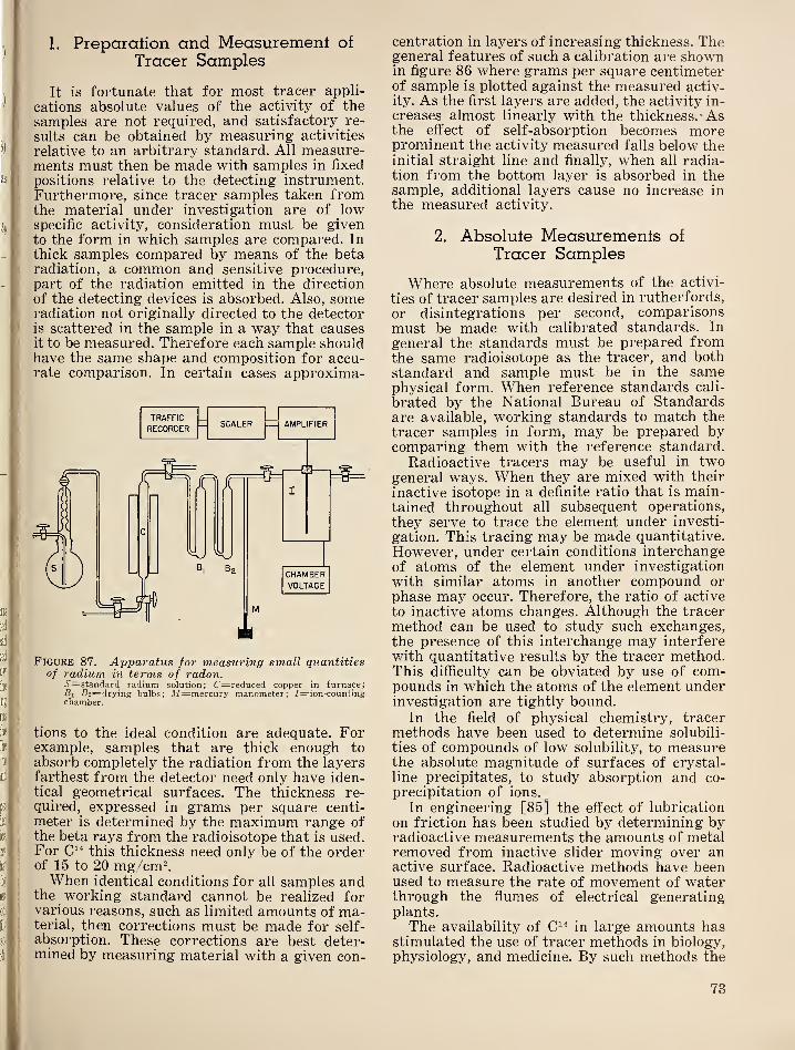
1. Preparation and Measurement of
Tracer Samples
It is fortunate that for most tracer appli-
cations absolute values of the activity of the
samples are not required, and satisfactory re-
sults can be obtained by measuring activities
relative to an arbitrary standard. All measure-ments must then be made with samples in fixed
positions relative to the detecting instrument.Furthermore, since tracer samples taken fromthe material under investigation are of lowspecific activity, consideration must be givento the form in which samples are compared. Inthick samples compared by means of the betaradiation, a common and sensitive procedure,part of the radiation emitted in the direction
of the detecting devices is absorbed. Also, someradiation not originally directed to the detectoris scattered in the sample in a way that causesit to be measured. Therefore each sample shouldhave the same shape and composition for accu-rate comparison. In certain cases approxima-
Figure 87. Apparatus for measuring small quantitiesof radium in terms of radon.
vS'=standard radium solution; C=reduced copper in furnace;Si S2=drying bulbs; M=mercury manometer; /—ion-countingchamber.
tions to the ideal condition are adequate. Forexample, samples that are thick enough to
absorb completely the radiation from the layersfarthest from the detector need only have iden-tical geometrical surfaces. The thickness re-
quired, expressed in grams per square centi-
meter is determined by the maximum range ofthe beta rays from the radioisotope that is used.For this thickness need only be of the orderof 15 to 20 mg/cm^.When identical conditions for all samples and
the working standard cannot be realized forvarious reasons, such as limited amounts of ma-terial, then corrections must be made for self-absorption. These corrections are best deter-mined by measuring material with a given con-
centration in layers of increasing thickness. Thegeneral features of such a calibration are shownin figure 86 where grams per square centimeterof sample is plotted against the measured activ-
ity. As the first layers are added, the activity in-
creases almost linearly with the thickness.- Asthe effect of self-absorption becomes moreprominent the activity measured falls below theinitial straight line and finally, when all radia-tion from the bottom layer is absorbed in thesample, additional layers cause no increase inthe measured activity.
2. Absolute Measurements of
Tracer Samples
Where absolute measurements of the activi-
ties of tracer samples are desired in rutherfords,
or disintegrations per second, comparisonsmust be made with calibrated standards. In
general the standards must be prepared fromthe same radioisotope as the tracer, and bothstandard and sample must be in the samephysical form. When reference standards cali-
brated by the National Bureau of Standardsare available, working standards to match thetracer samples in form, may be prepared bycomparing them with the reference standard.
Radioactive tracers may be useful in twogeneral ways. When they are mixed with their
inactive isotope in a definite ratio that is main-tained throughout all subsequent operations,
they serve to trace the element under investi-
gation. This tracing may be made quantitative.
However, under certain conditions interchangeof atoms of the element under investigation
with similar atoms in another compound or
phase may occur. Therefore, the ratio of active
to inactive atoms changes. Although the tracer
method can be used to study such exchanges,the presence of this interchange may interferewith quantitative results by the tracer method.This difficulty can be obviated by use of com-pounds in which the atoms of the element underinvestigation are tightly bound.
In the field of physical chemistry, tracermethods have been used to determine solubili-
ties of compounds of low solubility, to measurethe absolute magnitude of surfaces of crystal-
line precipitates, to study absorption and co-
precipitation of ions.
In engineering [85] the effect of lubrication
on friction has been studied by determining byradioactive measurements the amounts of metalremoved from inactive slider moving over anactive surface. Radioactive methods have beenused to measure the rate of movement of waterthrough the flumes of electrical generatingplants.
The availability of in large amounts hasstimulated the use of tracer methods in biology,physiology, and medicine. By such methods the
73

behavior of many organic compounds in living
organisms can be studied in detail quite impos-sible without this aid. The movement of sub-
stances labelled with radioactive carbon can befollowed and quantitative determinations madeat various intervals to determine not only the
location but rate of arrival of the substances.
Similarly, such elements as phosphorus, so-
dium, boron, and iodine, to mention a few, J
which play important roles in animal and vege-
table life are finding increasing use as biologi- ••
cal tracers.
VIII. RADIOACTIVE STANDARDS AND UNITS
Much of the development of the subject of
radioactivity has resulted from relative meas-urements expressed in arbitrary units.
When practical applications are made ofradioactive isotopes, common standards ofcomparison become necessary. This is wellillustrated by the history of the discovery anduse of radium. As long as radium and its decayproducts remained a, tool of physicists engagedin studying the phenomenon of radioactivity,very little need was felt for standards. Aboutthe only standardization attempted was foreach laboratory engaged in radioactive investi-gations to select a preparation of radium in its
possession as a laboratory standard to whichall measurements in that particular laboratorywere referred. Frequently these preparationsof radium were of unknown and doubtful purityand the exact amount of radium present unde-termined.Under these circumstances all measurements
based on quantitative knowledge of the amountof radium used were subject to widely conflict-ing variations. The situation was further in-tensified when practical use for radium intreatment of malignancies developed and ra-dium became an article of commerce. There-fore, in 1910 an International Radium Com-mission was established to prepare radiumstandards. These standards were weighed outfrom pdium used by Mme Curie in the deter-mination of the atomic weight of radium.These were intercompared by gamma-ray meth-ods and distributed to various nations as pri-mary national standards, one being retainedat Sevres as an international standard.The development of artificial radioactivity
has repeated the cycle of events illustrated byradium. Recently the need for standards in thefield of radioactive isotopes has been empha-sized by a divergence of the order of 300 per-cent among laboratories measuring such iso-topes as and for clinical use. The pro-vision of standards for induced activities ismade difficult by their relatively short half-value periods in most instances. Since radio-active standards preferably should be preparedfor each isotope, the problem assumes consid-erable proportions. The National Bureau ofStandards has undertaken to provide standards
of those isotopes that are suitable and can be :
calibrated in absolute disintegration rates. Forthose of short half-value periods, a system of .
distribution of standard samples is under con-
sideration.
1. Alpha-Ray Slandards
Uranium has long been used for the calibra-
tion of alpha-ray electroscopes and ionization ,
chambers. The advantage of a long life and con-
sequent use of weighable quantities is partly
offset by the self-absorption of the particles in
thicker layers. When used in connection withion chambers and amplifiers arranged to countthe individual particles, uranium can be usedin thin electrolytic deposits where the self-
absorption is slight. Plutonium will probablyprove to be superior to uranium since it emitsparticles of a single range and has a muchhigher disintegration rate.
2, Bela-Ray Standards
Standards emitting beta rays are certain to
prove most useful in the measurement of radio- :
active isotopes where beta and positron disin-
tegrations are most common. Comparativelyfew of the artificial isotopes appear to beadapted to the preparation of absolute stand-ards. For an absolute standard, the disintegra-
tion scheme must be known and be preferablysimple
;that is, consist of the emission of a beta
ray followed by one or more gamma rays. Forideal conditions, conversion electrons must beabsent. However if the details of the disinte-
;
gration scheme are accurately known, morecomplex modes of disintegration can be dealt
with, including the presence of conversionelectrons.
The most promising isotopes at the momentare Co®° and Na^^. As more is known regardingthe disintegration schemes of other isotopes of
reasonable half-life, this list may grow.There are two general ways in which beta,
ray standards may be prepared. One is to pre-
pare a deposit having a known disintegrationrate. This standard may then be used to cali- i
brate a beta-ray counter. For the bell-type mica f
window counters this standard should have a ;.
74

es,
so-
«,
?e-
gi-
be
'or
of
)ii-
ra-
OB
)ii-
in
iint
led
ilf-
)!)
its
ick
to
lio-
in-
ely
be
nd-
ra-
bhi
etaI
fOP*
ore
all
iOB
ent
inf
of
f
rH
»
if-
iti
circular deposit of smaller diameter than that of
the counter window. Back-scattering will play
an important role in the use of such a standard.
The most satisfactory arrangement is to de-
posit the activity on a thick support that yields
saturation back-scattering. If all samples com-pared with this standard are similarly mount-ed, the effect of the back-scattering on the com-parison is eliminated.
A second method of providing beta-raystandards is to prepare a solution of the isotope
with a known disintegration rate per milliliter.
The user can then prepare deposits of knownactivity to suit his individual needs. This meth-od relies on the experience and skill of the userbut does provide for more flexible use.
A variation of the solution standard that pro-vides both a beta- and gamma-ray standard is
to prepare a sealed ampoule containing a solu-
tion of the standardized isotope. This ampoule,the contents of which are never disturbed, maybe used to prepare beta-ray working standards.The gamma radiation from a solution of thesame isotope in a volume similar to that of thestandard is compared by a gamma-ray instru-ment with that from the standard. This givesthe data for computing the disintegration ratein the unknown solution. Appropriate depositsof known disintegration rates may how be pre-pared from the calibrated solution.
Where the amount of an isotope for thepreparation of a standard is limited, it is
preferable to prepare deposits. This situationis illustrated by the RaD + E standards pre-pared by the National Bureau of Standards. Toprepare them, the lead is quantitatively re-rnoved from a carefully weighed specimen ofhigh-grade pitchblende. The amount of radiumper gram of pitchblende is determined by theradon method used for determination of radiumin ores and rocks. From the radium content andthe total amount of lead, the number of disinte-grating RaD atoms per unit time in the sampleof lead can be determined, and the correspond-ing number per milligram of lead computed.Standards are prepared by depositing the leadin the form of PbOa by electrolysis on palladiumfoil backed by 1/16 in. of silver. In a typicalpreparation, 1 mg of deposited lead corre-sponded to 138 disintegrations per second. TheRaE comes into equilibrium in approximately30 days and then the standard decays with thehalf-value period of RaD (22.2 yrs). Poloniumgradually comes into equilibrium in these stand-ards. Therefore, in use, the alpha particles frompolonium must be screened out in those caseswhere the counter window is thin enough totransmit them. When the polonium is in equi-librium, which requires about 3 yrs, the acuracyof these standards can be rechecked by count-ing the alpha particles with suitable correc-tions for self-absorption and scattering. Stand-
ards prepared by this procedure can be ex-
pected to be accurate within ±5 percent. Thechief uncertainty is in the assumed value of the
curie used to compute the rate of disintegra-
tion of the measured amount of radium in the
pitchblende.
Since the shape of the continuous beta-ray
spectrum of an isotope influences considerably
the percentage of the spectrum transmitted
through a counter window, a beta-ray standard
prepared from one isotope cannot be used for
calibrating a counter to measure another iso-
tope, even though the maximum energies of the
beta rays are nearly the same. In extreme cases,
such a procedure may result in errors of 40
percent or more. Therefore, beta-ray standards
are, in general, required for every isotope that
can be measured in disintegrations per second.
It is to be noted that isotopes that emit only
beta rays cannot be calibrated by the coinci-
dence method. In view of the restrictions on
the measurement of isotopes by use of stand-
ards prepared from other isotopes, it is diffi-
cult to measure isotopes that emit only beta
rays in disintegrations per second. Attemptshave been made to measure this class of beta-
ray emitters in terms of an absolute geometry.For relatively strong preparations, this methodmay be developed to provide satisfactory
measurements particularly for beta rays thathave fairly high energies. This method, for
best results, requires the use of thin windows,a geometry for which the solid angle can becomputed, and an experimental arrangement in
which scattering into the aperture of the
counter is reduced to a negligible amount. Fin-ally, in general, corrections are required forthe back-scattering from the support and for
self-absorption in the source.
3. Gamma-Ray Standards
For calibrating counters, electroscopes, andionization chambers, radium gamma-ray stand-
ards, containing suitable amounts of radium,are useful. They can be used quantitatively only
for calibrating instruments to measure radium,however. Furthermore, all beta rays should bescreened out for reliable gamma-ray compari-sons. The equivalent of 1/8-in. of lead is suffi-
cient for this purpose. Uniform radium gamma-ray standards can be used in checking thelinearity of the gamma-ray response of gamma-ray counters. The National Bureau of Stand-ards has available for distribution radiumgamma-ray standards consisting of ampouleswith 5 ml of radium solution containing 0.1,
0.2, 0.5, 1.0, 2.0, 5.0, 10.0, 20.0, 50.0, and 100
/4g of radium.Gamma-ray standards of artiflcially active
isotopes are required for calibrating devicesfor gamma-ray measurements of these isotopes
75
in absolute disintegrations per second. As in the
case of beta-ray standards, few radioactive iso-
topes are suitable for absolute standards. Vari-
ous compromises can be made to secure ap-
proximate calibrations of gamma-ray instru-
ments. A series of several isotopes having suit-
able disintegration schemes, including approxi-mately monochromatic gamma rays, may beused to provide standards with a range of
gamma-ray energies. This series of standardsmay be used to determine the sensitivity of the
detector for the various energies of the gamma-ray standards. By using a calibration of this
type, other isotopes with known gamma-rayenergies and disintegration schemes can bemeasured approximately in terms of disinte-
gration rates, provided the disintegrationscheme shows that each disintegration is ac-
companied by gamma radiation.
4. Neutron Standards
At present, no very satisfactory neutronstandards exist. The earlier standards consistedof radium mixed with beryllium in a sealedcapsule. There is much evidence [86] to showthat such preparations vary in relative effi-
ciency of production of neutrons, depending onthe details of the method of preparation.Therefore the rate of emission of neutronscannot be predicted from a knowledge of theradium content and the ratio of beryllium toradium. These 'preparations have other seriousdisadvantages that impair their usefulness,
such as lack of knowledge of the relative dis-
tribution of energies of the neutrons.
Gamertsfelder and Goldhaber [87] have sug-gested photo neutron sources to obviate thedifficulties of reproducibility encountered withmixtures of radium and beryllium. They sug-gest that irradiating a definite amount of beryl-
lium with the gamma rays from radium in awell-defined geometry should give a reproduce-able standard.
They gave consideration to a geometry in
which the dirpensions of the radium source donot play an important role to permit standardsto be constructed by using existing preparationsof radium. For an experimental trial, they useda source consisting of 100 mg of radium in amonel tube of 1-mm wall thickness, 4.85-mmexternal diameter and 2-cm length. This source
was used to irradiate a cylindrical block of
beryllium of 1.5-in. diameter and height. Thecenter of the source was placed 4 cm above the
upper surface of the beryllium with the axis of
the source parallel to the upper surface of the
beryllium. The absolute number of neutronsemitted by this source was determined by slow-
ing all neutrons to thermal velocity. Then the
ratio, R, of the number of neutrons activating
a MnSO^ solution, with and without an ab-
sorber, was determined by using a volume of
solution large enough that only 1 percent of the
neutrons escaped. Then the number of neutrons,
Na captured by the absorber per unit time wasdetermined by determining the activity of the
manganese powder used as an absorber. Thetotal number of neutrons emitted per unit timeis given by
NaN= . (109)
1-R
For the source described above this gave
A=(8.6 ±0.8) X 10^ neutrons per second. Suchmethods of calibration give an estimate of the
number of neutrons emitted per unit time but
do not, of course, reveal the original distribu-
tion of energies.
The need for neutron standards will increase
v\^ith time, and it may be expected that moresuitable standards will be developed.
5. Units Used in RadioactiveMeasurements
Curie unit .—When radium was the principal
radioactive element in general use, two well-
defined units met all requirements for quanti-
tative measurement. One was simply 1 g of
radium, that could be determined from grpi-
metric weighing. Since preparations of radium
commonly were used in amounts of milligrams,
this unit of weight was employed in practice.
Amounts of radium are determined by com-
paring the gamma radiation from an unknownsample with that of a carefully weighed stand-
ard under the same conditions of filtration, by
using the same instrument for detection of the
gamma radiation. In many cases radon is used
in the place of radium, since all the products
emitting important gamma rays in terms of in-;;
tensity and energy occur subsequent to radon ji
in the decay chain; Therefore, the narne curiejj
was applied to that quantity of radon in equi-;
librium with 1 g of radium. Again quantities |'
of radon can be measured in curies by com-,
parison of the gamma radiation with that fromj
a radium standard. Subsequently, it was recog-
nized that the curie also could be applied to any
equilibrium quantity of the decay products of
radium, and this was done by specific recom-
mendation of the International Radium Com- i
mission. Although it is recognized that the curie i
also refers to a disintegration rate, namely the :
number of atoms disintegrating per unit time in i
1 g of radium or any of its products in equili-;
brium, it has never been possible to determine ;
this number better than ±5 percent.
76

In extending the use of the curie to other
members of the radium family, the Interna-
tional Radium Commission [88] definitely op-
posed its use outside this family. In other words,it cannot be used correctly in referring to
amount of various members of the actinium or
thorium families. In spite of this published op-
position, it became quite common in the decadefollowing this pronouncement for workers to
express quantities of artificially radioactive iso-
topes in curies, frequently when they could notpossibly measure the quantities in disintegra-
tions per unit time, which would be the onlycondition under which such unofficial use mightbe logical. For those isotopes that do not emitalpha rays, it is very difficult to measure thedisintegration rate. For beta-ray and positronemitters where it is known that one particle is
emitted per disintegration, a beta-ray counter
or other detector must be calibrated in absolute
over-all efficiency for the radiation emitted bythe isotope in question before the disintegra-
tion rate can be determined reliably. Such dis-
integration schemes are known for a relatively
small fraction of known radioisotopes. It is
obvious then that the measurement of isotopes
in terms of disintegration rates is restricted.
Therefore, the unofficial use of the curie hasbeen even more unfortunate than a mere mis-interpretation of the definition and restrictions
on its use.
It may be well to point out here anotherpatently erroneous use of the curie unit forwhich there is no logical justification. In theuse of radon for therapy, the curie has beenused loosely to refer to the gamma radiationfrom a curie of radon. As long as this use wasconfined to radium or radon no serious errorwas involved. However, this misuse leads to
considerable error when attempts are made tocompare the gamma radiation from any otherradioactive isotope with that from radium orradon. Since nearly all detection instrumentsgive widely differing indications for gammarays of different energies, the equality of re-
sponse of a given instrument by no means rep-resents equal intensities of gamma rays fromdifferent isotopes. When, as has been done fre-
quently, this misuse is extended to imply thatequal amounts of the isotopes are present underthese circumstances, utter confusion results,
particularly when measurements are made indifferent laboratories with different instru-ments. Therefore, the use of the curie to expresseither the intensity of the gamma radiation orthe relative amount of the isotope present in asource must be discarded.
Rutherford .—In those cases where disinte-gration rates can be measured, a unit has beenproposed by Condon and Curtiss [89] with thesuggestion that it be named after Lord Ruther-ford. The rutherford (abbreviation rd) is de-
fined as that quantity of any radioisotope thatdisintegrates at the rate of 10® disintegrationsper second. The purpose in proposing this unitwas to eliminate the necessity for the unofficial
use of the curie, with the attendant confusion,and to provide a unit that refers directly to thedisintegration rate for any radioisotope. Sincethis unit can only be used in cases where thedisintegration rate can be measured, the properuse of the unit automatically confirms that anactual disintegration rate is under discussion.
The magnitude of the rutherford was selectedafter considerable discussion with variousworkers in several countries. When applied tomembers of the radium family, 1 rutherfordis 1/37 millicurie (assuming a nominal valueof 3.7x10^® disintegrations per second for thecurie). The usual prefixes may be applied tothe rutherford giving the following series
:
Megarutherford (Mrd)=10® rd, or10'^ disintegrations per second;
Kilorutherford (Krd)rz:10® rd, or10® disintegrations per second;
Millirutherford (Mrd)=10“® rd, or10'^ disintegrations per second, andMicrorutherford (/xrd)=10“® rd, or
1 disintegration per second.
Thus, the microrutherford can be regardedas the basic unit. However, it should be notedthat the majority of sources used in the labora-tory will be expressed directly in rutherfords,with the millirutherford and microrutherfordfinding somewhat less frequent use. For ex-ample, the present therapeutic dose of is ofthe order of 100 rd, and tracer quantities ofmost radioelements are of the order of 0.1 to10 rd. Very rarely will a unit smaller than themicrorutherford be required, since this corre-sponds to 60 disintegrations per minute, whichis about the limit of reasonably accurate meas-urement with the more sensitive detectors.
Roentgen and roentgen 'per hour at a 'meter{rhm ).—There is considerable need for a unitof measurement for radioisotopes for whichthe disintegration scheme is either unknownor is of a type that does not readily permitmeasurements of disintegration rates. For thoseradioisotopes in this group that emit gammarays, a convenient unit can be derived fromthe roentgen.
The roentgen (r) is defined as “that quantityof X- or gamma-radiation such that the asso-ciated corpuscular emission per 0.001293 g ofair, produces in air, ions carrying 1 esu ofelectricity of either sign.” Since 1 esu represents2.08x10® ion pairs, the r corresponds to 1.61 X10^- ion pairs per gram of air. Assuming anaverage value of 32.-5 ev for the production ofa pair of ions in air, the roentgen correspondsto the absorption of 5.24x10^® ev or approxi-mately 83 ergs (1 ev=1.60x 10“^^ erg) per
77
gram of air. Thorofore, it is to be noted that
the roentgen is defined in terms of the energy
absorbed from the radiation by a selected quan-
tity of air. From this definition it is apparent
that the roentgen does not describe the radia-
tion from which this energy is derived in re-
spect to any of the basic characteristics of the
radiation, such as energy of the photons corn-
prising the radiation or the number of such
photons. Consequently it is neither a measure
of the energy per photon, sometimes referred
to as “quality” or the intensity of the radiation
in definite physical terms. Since its definition
does not specify the tirne required to produce
the specified number of ions, the roentgen does
not measure a rate of delivery of energy that
must be expressed as roentgens per unit time.
In view of what has been stated above, it is
obvious that the r per second is a dosage rate,
that is, a measure of the rate of delivery of
energy, and not a measure of the intensity of
the radiation, an error that is frequently made.
Roentgen per hour at 1 meter .—When the
true nature of the roentgen is kept clearly in
view, it provides a means for describing the
relative amount of activity in a sample of any
radioisotope emitting gamma rays. The first
requirement is an instrument that measures
roentgens reliably for radiations of various
energies and in terms of the definition of the
unit. Then the relative strength of the source
is given by measuring the roentgens per unit
time at a selected distance from the source.
This determination yields a figure proportional
to the activity permitting uniform relative com-
parisons of activity of any quantity of an iso-
tope. A convenient unit for this determination
is the roentgen per hour at 1 m, abbreviated
rhm. With the restrictions indicated, 1 rhm of
any particular isotope will represent the same
activity whenever measured. From determina-
tions of the roentgens per unit time produced
by 1 g of radium at a selected distance, it can
be computed that 1 g of radium or 1 curie of
radon is equal, within the accuracy of such
measurements, to 0.83 rhm. Similarly, for
Co"", for which the disintegration scheme is
relatively well established, it can be estimated
that 1 rd=0.036 rhm.
Roentgen-equivalent-physical {rep). — In
dealing with problems of protection of per-
sonnel, need has arisen for a unit, equivalent
to the roentgen, that may be used in connection
with other types of radiation that X- or gamma-rays for which the roentgen is defined. This
unit should express the energy absorbed fromthese other radiations, such as beta rays, pro-
tons, alpha rays, and neutrons, by 1 g pf tissue
in the body. This conforms to the fairly well
established general principle that bodily injury
is proportional to the energy absorbed. It has
been noted that 1 roentgen corresponds to ap-
proximately 83 ergs per gram of air. Therefore,
it is logical to define a unit for other types of
radiation in terms of this amount of energy.
This unit is the roentgen-equivalent-physical,
rep, and is defined as that radiation which de-
livers 83 ergs per gram of tissue.
n units .
—
Fast neutrons produce ionization in
body tissues by means of the hydrogen recoil
nuclei, which are released by impact of the neu-
trons on hydrogen in the tissues. Therefore,
tissue damage in terms of energy absorbed in
the tissues from fast neutron bombardnientmust be estimated from some convenient
method of measuring the ionization produced bythese neutrons.
A method of measurement that has* proved
convenient is to use an ionization chamber with
Bakelite wall of the type represented by the
Victoreen 100-r chamber. Fast neutrons drive
hydrogen nuclei from the Bakelite, producing
the measured ionization. When fast neutrons
produce ionization equal to 1 r, as measured bychambers of this type, it has become customary
to refer to this as 1 n of neutrons. Evidence
exists to show, however, that ionization of the
body is approximately 2.5 times as great as
that produced in a Bakelite chamber. There-
fore, 1 % is equivalent to 2.5 rep, or about 200
ergs per gram of tissue.
Roentgen-equivalent-biological, {rem)—The!
whole story of radiation damage by such agen-
cies as alpha particles or fast neutrons is not;
revealed when an estimate of the ionization in
the tissue has been made. Biological evidence
shows that the density of the ionization along
the path of the ionizing agent has a great deal
to do with the biological damage. For example,
the energy absorbed from hydrogen recoil
nuclei produced by fast neutrons is about five
times as effective in producing injury to tissue
as the same amount of energy absorbed from[
gamma radiation. Therefore, a unit that meas-;;
ures the biological effectiveness of various types\
of radiation has sometimes been employed. A;
commonly used example is the rem, used on the i
Manhattan Project. This abbreviation stands I
for radiation-equivalent-biological, the abbre- I
viation m being used instead of b to avoid phon- i
etic confusion with rep.
Therefore, 1 rem is the amount of energy h
absorbed in tissue that produces the same bio- i'
logical effect as 1 r of gamma radiation or
X-rays. '
An estimate of the commonly accepted varia-j
tions in biological effects from different radia- »
tions can be made from the value currently Si
assigned to the 1 rem.
gamma and beta rays: 1 rep=l remalpha rays: 0.1 rep=l remfast neutrons: .2 rep=l rem
|
78

IX. RADIOACTIVITY IN GEOLOGY
r,,
'
One of the principal applications of radio-
alactivity in geology has been the measurement
If!of the age of various rock formations in the
earth’s crust. Such measurements are based
on a knowledge of the decay constant of the
*!, a natural radioactive isotopes and the ratio of““ Sthese isotopes as they exist in nature.
1.
Uranium Lead Ratio
ill
by
'd
itt
i{
ive
B?
IBS
by
iry
ICf
He
as
I'fr
i
\ei'
BOt
lit
i; A simple example is furnished by the uran-
ium series. If it can be assumed that the uran-
ium in a specimen of mineral containing this
-element was entirely separated from lead of
radioactive origin at the time the mineral wasformed, a measurement of the ratio RaG/U in
the mineral will give the time in which uraniumhas existed undisturbed in this specimen. Onegram of with a decay constant A=1.52x10“^® per year, produces approximately 1.32
X
10“^° g of lead, RaG, per year. The interpre-
-tation of the RaG/U ratio as measured in the
minerals in terms of the time must take into
account the decrease in the original amount of
uranium during this period. An approximatecorrection is obtained by use of the ratio
RaG/U+ 0.58 RaG. This multiplied by 7.5x10®gives the age in years. It is necessary to knowwhat fraction of the lead found in uraniumminerals is RaG to apply this method. Ages of
from 100 to 2,000 million years have been esti-
mated by measurements of this type.
2.
Helium ConlenI
pie
£i)i
sit
1a}
|(!
Atk
Bii
)»
ffl'
ii
bI
Measurement of the amount of helium in
rocks that contain uranium and thorium in
small quantities is a practicable method of
estimating their age. This method is not limited
to minerals rich in uranium as is true of
measurements based on the amount of lead. Ingoing from uranium to lead, eight alpha par-ticles are emitted. If these remain in the rockuntil driven out by fusing in the laboratory,
1 g of uranium produces about 1.18xl0~^ ccof helium per year. It is customary to determinethe uranium content by measuring the radiumand computing the equilibrium amount of ura-nium that is of the order of 3 x 10® g of uraniumfor 1 g of radium. Therefore, the age may beexpressed in terms of the radium and heliumand expressed in years, it is He/Rax 2.8, whichalso requires a correction for the decrease inthe amount of uranium.With both thorium and uranium present, as
is the case for ordinary rocks where the heliumniethod is most useful, a formula has beengiven by Hevesy and Paneth [90] for the com-putation of the age in years, as follows:
He (cc)
Age= . (110)0.35 Ra(g) 3.0x10-® Th(g)
Whereas many radioactive minerals are un-
suited for age determinations by the heliummethod because the structure of the mineralspermits the escape of helium and the prob-ability of loss is greater for the relatively largeamounts of helium, the method does have ad-vantages for ordinary rocks. First, the methodof detecting and measuring helium is suffi-
ciently sensitive and reliable to permit quanti-tative measurements for rocks containing aslittle as 10“^® g of radium per gram of rock.
Secondly, rocks can be selected for measure-ment which have a structure which pretty wellprecludes the loss of helium by diffusion.
3.
Age of Terreslial Matter
Koczy [91] has called attention to the com-putation by Stefan Meyer of the age of terres-tial matter. Assuming that radioactive disinte-gration began when matter took its presentform, Meyer [92] calculated the length of timerequired for producing all the uranium andactinium lead in existence through the disinte-gration of uranium. Koczy has recomputed thistime by using the data provided by the mass-spectrometer measurements of Nier on lead anduranium. The values used are the isotope ratiosof Pb®®^ Pb®®®; Pb®®'=1.5; 22.6; 22.6 the decayconstant of U®®®=9.72xl0-^® year-^, and theisotope ratio U®®®/U®®®=/3==139 :1.
From the law of radioactive decay we havefor uranium
UaA„ fa=ln -, (111)
Uo
where [/„ is the number of uranium atomspresent t,, years ago, and Uo is their presentnumber.Also
Ua=Ug+ au SPb,
where 2Pb is the total lead produced by decayand a„ is the ratio Pb®®®/2Pb=0.226. Combiningthese two equations gives
2PbG=l/A„ln(l+a„ ), (112)
Uo
with a similar equation for actinium lead. Agraphical solution gives ta as 5.3x10® yr.
79

4.
Delerminaiion of Radium andThorium in Rocks
A convenient method for determination of ra-
dium in rocks consists in extracting the radonand measuring it with reference to a dilute
radium standard. Standards containing 10
g
of radium are available from the NationalBureau of Standards. The procedure consists in
fusing the rock in a vacuum furnace and flush-
ing the radon with purified nitrogen into anionization chamber where the separate ionpulses due to the alpha particles of the disinte-
grating radon and RaA are detected and ampli-fied for counting. The chamber can be calibratedby introducing known amounts of radon into
the chamber and determining the counting rate.
When carefully purified nitrogen is used, thepulses in a cylindrical ion chamber of about 2liters volume with a central electrode are suffi-
ciently sharp for amplification by a conven-tional resistance capacity coupled amplifier.
For rocks in which some question regardingloss of radon through the surfaces exists, it is
preferable to dissolve the rock and store thesolution in a flask, with connections for re-
moving the radon. The amount of radium in
the solution can then be determined from theamount of radon collected over a definite periodof time.
A diagram of the equipment for measurementof radium in rocks is shown in figure 87 .
1
is theion-counting chamber which may be evacuatedby connection to a pump at (5) . S is a flask con-taining the standard radium solution. To cali-
brate the chamber nitrogen is introduced at
(1) and bubbled through the heated solution,
passing through a furnace containing reducedcopper, C, and drying bulbs, on the wayto the evacuated chamber. A flask similar to Sis connected at (3) containing the solution of
rock to be measured, from which radon may betransferred to the calibrated chamber for meas-urement. To rejuvenate the copper, hydrogenmay be introduced at (4) and the water vaporpermitted to escape at (2).
Thorium may be measured in a similar man-ner. However, the short half-value period of
thoron requires that the gas containing the
thoron be circulated at a constant rate throughthe thorium solution and the chamber. Stand-ards consist of thorium that has been separatedchemically from the ore for a period of at least
40 yrs. so that the decay products have comepractically into equilibrium. Such standards will
contain ionium, but the amount of radium will
be negligible. In any case, the gas containingthe thoron must be circulated at such a rate, to
obtain adequate amounts of thoron for meas-urement, so that any radon present contributes
a negligible number of alpha particles.
5.
Pleochroic Halves
Radiation produces discoloration of manytransparent materials. Mica is a substance thatreadily responds to the intense ionization pro-duced by alpha rays and exhibits degrees ofcoloration depending on the intensity of thebombardment. Various types of mica, such as
biotite, cordierite, and muscovite which have;
small circular discolorations that have a pat-
tern of rings of varying graduations are foundin nature. When examined with polarized light,
they reveal the colors characteristic of pleo-
chroism from which they derive their name.Joly [93] was first to show that these haloes
were produced by small deposits of radioactive
elements. Actually the haloes are spherical in i
homogeneous material and composed of con-
centric shells of various degrees of coloration.
In a plane section the rings correspond to the|
ranges of the alpha particles that were emittedby the decay products of the radioactive ele-
ment originally deposited.
These haloes have not provided very accurate;
measurements of geologic time, since some of
the quantities entering into such a computation,such as the quantity of the radioactive elementoriginally deposited, cannot be determined ex-
cept by rough estimates. However, they do pro-
vide information regarding the ranges of alpha i
particles and decay periods of well-known radio- i
active elements over a period of the order of
millions of years, revealing that no changeshave occurred in this long interval of time.
6.
Generation of Heat in the Earth
The accumulation of data that reveals that ;
radioactive substances are widely distributed
in the earth’s crust has provided partial solu- .
tion to the problem of the cooling of the earth. !
Previous to this knowledge it had been assumedthat the earth, subsequent to its separation
|
from the sun, had proceeded to cool until it i
!
reached its present state. However, the best
available estimate would require about 20 mil-
lion years for this process, whereas by radio-
active methods, geological formations havingages several times this value have been studied. ‘
An estimate of the amount of heat developed
by the radioactive substances in the earth pro-'
vides an explanation for the regarded rate of
cooling.
The principal substances providing heat of
radioactive origin in the earth are uranium,thorium, and potassium. These substances, with
their decay products, provide roughly 0.8, 0.2,
and 0.00001 calories per gram per year. The low
value for potassium does not mean that it is
an unimportant source of heat. In fact, the rela-
tive abundance of potassium results in a con-
tribution of the order of one-tenth of that of
uranium and thorium. For a quantitative esti-
mate of the heat developed in the earth fromthese substances, information is required re-
garding their total amounts in the earth. Nodefinite information is available on this sub-ject. However, if the surface distribution ofradioactivity is maintained to a depth of only16 km it has been estimated that this would besufficient to balance the loss of heat by the
earth. On the other hand, if the surface dis-
tribution is typical of that throughout the earththen the amount of heat generated is of the or-
der of 200 times that lost to outer space. Theseestimates reveal the importance of the wide-spread distribution of radioactivity in main-taining the temperature of the earth for an al-
most unlimited duration of time.
X. HEALTH PROTECTION
A few general remarks on handling radio-active substances from the point of view of per-sonal injury are included in this section. Theyare intended as a rough outline of the natureof the problems encountered with suggestionsfor the provision of reasonably safe conditions.It must be noted, however, that there is con-siderable divergence of opinions regarding tol-
erance levels of radiation. As long as these fac-tors are based on opinions, they will be thebasis for arguments. When better biologicaldata are available, it is to be anticipated thatthe question of tolerances will be answeredauthoritatively. In the meantime investigatorsand technicians should exercise all reasonablecare to maintain exposures well below currentlyacceptable levels in all cases where this canbe done.
1. Nature of Radiation Injuries
It is well known that radiation absorbed inthe body produces undesirable effects when-ever the absorbed energy exceeds certainamounts to which the body has become accus-tomed, in its natural surroundings. Investiga-tion has shown that injuries to living cells arein general proportional to the ionization pro-duced in their structure. However, injuries varyfor different types of ionization, the intenselocal ionization produced by alpha particles andprotons being more damaging than the lessdensely localized ions produced by gamma rays,for example.
It is the lethal effect of ionization on individ-ual cells that plays the dominant role in theradiation injuries in the body. However, anadditional factor is present when comparingthe effect of radiation on individual cells andthat produced on an animal as a whole. Thisis the ability of many types of cells to replacedestroyed cells. Therefore, radiation sufficientlyintense to destroy only a small fraction of thecells produces no permanent injury, providedsufficient time elapses between exposures topermit recovery from the damage. This is thebasis of the commonly accepted ideas regardingtolerance limits of exposure to radiation. How-ever, not all types of cells can cooperate to re-
pair damage of this type. For example, parts
of the eye, brain, and some muscular tissue,
cannot produce new tissue to replace that whichhas been destroyed.
2. Genetic Effects of Radiation
In recent years investigations have revealed
that cells of the body can suffer damaging al-
teration without being destroyed by radiation.
This is accomplished by altering the structure
of the chromosomes, the thread-like structuresin the nuclei of the cells that control the char-acteristics of the organism. If this occurs in acell that later divides, the alteration affects thecharacteristics of the descendants of the alteredcell. In this process the intricate system of ele-
ments in the chromosomes, called genes, whichare assumed to have a definite number and ar-
rangement for each type of cell, play an import-ant role. The effect of the radiation may beto destroy or alter the chromosomes or genes,or both. The result is a mutation in which thesubsequent cells differ from the parent cell.
This genetic effect of radiation has two im-portant implications for man. In one case cells
iltered in this way may produce abnormal or-
gans in the body. In the other, if the changeaas been produced in a germ cell, subsequentDffspring may develop abnormally. The import-ince of these possibilities becomes more prom-nent in the light of knowledge that mutationchanges are irreversible. There is no recovery,and if a certain dose of radiation will producea certain percentage increase in mutations it
does not matter whether this dose is adminis-tered over a few days or a few years. It alsoappears to be well established that the per-centage change in mutations is directly propor-tional to the dose. The combination of this factand the condition of irreversibility indicatesthat genetic effects of radiation are permanentlycumulative.
These facts have an important bearing ontolerance limits of exposures of individuals toradiation, particularly to penetrating radiationswhere the germ cells may be affected. It is
obvious that so far as man is concerned, no in-
formation is available nor will become available
81

within present generations, to determine whatintensities of radiation can be tolerated over a
life span without producing a noticeable changein the mutation rate. This problem is further
complicated by the fact that most mutations are
recessive and result in deleterious changes. This
means that effects will not ordinarily appearin the first succeeding generation. Whereas a
low mutation rate is normally present, anymarked increase could not be tolerated. Al-
though much more information is required onthis subject before definite conclusions can be
drawn, it appears unlikely that exposures cur-
rently recommended will produce significant
genetic effects. This view is further strength-
ened when it is remembered that a small per-
centage of the population is exposed to these
levels of radiation.
3.
Visible Evidence of Injury
from Radialion
The disruptive effects that radiation can pro-
duce in man may result in a great variety of
bodily injuries in persons exposed to them.These effects depend on the individual, the type
of -radiation, particularly its penetrating power,
and on the method of exposure, whether partial
or over the whole body. The injuries range all
the way from slight erythema to radiation
osteitis. In many cases anemias occur that maybe aplastic or regenerative, depending on the
cell groups affected. Leucopenias are commonlyassociated with intense doses over a short peri-
od of exposure to hard X-rays or gamma-rays.Any of these effects may prove fatal if expo-
sures are prolonged or repeated at too-frequent
intervals. It is fortunate, however, that these
and other symptoms and disabilities attendanton exposures to radiation are increasingly in-
frequent, now that sufficient information is
available regarding presently known radiations
to provide protective measures to prevent all
but the fool-hardy or grossly ignorant fromsuffering any of the more serious consequencesof over-exposure. However, a word of warningis not out of place in regard to the productionof radiations of energies well beyond those thathave been investigated. It is not improbablethat new effects either in kind or degree will
be discovered, and considerable caution is re-
quired until the biological effects of super-energy radiations have been investigated.
4.
Tolerance Limits
The limits of exposure can be expressed in
terms of units based on the energy absorbed in
the body, that is, the roentgen for X- and gam-ma rays, the roentgen-equivalent-biological forbeta rays, protons, slow neutrons, and alphaparticles and roentgen-equivalent-man for fast
neutrons. The commonly accepted tolerance level
for X- and gamma-rays has been 0.1 r per 8-hr.
day, or 12.5 milliroentgens per hour. Evidenceis accumulating that this level is probably toohigh, even apart from genetic effects. It can beexpected that it will be revised downward. Tol-
erance levels in terms of rep for other typesof radiation are determined from the relative
biological effectiveness of each particular type.
5.
Measurement of Tolerance Levels
Since all tolerances are referred basically to
the roentgen, instruments for determining tol-
erance levels must be designed to measure theeffect of radiation and calibrated in terms ofthis unit. This is particularly important whenseveral types of radiation are present simul-taneously. This limits survey meters to ioniza-
tion chambers of special design.At present the number of satisfactory instru-
ments commercially available is limited. In-creasing demands can be expected to lead to
increase in the number and improvement ofthe quality. For gamma-ray exposures, includ-ing the effects of slow neutrons as far as theyproduce induced activities emitting gammarays, pocket chambers of the type originallydeveloped by Victoreen provide satisfactorymeasurement of the daily dose. This assumesthat the chambers are provided with ade-quate insulation and protected from unnec-essarily rough handling. For integrating ex-posures over longer periods, photographicfilms worn on the person are useful. Carefulcalibration and photometric measurement ofthe developed films are required to make this
method reliable. Furthermore, the variationof the sensitivity of photographic emulsionswith the quality of the radiation may leadto serious errors of interpretation.
6.
Alpha Radiation
The most serious hazard in connection withsubstances emitting alpha radiation arises
when these substances are taken into thebody. The radium poisoning of radium dial
painters in the approximate interval 1918-25brought this aspect of radiation injury to light.
When substances emitting alpha rays are in-
gested or are otherwise assimilated into thebody and are then localized by biological ac-tions into particular tissues, these tissues areexposed at close range to the powerful bom-bardment of this densely ionizing radiation.In the case of radium, there was preferentiallocalization in the bone marrow where the redcells of the blood are manufactured. In thosecases where relatively large amounts of radi-um were deposited, from 2 to 100 /xg, in theskeletal tissue, fatalities resulted. Damage was
82
greatly increased by the slow rate of elimina-
tion of ingested radium from the body.Radium in the body can be detected and esti-
mated qualitatively by measuring the radonin the exhaled breath. It can also be detected
by Geiger-Miiller counters, though less reli-
ably, since contamination external to the bodymay contribute to the readings. However,radioisotopes that do not produce radon orsimilar emanation and that have no stronggamma rays, such as polonium and plutonium,cannot be readily detected in the living body.This circumstance calls for even greater pre-
cautions in handling.
7. Protective Precautions for SubstancesEmitting Alpha Rays
The nature of the problem encountered withsubstances emitting alpha rays suggests quiteobviously the procedure for reducing hazards.Absolute radioactive cleanliness must beachieved, so that only minimal amounts maybe inhaled or ingested. This cleanliness mustbe enforced by careful survey, by use of in-
struments specifically sensitive to alpha raysto determine that work tables, apparatus, thehands of the workers, and the workroom air
are free from injurious amounts of contami-
nation. Various arbitrary limits have beensuggested for various elements, depending ontheir tendency to localize in the body and their
rate of elimination. It is sufficient to note herethat these limits should always be set as lowas is practicable.
8. Profeclion from Gamma Rays
In maintaining gamma-ray exposures belowany prescribed measurable tolerance level,
three general methods of reducing exposuresare available: (1) maintain a sufficient dis-
tance between the source and operator, thustaking advantage of the inverse square law;
(2) interpose relatively thick shields of mat-ter between source and operator; (3) per-form all operations where the operator is re-
quired to be in the vicinity of the source asrapidly as possible. Under certain circum-stances any one of these measures may be ade-quate, whereas under other conditions theymust be used together to achieve the requiredprotection.
Where relatively large numbers of workersare engaged in operations with radioactivematerial, a general program of inspection,measurement, and enforcement of regulationsis required to provide adequately safe averageconditions.
83

XL REFERENCES[1] E. Rutherford, Phil. Trans. Roy. Soc [A] 204,
169 (1904).
[2] C. D. Ellis and W. A. Wooster, Proc. Roy. Soc.
[A] 114, 266 (1927).
[3] P. J. VanHeerden, the crystal counter. (N. V.Noord-Hollandsche Uitgevers Maatschappij,1945).
[4] R. C. Waddell, Rev. Sci. Instr. 10, 311 (1939).
[5] A. Trost, Z. Physik 105, 399 (1937).
[6] L. I. Schiffand and R. D. Evans, Rev. Sci. Instr.
7, 456 (1946).
[7] J. R. Pierce, Bell Lab. 16, 305 (1928).
[8] W. Orthmann, Z. Physik 60, 137 (1930).
[9] C. C. Lauritsen, Rev. Sci. Instr. 8, 438 (1937).
[10] J. S. Townsend, Phil. Mag. 6, 598 (1903).
[11] L. A. DuBridge and H. Brown, Rev. Sci. Instr.
4, 532 (1933).
[12] H. L. Anderson, A. W. Lawson, and G. L. Weil,Rev. Sci. Instr. 12, 511 (1941).
[13] J. M. Lafferty and K. N. Kingdon, J. AppliedPhys. 17, 894 (1946).
[14] A. W. Hull, Physics 2, 409 (1932).
[15] H. LeCain and J. H. Waghoren, Can. J. Re-search 19, 21, 1941); H. Palevsky, R. K. Swant,and R. Grenchik, Rev. Sci. Instr. 18, 298(1947).
[16] J. D. Cockcroft and E. Walton, Proc. Roy. Soc.
129, 477 (1930).
[17] J. Chadwick and M. Goldhaber, Proc. Roy. Soc.
151, 473 (1935).
[18] R. G. Herb, C. M. Turner, C. M. Hudson, andR. E. Warren, Phys. Rev. 58, 519 (1940).
[19] E. O. Lawrence and S. Livingston, Phys. Rev.37, 1707 (1931).
[20] D. W. Kerst, Phys. Rev. 58, 841 (1940).
[21] E. M. MacMillan, Phys. Rev. 68, 143 (1945).
[22] W. Bothe and H. Becker, Z. Physik 66, 289(1930).
[23] J. Chadwick, Proc. Roy. Soc. 136, 692 (1932).
[24] J. Chadwick and M. Goldhaber, Nature 134, 237(1937).
[25] G. Breit and E. P. Wigner, Phys. Rev. 49, 519(1936).
[26] H. Urey, F. Brickwedde, and G. Murphy, Phys.Rev. 37, 1669 (1931).
[27] W. Bleakney, Phys. Rev. 39, 164 (1932).[28] J. R. Oppenheimer and M. Phillips, Phys. Rev.
48, 500 (1935).[29] J. M. Cork and J. Halpern, Phys. Rev. 57, 667
(1940).
[30] E. Rutherford and T. Royds, Phil. Mag. 17, 281(1909).
[31] G. H. Briggs, Proc. Roy. Soc. 118, 549 (1928).
[32] R. H. Birge, Rev. Mod. Phys. 13, 233 (1941).
[33] M. G. Holloway and M. S. Livingston, Phys.Rev. 54, 18 (1938).
[34] W. B. Lewis and C. E. Wynn-Williams, Proc.Roy. Soc. 136, 349 (1932).
[35] G. G. Darwin, Phil. Mag. 23, 901 (1912).
[36] A. King and W. M. Rayton, Phys. Rev. 51, 826(1937).
[37] W. H. Bragg and R. Kleeman, Phil. Mag. 10,
318 (1905).[38] H. Geiger and J. M. Nuttall, Phil. Mag. 22, 613
(1911).
[39] E. Rutherford, Phil. Mag. 11, 166 (1906).
[40] H. Geiger and E. Marsden, Proc. Roy. Soc. 82,
495 (1909).
[41] E. Rutherford, Phil. Mag. 21, 669 (1911).
[42] H. Geiger, Proc. Manchester Lit. Phil. Soc. 55,
20 (1911).[43] H. Geiger and E. Marsden, Phil. Mag. 25, 604
(1913).
[44] G. Gamow, Z. Physik 51, 204 (1928).
[45] R. W. Gurney and E. U. Condon, Phys. Rev. 33,127 (1929).
[46] J. J. Thompson, Phil. Mag. 44, 293 (1897).[47] A. H. Bucherer, Z. Physik 9, 755 (1908).[48] 0. Klemperer, Phil. Mag. 20, 549 (1935).1 49] M. Deutsch, L. G. Elliot and R. D. Evans,
Rev. Sci. Instr. 15, 178 (1944).
[50] A. Bouwers, Physica, 4, 200 (1937).
[61]
C. D. Ellis and W. A. Wooster, Proc. Roy. Soc.117, 109 (1927).
[52] B. W. Sargent, Proc. Roy Soc. 139, 659 (1933).
[53] E. Fermi, Z. Physik 88, 161 (1934).[54] W. Heisenberg, Z. Physik 77, 1 (1932).[55] P. Jordan and 0. Klein, Z. Physik 45, 751 (1927).
[56] F. Kurie, J. Richardson and H. Paxton, Phys.Rev. 49, 368 (1936).
[57] N. Feather, Proc. Cambridge Phil. Soc. 34, 599(1938).
[58] W. F. Libby and D. D. Lee, Phys. Rev. 55, 245(1939).
[59] C. D. Anderson, Phys. Rev. 41, 405 (1932).
[60] C. D. Anderson and S. Neddermeyer, Phys. Rev.50, 263 (1936).
[61] J. Street and E. Stevenson, Phys. Rev. 52, 1103(1937).
[62] L. LePrince-Ringuet, S. Goredeztky, E. Mage-otte and R. Richard-Foy, Phys. Rev. 59, 460(1941).
[63] F. Basetti, Phys. Rev. 59, 706 (1941).
[64] J. J. Lord and Marcel Schein, Science 109, 114(1949); E. W. Cowan, Science 108, 534 (1945).
[65] E. Gardner and C. M. G. Lattes, Science 107, 270(1948).
[66] A. H. Compton, Phys. Rev. 21, 482 (1921).
[67] K. Siegbahn, Phys. Rev. 70, 127 (1946).
[68] W. Bothe and H. J. V. Baeyer, Z. Physik 95,
418 (1935).
[69] B. Rossi, Nature 125, 636 (1930).
[70] W. B. Lewis, Electrical counting (CambridgeUniversity Press, Cambridge, Eng., 1943).
[71] B. B. Bensen, Rev. Sci. Instr. 17, 533 (1946).
[72] E. Fermi, Nature 133, 898 (1934).
[73] O. Hahn, L. Meitner, and F. Strassmann, Z.
Physik 106, 249 (1937).
[74] O. Hahn and F. Strassmann, Naturwissen-schaften 27, 11, 89 (1939).
[75] N. 0. Lassen. Phys. Rev. 68, 142 (1945).
[76] N. O. Lassen, Phys. Rev. 69, 137 (1946).
[77] N. O. Lassen, Phys. Rev. 70, 578 (1946).
[78] A. G. Ward, Proc. Roy. Soc. 181, 183 (1942).
[79] A. Graves and R. Walker, Phys. Rev. 71, 1
(1947).[80] H. Fesefeldt, Z. Physik 86, 605 (1933).
[81] J. Riedhammer, Naturwissenschaften 32, 70
(1944).
[82] R. Peierls, Proc. Roy. Soc. 149, 467 (1935).
[83] G. V. Hevesy and F. Paneth, Z. Anorg. Chem.82, 323 (1913).
[84] G. V. Hevesy, Z. Physik 16, 52 (1915).
[85] B. W. Sakmann, J. T. Burwell, and J. W. Irvine,
Jr., J. Applied Phys. 15, 459 (1944).
[86] E. J. Murphy, et ah, J. Franklin Inst. 231, 357
(1941).
[87] R. D. O’Neal and G. Scharff-Goldhaber, Phys.Rev. 69, 368 (1946); G. R. Gamertsfelder andM. Goldhaber, Phys. Rev. 69, 369 (1946).
[88] Rev. Mod. Phys. 3, 427 (1931).
[89] E. U. Condon and L. F. Curtiss, Science 103, 712
(1946).
[90] Hevesy and Paneth, Radioactivity.
[91] F. F. Koczy, Nature 151, 24 (1943).
[92] S. Meyer, Naturwissenschaften 25, 764 (1937).
[93] J. Joly, Phil. Mag. 13, 381 (1907).
Washington, February 1,1949 ,
S. GOVERNMENT PRINTING OFFICE: 1949—831765
84

1!