MDP PRODUCTION TEAM TRAINING MATERIALS FOR ... - IRC
298
204.1 85 TR DIRECTORATE OF WATER SUPPLY DIRECTORATE GENERAL CIPTA KARYA MINISTRY OF PUBLIC WORKS REPUBLIC OF INDONESIA DIRECTORATE GENERAL INTERNATIONAL COOPERATION MINISTRY OF FOREIGN AFFAIRS KINGDOM OF THE NETHERLANDS MDP PRODUCTION TEAM TRAINING MATERIALS FOR WATER ENTERPRISES VOLUME 5B I GUIDE FOR USERS OF TRAINING MATERIALS TRAINING MODULES GENERAL ORGANISATIONAL Basic knowledge / skills Processes/procedures Equipment/materials • TECHNICAL Basic knowledge/skills • Processes/procedures withdrawal treatment distribution consumption Equipment/materials TAPE / SLIDE PROGRAMMES I.. LIBRARY INTERNATIONAL REFERENCE CENTRE FOR COMMUNITY WATER SUPPLY AND SANITATION (IRC) MDP PRODUCTION TEAM L DHV - IWACO - 204. l—3610--5B ]
-
Upload
khangminh22 -
Category
Documents
-
view
0 -
download
0
Transcript of MDP PRODUCTION TEAM TRAINING MATERIALS FOR ... - IRC

204.1
85 TR
DIRECTORATE OF WATER SUPPLYDIRECTORATE GENERAL CIPTA KARYAMINISTRY OF PUBLIC WORKS
REPUBLIC OF INDONESIA
DIRECTORATE GENERALINTERNATIONAL COOPERATIONMINISTRY OF FOREIGN AFFAIRSKINGDOM OF THE NETHERLANDS
MDP PRODUCTION TEAM
TRAINING MATERIALS FOR WATER ENTERPRISES
VOLUME 5B
I GUIDE FOR USERS OF TRAINING MATERIALS
TRAINING MODULES
GENERAL
ORGANISATIONAL
Basic knowledge / skills
Processes/procedures
Equipment/materials
• TECHNICAL
Basic knowledge/skills
• Processes/procedures
withdrawal
treatment
distribution
consumption
Equipment/materials
TAPE / SLIDE PROGRAMMESI..
LIBRARYINTERNATIONAL REFERENCE CENTREFOR COMMUNITY WATER SUPPLY ANDSANITATION (IRC)
MDP PRODUCTION TEAM
L DHV - IWACO -
204. l—3610--5B
]


0;
a
-1

DIRECTORATED IRECTOHATEDEPARTMENTGOVERNMENT
OF WATERSUPPLYGENERALCIPTA KARYA
OF PUBLIC WORKSOF INDONESIA
DIRECTORATE GENERALFOR INTERNATIONAL COOPERATIONMINISTRY OF FOREIGN AFFAIRSGOVERNMENT OF THE NETHERLANDS
MDF’ PRODUCTION TEAM
TRAINING MATERIALS FOR WATER ENTERPHI SE S
VOLUME ~BTRAINING MODULE STECHNICAL ~
DHV CONSULTING ENGINEERSIWACO LV.T.G. INTERNATIONAL
JAKARTAAPRIL 1985

PREFACE
This volume is part of the Final Report of the MDP Production Team whichproduced Training Materials for Water Enterprises as part of a projectunder the bilateral cooperation programme between the Government of theRepublic of Indonesia and the Government of the Kingdom of the Nether-lands.
following volumes:
training materials
GENERAL + ORGANIZATIONAL(basic knowledge/skills)
GENERAL + ORGANIZATIONAL(basic knowledge/skills)
ORGANIZATIONAL (processes/procedures;equipment/materials)
TECHNICAL (basic knowledge/skills)
TECHNICAL (processes/procedures)
TECHNICAL (processes/procedures)
TECHNICAL (Withdrawal + Treatment)
TECHNICAL (Withdrawal + Treatment)
TECHNICAL (Distribution + Consumption)
TECHNICAL (equipment/materials)
This Final Report contains the
Volume 1 Guide for users of
Volume 2A Training Modules,
Volume 2B Training Modules,
Volume 3 Training Modules,
Volume 4 Training Modules,
Volume 5A Training Modules,
Volume SB Training Modules,
Volume 6A Training Modules,
Volume 6B Training Modules,
Volume 7 Training Modules,
Volume 8 Training Modules,
Volume 9 Tape/slide programmes

TABLE OF CONTENTS
TRAINING MODULES
CODE
mc
TPC
TPC
TPC
TPC
TPC
TPC
TPC
TPC
mc
mc
TPC
mc
mc
151
152
153
155
156
160
161
162
163
164
170
179
180
190
cutting —
cutting —
cutting —
cutting —
jointing —
jointing —
jointing —
jointing —
I
cement pipesPipe
Pipe
Pipe
Pipe
Pipe
Pipe
Pipe
Pipe
TITLE
Pipe cutting — uPVC pipes
asbestos
GI pipes
grey cast iron pipes
ductile iron pipes
introduction
uPVC pipes
AC pipes
GI pipes
Pipe jointing - spun and ductile iron pipes
Mainlaying — introduction
Mainlaying safety
Pressure testing pipes
Tapping mains

a.

—
.1
— Pipelayer;— Pipeline Inspector;— Construction Supervisor.
— A.C. pipe length;— Masonry saw; -
— Mechanical pipe cutter— Measuring tape (10 m);— Chalk;— Viewfoils— Handout
TPC 152/V 1;TPC 152/H 1.
- - -
~ ~--r~ -~ -
;L
DEPARTMENT OF PUBLIC WORKS
DIRECTORATE GENERAL CIPTA KARVA______ DIRECTORATE OF WATER SUPPLY
a
—~
MDPPDHVTG I
IWACO
Module : PIPE CUTTING,ASBESTOS—cEMENTPIPE
- -
Code : TPC 152
Edition 20—09—1984
Section 1 : - IN F 0 R MAT I ON S H ~ E T Page : 01 of 01/05
-- P
:~~,
¶1 -
— -,
-
- -iH
--
1~lSZ~ -t - -;
- • -t.e.
H
45 minutes.
After the session the trainees will be able to:— list the two methods for cutting AC pipe;— use both methods.
for AC pipe;
Duration
Training objectives
Trainee selecti6n
Training aids -
Special features
Keywords:
-.
I.
• a-
p —
Pipe cutting/AC pipe.
1~~~~
I _- — - —
- .- I, - -
--~-t- —
—

I
S.

Module PIPE CUTTING,uPVC PIPES
Code : TPC 151
Edition : 19—09—1984
Section2 : SESSION NOTES Page : OlofOl
1. Introduction
— Basically there are two methodsuPVC pipe, using:a. saw;b. mechnanical cutter.
of cutting
Show sawShow mechanical cutter
2. Saw cut method
— Important to measure accurately where pipeis to be cut.
— Mark pipe where cut has to be made.— Cut pipe using saw.— Make sure cut is at 90° angle to the axis
of the pipe.
3. Mechanical cutter
— There are many types of commercially pro-duced cutters but the basic principles arethe same for each.
— Important to measureaccurately where thepipe is to be cut.
— Mark pipe.— Fix mechanical cutter to the pipe.— Rotate cutter and cut.— Observe instructions for particular cut-
ter in use.
4. Safety
— Safety precautions with saw.— Safety precautions with mechanical cutter.
Demonstrate
Let trainees practice
Show V 1Show mechanical cutterExplain operationDemonstrate
Let trainees practice
5. Summary Give H 1

S

.
Module : PIPE CUTTING,UPVC PIPES
Code : TPC 151
Edition : 19—09—1984
Section3: TRAINING AIDS Page :OlofOl
Pipe cutter TPC 151/V 1
Pipe cutting, TPC 151/H 1uPVC pipes

-a

DEPARTMENT OF PUBLIC WORKS MDPP
~ DIRECTORATE GENERAL CIPTA KARYA
DIRECTORATE OF WATER SUPPLY IW~O -
Module PIPE CUTTING,uPVC PIPES
Code : TPC 151
Edition : 19—09—1984
Section 4 : H A N D 0 U T Page : 01 of 02
1. INTRODUCTION
Basically there are only two methods of cutting uPVC pipes:a. with-a saw;b. with a mechanical cutter.Each one achieves the objective of cutting the pipe where required.
2. SAW CUT METHOD
Before making any cut on any pipe it is essential to mark the pipewhere the cut is to be made.Use a measuring tape and mark the pipe with chalk exactly where thecut should be made.Use a fine—toothed saw to cut the pipe at the mark but make sure thatthe cut is at 90° to the axis of the pipe.
3. MECHANICAL CUTTER
There are many types of commercially produced mechanical cuttersavailable for cutting uPVC pipe but essentially the basic principlesfor cutting the pipe are the same.
Pig. 1. Pipe cutter for larger-diameter pipes.

-4-
Module : PIPE CUTTING,- uPVC PIPES
Code : TPC 151
Edition : 19—09—1984
Section4 : HANDOUT Page : 02of02
The cutter normally has three or four rotating cutting wheels locatedin a frame which clamps around the outside of the pipe. The diameterof this frame is adjustable, usually by way of the turning handle.
The length of pipe must be correctly marked at the place where thecut is to be made. Fix the mechanical cutter to the pipe and rotateit, gradually increasing the tension on the handle to cut deeper intothe uPVC pipe. It is most important to make this adjustment slowly asthe cutter tends to jam and distort the uPVC pipe if the adjustmentis too rapid.This method is relatively quick for cutting uPVC pipe.
4. SAFETY
All reasonable safety precautions should be observed when using thesaw and the cutter as their cutting edges are sharp.Although uPVC pipe is relatively light in weight, long lengths whendropped can cause considerable damageto human beings.
5. SU*IARY
There are two basic methods of cutting uPVC pipesa. saw cuttingb. mechanical cuttersAt all times safety precautions should be observed.

‘V

Module PIPE CUTTING, .
UPVC PIPESCode : TPC 151
Edition 19—09—1984
Annex : VIEWFOILS Page : ‘01 of 02
TITLE CODE
1. Pipe cutter TPC 151/V 1

I

Pipe cutter TPC 151/V 1

1~

- 1
Special features
- -~-~- -~
- H-~- ~— I
MDPPDHVTGI
IWACO
Module : PIPE CUTTING,- UPVC PIPES - --
Code : TPC 151
Edition: 19—09-1984
Section 1 : I N F 0 RMAT I 0 N SH E E T Page : 01 of 01/05
Duration
Training objectives
Trainee selection
___ --
-- c,--- - - -~-~-~-- -- -
— :3—---=-:t~i:
— ___~it —-5--- ~1~- - I — -
~ - -.— —~
- DEPARTMENT. 9F P~BJ,JC ~- --
- DIRECTORATE GENERAL CIPTA KARVA
:~ DIRECTORATE QF W~T~ ~
— - - -
.~-.-- ~ -
~
~ -~ -
~ -~:I—- -~
,~$ 5:•_ -
i~! ~
- --
~ -—
—
-
—- - - - -
--
- 1
—
—5-
--
- - - -
—SI—-
In - — -
--
—
-~S ~- -~
Training aids
90 minutes.
After the session the trainees will be able to:— list the two methods for cutting uPVC pipe;— use both methods.
— Pipelayer;— Pipeline Inspector;— Construction Supervisor.
— uPVC pipe lengths;— Mechanical pipe cutter for uPVC pipe;— Saw;— Measuring tape (10 m);— Chalk;— Viewfoil : TPC 151/V 1;— Handout : TPC 151/H 1.
Pipe cutting/uPVC pipe.
-S -~
Keywords
5— - -I~___:_-- - —~~S--- - ~-~----~ - ‘-- —5 *.11 - - - 5— - — - —~ ~-~c _ ~--I-~~ --
-~ ~•~-~--- ~ .~ — —~ ~•- - - -~ -. ~-‘~ ~- -- -j~--;-~ — -P~--~ --~--~s--s~~. - -~- - 5- iI - -~- - — ~ 4~--~ . - -5- -5.—- - -5-5 - -- - - - S
-5 —5--’ -~ -~4i a- ~?~—— -~- ~ — - r
— -t - —- ~ - - - — - -— —I—- - - — - - - - - ~---_-V--~- ‘5-- ~
5-t - ~‘•‘-~ -~-~ - - F~ ~ —- - --

a
—5
5!

Module : PIPE CUTTING,ASBESTOS-CEMENTPIPE
Code : TPC 152
Edition : 20—09—1984
Section2: SESSION NOTES Page : OlofOl
1. Introduction
— Basically there are two methods of cuttingAC pipe:a. masonry saw;b. mechanical cutter!
2. Masonry saw -
— Important to measure accuratelypipe is to be cut.
— Mark pipe with chalk.— Cut pipe with saw.— Cut to be at the right angle to the
of the pipe
CAUTION : DO NOT INHALE ASBESTOS CEMENT DUST
3 Methanical cutter
types of cutter commercially avail—but the basic principles are the
— Important to measure accurately where pipepipe is to be cut. -
- Mark pipe with chalk.— Fix mechanical cutter to the pipe.— Rotate cutter to cut pipe.— Observe instructions for particular cut-
ter.
CAUTION : DO NOT INHALE AS~ESTOSCEMENT DUST
4. Safety
where
ax is
- Manyablesame.
Show masonry sawShow mechanical cutter
Demonstrate
Show V 1Show mechanical cut—t er
Demonstrate and ex-plain method
Let trainees practice
~xp1ain safety pre-cautions
— Safety percautions with masonry saw.— Safety precautions with mechanical cutter.
CAUTION : DO NOT INIHALE ASBESTOS CEMENT DUST
5. Summary live H 1

4

Module : PIPE CUTTING,ASBESTOS—CEMENTPIPE
Code : TPC 152
Edition : 20—09—1984
Section3: TRAINING AIDS Page : OlofOl
Pipe cutters TPC 152/V 1
Pipe cutting, TPC 152/H 1asbestos cement pipe

4-
-4

DEPARTMENT OF PUBLIC WORKS MDPP
‘44 DIRECTORATE GENERAL CIPTA KARYA______ DIRECTORATE OF WATER SUPPLY IWA~O
Module : PIPE CUTTING,ASBESTOS—CEMENT PIPE
Code : TPC 152
Edition : 20—09—1984
Section 4 : H A N D 0 U T Page : 01 of 02
1. INTRODUCTION
There are two methods of cutting AC pipe, using eithera. masonry saw, orb. mechanical cutter.
Both methods require a correct marking of the point, where the pipe isto be cut.
2. MASONRYSAWMETHOD
Measure correctly the point where the pipe is to be cut and mark withchalk.Cut the pipe using a special masonry saw as used for cutting brickwork etc.It is essential that the pipe is cut at a right angle to its axis.
CAUTION : DO NOT INHALE ASBESTOSCEMENTDUST.
3. MECHANICALCUTTER
There are many types of mechanical cutter commercially available but,the principles of operation are basically the same for all.
Fig. 1. Pipe cutter for lar~~ei’-sizepipes


Module : PIPE CUTTING, -
ASBESTOS-CEMENTPIPECode : TPC 152
Edition : 20—09—1984
Section4 : HANDOUT Page : 02of02
The cutter is essentially a circular clamp with an adjustable cuttingblade. The clamp is fixed to the pipe and the blade is loweredprogressively on to the pipe. The cutting blade is rotated gradual—iy, cutting through the pipe with a constant, even adjustment.It is important to remember that the actual cut is normally about6 mm wide so care should be taken with marking the pipe cut andcutting to the outside edge of the mark.Accurately mark where the cut should be made and clamp the cutter tothe pipe. Rotate the cutter and cut progressively through the pipe.
CAUTION : DO NOT INHALE ASBESTOSCEMENTDUST.
4. SAFETY
The most important thing about asbestos cement when cut is that itreleases large quantities of very fine asbestos fibres which areexceedingly dangerous if they are inhaled and have been known tocause asbestosis and emphysema.Moreover, asbestos cement pipe is relatively heavy and can causesevere injuries if dropped on someone.
5. SIJt4IARY
There are two methods of cutting AC pipe, usinga. masonry saw;b. mechanical cutter.
They can be used effectively provided that the normal safety precau-tions are taken.


Module : PIPE CUTTING, -
ASBESTOS—CEMENT PIPECode : TPC 152
Edition : 20—09—1984
Annex : VIEWFOILS Page : OlofO2
TITLE CODE
1. Pipe cutter TPC 152/V 1


Pipe cutter TPC 152/V 1
~1

p

-‘
-
--
I -~
!
— -‘
-;
!t~”
1~i~ - -
‘a’-
IWr
a:
T :~
-.
t a _..t~.-
& ~~——-
~tr
3 r~~j
E &_~. -s~~ ~ -
4;’;-- ~-“
111: :
---w
a;
1~
h~
sL~~:~7L—~~t~-t$t~ ~1 4 W:~~c~~-~ ~ ~f --. ~-~tt .à~I2~’~fl~.%t--‘
.zcr—a ~r--~ ~ -a~z’- ~- —t ~- a zr-,---~~-s~~- ~ -~ P3-i _____.4 OEPAThA~WCö~CPU~L1CWORKS -~ — - —~ - -— MOPPI —~ —
r4a4DIRECTORATE GENERAL CIPTA KARVA I
______ DIRECTORATE OF WATER SUPPLY IWACOJ
Module: .1!?~cJ~fTIN1G.I.PIPE -
~-~
Code : TPC 153
Edition : 21—09—1984
Section 1 : IN FO H MA T I ON S BEE T2- = - --
Page : 01 of 01/05
Duration
Training objectives
- t-.~ --s-
Trainee selection
fl-C-
- ~
Training aids
- -
- ____
3~
~-
Special features
- -t
~ -~ r-’~- - -
Keywords
90 minutes.
After the session the trainees will be able to:list the two methods of cutting G.l. pipe;
— use both methods.
— Pipelayer;— Pipeline Instructor;— Construction Supervisor.
- Metal saw;— Pipe cutter;— Measuring tape;— Pipes of Galvanised Iron Pipe;— Viewfoils TPC 153/V 1;— Handout TPC 153/H 1.
Pipe cutting/GI pipe.
- -- - w- —2n7.~r- fl~ ~ ~.a - ~ ~ -— -2--V - — —
~ ztt~ n4c~2~a 1t~ ~ : ~- -- ~ - ~s -4~ ~- - - -~- -~,-~ntrW 2 -a~t~-~iit -~t~fptfl~ -~ ~ ~. -~c-¼~ —~ ‘-~4t1> *t4)t ~— n_ ; ~ ~~=tr —tt~ - ~ ---- .—~‘ - ~ r---~-’~—- -~~t-~-a-2’* --- - -- -— — —~--~t- ~


Module : PIPE CUTTING, G.I. PIPE Code : TPC 153
Edition : 21—09—1984
Section2: SESSION NOTES Page : OlofOl
1. Introduction
— There are basically twoGI pipe:a. metal saw;b. mechanical cutter.
2. Metal saw method
methods of cutting Use whiteboard
— The correct method is:measure accurately where pipe is to becut and mark with chalk or saw mark;fix pipe in vice, being careful not todamage the galvanising on pipe;cut pipe with saw.
a mechanical
be
to
wheelsLet trainees practice
Demonstrate and ex-plain methodShow V 1
Let trainees practice
3. Mechanical cutter method
— The correct method to usecutter is:• measure accurately where pipe is to
cut and mark with chalk or saw mark;• fix pipe in vice, being careful not
damage the galvanising on the pipe;fix mechanical cutter to pipe;rotate cutter to cut pipe;adjust cutting depth of cuttingprogressively.
4. Summary Give H 1


Module : PIPE CUTTING, G.I. PIPE Code : TPC 153
Edition 21—09—1984
Section3: TRAINING AIDS Page : OlofOl
Measuring length TPC 153/V 1to be cut
&“‘llh11I::::::zz::I::z~1II~~B~
Pipe cutting, GI pipe TPC 153/H 1


DEPARTMENT OF PUBLIC WORKS
DIRECTORATE GENERAL CIPTA KARYA______ DIRECTORATE OF WATER SUPPLY
[MD PP
9~YIWACO
Module : PIPE CUTTING, G.I. PIPE Code : TPC 153
Edition : 21—09—1984
Section4 : HANDOUT Page : OlofO2
1. INTRODUCTION
Galvanised iron pipe is basically an iron pipe which has been treatedor “galvanised” as a form of protection against corrosion•There are essentially two ways of cutting GI pipe:a. steel saw method;b. mechanical cutter method.
2. STEEL SAWMETHOD
First, the pipeand account mustthe pipe must be
it-
length to be cut shouldbe made of the fact that,threaded in most cases.
be measured accuratelywhen jointed, the ends of
B
has been fixed up to point A, where it terminates with aIt is intended that it will continue as a straight pipeline,90° bend at point C.
Length of pipe required from axis of bend to existing socket =
L + (allowance for threading).
The pipe should be marked at the point of cutting with either chalkor a saw mark and then fixed in a vice. Caution should be exercisedso as not to damage the galvanisation on the pipe.The pipe may then be cut with a metal saw.When cut, the end of the pipe should be filed to remove any sharpedges.
A
L
Fig. 1. Measuring the length to be cut.
A pipesocket.before a


Module : PIPE CUTTING, G.I. PIPE Code : TPC 153
Edition : 21—09—1984
Section 4 : H A N D 0 U T Page : 02 of 02
3. MECHANICALCUTTER METHOD
Again the pipe length to be cut should be measured and markedaccurately (see 2 above).The pipe should then be fixed in a vice as above and the mechanicalcutter clamped on to the pipe.There are many types of mechanical cutter commercially available butall work on the same principle, viz, a set of 3 or 4 cutting wheelsheld within a frame produce a cutting action when rotated around thecircumference of the pipe.Rotate the cutter around the pipe to cut it.The end of the pipe should be filed flat to remove sharp edges.
4. SUrI?4ARY
There are basically 2 ways of cutting galvanised iron pipe:a. steel saw method;b. mechanical cutter method.


Module : PIPE CUTTING, G.I. PIPE Code : TPC 153
Edition : 21—09—1984
Annex : VIEWFOILS Page : OlofO2
TITLE CODE
1. Measuring length to be cut TPC 153/V 1

F-

//I
Measuring length to be cut TPC 153/V 1
I
-J
—a


— - V-.- - ‘~~C-~- ~ _~tEC_ ; - --~ — ~ii~ IL
t’ ‘~‘ ‘.x
-~ -—. - - - -~rt~ - ~~hL -è~ - - -
- - - :?i~~ ~t V —: 7t? ~ - -n~i :2~~,t.t- -~ ~? j.~4-c - ~
____ ~-. ~ ~ i4 ,a
- - -. DEPARTMENT OF PUBLIC WORKS-— - -- DIRECTORATE GENERAL CIPTA KARYA
- — b
- ______ DIRECTORATE OF WAJER SUPPLY
- --— -—-
s
—- - - --- -
—
- - -
- - — — — - 1~-. “ It’ 0 ~ ~t~— ~ 2 - — —- -
t -fl Z5 C- — --n ,- —~
~- ~ ~ -- •_-- -&~r~r r--~-’1j~’-r — - - —~ — — -
r’~’-2- tT~~-1~1-t- ~ -~--~ S _~~- - -~ - -- .
; ~ --u--- ;t.. ~MDPP
DHVTG I
WACO
Module PIPE CUTTING, - --
- G~’UCAgT IRQIj PIPE - - -- -
- - 2-
Code : TPC 155
Edition : 19—09-1984
Sectioi~ I : t N F 0 H M AT I 0 N S HE E T - Page : 01 of 01/10~E;~-_:i”,L
--
-~- L~ - -
-‘&a~- ‘—- - -—Ia_I._—. - - —
~t
-
,~1 ‘tt- - ~~-- -
- -- - -
¶ tJi7-~
Duration - - - -- : 90 minutes.
Trainin~ objectftIes : After the session the trainees will be able to:- ~ - list the 4 methods of cutting grey cast iron
pipe;
- -- - — use all of these methods.
Trairj~q~e1eçtjqn - — Pipelayer;-- - - — Pipeline Inspectors;
- -- ~- — Construction Supervisor.
Training aids - — Measuring tape (10 m);
-- - --n- — Chalk;
- — Hammer;Chisel;Steel saw;
- - Mechanical pipe cutter;- - - - Hydraulic pipe cutter;
- Lengths of (grey) cast iron pipe;- Viewfoils : TPC 155/V 1;
Handout : TPC 1Sf/H 1.
Special featdres
- ~ -~
- --m -
Keywords - Pipe cutting/cast iron pipe.
A~W ~_; ~T—J~4-~ — -- ~t-~S~-rt rt~ -
- ~ - -~- iu~w-.c~~~ ~ -P N.~!3~
~ ~-k;*.~ — ____
--
7
: -~
-z -$W--~4aTr-~-~.--fl,-’ia~~-2-t - ~ fl’~-~7~p -~:n~-z~. . -~ L~t -


Module : PIPE CUTTING,GREY CAST IRON PIPE
Code : TPC 155
Edition 19—09—1984
Section2: SESSION NOTES Page : OlofO3
1. Introduction
— Essentially there are four methods ofcutting grey cast iron pipe:a. steel saw;b. chisel and hammer (controlled frac-
ture);c. mechanical cutter (controlled frac-
ture);d. hydraulic cutter (controlled fracture).
2 Steel saw method
— Important to measureaccurately where thepipe is to be cut.
— The correct procedure is:measure where pipe is to be cut;mark with chalk;cut pipe with steel saw; cut to beright angle to the axis of the pipe.
CAUTION: METAL EDGES ARE SHARP.
3. Chisel and hammer method
— Important to measure accurately where thepipe is to be cut.
— The correct procedure is:measurewhere pipe is to be cut;mark around circumference of the pipe;chisel progressively around the circum-ference of the pipe ;
continue chiseling until approximately30% through the thickness of the pipewall.
CAUTIONThis method of pipe cutting involves the useof a CONTROLLEDfracture of the pipe.After approximately 30% of the wallthickness has been cut through the pipe willfracture around the circumference.
Use whiteboard
at
Demonstrateplain method
Demonstrateplain method
and ex—
and ex—
Let trainees practice


Module : PIPE CUTTING, Code : TPC 155GREY CAST IRON PIPE
- Edition : 19—09—1984
Section2: SESSION NOTES Page : 02of03
4. Mechanical cutter
— There are many types of mechanical cuttersavailable commercially but the basic prin-ciples of operation are the same for all.
— Important to measure accurately where thepipe is to be cut.
— The correct procedure is:measure where pipe is to be cut;mark with chalk;fix mechanical cutter on to pipe follow-ing instructions for particular cutter;rotate cutter to cut pipe;do not tighten cutter.
CAUTIONThis method of pipe cutting involves theCONTROLLED fracture of the pipe. Afterapproximately 30% of the wall thickness hasbeen cut through, the pipe will fracturearound the circumference.
5. Hydraulic pipe cutter
— There are several types of hydraulic cut-ter available commercially but the samebasic principles operation apply to all.
— Important to measure accurately where thepipe is to be cut.
— The correct procedure is:measure where the pipe is to be cut;mark pipe with chalk;fix hydraulic cutter to pipe followinginstructions for particular cutter;cut pipe (controlled fracture).
CAUTIONINSTRUCTOR AND TRAINEES MUSTSIDE OF THE PIPE DURING THEAND PRACTICE SESSIONS AS THEWITH A JOLT WHEN CUT.
Show small—size cutterShow V 1
Demonstrate and ex-plain methods
Let trainees practice
Emphasize safetyDemonstrate and ex-plain method
STAND TO THEDEMONSTRATION
PIPE SEPARATESLet trainees practice


4
Module : PIPE CUTTING,GREYCAST IRON PIPE
Code TPC 155
Edition : 19—09—1984
Section 2: SESSION NOTES Page : 03 of 03
6. Safety
— Safety practices should be summarized.
NOTEIt is important to include safety pointswith each demonstration.
7. Summary Give H 1


Module : PIPE CUTTING,GREY CAST IRON PIPE
Code : TPC 155
Edition : 19—09—1984
Section3: TRAINING AIDS Page : OlofOl
Pipe cutters TPC 155/V 1(large—diameter pipe)
Pipe cutting, TPC 155/H 1grey cast iron pipe


;I4DEPARTMENT OF PUBLIC WORKSDIRECTORATE GENERAL CIPTA KARYA
DIRECTORATE OF WATER SUPPLY
1. INTRODUCTION
Essentially there are four basic methods ofpipe using:a. steel saw;b. chisel and hammer (controlled fracture);c. mechanical cutter (controlled fracture);d. hydraulic cutter (controlled fracture).
2. STEEL SAWMETHOD
cutting grey cast iron
It is very important to measure accurately where the pipe has to becut, using a measuring tape and marking chalk.With a steel saw, cut the pipe at a right angle to the axis of thepipe.
CAUTION : METAL EDGES OF THE PIPE ARE SHARP.
This method is particulary time consuming.
3. CHISEL ANtI EM4VIER METHOD (see Fig. 1.)
The pipe should be measured accurately for the position of the cut.It is essential to mark the cut around the whole of the circumferenceof the pipe.Chisel progressively around the circumference of the pipe untilapproximately 30% through the thickness of the pipe wall.With this method of pipe cutting the pipe is not really cut but thestresses built up surrounding the chisel mark around the circum-ference of the cut are such that after the wall thickness has beenreduced by 30% the pipe will fracture along this line.It is extremely important to note that the edges of the pipe when cutin this manner are very rough and sharp.
MDPPH
1W do
Module : PIPE CUTTING,GREY CAST IRON PIPE
ode : TPC 155
~dition : 19—09—1984
Section4 : HANDOUT Page : 01 ofOS


Module : PIPE CUTTING,GREYCAST IRON PIPE
Code TPC 155
Edition : 19—09—1984
Section4 : HANDOUT Page 02 of OS
Many mechanical cutters are presently commercially available forcutting grey cast iron but the basic principles of operation are thesame. It is important to measure accurately where the pipe is to becut. Fix the mechanical cutter on the pipe. Most mechanical cuttersconsist of a circular frame in which adjustable high tensile steelcutting discs are set. The cutter is rotated for approximately 1/4 ofthe circumference of the pipe moving it forwards and backwards andthe cutting edges are adjusted gradually downwards.The cutting edges, when about 305~ through the wall thickness of thepipe, produce a controlled fracture rather than a full cut.
4. MECHANICAL CUTTER
Fig. 1. Chisel and hammer method


Module PIPE CUTTING,GREYCAST IRON PIPE
Code : TPC 155
Edition 19—09—1984
Section4 HANDOUT Page 03 of OS
Fig. 2. Mechanical cutter for small--size cast iron pipe
Pig. 3. Pipe cutter for large—diameterpipe


Module : PIPE CUTTING,GREYCAST IRON PIPE
Code : TPC 155
Edition : 19—09—1984
Section 4: HANDOUT Page : O4ofOS
5. HYDRAULIC PIPE CUTTER
There are several types of hydraulic cutter commercially availablebut principally the operation is the same in each case.The pipe cutter is normally a heavy duty chain in which a series ofhigh tensile steel cutting discs are set. The chain is fixed aroundthe pipe and clamped to both sides of a hydraulic unit. When the unitis pumped the chain is tightened around the pipe and the cuttingdiscs are pressed into the pipe. Consequently, the higher the hy-draulic pressure the deeper the cutting discs cut into the pipe.
This again is a controlled fracture of the pipe but caution must beexercised by the trainers and trainees, who should stand to the sideof the hydraulic unit when cutting as the cut pipe has a tendency tojolt when the controlled fracture occurs.
6. SAFETY
Fig. 4. Hydraulic pipe cutter
It is important to remember that when cut, grey cast iron pipeduces very sharp edges which can be dangerous. Moreover, greyiron pipe is relatively heavy and can easily cause injuriesdropped.
pro—castwhen


Module : PIPE CUTTING,GREY CAST IRON PIPE
.
Code : TPC 155
Edition : 19—09—1984
Section 4 : H A N D 0 U T Page : 05 of 05
7. SIM4ARY
There are four basic methods of cutting grey cast iron pipe, using:a. steel saw;b. chisel and hammer (controlled fracture);c. mechanical cutter (controlled fracture);d. hydraulic cutter (controlled fracture).When using any of these methods, safety precautions should be exer-cised.


Module : PIPE CUTTING,GREY CAST IRON PIPE
Code : TPC 155
Edition 19—09—1984
Annex : V I E W F 0 I L S Page : 01 of 02
TITLE CODE
1. Pipe cutter TPC 155/V 1


Pipe cutter TPC 155/v 1


-~ - - — ~LDEPARTMENT OF PUBLIC - WORKS
DIRECTORATE GENERAL CIPTA KARYA
- DIRECTORATE OF WATER SUPPLY
Module - : PIPE CUTTING,DUCTILE IRON PIPE - - -~
—- —~ -
Code : TPC 156
Edition : 20-09—1984
Section 1: INFORMATION SHEET Page : 01 of 01/09
After the session the trainees will be able to:— list the 4 basic methods of cuLLing ductile
iron pipe;— use all of these methods.
— ~-~~_--
-~ —-~ -—.= ~t~’flt-~---- -
MDPPDHVTGI
IWACO
90 minutes.Duration
Training objectives
Trainee selection
Training aids
Special features
Keywords
~* ~
- Pipelayer;— Pipeline Inspector;— Construction Supervisor.
— Measuring tape (10 in);— Chalk;— Hammer;— Chisel;— Steel saw;— Mechanical pipe cutter;— Hydraulic pipe cutter;— Lengths of ductile iron pipe;— Viewfoils : TPC 156/V 1;— Handout : TPC 156/H 1.
Pipe cutting/ductile iron pipe.


Module : PIPE CUTTING,DUCTILE IRON PIPE
Code : TPC 156
Edition : 20—09—1984
Section2: SESSION NOTES Page : OlofO2
1. Introduction
— Essentially there are four basic methodsof cutting ductile iron pipe, using a:a. steel saw;b. chisel and hammer (controlled frac—ture);c. mechanical cutter - (controlled frac-
ture);d. hydraulic cutter (controlled fracture).
2. Steel saw method
— Important to measure accuratelypipe is to be cut.
— Mark pipe with chalk.— Cut pipe with steel saw.— Cut to be at right angle to the
the pipe. - -
CAUTION : METAL EDGES ARE SHARP
3. Chisel and hammer method
— Important to measure accurately where thepipe is to be cut.
— Measure where pipe is to be— Mark around the circumference— Chisel jrogressively around
ference of the pipe;— Continue chiseling until approximately 30%
through the thickness of the pipe wall.
CAUTION : - - _i__ -
This method of pipe cutting involves the useof a CONTROLLEDfracture of the pipe.After approximately 30% of the wall thick-ness has been cut through the pipe willfracture around the circumference.
4. Mechanical cutter
— There are many types of mechanical cut-ters available commercially but the basicprinèiples of operation is the same for
Use whiteboard
Show small—size cutterShow V 1Demonstrate and ex-plain method
where the
axis of
cut.of the pipe;the circum—
Demonstrate and ex-plain method
Let trainees practice
Demonstrate and ex-plain method:
Let trainees practice
all.


— Important to measure accurately where thepipe is to be cut.
— Mark with chalk.— Fix mechanical cutter on to
instructions for particular— Rotate cutter to cut pipe.— Do not overtighten cutter.
CAUTIONThis method of pipe cuttingCONTROLLED fracture of theapproximately 3O~of the wallbeen cut through, the pipearound the circumference.
5. Hydraulic pipe cutter
all.— Important to measure accurately where the
pipe is to be cut.— Mark pipe with chalk.— Fix hydraulic cutter to pipe following
instructions for particular cutter.— Cut pipe (controlled fracture).
CAUTION — INSTRUCTOR AND TRAINEES MUST STANDTO THE SIDE OF THE PIPE DURING THE DEMON-STRATION AND PRACTICE SESSIONSAS THE PIPESEPARATESWITH A JOLT WHEN CUT.
6. Safety
— Safety practices should be summarized.
important to include safety pointsdemonstration.
Module : PIPE CUTTING,DUCTILE IRON PIPE
Code : TPC 156
Edition : 20—09—1984
Section2 : SESSION NOTES Page : 02of02
pipe followingcutter.
involves thepipe. After
thickness haswill fracture
— Therecutterbasic
are several types of hydraulic pipeavailable commercially but the sameprinciples of operation apply to
Let trainees practice
ExplainEmphasize safety
Demonstrate and ex—plain method
Let trainees practice
Explain safety points
Give H 1
NOTEIt isin each
7. Summary


Module : PIPE CUTTING,DUCTILE IRON PIPE
Code : TPC 156
Edition : 20—09—1984
Section3 : TRAINING AIDS Page : OlofOl
Pipe cutters (large— TPC 156/V 1diameter pipe)
Pipe cutting, TPC 156/H 1ductile iron pipe


DEPARTMENT
DIRECTORATE
______ DIRECTORATE
OF PUBLIC WORKSGENERAL CIPTA KARYA
OF WATER SUPPLY
IMDPP
19~YJIWACO
1. INTRODUCTION
Essentially there are four basic methods of cutting ductile iron pipeusinga. steel saw;b. chisel and-hammer (controlled fracture);c. mechanical cutter (controlled fracture);d. hydraulic cutter (controlled fracture).
It is very important to measure accurately where the pipe is to becut.Use a measuring tape and marking chalk. -
With a steel saw, cut the pipe at a right angle to its axis.
CAUTION : METAL EDGES OF THE PIPE ARE SHARP
This method is particulary time consuming for this type of pipe.
3. CHISEL AND HM44ERMETHOD
The pipe should be measured accurately for the position of the cut.It is essential to mark the cut around the whole of the circumferenceof the pipe.
Chisel progressively around the circumference of the pipe untilapproximately 30% through the thickness of the pipe wall.With this method of pipe cutting the pipe is not really cut but thestresses built up surrounding the chisel mark around the circum-ference of the cut are such that after the wall thickness has beenreduced by 30% the pipe will fracture along this line.It is extremely important to note that the edges of the pipe when cutin this manner are very rough and sharp.
Module PIPE CUTTING,DUCTILE IRON PIPE
Jode TPC 156
Edition 20—09—1984
Section 4: HANDOUT Page : 01 of 05
2. STEEL SAWMETHOD


PIPE CUTTING,DUCTILE IRON PIPE
Many mechanical cutters are presently commercially available fcutting ductile iron but the basic principles of operation are tisame. It is important to measure accurately where the pipe is to becut. Fix the mechanical cutter on the pipe. Most mechanical cuttersconsist of a circular frame in which adjustable high tensile steelcutting discs are set. The cutter is rotated for approximately 1/4the circumference of the pipe at a time, moving it forwardsbackwards. The cutting edges are adjusted gradually downwards.cutting edges, when about 30% through the wall thickness of the pipe,produce a controlled fracture rather than a full cut.
4. MECHANICAL CUTTER
Fig. 1. Chisel and hammer-method.


Module : PIPE CUTTING,DUCTILE IRON PIPE
Code TPC 156
Edition : 20—09—1984
Section 4 : H A N D 0 U T Page 03 of 05
Fig. 2. Mechanical cutter for small—size ductile iron pipe.
Fig. 3. Pipe cutters for large-diameter pipe.


Module PIPE CUTTING,DUCTILE IRON PIPE
Code TPC 156
Edition : 20—09—1984
Section 4 : H A N D 0 U T Page : 04 of 05
5. HYDRAULIC PIPE CUTTER
There are several types of hydraulic cutter commercially availablebut principally the operation is the same in each case.The pipe cutter is normally a heavy duty chain in which a series ofhigh tensile steel cutting discs are set. The chain is fixed aroundthe pipe and clamped toboth sides of a hydraulic unit. When the unitis pumped, the chain is tightened around the pipe and the cuttingdiscs are pressed into the pipe. Consequently, the higher the hy-draulic pressure, the deeper the cutting discs cut into the pipe.
This again is a controlled fracture of the pipe. Still, cautionbe exercised by the trainers and trainees, who should stand toside of the hydraulic unit when cutting as the cut pipe has adency to jolt when the controlled fracture occurs.
It is important to remember that when cut, ductile iron pipe producesvery sharp edges which can be dangerous. Moreover, ductile iron pipeis relatively heavy and can easily cause injuries when dropped.
mustthe
ten—
6. SAFETY
Fig. 4. Hydraulic pipe cutter.


Module : PIPE CUTTING,DUCTILE IRON PIPE
Code : TPC 156
Edition : 20—09—1984
Section 4 : H A N D 0 U T Page : 05 of 05
7. SU?+IARY
There are four basic methods of cutting ductile iron pipe, using:a. steel saw;b. chisel and hammer (controlled fracLure);c. mechanical cutter (controlled fracture);d. hydraulic cutter (controlled fracture).
When using any of these methods, safety precautions should be exer-cised.


TITLE
1. Pipe cutter
CODE
TPC 156/V 1
Module : PIPE CUTTING,DUCTILE IRON PIPE
Code : TPC 156
Edition : 20—09—1984
Annex : VIEWFOILS Page : OlofO2


Pipe cutter TPC 156/V 1


45 minutes.
After the session the trainees will be able to:— list the 2 basic types of joints;— list the 4 most common types of flexible
joints and indicate which of them can be usedfor which of the 4 basic types of pipe mate—rial;
— list the 4 most common types of solid jointsand indicate which of them can used for whichof the 4 basic types of pipe material.
— Pipelayer;— Pipeline Inspector;— Construction Supervisor;— Head of Sub—section Distribution
tions;— Head of Sub—section Supervision.
— Flexible push—on joints;— Flexible compression joints;— Solid joints — flanged;— Threaded joint;— Viewfoils : TPC 160/V 1—2;— Handout : TPC 160/H 1.
~L
DEPAATMENt OF PUBLIC WORKS
DIRECTORATE GENERAL CIPTA KARYA
______ DIRECTORATE OF WATER SUPPLY
~
MDPPDHVTGI
IWACO
Module :-~-~----.-.
PIPE JOINTING INTRODUCTION. -~-~--~--~--- ~ •
Code : TPC 160
: ~— Edition : 17—04—1985
Sect jo~l : IN F 0 R M A T I 0 N S H E E T Page : 01 of 01/05
—-
—~~-
-.
—
.~-: -k~’. ~
- -
-—
:~~• ~
Duration
Training objectives
Trainee selection
-t L ~-~-
F-
Training aids
-____-t _L~—__~
Special features
Keywords -
& Connec—
Pipe jointing/fie.~d~ie j~,ints/su±~uj~iiiits.
- -_I~”~ I ~ ~ ~ —.. ~- ~ ~ - -~ ~ ~t .~- - - - r ?~ -~~b’ ~ ‘_ - ;-U - fr~ - d -, . - - I t~ £ ~ ~cr
1I~•;—~-~---t.*~—--~~- — ~-~-- ~ ~ £~ - - ~ ~ ~ - - —. - - - - -
— ~E~~=-tzL ~— ~ ~
~ ~ ~r - ~


Module : PIPE JOINTING INTRODUCTION
~
Code : TPC 160
Edition : 15—03—1985
Section 2 : S E S S I 0 N N 0 T E S Page : 01 of 01
1. Introduction
— Good jointing is essential forlaying.
— Each joint can be a potentialleakage.
— There are basically two typesfor use on all types of pipe:a. flexible;b. solid.
good main—
source of
of joints
Use whiteboard
2. Flexible joints
— Flexible joints allow approximatelyvariation from the straight when made.
50
— There are essentially two types of flexi-ble joints:a. push-on; -
b. compresiion.
— Flexible joints normally rely on a rubbergasket being compressedbetweer the socketand spigot pipe to form the joint.
— Flexible joints can be usedwith thelowing materials
3. Solid joints
— Solid joints allow no deviations fromdirection of the pipe run.
— When made they are solid.— Solid joints are basically of
a. flanged;b. welded;c. lead—run;d. threaded.
— Solid Joints can be useding pipe material.
fo 1—
Show examplesof push-on joint and compres-sion jointDemonstrate flexibi—1 ity
Show V 1
the
four types:
with the follow— Show V 2
4. Su~ary Give H 1.


Module : PIPE JOINTING INTRODUCTION Code : TPC 160
Edition 15—03—1985
Section3 : TRAINING AIDS Page : OlofOl
Use of flexible TPC 160/V 1joints
FLEXIBLE JOINTS
PVC ~ DI
Push.on gasket * * *
Bolted gland (comp.) * *
Viking Johnson (comp.) * * * *
Gibeult (compJ * * ~
Use of solid joints TPC 160/V 2
SOLID JOINTS
PVC AC cDV GI
Flange — — * *
Lead run (*) *
Solvent weld *Threaded
Pipe jointing TPC 160/H 1introduction


Module : PIPE JOINTING INTRODUCTION Code : TPC 160
Edition : 17—04—1985
Section4: IIANDOUT Page : 01of02
1. INTRODUCTION
The majority of leakages which occur on water mains are located atthe joints. Normally this is not through deterioration of the jointor jointing materials but because of bad jointing techniques. There-fore good jointing is absolutely essential to minimise the amount ofmaintenancedisturbances in the future.There are basically only two types of joint which can be used in anytype of pipe:a. flexible;b. solid.
2. FLEXIBLE JOINTS
Flexible joints have the advantageof allowing a diversion tofrom the straight line when laying pipes. This diversion willvariation of approximately 5° from the straight linedirection, i.e. up and down as well as sideways.
Essentially there are only two types of flexible joints:a. push—on;b. compression.Both these joints normally rely on a rubber gasket being compressedbetween the socket and spigot to form the joint. The rubber gasketcan vary in section according to the manufacturer’s designbut whenjointed it is compressedand deformed, making a tight water seal inthe pipeline. In most circumstanceswhen the pipe is pressurisedthejoint becomesstronger.Both push—on and compressionjoints are made by most manufacturersand although their manufactureappearsdifferent, the basic princi-ples of operation are identical.
Flexible joints can be used with the following materials:
Material
JointuPVC AC CAST
IRONGI
Push—on gasket x x x
Bolted gland (comp.) x x
Viking Johnson (comp.) (x) x x x
Gibault (comp.) Cx) x x x
be madeallow ain any


Module : PIPE JOINTING INTRODUCTION Code : TPC 160
Edition : 17—04—1985
Section4: HANDOUT Page : 02of02
3. SOLID JOINTS
Solid joints, when made, do not allow forjoint.
There are essentially 4 types of solid jointswater pipes— flanged;- lead—run;— solvent weld;- Mhreaded.
These joints can be used according to the table below.
MaterialJoint
iiPVC AC IRON (31
Flange x x
Lead Run (x) x
Solvent Weld x
Threaded x
4. SIM4ARY
There are only two types of joint used in pipe jointing:— flexible;— solid.
The details of making these joints are given in other modules.
any flexibility at the
normally used to joint


Module : PIPE JOINTING INTRODUCTION Code : TPC 160
Edition : 17—04—1985
Annex : VIEWFOILS Page : OlofO3
TITLE CODE
1. Use of flexible joints
2. Use of solid joints
TPC 160/V 1
TPC 160/V 2


Use of flexible joints TPC 160/V 1
C/)
F-
0
w-J
w-JU-
a **
~a ****
****
0~ * **
~ci~E
00
0~—0
-~ 0Cl) CI) E
0C) -~ 0
-~0~-~-,
0 —I
11) Co—— -~
~rL~>(


Use of solid joints TPC 160/V 2
U)
I-
0
a * *
~36 **
<
0>o_
*~
C-~5
c~t~G)
G) -~
C) Ci) CoCo
-~o-~-~LLJU)•E-
0U)


±1~Tt~ it~t~ ~r
1 DE~ARTMEI4t d~ rSUñtiC ThWOFIKS
DIRECTORATE GENERAL CIPTA KARYA______ DIRECTORATE OF WATER SUPPLY IWACO
Module : PIPE JOINTING,-uPVC PIPE
-
Code : TPC 161
Edition : 19—09—1984-__________Section 1 I NFORMATIO N S H RE T Page : 01 of 01/li
n-~ ~—L~
.S”-r-
:n’--:~~ 4Th
-~ ‘-s- --.‘
-t
a
~: V~iC
H:
i~It. ~
It?~t ~. ‘4~ b
~t
:-~-~~- ~
— -rrat ~-
t~n~r~y ~
~S~i~F~5 -~
a~ —
t~L
Duration
Training objectives
• ~J
Trainee selection
Training aids
-
Special features
Keywords
135 minutes.
After the session the trainees will be able to:— list the 3 methods of jointing uPVC pipe;— make uPVC joints using these3 methods.
- Pipelayer; - -
— Pipeline Inspector;— ConstructjQn Supervisor.
— uPVC joints:a. solvent weld;b. push—on;c. compression;
— Lubricant;— Solvent cement;— Cleaning fluid;— Brush;— Blocks;— Levers;— Viewfoils : TPC 161/V 1—3;— Handout : TPC 161/H 1.
Pipe jointing/uPVC pipe/uPVC pipe joints.
- ~ —
--,--
-
:~si’~ ~•~1~r-~ ~..
•,-‘ ~-. a ~ - -~-
-~----~----•--•-
,•-~-
— *~-•-_ — . a n•~%— -~-~ ,•—~•-- -~ 3~ — — -.•••— --

t

Module : PIPE JOINTING,UPVC PIPE
Code : TPC 161—
Edition : 19—09—1984
Section2 : SESSION NOTES Page : OlofO3
1. Introduction
— There are basically three types ofused on uPVC pipe:a. push—on (flexible);b. solvent weld (solid);c. compression (flexible).
2. Push—on (flexible) joint
— Push—on joints are flexible, allowing a 50
deflection at the joint.
— Good preparation of the joint is essen-tial.
-- The procedure to apply a push—on flexiblejoint:
cut pipe to correct length;clean the inside of the socket thorough—ly;
• insert gasket in the recess of thesocket;
• lubricate the exposedarea of the gasketwith manufacturer’s lubricant;chamfer the spigot end of the pipe withfile;mark depth of the socket on the spigotend of pipe;insert spigot into socket as far as thefront of the gasket;align spigot~and socket;push home the spigot into the spigotinto the socket as far as the mark pre-viously made, using either:a. lever;b. chain puller;clean surplus lubricant from the joint.
3. Solvent weld (solid) joint
— Solvent weld joints, once are solid.
— Good preparation of the joint is essen-tial.
joint Use whiteboard
Show and explain jointShow V 1 (a—b)
Show and explain pro-cedures
Show V 2 (a—b)
Let trainees practice
Show V 3Show and explain jointShow and explain pro—procedure


— The correct procedureto make a solventweld (solid) joint:• cut the pipe to the correct length;• clean inside of socket using manufac-
turer’s cleaning fluid;• abrade inside of socket with sand paper
— abrasions to be made around the cir-cumference at 90° to the axis of thepipe;
• abrade the outside of spigot with sandpaper — abrasionsto be madearound thecircumferenceat 90° to the axis of thepipe;
• mark depth of socket on spigot pipe;• apply solvent cement to:
a. inside of socket;b• outside of spiogt;
CAUTION — DO NOT INHALE FUMES OF
CLEANING FLUID OR SOLVENT CEMENT!
• push spigot into socket up to the mark;
NOTE:The joint can be madeup to approximately 2minutes after the first application of thecement — after this time the cement beginsto set.
• wipe off any surplus cement;• allow joint to stand for at least 20
minutes in order that the cement can setproperly.
4. Compression type joints
— There are several types of compressionjoint available commercially, e.g.a. Gibault;b. Viking Johnson etc.They all work on the same principle ofcompressinga rubber gasket at each end ofa sleeve by means of tie bolts. Spigotpipe is indicated at each end of thesleeve.
Module : PIPE JOINTING,uPVC PIPE
Code : TPC 161
Edition : 19-09-1984
Section 2 : S E S S I 0 N N 0 T E S Page : 02 of 03
Explain
Demonstrate
Explain
Let trainees practice
Show joints and ex-plain functioning


— The correct procedure to apply compressiontype joints:
cut the pipe to the correct length;mark depth of socket on spigot end ofpipe;slide joint sleeve over end of pipe andalign to markings on spigot;tighten bolts on sleeve in sequence;tighten to correct torque as per manu-facturer’ s instructions.
5. Safety
— Safety should be noted when cutting andjointing uPVC pipes.
— Highly dangeroustoxic gasesare releasedby solvent cement and cleaning fluid.
Module : PIPE JOINTING,uPVC PIPE
Code : TPC 161—
Edition : 19—09—1984
Section2: SESSION NOTES Page : 03of03
Show and explain pro-
cedure
Let trainees practice
6. Summary Give H 1

Module : PIPE JOINTING,UPVC PIPE
Code : TPC 161
Edition : 19—09—1984
Section3 : TRAINING AIDS Page : OlofOl
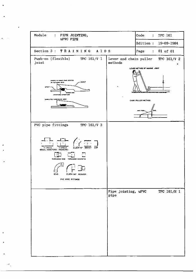
Push—on (flexible) TPC 161/V 1joint
• ISU1~ $4 LDCATCD
~
D~~’C~D$~~ØTV
CO~~LTC~.Y£~U~•Lt~J~T~
Lever and chain puller TPC 161/V 2methods
LEVER I~T)CO ~ MAXP~ J~IT
cHArJ PUJ..ER I.�ThOO
~. io~ ro~~
x
PVC pipe fittings TPC 161/V 3
EL ~-~i- /H ~LiJ
T-PIECE T-PIECE ELSOW45~ SOCKET CAPIEOUAt. D(AMETERSI (REDUC)
E~~:THREADED END T)~E.4D�DSOCKETS
~2(~]BEND ELBOW 90 REDUCER
PVC PIPE FITTINGS
Pipe jointing, UPVC TPC 161/H 1pipe

S

1. INTRODUCTION
MDPP
L~c~’oJ
There are essentially three types of joint which may be used on uPVCpipesa. push—on (flexible);b. solvent weld (solid);.c. compression (flexible).The use of each type of joint is determined by the siteavailability, cost etc. Push—on and solid weld jointsthan compression joints.
2. PUSH—ON (FLEXIBLE) JOINTS
As with all push—on (flexible) joints, these allow a 5° deviation atthe joint, and in the caseof uPVC pipe, becauseof the nature of thematerial, good preparation of the joint is essential.The spigot pipe must be cut to the correct length and the inside ofthe socket must be cleaned thoroughly to remove any traces of dirt,grit, stones etc. This is very important, as a rubber gasket mustfit into the recess which is formed into the socket during sianufac—ture~ Having fitted the gasket, the exposed area of the gasket shouldbe lubricated, using the lubricant recommended by the manufacturer.l~TOstlubricants are chemically similar to a soft detergent soap.
In order to introduce the spigot into the socket the end of thespigot must be chamfered at approximately 45° and lubricated beforeinsertion into the socket. Normally the chamfering is done on siteusing a file but when full pipe lengths are supplied the manufacturermechanically wakes these chamfers at the factory.
GROOVE IN RUBBER RING LOCATED
ON RETAINING BEAD SOCKET
SPIGOT
I RUBBER RINGCHAMFERED SPIGOT END
p:L DEPARTMENT OF PUBLICDIRECTORATE GENERAL CIPTA
J DIRECTORATE OF WATER
WORKS
KARYA
SUPPLY
Module : PIPE JOINTING,uPVC PIPE
Code : TPC 161~
Edition : 19—09—1984
Section 4 : H A N D 0 U T Page : 01 of 06
conditions,are cheaper
Fig. 1. Push-on joint; (A) Initial entry of spigot into socket.


Module : PIPE JOINTING,uPVC PIPE
Code : TPC 161
Edition : 19-09-1984
Section4: HANDOUT Page : 02of06
COMPLETELY ASSEMBLED JOINT
Fig. -1. (B) Completely assembled unit.
uPVC pipe is springey by nature and very often when making a joint itappears to be fully home when it is not. Therefore, it is essentialto mark on the spigot end of the pipe the depth of the socket, sothat when it is pushed home the jointer can see instantly that thejoint is properly made. As with all push—on joints the socket andspigot should be aligned prior to jointing and the spigot pushed intothe socket firmly up to themark. This can be done by means of-8-~ a~~ver;b. a chain puller.
LEVER METHOD OF MAKING JOINT
Fig. 2. Lever method of making joint.


Module : PIPE JOINTING,uPVC PIPE
Code : TPC 161
Edition : 19—09—1984
Section 4: HANDOUT Page : 03of06
CHAIN PULLER METHOD
Wire
IC I II
should be
Fig. 3. Chain puller method.
After completion of the joint, all surplus lubricantcleaned away.
3. SOLVENTWELD (SOLID) JOINTS
All solvent weld joints are solid and cannot be broken.A solvent cement is introduced between the socket and the spigot andthe chemical reaction of the cement on the uPVC forms what is prin-cipally a chemical weld due to the chemical reaction taking placewithin the joint. This reaction takes approximately 20 minutes tocomplete, but most of the welding has to be done within the first two(2) minutes.
As with all pipe joints the preparation prior to jointing is asimportant as the joint itself. The pipe should be cut to the correctlength.
Both the socket and the spigot should be wiped clean of any surplusdirt and then abraded with sand paper to aid the chemical reaction.These abrasions should follow the circumference of the pipe to elimi-nate the possibility of leakage if the cement is applied incorrectly.The socket and spigot must then be cleaned, using the manufacturer’sspecial cleaning fluid, and the depth of the socket marked on thespigot pipe. The cleaning fluid will evaporate in approximatelythirty (30) seconds, leaving the joint perfectly clean and ready forapplication of the solvent cement. This must be applied with a smallpaint brush approximately 2.5 cm in width, around the internal sur-face of the spigot.

Module : PIPE JOINTING,UPVC PIPE
Code : TPC 161—
Edition : 19-09-1984
Section 4 : H A N D 0 U T Page : 04 of 06
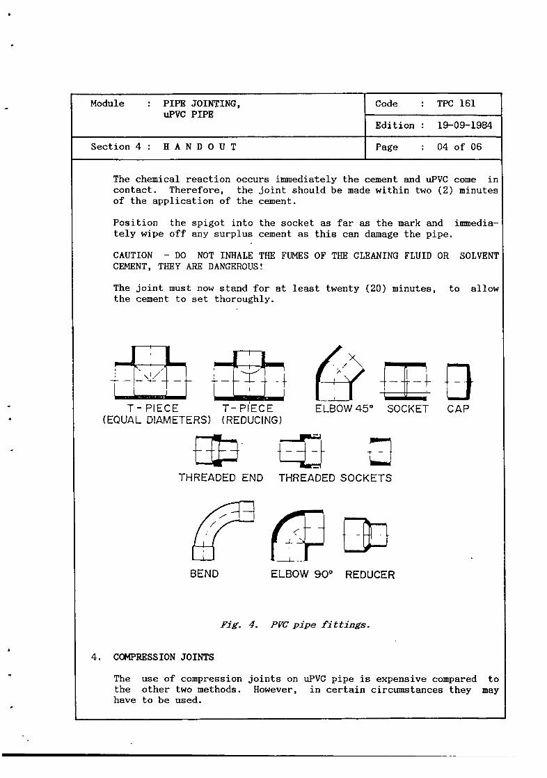
The chemical reaction occurs immediately the cement and uPVC come incontact. Therefore, the joint should be made within two (2) minutesof the application of the cement.
Position the spigot into the socket as far as the mark and immedia-tely wipe off any surplus cement as this can damage the pipe.
CAUTION — DO NOT INHALE THE FUMES OF THE CLEANING FLUID OR SOLVENTCEMENT, THEY ARE DANGEROUS!
The joint must now stand for at least twenty (20) minutes, to allowthe cement to set thoroughly.
THREADED END
H-} BELBOW 45° SOCKET CAP
THREADED SOCKETS
4. COMPRESSIONJOINTS
w
ELBOW 900 REDUCER
Fig. 4. PVCpipe fittings.
joints on uPVC pipe is expensivecompared toHowever, in certain circumstances they may
T-PIECE T-PIECE(EQUAL DIAMETERS) (REDUCING)
BEND
Thethehave
use of compressionother two methods.to be used.


Module : PIPE JOINTING,UPVC PIPE
Code : TPC 161
Edition : 19—09—1984
Section 4 : H A N D 0 U T Page : 05 of 06
There are several types of compression joints commercially avail-able e.g.a. Gibault;b. Viking Johnson etc.
They all work on the same basic principle of compressing a rubbergasket at each end of the sleeve socket (between the sleeve and thespigot pipe) by means of bolts.The pipe must be cut to the correct length and the depth of thesocket marked on the spigot. Then the joint sleeve must be slid overthe end of the pipe and aligned to the mark on the spigot.
The bolts must bethe manufacturer.
tightened in sequenceto a torque as specified by
Fig. 5. Gibault joint
Fig. 6. Viking Johnson coupling.


Module PIPE JOINTING,uPVC PIPE
Code : TPC 161
Edition : 19-09—1984
Section 4 : H A N D 0 U T Page : 06 of 06
5. SAFETY
There are several additional safety points which should be noted whenusing uPVC pipes, particularly when solvent welding. The gasesre-leasedby the cleaning fluid and the solvent cement are highly dange-rous when inhaled.Although uPVC pipe is light in weight, caution should still be exer-cised when carrying and handling this type of pipe.
6. SIM4ARY
The three types of joint available for jointing uPVC pipe area. push—on (flexible);b. solvent weld (solid);c. compression (flexible).
All safety points should be noted when handling these types of joint.


Module : PIPE JOINTING,uPVC PIPE
Code : TPC 161
Edition : 19—09—1984
Annex : VIEWFOILS Page : OlofO4
TITLE CODE
1. Push—on (flexible) joint
2. Lever and chain puller methods
3. PVC pipe fittings
TPC 161/V 1
TPC 161/V 2
TPC 161/V 3


Push—on (flexible) joint TPC 161/V 1
aIii
C)0-J
za: a
zz
>w
(DO
azwI—
0
Ci)
awa:UiLi~
I0
I—z0
aUi-J
UiC,)Cl)
UiI—Ui-J0~
00
I-Ui
C)0U)
za:a:Uia]
a:
F-0
a-Cl)

q

Lever and chain puller methods TPC 161/V 2
LEVER METHOD OF MAKING
CHAIN PULLER METHOD
JOINT
wire rope


PVC pipe fittings TPC 161/V 3
3—
0
HLU
00Cl) U0LU
0-JuJ
LU0
aLU
(I)HLU
00(I)
0LUaLUc~
H
(I)CD2:HF-LL
00O~)
03D-JLU
0DaLU
LU0LU3-
LUa-0~
02:LUaLUa
LU0::IH
0>3-
a2:LU3Dc~
LUHLU
a
-J
0LU
LU0LU0~


-
•.~:~_3,~.
-
-
-~, ~ ~
~ .3~ ~ - ‘~
± 3’ - --t . - -~ ~3_~.± —+-.~-- 3- - - ~
T:j~~ ~‘‘ --~~
- -
~-,:-~~-
V--.--,~-
-~~- .‘-
.
~ -~ -~-_-‘,-—~ -~
.- ~ -.-..----~
- i=___ ~ ~-
- -. -~
- - - r44DEPARTMENT OF PUBLIC WORKSDIRECTORATE GENERAL CIPTA KARYA
DIRECTORATE OF WATER SUPPLY
MDPP
!j?~f(IWACO
Module : PIPE JOINTING,ASBESTOS—CEMENT PIPES
- - - - - -~
Code : TPC 162
Edition 20—09—1984
Sectibh 1 - I NF 0 R M ~A7i~I 0 N ~ H~EE T Page : 01 of 01/10
- -
~-~‘ I±3
— -.3
~ ~ -
3 - -
• -p - -.
-~‘ ~--
~ ~. -
~
-. -~
:~—-~
-
3---
r~~#•~~ -
-r
Duration
Training objectives
~
Trainee selection
~ ~-__.t~
Training aids
— - - -
Special features
3-:. • ~-
Keywords
135 minutes.
After the session the trainees will be able to:— list the two methods of making AC pipe
joints;— use both methods.
— Pipelayer;— Pipeline Inspector;— Construction Supervisor.
— AC pipe lathe;— Short lengths of AC pipe;— Push—on AC joint;- Compressionjoint;
— Lubricant;— Levers;— Chain puller;— Blocks;— Viewfojls : TPC 162/V 1;— Handout : TPC 162/H 1.
Pipe jointing/AC pipe/AC pipe joints.
3-~
—•---
3-~.#
- —. -
~-- - ~
-
-~3-.-~
- ~- -
.~
~
-..-.-~-
.3-.N._r3- - 3- -_~
-3;~7.---i-n-~~--
3— -...
-~--
--
---_-~.
.,~-.—
~-~:
.--~•;-
-~.-
~
-
-.-;~~-~-_---f.- --
~c_-- - — - ~ — -~-
.- ~:- ~ ~ —‘-- -~ - —-
~--±.-3- ~—-- -“---3-3- -
-
~
--
-
—‘ — -~~
----- -

a

Module : PIPE JOINTING,ASBESTOS—CEMENT PIPES -
Code : TPC 162
Edition : 20—09—1984
Section2 : SESSION NOTES Page : 01 of 02
1. Introduction
— -There are basically two types ofused on AC pipe:a. push—on;b. compression.
— As it is extremely difficult to form asocket on AC pipe during the manufacturingprocess, AC push—on joints are essentiallycollars with sockets at both ends.
— Push—on joints are flexible, allowing a 5°deflection at each joint.
— Good preparation of the joint is essen-tial.
— The pipe -has to be cut to the correctlength.
- The manufacturer normally turns down theends to an outside diameter consistentwith (grey) cast iron, consequentlywhenan AC pipe is cut, the ends must beturned down to the correct diameter priorto jointing.
— The next steps of the correct procedureare:
to
Show on sample
Demonstrate and ex-plain method
Explain
2. Push—on joints
joint Use whiteboard
Show push—on joint
Show V 1
mark the depth of the socket on thespigot end of the pipe with chalk;insert the rubber gaskets into the re-cessesat both ends of the socket;lubricate the exposedpart of the gasketwith manufacturer’s lubricant;lubricate the spigot end of the pipe;insert spigot into socket as far as thegasket;align socket and spigot.
NOTEIt is critical on all push—on AC jointsalign the spigot and socket perfectly.


— The remaining steps of the procedure are:push home spigot into socket as far asthe mark on spigot, using:a. lever, orb. chain puller;make the push—on joint at the other endof the socket in the same manner butcaution must be excercised with thesocket as it tends to slide along thepipe.The socket must be held in positionduring the jointing sequence.
— Good preparation of the joint is essen-tial.
— The correct procedure is:cut pipe to correct length;turn down end of AC pipe using AC pipeturner;mark depth of socket on spigot;insert spigot into socket as far as themarkturn down end of 2nd AC pipe;mark depth of socket on spigot;insert spigot into socket;tighten bolts on compressionjoint insequence;tighten to torque as recommended bymanufacturer.
— Do not inhale asbestos cement dust.
— Caution is necessary when handling pipe asit is heavy.
Module : PIPE JOINTING,ASBESTOS—CEMENT PIPES
Code : TPC 162
Edition : 20—09—1984
Section2 : SESSION NOTES Page : 02of02
3. Compression joint
S
Demonstrate appropri-ate method
Let trainees practice
Demonstrate and ex-plain method
Let trainees practice
Explain key points ofsafety
4. Safety
5. Summary Give H 1


FELO LATHES FOR AC PFES
Module : PIPE JOINTING,ASBESTOS—CEMENT PIPES
Code : TPC 162
Edition : 20—09—1984
Section3 : TRAINING AIDS Page : OlofOl
Field lathe for TPC 162/V 1AC pipes
Pipe jointing, TPC 162/H 1asbestos—cement pipes


;~DEPARTMENTDIRECTORATEDIRECTORATE
OF PUBLIC WORKSGENERAL CIPTA KARVA
OF WATER SUPPLY
LMP~1
~iflIWACOI
1. INTRODUCTION
Two types of joints are normally used on AC pipes:a. push—on joints;b. compression joints.Whilst there are many variations on these joints by individualmanufacturers, the essential mode of operation is the same for all.
2. PUSH—ONJOINTS
It is extremely difficult to form a socket on AC pipe during themanufacturing process so that the cost of making such a joint wouldbe prohibitive. Therefore, separate AC push—on joints are used,which are basically collars with socket joints at both ends,,These joints are flexible, allowing a 5° deviation at each joint.Good preparation of the joint is essential and the pipe should be cutcorrectly.
Module : PIPE JOINTING,ASBESTOS—CEMENTPIPES
Code : TPC 162
Edition : 20—09—1984
Seôtion 4 : H A N D 0 U T Page : 01 of 06
PIPE
F~ffTL
Fig. 1. Push-on joint.


Module : PIPE JOINTING,ASBESTOS—CEMENT PIPES
Code : TPC 162
Edition : 20—09—1984
Section 4 : H A N D 0 U T Page : 02 of 06
AC pipe has a standard internal diameter, but the outside diametervaries along the length of the pipe. The manufacturer normally turnsdown the ends of each piece of pipe to an outside diameter consistentwith cast iron pipe. Consequently, when the pipe is cut, the endmust be turned down to the correct diameter to make it ready forjointing.This turning down is done with a commercially available AC pipeturner. This is essentially a rotating lathe which clamps on thepipe, allowing the spigot end to be turned down to the correctdiameter.
The depth of the socket should be marked on the spigot before,also after the turning process. The reason for this is thatoriginal mark is obliterated by the turning process itself, asis continued for approximately 4 cm beyond the original marking.
Insert the rubber gaskets into the recesses at both ends of thesocket, lubricating the exposed parts of the gasket with the manufac-turer’s lubricant. Additionally the spigot ends of the pipe shouldbe lubricated.Insert the spigot into the socket as far as the gasket and align thesocket with the spigot.
Note : IT IS CRITICAL ON ALL PUSH—ON_ACJOINTS TO ALIGN THE_SPIGOT
Fig. 2. Field lathes for AC pipes.
butthe
this
AND SOCKET PERFECTLY


Module : PIPE JOINTING,ASBESTOS—CEMENT PIPES
Code : TPC 162
Edition : 20—09—1984
Section 4 : H A N D 0 U T Page : 03 of 06
— Push home spigot into socket as far as the mark on spigot using:a. lever (see Fig. 3.), orb. chain puller (see Fig. 4.).
— Make the push—on joint at the other end of the socket in the samemanner but ensure that the socket does not slide along the pipe.The socket must be held in position during the jointing sequence.
3. COMPRESSION JOINT — AC PIPE
Good preparation of the joint is again essential and the pipe shouldbe cut to the correct length and turned down using the AC pipeturner. The compression type of joint normally comprises a middlesleeve with a gasket at each end, thus forming a double joint.The gasket is compressed by means of a collar and tie bolts. Markthe depth of the socket on each end of the AC pipe and slide thesleeve over the pipe. Tighten the bolts in sequence, applying atorque as recommended by the manufacturer.


Module : PIPE JOINTING,ASBESTOS—CEMENT PIPES
Code : TPC 162
Edition : 20—09—1984
Section 4 : H A N D 0 U T Page : 04 of 06
WOODEN BLOCK
FITTING THE SOCKET (OVER 0 200)
MARKING
INSTALLING THE PIPE (UP TO 0200)
WOODEN BLOCK
INSTALLING THE PIPE (OVER 0 200)
Fig. 3. Pipe assembly using lever.


Module PIPE JOINTING,ASBESTOS—CEMENT PIPES
Code : TPC 162
Edition : 20—09—1984
Section 4 : H A N D 0 U T Page : 05 of 06
ANCHOR PULLER
CHA~Jç~L~~
DIRECTION OF LAY —*
PULLING
CHAIN
BEFORE ASSEMBLING
AFTER ASSEMBLING
It is dangerous to inhale asbestos cement dust, so extrememust be exercised when cutting or turning AC pipe. The pipeand care must be taken when handling and carrying this typeThe pipe is also easily danaged when dropped.
Fig. 4. Pipe assemblyusing chain puller.
4. SAFETY
Fig. 5. Gihault joint.
cautionis heavyof pipe.


Module PIPE JOINTING,ASBESTOS—CEMENTPIPES
Code : TPC 162
Edition : 20—09—1984
Section 4 H A N D 0 U T Page : 06 of 06
5. SU!+IARY
There are basically two types of joints for use on AC pipes— push—on;— compression.Safety points should be noted when handling AC pipe.


Module : PIPE JOINTING,ASBESTOS—CEMENT PIPES
Code : ~UPC162~
Edition : 20—09—1984
Annex : V I E W F 0 I L S Page : 01 of 02
TITLE
1. Field lathes for AC pipes
CODE
TPC 162/V 1


Field lathes for AC pipes TPC 162/V 1
(J)U0~0~
C
0LL
Cr’)UI
-J
0-JLUU-

0” —

—
--
- ___
-.~‘---~ ~-~‘--,~
,~:— ~
!1 ~fl~=X~ •.I~~U,_ .4 -
$EF~ARTMEF~T~b~LIc~’woAKS
DIRECTORATE GENERAL CIPTA KARYA
- DIRECTORATE OF WATER SUPPLY
~-~-
MDPPDHVTGI
IWACO
Module : PIPE JOINTING, (hI. PIPE
-
Code : TPC 163
Edition : 15—03—1985
Section 1 : I N F 0 R MA T I 0 N S H B B T Page : 01 of 01/10
- ,s”-
‘~~-‘ ~
~
Duration
Training objectives
Trainee selection
.1,;-
Training aids
Special features
Keywords
135 minutes.
After the session the trainees will be able to:— list the two methods of jointing G.I. pipes;— use both methods.
— Pipelayer;— Pipeline Inspector;— Construction Supervisor.
— Threadedjoints;— Compressionjoints;— Dicing machine;— Spanners;— Thread tape (PTFE);— Viewfoils : TPC 163/V1—3;— Handout : TPC 163/H 1.
Pipe jointing/G.I. pipe/G.I. pipe joints.
.~--‘ —
-
a :*~.;:;—~
- ;~‘- - -~~- ~ -~ ~-~--~--~ ~ - - ---~
* ~i_ —~ ~ ~_ ~—t-.-- j~._ -~ t-~ ~.
- ,,,- --—,,-~-- *~—~-‘ - .,~-*-‘ ,,-,.,---- -t~ ‘‘-‘~‘L~”—~ ~ .r~ - — •~

C

Module : PIPE JOINTING, 0.1. PIPE Code : TPC 163
Edition : 15—03—1985
Section2: SESSION NOTES Page : OlofO2
1. Introduction
— There are essentially two ways0.1. pipe:a. threaded joint method;b. compressionjoint method;and both are used extensively0.1. pipe.
of jointing
to joint
Use whiteboard
2. Threadedjoint method
3. Coupressiori joints
now bescrewedwith a
— There are many types of compression jointscommercially available e.g.
bolted gland;Gibault;Viking Johnsonetc.
— Each operateson the same basic principleof compressinga rubber gasket by meansoftie bolts.
Demonstratelain method
Show samples
teeth and
amount of
— The correct procedure is:measure and cut pipes to correct length;
• fix pipe in vice;select dicing machine cuttingfix in dicing machine;
• fix machine to end of’ pipe;• lubricate the pipe end;
continue to cut until requiredthread is available on pipe;
• remove dicing machine from pipe;• clean treads of any “burrs” etc;
NoteThe thread cut should be taperedwhen com-plete.
• apply sealing tape(PTFE tape);the screwed joint or socket can now bescrewed on to the pipe and tightenedwith a spanner;
• another piece of pipe canthreaded in the sameway andinto the socket and tightenedspanner.
and ex—
Show tapered thread
Let trainees practice
to pipe threads


— The correct procedure is:• cut the pipe to the correct length;• mark depth of the socket on the spigot
end of the pipe;• push collar and gasket over spigot end
of the pipe;• insert spigot end of pipe into socket up
to the mark;• align socket and spigot pipes;• push collar and gasket as far as pose i—
- ble towards the socket;• insert tie—bolts;• tighten tie—bolts in sequence and in
accordance with the manufacturer’s re—- co~eñdations regarding torque.
Module : PIPE JOINTING, 0.1. PIPE Code : TPC 163
Edition : 15—03—1985
Section2: SESSION NOTES Page : 02of02
— Some are single joints with a socketformed on the end of the pipe e.g. boltedgland, gland, whilst others are double-joints with a sleeve to joint two spigotends together e.g. Gibault, Viking John-son.
— Good preparation of the joint is essen-tial.
Show V 2/V 3 in caserelevant type of coup—ling is not available
Explain and demon-strate method
Let trainees practice
4. Summary Give H 1


Module : PIPE JOINTING, 0.1. PIPE Code : TPC 163
Edition : 15—03—1985
Section3: TRAINING AIDS Page : OlofOl
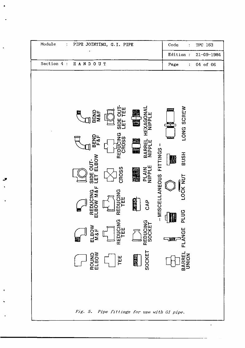
GI pipe fittings TPC 163/V 1
~ROUND ELBOW REDUCiNG SIDE O’JT~ END BENDELBOW MEP ELBOW MEF LET ELBOW FEF MB,
~öL~1®L~J(b1TEE REDUCING REDUCING RED ING SIDE OUT-
TEE TEE CROSS CROSS LET TEE
~SOCKET g~~’CAP PLAIN BARREL HEXAGONALNIPPLE NIPPLE NIPPLE
MISCELLANEOUS FITTINGS -
~•ARREL FLANGE PLUG LOCKNUT BUSH LONG SCREWUIBON
PIPE FITTINGS FOR USE WITH G.I. PIPE
Viking Johnsoncoupling TPC 163/V 2
VIKING-JOHNSON COUPLING
Gibault joint TPC 163/V 3
~
GIBAULT JOINT
Pipe jointing, GI pipe TPC 163/H 1


;~4
DEPARTMENT OF PUBLIC WORKS
DIRECTORATE GENERAL CIPTA KARYA
______ DIRECTORATE OF WATER SUPPLY
1. INTRODUCTION
Jointing galvanised iron pipe is relatively simple and there are onlytwo basic types of joints:a. threaded joints;b. compression joints.
2, THREADED JOINT METHOD
This type of joint involves cutting a thread on the end of the pipewhich can then be screwed into a socket.A dicing machine is used to make these threads.
cutting teeth
DICING MACHINE
MD PPDHVTG I
I WA CO
Module : PIPE JOINTING, 0.1. PIPE Code : TPC 163
Edition : 15—03—1985
Section 4 : H A N D 0 U T Page : 01 of 06
Fig. 1. Dicing machine.

r.-’ q 7~ae~ .4.,

Module : PIPE JOINTING, 0.1. PIPE Code : TPC 163
Edition : 15—03—1985
Section 4 : H A N D 0 U T Page : 02 of 06
It is operated in the following way
1. Choose the correct cutting teeth to suit the pipe diameter.2. For the first “pass”, set the cutting teeth a little wider than
the final setting.3. Put some oil on the pipe end.4. Fix the dicing machine over the pipe, ensuring that it is per—
pendicular to the pipe.5. Apply pressure to the die for the first 3 threads, adding more
oil when necessary.6. Operate the handle clock—wise in a push—arc.7. Do not force the dicing machine, but continue cutting until the
required length of thread has been made.8. Remove the dicing machine by rotating anti—clockwise. Do not
force it as this may break the threads or the cutting teeth.Support with hand as it nears the end of the pipe.
9. Set the cutting teeth to their final position and repeat steps5 to 8.
NOTE : For pipes larger than 50 mmdiameter, 3 passesof the dicingmachine will be necessary. Also, an assistant will be neededto help support the weight of the heavier equipment.
Allowances for threading for pipesbelow
PIPE DIAMETER
50 mm75 mm
100 mm
of various diameters are given
LENGTH OF THREAD
24 nun
30 nun30 mm
The threads which have been cut in accordancewith the above willhave a slight taper
—------—.... taper
Fig. 2. Taper at threaded end.


Module : PIPE JOINTING, 0.1. PIPE Code : TPC 163
Edition : 15—03—1985
Section 4 : H A N D 0 U T Page 03 of 06
To prepare the threads for jointing it is wise to roughen the metalbetween the threads using an old saw—blade, so that the sealingmaterial will grip more readily
Next, roll on PTFE tape over the threads, in a clockwise direction.
The screwed socket can now be attached, but care must be taken toensureproper alignment, to avoid cross—threading. Tighten by handinitially, then tighten gradually with a wrench until the fitting hastravelled the full length of the thread.
NOTE : Pipes usually arrive from the manufacturer with threadsalready cut at each end. These are often damagedin transit.It is sometimesstandardprocedureto cut—off half the lengthof thread at each end of the pipes, and to recut the threadson site. This helps to ensurea watertight joint.
old saviblade
Pig. 3. Roughening threaded end
Fig. 4. Applying PTFZ tape.

Module : PIPE JOINTING, G.I. PIPE Code : TPC 163
Edition : 21—09—1984
Section 4 : H A N D 0 U T Page : 04 of 06
I~-w
LU—w
c4
-J
zw0-i(f3Q.<2:
I
LUJ
ccci~
w
-Jo-ri~~
C-
C)
(‘ ‘,~ ~o~==~0WC/)
U)
zI-I-L1~
U)
0LUz-i-iLU0U)
(/)-i
L1~(Dod
(‘1~L~’ c~0~ wcocc.~i
w
0L1.cooö
zo0~ic~w
Ui
0U,
z0-J
=U)
r1ThI~II~uI —Jiwo-
LU
L~
nDiLW
U)
U)00
n-ni
L~I1WLUI-
I—LU
00U)
Fig. 5. Pipe fittings for use with UI pipe.


Module : PIPE JOINTING, G.I. PIPE Code : TPC 163
Edition : 15—03—1985
Section 4 : H A N D 0 U T Page : 05 of 06
3. COMPRESSION JOINTS
There are many varieties of compressionjoints available commerciallya. bolted gland;b. Gibault;c. Viking Johnson etc.
Fig. 6. Viking Johnson coupling.
Pig. 7. Gibault joint.

V

Module PIPE JOINTING, 0.1. PIPE Code : TPC 163
Edition : 15—03—1985
Section4: HANDOUT Page : 06of06
Each of these joints operates on the same basic principle of conipres—sing a rubber gasket by means of tie bolts. Some are single jointswith a socket formed on the end of the pipe, e.g. bolted gland,whilst other are double joints with a sleeve to join two spigot endstogether, e.g. Gibault, Viking Johnson.The joint should be prepared correctly and the pipe cut to thecorrect length.Having markedthe depth’of the socket on the spigot, insert the endof the spigot into the socket up to the mark and align the socket andspigot.After pushing the collar and gasket as far as possible towards thesocket, insert the tie bolts and tighten in sequence, in accordancewith the torque as recommended by the manufacturers.
4.
There are essentially only two methods of jointing galvanised ironpipe:a. threaded joint method;b. compression joint method.


Module PIPE JOINTING, G.I. PIPE Code TPC 163
Edition 15—03—1985
Annex : VIEWFOILS Page : OlofO4
TITLE CODE
1. GI pipe fittings
2. Viking—Johnson coupling
3. Gibault joint
TPC 163/V 1
TPC 163/V 2
TPC 163/V 3


GI pipe fittings TPC 163/V 1
aLkZc,~5~u_
~•~
Fco
wI__2~
C/)~~i
U-Oo~z~
wc~~Lu
~
iii~
I-~-w
~Zo~QOi~~
1~~-j
w
~
cn
Qcc0
0z
~Wcc
~~
rr-~fl0 Lu
U—~=J~al-Lucc
-J~
i~iO~Q~
w ~zI
U)~I,~jccQ~
~DDZ
~c~_~
~fl
OF-~w
c~ 0 ~~LLiC/)cc
w
0
C/)
a0
C,)
Z~
~
(I)~
~
-j 0-j -JLu0
a~
~~I1L.wa
~
‘U-
LU~-
~.
(
I~.us
~
LU~
~
~0LL.
C,)~
z—~..
~
~
ccw~L~w wI—
I-w
~Io ~~
~
-J
L~I1cc0~
LU


Viking—Johnson coupling TPC 163/V 2
0
-J0~
00z0Cl)
zI0
I
0z
5;
C/)0LuccLu [I fl


Gibault joint
I—zSI—-J
TPC 163/V 3


• - DEPARTMENT
-~ DIRECTORATE______ DIRECTORATE
- “i”
Module
- Duration
•~-z~~~- -,
4 a-’
—
—7—- ‘ “-
4’, - • j +
sac- -49s~t~+
-~- -‘
Training aids
I-“’-‘-1 - -a-7---~---
1 ‘-1-- ~ -‘-,~~---~
-t_~a~_ n’S”’ ~ 4. t_ ~b — ~—t _‘t~’ ~ —---- ‘-a, - — +~-a — - ,-r—+
4 - *- a—-t.--++c~— ‘-v~+ -- - ~-~1 ~P~.’—5~ -.a34ta+ U,. -“ ‘ -s--- - — ~a-
-~ ~+~*
~s -t7-. r± ‘a” ‘ —trr—’-~- ?- -—-y•--~’--~--’-- ——-,“’ —---
OF PUBLIC WORKS - MDPPGENERAL CIPTA KARVA
OF WATER SUPPLY IWACO
PIPE JOINTING CASTANDJUcIILE_ IRON PIPE
Code : TPC 164
Section 1: INFORMATION SHEET Page 01 of 01/10
Edition 20—09—1984
P -“4-”
&a-~-- -;7+,-a,-—.,-—~—~
-‘
—
- , -
I — — —
-U
135 minutes
Training objectives After the session the trainees will be able to- -- - a — list the three basic methods of jointing grey
cast iron or ductile iron pipe;-~ — use all three methods.
Trainee selection - : — Pipelayer;a — ‘Pipeline Inspector;
-- -- ~--~-~ - ~-~- — Construction Supervisor.
— Short lengths of Cast and Ductile Iron Pipe;— Push—on joints;— Flange joints;
- --~t-~-J-~’ — Compression joints;- - —- — Levers;
- — Blocks;- - — Chain puller;
— — Lubricant;- - ~— --- — Viewfoils TPC 164/V 1—2;
-- - T — Handout TPC 164/H 1.
Special features : — To be given after modules TPC 155 and TPC 156.
Keywords : Pipe jointing/cast iron/ductile iron.
+ -,, —,-,,—+- a+ a4 -- ,.-a. -— - - tU~—-’~tt~ -~— -~ ,a,++,+.-t ‘a *aU-~s-7-~-44,asa, 7+Z---’-S+- tat,+
~ ~‘t4-k~$’ ah~t a~~ac4 mctt ~p, -4*- ~ +~~4•—- _-~r - ‘~ -t , —1ff” — SW*~ a~~’-~ ‘~ “~‘lt””HI ‘~-~- I—c--— :~.-, ~ -. ~‘a’H-4~,+, 7+ ‘~‘‘~t~I~ ~
+-. r -~ ~ fr~ ‘ ~-l’ - 4- -5- -a,--’U- -- 5-~-~ —~s—’-!--,~-~ a — - —,- ‘H’ ~ 5- —
t~•-

S
I

Module : PIPE JOINTING CASTAND DUCTILE IRON PIPE
Code : TPC 164
Edition : 20—09—1984
Section2: SESSION NOTES Page : OlofO3
1. Introduction
— There are three basic ways of jointing Use whiteboardcast or ductile iron pipe:
push—oncompressionflanged.
2. Push—on joints
joint is essen—
— The correct procedure isinsert gasket into socket;lubricate the exposed area of thegasket, using manufacturer’s lubricant;mark depth of socket on spigot pipe;insert spigot into socket as far asfront of gasket;align socket and spigot;push spigot home into socket usingeither : --
a. lever;b. chain puller.
Give length of pipe,push—on joints, lubri-cant, levers and chainpullers
3. Compressionjoints
— There are many types of compressionjoints commercially available e.g.:
Bolted gland;Gibault;Viking Johnson.
— Each operates on the same basic principleof compressing a rubber gasket by meansof tie—bolts.
— Good preparation of thetial.
Demonstrateplain method
and ex—
— Divide trainees in groups.
— Do exercise (10 minutes). Let trainees practice
Show models
Show V 1 (a—b)


— Some are single joints with a socketformed on the end of the pipe e.g. boltedgland, whilst others are double jointswith a sleeve to joint two spigot endstogether, e.g. Gibault, Viking Johnson.
— Good preparation of the joint is essen— Demonstrateplain method
I
— The correct procedure to be used forcompression joints is
mark depth of the socket on the spigotend of the pipe;push collar and gasket over spigot endof the pipe;
• insert spigot end of pipe into socket upto the mark;align socket and spigot pipes;push collar and gasket as far as pos-sible towards the socket;insert tie—bolts;
• tighten tie-bolts in sequence in accor-dance with manufacturer’s recommenda-tions regarding torque;
- Let trainees practice
4. Flanged joints
— Flanged jointsflexibility.
Demonstrate and ex-plain method
Module : PIPE JOINTING CASTAND DUCTILE IRON PIPE
Code : TPC 164
Edition : 20—09-1984
Section2: SESSION NOTES Page : 02of03
t ialand ex—
Show V 2
Give flanged joints,and lengths of pipe
Give compressionjoints and lengths ofpipe
— Do exercise (15 minutes).
are solid allowing no
— Good preparation of thetial.
joint is essen—


Give flanged joints,and lengths of pipeLet trainees practice
Module : PIPE JOINTING CASTAND DUCTILE IRON PIPE
Code : TPC 164
Edition : 20—09—1984
Sect ion 2 : S E S S I 0 N N 0 T E S Page : 03 of 03
Show V 2— The correct procedure to be used forflanged joints is• clean faces of the flanges to remove any
traces of corrosion or high spots;align bolt holes of the flanges;
• insert bolts in holes;tighten bolts in sequence, in accordancewith manufacturer’s recommendations re-garding torque;
— Do exercise (15 minutes).
5. Safety
— Safety measures are necessary becauseheavy pipes have to be handled andlifted;pipe edges are sharp.
6. Summary Give H 1


Module PIPE JOINTING CASTAND DUCTILE IRON PIPE
~ode TPC 164 --
dition : 20--09—1984
Section 3 T R A I N I N G A I D S ~age 01 of 01
Push—on joints TPC 164/V I
.4 Is..(. mo. 5-0cAV~I044 1(7*44101 1(00 I~KCT
~
~CM044’(IW I~400TC404
~
Bolt tighten Lng TPC 164/V 2sequence
~r ‘rcrE,~ sco(~NcE
FOR SZEZLP TO AM) l9~WI1G3OOrcmCIAIETERi
0403 ISI. 4 O~IQo:~o171004
Pipe joinUng castand ductLle iron pipe
TPC 164/1-1 1


;tDEPARTMENT OF PUBLIC WORKSDIRECTORATE GENERAL CIPTA KARVA
DIRECTORATE OF WATER SUPPLY
MDPPI
9~YIWACOI
Module : PIPE JOINTING CASTAND DUCTILE IRON PIPE
Code : TPC 164
Edition : 20—09—1984
Section4 : HANDOUT Page : 01 of 05
1. INTRODUCTION
Essentially there are three basic ways of jointing grey cast iron orductile iron pipea. push—on;b. compression;c. flange.The choice of the type of joint is usually made by the engineer andbased on the design criteria, availability and cost.
2. PUSH—ONJOINTS
The joint itself should be correctly prepared by first cutting thepipe to the correct length. The gasket is inserted into the recess ofthe socket after this has been cleaned first.
The manufacturer’s lubricant should be used to lubricate the gasket,and the socket up to the depth marked on the spigot piece of pipe.
Insert the spigot into the socket as far as the gasket, taking careto align the socket and the spigot.Finally the spigot should be pushed fully home into the socket using:a. leverb. chain puller
Fig. 1. Inserting rubber gasket into socket.


Module PIPE JOINTING CASTAND DUCTILE IRON PIPE
Code : TPC 164
Edition : 20—09—1984
Section 4 : H A N D 0 U T Page : 02 of 05
GROOVE IN RUBBER RING LOCATED
ON RETAI
SPIGOT ~~BEADS~KET
RUBBER RING
CHAMFERED SPIGOT END
!III1nr!T,JwnhIfl!I7It~’
~
3. COMPRESSIONJOINTS
Fig. 2. Push—onjoint (schematical).
There are manycommerciallya. Bolted gland;b. Gibault;c. Viking Johnson etc.
varieties of compression joints available
Each of these joints operates on the same basic principle of corn—pressing a rubber gasket by means of tie bolts. Some are singlejoints with a socket formed on the end of the pipe, e.g. boltedgland. Others are double joints with a sleeve to join two spigot endstogether e.g. Gibault, Viking Johnson.The joint should be prepared correctly and the pipe cut to thecorrect length.

t

Module : PIPE JOINTING CASTAND DUCTILE IRON PIPE
Code : TPC 164
Edition : 20—09—1984
Section 4 H A N D 0 U T Page 03 of 05
Fig. 3. Viking .Johnson coupling
Fig. 4. Gibault joint.


Module : PIPE JOINTING CASTAND DUCTILE IRON PIPE
Code : TPC 164
Edition : 20—09—1984
Section 4 : H A N D 0 U T Page : 04 of 05
Having marked the depth of the socket on the spigot, insert the endof the spigot into the socket up to the mark and align the socket andspigot. After pushing the collar and gasket as far as possible to-wards the socket, insert the tie bolts and tighten in sequence, inaccordancewith the torque as recommended by the manufacturer.
4. FLANGEDJOINTS
Flanged joints are solid, allowing no flexibility at the joint. Theface of the flanges must be cleaned thoroughly with a wire brush toremove any traces of corrosion or high spots. The gasket is insertedbetween the flange faces and the bolt holes on the flanges arealigned.The bolts must then be tightened in the sequence and with the torqueas reconunended by the manufacturer.
1 1
3 Bolts1 3
4 Bolts
Bolts
6 Bolts 8 Bolts
Fig. 5. Bolt tightening sequence (for sizes not larger than 300 jim,).

+

Module : PIPE JOINTING CASTAND DUCTILE IRON PIPE
Code : TPC 164
Edition : 20—09—1984
Section 4 : H A N D 0 U T Page : 05 of 05
5. SAFETY
Metal pipes are heavy, consequently care should be exercised whenlifting and handling theni. Also keep in mind that cut edges areextremely sharp and dangerous!
6. SITh?4ARY
There are three types of joints used on cast or ductile iron pipea. push—on;b. compression;c. flanged.Safety points should be noted whenever handling or using these typesof joint.


Module PIPE JOINTING CASTAND DUCTILE IRON PIPE
Code : TPC 164
Edition : 20—09—1984
Annex : VIEWFOILS Page 01 of 03
TITLE CODE
1. Push—on joints ~
2. Bolt tightening sequence
TPC 164/V 1
TPC 164/v 2


0w
C)0-J
0z
w
zw>00cr0
0
wo
0
0
U)
0lii
Ui
41:C-)
Push—on joints TPC 164/V 1
I—Ui
C-,0
C/)
4
Ui
C,zz
Ui
z0
I-0
CDILU)

4

Bolt tightening sequence TPC 164/V 2
BOLT
FOR SIZES UP
TIGHTENING SEQUENCE
TO AND INCLUDING 300 mm DIAMETER1
1
1
3 Bolts3
4 Bolts
6 Bolts 8 Bolts


£
-~ - - -:-%2~5. --~ ~-R~ ~--.‘P. t ~ .a~--- C
-~ -~- -~ ~ —C-- - *4~E~i~-~ -~2sTh.~L - - - ___
1 DEPARTMENT OF PUBLIC - WORKS MDPP
r&dDIRECTORATE GENERAL CIPTA KARVA
______ DIRECTORATE OFWAT E~UPP(..t IWACO
Module : INTRODUCTION TO MAINLAYING
-- -
Code : TPC 170
Edition : 18—09—1984
Section 1: INFORMATION SHEET Page : 01 of 01/06
- a--.
- c--- 9
!a11 4~ .
Duration
Training objectives
Trainee selection
Trainin~ aids
Special features
Keywords
45 minutes.
After the session the trainees will be able to:— list the 6 basic aspects of mainlaying.
- Head of Section Distribution;— Head of Sub—section Distribution & Connec-
tions;— Pipelayer;— Pipeline Inspector;— Head of Sub—section Supervision;
Construction Supervisor.
— Viewfoil TPC 170/V 1;— Handout : TPC 170/H 1.
This module is designed as an introduction to atraining course on mainlaying.
Mainlaying/introduction to mainlaying.
—9-,---—- 9---- - — -- — --~- - —- - .-_--+z’ -~
~ ~ ~ã~1i1~ ~ ~ -.- :~-.
— —-~---r-- —~ r— —-r —


Module : INTRODUCTION TO MAINLAYING Code : TPC 170
Edition : 18—09—1984
Section2 : SESSION NOTES Page : OlofO2
1. Introduction
— There are essentially 6 areas in main— Show V 1laying:a. excavation, bedding and backfilling;b. setting out the line of the main;c. handling pipes;d. cutting and preparing pipes for joint-
ing;e. jointing pipes;f. testing.
— Linking all these areas is safety.
2. Excavation, bedding and backfilling
— Important to do correct excavation, bed-ding and backfilling as this leads to lessmaintenance problems in the future.
3. Setting out
— Essential to set out line of main properlyin order to plan the practical aspects ofthe job correctly.
4. Handling and stacking pipes
— Pipes should always be handled and stackedcorrectly:
to avoid damage;for safety.
5. Cutting and preparing pipes
— Essential to cut pipes correctly to lengthto:
avoid wastage;make good joints.


Module : INTRODUCTION TO MAINLAYING Code : TPC 170
Edition : 18—09-1984
Section2 : SESSION NOTES Page : 02of02
6. Jointing pipes
— Joints should always be made correctlyorder to:• prevent leakage;
minimize maintenance.
in
7. Testing
— New mains should always be tested to checkthat mainlaying has been carried out cor-rectly.
8. Safety
— Pipelaying can be dangerous as pipesheavy and difficult to handle.
are
9. Summary Give H 1

~1-

Module : INTRODUCTION TO MAINLAYING Code TPC 170
Edition : 18—09—1984
Section 3 : T R A I N I N G A I D S Page 01 of 01
Mainlaying TPC 170/V 1
MAIN LAYING
Setting out• Excavation- Bedding- Pipe handling I stacking- Pipe cutting- Pipe jointing- Backuilling- Testing
SAFETY
Introduction to main— TPC 170/H 1laying.


DEPARTMENT OF PUBLIC WORKS MDPP
r&dDIRECTORATE GENERAL CIPTA KARYA
DIRECTORATE OF WATER SUPPLY IWACO
Module : INTRODUCTION TO MAINLAYING Code : TPC 170
Edition : 18—09—1984
Section 4 : H A N D 0 U T Page : 01 of 02
1. INTRODUCTION
There are essentially 6 areas in mainlaying:a. excavation, bedding and backfilling;b. setting out the line of the main;c. handling pipes;d. cutting and preparing pipes for jointing;e. jointing pipes;f. testing.
Linking all these areas is safety.
2. EXCAVATION, BEDDING AND BACKFILLING
It is important to carry out excavation, bedding and backfillingcorrectly as this leads to less maintenance problems in the future.
3. SETTING OUT
It is essential to set out the line of the main properly, in order toplan the practical aspects of the job correctly.
4. HANDLING AND STACKING PIPES
Pipes should always be handled and stacked correctly:— to avoid damage;— for safety.
5. Cutting and preparing pipes
It is essential to cut pipes correctly to length to:— avoid wastage;— make good joints.
6. JOINTING PIPES
Joints should always be made correctly in order to:— prevent leakage;— minimize maintenance.


Module : INTRODUCTION TO MAINLAYING Code : TPC 170
Edition : 18—09—1984
Section 4 : H A N D 0 U T Page : 02 of 02
7. TESTING
New mains should always be tested to check that inainlaying has been
carried out correctly.
8. SAFETY
Pipelaying can be dangerous as pipes are heavy and difficult tohandle.
9. STM4ARY
There are 6 important aspects in mainlaying:a. excavation, bedding and backfilling;b. setting out line of pipes;c. handling pipes;d. cutting and preparing pipes;e. jointing pipes;f. testing.
At all times safety precautions should be taken.

4

Module : INTRODUCTION TO MAINLAYING Code : TPC 170
Edition : 18—09—1984
Annex : VIEWFOILS Page OlofO2
TITLE CODE
1. Mainlaying TPC 170/V 1

-* -- -9- —- - 9-, - -
7 - L
- - 41
-9 - 9— - —
- ~:_ - - 1
- —
— I
— — 2
-~ - - -
7 - - -:
- 9 -2
9; — — 5
-i
- -
4-
- -i
1_c
-f--
a ~

Mainlaying TPC 170/v 1
0)•
0 9
C/)
0)
a — =
z •—.— C)0— 0 • — ~ — U —
— C)co ~••~= 0)0) c~ -~ 0 .2. ~ >-
>.—U— I
U— -C -~ —
z LI_I— w a) U — U — • — U ~) LL
I I I I I I I I


Duratj911:
TraiñiiiTdbijettives
-a-
~cz:-~ ~t~—-~-
- 4~-~a9~ ~
-- --
- -9— -=
-.
-a--- -C—a-
Trainee ~se1ect
- ~ 9-
-r
t — 9 £7
- - !-~--!-.aan,~.~ - —
- - - 5Xt~- £~ - ‘~
-e1t4~~ff ti*-a9~~i~
~ r~----,cf-a--~ r
Train iij aidà -~
- ~~7J ~ ~ ~__ -
- -- - ,- -
a_-a--- -
t~9iC~-i --t-&- -
--—~-~ -9;~,-_
- -9--
Tllr
- - a-i-if--
Special features
: ~
- ...—-- -f-if
- 1*KeywordiE -- -
t! ~t_~ -- - -
- ~ t~Ja-~H~ -~-a_ ~‘—
-- -~t&~~-a ~ -~-*‘--
- if ~
— - :~-;~=~t arr~
— Gloves;— Boots;— Overalls;— Safety hats;— Eye protector;— Viewfoil : TPC flY/V 1;— Handout : TPC 179/H 1.
-Ic ~ - -~ti~ ~—~- -
-‘ ~fft~i ~ CIIC~ --
° ~ 4-fla-s--— — --- ~-_~9=4= ~ _--#a-#--*~ -- ~ ~ ~ ~, - - --_~ -— —
— if 1”~C - -~ -. --9-,-- ~ - ~~__ - - ~ £2~_~~L a~a r a~ £~ -
1 DEPARtMENT OF PUBLIC WORKS MDPP
p4a DIRECTORATE CENE~ALCIPTA KARYA - -
- DIRECTORATE OF WATER SUPPLY IWACO
ModuleTjPM~jNLAYING SAFETY:~It±’~~i~:~ -; ~ -
~ ~ - -~. -.-~-—--. - - -
Code : TPC 179
Edition : 18—09—1984— ç - -
Section 1 :INFQRMATI0N SHEET - Page : 01 of 01/04
45 minutes
After the session the trainess will be able to:— name the 2 main areas of safety;— list the components of protective clothing;— list the aspects involved in safety of others.
— Head of Section Distribution;— Head of Sub—sectionDistribution & Connec-
tions;— Pipelayer;— Pipeline Inspector;— Head of Sub—sectionSupervision;— Construction Supervisor.
I—
Mainlaying safety/safety clothing.
- #~‘ ?- ~4a_ £-~
- -
_~t ~ ~I- -- F~r_a~t
-- -- — - ----


Module : MAINLAYING SAFETY Code : TPC 179
Edition : 18—09—1984
Section 2 : S E S S I 0 N NO T E S Page : 01 of 01
1. Introduction
— Safety is relevant to two areas:a. personal safety;b. the safety of others.
2. Personalsafety
— Use of protective clothing:a. bootsb. overallsc. glovesd. hatse. eye protectors.
— Correct use of tools and equipment.
3. Safety of others
— Tools and equipment left in dangerousplaces. -
— Obstructions to pedestrians and traffic.— Storage of dangerous materials.— Excavations.— Flooding due to discharge of water.— Use of equipment and machines.
Show V 1
Sho~protective clc1th—ing and demonstrateits ube
4. Summary Give H 1


Module MAINLAYING SAFETY ~ode : TPC 179
Edition 18-~O9-~1984
Section3 TRAINING AIDS Page : OlofOl
Safety TPC 179/V 1
SAFETY
- For oneself- For others
Mainlaying safety TPC 179/H 1


DEPARTMENT OF PUBLIC WORKS MDPP
r&dDIRECTORATE GENERAL CIPTA KARYA
DIRECTORATE OF WATER SUPPLY IW~O
Module : MAINLAYING SAFETY Code TPC 179
Edition 18—09—1984
Section4: HANDOUT Page : OlofOl
I. INTRODUCTION
Safety is relevant to two areas:a. personal safety;b. the safety of others.
2. PERSONALSAFETY
Use of protective clothing:a. bootsb. overallsc. glovesd. hatse. eye protectors.
Correct use of tools and equipment.
3. SAFETY OF OTHERS
Tools and equipment left in dangerous places.Obstructions to pedestrians and traffic.Storage of dangerous materials.Excavations.Flooding due to discharge of water.Use of equipment and machines.
4. SU?+IARY
Personal safety;Safety of others.


Module : MAINLAYING SAFETY Code TPC 179
Edition : 18—09—1984
Annex VIEWFOILS Page : OlofO2
TITLE CODE
1. Safety TPC 179/V 1

4

Safety TPC 179/V 1
9-
~C/)(I)
wLL 00
LLUCl) I I


Module PRESSUflE TESTING PIPES - Code TPC 180
::E:;~ti~i ~ -: ~::~t :I~T~Sectionj : I~ FQJ1M~T I QN S REET~
Edition 20-09-1984
Page : 01 of 01/06
Duration-“ t --
Training objectives-v
_____~ -~-e=.~-- --
-~“#---_-- -
99
tif7fl -V-i&--
—= 4I~-a-— -_ -a-- — -
- ~ct-~-~-
-- -~M a- -
-- —-- --ut!~~,~-; ~
Trainee selection
~
-- -2 ~—9-~- -
- -1-9-- - ~ -# ar_a- ~—
- ~‘~t-t’~~ :r.—~-- — -
-~ &- -~aa~~z~ -
- -°--
rifaif~-— 4 -~-9- -
Training aids-—---~ —-‘--I
- -- -- -4r-~ -‘i—a -- —- --
-— ;e_ - -
- — — - —
:~tS- ~
- -i £—it-— - - -
— -
Spectal features -
- a9-- - -
- -‘ ~ — ~- -:—a
- a-Keywords ~. I~
-~
-
~~i1~-~ta~-
ni~e~~YL9-i ~~f—1~
I - :L-r. -
;~
;~ii~-~~-~_- -~-:
~1_~
:- ~ s~-V--
- -- ~ -c-—-:
~::-3-T- - - :;- -t—
~r-
:
~-
- -a-
-v
~--~- ~-~-.- ~
-
-~-~
-~ - —4 - -L~_rL4 - 4~’ --
-- -~4fr~_- T a5~ - ~ ~-- -~ II ~ ±~n ~ -f~ ~- ----~ —-- -t ~. -~
- ~ - -- - ~- —
- ~U-~L ~L---aT±~~ ~-- -
~ DEPATh~ME~N1 OF ~PUBLFC WORKS MDPP
4’ DIRECTORATE GENERAL CIPTA KARYA
-- DIREcToRATE OF WATER SUPPLY IWACO
90 minutes.
After the session the trainees will be able to;- describe the method for carrying out a pres-
sure test;— carry out such a test.
— Pipeline Inspector;— Construction Supervisor;— Head of Sub—section Distribution & Connec-
tions.
— Water main;— Pressurepump;— Pressuregauges;— Viewfoils : TPC 180/V 1—2;— Handout : TPC 180/H 1.
Pressure testing / pipe testing.
t

j

Module : PRESSURE TESTING PIPES Code : TPC 180
Edition : 20—09—1984
Section2: SESSION NOTES Page : O~Iof02
1. Introduction
— Testing is necessary on all new watermains to ensure that
the pipe is sound;the joints are watertight.
— Testing involvesapplying a measuredpressureto a watermain;observing the ability of that main tomaintain the pressure over a givenperiod of time.
— The most commonly used method is to in-crease the pressure in a new water main to1.5 TIMES THE NORMAL WORKING PRESSURE andto maintain this for a minimum period of 2HOURS.
— If there is a drop in pressure during thisperiod the main is pressurised again tothe original test pressure and the amountof additional water required is measured.
— Certain pipe materials (cement lining,concrete, AC) absorb water themselves. Toavoid wrong conclusions : pre—pressurizeduring at least 24 hours, until saturationtakes place.
— After completion of actualcompare amount of additionalfollowing calculation
test phase,water with
Show V 1
Show V 2ALLOWABLE LOSSES IN LITRES PER HOUR
Q = (d\f~)/1O0L for iron, steel anduPVC pipe
Q = (d\f~)/60L for AC pipe


Module : PRESSURETESTING PIPES Code : TPC 180
Edition : 20—09—1984
Section2: SESSION NOTES Page : 02of02
WhereQ allowable
pipelinetesting phase
d = internal diameter of pipe in mmp = pressure in kg/cm2L average pipe length in m
Note : L is the average length of theindividual pipes used e.g. 4, 6 or 10 m.
— The method of testing is:connect test pump to pipe (Usually bymeans of a service connection ferrule);pump pressure up to 1.5 times normalworking pressure;leave for 2 hours;periodically check pressure gauge;let trainees practice.
— After 2 hours, if the pressure has drop-ped, re—pressurize the main to the origi-nal pressure (1.5 times normal workingpressure).
— Measure the amount of’ additional waterneededto re—pressurize.
— Calculatefrom theactual loss.
— Investigate the causeof abnormal losses,if theseoccur.
loss in litres per km ofand per hour during the
2. Method of testing
— Ensure that the pipe tosealed at each end
be tested is Explainstrate
Explaintivities
and demon—
remaining ac—
the acceptable lossformula and compare
of waterwith the
3. Summary live H 1


Module : PRESSURETESTING PIPES Code : TPC 180
Edition : 20—09—1984
Sectjon3: TRAINING AIDS Page : OlofOl
Pre--pressurization TPC 180/V 1
PRE- PRESSURIZATIONFOR
WATER ABSORBING MATERIALS
- CONCRETE
- A.C.- CEMENT LINING
PRE-PRESSURIZE FOR ~ 24 HOURS
1.5 WORKING PRESSURE
Pressure testing TPC 180/V 2
PRESSURE TESTING
1. TEST PRESSURE .15~WQRKINGPRESSURE -
2. DURATION AT LEAST 2 HOURS
3. ALLOWABLE LOSSES
A.C. PIPES Q~ -
OTHER PIPES Q 100L
Pressure testing pipes TPC 180/H 1


DEPARTMENT
DIRECTORATE
______ DIRECTORATE
OF PUBLIC WORKS
GENERAL CIPTA KARYA
OF WATER SUPPLY
MDPPH
1W 0
1. INTRODUCTION
Testing is necessary on all new water mains toa. the pipe is sound;b. the joints are watertight.
ensure that
Testing involves applying a measured pressure to a water main andthen observing the ability of that main to maintain the pressure overa given period of time. A larger loss of pressure would normallyindicate that water is lost or that the pipe material is expandingabnormally.
Certain pipe materials, however, such as (prestressed) concrete orasbestos cement, will absorb water until the material is saturatedwith it. Although this does not mean that anything undesirable ishappening, it will result in a loss of pressure. To avoid confusion,therefore, it is common practice to pressurize pipes of such mate—rials during a preparatory phase first, until the absorption of waterby the pipe material has come to an end. Any further losses inpressure are then no longer the result of absorption of water by thepipe material itself.
The preparatory phase involves applying a test pressure of 1.5 times
ure for at_l eas t 24 hours.
For the actual pressure test itself, the most commonly used method isto increase the pressure in the new water main to
1.5 TIMES THE NOI~4AL WORKING PRESSURE
and to mantain this for a niinimum period of
2 HOURS
If there is a drop in pressure during this period the mainrized again to the original test pressure and the amounttional water required is measured.
is pressu—of addi—
This amount of additional water (or losses from the first pressuriza-tion) is compared with the following calculation.
Module PRESSURETESTING PIPES Code : TPC 180
Edition : 20—09—1984
Section 4 : H A N D 0 U T Page 01 of 02

K-

Module : PRESSURETESTING PIPES Code : TPC 180
Edition : 20—09--1984
Section 4 H A N D 0 U T Page : 02 of 02
AUowab1 e
Q (dV~)/lOOL for iron, steel and uPVC pipe
Q = (d\f~)/60L for AC pipe
allowable loss in litres per km of pipeline and per hour,the testing phase;
d = internal diameter of pipe in mm;p = pressure in kg/cm2L = average length of the individual pipes, in in (e.g.
etc.).
2. METHODOF TESTING
Ensure that the pipe to be tested is sealed at each end.Connect test pump to pipe. This is usually done by means of aservice—connection ferrule.Pump pressure up to 1.5 times normal working pressure.Leave for 2 hours.Periodically check pressure gauge.After 2 hours, if the pressure has dropped, re—pressurize the mainto the original pressure (1.5 times normal working pressure).Measure the amount of additional water needed to re—pressurise.Calculate from the formula the acceptable loss of water and comparewith the actual loss measured. Investigate the cause of anyexcessive loss of water.
3. SU~4~1ARY
— Pipe aiid joints are checked by applying overpressure and checkingany decrease in pressure with time.
— Certain pipe materials absorb water and need to be pre—pressurizedfirst. -
— Pressurization normally is to 1.5 times normal working pressure andfor at least 2 hours.
Whereduring
4, 6, 10 in,


Module PRESSURETESTING PIPES Code TPC 180
Edition : 20—09—1984
Annex VIEWFOILS Page OlofO3
TITLE CODE
1. Pre—pressurizat ion
2. Pressuretesting
TPC 180/V 1
TPC 180/V 2


Pre—pressurization TPC 180/V 1
z
2
N
C’)
U)
LU
I
LU
±
0U-
Cl)
-J
LU
F—
.0zcr0Cl)
co
UiI-
0
z
1—zLU
LU0
I
LUI—LU
0z00
U)
0
=A\
0LL
LUN
U)U)LUcc0~I
LUcc
C
LUccU)U)LUcc0~
0zcc0
x
L()U
1~
I I
-K -K


Pressure testing TPC 180/V 2
0zU)LUF—
LUccU)U)LUcc0~
0
2:
cc0
L>Q0
II
a[a—i
U.
U)cc0I
F-U)LU-J
I—
C/)LUU)U)0-J
II
aLU
Cl)
Cl)
LUcc0~
U
C/)LU0~
C/)LU0~
LU-Jc~
0-J-J
2:QI—ccF-
U)LUF-
ccLU=I—0

C
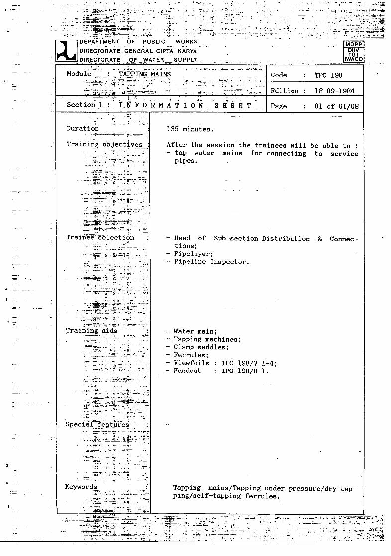
Duration
Training objectives
~
i~.t- ~—~-‘-
Traine& ~e1ect ion
IF -~
~
— -¼.-. ~- ~ ~ -
~:-i7j4~3 ~a-
- ~--~-~v -~ 4-
TrainipgaiSs ~
~e=~a~-±-- ~- -~-~ ! ~
i~1~- ~-..:at r - -.
Speciaj’~1eflvres
-
-~
-~
Keywords- a
- --~ -~~_-_t-.~
-- —i~ç~~---- t
— Water main;— Tapping machines;— Clamp saddles;— .Ferrules;— Viewfoils- Handout
- --- - ;a~~—~ t - -- ~ - -:-
- -~ —- =—&-w- r —:-
. —
z~-s—s ~._---
— — ~.. ——
• -
..~T~c~4
—-----;-- -~
- :~-‘ -a----- - - -~-
I DEPARTMENT OF !UBLIC W9~KS- -.
~ DIRECTORATE GENERAL CIPTA KARVA
- DIRECTORATE QF WATER~SUPPLY
- -p-- - --
-
-
. -
-- -
-
-~
MDPP~kç~V
IWA~O
Module TAPPING MAINS -
~
t—~-; -.~ -~ -.
Code TPC 190
Edition 18—09—1984
Sectionj IN FORMAT I ON SHEET Page 01 of 01/08
135 minutes.
After the session the trainees will be able to— tap water mains for connecting to service
pipes.
— Head of Sub—sectionDistribution & Connec-tions;
— Pipelayer;— Pipeline Inspector.
TPC 190/V 1—4;TPC 190/H 1.
Tapping mains/Tapping under pressure/dry tap-ping/self—tapping ferrules.
-~ .-+.à. ~~4~rif_ - 1- J -~. -; -—
- ~ ;i~a~~ -- - 2.: -~ F - - - -
-- -
-~~4t~a~L/. .~t- -:r-r1~T~~- 4~~_t ~:—~i’7

-1~ ~
4-
-4
-~-
r
- 4-
—¼
4-
~
T
p 4-
-f ~:~ t~-
- - -~-1. ~ —
IL -t ~-
~IL
~
— -~ ~-
4:— ~.—
1~
4-
1.
-4-
—1-
--
~
~ :~
— I —~t
— -I— -
r -
--4
B -
r
- ¼
- —
II
- .—
-s-- ,~
I

Module : TAPPING MAINS Code : TPC 190
Edition : 18—09—1984
Section2: SESSION NOTES Page : OlofOl
1. Introduction
— Water mains are tapped to provide a con-nection between the water main and theservice pipe to a consumer.
— They are tapped under two conditions:a. under pressure;b. dry (not under pressure).
2. Tapping under pressure
Show V 1
— The sequenceof tapping under pressure is:
clamp under—pressure—tapping machine tothe water main;insert the ferrule and drill;
- clamp turret in position;- drill and tap main;
withdraw drill;rotate turret head through 180°;
- insert ferrule by screwing;seal ferrule with plug;remove tapping machine from main.
4. Self—tapping ferrules
— The sequence for self—tapping ferrules- connect saddle and ferrule to main;• rotate ferrule to cut and tap hole;- withdraw tapping plug to tap of ferrule
by screwing.
Show equipmentDemonstrateShow V 2—4
Let trainees practice
— Can be used under pressureor dry
5.
Show self—tappingferruleDemonstrate
Let trainees practice
Summary Give H 1


Module : TAPPING MAINS ~ode : TPC 190
dition : 18—09—1984
Section3 : TRAINING AIDS ~age : OlofOl
Service connection TPC 190/V 1assembly
FERRULEI SERVICE STOP COCKS WATER METERI ~HOUSE~
TYPICAL SERVICE CONNECTION ASSEMBLY
Tapping equipment I TPC 190/V 2(a—b)
4
FOR AC/STEEL FOR ~PVC
L~ERPPESS’PZ TAPPf~G EO&WI.ENT
Tapping equipment TPC 190/V 3
EO&WI.ENT FOR TAPP~4G rCER PRESSI$~E
(IPVC PIPE I
Dry tapping equipment TPC 190/V 4
,~CRY TAPPtNG EOI~MENT
Tapping mains TPC 190/H 1
o LO~(o STOP ThP PU~JO0 STOP T~PSOOT
0 ~.L WIC

4

1
r44DEPARTMENTDIRECTORATE
DIRECTORATE
OF PUBLICGENERAL CIPTA
OF WATER
WORKS
KARVASUPPLY
MPffJ
9~JIiwLP]
Module : TAPPING MAINS Code TPC 190
Edition 18—09—1984
Section4 : HANDOUT Page 01 of 05
INTRODUCTION
Water mains are tapped to allow a connection to be made from theWater Enterprise’s water main to the service pipe which provideswater to the consumer.When a main is tapped it is either ful]. of water under pressure orempty. Consequently tapping machines are designed to tap water mainsa. under pressure, orb. dry.
2. TAPPING UNDER PRESSURE
A tapping machine for use under pressure is essentially a water tightchamber within which there are a drill and a ferrule that are at-tached to a rotating turret at the top of the chamber.
The machine is clamped •to the main and the drill rotated to drill ahole and .~ap the same hole.
The turret head is then roated over 180° to allow the ferrule to bescrewed into this hole.
There are different tapping machines, for use with AC or steel pipes(see Fig. 2), or with uPVC pipes (see Fig 3).
FERRULE’PIPE
WATER METERi
4
Fig. 1. Typical service connection

4

Module : TAPPING MAINS Code : TPC 190
Edition : 18—09--l984
Section 4 : H A N D 0 U T Page : 02 of 05
Fig. 2. Equipment to tap A.C./stee] pipes under pressure

a

Module : TAPPING MAINS Code TPC 190
Edition : 18—09—1984
Section 4 : H A N D 0 U T Page 03 of 05
000
LOCK PIN
STOP TAP PLUG
STOP TAP BODY
DRILL BIT
CLAMP SADDLE
Fig. 3. Equipment for tapping uPVC pipes wider pressure

a
1~

Module : TAPPING MAINS Code : TFC 190
Edition : 17—04—1985
Section 4 : B A N D 0 U T Page : 04 of 05
4.
water main is not under pressure (usually before coinisis—tappings can be made with a dry tapping machine.
essentially a drill tap machine which is clamped to the waterA hole is simultaneously drilled and tapped, after which theis inserted.
SELF-TAPPING FERRUlES
This is a type of ferrule which drills and taps the hole in the mainby incorporating a drill and tap with the ferrule itself.They may be used either under pressure or dry.The ferrule is normally used with a tapping saddle.
3. DRY TAPPING
When asioning)This ismain.ferrule
Fig. 4. Dry tapping equipment
Fig. 5. Self-tapping ferrule

I
V

Module : TAPPING MAINS
.
Code : TPC 190
Edition : 18—09—1984
Section 4 : H A N D 0 U T Page : 05 of 05
5. S~M4ARY
Water mains are tapped to provide a connection from the Water Enter-prise’s main to the service pipe.They are tapped under two conditionsa. under pressure;b. dry.
There are also self—tapping ferrules which may be used either underpressure or not.

V
Module : TAPPING MAINS - Code : TPC 190
Edition 17—04—1985
Annex~ : VIEWFOILS Page 01 of 05
TITLE CODE
1. Service connection assembly
2. Tapping equipment (I)
3. Tapping equipment (II)
4. Dry tapping equipment
TPC 190/V 1
TPC 190/V 2
TPC 190/V 3
TPC 190/V 4

.‘
p

Service connection assembly
z2
-j
TPC 190/V 1
C-)0C-)0~
C,,
Lii
>
liiC,)
LuC’)C,)
z21-1i~zz0C-)
LuC-)5;
crLuU)
-J
0
>-I-
cg
c~LuI—Lu
Lu
Lii2:0~
Lu
-j
Lu

4
a

Tapping equipment (I) TPC 190/V 2
0>0~
I-
LL
0LU
(9zLi-0~
U
(I)(I)
LU ~I-Cl) a:
Liia
a:

I
3

4
Tapping equipment (II)
11
O~-H~jJC~U)OO
00000
TPC 190/V 3
LUa:
(I)(1)LUa:ci~
ci:Uaz(9WZ~
0>~
-Jo
z-~j~~
‘-/

a

Dry tapping equipment
zUi
0~
0LU
(9z0~ci-
ci:a
TPC 190/V 4

S
a
*