
MD SWM Volume 1 - Maryland Department of the Environment
289
-
Upload
khangminh22 -
Category
Documents
-
view
0 -
download
0
Transcript of MD SWM Volume 1 - Maryland Department of the Environment


TOC-1 Supp. 1
Table of Contents Maryland Stormwater Design Manual
VOLUME ONE Page List of Tables ................................................................................................................................... i List of Figures ................................................................................................................................. ii Preface.............................................................................................................................................iv Chapter 1: Introduction to the Manual 1.0 Purpose of Manual ............................................................................................................1.1 1.1 Why Stormwater Matters: Impact of Runoff on Maryland Watersheds...........................1.3
1.1.1 Declining Water Quality .......................................................................................1.5 1.1.2 Diminishing Groundwater Recharge and Quality ................................................1.7 1.1.3 Degradation of Stream Channels ..........................................................................1.8 1.1.4 Increased Overbank Flooding.............................................................................1.10 1.1.5 Floodplain Expansion .........................................................................................1.11
1.2 General Performance Standards for Stormwater Management in Maryland..................1.13 1.3 How to Use the Manual ..................................................................................................1.16
1.3.1 Volume One ........................................................................................................1.16 1.3.2 Volume Two (Appendices) ................................................................................1.17
1.4 Revising the Manual .......................................................................................................1.19 1.5 What’s New ....................................................................................................................1.19 1.6 Symbols and Acronyms ..................................................................................................1.21 Chapter 2: Unified Stormwater Sizing Criteria 2.0 Unified Stormwater Sizing Criteria ..................................................................................2.1 2.1 Water Quality Volume (WQv) ..........................................................................................2.2 2.2 Recharge Volume Requirements (Rev).............................................................................2.5 2.3 Channel Protection Storage Volume Requirements (Cpv)................................................2.8 2.4 Overbank Flood Protection Volume Requirements (Qp2 or Qp10) .................................2.12 2.5 Extreme Flood Volume (Qf ) ..........................................................................................2.13 2.6 Design Examples: Computing Stormwater Storage Requirements ................................2.14
NOTE: The Maryland Stormwater Design Manual has been revised. Changes are identified as Supplements (e.g., Supp. 1) and occur throughout the design manual. When there are conflicts between supplemental and original requirements, the newest shall supersede.

Supp. 1 TOC-2
2.7 Acceptable Urban BMP Options ....................................................................................2.37 2.7.1 Urban BMP Groups ............................................................................................2.37 2.7.2 Structural BMPs that do not fully meet the WQv Requirement .........................2.39
2.8 Designation of Stormwater Hotspots .............................................................................2.41 Chapter 3: Performance Criteria for Urban BMP Design 3.0 Performance Criteria for Urban BMP Design ..................................................................3.1 3.1 Stormwater Ponds .............................................................................................................3.2
3.1.1 Pond Feasibility Criteria .......................................................................................3.8 3.1.2 Pond Conveyance Criteria ....................................................................................3.9 3.1.3 Pond Pretreatment Criteria..................................................................................3.10 3.1.4 Pond Treatment Criteria......................................................................................3.10 3.1.5 Pond Landscaping Criteria..................................................................................3.11 3.1.6 Pond Maintenance Criteria .................................................................................3.12
3.2 Stormwater Wetlands......................................................................................................3.16 3.2.1 Wetland Feasibility Criteria................................................................................3.21 3.2.2 Wetland Conveyance Criteria .............................................................................3.21 3.2.3 Wetland Pretreatment Criteria ............................................................................3.21 3.2.4 Wetland Treatment Criteria ................................................................................3.21 3.2.5 Wetland Landscaping Criteria ............................................................................3.22 3.2.6 Wetland Maintenance Criteria ............................................................................3.24
3.3 Stormwater Infiltration ...................................................................................................3.25 3.3.1 Infiltration Feasibility Criteria ............................................................................3.28 3.3.2 Infiltration Conveyance Criteria .........................................................................3.28 3.3.3 Infiltration Pretreatment Criteria ........................................................................3.29 3.3.4 Infiltration Treatment Criteria ............................................................................3.30 3.3.5 Infiltration Landscaping Criteria ........................................................................3.30 3.3.6 Infiltration Maintenance Criteria ........................................................................3.30
3.4 Stormwater Filtering Systems.........................................................................................3.31 3.4.1 Filtering Feasibility Criteria ...............................................................................3.38 3.4.2 Filtering Conveyance Criteria.............................................................................3.38 3.4.3 Filtering Pretreatment Criteria ............................................................................3.38 3.4.4 Filtering Treatment Criteria ................................................................................3.39 3.4.5 Filtering Landscaping Criteria ............................................................................3.40 3.4.6 Filtering Maintenance Criteria............................................................................3.41
3.5 Open Channel Systems ...................................................................................................3.42 3.5.1 Open Channel Feasibility Criteria ......................................................................3.45 3.5.2 Open Channel Conveyance Criteria ...................................................................3.45 3.5.3 Open Channel Pretreatment Criteria...................................................................3.45 3.5.4 Open Channel Treatment Criteria.......................................................................3.46 3.5.5 Open Channel Landscaping Criteria...................................................................3.46

Table of Contents Maryland Stormwater Design Manual
TOC-3 Supp. 1
3.5.6 Open Channel Maintenance Criteria...................................................................3.46 Chapter 4: A Guide to BMP Selection and Location in the State of Maryland 4.0 Selecting the Best BMP at a Site ......................................................................................4.1 4.1 Watershed Factors.............................................................................................................4.3 4.2 Terrain Factors ..................................................................................................................4.6 4.3 Stormwater Treatment Suitability.....................................................................................4.8 4.4 Physical Feasibility Factors ............................................................................................4.10 4.5 Community and Environmental Factors .........................................................................4.12 4.6 Checklist: Location/Permitting Factors ..........................................................................4.14 Chapter 5: Environmental Site Design 5.0 Introduction.......................................................................................................................5.1 5.1 Design Process and Planning Techniques ........................................................................5.4 5.2 Addressing the Unified Sizing Criteria...........................................................................5.17 5.3 Alternative Surfaces........................................................................................................5.41 5.4 Treatment Using Nonstructural and Micro-Scale Practices ...........................................5.55 5.5 Redevelopment .............................................................................................................5.117 5.6 Special Criteria for Sensitive Waters ...........................................................................5.121 Glossary ..................................................................................................................................... G.1 References...................................................................................................................................R.1

Supp. 1 TOC-4
VOLUME TWO: APPENDICES Appendix A: Landscaping Guidance for Stormwater BMPs A.1 General Landscaping Guidance for All Stormwater BMPs.............................................A.2 A.2 Specific Landscaping Criteria for BMP Groups..............................................................A.4
A.2.1 Ponds and Wetlands.............................................................................................A.4 A.2.2 Infiltration and Filter Systems ...........................................................................A.12 A.2.3 Bioretention .......................................................................................................A.12 A.2.4 Open Channels ...................................................................................................A.18 A.2.5 Filter Strips and Stream Buffer ..........................................................................A.18
A.3 Plant Selection for Stormwater Facilities ......................................................................A.19 A.3.1 Hardiness Zones.................................................................................................A.19 A.3.2 Physiographic Provinces....................................................................................A.21 A.3.3 Hydrologic Zones ..............................................................................................A.25 A.3.3 Other Considerations in Stormwater BMP Landscaping...................................A.26
A.4 Stormwater Plant List ....................................................................................................A.27 A.5 References......................................................................................................................A.49 Appendix B: BMP Construction Specifications B.1 NRCS-MD Code No 378 Pond Standards/ Specifications ..............................................B.1 B.1.1 Supplemental Pond and Wetland Stormwater Specifications........................B.1.1.1 B.1.2 MDE Dam Safety Small Pond Review Criteria.............................................B.1.2.1 B.2 Construction Specifications for Infiltration Practices...................................................B.2.1 B.3 Construction Specifications for Bioretention, Sand Filters, and Open Channels.........B.3.1 B.4 Construction Specifications for Environmental Site Design Practices.........................B.4.1 Appendix C: Step-by-Step Design Examples C.1 Shallow Wetland Design Example ...............................................................................C.1.1 C.2 Design Example 2 – Water Quality BMPs ...................................................................C.2.1 C.2.1 Design Criteria ..................................................................................................C.2.2 C.2.2 Preliminary Design ...........................................................................................C.2.2 C.2.3 BMP Design Option 1.......................................................................................C.2.8 C-2.3.1 Perimeter Sand Filter (F-3) .............................................................C.2.8 C-2.3.2 Pocket Sand Filter (F-5)................................................................C.2.12 C.2.4 BMP Design Option 2.....................................................................................C.2.16 C.2.4.1 Bioretention System (F-6) ..................................................................C.2.17 C.2.4.2 Infiltration Trench (I-1) ......................................................................C.2.18 C.2.5 BMP Design Option 3.....................................................................................C.2.21 C.2.5.1 Dry Swale (O-1)..................................................................................C.2.21

Table of Contents Maryland Stormwater Design Manual
TOC-5 Supp. 1
Appendix D: Assorted Design Tools D.1 Testing Requirements for Infiltration, Bioretention, and Sand Filter Subsoils ............D.1.1 D.2 Geotechnical Methods for Karst Feasibility Testing ....................................................D.2.1 D.3 Short Cut Method for a Wetland Drawdown Assessment ............................................D.3.1 D.4 Stormwater Criteria for the Maryland Critical Area IDA Zone ...................................D.4.1 D.5 Documentation of BMP Ability to Meet the 80% TSS Removal Requirement ...........D.5.1 D.6 Industrial Stormwater NPDES Permit Requirements ...................................................D.6.1 D.7 MDE/WMA Overview of the NPDES Stormwater Program .......................................D.7.1 D.8 Miscellaneous Details for Compliance with Performance Criteria ..............................D.8.1 D.9 MD Stream Use Designations.......................................................................................D.9.1 D.10 Method for Computing Peak Discharge for Water Quality Storm .............................D.10.1 D.11 Method for Computing the Channel Protection Storage Volume (Cpv) .....................D.11.1 D.12 Critical Erosive Velocity for Grass and Soil ..............................................................D.12.1 D.13 Method for Designing Infiltration Structures .............................................................D.13.1 D.14 Eastern Shore (Delmarva) Dimensionless Hydrograph..............................................D.14.1 D.15 Miscellaneous MD SHA Design Charts for Determining Pipe Inlet Control.............D.15.1 Appendix E: Archived Material E.1 Stormwater Credits for Innovative Site Planning ......................................................... E.1.1

i Supp. 1
LIST OF TABLES No. Title Page 1.1 Typical Pollutant Concentrations Found in Urban Stormwater........................................1.6 1.2 NRCS Estimates of Annual Recharge Rates, Based on Soil Type ...................................1.7 1.3 Symbols and Acronyms ..................................................................................................1.21 2.1 Summary of the Statewide Stormwater Criteria ...............................................................2.1 2.2 Rainfall Depths Associated with the 1,2,10, and 100 Year 24-hour Storm Events........2.11 2.3 Summary of General Storage Requirements for Reker Meadows..................................2.19 2.4 Summary of General Design Information for Claytor Community Center ....................2.25 2.5 Summary of General Storage Requirements for Pensyl Pointe ......................................2.34 2.6 Classification of Stormwater Hotspots ...........................................................................2.42 4.1 BMP Selection Matrix No. 1: Watershed Factors ............................................................4.5 4.2 BMP Selection Matrix No. 2: Terrain Factors..................................................................4.7 4.3 BMP Selection Matrix No. 3: Stormwater Treatment Suitability ....................................4.9 4.4 BMP Selection Matrix No. 4: Physical Feasibility.........................................................4.11 4.5 BMP Selection Matrix No. 5: Community and Environmental Factors.........................4.13 4.6 Location and Permitting Factors Checklist.....................................................................4.15 5.1 Natural Resources & Corresponding Regulatory Authorities ..........................................5.7 5.2 Summary of Site Development Strategies ......................................................................5.10 5.3 Rainfall Targets/Runoff Curve Number Reductions Used for ESD...............................5.21 5.4 Effective RCNs for Extensive Green Roofs ...................................................................5.42 5.5 Effective RCNs for Permeable Pavements .....................................................................5.48 5.6 ESD Sizing Factors for Rooftop Disconnection .............................................................5.59 5.7 ESD Sizing Factors for Non-Rooftop Disconnection.....................................................5.62 5.8 Sheetflow to Conservation Area Sizing Factors .............................................................5.67 5.9 Solar Reflectance Indices for Typical Paving & Roofing Materials ............................5.122

LIST OF FIGURES No. Title Page 1.1 Water Balance at a Developed and Undeveloped Site .....................................................1.3 1.2 Relationship between Impervious Cover and the Volumetric Runoff Coefficient...........1.4 1.3 Decline in Stream Flow Due to Diminished Groundwater Recharge...............................1.8 1.4 Increased Frequency of Flows Greater than the Critical Discharge Rate in a Stream
Channel After Development… .........................................................................................1.9 1.5 Change in Hydrograph Following Development............................................................1.11 1.6 Change in Floodplain Elevations....................................................................................1.12 2.1 Location of the Eastern and Western Rainfall Zones in Maryland...................................2.3 2.2 Relationship between Impervious Cover and the Water Quality Volume........................2.3 2.3 Relationship between Rev and Site Impervious Cover .....................................................2.6 2.4 Regions of Maryland Not Subject to the Channel Protection Requirement (Cpv)............2.8 2.5 Example of Conventional Stormwater Detention Pond....................................................2.9 2.6 Reker Meadows ..............................................................................................................2.15 2.7 Reker Meadows: Pre Developed Conditions ..................................................................2.20 2.8 Reker Meadows: Developed Conditions ........................................................................2.21 2.9 Claytor Community Center.............................................................................................2.22 2.10 Claytor Community Center: Pre Developed Conditions ................................................2.26 2.11 Claytor Community Center: Developed Conditions.......................................................2.27 2.12 Pensyl Pointe...................................................................................................................2.29 2.13 Pensyl Pointe: Drainage Area 1-Post Developed Conditions.........................................2.35 2.14 Pensyl Pointe: Drainage Area 2–Post Developed Conditions ........................................2.36 3.1 Example of "Micropool" Extended Detention Pond.........................................................3.3 3.2 Example of Wet Pond .......................................................................................................3.4 3.3 Example of Wet Extended Detention Pond ......................................................................3.5 3.4 Example of Multiple Pond System ...................................................................................3.6 3.5 Example of Pocket Pond...................................................................................................3.7 3.6 Example of Shallow Wetland .........................................................................................3.17 3.7 Example of Extended Detention Shallow Wetland ........................................................3.18 3.8 Example of Pond/Wetland System .................................................................................3.19 3.9 Example of Pocket Wetland............................................................................................3.20 3.10 Example of Infiltration Trench .......................................................................................3.26 3.11 Example of Infiltration Basin .........................................................................................3.27 3.12 Example of Surface Sand Filter ......................................................................................3.32
Supp. 1 ii

iii Supp. 1
No. Title Page 3.13 Example of Underground Sand Filter .............................................................................3.33 3.14 Example of Perimeter Sand Filter...................................................................................3.34 3.15 Example of Organic Filter ..............................................................................................3.35 3.16 Example of Pocket Sand Filter .......................................................................................3.36 3.17 Example of Bioretention .................................................................................................3.37 3.18 Example of Dry Swale ....................................................................................................3.43 3.19 Example of Wet Swale....................................................................................................3.44 4.1 Map of Maryland Showing Key Terrain Factors..............................................................4.6 5.1 Design Process for New Development .............................................................................5.6 5.2 Cutaway of a Typical Green Roof ..................................................................................5.44 5.3 Examples of Permeable Pavements ................................................................................5.49 5.4 Example of Disconnection of Rooftop Runoff ...............................................................5.58 5.5 Example of Non-Rooftop Disconnection........................................................................5.64 5.6 Example of Non-Rooftop Disconnection........................................................................5.65 5.7 Example of Sheetflow to Conservation Area..................................................................5.68 5.8 Example of Rain Barrels.................................................................................................5.74 5.0 Example of Cistern .........................................................................................................5.75 5.10 Example of Submerged Gravel Wetland ........................................................................5.79 5.11 Example of Landscape Infiltration .................................................................................5.85 5.12 Example of Infiltration Berms ........................................................................................5.89 5.13 Example of Dry Wells ....................................................................................................5.93 5.14 Example of Micro-Bioretention (Variation 1) ................................................................5.99 5.15 Example of Micro-Bioretention (Variation 2) ..............................................................5.100 5.16 Example of Micro-Bioretention (Variation 3) ..............................................................5.101 5.17 Example of Rain Garden...............................................................................................5.107 5.18 Example of a Bio-Swale ...............................................................................................5.111 5.19 Example of a Wet Swale...............................................................................................5.112 5.20 Example of Enhanced Filters ........................................................................................5.116 5.21 Design Process for Redevelopment ..............................................................................5.120

A publication of the Maryland Department of the Environment in cooperation with the Maryland Department of Natural Resources Coastal Zone Management Program pursuant to National Oceanic and Atmospheric Administration Award No. NA67OZ0302.
Preface Stormwater management has evolved dramatically in Maryland since it became the first state to adopt stormwater quality regulations some fifteen years ago. Much has been learned about what works in the field and what does not. The goal for this project is to compile this hard-won knowledge and experience into a single comprehensive design manual that is truly useful to engineers and plan reviewers who design and construct stormwater practices. We would like to acknowledge the many people who helped us get to this point. In particular, we are grateful to the staff at the Water Management Administration of the Maryland Department of Environment who played an active role in getting the manual to this point. In particular, the patience and support of Stewart Comstock (Project Manager), Ken Pensyl, Brian Clevenger and James Tracy is gratefully acknowledged. In addition, the assistance of other MDE staff was most helpful. The manual could never have been produced without the talents, experience and hard work of our project team partners, Environmental Quality Resources, Inc. (EQR), and Loiederman Associates, Inc (LAI). In particular, we would like to acknowledge the great contributions of Timothy Schueler, Richard Scafidi, and Joanne Reker of EQR, and Karen Carpenter, Michael Wagner, Josie Greenberg, and Cliff Deward of LAI. Thanks are also extended to the members of the Stormwater Management Regulations Committee (SMRC), whose insightful comments and local perspective in reviewing earlier drafts were most helpful in improving the manual. SMRC members who graciously gave their time and advice included: David Bourdon (Prince George’s Soil Conservation District), Richard Brush (Montgomery County), Michael Clar (Engineering Technology Associates), Andrew Daneker (Howard County Bureau of Highways), Neal Fitzpatrick (Audubon Naturalist Society), John Galli (Metropolitan Washington Council of Governments), James Gracie (Brightwater, Inc.), Terrence McGee (Washington County), John Mickley (Washington County Soil Conservation District), Joseph Necker (The Rouse Company), Steven Oder (Cavalier Development), Daniel O’Leary (Parsons Brinkerhoff, Inc), John Redden (Wicomico County), James Slater (Carroll County), Susan Straus (City of Rockville), William Street (Chesapeake Bay Foundation), Raja Veeramachaneni (Maryland State Highway Administration) and Tom Vidmar (Baltimore County). The authors would also like to acknowledge Tom Devilbiss (Carroll County), John Redden (Wicomico County), and Terrence McGee (Washington County) for their help in providing their perspectives on stormwater management in unique terrain areas of the State.
VOLUMES I AND II MARYLAND STORMWATER DESIGN MANUAL

v
Special thanks are extended to Hye Yeong Kwon of the Center for Watershed Protection (CWP) for her heroic efforts to assemble and knit together the many pieces of the manual into a final product. Chris Swann and Deborah Caraco also provided valuable input and review. This manual was prepared for the Water Management Administration under a cooperative agreement between that agency and the Maryland Department of Natural Resources pursuant to National Oceanic and Atmospheric Administration Grant No. NA67OZ0302. Reference to any particular commercial products and trade names in this manual does not in any way constitute an endorsement by the State. Thomas Schueler Richard Claytor Center for Watershed Protection


+
Chapter
1.0
Intr
oduc
tion


Chapter 1. Introduction to the Manual..................................................... Introduction and Purpose
1.0 Introduction and Purpose of Manual Title 4, Subtitle 2 of the Environment Article of Annotated Code of Maryland states that “…the management of stormwater runoff is necessary to reduce stream channel erosion, pollution, siltation and sedimentation, and local flooding, all of which have adverse impacts on the water and land resources of Maryland.” The program designed in the early 1980s to address this finding of the General Assembly concentrated primarily on controlling runoff increases and mitigating water quality degradation associated with new development. The counties and municipalities in Maryland are responsible for administering effective stormwater management programs that “…maintain after development, as nearly as possible the predevelopment characteristics…” These localities have performed remarkably in establishing Maryland as a national leader in stormwater management technology. Over the last 14 years, tens of thousands of best management practices (BMPs) have been constructed in an attempt to meet program mandates. However, the experience gained since Maryland’s stormwater statute was enacted has identified necessary improvements and revealed a need to refocus the approach to fulfill the original intent of this essential water pollution control program. Recently, increased emphasis on water quality, resource protection needs, increased BMP maintenance costs, and identified shortcomings in Maryland’s program have all contributed to basic philosophical changes regarding stormwater management. The “Maryland Stormwater Design Manual” is an effort to incorporate the significant experiences gained by the State’s stormwater community and accommodate much needed improvements for managing urban runoff. It is hoped that the design standards and environmental incentives provided below will produce better methods and advance the science of managing stormwater by relying less on single BMPs for all development projects and more on mimicking existing hydrology through total site design policies. Additionally, the inherent philosophical change should produce smaller less obtrusive facilities that are more aesthetic and less burdensome on those responsible for long-term maintenance and performance. The purpose of this manual is threefold:
to protect the waters of the State from adverse impacts of urban stormwater runoff,
to provide design guidance on the most effective planning techniques, and nonstructural and structural BMPs for development sites, and
to improve the quality of BMPs that are constructed in the State, specifically with regard to
performance, longevity, safety, ease of maintenance, community acceptance and environmental benefit.
The BMPs and the required design criteria below represent conventional stormwater management technology for controlling runoff from new development projects. Based upon current available research, the Maryland Department of the Environment, Water Management
1.1 Supp. 1

Chapter 1. Introduction to the Manual..................................................... Introduction and Purpose
Supp. 1 1.2
Administration (MDE/WMA) has evaluated each BMP group and the associated design variants and has developed standards for each so that all perform similarly. The “General Performance Standards” outlined in this manual (see Section 1.2, page 1.13) specify those criteria that were used to create runoff control options that would perform equally. The BMPs contained in this manual are by no means exclusive. MDE encourages the development of innovative practices that meet the intent of Maryland’s stormwater management law and can perform according to the standards in Section 1.2. In the future, should structural or non-structural practices be developed that meet the standards specified below, MDE will approve their use for controlling new development runoff. MDE encourages wise, environmentally sensitive site designs to reduce the generation of runoff borne pollution. Additionally, Maryland has adopted “Smart Growth” policies that are geared toward concentrating development where it currently exists thereby reducing “suburban sprawl.” Therefore, redevelopment is encouraged. A stormwater management policy for redevelopment is established in the Code of Maryland Regulations (COMAR 26.17.02). Additionally, redevelopment is defined in both COMAR and this manual. The policy required in COMAR for redevelopment basically specifies a 50% reduction in impervious surface area below existing conditions. Because this may be impractical due to site constraints, environmental site design (ESD) practices are to be used to the maximum extent practicable (MEP) to meet the equivalent in water quality control of a 50% decrease in impervious surface area. Various alternative BMPs that do not necessarily meet the performance criteria established in this manual may be implemented for redevelopment projects provided that it is demonstrated that impervious area reduction and ESD have been implemented to the MEP. These alternative BMPs may also be implemented to satisfy the pretreatment volume requirements established in Chapter 3 below. Individual project designers should contact the appropriate approval authority for the specific practices allowed for redevelopment and pretreatment purposes. The approval of new control technologies, modifications to the practices contained in this manual, and alternative policies regarding stormwater management for new development is the responsibility of MDE. Typically, information is submitted to the WMA that describes the policy or practice. For new BMPs, monitoring data need to be submitted that demonstrate that the performance criteria in this manual can be met. WMA then reviews this material to determine if the proposed practice is appropriate for use on new development projects. Because of local variations in ownership policies, maintenance abilities, cost, design standards, hydrology, etc., information on practices to be used for redevelopment and pretreatment should be submitted to the appropriate authority for approval. NOTE: The Maryland Stormwater Design Manual has been revised. Changes are identified as Supplements (e.g., Supp. 1) and occur throughout the design manual. When there are conflicts between supplemental and original requirements, the newest shall supersede.

Chapter 1. Introduction to the Manual ................................................Impact of Runoff
1.3
Section 1.1 Why Stormwater Matters: Impact of Runoff on Maryland’s Watersheds Urban development has a profound influence on the quality of Maryland’s waters. To start, development dramatically alters the local hydrologic cycle (see Figure 1.1). The hydrology of a site changes during the initial clearing and grading that occur during construction. Trees, meadow grasses, and agricultural crops that had intercepted and absorbed rainfall are removed and natural depressions that had temporarily ponded water are graded to a uniform slope. Cleared and graded sites erode, are often severely compacted, and can no longer prevent rainfall from being rapidly converted into stormwater runoff.
Figure 1.1 Water Balance at a Developed and Undeveloped Site (Source: Schueler, 1987)
Surface runoff is minimal in an undeveloped site, but dominates the water balance at a highly impervious site.

Chapter 1. Introduction to the Manual ................................................Impact of Runoff
1.4
The situation worsens after construction. Roof tops, roads, parking lots, driveways and other impervious surfaces no longer allow rainfall to soak into the ground. Consequently, most rainfall is converted directly to stormwater runoff. This phenomenon is illustrated in Figure 1.2, which shows the increase in the volumetric runoff coefficient (Rv) as a function of site imperviousness. The runoff coefficient expresses the fraction of rainfall volume that is converted into stormwater runoff. As can be seen, the volume of stormwater runoff increases sharply with impervious cover. For example, a one acre parking lot can produce 16 times more stormwater runoff than a one acre meadow each year (Schueler, 1994). The increase in stormwater runoff can be too much for the existing natural drainage system to handle. As a result, the natural drainage system is often “improved” to rapidly collect runoff and quickly convey it away (using curb and gutter, enclosed storm sewers, and lined channels). The stormwater runoff is subsequently discharged to downstream waters such as streams, reservoirs, lakes or estuaries. Figure 1.2 Relationship between Impervious Cover and the Volumetric Runoff Coefficient
(Source: Schueler, 1987)
The runoff coefficient (Rv) expresses the fraction of rainfall that is converted into runoff. The data points reflect over 35 monitoring stations in the U.S.

Chapter 1. Introduction to the Manual ................................................Impact of Runoff
1.5
1.1.1 Declining Water Quality Impervious surfaces accumulate pollutants deposited from the atmosphere, leaked from vehicles, or windblown from adjacent areas. During storm events, these pollutants quickly wash off and are rapidly delivered to downstream waters. Some common pollutants found in urban stormwater runoff are profiled in Table 1.1 and include: Nutrients. Urban runoff has elevated concentrations of both phosphorus and nitrogen, which can enrich streams, lakes, reservoirs and estuaries (known as eutrophication). In particular, excess nutrients have been documented to be a major factor in the decline of Chesapeake Bay. Excess nutrients promote algal growth that blocks sunlight from reaching underwater grasses and depletes oxygen in bottom waters. Urban runoff has been identified as a key and controllable source. Maryland has committed to reducing tributary nutrient loadings by 40% as part of the Chesapeake Bay restoration effort. Suspended solids. Sources of sediment include washoff of particles that are deposited on impervious surfaces and the erosion of streambanks and construction sites. Both suspended and deposited sediments can have adverse effects on aquatic life in streams, lakes and estuaries. Sediments also transport other attached pollutants. Organic Carbon. Organic matter, washed from impervious surfaces during storms, can present a problem in slower moving downstream waters. As organic matter decomposes, it can deplete dissolved oxygen in lakes and tidal waters. Low levels of oxygen in the water can have an adverse impact on aquatic life. Bacteria. Bacteria levels in stormwater runoff routinely exceed public health standards for water contact recreation. Stormwater runoff can also lead to the closure of adjacent shellfish beds and swimming beaches and may increase the cost of treating drinking water at water supply reservoirs. Hydrocarbons. Vehicles leak oil and grease that contain a wide array of hydrocarbon compounds, some of which can be toxic at low concentrations to aquatic life. Trace Metals. Cadmium, copper, lead and zinc are routinely found in stormwater runoff. These metals can be toxic to aquatic life at certain concentrations and can also accumulate in the sediments of streams, lakes and the Chesapeake Bay. Pesticides. A modest number of currently used and recently banned insecticides and herbicides have been detected in urban streamflow at concentrations that approach or exceed toxicity thresholds for aquatic life.

Chapter 1. Introduction to the Manual ................................................Impact of Runoff
1.6
Chlorides. Salts that are applied to roads and parking lots in the winter months appear in stormwater runoff and meltwater at much higher concentrations than many freshwater organisms can tolerate. Thermal Impacts. Impervious surfaces may increase temperature in receiving waters, adversely impacting aquatic life that requires cold and cool water conditions (e.g., trout). Trash and Debris. Considerable quantities of trash and debris are washed through storm drain networks. The trash and debris accumulate in streams and lakes and detract from their natural beauty. Table 1.1 Typical Pollutant Concentrations Found in Urban Stormwater Typical Pollutants Found in Stormwater Runoff (Data Source)
Units
Average Concentration (1)
Total Suspended Solids (a)
mg/l
80
Total Phosphorus (b) mg/l
0.30
Total Nitrogen (a) mg/l
2.0
Total Organic Carbon (d) mg/l
12.7
Fecal Coliform Bacteria (c) MPN/100 ml
3600
E. coli Bacteria (c) MPN/100 ml
1450
Petroleum Hydrocarbons (d) mg/l
3.5
Cadmium (e) ug/l
2
Copper (a) ug/l
10
Lead (a) ug/l
18
Zinc (e) ug/l
140
Chlorides (f) (winter only) mg/l
230
Insecticides (g) ug/l
0.1 to 2.0
Herbicides (g) ug/l
1 to 5.0
(1) these concentrations represent mean or median storm concentrations measured at typical sites and may be greater during individual storms. Also note that mean or median runoff concentrations from stormwater hotspots are 2 to 10 times higher than those shown here. Units = mg/l = milligrams/liter, µg/l = micrograms/liter, MPN = Most Probable Number.
Data Sources: (a) Schueler (1987) (b) Schueler (1995), (c) Schueler (1997), (d) Rabanal and Grizzard (1996) (e) USEPA (1983) (f) Oberts (1995) (g) Schueler, (1996)

Chapter 1. Introduction to the Manual ................................................Impact of Runoff
1.7
1.1.2 Diminishing Groundwater Recharge and Quality The slow infiltration of rainfall through the soil layer is essential for replenishing groundwater. The amount of rainfall that recharges groundwater varies, depending on the slope, soil, and vegetation. Some indication of the importance of recharge is shown in Table 1.2 which shows Natural Resources Conservation Service (NRCS) regional estimates of average annual recharge volume based on soil type. Table 1.2 NRCS Estimates of Annual Recharge Rates, Based on Soil Type
Hydrologic Soil Group (NRCS)
Average Annual Recharge Volume
“A” Soils
18 inches/year
“B” Soils
12 inches/year
“C” Soils
6 inches/year
“D” Soils
3 inches/year
Average annual rainfall is about 42 inches per year across Maryland.
Groundwater is a critical water resource across the State. Not only do many residents depend on groundwater for their drinking water, but the health of many aquatic systems is also dependent on its steady discharge. For example, during periods of dry weather, groundwater sustains flows in streams and helps to maintain the hydrology of non-tidal wetlands (Figure 1.3). Because development creates impervious surfaces that prevent natural recharge, a net decrease in groundwater recharge rates can be expected in urban watersheds. Thus, during prolonged periods of dry weather, stream flow sharply diminishes. In smaller headwater streams, the decline in stream flow can cause a perennial stream to become seasonally dry.

Chapter 1. Introduction to the Manual ................................................Impact of Runoff
1.8
Figure 1.3 Decline in Stream Flow Due to Diminished Groundwater Recharge
After development, stream flow declines during extended periods of dry weather because of the diminished recharge of groundwater.
Urban land uses and activities can also degrade groundwater quality if stormwater runoff is directed into the soil without adequate treatment. Certain land uses and activities are known to produce higher loads of metals and toxic chemicals and are designated as stormwater hotspots. Soluble pollutants, such as chloride, nitrate, copper, dissolved solids and some polycyclic aromatic hydrocarbons (PAH’s) can migrate into groundwater and potentially contaminate wells. Stormwater runoff should never be infiltrated into the soil if a site is a designated hotspot. 1.1.3 Degradation of Stream Channels Stormwater runoff is a powerful force that influences the geometry of streams. After development, both the frequency and magnitude of storm flows increase dramatically. Consequently, urban stream channels experience more bankfull and sub-bankfull flow events each year than they had prior to development (see Figure 1.4).

Chapter 1. Introduction to the Manual ................................................Impact of Runoff
1.9
Figure 1.4 Increased Frequency of Flows Greater than the Critical Discharge Rate
in a Stream Channel after Development
Development greatly increases the frequency that a stream exceeds the critical discharge rate (the discharge rate associated with bankfull flow) that corresponds to the onset of channel erosion and enlargement.
As a result, the stream bed and banks are exposed to highly erosive flows more frequently and for longer periods. Streams typically respond to this change by increasing cross-sectional area to handle the more frequent and erosive flows either by channel widening or down cutting, or both. This results in a highly unstable phase where the stream experiences severe bank erosion and habitat degradation. In this phase, the stream often experiences some of the following changes: rapid stream widening increased streambank and channel erosion decline in stream substrate quality (through sediment deposition and embedding of the
substrate) loss of pool/riffle structure in the stream channel degradation of stream habitat structure

Chapter 1. Introduction to the Manual ................................................Impact of Runoff
1.10
The decline in the physical habitat of the stream, coupled with lower base flows and higher stormwater pollutant loads, has a severe impact on the aquatic community. Recent research has shown the following changes in stream ecology: decline in aquatic insect and freshwater mussel diversity decline in fish diversity degradation of aquatic habitat
Traditionally, Maryland has attempted to provide some measure of channel protection by imposing the two-year storm peak discharge control requirement, which requires that the discharge from the two-year post development peak rates be reduced to pre development levels. However, recent research and experience indicate that the two-year peak discharge criterion is not capable of protecting downstream channels from erosion. In some cases, controlling the two-year storm may actually accelerate streambank erosion because it exposes the channel to a longer duration of erosive flows than it would have otherwise received. 1.1.4 Increased Overbank Flooding Flow events that exceed the capacity of the stream channel spill out into adjacent floodplains. These are termed “overbank” floods and can damage property and downstream drainage structures. While some overbank flooding is inevitable and even desirable, the historical goal of drainage design in most of Maryland has been to maintain pre development peak discharge rates for both the two and ten-year frequency storms after development, thus keeping the level of overbank flooding the same over time. This prevents costly damage or maintenance for culverts, drainage structures, and swales. Overbank floods are ranked in terms of their statistical return frequency. For example, a flood that has a 50% chance of occurring in any given year is termed a “two-year” flood. The two-year storm is also known as the “bankfull flood,” as researchers have demonstrated that most natural stream channels in the State have just enough capacity to handle the two-year flood before spilling into the floodplain. In Maryland, about 3.0 to 3.5 inches of rain in a 24-hour period produces a two-year or bankfull flood. This rainfall depth is termed the two-year design storm. Similarly, a flood that has a 10% chance of occurring in any given year is termed a “ten-year flood." A ten-year flood occurs when a storm event produces about 4.5 to 5.5 inches of rain in a 24 hour period. Under traditional engineering practice, most channels and storm drains in Maryland are designed with enough capacity to safely pass the peak discharge from the ten-year design storm.

Chapter 1. Introduction to the Manual ................................................Impact of Runoff
1.11
Urban development increases the peak discharge rate associated with a given design storm because impervious surfaces generate greater runoff volumes and drainage systems deliver it more rapidly to a stream. The change in post development peak discharge rates that accompany development is profiled in Figure 1.5.
Figure 1.5 Change in Hydrograph following Development (Source: Schueler, 1987)
The impervious surfaces and conveyance systems of developed sites result in an earlier and higher peak discharge rate.
1.1.5 Floodplain Expansion The level areas bordering streams and rivers are known as floodplains. Operationally, the floodplain is usually defined as the land area within the limits of the 100-year storm flow water elevation. The 100-year storm has a 1% chance of occurring in any given year and typically serves as the basis for controlling development in the State and establishing insurance rates by the Federal Emergency Management Agency. In Maryland, a 100-year flood occurs after about 7 to 8 inches of rainfall in a 24 hour period (e.g., the 100-year storm). These floods can be very destructive and can pose a threat to property and human life. Floodplains are natural flood storage areas and help to attenuate downstream flooding.

Chapter 1. Introduction to the Manual ................................................Impact of Runoff
1.12
Floodplains are very important habitat areas, encompassing riparian forests, wetlands, and wildlife corridors. Consequently, all local jurisdictions in Maryland restrict or even prohibit new development within the 100-year floodplain to prevent flood hazards and conserve habitats. Nevertheless, prior development that has occurred in the floodplain remains subject to periodic flooding during these storms. As with overbank floods, development sharply increases the peak discharge rate associated with the 100-year design storm. As a consequence, the elevation of a stream’s 100 year floodplain becomes higher and the boundaries of its floodplain expand (see Figure 1.6). In some instances, property and structures that had not previously been subject to flooding are now at risk. Additionally, such a shift in a floodplain’s hydrology can degrade wetlands and forest habitats.
Figure 1.6 Change in Floodplain Elevations (Source: Schueler, 1987)
Both the elevation and the lateral boundaries of the 100-year floodplain increase when development occurs upstream.

Chapter 1. Introduction to the Manual...........................................General Performance Standards
1.13 Supp. 1
Section 1.2 General Performance Standards for Stormwater Management in Maryland To prevent adverse impacts of stormwater runoff, the State of Maryland has developed fourteen performance standards that must be met at development sites. These standards apply to any construction activity disturbing 5,000 or more square feet of earth. The following development activities are exempt from these performance standards in Maryland:
1. Additions or modifications to existing single family structures; 2. Developments that do not disturb more than 5000 square feet of land; or 3. Agricultural land management activities.
The following performance standards shall be addressed at all sites where stormwater management is required: Standard No. 1 Site designs shall minimize the generation of stormwater and maximize
pervious areas for stormwater treatment. Standard No. 2 Stormwater runoff generated from development and discharged directly into
a jurisdictional wetland or waters of the State of Maryland shall be adequately treated.
Standard No. 3 Annual groundwater recharge rates shall be maintained by promoting
infiltration through the use of structural and non-structural methods. At a minimum, the annual recharge from post development site conditions shall mimic the annual recharge from pre development site conditions.
Standard No. 4 Water quality management shall be provided through the use of
ennvironmental site design practices. Standard No. 5 Structural BMPs used for new development shall be designed to remove 80%
of the average annual post development total suspended solids load (TSS) and 40% of the average annual post development total phosphorous load (TP). It is presumed that a BMP complies with this performance standard if it is:
sized to capture the prescribed water quality volume (WQv), designed according to the specific performance criteria outlined in
this manual, constructed properly, and maintained regularly.

Chapter 1. Introduction to the Manual...........................................General Performance Standards
Supp. 1 1.14
Standard No. 6 Control of the two-year and ten-year frequency storm events is required if the local authority determines that additional stormwater management is necessary because historical flooding problems exist and downstream floodplain development and conveyance system design cannot be controlled. In addition, safe conveyance of the 100-year storm event through stormwater management practices shall be provided.
Standard No. 7 To protect stream channels from degradation, the channel protection storage
volume (Cpv) shall be based on the runoff from the one-year frequency storm event. Environmental site design practices shall be used to the maximum extent practicable to address Cpv. Any remaining Cpv requirements shall be addressed using stormwater practices described in Chapter 3.
Standard No. 8 Stormwater discharges to critical areas with sensitive resources [e.g., cold
water fisheries, shellfish beds, swimming beaches, recharge areas, water supply reservoirs, Chesapeake and Atlantic Coastal Bays Critical Area (see Appendix D.4)] may be subject to additional performance criteria or may need to utilize or restrict certain BMPs.
Standard No. 9 All stormwater management practices shall have an enforceable operation
and maintenance agreement to ensure the system functions as designed. Standard No. 10 Every BMP shall have an acceptable form of water quality pretreatment. Standard No. 11 Redevelopment, defined as any construction, alteration or improvement on
sites where existing land use is commercial, industrial, institutional or multi-family residential and site impervious area exceeds 40%, is governed by special stormwater sizing criteria depending on the amount of increase or decrease in impervious area created by the redevelopment.
Standard No. 12 Certain industrial sites are required to prepare and implement a stormwater
pollution prevention plan and file a notice of intent (NOI) under the provisions of Maryland’s Stormwater Industrial National Pollutant Discharge Elimination System (NPDES) general permit (a list of industrial categories subject to the pollution prevention requirement can be found in Appendix D.6). The requirements for preparing and implementing a stormwater pollution prevention plan are described in the general discharge permit available from MDE and guidance can be found in the United States Environmental Protection Agency’s (EPA) document entitled, “Storm Water Management for Industrial Activities, Developing Pollution Prevention Plans and Best Management Practices” (1992). The stormwater pollution prevention plan requirement applies to both existing and new industrial sites.

Chapter 1. Introduction to the Manual...........................................General Performance Standards
1.15 Supp. 1
Standard No. 13 Stormwater discharges from land uses or activities with higher potential for
pollutant loadings, defined as hotspots in Chapter 2, may require the use of specific structural BMPs and pollution prevention practices. In addition, stormwater from a hotspot land use may not be infiltrated without proper pretreatment.
. Standard No. 14 In Maryland, local governments are usually responsible for most stormwater
management review authority. Therefore, prior to design, applicants should always consult with their local reviewing agency to determine if they are subject to additional stormwater design requirements. In addition, certain earth disturbances may require NPDES construction general permit coverage from MDE (see Appendix D.7).

Chapter 1. Introduction to the Manual....................................................... How to Use the Manual
Supp. 1 1.16
Section 1.3 How to Use the Manual The Maryland Stormwater Design Manual is provided in two volumes. This first volume provides designers a general overview on how to size, design, select and locate BMPs at a new development site to comply with State stormwater performance standards. The second volume contains appendices with more detailed information on landscaping, BMP construction specifications, step-by-step BMP design examples and other assorted design tools. Section 1.3.1 VOLUME ONE: STORMWATER MANAGEMENT CRITERIA The first volume of the manual is organized as follows: Chapter 1. Introduction to the Manual. Chapter 2. Unified Stormwater Sizing Criteria. This chapter explains the five new sizing criteria for water quality, recharge, channel protection, overbank flood control, and extreme flood management in the State of Maryland. The chapter also outlines the basis for design calculations. Three step-by-step design examples are provided to familiarize the reader with the new procedures for computing storage volumes under the five sizing criteria. The chapter also briefly outlines the six groups of acceptable BMPs that can be used to meet recharge and water quality volume sizing criteria. Acceptable BMP groups are:
Stormwater Ponds Stormwater Wetlands Infiltration Practices Filtering Systems Open Channel Practices Non-structural Practices
Lastly, the chapter presents a list of land uses or site activities that have been designated as “stormwater hotspots.” If a development site is considered a “hotspot," it may have special requirements for pollution prevention and groundwater protection. Chapter 3. Performance Criteria for Urban BMP Design. The third chapter presents specific performance criteria and guidelines for the design of five groups of structural BMPs. The performance criteria for each group of BMPs are based on six factors:
General Feasibility Conveyance Pretreatment Treatment Geometry Landscaping Maintenance

Chapter 1. Introduction to the Manual....................................................... How to Use the Manual
1.17 Supp. 1
In addition, Chapter 3 presents a series of schematic drawings to illustrate typical BMP designs. Chapter 4. Guide to BMP Selection and Location in the State of Maryland This chapter presents guidance on how to select the best BMP or group of practices at a new development site, as well as environmental and other factors to consider when actually locating each BMP. The chapter contains six comparative tables that evaluate BMPs from the standpoint of the following factors:
Watershed Factors Terrain Factors Stormwater Treatment Suitability Physical Feasibility Factors Community and Environmental Factors Location and Permitting Factors
Chapter 4 is designed so that the reader can use the tables in a step-wise fashion to identify the most appropriate BMP or group of practices to use at a site. Chapter 5. Environmental Site Design The Stormwater Management Act of 2007 requires establishing a comprehensive process for stormwater management approval, implementing ESD to the MEP, and ensuring structural practices (Chapter 3) are used only where absolutely necessary. Implementing ESD not only reduces the impact of development on the environment, but also reduces the size and cost of stormwater practices needed at the site. The Chapter includes:
Design Process and Planning Techniques ESD Sizing Criteria Alternative Surfaces Nonstructural and Micro-Scale Practices Redevelopment Design Process Special Criteria for Sensitive Waters
The chapter defines ESD and describes planning techniques and design requirements that are used to implement ESD and treat runoff at the source. Section 1.3.2 VOLUME TWO: STORMWATER DESIGN APPENDICES The second volume is provided separately and contains the technical information needed to actually design, landscape and construct a BMP. Volume Two is divided into four appendices, including:

Chapter 1. Introduction to the Manual....................................................... How to Use the Manual
Supp. 1 1.18
Appendix A. Landscaping Guidance for Stormwater BMPs. Good landscaping can often be an important factor in the performance and community acceptance of many stormwater BMPs. The Landscaping Guide provides general background on how to determine the appropriate landscaping region and hydrologic zone in Maryland. Appendix A also includes tips on how to establish more functional landscapes within stormwater BMPs and contains an extensive list of trees, shrubs, ground covers, and wetland plants that can be used to develop an effective and diverse planting plan. Appendix B. BMP Construction Specifications. Good designs only work if careful attention is paid to proper construction techniques and materials. Appendix B contains detailed specifications for constructing infiltration practices, filters, bioretention areas and open channels. In addition, Appendix B includes a copy of the NRCS Code 378 Standards and Specifications for Ponds. Appendix C. Step-by-Step Design Examples. A series of design examples are provided in this appendix to help designers and plan reviewers better understand the new stormwater sizing criteria and design procedures. Step-by-step design examples are provided for a pond, a sand filter, an infiltration trench, a dry swale, and a bioretention area.
Appendix D. Assorted Design Tools. This appendix contains an assortment of design tools for stormwater management, including guidance on geotechnical testing, calculating water balance, documenting whether a site complies with the Chesapeake Bay Critical Area “10% Rule,” NPDES stormwater permits, pollution prevention, design details, State Water Use Designations and other useful design information. Appendix E. Archived Material and Supplemental Design Guidance. The last appendix contains material removed from Volume I of the Design Manual for historical purposes. The appendix also includes guidance material for associated with Design Manual supplements.

Chapter 1. Introduction to the Manual............................................................ Revising the Manual
1.19 Supp. 1
Section 1.4 Revising the Design Manual The Maryland Stormwater Design Manual establishes minimum performance criteria that should be met by all techniques and devices used for stormwater management in Maryland. On occasion, variations or other techniques and devices may be found to function better or be more desirable for stormwater management by plan approval authorities. As stated above, MDE is responsible for approving the use of new techniques for controlling runoff from new development. If an approval authority decides it would like to utilize a revised technique or device on a regular basis, it needs to prepare a Standard and accompanying Specifications with a cover letter to be submitted to the MDE/WMA. A subcommittee consisting of MDE technical personnel will review the revised technique or device and any supporting data submitted. When the technique or device is approved by the technical subcommittee, an approval authorization from the Director of WMA and the technical representative of the local approval authority will be issued. Once the revised or new technique or device has received approval it can be used on a regular basis within the jurisdiction. If other jurisdictions desire to utilize the same technique or device then they must seek approval from the technical subcommittee. A great amount of deviation from the methods within this design manual is not anticipated, but when better stormwater management can be achieved, revisions will generally be looked upon favorably. Section 1.5 What’s New? This section highlights some of the new stormwater design requirements that are being introduced in the manual. It is provided to help designers understand how the new manual may affect how they prepare stormwater plans and practices. At most sites, designers shall now:
Measure the amount of impervious cover created by the development. Determine if the proposed land use or activity at the site is designated as a “stormwater
hotspot.” Determine the Use Designation of the receiving water and the condition of the watershed. Provide a volume that mimics the natural rate of groundwater recharge using structural
and/or nonstructural BMPs (Rev). Implement ESD to the MEP to mimic predevelopment conditions. Follow a specific design process to implement a comprehensive site development plan. Provide water quality and recharge volume storage using approved ESD practices. Use ESD practices to the MEP to provide Cpv storage. Any remaining Cpv storage
requirements must be addressed using approved BMP options that can meet pollutant removal targets.
Ensure that the BMP selected meets specific performance criteria with respect to feasibility, conveyance, pretreatment, treatment, landscaping and maintenance.
Follow new geotechnical testing procedures and provide the contractor with formal construction specifications.

Chapter 1. Introduction to the Manual......................................................................... What’s New
Supp. 1 1.20
Consider where the BMP is located in relation to natural features and development infrastructure.
Consider innovative site planning techniques that can reduce both the size and cost of stormwater practices.
Include operation and maintenance information on approved stormwater management plans.

Chapter 1. Introduction to the Manual....................................................... Symbols and Acronyms
1.21 Supp. 1
Section 1.6 Symbols and Acronyms As an aid to the reader, the following table outlines the symbols and acronyms that are used throughout the text. In addition, a glossary is provided at the end of this volume that defines the terminology used in the text. Table 1.3 Key Symbols and Acronyms Cited in Manual
A drainage area qi peak inflow discharge Af filter bed area qo peak outflow discharge Asf surface area, sedimentation basin
full Qp overbank flood protection volume
Asp surface area, sedimentation basin partial
qu unit peak discharge
BMP best management practice qp water quality peak discharge cfs cubic feet per second Rev recharge volume Cpv channel protection storage volume
(extended detention of the 1-year post development runoff)
Rv volumetric runoff coefficient
CMP corrugated metal pipe R/W right of way CN curve number S soil specific recharge factor df depth of filter bed SD separation distance du dwelling units tc time of concentration ED 24 hour drawdown of the water
quality volume tf time to drain filter bed
ESD environmental site design TP total phosphorous ESDv environmental site design storage
volume tt time of travel
f soil infiltration rate TR-20 Technical Release No. 20 Project Formulation-Hydrology, computer program
fps feet per second TR-55 Technical Release No. 55 Urban Unit Hydrology for Small Watersheds
hf head above filter bed TSS total suspended solids HSG hydrologic soil group Vf filter bed volume
Ia initial abstraction Vr volume of runoff I percent impervious cover Vs volume of storage k coefficient of permeability Vt total volume
MEP Maximum extent practicable Vv volume of voids PE ESD rainfall target WQv water quality storage volume P precipitation depth WSE water surface elevation Qe ESD runoff depth Qf extreme flood protection volume

Chapter
2.0
Uni
fied
Sto
rmw
ater
Siz
ing
Cri
teri
a


Chapter 2. Unified Stormwater Sizing Criteria ............................................Introduction
2.1
2.0 Unified Stormwater Sizing Criteria
This chapter presents a unified approach for sizing stormwater BMPs in the State of Maryland to meet pollutant removal goals, maintain groundwater recharge, reduce channel erosion, prevent overbank flooding, and pass extreme floods. For a summary, please consult Table 2.1 below. The remaining sections describe the five sizing criteria in detail and present guidance on how to properly compute and apply the required storage volumes. This chapter also presents a list of acceptable BMP options that can be used to comply with the sizing criteria. Lastly, the chapter designates certain land uses as “stormwater hotspots” which restrict the use of certain BMPs and may also require a pollution prevention plan. Table 2.1 Summary of the Statewide Stormwater Criteria
Sizing Criteria Description of Stormwater Sizing Criteria
Water Quality Volume (WQv) (acre-feet)
( )( )( )[ ] 12ARPWQ vv =
P= rainfall depth in inches and is equal to 1.0” in the Eastern Rainfall Zone and 0.9” in the Western Rainfall Zone (Fig. 2.1), Rv = volumetric runoff coefficient, and A = area in acres.
Recharge Volume (Rev) (acre-feet)
Fraction of WQv, depending on pre development soil hydrologic group. ( )( )( )[ ] 12Re ARS vv =
S = soil specific recharge factor in inches. Channel Protection Storage Volume (Cpv)
Cpv = 24 hour (12 hour in USE III and IV watersheds) extended detention of post-developed one-year, 24 hour storm event. Not required for direct discharges to tidal waters and the Eastern Shore of Maryland. (See Figure 2.4.)
Overbank Flood Protection Volume (Qp)
Controlling the peak discharge rate from the ten-year storm event to the pre development rate (Qp10) is optional; consult the appropriate review authority. For Eastern Shore: Provide peak discharge control for the two-year storm event (Qp2 ). Control of the ten-year storm event is not required (Qp10).
Extreme Flood Volume (Qf)
Consult with the appropriate reviewing authority. Normally, no control is needed if development is excluded from 100-year floodplain and downstream conveyance is adequate.

Chapter 2. Unified Stormwater Sizing Criteria ...............................Water Quality Volume
2.2
Section 2.1 Water Quality Volume (WQv)
The WQv is directly related to the amount of impervious cover created at a site. The relationship between WQv and impervious cover is shown in Figure 2.2. * The water quality volume (WQv) is required to be controlled only for the specific project. WQv for offsite areas is not required (see page 2.4 “Offsite Drainage Areas”)
The Water Quality Volume (denoted as the WQv) is the storage needed to capture and treat the runoff from 90% of the average annual rainfall. In numerical terms, it is equivalent to an inch of rainfall multiplied by the volumetric runoff coefficient (Rv) and site area. The specific rainfall depth to be used depends on whether the site is located in the Eastern or Western rainfall zone of Maryland (see Figure 2.1). The following equations are used to determine the storage volume, WQv (in acre-feet of storage): WQv = (1.0) (Rv)(A) Eastern Rainfall Zone P = 1.0 inches of rainfall 12 WQv = (0.9) (Rv)(A) Western Rainfall Zone P = 0.9 inches of rainfall
12
where: WQv = water quality volume (in acre-feet) Rv = 0.05 + 0.009(I) where I is percent impervious cover
A = area in acres∗ Treatment of the WQv shall be provided at all developments where stormwater management is required. A minimum WQv of 0.2 inches per acre shall be met at sites or in drainage areas that have less than 15% impervious cover. Drainage areas having no impervious cover and no proposed disturbance during development may be excluded from the WQv calculations. Designers are encouraged to use these areas as non-structural practices for WQv treatment (see Chapter 5, “Stormwater Credits for Innovative Site Planning”).

Chapter 2. Unified Stormwater Sizing Criteria ...............................Water Quality Volume
2.3
Figure 2.1 Location of the Eastern and Western Rainfall Zones in Maryland (For use in selecting the appropriate WQv equation.)
Figure 2.2 Relationship between Impervious Cover and the Water Quality Volume
0
0.2
0.4
0.6
0.8
1
0 10 20 30 40 50 60 70 80 90 100
Site Imperviousness %
Wat
er Q
ualit
y V
olum
e St
orag
e(i
nche
s pe
r ac
re)
Eastern Zone
Western Zone

Chapter 2. Unified Stormwater Sizing Criteria ...............................Water Quality Volume
2.4
Basis for Determining Water Quality Treatment Volume As a basis for design, the following assumptions may be made:
Measuring Impervious Cover: the measured area of a site plan that does not have vegetative or permeable cover shall be considered total impervious cover. Where direct measurement of impervious cover is impractical, NRCS land use/impervious cover relationships can be used to estimate impervious cover (see Table 2.2a in TR-55, NRCS, 1986). Estimates should be based on actual land use and homogeneity.
Multiple Drainage Areas: When a project contains or is divided by multiple drainage areas, the WQv volume shall be addressed for each drainage area. See the design examples in Chapter 2, Section 2.6.
Offsite Drainage Areas: The WQv shall be based on the impervious cover of the proposed site. Offsite existing impervious areas may be excluded from the calculation of the water quality volume requirements.
Sensitive Streams: Consult with the appropriate local review authority to determine if a greater WQv is warranted to protect sensitive streams.
BMP Treatment: The final WQv shall be treated by an acceptable BMP(s) from the list presented in Chapter 2, Section 2.7, or an equivalent practice allowed by the appropriate review authority.
Subtraction for Structural Practices: Where structural practices for treating the Rev are employed upstream of a BMP, the Rev may be subtracted from the WQv used for design.
Subtraction for Non-structural Practices: Where non-structural practices are employed in the site design, the WQv volume can be reduced in accordance with the conditions outlined in Chapter 5.
Determining Peak Discharge for WQv Storm: When designing flow splitters for off-line practices, consult the small storm hydrology method provided in Appendix D.10.
Extended Detention for Water Quality Volume: The water quality requirement can be met by providing a 24 hour drawdown of a portion of the water quality volume (WQv) in conjunction with a stormwater pond or wetland system as described in Chapter 3. Referred to as ED, this is different than providing the extended detention of the one-year storm for the channel protection volume (Cpv). The ED portion of the WQv may be included when routing the Cpv.

Chapter 2. Unified Stormwater Sizing Criteria .....................................Recharge Volume
2.5
The criteria for maintaining recharge is based on the average annual recharge rate of the hydrologic soil group(s) (HSG) present at a site as determined from USDA, NRCS Soil Surveys or from detailed site investigations. More specifically, each specific recharge factor is based on the USDA average annual recharge volume per soil type divided by the annual rainfall in Maryland (42 inches per year) and multiplied by 90%. This keeps the recharge calculation consistent with the WQv methodology. Thus, an annual recharge volume requirement is specified for a site as follows:
Site Recharge Volume Requirement
( )( )( )[ ] 12Re ARS vv = (percent volume method)
where: Rv = 0.05 + 0.009(I) where I is percent impervious cover A = site area in acres
Rev = (S)(Ai) (percent area method) where: Ai = the measured impervious cover
Hydrologic Soil Group Soil Specific Recharge Factor (S)
A 0.38 B 0.26 C 0.13 D 0.07
The recharge volume is considered part of the total WQv that must be provided at a site and can be achieved either by a structural practice (e.g., infiltration, bioretention), a non-structural practice (e.g., buffers, disconnection of rooftops), or a combination of both. Drainage areas having no impervious cover and no proposed disturbance during development may be excluded from the Rev calculations. Designers are encouraged to use these areas as non-structural practices for Rev treatment (see Chapter 5, “Stormwater Credits for Innovative Site Planning”).
Note: Rev and WQv are inclusive. When treated separately, the Rev may be subtracted from the WQv when sizing the water quality BMP (see page 2.4, ‘Subtraction for Structural Practices).
Section 2.2 Recharge Volume Requirements (Rev)
The intent of the recharge criteria is to maintain existing groundwater recharge rates at development sites. This helps to preserve existing water table elevations thereby maintaining the hydrology of streams and wetlands during dry weather. The volume of recharge that occurs on a site depends on slope, soil type, vegetative cover, precipitation and evapo-transpiration. Sites with natural ground cover, such as forest and meadow, have higher recharge rates, less runoff, and greater transpiration losses under most conditions. Because development increases impervious surfaces, a net decrease in recharge rates is inevitable.

Chapter 2. Unified Stormwater Sizing Criteria .....................................Recharge Volume
2.6
The relationship between Rev and site imperviousness is shown in graphical form in Figure 2.3. Figure 2.3 Relationship between Rev and Site Impervious Cover
Basis for Determining Recharge Volume
If more than one HSG is present at a site, a composite soil specific recharge factor shall be computed based on the proportion of total site area within each HSG. The recharge volume provided at the site shall be directed to the most permeable HSG available.
The “percent volume” method is used to determine the Rev treatment requirement when structural practices are used to provide recharge. These practices must provide seepage into the ground and may include infiltration and exfiltration structures (e.g., infiltration, bioretention, dry swales or sand filters with storage below the underdrain). Structures that require impermeable liners, intercept groundwater, or are designed for trapping sediment (e.g., forebays) may not be used. In this method, the volume of runoff treated by structural practices shall meet or exceed the computed recharge volume.
The “percent area” method is used to determine the Rev treatment requirements when non-structural practices are used. Under this method, the recharge requirement is evaluated by mapping the percent of impervious area that is effectively treated by an acceptable non-structural practice and comparing it to the minimum recharge requirements.
C Soils
D Soils
B Soils A Soils

Chapter 2. Unified Stormwater Sizing Criteria .....................................Recharge Volume
2.7
Acceptable non-structural practices include filter strips that treat rooftop or parking lot runoff, sheet flow discharge to stream buffers, and grass channels that treat roadway runoff (see Chapter 5.)
The recharge volume criterion does not apply to any portion of a site designated as a stormwater hotspot nor any project considered as redevelopment. In addition, the appropriate local review authority may alter or eliminate the recharge volume requirement if the site is situated on unsuitable soils (e.g., marine clays), karst or in an urban redevelopment area. In this situation, non-structural practices (percent area method) should be implemented to the maximum extent practicable and the remaining or untreated Rev included in the WQv treatment.
If Rev is treated by structural or non-structural practices separate and upstream of the WQv treatment, the WQv is adjusted accordingly.

Chapter 2. Unified Stormwater Sizing Criteria ...............Channel Protection Storage Volume
2.8
Section 2.3 Channel Protection Storage Volume Requirements (Cpv )
The method for determining the Cpv requirement is detailed in Appendix D.11. A detention pond or underground vault is normally needed to meet the Cpv requirement (and subsequent Qp10 and Qf criteria). Schematics of a typical design are shown in Figures 2.5.
Figure 2.4 Regions of Maryland Not Subject to the Channel Protection Requirement (Cpv)
To protect channels from erosion, 24 hour extended detention of the one-year, 24 hour storm event (MDE, 1987) shall be provided. In Use III and IV watersheds, only 12 hours of extended detention shall be provided. The rationale for this criterion is that runoff will be stored and released in such a gradual manner that critical erosive velocities during bankfull and near-bankfull events will seldom be exceeded in downstream channels. The Cpv requirement does not apply to direct discharges to tidal water or Maryland’s Eastern Shore (as defined in Figure 2.4) unless specified by an appropriate review authority on a case by case basis. Local governments may wish to use alternative methods to provide equivalent stream channel protection such as the Distributed Runoff Control method or bankfull capacity/duration criteria (MacRae, 1993).

Chapter 2. Unified Stormwater Sizing Criteria ...............Channel Protection Storage Volume
2.9
Figure 2.5 Example of Conventional Stormwater Detention Pond
A typical detention facility provides channel protection control (Cpv) and overbank flood control (Qp) but not water quality control (WQv).

Chapter 2. Unified Stormwater Sizing Criteria ...............Channel Protection Storage Volume
2.10
Basis for Determining Channel Protection Storage Volume The following represent the minimum basis for design:
The models TR-55 and TR-20 (or approved equivalent) shall be used for determining peak discharge rates.
Rainfall depths for the one-year, 24 hour storm event are provided in Table 2.2.
Off-site areas should be modeled as present land use in good condition for the one-year storm event.
The length of overland flow used in time of concentration (tc) calculations is limited to no more than 100 feet for post development conditions. On the Eastern Shore, the maximum distance for tc calculations is 150 feet for the post development conditions.
The Cpv storage volume shall be computed using the detention lag time between hydrograph centroids developed in “Design Procedures for Stormwater Management Extended Detention Structures” (MDE, 1987) and outlined in Appendix D.11. The detention lag time (T) for the one-year storm is defined as the interval between the center of mass of the inflow hydrograph and the center of mass of the outflow hydrograph. Examples of this technique are shown in Appendix C.1 and in the design example under Section 2.6.
Cpv is not required at sites where the one-year post development peak discharge (qi) is less than or equal to 2.0 cfs. A Cpv orifice diameter (do) of less than 3.0” is subject to approval by the appropriate review authority and is not recommended unless an internal control for orifice protection is used (see Appendix D.8).
Cpv shall be addressed for the entire site. If a site consists of multiple drainage areas, Cpv may be distributed proportionately to each drainage area.
Extended detention storage provided for the Cpv does not meet the WQv requirement (that is Cpv and WQv should be treated separately).
The stormwater storage needed for Cpv may be provided above the WQv storage in stormwater ponds and wetlands; thereby meeting all storage criteria except Rev in a single facility with appropriate hydraulic control structures for each storage requirement.
Infiltration is not recommended for Cpv control because of large storage requirements.

Chapter 2. Unified Stormwater Sizing Criteria ................................. Rainfall Depth Chart
2.11
Table 2.2 Rainfall Depths Associated with the 1,2,10 and 100-year, 24-hour Storm Events
Rainfall Depth County
1 yr - 24 hr 2 yr-24 hr 10 yr-24 hr 100 yr-24 hr
Allegany 2.4 inches 2.9 inches 4.5 inches 6.2 inches
Anne Arundel 2.7 3.3 5.2 7.4
Baltimore 2.6 3.2 5.1 7.1
Calvert 2.8 3.4 5.3 7.6
Caroline 2.8 3.4 5.3 7.6
Carroll 2.5 3.1 5.0 7.1
Cecil 2.7 3.3 5.1 7.3
Charles 2.7 3.3 5.3 7.5
Dorchester 2.8 3.4 5.4 7.8
Frederick 2.5 3.1 5.0 7.0
Garrett 2.4 2.8 4.3 5.9
Harford 2.6 3.2 5.1 7.2
Howard 2.6 3.2 5.1 7.2
Kent 2.7 3.3 5.2 7.4
Montgomery 2.6 3.2 5.1 7.2
Prince George’s 2.7 3.3 5.3 7.4
Queen Anne’s 2.7 3.3 5.3 7.5
St. Mary’s 2.8 3.4 5.4 7.7
Somerset 2.9 3.5 5.6 8.1
Talbot 2.8 3.4 5.3 7.6
Washington 2.5 3.0 4.8 6.7
Wicomico 2.9 3.5 5.6 7.9
Worcester 3.0 3.6 5.6 8.1

Chapter 2. Unified Stormwater Sizing Criteria ...............Overbank Flood Protection Volume
2.12
Section 2.4 Overbank Flood Protection Volume Requirements (Qp)
Basis for Determining Overbank Flood Protection Volume When addressing the overbank flooding design criteria, the following represent the minimum basis for design:
The models TR-55 and TR-20 (or an equivalent approved by the appropriate local authority) will be used for determining peak discharge rates. The Eastern Shore Dimensionless Hydrograph may be used for sites where appropriate (see Appendix D.14). Any adjustments for unique land features such as Karst topography shall be determined by the local approving authority.
The standard for characterizing pre development hydrologic land use for non-forested vegetated areas (including agriculture) shall be meadow in good hydrologic condition.
Off-site areas should be modeled as "present land use condition" in good hydrologic condition for both the 2 and 10-year storm events.
The length of overland flow used in tc calculations is limited to no more than 150 feet for pre development conditions and 100 feet for post development conditions. On the Eastern Shore (see Figure 2.4) this maximum distance is extended to 250 feet for pre development conditions and 150 feet for post development conditions.
Overbank flood protection does not apply to direct discharges to tidal water.
The primary purpose of the overbank flood protection volume sizing criteria is to prevent an increase in the frequency and magnitude of out-of-bank flooding generated by development (e.g., flow events that exceed the bankfull capacity of the channel and therefore must spill over into the floodplain). Overbank flood protection for the ten-year storm shall only be required if local approval authorities have no control of floodplain development, no control over infrastructure and conveyance system capacity design, or determine that downstream flooding will occur as a result of the proposed development. For most regions of the State, the overbank flood control criteria translates to preventing the post development ten-year, 24 hour storm peak discharge rate (Qp10) from exceeding the pre development peak discharge rate. On the Eastern Shore of Maryland, the overbank flood control criteria is defined as preventing the post development two-year, 24 hour storm peak discharge rate (Qp2) from exceeding the pre development peak discharge rate. The rainfall depths associated with the two and ten-year, 24 hour storm events are shown in Table 2.2.

Chapter 2. Unified Stormwater Sizing Criteria ................ Extreme Flood Protection Volume
2.13
Section 2.5 Extreme Flood Volume (Qf)
Basis for Determining Extreme Flood Criteria
Consult with the appropriate review authority to determine the analyses required for the Qf storm.
The same hydrologic and hydraulic methods used for overbank flood control shall be used to analyze Qf.
In addition, off-site areas should be modeled as “ultimate condition” when the 100-year design storm event is analyzed. Table 2.2 indicates the depth of rainfall (24 hour) associated with the 100-year storm event for all counties in the State of Maryland
The intent of the extreme flood criteria is to (a) prevent flood damage from large storm events, (b) maintain the boundaries of the pre development 100-year Federal Emergency Management Agency (FEMA) and/or locally designated floodplain, and (c) protect the physical integrity of BMP control structures. This is typically done in two ways: 100-Year Control: requires storage to attenuate the post development 100-year, 24 hour peak discharge (Qf) to pre development rates. The Qf is the most stringent and expensive level of flood control and is generally not needed if the downstream development is located out of the 100-year floodplain. In many cases, the conveyance system leading to a stormwater structure is designed based on the discharge rate for the ten-year storm (Qp10). In these situations, the conveyance systems may be the limiting hydrologic control. Reserve Ultimate 100-Year Floodplain: 100-year storm control may be required by an appropriate review authority if: • buildings or development are located within the ultimate 100-year floodplain, or • the reviewing authority does not completely control the 100-year floodplain. Hydraulic/hydrologic investigations may be required to demonstrate that downstream roads, bridges and public utilities are adequately protected from the Qf storm. These investigations typically extend to the first downstream tributary of equal or greater drainage area or to any downstream dam, highway, or natural point of restricted stream flow

Chapter 2. Unified Stormwater Sizing Criteria .................................Design Examples
2.14
Section 2.6 Design Examples: Computing Stormwater Storage Volumes Design examples are provided only to illustrate how the five stormwater management sizing criteria are computed for hypothetical development projects. These design examples are also utilized elsewhere in the manual to illustrate structural and non-structural BMP design. Design Example No. 1: Residential Development - Reker Meadows Site data and the layout of the Reker Meadows subdivision are shown in Figure 2.6. Step 1. Compute WQv Volume
Step 1a. Compute Volumetric Runoff Coefficient (Rv)
Rv = 0.05 + (0.009) (I); I = 13.8 acres/38.0 acres = 36.3% = 0.05 + (0.009) (36.3) = 0.38
Step 1b. Determine Rainfall Zone for WQv Formula
Location Rainfall (P) Eastern Rainfall Zone 1.0 inches Western Rainfall Zone 0.9 inches Minimum WQv ( I ≤ 15%) 0.2 inches
Because this site is located in the Western Rainfall Zone, use 0.9″ of rainfall to determine WQv.
Step 1c. Compute WQv
WQv = [(0.9″) (Rv ) (A)] 12 = [(0.9″)(0.38)(38.0 ac)] 12 = 1.08 ac-ft
Check Minimum: [(0.2″)(38.0 ac)] 12 = 0.63 ac-ft < 1.08 ac-ft ∴ Use WQv = 1.08 ac-ft
12))()(( ARPWQ v
v =

Chapter 2. Unified Stormwater Sizing Criteria .................................Design Examples
2.15
Figure 2.6 Reker Meadows
Hydrologic Data
Pre Post
CN 63 78
Base Data Location: Frederick, MD Site Area = Total Drainage Area (A) = 38.0 ac Measured Impervious Area = 13.8 ac; I=13.8/38 = 36.3% Soils Types: 60% “B”, 40% “C” Stream Use Designation – I Zoning: Residential (½ acre lots)
tc 0.35 hr 0.19 hr

Chapter 2. Unified Stormwater Sizing Criteria .................................Design Examples
2.16
Step 2. Compute Recharge Volume (Rev) (percent volume method) or (percent area method) Step 2a. Determine Soil Specific Recharge Factor (S) Based on Hydrologic Soil Group
HSG Soil Specific Recharge Factor (S) A 0.38 B 0.26 C 0.13 D 0.06
Assume imperviousness is located proportionally (60/40) in B and C soils and compute a composite S: S = (0.26)(0.60) + (0.13)(0.40) = 0.208; Use 0.208 or 20.8% of site imperviousness
Step 2b. Compute Recharge Using Percent Volume Method
Rev = [(S)(Rv)(A)] 12 = [(0.208)(0.38)(38 ac)] 12 = 0.25 ac-ft or
For “B” soils =[(0.26)(.38)(38 ac)] 12 × 60%= 0.19 ac-ft For “C” soils =[(0.13)(.38)(38 ac)] 12 × 40% = .06 ac-ft Add recharge requirement for both soils for a total volume of 0.25 ac-ft Step 2c. Compute Recharge Using Percent Area Method Rev = (S)(Ai) = (0.208)(13.8 ac) = 2.87 acres or
12))()(( ARSRe v
v =
))(( iv ASRe =

Chapter 2. Unified Stormwater Sizing Criteria .................................Design Examples
2.17
For “B” soils = (0.26)(13.8 ac)(60%) = 2.15 acres For “C” soils = (0.13)(13.8 ac)(40%) = 0.72 acres Added together = 2.87 acres of the total site impervious area needs to be treated by non-structural practices.
The Rev requirement may be met by: a) treating 0.25 ac-ft using structural methods, b) treating 2.87 acres using non-structural methods, or c) a combination of both (e.g., 0.12 ac-ft structurally and 1.44 acres non-structurally). Step 3. Compute Channel Protection Volume (Cpv): (See Appendix D.11) Step 3a. Select Cpv Sizing Rule For channel protection, provide 12 or 24 hours of extended detention time (T) for the one-year design storm event.
Use Classification
Maximum Hours Allowable
Use I (general)
24 Use II (tidal)
N/A (if direct discharge)
Use III (reproducing trout)
12 Use IV (recreational trout)
12
Given that our stream is Use I, we will use a T of 24 hours for the one-year design storm event. Step 3b. Develop site hydrologic and TR-55 Input Parameters
Per attached TR-55 calculations (see Figures 2.7 and 2.8).
Condition CN tc Runoff (Qa) 1 yr storm
Q 1-year
Q 2-year
Q 10-year
Q 100 year
hours inches cfs cfs cfs cfs pre-developed 63 0.35 0.2 4.62 13.58 50.38 102.6 developed 78 0.19 0.8 35.0 54.94 129.96 216.30
Step 3c. Utilize MDE Method to Compute Storage Volume (Appendix D.11)
Initial abstraction (Ia) for CN of 78 is 0.564: (TR-55) [Ia = (200/CN) - 2]
Ia/P = (0.564)/2.5” = 0.226 tc = 0.19 hours

Chapter 2. Unified Stormwater Sizing Criteria .................................Design Examples
2.18
Figure D.11.1 (App. D.11), qu = 740 csm/in Knowing qu and T (extended detention time) find qo/qi from Figure D.11.2, “Detention Time Versus Discharge Ratios.” Peak outflow discharge/peak inflow discharge (qo/qi) = 0.024 With qo/qi, compute Vs/Vr for a Type II rainfall distribution,
Vs/Vr = 0.683 - 1.43(qo/qi)+1.64(qo/qi) 2 - 0.804(qo/qi) 3 (App. D.11) Vs/Vr = 0.65
Therefore, Vs = 0.65(0.8″)(1/12)(38 ac) = 1.65 ac-ft Step 3d. Define the Cpv Release Rate
qi is known (35.0 cfs), therefore, qo = (qo/qi) qi = .024 (35.0) = .84 cfs
Step 4. Compute Overbank Flood Protection Volume (Qp): Step 4a. Determine Appropriate Qp Requirement
Location Type of Peak Control
Eastern Shore 2 year/2 year
Western Shore 10 year/10 year
Because this site is located on the Western Shore, ten-year quantity peak control may be required. Assume ten-year control is needed.
Step 4b. Model Site Using TR-55 for 10 year storm
Per TR-55, Figure 6-1 (Page 6-2 of TR-55) for a Qin of 130.0 cfs, and an allowable Qout of 50.4 cfs, the Vs necessary for control is 2.83 ac-ft, with a developed CN of 78. (See TR-55 Worksheet 6a, Page 6-5 of TR-55). Note that there is 5.0 inches of rainfall during this event, with 2.7 inches of runoff.
Step 5. Extreme Flood Volume (Qf)
For this example, management of Qf is not required. However, at final design the 100-year event must be conveyed safely through the stormwater management practice. Based on field observation, downstream conveyance may require analysis for passing the 100-year event through an existing culvert.

Chapter 2. Unified Stormwater Sizing Criteria .................................Design Examples
2.19
Table 2.3 Summary of General Storage Requirements for Reker Meadows Step Requirement Volume Required
(ac- ft) Notes
1. Water Quality Volume (WQv)
1.08
2. Recharge Volume (Rev)
.25 (or 2.87 acres)
this volume is included within the WQv storage
3. Channel Protection Volume (Cpv)
1.65 Cpv release rate is .84 cfs
4. Overbank Flood Protection Volume (Qp)
2.83 10-year, in this case
5. Extreme Flood Volume (Qf)
N/A provide safe passage for the 100-year event in final design

Chapter 2. Unified Stormwater Sizing Criteria .................................Design Examples
2.20
RUNOFF CURVE NUMBER COMPUTATION Version 2.00 Project : REKER MEADOWS User: SRC Date: 08-01-97 County : FREDERICK State: MD Checked: ____ Date: ________ Subtitle: PRE-DEVELOPED CONDITIONS ------------------------------------------------------------------------------- Hydrologic Soil Group COVER DESCRIPTION A B C D Acres (CN) ------------------------------------------------------------------------------- OTHER AGRICULTURAL LANDS Meadow -cont. grass (non grazed) ---- - 22.8(58) 9.2(71) - Woods good - - 6.0(70) - Total Area (by Hydrologic Soil Group) 22.8 15.2 ==== ==== TOTAL DRAINAGE AREA: 38 Acres WEIGHTED CURVE NUMBER: 63* TIME OF CONCENTRATION AND TRAVEL TIME Version 2.00 ------------------------------------------------------------------------------- Flow Type 2 year Length Slope Surface n Area Wp Velocity Time rain (ft) (ft/ft) code (sq/ft) (ft) (ft/sec) (hr) ------------------------------------------------------------------------------- Sheet 3.1 150 .025 F 0.306 Shallow Concent'd 500 0.04 U 0.043 Time of Concentration = 0.35* ===== --- Sheet Flow Surface Codes --- A Smooth Surface F Grass, Dense --- Shallow Concentrated --- B Fallow (No Res.) G Grass, Burmuda --- Surface Codes --- C Cultivated < 20 % Res. H Woods, Light P Paved D Cultivated > 20 % Res. I Woods, Dense U Unpaved E Grass-Range, Short J Range, Natural * - Generated for use by GRAPHIC method GRAPHICAL PEAK DISCHARGE METHOD Version 2.00 Data: Drainage Area : 38 * Acres Runoff Curve Number : 63 * Time of Concentration: 0.35 * Hours Rainfall Type : II Pond and Swamp Area : NONE ========================================================================= | Storm Number | 1 | 2 | 3 | 4 | 5 | 6 | 7 | |----------------------|------|------|------|------|------|------|------| | Frequency (yrs) | 1 | 2 | 5 | 10 | 25 | 50 | 100 | | 24-Hr Rainfall (in) | 2.5 | 3.1 | 4 | 5 | 5.4 | 6.1 | 7 | | Ia/P Ratio | 0.47 | 0.38 | 0.29 | 0.23 | 0.22 | 0.19 | 0.17 | | Runoff (in) | 0.24 | 0.48 | 0.92 | 1.51 | 1.77 | 2.25 | 2.90 | | Unit Peak Discharge |0.504 |0.698 |0.834 |0.880 |0.894 |0.913 |0.932 | | (cfs/acre/in) | | | | | | | | | Pond and Swamp Factor| 1.00 | 1.00 | 1.00 | 1.00 | 1.00 | 1.00 | 1.00 | | 0.0% Ponds Used | | | | | | | | |----------------------|------|------|------|------|------|------|------| | Peak Discharge (cfs) | 5 | 13 | 29 | 50 | 60 | 78 | 103 | ========================================================================= * - Value(s) provided from TR-55 system routines
Figure 2.7: Reker Meadows – Pre Developed Conditions (Source: TR-55 computer printouts)

Chapter 2. Unified Stormwater Sizing Criteria .................................Design Examples
2.21
RUNOFF CURVE NUMBER COMPUTATION Version 2.00 Project : REKER MEADOWS User: SRC Date: 08-01-97 County : FREDERICK State: MD Checked: ____ Date: ________ Subtitle: DEVELOPED CONDITIONS ------------------------------------------------------------------------------- Hydrologic Soil Group COVER DESCRIPTION A B C D Acres (CN) ------------------------------------------------------------------------------- FULLY DEVELOPED URBAN AREAS (Veg Estab.) Open space (Lawns,parks etc.) Good condition; grass cover > 75% - 13.0(61) 5.2(74) - Impervious Areas Paved parking lots, roofs, driveways - 7.9(98) 5.9(98) - OTHER AGRICULTURAL LANDS Woods good - - 6.0(70) - Total Area (by Hydrologic Soil Group) 20.9 17.1 ==== ==== TOTAL DRAINAGE AREA: 38 Acres WEIGHTED CURVE NUMBER: 78*
TIME OF CONCENTRATION AND TRAVEL TIME Version 2.00 ------------------------------------------------------------------------------- Flow Type 2 year Length Slope Surface n Area Wp Velocity Time rain (ft) (ft/ft) code (sq/ft) (ft) (ft/sec) (hr) ------------------------------------------------------------------------------- Sheet 3.1 100 .025 E 0.152 Shallow Concent'd 300 0.02 P 0.029 Open Channel 600 16.2 0.010 Time of Concentration = 0.19* ===== --- Sheet Flow Surface Codes --- A Smooth Surface F Grass, Dense --- Shallow Concentrated --- B Fallow (No Res.) G Grass, Burmuda --- Surface Codes --- C Cultivated < 20 % Res. H Woods, Light P Paved D Cultivated > 20 % Res. I Woods, Dense U Unpaved E Grass-Range, Short J Range, Natural * - Generated for use by GRAPHIC method GRAPHICAL PEAK DISCHARGE METHOD Version 2.00 Data: Drainage Area : 38 * Acres Runoff Curve Number : 78 * Time of Concentration: 0.19 * Hours Rainfall Type : II Pond and Swamp Area : NONE ========================================================================= | Storm Number | 1 | 2 | 3 | 4 | 5 | 6 | 7 | |----------------------|------|------|------|------|------|------|------| | Frequency (yrs) | 1 | 2 | 5 | 10 | 25 | 50 | 100 | | 24-Hr Rainfall (in) | 2.5 | 3.1 | 4 | 5 | 5.4 | 6.1 | 7 | | Ia/P Ratio | 0.23 | 0.18 | 0.14 | 0.11 | 0.10 | 0.09 | 0.08 | | Used | 0.23 | 0.18 | 0.14 | 0.11 | 0.10 | 0.10 | 0.10 | | Runoff (in) | 0.79 | 1.20 | 1.89 | 2.71 | 3.05 | 3.67 | 4.47 | | Unit Peak Discharge |1.175 |1.209 |1.242 |1.264 |1.271 |1.275 |1.275 | | (cfs/acre/in) | | | | | | | | | Pond and Swamp Factor| 1.00 | 1.00 | 1.00 | 1.00 | 1.00 | 1.00 | 1.00 | | 0.0% Ponds Used | | | | | | | | |----------------------|------|------|------|------|------|------|------| | Peak Discharge (cfs) | 35 | 55 | 89 | 130 | 148 | 178 | 217 | ========================================================================= * - Value(s) provided from TR-55 system routines
Figure 2.8: Reker Meadows –Developed Conditions (Source: TR-55 Computer Printouts)

Chapter 2. Unified Stormwater Sizing Criteria .................................Design Examples
2.22
USE I STREAM
Design Example No. 2: Commercial Development - Claytor Community Center Site data and the layout of the Claytor Community Center are shown in Figure 2.9. Figure 2.9 Claytor Community Center
Hydrologic Data
Pre Post
CN 57 83
Base Data Location: Easton, MD Site Area = Total Drainage Area (A) = 3.0 ac Impervious Area = 1.9 ac; I= 1.9/3.0 = 63.3% Rv = 0.05 + (63.3)(0.009) = 0.62 Soils Type “B” Stream Use Designation I tc 0.42 hr 0.16 hr

Chapter 2. Unified Stormwater Sizing Criteria .................................Design Examples
2.23
Step 1. Compute Water Quality Volume WQv
Step 1a. Compute Volumetric Runoff Coefficient (Rv)
Rv = 0.05 + (0.009) (I); I = 1.9 acres/3.0 acres = 63.3% = 0.05 + (0.009) (63.3) = 0.62 Step 1b. Determine Rainfall Zone for WQv Formula
Location Rainfall (P)
Eastern Rainfall Zone 1.0 inches
Western Rainfall Zone 0.9 inches Minimum WQv (I ≤ 15%)
0.2 inches
Because this site is located in the Eastern Rainfall Zone, use the 1″ of rainfall to determine WQv. Step 1c. Compute WQv
WQv = [(1.0″)(Rv)(A)] 12 = [(1.0″)(0.62)(3.0ac)] 12×(43560ft2 acre) = 6752 ft3 Check Minimum: [(0.2″)(3.0 ac)] 12×(43560ft2 acre) = 2178 ft3 < 6752 ft3 ∴Use WQv=6752 ft3
Step 2. Compute Recharge Volume (Rev) (percent volume method) or (percent area method)
12))()(( ARPWQ v
v =
))(( iv ASRe =
12))()(( ARSRe v
v =

Chapter 2. Unified Stormwater Sizing Criteria .................................Design Examples
2.24
Step 2a. Determine Soil Specific Recharge Factor (S) Based on Hydrologic Soil Group
HSG
Soil Specific Recharge Factor (S) A
0.38
B
0.26 C
0.13
D
0.06 Site is located within B soils, ∴ S = 0.26; Use 0.26 or 26% Step 2b. Compute Recharge Using Percent Volume Method Rev = [(S)(Rv)(A)] 12 = [(0.26)(0.62)(3.0 ac)] 12 ×(43560ft2 acre) = 1,755.5 ft3 Step 2c. Compute Recharge Using Percent Area Method Rev = (S)(Ai) = (0.26)(1.9 ac) ×(43560ft2 acre) = 21,518.6 ft2 The Rev requirement may be met by: a) treating 1,755 ft3 using structural methods, b) treating 21,518.6 ft2 using non-structural methods, or c) a combination of both (e.g., 580 ft3 structurally and 14,200 ft2 non-structurally). Step 3. Compute Channel Protection Volume (Cpv): Because this site is located on the Eastern Shore (see Fig. 2.4), Cpv is not required. Step 4. Compute Overbank Flood Protection Volume (Qp): Step 4a. Determine Appropriate Qp Requirement
Location Type of Peak Control
Eastern Shore 2-year/2-year
Western Shore 10-year/10-year

Chapter 2. Unified Stormwater Sizing Criteria .................................Design Examples
2.25
Per attached TR-55 calculations (Figure 2.10 and 2.11)
Condition
CN tc
Q 1-year
Q
2-year
Q
10-year
Q
100-year
hours
cfs
cfs
cfs
cfs
pre-developed
57 0.42
0.22
0.58
2.91
6.75 developed
83 0.16
5.08
7.11
13.97
22.69
Because this site is located on the Eastern Shore, two-year quantity peak control is required (Qp2). Per TR-55, Figure 6-1 (Page 6-2 in TR-55), for a Qin of 7.11 cfs, and an allowable Qout of 0.58 cfs, the Vs necessary for 2-year control is 0.24 ac-ft or 10,630 ft3, under a developed CN of 83. (See TR-55 Worksheet 6a, Page 6-5 of TR-55.) Note that there is 3.4 inches of rainfall during this event, with 1.8 inches of runoff. Step 5. Extreme Flood Volume (Qf): For this example, management of Qf is not required. However, at final design the 100-year event must be conveyed safely through the stormwater management practice and to receiving waters. Table 2.4 Summary of General Design Information for Claytor Community Center
Step Category
Volume Required (cubic feet)
Notes
1
Water Quality Volume (WQv)
6,752
2
Recharge Volume (Rev)
1,688
this volume can be included within the WQv storage
3 Channel Protection Volume (Cpv)
N/A
not required on the Eastern Shore
4 Overbank Flood Protection Volume (Qp)
10,630
2-year, in this case
5
Extreme Flood Volume (Qf)
N/A
provide safe passage for the 100-year event in final design

Chapter 2. Unified Stormwater Sizing Criteria .................................Design Examples
2.26
Figure 2.10: Claytor Community Center – Pre Developed Conditions
RUNOFF CURVE NUMBER COMPUTATION Version 2.00 Project : CLAYTOR COMMUNITY CENTER User: SRC Date: 07-31-97 County : DORCHESTER State: MD Checked: ____ Date: ________ Subtitle: PRE-DEVELOPED ------------------------------------------------------------------------------- Hydrologic Soil Group COVER DESCRIPTION A B C D Acres (CN) ------------------------------------------------------------------------------- OTHER AGRICULTURAL LANDS Meadow -cont. grass (non grazed) ---- - 2.4(58) - - Woods good - 0.6(55) - - Total Area (by Hydrologic Soil Group) 3 ==== TOTAL DRAINAGE AREA: 3 Acres WEIGHTED CURVE NUMBER: 57*
TIME OF CONCENTRATION AND TRAVEL TIME Version 2.00 -------------------------------------------------------------------------------
Flow Type 2 year Length Slope Surface n Area Wp Velocity Time rain (ft) (ft/ft) code (sq/ft) (ft) (ft/sec) (hr) ------------------------------------------------------------------------------- Sheet 3.4 150 0.015 F 0.358 Shallow Concent'd 500 0.02 U 0.061 Time of Concentration = 0.42* ===== --- Sheet Flow Surface Codes --- A Smooth Surface F Grass, Dense --- Shallow Concentrated --- B Fallow (No Res.) G Grass, Burmuda --- Surface Codes --- C Cultivated < 20 % Res. H Woods, Light P Paved D Cultivated > 20 % Res. I Woods, Dense U Unpaved E Grass-Range, Short J Range, Natural GRAPHICAL PEAK DISCHARGE METHOD Version 2.00 Data: Drainage Area : 3 * Acres Runoff Curve Number : 57 * Time of Concentration: 0.42 * Hours Rainfall Type : II Pond and Swamp Area : NONE ========================================================================= | Storm Number | 1 | 2 | 3 | 4 | 5 | 6 | 7 | |----------------------|------|------|------|------|------|------|------| | Frequency (yrs) | 1 | 2 | 5 | 10 | 25 | 50 | 100 | | 24-Hr Rainfall (in) | 2.8 | 3.4 | 4.6 | 5.4 | 6.2 | 6.9 | 7.8 | | Ia/P Ratio | 0.54 | 0.44 | 0.33 | 0.28 | 0.24 | 0.22 | 0.19 | | Used | 0.50 | 0.44 | 0.33 | 0.28 | 0.24 | 0.22 | 0.19 | | Runoff (in) | 0.19 | 0.38 | 0.90 | 1.32 | 1.80 | 2.25 | 2.86 | | Unit Peak Discharge |0.392 |0.511 |0.712 |0.769 |0.796 |0.814 |0.833 | | (cfs/acre/in) | | | | | | | | | Pond and Swamp Factor| 1.00 | 1.00 | 1.00 | 1.00 | 1.00 | 1.00 | 1.00 | | 0.0% Ponds Used | | | | | | | | |----------------------|------|------|------|------|------|------|------| | Peak Discharge (cfs) | 0 | 1 | 2 | 3 | 4 | 5 | 7 | ========================================================================= * - Value(s) provided from TR-55 system routines

Chapter 2. Unified Stormwater Sizing Criteria .................................Design Examples
2.27
Figure 2.11: Claytor Community Center - Developed Conditions
RUNOFF CURVE NUMBER COMPUTATION Version 2.00 Project : CLAYTOR COMMUNITY CENTER User: SRC Date: 07-31-97 County : DORCHESTER State: MD Checked: ____ Date: ________ Subtitle: POST-DEVELOPED ------------------------------------------------------------------------------- Hydrologic Soil Group COVER DESCRIPTION A B C D Acres (CN) ------------------------------------------------------------------------------- FULLY DEVELOPED URBAN AREAS (Veg Estab.) Open space (Lawns,parks etc.) Good condition; grass cover > 75% - 0.5(61) - - Impervious Areas Paved parking lots, roofs, driveways - 1.9(98) - - OTHER AGRICULTURAL LANDS Woods good - 0.6(55) - - Total Area (by Hydrologic Soil Group) 3 ==== TOTAL DRAINAGE AREA: 3 Acres WEIGHTED CURVE NUMBER: 83* TIME OF CONCENTRATION AND TRAVEL TIME Version 2.00 ------------------------------------------------------------------------------- Flow Type 2 year Length Slope Surface n Area Wp Velocity Time rain (ft) (ft/ft) code (sq/ft) (ft) (ft/sec) (hr) ------------------------------------------------------------------------------- Sheet 3.4 50 0.015 E 0.102 Shallow Concent'd 600 0.02 P 0.058 Open Channel 50 7.25 0.002 Time of Concentration = 0.16* ===== --- Sheet Flow Surface Codes --- A Smooth Surface F Grass, Dense --- Shallow Concentrated --- B Fallow (No Res.) G Grass, Burmuda --- Surface Codes --- C Cultivated < 20 % Res. H Woods, Light P Paved D Cultivated > 20 % Res. I Woods, Dense U Unpaved E Grass-Range, Short J Range, Natural * - Generated for use by GRAPHIC method
GRAPHICAL PEAK DISCHARGE METHOD Version 2.00 Data: Drainage Area : 3 * Acres Runoff Curve Number : 83 * Time of Concentration: 0.16 * Hours Rainfall Type : II Pond and Swamp Area : NONE ========================================================================= | Storm Number | 1 | 2 | 3 | 4 | 5 | 6 | 7 | |----------------------|------|------|------|------|------|------|------| | Frequency (yrs) | 1 | 2 | 5 | 10 | 25 | 50 | 100 | | 24-Hr Rainfall (in) | 2.8 | 3.4 | 4.6 | 5.4 | 6.2 | 6.9 | 7.8 | | Ia/P Ratio | 0.15 | 0.12 | 0.09 | 0.08 | 0.07 | 0.06 | 0.05 | | Used | 0.15 | 0.12 | 0.10 | 0.10 | 0.10 | 0.10 | 0.10 | | Runoff (in) | 1.29 | 1.77 | 2.81 | 3.54 | 4.28 | 4.93 | 5.79 | | Unit Peak Discharge |1.322 |1.342 |1.357 |1.357 |1.357 |1.357 |1.357 | | (cfs/acre/in) | | | | | | | | | Pond and Swamp Factor| 1.00 | 1.00 | 1.00 | 1.00 | 1.00 | 1.00 | 1.00 | | 0.0% Ponds Used | | | | | | | | |----------------------|------|------|------|------|------|------|------| | Peak Discharge (cfs) | 5 | 7 | 11 | 14 | 17 | 20 | 24 | ========================================================================= * - Value(s) provided from TR-55 system routines

Chapter 2. Unified Stormwater Sizing Criteria .................................Design Examples
2.28
12))()(( ARPWQ v
v =
Design Example No. 3: Multiple Drainage Areas – Pensyl Pointe Site data and the layout of the Pensyl Pointe subdivision are shown in Fig. 2-12. Step 1. Compute WQv Volume
Step 1a. Compute Runoff Coefficient
Drainage Area 1 Rv = 0.05 + (0.009)(I); I = 2.25 acres 7.6 acres = 29.6% = 0.05 + (0.009)(29.6) = 0.32 Drainage Area 2 Rv = 0.05 + (0.009)(I); I = 11.55 acres 30.4 acres = 38.0% = 0.05 + (0.009)(38.0) = 0.39 or Total Site Rv = 0.05 + (0.009)(I); I = 13.8 acres 38.0 acres = 36.3% = 0.05 + (0.009)(36.3) = 0.38
Step 1b. Determine Rainfall Zone for WQv Formula
Location Formula Eastern Rainfall Zone 1.0 inches Western Rainfall Zone 0.9 inches Minimum WQv (I ≤ 15%) 0.2 inches
Because this site is located in the Eastern Rainfall Zone and imperviousness exceeds 15%, use 1.0” of rainfall to determine WQv.
Step 1c. Compute WQv Drainage Area 1 WQv = [(1.0”)(Rv)(A)]/12 = [(1.0”)(0.32)(7.6 ac)]/12 = 0.20ac-ft

Chapter 2. Unified Stormwater Sizing Criteria .................................Design Examples
2.29
Figure 2.12 Pensyl Pointe
Hydrologic Data (Post-developed)
DA 1 DA 2 CN 76 78
Base Data Location: Olney, MD Site Area = 38.0 ac Measured Site Impervious Area = 13.8 ac; I = 13.8/38 = 36.3% Soils Types: 60% “B”, 40% C Stream Use Designation – III, Zoning: Residential (½ acre lots) Drainage Area (DA) 1 Area = 7.6 ac. Measured Impervious Area = 2.25 ac; I = 2.25/7.6 = 30.0% Drainage Area (DA) 2 Area = 30.4 ac. Measured Impervious Area = 11.55 ac; I = 11.55/30.4 = 38.0%
tc 0.15 0.19
Drainage Area 2
Drainage Area 1

Chapter 2. Unified Stormwater Sizing Criteria .................................Design Examples
2.30
Drainage Area 2 WQv = [(1.0”)(Rv)(A)]/12 = [(1.0”)(0.39)(30.4 ac)]/12 = 0.99 ac-ft
or
Total Site WQv = [(1.0”)(Rv)(A)]/12 = [(1.0”)(0.38)(38.0)]/12 = 1.20 ac-ft
Step 2. Compute Recharge Volume Step 2a. Determine Recharge Equation Based on Hydrologic Soil Group
HSG Soil Specific Recharge Factor (S) A 0.38 B 0.26 C 0.13 D 0.06
Assume imperviousness is located proportionally (60/40) in B and C soils and compute a composite S:
Step 2b. Compute Recharge Using Percent Volume Method Drainage Area 1 Rev = [(S)(Rv)(A)] 12 = [(0.208)(0.32)(7.6 ac)]/12 = 0.04 ac-ft Drainage Area 2 Rev = [(S)(Rv)(A)] 12 = [(0.208)(0.39)(30.4 ac)]/12
= 0.21 ac-ft
( )( ) %8.20208.00.38
2.1513.08.2226.0 oracres
acresacresS =××=

Chapter 2. Unified Stormwater Sizing Criteria .................................Design Examples
2.31
or Total Site Rev = [(S)(Rv)(A)] 12 = [(0.208)(0.38)(38.0 ac)]/12
= 0.25 ac-ft
Step 2c. Compute Recharge Using Percent Area Method
Drainage Area 1 Rev = (S)(Ai) = (0.208)(2.25 ac) = 0.47 acres Drainage Area 2 Rev = (S)(Ai) = (0.208)(11.55 ac) = 2.40 acres or Total Site Rev = (S)(Ai) = (0.208)(13.8 ac) = 2.87 acres
The Rev requirement may be met by: a) treating 0.25 ac-ft using structural methods, b) treating 2.87 acres using non-structural methods, or c) a combination of both (e.g., 0.19 ac-ft structurally and 0.72 acres non-structurally). Step 3. Compute Channel Protection Volume (Cpv): Step 3a. Select Cpv Sizing Rule For channel protection, provide 12 or 24 hours of extended detention time (T) for the one-year design storm event.
Stream Use Designation Maximum Hours Allowable (T) Use I (general) 24 Use II (tidal) N/A
Use III (reproducing trout) 12 Use IV (recreational trout) 12

Chapter 2. Unified Stormwater Sizing Criteria .................................Design Examples
2.32
Given that our stream is Use III, we will use a T of 12 hours for the one-year design storm event. Step 3b. Develop site hydrologic and TR-55 Input Parameters. Per attached TR-55 calculations (see Figures 2.13 and 2.14) .
Drainage Area CN tc Runoff (Qa), 1 yr storm
Discharge (Q) 1 yr storm
hrs inches cfs 1 76 0.15 0.76 7.40 2 78 0.19 0.85 30.5
Step 3c. Utilize MDE Method to Compute Storage Volume (Appendix D.11) Drainage Area 1 Initial abstraction (Ia) for CN of 76 is 0.63: (TR-55) [Ia = (200/CN) – 2]
Ia/P = (0.63)/2.6” = 0.24 tc = 0.15 hours
From Figure D.11.1, qu = 840 csm/in Knowing qu and T, find qo/qi from Figure D.11.2, “Detention Time Versus Discharge Ratios” Peak outflow discharge/peak inflow discharge (qo/qi) = 0.040 With qo/qi , compute Vs/Vr ; for a Type II rainfall distribution,
Vs/Vr = 0.683-1.43(qo/qi)+1.64(qo/qi)2-0.804(qo/qi)3 (App.D.11) Vs/Vr = 0.62
Therefore Vs = 0.62(0.76”)(1’/12”)(7.6 ac) = 0.30 ac-ft Drainage Area 2 Initial abstraction (Ia) for CN of 78 is 0.564: (TR-55) [Ia = (200/CN) – 2]
Ia/P = (0.63)/2.6” = 0.22 tc = 0.19 hours
From Figure D.11.1, qu = 740 csm/in

Chapter 2. Unified Stormwater Sizing Criteria .................................Design Examples
2.33
Knowing qu and T, find qo/qi from Figure D.11.2, “Detention Time Versus Discharge Ratios” Peak outflow discharge/peak inflow discharge (qo/qi) = 0.050 With qo/qi , compute Vs/Vr ; for a Type II rainfall distribution,
Vs/Vr = 0.683-1.43(qo/qi)+1.64(qo/qi)2-0.804(qo/qi)3 (App. D.11) Vs/Vr = 0.61
Therefore Vs = 0.61(0.85”)(1’/12”)(30.4 ac) = 1.31 ac-ft Step 3d. Define the Cpv Release Rate Drainage Area 1 qi is known (7.4 cfs), therefore, qo = (q0/qi) qi = .040 (7.4 cfs) = 0.30 cfs Drainage Area 2 qi is known (30.5 cfs), therefore, qo = (q0/qi) qi = .050 (30.5 cfs) = 1.53 cfs Step 4. Compute Overbank Flood Protection Volume (Qp): Step 4a. Determine Appropriate Qp Requirement
Location Type of Peak Control Eastern Shore 2-year/2-year All Other Areas 10-year/10-year * *Varies according to local approval authority.
Because the site is located on the Western Shore, ten-year peak management for quantity control may be required. For the purpose of this example, the local approval authority has not required the ten-year peak management requirement.
Step 5. Extreme Flood Volume (Qf) For this example, management of Qf is not required. However, at final design the 100-year event must be conveyed safely through any stormwater management practices. Based on field observation, downstream conveyance may require analysis for passing the 100-year event through existing infrastructure.

Chapter 2. Unified Stormwater Sizing Criteria .................................Design Examples
2.34
Table 2.5 Summary of General Storage Requirements for Pensyl Pointe No. Category Volume Required
Drainage Area 1 Drainage Area 2 Notes
1 Water Quality Volume (WQv)
0.20 ac-ft 0.99 ac-ft
2 Recharge Volume (Rev)
0.04 ac-ft 0.21 ac-ft this volume is included within the WQv storage
3 Channel Protection Volume (Cpv)
0.30 ac-ft 1.31 ac-ft release rates are 0.30 and 1.53 cfs, respectively.
4 Overbank Flood Protection Storage Volume (Qp)
N/A N/A 10-year peak management has been waived.
5 Extreme Flood Volume (Qf)
N/A N/A provide safe passage for the 100-year event in final design.

Chapter 2. Unified Stormwater Sizing Criteria .................................Design Examples
2.35
Figure 2.13: Pensyl Pointe, Drainage Area 1 – Post Developed Conditions
RUNOFF CURVE NUMBER COMPUTATION Version 2.00
Project : Pensyl Pointe User: SRC Date: 08-31-98 County : Montgomery State: MD Checked: ____ Date: ________ Subtitle: Design Example 3 Subarea : DRAINAGE AREA 1 ------------------------------------------------------------------------------- Hydrologic Soil Group COVER DESCRIPTION A B C D Acres (CN) ------------------------------------------------------------------------------- FULLY DEVELOPED URBAN AREAS (Veg Estab.) Open space (Lawns,parks etc.) Good condition; grass cover > 75% - 2.60(61) 1.04(74) - Impervious Areas Paved parking lots, roofs, driveways - 1.35(98) 0.90(98) - OTHER AGRICULTURAL LANDS Woods good - - 1.71(70) - Total Area (by Hydrologic Soil Group) 3.95 3.65 ==== ==== ------------------------------------------------------------------------------- SUBAREA: DA 1 TOTAL DRAINAGE AREA: 7.6 Acres WEIGHTED CURVE NUMBER: 76 ------------------------------------------------------------------------------- GRAPHICAL PEAK DISCHARGE METHOD Version 2.00 Project : Comstock Pointe User: SRC Date: 08-31-98 County : Montgomery State: MD Checked: ____ Date: ________ Subtitle: Design Example 3 Data: Drainage Area : 7.6 * Acres Runoff Curve Number : 76 * Time of Concentration: 0.15 Hours Rainfall Type : II Pond and Swamp Area : NONE ========================================================================= | Storm Number | 1 | 2 | 3 | 4 | 5 | 6 | 7 | |----------------------|------|------|------|------|------|------|------| | Frequency (yrs) | 1 | 2 | 5 | 10 | 25 | 50 | 100 | | 24-Hr Rainfall (in) | 2.6 | 3.2 | 4.2 | 5.1 | 5.6 | 6.3 | 7.2 | | Ia/P Ratio | 0.24 | 0.20 | 0.15 | 0.12 | 0.11 | 0.10 | 0.09 | | Used | 0.24 | 0.20 | 0.15 | 0.12 | 0.11 | 0.10 | 0.10 | | Runoff (in) | 0.76 | 1.15 | 1.89 | 2.62 | 3.04 | 3.64 | 4.44 | | Unit Peak Discharge |1.281 |1.315 |1.351 |1.371 |1.379 |1.388 |1.388 | | (cfs/acre/in) | | | | | | | | | Pond and Swamp Factor| 1.00 | 1.00 | 1.00 | 1.00 | 1.00 | 1.00 | 1.00 | | 0.0% Ponds Used | | | | | | | | |----------------------|------|------|------|------|------|------|------| | Peak Discharge (cfs) | 7 | 12 | 19 | 27 | 32 | 38 | 47 | =========================================================================

Chapter 2. Unified Stormwater Sizing Criteria .................................Design Examples
2.36
Figure 2.14: Pensyl Pointe, Drainage Area 2 – Post Developed Conditions
RUNOFF CURVE NUMBER COMPUTATION Version 2.00
Project : Pensyl Pointe User: SRC Date: 08-31-98 County : Montgomery State: MD Checked: ____ Date: ________ Subtitle: Design Example 3 Subarea : DRAINAGE AREA 2 ------------------------------------------------------------------------------- Hydrologic Soil Group COVER DESCRIPTION A B C D Acres (CN) ------------------------------------------------------------------------------- FULLY DEVELOPED URBAN AREAS (Veg Estab.) Open space (Lawns,parks etc.) Good condition; grass cover > 75% - 10.4(61) 4.16(74) - Impervious Areas Paved parking lots, roofs, driveways - 6.63(98) 4.92(98) - OTHER AGRICULTURAL LANDS Woods good - - 4.29(70) - Total Area (by Hydrologic Soil Group) 17.0 13.3 ==== ==== ------------------------------------------------------------------------------- SUBAREA: DA 2 TOTAL DRAINAGE AREA: 30.4 Acres WEIGHTED CURVE NUMBER: 78
GRAPHICAL PEAK DISCHARGE METHOD Version 2.00 Data: Drainage Area : 30.4 Acres Runoff Curve Number : 78 Time of Concentration: 0.19 Hours Rainfall Type : II Pond and Swamp Area : NONE ========================================================================= | Storm Number | 1 | 2 | 3 | 4 | 5 | 6 | 7 | |----------------------|------|------|------|------|------|------|------| | Frequency (yrs) | 1 | 2 | 5 | 10 | 25 | 50 | 100 | | 24-Hr Rainfall (in) | 2.6 | 3.2 | 4.2 | 5.1 | 5.6 | 6.3 | 7.2 | | Ia/P Ratio | 0.22 | 0.18 | 0.13 | 0.11 | 0.10 | 0.09 | 0.08 | | Used | 0.22 | 0.18 | 0.13 | 0.11 | 0.10 | 0.10 | 0.10 | | Runoff (in) | 0.85 | 1.27 | 2.05 | 2.80 | 3.23 | 3.85 | 4.66 | | Unit Peak Discharge |1.182 |1.214 |1.247 |1.266 |1.274 |1.275 |1.275 | | (cfs/acre/in) | | | | | | | | | Pond and Swamp Factor| 1.00 | 1.00 | 1.00 | 1.00 | 1.00 | 1.00 | 1.00 | | 0.0% Ponds Used | | | | | | | | |----------------------|------|------|------|------|------|------|------| | Peak Discharge (cfs) | 31 | 47 | 78 | 108 | 125 | 149 | 180 | =========================================================================

Chapter 2. Unified Stormwater Sizing Criteria ................... Acceptable Urban BMP Options
2.37
Section 2.7 Acceptable Urban BMP Options This section sets forth six acceptable groups of BMPs that can be used to meet the water quality and/or groundwater recharge volume criteria. 2.7.1 Urban BMP Groups The dozens of different BMP designs currently used in the State of Maryland are assigned into six general categories for stormwater quality control (WQv and/or Rev):
BMP Group 1 stormwater ponds BMP Group 2 stormwater wetlands BMP Group 3 infiltration practices BMP Group 4 filtering practices BMP Group 5 open channel practices BMP Group 6 non-structural practices
Within each BMP group, detailed performance criteria are presented that govern feasibility, conveyance, pretreatment, treatment, environmental/landscaping and maintenance requirements (see Chapter 3). To be considered an effective BMP for stand-alone treatment of WQv, a design shall be capable of:
1. capturing and treating the required water quality volume (WQv), 2. removing 80% of the TSS, 3. removing 40% of the TP, and 4. having an acceptable longevity rate in the field.
A combination of structural and/or non-structural BMPs are normally required at most development sites to meet all five stormwater sizing criteria. Documentation of the capability of the BMPs to remove TSS is provided in Appendix D.5. Guidance on selecting the most appropriate combination of BMPs is provided in Chapter 4.
BMP Group 1. Stormwater Ponds Practices that have a combination of a permanent pool, extended detention or shallow wetland equivalent to the entire WQv include:
P-1 micropool extended detention pond P-2 wet pond P-3 wet extended detention pond

Chapter 2. Unified Stormwater Sizing Criteria ................... Acceptable Urban BMP Options
2.38
P-4 multiple pond system P-5 pocket pond
BMP Group 2. Stormwater Wetlands Practices that include significant shallow wetland areas to treat urban stormwater but often may also incorporate small permanent pools and/or extended detention storage to achieve the full WQv include:
W-1 shallow wetland W-2 ED shallow wetland W-3 pond/wetland system W-4 pocket wetland
BMP Group 3. Infiltration Practices Practices that capture and temporarily store the WQv before allowing it to infiltrate into the soil over a two day period include:
I-1 infiltration trench I-2 infiltration basin
BMP Group 4. Filtering Practices Practices that capture and temporarily store the WQv and pass it through a filter bed of sand, organic matter, soil or other media are considered to be filtering practices. Filtered runoff may be collected and returned to the conveyance system. Design variants include:
F-1 surface sand filter F-2 underground sand filter F-3 perimeter sand filter F-4 organic filter F-5 pocket sand filter F-6 bioretention*
* may also be used for infiltration.

Chapter 2. Unified Stormwater Sizing Criteria ................... Acceptable Urban BMP Options
2.39
BMP Group 5. Open Channel Practices
Vegetated open channels that are explicitly designed to capture and treat the full WQv within dry or wet cells formed by checkdams or other means include:
O-1 dry swale O-2 wet swale
BMP Group 6. Non-structural BMPs Non-structural BMPs are increasingly recognized as a critical feature of stormwater BMP plans, particularly with respect to site design. In most cases, non-structural BMPs shall be combined with structural BMPs to meet all stormwater requirements. The key benefit of non-structural BMPs is that they can reduce the generation of stormwater from the site; thereby reducing the size and cost of structural BMPs. In addition, they can provide partial removal of many pollutants. The non-structural BMPs have been classified into seven broad categories. To promote greater use of non-structural BMPs, a series of credits and incentives are provided for developments that use these progressive site planning techniques in Chapter 5.
natural area conservation disconnection of rooftop runoff disconnection of non-rooftop impervious area sheet flow to buffers open channel use environmentally sensitive development impervious cover reduction
2.7.2 Structural BMPs that do not fully meet the WQv Requirement Many current and future stormwater management structures may not meet the performance criteria specified in Section 1.2 above to qualify to be used as “stand-alone” practices for full WQv treatment. Reasons for this include poor longevity, poor performance, inability to decrease TSS by 80% and TP by 40%, or inadequate testing. Some of these practices include:
catch basin inserts dry extended detention ponds water quality inlets and oil/grit separators hydro-dynamic structures filter strips grass channels street sweeping

Chapter 2. Unified Stormwater Sizing Criteria .................................Stormwater Hotspots
2.40
deep sump catch basins dry wells on-line storage in the storm drain network
In some cases, these practices are appropriately used for pretreatment, to meet recharge volume (Rev) requirements, as part of an overall BMP system, or may be applied in redevelopment situations on a case-by-case basis where other practices are not feasible. New structural BMP designs are continually being developed, including many proprietary designs. All current and future structural practice design variants should fit in one of the six BMP groups referenced above if the intent is to use them independently to treat the full WQv. Current or new BMP design variants cannot be accepted for inclusion on the list until independent pollutant removal performance and monitoring data determine that they can meet the 80% TSS and 40% TP removal targets and that the new BMPs conform with local and/or State criteria for treatment, maintenance, and environmental impact. Section 2.8 Designation of Stormwater Hotspots A stormwater hotspot is defined as a land use or activity that generates higher concentrations of hydrocarbons, trace metals or toxicants than are found in typical stormwater runoff, based on monitoring studies. Table 2.6 provides a list of designated hotspots for the State of Maryland. If a site is designated as a hotspot, it has important implications for how stormwater is managed. First and foremost, untreated stormwater runoff from hotspots cannot be allowed to infiltrate into groundwater where it may contaminate water supplies. Therefore, the Rev requirement is NOT applied to development sites that fit into the hotspot category (the entire WQv must still be treated). Second, a greater level of stormwater treatment is needed at hotspot sites to prevent pollutant washoff after construction. This typically involves preparing and implementing a stormwater pollution prevention plan that involves a series of operational practices at the site that reduces the generation of pollutants by preventing contact with rainfall. Under EPA’s NPDES stormwater program, some industrial sites are required to prepare and implement a stormwater pollution prevention plan. A list of industrial categories that are subject to the pollution prevention requirement can be found in Appendix D.6. In addition, Maryland’s requirements for preparing and implementing a stormwater pollution prevention plan are also described in the general discharge permit provided in the same Appendix. The stormwater pollution prevention plan requirement applies to both existing and new industrial sites. In addition, if a site falls into a "hotspot" category outlined in Table 2.6, a pollution prevention plan may also be required by the appropriate reviewing authority. Golf courses and commercial nurseries may also be required to implement a plan by the appropriate approval authority.

Chapter 2. Unified Stormwater Sizing Criteria .................................Stormwater Hotspots
2.41
Table 2.6 Classification of Stormwater Hotspots
The following land uses and activities are deemed stormwater hotspots:
vehicle salvage yards and recycling facilities* vehicle service and maintenance facilities vehicle and equipment cleaning facilities* fleet storage areas (bus, truck, etc.)* industrial sites (for SIC codes outlined in Appendix D.6) marinas (service and maintenance)* outdoor liquid container storage outdoor loading/unloading facilities public works storage areas facilities that generate or store hazardous materials* commercial container nursery other land uses and activities as designated by an appropriate review authority
* stormwater pollution prevention plan implementation is required for these land uses or activities under the EPA NPDES stormwater program (see Appendix D.6).
The following land uses and activities are not normally considered hotspots:
residential streets and rural highways residential development institutional development commercial and office developments non-industrial rooftops pervious areas, except golf courses and nurseries [which may need an Integrated Pest Management Plan (IPM)].
While large highways [average daily traffic volume (ADT) greater than 30,000] and retail gasoline outlet facilities are not designated as stormwater hotspots, it is important to ensure that highway and retail gasoline outlet stormwater management plans adequately protect groundwater.

Chapter
3.0
Perf
orm
ance
Cri
teri
a fo
r U
rban
BM
P D
esig
n

Chapter 3. Performance Criteria for Urban BMP Design ...............................Introduction
3.1
3.0 Performance Criteria for Urban BMP Design This chapter outlines performance criteria for five groups of structural water quality stormwater BMPs that include ponds, wetlands, infiltration practices, filtering systems and open channels. Each set of BMP performance criteria, in turn, is based on six factors: General Feasibility Conveyance Pretreatment Treatment/Geometry Environmental/Landscaping Maintenance
One significant caveat applies to all performance criteria. The criteria represent a set of conditions that ensure an effective and durable BMP. In this chapter, Mandatory performance criteria are distinguished from suggested design criteria (the former is required at all sites in Maryland, while the latter are only recommended for most sites and conditions). Thus, in the text, mandatory performance criteria are indicated by italics, whereas suggested design criteria are shown in normal typeface. IMPORTANT NOTES: 1) Any stormwater management BMP that uses an embankment for impounding water is
required to follow the latest version of the NRCS-MD 378 Pond Code Standards And Specifications For Small Pond Design (Appendix B.1) and obtain approval from the local Soil Conservation District (SCD) or appropriate review authority.
2) In USE III watersheds, temperature increases caused by development are a primary
impact to the quality of receiving waters. Stormwater BMPs may contribute to this problem. Therefore, to minimize temperature increases caused by new development in USE III watersheds, stormwater BMP designs should: a) Minimize permanent pools, b) Limit extended detention times for Cpv to 12 hours (see Appendix D.11), c) Provide shading for pools and channels, d) Maintain existing forested buffers, and e) Bypass available baseflow and/or springflow.

Chapter 3. Performance Criteria for Urban BMP Design ....................... Stormwater Ponds
3.2
Section 3.1 Stormwater Ponds
Definition: Practices that have a permanent pool, or a combination of extended detention or shallow wetland with a permanent pool equivalent to the entire WQv. Design variants include: P-1 micropool extended detention pond (Figure 3.1) P-2 wet pond (Figure 3.2) P-3 wet extended detention pond (Figure 3.3) P-4 multiple pond system (Figure 3.4) P-5 pocket pond (Figure 3.5)
The term "pocket" refers to a pond or wetland that has such a small contributing drainage area that little or no baseflow is available to sustain water elevations during dry weather. Instead, water elevations are heavily influenced and, in some cases, maintained by a locally high water table. Dry extended detention ponds that have no permanent pool are not considered an acceptable option for meeting WQv. Stormwater ponds may also provide storage for the Cpv, Qp and/or Qf above the WQv storage elevation.
IMPORTANT NOTE: Any stormwater management BMP that uses an embankment for impounding water is required to follow the latest version of the NRCS-MD 378 Pond Code Standards And Specifications For Small Pond Design (Appendix B.1) and obtain approval from the local Soil Conservation District (SCD) or appropriate review authority.

Chapter 3. Performance Criteria for Urban BMP Design ....................... Stormwater Ponds
3.3
P-1 Figure 3.1 Example of “Micropool” Extended Detention Pond P-1
PILOT CHANNEL
MAXIMUM ELEVATIONOF ED POOL
OUTFALL
INFLOWFOREBAY
MICROPOOL
EXISTINGVEGETATION RETAINED
AQUATICBENCH
MAXIMUM ELEVATIONOF 100 YEAR STORM
SAFETYBENCH
MAINTENANCE ACCESS TO MICROPOOL
EMERGENCYSPILLWAY
BARREL
ANTI-SEEP COLLAR orFILTER DIAPHRAGM
HOOD
RISER
EMBANKMENT
EMERGENCYSPILLWAY
STABLEOUTFALL
FOREBAY MICROPOOL
Q LEVELf
INFLOW
2
PLAN VIEW
PROFILE
Cp LEVELv
Q LEVELp
ED LEVEL
A micropool is provided in an extended detention pond to prevent resuspension of previously settled sediments and prevent clogging of the low flow orifice.

Chapter 3. Performance Criteria for Urban BMP Design ....................... Stormwater Ponds
3.4
P-2 Figure 3.2 Example of Wet Pond P-2
A wet pond provides all of water quality volume storage in a permanent pool.

Chapter 3. Performance Criteria for Urban BMP Design ....................... Stormwater Ponds
3.5
P-3 Figure 3.3 Example of Wet Extended Detention Pond P-3
The wet ED pond provides water quality storage through a combination of permanent pool and extended detention storage.

Chapter 3. Performance Criteria for Urban BMP Design ....................... Stormwater Ponds
3.6
P-4 Figure 3.4 Example of Multiple Pond System P-4
RISER
EMBANKMENT
EMERGENCYSPILLWAY
STABLEOUTFALL
CELL 1(FOREBAY) CELL 3
(WET POOL)
INFLOW
10 YEAR LEVEL
CELL 2(WET POOL)
AQUATICBENCH
SAFETYBENCH
MAINTENANCE ACCESS ROAD
CELL 1(FOREBAY)
OVERFLOW SPILLWAY(TYPICAL)
CELL 2
CELL 3
MAINTENANCE
ACCESS ROAD
RISER /BARREL
AQUATIC BENCH
BARREL
ANTI-SEEP COLLAR orFILTER DIAPHRAGM
POND DRAINREVERSE PIPE
100 YEAR LEVEL
INFLOW
PLAN VIEW
PROFILE
SAFETYBENCH
SAFETY BENCH
Cpv or 2 YEAR LEVEL
OUTFALL
EMERGENCYSPILLWAY
Multiple pond systems provide WQv storage in two or more cells that create longer pollutant removal pathways.

Chapter 3. Performance Criteria for Urban BMP Design ....................... Stormwater Ponds
3.7
P-5 Figure 3.5 Example of Pocket Pond P-5
A high water table or groundwater interception maintains permanent pool level in a pocket pond. However, excavation to groundwater interception should be avoided where the land uses draining to the pond may contaminate drinking water supplies.

Chapter 3. Performance Criteria for Urban BMP Design ....................... Stormwater Ponds
3.8
3.1.1 Pond Feasibility Criteria Stormwater ponds shall have a minimum contributing drainage area of ten acres or more (25 or more are preferred), unless groundwater is confirmed as the primary water source (e.g., pocket pond). Stormwater ponds cannot be located within jurisdictional waters, including wetlands, without obtaining a Section 404 permit under the Clean Water Act and a State of Maryland wetlands and waterway permit (See Chapter 4, Section 4.6.). Stormwater ponds located within USE III watersheds shall require a small pond review and approval from the MDE Dam Safety Division. The use of stormwater ponds on coldwater streams capable of supporting trout (Use III and IV) may be prohibited. Stormwater ponds located in Use III and IV watersheds should be designed to significantly reduce and/or eliminate thermal impacts (See Chapter 4, Section 4.1). The design and construction of stormwater management ponds are required to follow the latest version of the NRCS-MD 378 Pond Code Standards and Specifications for Small Pond Design (Appendix B.1) and obtain approval from the local Soil Conservation District (SCD) or appropriate review authority. Pages 1 and 2 of the NRCS-MD 378 Pond Code Standards and Specifications for Small Pond Design (MD-378) describe the conditions for exemption from formal review by the local SCD. While not required to meet all conditions of MD-378, facilities that are exempt shall be approved by the appropriate authority and conform to the following minimum design and construction criteria:
1) design for a stable outfall using the ten year design storm (or two year design storm if the pond is an off-line structure providing WQv storage only).
2) dams shall meet class A dam safety hazard classification,
3) principal spillway/riser shall provide anti-floatation, anti-vortex, and trash-rack
designs.
4) one (1) foot of freeboard shall be provided above the design high water for the 10 year storm.
5) material and construction specifications for the principal spillway shall be in
accordance with MD 378 code.

Chapter 3. Performance Criteria for Urban BMP Design ....................... Stormwater Ponds
3.9
6) material and construction specifications for the embankment shall be in accordance with
MD 378 code, except that fill material for the embankment shall conform to Unified Soil Classification GC, SC, SM, MH, ML, CH, or CL, and no cutoff trench is required.
7) woody vegetation is prohibited on the embankment.
A pond structure requires review and approval by the MDE Dam Safety Division if any of the following conditions apply:
a) the proposed embankment is twenty feet or greater in height from the upstream toe to the top of dam, or
b) the contributing drainage area is a square mile (640 acres) or greater, or
c) the structure is classified as “high” or “intermediate” hazard, according to the MD
Dam Safety Manual, or d) the proposed pond is in USE III waters.
3.1.2 Pond Conveyance Criteria When reinforced concrete pipe is used for the principal spillway to increase its longevity, “O-ring” gaskets (ASTM C-361) should be used to create watertight joints and should be inspected during installation. Inlet Protection Inlet pipes to the pond should not be fully submerged at normal pool elevations. A forebay shall be provided at each inlet, unless the inlet provides less than 10% of the total design storm inflow to the pond. Adequate Outfall Protection Flared pipe sections that discharge at or near the stream invert or into a step-pool arrangement should be used at the spillway outlet. The channel immediately below the pond outfall shall be modified to prevent erosion and conform to natural dimensions in the shortest possible distance, typically by use of large rip-rap placed over filter cloth.

Chapter 3. Performance Criteria for Urban BMP Design ....................... Stormwater Ponds
3.10
A stilling basin or other outlet protection should be used to reduce flow velocities from the principal spillway to non-erosive velocities (see Appendix D.12 for critical non-erosive velocities for grass and soil). If a pond daylights to a channel with dry weather flow, care should be taken to minimize tree clearing along the downstream channel and to reestablish a forested riparian zone in the shortest possible distance. Excessive use of rip-rap should be avoided to reduce stream warming. Pond Liners When a pond is located in karst topography, gravelly sands or fractured bedrock, a liner may be needed to sustain a permanent pool of water. If geotechnical tests confirm the need for a liner, acceptable options include: (a) 6 to 12 inches of clay soil (minimum 15% passing the #200 sieve and a maximum permeability of 1 x 10⁻⁵ cm/sec), (b) a 30 mil poly-liner, (c) bentonite, (d) use of chemical additives (see NRCS Agricultural Handbook No. 387, dated 1971, Engineering Field Manual), or (e) other suitable materials approved by the appropriate review authority. 3.1.3 Pond Pretreatment Criteria Sediment Forebay Each pond shall have a sediment forebay or equivalent upstream pretreatment. The forebay shall consist of a separate cell, formed by an acceptable barrier. The forebay shall be sized to contain 0.1 inches per impervious acre of contributing drainage. The forebay storage volume counts toward the total WQv requirement. Exit velocities from the forebay shall be non-erosive. Direct maintenance access for appropriate equipment shall be provided to the forebay. The bottom of the forebay may be hardened (e.g., using concrete, paver blocks, etc.) to make sediment removal easier. A fixed vertical sediment depth marker should be installed in the forebay to measure sediment deposition over time.

Chapter 3. Performance Criteria for Urban BMP Design ....................... Stormwater Ponds
3.11
3.1.4 Pond Treatment Criteria Minimum Water Quality Volume (WQv) Ponds shall be designed to capture and treat the computed WQv through any combination of permanent pool, extended detention (ED) or wetland. If treated separately, the Rev may be subtracted from the WQv for pond design. It is generally desirable to provide water quality treatment off-line when topography, head and space permit (e.g., apart from stormwater quantity storage). Water quality storage can be provided in multiple cells. Performance is enhanced when multiple treatment pathways are provided by using multiple cells, longer flowpaths, high surface area to volume ratios, complex microtopography, and/or redundant treatment methods (combinations of pool, ED, and wetland). If ED is provided in a pond, storage for WQv and Cpv shall be computed and routed separately (e.g., the WQv requirement cannot be met simply by providing Cpv storage for the one-year storm). Minimum Pond Geometry Flowpaths from inflow points to outlets shall be maximized. Flowpaths of 1.5:1 (length relative to width) and irregular shapes are recommended. 3.1.5 Pond Landscaping Criteria Pond Benches The perimeter of all deep permanent pool areas (four feet or greater in depth) shall be surrounded by two benches with a combined minimum width of 15 feet:
A safety bench that extends outward from the normal water edge to the toe of the pond side slope. The maximum slope of the safety bench shall be 6%.
An aquatic bench that extends inward from the normal shoreline and has a maximum
depth of eighteen inches below the normal pool water surface elevation. An aquatic bench is not required in forebays.

Chapter 3. Performance Criteria for Urban BMP Design ....................... Stormwater Ponds
3.12
Landscaping Plan A landscaping plan for a stormwater pond and its buffer shall be prepared to indicate how aquatic and terrestrial areas will be vegetatively stabilized and established. Landscaping guidance for stormwater ponds is provided in Appendix A. Wherever possible, wetland plants should be encouraged in a pond design, either along the aquatic bench (fringe wetlands), the safety bench and side slopes (emergent wetlands) or within shallow areas of the pool itself. The best elevations for establishing wetland plants, either through transplantation or volunteer colonization, are within six inches (plus or minus) of the normal pool. The soils of a pond buffer are often severely compacted during the construction process to ensure stability. The density of these compacted soils is so great that it effectively prevents root penetration, and therefore, may lead to premature mortality or loss of vigor. Consequently, it is advisable to excavate large and deep holes around the proposed planting sites, and backfill these with uncompacted topsoil. As a rule of thumb, planting holes should be at least six inches larger than the diameter of the rootball (of balled and burlap stock), and three inches wider for container grown stock. This practice should enable the stock to develop unconfined root systems. Avoid species that require full shade, are susceptible to winterkill, or are prone to wind damage. Extra mulching around the base of the tree or shrub is strongly recommended as a means of conserving moisture and suppressing weeds. Pond Buffers and Setbacks A pond buffer should be provided that extends 25 feet outward from the maximum water surface elevation of the pond. The pond buffer should be contiguous with other buffer areas that are required by existing regulations (e.g., stream buffers). An additional setback may be provided to permanent structures. Existing trees should be preserved in the buffer area during construction. It is desirable to locate forest conservation areas adjacent to ponds. To discourage resident geese populations, the buffer can be planted with trees, shrubs and native ground covers. Woody vegetation may not be planted on nor allowed to grow within 15 feet of the toe of the embankment and 25 feet of the principal spillway structure. Annual mowing of the pond buffer is only required along maintenance rights-of-way and the embankment. The remaining buffer can be managed as a meadow (mowing every other year) or forest.

Chapter 3. Performance Criteria for Urban BMP Design ....................... Stormwater Ponds
3.13
3.1.6 Pond Maintenance Criteria Maintenance Measures Maintenance responsibility for a pond and its buffer shall be vested with a responsible party by means of a legally binding and enforceable maintenance agreement that is executed as a condition of plan approval or local permitting processes. The principal spillway shall be equipped with a trash rack that provides access for maintenance. Sediment removal in the forebay shall occur when 50% of the total forebay capacity has been lost. Sediments excavated from stormwater ponds that do not receive runoff from designated hotspots are not considered toxic or hazardous material and can be safely disposed by either land application or land filling. Sediment testing may be required prior to sediment disposal when a hotspot land use is present. Sediment removed from stormwater ponds should be disposed of according to current erosion and sediment control regulations. Maintenance Access A maintenance right-of-way or easement shall extend to a pond from a public or private road. Maintenance access should be at least 12 feet wide; have a maximum slope of no more than 15%; and be appropriately stabilized to withstand maintenance equipment and vehicles. The maintenance access should extend to the forebay, safety bench, riser, and outlet and be designed to allow vehicles to turn around. Non-clogging Low Flow Orifice The low flow orifice shall have a minimum diameter of 3 inches and shall be adequately protected from clogging by an acceptable external trash rack. Two examples of approved external trash racks are provided in Detail No. 1 and 2 of Appendix D.8. The low flow orifice diameter may be reduced to one inch if an internal orifice is used (e.g., an over-perforated vertical standpipe that is protected by hardware cloth and a stone filtering jacket). A schematic design of an acceptable internal orifice protection design is provided in Detail No. 3 of Appendix D.8.

Chapter 3. Performance Criteria for Urban BMP Design ....................... Stormwater Ponds
3.14
The preferred method is a submerged reverse-slope pipe that extends downward from the riser to an inflow point one foot below the normal pool elevation. Alternative methods are to employ a broad crested rectangular, V-notch, or proportional weir, protected by a half-round corrugated metal pipe (CMP) or similar device that extends at least 12 inches below the normal pool. (See Detail No. 7 of Appendix D.8.) The use of horizontal perforated pipe protected by geotextile and gravel is not recommended. Vertical pipes may be used as an alternative if a permanent pool is present. Riser The riser shall be located within the embankment for maintenance access, safety and aesthetics. Access to the riser is to be provided by lockable manhole covers and manhole steps within easy reach of valves and other controls. Riser openings should be fenced with pipe or rebar to prevent trash accumulation. Pond Drain Each pond shall have a drain pipe that can completely or partially drain the pond within 24 hours. This requirement is waived for the Lower Eastern Shore where positive drainage is difficult to achieve due to very low relief. Care should be exercised during pond drawdowns to prevent downstream discharge of sediments or anoxic water and slope instability caused by rapid drawdown. The approving jurisdiction shall be notified before draining a pond. Valves The pond drain shall be equipped with an adjustable valve (typically a handwheel activated knife or gate valve). The pond drain should be sized one pipe size greater than the calculated design diameter. Valve controls shall be located inside of the riser at a point where they (a) will not normally be inundated and (b) can be operated in a safe manner. To prevent vandalism, the handwheel should be chained to a ringbolt, manhole step or other fixed object.

Chapter 3. Performance Criteria for Urban BMP Design ....................... Stormwater Ponds
3.15
Safety Features Fencing of ponds is not generally desirable but may be required by the local review authority. A preferred method is to manage the contours of the pond to eliminate dropoffs and other safety hazards. Internal side slopes to the pond should not exceed 3:1 (h:v) and should terminate on a safety bench. Both the safety bench and the aquatic bench may be landscaped to prevent access to the pool. The bench requirement may be waived if slopes are 4:1 or gentler. Riser openings shall not permit unauthorized access. Riser tops that are four feet or greater above the ground shall include railings for safety. Endwalls above pipe outfalls greater than 48 inches in diameter shall be fenced to prevent injury. Warning signs prohibiting swimming and skating should be posted.

Chapter 3. Performance Criteria for Urban BMP Design ................... Stormwater Wetlands
3.16
Section 3.2 Stormwater Wetlands
IMPORTANT NOTES: 1) Except for specific minimum contributing drainage area and the use of these practices in
coldwater streams (USE III AND IV), all of the pond performance criteria presented in section 3.1 also apply to the design of stormwater wetlands. Additional criteria that govern the geometry and establishment of created wetlands are presented in this section.
2) Any stormwater management BMP that uses an embankment for impounding water is
required to follow the latest version of the NRCS-MD 378 Pond Code Standards And Specifications For Small Pond Design (Appendix B.1) and obtain approval from the local SCD or appropriate review authority.
Definition: Practices that create shallow wetland areas to treat urban stormwater and often incorporate small permanent pools and/or extended detention storage to achieve the full WQv. Design variants include:
W-1 shallow wetland (Figure 3.6) W-2 ED shallow wetland (Figure 3.7) W-3 pond/wetland system (Figure 3.8) W-4 pocket wetland (Figure 3.9)
Stormwater wetlands may also provide Cpv and Qp storage above the WQv storage.

Chapter 3. Performance Criteria for Urban BMP Design ................... Stormwater Wetlands
3.17
W-1 Figure 3.6 Example of Shallow Wetland W-1
Shallow wetlands provide WQv in a shallow pool that has a large surface area.

Chapter 3. Performance Criteria for Urban BMP Design ................... Stormwater Wetlands
3.18
W-2 Figure 3.7 Example of Extended Detention Shallow Wetland W-2
ED shallow wetlands provide water quality storage by a combination of shallow wetland pool and extended detention storage.

Chapter 3. Performance Criteria for Urban BMP Design ................... Stormwater Wetlands
3.19
W-3 Figure 3.8 Example of Pond/Wetland System W-3
In this BMP, a deep permanent pool is placed before the shallow wetland.

Chapter 3. Performance Criteria for Urban BMP Design ................... Stormwater Wetlands
3.20
W-4 Figure 3.9 Example of Pocket Wetland W-4
SAFETY BENCH
MAXIMUM SAFETY STORM LIMIT
EMBANKMENT
FOREBAY MICROPOOL
10 YEAR LEVEL
100 YEAR LEVEL
LOW MARSH ZONE
FOREBAY
MICROPOOL
HIGH MARSH WEDGES
HALF ROUNDTRASH RACK
BROADCRESTEDWEIR
MAINTENANCE ACCESS
BUFFER
SWALE
BARREL
ANTI-SEEP COLLAR orFILTER DIAPHRAGM
POND DRAIN
HALF ROUNDTRASH RACK
SWALE
10
PLAN VIEW
PROFILE
Cpv or 2 YEAR LEVEL
GROUND WATERTABLE
STABLEOUTFALL
LOW MARSH
HIGH MARSH
WQ LEVELv
A high water table or groundwater interception helps maintain the shallow wetland pool in a pocket wetland.

Chapter 3. Performance Criteria for Urban BMP Design ................... Stormwater Wetlands
3.21
3.2.1 Wetland Feasibility Criteria A water balance must be performed to demonstrate that a stormwater wetland can withstand a thirty day drought at summer evaporation rates without completely drawing down. See Appendix D.3 for a shortcut assessment method for determining the adequacy of water balance. Stormwater wetlands may not be located within jurisdictional waters, including wetlands without obtaining a Section 404 permit and/or State of Maryland wetlands and waterways permit (see Chapter 4, Section 4.6.). In USE III watersheds, stormwater wetlands that include permanent ponds as an integral design component [e.g., pond/wetland systems (W-3)] may require a small pond review and approval from the MDE Dam Safety Division (see Appendix B.1.2). 3.2.2 Wetland Conveyance Criteria Flowpaths from inflow points to outflow points within stormwater wetlands shall be maximized. Flowpaths of 1.5:1 (length relative to width) and irregular shapes are recommended. These paths may be achieved by constructing internal berms (e.g., high marsh wedges or rock filter cells). Microtopography is encouraged to enhance wetland diversity. 3.2.3 Wetland Pretreatment Criteria Sediment regulation is critical to sustaining stormwater wetlands. Consequently, a forebay shall be located at the inlet and a micropool shall be located at the outlet. Forebays are designed in the same manner as ponds (see Section 3.1.3). A micropool is a three to six foot deep pool used to protect the low flow pipe from clogging and prevent sediment resuspension. Forebays in Use III watersheds should be designed to drain within 24 hours. 3.2.4 Wetland Treatment Criteria The surface area of the entire stormwater wetland shall be at least one percent of the total drainage area to the facility (1.5% for the shallow wetland design). At least 25% of the total WQv shall be in deepwater zones with a minimum depth of four feet (the forebay and micropool may meet this criteria). This criteria may be reduced if the wetland is located where thermal impacts are a primary concern (e.g., Use III watersheds). A minimum of 35% of the total surface area shall have a depth of six inches or less and at least 65% of the total surface area shall be shallower than 18 inches.

Chapter 3. Performance Criteria for Urban BMP Design ................... Stormwater Wetlands
3.22
The bed of the wetland should be graded to create a maximum internal flowpath and microtopography. If extended detention is utilized in a stormwater wetland, the ED volume shall not comprise more than 50% of the total wetland design, and the maximum water surface elevation shall not extend more than three feet above the normal pool. Qp and/or Cpv storage can be provided above the maximum WQv elevation within the wetland. To promote greater nitrogen removal, rock beds may be used as a medium for the growth of wetland plants. The rock should be one to three inches in diameter and placed up to the normal pool elevation. Rock beds should also be open to flow-through from either direction. 3.2.5 Wetland Landscaping Criteria A landscaping plan shall be provided that indicates the methods used to establish and maintain wetland coverage. Minimum elements of a plan include: delineation of pondscaping zones, selection of corresponding plant species, planting configuration, and sequence for preparing wetland bed (including soil amendments, if needed). Landscaping plans for stormwater wetlands located within Use III and IV watersheds should incorporate features and plant species commonly found in wooded wetlands. Structures such as fascines, coconut rolls, or straw bales can be used to create shallow marsh cells in high energy areas of the stormwater wetland. The landscaping plan should provide elements that promote greater wildlife and waterfowl use within the wetland and buffers. A wetland buffer should extend 25 feet outward from the maximum water surface elevation with an additional 15 foot setback to structures. Wetland Establishment Guidance The most common and reliable technique for establishing an emergent wetland community in a stormwater wetland is to transplant nursery stock obtained from local aquatic plant nurseries. The following guidance is suggested when transplants are used to establish a wetland. The transplanting window extends from early April to mid-June. Planting after these dates is not recommended, as the wetland plants need a full growing season to build the root reserves needed to get through the winter. If at all possible, the plants should be ordered at least three months in advance to ensure the availability of the desired species.

Chapter 3. Performance Criteria for Urban BMP Design ................... Stormwater Wetlands
3.23
The optimal depth requirements for several common species of emergent wetland plants are often six inches of water or less. To add diversity to the wetland, 5 to 7 species of emergent wetland plants should be used, drawn from the suggested species listed in Appendix A. Of these, at least three species should be selected from the "aggressive colonizer" group (e.g., bulrush, pickerelweed, arrow arum, three square and rice cutgrass) (MDE, 1986). The wetland area should be sub-divided into separate planting zones of more or less constant depth. Approximately half the wetland surface area should be planted. One plant species should be planted within each flagged planting zone, based on their approximate depth requirements. Plants should be installed in clumps with individual plants located an average of 18 inches on center within each clump. Individual plants should be spaced 12 inches to 24 inches on center. Post-nursery care of wetland plants is very important in the interval between delivery of the plants and their subsequent installation, as they are prone to desiccation. Stock should be frequently watered and shaded while on-site. A wet hydroseed mix should be used to establish permanent vegetative cover in the buffer outside of the permanent pool. For rapid germination, scarify the soil to ½ inch prior to hydroseeding. Alternatively, red fescue or annual rye can be used as a temporary cover for the wet species. Because most stormwater wetlands are excavated to deep sub-soils, they often lack the nutrients and organic matter needed to support vigorous growth of wetland plants. At these sites, three to six inches of topsoil or wetland mulch should be added to all depth zones in the wetland from one foot below the normal pool to six inches above. Wetland mulch is preferable to topsoil if it is available. The stormwater wetland should be staked at the onset of the planting season. Depths in the wetland should be measured to the nearest inch to confirm the original planting zones. At this time, it may be necessary to modify the pondscape plan to reflect altered depths or the availability of wetland plant stock. Surveyed planting zones should be marked on an “as-built” or design plan and located in the field using stakes or flags. The wetland drain should be fully opened at least three days prior to the planting date (which should coincide with the delivery date for the wetland plant stock). Wetland mulch is another technique to establish a plant community that utilizes the seedbank of wetland soils to provide the propagules for marsh development. The majority of the seedbank

Chapter 3. Performance Criteria for Urban BMP Design ................... Stormwater Wetlands
3.24
is contained within the upper six inches of the donor soils. The mulch is best collected at the end of the growing season. Best results are obtained when the mulch is spread 3 to 6 inches deep over the high marsh and semi-wet zones of the wetland (-6 inches to +6 inches relative to the normal pool). Donor soils for wetland mulch shall not be removed from natural wetlands without proper permits. 3.2.6 Wetland Maintenance Criteria If a minimum coverage of 50% is not achieved in the planted wetland zones after the second growing season, a reinforcement planting will be required Stormwater wetlands that are created in upland areas and away from jurisdictional wetlands are not regulated under the appropriate federal and State laws as long as they are regularly maintained.

Chapter 3. Performance Criteria for Urban BMP Design ..................Stormwater Infiltration
3.25
Section 3.3 Stormwater Infiltration
IMPORTANT NOTE: Any stormwater management BMP that uses an embankment for impounding water is required to follow the latest version of the NRCS-MD 378 Pond Code Standards And Specifications For Small Pond Design (Appendix B.1) and obtain approval from the local SCD or appropriate review authority.
Definition: Practices that capture and temporarily store the WQv while allowing infiltration into the soil over a prescribed period. Design variants include:
I-1 infiltration trench (Figure 3.10) I-2 infiltration basin (Figure 3.11)
Infiltration practices are an excellent technique for meeting the Rev requirement and may also provide Cpv and Qp storage in certain limited cases.

Chapter 3. Performance Criteria for Urban BMP Design ..................Stormwater Infiltration
3.26
I-1 Figure 3.10 Example of Infiltration Trench I-1
The infiltration trench provides Rev and WQv in one location.
PLAN VIEW
PROFILE

Chapter 3. Performance Criteria for Urban BMP Design ..................Stormwater Infiltration
3.27
I-2 Figure 3.11 Example of Infiltration Basin I-2
The WQv is retained in an infiltration basin, where it percolates through the floor of the basin in a two day period.
PLAN VIEW
PROFILE

Chapter 3. Performance Criteria for Urban BMP Design ..................Stormwater Infiltration
3.28
3.3.1 Infiltration Feasibility Criteria To be suitable for infiltration, underlying soils shall have an infiltration rate (f) of 0.52 inches per hour or greater, as initially determined from NRCS soil textural classification and subsequently confirmed by field geotechnical tests. Approved geotechnical testing procedures for feasibility and design are outlined in Appendix D.1. The minimum geotechnical testing is one test hole per 5000 sf, with a minimum of two borings per facility (taken within the proposed limits of the facility). Soils should also have a clay content of less than 20% and a silt/clay content of less than 40%. Infiltration cannot be located on slopes greater than 15% or within fill soils. To protect groundwater from possible contamination, runoff from designated hotspot land uses or activities cannot be infiltrated without proper pretreatment to remove hydrocarbons, trace metals, or toxicants. A list of designated stormwater hotspots is provided in Section 2.8. Infiltration may be prohibited within areas of karst topography. If a site overlies karst geology, the local approval authority should be consulted for specific design requirements. Recommended procedures for determining whether a site overlies karst are provided in Appendix D.2. The bottom of the infiltration facility shall be separated by at least four feet vertically from the seasonally high water table or bedrock layer, as documented by on-site soil testing. This distance is reduced to 2 feet on the Lower Eastern Shore (see Figure 4.1). Infiltration facilities should be located a minimum of 100 feet horizontally from any water supply well. The maximum contributing area to an individual infiltration practice should generally be less than 5 acres. Infiltration practices should not be placed in locations that cause water problems to downgrade properties. Infiltration facilities should be setback 25 feet (10 feet for dry wells) down-gradient from structures. 3.3.2 Infiltration Conveyance Criteria A conveyance system shall be included in the design of all infiltration practices in order to ensure that excess flow is discharged at non-erosive velocities. The overland flow path of surface runoff exceeding the capacity of the infiltration system shall be evaluated to preclude erosive concentrated flow. If computed flow velocities do not exceed

Chapter 3. Performance Criteria for Urban BMP Design ..................Stormwater Infiltration
3.29
the non-erosive threshold, overflow may be accommodated by natural topography (see Appendix D.12 for the critical erosive velocities for grass and soil). All infiltration systems shall be designed to fully de-water the entire WQv within 48 hours after the storm event. The truncated hydrograph method shall be used if infiltration is used to control Cpv or Q p (see Appendix D.13 for details on this method). If runoff is delivered by a storm drain pipe or along the main conveyance system, the infiltration practice should be designed as an off-line practice. (See Detail No. 5, Appendix D.8 for example of an off-line infiltration practice.) Adequate stormwater outfalls shall be provided for the overflow associated with the ten-year design storm event (non-erosive velocities on the down-slope). 3.3.3 Infiltration Pretreatment Criteria Pretreatment Volume A minimum of 25% of the WQv must be pretreated prior to entry to an infiltration facility. If the f for the underlying soils is greater than 2.00 inches per hour, 50% of the WQv shall be pretreated prior to entry into an infiltration facility. This can be provided by a sedimentation basin, stilling basin, sump pit or other acceptable measures. Exit velocities from pretreatment shall be non-erosive during the two-year design storm. The Camp-Hazen equation (Chapter 3.4.3) may be used as an acceptable alternative for determining infiltration pretreatment requirements. Pretreatment Techniques to Prevent Clogging Each system shall have redundant methods to protect the long term integrity of the infiltration rate. The following techniques, at least three per trench (I-1) and two per basin (I-2), must be installed in every infiltration practice:
grass channel (see Chapter 5 - Credit #5 for example computation and requirements for use) grass filter strip (minimum 20 feet and only if sheet flow is established and maintained) bottom sand layer upper sand layer (6” minimum) with filter fabric at the sand/gravel interface. use of washed bank run gravel as aggregate

Chapter 3. Performance Criteria for Urban BMP Design ..................Stormwater Infiltration
3.30
The sides of infiltration trenches shall be lined with an acceptable filter fabric that prevents soil piping but has greater permeability than the parent soil (see Appendix B.2). 3.3.4 Infiltration Treatment Criteria Infiltration practices shall be designed to exfiltrate the entire WQv less the pretreatment volume through the floor of each practice using the design methods outlined in Appendix D.13. Infiltration practices are best used in conjunction with other BMPs and often downstream detention is still needed to meet the Cpv and Qp sizing criteria. The construction sequence and specifications for each infiltration practice shall be followed, as outlined in Appendix B.2. Experience has shown that the longevity of infiltration practices is strongly influenced by the care taken during construction. A porosity value “n” (n=Vv/Vt) of 0.40 should be used in the design of stone reservoirs for infiltration practices. 3.3.5 Infiltration Landscaping Criteria A dense and vigorous vegetative cover shall be established over the contributing pervious drainage areas before runoff can be accepted into the facility. Infiltration trenches shall not be constructed until all of the contributing drainage area has been completely stabilized. 3.3.6 Infiltration Maintenance Criteria Infiltration practices may not serve as a sediment control device during the site construction phase. In addition, the erosion and sediment control plan for the site must clearly indicate how sediment will be prevented from entering the infiltration site. An observation well shall be installed in every infiltration trench, consisting of an anchored six-inch diameter perforated PVC pipe with a lockable cap. (See Detail No. 4, Appendix D.8.) It is recommended that infiltration designs include dewatering methods in the event of failure. This can be done with underdrain pipe systems that accommodate drawdown. Direct access shall be provided to all infiltration practices for maintenance and rehabilitation. Infiltration practices should not be covered by an impermeable surface. OSHA safety standards should be consulted for trench excavation.

Chapter 3. Performance Criteria for Urban BMP Design ......... Stormwater Filtering Systems
3.31
Section 3.4 Stormwater Filtering Systems
IMPORTANT NOTE: Any stormwater management BMP that uses an embankment for impounding water is required to follow the latest version of the NRCS-MD 378 Pond Code Standards And Specifications For Small Pond Design (Appendix B.1) and obtain approval from the local Soil Conservation District (SCD) or appropriate review authority.
Definition: Practices that capture and temporarily store the WQv and pass it through a filter bed of sand, organic matter, soil or other media. Filtered runoff may be collected and returned to the conveyance system or allowed to partially exfiltrate into the soil. Design variants include:
F-1 surface sand filter (Figure 3.12) F-2 underground sand filter (Figure 3.13) F-3 perimeter sand filter (Figure 3.14) F-4 organic filter (Figure 3.15) F-5 pocket sand filter (Figure 3.16) F-6 bioretention (Figure 3.17)
Filtering systems shall not be designed to meet Cpv or Qp requirements except under extremely unusual conditions. Filtering practices shall generally be combined with a separate facility to provide those controls. Filtering systems may be used to meet the Rev if designed to exfiltrate into the soil (e.g., if additional storage is provided below the invert of the underdrain).

Chapter 3. Performance Criteria for Urban BMP Design ......... Stormwater Filtering Systems
3.32
F-1 Figure 3.12 Example of Surface Sand Filter F-1
Surface sand filters can treat the largest drainage area of all the filtering systems.
PLAN VIEW
BYPASS FLOW DIVERSION
UNDERDRAIN COLLECTION SYSTEM
OUTFLOW
OVERFLOW SPILLWAY
PRETREATMENT SEDIMENTATION CHAMBER
FILTER BED
INFLOW
PRETREATMENT
PERFORATED STANDPIPE
FILTER BED
UNDERDRAIN COLLECTION SYSTEM
OVERFLOW SPILLWAY
OUTFLOW
PROFILE
3” TOPSOIL
18” CLEAN WASHED “CONCRETE” SAND
GEOTEXTILE ALL SIDES, TOP & BOTTOM
6” PERFORATED PIPE/GRAVEL UNDERDRAIN SYSTEM
TYPICAL SECTION

Chapter 3. Performance Criteria for Urban BMP Design ......... Stormwater Filtering Systems
3.33
F-2 Figure 3.13 Example of Underground Sand Filter F-2
The underground sand filter is an option for providing WQv where space is limited.
PLAN VIEW
PROFILE
TYPICAL SECTION

Chapter 3. Performance Criteria for Urban BMP Design ......... Stormwater Filtering Systems
3.34
F-3 Figure 3.14 Example of Perimeter Sand Filter F-3
The perimeter sand filter is most practical for small sites with flat terrain or a high water table.
PLAN VIEW
PROFILE
TYPICAL SECTION

Chapter 3. Performance Criteria for Urban BMP Design ......... Stormwater Filtering Systems
3.35
F-4 Figure 3.15 Example of Organic Filter F-4
The organic filter is used when maximum nutrient or trace metal removals are desired.
PLAN VIEW
BYPASS FLOW DIVERSION
UNDERDRAIN COLLECTION SYSTEM
OUTFLOW
OVERFLOW SPILLWAY
PRETREATMENT SEDIMENTATION
CHAMBER
ORGANIC FILTER BED
INFLOW
PRETREATMENT
PERFORATED STANDPIPE
FILTER BED
UNDERDRAIN COLLECTION SYSTEM
OVERFLOW SPILLWAY
OUTFLOW
PROFILE
3” TOPSOIL
18” 50/50 PEAT/SAND MIXTURE
6” SAND
3” TOPSOIL
18” TO 24” LEAF COMPOST
6” PERFORATED PIPE /GRAVEL
UNDERDRAIN SYSTEM
GEOTEXTILE ALL SIDES,
TOP & BOTTOM
TYPICAL SECTIONS

Chapter 3. Performance Criteria for Urban BMP Design ......... Stormwater Filtering Systems
3.36
F-5 Figure 3.16 Example of Pocket Sand Filter F-5
The pocket sand filter is applied to small sites where sediment loads are expected to be moderate to low. The pea gravel windows allow runoff into the filter if the surface becomes clogged.
3” TOPSOIL
18” CLEAN WASHED “CONCRETE” SAND
GEOTEXTILE ALL SIDES, TOP & BOTTOM
6” PERFORATED PIPE/GRAVEL UNDERDRAIN SYSTEM
TYPICAL SECTION
PRETREATMENT UNDERDRAIN COLLECTION SYSTEM
FILTER BED
FILTER BED
OUTFLOW
PEA GRAVEL WINDOW
FILTER STRIP
UNDERDRAIN COLLECTION SYSTEM
OUTFLOW
PRETREATMENT FILTER BED CLEANOUTS
OVERFLOW SPILLWAY
OVERFLOW SPILLWAY
OVERFLOW SPILLWAY INFLOW
PLAN VIEW
PROFILE

Chapter 3. Performance Criteria for Urban BMP Design ......... Stormwater Filtering Systems
3.37
F-6 Figure 3.17 Example of Bioretention F-6
Bioretention combines open space with stormwater treatment.
PLAN VIEW
PROFILE
TYPICAL SECTION

Chapter 3. Performance Criteria for Urban BMP Design ......... Stormwater Filtering Systems
3.38
3.4.1 Filtering Feasibility Criteria Most stormwater filters normally require two to six feet of head. However, the perimeter sand filter (F-3) can be designed to function with as little as one foot of head. The maximum contributing area to an individual stormwater filtering system is usually less than 10 acres. Sand and organic filtering systems are generally applied to land uses with a high percentage of impervious surfaces. Drainage areas with imperviousness less than 75% discharging to a filtering practice shall require full sedimentation pretreatment techniques (see Equation on p. 3.39). 3.4.2 Filtering Conveyance Criteria If runoff is delivered by a storm drain pipe or is along the main conveyance system, the filtering practice shall be designed off-line. (See Detail No. 5 in Appendix D.8.) Overflow for the ten-year storm shall be provided to a non-erosive outlet point (e.g., prevent downstream slope erosion). See Appendix D.12 for critical non-erosive velocities for grass and soil. A flow regulator (or flow splitter diversion structure) shall be provided to divert the WQv to the filtering practice (see Detail No. 5, Appendix D.8). Stormwater filters shall be equipped with a minimum 4" perforated pipe underdrain (6" is preferred) in a gravel layer. A permeable filter fabric (Appendix B.3) shall be placed between the gravel layer and the filter media. 3.4.3 Filtering Pretreatment Criteria Dry or wet pretreatment equivalent to at least 25% of the computed WQv shall be provided prior to filter media. The typical method is a sedimentation basin that has a length to width ratio of 2:1. The Camp-Hazen equation, which accounts for the effects of turbulent flow, is used to compute the required minimum surface area for sand and organic filters for pretreatment (WSDE, 1992).

Chapter 3. Performance Criteria for Urban BMP Design ......... Stormwater Filtering Systems
3.39
EWQ
A os ′×=
The required sedimentation basin minimum surface area is computed using the following equation:
where:
As = sedimentation basin surface area (ft2) Qo = discharge rate from basin = (WQv/24 hr) W = particle settling velocity (ft/sec)
for I ≤ 75%, use 0.0004 ft/sec (particle size=20 microns) for I >75%use 0.0033 ft/sec (particle size=40 microns) 1
(I = percent impervious) E′ = sediment trapping efficiency constant; for a sediment trapping
efficiency (E) of 90%, E′ = 2.30 2
1) Sites with greater than 75% imperviousness have a higher percentage of coarse-grained sediments (Shaver and Baldwin, 1991). Therefore, the target particle size for sedimentation basins may be increased to 40 microns and the surface area reduced.
2) The sediment trapping efficiency constant (E′) may be calculated from the sediment trapping
efficiency (E) using the following equation: E′ = -ln [1-(E/100)] The equation reduces to:
Asf = (0.066) (WQv) ft2 for I ≤ 75% Asp = (0.0081) (WQv) ft2 for I > 75%
where: Asf = sedimentation basin surface area full Asp = sedimentation basin surface area partial
Adequate pretreatment for bioretention systems (F-6) is provided when all of the following are provided: (a) 20’ grass filter strip below a level spreader or optional sand filter layer, (b) gravel diaphragm and (c) a mulch layer. 3.4.4 Filtering Treatment Criteria The entire treatment system (including pretreatment) shall temporarily hold at least 75% of the WQv prior to filtration. The filter bed typically has a minimum depth of 18". Sand filters shall have a minimum filter bed depth of 12". Filtering practices typically cannot provide Cpv or Qp under most site conditions. The filter media shall conform to the specifications listed in Table B.3.1 (Appendix B.3).

Chapter 3. Performance Criteria for Urban BMP Design ......... Stormwater Filtering Systems
3.40
The filter area for filter designs F-1 to F-5 shall be sized based on the principles of Darcy’s Law. A coefficient of permeability (k) shall be used as follows: Sand: 3.5 ft/day (City of Austin 1988) Peat: 2.0 ft/day (Galli 1990) Leaf compost: 8.7 ft/day (Claytor and Schueler, 1996) Bioretention Soil: 0.5 ft/day (Claytor and Schueler, 1996) Bioretention systems (F-6) shall consist of the following treatment components: A 2½ to 4 foot deep planting soil bed, a surface mulch layer, and a 12" deep surface ponding area. The required filter bed area (Af) is computed using the following equation:
Af = (WQv) (df) / [ (k) (hf + df) (tf)] where:
Af = Surface area of filter bed (ft2) WQv = water quality volume (ft3) df = filter bed depth (ft) k = coefficient of permeability of filter media (ft/day) hf = average height of water above filter bed (ft) tf = design filter bed drain time (days)*
*1.67 days is recommended maximum for sand filters, 2.0 days for bioretention
3.4.5 Filtering Landscaping Criteria A dense and vigorous vegetative cover shall be established over the contributing drainage area before runoff can be accepted into the facility. Landscaping is critical to the performance and function of bioretention areas. Therefore, a landscaping plan shall be provided for bioretention areas per the guidance provided in Appendix-A. Filters F-1, F-4 and F-5 may have a grass cover to aid in pollutant adsorption. The grass should be capable of withstanding frequent periods of inundation and drought (see Appendix A for grass species selection guide). Planting recommendations for bioretention facilities are as follows:
• Native plant species should be specified over non-native species. • Vegetation should be selected based on a specified zone of hydric tolerance. • A selection of trees with an understory of shrubs and herbaceous materials should
be provided.

Chapter 3. Performance Criteria for Urban BMP Design ......... Stormwater Filtering Systems
3.41
• Woody vegetation should not be specified at inflow locations.
3.4.6 Filtering Maintenance Criteria The sediment chamber outlet devices shall be cleaned/repaired when drawdown times within the chamber exceed 36 hours. Trash and debris shall be removed as necessary. Sediment should be cleaned out of the sedimentation chamber when it accumulates to a depth of more than six inches. Vegetation within the sedimentation chamber should be limited to a height of 18 inches. When the filtering capacity of the filter diminishes substantially (e.g., when water ponds on the surface of the filter bed for more than 72 hours), the top few inches of discolored material shall be removed and shall be replaced with fresh material. The removed sediments should be disposed in an acceptable manner (e.g., landfill). Silt/sediment should be removed from the filter bed when the accumulation exceeds one inch. Organic filters (F-4) or surface sand filters (F-1) that have a grass cover should be mowed a minimum of 3 times per growing season to maintain maximum grass heights less than 12 inches. A drop of at least six inches shall be provided at the inlet of bioretention facilities (F-6) (stone diaphragm). Dead or diseased plant material shall be replaced. Areas devoid of mulch should be re-mulched on an annual basis. Direct maintenance access shall be provided to the pretreatment area and the filter bed. Construction of sand filters and bioretention areas shall conform to the specifications outlined in Appendix B.3.
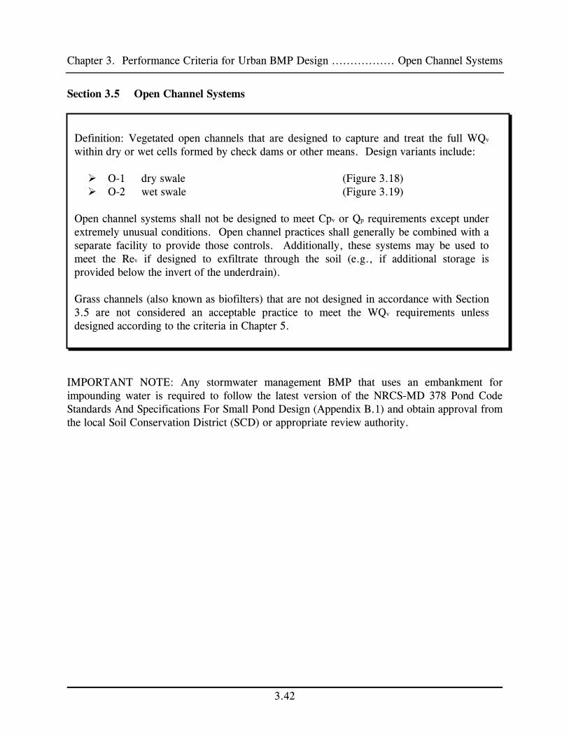
Chapter 3. Performance Criteria for Urban BMP Design ................. Open Channel Systems
3.42
Section 3.5 Open Channel Systems
IMPORTANT NOTE: Any stormwater management BMP that uses an embankment for impounding water is required to follow the latest version of the NRCS-MD 378 Pond Code Standards And Specifications For Small Pond Design (Appendix B.1) and obtain approval from the local Soil Conservation District (SCD) or appropriate review authority.
Definition: Vegetated open channels that are designed to capture and treat the full WQv within dry or wet cells formed by check dams or other means. Design variants include: O-1 dry swale (Figure 3.18) O-2 wet swale (Figure 3.19)
Open channel systems shall not be designed to meet Cpv or Qp requirements except under extremely unusual conditions. Open channel practices shall generally be combined with a separate facility to provide those controls. Additionally, these systems may be used to meet the Rev if designed to exfiltrate through the soil (e.g., if additional storage is provided below the invert of the underdrain). Grass channels (also known as biofilters) that are not designed in accordance with Section 3.5 are not considered an acceptable practice to meet the WQv requirements unless designed according to the criteria in Chapter 5.

Chapter 3. Performance Criteria for Urban BMP Design ................. Open Channel Systems
3.43
O-1 Figure 3.18 Example of Dry Swale O-1
Dry swales are used at low density residential projects or for very small impervious areas.

Chapter 3. Performance Criteria for Urban BMP Design ................. Open Channel Systems
3.44
O-2 Figure 3.19 Example of Wet Swale O-2
Wet swales are ideal for treating highway runoff in low lying or flat terrain areas.

Chapter 3. Performance Criteria for Urban BMP Design ................. Open Channel Systems
3.45
3.5.1 Open Channel Feasibility Criteria Open channel systems shall have longitudinal slopes less than 4.0% to qualify for WQv treatment. Open channel systems, designed for WQv treatment, are primarily applicable for land uses such as roads, highways, residential development (dry swales only), and pervious areas. 3.5.2 Open Channel Conveyance Criteria The peak velocity for the ten-year storm shall be non-erosive (see Appendix D.12 for critical non-erosive velocities for grass and soil) for the soil and vegetative cover provided. Open channels shall be designed to safely convey the ten-year storm. Three inches of freeboard should be provided. Channels should be designed with moderate side slopes (flatter than 3:1) for most conditions. In no event may side slopes be steeper than 2:1. The maximum allowable ponding time within a channel shall be less than 48 hours. The minimum ponding time of 30 minutes is recommended for meeting WQv treatment goals. Open channel systems which directly receive runoff from impervious surfaces may have a six inch drop onto a protected shelf (pea gravel diaphragm) to minimize clogging of the inlet. An underdrain system shall be provided for the dry swale to ensure a maximum ponding time of 48 hours. 3.5.3 Open Channel Pretreatment Criteria Pretreatment storage of 0.1 inch of runoff per impervious acre storage shall be provided. This storage is usually obtained by providing check dams at pipe inlets and/or driveway crossings. A pea gravel diaphragm and gentle side slopes should be provided along the top of channels to accommodate pretreatment for lateral sheet flows. Direct discharge of concentrated flow (e.g., by pipe) shall be pretreated.

Chapter 3. Performance Criteria for Urban BMP Design ................. Open Channel Systems
3.46
3.5.4 Open Channel Treatment Criteria Dry and wet swales shall be designed to temporarily store the WQv within the facility for a maximum 48 hour period. Open channels shall have a bottom width no wider than 8 feet or a meandering drainage pattern shall be established to avoid gullying or channel braiding. Dry and wet swales should maintain a maximum ponding depth of one foot at the "mid-point" of the channel profile (longitudinal dimension) and a maximum depth of 18" at the downstream end point of the channel (for storage of the WQv). 3.5.5 Open Channel Landscaping Criteria Wet swales are not recommended for residential developments as they can create potential nuisance or mosquito breeding conditions. Landscape design should specify proper grass species and wetland plants based on specific site, soils and hydric conditions present along the channel (see Appendix A). 3.5.6 Open Channel Maintenance Criteria Open channel systems and grass filter strips should be mowed as required during the growing season to maintain grass heights in the 4 to 6 inch range. Wet swales, employing wetland vegetation or other low maintenance ground cover do not require frequent mowing of the channel. Sediment build-up within the bottom of the channel or filter strip shall be removed when 25% of the original WQv has been exceeded. Construction specifications for open channel systems are specified in Appendix B.3.

Chapter
4.0
A G
uide
to
BM
P S
elec
tion
and
Loc
atio
n in
the
Sta
te o
f M
aryl
and


Chapter 4. Guide to BMP Selection and Location in Maryland
4.1
4.0 Selecting the Best BMP at a Site
This chapter outlines a process for selecting the best BMP or group of BMPs for a development site and provides guidance on factors to consider when deciding where to locate them. The process is used to screen which BMPs can meet the pollutant removal targets for the WQv and guides the designer through six steps that progressively screen: Watershed Factors Terrain Factors Stormwater Treatment Suitability Physical Feasibility Factors Community and Environmental Factors Locational and Permitting Factors
More detail on the step-wise screening process is provided below: Step ❶ Watershed Factors Is the project located in a watershed that has special design objectives or constraints that must be met? Table 4.1 outlines BMP restrictions or additional design requirements that must be considered if a project lies within the Maryland Critical Area, a cold water watershed, a sensitive watershed, an aquifer protection area, a water supply reservoir, or a shellfish/beach protection zone. Step ❷ Terrain Factors Is the project located in a portion of the State that has particular design constraints imposed by local terrain and or underlying geology? Table 4.2 details BMP restrictions for regions of Maryland that have karst, mountainous terrain, or low relief. Step ❸ Stormwater Treatment Suitability Can the BMP meet all five stormwater sizing criteria at the site or are a combination of BMPs needed? In this step, designers can screen the BMP list using Table 4.3 to determine if a particular BMP can meet the Rev, Cpv and/or Q p storage requirements. In addition, Table 4.3 indicates whether a BMP is capable of treating hotspot runoff and provides comparative indexes on land consumption and safety risks that may preclude a BMP. At the end of this step, the designer can screen the BMP options down to a manageable number and determine if a single BMP or a group of BMPs is needed to meet stormwater sizing criteria at the site.

Chapter 4. Guide to BMP Selection and Location in Maryland
4.2
Step ❹ Physical Feasibility Factors Are there any physical constraints at the project site that may restrict or preclude the use of a particular BMP? In this step, the designer screens the BMP list using Table 4.4 to determine if the soils, water table, drainage area, slope or head conditions present at a particular development site might limit the use of a BMP. In addition, the matrix indicates which BMP options work well in highly urban areas. Step ❺ Community and Environmental Factors Do the remaining BMPs have any important community or environmental benefits or drawbacks that might influence the selection process? In this step, Table 4.5 is used to compare BMP options with regard to maintenance, habitat, community acceptance, cost and other environmental factors. Step ❻ Locational and Permitting Factors What environmental features must be avoided or considered when locating the BMP system at a site to fully comply with local, State and federal regulations? In this step, the designer may use Table 4.6 as a checklist that asks whether any of the following are present at the site: wetlands, waters of the United States, stream or shoreline buffers, floodplains, forest conservation areas, and development infrastructure. Brief guidance is then provided on how to locate BMPs to avoid impacts to sensitive resources. If a BMP must be located within a sensitive environmental area, a brief summary of applicable permit requirements is provided.

Chapter 4. Guide to BMP Selection and Location in Maryland .........................Watershed Factors
4.3
Section 4.1 Watershed Factors The design of urban BMPs is fundamentally influenced by the nature of the downstream water body that will be receiving the stormwater discharge. Consequently, designers must determine the Use Designation of the watershed in which their project is located prior to design (see COMAR 26.08.02.08 and Appendix D.9). In some cases, higher pollutant removal or environmental performance is needed to fully protect aquatic resources and/or human health and safety within a particular watershed or receiving water. Therefore, a shorter list of BMPs may need to be considered for selection within these watersheds or zones. The areas of concern include: Maryland Critical Area Intensely Developed Areas. BMPs located within the Intensely Developed Area (IDA) of the Maryland Critical Area (a zone extending 1000 feet landward from mean high tide and the landward edge of tidal wetlands) shall demonstrate compliance with the "10% Rule." The rule mandates that post development stormwater phosphorus loads must be reduced to 10% below pre development loads, using the methodology developed by Herson et al. (1994). For a summary review of the 10% Rule and updated estimates of long term phosphorus pollutant removal rates please consult Appendix D.4. Coldwater Streams (Use III and IV). Cold and cool water streams have habitat qualities capable of supporting trout and other sensitive aquatic organisms. Therefore, the design objective for these streams is to maintain habitat quality by preventing stream warming, maintaining natural recharge, preventing bank and channel erosion, and preserving the natural riparian corridor. Techniques for accomplishing these objectives may include:
• Minimizing the creation of impervious surfaces, • Minimizing surface areas of permanent pools, • Preserving existing forested areas, • Bypassing existing baseflow and/or springflow, or • Providing shade-producing landscaping
Some BMPs can have adverse downstream impacts on cold water streams and their use is highly restricted. Sensitive Streams (e.g., streams with a watershed impervious cover less than 15%). These streams may also possess high quality cool water or warm water aquatic resources. The design objectives are to maintain habitat quality through the same techniques used for cold water streams, with the exception that stream warming is not as severe of a design constraint. These streams may also be specially designated by local authorities.

Chapter 4. Guide to BMP Selection and Location in Maryland .........................Watershed Factors
4.4
Wellhead Protection. Areas that recharge existing public water supply wells present a unique management challenge. The key design constraint is to prevent possible groundwater contamination by preventing infiltration of hotspot runoff. At the same time, recharge of unpolluted stormwater is needed to maintain flow in streams and wells during dry weather. Reservoir Protection (Use I-P, III-P and IV-P). Watersheds that deliver surface runoff to a public water supply reservoir or impoundment are of special concern. Depending on the treatment available at the water intake, it may be necessary to achieve a greater level of pollutant removal for the pollutants of concern such as bacteria pathogens, nutrients, sediment or metals. One particular management concern for reservoirs is ensuring that stormwater hotspots are adequately treated so that they do not contaminate drinking water. Shellfish/Beach (Use II). Watersheds that drain to specific shellfish harvesting areas or public swimming beaches require a higher level of BMP treatment to prevent closings caused by bacterial contamination from stormwater runoff. In these watersheds, BMPs are explicitly designed to maximize bacteria removal. Other Criteria. Designers should consult with the appropriate review authority to determine if their development project is subject to additional stormwater BMP criteria as a result of an adopted local watershed plan or protection zone.

Chapter 4. Guide to BMP Selection and Location in Maryland .........................Watershed Factors
4.5
Table 4.1 BMP Selection - Watershed Factors
BMP
GROUP CRITICAL
AREA COLD WATER SENSITIVE
STREAM AQUIFER
PROTECTION RESERVOIR
PROTECTION SHELLFISH
BEACH
Ponds Drainage Area may limit except for P-5,
P-1 has lower removal rates
Restricted
(see Appendix B.1.2)
Offline design recommended
Maximize shading of open pool areas
Require additional storage for control of Cpv
May require liner if A soils are present
Pretreat hotspots
2-4 ft SD*
Require control of Cpv
Moderate bacteria removal, design to prevent geese problems, provide permanent pools
Wetlands Drainage area may limit, W-4 excepted
May be restricted
(see Appendix B.1.2)
Require additional storage for control of Cpv
May require liner if A soils are present
2-4 ft SD*
Require control of Cpv
Provide 48 hr ED for max. bacterial dieoff
Infiltration Often infeasible due to soils or water table in tidal areas.
OK, if site has appropriate soils
OK, if site has appropriate soils
SD* from wells and water table
No untreated hotspot runoff
OK to infiltrate rooftop runoff
SD* from bedrock and water table
OK, but a min. 2 to 4 ft SD* is required
Filtering Systems
OK OK, but evaluate for stream warming
May be necessary for pretreatment
OK, if designed w/out exfiltration
May be necessary for pretreatment prior to another BMP
OK, Moderate to high bacterial removal
Open Channels
OK OK Should be linked w/basin to provide Cpv
OK, but hotspot runoff must be adequately pretreated
OK, but hotspot runoff must be adequately pretreated
Poor bacterial removal for O-2
*SD = Separation Distance or distance from well or water table to BMP.

Chapter 4. Guide to BMP Selection and Location in Maryland .............................. Terrain Factors
4.6
Section 4.2 Terrain Factors Three key factors to consider are low-relief, karst and mountainous terrain. In Maryland, Low Relief Areas are located in the lower Eastern Shore, particularly below the Choptank River (see Figure 4.1 below). Karst and major carbonaceous rock areas are found in portions of Carroll, Frederick, Washington, and Garrett Counties. Mountainous areas are found in the Western part of the State. Special geotechnical testing requirements may be needed in karst areas (see Appendix D.2). The terrain regions shown on the map are approximate. Please consult with your local reviewing authority to determine if your project is subject to terrain constraints.
Figure 4.1 Map of Maryland Showing Key Terrain Factors
Lower Eastern Shore

Chapter 4. Guide to BMP Selection and Location in Maryland .............................. Terrain Factors
4.7
Table 4.2 BMP Selection - Terrain Factors
BMP GROUP
LOW RELIEF
KARST
MOUNTAINOUS
Ponds Maximum normal pool depth of 4 feet (dugout)
Embankment heights
restricted
Wetlands OK
• geotechnical tests
• max ponding depth
• Require poly or clay liner
Embankment heights
restricted
Infiltration
Minimum distance to water table of 2 feet
May be prohibited. Consult with local approval authority.
Max slope 15%
trenches must have flat bottom
Filtering Systems
Several designs limited by low head (F-1 and F-2)
Require poly-liner or impermeable membrane to seal bottom
OK
Open Channels
Generally feasible due to low slopes
OK Often infeasible in steeper slopes

Chapter 4. Guide to BMP Selection and Location in Maryland .................. Stormwater Treatment
4.8
Section 4.3 Stormwater Treatment Suitability Table 4.3 examines the capability of each BMP option to meet the five stormwater treatment sizing criteria outlined in Chapter 2. Thus, it shows whether a BMP has: Ability to Meet the Rev. It should be noted that other practices, not on the BMP list, are capable of meeting the Rev requirement (e.g., grass channel, filter, disconnection of rooftop runoff and other practices outlined in Chapter 5). Thus, if a BMP cannot meet the Rev requirement, supplemental practices that can provide recharge may be needed. Ability to Provide Cpv. The table indicates whether the BMP can typically provide the Cpv that is needed in some watersheds. The finding that a particular BMP cannot meet the Cpv requirement does not necessarily imply that it should be eliminated from consideration, but is a reminder that more than one practice may be needed at a site (e.g., a bioretention area and a downstream pond). Ability to Provide Qp2 and/or Qp10. The table indicates whether the BMP can typically provide the Qp criteria for the site. Again, the finding that a particular BMP cannot meet the requirement does not necessarily mean that it should be eliminated from consideration, but rather is a reminder that more than one practice may be needed at a site (e.g., a dry swale and a downstream pond) Additional Safety Concerns. A comparative index expresses the potential need for additional safety features within a BMP. A “no” indicates no additional features are needed while a “yes” indicates deep pools may create potential safety risks. The safety factor is included at this stage of the screening process because liability and safety are a prime concern in many residential settings. Adequate Space. This comparative index expresses how much space a BMP typically consumes at a site. A “yes” indicates that the BMP consumes a relatively small amount of land, whereas a “no” indicates the BMP may consume a relatively high fraction of land at the site. Again, this factor is included in this early screening stage because many BMPs are severely constrained by land consumption. Ability to Accept Hotspot Runoff. This last column examines the capability of a BMP to treat runoff from designated hotspots as defined in Chapter 2. A BMP that receives hotspot runoff may have design restrictions as noted and may require additional measures to protect downstream resources from potential spills.

Chapter 4. Guide to BMP Selection and Location in Maryland .................. Stormwater Treatment
4.9
Table 4.3 BMP Selection - Stormwater Treatment Suitability
CODE BMP List Rev
Ability Cpv
Control Qp
Control
Additional Safety
Concerns SPACE
ACCEPT HOTSPOT RUNOFF
P-1 Micropool ED No1 Yes Yes No Yes Yes3
P-2 Wet Pond No1 Yes Yes Yes Varies Yes3
P-3 Wet ED Pond No1 Yes Yes Yes Yes Yes3
P-4 Multiple Pond No1 Yes Yes Yes No Yes3
P-5 Pocket Pond No1 Yes Yes Varies Yes Yes3
W-1 Shallow Wetland Varies2 Yes Yes No No Yes3
W-2 ED Wetland Varies2 Yes Yes Varies Varies Yes3
W-3 Pond/Wetland Varies2 Yes Yes Yes No Yes3
W-4 Pocket Wetland No Varies Varies No Varies Yes3
I-1 Infiltration Trench Yes Varies Varies No Yes No3
I-2 Infiltration Basin Yes Varies Varies No Varies No3
F-1 Surface Sand Filter
Varies2 Varies Varies No Yes Yes4
F-2 Underground SF No No No Varies Yes Yes
F-3 Perimeter SF No No No No Yes Yes
F-4 Organic Filter Varies2 Varies Varies No Yes Yes4
F-5 Pocket Sand Filter Varies2 Varies Varies No Yes Yes4
F-6 Bioretention Yes Varies Varies No Varies Yes4
O-1 Dry Swale Yes No No No Varies Yes4
O-2 Wet Swale No No No No Varies No
1 Structures that require impermeable liners or that intercept groundwater may not be used for groundwater recharge.
2 Rev may be provided by exfiltration (see Chapter 3.4).
3 Not allowed unless pretreatment to remove hydrocarbons, trace metals, and toxicants is provided.
4 Yes, but only if bottom of facility is lined with impermeable filter fabric that prevents leachate infiltration.

Chapter 4. Guide to BMP Selection and Location in Maryland ....................... Physical Feasibility
4.10
Section 4.4 Physical Feasibility Factors At this point, the designer has narrowed the BMP list to a manageable size and can evaluate the remaining options given the physical conditions at a site. This table cross-references testing protocols needed to confirm physical conditions at the site. The six primary factors are: Soils. The key evaluation factors are based on an initial investigation of the USDA hydrologic soils groups at the site. Note that more detailed geotechnical tests are usually required for infiltration feasibility and during design to confirm permeability and other factors (see Appendix D.1). Water Table. This column indicates the minimum depth to the seasonally high water table from the bottom or floor of a BMP. Drainage Area. This column indicates the recommended minimum or maximum drainage area that is considered suitable for the practice. If the drainage area present at a site is slightly greater than the maximum allowable drainage area for a practice, some leeway is permitted or more than one practice can be installed. The minimum drainage areas indicated for ponds and wetlands are flexible depending on water availability (baseflow or groundwater) or the mechanisms employed to prevent clogging. Slope Restriction. This column evaluates the effect of slope on the practice. Specifically, the slope restrictions refer to how flat the area where the practice may be. Head. This column provides an estimate of the elevation difference needed at a site (from the inflow to the outflow) to allow for gravity operation within the practice. Ultra-Urban Sites. This column identifies BMPs that work well in the ultra-urban environment, where space is limited and original soils have been disturbed. These BMPs are frequently used at redevelopment sites.

Chapter 4. Guide to BMP Selection and Location in Maryland ....................... Physical Feasibility
4.11
Table 4.4 BMP Selection - Physical Feasibility
CODE BMP LIST SOILS WATER
TABLE
DRAINAGE
AREA
(Acres)
SLOPE RESTRICT.
HEAD
(Ft)
ULTRA
URBAN
P-1 Micropool ED 10 Min2
P-2 Wet Pond
P-3 Wet ED Pond
P-4 Multiple Pond
"A" Soils May
Require Pond Liner
"B" Soils May Require Testing
4 Feet1
If Hotspot
Or
Aquifer 25 Min2
6 to 8 Ft Not
Practical
P-5 Pocket Pond OK Below WT 5 Max3
None
4 Ft OK
W-1 Shallow Wetland
W-2 ED Wetland
W-3 Pond/Wetland
“A” Soils May
Require Liner
4 Feet1
If Hotspot
Or Aquifer
25 Min 3 to 5 Ft Not
Practical
W-4 Pocket Wetland OK Below WT 5 Max
None
2 To 3 Ft Depends
I-1 Infiltration Trench 5 Max 1 Ft Depends
I-2 Infiltration Basin
f ≥ 0.52 Inch/Hr
4 Feet1
10 Max
Installed in
No More Than 15%
Slopes 3 Ft
Not Practical
F-1 Surface Sand Filter 10 Max 3 5 Ft Depends
F-2 Underground SF 2 Max 3 5 to 7ft
F-3 Perimeter SF 2 Max 3 2 to 3 Ft
F-4 Organic Filter 5 Max3 2 to 4 Ft
F-5 Pocket SF
OK
2 to 5 Ft
F-6 Bioretention Made Soil
2 Feet
5 Max 3
None
5 Ft
OK
O-1 Dry Swale Made Soil 2 Feet 5 Max 3 to 5 Ft
O-2 Wet Swale OK Below WT 5 Max
4% Max Cross-slope 1 Ft
Not Practical
Notes: OK= not restricted, WT= water table
1 Four foot separation distance is maintained to the seasonally high water table (2 feet on Lower Eastern Shore).
2 Unless adequate water balance and anti-clogging device installed
3 Drainage area can be larger in some instances

Chapter 4. Guide to BMP Selection and Location............ Community and Environmental Factors
4.12
Section 4.5 Community and Environmental Factors The fifth step assesses community and environmental factors involved in BMP selection. This table employs a comparative index approach indicating whether the BMP has a high or low benefit. Ease of Maintenance. This column assesses the relative maintenance effort needed for a BMP in terms of three criteria: frequency of scheduled maintenance, chronic maintenance problems (such as clogging) and reported failure rates. It should be noted that all BMPs require routine inspection and maintenance. Community Acceptance. This column assesses community acceptance as measured by three factors: market and preference surveys, reported nuisance problems, and visual aesthetics. It should be noted that a low rank can often be improved by a better landscaping plan. Construction Cost. The BMPs are ranked according to their relative construction cost per impervious acre treated as determined from cost surveys and local experience. Habitat Quality. BMPs are evaluated on their ability to provide wildlife or wetland habitat, assuming that an effort is made to landscape them appropriately. Objective criteria include size, water features, wetland features and vegetative cover of the BMP and its buffer. Other Factors. This column indicates other considerations in BMP selection.

Chapter 4. Guide to BMP Selection and Location............ Community and Environmental Factors
4.13
Table 4.5 BMP Selection - Community and Environmental Factors
CODE
BMP LIST
EASE OF
MAINTENANCE
COMMUNITY ACCEPTANCE
COST
(Relative To Drainage Area)
HABITAT QUALITY
OTHER
FACTORS
P-1 Micropool ED Medium Medium Low Medium Trash/debris
P-2 Wet Pond Easy High Low High
P-3 Wet ED Pond Easy High Low High
P-4 Multiple Pond Easy High Medium High
P-5 Pocket Pond Difficult Medium Low Low Drawdowns
W-1 Shallow Wetland Medium High Medium High
W-2 ED Wetland Medium Medium Medium High Limit ED depth
W-3 Pond/Wetland Difficult High Medium High
W-4 Pocket Wetland Medium Low Low Medium Drawdowns
I-1 Infiltration Trench Difficult High Medium Low Avoid large stone
I-2 Infiltration Basin Medium Low Medium Low Frequent pooling
F-1 Surface SF Medium Medium High Low
F-2 Underground SF Difficult High High Low Underground ∴Out of sight
F-3 Perimeter SF Difficult High High Low Traffic Bearing
F-4 Organic Filter Medium High High Low Filter Media Replacement
F-5 Pocket SF Medium Medium Medium Low
F-6 Bioretention Medium Medium Medium Low Landscaping
O-1 Dry Swale Easy High Medium Low
O-2 Wet Swale Easy High Low Low Mosquitoes
Possible

Chapter 4. Guide to BMP Selection and Location......... Checklist for Locating Stormwater BMPs
4.14
Section 4.6 Checklist: Location and Permitting Factors In the last step, a designer assesses the physical and environmental features at the site to determine the optimal location for the selected BMP or group of BMPs. The checklist below provides a condensed summary of current BMP restrictions as they relate to common site features that may be regulated under local, State or federal law. These restrictions fall into one of three general categories:
1. Locating a BMP within an area that is expressly prohibited by law.
2. Locating a BMP within an area that is strongly discouraged and is only allowed on a case by case basis. Local, State and/or federal permits shall be obtained and the applicant will need to supply additional documentation to justify locating the BMP within the regulated area.
3. BMPs must be setback a fixed distance from the site feature.
This checklist is only intended as a general guide to location and permitting requirements as they relate to siting stormwater BMPs. Consultation with the appropriate regulatory agency is the best strategy. The symbol “✔” denotes when an MDE Nontidal Wetland And Waterways Permit shall be obtained.

Chapter 4. Guide to BMP Selection and Location......... Checklist for Locating Stormwater BMPs
4.15
Table 4.6 Location and Permitting Factors Checklist SITE FEATURE
LOCATION AND PERMITTING GUIDANCE
❑ Jurisdictional Wetland U.S. Army Corps of Engineers Section 404 Permit and/or MDE Wetlands Permit ✔
• wetlands should be delineated prior to siting stormwater BMPs.
• use of wetlands for stormwater treatment strongly discouraged and requires State and federal permit.
• BMPs are also restricted in the 25 to 100 foot required wetland buffer.
• buffers may be utilized as a non-structural filter strip (e.g., accept sheetflow).
• must justify that no practical upland treatment alternatives exist.
• stormwater must be treated prior to discharge into a wetland.
• where practical, excess stormwater flows should be conveyed away from jurisdictional wetlands.
❑ Stream Channel (Waters of the U.S) U.S. Army Corps of Engineers (COE) Section 404 Permit MDE Wetlands and Waterways Permit ✔
• stream channels should be delineated prior to design using MDE criteria.
• instream ponds require MDE review and permit.
• instream ponds are prohibited in Use III waters.
• ponds located within USE III watersheds may require small pond review and approval from the MDE Dam Safety Division.
• must justify that no practical upland treatment alternatives exist.
• Qp and Cpv treatment is preferred over WQv treatment.
• implement measures that reduce downstream warming. ❑ 100 Year Floodplain Local Stormwater review Authority MDE Wetlands and Waterways Permit ✔
• grading and fill for BMP construction is strongly discouraged within the ultimate 100 year floodplain, as delineated by FEMA flood insurance rate, FEMA flood boundary and floodway, or local floodplain maps.
• floodplain fill cannot raise the floodplain water surface elevation by more than a tenth of a foot.
❑ Stream Buffer Check with appropriate review authority whether stream buffers are required
• consult local authority for stormwater policy. • ponds located within 100 feet of a flowing stream in a USE III watershed
may require a small pond approval by the MDE Dam Safety Division • BMPs are strongly discouraged in the stream-side zone (within 25 feet of
streambank). • consider how outfall channel will cross buffer to reach stream. • BMPs can be located within the outer portion of a buffer.

Chapter 4. Guide to BMP Selection and Location......... Checklist for Locating Stormwater BMPs
4.16
Table 4.6 Location and Permitting Factors Checklist (Continued) SITE FEATURE
LOCATION AND PERMITTING GUIDANCE
❑ Forest Conservation District Forest Conservation Review Authority
• BMPs are strongly discouraged within Priority 1 Forest Retention Areas. • BMPs must be setback at least 25 feet from the critical root zone of
specimen trees, or • designers should consider the effect of more frequent inundation for Qp, Cpv
and WQv on existing forest stands. • BMP buffer areas are acceptable as reforestation sites if they are protected
by a conservation agreement ❑ Critical Area Local Critical Area Review Authority
• BMPs w/in the Critical Area shoreline buffer are prohibited unless a variance is obtained from the local review authority.
• BMPs are acceptable within mapped buffer exemption areas. • BMPs in the IDA must meet the 10% Rule - see Appendix D.4.
❑ Utilities Local Review Authority
• call Miss Utility to locate existing utilities prior to design. • note the location of proposed utilities to serve development. • BMPs are discouraged within utility easements or rights of way for public
or private utilities. ❑ Roads Local DOT, DPW, or State Highway Administration
• consult local DOT or DPW for any setback requirement from local roads. • consult SHA for setbacks from State maintained roads. • approval must also be obtained for any stormwater discharges to a local or
State-owned conveyance channel.
❑ Structures Local Review Authority
• consult local review authority for BMP setbacks from structures. • recommended setbacks for each BMP group are provided in the performance
criteria in Chapter 3 of this manual. ❑ Septic Drain fields • consult local health authority.
• recommended setback is a minimum of 50 feet from drain field edge. ❑ Water Wells Local Health Authority
• 100 foot setback for stormwater infiltration. • 50 foot setback for all other BMPs. • water appropriation permit needed if well water used for water supply to a
BMP. ❑ Sinkholes
• infiltration or pooling of stormwater near sinkholes is prohibited. • geotechnical testing may be required within karst areas
(see Appendix D.2).

Chapter
5.0
Envi
ronm
enta
l Site
Des
ign


Chapter 5. Environmental Site Design..........................................................................Introduction
5.1 Supp.1
Section 5.0 Introduction 5.0.1 Background The primary goal of Maryland’s stormwater management program is to maintain after development, as nearly as possible, the predevelopment runoff characteristics. Traditional stormwater management strategies treat runoff to mitigate adverse water quality and/or quantity impacts associated with new development. Designs applying these strategies often combine centralized structural practices for pollutant removal with channel erosion or flood control impoundments. These designs are less able to mimic predevelopment conditions because they focus on managing large volumes of polluted stormwater rather than treating runoff closer to the source. A comprehensive design strategy for maintaining predevelopment runoff characteristics and protecting natural resources is available. This strategy, known as Environmental Site Design or “ESD,” relies on integrating site design, natural hydrology, and smaller controls to capture and treat runoff. This chapter provides the foundation to refocus stormwater design from centralized management to more effective planning and implementation of ESD. 5.0.2 Requirements of the Stormwater Management Act of 2007 The “Stormwater Management Act of 2007” (Act), requires establishing a comprehensive process for stormwater management approval, implementing ESD to the maximum extent practicable (MEP), and ensuring that structural practices (see Chapter 3) are used only where absolutely necessary. The Act also establishes several performance standards for stormwater management plans. Designers must now ensure that these plans are designed to:
Prevent soil erosion from development projects. Prevent increases in nonpoint pollution. Minimize pollutants in stormwater runoff from both new development and redevelopment. Restore, enhance, and maintain chemical, physical, and biological integrity of receiving
waters to protect public health and enhance domestic, municipal, recreational, industrial and other uses of water as specified by MDE.
Maintain 100% of the average annual predevelopment groundwater recharge volume. Capture and treat stormwater runoff to remove pollutants. Implement a channel protection strategy to protect receiving streams. Prevent increases in the frequency and magnitude of out-of-bank flooding from large, less
frequent storms. Protect public safety through the proper design and operation of stormwater management
facilities. The Act presents a new opportunity to improve Maryland’s stormwater management program. The original Chapter 5 encouraged ESD through a series of optional credits for the design of nonstructural practices. Changes in response to the Act not only expand on the ESD practices first introduced in the Manual but also allow for planning techniques to improve implementation
NOTE: In this chapter, italics indicate mandatory criteria, whereas recommended criteria are shown in normal typeface.

Chapter 5. Environmental Site Design..........................................................................Introduction
and overall performance. The remaining sections of this chapter will further define ESD, discuss planning techniques used in its implementation, and provide design requirements for nonstructural and micro-scale practices used to treat runoff at the source. For reference purposes, the original Chapter 5 can be found in Appendix E.1. 5.0.3 Environmental Site Design Definition There are many stormwater design strategies that seek to replicate natural hydrology. Sometimes known as better site design, low impact development, green infrastructure, or sustainable site design, these strategies all espouse similar techniques. In each, a combination of planning techniques, alternative cover, and small-scale treatment practices is used to address impacts associated with development. For consistency, the Act adopts ESD as a more generic classification for use in Maryland. Title 4, Subtitle 201.1(B) of the Act defines ESD as “…using small-scale stormwater management practices, nonstructural techniques, and better site planning to mimic natural hydrologic runoff characteristics and minimize the impact of land development on water resources.” Under this definition, ESD includes:
Optimizing conservation of natural features (e.g., drainage patterns, soil, vegetation). Minimizing impervious surfaces (e.g., pavement, concrete channels, roofs). Slowing down runoff to maintain discharge timing and to increase infiltration and
evapotranspiration. Using other nonstructural practices or innovative technologies approved by MDE.
Impacts of Imperviousness The goal of traditional site design strategies is to maximize development potential by focusing on the layout of buildings, roads, parking, and other features. Conventional development practices tend to maximize site imperviousness and contribute to many of the impacts discussed in Chapter 1. These include diminished groundwater recharge, increased flows and runoff volumes, pollutant accumulation, and elevated water temperatures. Documentation such as the Impacts of Impervious Cover on Aquatic Systems (Center for Watershed Protection, 2003) and other studies of Eastern Piedmont and Coastal Plain streams in Maryland (Morgan and Cushman, 2005) and headwater streams in Montgomery County (Moore and Palmer, 2005) all indicate that stream biodiversity decreases as impervious cover increases. There is no simple formula, rule, or threshold for determining how much impervious cover may be sustained in a given watershed. Generally, stream quality and watershed health diminish when impervious cover exceeds 10% and become severely degraded beyond 25% (Center for Watershed Protection, 2003). Results from the Maryland Biological Stream Survey (MBSS) indicated that in surveyed streams, health was never good when watershed imperviousness exceeded 15%, (Boward, 1999). These studies establish a fundamental connection between impervious cover and watershed impairment.
Supp. 1 5.2

Chapter 5. Environmental Site Design..........................................................................Introduction
5.3 Supp.1
Integrating the fundamental principles of ESD during the planning process helps minimize the adverse impacts of imperviousness. The resulting designs reduce the need for costly infrastructure and maintenance while providing treatment closer to the source. To accomplish this, the designer must consider the basic concepts found in Section 5.1, Planning Techniques.

Chapter 5. Environmental Site Design...............................................Design Process and Planning
Section 5.1 Design Process and Planning Techniques 5.1.1 Introduction The design process described in this section will provide guidance for implementing ESD planning strategies and practices into a comprehensive site development plan. These techniques involve protecting natural resources, integrating erosion and sediment controls with stormwater management practices, minimizing site imperviousness, and using natural conveyance and ESD practices throughout the site. Applying these techniques early in the design process will ensure that all available resources have been considered in order to protect streams and waterways from the impact of land development activities. The design process will require the developer to adhere to the following procedures to achieve ESD to the MEP:
Following the Design Process for New Development as outlined in the step wise procedures in Figure 5.1.
Developing a map that identifies natural resource areas and drainage patterns and devising strategies for protection and enhancement.
Minimizing total site imperviousness by implementing clustered development and other better site design techniques.
Demonstrating that all reasonable opportunities for meeting stormwater requirements using ESD have been exhausted by using natural areas and landscape features to manage runoff from impervious surfaces and that structural BMPs have been used only where absolutely necessary.
Participate in the comprehensive review process for interim plans review and approval at the conceptual, site development, and final phases of project design.
Integrating strategies for erosion and sediment control and stormwater management into a comprehensive development plan.
5.1.2 Comprehensive Erosion & Sediment Control and Stormwater Management Review The Act requires that “a comprehensive process for approving grading and sediment control plans and stormwater management plans” shall be established. Therefore, county and municipal stormwater authorities shall establish a coordinated approval process among all appropriate local agencies. Erosion and sediment control review and approval authorities [e.g., local Soil Conservation Districts(SCD)] and input from any other local agency deemed appropriate (e.g., planning and zoning, public works) shall be included. The process will be tailored to meet local initiatives and should consider the scope and extent of environmental impacts for individual site developments. Review agencies involved will provide comments and approval during each of the following phases of plan development:
1. Concept 2. Site Development 3. Final
At each phase of this review process, the designer will receive feedback provided by the agencies allowing the developer to incorporate any concerns and recommendations throughout project
Supp. 1 5.4

Chapter 5. Environmental Site Design...............................................Design Process and Planning
planning and design. The concept plan will include site and resource mapping and protection and conservation strategies. The designer will also provide preliminary stormwater management ESD calculations. Review of the concept plan will ensure that all important resources have been mapped, protected, and all opportunities to enhance natural areas have been explored early in the design process. The site development plan will establish the footprint of the proposed project and demonstrate the relationship between proposed impervious surfaces and the existing natural conditions identified during concept plan design. This will better protect natural resources and buffers and allow for using ESD practices throughout the site. Included in this step are the preparation of detailed designs, computations, and grading plans for a second comprehensive review and approval. This ensures that all options for implementing ESD have been exhausted. After approval from the review agencies, the applicant will then proceed with final plan preparation including the design of any structural practices needed to address remaining channel protection requirements. Final plans will go to both the stormwater and erosion and sediment control review agencies for approval. The design process and planning techniques described in this section provide guidelines for protecting natural areas, minimizing imperviousness, using available landscaping for ESD practices, and integrating stormwater and erosion and sediment control strategies. Following this process will achieve the goal of implementing ESD to the MEP. Involving all review agencies from the beginning of site planning through the more detailed design will foster feedback and allow for a more efficient review and approval of final plans. 5.1.3 Design Process for New Development All new development projects shall be subject to the Design Process for New Development as outlined in the step wise procedures in Figure 5.1. As described above, the design process will require review and approval during three different phases of project planning that include the concept, site development, and final stages. Approving agencies shall use the process outlined in Figure 5.1 as an enforceable mechanism during review of the plan. Documentation that all steps were followed during project development and specific rationale to support the proposed design shall be required. 5.1.3.1 Concept Design Phase The concept design phase is the first step in project development as shown in Figure 5.1. This step will include the following:
Site and Resource Mapping Site Fingerprinting and Development Layout Locating ESD Practices
5.5 Supp.1

Chapter 5. Environmental Site Design...............................................Design Process and Planning
Supp. 1 5.6
Figure 5.1 Design Process for New Development

Chapter 5. Environmental Site Design...............................................Design Process and Planning
5.7 Supp.1
Site and Resource Mapping
d
nized by government regulatory
authority in Table 5.1 below.
Table 5. Resources and the C nding Regulatory Author
The resource mapping component will be used as a basis for all subsequent decisions during project design. During this step, the developer shall identify significant natural resources andemonstrate that these areas will be protected and preserved. Additionally, options will be evaluated to enhance important hydrologic functions. Approving authorities may require that other features be shown depending on site characteristics. This map shall be field verified by theproject designer. Specific areas that should be mapped are orga
1 Natural orrespo ities:
Federal State Local • Wetlands • Major waterway• Floodplains
nontida
ec
ams ins
• Critical Areas
ffers hy/slopes
s ative cover
• Existing drainage areas
s wetlands • Wetlands of Sp
• Tidal and l • Steep slopes
ial • Enhanced stream buState Concern
• Wetland buffers• Stream buffers • Perennial stre• Floodpla• Forests • Forest buffers
• Highly erodible soils
• Topograp• Springs• Seeps • Intermittent stream• Veget• Soils • Bedrock/geology
The mapping process will identify important natural resources as well as areas that are highly susceptible to erosion caused by construction activities. Identifying these important resourceand high risk locations and protecting them from disturbance is the first step in the planning process. When steep slopes and highly erodible soils are found measures need to be taken to limit disturbance and minimize impacts. This may be done by using information developed by the local SCDs. These offices maintain lists that identify highly erodible soil map units for each county in Maryland. Additionally, steep slopes are defined as those with gradients of 20 perceor more and moderately steep slopes fall within the range of 10 to 30 percent (USDA NRCSSoil Survey Manual, October, 1993). For the purpose of project planning, stee
s
nt ,
p slopes are onsidered to be any mapping unit with a slope class of 15 percent or greater.
sis of
emain undisturbed, protected during the construction process, and/or preserved as open space.
c While it may not be practicable to eliminate earth disturbing activities exclusively on the basoil erodibility or slope alone, constraints are warranted when both steep slopes and highlyerodible soils occupy the same area within the development footprint. Areas with highly erodible soils and slopes equal to or greater than 25 percent should be incorporated into adjacent buffers, r

Chapter 5. Environmental Site Design...............................................Design Process and Planning
Strategies to protect steep slopes and highly erodible soils include:
Identify and map all highly erodible soils and steep slopes; and Protect areas with highly erodible soils on slopes equal to or greater than 25 percent from
earth disturbing activities.
In addition to preserving sensitive areas during disturbances, the environmental benefits of other existing natural resources should be maximized by incorporating protection strategies into the overall goals of the project. Protecting these resources up front in the planning process will allow their many functions to be utilized for infiltration, flow attenuation, groundwater recharge, flood storage, runoff reduction, nutrient cycling, air and water pollution reduction, habitat diversity, and thermal impact reduction. When ESD practices are located later in the planning process, these protected areas may be further enhanced by using them to meet stormwater requirements. Natural resource protection and enhancement strategies include:
Protecting large tracts of contiguous open space, forested areas, and other important resources through conservation easements.
Identifying afforestation opportunities in open space areas and setting aside land for natural regeneration.
Identifying important resource areas that may be expanded such as stream buffers and floodplains.
Minimize disturbance to highly permeable soils. Site Fingerprinting and Development Layout
After conserving and protecting sensitive resources has been addressed, the next step in the planning process involves determining the approximate location of buildings, roadways, parking lots, and other impervious areas. These site improvements should be placed at a sufficient distance to protect the conservation areas. Protecting these resources will involve enhancing or expanding forested and stream buffers of adequate widths based on site characteristics. Minimum buffer widths may be expanded based on receiving stream characteristics, stream order, adjacent land slopes, 100-year floodplain, wetlands, mature forests, vegetative cover, depth of the groundwater table, and the presence of spring seeps and other sensitive areas. Several studies have suggested that minimum buffer widths could be based on site specific functions (Palone and Todd, 1998) including: bank stability and water temperature moderation (50 feet), nitrogen removal (100 feet), sediment removal (150 feet), or flood mitigation (200 feet). The approving agency may enhance existing buffer requirements depending upon resource protection goals identified at the local level. After the development footprint has been established, consideration should be given to natural drainage areas and how runoff will travel over and through the site. Sheetflow and existing drainage patterns should be maintained and discharges from the site should occur at the natural location wherever possible. New drainage patterns result in concentrated flow leaving the site at
Supp. 1 5.8

Chapter 5. Environmental Site Design...............................................Design Process and Planning
an inappropriate or unstable location, as well as creating erosion, sediment transport, and stream channel stability problems. The use of storm drains and engineered conveyance systems should be minimized by using vegetated swales and other natural systems so that forests, buffers and overland flow characteristics remain intact. Planning for on-site and off-site drainage patterns must be done early in the design process to establish a stable outfall for downstream discharges. Some of the strategies listed below can be used to establish nonstructural practices such as sheetflow to natural areas. These protection and enhancement tools, can then double as important strategies for meeting on-site stormwater requirements. Strategies for site layout and connecting landscape features include:
Plan the building footprint and layout to protect conservation areas. Evaluate opportunities to enhance/expand forested, wetland, and stream buffers. Grade the site so that runoff will flow from impervious areas directly to pervious areas or
other natural conveyance systems. Maintain natural flow paths between the site and upstream and downstream systems. Maintain sheetflow and natural overland flow processes wherever feasible. Provide stable conveyance of runoff off-site.
In addition to the site fingerprinting techniques described above, other strategies may be used to protect important natural resources. One type of practice that encompasses many of these design techniques in residential developments is clustering. This practice allows for concentrating development in one area, thereby reducing the distance between individual lots, the length of subdivision roadways, and overall impervious areas. It will also allow for protecting open space and buffer areas and reduce clearing and grading in natural areas. Commercial and industrial developments offer other opportunities to reduce impervious cover. Because parking lots are the dominant land cover for most commercial and industrial projects, designers can minimize the surface area dedicated to parking and use ESD practices in landscaped areas for stormwater treatment. Table 5.2 below provides a list of better site design techniques that may be used to reduce site imperviousness, protect environmentally sensitive areas, and provide more open space. More details and information may be found in, Better Site Design: A Handbook for Changing Development Rules in Your Community (Center for Watershed Protection, 1998). Locating ESD Practices
Reducing the impervious area in residential, commercial, and industrial development enhances the space available for landscaped features (e.g., parking lot islands, medians, plazas). Many of the micro-scale practices discussed in this chapter are tailored to fit in these smaller landscaped areas. When strategies for reducing imperviousness and protecting natural resources are combined with design options that distribute ESD practices throughout a site, the resulting plans will provide an effective means to address stormwater requirements at the source. After the site footprint has been established, preliminary calculations for determining stormwater requirements using ESD can be provided and potential management areas can be identified. The concept plan shall include a drawing or sketch identifying the preliminary location of ESD practices.
5.9 Supp.1

Chapter 5. Environmental Site Design...............................................Design Process and Planning
Table 5.2 Summary of Site Development Strategies Better Site Design Technique
Recommendations
Using narrower, shorter streets, rights-of-way, and sidewalks
Streets may be as narrow as 22 ft. in neighborhoods serving low traffic volumes; open space designs and clustering will reduce street lengths; rights-of-way can be reduced by minimizing sidewalk width, providing sidewalks on one side of the road, and reducing the border width between the street and sidewalks.
Cul-de-sacs Allow smaller radii for turn arounds as low as 33 ft.; use a landscaped island in the center of the cul-de-sac and design these areas to treat stormwater runoff.
Open vegetated channels
Allow grass channels or biofilters for residential street drainage and stormwater treatment.
Parking ratios, parking codes, parking lots, and structured parking
Parking ratios should be interpreted as maximum number of spaces; use shared parking arrangements; minimum parking stall width should be less than 9 ft. and stall length less than 18 ft.; parking garages are encouraged rather than surface lots.
Parking lot runoff Parking lots are required to be landscaped and setbacks are relaxed to allow for bioretention islands or other stormwater practices in landscaped areas.
Open space Flexible design criteria should be provided to developers who wish to use clustered development and open space designs.
Setbacks and frontages
Relax setbacks and allow narrower frontages to reduce total road length; eliminate long driveways.
Driveways Allow for shared driveways and alternative impervious surfaces. Rooftop runoff Direct to pervious surfaces. Buffer systems Designate a minimum buffer width and provide mechanisms for long-
term protection. Clearing and grading Clearing, grading, and earth disturbance should be limited to that
required to develop the lot. Tree conservation Provide long-term protection of large tracts of contiguous forested
areas; promote the use of native plantings. Conservation incentives
Provide incentives for conserving natural areas through density compensation, property tax reduction, and flexibility in the design process.
(Adapted from Center for Watershed Protection, 1998) Review of Concept Plans Concept plans should be submitted to the appropriate review agencies and include the information discussed above along with a narrative to support the design. The narrative should describe how important natural areas will be preserved and protected, and show how ESD may be achieved for meeting on-site stormwater requirements. Review authorities may require additional information at this phase, however, at a minimum a concept plan should include the following elements:
Supp. 1 5.10

Chapter 5. Environmental Site Design...............................................Design Process and Planning
• A map of all site resources shown in Table 5.1. • Field verification from the project engineer of the natural resource map. • Proposed limits of clearing and grading. • Location of proposed impervious areas (buildings, roadways, parking, and sidewalks). • Location of existing and proposed utilities. • Preliminary estimates of stormwater requirements. • Preliminary location of ESD practices. • Stable conveyance of stormwater at potential outfall locations. • A narrative that supports the concept and describes how the design will achieve.
o Natural resource protection and enhancement. o Maintenance of natural flow patterns. o Reduction of impervious areas through better site design, alternative surfaces, and
nonstructural practices. o Integration of erosion and sediment controls into the stormwater strategy. o Implementation of ESD planning techniques and practices to the MEP.
County and municipal stormwater management agencies are required to have a comprehensive review process in place so that input is provided for all aspects of development project planning, design, and construction. The review of concept plans begins this process. Stormwater and erosion and sediment control authorities will collaborate to provide coordinated feedback to the designer before a project proceeds to the more detailed site development phase. This feedback will accompany the concept plan approval and should be incorporated into future submissions. 5.1.3.2 Site Development Phase Preparation of site development plans will include more detailed designs for stormwater management and erosion and sediment control. During this phase the site footprint will be finalized with respect to the layout of buildings, roadways, parking, and other structures in order to develop more detailed design. The following plans will be required for site development review:
Stormwater Management Erosion and Sediment Control An Overlay Showing Stormwater and Erosion and Sediment Control Practices
Stormwater Management Plans
After concept plan approval, the developer should use comments and feedback as a basis for the next design phase. When the development layout is finalized, the proposed topography may be determined and final drainage areas established. Natural features and conservation areas can be utilized to serve stormwater quantity and quality management requirements. Individual ESD locations will be determined and all alternative surfaces, nonstructural, and micro-scale practices will be finalized. When locating and sizing ESD practices, the primary objective is to manage runoff as close to its source as possible by using vegetated buffers, natural flow paths, sheetflow to natural areas, and landscape features. ESD practices are then designed according to sizing requirements specified later in this chapter and discharge computations and storage volumes
5.11 Supp.1

Chapter 5. Environmental Site Design...............................................Design Process and Planning
provided. Calculations and details will be submitted to the review agencies to verify the design approach. Section 5.2 provides more information on sizing requirements and design specifications for all ESD practices. A narrative will also be required to justify that the design will achieve ESD to the MEP.
Erosion and Sediment Control Plans After concept plan approval, the final grading and proposed drainage areas during construction will also be established. This is critical to developing erosion and sediment control plans. Erosion and sediment control plans prepared at this phase will include measures for:
Preservation Phasing and construction sequencing during each stage of development Design of sediment controls Stabilization strategies
Preservation Comments received during concept plan review should be used as a basis for preparing erosion and sediment control plans. Strategies to preserve sensitive resources, ensure soil stability, and prevent erosion begin with protecting those areas during project construction. Erosion and sediment control plans should identify areas to be protected by marking the limit of disturbance, sensitive areas, buffers, and forested areas that are to be preserved or protected. In addition, infiltration and recharge areas that need to be protected from fine sediments and compaction should be identified. Plans should also note that all protected areas be marked in the field prior to any land disturbing activity. Phasing and Sequences of Construction During Each Stage of Development The site development plan will provide sequences of construction for each stage of development. These include initial clearing and grubbing, rough grading, site development, and final grading. Because initial and final flow patterns will not apply to all intermediate phases, these sequences should consider flow pattern changes, drainage areas, and discharge points at transitional phases of the construction process. Phased plans need to ensure that erosion and sediment controls adequately address the changing runoff patterns. Erosion and sediment control strategies for minimizing erosion during interim grading include:
Interim plans to address grade changes and flow patterns during clearing and grading, rough grading, site development, and final grading.
Slope length and steepness reductions. Divert clean water around or through a site and discharge it to a stable outlet.
Supp. 1 5.12

Chapter 5. Environmental Site Design...............................................Design Process and Planning
Design of Sediment Controls Water handling practices need to provide erosion protection during site grading operations. This may be done by diverting runoff away from highly erodible soils, steep slopes, and disturbed areas by using dikes, swales, or reverse benches. Similarly, runoff can be safely conveyed from the top of slopes to a stable outfall using pipe slope drains or channels. Check dams may be needed to reduce velocities and prevent erosion. Runoff from all discharge points shall provide a stable outlet. Stabilization Strategies
When vegetation is removed and soil disturbance occurs, the extent and duration of exposure should be minimized. All efforts should be made to delay grading operations until it is certain that final grades can be reached in as little time as possible. Where this cannot be accommodated, soils shall be stabilized within 14 days of disturbance. The extent and duration of disturbance should be limited (e.g., 72 hours) and enhanced stabilization techniques such as soil stabilization matting or turf reinforcement used on areas with highly erodible soils and slopes greater than 15 percent. Soil exposure should be shortened by the local permitting authority if warranted by site conditions. Perimeter controls, perimeter slopes, and extreme grade modifications (e.g., slopes greater than 3:1 or where cuts and fills exceed 15 feet) require stabilization within seven days. Mass clearing and grading should be avoided with larger projects (e.g., 25 acres) being phased so disturbed areas remain exposed for the shortest time possible. All other areas should have a good cover of temporary or permanent vegetation or mulch. Natural vegetation should be retained in an undisturbed state wherever possible. If it is not possible to retain natural vegetation, the topsoil should be salvaged, stockpiled on-site, protected from erosion, and replaced at final grade. Topsoil removal, grading, and filling reduce soil quality resulting in detrimental impacts on plant growth and increase runoff. Additionally, the removal of topsoil inhibits biological activity and reduces the supply of organic matter and plant nutrients. Similarly, unrestricted use of construction equipment can result in soil compaction. Applicable practices include, but are not limited to, temporary and permanent seeding, sodding, mulching, plastic covering, erosion control fabrics and matting, the early application of gravel base on areas to be paved, and dust control. Soil stabilization measures should be appropriate for the time of year, site conditions, and estimated duration of use. Soil stockpiles must be stabilized, protected with sediment trapping or filtering measures, and be located away from storm drain inlets, waterways, and drainage channels. Linear construction activities, including right-of-way and easement clearing, roadway development, pipelines, and trenching for utilities shall be phased so that soils are stabilized as quickly as possible.
5.13 Supp.1

Chapter 5. Environmental Site Design...............................................Design Process and Planning
Strategies to limit the extent and duration that soils are exposed may include:
Minimizing disturbed area. Phasing earth disturbing activities so that the smallest area is exposed for the shortest
possible time. Salvaging topsoil for later use. Stabilizing as work progresses.
Overlay Plan Many of the stormwater ESD practices deal with alternative surfaces or are nonstructural and promote hydraulic connection of impervious surfaces with natural landscape features. The practices for stormwater management and erosion and sediment control may share the same location while serving different functions. For example, swales used initially to convey sediment-laden runoff to a trap or basin during the sediment control phase could be used for water quality treatment and flow attenuation of stormwater runoff at final grade. Similarly, natural berms and vegetative buffers coupled with traditional sediment filtering controls may be integrated into the site design and meet both sediment control and stormwater management requirements. Once the ESD practices have been located and sized appropriately, consideration to how these areas will function under proposed conditions is needed. The location of any ESD practice that requires natural infiltration needs to be identified on the plans and in the field. These areas need to be protected during construction. An overlay plan should include the location of all ESD practices to allow for efficient sediment control design and the protection of locations that will be used to treat stormwater. An overlay plan should include:
The location of ESD practices on the plan and in the field. The location of areas that must remain undisturbed, protected, or used for erosion and
sediment control. Identifiable areas where construction equipment may compact soil and will need
rehabilitation after grading operations. Removal of sediment from the locations of ESD practices. Stabilization measures needed to enhance stormwater functions.
Review of Site Development Plans Site development plans should be submitted to the appropriate review agencies and should include a stormwater plan, erosion and sediment control plan, an overlay plan, and a narrative to support the design. Review authorities may require additional information at this phase, however, at a minimum a site development plan shall include the following:
• All of the information provided in the concept review. • Comments received by review agencies during the concept review.
Supp. 1 5.14

Chapter 5. Environmental Site Design...............................................Design Process and Planning
• Determination of final site layout and acreage of total impervious area on site. • Proposed topography. • Proposed drainage areas at all points of discharge from the site. • Proposed stormwater volume requirements for ESD targets and quantity control. • The location and size of ESD practices used to the MEP and all nonstructural, alternative
surfaces, and micro-scale practices used. • Proposed hydrology analysis for runoff rates, storage volumes, and discharge velocities. • Stormwater design details and specifications. • Discharge calculations demonstrating stable conveyance of runoff off site. • Preliminary erosion and sediment control plans showing limits of disturbance, sensitive
areas, buffers, and forests that are to be preserved, proposed phasing, construction sequencing, proposed practices, and stabilization techniques.
• An overlay plan showing the location of stormwater ESD practices and proposed erosion and sediment controls.
• A narrative to support the site development design and demonstrate that ESD will be achieved to the MEP.
Stormwater and erosion and sediment control authorities will collaborate to provide coordinated feedback to the designer before a project proceeds to the more detailed final design phase. This feedback will accompany the site development approval and should be incorporated into future submission. 5.1.3.3 Final Plan Design and Review After site development plan approval, the developer may prepare final designs by incorporating comments from the appropriate review agencies. After all reasonable ESD options have been exhausted, structural practices may be needed (see Chapter 3) to address additional Cpv requirements. Final plan approval shall be required for issuing local grading and building permits. Review authorities may require additional information at this phase, however, at a minimum final plans shall include the following information and meet the requirements established in COMAR 26.17.01.05 and 26.17.02 .09:
• All of the information provided in the site development review. • Comments received by review agencies during the site development review. • Development details and site data including site area, disturbed area, new impervious
area, and total impervious area. • Existing and proposed topography. • Proposed drainage areas. • Representative cross sections and details (existing and proposed structure elevations and
water surface elevations). • The location of existing and proposed structures. • Construction specifications. • Operation and maintenance plans. • As-built design certification block. • Inspection schedule.
5.15 Supp.1

Chapter 5. Environmental Site Design...............................................Design Process and Planning
Supp. 1 5.16
• Easements and rights-of-way. • Certification by the owner/developer that all construction will be done according to the
plan. • Performance bonds. • Final erosion and sediment control plans. • Stormwater management report including;
o A narrative to support the final design and demonstrate that ESD will be achieved to the MEP.
o Table showing the ESD and Unified Sizing Criteria. o Hydrology and hydraulic analysis of the stormwater management system for all
applicable sizing criteria. o Final sizing calculations for stormwater controls including drainage area, storage,
and discharge points. o Final analysis of stable conveyance to downstream discharge points. o Geotechnical investigations including soil maps, borings, and site-specific
recommendations. The design process described above is intended to be iterative, as comments from all review agencies are incorporated during each phase of project design. This will help local jurisdictions coordinate with other programs requiring environmental review and ensure that development plans fit priorities for resource protection, enhancement, and restoration. Many counties have performed restoration assessments on targeted watersheds. The planning process described in Figure 5.1 and above allows individual site development to be evaluated in the context of these larger resource protection efforts.

Chapter 5. Environmental Site Design...................................................................... Sizing Criteria
Section 5.2 Addressing the Unified Sizing Criteria To accomplish the goal of maintaining predevelopment runoff characteristics, there must be a reasonable standard that is easily recognized, reproducible, and applied without opportunity for misrepresentation. The simplest and most effective solution is to eliminate the need for evaluating predevelopment conditions on a site-by-site basis and apply the same standard to all sites. For rainfall amounts less than two to three inches, there is little difference in the amount of runoff from most sites in undeveloped conditions although runoff amounts are lowest for woods. To best maintain predevelopment runoff characteristics, the target for ESD implementation should be “woods in good condition”. The Act requires the implementation of ESD to the MEP to mimic natural hydrologic runoff characteristics and minimize the impact of land development on water resources. While ESD may be used to address Rev and WQv, limiting it to these criteria alone may not provide sufficient treatment to mimic natural hydrology for wooded conditions or address Cpv. It may be necessary to increase the size of single ESD practices and/or connect them in series to decrease the volume of runoff to that expected from a naturally forested area. Implementing ESD to that extent may not be practicable on all projects and a minimum standard is needed. Sizing ESD practices to capture and treat both Rev and WQv is a practical minimum requirement for all projects. 5.2.1 Performance Standards for Using Environmental Site Design
The standard for characterizing predevelopment runoff characteristics for new development projects shall be woods in good hydrologic condition;
ESD shall be implemented to the MEP to mimic predevelopment conditions;
As a minimum, ESD shall be used to address both Rev and WQv requirements; and
Channel protection obligations are met when ESD practices are designed according to
the Reduced Runoff Curve Number Method described below.
5.17 Supp.1

Chapter 5. Environmental Site Design...................................................................... Sizing Criteria
Supp. 1 5.18
5.2.2 Environmental Site Design Sizing Criteria The criteria for sizing ESD practices are based on capturing and retaining enough rainfall so that the runoff leaving a site is reduced to a level equivalent to a wooded site in good condition as determined using United States Department of Agriculture (USDA) Natural Resource Conservation Service (NRCS) methods (e.g., TR-55). The basic principle is that a reduced runoff curve number (RCN) may be applied to post-development conditions when ESD practices are used. The goal is to provide enough treatment using ESD practices to address Cpv requirements by replicating an RCN for woods in good condition for the 1-year rainfall event. This eliminates the need for structural practices from Chapter 3. If the design rainfall captured and treated using ESD is short of the target rainfall, a reduced RCN may be applied to post-development conditions when addressing stormwater management requirements. The reduced RCN from Table 5.3 is calculated by subtracting the runoff treated by ESD practices from the total 1-year 24-hour design storm runoff. Table 5.3 was developed using the “Change in Runoff Curve Number Method” (McCuen, R., MDE, 1983) to determine goals for sizing ESD practices and reducing RCNs if those goals are not met. During the planning process, site imperviousness and soil conditions are used with Table 5.3 to determine a target rainfall for sizing ESD practices. Table 5.3 is also used to determine the reduced RCNs for calculating additional stormwater management requirements if the targeted rainfall cannot be met using ESD practices. ESD Sizing Requirements: PE = Rainfall Target from Table 5.3 used to determine ESD goals and size practices QE = Runoff depth in inches that must be treated using ESD practices = PE x Rv; Rv = the dimensionless volumetric runoff coefficient = 0.05 + 0.009(I) where I is percent impervious cover ESDv = Runoff volume (in cubic feet or acre-feet) used in the design of specific ESD practices where A is the drainage area (in square feet or acres) 5.2.3 Addressing Stormwater Management Requirements Using ESD
Treatment: ESD practices shall be used to treat the runoff from 1 inch of rainfall (i.e.,
SD practices shall be used to the MEP to address Cp (e.g., treat the runoff from the 1-
Cp shall be addressed on all sites including those where the 1-year post-
PE = 1 inch) on all new developments where stormwater management is required. E vyear 24-hour design storm) in accordance with the following conditions:
o v
development peak discharge (qi) is less than or equal to 2.0 cfs.
12)(A)(P v=
)(RE

Chapter 5. Environmental Site Design...................................................................... Sizing Criteria
o Cpv shall be based on the runoff from the 1-year 24-hour design storm calculated using the reduced RCN (see Table 5.3). If the reduced RCN for a drainage area reflects “woods in good condition”, then Cpv has been satisfied for that drainage area.
o When the targeted rainfall is not met, any remaining Cpv requirements shall be treated using structural practices described in Chapter 3.
The runoff stored in ESD practices may be subtracted from the Overbank Flood Protection and Extreme Flood Volumes (i.e., Qp2, Qp10, Qf) where these are required.
Practices: The runoff, QE, shall be treated by acceptable practices from the lists presented in this Chapter (see Sections 5.3 and 5.4). QE may be treated using an interconnected series or “treatment train” of practices.
Multiple Drainage Areas: ESD requirements shall be addressed for the entire limit of
disturbance. When a project is divided into multiple drainage areas, ESD requirements should be addressed for each drainage area.
Off-Site Drainage Areas: ESD requirements shall be based on the drainage area to the
practices providing treatment. It is recommended that runoff from off-site areas be diverted away from or bypass ESD practices. However, if this is not feasible, then ESD practices should be based on all pervious and impervious areas located both on-site and off-site draining to them.
Reduced RCNs: When using reduced RCNs, the following conditions apply:
o ESD practices should be distributed uniformly within each drainage area. o Where multiple ESD practices are used within a drainage area, individual
practices may be oversized on a limited scale to compensate or over manage for smaller practices. The size of any practice(s) is limited to the runoff from the 1-year 24-hour storm, QE, draining to it.
5.2.4 Basis for Using Table 5.3 to Determine ESD Sizing Criteria
Application: Table 5.3 shall be used to determine both the rainfall targets for sizing ESD practices and the additional stormwater management requirements if those targets are not met.
Hydrologic Soil Groups: Each chart in Table 5.3 reflects a different hydrologic soil
group (HSG). Designers should use the charts that most closely match the project’s soil conditions. If more than one HSG is present within a drainage area, a composite RCN may be computed based on the proportion of the drainage area within each HSG (see examples below).
Measuring Imperviousness: The measured area of a site that does not have vegetative
or permeable cover shall be considered total impervious cover. Estimates of proposed
5.19 Supp.1

Chapter 5. Environmental Site Design...................................................................... Sizing Criteria
imperviousness may be used during the planning process where direct measurements of impervious cover may not be practical. Estimates should be based on actual land use and homogeneity and may reflect NRCS land use/impervious cover relationships (see Table 2.2a in TR-55, USDA-NRCS, 1986) where appropriate. The percent imperviousness (%I) may be calculated from measurements of site imperviousness.
RCN*: RCN* is an alternate method to estimate PE when alternative surfaces (e.g.,
permeable pavements, green roofs) are used to reduce runoff. RCN* is a composite value for the limit of disturbance using the effective RCNs identified in Section 5.3 for each alternative surface.
Reduced RCNs: Areas shown in green (right hand side) on Table 5.3 show the target
RCN for “woods in good condition” for the respective HSG. Areas shown in yellow (left hand side) show the reduced RCN for each HSG that is applied to stormwater management calculations if the design rainfall is below the target.
Rainfall (Inches): Target rainfall (PE) amounts for sizing ESD practices to mimic
wooded conditions for each respective HSG are located across the top of Table 5.3. These rainfall amounts are also used to determine the reduced RCNs for calculating additional stormwater management requirements if the targeted amounts cannot be met.
Supp. 1 5.20

Chapter 5. Environmental Site Design...................................................................... Sizing Criteria
5.21 Supp.1
Table 5.3 Rainfall Targets/Runoff Curve Number Reductions used for ESD Hydrologic Soil Group A
%I RCN* PE = 1" 1.2" 1.4" 1.6" 1.8" 2.0" 2.2" 2.4" 2.6" 0% 40 5% 43
10% 46 15% 48 38 20% 51 40 38 38 25% 54 41 40 39 30% 57 42 41 39 38 35% 60 44 42 40 39 40% 61 44 42 40 39 45% 66 48 46 41 40 50% 69 51 48 42 41 38 55% 72 54 50 42 41 39 60% 74 57 52 44 42 40 38 65% 77 61 55 47 44 42 40 70% 80 66 61 55 50 45 40 75% 84 71 67 62 56 48 40 38 80% 86 73 70 65 60 52 44 40 85% 89 77 74 70 65 58 49 42 38 90% 92 81 78 74 70 65 58 48 42 38 95% 95 85 82 78 75 70 65 57 50 39 100% 98 89 86 83 80 76 72 66 59 40
Hydrologic Soil Group B
%I RCN* PE = 1" 1.2" 1.4" 1.6" 1.8" 2.0" 2.2" 2.4" 2.6" 0% 61 5% 63
10% 65 15% 67 55 20% 68 60 55 55 25% 70 64 61 58 30% 72 65 62 59 55 35% 74 66 63 60 56 40% 75 66 63 60 56 45% 78 68 66 62 58 50% 80 70 67 64 60 55% 81 71 68 65 61 55 60% 83 73 70 67 63 58 65% 85 75 72 69 65 60 55 70% 87 77 74 71 67 62 57 75% 89 79 76 73 69 65 59 80% 91 81 78 75 71 66 61 85% 92 82 79 76 72 67 62 55 90% 94 84 81 78 74 70 65 59 55 95% 96 87 84 81 77 73 69 63 57 100% 98 89 86 83 80 76 72 66 59 55
Cpv Addressed (RCN = Woods in Good Condition)
RCN Applied to Cpv Calculations

Chapter 5. Environmental Site Design...................................................................... Sizing Criteria
Supp. 1 5.22
Table 5.3 Runoff Curve Number Reductions used for Environmental Site Design (continued) Hydrologic Soil Group C
%I RCN* PE = 1" 1.2" 1.4" 1.6" 1.8" 2.0" 2.2" 2.4" 2.6" 0% 74 5% 75
10% 76 15% 78 20% 79 70 25% 80 72 70 70 30% 81 73 72 71 35% 82 74 73 72 70 40% 84 77 75 73 71 45% 85 78 76 74 71 50% 86 78 76 74 71 55% 86 78 76 74 71 70 60% 88 80 78 76 73 71 65% 90 82 80 77 75 72 70% 91 82 80 78 75 72 75% 92 83 81 79 75 72 80% 93 84 82 79 76 72 85% 94 85 82 79 76 72 90% 95 86 83 80 77 73 70 95% 97 88 85 82 79 75 71 100% 98 89 86 83 80 76 72 70
Hydrologic Soil Group D
%I RCN* PE = 1" 1.2" 1.4" 1.6" 1.8" 2.0" 2.2" 2.4" 2.6" 0% 80 5% 81
10% 82 15% 83 20% 84 77 25% 85 78 30% 85 78 77 77 35% 86 79 78 78 40% 87 82 81 79 77 45% 88 82 81 79 78 50% 89 83 82 80 78 55% 90 84 82 80 78 60% 91 85 83 81 78 65% 92 85 83 81 78 70% 93 86 84 81 78 75% 94 86 84 81 78 80% 94 86 84 82 79 85% 95 86 84 82 79 90% 96 87 84 82 79 77 95% 97 88 85 82 80 78 100% 98 89 86 83 80 78 77
Cpv Addressed (RCN = Woods in Good Condition)
RCN Applied to Cpv Calculations

Chapter 5. Environmental Site Design...................................................................... Sizing Criteria
5.2.5 Design Examples: Computing ESD Stormwater Criteria Design examples are provided only to illustrate how ESD stormwater sizing criteria are computed for hypothetical development projects. These design examples are also utilized elsewhere in the manual to illustrate design concepts. Design Example No. 5.1: Residential Development – Reker Meadows The layout of the Reker Meadows subdivision is shown in Figure 2.6. Site Data: Location: Frederick County, MD Site Area: 38.0 acres Drainage Area: 38.0 acres Soils: 60% B, 40% C Impervious Area: 13.8 acres Step 1: Determine ESD Implementation Goals The following basic steps should be followed during the planning phase to develop initial targets for ESD implementation. A. Determine Pre-Developed Conditions: The goal for implementing ESD on all new development projects is to mimic forested runoff characteristics. The first step in this process is to calculate the RCN for “woods in good condition” for the project: • Determine Soil Conditions and RCNs for “woods in good condition” Soil Conditions
HSG RCN† Area Percent A 38‡ 0 0% B 55 22.8 acres 60% C 70 15.2 acres 40% D 77 0 0%
† RCN for “woods in good condition” (Table 2-2, TR-55) ‡ Actual RCN is less than 30, use RCN = 38 • Determine composite RCN for “woods in good condition”
61acres38
)acres2.1570()acres8.2255(RCNwoods =×+×
=
The target RCN for “woods in good condition” is 61.
5.23 Supp.1
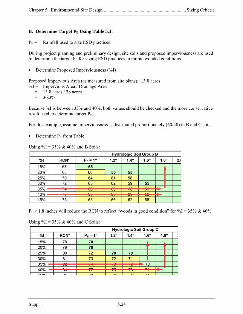
Chapter 5. Environmental Site Design...................................................................... Sizing Criteria
B. Determine Target PE Using Table 5.3: PE = Rainfall used to size ESD practices During project planning and preliminary design, site soils and proposed imperviousness are used to determine the target PE for sizing ESD practices to mimic wooded conditions. • Determine Proposed Imperviousness (%I) Proposed Impervious Area (as measured from site plans): 13.8 acres %I = Impervious Area / Drainage Area = 13.8 acres / 38 acres = 36.3%; Because %I is between 35% and 40%, both values should be checked and the more conservative result used to determine target PE. For this example, assume imperviousness is distributed proportionately (60/40) in B and C soils. • Determine PE from Table Using %I = 35% & 40% and B Soils:
PE ≥ 1.8 inches will reduce the RCN to reflect “woods in good condition” for %I = 35% & 40% Using %I = 35% & 40% and C Soils:
Supp. 1 5.24

Chapter 5. Environmental Site Design...................................................................... Sizing Criteria
For %I = 35%, PE ≥ 1.6 inches will reduce the RCN to reflect “woods in good condition” For %I = 40%, PE ≥ 1.8” to achieve the same goal. For this project, PE happens to be the same for both soil groups, therefore use PE = 1.8 inches of rainfall as the target for ESD implementation. C. Compute QE : QE = Runoff depth used to size ESD practices
QE = PE x Rv, where PE = 1.8 inches Rv = 0.05 + (0.009)(I); I = 36.3
= 0.05 + (0.009 x 36.3) = 0.38 QE = 1.8 inches x 0.38 = 0.68 inches ESD targets for the Reker Meadows project: PE = 1.8 inches QE = 0.68 inches By using ESD practices that meet these targets, Rev, WQv, and Cpv requirements will be satisfied. Potential practices could include swales or micro-bioretention to capture and treat runoff from the roads. Likewise, raingardens and disconnection of rooftop runoff could be used to capture and treat runoff from the houses. Step 2: Determine Stormwater Management Requirements After Using ESD For this example, it is assumed that ESD techniques and practices were implemented to treat only 1.2 inches of rainfall (e.g., PE = 1.2 inches) over the entire project. After all efforts to implement ESD practices have been exhausted, the following basic steps should be followed to determine how much additional stormwater management is required. A. Calculate Reduced RCNs PE = Rainfall used to size ESD practices During the planning and design processes, site soils, measured imperviousness, and PE are used to determine reduced RCNs for calculating Cpv requirements. • Determine Reduced RCN for PE = 1.2 inches
5.25 Supp.1

Chapter 5. Environmental Site Design...................................................................... Sizing Criteria
Using %I = 35% & 40%, B Soils, and PE = 1.2 inches:
For B Soils, PE = 1.2 inches, and %I = 35% & 40%, reduced RCN = 63 Using %I = 35% & 40%, C Soils, and PE = 1.2 inches:
For C Soils, PE = 1.2 inches, and %I = 35% & 40%, reduced RCN = 73 & 75, respectively Use the more conservative value, 75, for calculating a composite RCN for the site. A composite RCN may be calculated as follows: For PE = 1.2 inches:
8.67acres38
)acres2.1575()acres8.2263(RCN =×+×
=
Use 68 B. Calculate Cpv Requirements The composite RCN for “woods in good condition” is 61 (see Step 1A above). The design RCN (68) does not reflect the composite RCN for “woods in good condition” (61) and, therefore Cpv must be addressed. However, PE ≥ 1.0 inches and Cpv requirements are based on the runoff from the 1-year 24-hour design storm calculated using the reduced RCN (68).
Supp. 1 5.26

Chapter 5. Environmental Site Design...................................................................... Sizing Criteria
• Compute Cpv Storage Volume When PE ≥ 1.0 inches, Cpv shall be the runoff from the 1-year 24-hour design storm calculated using the reduced RCN. If the reduced RCN for a drainage area reflects “woods in good condition”, then Cpv has been satisfied for that drainage area. Calculate Cpv using design PE = 1.2 inches (RCN = 68): Cpv = Q1 x A where: Q1 is the runoff from the 1-year 24-hour design storm
)S8.0P()S2.0P(Q
2
1 +−
= (Equation 2.3, TR-55, USDA NRCS 1986)
where: P = 1-year 24-hour design storm
S = (1000/RCN) – 10 (Equation 2-4, TR-55) = (1000/68) – 10 = 4.7
inches43.036.676.2
)]7.4x8.0(6.2[)]7.4x2.0(6.2[Q
2
1 ==+−
=
Cpv = 0.43 inches x 38 acres
= 1.36 ac. – ft. or 59, 240 cubic feet
Cpv Storage Requirements for Reker Meadows Additional Cpv Required Rainfall (PE)
(ac-ft) (cu. ft.) Notes:
PE ≥ 1.8 inches NA NA Target PE for RCN = woods PE = 1.2 inches 1.36 59,240 Design PE Conventional Design 1.65 71,875 from Chapter 2 (see page 2.18)
Stormwater management requirements for the Reker Meadows project include using ESD practices to treat 1.2 inches of rainfall and structural practices from Chapter 3 (e.g., shallow wetland) to treat the Cpv of 59,240 cubic feet.
5.27 Supp.1

Chapter 5. Environmental Site Design...................................................................... Sizing Criteria
Design Example No. 5.2: Commercial Development - Claytor Community Center The layout of the Claytor Community Center is shown in Figure 2.9. Site Data: Location: Dorchester County Site Area: 3.0 acres Drainage Area: 3.0 acres Soils: 100% B Impervious Area: 1.9 acres Step 1: Determine ESD Implementation Goals The following basic steps should be followed during the planning phase to develop initial targets for ESD implementation. A. Determine Pre-Developed Conditions: The goal for implementing ESD on all new development projects is to mimic forested runoff characteristics. The first step in this process is to calculate the RCN for “woods in good condition” for the project. • Determine Soil Conditions and RCNs for “woods in good condition” Soil Conditions
HSG RCN† Area Percent A 38‡ 0 0% B 55 3.0 acres 100% C 70 0 acres 0% D 77 0 0%
† RCN for “woods in good condition” (Table 2-2, TR-55) ‡ Actual RCN is less than 30, use RCN = 38 The site is entirely located in HSG B, and the target RCN for “woods in good condition” is 55. B. Determine Target PE Using Table 5.3 PE = Rainfall used to size ESD practices During the project planning and preliminary design, site soils and proposed imperviousness are used to determine target PE for sizing ESD practices to mimic wooded conditions.
Supp. 1 5.28

Chapter 5. Environmental Site Design...................................................................... Sizing Criteria
• Determine Proposed Imperviousness (%I) Proposed Impervious Area (as measured from site plans): 1.9 acres %I = Impervious Area / Drainage Area = 1.9 acres / 3.0 acres = 63.3% Because %I is closer to 65% than 60%, use the more conservative value, 65%. • Determine PE from Table Using %I = 65% & B Soils:
PE ≥ 2.0 inches will reduce the RCN to reflect “woods in good condition” for %I = 65% For this project, use PE = 2.0 inches C. Compute QE : QE = Runoff depth used to size ESD practices QE = PE x Rv, where
PE = 2.0 inches Rv = 0.05 + (0.009)(I); I = 63.3%
= 0.05 + (0.009 x 63.3) = 0.62 QE = 2.0 inches x 0.62 = 1.24 inches
5.29 Supp.1

Chapter 5. Environmental Site Design...................................................................... Sizing Criteria
ESD targets for the Claytor Community Center project: PE = 2.0 inches QE = 1.24 inches By using ESD practices that meet these targets, Rev, WQv, and Cpv requirements will be satisfied. Potential practices could include permeable pavements, micro-bioretention, or landscape infiltration to capture and treat runoff from the rooftops, parking lots, and drive aisles. Step 2. Determine Stormwater Management Requirements After Using ESD For this example, it is assumed that ESD techniques and practices were implemented to treat only 1.6 inches of rainfall (e.g., PE = 1.6 inches) over the entire project. After all efforts to implement ESD practices have been exhausted, the following basic steps should be followed to determine if any additional stormwater management is required. A. Calculate Reduced RCNs PE = Rainfall used to size ESD practices During the design process, site soils, measured imperviousness, and PE are used to determine reduced RCNs for calculating Cpv requirements. • Determine Reduced RCN for PE = 1.6 inches Using %I = 65%, B Soils, and PE = 1.6 inches:
For B Soils, PE = 1.6 inches, and %I = 65%, reduced RCN = 65 B. Calculate Cpv Requirements The RCN for “woods in good condition” = 55 (see Step 1A above).
Supp. 1 5.30

Chapter 5. Environmental Site Design...................................................................... Sizing Criteria
The design RCN (65) does not reflect “woods in good condition” (55) and therefore Cpv must be addressed. However, PE ≥ 1.0 inches, and Cpv is based on the runoff from the 1-year 24-hour design storm calculated using the reduced RCN (65). • Compute Cpv Storage Volume When PE ≥ 1.0 inches, Cpv shall be the runoff from the 1-year 24-hour design storm calculated using the reduced RCN. If the reduced RCN for a drainage area reflects “woods in good condition”, then Cpv has been satisfied for that drainage area.
Calculate Cpv using design PE = 1.6 inches (RCN = 65) Cpv = Q1 x A where: Q1 = runoff from the 1-year 24-hour design storm
)S8.0P()S2.0P(Q
2
1 +−
= (Equation 2.3, TR-55, USDA NRCS 1986)
where: P = 1-year 24-hour design storm S = (1000/RCN) – 10 (Equation 2-4, TR-55)
= (1000/65) – 10 = 5.4
inches42.012.796.2
)]4.5x8.0(8.2[)]4.5x2.0(8.2[Q
2
1 ==+−
=
Cpv = 0.42 inches x 3.0 acres
= 0.105 ac. – ft. or 4,574 cubic feet
Cpv Storage Requirements for Claytor Community Center Additional Cpv Required Rainfall (PE)
(ac-ft) (cu. ft.) Notes:
PE ≥ 2.0 inches NA NA Target PE for RCN = woods PE = 1.6 inches 0.105 4,574 Design PE Conventional Design 0.21 9,150 See Note Below*
*NOTE: Prior to 2009, Cpv was not required on the Eastern Shore. However, an estimated 0.21 ac.-ft (9,150 cubic feet) would have been needed to address Cpv in Design Example No. 2 in Chapter 2. Stormwater management requirements for the Claytor Community Center project include using ESD practices to treat 1.6 inches of rainfall and structural practices from Chapter 3 (e.g., shallow wetland) to treat the Cpv of 4,574 cubic feet.
5.31 Supp.1

Chapter 5. Environmental Site Design...................................................................... Sizing Criteria
Design Example No. 5.3: Multiple Drainage Areas – Pensyl Pointe The layout of the Pensyl Pointe subdivision is shown in Figure 2.12. Site Data: Location: Montgomery County, MD Site Area: 38.0 acres Drainage (DA) 1 Area: 7.6 acres Soils: 60% B, 40% C Impervious Area: 2.25 acres Drainage (DA) 2 Area: 30.4 acres Soils: 60% B, 40% C Impervious Area: 11.55 acres Step 1: Determine ESD Implementation Goals The following basic steps should be followed during the planning phase to develop initial targets for ESD implementation. A. Determine Pre-Developed Conditions: The goal for implementing ESD on all new development sites is to mimic forested runoff characteristics. The first step in this process is to calculate the RCNs for “woods in good condition” for the project. • Determine Soil Conditions and RCNs for “woods in good condition” DA 1 Soil Conditions (DA 1)
HSG RCN† Area Percent A 38‡ 0 0% B 55 4.6 acres 60% C 70 3.0 acres 40% D 77 0 0%
† RCN for “woods in good condition” (Table 2-2, TR-55) ‡ Actual RCN is less than 30, use RCN = 38 • Determine Composite RCN for “woods in good condition” for DA 1
61acres6.7
)acres0.370()acres6.455(RCN woods =×+×
=
Supp. 1 5.32

Chapter 5. Environmental Site Design...................................................................... Sizing Criteria
The target RCN for “woods in good condition” is 61 DA 2 Soil Conditions (DA 2)
HSG RCN† Area Percent A 38‡ 0 0% B 55 18.2 acres 60% C 70 12.2 acres 40% D 77 0 0%
† RCN for “woods in good condition” (Table 2-2, TR-55) ‡ Actual RCN is less than 30, use RCN = 38 Determine Composite RCN for “woods in good condition” for DA 2
61acres4.30
)acres2.1270()acres2.1855(RCN woods =×+×
=
The target RCN for “woods in good condition” is 61 B. Determine Target PE Using Table 5.3: PE = Rainfall used to size ESD practices During the planning and preliminary design processes, site soils and proposed imperviousness are used to determine target PE for sizing ESD practices to mimic wooded conditions. • Determine Proposed Imperviousness (%I) DA 1 Proposed Impervious Area (as measured from site plans): 2.25 acres; %I = Impervious Area / Drainage Area = 2.25 acres / 7.6 acres = 30.0% DA 2 Proposed Impervious Area (as measured from site plans): 11.55 acres; %I = Impervious Area / Drainage Area = 11.55 acres / 30.4 acres = 38.0% Because %I is closer to 40% than 35%, use the more conservative value , 40%, to determine target PE.
5.33 Supp.1

Chapter 5. Environmental Site Design...................................................................... Sizing Criteria
For this example, assume imperviousness in DA 1 & DA 2 is distributed proportionately (60/40) in B and C soils. • Determine PE from Table DA 1 Using %I = 30% and B Soils:
P ≥ 1.6 inches will reduce RCN to reflect “woods in good condition” Using %I = 30% and C Soils:
PE ≥ 1.6 inches will reduce the RCN to reflect “woods in good condition”. For DA 1, PE happens to be the same for both soil groups, therefore use PE = 1.6 inches of rainfall.
Supp. 1 5.34

Chapter 5. Environmental Site Design...................................................................... Sizing Criteria
DA 2 Using %I = 40% and B Soils:
PE ≥ 1.8 inches will reduce the RCN to reflect “woods in good condition”. Using %I = 40% and C Soils:
PE ≥ 1.8 inches will reduce the RCN to reflect “woods in good condition”. For DA 2, PE happens to be the same for both soil groups, therefore use PE = 1.8 inches of rainfall. C. Compute QE: DA 1 QE = Runoff depth used to size ESD practices QE = PE x Rv, where PE = 1.6 inches Rv = 0.05 + (0.009)(I); I = 30.0% = 0.05 + (0.009 x 30.0) = 0.32 QE = 1.6 inches x 0.32 = 0.51 inches
5.35 Supp.1

Chapter 5. Environmental Site Design...................................................................... Sizing Criteria
DA 2 QE = Runoff depth used to size ESD practices QE = PE x Rv, where PE = 1.8 inches Rv = 0.05 + (0.009)(I); I = 38.0% = 0.05 + (0.009 x 38.0) = 0.39 QE = 1.8 inches x 0.39 = 0.70 inches ESD targets for the Pensyl Pointe project: DA 1 DA 2 PE = 1.6 inches PE = 1.8 inches QE = 0.51 inches QE = 0.70 inches By using ESD practices that meet these targets, Rev, WQv, and Cpv requirements will be satisfied. Potential practices could include swales or micro-bioretention to capture and treat runoff from the roads. Likewise, raingardens and disconnection of runoff could be used to capture and treat runoff from the houses. Step 2. Determine Stormwater Management Requirements After Using ESD For this example, it is assumed that ESD techniques and practices were implemented to treat only 1.6 inches of rainfall (e.g., PE = 1.6 inches) over the entire project. After all efforts to implement ESD practices have been exhausted, the following basic steps should be followed to determine if any additional stormwater management is required. A. Calculate Reduced RCNs PE = Rainfall used to size ESD practices During the planning and design processes, site soils, measured imperviousness, and PE are used to determine reduced RCNs for calculating Cpv requirements. • Determine Reduced RCNs for PE = 1.6 inches
Supp. 1 5.36

Chapter 5. Environmental Site Design...................................................................... Sizing Criteria
DA 1 Using %I = 30%, B Soils, and PE = 1.6 inches:
For B Soils, PE = 1.6 inches, and %I = 30%, reduced RCN = 55 (woods in good condition) Using %I = 30%, C Soils, and PE = 1.6 inches:
For C Soils, PE = 1.6 inches, and %I = 30%, reduced RCN = 70 (woods in good condition) Composite RCNs may be calculated as follows: For PE = 1.6 inches:
9.60acres6.7
)acres0.370()acres6.455(RCN =×+×
=
Use 61
5.37 Supp.1

Chapter 5. Environmental Site Design...................................................................... Sizing Criteria
DA 2 Using %I = 40%, B Soils, and PE = 1.6 inches:
For B Soils, PE = 1.6 inches, and %I = 40%, reduced RCN = 56 Using %I = 40%, C Soils, and PE = 1.6 inches:
For C Soils, PE = 1.6 inches, and %I = 40%, reduced RCN = 71 Composite RCNs may be calculated as follows: For PE = 1.6 inches:
62acres4.30
)acres2.1271()acres2.1856(RCN =×+×
=
Reduced RCNs for the Pensyl Pointe project:
DA 1 DA 2 PE = 1.6 inches RCN = 61 RCN = 62
Supp. 1 5.38

Chapter 5. Environmental Site Design...................................................................... Sizing Criteria
B. Calculate Cpv Requirements DA 1 The composite RCN for “woods in good condition” is 61 (see Step 1A above). The design RCN (61) for PE = 1.6 inches reflects “woods in good condition” and therefore Cpv is addressed.
Cpv Storage Requirements for Pensyl Pointe - DA 1 Additional Cpv Required Rainfall (PE)
(ac-ft) (cu. ft.) Notes:
PE ≥ 1.6 inches NA NA Target PE for RCN = woods PE = 1.6 inches NA NA Design PE Conventional Design 0.30 13,070 From Chapter 2 (see page 2.32)
DA 2 The composite RCN for “woods in good condition” is 61 (see Step 1A above). The design RCN (62) does not reflect the composite RCN for “woods in good condition” (61) and Cpv must be addressed. However, PE ≥ 1.0 inches, and Cpv is based on the runoff from the 1-year 24-hour design storm calculated using the reduced RCN (62). Calculate Cpv using design PE = 1.6 inches (RCN = 62) Cpv = Q1 x A Where Q1 is the runoff from the 1-year 24-hour design storm
)S8.0P()S2.0P(Q
2
1 +−
= (Equation 2.3, TR-55, USDA NRCS 1986)
where: P = 1-year 24-hour design storm S = (1000/RCN) – 10 (Equation 2-4, TR-55) = (1000/62) – 10 = 6.1
inches25.048.790.1
)]1.6x8.0(6.2[)]1.6x2.0(6.2[Q
2
1 ==+−
=
Cpv = 0.25 inches x 30.4 acres
= 0.63 ac. – ft. or 27,440 cubic feet
5.39 Supp.1

Chapter 5. Environmental Site Design...................................................................... Sizing Criteria
Supp. 1 5.40
Cpv Storage Requirements for Pensyl Pointe – DA 2 Additional Cpv Required Rainfall (PE)
(ac-ft) (cu. ft.) Notes:
PE ≥ 1.8 inches NA NA Target PE for RCN = woods PE = 1.6 inches 0.63 27,440 Design PE Conventional Design 1.31 57,065 From Chapter 2 (see page 2.33)
Stormwater management requirements for the Pensyl Pointe project include using ESD practices to treat 1.6 inches of rainfall and structural practices from Chapter 3 (e.g., shallow wetland) to treat the Cpv of 27,440 cubic feet.

Chapter 5. Environmental Site Design.............................................................Alternative Surfaces
Section 5.3 Alternative Surfaces An effective method to reduce imperviousness in residential, commercial, and industrial applications is to use more permeable alternatives. Roofs and pavements are often overlooked areas that may be replaced with more permeable surfaces. Green roofs are particularly useful alternatives for reducing impervious cover and provide much needed green space in ultra-urban or high-density developments. Whether made from porous asphalt or concrete, interlocking pavers, or reinforced turfs, permeable pavements are a cost-effective alternative for parking lot and roadway surfaces. Alternative surface variants include:
A-1. Green Roofs A-2. Permeable Pavements A-3. Reinforced Turf
5.41 Supp.1

Chapter 5. Environmental Site Design.............................................................Alternative Surfaces
A-1. Green Roofs Green roofs are alternative surfaces that replace conventional construction materials and include a protective covering of planting media and vegetation. Also known as vegetated roofs, roof gardens, or eco-roofs, these may be used in place of traditional flat or pitched roofs to reduce impervious cover and more closely mimic natural hydrology. Green roofs produce less heat than conventional systems. Therefore, they may be used to help mitigate stormwater impacts and temperature increases caused by new development. There are two basic green roof designs that are distinguished by media thickness and the plant varieties that are used. The more common or “extensive” green roof is a lightweight system where the media layer is between two and six inches thick. This limits plants to low-growing, hardy herbaceous varieties. An extensive green roof may be constructed off-site as a modular system with drainage layers, growing media, and plants installed in interlocking grids. Conventional construction methods may also be used to install each component separately. “Intensive” green roofs have thicker soil layers (eight inches or greater) and are capable of supporting more diverse plant communities including trees and shrubs. A more robust structural loading capacity is needed to support the additional weight of the media and plants. Intensive green roofs are more complex and expensive to design, construct, and maintain, are less commonly used, and are therefore not covered here. Applications: Green roofs may be used to replace most conventional roofs in both new and redevelopment applications in residential, commercial, and industrial projects. Green roofs are particularly useful for reducing impervious cover in ultra-urban or high-density areas as well. Green roofs may also mitigate temperature increases on projects located in thermally sensitive watersheds. Performance: When designed according to the guidance provided below, the rooftop area covered by a green roof will have runoff characteristics more closely resembling grassed or open space areas. The capacity of a green roof to detain runoff is governed by planting media thickness and roof slope or “pitch.” However, the RCNs shown in Table 5.4 below are used to determine how green roofs contribute to addressing the ESD Sizing Criteria. Table 5.4 Effective RCNs for Extensive Green Roofs Roof Thickness (in.): 2 3 4 6 8 Effective RCN: 94 92 88 85 77 Because impermeable liners are an integral component in all systems, green roofs do not provide groundwater recharge. Therefore, additional treatment is needed to compensate for the loss of recharge from rooftop areas. This is equal to Rev for the rooftop area and may be provided in separate infiltration practices or as additional storage within downstream ESD practices.
Supp. 1 5.42

Chapter 5. Environmental Site Design.............................................................Alternative Surfaces
Constraints: The following constraints are critical when considering the use of green roofs to treat stormwater runoff:
Infrastructure: The location of existing and proposed utilities (e.g., HVAC, gutters, downspouts, electricity) will influence the design and construction of green roofs.
Structure: Green roofs are not suitable for use on steep roofs (> 30% or 4:12). Sloped
roofs may require additional measures to prevent sliding and ensure stability. The structure must also be capable of supporting the additional weight (live and dead load) of a green roof. Typical dead load ranges from 8 to 36 lbs/ft2. Live load is a function of rainfall retention (e.g., 1 inch of rain or 10 inches of snow equals 5.2 lbs/ft2). For redevelopment projects and existing buildings, additional measures (e.g., trusses, joists, columns) may be needed for support.
Waterproofing: Materials should be durable under the conditions associated with vegetated
covers. Supplemental barrier layers may be required with waterproofing membranes that may be damaged by plant roots.
Drainage: Building drainage (e.g., gutters, deck drains, scuppers) must be capable of
managing large rainfall events without inundating the roof. Design Guidance: The following conditions should be considered when designing green roofs:
Conveyance: Runoff shall flow through and exit green roof systems in a safe and non-erosive manner. Overflow structures should be capable of passing the 2-year 24-hour design storm without inundating the roof. A semi-rigid, plastic geocomposite drain or mat layer should be included to convey runoff to the building drainage system. Flat roof applications may require a perforated internal network to facilitate drainage of rainfall. Additionally, roof flashing should extend six inches above the media surface and be protected by counter-flashing.
Runoff from adjacent roofs should not drain to the green roof. If bypassing a green roof is impractical, an overflow device (e.g., gutter, deck drain) should be used. All green roofs shall include a waterproofing system or membrane. Materials used should be durable under vegetated cover conditions and resistant to biological and root attack. A supplemental barrier may be needed to protect the waterproofing from plant roots.
5.43 Supp.1

Chapter 5. Environmental Site Design.............................................................Alternative Surfaces
Treatment: Green roof systems shall meet the following conditions:
o Planting media shall be non-soil engineered mixes conforming to the specifications found in Appendix B.4. Media layers should be between two to six inches thick. Dual media systems may be applied where green roof assemblies are four inches or thicker.
o Individual layers (e.g., root barriers, drainage mats, separation geotextiles) shall conform to the specifications found in Appendix B.4.
Figure 5.2 Cutaway of a Typical Green Roof
Structure:
o The roof structure shall be capable of bearing the maximum predicted dead and live loads associated with green roof systems. Standardized media weights and procedures (e.g., ASTM E-2397-05, E-2399-05) shall be used to establish the dead load bearing capacity of the roof.
o Green roofs with pitches steeper than 2:12 shall include supplemental measures (e.g., slope bars, rigid stabilization panels, reinforcing mesh) to enhance stability and prevent media sliding.
Landscaping: Vegetation is critical to the function and appearance of any green roof.
Therefore landscaping plans should be provided according to the guidance in Appendix B.4.
Supp. 1 5.44

Chapter 5. Environmental Site Design.............................................................Alternative Surfaces
A vigorous, drought-tolerant vegetative cover should be established using varieties of sedum, delosperma, or similar varieties native or suitable for growth in Maryland.
Construction Criteria: The following items should be addressed during construction of projects with green roofs:
Waterproofing Installation: Measures shall be taken to prevent membrane damage during green roof installation. Any flaws, irregularities, or conditions that may cause leaks or roof damage shall be identified and repaired. The waterproofing membrane should be visually inspected and tested for water tightness prior to installation of the planting mix.
Slope Stabilization Measures: Where required, slope stabilization measures should be
placed prior to green roof installation. In some situations, slope stabilization may be integrated into the roof structure.
Green Roof Installation: Green roof systems should be installed according to the
manufacturer’s instructions. Generally, root-barrier layers, walkways, and irrigation systems should be installed first.
Inspection:
The following certifications shall be required during construction:
o Prior to placement of the waterproofing, drainage, and treatment materials, certification that the constructed roof meets the load bearing capacity specified on the approved plans.
o After its installation and prior to placement of the planting media and stock, certification regarding the water tightness of the waterproofing membrane.
Regular inspections shall be made during the following stages of construction:
o During placement of the waterproofing membrane. o During placement of the drainage system. o During placement of the planting media. o Upon installation of the plant material. o Before issuing use and occupancy approvals (new construction only). o During the second growing season to ensure adequate vegetation survival.
Maintenance Criteria: Green roofs require annual maintenance to ensure optimum performance. Typically, eighteen months are needed to establish adequate initial plant growth. Periodic irrigation may be needed during this time and basic weeding, fertilizing, and in-fill planting may be required as well. After plants are established, the roof should be inspected and light weeding performed once or twice per year.
5.45 Supp.1

Chapter 5. Environmental Site Design.............................................................Alternative Surfaces
A-2. Permeable Pavements Permeable pavements are alternatives that may be used to reduce imperviousness. While there are many different materials commercially available, permeable pavements may be divided into three basic types: porous bituminous asphalt, pervious concrete, and permeable interlocking concrete pavements. Permeable pavements typically consist of a porous surface course and open graded stone base/subbase or sand drainage system. Stormwater drains through the surface course, is captured in the drainage system, and infiltrates into the surrounding soils. Permeable pavements significantly reduce the amount of impervious cover, provide water quality and groundwater recharge benefits, and may help mitigate temperature increases. Applications: Permeable pavements are effective for reducing imperviousness in pedestrian pavements, parking lots, driveways, plazas, and access roads. They may be used in both new and redevelopment applications in residential, commercial, and industrial projects. Permeable pavements are particularly useful in high-density areas where space is limited. Performance: When designed according to the guidance provided below, areas covered by permeable pavements will have runoff characteristics more closely resembling vegetated areas. The capacity of permeable pavements to capture and detain runoff is governed by the storage capacity, compaction of the soil subgrade, and in-situ soil properties. Consequently, RCN’s applied to these systems vary with individual design characteristics. The effective RCN’s shown in Table 5.5 are used when addressing the ESD Sizing Criteria. Constraints: The following constraints are critical when considering the use of permeable pavements to capture and treat stormwater runoff:
Space: The size and distribution of paved surfaces within a project must be considered early during planning and design. Permeable pavements should not be used in areas where there are risks for foundation damage, basement flooding, interference with subsurface sewage disposal systems, or detrimental impacts to other underground structures.
Topography: Runoff should sheetflow across permeable pavements. Pavement surfaces
should be gradual (≤ 5%) to prevent ponding of water on the surface and within the subbase.
Soils: Sandy and silty soils are critical to successful application of permeable pavements. The HSG should be A, B or C.
Supp. 1 5.46

Chapter 5. Environmental Site Design.............................................................Alternative Surfaces
Subsurface water conditions (e.g., water table) will help determine the stone reservoir thickness used. The probability of practice failure increases if the reservoir intercepts groundwater. Therefore, subbase inverts should be above local groundwater tables.
Drainage Area: Permeable pavements are an at-source practice for reducing the effects of
impervious cover and addressing ESD criteria. As the impervious area draining to each practice increases, practice effectiveness weakens. Therefore, runoff from adjacent areas (or “run-on”) should be limited.
Hotspot Runoff: Permeable pavements should not be used to treat hotspots that generate
higher concentrations of hydrocarbons, trace metals, or toxicants than are found in typical stormwater runoff and may contaminate groundwater.
Structure: Most permeable alternatives have a lower load bearing capacity than
conventional pavements. Therefore, applications should be limited to locations that do not receive heavy vehicle traffic and where sub soils are not compacted.
Operation: Permeable pavements are highly susceptible to clogging and subject to owner
neglect. Individual owners need to be educated to ensure that proper maintenance and winter operation activities will allow the system to function properly.
Design Guidance: The following conditions should be considered when designing permeable pavements:
Conveyance: Runoff shall flow through and exit permeable pavements in a safe and non-erosive manner. Permeable pavements should be designed off-line whenever possible. Runoff from adjacent areas should be diverted to a stable conveyance system. If bypassing these areas is impractical, then runoff should sheetflow onto permeable pavements.
Pavement surfaces shall have a permeability of eight inches per hour or greater to convey water into the subbase rapidly. The slope of the permeable pavement shall be no greater than 5%. Any grade adjustments requiring fill should be accomplished using the subbase material. Permeable pavements may be placed in sloped areas by terracing levels along existing contours. Pavement systems should include an alternate mode for runoff to enter the subbase reservoir. In curbless designs, this may consist of a two-foot wide stone edge drain. Raised inlets may be required in curbed applications. The bottom of the subbase shall be level to enhance distribution and reduce ponding within the reservoir. A network of perforated pipes may be used to uniformly distribute runoff over the bed bottom. Perforated pipes may also be used to connect structures (e.g., cleanouts, inlets) located within the permeable pavement section.
5.47 Supp.1

Chapter 5. Environmental Site Design.............................................................Alternative Surfaces
All permeable pavements shall be designed to ensure that water surface elevations for the 10-year 24 hour design storm do not rise into the pavement to prevent freeze/thaw damage to the surface. Designs should include overflow structures like overdrains, inlets, edge drains, or similar devices that will convey excess runoff safely to a stable outfall.
Treatment: All permeable pavement systems shall meet the following conditions: o Applications that exceed 10,000 ft2 shall be designed as infiltration practices using
the design methods outlined in Appendix D.13 for infiltration trenches. A porosity (n) of 30% and an effective area of the trench (At) equal to 30% of the pavement surface area shall be used.
o A subbase layer of a clean, open graded, washed aggregate with a porosity (n) of 30% (1.5” to 2” stone is preferred) shall be used below the pavement surface. The subbase may be 6”, 9” or 12” thick.
o Filter cloth shall not be used between the subbase and soil subgrade. If needed, a 12” layer of washed concrete sand or pea gravel (⅛” to ⅜” stone) may be used to act as a bridging layer between the subbase reservoir and subsurface soils.
Table 5.5 Effective RCNs for Permeable Pavements Hydrologic Soil Group
Subbase A B C D
6” 761 841 932 ─ 9” 623 653 773 ─ 12” 40 55 70 ─
1. Design shall include 1 - 2” min. overdrain (inv. 2” below pavement base) per 750 s.f. of pavement area. 2. Design shall include 1 - 2” min. overdrain (inv. 2” below pavement base) per 600 s.f. of pavement area 3. Design shall include 1 - 3” min. overdrain (inv. 3” below pavement base) and a ½” underdrain at subbase invert.
Soils:
o Permeable pavements shall not be installed in HSG D or on areas of compacted fill.
Underlying soil types and condition shall be field-verified prior to final design. o For applications that exceed 10,000 ft2, underlying soils shall have an infiltration
rate ( f ) of 0.52 in/hr or greater. This rate may be initially determined from NRCS soil textural classification and subsequently confirmed by geotechnical tests in the field as required in Chapter 3.3.1.
o The invert of the subbase reservoir shall be at least four feet above (two feet on the lower Eastern Shore) the seasonal high water table.
Supp. 1 5.48

Chapter 5. Environmental Site Design.............................................................Alternative Surfaces
Figure 5.3 Examples of Permeable Pavements
Typical Section
Typical Section w/Overdrain & Underdrain
Permeable Pavement w/Micro-Bioretention - Plan View
5.49 Supp.1

Chapter 5. Environmental Site Design.............................................................Alternative Surfaces
Setbacks:
o Permeable pavements shall be located down gradient of building structures and be setback at least 10 feet from buildings, 50 feet from confined water supply wells, 100 feet from unconfined water supply wells, and 25 feet from septic systems.
o Permeable pavements should also be sized and located to meet minimum local requirements for underground utility clearance.
Structure: All permeable pavement systems shall be capable of bearing the anticipated
vehicle and traffic loads. Pavement systems conforming to the specifications found in Appendix B.4 should be structurally stable for typical (e.g., light duty) applications.
Landscaping: Permeable pavement shall be identified on landscaping plans. Trees and
shrubs should not be located adjacent to asphalt and concrete if damage by root penetration and clogging from leaves is a concern.
Construction Criteria: The following items should be addressed during construction of projects with permeable pavement:
Erosion and Sediment Control: Final grading for installation should not take place until the surrounding site is stabilized. If this cannot be accomplished, runoff from disturbed areas shall be diverted around proposed pavement locations.
Soil Compaction: Sub soils shall not be compacted. Construction should be performed with
lightweight, wide tracked equipment to minimize compaction. Excavated materials should be placed in a contained area.
Distribution Systems: Overdrain, underdrain, and distribution pipes shall be checked to
ensure that both the material and perforations meet specifications (see Appendix B.4). The upstream ends of pipes should be capped prior to installation. All underdrain or distribution pipes used should be installed flat along the bed bottom.
Subbase Installation: Subbase aggregate shall be clean and free of fines. The subbase
shall be placed in lifts and lightly rolled according to the specifications (see Appendix B.4).
Supp. 1 5.50

Chapter 5. Environmental Site Design.............................................................Alternative Surfaces
Inspection:
Regular inspections shall be made during the following stages of construction:
o During excavation to subgrade. o During placement and backfill of any drainage or distribution system(s). o During placement of the crushed stone subbase material. o During placement of the surface material. o Upon completion of final grading and establishment of permanent stabilization.
Maintenance Criteria: The following procedures should be considered essential for maintaining permeable pavement systems:
Pavements should be used only where regular maintenance can be performed. Maintenance agreements should clearly specify how to conduct routine tasks to ensure long-term performance.
Pavement surfaces should be swept and vacuumed to reduce sediment accumulation and
ensure continued surface porosity. Sweeping should be performed at least twice annually with a commercial cleaning unit. Washing systems and compressed air units should not be used to perform surface cleaning.
Drainage pipes, inlets, stone edge drains, and other structures within or draining to the
subbase should be cleaned out at regular intervals.
Trucks and other heavy vehicles can grind dirt and grit into the porous surfaces, leading to clogging and premature failure. These vehicles should be prevented from tracking and spilling material onto the pavement.
Deicers should be used in moderation. When used, deicers should be non-toxic and organic
and can be applied either as calcium magnesium acetate or as pretreated salt. Snow plowing should be done carefully with blades set one-inch higher than normal. Plowed snow piles and snowmelt should not be directed to permeable pavement.
5.51 Supp.1

Chapter 5. Environmental Site Design.............................................................Alternative Surfaces
A-3. Reinforced Turf Reinforced turf consists of interlocking structural units with interstitial areas for placing gravel or growing grass. These systems are suitable for light traffic loads and are commonly used for emergency vehicle access roads and overflow or occasionally used parking. Applications: Reinforced turf is effective for reducing imperviousness in parking lots, driveways, plazas, and access roads in both new and redevelopment applications in residential, commercial, and industrial projects. It is particularly useful in high-density areas where space is limited. Because reinforced turf is an open load-bearing matrix within a vegetated or gravel surface, runoff characteristics are similar to open space in good condition or gravel. Performance: When designed according to the guidance provided below, reinforced turf areas are considered as permeable surfaces. Post development RCN’s for reinforced turf applications should reflect the surfacing material used (e.g., “open space in good condition” for grass). Constraints: The following constraints are critical when considering the use of reinforced turf to capture and treat stormwater runoff:
Space: Reinforced turf works best when designed as small areas or in a series of narrow strips. The size and distribution of these surfaces within a project must be considered early during planning and design.
Topography: Runoff should sheetflow onto and across reinforced turf. Contributing
drainage slopes should be moderate (≤ 5%). If slopes are too steep, then level-spreading devices may be needed to redistribute flow. Turf surfaces should be gradual (≤ 4%) to prevent ponding of water within the subbase.
Soils: Reinforced turf may be used in all soils but works best in sandy soils.
Drainage Area: Reinforced turf is an at source practice for reducing impervious cover. As
the impervious area draining to each application increases, effectiveness weakens. Therefore, runoff from adjacent areas should be limited.
Hotspot Runoff: Reinforced turf should not be used to treat hotspots that generate higher
concentrations of hydrocarbons, trace metals, or toxicants than are found in typical stormwater runoff and may contaminate groundwater.
Supp. 1 5.52

Chapter 5. Environmental Site Design.............................................................Alternative Surfaces
Structure: Most reinforced turf has a lower load bearing capacity than conventional pavements. Therefore, applications should be limited to locations that do not receive heavy vehicle traffic and where sub soils are not compacted.
Operation: Reinforced turf is susceptible to owner neglect. Individual owners need to be
educated to ensure that proper maintenance and winter operation activities will allow the system to function properly.
Design Guidance: The following conditions should be considered when designing reinforced turf:
Conveyance: Runoff shall enter, flow through, and exit reinforced turf in a safe and non-erosive manner. Reinforced turf should be designed off-line whenever possible. The slope of reinforced turf shall be at least 1% but no greater than 5%. Reinforced turf applications may be placed in sloped areas by terracing levels along existing contours.
Treatment: All reinforced turf systems shall meet the following conditions: o A subbase layer of clean, open graded stone or sand with a porosity (n) of 30% (1.5”
to 2” stone is preferred) shall be used below the turf surface. The subbase may be 6” to 12” thick.
Soils:
o Reinforced turf shall not be placed on areas of compacted fill. o Reinforced turf should be installed in HSG A. B, or C for maximum effiectiveness.
Setbacks:
o Reinforced turf should be sized and located to meet minimum local requirements for
underground utility clearance.
Structure: Reinforced turf shall be capable of bearing the anticipated vehicle and traffic loads. Systems conforming to the specifications found in Appendix B.4 should be structurally stable for typical (e.g., light duty) applications.
Landscaping: Reinforced turf shall be identified on landscaping plans. Trees and shrubs
should not be located adjacent to reinforced turf where damage by root penetration is a concern.
5.53 Supp.1

Chapter 5. Environmental Site Design.............................................................Alternative Surfaces
Supp. 1 5.54
Construction Criteria: The following items should be addressed during construction of projects with reinforced turf:
Erosion and Sediment Control: Final grading for installation shall not take place until the surrounding site is stabilized. If this cannot be accomplished, runoff from disturbed areas shall be diverted around proposed locations.
Soil Compaction: Sub soils shall not be compacted. Construction should be performed with
lightweight, wide tracked equipment to minimize compaction. Excavated materials should be placed in a contained area.
Filter Cloth: Filter cloth shall not be used between the subbase and sub soils.
Subbase Installation: The subbase shall be placed in lifts and lightly rolled according to
the specifications (see Appendix B.4). Subbase aggregate should be clean, washed, and free of fines.
Inspection:
Regular inspections shall be made during the following stages of construction:
o During excavation to sub grade. o During placement of the subbase material. o During placement of the surface material. o Upon completion of final grading and establishment of permanent stabilization.
Maintenance Criteria: The following procedures should be considered essential for maintaining reinforced turf:
Reinforced turf should be used only where regular maintenance can be performed. Maintenance agreements should clearly specify how to conduct routine tasks to ensure long-term performance of these systems.
Drainage pipes, inlets, stone edge drains, and other structures within or draining to the
subbase should be cleaned out at regular intervals.
Trucks and other heavy vehicles can damage the interlocking matrix, leading to premature failure. These vehicles should be prevented from driving onto the turf.
Reinforced turf should be mown regularly and clippings removed from the application area.

Chapter 5. Environmental Site Design.............................Nonstructural and Micro-Scale Practices
Section 5.4 Treatment Using Nonstructural and Micro-Scale Practices 5.4.1 Introduction Disconnecting impervious cover and treating urban runoff closer to its source are the next steps in the design process for implementing ESD. Using nonstructural techniques (e.g., disconnection of rooftop runoff, sheetflow to conservation areas) and micro-scale practices (e.g., rain gardens, bio-swales) throughout a development is an effective way to accomplish this goal. Nonstructural practices may be used to disconnect impervious cover and direct runoff over vegetated areas to promote overland filtering and infiltration. Micro-scale practices are useful for capturing and treating runoff near the source. Whether runoff is directed over permeable areas or captured in small water quality treatment practices, there are reductions in both volume and pollutants delivered to receiving streams. Accordingly, these practices may be used to address the ESD sizing criteria when designed and implemented properly. Nonstructural and micro-scale practices are an integral part of the ESD stormwater management plans. Therefore, the use of these practices shall be documented at the concept, site development, and final design stages and verified with “as-built” certification. If practices are not implemented as planned, then volumes used to design structural practices shall be increased appropriately to meet the ESD sizing criteria.
5.55 Supp.1

Chapter 5. Environmental Site Design............................Nonstructural and Micro-Scale Practices
5.4.2 Nonstructural Practices Nonstructural practices combine relatively simple features, grading, and landscaping to divert runoff into vegetated areas and away from conventional storm drain systems. Runoff flows over these areas, filters through the vegetation, and soaks into the ground. Runoff should be conveyed as sheetflow into and through these areas. As depth and velocity of flow increase, runoff concentrates and the ability of vegetation to filter and detain runoff diminishes rapidly. Consequently, requirements and conditions for nonstructural practices reflect the need to maintain sheetflow conditions. Nonstructural practices include:
N-1. Disconnection of Rooftop Runoff N-2. Disconnection of Non-Rooftop Runoff N-3. Sheetflow to Conservation Areas
Supp. 1 5.56

Chapter 5. Environmental Site Design.............................Nonstructural and Micro-Scale Practices
N-1. Disconnection of Rooftop Runoff Rooftop disconnection involves directing flow from downspouts onto vegetated areas where it can soak into or filter over the ground. This disconnects the rooftop from the storm drain system and reduces both runoff volume and pollutants delivered to receiving waters. To function well, rooftop disconnection is dependent on several site conditions (e.g., flow path length, soils, slopes). Applications: There are many opportunities for disconnecting rooftops in both new and redevelopment designs. Runoff may be directed to undisturbed natural areas (e.g., vegetated buffers) or landscaped areas (e.g., lawns, grass channels). Rooftop disconnection is possible in commercial, industrial, and residential settings given the constraints listed below. Performance: The PE values shown in Table 5.6 may be applied to the ESD sizing criteria when the contributing rooftop area is adequately disconnected. Rev requirements (see Chapter 2) are also addressed when the PE from Table 5.6 meets or exceeds the soil specific recharge factor listed in Section 2.2. Constraints: The following constraints are critical when considering the use of rooftop disconnection to capture and treat stormwater runoff:
Space: A permeable, vegetated treatment area equal to the flow path length must be available down gradient from the downspout to effectively disconnect rooftop runoff. Additional treatment using micro-scale practices may be used to fully meet PE requirements.
Topography: Runoff must be conveyed as sheetflow from the downspout and across open
areas to maintain proper disconnection. Level spreaders may be needed at the downspout to dissipate flow. Additionally, disconnected downspouts should be located on gradual slopes (≤ 5%) and directed away from buildings to both maintain sheetflow and prevent water damage to basements and foundations. If slopes are too steep (> 5%), a series of terraces or berms may be required to maintain sheetflow. These terraces may be readily constructed of landscaping stones, timber, or earthen berms.
Soils: Downspout disconnections work best in undisturbed, sandy soils that allow runoff to
infiltrate. Clayey soils or soils that have been compacted by construction equipment greatly reduce the effectiveness of this practice and soil amendments may be needed.
5.57 Supp.1

Chapter 5. Environmental Site Design............................Nonstructural and Micro-Scale Practices
Figure 5.4 Disconnection of Rooftop Runoff
Plan View
Profile
Supp. 1 5.58

Chapter 5. Environmental Site Design.............................Nonstructural and Micro-Scale Practices
Drainage Area: The rooftop area to each downspout should be small enough to prevent concentration of flow within the permeable treatment area. Disconnections may not be feasible for large rooftops or those with a limited number of downspouts.
Reconnections: Disconnections are ineffective if runoff flows onto impervious areas located
directly below the downspout. This practice may not be feasible if there are large areas of imperviousness close to downspouts.
Design Guidance: The following conditions should be considered when designing rooftop disconnections:
Conveyance: Runoff from disconnected downspouts shall drain in a safe and non-erosive manner through vegetated areas to the property line or downstream BMP.
Treatment: Disconnections shall meet the following conditions:
o A pervious area at least 15 feet long (12 feet for Eastern Shore projects) shall be
available down gradient of disconnected downspouts. The length of the disconnection flow path may be increased up to 75 feet to address larger values of PE as shown in Table 5.6.
o Disconnections shall be located on an average slope of 5% or less. Terraces, berms, or similar grade controls may be used where average slopes exceed 5%.
o The drainage area to each disconnected downspout shall be 500 ft2 or less. o Disconnected downspouts shall be at least 10 ft. from the nearest impervious surface
of similar or lower elevation to prevent reconnection. Table 5.6. ESD Sizing Factors for Rooftop Disconnection
Disconnection Flow Path Length (ft.) Western
Shore 15 30 45 60 75
Eastern Shore 12 24 36 48 60
PE (in.) = 0.2 0.4 0.6 0.8 1.0
Landscaping: Areas receiving disconnected rooftop runoff shall be identified and notations related to grading and construction operations included on the landscaping plans. Disconnections should be directed over HSG A, B, or C (e.g., sands, sandy loams, loams). HSG D or soils that are compacted by construction equipment may need to be tilled and/or amended to increase permeability. Groundcover should be provided after any soil amendments are used. Turf grass is the most common groundcover in residential applications. However, trees and shrubs as well as other herbaceous plants will enhance infiltration and evapotranspiration of runoff.
5.59 Supp.1

Chapter 5. Environmental Site Design............................Nonstructural and Micro-Scale Practices
Construction Criteria: The following items should be addressed during the construction of projects with planned rooftop disconnections:
Erosion and Sediment Control: Erosion and sediment control practices (e.g., sediment traps) shall not be located in vegetated areas receiving disconnected runoff.
Site Disturbance: Construction vehicles and equipment should avoid areas receiving
disconnected runoff to minimize disturbance and compaction. Should areas receiving disconnected runoff become compacted, scarifying the surface or rototilling the soil to a depth of four to six inches shall be performed to ensure permeability. Additionally, amendments may be needed for tight, clayey soils.
Inspection: A final inspection shall be conducted before use and occupancy approval to ensure that sizing for treatment areas have been met and permanent stabilization has been established. Maintenance Criteria: Maintenance of areas receiving disconnected runoff is generally no different than that required for other lawn or landscaped areas. The areas receiving runoff should be protected from future compaction (e.g., by planting trees or shrubs along the perimeter). In commercial areas, foot traffic should be discouraged as well.
Supp. 1 5.60

Chapter 5. Environmental Site Design.............................Nonstructural and Micro-Scale Practices
N-2. Disconnection of Non-Rooftop Runoff Non-rooftop disconnection involves directing flow from impervious surfaces onto vegetated areas where it can soak into or filter over the ground. This disconnects these surfaces from the storm drain system, reducing both runoff volume and pollutants delivered to receiving waters. Non-rooftop disconnection is commonly applied to smaller or narrower impervious areas like driveways, open section roads, and small parking lots and is dependent on several site conditions (e.g., permeable flow path length, soils, slopes, compaction) to function well. Applications: There are many opportunities for disconnecting impervious surfaces in both new and redevelopment designs. Runoff may be directed as sheetflow to undisturbed natural areas (e.g., vegetated buffers) or landscaped areas (e.g., lawns, grass channels). Non-rooftop disconnection is possible in commercial, industrial, and residential settings given the constraints listed below. Performance: The PE values shown in Table 5.7 below may be applied to the ESD sizing criteria when the contributing developed area is adequately disconnected. Rev requirements (see Chapter 2) are also met when the PE from Table 5.7 meets or exceeds the soil specific recharge factor listed in Section 2.2. Constraints: The following constraints are critical when considering the use of non-rooftop disconnection to capture and treat stormwater runoff:
Space: A permeable, vegetated treatment area equal to the minimum flow path length needed for treatment must be available down gradient of the impervious cover to effectively disconnect runoff. If the flow path length is insufficient, additional treatment may be provided using micro-scale practices.
Topography: Runoff must be conveyed as sheetflow onto and across open areas to maintain
proper disconnection. Additionally, disconnections should be located on gradual slopes (≤ 5%) and directed away from buildings to both maintain sheetflow and prevent water damage to basements and foundations. If slopes are too steep (> 5%), a series of terraces or berms may be required to maintain sheetflow. These terraces may be readily constructed of landscaping stones or timber.
Soils: Non-rooftop disconnection works best in undisturbed, sandy soils that allow runoff to
infiltrate. Clayey soils or soils that have been compacted by construction greatly reduce the effectiveness of this practice.
5.61 Supp.1

Chapter 5. Environmental Site Design............................Nonstructural and Micro-Scale Practices
Drainage Area: The impervious area to each discharge location should be small enough to prevent flow concentration onto permeable treatment areas. Disconnections may not be feasible for large blocks of impervious cover or areas with limited discharge points.
Hotspot Runoff: Disconnections should not be used to treat hotspots that generate higher
concentrations of hydrocarbons, trace metals, or toxicants than are found in typical stormwater runoff and may contaminate groundwater.
Design Guidance: The following conditions should be considered when designing non-rooftop disconnections:
Conveyance: Runoff from disconnected areas shall drain in a safe and non-erosive manner through vegetated areas to the property line or downstream BMP. A 1 to 2 foot wide gravel (typ. No. 67 stone) transition strip should be provided from the disconnected area to the vegetated area to assure that runoff will flow in a safe and non-erosive manner.
Treatment: Disconnections shall meet the following conditions:
o The flow path or “disconnection” through vegetated areas shall be at least 10 feet
and shall not exceed 75 feet. The flow path may be increased to address larger values of PE to a maximum of 1 inch as shown in Table 5.7.
o The maximum contributing impervious flow path length shall be 75 feet, and the maximum contributing pervious flow path shall be 150 feet.
o Disconnections shall be located on an average slope of 5% or less. Terraces, berms, or similar grade controls may be used where average slopes exceed 5%.
o The drainage area to each disconnection shall be 1,000 ft2 or less. o Disconnections shall be at least 10 ft. from the nearest impervious surface of similar
or lower elevation to prevent reconnection. Table 5.7. ESD Sizing Factors for Non-Rooftop Disconnection
Ratio of Disconnection Length to Contributing Length Impervious
Ratio 0.2:1 0.4:1 0.6:1 0.8:1 1:1
Pervious Ratio 0.1:1 0.2:1 0.3:1 0.4:1 0.5:1
PE (in.) = 0.2 0.4 0.6 0.8 1.0
Landscaping: Areas receiving disconnected runoff shall be identified and notations related to grading and construction operations included on the landscaping plans. Disconnections should be directed over HSG A, B, or C (e.g., sands, sandy loams, loams). HSG D and soils that are compacted by construction equipment may need to be tilled and/or amended to increase permeability. Groundcover vegetation should be provided after any soil
Supp. 1 5.62
Chapter 5. Environmental Site Design.............................Nonstructural and Micro-Scale Practices
amendments are used. Turf grass is the most common groundcover in residential applications. Trees and shrubs as well as other herbaceous plants will enhance infiltration and evapotranspiration of runoff.
Construction Criteria: The following should be addressed during construction of projects with non-rooftop disconnections:
Erosion and Sediment Control: Erosion and sediment control practices (e.g., sediment traps) shall not be located in areas designated for non-rooftop disconnections.
Site Disturbance: To minimize disturbance and compaction, construction vehicles and
equipment should avoid areas receiving disconnected runoff. Should areas receiving disconnected runoff become compacted, scarifying the surface or rototilling the soil to a depth of four to six inches shall be performed to ensure permeability. Additionally, amendments may be needed for tight, clayey soils.
Inspection: A final inspection shall be conducted before use and occupancy approval to ensure that adequate treatment areas and permanent stabilization has been established. Maintenance Criteria: Maintenance of areas receiving disconnected runoff is generally no different than that required for other lawn or landscaped areas. The areas receiving runoff should be protected from future compaction (e.g., by planting trees or shrubs along the perimeter). In commercial areas, high foot traffic should be discouraged as well.
5.63 Supp.1

Chapter 5. Environmental Site Design............................Nonstructural and Micro-Scale Practices
Fig. 5.5 Non-Rooftop Disconnection
Plan View
Profile
Supp. 1 5.64

Chapter 5. Environmental Site Design.............................Nonstructural and Micro-Scale Practices
Figure 5.6 Non-Rooftop Disconnection
Plan View
Isometric
5.65 Supp.1

Chapter 5. Environmental Site Design............................Nonstructural and Micro-Scale Practices
N-3. Sheetflow to Conservation Areas Stormwater runoff is effectively treated when flow from developed land is directed to adjacent natural areas where it can soak into or filter over the ground. To function well, this practice is dependent on several site conditions (e.g., buffer size, contributing flow path length, slopes, compaction). Applications: Sheetflow to conservation areas can be used in most development situations provided that site conditions allow implementation. This practice may be used wherever existing stream buffers and other natural areas are protected, expanded, or created during project planning and stormwater runoff may be directed into them, given the constraints listed below. Performance: The PE values shown in Table 5.8 may be applied to the ESD sizing criteria when runoff from developed areas is directed into a conservation area meeting the criteria below. Rev requirements (see Chapter 2) are also met for the contributing drainage area. Constraints: The following constraints are critical when considering the use of sheetflow to conservation areas to treat stormwater runoff:
Space: Conservation areas need to be wide enough to effectively treat runoff and protect natural resources. Flow path lengths from impervious and pervious areas should be minimized to prevent concentration and erosive conditions.
Topography: Runoff should enter conservation areas as sheetflow to enhance performance
and prevent erosion. If slopes are too steep to maintain sheetflow (> 5%), then level-spreading devices will be needed to redistribute flow prior to entering designated buffers.
Hotspot Runoff: Conservation areas should not be used to treat hotspots that generate
higher concentrations of hydrocarbons, trace metals, or toxicants than are found in typical stormwater runoff and may contaminate groundwater.
Easements: Public maintenance access and formal, legal protection are essential for long-
term viability of conservation areas. Acceptable conservation easements, vegetation management plans, or other enforceable instruments are required to prevent encroachment by surrounding landowners minimize invasive or noxious plant growth, and protect conservation areas.
Supp. 1 5.66

Chapter 5. Environmental Site Design.............................Nonstructural and Micro-Scale Practices
Design Guidance: The following conditions should be considered when designing sheetflow to conservation areas:
Conveyance: Runoff from contributing areas shall sheetflow into conservation areas. Either the average contributing overland slope should be 5% or less or a level-spreading device must be used. A boundary spreader, gravel diaphragm, or infiltration berm should be located along the upstream perimeter of the conservation area to diffuse flows from larger storms.
Treatment: Designs using sheetflow to conservation areas shall meet the following
conditions:
o Conservation areas shall be 20,000 square feet or larger to be accepted for ESD purposes.
o The minimum effective width for conservation areas shall be 50 feet. Conservation area widths may be increased to address larger values of PE as shown in Table 5.8.
o The maximum PE applied to conservation areas shall be 1.0 inch. o Conservation areas may include existing natural resources, created or restored
resources, or a combination of both.
Table 5.8. Sheetflow to Conservation Area Sizing Factors Min. Width (ft) = 50 75 100
PE (in.) = 0.6 0.8 1.0
Example: An existing wooded area (60 ft. wide by 250 ft. long) is placed in a conservation easement and identified as a possible area for treating stormwater runoff. While the effective width (60 ft.) is sufficient to treat the area, 15,000 square feet is less than the 20,000 square foot minimum. To meet the minimum area requirement, the conservation area will then be expanded an additional 20 feet in width through reforestation. This increases the conservation area to 20,000 square feet. Expanding the width by 20 feet through reforestation also increases the effective width to 80 feet. Therefore, a PE = 0.8 may be applied to the contributing drainage area.
Landscaping: Landscaping plans should clearly specify how vegetation within buffers will be established and managed. These plans should include plants that are native or adapted to Maryland and procedures for preventing noxious or invasive plants. Managed turf (e.g., playgrounds, regularly mown and maintained open areas) is not an acceptable form of vegetation management.
5.67 Supp.1

Chapter 5. Environmental Site Design............................Nonstructural and Micro-Scale Practices
Figure 5.7 Sheetflow to Conservation Areas
Profile
Plan View
Supp. 1 5.68

Chapter 5. Environmental Site Design.............................Nonstructural and Micro-Scale Practices
Easements: Conservation areas shall be protected by an acceptable easement or other enforceable instrument that ensures perpetual protection of the area. The easement must clearly specify how the natural area vegetation shall be managed and boundaries will be marked.
Construction Criteria: The following should be addressed during construction of projects with sheetflow to conservation areas:
Erosion and Sediment Control: Erosion and sediment control plans shall clearly indicate where conservation areas are located and what measures will be used for protection during construction. These areas shall be clearly marked in the field and not receive sediment-laden runoff prior to project completion. Erosion and sediment control practices shall not be located within buffers.
Site Disturbance: Buffers shall not be disturbed (i.e., cleared or graded) during
construction except for temporary impacts associated with incidental utility construction or mitigation and afforestation projects. Any temporary impacts shall be immediately repaired and stabilized.
Inspection:
Regular inspections shall be made during the following stages of construction:
o During initial grading operations to ensure that buffers are clearly marked in the field.
o Before use and occupancy approval to verify area measurements andensure that permanent stabilization has been established.
Maintenance Criteria: Conservation areas shall remain unmanaged other than routine debris removal and repairing areas of concentrated flow. Invasive and noxious plant removal and bi-annual mowing for meadow areas may be needed. Signs should be maintained and supplemental plantings performed as needed.
5.69 Supp.1

Chapter 5. Environmental Site Design............................Nonstructural and Micro-Scale Practices
5.4.3 Micro-Scale Practices Micro-scale practices are small water quality treatment devices used to capture and treat stormwater runoff from discrete impervious areas (e.g., less than one acre). These practices typically include natural systems, vegetation, and soils and may be interconnected to create a more natural drainage system. In many cases, they may resemble the larger structural practices (e.g., infiltration, filters, dry swales) described in Chapter 3. However, the design variants listed below can be distributed throughout a project to provide stormwater management at the source unlike their structural relatives that were typically used as “end-of-pipe” treatment for larger drainage areas. Micro-scale practice variants include:
M-1. Rainwater Harvesting M-2. Submerged Gravel Wetlands M-3. Landscape Infiltration M-4. Infiltration Berms M-5. Dry Wells M-6. Micro-Bioretention M-7. Rain Gardens M-8. Swales M-9. Enhanced Filters
Performance Standards for Micro-Scale Practices
Micro-scale practices used for new development shall promote runoff reduction and water quality treatment through infiltration, filtration, evapotranspiration, rainwater harvesting, or a combination of these techniques.
Micro-scale filters used for new development shall be designed to promote recharge
(e.g., enhanced filter) and be planted as part of the landscaping plans.
Supp. 1 5.70

Chapter 5. Environmental Site Design.............................Nonstructural and Micro-Scale Practices
M-1. Rainwater Harvesting (Cisterns and Rain Barrels) Rainwater harvesting practices intercept and store rainfall for future use. Stored water may be used for outdoor landscaping irrigation, car washing, or non-potable water supply. The capture and re-use of rainwater promotes conservation, as well as reduces runoff volumes and the discharge of pollutants downstream. Applications: Rainwater harvesting can be applied on residential, commercial, municipal, or industrial sites. For small-scale residential applications, rain barrels are typically used to provide storage of rooftop runoff. These systems are generally designed for outdoor use. However, because water demand varies seasonally, other treatment practices may be needed for dewatering during winter months. Larger storage tanks or cisterns are used in commercial or industrial applications. These systems use the captured rainwater for non-potable water supply, providing a year-round source. The complexity of the sizing, installation, and accessories of this type of application make it more realistic for commercial operations. Separate plumbing, pressure tanks, pumps, and backflow preventers are necessary for indoor applications. Performance: The pollutant removal capability of rainwater harvesting systems is directly proportional to the amount of runoff captured, stored, and re-used. Therefore, PE for the contributing drainage area is based on the volume captured in the rainwater harvesting design. In addition, Rev requirements may be met only when stored water is used on landscaped areas. Constraints: The following constraints are critical when considering the use of rainwater harvesting techniques to capture and re-use stormwater runoff:
Space: Lack of space and the presence of surrounding trees can limit the opportunities for rain barrels and cisterns. Leaves and woody debris from overhead trees can clog the storage tanks or attract birds whose droppings may contaminate the tank. Space limitations can be overcome if storage is provided on the roof or underground. The proximity to building foundations also needs to be considered for dewatering and overflow conditions.
Topography: Locating storage tanks in low areas may increase the volume of rainwater
stored but will require pumping for distribution. To prevent erosion on steeply sloped surfaces, a bermed or concave holding area down gradient can store water for landscape irrigation.
5.71 Supp.1

Chapter 5. Environmental Site Design............................Nonstructural and Micro-Scale Practices
Drainage Area: The drainage area to each storage tank needs to consider year-round water demands. The drainage area to each rain barrel needs to be small enough to prevent concentrated flow during dewatering operations.
Operation: Rain barrels and other storage tanks must be operated and maintained
throughout the year. This includes any necessary dewatering in between rain events so that the required storage volume is available. Where freezing and ice formation are concerns, rainwater harvesting systems should be located underground or indoors.
Rain barrels are subject to elimination and/or neglect by homeowners. Education is needed to ensure that captured runoff will flow to pervious surfaces and overall system function is sustained.
Design Guidance: The following conditions should be considered when designing rainwater harvesting systems:
Conveyance: A stable discharge shall be provided to pervious areas for any necessary dewatering between storm events. An overflow shall be provided to pass larger storm events. Conveyance to rainwater harvesting storage tanks consists of gutters, downspouts, and pipes. The overflow should be near the top of the storage unit and may consist of plastic hoses or similar materials to direct runoff safely to a stable outfall to down gradient properties.
Treatment: Rainwater harvesting systems shall meet the following conditions:
o Screens and filters shall be used to remove sediment, leaves, and other debris from
runoff for pretreatment and can be installed in the gutter or downspout prior to storage.
o Rain barrels and cisterns shall be designed to capture at least 0.2 inches of rainfall from the contributing rooftop area. A PE value based on the ESDv captured and treated shall be applied to the contributing rooftop area.
o Where rainwater harvesting systems are connected to indoor plumbing, the Rev requirement shall be addressed separately.
o The design shall plan for dewatering to vegetated areas. o The design of large commercial and industrial storage systems shall be based on
water supply and demand calculations. Stormwater management calculations shall include the discharge rate for distribution and demonstrate that captured rainwater will be used prior to the next storm event.
o Large capacity systems shall provide dead storage below the outlet and an air gap at the top of the tank. Gravity-fed systems should provide a minimum of six inches of dead storage. For systems using a pump, the dead storage depth will be based on the pump specifications.
Distribution System: Most outdoor distribution is gravity fed or can be operated with a
pump. For underground tanks or cisterns, a pump, pressure tank, and backflow preventer will be needed.
Supp. 1 5.72

Chapter 5. Environmental Site Design.............................Nonstructural and Micro-Scale Practices
Dewatering: During the non-growing season, irrigation systems are typically turned off and
may need to be dewatered.
Observation Wells: An observation well consisting of an anchored, perforated pipe (4” min.) shall be provided on all below-ground installations. The top of the observation well shall be at least six inches above grade.
Safety: Above ground home storage tanks shall have secured openings small enough to
prevent child entry. For underground systems, manholes shall be secured to prevent unauthorized access.
Operation: Rainwater storage designs need to consider the potential for freezing. These
systems may need to be located indoors or underground below the frost line if freezing conditions are expected.
Mosquitoes: Screens should be provided to prevent mosquitoes and other insects from
entering the tanks.
Setbacks: Overflow devices shall be designed to avoid ponding or soil saturation within 10 ft. of building foundations.
Construction Criteria: The following should be addressed during construction of projects with rainwater harvesting systems:
Site Disturbance: Underground storage tanks shall be placed on or in native soils. If placement on fill material is necessary, a geotechnical analysis may be required by the approving authority.
Storage Tanks:
o Storage tanks shall be designed to be watertight and all materials should be sealed with a water safe, non-toxic substance.
o Storage tanks shall be protected from direct sunlight and shall be opaque to prevent the growth of algae.
o The top of underground tanks shall be beneath the frost line. o Cisterns may be ordered from a manufacturer or constructed on-site. Typical
materials used to construct cisterns are fiberglass, wood, metal, or reinforced concrete.
o Rain barrels can be purchased or custom made from large, plastic (e.g., 55-gallon) drums.
5.73 Supp.1

Chapter 5. Environmental Site Design............................Nonstructural and Micro-Scale Practices
Figure 5.8 Rain Barrels
Supp. 1 5.74

Chapter 5. Environmental Site Design.............................Nonstructural and Micro-Scale Practices
Figure 5.9 Cistern – Plan View
5.75 Supp.1

Chapter 5. Environmental Site Design............................Nonstructural and Micro-Scale Practices
Pressurization: Depending on the use of stored water, pressurization may be required. To add pressure, a pump or pressure tank can be used.
Inspection: Prior to operation, certification shall be required that the constructed system meets the conditions specified on the approved plans. Additionally, certification regarding the water tightness of the underground storage tank shall be required after its installation. Maintenance Criteria: The following items should be addressed to ensure proper maintenance and long-term performance of rainwater harvesting systems:
Privately owned practices shall have a maintenance plan and shall be protected by easement, deed restriction, ordinance, or other legal measures preventing its neglect, adverse alteration, and removal.
Access shall be provided for cleaning, inspection, and maintenance in all cisterns. A drain
plug shall also be provided to allow the system to be completely emptied if needed.
Leaf screens, gutters, and downspouts should be cleaned to prevent clogging. Built-up debris can also foster bacterial growth in gutters and downspouts.
Storage tank lids and mosquito screens should be inspected and cleaned.
Damaged components should be replaced as needed.
To avoid freezing of components, above ground systems should be disconnected, drained,
and cleaned at the start of the Winter season.
Underground system connections should be checked for frozen lines and ice blockages during Winter.
Indoor systems may require more specific maintenance.
Supp. 1 5.76

Chapter 5. Environmental Site Design.............................Nonstructural and Micro-Scale Practices
M-2. Submerged Gravel Wetlands A submerged gravel wetland is a small-scale filter using wetland plants in a rock media to provide water quality treatment. Runoff drains into the lowest elevation of the wetland, is distributed throughout the system, and discharges at the surface. Pollutant removal is achieved in a submerged gravel wetland through biological uptake from algae and bacteria growing within the filter media. Wetland plants provide additional nutrient uptake and physical and chemical treatment processes allow filtering and absorption of organic matter. Applications: A submerged gravel wetland can be located in limited spaces, typically set aside for site landscaping such as traffic islands or roadway medians. These systems are best suited for Maryland’s Eastern Shore or areas where a high water table or poorly drained soils are present. This practice is not recommended for individual lots in a residential subdivision. Depending on individual site soil characteristics, a larger drainage area may be required to maintain saturated conditions within the wetland. Performance: When designed according to the guidance provided below, PE for the contributing drainage area is based on the volume captured by submerged gravel wetlands. Constraints: The following constraints are critical when considering the use of submerged gravel wetlands to capture and treat stormwater runoff:
Space: Additional space is needed for pretreatment measures to prevent sediment or debris from entering and clogging the gravel bed.
Topography: While surrounding local slopes should be relatively flat (<2%), there needs to
be sufficient elevation drop to maintain positive drainage to and through the filter media.
Soils: The HSG should be C or D, or a high groundwater table, hard pan, or other confining layer should be present to maintain submerged flow conditions.
Drainage Area: The drainage area should be large enough (e.g., one acre) to maintain
submerged flow conditions.
Hotspot Runoff: Submerged gravel wetlands without a liner should not be used to treat hotspots that generate higher concentrations of hydrocarbons, trace metals, or toxicants than are found in typical stormwater runoff and may contaminate groundwater.
5.77 Supp.1

Chapter 5. Environmental Site Design............................Nonstructural and Micro-Scale Practices
Wetland Vegetation Establishment: Use of native wetland plant stock obtained from a local aquatic plant nursery is recommended for establishing vegetation. Design variations may use wetland mulch or topsoil on top of the gravel, which may allow for successful seed germination. However, use of the rock media for establishing wetland conditions requires specific planting stock. Frequent inspection and maintenance will be necessary until wetland plantings are well established.
Design Guidance: The following conditions should be considered when designing submerged gravel wetlands:
Conveyance: Pretreated stormwater enters via piped or overland flow and discharges into the gravel-filled chamber. A perforated pipe (4 to 6-inch preferred) at the base of the gravel layer allows for flow-through conditions and maintains a constant water surface elevation. Discharges that exceed the ESDv exit to a stable outfall at non-erosive velocities. These systems should be located off-line.
Treatment: Submerged gravel wetlands shall meet the following conditions:
o Pretreatment shall be provided for 10% of the total ESDv. An above ground forebay
area or below ground pretreatment chamber may be used. o Storage for 75% of ESDv for the entire drainage area contributing to the wetland
shall be provided. A PE value based on the ESDv captured and treated shall be applied to the contributing drainage area. Temporary ponding depth shall not be greater than the tolerance levels of the wetland vegetation. Temporary storage of ESDv may be provided above the gravel bed.
o Storage calculations shall account for the porosity of the gravel media. o The gravel substrate shall be no deeper than four feet. o Surface area requirements for stormwater wetlands in Chapter 3 do not apply to this
practice because pollutant removal primarily takes place within the rock media.
Flow Splitter: A flow splitter should be provided to divert the ESDv to the submerged gravel wetland (see Details No. 5 and No. 6, Appendix D.8).
Treatment Cells: Multiple treatment cells are optional and may be separated by earth
berms.
Observation Wells: An observation well consisting of an anchored, six-inch diameter perforated pipe shall be required. The top of the observation well shall be at least six inches above grade.
Landscaping: A minimum of three different types of wetland species shall be provided.
Replacement plantings may be necessary.
Supp. 1 5.78

Chapter 5. Environmental Site Design.............................Nonstructural and Micro-Scale Practices
Figure 5.10 Submerged Gravel Wetland
Section
Section
Plan View
5.79 Supp.1

Chapter 5. Environmental Site Design............................Nonstructural and Micro-Scale Practices
Construction Criteria: The following items should be addressed during the construction of projects with submerged gravel wetlands:
Site Disturbance: All on-site disturbed areas should be stabilized prior to allowing runoff to enter the newly constructed wetland.
Erosion and Sediment Control: The proposed location of a submerged gravel wetland
shall be protected during construction. Surface runoff shall be diverted away from the practice during grading operations. Flow splitters and other conveyance infrastructure shall be blocked.
Wetland construction shall be performed with lightweight, wide-tracked equipment to minimize disturbance and compaction. Excavated materials shall be placed in a contained area. Any pumping operations shall discharge filtered water to a stable outlet.
Gravel Media: The aggregate shall be composed of an 18 to 48 inch layer of clean washed, uniformly graded material with a porosity of 40%. Rounded bank run gravel is recommended (e.g., ASTM D448 4,5, or 6 stone or equal)..
Inspection:
Regular inspections shall be made during the following stages of construction:
o During excavation to subgrade. o During placement of backfill of perforated inlet pipe and observation wells. o During placement of geotextiles and all filter media. o During construction of any appurtenant conveyance systems such as diversion
structures, inlets, outlets, and flow distribution structures. o Upon completion of final grading and establishment of permanent stabilization, and
before allowing runoff to enter the wetland. Maintenance Criteria: The following items should be addressed to ensure proper maintenance and long-term performance of submerged gravel wetlands:
Privately owned practices shall have a maintenance plan and shall be protected by easement, deed restriction, ordinance, or other legal measures preventing its neglect, adverse alteration, and removal.
During the first year of operation, inspections should be conducted after every major storm
and poorly established areas revegetated.
Sediment accumulation in the pretreatment areas should be removed as necessary.
Supp. 1 5.80

Chapter 5. Environmental Site Design.............................Nonstructural and Micro-Scale Practices
Signs of uneven flow distribution within the wetland may mean that the gravel or underdrain is clogged. The gravel and/or underdrain may need to be removed, cleaned, and replaced.
A dense stand of wetland vegetation should be maintained through the life of the facility with
plantings replaced as needed.
Inlets and outlets to each submerged gravel wetland cell should be free from debris to prevent clogging.
Erosion at inflow points should be repaired. Flow splitters should be functional to prevent
bypassing of the facility.
5.81 Supp.1

Chapter 5. Environmental Site Design............................Nonstructural and Micro-Scale Practices
M-3. Landscape Infiltration Landscape infiltration utilizes on-site vegetative planting areas to capture, store, and treat stormwater runoff. Rainwater is stored initially, filters through the planting soil and gravel media below, and then infiltrates into native soils. These practices can be integrated within the overall site design by utilizing a variety of landscape features for storage and treatment of stormwater runoff. Storage may be provided in constructed planters made of stone, brick, concrete, or in natural areas excavated and backfilled with stone and topsoil. Applications: Landscape infiltration can be best implemented in residential and commercial land uses. Residential areas with compact housing such as clustered homes and townhouses can utilize small green spaces for landscape infiltration. Because space in these instances prevents structural pretreatment, the drainage area to these practices should be limited to less than 10,000 ft2. Larger drainage areas may be allowed where soil testing is performed and pretreatment forebays can be implemented. Successful application is dependent upon soil type and groundwater elevation. Performance: The PE values determined by Equation 5.1 may be applied to the ESD sizing criteria when landscape infiltration systems are designed according to the guidance provided below. Rev requirements are also met when the PE from Equation 5.1 meets or exceeds the soil specific recharge factor listed in Section 2.2. Constraints: The following constraints are critical when considering the use of landscape infiltration to capture and treat stormwater runoff:
Space: Landscape infiltration should not be used in areas where operation may create a risk for basement flooding, interfere with subsurface sewage disposal systems, or other underground structures. The initial site planning process shall consider landscaping opportunities where these practices may be implemented.
Topography: Steep terrain affects the successful performance of landscape infiltration.
These practices should be constructed without a slope. If slopes entering these practices are too steep, then level-spreading devices such as check dams, terraces, or berms may be needed to maintain sheetflow.
Soils: Permeable soils are critical to the successful application of landscape infiltration.
The HSG should be A or B. For HSG C or D, designers should consider using practices with underdrains like micro-bioretention.
Supp. 1 5.82

Chapter 5. Environmental Site Design.............................Nonstructural and Micro-Scale Practices
Drainage Area: Drainage areas less than 10,000 ft2 are most appropriate for landscape infiltration. Larger drainage areas may require pretreatment and soils testing to verify the infiltration rates.
Hotspot Runoff: Landscape infiltration should not be used to treat hotspots that generate
higher concentrations of hydrocarbons, trace metals, or toxicants than are found in typical stormwater runoff and may contaminate groundwater.
Infrastructure: Landscape designers should consider overhead electrical and
telecommunication lines when selecting plant materials. Design Guidance: The following conditions should be considered when designing landscape infiltration:
Conveyance: Stormwater runoff is collected in landscaped areas where water will sheetflow across the facility, percolate through the planting media, and infiltrate into underlying soils. A flow splitter should be used to divert runoff in excess of the ESDv away from the facility at non-erosive velocities to a stable, downstream conveyance system. If bypassing the practice is not feasible, an internal overflow devise such as an elevated yard inlet may be used.
Treatment: Landscape infiltration shall meet the following design criteria:
o The drainage area to any individual practice shall be 10,000 ft2 or less. o The surface area (At) of landscape infiltration practices shall be at least 2% of the
contributing drainage area. A PE value based on Equation 5.1 shall be applied to the contributing drainage area.
5.1)(EquationDAA
P fE ×= "20
o Landscape infiltration facilities located in HSG B (i.e., loams, silt loams) shall not exceed 5 feet in depth. Facilities located in HSG A (i.e., sand, loamy sand, sandy loam) shall not exceed 12 feet in depth.
o Landscape infiltration facilities shall be designed to fully dewater the entire ESDv within 48 hours. Temporary storage of the ESDv may be provided above the facility.
o A 12 to 18-inch layer of planting soil shall be provided as a filtering media at the top of the facility.
o A minimum 12-inch layer of gravel is required below the planting soil. o A 12-inch layer of clean sand shall be provided at the bottom to allow for a bridging
medium between the existing soils and stone within the bed. o The storage volume for the ESDv shall be determined for the entire system and
includes the temporary ponding area, the soil, and the sand and gravel layers in the bottom of the facility. Storage calculations shall account for the porosity (n=0.40) of the gravel and soil media.
o Pretreatment measures shall be implemented along the main stormwater runoff collection system where feasible. These include installing gutter screens, a
5.83 Supp.1

Chapter 5. Environmental Site Design............................Nonstructural and Micro-Scale Practices
removable filter screen on rooftop downspout pipes, a sand layer or pea gravel diaphragm at the inflow, or a two to three-inch surface mulch layer.
Soils: Landscape infiltration shall be installed in HSG A or B. The depth from the bottom of
the facility to the seasonal high water table, bedrock, hard pan, or other confining layer shall be greater than or equal to four feet (two feet on the lower Eastern Shore).
Flow Splitter: A flow splitter should be provided to divert excess runoff away from
landscape infiltration. An elevated yard inlet may also be used in the facility for this purpose.
Setbacks:
o Landscape infiltration shall be located down gradient of building structures and shall
be setback at least 10 feet from buildings, 50 feet from confined water supply wells, 100 feet from unconfined water supply wells, and 25 feet from septic systems.
o Landscape infiltration shall be sized and located to meet minimum local requirements for clearance from underground utilities.
Observation Wells: An observation well consisting of an anchored, perforated pipe (4” to
6” diameter) shall be provided. The top of the observation well shall be at least six inches above grade.
Landscaping: Landscaping plans shall be provided according to the guidance in Appendix
A. Plant tolerance to saturated and inundated conditions shall be considered as part of the design. A dense and diverse planting plan will provide an aesthetically pleasing design, which will enhance property value and community acceptance.
Construction Criteria: The following items should be addressed during construction of projects with landscape infiltration:
Erosion and Sediment Control: Final grading for landscape infiltration should not take place until the surrounding site is stabilized. If this cannot be accomplished, runoff from disturbed areas shall be diverted around the proposed location of the facility.
Soil Compaction: Sub soils shall not be compacted. Excavation should be conducted in dry
conditions with equipment located outside of the practice to minimize bottom and sidewall compaction. Cnstruction of the should be performed with lightweight, wide-tracked equipment to minimize disturbance and compaction. Excavated materials should be placed in a contained area.
Planter Boxes: Planter boxes may be made of stone, brick, or concrete.
Supp. 1 5.84

Chapter 5. Environmental Site Design.............................Nonstructural and Micro-Scale Practices
Figure 5.11 Landscape Infiltration
Section
Plan View
Filter Cloth: Filter cloth shall not be installed on the bottom of any landscape infiltration practice. Landscape infiltration may be constructed as an excavated trench in natural ground and backfilled with sand, gravel, and planting soil. These applications should use non-woven filter cloth to line the sides of the facility to prevent clogging.
5.85 Supp.1

Chapter 5. Environmental Site Design............................Nonstructural and Micro-Scale Practices
Gravel and Filter Media: See Appendix B.4 for material specifications for the sand, gravel, and planting soil media.
Landscape Installation: The optimum planting time is during the autumn months. Spring
is also acceptable but may require watering. Inspection:
Regular inspections shall be made during the following stages of construction:
o During excavation to subgrade. o During placement of backfill and observation well. o During placement of filter fabric, soil, and gravel media. o During construction of appurtenant conveyance structures. o Upon completion of final grading and establishment of permanent stabilization.
Maintenance Criteria: The following items should be addressed to ensure proper maintenance and long-term performance of landscape infiltration:
Privately owned practices shall have a maintenance plan and shall be protected by easement, deed restriction, ordinance, or other legal measures preventing its neglect, adverse alteration, and removal.
During the first year of operation, inspection frequency should be after every major storm
and poorly established areas revegetated.
Sediment accumulation on the surface of the facility should be removed and the top two to three inches of surface layer replaced as needed.
The top few inches of the planting soil should be removed and replaced when water ponds
for more than 48 hours or there is algal growth on the surface of the facility.
If standing water persists after filter media has been maintained, the gravel, soil, and sand may need to be cleaned and/or replaced.
Occasional pruning and replacement of dead vegetation is necessary. If specific plants are
not surviving, more appropriate species should be used. Watering may be required during prolonged dry periods.
Supp. 1 5.86

Chapter 5. Environmental Site Design.............................Nonstructural and Micro-Scale Practices
M-4. Infiltration Berms An infiltration berm is a mound of earth composed of soil and stone that is placed along the contour of a relatively gentle slope. This practice may be constructed by excavating upslope material to create a depression and storage area above a berm or earth dike. Stormwater runoff flowing downslope to the depressed area filters through the berm in order to maintain sheetflow. Infiltration berms should be used in conjunction with practices that require sheetflow (e.g., sheetflow to buffers) or in a series on steeper slopes to prevent flow concentration. Applications: Infiltration berms may be used on gently sloping areas in residential, commercial, open space, or wooded land use conditions. They must be installed along the contour in order to perform effectively. The purpose of this practice is to augment natural stormwater drainage functions in the landscape by promoting sheetflow and dissipating runoff velocities. Performance: Infiltration berms may be incorporated into the design with other practices such as disconnection of rooftop and non-rooftop runoff, sheetflow to conservation areas, or grass swales to enhance pollutant removal. Constraints: The following constraints are critical when considering the use of infiltration berms to treat stormwater runoff:
Space: The presence of large trees may limit the use of infiltration berms along a hillside. Berms may be threaded carefully along the contour of wooded slopes in order to avoid disturbing existing vegetation.
Topography: Infiltration berms should not be installed on slopes greater than 10% to
prevent erosion at the upstream toe of the berm.
Soils: Infiltration berms should not be installed on slopes where soils have low shear strength (or identified as “slough prone” or “landslide prone”).
Drainage Area: The drainage area should be small enough to prevent flow concentration
upslope of the berm.
Hotspot Runoff: When infiltration berms are designed in conjunction with other infiltration practices, they should not be used to treat hotspots that generate higher concentrations of hydrocarbons, trace metals, or toxicants than found in typical stormwater runoff and may contaminate groundwater.
5.87 Supp.1

Chapter 5. Environmental Site Design............................Nonstructural and Micro-Scale Practices
Storage Capacity: Infiltration berms have relatively limited capacity to meet ESDv requirements as a stand-alone practice. They may provide storage for pretreatment, address Rev, or be incorporated within the design of other practices.
Design Guidance: The following conditions should be considered when designing infiltration berms:
Conveyance: Stormwater discharges greater than the 2-year, 24 hour design storm or other storm specified by the approval authority shall flow over the berm at non-erosive velocities. Stormwater runoff from impervious areas is intercepted by infiltration berms that are placed on the contour to prevent erosive, concentrated runoff patterns. Runoff flows to a depressed area immediately above the berm where velocities are reduced, stormwater flows through the berm, and sheetflows downslope.
Treatment: Infiltration berms shall meet the following conditions:
o Berms shall be installed along the contour at a constant elevation and be level. o When used in a series along a slope, the elevation at the downstream toe of each
berm shall be the same elevation as the crest of the next berm downslope. o The berm shall be asymmetric in shape. The crest should be two feet wide. o The berm shall be graded so that a concave shape is provided at the up gradient toe. o The design shall consider soils suitable to resist slope failure and slumping. Side
slopes should be very shallow and a ratio of 3:1 is recommended for mowed berms. o A berm will consist of a six-inch layer of compacted topsoil with a gravel or
aggregate interior. o The storage volume created behind and up to the crest of the berm may be used to
address pretreatment, or Rev, or contribute to ESDv requirements.
Soils: Subsurface soils shall be uncompacted and may need to be scarified in order to encourage infiltration.
Plant Materials: Berms should be planted with native meadow vegetation and shrubs. Turf
grass may be used on berms that are to be mown. Construction Criteria: The following items should be addressed during construction of projects with infiltration berms:
Erosion and Sediment Control: Final grading for infiltration berms should not take place until the surrounding site is stabilized. If this cannot be accomplished, runoff from disturbed areas shall be diverted around proposed locations.
Soil Compaction: Soils within storage areas shall not be compacted.
Supp. 1 5.88

Chapter 5. Environmental Site Design.............................Nonstructural and Micro-Scale Practices
Figure 5.12 Infiltration Berms
Section
Plan View
Soil Compaction: Excavation should be conducted in dry conditions with equipment located outside of the practice to minimize bottom and sidewall compaction. Construction shall be performed with lightweight, wide-tracked equipment to minimize disturbance and compaction. Existing soils in the location of proposed berms should be scarified to maximize infiltration.
Gravel and Soil Media: See Appendix B.4.B for material specification for the gravel and planting soil media.
Landscape Installation: The optimum planting time is during the Fall. Spring is also
acceptable but may require watering.
5.89 Supp.1

Chapter 5. Environmental Site Design............................Nonstructural and Micro-Scale Practices
Implementation with Other Practices: When infiltration berms are incorporated into a system using other practices (e.g., Disconnection of Non-Rooftop Runoff), the Construction Criteria for that practice shall also be considered.
Inspection:
Regular inspections shall be made during the following stages of construction:
o During placement of gravel media, and soil. o Upon completion of final grading and establishment of permanent stabilization.
Maintenance Criteria: The following items should be addressed to ensure proper maintenance and long-term performance of infiltration berms:
Berms should be inspected regularly to ensure that ponding water does not create nuisance conditions.
Signs of concentrated flow and other surface erosion should be repaired to promote
sheetflow.
A dense mat of vegetation should be present at all times. Vegetation should be replaced as needed.
When infiltration berms are incorporated in a system using other practices, the Maintenance
Criteria for that practice shall also be considered.
Supp. 1 5.90

Chapter 5. Environmental Site Design.............................Nonstructural and Micro-Scale Practices
M-5. Dry Wells A dry well is an excavated pit or structural chamber filled with gravel or stone that provides temporary storage of stormwater runoff from rooftops. The storage area may be constructed as a shallow trench or a deep well. Rooftop runoff is directed to these storage areas and infiltrates into the surrounding soils prior to the next storm event. The pollutant removal capability of dry wells is directly proportional to the amount of runoff that is stored and allowed to infiltrate. Applications: Dry wells can be used in both residential and commercial sites and are best suited for treating runoff from small drainage areas such as a single rooftop or downspout. Dry wells are not appropriate for treating runoff from large impervious areas such as a parking lot. Successful application is dependent upon soil type and groundwater elevation. Performance: When designed according to the guidance provided below, dry wells will provide treatment for the required ESDv and Rev. Constraints: The following constraints are critical when considering the use of dry wells to capture and infiltrate stormwater runoff:
Space: Dry wells should not be used in areas where their operation may create a risk for basement flooding, interfere with subsurface sewage disposal systems, or affect other underground structures. There are limited opportunities for dry well implementation in high-density neighborhoods.
Topography: Steep terrain affects the successful performance of a dry well. Installation on
slopes greater than 20% should be avoided.
Soils: Permeable soils are critical to the successful application of dry wells. The HSG should be A or B. For HSG C or D or compacted soils, designers should consider using practices with underdrains like micro-bioretention.
Drainage Area: Small drainage areas (e.g., 500 ft2) are most appropriate for dry well
applications. Larger non-residential areas may be treated provided the dry well is sized according to the requirements for infiltration practices found in Section 3.3.
Hotspot Runoff: Dry wells should not be used to treat hotspots that generate higher
concentrations of hydrocarbons, trace metals, or toxicants than are found in typical stormwater runoff and may contaminate groundwater.
5.91 Supp.1

Chapter 5. Environmental Site Design............................Nonstructural and Micro-Scale Practices
Operation: Dry wells are subject to neglect by homeowners. Education is needed to ensure that proper maintenance will allow the system to continue to function properly.
Design Guidance: The following conditions should be considered when designing dry wells:
Conveyance: Discharge from the overflow shall be directed to an above ground splash pad and conveyed in a non-erosive manner to a stable outfall. Rooftop runoff is collected through gutters and downspouts and discharged directly into a dry well. The downspout extends underground and across the entire length of a dry well. An overflow pipe is also installed to pass excess runoff generated from larger storms.
Treatment: Dry wells shall meet the following conditions:
o Pretreatment measures shall be installed to allow filtering of sediment, leaves, or
other debris. This may be done by providing gutter screens and a removable filter screen installed within the downspout pipe or other locally-approved method. The removable filter screen should be installed below the overflow outlet and easily removed so that homeowners can clean the filter.
o A dry well shall be designed to capture and store the ESDv. A PE value based on the ESDv captured and treated shall be applied to the contributing drainage area. The storage area for the ESDv includes the sand and gravel layers in the bottom of the facility. Storage calculations shall account for the porosity of the gravel and sand media.
o The drainage area to each dry well shall not exceed 1,000 square feet. Drainage areas should be small enough to allow infiltration into the ground within 48 hours (e.g., 500 ft2 to each downspout). Infiltration trenches may be used to treat runoff from larger drainage areas (see Section 3.3).
o Dry wells located in HSG B (i.e., loams, silt loams) shall not exceed 5 feet in depth. Dry wells located in HSG A (i.e., sand, loamy sand, sandy loam) shall not exceed 12 feet in depth.
o The length of a dry well should be longer than the width to ensure proper water distribution and maximize infiltration.
o A one-foot layer of clean sand shall be provided in the bottom of a dry well to allow for bridging between the existing soils and trench gravel.
Soils: Dry wells shall be installed in HSG A or B. The depth from the bottom of a dry well to
the seasonal high water table, bedrock, hard pan, or other confining layer shall be greater than or equal to four feet (two feet on the lower Eastern Shore).
Supp. 1 5.92

Chapter 5. Environmental Site Design.............................Nonstructural and Micro-Scale Practices
Figure 5.13 Dry Well
Section
Gutter Drain Filter (Typical)
5.93 Supp.1

Chapter 5. Environmental Site Design............................Nonstructural and Micro-Scale Practices
Setbacks:
o Dry wells shall be located down gradient of building structures and shall be setback at least 10 feet from buildings, 50 feet from confined water supply wells, 100 feet from unconfined water supply wells, and 25 feet from septic systems.
o Dry wells shall be setback a minimum of 100 feet from fill slopes of 15% and 200 feet from fill slopes of 25%.
Observation Wells: An observation well consisting of an anchored, 4 to 6-inch diameter
perforated pipe shall be required. The top of the observation well shall be at least six inches above grade.
Underground Distribution Pipe: This pipe (4 to 6 inch diameter) will be perforated to fill
the trench along its entire length.
Landscaping: A minimum one-foot of soil cover shall be provided from the top of the trench to the ground surface elevation. The soil should be stabilized with a dense cover of vegetation. In areas where frost heave is a concern, soil cover may need to be as much as four feet. In these cases, a geotechnical engineer should be consulted.
Construction Criteria: The following items should be addressed during construction of projects with dry wells:
Erosion and Sediment Control: Final grading for proposed dry wells should not take place until the surrounding site is completely stabilized. If this cannot be accomplished, runoff from disturbed areas shall be diverted.
Soil Compaction: Excavation should be conducted in dry conditions with equipment located
outside of the practice to minimize bottom and sidewall compaction. Construction of a dry well shall be performed with lightweight, wide-tracked equipment to minimize disturbance and compaction. Excavated materials shall be placed in a contained area.
Underground Chamber: A subsurface prefabricated chamber may be used.
Dry Well Bottom: The bottom shall be as level as possible to minimize pooled water in
small areas that may reduce overall infiltration and longevity.
Filter Cloth: Filter cloth shall not be installed on the bottom of the well. Non-woven filter cloth should be used to line the top and sides of the dry well to prevent the pore space between the stones from being blocked by the surrounding native material.
Gravel Media: The aggregate shall be composed of an 18 to 48-inch layer of clean washed,
open graded material with 40% porosity (e.g., ASTM D448 4,5, or 6 stone or equal).
Supp. 1 5.94

Chapter 5. Environmental Site Design.............................Nonstructural and Micro-Scale Practices
Inspection:
Regular inspections shall be made during the following stages of construction:
o During excavation to subgrade. o During placement of backfill and perforated inlet pipe and observation well. o During placement of geotextiles and all filter media. o During construction of the appurtenant conveyance. o Upon completion of final grading and establishment of permanent stabilization.
Maintenance Criteria: The following items should be addressed to ensure proper maintenance and long-term performance of dry wells:
Privately owned practices shall have a maintenance plan and shall be protected by easement, deed restriction, ordinance, or other legal measures preventing its neglect, adverse alteration, and removal.
Dry wells shall be inspected and cleaned annually. This includes pipes, gutters, downspouts,
and all filters.
Ponding, standing water, or algal growth on the top of a dry well may indicate failure due to sedimentation in the gravel media. If water ponds for more than 48 hours after a major storm or more than six inches of sediment has accumulated, the gravel media should be excavated and replaced.
5.95 Supp.1

Chapter 5. Environmental Site Design............................Nonstructural and Micro-Scale Practices
M-6. Micro-Bioretention Micro-bioretention practices capture and treat runoff from discrete impervious areas by passing it through a filter bed mixture of sand, soil, and organic matter. Filtered stormwater is either returned to the conveyance system or partially infiltrated into the soil. Micro-bioretention practices are versatile and may be adapted for use anywhere there is landscaping. Applications: Micro-bioretention is a multi-functional practice that can be easily adapted for new and redevelopment applications in commercial and industrial projects. Stormwater runoff is stored temporarily and filtered in landscaped facilities shaped to take runoff from various sized impervious areas. Micro-bioretention provides water quality treatment, aesthetic value, and can be applied as concave parking lot islands, linear roadway or median filters, terraced slope facilities, residential cul-de-sac islands, and ultra-urban planter boxes. Performance: The PE values determined by Equation 5.2 may be applied to the ESD sizing criteria when micro-bioretention systems are designed according to the guidance provided below. Rev requirements are also met when the PE from Equation 5.2 meets or exceeds the soil specific recharge factor listed in Section 2.2. Constraints: The following constraints are critical when considering the use of micro-bioretention to capture and treat stormwater runoff:
Space: The surface area of a typical micro-bioretention filter is dependent on the area of the contributing imperviousness. The size and distribution of open areas within a project (e.g., parking lot islands, landscaped areas) must be considered early during a project’s planning and design if these practices are considered.
Topography: Slopes of contributing areas and filter beds should be gradual (< 5%). If
slopes are too steep, then level-spreading devices may be needed to redistribute flow prior to filtering. If slopes within micro-bioretention practice are too steep, then a series of check dams, terraces, or berms may be needed to maintain sheetflow internally.
There should also be an elevation difference between the inflow and outflow of a micro-bioretention practice to allow flow through the filter. This difference is critical when designing downstream conveyance systems (e.g., grass channels, storm drains).
Soils: Soil conditions are a crucial determining factor for micro-bioretention because
specific applications will be affected. When located in sandier soils, these practices may be used to promote recharge (see M-3, Landscape Infiltration). If clayey soils are encountered,
Supp. 1 5.96

Chapter 5. Environmental Site Design.............................Nonstructural and Micro-Scale Practices
an underdrain system may be needed to convey water downstream. Also, elevated groundwater may limit filter bed thickness and excavated applications.
Subsurface water conditions (e.g., water table) will help determine the thickness of filter beds used. The probability of practice failure increases if the filter bed intercepts groundwater. Therefore, micro-bioretention practice inverts should be above local groundwater tables.
Drainage Area: The drainage area to micro-bioretention practices should be limited. As the impervious area draining to each practice exceeds ½ acre, practice effectiveness weakens and larger systems designed according to Chapter 3 should be considered.
Hotspot Runoff: Micro-bioretention practices that are designed to promote infiltration of
runoff into the ground should not be used to treat hotspots that generate higher concentrations of hydrocarbons, trace metals, or toxicants than are typically found in stormwater runoff and may contaminate groundwater.
Infrastructure: The location of existing and proposed buildings and utilities (e.g., water
supply wells, sewer, storm drains, electricity) will influence the design and construction of micro-bioretention. Landscape designers should also consider overhead electrical and telecommunication lines when selecting trees to be planted.
Design Guidance: The following conditions should be considered when designing micro-bioretention practices:
Conveyance: Micro-bioretention systems should be designed off-line whenever possible. A flow splitter should be used to divert excess runoff away from the filter media to a stable, downstream conveyance system. If bypassing a micro-bioretention practice is impractical, an internal overflow device (e.g., elevated yard inlet) may be used.
Runoff shall enter, flow through, and exit micro-bioretention practices in a safe and non-erosive manner. Inflow may be through depressed curbs with wheel stops, curb cuts, or conveyed directly using downspouts, covered drains, or catch basins. Depending on site layout and the size and shape of the impervious area being treated, overflow structures should be located to maximize internal flow paths through the filter media. An underdrain system may be necessary to discharge treated stormwater safely downstream. Underdrains may be interconnected to other micro-scale practices as part of a treatment system or directly to the storm drain.
5.97 Supp.1

Chapter 5. Environmental Site Design............................Nonstructural and Micro-Scale Practices
Treatment: Micro-bioretention practices shall meet the following conditions:
o The drainage area to any individual practice shall be 20,000 ft2 or less. o Micro-bioretention practices shall capture and store at least 75% of the ESDv. o The surface area (Af) of micro-bioretention practices shall be at least 2% of the
contributing drainage area. A PE value based on Equation 5.2 shall be applied to the contributing drainage area. Temporary storage of the ESDv may be provided above the facility with a surface ponding depth of 12 inches or less.
5.2)(EquationDAA
P fE ×= "15
o Filter beds shall be between 24 and 48 inches deep. o Filter beds shall not intercept groundwater. If designed as infiltration practices,
filter bed inverts shall be separated at least four feet vertically (two feet on the lower Eastern shore) from the seasonal high water table.
o A surface mulch layer (maximum 2 to 3 inches thick) should be provided to enhance plant survival and inhibit weed growth.
o The filtering media or planting soil, mulch, and underdrain systems shall conform to the specifications found in Appendix B.4.
Setbacks:
o Micro-bioretention practices should be located down gradient and setback at least 10
feet from structures. Micro-bioretention variants (e.g., planter boxes) that must be located adjacent to structures should include an impermeable liner.
o Micro-bioretention practices shall be located at least 30 feet from water supply wells and 25 feet from septic systems. If designed to infiltrate, then the practice shall be located at least 50 feet from confined water supply wells and 100 feet from unconfined water supply wells.
o Micro-bioretention practices shall be sized and located to meet minimum local requirements for clearance from underground utilities.
o Any trees planted in micro-bioretention practices shall be located to avoid future problems with overhead electrical and telecommunication lines.
Landscaping: Landscaping plans shall be provided according to the guidance in Appendix
A. Vegetation is critical to the function and appearance of any micro-bioretention system. Native and adapted plants are preferred, hardier, and usually require minimal nutrient or pesticide application. Also, aesthetically pleasing landscape designs generally enhance property value and community acceptance.
Supp. 1 5.98
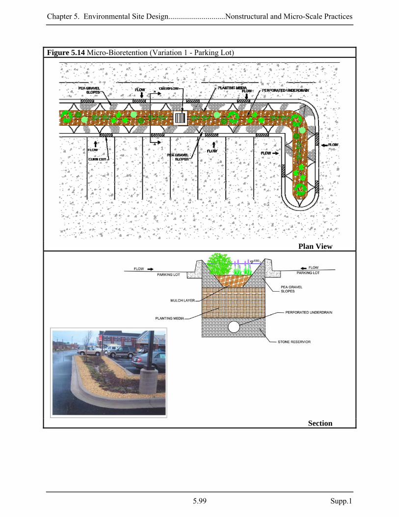
Chapter 5. Environmental Site Design.............................Nonstructural and Micro-Scale Practices
Figure 5.14 Micro-Bioretention (Variation 1 - Parking Lot)
Plan View
Section
5.99 Supp.1

Chapter 5. Environmental Site Design............................Nonstructural and Micro-Scale Practices
Figure 5.15 Micro-Bioretention (Variation 2 - Parking Lot)
Plan View
Section
Supp. 1 5.100

Chapter 5. Environmental Site Design.............................Nonstructural and Micro-Scale Practices
Figure 5.16 Micro-Bioretention (Variation 3)
Profile
Plan View
Construction Criteria: The following items should be addressed during construction of projects with micro-bioretention:
Erosion and Sediment Control: Micro-bioretention practices should not be constructed until the contributing drainage area is stabilized. If this is impractical, runoff from disturbed
5.101 Supp.1

Chapter 5. Environmental Site Design............................Nonstructural and Micro-Scale Practices
areas shall be diverted away and no sediment control practices shall be used near the proposed location.
Soil Compaction: Excavation should be conducted in dry conditions with equipment
located outside of the practice to minimize bottom and sidewall compaction. Only lightweight, low ground-contact equipment should be used within micro-bioretention practices and the bottom scarified before installing underdrains and filtering media.
Underdrain Installation: Gravel for the underdrain system should be clean, washed, and
free of fines. Underdrain pipes should be checked to ensure that both the material and perforations meet specifications. The upstream ends of the underdrain pipe should be capped prior to installation.
Filter Media Installation: Bioretention soils may be mixed on-site before placement.
However, soils should not be placed under saturated conditions. The filter media should be placed and graded using excavators or backhoes operating adjacent to the practice and be placed in horizontal layers (12 inches per lift maximum). Proper compaction of the media will occur naturally. Spraying or sprinkling water on each lift until saturated may quicken settling times.
Landscape Installation: The optimum planting time is during the Fall. Spring planting is
also acceptable but may require watering. Inspection:
Regular inspections shall be made during the following stages of construction:
o During excavation to subgrade and placement and backfill of underdrain systems. o During placement of filter media. o During construction of appurtenant conveyance. o Upon completion of final grading and establishment of permanent stabilization.
Maintenance Criteria: The following items should be addressed to ensure proper maintenance and long-term performance of micro-bioretention practices:
Privately owned practices shall have a maintenance plan and shall be protected by easement, deed restriction, ordinance, or other legal measures preventing its neglect, adverse alteration, and removal.
The top few inches of filter media should be removed and replaced when water ponds for
more than 48 hours. Silts and sediment should be removed from the surface of the filter bed when accumulation exceeds one inch.
Supp. 1 5.102

Chapter 5. Environmental Site Design.............................Nonstructural and Micro-Scale Practices
Where practices are used to treat areas with higher concentrations of heavy metals (e.g., parking lots, roads), mulch should be replaced annually. Otherwise, the top two to three inches should be replaced as necessary.
Occasional pruning and replacement of dead vegetation is necessary. If specific plants are
not surviving, more appropriate species should be used. Watering may be required during prolonged dry periods.
5.103 Supp.1

Chapter 5. Environmental Site Design............................Nonstructural and Micro-Scale Practices
M-7. Rain Gardens A rain garden is a shallow, excavated landscape feature or a saucer-shaped depression that temporarily holds runoff for a short period of time. Rain gardens typically consist of an absorbent-planted soil bed, a mulch layer, and planting materials such as shrubs, grasses, and flowers. An overflow conveyance system is included to pass larger storms. Captured runoff from downspouts, roof drains, pipes, swales, or curb openings temporarily ponds and slowly filters into the soil over 24 to 48 hours. Applications: Rain gardens can be primary or secondary practices on residential, commercial, industrial, or institutional sites. This practice is typically used to treat runoff from small impervious areas like rooftops, driveways, and sidewalks. Rain gardens can also be used in retrofitting and redevelopment applications and in series where existing slopes require energy dissipation. Performance: The PE values determined by Equation 5.3 may be applied to the ESD sizing criteria when rain gardens are designed according to the guidance provided below. Rev requirements are also met when the PE from Equation 5.3 meets or exceeds the soil specific recharge factor listed in Section 2.2. Constraints: The following constraints are critical when considering the use of rain gardens to capture and treat stormwater runoff:
Topography: Rain gardens require relatively flat slopes (< 5%) to accommodate runoff filtering through the system. Some design modifications can address this constraint through the use of infiltration berms, terracing, and timber or block retaining walls on moderate slopes.
Soils: Clayey soils or soils that have been compacted by construction equipment greatly
reduce the effectiveness of this practice. Loosening of compacted soils may improve drainage capability.
Drainage Area: The drainage area to a rain garden should be relatively small, typically less
than 2,000 square feet.
Infrastructure: The location of existing and proposed buildings and utilities (e.g., water supply wells, sewer, storm drains, electricity) will influence rain garden design and construction. Landscape designers should also consider overhead electrical and telecommunication lines when selecting trees to be planted.
Supp. 1 5.104

Chapter 5. Environmental Site Design.............................Nonstructural and Micro-Scale Practices
Location:
o Lot-by-lot use of rain gardens is not recommended in residential subdivisions due to removal by homeowners. If used on a lot-by-lot basis, educating the homeowners will be needed to prevent removal.
o Rain garden excavation in areas with heavy tree cover may damage adjacent tree root systems.
Design Guidance: The following conditions should be considered when designing rain gardens:
Conveyance: Runoff shall enter, flow through, and exit rain gardens in a safe and non-erosive manner. Energy dissipation shall be provided for downspout discharges using a plunge area, rocks, splash blocks, stone dams, etc. Runoff shall enter a rain garden at the surface through grass swales and/or a gravel bed. A minimum internal slope of one percent should be maintained and a shallow berm surrounding the rain garden is recommended to avoid short-circuiting. For sloped applications, a series of rain gardens can be used as “scalloped” terraces to convey water non-erosively.
Treatment: Rain gardens shall meet the following conditions:
o The drainage area to a rain garden serving a single lot in a residential subdivision
shall be 2,000 ft² or less. The maximum drainage area to a rain garden for all other applications shall be 10,000 ft2. Micro-bioretention (M-6) or bioretention (F-6) should be considered when these requirements are exceeded.
o The surface area (Af) of rain gardens shall be at least 2% of the contributing drainage area. A PE value based on Equation 5.3 shall be applied to the contributing drainage area. Temporary storage of the ESDv may be provided above the facility with a surface ponding depth of 6 inches or less.
5.3)(EquationDAA
P fE ×= "10
o Excavated rain gardens work best where HSG A and B are prevalent. In areas of HSG C and D, at-grade applications or soil amendments should be considered.
o A minimum six to twelve-inch layer of planting soil shall be provided. o A mulch layer two to three inches deep shall be applied to the planting soil to
maintain soil moisture and to prevent premature clogging. o The planting soil and mulch shall conform to the specifications found in Appendix
B.4.
Landscaping: Landscaping plans shall clearly specify how vegetation will be established and managed. A rain garden should be located in full to partial sun, at least two feet above the seasonal high water table and be 12 to 18 inches deep. Plants selected for use in a rain garden should tolerate both saturated and dry conditions and be native or adapted to
5.105 Supp.1

Chapter 5. Environmental Site Design............................Nonstructural and Micro-Scale Practices
Maryland. Neatly trimmed shrubs, a crisp lawn edge, stone retaining walls, and other devices can be used to keep a rain garden neat and visually appealing.
Construction Criteria: The following items should be addressed during the construction of projects with rain gardens:
Erosion and Sediment Control: Rain gardens shall not be constructed until the contributing drainage area is stabilized. During construction, runoff should be diverted and the use of heavy equipment avoided to minimize compaction.
Planting Soil: Planting soil should be mixed on-site prior to installation. If poor soils are
encountered beneath the rain garden, a four-inch layer of washed gravel (⅛ to ⅜ inch gravel preferred) may be used below the planting soil mix.
Landscape Installation: The optimum planting time is during the Fall. Spring planting is
also acceptable but may require watering. Inspection:
Regular inspections shall be made during the following stages of construction:
o During excavation to subgrade and placement of planting soil. o Upon completion of final grading and establishment of permanent stabilization.
Maintenance Criteria: The following items should be addressed to ensure proper maintenance and long-term performance of rain gardens:
Privately owned practices shall have a maintenance plan and be protected by easement, deed restriction, ordinance, or other legal measures preventing its neglect, adverse alteration, and removal.
Rain garden maintenance is generally no different than that required of other landscaped
areas.
The top few inches of the planting soil should be removed and replaced when water ponds for more than 48 hours. Silts and sediment should be removed from the surface of the bed as needed.
Where practices are used to treat areas with higher concentrations of heavy metals (e.g.,
parking lots, roads), mulch should be replaced annually. Otherwise, the top two to three inches should be replaced as necessary.
Occasional pruning and replacement of dead vegetation is necessary. If specific plants are
not surviving, more appropriate species should be used. Watering may be required during prolonged dry periods.
Supp. 1 5.106

Chapter 5. Environmental Site Design.............................Nonstructural and Micro-Scale Practices
Figure 5.17 Rain Garden
Section
Plan View
Section
5.107 Supp.1

Chapter 5. Environmental Site Design............................Nonstructural and Micro-Scale Practices
M-8. Swales Swales are channels that provide conveyance, water quality treatment, and flow attenuation of stormwater runoff. Swales provide pollutant removal through vegetative filtering, sedimentation, biological uptake, and infiltration into the underlying soil media. Three design variants covered in this section include grass swales, wet swales, and bio-swales. Implementation of each is dependent upon site soils, topography, and drainage characteristics. Applications: Swales can be used for primary or secondary treatment on residential, commercial, industrial, or institutional sites. Swales can also be used for retrofitting and redevelopment. The linear structure allows use in place of curb and gutter along highways, residential roadways, and along property boundaries. Wet swales are ideal for treating highway runoff in low-lying or flat terrain with high groundwater. Bio-swales can be used in all soil types due to the use of an underdrain. Grass swales are best suited along highway and roadway projects. Performance: The PE values determined by the equations 5.2 and 5.3 (reprinted below) may be applied to the ESD sizing criteria when grass swales and bio-swales are designed according to the guidance provided below. For wet swales, PE for the contributing drainage area is based on the volume captured. Rev requirements are also met when the applicable PE meets or exceeds the soil specific recharge factor listed in Section 2.2. Swales should not be designed to meet Qp or Qf requirements except under extremely unusual conditions. Swales may be used to convey runoff for these larger storm events however, the ESDv should be treated separately. This can be accomplished with a flow splitter or diversion so that the entire design storm is passed safely. Constraints: The following constraints are critical when considering the use of swales to capture and treat stormwater runoff:
Topography: Steep slopes will increase velocity, erosion, and sediment deposition thus shortening the design life of the swale.
Soils: Design variants are dependent upon soil types. Grass swales work best in HSG A, B,
or C and wet swales are best suited for HSG C or D. Bio-swales typically include an underdrain and may be installed in all soil types. Extreme temperatures and frozen ground need to be considered when calculating design volumes.
Drainage Area: The drainage area contributing to all design variants should be less than
one acre. Practices in Chapter 3 should be considered for larger drainage areas.
Supp. 1 5.108

Chapter 5. Environmental Site Design.............................Nonstructural and Micro-Scale Practices
5.109 Supp.1
Hotspot Runoff: Swales should not be used to treat hotspots that generate higher concentrations of hydrocarbons, trace metals, or toxicants than are found in typical stormwater runoff and may contaminate groundwater.
Location: The location of swales needs to be considered carefully. Wet swales are not
recommended for residential developments due to the potential nuisance or mosquito breeding conditions. Swales along roadways can be damaged by off-street parking and are susceptible to winter salt applications. Also, the choice of vegetation and landscaping can be limited in adjacent areas.
Design Guidance: The following conditions should be considered when designing swales:
Conveyance: Stormwater discharged into and through swales needs to be non-erosive. Sheetflow should be promoted wherever possible using precise grading, level earthen weirs, or pea gravel diaphragms. If concentrated flow is delivered from curb cuts or storm drain pipes, some form of energy dissipation (e.g., plunge pools or rip-rap) is needed.
Treatment: All swales shall meet the following criteria:
o Swales shall have a bottom width between two and eight feet. o The channel slope shall be less than or equal to 4.0%. o The maximum flow velocity for the ESDv shall be less than or equal to 1.0 fps. o Swales shall be designed to safely convey the 10-year, 24-hour storm at a non-erosive
velocity with at least six inches of freeboard. o Channel side slopes shall be 3:1 or flatter. o A thick vegetative cover shall be provided for proper function.
The following criteria apply to each specific design variant: Grass swales: Grass swales shall be used for linear applications (e.g., roadways) only, and shall be as long as the treated surface. The surface area (Af) of the swale bottom shall be at least 2% of the contributing drainage area, and a PE value based on Equation 5.3 shall be applied to the contributing drainage area. The maximum flow depth for ESDv treatment should be 4 inches, and the channel should have a roughness coefficient (Manning’s n) value of 0.15. This can be accomplished by either maintaining vegetation height equal to the flow depth or using energy dissipaters like check dams, infiltration berms, or riffle/pool combinations.
Bio-swales: The surface area (Af) of the bio-swale bottom shall be at least 2% of the contributing impervious area and a PE value based on Equation 5.2 shall be applied to the contributing drainage area. Bio-swales shall be designed to temporarily store at least 75%
5.3)(EquationDAA
P fE ×= "10

Chapter 5. Environmental Site Design............................Nonstructural and Micro-Scale Practices
Supp. 1 5.110
of the ESDv. A two to four-foot deep layer of filter media shall be provided in the swale bottom. Underdrains shall be provided in HSG C or D and shall conform to the specifications found in Appendix B.4. The use of underdrains is recommended for all applications.
Wet swales: Wet swales shall be designed to store at least 75% of the ESDv. A PE value equivalent to the volume captured and treated shall be applied to the contributing drainage area. Wet swales should be installed in areas with a high groundwater table and check dams or weirs may be used to enhance storage.
Check Dams: Check dams or weirs may be used to enhance storage and channel roughness or provide grade control in steeper applications. Where used, these structures should be anchored into the swale wall and notched to allow passage of larger design storms with a minimum six-inch freeboard. Plunge pools or other energy dissipation may be required where the elevation difference between the tops of weirs to the downstream channel invert is a concern.
Landscaping: Landscaping plans shall specify proper grass or wetland plantings based on
the design variant chosen and anticipated hydrologic conditions along the channel (see Appendix A). Native species are best for survival and enhancing bio-diversity and wildlife.
Construction Criteria: Construction specifications for swales can be found in Appendix B.3. In addition, the following items should be addressed during the construction of projects with swales:
Erosion and Sediment Control: Swales are often used for conveying runoff to sediment trapping devices during site construction. Care should be taken to ensure proper construction where stormwater management swales are used for this purpose. After the drainage area is completely stabilized, accumulated sediment should be removed and the swale excavated to the required dimensions. Any required infrastructure (e.g., check dams, underdrains) may then be installed, the bottom and side slopes scarified, and a good stand of vegetation established.
Inspection:
Regular inspections shall be made during the following stages of construction:
o During placement and backfill of underdrains and the installation of diaphragms, forebays, check dams, or weirs.
o Upon completion of final grading and establishment of permanent stabilization.
5.2)(EquationDAA
P fE ×= "15

Chapter 5. Environmental Site Design.............................Nonstructural and Micro-Scale Practices
Figure 5.18 Bio-Swale
Section
Plan View Maintenance Criteria: The following items should be addressed to ensure proper maintenance and long-term performance of swales:
For grassed swales, regular mowing (at least bi-annually) is critical in order to reduce competition from weeds and irrigation may be needed during dry weather to establish vegetation. Sparsely vegetated areas need to be re-seeded to maintain dense coverage.
If water does not drain within 48 hours, the bottom soil should be tilled and revegetated.
Inspections should be performed once a year to assess slope integrity, vegetative health, soil
stability, compaction, erosion, ponding, and sedimentation. Periodic removal of sediment, litter, or obstructions should be done as needed. Eroded side slopes and the swale bottom should be repaired and stabilized where needed.
5.111 Supp.1

Chapter 5. Environmental Site Design............................Nonstructural and Micro-Scale Practices
Supp. 1 5.112
Figure 5.19 Wet Swale
Profile
Plan View
Section

Chapter 5. Environmental Site Design.............................Nonstructural and Micro-Scale Practices
M-9. Enhanced Filters An enhanced filter is a modification applied to specific practices (e.g., micro-bioretention) to provide water quality treatment and groundwater recharge in a single facility. This design variant uses a stone reservoir under a conventional filtering device to collect runoff, remove nutrients, and allow infiltration into the surrounding soil. Applications: The structural stormwater filtering systems in Chapter 3 and the micro-filtering structures above can be modified relatively easily for most development projects. Depending on soil conditions, a stone reservoir can be sized appropriately to provide Rev for the drainage area to the system. These practices are subject to the same constraints and design requirements as conventional and micro-scale filters. Performance: When designed according to the guidance provided below, enhanced filters may be used to address Rev for the contributing impervious area using the percent volume method. When coupled with other properly designed structural or micro-scale practices, the combined system will address the ESD sizing criteria. Constraints: The following constraints are critical when considering the use of enhanced filters to capture and treat stormwater runoff:
Space: The surface area of a typical enhanced filter is dependent on the design of the practice above. Similarly, the size and distribution of open areas within a project (e.g., parking lot islands, landscaped areas) must be considered early during a project’s planning and design if these practices are used.
Enhanced filters should not be used in areas where their operation may create a risk for basement flooding, interfere with subsurface sewage disposal systems, or affect other underground structures.
Soils: Soil conditions are important when designing enhanced filters. Local soil type is a primary factor for determining Rev and in sizing the stone reservoir.
Subsurface water conditions (e.g., water table) will help determine the stone reservoir thickness used. The probability of practice failure increases if the reservoir intercepts groundwater. Therefore, enhanced filter practice inverts should be above local groundwater tables.
5.113 Supp.1

Chapter 5. Environmental Site Design............................Nonstructural and Micro-Scale Practices
Hotspot Runoff: Enhanced filters should not be used to treat hotspots that generate higher concentrations of hydrocarbons, trace metals, or toxicants than are found in typical stormwater runoff and may contaminate groundwater.
Infrastructure: The location of existing and proposed buildings and utilities (e.g., water
supply wells, sewer, storm drains, electricity) will influence the design and construction of enhanced filters.
Design Guidance: The following conditions should be considered when designing enhanced filters:
Conveyance: Runoff shall enter the stone reservoir in a safe and non-erosive manner. Typically, runoff flows through the upper scale practice, into the stone reservoir and infiltrates into the ground. As the reservoir fills, an underdrain system is used to discharge treated stormwater safely downstream. Underdrains may be connected to other micro-scale practices or open or closed storm drain systems. All structural and micro-scale filters should be designed off-line whenever possible. A flow splitter should be used to divert excess runoff away from the filter media to a stable, downstream conveyance system. If bypassing these practices is impractical, internal overflow devices (e.g., elevated yard inlet) may be used.
Treatment: Enhanced filters shall meet the following conditions:
o Enhanced filters shall be coupled with properly designed filters to address both ESD
and Rev requirements. o At a minimum, enhanced filter reservoirs shall be designed to store the Rev. The
stone reservoir volume is equal to the surface area multiplied by depth divided by the porosity (n) of the stone [Volume = Surface Area (ft2) x Depth (ft) x 0.4].
o When using Variation A, the stone reservoir (#57 stone preferred) shall be at least 12 inches thick below the underdrain.
o A 12-inch layer of sand or pea gravel (⅛ to ⅜ inch stone) may be used to act as a bridging layer between the stone reservoir and subsurface soils.
o The invert of the stone reservoir shall be separated at least four feet (two feet on the lower Eastern Shore) from the seasonal high water table.
Setbacks:
o Enhanced filters shall be located at least 25 feet from septic systems, 100 feet from
unconfined water supply wells, and 50 feet from confined water supply wells.
o Enhanced filters shall be sized and located to meet minimum local requirements for clearance (both vertical and horizontal) from sewer and water lines. Designs may need to include special protection if underground utilities cross through enhanced filters.
Supp. 1 5.114

Chapter 5. Environmental Site Design.............................Nonstructural and Micro-Scale Practices
Observation Wells: An observation well consisting of an anchored, 4 to 6-inch diameter perforated pipe shall be provided. The top of the observation well shall be at least six inches above grade.
Construction Criteria: The following items should be addressed during the construction of projects with enhanced filtering practices:
Erosion and Sediment Control: Enhanced filters shall not be used as sediment control practices (e.g., sediment traps). Enhanced filters should not be constructed until the contributing drainage area is stabilized. Construction runoff shall be directed away after initial rough grading.
Soil Compaction: Existing soils in the location of enhanced filters should be scarified to
maximize infiltration. Construction shall be performed with lightweight, wide-tracked equipment to minimize disturbance and compaction.
Reservoir Installation: Stone for the reservoir system should be clean, washed, and free of
fines. Stone should be placed in horizontal layers (six inches per lift maximum) over the entire area of the practice using excavators or backhoes operating adjacent to the practice.
Inspection:
Regular inspections shall be made during the following stages of construction:
o During excavation to subgrade. o During placement of gravel, and installation of underdrain systems and observation
wells. o At all stages required for the ESD practice located above the enhanced filter.
Maintenance Criteria: Enhanced filters require minimal maintenance in addition to that needed for the practice above to ensure optimum performance. Generally, maintenance is the same as that used to keep the primary practice in good condition. Additional measures include making sure there is no water in the observation well. The presence of water 48 hours after a rain event indicates that the enhanced filter may be clogged and need replacement.
5.115 Supp.1

Chapter 5. Environmental Site Design............................Nonstructural and Micro-Scale Practices
Supp. 1 5.116
Figure 5.20 Enhanced Filters
Section -Variation 1
Section – Variation 2

Chapter 5. Environmental Site Design.................................................................... Redevelopment
Section 5.5 Redevelopment 5.5.1 Introduction Redevelopment is defined as any construction, alteration, or improvement performed on sites where the existing land use is commercial, industrial, institutional, or multifamily residential and existing site impervious area exceeds 40%. The term “site” is defined as a single tract, lot, parcel of land, or combination of tracts, lots, parcels of land that are in one ownership, or are contiguous and in diverse ownership where development is to be performed as part of a unit, subdivision or project. Therefore, when the total site impervious area under existing conditions exceeds the 40% threshold, redevelopment requirements will apply. When calculating site imperviousness, the local approving agency may allow lands protected by forest preservation, conservation easements, or other mechanism to be subtracted from the total site area. This will create incentive to preserve and protect natural resources in redevelopment projects. 5.5.2 Redevelopment Policy As described above, the 40% site impervious area threshold will determine whether a project will be regulated as new development or redevelopment. When redevelopment requirements apply, all existing impervious areas located within a project’s limit of disturbance (LOD) are required for management. Because redevelopment projects present a wide range of constraints and limitations, the policy below allows for flexibility and an evaluation of options that can work in conjunction with broader watershed goals and local initiatives. 1. Stormwater management shall be addressed for redevelopment according to the following
criteria:
a. Reduce existing impervious area within the LOD by at least 50%; or b. Implement ESD practices to the MEP to provide water quality treatment for at
least 50% of existing impervious area within the LOD; or c. Use a combination of impervious area reduction and ESD implementation for at
least 50% of existing impervious areas.
2. Alternative stormwater management measures may be used to meet the requirements above provided that the developer satisfactorily demonstrates to the approving authority that impervious area reduction and ESD have been implemented to the MEP. Alternative stormwater management measures include but are not limited to:
a. An on-site structural BMP; or b. An off-site structural BMP to provide water quality treatment for an area equal to
or greater than 50% of existing impervious areas; or c. A combination of impervious area reduction, ESD implementation, and on-site or
off-site structural BMP for an area equal to or greater than 50% of existing impervious area within the LOD.
5.117 Supp.1

Chapter 5. Environmental Site Design.................................................................... Redevelopment
3. An approving agency may develop separate programmatic policies for providing water quality treatment for redevelopment projects when the above requirements cannot be met. These policies shall be reviewed and approved by MDE and may include but are not limited to:
a. Retrofitting existing structural BMPs; b. Stream restoration; c. Trading policies that involve other pollution control programs; or d. Watershed management plans.
4. Stormwater management shall be addressed according to new development requirements
for any net increase in impervious area. 5.5.3 Management Considerations
Stormwater management requirements for redevelopment will apply to existing impervious areas within the project LOD. Impervious area is defined as any surface that does not allow stormwater to infiltrate into the ground. As a matter of policy, if gravel is compacted to the point where it will no longer infiltrate, then it is impervious. Any gravel driveway or parking area that is regularly used is likely to become impervious over time. However, a gravel road that is infrequently used may be considered pervious. These determinations should be done on a case-by-case basis. Alternative surfaces may be used to meet redevelopment requirements. However, when designing to meet runoff reduction requirements the appropriate curve number should be used according to the design specifications in this Chapter. These practices however, are not considered permeable surfaces, and may be regulated differently by other State and local programs. Redevelopment activities may occur on a site where a BMP is providing treatment for existing impervious areas. These BMPs shall be inspected and their performance verified. The requirements described in 5.5.2 apply to existing impervious areas that are not treated by BMPs meeting current design standards. Existing BMPs may be retrofitted to current standards and treat additional impervious areas to meet redevelopment requirements. 5.5.4 Design Process for Redevelopment All redevelopment projects shall be subject to the Design process for Redevelopment as outlined in the step wise procedures in Figure 5.21. Section 5.1 of this chapter describes the design process for all development in Maryland that includes a comprehensive review and approval of concept, site development, and final plans by the local review agencies. These procedures will also apply to redevelopment projects and the guidance provided in Section 5.1 of this chapter should be referenced for more specific detail at each step and for a check list of items required for interim reviews. The process described below outlines the steps in Figure 5.21 and will highlight considerations specific to the design of a
Supp. 1 5.118

Chapter 5. Environmental Site Design.................................................................... Redevelopment
redevelopment project. Approving agencies shall use the process outlined in Figure 5.21 as an enforceable mechanism during review of the plan. Documentation that all steps were followed during project development and specific rationale to support the proposed design shall be required. Step 1. Concept Phase: Develop a site map and assess existing natural resources as described in Section 5.1.3.1. Existing buildings, impervious areas, utilities, storm drain systems, neighboring properties, and all environmental and infrastructure constraints are identified. Opportunities to reduce existing and proposed impervious cover by using site design techniques and alternative surfaces are evaluated. The approximate locations of proposed impervious areas are identified and opportunities for using ESD practices are evaluated. Additionally the developer shall provide a narrative to the appropriate review agencies to support the design for concept approval. Step 2. Submit Concept Plan: Approval agencies provide review and comment back to the developer. Concept plan approval must be given by the appropriate review agencies before proceeding to the site development phase. Step 3. Site Development Phase: Incorporate comments from review agencies and finalize proposed site layout indicating how existing and proposed impervious areas are hydrologically connected to landscaped features (e.g., islands, vegetated planters, and green spaces). Evaluate opportunities for implementing ESD practices on open space and landscaped areas for storage, filtration, infiltration, and water quality treatment of stormwater runoff. Develop an erosion and sediment control plan and an overlay plan. Provide a narrative to the appropriate review agencies to support the design for site development approval. Step 4. Submit Site Development Plan: Approval agencies provide review and comment on the site development plan back to the developer. All reasonable options for meeting stormwater management requirements using ESD planning techniques and practices have been exhausted. Approval agencies will provide comments and suggestions for final design. These may include potential management strategies in the event that stormwater requirements cannot be met using ESD. Site development plan approval must be given by the appropriate review agencies before proceeding to final design. Step 5A. Final Design Phase – A: After all reasonable ESD options have been exhausted, evaluate alternative management strategies including on-site and off-site structural BMPs and design according to Chapter 3. Review agencies should provide guidance on acceptable stormwater treatment measures that may include retrofit projects, stream restoration, pollution trading, watershed management plans, or other approved practices. Step 5B. Final Design Phase – B: Finalize plans and address any remaining comments from the appropriate review agencies. Step 6. Submit Final Plans: Final stormwater management and erosion and sediment control plans are submitted for approval. The designer needs to demonstrate that on-site ESD practices have been implemented to the MEP.
5.119 Supp.1

Chapter 5. Environmental Site Design.................................................................... Redevelopment
Supp. 1 5.120
Figure 5.21 Design Process for Redevelopment

Chapter 5. Environmental Site Design.................................................................... Special Criteria
Section 5.6 Special Criteria for Sensitive Waters 5.6.1 Introduction In Maryland, there are several different types of sensitive watersheds, each with unique features or regulatory requirements. In some watersheds, enhanced pollutant removal may be needed to protect drinking water supply or shellfish harvesting. In others, temperature increases caused by new development may need to be mitigated to preserve coldwater habitat. In addition to these special needs, there are numerous State programs (e.g., Critical Areas, Wetlands and Waterways, Forest Conservation) that regulate activities within receiving waters. This section presents additional criteria that should be considered when designing projects in sensitive watersheds. This section also identifies requirements from other State regulatory programs that will influence ESD implementation. 5.6.2 Water Quality Standards The purpose of Maryland’s water quality standards is to protect, maintain, and improve surface water quality. Two of the components of these standards are the Designated Uses and water quality criteria to protect them. Each major stream segment in Maryland is assigned one of the following Designated Uses: • USE I & I-P: Water Contact Recreation and Protection of Nontidal Warmwater Aquatic Life
where P indicates public water supply or reservoir protection areas. • USE II & II-P: Support of Estuarine and Marine Aquatic Life and Shellfish Harvesting • USE III & III-P: Nontidal Cold Water • USE IV & IV-P: Recreational Trout Waters For each designated use, specific water quality criteria are designed to protect aquatic life and human health. Typically, there are numeric criteria for toxics, dissolved oxygen, bacteria, and temperature (e.g., 5 mg/l for dissolved oxygen). There are also narrative standards that are used for other pollutants (e.g., oil, grease, odor) where specific values are impractical. For the majority of Maryland’s waters, these criteria represent minimum standards for the support of balanced indigenous populations and contact recreation commonly known as "fishable/swimmable." For higher quality waters that exceed fishable/swimmable standards, the existing water quality conditions must be maintained. 5.6.3 ESD Implementation and Watershed Use Stormwater management decisions are influenced by the nature and quality of the receiving waters. Therefore, Designated Uses should be identified during the initial site and resource mapping steps. In most cases, the majority of water quality concerns in a given watershed can be addressed through the use of ESD to the MEP. For example, maximizing the use of ESD is a critical component of any approval for additional discharges to higher quality waters identified in Maryland’s Tier II Antidegradation Policy. However, in Use III and IV, ESD implementation alone may not be sufficient to maintain critical in-stream temperatures.
5.121 Supp.1

Chapter 5. Environmental Site Design.................................................................... Special Criteria
5.6.4 At-Source Techniques for Mitigating Thermal Impacts Temperature increases caused by development impact the quality of coldwater streams. Temperatures should not exceed 68º F in Use III and 75º F in Use IV streams or the ambient water temperature, whichever is greater. The lethal temperatures for brook, and brown and rainbow trout are 72º and 82º F, respectively. Therefore, one of the primary design objectives is to prevent stream warming and maintain habitat quality for coldwater aquatic life. Implementing ESD to the MEP, including using infiltration where appropriate, will help mitigate many of the thermal impacts associated with development. However, additional techniques may be needed to limit thermal impacts at the source. In a study prepared for MDE in 1990 by the Metropolitan Washington Council of Governments, it was determined that “[i]mperviousness together with local meteorological conditions had the largest influence on urban stream temperatures” (Thermal Impacts Associated with Urbanism and Stormwater Best Management Practices, John Galli, 1990). This study reported that as watershed imperviousness increased, progressively smaller rainfall depths were needed to produce large stream temperature fluctuations. Clearly, reducing imperviousness will help reduce thermal impacts and techniques for accomplishing this are listed in Section 5.1. The color of impervious surfaces also affects temperature increases. Darker surfaces like asphalt pavement or shingles absorb solar radiation, elevating temperatures as this energy is transferred as heat to surrounding areas, including stormwater runoff. Lighter colored materials like grey or white concrete reflect solar radiation resulting in less elevated temperatures. A material’s ability to reflect solar heat is measured as its Solar Reflectance Index or “SRI” and varies from 0 (a black surface) to 100 (a white surface) and above. In thermally-sensitive watersheds, designers should consider using materials with SRI values greater than 29 (see Table 5.9) for paving and steep-sloped (≥2:12) roofing, and materials with SRI values greater than 78 for low-sloped (≤2:12) roofing. Table 5.9 Solar Reflectance Indices (SRI) for Typical Paving & Roofing Materials Paving Materials: Condition SRI
Asphalt New 0 Weathered 6 Gray Concrete New 35 Weathered 29 White Concrete New 86 Weathered 45
Roofing Materials: Gray Asphalt Shingles 22 Gray EPDM (Rubber) 21 Light Gravel on Built-Up Roof 37 White-Coated Gravel on a Built-Up Roof 79 White EPDM (Rubber) 84 White PVC 104
Source: LEED®-NC for New Construction Reference Guide Ver. 2.2 (USGBC, October 2005)
Supp. 1 5.122

Chapter 5. Environmental Site Design.................................................................... Special Criteria
Another option for mitigating thermal impacts at the source is to shade buildings and paved areas from the sun. Trees, large shrubs, and non-invasive vines on trellises can be used to screen these areas from the sun and cool the air through evapotranspiration. The full benefits of shading may not be realized until the trees and shrubs mature. Depending on the age and type of plants used, this may be several years. In the interim, any receiving waters may be degraded and resources lost as a result of temperature increases. When using this technique, designers should strive to provide shade within five years of project completion. 5.6.5 Additional Techniques for Mitigating Thermal Impacts While thermal impacts are primarily caused by increases in impervious area, stormwater management practices, including ESD techniques, may contribute to the problem. When designing these techniques for use in coldwater areas, minimizing temperature increases is a primary concern. The following techniques will help reduce thermal impacts associated with ESD practices:
Maximize the infiltration capacity of each practice. Increasing infiltration reduces the amount of surface runoff and lowers the thermal energy flowing into coldwater streams.
Design filtering practices (e.g., micro-bioretention) so that underdrains are at least four feet
below the surface. Soil temperatures at this depth are cooler and fluctuate little in response to surface weather conditions. As runoff flows through, thermal energy is dissipated and effluent temperatures are decreased. If overflow and conveyance connection constraints limit underdrain depth, use the enhanced filter option 2 (see M-9, Section 5.4.3). In this variant, the perforated underdrain is located at the bottom of a stone reservoir and below the outlet pipe. As the water surface elevation within the reservoir rises above the invert of the outlet pipe, cooler water is siphoned from the bottom.
Use shade-producing plants in landscaped practices. As discussed above, trees, shrubs, and
non-invasive vines on trellises can be used to screen impervious areas from the sun. 5.6.6 Other Resources In addition to the various Designated Uses, designers must also consider sensitive conditions and design requirements associated with other programs that regulate development activities related to critical resources. Similar to water quality concerns, most of these may also be addressed through the use of ESD to the MEP. However, there are additional concerns like buffer widths, construction materials used, or wetland types that may need to be considered. This section identifies some of these program-specific requirements.
5.123 Supp.1

Chapter 5. Environmental Site Design.................................................................... Special Criteria
Wetlands & Waterways Wetlands are essential natural resources that provide fish and wildlife habitat, flood protection, and water quality enhancement. These sensitive areas are impacted by even the smallest of changes in hydrology or water quality. For this reason, stormwater management measures should not be located within nontidal wetlands and their buffers, tidal wetlands, and 100-year floodplains. This includes many of the ESD techniques listed in this Chapter. If stormwater management facilities must be located within these areas, State and federal permits are required. In addition to the above restrictions, runoff from new development and redevelopment must be treated prior to discharging directly into jurisdictional wetlands or waters of the State. In most cases, using ESD to MEP will provide adequate treatment and meet this requirement. Where discharges are permitted, there are additional concerns. When implementing ESD within areas of sensitive wetlands with unusual or unique plant communities like bogs, Delmarva bays, or Wetlands of Special State Concern, designers should incorporate features and materials that complement or mimic local natural conditions. For example, bogs are nutrient-deficient, acidic environments where runoff pH is critical. In these areas, designers should specify the use of native or locally available materials that are acidic (pH < 7) like granite or sandstone instead of limestone or marble (pH > 7) for riprap in conveyance channels and energy dissipaters. Likewise, landscaping should promote native plants that match both the conditions found within ESD practices and local wetland communities. In addition to using local or native materials and plants, designers should consider how runoff is conveyed to wetlands. Storm drainage systems are usually designed to discharge directly into wetlands and/or floodplains. This approach minimizes the ecological interaction that occurs between wetland areas and adjacent buffers. Using more natural channel designs (e.g., coastal plains outfalls, step/pool systems, bioswales) or promoting sheetflow to convey runoff from ESD practices into wetlands connects and promotes interaction within these areas Maryland’s Critical Areas Maryland’s Critical Area Act recognizes that the land immediately surrounding the Chesapeake and Atlantic Coastal Bays and their tributaries has the greatest potential to affect water quality and wildlife habitat. Therefore, all land within 1,000 feet of tidal waters or adjacent tidal wetlands is designated as the “Critical Area.” While the State Critical Area Commission provides oversight and reviews some development projects, each appropriate County and municipality enforces this law. All development located within the Critical Area must address additional criteria. Some provisions of these criteria, like those relating to the protection of habitat, are applied uniformly throughout the Critical Area. Others provisions that may impact ESD implementation are related to water quality and site imperviousness and are specific to land classifications discussed below.
Supp. 1 5.124

Chapter 5. Environmental Site Design.................................................................... Special Criteria
Within the Critical Area, land is designated as either Intensely Developed Area, Limited Development Area, or Resource Conservation Area (IDA, LDA, & RCA, respectively) based on uses that existed at the time the local programs were adopted. The IDAs are those areas of concentrated development where there is little natural habitat. Any new development and redevelopment projects within the IDA must include stormwater management practices to reduce post-development phosphorus loads to at least 10% below pre-developed levels. Commonly known as the 10% Rule, this requirement may be addressed using many of the ESD practices described in this Chapter or by using structural practices found in Chapter 3. While implementing ESD to the MEP should meet or exceed phosphorus reduction requirements in most cases, applicants may be required to use the Critical Areas methodology to demonstrate compliance with the 10% Rule as part of the plan approval process. Additional guidance for addressing the 10% Rule within the IDA may be found in the Critical Area 10% Rule Guidance Manual (MDNR, 2003). LDAs are those regions where development density is low to moderate and wildlife habitat is not dominated by agriculture, wetlands, forests, or other natural areas. Similarly, RCAs are characterized by the dominance of agriculture or protected resources like forests or wetlands. Within these areas, new development or redevelopment must address standard water quality requirements, conserve natural areas, and incorporate corridors to connect wildlife and plant habitat. To accomplish these goals, imperviousness, alternative surfaces, or “lot coverage” is generally limited to 15% of the property or project area. There are also strict limits on clearing of existing woodland or forests. All clearing of these areas requires at least a 1:1 replacement. To protect habitat, a forested buffer is required on all new development in all three land designations. Extending a minimum of 100 feet from the Mean High Water Line of tidal waters or the landward edge of tidal wetlands and tributary streams, this buffer acts as a water quality filter and protects important riparian habitat within the Critical Area. This distance may be expanded to include adjacent sensitive areas like hydric or highly erodible soils or steep slopes. If it is within a subdivision in the RCA, the minimum width of the buffer is 200 feet. Disturbance associated with new development is generally prohibited within the buffer, and, accordingly, stormwater practices (e.g., micro-scale practices, structural facilities) cannot be located within it. Forest Conservation Act The Maryland Forest Conservation Act (FCA) was enacted in 1991 to minimize the loss of forests during land development. As a result, identifying and protecting forests is an integral part of the development process. The primary areas targeted for protection include forests adjacent to streams or wetlands, located on steep slopes, or within or adjacent to forest blocks or wildlife corridors. Any activity requiring a subdivision application, grading permit, or erosion and sediment control plan approval on areas exceeding 40,000 square feet is subject to the FCA and a Forest Conservation Plan may be required. The Forest Conservation Plan includes a map and narrative that describes how existing forested and sensitive areas will be protected, if afforestation will be required, and how any replanted trees will be protected. While implementation is not directly affected by the FCA, trees may be planted within ESD practices and associated buffers located adjacent to critical habitat, steeply sloping ground and highly
5.125 Supp.1

Chapter 5. Environmental Site Design.................................................................... Special Criteria
Supp. 1 5.126
erodible soils, large forest tracts, 50-foot stream buffers, or similar areas. Additionally, landscaping within ESD practices may be used to meet afforestation requirements when it exceeds 2,500 square feet, is at least 35 feet wide and protected by an approved landscape management plan.

Glossary
G
Glo
ssar
y

............................................................................................................................................. Glossary
G.1
G.1 Glossary Portions of this glossary were adapted from the “1994 Maryland Standards and Specifications for Soil Erosion and Sediment Control” produced by the Maryland Department of the Environment, Water Management Administration.
ANTI-SEEP COLLAR - An impermeable diaphragm usually of sheet metal or concrete constructed at intervals within the zone of saturation along the conduit of a principal spillway to increase the seepage length along the conduit and thereby prevent piping or seepage.
ANTI-VORTEX DEVICE - A device designed and placed on the top of a riser or the entrance of a pipe to prevent the formation of a vortex in the water at the entrance.
AQUATIC BENCH - A bench which is located around the inside perimeter of a permanent pool and is normally vegetated with aquatic plants; the goal is to provide pollutant removal and enhance safety in areas using stormwater pond BMP’s.
AQUIFER – A porous water bearing geologic formation generally restricted to materials capable of yielding an appreciable supply of water
“AS-BUILT” - Drawing or certification of conditions as they were actually constructed.
BAFFLES - Guides, grids, grating or similar devices placed in a pond to deflect or regulate flow and create a longer flow path.
BANKFULL FLOW - The condition where streamflow fills a stream channel to the top of the bank and at a point where the water begins to overflow onto a floodplain.
BARREL - The closed conduit used to convey water under or through an embankment; part of the principal spillway.
BASE FLOW - The stream discharge from groundwater.
BERM - A shelf that breaks the continuity of a slope; a linear embankment or dike.
BEST MANAGEMENT PRACTICE (BMP) - A structural or non-structural device designed to temporarily store or treat stormwater runoff in order to mitigate flooding, reduce pollution and provide other amenities.
BIORETENTION - A water quality practice that utilizes landscaping and soils to treat urban stormwater runoff by collecting it in shallow depressions before filtering through a fabricated planting soil media.
BUFFER – Zone of variable width located along both sides of a natural feature (e.g., stream or forested area) and designed to provide a protective area along a corridor.
CHANNEL - A natural stream that conveys water; a ditch or channel excavated for the flow of water.

............................................................................................................................................. Glossary
G.2
CHANNEL PROTECTION VOLUME (CpV) - A design criteria which requires 24 hour detention of the one year post-developed, 24 hour storm event for the control of stream channel erosion and is calculated according to Appendix D.11.
CHANNEL STABILIZATION - Erosion prevention and stabilization of velocity distribution in a channel using jetties, drops, revetments, structural linings, vegetation and other measures.
CHECK DAM - A small dam constructed in a gully or other small watercourse to decrease flow velocity (by reducing the channel gradient), minimize scour, and promote deposition of sediment.
CHUTE - A high velocity, open channel for conveying water to a lower level without erosion.
CLAY (SOILS) - 1. A mineral soil separate consisting of particles less than 0.002 millimeter in equivalent diameter. 2. A soil texture class. 3. (Engineering) A fine grained soil (more than 50 percent passing the No. 200 sieve) that has a high plasticity index in relation to the liquid limit. (Unified Soil Classification System)
COCONUT ROLLS - Also known as coir rolls, these are rolls of natural coconut fiber designed to be used for streambank stabilization.
COMPACTION (SOILS) - Any process by which the soil grains are rearranged to decrease void space and bring them in closer contact with one another, thereby increasing the weight of solid material per unit of volume, increasing the shear and bearing strength and reducing permeability.
CONDUIT - Any channel intended for the conveyance of water, whether open or closed.
CONTOUR - 1. An imaginary line on the surface of the earth connecting points of the same elevation. 2. A line drawn on a map connecting points of the same elevation.
CORE TRENCH - A trench, filled with relatively impervious material intended to reduce seepage of water through porous strata.
CRADLE - A structure usually of concrete shaped to fit around the bottom and sides of a conduit to support the conduit, increase its strength and, in dams, to fill all voids between the underside of the conduit and the soil.
CREST - 1. The top of a dam, dike, spillway or weir, frequently restricted to the overflow portion. 2. The summit of a wave or peak of a flood.
CRUSHED STONE - Aggregate consisting of angular particles produced by mechanically crushing rock.
CURVE NUMBER (CN) - A numerical representation of a given area’s hydrologic soil group, plant cover, impervious cover, interception and surface storage derived in accordance with Natural Resources Conservation Service methods. This number is used to convert rainfall depth into runoff volume.
CUT - Portion of land surface or area from which earth has been removed or will be removed by excavation; the depth below original ground surface to excavated surface.
CUT-AND-FILL - Process of earth moving by excavating part of an area and using the excavated material for adjacent embankments or fill areas.
CUTOFF - A wall or other structure, such as a trench, filled with relatively impervious material

............................................................................................................................................. Glossary
G.3
intended to reduce seepage of water through porous strata.
CZARA - Acronym used for the Coastal Zone Act Reauthorization Amendments of 1990. These amendments sought to address the nonpoint source pollution issue by requiring states to develop coastal nonpoint pollution control programs in order to receive federal funds.
DAM - A barrier to confine or raise water for storage or diversion, to create a hydraulic head, to prevent gully erosion, or for retention of soil, sediment or other debris.
DETENTION - The temporary storage of stormwater runoff in a BMP with the goals of controlling peak discharge rates and providing gravity settling of pollutants.
DETENTION STRUCTURE – A permanent structure for the temporary storage of runoff that is designed to not create a permanent pool of water.
DIKE - An embankment to confine or control water, for example, one built along the banks of a river to prevent overflow to lowlands; a levee.
DISTRIBUTED RUNOFF CONTROL (DRC) - A stream channel protection criteria which utilizes a non-uniform distribution of the storage-stage-discharge relationship within a BMP to minimize the change in channel erosion potential from pre-developed to developed conditions.
DISTURBED AREA - An area in which the natural vegetative soil cover has been removed or altered and, therefore, is susceptible to erosion.
DIVERSION - A channel with a supporting ridge on the lower side constructed across the slope to divert water to areas where it can be used or disposed of safely. Diversions differ from terraces in that they are individually designed.
DRAINAGE - 1. The removal of excess surface water or ground water from land by means of surface or subsurface drains. 2. Soil characteristics that affect natural drainage.
DRAINAGE AREA (WATERSHED) – That area contributing runoff to a single point measured in a horizontal plane, which is enclosed by a ridge line.
DROP STRUCTURE - A structure for dropping water to a lower level and dissipating surplus energy; a fall.
DRY SWALE - An open drainage channel explicitly designed to detain and promote the filtration of stormwater runoff through an underlying fabricated soil media.
EMERGENCY SPILLWAY - A dam spillway, constructed in natural ground, that is to discharge flow in excess of the principal spillway design discharge.
ENERGY DISSIPATOR - A designed device such as an apron of rip-rap or a concrete structure placed at the end of a conduit for the purpose of reducing the velocity, energy and turbulence of the discharged water.
EROSION - 1. The process by which the land surface is worn away by the action of water, wind, ice, or gravity. 2. Detachment and movement of soil or rock fragments by water, wind, ice or gravity. The following terms are used to describe different types of water erosion:

............................................................................................................................................. Glossary
G.4
Accelerated erosion - Erosion much more rapid than normal, natural or geologic erosion, primarily as a result of the influence of the activities of man or, in some cases, of other animals or natural catastrophes that expose base surfaces.
Gully erosion - The erosion process whereby water accumulates in narrow channels and removes the soil from this narrow area to considerable depths ranging from 1 or 2 feet to as much as 75 to 100 feet.
Rill erosion - An erosion process in which numerous small channels only several inches deep are formed. See rill.
Sheet erosion - The spattering of small soil particles caused by the impact of raindrops on wet soils. The loosened and spattered particles may or may not subsequently be removed by surface runoff.
EROSIVE VELOCITIES - Velocities of water that are high enough to wear away the land surface. Exposed soil will generally erode faster than stabilized soils. Erosive velocities will vary according to the soil type, slope, structural, or vegetative stabilization used to protect the soil.
EXFILTRATION - The downward movement of water through the soil; the downward flow of runoff from the bottom of an infiltration BMP into the soil.
EXTENDED DETENTION - A stormwater design feature that provides for the gradual release of a volume of water in order to increase settling of pollutants and protect downstream channels from frequent storm events.
EXTREME FLOOD VOLUME (Qf) - The storage volume required to control those infrequent but large storm events in which overbank flows reach or exceed the boundaries of the 100-year floodplain.
FILTER BED - The section of a constructed filtration device that houses the filter media and the outflow pipe.
FILTER FENCE - A geotextile fabric designed to trap sediment and filter runoff.
FILTER MEDIA - The sand, soil, or other organic material in a filtration device used to provide a permeable surface for pollutant and sediment removal.
FILTER STRIP - A strip of permanent vegetation above ponds, diversions and other structures to retard the flow of runoff, causing deposition of transported material, thereby reducing sedimentation.
FINES (SOIL) - Generally refers to the silt and clay size particles in soil.
FLOODPLAIN - Areas adjacent to a stream or river that are subject to flooding or inundation during a storm event that occurs, on average, once every 100 years (or has a likelihood of occurrence of 1/100 in any given year).
FLOW SPLITTER - An engineered, hydraulic structure designed to divert a percentage of storm flow to a BMP located out of the primary channel, or to direct stormwater to a parallel pipe system or to bypass a portion of baseflow around a BMP.
FOREBAY - Storage space located near a stormwater BMP inlet that serves to trap incoming coarse sediments before they accumulate in the main treatment area.

............................................................................................................................................. Glossary
G.5
FREEBOARD (HYDRAULICS) - The distance between the maximum water surface elevation anticipated in design and the top of retaining banks or structures. Freeboard is provided to prevent overtopping due to unforeseen conditions.
FRENCH DRAIN - A type of drain consisting of an excavated trench filled with pervious material, such as coarse sand, gravel or crushed stone; water percolates through the voids in this material and flows to an outlet.
GABION - A flexible woven wire basket composed of rectangular cells filled with small stones. Gabions may be assembled into many types of structures such as revetments, retaining walls, channel liners, drop structures and groins.
GABION MATTRESS - A thin gabion, usually six or nine inches thick, used to line channels for erosion control.
GRADE - 1. The slope or finished surface of a road, channel, canal bed, roadbed, top of embankment, bottom of excavation, or natural ground; any surface prepared for the support of construction, like paving or laying a conduit. 2. To finish the surface of a canal bed, roadbed, top of embankment or bottom of excavation.
GRASS CHANNEL - An open vegetated channel used to convey runoff and to provide treatment by filtering pollutants and sediments.
GRAVEL - 1. Aggregate consisting of mixed sizes of 1/4 inch to 3 inches which normally occur in or near old streambeds and have been worn smooth by the action of water. 2. A soil having particle sizes, according to the Unified Soil Classification System, ranging from the No. 4 sieve size, angular in shape, as produced by mechanical crushing.
GRAVEL DIAPHRAGM - A stone trench filled with small, river-run gravel used as pretreatment and inflow regulation in stormwater filtering systems.
GRAVEL FILTER - Washed and graded sand and gravel aggregate placed around a drain or well screen to prevent the movement of fine materials from the aquifer into the drain or well.
GRAVEL TRENCH - A shallow excavated channel backfilled with gravel and designed to provide temporary storage and permit percolation of runoff into the soil substrate.
GROUND COVER - Plants which are low-growing and provide a thick growth which protects the soil as well as providing some beautification of the area occupied.
GULLY - A channel or miniature valley cut by concentrated runoff through which water commonly flows during and immediately after heavy rains or snow melt. The distinction between gully and rill is one of depth. A gully is sufficiently deep such that it would not be obliterated by normal tillage operations, whereas a rill is of lesser depth and would be smoothed by ordinary farm tillage or grading activities.
HEAD (HYDRAULICS) - 1. The height of water above any plane of reference. 2. The energy, either kinetic or potential, possessed by each unit weight of a liquid expressed as the vertical height through which a unit weight would have to fall to release the average energy possessed. Used in various terms such as pressure head, velocity head, and head loss.
HERBACEOUS PERENNIAL (PLANTS) - A plant whose stems die back to the ground each year.

............................................................................................................................................. Glossary
HIGH MARSH - A pondscaping zone within a stormwater wetland that exists from the surface of the normal pool to a six inch depth and typically contains the greatest density and diversity of emergent wetland plants.
HIGH MARSH WEDGES - Slices of shallow wetland (less than or equal to 6 inches) dividing a stormwater wetland.
HOTSPOT - Area where land use or activities generate highly contaminated runoff, with concentrations of pollutants in excess of those typically found in stormwater.
HYDRAULIC GRADIENT - The slope of the hydraulic grade line. That includes static and potential head.
HYDRODYNAMIC STRUCTURE – An engineered structure to separate sediments and oils from stormwater runoff using gravitational separation and/or hydraulic flow.
HYDROGRAPH - A graph showing variation in stage (depth) or discharge of a stream of water over a period of time.
HYDROLOGIC SOIL GROUP (HSG) - A Natural Resource Conservation Service classification system in which soils are categorized into four runoff potential groups. The groups range from A soils, with high permeability and little runoff production, to D soils, which have low permeability rates and produce much more runoff.
HYDROSEED – An application of seed or other material applied with forced water in order to revegetate.
IMPERVIOUS COVER (I) - Those surfaces in the landscape that cannot infiltrate rainfall consisting of building rooftops, pavement, sidewalks, driveways, etc..
INDUSTRIAL STORMWATER PERMIT - An NPDES permit issued to an identified land use that regulates the pollutant levels associated with industrial stormwater discharges or specifies on-site pollution control strategies.
INFILTRATION RATE ( f ) - The rate at which stormwater percolates into the subsoil measured in inches per hour.
INFLOW PROTECTION - A water handling device used to protect the transition area between any water conveyance (dike, swale, or swale dike) and a sediment trapping device.
KARST GEOLOGY - Regions that are characterized by formations underlain by carbonate rock and typified by the presence of limestone caverns and sinkholes.
LEVEL SPREADER - A device for distributing stormwater uniformly over the ground surface as sheet flow to prevent concentrated, erosive flows and promote infiltration.
MANNING’S FORMULA (HYDRAULICS) - A formula used to predict the velocity of water flow in an open channel or pipeline:
G.6
2/13/2486.1 srn
V =

............................................................................................................................................. Glossary
G.7
Where V is the mean velocity of flow in feet per second; r is the hydraulic radius; s is the slope of the energy gradient or for assumed uniform flow the slope of the channel, in feet per foot; and n is the roughness coefficient or retardance factor of the channel lining.
MICROPOOL - A smaller permanent pool which is incorporated into the design of larger stormwater ponds to avoid resuspension of particles and minimize impacts to adjacent natural features.
MICROTOPOGRAPHY - The complex contours along the bottom of a shallow wetland system, providing greater depth variation that increases the wetland plant diversity and increases the surface area to volume ratio.
MULCH - Covering on the soil surface to protect and enhance certain characteristics, such as water retention qualities.
MUNICIPAL STORMWATER PERMIT - An NPDES permit issued to municipalities to regulate discharges from municipal separate storm sewers for compliance with EPA regulations.
NPDES - Acronym for the National Pollutant Discharge Elimination System, which regulates point source discharges.
NON-STRUCTURAL BMPs - Stormwater runoff treatment techniques which use natural measures to reduce pollution levels, do not require extensive construction efforts and/or promote pollutant reduction by eliminating the pollutant source.
NITROGEN-FIXING (BACTERIA) - Bacteria having the ability to fix atmospheric nitrogen, making it available for use by plants.
NORMAL DEPTH - Depth of flow in an open conduit during uniform flow for any given conditions.
OUTFALL - The point where water discharges from a conduit, stream, or drain.
OFF-LINE - A management system designed to control a storm event by diverting a percentage of stormwater events from a stream or storm drainage system.
ON-LINE - A management system designed to control stormwater in its original stream or drainage channel.
ONE YEAR STORM - A stormwater event which occurs on average once every year or statistically has a 100% chance on average of occurring in a given year.
ONE HUNDRED YEAR STORM - An extreme flood event which occurs on average once every 100 years or statistically has a 1% chance on average of occurring in a given year.
OPEN CHANNEL - Also known as swale, grass channel, and biofilter. This system is used for the conveyance, retention, infiltration and filtration of stormwater runoff.
OUTLET - The point at which water discharges from such things as a stream, river, lake, tidal basin, pipe, channel or drainage area.
OUTLET CHANNEL - A waterway constructed or altered primarily to carry water from man-made structures such as terraces, subsurface drains, diversions and impoundments.

............................................................................................................................................. Glossary
G.8
OVERBANK FLOOD PROTECTION VOLUME (Qp) – The volume controlled by structural practices to prevent an increase in the frequency of out of bank flooding generated by development.
PEAK DISCHARGE RATE - The maximum instantaneous rate of flow during a storm, usually in reference to a specific design storm event.
PERCENT AREA METHOD - Technique used to evaluate the compliance of a non-structural BMP for meeting recharge requirements by calculating the percent of impervious area effectively treated and comparing to a minimum recharge target percentage for the various soil groups.
PERCENT VOLUME METHOD - Procedure used with structural BMPs to evaluate compliance with recharge requirements by assuring that the volume of runoff treated by the practice exceeds the computed recharge volume.
PERMANENT SEEDING - The establishment of perennial vegetation which may remain for many years.
PERMEABILITY - The rate of water movement through a soil column under saturated conditions.
PERMEABLE COVER – Those surfaces in the landscape consisting of open space, forested areas, meadows, etc. that infiltrate rainfall.
PERMISSIBLE VELOCITY (HYDRAULICS) - The highest average velocity at which water may be carried safely in a channel or other conduit. The highest velocity that can exist through a substantial length of a conduit and not cause scour of the channel. A safe, non-eroding or allowable velocity
pH - A number denoting the common logarithm of the reciprocal of the hydrogen ion concentration. A pH of 7.0 denotes neutrality, higher values indicate alkalinity, and lower values indicate acidity.
PIPING - Removal of soil material through subsurface flow channels.
PLUGS - Pieces of turf or sod, usually cut with a round tube, which can be used to propagate the turf or sod by vegetative means.
POCKET POND - A stormwater pond designed for treatment of small drainage area (< 5 acres) runoff and which has little or no baseflow available to maintain water elevations and relies on groundwater to maintain a permanent pool.
POCKET WETLAND - A stormwater wetland design adapted for the treatment of runoff from small drainage areas (< 5 acres) and which has little or no baseflow available to maintain water elevations and relies on groundwater to maintain a permanent pool.
POND BUFFER - The area immediately surrounding a pond which acts as a filter to remove pollutants and provide infiltration of stormwater prior to reaching the pond. Provides a separation barrier to adjacent development.
POND DRAIN - A pipe or other structure used to drain a permanent pool within a specified time period.
PONDSCAPING - Landscaping around stormwater ponds which emphasizes using native vegetative species to meet specific design intentions. Species are selected for up to six zones in the pond and its surrounding buffer based on their ability to tolerate inundation and/ or soil saturation.

............................................................................................................................................. Glossary
G.9
POROSITY (n) - Ratio of pore volume to total volume.
PRETREATMENT - Techniques employed in stormwater BMPs to provide storage or filtering to help trap coarse materials and other pollutants before they enter the system.
PRINCIPAL SPILLWAY - The primary pipe or weir which carries baseflow and storm flow through a dam embankment.
RECHARGE RATE - Annual amount of rainfall which contributes to groundwater as a function of hydrologic soil group.
RECHARGE VOLUME (Rev) – The portion of the water quality volume (WQv) used to maintain groundwater recharge rates at development sites.
REDEVELOPMENT - Any construction, alteration, or improvement exceeding five thousand square feet of land disturbance performed on sites where existing land use is commercial, industrial, institutional, or multifamily residential.
RETENTION - The amount of precipitation on a drainage area that does not escape as runoff. It is the difference between total precipitation and total runoff.
REVERSE-SLOPE PIPE - A pipe which draws from below a permanent pool extending in a reverse angle up to the riser and determines the water elevation of the permanent pool.
RIGHT-OF-WAY - Right of passage, as over another’s property. A route that is lawful to use. A strip of land acquired for transport, conveyance or utility construction.
RIP-RAP - Broken rock, cobbles, or boulders placed on earth surfaces, such as the face of a dam or the bank of a stream, for protection against the action of water (waves); also applies to brush or pole mattresses or brush and stone, or similar materials used for soil erosion control.
RISER - A vertical pipe or structure which extends from the bottom of a pond and houses the control devices (weirs/orifices) to achieve the discharge rates for specified designs.
ROUGHNESS COEFFICIENT (HYDRAULICS) - A factor in velocity and discharge formulas representing the effect of channel roughness on energy losses in flowing water. Manning’s “n” is a commonly used roughness coefficient.
RUNOFF (HYDRAULICS) - That portion of the precipitation on a drainage area that is discharged from the area in the stream channels. Types include surface runoff, groundwater runoff or seepage.
SAFETY BENCH - A relatively flat area above the permanent pool and surrounding a stormwater pond designed to provide a separation to adjacent slopes.
SAND - 1. (Agronomy) A soil particle between 0.05 and 2.0 millimeters in diameter. 2. A soil textural class. 3. (Engineering) According to the Unified Soil Classification System, a soil particle larger than the No. 200 sieve (0.074mm) and passing the No. 4 sieve (approximately 1/4 inch).
SEDIMENT – Soils or other surficial materials transported or deposited by the action of wind, water, ice, or gravity as a product of erosion.
SEEPAGE - 1. Water escaping through or emerging from the ground. 2. The process by which water percolates through soil.

............................................................................................................................................. Glossary
G.10
SEEPAGE LENGTH - In sediment basins or ponds, the length along the pipe and around the anti-seep collars that is within the zone of saturation through an embankment.
SETBACKS - The minimum distance requirements for locating certain structures in relation to roads, wells, septic fields, or other structures.
SHEET FLOW - Water, usually storm runoff, flowing in a thin layer over the ground surface.
SIDE SLOPES (ENGINEERING) - The slope of the sides of a channel, dam or embankment. It is customary to name the horizontal distance first, as 1.5 to 1, or frequently, 1 ½: 1, meaning a horizontal distance of 1.5 feet to 1 foot vertical.
SILT - 1. (Agronomy) A soil separate consisting of particles between 0.05 and 0.002 millimeter in equivalent diameter. 2. A soil textural class. 3. (Engineering) According to the Unified Soil Classification System a fine grained soil (more than 50 percent passing the No. 200 sieve) that has a low plasticity index in relation to the liquid limit.
SOIL TEST – 1. Physical analysis of soil properties such as grain size, plasticity, or texture. 2. Chemical analysis of soil to determine the need for fertilizers or amendments for species of plant being grown.
SPILLWAY - An open or closed channel, or both, used to convey excess water from a reservoir. It may contain gates, either manually or automatically controlled to regulate the discharge of excess water.
STABILIZATION - Providing vegetative and/or structural measures that will reduce or prevent erosion.
STAGE (HYDRAULICS) - The variable water surface or the water surface elevation above any chosen datum.
STILLING BASIN - An open structure or excavation at the foot of an outfall, conduit, chute, drop, or spillway to reduce the energy of the descending stream of water.
STORMWATER FILTERING - Stormwater treatment methods which utilize an artificial media to filter out pollutants entrained in urban runoff.
STORMWATER PONDS - A land depression or impoundment created for the detention or retention of stormwater runoff.
STORMWATER WETLANDS - Shallow, constructed pools that capture stormwater and allow for the growth of characteristic wetland vegetation.
STREAM BUFFERS - Zones of variable width which are located along both sides of a stream and are designed to provided a protective natural area along a stream corridor.
STRUCTURAL BMPs - Devices which are constructed to provide temporary storage and treatment of stormwater runoff.
SUBGRADE - The soil prepared and compacted to support a structure or a pavement system.
TAILWATER - Water, in a river or channel, immediately downstream from a structure.

............................................................................................................................................. Glossary
G.11
TECHNICAL RELEASE No. 20 (TR-20) - A Soil Conservation Service (now NRCS) watershed hydrology computer model that is used to compute runoff volumes and provide routing of storm events through stream valleys and/or ponds.
TECHNICAL RELEASE No. 55 (TR-55) - A watershed hydrology model developed by the Soil Conservation Service (now NRCS) used to calculate runoff volumes and provide a simplified routing for storm events through stream valleys and/or ponds.
TEMPORARY SEEDING - A seeding which is made to provide temporary cover for the soil while waiting for further construction or other activity to take place.
TEN-YEAR STORM - The 24 hour storm event which exceeds bankfull capacity and occurs on average once every ten years (or has a likelihood of occurrence of 1/10 in a given year).
TIME OF CONCENTRATION (tc) - Time required for water to flow from the most remote point of a watershed, in a hydraulic sense, to the outlet.
TOE (OF SLOPE) - Where the slope stops or levels out. Bottom of the slope.
TOE WALL - Downstream wall of a structure, usually to prevent flowing water from eroding under the structure.
TOPSOIL - Fertile or desirable soil material used for the preparation of a seedbed.
TOTAL PHOSPHORUS (TP) – The total amount of phosphorus that is contained within the water column.
TOTAL SUSPENDED SOLIDS (TSS) - The total amount of particulate matter that is suspended in the water column.
TRASH RACK - Grill, grate or other device installed at the intake of a channel, pipe, drain or spillway for the purpose of preventing oversized debris from entering the structure.
TRUNCATED HYDROGRAPH - A method of computing the required design infiltration storage volume utilizing the differences from post-developed and pre-developed hydrograph volumes over a specific time frame.
TWO-YEAR STORM - The 24 hour storm event which exceeds bankfull capacity and occurs on average once every two years (or has a likelihood of occurrence of 1/2 in a given year).
ULTIMATE CONDITION - Full watershed build-out based on existing zoning.
ULTRA-URBAN - Densely developed urban areas in which little pervious surface exists.
VELOCITY HEAD - Head due to the velocity of a moving fluid, equal to the square of the mean velocity divided by twice the acceleration due to gravity (32.16 feet per second per second)[v2/2g].
VOLUMETRIC RUNOFF COEFFICIENT (Rv) - The value that is applied to a given rainfall volume to yield a corresponding runoff volume based on the percent impervious cover in a drainage basin.
WATER QUALITY VOLUME (WQV) - The volume needed to capture and treat 90% of the average annual stormwater runoff volume equal to 1" (or 0.9" in Western Rainfall Zone) times the volumetric runoff coefficient (Rv) times the site area.

............................................................................................................................................. Glossary
G.12
WATER SURFACE PROFILE - The longitudinal profile assumed by the surface of a stream flowing in an open channel; the hydraulic grade line.
WATER USE DESIGNATION - State of Maryland water use classification for the protection of resources (i.e., Use I-contact recreational use, Use II-shellfish harvest waters, Use III-natural trout waters, Use IV-recreational trout waters).
WEDGES - Design feature in stormwater wetlands that increases flow path length to provide for extended detention and treatment of runoff.
WET SWALE - An open drainage channel or depression, explicitly designed to retain water or intercept groundwater for water quality treatment.
WETTED PERIMETER - The length of the wetted surface of the channel.
WING WALL – Side wall extensions of a structure used to prevent sloughing of banks or channels.

References
R
Refe
renc
es

..........................................................................................................................................References
R.1
R. References Brown, W. and T. Schueler. 1997. National Pollutant Removal Performance Database for Stormwater BMPs. Center for Watershed Protection. Chesapeake Research Consortium. 220 pp. City of Austin, TX. 1988. Water Quality Management. Environmental Criteria Manual. Environmental and Conservation Services. Austin, TX. Claytor, R. and T. Schueler. 1996. Design of Stormwater Filtering Systems. Center for Watershed Protection. Chesapeake Research Consortium. Silver Spring, MD. Chang, G., J. Parish and C. Sober 1990. The First Flush Of Runoff And Its Effect On Control Structure Design. Environmental Resource Management Division. City of Austin, Texas. Driscoll, G. 1983. Rainfall/Runoff Relationships for Sizing Urban Best Management Practices. US EPA. Environmental Quality Resources (EQR). 1996. Unpublished data on Maryland Rainfall Analysis and Storage Volume Scenarios. Silver Spring, MD. Galli, J. 1997. Montgomery County Stormwater Management Manual. Montgomery County Department of Environmental Protection. Metropolitan Washington Council of Governments (MWCOG). Washington, DC. Galli, J. 1990. Peat-Sand Filters: A Proposed Stormwater Management Practice for Urbanized Areas. MWCOG. Washington, DC. Horsley, S. 1996. Memorandum dated July 10, 1996. Methods for Calculating Pre and Post Development Recharge Rates. Prepared for State of Massachusetts Stormwater Technical Advisory Group. Laughland, J.C. 1996. Adjusting Hydrology Models for Karst Hydrology. Public Works (8): 41-42. MDE, 1987. Design Procedures For Stormwater Management Extended Detention Structures. Report To Water Resources Administration. Maryland Department of Natural Resources. Annapolis, MD, 11 pp. MDE, 1986. Feasibility And Design Of Wet Ponds To Achieve Water Quality Control. Sediment And Stormwater Division. Maryland Water Management Administration. Annapolis, MD. 52 pp. MDE, 1994. Stormwater Management Regulations Update. Nonpoint Source Program. Water Management Administration. Baltimore, MD. MDE, 1986. Wetland Basins For Stormwater Treatment: Analysis And Guidelines. Report to Water

..........................................................................................................................................References
R.2
Resources Administration. Maryland Department of Natural Resources. Annapolis, MD, 146 pp. MacRae, C.R. 1993. An Alternate Design Approach For The Control Of In Stream Erosion Potential In Urbanizing Watersheds. pp. 1086-1091. in proceedings of the Sixth International Conference on Urban Storm Drainage. Niagara Falls, Ontario. Marsalek and Torno (eds.) MacRae, C.R. 1996. Experience From Morphological Research On Canadian Streams: Is Control Of The Two Year Frequency Runoff Event The Best Basis For Stream Channel Protection? pp. 144-162 in Effects of Watershed Development and Management on Aquatic Ecosystems. Engineering Foundation. New York, NY. Oberts, G, 1994. Influence of Snowmelt Dynamics on Stormwater Runoff Quality. Watershed Protection Techniques 1(2): 55-61 Schueler, T. 1987. Controlling Urban Runoff: A Practical Manual For Planning And Designing Urban BMPs. MWCOG. Washington, DC. Schueler, T. 1992. Design of Stormwater Wetland Systems. MWCOG. Anacostia Restoration Team. Washington, D.C. 116 pp. Schueler, T. 1995a Nutrient Movement From Urban Lawns. Watershed Protection Techniques. 2(1): 239-246. Schueler, T. 1995b. Urban Pesticides: From The Lawn To The Stream. Watershed Protection Techniques. 2(1): 247-253. Schueler, 1997. Bacterial Levels in Urban Stormwater. Watershed Protection Techniques 3(1): in press. Tapley, T, W. Jenkins and R. Gardner. 1996. Managing Stormwater Runoff: A New Direction. pp. 864-866. Proceedings of Watershed '96. Water Environment Federation. U.S. Environmental Protection Agency. 1983 Results of the Nationwide Urban Runoff Program (Volume 1)--Final Report. Office of Water. Washington, DC. 159 pp. Washington State Department of Ecology. 1992. Stormwater Management Manual for the Puget Sound Basin (Volumes I-IV). Olympia, Washington.