
MD 72/MD 120 MD 294/MD 504 USER'S MANUAL - Genaxy
27
NÜVE SANAYİ MALZEMELERİ İMALAT VE TİCARET A.Ş. MD 72/MD 120 MD 294/MD 504 MEDICAL REFRIGERATORS USER’S MANUAL Z14.K 25 288 Rev. No: 06 Rev. Date: 01/2016
-
Upload
khangminh22 -
Category
Documents
-
view
0 -
download
0
Transcript of MD 72/MD 120 MD 294/MD 504 USER'S MANUAL - Genaxy

NÜVE SANAYİ MALZEMELERİ İMALAT VE TİCARET A.Ş.
MD 72/MD 120
MD 294/MD 504
MEDICAL REFRIGERATORS
USER’S MANUAL
Z14.K 25 288 Rev. No: 06 Rev. Date: 01/2016

2
Dear Nüve User,
We would like to take this opportunity to thank you for preferring this Nüve product. Please read the operating instructions carefully and keep them handy for future reference.
Please detain the packing material until you see that the unit is in good condition and it is operating properly. If an external or internal damage is observed, contact the transportation company immediately and report the damage. According to ICC regulations, this responsibility belongs to the customer.
While you are operating the instrument please;
obey all the warning labels,
do not remove the warning labels,
do not operate damaged instrument,
do not operate the instrument with a damaged cable,
do not move the instrument during operation.
In case of a problem contact your Nüve agent for an authorized service or maintenance.
The validity of the guarantee is subject to compliance with the instructions and precautions described in this manual.
Nüve reserves the right to improve or change the design of its products without any obligation to modify previously manufactured products.
Information contained in this document is the property of Nüve. It may not be duplicated or distributed without its permission.
NÜVE SANAYİ MALZEMELERİ İMALAT VE TİCARET A.Ş.
Saracalar Mah. Saracalar Kümeevleri No: 4/2 Akyurt 06750 Ankara / TURKEY Tel : (90.312) 399 28 30 (pbx) Fax : (90.312) 399 21 97 Sales : [email protected] Technical Service: [email protected]

3
WARRANTY CERTIFICATE
1. Nüve warrants that the equipment delivered is free from defects in material and workmanship. This warranty is given for a period of two years. The warranty period begins from the delivery date.
2. Warranty does not apply to parts normally consumed during operation or general maintenance or any adjustments described in the operating instructions provided with the instrument.
3. Nüve does not accept any liability in case where the goods are not used in accordance with their proper intent.
4. The warranty may not be claimed for damages incurred during the shipment, for damages resulting from improper handling or use, abuse, fire, liquid spillage, tampering or unauthorized repairs by any persons, use of defective or incompatible accessories, exposure to abnormally corrosive conditions, use of the product in non-standard environmental conditions, including but not limited to failure to meet requirements of ambient temperature, lubrication, humidity or magnetic field influences, from the defects in maintenance, negligence, bad functioning of auxiliary equipment, in the case of force majeure or accident and incorrect power supply.
5. Any injury, loss or damage caused; due to a failure resulting from negligence of the instructions given in this manual; is beyond the scope of the warranty conditions.
BEFORE OPERATING THE INSTRUMENT THIS MANUAL SHOULD BE READ CAREFULLY.
THE VALIDITY OF THE GUARANTEE IS SUBJECT TO THE OBSERVATION OF THE INSTRUCTIONS AND PRECAUTIONS DESCRIBED IN THIS MANUAL.
INFORMATION CONTAINED IN THIS DOCUMENT IS THE PROPERTY OF NÜVE. IT MAY NOT BE DUPLICATED OR DISTRIBUTED WITHOUT PERMISSION.
PLEASE REGISTER ONLINE TO VALIDATE YOUR WARRANTY:
To register your warranty online, please visit our webpage www.nuve.com.tr and fill in the “Warranty Registration Form”.

4
CONTENT Page
1. INTRODUCTION .................................................................................................................................................... 5
1.1. USE AND FUNCTION ..................................................................................................................................... 5
2. TECHNICAL SPECIFICATIONS ................................................................................................................................. 6
2.1. TECHNICAL SPECIFICATIONS TABLE .............................................................................................................. 6
2.2. ACCESSORIES ................................................................................................................................................ 7
3. PRECAUTIONS AND LIMITATIONS ON USE ........................................................................................................... 7
4. SYMBOLS .............................................................................................................................................................. 8
5. INSTALLATION....................................................................................................................................................... 8
5.1. ENVIRONMENTAL CONDITIONS ................................................................................................................... 8
5.2. HANDLING AND TRANSPORTATION ............................................................................................................. 8
5.3. UNPACKING .................................................................................................................................................. 9
5.4. MAINS SUPPLY .............................................................................................................................................. 9
5.5. POSITIONING ................................................................................................................................................ 9
5.6. GENERAL PRESENTATION ........................................................................................................................... 10
5.7. CONTROL PANEL ......................................................................................................................................... 11
5.8. PRIOR TO OPERATION ................................................................................................................................ 12
6. OPERATING PRINCIPLES ...................................................................................................................................... 13
6.1. PROGRAMMING ......................................................................................................................................... 13
OPERATING MODE ............................................................................................................................. 13
SETTINGS ............................................................................................................................................ 14
MEMORY ............................................................................................................................................ 15
6.1.3.1. INTERNAL MEMORY .................................................................................................................. 15
6.1.3.2. EXTERNAL MEMORY (USB STICK) .............................................................................................. 16
SMS .................................................................................................................................................... 17
E-MAIL ................................................................................................................................................ 18
SET TEMPERATURE ............................................................................................................................ 19
GRAPH WORKING SCREEN ................................................................................................................. 19
7. PERIODIC MAINTENANCE AND CLEANING ......................................................................................................... 20
7.1. PERIODIC MAINTENANCE ........................................................................................................................... 20
7.2. CLEANING ................................................................................................................................................... 20
8. DISPOSAL MANAGEMENT CONCEPT .................................................................................................................. 20
9. TROUBLESHOOTING ........................................................................................................................................... 20
9.1. ERROR CODES ............................................................................................................................................. 20
9.2. FUSE REPLACEMENT ................................................................................................................................... 21
10. OPTIONS......................................................................................................................................................... 21
10.1. GSM MODULE ........................................................................................................................................ 21
10.2. REMOTE ALARM ..................................................................................................................................... 22
MOUNTING REMOTE ALARM ........................................................................................................ 23
10.3. CHART RECORDER .................................................................................................................................. 23
11. ELECTRICAL CIRCUIT DIAGRAM ...................................................................................................................... 25
11.1. MD 72 AND MD 120 ELECTRICAL CIRCUIT DIAGRAM............................................................................. 25
11.2. MD 294 ELECRICAL CIRCUIT DIAGRAM .................................................................................................. 26
11.3. MD 504 ELECTRICAL CIRCUIT DIAGRAM ................................................................................................ 27

5
1. INTRODUCTION 1.1. USE AND FUNCTION MD 72, MD 120, MD 294 and MD 504 Medical Refrigerators are designed to store heat sensitive products as drugs, vaccines, pharmaceutical and medical products. The medical refrigerators are also suitable for any cooling application in the allowed temperature range.
MD series Medical Refrigerators are capable of cooling down between 0.0C and 10.0C and keeps temperature stable within given tolerances. The circulation and homogeneity of the air flowing over the stored samples is provided by a fan assembled at the top of the chamber. It is supported by a defrost system that protects the evaporator against icing and maintains cooling performance. MD series Refrigerators are safely operated via N-SmArt™ microprocessor control system. Temperature in the chamber is displayed digitally. It is possible to adjust the working temperature in the range 0.0°C to 10.0°C with 0.1°C sensitivity. The chamber is lit by a fluorescent lamp and it is controlled electronically by a key on the display board. The on/off switch of the device is equipped with a key lock to prevent unauthorized tampering. Samples can be observed through a triple heat resistant glass door. Also, triple heat resistant glass door provides that the ambient temperature does not have effect on the chamber temperature. The self-closing door is equipped with magnetic gasket and with a key lock to prevent unauthorized access. MD series have audible and visual alarm system alarm systems for high and low temperature conditions, power failure, temperature sensor failure and other faults associated with the microprocessor control system. As an additional safety feature, audible and visible alarm is activated when the door remains open more than two minutes. MD series store last 50 failures in the memory and these errors can be followed on the display. Standard Ethernet connection feature enables email sending to five different e-mail addresses in case of any error. MD series offers GSM module as an option and SMS can be sent to five different telephone numbers in case of error. The alarm system is fed by an automatically re-chargeable battery. In case of electricity interruption, the chamber temperature is measured and displayed as well. Remote alarm outlet and the outlet for connection to central alarm system are offered as standard. MD series refrigerators have internal memory which can store temperature values for 10 years. In addition to internal memory, temperature values can be recorded in USB stick. MD series have a weekly circular chart recorder as an option. The temperature in the chamber is recorded by this chart recorder operated by the backup battery. Chart recorder is equipped with a key lock to prevent unauthorized usage. MD series Medical Refrigerators are manufactured according to the following standards: EN 61010-1, EN 61000-6-3, EN 61000-4-2, EN 50419, EN 55014-1. This device is in compliance with WEEE Regulation. If mentioned warnings in this manual are not considered, NUVE will not be responsible from their results.

6
2. TECHNICAL SPECIFICATIONS
2.1. TECHNICAL SPECIFICATIONS TABLE
TECHNICAL SPECIFICATIONS MD 72 MD 120 MD 294 MD 504
Temperature Range 0.0°C - 10.0°C
Temperature Sensor Pt-100
Temperature Setting And Reading Sensitivity
0.1°C
Thermostat Sensitivity ± 0.1°C
Temperature Homogeneity at 4°C
± 1°C ± 1.5°C
Capacity (liters) 200 303 630 1090
Refrigerant R134A
Alarm Back-Up Automatically re-chargeable battery for 12-hour
Alarm System Audible and visible
Temperature Alarm Range ± 2°C
Chamber Illumination (Fluorescent)
15 Watt 18 Watt 30 Watt 2x30 Watt
Door Insulated steel frame with triple glass window and key lock
Shelves (Standard / Max) 3 / 8 pcs. 5 / 14 pcs. 6 / 15 pcs. 12 / 30 pcs.
Control System N-SmArt™ Programmable microprocessor control system
Temperature Indicator Colorful LCD
Temperature Recorder Battery operated 7-day circular chart with key lock
Internal Memory 10-year memory, one record per hour
USB Standard
Ethernet Standard
RS 232 / GSM Standard
Central Alarm Outlet Standard
Central alarm system Standard
Power Supply 230 V, 50/60 Hz
Power Consumption 330 Watt 330 Watt 800 Watts 1000 Watts
Internal Material Stainless steel
External Material Epoxy polyester powder coated stainless steel
Insulation High density injected polyurethane
Internal Dimensions (WxDxH) (mm)
480x545x770 480x545x1170 735x635x1350 1274x635x1350
External Dimensions(WxDxH) (mm)
610x805x1255 610x805x1855 917x895x1985 1544x900x1985

7
2.2. ACCESSORIES
2.2.1. FACTORY FITTED OPTIONS
MD XXX Y Battery operated 7- day chart recorder (0 ºC - 10 ºC)
2.2.2. OPTIONAL ACCESSORIES
A 08 191 AlerText™ GSM alarm module A 08 195 NuveCloser™ Software CD with 3 m. RS 232 cable K 13 009 NüveWarn™ Remote alarm system with 10 m cable A 08 073 Diagram paper for chart recorder (pack of 100) A 08 070 Pen for chart recorder R 01 139 Mesh type shelf for MD 72 / MD 120 R 01 158 Mesh type shelf for MD 294 R 01 162 Mesh type shelf for MD 504 K 23 040 Shelf carrier for MD 72 / MD 120 K 23 064 Shelf carrier for MD 294 / MD 504
2 pcs. shelf carrier should be ordered for each shelf.
3. PRECAUTIONS AND LIMITATIONS ON USE
The user shall pay attention to the following:
Do not operate the instrument for purposes other than its main purpose.
The instrument should only be used by authorized and trained stuff after the instruction manual has been read carefully. Only authorized technical stuff can handle the product in case of a failure.
Only original spare parts and original accessories supplied by Nüve should be used.
Correctly grounded power supply should be used.
Do not load the device more than their capacities.
In the chamber, there should not be any material that can damage the device.
The set temperature should be adjusted carefully so that the structure of the samples is not destroyed.

8
4. SYMBOLS
Symbol in the operating instructions:
Attention, general hazard area.
This symbol refers to safety relevant warnings and indicates possibly dangerous situations. The non-adherence to these warnings can lead to material damage and injury to personal.
Symbol in the operating instructions:
This symbol refers to important circumstances.
Labels on the device:
MD 72-120-294 Fuses (2 x 10A)
MD 504 Fuses (2 x 13A)
Earthed Wall Socket
5. INSTALLATION
5.1. ENVIRONMENTAL CONDITIONS
The instrument is designed to operate safely under the following conditions:
Indoor use only
Ambient temperature: 5°C to 40°C
Maximum relative humidity for temperature up to 31°C: 80%
Maximum altitude: 2000 m
Temperature for maximum performance: 15°C / 25°C.
5.2. HANDLING AND TRANSPORTATION
All handling and transportation must be carried out by using proper equipment and experienced staff. The instrument must be supported underneath, never be turned upside down and be moved in vertical position.

9
5.3. UNPACKING Remove the cardboard box packing and the second nylon wrapping around the instrument. Ensure that no damage has occurred during transportation. The below mentioned are provided with the instrument, please check them;
1 ea. user’s manual and warranty
2 ea. door key
2 ea. on / off key
1 ea. connector
3 ea. shelves for MD 72
5 ea. shelves for MD 120
6 ea. shelves for MD 294 / 504
6 ea. shelf carriers for MD 72
10 ea. shelf carriers for MD 120
12 ea. shelf carriers for MD 294 / 504
5.4. MAINS SUPPLY
The instrument requires 230 V, 50/60 Hz.
Please make sure that the supplied mains matches the required power ratings which are written on the name of plate of the instrument located at the back of the instrument.
Always plug-in the instrument to correctly grounded sockets.
A supply fitted with a circuit breaker should be used for protection against indirect contact in case of isolation fault.
5.5. POSITIONING
Check that the proposed location is suitable to the purpose of usage and appropriate for the users.
Check that the refrigerator is stable on four feet. If necessary, provide stable standing by adjusting the pedestal heights.
Check that the user has opportunity to follow up the device.
Check that the refrigerator does not occupy the utilisation space of other instruments or does not damage them.
Leave at least 30 cm free space between the device and the wall/other equipment due to ventilation of compressor.

10
5.6. GENERAL PRESENTATION
Figure 1
Figure 2 – Communication Unit
USB PORT-1
USB PORT-2
ETHERNET
RS 232
DOOR LOCK
SHELF
DOOR HANDLE
CONTROL PANEL
DOOR
LAMP
COMMUNICATION UNIT
EXTERNAL PROBE ACCESS PORT
11
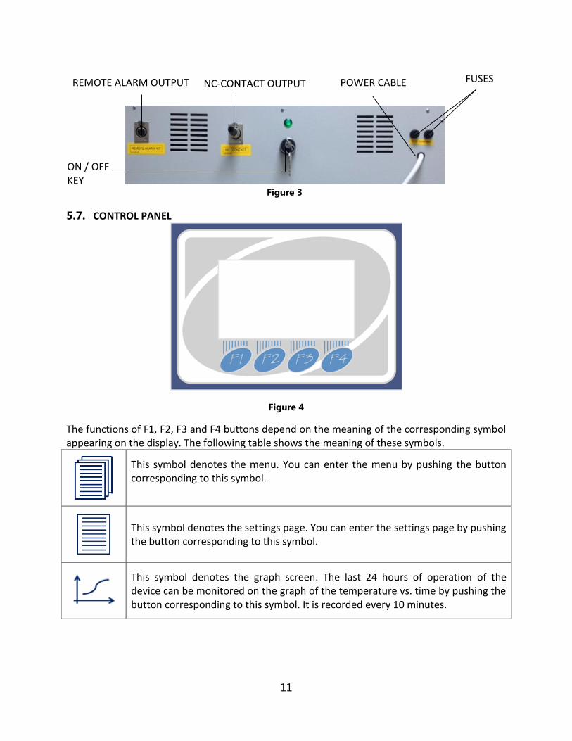
Figure 3
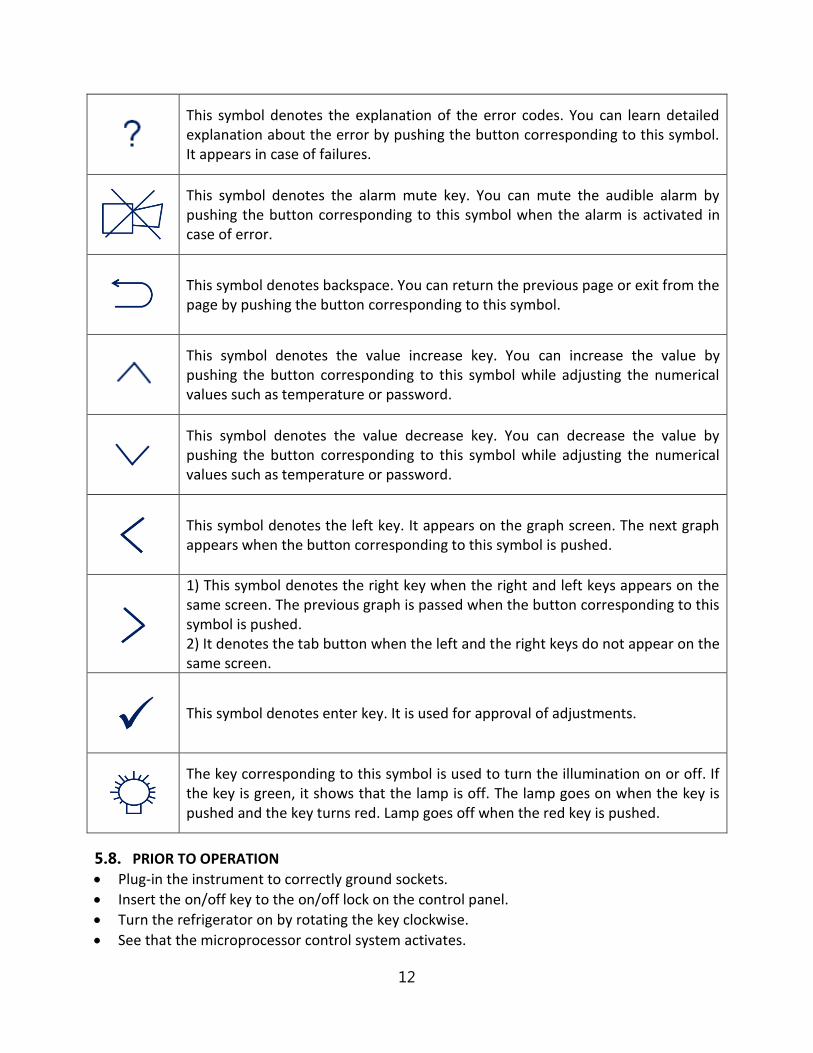
5.7. CONTROL PANEL
Figure 4
The functions of F1, F2, F3 and F4 buttons depend on the meaning of the corresponding symbol appearing on the display. The following table shows the meaning of these symbols.
This symbol denotes the menu. You can enter the menu by pushing the button corresponding to this symbol.
This symbol denotes the settings page. You can enter the settings page by pushing the button corresponding to this symbol.
This symbol denotes the graph screen. The last 24 hours of operation of the device can be monitored on the graph of the temperature vs. time by pushing the button corresponding to this symbol. It is recorded every 10 minutes.
FUSES POWER CABLE NC-CONTACT OUTPUT REMOTE ALARM OUTPUT
ON / OFF KEY
12
This symbol denotes the explanation of the error codes. You can learn detailed explanation about the error by pushing the button corresponding to this symbol. It appears in case of failures.
This symbol denotes the alarm mute key. You can mute the audible alarm by pushing the button corresponding to this symbol when the alarm is activated in case of error.
This symbol denotes backspace. You can return the previous page or exit from the page by pushing the button corresponding to this symbol.
This symbol denotes the value increase key. You can increase the value by pushing the button corresponding to this symbol while adjusting the numerical values such as temperature or password.
This symbol denotes the value decrease key. You can decrease the value by pushing the button corresponding to this symbol while adjusting the numerical values such as temperature or password.
This symbol denotes the left key. It appears on the graph screen. The next graph appears when the button corresponding to this symbol is pushed.
1) This symbol denotes the right key when the right and left keys appears on the same screen. The previous graph is passed when the button corresponding to this symbol is pushed. 2) It denotes the tab button when the left and the right keys do not appear on the same screen.
This symbol denotes enter key. It is used for approval of adjustments.
The key corresponding to this symbol is used to turn the illumination on or off. If the key is green, it shows that the lamp is off. The lamp goes on when the key is pushed and the key turns red. Lamp goes off when the red key is pushed.
5.8. PRIOR TO OPERATION
Plug-in the instrument to correctly ground sockets.
Insert the on/off key to the on/off lock on the control panel.
Turn the refrigerator on by rotating the key clockwise.
See that the microprocessor control system activates.

13
Learn the functions of the control panel (See Section 5.7).
The instrument starts to operate automatically at factory set temperature. You can change this value (See Section 6).
6. OPERATING PRINCIPLES
6.1. PROGRAMMING
For temperature homogeneity do not overload the drawers.
OPERATING MODE
When the refrigerator is powered on, it starts to operate automatically according to the last set values. The screen on the left is operating mode screen. Set temperature and chamber temperature values appear in this screen. Current
time and date are shown at the top line. “ ” symbol flashes on this screen while refrigerator performs cooling.
Password screen will appear when the MENU button (F1) is pushed. You can enter the password by using the value increase (F1) and decrease keys (F2). The password is user’s password and can be changed on settings page (See section 6.1.2.). The password is 0000 for the first usage.
Main menu page appears when the password is approved by pushing enter key (F4). Submenu can be selected by using the value increase and decrease keys. The selected menu becomes red and enter key (F4) is pushed to enter this menu.

14
SETTINGS
Settings page appears when “settings” submenu is selected from the menu page by the value increase (F1) and decrease (F2) keys. The required submenu is chosen by using the value increase and decrease keys.
“Date/Time Settings” submenu is selected on the settings page by the value increase (F1) and decrease (F2) keys. The page shown on the left appears when enter key (F4) is pushed. Time is shown in the format of “hour:minute” and the cursor is on hour part when “Date/Time Settings” page comes to the screen. Hour is adjusted by pushing the value increase (F1) and decrease (F2) keys. In order to continue to adjust, push enter key (F4).
If you want to exit this page without any change, push the backspace key (F3).
“Select Language” submenu is selected on the settings page by using the value increase (F1) and decrease (F2) keys. The page on the left appears when enter key (F4) is pushed. The language of the control panel can be set as Turkish, English, French, Russian or Spanish. Push the value increase (F1) and decrease (F2) keys to select the language and then push the enter key (F4) to save the selection. If you want to exit this page without any change, push the backspace key (F3).
“Screen Saver Settings” submenu is selected on the settings page by using the value increase (F1) and decrease (F2) keys. The page on the left appears when enter key (F4) is pushed. Screen saver can be on or off by pushing the value increase (F1) and decrease (F2). If the option of “open” is selected, activation time of screen saver is adjusted on screen saver time in minutes. If you want to exit this page without any change, push the backspace key (F3).
It is suggested to use Screen Saver as ON for energy saving.

15
“Change Password” submenu is selected on the settings page by the value increase (F1) and decrease (F2) keys. The page on the left appears when enter key (F4) is pushed. After old password value is entered by pushing the value increase and decrease keys, push the enter key. New password value can be entered in the “New Password” and “Retype New” sections. If you want to exit this page without any change, push the backspace key (F3).
MEMORY
“Memory” submenu is selected on the menu page by the value increase (F1) and decrease (F2) keys. The page on the left appears when enter key (F4) is pushed.
6.1.3.1. INTERNAL MEMORY
“Failure History” submenu is selected on the memory page by the value increase (F1) and decrease (F2) keys. The page on the left appears when enter key (F4) is pushed. The last 50 failures can be followed on this page. There are 10 pages in total for error history and 5 failures are listed on each page. Failures are listed from the current date to the earlier. Push the value increase (F1) and decrease (F2) keys to pass the other page.
Push the backspace key (F4) in order to exit the page.
“History (TABLE)” submenu is selected on the memory page by the value increase (F1) and decrease (F2) keys. The page on the left appears when enter key (F4) is pushed. Enter a date to analyze corresponding operation by pushing the value increase and decrease keys. Push the enter key (F4) to access the table.

16
Temperature values corresponding to the selected date are shown on three pages. Push the value increase (F1) and decrease (F2) keys to pass from one page to another. “–“appears in the temperature column if the refrigerator does not run on the selected date. Push the backspace key (F3) to return previous page.
When the temperature sensor is broken, “–“appears in the temperature column since temperature cannot be read by the sensor.
“History (GRAPH)” submenu is selected on the memory page by the value increase (F1) and decrease (F2) keys. “Select Record Date” page appears when enter key (F4) is pushed. Enter a date to analyze corresponding operation and then push the enter key (F4). You can analyze the data in the graph. The data belonging to the other dates can be followed by using left (F2) and right (F3) keys. Push the backspace key (F4) to return the previous page.
The page on the left appears when the settings key (F1) is pushed on the graph page. Temperature axis (y-axis) can be adjusted on this page. Working temperature determines the midpoint of the temperature axis. The working temperature value should be close to the set temperature value for more comfortable observation. Sensitivity value is the difference between two values on the y-axis. As sensitivity
value getting smaller, a more detailed graph appears.
6.1.3.2. EXTERNAL MEMORY (USB STICK) USB Stick is connected to USP port-1 of the communication unit (Figure 2). “ ” appears on the operating mode screen when the USB stick is identified by the microprocessor system.
If does not appear on the screen, USB stick may be defective or may not be connected correctly.
When “USB Stick” submenu is selected on the memory page, there are three options: “Copy History”, “Instant Record” and “Copy Failure History” Copy History: As USB stick is connected to the device, all data in the internal memory is transferred to USB stick when “Copy History” is selected. When loading bar shows 100%, push the enter key (F4) to exit the page.

17
Instant Record: As USB stick is connected to the refrigerator, the page on the right appears when “Instant Record” is selected. The period of the record time can be selected by using the value increase (F1) and decrease (F2) keys. As soon as the enter key (F4) is pushed, recording starts and the display returns the main page. If you want to exit this page without starting to record, push
the backspace key (F3). You can remove USB stick when you want to finish the record process. Copy Failure History: As USB stick is connected to the device, all error history in the internal memory is transferred to USB stick when “Copy Failure History” is selected. When loading is finished completely, push the enter key (F4) to exit from this page.
SMS
In order to use SMS, optional GSM module is mandatory to have. Refer to Section 10.1 for information regarding GSM module connection.
“SMS” submenu is selected on the menu page by the value increase (F1) and decrease (F2) keys. The page on the left appears when enter key (F4) is pushed. Submenus on SMS page is selected by using increase (F1) and decrease (F2) keys. Selected submenu can be adjusted by using enter key (F4). If you want to exit the page, push the backspace key (F3).
Activation or deactivation of SMS function can be adjusted on “SMS” submenu. If you want to activate this function, choose “on” by pushing the enter key (F4). If you want to deactivate SMS function, choose “Off” by pushing the enter key (F4).
“Repeat time” is the frequency of sending SMS. The user is notified again by sending SMS if the failure still continues. Repeat time can be adjusted to 8 hours, 16 hours and 24 hours by pushing enter key (F4).
“SMS Numbers” is selected on the SMS page by using the value increase (F1) and decrease (F2) keys. The page on the left appears when enter key (F4) is pushed. The phone numbers can be entered in this page and SMS notifications are delivered to these phone numbers in case of any failure.
SMS can be sent to 5 different mobile phones. According to demand, 1st, 2nd and 3rd numbers can be users’ numbers and 4th and 5th numbers can be technical service staffs’ numbers.
Enter country code before the phone numbers.

18
A cursor flashes under a digit which means you can set this digit of the number. Each digit of phone numbers is entered one by one. The first digit of the phone number is entered by pushing value increase (F1) and decrease keys (F2) and tab key (F3) is pushed to enter the second digit. The second number is entered pushing value increase (F1) and decrease keys (F2) and tab key (F3) is pushed to enter the next digit. After all digits of the phone number are entered completely by this way, push the enter key (F4) to enter the next phone number.
Tab key (F3) is used for changeover from one digit of phone number to another.
After all phone numbers from “Phone 1” to “Service 2” is entered as mentioned above, push the enter key (F4) and return to main page.
“E-Mail” submenu is selected on the menu page by the value increase (F1) and decrease (F2) keys. The page shown on the left appears when enter key (F4) is pushed. The choice of submenus on e-mail page is changed by pushing increase (F1) and decrease (F2) keys. After choosing a submenu, the adjustments for this submenu is made by pushing enter key (F4). If you want to exit this page, push the backspace key (F3).
Activation or deactivation of e-mail function can be adjusted from “E-mail” submenu. If you want to activate this function, choose “on” by pushing the enter key (F4). If you want to deactivate e-mail function, choose “off” by pushing the enter key (F4).
Ethernet settings should be adjusted by technical service staff for the first usage. Otherwise, this function does not work.
“E-Mails” is the page which e-mail addresses will be written on.
“Login” is the adjustments for the e-mail addresses.
“E-Mails” is selected on the e-mail page by the value increase (F1) and decrease (F2) keys. The page on the left appears when enter key (F4) is pushed. The e-mail addresses can be typed in this page and e-mail is sent to these addresses in case of any failure.
Each character of e-mail addresses is typed one by one. The first character is entered by pushing value increase (F1) and decrease keys (F2) and tab key (F3) is pushed to enter the second character. The second character is written by pushing value increase (F1) and

19
decrease keys (F2) and tab key (F3) is pushed to enter the next character. After all characters are written completely in this way, push the enter key (F4) to enter the mail server. After mail server is written in the same way, push the enter key (F4) to write next e-mail address. After third email address is written, push enter key (F4) to enter other e-mail addresses.
After all e-mail addresses are written as mentioned above, push enter key (F4) and return to main page.
Tab key (F3) is used for changeover from one character of address to another.
“Login” is selected on the e-mail page by the value increase (F1) and decrease (F2) keys. The page on the left appears when enter key (F4) is pushed. Each character of e-mail addresses is written one by one. The first character is entered by pushing value increase (F1) and decrease keys (F2) and tab key (F3) is pushed to enter the next character. The second character is entered by pushing value increase (F1) and decrease keys
(F2) and tab key (F3) is pushed to enter the next character. After all characters of user’s name are entered by this way, push enter key (F4) to enter the mail server of the e-mail address. After mail server is entered in the same way, push enter key (F4) to pass the “password” submenu. Enter the password and push enter key (F4). The port provided by internet server is entered on the part of “Port”. After port is entered, enter key (F4) is pushed to return the main menu. Tab key (F3) is used for changes from one character of address to another.
SET TEMPERATURE
When the setting key (F2) is pushed in the operation mode, password page appears. This password is the user’s password. The password is 0000 for the first usage. “Working Settings” page on the left appears. The set temperature can be adjusted between 0⁰C and 10⁰C by pushing the value increase (F1) and decrease (F2) keys. After set temperature value is entered, push the enter key (F4) to save the value. Push the backspace key (F3) to exit this page without any change.
In case of active audible alarm, firstly, push the alarm mute key (F2) to access the working settings page.
GRAPH WORKING SCREEN When the graph button (F3) is pushed in the operation mode, the graph page comes to the screen. Daily operation can be followed on this graph. If you want to analyze old operations, visit the memory page (See Section 6.1.3).

20
7. PERIODIC MAINTENANCE AND CLEANING
7.1. PERIODIC MAINTENANCE Clean the condenser surface with a vacuum cleaner every 3 months.
7.2. CLEANING
Clean the refrigerator at room temperature after disconnecting the power cable.
Remove the shelves from their shelf carriers.
Clean the refrigerator with a wet cloth to remove dirt and dust.
Liquid detergent can be used to remove tough dirt.
Take precautions handling chemical cleaners.
Check the external condition of the refrigerator regularly and ensure any rust spots that may develop are removed.
8. DISPOSAL MANAGEMENT CONCEPT
The currently valid local regulations governing disposal must be observed. It is in the responsibility of the user to arrange proper disposal of the individual components.
All parts which may comprise potentially infectious materials have to be disinfected by suitable validated procedures (autoclaving, chemical treatment) prior to disposal. Applicable local regulations for disposal have to be carefully observed.
The instruments and electronic accessories (without batteries, power packs etc.) must be disposed off according to the regulations for the disposal of electronic components. Batteries, power packs and similar power source have to be dismounted from electric/electronic parts and disposed off in accordance with applicable local regulations.
9. TROUBLESHOOTING
If the device fails to operate, please check the followings:
The power switch is on,
It is plugged in properly or connected properly to the electric supply,
The mains supply is present,
The plug is not defective,
The fuses are sound.
9.1. ERROR CODES Blue colored screen turns into red in case of any failure and a short explanation of the error appears at the bottom line on the red screen. Push the key corresponding to question mark (F3) for detailed explanation of failures.
Failures which may be encountered during operation is listed below:
21
EoFF: This error code shows power failure.
After power interruption, push the key corresponding to question mark (F3) in order to see the time when power interruption occurs.
Err1: It appears when temperature sensor is defective.
Err2: It appears when there is a communication error between display and main PCB.
Err5: It appears when door is kept open for a while.
Err6: It shows that the temperature in the chamber is not in the temperature alarm range.
Err7: It appears when software version is not compatible. Push the F3 key corresponding to the question mark to see the explanation. Inform the authorized NÜVE agent regarding the error explanation.
A list consisting of the codes of errors can be accessed from the memory page (See section 6.1.3.1). ‘EoFF’, ‘Err5’ and ‘Err6’ do not appear on working screen and they are only shown in the list of the error history.
Please contact with an authorized NÜVE agent to seek technical help if an error occurs.
9.2. FUSE REPLACEMENT The fuses shall be always be replaced by the authorized personnel.
10. OPTIONS
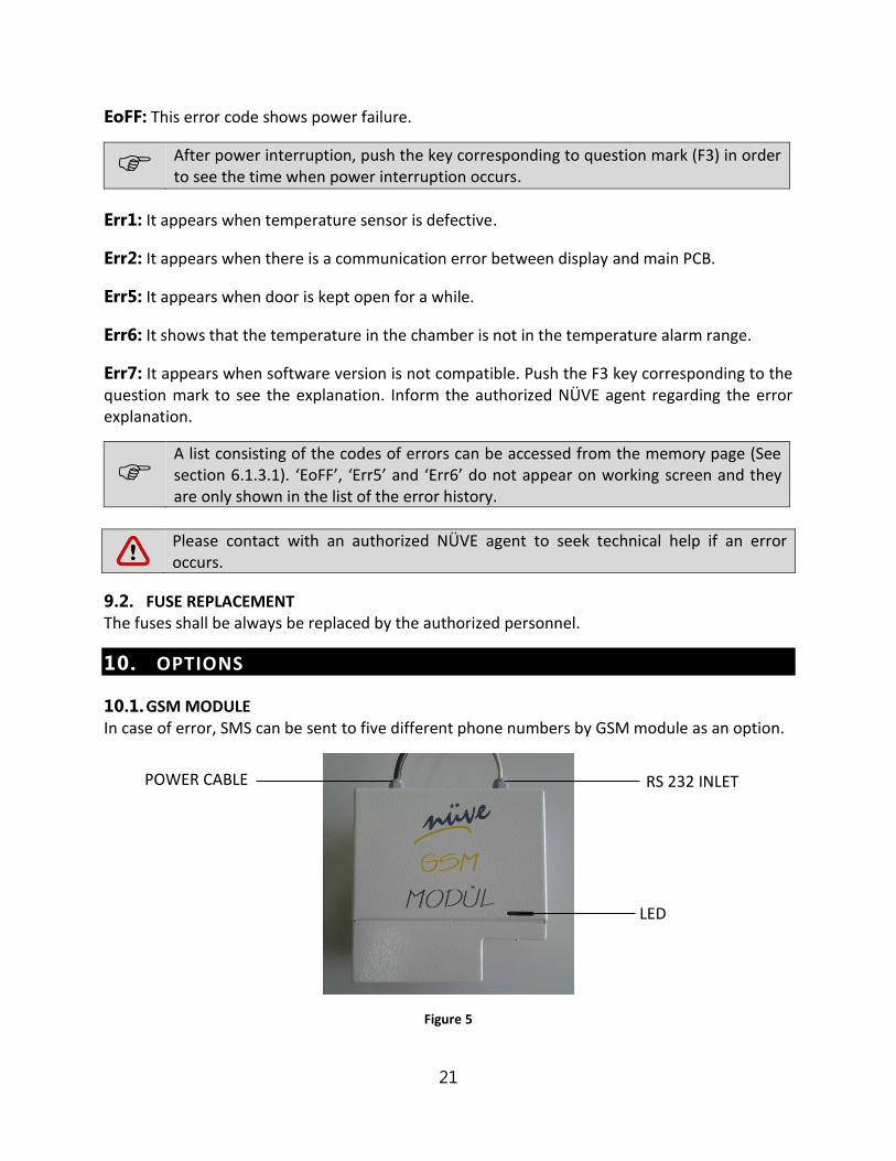
10.1. GSM MODULE In case of error, SMS can be sent to five different phone numbers by GSM module as an option.
Figure 5
RS 232 INLET
LED
POWER CABLE

22
Figure 6
Figure 7
Please carry out the following steps for connection of GSM module:
Insert SIM card in the GSM module (See Figure 7).
SIM card is provided by the user. The cost of SIM card and SMS differs according to the GSM providers and all charges will be covered by the user.
SIM card which will be used for GSM module should not have PIN code.
Plug-in the GSM module to correctly grounded sockets.
Connect the end of RS 232 cable of GSM module (See Figure 5) to RS 232 port on the refrigerator (See Figure 2).
Ensure that power led is turned on (See Figure 7). Power led is on when energy is supplied to the GSM module. SMS led starts to flash while the module sending SMS.
Connect the antenna cable to antenna inlet on the GSM module (See Figure 6).
Antenna has magnet to place it easily. Place the antenna on a place where the signal of GSM module is high.
If the GSM module is not connected or does not send messages although it is connected, “modem” error code appears in the error history. If the GSM module is connected and cannot send messages, “SMS” error code appears in the error history. Modem and SMS errors do not appear when SMS submenu on the SMS page is selected as “off”.
10.2. REMOTE ALARM MD series medical refrigerators have “remote alarm” feature. This feature can be used only if an optional “remote alarm kit” is connected to the device.
The remote alarm will be activated for all alarm situations as power failure, open door, broken
temperature sensor, 2°C deviation of chamber temperature from set value.
ANTENNA INLET
SIM CARD INLET POWER LED
SMS LED

23
MOUNTING REMOTE ALARM The remote alarm kit includes an alarm unit and 10 meters of cable with a connector. Connect one side of the cable to the connector at the rear of the refrigerator and the other side to the alarm unit.
Mount the remote alarm kit to a wall or board no more than 10 meters away from the refrigerator where it is easily accessible and observable.
Figure 8
10.3. CHART RECORDER The below mentioned are provided with the chart recorder, please check them;
100 ea. circular diagram paper for chart recorder
1 ea. pen for chart recorder
1 ea. battery
2 ea. circular recorder keys.
Chart recorder measures the temperature in the chamber and records this value by using a pen.
Chart recorder is assembled on the device. Open the lid of the circular recorder by using the
key.
Pull the battery unit and take it out. Put on the battery supplied with device to the hole at
the back of the unit paying attention to + and – poles. Please use always leak protected high
quality batteries.
Put the battery unit to its place.
Remove the circular recorder paper holding screw (1) by turning counterclockwise.
Put on one of the circular recorder papers supplied with the device, printed side facing
towards you (2).

24
Replace the circular recorder paper holding screw.
Adjust the paper according to the pen by considering day and hour lines.
Insert the writer tip (3), remove the cap on the pen.
Close the circular recorder lid.
Figure 9

25
11. ELECTRICAL CIRCUIT DIAGRAM
11.1. MD 72 AND MD 120 ELECTRICAL CIRCUIT DIAGRAM

26
11.2. MD 294 ELECRICAL CIRCUIT DIAGRAM

27
11.3. MD 504 ELECTRICAL CIRCUIT DIAGRAM


![Contabilitate manageriala.[conspecte md]](https://static.fdokumen.com/doc/165x107/634610f6df19c083b1085ad3/contabilitate-managerialaconspecte-md.jpg)

