
MCUez LINKER USER'S MANUAL
129
MCUEZLNK0508/D February 1998 MCUez LINKER USER'S MANUAL © Copyright 1998 MOTOROLA and HIWARE AG; All Rights Reserved Freescale Semiconductor, I Freescale Semiconductor, Inc. For More Information On This Product, Go to: www.freescale.com nc...
-
Upload
khangminh22 -
Category
Documents
-
view
0 -
download
0
Transcript of MCUez LINKER USER'S MANUAL

F
ree
sca
le S
em
ico
nd
uc
tor,
I
Freescale Semiconductor, Inc.n
c..
.
MCUEZLNK0508/D
February 1998
MCUezLINKER
USER'S MANUAL
© Copyright 1998 MOTOROLA and HIWARE AG; All Rights Reserved
For More Information On This Product,
Go to: www.freescale.com

in
F
ree
sca
le S
em
ico
nd
uc
tor,
I
Freescale Semiconductor, Inc.n
c..
.
Important Notice to Users
While every effort has been made to ensure the accuracy of all information in this document,Motorola assumes no liability to any party for any loss or damage caused by errors or omissionsor by statements of any kind in this document, its updates, supplements, or special editions,whether such errors are omissions or statements resulting from negligence, accident, or any othercause. Motorola further assumes no liability arising out of the application or use of anyinformation, product, or system described herein; nor any liability for incidental or consequentialdamages arising from the use of this document. Motorola disclaims all warranties regarding theinformation contained herein, whether expressed, implied, or statutory, including impliedwarranties of merchantability or fitness for a particular purpose. Motorola makes norepresentation that the interconnection of products in the manner described herein will notinfringe on existing or future patent rights, nor do the descriptions contained herein imply thegranting or license to make, use or sell equipment constructed in accordance with thisdescription.
Information contained in this document applies toREVision (0) MCUez.
The computer program contains material copyrighted by Motorola Inc., first published 1997, and maybe used only under a license such as the License For Computer Programs (Article 14) contained Motorola's Terms and Conditions of Sale, Rev. 1/79.
Trademarks
This document includes these trademarks:
MCUez is a trademark of Motorola Inc.EXORciser is a trademark of Motorola Inc.
The MCUez development, emulation, and debugging application is based on HI-WAVE; asoftware technology developed by HIWARE. HI-WAVE is a registered trademark of HIWAREAG.
AIX, IBM, and PowerPC are trademarks of International Business Machines Corporation.SPARC is a trademark of SPARC international, Inc.Sun and SunOS are trademarks of Sun Microsystems, Inc.UNIX is a trademark of Novell, Inc., in the United States and other countries, licensedexclusively through X/Open Company, Ltd.X Window System is a trademark of Massachusetts Institute of Technology.
For More Information On This Product,
Go to: www.freescale.com

CONTENTS
CONTENTS
. 1-1
. . 1
. 2-1
. . . 2-2
.
.
. 2-11. 2-11
. 2-13. . 2-. . 2-15. 2- 2-16 2-16 . 2-16
2-17 . 2-17. 2-17. 2-17
F
ree
sca
le S
em
ico
nd
uc
tor,
I
Freescale Semiconductor, Inc.n
c..
.
CHAPTER 1 GENERAL INFORMATION
1.1 INTRODUCTION . . . . . . . . . . . . . . . . . . . . . . . . . . . . . . . . . . . . . . . . . . . . . . . . . . . . . . . . . . 1-1
1.2 FUNCTIONAL DESCRIPTION . . . . . . . . . . . . . . . . . . . . . . . . . . . . . . . . . . . . . . . . . . . . . .
1.3 FEATURES . . . . . . . . . . . . . . . . . . . . . . . . . . . . . . . . . . . . . . . . . . . . . . . . . . . . . . . . . . . . . . . . 1-1
1.4 SUPPORT INFORMATION . . . . . . . . . . . . . . . . . . . . . . . . . . . . . . . . . . . . . . . . . . . . . . . . -2
CHAPTER 2 USER INTERFACE
2.1 INTRODUCTION . . . . . . . . . . . . . . . . . . . . . . . . . . . . . . . . . . . . . . . . . . . . . . . . . . . . . . . . . . 2-1
2.2 INTERACTIVE USER INTERFACE . . . . . . . . . . . . . . . . . . . . . . . . . . . . . . . . . . . . . . . . . .
2.2.1 Starting the MCUez Linker . . . . . . . . . . . . . . . . . . . . . . . . . . . . . . . . . . . . . . . . . . . . . .. 2-12.2.2 Starting from WinEdit or Codewright . . . . . . . . . . . . . . . . . . . . . . . . . . . . . . . . . . . . . . 2.2.3 Linker Graphical Interface . . . . . . . . . . . . . . . . . . . . . . . . . . . . . . . . . . . . . . . . . . . . . .. . 2-2
2.2.3.1 Window Title . . . . . . . . . . . . . . . . . . . . . . . . . . . . . . . . . . . . . . . . . . . . . . . . . . . . . . . 2-32.2.3.2 Content Area . . . . . . . . . . . . . . . . . . . . . . . . . . . . . . . . . . . . . . . . . . . . . . . . . . . . . . 2-32.2.3.3 Tool Bar . . . . . . . . . . . . . . . . . . . . . . . . . . . . . . . . . . . . . . . . . . . . . . . . . . . . . . . . . . . 2-42.2.3.4 Status Bar . . . . . . . . . . . . . . . . . . . . . . . . . . . . . . . . . . . . . . . . . . . . . . . . . . . . . . . . . 2-52.2.3.5 Linker Menu Bar . . . . . . . . . . . . . . . . . . . . . . . . . . . . . . . . . . . . . . . . . . . . . . . . . .. 2-62.2.3.6 File Menu . . . . . . . . . . . . . . . . . . . . . . . . . . . . . . . . . . . . . . . . . . . . . . . . . . . . . . . . . 2-6
2.2.3.6.1 Important remarks . . . . . . . . . . . . . . . . . . . . . . . . . . . . . . . . . . . . . . . . . . . . .2.2.3.6.2 Save Configuration Dialog . . . . . . . . . . . . . . . . . . . . . . . . . . . . . . . . . . . . . . .
2.2.3.7 Linker Menu . . . . . . . . . . . . . . . . . . . . . . . . . . . . . . . . . . . . . . . . . . . . . . . . . . . . . . 2-122.2.3.8 View Menu . . . . . . . . . . . . . . . . . . . . . . . . . . . . . . . . . . . . . . . . . . . . . . . . . . . . . . . 2-132.2.3.9 Advanced Options Dialog Box . . . . . . . . . . . . . . . . . . . . . . . . . . . . . . . . . . . . . . .
2.2.4 Message Settings Dialog Box . . . . . . . . . . . . . . . . . . . . . . . . . . . . . . . . . . . . . . . . . . . 142.2.4.1 Changing the Class Associated With a Message . . . . . . . . . . . . . . . . . . . . . . . . . 2.2.4.2 Specifying the Input File . . . . . . . . . . . . . . . . . . . . . . . . . . . . . . . . . . . . . . . . . . . . 16
2.2.4.2.1 Using the Editable Combo Box in the Tool Bar. . . . . . . . . . . . . . . . . . . . . . . .2.2.4.2.2 Using the Entry File | Link ... . . . . . . . . . . . . . . . . . . . . . . . . . . . . . . . . . . . . . .2.2.4.2.3 Using Drag and Drop . . . . . . . . . . . . . . . . . . . . . . . . . . . . . . . . . . . . . . . . . . .
2.2.5 Error Feedback . . . . . . . . . . . . . . . . . . . . . . . . . . . . . . . . . . . . . . . . . . . . . . . . . . . . . . . . 2-162.2.5.1 Error Feedback Using Information From the Linker Window . . . . . . . . . . . . . . . .2.2.5.2 Error Feedback Using a User-Defined Editor . . . . . . . . . . . . . . . . . . . . . . . . . . . .
2.2.5.2.1 Line Number Can be Specified on the Command Line . . . . . . . . . . . . . . . . . 2.2.5.2.2 Line Number Cannot be Specified on the Command Line . . . . . . . . . . . . . .
MCUEZLNK0508/D iii For More Information On This Product,
Go to: www.freescale.com

CONTENTS
. .
.
. 4-
. 4-1
. . 5-5
F
ree
sca
le S
em
ico
nd
uc
tor,
I
Freescale Semiconductor, Inc.n
c..
.
CHAPTER 3 ENVIRONMENT VARIABLES
3.1 INTRODUCTION . . . . . . . . . . . . . . . . . . . . . . . . . . . . . . . . . . . . . . . . . . . . . . . . . . . . . . . . . . 3-1
3.2 SETTING PARAMETERS . . . . . . . . . . . . . . . . . . . . . . . . . . . . . . . . . . . . . . . . . . . . . . . . . 3-1
3.3 PATH VARIABLES . . . . . . . . . . . . . . . . . . . . . . . . . . . . . . . . . . . . . . . . . . . . . . . . . . . . . . . . . 3-2
3.3.1 LINKOPTIONS . . . . . . . . . . . . . . . . . . . . . . . . . . . . . . . . . . . . . . . . . . . . . . . . . . . . . . . . 3-23.3.2 GENPATH . . . . . . . . . . . . . . . . . . . . . . . . . . . . . . . . . . . . . . . . . . . . . . . . . . . . . . . . . . . . . 3-33.3.3 OBJPATH . . . . . . . . . . . . . . . . . . . . . . . . . . . . . . . . . . . . . . . . . . . . . . . . . . . . . . . . . . . . . 3-33.3.4 ABSPATH . . . . . . . . . . . . . . . . . . . . . . . . . . . . . . . . . . . . . . . . . . . . . . . . . . . . . . . . . . . . . 3-33.3.5 TEXTPATH . . . . . . . . . . . . . . . . . . . . . . . . . . . . . . . . . . . . . . . . . . . . . . . . . . . . . . . . . . . . 3-43.3.6 SRECORD . . . . . . . . . . . . . . . . . . . . . . . . . . . . . . . . . . . . . . . . . . . . . . . . . . . . . . . . . . . . 3-53.3.7 ERRORFILE . . . . . . . . . . . . . . . . . . . . . . . . . . . . . . . . . . . . . . . . . . . . . . . . . . . . . . . . . . . 3-5
CHAPTER 4 FILES
4.1 INTRODUCTION . . . . . . . . . . . . . . . . . . . . . . . . . . . . . . . . . . . . . . . . . . . . . . . . . . . . . . . . . . 4-1
4.2 PARAMETER FILE: INPUT . . . . . . . . . . . . . . . . . . . . . . . . . . . . . . . . . . . . . . . . . . . . . . . . .4-1
4.3 ABSOLUTE FILES: OUTPUT . . . . . . . . . . . . . . . . . . . . . . . . . . . . . . . . . . . . . . . . . . . . . . .1
4.4 MOTOROLA S FILES: OUTPUT . . . . . . . . . . . . . . . . . . . . . . . . . . . . . . . . . . . . . . . . . . . . .
4.5 MAP FILES . . . . . . . . . . . . . . . . . . . . . . . . . . . . . . . . . . . . . . . . . . . . . . . . . . . . . . . . . . . . . . . 4-2
CHAPTER 5 LINKER OPTIONS AND ISSUES
5.1 INTRODUCTION . . . . . . . . . . . . . . . . . . . . . . . . . . . . . . . . . . . . . . . . . . . . . . . . . . . . . . . . . . 5-1
5.2 -E LINKER OPTION . . . . . . . . . . . . . . . . . . . . . . . . . . . . . . . . . . . . . . . . . . . . . . . . . . . . . . . . 5-2
5.3 -O LINKER OPTION . . . . . . . . . . . . . . . . . . . . . . . . . . . . . . . . . . . . . . . . . . . . . . . . . . . . . . . . 5-2
5.4 -M LINKER OPTION . . . . . . . . . . . . . . . . . . . . . . . . . . . . . . . . . . . . . . . . . . . . . . . . . . . . . . . 5-3
5.5 -S LINKER OPTION . . . . . . . . . . . . . . . . . . . . . . . . . . . . . . . . . . . . . . . . . . . . . . . . . . . . . . . . 5-3
5.6 -V LINKER OPTION . . . . . . . . . . . . . . . . . . . . . . . . . . . . . . . . . . . . . . . . . . . . . . . . . . . . . . . . 5-4
5.7 -W1 LINKER OPTION . . . . . . . . . . . . . . . . . . . . . . . . . . . . . . . . . . . . . . . . . . . . . . . . . . . . . . 5-4
5.8 -W2 LINKER OPTION . . . . . . . . . . . . . . . . . . . . . . . . . . . . . . . . . . . . . . . . . . . . . . . . . . . . . . 5-4
5.9 LINKING ISSUES . . . . . . . . . . . . . . . . . . . . . . . . . . . . . . . . . . . . . . . . . . . . . . . . . . . . . . . . . . 5-5
5.9.1 Object Allocation . . . . . . . . . . . . . . . . . . . . . . . . . . . . . . . . . . . . . . . . . . . . . . . . . . . . . . . 5-55.9.1.1 The SEGMENTS Block . . . . . . . . . . . . . . . . . . . . . . . . . . . . . . . . . . . . . . . . . . . .
iv MCUEZLNK0508/D For More Information On This Product,
Go to: www.freescale.com

. . 5-6 . . 5-7 . . 5-9 . 5-9. 5-10 . 5-10 . 5-11
6-1
. .. 6-1
. . 6-3
. . 6-6
. . 6-8
. 6-8 . 6-8
-9
. 6-10
.
. . 6- . 6-15
6-16 6-17 6-18
6-196-21 . 6-22. 6-23
F
ree
sca
le S
em
ico
nd
uc
tor,
I
Freescale Semiconductor, Inc.n
c..
.
5.9.1.1.1 Segment Qualifier . . . . . . . . . . . . . . . . . . . . . . . . . . . . . . . . . . . . . . . . . . . . .5.9.1.1.2 Segment Alignment . . . . . . . . . . . . . . . . . . . . . . . . . . . . . . . . . . . . . . . . . . . .5.9.1.1.3 Segment Fill Pattern . . . . . . . . . . . . . . . . . . . . . . . . . . . . . . . . . . . . . . . . . . . .
5.9.1.2 PLACEMENT Block . . . . . . . . . . . . . . . . . . . . . . . . . . . . . . . . . . . . . . . . . . . . . . .5.9.1.2.1 Specifying a List of Sections . . . . . . . . . . . . . . . . . . . . . . . . . . . . . . . . . . . . . 5.9.1.2.2 Specifying a List of Segments . . . . . . . . . . . . . . . . . . . . . . . . . . . . . . . . . . . .
5.9.2 Allocating User-Defined Sections . . . . . . . . . . . . . . . . . . . . . . . . . . . . . . . . . . . . . . . .
CHAPTER 6 OPERATING PROCEDURES
6.1 INTRODUCTION . . . . . . . . . . . . . . . . . . . . . . . . . . . . . . . . . . . . . . . . . . . . . . . . . . . . . . . . . . 6-1
6.2 INITIALIZING THE VECTOR TABLE . . . . . . . . . . . . . . . . . . . . . . . . . . . . . . . . . . . . . . . . .
6.2.1 VECTOR Command . . . . . . . . . . . . . . . . . . . . . . . . . . . . . . . . . . . . . . . . . . . . . . . . . . . 6-16.2.1.1 Initializing the Vector Table in the Linker PRM File . . . . . . . . . . . . . . . . . . . . . . . 6.2.1.2 Initializing the Vector Table in the Assembly Source File
Using a Relocatable Section . . . . . . . . . . . . . . . . . . . . . . . . . . . . . . . . . . . . . . . . .6.2.1.3 Initializing the Vector Table in the Assembly Source File Using
an Absolute Section . . . . . . . . . . . . . . . . . . . . . . . . . . . . . . . . . . . . . . . . . . . . . . . .
6.3 SMART LINKING . . . . . . . . . . . . . . . . . . . . . . . . . . . . . . . . . . . . . . . . . . . . . . . . . . . . . . . . . . 6-8
6.3.1 Mandatory Linking From an Object . . . . . . . . . . . . . . . . . . . . . . . . . . . . . . . . . . . . . . 6.3.2 Mandatory Linking From All Objects Defined in a File . . . . . . . . . . . . . . . . . . . . . . . . 6.3.3 Switching OFF Smart Linking for the Application . . . . . . . . . . . . . . . . . . . . . . . . . . . .
6.4 BINARY FILES BUILDING AN APPLICATION . . . . . . . . . . . . . . . . . . . . . . . . . . . . . . . . . 6
6.4.1 NAMES Block . . . . . . . . . . . . . . . . . . . . . . . . . . . . . . . . . . . . . . . . . . . . . . . . . . . . . . . . . 6-96.4.2 ENTRIES Block . . . . . . . . . . . . . . . . . . . . . . . . . . . . . . . . . . . . . . . . . . . . . . . . . . . . . . . . 6-96.4.3 Linking an Assembly Application . . . . . . . . . . . . . . . . . . . . . . . . . . . . . . . . . . . . . . . . 6.4.4 Warning Messages . . . . . . . . . . . . . . . . . . . . . . . . . . . . . . . . . . . . . . . . . . . . . . . . . . .. . 6-11
6.5 THE PARAMETER FILE . . . . . . . . . . . . . . . . . . . . . . . . . . . . . . . . . . . . . . . . . . . . . . . . . . 6-13
6.5.1 The Syntax of the Parameter File . . . . . . . . . . . . . . . . . . . . . . . . . . . . . . . . . . . . . . . . 136.5.2 Mandatory Parameter File Linker Commands . . . . . . . . . . . . . . . . . . . . . . . . . . . . . . .
6.6 LINKER COMMANDS . . . . . . . . . . . . . . . . . . . . . . . . . . . . . . . . . . . . . . . . . . . . . . . . . . . . .6-16
6.6.1 ENTRIES: List of Objects to Link With the Application . . . . . . . . . . . . . . . . . . . . . . . . 6.6.2 INIT: Specify the Application Entry Point . . . . . . . . . . . . . . . . . . . . . . . . . . . . . . . . . . .6.6.3 LINK - Specify Name of the Output File . . . . . . . . . . . . . . . . . . . . . . . . . . . . . . . . . . . .6.6.4 MAIN . . . . . . . . . . . . . . . . . . . . . . . . . . . . . . . . . . . . . . . . . . . . . . . . . . . . . . . . . . . . . . . 6-196.6.5 MAPFILE: Configure the MAP File Content . . . . . . . . . . . . . . . . . . . . . . . . . . . . . . . . .6.6.6 NAMES: List the Files building the Application. . . . . . . . . . . . . . . . . . . . . . . . . . . . . . 6.6.7 PLACEMENT: Place Sections Into Segments . . . . . . . . . . . . . . . . . . . . . . . . . . . . . . .6.6.8 SEGMENTS: Define Memory Map . . . . . . . . . . . . . . . . . . . . . . . . . . . . . . . . . . . . . . .
MCUEZLNK0508/D v For More Information On This Product,
Go to: www.freescale.com

CONTENTS
. 6-25. . 6-27 6-28. 6-29
. . 6-
.
. . 6
. . 6-
. . 7-1
F
ree
sca
le S
em
ico
nd
uc
tor,
I
Freescale Semiconductor, Inc.n
c..
.
6.6.8.1 Defining an Alignment Rule . . . . . . . . . . . . . . . . . . . . . . . . . . . . . . . . . . . . . . . . 6.6.8.2 Defining a Fill Pattern . . . . . . . . . . . . . . . . . . . . . . . . . . . . . . . . . . . . . . . . . . . . . . 6-26
6.6.9 STACKSIZE: Define Stack Size . . . . . . . . . . . . . . . . . . . . . . . . . . . . . . . . . . . . . . . . . .6.6.10 STACKTOP: Define Stack Pointer Initial Value . . . . . . . . . . . . . . . . . . . . . . . . . . . . .6.6.11 VECTOR: Initialize Vector Table . . . . . . . . . . . . . . . . . . . . . . . . . . . . . . . . . . . . . . . .
6.7 SECTIONS . . . . . . . . . . . . . . . . . . . . . . . . . . . . . . . . . . . . . . . . . . . . . . . . . . . . . . . . . . . . . . . 6-30
6.7.1 Terms: Segments and Sections . . . . . . . . . . . . . . . . . . . . . . . . . . . . . . . . . . . . . . . . . .316.7.2 Definition of Section . . . . . . . . . . . . . . . . . . . . . . . . . . . . . . . . . . . . . . . . . . . . . . . . . . . . 6-316.7.3 Predefined Sections . . . . . . . . . . . . . . . . . . . . . . . . . . . . . . . . . . . . . . . . . . . . . . . . . . . . . 6-31
6.8 EXAMPLES . . . . . . . . . . . . . . . . . . . . . . . . . . . . . . . . . . . . . . . . . . . . . . . . . . . . . . . . . . . . . . 6-33
6.9 PROGRAM STARTUP . . . . . . . . . . . . . . . . . . . . . . . . . . . . . . . . . . . . . . . . . . . . . . . . . . . . 6-34
6.9.1 The Startup Descriptor . . . . . . . . . . . . . . . . . . . . . . . . . . . . . . . . . . . . . . . . . . . . . . . . . . 6-346.9.2 User-Defined Startup Structure: . . . . . . . . . . . . . . . . . . . . . . . . . . . . . . . . . . . . . . . . . -366.9.3 User-Defined Startup Routines . . . . . . . . . . . . . . . . . . . . . . . . . . . . . . . . . . . . . . . . . . 37
6.10 THE MAP FILE . . . . . . . . . . . . . . . . . . . . . . . . . . . . . . . . . . . . . . . . . . . . . . . . . . . . . . . . . . 6-38
CHAPTER 7 LINKER MESSAGES
7.1 INTRODUCTION . . . . . . . . . . . . . . . . . . . . . . . . . . . . . . . . . . . . . . . . . . . . . . . . . . . . . . . . . . 7-1
7.2 LINKER MESSAGES REFERENCE . . . . . . . . . . . . . . . . . . . . . . . . . . . . . . . . . . . . . . . . .
vi MCUEZLNK0508/D For More Information On This Product,
Go to: www.freescale.com

MCUEZLNK0508/D vii
CONTENTS
FIGURES
Figure 2-1. MCUez Linker Tip of The Day Window . . . . . . . . . . . . . . . . . . . . . . . . . . . . . . . . . . . . 2-1Figure 2-2. MCUez Linker Graphical User Interface. . . . . . . . . . . . . . . . . . . . . . . . . . . . . . . . . . . . 2-2Figure 2-3. MCUez Linker Tool Bar . . . . . . . . . . . . . . . . . . . . . . . . . . . . . . . . . . . . . . . . . . . . . . . . 2-4Figure 2-4. MCUez Linker Status Bar . . . . . . . . . . . . . . . . . . . . . . . . . . . . . . . . . . . . . . . . . . . . . . . 2-5Figure 2-5. Configuration Dialog - Global Editor . . . . . . . . . . . . . . . . . . . . . . . . . . . . . . . . . . . . . . 2-7Figure 2-6. Configuration Dialog - Local Editor . . . . . . . . . . . . . . . . . . . . . . . . . . . . . . . . . . . . . . . 2-8Figure 2-7. Configuration Dialog - Editor Started With Command Line. . . . . . . . . . . . . . . . . . . . . 2-9Figure 2-8. Configuration Dialog - Editor Started With DDE . . . . . . . . . . . . . . . . . . . . . . . . . . . . 2-10Figure 2-9. Save Configuration Dialog Window . . . . . . . . . . . . . . . . . . . . . . . . . . . . . . . . . . . . . . 2-11Figure 2-10. Advanced Options Dialog Window . . . . . . . . . . . . . . . . . . . . . . . . . . . . . . . . . . . . . . 2-13Figure 2-11. Message Settings Dialog Window . . . . . . . . . . . . . . . . . . . . . . . . . . . . . . . . . . . . . . . 2-14Figure 4-1. Link Process Conceptual Diagram. . . . . . . . . . . . . . . . . . . . . . . . . . . . . . . . . . . . . . . . . 4-2
Fre
esc
ale
Se
mic
on
du
cto
r, I
Freescale Semiconductor, Inc.
For More Information On This Product, Go to: www.freescale.com
nc
...

CONTENTS
. .. . 5-1. . . . . 5-. . . 6- . 6
. 6. .
F
ree
sca
le S
em
ico
nd
uc
tor,
I
Freescale Semiconductor, Inc.n
c..
.
TABLES
Table 2-1. Message Group Definitions . . . . . . . . . . . . . . . . . . . . . . . . . . . . . . . . . . . . . . . . . . . 2-15Table 5-1. MCUez Linker Options Descriptions . . . . . . . . . . . . . . . . . . . . . . . . . . . . . . . . . . . . . Table 5-2. Segment Qualifier Descriptions . . . . . . . . . . . . . . . . . . . . . . . . . . . . . . . . . . . . . . . . . 5-7Table 5-3. Segment Alignment Rule Format . . . . . . . . . . . . . . . . . . . . . . . . . . . . . . . . . . . . . . . 8Table 6-1. VECTOR Command Syntax . . . . . . . . . . . . . . . . . . . . . . . . . . . . . . . . . . . . . . . . . . . 1Table 6-2. ENTRIES Block Supported . . . . . . . . . . . . . . . . . . . . . . . . . . . . . . . . . . . . . . . . . . . .-16Table 6-3. MAP File Specifiers . . . . . . . . . . . . . . . . . . . . . . . . . . . . . . . . . . . . . . . . . . . . . . . . . . . 6-20Table 6-4. Segment Alignment Items List . . . . . . . . . . . . . . . . . . . . . . . . . . . . . . . . . . . . . . . . . .-25Table 6-5. Setting Startup Descriptor Flags . . . . . . . . . . . . . . . . . . . . . . . . . . . . . . . . . . . . . . . . 6-35Table 6-6. MAP File Sections . . . . . . . . . . . . . . . . . . . . . . . . . . . . . . . . . . . . . . . . . . . . . . . . . . . . 6-38
MCUEZLNK0508/D viii For More Information On This Product,
Go to: www.freescale.com

CONTENTS
F
ree
sca
le S
em
ico
nd
uc
tor,
I
Freescale Semiconductor, Inc.n
c..
.
ix MCUEZLNK0508/D For More Information On This Product,
Go to: www.freescale.com

GENERAL INFORMATION
of an
nt onto
data,ts into
tion.ram.
Also, once
rent e
t the
ine
artup
F
ree
sca
le S
em
ico
nd
uc
tor,
I
Freescale Semiconductor, Inc.n
c..
.
CHAPTER 1
GENERAL INFORMATION
1.1 INTRODUCTION
This manual describes the MCUez Linker. The Linker merges the various object files application into one file; an “absolute file” (.ABS file for short). The file is termed an“absolute file” because it contains absolute code (not relocatable code) that can be buran EPROM or loaded into the target using the MCUez Debugger.
1.2 FUNCTIONAL DESCRIPTION
Linking is the process of assigning memory to all global objects (functions, global strings and initialization data) needed for a given application and combining these objeca format suitable for downloading into a target system or an emulator.
The Linker is a smart linker. It only links those objects actually used by the applicaVarious optimization capablities ensure low memory requirements for the linked progUnused functions and variables will not occupy memory in the target system. initialization of global variables is stored in compact form and memory is reserved onlyfor equivalent strings.
1.3 FEATURES
The most important features supported by the Linker are:
• Complete control over placement of objects in memory: It is possible to allocate diffegroups of functions or variables to different memory areas (Segmentation, please sesection on Sections).
• Initialization of vectors.
When linking High level Language modules (C, C++, ...), the linker should supporfollowing features:
• User defined startup: The application startup script is in a separate file written in “inlassembly” and can be easily modified. The startup file is named startup.c /startup.o . This is a generic file name that has to be replaced by the real target stfile name given in the \LIB\COMPILER directory; as mentioned in the README.TXT file. Usually the file name is start*.c / start*.o , where * is the name or part of theMCU name and might also contain an abbreviation of the memory model.
MCUEZLNK0508/D 1-1 For More Information On This Product,
Go to: www.freescale.com
GENERAL INFORMATION
F
ree
sca
le S
em
ico
nd
uc
tor,
I
Freescale Semiconductor, Inc.n
c..
.
• Mixed language linking: Modula-2, Assembly, and C object files can be mixed in thesame application.
1.4 SUPPORT INFORMATION
For information about a Motorola sales or distribution office near you call:
AUSTRALIA, Melbourne – (61-3)887-0711 Sydney – 61(2)906-3855
BRAZIL, Sao Paulo – 55(11)815-4200
CANADA, B. C., Vancouver – (604)606-8502 ONTARIO, Toronto – (416)497-8181 ONTARIO, Ottawa – (613)226-3491 QUEBEC, Montreal – (514)333-3300
CHINA, Beijing – 86-10-68437222
DENMARK – (45)43488393
FINLAND, Helsinki – 358-9-6824-400
FRANCE, Paris – 33134 635900
GERMANY,Langenhagen/Hannover – 49(511)786880Munich – 49 89 92103-0Nuremberg – 49 911 96-3190Sindelfingen – 49 7031 79 710Wiesbaden – 49 611 973050
HONG KONG, Kwai Fong – 852-6106888Tai Po – 852-6668333
INDIA, Bangalore – (91-80)5598615
ISRAEL, Herzlia – 972-9-590222
ITALY, Milan – 39(2)82201
JAPAN, Fukuoka – 81-92-725-7583Gotanda – 81-3-5487-8311Nagoya – 81-52-232-3500Osaka – 81-6-305-1802Sendai – 81-22-268-4333Takamatsu – 81-878-37-9972Tokyo – 81-3-3440-3311
KOREA, Pusan – 82(51)4635-035 Seoul – 82(2)554-5118
MALAYSIA, Penang – 60(4)2282514
MEXICO, Mexico City – 52(5)282-0230 Guadalajara – 52(36)21-8977
PUERTO RICO, San Juan – (809)282-2300
SINGAPORE – (65)4818188
SPAIN, Madrid – 34(1)457-8204
SWEDEN, Solna – 46(8)734-8800
SWITZERLAND, Geneva – 41(22)799 11 11 Zurich – 41(1)730-4074
TAIWAN, Taipei – 886(2)717-7089
THAILAND, Bangkok – 66(2)254-4910
UNITED KINGDOM, Aylesbury – 441(296)395-252
UNITED STATES, Phoenix, AZ – 1-800-441-2447
For a list of the Motorola sales offices and distributors:http://www.mcu.motsps.com/sale_off.html
1-2 MCUEZLNK0508/D For More Information On This Product,
Go to: www.freescale.com

USER INTERFACE
e
F
ree
sca
le S
em
ico
nd
uc
tor,
I
Freescale Semiconductor, Inc.n
c..
.
CHAPTER 2
USER INTERFACE
2.1 INTRODUCTION
This chapter describes:
• The MCUez Linker User Interface
• How to start the Linker
• Environment variables
2.2 Interactive User Interface
Click the Linker icon on the shell tool bar to run the linker.
2.2.1 Starting the MCUez Linker
When the linker is started, a standard Tip of the Day window containing features about thlinker is displayed.
Figure 2-1. MCUez Linker Tip of The Day Window
MCUEZLNK0508/D 2-1 For More Information On This Product,
Go to: www.freescale.com

USER INTERFACE
,
w.
faultluesindow
ing
F
ree
sca
le S
em
ico
nd
uc
tor,
I
Freescale Semiconductor, Inc.n
c..
.
Click Next Tip to view more information about the linker. Click Close to close the Tip of theDay dialog. If you do not want to view the Tip of the Day window when the linker is starteduncheck Show Tips on StartUp.
To re-enable the automatic display, choose Help|Tip of the Day .... The Tip of the Day dialogwill display and you can check Show Tips on StartUp.
2.2.2 Linker Graphical Interface
Starting the MCUez Linker without specifying a filename will display the following windo
Figure 2-2. MCUez Linker Graphical User Interface
The Linker Window provides a Menu Bar, Tool Bar, Content Area, and Status Bar.
2.2.2.1 Window Title
The window title displays the linker name and project name. If no project is loaded, “DeConfiguration” is displayed. A “*” after the configuration name indicates that some vahave been changed. Changes in options, editor configuration, and appearance (Wposition, size, font, ...) will cause the “*” to appear.
2.2.2.2 Content Area
The Content Area displays logging information about the link session. This logginformation consists of:
• The name of the PRM file being linked.
Menu Bar
Tool Bar
Content Area
Status Bar
2-2 MCUEZLNK0508/D For More Information On This Product,
Go to: www.freescale.com

USER INTERFACE
file ise file
a filen thealose. If aSettings
hough
entry in
message
ave a
s onlyunder
y
F
ree
sca
le S
em
ico
nd
uc
tor,
I
Freescale Semiconductor, Inc.n
c..
.
• The name (including full path) of the files building the application.
• Thle list of errors, warnings, and information messages.
When a file name is dropped into the Linker window content area, the corresponding either loaded as configuration data or linked. It is loaded as configuration data if thextension is “ini”. If not, the file is linked with the current option settings (See Specifying theInput File below).
The Linker window content area can have context information consisting of two items:
• a file name including a position inside of a file
• a message number
File context information is available for all output lines where a file name is displayed. If context is available for a line, double-clicking on this line opens the appropriate file ieditor specified in your MCUez configuration. Double-clicking the right mouse button opens a context menu. The menu contains an “Open ..” entry if a file context is availablfile can not be opened although a context menu entry is present, see the section Editor Dialog.
Note that under Win32s the context menu is not available. If a file can not be opened alta context menu entry is present, see the section on “Editor Settings” below.
The message number is available for any message output. To open the corresponding the help file, do one of the following.
• Select one line of the message and press F1. If the selected line does not have a number, the main help is displayed.
• Press Shift-F1 and then click on the message text. If the clicked point does not hmessage number, the main help is displayed.
• Click the right mouse button at the message text and select “Help on ...”. This entry iavailable if a message number is available. The context menu is not available Win32s.
Once a link session has completed, an Error Feedback can be performed automatically bdouble clicking on the message in the content area. To allow Error Feedback, the desirededitor must be configured (See Error Feedback below).
MCUEZLNK0508/D 2-3 For More Information On This Product,
Go to: www.freescale.com

USER INTERFACE
mand
F
ree
sca
le S
em
ico
nd
uc
tor,
I
Freescale Semiconductor, Inc.n
c..
.
2.2.2.3 Tool Bar
The following illustrates the MCUez Linker Tool Bar.
Figure 2-3. MCUez Linker Tool Bar
• The New, Load and Save buttons are linked to the corresponding entries of the File menu.
• The ? and Context Help buttons are linked to the corresponding entries of the Help menu.
• The editable combo box contains a list of the last commands executed. Once a comline has been selected or entered in this combo box, click Link to execute this command.
• The Open Advanced Options button opens the corresponding dialog.
• The Message Setting button opens the corresponding dialog.
MessageSetting
Lists Last Command Executed (command line)
Context HelpDisplays Program Information
Saves Current ConfigurationLoads a Configuration
New Configuration
OpensAdvancedDialog Box
Link: ExecutesLink Process
2-4 MCUEZLNK0508/D For More Information On This Product,
Go to: www.freescale.com

USER INTERFACE
e
F
ree
sca
le S
em
ico
nd
uc
tor,
I
Freescale Semiconductor, Inc.n
c..
.
2.2.2.4 Status Bar
Point at a menu entry or button in the Tool Bar to display the corresponding description in thmessage field. The following illustration shows the MCUez Linker Status Bar.
Figure 2-4. MCUez Linker Status Bar
Current TimeMessage Field Status Bar
MCUEZLNK0508/D 2-5 For More Information On This Product,
Go to: www.freescale.com

USER INTERFACE
ied
ese
. ker
F
ree
sca
le S
em
ico
nd
uc
tor,
I
Freescale Semiconductor, Inc.n
c..
.
2.2.2.5 Linker Menu Bar
The following entries are available in the Menu Bar:
2.2.2.6 File Menu
A typical linker Configuration File contains the following information:
• The linker option settings specified in the Advanced Options Settings and Message Settings dialogs.
• List of commands executed.
• Window position, size and font used.
• The editor associated with the Linker.
Linker Configuration information is stored in section [ELF_LINKER] in the specifconfiguration file.
Configuration Files are ASCII files with a .ini extension. You can define as many of thfiles as you need for any given project. You can switch between different Configuration Filesby choosing File|Load Configuration and File|Save Configuration in the Linker Menu Bar, orby clicking the corresponding tool bar buttons.
• Choose File|Linker to open a standard Open File dialog box that displays a list of all .PRM files in the project directory. Select the input file to be linked and click OK.
• Choose File|New/Default Configuration to reset the linker settings to the default valuesDefault linker options are specified in the Command Line Options chapter in the Linmanual.
• Choose File|Load Configuration to open the Open File dialog box and display a list of all.INI files in the project directory. Select a configuration file containing the data to be loaded.
• Choose File|Save Configuration to store the current settings in the configuration file specified on the title bar.
• Choose File|Save Configuration as ... to open a standard Save As dialog box and display a list of all .INI files. Specify the name or location of the configuration file to store the current settings. Click OK.
Menu entry Description
File Linker Configuration File management.
Linker Linker option settings.
View Linker Window settings.
Help Standard Windows Help menu.
2-6 MCUEZLNK0508/D For More Information On This Product,
Go to: www.freescale.com
USER INTERFACE
itial-
F
ree
sca
le S
em
ico
nd
uc
tor,
I
Freescale Semiconductor, Inc.n
c..
.
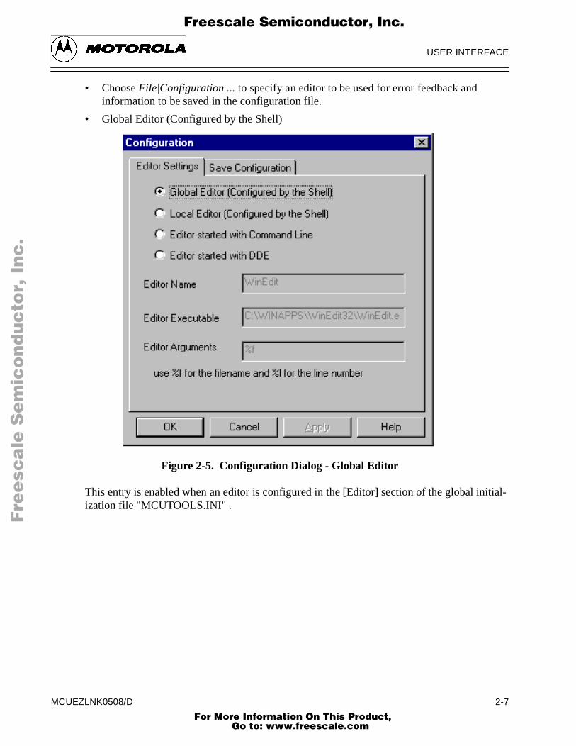
• Choose File|Configuration ... to specify an editor to be used for error feedback and information to be saved in the configuration file.
• Global Editor (Configured by the Shell)
Figure 2-5. Configuration Dialog - Global Editor
This entry is enabled when an editor is configured in the [Editor] section of the global inization file "MCUTOOLS.INI" .
MCUEZLNK0508/D 2-7 For More Information On This Product,
Go to: www.freescale.com
USER INTERFACE
ually
or the
F
ree
sca
le S
em
ico
nd
uc
tor,
I
Freescale Semiconductor, Inc.n
c..
.
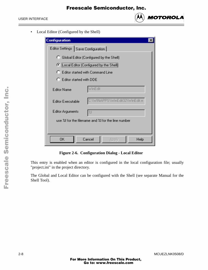
• Local Editor (Configured by the Shell)
Figure 2-6. Configuration Dialog - Local Editor
This entry is enabled when an editor is configured in the local configuration file; us"project.ini" in the project directory.
The Global and Local Editor can be configured with the Shell (see separate Manual fShell Tool).
2-8 MCUEZLNK0508/D For More Information On This Product,
Go to: www.freescale.com

USER INTERFACE
r errorn the
rt line
pports
F
ree
sca
le S
em
ico
nd
uc
tor,
I
Freescale Semiconductor, Inc.n
c..
.
• Editor started with Command Line
Figure 2-7. Configuration Dialog - Editor Started With Command Line
When this editor type is selected, a separate editor is associated with the Linker fofeedback. Enter the command line to start the editor. Modifiers can be specified ocommand line.
Example:
For Winedit 32-bit version use (with an adapted path to the winedit.exe file)
C:\WinEdit32\WinEdit.exe %f /#:%l
For Write.exe (with an adapted path to the Write.exe file, note that Write does not supponumbers).
C:\Winnt\System32\Write.exe %f
For Motpad.exe use (with an adapted path to the Motpad.exe file, note that Motpad suline number).
C:\TOOLS\MOTPAD\MOTPAD.exe %f::%l
MCUEZLNK0508/D 2-9 For More Information On This Product,
Go to: www.freescale.com
USER INTERFACE
or. All
’ isopen
ected.
F
ree
sca
le S
em
ico
nd
uc
tor,
I
Freescale Semiconductor, Inc.n
c..
.
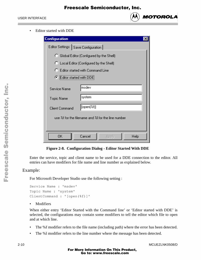
• Editor started with DDE
Figure 2-8. Configuration Dialog - Editor Started With DDE
Enter the service, topic and client name to be used for a DDE connection to the editentries can have modifiers for file name and line number as explained below.
Example:
For Microsoft Developer Studio use the following setting :
Service Name : "msdev"
Topic Name : "system"
ClientCommand : "[open(%f)]"
• Modifiers
When either entry ‘Editor Started with the Command line’ or ‘Editor started with DDEselected, the configurations may contain some modifiers to tell the editor which file to and at which line.
• The %f modifier refers to the file name (including path) where the error has been det
• The %l modifier refers to the line number where the message has been detected.
2-10 MCUEZLNK0508/D For More Information On This Product,
Go to: www.freescale.com
USER INTERFACE
. Someual to
an belower,tarted
F
ree
sca
le S
em
ico
nd
uc
tor,
I
Freescale Semiconductor, Inc.n
c..
.
The format from the editor command depends on the syntax used to start the editormodifiers can be specified in the editor command line. Please check your editor mandefine the command line which should be used to start the editor.
2.2.2.6.1 Important remarks
Caution should be taken using %l. This modifier can only be used with an editor that cstarted with a line number as a parameter. Editors such as WinEdit version 3.1 or Notepad, and Motpad do not allow this kind of parameter. This kind of editor can be susing the file name as a parameter. Choose Go to to jump to the line containing the error.
The Command Line looks like: C:\WINAPPS\WINEDIT\Winedit.EXE %f
Check your editor manual to define the Command Line used to start the editor.
MCUEZLNK0508/D 2-11 For More Information On This Product,
Go to: www.freescale.com
USER INTERFACE
In the
uration
ration
mandin the
F
ree
sca
le S
em
ico
nd
uc
tor,
I
Freescale Semiconductor, Inc.n
c..
.
NOTE
If you are using a word processing editor (Microsoft Word, Wordpad, ...),save your input file as an ASCII text file.
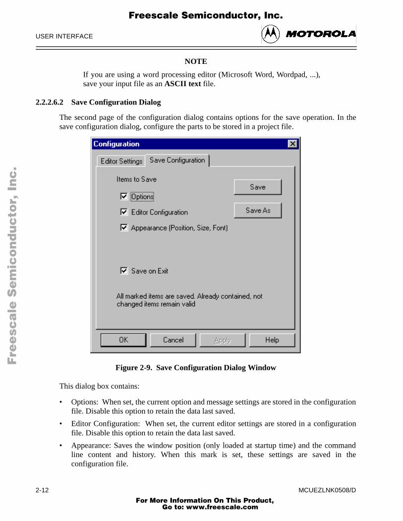
2.2.2.6.2 Save Configuration Dialog
The second page of the configuration dialog contains options for the save operation.save configuration dialog, configure the parts to be stored in a project file.
Figure 2-9. Save Configuration Dialog Window
This dialog box contains:
• Options: When set, the current option and message settings are stored in the configfile. Disable this option to retain the data last saved.
• Editor Configuration: When set, the current editor settings are stored in a configufile. Disable this option to retain the data last saved.
• Appearance: Saves the window position (only loaded at startup time) and the comline content and history. When this mark is set, these settings are saved configuration file.
2-12 MCUEZLNK0508/D For More Information On This Product,
Go to: www.freescale.com

USER INTERFACE
iontion
oose
rthe
F
ree
sca
le S
em
ico
nd
uc
tor,
I
Freescale Semiconductor, Inc.n
c..
.
NOTE
By disabling selective options only parts of a configuration file can bewritten. For example when the suitable editor is found, the save optionmark can be removed. Then future save commands will not modify theeditor setting.
• Save on Exit: If set, the Linker will write the configuration on exit. No confirmatprompt will appear. If options have changed, the Linker will not write the configuraunless this option is set.
NOTE
Almost all settings are stored in the configuration file, except for the recentlyused configuration list and all settings in this dialog.These settings are stored in the [ELF_LINKER] section of the MCUTOOLS.INIinitialization file.
NOTE
Linker configurations can coexist in the same file as the projectconfiguration of the shell and other MCUez tools. When an editor isconfigured by the shell, the linker can read the content from the project file,if present. The project configuration file of the shell is named project.ini.This file name is therefore also suggested (but not mandatory) to theLinker.
2.2.2.7 Linker Menu
This menu allows you to customize the linker and set or reset linker options. ChLinker|Options to define the options for linking an input file (See section 2.2.3.9, AdvancedOptions Dialog Box, in this chapter).
2.2.2.8 View Menu
This menu enables you to customize the Linker Window. You can define whether to display ohide the Status Bar or Tool Bar. You can also define the font used in the window or clear window.
• Choose View|Tool Bar to switch on/off the Linker Window Tool Bar.
• Choose View|Status Bar to switch on/off the Linker Window Status Bar.
• Choose View|Log ... to customize the output in the Linker Window Content Area.
• Choose View|Log ...|Change Font to open a standard Font Selection dialog box. Options selected in this dialog are applied to the Linker Window Content Area.
• Choose View|Log ...|Clear Log to clear the Linker Window Content Area.
MCUEZLNK0508/D 2-13 For More Information On This Product,
Go to: www.freescale.com

USER INTERFACE
ged ins the
F
ree
sca
le S
em
ico
nd
uc
tor,
I
Freescale Semiconductor, Inc.n
c..
.
2.2.2.9 Advanced Options Dialog Box
This dialog box allows you to set/reset linker options. The options available are arrandifferent groups. A register card is available for each group. The following figure showAdvanced Options Dialog window.
Figure 2-10. Advanced Options Dialog Window
The content of the list box depends on the selected sheet:
A linker option is set when the corresponding check box is checked.
Option Group Description
Output Lists options related to generated output files (type of files tobe generated).
Input Lists options related to input files.
Messages Lists options controlling generation of error messages.
2-14 MCUEZLNK0508/D For More Information On This Product,
Go to: www.freescale.com

USER INTERFACE
vailableeet.
F
ree
sca
le S
em
ico
nd
uc
tor,
I
Freescale Semiconductor, Inc.n
c..
.
NOTE
When options requiring additional parameters are selected, an edit box oranother window can be opened to set the additional parameters.
2.2.3 Message Settings Dialog Box
The following figure shows the Message Settings Dialog window.
Figure 2-11. Message Settings Dialog Window
This dialog box allows you to map messages to a different message class. A sheet is afor each error message class and the content of the list box depends on the selected sh
MCUEZLNK0508/D 2-15 For More Information On This Product,
Go to: www.freescale.com

USER INTERFACE
mber.
of thee class. click the
ge:
f youalid.
F
ree
sca
le S
em
ico
nd
uc
tor,
I
Freescale Semiconductor, Inc.n
c..
.
The table below identifies and defines each message group.
Table 2-1. Message Group Definitions
Each message has its own character (‘L’ for Linker message) followed by a 4-5 digit nuThis number allows an easy search for the message both in the manual or online help.
2.2.3.1 Changing the Class Associated With a Message
You can configure your own mapping of messages in the different classes by using onebuttons located on the right hand side of the dialog box. Each button refers to a messagTo change the class associated with a message, select the message in the list box andbutton associated with the class where you want to move the message.
Example
To define the message ‘L1201: No stack defined' (warning message) as an error messa
1. Click the Warning sheet to display the list of all warning messages in the list box.
2. Click on the string ‘L1201: No stack defined' in the list box to select the message.
3. Click Error to define this message as an error message.
Click on the 'OK' button to validate the modification to the error message mapping. Iclose the dialog box with the 'Cancel' button, the previous message mapping remains v
Message Group Description
Disabled Lists all disabled messages. Messages displayed in the list box will not be generated by the Linker.
Information Lists all information messages. Information messages depict action taken by the Linker.
Warning Lists all warning messages. When such a message is generated, linking continues and an absolute file is generated.
Error Lists all error messages. When such a message is generated, linking of the input application continues but no absolute file will be generated.
Fatal Lists all fatal error messages. When such a message is generated, linking stops immediately.
2-16 MCUEZLNK0508/D For More Information On This Product,
Go to: www.freescale.com

USER INTERFACE
, the
the
tool
e
ed in fileother
th the
F
ree
sca
le S
em
ico
nd
uc
tor,
I
Freescale Semiconductor, Inc.n
c..
.
2.2.3.2 Specifying the Input File
The input file to be linked can be specified in several ways. During the link sessionoptions will be set according to the configuration set by the user in the Advanced OptionsSettings dialog box. Before linking a file, ensure that you have associated a Project Directorywith your linker.
2.2.3.2.1 Using the Editable Combo Box in the Tool Bar
• Linking a New File - A new file name and additional linker options can be entered in editable combo box. Click the Link button in the tool bar to link the specified file.
• Linking a File Which Has Already Been Linked - The command executed previouslycan be displayed using the arrow on the right side of the editable combo box. Click acommand line to select it and display it in the combo box. Click the Link button in thebar to assemble the specified file.
2.2.3.2.2 Using the Entry File | Link ...
Choose File|Link ..., to open a standard Open File dialog box. The desired file can then bbrowsed. Click OK to link the selected file.
2.2.3.2.3 Using Drag and Drop
A file name can be dragged from another program (e.g., the File Manager) and dropped intothe Linker Window. The dropped file will be linked as soon as the mouse button is releasthe Linker Window. A dragged file with a .ini extension is considered to be a configurationand it is loaded and not linked. To link a parameter file with a .ini extension use anmethod.
2.2.4 Error Feedback
After a parameter file has been linked, you can detect error or warning locations wifollowing error message format.
‘>> <FileName>, l ine < l ine number>, co l <column number>, pos<absolute position in file><Portion of code generating the problem><message class> <message number>: <Message string>‘
Example
>> in "placemen\tstpla8.prm", line 23, col 0, pos 668 fpm_data_sec INTO MY_RAM2;
END
ERROR L1110: MY_RAM2 appears twice in PLACEMENT block
MCUEZLNK0508/D 2-17 For More Information On This Product,
Go to: www.freescale.com

USER INTERFACE
rerrors.
the
er ing onor and
n thelly by
e file
creen.
F
ree
sca
le S
em
ico
nd
uc
tor,
I
Freescale Semiconductor, Inc.n
c..
.
2.2.4.1 Error Feedback Using Information From the Linker Window
Once a file has been linked, the Linker Window Content Area displays a list of all errors owarnings detected. Any editor can then be used to open the source file and correct the
2.2.4.2 Error Feedback Using a User-Defined Editor
The editor for Error Feedback must first be configured using either the MCUez Shell or Configuration dialog box.
2.2.4.2.1 Line Number Can be Specified on the Command Line
Motpad, WinEdit V95 or higher, Codewright, or Motpad can be started with a line numbthe command line. Properly configured editors will start automatically by double clickinan error message. The configured editor will start and open the file containing the errplace the cursor on the line where the error occurred.
2.2.4.2.2 Line Number Cannot be Specified on the Command Line
WinEdit V31 or lower, Notepad, and Wordpad cannot be started with a line number icommand line. When correctly configured, these editors can be activated automaticadouble clicking on an error message. The configured editor will start and open thcontaining the error. To scroll to the error:
• Activate the linker again
• Click the line on which the message was generated. This line is highlighted on the s
• Copy the line to the clipboard pressing CTRL + C
• Activate the editor again.
• Select Search|Find, the standard Find dialog box is opened.
• Press CTRL + V to paste the line in the Edit box.
• Click Forward to jump to the detected error position.
2-18 MCUEZLNK0508/D For More Information On This Product,
Go to: www.freescale.com

ENVIRONMENT VARIABLES
of ther, ...).
ment,ile
F
ree
sca
le S
em
ico
nd
uc
tor,
I
Freescale Semiconductor, Inc.n
c..
.
CHAPTER 3
ENVIRONMENT VARIABLES
3.1 INTRODUCTION
This chapter describes environment variables used by the MCUez Linker. Some environment variables are also used by other tools (e.g. Macro Assembler, CompileConsult their respective manuals for more information.
3.2 SETTING PARAMETERS
Various linker parameters may be set with environment variables. The syntax is:
KeyName=ParamDefinition
NOTE
No blanks are allowed in the definition of an environment variable.
Example:
GENPATH=C:\INSTALL\LIB;D:\PROJECTS\TESTS;\usr\local\lib;
These parameters may be defined in several ways:
• Using system environment variables supported by your operating system.
• Putting the definitions in a file called DEFAULT.ENV (.hidefaults for UNIX) in the project directory.
• Putting the definitions in a file given by the value of the system environment variableENVIRONMENT.
NOTE
The default directory mentioned above can be set via the system environmentvariable DEFAULTDIR.
When looking for an environment variable, all programs first search the system environthen the DEFAULT.ENV (.hidefaults for UNIX) file and finally the global environment fgiven by ENVIRONMENT. If no definition can be found, a default value is assumed.
MCUEZLNK0508/D 3-1 For More Information On This Product,
Go to: www.freescale.com

ENVIRONMENT VARIABLES
ist is
en the
ns ofez
rent
sed for
to itsallye to
F
ree
sca
le S
em
ico
nd
uc
tor,
I
Freescale Semiconductor, Inc.n
c..
.
3.3 PATH VARIABLES
Most environment variables contain path lists indicating where to look for files. A path la list of directory names separated by semicolons; as follows:
DirSpec;DirSpec;DirSpec*DirectoryName
Example:
GENPATH=C:\INSTALL\LIB;D:\PROJECTS\TESTS;\usr\local\lib;
If a directory name is preceded by an asterisk ("*" ), the programs recursively search thwhole directory tree for a file, not just the given directory. Directories are searched iorder they appear in the path list.
Example:
LIBPATH=*C:\INSTALL\LIB
NOTE
Some DOS/UNIX environment variables (like GENPATH, LIBPATH, etc.) areused. For further details refer to “Environment” chapter.
We strongly recommend working with MCUez Shell and setting the environment by meaa DEFAULT.ENV file in your project directory. This project directory can be set in the MCUShell 'Configure...' dialog box. This way, you can have different projects in diffedirectories, each with its own environment.
For some environment variables a synonym also exists. These synonyms may be uolder releases of the linker and will be removed in the future.
3.3.1 LINKOPTIONS
Synonym: None
Syntax: "LINKOPTIONS=" {<option>}.
Arguments: <option>: Linker command line option
Description: If this environment variable is set, the linker appends its contents command line each time a file is linked. It can be used to globspecify certain options that should always be set, so you don’t havspecify them each time a file is linked.
Example: LINKOPTIONS=-W2
See also: Linker options
3-2 MCUEZLNK0508/D For More Information On This Product,
Go to: www.freescale.com

ENVIRONMENT VARIABLES
heecttheble
theerthe
the ishere
F
ree
sca
le S
em
ico
nd
uc
tor,
I
Freescale Semiconductor, Inc.n
c..
.
3.3.2 GENPATH
Synonym: HIPATH
Syntax: "GENPATH=" {<path>}.
Arguments: <path>: Paths separated by semicolons, without spaces.
Description: The linker will look for the PRM file in the project directory, then in tdirectories listed in the environment variable GENPATH. The objand library files specified in the linker PRM file are searched for in project directory, then in directories listed in the environment variaOBJPATH and finally in directories specified in GENPATH.
NOTE
If a directory specification in this environment variable starts with an asterisk(“*” ), the whole directory tree is searched recursively, i.e. all subdirectories arealso searched. Within one level in the tree, the search order of the subdirectoriesis indeterminate (not valid for Win32).
Example: GENPATH=\obj;..\..\lib;
See also: None
3.3.3 OBJPATH
Synonym: None
Syntax: "OBJPATH=" {<path>}.
Arguments: <path>: Paths separated by semicolons, without spaces.
Description: When this environment variable is defined, the linker searchesproject directory for the object and library files specified in the linkPRM file. The linker then searches the directories listed in environment variable OBJPATH and GENPATH.
Example: OBJPATH=\sources\bin;..\..\headers;\usr\local\bin
3.3.4 ABSPATH
Synonym: None
Syntax: "ABSPATH=" {<path>}.
Arguments: <path>: Paths separated by semicolons, without spaces.
Description: When this environment variable is defined, the linker will store absolute files it produces in the first directory specified. If ABSPATHnot set, the generated absolute files will be stored in the directory wthe parameter file was found.
MCUEZLNK0508/D 3-3 For More Information On This Product,
Go to: www.freescale.com

ENVIRONMENT VARIABLES
thes the
F
ree
sca
le S
em
ico
nd
uc
tor,
I
Freescale Semiconductor, Inc.n
c..
.
Example: ABSPATH=\sources\bin;..\..\headers;\usr\local\bin
See also: None
3.3.5 TEXTPATH
Synonym: None
Syntax: "TEXTPATH=" {<path>}.
Arguments: <path>: Paths separated by semicolons, without spaces.
Description: When this environment variable is defined, the linker will store MAP file it produces in the first directory specified. If TEXTPATH inot set, the generated MAP file will be stored in the directory wherePRM file was found.
Example: TEXTPATH=\sources ..\..\headers;\usr\local\txt
See also: None
3-4 MCUEZLNK0508/D For More Information On This Product,
Go to: www.freescale.com

ENVIRONMENT VARIABLES
st be
te ards
cords
error
me
F
ree
sca
le S
em
ico
nd
uc
tor,
I
Freescale Semiconductor, Inc.n
c..
.
3.3.6 SRECORD
Synonym: None
Syntax: SRECORD=<RecordType>.
Arguments: <Record Type>: Force the type for the Motorola S record that mugenerated. This parameter value can be ‘S1’, ‘S2’ or ‘S3’.
Description: When this environment variable is defined, the linker will generaMotorola S file containing records from the specified type (S1 recowhen S1 is specified, S2 records when S2 is specified and S3 rewhen S3 is specified).
NOTE
If the environment variable SRECORD is set, it is the user responsibility tospecify the appropriate S record type. If you specify S1 while your code isloaded above 0xFFFF, the Motorola S file generated will not be correct, as theaddresses will all be truncated to 2-byte values.
NOTE
When this variable is not set, the type of S record generated will depend on thesize of the address loaded. If the address can be coded on two bytes, a S1 recordis generated. If the address is coded on three bytes, a S2 record is generated.Otherwise, a S3 record is generated.
Example: SRECORD=S2
See also: None
3.3.7 ERRORFILE
Synonym: None.
Syntax: ERRORFILE=<filename>
Arguments: <filename>: File name with format specifiers.
Description: The environment variable ERRORFILE specifies the name of the file (used by the Linker).
Possible format specifiers are:
%n: Substitute with the file name, without the path.
%p: Substitute with the path of the source file.
%f: Substitute with the full file name, i. e. with the path and na(same as %p%n).
In case of an illegal error file name, a notification box is displayed.
MCUEZLNK0508/D 3-5 For More Information On This Product,
Go to: www.freescale.com

ENVIRONMENT VARIABLES
with the list
be
txt
ent
rrectile
F
ree
sca
le S
em
ico
nd
uc
tor,
I
Freescale Semiconductor, Inc.n
c..
.
Example: ERRORFILE=MyErrors.err
Lists all errors in the file “MyErrors.err” in the project directory.
ERRORFILE=\tmp\errors
Lists all errors in the file “errors” in the directory \tmp.
ERRORFILE=%f.err
Lists all errors in a file with the same name as the source file, but extension .err. The error file is placed in the same directory assource file. For example, if we link a file \sources\test.prm, an errorfile \sources\test.err will be generated.
ERRORFILE=\dir1\%n.err
For a source file test.prm, an error list file \dir1\test.err will generated.
ERRORFILE=%p\errors.txt
For a source file \dir1\dir2\test.prm, an error list file \dir1\dir2\errors.will be generated.
If the environment variable ERRORFILE is not set, the errors are written to the default error file. The default error file name is dependupon how the assembler is configured and started. If a file name isprovided in the assembler command line, errors are written to the EDOUT file (to the name-specified file) in the project directory. If nofile name is provided, errors are written to the ERR.TXT file in the project directory.
Example: Another example shows the usage of this variable to support coerror feedback with the WinEdit Editor which looks for an error fcalled EDOUT:
Installation directory: E:\INSTALL\PROGProject sources: D:\MEPHISTOCommon Sources for projects: E:\CLIB
Entry in default.env (D:\MEPHISTO\DEFAULT.ENV):ERRORFILE=E:\INSTALL\PROG\EDOUT
Entry in WINEDIT.INI (in Windows directory):OUTPUT=E:\INSTALL\PROG\EDOUT
See also: None
3-6 MCUEZLNK0508/D For More Information On This Product,
Go to: www.freescale.com

FILES
st thateSCII
t code the fileen tonsion
an beionson the
If thise was
F
ree
sca
le S
em
ico
nd
uc
tor,
I
Freescale Semiconductor, Inc.n
c..
.
CHAPTER 4
FILES
4.1 INTRODUCTION
The following sections describe the files used and generated by the MCUez Linker.
4.2 PARAMETER FILE: INPUT
The linker takes any file as input. No special extension is required. However, we suggeparameter file names have the extension .prm . Parameter files will be searched first in thproject directory and then in the GENPATH directories. The parameter file must be an Atext file.
4.3 ABSOLUTE FILES: OUTPUT
After a successful link session, the linker generates an absolute file containing the targeas well as some debugging information. This file is written to the directory given inenvironment variable ABSPATH. If the variable contains more than one path, the absoluteis written to the first directory specified. If this variable is not set, the absolute file is writtthe directory where the parameter file was found. Absolute files always get the exte.abs .
4.4 MOTOROLA S FILES: OUTPUT
After a successful link session, the linker generates a Motorola S record file, which cburnt into an EPROM. This file contains information stored in all the READ_ONLY sectin the application. The extension for the generated Motorola S record file depends setting from the SRECORD variable.
• If SRECORD = S1, the Motorola S record file gets the extension .s1 .
• If SRECORD = S2, the Motorola S record file gets the extension .s2 .
• If SRECORD = S3, the Motorola S record file gets the extension .s3 .
• If SRECORD is not set, the Motorola S record file gets the extension .sx .
This file is written to the directory given in the environment variable ABSPATH. If the variablecontains more than one path, the S record file is written to the first directory specified. variable is not set, the S record file is written to the directory where the parameter filfound.
MCUEZLNK0508/D 4-1 For More Information On This Product,
Go to: www.freescale.com

FILES
aboutthe is the
F
ree
sca
le S
em
ico
nd
uc
tor,
I
Freescale Semiconductor, Inc.n
c..
.
4.5 MAP FILES
After a successful link session, the linker generates a MAP file containing information the link process (see figure below). This file is written to the directory given in environment variable TEXTPATH. If the variable contains more than one path, the MAP filewritten to the first directory specified. If this variable is not set, the MAP file is written todirectory where the parameter file was found. MAP files always get the extension .map .
Figure 4-1. Link Process Conceptual Diagram
Linker
“.o”1.current dir2.GENPATH
ERRORFILE
ERR.TXT EDOUT
.abs
1.current dir2. OBJPATH3.GENPATH
1.ABSPATH2.Source
.prm “.lib” “.abs”
.sx or.map 1.TEXTPAT
H2.Source
4-2 MCUEZLNK0508/D For More Information On This Product,
Go to: www.freescale.com

LINKER OPTIONS AND ISSUES
are not Linkerally,
itsecify
e linkerns.
F
ree
sca
le S
em
ico
nd
uc
tor,
I
Freescale Semiconductor, Inc.n
c..
.
CHAPTER 5
LINKER OPTIONS AND ISSUES
5.1 INTRODUCTION
The MCUez Linker offers a number of options to control linker operation. Optionscomposed of a minus/dash (‘-’) followed by one or more letters or digits. Anythingstarting with a dash/minus is assumed to be the name of a parameter file to be linked.options may be specified on the command line or in the LINKOPTIONS variable. Typiceach option is specified once per linking session.
NOTE
Arguments for an option must not exceed 128 characters.
Command line options are not case sensitive. For example, "–o=test.abs " is the same as"–O=TEST.ABS".
When the LINKOPTIONS variable is set, the linker appends the variable settings to command line each time a new file is linked. This variable can be used to globally spoptions that should always be set. The remainder of this section describes each of thoptions. The options are listed in alphabetical order and divided into the following sectio
Table 5-1. MCUez Linker Options Descriptions
Topic Description
Syntax Specifies the syntax of the option in an EBNF format.
Arguments Describes and lists optional and required arguments.
Default Shows the default setting for the option.
Description Provides a detailed description of the option and how to use it.
Example Gives an example of usage and effects where possible. Linker settings, source code and/or Linker PRM files are displayed where applicable. The examples show an entry in the default.env file for PC or in the .hidefaults for UNIX.
See also Names related options.
MCUEZLNK0508/D 5-1 For More Information On This Product,
Go to: www.freescale.com

LINKER OPTIONS AND ISSUES
e the
n theing
king
d.
F
ree
sca
le S
em
ico
nd
uc
tor,
I
Freescale Semiconductor, Inc.n
c..
.
5.2 -E LINKER OPTION
-E: Define Application Entry Point
Syntax: "-E=" <FunctionName>.
Arguments: <FunctionName>: Name of the function, which is considered to bentry point in the application.
Default: none.
Description: This option specifies the name of the application entry point. Wheentry point is located in an assembly object file, the correspondsymbol must be a global symbol (Specified in an XDEF directive).
Example: LINKOPTIONS=-E=entry
This is the same as using the command:
INIT entry
in the PRM file
See also: Command INIT
5.3 -O LINKER OPTION
-O: Define Absolute File Name
Syntax: "-O=" <FileName>
Arguments: <fileName>: Name of the absolute file to be generated by the linsession.
Default: None.
Description: This option defines the name of the ABS file that must be generate
Example: LINKOPTIONS=-O=test.abs
This is the same as using the command:
LINK test.abs
in the PRM file
See also: Command LINK
5-2 MCUEZLNK0508/D For More Information On This Product,
Go to: www.freescale.com

LINKER OPTIONS AND ISSUES
link
olute
F
ree
sca
le S
em
ico
nd
uc
tor,
I
Freescale Semiconductor, Inc.n
c..
.
5.4 -M LINKER OPTION
-M: Generate MAP File
Syntax: "-M"
Arguments: None.
Default: None.
Description: This option forces generation of a MAP file after a successful session.
Example: LINKOPTIONS=-M
This is the same as using the command:
MAPFILE ALL
in the PRM file
See also: Command MAPFILE
5.5 -S LINKER OPTION
-S: Do not generate DWARF Information
Syntax: "-S"
Arguments: None.
Default: None.
Description: This option disables the generation of DWARF sections in the absfile. This will reduce the amount of memory used on your PC.
Example: LINKOPTIONS=-S
See also: None
NOTE
If the absolute file does not contain DWARF information, you will not be able todebug it.
MCUEZLNK0508/D 5-3 For More Information On This Product,
Go to: www.freescale.com

LINKER OPTIONS AND ISSUES
OR
nly
F
ree
sca
le S
em
ico
nd
uc
tor,
I
Freescale Semiconductor, Inc.n
c..
.
5.6 -V LINKER OPTION
-V: Prints the Linker Version
Syntax: "-V".
Arguments: None.
Default: None.
Description: Prints the Linker version and the project directory.
Example: -V produces the following list:
Directory: D:\mcuez\PROGMCUez ELF Linker V-1.0.29CCPP User Interface Module, V-1.0.4, Date Jul 18 1997
See also: None.
NOTE
This option can be used to determine the project directory.
5.7 -W1 LINKER OPTION
-W1: No Information Messages
Syntax: "-W1"
Arguments: None.
Default: None.
Description: Suppresses all INFORMATION messages; WARNING and ERRmessages are printed.
Example: LINKOPTIONS=-W1
See also: None
5.8 -W2 LINKER OPTION
-W2: No Information and Warning Messages
Syntax: "-W2".
Arguments: None.
Default: None.
Description: Suppresses all INFORMATION and WARNING messages, oERRORs are printed.
Example: LINKOPTIONS=-W2
See also: None
5-4 MCUEZLNK0508/D For More Information On This Product,
Go to: www.freescale.com

LINKER OPTIONS AND ISSUES
gninguch an
board
er one
for the
F
ree
sca
le S
em
ico
nd
uc
tor,
I
Freescale Semiconductor, Inc.n
c..
.
5.9 LINKING ISSUES
The following sections identify specific application issues for the MCUez Linker.
5.9.1 Object Allocation
Object allocation is performed through the SEGMENTS and PLACEMENT blocks.
5.9.1.1 The SEGMENTS Block
The segments block is optional. It increases readability of the linker input file by assimeaningful names to contiguous memory areas on the target board. Memory within sarea share common attributes:
• Qualifier
• Alignment Rules
• Filling Character
Two types of segments can be defined:
• Physical Segments
• Virtual Segments
Physical segments are closely related to hardware memory areas.
For example, there may be one READ_ONLY segment for each bank of the target ROM area and another one covering the RAM area.
Example:
Using the small memory model you can define a segment for the RAM area and anothfor the ROM area.
LINK test.abs NAMES test.o startup.o END SEGMENTS RAM_AREA = READ_WRITE 0x00000 TO 0x07FFF; ROM_AREA = READ_ONLY 0x08000 TO 0x0FFFF; END PLACEMENT .data INTO RAM_AREA; .text INTO ROM_AREA; END STACKSIZE 0x50
Using the banked memory model you can define a segment for the RAM area, anothernon-banked ROM area, and one for each target processor bank.
LINK test.abs NAMES test.o startup.o END
MCUEZLNK0508/D 5-5 For More Information On This Product,
Go to: www.freescale.com

LINKER OPTIONS AND ISSUES
ing of
for the
s all
F
ree
sca
le S
em
ico
nd
uc
tor,
I
Freescale Semiconductor, Inc.n
c..
.
SEGMENTS RAM_AREA = READ_WRITE 0x00000 TO 0x07FFF; NON_BANKED_AREA = READ_ONLY 0x0C000 TO 0x0FFFF; BANK0_AREA = READ_ONLY 0x08000 TO 0x0BFFF; BANK1_AREA = READ_ONLY 0x18000 TO 0x1BFFF; BANK2_AREA = READ_ONLY 0x28000 TO 0x2BFFF; END PLACEMENT .data INTO RAM_AREA; .init, .startData, .rodata1, NON_BANKED, .copy INTO NON_BANKED_AREA; .text INTO BANK0_AREA, BANK1_AREA, BANK2_AREA; END STACKSIZE 0x50
A physical segment may be split into several virtual segments, allowing a better structurobject allocation and taking advantage of some processor specific properties.
Example:
In the small memory model you can define a segment for the direct page area, anotherrest of the RAM area, and another one for the ROM area.
LINK test.abs NAMES test.o startup.o END SEGMENTS DIRECT_RAM = READ_WRITE 0x00000 TO 0x000FF; RAM_AREA = READ_WRITE 0x00100 TO 0x07FFF; ROM_AREA = READ_ONLY 0x08000 TO 0x0FFFF; END PLACEMENT myRegister INTO DIRECT_RAM; .data INTO RAM_AREA; .text INTO ROM_AREA; END STACKSIZE 0x50
5.9.1.1.1 Segment Qualifier
Different qualifiers are available for segments. The following table identifies and defineavailable qualifiers.
5-6 MCUEZLNK0508/D For More Information On This Product,
Go to: www.freescale.com

LINKER OPTIONS AND ISSUES
HC12,e can
for ar and
F
ree
sca
le S
em
ico
nd
uc
tor,
I
Freescale Semiconductor, Inc.n
c..
.
Table 5-2. Segment Qualifier Descriptions
5.9.1.1.2 Segment Alignment
The default alignment rule depends on the processor and memory model used. TheHC08, and HC05 processors do not require alignment for code or data objects. Onchoose to define their own alignment rule for a segment. The alignment rule definedsegment block overrides the default alignment rules associated with the processomemory model.
Qualifier Meaning
READ_ONLY Qualifies a segment, where read only access is allowed. Objects within such a segment are initialized at application loading time.
READ_WRITE Qualifies a segment, where read and write accesses are allowed. Objects within such a segment are initialized at application startup. This is only the case when linking a High Level Language (ANSI C or C++) application.
NO_INIT Qualifies a segment, where read and write accesses are allowed. Objects within such a segment remain unchanged during application startup. This qualifier may be used for segments refering to a battery backed RAM. Sections placed in a NO_INIT segment should not contain an initialized variable (variable defined as ‘int c = 8’).This is only the case when linking a High Level Language (ANSI C or C++) application.
PAGED Qualifies a segment, where read and write accesses are allowed. Objects within such a segment remain unchanged during application startup. Additionally, objects located in two PAGED segments may overlap. This qualifier is used for memory areas, where some user defined page switching mechanism is required. Sections placed in a NO_INIT segment should not contain an initialized variable (variable defined as ‘int c = 8’).This is only the case when linking a High Level Language (ANSI C or C++) application.
MCUEZLNK0508/D 5-7 For More Information On This Product,
Go to: www.freescale.com

LINKER OPTIONS AND ISSUES
ry, all
F
ree
sca
le S
em
ico
nd
uc
tor,
I
Freescale Semiconductor, Inc.n
c..
.
The alignment rule has the following format:
[defaultAlignment] {“[“ObjSizeRange”:”alignment”]”}
Table 5-3. Segment Alignment Rule Format
Example:
LINK test.abs NAMES test.o startup.o END SEGMENTS DIRECT_RAM = READ_WRITE 0x00000 TO 0x000FF ALIGN 2 [< 2: 1]; RAM_AREA = READ_WRITE 0x00100 TO 0x07FFF ALIGN [1:1] [2..3:2] [>=4:4]; ROM_AREA = READ_ONLY 0x08000 TO 0x0FFFF; END PLACEMENT myRegister INTO DIRECT_RAM; .data INTO RAM_AREA; .text INTO ROM_AREA; END STACKSIZE 0x50
In previous example:
• In segment DIRECT_RAM, objects whose size is 1 byte are aligned on byte boundaother objects are aligned on 2-byte boundary.
Item Description
defaultAlignment The alignment value for all objects that do not match the conditions of a range defined afterward.
ObjSizeRange Defines a certain condition. The condition has the form:
size : rule applies to objects, where size is equal to ‘size’
< size : rule applies to objects, where size is smaller than ‘size’
> size: rule applies to objects, where size is bigger than ‘size’
<= size: rule applies to objects, where size is smaller or equal to ‘size’
>= size: rule applies to objects, where size is bigger or equal to ‘size’
From size1 to size2: the rule applies to objects, where size is greater or equal to ‘size1’ and smaller or equal to ‘size2’.
alignment Defines the alignment value for objects matching the condition defined in the current alignment block (enclosed in square brackets).
5-8 MCUEZLNK0508/D For More Information On This Product,
Go to: www.freescale.com

LINKER OPTIONS AND ISSUES
l to 2
e yours thenly
A.
y areactions
F
ree
sca
le S
em
ico
nd
uc
tor,
I
Freescale Semiconductor, Inc.n
c..
.
• In segment RAM_AREA, 1 byte objects are aligned on byte boundary, objects equaor 3 bytes are aligned on 2-byte boundary, all other objects are aligned on 4-byte boundary.
• Default alignment rule applies to the ROM_AREA segment.
5.9.1.1.3 Segment Fill Pattern
The default fill pattern for code and data segments is the null character. You can definown fill pattern for a segment. The fill pattern definition in the segment block overridedefault fill pattern. A fill pattern can be defined for the READ_WRITE memory area owhen linking a high level language (ANSI C, C++) application.
Example:
LINK test.abs NAMES test.o startup.o END SEGMENTS DIRECT_RAM = READ_WRITE 0x00000 TO 0x000FF FILL 0xAA; RAM_AREA = READ_WRITE 0x00100 TO 0x07FFF FILL 0x22; ROM_AREA = READ_ONLY 0x08000 TO 0x0FFFF; END PLACEMENT myRegister INTO DIRECT_RAM; .data INTO RAM_AREA; .text INTO ROM_AREA; END STACKSIZE 0x50
In previous example:
• In segment DIRECT_RAM, alignment bytes between objects are initialized with 0xA
• In segment RAM_AREA, alignment bytes between objects are initialized with 0x22.
• In segment ROM_AREA, alignment bytes between objects are initialized with 0x00.
5.9.1.2 PLACEMENT Block
The placement block allows you to physically place each section in a specific memor(segment). The sections specified in a PLACEMENT block may be linker-predefined seor user sections specified in one of the source files used to build the application.
A programmer may decide to organize data into sections:
• to enhance application structure
• to ensure that common purpose data is grouped together
• to take advantage of target processor specific addressing mode.
MCUEZLNK0508/D 5-9 For More Information On This Product,
Go to: www.freescale.com

LINKER OPTIONS AND ISSUES
located
first, ec2.
en
used intil thistil all
F
ree
sca
le S
em
ico
nd
uc
tor,
I
Freescale Semiconductor, Inc.n
c..
.
5.9.1.2.1 Specifying a List of Sections
When several sections are specified on a PLACEMENT statement, the sections are alin the sequence they are listed.
Example:
LINK test.abs NAMES test.o startup.o END SEGMENTS RAM_AREA = READ_WRITE 0x00100 TO 0x002FF; STK_AREA = READ_WRITE 0x00300 TO 0x003FF; ROM_AREA = READ_ONLY 0x08000 TO 0x0FFFF; END PLACEMENT .data, dataSec1, dataSec2 INTO RAM_AREA; .text, myCode INTO ROM_AREA; .stack INTO STK_AREA; END
In previous example:
• Inside of segment RAM_AREA, the objects defined in the .data section are allocatedthen objects defined in section dataSec1 and finally objects defined in section dataS
• Inside of segment ROM_AREA, objects defined in the .text section are allocated, thobjects defined in section myCode.
NOTE
Since the linker is case sensitive, section names specified in the PLACEMENTblock must be valid predefined or user defined sections. Sections DataSec1 anddataSec1 are different sections.
5.9.1.2.2 Specifying a List of Segments
When several segments are specified on a PLACEMENT statement, the segments arethe sequence they are listed. Allocation is performed for the first segment in the list, unsegment is full. Then allocation continues for the next segment in the list, an so on unobjects are allocated.
Example:
LINK test.abs NAMES test.o startup.o END SEGMENTS RAM_AREA = READ_WRITE 0x00100 TO 0x002FF; STK_AREA = READ_WRITE 0x00300 TO 0x003FF; NON_BANKED_AREA = READ_ONLY 0x0C000 TO 0x0FFFF;
5-10 MCUEZLNK0508/D For More Information On This Product,
Go to: www.freescale.com

LINKER OPTIONS AND ISSUES
.
s are
to the
F
ree
sca
le S
em
ico
nd
uc
tor,
I
Freescale Semiconductor, Inc.n
c..
.
BANK0_AREA = READ_ONLY 0x08000 TO 0x0BFFF; BANK1_AREA = READ_ONLY 0x18000 TO 0x1BFFF; BANK2_AREA = READ_ONLY 0x28000 TO 0x2BFFF; END PLACEMENT .data INTO RAM_AREA; .stack INTO STK_AREA; .init, .startData, .rodata1, NON_BANKED, .copy INTO NON_BANKED_AREA; .text INTO BANK0_AREA, BANK1_AREA, BANK2_AREA; END
In previous example:
• Functions implemented in section .text are allocated first in segment BANK0_AREAWhen memory for this segment is filled, allocation continues in segment BANK_1_AREA, then in BANK2_AREA.
NOTE
Since the linker is case sensitive, segment names specified in the PLACEMENTblock must be valid segment names defined in the SEGMENTS block. SegmentsRam_Area and RAM_AREA are different segments.
5.9.2 Allocating User-Defined Sections
Not all sections need to be listed in the PLACEMENT block. Segments in which sectionallocated, depends on the type of section.
• Sections containing data are allocated next to the .data section.
• Sections containing code, constant variables, or string constants are allocated next .text section.
In the segment where .data is placed, allocation is performed as follows:
• Objects from section .data are allocated
• Objects from section .bss are allocated (if .bss is not specified in the PLACEMENT block).
• Objects from the first user defined data section, which is not specified in the PLACEMENT block, are allocated.
• Objects from the next user defined data section, which is not specified in the PLACEMENT block, are allocated.
• and so on until all user defined data sections are allocated.
MCUEZLNK0508/D 5-11 For More Information On This Product,
Go to: www.freescale.com

LINKER OPTIONS AND ISSUES
ENT
T
F
ree
sca
le S
em
ico
nd
uc
tor,
I
Freescale Semiconductor, Inc.n
c..
.
• If the section .stack is not specified in the PLACEMENT block and is defined with a STACKSIZE command, the stack is allocated.
Allocation in the segment where .text is placed is performed as follows:
• Objects from section .init are allocated (if .init is not specified in the PLACEMENT block).
• Objects from section .startData are allocated (if .startData is not specified in the PLACEMENT block).
• Objects from section .text are allocated.
• Objects from section .rodata are allocated (if .rodata is not specified in the PLACEMblock).
• Objects from section .rodata1 are allocated (if .rodata1 is not specified in the PLACEMENT block).
• Objects from the first user defined code section, which is not specified in the PLACEMENT block, are allocated.
• Objects from the next user defined code section, which is not specified in the PLACEMENT block, are allocated.
• and so on until all user defined code sections are allocated.
• Objects from section .copy are allocated (if .copy is not specified in the PLACEMENblock).
.data .bss user data section 1
user data section 2
user data section n .stack
.init .start- rodata1user sec. 1
user sec. n.text .rodata .copy
Data
5-12 MCUEZLNK0508/D For More Information On This Product,
Go to: www.freescale.com

OPERATING PROCEDURES
n beRM
alidalid inifferent
tine.
the in the andannot
F
ree
sca
le S
em
ico
nd
uc
tor,
I
Freescale Semiconductor, Inc.n
c..
.
CHAPTER 6
OPERATING PROCEDURES
6.1 INTRODUCTION
This chapter defines operating procedures for the MCUez Linker application.
6.2 INITIALIZING THE VECTOR TABLE
The following sections describe how to initialize the vector table. The vector table cainitialized in the assembly source file or in the linker parameter file. Initialization in the Pfile is recommended.
6.2.1 VECTOR Command
This command initializes the vector table. The syntax “VECTOR <Number>” is only vwhen the vector table starts at address 0x0000. The syntax VECTOR ADDRESS is vany case. The size of entries in the vector table depends on the target processor. Dsyntaxes are available for the VECTOR command (Table 6-1).
Table 6-1. VECTOR Command Syntax
The last syntax may be very useful, when working with a common interrupt service rou
6.2.1.1 Initializing the Vector Table in the Linker PRM File
Initializing the vector table from the PRM file allows you to initialize single entries in table (shown in the example below). The user can decide whether to initialize all entriesvector table or not. The labels or functions, must be inserted in the vector tableimplemented in the assembly source file. All labels must be published otherwise they cbe addressed in the linker PRM file.
Command Meaning
VECTOR ADDRESS 0xFFFE 0x1000 Indicates that the value 0x1000 must be stored at address 0xFFFE
VECTOR ADDRESS 0xFFFE FName Indicates that the address of the FName function must be stored at address 0xFFFE
VECTOR ADDRESS 0xFFFE FName + 2 Indicates that the address of the FName function incremented by 2 must be stored at address 0xFFFE
MCUEZLNK0508/D 6-1 For More Information On This Product,
Go to: www.freescale.com

OPERATING PROCEDURES
F
ree
sca
le S
em
ico
nd
uc
tor,
I
Freescale Semiconductor, Inc.n
c..
.
Example for HC08:
XDEF IRQFunc, SWIFunc, ResetFuncDataSec: SECTIONData: DS.W 5 ; Each interrupt increments another element of table.CodeSec: SECTION; Implementation of the interrupt functions.IRQ1Func: LDA #0 BRA intSWIFunc: LDA #4 BRA intResetFunc: LDA #8 BRA entryint: PSHH LDHX #Data ; Load address of symbol Data in X ; X <- address of the appropriate element in the tableOfset: TSTA BEQ Ofset3Ofset2: AIX #$1 DECA BNE Ofset2Ofset3: INC 0, X ; The table element is incremented PULH RTIentry: LDHX #$0E00 ; Init Stack Pointer to $E00-$1=$DFF TXS CLRX CLRH CLI ; Enables interrupts loop: BRA loop
6-2 MCUEZLNK0508/D For More Information On This Product,
Go to: www.freescale.com

OPERATING PROCEDURES
k wheners it iss thest beand
pointRESSn at
n
ble be
ted ine file in
F
ree
sca
le S
em
ico
nd
uc
tor,
I
Freescale Semiconductor, Inc.n
c..
.
NOTE
The functions ‘IRQFunc’, ‘XIRQFunc’, ‘SWIFunc’, ‘OpCodeFunc’, and‘ResetFunc’ are published. This is required, because they are referenced in thelinker PRM file.
The HC08 processor automatically pushes the PC, X, A, and CCR registers on the stacan interrupt occurs. The interrupt function does not need to save and restore the registusing. To maintain compatibility with the M6805 Family, the H register is not stacked, it iuser’s responsibility to save and restore it prior to returning. All interrupt functions muterminated with an RTI instruction. The vector table is initialized using the linker commVECTOR ADDRESS.
Example:
LINK test.absNAMES test.o END SEGMENTS MY_ROM = READ_ONLY 0x0800 TO 0x08FF; MY_RAM = READ_WRITE 0x0B00 TO 0x0CFF; MY_STACK = READ_WRITE 0x0D00 TO 0x0DFF;ENDPLACEMENT .data INTO MY_RAM; .text INTO MY_ROM; .stack INTO MY_STACK;ENDINIT ResetFuncVECTOR ADDRESS 0xFFF8 IRQ1FuncVECTOR ADDRESS 0xFFFC SWIFuncVECTOR ADDRESS 0xFFFE ResetFunc
The statement ‘INIT ResetFunc’ defines the application entry point. Usually, this entry is initialized with the same address as the reset vector. The statement ‘VECTOR ADD0xFFF2 IRQFunc’ specifies that the address of function ‘IRQFunc’ should be writteaddress 0xFFF2.
6.2.1.2 Initializing the Vector Table in the Assembly Source File Using a Relocatable Sectio
Initializing the vector table in the assembly source file requires that all entries in the tainitialized. Unused interrupts must be associated with a standard handler.
The labels or functions, which should be inserted in the vector table, must be implemenone of the assembler source files. The vector table can be defined in an assembly sourcan additional section containing constant variables.
MCUEZLNK0508/D 6-3 For More Information On This Product,
Go to: www.freescale.com

OPERATING PROCEDURES
F
ree
sca
le S
em
ico
nd
uc
tor,
I
Freescale Semiconductor, Inc.n
c..
.
Example for HC08:
XDEF ResetFuncDataSec: SECTIONData: DS.W 5 ; Each interrupt increments an element of thetable.CodeSec: SECTION; Implementation of the interrupt functions.IRQ1Func: LDA #0 BRA intSWIFunc: LDA #4 BRA intResetFunc: LDA #8 BRA entryDummyFunc: RTIint: PSHH LDHX #Data ; Load address of symbol Data in X ; X <- address of the appropriate element in the tabOfset: TSTA BEQ Ofset3Ofset2: AIX #$1 DECA BNE Ofset2Ofset3: INC 0, X ; The table element is incremented PULH RTI entry: LDHX #$0E00 ; Init Stack Pointer to $E00-$1=$DFF TXS CLRX CLRH CLI ; Enables interruptsloop: BRA loopVectorTable: SECTION; Definition of the vector table.IRQ1Int: DC.W IRQ1FuncIRQ0Int: DC.W DummyFuncSWIInt: DC.W SWIFuncResetInt: DC.W ResetFunc
6-4 MCUEZLNK0508/D For More Information On This Product,
Go to: www.freescale.com
OPERATING PROCEDURES
wordnt’ isith
st bection.
e non-
linker
fortablell beFFA,
ementRM. The
F
ree
sca
le S
em
ico
nd
uc
tor,
I
Freescale Semiconductor, Inc.n
c..
.
Each constant in the section ‘VectorTable’ is defined as a word (2 Byte constant). Eachentry in the vector table is 16 bits wide. In the previous example, the constant ‘IRQ1Iinitialized with the address of the label ‘IRQ1Func’. The constant ‘SWIInt’ is initialized wthe address of the label ‘SWIFunc’. All labels specified as an initialization value mudefined, published (using XDEF), or imported (using XREF) before the vector table seForward referencing is not allowed in the DC directive.
When developing a banked application, ensure that interrupt functions are located in thbanked memory area.
The section should now be placed at the expected address. This is performed in theparameter file, shown in the example below.
Example:
LINK test.absNAMES test.o END SEGMENTS MY_ROM = READ_ONLY 0x0800 TO 0x08FF; MY_RAM = READ_WRITE 0x0B00 TO 0x0CFF; MY_STACK = READ_WRITE 0x0D00 TO 0x0DFF;/* Define the memory range for the vector table */ Vector = READ_ONLY 0xFFF8 TO 0xFFFF;ENDPLACEMENT .data INTO MY_RAM; .text INTO MY_ROM; .stack INTO MY_STACK;/* Place the section 'VectorTable' at the appropriated address. */ VectorTable INTO Vector; ENDINIT ResetFuncENTRIES *END
The statement ‘Vector = READ_ONLY 0xFFF8 TO 0xFFFF’ defines the memory rangethe vector table. The statement ‘VectorTable INTO Vector’ specifies that the vector should be loaded in the read only memory area Vector. The constant ‘IRQ1Int’ wiallocated at address 0xFFF8, the constant ‘XIRQ0Int’ will be allocated at address 0xFand so on. The constant ‘ResetInt’ will be allocated at address 0xFFFE. The stat‘ENTRIES * END’ switches smart linking OFF. If this statement is missing from the Pfile, the vector table will not be linked with the application; because it is never referencedsmart linker only links the objects referenced in the absolute file.
MCUEZLNK0508/D 6-5 For More Information On This Product,
Go to: www.freescale.com

OPERATING PROCEDURES
ble bections
s. Theaining
F
ree
sca
le S
em
ico
nd
uc
tor,
I
Freescale Semiconductor, Inc.n
c..
.
6.2.1.3 Initializing the Vector Table in the Assembly Source File Using an Absolute Section
Initializing the vector table in the assembly source file requires that all entries in the tainitialized. Unused interrupts must be associated with a standard handler. Labels or funinserted in the vector table must be implemented in one of the assembly source filevector table can be defined in an assembly source file in an additional section contconstant variables, shown in the example below.
Example for HC08:
XDEF ResetFuncDataSec: SECTIONData: DS.W 5 ; Each interrupt increments an element of thetable.CodeSec: SECTION; Implementation of the interrupt functions.IRQ1Func: LDA #0 BRA intSWIFunc: LDA #4 BRA intResetFunc: LDA #8 BRA entryDummyFunc: RTIint: PSHH LDHX #Data ; Load address of symbol Data in X ; X <- address of the appropriate element in the tabOfset: TSTA BEQ Ofset3Ofset2: AIX #$1 DECA BNE Ofset2Ofset3: INC 0, X ; The table element is incremented PULH RTI entry: LDHX #$0E00 ; Init Stack Pointer to $E00-$1=$DFF TXS CLRX CLRH CLI ; Enables interrupts loop: BRA loop
6-6 MCUEZLNK0508/D For More Information On This Product,
Go to: www.freescale.com

OPERATING PROCEDURES
entryt’ isstant anEF) The8.
e non- This is
theot a
F
ree
sca
le S
em
ico
nd
uc
tor,
I
Freescale Semiconductor, Inc.n
c..
.
ORG $FFF8; Definition of the vector table in an absolute section ; starting at address $FFF8.IRQ1Int: DC.W IRQ1FuncIRQ0Int: DC.W DummyFuncSWIInt: DC.W SWIFuncResetInt: DC.W ResetFunc
Each constant in the section ‘VectorTable’ is defined as a word (2 Byte constant). Eachin the vector table is 16 bits wide. In the previous example, the constant ‘IRQ1Ininitialized with the address of the label ‘IRQ1Func’. In the previous example, the con‘SWIInt’ is initialized with the address of the label ‘SWIFunc’. All labels specified asinitialization value must be defined, published (using XDEF), or imported (using XRbefore the vector table section. Forward referencing is not allowed in DC directive.statement ‘ORG $FFF8‘ specifies that the following section must start at address $FFF
When developing a banked application, ensure that interrupt functions are located in thbanked memory area. The section should now be placed at the expected address.performed in the linker parameter file, shown in the following example.
Example:
LINK test.abs NAMES test.o END SEGMENTS MY_ROM = READ_ONLY 0x0800 TO 0x08FF; MY_RAM = READ_WRITE 0x0A00 TO 0x0BFF; END PLACEMENT .data INTO MY_RAM; .text INTO MY_ROM; END INIT ResetFunc ENTRIES * END
The statement ‘ENTRY * END’ switches smart linking OFF. If this statement is missing inPRM file, the vector table will not be linked with the application. The vector table is nreferenced entity. The linker links referenced objects only in the absolute file.
MCUEZLNK0508/D 6-7 For More Information On This Product,
Go to: www.freescale.com

OPERATING PROCEDURES
in the
with
ful toe final beenith the
c2 are
tants)he
F
ree
sca
le S
em
ico
nd
uc
tor,
I
Freescale Semiconductor, Inc.n
c..
.
6.3 SMART LINKING
Smart linking links referenced objects with the application. Application entry points are:
• The application init function
• The functions or constants located in an absolute section (section defined with ORGassembly source file)
• The function specified in a VECTOR command.
All previously listed entry points and the objects they referenced are automatically linkedthe application. You can specify additional entry points using the ENTRIES command in thePRM file.
6.3.1 Mandatory Linking From an Object
You can choose to link non-referenced objects in your application. This may be useensure that a software version number is linked with the application and stored in thproduct EPROM. This may also be useful to ensure that a vector table, which hasdefined as a constant table of function pointers or as a constant section, is linked wapplication.
Example :
ENTRIES myVar1 myVar2 myProc1 myProc2 END
In this example, the variables myVar1 and myVar2, and functions myProc1 and myProspecified to be additional entry points in the application.
6.3.2 Mandatory Linking From All Objects Defined in a File
You can choose to link all objects defined in a specified object file.
Example :
ENTRIES myFile1.o:* myFile2.o:* END
In this example, all objects (functions, variables, constant variables or string consdefined in myFile1.o and myFile2.o are specified as additional entry points in tapplication.
6-8 MCUEZLNK0508/D For More Information On This Product,
Go to: www.freescale.com

OPERATING PROCEDURES
f the
ock
the
to beed inlow).
F
ree
sca
le S
em
ico
nd
uc
tor,
I
Freescale Semiconductor, Inc.n
c..
.
6.3.3 Switching OFF Smart Linking for the Application
Switch smart linking off to link all objects in the application.
Example :
ENTRIES * END
In this example:
Smart linking is switched OFF for the whole application. All objects, defined in one obinary files that builds the application, are linked with the application.
6.4 BINARY FILES BUILDING AN APPLICATION
Specify binary file names in the NAMES block or ENTRIES block. Usually a NAMES blis sufficient.
6.4.1 NAMES Block
All binary files building the application are usually listed in the NAMES block. This is only place where absolute, library, or object library files may be specified.
Example :
NAMES myFile1.o myFile2.o END
In this example, the binary files myFile1.o and myFile2.o build the application.
6.4.2 ENTRIES Block
If a file name is specified in the ENTRIES block, the corresponding file is considered part of the application, even if it does not appear in the NAMES block. The file specifithe ENTRIES block may also be present in the NAMES block (shown in the example beNames of absolute, ROM library or library files are not allowed in the ENTRIES block.
Example:
LINK test.abs NAMES test.o startup.o END SEGMENTS DIRECT_RAM = READ_WRITE 0x00000 TO 0x000FF; STK_AREA = READ_WRITE 0x00200 TO 0x002FF; RAM_AREA = READ_WRITE 0x00300 TO 0x07FFF; ROM_AREA = READ_ONLY 0x08000 TO 0x0FFFF;
MCUEZLNK0508/D 6-9 For More Information On This Product,
Go to: www.freescale.com

OPERATING PROCEDURES
d.
e
F
ree
sca
le S
em
ico
nd
uc
tor,
I
Freescale Semiconductor, Inc.n
c..
.
END PLACEMENT myRegister INTO DIRECT_RAM; .data INTO RAM_AREA; .text INTO ROM_AREA; .stack INTO STK_AREA; END ENTRIES test1.o:* test.o:* END
In previous example, the files test.o , test1.o, and startup.o build the application. Allobjects defined in the modules test1.o and test.o will be linked with the application.
6.4.3 Linking an Assembly Application
The following example shows how to link an application.
When an application consists only of assembly files, the linker PRM file can be simplifie
• No startup structure is required.
• No stack initialization is required, because the stack is directly initialized in the sourcfile.
• No main function is required.
• An entry point in the application is required.
• All symbols referenced in the PRM file must be published (specified in a XDEF directive). There is no local symbol defined in the assembler.
Example:
LINK test.absNAMES test.o test2.o ENDSEGMENTS DIRECT_RAM = READ_WRITE 0x00000 TO 0x000FF; RAM_AREA = READ_WRITE 0x00300 TO 0x07FFF; ROM_AREA = READ_ONLY 0x08000 TO 0x0FFFF;ENDPLACEMENT myRegister INTO DIRECT_RAM; .data INTO RAM_AREA; .text INTO ROM_AREA;ENDINIT Start ; Application entry pointVECTOR ADDRESS 0xFFFE Start ; Initialize Reset Vector
In the previous example:
6-10 MCUEZLNK0508/D For More Information On This Product,
Go to: www.freescale.com

OPERATING PROCEDURES
e
st be
on d with
F
ree
sca
le S
em
ico
nd
uc
tor,
I
Freescale Semiconductor, Inc.n
c..
.
• All data sections defined in the assembly input files are allocated in the segment RAM_AREA.
• All code and constant sections defined in the assembly input files are allocated in thsegment ROM_AREA.
• The START function defines an application entry point and a reset vector. START mua global symbol defined in one of the assembly modules.
6.4.4 Warning Messages
An assembly application does not need a startup structure or root function.
The two warnings:
‘WARNING: _startupData not found‘
and
‘WARNING: Function main not found‘
can be ignored.
• Smart Linking - When an assembly application is linked, smart linking is performed section level instead of object level. Sections containing referenced objects are linkethe application.
Example for HC08:
Assembly source file
XDEF entry dataSec1: SECTION SHORT data1: DS.W 1 dataSec2: SECTION SHORT data2: DS.W 2 codeSec: SECTION entry: NOP NOP LDX #data1 LDA #$45 STA 0, X loop: BRA loop
Linker PRM file
LINK test.abs NAMES test.o END
MCUEZLNK0508/D 6-11 For More Information On This Product,
Go to: www.freescale.com

OPERATING PROCEDURES
s
,
se
the
linked
ows:
s a
F
ree
sca
le S
em
ico
nd
uc
tor,
I
Freescale Semiconductor, Inc.n
c..
.
SEGMENTS RAM_AREA = READ_WRITE 0x00050 TO 0x000FF; ROM_AREA = READ_ONLY 0x08000 TO 0x0FFFF; END PLACEMENT .data INTO RAM_AREA; .text INTO ROM_AREA; END INIT entry VECTOR ADDRESS 0xFFE entry
In the previous example:
• The ENTRY function is defined as an application entry point and also specified areset vector.
• The data section ‘dataSec1’ defined in the assembly input file is allocated in the segment RAM_AREA at address 0x50. This section is linked with the applicationbecause the label ‘data1’ is referenced in the function ‘entry’.
• The code section ‘codeSec’ defined in the assembly input file is allocated in the segment ROM_AREA at address 0x8000. It is linked with the application, becau‘entry’ is the application entry point.
• The data section ‘dataSec2’ defined in the assembly input file is not linked with application, because the symbol ‘data2’ is never referenced.
You can choose to switch smart linking OFF, so that assembly code and objects will bewith the application.
For the previous example, the PRM file used to switch smart linking OFF will look as foll
LINK test.abs NAMES test.o END SEGMENTS RAM_AREA = READ_WRITE 0x00050 TO 0x000FF; ROM_AREA = READ_ONLY 0x08000 TO 0x0FFFF; END PLACEMENT .data INTO RAM_AREA; .text INTO ROM_AREA; END INIT entry VECTOR ADDRESS 0xFFE entry ENTRIES * END
In the previous example:
• The ENTRY function is defined as an application entry point and also specified areset vector.
6-12 MCUEZLNK0508/D For More Information On This Product,
Go to: www.freescale.com

OPERATING PROCEDURES
the
tains file inmightion.
F
ree
sca
le S
em
ico
nd
uc
tor,
I
Freescale Semiconductor, Inc.n
c..
.
• The data section ‘dataSec1’ defined in the assembly input file is allocated in the segment RAM_AREA at address 0x50.
• The data section ‘dataSec2’ defined in the assembly input file is allocated next tosection ‘dataSec1’ at address 0x52.
• The code section ‘codeSec’ defined in the assembly input file is allocated in the segment ROM_AREA at address 0x8000.
6.5 THE PARAMETER FILE
The linker parameter file is an ASCII text file that is required for each application. It conlinker commands that define the linking process. This section describes the parameterdetail, giving examples you may use as templates for your own parameter files. You also want to take a look at the example parameter files included in your installation vers
6.5.1 The Syntax of the Parameter File
Following is the EBNF syntax of the parameter file.
ParameterFile={Command}
Command= LINK NameOfABSFile
| NAMES ObjFile {ObjFile} END
| SEGMENTS {SegmentDef} END
| PLACEMENT {Placement} END
| (STACKTOP | STACKSIZE) exp
| MAPFILE MapSecSpecList
| ENTRIES EntrySpec {EntrySpec } END
| VECTOR (InitByAddr | InitByNumber)
| INIT FuncName
| MAIN FuncName
NameOfABSFile= FileName
ObjFile= FileName [”+”]
ObjName= Ident
QualIden = FileName “:” Ident
FuncName= ObjName | QualIdent
MapSecSpecList= MapSecSpec “,” { MapSecSpec }
EntrySpec= [FileName“:”] (* | ObjName)
MapSecSpec= ALL | NONE | TARGET | FILE | STARTUP | SEC_ALLOC |
MCUEZLNK0508/D 6-13 For More Information On This Product,
Go to: www.freescale.com

OPERATING PROCEDURES
F
ree
sca
le S
em
ico
nd
uc
tor,
I
Freescale Semiconductor, Inc.n
c..
.
OBJ_ALLOC | OBJ_DEP | OBJ_UNUSED | COPYDOWN |
STATSTIC
SegmentDef= SegmentName “=“ SegmentSpec “;”
SegmentName= Ident
SegmentSpec= StorageDevice Range [Alignment] [FILL CharacterList]
StorageDevice= READ_ONLY | READ_WRITE | PAGED | NO_INIT
Range= exp (TO | SIZE) exp
Alignment= ALIGN [exp] {“[“ObjSizeRange“:” exp”]”}
ObjSizeRange= Number | Number TO Number | CompareOp Number
CompareOp= (“<“ | “>=“ | “>“ | “>=“)
CharacterList= HexByte { HexByte}
Placement= SectionList INTO SegmentList “;”
SectionList= SectionName {“,” SectionName}
SectionName=Ident
SegmentList= Segment {“,” Segment}
Segment= SegmentName | SegmentSpec
InitByAddr= ADDRESS Address Vector
InitByNumber= VectorNumber Vector
Address= Number
VectorNumber= Number
Vector= (FuncName [OFFSET exp] | exp) [“,” exp]
Ident= <any C style identifier>
FileName= <any file name>
exp= Number
Number= DecimalNumber | HexNumber | OctalNumber
HexNumber= 0xHexDigit{HexDigit}
DecimalNumber= DecimalDigit{DecimalDigit}
HexByte= HexDigit HexDigit
HexDigit= “0” | “1”| “2” | “3” | “4” | “5” | “6” | “7” | “8” | “9”|
“A” | “B” | “C” | “D” | “E” | “F” |
“a” | “b” | “c” | “d” | “e” | “f”
DecimalDigit= “0” | “1”| “2” | “3” | “4” | “5” | “6” | “7” | “8” |
6-14 MCUEZLNK0508/D For More Information On This Product,
Go to: www.freescale.com

OPERATING PROCEDURES
if you inker
the
file:
ent
F
ree
sca
le S
em
ico
nd
uc
tor,
I
Freescale Semiconductor, Inc.n
c..
.
“9” |• Comments may appear anywhere in a parameter file, except where file names are
expected. You may use either C style comments (/* */) or C++(//) style comments.
• File names should not contain paths. This keeps your sources portable. Otherwise, copy the sources to another directory, the linker might not find all files needed. The luses the paths in the environment variables GENPATH, OBJPATH, TEXTPATH and ABSPATH to decide where to look for files and where to write output files.
• The order of commands in the parameter file does not matter. However, ensure thatSEGMENTS block is specified before the PLACEMENT block.
• There are default sections named .data , .text , .stack , .copy , .rodata1 , .rodata , .startData and .init .
6.5.2 Mandatory Parameter File Linker Commands
A linker parameter file always contains at least the entries for LINK , NAMES, and PLACEMENT.All other commands are optional. The following example shows the minimal parameter
LINK mini.abs /* Name of resulting ABS file */NAMES mini.o startup.o /* Files to link */ENDSTACKSIZE 0x20 /* in bytes */PLACEMENT .text INTO READ_ONLY 0xA00 TO 0xBFF; .data INTO READ_WRITE 0x800 TO 0x8FF;END
The first placement statement
.text INTO READ_ONLY 0xA00 TO 0xBFF ;
reserves the address range from 0xA00 to 0xBFF for allocation of read-only objects (hencthe qualifier READ_ONLY). The .text section includes all linked functions, constavariables, string constants and initialization parts of variables copied to RAM at startup.
The second placement statement
.data INTO READ_WRITE 0x800 TO 0x8FF ;
reserves the address range from 0x800 to 0x8FF for allocation of variables.
MCUEZLNK0508/D 6-15 For More Information On This Product,
Go to: www.freescale.com

OPERATING PROCEDURES
h then. All
file
ust be
F
ree
sca
le S
em
ico
nd
uc
tor,
I
Freescale Semiconductor, Inc.n
c..
.
6.6 LINKER COMMANDS
The following sections describe all Linker commands.
6.6.1 ENTRIES: List of Objects to Link With the Application
Syntax:
ENTRIES [Filename”:”] (*|objName)
Description:
The ENTRIES block is optional in a PRM file.
Use the ENTRIES block to list objects (referenced or not) that are always linked witapplication. The specified objects are used as additional entry points in the applicatioobjects referenced within these objects will also be linked with the application.
The table below identifies the notation supported in the ENTRIES block.
Table 6-2. ENTRIES Block Supported
If a file name specified in the ENTRIES block is not present in the NAMES block, thename will be inserted in the list of binary files building the application.
Symbols defined in an assembly module, which are used as additional entry points, mpublished (specified in a XDEF directive).
Example:
NAMES startup.o END
ENTRIES fibo.o:* END
Notation Meaning
<Object Name> The specified global object will be linked with the application.
<File Name>:<Object Name> The local object defined in the binary file will be linked with the application. This notation is only valid when referring to a symbol defined in a high level language (ANSI C or C++) module.
<File Name>:* All objects defined within the specified file will be linked with the application.
* All objects will be linked with the application. This switches OFF smart linking for the application.
6-16 MCUEZLNK0508/D For More Information On This Product,
Go to: www.freescale.com

OPERATING PROCEDURES
IES
everalINIT it as
uses
F
ree
sca
le S
em
ico
nd
uc
tor,
I
Freescale Semiconductor, Inc.n
c..
.
In the previous example, the application is built from the files fibo.o and startup.o .
Example:
NAMES fibo.o startup.o END ENTRIES fibo.o:* END
In the previous example, the application is built from the files fibo.o and startup.o . Thefile ‘ fibo.o ’ specified in the NAMES block is the same as the one specified in the ENTRblock.
NOTE
We strongly recommend to avoid switching smart linking OFF, when the ANSIlibrary is linked with the application. The ANSI library contains theimplementation of all run time functions and standard functions. This generates alarge amount of code, which is not required by the application.
6.6.2 INIT: Specify the Application Entry Point
Syntax:
INIT FuncName
Description:
The INIT command is mandatory for an assembly application and cannot be specified stimes in the PRM file. This command defines the entry point for the application. When is not specified in the PRM file, the linker looks for a function named ‘_Startup’ and usesthe application entry point. If an INIT command is specified in the PRM file, the linker the specified function as the application entry point.
MCUEZLNK0508/D 6-17 For More Information On This Product,
Go to: www.freescale.com

OPERATING PROCEDURES
for an
nd ison the
ctoryn.
e as
the it is
me as
the it is
ker
F
ree
sca
le S
em
ico
nd
uc
tor,
I
Freescale Semiconductor, Inc.n
c..
.
You can specify any static or global function as an entry point.
Example:
INIT MyGlobStart /* Specify a global variable as application entry point.*/INIT myFile.o:myLocStart /* Specify a local variable as application entry point.*/
Local symbols defined in an assembly module cannot be specified as an entry point application.
6.6.3 LINK - Specify Name of the Output File
Syntax:
LINK <NameOfABSFile>
Description:
The LINK command defines the file to be generated by the link session. This commamandatory and can only be specified once in a PRM file. After a successful link sessifile “ NameOfABSFile” is created. If the environment variable ABSPATH is defined, theabsolute file is generated in the first directory listed. Otherwise, it is written to the direwhere the parameter file was found. If a file with this name already exists, it is overwritte
A successful link session also creates a MAP file with the same base nam“NameOfABSFile” and with extension .MAP. If the environment variable TEXTPATH isdefined, the MAP file is generated in the first directory listed. Otherwise, it is written todirectory where the parameter file was found. If a file with this name already exists,overwritten.
A successful link session also creates an S record file with the same base na“NameOfABSFile” and with extension .Sx. If the environment variable ABSPATH is defined,the S Record file is generated in the first directory listed. Otherwise, it is written todirectory where the parameter file was found. If a file with this name already exists,overwritten.
The LINK command is mandatory in a PRM file. If the LINK command is missing, the lingenerates an error message unless the option -O is specified on the command line.
Example:
LINK fibo.abs NAMES fibo.o startup.o ENDSEGMENTS MY_RAM = READ_WRITE 0x1000 TO 0x18FF;
6-18 MCUEZLNK0508/D For More Information On This Product,
Go to: www.freescale.com

OPERATING PROCEDURES
om the
C ornott.
n as
F
ree
sca
le S
em
ico
nd
uc
tor,
I
Freescale Semiconductor, Inc.n
c..
.
MY_ROM = READ_ONLY 0x8000 TO 0x8FFF; MY_STK = READ_WRITE 0x1900 TO 0x1FFF;PLACEMENT DEFAULT_ROM INTO MY_ROM; DEFAULT_RAM INTO MY_RAM; SSTACK INTO MY_STK;ENDVECTOR ADDRESS 0xFFFE _Startup /* set reset vector */
The files fibo.abs, fibo.sx and fibo.map are generated after a successful link process frprevious PRM file.
6.6.4 MAIN
Syntax:
MAIN FuncName
Description:
The MAIN command is optional. This command defines the root function for an ANSI C++ application (function invoked at the end of startup function). When MAIN is specified in the PRM file, the linker looks for a function named ‘main’ and uses it as roo
Assembly applications do not require a MAIN function.
If a MAIN command is specified in the PRM file, the linker uses the specified functioroot. You can specify any static or global function as the application root function.
Example:
MAIN MyGlobMain /* Specify a global variable as application root.*/MAIN myFile.o:myLocMain /* Specify a local variable as application root.*/
Local symbols defined in an assembly module cannot be specified as the root function.
6.6.5 MAPFILE: Configure the MAP File Content
Syntax:
MAPFILE (ALL|NONE|TARGET|FILE|STARTUP_STRUCT|SEC_ALLOC| OBJ_ALLOC|OBJ_DEP|OBJ_UNUSED|COPYDOWN|STATISTIC)[,{(ALL|NONE|TARGET|FILE|STARTUP_STRUCT|SEC_ALLOC|OBJ_ALLOC|OBJ_DEP|OBJ_UNUSED|COPYDOWN|STATISTIC)}]
MCUEZLNK0508/D 6-19 For More Information On This Product,
Go to: www.freescale.com

OPERATING PROCEDURES
t, the and
ile
L is
ssible
F
ree
sca
le S
em
ico
nd
uc
tor,
I
Freescale Semiconductor, Inc.n
c..
.
Description:
This command is optional and controls the generation of the MAP file. Per defaulcommand MAPFILE ALL is activated. This indicates that a map file must be createdcontain all linking time information. The following table lists all available MAP fspecifiers.
Table 6-3. MAP File Specifiers
Information generated for each specifier is described in the MAP file chapter. If ALspecified in the MAPFILE command, all sections are inserted in the MAP file.
Example:
Following commands are all equivalent. A map file is generated, which contains all poinformation about the linking session.
Specifier Meaning
ALL A map file will be generated containing all information available.
COPYDOWN Information about the initialization value for objects allocated in RAM will be written to the MAP file (Section COPYDOWN in the map file). This section is only relevant for High level language (ANSI C or C++) applications.
FILE Information about application source files will be inserted in the MAP file.
NONE No map file will be generated.
OBJ_ALLOC Information about allocated objects will be inserted in the map file (Section OBJECT ALLOCATION in the map file).
OBJ_UNUSED List of all unused objects will be inserted in the map file (Section UNUSED OBJECTS in the map file).
OBJ_DEP Dependencies between objects in the application will be inserted in the map file (Section OBJECT DEPENDENCY in the map file).
SEC_ALLOC Information about sections used in the application will be inserted in the map file (Section SECTION ALLOCATION in the map file).
STARTUP_STRUCT Information about the startup structure will be inserted in the map file (Section STARTUP in the map file). This section is only relevant for High level language (ANSI C or C++) applications.
STATISTIC Statistic information about the link session will be inserted in the map file (Section STATISTICS in the map file).
TARGET Information about the target processor and memory model will be inserted in the map file (Section TARGET in the map file).
6-20 MCUEZLNK0508/D For More Information On This Product,
Go to: www.freescale.com

OPERATING PROCEDURES
k isgiventheay be
linked
dn thisis is.
F
ree
sca
le S
em
ico
nd
uc
tor,
I
Freescale Semiconductor, Inc.n
c..
.
MAPFILE ALL MAPFILE TARGET, ALL MAPFILE TARGET, ALL, FILE, STATISTIC
If NONE is specified in the MAPFILE command, no map file is generated.
Example:
Following commands are all equivalent. No map file is generated.
MAPFILE NONE MAPFILE TARGET, NONE MAPFILE TARGET, NONE, FILE, STATISTIC
NOTE
The following map file commands are also supported:
• MAPFILE OFF is equivalent to MAPFILE NONE
• MAPFILE ON is equivalent to MAPFILE ALL
6.6.6 NAMES: List the Files building the Application.
Syntax:
NAMES <FileName>[‘+’] {<FileName>[‘+’]} END
Description:
The NAMES block contains the list of all binary files building the application. This blocmandatory and can only be specified once in a PRM file. The linker reads all files between NAMES and END. The files are searched for in the project directory, then in directories specified in the environment variables OBJPATH and GENPATH. The files meither object files, absolute, or ROM library files or libraries.
Since the linker is a smart linker, only referenced objects (variables and functions) are to the application.
A plus sign after a file name ( e.g. FileName+ ) switches OFF smart linking for the specifiefile. No blank is allowed between the file name and the plus sign. All objects defined ifile will be linked with the application, regardless of whether they are used or not. Thequivalent to specifying the file name followed by a * (fileName:*) in the ENTRIES block
Example:
LINK fibo.abs NAMES fibo.o startup.o ENDSEGMENTS MY_RAM = READ_WRITE 0x1000 TO 0x18FF;
MCUEZLNK0508/D 6-21 For More Information On This Product,
Go to: www.freescale.com

OPERATING PROCEDURES
n themory
from
t. If a
F
ree
sca
le S
em
ico
nd
uc
tor,
I
Freescale Semiconductor, Inc.n
c..
.
MY_ROM = READ_ONLY 0x8000 TO 0x8FFF; MY_STK = READ_WRITE 0x1900 TO 0x1FFF;PLACEMENT DEFAULT_ROM INTO MY_ROM; DEFAULT_RAM INTO MY_RAM; SSTACK INTO MY_STK;ENDVECTOR ADDRESS 0xFFFE _Startup /* set reset vector */
In this example, the application fibo is built from the files ‘fibo.o’ and ‘startup.o’.
6.6.7 PLACEMENT: Place Sections Into Segments
Syntax:
PLACEMENT SectionName{,sectionName} INTO SegSpec{,SegSpec}; {SectionName{,sectionName} INTO SegSpec{,SegSpec};}END
Description:
The PLACEMENT block is mandatory in a PRM file. Each placement statement betweePLACEMENT and END defines a relation between logical sections and physical meranges called segments.
Example:
SEGMENTS MY_RAM = READ_WRITE 0x1000 TO 0x18FF; ROM_1 = READ_ONLY 0x8000 TO 0x8FFF; END PLACEMENT .text, .rodata INTO ROM_1; END
In the previous example, objects from section ‘.text’ are allocated first and then objectssection ‘.rodata’.
Starting with the first section, objects are allocated in the first memory range in the lissegment is full, allocation continues in the next segment.
Example:
SEGMENTS MY_RAM = READ_WRITE 0x1000 TO 0x18FF; ROM_1 = READ_ONLY 0x8000 TO 0x8FFF; ROM_2 = READ_ONLY 0xA000 TO 0xAFFF; END
6-22 MCUEZLNK0508/D For More Information On This Product,
Go to: www.freescale.com

OPERATING PROCEDURES
M_1’ splitys beENT
ions,
ock. e or
he the
bsequent
F
ree
sca
le S
em
ico
nd
uc
tor,
I
Freescale Semiconductor, Inc.n
c..
.
PLACEMENT .text INTO ROM_1, ROM_2; END
In the previous example, objects from section ‘.text’ are allocated first in segment ‘ROand continues in section ‘ROM_2’. A statement inside the PLACEMENT block can beover several lines and terminated with a semicolon. The SEGMENTS block must alwadefined before the PLACEMENT block, because segments referenced in the PLACEMblock must previously be defined in the SEGMENTS block.
Some restrictions apply to commands specified in the PLACEMENT block:
• The .copy section should be the last section in the section list to be specified in the PLACEMENT block.
• When the .stack section is specified in the PLACEMENT block along with other sectan additional STACKSIZE command is required in the PRM file.
• Predefined sections .text and .data must always be specified in the PLACEMENT blThey are used to retrieve the default placement for code or variable sections. All codconstant sections, which do not appear in the PLACEMENT block, are allocated in tsame segment list as the .text section. All variable sections, which do not appear in PLACEMENT block, are allocated in the same segment list as the .data section.
6.6.8 SEGMENTS: Define Memory Map
Syntax:
SEGMENTS {(READ_ONLY|READ_WRITE|NO_INIT|PAGED) <startAddr> (TO <endAddr> | SIZE <size>) [ALIGN <alignmentRule>] [FILL <fillPattern>]}END
Description:
The SEGMENTS block is optional in a PRM file. The SEGMENTS command allows the user toassign meaningful names to address ranges. These names can then be used in suplacement statements, thus increasing the readability of the parameter file.
Each address range you define is associated with:
• A qualifier.
• A start and end address or a start address and a size.
• An optional alignment rule.
• An optional fill pattern.
The following qualifiers are available for segments:
• READ_ONLY: Used for address ranges, where read only accesses are allowed.
MCUEZLNK0508/D 6-23 For More Information On This Product,
Go to: www.freescale.com

OPERATING PROCEDURES
emory
y area be
area ly,
ge
ds at
d
pping ta from
usefulrdware
F
ree
sca
le S
em
ico
nd
uc
tor,
I
Freescale Semiconductor, Inc.n
c..
.
• READ_WRITE: Used for address ranges, where read write accesses are allowed. Marea defined with this qualifier will be initialized with 0 at application startup. This is only the case when linking a High Level Language (ANSI C or C++) application.
• NO_INIT: Used for address ranges, where read write accesses are allowed. Memordefined with this qualifier will not be initialized with 0 at application startup. This mayuseful if your target has a battery buffered RAM. This is only the case when linking a High Level Language (ANSI C or C++) application.
• PAGED: Used for address ranges, where read write accesses are allowed. Memorydefined with this qualifier will not be initialized with 0 at application startup. Additionalthe linker will not maintain control if there is an overlap between segments. When overlapped segments are used, it is the user’s responsibility to select the correct pabefore accessing data allocated on a page. This is only the case when linking a High Level Language (ANSI C or C++) application.
Example:
SEGMENTS ROM = READ_ONLY 0x1000 SIZE 0x2000; CLOCK = NO_INIT 0xFF00 TO 0xFFFF; RAM = READ_WRITE 0x3000 TO 0x3EFF; Page0 = PAGED 0x4000 TO 0x4FFF; Page1 = PAGED 0x4000 TO 0x4FFF;END
In the previous example:
• Segment ’ROM’ is a READ_ONLY memory area. It starts at address 0x1000 and is 0x2000 bytes (from address 0x1000 to 0x2FFF).
• Segment ’RAM’ is a READ_WRITE memory area. It starts at address 0x3000 and en0x3FFF (size = 0x1000 bytes).
• Segment ’CLOCK’ is a READ_WRITE memory area. It starts at address 0xFF00 anends at 0xFFFF (size = 100 bytes).
• Segments ’Page0’ and ‘Page1’ are READ_WRITE memory areas. These are overlasegments. It is the user responsibility to select the correct page before accessing dathese segments.
6.6.8.1 Defining an Alignment Rule
An alignment rule can be associated with each segment in the application. This may bewhen specific alignment rules are expected on a certain memory range due to harestrictions.
An alignment rule can be specified as follows:
ALIGN [<defaultAlignment>] [{‘ [‘ (<Number>|
6-24 MCUEZLNK0508/D For More Information On This Product,
Go to: www.freescale.com

OPERATING PROCEDURES
h aultctor is
te
a 2 One
F
ree
sca
le S
em
ico
nd
uc
tor,
I
Freescale Semiconductor, Inc.n
c..
.
<Number> ‘ TO’ <Number>| (‘ <‘ | ’ >’ | ’ <=’ | ’ >=’ )<Number>)’ ]:’ <alignment>}]
defaultAlignment : Used to specify the alignment factor for objects that do not matccondition in the following alignment list. If no alignment list is specified, the defaalignment factor applies to all objects allocated in the segment. The default alignment faoptional.
The alignment list contains items of the following form. The specified alignment applies to eachobject inside the segment.
Table 6-4. Segment Alignment Items List
Example:
SEGMENTS RAM_1 = READ_WRITE 0x800 TO 0x8FF ALIGN 2 [1:1]; RAM_2 = READ_WRITE 0x900 TO 0x9FF ALIGN [2 TO 3:2] [>= 4:4]; RAM_3 = READ_WRITE 0xA00 TO 0xAFF ALIGN 1 [>=2:2];END
In the previous example:
• Inside of segment RAM_1, all objects with size equal to 1 byte are aligned on a 1 byboundary and all other objects are aligned on a 2 byte boundary.
• Inside of segment RAM_2, all objects with size equal to 2 or 3 bytes are aligned on byte boundary and all objects bigger or equal to 4 are aligned on a 4 byte boundary.byte objects follow the default processor alignment rule.
Notation Meaning
[<size>:<align.>] Size is equal to <size>.
[<sz1> TO <sz2>:<align.>] Size is bigger or equal to <sz1> and smaller or equal to <sz2>.
[<<size>:<align.>] Size is smaller than <size>.
[<=<size>:<align.>] Size is smaller or equal to <size>.
[><size>:<align.>] Size is bigger than <size>.
[>=<size>:<align.>] Size is bigger or equal to <size>.
MCUEZLNK0508/D 6-25 For More Information On This Product,
Go to: www.freescale.com

OPERATING PROCEDURES
yte
eful to. For
tern isject of
atternte will
ted to
d fill byteswith aosition
on.
F
ree
sca
le S
em
ico
nd
uc
tor,
I
Freescale Semiconductor, Inc.n
c..
.
• Inside of segment RAM_3, all objects bigger or equal to 2 bytes are aligned on a 2 bboundary and all other objects are aligned on a 1 byte boundary.
6.6.8.2 Defining a Fill Pattern
A fill pattern can be associated with each segment in the application. This may be usautomatically initialize uninitialized variables in the segments with a predefined patternassembly applications, the fill pattern can only be used in READ_ONLY segments.
A fill pattern can be specified as follows:
FILL <HexByte> {<HexByte>}
Example:
SEGMENTS ROM_1 = READ_ONLY 0x800 TO 0x8FF FILL 0xAA 0x55; END
In the previous example, fill bytes are initialized with the pattern 0xAA55.
If the size of an object to initialize is higher than the size of the specified pattern, the patrepeated as many times as required to fill the objects. In the previous example, an obfour bytes will be initialized with 0xAA55AA55.
If the size of an object to initialize is smaller than the size of the specified pattern, the pis truncated to match the size of the object. In the previous example, an object of one bybe initialized with 0xAA.
When the value specified in an element of a fill pattern does not fit in a byte, it is truncaa byte value.
Example:
SEGMENTS ROM_1 = READ_ONLY 0x800 TO 0x8FF FILL 0xAA55; END
In the previous example, fill bytes are initialized with the pattern 0x55. The specifiepattern is truncated to a 1-byte value. Fill patterns provide an initial value to the paddinginserted between two objects during object allocation. This marks the unused position specific marker and can be detected inside the application. For example, an unused pinside a code section can be initialized with the hexadecimal code for the NOP instructi
6-26 MCUEZLNK0508/D For More Information On This Product,
Go to: www.freescale.com

OPERATING PROCEDURES
othinestack is
and
oess
of the by the
F
ree
sca
le S
em
ico
nd
uc
tor,
I
Freescale Semiconductor, Inc.n
c..
.
6.6.9 STACKSIZE: Define Stack Size
Syntax:
STACKSIZE Number
Description:
The STACKSIZE command is optional in a PRM file. Additionally, you cannot specify bSTACKTOP and STACKSIZE commands in a PRM file. The STACKSIZE command defthe stack size. We recommend using this command if you do not care where the sallocated but only how large it is. When the stack is defined by a STACKSIZE commalone, the stack is placed next to the .data section.
Example:
SEGMENTS MY_RAM = READ_WRITE 0xA00 TO 0xAFF; MY_ROM = READ_ONLY 0x800 TO 0x9FF; END PLACEMENT .text IN MY_ROM; .data IN MY_RAM; END STACKSIZE 0x60
In the previous example, if the section .data is four bytes wide (from address 0xA00 t0xA03), the section .stack is allocated next to it from address 0xA63 down to addr0xA04. The stack initial value is set to 0xA62.
When the stack is defined by a STACKSIZE command associated with the placement.stack section, the stack should start at the segment start address. It is incrementedspecified value and defined to the start address of the segment, where .stack has beenplaced.
Example:
SEGMENTS MY_STK = NO_INIT 0xB00 TO 0xBFF; MY_RAM = READ_WRITE 0xA00 TO 0xAFF; MY_ROM = READ_ONLY 0x800 TO 0x9FF; END PLACEMENT .text IN MY_ROM; .data IN MY_RAM; .stack IN MY_STK; END STACKSIZE 0x60
MCUEZLNK0508/D 6-27 For More Information On This Product,
Go to: www.freescale.com

OPERATING PROCEDURES
to
finingor data
othines
to thessor PC. of thee start
n to
F
ree
sca
le S
em
ico
nd
uc
tor,
I
Freescale Semiconductor, Inc.n
c..
.
In the previous example, the section .stack is allocated from address 0xB5F down address 0xB00. The stack initial value is set to 0xB5E.
In an assembly application, the stack pointer must be initialized in the source code. Dethe stack in the PRM file only ensures no overlap between your stack and the code sections in your application.
6.6.10 STACKTOP: Define Stack Pointer Initial Value
Syntax:
STACKTOP Number
Description:
The STACKTOP command is optional in a PRM file. Additionally, you cannot specify bSTACKTOP and STACKSIZE commands in a PRM file. The STACKTOP command defthe initial value for the stack pointer.
Example:
If STACKTOP is defined as:
STACKTOP 0xBFF
the stack pointer will be initialized with 0xBFF at application startup.
When the stack is defined by a STACKTOP command alone, a default size is assignedstack. This size depends on the processor and is big enough to store the target proceWhen the stack is defined by a STACKTOP command associated with the placement.stack section, the stack should start at the specified address. It is defined down to thaddress of the segment, where .stack has been placed.
Example:
SEGMENTS MY_STK = NO_INIT 0xB00 TO 0xBFF; MY_RAM = READ_WRITE 0xA00 TO 0xAFF; MY_ROM = READ_ONLY 0x800 TO 0x9FF; END PLACEMENT .text IN MY_ROM; .data IN MY_RAM; .stack IN MY_STK; END STACKTOP 0xB7E
In the previous example, the stack pointer will be defined from address 0xB7E dowaddress 0xB00.
6-28 MCUEZLNK0508/D For More Information On This Product,
Go to: www.freescale.com

OPERATING PROCEDURES
finingor data
mandile. And a
ss 0). nction
.
ction
xA00.
F
ree
sca
le S
em
ico
nd
uc
tor,
I
Freescale Semiconductor, Inc.n
c..
.
In an assembly application, the stack pointer must be initialized in the source code. Dethe stack in the PRM file only ensures no overlap between your stack and the code sections in your application.
6.6.11 VECTOR: Initialize Vector Table
Syntax:
VECTOR (InitByAddr | InitByNumber)
Description:
The VECTOR command is optional in a PRM file.
A vector is a small amount of memory about the size of a function address. This comallows the user to initialize the processor vectors while downloading the absolute fVECTOR command consists of a vector location part (containing vector location) avector target part (containing the value to store in the vector).
The vector location part can be specified:
• Through a vector number (only valid when the processor vector table starts at addreThe address where the vector is allocated is evaluated as <Number> * <Size of a FuPointer>.
• Through a vector address. The keyword ADDRESS must be specified in the vectorcommand.
The vector target part can be specified:
• As a function name
• As an absolute address
Example:
VECTOR ADDRESS 0xFFFE _Startup VECTOR ADDRESS 0xFFFC 0xA00 VECTOR 0 _Startup VECTOR 1 0xA00
In the previous example, if the size of a function pointer is coded on two bytes:
• The vector located at address 0xFFFE is initialized with the address of the function ‘_Startup’.
• The vector located at address 0xFFFC is initialized with the absolute address 0xA00
• Vector number 0 (located at address 0x000) is initialized with the address of the fun‘_Startup’.
• Vector number 1 (located at address 0x002) is initialized with the absolute address 0
MCUEZLNK0508/D 6-29 For More Information On This Product,
Go to: www.freescale.com

OPERATING PROCEDURES
se, the
ress of, thedler.y are
y. Aemoryociated
nt
sed.
s andkerallocate
, ande filese
ined
F
ree
sca
le S
em
ico
nd
uc
tor,
I
Freescale Semiconductor, Inc.n
c..
.
You can specify an additional offset when the vector target is a function name. In this cavector will be initialized with the address of the object plus the specified offset.
Example:
VECTOR ADDRESS 0xFFFE CommonISR + 0x10
In the previous example, the vector located at address 0xFFE is initialized with the addthe function ‘CommonISR’ plus 0x10 bytes. If ‘CommonISR’ starts at address 0x800vector will be initialized with 0x810. This notation is useful for the common interrupt hanAll objects specified in a VECTOR command are entry points in the application. Thealways linked with the application, as well as the objects they refer to.
6.7 SECTIONS
The concept section gives you complete control over allocation of objects in memorsection is a named group of global objects (variables or functions) associated with a marea that may be non-contiguous. Objects belonging to a section are allocated in its assmemory range. This chapter describes the use of segmentation in detail.
There are many ways to make use of the concept section, the most important being:
• Distribution of two or more groups of functions and other read-only objects to differeROMs.
• Allocating a single function or variable to a fixed absolute address (e.g. to access processor ports using high level language variables).
• Allocating variables in memory locations where special addressing modes may be u
6.7.1 Terms: Segments and Sections
A Section is a named group of global objects declared in the source file, i.e. functionglobal variables. A Segment is not necessarily a contiguous memory range. In the linparameter file, each section is associated with a segment so the linker knows where to objects belonging to a section.
6.7.2 Definition of Section
A section definition always consists of two parts: the definition of objects belonging to itthe memory area(s) associated with it, called segments. The first is done in the sourcusing pragmas or directives, see Compiler or Assembler Manual. The second is done in thparameter file using the SEGMENTS and PLACEMENT commands (see section on TheSemantics of the Linker Commands).
6.7.3 Predefined Sections
When linking a high level language (ANSI C or C++) application, a couple of predefsection names can be grouped into sections named by the run-time routines.
6-30 MCUEZLNK0508/D For More Information On This Product,
Go to: www.freescale.com

OPERATING PROCEDURES
g
er
nt
om
nt
F
ree
sca
le S
em
ico
nd
uc
tor,
I
Freescale Semiconductor, Inc.n
c..
.
• Sections for things besides variables and functions: .rodata1 , .copy , .stack .
• Sections for grouping large sets of objects:.data , .text .
• A section for placing objects initialized by the linker: .startData .
• A Section to allocate read-only variables: .rodata .
NOTE
The sections .data and .text provide default sections for allocating objects.
Subsequently we will discuss each of these predefined sections.
.rodata1 All string literals (e.g. “This is a string”) are allocated in section .rodata1 . If thissection is associated with a segment qualified as READ_WRITE, the strings are copied fromROM to RAM at startup.
If this section is not mentioned in the PLACEMENT block in the parameter file, the strinlitterals are allocated next to the section .text .
.rodata Any constant variable declared as const in a C module or as DC in an assemblmodule, which is not allocated in a user-defined section, is allocated in section .rodata .Usually, the .rodata section is associated with the READ_ONLY segment.
If this section is not mentioned in the PLACEMENT block in the parameter file, the constavariables are allocated next to the section .text .
.copy Initialization data belongs to section .copy . If a source file contains the declaration
int a[] = {1, 2, 3};
the hex string 000100020003 (6 bytes), which is copied to a location in RAM at programstartup, belongs to segment .copy .
If the .rodata1 or .rodata section is allocated to a READ_WRITE segment, all strings orconstants also belong to the .copy section. Objects in this section are copied at startup frROM to RAM.
.stack The runtime stack has its own segment named .stack . It should always be allocatedto a READ_WRITE segment.
If this section is not mentioned in the PLACEMENT block in the parameter file, the constavariables are allocated next to the section .data .
MCUEZLNK0508/D 6-31 For More Information On This Product,
Go to: www.freescale.com

OPERATING PROCEDURES
forin thehey
rtainameter
artup
e
F
ree
sca
le S
em
ico
nd
uc
tor,
I
Freescale Semiconductor, Inc.n
c..
.
.data This is the default section for all objects normally allocated to RAM. It is usedvariables not belonging to any section or to a section not assigned a segment PLACEMENT block. If the .bss or .stack sections are not associated with a segment, tare included in the .data memory area in the following structure.
.text This is the default section for all functions. If a function is not assigned to a cesection in the source code or if its section is not associated with a segment in the parfile, it is automatically added to section .text . If the .rodata, .rodata1, .startDataor .init sections are not associated with a segment, they are included in the .text memoryarea in the following structure.
.startData The startup description data initialized by the linker and used by the stroutine is allocated to segment .startData . This section must be allocated to a READ_ONLYsegment.
.init The application entry point is stored in the .init section. This section also has to bassociated with a READ_ONLY segment.
NOTE
The .data and .text sections must always be associated with a segment.
.data .bss .Stack
.init .startData .text .rodata .rodata1
6-32 MCUEZLNK0508/D For More Information On This Product,
Go to: www.freescale.com

OPERATING PROCEDURES
ctions
F
ree
sca
le S
em
ico
nd
uc
tor,
I
Freescale Semiconductor, Inc.n
c..
.
6.8 EXAMPLES
Examples 1 and 2 illustrate the use of sections to control allocation of variables and funprecisely.
Example 1:
Distributing code into two different ROMs:
LINK first.ABSNAMES first.o strings.o startup.o ENDSTACKSIZE 0x200SECTIONS ROM1 = READ_ONLY 0x4000 TO 0x4FFF; ROM2 = READ_ONLY 0x8000 TO 0x8FFF;PLACEMENT .text INTO ROM1, ROM2; .data INTO READ_WRITE 0x1000 TO 0x1FFF;END
Example 2:
Allocation in battery buffered RAM:
/* Extract from source file "bufram.c" */#pragma DATA_SEG Buffered_RAM int done; int status[100];#pragma DATA_SEG DEFAULT/* End of extract from "bufram.c" */
Linker parameter file:
LINK bufram.ABSNAMES bufram.o startup.oENDSTACKSIZE 0x200SECTIONS BatteryRAM = NO_INIT 0x1000 TO 0x13FF; MyRAM = READ_WRITE 0x5000 TO 0x5FFF;PLACEMENT .text INTO READ_ONLY 0x2000 TO 0x2800; .data INTO MyRAM; Buffered_RAM INTO BatteryRAM;END
MCUEZLNK0508/D 6-33 For More Information On This Product,
Go to: www.freescale.com

OPERATING PROCEDURES
(ANSItartupules to file
cessary.Startup
F
ree
sca
le S
em
ico
nd
uc
tor,
I
Freescale Semiconductor, Inc.n
c..
.
6.9 PROGRAM STARTUP
This section deals with advanced material and is only relevant for high level language C or C++) applications. First time users of MCUez may skip this section. Standard smodules are delivered with the MCUez programs and examples. Include startup modlink the parameter file. For more information about startup modules see theStartup.TXT in directory LIB.
Prior to calling root function (main ):
• initialize the processor registers
• zero out memory
• copy initialization data from ROM to RAM.
Depending on the processor and application needs different startup routines may be neIn MCUez, there are standard startup routines for every processor and memory model. routines are based on a startup descriptor containing all information.
6.9.1 The Startup Descriptor
The linker startup descriptor is declared as:
typedef struct{ unsigned char *far beg;int size;} _Range;typedef struct{ int size; unsigned char * far dest;} _Copy;typedef void (*_PFunc)(void);typedef struct{ _PFunc *startup; /* address of startup desc */} _LibInit;typedef struct{ _PFunc *initFunc; /* address of init function */} _Cpp;extern struct _tagStartup { unsigned short flags; _PFunc main; unsigned short stackOffset; unsigned short nofZeroOuts; _Range *pZeroOut; _Copy *toCopyDownBeg; unsigned short nofLibInits; _LibInit *libInits; unsigned short nofInitBodies; _PFunc *initBodies;} _startupData;
6-34 MCUEZLNK0508/D For More Information On This Product,
Go to: www.freescale.com

OPERATING PROCEDURES
ur
tor. Inbal
.
ed.
uallyIn a once
k
ed at
s notp. Be
atas the
F
ree
sca
le S
em
ico
nd
uc
tor,
I
Freescale Semiconductor, Inc.n
c..
.
The linker expects the _startupData variable to be declared somewhere in yoapplication.
struct _tagStartup _startupData;
Fields of this struct are initialized by the linker and struct is allocated in ROM in section.startData . If this variable is not declared, the linker does not create a startup descripthis case, there is no .copy section and the stack is not initialized. Furthermore, the gloC++ constructor and ROM libraries are not initialized.
The fields have the following semantics:
flags Contains flags to detect special conditions at startup. Currently two bits are used
Table 6-5. Setting Startup Descriptor Flags
This flag is tested in the startup code, to determine if the stack pointer should be initializ
main is a function pointer set to the application’s root function. In a C program, this is usfunction main unless a MAIN entry in the parameter file specifies another function as root. ROM library, this field is zeroed out. The standard startup code jumps to this addressinitialization completes.
stackOffset is valid only if flags == 0 . This field contains the initial value of the stacpointer.
nofZeroOuts is the number of READ_WRITE segments to fill with zero bytes at startup.
This field is not required if you do not have a RAM memory area that should be initializstartup. Be careful, if this field is not present in the startup structure, the field pZeroOutmust not be present either.
pZeroOut is a pointer to a vector with elements of type _Range. It has exactlynofZeroOuts elements, each describing a memory area to be cleared. This field irequired if you do not have a RAM memory area that should be initialized at startucareful, if this field is not present, the field nofZeroOuts must not be present either.
toCopyDownBeg contains the address of the first item to be copied from ROM to RAMruntime. All data to be copied is stored in a contiguous piece of ROM memory and hfollowing format:
CopyData = {Size [2] TargetAddr {Byte} Size } 0x0 [2] .
Bit Number Set If ...
0 The application has been linked as a ROM Library
1 There is no stack specification.
MCUEZLNK0508/D 6-35 For More Information On This Product,
Go to: www.freescale.com

OPERATING PROCEDURES
s not
beour
lizeour
or to notfield
lobalxactlytor isf this
startup
, you
F
ree
sca
le S
em
ico
nd
uc
tor,
I
Freescale Semiconductor, Inc.n
c..
.
The size is a binary number whose most significant byte is stored first. This field irequired if you do not have a RAM memory area that should be initialized at startup.
nofLibInits is the number of ROM libraries linked with the application that mustinitialized at startup. This field is not required if you do not link any ROM libraries with yapplication. Be careful, if this field is not present in the startup structure, the field libInitsmust not be present.
libInits is a vector of pointers to the _startupData records of all ROM libraries in theapplication. It has exactly nofLibInits elements. These addresses are needed to initiathe ROM libraries. This field is not required if you do not link any ROM libraries with yapplication. Be careful, if this field is not present, the field nofLibInits must not bepresent.
nofInitBodies is the number of C++ global constructors that must be executed priinvoking the application root function. This field is not required if your application doescontain any C++ modules. If this field is not present in the startup structure, the initBodies must not be present.
initBodies is a pointer to a vector of function pointers containing addresses of the gC++ constructors. They are sorted in the order they need to be called. It has enofInitBodies elements. If an application does not contain any C++ modules, the vecempty. This field is not required if your application does not contain any C++ modules. Ifield is not present in the startup structure, the field nofInitBodies must not be present.
6.9.2 User-Defined Startup Structure:
The user can define a startup structure. If you change the startup structure, adapt thefunction to match the modifications.
Example:
If there is no RAM area to initialize at startup and no ROM libraries and C++ modulescan define the startup structure as follows:
extern struct _tagStartup { unsigned short flags; _PFunc main; unsigned short stackOffset; } _startupData;
The startup code must be adapted accordingly:
extern void near _Startup(void) { /* purpose: 1) initialize the stack 2) call main; parameters: NONE */ do { /* forever: initialize the program; call the root-procedure*/
6-36 MCUEZLNK0508/D For More Information On This Product,
Go to: www.freescale.com

OPERATING PROCEDURES
the
F
ree
sca
le S
em
ico
nd
uc
tor,
I
Freescale Semiconductor, Inc.n
c..
.
asm{ LDD _startupData.flags BNE Initialize LDS _startupData.stackOffset Initialize: } /* Here user defined code could be inserted, the stack can be used */ /* call main() */ (*_startupData.main)(); } while(1); /* end loop forever */ }
NOTE
Field names in the startup structure should not be changed. You can removefields inside the structure, but do not change the names of the different fields.
6.9.3 User-Defined Startup Routines
Two ways to replace the standard startup routine with one of your own:
1. Provide a startup module containing a function named _Startup and link it with the application.
2. Implement your own function and define it as an entry point for your application usingcommand INIT.
INIT function_name
MCUEZLNK0508/D 6-37 For More Information On This Product,
Go to: www.freescale.com

OPERATING PROCEDURES
s the
tion.
F
ree
sca
le S
em
ico
nd
uc
tor,
I
Freescale Semiconductor, Inc.n
c..
.
6.10 THE MAP FILE
If linking succeeds, a protocol of the link process is written to a list file; referred to aMAP file. The name of the map file is the same as the .ABS file, but with extension .MAP. Themap file is written to the directory given by the environment variable TEXTPATH.
The map file consists of up to 9 sections. The following table lists and defines each sec
Table 6-6. MAP File Sections
NOTE
No map file is written when objects can not be found in an object file and thelinking process fails.
Alignment Item Description
TARGET This section names the target processor and memory model.
FILE This section lists the names of all files from which objects were used or referenced during the link process. In most cases, these are the same names that are also listed in the linker parameter file between the keywords NAMES and END.
STARTUP This section lists the prestart code and the values used to initialize the startup descriptor _startupData . The startup descriptor is listed member by member with the initialization data at the right hand side of the member name.
SEGMENT ALLOCATION This section lists segments, in which at least one object was allocated. At the right hand side of the segment name there is a pair of numbers, which gives the address range the objects belonging to the segment were allocated.
OBJECT ALLOCATION This section contains the names of all allocated objects and their addresses. The objects are grouped by module. If an address of an object is followed by the “@” sign, the object comes from a ROM library. In this case the absolute file contains no code for the object (if it is a function), but the object’s address was used for linking. If an address of a string object is followed by a dash “–”, the string is a suffix of some other string. As an example, if the strings "abc" and "bc" are present in the same program, the string "bc" is not allocated and its address is the address of "abc" plus one.
OBJECT DEPENDENCY This section lists the names of global objects used by functions and variables.
UNUSED OBJECTS This section lists all objects found in the object files that were not linked.
COPYDOWN This section lists all blocks that are copied from ROM to RAM at program startup.
STATISTICS This section generates information about the size or code generated.
6-38 MCUEZLNK0508/D For More Information On This Product,
Go to: www.freescale.com
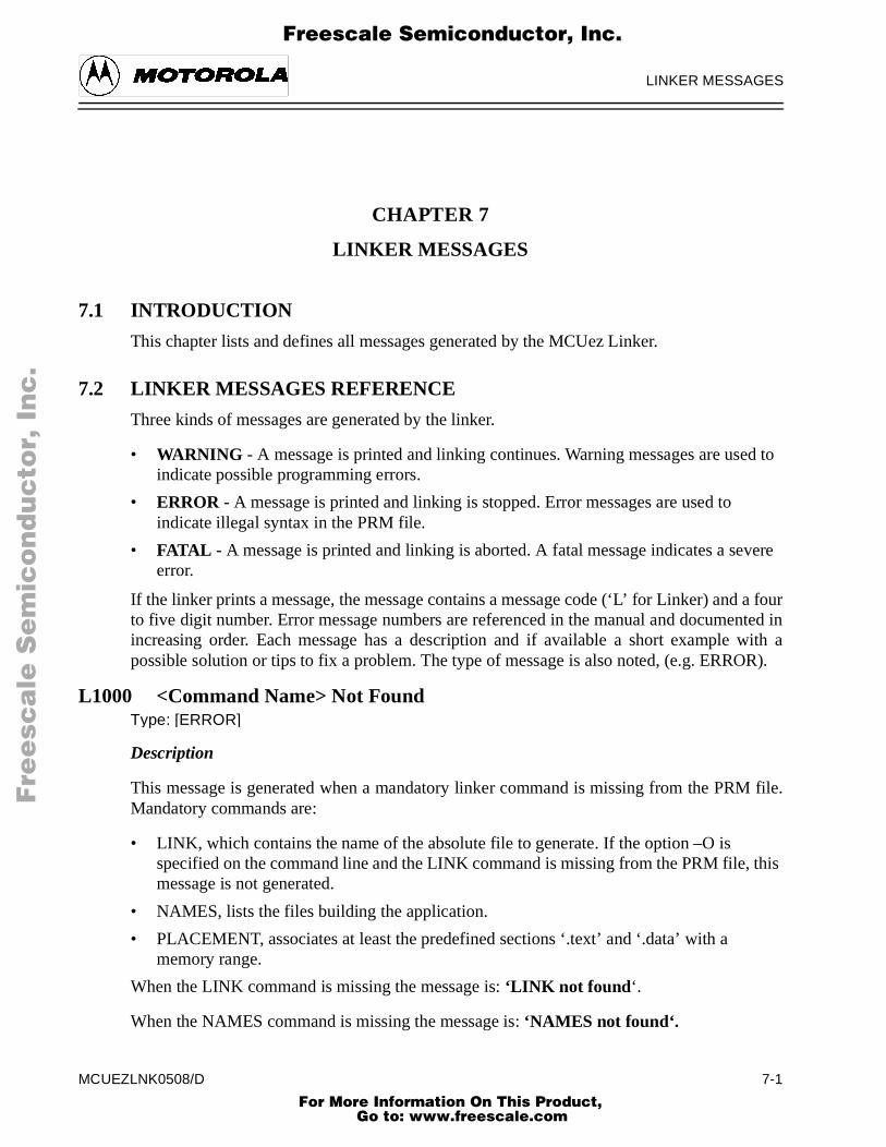
LINKER MESSAGES
ed to
vere
a fournted in with a
R).
M file.
this
F
ree
sca
le S
em
ico
nd
uc
tor,
I
Freescale Semiconductor, Inc.n
c..
.
CHAPTER 7
LINKER MESSAGES
7.1 INTRODUCTION
This chapter lists and defines all messages generated by the MCUez Linker.
7.2 LINKER MESSAGES REFERENCE
Three kinds of messages are generated by the linker.
• WARNING - A message is printed and linking continues. Warning messages are usindicate possible programming errors.
• ERROR - A message is printed and linking is stopped. Error messages are used to indicate illegal syntax in the PRM file.
• FATAL - A message is printed and linking is aborted. A fatal message indicates a seerror.
If the linker prints a message, the message contains a message code (‘L’ for Linker) andto five digit number. Error message numbers are referenced in the manual and documeincreasing order. Each message has a description and if available a short examplepossible solution or tips to fix a problem. The type of message is also noted, (e.g. ERRO
L1000 <Command Name> Not FoundType: [ERROR]
Description
This message is generated when a mandatory linker command is missing from the PRMandatory commands are:
• LINK, which contains the name of the absolute file to generate. If the option –O is specified on the command line and the LINK command is missing from the PRM file,message is not generated.
• NAMES, lists the files building the application.
• PLACEMENT, associates at least the predefined sections ‘.text’ and ‘.data’ with a memory range.
When the LINK command is missing the message is: ‘LINK not found ‘.
When the NAMES command is missing the message is: ‘NAMES not found‘.
MCUEZLNK0508/D 7-1 For More Information On This Product,
Go to: www.freescale.com

LINKER MESSAGES
M file.
ge.
F
ree
sca
le S
em
ico
nd
uc
tor,
I
Freescale Semiconductor, Inc.n
c..
.
When the PLACEMENT command is missing the message is: ‘PLACEMENT not found‘.
Example:
NAMES fibo.o start12s.o ansis.lib ENDSEGMENTS MY_RAM = READ_WRITE 0x800 TO 0x80F; MY_ROM = READ_ONLY 0x810 TO 0xAFF; MY_STK = READ_WRITE 0xB00 TO 0xBFF;PLACEMENT .text INTO MY_ROM; .data INTO MY_RAM; .stack INTO MY_STK;END/* Set reset vector on _Startup */VECTOR ADDRESS 0xFFFE _Startup
Tips
Insert the missing command in the PRM file.
Example
LINK fibo.absNAMES fibo.o start12s.o ansis.lib ENDSEGMENTS MY_RAM = READ_WRITE 0x800 TO 0x80F; MY_ROM = READ_ONLY 0x810 TO 0xAFF; MY_STK = READ_WRITE 0xB00 TO 0xBFF;PLACEMENT .text INTO MY_ROM; .data INTO MY_RAM; .stack INTO MY_STK;END/* Set reset vector on _Startup */VECTOR ADDRESS 0xFFFE _Startup
L1001 <Command Name> Multiply DefinedType: [ERROR]
Description:
This message is generated when a linker command is detected more than once in the PR
The following linker commands cannot be specified more than once in a PRM file.
• LINK, which contains the name of the absolute file to generate.
• NAMES, where files building the application are listed.
• SEGMENTS, where a name can be associated with a memory area.
• PLACEMENT, where sections used in the application are assigned to a memory ran
7-2 MCUEZLNK0508/D For More Information On This Product,
Go to: www.freescale.com

LINKER MESSAGES
F
ree
sca
le S
em
ico
nd
uc
tor,
I
Freescale Semiconductor, Inc.n
c..
.
• ENTRIES, where objects linked with the application are listed.
• MAPFILE, where information stored in the MAP file is specified.
• MAIN, defines the application main function.
• INIT, defines the application entry point.
• STACKSIZE, defines the stack size.
• STACKTOP, defines the stack pointer initial value.
When the LINK command is detected more than once, the message will be:
‘LINK multiply defined‘
Example:
LINK fibo.absNAMES fibo.o start12s.o ansis.lib ENDSEGMENTS MY_RAM = READ_WRITE 0x800 TO 0x80F; MY_ROM = READ_ONLY 0x810 TO 0xAFF; MY_STK = READ_WRITE 0xB00 TO 0xBFF;ENDPLACEMENT .text INTO MY_ROM; .data INTO MY_RAM; .stack INTO MY_STK;ENDLINK fibo.abs/* Set reset vector on _Startup */VECTOR ADDRESS 0xFFFE _Startup
Tips
Remove one of the duplicated commands.
Example:
LINK fibo.absNAMES fibo.o start12s.o ansis.lib ENDSEGMENTS MY_RAM = READ_WRITE 0x800 TO 0x80F; MY_ROM = READ_ONLY 0x810 TO 0xAFF; MY_STK = READ_WRITE 0xB00 TO 0xBFF;ENDPLACEMENT .text INTO MY_ROM; .data INTO MY_RAM; .stack INTO MY_STK;END/* Set reset vector on _Startup */VECTOR ADDRESS 0xFFFE _Startup
MCUEZLNK0508/D 7-3 For More Information On This Product,
Go to: www.freescale.com

LINKER MESSAGES
M file.
n the
. Theility
F
ree
sca
le S
em
ico
nd
uc
tor,
I
Freescale Semiconductor, Inc.n
c..
.
L1002 Command <Command Name> Overwritten by Option <Option Name>Type: [WARNING]
Description
This message is generated when a command line option overrides a command in the PR
<command name>: Name of the command in the PRM file
<option name>: Linker command line option
Commands that may be overridden by a command line option are:
• LINK, overridden by the option –O (defines the output file name)
• MAPFILE, overridden by the option –M (enables generation of the MAP file)
• INIT, overridden by the option –E (defines the application entry point)
When the LINK command is detected in the PRM file and the option –O is specified ocommand line, the following message is generated:
‘Command LINK overwritten by option -O‘
Tips
Remove either the command in the PRM file or the command line option.
L1003 Only a Single SEGMENTS or SECTIONS Block is AllowedType: [ERROR]
Description
This error occurs when the PRM file contains both a SECTIONS and a SEGMENTS blockSECTIONS block is a synonym for the SEGMENTS block. It is supported for compatibwith an old style MCUez PRM file.
Example
LINK fibo.absNAMES fibo.o start12s.o ansis.lib ENDSEGMENTS MY_RAM = READ_WRITE 0x800 TO 0x80F; MY_ROM = READ_ONLY 0x810 TO 0xAFF; MY_STK = READ_WRITE 0xB00 TO 0xBFF;ENDSECTIONS MY_RAM = READ_WRITE 0x800 TO 0x80F; MY_ROM = READ_ONLY 0x810 TO 0xAFF; MY_STK = READ_WRITE 0xB00 TO 0xBFF;PLACEMENT .text INTO MY_ROM;
7-4 MCUEZLNK0508/D For More Information On This Product,
Go to: www.freescale.com

LINKER MESSAGES
pected
ed on a
F
ree
sca
le S
em
ico
nd
uc
tor,
I
Freescale Semiconductor, Inc.n
c..
.
.data INTO MY_RAM; .stack INTO MY_STK;END/* Set reset vector on _Startup */VECTOR ADDRESS 0xFFFE _Startup
Tips
Remove either the SEGMENTS or SECTIONS block.
L1004 <Separator> ExpectedType: [ERROR]
Description
This message is generated when the specified <separator> is missing from an exposition.
<separator>: character or expression expected
Example 1:
SEGMENTS MY_RAM = READ_WRITE 0x800 TO 0x8FF ALIGN [2TO 4, 4] ^ ERROR: : expected.
Tips
Insert the specified separator at the expected position.
L1005 Fill Pattern Will Be Truncated (>0xFF)Type: [WARNING]
Description
This message is generated when the constant specified as a fill pattern cannot be codbyte. The constant truncated to a byte value will be used as the fill pattern.
Example
SEGMENTS MY_RAM = READ_WRITE 0x0800 TO 0x8FF FILL 0xA34;END
Tips
To avoid this message, split the constant into two byte constants.
Example
MCUEZLNK0508/D 7-5 For More Information On This Product,
Go to: www.freescale.com
LINKER MESSAGES
file.
inside
d as a
ined
F
ree
sca
le S
em
ico
nd
uc
tor,
I
Freescale Semiconductor, Inc.n
c..
.
SEGMENTS MY_RAM = READ_WRITE 0x0800 TO 0x8FF FILL 0xA 0x34;END
L1007 <Character> Not Allowed in File Name (Restriction)Type: [ERROR]
Description
A file name specified in the PRM file contains an illegal character.
<character>: characters not allowed in a file name at the indicated position.
Following characters are not allowed in a file name:
• Colon (:), Used as separator to specify a local object (function or variable) in a PRM
• Semi-colon(;), Used as delimiter for a command line in a LAYOUT or OBJECT_ALLOCATION block.
• Greater than symbol (>), Used as separator to refer to an object located in a sectiona LAYOUT or OBJECT_ALLOCATION block.
Avoid putting characters ‘+’ and ‘-‘ in a file name. This may cause a problem when usefile name suffix in the NAMES block.
Example
NAMES file:1.o; ^ERROR: ':' or '>' not allowed in file name (restriction)END
or
NAMES file1.o file>2.lib; ^ERROR: ':' or '>' not allowed in file name (restriction)END
Tips
Change the file name and avoid the illegal characters.
L1009 Segment Name <Segment Name> UnknownType: [ERROR]
Description
Segment specified in a PLACEMENT or LAYOUT command line was not previously defin the SEGMENTS block.
7-6 MCUEZLNK0508/D For More Information On This Product,
Go to: www.freescale.com
LINKER MESSAGES
d with
F
ree
sca
le S
em
ico
nd
uc
tor,
I
Freescale Semiconductor, Inc.n
c..
.
<segment name>: name of the segment, which is not known
Example
LINK fibo.absNAMES fibo.o start12s.o ansis.lib ENDSEGMENTS MY_RAM = READ_WRITE 0x800 TO 0x80F; MY_ROM = READ_ONLY 0x810 TO 0xAFF; MY_STK = READ_WRITE 0xB00 TO 0xBFF;ENDPLACEMENT .text INTO ROM_AREA; ^ERROR: Segment Name ROM_AREA unknown .data INTO MY_RAM; .stack INTO MY_STK;END/* Set reset vector on _Startup */VECTOR ADDRESS 0xFFFE _Startup
Tips
Define the segment names in the SEGMENTS block.
Example
LINK fibo.absNAMES fibo.o start12s.o ansis.lib ENDSEGMENTS RAM_AREA = READ_WRITE 0x800 TO 0x80F; ROM_AREA = READ_ONLY 0x810 TO 0xAFF; STK_AREA = READ_WRITE 0xB00 TO 0xBFF;ENDPLACEMENT .text INTO ROM_AREA; .data INTO RAM_AREA; .stack INTO STK_AREA;END/* Set reset vector on _Startup */VECTOR ADDRESS 0xFFFE _Startup
L1011 Incompatible Segment Qualifier: <Qualifier1> in Previous Segment and<Qualifier> in <Segment Name>
Type: [ERROR]
Description
Two segments specified in the same statement in the PLACEMENT block are not definethe same qualifier.
MCUEZLNK0508/D 7-7 For More Information On This Product,
Go to: www.freescale.com

LINKER MESSAGES
alifier
alifier
F
ree
sca
le S
em
ico
nd
uc
tor,
I
Freescale Semiconductor, Inc.n
c..
.
<qualifier1>: Segment qualifier associated with the previous segment in the list. This qumay be READ_ONLY, READ_WRITE, NO_INIT, or PAGED.
<qualifier2> Segment qualifier associated with the current segment in the list. This qumay be READ_ONLY, READ_WRITE, NO_INIT, or PAGED.
<segment name >: Name of the current segment in the list.
Example
LINK fibo.absNAMES fibo.o start12s.o ansis.lib ENDSEGMENTS MY_RAM = READ_WRITE 0x800 TO 0x80F; SEC_RAM= READ_WRITE 0x020 TO 0x02F; MY_ROM = READ_ONLY 0x810 TO 0xAFF; MY_STK = READ_WRITE 0xB00 TO 0xBFF;ENDPLACEMENT .data INTO MY_RAM; .text INTO MY_ROM, SEC_RAM; ^ERROR: Incompatible segment qualifier: READ_ONLY in previous segment and READ_WRITE in SEC_RAM .stack INTO MY_STK;END/* Set reset vector on _Startup */VECTOR ADDRESS 0xFFFE _Startup
Tips
Modify the qualifier associated with the specified segment.
Example
LINK fibo.absNAMES fibo.o start12s.o ansis.lib ENDSEGMENTS MY_RAM = READ_WRITE 0x800 TO 0x80F; SEC_ROM= READ_ONLY 0x020 TO 0x02F; MY_ROM = READ_ONLY 0x810 TO 0xAFF; MY_STK = READ_WRITE 0xB00 TO 0xBFF;ENDPLACEMENT .data INTO MY_RAM; .text INTO MY_ROM, SEC_ROM; .stack INTO MY_STK;END/* Set reset vector on _Startup */VECTOR ADDRESS 0xFFFE _Startup
7-8 MCUEZLNK0508/D For More Information On This Product,
Go to: www.freescale.com

LINKER MESSAGES
F
ree
sca
le S
em
ico
nd
uc
tor,
I
Freescale Semiconductor, Inc.n
c..
.
L1015 No Binary Input File SpecifiedType: [ERROR]
Description
No file names specified in the NAMES block.
Example
LINK fibo.absNAMES ENDSEGMENTS MY_RAM = READ_WRITE 0x800 TO 0x80F; MY_ROM = READ_ONLY 0x810 TO 0xAFF; MY_STK = READ_WRITE 0xB00 TO 0xBFF;ENDPLACEMENT .text INTO MY_ROM; .data INTO MY_RAM; .stack INTO MY_STK;END/* Set reset vector on _Startup */VECTOR ADDRESS 0xFFFE _Startup
Tips
Specify at least one file name in the NAMES block.
L1016 File <File Name> Found Twice in The NAMES BlockType: [ERROR]
Description
A file name is detected twice in the NAMES block.
<file name >: Name of file detected twice in the NAMES block.
Example
LINK fibo.absNAMES fibo.o startup.o fibo.o END ^ERROR: File fibo.o found twice in the NAMES blockSEGMENTS MY_RAM = READ_WRITE 0x800 TO 0x80F; MY_ROM = READ_ONLY 0x810 TO 0xAFF; MY_STK = READ_WRITE 0xB00 TO 0xBFF;ENDPLACEMENT .text INTO MY_ROM;
MCUEZLNK0508/D 7-9 For More Information On This Product,
Go to: www.freescale.com

LINKER MESSAGES
F
ree
sca
le S
em
ico
nd
uc
tor,
I
Freescale Semiconductor, Inc.n
c..
.
.data INTO MY_RAM; .stack INTO MY_STK;END/* Set reset vector on _Startup */VECTOR ADDRESS 0xFFFE _Startup
Tips
Remove the second occurrence of the specified file.
L1100 Segments <Segment1 Name> and <Segment2 Name> OverlapType: [ERROR]
Description
Two segments defined in the PRM file overlap each other.
<segment1 name >: Name of the first overlapping segment.
<segment2 name >: Name of the second overlapping segment.
Example
^Segments MY_RAM and MY_ROM overlapLINK fibo.absNAMES fibo.o startup.o ENDSEGMENTS MY_RAM = READ_WRITE 0x800 TO 0x80F; MY_ROM = READ_ONLY 0x805 TO 0xAFF; MY_STK = READ_WRITE 0xB00 TO 0xBFF;ENDPLACEMENT .text INTO MY_ROM; .data INTO MY_RAM; .stack INTO MY_STK;END/* Set reset vector on _Startup */VECTOR ADDRESS 0xFFFE _Startup
Tips
Modify the segment definition to remove the overlap.
Example
LINK fibo.absNAMES fibo.o startup.o ENDSEGMENTS MY_RAM = READ_WRITE 0x800 TO 0x80F; MY_ROM = READ_ONLY 0x810 TO 0xAFF;
7-10 MCUEZLNK0508/D For More Information On This Product,
Go to: www.freescale.com

LINKER MESSAGES
st
t.
ddress
and a
F
ree
sca
le S
em
ico
nd
uc
tor,
I
Freescale Semiconductor, Inc.n
c..
.
MY_STK = READ_WRITE 0xB00 TO 0xBFF;ENDPLACEMENT .text INTO MY_ROM; .data INTO MY_RAM; .stack INTO MY_STK;END/* Set reset vector on _Startup */VECTOR ADDRESS 0xFFFE _Startup
L1102 Out of Allocation Space in Segment <Segment Name> at Address <FirAddress Free>
Type: [ERROR]
Description
The specified segment is not big enough to contain all objects from sections placed in i
<segment name> : Name of the undersized segment.
<first address free>: First address free in this segment (i.e. address following the last aused).
Example
In the following example, assume the section ‘.data’ contains a character variable structure of 5 bytes.
^Out of allocation space in segment MY_RAM at address 0x801LINK fibo.absNAMES fibo.o startup.o ENDSEGMENTS MY_RAM = READ_WRITE 0x800 TO 0x803; MY_ROM = READ_ONLY 0x805 TO 0xAFF; MY_STK = READ_WRITE 0xB00 TO 0xBFF;ENDPLACEMENT .text INTO MY_ROM; .data INTO MY_RAM; .stack INTO MY_STK;END/* Set reset vector on _Startup */VECTOR ADDRESS 0xFFFE _Startup
Tips
Set the end address of the specified segment to a higher value.
MCUEZLNK0508/D 7-11 For More Information On This Product,
Go to: www.freescale.com

LINKER MESSAGES
always
forUez
ge is
F
ree
sca
le S
em
ico
nd
uc
tor,
I
Freescale Semiconductor, Inc.n
c..
.
L1103 <Section Name> Not Specified in The PLACEMENT BlockType: [ERROR]
Description
Indicates that a mandatory section is not specified in the placement block. Sections specified in the PLACEMENT block are .text and .data.
Example
^ERROR: .text not specified in the PLACEMENT blockLINK fibo.absNAMES fibo.o startup.o ENDSEGMENTS MY_RAM = READ_WRITE 0x800 TO 0x80F; MY_ROM = READ_ONLY 0x810 TO 0xAFF; MY_STK = READ_WRITE 0xB00 TO 0xBFF;ENDPLACEMENT .init, .rodata INTO MY_ROM; .data INTO MY_RAM; .stack INTO MY_STK;END/* Set reset vector on _Startup */VECTOR ADDRESS 0xFFFE _Startup
Tips
Insert the missing section in the PLACEMENT block.
Note:
The section DEFAULT_RAM is a synonym for .data and DEFAULT_ROM is a synonym.text. These two section names have been defined for compatibility with the old MCLinker.
L1106 <Object Name> Not FoundType: [ERROR|WARNING]
Description
An object referenced in the PRM file or in the application is not found. This messagenerated when:
• An object specified in a VECTOR or VECTOR ADDRESS command is not found (ERROR).
• No startup structure detected in the application (WARNING).
7-12 MCUEZLNK0508/D For More Information On This Product,
Go to: www.freescale.com

LINKER MESSAGES
).
.
s the
nameea is
F
ree
sca
le S
em
ico
nd
uc
tor,
I
Freescale Semiconductor, Inc.n
c..
.
• An object (function or variable) referenced in another object is not found in the application (ERROR).
• An object (function or variable) specified in the ENTRIES block is not found (ERROR
Example
^ ERROR: globInt not found LINK fibo.abs NAMES fibo.o startup.o END SEGMENTS MY_RAM = READ_WRITE 0x800 TO 0x80F; MY_ROM = READ_ONLY 0x810 TO 0xAFF; MY_STK = READ_WRITE 0xB00 TO 0xBFF; END PLACEMENT .text, .rodata INTO MY_ROM; .data INTO MY_RAM; .stack INTO MY_STK; END ENTRIES globInt; END /* Set reset vector on _Startup */ VECTOR ADDRESS 0xFFFE _Startup
Tips
The missing object must be implemented in one of the modules building the application
Ensure that your definition of OBJPATH and GENPATH is correct and the linker uselatest version of the object files.
Check the NAMES block to ensure all binary files building the application are listed.
L1109 <Segment Name> Appears Twice in SEGMENTS BlockType: [ERROR]
Description
A segment name is specified twice in a PRM file. This is not allowed. When this segmentis referenced in the PLACEMENT block, the linker cannot detect which memory arreferenced.
Example
LINK fibo.abs
MCUEZLNK0508/D 7-13 For More Information On This Product,
Go to: www.freescale.com

LINKER MESSAGES
ory area
ENTMENTboth
cified
F
ree
sca
le S
em
ico
nd
uc
tor,
I
Freescale Semiconductor, Inc.n
c..
.
NAMES fibo.o startup.o END SEGMENTS MY_RAM = READ_WRITE 0x800 TO 0x80F; MY_ROM = READ_ONLY 0x810 TO 0xAFF; MY_STK = READ_WRITE 0xB00 TO 0xBFF; MY_RAM = READ_WRITE 0xC00 TO 0xCFF; ^ ERROR: MY_RAM appears twice in SEGMENTS block END PLACEMENT .text, .rodata INTO MY_ROM; .data INTO MY_RAM; .stack INTO MY_STK; END /* Set reset vector on _Startup */ VECTOR ADDRESS 0xFFFE _Startup
Tips
Change one of the segment names, to generate unique segment names. If the same memis defined twice, you can remove one of the definitions.
L1110 <Segment Name> Appears Twice in PLACEMENT BlockType: [ERROR]
Description
The specified segment appears twice in a PLACEMENT block, and one of the PLACEMlines is part of a segment list. A segment name may appear in several lines in the PLACEblock, if it is the only segment specified in the segment list. Sections specified in PLACEMENT lines are merged into one list of sections, which are allocated in the spesegment.
Example
LINK fibo.abs NAMES fibo.o startup.o END SEGMENTS MY_RAM = READ_WRITE 0x800 TO 0x80F; MY_ROM = READ_ONLY 0x810 TO 0xAFF; MY_STK = READ_WRITE 0xB00 TO 0xBFF; ROM_2 = READ_ONLY 0x500 TO 0x7FF; END PLACEMENT .text, .rodata INTO MY_ROM; .data INTO MY_RAM;
7-14 MCUEZLNK0508/D For More Information On This Product,
Go to: www.freescale.com
LINKER MESSAGES
F
ree
sca
le S
em
ico
nd
uc
tor,
I
Freescale Semiconductor, Inc.n
c..
.
.stack INTO MY_STK; codeSec1, codeSec2 INTO ROM_2, MY_ROM; ^ ERROR: MY_ROM appears twice in PLACEMENT block END /* Set reset vector on _Startup */ VECTOR ADDRESS 0xFFFE _Startup
Tips
Remove one instance of the segment from the PLACEMENT block.
L1111 <Section Name> Appears Twice in PLACEMENT BlockType: [ERROR]
Description
The specified section appears multiple times in a PLACEMENT block.
Example
LINK fibo.abs NAMES fibo.o startup.o END SEGMENTS MY_RAM = READ_WRITE 0x800 TO 0x80F; MY_ROM = READ_ONLY 0x810 TO 0xAFF; MY_STK = READ_WRITE 0xB00 TO 0xBFF; ROM_2 = READ_ONLY 0x500 TO 0x7FF; END PLACEMENT .text, .rodata INTO MY_ROM; .data INTO MY_RAM; .stack INTO MY_STK; .text INTO ROM_2; ^ ERROR: .text appears twice in PLACEMENT block END /* Set reset vector on _Startup */ VECTOR ADDRESS 0xFFFE _Startup
Tips
Remove one occurrence of the specified section from the PLACEMENT block.
MCUEZLNK0508/D 7-15 For More Information On This Product,
Go to: www.freescale.com

LINKER MESSAGES
Il-
ge is
lifier.
F
ree
sca
le S
em
ico
nd
uc
tor,
I
Freescale Semiconductor, Inc.n
c..
.
L1112 The <Section name> Section Has Segment Type <Segment Qualifier> (legal)
Type: [ERROR]
Description
A section is placed in a segment defined with an incompatible qualifier. This messagenerated when:
• The section ‘.stack’ is placed in a READ_ONLY segment.
• The section ‘.bss’ is placed in a READ_ONLY segment.
• The section ‘.startData’ is placed in a READ_WRITE, NO_INIT or PAGED segment.
• The section ‘.init’ is placed in a READ_WRITE, NO_INIT or PAGED segment.
• The section ‘.copy’ is placed in a READ_WRITE, NO_INIT or PAGED segment.
• The section ‘.text’ is placed in a READ_WRITE, NO_INIT or PAGED segment.
• The section ‘.data’ is placed in a READ_ONLY segment.
• A data section is placed in a READ_ONLY segment.
• A code section is placed in a READ_WRITE segment.
Example
^ ERROR: The .data section has segment type READ_ONLY (illegal) LINK fibo.abs NAMES fibo.o startup.o END SEGMENTS MY_RAM = READ_WRITE 0x800 TO 0x80F; MY_ROM = READ_ONLY 0x810 TO 0xAFF; MY_STK = READ_WRITE 0xB00 TO 0xBFF; ROM_2 = READ_ONLY 0x500 TO 0x7FF; END PLACEMENT .text, .rodata INTO MY_ROM; .data INTO ROM_2; .stack INTO MY_STK; END /* Set reset vector on _Startup */ VECTOR ADDRESS 0xFFFE _Startup
Tips
Place the specified section in a segment that has been defined with an appropriate qua
7-16 MCUEZLNK0508/D For More Information On This Product,
Go to: www.freescale.com

LINKER MESSAGES
r>
_INITialized when:
F
ree
sca
le S
em
ico
nd
uc
tor,
I
Freescale Semiconductor, Inc.n
c..
.
Example
LINK fibo.abs NAMES fibo.o startup.o END SEGMENTS MY_RAM = READ_WRITE 0x800 TO 0x80F; MY_ROM = READ_ONLY 0x810 TO 0xAFF; MY_STK = READ_WRITE 0xB00 TO 0xBFF; ROM_2 = READ_ONLY 0x500 TO 0x7FF; END PLACEMENT .text INTO MY_ROM; .data INTO MY_RAM; .stack INTO MY_STK; END /* Set reset vector on _Startup */ VECTOR ADDRESS 0xFFFE _Startup
L1114 The <Section Name> Section Has Segment Type <Segment Qualifie(Initialization Problem)
Type: [WARNING]
Description
The specified section is loaded in a segment that has been defined with the qualifier NOor PAGED. This may generate a problem because the section contains some initconstants, which will not be initialized at application startup. This message is generated
• The section ‘.rodata’ is placed in a NO_INIT or PAGED segment.
• The section ‘.rodata1’ is placed in a NO_INIT or PAGED segment.
Example
^ WARNING: The .rodata section has segment type NO_INIT (initial-ization problem) LINK fibo.abs NAMES fibo.o startup.o END SEGMENTS MY_RAM = READ_WRITE 0x800 TO 0x80F; MY_ROM = READ_ONLY 0x810 TO 0xAFF; MY_STK = READ_WRITE 0xB00 TO 0xBFF; RAM_2 = NO_INIT 0x500 TO 0x7FF; END PLACEMENT .text INTO MY_ROM; .data INTO MY_RAM;
MCUEZLNK0508/D 7-17 For More Information On This Product,
Go to: www.freescale.com

LINKER MESSAGES
ITE
main
n. tion nd
F
ree
sca
le S
em
ico
nd
uc
tor,
I
Freescale Semiconductor, Inc.n
c..
.
.stack INTO MY_STK; .rodata INTO RAM_2; END /* Set reset vector on _Startup */ VECTOR ADDRESS 0xFFFE _Startup
Tips
Place the specified section in a segment defined with the READ_ONLY or READ_WRqualifier.
Example
LINK fibo.abs NAMES fibo.o startup.o END SEGMENTS MY_RAM = READ_WRITE 0x800 TO 0x80F; MY_ROM = READ_ONLY 0x810 TO 0xAFF; MY_STK = READ_WRITE 0xB00 TO 0xBFF; RAM_2 = NO_INIT 0x500 TO 0x7FF; END PLACEMENT .text INTO MY_ROM; .data INTO MY_RAM; .stack INTO MY_STK; .rodata INTO MY_ROM; END /* Set reset vector on _Startup */ VECTOR ADDRESS 0xFFFE _Startup
L1115 Function <Function Name> Not FoundType: [ERROR|WARNING]
Description
The specified function is not found in the application. This message is generated when:
• No main function is available in the application. This function is not required for an assembly application. For ANSI C applications, if no main function is available, the programmer must ensure that application startup is performed correctly. Usually thefunction is called ‘main’, but you can define your own main function using the linker command MAIN.
• No init function is available. The init function defines the entry point in the applicatioThis function is required for ANSI C and assembly applications. Usually the init funcis called ‘_Startup’, but you can define your own init function using the linker commaINIT.
7-18 MCUEZLNK0508/D For More Information On This Product,
Go to: www.freescale.com

LINKER MESSAGES
ENTctions.
lock.
F
ree
sca
le S
em
ico
nd
uc
tor,
I
Freescale Semiconductor, Inc.n
c..
.
Tips
Provide the application with the requested function.
L1118 Vector Allocated at Absolute Address <Address> Overlaps With AnotherVector or an Absolutely Allocated Object
Type: [ERROR]
Description
A vector overlaps with an absolute object or another vector.
Example
^ ERROR: Vector allocated at absolute address 0xFFFE overlaps with another vector or an absolutely allocated object LINK fibo.abs NAMES fibo.o startup.o END SEGMENTS MY_RAM = READ_WRITE 0x800 TO 0x80F; MY_ROM = READ_ONLY 0x810 TO 0xAFF; MY_STK = READ_WRITE 0xB00 TO 0xBFF; END PLACEMENT .text, .rodata INTO MY_ROM; .data INTO MY_RAM; .stack INTO MY_STK; END /* Set reset vector on _Startup */ VECTOR ADDRESS 0xFFFE _Startup VECTOR ADDRESS 0xFFFF 0x000A
Tips
Move the object or vector to a free position.
L1119 Vector Allocated at Absolute Address <Address> Overlaps With SectionsPlaced in Segment <Segment Name>
Type: [ERROR]
Description
The specified vector is allocated inside a segment, which is specified in the PLACEMblock. This is not allowed because the vector may overlap with objects defined in the se
A vector may be allocated inside a segment that does not appear in the PLACEMENT b
MCUEZLNK0508/D 7-19 For More Information On This Product,
Go to: www.freescale.com

LINKER MESSAGES
F
ree
sca
le S
em
ico
nd
uc
tor,
I
Freescale Semiconductor, Inc.n
c..
.
Example
^ ERROR: Vector allocated at absolute address 0xFFFE overlaps with sections placed in segment ROM_2 LINK fibo.abs NAMES fibo.o startup.o END SEGMENTS MY_RAM = READ_WRITE 0x800 TO 0x80F; MY_ROM = READ_ONLY 0x810 TO 0xAFF; MY_STK = READ_WRITE 0xB00 TO 0xBFF; ROM_2 = READ_ONLY 0xFF00 TO 0xFFFF; END PLACEMENT .text INTO MY_ROM; .data INTO MY_RAM; .stack INTO MY_STK; .rodata INTO ROM_2; END /* Set reset vector on _Startup */ VECTOR ADDRESS 0xFFFE _Startup
Tips
Define the specified segment outside the vector table.
Example
LINK fibo.abs NAMES fibo.o startup.o END SEGMENTS MY_RAM = READ_WRITE 0x800 TO 0x80F; MY_ROM = READ_ONLY 0x810 TO 0xAFF; MY_STK = READ_WRITE 0xB00 TO 0xBFF; ROM_2 = READ_ONLY 0xC00 TO 0xCFF; END PLACEMENT .text INTO MY_ROM; .data INTO MY_RAM; .stack INTO MY_STK; .rodata INTO ROM_2; END /* Set reset vector on _Startup */ VECTOR ADDRESS 0xFFFE _Startup
7-20 MCUEZLNK0508/D For More Information On This Product,
Go to: www.freescale.com

LINKER MESSAGES
t
NLY.shouldn, the
F
ree
sca
le S
em
ico
nd
uc
tor,
I
Freescale Semiconductor, Inc.n
c..
.
L1120 Vector Allocated at Absolute Address <Address> Placed in Segmen<Segment Name>, Which Has No READ_ONLY qualifier.
Type: [ERROR]
Description
The specified vector is defined inside a segment not defined with the qualifier READ_OThe vector table should be initialized at application load time during the debug phase. It be burned into the EPROM when application development is terminated. For this reasovector table must always be located in a READ_ONLY memory area.
Example
^ ERROR: Vector allocated at absolute address 0xFFFE placed in segment RAM_2 which has not READ_ONLY qualifier LINK fibo.abs NAMES fibo.o startup.o END SEGMENTS MY_RAM = READ_WRITE 0x800 TO 0x80F; MY_ROM = READ_ONLY 0x810 TO 0xAFF; MY_STK = READ_WRITE 0xB00 TO 0xBFF; RAM_2 = READ_WRITE 0xFF00 TO 0xFFFF; END PLACEMENT .text INTO MY_ROM; .data INTO MY_RAM; .stack INTO MY_STK; END /* Set reset vector on _Startup */ VECTOR ADDRESS 0xFFFE _Startup
Tips
Define the specified segment with the READ_ONLY qualifier.
L1121 Out of Allocation Space at Address <Address> for .copy SectionType: [ERROR]
Description
Insufficient memory to store information for initialized variables in the ‘.copy’ section.
Tips
Specify a higher end address for the segment, where the ‘.copy’ section is allocated.
MCUEZLNK0508/D 7-21 For More Information On This Product,
Go to: www.freescale.com
LINKER MESSAGES
lock.en, the
arate
F
ree
sca
le S
em
ico
nd
uc
tor,
I
Freescale Semiconductor, Inc.n
c..
.
L1122 Section .copy Must be The Last Section in The Section ListType: [ERROR]
Description
The ‘.copy’ section is not specified at the end of a section list from the PLACEMENT bSince the size of this section cannot be evaluated before all initialization values are writt.copy section must be the last section in a section list.
Example
^ ERROR: Section .copy must be the last section in the section list LINK fibo.abs NAMES fibo.o startup.o END SEGMENTS MY_RAM = READ_WRITE 0x800 TO 0x80F; MY_ROM = READ_ONLY 0x810 TO 0xAFF; MY_STK = READ_WRITE 0xB00 TO 0xBFF; END PLACEMENT .copy, .text INTO MY_ROM; .data INTO MY_RAM; .stack INTO MY_STK; END /* Set reset vector on _Startup */ VECTOR ADDRESS 0xFFFE _Startup
Tips
Move the section .copy to the last position in the section list or define it on a sepPLACEMENT line in a separate segment.
Example
LINK fibo.abs NAMES fibo.o startup.o END SEGMENTS MY_RAM = READ_WRITE 0x800 TO 0x80F; MY_ROM = READ_ONLY 0x810 TO 0xAFF; MY_STK = READ_WRITE 0xB00 TO 0xBFF; ROM_2 = READ_ONLY 0xC00 TO 0xDFF; END PLACEMENT .text INTO MY_ROM; .data INTO MY_RAM; .stack INTO MY_STK;
7-22 MCUEZLNK0508/D For More Information On This Product,
Go to: www.freescale.com

LINKER MESSAGES
s
ress is
w
F
ree
sca
le S
em
ico
nd
uc
tor,
I
Freescale Semiconductor, Inc.n
c..
.
.copy INTO ROM_2; END /* Set reset vector on _Startup */ VECTOR ADDRESS 0xFFFE _Startup
L1123 Invalid Range Defined For Segment <Segment Name> - End AddresMust Be Bigger Than Start Address
Type: [ERROR]
Description
The memory range specified in the segment definition is not valid. The segment end addsmaller than the segment start address.
Example
LINK fibo.abs NAMES fibo.o startup.o END SEGMENTS MY_RAM = READ_WRITE 0x800 TO 0x7FF; ^ ERROR: Invalid range defined for segment MY_RAM. End address must be bigger than start address MY_ROM = READ_ONLY 0x810 TO 0xAFF; MY_STK = READ_WRITE 0xB00 TO 0xBFF; END PLACEMENT .text INTO MY_ROM; .data INTO MY_RAM; .stack INTO MY_STK; END /* Set reset vector on _Startup */ VECTOR ADDRESS 0xFFFE _Startup
Tips
Change the segment start or end address to define a valid memory range.
L1124 '+' or '-' Should Directly Follow The File NameType: [ERROR]
Description
The ‘+’ or ‘-‘ suffix specified after a file name in the NAMES block does not directly follothe file name. A space probably exists between the file name and suffix.
Example
MCUEZLNK0508/D 7-23 For More Information On This Product,
Go to: www.freescale.com

LINKER MESSAGES
emory
F
ree
sca
le S
em
ico
nd
uc
tor,
I
Freescale Semiconductor, Inc.n
c..
.
LINK fibo.abs NAMES fibo.o + startup.o END ^ ERROR: '+' or '-' should directly follow the file name SEGMENTS MY_RAM = READ_WRITE 0x800 TO 0x80F; MY_ROM = READ_ONLY 0x810 TO 0xAFF; MY_STK = READ_WRITE 0xB00 TO 0xBFF; END PLACEMENT .text INTO MY_ROM; .data INTO MY_RAM; .stack INTO MY_STK; END /* Set reset vector on _Startup */ VECTOR ADDRESS 0xFFFE _Startup
Tips
Remove the extra space after the file name.
Example
LINK fibo.abs NAMES fibo.o+ startup.o END SEGMENTS MY_RAM = READ_WRITE 0x800 TO 0x80F; MY_ROM = READ_ONLY 0x810 TO 0xAFF; MY_STK = READ_WRITE 0xB00 TO 0xBFF; END PLACEMENT .text INTO MY_ROM; .data INTO MY_RAM; .stack INTO MY_STK; END /* Set reset vector on _Startup */ VECTOR ADDRESS 0xFFFE _Startup
L1125 In Small Memory Model, Code and Data Must Be Located on Bank 0Type: [ERROR]
Description
The application has been assembled or compiled in a small memory model and the marea specified for a segment is not located on the first 64K (0x0000 to 0xFFFF).
7-24 MCUEZLNK0508/D For More Information On This Product,
Go to: www.freescale.com

LINKER MESSAGES
t beFF is
not
F
ree
sca
le S
em
ico
nd
uc
tor,
I
Freescale Semiconductor, Inc.n
c..
.
Example
^ ERROR: In small memory model, code and data must be located on bank 0 LINK fibo.abs NAMES fibo.o startup.o END SEGMENTS MY_RAM = READ_WRITE 0x800 TO 0x80F; MY_ROM = READ_ONLY 0x10810 TO 0x10AFF; MY_STK = READ_WRITE 0xB00 TO 0xBFF; END PLACEMENT .text INTO MY_ROM; .data INTO MY_RAM; .stack INTO MY_STK; END /* Set reset vector on _Startup */ VECTOR ADDRESS 0xFFFE _Startup
Tips
If memory higher than 0xFFFF is required for the application, the application musassembled or compiled using the banked memory model. If no memory above 0xFFrequired, modify the memory range and place it on the first 64K of memory.
L1200 Both STACKTOP and STACKSIZE DefinedType: [ERROR]
Description
The STACKTOP and STACKSIZE commands are specified in the PRM file. This isallowed, because it generates ambiguity for the definition of the stack.
Example
^ ERROR: Both STACKTOP and STACKSIZE defined LINK fibo.abs NAMES fibo.o startup.o END STACKTOP 0xBFE SEGMENTS MY_RAM = READ_WRITE 0x800 TO 0x80F; MY_ROM = READ_ONLY 0x810 TO 0xAFF; END PLACEMENT .text INTO MY_ROM; .data INTO MY_RAM;
MCUEZLNK0508/D 7-25 For More Information On This Product,
Go to: www.freescale.com

LINKER MESSAGES
mern be
ation
F
ree
sca
le S
em
ico
nd
uc
tor,
I
Freescale Semiconductor, Inc.n
c..
.
END STACKSIZE 0x60 /* Set reset vector on _Startup */ VECTOR ADDRESS 0xFFFE _Startup
Tips
Remove either the STACKTOP or STACKSIZE command from the PRM file.
L1201 No Stack DefinedType: [WARNING]
Description
The PRM file does not contain a stack definition. In that case, it is the programresponsibility to initialize the stack pointer inside the application code. The stack cadefined in the PRM file in one of the following ways:
• Through the STACKTOP command in the PRM file.
• Through the STACKSIZE command in the PRM file.
• Through the specification of the .stack section in the placement block.
Example
^WARNING: No stack defined LINK fibo.abs NAMES fibo.o startup.o END SEGMENTS MY_RAM = READ_WRITE 0x800 TO 0x80F; MY_ROM = READ_ONLY 0x810 TO 0xAFF; END PLACEMENT .text INTO MY_ROM; .data INTO MY_RAM; END /* Set reset vector on _Startup */ VECTOR ADDRESS 0xFFFE _Startup
Tips
Define the stack in one of the three ways specified above.
Note that if the programmer initializes the stack pointer inside the source code, initializfrom the linker will be overridden.
7-26 MCUEZLNK0508/D For More Information On This Product,
Go to: www.freescale.com

LINKER MESSAGES
d. Thisd cannot
ck.
a
ectionIZE
F
ree
sca
le S
em
ico
nd
uc
tor,
I
Freescale Semiconductor, Inc.n
c..
.
L1202 Stack Cannot Be Allocated on More Than One SegmentType: [ERROR]
Description
The section .stack is specified on a PLACEMENT line where several segments are listeis not allowed, because the memory area reserved for the stack must be contiguous anbe split over different memory ranges.
Example
^ ERROR: stack cannot be allocated on more than one segment LINK fibo.abs NAMES fibo.o startup.o END SEGMENTS MY_RAM = READ_WRITE 0x800 TO 0x80F; MY_ROM = READ_ONLY 0x810 TO 0xAFF; STK_1 = READ_WRITE 0xB00 TO 0xBFF; STK_2 = READ_WRITE 0xD00 TO 0xDFF; END PLACEMENT .text INTO MY_ROM; .data INTO MY_RAM; .stack INTO STK_1, STK_2; END /* Set reset vector on _Startup */ VECTOR ADDRESS 0xFFFE _Startup
Tips
Define a single segment with the READ_WRITE or NO_INIT qualifier to allocate the sta
L1203 STACKSIZE Command Defines a Size of <Size> But .stack Specifies Stacksize of <Size>
Type: [ERROR]
Description
The stack is defined through both a STACKSIZE command and placement of the .stack sin a READ_WRITE or NO_INIT segment. However, the size specified in the STACKScommand is bigger than the size of the segment where the stack is allocated.
Example
^ ERROR: STACKSIZE command defines a size of 0x120 but .stack specifies a stacksize of 0x100 LINK fibo.abs
MCUEZLNK0508/D 7-27 For More Information On This Product,
Go to: www.freescale.com

LINKER MESSAGES
and toZE.
lize
where:
F
ree
sca
le S
em
ico
nd
uc
tor,
I
Freescale Semiconductor, Inc.n
c..
.
NAMES fibo.o startup.o END SEGMENTS MY_RAM = READ_WRITE 0x800 TO 0x80F; MY_ROM = READ_ONLY 0x810 TO 0xAFF; STK_1 = READ_WRITE 0xB00 TO 0xBFF; END PLACEMENT .text INTO MY_ROM; .data INTO MY_RAM; .stack INTO STK_1; END STACKSIZE 0x120 /* Set reset vector on _Startup */ VECTOR ADDRESS 0xFFFE _Startup
Tips
To avoid this message you can either adapt the size specified in the STACKSIZE commfit into the segment where .stack is allocated or simply remove the command STACKSI
If you remove the command STACKSIZE from the previous example, the linker will initiaa stack from 0x100 bytes. The stack pointer initial value will be set to 0xBFE.
Example
LINK fibo.abs NAMES fibo.o startup.o END SEGMENTS MY_RAM = READ_WRITE 0x800 TO 0x80F; MY_ROM = READ_ONLY 0x810 TO 0xAFF; MY_STK = READ_WRITE 0xB00 TO 0xBFF; END PLACEMENT .text INTO MY_ROM; .data INTO MY_RAM; .stack INTO MY_STK; END /* Set reset vector on _Startup */ VECTOR ADDRESS 0xFFFE _Startup
If the size specified in a STACKSIZE command is smaller than the size of the segment the section .stack is allocated, the stack pointer initial value will be evaluated as follows
<segment start address> + <size in STACKSIZE> - <Additional Byte Required by the processor.>
Example
LINK fibo.abs NAMES fibo.o startup.o END
7-28 MCUEZLNK0508/D For More Information On This Product,
Go to: www.freescale.com

LINKER MESSAGES
sectionOP
F
ree
sca
le S
em
ico
nd
uc
tor,
I
Freescale Semiconductor, Inc.n
c..
.
SEGMENTS MY_RAM = READ_WRITE 0x800 TO 0x80F; MY_ROM = READ_ONLY 0x810 TO 0xAFF; MY_STK = READ_WRITE 0xB00 TO 0xBFF; END PLACEMENT .text INTO MY_ROM; .data INTO MY_RAM; .stack INTO MY_STK; END STACKSIZE 0x60 /* Set reset vector on _Startup */ VECTOR ADDRESS 0xFFFE _Startup
In the previous example, the initial value for the stack pointer is evaluated as:
0xB00 + 0x60s –2 = 0xB5E
L204 STACKTOP Command Defines an Initial Value of <Stack Top> But.stack Specifies an Initial Value of <Initial Value>
Type: [ERROR]
Description
The stack is defined through both a STACKTOP command and placement of the .stack in a READ_WRITE or NO_INIT segment. However, the value specified in the STACKTcommand is bigger than the end address of the segment where the stack is allocated.
Example
^ ERROR: STACKTOP command defines an initial value of 0xCFE but .stack specifies an initial value of 0xBFF LINK fibo.abs NAMES fibo.o startup.o END SEGMENTS MY_RAM = READ_WRITE 0x800 TO 0x80F; MY_ROM = READ_ONLY 0x810 TO 0xAFF; STK_1 = READ_WRITE 0xB00 TO 0xBFF; END PLACEMENT .text INTO MY_ROM; .data INTO MY_RAM; .stack INTO STK_1; END STACKTOP 0xCFE /* Set reset vector on _Startup */ VECTOR ADDRESS 0xFFFE _Startup
MCUEZLNK0508/D 7-29 For More Information On This Product,
Go to: www.freescale.com

LINKER MESSAGES
mmandTOP.
initial
sectiontions
F
ree
sca
le S
em
ico
nd
uc
tor,
I
Freescale Semiconductor, Inc.n
c..
.
Tips
To avoid this message you can either adapt the address specified in the STACKTOP coto fit into the segment where .stack is allocated, or simply remove the command STACK
If you remove the command STACKTOP from the previous example, the stack pointer value will be set to 0xBFE.
Example
LINK fibo.abs NAMES fibo.o startup.o END SEGMENTS MY_RAM = READ_WRITE 0x800 TO 0x80F; MY_ROM = READ_ONLY 0x810 TO 0xAFF; MY_STK = READ_WRITE 0xB00 TO 0xBFF; END PLACEMENT .text INTO MY_ROM; .data INTO MY_RAM; .stack INTO MY_STK; END /* Set reset vector on _Startup */ VECTOR ADDRESS 0xFFFE _Startup
L1205 STACKTOP Command Incompatible With .stack Being Part of a List ofSections
Type: [ERROR]
Description
The stack is defined through both a STACKTOP command and placement of the .stack in a READ_WRITE or NO_INIT segment. The .stack section is specified in a list of secin the PLACEMENT block.
Example
^ ERROR: STACKTOP command incompatible with .stack being part of a list of sections LINK fibo.abs NAMES fibo.o startup.o END SEGMENTS MY_RAM = READ_WRITE 0x800 TO 0x80F; MY_ROM = READ_ONLY 0x810 TO 0xAFF; STK_1 = READ_WRITE 0xB00 TO 0xBFF; END PLACEMENT .text INTO MY_ROM;
7-30 MCUEZLNK0508/D For More Information On This Product,
Go to: www.freescale.com

LINKER MESSAGES
ide a
F
ree
sca
le S
em
ico
nd
uc
tor,
I
Freescale Semiconductor, Inc.n
c..
.
.data, .stack INTO STK_1; END STACKTOP 0xBFE /* Set reset vector on _Startup */ VECTOR ADDRESS 0xFFFE _Startup
Tips
Specify the .stack section in a placement line, where the stack alone is specified.
L1206 Stack Overlaps With a Segment Which Appears in The PLACEMENTBlock
Type: [ERROR]
Description
The stack is defined through the command STACKTOP and the initial value is inssegment, which is used in the PLACEMENT block.
This is not allowed because the stack may overlap with allocated objects.
Example
^ ERROR: .stack overlaps with a segment which appears in the PLACEMENT block LINK fibo.abs NAMES fibo.o startup.o END SEGMENTS MY_RAM = READ_WRITE 0x800 TO 0x80F; MY_ROM = READ_ONLY 0x810 TO 0xAFF; STK_1 = READ_WRITE 0xB00 TO 0xBFF; END PLACEMENT .text INTO MY_ROM; .data INTO STK_1; END STACKTOP 0xBFE /* Set reset vector on _Startup */ VECTOR ADDRESS 0xFFFE _Startup
Tips
Define the stack initial value outside all segments specified in the PLACEMENT block.
Example
LINK fibo.abs NAMES fibo.o startup.o END
MCUEZLNK0508/D 7-31 For More Information On This Product,
Go to: www.freescale.com

LINKER MESSAGES
ent,mand
F
ree
sca
le S
em
ico
nd
uc
tor,
I
Freescale Semiconductor, Inc.n
c..
.
SEGMENTS MY_RAM = READ_WRITE 0x800 TO 0x80F; MY_ROM = READ_ONLY 0x810 TO 0xAFF; MY_STK = READ_WRITE 0xB00 TO 0xBFF; END PLACEMENT .text INTO MY_ROM; .data INTO MY_RAM; END STACKTOP 0xBFE /* Set reset vector on _Startup */ VECTOR ADDRESS 0xFFFE _Startup
L1207 STACKSIZE Command is MissingType: [ERROR]
Description
The stack is defined by placing the .stack section in a READ_WRITE or NO_INIT segmalthough the .stack section is not alone in the section list. In this case, a STACKSIZE comis required to specify the stack size.
Example
^ ERROR: STACKSIZE command is missing LINK fibo.abs NAMES fibo.o startup.o END SEGMENTS MY_RAM = READ_WRITE 0x800 TO 0x80F; MY_ROM = READ_ONLY 0x810 TO 0xAFF; STK_1 = READ_WRITE 0xB00 TO 0xBFF; END PLACEMENT .text INTO MY_ROM; .data, .stack INTO STK_1; END /* Set reset vector on _Startup */ VECTOR ADDRESS 0xFFFE _Startup
Tips
Specify the stack size in a STACKSIZE command.
L1301 Cannot Open File <File Name>Type: [ERROR]
7-32 MCUEZLNK0508/D For More Information On This Product,
Go to: www.freescale.com

LINKER MESSAGES
used
o store
tory
firstd.
pathsn the
n:
ted in
les.
on to
listed
F
ree
sca
le S
em
ico
nd
uc
tor,
I
Freescale Semiconductor, Inc.n
c..
.
Description
The linker is unable to open the application map file, absolute file or one of the binary filesto build the application.
Tips
If the abs or map file cannot be found, ensure that memory is available for the directory tthe file and the directory has read/write access.
If the environment variable TEXTPATH is defined, the MAP file is stored in the first direcspecified, otherwise it is created in the directory where the source file is detected.
If the environment variable ABSPATH is defined, the absolute file is stored in the directory specified, otherwise it is created in the directory where the PRM file is detecte
If a binary file cannot be found, make sure the file exists and spelled correctly. Check ifare defined correctly. The binary files must be located in one of the paths listed ienvironment variables OBJPATH or GENPATH, or in the working directory.
L1302 File <File Name> Not FoundType: [ERROR]
Description
A file required during the link session cannot be found. This message is generated whe
• The parameter file specified on the command line cannot be found.
Tips
Make sure the file really exists and spelled correctly.
Check if paths are defined correctly. The PRM file must be located in one of the paths listhe environment variable GENPATH or in the project directory.
L1303 <File Name> Is Not a Valid ELF FileType: [ERROR]
Description
The specified file is not a valid ELF binary file. The linker is only able to link ELF binary fi
Tips
Check that you have compiled or assembled the specified file with the correct optigenerate an ELF binary file.
Check if paths are defined correctly. The binary files must be located in one of the pathsin the environment variables OBJPATH or GENPATH, or in the project directory.
MCUEZLNK0508/D 7-33 For More Information On This Product,
Go to: www.freescale.com

LINKER MESSAGES
-
essor.
listed
del. In
listed
listed
.
F
ree
sca
le S
em
ico
nd
uc
tor,
I
Freescale Semiconductor, Inc.n
c..
.
L1400 Incompatible Processor: <Processor Name> in Previous Files and <Processor Name> in Current File
Type: [ERROR]
Description
The binary files building the application have been generated for a different target procIn this case, the linked code cannot be compatible.
Tips
Make sure you are compiling or assembling all your sources for the same processor.
Check if paths are defined correctly. The binary files must be located in one of the pathsin the environment variables OBJPATH or GENPATH, or in the project directory.
L1401 Incompatible Memory Model: <Memory Model Name> in Previous Filesand <Memory Model Name> in Current File
Type: [ERROR]
Description
The binary files building the application have been generated for a different memory mothis case, the linked code cannot be compatible.
Tips
Make sure you are compiling or assembling all sources in the same memory model.
Check if paths are defined correctly. The binary files must be located in one of the pathsin the environment variables OBJPATH or GENPATH, or in the project directory.
L1403 Unknown Processor <Processor Constant>Type: [ERROR]
Description
The processor encoded in the binary object file is not a valid processor constant.
Tips
Check if paths are defined correctly. The binary files must be located in one of the pathsin the environment variables OBJPATH or GENPATH, or in the project directory.
L1404 Unknown Memory Model <Memory Model Constant>Type: [ERROR]
Description
The memory model encoded in the binary object file is not valid for the target processor
7-34 MCUEZLNK0508/D For More Information On This Product,
Go to: www.freescale.com

LINKER MESSAGES
listed
ROM
int is
his ishe field
ture
F
ree
sca
le S
em
ico
nd
uc
tor,
I
Freescale Semiconductor, Inc.n
c..
.
Tips
Check if paths are defined correctly. The binary files must be located in one of the pathsin the environment variables OBJPATH or GENPATH, or in the project directory.
L1600 Main Function Detected in ROM LibraryType: [WARNING]
Description
A main function has been detected in a ROM library. A main function is not required in a library since they are not self executable applications.
Tips
Remove the MAIN command from the PRM file.
If the application contains a ‘main’ function, rename it.
L1601 Startup Function detected in ROM libraryType: [WARNING]
Description
An application entry point has been detected in a ROM library. An application entry ponot required in a ROM library.
Tips
Remove the INIT command from the PRM file.
If the application contains a ‘_Startup’ function, rename it.
L1700 File <File Name> Should Contain DWARF InformationType: [ERROR]
Description
The binary file that defines the startup structure does not contain DWARF information. Trequired because the type of startup structure is not fixed by the linker and depends on tand field position inside the user defined structure.
Tips
Insert DWARF information and recompile the ANSI C file containing the startup strucdefinition.
MCUEZLNK0508/D 7-35 For More Information On This Product,
Go to: www.freescale.com

LINKER MESSAGES
listed
listed
F
ree
sca
le S
em
ico
nd
uc
tor,
I
Freescale Semiconductor, Inc.n
c..
.
L1701 Start Up Data Structure is EmptyType: [ERROR]
Description
The size of the user defined startup structure is 0 bytes.
Tips
Check if you actually need a startup structure.
If a startup structure is available, ensure that the correct field name is listed.
L1803 Out of Memory in <Function Name>Type: [ERROR]
Description
Insufficient memory to allocate the internal structure required by the linker.
L1804 No Elf Section Header Table Found in <File Name> Type: [ERROR]
Description
Section header table not detected in the binary file.
Tips
Ensure that you are using the correct binary file.
Check if paths are defined correctly. The binary files must be located in one of the pathsin the environment variables OBJPATH or GENPATH, or in the project directory.
L1806 Elf file <File Name> appears to be corruptedType: [ERROR]
Description
The specified binary file is not a valid ELF binary file.
Tips
Ensure that you are using the correct binary file.
Check if paths are defined correctly. The binary files must be located in one of the pathsin the environment variables OBJPATH or GENPATH, or in the project directory.
L1808 String overflow in <Function Name>, contact vendor Type: [ERROR]
7-36 MCUEZLNK0508/D For More Information On This Product,
Go to: www.freescale.com

LINKER MESSAGES
In one
in the
F
ree
sca
le S
em
ico
nd
uc
tor,
I
Freescale Semiconductor, Inc.n
c..
.
Description
A section name detected in a section table is longer than 100 characters.
Tips
Ensure all section names are smaller than 100 characters.
L1809 Section <Section Name> located in a segment with invalid qualifier.Type: [ERROR]
Description
Attributes associated with a section and used in several binary files are not compatible.file, the section contains variables in the other it contains constants, variables, or code.
Tips
Check usage of the different sections in all binary files. A specific section should contasame type of information throughout the project.
L1811 Symbol <Symbol Number> - < Symbol Name> duplicated in <First FileName> and <Second file Name>
Type: [ERROR]
Description
The specified global symbol is defined in two different binary files.
Tips
Rename the symbol defined in one of the specified files.
L1820 Weak symbol <Symbol Name> duplicated in <First File Name> and<Second file Name>
Type: [WARNING]
Description
The specified weak symbol is defined in two different binary files.
Tips
Rename the symbol defined in one of the specified files.
L1822 Symbol <Symbol Name> in file <File Name> is UndefinedType: [ERROR]
MCUEZLNK0508/D 7-37 For More Information On This Product,
Go to: www.freescale.com

LINKER MESSAGES
n.
inary
listed
er, anbject
F
ree
sca
le S
em
ico
nd
uc
tor,
I
Freescale Semiconductor, Inc.n
c..
.
Description
The specified symbol is referenced in the file, but not defined anywhere in the applicatio
Tips
Check if an object file is missing in the NAMES block and if you are using the correct bfile.
Check if paths are defined correctly. The binary files must be located in one of the pathsin the environment variables OBJPATH or GENPATH, or in the project directory.
L1823 External Object <Symbol Name> in <File Name> Created by DefaultType: [WARNING]
Description
The specified symbol is referenced in the file, but not defined in the application. Howevexternal declaration for this object is available in at least one of the binary files. The oshould be defined in the first binary file where it is externally defined.
This is only valid for ANSI C applications.
In this case an external definition for a variable var looks like:
extern int var;
The definition of the corresponding variable looks like:
int var;
Tips
Define the specified symbol in one of the files building the application.
7-38 MCUEZLNK0508/D For More Information On This Product,
Go to: www.freescale.com

INDEX
F
ree
sca
le S
em
ico
nd
uc
tor,
I
Freescale Semiconductor, Inc.n
c..
.
Index
Symbols
.abs 1-1, 4-1
.copy 6-31, 6-35
.data 6-31, 6-32
.ini 2-6
.init 6-32
.map 4-2, 6-37
.prm 4-1
.rodata 6-31
.rodata1 6-31
.s1 4-1
.s2 4-1
.s3 4-1
.stack 6-31, 6-32
.startData 6-31, 6-32, 6-35
.sx 4-1
.text 6-31, 6-32
A
Absolute File 1-1, 4-1, 6-18, 6-21ABSPATH 4-1, 6-15Application
Startup (also see Startup) 6-34Assembly
Application 6-10, 6-17Smart Linking 6-11
C
Codewright 2-2Command
ENTRIES 6-8, 6-9, 6-16INIT 5-2, 6-17LINK 5-2, 6-15, 6-18MAIN 6-19MAPFILE 5-3, 6-19NAMES 6-9, 6-15, 6-21PLACEMENT 5-9, 6-15, 6-22, 6-32SEGMENTS 5-5, 6-15, 6-23STACKSIZE 6-27STACKTOP 6-28VECTOR 6-1, 6-29
D
DEFAULT.ENV 3-1Drag and Drop 2-16
E
-E option 5-2ENTRIES 6-8, 6-9, 6-16Environment
File 3-1Environment Variable
ABSPATH 3-3, 4-1, 6-15, 6-18ENVIRONMENT 3-1ERRORFILE 3-5GENPATH 3-3, 4-1, 6-15, 6-21LINKPTIONS 3-2, 5-1OBJPATH 3-3, 6-15, 6-21SRECORD 3-5, 4-1TEXTPATH 3-4, 4-2, 6-15, 6-18
Error feedback 2-16
F
FileAbsolute 1-1, 4-1, 6-18, 6-21Environment 3-1Library 6-21MAP 4-2, 6-18, 6-20, 6-37Motorola S 4-1Object 6-21Parameter 4-1Parameter (Linker) 6-13
File Menu 2-6
G
GENPATH 6-15, 6-21Graphical Interface 2-2
I
INIT 5-2, 6-17Input 2-14Input File 2-16
L
Library File 6-21LINK 5-2, 6-15, 6-18Linker Menu 2-12
MCUEZLNK0508/D I-1 For More Information On This Product,
Go to: www.freescale.com

INDEX
F
ree
sca
le S
em
ico
nd
uc
tor,
I
Freescale Semiconductor, Inc.n
c..
.
M
-M Option 5-3MAIN 6-19MAP File 4-2, 6-18, 6-20, 6-37
COPYDOWN 6-38FILE 6-38OBJECT ALLOCATION 6-38OBJECT DEPENDENCY 6-38SEGMENT ALLOCATION 6-38STARTUP 6-38STATISTICS 6-38TARGET 6-38UNUSED OBJECTS 6-38
MAPFILE 5-3, 6-19MCUTOOLS.INI 2-7Menu Bar 2-6MESSAGE 2-14Message
ERROR 7-1FATAL 7-1WARNING 7-1
Motorola S File 4-1
N
NAMES 6-9, 6-15, 6-21NO_INIT 5-7, 6-24
O
-O Option 5-2, 6-18Object File 6-21OBJPATH 6-15, 6-21Option
-E 5-2-M 5-3-O 5-2, 6-18-S 5-3-V 5-4-W1 5-4-W2 5-4
Output 2-14
P
PAGED 5-7, 6-24Parameter
File (Linker) 6-13
Parameter File 4-1Path List 3-2PLACEMENT 5-9, 6-15, 6-22, 6-32Program Startup (also see Startup) 6-34
Q
Qualifier 5-5, 5-6, 6-23NO_INIT 5-7, 6-24PAGED 5-7, 6-24READ_ONLY 5-7, 6-24READ_WRITE 5-7, 6-24
R
READ_ONLY 5-7, 6-24READ_WRITE 5-7, 6-24ROM library 6-21, 6-35
S
-S Option 5-3Section 6-31
.copy 6-31, 6-35
.copy] 6-31
.data 6-31, 6-32
.init 6-32
.rodata 6-31
.rodata1 6-31
.stack 6-31, 6-32
.startData 6-31, 6-32, 6-35
.text 6-31, 6-32rodata 6-31
Segment 6-31Alignment 5-5, 5-7, 6-24, 6-25Ffill pattern 6-24Fill Pattern 5-5, 5-9, 6-26Qualifier 5-5, 5-6, 6-23
SEGMENTS 5-5, 6-15, 6-23Smart Linking 1-1, 6-8STACKSIZE 6-27STACKTOP 6-28Starting 2-1Startup
Application 6-34Startup Function 6-37
User Defined 6-37Startup Structure 6-34
I-2 MCUEZLNK0508/D For More Information On This Product,
Go to: www.freescale.com

INDEX
F
ree
sca
le S
em
ico
nd
uc
tor,
I
Freescale Semiconductor, Inc.n
c..
.
flags 6-35initBodies 6-36libInits 6-36main 6-35nofInitBodies 6-36nofLibInits 6-36nofZeroOuts 6-35pZeroOut 6-35stackOffset 6-35toCopyDownBeg 6-35User Defined 6-36
Startup.TXT 6-34Status Bar 2-5
T
TEXTPATH 4-2, 6-15Tip of the Day 2-1Tool Bar 2-4
V
-V Option 5-4VECTOR 6-1, 6-29Vector 1-1View Menu 2-13
W
-W1 option 5-4-W2 Option 5-4Win32s 2-3Window 2-2WinEdit 2-2WINEDIT.INI 2-2
MCUEZLNK0508/D I-3 For More Information On This Product,
Go to: www.freescale.com
INDEX
F
ree
sca
le S
em
ico
nd
uc
tor,
I
Freescale Semiconductor, Inc.n
c..
.
I-4 MCUEZLNK0508/D For More Information On This Product,
Go to: www.freescale.com