
MCU-OTA SBL and SFW User Guide - NXP
127
MCU-OTA SBL and SFW User Guide NXP Semiconductors Document identifier: MCUOTASBLSFWUG User Guide Rev. 1.1.0, 08 November 2021
-
Upload
khangminh22 -
Category
Documents
-
view
1 -
download
0
Transcript of MCU-OTA SBL and SFW User Guide - NXP

MCU-OTA SBL and SFW User Guide
NXP Semiconductors Document identifier: MCUOTASBLSFWUGUser Guide Rev. 1.1.0, 08 November 2021

ContentsChapter 1 Introduction........................................................................................... 5
1.1 Acronyms and abbreviations..................................................................................................... 51.2 About MCU SBL and SFW........................................................................................................ 61.3 Features.................................................................................................................................... 71.4 Supported MCU boards.............................................................................................................81.5 SBL and SFW organization....................................................................................................... 91.6 Host system requirements.......................................................................................................10
Chapter 2 Quick start........................................................................................... 122.1 Windows host.......................................................................................................................... 12
2.1.1 GCC_ARM.................................................................................................................................122.1.2 IAR IDE..................................................................................................................................... 132.1.3 MDK IDE................................................................................................................................... 14
2.2 Linux host................................................................................................................................ 152.3 SFW.........................................................................................................................................17
Chapter 3 Framework.......................................................................................... 183.1 SCons......................................................................................................................................18
3.1.1 Overview................................................................................................................................... 183.1.2 SConscript and SConstruct.......................................................................................................183.1.3 Basic commands.......................................................................................................................18
3.2 Kconfig.....................................................................................................................................193.3 Host tool.................................................................................................................................. 19
Chapter 4 MCU ISP............................................................................................. 214.1 About ISP................................................................................................................................ 214.2 Features.................................................................................................................................. 214.3 Set ISP timeout........................................................................................................................214.4 MCU Boot Utility usage........................................................................................................... 22
Chapter 5 Security............................................................................................... 245.1 BootROM secure boot.............................................................................................................24
5.1.1 High Assurance Boot (HAB)......................................................................................................245.1.2 LPC55S69 secure boot............................................................................................................. 255.1.3 Encrypted XIP Boot...................................................................................................................25
5.1.3.1 Encrypted XIP boot based on BEE.............................................................................................. 255.1.3.2 Encrypted XIP boot based on OTFAD......................................................................................... 265.1.3.3 Encrypted XIP boot based on PRINCE........................................................................................26
5.1.4 Image format............................................................................................................................. 265.1.5 Tools......................................................................................................................................... 26
Chapter 6 Firmware............................................................................................. 286.1 SFW.........................................................................................................................................286.2 Operation to set the OTA flag..................................................................................................28
6.2.1 Operation for swap mode OTA................................................................................................. 286.2.2 Operation for the remap mode OTA..........................................................................................30
NXP Semiconductors
MCU-OTA SBL and SFW User Guide , Rev. 1.1.0, 08 November 2021User Guide 2 / 127

Chapter 7 FOTA...................................................................................................327.1 Design..................................................................................................................................... 32
7.1.1 Single image mode of OTA....................................................................................................... 327.1.2 Swap mode of OTA...................................................................................................................337.1.3 Remap mode of OTA................................................................................................................ 37
7.2 Local FOTA............................................................................................................................. 407.2.1 Single image OTA..................................................................................................................... 427.2.2 SD card OTA.............................................................................................................................457.2.3 U-Disk OTA............................................................................................................................... 47
7.3 Remote FOTA......................................................................................................................... 487.3.1 AWS OTA..................................................................................................................................48
7.3.1.1 AWS OTA Prerequisites.............................................................................................................. 497.3.1.2 Prepare the SBL.......................................................................................................................... 657.3.1.3 Prepare the SFW......................................................................................................................... 657.3.1.4 Prepare image............................................................................................................................. 687.3.1.5 Upload new image to S3 bucket.................................................................................................. 707.3.1.6 Create OTA Job........................................................................................................................... 707.3.1.7 Run the application...................................................................................................................... 72
7.3.2 Aliyun OTA................................................................................................................................ 767.3.2.1 Create a testing device................................................................................................................ 767.3.2.2 Customize device-side SDK........................................................................................................ 807.3.2.3 Set test equipment information.................................................................................................... 817.3.2.4 Modify the cur_version for testing..............................................................................................867.3.2.5 Create OTA task.......................................................................................................................... 877.3.2.6 Run the application...................................................................................................................... 89
7.4 Secure FOTA...........................................................................................................................957.4.1 Secure boot demonstration for the platform EVKMIMXRTxxxx................................................ 95
7.4.1.1 Generating Keys and Certificates................................................................................................ 957.4.1.2 SBL image preparation................................................................................................................ 977.4.1.3 Application image preparation................................................................................................... 1007.4.1.4 Program OCOTP (eFuse).......................................................................................................... 1017.4.1.5 Run SBL and application........................................................................................................... 102
7.4.2 Encrypted XIP boot demonstration for the platform EVKMXRTxxxx.......................................1037.4.2.1 SBL image preparation.............................................................................................................. 1037.4.2.2 Application image preparation................................................................................................... 1057.4.2.3 Program KEK (eFuse)................................................................................................................1057.4.2.4 Run SBL and application........................................................................................................... 1067.4.2.5 Application OTA image preparation........................................................................................... 106
7.4.3 Secure boot demonstration for the platform LPC55S69......................................................... 1077.4.3.1 Generating Keys and Certificates.............................................................................................. 1077.4.3.2 SBL image preparation.............................................................................................................. 1087.4.3.3 Application image preparation................................................................................................... 1097.4.3.4 Sign and Program encrypted SBL............................................................................................. 1107.4.3.5 Sign and Program application image......................................................................................... 113
7.4.4 Secure boot demonstration for the platform EVKMIMXRTxxx................................................ 1147.4.4.1 Generating Keys and Certificates.............................................................................................. 1147.4.4.2 SBL image preparation.............................................................................................................. 1167.4.4.3 Application image preparation................................................................................................... 1197.4.4.4 Run signed SBL and SFW......................................................................................................... 1217.4.4.5 Run encrypted SBL and SFW....................................................................................................1227.4.4.6 Program OTP (eFuse)............................................................................................................... 1237.4.4.7 Application OTA image preparation........................................................................................... 124
NXP SemiconductorsContents
MCU-OTA SBL and SFW User Guide , Rev. 1.1.0, 08 November 2021User Guide 3 / 127

Chapter 8 Known issues.................................................................................... 125
Chapter 9 Revision history.................................................................................126
NXP SemiconductorsContents
MCU-OTA SBL and SFW User Guide , Rev. 1.1.0, 08 November 2021User Guide 4 / 127

Chapter 1IntroductionThis document provides a complete description of Secure Bootloader (SBL) features, project framework, quick start, and thevarious software settings. It describes FOTA in detail, including image programming, switch, revert, signature, encryption, and soon. Security is very important and is described based on NXP MCU SoC secure engines. It includes detailed steps to programimages via MCU ISP (UART/USB). Other necessary information can be found in the document for convenient understandingand developing.
Secure Firmware (SFW) was created based on FreeRTOS and developed to implement the complete FOTA process along withSBL. SFW supports obtaining the OTA firmware image by U-Disk, SD card in local, or AWS cloud, Aliyun cloud in the remote.Then, SBL checks, authenticates the OTA firmware image, and boots it up in normal.
1.1 Acronyms and abbreviationsThe following table lists the acronyms used in this document.
Table 1. Acronyms and abbreviations
Term Description
AES Advanced Encryption Standard
Aliyun Alibaba cloud
AWS Amazon Web Services
BEE Bus Encryption Engine
CAAM Cryptographic Accelerator and Assurance Module
CRC Cyclic Redundancy Check
DCP Data Co-Processor
FOTA Firmware Over-The-Air
HAB High Assurance Boot
LWIP Lightweight TCP/IP stack
MCU ISP MCU In-System programming
MQTT Message Queuing Telemetry Transport
OCOTP On-Chip One Time Programmable
OTA Over-The-Air
OTFAD On-The-Fly AES Decryption
OTPMK One-Time Programmable Master Key
Table continues on the next page...
NXP Semiconductors
MCU-OTA SBL and SFW User Guide , Rev. 1.1.0, 08 November 2021User Guide 5 / 127

Table 1. Acronyms and abbreviations (continued)
Term Description
RTOS Real-time operating system
SB NXP MCU Secure Binary
SBL Secure Bootloader
SFW Secure Firmware
SHA Secure Hash Algorithms
SKB Secure Kinetis bootloader
SNVS Secure Non-Volatile Storage
TRNG True Random Number Generator
XIP eXecute In Place
1.2 About MCU SBL and SFWMCU SBL and SFW are C code projects for secure OTA, they support local OTA via UART, USB, or remote OTA via Ethernet,WIFI, and others, and can provide a complete secure trust chain. The Host Tool makes it convenient to program image viaUART/USB interface, sign and encrypt image, manage the eFuse and create an SB/SB2 binary.
Figure 1. SBL and SFW diagram
Figure 2 shows detailed information about the SBL architecture, and the relationship with Firmware and Host Tool. It includes allthe possible modules in the project. When building a specific SBL image for one MCU platform, the project can (should) be easilyconfigured based on SoC features.
NXP SemiconductorsIntroduction
MCU-OTA SBL and SFW User Guide , Rev. 1.1.0, 08 November 2021User Guide 6 / 127
NHN MCU
Eii:11::i► --
Secure Firmware (SFW)
' SBL& SFW
orNXPMCU Extern~ or inlemal flash dew:e ~OTAseantrustcl'lain SBllSP'UART, USB Local OTA. U-Oiskand SOCml Remole OTA. AWS , Alr,'IIII SupporlsGCC, IAR,r,,1)1(
• lighscaLlbiilyYiamenuconfig
-~---r::, ----· t..:.:J
SBLISP
Program Sign Encrypt
efuseSB/S62

Figure 2. MCU-OTA project architecture
1.3 Features• Support NXP MCU platforms (Table 2 lists the platforms by now), uniform code, and architecture for all platforms.
• Complete OTA secure trust chain, support SoC secure engine for signature and encryption
• Single image or swap images OTA feature
• Support SoC remap to reduce Flash erase/program
• Local OTA: UART, USB communication (SBL)
• Local OTA: SD card, U-Disk (SFW)
• Remote OTA: AWS, Aliyun (SFW)
• Minimal MCU system resource requirement
• Support external or internal flash device
• Support multiple toolchains and developing environment:
— Linux host: GCC_ARM
— Windows host: GCC_ARM, IAR, MDK
— Conveniently create IAR, MDK project by SCons extended command
• High and easy scalability via Kconfig mechanism
• Following the OTA process from open-source MCUboot project
NXP SemiconductorsIntroduction
MCU-OTA SBL and SFW User Guide , Rev. 1.1.0, 08 November 2021User Guide 7 / 127
Secure Firmware (SFW)
AWS/Aliyun FOTA
MQTT/COAP/HTTPS
MbedTLSIMAC
LWIP
Customer APP Hello World Demo
FreeRTOS Kernel USB SD Filesystem
Metadata Header (Remap flag, Revert flag , ... )
Secure Bootloader (SBL)
Swap/Remap Program/ Switch/Revert
••• .. .. . . . . .
■
lmgtool (genkeylsignature/script)
AES-CCMIGCM ECDSA RSA
HAB Authentication API
Driver/FlashlAP
Opensource-MCUBoot + Scons + Kconfig
Soc
GUI/Command host tools
Sign/Encrypt
eFuse
Create SB/SB2 file
Program Image
UARTIUSB communication
Swap status record and recovery
MCU_ISP Local OTA via UART/USS
Windows/Linux host GCC_ARMIIARIMDK
BEEIOTFAD/IEE HASHCRYPTICAAM/DCP (CRC32/SHA1/SHA256/AES128) -Mii'Mi4'4t◄ ~ OCOTP/PFR/PUF ►foii11MIM Midi+ W1MM

1.4 Supported MCU boardsThe following table lists the NXP MCU boards supported by SBL and SFW.
Table 2. Supported NXP MCU boards
Board Architecture BootDevice
Security SBL SFW OTA
Signature Encryption ISP Swap Remap U-Disk SDcard
AWS Aliyun
evkmimxrt1010 CM7 QSPIFlash ● ● ● ● ●
evkmimxrt1020 CM7 QSPIFlash ● ● ● ● ● ● ● ●
evkbmimxrt1050 CM7 HyperFlash ● ● ● ● ● ● ● ●
evkmimxrt1060 CM7 QSPIFlash ● ● ● ● ● ● ● ●
evkmimxrt1064 CM7 QSPIFlash ● ● ● ● ● ● ● ●
evkmimxrt1170 CM7+CM4 QSPIFlash ● ● ● ● ● ● ● ●
evkmimxrt500 CM33+F1 OctalFlash ● ● ● ● ● ●
evkmimxrt600 CM33+HiFi4 OctalFlash ● ● ● ● ● ●
lpc55s69 CM33+CM33 InternalFlash ● ● ● ● ● ●
For detailed platform information, refer to the following documents.
• MIMXRT1010 EVK Board Hardware User’s Guide
• MIMXRT1020 EVK Board Hardware User’s Guide
• MIMXRT1050 EVK Board Hardware User’s Guide
• MIMXRT1060 EVK Board Hardware User’s Guide
• MIMXRT1064 EVK Board Hardware User’s Guide
• MIMXRT1170 EVK Board Hardware User’s Guide
• MIMXRT500 EVK Board Hardware User’s Guide
• MIMXRT600 EVK Board Hardware User’s Guide
• LPC55S69 EVK Board Hardware User’s Guide
NXP SemiconductorsIntroduction
MCU-OTA SBL and SFW User Guide , Rev. 1.1.0, 08 November 2021User Guide 8 / 127

1.5 SBL and SFW organizationSBL and SFW projects are constructed with source code, SCons tool, Kconfig scripts, Python scripts, Windows executable filesand documents. The layer and description of SBL are showed in the Figure 3 and Table 3. The layer and description of SFW areshowed in the Figure 4 and Table 4.
Figure 3. SBL directory organization
Table 3. SBL source code directories
Directory Description
boot Source code of MCUboot partly from open source
component It includes SDK components and board peripheral drivers, for example, flash IAP andUART drivers
doc Documents of SBL project
include Header files of SBL project
pic Pictures used by README.md
target All supported platforms: RT1010, RT1020, RT1050, RT1060, RT1064, RT1170, RT500,RT600, LPC55S69
tools Tools used to build and configure the project
Kconfig Script file of menuconfig tool
LICENSE Apache License
README.md Introduction to SBL project
SW-Content-Register.txt Used for license check of SBL project
NXP SemiconductorsIntroduction
MCU-OTA SBL and SFW User Guide , Rev. 1.1.0, 08 November 2021User Guide 9 / 127
I component I ~ I include
~ SBL 1----+-----< target ~-~
tools I Kconfig I LICENSE I README.md
SW-Content-Register. txt

Figure 4. SFW directory organization
Table 4. SFW source code directories
Directory Description
component It includes SDK components and board peripheral drivers, for example, flash IAP andUART drivers
doc Documents of SFW project
firmware It includes OTA related source code, for example, FreeRTOS, AWS, Aliyun
include Header files of SFW project
pic Pictures used by README.md
target All supported platforms: RT1010, RT1020, RT1050, RT1060, RT1064, RT1170, RT500,RT600, LPC55S69
tools Tools used to build and configure the project
Kconfig Script file of menuconfig tool
LICENSE Apache License
README.md Introduction to SFW project
SW-Content-Register.txt Used for license check of SFW project
1.6 Host system requirementsSBL and SFW projects can be developed in both Linux host and Windows host. The system requirements are as below:
• Linux host
— Git
— Python 3.6
— SCons
NXP SemiconductorsIntroduction
MCU-OTA SBL and SFW User Guide , Rev. 1.1.0, 08 November 2021User Guide 10 / 127
~ SFW target
tools
LICENSE
README.md
SW-Content-Register.txt

— GCC_ARM toolchain
— Library: ncurses5-dev
• Windows host
— Git bash
— GCC_ARM toolchain
— or IAR IDE v8.40
— or MDK IDE v5.30
NXP SemiconductorsIntroduction
MCU-OTA SBL and SFW User Guide , Rev. 1.1.0, 08 November 2021User Guide 11 / 127

Chapter 2Quick startThis chapter introduces the quick start for SBL and SFW projects. Sections 2.1 and 2.2 introduce the quick start for the SBL project,while section 2.3 introduces the quick start for the SFW project. Use the EVKMIMXRT1170 platform as example.
2.1 Windows hostOn the Windows host, three toolchains can be selected to build SBL: GCC_ARM, IAR, and MDK.
2.1.1 GCC_ARMFirst, obtain the GCC_ARM toolchain from the Arm or MinGW website and install it to the Windows host.
1. Clone SBL project and checkout to v1.1.0, or download the release package
git clone https://github.com/NXPmicro/sbl.git.
2. Enter the directory sbl/target/evkmimxrt1170/.
3. Double-click the batch file env.bat.
4. Configure the evkmimxrt1170 project.
In env.bat, run the scons --menuconfig command. Then the SBL configuration menu is generated.
Figure 5. SBL configuration menu
Configure SBL project according to a specific platform and specific application. After the configuration is completed, savethe configuration and exit the menu.
5. Build and download the SBL project.
a. Set EXEC_PATH as the gcc toolchain install path in the sblprofile.py file for gcc CROSS_TOOL:
NXP Semiconductors
MCU-OTA SBL and SFW User Guide , Rev. 1.1.0, 08 November 2021User Guide 12 / 127
MCU-SBL RT1170 Configuration Ar row keys navigate t he menu . <Enter > select s submenus submenus ----) . Highlighted lette r s are hotkeys . Pressi ng <Y> includes , <N> excludes , <M> modu l ar izes f eatu res . Pres s <Esc>< Esc> exit , <?> f or Help, </> f or Sea r ch. Legend: [ " ] built-in [ ]
I Mu SB L core ---> MCU SB L Component ---> Platform Dr ivers Config --->

Figure 6. EXEC_PATH in sblprofile.py
For example, in my windows, the gcc toolchain install path is C:\Program Files (x86)\GNU Tools ArmEmbedded\9 2019-q4-major\bin. Set the EXEC_PATH as below:
EXEC_PATH = r'C:\Program Files (x86)\GNU Arm Embedded Toolchain\9 2020-q2-update\bin'
Alternatively, SBL_EXEC_PATH can be added to the Windows environment variable to cover the EXEC_PATH. For SFW,the environment variable is SFW_EXEC_PATH.
Figure 7. Windows environment variable SBL_EXEC_PATH
b. Build the project
In the env.bat file, use the scons command to build the project.
If successfully built, the sbl.bin image is built in the sbl/target/evkmimxrt1170/build directory.
c. Download the project
i. Use a micro USB cable to connect the EVKMIMXRT1170 board to the computer.
ii. Set the board to serial download mode.
iii. Use the DapLink drag-n-drop function or other tools to download the sbl.bin image to the board.
iv. Set the board to XIP mode
v. Reset the board.
2.1.2 IAR IDEFor the IAR toolchain, the steps of quick start are as below:
Step 1~ Step 4 are the same as in section 2.1.1
Step 5: Build and download the SBL project.
1. Create the IAR project for the EVKMIMXRT1170 platform.
NXP SemiconductorsQuick start
MCU-OTA SBL and SFW User Guide , Rev. 1.1.0, 08 November 2021User Guide 13 / 127
' gee ' CROSS TOOL PLATFORM EXEC PATH
= 'gre_e_'------------------------~~--------~ = r' t oot/share/toolehain/aee- arm- none - eabi-9-2019-a4-mai or/~i j '
t '!:II > Control Panel > All Control Panel Items > System
Control Panel Home
$ Device Manager
$ Remotesettings
System Properties
ComputerName Har<1Nare Advanced SystemProtecllOn Remote
$ System protection 1
You mus1 ba logged on as anAdminislrator to make most ofth8sa thangu
Performanca I (9 Advanced system sett ings Visual effects, processor scheduling, memory usage, a!ld virtual memory
User Profiles
Desklopsellingsrelatedtoyoursign-in
Startup and Recovery
Systemstartup, systemfailure. anddebuggingmformabon
New System V<1ri<1ble 4
V<1ri<1ble n<1me: SBL_EXEC_PATH
Setti ngs
Sel!mgs
Seaing1
X
GH,
X
~===============================➔====~ Vi!riilble v<1 lue: C:\Progrilm f iles {KB6)\GNU Tools Arm Embedded\9 2019-q4-m<1jor\bin
Browse Directory._ Browse File ... 5 ~ cancel
EnvironmentV<1riables
Uservariablesforr1Xf5S126
V<1 riable V<1lue
ChocolcueyuslPathUpdate 132682175566473930
MOZ_PLUGIN_PATH C:\_SOFTWARE_INSTALL\FOXIT READER\plugins\
OneDrive
OneDriveCommercial
Path
TEMP
TMP
Systemv<1riables
V<1 ri<1ble
ARMGCC_DIR
Chocol<1teylns1<1II
ComSpec
DriverD<1ta
myCleanUp
myDestPa!h
C:\Users\ nxf55126\ 0neDrive - NXP
C:\Users\ nxf55126\ 0neDrive - NXP
C:\Users\ nxf55126\AppD<1t<1\loc<11\Microsoft\ WindowsApps;
C:\Users\ nxf55126\AppD<1t<1\loc<11\Temp
C:\Users\ nxf55126\AppD<1t<1\loc<11\Temp
Edit Oelete
V<1lue
C:\Program Fi les (KB6)\GNU Tools Arm Embedded\9 2019-q4-_
C:\ProgramData\chocolatey
C:\WINDOWS\System32\cmd.eKe
C:\WiMows\System32\Drivers\DriverOata
No
C:\wiMows\ Temp
myDisableADlntegrallon No
~ Edit Delete
OK C<1ncel
V <:.)
X

In the env.bat file, use the scons --ide=iar command to generate the IAR project.
2. Enter the directory: sbl/target/evkmimxrt1170/iar
3. Double-click the IAR project file: sbl.eww
4. Click the Make button to build the project.
5. Use a micro USB cable to connect the EVKMIMXRT1170 board to the computer, set the board to serial downloadmode. To download the project to the board, click the Download button. After the image is successfully downloaded intothe board, set the board to XIP mode, then reset the board.
2.1.3 MDK IDEFor the MDK toolchain, the steps of quick start are as below:
Step 1~ Step 4 are the same as in section 2.1.1
Step 5: Build and download the SBL project.
1. Create the MDK project for the EVKMIMXRT1170 platform.
In the env.bat file, use the scons --ide=mdk5 command to generate the MDK project.
2. Enter the directory: sbl/target/evkmimxrt1170/mdk.
3. Double-click the MDK project file: sbl.uvprojx.
4. Click the Build button to build the project.
5. Use a micro USB cable to connect the EVKMIMXRT1170 board to the computer, set the board to serial downloadmode. To download the project to the board, click the Download button. After the image is successfully downloaded tothe board, set the board to XIP mode, then reset the board.
The following errors may be encountered when building SBL project with MDK.
NOTE
Figure 8. Compile errors
It can be solved in the following ways:
NXP SemiconductorsQuick start
MCU-OTA SBL and SFW User Guide , Rev. 1.1.0, 08 November 2021User Guide 14 / 127
la C:\_DDM\OTA\secure -boollo ade r\sbl\larget\evkmimxrt1170\mdk\sbl.wprojx - µVi sion
file f dit Vltw Proj t d fl•sh Ot bug Ptripht11l1 Tool1 SVCS Window Hdp
1.1 .;i1 I ~ "" l ~Lili::i lil · t.al :.i l "'
ProJtct
I .. I fl ft fl ft I ~, ~, /f //W. I t luspiRootClk
- .c<J li ~ ♦ .,.,
Cl X
S it'.) sbl
9
IJ El _) startup_MIMXRT1 176_cm7.s MIMXRT1176mool_cm7_11 t x1pi_nor.1 cf _) ~ .cl ~"--,~----=---------=-= ~ ----------------------1 : 1 '. Copyu.oht (e) 20 13 - 20 1S, rreeseale Selllieonduetor,
bo,rd
8 xip
mJ m(ffiimxrt1170_flenpi_nor_config.c
J m(fflirmrt 1170_sdr1m_ini_dcd.c
1t1 J fsl_flexspi_nor_boot.c
utilitie
device
3 ' Copyrioht 20 16-20 17 NXP 4 • All r..ioht.!11 rel!lerved s . 6 ' SPDX-Lieeniie- Identifier BSD-3-Cl a use 1 . ,
• 9 hnclude <sbl. h >
10 #include "flll device reqil!lter.!11 . h" 11 tinclud@ "flll-debuo Conllol@ . h" 12 hnclude "boaid . h " -
#include "pin mux. h" tinclude "c10C1t contio -h"
Inc.
;! l/:: ~~;;;;;~;~ :~:::::::::::::::::::::::::::::::::::::::::::::::::::::::::::::: :~ mcuboot-st<ure
ID serial_man1ger
1' l hfdef soc REMAP ENABLE 20 #define RriiAPADDii:START Ox 400CC420 21 fd@tine REMAPADOR?NO Ox 400CC"24
!~ ::=~~~e REMAPADDRor r su Ox 400CC428 uart•ad•pter
♦ CMSIS H l1: : ~;~;~;~;~ ::::::::::::::::::::::: ::: :::::::::::::::: :: : : : : : : : : : : : : : : : : : : : : : :~
±J 27 ~ hf (defined(COMPONt.NT_KBOOT))
Build Output
al!ll!lell'.blino startup HIHXRT1176 cm7 . s ..
. . \ device\ HIHXRT1176\ ar111\ 11tartup HIMXRT 1176 cm.7 . s(2) : @rror : All67t. : Invalid lin@ l!ltart
. . \ device \ HIHXRT1176\ arm\ startup-HlHXRTll 76-cm.7 . s (3) : All67t. : Invalid line start
.. \ deviee\HIHXRT1176\ ar:a\ startup-HIHXRT1176-C!Jl7 . s(~l : All63t. : Unknown opeode HIHXRT1176_C!Jl7 , e xpeetino opeode or Haero
.. \ devic@ \ HIHXRT1176\ ar111\ .!11tartup-HIHXRTll 76-cm7 . s (5) : All67t. : Invalid line lltart
. . \ device\HIHXRTll 76\ ar111\startup-HlHXRTll 76-cm7 . s (6) : All67t. : Invalid line start
.. \ device\HI HXRTll 76\ ar:a\ star t up- HIHXRTll 76- C!Jl7 . s (7) : All67t. : Invalid line star t
.. \ devic@ \ HIHXRTll 76\ arm\ l!ltartup-HIHXRTll 76- C!Jl7 . s (8) : All67t. : Invalid line lltart
.. \ devic@\HIHXRT1176\ arm\ atartup-HIHXRtll 76-cm7 . a (9) : error : All67t. : Invalid line start
.. \ device \ HI HXRTll 76\ a. r m\st,Htuo - HIHXRTll 76- C!Jl7 . s ( 101 : e r ror: Al l63!'. : Unknown ooeode Coovriaht . exoectina ooeode or ff.aero
CMSIS-OAP Oebuggu
• II
CAP NUM SCRl OVR R/W

• With MDK version 5.30 (or later)
Configure the project for the Assembler Option: armclang (GUN Syntax).
Figure 9. Assembler Option
• With an earlier version than MDK 5.30
1. Select the option Assemble by using ArmClang V6
2. Configure Misc Controls to -masm=auto
Figure 10. Asm Option
2.2 Linux hostOn Linux host, the steps of quick start are as below:
1. Install SCons
For Ubuntu or Debian, use the command:
$ sudo apt-get install scons
NXP SemiconductorsQuick start
MCU-OTA SBL and SFW User Guide , Rev. 1.1.0, 08 November 2021User Guide 15 / 127
~ Options for Target 'sb l'
Device I Ta,get I D,;pu I ~ I Use, I CIC++ (PC6) k,m J Lnker I Debug I Uilities I Conditional Assen-bly Cortrol S)'nbols
Defne: l □ EBUG . _STARTUP _INITIALIZE_NONCACHEDATA
I Jr"' 1n I language / Code Generation
AssemblerOption: lilpiiiiii.iii@jiiii,ii.~.,mjjii,1:r.iffiii!ii,iiiji'3-:-i.
r Read-Only Posiion ndependent r Split Load and St<>'e t.Uiple
r Read-Wrie Posiion ndependent
r Thur!, Mode
r NoWamngs
~ I I t,bc
Controls
r No Puo ridudes
Assembler 1-<argel:ami--,i"oOOe-eabi fflCl)U:cortex,n 71rlpu./pv5-d16 -mfloat-abi~ard 1nasm-v,u -c control -¢warl-3 -Wa,-defsym,_MICROLIB• 1
stmg
OK Cancel Defaults
Delrice j T¥Q<t I ().;pu I Umo I User I CA: .. (K6) hrn J Uiker I Debuo I Uities I
X
.J
"
~
I Condiional Asse,;bly Control S,.,-bol, ~ I 0er.,., 1
Un ~ l~-----------------------
7 ,~-=~==' r Read.Woie Position ndepender<
r Thurb Mode
r NoWa,mgs
r Spit Load and 51.,., Mul;ple
r NohJ.oncudes
.J ~ 1-masmsa.io
Asseirble, 111: asserrbler-wth-,cpp -ta,get-arm-arm-f'IOne--eabi fflCPU-corl:exffl7 fflpu..fpv5-d16 "ffilo'9.-.,bi-tlard ,. corool -c
stmo
OK Cancel Defds Help

For RPM-based (Red Hat, SUSE, Fedora …), use the command:
$ sudo yum install scons
2. Install the GCC_ARM toolchain like gcc-arm-none-eabi-9-2019-q4-major.
3. Clone the SBL project and checkout to v1.1.0, or download the release package
$ git clone https://github.com/NXPmicro/sbl.git
4. Switch to the evkmimxrt1170 directory
$ cd target/evkmimxrt1170
5. Set EXEC_PATH as gcc toolchain install path in sblprofile.py file for gcc CROSS_TOOL:
Figure 11. EXEC_PATH in sblprofile.py
Alternatively, SBL_EXEC_PATH can be added to the Linux environment variable to cover the EXEC_PATH. For SFW, theenvironment variable is SFW_EXEC_PATH.
6. Configure the evkmimxrt1170 project
$ scons --menuconfig
Figure 12. SBL configuration menu
In this menu, configure the SBL project according to the platform and specific bootloader case, such as enabling the singleimage function or not. After the configuration is completed, save the configuration and exit the menu.
7. Build the image with GCC_ARM toolchain
$ scons
The sbl.bin image is built in sbl/target/evkmimxrt1170/build directory.
8. Program the image.
NXP SemiconductorsQuick start
MCU-OTA SBL and SFW User Guide , Rev. 1.1.0, 08 November 2021User Guide 16 / 127
CROSS TOOL PLATFORM EXEC PATH
'gee' 'gee'
= r'/oot/share/toolehain/aee-arm-none-eabi-9-2019-a4-maior/big '
MCU-SBL RT1170 Configurat on Arrow keys navigate the menu . <Enter> selects submenu s - - -> (or empty submenus - --· ), Hi ghlighted letters are hotkeys . Pressing <Y> includes , <N> excludes , <M> modularizes features . Press <Esc><Esc> t o exit, <?> for Hel p, </> for Search. Legend : [ * ] built -in [ ] excluded <M> module < > module capabl e
LMH11*i4■·■1· MCU SBL Component • • ·> Platfonn Drivers Config
Blm'l < Exit > < Help > < Save > < Load >

Use a micro USB cable to connect the EVKMIMXRT1170 board to the computer, and program sbl.bin by DapLinkdrag-n-drop or other tools. Set the board to XIP boot mode, and reset to start up the SBL.
2.3 SFWThe architecture of the SFW project is similar to the SBL project, so quick start steps are the same as the SBL introduced in section2.1 and section 2.2 except for the following steps:
1. Clone the SFW project and checkout to v1.1.0, or download the release package
git clone https://github.com/NXPmicro/sfw.git
2. SFW supports two debug modes: SFW project XIP separately or SFW generates the bin file used with SBL. SFWconfigures which mode to use via scons --menuconfig.
Figure 13. SFW configuration menu
Then select MCU SFW core, in the MCU SFW core menu, if the Enable sfw standalone xip option is selected, theSFW project will XIP separately. If the Enable sfw standalone xip option is not selected, SFW generates the bin filewhich is used with SBL.
Figure 14. SFW Debug mode config
NXP SemiconductorsQuick start
MCU-OTA SBL and SFW User Guide , Rev. 1.1.0, 08 November 2021User Guide 17 / 127
I
MCU SFW RT1050 Configu ration Arrow keys navigate the menu . <Enter> se l ects submenus - - - > (or empty submenus - - - - ) . Highlighted letters are hot keys . Pressing <Y> includes, <N> excludes , <M> modularizes features . Pre ss <Esc><Esc> to exit, <?> fo r Help, </> for search . Legend : [*] built - in [ ] excluded <M> module < > module capable
1+;1f►ii1iiii MCU SFW Component - - - > Platform Driver s Config
MCU SFW core Arrow keys navigate the menu . <Enter> selects submenus --- > (or empty submenus ---- ) . Highlighted letters are hotkeys . Pressing <Y> includes , <N> excludes , <M> modularizes featu r es . Press <Ese>< Esc> to exit, <?> for Help, </> for Search. Legend: [ *] built - in [ ] excluded <M> module < > module capable
IIIIMIMMMMl■ii1MII§ { *] Enable OTA [ •] OT A from cloud
OTA cloud select (AWS) --- > AWS Conf i g --- >
{ *] OTA from sdcard {*] OTA from u-disk
MCU SFW Flash Map --- > MCU SFW metadata header - - - >

Chapter 3FrameworkThis chapter introduces the build framework of SBL and SFW. SBL and SFW projects are built by SCons software constructiontool and are configured by the Kconfig file.
3.1 SConsThis section gives the specifics of the SCons software construction tool.
3.1.1 OverviewSCons is an open-source build system written in Python, similar to GNU Make. However, it uses SConstruct and SConscript filesinstead of usual Makefile files. These files are also Python scripts and can be written using standard Python syntax. Thus, inSConstruct and SConscript files, the Python standard library can be called to perform various complex processing, not limited tothe rules set by the Makefile.
SCons and Python tools should be installed before using them. On Windows host, there is no need to install these SCons andPython because the Env configuration tool in SBL comes with them. On Linux host, Python should be installed by default, andSCons can be installed following the command in section 2.1.
3.1.2 SConscript and SConstructSCons uses SConscript and SConstruct files to organize the source code structure.
The following three files exist in each SBL and SFW platform directory: sblconfig.py (for SBL) or sfwconfig.py (for SFW),SConstruct, and SConscript, which controls the compilation of the platform. In general, there is only one SConstruct file in oneplatform, but there are multiple SConscript files.
The SConscript file can control the addition of source code files and can specify the Group of source code files (similar to theconcept of Group in IDEs such as MDK/IAR).
SConscript files also exist in most of the source code folders of SBL and SFW projects. These files are "found" by the SConscriptfiles in the specific platform directory to add the source code corresponding to the macros defined in sblconfig.h or sfwconfig.hinto the compiler.
3.1.3 Basic commandsThis section introduces some basic SCons commands. On Windows host, these commands are used in the env.bat file of aspecific platform in the target directory. On Linux host, these commands are used directly in a specific platform directory.
1. scons
Build the project for a specific platform.
If some source files are modified after executing the command, when the scons command is executed again, SConsperforms incremental compilation, and only the modified source files are compiled and linked.
2. scons --menuconfig
Call Kconfig file to configure the project and generate the sblconfig.h file.
3. scons --ide=xxx
Generate IAR or MDK projects for a specific platform.
Use the scons --ide=iar command to generate one IAR project.
Use the scons --ide=mdk5 command to generate one MDK project.
NXP Semiconductors
MCU-OTA SBL and SFW User Guide , Rev. 1.1.0, 08 November 2021User Guide 18 / 127

3.2 KconfigThe SBL project uses the configuration file sblconfig.h generated by the Kconfig file to configure the system, and the SFWproject uses sfwconfig.h. The Kconfig file is the source file for various configuration interfaces.
All configuration tools generate the configuration interface by reading the Kconfig file in the current platform directory. This fileis the total entry for all configurations. It contains Kconfig files in other directories. The configuration tool reads each Kconfigfile, generates a configuration interface for developers to configure the system, and finally generates the configuration filesblconfig.h of the SBL system and sfwconfig.h of the SFW.
When the scons --menuconfig command is executed with the env tool or with Linux host in the specific platform (target/xxx/)directory, the configuration interface of the SBL and SFW systems appears, as shown on Figure 15 and Figure 16 .
Figure 15. SBL menuconfig menu
Figure 16. SFW menuconfig menu
In this menu, there are three submenus to select. For example, to select the MCU SBL core, use the submenu below:
Figure 17. MCU SBL submenu
In this menu, there are some configurable items, press ‘y’ to include the item, and press ‘n’ to exclude the item.
After configuring all items, save the configuration and exit the menu. Then the project can be compiled.
3.3 Host toolNXP provides various host tools to help with the SBL and SFW developing and testing. Here are three basic tools, for more others,visit NXP official website or contact FAE.
1. MCUXpresso Config Tools
MCUXpresso Config Tools is an integrated suite of configuration tools that help guide users from first evaluation toproduction software development. These configuration tools allow developers to quickly build a custom SDK and leveragepins, clocks, and peripheral tools to generate initialization C code for custom board support. In the SBL target platform,there is an MCUX_Config.mex file which can be opened by MCUXpresso Config Tools and help to generate specific C codefor clocks, pins, and so on. For example: target/evkbmimxrt1050/board/MCUX_Config/ MCUX_Config.mex. For moreinformation, refer to the website.
NXP SemiconductorsFramework
MCU-OTA SBL and SFW User Guide , Rev. 1.1.0, 08 November 2021User Guide 19 / 127
I
MCU-SBL RT1170 Configuration Arrow keys navigate the menu. <Enter> selects submenus ---> (or empty submenus ---- } . Highlighted letters are hotkeys. Pressing <Y> includes, <N> excludes, <M> modu larizes features , Press <Esc><Esc> to exit, <?> for Help, </> for Search, Legend: [*] built-in [ ] excluded <M> module < > module capable
1-Miil►i&Yi■i MCU SBL COllponent ---> Platfor m Drivers config --- >
MCU SFW RT1050 Configuration Arrow keys navigate the menu. <Enter> selects submenus -- - > (or empty submenu s -- - - } . Highlighted letter s are hot keys . Pressing <Y> includes , <N> excludes , <M> modu lari zes features . Press <Esc>< Esc> to exit , <?> for Help, </> for sear ch . Legend: [*] built - in [ ] excluded <M> module < > module capable
I
I-Mil■►i4iiiii MCU SFW Component - - - > Platform Drivers Config
MCU SBL core Arrow keys navigate the menu. <Enter> selects submenus ---> (or empty submenus - -- }. Highlighted letters are hotkeys. Pressing <Y> includes, <N> excl udes, <M> modu larizes features , Press <Esc><Esc> to exit , <?> for Help , </> for search , Legend: [*] built - in [ ] excluded <M> module < > module capable
l•IIIMilN HIF-9&$-liMII (400} Maximum number of flash sectors per i mage [ ] Enable single image function
MCU SB L Flash Map
I
I

2. Bootloader Host Application (blhost)
The blhost application is a command-line utility used on the host computer to initiate communication and issue commandsto the MCU ISP module over the UART or USB connections. The application only sends one command per invocation. Theblhost application supports multi-platforms, including Windows, Linux (X86-based), MACOSX, and Linux (Arm-based). Formore information, refer to the website.
3. MCU Boot Utility
NXP-MCU Boot Utility is a GUI tool specially designed for NXP MCU secure boot. Its features correspond to theBootROM function in NXP MCU. Currently, it mainly supports i.MXRT series MCU chips, Compared to NXP official securityenablement toolset (OpenSSL, CST, sdphost, blhost, elftosb, BD, MfgTool2), NXP-MCU Boot Utility is a real one-stop tool,a tool that includes all the features of NXP's official security enablement toolset, and what is more, it supports full graphicaluser interface operation. With NXP-MCU Boot Utility, it is easy to get started with NXP MCU secure boot. The main featuresof NXP-MCU Boot Utility include:
• Support both UART and USB-HID serial downloader modes
• Support various user application image file formats (elf/axf/srec/hex/bin)
• Can validate the range and applicability of user application image
• Support for converting bare image into bootable image
• Support for loading bootable image into external boot devices
• Support common boot device memory operation (Flash Programmer)
For more information about the MCU boot utility, refer to the website.
NXP SemiconductorsFramework
MCU-OTA SBL and SFW User Guide , Rev. 1.1.0, 08 November 2021User Guide 20 / 127

Chapter 4MCU ISPThis section descibes the specifics of the MCU ISP.
4.1 About ISPThe MCU ISP provides flash programming utility that operates over a serial connection on the MCUs. It enables quick and easyprogramming of MCUs. Host-side command line and GUI tools are available to communicate with the SBL device. Users canutilize host tools to upload/download application code and do manufacturing via the MCU ISP.
4.2 Features• Supports UART and USB peripheral interfaces.
• Supports NXP blhost tool and NXP-MCUBootUtility GUI tool.
• Automatic detection of the active peripheral.
• User-defined timeout for active peripheral detection.
• Autobaud on UART peripheral.
• Protection of RAM used by the SBL while it is running.
• Programming Serial NOR Flash.
4.3 Set ISP timeoutIn SBL menuconfig, when MCU ISP support is enabled, ISP timeout can be set, the default timeout value is 5 seconds. If SBLtarget does not receive the ISP command from host within the timeout period, then ISP process is bypassed.
Figure 18. SBL menuconfig set timeout
NXP Semiconductors
MCU-OTA SBL and SFW User Guide , Rev. 1.1.0, 08 November 2021User Guide 21 / 127
i sp support Arrow keys navigate t he menu. <Enter> sel ects s ub me nus --- > ( or empt y s ubmenu s ---- ) . Hi ghl ighted letter s ar e hotkeys . Pr essing <Y> includes , <N> excludes, <M> modularizes f eatures . Pr ess <Esc ><E sc> exi t, <?> f or Help, </> f or Sear ch. Legend: [ * ) built - i n [ )
[ *) Enab l e mcu isp s up por t n ) et isp t imeout by seconds

If the default 5 seconds timeout value is not enough, select this option and edit the timeout value.
Figure 19. SBL menuconfig set timeout
4.4 MCU Boot Utility usageThe NXP-MCU Boot Utility GUI tool (v3.3 or later) is recommended as the preferred host tool for ISP downloading. The ones whowant to use the blhost command-line tool, should contract NXP. For detailed information, see the steps below:
1. Open MCUBootUtility, set mode to SBL OTA in menu Tools/Run Mode.
Figure 20. Set tool run mode
2. Power on the SBL target board (take EVKMIMXRT1010 as example), then connect USB cable to J9. If everything is fine,USB vid/pid is detected. Click the Connect to SBL ISP button.
NXP SemiconductorsMCU ISP
MCU-OTA SBL and SFW User Guide , Rev. 1.1.0, 08 November 2021User Guide 22 / 127
~ cmd - s:cons: - -menuconf1g - D X
ii < 1 > cmd - scans - C ~ □ ~ ~ □ =:
Set isp timeout by seconds a decimal value. Fr actions wi l l not be ac cept ed . Use move f r om t he i nput f ield t o the but tons below it .
[i] NXP MCU Boot Utility v3.3.0
Fil e Edit View Tool, Window Help
Targ et Setup Run Mode
MCU Series: USB Detection
Generate ., b fil e
MCU Devic e: Imag e Read ba ck
Boot Device: Flash loader Resident
eFus:e Group
~ eFus:e Locker
FlexSPI XIP Regi on
~ ice C1 IVT Entry Type
-Entry
Ma ster
> • SBL OTA
:V Unsigned Image Boot
ce Image Loading Sequ enc e ef
Byte Length (For Rea d/ Er: art / Offset: I Ox0 ~----~
Rea d Erase

Figure 21. USB IDs are detected
3. Can do the read/erase/write ISP operation now. The image format can be bin/hex/s19
Figure 22. Download app
NXP SemiconductorsMCU ISP
MCU-OTA SBL and SFW User Guide , Rev. 1.1.0, 08 November 2021User Guide 23 / 127
NXP MCU Boot Utility v3.3.0
Fil l!' Edit Vil!".Y Tools Window Hl!' lp
TargdSclup
MC USl!'ri es: ~ ITT
MC U Dl!'Vicie: l i, MXIIT1011
BootDl!'Vicie: [FLEXSPI NOR
F configurationData~
PortSdup
Q UART @) USB-HID
Vt:ndor lD:
Product ID:
00n1!'Stl!'p
Connl!'ct toSBL ISP
Dl!'Vic l!'Status
NXP MCU Boot Utility v3.3.0
Fill!' Edit Vil!".Y Tools Window Hl!'lp
Targl!'tSclup
[i.MXRT
MCU Dl!'Vicl!: l i.MXIIT1011
BootDl!'Vicie: FLEXSPI NOR
L Boot Dl!'Vicl!' Configuration J l..i,.l!'Vicl!' Configuration Data (OcoiJ
PortSdup
Q UART @)USB-HID
Vl!'ndorlD: Ox15A2
3 · I V
~==~ ·I Product ID: IL0._00_7_3 ----~
• 00n1!'Stl!'p
Resl!'tdl!'Vicl!'
-----FlaSPI NOR ml!'mory
Pagl!'Sizl!' = 256Bytes
Sedor Sizl!' :4.0 KB
BlockSizl!' = 64.0KB
D
Secure Boot Type I DEV Unsignl!'d I magi!' Boot vi All-ln-Onl!' Action
lmagl!' Gi!'nl!'ration Sl!'qul!'ncl!' I magi!' Loading Sequl!'ncl!' l!'Fusl!' Opl!'rat ion Utility Boot Dl!'Vicl!' Ml!' mory
Start / Offsl!'t ~ Bytl!'Ll!'ngth (For Rl!'ad/Erasl!'): ~ bin/s19/ ha: ~ ,-L_-_-_-_-_-_-_-_-_~_ ~,
Rl!'ad Erasl!' Writl!'(Auto Erasl!') Exl!'cutl!' FromStart
0Savl!' imagl!'/datafil l!' to
log
00:00.00)
Sec ure Boot Type DEV Unsignl!'d lmagl!' Boot All -ln- Onl!'Action
lmagl!' Gi!'nl!'ration Sl!'qul!'ncl!' lmagl!' Loading Sl!'qul!'ncl!' l!'Fusl!' Operation Ut ility Boot Dl!'Vice Memory
Start / Offsl!'t ~ Byte l ength (For Read/Erasl!'): ~ bin/s19/ha : fjoj,r.jjiiiffli'.i,j"""7
Read
Ox60!00000 •uk~~•%~Hd~Hhh~O .T Ox6 0100010 81 df di 69 41 eO 61 fa 31 d2 13 9b di af f4 3f ... iA. a. 1 Ox60!00020 f e 35 97 95 fd cO aO f 7 l e 33 df 24 2e df 44 2a . 5 ....... 3.$ . . D* Ox60100030 If 83 37 58 98 b2 22 ld 49 50 39 le 4a ed cb f 2 . . 7X .. ~. IP9. J .. Ox6 0100040 dO 2d a5 60 06 Be 5d df d5 23 83 d7 e8 32 11 f 1 - .. ] . . ti . .. 2 .. Ox60!00050 38 c l 9c 44 e4 70 la 5d 38 48 3f 52 Ob 49 ce 66 8 . . D. p. ]8H?R. I.f
Ox60100060 ~dHh~dB@knd~mnn~ .. s . .. ).1. .. i .. Ox60I 00070 Od 40 28 54 cb ae Oe fb le b4 e l 4d 45 19 88 b6 .@ (T •••••. ME ••
Ox60100080 ~hUhOOOOMk~~dn~~MM - TJ . •• • •. • N •• a: Ox60100090 94 2c 97 93 63 45 19 da 47 92 ef 81 le 77 5a Id . , .. cE .. G . . .. w!. Ox60!000a0 09 af ed 00 a3 e5 03 b8 4c ed 40 c3 c3 71 6d 10 ........ L. lil .. qm.
Ox601000b0 77 36 39 fl 39 50 aa 81 41 el 4f c7 ad 40 76 f c w69.9P .. A.0 .. @v.
Ox6 0!000c0 ~~HdnM•hn-•~-n~• ...... n>tl .. V. c .. Ox601000d0 13 91 fl 40 4d 31 83 1d c3 a7 fa 5c 00 14 e3 d9 • •• ®Ml •• • •. \ • •• • Ox6 01000e0 ad lb e3 14 50 58 a2 ec f4 43 81 5b d3 3b 66 bb . . .. PX ... c_ [. :f. Ox60!000f 0 :z . 78 ... .... [)[
. F.· .. . tl . .•.. •
Clear The Screen 0Saveimagl!'/data fil eto
log
Exe<:uting D:\ github_repojay\NXP-MCUBootUtility\tools\ blhost2_3\win\ blhost -t 524200)-u Ox15A2,0x0073 -j -read-memory 1611661312 8192 D:\ github_repojay\NXP-MCUBootUtil ity\tools\ blhost2_3\win\ve<:tors \ commonDataFromBootDl!'Vice.dat 9
00:01.481
D
. ■
X
X

Chapter 5SecurityThis section describes the implemented security feature. Secure Bootloader (SBL) is based on the MCUboot project. SBL keepsthe MCUboot legacy RSA and ECDSA signatures. It also provides secure boot based on ROM bootloader and encrypted boot(XIP) based on hardware engine. So images can be signed, encrypted, or signed + encrypted.
MCUboot legacy signing method RSA and ECDSA sign the image by computing hash over the image and then signing that hash.Refer to the MCUboot design document for the details. SBL uses RSA-2048 and ECDSA-P256 by default.
SBL can support ROM secure boot and encrypted boot (XIP) on MIMXRT 4-digit platforms (MIMXRTxxxx), MIMXRT 3-digitplatforms (MIMXRTxxx), and LPC55S69.
5.1 BootROM secure bootThe Secure Boot provides the guarantee that unauthorized code cannot be executed on a given product. It involves the device'sROM always executing when coming out of reset. The ROM examines the first user executable image resident in the flash memoryto determine the authenticity of that code. If the code is authentic, the control is transferred to it. It establishes a chain of trustedcode from the ROM to the user boot code. In this case, BootROM verifies SBL and SBL verifies the application image.
5.1.1 High Assurance Boot (HAB)NXP MIMXRT 4-digit platforms provide the High Assurance Boot (HAB). It is the high-assurance boot feature in the system bootROM, that detects and prevents the execution of unauthorized software (malware) during the boot sequence.
HAB uses asymmetric cryptography to sign the image. The bootable image can be signed by the CST tool. The tool generates theCSF data in the binary file format that consists of command sequences and signatures based on a given input command sequencefile (CSF file).
The OEM uses a utility provided by NXP to generate a private key and corresponding public key pairs. Then the private key is usedto encrypt the digest of the image which OEM wants to release. This encryption generates a unique identifier for the image whichis called a signature. The certification with the public key is also attached to the image. Before applying the application, the publickey is used to decrypt the signature. The OEMs burn the digest (hash) of the public key to the eFuses of MIMXRT chips. Onceburned, it cannot be modified. BootRom can verify the public key by this value.
Below is the bootable image format for HAB.
Figure 23. HAB signed image format without MCUboot header
It does not include Flash Configuration Block for a bootable application. As BootROM has configured flash by reading this fieldof SBL. All MIMXRT platforms support the RSA public key (1024, 2048, 3072 or 4096). MIMXRT1170 also supports ECDSAsignature verification using the ECC public key (P256, P384, P521).
NXP Semiconductors
MCU-OTA SBL and SFW User Guide , Rev. 1.1.0, 08 November 2021User Guide 24 / 127
Fla!.hCodir;umionBlock
IVT Omagt \''ectcr Tible:)
BD(BootData)
D~vic~ Cofl.fi~:11i00 D.u a(Oplion.1l)
Plclding
.Ap,Jtiation bim.ry
Plclding
Comn.nd Sequence: File: (Comollndl - SRK oote - signl!um - cenilic11e,)

5.1.2 LPC55S69 secure bootLPC55S69 devices support booting of RSA signed images using RSASSA-PKCS1-v1_5 signature verification. The boot codeis signed with RSA private keys. The corresponding RSA public keys used for signature verification are contained in thesigned image.
LPC55S69 devices support 2048-bit or 4096-bit RSA keys and X.509 V3 certificates.
Image validation is a two-step process.
1. Validate and extracts the Image public Key from the x509 certificate embedded in the image.
2. Uses Image_key (Public) to validate image signature.
The BootROM API skboot_authenticate is used to verify the authenticity of an image. Before running the application with this IAPAPI, the PFR region (CFPA and CMPA) should be configured.
PFR resides at the end of the flash region and can be programmed through ROM in ISP mode.
LPC55S69 stores configuration for the boot ROM in Protected Flash Region (PFR).
Figure 24. Signed image format without MCUboot header
5.1.3 Encrypted XIP BootMIMXRT 4-digit series BootROM supports XIP on the Serial NOR flash device directly with On-the-fly decryption feature (usingAES) powered by BEE/OTFAD controller.
The PRINCE is used for real-time encrypt/decrypt operation on LPC55S69 on-chip flash contents.
5.1.3.1 Encrypted XIP boot based on BEE
EVKMIMXRT1060/1064/1050/1020 supports XIP with on-the-fly FlexSPI (QSPI) Flash decryption via Bus Encryption Engine(BEE). The BootROM supports two separate encrypted regions using two separate AES Keys. One encrypted region can be usedfor SBL, another can be used for application. The image can be encrypted by AES-CTR-128 or AES-ECB-128.
Before doing Encrypted XIP, the BootROM must set the BEE controller correctly, the configurable parameters are organized asProtection Region Descriptor Block (PRDB), the entire PRDB is encrypted using AES-CBC-128 mode with the AES KEY and IVin a Key Info Block (KIB). The KIB is encrypted as Encrypted KIB (EKIB) using the AES key provisioned in eFUSE (SW_GP2) orderived from OTPMK (One-Time Programmable Master Key). The BootROM decrypts KIB using AES ECB-128 mode, up to 2EKIBs are supported, EKIB0 is located at offset 0x400, and KIB1 is located at offset 0x800.
The image key is AES KEY in the key info. In this solution, SW_GP2 is used as KEK to encrypt the key info.
The tool image_enc.exe can be used to encrypt the image on the host. It is a command-line host program that a customer canuse to verify the encrypted procedure.
NXP SemiconductorsSecurity
MCU-OTA SBL and SFW User Guide , Rev. 1.1.0, 08 November 2021User Guide 25 / 127
OxlO Imag,e ]ength
Ox24 Image type
Ox34 Load addr
Plain Image
Trnst zone conf _ (Optiona])

5.1.3.2 Encrypted XIP boot based on OTFAD
EVKMIMXRT1170/1010 and EVKMIMXRTxxx support XIP with on-the-fly FlexSPI(QSPI)Flash decryption via On-the-Fly AESDecryption Module (OTFAD). The OTFAD supports up to 4 separate encrypted regions using separate AES keys.
Before booting Encrypted XIP, the BootROM must set the OTFAD module correctly, the configurable parameters are organizedas KeyBlob. A KeyBlob contains encryption keys for OTFAD, and is always encrypted with a KEK. The KEK can be scrambledfor each encryption region. The entire KeyBlob is encrypted using AES-CTR-128 mode. KeyBlob is at offset 0x0 in flash.
The KEK is stored in the OTP/EFUSE block. For EVKMIMXRT1170, the KEK can be restored by the PUF, using the PUF key storeas part of the Encrypted XIP image.
In this solution, two KeyBlobs are used. One KeyBlob is used for SBL and another is used for application.
5.1.3.3 Encrypted XIP boot based on PRINCE
LPC55S69 supports on-the-fly encryption/decryption to/from internal flash through PRINCE. Data stored in on-chip internal Flashcould be encrypted in real time.
LPC55S69 supports 3 regions that allow multiple code images from independent encryption base to co-exist. Each PRINCE regionhas a secret-key supplied from on-chip SRAM PUF via secret-bus interface (not SW accessible). PRINCE encryption algorithmdoes not add latency.
PRINCE keys are 128-bit symmetric key and are sourced from on-chip SRAM PUF via an internal hardware interface, withoutexposing the key on the system bus.
The PUF controller provides secure key storage without storing the key. It is done by using the digital fingerprint of a devicederived from SRAM. Instead of storing the key, a key code is generated, which in combination with the digital fingerprint is usedto reconstruct PRINCE keys that are routed to the AES engine or for use by software. These key codes are stored in PFR regionof flash.
During the startup, the ROM checks if valid key store data structure is present in PFR. If so, the whole key store data structure isloaded into RAM and ROM issues PUF start procedure. It initializes PUF and reconstructs original keys so that each key can beused if needed.
5.1.4 Image formatBelow is the final file format. Application image can be signed, encrypted, or signed + encrypted. If the image is encrypted, the keycontext should be inserted into the image header part for the MIMXRT 4-digit platform. It is at offset 0x100 in the MCUboot header.
Figure 25. Final image format
5.1.5 ToolsTo use the security feature, prepare the following tools:
• CST Tool (Optional) - Code Signing Tool, an application running on a build host to allow manufacturers to sign or encryptthe software for their products incorporating NXP processors.
• elftosb.exe v4.0.0 – Combined with CST is used to generate an unsigned/signed bootable image.
• image_enc.exe - It is a command-line host program used to encrypt image.
NXP SemiconductorsSecurity
MCU-OTA SBL and SFW User Guide , Rev. 1.1.0, 08 November 2021User Guide 26 / 127
Image Header
Key context
Application Image (Signed,Encrypted)
Tivs

• MCUXpresso Secure Provisioning Tool (SPT) – It is a GUI tool made to simplify the generation and provisioning ofbootable executables on NXP MCU platforms.
MCUX Secure Provisioning Tool includes cst.exe, elftosb.exe, and image_enc.exe. Download them from the website.
In the folder sbl\target\evkmimxrtxxxx\secure, there are one-stop scripts to generate signed and encrypted image with thesetools. For more details, please see section 7.4.
NXP SemiconductorsSecurity
MCU-OTA SBL and SFW User Guide , Rev. 1.1.0, 08 November 2021User Guide 27 / 127

Chapter 6FirmwareThis section gives the details of the operation of Secure Firmware (SFW).
6.1 SFWSecure Firmware (SFW) is an instance of application, it was created based on FreeRTOS, and developed to implement thecomplete FOTA process together with SBL. SFW supports obtaining the OTA firmware image by U-Disk, SD card in local or AWScloud, Aliyun cloud in remote. Then SBL checks, authenticates the OTA firmware image and boots it up in normal.
SFW follows the same framework of SBL, they have the same building environment, configuring process, and compilingcommands. Once familiar with SBL, it is not difficult to use SFW.
For both swap and remap mode, SFW provides a function enable_image() to let the users call after writing new image to the flash.Because of the different flag mechanism of these two modes, SFW uses macros to distinguish them.
6.2 Operation to set the OTA flagThis section gives the details of setting the OTA flag.
6.2.1 Operation for swap mode OTAFor the swap mode OTA, the image_trailer of the two slots (the trailer is in the last 32 bytes of two slots) is used to judge the swaptype and control the rollback. Figure 26 shows the state of the flag. Unset is 0xFF, Set is 0x01.
NXP Semiconductors
MCU-OTA SBL and SFW User Guide , Rev. 1.1.0, 08 November 2021User Guide 28 / 127

Figure 26. Swap flag state
To initialize the OTA process, after writing the new firmware to slot2, the old firmware that receives the new firmware must writethe magic (fixed value, 16 bytes) to the end of slot2 to inform the bootloader that the new firmware has been written to the slot2.After writing down the magic value, reset the board.
The bootloader now detects the OTA type, which is test type. Then the bootloader performs the exchange, during the exchangeprocess, the trailer in slot1 becomes the trailer in slot2, and the position of the trailer in slot2 is cleared. The bootloader goes toslot1 to execute the new firmware. If the new firmware operates normally, it writes the image_ok flag to the slot1 trailer to disablethe revert. Otherwise, an error occurs in the new firmware, the image_ok flag is not set, then the watchdog resets the board, thebootloader judges the OTA type, now the type is Revert, exchange the two slots, and clear the trailer position of the slot2, nowthe trailers of the two slots are all unset.
Note: For a board using swap mode OTA, the firmware must contain two writing flag operations. First, the magic part of the flag iswritten, this operation must be performed after the new firmware is written. The magic address is 0x2FFFF0. The second operationis writing image_ok flag. After the firmware itself runs the whole task period and during the period everything is OK, the firmwaremust set the flag. The address of image_ok is 0x2FFFE8. The magic value is as on Figure 27.
NXP SemiconductorsFirmware
MCU-OTA SBL and SFW User Guide , Rev. 1.1.0, 08 November 2021User Guide 29 / 127
Test Type Slotl Slot2
copy_done
image_ok
magic
Test Type Slotl
!Swap Slot2
copy_done
image_ok
magic
Revert Type Slotl Normal Run Slotl Slot2
copy_done copy_do ne
image_ok image_ok
magic magic

Figure 27. Magic value
6.2.2 Operation for the remap mode OTAFor the remap mode OTA, the remap update flag is used to judge the remap type and control the rollback. The flag is in the fixedoffset address of the flash, the offset is 0xFFFE0, flag structure occupies 32 bytes of space. Figure 28 shows the state of the flag.Unset is 0xFF, set is 0x01, revert is 0x04.
Figure 28. Remap flag state
To initialize the OTA process, after writing the new firmware to slot2 or slot1, the old firmware that receives the new firmware mustwrite the magic (fixed value, 16 bytes, same value as the swap mode) to the position of the magic flag to inform the bootloaderthat the new firmware has been written to slot1 or slot2. After writing the magic value is done, reset the board.
The bootloader reads the remap update flag to get the current firmware position and judge the OTA type, now the type is testtype. If the current position is 0x01 (slot1), set the image_ok part of the flag to 0x04 (means revert) and enable the remap function
NXP SemiconductorsFirmware
MCU-OTA SBL and SFW User Guide , Rev. 1.1.0, 08 November 2021User Guide 30 / 127
const u i nt32_ t boot r emap _magic [ ] = Oxf3 95c277 ,
} ;
Revert Type
image_posit ion
image_ok
magic
Ox7 f e f d260 , Ox0 f 505235 , Ox8079b 62c ,
Test Type
image_position
image_ok
magic
Test Type
image_position
image_ok
magic
OxFFFEO
1 Remap
OxFFFEO
WDOG7 OxFFFEO
'-. :~er1a~image_ok ~agicflag
Normal run OxFFFEO
image_position
image_ok
magic

and run on slot2 physically. If the new firmware operates normally, it clears the image_ok and the magic part of the flag to disablerollback. Otherwise, an error occurs in the new firmware, the new firmware does not clear the flag, then the watchdog resets theboard, the bootloader judges the OTA type, now the type is Revert, flip the state of the remap function, and clear the image_okand the magic part of the flag.
Note: For a board using swap mode OTA, the firmware must contain two writing flag operations. First, the magic part of the flag iswritten, this operation must be performed after the new firmware is written. The magic address is 0xFFFF0. The second operationis writing image_ok flag. After the firmware itself runs the whole task period and during the period everything is OK, the firmwaremust clear these two parts of the flag.
NXP SemiconductorsFirmware
MCU-OTA SBL and SFW User Guide , Rev. 1.1.0, 08 November 2021User Guide 31 / 127

Chapter 7FOTASBL is a secondary bootloader designed for the Firmware Over-The-Air (OTA) application. It stores and manages the OTA imageupgrade by reading, authenticating, and writing the OTA image to internal/external memory devices.
It provides the following OTA features:
• Image swap and revert
• Image remap and revert
• FlashIAP
• Security
• ISP
7.1 DesignThis section is dedicated to the design of the Firmware Over-The-Air (OTA) application.
7.1.1 Single image mode of OTAThe flash layout for the single image mode of OTA is as below:
Figure 29. Flash layout for single image mode
The workflow for the single image mode of OTA is as below:
NXP Semiconductors
MCU-OTA SBL and SFW User Guide , Rev. 1.1.0, 08 November 2021User Guide 32 / 127
Sta rt Address

Figure 30. Bootloader workflow for single image mode
The period for the single image mode of OTA is as below:
Figure 31. Update period of bootloader for single image mode
7.1.2 Swap mode of OTAThe OTA image itself consists of the image header, image data and image trailer. The image header information is shown in thebelow table.
Table 5. Image header format
Offset Width (bytes) Field Description
0x00 4 magicImage header tag
Fixed value
0x04 4 load_addr Point to the load address of the application
Table continues on the next page...
NXP SemiconductorsFOTA
MCU-OTA SBL and SFW User Guide , Rev. 1.1.0, 08 November 2021User Guide 33 / 127
t
Bootloader entry I ---
I I I I I
Write new firmware to the firmware location in
flash
L----------,... ____ .._ ___ _ blhost do
Validate the signature of the new firmware
Set stack pointer and jump to the app
End
• Single Image Boot
Device Reset
Writing (blhost)
Execution (Firmware)
Execution (Bootloader)
Other Tasks
Firmware program
Yes
Bootloader execution
Gantt chart
Firmware execution

Table 5. Image header format (continued)
Offset Width (bytes) Field Description
0x08 2 header_size Size of the image header
0x0a 2 reserved Reserved for future use
0x0c 4 image_size The size of the image (not including the Image Header Size)
0x10 4 flags Not used now
0x14 8 image_version Image version
0x1c 4 reserved Reserved for future use
The image data are the actual image content, it supports raw binary image format.
The image trailer information is shown in the below table.
Table 6. Image trailer format
Offset Width (bytes) Field Description
0x00 1 copy_done Flag that the swap done
0x01 7 Pad Reserved
0x08 1 image_ok Flag that control the OTA state
0x09 7 pad Reserved
0x10 16 magicImage trailer tag
Fixed value
The flash layout for swap mode of OTA is as below:
NXP SemiconductorsFOTA
MCU-OTA SBL and SFW User Guide , Rev. 1.1.0, 08 November 2021User Guide 34 / 127

Figure 32. Flash layout for swap mode
• The SBL resides at the start of the Flash memory.
• The Swap area now is equal to slot1 and 2, this area can be reduced to the size of a sector.
The workflow for swap mode of OTA is as below:
NXP SemiconductorsFOTA
MCU-OTA SBL and SFW User Guide , Rev. 1.1.0, 08 November 2021User Guide 35 / 127

Figure 33. Bootloader workflow for swap mode
The period for swap mode of OTA is as below:
NXP SemiconductorsFOTA
MCU-OTA SBL and SFW User Guide , Rev. 1.1.0, 08 November 2021User Guide 36 / 127
Bootloader entry ,- - - - - -- - -Opt,ona I
I
I ls ISP Yes 1
I : nnectedl
I No
No I Is update t flag set? I
Yes I I
Swap Ille tmage of two slot,;,
Validate lihe sig r1alure o1 tlile new firmware
< Validate Yes fail?
No
Set stack polnterand
jum lo heapp
End
_____ liii_llil ______ ,
SelliMswap updal.efl'ag
Write eJW
firmware lo slol2 in flash
, 1 I I I I I I I I
---------- ___ J I blhost do- - -
Reset

Figure 34. Update period of bootloader for swap mode
7.1.3 Remap mode of OTAThe OTA image of remap mode contains the image header, image data. The image header information is the same as swap mode,refer to Table 5.
To control the remap state, before the first slot, the remap update flag structure is set to control the update process. The formatis as shown in the table below.
Table 7. Remap flag format
Offset Width (bytes) Field Description
0x00 1 Image_position The current firmware position
0x01 7 Pad Reserved
0x08 1 image_ok Flag that control the OTA state
0x09 7 pad Reserved
0x10 16 magicImage trailer magic
Fixed value
The flash layout for remap mode of OTA is as below:
NXP SemiconductorsFOTA
MCU-OTA SBL and SFW User Guide , Rev. 1.1.0, 08 November 2021User Guide 37 / 127
Device Reset
OTA indicator
slot2
slot1
Bootloader
Other Tasks
Device Reset
OTA indicator
slot2
slot1
Bootloader
Other Tasks
Device Reset
OTA indicator
slo
slot1
Boatload er
Other Tasks
Swap Boot -> Roll Back Boot -> Swap Boot
Wifl::lili:Miii◄( ·i·l:::l@iiiiiH+IM ~- Wiflr:lllluf&iiii
FFl,iiiuilM llf liiu#&lidl'J Bootloader execution
~
&~@::1111::&iilii WifiullHU\MiiH \ E IFl::··11:Miiii _ r !=till#IUMWIM 11Y
w;;;,,;,;;,.;1111 Firmware 1 execution Wifl::IUl:,\Mh¥9
Wl&l::b:dli& 4¥161::iii:::i@iiiA / 1411::I ;;;;;;;;;:;a
Gantt chart
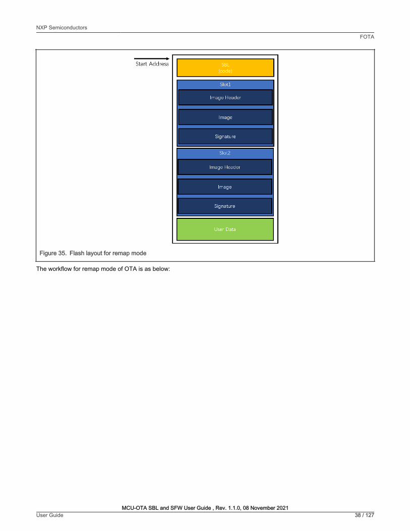
Figure 35. Flash layout for remap mode
The workflow for remap mode of OTA is as below:
NXP SemiconductorsFOTA
MCU-OTA SBL and SFW User Guide , Rev. 1.1.0, 08 November 2021User Guide 38 / 127
Start Add ress

Figure 36. Bootloader workflow for remap mode
The period for remap mode of OTA is as below:
NXP SemiconductorsFOTA
MCU-OTA SBL and SFW User Guide , Rev. 1.1.0, 08 November 2021User Guide 39 / 127
Bootloader enitiy -·---.con11ecled~ Set Iha remap
Is ISP Yes f, _ _ _ _ _ Nn ___ i 1.1pd'ate fllag
l'itiirTie\ No lls update firmware ·10
flag sel? 1 : desig 11aled
Yes,
Flip tl'le remap seui g1
Validate the signature or the new firmware
< Validate· fail?
No Set slack
pointer and j,1.1rnp to th.e app
nd
'
11 localioo in,,flasl:l 1 I •-------------· .J - b hos o -
Reset J
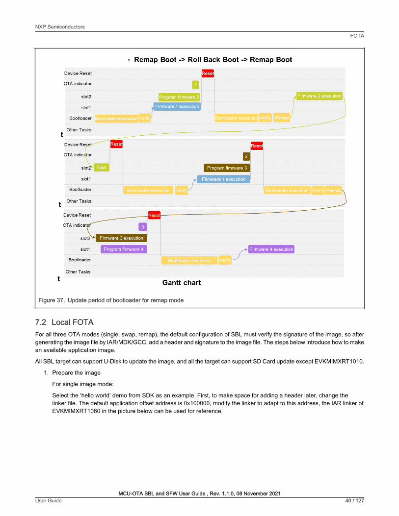
Figure 37. Update period of bootloader for remap mode
7.2 Local FOTAFor all three OTA modes (single, swap, remap), the default configuration of SBL must verify the signature of the image, so aftergenerating the image file by IAR/MDK/GCC, add a header and signature to the image file. The steps below introduce how to makean available application image.
All SBL target can support U-Disk to update the image, and all the target can support SD Card update except EVKMIMXRT1010.
1. Prepare the image
For single image mode:
Select the ‘hello world’ demo from SDK as an example. First, to make space for adding a header later, change thelinker file. The default application offset address is 0x100000, modify the linker to adapt to this address, the IAR linker ofEVKMIMXRT1060 in the picture below can be used for reference.
NXP SemiconductorsFOTA
MCU-OTA SBL and SFW User Guide , Rev. 1.1.0, 08 November 2021User Guide 40 / 127
t
t
t
Device Reset
OTA indicator
slot2
slot1
Bootloader
Other Tasks
Device Rese~
OTA indicator
slot2
slot1
Bootloader
Other Tasks
Device Reset
OTA indicat r
• Remap Boot -> Roll Back Boot -> Remap Boot
Program firmware 2
-- -
Bootloader execution
II
Bootloader execution
r --II
II Program fi rmware 3
Firmware 1 execution
slot2 Firmware 3 execution
slot1 Program firmware 4 Firmware 4 execution
Bootloader Bootloader execution
Other Tasks
Gantt chart
Firmware 2 execution

Figure 38. Linker file modification example
Remove the XIP header information by set XIP_BOOT_HEADER_ENABLE = 0 in iar project option, and then compile the projectand generate a binary file named hello_world.bin.
The SFW project already included above changes, so build and use the SFW image directly for single image mode.
For swap mode and remap mode:
Double-click the env.bat in the directory of the corresponding target of SFW. Using command then in the configurationmenu, uncheck the Enable sfw standalone xip option, and check the OTA from sdcard and OTA from u-disk options.
Figure 39. Configure the SFW
Following commands described in chapter 2 to generate project, build the project and the images are generated .
2. Generate signature key pair and prepare the bootloader
Double click the env.bat in the directory of the corresponding target of SBL. Run to the directory in thecd ..\..\component\secure\mcuboot\scripts pop-up command shell, then use the script command to generatea signature key:
python imgtool.py keygen -k xxxx_priv.pem -t rsa-2048-sign
The xxxx_priv.pem is used to sign the application image.
Generate the public key python imgtool.py getpub -k xxxx_priv.pem -o xxxx_pub.pem -t sign.
The xxxx_pub.c file generated by the above command contains the data structure of the public key, which is an array.It should be compiled with the bootloader to verify the signature. Use it to replace the content in sign-rsa2048-pub.c insbl\component\secure\mcuboot\ directory.
3. Add signature and header to the image
NXP SemiconductorsFOTA
MCU-OTA SBL and SFW User Guide , Rev. 1.1.0, 08 November 2021User Guide 41 / 127
ZI define syabol _r .. _vec t or_uble_size_ ■ isdefinedsyabol (_r .. _vectOf'_Uble_)? ltx-, It; n define syabol _rN_vector_Uble_of het_ ■ isdefinedsyabol(_rN_vec t Of'_t • ble_) ? ltx0t000JFF It;
~ 1, define syabol•_inurrupts_nart L J2 deflnesy,,t>ol ■_interrupts_end
~ 14 define syabol•_te>rt_surt l6 deflne syabol ■_te>rt_end
11 define syabol•_inurrupts_rN _st1rt •ltx2-; JI defl ne sy,,t>ol ■_interrupts_ra■_end • 9><2-+_ro■_vector_hble_ofhet_;
"° define syabol • _dau _start • • _inurrupts_rN_surt + _r .. _vec t Of'_table_she_; " define syabol ■_dna_end • lt><2991FFFF;
43 define syabol•_data2_surt •lt><21t2ootll9 ; .. defi ne sy,,t>ol ■_dna2_end • 9><292BFfFF;
21 define syabol _r .. _vector_uble_she_ ■ lsddinedsyabol(_r .. _vector_uble_) ? ,_ : It; z, define syabol _r .. _vector_hble_offset_ ■ hdefi~dsyabol(_r .. _vector_hble_) ? B-Jff , It ;
¢o define syabol •_inurrupts_surt l i. definesyabol ■_interrupts_end
¢, 14 definesyabol•_tut_surt 1, definesyabol ■_tut_end
define syabol •_inurrupu_r .. _surt • ltx20000000; II define syabol ■_interrupts_ro■_end ■ ltx2000lt0Blt + _r•_vect0f'_t•ble_offset_;
"° define syabol •_dau_surt ■ •_inurrupu_r .. _surt t _r .. _vector_uble_she_; ., define syabol ■_d•h_end ■ ltxlltelfFFf;
•i define syabol •_dau2_nart • ltx21t2ootll9; .. define syabol ■_d•h2_end ■ ltx21t2BfFFf;
• •-------------------------- MCU SFW core --------------------------71 Arrow keys na vigate t he menu. <Enter> selects submenus - - - > ( or empty sub menus - - - - ) . Highlighted l etters are hotkeys . Pressing <Y> includes, <N> excludes, <1'1> modu l ari zes features . Press <Esc><Esc> to exit, <?> for Help , </> for Search . Legend: ["'] built-in [ J excluded <M> modu l e < > module capable
l•!IMdMMild&l%MIIG [~] Enab l e OTA [ ] OTA from cloud [*] OTA from sdcard [•] OTA from u-disk
,.,cu SFW Fl ash Map
l'IIIIDII < E -

Using the imgtool command to generate the useful application image, type the command in the shell to finish the operation. Forsingle image mode, use hello_world.bin generated in step1. For swap and remap modes, to run the test, use the image thatSFW project generated.
And use the command below to generate the first signed image:
python imgtool.py sign --key xxxx_priv.pem --align 4 --version "1.1" --header-size 0x400 --pad-header --slot-size 0x100000 --max-sectors 32 hello_world1.bin app1.bin
Use another image which differs from the first image and repeat the command:
python imgtool.py sign --key xxxx_priv.pem --align 4 --version "1.2" --header-size 0x400 --pad-header --slot-size 0x100000 --max-sectors 32 hello_world2.bin app2.bin
Now two signed images are generated. More information about the above sign commands is described below.
• xxxx_priv.pem: The private key certificate generated in step 2
• --version: The version format can be major.minor.rev
• hello_world.bin, app.bin: The file path can also be added for hello_world1.bin, app1.bin, hello_world2.bin, andapp2.bin in the command.
For EVKMIMXRT685, to enable the remap function and the single image function (which have reset operations),use J-link to write the shadow register in advance, the specific steps are as follows:
1. Remove the JP2 jumper cap.
2. Make sure to connect EVKMIMXRT685 with J-link, then use J-link to write the shadow register in advance,the instruction is as follows: w4 0x40130184 0x314000.
3. After shadow register is written, make sure that the MCU cannot be powered down during the entireoperation, otherwise the previous operation is invalid. This limitation only exists on EVKMIMXRT685FlexSPI port b. To ensure that the entire operation is not powered down, after the image is downloadedto the flash, reset the MCU by SW3 instead of power-down reset. In addition, if the DAPLink is used todownload images, make JP2(PIN1-2) short, then remove the J-Link probe.
NOTE
For the EVKMIMXRT595 / EVKMIMXRT685 U-disk update function, power on the EXT PWR port. Otherwise, thepower supply current is not enough, which causes the U-disk update to fail.
NOTE
The default SDIO interface of the latest EVKMIMXRT595 board is eMMC, not SD card. When using the U diskupdate function with the latest board, rewrite the board first.
NOTE
7.2.1 Single image OTA1. Configure the SBL
The single image function only involves verification of the signature of the image, and there is no erase and write operationson the flash during the bootloader stage of SBL. OTA in this mode must be carried out with MCU ISP.
Check the Enable single image function option in the menuconfig interface of Scons to enable single image mode.At the same time, check theEnable mcu isp support option in the menuconfig interface of Scons to enable the MCUISP function.
NXP SemiconductorsFOTA
MCU-OTA SBL and SFW User Guide , Rev. 1.1.0, 08 November 2021User Guide 42 / 127

Figure 40. Enable single image
Figure 41. Enable mcu ISP
Generate the project, compile, and download the SBL to the target board. Then, connect the UART or USB port to the PCand reset the board.
2. Run the test
UART connect command type: blhost -p COMx,115200 -- command
USB connect command type: blhost -u <vid>,<pid> -- command
When using UART type to run the test, it must directly connect the UART port to PC by using the TTL2USB module,refer to the schematic of EVK board.
NOTE
NXP SemiconductorsFOTA
MCU-OTA SBL and SFW User Guide , Rev. 1.1.0, 08 November 2021User Guide 43 / 127
MCU SBL core Arrow keys navigate the menu . <Enter> selects submenus ---> (or empty submenus ---- ) . Hi ghlighted letters are hotkeys . Pressing <V> inc l udes, <N> excludes, <M> modu l arizes features. Press <Esc><Esc> to exit, <?> for Hel p , </ > for Search . Legend: [ • ] built-in [ ] excluded <M> module < > module capable
( ) Enab l e ROM to verify sbl (400 ) Maxi mum number of fl ash sectors per image 11!Mfiid1Miiiii■Mi,,hi8Ml'i,Nii ii
MCU SBL Flash Map - - - >
- < E .... > < Sa, > < Load >
mcu isp support Arrow keys na vigate the menu. <Enter> selects submenus ---> (or empty submenus ---- ) . Highlighted l etters are hotkeys . Pressing <V> includes , <N> excludes , <M> modu l arizes features . Press <Esc><Esc> to exi t, <?> for He l p, </ > for Search. Legend: ("') buil t-in [ ) excluded <M> modu l e < > module capable
l•i-MfiiHIW,il-114-IWUUW (5 ) Set isp timeout by seconds
.... ( , _ < H, ..I. > < Sa\ >

After the reset, the board waits for 5 seconds. During the 5 seconds, if the PC sends the connect command ( blhostsend the get-property command and get success in terminal), the board runs into MCU ISP mode. If it does not, theboard runs into boot mode.
On PC side, put the image which is download and the blhost.exe tool into a folder, and open the terminal under thisfolder, type the command to connect the blhost and the board within 5 s after the board is powered on. blhost -u --get-property 1 0
After connecting successfully, type the below commands to do the flash related operations.
Read: blhost -u -- read-memory [address] [size]
Erase: blhost -u -t [ms] -- flash-erase-region [address] [size]
Write: blhost -u -- write-memory 0x60100000 xxx.bin
If the size is very large, when using erase operation to erase the flash, add -t [ms] in the command to add thetimeout. In case the timeout is too short, the mcu ISP may return erase failed.
NOTE
The picture below shows the entire PC-side blhost update image operation process.
Figure 42. Blhost operation on PC
To reset the board, write the new image to the flash slot and then type the reset command. Enter the boot process after5 s.
NXP SemiconductorsFOTA
MCU-OTA SBL and SFW User Guide , Rev. 1.1.0, 08 November 2021User Guide 44 / 127
f:J Windows Power5hell
S _C:\Users\nxf~5067\Desktop;sbl_test) blhost get-property 1 0 lnJect command get-property esponse status = 0 (0x0) Success. esponse word 1 = 1258487808 (0x4b030000) urrent Version = K3. 0. 0 S C:\Users\nxf55067\Desktop\sbl_test) blhost read--1Ttemory 0x60100000 16
Inject command 'read-memory' Successful response to command 'read-memory' 3d b8 f3 96 00 00 00 00 00 04 00 00 2e 30 00 00 (1/1) 100% Completed! Successful generic response to command 'read-memory'
esponse status = 0 (0x0) Success. esponse word 1 = 16 (0xl0) ead 16 of 16 bytes. S C: \Users \nxf55067\Desktop \sbl_ test> blhost 50000 flash-erase---,:egion 0x60100000 0xlO0000
Inject command 'flash-erase-region' Successful generic response to command 'flash-erase-region'
esponse status = 0 (0x0) Success. S C:\Users\nxf55067\Desktop\sbl_test) blhost write--1Ttemory 0x60100000. \1060_appl. bin
Inject command 'write-memory' reparing to send 13694 (0x357e) bytes to the target.
Successful generic response to command 'write-memory' (1/1) 100% Completed! Successful generic response to command 'write-memory'
esponse status = 0 (0x0) Success. /rote 13694 of 13694 bytes. S C: \Users \nxf55067\Desktop \sbl_ test> blhost reset
Inject command 'reset' Successful generic response to command 'reset'
esponse status = 0 (0x0) Success. S C: \Users \nxf5506 7\Desktop \sbl_ test) •
□ X

Figure 43. Single image updating log
7.2.2 SD card OTAIn this mode, the SD card is used to update the image as reference.
For EVKMIMXRT1170, to enable the SD card, connect R136 to the REV C EVK board.
NOTE
1. Prepare the SBL
To disable single image mode and disable MCU ISP support, disable the 'Enable single image function option andthe Enable mcu isp support option in the menuconfig interface of Scons.
Compile the SBL project and download it to the target board.
For EVKMIMXRT595, EVKMIMXRT685, EVKMIMXRT1170, and EVKMIMXRT1010, when downloading thesbl.bin file, start from 0x400 offset of the flash.
NOTE
2. Download the first image
To test the SBL for the first time, download the first image to the board to run the test. Use the MCUBootUtility toolto download app1.bin to the first slot of the board, the default location of the slot1 is from flash_offset+0x100000 toflash_offset+0x200000, the whole slot size is 1 MB.
Set the MCUBootUtility to master mode, if MCU ISP function is not enabled.
NOTE
NXP SemiconductorsFOTA
MCU-OTA SBL and SFW User Guide , Rev. 1.1.0, 08 November 2021User Guide 45 / 127

Figure 44. Download image1 to slot1
3. Run the test
• Insert an SD card to the PC, and copy the app2.bin to the SD card.
• Rename the filename to newapp.bin.
• Remove the SD card and insert it to the target board.
• The debug console then prints the updating log.
• After the SD card downloading finished, when the log ‘sys rst…’ printed, remove the SD card from the board,otherwise, it starts a new updating.
NXP SemiconductorsFOTA
MCU-OTA SBL and SFW User Guide , Rev. 1.1.0, 08 November 2021User Guide 46 / 127
NXP MCU Boot Utility v2.3.0
File Edit V1~ Tools Window Help
Target Setup
MCU Series: i.MXRT
MCU Device: § RT117x
Boot Device: I FLEXSPI NOR
PortSetup
Q UART @USB·HID
Vendor ID: 10.11A2
Product ID: ~
• 00neStep
Device Status
Fuse BOOT_CFGx
········FlexRAM memory--·
IOMUXC_GPR· >GPR16 = -····
· · ···•• · FlexSPI NORmemory•-·
PageSize = 256Bytes
Sector Size =4KB
Block Size= 64KB
3
Secu r e Boot Ty pe [ DEV Unsigned Image Boot ..., J All · ln· One Action
Image Generat ion Sequ,1 , Image Loading Sequence ,Fuse Operation Ut ility Boot Device Memory 2 Start / Offset ~ IByte length (ForReadN/rit e): ~ BinFile: rl -;:I =C:\=U=,.=,.,=.,,,=,=,..=7\=D:;-1;::~= ,,=,==• :::;,I
Read Erase [I Write(AutoErase) 11 ExecuteFromStart
3
I Clear l heScreen j 0Saveimage/data fileto ~---~~
l og
Executing C:\._small_tools\ NXP·MCUBootUtility·2.3.0\tools\ blhost2_3\win\ blhost ·t 5242000-u Ox15A2,0x0073 -j ·· read•memory8053073g21024 C:\._sma ll_too ls\ NXP·MCUBootUtility-2.3.0\tools\ blhost2_3\win\ vectors \ flenpiNorCfg.dat9
00:00.SSO
D X

Figure 45. Swap updating log
After the app2 log is printed, push the Reset button on the board. To confirm that the updating is successful, the app2 log shouldbe printed.
7.2.3 U-Disk OTAIn this mode, the U-Disk is used to update the image as reference.
1. Prepare the SBL
To disable single image mode and disable MCU ISP support, disable the 'Enable single image function option andthe Enable mcu isp support option in the menuconfig interface of Scons.
Compile the SBL project and download it to the target board.
2. Download the first image and the remap image flag
To test the SBL for the first time, download the first image to the board to run the test. Use the MCUBootUtility toolto download app1.bin to the first slot of the board, the default location of the slot1 is from flash_offset+0x100000 toflash_offset+0x200000, the whole slot size is 1 MB.
3. Run the test
• Connect a U-Disk to the PC.
NXP SemiconductorsFOTA
MCU-OTA SBL and SFW User Guide , Rev. 1.1.0, 08 November 2021User Guide 47 / 127

• Copy the app2.bin to the U-Disk,
• Rename the bin file to newapp.bin
• Disconnect the U-Disk from the PC and connect it to the target board (using an otg cable, if the board has two USBports, connect it to USB1)
• The debug console prints the updating log
• after the image downloading finished, when the log sys rst… printed, remove the U-Disk from the board, otherwise,it starts a new updating.
Figure 46. Remap updating log
After the app2 log is printed, push the Reset button on the board. To confirm that the updating is successful, the app2 log shouldbe printed.
7.3 Remote FOTAThis section is dedicated to remote FOTA.
7.3.1 AWS OTAThis section walks through the steps how to perform the AWS OTA firmware update of the board using AWS IoT and theEVKMIMXRT1170 platform as an example. The aim is to demonstrate the testing process.
NXP SemiconductorsFOTA
MCU-OTA SBL and SFW User Guide , Rev. 1.1.0, 08 November 2021User Guide 48 / 127
,,;,.., 2. Serial (COM}
hello sbl . Bootloade r Version 1.0.0 Remap type:
The image now in SECONDARY SLOT slot
Bootloade r chainload address offset: OxlOOOOO Reset Handler address off set: Oxl00400 Jumping to the image
hello sfw • Current image verison : 1.1.2 U-Disk updating task enable . SD Card updating task enable. Please insert a card into board. Please plug in au -disk to board. mass storage device attached:pid =Oxl666vid=Ox951 address =l U- Disk OTA test fa t fs mount as logiacal driver 1 ..... . reading .. . new img verison : 1.1.4 updating . .. finished write update type = Ox2 write magic number off set Please unplug the u -disk • sys rs t ...
hello sbl . Bootloade r Version 1.0.0 Remap type: test
ox f ff f o
The image now in PRIMAR Y SLOT slot
Bootloade r chainload address offset: OxlOOOOO Reset Handle r address off set: Oxl00400 Jumping to the image
hello sfw • Current image verison : 1.1.4 U- Disk updating task enable . SD Card updating task enable. Please insert a card into board. Please lu in au-disk to board.

7.3.1.1 AWS OTA Prerequisites
• Create an AWS Account
Create an AWS account: https://console.aws.amazon.com/console/home
• Create an Amazon S3 Bucket to store the update
1. Go to the https://console.aws.amazon.com/s3/
2. Choose Create bucket.
Figure 47. Create bucket
3. Type a bucket name.
4. Select Enable for Bucket Versioning.
Figure 48. Bucket versioning
5. Other options keep default configurations and choose Create bucket.
• Create an OTA service role
1. Sign in to the https://console.aws.amazon.com/iam/
2. From the navigation pane, choose Roles.
Figure 49. Roles
3. Choose Create role.
4. Under Select type of trusted entity, choose AWS Service.
NXP SemiconductorsFOTA
MCU-OTA SBL and SFW User Guide , Rev. 1.1.0, 08 November 2021User Guide 49 / 127
► Accou nt snapshot Storaqo-p.-c,,;idflmibilityln!ostoraqousagear,dactivltyt,- LH m....,,. I!:
Buckets (2)
Bucket Versioning
[QJ O Copy ARN
I ViewStora9e Le ns dashboard I
Empty
< 1 ) ®
Versioning is a means of keeping multiple variants of an object in the same bucket. You can use versioning to preserve, retrieve, and restore every version of every object stored in your Amazon S3 bucket. With versioning, you can easily recover f rom both unintended user actions and application failures. Learn more 0
Bucket Versioning
0 Disable
0 Enable
Identity and Access Management (1AM)
Dashboard
..- Access management
User groups
Users
Roles
Policies
Identity providers
Account settings

Figure 50. AWS service
5. Choose IoT from the list of AWS services.
Figure 51. IoT service
6. Under Select the use case, choose IoT.
Figure 52. IoT use case
7. Choose Next: Permissions.
8. Choose Next: Tags.
9. Choose Next: Review.
10. Enter a role name and description and then choose to Create role.
NXP SemiconductorsFOTA
MCU-OTA SBL and SFW User Guide , Rev. 1.1.0, 08 November 2021User Guide 50 / 127
Create role
Select type of trusted en?
I O :~\:!~::,, ,,,.,, I .a. Another AWS account Bekmgmg lo you OI' 3rd party • Web identity
Cognrto or any OpenlO provider
Allows AWS services to perform actiOns on your behalf. Learn more
Common use cases
EC2 Allows EC2 instances to cal AWS services on your behalf.
Lambda Allows Lambda functions to call AWS services on your behalf
Or select a service to view its use cases
API Gateway CodeBuild
AWS Backup CodeOeploy
AWSChalbol CodeGuru
AWSMar1<etplace CodeStar Notlflcabons
AWSSupport Comprehend
Amplify Conrig
Appstream20 Connect
AppSync OMS
AppNcation Auto Scaling Data Lifecycle Manager
Application Discovery Data Pipelfne SeNke
OalaBrew Balch
OataSync Brake!
Oeepl..ens Budgets
Directory Service Certificate Manager
OynamoOB Crume
EC2 CloudFonnation
EC2-Fleel C1oudHSM
EC2Auto scanno CloudTrail
EC2 Image Builder CloudWaleh Alarms
EKS
CloudWalch Appliealion Insights
Select your use case
AkNiS 1oT to callAWS sefVices on your behatr
EMR
EMR Containers
ElasbCache
EtasbCBeanstalk
Elasbe Container ReoiStry
Elastic Container Service
Elastic Transcoder
Elasliel.oadBalancing
EventBridge
Forecast
Gamellft
Global Accelerator
Gloe
Greengrass
GuardDuty
HealthOro;ianiZationaJView
Honeycocte
1AM Access Analyzer
Inspector
loT
loT - Dlvic1Dll1ndu Aud1t
P<OIIIOesAWSIOTDevlceDetenoerreaaaccesstolOTandretate<Jresources
loTSlteW'ise
loT Things Graph
KMS
KinesiS
LakeFomiation
Lambda
'"' license Manager
MQ
Machine Leaming
Maae
Managed Blockcha1n
MediaConvert
Migration Hub
NetwoocFirewal
()psWO<ks
PersonaliZe
Purdlase Orders
QLDB
RAM
IOT • DIYICI DlflnllU Mitlg3tionActions
ProvidesAWSloTDevlceDefeooefwrtleaccesstoloTaodrelate<JresourcesforexecutionofMlligationActions
• • SAML 2.0 federation
Yourcorporaled1reclory
ROS
Redshift
RekOQnibon
RoboMaker
S3
SMS
SNS
SWF
Sao;ieMaker
Security Hub
SeMceGataloQ
step Functions
storage Gateway
Systems Manao;ier
Textract
Transfer
Trusted Advisor
VPC
Worklink
WorkMail

Figure 53. Create role
• Add OTA update permissions to the OTA service role
1. In the search box on the IAM console page, enter the name of the role, and then choose it from the list.
Figure 54. Role search
2. Choose Attach policies.
Figure 55. Attach policies
3. In the Search box, enter AmazonFreeRTOSOTAUpdate, select AmazonFreeRTOSOTAUpdate from the list of filteredpolicies, and choose Attach policy to attach the policy to the service role.
NXP SemiconductorsFOTA
MCU-OTA SBL and SFW User Guide , Rev. 1.1.0, 08 November 2021User Guide 51 / 127
ldentity•ndAc:cen Management(IAM)
• AWSAccount( ,___j
"'~-
IE)
IOellltyprovioers
Al;c;oontsellng$
Creoenualrepon
Summary
Create role
Review
Providettierequired inlomlaliootlelowandreviewtlnsrolebelore youcreate l
· Requirt-d
Usealphammericand'•= .. @-_'cllaracteR Maxnun6.(ctlaracNfS
Roledescription AllowsloTtocalAWS seJVicesonyourbellatl
Maunlm1000dlarldan US.-~-••:,(t-_'Cl'..-Etn
Policies Q AWSl0Tlogg111913'
0 AWSloTRuleAcuons 13'
0 AWSloTTh~Regrstratlon 13'
Pem,issionsboundary Permissionsboundaryisoo!sel
AIIOwSIOT10callAWSseMcesooyou,:De!1311
am.am iam _)rol!!IOTAROle Qi
RoledHcription AllowsloTtocalAWSservicesooyou r behaW I Ed~
lnsunc.Prolil tARHs QI
Ttustl'9lationships T.1gs
.. Permlssloos pollcies (3 polldes applied)
Policynam, •
0 AWSIOTThlllgSReg1Slra!lon
0 AWSloTLogglng
,.
I -
Poticylyp••
AWSmanage<lpollCy
AWSmanage<ipolicy
0 AdGlnlinepollcy

Figure 56. Attach AmazonFreeRTOSOTAUpdate policy
• Add the required IAM permissions to the OTA service role
1. Choose Add inline policy.
Figure 57. Add inline policy
2. Choose the JSON tab.
3. Copy and paste the following policy document into the text box:
{ "Version": "2012-10-17", "Statement": [ { "Effect": "Allow", "Action": [ "iam:GetRole", "iam:PassRole" ], "Resource": "arn:aws:iam::<your_account_id>:role/<your_role_name>" } ] }
NXP SemiconductorsFOTA
MCU-OTA SBL and SFW User Guide , Rev. 1.1.0, 08 November 2021User Guide 52 / 127
Add permissions to OTARole Attach Permissions
F1"-<polic1H v
Policyl\3ma •
EJ • 8 Amazonf'reeRTOSOTAUpOate
Summary
P0iicy.A.mazonF1eeRT0SOTAIJpOatehasDeenattacnedlof!he0TARole
am:aws iam:: ~ OTARole ~
Rol9dn<:ription AllowsloTtoca~AWSse<Vlcesonyour bellalf I Ed~
lnsl.lnctPfOtiltARNs ~
Tnmr.1~11onsn1ps 't.lgs
• Permissions pol icies (4 policies appl ied)
Policy name•
0 AWSloTTh,ngsReglSlrauon
ft AWSloTLogg,ng
O Amazorl'reeRTOSOTAIJpOa1e
ft AWSloTRuleA.ctions
, Permissions boundary (not set)
Pollcytypt•
AWSmanage<lpolicy
AWSmanage<lpolicy
AWSmanage<lpolicy
AWSmanagedpolicy
✓ 0 Addinlinapo~cy
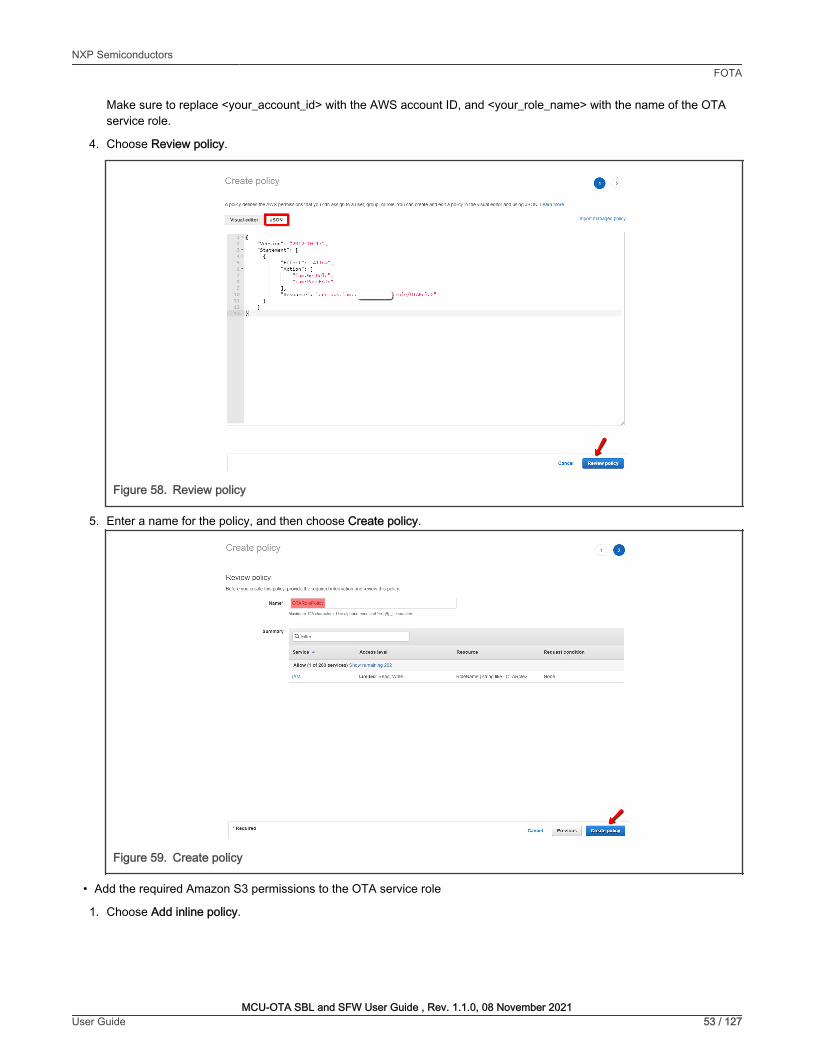
Make sure to replace <your_account_id> with the AWS account ID, and <your_role_name> with the name of the OTAservice role.
4. Choose Review policy.
Figure 58. Review policy
5. Enter a name for the policy, and then choose Create policy.
Figure 59. Create policy
• Add the required Amazon S3 permissions to the OTA service role
1. Choose Add inline policy.
NXP SemiconductorsFOTA
MCU-OTA SBL and SFW User Guide , Rev. 1.1.0, 08 November 2021User Guide 53 / 127
Create policy o , A policy deflnes the AWS permissions that you can assign to a user, group, Of role You can create and edit a polk:y WI the visual editor and using JSON Learn more
Visua1Klitor 8 lmponmanagedpollcy
'" l
"Vers i on"; " 2012-10- 17 " , "St.iternent": (
{
)
l
"Effect": "Allow" , "Action": (
" ic1m:Get Role" , " i ;im: PilssRole"
l, "Resource": "a rn :aws:iam : _____J role /OTARol e >"
Review policy
6eforeyoucre<1telhispolicy, providelherequ1redinformationan<lrevieWthlspolicy
summ,uy
' Rtquirtd
Maxrnum 12& Characters. Use afl)hanumenc .-.a••~.@-_' C!larilden
Allow (1 ol 203 nrvicn) Show remaining 202
LimitKI Reacl write
I Cane~ I ;;;;;;w+
Rtquntcondition
RoleName I string like I OTARole>
✓ Cance l Previous --

Figure 60. Add inline policy
2. Choose the JSON tab.
3. Copy and paste the following policy document into the box:
{ "Version": "2012-10-17", "Statement": [ { "Effect": "Allow", "Action": [ "s3:ListBucketVersions", "s3:GetObjectVersion", "s3:GetObject", "s3:PutObject" ], "Resource": [ "arn:aws:s3:::<example-bucket>/*", "arn:aws:s3:::<example-bucket>" ] } ]}
This policy grants the OTA service role permission to read Amazon S3 objects. Make sure to replace <example-bucket>with the name of the bucket.
4. Choose Review policy.
5. Enter a name for the policy, and then choose Create policy.
NXP SemiconductorsFOTA
MCU-OTA SBL and SFW User Guide , Rev. 1.1.0, 08 November 2021User Guide 54 / 127
Summary
ROll<IHcnptlon -.10TIOcallAWSseMcesonyoo,1>e11a11, E<ll
• Permissionspolicies(5policiesapplied)
ii AWS10TTnw1gsReg1s1rauon
ii AWSloTL"IJlll>'III
il MIIIZonfreeRTOSOTA~
0 AWSIOTRuleActlons
, Perm!ssionsbooOOary(notset)
AWSrnanage<!polCJ
AWSrnanage<!polCJ
AWSrnanage<!polCJ
AWSrnanage<!polCJ
lnlinepolcy
✓ C .o.aa 1nunepo11cy

Figure 61. OTA bucket policy
• Create an OTA User Policy
1. Open the https://console.aws.amazon.com/iam/https://console.aws.amazon.com/iam/console.
2. In the navigation pane, choose Users.
3. Choose Add user.
4. Enter a user name, select Programmatic access type, and then choose Next: Permissions.
Figure 62. Add user
5. Choose Next: Tags.
6. Choose Next: Review
7. Choose Create user.
8. After adding the user, choose the IAM user from the list.
9. Choose Add permissions.
NXP SemiconductorsFOTA
MCU-OTA SBL and SFW User Guide , Rev. 1.1.0, 08 November 2021User Guide 55 / 127
Create policy
Review policy
seroreyoocreatelhtspolicy.pn:wlljetherequiredlnformationandrevieWlhlspollcy
" Required
Summ3ry -Mlxlmum12tmaracters use11J)hll'lJmerlc-••:_ft-_'Cfl8facters
0. Fiter
Allow (1 of 203 s1rvlcu) Show remaww,g 202
Llmitt<I Reaa.Wl1te
Add user
Set user details
Muttiple
You can add multiple users al once with the same access lype and permssions learn more
Username• testota
O Add anolheruser
Select AWS access type
., Select how these users will access AW$. Access keys and autogenerated passworcts are provicled in the lasl step Learn mOfe
Access type' ~ Programmatic access
R1quHtcondition
Enables an access key 10 and secret access key for Ille AWS API, CU, SOK, and olherOE!velopmenltools
AWS Management Console access
Enables a password that anows users to sign-in to the AWS Man311ement console
,.
I --

Figure 63. Add permissions
10. Choose Attach existing policies directly, and then choose Create policy.
Figure 64. Create policy
11. Choose the JSON tab, and copy and paste the following policy document into the policy editor:
{ "Version": "2012-10-17", "Statement": [ { "Effect": "Allow", "Action": [ "s3:ListBucket", "s3:ListAllMyBuckets", "s3:CreateBucket", "s3:PutBucketVersioning", "s3:GetBucketLocation", "s3:GetObjectVersion", "acm:ImportCertificate", "acm:ListCertificates", "iot:*", "iam:ListRoles", "freertos:ListHardwarePlatforms", "freertos:DescribeHardwarePlatform" ], "Resource": "*" }, { "Effect": "Allow", "Action": [ "s3:GetObject", "s3:PutObject" ], "Resource": "arn:aws:s3:::<example-bucket>/*" }, { "Effect": "Allow", "Action": "iam:PassRole", "Resource": "arn:aws:iam::<your-account-id>:role/<role-name>" } ]}
NXP SemiconductorsFOTA
MCU-OTA SBL and SFW User Guide , Rev. 1.1.0, 08 November 2021User Guide 56 / 127
Permiss ions Groups Togs Security credentials Access Advisor
• Permissions policies (2 policies applied)
EVHi:::ifHH:i •
Grant permissions
Use 1AM policies to grant permissions. You can assign an existing policy or create a new one.
I,&.\. Add user to group a Copy permissions from I l!!!lrii Attach existing policies I ._. ex1st1ng user l;;I directly
Create po licy ~

Replace <example-bucket> with the name of the Amazon S3 bucket where the OTA update firmware image is stored.
Replace <your-account-id> with the AWS account ID. The AWS account ID can be found in the upper right of theconsole. When entering the account ID, remove any dashes (-). Replace <role-name> with the name of the created IAMservice role.
12. Choose Review policy.
13. Enter a name for the new OTA user policy, and then choose Create policy.
Figure 65. OTA user policy
• Windows Pre-Requisites
1. OpenSSL
a. Install OpenSSL: https://slproweb.com/products/Win32OpenSSL.html
b. Modify the system environment variable path to add the OpenSSL bin directory
Figure 66. OpenSSL config
Make sure OpenSSL gets assigned to the OpenSSL executable in the command prompt or terminal environment.
NXP SemiconductorsFOTA
MCU-OTA SBL and SFW User Guide , Rev. 1.1.0, 08 November 2021User Guide 57 / 127
Create policy
Review policy
N,1m1• OTAUselPollcy
Description
Summary
" Rtqutrl'd
Use alphanumenc and·+=.@-_·characters Maumrn 128 dlaracters
Maunum 1000 dlaracte.s Use alpharoumerlC and·+~,.@-_. Cllaracters
Allow (5 ol 203 services) SttOW remaifung 198
certmca1eManager
FreeRTOS Limited List.Read
Limited Lis~Wrtte
fullaccess
Limited Ust, Read, write
Request condition
Munlple
Edit environment variable X
C:\ MinGW\msys\ 1.0\M inGW
%USERPROF ILE%\AppData\ Local\Microsoft\WindowsApps
%USERPROFILE%\App0ata\ Roaming\ Python\ Python38\Scripts
Edit
[ srowse .J [ Delete
~ eDown
~ text ...
.__o_K_....,I [ Cancel J
,.
I --

2. Install the AWS CLI
a. Follow the instructions for AWS CLI version 1 bundler installer https://docs.aws.amazon.com/cli/latest/userguide/install-cliv1.html
b. Go to the IAM console https://console.aws.amazon.com/iam/
c. In the navigation pane, choose Users.
Figure 67. Users
d. Choose the IAM user account.
e. Select Security credentials.
f. In the Access keys section, choose Create access key.
g. To view the new access key pair, choose Show. The secret access key cannot be accessed again after closingthis dialog box. The credentials look something like this:
Access key ID: AKIAIOSFODNN7EXAMPLE
Secret access key:wJalrXUtnFEMI/K7MDENG/bPxRfiCYEXAMPLEKEY
h. To download the key pair, choose the Download .csv file. Store the keys in a secure location. The secret accesskey cannot be accessed again after closing this dialog box. Keep the keys confidential to protect the AWSaccount and never email them. Do not share them outside user’s organization, even if an inquiry appears to comefrom AWS or Amazon.com. No one who legitimately represents Amazon ever asks someone for the secret key.
Figure 68. Download .csv file
i. After downloading the .csv file, choose Close. Once the access key is generated, the key pair is active bydefault, and the pair can be used right away.
j. For general use, the AWS configure command is the fastest way to set up the AWS CLI installation
NXP SemiconductorsFOTA
MCU-OTA SBL and SFW User Guide , Rev. 1.1.0, 08 November 2021User Guide 58 / 127
Create access key
C, Success
Identity and Access Management (1AM)
.. AWSAccount(_..__J
Dashboard
Groups
I users I Roles
Policies
Identity providers
Account settings
Credential report
Q search/AM
TIiis is the only time Iha! the secre1 access keys can be viewed or doWllloaded. You cannot recover them
latef HOwever. you can create new access keys at any Ume
.I. Download .csvfile ,...-
AccnskeylD StcrtlolCCHSkty

Figure 69. AWS CLI installation
3. Creating a Code-Signing Certificate
a. In the working directory, use the following text to create a file named cert_config.txt. [email protected] with user’s email address:
[ req ]prompt = nodistinguished_name = my_dn[ my_dn ]commonName = [email protected][ my_exts ]keyUsage = digitalSignatureextendedKeyUsage = codeSigning
b. Using openSSL command line, create an ECDSA code-signing private key:
openssl genpkey -algorithm EC -pkeyopt ec_paramgen_curve:P-256 -pkeyopt ec_param_enc:named_curve -outform PEM -out ecdsasigner.key
c. Create an ECDSA code-signing certificate:
openssl req -new -x509 -config cert_config.txt -extensions my_exts -nodes -days 365 -key ecdsasigner.key -out ecdsasigner.crt
d. Import the code-signing certificate, private key, and certificate chain into AWS Certificate Manager:
aws acm import-certificate --certificate file://ecdsasigner.crt --private-key file://ecdsasigner.key
This command displays ARN for the certificate. Save it locally to use it while creating the OTA update job.
NOTE
Figure 70. Creating a Code-Signing certificate
• Grant access to code signing for AWS IoT
1. Sign in to the https://console.aws.amazon.com/iam/
2. In the navigation pane, choose Policies.
NXP SemiconductorsFOTA
MCU-OTA SBL and SFW User Guide , Rev. 1.1.0, 08 November 2021User Guide 59 / 127

Figure 71. Policies
3. Choose Create Policy.
4. On the JSON tab, copy and paste the following JSON document into the policy editor. This policy allows the IAM useraccess to all code-signing operations:
{ "Version": "2012-10-17", "Statement": [ { "Effect": "Allow", "Action": [ "signer:*" ], "Resource": "*" } ]}
5. Choose Review policy.
6. Enter a policy name and description, and then choose Create policy.
Figure 72. OTA signing policy
7. In the navigation pane, choose Users.
NXP SemiconductorsFOTA
MCU-OTA SBL and SFW User Guide , Rev. 1.1.0, 08 November 2021User Guide 60 / 127
Create policy
Review policy
O.scnplion
Summary
-
Identity and Access Management (1AM)
~ AWSAccount( _ ___ _.
Dashboard
Groups
Users
Roles
I Policies I ldenttty providers
Account settings
Credential report
Alow (1 ot 203 ,...,ices) soow,emanmg 202 -
,.

8. Choose the IAM user account.
9. On the Permissions tab, choose Add permissions.
10. Choose Attach existing policies directly, and select the checkbox next to the code-signing policy created before.
Figure 73. Attach policy
11. Choose Next: Review.
12. Choose Add permissions.
• Create an AWS IoT Thing
1. Open the AWS IoT console website https://console.aws.amazon.com/iot/
When opening the web, first check if the region is the one which the bucket is.
NOTE
2. In the navigation pane, choose Manage -> Things.
3. Choose Create.
4. On the Creating AWS IoT things page, choose Create a single thing.
Figure 74. Create a single thing
5. On the Create a thing page, in the Name field, enter a name for the thing, such as MyThing. Choose Next.
NXP SemiconductorsFOTA
MCU-OTA SBL and SFW User Guide , Rev. 1.1.0, 08 November 2021User Guide 61 / 127
Grant permissions .... ...,_,...,.,.,...,__,..,._., _ __,m,,._._..,.
... ==-- .... I m-=------I1 ·--v 0. 0T""
■ . ··--
Creating AWS loT things
Alll0Tthlngfsar,pruen1atlonand""ordofyourphytslcaldm"1n1hl!doud.Allyphy5icat d~ce n~a lhlng recordlnort!,rtowofltwlthAWS 10T. wmmore.
Register a single AWS loT thing Createathlnglnyourreglstry
Bulk register many AWS loT things Crute things In your registry for a t,r9e number of dmces alreioldy using AWS 10T, or register d~cessotheyarereadytoconnecttoAWSloT.
Createaslnglethlng
Cre;ite m.anythlng$
15%1++

Figure 75. Thing name
6. On the Add a certificate for the thing page, choose Create certificate. It generates an X.509 certificate and key pair.
Figure 76. Create certificate
7. On the ‘Certificate created!’ page, download the public and private keys, certificate, and root certificate authority (CA).
8. Choose Download for the certificate.
9. Choose Download for the private key.
10. Choose Download for the Amazon root CA. A new webpage is displayed. Choose RSA 2048 bit key: Amazon RootCA1. It opens another webpage with the text of the root CA certificate. Copy this text and paste it into a file namedAmazon_Root_CA_1.pem.
NXP SemiconductorsFOTA
MCU-OTA SBL and SFW User Guide , Rev. 1.1.0, 08 November 2021User Guide 62 / 127
CREATE A TI-ING SIB'
Add your device to the thing registry '"
This stli!p creiltli!s iln li!ntry in thli! thing rli!gistry ilnd ii thing shildow foryourdli!viCli!.
Name
myThi
Apply a type to th is th ing
Using ii thing typli! simplifies dli!vice management by providing consistent registry di1to1 for things thilt shilre a typli!. Type,s providli! things with;,
common set of attributli!s, which dli!scribe the identity .;ind cilpabilities of your devicli!, .;ind ii description.
Thing Type
No t ype selected I Createatype I
Add this thing to a gro up
Adding your thing to ii group illlows you to manilge devices remotely using jobs.
Thing Group
Groups/
Set sea rchable thing attri butes (o ptional)
Create group Change
Enter;, v.ilui! for one or more of thes-e .ittributes so thilt you c.1n s-earch for your things in the registry.
Attribute key Value
KJ ii ilt 1oute ~ il Manufilctur4!r an c1nr1bute v.i ue, e Acme-C rpo,-atlon
Showthing shad ow •
C.incel
Add a certificate for your thing ~
Acertlflatelsusedtoiuthentlateyourdevke"sconnectlontoAWSloT.
One-<lick certificate creation (recommended)
Tlllswlllgenerateicertiflcate,publlc key, andprtvatekeyuslngAWS loT'5Cfftlflcate iutho<lty.
Create with CSR
UplOild your own certificate signing ~quest (CSR) based on i private key you own.
Use my certificate
ReglsteryourCA«nlflcateinduseyourowncertlflcatesforoneormanydevlces.
Skip certifica te and create thing
Youwlllnttdtoaddacertiflca tetoyourlhlnglaterbefo~yourdevlcecanconnecttoAWS IOT.
Cn!i teee rtfflate
.LCn!ate wtthCSR
Get started
Crnt l thlngwlthout t:ertlll~•

Most web browsers save downloaded files into a Downloads directory. Copy these files to a different directory whenrunning the sample applications. Choose Activate to activate the X.509 certificate, and then choose Attach a policy.
Figure 77. Files download
11. On the Add a policy for your thing page, choose Register Thing. After registering the thing, create and attach anew policy to the certificate.
• Create an AWS IoT Policy
1. Open the AWS IoT console website: https://console.aws.amazon.com/iot/.
2. In the left navigation pane, choose Secure, choose Policies, then choose Create.
3. On the Create a policy page, in the Name field, enter a name for the policy (for example, MyIotPolicy). In the Actionfield, enter iot:*. In the Resource ARN field, enter *. Select the Allow checkbox. It allows all clients to connect to AWSIoT. After entering the information for the policy, choose Create.
Figure 78. Create IoT policy
• Attach an AWS IoT Policy to a Device Certificate
1. Open the AWS IoT console website:https://console.aws.amazon.com/iot/.
2. In the left navigation pane, choose Secure, and then choose Certificates.
3. In the box for the certificate created, choose ... to open a drop-down menu, and then choose Attach policy.
NXP SemiconductorsFOTA
MCU-OTA SBL and SFW User Guide , Rev. 1.1.0, 08 November 2021User Guide 63 / 127
Certificate created!
Down I~ these flies and wve them In a safe place. Certificates c.an be retrl~ a1 any time, bu1 the private and public: keys c.annot be retnl!Vl/d afleryouclOSl!thlspage.
lnordertoconnectadeYice,youneedtodownloadthefollow!ng:
Acert1fla1eforthl$ thing
Apubllckey
Aprtvatekey
c3c4ff2375.cert.pem
c3c4ff2375.publlc.key
c3c4fl2375.prtvate.key
Yo11 also nffd to download a root CA for AWS loT: A root CA for AWS loTDownload
Create a policy
~ EIHIIM
Crea!eapolicytodeflneasetofauthorizedactions.Youc.anauthorileiKt>O<lsononeormoreresources(thlngs,toplcs,toplcfilters).Toleam more abolll loT poli<ie• go to the A W'S loT Poli<ie,;documefltalion page. -Add statements
Policyst.atemernsdefinethetypesofactionsthatcanbeperformedbyaresource
Ill
I 11111

4. In Attach policies to certificate(s), select the checkbox next to the policy created in the previous step, and then chooseAttach.
Figure 79. Attach IoT policy
• Attach a Certificate to a Thing
1. Open the AWS IoT console website: https://console.aws.amazon.com/iot/.
2. In the left navigation pane, choose Secure, and then choose Certificates.
3. In the box for the certificate created, choose ... to open a drop-down menu, and then choose Attach thing.
4. In Attach things to certificate(s), select the checkbox next to the thing registered, and then choose Attach.
Figure 80. Attach Thing
5. To verify that the thing is attached, select the box for the certificate.
NXP SemiconductorsFOTA
MCU-OTA SBL and SFW User Guide , Rev. 1.1.0, 08 November 2021User Guide 64 / 127
Attach policies to certificate(s)
Policies will be attached to the following certificate{s):
Choose one or more policies
Q Search oolic1es
IJmyloTPolicy View
✓ 1 policy selected I Cancel I IHI
Attach things to certificate(s)
Things will be attached to the following certificate(s):
Choose one or more t hi ngs
0 Se.irch thino
l§JmyThing
1 thing selected I Cancel I IHI

Figure 81. Select certificate to verify
6. On the Details page for the certificate, in the left navigation pane, choose Things.
Figure 82. Verify attached thing
7. To verify that the policy is attached, on the Details page for the certificate, in the left navigation pane, choose Policies.
Figure 83. Verify attached policy
7.3.1.2 Prepare the SBL
In SBL project, enter the sbl/target/evkmimxrt1170 path.
Disable the Enable single image function option and the Enable mcu isp support option in the menuconfig interface ofScons to disable single image mode and disable MCU ISP support.
Compile the SBL project and download it to the target board.
1. If the new signature key is used, modify the sign-rsa2048-pub.c
2. Programming SBL image by drag-drop of DAPLink may erase the whole flash.
NOTE
7.3.1.3 Prepare the SFW
To prepare SFW config in an SFW project, follow the steps below:
1. Generate aws_clientcredential_keys.h file.
a. Enter sfw/firmware/aws_ota/tool path.
NXP SemiconductorsFOTA
MCU-OTA SBL and SFW User Guide , Rev. 1.1.0, 08 November 2021User Guide 65 / 127
,$,AWS loT Certificates
I ~40e234673bd148 ..
Actions•
Things
myThing
Non-<ompl,a,nce
Actions•
Policies
myloTPolicy
Non--<DfflllUance

b. Using a web browser, open the CertificateConfigurator.html.
c. Browse to the Certificate and Key files downloaded from the Thing in ‘Create an AWS IoT Thing’ part of section7.3.1.1. Click on Generate and save aws_clientcredential_keys.h.
Figure 84. Generate aws_clientcredential_keys.h
d. Replace the sfw/firmware/aws_ota/demos/include/aws_clientcredential_keys.h with the file generated inthe c) step.
2. Modify the aws_ota_codesigner_certificate.h file.
a. Open the ecdsaigner.crt file generated in ‘Windows Pre-Requisites’ part of section 7.3.1.1 using a text editor.
b. Opensfw/firmware/aws_ota/demos/include/aws_ota_codesigner_certificate.h file.
c. Copy all the content in ecdsaigner.crt and paste to aws_ota_codesigner_certificate.h in thesigningcredentialSIGNING_CERTIFICATE_PEM.
Be sure to add ' “ ' at the begging of a line and ' \n” ' on every line break as below figure.
NOTE
Figure 85. Certificate format
3. Enter sfw/target/evkmimxrt1170 path.
4. Double-click the batch file env.bat
5. Input the scons --menuconfig command to configure the evkmimxrt1170 project
6. Select MCU SFW core.
NXP SemiconductorsFOTA
MCU-OTA SBL and SFW User Guide , Rev. 1.1.0, 08 November 2021User Guide 66 / 127
Certificate Configuration Tool Amazon FreeRTOS Developer Demos
Provide client certificate and private key PEM files downloaded from the AWS loT Console.
Certificate PEM file :
I Choose File I ___ _, .. ate.pem.crt
Private Key PEM file:
I Choose File I_______) .. ate.pem.key
© Generate and save aws_chentcredent,al_keys h
~ I ' ,. FEM- encoded code signer certi f icate
,. Must include the PEM header and f ooter: ,. "-----BEGIN CERTI FICATE----- \n " ,. " .. . base64 data .. . \ n " ,. "-----END CERTIFICATE -- - - - \ n ";
' I s tati c con s t ch ar signi n g c red e n t i a l SI GNING_ CERTIFICATE_ PEM [] " -----BEGIN CERTIFICATE-----\n "
"MI I BYTCCAQegAwI BAg I JAKCX 9bi h ki 1 Fl'.AoGCCqGSM49BAMO!Cl'.xIIAfBgNVBAMM\ n "
"GEFs ZliphbmRyYSSHdXpt YliSAbnhwLmllvbTAeFw0xOTEwMj MxNj MzNDJaFw0yMDEw\ n"
"Mj I xNj MzNDJ aMCMxIT AfBgNVBAMMGEFs ZliphbmRyYS SHdXpt YliSAbnhwLmllv bTBZ \ n"
"MBMGByqGSM4 9AgEGCCqGSM4 9AwEi!A0 I ABGUghBDS lmFl J 3wf 4 LY s 2VgOa DPg9 8G \ n "
"dNC3 8 Fl/GS 7owT 4NC5 8 4 8 JumrDS SonnnXpu 7 7 Pt 7 Sh ul/3 9hC3Vdi 7 z 1 Gj J DAi MAsG \ n"
"AlUdDwQEAwIHgDATBgNVHSUEDDAKBggrBgEFBQc DAzAKBggqhk j OPQQDAg NI ADBF\n"
"AiEAr0pNz l al!ax4 a.rCPNi li9HYFdQTvUGyZdRLcDrUol / LQoCi fi2U2REo Z5 9V7r6z \ n "
"CMLf f!A + l.'"liq S 4 I j KDUE:20gV60RVVC\n"
" -----END CERTI FICATE-----\ n ";

7. Disable Enable sfw standalone xip option, enable OTA, and select AWS OTA cloud.
Figure 86. SFW config
8. To enter below config menu, select AWS Config.
Figure 87. AWS config
9. Input MQTT DNS name.
a. Open the AWS IoT console website https://console.aws.amazon.com/iot/
b. In the navigation pane, choose Manage – Things and select the previously created Thing.
c. In the navigation pane, choose Interact
Figure 88. Interact of Thing
d. Select Set MQTT broker DNS name, copy Rest API Endpoint and paste.
Figure 89. MQTT broker DNS name set
e. Press Ok
10. Input IoT Thing name.
a. Select Set IoT Thing name, copy IoT Thing name, and paste.
NXP SemiconductorsFOTA
MCU-OTA SBL and SFW User Guide , Rev. 1.1.0, 08 November 2021User Guide 67 / 127
myThing NO ! YPf
Secunty
Billing Groups
Shadow
lnte~ ct
g
[ ] Enable sfw standalone xip [*] Enable OTA [*] OTA from cloud
TA c l oud Select (AWS) > AWS Config --->
[*] OTA from sdcard [*] OTA from u-disk
MCU SFW Flas h Map ---> MCU SFW metadata header --->
et MQTT broker DNS name NEW () s et IoT Thi ng name (N EW)
This thing already appears to be connected.
HTTPS
MQTT
Set MQTT broker DNS name
Connf'ct a df'vkr
Please enter a string value. Use the <TAB> key to move from the input field to the buttons belm; it.
I .iot.us-east-1.amazonaws.co~ I I
-- < Help >

Figure 90. Thing name set
b. Press Ok
11. Select MCU SFW Component -> secure
12. Enable mbedtls and modify mbedtls config file to aws_mbedtls_config.h, and press Ok
Figure 91. Modify mbedtls config file
13. Exit and save the configuration.
Figure 92. Save config
7.3.1.4 Prepare image
1. Enter the sfw/target/evkmimxrt1170 path, double click the batch file env.bat
2. Input command to generate the iar project.
To generate the keil or gcc project, refer to section 2.
NOTE
3. Enter the sfw/target/evkmimxrt1170/iar path, open sfw.eww project.
4. Go to options, select generate additional output, and choose raw binary format.
NXP SemiconductorsFOTA
MCU-OTA SBL and SFW User Guide , Rev. 1.1.0, 08 November 2021User Guide 68 / 127
I.---------- Set IoT Thing name -----------, Pl ease enter a st r i ng va l ue . Use the <TAB> key to move from the i nput f i eld to the buttons below it .
I myThingl
-- < H· .._p >
Set mbedtls config file Please enter a string value. use t he <TAB> key to move from t he i nput fie l d to the buttons be l ow it .
I aws_mbedtls_config . hi
-- < He_._ >
Do you 1-iish to save you r new conf igu ration? (P ress <ESC> <ESC> to continue ker nel conf igu ration . )
< No >
I

Figure 93. Modify to generate .bin file
5. Check the application version in sfw/firmware/aws_ota/main_enet.c file
Figure 94. Application version
6. Click the make button to start building the application.
7. If the build is successful, sfw.bin is generated in sfw/target/evkmimxrt1170/iar/build/iar/Exe folder. Change itsname according to the application version. Move sfw_092.bin to the sbl/component/secure/mcuboot/scripts folder.
8. Change APP_VERSION_BUILD to 3 to build a newer image. Rename the new bin file to sfw_093.bin and also move it tosbl/component/secure/mcuboot/scripts folder.
Figure 95. New version
9. Sign sfw_092.bin and sfw_093.bin images with RSA using below commands. Then sfw092.bin and sfw093.bin aregenerated.
python imgtool.py sign --key sign-rsa2048-priv.pem --align 4 --version "0.9.2" --header-size0x400 --pad-header --slot-size 0x100000 --max-sectors 32 sfw_092.bin sfw092.bin
python imgtool.py sign --key sign-rsa2048-priv.pem --align 4 --version "0.9.3" --header-size 0x400 --pad-header --slot-size 0x100000 --max-sectors 32 sfw_093.bin sfw093.bin
NXP SemiconductorsFOTA
MCU-OTA SBL and SFW User Guide , Rev. 1.1.0, 08 November 2021User Guide 69 / 127
Options for node "sfw"
Category:
General Options Static Analysis
Runtime Olecking CIC++ Compiler Assembler
CUstom Build Build/\ctions Linker
Debugger Simulator CAD! O,,SISOAP GOB Server I-jet J-Link/J-Trace 11 St!!llaris Nu-link
PE micro ST-LINK Third-Party Driver
11 MSP-FET 11 XDS
119 120 121
119
120 121
Output
Ea Generate additional output
Output fonnat
Raw binary
Output file
0 Override default
sfw.b01
F acto,y Settings
OK Cancel
#define APP VERSION MAJOR 0 - -#define APP VERSION MINOR 9 fdefine APP VERSION BUILD 2
defi ne APP vgRSION MAJOR 0 fdefi ne APP vgRSION MINOR 9 defi ne ~pp V~RSlON BUILC 3
X

7.3.1.5 Upload new image to S3 bucket
1. Use AWS console to open the S3 service https://console.aws.amazon.com/s3
2. Select the previously created bucket.
3. Click Upload.
4. Drag and drop sfw093.bin.
5. Click Upload.
7.3.1.6 Create OTA Job
1. Open the AWS IoT console website https://console.aws.amazon.com/iot/
2. In the navigation pane, choose Manage – Jobs
3. Select Create job
4. Choose Create FreeRTOS OTA update job, then choose Next.
5. In step 1, Input Job name, then choose Next.
Figure 96. Input job name
6. In step 2, choose Thing created in previous section, choose MQTT, and Sign a new file for me
Figure 97. Thing, protocol, and file select
7. Under Code signing profile, choose Create new profile.
NXP SemiconductorsFOTA
MCU-OTA SBL and SFW User Guide , Rev. 1.1.0, 08 November 2021User Guide 70 / 127
OTA job properties '"''
Job properties
Job name
OTAUpdateJob
Enterauniquenamewithoutspaces.Validcharacters:a-z,A-2,0-9,-(hyphen),and (underscore)
Description - optional
Enter job descripti,:m
► Tags - optional
Devices Info
Cancel -
This OTA update job w ill send your file securely over MQTT or HTTP to the FreeRTOS-based things and/or the thing groups that you choose.
Devices to update
[i"hoose things and/or thing groups
Select the protocol fo r fi le transfer Sel.ec:t the protocol that your device supports.
l!'lJ MQTT
0 HTTP
File Info
Sign and choose your file
.. l
Code signing ensures that devices ooly run code published by trusted authors and that the code hasn't been changed or corrupted since it was signed. You have three options for code signing.
O Sign a new file for me.
0 Choose a
previously signed
fi le.
I I O Use my custom
sig ned fi le.

8. Enter a name for the code-signing profile.
a. Under Device hardware platform, choose Windows Simulator.
Figure 98. Device hardware platform
b. Under Code signing certificate, choose Import new code signing certificate, and browse for the certificate filescreated with AWS CLI, then choose Import.
Figure 99. Select certificate and key
c. Under Pathname of code signing certificate on device, type the default path /certificates/authcert.pem,then click Create.
Figure 100. Pathname of certificate
9. Under File, choose Select an existing file, then choose Browse S3 to select sfw093.bin file uploaded in S3.
NXP SemiconductorsFOTA
MCU-OTA SBL and SFW User Guide , Rev. 1.1.0, 08 November 2021User Guide 71 / 127
Create a code signing profile
Profile name
[_ii,yOTACodeSigning
Enter a unique name without spaces. Valid characters: a-2, A-2, 0-9, and_ (underscore)
Device hardware platform
[ windows Simulator
0 Import new code signing certificate
Certificates
Certificate body
] Et) Choose file
Certificate private key
I EtJ Choose file I
Certificate chain - optional
I Et) Choose file I
O Select an existing certificate
ecdsasigner.crt 544bytes
0 Uploaded
ecdsasigner.key 246bytes
0 Uploaded
Path name of code signing cert ificate on device This is the name and location of the certificate that your FreeRTOS device finnware uses to perform OTA image signature verification.
I /certificates/authcert.pem
J
Cancel MME

Make sure that the region must be the correct one where the bucket is located. Otherwise the uploaded binarycannot be found.
Figure 101. Image select
NOTE
10. Under Pathname of file on device, type the default path /device/updates.
Figure 102. Pathname of file
11. Under IAM role, choose the role created in previous steps.
Figure 103. Select role
12. Choose Next.
13. Under Job run type, choose first item.
Figure 104. Job run type
14. Before clicking Create job, run the application.
7.3.1.7 Run the application
1. Use the MCUBootUtility tool to download the sfw092.bin generated previously to the first slot of the board. Thedefault location of slot1 is the flash_offset+0x100000 to flash_offset+0x200000, the whole slot size is 1 MB.
NXP SemiconductorsFOTA
MCU-OTA SBL and SFW User Guide , Rev. 1.1.0, 08 November 2021User Guide 72 / 127
File
LI _o __ u_pl_o_ad_ a_n_ew_ fi_le_. -----~I I O Select an exist ing file.
S3 URL
@c_Q_ s_3:_//--==-' -'fw093.bin Format s3://bucket/ prefix/ object.
Pdth name of fil~ on device
xj I View r!l I
Thrs Is the name and locabon 'MH!re tht- fie w,U ~ stOR!d on tlv f re-eRTOS device
/device/updates
1AM role Info
.,. ChooWJl'04eUW.grlnUAWSloT•~lOS5, AWSloTj()b\..-.:IAWSCOdit~rw,g~ts
W<""
Job run type Choose how to run this job.
Browse S3
O You r job will complete after deploying to the devices and groups that you chose (snapshot)
O Your job will continue to deploy to any devices added to the groups that you chose (continuous)

Figure 105. Download sfw092.bin to slot1
2. After successfully downloading the image, reset the board. The debug console prints the application log as shown:
Figure 106. Application log
3. When running the application, wait until the message of the OTA State Ready appears in the serial terminal as shown:
Figure 107. OTA ready log
4. At this point, the OTA agent is waiting for an OTA job. Go back to the Create OTA job window and click Create job.
NXP SemiconductorsFOTA
MCU-OTA SBL and SFW User Guide , Rev. 1.1.0, 08 November 2021User Guide 73 / 127
i)NX.OMCUBoolUtilityv2.l.O
Fik td~ v- Tool> Window Help
~ 17,,
FlEXSPINOI\
Bool~eConf,gU<OIK>II
~ fi,g urOlionDru (DCDQ
PonMlup
Q UARf @USB-HlD
• 00neSCrp
F....,BOOT_CFG>:
----------Flm!AM~-IOMUXC_GPR->GPR16:••
Fl<J6PI NOR memory-
1•-,.S.• :r,t
L becuting C:\_,m.ol _tool<\NXP-MCUBoot Utility-2.3.C,,.tool>\ blhost.l_l\win\ blhost -t S.?42(0) -u Cbc1SA2,0,iXm -j read-memory l!O'il07l9.I 10.1.4 ( :\_.,,..ll_tool>\NXP -MC UBootUtility-l.J,11\tooh\blhort2_l\win\VKlo" \flo:spiNo<Cf9.da1'1
" ·" , .., ~" " ... " . , .. .. • t
1 II -
1 - I - < " - .. .. . .. .. "
- .. .. -. . .. .. ,, " .. .. , . . .. ..
' . . ' ' ,. " .. .. .. \ " .. ..
' .. ... ., . ' .
~4 28blO [1ot thread) State Wa1trnglo1Job Received l Queued O Processed 0 O1opped 0 Hello wo1ldl HPl lo -..mr ld7 SS 2%10 [iot thread) State WaitrnqforJob Received l Queued O Processed 0 Dropped 0 Hello wo1ldl Hdlo wo rld2 S6 3061 0 [ 1ot thread) State Wa1tinqFor Job Received I Queued 0 Proce<;<;ed O Dropped 0 Hello wo1 ldl Hello wo1 ld2

Figure 108. Create job
5. The process starts, and the outputs are as below.
a. Start file transfer
Figure 109. Start file transfer log
b. Received the whole file
Figure 110. Received whole file log
c. Check file signature
Figure 111. File signature check log
d. Check image version
Figure 112. Image version check log
e. Write update type
Figure 113. Write update type log
NXP SemiconductorsFOTA
MCU-OTA SBL and SFW User Guide , Rev. 1.1.0, 08 November 2021User Guide 74 / 127
OTA job configuration Info
Job run type Choose how to run this job.
O Your job will complete after deploying to the devices and groups that you chose (snapshot)
0 Your job will continue to deploy to any devices added to the groups that you chose (continuous)
► Job start rollout configuration - optional Specify how quickly devices will be notified when a pending job starts.
► Job stop configuration - optional These configurations define when to automatically stop the job. The job stops if a percentage of devices fail the deployment after a minimum number have deployed. The job ca ncels if any of the criteria a re met after the job starts.
► Job run timeout configuration - optional Specify how long the job will run.
Cancel ~ l§@M

f. Write image trailer
Figure 114. Write image trailer log
g. Active new image, device reset
Figure 115. Active new image log
h. Running new image
Figure 116. Run new image log
i. Self-test
Figure 117. Self-test log
j. Write OK flag
Figure 118. Write OK flag log
k. OTA success
Figure 119. OTA success log
6. After OTA success, push the Reset button on the board to confirm that the update is successful, the sfw093.bin logmust be printed.
NXP SemiconductorsFOTA
MCU-OTA SBL and SFW User Guide , Rev. 1.1.0, 08 November 2021User Guide 75 / 127

Figure 120. New image log
7.3.2 Aliyun OTAThis section walks through the steps of how to perform the Aliyun OTA firmware update of the board using Aliyun IoT and use theEVKMIMXRT1064 platform as an example to demonstrate the testing process.
7.3.2.1 Create a testing device
1. Open the link: https://iot.console.aliyun.com/. Register an account to log in to the platform and create the Alibaba Cloudaccount.
Figure 121. Account creation interface
2. After the login is successful, the page of the Alibaba Cloud IOT platform is displayed, click to enter the “Public Instance”interface.
NXP SemiconductorsFOTA
MCU-OTA SBL and SFW User Guide , Rev. 1.1.0, 08 November 2021User Guide 76 / 127
( -) Ahbaba Cloud Gil ,n,. English V Homepage Sign Up
ACCELER E DIGITALIZATION _ ALIBABA CLOUO SUMMIT LIVE!
JuneS.2021 I 14:00-17:30 (GMT+S)
Sign In
Account:
Password: Forgot Password1
Don t h<l an c Jnt? Register Now
Sign ln as RAM User

Figure 122. Alibaba Cloud IOT platform
3. After entering the “Public Instance”, click “Create Product”, set the parameters as shown in the figure on the “NewProduct” page, customize a product name, and select the first one by default in the category (to test the OTA function).
Figure 123. Create Product
NXP SemiconductorsFOTA
MCU-OTA SBL and SFW User Guide , Rev. 1.1.0, 08 November 2021User Guide 77 / 127
lol Platform
Overview 0
Documentation C:::
Value-added Services
~ Public Instance
Devices
Products
Devices
Groups
CA Certi~cate
Rules V
M aintenance V
Resource Allocation V
Link Analyt ics i:,-;
Link Visual V
Documentation and Tools
§'I Feedback
3l;(lj
loTPlatform Devices Products
llll1MJ!!ll
0
Create Product
~~1i'~i91J
ffi!J!!ll
0
-~lll!'J!'~a8'11/J11!. -~•-~ .8:JSLA~
~ Create Product(Device TSL)
Create Product Create Product from Device Center
• Product Name
You must specify a product name
• Category
@ Standard Category O Custom Category
• Node Type
t Directly Connect ed De1,ice
Networking and Data Format
• Network Connection Method
I Ethernet
• Data Type
1~ Gateway sub-dev ICe
ICA Standard Data Format (Ali nk JSON)
v Checksum Type
v Authent icat ion M ode
More
v Product Descript ion
- Cance l
v fe3tu es
~ Gateway detice
V

Figure 124. Product Type
Add equipment to the product after it is successfully created.
Figure 125. Create product successfully
4. Select the product that needs to add a device for testing, and click the blue button of “Add Device” to set the devicename.
NXP SemiconductorsFOTA
MCU-OTA SBL and SFW User Guide , Rev. 1.1.0, 08 November 2021User Guide 78 / 127
Groups
Link.Anatyt,cs ~
~ Create Product
$ You have created a product. Now you can:
♦ Add Dence
Ade\,cebelollp101PfoduCl.loTPlafonn...,.. 1de\,co 10.....,.Xamelhalu,miquelllldertbep<OINCI.Ade\,cocaaCOIIDOCIIOloTPlalf01111dinrcd)· orthroqb1P'"""IJ"
Ill
Select Category X
Al <ot,goo<> V S...chby<otogo,)'Nm<O< ''"""''° Q
loTPlatfar:m~~ youto<=ll~ • TSl.forap<OINCl.\"oucma!ndtbopropimel,...,.,as,lllldo,.-...boftbo~mlDtboTSLTh,1bcilibte,pr<>dud"'"""!!...-.llllddm.-mtbecloud..Alh,rJ""aede•TSL lm a ~lbodr,,-.ceo-l!nspr<>dudlllll<
E@&Sifa&
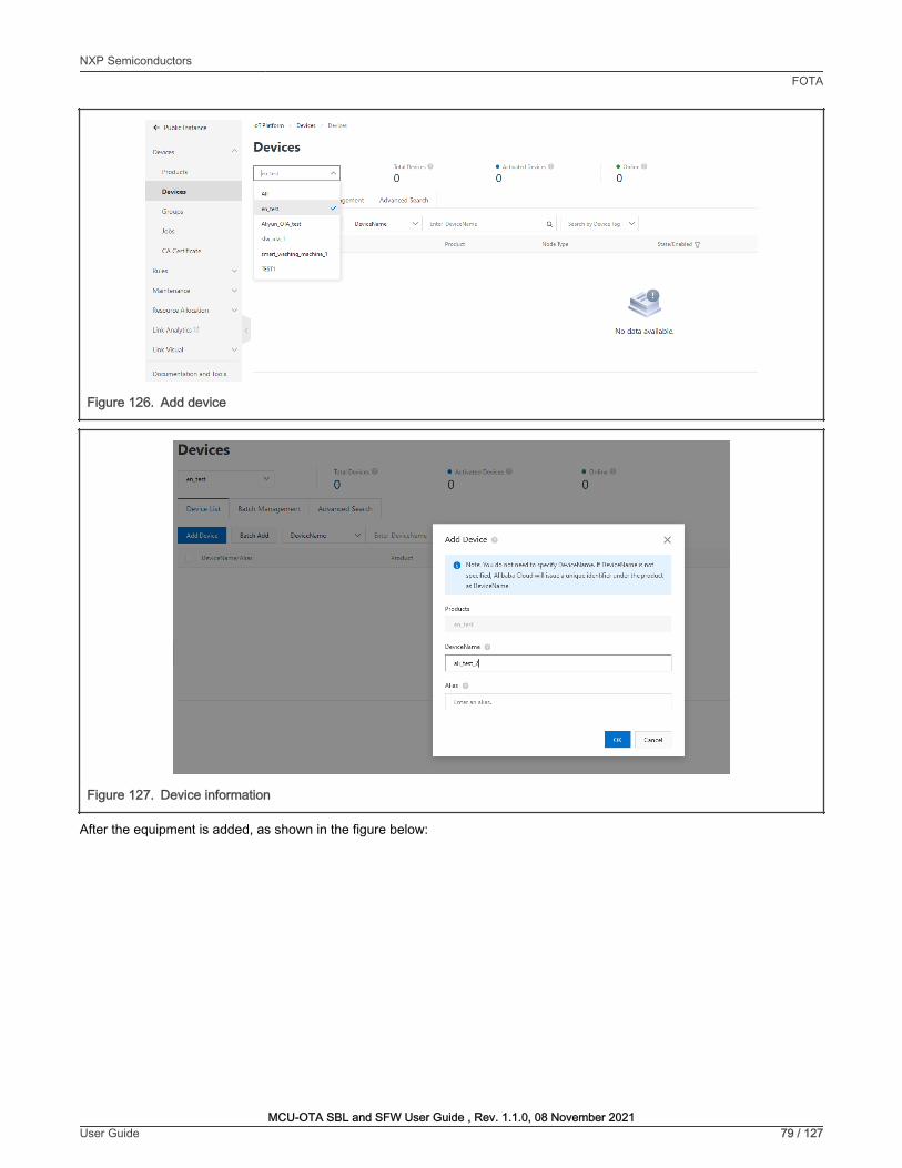
Figure 126. Add device
Figure 127. Device information
After the equipment is added, as shown in the figure below:
NXP SemiconductorsFOTA
MCU-OTA SBL and SFW User Guide , Rev. 1.1.0, 08 November 2021User Guide 79 / 127
~ Public Instance
Devices
Products
Devices
Groups
Jobs
CA Certificate
Rules
Maintenance
Resource Allocation
link Analytics~
link Visual
Documentation and Tools
loT Platform Devices Devices
Devices TotalDevices O • ActivatedDevices O • Online
0 0 0 All
1gement Advanced Search en_test
Aliyun_OTA_test
rlw_ota_1
DeviceName Enter DeviceName Q Search by Device Tag
smart_washing_mach ine_1
mn
Product Node Type State/Enabled~
No data avai lab le.
Add Device
C, Note: You do not need to specify DeviceName. If DeviceName is not
specified, Alibaba Cloud will issue a unique identifier under the product
as DeviceName.
Products
DeviceName
ali_testj
Alias
Enteranalias.
X

Figure 128. Device details
7.3.2.2 Customize device-side SDK
1. Select “Documents and Tools” in the menu bar on the left. To display the interface as shown in the figure below, select“SDK custom” in “Link SDK”, set the SDK version information as shown in the figure below, then click “Start Generation”to generate the device side SDK.
Figure 129. Download SDK
NXP SemiconductorsFOTA
MCU-OTA SBL and SFW User Guide , Rev. 1.1.0, 08 November 2021User Guide 80 / 127
~ ali_test_2 '~""'
Productl<ey
en_test Vioew
alDVFDaRCtT Copy
Device Information Topic List TSL Data Device Shadow Manage Files Device Log Online Debug Groups Task
Device Information
NodtTypt
Alias Q
May21,2021, 10:38:17
Tag lnfarm.ation L Edrt
oev;ce T19: No results found
!Document And Tools I Documentat ion
~l(' Device Connection and Management
loT Studio
E) The Internet of Things link SOK
Equipment Access SOK
E) linkSDK
For with TCP/IP Protocol Stack of Equipment Provide Access Ali Cloud Internet of
Things Platform of Ability
11111 SOKCustom
P,oductKey alDVfOaRCtT Copy Region
ali_test._2 Copy
Rul-t,mtDtlay 0 DMctlocallogrtport-
-:;:- linkVisual
~1~ lol network management service
link lo T Edge SOK
For Equipment Provide Security Reliable, Low Delay, low-Cost, Easy to Expand,
WukNetworkRelyonthelocalCalculationservice
Ch1n1(Shu19Mij
~ Edge Computing
lb' Authentication of lo T de
Link WAN SDK
For Lora Equipment Provide
Ability
1111 NodeSOK

Figure 130. Customize SDK
2. Unzip the downloaded SDK package, replace the ali_ca_cert.c in \LinkSDK\external with the corresponding file of thetested project. It is consistent with the certificate in the current project, and it does not need to be replaced in this test.
7.3.2.3 Set test equipment information
1. Under the Device option of the Alibaba Cloud IOT platform, save the DeviceName, ProductKey, and DeviceSecretinformation.
Figure 131. Triple information
NXP SemiconductorsFOTA
MCU-OTA SBL and SFW User Guide , Rev. 1.1.0, 08 November 2021User Guide 81 / 127
SDK version
v4.x
" Device OS
FreeRTOS
" Equipment hardware form
@ single board system
0 MCU + Communication Modu le
" Connect to loT platform protocol
l!'J MQTT 3.1.1 V
HTTPS
" Data encryption
@ TLS-CA
0 TLS-PSK
0 No enc ryption
" Device authentication scheme
Device key
Dynam ic reg istration
Advanced Capabilities
W Thing model
C, Device shadow
0 Bootstrap Service
a Task management
loTPlatform Devices Devices Device Details
t- ali_test_2 loactove
Products
ProductKey
en_test View
alDVFDaRCel Copy
Device Information Topic List
Device Information
Product Name en_test
Node Type Devices
TSL Data Device Shadow
f OTA J Eil Device log
0 Sub-device management
Manage Files Device Log
ProductKey
DeviceName
V
:II
Time Synchronization
Device label
'-l, Device diagnostics
I OeviceSemt
Onli ne Debug Groups Task
alDVFDaRCeT Copy
ali_test_2 Copy

2. Open the test project \ sfw \target \evkbmimxrt10XX, double-click the script env.bat, using the command scons--menuconfig to select the Alibaba Cloud project, set the triple information as shown below. Copy the product key/device name/product secret into it.
Figure 132. Menuconfig
NXP SemiconductorsFOTA
MCU-OTA SBL and SFW User Guide , Rev. 1.1.0, 08 November 2021User Guide 82 / 127
El cmd - scans --menucon fig □
...----------- MCU-SFW RT1050 Configuration Arrow keys navigate the menu . <Enter> selects submenus submenus - - - -). Highlighted letters are hotkeys. Pressing <Y> includes, <N> excludes, <M> modu l arizes features. Press <Esc>< Esc> exit, <?> for Help, </> for Search . Legend: [ * ] built-in [ ]
I M U SFW core ---> MCU SFW Component ---> Platform Drivers Config --->
X

Figure 133. Set Aliyun OTA information
NXP SemiconductorsFOTA
MCU-OTA SBL and SFW User Guide , Rev. 1.1.0, 08 November 2021User Guide 83 / 127
El cmd - scons --menuconfig □
Arrow keys navigate the menu . <Enter> selects submenus ---> (or empty submenus ----) . Highlighted lette r s a re hot keys . Pressing <Y> includes, <N> excludes, <M> modula r izes f eatures . Press <Esc>< Esc> exit, <?> fo r Help, </> for Sea rch. Legend : [*] built-in [ ]
[ ] Enable sf w standalone xip [*] Enable OTA [*] OTA f rom cloud
OTA Cloud Select (Aliyun) --- > I LIYUN Config ---> [*] OTA f rom sdca rd [*] OTA f rom u-dis k
MCU SFW Flash Map ---> MCU SFW metadata heade r --->
X
kconf1g-mconf.exe> [32] 32000 « 180206 [64] 1/ 1 [ +] ·. _" PRI 80x25 (11, 13) 25V 33344 100%

Figure 134. Set triple information
3. In the script, choose MCU SFW Component -> secure -> enable mbedtls, and change the mbedtls config file toksdk_mbedtls_config.h
NXP SemiconductorsFOTA
MCU-OTA SBL and SFW User Guide , Rev. 1.1.0, 08 November 2021User Guide 84 / 127
El cmd - scans --menuconfig □
~------------- ALIYUN Config Ar row keys navigate the menu. <Ente r > selects submenus ---> (or empty submenus ----). Highlighted letters a re hot keys . Pressing <Y> includes, <N> excludes, <M> modularizes f eatu res . Press <Esc>< Esc> exit, <?> fo r Help, </> fo r Sea rch. Legend : [*] built-in [ ]
g 1X3jdyVAyF) et product key (SFW_K_1) set device name (1f ad545317c 5c50ee b3512359c2e22e8) Set device sec ret
X

Figure 135. Set mbedtls config file
NXP SemiconductorsFOTA
MCU-OTA SBL and SFW User Guide , Rev. 1.1.0, 08 November 2021User Guide 85 / 127
El cmd - scans --menuconfig □
secure Arrow keys navigate t he menu . <Ente r > selects submenus ---> (o r empty su bmenus ----). Highlighted lette r s are hot keys . Pressing <Y > includes, <N> excludes, <M> modula r izes f eatu res . Press <Esc ><Esc> exit, <? > for Help, </> fo r Search . Legend: [ * ] built-in [ ]
Enc r ted XIP f unction [ * ] enable mbedtls g <sdk_mbedtls_conf ig . h) et mbedtls conf ig f ile
X

Figure 136. ksdk_mbedtls_config.h
Save the setting and use command scons –ide=iar to generate the iar project.
7.3.2.4 Modify the cur_version for testing
1. Enter sfw/target/evkmimxrt1064 path, double-click the batch file env.bat
2. Input scons –ide=iar command to generate the iar project.
Refer to section 2 to generate keil or gcc project.
NOTE
3. Enter sfw/target/evkmimxrt1064/iar path, open sfw.eww project.
4. Go to options, select generate additional output, and choose raw binary format.
NXP SemiconductorsFOTA
MCU-OTA SBL and SFW User Guide , Rev. 1.1.0, 08 November 2021User Guide 86 / 127
El cmd - scans --menuconfig
Set mbedtls config file Pl ease enter a string val ue . Use the <TAB> key field to the buttons below it .
I ksd k _ mbedtls _ config. hi I
□ X

Figure 137. Output file
5. Check the current version in sfw/firmware/Aliyun_ota/fota_basic_demo.c file. Set cur_version to 1.0.0.
Figure 138. Set the version
6. Change bin file to sfw_1064_100.bin and click make button to build the project. The bin file will be generated in /sfw/target/evkmimxrt1064/iar/build/iar/Exe.
7. Change the cur_version to “1.4.0”, and change bin file name to sfw_1064_140.bin. Generate it.
8. Copy the generated bin files to sbl/component/secure/mcuboot/scripts folder.
9. Sign sfw_1064_100.bin and sfw_1064_140.bin images with RSA using the command below. Then 1064_ali_100.binand 1064_ali_140.bin are generated.
python imgtool.py sign --key sign-rsa2048-priv.pem --align 4 --version "1.0.0" --header-size 0x400 --pad-header --slot-size 0x100000 --max-sectors 32 sfw_1064_100.bin 1064_ali_100.binpython imgtool.py sign --key sign-rsa2048-priv.pem --align 4 --version "1.4.0" --header-size 0x400 --pad-header --slot-size 0x100000 --max-sectors 32 sfw_1064_140.bin 1064_ali_140.bin
7.3.2.5 Create OTA task
1. Under the "Maintenance" directory on the left, select "OTA Update".
NXP SemiconductorsFOTA
MCU-OTA SBL and SFW User Guide , Rev. 1.1.0, 08 November 2021User Guide 87 / 127
Options for node "sfw"
Category:
General Options
Static Analysis Runtime Checking
CIC++ C.Ompiler
Assembler
Output C.Onverter
Custom Build Build ktions
Linker
Debugger
Simulator
CAD!
CMSIS OAP GOB Server 1-jet
}-Unk/J-Trace
Tl Stellaris
Nu-Link
PE micro
ST-LINK
Third-Party Driver Tl MSP-FET TIXDS
X
Factory Settings
Output
0 Generate additional output
91 noi n tomer I Raw binary
Output file
0 Override default
.lstw _ __ 1_o_s4 ___ , __ o ___ ~-b-in __ 1 _________ 7~
OK Cancel
342 I cur version " 1 . o. O"; I I !1!"i1Jr./y/yj$fJ.t-"!1!Jilif/J/N,1s:, fl/J1 . 1 . al

Figure 139. OTA upgrade
2. Click the “Add Update Package” button to add the upgrade package, enter the upgrade package name, select thecorresponding product module, and “Update package version” should correspond to the version of the uploaded bin file,and then click upload to confirm. Now the 1.4.0 version number is used.
NXP SemiconductorsFOTA
MCU-OTA SBL and SFW User Guide , Rev. 1.1.0, 08 November 2021User Guide 88 / 127
+- Public Instance
Devices
Rules
Maintenance
Real-time Monitoring
Dashboard
Online Debug
Device Simulation
Device Log
OTA Update
Remote Config
Alert Center

Figure 140. Upgrade package information
7.3.2.6 Run the application
1. Using the MCUBootUtility tool to download the 1064_ali_100.bin generated previously to the first slot of the board.The default location of slot1 is the flash_offset+0x100000 to flash_offset+0x200000, the whole slot size is 1MB.
NXP SemiconductorsFOTA
MCU-OTA SBL and SFW User Guide , Rev. 1.1.0, 08 November 2021User Guide 89 / 127
Add Update Package
• Types of Update Packages
~ Differential
• Update Package Name
sfw_1 064_1 40
• Product
en_tes.t
• Update Package Module
default
+ Add Mod ul e
• Update Package Version
1.4.0
• Signature Algorithm
MD5
• Select Update Package
Re-upload
fJ 1064_ali_l40.bin (266.21 KB)
• Ve rify Update Package?
@ Yes 0 No
Update Package Description
Please enter upgrade package description
v Security Check Service of Updat e Package
X
V
V
V
0/1 024
- Cancel

Figure 141. Use image tool to download bin file
2. Prepare the bootloader.
In SBL project, enter sbl/target/evkmimxrt1064 path. Disable the Enable single image function option and theEnable mcu isp support option in the menuconfig interface of Scons to disable single image mode and disable MCUISP support.
Compile the SBL project and download it to the target board.
a. If the new signature key is used, please also modify the sign-rsa2048-pub.c
b. Programming SBL image by drag-drop of DAPLink may erase whole flash.
NOTE
3. Plug in the ethernet cable. Run the project and the debug console prints the log as shown below.
The log “The image now in PRIMARY_SLOT slot” and “Getting IP address from DHCP” shows that the image in first slot isbooted successfully. The “IPv4 Address:” and “version:1.0.0” shows that the network is connected successfully and AlibabaCloud get the current device version 1.0.0.
NXP SemiconductorsFOTA
MCU-OTA SBL and SFW User Guide , Rev. 1.1.0, 08 November 2021User Guide 90 / 127
J] NXP MCU Boot Utility v2.3.0
File Edit ~- Tools Window ""' TargetSetup
MCUSenes: i.MXRT
MCUDevice: § RTI064 SIP
Boot Device: FLEXSPI NOR
Boot Oevic1P:(onfiguration
Dtll'lce Configuration Oat1 (DCD)
PortSetup
Q UART @USB-HIO
Vendor ID: Ox1SA2
Product ID: 0nl073
- l;10nll':Slf:P
Resetdevice
Oevicll':Status
OCOTP->M1SC_CONF0[31:00J = Ox40
Fl9RAM P1rtion :0000 · 128KB ITC M, 128KB OTCM, 2S6KB OCRAM
·······•Fl9SPI NOR memory·-· Page Size = Z56Bytes SectorSize:4K8 BlockSize::64KB
Secure Boot Type DEV Unsigned Image Boot All-In-One Action
Image Generation 1.uence Image loading ~uence efuse Operation Utility Boot Device Memory 2 Start / Offset: 1~ , Bytelength(ForRead/Write): ~ B,nFile: r;ll"c:\"u"~n"w= l6"m"S\"o:'"I - •-,-- , -,
~ d Er~ 11 Write(AutoEme) 1)3 ExecuteFromSt,rt
1...3-Bootable~ ClearThlP:Scrttn 0Saveimage/datafileto
l og
Executing C:\Users\ nxf6S 13S\Oesktop\ tools\NXP-MCU8ootlflilily-2.3.0\tools\ blhost.2_3\win\ blho~ ·t 5242000 -u Ox1SAZ,0x0073 -j •• writ1P:-memory 1880096768 C:\ Users\ nxf6S13S\0Hktop\ tools\ NXP-MCUBootUtilily-Z.3.0\gen \ uSff_file\user.dat9
Oli.OS108
Clear
Sm
□ X

Figure 142. Run sbl project
Figure 143. Jump to first image
4. Verify the upgrade package in Web. Click the Verify button, fill in the version number that needs to be upgraded, andselect the device to be tested. The upgrade timeout period can be omitted. Then click “OK”.
Figure 144. Verify the OTA package
NXP SemiconductorsFOTA
MCU-OTA SBL and SFW User Guide , Rev. 1.1.0, 08 November 2021User Guide 91 / 127
.,,aw SKureUpdatt Enttranupdatepackag,name Q
UpdatePaclcegeName UpdatePackageVe~ion Product St.atu~ Created At
sfw_1064_140 @ 1.4.0 en_test May21,2021,10:S6:26
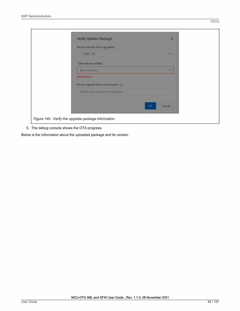
Figure 145. Verify the upgrade package information
5. The debug console shows the OTA progress.
Below is the information about the uploaded package and its version.
NXP SemiconductorsFOTA
MCU-OTA SBL and SFW User Guide , Rev. 1.1.0, 08 November 2021User Guide 92 / 127
Verify Update Package X
Yeision number ID be upgnided
V
* Devicelo be verified
I ~a e
Select Device
Please input t meout t me
- Canm

Figure 146. Get the package information
Figure 147. Target firmware version
NXP SemiconductorsFOTA
MCU-OTA SBL and SFW User Guide , Rev. 1.1.0, 08 November 2021User Guide 93 / 127

Below is shown that the download request was successfully sent and the download process begins.
Figure 148. Download request
Below is shown the download progress finished and the system reset action started.
Figure 149. Download all
Below is shown the current package version is 1.4.0. In Alibaba Cloud web, the OTA information shows the verification isdone successfully.
Figure 150. Run the new image
NXP SemiconductorsFOTA
MCU-OTA SBL and SFW User Guide , Rev. 1.1.0, 08 November 2021User Guide 94 / 127

Figure 151. Alibaba Cloud IOT platform shows the OTA success
7.4 Secure FOTAThis section walks through the steps of how to perform the Secure OTA firmware.
7.4.1 Secure boot demonstration for the platform EVKMIMXRTxxxxThis section describes the steps how to enable secure boot and generate signed image. The demo targeted for theEVKMIMXRT1060 hardware platform is used as an example, although these steps can be applied to other i.MX RT platforms.
7.4.1.1 Generating Keys and Certificates
To enable ROM secure boot, generate keys and certificates. Do the following steps to generate them.
1. Retrieve and install the MCUXpresso Secure Provisioning tool
2. Run this tool, click the button to switch the processor, select MIMXRT1060. To select a processor from a differentfamily, create a new workspace.
: Open MCUXpresso Secure Provisioning tool with administrator mode. Otherwise some important material will notbe generated.
NOTE
: For EVKMIMXRT1010 platform, select MIMXRT1015 to generate keys.
NOTE
NXP SemiconductorsFOTA
MCU-OTA SBL and SFW User Guide , Rev. 1.1.0, 08 November 2021User Guide 95 / 127
~ !sfw_ 1064_ 140 lypHofUpdatePackagH Full UpdatePad:age Signature 'i2a'k02u7afcddc53b&f64ba46144d Download
Signature Algorithm MOS
Totalnumber oftargetdMcH • Nu mber of target failurH • NumberofCancelMTaslcs
0 0
Baldi Management Device List Update Package Information
Q§i§IM BatchUpdate Q
Batch ID Batch type Upgrade policy Status'iJ Created At Actions
b Cm6rHXh08qdhi... Verify Update Package St.JticUp<fate • Hascomplete May 21,2021, 11:10:40 View

Figure 152. Creating a new workspace
3. Choose Boot Type as Authenticated (HAB).
Figure 153. Selecting Boot Type
4. In the Keys Management view, click Generated keys, then specify all parameters in this menu.
NXP SemiconductorsFOTA
MCU-OTA SBL and SFW User Guide , Rev. 1.1.0, 08 November 2021User Guide 96 / 127
MCUXpresso Secure Provisioning - C:\Users\nxp96245\secure _provision in go
File Target Tools Help
□ X
Processor:I MIMXRT1O6O I Boot Type: Unsigned
A Build image A write image 0 Keys Management
Source executable image:
v] I Boot Device: flex-spi-nor/lS25LPxxxA _IS25WPxxxA v Edit I Connect ion: ~
Browse ...
Start address: XIP: no
D Use custom bootable image path: _tlb':o~o.'.'.ta'rb""---le;l!.l!em,a=~0 •u'.,ibcu.m' c_ _________________ 7 f-________ _:v:_J' I Browse ...
Select Processor X D Use custom DCD (binary):
Use the fo llowing keys:
XIP Encryption (BEE User Keys)
Series
LPC55Sxx
RT1Oxx
RT11xx
RTxxx
Processor
O M IMXRn 01 s i @ MIMXRn 060 I 0 M IMXRT1020 0 MIMXRT1064
Q MIMXRT1024
0 M IMXRT1050
To select processor from d ifferent family/series: Create New Workspace
MCUXpresso Secure Provision ing - C:\Users\nxp96245\secure _provision in go
File Target Tools Help
OK
Brow_.e ...
Build Iaage
□ X
Processor: MIMXRT1O6O I Boot Type Authenticated (HAB) 3 1 Boot Device: flex-spi-nor/lS25LPxxxA _IS25WPxxxA v ~ I Connect ion: USB
A Build image A Write image A Keys Management
Source executable image:
Start address:
Browse ...
XIP: no
D Use custom bootable image path: ~lb_o_o_ta_b_le __ i_m_a_g_es_\._b_in _____________________________ v~I Browse ...
D Use custom DCD (binary): ,e.
Use the following keys:
XIP Encryption (BEE User Keys)
Build Iaage

Figure 154. Generate keys (EVKMIMXRTRT10xx, EVKMIMXRTRT11xx)
5. Click Generate, OpenSSL output is displayed in the progress window.
Figure 155. Generate Keys - Success
6. You can find generated keys and certificates in the folder “keys” and “crts” in the workspace directory, Copy folder“keys”, “crts” and “gen_hab_certs” to the folder sbl/target/evkmimxrt1060/secure.
7.4.1.2 SBL image preparation
To generate a signed bootable SBL image, the steps are as below:
1. Run env.bat in target board
2. Run scons --menuconfig to enter menu MCU SBL Core to select Enable ROM to verify sbl
NXP SemiconductorsFOTA
MCU-OTA SBL and SFW User Guide , Rev. 1.1.0, 08 November 2021User Guide 97 / 127
MCUXpresso Secure Provisioning - C:\Users\nxp96245\secure _provisioning
File Target Tools Help
□ X
Processor: M IMXRT1060 I Boot Type: Authenticated (HAB)
A Build image A Write image A Keys Management
v I Boot Device: flex-spi -nor/1S25LPxxxA _JS25WPxxxA v ~
Generate Keys
@Create new CA
Private key
Certificate
Key type RSA v
A Advanced
X
0 Use existing CA
Key length 2048 v
Ser i al number 112345678 Password phrase ~I t_es_t ____ ~
Duration [years) ~I 1_0 ____ ~ Number of keys 4
Generate Close
Missing SRK keys, at least one SRK key is needed for selected boot type Add Keys Generate keys
flflfl#flflflflflflflfl#flflflflflflflfl#flflflflflflflfl#flflflflflflflfl#flflflflflflfl##flflflflflflflfl#flflflflflflfl##flflflflflflfl##flflflflflflfl##flflflflflflfl##flflflflflflfl##flflfl
Status of the operation : SUCCESS : New workspace created : C: \Users\nxp96245\secure_provisioning
Generating keys (C:\Users\nxp96245\secure _provisioning\gen _ scripts\generate _keys_ win.bat)
.. . .. . .. . .. . .. . .. . .. . .. . .. +++++
..... . ..... . .. +++++
e is 65537 (0x010001) Using configurat i on from C:\nxp\MCUX_Provi_v3\bin\tools\cs t\ca\openssl. cnf Check that the request matches the signature Signature ok The Subject's Distinguished Name is as foll ows commonName :T61STRING: ' IMG4_1_sha256_2048_65537_v3_usr ' Certificate is to be certified until Apr 20 06:08: 19 2031 GMT (3650 days)
Write out database with 1 new entries Data Ease Updated
SUCCESS: Generating keys
Import Keys
11 Close
I
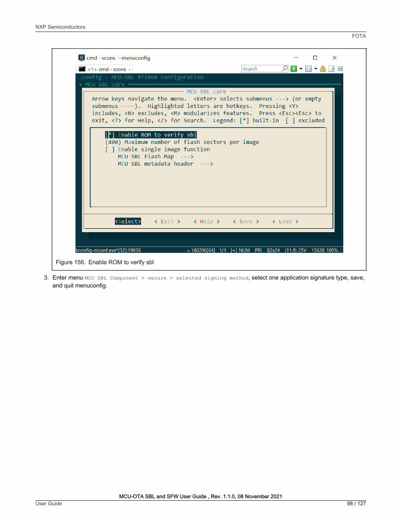
Figure 156. Enable ROM to verify sbl
3. Enter menu MCU SBL Component > secure > selected signing method, select one application signature type, save,and quit menuconfig.
NXP SemiconductorsFOTA
MCU-OTA SBL and SFW User Guide , Rev. 1.1.0, 08 November 2021User Guide 98 / 127
El cmd - scons --menuconfig □
Ar row keys navigate the menu . <Enter> selects su bmenus --- > (o r empty su bmenus ----) . Highlighted lette r s a re hot keys. Pressing <Y> includes, <N> excludes, <M> modula r izes f eatu res . Press <Esc>< Esc> to exit, <?> fo r Help , </> fo r Sea rch . Legend : [ *] built - in [ ] excluded
n ] nable ROM to verify sbl (400) Maximum number of f lash secto r s pe r image [ ] Ena ble single image f unction
MCU SBL Flash Map --- > MCU SBL metadata heade r --- >
X

Figure 157. Select signing method
4. Run scons --ide=iar command to generate IAR project or run scons --ide=mdk5 to generate Keil project.
5. Configure the option to generate an image with .srec format in IAR project, then build the project. For Keil project,user may generate a srec format image by running:
fromelf.exe --m32combined --output "[email protected]" "#L"
NXP SemiconductorsFOTA
MCU-OTA SBL and SFW User Guide , Rev. 1.1.0, 08 November 2021User Guide 99 / 127
El cmd - scons --menuconfig
signing keys to navigate this window or press the
hot key of the item you wish to select f ollowed by the BAR> . Press< ?> f or additional inf ormation about this
() Select signatu re type RSA [D] elect signature type ROM use ( ) Select signatu re type ECDSA P256
□ X

Figure 158. Update defined Symbols
7.4.1.3 Application image preparation
To generate the application image, the steps are as below:
1. Open linker file sfw\target\xxxx\board\link\MIMXRTXXXX_flexspi_nor.icf (take IAR linker file as example), andmake the following changes in the linker file:
define symbol m_interrupts_start = BOOT_FLASH_ACT_APP + 0x2000;define symbol m_interrupts_end = BOOT_FLASH_ACT_APP + 0x2000 + 0x3FF;
define symbol m_text_start = BOOT_FLASH_ACT_APP + 0x2000 + 0x400;define symbol m_text_end = BOOT_FLASH_CAND_APP - 0x1000;
2. Run env.bat in one target board in SFW
3. Enter menu MCU SFW core and uncheck menu Enable sfw standalone xip, save and quit menuconfig
NXP SemiconductorsFOTA
MCU-OTA SBL and SFW User Guide , Rev. 1.1.0, 08 November 2021User Guide 100 / 127
Options for node "sbl "
Category:
General Options
Static Analysis
Runtime Checking
C/C+ + Compiler
Assembler
Output Converter
Custom Build
Build Actions
Linker
Debugger
Simulator
CAD!
CMS!S DAP
GDB Server
I-jet
J-link/J-Trace
TI Stellar is
Nu-link
PE micro
ST-l!NK
Third.Party Driver
TI MSP -FET
TI XDS
Output
0 Generate addit ional output
Output fo rmat:
I Motorola S-records
Output fil e
D Override default
sbl.srec
X
Factory Settings

Figure 159. Uncheck enable sfw standalone
4. Run scons --ide=iar to generate IAR project or run scons --ide=mdk5 to generate the Keil project for SFW.
5. Configure the option to generate an image with .srec format, then build the project.
Figure 160. Output binary format
For the other signing method, generate a binary format application.
NOTE
7.4.1.4 Program OCOTP (eFuse)
Below is an example of how to program SRK table and enable HAB closed mode.
In the Development phase, the device may be under HAB open mode for most use cases.
NOTE
NXP SemiconductorsFOTA
MCU-OTA SBL and SFW User Guide , Rev. 1.1.0, 08 November 2021User Guide 101 / 127
MCU SFW core Arrow keys navigate the menu. <Ente r > selects submenus ---> (or empty submenus ----). Highlighted letters are hotkeys. Pressing <Y> includes, <N> excludes, <M> modularizes features . Press <Esc>< Esc> to exit, <?> for Help, </> for Search. Legend: [ *] built-in [ ] excluded
n ] nable sfw standalone xip [ * ] [ *]
[ *] [ *]
Enable OTA OTA from cloud
OTA Cloud Select OTA from sdcard OTA from u-disk
(AWS) --->
i(+)--------------------------'
< Exit > < Help >
Opti0M ror node "slw'
COlego,y. ....,.,_ St.Hie~ --c.<:-~ -.,. ........ ........... ...... --... ...
C.IDI
"""'""' ... ..._ ,.,., Hn\/Ht~ ,,, ....... -....... 5T-U,,C
~ .......... T1"'1'ffT
mos
7 Output
0 Generate •dditional output
Output format:
Motorola S•records
Output file
D Override default
,fw.vec
< Load >
X
FodOlyS.lllngt

1. Find and open the script program_ocotp.bat in sbl/target/evkmimxrt1060/secure, then set the correct installationpath for tools elftosb, cst, blhost and so on:
SET "PATH=C:\nxp\MCUX_Provi_v3\bin\tools\elftosb\win;%PATH%"SET "PATH=C:\nxp\MCUX_Provi_v3\bin\tools\sdphost\win;%PATH%"SET "PATH=C:\nxp\MCUX_Provi_v3\bin\tools\blhost\win;%PATH%"SET "PATH=C:\nxp\MCUX_Provi_v3\bin\tools\cst\mingw32\bin;%PATH%"
2. Open the file SRK_fuses.bin in hex mode under the folder gen_hab_certs.
Figure 161. SRK hash value in hex
3. The value located in the efuse file is intended to be burned to the SRK_HASH efuse field on the SoC. This hash valuemust be burned to the SoC efuses in the following order (the first word to the first fuse row index):
f7e8225d, 914609c5, d3e00033, 293a9284, c59765a8, 46d1fde3, ddc01446, bb8d0bca. Note the data endianness.
If the user program efuses with the script program_ocotp.bat, remember to update the SRK hash value according to user’sSRK_fuses.bin in script. The commands used to program efuses are commented out by default. Enable it by hand. Forother platform, eFuse OCOTP index of SRK hash table may be different. Refer to the fuse map for the NXP processor used.
blhost.exe -u 0x15A2,0x0073 -j -- efuse-program-once 0x18 f7e8225dblhost.exe -u 0x15A2,0x0073 -j -- efuse-program-once 0x19 914609c5blhost.exe -u 0x15A2,0x0073 -j -- efuse-program-once 0x1a d3e00033blhost.exe -u 0x15A2,0x0073 -j -- efuse-program-once 0x1b 293a9284blhost.exe -u 0x15A2,0x0073 -j -- efuse-program-once 0x1c c59765a8blhost.exe -u 0x15A2,0x0073 -j -- efuse-program-once 0x1d 46d1fde3blhost.exe -u 0x15A2,0x0073 -j -- efuse-program-once 0x1e ddc01446blhost.exe -u 0x15A2,0x0073 -j -- efuse-program-once 0x1f bb8d0bca
4. Enable HAB close mode using the following command. In Production phase, enable HAB closed mode and sign theSBL image.
blhost.exe -u 0x15A2,0x0073 -j -- efuse-program-once 0x06 00000002
5. Verify the eFuse value via command efuse-read-once.
blhost.exe -u 0x15A2,0x0073 -j -- efuse-read-once 0x18
6. Put switch SW7-4 on the EVKMIMXRT1060 board to enter Serial Downloader mode, then run scriptprogram_ocotp.bat.
7.4.1.5 Run SBL and application
To generate signed SBL and application, do the following steps. Then program them to board.
1. Copy sbl.srec and sfw.srec to the folder sbl/target/evkmimxrt1060/secure. If you select RSA or ECDSA signingtype, use sfw.bin.
2. To enter Serial Downloader mode and connect USB OTG and DEBUG USB port, make the EVKMIMXRT1060 board.
3. Enter folder secure in scons environment by inputting cd secure.
4. Run sign_sbl_app.bat to generate the final signed SBL and application. If you want to generate the application imagefor the next update, remember to change the parameter version number in the imgtool.py command line.
5. Download the signed SBL and application by the script sign_sbl_app.bat or other tools. This script downloads theapplication image into slot1. If you tested the OTA procedure before, SBL may still try to run application in slot2.
NXP SemiconductorsFOTA
MCU-OTA SBL and SFW User Guide , Rev. 1.1.0, 08 November 2021User Guide 102 / 127
00000000h : SD 22 EB F7 CS 09 46 91 33 00 EO D3 8 4 92 3A 2 9 0000001 0h: ms 65 9 7 CS E3 FD Dl 46 4 6 14 CO DD CA OB SD BB

6. Switch (SW7-3 on, SW7-4 off) to normal boot mode, then reset board. You see output in the terminal.
Figure 162. Terminal log
7.4.2 Encrypted XIP boot demonstration for the platform EVKMXRTxxxxThis section describes the steps to enable XIP encrypted authenticated boot. The demo targeted for EVKMIMXRT1060 hardwareplatform is used as an example.
7.4.2.1 SBL image preparation
To generate signed bootable SBL image, the steps are as below:
1. Run env.bat in the target board.
2. Run scons --menuconfig to enter menu "MCU SBL Core" to select "Enable ROM to verify sbl".
NXP SemiconductorsFOTA
MCU-OTA SBL and SFW User Guide , Rev. 1.1.0, 08 November 2021User Guide 103 / 127
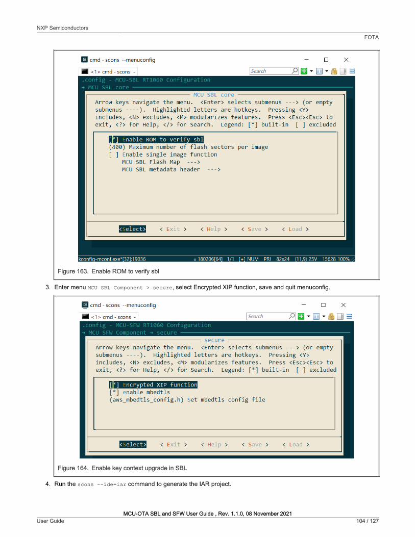
Figure 163. Enable ROM to verify sbl
3. Enter menu MCU SBL Component > secure, select Encrypted XIP function, save and quit menuconfig.
Figure 164. Enable key context upgrade in SBL
4. Run the scons --ide=iar command to generate the IAR project.
NXP SemiconductorsFOTA
MCU-OTA SBL and SFW User Guide , Rev. 1.1.0, 08 November 2021User Guide 104 / 127
El cmd - scons --menuconfig □
Ar row keys navigate the menu . <Enter> selects su bmenus --- > (o r empty su bmenus ----) . Highlighted lette r s a re hot keys. Pressing <Y> includes, <N> excludes, <M> modula r izes f eatu res . Press <Esc>< Esc> to exit, <?> fo r Help , </> fo r Sea rch . Legend : [*] built - in [ ] excluded
n ] nable ROM to verify sbl (400) Maximum number of f lash secto r s pe r image [ ] Ena ble single image f unction
MCU SBL Flash Map --- > MCU SBL metadata heade r --- >
X
El cmd - scons --menuconfig □ X
secure ----------------~ Arrow keys navigate the menu . <Enter> selects submenus ---> (o r empty su bmenus - -- - ) . Highlighted lette r s are hot keys . Pressing <Y> includes, <N> excludes, <M> modula r izes f eatu res. Press <Esc>< Esc> to exit, <?> for Help, </> fo r Sea rch . Legend: [*] built-in [ ] excluded
n ] ncrypted XIP function [*] enable mbedtls (aws_mbedtls_conf ig . h) set mbedtls conf ig f ile
MWIR < Exit > < Help > < Sa\ie > < Load >

5. Configure the project to generate an image with the .srec format, then build the project. For the Keil project, generatethe srec format image by running fromelf.exe --m32combined --output "[email protected]".
7.4.2.2 Application image preparation
To generate application image for encryption, the steps are as below:
1. Open the linker file sfw\target\xxxx\board\link\MIMXRTXXXX_flexspi_nor.icf (take the IAR linker file asexample), and make the following changes in the linker file:
define symbol m_interrupts_start = BOOT_FLASH_ACT_APP + 0x2000;define symbol m_interrupts_end = BOOT_FLASH_ACT_APP + 0x2000 + 0x3FF;
define symbol m_text_start = BOOT_FLASH_ACT_APP + 0x2000 + 0x400;define symbol m_text_end = BOOT_FLASH_CAND_APP - 0x1000;
2. Run env.bat in target platform
3. Enter the menu MCU SFW core and uncheck the menu Enable sfw standalone xip
4. Enter the menu MCU SFW component > secure and check the menu Encrypted XIP function, then save and quitmenuconfig.
Figure 165. Enable key context upgrade in SFW
5. Generate the SFW project.
6. Change codes to call the function update_key_context() after calling enable_image() if application supports OTA.
7. Configure option to generate an image with thesrec format, then build the project.
For RSA or ECDSA signing method, don’t change linker file in step1 and need to generate binary format image.
NOTE
7.4.2.3 Program KEK (eFuse)
The KEK (Key of Encryption Key) serves as the key for the BEE to unwrap the Key context.
NXP SemiconductorsFOTA
MCU-OTA SBL and SFW User Guide , Rev. 1.1.0, 08 November 2021User Guide 105 / 127
El cmd - scons --menuconfig □ X
secure ----------------~ Arrow keys navigate the menu . <Enter> selects submenus ---> (o r empty submenus ----) . Highlighted lette r s are hotkeys. Pressing <Y> includes, <N> excludes, <M> modularizes f eatu res. Press <Esc>< Esc> to exit, <?> for Help, </> for Search . Legend : [ * ] built-in [ ] excluded
n ] ncrypted XIP function [ *] enable mbedtls (aws_mbedtls_conf ig.h) set mbedtls config file
..... < Exit > < Help > < Sa\ie > < Load >

You may not write KEK and keep that efuse value as all 0 s in test phase. Below is an example how to burn KEK to efuse SW_GP2for EVKMIMXRT1060, add the command below into the file program_ocotp.bat.
:: kek=00112233445566778899aabbccddeeffblhost.exe -u 0x15A2,0x0073 -j -- efuse-program-once 0x29 ccddeeffblhost.exe -u 0x15A2,0x0073 -j -- efuse-program-once 0x2a 8899aabbblhost.exe -u 0x15A2,0x0073 -j -- efuse-program-once 0x2b 44556677blhost.exe -u 0x15A2,0x0073 -j -- efuse-program-once 0x2c 00112233
The KEK (Key of Encryption Key) serves as the key for the OTFAD which uses EVKMIMXRT1010 or EVKMIMXRT1170. Followthe order shown below: 0xffeeddcc, 0xbbaa9988, 0x77665544, 0x33221100.
7.4.2.4 Run SBL and application
Do the following steps to generate signed and encrypted SBL and application together.
1. Copy sbl.srec and sfw.srec to the folder sbl/target/evkmimxrt1060/secure
2. Edit sign_enc_sbl_app.bat and set the KEK and the encrypted region.
3. Make the EVKMIMXRT1060 board to enter Serial Downloader mode and connect USB OTG and the DEBUG USB port.
4. Run sign_enc_sbl_app.bat to generate final signed and encrypted SBL and application1.
5. Download SBL and application by this script or other tools.
6. Switch (SW7-3 ON, SW7-4 OFF) to normal boot mode, set SW5-1 ON then reset board. You see the output in theterminal.
Figure 166. Terminal log
7.4.2.5 Application OTA image preparation
To generate the signed and encrypted application for upgrading, do the following steps:
1. Generate a project as in section 7.4.2.2
2. Build the image and rename it to sfw2.srec or sfw2.bin
3. Open script sign_enc_sfw2.bat, set the KEK and encrypted region.
4. Run sign_enc_sfw2.bat, file sfw_2_enc.bin is the final image.
NXP SemiconductorsFOTA
MCU-OTA SBL and SFW User Guide , Rev. 1.1.0, 08 November 2021User Guide 106 / 127

7.4.3 Secure boot demonstration for the platform LPC55S69This section describes the steps to enable an XIP encrypted authenticated boot. The demo targeted for LPC55S69(revision 1B)hardware platform is used as an example.
7.4.3.1 Generating Keys and Certificates
To enable ROM secure boot, generate keys and certificates. Follow the steps to generate them.
1. Install the MCUXpresso Secure Provisioning tool
2. Run this tool, click File > New Workspace, then select processor LPC55S69 to create a new workspace.
Figure 167. Creating a new workspace
3. Choose Boot Type as Encrypted (PRINCE) and Signed.
Figure 168. Selecting Boot Type
4. In the Keys Management view, click the button Generated keys, then specify all parameters in this menu.
NXP SemiconductorsFOTA
MCU-OTA SBL and SFW User Guide , Rev. 1.1.0, 08 November 2021User Guide 107 / 127
New Workspace
Workspace: I C:\Users\nxp96245\secure _lpc55s69I
Series Processor
@ LPCSSSxx Q LPC55S04 0 LPC55S26
0 RT10xx 0 LPC55S06 0 LPC55S28
Q RT11xx Q LPC55S14 0 LPC55S66
0 RTxxx 0 LPC55S16 @ LPC55S69
MCUXpresso Secure Prov isioning - C:\Users\nxp96245\secure_lpc55s69
File Target Tools Help
X
1 1 Browse
[ Create J ,;
□ X
Processo r: LPC55S69 I soot Typ~ Encrypted (PRINCE) and Signed v lt3oot Device: onchip memory/Internal Flash v d I Connection: ~
✓ Build image ✓Write image ✓ Keys Management
Source executable image: ~lc_:\_Lo_c_a_lD_a_ta_\W_ o_rk_\s_b_l\_ta_rg_e_t_\ lp_c_5_5_s6_9_\i_ar_\ b_u_il_d_\ia_r_\ Ex_ e\_s_bl_.b_in _________ v I Browse ...
Start address: 10 I XIP:yes
D Use custom beatable image path: Llb_o_o_ta_b_le~_i_m_a~g_es_\s_b_l._sb ____________________ ~ v I Browse ...
TrustZone pre-configuration Enabled (preset)
Use the following keys:
Key source:
-Jserkey:
SBKEK:
PRINCE Regiony]
ROT4:IMG4_1
KeyStore
I 7F393C4207EC4864F6663FC54583F5958EA789DFDFECDED249DF2304506ABE9C
.,, w:.e.
Random
Build hage

Figure 169. Figure 7-141: Generate keys
5. Click the button Generate, OpenSSL output is displayed in the progress window.
Figure 170. Generating keys - success
6. You can find generated keys and certificates in the folder keys and crts in the workspace directory.
7.4.3.2 SBL image preparation
The following steps describe the procedure of creating an SBL image.
1. Run env.bat in target board.
2. Enter the menu MCU SFW Core > , select one application signature type, save and quit menuconfig.
NXP SemiconductorsFOTA
MCU-OTA SBL and SFW User Guide , Rev. 1.1.0, 08 November 2021User Guide 108 / 127
MCUXpresso Secure Provisioning - C:\Users\nxp96245\secure_lpc5Ss69
File Target Tools Help
Processor: LPCSSS69 I Boot Type: Encrypted (PRINCE) and Signed v j I Boot Device: onchip _ memory/Internal Flash v
✓ Bui ld image ✓ Write image ✓ Keys Management
Generate Keys X
Certificate chain Chain Ro T + IMG
Serial maber I 3cc30000abababab
Key type RSA
Key length 2048
Number of RoT 4 Duration [years] IL1_0 ____ ~
Generate Close
D X
it I Connection: UART
Add Keys Generate keys Export Keys Import Keys
Generating keys (C:\Users\nxp96245\ secure _lpc55s69\ gen _ scripts\generate _keys_ win.bat)
.. . .. . .. . .. . .. . .. . .. . .. . . +++++
e is 65537 (Ox010001) Si gnature ok subject=CN = ROT4_sha256_2048_65537_v3_ca Getting Priva te key Generat ing RSA private key, 2048 bit l ong modulus .. +++++
.. . .. . .. . .. . .. . .. . .. . .. . .. . .. . .. . .. . .. . .. . .. . .. . .. . .. . . +++++
e is 65537 (O x010001) Si gnature ok subject=CN = IMG4_1_ sha256 - 2048_65537_v3_usr Get t ing CA Priva te Key
I
SUCCESS: Generating keys II Close
"
V
I

Figure 171. Selecting signing method
3. Run the scons --ide=iar command to generate the IAR project.
4. Build binary a image from IDE, it is plain image for unsecure boot.
7.4.3.3 Application image preparation
The following steps describe the procedure for creating signed image.
1. Run env.bat in target board under SFW repo
2. Enter the menu MCU SFW core and uncheck the menu Enable sfw standalone xip, save and quit menuconfig
NXP SemiconductorsFOTA
MCU-OTA SBL and SFW User Guide , Rev. 1.1.0, 08 November 2021User Guide 109 / 127
IJ cmd - scons --menuconfig
signing keys to navigate this window or press the
hot key of the item you wish to select f ollowed by the BAR>. Press<?> f or additional inf ormation about this
() Select signatu re type RSA [G] elect signature type ROM use () Select signatu re type ECDSA P256
□ X

Figure 172. Uncheck Enable sfw standalone
3. Generate an IAR project, following the example below:
scons --ide=iar
4. In Project > Options > Output Converter, check Generate additional output and select Raw binary outputformat
5. Build the project.
7.4.3.4 Sign and Program encrypted SBL
This section describes the building and writing of authenticated SBL image by tool MCUXpresso Secure Provisioning Tool (SPT).
1. In the Build Image view, select the image position as a Source executable image.
2. In Start address tab, input 0.
3. Select Enabled(present) in TrustZone pre-configuration.
4. For use the following keys, select any key chain, for example ROT1: IMG1_1.
5. Input SBKEK or generate one with the Random button.
NXP SemiconductorsFOTA
MCU-OTA SBL and SFW User Guide , Rev. 1.1.0, 08 November 2021User Guide 110 / 127
Ar row keys navigate the menu. <Ente r > selects submenus -- - > (or empty submenus ----) . Highlighted letters a re hot keys . Pressing <Y> includes, <N> excludes, <M> modula r izes f eatur es . Press <Esc>< Esc> to exit, <?> f or Help, </> f or Sea rch. Legend : [ *] built - in [ ] excluded
n ] nable sfw standalone xip [*] Enable OTA [*] OTA f r om sdca rd [*] OTA from u-dis k
MCU SFW Flash Map --- > MCU SFW metadata heade r --->
MIMI < Exit > < Help > < Save > < Load >

Figure 173. Setting parameters for building image
6. Open the PRINCE configuration and check the configuration. Set the encrypted size of the SBL image in the PRINCEregion. If you do not encrypt the image, skip this step. Select Signed in Boot Type.
Figure 174. Setting encryption region
7. Click Build image, output is displayed in the progress window.
NXP SemiconductorsFOTA
MCU-OTA SBL and SFW User Guide , Rev. 1.1.0, 08 November 2021User Guide 111 / 127
MCUXpresso Secure Provisioning - C:\Users\nxp96245\secure _lpc5Ss69
File Target Tools Help
□ X
Processor: LPC55S69 I Boot Type: Encrypted (PRINCE) and Signed v] I Boot Device: onchip _ memory/Internal Flash v it I Connection: USB
✓ Bui ld image A Write image ✓ Keys M anagement
l:""""'"""""""""""""""""""""""""""""""""""""""""""""""""""""""""""""""""1-----~ Source executable image: C:\l oca1Data\Work\sbl\target\1pc5Ss69\iar\build\iar\Exe\sbl.bin Browse ...
Start address: .,lj_ox_o_,._ __________ ~ XIP:yes
D Use custom bootable image path: ~I b_o_o_ta_b_le=i_m_a~ge_,_\s_b_l._sb ____________________ ~v I Browse ...
TrustZone pre-configurationl Enabled (preset) , e.
Use the following keys: I ROT1: IMG1 _ 1
Key source: KeyStore
User key: R,
SBKEK: OF7C29CA4BSE03E37E77F354335590C7FOAD7700586DA7 AD25BE33F1 85EB1 EBO Random
PRINCE Regions
Buil d laage
PRINCE Region Configurat ion X
Region: Region 0 Reg ion 1 Region 2
Erase check: G2I Check erase D Check erase D Check erase
Lock: □ Lock □ Lock Lock not supported
Enable: G2] Enable D Enable D Enable
Base addr: I 0x0000#### vi I 0x0004#### vi I 0x0008#### vi
Start offset : I 0x###00000 vi 0x###00000 0x###00000
End offset : I 0x###0FFFF vi 0x###3FFFF 0x###1BFFF
Addr range: 0x00000000-0x0000FFFF 0x00000000-0x00000000 0x00000000-0x00000000
OK 1 1 Cancel

Figure 175. Generate booting image
8. Make sure that the board is connected and make the processor into ISP mode by pressing the ISP pin during resetstage.
9. Click the USB tab, set the connection to USB or UART according to selected port and test the connection to theprocessor
Figure 176. Connection dialog
10. Make sure that the Use built image checkbox is selected.
11. Click Write Image.
check Enable security checkbox to seal the device security permanently.
NOTE
NXP SemiconductorsFOTA
MCU-OTA SBL and SFW User Guide , Rev. 1.1.0, 08 November 2021User Guide 112 / 127
Building image (C:\Users\ nxp96245\ secure _lpc55s69\ build _image_ win.bat)
· c:,u;;;;,~;~96245\;;~;:;;;=i~~55;69\k;;;,iMG1:1::h;256:204s_65537_v3_usr_key.pem" -R "C:\Users\nxp96245\secure_lpc55s69\crts\ROTl_sha256_2048_65537_v3_ca_crt. der" -R "C: \ Users \ nxp96245 \ secure_lpc55s69\crts \ ROT2_sha256_2048_65537_v3_ca_crt. der" -R "C:\Users\nxp96245\secure_lpc55s69\crts\ROT3_sha256_2048_65537_v3_ca_crt. der" -R "C:\Users\nxp96245\secure_lpc55s 69\crts\ROT4_sha256_2048_65537_v3_ca_crt. der" -S "C:\Users\nxp96245\secure_lpc55s69\ crts\ROTl_sha256_2048_65537_v3_ca_crt. der" -S "C: \ Users \ nxp96245 \ secure_lpc55s69\crts \ IMG1_1_sha256_2048_65537_v3_usr_crt. der" -h "C:\Users\nxp96245\secure_lpc55s69\gen_sb \ rkth.bin" "C:\Users\nxp96245\secure_lpc55s69\bootable_images \ sbl. bin"
RKTH: 122a7fd6fc2527a5741425ffe433e33001045dde783e6al c59flafef75eadf72 "security enabled" elftosb succeeded I
[ SUCCESS: Building image 11 Close
MCUXpresso Secure Provisioning - C:\Users\nxp96245\secure _lpc55s69
File Target Tools Help
□ X
Processor: LPC55S69 I Boot Type: Encrypted (PRINCE) and Signed v I Boot Device: onchip_memory/lnternal Flash v E it I Connection US
✓ Build image ✓ Write image ✓ Keys Management
Bootable Image to be written
[21 Use built image
Image path: bootable_images\s
Additional Input Files
Title Path
M asterBootlmag ... gen_ sb\mbi_ config SBKEK (.bin) gen _scripts\sbkek.
Prince Configurat. .. gen _sb\prince.j son
Connection
Q USB
Vendor ID 0x1 FC9
Product ID 0x0021
@UART
COM port lcoM14
Baud Ra te I 115200 I
Connection Status
Feature
Connection
Mode
Security
Key-Store
Detected va lue
OK
ROM Bootloader
PFR not sealed yet
Not enrolled yet
X
viii be enrolled by the write script during first execution
LPC55S69 match
II Test Connection II Result: 1 __ ,,o_K __ !!!J
OK Cancel

Figure 177. Programming image SBL
12. Write result is displayed in the progress window.
Figure 178. Write image message - success
7.4.3.5 Sign and Program application image
You can download an SFW image with BootRom in ISP mode or with SBL in ISP mode. Do the following steps to generate a signedSFW image:
1. Copy sfw.bin into folder sbl/target/lpc55s69/secure.
2. Edit mbi_config.json to set correct keys and certifications path or copy the older keys and crts from MCUXpressoSecure Provisioning lpc55s69 workspace to here.
"rootCertificate0File": "./crts/ROT1_sha256_2048_65537_v3_ca_crt.der","rootCertificate1File": "./crts/ROT2_sha256_2048_65537_v3_ca_crt.der","rootCertificate2File": "./crts/ROT3_sha256_2048_65537_v3_ca_crt.der","rootCertificate3File": "./crts/ROT4_sha256_2048_65537_v3_ca_crt.der","mainCertPrivateKeyFile": "./keys/IMG1_1_sha256_2048_65537_v3_usr_key.pem","chainCertificate0File0": "./crts/ROT1_sha256_2048_65537_v3_ca_crt.der","chainCertificate0File1": "./crts/IMG1_1_sha256_2048_65537_v3_usr_crt.der"
NXP SemiconductorsFOTA
MCU-OTA SBL and SFW User Guide , Rev. 1.1.0, 08 November 2021User Guide 113 / 127
MCUXp resso Secure Provisioning - C:\Users\ nxp96245\secure_lpc55s69
File Ta rget Tools He lp
□ X
Processor: LPC55S69 I Boot Type: Encrypted (P RINCE) and Signed v 11 Boot Device: onchip _ memory/Internal Flash v E I Connect ion: USB
✓ Build image ✓Write image ✓ Keys Management
Beatable Image to be written
I 121 Use built image I Image path: 'lb_o_o-ta_b_le-_i_m_a-ge- ,-, ,-b-1.-,b--------------------------~v I Browse ...
Additio nal Input Files
I Tit le Path
Maste rBoot lmag... gen _sb\m bi_ config.json
SBKEK (. bin) gen_ sc ripts\ sbkek.b in
Prince Co nfi gurat... gen_sb\ prince.json
Description
Config uration fi le for generat ion of Maste r Boot Image
Key used to sign SB image capsule
PRINCE regions configu ration fi le
_J Im port.
□ Enable securityo lri te Iaage I
W riting Image (C:\Users\ nxp96245\ secure _lpc55s69\wri te _image_ win.bat)
] , ustatus u :
,des cripti on,: ,0 (OxO) Success.•, "value" : 0
blhost succeeded tttttt Update bootable image using SB2 capsule tttttt blhost -t 5000 -p COM14, 115200 -- receive-sb-file ' C:\Users\nxp96245\secure_lpc55s69\bootable_images\sbl.sb' Response status= 0 (OxO) Success. blhost succeeded
I
SUCCESS: Writing Image I Close
.--
V

3. Open signed_enc_sfw.bat and set the correct installation path for tools elftosb and blhost.
SET "PATH=C:\nxp\MCUX_Provi_v3\bin\tools\elftosb\win;%PATH%"SET "PATH=C:\nxp\MCUX_Provi_v3\bin\tools\blhost\win;%PATH%"
4. Set correct com port and configure PRINCE region in sign_enc_sfw.bat.
5. Enter folder secure in scons environment by inputting cd secure.
6. Run sign_enc_sfw.bat to generate final signed application image.
7. Press any key to configure the PRINCE region to set encrypted region after generating signed image. You can omit thisstep and download the signed image.
8. Make the LPC55S69 EVK board to enter ISP mode.
9. Download image, if the write operation was successful, reset the board.
Figure 179. Terminal log
For whole encrypted application image, pad image with 8k bytes aligned.
NOTE
7.4.4 Secure boot demonstration for the platform EVKMIMXRTxxxThis section describes the steps to enable XIP encrypted authenticated boot. The demo targeted for the MIMXRT685S hardwareplatform is used as an example. This section also applies to platform MIMXRT595S.
7.4.4.1 Generating Keys and Certificates
To enable ROM secure boot, generate keys and certificates. Follow the steps to generate them.
1. Install the MCUXpresso Secure Provisioning tool.
2. Run this tool, click File > New Workspace, then select processor MIMXRT685 to create a new workspace.
NXP SemiconductorsFOTA
MCU-OTA SBL and SFW User Guide , Rev. 1.1.0, 08 November 2021User Guide 114 / 127

Figure 180. Creating a new workspace
3. Choose Boot Type as Signed.
Figure 181. Selecting Boot Type
4. In the Keys Management view, click the button Generated keys, then specify all parameters in this menu.
NXP SemiconductorsFOTA
MCU-OTA SBL and SFW User Guide , Rev. 1.1.0, 08 November 2021User Guide 115 / 127
New Workspace
Workspace: I C:\Users\nxp96245\ secure _ RT68SI
Series
Q LPCSSSxx
Q RT10xx
Q RT11xx
@ RTxxx
Processor
Q M IMXRT533S @ M IMXRT685S
Q M IMXRTSSSS
Q M IMXRT595S
Q M IMXRT633S
MCUXpresso Secure Provision ing - C:\Users\nxp96245\secure_RT685
File Target Tools Help
X
11 Browse
[Dea;:]
D X
~ssor: MIMXRT685S1 I Boot Type: Signed ..., I f oot Device: flex-spi-nor/MX2SUM51345G - Port B ..., Edit 11 Connection: u'ill A Build image A Write image A Keys Management
Source executable image:
Start address: I I
vi Browse ...
XIP: no
D Use custom bootable image path: ILb_o_ot_a_b_le~i_m_a~ge_s_\._b_in ________________________ _ vi Browse ...
TrustZone pre-configuration Disabled
Use the following keys:
Key source: OTP
User key:
SBKEK:
fffffffffHHHlfffffffffffHHHlfffffffffffHHHlfffffffffffHHHlfffffffffffHHHlfffffffffffHHHlfffffffffffHHHlfffffffffffHHHlfffffffffffHHHlfffffffffffHHHlfffffffffffHHHlfffffffffffHHI
Status of the operat i on: SUCCESS : New workspace created : C: \Users\nxp96245\secure_RT 685
Status o f the last operation: SUCCESS : New workspace created: C:\Users\nxp96245\secure RT685
Br .......
Random
R,
Build hage

Figure 182. Generate keys
5. Click the button Generate. OpenSSL output is displayed in the progress window.
Figure 183. Generating keys - success
6. You can find generated keys and certificates in the folder keys and crts in the workspace directory. Copy folder “keys”and “crts” to folder sbl/target/evkmimxrt600/secure.
7.4.4.2 SBL image preparation
The following steps describe the procedure for creating SBL image.
1. Run env.bat which is under folder sbl/target/evkmimxrt600
2. Run scons --menuconfig to enter the menu MCU SBL Core to select Enable ROM to verify sbl.
NXP SemiconductorsFOTA
MCU-OTA SBL and SFW User Guide , Rev. 1.1.0, 08 November 2021User Guide 116 / 127
Ill MCUXpresso Secure Provisioning C:\Users\nxp96245\secure_RT685 □
File Target Tools Help
Processor: MIMXRT685S I Soot Type: Signed v j aoot Device; flex-spi-nor/MX25UM51345G Port 8 " Edit I Connection: USB
A Build image A Write image A Keys Management
Generate Keys
Certificate chain Chain RoT + IMG
Serial nuaber I 3cc30000abababab
Keytype RSA
Key length 2048
X
Number of RoT 4 .., Duration(years] Ll1_0 ___ ~
Generate Close
Missing ROT keys, at least one ROT key is needed for selected boot type Add Keys I Generate keys I >Or1 K
Generating keys (C:\Users\ nxp96245\ secure _ RT685\ gen _ scripts\generate _keys_ win.bat)
e is 65537 (Ox010001) Signature ok subject =CN = ROT4_sha256_2048_65537_v3_ca Getting Private key Generating RSA private key, 2048 bit l ong modulus
+++++
.. . .. . .. . .. . .. . .. . .. . .. . .. . . .. .. . . .. .. . +++++
e is 65537 (Ox010001) Si gnature okl subject =CN = IMG4_1_sha256 2048_65537_v3_usr Getting CA Private Key
[ SUCCESS: Generating keys
Import Keys
i
II Close

Figure 184. Enable ROM to verify sbl
3. Enter menu MCU SBL Component > secure > selected signing method, select one application signature type, save,and quit menuconfig.
NXP SemiconductorsFOTA
MCU-OTA SBL and SFW User Guide , Rev. 1.1.0, 08 November 2021User Guide 117 / 127
El cmd - scons --menuconfig □
Arrow keys navigate the menu. <Ente r > selects su bmenus -- -> (o r empty submenus - ---) . Highlighted lette r s a re hot keys. Press i ng <Y> includes, <N> excludes, <M> modula r izes f eatu res. Press <Esc>< Esc> to exit, <?> fo r Help, </> fo r Sea rch . Legend : [ *] built - in [ ] excluded
n ] nable ROM to verify sbl (400) Maximum num ber of f lash secto r s pe r image [ ] Enable single image f unction
MCU SBL Flash Ma p ---> MCU SBL metadata heade r - -- >
X
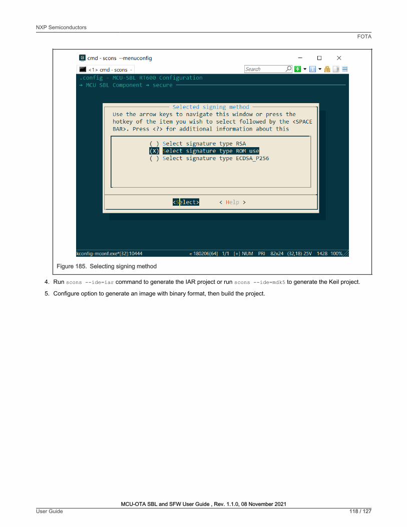
Figure 185. Selecting signing method
4. Run scons --ide=iar command to generate the IAR project or run scons --ide=mdk5 to generate the Keil project.
5. Configure option to generate an image with binary format, then build the project.
NXP SemiconductorsFOTA
MCU-OTA SBL and SFW User Guide , Rev. 1.1.0, 08 November 2021User Guide 118 / 127
El cmd - scans --menuconfig
.. signing • • keys to navigate this window or press the
hotkey of the item you wish to select followed by the BAR>. Press<?> for additional information about this
() Select signature type RSA [D] elect signature type ROM use ( ) Select signature type ECDSA P256
1111111 < Help >
□ X
. .
kconfig-mconf.exe*[32 ]:10444 « 180206[64] 1/ 1 [+] NUM PRI 82x24 (32,18) 25V 1428 100%

Figure 186. Set output format
7.4.4.3 Application image preparation
To generate plain application image, the steps are as below:
1. Run env.bat which is under folder sfw/target/evkmimxrt600.
2. Run command scons --menuconfig.
3. Enter menu MCU SFW core and uncheck menu Enable sfw standalone xip.
NXP SemiconductorsFOTA
MCU-OTA SBL and SFW User Guide , Rev. 1.1.0, 08 November 2021User Guide 119 / 127
Category:
General Options
Static Analysis
Runtime Checking
C/C ++ Compiler
Assembler
Output Converter
Custom Build
Build Actions
Linker
Debugger
Simulator
CAD!
CMSIS DAP
GOB Server
I -j et
J-link/J-Trace
Tl Stellaris
Nu-link
PE micro
ST-l!NK
Third.Party Driver
Tl MSP-FET
Tl XDS
Output
!;21 Gene rate addit ional o utput
Oll!Pllt format-I I Raw b inary
Output fil e
D Ove rride default
sbl.bin
Factory Settings
._ __ o_K __ ...,I ._I __ c_a_n_c_e_l _ _,

Figure 187. Uncheck enable sfw standalone
4. For image, which must be encrypted, enter the menu MCU SFW component > secure and check the menu EncryptedXIP function, then save and quit menuconfig .
NXP SemiconductorsFOTA
MCU-OTA SBL and SFW User Guide , Rev. 1.1.0, 08 November 2021User Guide 120 / 127
El cmd - scons --menuconfig □
Ar row keys navigate the menu. <Ente r > selects submenus ---> (or empty submenus ----) . Highlighted lette r s are hotkeys . Pressing <Y> includes, <N> excludes, <M> modula r izes f eatu res . Press <Esc>< Esc> to exit, <?> fo r Help, </> for Sea rch . Legend: [ *] built-in [ ] excluded
n ] nable sf w standalone xip [ *] Enable OTA [ *] OTA fr om sdca rd [ * ] OTA fr om u-dis k
MCU SFW Flash Map ---> MCU SFW metadata heade r --->
Hi=iidl < Exit > < Help > < Sae > < Load >
X

Figure 188. Enable key context upgrade in sfw
5. Generate the SFW project.
6. Configure the option to generate an image with binary format, then build the project.
7.4.4.4 Run signed SBL and SFW
Do the following steps to generate signed SBL and application, then program them to board.
1. Copy sbl.bin and sfw.bin into the folder sbl/target/ evkmimxrt600/secure.
2. Make the evkmimxrt600 board to enter ISP mode Downloader modes based on ISP pins (ISP0 on, ISP1 off, ISP2 off).
3. Connect a micro USB cable from connector J5 (LINK USB).
4. Enter folder secure in scons environment by inputting cd secure.
5. Run sign_sbl_app.bat to generate final signed SBL and application. If you want to generate the application image forthe next update, remember to change the parameter version number in the imgtool.py command line.
6. Download signed SBL and application by the script sign_sbl_app.bat or other tools. This script downloads theapplication image into slot1. If you test the OTA procedure before, SBL may still try to run application in slot2.
7. Program OTP according to section 7.4.4.6
8. Switch to normal boot mode, then reset board. You see the output in the terminal.
NXP SemiconductorsFOTA
MCU-OTA SBL and SFW User Guide , Rev. 1.1.0, 08 November 2021User Guide 121 / 127
IJ cmd - scans --menuconfig □
secure Arrow keys navigate the menu . <Enter> selects submenus ---> (o r empty submenus ----) . Highlighted lette r s are hot keys . Pressing <Y> includes, <N> excludes, <M> modula r izes featu res . Press <Esc>< Esc> to exit, <?> for Help, </> fo r Sea r ch . Legend: [ *] built-in [ ] excluded
n ] ncrypted XIP function [ ] enable mbedtls
X

Figure 189. Terminal log
7.4.4.5 Run encrypted SBL and SFW
Do the following steps to generate signed and encrypted SBL and application together.
1. Copy sbl.bin and sfw.bin into folder sbl/target/ evkmimxrt600/secure.
2. Edit sign_enc_sbl_app.bat and set the KEK and encrypted region.
3. Make the evkmimxrt600 board to enter ISP mode Downloader modes based on ISP pins (ISP0 on, ISP1 off, ISP2 off).
4. Connect a micro USB cable from connector J5 (LINK USB).
5. Enter folder secure in scons environment by inputting cd secure.
6. Run sign_enc_sbl_app.bat to generate final signed and encrypted SBL and application.
7. Download SBL and application by this script or other tools.
8. Program OTP according to section 7.4.4.6
9. Switch to normal boot mode, then reset board. You see the output in the terminal.
NXP SemiconductorsFOTA
MCU-OTA SBL and SFW User Guide , Rev. 1.1.0, 08 November 2021User Guide 122 / 127
• •
hello sb l . Bootloade r Ve r sion 1.0.0 Remap type: none
• •
The i mage nOl•J i n PR HIARY _S LOT s l ot
. .
Bootloader cha i nload address offset: 0x100000 Reset_Handl er address offset: 0x100400 Jumping to the image
hello sfo. Current i mage ue ri son: 1.0.0 U-Disk updating tas k enabl e. SD Card updating task enabl e . Hell o ,,orld l. Hello wor ld2. Pl ease pl ug in au-d i s k to board . Hell o wor ldl. Hello ,,,or ld2. Hell o ,,orld l. Hello wor ld2.

Figure 190. Terminal log
7.4.4.6 Program OTP (eFuse)
Below is an example to program SRK table and enable secure boot. In Development phase, user could use shadow registers totest the Secure boot.
1. Find and open script program_ocotp.bat in sbl/target/evkmimxrt600/secure, then set the correct installation pathfor tool blhost and com port.
SET "PATH=C:\nxp\MCUX_Provi_v3\bin\tools\blhost\win;%PATH%"SET com_port=COMX,115200
2. Find the RKT hash(RKTH) value in the log of generating SBL image.
Figure 191. RKTH value in hex
3. The RKTH value showed in the log is intended to be burned into the OTP fuses.The RKTH value generated by elftosbis in big-endian format. To store the value in OTP correctly, the byte order of the words supplied to efuse-program-oncecommand needs to be byte-swapped to little-endian format. For example, 1923818b, 9f48273c, 04e135e8, 876104be,7c50c5db, 1be40d31, d5689e46, c0ec2d84.
blhost -p COMx,115200 -t 15000 -- efuse-program-once 0x78 1923818b blhost -p COMx,115200 -t 15000 -- efuse-program-once 0x79 9f48273c blhost -p COMx,115200 -t 15000 -- efuse-program-once 0x7A 04e135e8 blhost -p COMx,115200 -t 15000 -- efuse-program-once 0x7B 876104be blhost -p COMx,115200 -t 15000 -- efuse-program-once 0x7C 7c50c5db blhost -p COMx,115200 -t 15000 -- efuse-program-once 0x7D 1be40d31 blhost -p COMx,115200 -t 15000 -- efuse-program-once 0x7E d5689e46 blhost -p COMx,115200 -t 15000 -- efuse-program-once 0x7F c0ec2d84
NXP SemiconductorsFOTA
MCU-OTA SBL and SFW User Guide , Rev. 1.1.0, 08 November 2021User Guide 123 / 127
15. output the root certificates 5HA256 hash (RKTH). Success . RKTH: 8b8123193c27489fe835el04be046187dbc5507c310de4lb469e68d5842decc0

If user program efuses with script program_ocotp.bat, remember to update the RKTH value according to user’s log.The commands used to program efuses are commented out by default. User needs to enable it by hand.
NOTE
4. User can enable secure boot using the following command:
blhost -p COMx,115200 -t 15000 -- efuse-program-once 0x60 0x900000
5. User can verify the eFuse value via command efuse-read-once
blhost -p COMx,115200 -t 15000 -- efuse-read-once 0x60
6. Enable OTFAD and configure OTP_MASTER_KEY, OTFAD_SEED efuses for image decryption
// program OTP_MASTER_KEY blhost -p COMx,115200 -t 15000 -- efuse-program-once 0x70 ccddeeffblhost -p COMx,115200 -t 15000 -- efuse-program-once 0x71 8899aabbblhost -p COMx,115200 -t 15000 -- efuse-program-once 0x72 44556677blhost -p COMx,115200 -t 15000 -- efuse-program-once 0x73 00112233blhost -p COMx,115200 -t 15000 -- efuse-program-once 0x74 0c0d0e0fblhost -p COMx,115200 -t 15000 -- efuse-program-once 0x75 08090a0bblhost -p COMx,115200 -t 15000 -- efuse-program-once 0x76 04050607blhost -p COMx,115200 -t 15000 -- efuse-program-once 0x77 00010203// program OTFAD SEEDblhost -p COMx,115200 -t 15000 -- efuse-program-once 0x6c 62184d50blhost -p COMx,115200 -t 15000 -- efuse-program-once 0x6d d5ae8d29blhost -p COMx,115200 -t 15000 -- efuse-program-once 0x6e bf6af264blhost -p COMx,115200 -t 15000 -- efuse-program-once 0x6f 3a72eb7f// enable OTFAD bootblhost -p COMx,115200 -t 15000 -- efuse-program-once 0x6a 00001000// config flash settings for MIMXRT685-EVKblhost -p COMx,115200 -t 15000 -- efuse-program-once 0x61 314000
7. Put ISP pins (ISP0 on, ISP1 off, ISP2 off) to make evkmimxrt600 board enter ISP mode Downloader mode, then run thescript program_ocotp.bat.
7.4.4.7 Application OTA image preparation
Do the following steps to generate signed and encrypted application for upgrading.
1. Build the image as in section 7.4.4.3
2. Rename it to sfw2.bin and copy it to folder sbl/target/evkmimxrt600/secure.
3. Open script sign_enc_sfw2.bat, set the KEK and encrypted region.
4. Run sign_enc_sfw2.bat, file sfw_2_enc.bin is final image.
NXP SemiconductorsFOTA
MCU-OTA SBL and SFW User Guide , Rev. 1.1.0, 08 November 2021User Guide 124 / 127

Chapter 8Known issuesNone
NXP Semiconductors
MCU-OTA SBL and SFW User Guide , Rev. 1.1.0, 08 November 2021User Guide 125 / 127

Chapter 9Revision historyTable 8. Revision history
Revision Date Description
0 26 August 2021 First release to open source
1.1.0 08 November 2021 1. Support RT500, RT600 signature and encryption feature
2. Optimize the revert flow
NXP Semiconductors
MCU-OTA SBL and SFW User Guide , Rev. 1.1.0, 08 November 2021User Guide 126 / 127

How To Reach Us
Home Page:
nxp.com
Web Support:
nxp.com/support
Limited warranty and liability — Information in this document is provided solely to enable system and software implementers to use NXPproducts. There are no express or implied copyright licenses granted hereunder to design or fabricate any integrated circuits based onthe information in this document. NXP reserves the right to make changes without further notice to any products herein.
NXP makes no warranty, representation, or guarantee regarding the suitability of its products for any particular purpose, nor doesNXP assume any liability arising out of the application or use of any product or circuit, and specifically disclaims any and all liability,including without limitation consequential or incidental damages. “Typical” parameters that may be provided in NXP data sheets and/orspecifications can and do vary in different applications, and actual performance may vary over time. All operating parameters, including“typicals,” must be validated for each customer application by customer's technical experts. NXP does not convey any license underits patent rights nor the rights of others. NXP sells products pursuant to standard terms and conditions of sale, which can be found atthe following address: nxp.com/SalesTermsandConditions.
Right to make changes - NXP Semiconductors reserves the right to make changes to information published in this document, includingwithout limitation specifications and product descriptions, at any time and without notice. This document supersedes and replaces allinformation supplied prior to the publication hereof.
Security — Customer understands that all NXP products may be subject to unidentified or documented vulnerabilities. Customeris responsible for the design and operation of its applications and products throughout their lifecycles to reduce the effect of thesevulnerabilities on customer’s applications and products. Customer’s responsibility also extends to other open and/or proprietarytechnologies supported by NXP products for use in customer’s applications. NXP accepts no liability for any vulnerability. Customershould regularly check security updates from NXP and follow up appropriately. Customer shall select products with security featuresthat best meet rules, regulations, and standards of the intended application and make the ultimate design decisions regarding itsproducts and is solely responsible for compliance with all legal, regulatory, and security related requirements concerning its products,regardless of any information or support that may be provided by NXP. NXP has a Product Security Incident Response Team(PSIRT) (reachable at [email protected]) that manages the investigation, reporting, and solution release to security vulnerabilities ofNXP products.
NXP, the NXP logo, NXP SECURE CONNECTIONS FOR A SMARTER WORLD, COOLFLUX,EMBRACE, GREENCHIP, HITAG,ICODE, JCOP, LIFE, VIBES, MIFARE, MIFARE CLASSIC, MIFARE DESFire, MIFARE PLUS, MIFARE FLEX, MANTIS, MIFAREULTRALIGHT, MIFARE4MOBILE, MIGLO, NTAG, ROADLINK, SMARTLX, SMARTMX, STARPLUG, TOPFET, TRENCHMOS,UCODE, Freescale, the Freescale logo, AltiVec, CodeWarrior, ColdFire, ColdFire+, the Energy Efficient Solutions logo, Kinetis,Layerscape, MagniV, mobileGT, PEG, PowerQUICC, Processor Expert, QorIQ, QorIQ Qonverge, SafeAssure, the SafeAssure logo,StarCore, Symphony, VortiQa, Vybrid, Airfast, BeeKit, BeeStack, CoreNet, Flexis, MXC, Platform in a Package, QUICC Engine, Tower,TurboLink, EdgeScale, EdgeLock, eIQ, and Immersive3D are trademarks of NXP B.V. All other product or service names are theproperty of their respective owners. AMBA, Arm, Arm7, Arm7TDMI, Arm9, Arm11, Artisan, big.LITTLE, Cordio, CoreLink, CoreSight,Cortex, DesignStart, DynamIQ, Jazelle, Keil, Mali, Mbed, Mbed Enabled, NEON, POP, RealView, SecurCore, Socrates, Thumb,TrustZone, ULINK, ULINK2, ULINK-ME, ULINK-PLUS, ULINKpro, µVision, Versatile are trademarks or registered trademarks of ArmLimited (or its subsidiaries) in the US and/or elsewhere. The related technology may be protected by any or all of patents, copyrights,designs and trade secrets. All rights reserved. Oracle and Java are registered trademarks of Oracle and/or its affiliates. The PowerArchitecture and Power.org word marks and the Power and Power.org logos and related marks are trademarks and service markslicensed by Power.org. M, M Mobileye and other Mobileye trademarks or logos appearing herein are trademarks of Mobileye VisionTechnologies Ltd. in the United States, the EU and/or other jurisdictions.
© NXP B.V. 2021. All rights reserved.
For more information, please visit: http://www.nxp.comFor sales office addresses, please send an email to: [email protected]
Date of release: 08 November 2021Document identifier: MCUOTASBLSFWUG
arm