Instructables.com - 16-key Keypad Decoding with an AVR MCU
12
http://www.instructables.com/id/16-key-Keypad-Decoding-with-an-AVR-MCU/ Home Sign Up! Explore Community Submit All Art Craft Food Games Green Home Kids Life Music Offbeat Outdoors Pets Ride Science Sports Tech 16-key Keypad Decoding with an AVR MCU by nevdull on July 26, 2009 Table of Contents intro: 16-key Keypad Decoding with an AVR MCU . . . . . . . . . . . . . . . . . . . . . . . . . . . . . . . . . . . . . . . . . . . . . . . . . . . . . . . . . . . . . . . . . . . . . . . . . . . . . . . . . . . . 2 step 1: Equipment List . . . . . . . . . . . . . . . . . . . . . . . . . . . . . . . . . . . . . . . . . . . . . . . . . . . . . . . . . . . . . . . . . . . . . . . . . . . . . . . . . . . . . . . . . . . . . . . . . . . . . . . . . 2 Optional . . . . . . . . . . . . . . . . . . . . . . . . . . . . . . . . . . . . . . . . . . . . . . . . . . . . . . . . . . . . . . . . . . . . . . . . . . . . . . . . . . . . . . . . . . . . . . . . . . . . . . . . . . . . . . . . . . 2 step 2: Wire up your keypad . . . . . . . . . . . . . . . . . . . . . . . . . . . . . . . . . . . . . . . . . . . . . . . . . . . . . . . . . . . . . . . . . . . . . . . . . . . . . . . . . . . . . . . . . . . . . . . . . . . . . 3 step 3: Reading Keypresses on AVR . . . . . . . . . . . . . . . . . . . . . . . . . . . . . . . . . . . . . . . . . . . . . . . . . . . . . . . . . . . . . . . . . . . . . . . . . . . . . . . . . . . . . . . . . . . . . . 5 File Downloads . . . . . . . . . . . . . . . . . . . . . . . . . . . . . . . . . . . . . . . . . . . . . . . . . . . . . . . . . . . . . . . . . . . . . . . . . . . . . . . . . . . . . . . . . . . . . . . . . . . . . . . . . . . . . 5 step 4: Using 74C922 to Reduce I/O Requirements . . . . . . . . . . . . . . . . . . . . . . . . . . . . . . . . . . . . . . . . . . . . . . . . . . . . . . . . . . . . . . . . . . . . . . . . . . . . . . . . . . . 6 The 74C922 16-Key Encoder . . . . . . . . . . . . . . . . . . . . . . . . . . . . . . . . . . . . . . . . . . . . . . . . . . . . . . . . . . . . . . . . . . . . . . . . . . . . . . . . . . . . . . . . . . . . . . . . 6 Build the Circuit . . . . . . . . . . . . . . . . . . . . . . . . . . . . . . . . . . . . . . . . . . . . . . . . . . . . . . . . . . . . . . . . . . . . . . . . . . . . . . . . . . . . . . . . . . . . . . . . . . . . . . . . . . 6 step 5: Write, Upload, and Run your AVR Code . . . . . . . . . . . . . . . . . . . . . . . . . . . . . . . . . . . . . . . . . . . . . . . . . . . . . . . . . . . . . . . . . . . . . . . . . . . . . . . . . . . . . . 8 Code Logic . . . . . . . . . . . . . . . . . . . . . . . . . . . . . . . . . . . . . . . . . . . . . . . . . . . . . . . . . . . . . . . . . . . . . . . . . . . . . . . . . . . . . . . . . . . . . . . . . . . . . . . . . . . . . . . . 8 Code Sections . . . . . . . . . . . . . . . . . . . . . . . . . . . . . . . . . . . . . . . . . . . . . . . . . . . . . . . . . . . . . . . . . . . . . . . . . . . . . . . . . . . . . . . . . . . . . . . . . . . . . . . . . . . . . 9 step 6: Visualizing Output with a Dotmatrix LED . . . . . . . . . . . . . . . . . . . . . . . . . . . . . . . . . . . . . . . . . . . . . . . . . . . . . . . . . . . . . . . . . . . . . . . . . . . . . . . . . . . . . . 10 step 7: Finalizing It All . . . . . . . . . . . . . . . . . . . . . . . . . . . . . . . . . . . . . . . . . . . . . . . . . . . . . . . . . . . . . . . . . . . . . . . . . . . . . . . . . . . . . . . . . . . . . . . . . . . . . . . . . 11 File Downloads . . . . . . . . . . . . . . . . . . . . . . . . . . . . . . . . . . . . . . . . . . . . . . . . . . . . . . . . . . . . . . . . . . . . . . . . . . . . . . . . . . . . . . . . . . . . . . . . . . . . . . . . . . . . . 11 Related Instructables . . . . . . . . . . . . . . . . . . . . . . . . . . . . . . . . . . . . . . . . . . . . . . . . . . . . . . . . . . . . . . . . . . . . . . . . . . . . . . . . . . . . . . . . . . . . . . . . . . . . . . . . . . . 12 Advertisements . . . . . . . . . . . . . . . . . . . . . . . . . . . . . . . . . . . . . . . . . . . . . . . . . . . . . . . . . . . . . . . . . . . . . . . . . . . . . . . . . . . . . . . . . . . . . . . . . . . . . . . . . . . . . . . 12
-
Upload
khangminh22 -
Category
Documents
-
view
0 -
download
0
Transcript of Instructables.com - 16-key Keypad Decoding with an AVR MCU

http://www.instructables.com/id/16-key-Keypad-Decoding-with-an-AVR-MCU/
Home Sign Up! Explore Community Submit
All Art Craft Food Games Green Home Kids Life Music Offbeat Outdoors Pets Ride Science Sports Tech
16-key Keypad Decoding with an AVR MCUby nevdull on July 26, 2009
Table of Contents
intro: 16-key Keypad Decoding with an AVR MCU . . . . . . . . . . . . . . . . . . . . . . . . . . . . . . . . . . . . . . . . . . . . . . . . . . . . . . . . . . . . . . . . . . . . . . . . . . . . . . . . . . . . 2
step 1: Equipment List . . . . . . . . . . . . . . . . . . . . . . . . . . . . . . . . . . . . . . . . . . . . . . . . . . . . . . . . . . . . . . . . . . . . . . . . . . . . . . . . . . . . . . . . . . . . . . . . . . . . . . . . . 2
Optional . . . . . . . . . . . . . . . . . . . . . . . . . . . . . . . . . . . . . . . . . . . . . . . . . . . . . . . . . . . . . . . . . . . . . . . . . . . . . . . . . . . . . . . . . . . . . . . . . . . . . . . . . . . . . . . . . . 2
step 2: Wire up your keypad . . . . . . . . . . . . . . . . . . . . . . . . . . . . . . . . . . . . . . . . . . . . . . . . . . . . . . . . . . . . . . . . . . . . . . . . . . . . . . . . . . . . . . . . . . . . . . . . . . . . . 3
step 3: Reading Keypresses on AVR . . . . . . . . . . . . . . . . . . . . . . . . . . . . . . . . . . . . . . . . . . . . . . . . . . . . . . . . . . . . . . . . . . . . . . . . . . . . . . . . . . . . . . . . . . . . . . 5
File Downloads . . . . . . . . . . . . . . . . . . . . . . . . . . . . . . . . . . . . . . . . . . . . . . . . . . . . . . . . . . . . . . . . . . . . . . . . . . . . . . . . . . . . . . . . . . . . . . . . . . . . . . . . . . . . . 5
step 4: Using 74C922 to Reduce I/O Requirements . . . . . . . . . . . . . . . . . . . . . . . . . . . . . . . . . . . . . . . . . . . . . . . . . . . . . . . . . . . . . . . . . . . . . . . . . . . . . . . . . . . 6
The 74C922 16-Key Encoder . . . . . . . . . . . . . . . . . . . . . . . . . . . . . . . . . . . . . . . . . . . . . . . . . . . . . . . . . . . . . . . . . . . . . . . . . . . . . . . . . . . . . . . . . . . . . . . . 6
Build the Circuit . . . . . . . . . . . . . . . . . . . . . . . . . . . . . . . . . . . . . . . . . . . . . . . . . . . . . . . . . . . . . . . . . . . . . . . . . . . . . . . . . . . . . . . . . . . . . . . . . . . . . . . . . . 6
step 5: Write, Upload, and Run your AVR Code . . . . . . . . . . . . . . . . . . . . . . . . . . . . . . . . . . . . . . . . . . . . . . . . . . . . . . . . . . . . . . . . . . . . . . . . . . . . . . . . . . . . . . 8
Code Logic . . . . . . . . . . . . . . . . . . . . . . . . . . . . . . . . . . . . . . . . . . . . . . . . . . . . . . . . . . . . . . . . . . . . . . . . . . . . . . . . . . . . . . . . . . . . . . . . . . . . . . . . . . . . . . . . 8
Code Sections . . . . . . . . . . . . . . . . . . . . . . . . . . . . . . . . . . . . . . . . . . . . . . . . . . . . . . . . . . . . . . . . . . . . . . . . . . . . . . . . . . . . . . . . . . . . . . . . . . . . . . . . . . . . . 9
step 6: Visualizing Output with a Dotmatrix LED . . . . . . . . . . . . . . . . . . . . . . . . . . . . . . . . . . . . . . . . . . . . . . . . . . . . . . . . . . . . . . . . . . . . . . . . . . . . . . . . . . . . . . 10
step 7: Finalizing It All . . . . . . . . . . . . . . . . . . . . . . . . . . . . . . . . . . . . . . . . . . . . . . . . . . . . . . . . . . . . . . . . . . . . . . . . . . . . . . . . . . . . . . . . . . . . . . . . . . . . . . . . . 11
File Downloads . . . . . . . . . . . . . . . . . . . . . . . . . . . . . . . . . . . . . . . . . . . . . . . . . . . . . . . . . . . . . . . . . . . . . . . . . . . . . . . . . . . . . . . . . . . . . . . . . . . . . . . . . . . . . 11
Related Instructables . . . . . . . . . . . . . . . . . . . . . . . . . . . . . . . . . . . . . . . . . . . . . . . . . . . . . . . . . . . . . . . . . . . . . . . . . . . . . . . . . . . . . . . . . . . . . . . . . . . . . . . . . . . 12
Advertisements . . . . . . . . . . . . . . . . . . . . . . . . . . . . . . . . . . . . . . . . . . . . . . . . . . . . . . . . . . . . . . . . . . . . . . . . . . . . . . . . . . . . . . . . . . . . . . . . . . . . . . . . . . . . . . . 12

http://www.instructables.com/id/16-key-Keypad-Decoding-with-an-AVR-MCU/
intro: 16-key Keypad Decoding with an AVR MCUThis instructable will show you how to interface a 16-key keypad to your AVR microcontroller and read the key when a key is pressed. I'll introduce the keypad first, thenthe 74HC922 16-key decoder IC as a pin-saving mechanism, then finally how to take the data and massage it so that you get the correct number for the keypress.
A 16-key keypad can be a useful addition to any embedded project, possibly acting as a code input device for opening a door or as a general input to any projectrequiring the input of multiple values, like alarm circuits, games, puzzles, DTMF generators.
step 1: Equipment ListThis instructable doesn't have (m)any expensive components if you already have an AVR setup. You can buy everything online, although I've found if you check yourlocal electronic warehouse/shop (if you have one) you will be able to pick up everything considerably cheaper, though.
You'll need the following:
AVR microcontroller and a programmer. Arduino, Bare Bones Kit, Freeduino, Boarduino, and all the other clones work just fine. Of course, your custom ownghetto setup will suffice too. Just for the record, the firmware was written for an ATmega328p, so it should run well on that class of AVR's and probably manyothers with little to no modification.Something to compile your code.A 16-key keypad. The leading outlets carry them but they can tend to be spendy, so maybe try Jameco.com or do a search for "16-key keypad" on google. Itshouldn't run you more than $6-7Solderless breadboardhookupwire, soldering iron, wire cutters, etc4 10k resistors
OptionalThese parts aren't necessary for you to figure out how it works, but this instructable shows several different ways to connect this keypad and read data from it, sodepending on the parts you want to do, you may or may not need the following.
74C922 IC. This is a 16-key encoder. You can pick them up from mouser.com or digikey.com for around $5. I got a handful at my local electronics shop for $0.95each.2 x 0.1 uF tantalum capacitors. You can probably get away with ceramic if you have them already.DLO7135 Dot matrix LED. This is one SWEEET component. They sell for over $10-15 each online, but, again, I picked up 10 of these at my local electronics shopfor $1.50 each.8 pin right-angle header and matching female header for the keypad
I think that's about it. Let's get building!

http://www.instructables.com/id/16-key-Keypad-Decoding-with-an-AVR-MCU/
Image Notes1. Optional, from top: [DLO CMOS LED] [74C922 16-key encoder] [resistors] [capacitors]
step 2: Wire up your keypadTake your keypad an examine the bottom aspect for soldering pads. My keypad came in a package with hardly any information. Definitely no insert, just some markingson the cardboard outer part that described how the pins matched to columns. Well, that's really all we need, isn't it?
I first started by breaking an 8-piece section from a long male right angle breakaway header that I always like to keep lying around. This is totally optional. You can solderyour wires directly to the pads if that suits you. The pictures below show the header soldered on.
If you soldered your wires directly to the board then you don't have to worry about making a cable for it. If you did attach a header, then mate it with the female 8-pinheader (again, I just snipped off the right section from a long piece I had around). Solder your wires to it, maybe throw on some shrink tubing and call that part a day.Because I am a bone head and constantly worried that I'll hook up the wrong wires, i chose hookup wire of different colors and used the mnemonic for the visiblespectrum ROYGBIV to choose my wire color from pin 1 to pin 8. I need help.
Got your keypad setup? Good, we'll connect it to our microcontroller and start reading keypresses.
http://www.instructables.com/id/16-key-Keypad-Decoding-with-an-AVR-MCU/
http://www.instructables.com/id/16-key-Keypad-Decoding-with-an-AVR-MCU/
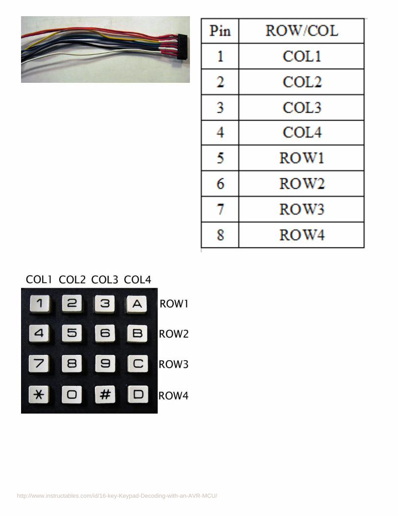
step 3: Reading Keypresses on AVROk, first thing you'll notice is that we're going to be sucking up 8 I/O ports for this bloody keypad. That's a lot of I/O. In the next steps I'll show you how you can reducethat to around four, maybe a couple more depending on how much control you want. But for now, we're going to hook this sucker right into eight free I/O ports of ourAVR.
I chose PD[2..7] and PB[0..1] for my connections. Shy away from PD[0..1] if you want to use serial communication on your arduino or other clone. I also had problemswith my pins floating, so i used four 10k resistors to pull down the column pins to ground. Your AVR probably has internal pull-ups, but the logic I had already come upwith in my head didn't work well with that. You'll note that there's no pin or hookup for power to the keypad, unlike the binary thumbwheel switch I talked about in aprevious instructable.
Here's the basic idea. Pull the four column pins down to 0V. Set those pins as input. Set your row pins as output with initial logic 0 values. Loop through each row,sending a logic 1 to the row and read the column pins. If there is a one in there, then you have a keypress. Also of note is the issue of key debounce. Throughexperimentation I found a workable delay rate, otherwise you'll get many many keypress notifications for each single keypress. Depending on the speed of your MCU,you may have to tweek it a little, too.
I've attached a file at the bottom that I wrote for this section to demonstrate direct connection and reading of the keypad. If you choose to use it you will have to modify itas I reference libraries that I wrote for serial communication. Other than that, I think it should be generally fine. Here's pseudo code to show the flow:
ROWS set INPUT COLS set OUTPUT
for (ever) for each ROW from 0 to 3 Set ROW HIGH if COL1 HIGH number pressed is ( 4 * ROW) else if COL2 HIGH number pressed is ( (4 * ROW) + 1) if COL3 HIGH number pressed is ( 4 * ROW) + 3) if COL4 HIGH number pressed is ( (4 * ROW) + 3) delay for debounce Set ROW LOW
N.B. The numbers are their logical numbers from 0 to 15, not the actual number on the key that was pressed. To do this, you need to either add more logic in your"number pressed is ..." section, or map it to an array, which is just a couple of steps away. First, let's see how to reduce the number of I/O pins this keypad is taking onour microcontroller.
File Downloads
keypad.c (1 KB)[NOTE: When saving, if you see .tmp as the file ext, rename it to 'keypad.c']
http://www.instructables.com/id/16-key-Keypad-Decoding-with-an-AVR-MCU/
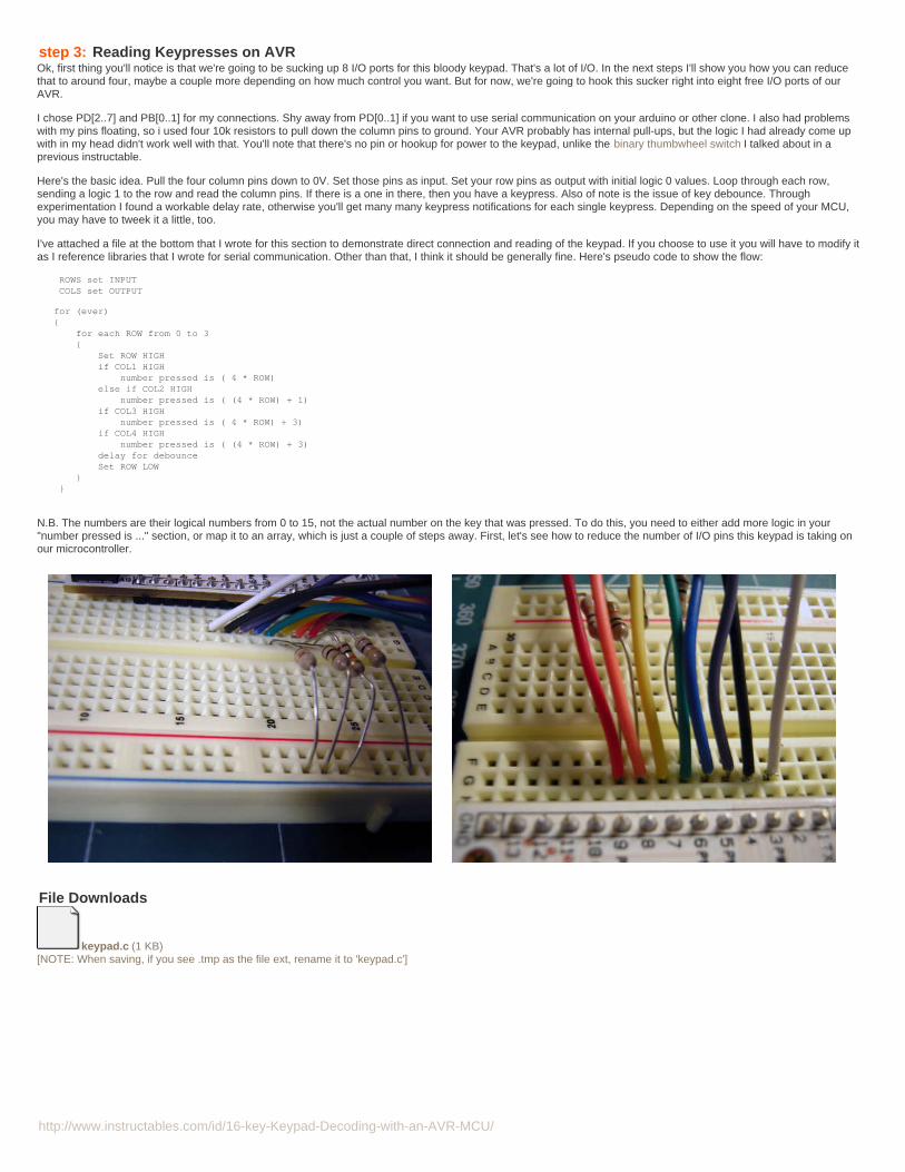
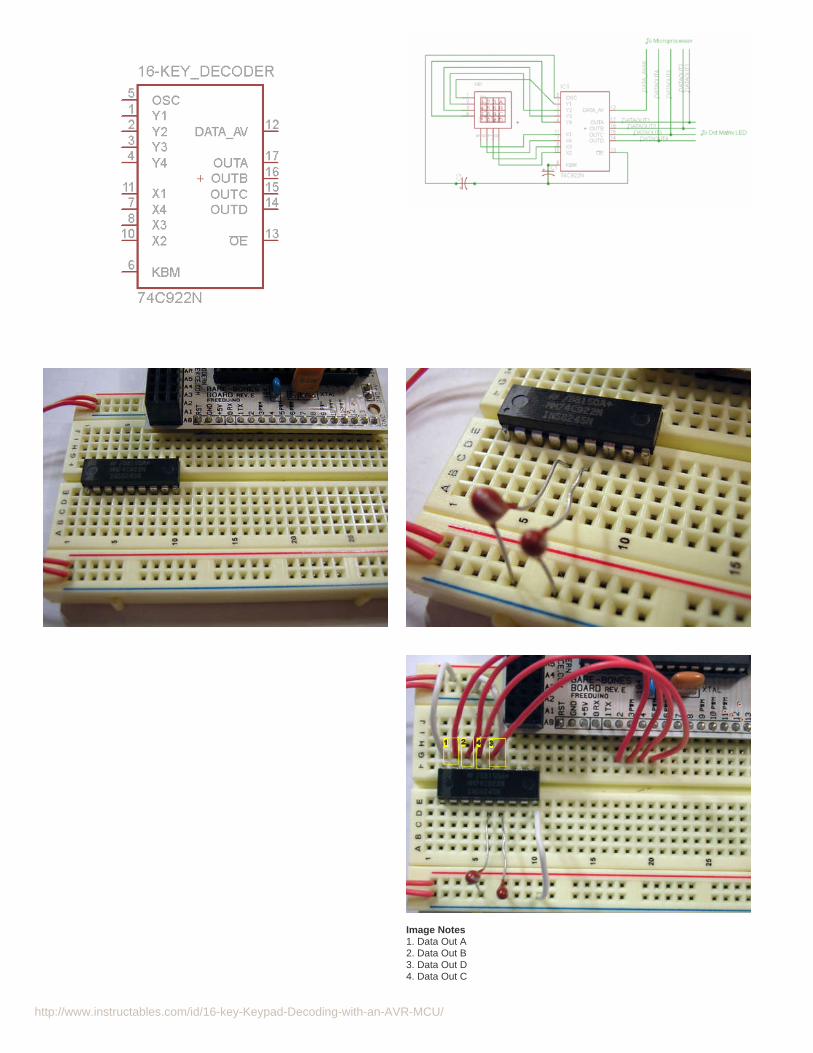
step 4: Using 74C922 to Reduce I/O RequirementsThe MM74C922N is a 16-key encoder that includes all the internals to take the output of a 16-key switch that we just saw from the previous step, and encode it onto onlyfour outputs using a truth table. This is a boon, as it gives you more I/O to control or monitor other things without having to go buy a bigger (in the sense of more pinoutsfor I/O) microcontroller.
The 74C922 16-Key Encoder
From the datasheet, the MM74C922 can use an external clock for synchronous keypad scanning, has internal pull-ups, and has an internal debounce circuit! Both thescan rate and debounce time is configurable via an external clock or capacitor. It also keeps the last key pressed on the outputs even after they key has been depressed,in case your MCU has a moment and needs to retrieve the value again (at least before the next keypress). It also operates from 3V to 15V so it integrates well into TTLand CMOS designs.
The rows of the keypad are connected through its internal pull-up resistors when no key has been pressed. When a key is pressed the chip goes through it's debouncemechanism and when that times out, the encoded data is latched and the DA pin (Data Available) goes high. The DA pin stays high (logical 1) until the key is released,then it drops to a logical 0. There is also an OE pin (Output Enabled) which is the inverse of the DA pin.
The 74C922N pinout is shown in a schematic I've included below that only shows this IC. I've also included an Eagle schematic, although the keypad device's rows andcolumns made the circuit difficult to interpret, so I also include my hand written schematic that I made when I first started toying with the keypad and the 74C922.Hopefully one of those will clear up any connectivity issues, if you get any.
Build the Circuit
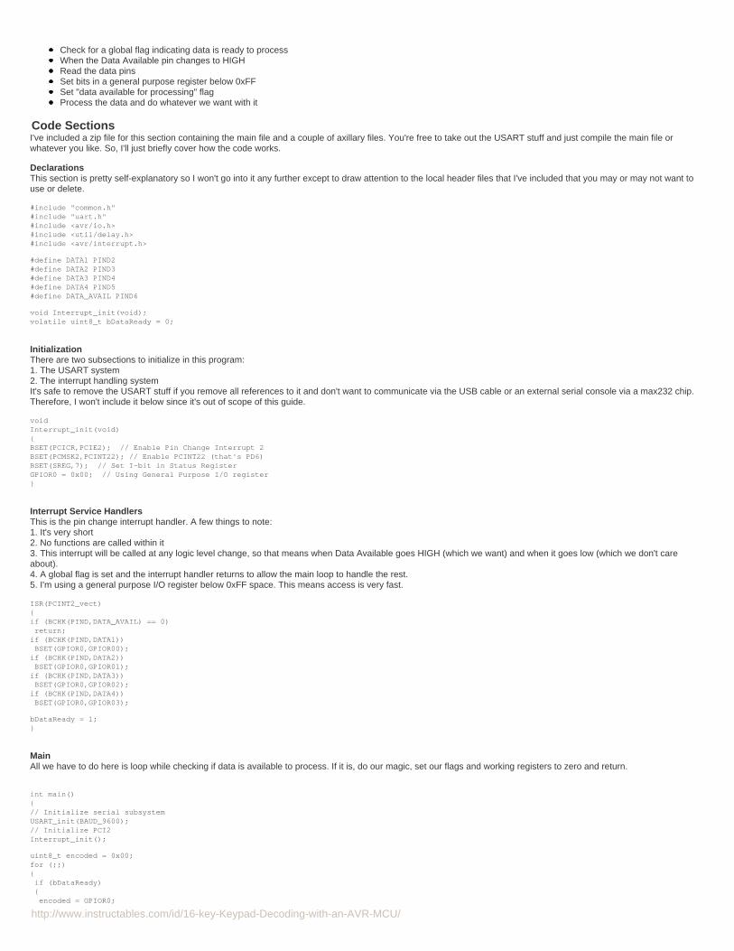
Put in your 74C922 into your breadboard, somewhere close but where you're not too cramped. If you're not familiar with IC's, take a moment to wonder at your new shinychip and notice that the legs are splayed out when they come out of the factory. It can help getting it into the breadboard if you lay it on its side with its legs flat on thetable, and with a gentle rolling motion slightly bend them inward. When placing your IC note that there is a stripe or divot on one side. That indicates where pin one is.
Connect the 0.1uF capacitors to pins 6 and 7 and take them to ground. See below. If you're using tantalum capacitors remember they're polarized so put the positive side(usually the longer leg) closest to the pin and the short leg in the ground terminal.N.B.You may have to play around with the capacitors for your setup. I've found 1uF on the oscillator and 10uF to 15uF (I had 3 in parallel) gives me the best responsive scanwith the least debounce. Figuring it out for your setup can be fun.
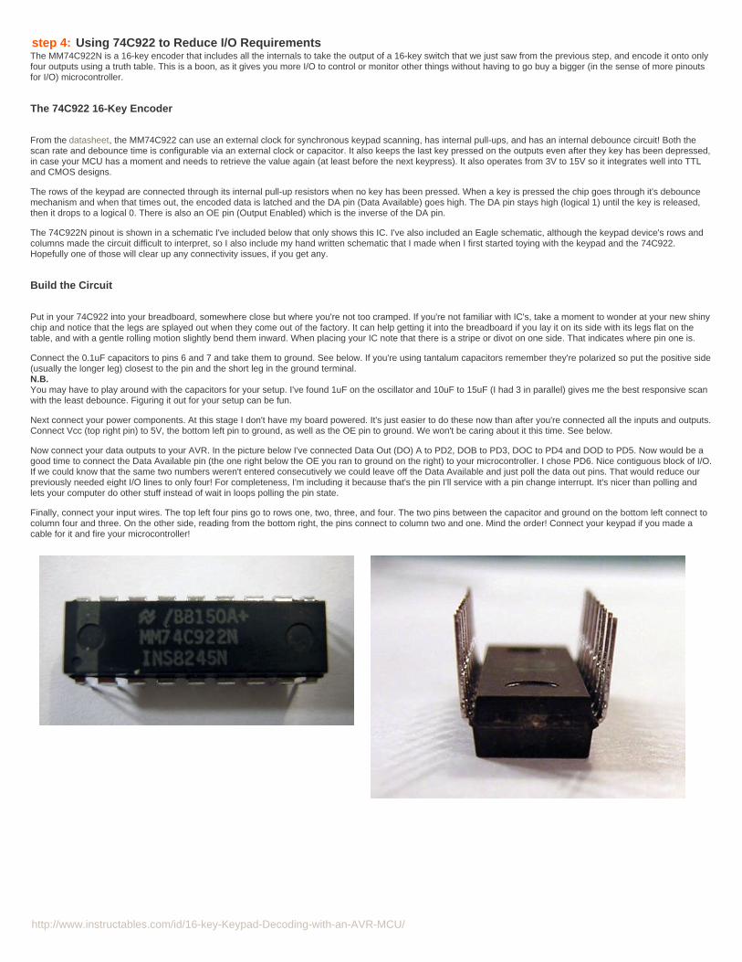
Next connect your power components. At this stage I don't have my board powered. It's just easier to do these now than after you're connected all the inputs and outputs.Connect Vcc (top right pin) to 5V, the bottom left pin to ground, as well as the OE pin to ground. We won't be caring about it this time. See below.
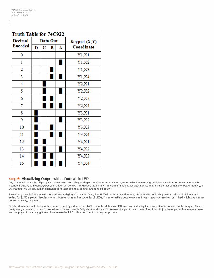
Now connect your data outputs to your AVR. In the picture below I've connected Data Out (DO) A to PD2, DOB to PD3, DOC to PD4 and DOD to PD5. Now would be agood time to connect the Data Available pin (the one right below the OE you ran to ground on the right) to your microcontroller. I chose PD6. Nice contiguous block of I/O.If we could know that the same two numbers weren't entered consecutively we could leave off the Data Available and just poll the data out pins. That would reduce ourpreviously needed eight I/O lines to only four! For completeness, I'm including it because that's the pin I'll service with a pin change interrupt. It's nicer than polling andlets your computer do other stuff instead of wait in loops polling the pin state.
Finally, connect your input wires. The top left four pins go to rows one, two, three, and four. The two pins between the capacitor and ground on the bottom left connect tocolumn four and three. On the other side, reading from the bottom right, the pins connect to column two and one. Mind the order! Connect your keypad if you made acable for it and fire your microcontroller!
http://www.instructables.com/id/16-key-Keypad-Decoding-with-an-AVR-MCU/
Image Notes1. Data Out A2. Data Out B3. Data Out D4. Data Out C

http://www.instructables.com/id/16-key-Keypad-Decoding-with-an-AVR-MCU/
Image Notes1. Ground2. Vcc = 5V3. Output Enable is brought to ground
step 5: Write, Upload, and Run your AVR CodeIn order to read your data when a key is pressed, we will create service routine that will handle reading the data inputs when data becomes available. The AVR willautomatically tell us when data is available for reading if we ask it to (or command it to..I'm trying to be nice so I'm killed last by our soon-to-be Robot Overlords). Thisnotification is called an interrupt and the AVR has several types. The one I'm going to write is called a "pin change interrupt." It interrupts the flow of your code andexecutes your handling routine when -- you guessed it -- there is logic level change on a pin you've asked to be watched.
Have you wondered yet how the 74C922 distills 8 bits of data into just four data lines? If you've read my other instructable you'd probably have figured it out. Well, maybeyou've already figured it out. Once you've done one truth table you've done them all, right? :) The 8 pins from the keypad is encoded in binary using the four data pins.I've made a truth table for you.
If you're unclear what that means, take a look at my other instructables, or do a search for "truth table" or "binary logic" on your favorite search engine.
Code Logic
I'm not sure getting into the details of my code when it's available for you to download is appropriate, but I'll introduce a few things here, and if you're an old salt at thisstuff you can skip past it, otherwise I hope I can teach you something.
http://www.instructables.com/id/16-key-Keypad-Decoding-with-an-AVR-MCU/
Check for a global flag indicating data is ready to processWhen the Data Available pin changes to HIGHRead the data pinsSet bits in a general purpose register below 0xFFSet "data available for processing" flagProcess the data and do whatever we want with it
Code SectionsI've included a zip file for this section containing the main file and a couple of axillary files. You're free to take out the USART stuff and just compile the main file orwhatever you like. So, I'll just briefly cover how the code works.
DeclarationsThis section is pretty self-explanatory so I won't go into it any further except to draw attention to the local header files that I've included that you may or may not want touse or delete.
#include "common.h"#include "uart.h"#include <avr/io.h>#include <util/delay.h>#include <avr/interrupt.h>
#define DATA1 PIND2#define DATA2 PIND3#define DATA3 PIND4#define DATA4 PIND5#define DATA_AVAIL PIND6
void Interrupt_init(void);volatile uint8_t bDataReady = 0;
InitializationThere are two subsections to initialize in this program:1. The USART system2. The interrupt handling systemIt's safe to remove the USART stuff if you remove all references to it and don't want to communicate via the USB cable or an external serial console via a max232 chip.Therefore, I won't include it below since it's out of scope of this guide.
voidInterrupt_init(void)BSET(PCICR,PCIE2); // Enable Pin Change Interrupt 2BSET(PCMSK2,PCINT22); // Enable PCINT22 (that's PD6)BSET(SREG,7); // Set I-bit in Status RegisterGPIOR0 = 0x00; // Using General Purpose I/O register
Interrupt Service HandlersThis is the pin change interrupt handler. A few things to note:1. It's very short2. No functions are called within it3. This interrupt will be called at any logic level change, so that means when Data Available goes HIGH (which we want) and when it goes low (which we don't careabout).4. A global flag is set and the interrupt handler returns to allow the main loop to handle the rest.5. I'm using a general purpose I/O register below 0xFF space. This means access is very fast.
ISR(PCINT2_vect)if (BCHK(PIND,DATA_AVAIL) == 0) return;if (BCHK(PIND,DATA1)) BSET(GPIOR0,GPIOR00);if (BCHK(PIND,DATA2)) BSET(GPIOR0,GPIOR01);if (BCHK(PIND,DATA3)) BSET(GPIOR0,GPIOR02);if (BCHK(PIND,DATA4)) BSET(GPIOR0,GPIOR03);
bDataReady = 1;
MainAll we have to do here is loop while checking if data is available to process. If it is, do our magic, set our flags and working registers to zero and return.
int main()// Initialize serial subsystemUSART_init(BAUD_9600);// Initialize PCI2Interrupt_init();
uint8_t encoded = 0x00;for (;;) if (bDataReady) encoded = GPIOR0;
http://www.instructables.com/id/16-key-Keypad-Decoding-with-an-AVR-MCU/
USART_tx(encoded); bDataReady = 0; GPIOR0 = 0x00;
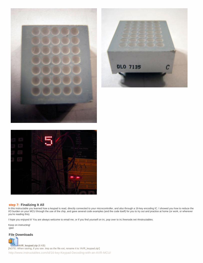
step 6: Visualizing Output with a Dotmatrix LEDOk, so I found the coolest flipping LED's I've ever seen. They're single container Dotmatrix LED's, or formally Siemens High Efficiency Red DLO7135 5x7 Dot MatrixIntelligent Display withMemory/Decoder/Driver. Um, wow? They're less than an inch in width and height but pack 5x7 led matrix inside that contains onboard memory, a96 character ASCII set, built-in character generator, intensity control, and runs off of 5V.
These things are $17 at mouser.com and $14 at digikey.com each. Yeah, EACH! Well, as luck would have it, my local electronic shop had a pull-out bin full of themselling for $1.50 a piece. Needless to say, I came home with a pocketful of LEDs, I'm sure making people wonder if I was happy to see them or if I had a lightbright in mypocket. Anyway, I digress...
So, the idea here would be to further connect our keypad, encoder, MCU up to this dotmatrix LED and have it display the number that is pressed on the keypad. This ispretty straight forward, but as I'd like to keep this instructable fairly short, and since I'd like to entice you to read more of my 'ibles, I'll just leave you with a few pics belowand tempt you to read my guide on how to use this LED with a microcontroller in your projects.
http://www.instructables.com/id/16-key-Keypad-Decoding-with-an-AVR-MCU/
step 7: Finalizing It AllIn this instructable you learned how a keypad is read, directly connected to your microcontroller, and also through a 16-key encoding IC. I showed you how to reduce theI/O burden on your MCU through the use of the chip, and gave several code examples (and the code itself) for you to try out and practice at home (or work, or whereveryou're reading this).
I hope you enjoyed it! You are always welcome to email me, or if you find yourself on irc, pop over to irc.freenode.net #instructables.
Keep on instructing!-gian
File Downloads
AVR_keypad.zip (6 KB)[NOTE: When saving, if you see .tmp as the file ext, rename it to 'AVR_keypad.zip']

http://www.instructables.com/id/16-key-Keypad-Decoding-with-an-AVR-MCU/
Related Instructables
Help: AnAbsoluteBeginner'sGuide to 8-BitAVRProgramming-AVR Dragon byPopSci
Tiny AVRMicrocontrollerRuns on a FruitBattery by Gadre
Getting startedwith ubuntu andthe AVR dragonby itch
Electronic Tic-Tac-Toe withRGB LEDs(video) bycedtlab
Using a DotMatrix LED withan Arduino andShift Register bynevdull
An Electronic,Battery-lessDice (video) byGadre
DIY Datalockerby yonsje LED holiday
star by susannes
Advertisements
http://www.instructables.com/id/An-Electronic-Battery-less-Dice/?utm_source=pdf&utm_campaign=related
http://www.instructables.com/id/An-Electronic-Battery-less-Dice/?utm_source=pdf&utm_campaign=related
http://www.instructables.com/id/An-Electronic-Battery-less-Dice/?utm_source=pdf&utm_campaign=related
http://www.instructables.com/id/An-Electronic-Battery-less-Dice/?utm_source=pdf&utm_campaign=related