MCU BASED SOLAR CHARGER
100
MICROCONTROLLER BASED SOLAR CHARGER N.B PATEL POLLYTECHNIC, COLLEGE Page 1 A PROJECT REPORT ON MICROCONTROLLER BASED SOLAR CHARGER CREATED AT ROYAL CIRCUIT DESIGNED, GANDHINAGAR DIPLOMA OF ENGINEERING IN ELECTRONICS & COMMUNICATION SUBMITTED BY NAME ENROLLMENT NO BHADANI DIPESH G. DEVDA SHRIPALSINH D. 106680311033 106680311012 N.B.PATEL POLYTECHNIC, PILUDARA 2012-2013 INTERNAL GUIDE EXTERNAL GUIDE Mr. RITESH PATEL Mr. ALKESH SUKHADAIYA
Transcript of MCU BASED SOLAR CHARGER

MICROCONTROLLER BASED SOLAR CHARGER
N.B PATEL POLLYTECHNIC, COLLEGE Page 1
AA
PPRROOJJEECCTT RREEPPOORRTT OONN
MMIICCRROOCCOONNTTRROOLLLLEERR BBAASSEEDD SSOOLLAARR
CCHHAARRGGEERR
CREATED AT ROYAL CIRCUIT DESIGNED,
GANDHINAGAR
DIPLOMA OF ENGINEERING IN
ELECTRONICS & COMMUNICATION
SUBMITTED BY
NAME ENROLLMENT NO
BHADANI DIPESH G.
DEVDA SHRIPALSINH D.
106680311033
106680311012
NN..BB..PPAATTEELL PPOOLLYYTTEECCHHNNIICC,, PPIILLUUDDAARRAA
22001122--22001133
INTERNAL GUIDE EXTERNAL GUIDE
Mr. RITESH PATEL Mr. ALKESH SUKHADAIYA

MICROCONTROLLER BASED SOLAR CHARGER
N.B PATEL POLLYTECHNIC, COLLEGE Page 2
NN..BB..PPAATTEELL PPOOLLYYTTEECCHHNNIICC,, PPIILLUUDDAARRAA
AAFFFFIILLIIAATTEEDD TTOO
GGUUJJAARRAATT TTEECCHHNNOOLLOOGGIICCAALL UUNNIIVVEERRSSIITTYY
CCEERRTTIIFFIICCAATTEE
This is to certify that Mr. DEVDA
SHRIPAL DUNGERSINH having Enrollment No.
106680311012 of 6th Semester Diploma Course in Electronics &
Communication Engineering has satisfactorily completed AN
INDUSTRY DEFINED PROBLEM (IDP PART-1 & PART-2) project
work.
Having title: MCU BASED SOLAR CHARGER
He has undergone the process of shodh yatra, literature survey &
problem definition along with the complete solution to meet the
objectives stated in the definition.
IDP-GUIDE
(R.H.PATEL)
I/C HOD
(R.H.PATEL)
DATE OF
SUBMISSION:
EXTERNAL EXAMINER

MICROCONTROLLER BASED SOLAR CHARGER
N.B PATEL POLLYTECHNIC, COLLEGE Page 3
NN..BB..PPAATTEELL PPOOLLYYTTEECCHHNNIICC,, PPIILLUUDDAARRAA
AAFFFFIILLIIAATTEEDD TTOO
GGUUJJAARRAATT TTEECCHHNNOOLLOOGGIICCAALL UUNNIIVVEERRSSIITTYY
CCEERRTTIIFFIICCAATTEE
This is to certify that Mr. DIPESH
GORDHANBHAI BHADANI having Enrollment No.
1096680311033 of 6th Semester Diploma Course in Electronics
& Communication Engineering have satisfactorily completed AN
INDUSTRY DEFINED PROBLEM: (PART-1 & IDP PART-2) project
work.
Having title: MCU BASED SOLAR CHARGER
He has undergone the process of shod yare, literature survey &
problem definition along with the complete solution to meet the
objective stated in the definition.
IDP-GUIDE
(R.H.PATEL)
I/C HOD
(R.H.PATEL)
DATE OF
SUBMISSION:
EXTERNAL EXAMINER

MICROCONTROLLER BASED SOLAR CHARGER
N.B PATEL POLLYTECHNIC, COLLEGE Page 4
CERTIFICATE
This is to certify that Bhadani Dipesh Gordhanbhai
Enrollment No. 106680311033 of Diploma Electronics & communication
He has successfully completed PROJECT WORK carried out in the
particular topic of MICROCONTROLLER BASED SOLAR CHARGER
in our company. He has prepared its journal during the academic year 2012-
2013 from Narayanbhai Bhikhabhai Patel Polytechnic, Meshana – Visnagar
Highway, Basana Education Campus, AT & PO: Piludara, Ta & Dist
Meshsana, Gujarat, India.
Place: - Gandhinagar For, Royal Circuit Design
Date: - 25-04-2013
Propritpr
MICROCONTROLLER BASED SOLAR CHARGER
N.B PATEL POLLYTECHNIC, COLLEGE Page 5
CERTIFICATE
This is to certify that Devda Shripal Dungarsigh
Enrollment No. 106680311012 of Diploma Electronics & communication
V & VIth
semester in the Branch of Electronics Engineering. He has
successfully completed PROJECT WORK carried out in the particular
topic of MICROCONTROLLER BASED SOLAR CHARGER in our
company. He has prepared its journal during the academic year 2012-2013
from Narayanbhai Bhikhabhai Patel Polytechnic, Meshana – Visnagar
Highway, Basana Education Campus, AT & PO: Piludara, Ta & Dist
Meshsana, Gujarat, India.
Place: - Gandhinagar For, Royal Circuit Design
Date: - 25-04-2013
Propritpr

MICROCONTROLLER BASED SOLAR CHARGER
N.B PATEL POLLYTECHNIC, COLLEGE Page 6
AKNOWLEGMENT
I owe a great many thanks to a great many people who helped and supported me
during the writing of this project report.
I would love to say my deepest thanks to Mr. ALKESH SUKAHDIYA; the
external guide of the project for guiding me in each difficulty that I found during the
entire period of the project.
I express my thanks to lecturer, Mr. RITESH PATEL (Head of Department
Electronics and communication engineering) the internal guide of my project. He has
taken pain to go through the entire project and make necessary correction as and when
needed.
I would also my institution and my faculty members without this project would have
been a distance reality.
I also extend my heartfelt thanks to my friends and well wishers.
DIPESH BHADANI G.
DEVDA SHRIPALSINH D.

MICROCONTROLLER BASED SOLAR CHARGER
N.B PATEL POLLYTECHNIC, COLLEGE Page 7
ABSTRACT
Automatic solar charger using microcontroller is intelligent device for on/off
system with solar charger. It is also give the all status about the battery voltage. Now a
day the solar charger is very useful to store the voltage in battery. The conventional solar
charger can‘t operate the load itself, but this project can operate the load also
automatically. This project is provided with dusk to down sensor for automatic turn on
load at dusk and automatic turn off the load at down. For the observation of battery
voltage we used the LCD. It always shows the battery voltage. This project is protecting
the battery also. The battery can damage due to overcharging. So to protect the battery we
used the relay in this solar charger. Relay automatic disconnect the battery when it is fully
charged and the connect the battery when it is low.
As the sources of conventional energy deplete day by day, resorting to alternative
sources of energy like solar and wind energy has become need of the hour. Solar-powered
lighting systems are already available in rural as well as urban areas. These include solar
lanterns, solar home lighting systems, solar streetlights, solar garden lights and solar
power packs. All of them consist of four components: solar photovoltaic module,
rechargeable battery, solar charge controller and load. In the solar-powered lighting
system, the solar charge controller plays an important role as the system‘s overall success
depends mainly on it. It is considered as an indispensable link between the solar panel,
battery and load.
TABLE OF CONTANS

MICROCONTROLLER BASED SOLAR CHARGER
N.B PATEL POLLYTECHNIC, COLLEGE Page 8
CHAPTER
NO.
NAME PAGE
NO. LIST OF FIG. 1-2
LIST OF TABLE 3
CHAPTER-1 INDUSTRIAL PROFILE 4-6
CHAPTER-2 INTRODUCTION TO SYSTEM 7-11
CHAPTER-3 PROTOTYPE HARDWARE &
DESIGN
12-53
3.1 Block diagram of system 14-17
3.2 Hardware tools 18-53
3.2.1 Microcontroller (AT89C2051) 18-21
3.2.2 ADC converter (ADC 0831) 22-23
3.2.3 Dusk dawn sensor (MCT2E) 24-26
3.2.4 Power sever unit (LM7805) 27-28
3.2.5 Charge control relay 29-34
3.2.6 LCD (liquid crystal display) 35-37
3.2.7 Photovoltaic panel 38-43
3.3 LCD with MCU interfacing 44
3.4 Circuit diagram 45-47
3.5 PCB layout & manufacturing 48-53
3.5.1 PCB layout 48-50
3.5.2 PCB manufacturing 51-53
CHAPTER-4 SOFTWARE DEVELOPMENT &
DESIGN
54-85
4.1 Flowchart to the system 56-57
4.2 Program code to the system 58-68
4.3 Creating circuit diagram using proteus 69-72
4.4 Flowchart of software tools 73-76
4.5 Generating code for AT89C2051 using keil
µvision
77
4.6 Program loader using proloader 78-85
CHAPTER-5 CONCLUSION 86-89
5.1 Conclusion 86
5.2 Applications 86
5.3 Limitations 86
5.4 Advantages 89
REFERANCE 90-91
LIST OF FIGURE

MICROCONTROLLER BASED SOLAR CHARGER
N.B PATEL POLLYTECHNIC, COLLEGE Page 9
SR NO. FIG NO. NAME OF FIG. PAGE NO.
1 3.1 Block diagram of solar charger 14
2 3.2 Pin diagram of (AT89C2051) 18
3 3.3 Pin diagram of (ADC0831) 22
4 3.4 Pin diagram of (MCT2E) 24
5 3.5 Typical characteristic 25
6 3.6 Collector current characteristic 25
7 3.7 Pin diagram of (LM 7805) 27
8 3.8 Different type of relay 29
9 3.9 Relay location 30
10 3.10 Circuit diagram of relay 30
11 3.11 Relay operation 31
12 3.12 Relay energized 31
13 3.13 Relay de-energized 32
14 3.14 Relay operation 32
16 3.15 ON-OFF relay 33
17 3.16 OFF relay 33
18 3.17 Relay design 34
19 3.18 Manufacturing of relay 34
20 3.19 LCD 16*2 35
21 3.20 Elements of a PV system 39
22 3.21 Graph of power output 40
23 3.22 The photovoltaic effect in a solar cell 42
24 3.23 Graph of current and voltage output 43
25 3.24 LCD with MCU interfacing 44
26 3.25 Circuit diagram 45
27 3.26 PCB layout 48
28 3.27 3D front view 49
29 3.28 3D back view 50
30 3.29 Manufacturing of front side 51
31 3.30 Manufacturing of back side 51
32 4.31 Flowchart to solar charger 56
33 4.32 Proteus 69
34 4.33 Proteus step-1 70
35 4.34 Proteus step-2 70

MICROCONTROLLER BASED SOLAR CHARGER
N.B PATEL POLLYTECHNIC, COLLEGE Page 10
36 4.35 Proteus step-3 71
37 4.36 Proteus step-4 71
38 4.37 Proteus step-5 72
39 4.38 Proteus step-6 72
40 4.39 Flowchart of software tools 73
41 4.40 Keil µvision 77
42 4.41 Proload 78
43 4.42 Proload step-2 79
44 4.43 Proload step-3 80
45 4.44 Proload step-4 81
46 4.45 Proload step-5 82
47 4.46 Proload step-6 83
48 4.47 Proload step-7 84
49 4.48 Proload step-8 85

MICROCONTROLLER BASED SOLAR CHARGER
N.B PATEL POLLYTECHNIC, COLLEGE Page 11
LIST OF TABLE
SR. NO. TABEL NO. NAME OF TABEL PAGE NO.
1 3.1 Port 3 pin function (AT89c205) 20
2 3.2 Pin function of (ADC 0831) 23
3 3.3 Pin function of (LM 7805) 27
4 3.4 LCD pin function 36

MICROCONTROLLER BASED SOLAR CHARGER
N.B PATEL POLLYTECHNIC, COLLEGE Page 12
CHAPTER 1
INDUSRIAL
PROFILE

MICROCONTROLLER BASED SOLAR CHARGER
N.B PATEL POLLYTECHNIC, COLLEGE Page 13
ROYAL CIRCUIT DESIGN PVT. LTD.
Royal Circuit Design is situated in Gandhinagar, Gujarat state since 1993. The
Company had established in small scale basic in 1993 by Mr. Alkesh Sukhadia. He is
Diploma Electronics in Ahmadabad and I.T.I. Mechanical from Gandhinagar. He is
expert in Mechanical & Electronics Drawing. He had setup one of the best manufacturing
PRINTED CIRCUIT BOARD Unit with well equipped.
FEW WORDS ABOUT COMPANY:
The company situated Electronics Industries zone in plot No.B-150, Electronics
Estate, Sector-25, and G.I.D.C Gandhinagar in 500 sq met. Plot. Area. All facilities to
staff and all testing measuring and manufacturing equipments. The company has
mechanical workshop for fabrication of various P.C.B. (Printed Circuit Board). ROYAL
CIRCUIT DESIGN has in-house facility for producing from Schematic Diagram to best
quality Printed Circuit Board by Design Tool. Companies have facilities for proto type
through large production in PCB. They are manufacturing different types of PCB like:
1) Single Side,
2) Double Sided,
3) Flexible PCB
With Epoxy base, Aluminum base and other raw materials. Royal Circuit Design is
capable of 2 mil line and 2 mil spacing, plus fine pitch in PCB and Design with electrical
testing. With its enhanced capabilities are renewed commitments to growth through
aggressive representation. Royal Circuit Design is now, more than ever in a position to
provide its customers with extremely competitive price, delivery, quality and service.
Royal Circuit Design is fast becoming a major manufacturing facility in the PRINTED
CIRCUIT BOARD industry. Company is well equipped and well known staff in this

MICROCONTROLLER BASED SOLAR CHARGER
N.B PATEL POLLYTECHNIC, COLLEGE Page 14
particular area. They cover all aspects of circuit board production including ―ARTWORK
DESIGN and LAYOUT using advanced CAD techniques.
FACILITY UNDER ONE ROOF:
1) PCB DESIGNING FROM SECHEMATIC DIAGRAM BY LATEST TOOL
―CIRCUIT MAKER‖.
2) GERBER PLOTTING FACILITIES
3) MANUFACTURING OF VARIOUS TYPE PRINTED CIRCUIT BOARD BY
CNC DRILLING, PHOTO PLOTTING, DRYFILM PROCESS, QUALITY
CONTROL, HEAT & RUN PROCESS, SCREEN PRINTING, COPPER,
PLATTING, TIN PLATTING,
4) ELECTRONICS TRAINING CENTRE
Company has lot of satisfied valuable customers in private and Government sector
in all over India. Company‘s quality of work approved by ISHRO, PRL, PLASMA
RESEARCH and other Central Government Electronics division.
Royal Circuit Design is also member of GEZIA (GANDHINAGAR
ELECTRONICS ZONE INDUSTRIES ASSOCIATION) and connected with EQDC
(Electronics & Quality Development Centre) Gandhinagar.

MICROCONTROLLER BASED SOLAR CHARGER
N.B PATEL POLLYTECHNIC, COLLEGE Page 15
CHAPTER
2 INTRODUCTION
TO
SYSTEM

MICROCONTROLLER BASED SOLAR CHARGER
N.B PATEL POLLYTECHNIC, COLLEGE Page 16
AIM: -
Detail study of solar charger by using of Micro-controller.
OBJECTIVES: -
The objective of this project is to design and implement the microcontroller based
Proportional-integral (PI) control in a battery charger. This battery charger is design to be
powered by a solar panel which produces DC output voltage and being control using
pulse width modulation (PWM) technique to obtain maximum charging efficiency at
fastest time.
Solar power can be used to charge 12 V sealed lead acid battery using fast charging
method consist of constant current and constant voltage mode.
Fast charging method needs a precise termination technique to ensure the battery is
not being overcharge that can lead to battery damages. A wrong charging algorithm will
result in getting less life and capacity than what the battery can offer.
INTODUCTION TO SOLAR CHARGER:-
As the sources of conventional energy deplete day by day, resorting to alternative
sources of energy like solar and wind energy has become need of the hour.
Solar-powered lighting systems are already available in rural as well as urban areas.
Include solar lanterns, solar home lighting systems, solar streetlights, solar garden lights
and solar power packs. All of them consist of four components: solar photovoltaic
module, rechargeable battery, solar charge controller and load. In the solar-
powered lighting system, the solar charge controller plays an important role as the
system‘s overall success depends mainly on it.

MICROCONTROLLER BASED SOLAR CHARGER
N.B PATEL POLLYTECHNIC, COLLEGE Page 17
It is considered as an indispensable link between the solar panel, battery and load.
the microcontroller plays important role for this automatic system ,microcontroller can
turn on/off the load at dusk to down. it also protect the battery from the overcharging
.battery can damage due to overcharging.
Microcontroller disconnects the battery automatically from the charging system.
Due to disconnect the battery from the solar system is the safe way to protect the battery
from the charging.
This report outlines the design and performance of a solar electric charge controller
and portable power supply, an extremely portable device which recharges electronic
devices. Along with a solar panel, this device employs microprocessor-based control
which continuously monitors the power output of the solar panel to deliver the maximum
electric power to the batteries. This is called Maximum Power Point Tracking, and it
enables the most efficient battery recharge. Our product also contains internal
rechargeable batteries (at 12 Volts). The solar panel actually charges these internal
batteries, and these batteries are used to recharge any external electronic devices which
are attached.
CURRENT WORLD IN ENERGY CRISSIS

MICROCONTROLLER BASED SOLAR CHARGER
N.B PATEL POLLYTECHNIC, COLLEGE Page 18
The use of petroleum as an energy source will cease to be economically viable. But
petroleum and energy are not synonymous; there are alternative sources of energy
available to us, and it is probable that the transition from using petroleum to using
alternative sources will be a smooth and nearly painless one. And since some of these
alternative fuels are renewable, there is absolutely no need to worry about energy until
our sun ceases to shine.
In words, the "energy shortage" is a crock.
THE SOLUSION OF ENERGY CRISIS
The Use renewable energy such as (solar, wind, water, hydro, tidal and wave,
geothermal, ocean thermal, biomass and biofuel.
The solution is to produce more energy. How that energy is produced is a matter of
personal opinion. Every source has pros and cons, advantages and disadvantages, and
whose weigh differently on different people.

MICROCONTROLLER BASED SOLAR CHARGER
N.B PATEL POLLYTECHNIC, COLLEGE Page 19
ENERGY CRISIS:
THE SOLUTION TO ENERGY CRISIS IS SHIFTING FROM NON-
RENEWABLE SOURCES TO RENEWABLE SOURCES OF ENERGY. ONE OF THE
RENEWABLE SOURCES IS 'BIOMASS'. WE CAN GROW ENERGY CROPS AND
USE THE BIOMASS TO LIQUID FUEL (BTL) WHICH COULD PROVE TO BE
PROMISING ALTERNATIVE. For example: Jatropha curcas, Euphorbia lathyris
Either find new ways to produce energy, or use less energy. Or a bit of both.
1. Use renewable energies such as solar energy, wind energy and things
2. Stop wasting energy in cars, and lights!

MICROCONTROLLER BASED SOLAR CHARGER
N.B PATEL POLLYTECHNIC, COLLEGE Page 20
CHAPTER
3 PROTOTYPE
HARDWARE
&
DESIGN

MICROCONTROLLER BASED SOLAR CHARGER
N.B PATEL POLLYTECHNIC, COLLEGE Page 21
PROTOTYPE HARDWARE & DESIN
3.1:- BLOCK DIAGRAM OF SYSTEM
3.2:- HARDWARE TOOLS
3.3:- LCD WITH MCU INTERFACING
3.4:- CIRCUIT DIAGRAM
3.5:- PCB LAYOUT AND MENIFECTURING

MICROCONTROLLER BASED SOLAR CHARGER
N.B PATEL POLLYTECHNIC, COLLEGE Page 22
3.1 BLOCK DIAGRAM OF SYSTEM
Fig. 3.1 BLOCK DIAGRAM OF SOLAR CHARGER

MICROCONTROLLER BASED SOLAR CHARGER
N.B PATEL POLLYTECHNIC, COLLEGE Page 23
Block Diagram contains different blocks like:
Solar panel
Analog to digital converter
Microcontroller
Battery
Relay
Load control
Inverter
16*2 LCD display
MAJOR COMPONANT IN DETAILS
RECHARGEABLE BATTERY:
It is for the storage of energy received from the panel.
The solar energy is converted into electrical energy and stored in a 12V lead-acid
battery.
The ampere-hour capacity ranges from 5Ah-100Ah.
MICROCONTROLLER:
Microcontroller AT89c2051 is the heart of the circuit.
It is a low-voltage,high-performance,8-bit microcontroller that features 2kb of
flash, 128bytes of RAM,15 input/output lines, two 16-bittimers/counters, a five-
vector two-level interrupt architecture, a full-duplex serial port, a precision analog
comparator.
SOLAR PANEL:
Solar panel is used for the conversion of energy directly into electricity. It is com
-posed of photo voltaic cell, which convert solar energy into electrical energy.
Higher-wattage panels can be used with some modifications to the controller unit.

MICROCONTROLLER BASED SOLAR CHARGER
N.B PATEL POLLYTECHNIC, COLLEGE Page 24
ANALOG TO DIGITAL CONVETER:
The ADC0831 is an 8-bit successive approximation analogue-to-digital converter
with a serial I/O and very low conversion time of typically 32microsecound.
The differential analogues voltage input allows increase of the common-mode
rejection and offsetting of the analogue zero input voltage.
DUSK-TO-DAWN SENSOR :
Normally, in a solar-photovoltaic-based installation-for example, solar streetlight
-the load is switched on at dusk (evening) and switched off at dawn (morning).
During daytime, the load is disconnected from the battery and the battery rechar-
-ged with current from the solar panel.
RELAY:
Relay connected the solar panel to the battery through diode D1.
Under normal conditions, it allows the charging current from the panel to flow
into the battery.
When the battery is at full charge, the charging current consumption of the solar
controller low, normally closed contacts of the relay are used and the relay is
normally in de-energized state.
LOAD CONTOL:
One terminal of the load is connected to the battery through fuse F1 and another
terminal of the load to n-channel power MOSFET T3.
MOSFETs are voltage-driven devices that required virtually no drive current.
The load current should be limited to 10A.
One additional MOSFET is connected in parallel for more than 10A load current.
INVERTER:
Inverter is a direct current (DC) to alternate current (AC) converted.

MICROCONTROLLER BASED SOLAR CHARGER
N.B PATEL POLLYTECHNIC, COLLEGE Page 25
16*2 LCD DISPLAY:
The system status and battery voltage are displayed on an LCD based on
HD44780 controller.
The backlight feature of the LCD makes it readable even in low light conditions.
The LCD is used here in4-bitmoad to save the microcontroller‘s port pins.
Usually the 8-bit mode of interfacing with a microcontroller required eleven pins,
but in 4-bit mode the LCD can be interfaced to the microcontroller using only
seven pins.
FEATURE OF SOLAR CHARGER
1. Automatic dusk-to-dawn operation of the load
2. Built-in digital voltmeter (0V-20Vrange)
3. Parallel- or shunt-type regulation
4. Overcharge protection
5. System status display on LCD
6. Deep-discharge protection
7. Low battery lock
8. Charging current changes to ‗pulsed‘ at full charge
9. Low current consumption
10. Highly efficient design based on microcontroller
11. Suitable for 10-40W solar panels for 10A load

MICROCONTROLLER BASED SOLAR CHARGER
N.B PATEL POLLYTECHNIC, COLLEGE Page 26
3.2 HARDWARE TOOLS
LIST OF HARDWARE
List of hardware tools which is used in my project are as below
1. Microcontroller (AT89C2051)
2. 1Analog to digital converter ( ADC0831)
3. Opt coupler (MCT2E)
4. LM7805
5. Relay (12V,1C/O)
6. LCD (16*2)
7. Solar panel (10-40W)
3.2.1 MICROCANTROLAR (AT89C2051)
Fig 3.2 PIN DIAGRAM OF(AT89C2051)

MICROCONTROLLER BASED SOLAR CHARGER
N.B PATEL POLLYTECHNIC, COLLEGE Page 27
The AT89c2051 is a low-voltage, high-performance CMOS 8-bit microcontroller
with 2K bytes of Flash programmable and erasable read-only memory (PEROM).
The device is manufactured using Atmel‘s high-density nonvolatile memory
technology and is compatible with the industry-standard MCS-51 instruction set
and pin out. The on-chip Flash allows the program memory to be reprogrammed
in-system or by a conventional nonvolatile memory programmer.
By combining a versatile 8-bit CPU with in-system programmable Flash on a
Monolithic chip, the Atmel AT89C2051 is a powerful microcontroller which
Provides a highly-flexible and cost-effective solution to many embedded control
applications.
PIN DISCRIPATION:
VCC: Supply voltage.
GND: Ground.
Port 1 (P1.0 TO P1.7):
The port 1 is an 8-bit bi-directional I/O port. Port pins p1.2 to p1.7 provides internal
pull-UPS. P1.0 and p1.1 required external pull-UPS, p1.0 and p1.1 also serve as the
positive input (AIN1) and the negative input (AIN1), respectively, of the on-chip
precision analog comparator. The port 1 output buffers can sink 20mA and can drive LED
display directly. When is are written to port 1 pins, they can be used as input. When pins
p1.2 to p1.7 are used as input and are externally pulled low, they will source current (IIL)
because of the internal pull-UPS.
Port-1 also receives coad data during flash programming and verification.

MICROCONTROLLER BASED SOLAR CHARGER
N.B PATEL POLLYTECHNIC, COLLEGE Page 28
Port 2(P3.0 TO P3.7):
port 3 pins p3.0 to p3.5, p3.5 are seven bi-directional I/O pins with internal pull-
UPS p3.6 is hard-wired as an input to the output of the on-chip comparator and is not
accessible as a general-purpose I/O pin. The port 3 output buffers can sink 20mA. When
is are written to port 3 pins they are pulled high by the internal pull-UPS and can be used
as input. As input, port 3 pins that are externally being pulled low will source current (IIL)
because of the pull-UPS.
Port 3 also serves the functions of various special features of the AT89C2051 as
listed below
PORT PIN Alternate functions
P3.0 RXD(serial input port)
P3.1 TXD(serial output port)
P3.2 ____
INT0 (external interrupt)
P3.3 ____
INT1(external interrupt)
P3.4 T0(timer 0 external input)
P3.5 T1(timer 1 external output)
TABEL 3.1 PORT 3 PIN FONCTION
RST:
Reset input All I/O pins are reset to is as soon as RST goes high. Holding the RST
pin high for two machine cycles while the oscillator is running resets the device.
Each machine cycle takes 12 oscillator or clock cycle.
XTAL1:
input to the inverting oscillator amplifier and input to the internal clock operating
circuit.

MICROCONTROLLER BASED SOLAR CHARGER
N.B PATEL POLLYTECHNIC, COLLEGE Page 29
XTAL2:
output from the inverting oscillator amplifier
FEATURES
Compatible with MCS -51 products
2Kbyte of reprogrammable flash memory –endurance:1,000 write/Erase cycles.
2.7V to 6V operating range
Fully static operation range
Two-level program memory lock
128*8-bit internal RAM
15 programmable I/O lines
Two 16-bit timer/counters
Six interrupt sources
Programmable serial UART channel
Direct LED drive outputs
On-chip analog comparator
Low-power idle and power –down modes
Green(pb/halide-free) packaging option

MICROCONTROLLER BASED SOLAR CHARGER
N.B PATEL POLLYTECHNIC, COLLEGE Page 30
3.2.2 ANALOG TO DIGITAL CONVATER (ADC0831)
What is ADC
An analog-to-digital converter (abbreviated ADC, A/D or A to D) is a device
that converts a continuous physical quantity (usually voltage) to a digital number that
represents the quantity's amplitude.
Fig 3.3 PIN DIAGRAM OF(ADC 0831)
8-bit resolution
Easy microcontroller interface or stand-alone operation
Operates ratio metrically or with 5-V reference
Single channel or multiplexed twin channels with single-ended or differential
input option

MICROCONTROLLER BASED SOLAR CHARGER
N.B PATEL POLLYTECHNIC, COLLEGE Page 31
Input range 0 to 5V with single 5-Vsupply
Input and outputs are compatible with TTL and MOS
Conversion time of 32microsecound at CLK=250 KHZ
Designed to be interchangeable with national semiconductor ADC0831
Pin Number Description
1 CS - Chip Select (Active Low)
2 Vin+ - Analog Voltage Input +
3 Vin- - Analog Voltage Input -
4 GND – Ground
5 Vref - Voltage Reference
6 DO - Data Out
7 CLK – Clock
8 Vcc - Positive Supply
Fig. 3.2 pin function of ADC0831

MICROCONTROLLER BASED SOLAR CHARGER
N.B PATEL POLLYTECHNIC, COLLEGE Page 32
3.2.3 DUSK DAWN SENSOR (MCT2E)
Fig 3.4 PIN DIAGRAM OF MCT2E
Operation of MCT2E opt coupler IC?
Normally, in a solar-photovoltaic-based installation—for example, solar home
lighting system, solar lantern or solar streetlight—the load (the light) is switched on at
dusk (evening) and switched off at dawn (morning). During daytime, the load is
disconnected from the battery and the battery is recharged with current from the solar
panel. The microcontroller needs to know the presence of the solar panel voltage to
decide whether the load is to be connected to or disconnected from the battery, or whether
the battery should be in charging mode or discharging mode. A simple sensor circuit is
built using a potential divider formed around resistors R8 and R9, zener diode ZD1 and
transistor T1 for the presence of panel voltage.
This is the block diagram of optocoupler. The optocoupler is basically combine form
of diode and transistor. When the light strike on photo diode, the electron –hall pairs are
generated . due to this the optocoupler will be set and send the signal to controller to
deactivate load.
Similarly the reverse process is done at night time. At night time optocoupler send
signal to controller for active the load.

MICROCONTROLLER BASED SOLAR CHARGER
N.B PATEL POLLYTECHNIC, COLLEGE Page 33
Fig.3.5 TYPICAL CHARACTERISTICS
Fig.3.6 Collector current characteristic
MICROCONTROLLER BASED SOLAR CHARGER
N.B PATEL POLLYTECHNIC, COLLEGE Page 34
This is the typical characteristics of optocoupler .the graph is collector current Vs
input diode forward current. The input diode forward current is increases with increase in
collector current.
FEATURES:
Current transfer ratio (CTR min 50% at IF =10mA Vce=10V)
High isolation voltage be

MICROCONTROLLER BASED SOLAR CHARGER
N.B PATEL POLLYTECHNIC, COLLEGE Page 35
3.2.4 POWER SEVERS UNIT LM7805:-
LM7805 is 3 terminal positive power regulators IC. Which gives +5V DC output.
The LM7805 monolithic 3-terminal positive voltage regulators employ internal
current-limiting, thermal shutdown and safe-area compensation, making them
essentially indestructible.
In addition to use as fixed voltage regulators, these devices can be used with
external components to obtain adjustable output voltages and currents.
Pin no.1 is a input pin, Pin no.2 is ground and Pin no 3 is output pin.
Fig.3.7 PIN DIAGRAM OF LM7805
Pin No Function Name
1 Input voltage (5V-18V) Input
2 Ground (0V) Ground
3 Regulated output; 5V (4.8V-5.2V) Output
Fig. 3.3 PIN FUNCTION OF LM7805

MICROCONTROLLER BASED SOLAR CHARGER
N.B PATEL POLLYTECHNIC, COLLEGE Page 36
DISADVANTAGES
The input voltage must always be higher than the output voltage by some
minimum amount (typically 2 volts).
This can make these devices unsuitable for powering some devices from certain
types of power sources (for example, powering a circuit that requires 5 volts using 6-volt
batteries will not work using a 7805).
Even in larger packages, 78xx integrated circuits cannot supply as much power as
many designs which use discrete components, and are generally inappropriate for
applications requiring more than a few amperes of current
Maximum Rating of the LM7805 are follows:
DC input voltage 35v
Maximum junction temperature 150oc
Storage temperature range -65oc to +150
oc
Lead temperature range 300oc
ESD susceptibility 2KV

MICROCONTROLLER BASED SOLAR CHARGER
N.B PATEL POLLYTECHNIC, COLLEGE Page 37
3.2.5 CHARGE CANTROL RELAY:
What is relay
electrical device such that current flowing through it in one circuit can switch on
and off a current in a second circuit relay.
Relays are used throughout the automobile. Relays which come in assorted sizes,
ratings, and applications, are used as remote control switches. A typical vehicle can have
20 relays or more.
Fig. 3.8 DIFFERENT TYPE RELAY
RELAY LOCATIONS:
Relays are located throughout the entire vehicle relay blocks, both large and small,
are located in the engine compartment behind the left or under the dash by themselves.
are common location. Relays are often grouped or with other components like fuses or
placed

MICROCONTROLLER BASED SOLAR CHARGER
N.B PATEL POLLYTECHNIC, COLLEGE Page 38
Fig. 3.9 RELAY LOCATION
Relays are remote control electrical switches that are controlled by another switch,
such as a horn switch or a computer as in a power train control module relay allow a
small current flow circuit to control a higher current circuit. Several designs of relays are
in use, today 3-pin, 4-pin, 5-pin, and 6-pin sign switch or dual switches.
Fig. 3.10 CIRCUIT DIAGRAM OF RELAY

MICROCONTROLLER BASED SOLAR CHARGER
N.B PATEL POLLYTECHNIC, COLLEGE Page 39
RELAYS OPERATION:
All relays operate using the some basic principal. Our example will use a
commonly used 4-pin relay. Relay have two circuits: a control circuit (shown in green)
and load circuit (shown in red) the control has a small control coli while the load circuit
has a switch. The coil controls the operation of the switch.
Fig. 3.11 RELAY OPERATION
RELAY ENERGIZED:
Current flowing through the control circuit coil (pin 1 and 3) creates a small
magnetic field which causes the switch to close, pins 2 and 4. The switch, which is part of
the load circuit, is used to control an electrical circuit that many connect to its current
now flows through pins 2 and 4 shown in red, when the relay in energized.
Fig. 3.12 RELAY ENERGIZED
MICROCONTROLLER BASED SOLAR CHARGER
N.B PATEL POLLYTECHNIC, COLLEGE Page 40
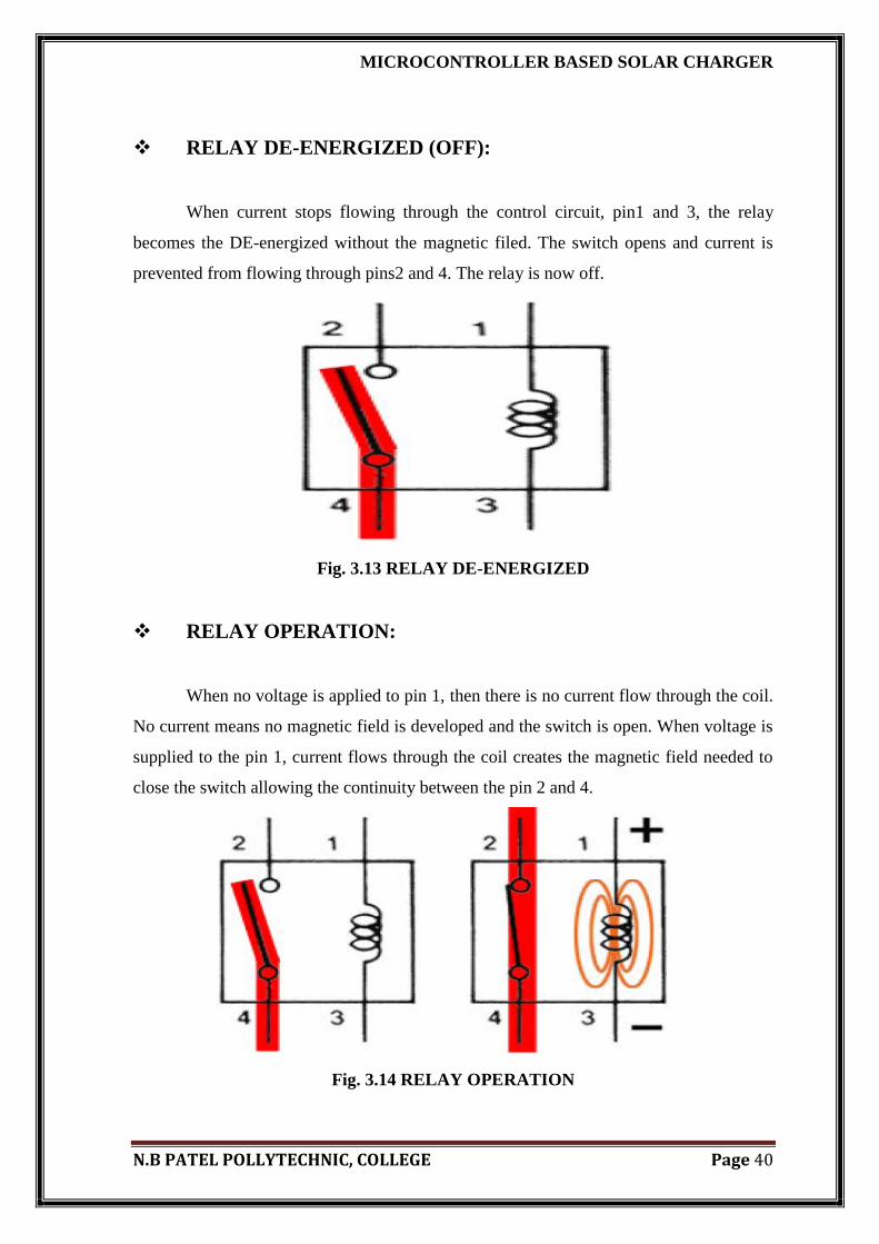
RELAY DE-ENERGIZED (OFF):
When current stops flowing through the control circuit, pin1 and 3, the relay
becomes the DE-energized without the magnetic filed. The switch opens and current is
prevented from flowing through pins2 and 4. The relay is now off.
Fig. 3.13 RELAY DE-ENERGIZED
RELAY OPERATION:
When no voltage is applied to pin 1, then there is no current flow through the coil.
No current means no magnetic field is developed and the switch is open. When voltage is
supplied to the pin 1, current flows through the coil creates the magnetic field needed to
close the switch allowing the continuity between the pin 2 and 4.
Fig. 3.14 RELAY OPERATION

MICROCONTROLLER BASED SOLAR CHARGER
N.B PATEL POLLYTECHNIC, COLLEGE Page 41
RELAY DESINE:
Relays are either open or normally closed. Notice the position of the switch in the
two relay shows bellow. Normally the open switch has a switch that remains open until
energized (ON) while closed relays are closed until energized. Relays are always shown
in the de-energized position (no current flows through the control circuit-OFF). Normally
open relays are the most common in vehicle; however other can be used in automatic
application.
Fig. 3.15 ON-OFF RELAY
NORMALLY CLOSED REALYS:
The operation of normal closed relays is the same to that of a normal open relay,
except backward. In other words, when relay control coil is not energized, the relay
switch control are closed, completing the circuit through pin 2 and 4. When control coil is
energized, the relay switch control open, which breaks the circuit open and no continuity
exist between pin 2 and 4.
Fig.3.16 OFF RELAY

MICROCONTROLLER BASED SOLAR CHARGER
N.B PATEL POLLYTECHNIC, COLLEGE Page 42
ACTUSL RELAY DESIGNE:
Current flows through the control coil, which is wrapped around an iron core. The
iron core intensifies the magnetic field. The magnetic field attracts the upper contact arm
and pulls it down, closing the contact and allowing power from the power source to go to
the load.
Fig. 3.17 RELAY DESIGNE
Fig. 3.19 MENYFECTURING OF RELAY

MICROCONTROLLER BASED SOLAR CHARGER
N.B PATEL POLLYTECHNIC, COLLEGE Page 43
3.1.6 LCD (LIQUID CRISTEL DISPLAY)
Fig. 3.19 LCD 16*2
A liquid crystal display is a thin, flat electronic visual display that uses the light
modulating properties of liquid crystals. They do not emit light directly. They are used in
wide range of application including: computer monitor, television, instrument panels,
aircraft cockpit display, etc.
LCDs have displaced cathode ray tube (CRT) display in most applications. They
are usually more compact, light weight, portable, less expensive, more reliable and easier
on the eyes.
LCDs with a small number of segments, such as those used in digital watches and
pocket calculators, have individual electrical contacts for each segment.
Liquid crystal display (LCD) is a passive display technology. This manse they do
not emit light, instead, they use the ambient light in the environment.

MICROCONTROLLER BASED SOLAR CHARGER
N.B PATEL POLLYTECHNIC, COLLEGE Page 44
The most common LCDs connected to the 8051 are 16*2 and 20*2 display. This
means 16 characters per line by 2 lines.
The 2 line x 16 character LCD modules are available from a wide range of
manufacturers and should all be compatible with the HD44780.
LCD PINS:
Table 3.4 LCD PIN FUNCTION
Pin
No Function Name
1 Ground (0V) Ground
2 Supply voltage; 5V (4.7V – 5.3V) Vcc
3 Contrast adjustment; through a variable resistor
VEE
4 Selects command register when low; and data register when
high
Register Select
5 Low to write to the register; High to read from the register Read/write
6 Sends data to data pins when a high to low pulse is given Enable
7
8-bit data pins
DB0
8 DB1
9 DB2
10 DB3
11 DB4
12 DB5
13 DB6
14 DB7
15 Backlight VCC (5V) Led+
16 Backlight Ground (0V) Led-

MICROCONTROLLER BASED SOLAR CHARGER
N.B PATEL POLLYTECHNIC, COLLEGE Page 45
To initialize LCD
Step 1:- initialize port 2 as output port
Step 2:- set control lines i.e. RS=0 and RW=0
Step 3:- send LCD init value
I.e. 0x38 for 8-bit mode OR 0x28 for 4-bit mode
Step 4:- generate Hi-Low pulse on Enable pin of LCD
Step 5:- send LCD clear value i.e. 0x01
Step 6:- send LCD display on value i.e. 0x0f
Step 7:- send LCD cursor Home i.e. 0x02
FEATURES
5*8 dots with courser
Built in controller (KS 0066 or equivalent)
+5v power supply (Also available for +3v
B/L to be driven by pin15, pin 16 or A.K (LED)
N.V. optional for +3v power supply

MICROCONTROLLER BASED SOLAR CHARGER
N.B PATEL POLLYTECHNIC, COLLEGE Page 46
3.2.7 PHOTOVOLTAIC PANEL
What are Solar Cells?
Solar cells are devices which convert solar energy directly into electricity, either
directly via the photovoltaic effect, or indirectly by first converting the solar
energy to heat or chemical energy.
The most common form of solar cells are based on the photovoltaic (PV) effect in
which light falling on a two layer semi-conductor device produces a photo voltage
or potential difference between the layers. This voltage is capable of driving a
current through an external circuit and thereby producing useful work.
PV PANELS:-
As single PV cells have a working voltage of about 0.5 V, they are usually
connected together in series (positive to negative) to provide larger voltages. Panels are
made in a wide range of sizes for different purposes. They generally fall into one of three
basic categories:
Low voltage/low power panels are made by connecting between 3 and 12 small
segments of amorphous silicon PV with a total area of a few square centimeters
for voltages between 1.5 and 6 V and outputs of a few milliwatts. Although each
of these panels is very small, the total production is large. They are used mainly in
watches, clocks and calculators, cameras and devices for sensing light and dark,
such as night lights.
Small panels of 1 - 10 watts and 3 - 12 V, with areas from 100cm2 to1000cm2
are made by either cutting 100cm2 single or polycrystalline cells into pieces and
joining them in series , or by using amorphous silicon panels. The main uses are
for radios, toys, small pumps, electric fences and trickle charging of batteries.
Large panels, ranging from 10 to 60 watts, and generally either 6 or 12 volts,
with areas of 1000cm2 to 5000cm2 are usually made by connecting from 10 to 36
full-sized cells in series. They are used either separately for small pumps and

MICROCONTROLLER BASED SOLAR CHARGER
N.B PATEL POLLYTECHNIC, COLLEGE Page 47
caravan power (lights and refrigeration) or in arrays to provide power for houses,
communications pumping and remote area power supplies (RAPS).
Arrays and Systems
If an application requires more power than can be provided by a single panel, larger
systems can be made by linking a number of panels together. However, an added
complexity arises in that the power is often required to be in greater quantities and
voltage, and at a time and level of uniformity than can be provided directly from the
panels. In these cases, PV systems are used, comprised of the following parts.
1. a PV panel array, ranging from two to many hundreds of panels;
2. a control panel, to regulate the power from the panels;
3. a power storage system, generally comprising of a number of specially designed
batteries.
4. An inverter, for converting the DC to AC power (e.g. 240 V AC).
5. backup power supplies such as diesel startup generators (optional)
framework and housing for the system trackers and sensors (optional).
Fig.3.20 Elements of a PV System

MICROCONTROLLER BASED SOLAR CHARGER
N.B PATEL POLLYTECHNIC, COLLEGE Page 48
Arrays generally run the panels in series/parallel with each other, so that the
output voltage is limited to between 12 and 50 volts, but with higher amperage (current).
This is both for safety and to minimize power losses. Panels currently cost about $3 - 6
per Watt. That is, a 50 Watt panel presently costs about $200. Eight years ago, this same
standard panel would have cost about $500 at a cost of about $8 - 10 per Watt.
Arrays of panels are being increasingly used in building construction where they
serve the dual purpose of providing a wall or roof as well as providing electric power for
the building. Eventually as the prices of solar cells fall, building integrated solar cells may
become a major new source of electric power.
The daily energy output from PV panels will vary depending on the orientation,
location, daily weather and season. On average, in summer, a panel will produce about
five times its rated power output in watt hours per day, and in winter about two times that
amount. For example, in summer a 50 watt panel will produce an average of 250 watt-
hours of energy, and in winter about 100 watt-hours. These figures are indicative only,
and professional assistance should be sought for more precise calculations.
Trackers are used to keep PV panels directly facing the sun, thereby increasing the
output from the panels. Trackers can nearly double the output of an array (see figure 7).
Careful analysis is required to determine whether the increased cost and mechanical
complexity of using a tracker is cost effective in particular circumstances. A variety of
trackers, which will take about 10 panels, are manufactured in Australia.
Fig. 3.21 Graph of power output.

MICROCONTROLLER BASED SOLAR CHARGER
N.B PATEL POLLYTECHNIC, COLLEGE Page 49
Energy storage is often necessary when power is required when the sun is not
shining either at night or in cloudy periods - or in quantities greater than can be supplied
directly from the array. Specially designed "deep-cycle" lead acid batteries are generally
used. Unlike normal batteries, they can discharge about half of their stored energy several
thousand times before they deteriorate. Each battery is usually 2 V, and the total battery
bank usually has many batteries in series and parallel to give the required power rating.
Battery banks need to be individually sized to suit the particular applications, depending
on total daily solar radiation, total load, peak load and the number of days storage
required. As a rule of thumb, battery storage costs about $250 per kWh of energy stored
for domestic sized systems.
How do Solar Cells Work?
To understand the operation of a PV cell, we need to consider both the nature of
the material and the nature of sunlight. Solar cells consist of two types of material, often
p-type silicon and n-type silicon. Light of certain wavelengths is able to ionise the atoms
in the silicon and the internal field produced by the junction separates some of the
positive charges ("holes") from the negative charges (electrons) within the photovoltaic
device.
The holes are swept into the positive or p-layer and the electrons are swept into
the negative or n-layer. Although these opposite charges are attracted to each other, most
of them can only recombine by passing through an external circuit outside the material
because of the internal potential energy barrier. Therefore if a circuit is made (see figure
3) power can be produced from the cells under illumination, since the free electrons have
to pass through the load to recombine with the positive holes.

MICROCONTROLLER BASED SOLAR CHARGER
N.B PATEL POLLYTECHNIC, COLLEGE Page 50
Fig.3.22 The Photovoltaic Effect in a Solar Cell
The amount of power available from a PV device is determined by;
The type and area of the material;
The intensity of the sunlight; and
The wavelength of the sunlight.
Single crystal silicon solar cells, for example cannot currently convert more than
25% of the solar energy into electricity, because the radiation in the infrared region of the
electromagnetic spectrum does not have enough energy to separate the positive and
negative charges in the material.
Polycrystalline silicon solar cells have an efficiency of less than 20% at this time
and amorphous silicon cells, are presently about 10% efficient, due to higher internal
energy losses than single crystal silicon.

MICROCONTROLLER BASED SOLAR CHARGER
N.B PATEL POLLYTECHNIC, COLLEGE Page 51
A typical single crystal silicon PV cell of 100 cm2 will produce about 1.5 watts of
power at 0.5 volts DC and 3 amps under full summer sunlight (1000Wm-2
). The power
output of the cell is almost directly proportional to the intensity of the sunlight. (For
example, if the intensity of the sunlight is halved the power will also be halved).
Fig.3.23 Graph of current and voltage output.
An important feature of PV cells is that the voltage of the cell does not depend on
its size, and remains fairly constant with changing light intensity. However, the current in
a device is almost directly proportional to light intensity and size. When people want to
compare different sized cells, they record the current density, or amps per square
centimeter of cell area.
The power output of a solar cell can be increased quite effectively by using a
tracking mechanism to keep the PV device directly facing the sun, or by concentrating the
sunlight using lenses or mirrors. However, there are limits to this process, due to the
complexity of the mechanisms, and the need to cool the cells.

MICROCONTROLLER BASED SOLAR CHARGER
N.B PATEL POLLYTECHNIC, COLLEGE Page 52
3.3 LCD WITH MCU INTERFACING
CIRCUIT DIAGRAM OF LCD WITH MCU
Fig. 3.24 LCD with MCU interfacing

MICROCONTROLLER BASED SOLAR CHARGER
N.B PATEL POLLYTECHNIC, COLLEGE Page 53
3.4 CIRCUIT DIAGRAM
Fig. 3.25 circuit diagram

MICROCONTROLLER BASED SOLAR CHARGER
N.B PATEL POLLYTECHNIC, COLLEGE Page 54
CRICUIT DISCRIPTION
Basically, there are two methods of controlling the charging current: series
regulation and parallel (shunt) regulation. A series regulator is inserted between the solar
panel and the battery. The series type of regulation ‗wastes‘ a lot of energy while
charging the battery as the control circuitry is always active and series regulator requires
the input voltage to be 3-4 volts higher than the output voltage. The current and voltage
output of a solar panel is governed by the angle of incidence of light, which keeps
varying.
Parallel regulation is preferred in solar field. In parallel regulation, the control
circuitry allows the charging current (even in mA) to flow into the battery and stop
charging once the battery is fully charged. At this stage, the charging current is wasted by
converting into heat (current is passed through low-value, high-wattage resistor); this part
of the regulation dissipates a lot of heat.
After power-on, the microcontroller reads the battery voltage with the help of the
ADC and displays the values on the LCD. It monitors the input signal from the dusk-to-
dawn sensor and activates the load or charging relay RL1 accordingly. The digital
voltmeter works up to 20V.
As Vref of the ADC is connected to VCC (5V), the input voltage to the ADC
cannot exceed +5V. A potential divider is used at pin 2 of the ADC (IC2) using resistors
R5, R6 and R7 to scale down the voltage from 0V-20V to 0V-05V. The ADC output is
multiplied four times and displayed on the LCD as battery voltage. When the solar panel
voltage is present, the dusk-to-dawn sensor provides a signal to the microcontroller,
which then displays ‗charging‘ message on the LCD. During charging, the battery voltage
is continuously monitored. When the voltage reaches 14.0V, the microcontroller
interrupts the charging current by energising the relay, which is connected to MOSFET
BS170 (T2), and starts a5-minute timer. During this stage, the LCD shows ―battery full.‖

MICROCONTROLLER BASED SOLAR CHARGER
N.B PATEL POLLYTECHNIC, COLLEGE Page 55
After five minutes, the relay reconnects the panel to the battery. This way, the
charging current is pulsed at the intervals of five minutes and the cycle repeats until the
panel voltage is present. When the panel voltage falls below the zener diode (ZD1)
voltage of the dusk-to-dawn sensor, the microcontroller senses this and activates the load
by switching on MOSFET T3 via optocoupler IC3 and ―load on‖ message is displayed.
In this mode, the microcontroller monitors for low battery. When the battery voltage
drops below 10 volts, the microcontroller turns off the load by switching off MOSFET T3
and ―battery low—load off‖ message is displayed.
Normally, when the load is switched off, the battery voltage tends to rise back and
the load oscillates between ‗on‘ and ‗off‘ states. To avoid this, the microcontroller
employs a hysteresis control by entering into a ‗lock‘ mode during low battery state and
comes out of the lock mode when the dusk-to-dawn sensor receives the panel voltage (the
next morning). During lock mode, the microcontroller keeps converting the ADC value
and displays the battery voltage on the LCD.

MICROCONTROLLER BASED SOLAR CHARGER
N.B PATEL POLLYTECHNIC, COLLEGE Page 56
3.5 PCB LAYOUT AND MENIFACTURING
3.5.1 PCB LAYOUT
Fig.3.26 PCB layout

MICROCONTROLLER BASED SOLAR CHARGER
N.B PATEL POLLYTECHNIC, COLLEGE Page 57
PCB 3D VIEW IN FRONT SIDE
Fig.3.27 3D front view

MICROCONTROLLER BASED SOLAR CHARGER
N.B PATEL POLLYTECHNIC, COLLEGE Page 58
PCB 3D VIEW IN BACK SIDE
Fig.3.28 3D back view

MICROCONTROLLER BASED SOLAR CHARGER
N.B PATEL POLLYTECHNIC, COLLEGE Page 59
3.5.2 PCB MENIFACTURING
PCB LAYOUT OF FANT SIDE
Fig.3.29 manufacturing of fant side

MICROCONTROLLER BASED SOLAR CHARGER
N.B PATEL POLLYTECHNIC, COLLEGE Page 60
How to Make a PCB manufacturing
Lamination:
"Multi layer" printed circuit boards have trace layers inside the board. One way to
make a 4-layer PCB is to use a two-sided copper-clad laminate, etch the circuitry on both
sides, then laminate to the top and bottom prepreg and copper foil. Lamination is done by
placing the stack of materials in a press and applying pressure and heat for a period of
time.
Drilling:
Holes through a PCB are typically drilled with small-diameter drill bits made of
solid coated tungsten carbide. Coated tungsten carbide is recommended since many board
materials are very abrasive and drilling must be high RPM and high feed to be cost
effective. Drill bits must also remain sharp so as not to mar or tear the traces. Drilling
with high-speed-steel is simply not feasible since the drill bits will dull quickly and thus
tear the copper and ruin the boards. The drilling is performed by automated drilling
machines with placement controlled by a drill tape or drill file.
It is also possible with controlled-depth drilling, laser drilling, or by pre-drilling the
individual sheets of the PCB before lamination, to produce holes that connect only some
of the copper layers, rather than passing through the entire board.
Test:
Unpopulated boards may be subjected to a bare-board test where each circuit
connection (as defined in a netlist) is verified as correct on the finished board. For high-
volume production, a bed of nails tester, a fixture or a rigid needle adapter is used to
make contact with copper lands or holes on one or both sides of the board to facilitate
testing. A computer will instruct the electrical test unit to apply a small voltage to each
contact point on the bed-of-nails as required, and verify that such voltage appears at other
appropriate contact points.

MICROCONTROLLER BASED SOLAR CHARGER
N.B PATEL POLLYTECHNIC, COLLEGE Page 61
Protection and packaging :
PCBs intended for extreme environments often have a conformal coating, which is
applied by dipping or spraying after the components have been soldered. The coat
prevents corrosion and leakage currents or shorting due to condensation. The earliest
conformal coats were wax; modern conformal coats are usually dips of dilute solutions of
silicone rubber, polyurethane, acrylic, or epoxy. Another technique for applying a
conformal coating is for plastic to be sputtered onto the PCB in a vacuum chamber. The
chief disadvantage of conformal coatings is that servicing of the board is rendered
extremely difficult.[25]
Copper thickness :
Copper thickness of PCBs can be specified in units of length, but is often specified
as weight of copper per square foot, in ounces, which is easier to measure. Each ounce of
copper is approximately 1.4 mils (0.0014 inch) or 35 μm of thickness.
The printed circuit board industry defines heavy copper as layers
exceeding 3 ounces of copper, or approximately 0.0042 inches (4.2 mils, 105 μm) thick.
PCB designers and fabricators often use heavy copper when design and manufacturing
circuit boards in order to increase current-carrying capacity as well as resistance to
thermal strains. Heavy copper plated vias transfer heat to external heat sinks.
Safety certification (US) :
Safety Standard UL 796 covers component safety requirements for printed
wiring boards for use as components in devices or appliances. Testing analyzes
characteristics such as flammability, maximum operating temperature, electrical tracking,
heat deflection, and direct support of live electrical parts.
MICROCONTROLLER BASED SOLAR CHARGER
N.B PATEL POLLYTECHNIC, COLLEGE Page 62
CHAPTER
4 SOFTWARE
DEVELOPMENT
&
DESIGN

MICROCONTROLLER BASED SOLAR CHARGER
N.B PATEL POLLYTECHNIC, COLLEGE Page 63
SOFTAWARE DEVELOPMENT & DESIGN
4.1:- FLOWCHART TO THE SYSTEM
4.2:- PROGRAM CODE TO THE SYSTEM
4.3:- CREATING CIRCUIT DIAGRAM USING PROTEUS
4.4:- FLOWCHART OF SOTWARE TOOLS
4.5:- GENERATING CODE FOR AT89C2051 USING KEIL µVISION

MICROCONTROLLER BASED SOLAR CHARGER
N.B PATEL POLLYTECHNIC, COLLEGE Page 64
4.1 FLOWCHART TO SYSTEM:
Fig. 4.31 FLOW CHART TO SOLAR CHARGER

MICROCONTROLLER BASED SOLAR CHARGER
N.B PATEL POLLYTECHNIC, COLLEGE Page 65
The flow chart shown in figure.17. Flow chart is starting from the get battery voltage
at starting time. When solar charger is started, the first step is the microcontroller send
battery voltage detail to LCD. It is done with the help of A/D convertor. Now dusk to
down sensor sense the temperature and decide it is dusk or down. So we have two cases.
1. Dusk, 2. Down
1 .DUSK (evening):-
If dusk, than temperature of atmosphere is a decrease. At night time optocoupler
send the signal to microcontroller to active the load. During the load active time, battery
is discharge
The microcontroller is automatically disconnecting the load from battery. This is
done with help of relay. Relay is worked as switch in the circuit. During this all operation,
LCD will continuously display battery voltage. Like low battery.
2. DOWN (morning):-
If down, than temperature of atmosphere is increases. At day time optocoupler send
the signal to microcontroller to deactivate the load. During the load deactivate, battery is
charged through the solar panel. When the battery is fully charged LCD will show the
message ―BATTERY FULL‖. At this time microcontroller disconnect the battery from
the solar panel.

MICROCONTROLLER BASED SOLAR CHARGER
N.B PATEL POLLYTECHNIC, COLLEGE Page 66
4.2 PROGRAM CODE TO SYSTEM
$MOD51; LCD 4-BIT MODE CONNECTIONS
RS EQU P1.7 ; LCD REGISTER SELECT LINE
EN EQU P1.6 ; LCD ENABLE LINE
DB4 EQU P1.5 ;
DB5 EQU P1.4 ;
DB6 EQU P1.3 ;
DB7 EQU P1.2 ; ADC0831 CONNECTIONS
CS EQU P3.0
CLK EQU P3.1
DO EQU P3.2 ; INPUT & OUTPUT
DYI EQU P3.4 ; SOLAR PANEL VOLTAGE SENSOR
CHG_RL EQU P3.5 ; CHARGING CONTROL RELAY
LD_RL EQU P3.7 ; LOAD CONTROL RELAY DSEG
ORG 0020H
VAL1: DS 1
VAL2: DS 1
VAL3: DS 1
ADC_VAL: DS 1
BUF: DS 1
CNT1: DS 1
CNT2: DS 1
IMG: DS 1
FLAGS: DS 1
OCF BIT FLAGS.0 ; OVER CHARGE FLAG
LBF BIT FLAGS.1 ; LOW BATT FLAG
CSEG
ORG 0000H
JMP MAIN
ORG 000BH ; Timer Interrupt0
JMP COUNTDOWN
MAIN: MOV SP, #50H
MOV P3, #0FFH

MICROCONTROLLER BASED SOLAR CHARGER
N.B PATEL POLLYTECHNIC, COLLEGE Page 67
MOV P1,#0FFH
CLR CHG_RL
CLR LD_RL
LCALL PWR_DELAY
LCALL INIT
SETB CLK
SETB DO
SETB CS
SETB DYI
MOV VAL1, #00H
MOV VAL2, #00H
MOV VAL3, #00H
MOV FLAGS, #00H
LOADCHAR: MOV BUF, #40H
LCALL CMD
MOV DPTR, #RCHARG
REP:
CLR A
MOVC A,@A+DPTR
JZ SCREEN1
MOV BUF, A
LCALL DAT
INC DPTR
SJMP REP
SCREEN1: MOV BUF, #80H
MOV DPTR, #MSG1
HERE: CLR A
MOVC A,@A+DPTR
JZ NEXT
MOV BUF,A
LCALL DAT
INC DPTR
SJMP HERE
NEXT: MOV BUF, #0C0H
LCALL CMD

MICROCONTROLLER BASED SOLAR CHARGER
N.B PATEL POLLYTECHNIC, COLLEGE Page 68
MOV DPTR, #MSG2
HERE1: CLR A
MOVC A,@A+DPTR
JZ OVER
MOV BUF, A
LCALL DAT
INC DPTR
SJMP HERE1
OVER: LCALL ONE_SEC_DELAY
LCALL ONE_SEC_DELAY
LCALL CLEAR
MOV BUF, #0C0H
LCALL CMD
MOV DPTR, #MSG7
HERE2: CLR A
MOVC A,@A+DPTR
JZ CONVERT
MOV BUF, A
LCALL DAT
INC DPTR
SJMP HERE2
CONVERT: LCALL DELAY
CLR CS ; INITIATE CONVERSION
SETB CLK
CLR CLK ; FIRST CLOCK
SETB CLK
CLR CLK ; SECOND CLOCK
MOV A, #00H ; CLEAR A
MOV R5, #08H ; 8 CLOCK PULSES
AGAIN: MOV C, DO
RLC A
SETB CLK
CLR CLK
DJNZ R5, AGAIN
SETB CS
MOV ADC_VAL, A

MICROCONTROLLER BASED SOLAR CHARGER
N.B PATEL POLLYTECHNIC, COLLEGE Page 69
MOV B, #79D
MUL AB ; PRODUCT IN AB
MOV R1, B ; HIGH BYTE IN B
MOV R2, A ; LOW BYTE IN A
LCALL HEX2BCD
MOV VAL1, R7
MOV VAL2, R6
MOV VAL3, R5
LCALL SENDVAL2LCD
CHECK: JNB LBF, CHECK2 ; SEE IF ANY FLAGS ARE SET,
I , e LOW BATT FLAG OR BATTFULL FLAG
JB DYI, CONVERT
CHECK2: JNB OCF, PROCEED
JB DYI, NIGHT
SJMP CONVERT
PROCEED: JB DYI, NIGHT
CLR LD_RL ; OFF LOAD
CLR LBF ; CLEAR LOW BATT FLAG
MOV A, VAL2 ; SEE IF BATT.IS FULL
XRL A, #04H
JZ FULLCHG
CLR CHG_RL ; CONNECT BATT. TO PANEL
MOV DPTR, #MSG4 ; DISPLAY CHARGING MSG
MOV IMG, #00H
LCALL SENDSTAT2LCD
LJMP CONVERT
FULLCHG: SETB OCF ; SET OVERCHARGE FLAG
SETB CHG_RL ; DISCONNECT BATT.FROM PANEL
MOV TH0, #03CH ; START 5 MIN TIMER HERE
MOV TL0, #0B0H ; DISCONNECT BATT FROM PANEL
MOV CNT1, #200D
MOV CNT2, #30D
SETB ET0
SETB TR0
SETB EA
MOV DPTR, #MSG5 ; DISPLAY BATT.FULL MSG

MICROCONTROLLER BASED SOLAR CHARGER
N.B PATEL POLLYTECHNIC, COLLEGE Page 70
MOV IMG, #01H
LCALL SENDSTAT2LCD
LJMP CONVERT
NIGHT: CLR CHG_RL ; RECONNECT BATT. TO PANEL
CLR TR0 ; STOP TIMER0 INCASE ITS RUNNING
CLR OCF ; CLEAR OVER CHARGE FLAG
SETB LD_RL ; CONNECT LOAD TO BATT.
MOV A, VAL1
XRL A, #00H
JZ LOWBAT
MOV DPTR, #MSG3 ; DISPLAY LOAD ON MSG
MOV IMG, #02H
LCALL SENDSTAT2LCD
LJMP CONVERT
LOWBAT: SETB LBF
CLR LD_RL ; DISCONNECT LOAD FROM BATT.
MOV DPTR, #MSG6 ; DISPLAY LOAD OFF MSG
MOV IMG, #03H
LCALL SENDSTAT2LCD
LJMP CONVERT
SENDVAL2LCD: MOV BUF, #0C7H
LCALL CMD
MOV A, VAL1
ORL A, #30H
MOV BUF, A
LCALL DAT
MOV A, VAL2
ORL A, #30H
MOV BUF, A
LCALL DAT
MOV BUF, #'.'
LCALL DAT
MOV A, VAL3
ORL A, #30H
MOV BUF, A
LCALL DAT

MICROCONTROLLER BASED SOLAR CHARGER
N.B PATEL POLLYTECHNIC, COLLEGE Page 71
RET
SENDSTAT2LCD:
MOV BUF, #080H
LCALL CMD
HERE3: CLR A
MOVC A,@A+DPTR
JZ PICT
MOV BUF, A
LCALL DAT
INC DPTR
SJMP HERE3
PICT: MOV BUF, #0CEH
LCALL CMD
MOV BUF, IMG
LCALL DAT
BACK:
RET
;********************************
; TIMER0 ISR (5 MINUTES TIMER)
;********************************
COUNTDOWN: CLR TR0
MOV TH0, #03CH
MOV TL0, #0B0H
SETB TR0
DJNZ CNT1, BACK2
MOV CNT1, #200D
DJNZ CNT2, BACK2
CLR TR0 ; OFF 5 MIN TIMER
CLR ET0
CLR OCF ; CLEAR OVER CHARGE FLAG
CLR CHG_RL ; RE-CONNECT BATT TO PANEL
BACK2: RETI
Hex2BCD: MOV R3, #00D
MOV R4, #00D
MOV R5, #00D
MOV R6, #00D

MICROCONTROLLER BASED SOLAR CHARGER
N.B PATEL POLLYTECHNIC, COLLEGE Page 72
MOV R7, #00D
ACALL H2B
RET
H2B: MOV B, #10D
MOV A, R2
DIV AB
MOV R3, B ;
MOV B, #10 ; R7, R6, R5, R4, R3
DIV AB
MOV R4, B
MOV R5, A
CJNE R1, #00H, HIGH_BYTE ; CHECK FOR HIGH BYTE
SJMP ENDD
HIGH_BYTE: MOV A, #6
ADD A, R3
MOV B, #10
DIV AB
MOV R3, B
ADD A, #5
ADD A, R4
MOV B, #10
DIV AB
MOV R4, B
ADD A, #2
ADD A, R5
MOV B, #10
DIV AB
MOV R5, B
CJNE R6, #00D, ADD_IT
SJMP CONTINUE
ADD_IT: ADD A, R6
CONTINUE: MOV R6, A
DJNZ R1, HIGH_BYTE
MOV B, #10D
MOV A, R6
DIV AB

MICROCONTROLLER BASED SOLAR CHARGER
N.B PATEL POLLYTECHNIC, COLLEGE Page 73
MOV R6, B
MOV R7, A
ENDD: RET
ONE_SEC_DELAY: MOV R0, #10D ; One second delay routine
RZ3: MOV R1, #100D
RZ1: MOV R2, #250D
RZ2: NOP
NOP
DJNZ R2, RZ2
DJNZ R1, RZ1
DJNZ R0, RZ3
RET
PWR_DELAY:; 15 mSec DELAY FOR LCD TO INTIALIZE AFTER POWER-ON
MOV R4, #100D
H2: MOV R3, #250D
H1: DJNZ R3, H1
DJNZ R4, H2
RET;******LCD SUBROUTINES********
CMD: PUSH ACC ; SAVE ACCUMULATOR
SETB EN
CLR RS ; SELECT SEND COMMAND
MOV A, BUF ; PUT DATA BYTE IN ACC
MOV C, ACC.4 ; LOAD HIGH NIBBLE ON DATA BUS
MOV DB4, C ; ONE BIT AT A TIME USING...
MOV C, ACC.5 ; BIT MOVE OPERATOINS
MOV DB5, C
MOV C, ACC.6
MOV DB6, C
MOV C, ACC.7
MOV DB7, C
CLR EN
NOP
SETB EN ; PULSE THE ENABLE LINE
MOV C, ACC.0 ; SIMILARLY, LOAD LOW NIBBLE
MOV DB4, C
MOV C, ACC.1

MICROCONTROLLER BASED SOLAR CHARGER
N.B PATEL POLLYTECHNIC, COLLEGE Page 74
MOV DB5, C
MOV C, ACC.2
MOV DB6, C
MOV C, ACC.3
MOV DB7, C
CLR EN
NOP
SETB EN ; PULSE THE ENABLE LINE
LCALL MSDELAY
POP ACC
RET; ******LCD SUBROUTINES*******
DAT: PUSH ACC ; SAVE ACCUMULATOR
SETB EN
SETB RS ; SELECT SEND DATA
MOV A, BUF ; PUT DATA BYTE IN ACC
MOV C, ACC.4 ; LOAD HIGH NIBBLE ON DATA BUS
MOV DB4, C ; ONE BIT AT A TIME USING...
MOV C, ACC.5 ; BIT MOVE OPERATOINS
MOV DB5, C
MOV C, ACC.6
MOV DB6, C
MOV C, ACC.7
MOV DB7, C
CLR EN
NOP
SETB EN ; PULSE THE ENABLE LINE
MOV C, ACC.0 ; SIMILARLY, LOAD LOW NIBBLE
MOV DB4, C
MOV C, ACC.1
MOV DB5, C
MOV C, ACC.2
MOV DB6, C
MOV C, ACC.3
MOV DB7, C
CLR EN
NOP

MICROCONTROLLER BASED SOLAR CHARGER
N.B PATEL POLLYTECHNIC, COLLEGE Page 75
SETB EN ; PULSE THE ENABLE LINENOP
LCALL MSDELAY
POP ACC
RET;******LCD SUBROUTINES******
CLEAR: MOV BUF, #01H
LCALL CMD
RET;******LCD SUBROUTINES*******
DDELAY: MOV R5, #41D ; 4.1 mS DELAY
QT2: MOV R6, #50D
QT1: DJNZ R6, QT1
DJNZ R5, QT2
RET;******LCD SUBROUTINES*******
MSDELAY: MOV R5, #26D
QT22: MOV R6, #50D
QT11: DJNZ R6, QT11
DJNZ R5, QT22
RET;******LCD SUBROUTINES*******
INIT: MOV BUF, #30H ; FUNCTION SET -DATA BITS, LINES, FONTS
LCALL CMD
ACALL DDELAY ; INITIAL DELAY 4.1MSEC
MOV BUF, #30H ; FUNCTION SET - DATA BITS, LINES, FONTS
LCALL CMD
ACALL DDELAY ; INITIAL DELAY 4.1MSEC
MOV BUF, #30H ; FUNCTION SET-DATA BITS, LINES, FONTS
LCALL CMD
ACALL DDELAY ; INITIAL DELAY 4.1MSEC
MOV BUF, #28H ; 2 LINES 5X7, 4-BIT MODE
LCALL CMD
MOV BUF, #0CH ; DISPLAY ON
LCALL CMD
MOV BUF, #01H ; CLEAR DISPLAY, HOME CURSOR
LCALL CMD
MOV BUF, #06H ; SET ENTRY MODE
LCALL CMD ; INCREMENT CURSOR RIGHT, NO SHIFT
RET
ORG 0320H

MICROCONTROLLER BASED SOLAR CHARGER
N.B PATEL POLLYTECHNIC, COLLEGE Page 76
MSG1: DB ' SOLAR CHARGE ', 00H
MSG2: DB ' DIPESH, SHRIPAL ', 00H
MSG3: DB ' LOAD ON ', 00H
MSG4: DB ' CHARGING ', 00H
MSG5: DB ' BATTERY FULL ', 00H
MSG6: DB ' BAT.LOW-LOAD OFF', 00H
MSG7: DB ' Volts: ', 00H
ORG 0400H
RCHARG: DB 04D, 31D, 17D, 31D, 17D, 31D, 17D, 31D ; CHARGING
DB 04D, 31D, 31D, 31D, 31D, 31D, 31D, 31D ; FULL
DB 31D, 31D, 14D, 04D, 04D, 14D, 31D, 31D ; LOAD
DB 04D, 31D, 17D, 17D, 17D, 17D, 17D, 31D ; LOW BATT
DB 31D, 31D, 31D, 31D, 31D, 31D, 31D, 31D
DB 31D, 31D, 31D, 31D, 31D, 31D, 31D, 31D
DB 31D, 31D, 31D, 31D, 31D, 31D, 31D, 31D
DB 031D, 31D, 31D, 31D, 31D, 31D, 31D, 31D, 00H
END

MICROCONTROLLER BASED SOLAR CHARGER
N.B PATEL POLLYTECHNIC, COLLEGE Page 77
4.3 CREATING CIRCUIT DIAGRAM USING PROTEUS:-
Fig.4.32 proteus

MICROCONTROLLER BASED SOLAR CHARGER
N.B PATEL POLLYTECHNIC, COLLEGE Page 78
5 STEPS:
1. Start with proteus design suit. To add component click on the P.
Fig. 4.33 PROTEUS STEPS-1
2. A dialogue box will open asking you to select you‘re your component used. Select
the appropriate device for e.g. at89s52.Then click OK. Put all the components which you
have to use to create design.
Fig. 4.34 PROTEUS STEPS-2

MICROCONTROLLER BASED SOLAR CHARGER
N.B PATEL POLLYTECHNIC, COLLEGE Page 79
3. Make the connection as required.
Fig. 4.35 PROTEUS STEPS-3
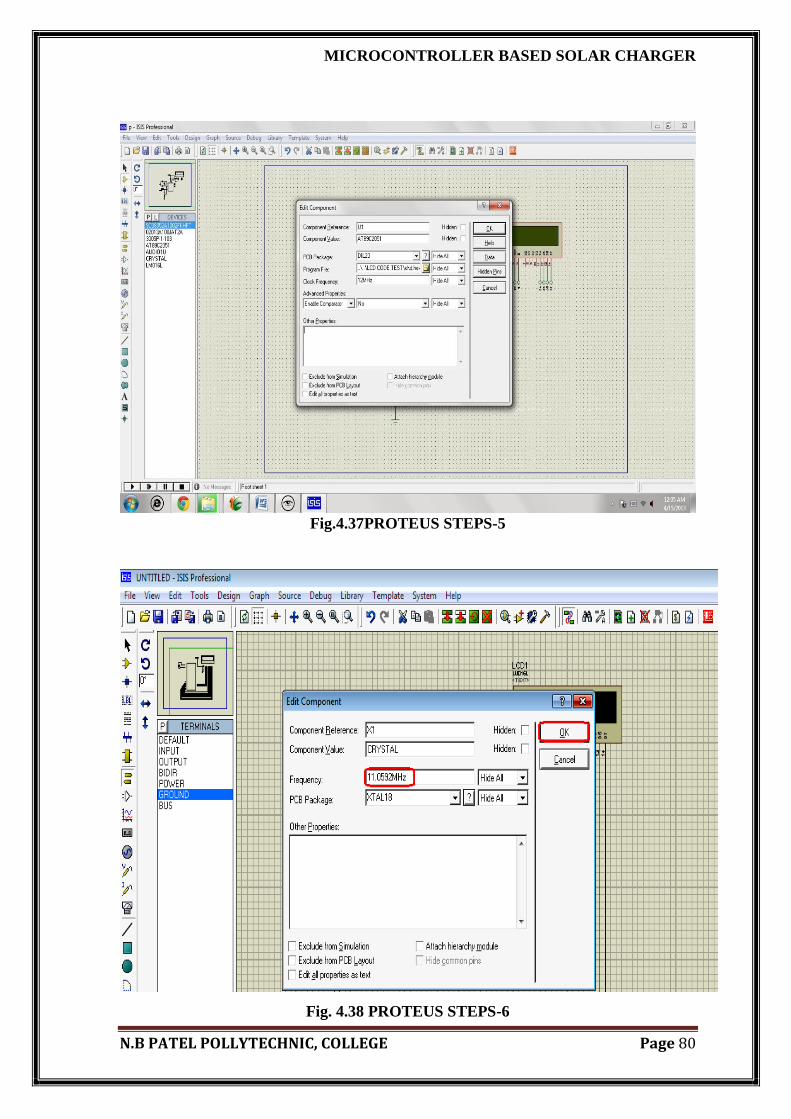
4. Now edit the properties of the device as required like to load the hex file in the
microcontroller then right click on the component and select edit property. Then browse
your file from project folder then click on OK.
Fig. 4.36PROTEUS STEPS-4
MICROCONTROLLER BASED SOLAR CHARGER
N.B PATEL POLLYTECHNIC, COLLEGE Page 80
Fig.4.37PROTEUS STEPS-5
Fig. 4.38 PROTEUS STEPS-6

MICROCONTROLLER BASED SOLAR CHARGER
N.B PATEL POLLYTECHNIC, COLLEGE Page 81
4.4 FLOWCHART OF SOFTWARE TOOLS
Fig. 4.39 FLOW CHART OF SOFTWARE TOOLS

MICROCONTROLLER BASED SOLAR CHARGER
N.B PATEL POLLYTECHNIC, COLLEGE Page 82
Developing an assembly language program is a four step process. the steps are as
follows:
A. To specify the source code as per the assembly language definition
B. Assembly the program to create the object code.
C. Link the program to create an executable code.
D. Test and debug the program.
Fig. shows the steps involved in developing and executing an assembly language
Program.
Description:
Step 1:
The first step is to analyze what the program is to do and how we want the
program to do it.
Then using an editor create the source file for program
Step 2:
The second step is to assemble this source file.
If the assembler indicates errors then use the editor for correcting them.
Step 3:
If the program consists of several modules, then use the linker to join them into
one large object module.
If the system needs to locate a program in order to specify its location in the
memory then use the locator.
At this stage the program is ready for loading into the memory and run.
Step 4:
If the developed program does not interact with any external hardware other than
that connected directly to the system then use debugger for running and debugging
your program.

MICROCONTROLLER BASED SOLAR CHARGER
N.B PATEL POLLYTECHNIC, COLLEGE Page 83
If the program is supposed to work with the external hardware system such a
microprocessor based instrument then use emulator to run and debug the program.
Development Tools:
1) Editor :
An editor is basically software. It helps the user to create a file that contains the
assembly language statements.
The job of the editor is to store the ASCII codes for the letters and numbers in the
successive RAM locations.
When program is stored in hard disk then the file is called source file whose
extension is (.ASM)
2) Assembler :
To convert assembly language statement into corresponding Binary code.
Two types of assembler available for IBM-PC are:
(.OBJ) file contains binary code of program instruction and information about
their address.
(.LST) file contains assembly language statement, binary code and relative offset
of each instruction.
(.LST) file indicate assembly language syntax errors but not logical errors.
3) Linker :
It is program which is used for joining many object files (.OBJ) into one large
object files (.OBJ).
When a large program is being written, it is always to break it into small modules
so that each module can be separately tested and debugged.
(.EXE) file contains binary codes for all combined modules.
(.MAP) file contains address all linked file but not their absolute address.
4) Locator :
It assigned specific address of the locations where their segment off the object
code are to loaded into memory.

MICROCONTROLLER BASED SOLAR CHARGER
N.B PATEL POLLYTECHNIC, COLLEGE Page 84
A locator program converts an (.EXE) file into a (.BIN) file which has physical
address.
5) Debugger :
A software tool that is used to detect the source of program or script errors by
performing step by step execution of application code and viewing the content of
code variables.
If a program is directly accessible from the microcomputer and does not need any
external hardware, then we can use debugger to run and test the program.
Debugger is basically a program which permits the user to load object code
program into the system memory, execute the program and debug it.
The debugger also permits the change in register contents, memory locations and
rerun the program.
6) Emulator :
The emulator is used to test and debug the hardware and software of an external
system such as the microprocessor based system.
Emulator is a combination of hardware and software.
An emulator consists of a multi-wire cable that connects the host system to the
external system.
Through this cable the software of the emulator allows the users the download the
object code program into RAM in the external system being developed.
Like the debugger the emulator also allows the users to load the programs to be
tested, run the, programs check and modify the contents of various register and
memory locations and also insert the breakpoints.

MICROCONTROLLER BASED SOLAR CHARGER
N.B PATEL POLLYTECHNIC, COLLEGE Page 85
4.5 GENERATING CODES FOR AT89C2051 USING KEIL
µVISION:-
AT89S52 weighing system programming involves two steps.
A. First step is to write and compile the code and generate the (.HEX) file.
B. Second step is to load this (.HEX) file into microcontroller.
We are use keil-µvision software for writing the code for the microcontroller
following steps are for generate code for keil-µvision
Fig.4.40 keil µVISION

MICROCONTROLLER BASED SOLAR CHARGER
N.B PATEL POLLYTECHNIC, COLLEGE Page 86
4.6 PROGRAM LODE USING PROLOADER
5 How to program the IC by programmer
Fig.4.41 prolad
Step 1: install the proload v5.4 microcontroller programmer software in your PC
You can download the hex code you have prepared, into the microcontroller using
our microcontroller programmer software. To install this software, choose the folder
―programmer setup ―in the accompanying CD(CD – NV5001-Programmer setup). You
will find file setup .exe. Now double click on setup .exe to run the installation program.
Follow the instruction on the screen. Click finish to complete the installation. To run the
program chooses ―proload v5.4‖ from the menu & Nvis technologies. Shortcut of proload
v5.4 icon also have made in desktop

MICROCONTROLLER BASED SOLAR CHARGER
N.B PATEL POLLYTECHNIC, COLLEGE Page 87
Step 2:
Check the correct com port in device manager for communication.
Fig.4.42 proload step-2

MICROCONTROLLER BASED SOLAR CHARGER
N.B PATEL POLLYTECHNIC, COLLEGE Page 88
Step 3:
Select the correct com port in proload v5.4 programmer
.
Fig.4.43 proload step-3

MICROCONTROLLER BASED SOLAR CHARGER
N.B PATEL POLLYTECHNIC, COLLEGE Page 89
Step 4:
Click device option or recent devices for selecting desired microcontroller.
Fig.4.44 proload sstep-4

MICROCONTROLLER BASED SOLAR CHARGER
N.B PATEL POLLYTECHNIC, COLLEGE Page 90
Step 5:
After selecting device select option follow the following root.
Device search-> AT89C51/52->select device->OK.
Fig.4.45 proload step-5

MICROCONTROLLER BASED SOLAR CHARGER
N.B PATEL POLLYTECHNIC, COLLEGE Page 91
Step 6:
After selecting the device, click signature to detect the controller.
Fig.4.46 proload step-6

MICROCONTROLLER BASED SOLAR CHARGER
N.B PATEL POLLYTECHNIC, COLLEGE Page 92
Step 7:
Erase facility: erase facility can be used to erase whole flash area in the selected
microcontroller.
Fig.4.47 proload step-7

MICROCONTROLLER BASED SOLAR CHARGER
N.B PATEL POLLYTECHNIC, COLLEGE Page 93
Step 8:
After erasing, load the hex file which you have created, for this follow the following
root:
File optionopen
Fi.4.48 proload step-8

MICROCONTROLLER BASED SOLAR CHARGER
N.B PATEL POLLYTECHNIC, COLLEGE Page 94
CHAPTER
5
CONCLUSION

MICROCONTROLLER BASED SOLAR CHARGER
N.B PATEL POLLYTECHNIC, COLLEGE Page 95
CONCLUSTION
5.1:- CONCLUSTION
5.2:- APPLICATIONS
5.3:- LIMITATIONS
5.4:- ADVANTAGES

MICROCONTROLLER BASED SOLAR CHARGER
N.B PATEL POLLYTECHNIC, COLLEGE Page 96
5.1 CONCLUSION
By using the technique of microcontroller based solar charger we can accurately
control the voltage of solar Charger. It is automatic control the load, not need to control
manually and it is reduce the damages of battery due to over charging.
5.2 APPLICATIONS:-
These include solar lanterns, solar home lighting systems, solar streetlights, solar
garden lights and solar power packs
A charge controller for a wind-electric or hydro-electric system must protect
batteries from overcharge, just a PV controller
It can also be used in automobiles to increase their battery life.
It can be also used a supplement for the inverter to control battery charging etc.
Coast guard navigation
Off-grid and grid –connected homes
Railroad signaling
Satellites and space station
Outdoor lighting‘s
Telecommunication and water pumping etc.
5.3 LIMITATIONS:-
Large initial setup is required to supply high rating solar energy supplies.
Solar panels are costlier and its bulkiness increases to have large power supplies
of dc.
Solar panels are very delicate and a slight mishandling may lead to destruction of
solar cells which are embedded in solar panels.

MICROCONTROLLER BASED SOLAR CHARGER
N.B PATEL POLLYTECHNIC, COLLEGE Page 97
5.4 ADVANTAGES:-
Salient and low maintenance
Solid states with no moving parts
High-quality powers
Life times of 20 to 30 year
Flexible and reliable
Modular and expandab

MICROCONTROLLER BASED SOLAR CHARGER
N.B PATEL POLLYTECHNIC, COLLEGE Page 98
REFERENCES
MICROCONTROLLER BASED SOLAR CHARGER
N.B PATEL POLLYTECHNIC, COLLEGE Page 99
ALL DATASHIT.COM
FAADOOENGINEEARS.COM
WORLD MICROCANTROLLER.COM
SOLARB.COM
AMERICAN SOCIETY FOR ENGINEERING EDUCATION
KIDWIDE.ORG
WIKIPEDIA.COM
REFERANCE BOOK
Microcontroller and interfacing
By :- muhmad ali mazidi

MICROCONTROLLER BASED SOLAR CHARGER
N.B PATEL POLLYTECHNIC, COLLEGE Page 100