Conext XW+ hybrid inverter/charger - NET
39
Conext XW+ hybrid inverter/charger One solution for global power needs Designed for reliability • Extensive quality and reliability testing • Highly accelerated life testing • Globally proven and recognized field performance Flexible • Single or three-phase off-grid systems from 7.0 kW to 76.5 kW (30 minutes rating at 25 °C) • Supports DC-coupled and AC-coupled off-grid and grid-tie architectures • Supports charging of lithium ion battery packs Easy to service • Monitor, troubleshoot, or upgrade firmware with Conext™ Gateway Easy to install • System configures quickly into compact, wall-mounted system • Integrates both grid and generator power with dual AC inputs • Balance-of-system components integrates battery bank, solar charge controllers, and generators • Commission the entire system with PC software tool and Conext™ Gateway Conext XW+ Product application Self-consumption Residential grid-tie solar with backup power Off-grid solar Backup power Community electrification Product at a glance Conext TM XW+ is an adaptable single-phase and three-phase inverter/charger system with grid-tie functionality and dual AC power inputs. Compatible solar charge controllers, monitoring, and automated generator control modules enable further compatibility. From a single Conext XW+ unit to clusters up to 76.5 kW, the Conext XW+ is a scalable system that allows for the integration of solar capacity as required. Adaptable and scalable, the Schneider Electric Conext XW+ system is a complete solution for grid-interactive and off-grid, residential and commercial, solar and backup power applications. 08/24/2020 7:54:55 AM ELECTRICAL shelby Released for Permit
-
Upload
khangminh22 -
Category
Documents
-
view
2 -
download
0
Transcript of Conext XW+ hybrid inverter/charger - NET

Conext XW+ hybrid inverter/chargerOne solution for global power needs
Designed for reliability• Extensive quality and reliability testing
• Highly accelerated life testing
• Globally proven and recognized field performance
Flexible• Single or three-phase off-grid systems from 7.0 kW to 76.5 kW (30 minutes rating
at 25 °C)
• Supports DC-coupled and AC-coupled off-grid and grid-tie architectures
• Supports charging of lithium ion battery packs
Easy to service• Monitor, troubleshoot, or upgrade firmware with Conext™ Gateway
Easy to install• System configures quickly into compact, wall-mounted system
• Integrates both grid and generator power with dual AC inputs
• Balance-of-system components integrates battery bank, solar charge controllers, and generators
• Commission the entire system with PC software tool and Conext™ Gateway
Conext XW+ Product application
Self-consumption
Residential grid-tie solar with backup power
Off-grid solar
Backup power
Community electrification
Product at a glance
ConextTM XW+ is an adaptable single-phase and three-phase inverter/charger system with grid-tie functionality and dual AC power inputs. Compatible solar charge controllers, monitoring, and automated generator control modules enable further compatibility. From a single Conext XW+ unit to clusters up to 76.5 kW, the Conext XW+ is a scalable system that allows for the integration of solar capacity as required. Adaptable and scalable, the Schneider Electric Conext XW+ system is a complete solution for grid-interactive and off-grid, residential and commercial, solar and backup power applications.
08/24/2020 7:54:55 AM
ELECTRICALshelby
Released for Permit
Device short name XW+ 5548 NA (Discontinued) XW+ 6848 NAInverter AC output (standalone)
Output power (continuous) at 25°C 5500 W 6800 W
Overload 30 min/60 sec at 25°C 7000 W/9500 W 8500 W/12000 W
Output power (continuous) at 40°C 4500 W 6000 W
Maximum output current 60 seconds (rms) 82 A (120 V); 41 A (240 V) 102 A (120 V); 52 A (240 V)
Output frequency (selectable) 50/60 Hz 50/60 Hz
Output voltage L-N: 120 V +/- 3%; L-L: 240 V +/- 3% L-N: 120 V +/- 3%; L-L: 240 V +/- 3%
Total harmonic distortion at rated power < 5 % < 5 %
Idle consumption search mode < 8 W < 8 W
Input DC voltage range 42 to 60 V (48 V nominal) 42 to 60 V (48 V nominal)
Maximum input DC current 150 A 180 A
Charger DC output
Maximum output charge current 110 A 140 A
Output charge voltage range 40 – 64 V (48 V nominal) 40 – 64 V (48 V nominal)
Charge control Three stage, two stage, boost, custom Three stage, two stage, boost, custom
Charge temperature compensation Battery temperature sensor included Battery temperature sensor included
Power factor corrected charging 0.98 0.98
Compatible battery types Flooded (default), Gel, AGM, Lithium ion, custom* Flooded (default), Gel, AGM, Lithium ion, custom*
Battery bank range (scaled to PV array size) 440 – 10000 Ah 440 – 10000 Ah
AC input
AC 1 (grid) input current (selectable limit) 3 – 60 A (60 A default) 3 – 60 A (60 A default)
AC 2 (generator) input current (selectable limit) 3 – 60 A (60 A default) 3 – 60 A (60 A default)
Automatic transfer relay rating/typical transfer time 60 A/8 ms 60 A/8 ms
AC input voltage limits (bypass/charge mode)L-N: 78 - 140 V (120 V nominal); L-L: 160 - 270 V (240 V nominal)
L-N: 78 - 140 V (120 V nominal); L-L: 160 - 270 V (240 V nominal)
AC input frequency range (bypass/charge mode) 55 – 65 Hz (default) 52 – 68 Hz (allowable) 55 – 65 Hz (default) 52 – 68 Hz (allowable)
AC grid-tie output
Grid sell current range on AC1(selectable limit) 0 to 40 A (120 V) / 0 to 20 A (240 V) 0 to 48 A (120 V) / 0 to 27 A (240 V)
Grid sell voltage range on AC1 (auto adjusts entering sell mode)
L-N: 105.5 to 132 +/- 1.5 V; L-L: 211 to 264 +/- 3.0 V
L-N: 105.5 to 132 +/- 1.5 V; L-L: 211 to 264 +/- 3.0 V
Grid sell frequency range on AC1 (auto adjust entering sell mode)
59.4 to 60.4 +/- 0.05 Hz 59.4 to 60.4 +/- 0.05 Hz
Efficiency
Peak 95.7% 95.7%
CEC weighted efficiency 93.0% 92.5%
General specifications
Part number 865-5548-01 (Discontinued) 865-6848-01
Product/shipping weight 53.5 kg (118.0 lb)/75.0 kg (165.0 lb) 55.2 kg (121.7 lb)/76.7 kg (169.0 lb)
Product dimensions (H x W x D) 58 x 41 x 23 cm (23 x 16 x 9 in) 58 x 41 x 23 cm (23 x 16 x 9 in)
Shipping dimensions (H x W x D) 71.1 x 57.2 x 39.4 cm (28.0 x 22.5 x 15.5 in) 71.1 x 57.2 x 39.4 cm (28.0 x 22.5 x 15.5 in)
IP degree of protection NEMA Type 1 Indoor
Operating air temperature range -25°C to 70°C (-13°F to 158°F) (power derated above 25°C (77°F))
Warranty (depending on the country of installation) Please refer to our website, SEsolar.com for the latest version of the warranty statement.
Features
System monitoring and network communications Available
Intelligent features Grid sell, peak load shave, generator support, prioritized consumption of battery or external DC energy
Auxiliary port 0 to 12 V, maximum 250 mA DC output, selectable triggers
Off-grid AC coupling Frequency control
Regulatory approval
Safety UL1741, CSA 107.1
EMC directive FCC and Industry Canada Class B
Interconnect IEEE 1547 and CSA 107.1
Compatible products
Conext XW+ Mini Power Distribution Panel 865-1013-01
Conext XW + Power Distribution Panel 865-1015-01
Conext MPPT 60 150 865-1030-1
Conext MPPT 80 600 865-1032
Conext Gateway 865-0329
Conext System Control Panel 865-1050
Conext Automatic Generator Start 865-1060
Conext Battery Monitor 865-1080-01
Conext Battery Fuse Combiner Box 865-1031-01
Conext Configuration Tool 865-1155-01
Conext XW+ series (120/240 V)
Specifications are subject to change without notice.
©2020 Schneider Electric. All Rights Reserved. Schneider Electric | Life Is On is a trademark and the property of Schneider Electric SE, its subsidiaries, and affiliated companies. DS20200409_998-19875103_US_Conext XW+ 120-240 V.indd
Schneider Electric35 rue Joseph Monier92500 Rueil-Malmaison, FranceTel: +33 (0)1 41 29 70 00
solar.schneider-electric.com | 2Conext XW+ hybrid inverter/charger — One solution for global power needs
08/24/2020 7:54:55 AM
ELECTRICALshelby
Released for Permit
72M-BLK
HELIENEwww.heliene.com
72-CELL MONOCRYSTALLINE MODULE
370 WpMAX POWER OUTPUT
19.1%MAX EFFICIENCY
10 YEARPRODUCT WARRANTY
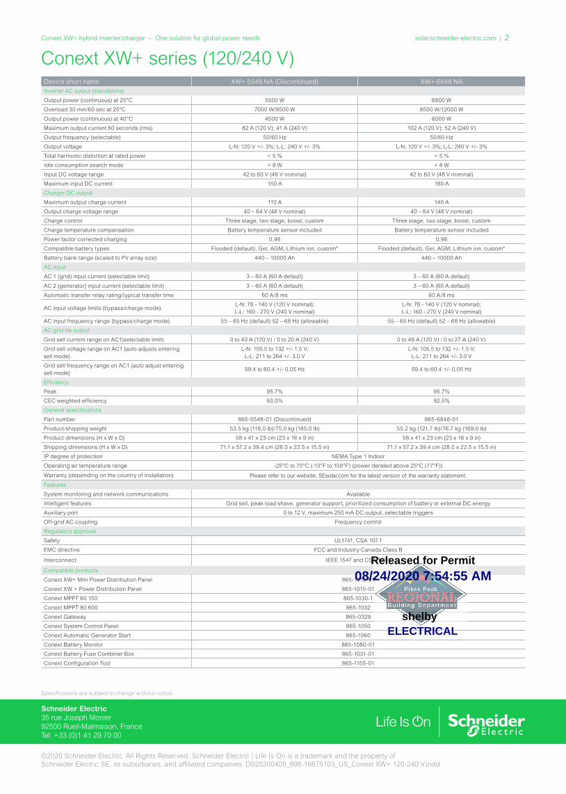
25 YEARLINEAR PERFORMANCE GUARANTEE
HELIENE IS A PREMIER SOLAR MODULE MANUFACTURER, SERVICING THE GROWING SOLAR ENERGY MARKETS OF NORTH AMERICA.
COMBINING PROVEN EUROPEAN TECHNOLOGY WITH NORTH AMERICAN INGENUITY ALLOWS HELIENE TO MAKE A REAL COMMITMENT IN PROVIDING SMARTER ENERGY CHOICES FOR THE FUTURE.
MONO POLY
70.00%
75.00%
80.00%
85.00%
90.00%
95.00%
100.00%
0 1 2 3 4 5 6 7 8 9 10 11 12 13 14 15 16 17 18 19 20 21 22 23 24 25
Guar
ante
ed P
ower
Out
put (
%)
Year
Ours Industry Standard
L I N E A R P E R F O R M A N C E G U A R A N T E E10 YEAR WORKMANSHIP WARRANTY • 25 YEAR LINEAR PERFORMANCE GUARANTEE
ADDED VALUE FROM HELIENE’S LINEAR WARRANTY
PERFECT FOR HIGH VISIBILITY INSTALLATIONS
MANUFACTURED ACCORDING TO INTERNATIONAL QUALITY SYSTEM STANDARDS: ISO9001
GUARANTEED POSITIVE POWER SORTING: [-0 : +4.99 WP]
H-BLACK INTEGRATION - BLACK FRAME & BACK-SHEET
08/24/2020 7:54:55 AM
ELECTRICALshelby
Released for Permit
DIMENSIONS FOR HELIENE 72M SERIES MODULES
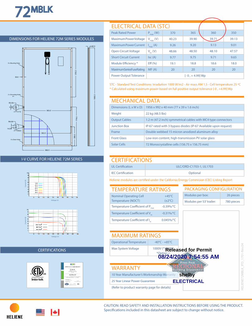
STC - Standard Test Conditions: Irradiation 1000 W/m2 - Air mass AM 1.5 - Cell temperature 25 ºC* Calculated using maximum power based on full positive output tolerance [-0 , +4.99] Wp
MECHANICAL DATADimensions (L x W x D) 1956 x 992 x 40 mm (77 x 39 x 1.6 inch)
Weight 22 kg (48.5 lbs)
Output Cables 1.2 m (47.2 inch) symmetrical cables with MC4 type connectors
Junction Box IP-67 rated with 3 bypass diodes (IP-67 Available upon request)
Frame Double webbed 15 micron anodized aluminum alloy
Front Glass Low-iron content, high-transmission PV solar glass
Solar Cells 72 Monocrystalline cells (156.75 x 156.75 mm)
I-V CURVE FOR HELIENE 72M SERIES
CERTIFICATIONS
72MBLK
TEMPERATURE RATINGSNominal Operating Cell Temperature (NOCT)
+45°C (±2°C)
Temperature Coefficient of Pmax -0.39%/°C
Temperature Coefficient of Voc -0.31%/°C
Temperature Coefficient of Isc 0.045%/°C
PACKAGING CONFIGURATIONModules per box: 26 pieces
Modules per 53’ trailer: 780 pieces
MAXIMUM RATINGSOperational Temperature -40°C - +85°C
Max System Voltage 1000V (*1500V) *Optional
WARRANTY10 Year Manufacturer’s Workmanship Warranty
25 Year Linear Power Guarantee
(Refer to product warranty page for details)
CAUTION: READ SAFETY AND INSTALLATION INSTRUCTIONS BEFORE USING THE PRODUCT.Specifications included in this datasheet are subject to change without notice.
ELECTRICAL DATA (STC)Peak Rated Power Pmpp (W) 370 365 360 350
Maximum Power Voltage Vmpp (V) 40.23 39.90 39.71 39.13
Maximum Power Current Impp (A) 9.26 9.20 9.13 9.01
Open Circuit Voltage Voc (V) 48.66 48.50 48.10 47.57
Short Circuit Current Isc (A) 9.77 9.75 9.71 9.65
Module Efficiency * Eff (%) 19.1 18.8 18.6 18.0
Maximum Series Fuse Rating MF (A) 20 20 20 20
Power Output Tolerance [- 0 , + 4.99] Wp
Curr
ent (
A)
Voltage (V)
Curr
ent (
A)
Voltage (V)
CERTIFICATIONSUL Certification ULC/ORD-C1703-1, UL1703
IEC Certification Optional
Heliene modules are certified under the California Energy Commision (CEC) Listing Report
HEL
IEN
E72M
BLK_
IFD
_170
1-Re
v.04
8 x Mounting Holes
2 x Grounding Holes
8 x Drain Holes
9.014.0
7.0
10.0
R4.50
R3.50
953.0
953.0
4.0
38
8.0
77
8.0
97
8.0
40.0
19
56
.0
992.0
30.0
08/24/2020 7:54:55 AM
ELECTRICALshelby
Released for Permit
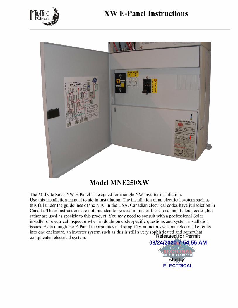
XW E-Panel Instructions
Model MNE250XW
The MidNite Solar XW E-Panel is designed for a single XW inverter installation.
Use this installation manual to aid in installation. The installation of an electrical system such as
this fall under the guidelines of the NEC in the USA. Canadian electrical codes have jurisdiction in
Canada. These instructions are not intended to be used in lieu of these local and federal codes, but
rather are used as specific to this product. You may need to consult with a professional Solar
installer or electrical inspector when in doubt on code specific questions and system installation
issues. Even though the E-Panel incorporates and simplifies numerous separate electrical circuits
into one enclosure, an inverter system such as this is still a very sophisticated and somewhat
complicated electrical system.
08/24/2020 7:54:55 AM
ELECTRICALshelby
Released for Permit

XW E-Panel installation manual
2 | P a g e 1 0 - 1 8 5 - 1 R E V : -
IMPORTANT SAFETY INSTRUCTIONS
SAVE THESE INSTRUCTIONS - These instructions contain important safety and operating instructions for MidNite Solar E-Panels.
If you do not fully understand any of the concepts, terminology, or hazards outlined in these instructions, please refer installation to a
qualified dealer, electrician or installer. These instructions are not meant to be a complete explanation of a renewable energy system.
GENERAL PRECAUTIONS
WORKING WITH OR IN THE VICINITY OF A LEAD ACID BATTERY, SEALED OR VENTED IS DANGEROUS. VENTED
BATTERIES GENERATE EXPLOSIVE GASES DURING NORMAL OPERATION. FOR THIS REASON, IT IS VERY
IMPORTANT THAT BEFORE SERVICING EQUIPMENT IN THE VICINITY OF LEAD-ACID BATTERIES YOU REVIEW AND
FOLLOW THESE INSTRUCTIONS CAREFULLY.
If service or repair should become necessary, contact MidNite Solar Inc. Improper servicing may result in a risk of shock, fire or
explosion. To reduce these risks, disconnect all wiring before attempting any maintenance or cleaning. Turning off the inverter will not
reduce these risks. Solar modules produce power when exposed to light. When it is not possible to disconnect the power coming from
the Photovoltaics by an external means such as a combiner, cover the modules with an opaque material before servicing any connected
equipment.
Never attempt to charge a frozen battery.
When it is necessary to remove a battery, make sure that the battery bank disconnect breaker is in the off position and that the PV
breakers, grid breakers and any other sources of power to the inverter are in the off position. Then remove the negative terminal from
the battery first.
To reduce risk of battery explosion follow these instructions and those published by the battery manufacturer as well as the
manufacturer of any additional equipment used in the vicinity of the batteries. Before installing the battery enclosure, read all
instructions and cautionary markings in or on any connected electrical equipment.
Avoid producing sparks in the vicinity of the batteries when using vented batteries. Provide ventilation to clear the area of explosive
gases. Sealed AGM and Gel batteries do not under normal conditions create explosive gases. Be especially cautious when using metal
tools. Dropping a metal tool onto batteries can short circuit them. The resulting spark can lead to personal injury or damage to the
equipment. Provide ventilation to outdoors from the battery compartment when installing vented batteries such as golf cart T-105
batteries. The addition of a spill tray is also a good idea.
Clean all battery terminals. Very high currents are drawn from the batteries; even a small amount of electrical resistance can result in
overheating, poor performance, premature failure or even fire.
Have plenty of fresh water and soap nearby in case battery acid contacts skin, clothing or eyes. Wear complete eye and clothing
protection. Always avoid touching eyes while working near batteries. If battery acid or battery terminal corrosion contacts skin or
clothing, wash immediately with soap and water. If acid enters the eyes, immediately flood with cool running water for at least 15
minutes and get medical attention immediately. Baking soda neutralizes battery acid electrolyte. Keep a supply near the batteries.
Do not work alone. Someone should be in the range of your voice or close enough to come to your aid when you work with or near
electrical equipment.
Remove rings, bracelets, necklaces, watches etc. when working with batteries, photovoltaic modules or other electrical equipment.
Power from an illuminated photovoltaic array makes a very effective arc welder with dire consequences if one of the welded pieces is
on your person.
To reduce the risk of injury, connect only deep cycle lead acid type rechargeable batteries. Other types of batteries may leak or
burst, causing personal injury or damage.
This equipment is NOT intended for use with life support equipment or other medical equipment or devices.
It is the responsibility of the installer to verify compliance with all applicable codes.
Before making any connections verify that the circuit breakers are in the off position including the inverter breaker. Double check
all wiring before applying power.
08/24/2020 7:54:55 AM
ELECTRICALshelby
Released for Permit

XW E-Panel installation manual
3 | P a g e 1 0 - 1 8 5 - 1 R E V : -
Mounting The XW E-Panel:
The XW inverter should be mounted to the wall prior to installing the E-Panel. Pay attention
to the total height of the system. Refer to the dimensioned drawing below.
Installing the E-Panel to the inverter: To install the E-Panel, remove the door and deadfront.
Attach top and bottom wall mounting brackets to the E-Panel using four M6 x 10mm taptite screws
supplied. The top mounting bracket slides up behind the inverter to space the inverter out the proper
distance from the wall. The top mounting bracket does not screw to the wall, but rather just acts as a
spacer
Top left Top right Bottom left Bottom right
Each mounting bracket is held on using two 6mm x 10mm thread forming screws.
Use a #3 Philips screwdriver for these four screws.
Dimensions of XW E-Panel and inverter
Mounting bracket dimensions.
08/24/2020 7:54:55 AM
ELECTRICALshelby
Released for Permit
XW E-Panel installation manual
4 | P a g e 1 0 - 1 8 5 - 1 R E V : -
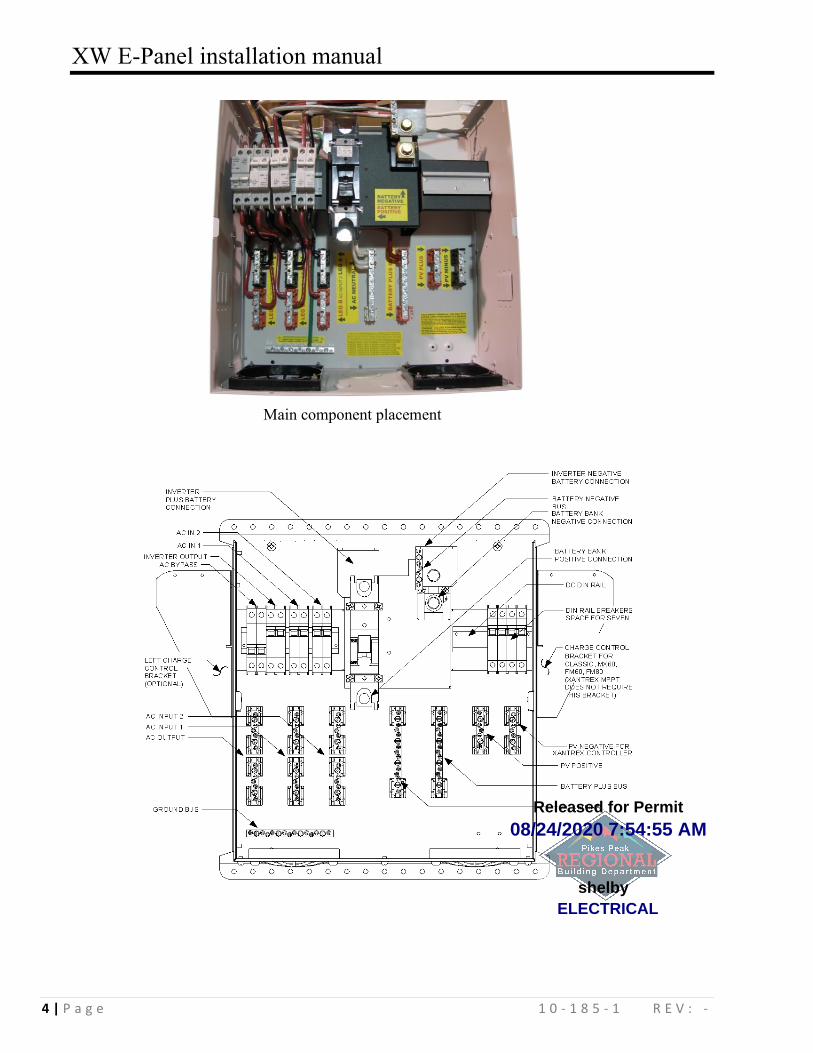
Main component placement
08/24/2020 7:54:55 AM
ELECTRICALshelby
Released for Permit

XW E-Panel installation manual
5 | P a g e 1 0 - 1 8 5 - 1 R E V : -
Installing the E-Panel to the inverter continued:
Remove two 5mm #2 Philips tip screws from the bottom of the inverter that will be used to attach
the E-Panel. These two screws are the only attachment to the inverter. The bottom wall mounting
bracket also needs to be secured to the wall. You must also remove the battery terminal bolts prior
to setting the E-Panel in place. Note: 10-32 UNF screws are interchangeable with the 5mm screws
if you should misplace them.
To gain access to these two main mounting screws, you will need a long #2 Philips screwdriver.
The tip must be at least 9 inches long. Most tool boxes do not have a Philips screwdriver this long,
so consider adding it to your arsenal of tools. Slide the AC breakers to the right a bit to allow the
screwdriver to line up with the screw. Move
them back after the E-Panel is secured to the
inverter. Install the battery terminal bolts as
shown to the left. Remove the left side plate
of the E-Panel. This allows access to tighten
the bottom of the battery plus bus bar
located on the 250 amp circuit breaker. Both
the Plus and Minus battery busbars are
shipped loose for ease of alignment and
must be tightened. Use a 9/16” wrench for
these connections. (Note: some earlier bus
bars may require enlarging the slot for
battery terminals). If required, use a 3/8”
drill and a strong pair of pliers to hold it
while drilling.
Left attachment. E-Panel to inverter Right attachment. E-Panel to inverter
08/24/2020 7:54:55 AM
ELECTRICALshelby
Released for Permit

XW E-Panel installation manual
6 | P a g e 1 0 - 1 8 5 - 1 R E V : -
Wiring: Start with the grounds. Wiring the system will be easier if grounds are done first.
The E-Panel comes with a 6AWG green ground wire shown above. The ground chassis lug on the
bottom of the inverter is the same electrical connection as the three inside the wiring compartment
of the inverter. You may use this large terminal as the one single ground connection to the inverter
and then connect all other grounds to the E-Panel ground bus. Since the E-Panel ground, inverter
chassis ground and wiring compartment grounds are all at the same potential, you may use any and
all as required although electrical inspectors are used to finding all grounds on just one busbar. The
E-Panel ground bus is the proper place for this single point ground on an off-grid system. Your
main distribution panel ground is the proper AC ground for utility connected systems. Use the E-
Panel ground bus for the DC grounds in a utility connected system. Inspectors will want to see a
separate ground wire from AC and DC on a utility connected system. You can use a single ground
wire from the E-Panel for AC and DC for an off-grid installation.
Neutral to ground bond: All AC electrical systems in North America must have an AC Neutral to
Earth Ground bonding connection. A typical distribution panel such as Square D makes this bond
by use of a bonding screw. That green screw grounds the neutral busbar when installed. Electrical
inspectors are used to looking in the main distribution panel for this electrical bond. In a battery
backed up grid tie or power back up installation, this bond has already been made in the main
distribution / service entrance panel. Do not add it inside the E-Panel when the utility is connected.
In an off-grid installation where there is no utility connection, the bond should be done inside the E-
Panel as shown here.
6AWG Neutral to Ground bonding wire. The bond should be done
at the power source and since the E-Panel is central to the power
generation, it is considered the source. Some electrical inspectors
are used to looking for this bond to be accomplished in the
distribution panel. They may ask you to move it to where they feel
comfortable finding it. Don’t fight it. The bond will work just fine
in a Square D box too.
DC-GFP installation: The NEC 2008 requires a DC-GFP in all US systems! When installing a DC-GFP in the PV circuit, make sure there is no battery minus to ground
connection. That would effectively short out the sense circuit on the DC-GFP. MidNite solar has
Chassis ground connection to inverter E-Panel earth ground bus (AC & DC)
08/24/2020 7:54:55 AM
ELECTRICALshelby
Released for Permit

XW E-Panel installation manual
7 | P a g e 1 0 - 1 8 5 - 1 R E V : -
two DC-GFP devices that fit the E-Panel. One is a 63 amp single circuit din rail mount device while
the other is an 80 amp single circuit panel mount device. OutBack Power offers a two circuit 80
amp panel mount DC-GFP that also fits inside the E-Panel. The Xantrex DC-GFP’s will not fit in
the E-Panel. The MidNite Solar single circuit DC-GFP’s are designed for a single PV array. Two
MidNite DC-GFP’s may be used to accommodate two arrays although the dual OutBack would for
dual arrays and dual controllers cost less and take up less room. DC-GFP’s are a very
misunderstood device. When looking at a wiring diagram you will notice that part of the DC-GFP is
a high current breaker. Connected in series with the GFP is yet another high current DC breaker. It
is a common mistake to think the second breaker is unnecessary. NEC2008 requires a DC-GFP on
all systems whether mounted on the roof top of a residence or not. The NEC also does not allow the
DC-GFP to be the PV disconnect. When the DC-GFP is turned off, it leaves the battery negative
ungrounded. The only time it is allowed that the system be ungrounded is during a fault condition.
This requirement necessitates a PV disconnect in series with the DC-GFP.
80 amp panel mount DC-GFP ready
for the high current wires. 63 amp din rail DC-GFP wired with a 63 amp
PV disconnect and a 63 amp controller output
breaker.
08/24/2020 7:54:55 AM
ELECTRICALshelby
Released for Permit
XW E-Panel installation manual
8 | P a g e 1 0 - 1 8 5 - 1 R E V : -
The DC-GFP device monitors current flowing between battery negative and earth ground and will
trip when more than ½ amp is present. There should be no current flowing in this circuit under
normal circumstances. In the event your DC-GFP trips, it is usually on a new installation. One of
two things is happening. 1: There is an actual ground fault in the wiring, or 2: there is an excess of
current flowing through the large 63 or 80 amp breaker. The first thing an installer usually suspects
in the case of this device tripping is that the device is faulty. Sorry, but this will not be the reason
for a DC-GFP tripping, so check your wiring! Refer to the wiring diagram in these instructions or
on the inside of the door. These wiring diagrams show a PV disconnect breaker connected directly
after the PV array + busbar and before the DC-GFP. It doesn’t matter which order these two devices
are connected. The DC-GFP can be connected to the Array plus output before the PV disconnect
just as well. Make sure the polarity of all DC breakers are correct. The din rail mount breakers have
a + sign at the bottom terminal. Panel mount breakers have a “Line” marking on the top connection.
The + and Line connections need to be connected to the most positive point in the circuit. Since the
DC-GFP is acting as a switch and not as a breaker, the PV disconnect is the device that polarity
needs to be observed. It is much easier to wire the din rail mount devices as shown in the picture,
but the DC-GFP + connection is furthest away from the PV+ array. In the case of the panel mount
80 amp PV disconnect breaker and 80 amp DC-GFP, connect the PV+ array output to the top of the
PV disconnect breaker. The DC-GFP polarity will not be important. The polarity of the PV
disconnect breaker is important!
The output of the PV charge controller also requires over-current protection. Most installations will
use either a 63 amp din rail mount breaker or an 80 amp panel mount breaker. The + or “Line” side
of this breaker must be connected to the Battery+ busbar. Use a red 6AWG wire for the 63 amp
breaker and 4AWG wire for an 80 amp breaker. The charge controller output breaker must be sized
large enough for the expected output. You can always use a larger breaker and wire than the array
output though. The breaker is there to protect the wire, not the controller, so you can use a 63 amp
breaker even if the controller is not capable of outputting more than 30 amps.
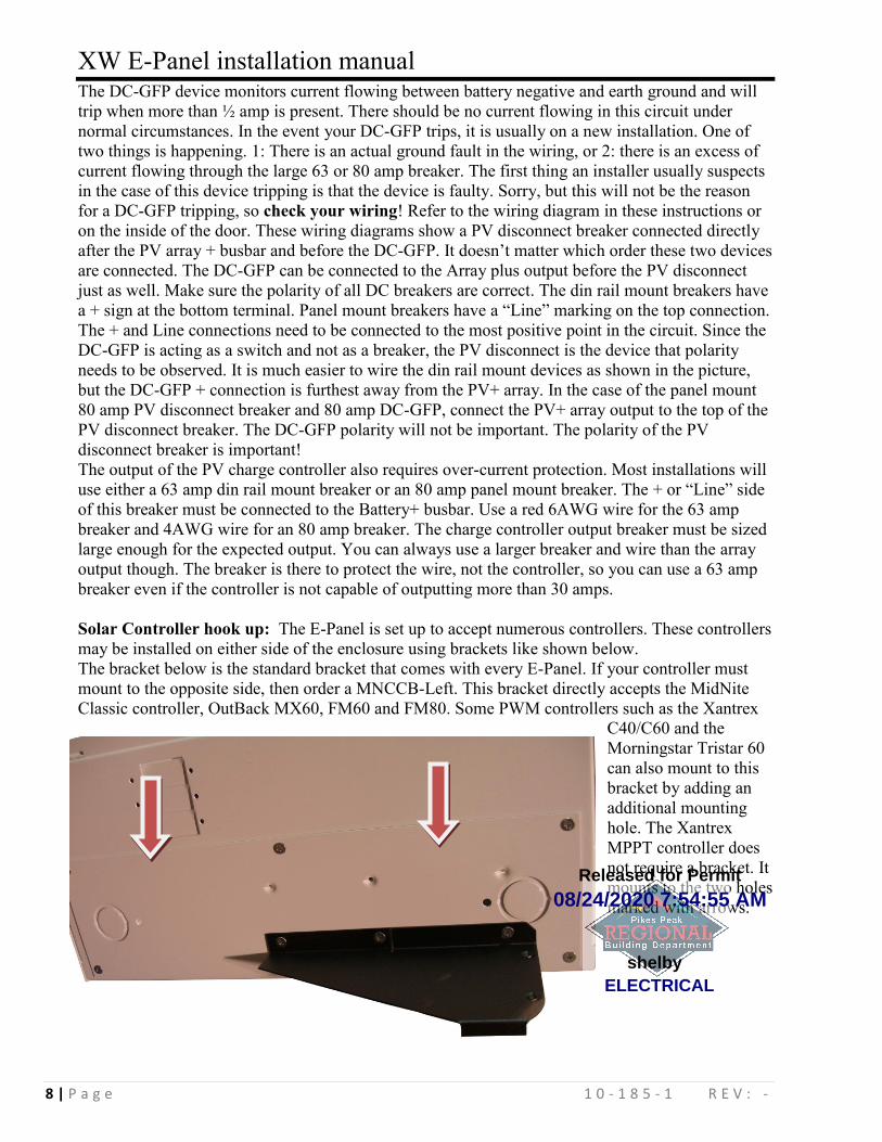
Solar Controller hook up: The E-Panel is set up to accept numerous controllers. These controllers
may be installed on either side of the enclosure using brackets like shown below.
The bracket below is the standard bracket that comes with every E-Panel. If your controller must
mount to the opposite side, then order a MNCCB-Left. This bracket directly accepts the MidNite
Classic controller, OutBack MX60, FM60 and FM80. Some PWM controllers such as the Xantrex
C40/C60 and the
Morningstar Tristar 60
can also mount to this
bracket by adding an
additional mounting
hole. The Xantrex
MPPT controller does
not require a bracket. It
mounts to the two holes
marked with arrows.
08/24/2020 7:54:55 AM
ELECTRICALshelby
Released for Permit
XW E-Panel installation manual
9 | P a g e 1 0 - 1 8 5 - 1 R E V : -
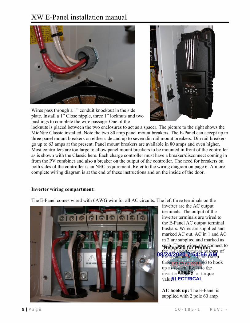
Wires pass through a 1” conduit knockout in the side
plate. Install a 1” Close nipple, three 1” locknuts and two
bushings to complete the wire passage. One of the
locknuts is placed between the two enclosures to act as a spacer. The picture to the right shows the
MidNite Classic installed. Note the two 80 amp panel mount breakers. The E-Panel can accept up to
three panel mount breakers on either side and up to seven din rail mount breakers. Din rail breakers
go up to 63 amps at the present. Panel mount breakers are available in 80 amps and even higher.
Most controllers are too large to allow panel mount breakers to be mounted in front of the controller
as is shown with the Classic here. Each charge controller must have a breaker/disconnect coming in
from the PV combiner and also a breaker on the output of the controller. The need for breakers on
both sides of the controller is an NEC requirement. Refer to the wiring diagram on page 6. A more
complete wiring diagram is at the end of these instructions and on the inside of the door.
Inverter wiring compartment:
The E-Panel comes wired with 6AWG wire for all AC circuits. The left three terminals on the
inverter are the AC output
terminals. The output of the
inverter terminals are wired to
the E-Panel AC output terminal
busbars. Wires are supplied and
marked AC out. AC in 1 and AC
in 2 are supplied and marked as
such. These wires also connect to
the E-Panel terminal busbars of
the same name. Cut and strip
these wires as required to hook
up as shown. Refer to the
inverter manual for torque
values.
AC hook up: The E-Panel is
supplied with 2 pole 60 amp
08/24/2020 7:54:56 AM
ELECTRICALshelby
Released for Permit
XW E-Panel installation manual
10 | P a g e 1 0 - 1 8 5 - 1 R E V : -
continuous breakers for the generator input, utility input and AC input/output bypass switch. Most
generators come with a UL489 branch circuit output breaker. All main distribution/service entrance
panels such as Square D utilize UL489 branch circuit rated breakers. The AC breakers supplied in
the E-Panel are supplementary protection listed to UL1077. These breakers are used as disconnects
or switches, but not as branch circuit devices. Branch circuit breakers made for a residential service
entrance panels are typically thermal breakers. These breakers are not allowed under NEC
guidelines to normally carry more than 80% of their rating. That means a 60 amp Square D QO stab
in breaker may only be sized for 48 amps continuous power. The MidNite breakers are a
hydraulic/magnetic variety and are allowed under NEC guidelines to carry full rated current. The
XW E-Panel comes with 60 amp hydraulic/magnetic breakers.
Bus bars are provided for easy hook up from a generator and or the utility and also for an AC sub-
panel. The AC input and output busbars are also the ideal place to connect lightning or surge
arrestors. The output busbar must not be connected to the main distribution panel in a utility
connected installation. The main utility connected distribution panel will go dead during an outage.
Only circuits connected to the AC output busbar (sub-panel) will have power during a power
outage. Do not try to back feed a utility connected distribution panel from the output of the inverter.
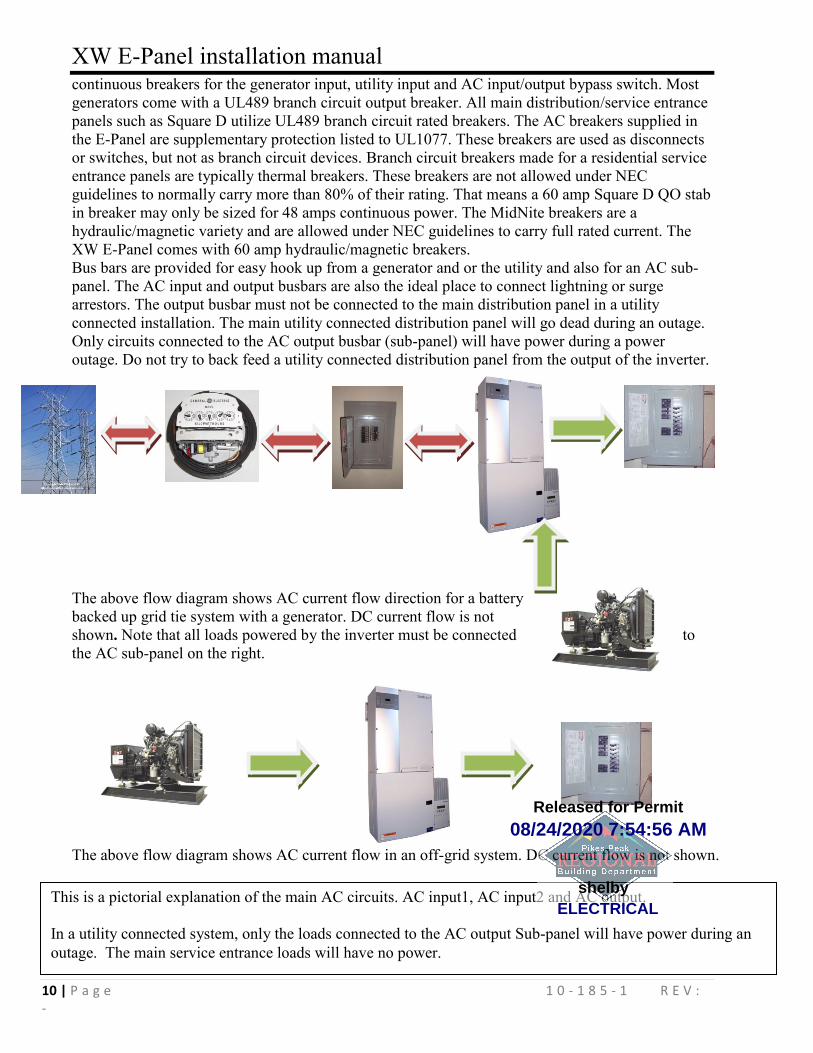
The above flow diagram shows AC current flow direction for a battery
backed up grid tie system with a generator. DC current flow is not
shown. Note that all loads powered by the inverter must be connected to
the AC sub-panel on the right.
The above flow diagram shows AC current flow in an off-grid system. DC current flow is not shown.
This is a pictorial explanation of the main AC circuits. AC input1, AC input2 and AC output.
In a utility connected system, only the loads connected to the AC output Sub-panel will have power during an
outage. The main service entrance loads will have no power.
08/24/2020 7:54:56 AM
ELECTRICALshelby
Released for Permit
XW E-Panel installation manual
11 | P a g e 1 0 - 1 8 5 - 1 R E V : -
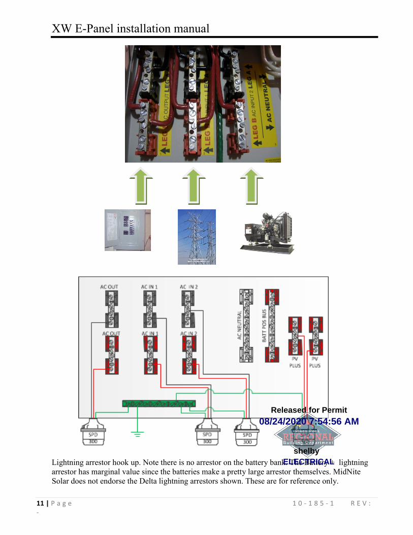
Lightning arrestor hook up. Note there is no arrestor on the battery bank. The Battery + lightning
arrestor has marginal value since the batteries make a pretty large arrestor themselves. MidNite
Solar does not endorse the Delta lightning arrestors shown. These are for reference only.
08/24/2020 7:54:56 AM
ELECTRICALshelby
Released for Permit
XW E-Panel installation manual
12 | P a g e 1 0 - 1 8 5 - 1 R E V : -
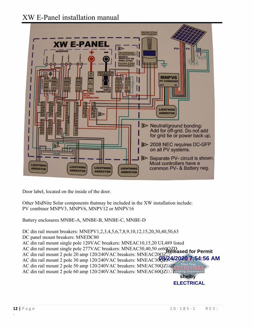
Door label, located on the inside of the door.
Other MidNite Solar components thatmay be included in the XW installation include:
PV combiner MNPV3, MNPV6, MNPV12 or MNPV16
Battery enclosures MNBE-A, MNBE-B, MNBE-C, MNBE-D
DC din rail mount breakers: MNEPV1,2,3,4,5,6,7,8,9,10,12,15,20,30,40,50,63
DC panel mount breakers: MNEDC80
AC din rail mount single pole 120VAC breakers: MNEAC10,15,20 UL489 listed
AC din rail mount single pole 277VAC breakers: MNEAC30,40,50 or60QZD
AC din rail mount 2 pole 20 amp 120/240VAC breakers: MNEAC20QZ2P
AC din rail mount 2 pole 30 amp 120/240VAC breakers: MNEAC30QZD2P
AC din rail mount 2 pole 50 amp 120/240VAC breakers: MNEAC50QZD2P
AC din rail mount 2 pole 60 amp 120/240VAC breakers: MNEAC60QZD2P
08/24/2020 7:54:56 AM
ELECTRICALshelby
Released for Permit
XW E-Panel installation manual
13 | P a g e 1 0 - 1 8 5 - 1 R E V : -
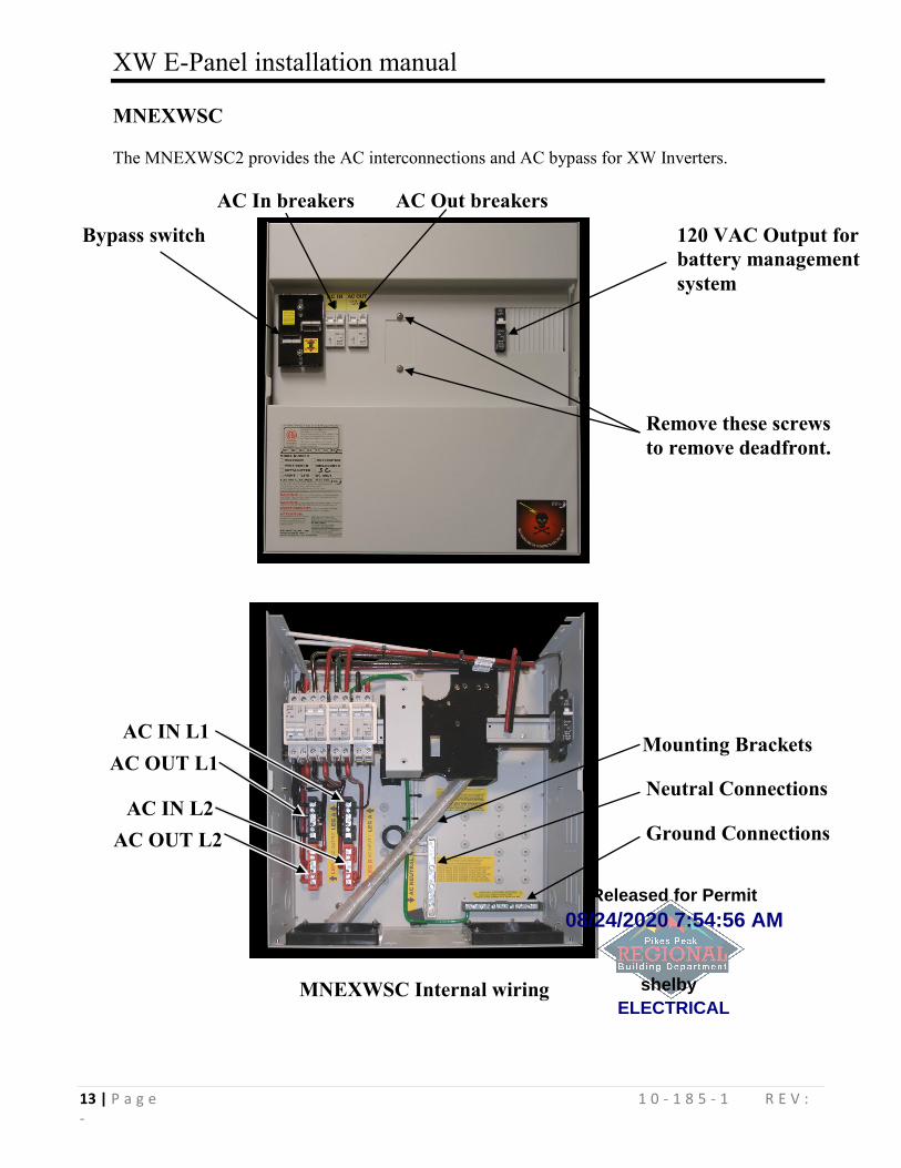
MNEXWSC
The MNEXWSC2 provides the AC interconnections and AC bypass for XW Inverters.
MNEXWSC Internal wiring
Remove these screws
to remove deadfront.
Bypass switch 120 VAC Output for
battery management
system
Mounting Brackets
Ground Connections
Neutral Connections
AC IN L1
AC OUT L1
AC IN L2
AC OUT L2
AC In breakers AC Out breakers
08/24/2020 7:54:56 AM
ELECTRICALshelby
Released for Permit
XW E-Panel installation manual
14 | P a g e 1 0 - 1 8 5 - 1 R E V : -
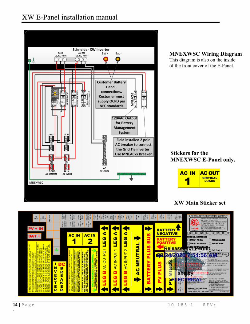
MNEXWSC Wiring Diagram
This diagram is also on the inside
of the front cover of the E-Panel.
XW Main Sticker set
Stickers for the
MNEXWSC E-Panel only.
08/24/2020 7:54:56 AM
ELECTRICALshelby
Released for Permit
XW E-Panel installation manual
15 | P a g e 1 0 - 1 8 5 - 1 R E V : -
MIDNITE SOLAR INC. LIMITED WARRANTY
MidNite Solar Power electronics, sheet metal enclosures and accessories MidNite Solar Inc. warrants to the original customer that its products shall be free from defects in materials and workmanship. This warranty will be valid for a period of five (5) years for all products except the MNKID Charge Controller which will be two (2) years.
At its option, MidNite Solar will repair or replace at no charge any MidNite product that proves to be defective within such warranty period. This warranty shall not apply if the MidNite Solar product has been damaged by unreasonable use, accident, negligence, service or modification by anyone other than MidNite Solar, or by any other causes unrelated to materials and workmanship. The original consumer purchaser must retain original purchase receipt for proof of purchase as a condition precedent to warranty coverage. To receive in-warranty service, the defective product must be received no later than two (2) weeks after the end of the warranty period. The product must be accompanied by proof of purchase and Return Authorization (RA) number issued by MidNite Solar. For an RMA number contact MidNite Solar Inc., 17722 67th Ave NE, Arlington, WA 98223 (360) 403-7207. Purchasers must prepay all delivery costs or shipping charges to return any defective MidNite Solar product under this warranty policy. Except for the warranty that the products are made in accordance with, the specifications therefore supplied or agreed to by customer: MIDNITE SOLAR MAKES NO WARRANTY EXPRESSED OR IMPLIED, AND ANY IMPLIED WARRANTY OF MERCHANTABILITY OR FITNESS FOR A PARTICULAR PURPOSE WHICH EXCEEDS THE FOREGOING WARRANTY IS HEREBY DISCLAIMED BY MIDNITE SOLAR AND EXCLUDED FROM ANY AGREEMENT MADE BY ACCEPTANCE OF ANY ORDER PURSUANT TO THIS QUOTATION. MIDNITE SOLAR WILL NOT BE LIABLE FOR ANY CONSEQUENTIAL DAMAGES, LOSS OR EXPENSE ARISING IN CONNECTION WITH THE USE OF OR THE INABILITY TO USE ITS GOODS FOR ANY PURPOSE WHATSOEVER. MIDNITE SOLAR’S MAXIMUM LIABILITY SHALL NOT IN ANY CASE EXCEED THE CONTRACT PRICE FOR THE GOODS CLAIMED TO BE DEFECTIVE OR UNSUITABLE. Products will be considered accepted by customer unless written notice to the contrary is given to MidNite Solar within ten (10) days of such delivery to customer. MIDNITE SOLAR is not responsible for loss or damage to products owned by customer and located on MIDNITE SOLAR’S premises caused by fire or other casualties beyond MIDNITE SOLAR’s control. This warranty is in lieu of all other warranties expressed or implied. MIDNITE SOLAR INC. 17722 67TH AVE NE ARLINGTON, WA 98223
Email: [email protected] PH: 360.403-7207 FAX: 360-691-6862
08/24/2020 7:54:56 AM
ELECTRICALshelby
Released for Permit

08/24/2020 7:54:56 AM
ELECTRICALshelby
Released for Permit
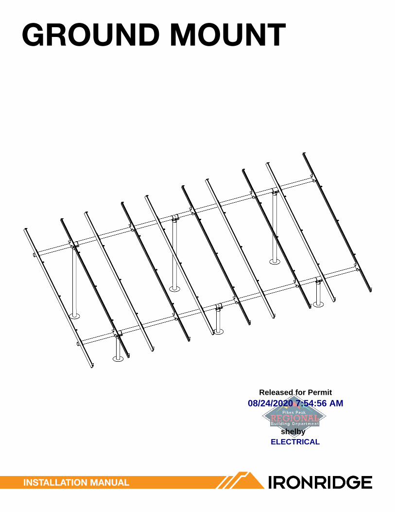
GROUND MOUNT
INSTALLATION MANUAL
08/24/2020 7:54:56 AM
ELECTRICALshelby
Released for Permit
CONTeNTS
GROUND MOUNT INSTALLATION MANUAL - 1© 2019 IRONRIDGE, INC. VERSION 2.3
DISCLAIMeR 1RATINGS 2MARKINGS 2CHeCKLIST 31. BUILD BASe 42. CONNeCT SUBSTRUCTURe 43. PLACe RAILS 54. SeCURe LUGS 55. SeCURe MODULeS 6CAMO 7eLeCTRICAL DIAGRAM 8DIAGONAL BRACeS (OPTIONAL) 9eND CAPS 9WIRe CLIPS 9SPLICING CROSS PIPe 10MICROINVeRTeR KITS 11SYSTeMS USING eNPHASe MICROINVeRTeRS OR SUNPOWeR AC MODULeS 11SYSTeMS USING MICROSTORAGe PRODUCTS 12FRAMeLeSS MODULe KITS 12MODULe COMPATIBILITY 13MODULe COMPATIBILITY 14MODULe COMPATIBILITY 15MODULe COMPATIBILITY 16
DISCLAIMeR
This manual describes proper installation procedures and provides necessary standards required for product reliability. Warranty details are available on website. All installers must thoroughly read this manual and have a clear understanding of the installation procedures prior to installation. Failure to follow these guidelines may result in property damage, bodily injury or even death.
IT IS THe INSTALLeR’S ReSPONSIBILITY TO:
• Ensure safe installation of all electrical aspects of the array. All electrical installation and procedures should be conducted by a licensed and bonded electrician or solar contractor. Routine maintenance of a module or panel shall not involve breaking or disturbing the bonding path of the system. All work must comply with national, state and local installation procedures, product and safety standards.
• Comply with all applicable local or national building and fire codes, including any that may supersede this manual.• Ensure all products are appropriate for the installation, environment, and array under the site’s loading conditions.• Use only IronRidge parts or parts recommended by IronRidge; substituting parts may void any applicable warranty.• Review the Design Assistant and Certification Letters to confirm design specifications.• Ensure provided information is accurate. Issues resulting from inaccurate information are the installer’s responsibility.• Validate foundation parameters prior to installation, as a local geotechnical report may be required to assess ground
conditions. We recommend consulting with a local engineer familiar with local regulations and build site requirements, including soil conditions, terrain and load criteria. All parameters may impact foundation requirements.
• Ensure bare copper grounding wire does not contact aluminum and zinc-plated steel components, to prevent risk of galvanic corrosion.
• If loose components or loose fasteners are found during periodic inspection, re-tighten immediately. If corrosion is found, replace affected components immediately.
• Provide an appropriate method of direct-to-earth grounding according to the latest edition of the National Electrical Code, including NEC 250: Grounding and Bonding, and NEC 690: Solar Photovoltaic Systems.
• Disconnect AC power before servicing or removing modules, AC modules, microinverters and power optimizers.• Review module manufacturer’s documentation for compatibility and compliance with warranty terms and conditions.
08/24/2020 7:54:56 AM
ELECTRICALshelby
Released for Permit
GROUND MOUNT INSTALLATION MANUAL - 2© 2019 IRONRIDGE, INC. VERSION 2.3
RATINGS
MARKINGS
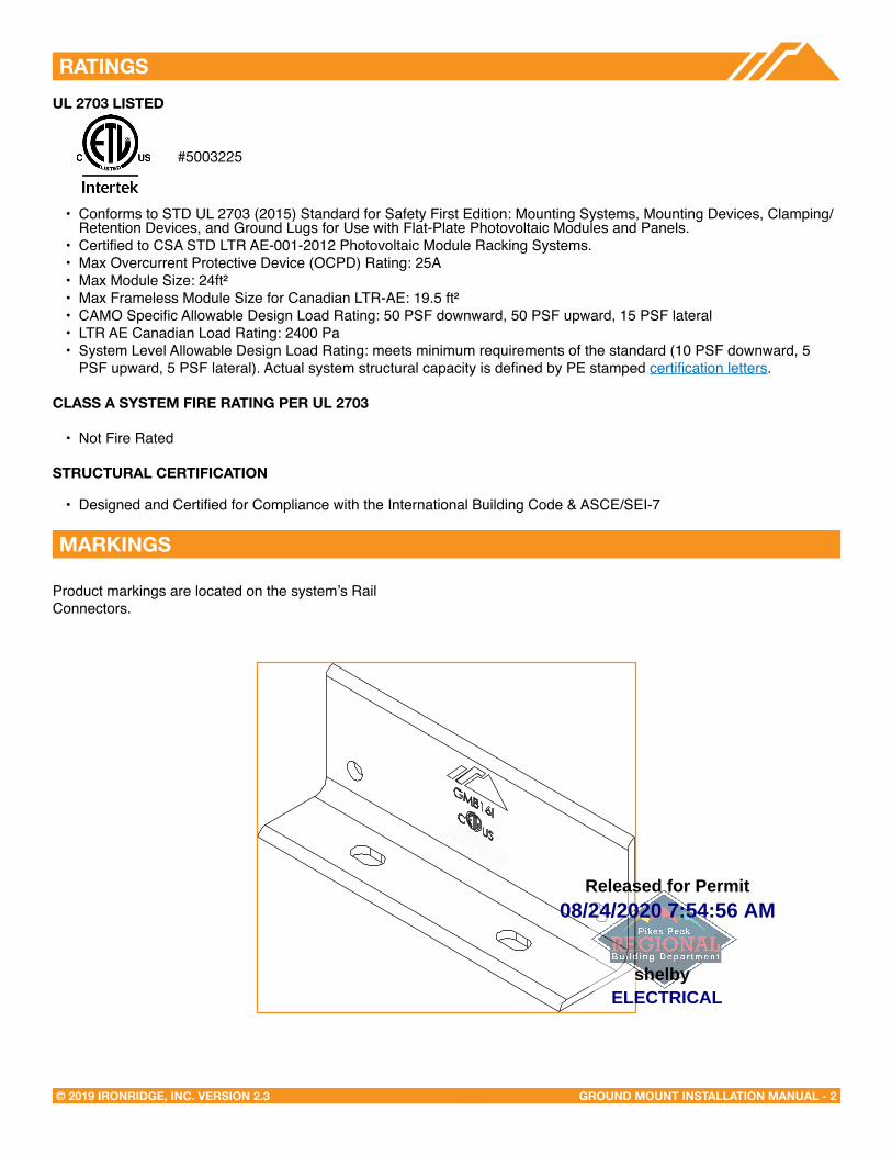
Product markings are located on the system’s Rail Connectors.
UL 2703 LISTeD
• Conforms to STD UL 2703 (2015) Standard for Safety First Edition: Mounting Systems, Mounting Devices, Clamping/Retention Devices, and Ground Lugs for Use with Flat-Plate Photovoltaic Modules and Panels.
• Certified to CSA STD LTR AE-001-2012 Photovoltaic Module Racking Systems.• Max Overcurrent Protective Device (OCPD) Rating: 25A• Max Module Size: 24ft² • Max Frameless Module Size for Canadian LTR-AE: 19.5 ft²• CAMO Specific Allowable Design Load Rating: 50 PSF downward, 50 PSF upward, 15 PSF lateral• LTR AE Canadian Load Rating: 2400 Pa• System Level Allowable Design Load Rating: meets minimum requirements of the standard (10 PSF downward, 5
PSF upward, 5 PSF lateral). Actual system structural capacity is defined by PE stamped certification letters.
CLASS A SYSTeM FIRe RATING PeR UL 2703
• Not Fire Rated
STRUCTURAL CeRTIFICATION
• Designed and Certified for Compliance with the International Building Code & ASCE/SEI-7
#5003225
08/24/2020 7:54:56 AM
ELECTRICALshelby
Released for Permit

GROUND MOUNT INSTALLATION MANUAL - 3© 2019 IRONRIDGE, INC. VERSION 2.3
CHECKLIST
IRONRIDGE COMPONENTSPRE-INSTALLATION
☐ Verify module compatibility. See Page 12 for info.
☐ Purchase 2” or 3” ASTM A53 Grade B Schedule 40 Pipe, galvanized to a min of ASTM A653 G90 or ASTM A123 G35, or 2.375” or 3.500” Allied Mechanical Tubing with Gatorshield or FlowCoat Zinc coating (ASTM A1057).
TOOLS REQUIRED
☐ Post Hole Digger or Powered Auger
☐ Socket Drive (7/16”, 9/16”, and 1/2” Sockets)
☐ Torque Wrenches (0-240 in-lbs and 10-40 ft-lbs)
☐ Transit, String Line, or Laser Level
☐ 3/16” Allen Head
TORQUE VALUES
☐ Top Cap Set Screws (3/16” Allen Head)
☐ Schedule 40 Grade B Pipe: 20 ft-lbs
☐ 2.” Allied Mechanical Tubing: 11 ft-lbs
☐ 3” Allied Mechanical Tubing: 16 ft-lbs
☐ Top Cap U-Bolt Nuts (9/16” Socket): 15 ft-lbs
☐ Rail Connector Bracket Nuts (9/16” Socket): 21 ft-lbs
☐ Rail Connector U-Bolt Nuts (9/16” Socket): 60 in-lbs
☐ Grounding Lug Nuts (7/16” Socket): 80 in-lbs
☐ Grounding Lug Terminal Screws (7/16 Socket): 20 in-lbs
☐ Universal Fastening Objects (7/16” Socket): 80 in-lbs
☐ Diagonal Brace Set Screws (1/2” Socket): 15 ft-lbs
☐ Diagonal Brace Bolts (1/2” Socket): 40 ft-lbs
☐ Microinverter Kit Nuts (7/16” Socket): 80 in-lbs
☐ Frameless Module Kit Nuts (7/16” Socket): 80 in-lbs
Þ If using previous version of: Integrated Grounding Mid Clamps, Grounding Lug, End Clamps, and Expansion Joints please refer to Alternate Components Addendum (Version 1.30).
Þ If installing on a low slope roof please refer to Ground Mount for Flat Roof Applications Addendum (Version 2.0).
XR100 & XR1000 Rail Rail Connector
Top Cap UFO
Diagonal Brace
Stopper Sleeve
Grounding Lug Microinverter Kit
Frameless Module Kit Frameless End/Mid Clamp
CAMO
End Cap Wire Clip08/24/2020 7:54:56 AM
ELECTRICALshelby
Released for Permit
GROUND MOUNT INSTALLATION MANUAL - 4© 2019 IRONRIDGE, INC. VERSION 2.3
1. BUILD BASe
A. MARK LOCATIONS
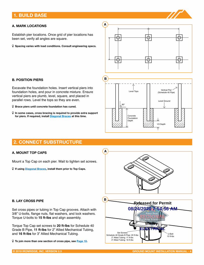
Establish pier locations. Once grid of pier locations has been set, verify all angles are square.
Þ Spacing varies with load conditions. Consult engineering specs.
B. POSITION PIeRS
Excavate the foundation holes. Insert vertical piers into foundation holes, and pour in concrete mixture. Ensure vertical piers are plumb, level, square, and placed in parallel rows. Level the tops so they are even.
Þ Brace piers until concrete foundation has cured.
Þ In some cases, cross bracing is required to provide extra support for piers. If required, install Diagonal Braces at this time.
A. MOUNT TOP CAPS
Mount a Top Cap on each pier. Wait to tighten set screws.
Þ If using Diagonal Braces, install them prior to Top Caps.
B. LAY CROSS PIPe
Set cross pipes or tubing in Top Cap grooves. Attach with 3/8” U-bolts, flange nuts, flat washers, and lock washers. Torque U-bolts to 15 ft-lbs and align assembly.
Torque Top Cap set screws to 20 ft-lbs for Schedule 40 Grade B Pipe, 11 ft-lbs for 2” Allied Mechanical Tubing, and 16 ft-lbs for 3” Allied Mechanical Tubing.
Þ To join more than one section of cross pipe, see Page 10.
2. CONNeCT SUBSTRUCTURe
A
B
A
B
Level Tops Vertical Pier(Schedule 40 Pipe)
Level Ground90°
U-Bolt15 ft-lbs
Set ScrewsSchedule 40 Grade B Pipe: 20 ft-lbs
2” Allied Tubing: 11 ft-lbs3” Allied Tubing: 16 ft-lbs
1/3 Depth
ConcreteFoundation Depth
08/24/2020 7:54:56 AM
ELECTRICALshelby
Released for Permit
GROUND MOUNT INSTALLATION MANUAL - 5© 2019 IRONRIDGE, INC. VERSION 2.3
3. PLACe RAILS
A. ATTACH HARDWARe
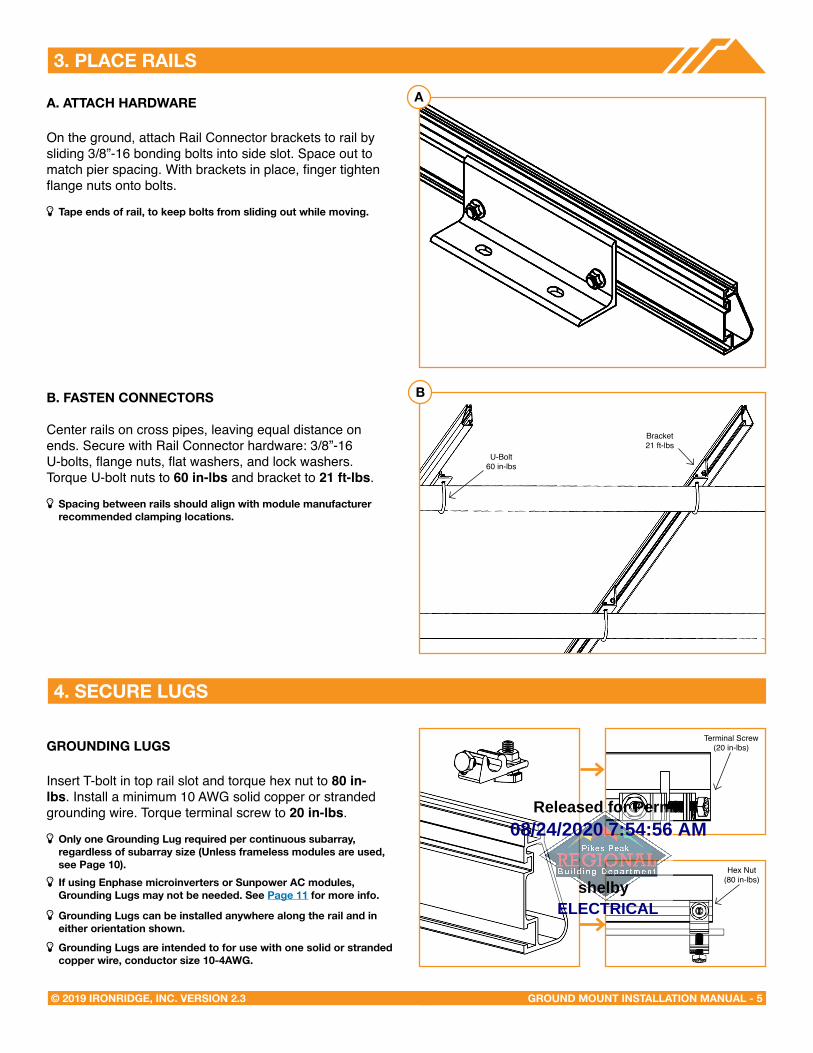
On the ground, attach Rail Connector brackets to rail by sliding 3/8”-16 bonding bolts into side slot. Space out to match pier spacing. With brackets in place, finger tighten flange nuts onto bolts.
Þ Tape ends of rail, to keep bolts from sliding out while moving.
B. FASTeN CONNeCTORS
Center rails on cross pipes, leaving equal distance on ends. Secure with Rail Connector hardware: 3/8”-16 U-bolts, flange nuts, flat washers, and lock washers. Torque U-bolt nuts to 60 in-lbs and bracket to 21 ft-lbs.
Þ Spacing between rails should align with module manufacturer recommended clamping locations.
GROUNDING LUGS
Insert T-bolt in top rail slot and torque hex nut to 80 in-lbs. Install a minimum 10 AWG solid copper or stranded grounding wire. Torque terminal screw to 20 in-lbs.
Þ Only one Grounding Lug required per continuous subarray, regardless of subarray size (Unless frameless modules are used, see Page 10).
Þ If using enphase microinverters or Sunpower AC modules, Grounding Lugs may not be needed. See Page 11 for more info.
Þ Grounding Lugs can be installed anywhere along the rail and ineither orientation shown.
Þ Grounding Lugs are intended to for use with one solid or stranded copper wire, conductor size 10-4AWG.
4. SeCURe LUGS
A
B
U-Bolt60 in-lbs
Bracket21 ft-lbs
Hex Nut(84 in-lbs)
Terminal Screw(20 in-lbs)
Hex Nut(80 in-lbs)
08/24/2020 7:54:56 AM
ELECTRICALshelby
Released for Permit
GROUND MOUNT INSTALLATION MANUAL - 6© 2019 IRONRIDGE, INC. VERSION 2.3
5. SeCURe MODULeS
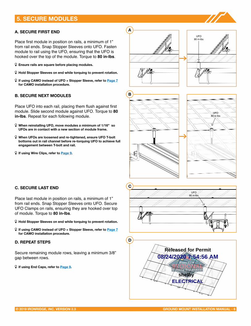
A. SeCURe FIRST eND
Place first module in position on rails, a minimum of 1” from rail ends. Snap Stopper Sleeves onto UFO. Fasten module to rail using the UFO, ensuring that the UFO is hooked over the top of the module. Torque to 80 in-lbs.
Þ ensure rails are square before placing modules.
Þ Hold Stopper Sleeves on end while torquing to prevent rotation.
Þ If using CAMO instead of UFO + Stopper Sleeve, refer to Page 7 for CAMO installation procedure.
B. SeCURe NeXT MODULeS
Place UFO into each rail, placing them flush against first module. Slide second module against UFO. Torque to 80 in-lbs. Repeat for each following module.
Þ When reinstalling UFO, move modules a minimum of 1/16” so UFOs are in contact with a new section of module frame.
Þ When UFOs are loosened and re-tightened, ensure UFO T-bolt bottoms out in rail channel before re-torquing UFO to achieve full engagement between T-bolt and rail.
Þ If using Wire Clips, refer to Page 9.
C. SeCURe LAST eND
Place last module in position on rails, a minimum of 1” from rail ends. Snap Stopper Sleeves onto UFO. Secure UFO Clamps on rails, ensuring they are hooked over top of module. Torque to 80 in-lbs.
Þ Hold Stopper Sleeves on end while torquing to prevent rotation.
Þ If using CAMO instead of UFO + Stopper Sleeve, refer to Page 7 for CAMO installation procedure.
D. RePeAT STePS
Secure remaining module rows, leaving a minimum 3/8” gap between rows.
Þ If using end Caps, refer to Page 9.
A
B
C
D
UFO80 in-lbs
UFO80 in-lbs
UFO80 in-lbs
08/24/2020 7:54:56 AM
ELECTRICALshelby
Released for Permit
GROUND MOUNT INSTALLATION MANUAL - 7© 2019 IRONRIDGE, INC. VERSION 2.3
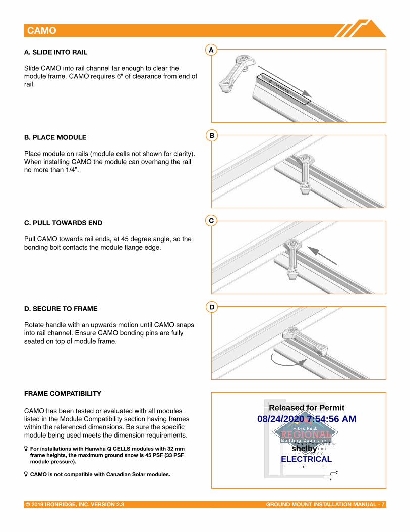
CAMO
A. SLIDe INTO RAIL
Slide CAMO into rail channel far enough to clear the module frame. CAMO requires 6" of clearance from end of rail.
B. PLACe MODULe
Place module on rails (module cells not shown for clarity). When installing CAMO the module can overhang the rail no more than 1/4”.
C. PULL TOWARDS eND
Pull CAMO towards rail ends, at 45 degree angle, so the bonding bolt contacts the module flange edge.
D. SeCURe TO FRAMe
Rotate handle with an upwards motion until CAMO snaps into rail channel. Ensure CAMO bonding pins are fully seated on top of module frame.
FRAMe COMPATIBILITY
CAMO has been tested or evaluated with all modules listed in the Module Compatibility section having frames within the referenced dimensions. Be sure the specific module being used meets the dimension requirements.
Þ For installations with Hanwha Q CeLLS modules with 32 mm frame heights, the maximum ground snow is 45 PSF (33 PSF module pressure).
Þ CAMO is not compatible with Canadian Solar modules.
A
B
C
D
6" Clearance
08/24/2020 7:54:56 AM
ELECTRICALshelby
Released for Permit
GROUND MOUNT INSTALLATION MANUAL - 8© 2019 IRONRIDGE, INC. VERSION 2.3
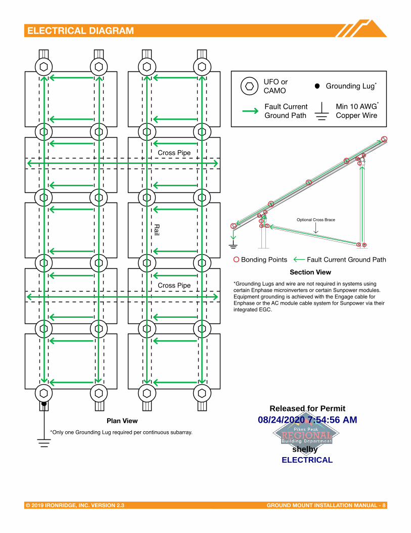
eLeCTRICAL DIAGRAM
UFO Clamp Grounding Lug
Min 10 AWGCopper Wire
Fault Current Ground Path
Bonding Points Fault Current Ground Path
*Grounding Lugs and wire are not required in systems using certain Enphase microinverters or certain Sunpower modules. Equipment grounding is achieved with the Engage cable for Enphase or the AC module cable system for Sunpower via their integrated EGC.
*
*
Section View
Plan View
Optional Cross Brace
Only one Grounding Lug required per continuous subarray.*
Cross Pipe
Rail
Cross Pipe
UFO or CAMO
08/24/2020 7:54:56 AM
ELECTRICALshelby
Released for Permit
GROUND MOUNT INSTALLATION MANUAL - 9© 2019 IRONRIDGE, INC. VERSION 2.3
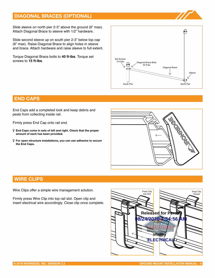
DIAGONAL BRACeS (OPTIONAL)
Slide sleeve on north pier 2-3” above the ground (6” max).Attach Diagonal Brace to sleeve with 1/2” hardware.
Slide second sleeve up on south pier 2-3” below top cap (6” max). Raise Diagonal Brace to align holes in sleeve and brace. Attach hardware and raise sleeve to full extent.
Torque Diagonal Brace bolts to 40 ft-lbs. Torque set screws to 15 ft-lbs.
eND CAPS
WIRe CLIPS
End Caps add a completed look and keep debris and pests from collecting inside rail.
Firmly press End Cap onto rail end.
Þ end Caps come in sets of left and right. Check that the proper amount of each has been provided.
Þ For open-structure installations, you can use adhesive to secure the end Caps.
Wire Clips offer a simple wire management solution.
Firmly press Wire Clip into top rail slot. Open clip and insert electrical wire accordingly. Close clip once complete.
South Pier North Pier
Diagonal Brace
Diagonal Brace Bolts40 ft-lbs
Set Screws15 ft-lbs
Sleeve
Press Clip into Slot
Run Wire
Snap Clip Closed
08/24/2020 7:54:56 AM
ELECTRICALshelby
Released for Permit
GROUND MOUNT INSTALLATION MANUAL - 10© 2019 IRONRIDGE, INC. VERSION 2.3
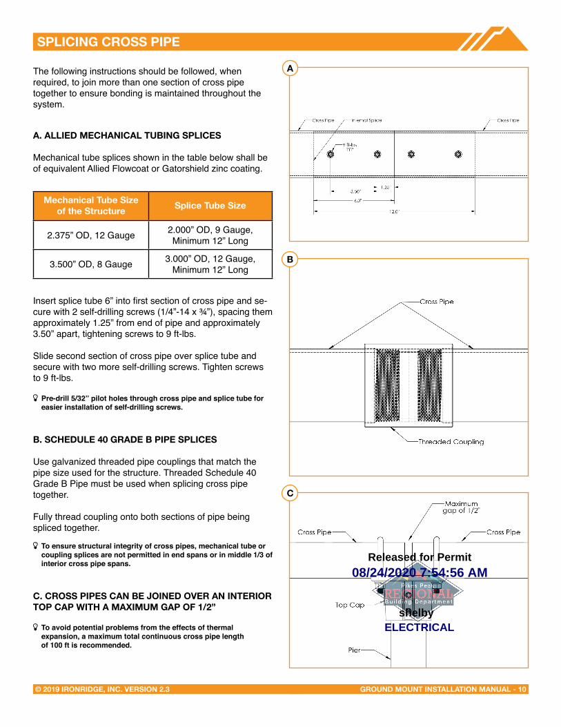
SPLICING CROSS PIPe
The following instructions should be followed, when required, to join more than one section of cross pipe together to ensure bonding is maintained throughout the system.
A. ALLIeD MeCHANICAL TUBING SPLICeS
Mechanical tube splices shown in the table below shall be of equivalent Allied Flowcoat or Gatorshield zinc coating.
Insert splice tube 6” into first section of cross pipe and se-cure with 2 self-drilling screws (1/4”-14 x ¾”), spacing them approximately 1.25” from end of pipe and approximately 3.50” apart, tightening screws to 9 ft-lbs.
Slide second section of cross pipe over splice tube and secure with two more self-drilling screws. Tighten screws to 9 ft-lbs.
Þ Pre-drill 5/32” pilot holes through cross pipe and splice tube for easier installation of self-drilling screws.
B. SCHeDULe 40 GRADe B PIPe SPLICeS
Use galvanized threaded pipe couplings that match the pipe size used for the structure. Threaded Schedule 40 Grade B Pipe must be used when splicing cross pipe together.
Fully thread coupling onto both sections of pipe being spliced together.
Þ To ensure structural integrity of cross pipes, mechanical tube or coupling splices are not permitted in end spans or in middle 1/3 of interior cross pipe spans.
C. CROSS PIPeS CAN Be JOINeD OVeR AN INTeRIOR TOP CAP WITH A MAXIMUM GAP OF 1/2”
Þ To avoid potential problems from the effects of thermal expansion, a maximum total continuous cross pipe length
of 100 ft is recommended.
Mechanical Tube Size of the Structure Splice Tube Size
2.375” OD, 12 Gauge 2.000” OD, 9 Gauge, Minimum 12” Long
3.500” OD, 8 Gauge 3.000” OD, 12 Gauge, Minimum 12” Long
A
B
C
08/24/2020 7:54:56 AM
ELECTRICALshelby
Released for Permit
GROUND MOUNT INSTALLATION MANUAL - 11© 2019 IRONRIDGE, INC. VERSION 2.3
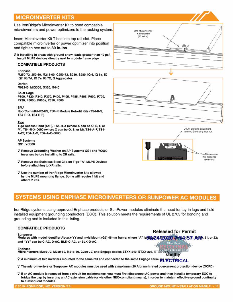
MICROINVeRTeR KITS
One Microinverter Kit Required
(80 in-lbs)
Use IronRidge's Microinverter Kit to bond compatible microinverters and power optimizers to the racking system.
Insert Microinverter Kit T-bolt into top rail slot. Place compatible microinverter or power optimizer into position and tighten hex nut to 80 in-lbs.
Þ If installing in areas with ground snow loads greater than 40 psf, install MLPE devices directly next to module frame edge
SYSTeMS USING eNPHASe MICROINVeRTeRS OR SUNPOWeR AC MODULeS
IronRidge systems using approved Enphase products or SunPower modules eliminate the need for lay-in lugs and field installed equipment grounding conductors (EGC). This solution meets the requirements of UL 2703 for bonding and grounding and is included in this listing.
COMPATIBLe PRODUCTSSunpowerModules with model identifier Ab-xxx-YY and InvisiMount (G5) 46mm frame; where “A” is either E, or X; “b” can be 17, 18, 19, 20, 21, or 22; and “YY” can be C-AC, D-AC, BLK-C-AC, or BLK-D-AC.
EnphaseMicroinverters M250-72, M250-60, M215-60, C250-72, and Engage cables ETXX-240, ETXX-208, ETXX-277. �
Þ A minimum of two inverters mounted to the same rail and connected to the same Engage cable are required.
Þ The microinverters or Sunpower AC modules must be used with a maximum 20 A branch rated overcurrent protection device (OCPD).
Þ If an AC module is removed from a circuit for maintenance, you must first disconnect AC power and then install a temporary EGC to bridge the gap by inserting an AC extension cable (or via other NEC-compliant means), in order to maintain effective ground continuity to subsequent modules.
On AP systems equipment, remove Grounding Washer
�COMPATIBLe PRODUCTSEnphaseM250-72, 250-60, M215-60, C250-72, S230, S280, IQ 6, IQ 6+, IQ IQ7, IQ 7A, IQ 7+, IQ 7X, Q Aggregator
DarfonMIG240, MIG300, G320, G640
Solar EdgeP300, P320, P340, P370, P400, P405, P485, P505, P600, P700, P730, P800p, P800s, P850, P860
SMA RoofCommKit-P2-US, TS4-R Module Retrofit Kits (TS4-R-S, TS4-R-O, TS4-R-F)
TigoTigo Access Point (TAP), TS4-R-X (where X can be O, S, F, or M), TS4-R-X-DUO (where X can be O, S, or M), TS4-A-F, TS4-A-2F, TS4-A-O, TS4-A-O-DUO
AP SystemsQS1, YC600
Þ Remove Grounding Washer on AP Systems QS1 and YC600 inverters before installing to XR rails.
Þ Remove the Stainless Steel Clip on Tigo-”A” MLPE Devices before attaching to XR rails.
Þ Use the number of IronRidge Microinverter kits allowed by the MLPE mounting flange. Some will require 1 kit and others 2 kits.
Two Microinverter Kits Required
(80 in-lbs)
08/24/2020 7:54:57 AM
ELECTRICALshelby
Released for Permit

DIAGONAL BRACeS (OPTIONAL)
GROUND MOUNT INSTALLATION MANUAL - 12© 2019 IRONRIDGE, INC. VERSION 2.3
Use IronRidge's Microinverter Kit to bond compatible microstroage devices to the racking system. Insert Microinverter Kit T-bolt into top rail slot. Place compatible microstorage into position and tighten hex nut to 80 in-lbs.
Microinverter Kit(80 in-lbs)
SYSTeMS USING MICROSTORAGe PRODUCTS
Insert Frameless Kit T-bolt in top rail slot. Place star washer over T-bolt, allowing it to rest on top of rail. Secure module clamps with a hex nut and torque to 80 in-lbs. Place
Star Washer
Module Clamp(80 in-lbs) Grounding Lugs
Required on Every Rail
FRAMeLeSS MODULe KITS
COMPATIBLe PRODUCTS
PHAZR PHAZR Devices PHAZR-X, where X is 6-12.
Þ Running a separate equipment grounding conductor to the PHAZRs is not required.
Þ If installing in areas with ground snow loads greater than 40 psf and underneath a module, install PHAZR devices as close as possible to module frame edge.
Þ Use the number of IronRidge Microinverter kits allowed by the microstorage mounting flange. Some will require 1 kit and others 2 kits.
COMPATIBLe PRODUCTS
SunforsonSunforson silver or black SFS-UTMC-200(B) mid and SFS-UTEC-200(B) end clamps.
SunpremeSunpreme silver or black mid and end clamps with part numbers 7500105X where “X” is 1, 5, 6 or 7.
IronridgeIronRidge silver or black mid and end clamps with part numbers FMLS-XC-001-Y where “X” is E or M and “Y” is B or blank.
Þ Follow module manufacturer’s installation instructions to installthe module clamps.
Þ Frameless modules require using a Grounding Lug on every rail.
Þ For Sunpreme Modules Only: If required to use slide prevention hardware, see Module Slide Prevention Addendum (Version 1.10).
08/24/2020 7:54:57 AM
ELECTRICALshelby
Released for Permit
GROUND MOUNT INSTALLATION MANUAL - 13© 2019 IRONRIDGE, INC. VERSION 2.3
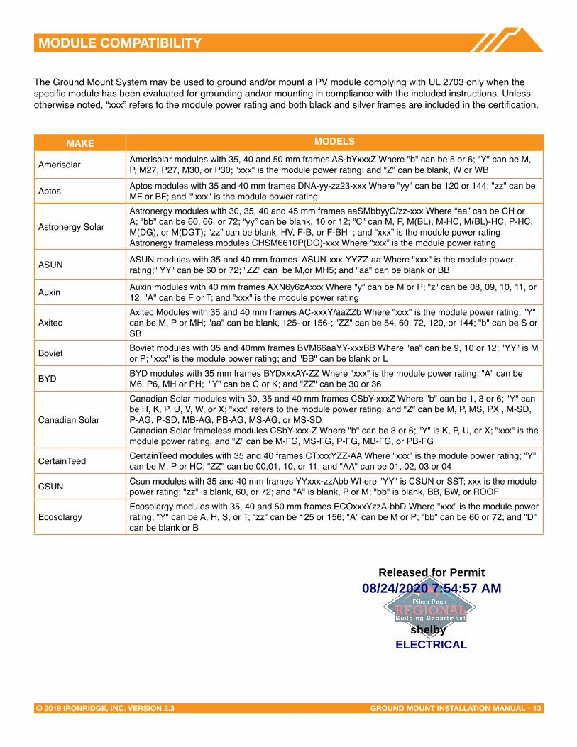
MODULe COMPATIBILITY
The Ground Mount System may be used to ground and/or mount a PV module complying with UL 2703 only when the specific module has been evaluated for grounding and/or mounting in compliance with the included instructions. Unless otherwise noted, “xxx” refers to the module power rating and both black and silver frames are included in the certification.
MAKe MODELS
Amerisolar Amerisolar modules with 35, 40 and 50 mm frames AS-bYxxxZ Where "b" can be 5 or 6; "Y" can be M, P, M27, P27, M30, or P30; "xxx" is the module power rating; and "Z" can be blank, W or WB
Aptos Aptos modules with 35 and 40 mm frames DNA-yy-zz23-xxx Where "yy" can be 120 or 144; "zz" can be MF or BF; and ""xxx" is the module power rating
Astronergy Solar
Astronergy modules with 30, 35, 40 and 45 mm frames aaSMbbyyC/zz-xxx Where “aa” can be CH or A; "bb" can be 60, 66, or 72; “yy” can be blank, 10 or 12; "C" can M, P, M(BL), M-HC, M(BL)-HC, P-HC, M(DG), or M(DGT); “zz” can be blank, HV, F-B, or F-BH ; and “xxx” is the module power rating Astronergy frameless modules CHSM6610P(DG)-xxx Where “xxx” is the module power rating
ASUN ASUN modules with 35 and 40 mm frames ASUN-xxx-YYZZ-aa Where "xxx" is the module power rating;" YY" can be 60 or 72; "ZZ" can be M,or MH5; and "aa" can be blank or BB
Auxin Auxin modules with 40 mm frames AXN6y6zAxxx Where "y" can be M or P; "z" can be 08, 09, 10, 11, or 12; "A" can be F or T; and "xxx" is the module power rating
AxitecAxitec Modules with 35 and 40 mm frames AC-xxxY/aaZZb Where "xxx" is the module power rating; "Y" can be M, P or MH; "aa" can be blank, 125- or 156-; "ZZ" can be 54, 60, 72, 120, or 144; "b" can be S or SB
Boviet Boviet modules with 35 and 40mm frames BVM66aaYY-xxxBB Where "aa" can be 9, 10 or 12; "YY" is M or P; "xxx" is the module power rating; and "BB" can be blank or L
BYD BYD modules with 35 mm frames BYDxxxAY-ZZ Where "xxx" is the module power rating; "A" can be M6, P6, MH or PH; "Y" can be C or K; and "ZZ" can be 30 or 36
Canadian Solar
Canadian Solar modules with 30, 35 and 40 mm frames CSbY-xxxZ Where "b" can be 1, 3 or 6; "Y" can be H, K, P, U, V, W, or X; "xxx" refers to the module power rating; and "Z" can be M, P, MS, PX , M-SD, P-AG, P-SD, MB-AG, PB-AG, MS-AG, or MS-SD Canadian Solar frameless modules CSbY-xxx-Z Where "b" can be 3 or 6; "Y" is K, P, U, or X; "xxx" is the module power rating, and "Z" can be M-FG, MS-FG, P-FG, MB-FG, or PB-FG
CertainTeed CertainTeed modules with 35 and 40 frames CTxxxYZZ-AA Where "xxx" is the module power rating; "Y" can be M, P or HC; "ZZ" can be 00,01, 10, or 11; and "AA" can be 01, 02, 03 or 04
CSUN Csun modules with 35 and 40 mm frames YYxxx-zzAbb Where "YY" is CSUN or SST; xxx is the module power rating; "zz" is blank, 60, or 72; and "A" is blank, P or M; "bb" is blank, BB, BW, or ROOF
EcosolargyEcosolargy modules with 35, 40 and 50 mm frames ECOxxxYzzA-bbD Where "xxx" is the module power rating; "Y" can be A, H, S, or T; "zz" can be 125 or 156; "A" can be M or P; "bb" can be 60 or 72; and "D" can be blank or B
08/24/2020 7:54:57 AM
ELECTRICALshelby
Released for Permit

GROUND MOUNT INSTALLATION MANUAL - 14© 2019 IRONRIDGE, INC. VERSION 2.3
MODULe COMPATIBILITY
ET SolarET Solar modules with 35, 40 and 50 mm frames ET-Y6ZZxxxAA Where “Y” can be P, L, or M; “ZZ” can be 60 or 72; “xxx” refers to the module power rating; and “AA” can be WB, WW, BB, WBG, WWG, WBAC, WBCO, WWCO, WWBCO or BBAC
FlexFlex modules with 35, 40 and 50 mm frames and model identifier FXS-xxxYY-ZZ; where "xxx" is the module power rating; "YY" can be BB or BC; and "ZZ" can be MAA1B, MAA1W, MAB1W, SAA1B, SAA1W, SAC1B, SAC1W, SAD1W, SBA1B, SBA1W, SBC1B, or SBC1W
GCL GCL modules with 35 mm and 40 mm frames GCL-ab/YY xxx Where "a" can be M or P; "b" can be 3 or 6; "YY" can be 60, 72, 72H, or 72DH; and xxx is the module power rating
GigaWatt Solar Gigawatt modules with 40 mm frames GWxxxYY Where “xxx” refers to the module power rating; and “YY” can be either PB or MB
Hansol Hansol modules with 35 and 40 frames HSxxxYY-zz Where "xxx" is the module power rating; "YY" can be PB, PD, PE, TB, TD, UB, UD, or UE; and "zz" can be AH2, AN1, AN3, AN4, HV1, or JH2
Hanwha Solar Hanwha Solar modules with 40, 45, and 50 mm frames HSLaaP6-YY-1-xxxZ Where "aa" can be either 60 or 72; "YY" can be PA or PB; "xxx" refers to the module power rating; and "Z" can be blank or B
Hanwha Q CELLS
Hanwha Q CELLS Modules with 32, 35, 40, and 42mm frames and model identifier aaYY-ZZ-xxxwhere "aa" can be Q. or B.; "YY" can be PLUS, PRO, PEAK, LINE PRO, LINE PLUS, PLUS DUO or PEAK DUO; and "ZZ" can be G3, G3.1, G4, G4.1, L-G2, L-G2.3, L-G3, L-G3.1, L-G3y, L-G4, L-G4.2, L-G4y, LG4.2/TAA, BFR-G3, BLK-G3, BFR-G3.1, BLK-G3.1, BFR-G4, BFR-G4.1, BFR G4.3, BLK-G4.1, G4/SC, G4.1/SC, G4.1/TAA, G4.1/MAX, BFR G4.1/TAA, BFR G4.1/MAX, BLK G4.1/TAA, BLK G4.1/SC, EC-G4.4, G5, BLK-G5, L-G5, L-G5.1, L-G5.2, L-G5.2/H, L-G5.3, G6, G6+, BLK-G6, L-G6, L-G6.1, L-G6.2, L-G6.3, G7, BLK-G6+, BLK-G7, G7.2, G8, BLK-G8, G8+, BLK-G8+ L-G7, L-G7.1, L-G7.2, L-G7.3, L-G8, L-G8.1, L-G8.2, or L-G8.3; and "xxx" is the module power rating
Heliene Heliene modules with 40 mm frames YYZZxxxA Where "YY" can be 36, 60, 72, or 96; "ZZ" can be M, P, or MBLK; "xxx" is the module power rating; and "A" can be blank, HomePV, or Bifacial
HT-SAAE HT-SAAE modules with 40 mm frames HT72-156Z-xxx Where "Z" can be M, P, M-C, P-C, M(S), M(VS), M(V), P(V), M(V)-C, P(V)-C; and "xxx" is the module power rating
HyundaiHyundai modules with 33, 35, 40 and 50 mm frames HiY-SxxxZZ Where "Y" can be A, D, M or S; "xxx" refers to the module power rating; and "ZZ" can be HG, HI, KI, MI, MF, MG, RI, RG, RG(BF), RG(BK), SG, TI, or TG
Itek Itek Modules with 40 and 50 mm frames IT-xxx-YY Where "xxx" is the module power rating; and "YY" can be blank, HE, or SE, or SE72
JA Solar
JA Solar modules with 30, 35, 40 and 45 mm frames JAyyzz-bbww-xxx/aa Where “yy” can be M, P, M6 or P6; “zz” can be blank, (K), (L), (R), (V), (BK), (FA), (TG), (FA)(R), (L)(BK), (L)(TG), (R)(BK), (R)(TG), (V)(BK), (BK)(TG), or (L)(BK)(TG); “bb” can be 48, 60, or 72; "ww" can be D09, S01, S02, S03, S06, S09, or S10; “xxx” is the module power rating; and “aa” can be BP, MP, SI, SC, PR, 3BB, 4BB, 4BB/RE, 5BB
Jinko
Jinko modules with 35 and 40 mm frames JKMYxxxZZ-aa Where "Y" can either be blank or S; "xxx" is the module power rating; "ZZ" can be M, P, or PP; and "aa" can be blank, 60, 60B, 60H, 60L, 60BL, 60HL, 60HBL, 60-J4, 60B-J4, 60B-EP, 60(Plus), 60-V, 60-MX, 72, 72-V, 72H-V, 72L-V, 72HL-V, 72-MX, 72H-BDVP, or 72HL-TV Jinko frameless modules JKMxxxPP-DV Where "xxx" is the module power rating
KyoceraKyocera Modules with 46mm frames KYxxxZZ-AA Where "Y" can be D or U; "xxx" is the module power rating; "ZZ" can be blank, GX, or SX; and "AA" can be LPU, LFU, UPU, LPS, LPB, LFB, LFBS, LFB2, LPB2, 3AC, 3BC, 3FC, 4AC, 4BC, 4FC, 4UC, 5AC, 5BC, 5FC, 5UC, 6BC, 6FC, 8BC, 6MCA, or 6MPA
LGLG modules with 35, 40, and 46 mm frames LGxxxYaZ-bb Where "xxx" is the module power rating; "Y" can be A, E, N, Q, S; "a" can be 1 or 2; "Z" can be C, K, T, or W; and "bb" can be A3, A5, B3, G3, G4, J5, K4, or V5
LongiLongi modules with 30, 35 and 40 mm frames LRa-YYZZ-xxxM Where "a" can be 4 or 6; "YY" can be blank, 60 or 72; "ZZ" can be blank, BK, BP, HV, PB, PE, PH, HBD, HPB, or HPH; "xxx" is the module power rating
08/24/2020 7:54:48 AM
ELECTRICALshelby
Released for Permit
GROUND MOUNT INSTALLATION MANUAL - 15© 2019 IRONRIDGE, INC. VERSION 2.3
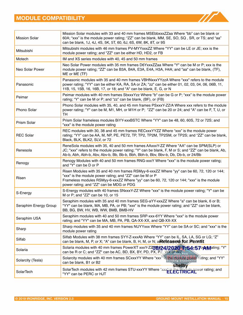
MODULe COMPATIBILITY
Mission SolarMission Solar modules with 33 and 40 mm frames MSEbbxxxZZaa Where “bb” can be blank or 60A; “xxx” is the module power rating; “ZZ” can be blank, MM, SE, SO, SQ , SR, or TS; and “aa” can be blank, 1J, 4J, 4S, 5K, 5T, 60, 6J, 6S, 6W, 8K, 8T, or 9S
Mitsubishi Mitsubishi modules with 46 mm frames PV-MYYxxxZZ Where "YY" can be LE or JE; xxx is the module power rating; and "ZZ" can be either HD, HD2, or FB
Motech IM and XS series modules with 40, 45 and 50 mm frames
Neo Solar PowerNeo Solar Power modules with 35 mm frames D6YxxxZZaa Where "Y" can be M or P; xxx is the module power rating; "ZZ" can be B3A, B4A, E3A, E4A, H3A, H4A; and "aa" can be blank, (TF), ME or ME (TF)
PanasonicPanasonic modules with 35 and 40 mm frames VBHNxxxYYzzA Where "xxx" refers to the module power rating; "YY" can be either KA, RA, SA or ZA; "zz" can be either 01, 02, 03, 04, 06, 06B, 11, 11B, 15, 15B, 16, 16B, 17, or 18; and "A" can be blank, E, G, or N
Peimar Peimar modules with 40 mm frames SbxxxYzz Where "b" can be G or P; “xxx” is the module power rating; “Y” can be M or P; and “zz” can be blank, (BF), or (FB)
Phono SolarPhono Solar modules with 35, 40, and 45 mm frames PSxxxY-ZZ/A Where xxx refers to the module power rating; "Y" can be M, M1, MH, or M1H or P; "ZZ" can be 20 or 24; and "A" can be F, T, U, or TH
Prism Solar Prism Solar frameless modules BiYY-xxxBSTC Where "YY" can be 48, 60, 60S, 72 or 72S; and "xxx" is the module power rating
REC SolarREC modules with 30, 38 and 45 mm frames RECxxxYYZZ Where “xxx” is the module power rating; “YY” can be AA, M, NP, PE, PE72, TP, TP2, TP2M, TP2SM, or TP2S; and “ZZ” can be blank, Black, BLK, BLK2, SLV, or 72
RenesolaReneSola modules with 35, 40 and 50 mm frames AAxxxY-ZZ Where "AA" can be SPM(SLP) or JC; "xxx" refers to the module power rating; "Y" can be blank, F, M or S; and "ZZ" can be blank, Ab, Ab-b, Abh, Abh-b, Abv, Abv-b, Bb, Bb-b, Bbh, Bbh-b, Bbv, Bbv-b, Db, Db-b, or 24/Bb
Renogy Renogy Modules with 40 and 50 mm frames RNG-xxxY Where "xxx" is the module power rating; and "Y" can be D or P
Risen
Risen Modules with 35 and 40 mm frames RSMyy-6-xxxZZ Where "yy" can be 60, 72, 120 or 144; "xxx" is the module power rating; and "ZZ" can be M or PFrameless modules RSMyy-6-xxxZZ Where "yy" can be 60, 72, 120 or 144; "xxx" is the module power rating; and "ZZ" can be MDG or PDG
S-Energy S-Energy modules with 40 frames SNxxxY-ZZ Where "xxx" is the module power rating; "Y" can beM or P; and "ZZ" can be 10, or 15
Seraphim Energy GroupSeraphim modules with 35 and 40 mm frames SEG-aYY-xxxZZ Where "a" can be blank, 6 or B; "YY" can be blank, MA, MB, PA, or PB; "xxx" is the module power rating; and "ZZ" can be blank, BB, BG, BW, HV, WB, WW, BMB, BMB-HV
Seraphim USA Seraphim modules with 40 and 50 mm frames SRP-xxx-6YY Where "xxx" is the module power rating; and "YY" can be MA, MB, PA, PB, QA-XX-XX, and QB-XX-XX
Sharp Sharp modules with 35 and 40 mm frames NUYYxxx Where “YY” can be SA or SC; and "xxx" is the module power rating
Silfab Silfab Modules with 38 mm frames SYY-Z-xxxAb Where “YY” can be IL, SA, LA, SG or LG; “Z” can be blank, M, P, or X; “A” can be blank, B, H, M, or N; and “b” can be A, L, G, or T
Solaria Solaria modules with 40 mm frames PowerXT xxxY-ZZ Where "xxx" is the module power rating; "Y" can be R or C; and "ZZ" can be AC, BD, BX, BY, PD, PX, PZ, WX or WZ
Solarcity (Tesla) Solarcity modules with 40 mm frames SCxxxYY Where "xxx" is the module power rating; and "YY" can be blank, B1 or B2
SolarTech SolarTech modules with 42 mm frames STU-xxxYY Where "xxx" is the module power rating; and "YY" can be PERC or HJT
08/24/2020 7:54:57 AM
ELECTRICALshelby
Released for Permit
MODULe COMPATIBILITY
GROUND MOUNT INSTALLATION MANUAL - 16© 2019 IRONRIDGE, INC. VERSION 2.3
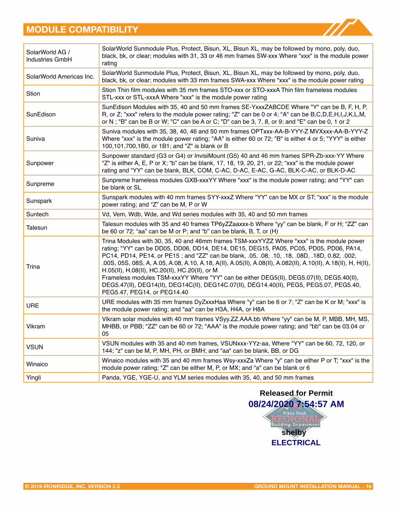
SolarWorld AG / Industries GmbH
SolarWorld Sunmodule Plus, Protect, Bisun, XL, Bisun XL, may be followed by mono, poly, duo, black, bk, or clear; modules with 31, 33 or 46 mm frames SW-xxx Where "xxx" is the module power rating
SolarWorld Americas Inc. SolarWorld Sunmodule Plus, Protect, Bisun, XL, Bisun XL, may be followed by mono, poly, duo, black, bk, or clear; modules with 33 mm frames SWA-xxx Where "xxx" is the module power rating
Stion Stion Thin film modules with 35 mm frames STO-xxx or STO-xxxA Thin film frameless modules STL-xxx or STL-xxxA Where "xxx" is the module power rating
SunEdisonSunEdison Modules with 35, 40 and 50 mm frames SE-YxxxZABCDE Where "Y" can be B, F, H, P, R, or Z; "xxx" refers to the module power rating; "Z" can be 0 or 4; "A" can be B,C,D,E,H,I,J,K,L,M, or N ; "B" can be B or W; "C" can be A or C; "D" can be 3, 7, 8, or 9; and "E" can be 0, 1 or 2
Suniva Suniva modules with 35, 38, 40, 46 and 50 mm frames OPTxxx-AA-B-YYY-Z MVXxxx-AA-B-YYY-Z Where "xxx" is the module power rating; "AA" is either 60 or 72; "B" is either 4 or 5; "YYY" is either 100,101,700,1B0, or 1B1; and "Z" is blank or B
SunpowerSunpower standard (G3 or G4) or InvisiMount (G5) 40 and 46 mm frames SPR-Zb-xxx-YY Where "Z" is either A, E, P or X; “b” can be blank, 17, 18, 19, 20, 21, or 22; “xxx” is the module power rating and “YY” can be blank, BLK, COM, C-AC, D-AC, E-AC, G-AC, BLK-C-AC, or BLK-D-AC
Sunpreme Sunpreme frameless modules GXB-xxxYY Where "xxx" is the module power rating; and "YY" can be blank or SL
Sunspark Sunspark modules with 40 mm frames SYY-xxxZ Where “YY” can be MX or ST; “xxx” is the module power rating; and “Z” can be M, P or W
Suntech Vd, Vem, Wdb, Wde, and Wd series modules with 35, 40 and 50 mm frames
Talesun Talesun modules with 35 and 40 frames TP6yZZaaxxx-b Where “yy” can be blank, F or H; “ZZ” can be 60 or 72; “aa” can be M or P; and “b” can be blank, B, T, or (H)
Trina
Trina Modules with 30, 35, 40 and 46mm frames TSM-xxxYYZZ Where "xxx" is the module power rating; "YY" can be DD05, DD06, DD14, DE14, DE15, DEG15, PA05, PC05, PD05, PD06, PA14, PC14, PD14, PE14, or PE15 ; and "ZZ" can be blank, .05, .08, .10, .18, .08D, .18D, 0.82, .002, .00S, 05S, 08S, A, A.05, A.08, A.10, A.18, A(II), A.05(II), A.08(II), A.082(II), A.10(II), A.18(II), H, H(II), H.05(II), H.08(II), HC.20(II), HC.20(II), or MFrameless modules TSM-xxxYY Where "YY" can be either DEG5(II), DEG5.07(II), DEG5.40(II), DEG5.47(II), DEG14(II), DEG14C(II), DEG14C.07(II), DEG14.40(II), PEG5, PEG5.07, PEG5.40, PEG5.47, PEG14, or PEG14.40
URE URE modules with 35 mm frames DyZxxxHaa Where "y" can be 6 or 7; "Z" can be K or M; "xxx" is the module power rating; and "aa" can be H3A, H4A, or H8A
VikramVikram solar modules with 40 mm frames VSyy.ZZ.AAA.bb Where "yy" can be M, P, MBB, MH, MS, MHBB, or PBB; "ZZ" can be 60 or 72; "AAA" is the module power rating; and "bb" can be 03.04 or 05
VSUN VSUN modules with 35 and 40 mm frames, VSUNxxx-YYz-aa, Where "YY" can be 60, 72, 120, or 144; "z" can be M, P, MH, PH, or BMH; and "aa" can be blank, BB, or DG
Winaico Winaico modules with 35 and 40 mm frames Wsy-xxxZa Where "y" can be either P or T; "xxx" is the module power rating; "Z" can be either M, P, or MX; and "a" can be blank or 6
Yingli Panda, YGE, YGE-U, and YLM series modules with 35, 40, and 50 mm frames
08/24/2020 7:54:57 AM
ELECTRICALshelby
Released for Permit
Outer dimensions (mm)
Constant Current Discharge Unit:A(25℃,77℉) Characteristics
Terminal Type (mm)
NPP Power Co.,Ltd.
Note: The above characteristics data can be obtained within three charge or discharge cycles.
Capacity
affected by
temperature
(20HR)
Terminal type
Internal resistance
(Fully charged,25℃)
120Ah
390 Watts/cell
T16
102%
100%
85%
65%
Capacity(10HR,25℃)
Capacity(15min.rate,25℃)
Approx.4m Ω
40℃
25℃
0℃
-15℃
3 months
6 months
12 months
Remaining Capacity:91%
Remaining Capacity:82%
Remaining Capacity:65%
Self-discharge (25 )℃
Nominal operating temperature
Operating
temperature
range
Discharge
Charge
Storage
Float charging voltage(25 )℃
Cyclic charging voltage(25 )℃
Maximum charging current
25 3 (77℃± ℃ ±5 )℉ ℉
-15 (5 ~℃~50℃ 122 )℉ ℉
-10 (14 ~℃~50℃ 122 )℉ ℉
-20 (-4 ~℃~50℃ 122 )℉ ℉
13.50 to 13.80VTemperature compensation:-18mV/℃
30A
14.50 to 15.00VTemperature compensation:-30mV/℃
Characteristics
Maximum discharge current
Designed floating life(20 )℃
800A(5 sec.)
10years
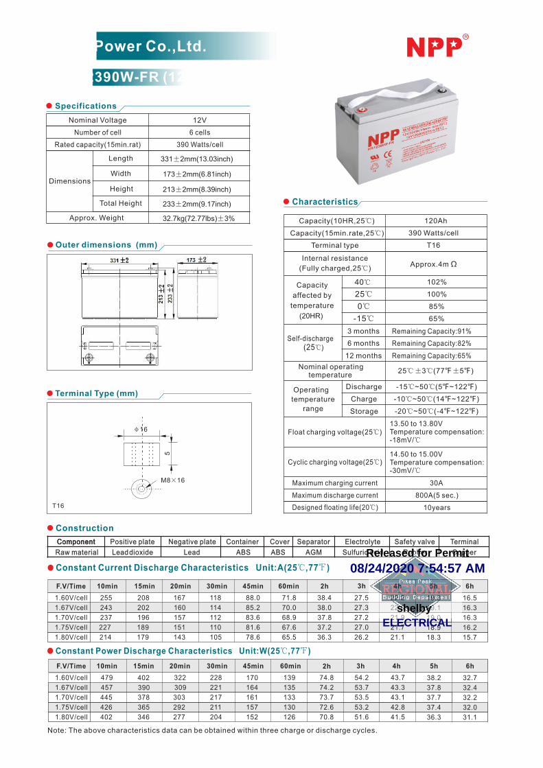
Specifications
Nominal Voltage 12V
Number of cell
Rated capacity(15min.rat)
6 cells
390 Watts/cell
331±2mm(13.03inch)
173±2mm(6.81inch)
213±2mm(8.39inch)
233±2mm(9.17inch)
32.7kg(72.77lbs)±3%
Total Height
Height
Length
WidthDimensions
Approx. Weight
HR12390W-FR (12V390 Watts/cell)
Constant Power Discharge Characteristics Unit:W(25℃,77℉)
ComponentComponent Positive plate Negative plate Container Cover Separator Electrolyte Safety valve Terminal
Raw material Lead dioxide Lead ABS ABS AGM Sulfuric acid Rubber Copper
Construction
F.V/Time
1.60V/cell
1.67V/cell
1.70V/cell
1.75V/cell
1.80V/cell
479
457
445
426
402
402
390
378
365
346
322
309
303
292
277
228
221
217
211
204
170
164
161
157
152
139
135
133
130
126
74.8
74.2
73.7
72.6
70.8
54.2
53.7
53.5
53.2
51.6
43.7
43.3
43.1
42.8
41.5
38.2
37.8
37.7
37.4
36.3
32.7
32.4
32.2
32.0
31.1
10min 15min 20min 30min 45min 60min 2h 3h 4h 5h 6h
F.V/Time
1.60V/cell
1.67V/cell
1.70V/cell
1.75V/cell
1.80V/cell
255
243
237
227
214
208
202
196
189
179
167
160
157
151
143
118
114
112
110
105
88.0
85.2
83.6
81.6
78.6
71.8
70.0
68.9
67.6
65.5
38.4
38.0
37.8
37.2
36.3
27.5
27.3
27.2
27.0
26.2
22.2
22.0
21.9
21.7
21.1
19.3
19.1
19.0
18.9
18.3
16.5
16.3
16.3
16.2
15.7
10min 15min 20min 30min 45min 60min 2h 3h 4h 5h 6h
φ16
5
M8×16
T16
08/24/2020 7:54:57 AM
ELECTRICALshelby
Released for Permit

Self-discharge characteristicsEffect of Temperature on Capacity
Floating Life on Temperature Cycle service Life on D.O.D (25℃)
The relationship for OCV and Capacity (25℃) The relationship for Charging voltage and Temperature
Discharge time
Vo
ltag
e (V
)
3C 2C 1C 0.6C
0.3C0.2C 0.1C 0.05C
min
1 2 5 10 20 30 60 2 3 5 10 20 303
Charging time(hours)
0 2 4 6 8 10 12 14 16 18 20
Charged volume
Charge voltage
Charging current
50% Discharge
100% Discharge
0
20
40
60
80
100
120
1C
0.25C
0.1C
0.05C
Cap
acity
(%
)
-20 -10 0 10 20 30 40 50
Temperature (℃)
40 C 30 C 20 C
Cap
acity
(%)
Storage time(months)
040
50
60
70
80
90
100
2 4 6 8 10 12 14 16
-10 0 10 20 30 40 50 60
Cycle Use
Floating Use
13.2
13.8
14.4
15.0
15.6
Temperature(℃)
Volta
ge (V
)
Number of cycles (cycles)
80
400
20
0 200
40
60100% D.O.D.
600 800
50% D.O.D.
100
120
1000 1200 1400
Ca
pa
city
(%
)
30% D.O.D.
13.0
12.0
11.0
10.0
9.00
8.00
12.0
11.0
13.0
14.0
15.0
0.05
0.10
0.15
20
40
60
0.20
0.25
140
80
100
120
Vol
tage
00
(V)
Cur
rent
(CA)
Cha
rged
(%)
Vol
ume
Residual Capacity (%)
0 20 40 60 80 100
Open C
ircu
it V
olta
ge (
V)
12.0
11.0
13.0
11.5
12.5
13.5
(25 C/77 F)
NPP Power Co.,Ltd.
HR12390W-FR (12V390 Watts/cell)
ISO
: 021009
08
ISO
: 020004
1
04
2.30V/Cell
Temperature(℃)
Life (y
ears
)
0.5
5
15
10 20 30 40 50 60
10
08/24/2020 7:54:57 AM
ELECTRICALshelby
Released for Permit