evo at series battery charger - Alpine Power Systems
224
OPERATION & SERVICE INSTRUCTIONS EVO - Microprocessor Controlled Float Battery Charger SINGLE PHASE INPUT - GROUP 1 (6-25 ADC) EVO AT SERIES BATTERY CHARGER AT SERIES BATTERY CHARGER E E EV V VO O O A A A T T T S S SE E ER R RI I IE E ES S S B B BA A A T T TT T TE E ER R RY Y Y C C CH H HA A AR R RG G GE E ER R R PRODUCT JA5011-51 A
-
Upload
khangminh22 -
Category
Documents
-
view
1 -
download
0
Transcript of evo at series battery charger - Alpine Power Systems

OPERATION & SERVICE INSTRUCTIONS
EVO - Microprocessor Controlled Float Battery Charger
SINGLE PHASE INPUT - GROUP 1 (6-25 ADC)
EVO AT SERIES BATTERY CHARGER
AT SERIES BATTERY CHARGER
EEEVVVOOO AAATTT SSSEEERRRIIIEEESSS BBBAAATTTTTTEEERRRYYY CCCHHHAAARRRGGGEEERRR
P R O D U C T
JA5011-51
A


NOTICE
! WARNING

iiAT SERIES BATTERY CHARGER
Table of Contents - ATevo
TABLE OF CONTENTS1. RECEIVING & UNPACKING THE EVO . . . . . . . . . . . . . . . . . . . . . . . . . . . . . . . . . 1
1.1 Storing the EVO. . . . . . . . . . . . . . . . . . . . . . . . . . . . . . . . . . . . . . 21.2 Reporting Shipping Damage . . . . . . . . . . . . . . . . . . . . . . . . . . 21.3 Unpacking and Inspecting the EVO . . . . . . . . . . . . . . . . . . . . . 2
1.3.1 Inspection Checklist . . . . . . . . . . . . . . . . . . . . . . . . . . . . . . . . . . . . .21.4 Moving the EVO . . . . . . . . . . . . . . . . . . . . . . . . . . . . . . . . . . . . . 3
1.4.1 EVO Weight Table . . . . . . . . . . . . . . . . . . . . . . . . . . . . . . . . . . . . . .31.5 Mounting the EVO . . . . . . . . . . . . . . . . . . . . . . . . . . . . . . . . . . . 3
1.5.1 Wall-Mounting the EVO . . . . . . . . . . . . . . . . . . . . . . . . . . . . . . . . . .31.5.2 Floor-Mounting the EVO . . . . . . . . . . . . . . . . . . . . . . . . . . . . . . . . . .61.5.3. Rack-Mounting the EVO . . . . . . . . . . . . . . . . . . . . . . . . . . . . . . . . . .7
2. WIRING THE EVO . . . . . . . . . . . . . . . . . . . . . . . . . . . . . . . . . . . . . . . . . . . . . . . . . . . 112.1 Mechanical Diagram and Component Location . . . . . . . . . 12
2.1.1 Main Control Board (A1) . . . . . . . . . . . . . . . . . . . . . . . . . . . . . . . . .142.1.2 Power Board (A2) . . . . . . . . . . . . . . . . . . . . . . . . . . . . . . . . . . . . . .142.1.3 Capacitor Board (A3) . . . . . . . . . . . . . . . . . . . . . . . . . . . . . . . . . . .142.1.4 Auxiliary I/O Board (A4) - optional . . . . . . . . . . . . . . . . . . . . . . . . . .142.1.5 Ethernet Communications Adapter (A5) – optional . . . . . . . . . . . . . .142.1.6 Serial Communication Adapter (A6) – optional . . . . . . . . . . . . . . . . .152.1.7 Eliminator Filter Capacitor (C2) - optional . . . . . . . . . . . . . . . . . . . . .152.1.8 AC Input Circuit Breaker (CB1) . . . . . . . . . . . . . . . . . . . . . . . . . . . .152.1.9 DC Output Circuit Breaker (CB2) . . . . . . . . . . . . . . . . . . . . . . . . . . .152.1.10 Filter Inductor #1 (L1) . . . . . . . . . . . . . . . . . . . . . . . . . . . . . . . . . .152.1.11 Filter Inductor #2 (L2) . . . . . . . . . . . . . . . . . . . . . . . . . . . . . . . . . .162.1.12 Main Transformer (T1) . . . . . . . . . . . . . . . . . . . . . . . . . . . . . . . . . .162.1.13 AC MOV Board (A7) . . . . . . . . . . . . . . . . . . . . . . . . . . . . . . . . . . .16
2.2 Removing the Protective Safety Shield . . . . . . . . . . . . . . . . . 162.3 EVO with Selectable Input Voltage (optional) . . . . . . . . . . . . 17
2.3.1 Determine if the Multi-Tap Option is Present. . . . . . . . . . . . . . . . . . .172.3.2 Verify the Multi-Tap AC Input Voltage Setting . . . . . . . . . . . . . . . . . .172.3.3 Modify the Multi-Tap AC Input Voltage Setting . . . . . . . . . . . . . . . . .18
2.4 Making the AC Input Connections . . . . . . . . . . . . . . . . . . . . . 18

iiiAT SERIES BATTERY CHARGER
Table of Contents - ATevo
2.5 Making the DC Output Connections . . . . . . . . . . . . . . . . . . . 202.6 EVO Remote Voltage Sense . . . . . . . . . . . . . . . . . . . . . . . . . . 232.7 Wiring the EVO Common Alarm . . . . . . . . . . . . . . . . . . . . . . 232.8 Wiring the Relays on Auxiliary I/O Board . . . . . . . . . . . . . . . 242.9 Wiring the Temperature Compensation Probe . . . . . . . . . . . 242.10 Wiring the Serial Communication Adapters . . . . . . . . . . . . 252.11 Wiring the Ethernet Adapter Board . . . . . . . . . . . . . . . . . . . 25
3. EVO STARTUP & CONFIGURATION . . . . . . . . . . . . . . . . . . . . . . . . . . . . . . . . . 263.1 Front Panel Controls and Indicators . . . . . . . . . . . . . . . . . . . 27
3.1.1 Main EVO Display . . . . . . . . . . . . . . . . . . . . . . . . . . . . . . . . . . . . .283.1.2 Navigation and Control Button Group . . . . . . . . . . . . . . . . . . . . . . .283.1.3 Operation Modes and Methods Button Group . . . . . . . . . . . . . . . . .283.1.4 Alarm Section . . . . . . . . . . . . . . . . . . . . . . . . . . . . . . . . . . . . . . . .283.1.5 Hindle Health System (HHS) Section . . . . . . . . . . . . . . . . . . . . . . .283.1.6 AC Input and DC Output Breakers . . . . . . . . . . . . . . . . . . . . . . . . . .28
3.2 Starting the EVO . . . . . . . . . . . . . . . . . . . . . . . . . . . . . . . . . . . 293.2.1 Understanding the Startup Sequence. . . . . . . . . . . . . . . . . . . . . . . .293.2.2 Checking the Installation . . . . . . . . . . . . . . . . . . . . . . . . . . . . . . . .343.2.3 Powering Up the EVO . . . . . . . . . . . . . . . . . . . . . . . . . . . . . . . . . . .343.2.4 The EVO Home Screen . . . . . . . . . . . . . . . . . . . . . . . . . . . . . . . . . .34
3.3 Confi guring Standard EVO Set Points and Alarms . . . . . . . 363.3.1. Understanding the General Parameter Settings . . . . . . . . . . . . . . . .363.3.2 Setting the Float Voltage . . . . . . . . . . . . . . . . . . . . . . . . . . . . . . . .383.3.3 Setting the Equalize Voltage . . . . . . . . . . . . . . . . . . . . . . . . . . . . . .393.3.4 Setting the Equalize Timer . . . . . . . . . . . . . . . . . . . . . . . . . . . . . . .403.3.5 Setting the High DC Voltage Alarm . . . . . . . . . . . . . . . . . . . . . . . . .413.3.6 Setting the Low DC Voltage Alarm . . . . . . . . . . . . . . . . . . . . . . . . .423.3.7 Setting the Current Limit Level . . . . . . . . . . . . . . . . . . . . . . . . . . . .43
3.4 Confi guring of Advanced EVO Settings . . . . . . . . . . . . . . . . . 443.4.1 Entering Advanced Configuration Mode . . . . . . . . . . . . . . . . . . . . .443.4.2 Enabling the High Voltage Shutdown. . . . . . . . . . . . . . . . . . . . . . . .453.4.3 Setting the High Level Detect . . . . . . . . . . . . . . . . . . . . . . . . . . . . .463.4.4 Setting the End of Discharge (EOD) Alarm . . . . . . . . . . . . . . . . . . . .483.4.5 Setting the Low Voltage Level Detect . . . . . . . . . . . . . . . . . . . . . . . .493.4.6 Setting the Ripple Alarm . . . . . . . . . . . . . . . . . . . . . . . . . . . . . . . . .503.4.7 Setting the Positive Ground Fault Sensitivity Level . . . . . . . . . . . . . . .513.4.8 Setting the Negative Ground Fault Sensitivity Level. . . . . . . . . . . . . .523.4.9 Enabling the Battery Temperature Compensation . . . . . . . . . . . . . . .533.4.10 Selecting Battery Type for Temperature Compensation . . . . . . . . . .54
3.5 Confi guring of the System Settings . . . . . . . . . . . . . . . . . . . . 563.5.1 Entering System Settings Mode . . . . . . . . . . . . . . . . . . . . . . . . . . . .563.5.2 Setting the EVO System Time . . . . . . . . . . . . . . . . . . . . . . . . . . . . .58

ivAT SERIES BATTERY CHARGER
Table of Contents - ATevo
3.5.3 Setting the EVO System Date . . . . . . . . . . . . . . . . . . . . . . . . . . . . .593.5.4 EVO Display Backlight ON/OFF Control . . . . . . . . . . . . . . . . . . . . .603.5.5 Adjusting EVO Display Contrast . . . . . . . . . . . . . . . . . . . . . . . . . . .623.5.6 Adjusting EVO Display Backlight Brightness . . . . . . . . . . . . . . . . . . .633.5.7 EVO Display Reverse Image Control . . . . . . . . . . . . . . . . . . . . . . . .64
3.6 Confi guring the EVO Relays . . . . . . . . . . . . . . . . . . . . . . . . . . 653.6.1 Configuring the Common Alarm Relay . . . . . . . . . . . . . . . . . . . . . . .653.6.2 Configuring the Auxiliary I/O Board Relays . . . . . . . . . . . . . . . . . . .69
3.7 Disabling Alarms in the Common Alarm List . . . . . . . . . . . . 703.8 Confi guring the EVO Serial Adapter . . . . . . . . . . . . . . . . . . . 713.9 Confi guring the EVO Ethernet Adapter . . . . . . . . . . . . . . . . . 713.10 Enable/Disable the High Level Detect . . . . . . . . . . . . . . . . . 71
4. BASIC OPERATION OF THE EVO . . . . . . . . . . . . . . . . . . . . . . . . . . . . . . . . . . . . .734.1 The EVO Display . . . . . . . . . . . . . . . . . . . . . . . . . . . . . . . . . . . . 74
4.1.1 The EVO HOME Screen . . . . . . . . . . . . . . . . . . . . . . . . . . . . . . . . . .744.1.2 The EVO Configuration Screens . . . . . . . . . . . . . . . . . . . . . . . . . . . .754.1.3 The EVO Status Screens . . . . . . . . . . . . . . . . . . . . . . . . . . . . . . . . .754.1.4 The Hindle Health System Screens . . . . . . . . . . . . . . . . . . . . . . . . . .75
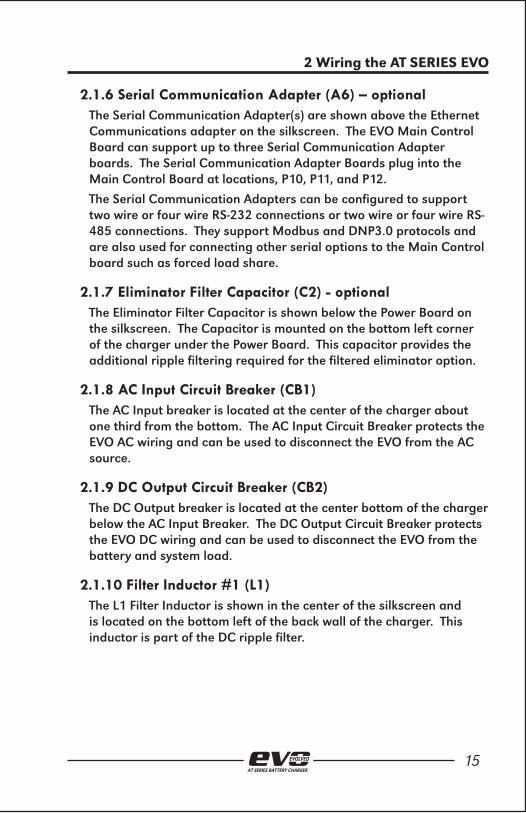
4.2 Standard EVO mode Operation . . . . . . . . . . . . . . . . . . . . . . . 764.2.1 Changing the Display Mode . . . . . . . . . . . . . . . . . . . . . . . . . . . . . .764.2.2 Changing the Charge Mode . . . . . . . . . . . . . . . . . . . . . . . . . . . . . .774.2.3 Changing the Equalize Method . . . . . . . . . . . . . . . . . . . . . . . . . . . .79 4.2.4 Lamp Test . . . . . . . . . . . . . . . . . . . . . . . . . . . . . . . . . . . . . . . . . . .804.2.5 Resetting Latched Relays (legacy method) . . . . . . . . . . . . . . . . . . . .80
4.3 High Voltage Shutdown . . . . . . . . . . . . . . . . . . . . . . . . . . . . . . 814.4 Low Level Detect . . . . . . . . . . . . . . . . . . . . . . . . . . . . . . . . . . . . 824.5 High Level Detect . . . . . . . . . . . . . . . . . . . . . . . . . . . . . . . . . . . 82
5. ADVANCED OPERATION OF THE EVO . . . . . . . . . . . . . . . . . . . . . . . . . . . . . . . 855.1 The EVO Main Menu . . . . . . . . . . . . . . . . . . . . . . . . . . . . . . . . 86
5.1.1 The Basic Settings Icon . . . . . . . . . . . . . . . . . . . . . . . . . . . . . . . . . .875.1.2 The Advanced Settings Icon . . . . . . . . . . . . . . . . . . . . . . . . . . . . . . .875.1.3 The System Settings Icon . . . . . . . . . . . . . . . . . . . . . . . . . . . . . . . . .875.1.4 Save|Reset Configuration Icon . . . . . . . . . . . . . . . . . . . . . . . . . . . .885.1.5 The Relays Icon . . . . . . . . . . . . . . . . . . . . . . . . . . . . . . . . . . . . . . .885.1.6 The Event Logs Icon . . . . . . . . . . . . . . . . . . . . . . . . . . . . . . . . . . . .895.1.7 The System information Icon . . . . . . . . . . . . . . . . . . . . . . . . . . . . . .895.1.8 The Security Icon . . . . . . . . . . . . . . . . . . . . . . . . . . . . . . . . . . . . . .895.1.9 The Communications Icon . . . . . . . . . . . . . . . . . . . . . . . . . . . . . . . .895.1.10 The Common Alarm Icon . . . . . . . . . . . . . . . . . . . . . . . . . . . . . . . .905.1.11 The AUX Inputs Icon . . . . . . . . . . . . . . . . . . . . . . . . . . . . . . . . . . .915.1.12 The Testing Icon . . . . . . . . . . . . . . . . . . . . . . . . . . . . . . . . . . . . . .91

vAT SERIES BATTERY CHARGER
Table of Contents - ATevo
5.2 The EVO Alarm Button . . . . . . . . . . . . . . . . . . . . . . . . . . . . . . . 925.3 The EVO Health Button . . . . . . . . . . . . . . . . . . . . . . . . . . . . . . 925.4 Security and Passwords . . . . . . . . . . . . . . . . . . . . . . . . . . . . . 92
5.4.1 Three (3) Levels of Password Protection . . . . . . . . . . . . . . . . . . . . . .935.4.2 Accessing the Security Features and Password Configuration . . . . . .935.4.3 Setting the EVO Passwords . . . . . . . . . . . . . . . . . . . . . . . . . . . . . . .955.4.4 Setting the Default Access . . . . . . . . . . . . . . . . . . . . . . . . . . . . . . .965.4.5 Logging In to a Password Authorization Level . . . . . . . . . . . . . . . . .975.4.6 Logging Out . . . . . . . . . . . . . . . . . . . . . . . . . . . . . . . . . . . . . . . . .99
5.5 Features Supported By the Optional SD Memory Card . . 1005.5.1 The SD Memory Card . . . . . . . . . . . . . . . . . . . . . . . . . . . . . . . . . .1005.5.2 Storing the Event Log File to the SD Memory Card . . . . . . . . . . . . . 1015.5.3 Storing and Recalling the Configuration Settings to/from the SD Memory Card . . . . . . . . . . . . . . . . . . . . . . . . . . . . . . . . . . . . .1025.5.4 Upgrading the Main Control Board Firmware via the SD Memory Card . . . . . . . . . . . . . . . . . . . . . . . . . . . . . . . . . . . . .105
6. EVO ALARMS & INDICATORS . . . . . . . . . . . . . . . . . . . . . . . . . . . . . . . . . . . . . 1096.1 EVO Legacy Alarms and Indicators . . . . . . . . . . . . . . . . . . . . 110
6.1.1 AC ON Indicator . . . . . . . . . . . . . . . . . . . . . . . . . . . . . . . . . . . . . . 1106.1.2 High DC Voltage Alarm . . . . . . . . . . . . . . . . . . . . . . . . . . . . . . . . 1106.1.3 Low DC Voltage Alarm . . . . . . . . . . . . . . . . . . . . . . . . . . . . . . . . . 1116.1.4 DC Output Failure Alarm . . . . . . . . . . . . . . . . . . . . . . . . . . . . . . . 1116.1.5 AC Input Failure Alarm . . . . . . . . . . . . . . . . . . . . . . . . . . . . . . . . . 1126.1.6 Positive Ground Fault Alarm . . . . . . . . . . . . . . . . . . . . . . . . . . . . . 1126.1.7 Negative Ground Fault Alarm . . . . . . . . . . . . . . . . . . . . . . . . . . . . 113
6.2 EVO Common Alarm Indicator . . . . . . . . . . . . . . . . . . . . . . . . 1136.2.1 Configuring The Common Alarm . . . . . . . . . . . . . . . . . . . . . . . . . . 114
6.3 Active Alarm Bar, Alarm View, and Alarm Log . . . . . . . . . . . 1146.3.1 The Active Alarm Bar . . . . . . . . . . . . . . . . . . . . . . . . . . . . . . . . . . 1146.3.2 The Active Alarm List . . . . . . . . . . . . . . . . . . . . . . . . . . . . . . . . . . 1156.3.3 The Alarm Logs . . . . . . . . . . . . . . . . . . . . . . . . . . . . . . . . . . . . . . 115
6.4 EVO Advanced Alarms . . . . . . . . . . . . . . . . . . . . . . . . . . . . . . . 116 6.4.1 High Voltage Shutdown Alarm . . . . . . . . . . . . . . . . . . . . . . . . . . . 1166.4.2 Low Level Detect Alarm . . . . . . . . . . . . . . . . . . . . . . . . . . . . . . . . 1176.4.3 End of Discharge (EOD) Alarm . . . . . . . . . . . . . . . . . . . . . . . . . . . 1186.4.4 High Ripple Alarm . . . . . . . . . . . . . . . . . . . . . . . . . . . . . . . . . . . . 1186.4.5 Battery Temperature Probe Failure Alarm . . . . . . . . . . . . . . . . . . . 1196.4.6 Rectifier Over Temperature Alarm . . . . . . . . . . . . . . . . . . . . . . . . . 1196.4.7 External Feedback Failure Alarm . . . . . . . . . . . . . . . . . . . . . . . . . . 1196.4.8 Internal Feedback Failure Alarm . . . . . . . . . . . . . . . . . . . . . . . . . .1206.4.9 Open DC Breaker Alarm . . . . . . . . . . . . . . . . . . . . . . . . . . . . . . . .120

viAT SERIES BATTERY CHARGER
Table of Contents - ATevo
6.4.10 Open AC Breaker Alarm (optional) . . . . . . . . . . . . . . . . . . . . . . . . 1216.4.11 DC Power Supply Failure Alarm . . . . . . . . . . . . . . . . . . . . . . . . . . 1216.4.12 SCR Failure Alarm . . . . . . . . . . . . . . . . . . . . . . . . . . . . . . . . . . .122
6.5 Reset Latch Alarm Relays . . . . . . . . . . . . . . . . . . . . . . . . . . . . 1226.6 Open Battery Test . . . . . . . . . . . . . . . . . . . . . . . . . . . . . . . . . . 125
6.6.1 Open Battery Test Settings . . . . . . . . . . . . . . . . . . . . . . . . . . . . . .1256.6.2 Run the Open Battery Test Periodically . . . . . . . . . . . . . . . . . . . . . 1276.6.3 Run the Open Battery Test Manually . . . . . . . . . . . . . . . . . . . . . . .1306.6.4 Resetting the Battery Open Alarm . . . . . . . . . . . . . . . . . . . . . . . . . 131
7. HINDLE HEALTH SYSTEM . . . . . . . . . . . . . . . . . . . . . . . . . . . . . . . . . . . . . . . . . . 1337.1 Hindle Health System - Overview . . . . . . . . . . . . . . . . . . . . . . 1347.2 Hindle Health System Components . . . . . . . . . . . . . . . . . . . . 134
7.2.1 Self-Diagnostics . . . . . . . . . . . . . . . . . . . . . . . . . . . . . . . . . . . . . .1347.2.2 Hindle Health Button . . . . . . . . . . . . . . . . . . . . . . . . . . . . . . . . . .1357.2.3 Hindle Health LED Indicators . . . . . . . . . . . . . . . . . . . . . . . . . . . .135
7.3 Hindle Health System Screens . . . . . . . . . . . . . . . . . . . . . . . . 1367.3.1 Introduction and Warning Screens . . . . . . . . . . . . . . . . . . . . . . . . . 1377.3.2 Choosing What to Test . . . . . . . . . . . . . . . . . . . . . . . . . . . . . . . . . 1377.3.3 The Test Screens . . . . . . . . . . . . . . . . . . . . . . . . . . . . . . . . . . . . . .138
8. EVO EVENT LOGS . . . . . . . . . . . . . . . . . . . . . . . . . . . . . . . . . . . . . . . . . . . . . . . . . 1398.1 EVO Event Logs . . . . . . . . . . . . . . . . . . . . . . . . . . . . . . . . . . . . . 1408.2 View The Event Log . . . . . . . . . . . . . . . . . . . . . . . . . . . . . . . . . 1408.3 View the Hindle Health Log . . . . . . . . . . . . . . . . . . . . . . . . . . 1418.4 Clearing the Event Logs . . . . . . . . . . . . . . . . . . . . . . . . . . . . . . 1438.5 Copy the Event Logs to the SD Memory Card . . . . . . . . . . . . 144
9. EVO BATTERY TEMPERATURE COMPENSATION . . . . . . . . . . . . . . . . . . . .1479.1 EVO Battery Temperature Compensation . . . . . . . . . . . . . . . 1489.2 Installing the TEMPCO Option . . . . . . . . . . . . . . . . . . . . . . . . 148
9.2.1 Configuring the TEMPCO Option . . . . . . . . . . . . . . . . . . . . . . . . . . 1519.3 Using the TEMPCO Option . . . . . . . . . . . . . . . . . . . . . . . . . . . 152
9.3.1 Home Screen with TEMPCO Option . . . . . . . . . . . . . . . . . . . . . . . .1539.4 Temperature Compensation Curves . . . . . . . . . . . . . . . . . . . 154
10. REMOTE SENSE . . . . . . . . . . . . . . . . . . . . . . . . . . . . . . . . . . . . . . . . . . . . . . . . . 15510.1 EVO Remote Voltage Sense . . . . . . . . . . . . . . . . . . . . . . . . . . 15610.2 Remote Sense Connection . . . . . . . . . . . . . . . . . . . . . . . . . . 15610.3 Procedure for Wiring Remote Sense . . . . . . . . . . . . . . . . . . 157

viiAT SERIES BATTERY CHARGER
Table of Contents - ATevo
10.4 Confi guring the Remote Sense Jumpers . . . . . . . . . . . . . . . 15910.4.1 Locating Remote Sense Configuration Jumpers . . . . . . . . . . . . . .15910.4.2 Enable Remote Sense . . . . . . . . . . . . . . . . . . . . . . . . . . . . . . . .159 10.4.3 Enable Local Sense . . . . . . . . . . . . . . . . . . . . . . . . . . . . . . . . .160
10.5 Disabling the Remote Sense . . . . . . . . . . . . . . . . . . . . . . . . . 160
11. AUXILIARY INPUTS/OUTPUTS . . . . . . . . . . . . . . . . . . . . . . . . . . . . . . . . . . . .16111.1 EVO Auxiliary Relay Board Types . . . . . . . . . . . . . . . . . . . . . 162
11.1.1 Relays . . . . . . . . . . . . . . . . . . . . . . . . . . . . . . . . . . . . . . . . . . . .16311.1.2 Binary Inputs . . . . . . . . . . . . . . . . . . . . . . . . . . . . . . . . . . . . . . .16311.1.3 Analog Inputs . . . . . . . . . . . . . . . . . . . . . . . . . . . . . . . . . . . . . . .163
11.2 Connections to the Auxiliary I/O Board . . . . . . . . . . . . . . . 16511.2.1 System Connections . . . . . . . . . . . . . . . . . . . . . . . . . . . . . . . . . .16511.2.2 Wiring the Relays Connections . . . . . . . . . . . . . . . . . . . . . . . . . .16511.2.3 Wiring the Binary Input Connections . . . . . . . . . . . . . . . . . . . . . .16611.2.4 Wiring the Analog Input Connections . . . . . . . . . . . . . . . . . . . . .168
11.3 Hardware Confi guration . . . . . . . . . . . . . . . . . . . . . . . . . . . 16911.3.1 Auxiliary I/O Board Address . . . . . . . . . . . . . . . . . . . . . . . . . . . .16911.3.2 Binary Input Voltage Configuration . . . . . . . . . . . . . . . . . . . . . . .170
11.4 Software Confi guration . . . . . . . . . . . . . . . . . . . . . . . . . . . . . 17011.4.1 Auxiliary I/O Board Relay Alarm Configuration . . . . . . . . . . . . . . . 17111.4.2 Auxiliary I/O Board Relay Latch Configuration . . . . . . . . . . . . . . .17311.4.3 Auxiliary I/O Board Relay Time Delay Configuration . . . . . . . . . . . 176
11.5 Software Confi guration for Auxiliary I/O Board Binary Inputs . . . . . . . . . . . . . . . . . . . . . . . . . . . . . . . . . . . . . . 178
11.5.1 Binary Input Name Assignment . . . . . . . . . . . . . . . . . . . . . . . . . .17811.5.2 Binary Active State Assignment . . . . . . . . . . . . . . . . . . . . . . . . . . 18111.5.3 Binary Input Alarm Enable . . . . . . . . . . . . . . . . . . . . . . . . . . . . .18311.5.4 Binary Input Action Assignment . . . . . . . . . . . . . . . . . . . . . . . . . .18611.5.5 Factory Default Binary Input Configuration . . . . . . . . . . . . . . . . .188
11.6 Software Confi guration for Auxiliary I/O Board Analog Inputs . . . . . . . . . . . . . . . . . . . . . . . . . . . . . . . . . . . . . 189
11.6.1 Analog Input Name Assignment . . . . . . . . . . . . . . . . . . . . . . . . .18911.6.2 Analog Input Primary Unit Assignment . . . . . . . . . . . . . . . . . . . .19211.6.3 Analog Input Scaling Assignment . . . . . . . . . . . . . . . . . . . . . . . .19411.6.4 Analog Input Alarm and Trigger Assignment . . . . . . . . . . . . . . . .19811.6.5 Analog Input Alarm Threshold Assignment . . . . . . . . . . . . . . . . .20111.6.6 Analog Input Action Assignment . . . . . . . . . . . . . . . . . . . . . . . . .20411.6.7 Factory Default Analog Input Configuration . . . . . . . . . . . . . . . . .207
12. DRAWINGS & APPENDICIES. . . . . . . . . . . . . . . . . . . . . . . . . . . . . . . . . . . . .209


1. RECEIVING & UNPACKING THE
EVO
AT SERIES BATTERY CHARGER

2AT SERIES BATTERY CHARGER
1 Receiving & Mounting the AT SERIES EVO
1.1 Storing the EVOIf you store the EVO for more than a few days before installation, you should store it in its original shipping container, and in a temperature controlled, dry climate. Ambient temperatures of 0 to 122 °F / -18 to 50°C are acceptable. Storage should not exceed two (2) years due to the limited shelf life of the DC fi lter capacitors when they are not in service.
1.2 Reporting Shipping DamageUpon delivery of the EVO (or related products) if you discover any damage or shortage, make notation on all copies of delivering carrier’s delivery receipt before signing and notify the delivery person of your fi ndings. If loss or damage is discovered after delivery, notify delivering carrier immediately and request an inspection. The manufacturer does not assume any liability for damage during transportation or handling. Should the products require an inspection by (or return to) the manufacturer, please contact your sales representative for further instructions. Any returned material must be properly packed in compliance with shipping regulations. It is preferable to use the original shipping materials if possible. Mark the outside of the shipping container with the Return Material Authorization (RMA) number issued by the manufacturer.
1.3 Unpacking and Inspecting the EVOCarefully remove all shipping materials from the EVO. Remove the EVO from the shipping pallet for inspection. Save all shipping materials until you are sure that there is no shipping damage. Once the EVO is unpacked, inspect the unit for possible shipping damage, using the checklist below. If shipping damage has occurred, refer to Section 1.2 for proper reporting.
1.3.1 Inspection Checklist □ Enclosure exterior and interior are not marred or dented.
□ There is no visible damage to exterior or interior components.
□ All internal components are secure.
□ Printed circuit boards are fi rmly seated on their standoffs.
□ All hardware is tight.

3AT SERIES BATTERY CHARGER
1 Receiving & Mounting the AT SERIES EVO
□ All wire terminations are secure.
□ The User’s Manual is included.
□ You received all items on the packing list.
1.4 Moving the EVOOnce you have established that the EVO is undamaged, identify the weight of your unit. Refer to the table below.
1.4.1 EVO Weight Table
OutputVoltage
AMPERE RATING6ADC 12ADC 16ADC 20ADC 25ADC
24 VDCTBD TBD TBD 101 lbs 101 lbsTBD TBD TBD 46 kg 46 kg
48VDC83 lbs 96 lbs 112 lbs 108 lbs 108 lbs38 kg 44 kg 51 kg 48 kg 48 kg
130VDC97 lbs 125 lbs 125 lbs 193 lbs 193 lbs44 kg 57 kg 57 kg 88 kg 88 kg
260VDCTBD 193 lbs N/A N/A N/ATBD 88 kg N/A N/A N/A
The EVO enclosure does not feature top lifting eyes for moving. Move the EVO with a forklift whenever possible, using the supplied shipping pallet. Lift the EVO into a wall-mount or rack-mount installation, using a heavy-duty sling or a scissor lift.
1.5 Mounting the EVOThe EVO must be installed in manner that allows easy access to the front AC (CB1) and DC (CB2) circuit breakers. Choose a mounting method for the EVO enclosure from the following choices.
1.5.1 Wall-Mounting the EVOWall-mounting is the standard means of installing the EVO. When wall-mounting the EVO, consider the following:
1. Refer to the enclosure outline drawing at the back of this

4AT SERIES BATTERY CHARGER
1 Receiving & Mounting the AT SERIES EVO
manual.
2. The wall must be strong enough to properly support the weight of the EVO, plus a safety factor. See the Weight Table featured in Section 1.4.1 The weight of your EVO may be different, depending on the features, options, and accessories ordered with the unit.
3. Be conscious of planned AC input and DC output wiring to the EVO, selecting conduit entrances carefully. Use of the pre-fab knockouts on the sides or bottom of the enclosure will allow removal of the cabinet shroud (and internal access for servicing) without removal of the unit from the wall.
4. The location:
» Should be free of drips and splatter. If falling particles and liquids are a problem, install a NEMA-2 type drip shield accessory.
» Should be between 0 and 122 °F / -18 and 50 °C, with relative humidity between 0% and 95% non-condensing.
» Must be free of fl ammable or explosive materials.
5. Maintain at least 6in / 152mm of free air on all vented surfaces for cooling.
6. Allow at least 36in / 914mm front clearance for access to the EVO for operation and maintenance.
PROCEDUREInstall four (4) 0.25in / 6.4mm anchor bolts (not supplied) rated to support the weight of the EVO, plus a safety factor of at least two (2) times, into the wall. Place the EVO onto the anchor bolts, add appropriate mounting hardware, and tighten securely. Refer to the following graphics for EVO wall-mounting pattern and specifi cation.

5AT SERIES BATTERY CHARGER
1 Receiving & Mounting the AT SERIES EVO

6AT SERIES BATTERY CHARGER
1 Receiving & Mounting the AT SERIES EVO
1.5.2 Floor-Mounting the EVOTo install the EVO onto a horizontal surface, the standard enclosure does not need to be modifi ed, but a special fl oor mounting accessory EI0192-00 is required. The kit includes a set of mounting brackets that elevate the top of the EVO approximately 47in /1194mm above fl oor level, with provisions for fl oor anchoring. The kit also includes appropriate hardware and installation instructions for the fl oor-mounting procedure.
When fl oor-mounting the EVO, consider the following:
1. Locate anchor bolt holes at least 4.25in /108mm from any wall, to allow clearance behind the mounting brackets.
2. Be conscious of planned AC input and DC output wiring to the EVO, selecting conduit entrances carefully. Use of the pre-fab knockouts on the sides or bottom of the enclosure will allow removal of the cabinet shroud (and internal access for servicing) without removal of the unit from the fl oor stand.
3. The location:
» Should be free of drips and splatter. If falling particles and liquids are a problem, install a NEMA-2 type drip shield accessory.
» Should be between 0 and 122 °F / -18 and 50 °C, with relative humidity between 0% and 95% non-condensing.
» Must be free of fl ammable or explosive materials.
4. Maintain at least 6in /152mm of free air on all vented surfaces for cooling.
5. Allow 36in /914mm front clearance for operation and maintenance.
PROCEDUREInstall four (4) 0.25in / 6.4mm anchor bolts (not supplied) rated to support the unit weight plus a safety factor of at least two (2) times, into the fl oor.
Assemble the fl oor-mounting accessory to the anchor bolts as shown. Place the EVO onto the vertical posts, add appropriate mounting hardware, and tighten.
Refer to the following graphics for fl oor mounting patterns and enclosure footprints.

7AT SERIES BATTERY CHARGER
1 Receiving & Mounting the AT SERIES EVO
1.5.3. Rack-Mounting the EVOThe EVO can be installed into most 23in/584mm and 24in/610mm relay racks with standard EIA hole spacing. The EVO enclosure does not need to be modifi ed for rack mounting, but a special kit is required.
The kit includes two (2) mounting brackets, appropriate hardware, and Installation Instructions for the rack-mounting procedure.

8AT SERIES BATTERY CHARGER
1 Receiving & Mounting the AT SERIES EVO
When rack-mounting the EVO, consider the following:
1. The rack must be strong enough to properly support the weight of the EVO. See the Weight Table located in Section 1.4.1
2. Be conscious of planned AC input and DC output wiring to the EVO, selecting conduit entrances carefully. Note the standard pre-fab conduit knockouts located on the sides, top, and bottom of the enclosures. Ensure that planned conduit is accessible after the EVO is rack-mounted.
3. The location:
» Should be free of drips and splatter. If falling particles and liquids are a problem, install a NEMA-2 type drip shield accessory.
» Should be between 0 and 122 °F / -18 and 50 °C, with relative humidity between 0% and 95% non-condensing.
» Must be free of fl ammable or explosive materials.
4. Maintain at least 6in /152mm of free air on all vented surfaces for cooling.
5. Allow at least 36in /914mm front clearance for access to the EVO for operation and maintenance.
PROCEDURETo rack mount the EVO, fi rst install the mounting brackets into the rack using proper hardware (not supplied). Second, mount the EVO onto the installed brackets, using the supplied kit hardware. Provide at least 6in /152mm of free air above and below the EVO for cooling. Refer to the following graphics for the rack-mounting confi gurations.

9AT SERIES BATTERY CHARGER
1 Receiving & Mounting the AT SERIES EVO


2. WIRING THE EVO
AT SERIES BATTERY CHARGER

12AT SERIES BATTERY CHARGER
2 Wiring the AT SERIES EVO
2.1 Mechanical Diagram and Component LocationThe EVO has the following mechanical layout and wiring diagram screen printed on the patented protective PlexiGlas shield internal to the charger.
The EVO is composed of the following basic components and subsections
• A1 – Main Control Board
• A2 – Power Board
• A3 – Capacitor Board
• A4 – Auxiliary I/O Board - optional
• A5 – Ethernet Communications Adapter - optional
• A6 – Serial Communications Adapter(s) – optional
• A7 – AC MOV Board
• C2 – Eliminator Filter Capacitor – optional
• CB1 – AC Input Circuit Breaker
• CB2 – DC Output Circuit Breaker
• L1 – Filter Inductor #1
• L2 – Filter Inductor #2
• T1 – Main Transformer

13AT SERIES BATTERY CHARGER
2 Wiring the AT SERIES EVO
PORT
1
PORT
2
PORT
3
ETHE
RNET
A7 M
OV B
OARD
P10
P11
P12
P13
PUSH
TO
RESE
TSW
13
MAIN
CON
TROL
CAR
D VI
EWED
FRO
M BA
CK O
F DO
OR
PUSH
CAR
D IN
TO E
JECT
RE-F
LASH
ENAB
LEJP
4
SD M
EMOR
YCA
RD
NORM
PRGM
HIGH
LEV
ELDE
TECT
SHU
TDOW
NJ1
P2
P1
CNC
NO1
23
TB6
COMM
ONAL
ARM
ENDI
S
A1
Mai
n C
ontr
ol C
ard
EN50
31-X
X
RIBBON CABLE TOA2 POWER BOARD
POS
NEG
DANG
ERHI
GH V
OLTA
GE
A
3 C
ap
B
oard
EN50
38-X
X
TB1
TB3
TB4
TB2
A4 A
ux R
elay
Boar
d
NC NO COM NC NO COM NC NO COM NC NO COM NC NO COM NC NO COM
RELAY1 RELAY2 RELAY3 RELAY4 RELAY5 RELAY6
AN 2AN 1
AN 3AN 4COM
B4 (+)B4 (-)
B3 (+)B3 (-)
B2 (+)B2 (-)
B1 (+)B1 (-)
S1
P1
EN50
40-X
X
P1
J1
A5 E
ther
net
Adap
ter
EN50
35-X
X
RXD/
RA (-
)TX
D/TA
(-)
CTS/
RB (+
)RT
S/TB
(+)
GND
SHIE
LD
P1
RXD/
RA (-
)TX
D/TA
(-)
CTS/
RB (+
)RT
S/TB
(+)
GND
SHIE
LD
P1
RXD/
RA (-
)TX
D/TA
(-)
CTS/
RB (+
)RT
S/TB
(+)
GND
SHIE
LD
P1
A6 S
erial
Ada
pter
A6 S
erial
Ada
pter
A6 S
erial
Ada
pter
EN50
34-X
X
EN50
34-X
X
EN50
34-X
XJ1
05
TP4 O
utput
(+)
TP3 O
utput
(-)TP
1 (-)
TP2 (
+)
JP10
1
P1
A8 D
C PO
WER
S
UPPL
Y
J102
EN50
42-X
XJ1
01
J104
TBS1
TBS2
JP103 LOCAL
REMOTE SENSE
JP104
POS
1
REMOTE SENSETB1
BATT TEMPTB8
NEG
3
SIG
1GN
D 2
GROUND DETECT
DISABLEDJP102
ENABLED
AC MOVEARTH
CB1COMM
CB2
C2 (+)
C2 (-)
X4 X1
L2-1
L1-2
L1-1 Y2
CB2
NEG
CB2
PO
S
L2-2Y1
A2
Pow
er B
oard
DA
NG
ERH
IGH
VO
LTA
GE
EN50
37-X
X
RIBBON CABLE TOA1 MAIN CONTROL
L1 Inductor
T1 Transformer
L2 In
duct
or
TP4
OU
TPU
TPO
S
TP3
OU
TPU
T
GR
OU
ND
C2
Cap
acito
r
EN50
39-X
X
CB2
AUX
CON
TACT
S
CB2
CB1
H1 H
3 H2
H5
H4 H
2
IA50
14-0
0 SH
EET
1 OF
3
H1 H
3 H2
H5
H4 H
2H1
H3
H2 H
5 H4
H2
H1H3
H2H5
H4H2
AC IN
PUT
VOLT
AGE
SELE
CTIO
N(O
PTIO
N NO
T AVA
ILABL
E ON
SIN
GLE
INPU
T UN
ITS)
USE
BOTH
JUMP
ERS
WHE
N MA
KING
SEL
ECTI
ONS
USE
COPP
ER C
ONDU
CTOR
ONL
YST
RIP
WIR
E IN
SULA
TION
1/2 I
N.TO
RQUE
SCR
EWS
TO 31
Lb-In
.
120 V
OLTS
INPU
T20
8 VOL
TS IN
PUT
240 V
OLTS
INPU
T
AC
IN
PU
T
DC
OU
TP
UT
L1 /
Lin
e
L2 /
Neu
tral
Neg
ativ
e
Posi
tive
ATev
o Se
ries
Com
pone
nt L
ayou
t

14AT SERIES BATTERY CHARGER
2 Wiring the AT SERIES EVO
2.1.1 Main Control Board (A1)The Main Control Board shown on the top right of the silkscreen is mounted on the EVO door. The Main Control Board contains the display, buttons, alarm indicators, and is responsible for charger controls.
2.1.2 Power Board (A2)The Power Board shown on the bottom left of the silkscreen is mounted on the heat sink along the left side of the charger. The Power Board contains the rectifi er and most power electronics connections as well as terminal blocks for the remote sense and battery temperature compensation options.
2.1.3 Capacitor Board (A3)The Capacitor Board is shown near the top left of the silkscreen. The Capacitor Board is bolted to the top of the Power Board. The capacitors create the fi lter for standard fi ltered EVO.
2.1.4 Auxiliary I/O Board (A4) - optionalThe Auxiliary I/O Board is shown at the top left of the silkscreen and is bolted to the heat sink along the left side of the EVO above the Power Board. The Auxiliary I/O Board plugs directly into the Power Board.
The Auxiliary I/O Board has six relays, four binary inputs, and four analog inputs. The relays can be confi gured to indicate the status of six different alarms or status points. The independently isolated binary inputs can be confi gured to report the ON/OFF status of four controls. The analog inputs include input scaling and can report the status of four analog controls referenced to the DC bus.
2.1.5 Ethernet Communications Adapter (A5) – optionalThe Ethernet Communications Adapter is shown directly to the bottom left of the Main Control Board. The Ethernet Adapter Board plugs into the Main Control Board at location P13. This option will support 10/100 copper Ethernet connections and Modbus and DNP3.0 protocols.
15AT SERIES BATTERY CHARGER
2 Wiring the AT SERIES EVO
2.1.6 Serial Communication Adapter (A6) – optionalThe Serial Communication Adapter(s) are shown above the Ethernet Communications adapter on the silkscreen. The EVO Main Control Board can support up to three Serial Communication Adapter boards. The Serial Communication Adapter Boards plug into the Main Control Board at locations, P10, P11, and P12.
The Serial Communication Adapters can be confi gured to support two wire or four wire RS-232 connections or two wire or four wire RS-485 connections. They support Modbus and DNP3.0 protocols and are also used for connecting other serial options to the Main Control board such as forced load share.
2.1.7 Eliminator Filter Capacitor (C2) - optionalThe Eliminator Filter Capacitor is shown below the Power Board on the silkscreen. The Capacitor is mounted on the bottom left corner of the charger under the Power Board. This capacitor provides the additional ripple fi ltering required for the fi ltered eliminator option.
2.1.8 AC Input Circuit Breaker (CB1)The AC Input breaker is located at the center of the charger about one third from the bottom. The AC Input Circuit Breaker protects the EVO AC wiring and can be used to disconnect the EVO from the AC source.
2.1.9 DC Output Circuit Breaker (CB2)The DC Output breaker is located at the center bottom of the charger below the AC Input Breaker. The DC Output Circuit Breaker protects the EVO DC wiring and can be used to disconnect the EVO from the battery and system load.
2.1.10 Filter Inductor #1 (L1)The L1 Filter Inductor is shown in the center of the silkscreen and is located on the bottom left of the back wall of the charger. This inductor is part of the DC ripple fi lter.

16AT SERIES BATTERY CHARGER
2 Wiring the AT SERIES EVO
2.1.11 Filter Inductor #2 (L2)The L2 Filter Inductor is shown in the center bottom of the silkscreen and is located on the bottom back wall of the charger directly to the right of the L1 Filter Inductor. This inductor is part of the ripple fi lter.
2.1.12 Main Transformer (T1)The Main Transformer is shown near the center on the silkscreen and is located on the back wall of the charger above the Filter Inductors. The Main Transformer provides isolation and converts the AC input voltage to the appropriate level prior to rectifi cation.
A multi-tap input option is available. EVO chargers with the multi-tap option will have a terminal block for tap selection above the AC Input Breaker. The jumper positions are shown on the silk screen to the direct right of the Main Transformer.
2.1.13 AC MOV Board (A7)The AC MOV Board shown to the left of the AC breaker on the silkscreen is mounted to the top left side of the breaker bracket. This board contains the AC input surge suppression and fi ltering. It is located for easy access, examination, and replacement in case an input transient event should occur.
2.2 Removing the Protective Safety ShieldIn order to prevent injuries, the EVO safety shield must always be installed when the charger is in operation and/or energized.
A standard fl at blade screwdriver is required to remove the safety shield.
• Open the EVO front door to access the safety shield.
• Locate the two screws that attach the safety shield to the EVO charger.
» One is located above the AC Input Breaker, the other is located below the DC Output Breaker
• Remove the two screws.
• Grab the safety shield on both the left and right sides and gently lift the safety shield up and off of the AC Input and DC Output Breakers.
• Reverse this procedure for reinstalling the safety shield.

17AT SERIES BATTERY CHARGER
2 Wiring the AT SERIES EVO
2.3 EVO with Selectable Input Voltage (optional)EVO may be equipped with a Multi-Tap AC input voltage option. There are two Multi-Tap input voltage options that allow the charger to be fi eld confi gured. The fi rst option supports input voltages of 120 VAC, 208 VAC, or 240 VAC, the second option supports input voltages of 120 VAC, 220 VAC, or 240 VAC.
2.3.1 Determine if the Multi-Tap Option is PresentCheck the EVO nameplate. If the AC Input Voltage is listed as 120/208/240 or 120/220/240 VAC the EVO is equipped with the Multi-Tap option. If the nameplate is not visible:
• Open the EVO front door.
• Look for a gray terminal block directly above the AC Input breaker (behind the safety shield).
» Reference the Input Voltage Selection silk screened on the center right of the safety shield.
» If this terminal block is present, the EVO is equipped with the Multi-Tap AC Input Voltage option.
2.3.2 Verify the Multi-Tap AC Input Voltage SettingBefore you connect AC power to the EVO, inspect the present AC Input Voltage setting and confi rm the correct jumper positions for the desired AC Input supply voltage. The Multi-Tap AC Input Voltage setting can be verifi ed without removing the safety shield.
• Open the EVO front door and locate the Multi-Tap terminal block above the AC Input Breaker.
• Observe the relative locations of the RED jumpers in the Multi-Tap terminal block.
• Refer to the adjacent diagram to confi rm the present AC Input Voltage Setting is correct.

18AT SERIES BATTERY CHARGER
2 Wiring the AT SERIES EVO
2.3.3 Modify the Multi-Tap AC Input Voltage SettingBefore changing the voltage selection jumper, shut down the EVO and lock out AC and DC power supplies. Merely turning off (opening) the EVO’s internal circuit breakers does not eliminate live voltages inside the enclosure.
A standard fl at blade screwdriver will be required to change the voltage selection jumper.
• Remove the EVO safety shield (see Section 2.2).
• Locate the Multi-Tap terminal block.
• Determine the correct location of the RED jumpers for the desired AC Input Voltage.
» Reference Section 2.3.2 for jumper settings.
• Move any jumpers that are not in the required positions.
» Use fl at blade screwdriver to carefully pry out jumpers in wrong locations.
» Re-install jumpers in correct locations for desired AC Input Voltage.
• Re-check the jumper locations and confi rm the jumpers are properly seated.
2.4 Making the AC Input ConnectionsThe EVO is a commercial product, and not intended for use at any time in a residential environment or to be powered by low-voltage public mains.
It is the responsibility of the installer of the EVO to provide suitable AC supply wiring. Wiring must be approved for use in the country in which the EVO is installed. When selecting wire sizes, consult the data nameplate decal affi xed to the EVO for voltage and current requirements.
Follow these steps to supply proper AC power to the EVO:
1. Confi rm that the EVO nameplate voltage rating is correct for your AC input supply voltage. If the EVO has the Multi-Tap AC Input Voltage option, make sure the AC Input Voltage setting matches the AC input supply voltage (refer to Section 2.3.2).

19AT SERIES BATTERY CHARGER
2 Wiring the AT SERIES EVO
2. Use a branch circuit breaker or fused disconnect switch upstream from the EVO. This device should have lockout capabilities so that the AC input supply to the EVO can be de-energized for unit maintenance. A time delay circuit breaker or slow-blow fuse is recommended.
3. Size the branch circuit breaker or fused disconnect switch for the maximum AC input current of the EVO. This rating is listed on the EVO data nameplate.
4. Size AC input wiring per the National Electric Code (NEC), Canadian Electrical Code, and local codes for the trip rating of the branch circuit breaker or fused disconnect switch.
5. Do not run external AC input power wiring through the same conduit as external DC wiring.
6. All site requirements of your facility take precedence over these instructions.
NOTES Conduit must be properly grounded, and in compliance with
the national wiring rules of the country where installed.

20AT SERIES BATTERY CHARGER
2 Wiring the AT SERIES EVO
Use copper or aluminum conductors only.
On 120 VAC input, connect the neutral leg to the terminal L2.
PROCEDURE1. Remove the safety shield (see Section 2.2).
2. Run the AC input supply wiring into the EVO, ending at the AC Input Breaker (CB1) and the Ground stud.
3. Connect the wires to the appropriate locations on the AC Input Breaker (CB1) and the system ground stud as indicated on the drawing.
4. Using a fl at-blade screwdriver, securely tighten the compression screws on CB1.
5. Securely tighten the ground wire on the system ground stud.
6. Check all connections and reinstall the safety shield.
2.5 Making the DC Output ConnectionsIt is the responsibility of the installer of the EVO to provide suitable DC output, battery, and DC load wiring.
Follow these steps to connect the battery to the EVO:
1. Size the DC wiring to minimize voltage drop. The acceptable wire size depends on your installation. As a guideline, the voltage drop should not exceed 1% of nominal output voltage at full current. Refer to the following table to determine the voltage drops for various wire sizes, currents and distances.

21AT SERIES BATTERY CHARGER
2 Wiring the AT SERIES EVO
WIRE SIZING CHARTVOLTAGE DROP PER 100ft / 30.5m OF WIRE
(for copper at 68 °F / 20 °C)WIRE SIZE
(AWG)
DC CURRENT (Amperes)
6 12 16 20 25
#16 2.5V 5.0V 6.7V 8.2V 10.5V#14 1.6V 3.2V 4.2V 5.3V 6.6V#12 1.0V 2.0V 2.6V 3.3V 4.2V#10 0.63V 1.3V 1.7V 2.1V 2.6V#8 0.40V 0.80V 1.1V 1.3V 1.7V#6 0.25V 0.50V 0.66V 0.83V 1.1V#4 0.16V 0.32V 0.42V 0.52V 0.65V
EXAMPLE: 100ft / 30.5m of #8 AWG wire at 16A has a 1.1V drop.
2. The EVO is factory wired to regulate output voltage at the output terminals. If the total voltage drop is greater than 1% (e.g., 1.3V for a 130 VDC system), remote sense wiring is recommended, see Section 10.0.
3. Do not run external AC and DC power wiring, feeding the EVO, through the same conduit.
4. All specifi c requirements of your facility take precedence over these instructions.

22AT SERIES BATTERY CHARGER
2 Wiring the AT SERIES EVO
PROCEDURE1. Use a DC disconnect switch or circuit breaker between the EVO
and DC bus. This device should have lockout capability to allow the EVO to be disconnected from the DC bus for maintenance.
2. Remove the safety shield (see Section 2.2).
3. Run the DC wiring to the DC Output Breaker (CB2).
4. Connect the wires to the appropriate locations on the DC Output Breaker (CB2) as indicated on the drawing above.
5. Using a fl at-blade screwdriver, securely tighten the compression screws on the DC Output Breaker (CB2).
6. Reinstall the safety shield after you have made and checked all connections.

23AT SERIES BATTERY CHARGER
2 Wiring the AT SERIES EVO
2.6 EVO Remote Voltage SenseYou can wire the EVO to regulate the output voltage at the battery terminals instead of at the charger output terminals (CB2). See Section 10.0 for information and wiring instructions on the EVO Remote Voltage Sense feature.
2.7 Wiring the EVO Common AlarmThe EVO Main Control Board (A1) is equipped with a “common” Summary Alarm relay. This relay contact transfers when any one or more of the standard EVO alarm(s) become active. One form -C alarm contact is provided and is accessible via terminal block (TB6) on the Main Control Board (refer to fi gure below).

24AT SERIES BATTERY CHARGER
2 Wiring the AT SERIES EVO
PROCEDURE1. Allow 30in / 762mm of wire inside the enclosure. Excess
should be trimmed.
2. Route annunciator wires to the EVO front panel door by following the existing harness past the door hinge. Use two (2) wire ties and allow a 4-6in / 102-153mm loop for the hinge.
3. Trim wires to the proper length for connecting to TB6. Strip 0.25in / 6.4mm of insulation from the wires.
4. Make the connections at TB6, and securely tighten compression screws.
NOTES1. Alarm contacts are rated at 0.5A / 125 VAC or VDC.
2. Summary Alarm relay terminal block (TB6) is compression type, accepting wire sizes #22-14 AWG.
3. Terminals are labeled in non-alarm condition.
4. If user alarm contacts (TB6) are to drive inductive DC loads (e.g. a larger DC relay) an external protective diode must be installed at the DC relay to avoid equipment damage. See Application Note JD5011-00.
2.8 Wiring the Relays on Auxiliary I/O BoardThe optional Auxiliary Alarm I/O Board (A4) when provided is mounted to the heat sink above the Power Board along the left side of the charger. See Section 11 for more information and wiring instructions for the Auxiliary I/O Board.
2.9 Wiring the Temperature Compensation ProbeThe battery temperature compensation (or TEMPCO) probe contains a temperature dependent resistor in an epoxy module that you install on your battery. See Section 9.0 for more information and wiring instructions for the TEMPCO Board Probe
.

25AT SERIES BATTERY CHARGER
2 Wiring the AT SERIES EVO
2.10 Wiring the Serial Communication AdaptersThe EVO will support up to three optional Serial Communication Adapter Boards. The Serial Communication Adapter Board(s) mount to the EVO door and plug directly into the Main Control Board via connection points P10, P11, and P12. See the supplementary EVO Communications Manual for more information and wiring instructions for the Serial Adapter Boards.
2.11 Wiring the Ethernet Adapter BoardThe EVO will support an optional Ethernet Adapter Board. The Ethernet Adapter Board mounts to the EVO door and plugs directly into the Main Control Board via connection point P13. See the supplementary EVO Communications Manual for more information and wiring instructions for the Ethernet Adapter Boards.

3. EVO STARTUP & CONFIGURATION
AT SERIES BATTERY CHARGER

27AT SERIES BATTERY CHARGER
3 AT SERIES EVO Startup & Confi guration
3.1 Front Panel Controls and IndicatorsThe EVO front panel controls and indicators are organized into 5 major groups or Sections.
MODES & METHODS
MAINDISPLAY
NAVIGATION& CONTROLS
HINDLEHEALTH
ALARM SECTION
AC INPUT &DC OUTPUT BREAKERS

28AT SERIES BATTERY CHARGER
3 AT SERIES EVO Startup & Confi guration
3.1.1 Main EVO DisplayThe EVO main Liquid Crystal Display (LCD) is back-lit and shows all charger status and confi guration information.
3.1.2 Navigation and Control Button GroupThis group of buttons (MENU, ESC, EDIT/ENTER, LEFT, RIGHT, UP and DOWN) is used to navigate through the screens and menus of the EVO.
3.1.3 Operation Modes and Methods Button GroupThis group of buttons (DISPLAY MODE, CHARGE MODE, and EQUALIZE METHOD) is used to select the EVO mode of operation.
3.1.4 Alarm SectionThe alarm section consists of the discrete alarm indication LEDs, the AC ON indicator (LED), and the ALARM button. The discrete alarm indicators will light when the associated alarm is active. The AC ON indicator is lit when AC power is detected by the EVO control board. The ALARM button is used to enter the ALARM screens which display all alarm status.
3.1.5 Hindle Health System (HHS) Section The Hindle Health System section consists of the HEALTH BUTTON (HH) and the RED and GREEN health indication LEDs at the bottom of the panel.
3.1.6 AC Input and DC Output BreakersThe AC Input Breaker is located directly below the front control panel. When open, the AC Input Breaker disconnects all internal EVO connections from the AC source except for the breaker terminal where the AC input feed is connected.
The DC Output breaker is located directly below the AC Input Breaker. When opened, the DC breaker disconnects the EVO output from the DC bus.
NOTE: There still may be live DC connected to some of the EVO internal boards (this will include areas such any relays wetted by the battery voltage)

29AT SERIES BATTERY CHARGER
3 AT SERIES EVO Startup & Confi guration
3.2 Starting the EVO
3.2.1 Understanding the Startup SequenceThe EVO is confi gured at the factory to work with most common batteries and loads without further adjustment. When you start the EVO for the fi rst time, the charger will utilize these factory default settings (fl oat voltage, equalize voltage, etc). You can change these settings after you start the EVO. The FACTORY SETTINGS are listed in the following tables. The EVO startup routine takes about 15 seconds. The control circuitry will “soft start” the EVO, such that the DC output voltage and current increase gradually to the rated value.

30AT SERIES BATTERY CHARGER
3 AT SERIES EVO Startup & Confi guration
24 V
olt C
harg
er S
et P
oint
s &
Def
ault
s24
Vol
t Cha
rger
Set
Poi
nts
& D
efau
lts
Para
met
erLo
w R
ange
Set
Poi
ntHi
gh R
ange
Set
Poi
ntNo
min
al (D
efau
lt)
Unit
s
Floa
t Vol
tage
22.0
29.5
26.0
volts
Equa
lize
Volta
ge23
.432
.028
.0vo
ltsC
urre
nt L
imit
(50%
ratin
g)(1
10%
ratin
g)(1
10%
ratin
g)am
pere
sEq
ualiz
e Tim
e0.
199
.024
.0ho
urs
High
VDC
Ala
rm24
.038
.028
.8vo
ltsLo
w V
DC A
larm
14.0
25.0
24.0
volts
HVDC
Shu
tdow
n24
.038
.028
.8vo
ltsHi
gh L
evel
Det
ect
24.0
38.0
28.8
volts
Low
Lev
el D
etec
t15
.024
.021
.0vo
ltsEn
d of
Disc
harg
e15
.024
.021
.0vo
ltsRi
pple
Ala
rm20
250
20m
illi-v
olts
Gro
und
Faul
t (+)
1040
15Ki
lo-o
hms
Gro
und
Faul
t (-)
1040
15Ki
lo-o
hms

31AT SERIES BATTERY CHARGER
3 AT SERIES EVO Startup & Confi guration
48 V
olt C
harg
er S
et P
oint
s &
Def
ault
s48
Vol
t Cha
rger
Set
Poi
nts
& D
efau
lts
Para
met
erLo
w R
ange
Set
Poi
ntHi
gh R
ange
Set
Poi
ntNo
min
al (D
efau
lt)
Unit
s
Floa
t Vol
tage
44.0
58.0
52.0
volts
Equa
lize
Volta
ge46
.061
.056
.0vo
ltsC
urre
nt L
imit
(50%
ratin
g)(1
10%
ratin
g)(1
10%
ratin
g)am
pere
sEq
ualiz
e Tim
e0.
199
.024
.0ho
urs
High
VDC
Ala
rm48
.076
.057
.6vo
ltsLo
w V
DC A
larm
28.0
50.0
48.0
volts
HVDC
Shu
tdow
n48
.076
.057
.6vo
ltsHi
gh L
evel
Det
ect
48.0
76.0
57.6
volts
Low
Lev
el D
etec
t33
.048
.042
.0vo
ltsEn
d of
Disc
harg
e33
.048
.042
.0vo
ltsRi
pple
Ala
rm20
250
20m
illi-v
olts
Gro
und
Faul
t (+)
1040
15Ki
lo-o
hms
Gro
und
Faul
t (-)
1040
15Ki
lo-o
hms

32AT SERIES BATTERY CHARGER
3 AT SERIES EVO Startup & Confi guration
130
Volt
Cha
rger
Set
Poi
nts
& D
efau
lts
130
Volt
Cha
rger
Set
Poi
nts
& D
efau
lts
Para
met
erLo
w R
ange
Set
Poi
ntHi
gh R
ange
Set
Poi
ntNo
min
al (D
efau
lt)
Unit
s
Floa
t Vol
tage
110.
014
0.0
131.
0vo
ltsEq
ualiz
e Vo
ltage
117.
014
9.0
139.
0vo
ltsC
urre
nt L
imit
(50%
ratin
g)(1
10%
ratin
g)(1
10%
ratin
g)am
pere
sEq
ualiz
e Tim
e0.
199
.024
.0ho
urs
High
VDC
Ala
rm12
0.0
175.
014
4.0
volts
Low
VDC
Ala
rm70
.014
1.0
120.
0vo
ltsHV
DC S
hutd
own
120.
017
5.0
144.
0vo
ltsHi
gh L
evel
Det
ect
120.
017
5.0
144.
0vo
ltsLo
w L
evel
Det
ect
87.0
120.
010
5.0
volts
End
of D
ischa
rge
87.0
120.
010
5.0
volts
Ripp
le A
larm
2025
070
milli
-vol
tsG
roun
d Fa
ult (
+)10
4015
Kilo
-ohm
sG
roun
d Fa
ult (
-)10
4015
Kilo
-ohm
s

33AT SERIES BATTERY CHARGER
3 AT SERIES EVO Startup & Confi guration
260
Volt
Cha
rger
Set
Poi
nts
& D
efau
lts
260
Volt
Cha
rger
Set
Poi
nts
& D
efau
lts
Para
met
erLo
w R
ange
Set
Poi
ntHi
gh R
ange
Set
Poi
ntNo
min
al (D
efau
lt)
Unit
s
Floa
t Vol
tage
220.
028
2.0
262.
0vo
ltsEq
ualiz
e Vo
ltage
234.
029
8.0
278.
0vo
ltsC
urre
nt L
imit
(50%
ratin
g)(1
10%
ratin
g)(1
10%
ratin
g)am
pere
sEq
ualiz
e Tim
e0.
199
.024
.0ho
urs
High
VDC
Ala
rm24
0.0
288.
035
0.0
volts
Low
VDC
Ala
rm14
0.0
282.
024
0.0
volts
HVDC
Shu
tdow
n24
0.0
288.
035
0.0
volts
High
Lev
el D
etec
t24
0.0
288.
035
0.0
volts
Low
Lev
el D
etec
t17
7.0
244.
021
0.0
volts
End
of D
ischa
rge
177.
024
4.0
210.
0vo
ltsRi
pple
Ala
rm20
250
70m
illi-v
olts
Gro
und
Faul
t (+)
1040
15Ki
lo-o
hms
Gro
und
Faul
t (-)
1040
15Ki
lo-o
hms

34AT SERIES BATTERY CHARGER
3 AT SERIES EVO Startup & Confi guration
3.2.2 Checking the InstallationConfi rm that you have followed the installation instructions carefully. Check the AC input supply voltage and the battery voltage, and make sure they match the information on the EVO nameplate. If the EVO has the Multi-tap option, verify that the AC input jumpers on the INPUT VOLTAGE SELECTION terminal block are correct for your AC supply voltage (see Section 2.3.2). Open the front panel, and check the battery polarity at the DC Output Breaker (CB2).
3.2.3 Powering Up the EVOWhen you are sure that all connections to the EVO are properly made, follow these steps to start up the EVO.
• Turn on (close) the AC Input Circuit Breaker (CB1) fi rst. You should hear a soft hum from the EVO as the output increases.
• The Main EVO Display should start up and indicate the DC output voltage. If the display does not light, do not proceed. Turn off (open) the AC breaker (CB1).
• Check all connections.
NOTICE:If you attempt to turn on the DC circuit breaker (CB2) fi rst, the DC breaker may trip due to the fi lter capacitor in rush.
• Turn on the front panel DC Output Breaker (CB2).
• If any error codes or alarms appear on the Main EVO Display and/or the Alarm Indicator LEDs, refer to Section 6.0 to interpret the origin and resolution of the indication before proceeding.
3.2.4 The EVO Home ScreenThe default HOME Screen should now be present on the Main EVO Display. The DEFAULT Screen will show the DC Bus Voltage and DC Charger Current.

35AT SERIES BATTERY CHARGER
3 AT SERIES EVO Startup & Confi guration
The HOME screen indicates the CHARGER MODE status and the active EQUALIZE METHOD on the top line of the display. The top left of the display will indicate “Float” when the charger is in FLOAT mode and “Equalize” when the charger is in EQUALIZE mode. The top right of display will indicate “Eqlz Mthd:” followed either by “Auto” or “Man”. “Man” will be displayed if the EQUALIZE METHOD is set for MANUAL TIMER or “Auto” will be displayed if the EQUALIZE METHOD is set for AUTOMATIC TIMER. The CHARGER MODEs and EQUALIZE METHODs are described in Section 4.2 The EVO will automatically switch back to the HOME Screen if any other display screen is active and no buttons have been pushed within ten minutes. Pressing the ESC button (escape) will return you to the HOME Screen as well. Each press of the ESC button will return back one level to the previous screen until you return back to the HOME Screen.

36AT SERIES BATTERY CHARGER
3 AT SERIES EVO Startup & Confi guration
3.3 Confi guring Standard EVO Set Points and Alarms
The EVO charger is the second generation of the AT charger series. It was designed such that users of legacy AT battery chargers will easily be able to adapt to using the new EVO. This section details how to confi gure the standard EVO set points and alarms that are present on legacy AT series chargers. Users of legacy AT chargers will notice that the confi guration button sequence is identical.
3.3.1. Understanding the General Parameter SettingsYou can change the settings of the EVO using the front panel controls while it is operating. The changes you make take effect immediately and are saved internally. If the EVO is taken out of service (powered down), and then later returned to service, it restarts using the last values you set. The standard EVO set points are:
• Float Voltage
• Equalize Voltage
• Equalize Timer
• High DC Voltage Alarm
• Low DC Voltage Alarm
• Current Limit Level
To change any parameter, press the EDIT/ENTER button to enter the AT Standard Edit Mode. The Main EVO Display will show the parameter to be edited and the present value. Navigation and control instruction icons (UP, DOWN, LEFT, RIGHT, ESC, & ENTER) appear on the bottom, top right and middle right side of the display. Adjust the parameter by pressing the UP or DOWN key until the desired value is displayed. Pressing and holding the UP or DOWN arrow will scroll the value until you release the button. Each parameter has a minimum and maximum allowable set point range. Once the endpoint of the allowable set point range is reached, pushing the UP or DOWN buttons will no longer increment or decrement the set point value to prevent you from entering a set point outside of the allowable range. To see what the limits are for each parameter, refer to the chart in Section 3.2.1.

37AT SERIES BATTERY CHARGER
3 AT SERIES EVO Startup & Confi guration
When you fi rst press the EDIT/ENTER key, the EVO prompts you to adjust the fi rst parameter in the list (Float Voltage). When you obtain the value you want on the display, press the EDIT/ENTER key again. The EVO saves the new setting internally, and then prompts you to adjust the second parameter. You continue this way to adjust the six (6) parameters in the list.
If you want to skip adjusting any parameter, press the EDIT/ENTER (or RIGHT arrow) key again to bypass that parameter. When you are fi nished adjusting the sixth parameter (Current Limit), press the EDIT/ENTER key again. The EVO saves all adjustments you made internally, switches back to the HOME Screen, and returns to normal operation.
The new settings take effect immediately. If you do not press any front panel key for 10 minutes, Edit Mode ends automatically and the display will return to the HOME Screen. Any change you made to the last setting will not be stored.
NOTE:The Standard EVO Set Point mode can also be entered from the Main Menu by selecting the CHARGER SETTINGS icon.

38AT SERIES BATTERY CHARGER
3 AT SERIES EVO Startup & Confi guration
3.3.2 Setting the Float VoltagePress the EDIT/ENTER button. The Edit Float Voltage Screen appears. To skip past the Edit Float Voltage Screen, press the RIGHT arrow button. To change Float Voltage setting, follow the steps below.
• “Float Voltage” is shown at the top of the display indicating that you are editing the Float Voltage. The present set point for Float Voltage will be displayed.
• Press and release the UP or DOWN buttons to adjust the set point to the desired Float Voltage level.
• Once the desired Float Voltage is displayed, press the EDIT/ENTER button to store the set point. After pressing EDIT/ENTER, the display will change to the Edit Equalize Voltage Screen.
• You can now either adjust/verify the Equalize Voltage set point or press the ESC button to return to the HOME Screen.

39AT SERIES BATTERY CHARGER
3 AT SERIES EVO Startup & Confi guration
3.3.3 Setting the Equalize VoltageIf the Edit Equalize Voltage Screen is presently being displayed (“Equalize Voltage” on top of display) continue to the instructions below. If the HOME Screen is presently being displayed, press the EDIT/ENTER button twice to advance to the Edit Equalize Voltage Screen.
• “Equalize Voltage” is shown at the top of the display indicating that you are editing the Equalize Voltage. The present set point for Equalize Voltage will be displayed.
• Press and release the UP or DOWN buttons to adjust the set point to the desired Equalize Voltage level.
• Once the desired Equalize Voltage is displayed, press the EDIT/ENTER button to store the set point. After pressing EDIT/ENTER, the display will change to the Edit Equalize Timer Screen.
• You can now either adjust/verify the Equalize Timer set point or press the ESC button to return to the HOME Screen.

40AT SERIES BATTERY CHARGER
3 AT SERIES EVO Startup & Confi guration
3.3.4 Setting the Equalize TimerIf the Edit Equalize Timer Screen is presently being displayed (“Eqlz. Time(hours)” on top of display) continue to the instructions below. If the HOME Screen is presently being displayed, press the EDIT/ENTER button three times to advance to the Edit Equalize Timer Screen.
• “Eqlz Time(hours)” is shown at the top of the display indicating that you are editing the Equalize Timer. The present set point for the Equalize Timer will be displayed.
• Press and release the UP or DOWN buttons to adjust the set point to the desired Equalize Timer timeout.
• Once the desired Equalize Time is displayed, press the EDIT/ENTER button to store the set point. After pressing EDIT/ENTER, the display will change to the Edit High DC Voltage Alarm Screen.
• You can now either adjust/verify the High DC Voltage Alarm set point or press the ESC button to return to the HOME Screen.

41AT SERIES BATTERY CHARGER
3 AT SERIES EVO Startup & Confi guration
3.3.5 Setting the High DC Voltage AlarmIf the Edit High DC Voltage Alarm Screen is presently being displayed (“High DC Alarm (V)” on top of display) continue to the instructions below. If the HOME Screen is presently being displayed, press the EDIT/ENTER button four times to advance to the Edit High DC Voltage Alarm Screen.
• “High DC Alarm (V)” is shown at the top of the display indicating that you are editing the High DC Voltage Alarm. The present set point for the High DC Voltage Alarm will be displayed.
• Press and release the UP or DOWN buttons to adjust the set point to the desired High DC Voltage Alarm level.
• Once the desired High DC Voltage Alarm level is displayed, press the EDIT/ENTER button to store the set point. After pressing EDIT/ENTER, the display will change to the Edit Low Voltage DC Alarm Screen.
• You can now either adjust/verify the Low Voltage DC Alarm set point or press the ESC button to return to the HOME Screen.

42AT SERIES BATTERY CHARGER
3 AT SERIES EVO Startup & Confi guration
3.3.6 Setting the Low DC Voltage AlarmIf the Edit Low DC Voltage Alarm Screen is presently being displayed (“Low DC Alarm (V)” on top of display) continue to the instructions below. If the HOME Screen is presently being displayed, press the EDIT/ENTER button fi ve times to advance to the Edit Low DC Voltage Alarm Screen.
• “Low DC Alarm (V)” is shown at the top of the display indicating that you are editing the Low DC Voltage Alarm. The present set point for the Low DC Voltage Alarm will be displayed.
• Press and release the UP or DOWN buttons to adjust the set point to the desired Low DC Voltage Alarm level.
• Once the desired Low DC Voltage Alarm level is displayed, press the EDIT/ENTER button to store the set point. After pressing EDIT/ENTER, the display will change to the Edit Current Limit Screen.
• You can now either adjust/verify the Current Limit Level set point or press the ESC button to return to the HOME Screen.

43AT SERIES BATTERY CHARGER
3 AT SERIES EVO Startup & Confi guration
3.3.7 Setting the Current Limit LevelIf the Edit Current Limit Level Screen is presently being displayed (“Current Limit(A)” on top of display) continue to the instructions below. If the HOME Screen is presently being displayed, press the EDIT/ENTER button six times to advance to the Edit Current Limit Level Screen.
• “Current Limit (A)” is shown at the top of the display indicating that you are editing the Current Limit Level. The present set point for the Current Limit Level will be displayed.
• Press and release the UP or DOWN buttons to adjust the set point to the desired Current Limit level.
• Once the desired Current Limit level is displayed, press the EDIT/ENTER button to store the set point. After pressing EDIT/ENTER, the confi guration of the Standard EVO Set Points and Alarms is complete and the display returns to the HOME screen.

44AT SERIES BATTERY CHARGER
3 AT SERIES EVO Startup & Confi guration
3.4 Confi guring of Advanced EVO SettingsThis Section details the confi guration of the new, more advanced features of the EVO charger and features that may have been present in the legacy AT series chargers where the confi guration process has been changed or simplifi ed.
3.4.1 Entering Advanced Confi guration ModeTo enter the Advanced Settings mode, you need to access the Main Menu.
• Press the MENU button. The EVO menu selection icons will appear on the display.
• Use the UP, DOWN, LEFT and RIGHT buttons to navigate to the ADVANCED SETTINGS icon. Note that there are multiple pages of icons, observe the arrow(s) at the top right of the display to determine which direction to scroll to view the next page of icons.
• Press the EDIT/ENTER button when the ADVANCED SETTINGS icon is selected (shown in inverse video). The EVO will enter the Advance Settings Mode and the fi rst page of parameters will be displayed.

45AT SERIES BATTERY CHARGER
3 AT SERIES EVO Startup & Confi guration
• Navigate through the list of ADVANCED SETTING parameters using the UP and DOWN arrow buttons. The list of parameters extends beyond the displayable screen. The scroll bar at the right of the screen indicates the location within the parameter list.
• To change a parameter, navigate to the parameter using the UP and DOWN button and select the parameter by pressing the EDIT/ENTER button.
• Press the LEFT and RIGHT arrow buttons to navigate to the digit to be modifi ed and press the UP and DOWN button to change the value of the setting. Once the desired setting is displayed, press the EDIT/ENTER button to store the set point.
• Press the ESC button to abort the editing process and return to the previous screen.
3.4.2 Enabling the High Voltage ShutdownThe High Voltage Shutdown control is accessed via the Advanced Confi guration Menu. Refer to Section 4.3 for a description of the High Voltage Shutdown feature. To change the High Voltage Shutdown status (enable/disable), follow the steps below.
• From the HOME SCREEN, press the MENU button, navigate to the ADVANCE SETTINGS icon and then press the EDIT/ENTER button.

46AT SERIES BATTERY CHARGER
3 AT SERIES EVO Startup & Confi guration
• Press the UP or DOWN button to navigate to the “HVDC shutdown:” parameter and press the EDIT/ENTER button.
• Press the UP or DOWN button to enable or disable the High Voltage Shutdown feature and then press the EDIT/ENTER button to store the setting.
3.4.3 Setting the High Level DetectThe High Level Detect set point is accessed via the Advanced Confi guration Menu. Refer to Section 4.5 for a description of the High Level Detect feature. To change the High Level Detect set point, follow the steps below.
• From the HOME SCREEN, press the MENU button, navigate to the ADVANCE SETTINGS icon and then press the EDIT/ENTER button.

47AT SERIES BATTERY CHARGER
3 AT SERIES EVO Startup & Confi guration
• Press the UP or DOWN button to navigate to the “High level detect” parameter and press the EDIT/ENTER button.
• Press the LEFT or RIGHT buttons to navigate to the digit to change and the UP or DOWN button to increment or decrement the set point value. Press the EDIT/ENTER button to store the new set point value.

48AT SERIES BATTERY CHARGER
3 AT SERIES EVO Startup & Confi guration
3.4.4 Setting the End of Discharge (EOD) AlarmThe End of Discharge set point is accessed via the Advanced Confi guration Menu. To change the End of Discharge set point, follow the steps below.
• From the HOME SCREEN, press the MENU button, navigate to the ADVANCE SETTINGS icon and then press the EDIT/ENTER button.
• Press the UP or DOWN button to navigate to the “End of discharge” parameter and press the EDIT/ENTER button.
• Press the LEFT or RIGHT buttons to navigate to the digit to change and the UP or DOWN button to increment or decrement the set point value. Press the EDIT/ENTER button to store the new set point value.

49AT SERIES BATTERY CHARGER
3 AT SERIES EVO Startup & Confi guration
3.4.5 Setting the Low Voltage Level DetectThe Low Level Detect set point is accessed via the Advanced Confi guration Menu. Refer to Section 4.4 for a description of the Low Level Detect feature. To change the Low Level Detect set point, follow the steps below.
• From the HOME SCREEN, press the MENU button, navigate to the ADVANCE SETTINGS icon and then press the EDIT/ENTER button.
• Press the UP or DOWN button to navigate to the “Low level detect” parameter and press the EDIT/ENTER button.
• Press the LEFT or RIGHT buttons to navigate to the digit to change and the UP or DOWN button to increment or decrement the set point value. Press the EDIT/ENTER button to store the new set point value.

50AT SERIES BATTERY CHARGER
3 AT SERIES EVO Startup & Confi guration
3.4.6 Setting the Ripple AlarmThe Ripple Alarm set point is accessed via the Advanced Confi guration Menu. To change the Ripple Alarm set point, follow the steps below.
• From the HOME SCREEN, press the MENU button, navigate to the ADVANCE SETTINGS icon and then press the EDIT/ENTER button.
• Press the UP or DOWN button to navigate to the “Ripple alarm” parameter and press the EDIT/ENTER button.
• Press the LEFT or RIGHT buttons to navigate to the digit to change and the UP or DOWN button to increment or decrement the set point value. Press the EDIT/ENTER button to store the new set point value.

51AT SERIES BATTERY CHARGER
3 AT SERIES EVO Startup & Confi guration
3.4.7 Setting the Positive Ground Fault Sensitivity LevelThe Positive Ground Fault Sensitivity set point is accessed via the Advanced Confi guration Menu. To change the Positive Ground Fault Sensitivity set point, follow the steps below.
• From the HOME SCREEN, press the MENU button, navigate to the ADVANCE SETTINGS icon and then press the EDIT/ENTER button.
• Press the UP or DOWN button to navigate to the “(+) ground fault” parameter and press the EDIT/ENTER button.

52AT SERIES BATTERY CHARGER
3 AT SERIES EVO Startup & Confi guration
• Press the LEFT or RIGHT buttons to navigate to the digit to change and the UP or DOWN button to increment or decrement the set point value. Press the EDIT/ENTER button to store the new set point value
3.4.8 Setting the Negative Ground Fault Sensitivity LevelThe Negative Ground Fault Sensitivity set point is accessed via the Advanced Confi guration Menu. To change the Negative Ground Fault Sensitivity set point, follow the steps below.
• From the HOME SCREEN, press the MENU button, navigate to the ADVANCE SETTINGS icon and then press the EDIT/ENTER button.
• Press the UP or DOWN button to navigate to the “(-) ground fault” parameter and press the EDIT/ENTER button.

53AT SERIES BATTERY CHARGER
3 AT SERIES EVO Startup & Confi guration
• Press the LEFT or RIGHT buttons to navigate to the digit to change and the UP or DOWN button to increment or decrement the set point value. Press the EDIT/ENTER button to store the new set point value.
3.4.9 Enabling the Battery Temperature CompensationThe Battery Temperature Compensation control (TEMPCO) is accessed via the Advanced Confi guration Menu. Refer to Section 9.0 for a description of the Battery Temperature Compensation feature. To change the Battery Temperature Compensation status (enable/disable), follow the steps below.
• From the HOME SCREEN, press the MENU button, navigate to the ADVANCE SETTINGS icon and then press the EDIT/ENTER button.

54AT SERIES BATTERY CHARGER
3 AT SERIES EVO Startup & Confi guration
• Press the UP or DOWN button to navigate to the “Temp compensation:” parameter and press the EDIT/ENTER button.
• Press the UP or DOWN button to turn ‘ON’ or turn ‘OFF’ the Battery Temperature Compensation feature and then press the EDIT/ENTER button to store the setting.
NOTE:Turning on the Battery Temperature Compensation feature without a battery temperature probe connected to EVO will generate a battery temperature probe failure alarm.
3.4.10 Selecting Battery Type for Temperature CompensationThe Battery Type for Temperature Compensation control (TEMPCO) is accessed via the Advanced Confi guration Menu. Refer to Section 9.0 for a description of the Battery Temperature Compensation feature. To change the Battery Type for Temperature Compenation, follow the steps below
• From the HOME SCREEN, press the MENU button, navigate to the ADVANCE SETTINGS icon and then press the EDIT/ENTER button.

55AT SERIES BATTERY CHARGER
3 AT SERIES EVO Startup & Confi guration
• Press the UP or DOWN button to navigate to the “Battery Type:” parameter and press the EDIT/ENTER button.
• Press the UP or DOWN button to turn scroll through the different battery chemistries available and press the EDIT/ENTER button to store the setting when the desired chemistry is in inverse video.
NOTE:This setting is irrelevant unless a Battery Temperature Compensation probe is connected to the EVO, and the probe is enabled.

56AT SERIES BATTERY CHARGER
3 AT SERIES EVO Startup & Confi guration
3.5 Confi guring of the System SettingsThis Section details the confi guration of the EVO system parameters. The system parameters include date, time, and the LCD controls (brightness, contrast, etc.).
3.5.1 Entering System Settings ModeTo enter the System Settings mode, you need to access the Main Menu.
• Press the MENU button. The EVO menu selection icons will appear on the display.
• Use the UP, DOWN, LEFT and RIGHT buttons to navigate to the SYSTEM SETTINGS icon. Note that there are multiple pages of icons, observe the arrow(s) at the top right of the display to determine which direction to scroll to view the next page of icons.
• Press the EDIT/ENTER button when the SYSTEM SETTINGS icon is selected (shown in inverse video). The EVO will enter the System Settings Mode and the fi rst page of parameters will be displayed.

57AT SERIES BATTERY CHARGER
3 AT SERIES EVO Startup & Confi guration
• Pressing the ESC button while in the System Settings mode will exit the System Settings mode and return the EVO to the Main Menu Screen. The System Setting mode will also terminate and return to the Main Menu Screen automatically after 10 minutes of inactivity (no button pushes).
• Navigate through the list of SYSTEM SETTING parameters using the UP and DOWN arrow buttons. The list of parameters extends beyond the displayable screen. The scroll bar at the right of the screen indicates the location within the parameter list.
• To change a parameter, navigate to the parameter using the UP and DOWN button and select the parameter by pressing the EDIT/ENTER button.
• Press the LEFT and RIGHT arrow buttons to navigate to the digit to be modifi ed and press the UP and DOWN button to change the value of the setting. Once the desired setting is displayed, press the EDIT/ENTER button to store the set point.
• Press the ESC button to abort the editing process and return to the previous screen.

58AT SERIES BATTERY CHARGER
3 AT SERIES EVO Startup & Confi guration
3.5.2 Setting the EVO System TimeThe System Time setting is accessed via the System Settings Menu. To change the System Time, follow the steps below.
• From the HOME SCREEN, press the MENU button, navigate to the SYSTEM SETTINGS icon and then press the EDIT/ENTER button.
• Press the UP or DOWN button to navigate to the “Time” parameter and press the EDIT/ENTER button.

59AT SERIES BATTERY CHARGER
3 AT SERIES EVO Startup & Confi guration
• Press the LEFT or RIGHT buttons to navigate to the digit to change and the UP or DOWN button to increment or decrement the time value. Press the EDIT/ENTER button to store the new time.
NOTE:The EVO uses a 24 clock. To set a time of 2:30 PM, enter a time of 14:30.
3.5.3 Setting the EVO System DateThe System Date setting is accessed via the System Settings Menu. To change the System Date, follow the steps below.
• From the HOME SCREEN, press the MENU button, navigate to the SYSTEM SETTINGS icon and then press the EDIT/ENTER button.

60AT SERIES BATTERY CHARGER
3 AT SERIES EVO Startup & Confi guration
• Press the UP or DOWN button to navigate to the “Date:” parameter and press the EDIT/ENTER button.
• Press the LEFT or RIGHT buttons to navigate to the digit to change and the UP or DOWN button to increment or decrement the date value. Press the EDIT/ENTER button to store the new date.
3.5.4 EVO Display Backlight ON/OFF ControlThe LCD Backlight control is accessed via the System Settings Menu. To change the LCD Backlight setting (ON/OFF), follow the steps below.
• From the HOME SCREEN, press the MENU button, navigate to the SYSTEM SETTINGS icon and then press the EDIT/ENTER button.

61AT SERIES BATTERY CHARGER
3 AT SERIES EVO Startup & Confi guration
• Press the UP or DOWN button to navigate to the “Backlight:” parameter and press the EDIT/ENTER button.
• Press the UP or DOWN button to turn ‘ON’ or turn ‘OFF’ the LCD Backlight and then press the EDIT/ENTER button to store the setting.

62AT SERIES BATTERY CHARGER
3 AT SERIES EVO Startup & Confi guration
3.5.5 Adjusting EVO Display ContrastThe LCD Display Contrast setting is accessed via the System Settings Menu. To change the LCD Display Contrast, follow the steps below.
• From the HOME SCREEN, press the MENU button, navigate to the SYSTEM SETTINGS icon and then press the EDIT/ENTER button.
• Press the UP or DOWN button to navigate to the “Contrast:” parameter and press the EDIT/ENTER button.
• Press the LEFT and RIGHT buttons to navigate to the digit to change and the UP or DOWN button to increment or decrement the contrast value. Press the EDIT/ENTER button to store the new contrast setting.

63AT SERIES BATTERY CHARGER
3 AT SERIES EVO Startup & Confi guration
3.5.6 Adjusting EVO Display Backlight BrightnessThe LCD Display Backlight Intensity setting is accessed via the System Settings Menu. To change the LCD Display Intensity, follow the steps below.
• From the HOME SCREEN, press the MENU button, navigate to the SYSTEM SETTINGS icon and then press the EDIT/ENTER button.
• Press the UP or DOWN button to navigate to the “Backlight intensity:” parameter and press the EDIT/ENTER button.
• Press the UP or DOWN button to increment or decrement the backlight intensity value. Press the EDIT/ENTER button to store the new intensity setting.

64AT SERIES BATTERY CHARGER
3 AT SERIES EVO Startup & Confi guration
3.5.7 EVO Display Reverse Image ControlThe LCD Display Reverse Image control is accessed via the System Settings Menu. To change the LCD Display Image preference, follow the steps below.
• From the HOME SCREEN, press the MENU button, navigate to the SYSTEM SETTINGS icon and then press the EDIT/ENTER button.
• Press the UP or DOWN button to navigate to the “lcd color:” parameter and press the EDIT/ENTER button.
• Press the LEFT and RIGHT buttons to navigate to the digit to change and the UP or DOWN button to switch the LCD Image control between normal and inverse modes. Press the EDIT/ENTER button to store the image control setting.

65AT SERIES BATTERY CHARGER
3 AT SERIES EVO Startup & Confi guration
3.6 Confi guring the EVO RelaysThe Standard EVO is equipped with one Common Alarm Relay. Optional Auxiliary I/O modules are also available which support six additional relays. The EVO will support up to four optional Auxiliary I/O modules (24 relays total).
3.6.1 Confi guring the Common Alarm RelayThe Common Alarm Relay (or Main Board Relay) has three confi guration parameters that allow the relay:
• To be assigned to a fault condition or status point
• To be assigned a delay period to wait before activating the relay after the alarm or status condition changes states
• To operate in a latching or non-latching mode
By default, the Common Alarm Relay is confi gured to indicate the status of the Common Alarm. This relay confi guration may be changed such that the Main Control Board relay will indicate the status of any EVO alarm or status state.
If this relay is confi gured to be “latching”, it will change to the active state after the confi gured time delay, and remain in the active state even if the alarming condition is no longer present. Latched relays must be cleared manually to ensure that they are acknowledged by the operator. See Section 6.5 for instructions on how to clear (or reset) latched relays.
The Common Alarm Relay confi guration is accessed via the Relays Menu. To change the Common Alarm Relay confi guration, follow the steps below.
• From the HOME SCREEN, press the MENU button, navigate to the RELAYS icon and then press the EDIT/ENTER button.

66AT SERIES BATTERY CHARGER
3 AT SERIES EVO Startup & Confi guration
• Press the UP or DOWN button to navigate to the “Relay Confi guration” parameter and press the EDIT/ENTER button.
• Press the UP or DOWN button to navigate to the “Main board relay” parameter and press the EDIT/ENTER button.

67AT SERIES BATTERY CHARGER
3 AT SERIES EVO Startup & Confi guration
• To change the alarm condition assigned to the relay, press the UP or DOWN button to navigate to the “Fault:” parameter and press the EDIT/ENTER button.
• Press the UP or DOWN button to navigate to the fault condition to assign to the Main Control Board relay. The fault list is multiple pages in length, the scroll bar to the right of the screen will indicate the position within the list. Press the EDIT/ENTER button to assign the highlighted fault to the Main Board relay.
• To change the latching status of this relay, press the UP or DOWN button to navigate to the “Latching:” parameter and press the EDIT/ENTER button.

68AT SERIES BATTERY CHARGER
3 AT SERIES EVO Startup & Confi guration
• Press the UP or DOWN button to either disable or enable the latching option and press the EDIT/ENTER button.
• To change the relay time delay, press the UP or DOWN button to navigate to the “Delay:” parameter and press the EDIT/ENTER button.

69AT SERIES BATTERY CHARGER
3 AT SERIES EVO Startup & Confi guration
• Press the LEFT or RIGHT buttons to navigate to the digit to change and the UP or DOWN button to increment or decrement the set point value. Press the EDIT/ENTER button to store the new set point value.
• Pressing the ESC button will return to the previous menu. Multiple ESC button presses will return the EVO to the HOME
screen.
3.6.2 Confi guring the Auxiliary I/O Board RelaysThe confi guration for the relays on the optional Auxiliary I/O Board is similar to the Common Alarm Relay confi guration on the Main Control Board. The Auxiliary I/O Board relays have the same three confi guration parameters as the relay on the Main Control Board. Refer to Section 11.4, the Auxiliary I/O Board Section, for instructions on how to confi gure the relays on the Auxiliary I/O Board.

70AT SERIES BATTERY CHARGER
3 AT SERIES EVO Startup & Confi guration
3.7 Disabling Alarms in the Common Alarm ListThe COMMON ALARM by default will activate when any EVO alarm is active. Alarms can be disabled in the COMMON ALARM list such that the individual alarm will activate, but it will not cause the COMMON ALARM to activate. The Common Alarm List confi guration is accessed via the Common Alarm icon in the Main Menu. For detailed instruction on how to change the Common Alarm List
confi guration, refer to Section 5.1.10.

71AT SERIES BATTERY CHARGER
3 AT SERIES EVO Startup & Confi guration
3.8 Confi guring the EVO Serial AdapterThe EVO can support up to three optional Serial Adapter modules.
Each Serial Adapter module:
• can support SCADA protocols (Modbus or DNP3.0)
• can be used in various applications (such as load share)
• can be used as a standard communication interface to connect to external serial devices.
Instructions on how to confi gure the Serial Communication Adapters are specifi ed in the EVO Communications Manual.
3.9 Confi guring the EVO Ethernet AdapterThe EVO can support an optional Ethernet Adapter module.
The Ethernet Adapter module:
• can support SCADA protocols (Modbus or DNP3.0).
• will support an AT SERIES EVO web page interface (future).
• will permit a fi le transfer mechanism to upload/download fi les for fi rmware upgrade and log fi le transfer (future).
Instructions on how to confi gure the Ethernet Adapter is specifi ed in the EVO Communications Manual.
3.10 Enable/Disable the High Level DetectThe AT SERIES EVO has a dedicated hardware circuit that can shut down the charger should a catastrophic microprocessor failure occur and the rectifi er control gets locked to the full on state.
The Analog High Voltage Shutdown jumper setting determines whether High Level Detect circuit is enabled or disabled.

72AT SERIES BATTERY CHARGER
3 AT SERIES EVO Startup & Confi guration
The High Voltage Shutdown jumper (J1) is located center right on the Main Control Board. To change the enable/disable status of the High Level Detect circuit:
• Turn both the AC and DC breakers OFF.
• Open the AT SERIES EVO front door.
• Locate the Main Control Board on the AT SERIES EVO door.
• Locate the jumper (J1) labeled “High Level Detect Shutdown” located on the center right of the Main Control Board.
• Move the jumper shorting block to the desired location:
» ‘EN’ to enable the High Level Detect Shutdown
» ‘DIS’ to disable the High Level Detect Shutdown
• Close the AT SERIES EVO door and turn on both breakers.
Refer to Section 4.4 for more information on the High Level Detect feature.

4. BASIC OPERATION OF
THE EVO
AT SERIES BATTERY CHARGER

74AT SERIES BATTERY CHARGER
4 Basic Operation of the AT SERIES EVO
4.1 The EVO DisplayThe EVO Display is a back-lit graphical Liquid Crystal Display (LCD) that is capable of displaying various font text sizes and graphical objects. The graphical display, in combination with the front panel control buttons, provides a powerful user interface that is easy to use. The various EVO screens include user prompts and user navigation icons to provide the user with an intuitive and hedonic experience.
The EVO screens can be grouped, by function, into four basic types:
• HOME screen
• Confi guration Screens
• Status Screens
• Hindle Health Screens (HHS)
4.1.1 The EVO HOME ScreenThe HOME screen is the primary EVO screen and is active most of the time the EVO in energized. The only time other screens are displayed is during confi guration changes, during testing, when the user requests more detailed status than what is provided on the HOME screen, or when the user wishes to utilize one of the advanced EVO features.
• The Factory Default HOME Screen displays the DC Voltage and DC Current in a large font for easy reading.
• “Float” or “Equalize” will appear on the left side of the top of the display to indicate that the charger is actively in either FLOAT or

75AT SERIES BATTERY CHARGER
4 Basic Operation of the AT SERIES EVO
EQUALIZE CHARGE MODE.
• “Eqlz Mthd: Man” or “Eqlz Mthd: Auto” will appear on the right side of the top of the display to indicate that the EQUALIZE METHOD is presently confi gured for MANUAL TIMER or AUTOMATIC TIMER mode.
• If a Temperature Compensation (TEMPCO) Probe option is installed and enabled, the present battery temperature and normalized voltage set point will also appear on the display (see Section 9 for more details on the TEMPCO option and display).
4.1.2 The EVO Confi guration ScreensThese screens are used for changing set points and confi guration. Many of these screens were described in the previous “EVO Startup and Confi guration” section. Additional confi guration screens for installed options will be described later in their respective installed option sections.
4.1.3 The EVO Status ScreensThe EVO Status screens do not permit any system changes and are used only for viewing information. Most of the status screens are covered in the Advanced EVO Operation Section. Examples of Status Screens include: the Event Log and Active Alarm list. The HOME screen can be thought of as a “special” Status Screen in that it can indicate the DC Voltage, DC Amperes and Equalize/Float mode and method status.
4.1.4 The Hindle Health System ScreensThe Hindle Health System screens are associated with the Hindle Health button. When the Hindle Health button (HH) is pressed, the EVO enters a user assisted self-diagnostic mode. The screens prompt the user to participate in and verify a series of tests that confi rm that the EVO is operating correctly. For more information, refer to the Hindle Health System section. (see Section 7.0)
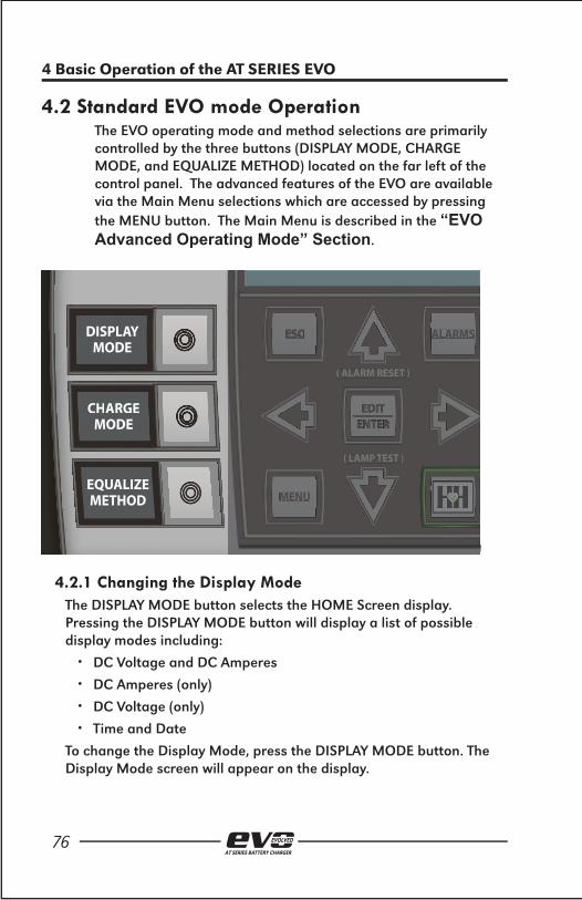
76AT SERIES BATTERY CHARGER
4 Basic Operation of the AT SERIES EVO
4.2 Standard EVO mode OperationThe EVO operating mode and method selections are primarily controlled by the three buttons (DISPLAY MODE, CHARGE MODE, and EQUALIZE METHOD) located on the far left of the control panel. The advanced features o f the EVO are available via the Main Menu selections which are accessed by pressing the MENU button. The Main Menu is described in the “EVO Advanced Operating Mode” Section.
CHARGEMODE
CHARGEMODE
DISPLAYMODE
EQUALIZEMETHOD
( ALARM RESET )
( LAMP TEST )
MENU
ESC ALARMS
( ALARM RESET )
( LAMP TEST )
MENU
ESCESC ALARMS
4.2.1 Changing the Display ModeThe DISPLAY MODE button selects the HOME Screen display. Pressing the DISPLAY MODE button will display a list of possible display modes including:
• DC Voltage and DC Amperes
• DC Amperes (only)
• DC Voltage (only)
• Time and Date
To change the Display Mode, press the DISPLAY MODE button. The Display Mode screen will appear on the display.

77AT SERIES BATTERY CHARGER
4 Basic Operation of the AT SERIES EVO
Use the UP and DOWN ARROW buttons to select the desired display mode and press the ENTER button. The display mode will be highlighted when it is selected.
NOTE:The DISPLAY MODE button is in the same relative location as the METER MODE button on legacy AT chargers. The functionality is equivalent in that it determines which measurements are to be shown on the HOME screen.
4.2.2 Changing the Charge ModeThe EVO has two output voltage settings, FLOAT and
EQUALIZE. Use the FLOAT mode for all normal battery charging. Use the EQUALIZE mode if it is necessary to balance the voltage among the cells of the battery. Consult your battery data sheets for information on equalize-charging your battery.
The CHARGE MODE button switches the charger between FLOAT and EQUALIZE modes. The present charge mode is displayed at the top left of the HOME screen. “Float” appears when the charger is in FLOAT mode, “Equalize” appears when the charger is in EQUALIZE mode.

78AT SERIES BATTERY CHARGER
4 Basic Operation of the AT SERIES EVO
To change the Charge Mode, press the CHARGE MODE button. The Charge Mode screen will appear on the display.
Press the UP or DOWN arrow button to highlight the desired mode. Press the enter button to switch to the desired mode.
When the EVO is placed in EQUALIZE mode, the charger will ramp up to the EQUALIZE VOLTAGE set point and start the EQUALIZE TIMER. The display will alternate between showing the HOME screen and a screen showing the EQUALIZE TIME REMAINING.
The EVO will remain in EQUALIZE mode until either the EQUALIZE TIMER expires or the charge mode is switched back to FLOAT mode by accessing the CHARGE MODE display and selecting FLOAT mode.

79AT SERIES BATTERY CHARGER
4 Basic Operation of the AT SERIES EVO
NOTE:The CHARGE MODE button is in the same relative location as the CHGR MODE button on legacy AT chargers. The functionality is equivalent in that when pressed, it changes the charge mode between EQUALIZE and FLOAT modes.
4.2.3 Changing the Equalize MethodThe EQUALIZE METHOD button switches the equalize method between MANUAL TIMER and AUTOMATIC. TIMER The present equalize method is displayed at the top right of the HOME screen “Eqlz Mthd: Man” specifi es MANUAL TIMER and “Eqlz Mthd: Auto” specifi es AUTOMACTIC TIMER.
To change the Equalize Method, press the EQUALIZE METHOD button. The Equalize Method screen will appear on the display.
Press the UP or DOWN arrow button to highlight the desired method. Press the enter button to switch to the desired method.
When the AUTOMATIC TIMER method is selected, the EVO will automatically switch to EQUALIZE mode and start the EQUALIZE TIMER after a loss of AC power for greater than 12 seconds. The EVO will remain in EQUALIZE mode until either the EQUALIZE TIMER expires or the charge mode is switched back to FLOAT mode by accessing the CHARGE MODE display and selecting FLOAT mode.
When the MANUAL TIMER method is selected, the charger will only

80AT SERIES BATTERY CHARGER
4 Basic Operation of the AT SERIES EVO
switch to EQUALIZE MODE when the mode is manually change by pressing the CHANGE MODE button and EQUALIZE is selected (see Section 4.2.2).
NOTE:The EQUALIZE METHOD button is in the same relative location as the EQLZ MTHD button on legacy AT chargers. The functionality is equivalent in that when pressed, it changes the equalize method. The Manual Equalize Method (no timer) available in legacy AT chargers is not supported by the EVO.
4.2.4 Lamp TestThe EVO has a Lamp Test mode that is activated by pressing and holding the DOWN arrow button. When activated, the Lamp Test will turn on all front panel LEDs (except for the AC ON LED) and keep them on until the DOWN arrow button is released. The AC ON LED is driven directly by the power supply and is not under software control but will be lit during normal operating conditions.
When the DOWN arrow button is released, the EVO will briefl y display the fi rmware versions installed in the charger. The display will than return to the HOME screen and the EVO will resume normal operation.
NOTE:The Lamp Test initiation (press & hold DOWN arrow) and function in the EVO is identical to the Lamp Test on legacy AT series chargers.
4.2.5 Resetting Latched Relays (legacy method)Latched relays can be RESET (or cleared) by pressing and holding the UP arrow button. Press and hold the UP arrow until the AT SERIES EVO displays the RESET LATCHED ALARMS confi rmation screen.
NOTE:The Reset Latched Alarms initiation (press & hold UP arrow) and function on the AT SERIES EVO is identical to the Reset Latching Alarms on legacy AT series chargers. Individual relays can be RESET or cleared or all relays can also be RESET or cleared via the RELAYs menu. See Section 6.5 for details on how to reset latched alarm relays via the RELAYS menu icon.

81AT SERIES BATTERY CHARGER
4 Basic Operation of the AT SERIES EVO
4.3 High Voltage ShutdownThe EVO has a High Voltage Shutdown feature similar to the High Voltage Shutdown feature in legacy AT chargers. The High Voltage Shutdown is a software feature whereby the Main Control Board monitors the DC voltage and will turn off the output drivers (rectifi er controllers) if the DC output voltage is too high.
The set point for the High DC Voltage Alarm is used as the threshold for initiating the High Voltage Shutdown. The output voltage must rise above the High DC Voltage Alarm set point and remain above the set point for 30 seconds in order for the Shutdown to occur. If a High Voltage Shutdown does occur, the High Voltage Shutdown Alarm and the Common Alarm Relay is activated. Once the shutdown occurs, the charger must be restarted (turn off both AC and DC breakers) to clear the shutdown condition. The charger will not turn on the rectifi er controls until it is reset.
The High Voltage Shutdown feature can be enabled or disabled. Refer to Section 3.4.2 for instructions on how to enable or disable the High Voltage Shutdown feature.
NOTE:The EVO has a hardware High Level Detect feature as well. Refer to Section 4.5 for more information on the High Level Detect hardware shutdown.

82AT SERIES BATTERY CHARGER
4 Basic Operation of the AT SERIES EVO
4.4 Low Level DetectThe EVO has a Low Level Detect feature similar to the Low Level Detect feature in legacy AT chargers. The Low Level Detect feature is a dedicated hardware circuit that detects if the DC Bus voltage is below a confi gurable set point. If the DC voltage drops below the set point threshold, the Low Level Detect circuit will force the Common Alarm Relay to the alarmed state.
The Low Level Detect circuit functions independent of microprocessor control. It will trigger the Common Alarm if a catastrophic microprocessor failure should occur to indicate that the DC Bus voltage is critically low and immediate attention is required. The Low Level Detect circuit includes a dedicated Analog Low Level alarm LED that illuminates if the Low Level Detect condition is triggered.
The Analog Low Level alarm LED is on the Main Control Board. You will need to open the EVO door to view the Analog Low Voltage Alarm LED.
Refer to Section 3.4.5 for instructions on how to confi gure the threshold for the Low Level Detect feature.
4.5 High Level DetectThe EVO High Level Detect has a dedicated hardware circuit that detects if the DC Bus voltage is above a confi gurable set point. If the DC voltage rises above the set point threshold for more than 30 seconds, the circuit disables the output drivers (rectifi er controllers)

83AT SERIES BATTERY CHARGER
4 Basic Operation of the AT SERIES EVO
and forces the Common Alarm Relay to the active state.
The High Level Detect is a true failsafe feature in that it can shut down the charger by disabling the rectifi er control signals. This circuit works independent of the microprocessor and will override the rectifi er control. The High Level Detect will shut down the charger output circuitry should a catastrophic microprocessor failure occur, turning the rectifi er to the full on condition.
If the High Level Detect shutdown occurs, the circuit latches until the charger is restarted (by turning of both the AC and DC breakers). The High Level Detect circuit has a dedicated Analog High Level Detect Shutdown alarm LED that illuminates if the High Level Detect condition is triggered. The Analog High Voltage Shutdown alarm LED is on the Main Control Board. You will need to open the EVO door to view the Analog High Voltage Shutdown alarm LED.
The High Level Detect circuit and associated shutdown can be enabled or disabled. Refer to Section 3.10 for instructions on how to enable or disable the High Level Detect feature. Refer to Section 3.4.3 for instructions on how to confi gure the threshold for the High Level Detect feature


5. ADVANCED OPERATION OF
THE EVO
AT SERIES BATTERY CHARGER

86AT SERIES BATTERY CHARGER
5 Advanced Operation of the AT SERIES EVO
5.1 The EVO Main MenuPress the “MENU” button to access the Main Menu. The fi rst six menu selection icons appear on the screen. Use the UP, DOWN, LEFT, or RIGHT arrow buttons to navigate through the menu selections. The icons appear in inverse video when they are selected.
The top of the screen indicates the Main Menu is being displayed and to the far right of “Main Menu” an up and/or down arrow icon is displayed. The arrow icon(s) indicate that more menu selection icons are available if you continue to navigate in the direction of the arrow. If a down arrow navigation icon is displayed, and either of the menu icons on the bottom are presently selected, pressing the DOWN arrow button again will display the next three menu icons.
Pressing the EDIT/ENTER button will activate the selected feature or function. Pressing the ESC button will return back one menu level. If the Main Menu is being displayed and the ESC button is pressed, the display will return to the HOME screen. If you have selected and entered the SYSTEM SETTINGS mode, pressing the ESC button while in the SYSTEM SETTINGS screen will return to the Main Menu. Pressing ESC again will return to the HOME screen.

87AT SERIES BATTERY CHARGER
5 Advanced Operation of the AT SERIES EVO
5.1.1 The Basic Settings IconWhen selected, this icon initiates the Basic EVO Set Points and Alarms screens. These Set Points are the typical legacy AT settings. The display will change to the fi rst confi guration screen (EDIT FLOAT VOLTAGE) of the Basic EVO Set Points and Alarms screens (see
Section 3.3.2 for details and instructions on how to proceed with the Basic EVO confi gurations). The display will return back to the Main Menu when all Basic EVO Set Points and Alarms have been confi gured or if the ESC button is pressed any time during the editing process.
Selecting the Basic Settings icon is equivalent to pressing the EDIT/ENTER button while the HOME screen is being displayed. The direct path to Basic EVO Set Points and Alarms screens from the HOME screen is supported to ensure backward operation compatibility with legacy AT series chargers.
5.1.2 The Advanced Settings IconWhen selected, this icon initiates the EVO Advanced Confi guration screens. The EVO will enter the Advance Settings Mode and the fi rst page of parameters will be displayed. See Section 3.4.1 for details and instructions on how to proceed with the advanced
setting confi gurations. The display will return back to the Main Menu
when the ESC button is pressed any time during the editing process.
5.1.3 The System Settings IconWhen selected, this icon initiates the EVO System Settings Confi guration screens. The EVO will enter the System Settings Mode and the fi rst page of parameters will be displayed. See Section 3.5.1 for details and instructions on how to proceed with the
system setting confi gurations. The display will return back to the Main Menu when the ESC button is pressed any time during the editing process.

88AT SERIES BATTERY CHARGER
5 Advanced Operation of the AT SERIES EVO
5.1.4 Save|Reset Confi guration IconWhen selected, this icon initiates the EVO Backup/Restore controls. The display will change to show the backup and restore controls. An optional SD memory card is required to store the EVO settings. All confi guration set points, alarm thresholds, and
communication settings can be stored on the SD memory card. The SD card can be removed and inserted into another charger and the confi guration can be stored in to the new charger. This allows a charger’s settings to be cloned to another charger automatically eliminating the need to re-enter the confi guration manually.
For more details on backing up and restoring the EVO confi guration, see Section 5.5 – Using the Optional SD Memory Card. Press the ESC button to return to the Main Menu.
5.1.5 The Relays IconWhen selected, this icon initiates the EVO Relay Confi guration and Control options. The display will change to a page with selections to confi gure the relays and reset or clear any latched alarm relays.
To change a relay confi guration, select “Relay confi guration” and press the EDIT/ENTER button. The screen will change to a list of all available relays. Select the desired relay and press the EDIT/ENTER button to view and edit the selected relay’s parameters. Refer to Section 3.6 for details on changing the Main board relay parameters and Section 11.4 for details on changing the Auxiliary Board relay parameters.
See Section 6.5 for details on how to reset latched alarm relays.

89AT SERIES BATTERY CHARGER
5 Advanced Operation of the AT SERIES EVO
5.1.6 The Event Logs Icon When selected, this icon initiates the EVO Event Log functions. The display will change to the Event Logs functions page with selections for viewing logged events and utilities for copying the logs to the SD memory card and clearing all events stored. Refer to
Section 8.0, EVO Event Logs for details on the event logging features and controls.
5.1.7 The System information IconWhen selected, this icon initiates the EVO System Information screens. The display will change to the fi rst page of the EVO system status. Follow the navigation instructions displayed at the top right of the screens to scroll through the EVO status pages.
Press the ESC button after viewing the System Information to return to the Main Menu.
5.1.8 The Security IconWhen selected, this icon initiates the EVO password setup and logon screens. The display will change to the main Security Screen with a list of security functions. Refer to Section 5.4 – Security and Passwords for more details on how to implement the
security features of the EVO. Press the ESC button to return to the Main Menu.
5.1.9 The Communications IconWhen selected, this icon initiates the EVO Communication ports confi guration. The EVO is capable of supporting three serial communication ports and one Ethernet port. Communication ports are optional and may not be included with
the EVO. The display will show all communication ports as well as whether or not they are assigned and confi gured. Two of the serial communication ports support Modbus and DNP3.0 communications. Refer to the supplementary EVO Communications manual for details on how to confi gure these ports. Press the ESC button after viewing
the System Information to return to the Main Menu.

90AT SERIES BATTERY CHARGER
5 Advanced Operation of the AT SERIES EVO
5.1.10 The Common Alarm IconWhen selected, this icon permits alarms to be excluded from the Common Alarm activation list. By default, all alarms, when active, will annunciate the Common Alarm. If it is desired to prevent an alarm from annunciating the Common Alarm, follow the
instructions below to disable the selected alarm from activating the Common Alarm.
• From the HOME SCREEN, press the MENU button, navigate to the COMMON ALARM icon and then press the EDIT/ENTER button.
• Press the UP or DOWN button to navigate through the list of EVO alarms. The alarm list is multiple pages in length, the scroll bar to the right of the screen will indicate the position within the list.

91AT SERIES BATTERY CHARGER
5 Advanced Operation of the AT SERIES EVO
• Press the EDIT/ENTER button while an alarm is highlighted to change the status of whether or not that alarm will activate the COMMON ALARM. If an ‘[X]’ appears in the box to the left of the alarm name, the alarm will activate the COMMON ALARM. If ‘[ ]’ appears in the box to the left of the alarm name, the alarm will not activate the COMMON ALARM.
• Pressing the ESC button will return to the previous menu. Multiple ESC button presses will return the EVO to the HOME screen.
5.1.11 The AUX Inputs Icon When selected, this icon initiates the EVO Binary Input and Analog Input confi gurations. The EVO is capable of supporting up to four Auxiliary I/O boards with each board containing a total of four generic binary inputs and four generic analog inputs.
Auxiliary I/O boards are optional and may not be included with the EVO. The display will have a selection for binary inputs and analog inputs. Refer to the Section 11.5 for detailed instructions on how to confi gure the binary inputs and Section 11.6 for detailed instructions on how to confi gure the analog inputs. Press the ESC button to return to the Main Menu.
5.1.12 The Testing Icon When selected, this icon displays the Open Battery Test confi guration and controls. Refer to Section 6.6 for details and instruction on how to start, schedule, and set up the parameters for the Open Battery Test.

92AT SERIES BATTERY CHARGER
5 Advanced Operation of the AT SERIES EVO
5.2 The EVO Alarm ButtonWhen pressed, the ALARM button initiates the EVO Active Alarm screen. The display will change to show the Active Alarm List. All active alarm conditions are reported on the Active Alarm List. The Active Alarm screen can only display four alarm conditions per page. If more than four alarms are active use the UP and/or DOWN arrow buttons to scroll through the list.
Not all EVO alarms have a dedicated LED alarm indicator on the front panel. Alarms without a dedicated LED alarm indicator will light the COMMON alarm LED on the front panel. Press the ESC button when you have fi nished reviewing the Active Alarm List to return to the Main Menu.
5.3 The EVO Health ButtonWhen pressed, the HEALTH button initiates the EVO Hindle Health System (HHS) screens. The Hindle Health System utilizes a sequence of interactive screens that prompts the user through a series of tests that verify that the charger is working properly. The Hindle Health System will verify set points, test alarms and relays, verify calibration, and test hardware.
Step by step instructions are provided on each screen for any interaction required by the user. The results of the tests are logged along with a time and date stamp. The health test can be aborted at any point by pressing the ESC button. For more information and detailed instructions on how to run the Hindle Health System health test, refer to Section 7.0.
5.4 Security and PasswordsThe EVO provides protection from unauthorized users from modifying charger set points, accessing critical features, and changing alarm settings. This protection is implemented by assigning and enabling passwords to authorize access to different levels of the EVO functionality.

93AT SERIES BATTERY CHARGER
5 Advanced Operation of the AT SERIES EVO
5.4.1 Three (3) Levels of Password ProtectionThe EVO incorporates three (3) levels of password authorization: READ, READ/WRITE and ADMINISTRATOR. Each authorization level requires a unique password to access the functions and features associated with that level.
The READ authorization level is the lowest privilege level and permits access to viewing the charger’s data and status. All measurements and set points may be observed and verifi ed but no confi guration changes are permitted.
The READ/WRITE authorization level is the mid privilege level. This level permits access to viewing the charger’s data and status as in the READ level, but also permits changing the charger’s confi guration and all set points except for passwords.
The ADMINISTRATOR level is the highest privilege level. This level permits access to all functions and features in both the READ and READ/WRITE privilege levels plus allows the passwords to be changed. The ADMINISTRATOR level permits access to all EVO charger features.
5.4.2 Accessing the Security Features and Password Confi guration
Each of the three (3) authorization levels has a unique password. Each password is composed of a text string of up to 14 characters. By default, the DEFAULT ACCESS level is ADMINISTRATOR. As stated in the previous section, you will need ADMINISTRATOR privilege to change any password or change the DEFAULT ACCESS level. To access the security features and password confi guration:
• Press the MENU button. The menu selection icons will appear on the display.
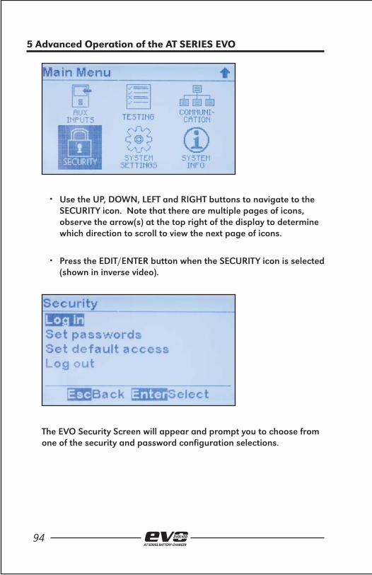
94AT SERIES BATTERY CHARGER
5 Advanced Operation of the AT SERIES EVO
• Use the UP, DOWN, LEFT and RIGHT buttons to navigate to the SECURITY icon. Note that there are multiple pages of icons, observe the arrow(s) at the top right of the display to determine which direction to scroll to view the next page of icons.
• Press the EDIT/ENTER button when the SECURITY icon is selected (shown in inverse video).
The EVO Security Screen will appear and prompt you to choose from one of the security and password confi guration selections.

95AT SERIES BATTERY CHARGER
5 Advanced Operation of the AT SERIES EVO
5.4.3 Setting the EVO PasswordsTo change the passwords, use the UP and DOWN arrow buttons to navigate to and select the “Set Passwords” feature. Press the EDIT/ENTER button. The screen will change to display the three (3) password authorization levels.
Use the UP and DOWN arrow buttons to navigate to and select the READ password privilege level. Press the EDIT\ENTER button to view the password confi guration screen for the READ privilege level.
Use the UP and DOWN arrow buttons to scroll though the choices for the fi rst character of the password. When the desired character is being displayed, press the RIGHT arrow button to move on to the next character. Continue this procedure until the desired password has been created. When the password had been created press the EDIT/ENTER button to store the new password.

96AT SERIES BATTERY CHARGER
5 Advanced Operation of the AT SERIES EVO
NOTE: If you do not have ADMINISTRATOR privilege (the DEFAULT ACCESS level is NOT set as ADMINISTRATOR or you are NOT logged in with ADMINISTARTOR privilege), you will not be able to change the passwords.
Use the same procedure to confi gure the READ/WRITE and ADMINISTRATOR passwords by selecting them from the “Select Access Level” Menu.
5.4.4 Setting the Default AccessThe DEFAULT ACCESS setting determines the authorization and password level when there is no log in. If you do not wish to implement any password security, the DEFAULT ACCESS should be set to ADMINISTRATOR, this is the default factory setting.
To change the DEFAULT ACCESS, use the UP and DOWN arrow buttons to navigate to and select the “DEFAULT ACCESS” feature. Press the EDIT/ENTER button. The screen will change to display the three (3) password authorization levels.
Use the UP and DOWN arrow buttons to navigate to and select the desired DEFAULT ACCESS privilege level. Press the EDIT\ENTER button to set the selected privilege level as the default level (this will be the authorization level when there is no log in).
NOTE: An ADMINISTRATOR password must be assigned before the

97AT SERIES BATTERY CHARGER
5 Advanced Operation of the AT SERIES EVO
DEFAULT ACCESS can be changed. If you do not have ADMINISTRATOR privilege (the DEFAULT ACCESS must be set as ADMINISTRATOR or you a must be logged in with ADMINISTRATOR privilege), you will not be able to change the DEFAULT ACCESS.
5.4.5 Logging In to a Password Authorization LevelIf you attempt to access a feature or change a parameter that is confi gured at a higher privilege level than the DEFAULT ACCESS level (or the present log in level), the EVO will prevent the action. You will need to log in at the confi gured privilege level (or higher) to be authorized to access the feature.
To LOG IN to a privilege level, use the UP and DOWN arrow buttons to navigate to and select the “LOG IN” feature. Press the EDIT/ENTER button. The screen will change to display the three (3) password authorization levels.
Use the UP and DOWN arrow buttons to navigate to and select the desired privilege level to log in to. Press the EDIT\ENTER button to view the password entry screen for the associated privilege level.

98AT SERIES BATTERY CHARGER
5 Advanced Operation of the AT SERIES EVO
Use the UP and DOWN arrow buttons to scroll though the choices for the fi rst character of the password. When the correct character is being displayed, press the RIGHT arrow button to move on to the next character. Continue this procedure until the entire correct password has been created. When the password had been created press the EDIT/ENTER button to submit the password.
If the password you entered is correct, you will receive an acknowledgement that you successfully logged into the new privilege level and all features that are authorized for that privilege level will become functional. The EVO will continue to allow access to all features at the logged in privilege level as long as there is activity (button presses). If there is no activity for more than ten minutes, the EVO will automatically switch back to the DEFAULT ACCESS level.
If the password you entered is incorrect, you will not be authorized to access the features in the new privilege level.

99AT SERIES BATTERY CHARGER
5 Advanced Operation of the AT SERIES EVO
5.4.6 Logging OutIn order for the password security features of the EVO to be secure, it is necessary to log out after you have completed any operations that require a higher privilege level. If you do not log out of the higher privilege level, all protected operations will still be available for anyone to access. When the LOG OUT operation is executed, the EVO will return back to the DEFAULT ACCESS privilege level.
NOTE: The EVO will automatically log out of an authorization level that was logged in to after ten minutes of inactivity.
To LOG OUT of the present privilege level, use the UP and DOWN arrow buttons to navigate to and select the “LOG OUT” feature. Press the EDIT/ENTER button. The screen will display a brief message confi rming that you successfully “logged out” of the present privilege level and the screen will return to the Main Menu.

100AT SERIES BATTERY CHARGER
5 Advanced Operation of the AT SERIES EVO
5.5 – Features Supported By the Optional SD Memory Card
The EVO provides a socket for an Optional SD Memory Card. The socket is located on the top left of the back of the Main Control Board. To access the SD Memory Card socket, open the EVO front panel and locate the Main Control Board attached to the door.
5.5.1 The SD Memory CardThe optional SD Memory card should be purchased as an EVO accessory from the supplier of the EVO battery charger. Although the SD card format is standard, there are subtle differences between different manufactures. Purchasing the SD card through your EVO supplier will ensure that the SD card has been tested and verifi ed to work with the EVO charger.
When installing the SD Memory Card into the Main Control Board, make sure the contacts are facing down and toward the Main Control Board (door) when inserting the SD Memory Card in to the socket. Gently press the card into the socket until you feel the card locking mechanism “click”. To remove the SD Card, gently press the card further into the socket and then allow it to “snap” back to disengage the card locking mechanism. Once the card is disengaged, you can gently pull the card from the socket.

101AT SERIES BATTERY CHARGER
5 Advanced Operation of the AT SERIES EVO
5.5.2 Storing the Event Log File to the SD Memory CardThe EVO Event Log can be transferred on to the SD Memory Card. The Event Log can then be transferred to a Personal Computer (PC) or other electronic device for archiving or evaluation. The fi le is stored in an ASCII text fi le format such that the events cans easily be imported into spreadsheets or other third party software.
To copy the Event Log to the SD Memory Card:
• Insert an EVO compatible SD Memory Card into the socket on the Main Control Board.
• Press the MENU button. The menu selection icons will appear on the display.
• Use the UP, DOWN, LEFT and RIGHT buttons to navigate to the EVENT LOGS icon. Note that there are multiple pages of icons, observe the arrow(s) at the top right of the display to determine which direction to scroll to view the next page of icons.
• Press the EDIT/ENTER button when the EVENT LOGS icon is selected (shown in inverse video).

102AT SERIES BATTERY CHARGER
5 Advanced Operation of the AT SERIES EVO
• The Event Log Operations screen will appear. Use the UP and DOWN arrow buttons to navigate to the “Copy event log to SD card” selection. Press the EDIT/ENTER button to copy the event log fi le.
The screen will briefl y display a message to confi rm the fi le was copied successfully. The event log fi le will be written to a fi le named ATgvaixx.LOG where:
• ‘g’ specifi es the charger family (1) <= 25 A,( 2) > 25A, (3) = 3 phase
• ‘v’ specifi es the voltage (A) = 12VDC, (B)= 24VDC, (C) = 48VDC, (D) = 130VDC, (E) = 260VDC
• ‘a’ specifi es the current (A) = 6ADC, (B) = 12 ADC, (C) = 16ADC, (D) = 20ADC, (E) = 25ADC
• ‘i’ specifi es the charger iD (A-Z) - this is specifi ed at the end of the SYSTEM INFO menu
• ‘xx’ specifi es a sequential assigned number
Each time the event log fi le is stored it will be written to a new fi le on the SD Memory card whereby the ‘xx’ number is incremented by one. This prevents previous event log fi les stored on the SD Memory Card from being overwritten.
5.5.3 Storing and Recalling the Confi guration Settings to/from the SD Memory Card
All of the EVO confi guration settings can be stored on to the SD Memory Card. The confi guration includes voltage and current

103AT SERIES BATTERY CHARGER
5 Advanced Operation of the AT SERIES EVO
set points, alarm thresholds, relay confi guration and all other confi guration.
To copy the EVO Confi guration to the SD Memory Card:
• Insert an EVO compatible SD Memory Card into the socket on the Main Control Board.
• Press the MENU button. The menu selection icons will appear on the display.
• Use the UP, DOWN, LEFT and RIGHT buttons to navigate to the SAVE:RESET SETTINGS icon. Note that there are multiple pages of icons, observe the arrow(s) at the top right of the display to determine which direction to scroll to view the next page of icons.
• Press the EDIT/ENTER button when the SAVE:EVENT SETTINGS icon is selected (shown in inverse video).
• The Backup/Restore Settings screen will appear. Use the UP and DOWN arrow buttons to navigate to the “Backup to Memory Card” selection. Press the EDIT/ENTER button to copy the confi guration fi le.

104AT SERIES BATTERY CHARGER
5 Advanced Operation of the AT SERIES EVO
The screen will briefl y display a message to confi rm the fi le was copied successfully. The confi guration fi le will be written to a fi le named ATgvai00.EVO where:
• ‘g’ specifi es the charger family (1) <= 25A,( 2) > 25A, (3) = 3 phase
• ‘v’ specifi es the voltage (A) = 12VDC, (B)= 24VDC, (C) = 48VDC, (D) = 130VDC, (E) = 260VDC
• ‘a’ specifi es the current (A) = 6ADC, (B) = 12 ADC, (C) = 16ADC, (D) = 20ADC, (E) = 25ADC
• ‘i’ specifi es the charger ID (A-Z) - this is specifi ed at the end of the SYSTEM INFO menu
This confi guration fi le can be used to restore the saved confi guration in case someone inadvertently changes a setting and doesn’t remember the original setting. It can also be used to clone the confi guration in to a similar charger to eliminate the need to setup the parameters manually. Lastly it can be used to confi gure a new Main Control Board automatically in case you ever need to replace the existing one.
To copy the EVO Confi guration from the SD Memory Card on to the Main Control Board:
• Insert an EVO compatible SD Memory Card into the socket on the Main Control Board.
• Press the MENU button. The menu selection icons will appear on the display.

105AT SERIES BATTERY CHARGER
5 Advanced Operation of the AT SERIES EVO
• Use the UP, DOWN, LEFT and RIGHT buttons to navigate to the SAVE:RESET SETTINGS icon. Note that there are multiple pages of icons, observe the arrow(s) at the top right of the display to determine which direction to scroll to view the next page of icons.
• Press the EDIT/ENTER button when the SAVE:RESET SETTINGS icon is selected (shown in inverse video).
• The Backup/Restore Settings screen will appear. Use the UP and DOWN arrow buttons to navigate to the “Restore from Memory Card” selection. Press the EDIT/ENTER button to copy the confi guration fi le.
The screen will briefl y display a message to confi rm the fi le was copied successfully. The charger will then RESET and restart with the restored confi guration settings.
5.5.4 Upgrading the Main Control Board Firmware via the SD Memory Card
One of the powerful and convenient new features of the EVO charger is that the Main Control Board fi rmware (or software) can be easily updated in the fi eld without uninstalling the charger or any boards. New features and fi rmware upgrades can be easily loaded in to the charger in minutes.

106AT SERIES BATTERY CHARGER
5 Advanced Operation of the AT SERIES EVO
The fi rst step in upgrading the EVO is to obtain the latest program fi les from your EVO battery charger supplier. There are two programing fi les used by the EVO:
• Mainapp.bin is the Main Control Application program
• Bruno.bin is the Display Application program
These programs can be updated independently or together at the same time.
Once you obtain the latest fi rmware version of these fi les, you will need to store them on to the SD Memory Card. This can be accomplished by copying them on to the SD Card with a Personal Computer (PC) that has a SD Memory Card slot, or by means of a USB to SD Memory Card adapter. After the fi le(s) are present on the SD Memory Card you will need to transfer them in to the EVO charger.
• Open the charger door and locate the SD Memory Card socket on the back of the Main Control Board.
• Directly below the socket will be a “RE-FLASH ENABLE JUMPER”. Move the shorting block on the jumper to the “PRGM” programming position.
• Insert the EVO compatible SD Memory Card with the program fi les into the socket on the Main Control Board.
• Find the RESET button (SW13) located 3 inches directly below the RE-FLASH JUMPER.

107AT SERIES BATTERY CHARGER
5 Advanced Operation of the AT SERIES EVO
• Press the RESET button and observe the display on the Main Control Board. The following message should appear (assuming you have the Mainapp.bin fi le stored on the SD Card).
• Select “YES” to upgrade the Main Application program. A message will appear on the main display confi rming that the Main Application program has been updated.
• If the SD Memory Card has the Bruno.bin fi le stored on it, the display will next prompt you to upgrade the Display Application program.
•
• Select “YES” to upgrade the Display Application program. A message will appear on the main display confi rming that the Display Application has been updated.
• The charger will reset and prompt again to upgrade the Main Application program.

108AT SERIES BATTERY CHARGER
5 Advanced Operation of the AT SERIES EVO
• Move the RE-FLASH JUMPER shorting block back to the “NORM”, normal operating position and press the RESEST button.
• The charger will re-boot and when it restarts, it will be running the new program(s) you installed.

6. EVO ALARMS & INDICATORS
AT SERIES BATTERY CHARGER

110AT SERIES BATTERY CHARGER
6 AT SERIES EVO Alarms & Indicators
6.1 EVO Legacy Alarms and Indicators The EVO alarms can be divided in to two groups, the Legacy AT Alarms and the Advanced Alarms.
The EVO Legacy Alarm group is a superset of the standard alarm group recommended by the NEMA and IEEE standards (PE5) for stationary battery chargers. These alarms have dedicated front panel LED indicators and are referred to as legacy alarms since they have the same functionality as the standard alarms available on legacy AT10 and AT30 series battery chargers.
AC ONAC ON
HIGH DC VOLTAGE
LOW DC VOLTAGE
DC OUTPUT FAILURE
AC INPUT FAILURE
POSITIVE (+) GROUND
NEGATIVE (-) GROUND
COMMON ALARM
SCAN TO VIEW :
MANUAL
STANDARDDRAWINGS
SERVICE INSTRUCTIONS
ATSERIES.NET
6.1.1 AC ON IndicatorThe AC ON LED indicator is illuminated when the Main Control Board senses AC power. This green LED will be illuminated when AC power is present on CB1 (the AC input breaker) and CB1 is closed.
6.1.2 High DC Voltage AlarmThe red High DC Voltage LED will illuminate when the High DC Voltage alarm is active. The High DC Voltage alarm is activated

111AT SERIES BATTERY CHARGER
6 AT SERIES EVO Alarms & Indicators
when the DC Bus voltage sensed by the Main Control Board is higher than the High DC Voltage alarm set point. The High DC Voltage set point is confi gurable; refer to Section 3.3 for instructions on how to adjust the alarm set points.
The High DC Voltage alarm will activate the Common Alarm relay. The Common Alarm relay will change to the alarmed state after a confi gured time delay. The High DC Voltage alarm will also be reported by any installed optional protocol communication board and may also be confi gured to activate a discrete relay on optional Auxiliary I/O boards. Refer to Section 11 for instructions on how to confi gure the relays.
6.1.3 Low DC Voltage AlarmThe red Low DC Voltage LED will illuminate when the Low DC Voltage alarm is active. The Low DC Voltage alarm is activated when the DC Bus voltage sensed by the Main Control Board is lower than the Low DC Voltage alarm set point. The Low DC Voltage set point is confi gurable; refer to Section 3.3 for instructions on how to adjust the alarm set points.
The Low DC Voltage alarm will activate the Common Alarm relay. The Common Alarm relay will change to the alarmed state after a confi gured time delay. The Low DC Voltage alarm will also be reported by any installed optional protocol communication board and may also be confi gured to activate a discrete relay on optional Auxiliary I/O boards. Refer to Section 11 for instructions on how to confi gure the relays.
6.1.4 DC Output Failure AlarmThe red DC Output Failure LED will illuminate when the DC Output Failure alarm is active. The DC Output Failure alarm is activated when the charger cannot support the connected load. This condition occurs if the DC Bus voltage is below the desired set point voltage and the charger is NOT in current limit. Possible causes of this alarm include an improperly tapped AC input or a defective rectifi er. The criteria for this alarm are not confi gurable.

112AT SERIES BATTERY CHARGER
6 AT SERIES EVO Alarms & Indicators
The DC Output Failure alarm will activate the Common Alarm relay. The Common Alarm relay will change to the alarmed state after a confi gured time delay. The DC Output Failure alarm will also be reported by any installed optional protocol communication board and may also be confi gured to activate a discrete relay on optional Auxiliary I/O boards. Refer to Section 11 for instructions on how to confi gure the relays.
6.1.5 AC Input Failure AlarmThe red AC Input Failure LED will illuminate when the AC Input Failure alarm is active. The AC Input Failure alarm is activated when the AC input voltage is detected to be below 75% of nominal. Possible causes of this alarm include an improperly tapped AC input or a missing phase. The criteria for this alarm are not confi gurable.
The AC Input Failure alarm will activate the Common Alarm relay. The Common Alarm relay will change to the alarmed state after a confi gured time delay. The AC Input Failure alarm will also be reported by any installed optional protocol communication board and may also be confi gured to activate a discrete relay on optional Auxiliary I/O boards. Refer to Section 11 for instructions on how to confi gure the relays.
6.1.6 Positive Ground Fault AlarmThe red Positive Ground Fault LED will illuminate when the Positive Ground Fault alarm is active. The Positive Ground Fault alarm is activated when the Main Control Board senses a leakage path from the positive DC Bus (DC+) to earth ground. The leakage impedance required to trigger the alarm is confi gurable; refer to Section 3.4 for instructions on how to adjust the alarm set points.
The Positive Ground Fault alarm will activate the Common Alarm relay. The Common Alarm relay will change to the alarmed state after a confi gured time delay. The Positive Ground Fault alarm will also be reported by any installed optional protocol communication board and may also be confi gured to activate a discrete relay on

113AT SERIES BATTERY CHARGER
6 AT SERIES EVO Alarms & Indicators
optional Auxiliary I/O boards. Refer to Section 11 for instructions on how to confi gure the relays.
6.1.7 Negative Ground Fault AlarmThe red Negative Ground Fault LED will illuminate when the Negative Ground Fault alarm is active. The Negative Ground Fault alarm is activated when the Main Control Board senses a leakage path from the negative DC Bus (DC-) to earth ground. The leakage impedance required to trigger the alarm is confi gurable; refer to Section 3.4 for instructions on how to adjust the alarm set points.
The Negative Ground Fault alarm will activate the Common Alarm relay. The Common Alarm relay will change to the alarmed state after a confi gured time delay. The Negative Ground Fault alarm will also be reported by any installed optional protocol communication board and may also be confi gured to activate a discrete relay on optional Auxiliary I/O boards. Refer to Section 11 for instructions on how to confi gure the relays.
6.2 EVO Common Alarm IndicatorThe red Common Alarm LED will illuminate when any EVO alarm (legacy alarms and/or advanced alarms) is active. With the exception of the six legacy alarms mentioned in the previous Section, the EVO alarms do not have individual LED indicators. The Common Alarm LED is used to indicate that one or more of these alarms are active.
When the Common Alarm is active, the Common Alarm relay on the Main Control Board will change to the alarmed state after a confi gured time delay. The Common Alarm will also be reported by any installed optional protocol communication board and may also be confi gured to activate a discrete relay on optional Auxiliary I/O boards. Refer to Section 11 for instructions on how to confi gure the relays.

114AT SERIES BATTERY CHARGER
6 AT SERIES EVO Alarms & Indicators
6.2.1 Confi guring The Common AlarmBy default, all EVO alarms when active are confi gured to annunciate the Common Alarm. In some applications, it may be desirable to prevent an EVO alarm from triggering the common alarm. As an example, by default the current limit alarm will trigger the Common Alarm. Any alarm can be individually removed from the list of alarms that, when active, will trigger a Common Alarm. The Common Alarm confi guration is described in detail in Section 5.1.10
6.3 Active Alarm Bar, Alarm View, and Alarm Log
6.3.1 The Active Alarm BarThe Active Alarm Bar is located at the bottom of the Home Screen.
Any and all active alarms will be reported at the bottom of the Home Screen. If multiple alarms are active, the Active Alarm Bar will cycle through and display each alarm. If no alarms are active, the Active Alarm Bar portion of the Home Screen will be blank.

115AT SERIES BATTERY CHARGER
6 AT SERIES EVO Alarms & Indicators
6.3.2 The Active Alarm ListThe Active Alarm List displays all active alarms. To view the Active Alarm List, press the ALARM button.
The Active Alarm List can display up to four active alarms at one time. If more than four alarms are active, use the ARROW buttons to scroll through the list. Press the ESC button to return to the Home Screen
6.3.3 The Alarm LogsAll alarms are considered system events and are stored in the EVO event log. When an alarm becomes active, it is entered into the log along with a time and date stamp. The clearing (return to non-alarm state) of any alarm is also considered a system event. The clearing of any and all alarms are entered in the EVO log along with the time and date of when the alarm was cleared. Refer to Section 8.0 for more information on the EVO logging feature.

116AT SERIES BATTERY CHARGER
6 AT SERIES EVO Alarms & Indicators
6.4 EVO Advanced AlarmsThe EVO contains a wealth of alarming features. In an effort to provide the utmost in fl exibility and expansion capability and yet maintain ease of use, the alarming features have been split in to two groups; the Legacy Group and the Advanced Group. The Legacy Alarms have been described earlier in this Section.
The following Advanced Alarms do not have dedicated LEDs to indicate when they are active. When active, the Advanced Alarms will illuminate the COMMON ALARM LED. The Advanced Alarms will also appear on the Active Alarm Bar and Active Alarm List when active. All Advanced Alarms are stored in the EVO event log along with the time and date they occur and clear.
6.4.1 High Voltage Shutdown AlarmThe High Voltage Shutdown Alarm is activated when the EVO initiates a High Voltage Shutdown. The High Voltage Shutdown must be enabled for the shutdown to occur (refer to Section 3.4.2).
High Voltage Shutdown is initiated by the EVO micro-controller when the DC Bus voltage sensed by the Main Control Board is higher than the High DC Voltage set point for a minimum of 30 seconds. Refer to Section 4.3 for more details on the High Voltage Shutdown feature.
The High Voltage Shutdown alarm will activate the Common Alarm relay. The Common Alarm relay will change to the alarmed state after a confi gured time delay. The High Voltage Shutdown alarm will also be reported by any installed optional protocol communication board and may also be confi gured to activate a discrete relay on optional Auxiliary I/O boards. Refer to Section 11 for instructions on how to confi gure the relays.

117AT SERIES BATTERY CHARGER
6 AT SERIES EVO Alarms & Indicators
6.4.2 Low Level Detect AlarmThe Low Level Detect Alarm is activated when the DC Bus voltage sensed by the Main Control Board is lower than the Low Level Detect set point. The Low Level Detect Alarm will activate the Common Alarm.
The Low Level Detect feature contains dedicated hardware and operates independent of microprocessor control. The Low Level Detect is a true failsafe feature in that it can activate the common alarm in response to a catastrophic failure such as a microprocessor failure. The Low Level Detect hardware will illuminate a dedicated LED located on the Main Control Board when alarm is active.
The Low Level Detect set point is confi gurable; refer to Advanced Settings Section 3.4.5 for instructions on how to adjust the Low Level Detect set point.
The Low Level Detect alarm will activate the Common Alarm relay. The Common Alarm relay will change to the alarmed state after a confi gured time delay. The Low Level Detect alarm will also be reported by any installed optional protocol communication board and may also be confi gured to activate a discrete relay on optional Auxiliary I/O boards. Refer to Section 11 for instructions on how to confi gure the relays.

118AT SERIES BATTERY CHARGER
6 AT SERIES EVO Alarms & Indicators
6.4.3 End of Discharge (EOD) AlarmThe End of Discharge alarm is activated when the DC Bus voltage sensed by the Main Control is lower than the End of Discharge alarm set point. The End of Discharge set point is confi gurable; refer to Advanced Settings Section 3.4.4 for instructions on how to adjust the End of Discharge set point.
The End of Discharge alarm will activate the Common Alarm relay. The Common Alarm relay will change to the alarmed state after a confi gured time delay. The End of Discharge alarm will also be reported by any installed optional protocol communication board and may also be confi gured to activate a discrete relay on optional Auxiliary I/O boards. Refer to Section 11 for instructions on how to confi gure the relays.
NOTE:
The End of Discharge alarm may be used to activate a battery disconnect contactor by mapping the alarm to a discrete relay of an optional Auxiliary I/O Board.
6.4.4 High Ripple AlarmThe High Ripple alarm is activated when the AC ripple voltage measured by the Main Control Board is higher than the Ripple Voltage alarm set point. The Ripple Voltage set point is confi gurable; refer to Advanced Settings Section 3.4.6 for instructions on how to adjust the High Ripple alarm set point.
The High Ripple alarm will activate the Common Alarm relay. The Common Alarm relay will change to the alarmed state after a confi gured time delay. The High Ripple alarm will also be reported by any installed optional protocol communication board and may also be confi gured to activate a discrete relay on optional Auxiliary I/O boards. Refer to Section 11 for instructions on how to confi gure the relays.

119AT SERIES BATTERY CHARGER
6 AT SERIES EVO Alarms & Indicators
6.4.5 Battery Temperature Probe Failure AlarmThe Battery Temperature Probe Failure alarm is activated when the Main Control Board senses an out of range value from the Battery Temperature probe. The EVO will switch to non-temperature compensated mode to determine the output voltage (output voltage will be adjusted for 25 °C). The set points for this alarm are fi xed internally and are not adjustable.
The Battery Temperature Probe Failure alarm will activate the Common Alarm relay. The Common Alarm relay will change to the alarmed state after a confi gured time delay. The Battery Temperature Probe Failure alarm will also be reported by any installed optional protocol communication board and may also be confi gured to activate a discrete relay on optional Auxiliary I/O boards. Refer to Section 11 for instructions on how to confi gure the relays.
6.4.6 Rectifi er Over Temperature AlarmThe Rectifi er Over Temperature alarm is activated when the Main Control Board senses that one or more of the SCRs are too hot. The set points for this alarm are fi xed internally and are not adjustable.
The Rectifi er Over Temperature alarm will activate the Common Alarm relay. The Common Alarm relay will change to the alarmed state after a confi gured time delay. The Rectifi er Over Temperature alarm will also be reported by any installed optional protocol communication board and may also be confi gured to activate a discrete relay on optional Auxiliary I/O boards. Refer to Section 11 for instructions on how to confi gure the relays.
6.4.7 External Feedback Failure AlarmThe External Feedback Failure alarm is activated when the Main Control Board senses the external voltage (post-fi ltered voltage) is out of range. The external voltage maybe measured at the output breaker or the battery if the remote sense option is connected. This failure typically indicates a problem with the voltage sense resistors. The set points for this alarm are fi xed internally and are not adjustable.

120AT SERIES BATTERY CHARGER
6 AT SERIES EVO Alarms & Indicators
The External Feedback Failure alarm will activate the Common Alarm relay. The Common Alarm relay will change to the alarmed state after a confi gured time delay. The External Feedback Failure alarm will also be reported by any installed optional protocol communication board and may also be confi gured to activate a discrete relay on optional Auxiliary I/O boards. Refer to Section 11 for instructions on how to confi gure the relays.
6.4.8 Internal Feedback Failure AlarmThe Internal Feedback Failure alarm is activated when the Main Control Board senses the internal voltage (pre-fi ltered voltage) is out of range. The internal voltage is always measured inside the charger before the output fi lter circuitry. This failure typically indicates a problem with the voltage sense resistors. The set points for this alarm are fi xed internally and are not adjustable.
The Internal Feedback Failure alarm will activate the Common Alarm relay. The Common Alarm relay will change to the alarmed state after a confi gured time delay. The Internal Feedback Failure alarm will also be reported by any installed optional protocol communication board and may also be confi gured to activate a discrete relay on optional Auxiliary I/O boards. Refer to Section 11 for instructions on how to confi gure the relays.
6.4.9 Open DC Breaker AlarmThe Open DC Breaker alarm is activated when the Main Control Board senses that CB2, the DC Breaker, is open. The set point for this alarm is fi xed internally and are not adjustable.
The Open DC Breaker alarm will activate the Common Alarm relay. The Common Alarm relay will change to the alarmed state after a confi gured time delay. The Open DC Breaker alarm will also be reported by any installed optional protocol communication board and may also be confi gured to activate a discrete relay on optional Auxiliary I/O boards. Refer to Section 11 for instructions on how to confi gure the relays.

121AT SERIES BATTERY CHARGER
6 AT SERIES EVO Alarms & Indicators
6.4.10 Open AC Breaker Alarm (optional)The Open AC Breaker alarm is activated when the Main Control Board senses that CB1, the AC Breaker, is open. The set point for this alarm is fi xed internally and are not adjustable.
The Open AC Breaker alarm will activate the Common Alarm relay. The Common Alarm relay will change to the alarmed state after a confi gured time delay. The Open AC Breaker alarm will also be reported by any installed optional protocol communication board and may also be confi gured to activate a discrete relay on optional Auxiliary I/O boards. Refer to Section 11 for instructions on how to confi gure the relays.
6.4.11 DC Power Supply Failure AlarmThe DC Power Supply Failure alarm is activated when the Main Control Board is not sensing power from its internal DC power source. The EVO internal electronics are powered by both AC and DC power sources. The EVO utilizes the AC power source when AC power is applied to the charger and the DC power source when there is no AC source. The EVO may be operating when this alarm is active, but it may fail when the AC power is removed.
The set points for this alarm are fi xed internally and are not adjustable.
The DC Power Supply Failure alarm will activate the Common Alarm relay. The Common Alarm relay will change to the alarmed state after a confi gured time delay. The DC Power Supply Failure alarm will also be reported by any installed optional protocol communication board and may also be confi gured to activate a discrete relay on optional Auxiliary I/O boards. Refer to Section 11 for instructions on how to confi gure the relays.

122AT SERIES BATTERY CHARGER
6 AT SERIES EVO Alarms & Indicators
6.4.12 SCR Failure AlarmThe SCR Failure Alarm is activated when the Main Control Board detects that the rectifi er is not working. This may indicate a defective SCR or issues with the SCR fi ring control or driver. The set points for this alarm are fi xed internally and are not adjustable.
The SCR Failure Alarm will activate the Common Alarm Relay. The Common Alarm Relay will change to the alarmed state after a confi gured time delay. The SCR Failure Alarm will also be reported by any installed optional protocol communication board and may also be confi gured to activate a discrete relay on optional Auxiliary I/O boards. Refer to Section 11 for instructions on how to confi gure the relays.
6.5 Reset Latch Alarm RelaysLatched alarm relays can be reset or cleared two different ways. The Legacy AT Series method may be used. Pressing and holding the UP arrow button for a few seconds will reset or clear all latched alarm relays. A confi rmation message will briefl y appear on the display acknowledging all latched alarm relays have been reset.
Individual latched alarm relays or all latched alarm relays may also be reset via the RELAYS icon from the Main Menu. . To reset an individual latch alarm relay:
• From the HOME SCREEN, press the MENU button, navigate to the RELAYS icon and then press the EDIT/ENTER button.

123AT SERIES BATTERY CHARGER
6 AT SERIES EVO Alarms & Indicators
• Press the UP or DOWN button to navigate to the “Unlatch selected relays” control and press the EDIT/ENTER button.
• A list of alarm relays that are presently latched will appear.
• Press the UP or DOWN button to navigate to the relay to be reset and press the EDIT/ENTER button.
To reset all latched alarm relays:
• From the HOME SCREEN, press the MENU button, navigate to the RELAYS icon and then press the EDIT/ENTER button.

124AT SERIES BATTERY CHARGER
6 AT SERIES EVO Alarms & Indicators
• Press the UP or DOWN button to navigate to the “Unlatch all relays (x)”. The number of presently latched relay will appear between the ( ) where the X is located.
• Press the EDIT/ENTER button to reset all the latched alarm relays. The number between the brackets will change to ‘0’.

125AT SERIES BATTERY CHARGER
6 AT SERIES EVO Alarms & Indicators
6.6 Open Battery TestThe Open Battery Test feature will detect if the connection between the battery and the EVO has been lost. This test can also detect a weak or faulty battery. The test lowers the charger voltage and verifi es whether the battery can assume the present DC load. This test can be run manually or be scheduled to run periodically.
The Open Battery Test will fail and the test will end if the DC bus drops below a confi gurable voltage set point. If the DC voltage drops below the voltage set point, the test aborts immediately and the EVO will raise the output voltage back to the present Float or Equalize setting. The duration of the test is also confi gurable.
If the test fails a Battery Open alarm is generated. This alarm is a latching alarm and can only be cleared by the Unlatch Battery Open Alarm control.
6.6.1 Open Battery Test SettingsThe settings of the Open Battery Test are accessed via the TESTING icon from the Main Menu. To confi gure the Open Battery Test:
• From the HOME SCREEN, press the MENU button, navigate to the TESTING icon and then press the EDIT/ENTER button.
• Press the UP or DOWN button to navigate to the “Test Settings” control and press the EDIT/ENTER button.

126AT SERIES BATTERY CHARGER
6 AT SERIES EVO Alarms & Indicators
• Press the UP or DOWN button to navigate to the “Run test for up to:” control and press the EDIT/ENTER button.
• Press the UP or DOWN button to adjust the duration of the test and press the EDIT/ENTER button.

127AT SERIES BATTERY CHARGER
6 AT SERIES EVO Alarms & Indicators
• Press the UP or DOWN button to navigate to the “Setpoint:” control and press the EDIT/ENTER button.
• Press the UP or DOWN button to adjust the voltage set point at which to terminate the test if no battery is present and press the EDIT/ENTER button.
6.6.2 Run the Open Battery Test PeriodicallyTo schedule the EVO to run the Open Battery Test periodically:
• From the HOME SCREEN, press the MENU button, navigate to the TESTING icon and then press the EDIT/ENTER button.

128AT SERIES BATTERY CHARGER
6 AT SERIES EVO Alarms & Indicators
• Press the UP or DOWN button to navigate to the “Test Settings” control and press the EDIT/ENTER button.
• Press the UP or DOWN button to navigate to the “Run periodically:” control and press the EDIT/ENTER button.

129AT SERIES BATTERY CHARGER
6 AT SERIES EVO Alarms & Indicators
• Press the UP or DOWN button to enable or disable the automatic scheduling of the test and press the EDIT/ENTER button.
• Press the UP or DOWN button to navigate to the “Every:” control and press the EDIT/ENTER button.
• Press the LEFT or RIGHT buttons to select the digit to change. Press the UP or DOWN button to adjust how often to run the test.

130AT SERIES BATTERY CHARGER
6 AT SERIES EVO Alarms & Indicators
• Press the EDIT/ENTER button when the scheduled number of days is displayed.
6.6.3 Run the Open Battery Test ManuallyThe Open Battery Test can be run manually on demand. To initiate the Open Battery test:
• From the HOME SCREEN, press the MENU button, navigate to the TESTING icon and then press the EDIT/ENTER button.
• Press the UP or DOWN button to navigate to the “Run now” control and press the EDIT/ENTER button.

131AT SERIES BATTERY CHARGER
6 AT SERIES EVO Alarms & Indicators
6.6.4 Resetting the Battery Open AlarmIf the EVO detects an open battery condition and the Open Battery Test alarm is activated, it can only be cleared by the Unlatch Battery Open Alarm control. To initiate the Unlatch Battery Open Alarm control and reset the Battery Open Alarm:
• From the HOME SCREEN, press the MENU button, navigate to the TESTING icon and then press the EDIT/ENTER button.

132AT SERIES BATTERY CHARGER
6 AT SERIES EVO Alarms & Indicators
• Press the UP or DOWN button to navigate to the “Unlatch battery open” control and press the EDIT/ENTER button.

7. HINDLE HEALTH SYSTEM
AT SERIES BATTERY CHARGER

134AT SERIES BATTERY CHARGER
7 HindleHealth System
7.1 Hindle Health System - Overview
The Hindle Health System (HHS) is a powerful, user friendly, standard feature designed in to the EVO charger. The HHS is composed of several subsystems that test and report the operational health of the EVO. Some portions of the HHS continuously run in the background and monitor the charger to ensure everything is working as designed. Other parts of the HHS require user intervention via stimulus or confi rmation to verify proper operation.
7.2 Hindle Health System ComponentsThe Hindle Health System is composed of four major components;
a self-diagnostic utility that continuously runs in the background
Hindle Health Button
Hindle Health LEDs
Hindle Health Screens
7.2.1 Self-DiagnosticsThe EVO microprocessors continuously run utilities that check to make sure the hardware components are operating correctly. These utilities test memory, communication interfaces, parameters, and discrete hardware devices such as relays.
The microprocessors also test that all input values and measurements are within tolerance of reasonable ranges. Some critical parameters such as DC voltage and DC current are sampled by multiple processors and have redundant qualifi cation requirements.

135AT SERIES BATTERY CHARGER
7 HindleHealth System
Any errors detected by the self-diagnostic utilities are reported immediately by means of alarms and/or status updates. Possible causes of problem and proposed solution to resolve the issues are also provided by the self-diagnostics utilities.
7.2.2 Hindle Health ButtonThe Hindle Health Button is located to the lower right of the EVO control overlay.
When pressed, the Hindle Health Button will start the user assisted portion of the Hindle Health System. This process will check and verify areas of the charger that the continuous self-diagnostics may not be
able to test. For example, the charger cannot test whether a relay is working correctly unless the test forces the relay to change states.
The user will be guided and prompted through the entire test procedure via the Hindle Health Screens described later in this Section. Pressing the Hindle Health Button starts this process.
7.2.3 Hindle Health LED IndicatorsThe Hindle Health LED Indicators are located at the bottom of the front panel overlay.
The GREEN LED, when lit, indicates that the EVO is healthy, tested, and working as designed.
The RED LED, when lit, indicates that the Hindle Health System detected an issue with the EVO.
The RED LED may be blinking or on continuously. If the RED LED is blinking, this indicates that there is a critical failure of the microprocessor that drives the Main EVO LCD display and the front panel controls. The Main LCD display may be blank, frozen, or displaying corrupted data. The core microprocessor responsible for charging the battery may still be operational.

136AT SERIES BATTERY CHARGER
7 HindleHealth System
If the RED HHS LED is blinking, the Main Control Board should be replaced immediately. If a spare Main Control Board is not readily available, a new board should be ordered as soon as possible.
If the RED LED is illuminated and is not fl ashing, this indicates that the EVO requires attention, but the issue is typically not as critical as when the RED LED is blinking.
In most cases, if the Red LED is solid, the Main LCD display will be operational and be able to report the issue creating the condition, along with instructions on how to resolve the issue. The RED LED is illuminated when the EVO detects any error condition, when any EVO alarm is active, or when the Hindle Health System detects any non-normal operating condition.
7.3 Hindle Health System ScreensThe Hindle Health System screens provide the user with a means to test the operation of the EVO to ensure it is operating correctly. The screens permit the operator to simulate alarm conditions, check set points and parameters, provide stimulus to exercise relays, and verify all indicators are working as designed.
The Hindle Health System screens provide step-by-step instructions and prompt the user through the entire testing process. To start the Hindle Health System, press the Hindle Health Button.

137AT SERIES BATTERY CHARGER
7 HindleHealth System
7.3.1 Introduction and Warning ScreensThe fi rst few health screens inform the user of how to navigate through the testing process and how to track the progress through the test process. The next few screens warn the user about any hazardous conditions and explain what tools will be required to complete the testing. To exit the health test at any point through the process, press the ESC button.
7.3.2 Choosing What to TestAfter the initial introduction and safety screens, a screen will appear prompting the user to make a choice of what to test.
There are two testing choices:
Operation, Set points, Alarms
Operation, Set points

138AT SERIES BATTERY CHARGER
7 HindleHealth System
The only difference between the two choices is that the second choice will NOT run the alarm and relay tests. The alarm test will exercise the alarms and relays. Any equipment monitoring the status of the charger will see the alarms during testing if the fi rst choice is selected. Use the UP or DOWN button to highlight the desired testing option and then press the ENTER button to begin the testing.
7.3.3 The Test ScreensThe remaining screens are all test screens. These test screens will prompt the user through an interactive process to verify the operation of the EVO. The interactive process will require the user to confi rm that LED indicators are lit, confi rm that relays change state, and verify that the set points are correct. The alarm test screens will simulate alarm conditions and prompt the user to verify the alarms operate and are confi rmed by any connected SCADA devices. The calibration test screen explains how to verify the EVO calibration and will automatically enter the calibration mode if required.
After the Hindle Health System runs and the testing is complete, the EVO will return to the Home Screen. An event will be added to the log fi le along with a time and date stamp to document when the charger was last tested. The results of each of the tests are included in the log fi le. The result status will indicate that each test; PASSED, FAILED or was NOT RUN. The resulting log fi le can be used to prove NERC compliance requirements for things such as verifying correct fl oat voltage.

8. EVO EVENT LOGS
AT SERIES BATTERY CHARGER

140AT SERIES BATTERY CHARGER
8 AT SERIES EVO Event Logs
8.1 EVO Event LogsThe Event Logging feature is accessed via the EVENT LOG Main Menu. There are two event logs associated with the event logging feature, one log is for the Hindle Health events, and the other log is for all other events. In addition to the logs, there are two controls associated with event logging, clearing the event log and saving the event log to the SD memory card.
8.2 View The Event LogTo view the event log:
• From the HOME SCREEN, press the MENU button, navigate to the EVENT LOGS icon and then press the EDIT/ENTER button.
• Press the UP or DOWN button to navigate to the “View event log (X)”. The number of new events since the log was last read are shown in the “( )”.

141AT SERIES BATTERY CHARGER
8 AT SERIES EVO Event Logs
• Press the EDIT/ENTER button to view the fi rst event.
The most recent event stored will appear on the display. Events include set point changes and when an alarm becomes active and when the alarm is cleared. The log will show the date and time the event occurred, the event name, and the status change that created the event.
The list of stored events can be scrolled through using the LEFT and RIGHT arrow buttons. Follow the navigation instructions at the top of the event log screens to scroll through the stored events. Press the ESC button to return to the Event Logs function page. For more information on the alarms listed in the charger event log refer to the EVO Alarms in Section 6.0.
8.3 View the Hindle Health LogTo view the Hindle Health log:
• From the HOME SCREEN, press the MENU button, navigate to the EVENT LOGS icon and then press the EDIT/ENTER button.

142AT SERIES BATTERY CHARGER
8 AT SERIES EVO Event Logs
• Press the UP or DOWN button to navigate to the “View Hindle Health log” selection.
• Press the EDIT/ENTER button to view the fi rst Hindle Health event.

143AT SERIES BATTERY CHARGER
8 AT SERIES EVO Event Logs
The most recent event or test stored will appear on the display. The log will show the date and time the event occurred, the event name, and the pass or fail status of the test.
The list of stored events can be scrolled through using the LEFT and RIGHT arrow buttons. Follow the navigation instructions at the bottom of the event log screens to scroll through the stored events. Press the ESC button to return to the Event Logs function page. For more information on the events listed in the Health Checkup Event log, refer to the Hindle Health System in Section 7.0.
8.4 Clearing the Event LogsWARNING:
All stored event history will be deleted. It is strongly recommended that you transfer a copy of the event logs to the SD memory card prior to deleting the event logs or all of the event history will be lost.
The event logs are stored in internal nonvolatile memory on the Main Control Board. The event logs can be erased by selecting the “Clear Event Log” utility. This utility will clear both the Event Log and the Hindle Health Log. To clear the logs:
• From the HOME SCREEN, press the MENU button, navigate to the EVENT LOGS icon and then press the EDIT/ENTER button.

144AT SERIES BATTERY CHARGER
8 AT SERIES EVO Event Logs
• Press the UP or DOWN button to navigate to the “Clear event log” selection.
• Press the EDIT/ENTER button. A confi rmation message will appear on the display.
• Press the UP or DOWN button to select YES and press the EDIT/ENTER button. Both logs are now deleted.
8.5 Copy the Event Logs to the SD Memory CardThe event logs can be copied to the removable SD memory card located on the Main Control Board. The event logs will be stored in a standard ASCII text fi le format that can be read by most Personal Computers (with a USB adapter) or other similar devices.
To copy the event log fi les to the SD memory card:

145AT SERIES BATTERY CHARGER
8 AT SERIES EVO Event Logs
• From the HOME SCREEN, press the MENU button, navigate to the EVENT LOGS icon and then press the EDIT/ENTER button.
• Press the UP or DOWN button to navigate to the “Copy event log to SD Card” selection
• Press the EDIT/ENTER button
Both log fi les are now stored on the SD memory card. If no card is present in the EVO, an error message will appear.


9. EVO BATTERY TEMPERATURE
COMPENSATION
AT SERIES BATTERY CHARGER

148AT SERIES BATTERY CHARGER
9. AT SERIES EVO Temperature Compensation
9.1 EVO Battery Temperature CompensationThe battery manufacturer will specify recommended fl oat and equalize voltages at 25 °C (77 °F). Temperatures above or below the nominal 25 degrees require a slightly lower or higher voltage (respectively) in order to prolong battery life and ensure reliable operation. The EVO Battery Temperature Compensation option automatically adjusts the charger’s DC output voltage based upon the battery temperature.
The EVO Battery Temperature Compensation (or TEMPCO) option consists of a Battery Temperature Probe and a cable to connect the temperature probe to the charger. The temperature compensation probe contains a temperature-dependent resistor in an epoxy module that you install on or near your battery. This option can be purchased with the charger or fi eld installed later.
9.2 Installing the TEMPCO OptionThere are four (4) steps to install the assembly:
1. Mounting the probe assembly on or near the battery.
2. Installing an interconnection cable from the probe assembly to the EVO.
3. Wiring the charger end of the cable to a terminal block on the EVO Power Board.
4. Confi guring the EVO to recognize the TEMPCO option.
The temperature compensation probe, or puck, is the same for all battery types and all EVO chargers regardless of output voltage. The accessory part numbers differ depending on cable length ordered.
PROCEDURE1. De-energize and lock out all AC and DC voltages to the EVO.
2. Allow internal voltages to dissipate.
3. Remove the safety shield and verify no hazardous voltages are present with a voltmeter.
4. Mount the probe on a clean dry surface on or as close to the battery as possible. DO NOT mount the probe on:

149AT SERIES BATTERY CHARGER
9. AT SERIES EVO Temperature Compensation
» unpainted wood
» bare galvanized metal
» plastic surfaces
NOTE: Consult battery manufacturer for mounting restrictions and adhesive compatibilities .
5. To apply the probe, clean the mounting surface with isopropyl alcohol and allow it to dry thoroughly. Remove the protective backing from the double-faced adhesive tape on the probe and securely press it onto the surface.
6. Install the cable supplied with the temperature compensation probe kit:
» The end of the cable with two (2) stripped wires and a quick-connect terminal will be installed inside the EVO.
» Leave 30in / 762mm of cable inside the enclosure. Run the cable through a conduit that does not contain power wiring.
» Route the other end of the cable to the probe at the battery and coil up excess cable.
» Make sure all wiring conforms to NEC, local, and site requirements.
7. Attach the interconnection cable to the EVO Power Board at TB8 and the EARTH terminal as shown:

150AT SERIES BATTERY CHARGER
9. AT SERIES EVO Temperature Compensation
» Route the TEMPCO cable to the lower end of the Power Board assembly.
» Locate TB8 on the Power Board and insert one of each of the stripped wires from the twisted pair into each location on the TB8 terminal block. Connection Points are not polartiy sensitive.

151AT SERIES BATTERY CHARGER
9. AT SERIES EVO Temperature Compensation
» Locate the EARTH quick connect terminal on the bottom of the Power Board. Carefully pull off the quick connect terminal and wire from the EARTH terminal.
» Plug the quick connect terminal attached to the end of the shield wire of the TEMPCO cable assembly onto the EARTH terminal of the Power Board.
» Reconnect the quick terminal removed from the EARTH terminal to the Piggy Back terminal on the end of the shield wire of the TEMPCO cable.
» Use plastic wire ties to fasten the TEMPCO cable to the existing wire harness.
8. At the battery, connect the quick connect terminals to the temperature compensation probe. Connection points are not polarity sensitive. Coil up and wire tie any excess wire to prevent damage.
9. Check your work. Confi rm that:
» All connections are secure.
» Both the TEMPCO shield and the original ground wire are connected to the EARTH quick connect terminal on the Power Board.
» The twisted pair wires of the TEMPCO cable are connected to TB8, the 2-position terminal block on the Power Board.
10. Replace the plastic safety shield and restart the EVO.
9.2.1 Confi guring the TEMPCO OptionThe EVO will need to be confi gured to enable the TEMPCO probe and to select the battery type. Refer to Sections 3.4.9 and 3.4.10 for instructions on how to confi gure the TEMPCO probe.

152AT SERIES BATTERY CHARGER
9. AT SERIES EVO Temperature Compensation
9.3 Using the TEMPCO OptionWhen the EVO is equipped with a temperature compensation probe, the charger auto-adjusts the output voltage applied to the battery to keep the fl oat current constant, thereby avoiding overcharging and undercharging. The probe senses the temperature of the battery and adjusts the output fl oat/equalize voltages to compensate for variations in temperature. If the battery temperature increases, the EVO output voltage decreases. If you are experiencing any inconsistencies in the EVO when the temperature compensation probe is installed, temporarily disable the TMEPCO Option see Section 3.4.9
Note the following:
• You should set the Float and Equalize voltages to the values recommended by your battery manufacturer for 77 °F / 25 °C.
• When you enter or adjust the Float or Equalize voltage, the front panel meter displays the 77 °F / 25 °C value for the Float or Equalize voltage, even if the battery is warmer or cooler than 77 °F / 25 °C.
• The actual output voltage of the EVO may be different from the set point, assuming the battery is warmer or cooler than 77 °F / 25 °C.
• Use a digital meter to measure the actual output voltage of the EVO. Determine the temperature at the compensation probe and use the graph shown in Section 9.4 to verify that the output voltage is correct.
• If the battery temperature falls below 32 °F / 0 °C, there will be no further increase in EVO output voltage. Likewise, if the battery temperature rises above 122 °F / 50 °C, there is no further decrease in output voltage.

153AT SERIES BATTERY CHARGER
9. AT SERIES EVO Temperature Compensation
9.3.1 Home Screen with TEMPCO OptionAdditional parameters will appear on the HOME SCREEN when the TEMPCO option is installed and enabled.
• The large voltage value (large font) is the actual charger output voltage which is compensated for the present battery temperature
• The 1st parameter in smaller font to the right of the actual charger voltage is the present battery temperature (in degrees C).
• The 2nd parameter in smaller font directly below the batery temperature is the charger set point value (at 25°C).

154AT SERIES BATTERY CHARGER
9. AT SERIES EVO Temperature Compensation
9.4 Temperature Compensation CurvesThe following graph depicts the voltage correction applied to the EVO output based on the battery temperature sensed by the TEMPCO probe.
EXAMPLE:
Suppose you have a lead-acid battery whose temperature is 100 °F / 37.8 °C. As shown on the graph, the output voltage should be approximately 97% of the 77 °F voltage. If the fl oat voltage is set on the front panel to 132 Vdc, the actual output voltage will be:
132 x 0. 97 = 128 Vdc

10. REMOTE SENSE
AT SERIES BATTERY CHARGER

156AT SERIES BATTERY CHARGER
10 Remote Sense
10.1 EVO Remote Voltage Sense
The EVO regulates the DC output voltage as measured at the charger’s output connection (the DC breaker). The Remote Voltage Sense feature permits the EVO to monitor and regulate the DC output voltage at the battery. This feature is useful for long battery cables where there may be a voltage drop associated with the resistance of the cabling that connects the EVO to the battery. All EVO chargers can be wired to utilize the Remote Voltage Sense feature.
10.2 Remote Sense ConnectionRemote sensing provides the following:
1. Compensates for voltage drop in the DC wiring between the EVO and the battery.
2. Directly monitors the battery or DC bus voltage. The front panel meter displays the actual voltage on the battery or DC bus.
SCHEMATIC

157AT SERIES BATTERY CHARGER
10 Remote Sense
To wire the EVO for remote sensing, install twisted pair cabling from the EVO remote sense terminals to the battery terminals or DC bus. The EVO control circuitry measures the DC voltage at the battery terminals and controls the output of the charger to maintain the battery voltage at the desired fl oat or equalize voltage.
CAUTION:The EVO cannot protect against short circuits in the remote sense wiring. Install a 1.0A fuse at the battery or DC bus end of each remote sense cable.
10.3 Procedure for Wiring Remote SenseRoute the twisted pair cable between the battery and EVO charger and make the connections described below BEFORE you move the Remote Sense enable jumpers to enable the Remote Sense feature.
1. De-energize and lock out all AC and DC voltages to the EVO.
2. Allow internal voltages to dissipate.
3. Remove the safety shield and verify no hazardous voltages are present with a voltmeter.
4. Route a #16 AWG twisted pair cable from the bottom of the EVO Power Board to the desired battery sense location.
5. Designate one of the wires of the twisted pair as DC+ and the other as DC-.
6. Locate TB1, the Remote Sense terminal block, on the bottom front of the EVO Power Board.

158AT SERIES BATTERY CHARGER
10 Remote Sense
1. Connect the wire from the twisted pair designated as DC+ to the POS (positive) terminal of TB1. Connect the wire designated as DC- to the NEG (negative) terminal of TB1.
2. Observing the correct polarity, connect the battery end of the DC+ wire of the twisted pair to the positive sense location on the battery. Connect the battery end of the DC- wire of the twisted pair to the negative sense location on the battery.
3. Check and verify your connections.
4. DO NOT energize the EVO until you confi gure the Remote
Sense jumpers (refer to Section 10.4).
5. After the Remote Sense Jumpers have been correctly
confi gured, replace the safety shield and energize the
charger.

159AT SERIES BATTERY CHARGER
10 Remote Sense
NOTES:1. Maximum current is 150mA.
2. Run the twisted pair cable with the sense leads in a
dedicated conduit.
3. Fuse each of the sense wires.
10.4 Confi guring the Remote Sense JumpersThe EVO must be confi gured to sense the DC output voltage used for regulation at either the charger’s DC output or at the voltage present on the Remote Sense terminal block. This confi guration is accomplished by moving shorting block jumpers located on the EVO Power Board.
10.4.1 Locating Remote Sense Confi guration Jumpers The EVO Remote Sense Confi guration Jumpers (JP103 and JP104) are located on the EVO Power Board next to TB1, the Remote Sense terminal block. Each Jumper consists of a three pin header and a SHORTING BLOCK that shorts (or connects) two pins of the header together.
10.4.2 Enable Remote Sense To have the EVO regulate the DC output to the voltage present at the Remote Sense leads, move both the Remote Sense

160AT SERIES BATTERY CHARGER
10 Remote Sense
SHORTING BLOCKs (JP103 and JP104) to the REMOTE SENSE side of the pin headers. The SHORTING BLOCKS should be installed on the two pins closest to the edge of the board.
10.4.3 Enable Local Sense To have the EVO regulate the DC output to the voltage present at the charger output terminals (the DC breaker), move both the Remote Sense SHORTING BLOCKs (JP103 and JP104) to the LOCAL SENSE side of the pin headers. The SHORTING BLOCKS should be installed on the two pins farthest from the edge of the board. Local Sense is the factory default confi guration. Unless otherwise specifi ed, all EVO chargers are shipped confi gured to use the local sense.
1 0.5 Disabling the Remote SenseIf you need to temporarily disable the Remote Sense:
1. De-energize and lock out all AC and DC voltages within the
EVO enclosure. Check with a voltmeter.
2. Remove the safety shield.
3. Move the SHORTING BLOCKs to the Local Sense
confi guration (see Section 10.4.3).
4. Replace the safety shield and energize the charger.
NOTE:
If the Remote Sense feature is to be disabled for extended periods of time
or permanently disabled, it is highly recommended that the sense leads
(the twisted pair cable) be disconnected from both the battery and from
the TB1 terminal block.

11. AUXILIARY INPUTS/OUTPUTS
AT SERIES BATTERY CHARGER

162AT SERIES BATTERY CHARGER
11 Auxilary Inputs/Outputs
11.1 EVO Auxiliary Relay Board TypesThe Auxiliary I/O Board is an optional board that mounts near the top of the heat sink along the left side of the charger. The Auxiliary I/O Board is equipped with six relays, four generic binary inputs, and four generic analog inputs.
The Auxiliary I/O Board communicates to the Main Control Board via serial communications. The Serial Communications Connection is part of the ribbon cable between the main control board and the Power Board. A green communications LED is located adjacent to the TB2 terminal block on the Auxiliary I/O Board. This LED will blink to indicate active communication between the Auxiliary I/O Board and the Main Control Board.
All relays are failsafe such that if communication is lost between the Main Control Board and the Auxiliary I/O Board, the relays will switch to the alarm state.

163AT SERIES BATTERY CHARGER
11 Auxilary Inputs/Outputs
11.1.1 RelaysThe Auxiliary I/O Board contains six confi gurable (1) Form-C relays. The relay contacts are rated for 0.5A @ 125 VAC/VDC. Each relay is confi gurable to:
• Change states based on the state of any one alarm condition or status point.
• Be latching or non-latching.
• Delay switching to the active state based on a pre-programmed interval of time.
Each relay has an associated red LED. The LED serves as a debugging aid as it will illuminate when the respective relay is in the alarmed state. In addition, each relay has a second contact set which feeds back to the EVO main processor to indicate the state of the relay.
11.1.2 Binary InputsThe four Binary Inputs are optically isolated from the EVO and each other. They can be confi gured via jumper selection to accept input voltages of 12VDC, 24VDC, 48VDC, or 130VDC. Each Binary Input has an associated yellow LED and a jumper selection block. The LED serves as a debugging aid as it will illuminate when the associated Binary Input is high (in the “ON” state).
The binary inputs may be confi gured to be active high or active low and generate alarms and controls such as charger shutdown. The confi guration also permits each input to be assigned a custom name (such as “2% Hydrogen”, or “Vent Fan Fail”). The EVO will report all activity of the input (status, alarms or log fi les) by the generic default name or the custom confi gured name.
11.1.3 Analog InputsThe four Analog inputs are rated for 0-10 VDC. They utilize a common ground (referenced to DC OUTPUT NEG) and can be used to import generic analog values into the EVO. The EVO assigns each analog input a unique generic name such as ”AUX 1 input AN1”. This name can be changed to be better identifi ed by the end user (for example: “Ambient Temp”). EVO will report all status and alarms with the default name or the custom name assigned.

164AT SERIES BATTERY CHARGER
11 Auxilary Inputs/Outputs
The analog inputs include scaling confi guration such that EVO can report their values in primary units. For example, a temperature transducer with a 0 to 10 VDC output can be confi gured to scale the voltage value directly to the associated temperature represented by the DC voltage. The associated “units” name can also be confi gured such that when the analog input value is displayed, it will display as “80.3 F” instead of “6.2 VDC”.
Each analog input can be confi gured to generate alarms based on its value. The available trigger conditions on which to generate an alarm include: below a threshold, above a threshold, within a range, or outside a range. The threshold and range values are confi gurable and are entered in the primary units (such as degrees F) based on the scaling confi guration.

165AT SERIES BATTERY CHARGER
11 Auxilary Inputs/Outputs
11.2 Connections to the Auxiliary I/O Board
11.2.1 System ConnectionsThe Auxiliary I/O Board plugs in to the top of the Power Board. All system connections are factory wired when the Auxiliary I/O option is ordered with the charger.
11.2.2 Wiring the Relays ConnectionsConnections to the Relays are made through terminal block TB4.
The terminal connections are labeled on the TB4 terminal block.
PROCEDURE1. De-energize and lock out all AC and DC voltages to the EVO.
2. Allow internal voltages to dissipate.
3. Remove the safety shield and verify no hazardous voltages are present with a voltmeter.
4. Route the remote annunciator wiring to the Auxiliary I/O Board through one of the unused knockouts of the enclosure.
5. Connect the wiring (use #22-14 AWG) to the appropriate terminals of TB4 on the Auxiliary I/O Board.
6. Strip each wire 0.25in / 6.4mm, and securely tighten the terminal screws.
7. Replace the safety shield.
8. Re-energize the charger.
NOTES• Alarm contacts are rated at 0.5A @ 125 VAC/VDC.
• Terminal block (TB4) is compression type, accepting #22-14 AWG wire.

166AT SERIES BATTERY CHARGER
11 Auxilary Inputs/Outputs
• Terminals are labeled in non-alarm condition.
11.2.3 Wiring the Binary Input ConnectionsConnections to the Binary Inputs are made through terminal block TB1. The terminal block is removable to simplify wiring.
The terminal connections are labeled along the edge of the Auxiliary I/O board next to the TB1 terminal block. Each Binary Input is optically isolated and has a polarized pair of terminals. Observe the (+) and (-) designators when wiring the terminal block.

167AT SERIES BATTERY CHARGER
11 Auxilary Inputs/Outputs
NOTEBefore wiring the Binary Inputs, verify the Binary Input voltage selection jumpers are confi gured for the correct input voltage (see Section 11.3.2). Incorrect voltage confi guration may damage the Auxiliary I/O Board.
PROCEDURE1. De-energize and lock out all AC and DC voltages to the EVO.
2. Allow internal voltages to dissipate, and then check with a voltmeter.
3. Remove the safety shield.
4. Route your Binary Input wiring to the Auxiliary I/O Board through one of the unused knockouts of the enclosure.
5. Connect the wiring (use #22-14 AWG) to the appropriate terminals of TB1 on the Auxiliary I/O Board.
6. Strip each wire 0.25in / 6.4mm, and securely tighten the terminal screws.
7. Replace the safety shield.
8. Re-energize the charger.
NOTES• Binary Inputs are confi gurable for 12VDC, 24VDC, 48VDC, or
130VDC.
• Terminal block (TB1) is compression type, accepting #22-14 AWG wire.
• Correct polarization is required.

168AT SERIES BATTERY CHARGER
11 Auxilary Inputs/Outputs
11.2.4 Wiring the Analog Input ConnectionsConnections to the Analog Inputs are made through terminal block TB3. The terminal block is removable to simplify wiring.
The terminal connections are labeled along the edge of the Auxiliary I/O board next to the TB3 terminal block. The Analog Inputs are NOT isolated and must be referenced to the DC(-) bus.
PROCEDURE1. De-energize and lock out all AC and DC voltages to the EVO.
2. Allow internal voltages to dissipate and verify with a voltmeter.
3. Remove the safety shield.
4. Route your remote analog inputs to the Auxiliary I/O Board through one of the unused knockouts of the enclosure.
5. Connect the wiring (use #22-14 AWG) to the appropriate terminals of TB3 on the Auxiliary I/O Board.
6. Strip each wire 0.25in / 6.4mm, and securely tighten the terminal screws.
7. Replace the safety shield.
8. Re-energize the charger.

169AT SERIES BATTERY CHARGER
11 Auxilary Inputs/Outputs
NOTES• Analog Inputs are rated at 0-10VDC.
• Terminal block (TB3) is compression type, accepting #22-14 AWG wire.
• All Analog Inputs (AN1, AN2, AN3, AN4) must be referenced to the EVO DC(-) bus voltage (COM) terminal.
11.3 Hardware Confi guration The Auxiliary I/O Board requires two hardware confi gurations; the Auxiliary I/O Board Address and the Binary Input Voltage settings.
11.3.1 Auxiliary I/O Board AddressThe EVO charger will support up to eight Auxiliary I/O Boards. Each Auxiliary I/O Board connected to the EVO must have a unique address setting to identify it to the system. The Auxiliary I/O dipswitch (S1) determines the Auxiliary I/O Board Address.
The Auxiliary I/O dipswitch contains three switches and is located near the top center of the board.
The Auxiliary I/O Board address is determined as follows:
• Auxiliary I/O Board #1 – (OFF,OFF,OFF)
• Auxiliary I/O Board #2 – (OFF,OFF,ON)
• Auxiliary I/O Board #3 – (OFF,ON,OFF)
• Auxiliary I/O Board #4 – (OFF,ON,ON)

170AT SERIES BATTERY CHARGER
11 Auxilary Inputs/Outputs
• Auxiliary I/O Board #5 – (ON,OFF,OFF)
• Auxiliary I/O Board #6 – (ON,OFF,ON)
• Auxiliary I/O Board #7 – (ON,ON,OFF)
• Auxiliary I/O Board #8 – (ON,ON,ON)
Note: switch positions are (3,2,1)
The switch setting will be factory set for your system and should not need to be changed unless an Auxiliary I/O Board is being replaced or added to the system. If an Auxiliary I/O Board is being replaced, set the dipswitch settings on the new board to match the board being replaced.
11.3.2 Binary Input Voltage Confi gurationEach Binary Input has an associated input voltage confi guration jumper. The confi guration jumpers (P3, P4, P6, and P7) are located adjacent to the Binary Input Terminal Block (TB1) on the Auxiliary I/O Board. The voltage jumper for Binary Input #1 is shown below.
To confi gure the Binary Input Voltage, move the SHORTING BLOCK to connect the 2 header pins directly above the voltage rating (12, 24, 48, or 130). This process needs to be repeated for the remaining three Binary Inputs using the associated confi guration jumpers for Binary Input #2, #3, and #4.
11.4 Software Confi gurationThe Auxiliary I/O Board’s inputs are generic and do not require any confi guration. The inputs (analog and binary) are defi ned by their associated number. Binary Input #1 through Binary Input #4 and Analog Input #1 through Analog Input #4 will reside on the Auxiliary

171AT SERIES BATTERY CHARGER
11 Auxilary Inputs/Outputs
I/O Board with its dipswitch confi gured for Auxiliary I/O Board #1.
Each relay has a dedicated confi guration for:
• alarm condition or status point mapping
• latching or non-latching
• time delay
The Auxiliary I/O Board Relays can be mapped to indicate the state of any EVO alarm or status point. Each relay can be independently confi gured to latch when the alarm or status point associated with the relay becomes active. Once latched, the relay must be cleared manually by initiating the RESET LATCHED RELAY feature (see section 6.5). All relays have a time delay confi guration. The relay will not change to the active state until the associated alarm or status point has changed to the active state and remains in the active state for the confi gured time delay.
11.4.1 Auxiliary I/O Board Relay Alarm Confi gurationTo change the alarm confi guration for a relay on the Auxiliary I/O board:
• From the HOME SCREEN, press the MENU button, navigate to the RELAYS icon and then press the EDIT/ENTER button.
• Press the UP or DOWN button to navigate to the “Relay Confi guration” parameter and press the EDIT/ENTER button.

172AT SERIES BATTERY CHARGER
11 Auxilary Inputs/Outputs
• Press the UP or DOWN button to navigate to and highlight the specifi c relay to confi gure. The Auxiliary I/O board relays are specifi ed by the Auxiliary I/O Board number and the relay number on the associated board. For example “Aux 1 relay 3” specifi es the Relay #3 on Auxiliary I/O board #1, as specifi ed by the DIP SWITCH setting (see Section 11.3.1).
• To change the alarm condition assigned to the relay, press the UP or DOWN button to navigate to the “Fault:” parameter and press the EDIT/ENTER button.

173AT SERIES BATTERY CHARGER
11 Auxilary Inputs/Outputs
• Press the UP or DOWN button to navigate to the fault condition to assign to the associated relay. The fault list is multiple pages in length, the scroll bar to the right of the screen will indicate the position within the list. Press the EDIT/ENTER button to assign the highlighted fault to the associated relay.
• Pressing the ESC button will return to the previous menu. Multiple ESC button presses will return the EVO to the HOME screen.
11.4.2 Auxiliary I/O Board Relay Latch Confi gurationTo change the latching control confi guration for a relay on the
Auxiliary I/O board: • From the HOME SCREEN, press the MENU button, navigate to
the RELAYS icon and then press the EDIT/ENTER button.

174AT SERIES BATTERY CHARGER
11 Auxilary Inputs/Outputs
• Press the UP or DOWN button to navigate to the “Relay Confi guration” parameter and press the EDIT/ENTER button.
• Press the UP or DOWN button to navigate to and highlight the specifi c relay to confi gure. The Auxiliary I/O board relays are specifi ed by the Auxiliary I/O Board number and the relay number on the associated board. For example “Aux 1 relay 3” specifi es the Relay #3 on Auxiliary I/O board #1, as specifi ed by the DIP SWITCH setting (see Section 11.3.1).

175AT SERIES BATTERY CHARGER
11 Auxilary Inputs/Outputs
• To change the latching control of this relay, press the UP or DOWN button to navigate to the “Latching:” parameter and press the EDIT/ENTER button.
• Press the UP or DOWN button to either disable or enable the latching option and press the EDIT/ENTER button.

176AT SERIES BATTERY CHARGER
11 Auxilary Inputs/Outputs
• Pressing the ESC button will return to the previous menu. Multiple ESC button presses will return the EVO to the HOME
screen.
11.4.3 Auxiliary I/O Board Relay Time Delay Confi gurationTo change the delay time confi guration for a relay on the Auxiliary I/O board:
• From the HOME SCREEN, press the MENU button, navigate to the RELAYS icon and then press the EDIT/ENTER button.
• Press the UP or DOWN button to navigate to the “Relay Confi guration” parameter and press the EDIT/ENTER button.
Press the UP or DOWN button to navigate to and highlight the specifi c relay to confi gure. The Auxiliary I/O board relays are

177AT SERIES BATTERY CHARGER
11 Auxilary Inputs/Outputs
specifi ed by the Auxiliary I/O Board number and the relay number on the associated board. For example “Aux 1 relay 3” specifi es the Relay #3 on Auxiliary I/O board #1, as specifi ed by the DIP SWITCH setting (see Section 11.3.1).
• To change the relay time delay, press the UP or DOWN button to navigate to the “Delay:” parameter and press the EDIT/ENTER button.
• Press the LEFT or RIGHT buttons to navigate to the digit to change and the UP or DOWN button to increment or decrement the set point value. Press the EDIT/ENTER button to store the new set point value.

178AT SERIES BATTERY CHARGER
11 Auxilary Inputs/Outputs
• Pressing the ESC button will return to the previous menu. Multiple ESC button presses will return the EVO to the HOME screen.
11.5 Software Confi guration for Auxiliary I/O Board Binary Inputs
The Auxiliary I/O board binary inputs are used to monitor, report, and/or alarm on the status of any external switch or contact. Each input can be independently confi gured to be active high or low, activate an alarm, and/or activate a control. The EVO assigns a unique generic name to each input and allows the user to replace the generic name with a custom name.
11.5.1 Binary Input Name AssignmentTo change the name of a binary input on the Auxiliary I/O board:
• From the HOME SCREEN, press the MENU button, navigate to the AUX INPUTS icon and then press the EDIT/ENTER button.

179AT SERIES BATTERY CHARGER
11 Auxilary Inputs/Outputs
• Press the UP or DOWN button to navigate to the “Binary Input Confi guration” parameter and press the EDIT/ENTER button.
• Press the UP or DOWN button to navigate to and highlight the specifi c binary input to confi gure. The Auxiliary I/O board binary inputs default names are specifi ed by the Auxiliary I/O Board number and the binary input number on the associated board. For example “Aux 1 input B2” specifi es the binary input #2 on Auxiliary I/O board #1, as specifi ed by the DIP SWITCH setting (see Section 11.3.1).

180AT SERIES BATTERY CHARGER
11 Auxilary Inputs/Outputs
• To change the name assigned to the binary input, press the UP or DOWN button to navigate to the “Name:” parameter and press the EDIT/ENTER button.
• Press the UP and DOWN buttons to scroll through the character set and the LEFT and RIGHT buttons to change character locations.

181AT SERIES BATTERY CHARGER
11 Auxilary Inputs/Outputs
• When the new name is complete, press the EDIT/ENTER button to store the new name.
• Pressing the ESC button will return to the previous menu. Multiple ESC button presses will return the EVO to the HOME screen.
11.5.2 Binary Active State AssignmentThe binary active state assignment determines the normal and alarm state of the input. To change the active state of a binary input on the Auxiliary I/O board:
• From the HOME SCREEN, press the MENU button, navigate to the AUX INPUTS icon and then press the EDIT/ENTER button.
• Press the UP or DOWN button to navigate to the “Binary Input Confi guration” parameter and press the EDIT/ENTER button.

182AT SERIES BATTERY CHARGER
11 Auxilary Inputs/Outputs
• Press the UP or DOWN button to navigate to and highlight the specifi c binary input to confi gure. The Auxiliary I/O board binary inputs default names are specifi ed by the Auxiliary I/O Board number and the binary input number on the associated board. For example “Aux 1 input B2” specifi es the binary input #2 on Auxiliary I/O board #1, as specifi ed by the DIP SWITCH setting (see Section 11.3.1).
• To change the active state assigned to the binary input, press the UP or DOWN button to navigate to the “Active state:” parameter and press the EDIT/ENTER button.

183AT SERIES BATTERY CHARGER
11 Auxilary Inputs/Outputs
• Press the UP and DOWN buttons to select either “high” or “low” and press the EDIT/ENTER button. This will specify the alarmed state of the input
• Pressing the ESC button will return to the previous menu. Multiple ESC button presses will return the EVO to the HOME screen
11.5.3 Binary Input Alarm EnableThe binary active alarm enable assignment determines whether the binary input will generate an alarm when it senses the alarmed state. Alarms generated by binary inputs will appear by their confi gured name in the alarm list and on the bottom of the HOME screen. To enable or disable the binary input alarm function:
• From the HOME SCREEN, press the MENU button, navigate to the AUX INPUTS icon and then press the EDIT/ENTER button.

184AT SERIES BATTERY CHARGER
11 Auxilary Inputs/Outputs
• Press the UP or DOWN button to navigate to the “Binary Input Confi guration” parameter and press the EDIT/ENTER button.
• Press the UP or DOWN button to navigate to and highlight the specifi c binary input to confi gure. The Auxiliary I/O board binary inputs default names are specifi ed by the Auxiliary I/O Board number and the binary input number on the associated board. For example “Aux 1 input B2” specifi es the binary input #2 on Auxiliary I/O board #1, as specifi ed by the DIP SWITCH setting (see Section 11.3.1).

185AT SERIES BATTERY CHARGER
11 Auxilary Inputs/Outputs
• To change the alarming status of the binary input, press the UP or DOWN button to navigate to the “Alarm:” parameter and press the EDIT/ENTER button.
• Press the UP and DOWN buttons to select either “enabled” or “disabled” and press the EDIT/ENTER button. This will specify the alarmed state of the input

186AT SERIES BATTERY CHARGER
11 Auxilary Inputs/Outputs
• Pressing the ESC button will return to the previous menu. Multiple ESC button presses will return the EVO to the HOME screen.
11.5.4 Binary Input Action AssignmentThe binary input action assignment links the binary input to a changer control. Examples of a charger control include charger shutdown or fl oat/equalize mode control. The EVO will execute the assigned charger control when the binary input is in the active state. To assign a control to a binary input:
• From the HOME SCREEN, press the MENU button, navigate to the AUX INPUTS icon and then press the EDIT/ENTER button.
• Press the UP or DOWN button to navigate to the “Binary Input Confi guration” parameter and press the EDIT/ENTER button.

187AT SERIES BATTERY CHARGER
11 Auxilary Inputs/Outputs
• Press the UP or DOWN button to navigate to and highlight the specifi c binary input to confi gure. The Auxiliary I/O board binary inputs default names are specifi ed by the Auxiliary I/O Board number and the binary input number on the associated board. For example “Aux 1 input B2” specifi es the binary input #2 on Auxiliary I/O board #1, as specifi ed by the DIP SWITCH setting (see Section 11.3.1).
• To change the control action status of the binary input, press the UP or DOWN button to navigate to the “Action:” parameter and press the EDIT/ENTER button.

188AT SERIES BATTERY CHARGER
11 Auxilary Inputs/Outputs
• Press the UP and DOWN buttons to scroll through the list of possible control actions (including “none”). Press the EDIT/ENTER button when the desired control action is selected.
• Pressing the ESC button will return to the previous menu. Multiple ESC button presses will return the EVO to the HOME screen.
11.5.5 Factory Default Binary Input Confi gurationUnless otherwise specifi ed, the EVO Auxiliary I/O Board will ship from the factory with the following Binary Input Confi guration:
Binary Input #1:
• Alarm: disabled
• Name: BI1-1

189AT SERIES BATTERY CHARGER
11 Auxilary Inputs/Outputs
• Action: none
• Active state: high
Binary Input #2:
• Alarm: disabled
• Name: BI1-2
• Action: none
• Active state: high
Binary Input #3:
• Alarm: disabled
• Name: BI1-3
• Action: none
• Active state: high
Binary Input #4:
• Alarm: disabled
• Name: BI1-14
• Action: none
• Active state: high
11.6 Software Confi guration for Auxiliary I/O Board Analog Inputs
The Auxiliary I/O board analog inputs are used to monitor, report, and/or alarm on the status of any external transducer or sensor. Each input can be scaled such that the value is reported in primary units (degrees C, VAC, etc.). The analog inputs can also generate alarms when their reported values are below, above, or out of range of a confi gured valued. The EVO assigns a unique generic name to each input and allows the user to replace the generic name with a custom name.
11.6.1 Analog Input Name AssignmentTo change the name of an analog input on the Auxiliary I/O board:
• From the HOME SCREEN, press the MENU button, navigate to

190AT SERIES BATTERY CHARGER
11 Auxilary Inputs/Outputs
the AUX INPUTS icon and then press the EDIT/ENTER button.
• Press the UP or DOWN button to navigate to the “Analog Input Confi guration” parameter and press the EDIT/ENTER button.
• Press the UP or DOWN button to navigate to and highlight the specifi c analog input to confi gure. The Auxiliary I/O board analog inputs default names are specifi ed by the Auxiliary I/O Board number and the analog input number on the associated board. For example “Aux 1 input AN2” specifi es the analog input #2 on Auxiliary I/O board #1, as specifi ed by the DIP SWITCH setting (see Section 11.3.1).

191AT SERIES BATTERY CHARGER
11 Auxilary Inputs/Outputs
• To change the name assigned to the analog input, press the UP or DOWN button to navigate to the “Name:” parameter and press the EDIT/ENTER button.
• Press the UP and DOWN buttons to scroll through the character set and the LEFT and RIGHT buttons to change character locations.

192AT SERIES BATTERY CHARGER
11 Auxilary Inputs/Outputs
• When the new name is complete, press the EDIT/ENTER button to store the new unit’s name.
• Pressing the ESC button will return to the previous menu. Multiple ESC button presses will return the EVO to the HOME screen
11.6.2 Analog Input Primary Unit AssignmentEVO can scale the analog input values such that they can be represented in primary units. To change the name of the primary measurement unit of an analog input on the Auxiliary I/O board:
• From the HOME SCREEN, press the MENU button, navigate to the AUX INPUTS icon and then press the EDIT/ENTER button.
• Press the UP or DOWN button to navigate to the “Analog Input Confi guration” parameter and press the EDIT/ENTER button.

193AT SERIES BATTERY CHARGER
11 Auxilary Inputs/Outputs
• Press the UP or DOWN button to navigate to and highlight the specifi c analog input to confi gure. The Auxiliary I/O board analog inputs default names are specifi ed by the Auxiliary I/O Board number and the analog input number on the associated board. For example “Aux 1 input AN2” specifi es the analog input #2 on Auxiliary I/O board #1, as specifi ed by the DIP SWITCH setting (see Section 11.3.1).
• To change the name assigned to the analog input’s unit, press the UP or DOWN button to navigate to the “Units:” parameter and press the EDIT/ENTER button.

194AT SERIES BATTERY CHARGER
11 Auxilary Inputs/Outputs
• Press the UP and DOWN buttons to scroll through the character set and the LEFT and RIGHT buttons to change character locations.
• When the new unit name is complete, press the EDIT/ENTER button to store the new unit’s name.
• Pressing the ESC button will return to the previous menu. Multiple ESC button presses will return the EVO to the HOME screen.
11.6.3 Analog Input Scaling AssignmentEVO can scale the analog input values such that the measurement can be represented in primary units. To adjust the scaling, enter the primary value when the analog input is a 0.0 VDC and the primary value when the analog input is at 10.0 VDC. EVO will report the measurements and adjust the alarm thresholds in true primary units. To change the scaling of an analog input on the Auxiliary I/O board:

195AT SERIES BATTERY CHARGER
11 Auxilary Inputs/Outputs
• From the HOME SCREEN, press the MENU button, navigate to the AUX INPUTS icon and then press the EDIT/ENTER button.
• Press the UP or DOWN button to navigate to the “Analog Input Confi guration” parameter and press the EDIT/ENTER button.
• Press the UP or DOWN button to navigate to and highlight the specifi c analog input to confi gure. The Auxiliary I/O board analog inputs default names are specifi ed by the Auxiliary I/O Board number and the analog input number on the associated board. For example “Aux 1 input AN2” specifi es the analog input #2 on Auxiliary I/O board #1, as specifi ed by the DIP SWITCH setting (see Section 11.3.1).

196AT SERIES BATTERY CHARGER
11 Auxilary Inputs/Outputs
• To change the low scale value assigned to the analog input, press the UP or DOWN button to navigate to the “0V=:” parameter and press the EDIT/ENTER button.
• Press the UP and DOWN buttons to change the digit and the LEFT and RIGHT buttons to change numbers. This number must represent the primary value when the input value is 0 VDC. If no scaling is required, this number should be 0.

197AT SERIES BATTERY CHARGER
11 Auxilary Inputs/Outputs
• When the lower scaling is correct, press the EDIT/ENTER button to store the new scaling.
• To change the high scale value assigned to the analog input, press the UP or DOWN button to navigate to the “10V=:” parameter and press the EDIT/ENTER button.
• Press the UP and DOWN buttons to change the digit and the LEFT and RIGHT buttons to change numbers. This number must represent the primary value when the input value is 10 VDC. If no scaling is required, this number should be 10.

198AT SERIES BATTERY CHARGER
11 Auxilary Inputs/Outputs
• When the upper scaling is correct, press the EDIT/ENTER button to store the new scaling.
• Pressing the ESC button will return to the previous menu. Multiple ESC button presses will return the EVO to the HOME screen.
11.6.4 Analog Input Alarm and Trigger AssignmentEVO can generate alarms based on the analog input value. There are several triggers that can be assigned to defi ne the alarm condition. An alarm can be generated if the analog value is above a threshold, below a threshold, within a defi ned range, or outside a defi ned range. The threshold parameter(s) required will depend on the trigger type selected. The threshold parameters must be entered based on the scaling values such that the thresholds assigned are within the range of the scaling. To assign an alarm trigger to an analog input:
• From the HOME SCREEN, press the MENU button, navigate to the AUX INPUTS icon and then press the EDIT/ENTER button.

199AT SERIES BATTERY CHARGER
11 Auxilary Inputs/Outputs
• Press the UP or DOWN button to navigate to the “Analog Input Confi guration” parameter and press the EDIT/ENTER button.
• Press the UP or DOWN button to navigate to and highlight the specifi c analog input to confi gure. The Auxiliary I/O board analog inputs default names are specifi ed by the Auxiliary I/O Board number and the analog input number on the associated board. For example “Aux 1 input AN2” specifi es the analog input #2 on Auxiliary I/O board #1, as specifi ed by the DIP SWITCH setting (see Section 11.3.1).

200AT SERIES BATTERY CHARGER
11 Auxilary Inputs/Outputs
• To assign a trigger for an analog input alarm, press the UP or DOWN button to navigate to the “Trigger:” parameter and press the EDIT/ENTER button.
• Press the UP and DOWN buttons to scroll through the list of alarm triggers.

201AT SERIES BATTERY CHARGER
11 Auxilary Inputs/Outputs
• Select the desired trigger and press the EDIT/ENTER button.
• Pressing the ESC button will return to the previous menu. Multiple ESC button presses will return the EVO to the HOME screen.
11.6.5 Analog Input Alarm Threshold AssignmentEVO can generate alarms based on the analog input value. The alarm threshold is the set point(s) at which the alarm occurs. Each analog input can be assigned an alarm with a trigger. Some triggers only require one threshold. The “above a threshold” alarm trigger requires a “high threshold” set point, the “below a threshold” trigger requires a “low threshold set point.” Other range based triggers require both a “low threshold” and a “high threshold” set point to determine the range. EVO will automatically determine which thresholds are required based on the trigger selected. Always set the trigger before adjusting the thresholds. To adjust the alarm trigger threholds for an analog input:
• From the HOME SCREEN, press the MENU button, navigate to the AUX INPUTS icon and then press the EDIT/ENTER button.
• Press the UP or DOWN button to navigate to the “Analog Input Confi guration” parameter and press the EDIT/ENTER button.

202AT SERIES BATTERY CHARGER
11 Auxilary Inputs/Outputs
• Press the UP or DOWN button to navigate to and highlight the specifi c analog input to confi gure. The Auxiliary I/O board analog inputs default names are specifi ed by the Auxiliary I/O Board number and the analog input number on the associated board. For example “Aux 1 input AN2” specifi es the analog input #2 on Auxiliary I/O board #1, as specifi ed by the DIP SWITCH setting (see Section 11.3.1).
• To adjust the low level threshold set point for a trigger for an analog input alarm, press the UP or DOWN button to navigate to the “Low threshold:” parameter and press the EDIT/ENTER button.

203AT SERIES BATTERY CHARGER
11 Auxilary Inputs/Outputs
• Press the UP and DOWN buttons to change the digit and the LEFT and RIGHT buttons to change numbers. This number may be in primary values based on the scaling settings for the associated analog input. The threshold set point confi gured will be scaled by the associated analog input scaling.
• When the low threshold is correct, press the EDIT/ENTER button to store the new set point.
• To adjust the high level threshold set point for a trigger for an analog input alarm, press the UP or DOWN button to navigate to the “High threshold:” parameter and press the EDIT/ENTER button.

204AT SERIES BATTERY CHARGER
11 Auxilary Inputs/Outputs
• Press the UP and DOWN buttons to change the digit and the LEFT and RIGHT buttons to change numbers. This number may be in primary values based on the scaling settings for the associated analog input. The threshold set point confi gured will be scaled by the associated analog input scaling.
• When the high threshold is correct, press the EDIT/ENTER button to store the new set point.
• Pressing the ESC button will return to the previous menu. Multiple ESC button presses will return the EVO to the HOME screen.
11.6.6 Analog Input Action AssignmentThe analog input action assignment links the analog input alarm to a changer control. Examples of a charger control include charger shutdown or fl oat/equalize mode control. The EVO will execute the

205AT SERIES BATTERY CHARGER
11 Auxilary Inputs/Outputs
assigned charger control when the analog input alarm is in the active state. To assign a control to an analog input:
• From the HOME SCREEN, press the MENU button, navigate to the AUX INPUTS icon and then press the EDIT/ENTER button.
• Press the UP or DOWN button to navigate to the “Analog Input Confi guration” parameter and press the EDIT/ENTER button.
• Press the UP or DOWN button to navigate to and highlight the specifi c analog input to confi gure. The Auxiliary I/O board analog inputs default names are specifi ed by the Auxiliary I/O Board number and the analog input number on the associated board. For example “Aux 1 input AN2” specifi es the analog input #2 on Auxiliary I/O board #1, as specifi ed by the DIP SWITCH setting (see Section 11.3.1).

206AT SERIES BATTERY CHARGER
11 Auxilary Inputs/Outputs
• To change the control action status of the analog input, press the UP or DOWN button to navigate to the “Action:” parameter and press the EDIT/ENTER button.
• Press the UP and DOWN buttons to scroll through the list of possible control actions (including “none”). Press the EDIT/ENTER button when the desired control action is selected.

207AT SERIES BATTERY CHARGER
11 Auxilary Inputs/Outputs
• Pressing the ESC button will return to the previous menu. Multiple ESC button presses will return the EVO to the HOME screen.
11.6.7 Factory Default Analog Input Confi gurationUnless otherwise specifi ed, the EVO Auxiliary I/O Board will ship from the factory with the following Analog Input Confi guration:
Analog Input #1:
• Name: AN1-1
• Units: V
• 0V=: 0.0V
• 10V=: 10.0V
• Trigger: off
• Action: none
Analog Input #2:
• Name: AN1-2
• Units: V
• 0V=: 0.0V
• 10V=: 10.0V
• Trigger: off
• Action: none
Analog Input #3:

208AT SERIES BATTERY CHARGER
11 Auxilary Inputs/Outputs
• Name: AN1-3
• Units: V
• 0V=: 0.0V
• 10V=: 10.0V
• Trigger: off
• Action: none
Analog Input #4:
• Name: AN1-4
• Units: V
• 0V=: 0.0V
• 10V=: 10.0V
• Trigger: off
• Action: none

12. DRAWINGS& APPENDICIES
AT SERIES BATTERY CHARGER