allPIXA evo camera | Manual - Chromasens
76
allPIXA evo camera | Manual CD40195 R03 / 2021-05-31
-
Upload
khangminh22 -
Category
Documents
-
view
0 -
download
0
Transcript of allPIXA evo camera | Manual - Chromasens
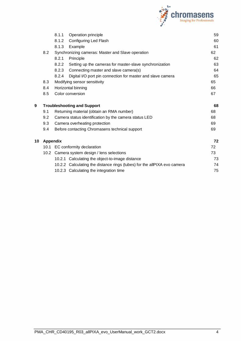
allPIXA evo camera | Manual
CD40195
R03 / 2021-05-31

PMA_CHR_CD40195_R03_allPIXA_evo_UserManual_work_GCT2.docx 2
Table of Contents
1 General information 5
1.1 About Chromasens 5
1.1.1 Contact information 5
1.1.2 Support 5
1.2 Firmware and software version in this manual 6
1.3 List of abbreviations 6
1.4 Definitions 7
1.5 Scope of supply of the allPIXA evo camera 8
1.6 Design of a line scan camera system 9
2 Specifications and definitions 10
2.1 Camera highlights 10
2.2 Feature Reference 11
2.3 Technical specification 12
2.4 Mechanical specification 13
2.4.1 Mechanical dimensions of the allPIXA evo 10k camera 13
2.4.2 Mechanical dimensions of the allPIXA evo 15k camera 14
2.4.3 Mechanical dimensions of the allPIXA evo 8k camera 15
2.5 Sensor alignment and orientation 16
2.6 Adapter and accessories 17
2.6.1 Lenses, adapters, and mounts 17
2.6.2 Cooling kit 17
2.6.3 Environmental requirements 18
3 Safety 19
3.1 Depiction of safety instructions 19
3.2 Basic safety regulations 19
3.3 Safety instructions on the allPIXA evo camera 20
3.4 Purpose / applications 20
3.5 Staff requirements 21
3.6 Organizational measurements 21
3.7 Safety instructions for maintenance / cleaning 21
3.8 Maintenance and cleaning of the allPIXA evo camera 22
3.8.1 Cleaning intervals 22
3.8.2 Cleaning process 22
3.9 Disposal 22
4 allPIXA evo – basic functionality 23
4.1 Basic design of the allPIXA evo camera 23
4.2 Line scan sensors of the 10K and 15K allPIXA evo cameras 24
4.2.1 Design 24
4.2.2 Sensor pixel arrangement of the color sensor 24
4.2.3 Spectral sensitivity 25
4.3 Line scan sensor of the 8K allPIXA evo camera 26
4.3.1 Design of the color sensor 26

PMA_CHR_CD40195_R03_allPIXA_evo_UserManual_work_GCT2.docx 3
4.3.2 Sensor pixel arrangement 26
4.4 Image processing 27
4.4.1 Digital image processing 27
4.5 Black-level correction and shading (flat-field) correction 28
4.6 White balancing with a closed-loop control 29
4.7 Setting concept 30
4.7.1 Available user sets 30
4.7.2 Data format 30
4.7.3 Restoring the factory default 30
4.8 SphinxLib API 30
5 Installing the allPIXA evo camera 31
5.1 Interface and status LED 31
5.1.1 Power supply 32
5.1.2 Micro-USB 32
5.1.3 SFP+ connectors 32
5.1.4 Status LED 32
5.1.5 Digital IO port 33
5.1.6 LVCMOS and RS422 levels 34
5.2 Trigger/IO and Encoder wiring 34
5.2.1 Using a light barrier – Start condition only 35
5.2.2 Using a light barrier – Start and stop condition 36
5.2.3 Using line trigger input 36
5.2.4 Using an encoder 37
5.3 Mechanical installation 38
5.4 Thermal links / cooling 39
5.5 Preventing installation errors 39
5.5.1 Conveyor belt tracking 39
5.5.2 Perpendicularity of the sensor to the direction of transport 40
5.5.3 Rotation around the longitudinal axis of the line scan sensor 40
5.5.4 Rotation around the transverse axis of the line sensor 41
5.6 Electrical installation 41
5.7 Connecting the camera to the PC 43
5.8 Configuring the network adapter 44
6 Working with GCT 46
6.1 Setting image parameters 46
6.2 Updating the firmware 46
6.3 Flat field correction: Creating a black-reference (DSNU) 48
6.4 Flat field correction: Creating a shading reference (PRNU) 49
7 Camera system set-up 52
7.1 Installing the camera 52
7.2 Starting up the system 53
7.3 Adjusting the camera to the environment (camera calibration) 55
8 Additional features 59
8.1 Configuring multi-channel flash control 59
PMA_CHR_CD40195_R03_allPIXA_evo_UserManual_work_GCT2.docx 4
8.1.1 Operation principle 59
8.1.2 Configuring Led Flash 60
8.1.3 Example 61
8.2 Synchronizing cameras: Master and Slave operation 62
8.2.1 Principle 62
8.2.2 Setting up the cameras for master-slave synchronization 63
8.2.3 Connecting master and slave camera(s) 64
8.2.4 Digital I/O port pin connection for master and slave camera 65
8.3 Modifying sensor sensitivity 65
8.4 Horizontal binning 66
8.5 Color conversion 67
9 Troubleshooting and Support 68
9.1 Returning material (obtain an RMA number) 68
9.2 Camera status identification by the camera status LED 68
9.3 Camera overheating protection 69
9.4 Before contacting Chromasens technical support 69
10 Appendix 72
10.1 EC conformity declaration 72
10.2 Camera system design / lens selections 73
10.2.1 Calculating the object-to-image distance 73
10.2.2 Calculating the distance rings (tubes) for the allPIXA evo camera 74
10.2.3 Calculating the integration time 75
PMA_CHR_CD40195_R03_allPIXA_evo_UserManual_work_GCT2.docx 5
1 General information
1.1 About Chromasens
The name of our company, Chromasens, is a combination of 'Chroma' which means color, and 'Sens' which stands for sensor technology.
Chromasens designs, develops, and produces high-quality and user-friendly products:
◼ Line scan cameras
◼ Camera systems
◼ Camera illumination systems
◼ Image acquisition systems
◼ Image processing solutions
Today, Chromasens GmbH is experiencing steady growth and is continually penetrating new sales markets around the globe. The company's technologies are used, for example, in products and for applications such as book and document scanners, sorting systems and inspection systems for quality assurance monitoring.
Customers from all over the world of a wide range of industrial sectors have placed their trust in the experience of Chromasens in the field of industrial image processing.
1.1.1 Contact information
Chromasens GmbH Max-Stromeyer-Str. 116 78467 Konstanz Germany
Phone: +49 (0) 7531 / 876-0
Fax: +49 (0) 7531 / 876-303 Email: [email protected] HP: www.chromasens.de
1.1.2 Support
Should you ever have problems with the allPIXA evo camera that you cannot solve by yourself, please look into this manual for additional information, check the troubleshooting chapter 9, contact your local distributor, or send us an e-mail.
Chromasens GmbH Max-Stromeyer-Str. 116 D-78467 Konstanz Germany
Phone: +49 (0) 7531 / 876-500 Fax: +49 (0) 7531 / 876-303 Email: [email protected] HP: http://www.chromasens.de/en/support
Visit our website at http://www.chromasens.de which features detailed information on our company and products.
PMA_CHR_CD40195_R03_allPIXA_evo_UserManual_work_GCT2.docx 6
1.2 Firmware and software version in this manual
This document refers to the following version:
Camera: Packet 1.52.3
The recent version may have additional functions. Therefore, contact the Chromasens support.
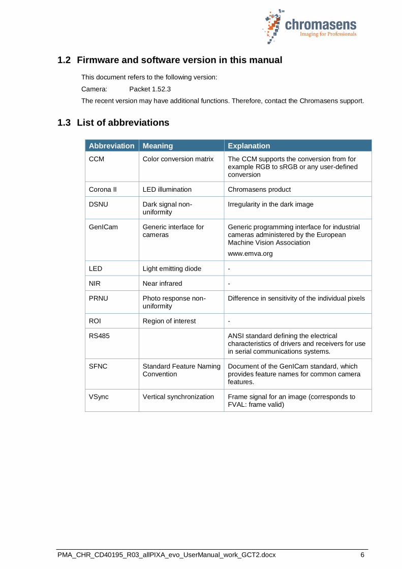
1.3 List of abbreviations
Abbreviation Meaning Explanation
CCM Color conversion matrix The CCM supports the conversion from for example RGB to sRGB or any user-defined conversion
Corona II LED illumination Chromasens product
DSNU Dark signal non-uniformity
Irregularity in the dark image
GenICam Generic interface for cameras
Generic programming interface for industrial cameras administered by the European Machine Vision Association
www.emva.org
LED Light emitting diode -
NIR Near infrared -
PRNU Photo response non-uniformity
Difference in sensitivity of the individual pixels
ROI Region of interest -
RS485 ANSI standard defining the electrical characteristics of drivers and receivers for use in serial communications systems.
SFNC Standard Feature Naming Convention
Document of the GenICam standard, which provides feature names for common camera features.
VSync Vertical synchronization Frame signal for an image (corresponds to FVAL: frame valid)
PMA_CHR_CD40195_R03_allPIXA_evo_UserManual_work_GCT2.docx 7
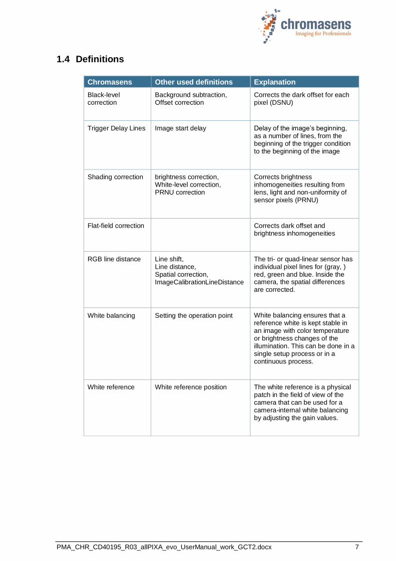
1.4 Definitions
Chromasens Other used definitions Explanation
Black-level correction
Background subtraction, Offset correction
Corrects the dark offset for each pixel (DSNU)
Trigger Delay Lines Image start delay
Delay of the image’s beginning, as a number of lines, from the beginning of the trigger condition to the beginning of the image
Shading correction brightness correction, White-level correction, PRNU correction
Corrects brightness inhomogeneities resulting from lens, light and non-uniformity of sensor pixels (PRNU)
Flat-field correction Corrects dark offset and brightness inhomogeneities
RGB line distance Line shift, Line distance, Spatial correction, ImageCalibrationLineDistance
The tri- or quad-linear sensor has individual pixel lines for (gray, ) red, green and blue. Inside the camera, the spatial differences are corrected.
White balancing Setting the operation point White balancing ensures that a reference white is kept stable in an image with color temperature or brightness changes of the illumination. This can be done in a single setup process or in a continuous process.
White reference White reference position The white reference is a physical patch in the field of view of the camera that can be used for a camera-internal white balancing by adjusting the gain values.
PMA_CHR_CD40195_R03_allPIXA_evo_UserManual_work_GCT2.docx 8
1.5 Scope of supply of the allPIXA evo camera
Check your device upon delivery to ensure that it is undamaged and complete.
The following components are supplied with the allPIXA evo camera:
◼ allPIXA evo camera packaging
Check the packaging for damage, which may have occurred during transport.
◼ allPIXA evo camera
Check the camera for damage, which may have occurred during transport.
The rating plate is located on the rear of the allPIXA evo camera. It shows the camera resolution and the serial number.
◼ Additionally ordered and supplied accessories
Lens adapters, extension rings, lenses and other accessories are not included in the standard scope of delivery. These items must be ordered separately as accessories.
Check additionally ordered accessories for completeness and for damage, which may have occurred during transport.
Read this manual carefully before using the camera, contacting your local partners or the Chromasens support.
Should there be any questions left, do not hesitate to contact your local partner or us.
We would be pleased to be of assistance to you.
PMA_CHR_CD40195_R03_allPIXA_evo_UserManual_work_GCT2.docx 9
1.6 Design of a line scan camera system
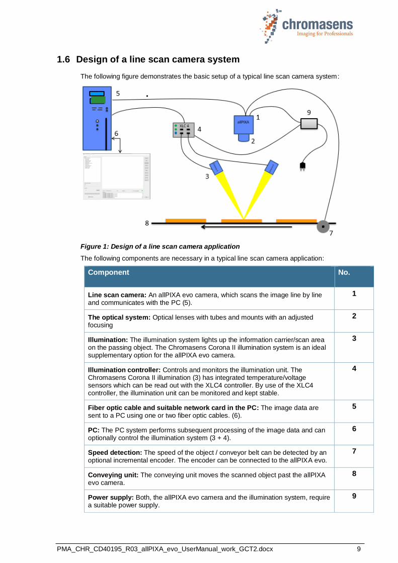
The following figure demonstrates the basic setup of a typical line scan camera system:
Figure 1: Design of a line scan camera application
The following components are necessary in a typical line scan camera application:
Component No.
Line scan camera: An allPIXA evo camera, which scans the image line by line and communicates with the PC (5).
1
The optical system: Optical lenses with tubes and mounts with an adjusted focusing
2
Illumination: The illumination system lights up the information carrier/scan area on the passing object. The Chromasens Corona II illumination system is an ideal supplementary option for the allPIXA evo camera.
3
Illumination controller: Controls and monitors the illumination unit. The Chromasens Corona II illumination (3) has integrated temperature/voltage sensors which can be read out with the XLC4 controller. By use of the XLC4 controller, the illumination unit can be monitored and kept stable.
4
Fiber optic cable and suitable network card in the PC: The image data are sent to a PC using one or two fiber optic cables. (6).
5
PC: The PC system performs subsequent processing of the image data and can optionally control the illumination system (3 + 4).
6
Speed detection: The speed of the object / conveyor belt can be detected by an optional incremental encoder. The encoder can be connected to the allPIXA evo.
7
Conveying unit: The conveying unit moves the scanned object past the allPIXA evo camera.
8
Power supply: Both, the allPIXA evo camera and the illumination system, require a suitable power supply.
9
PMA_CHR_CD40195_R03_allPIXA_evo_UserManual_work_GCT2.docx 10
2 Specifications and definitions
The allPIXA evo camera family is available in the following maximum resolutions:
◼ 8,192 pixels
◼ 10,240 pixels
◼ 15,360 pixels
The allPIXA evo camera comprises all functions required for supplying images with the same color, brightness, and resolution of each operational area.
The allPIXA evo camera is especially suitable for inspection systems requiring a very high speed and a consistently high color quality.
The camera is compliant with the GigE Vision 2.0 specification which defines the communication interface protocol for any GigE Vision device. The device description of the camera is contained in an XML file. For more information for GigE Vision see: https://www.emva.org/standards-technology/genicam.
The camera can be connected to the PC either with a single copper or fiber cable or with two cables using Link Aggregation.
Continuous white balancing is possible during image acquisition to ensure optimum color quality. In addition, offset and shading correction ensure the balance of different color pixel sensitivities (DSNU and PRNU) as well as the illumination process.
The design was fully revised during development of the housing, which is impressively tough but offers several screw-mounting options. Take notice that the wide range of adapter options makes the installation simple for users.
The standard mount connections M72x0.75 for the 10k camera, or M95x1.0 for the 15k camera, respectively, permit to use all commercially available standard lenses. In addition, special adapters are available that permit to connect Chromasens accessories.
2.1 Camera highlights
◼ 10k and 15k quad-linear CMOS color line scan with 5.6 µm pixel size
◼ 8k multiline CMOS color line scan sensor with 5.0 µm pixel size
◼ High accuracy sensor alignment
◼ GigE-Vision-compliant (GigE-Vision 2.0)
◼ 3 x 8 bits color information on the output side; RGB spatial compensation in the camera (also sub-pixel correction, patented)
◼ ROI mode (one ROI selectable)
◼ Continuous white balancing maintains a constant image brightness and color irrespective of the temperature and service life of the illumination system
◼ Incremental encoder port on the camera; this ensures simple handling and less programming work
◼ Flat field correction, fully automatic calculation internally in the camera
◼ Gamma correction, brightness and contrast controller, separate for each channel
◼ Robust metal housing
◼ Standard mount connections M72x0.75 for the 10k camera, or M95x1.0 for the 15k camera, respectively
◼ Special adapters permit to use Chromasens accessories
◼ Internal test image generator
◼ Area scanning with variable image lengths based on trigger inputs (light barriers)
PMA_CHR_CD40195_R03_allPIXA_evo_UserManual_work_GCT2.docx 11
2.2 Feature Reference
For detailed information on camera controls refer to the allPIXA evo Features Reference, which is available on the Chromasens website. It describes the standard and advanced camera controls for GigE Vision. Please make sure that you always refer to the feature reference that matches the used firmware version.
PMA_CHR_CD40195_R03_allPIXA_evo_UserManual_work_GCT2.docx 12
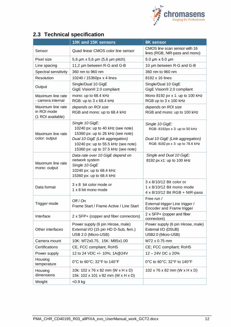
2.3 Technical specification
10K and 15K sensors 8K sensor
Sensor Quad linear CMOS color line sensor CMOS line scan sensor with 16
lines (RGB, NIR-pass and mono)
Pixel size 5,6 µm x 5,6 µm (5,6 µm pitch) 5.0 μm x 5.0 μm
Line spacing 11,2 µm between R-G and G-B 10 µm between R-G and G-B
Spectral sensitivity 360 nm to 960 nm 360 nm to 960 nm
Resolution 10240 / 15360px x 4 lines 8192 x 16 lines
Output Single/Dual 10 GigE
GigE Vision® 2.0 compliant
Single/Dual 10 GigE
GigE Vision® 2.0 compliant
Maximum line rate
- camera internal
mono: up to 68.4 kHz
RGB: up to 3 x 68.4 kHz
Mono 8192 px x 1: up to 100 kHz
RGB up to 3 x 100 kHz
Maximum line rate
in ROI mode
(1 ROI available)
depends on ROI size
RGB and mono: up to 68.4 kHz
depends on ROI size
RGB and mono: up to 100 kHz
Maximum line rate color: output
Single 10 GigE:
10240 px: up to 40 kHz (see note)
15360 px: up to 26 kHz (see note)
Dual 10 GigE (Link aggregation)
10240 px: up to 55.5 kHz (see note)
15360 px: up to 37.5 kHz (see note)
Single 10 GigE:
RGB: 8192px x 3: up to 50 kHz
Dual 10 GigE (Link aggregation)
RGB: 8192 px x 3: up to 78.6 kHz
Maximum line rate
mono: output
Data rate over 10 GigE depend on
network system
Single 10 GigE
10240 px: up to 68.4 kHz
15360 px: up to 68.4 kHz
Single and Dual 10 GigE:
8192 px x1: up to 100 kHz
Data format 3 x 8 bit color mode or
1 x 8 bit mono mode
3 x 8/10/12 Bit color or
1 x 8/10/12 Bit mono mode
4 x 8/10/12 Bit RGB + NIR-pass
Trigger mode Off / On
Frame Start / Frame Active / Line Start
Free run /
External trigger Line trigger / Encoder and Frame trigger
Interface 2 x SFP+ (copper and fiber connectors) 2 x SFP+ (copper and fiber connectors)
Other interfaces
Power supply (6 pin Hirose, male)
External I/O (15 pin HD D-Sub, fem.)
USB 2.0 (Micro-USB)
Power supply (6 pin Hirose, male)
External I/O (DSUB)
USB2.0 (Micro-USB)
Camera mount 10K: M72x0.75, 15K: M95x1.00 M72 x 0.75 mm
Certifications CE, FCC compliant, RoHS CE; FCC compliant; RoHS
Power supply 12 to 24 VDC +/- 10%; 1A@24V 12 – 24V DC ± 20%
Housing
temperature 0°C to 60°C; 32°F to 140°F 0°C to 60°C; 32°F to 140°F
Housing dimensions
10k: 102 x 76 x 82 mm (W x H x D)
15k: 102 x 101 x 82 mm (W x H x D)
102 x 76 x 82 mm (W x H x D)
Weight <0.9 kg
PMA_CHR_CD40195_R03_allPIXA_evo_UserManual_work_GCT2.docx 13
NOTE For reliable and fast image data transfer over 10 GigE use the Chromasens GenICam SDK and recommended network adapters. Take notice that Windows does not support LAG. Maximum line frequencies over 10 GigE depend on PC performance, network hardware, and configuration.
NOTE The power consumption may be up to 1 ampere@24V. It is recommended to provide a power supply with 24VDC/1amp or with higher possible power consumption.
2.4 Mechanical specification
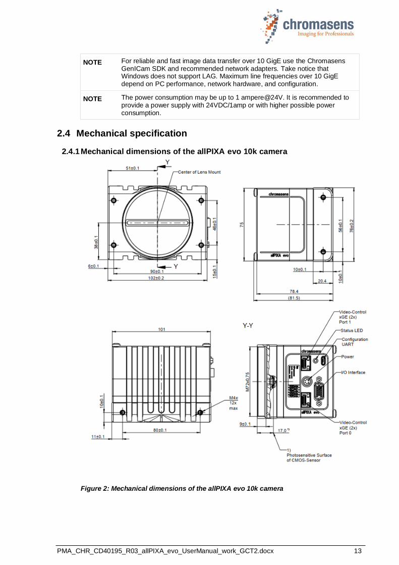
2.4.1 Mechanical dimensions of the allPIXA evo 10k camera
Figure 2: Mechanical dimensions of the allPIXA evo 10k camera
PMA_CHR_CD40195_R03_allPIXA_evo_UserManual_work_GCT2.docx 14
NOTE I Drawings and 3D-CAD-models are available on our homepage http://www.chromasens.de
NOTE II The shown position of the sensor surface is given as resulting optical value including lengthening of the sensor glass. For more details, see section 2.5.
NOTE III For information about the XYZ coordinate system and sensor alignment, see section 2.4.3.
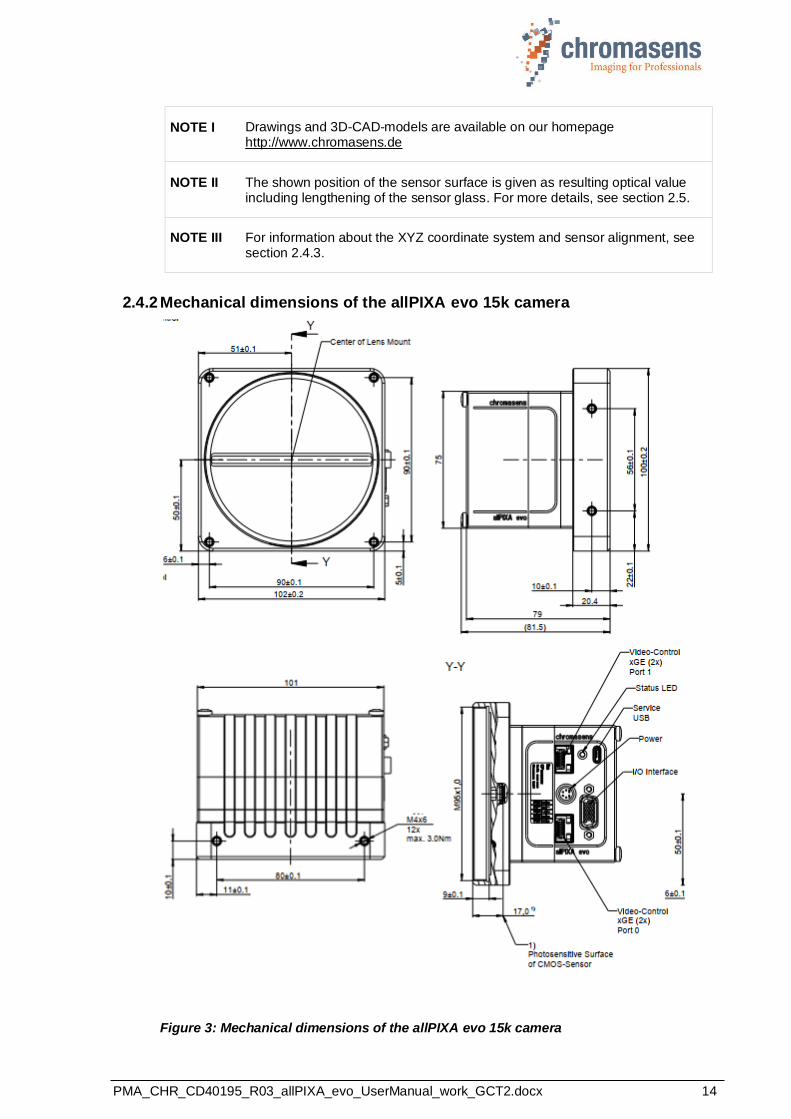
2.4.2 Mechanical dimensions of the allPIXA evo 15k camera
Figure 3: Mechanical dimensions of the allPIXA evo 15k camera
PMA_CHR_CD40195_R03_allPIXA_evo_UserManual_work_GCT2.docx 15
NOTE I Drawings and 3D-CAD-models are available on our homepage http://www.chromasens.de
NOTE II The shown position of the Sensor surface is given as resulting optical value including lengthening of the sensor glass. For more details, see section 2.5.
NOTE III For information about the XYZ coordinate system and sensor alignment, see section 2.52.4.3.
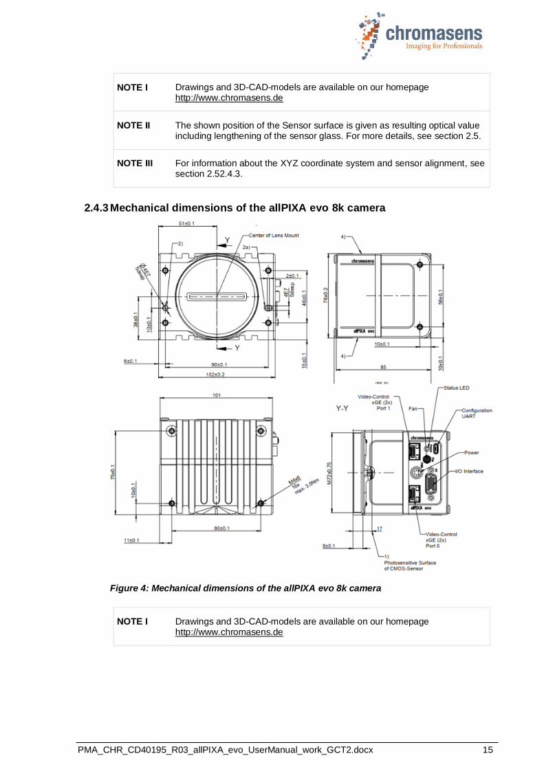
2.4.3 Mechanical dimensions of the allPIXA evo 8k camera
Figure 4: Mechanical dimensions of the allPIXA evo 8k camera
NOTE I Drawings and 3D-CAD-models are available on our homepage http://www.chromasens.de
PMA_CHR_CD40195_R03_allPIXA_evo_UserManual_work_GCT2.docx 16
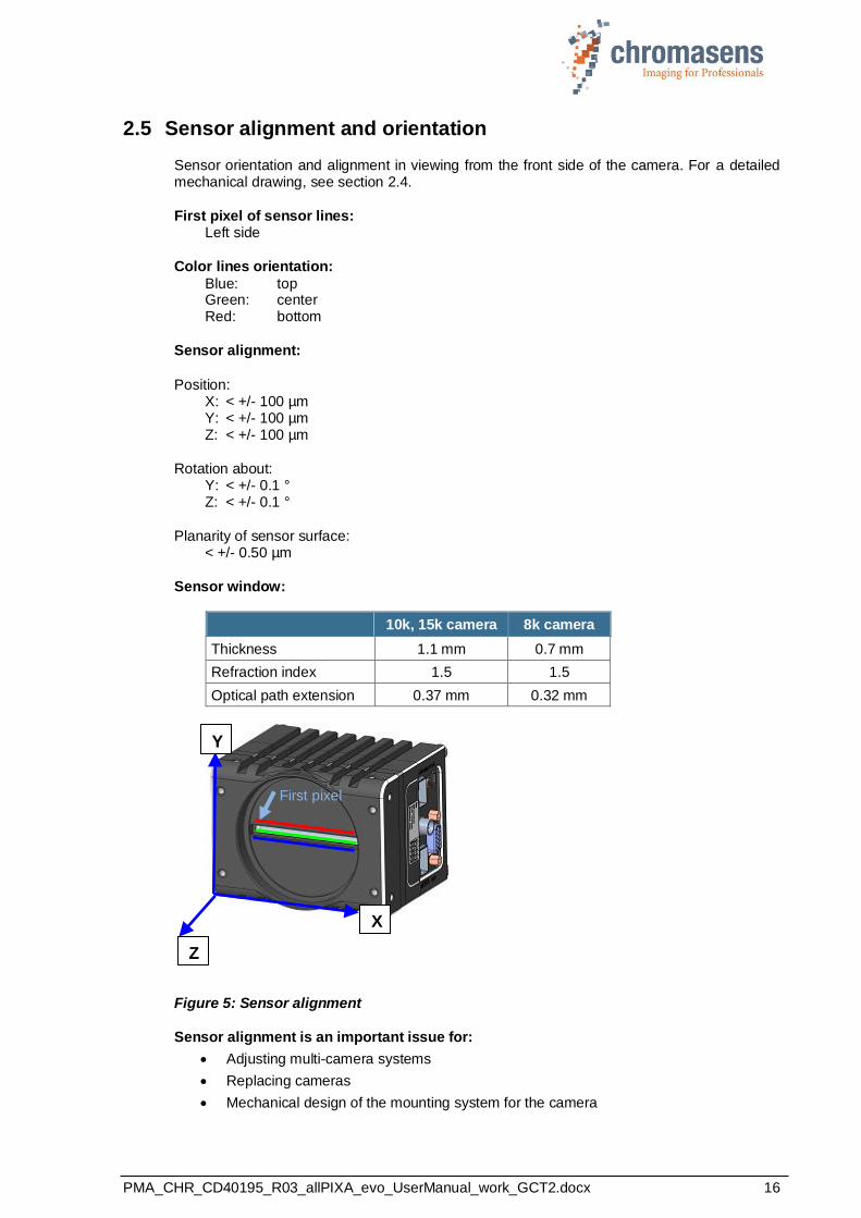
2.5 Sensor alignment and orientation
Sensor orientation and alignment in viewing from the front side of the camera. For a detailed mechanical drawing, see section 2.4.
First pixel of sensor lines: Left side
Color lines orientation:
Blue: top Green: center Red: bottom
Sensor alignment:
Position: X: < +/- 100 µm Y: < +/- 100 µm Z: < +/- 100 µm
Rotation about: Y: < +/- 0.1 ° Z: < +/- 0.1 °
Planarity of sensor surface: < +/- 0.50 µm
Sensor window:
10k, 15k camera 8k camera
Thickness 1.1 mm 0.7 mm
Refraction index 1.5 1.5
Optical path extension 0.37 mm 0.32 mm
Figure 5: Sensor alignment
Sensor alignment is an important issue for:
• Adjusting multi-camera systems
• Replacing cameras
• Mechanical design of the mounting system for the camera
First pixel
X
Y
Z
PMA_CHR_CD40195_R03_allPIXA_evo_UserManual_work_GCT2.docx 17
2.6 Adapter and accessories
2.6.1 Lenses, adapters, and mounts
Chromasens offers a large variety of accessories which are designed to provide maximum flexibility and to get most out of the camera.
For the allPIXA evo cameras, special adapters are available that permit to use the accessories of the allPIXA pro cameras.
You can find the complete list of all accessories including descriptions and detailed drawings in on our website at www.chromasens.de/user.
NOTE For more information about accessories, refer to the corresponding accessories catalogue.
2.6.2 Cooling kit
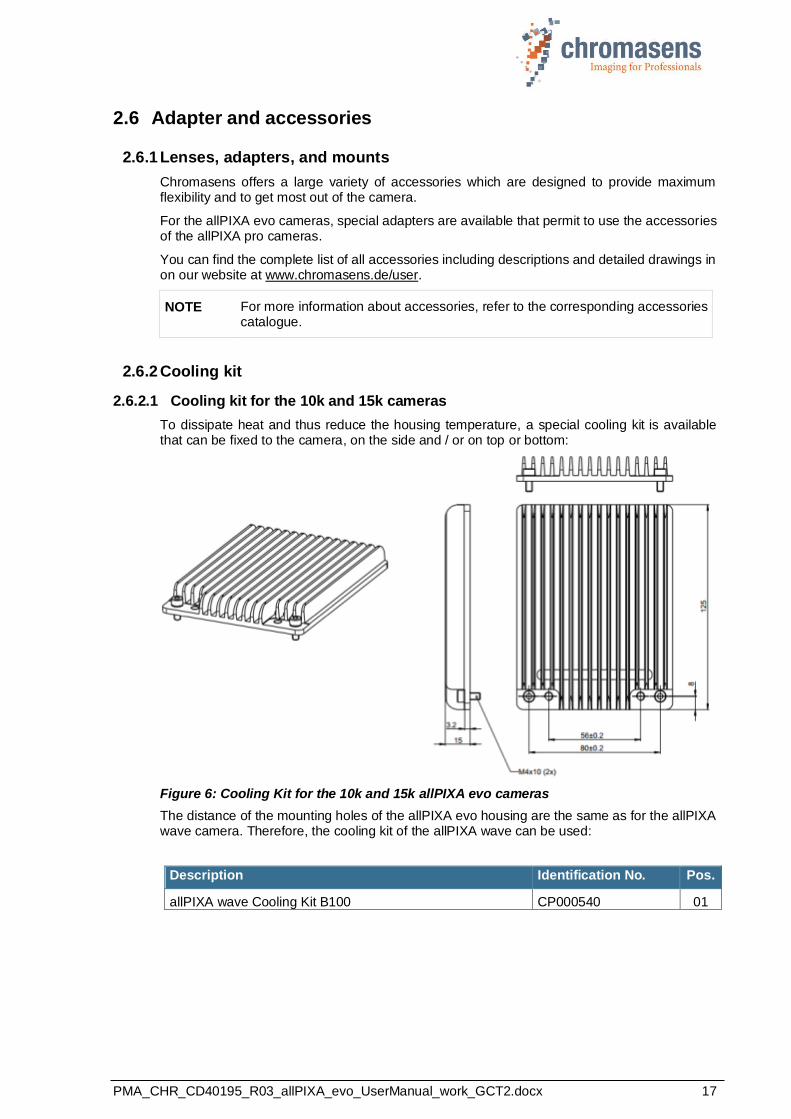
2.6.2.1 Cooling kit for the 10k and 15k cameras
To dissipate heat and thus reduce the housing temperature, a special cooling kit is available that can be fixed to the camera, on the side and / or on top or bottom:
Figure 6: Cooling Kit for the 10k and 15k allPIXA evo cameras
The distance of the mounting holes of the allPIXA evo housing are the same as for the allPIXA wave camera. Therefore, the cooling kit of the allPIXA wave can be used:
Description Identification No. Pos.
allPIXA wave Cooling Kit B100 CP000540 01

PMA_CHR_CD40195_R03_allPIXA_evo_UserManual_work_GCT2.docx 18
2.6.2.2 Cooling kit and fan for the 8k cameras
For the 8k evo camera, a cooling kit is available that can be mounted to the back, upper, or lower side of the camera:
Figure 7: Cooling Kit for the 8k allPIXA evo cameras
Use heat conducting pads between camera and cooling adapter. Different pads are included. Choose the pad which fits best to the camera side.
In addition, a fan is available that can be mounted in the same way as the cooling kit. Its power supply cable can be connected to the camera (see section 5.1.
Description Identification No.
allPIXA evo2 PIN Cooling CP000643
allPIXA evo2 FAN Cooling CP000644
2.6.3 Environmental requirements
Value
Temperature for camera operation See section 2.3 for the allowed housing
temperature
Air humidity during camera operation 20% - 85% relative air humidity,
non-condensing
Storage / transport temperature -20 ºC - +85 ºC; -4 °F - +185 °F
Protection category IP50
General ambient conditions
Operation IEC 721-3-3:IE33
Transport IEC 721-3-2:IE21
Storage IEC 721-3-1:IE11
NOTE: You should use thermal conductive mounting (for example direct attachment on metal frame) to decrease temperature and for improved camera performance. See also section 5.4.

PMA_CHR_CD40195_R03_allPIXA_evo_UserManual_work_GCT2.docx 19
3 Safety
3.1 Depiction of safety instructions
Safety-relevant information is indicated in this manual as follows:
WARNING
Indicates a potentially hazardous situation or task, which, if not avoided, could result in serious injury or death.
CAUTION
Indicates a potentially hazardous situation or task, which, if not avoided, may result in minor or moderate injury.
Indicates a potentially hazardous situation or task, which, if not avoided, could result in damage to the product or the surrounding environment.
3.2 Basic safety regulations
The basic safety regulations always observe the following:
◼ Do not attempt to install the device or start operation before you have read all supplied documentation carefully and have understood its contents.
◼ Safe and correct operation of the device requires correct and appropriate transport, storage,
mounting and installation as well as careful operation and maintenance.
◼ Operation of the allPIXA evo camera device is only permitted if it is in a faultless and safe condition. If a fault or defect occurs, the allPIXA evo camera, the machine, or the system in which the allPIXA evo camera is installed, must be stopped immediately, and the responsible person must be informed.
◼ Modifications and extensions to the allPIXA evo camera are only permitted if the prior written consent of Chromasens GmbH is obtained. This applies in particular to modifications and extensions which can negatively affect the safety of the allPIXA evo camera.
◼ Compliance with the ambient conditions described in this manual is essential.
PMA_CHR_CD40195_R03_allPIXA_evo_UserManual_work_GCT2.docx 20
3.3 Safety instructions on the allPIXA evo camera
Risks from hot surfaces
The body of the allPIXA evo camera heats up during operation.
Do not touch hot surfaces without suitable protective gloves. Always allow hot surfaces to cool down before carrying out any work on the unit.
Electric voltage hazard
The allPIXA evo camera runs with electric power. Before any work is carried out on the allPIXA evo camera, be aware to disconnect the mains cables. Make sure that the device is safely isolated from the power supply!
Risk of electrostatic discharge
The allPIXA evo camera contains components and units which are sensitive to electrostatic charge.
Observe all precautionary measures for handling electrostatically sensitive equipment.
Make sure that allPIXA evo camera, its corresponding tools, its equipment, and the knowledge of the person who is handling it have the same electrical potential.
3.4 Purpose / applications
◼ The allPIXA evo camera is designed for machines and systems which are used for commercial and industrial applications.
◼ The owner of the machine or system in which the allPIXA evo camera has been installed is
responsible for compliance with relevant safety regulations, standards and directives. Commissioning of the allPIXA evo camera is only permitted if the machine or system, in which the camera is installed, complies with the safety regulations and standards of the country in which the allPIXA evo camera runs.
◼ The owner of the machine or system with the installed allPIXA evo camera must verify the
suitability of the allPIXA evo camera for its intended use.
◼ Safety regulations of the country in which the device is used must be complied with it.
◼ The allPIXA evo camera may only be connected or used as described in this manual.
◼ The allPIXA evo camera must be set up and installed in compliance with the instructions contained in this manual.

PMA_CHR_CD40195_R03_allPIXA_evo_UserManual_work_GCT2.docx 21
3.5 Staff requirements
◼ The system owner must ensure that all persons working on the system are trained for the required work and have read and understood this manual. This applies particularly to the employees who only work occasionally with the allPIXA evo camera, for example, during commissioning and maintenance work.
◼ Work on the electrical installation of the system may only be carried out by a qualified electrician or persons who have undergone the necessary electrotechnical training under the supervision of a qualified electrician, in compliance with applicable electrotechnical regulations.
◼ Be aware that only suitably trained and qualified persons are permitted to work with the allPIXA evo camera. Such persons are qualified to work with the allPIXA evo camera device if they are familiar with its assembly, installation, care, and all necessary precautionary measures.
◼ Assignments and responsibilities of the staff charged with operation, commissioning, maintenance, and repair must be clearly defined and specified by the owner of the device in which the allPIXA evo camera is installed.
3.6 Organizational measurements
◼ The instruction manual must be stored safely in the vicinity of the camera in operation.
◼ Information contained in this manual must be integrated into the documentation of the
device in which the allPIXA evo camera is installed.
◼ The allPIXA evo camera and all connected peripheries must be checked regularly for visible external damages.
3.7 Safety instructions for maintenance / cleaning
◼ Before any service or maintenance work is carried out, the responsible staff has to be informed.
◼ Deadlines and intervals for regular inspections must be complied with.
◼ Before maintenance is started, the allPIXA evo camera must be isolated from the power supply.
◼ Due to the risk of fire, devices such as radiators, heaters, or lighting equipment must be allowed first to cool down.
◼ Only technicians of the Chromasens GmbH are permitted to open or slacken screws or
housing sections of the allPIXA evo camera.
◼ Necessary repairs may only be carried out by Chromasens GmbH.
◼ Cleaning of the device is only allowed with a soft, lint-free cloth and Isopropanol (optional).
◼ To avoid damages, the camera should only be transported in its original packaging.
PMA_CHR_CD40195_R03_allPIXA_evo_UserManual_work_GCT2.docx 22
3.8 Maintenance and cleaning of the allPIXA evo camera
During operation of the device, particles such as dust etc. may be settled on the optical
components (lens) of the camera. These deposits affect the optical image and the function of the camera negatively.
Chromasens recommends regular inspection and cleaning. The cleaning intervals depend on the actual operating and ambient conditions (for example dust-laden atmosphere).
3.8.1 Cleaning intervals
Cleaning intervals depend on the environment. Regular inspection and cleaning intervals must be specified depending on the degree of soiling.
3.8.2 Cleaning process
The body of the allPIXA evo camera heats up during operation.
Before cleaning, you must switch off the device. Always allow hot surfaces to cool down before cleaning the device.
The device works with electric power. Before cleaning the device, make sure that the device is disconnected from the power supply.
All surfaces requiring cleaning can be wiped with a soft, lint-free cloth which can be moistened with Isopropanol.
Never use any other liquid or cleaning agent than those stated in this manual.
Never use hard or sharp tools for cleaning the device.
Inspect the device to ensure that cleaning was effective and repeat, if necessary.
If it is not possible to clean a component due to irremovable contamination, it must be replaced.
3.9 Disposal
This symbol indicates that electrical and electronic equipment should not be disposed with normal garbage at the end of its working life. To prevent possible harm to the environment or human health from uncontrolled waste disposal, separate this from other types of wastes and recycle it responsibly to promote the sustainable reuse of material resources.
Please dispose this product in accordance with your local regulations and contact your local
government office, for details of where and how they can take this item for environmentally safe recycling.
PMA_CHR_CD40195_R03_allPIXA_evo_UserManual_work_GCT2.docx 23
4 allPIXA evo – basic functionality
4.1 Basic design of the allPIXA evo camera
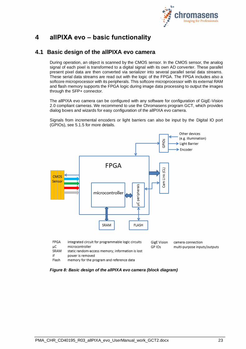
During operation, an object is scanned by the CMOS sensor. In the CMOS sensor, the analog signal of each pixel is transformed to a digital signal with its own AD converter. These parallel present pixel data are then converted via serializer into several parallel serial data streams. These serial data streams are read out with the logic of the FPGA. The FPGA includes also a softcore microprocessor with its peripherals. This softcore microprocessor with its external RAM and flash memory supports the FPGA logic during image data processing to output the images through the SFP+ connector.
The allPIXA evo camera can be configured with any software for configuration of GigE-Vision 2.0 compliant cameras. We recommend to use the Chromasens program GCT, which provides dialog boxes and wizards for easy configuration of the allPIXA evo camera.
Signals from incremental encoders or light barriers can also be input by the Digital IO port (GPIOs), see 5.1.5 for more details.
Figure 8: Basic design of the allPIXA evo camera (block diagram)

PMA_CHR_CD40195_R03_allPIXA_evo_UserManual_work_GCT2.docx 24
4.2 Line scan sensors of the 10K and 15K allPIXA evo cameras
4.2.1 Design
The 10K and 15K allPIXA evo camera color line scan cameras are equipped with a quad-linear CMOS line scan sensor with 4 spatially separated lines which are sensitive to brightness and the colors red, green and blue (RGB).
In this way, 3-color information is obtained from each image point (RGB). The spacing of sensor lines is compensated in the allPIXA evo camera.
Compared to camera systems with interpolating processes (for example single-line or bilinear color line scan cameras), the color information is acquired with 3 x 12 bits for each image point.
Take notice that high-quality color detection is only possible in that way.
Sensor pixels are 5.6 µm wide and 5.6 µm long. The distance between the color sensor lines is 11.2 µm.
Spatial correction is achieved by the corresponding delay of the individual items of color information. As a result of the object’s movement, for example, an object point first reaches the blue sensor line, then the green sensor line and finally the red sensor line.
These 3 color channels are then combined into a complete image.
Continual scanning provides a color image which can theoretically be infinitely long.
Figure 9: 10K and 15K line scan sensors
4.2.2 Sensor pixel arrangement of the color sensor
Figure 10 Pixel arrangement at the 10k and 15k allPIXA evo camera
PMA_CHR_CD40195_R03_allPIXA_evo_UserManual_work_GCT2.docx 25
4.2.3 Spectral sensitivity
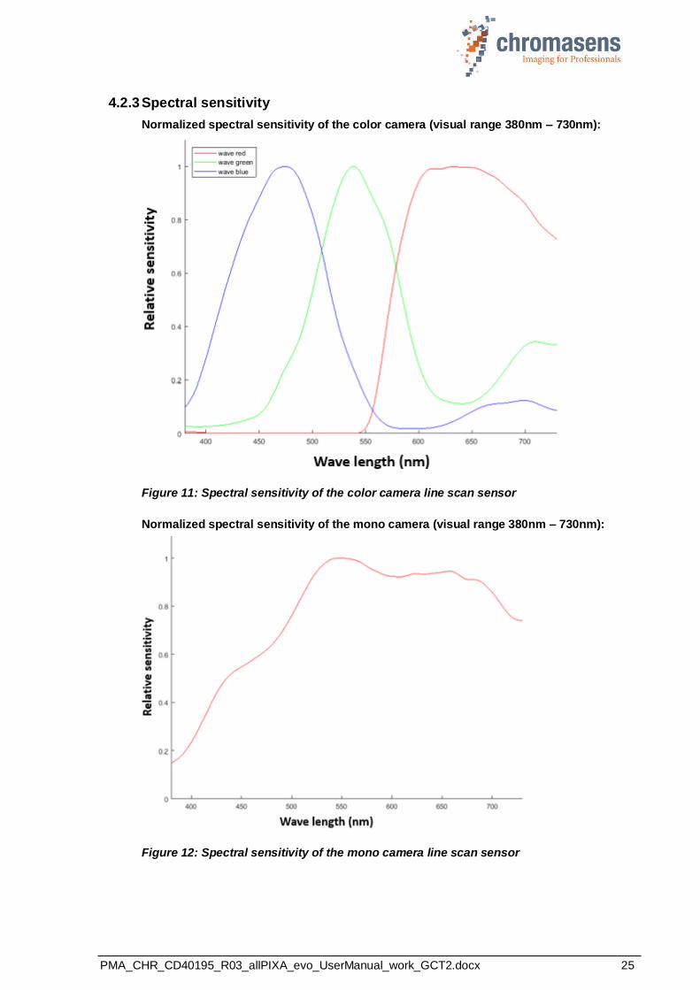
Normalized spectral sensitivity of the color camera (visual range 380nm – 730nm):
Figure 11: Spectral sensitivity of the color camera line scan sensor
Normalized spectral sensitivity of the mono camera (visual range 380nm – 730nm):
Figure 12: Spectral sensitivity of the mono camera line scan sensor

PMA_CHR_CD40195_R03_allPIXA_evo_UserManual_work_GCT2.docx 26
4.3 Line scan sensor of the 8K allPIXA evo camera
4.3.1 Design of the color sensor
The 8K allPIXA evo camera color line scan camera is equipped with a CMOS line scan sensor with 16 spatially separated lines which are sensitive to brightness and the colors.
Sensor pixels are 5 µm wide and 5 µm long. The distance between the color sensor lines is 10 µm.
Spatial correction is achieved by the corresponding delay of the individual items of color information. As a result of the object’s movement, for example, an object point first reaches the blue sensor line, then the green sensor line and finally the red sensor line.
These 3 color channels are then combined into a complete image.
Continual scanning provides a color image which can theoretically be infinitely long.
Figure 13: 8K line scan sensor
4.3.2 Sensor pixel arrangement
Figure 14 Pixel arrangement at the 8k allPIXA evo camera
PMA_CHR_CD40195_R03_allPIXA_evo_UserManual_work_GCT2.docx 27
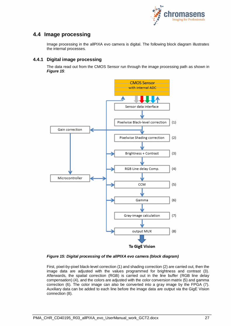
4.4 Image processing
Image processing in the allPIXA evo camera is digital. The following block diagram illustrates the internal processes.
4.4.1 Digital image processing
The data read out from the CMOS Sensor run through the image processing path as shown in Figure 15:
Figure 15: Digital processing of the allPIXA evo camera (block diagram)
First, pixel-by-pixel black-level correction (1) and shading correction (2) are carried out, then the image data are adjusted with the values programmed for brightness and contrast (3). Afterwards, the spatial correction (RGB) is carried out in the line buffer (RGB line delay compensation) (4), and the colors are adjusted with the color conversion matrix (5) and gamma correction (6). The color image can also be converted into a gray image by the FPGA (7). Auxiliary data can be added to each line before the image data are output via the GigE Vision connection (8).

PMA_CHR_CD40195_R03_allPIXA_evo_UserManual_work_GCT2.docx 28
4.5 Black-level correction and shading (flat-field) correction
The allPIXA evo camera supports black-level (offset) and shading correction.
The following points are important for understanding these kinds of operation:
• Both operations are based on pixel-by-pixel calculation, and the effects on behavior of
single pixels such as PRNU (photo response non-uniformity) are eliminated.
• Both operations are carried out separately for every line ((clear), red, green, blue).
• The allPIXA evo camera offers two data sets for black-level correction and two data sets
for shading correction Therefore, you are able to deal with, for example, two different lighting systems by selecting the necessary data sets without having to transfer or generate new shading data.
• Calculation of the correction data sets can be done offline on scanned images. Often, shading data have been calculated internally with a static white reference in front of the camera. In this case, spots of dust on the white reference lead to vertical lines in the image. This effect can be eliminated by slightly defocusing the lens during the generation of the references. The lighting distribution is then seen by the sensor and the lens. Another possibility to avoid this problem is to move the target slightly at the balancing process. In this way, distortions, for example by dust, may also be eliminated.
• The allPIXA evo camera permits offline calculation of the references. You can select a scanned image and define a region of the image, in which shading correction data shall be calculated. By averaging over a higher number of lines, distortions, for example caused by dust on the target, are eliminated. Therefore, it is possible to use an image with a moving white object.
• The allPIXA evo camera also permits to generate shading and offset data internally.
• Generated data sets may be stored to the hard disk of the PC. The stored data can be transferred to the camera later.
• For the calculation, the following formulas can be used:
Mode Recording of black reference line:
BRef(x) = VidRaw with black template or without illumination
Mode Recording of white reference line:
WRef(x) = VidRaw(x) – BRef(x) with white template
Mode / Correction (white- and black-correction is activated)
VidSHCOut(x,y) = (VidRaw(x,y) – BRef(x)) * VidMax
WRef(x)
This calculation is done separately for all color separations (CRGB).
• BRef Black-Reference value for each pixel in the line (DSNU)
• WRef White-Reference value for each pixel in the line (PRNU)
• VidRaw Raw values for each pixel output by A/D Converter
• (x, y) Number of pixels within the line or column
• VidMax Maximum brightness value
• VidSHCOut(x,y) Offset- and shading-corrected pixels of the image
PMA_CHR_CD40195_R03_allPIXA_evo_UserManual_work_GCT2.docx 29
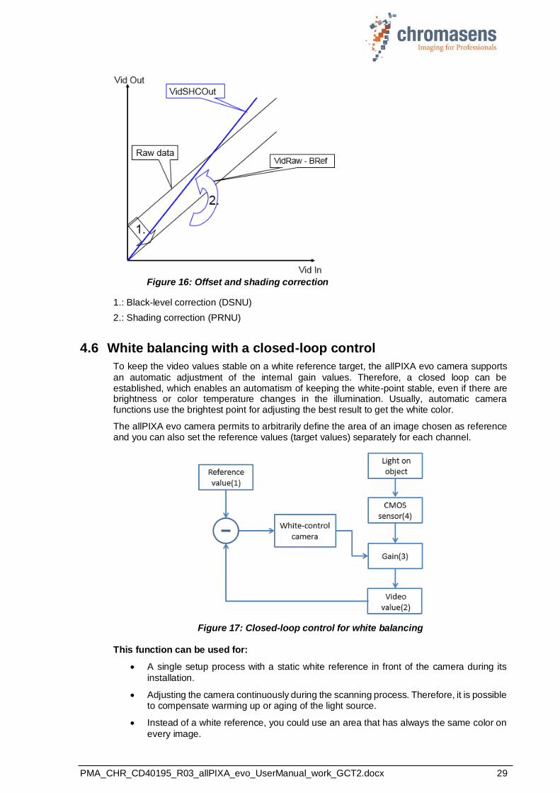
Figure 16: Offset and shading correction
1.: Black-level correction (DSNU)
2.: Shading correction (PRNU)
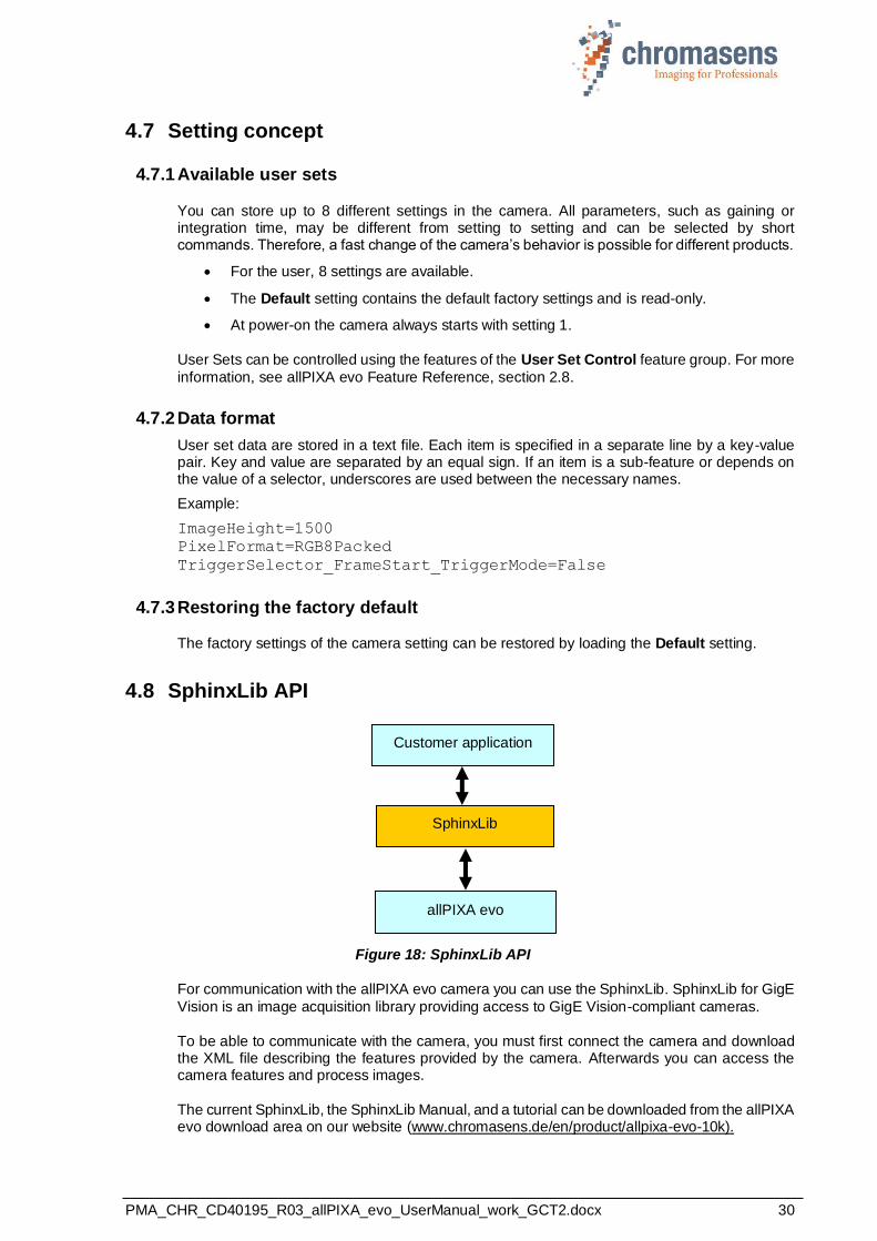
4.6 White balancing with a closed-loop control
To keep the video values stable on a white reference target, the allPIXA evo camera supports
an automatic adjustment of the internal gain values. Therefore, a closed loop can be established, which enables an automatism of keeping the white-point stable, even if there are brightness or color temperature changes in the illumination. Usually, automatic camera functions use the brightest point for adjusting the best result to get the white color.
The allPIXA evo camera permits to arbitrarily define the area of an image chosen as reference and you can also set the reference values (target values) separately for each channel.
Figure 17: Closed-loop control for white balancing
This function can be used for:
• A single setup process with a static white reference in front of the camera during its
installation.
• Adjusting the camera continuously during the scanning process. Therefore, it is possible to compensate warming up or aging of the light source.
• Instead of a white reference, you could use an area that has always the same color on
every image.
PMA_CHR_CD40195_R03_allPIXA_evo_UserManual_work_GCT2.docx 30
4.7 Setting concept
4.7.1 Available user sets
You can store up to 8 different settings in the camera. All parameters, such as gaining or integration time, may be different from setting to setting and can be selected by short commands. Therefore, a fast change of the camera’s behavior is possible for different products.
• For the user, 8 settings are available.
• The Default setting contains the default factory settings and is read-only.
• At power-on the camera always starts with setting 1.
User Sets can be controlled using the features of the User Set Control feature group. For more
information, see allPIXA evo Feature Reference, section 2.8.
4.7.2 Data format
User set data are stored in a text file. Each item is specified in a separate line by a key-value pair. Key and value are separated by an equal sign. If an item is a sub-feature or depends on the value of a selector, underscores are used between the necessary names.
Example:
ImageHeight=1500
PixelFormat=RGB8Packed
TriggerSelector_FrameStart_TriggerMode=False
4.7.3 Restoring the factory default
The factory settings of the camera setting can be restored by loading the Default setting.
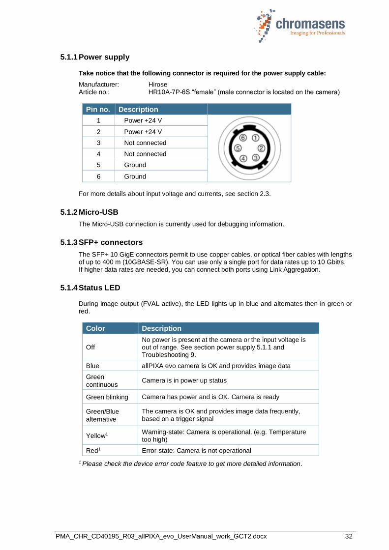
4.8 SphinxLib API
Figure 18: SphinxLib API
For communication with the allPIXA evo camera you can use the SphinxLib. SphinxLib for GigE
Vision is an image acquisition library providing access to GigE Vision-compliant cameras.
To be able to communicate with the camera, you must first connect the camera and download the XML file describing the features provided by the camera. Afterwards you can access the camera features and process images.
The current SphinxLib, the SphinxLib Manual, and a tutorial can be downloaded from the allPIXA evo download area on our website (www.chromasens.de/en/product/allpixa-evo-10k).
SphinxLib
Customer application
allPIXA evo

PMA_CHR_CD40195_R03_allPIXA_evo_UserManual_work_GCT2.docx 31
5 Installing the allPIXA evo camera
5.1 Interface and status LED
On the right side of the camera, you find the following interfaces:
◼ Two SFP+ (Enhanced Small Form-factor Pluggable) interface ports for 10 Gigabit Ethernet for image signaling and for communication between the allPIXA evo camera and the PC
◼ A digital port (IO interface 15 pin HD D-Sub female) for the incremental encoder signal, light barriers and other freely programmable inputs and outputs
◼ A USB port for service connection
◼ A power connection (Hirose HR10A-7R-6P, male) for power supply
◼ A multi-color LED, which indicates the allPIXA evo camera status
◼ Connector for cooling fan (8k camera only)
Figure 19: The allPIXA evo camera connections and status LED (10k and 15 k cameras)
Figure 20: The allPIXA evo camera connections and status LED (8k camera)
Status LED
Service USB
I/O interface
Power
SFP+ over 10 Gigabit Ethernet, GigE Vision Port 1
SFP+ over 10 Gigabit Ethernet, GigE Vision Port 2
SFP+ over 10
Gigabit Ethernet, GigE Vision Port 1
Power
SFP+ over 10 Gigabit Ethernet, GigE Vision Port 2
Status LED
Service USB
Cooling fan
connector
I/O interface
PMA_CHR_CD40195_R03_allPIXA_evo_UserManual_work_GCT2.docx 32
5.1.1 Power supply
Take notice that the following connector is required for the power supply cable:
Manufacturer: Hirose Article no.: HR10A-7P-6S “female” (male connector is located on the camera)
Pin no. Description
1 Power +24 V
2 Power +24 V
3 Not connected
4 Not connected
5 Ground
6 Ground
For more details about input voltage and currents, see section 2.3.
5.1.2 Micro-USB
The Micro-USB connection is currently used for debugging information.
5.1.3 SFP+ connectors
The SFP+ 10 GigE connectors permit to use copper cables, or optical fiber cables with lengths of up to 400 m (10GBASE-SR). You can use only a single port for data rates up to 10 Gbit/s. If higher data rates are needed, you can connect both ports using Link Aggregation.
5.1.4 Status LED
During image output (FVAL active), the LED lights up in blue and alternates then in green or red.
Color Description
Off No power is present at the camera or the input voltage is out of range. See section power supply 5.1.1 and Troubleshooting 9.
Blue allPIXA evo camera is OK and provides image data
Green
continuous Camera is in power up status
Green blinking Camera has power and is OK. Camera is ready
Green/Blue
alternative
The camera is OK and provides image data frequently, based on a trigger signal
Yellow1 Warning-state: Camera is operational. (e.g. Temperature too high)
Red1 Error-state: Camera is not operational
1 Please check the device error code feature to get more detailed information.

PMA_CHR_CD40195_R03_allPIXA_evo_UserManual_work_GCT2.docx 33
5.1.5 Digital IO port
You need a 15-pin HD D-Sub (male) to establish a connection to the digital I/O interface (X12) of the allPIXA evo camera:
Pin Gen<I>Cam Signal Level In/Out Example / Remark
1 Line 1 Enc0_InP RS 422 Input Encoder0 or LineTrigger
2 Line 2 Enc1_InP RS 422 Input Encoder1 or Frametrigger
3 Line 3 IO_0P LVCMOS Input
single-ended Trigger or AutoSelectMaster
4 - RT RS 485
5 Line 5 IO_2P LVCMOS Out LED-Out1
6 Line 1 Enc0_InN RS 422 Input Encoder0
7 Line 2 Enc1_InN RS 422 Input Encoder1
8 Line 4 IO_1N LVCMOS Input
single-ended
Trigger or Master-Slave
Cascaded
9 - RTN RS 485 Out To LightController XLC4
10 Line 6 IO_3 LVCMOS Out LED-Out2
11 - GND GND
12 Line 7 IO_4_SDA LVCMOS Out LED-Out3
13 - GND GND -
14 Line 9 Master/Slave LVCMOS Bi-directional Master/Slave
15 Line 8 IO_5_SCL LVCMOS Out LED-Out4
NOTE RS422: RS422 standard, input only LVCMOS: With 10 Ohm series resistor, In/Out selectable.
The single-ended inputs (Line 3 AND Line 4) have a pull-up resistor and must be switched to Ground:
PMA_CHR_CD40195_R03_allPIXA_evo_UserManual_work_GCT2.docx 34
Some requirements for using the RS422 interfaces:
a) Although RS422 is a differential signal, a proper ground connection is required additionally between the source (for example encoder) and the drain (for example camera).
b) The allPIXA evo contains an internal termination for the RS422 signal lines. The advantage of the internal termination is that you do not have to take care of termination if the RS422 is used as an interface between two devices.
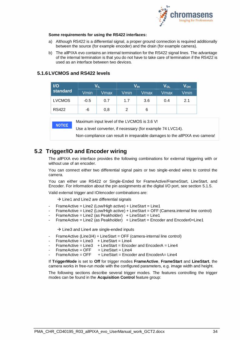
5.1.6 LVCMOS and RS422 levels
I/O standard
VIL VIH VOL VOH
Vmin Vmax Vmin Vmax Vmax Vmin
LVCMOS -0.5 0.7 1.7 3.6 0.4 2.1
RS422 -6 0,8 2 6
Maximum input level of the LVCMOS is 3.6 V!
Use a level converter, if necessary (for example 74 LVC14).
Non-compliance can result in irreparable damages to the allPIXA evo camera!
5.2 Trigger/IO and Encoder wiring
The allPIXA evo interface provides the following combinations for external triggering with or
without use of an encoder.
You can connect either two differential signal pairs or two single-ended wires to control the camera.
You can either use RS422 or Single-Ended for FrameActive/FrameStart, LineStart, and Encoder. For information about the pin assignments at the digital I/O port, see section 5.1.5.
Valid external trigger and IO/encoder combinations are:
→ Line1 and Line2 are differential signals
- FrameActive = Line2 (Low/High active) + LineStart = Line1 - FrameActive = Line2 (Low/High active) + LineStart = OFF (Camera.internal line control) - FrameActive = Line2 (as Peakholder) + LineStart = Line1 - FrameActive = Line2 (as Peakholder) + LineStart = Encoder and Encoder0=Line1
→ Line3 and Line4 are single-ended inputs
- FrameActive (Line3/4) + LineStart = OFF (camera-internal line control) - FrameActive = Line3 + LineStart = Line4 - FrameActive = Line3 + LineStart = Encoder and EncoderA = Line4 - FrameActive = OFF + LineStart = Line4 - FrameActive = OFF + LineStart = Encoder and EncoderA= Line4
If TriggerMode is set to Off for trigger modes FrameActive, FrameStart and LineStart, the camera works in free-run mode with the configured parameters, e.g. image width and height.
The following sections describe several trigger modes. The features controlling the trigger modes can be found in the Acquisition Control feature group:
PMA_CHR_CD40195_R03_allPIXA_evo_UserManual_work_GCT2.docx 35
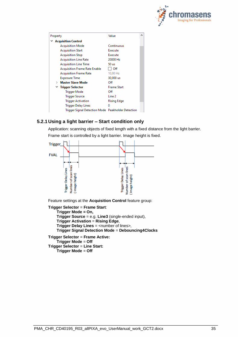
5.2.1 Using a light barrier – Start condition only
Application: scanning objects of fixed length with a fixed distance from the light barrier.
Frame start is controlled by a light barrier. Image height is fixed.
Feature settings at the Acquisition Control feature group:
Trigger Selector = Frame Start: Trigger Mode = On, Trigger Source = e.g. Line3 (single-ended input), Trigger Activation = Rising Edge, Trigger Delay Lines = <number of lines>, Trigger Signal Detection Mode = Debouncing4Clocks
Trigger Selector = Frame Active: Trigger Mode = Off Trigger Selector = Line Start: Trigger Mode = Off

PMA_CHR_CD40195_R03_allPIXA_evo_UserManual_work_GCT2.docx 36
5.2.2 Using a light barrier – Start and stop condition
Application: scanning objects with varying lengths with a fixed distance from the light barrier.
Trigger conditions control image start as well as image height.
Feature settings:
Trigger Selector = Frame Active: Trigger Mode = On, Trigger Source = e.g. Line3 (single-ended input), Trigger Activation = Level Low, Trigger Delay Lines = <number of lines>, Trigger Signal Detection Mode = Debouncing4Clocks Trigger Selector = Frame Start: Trigger Mode = Off Trigger Selector = Line Start: Trigger Mode = Off
Depending on your light barrier, you may have to adjust the value of Trigger Signal Detection Mode.
5.2.3 Using line trigger input
A line trigger triggers a single line in the camera. Exposure Time is also used.
Feature settings:
Trigger Selector = Line Start: Trigger Mode = On, Trigger Source = e.g. Line4 (single-ended input), Trigger Activation = Rising Edge, Trigger Divider = <number> Trigger Selector = Frame Start: Trigger Mode = Off Trigger Selector = Frame Active: Trigger Mode = Off
PMA_CHR_CD40195_R03_allPIXA_evo_UserManual_work_GCT2.docx 37
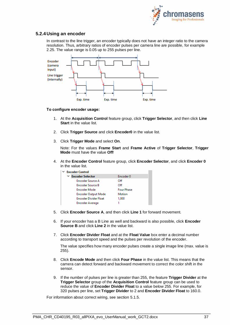
5.2.4 Using an encoder
In contrast to the line trigger, an encoder typically does not have an integer ratio to the camera resolution. Thus, arbitrary ratios of encoder pulses per camera line are possible, for example 2.25. The value range is 0.05 up to 255 pulses per line.
To configure encoder usage:
1. At the Acquisition Control feature group, click Trigger Selector, and then click Line Start in the value list.
2. Click Trigger Source and click Encoder0 in the value list.
3. Click Trigger Mode and select On.
Note: For the values Frame Start and Frame Active of Trigger Selector, Trigger Mode must have the value Off!
4. At the Encoder Control feature group, click Encoder Selector, and click Encoder 0
in the value list.
5. Click Encoder Source A, and then click Line 1 for forward movement.
6. If your encoder has a B Line as well and backward is also possible, click Encoder Source B and click Line 2 in the value list.
7. Click Encoder Divider Float and at the Float Value box enter a decimal number according to transport speed and the pulses per revolution of the encoder.
The value specifies how many encoder pulses create a single image line (max. value is 255).
8. Click Encode Mode and then click Four Phase in the value list. This means that the camera can detect forward and backward movement to correct the color shift in the sensor.
9. If the number of pulses per line is greater than 255, the feature Trigger Divider at the Trigger Selector group of the Acquisition Control feature group can be used to reduce the value of Encoder Divider Float to a value below 255. For example, for 320 pulses per line, set Trigger Divider to 2 and Encoder Divider Float to 160.0.
For information about correct wiring, see section 5.1.5.
PMA_CHR_CD40195_R03_allPIXA_evo_UserManual_work_GCT2.docx 38
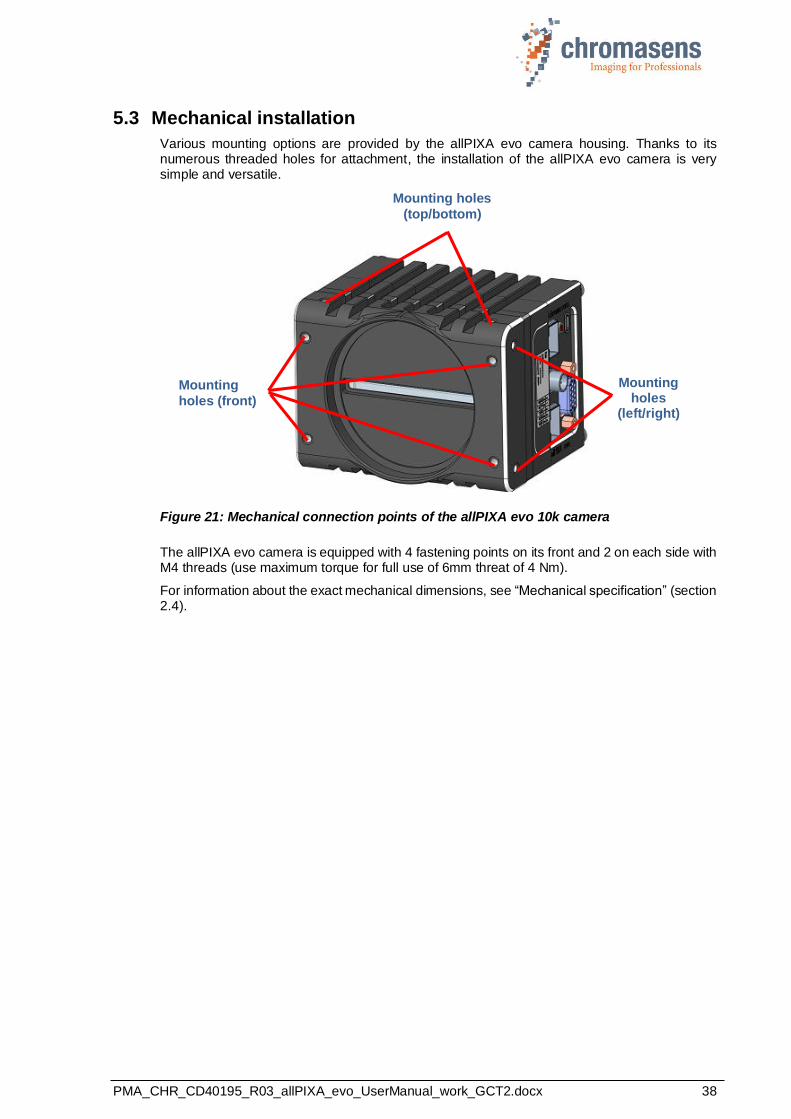
5.3 Mechanical installation
Various mounting options are provided by the allPIXA evo camera housing. Thanks to its numerous threaded holes for attachment, the installation of the allPIXA evo camera is very simple and versatile.
Figure 21: Mechanical connection points of the allPIXA evo 10k camera
The allPIXA evo camera is equipped with 4 fastening points on its front and 2 on each side with M4 threads (use maximum torque for full use of 6mm threat of 4 Nm).
For information about the exact mechanical dimensions, see “Mechanical specification” (section 2.4).
Mounting holes
(left/right)
Mounting holes
(top/bottom)
Mounting
holes (front)
PMA_CHR_CD40195_R03_allPIXA_evo_UserManual_work_GCT2.docx 39
5.4 Thermal links / cooling
The camera works within the defined temperature range (see sections 2.3 and 2.6.3). To this purpose it may be screwed to thermally conductive parts on a wide and flat surface. A thermal connection to heat-conductive parts has a positive effect on operation of the allPIXA evo camera.
To dissipate the heat more effectively to the surrounding area, we also recommend to use heat conduction pads between the allPIXA evo camera and heat-conductive parts. You can also cool the camera with a fan, which should be directed at a large surface area of the camera.
If questions are left, or if you are not sure how to adapt the allPIXA evo camera most effectively to its ambient conditions, do not hesitate to contact our support team.
The maximum allowed internal camera temperature, which can be monitored by the camera, is:
Board temperature: 80°C Sensor temperature: 80°C
5.5 Preventing installation errors
To ensure a high image and color quality, it is essential to align the camera correctly with the conveyor belt.
If the camera is misaligned, image artifacts may result.
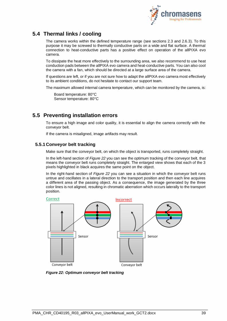
5.5.1 Conveyor belt tracking
Make sure that the conveyor belt, on which the object is transported, runs completely straight.
In the left-hand section of Figure 22 you can see the optimum tracking of the conveyor belt, that means the conveyor belt runs completely straight. The enlarged view shows that each of the 3 pixels highlighted in black acquires the same point on the object.
In the right-hand section of Figure 22 you can see a situation in which the conveyor belt runs untrue and oscillates in a lateral direction to the transport position and then each line acquires a different area of the passing object. As a consequence, the image generated by the three color lines is not aligned, resulting in chromatic aberration which occurs laterally to the transport position.
Figure 22: Optimum conveyor belt tracking
PMA_CHR_CD40195_R03_allPIXA_evo_UserManual_work_GCT2.docx 40
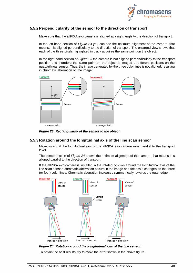
5.5.2 Perpendicularity of the sensor to the direction of transport
Make sure that the allPIXA evo camera is aligned at a right angle to the direction of transport.
In the left-hand section of Figure 23 you can see the optimum alignment of the camera, that means, it is aligned perpendicularly to the direction of transport. The enlarged view shows that each of the three pixels highlighted in black acquires the same point on the object.
In the right-hand section of Figure 23 the camera is not aligned perpendicularly to the transport position and therefore the same point on the object is imaged at different positions on the quad/trilinear sensor. Thus, the image generated by the three color lines is not aligned, resulting in chromatic aberration on the image:
Figure 23: Rectangularity of the sensor to the object
5.5.3 Rotation around the longitudinal axis of the line scan sensor
Make sure that the longitudinal axis of the allPIXA evo camera runs parallel to the transport level.
The center section of Figure 24 shows the optimum alignment of the camera, that means it is aligned parallel to the direction of transport.
If the allPIXA evo camera is installed in the rotated position around the longitudinal axis of the line scan sensor, chromatic aberration occurs in the image and the scale changes on the three (or four) color lines. Chromatic aberration increases symmetrically towards the outer edge.
Figure 24: Rotation around the longitudinal axis of the line sensor
To obtain the best results, try to avoid the error shown in the above figure.
PMA_CHR_CD40195_R03_allPIXA_evo_UserManual_work_GCT2.docx 41
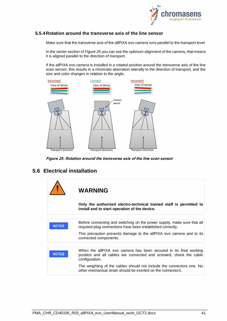
5.5.4 Rotation around the transverse axis of the line sensor
Make sure that the transverse axis of the allPIXA evo camera runs parallel to the transport level.
In the center section of Figure 25 you can see the optimum alignment of the camera, that means it is aligned parallel to the direction of transport.
If the allPIXA evo camera is installed in a rotated position around the transverse axis of the line scan sensor, this results in a chromatic aberration laterally to the direction of transport, and the size and color changes in relation to the angle.
Figure 25: Rotation around the transverse axis of the line scan sensor
5.6 Electrical installation
WARNING
Only the authorized electro-technical trained staff is permitted to
install and to start operation of the device.
Before connecting and switching on the power supply, make sure that all required plug connections have been established correctly.
This precaution prevents damage to the allPIXA evo camera and to its connected components.
When the allPIXA evo camera has been secured in its final working position and all cables are connected and screwed, check the cable configuration.
The weighting of the cables should not include the connectors one. No other mechanical strain should be exerted on the connectors.
PMA_CHR_CD40195_R03_allPIXA_evo_UserManual_work_GCT2.docx 42
NOTE Grounding the housing and the outer cable shield:
Due to an environment with electromagnetic contamination it may be necessary to establish contact between the housing to the installation’s electrical ground.
The mounting threads for the housing are not isolated; therefore, you may use any of the mounting threads for connecting the housing to the electrical ground.
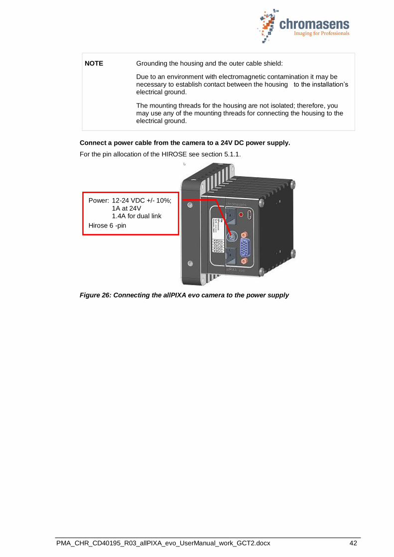
Connect a power cable from the camera to a 24V DC power supply.
For the pin allocation of the HIROSE see section 5.1.1.
Figure 26: Connecting the allPIXA evo camera to the power supply
Power: 12-24 VDC +/- 10%;
1A at 24V 1.4A for dual link
Hirose 6 -pin
PMA_CHR_CD40195_R03_allPIXA_evo_UserManual_work_GCT2.docx 43
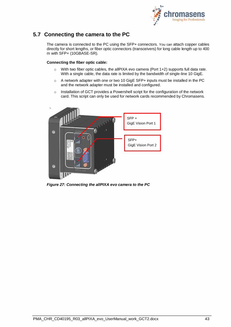
5.7 Connecting the camera to the PC
The camera is connected to the PC using the SFP+ connectors. You can attach copper cables directly for short lengths, or fiber optic connectors (transceivers) for long cable length up to 400 m with SFP+ (10GBASE-SR).
Connecting the fiber optic cable:
o With two fiber optic cables, the allPIXA evo camera (Port 1+2) supports full data rate. With a single cable, the data rate is limited by the bandwidth of single-line 10 GigE.
o A network adapter with one or two 10 GigE SFP+ inputs must be installed in the PC and the network adapter must be installed and configured.
o Installation of GCT provides a Powershell script for the configuration of the network card. This script can only be used for network cards recommended by Chromasens.
Figure 27: Connecting the allPIXA evo camera to the PC
SFP +
GigE Vision Port 1
SFP+
GigE Vision Port 2
PMA_CHR_CD40195_R03_allPIXA_evo_UserManual_work_GCT2.docx 44
5.8 Configuring the network adapter
For the supported 10GiGE network adapters GCT provides Powershell scripts which permit to
adjust the adapter settings automatically.
Supported network adapters are:
- Myricom ARC Series C-Class 10GigE network adapters - Network cards with Intel 82599 chipsets
Note: In the GCT Manual, the adapter configuration is described for an adapter with an Intel chipset. The description can also be used to configure a Myricom adapter manually, but a different Powershell script must be used for automatic configuration.
Install the S2i filter driver delivered with GCT, or install a different filter drive you want to use. Installation of the S2i filter driver is described in the GCT manual.
To modify the adapter settings automatically:
1. Select the correct Powershell script for your network adapter.
2. Run the Powershell script as administrator, as described in the GCT manual.
To modify the adapter settings manually:
1. On the Windows Start menu, click Settings.
2. On the Settings dialog box click Network & Internet, and then click Change adapter options.
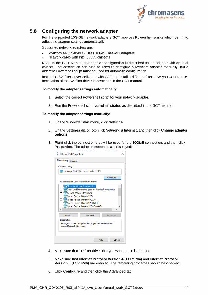
3. Right-click the connection that will be used for the 10GigE connection, and then click
Properties. The adapter properties are displayed:
4. Make sure that the filter driver that you want to use is enabled.
5. Make sure that Internet Protocol Version 4 (TCP/IPv4) and Internet Protocol Version 6 (TCP/IPv6) are enabled. The remaining properties should be disabled.
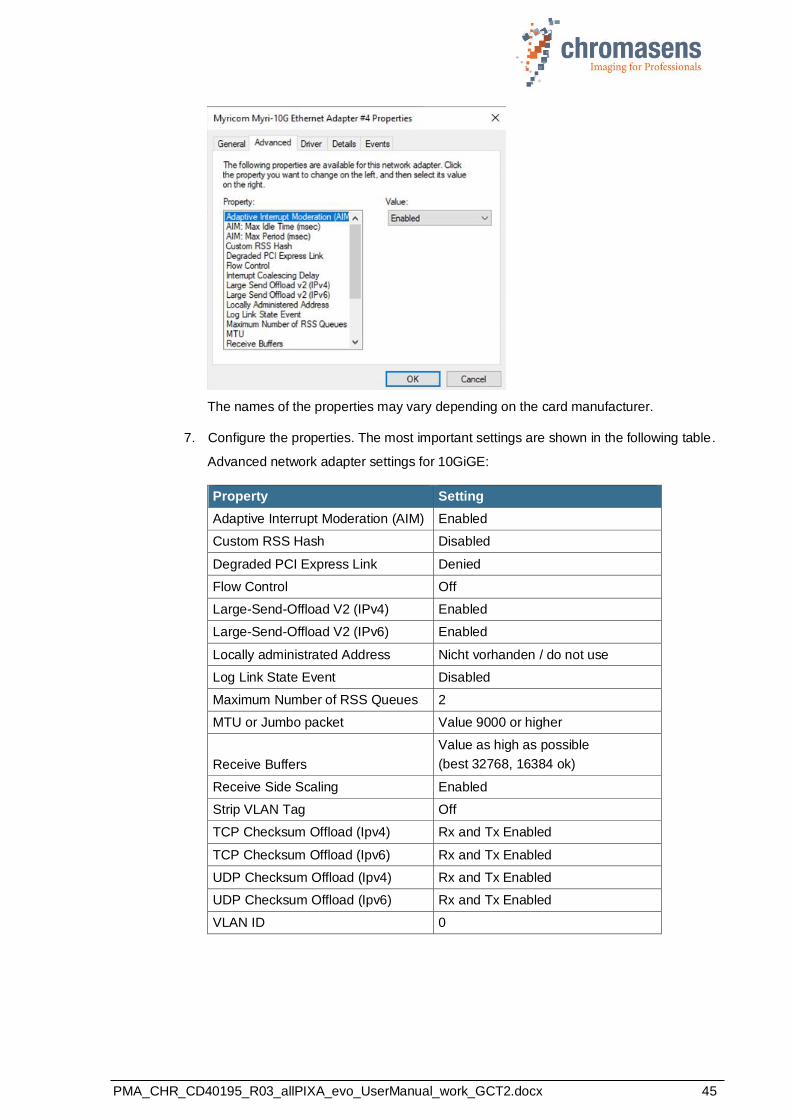
6. Click Configure and then click the Advanced tab:
PMA_CHR_CD40195_R03_allPIXA_evo_UserManual_work_GCT2.docx 45
The names of the properties may vary depending on the card manufacturer.
7. Configure the properties. The most important settings are shown in the following table.
Advanced network adapter settings for 10GiGE:
Property Setting
Adaptive Interrupt Moderation (AIM) Enabled
Custom RSS Hash Disabled
Degraded PCI Express Link Denied
Flow Control Off
Large-Send-Offload V2 (IPv4) Enabled
Large-Send-Offload V2 (IPv6) Enabled
Locally administrated Address Nicht vorhanden / do not use
Log Link State Event Disabled
Maximum Number of RSS Queues 2
MTU or Jumbo packet Value 9000 or higher
Receive Buffers
Value as high as possible
(best 32768, 16384 ok)
Receive Side Scaling Enabled
Strip VLAN Tag Off
TCP Checksum Offload (Ipv4) Rx and Tx Enabled
TCP Checksum Offload (Ipv6) Rx and Tx Enabled
UDP Checksum Offload (Ipv4) Rx and Tx Enabled
UDP Checksum Offload (Ipv6) Rx and Tx Enabled
VLAN ID 0
PMA_CHR_CD40195_R03_allPIXA_evo_UserManual_work_GCT2.docx 46
6 Working with GCT
The camera can be configured with any software for GenICam-compliant cameras. We recommend to use the Chromasens program GCT (GenICam Control Tool), which provides special dialog boxes and wizards that make configuring more comfortable.
You can download the GCT installation program from the Chromasens website. On the product page of any allPIXA evo model, click the Software tab.
For information about installation and use of GCT, refer to the GCT user manual.
6.1 Setting image parameters
The following table shows some parameters that control image acquisition. Check and modify
these parameters as needed:
Parameter Position in parameter tree Comment
Image Width Image Format Control / Region Selector / Width
Ensure the Region Selector has the value Region 1.
Image Height Image Format Control / Region Selector / Height
Ensure the Region Selector has the value Region 1.
Acquisition
Line Time
Acquisition Control -> Acquisition Line Time
Specifies the time between current scan line and next scan line. Increasing line time reduces line frequency.
Exposure
time
Acquisition Control -> Exposure Time
Specifies the integration time in micro-seconds.
Trigger Mode
Acquisition Control -> Trigger Selector -> Trigger Mode
If no explicit trigger is available, Trigger Mode must have the value Off for all three values of Trigger Selector
Test Pattern
Image Format Control / Test Pattern Generator Selector / Test Pattern,
Image Format Control / Test Pattern Generator Selector / Test Pattern Value
Default value: Off.
If you cannot produce a meaningful image, you can specify that the camera should send a specified test pattern by specifying a pattern and a pattern value.
Sometimes during grabbing the camera does not transmit an image and the message log shows GEV_TIMEOUT_ERROR. Possible reasons are the following:
• The Use Filter Driver check box is selected, but the filter driver is either not installed or it is not configured correctly. For more information see section 5.8.
• Trigger Mode is set to On for a value of Trigger Selector, but the respective external trigger is not available. See the respective line in the above table.
6.2 Updating the firmware
If a new firmware version is available, it can be downloaded on the Chromasens website as a
.zip file. The file contains the following components of the camera firmware:
• Application (allPIXAevo_application….bin),
• Bitstream (allPIXAevo_bitstream… .bin),
• Camera XML file (allPIXAevo_xml… .xml),
• Sensor file (allPIXAevo_sensorfile… .mk),
PMA_CHR_CD40195_R03_allPIXA_evo_UserManual_work_GCT2.docx 47
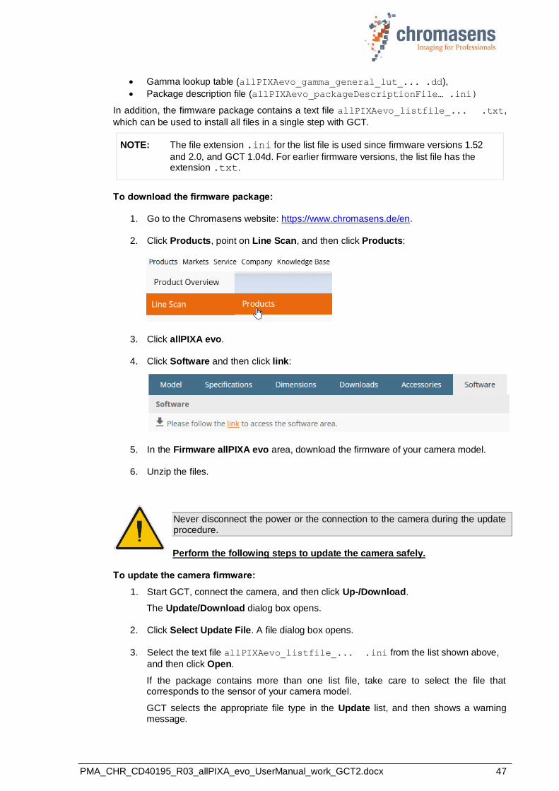
• Gamma lookup table (allPIXAevo_gamma_general_lut_... .dd),
• Package description file (allPIXAevo_packageDescriptionFile… .ini)
In addition, the firmware package contains a text file allPIXAevo_listfile_... .txt,
which can be used to install all files in a single step with GCT.
NOTE: The file extension .ini for the list file is used since firmware versions 1.52
and 2.0, and GCT 1.04d. For earlier firmware versions, the list file has the extension .txt.
To download the firmware package:
1. Go to the Chromasens website: https://www.chromasens.de/en.
2. Click Products, point on Line Scan, and then click Products:
3. Click allPIXA evo.
4. Click Software and then click link:
5. In the Firmware allPIXA evo area, download the firmware of your camera model.
6. Unzip the files.
Never disconnect the power or the connection to the camera during the update procedure.
Perform the following steps to update the camera safely.
To update the camera firmware:
1. Start GCT, connect the camera, and then click Up-/Download.
The Update/Download dialog box opens.
2. Click Select Update File. A file dialog box opens.
3. Select the text file allPIXAevo_listfile_... .ini from the list shown above,
and then click Open.
If the package contains more than one list file, take care to select the file that corresponds to the sensor of your camera model.
GCT selects the appropriate file type in the Update list, and then shows a warning message.
PMA_CHR_CD40195_R03_allPIXA_evo_UserManual_work_GCT2.docx 48
4. Check whether the file type is correct: for the list files, it is Firmware Package File. If the wrong file type is shown, select the correct file type.
5. Click Start Update.
6. On the appearing warning message, click Yes to start the upload process.
Depending on the file size, file upload may take a few seconds up to several minutes. During upload a progress bar is shown.
7. Wait until the files have been uploaded completely.
8. Check the log files: If the upload was successful, it contains a green confirmation
message for each uploaded file. If an upload was not successful, do not switch of the camera, but upload the respective file.
9. If all files have been uploaded successfully, switch the camera off and after a few seconds on again. This is necessary to complete the firmware update.
If you need to upload special files to the camera, contact support first. The files must be uploaded in a special order. If you upload files in the wrong order, this cause damage to the camera.
6.3 Flat field correction: Creating a black-reference (DSNU)
To create a black-reference:
1. Switch off illumination and cover the lens with a black or dark piece of cardboard or plastic so that there is no light on the sensor. Check that the piece covers the whole lens.
2. Prepare an image with GCT. Either click the Acquire a single frame on the
toolbar, or click Start grabbing , wait until an image is shown and then click
Stop grabbing .
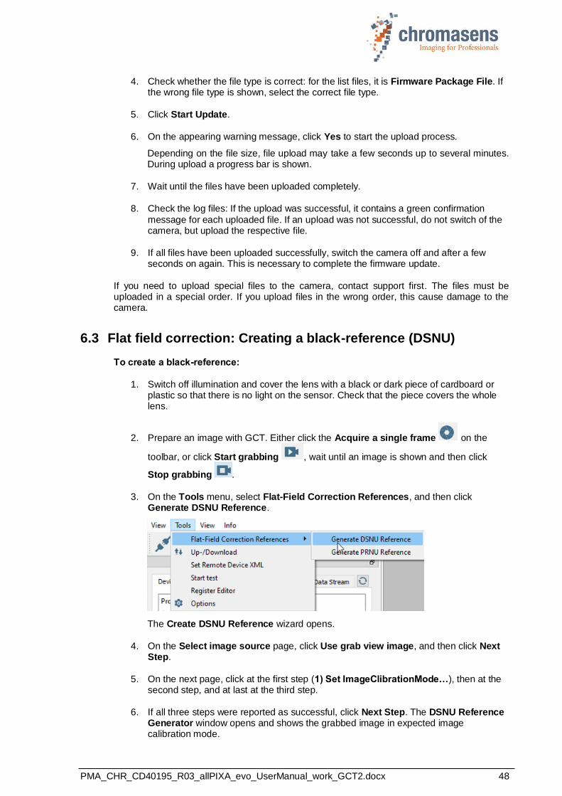
3. On the Tools menu, select Flat-Field Correction References, and then click Generate DSNU Reference.
The Create DSNU Reference wizard opens.
4. On the Select image source page, click Use grab view image, and then click Next Step.
5. On the next page, click at the first step (1) Set ImageClibrationMode…), then at the second step, and at last at the third step.
6. If all three steps were reported as successful, click Next Step. The DSNU Reference Generator window opens and shows the grabbed image in expected image calibration mode.

PMA_CHR_CD40195_R03_allPIXA_evo_UserManual_work_GCT2.docx 49
7. In the Settings for Average Value, enter values for Y-Position and Height to specify the area to be used for reference generation, or click Start 2-Click-Selection and click start and end position on the image.
8. To create and save the reference data, click Save DSNU File to Local PC, specify folder and file name in the appearing file dialog box, and then click Save and close the wizard.
9. On the toolbar click Open update dialog , and in the Update/Download dialog
box lick Select Update File. A file dialog box opens.
10. Select the DSNU file, and then click Open. GCT selects the appropriate file type in the Update list. If the file type is correct, confirm the appearing warning message.
11. Click Start Update, wait until the file has been uploaded completely, and then close the dialog box.
12. To activate DSNU, click the LUT Control feature group,
13. Click LUT Selector and click the respective DSNU LUT in the value list:
14.
15. At the LUT Enable feature, select the check box.
To create a dark-reference from an existing image file:
1. Perform steps 1 to 3 of the above procedure.
2. On the Select image source page, click Load image from storage, and then click Next Step.
3. Click Choose BMP File on the following page and open the desired image file in the appearing file dialog box.
4. Specify a pixel offset, and then click Next Step.
5. Continue with step 7 of the above procedure.
NOTE: While Image Calibration Control is active, the temporarily modified features are locked and cannot be modified until the feature is set to Off.
Currently, the input image (regardless of whether acquired directly with the grabbing process or loaded from PC) will be converted to 8 bit and then used to calculate the DSNU reference.
6.4 Flat field correction: Creating a shading reference (PRNU)
To create a shading reference:
1. Check lighting and focusing.
2. Disable continuous white-control and save the parameters to the camera.

PMA_CHR_CD40195_R03_allPIXA_evo_UserManual_work_GCT2.docx 50
3. If possible, prepare a moving white target. If you use a stationary target, place the target a bit out of focus, to reduce the effect of dust or scratches on the calibration result.
4. Prepare an image with GCT. Either click the Acquire a single frame on the
toolbar, or click Start grabbing ,wait until an image is shown, and then click
Stop grabbing .
5. On the Tools menu, select Flat-Field Correction References, and then click Generate PRNU Reference.
The Create PRNU Reference wizard opens.
6. On the Select image source page, click Use grab view image, and then click Next Step.
7. On the next page, click at the first step (1) Set ImageClibrationMode…), then at the second step, and at last at the third step.
8. If all three steps were reported as successful, click Next Step. The DSNU Reference Generator window opens and shows the grabbed image.
On the next page, shading parameters must be specified in the PRNU Settings area on the right side:
9. Specify the target value for white, and the area that should be used to create the
shading data:
Target Value: Target value of white after the shading reference has been applied. The default target is 255, but normally it is set to a smaller value between 220-230.

PMA_CHR_CD40195_R03_allPIXA_evo_UserManual_work_GCT2.docx 51
Y-Position, Height: Start and height of the area used to generate shading data. If you specify 100 and 300 as values, 300 lines starting at line 101 are used. Enter values into the boxes, or click Start 2-Click-Selection, and then click on the start and end position of the desired area on the image. The specified area is then marked with green color.
10. If the image has black borders on the left/right side, specify an area for extrapolation:
For extrapolation on the left side, select the Left check box, for the right side, the Right check box. In the Left and Right boxes, enter the start positions of the areas used for extrapolation, and in the Width box the width of the areas.
Start and end position of the areas are marked with red color on the image.
11. To show the result of the shading correction with the specified parameters, click Test
PRNU.
12. To save the shading reference data, click Save PRNU File to Local PC, specify folder and file name in the appearing file dialog box, and then click Save and close the wizard.
13. At the Image Calibration Control feature group, click Image Calibration Mode and then click Off in the value list.
This resets the previously modified features to their original values.
14. On the toolbar click Open update dialog , and in the Update/Download dialog box lick Select Update File. A file dialog box opens.
15. Select the PRNU file, and then click Open. GCT selects the appropriate file type in the Update list. If the file type is correct, confirm the appearing warning message.
16. Click Start Update, wait until the file has been uploaded completely, and then close the dialog box.
17. To activate PRNU, click the LUT Control feature group.
18. Click LUT Selector and click the respective PRNU LUT in the value list.
19. Click LUT Enable and select the check box.
20. Set Brightness and Contrast to a value about 0.9.
To create a shading reference from an existing image file:
• Perform the steps of the above procedure, but click Load image from storage in step 6, click Next Step, click Choose BMP File on the following page, and open the desired image file in the appearing file dialog box.
NOTE: While Image Calibration Control is active, the temporarily modified features are locked and cannot be modified until the feature is set to Off.
Currently, the input image (regardless of whether acquired directly with the grabbing process or loaded from PC) is converted to 8 bit and then used for calculating the PRNU reference
PMA_CHR_CD40195_R03_allPIXA_evo_UserManual_work_GCT2.docx 52
7 Camera system set-up
7.1 Installing the camera
1
Prepare the general setup:
Prepare the camera and lens
• Select the correct lens and accessories to operate your camera in the desired environment. (For more information about lens and tube selection, see section 10.1.)
• Install the lens and adapters correctly. For a detailed description of lens and mount
installation, see section 2.6.
2
Prepare the right cabling for your application
• Connection to the PC: The allPIXA evo can be connected with one or two fiber-optic cables.
• Power supply: Hirose 6-pin plug (HR10A-7P-6S).
The allPIXA evo connecting interfaces are described in section 5.1.
• Connect the camera to a power supply (24 VDC +/- 10 %; 1A; typical 20 W) (section 5.6).
3 Install and configure the network adapter on your PC
4
Adjust the focusing point of your illumination unit and position it correctly
• Refer to the manual of the illumination manufacturer for proper installation of the
illumination.
• Make sure that the illumination is positioned correctly to illuminate the scanning area.
5
Mechanically install the camera in your machine
• Make sure, it is positioned correctly
The sensor line should be adjusted horizontally to the transport direction and the camera should look perpendicular to the inspection area. For a detailed description of a correct camera installation, refer to chapter 5.
• Make sure, you have the correct object-to-sensor distance The sensor line is positioned 17 mm (optical photosensitive surface) behind the front surface of the allPIXA evo camera. You can find the detailed sensor position description in section 2.4.

PMA_CHR_CD40195_R03_allPIXA_evo_UserManual_work_GCT2.docx 53
7.2 Starting up the system
1
Start up the camera:
You can set camera parameters using the Chromasens program GCT. For information about installation and use of GCT, refer to the GCT manual.
• Turn on illumination and camera.
• Set up communication between PC and camera.
• Select the Use Filter Driver check box.
2
Set the camera to free-run mode:
To control the connection to the camera, set it to free-run mode, that means, switch all trigger modes off:
• At the Acquisition Control feature group, click Trigger Selector.
• Select Frame Active in the value list, and then click Trigger Mode and select Off in the
value list.
• Repeat the previous step for the values Frame Start and Line Start of the Trigger
Selector feature.

PMA_CHR_CD40195_R03_allPIXA_evo_UserManual_work_GCT2.docx 54
3
Produce a test image:
• At the Image Format Control feature group, click Test Pattern Generator Selector.
• Click Test Pattern and in the value list, click Grey Horizontal Ramp Moving.
• On the toolbar, click Start grabbing . The received images should look like this:
• On the toolbar click Stop grabbing .
• Click Test Pattern and click Off in the value list.
Proceed to section 0 to calibrate the camera and adjust the camera settings to your operating conditions.

PMA_CHR_CD40195_R03_allPIXA_evo_UserManual_work_GCT2.docx 55
7.3 Adjusting the camera to the environment (camera calibration)
Prepare the camera for calibration (see also section 7.1). - Set the camera in free-run mode for lines and images - Place a white reference target, covering the full scanning area
NOTE
The white reference target must be placed near the best focus plane of the
camera. Therefore, any features on its surface (for example dust, scratches) end up in the calibration profile of the camera. To avoid this, use a professional (non-moving) white reference target, like a clean white ceramic or plastic material, not paper. Ideally, the white object should move during the calibration process because the movement results in an averaging process and the camera diminishes the effects on any small variation in the white reference.
To calibrate the camera setting to your operating conditions, follow the steps below.
1
Check your line scan system application:
• Illumination setting:
Switch on the lighting and ensure that the adjustment of the lighting provides best illumination on the target.
• Camera adjustment:
Adjust the camera to the target for best orientation and for the best lighting.
• Focusing and f-stop:
Set the camera to best focus and select the requested f-stop.
2
Set integration time:
• In the Acquisition Control group, specify the Acquisition Line Time.
You can find an instruction for calculation in the appendix (section 10.2.3).

PMA_CHR_CD40195_R03_allPIXA_evo_UserManual_work_GCT2.docx 56
3
Set the operating point (1):
• Continuous white control must be disabled: In the Analog Control feature group, set Gain Selector to All, and then set Gain Auto to Off.
• Specify the reference mark position: In the Analog Control feature group, go to Gain Auto Settings -> Gain Control Region and specify position and size of the reference mark position using the features Offset X, Width, Offset Y, and Height. To control the position on images, you can temporarily select the Visible feature.
For this operation, the reference mark position should be at the brightest region of the
image. Typically, this will be at the center.
• Specify the target white reference values: Use the Gain Control Region Channel Selector to select the different colors, and for each color specify Target value.
The target values should be in the range of 800 to 880 (10-bit value) so that values are between 200 and 220 in the output image.
• At Gain Selector, set Gain Auto to Once. The camera then performs white balancing with the current settings.
• If white balancing was successful, Gain Auto Status should return Control Successful.
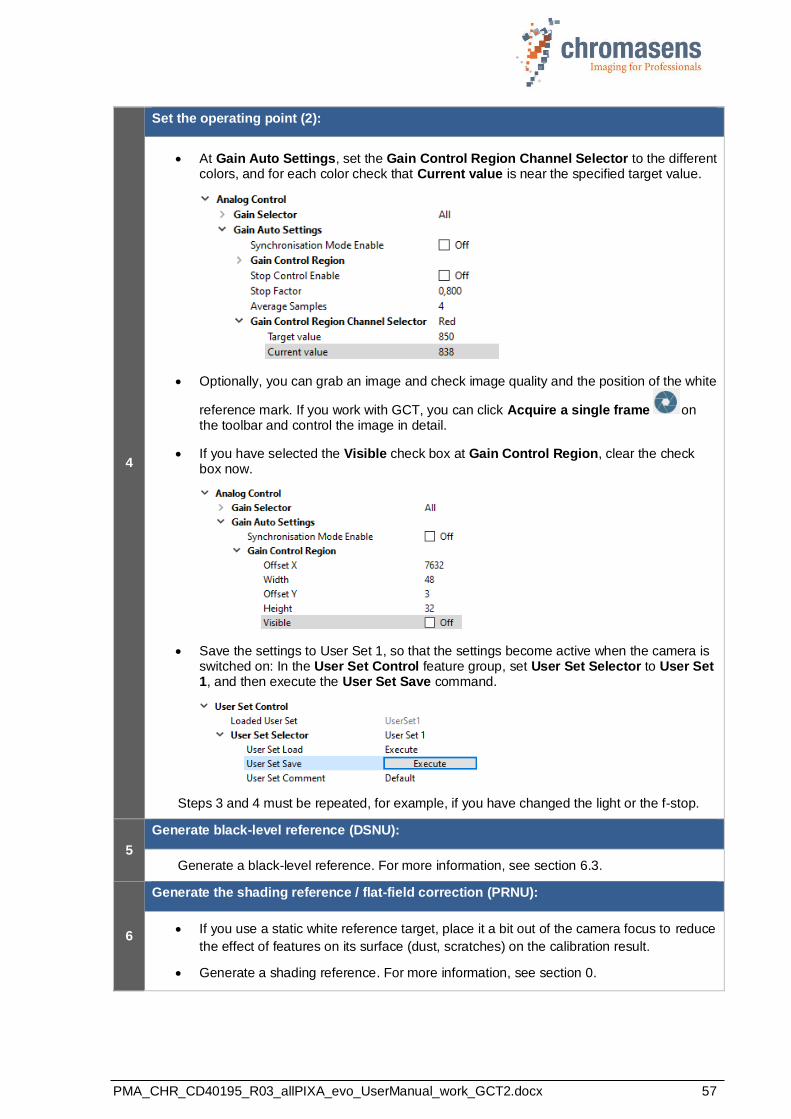
PMA_CHR_CD40195_R03_allPIXA_evo_UserManual_work_GCT2.docx 57
4
Set the operating point (2):
• At Gain Auto Settings, set the Gain Control Region Channel Selector to the different colors, and for each color check that Current value is near the specified target value.
• Optionally, you can grab an image and check image quality and the position of the white
reference mark. If you work with GCT, you can click Acquire a single frame on the toolbar and control the image in detail.
• If you have selected the Visible check box at Gain Control Region, clear the check box now.
• Save the settings to User Set 1, so that the settings become active when the camera is switched on: In the User Set Control feature group, set User Set Selector to User Set 1, and then execute the User Set Save command.
Steps 3 and 4 must be repeated, for example, if you have changed the light or the f-stop.
5
Generate black-level reference (DSNU):
Generate a black-level reference. For more information, see section 6.3.
6
Generate the shading reference / flat-field correction (PRNU):
• If you use a static white reference target, place it a bit out of the camera focus to reduce
the effect of features on its surface (dust, scratches) on the calibration result.
• Generate a shading reference. For more information, see section 0.
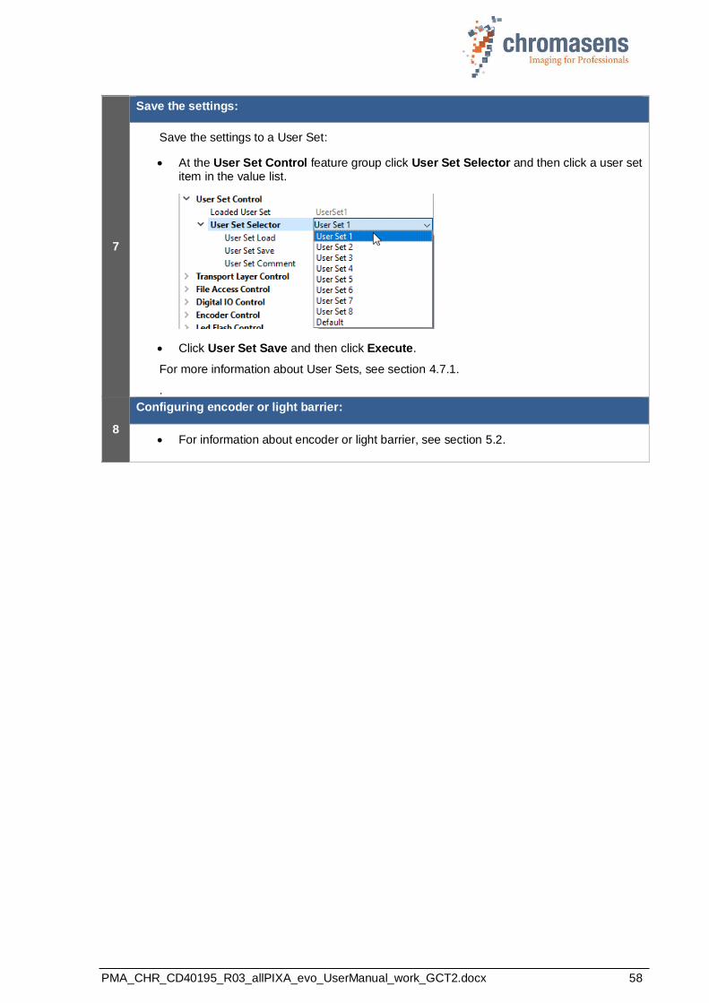
PMA_CHR_CD40195_R03_allPIXA_evo_UserManual_work_GCT2.docx 58
7
Save the settings:
Save the settings to a User Set:
• At the User Set Control feature group click User Set Selector and then click a user set item in the value list.
• Click User Set Save and then click Execute.
For more information about User Sets, see section 4.7.1.
.
8
Configuring encoder or light barrier:
• For information about encoder or light barrier, see section 5.2.

PMA_CHR_CD40195_R03_allPIXA_evo_UserManual_work_GCT2.docx 59
8 Additional features
8.1 Configuring multi-channel flash control
The allPIXA evo camera can be used to trigger up to four different flash controller channels
synchronized to its line acquisition. This can be used to acquire several images with different illumination colors simultaneously in a single scan using line-multiplexing. When LED flash is active, the camera starts a complete LED pattern sequence after each Line Trigger, or after Sequence time in free-running mode, respectively.
Figure 28: Connecting flash controllers and illumination modules
1. allPIXA evo camera 2. PC connection 3. Host PC 4. Illumination modules 5. LED controller 6. Encoder / Trigger
8.1.1 Operation principle
The camera provides up to four different outputs which can be operated individually to control illumination controllers.
Several outputs can be individually combined to be triggered at the same time. Each flashing scenario can be defined individually as line pattern.
The camera provides up to four different line patterns which are executed in a sequence. This sequence is repeated as long as scanning or triggering is active.
The following diagram demonstrates a sequence cycle with three different line patterns. In this example, the duration for each line pattern is set individually. All four available output channels are used:
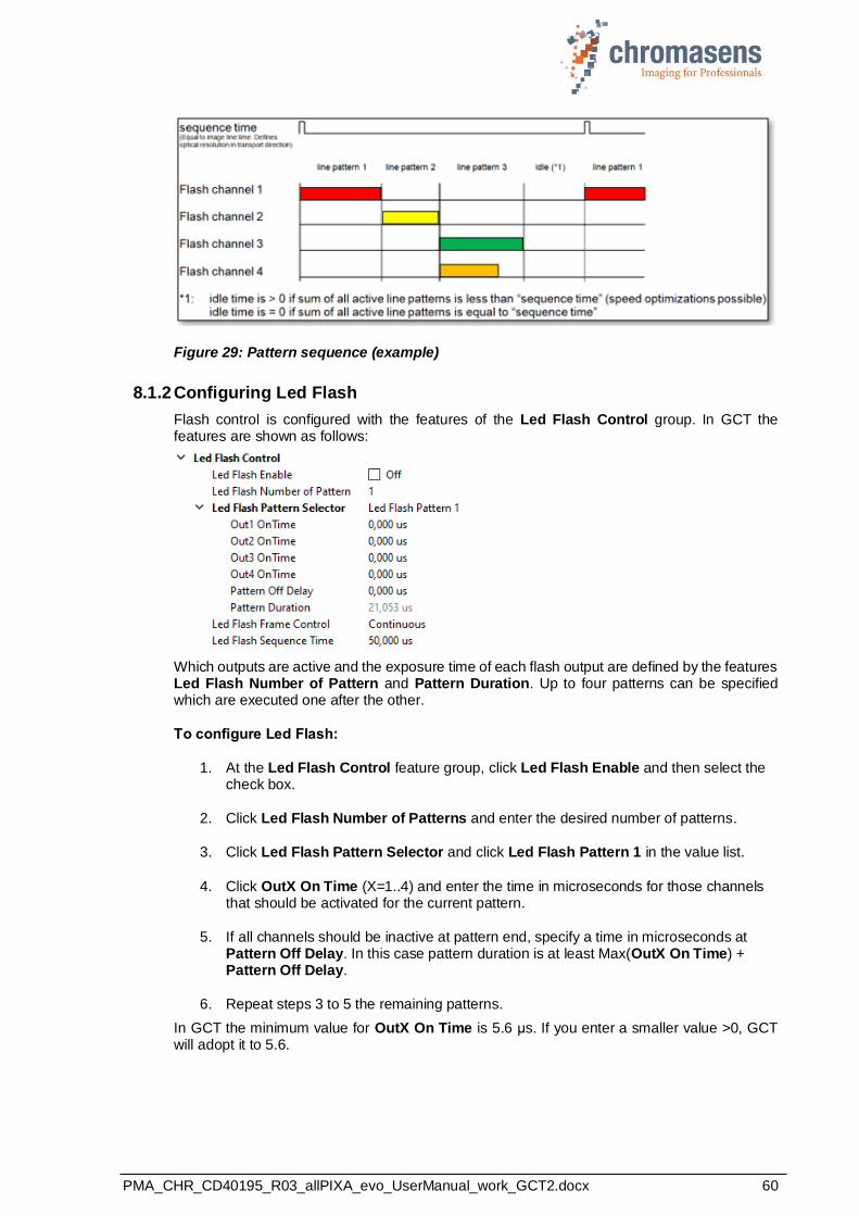
PMA_CHR_CD40195_R03_allPIXA_evo_UserManual_work_GCT2.docx 60
Figure 29: Pattern sequence (example)
8.1.2 Configuring Led Flash
Flash control is configured with the features of the Led Flash Control group. In GCT the features are shown as follows:
Which outputs are active and the exposure time of each flash output are defined by the features Led Flash Number of Pattern and Pattern Duration. Up to four patterns can be specified which are executed one after the other.
To configure Led Flash:
1. At the Led Flash Control feature group, click Led Flash Enable and then select the check box.
2. Click Led Flash Number of Patterns and enter the desired number of patterns.
3. Click Led Flash Pattern Selector and click Led Flash Pattern 1 in the value list.
4. Click OutX On Time (X=1..4) and enter the time in microseconds for those channels that should be activated for the current pattern.
5. If all channels should be inactive at pattern end, specify a time in microseconds at Pattern Off Delay. In this case pattern duration is at least Max(OutX On Time) + Pattern Off Delay.
6. Repeat steps 3 to 5 the remaining patterns.
In GCT the minimum value for OutX On Time is 5.6 μs. If you enter a smaller value >0, GCT will adopt it to 5.6.
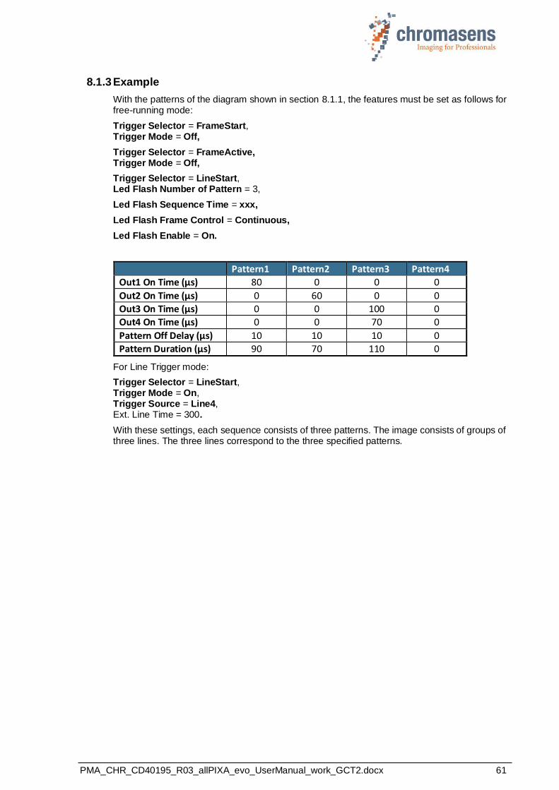
PMA_CHR_CD40195_R03_allPIXA_evo_UserManual_work_GCT2.docx 61
8.1.3 Example
With the patterns of the diagram shown in section 8.1.1, the features must be set as follows for free-running mode:
Trigger Selector = FrameStart, Trigger Mode = Off,
Trigger Selector = FrameActive, Trigger Mode = Off,
Trigger Selector = LineStart, Led Flash Number of Pattern = 3,
Led Flash Sequence Time = xxx,
Led Flash Frame Control = Continuous,
Led Flash Enable = On.
Pattern1 Pattern2 Pattern3 Pattern4
Out1 On Time (μs) 80 0 0 0
Out2 On Time (μs) 0 60 0 0
Out3 On Time (μs) 0 0 100 0
Out4 On Time (μs) 0 0 70 0
Pattern Off Delay (μs) 10 10 10 0
Pattern Duration (μs) 90 70 110 0
For Line Trigger mode:
Trigger Selector = LineStart, Trigger Mode = On, Trigger Source = Line4, Ext. Line Time = 300.
With these settings, each sequence consists of three patterns. The image consists of groups of three lines. The three lines correspond to the three specified patterns.

PMA_CHR_CD40195_R03_allPIXA_evo_UserManual_work_GCT2.docx 62
8.2 Synchronizing cameras: Master and Slave operation
The master slave mode of the allPIXAevo camera ensures that two cameras are synchronized
in such a way that each line is captured at exactly the same time by both cameras.
8.2.1 Principle
Figure 30: Principle of master/slave mode
To synchronize two or more cameras, use the Master-Slave… features of the Acquisition Control feature group. With these features you can:
• select the camera to be master or slave,
• configure the trigger input for master and slave,
• cascade cameras using one master and several slaves (up to 3 slaves).
The trigger signals from light barrier (frame trigger) and/or encoder (line trigger) are only connected to the master camera. This trigger information is transferred to the slave camera(s) via the master-slave interface. Due to this synchronization interface all cameras run with exactly the same timing for lines and optional frames.
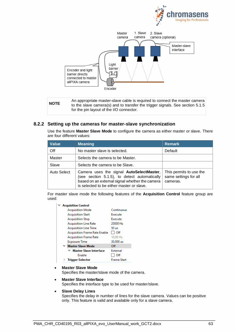
PMA_CHR_CD40195_R03_allPIXA_evo_UserManual_work_GCT2.docx 63
NOTE An appropriate master-slave cable is required to connect the master camera to the slave camera(s) and to transfer the trigger signals. See section 5.1.5 for the pin layout of the I/O connector.
8.2.2 Setting up the cameras for master-slave synchronization
Use the feature Master Slave Mode to configure the camera as either master or slave. There are four different values:
Value Meaning Remark
Off No master slave is selected. Default
Master Selects the camera to be Master.
Slave Selects the camera to be Slave.
Auto Select Camera uses the signal AutoSelectMaster,
(see section 5.1.5), to detect automatically based on an external signal whether the camera is selected to be either master or slave.
This permits to use the
same settings for all cameras.
For master slave mode the following features of the Acquisition Control feature group are used:
• Master Slave Mode
Specifies the master/slave mode of the camera.
• Master Slave Interface Specifies the interface type to be used for master/slave.
• Slave Delay Lines
Specifies the delay in number of lines for the slave camera. Values can be positive only. This feature is valid and available only for a slave camera.
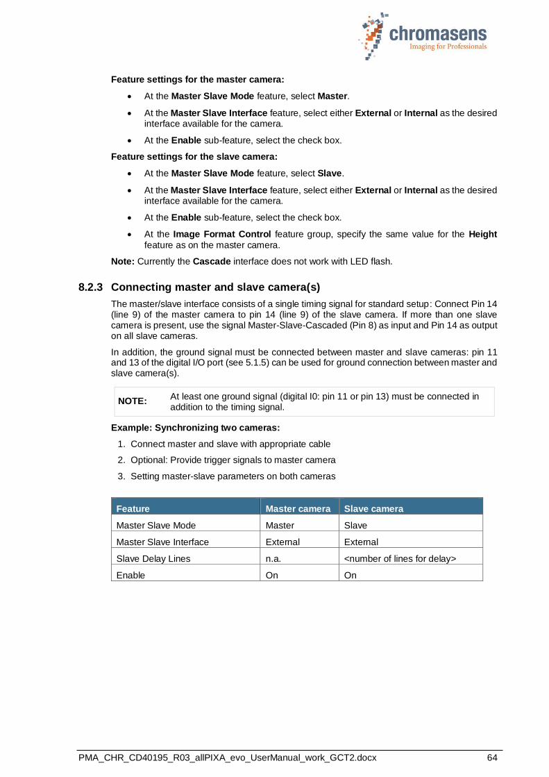
PMA_CHR_CD40195_R03_allPIXA_evo_UserManual_work_GCT2.docx 64
Feature settings for the master camera:
• At the Master Slave Mode feature, select Master.
• At the Master Slave Interface feature, select either External or Internal as the desired interface available for the camera.
• At the Enable sub-feature, select the check box.
Feature settings for the slave camera:
• At the Master Slave Mode feature, select Slave.
• At the Master Slave Interface feature, select either External or Internal as the desired interface available for the camera.
• At the Enable sub-feature, select the check box.
• At the Image Format Control feature group, specify the same value for the Height
feature as on the master camera.
Note: Currently the Cascade interface does not work with LED flash.
8.2.3 Connecting master and slave camera(s)
The master/slave interface consists of a single timing signal for standard setup: Connect Pin 14 (line 9) of the master camera to pin 14 (line 9) of the slave camera. If more than one slave camera is present, use the signal Master-Slave-Cascaded (Pin 8) as input and Pin 14 as output on all slave cameras.
In addition, the ground signal must be connected between master and slave cameras: pin 11 and 13 of the digital I/O port (see 5.1.5) can be used for ground connection between master and slave camera(s).
NOTE: At least one ground signal (digital I0: pin 11 or pin 13) must be connected in addition to the timing signal.
Example: Synchronizing two cameras:
1. Connect master and slave with appropriate cable
2. Optional: Provide trigger signals to master camera
3. Setting master-slave parameters on both cameras
Feature Master camera Slave camera
Master Slave Mode Master Slave
Master Slave Interface External External
Slave Delay Lines n.a. <number of lines for delay>
Enable On On
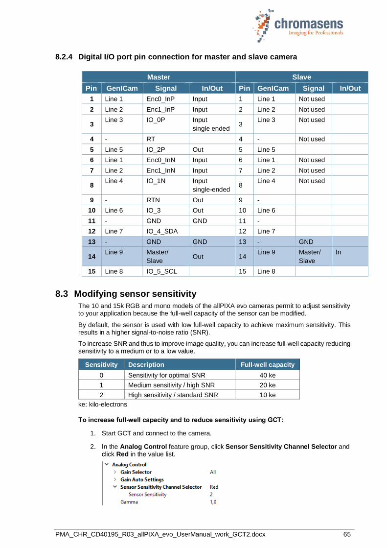
PMA_CHR_CD40195_R03_allPIXA_evo_UserManual_work_GCT2.docx 65
8.2.4 Digital I/O port pin connection for master and slave camera
Master Slave
Pin GenICam Signal In/Out Pin GenICam Signal In/Out
1 Line 1 Enc0_InP Input 1 Line 1 Not used
2 Line 2 Enc1_InP Input 2 Line 2 Not used
3 Line 3 IO_0P Input
single ended 3
Line 3 Not used
4 - RT 4 - Not used
5 Line 5 IO_2P Out 5 Line 5
6 Line 1 Enc0_InN Input 6 Line 1 Not used
7 Line 2 Enc1_InN Input 7 Line 2 Not used
8 Line 4 IO_1N Input
single-ended 8
Line 4 Not used
9 - RTN Out 9 -
10 Line 6 IO_3 Out 10 Line 6
11 - GND GND 11 -
12 Line 7 IO_4_SDA 12 Line 7
13 - GND GND 13 - GND
14 Line 9 Master/
Slave Out 14
Line 9 Master/
Slave
In
15 Line 8 IO_5_SCL 15 Line 8
8.3 Modifying sensor sensitivity
The 10 and 15k RGB and mono models of the allPIXA evo cameras permit to adjust sensitivity to your application because the full-well capacity of the sensor can be modified.
By default, the sensor is used with low full-well capacity to achieve maximum sensitivity. This results in a higher signal-to-noise ratio (SNR).
To increase SNR and thus to improve image quality, you can increase full-well capacity reducing sensitivity to a medium or to a low value.
Sensitivity Description Full-well capacity
0 Sensitivity for optimal SNR 40 ke
1 Medium sensitivity / high SNR 20 ke
2 High sensitivity / standard SNR 10 ke
ke: kilo-electrons
To increase full-well capacity and to reduce sensitivity using GCT:
1. Start GCT and connect to the camera.
2. In the Analog Control feature group, click Sensor Sensitivity Channel Selector and click Red in the value list.
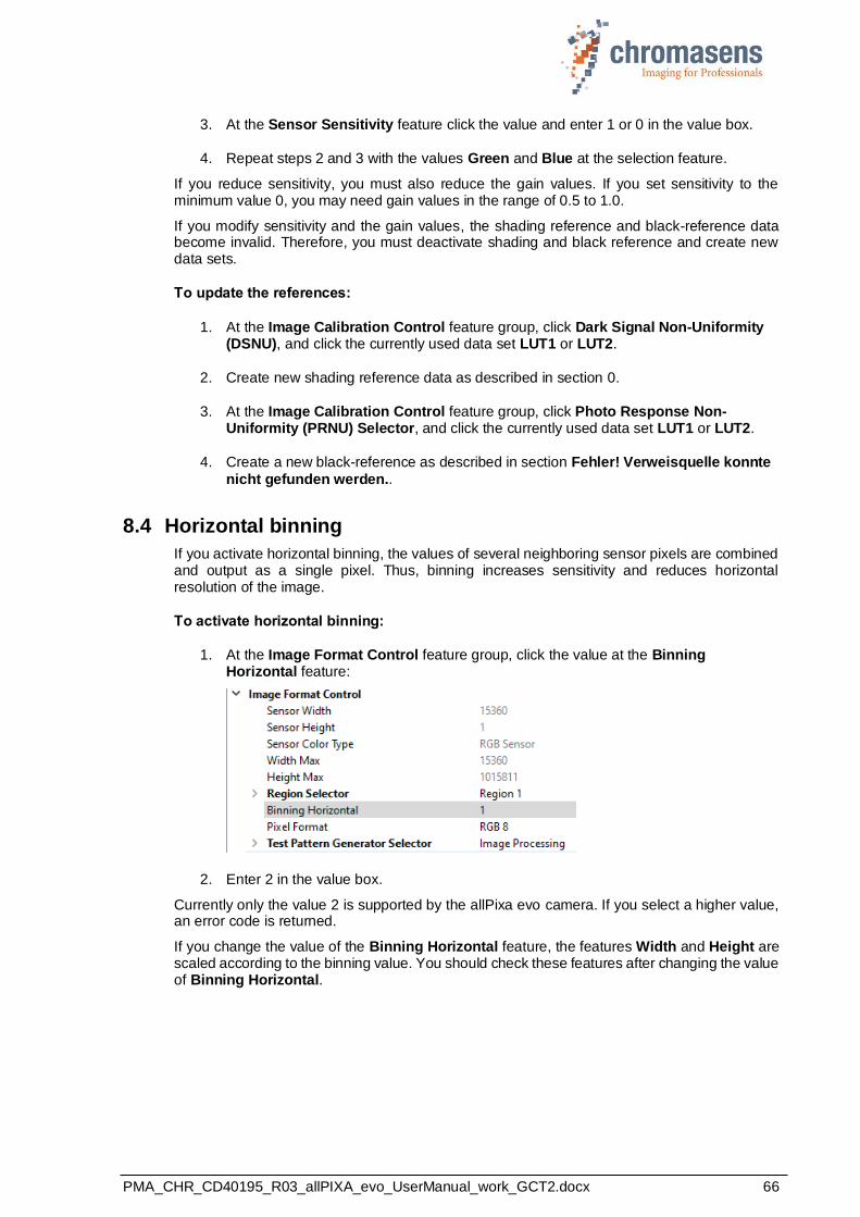
PMA_CHR_CD40195_R03_allPIXA_evo_UserManual_work_GCT2.docx 66
3. At the Sensor Sensitivity feature click the value and enter 1 or 0 in the value box.
4. Repeat steps 2 and 3 with the values Green and Blue at the selection feature.
If you reduce sensitivity, you must also reduce the gain values. If you set sensitivity to the minimum value 0, you may need gain values in the range of 0.5 to 1.0.
If you modify sensitivity and the gain values, the shading reference and black-reference data become invalid. Therefore, you must deactivate shading and black reference and create new data sets.
To update the references:
1. At the Image Calibration Control feature group, click Dark Signal Non-Uniformity (DSNU), and click the currently used data set LUT1 or LUT2.
2. Create new shading reference data as described in section 0.
3. At the Image Calibration Control feature group, click Photo Response Non-Uniformity (PRNU) Selector, and click the currently used data set LUT1 or LUT2.
4. Create a new black-reference as described in section Fehler! Verweisquelle konnte
nicht gefunden werden..
8.4 Horizontal binning
If you activate horizontal binning, the values of several neighboring sensor pixels are combined and output as a single pixel. Thus, binning increases sensitivity and reduces horizontal resolution of the image.
To activate horizontal binning:
1. At the Image Format Control feature group, click the value at the Binning Horizontal feature:
2. Enter 2 in the value box.
Currently only the value 2 is supported by the allPixa evo camera. If you select a higher value, an error code is returned.
If you change the value of the Binning Horizontal feature, the features Width and Height are scaled according to the binning value. You should check these features after changing the value of Binning Horizontal.
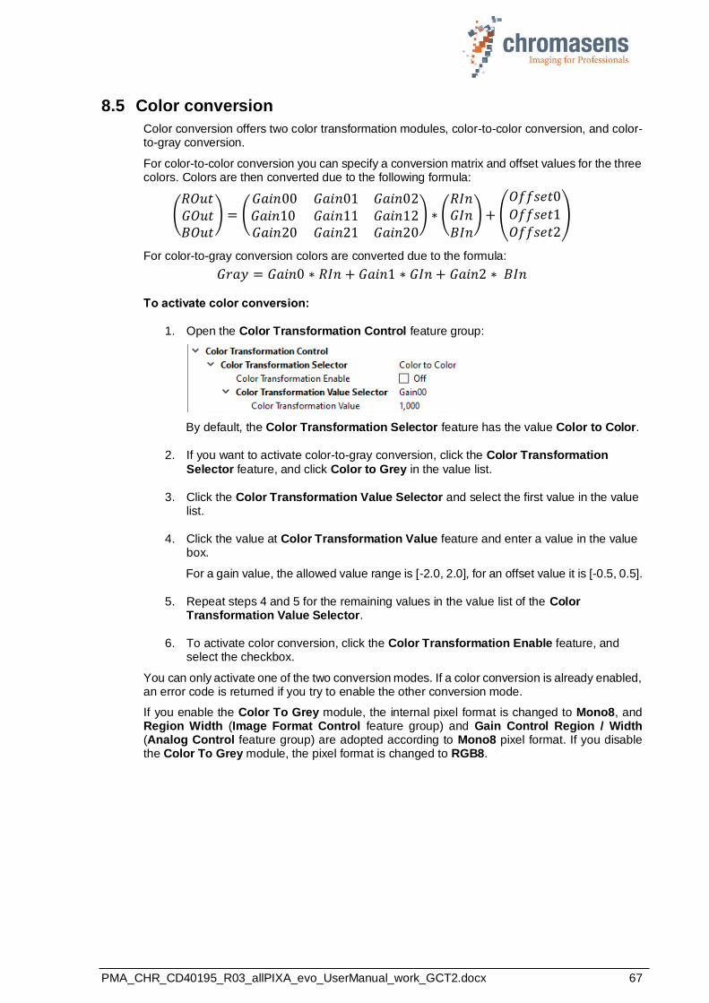
PMA_CHR_CD40195_R03_allPIXA_evo_UserManual_work_GCT2.docx 67
8.5 Color conversion
Color conversion offers two color transformation modules, color-to-color conversion, and color-to-gray conversion.
For color-to-color conversion you can specify a conversion matrix and offset values for the three colors. Colors are then converted due to the following formula:
(𝑅𝑂𝑢𝑡𝐺𝑂𝑢𝑡𝐵𝑂𝑢𝑡
) = (𝐺𝑎𝑖𝑛00 𝐺𝑎𝑖𝑛01 𝐺𝑎𝑖𝑛02𝐺𝑎𝑖𝑛10 𝐺𝑎𝑖𝑛11 𝐺𝑎𝑖𝑛12𝐺𝑎𝑖𝑛20 𝐺𝑎𝑖𝑛21 𝐺𝑎𝑖𝑛20
) ∗ (𝑅𝐼𝑛𝐺𝐼𝑛𝐵𝐼𝑛
) + (
𝑂𝑓𝑓𝑠𝑒𝑡0
𝑂𝑓𝑓𝑠𝑒𝑡1𝑂𝑓𝑓𝑠𝑒𝑡2
)
For color-to-gray conversion colors are converted due to the formula:
𝐺𝑟𝑎𝑦 = 𝐺𝑎𝑖𝑛0 ∗ 𝑅𝐼𝑛 + 𝐺𝑎𝑖𝑛1 ∗ 𝐺𝐼𝑛 + 𝐺𝑎𝑖𝑛2 ∗ 𝐵𝐼𝑛
To activate color conversion:
1. Open the Color Transformation Control feature group:
By default, the Color Transformation Selector feature has the value Color to Color.
2. If you want to activate color-to-gray conversion, click the Color Transformation
Selector feature, and click Color to Grey in the value list.
3. Click the Color Transformation Value Selector and select the first value in the value list.
4. Click the value at Color Transformation Value feature and enter a value in the value box.
For a gain value, the allowed value range is [-2.0, 2.0], for an offset value it is [-0.5, 0.5].
5. Repeat steps 4 and 5 for the remaining values in the value list of the Color Transformation Value Selector.
6. To activate color conversion, click the Color Transformation Enable feature, and select the checkbox.
You can only activate one of the two conversion modes. If a color conversion is already enabled, an error code is returned if you try to enable the other conversion mode.
If you enable the Color To Grey module, the internal pixel format is changed to Mono8, and Region Width (Image Format Control feature group) and Gain Control Region / Width (Analog Control feature group) are adopted according to Mono8 pixel format. If you disable the Color To Grey module, the pixel format is changed to RGB8.
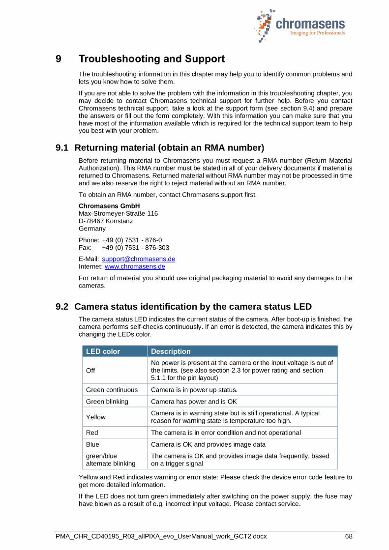
PMA_CHR_CD40195_R03_allPIXA_evo_UserManual_work_GCT2.docx 68
9 Troubleshooting and Support
The troubleshooting information in this chapter may help you to identify common problems and lets you know how to solve them.
If you are not able to solve the problem with the information in this troubleshooting chapter, you may decide to contact Chromasens technical support for further help. Before you contact Chromasens technical support, take a look at the support form (see section 9.4) and prepare the answers or fill out the form completely. With this information you can make sure that you have most of the information available which is required for the technical support team to help you best with your problem.
9.1 Returning material (obtain an RMA number)
Before returning material to Chromasens you must request a RMA number (Return Material Authorization). This RMA number must be stated in all of your delivery documents if material is returned to Chromasens. Returned material without RMA number may not be processed in time and we also reserve the right to reject material without an RMA number.
To obtain an RMA number, contact Chromasens support first.
Chromasens GmbH Max-Stromeyer-Straße 116 D-78467 Konstanz Germany
Phone: +49 (0) 7531 - 876-0 Fax: +49 (0) 7531 - 876-303
E-Mail: [email protected] Internet: www.chromasens.de
For return of material you should use original packaging material to avoid any damages to the cameras.
9.2 Camera status identification by the camera status LED
The camera status LED indicates the current status of the camera. After boot-up is finished, the camera performs self-checks continuously. If an error is detected, the camera indicates this by changing the LEDs color.
LED color Description
Off
No power is present at the camera or the input voltage is out of the limits. (see also section 2.3 for power rating and section 5.1.1 for the pin layout)
Green continuous Camera is in power up status.
Green blinking Camera has power and is OK
Yellow Camera is in warning state but is still operational. A typical reason for warning state is temperature too high.
Red The camera is in error condition and not operational
Blue Camera is OK and provides image data
green/blue alternate blinking
The camera is OK and provides image data frequently, based on a trigger signal
Yellow and Red indicates warning or error state: Please check the device error code feature to get more detailed information.
If the LED does not turn green immediately after switching on the power supply, the fuse may have blown as a result of e.g. incorrect input voltage. Please contact service.

PMA_CHR_CD40195_R03_allPIXA_evo_UserManual_work_GCT2.docx 69
9.3 Camera overheating protection
For safety reasons, the camera is equipped with an internal overheating protection.
Step 1: high-temperature warning:
If the camera internal temperature increases above the defined warning limit, the camera indicates this warning status by:
- Status LED of the camera turns yellow. - Please check the DeviceErrorCode. In case of high temperature warning it is set
to: DEV_CTRL_WARNING_TEMPERATURE_TOO_HIGH
Let the camera cool down and check environment. Improve cooling conditions of the camera if necessary.
Step 2: final safety shutdown:
If the temperature is still increasing and reaches the defined error limit the camera automatically switches to safety mode to protect the camera electronics from overheating. This camera state is indicated by:
- Status LED of the camera turns red - Please check the DeviceErrorCode. In case of high temperature error it is set
to:DEV_CTRL_ERROR_TEMPERATURE_TOO_HIGH - The camera outputs an image with a pin stripe test pattern with black background.
To get the camera back from step 2 to normal operation:
1. Switch off the camera and let the camera cool down.
2. Check the environment and improve cooling if necessary.
3. Start the camera (power on)
For information about temperature level definitions, see sections 2.3 and 5.4.
9.4 Before contacting Chromasens technical support
If you have a problem with the camera and decide to contact Chromasens technical support, it is very important that you collect all relevant system information beforehand.
This may guarantee a quick and efficient problem-solving process together with Chromasens technical support.
To collect the most important information of your issue, you may use the following list as a
guideline. You can also download the list from our website at https://www.chromasens.de/en/distribution/support
Please fill out this list and provide the information including the requested files before you contact Chromasens technical support.

PMA_CHR_CD40195_R03_allPIXA_evo_UserManual_work_GCT2.docx 70
Company name
Name
E-Mail Phone
Street City
Zip code State/Country
Contact person CS Date
System Information
Camera type allPIXA evo 8k 10k 15k
Camera serial number
GCT version used
Operating system
Frame grabber (wave) Type + manufacturer
Network adapter (evo) Type + manufacturer
Problem Description
Description of the problem: (as detailed as possible)
When did the problem occur?
after start during operation
at a specific action, please describe:
How often did problem occur?
once always
regularly rarely please describe:
Did the application ever run ok yes no
If known, please describe the reason for the problem or any abnormal behaviors.
Image and Parameter Files
Camera feature settings (It is very important to provide a copy of the exact camera settings when the problem occurred)
Live images (Live or test images showing the problem. Save images in BMP format)
Message log (Message log, which can be shown in GCT by clicking Show message log window )
Contact Data
Technical Information

PMA_CHR_CD40195_R03_allPIXA_evo_UserManual_work_GCT2.docx 71
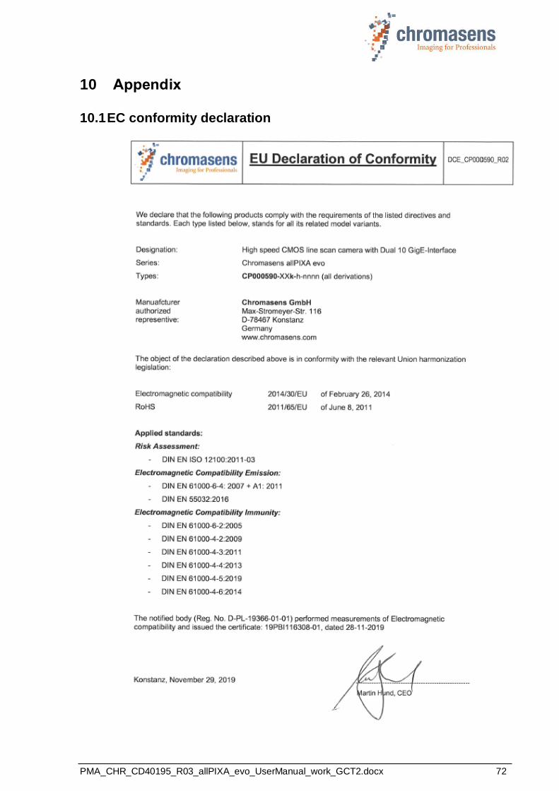
PMA_CHR_CD40195_R03_allPIXA_evo_UserManual_work_GCT2.docx 72
10 Appendix
10.1 EC conformity declaration
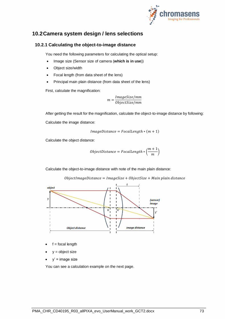
PMA_CHR_CD40195_R03_allPIXA_evo_UserManual_work_GCT2.docx 73
10.2 Camera system design / lens selections
10.2.1 Calculating the object-to-image distance
You need the following parameters for calculating the optical setup:
• Image size (Sensor size of camera (which is in use))
• Object size/width
• Focal length (from data sheet of the lens)
• Principal main plain distance (from data sheet of the lens)
First, calculate the magnification:
𝑚 =𝐼𝑚𝑎𝑔𝑒𝑆𝑖𝑧𝑒/𝑚𝑚
𝑂𝑏𝑗𝑒𝑐𝑡𝑆𝑖𝑧𝑒/𝑚𝑚
After getting the result for the magnification, calculate the object-to-image distance by following:
Calculate the image distance:
𝐼𝑚𝑎𝑔𝑒𝐷𝑖𝑠𝑡𝑎𝑛𝑐𝑒 = 𝐹𝑜𝑐𝑎𝑙𝐿𝑒𝑛𝑔𝑡ℎ ∗ (𝑚 + 1)
Calculate the object distance:
𝑂𝑏𝑗𝑒𝑐𝑡𝐷𝑖𝑠𝑡𝑎𝑛𝑐𝑒 = 𝐹𝑜𝑐𝑎𝑙𝐿𝑒𝑛𝑔𝑡ℎ ∗ (𝑚 + 1
𝑚)
Calculate the object-to-image distance with note of the main plain distance:
𝑂𝑏𝑗𝑒𝑐𝑡𝐼𝑚𝑎𝑔𝑒𝐷𝑖𝑠𝑡𝑎𝑛𝑐𝑒 = 𝐼𝑚𝑎𝑔𝑒𝑆𝑖𝑧𝑒 + 𝑂𝑏𝑗𝑒𝑐𝑡𝑆𝑖𝑧𝑒 + 𝑀𝑎𝑖𝑛 𝑝𝑙𝑎𝑖𝑛 𝑑𝑖𝑠𝑡𝑎𝑛𝑐𝑒
• f = focal length
• y = object size
• y’ = image size
You can see a calculation example on the next page.

PMA_CHR_CD40195_R03_allPIXA_evo_UserManual_work_GCT2.docx 74
Example:
Camera: allPIXA evo camera 15k 86 mm (5.6µm/pixel * 15360 pixels) Object width/size: 450 mm Lens: 90.1 mm real focal length -2.5 mm principal main plain distance
𝑚 =𝐼𝑚𝑎𝑔𝑒𝑆𝑖𝑧𝑒
𝑂𝑏𝑗𝑒𝑐𝑡𝑆𝑖𝑧𝑒= 0.162
𝐼𝑚𝑎𝑔𝑒𝐷𝑖𝑠𝑡𝑎𝑛𝑐𝑒 = 𝐹𝑜𝑐𝑎𝑙𝐿𝑒𝑛𝑔𝑡ℎ ∗ (𝑚 + 1) = 104.72 𝑚𝑚
𝑂𝑏𝑗𝑒𝑐𝑡𝐷𝑖𝑠𝑡𝑎𝑛𝑐𝑒 = 𝐹𝑜𝑐𝑎𝑙𝐿𝑒𝑛𝑔𝑡ℎ ∗ (𝑚 + 1
𝑚) = 645,51 𝑚𝑚
𝑂𝑏𝑗𝑒𝑐𝑡𝐼𝑚𝑎𝑔𝑒𝐷𝑖𝑠𝑡𝑎𝑛𝑐𝑒 = 𝐼𝑚𝑎𝑔𝑒𝑆𝑖𝑧𝑒 + 𝑂𝑏𝑗𝑒𝑐𝑡𝑆𝑖𝑧𝑒 + 𝑀𝑎𝑖𝑛 𝑝𝑙𝑎𝑖𝑛 𝑑𝑖𝑠𝑡𝑎𝑛𝑐𝑒 = 747.73
(w/o glass plates in the optical path)
10.2.2 Calculating the distance rings (tubes) for the allPIXA evo camera
Some applications require distance rings (tubes) for mounting the lens in the right position on the allPIXA evo camera. This section shows an example how to calculate the length of the distance ring.
To calculate the needed distance rings, you have to get some information about the optical setup:
Optical parameter:
• Real focal length (from data sheet)
• Image distance (calculated)
Parameters of the lens:
• Back flange length at infinite distance (from data sheet)
Parameters of additional focusing unit:
• Minimum offset distance of the unit from flange of the lens
• Maximum offset distance
Figure 31
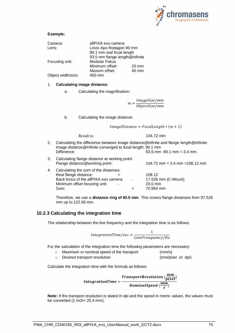
PMA_CHR_CD40195_R03_allPIXA_evo_UserManual_work_GCT2.docx 75
Example:
Camera: allPIXA evo camera Lens: Linos Apo Rodagon 90 mm
90.1 mm real focal length 93.5 mm flange length@infinite
Focusing unit: Modular Fokus Minimum offset 20 mm Maxium offset 45 mm Object width/size: 450 mm
1. Calculating image distance:
a. Calculating the magnification:
𝑚 =𝐼𝑚𝑎𝑔𝑒𝑆𝑖𝑧𝑒/𝑚𝑚
𝑂𝑏𝑗𝑒𝑐𝑡𝑆𝑖𝑧𝑒/𝑚𝑚
b. Calculating the image distance:
𝐼𝑚𝑎𝑔𝑒𝐷𝑖𝑠𝑡𝑎𝑛𝑐𝑒 = 𝐹𝑜𝑐𝑎𝑙𝐿𝑒𝑛𝑔𝑡ℎ ∗ (𝑚 + 1)
Result is: 104,72 mm
2. Calculating the difference between image distance@infinite and flange length@infinite: Image distance@infinite converged to focal length: 90.1 mm Difference: 93.5 mm -90.1 mm = 3.4 mm
3. Calculating flange distance at working point: Flange distance@working point: 104.72 mm + 3.4 mm =108.12 mm
4. Calculating the sum of the distances: Real flange distance: + 108.12 Back focus of the allPIXA evo camera: - 17.526 mm (C-Mount) Minimum offset focusing unit: - 20.0 mm Sum: = 70.954 mm Therefore, we use a distance ring of 60.0 mm. This covers flange distances from 97.526 mm up to 122.56 mm.
10.2.3 Calculating the integration time
The relationship between the line frequency and the integration time is as follows:
𝐼𝑛𝑡𝑒𝑔𝑟𝑎𝑡𝑖𝑜𝑛𝑇𝑖𝑚𝑒/𝑠𝑒𝑐. =1
𝐿𝑖𝑛𝑒𝐹𝑟𝑒𝑢𝑞𝑢𝑒𝑛𝑐𝑦/𝐻𝑧
For the calculation of the integration time the following parameters are necessary:
o Maximum or nominal speed of the transport (mm/s)
o Desired transport resolution (mm/pixel or dpi)
Calculate the integration time with the formula as follows:
𝑰𝒏𝒕𝒆𝒈𝒓𝒂𝒕𝒊𝒐𝒏𝑻𝒊𝒎𝒆 =𝑻𝒓𝒂𝒏𝒔𝒑𝒐𝒓𝒕𝑹𝒆𝒔𝒐𝒍𝒖𝒕𝒊𝒐𝒏 (
𝒎𝒎𝒑𝒊𝒙𝒆𝒍)
𝑵𝒐𝒎𝒊𝒏𝒂𝒍𝑺𝒑𝒆𝒆𝒅 (𝒎𝒎
𝒔 )
Note: If the transport resolution is stated in dpi and the speed in metric values, the values must be converted (1 inch= 25,4 mm).

PMA_CHR_CD40195_R03_allPIXA_evo_UserManual_work_GCT2.docx 76
Chromasens GmbH
Max-Stromeyer-Straße 116 Phone: +49 7531 876-0 www.chromasens.de
78467 Konstanz Fax: +49 7531 876-303 [email protected]
Germany
May
20
21 C
opyright
by C
hro
masens G
mbH