SyScrew Water EVO CO/HP/RC - Products
62
Installation and maintenance manual Manuel d’installation et de maintenance Installations- und Wartungshandbuch Manuale di installazione e di manutenzione Manual de instalación y de mantenimiento SyScrew Water EVO CO/HP/RC 444 1567 kW Part number / Code / Code / Codice / Código: 367236/C Supersedes / Annule et remplace / Annulliert und ersezt / Annulla e sostituisce / Anula y sustituye: 367236/B Notified Body /Organisme Notifié / Benannte Zertifizierungsstelle / Organismo Notificato / Organismo Notificado N°. 1115 ” Español Italiano Deutsch Français English Water/water Cooled Screw Chillers Réfrigérateurs Froid Seulement eau/eau à compresseurs à vis Wassergekulte Wasserkühler mit Schraubenkompressoren Refrigeratori Solo Freddo acqua/acqua con compressori a vite Refrigeradores Sólo Frío agua/agua con compresores a tornillo ISO 9001:2008 certified management system
-
Upload
khangminh22 -
Category
Documents
-
view
1 -
download
0
Transcript of SyScrew Water EVO CO/HP/RC - Products
Installation and maintenance manualManuel d’installation et de maintenanceInstallations- und WartungshandbuchManuale di installazione e di manutenzioneManual de instalación y de mantenimiento
SyScrew Water EVO CO/HP/RC
444
1567 kW
Part number / Code / Code / Codice / Código: 367236/CSupersedes / Annule et remplace / Annulliert und ersezt / Annulla e sostituisce / Anula y sustituye: 367236/BNotified Body /Organisme Notifié / Benannte Zertifizierungsstelle /Organismo Notificato / Organismo Notificado N°. 1115 ”
EspañolItalianoDeutschFrançaisEnglish
Water/water Cooled Screw ChillersRéfrigérateurs Froid Seulement eau/eau à compresseurs à visWassergekulte Wasserkühler mit SchraubenkompressorenRefrigeratori Solo Freddo acqua/acqua con compressori a viteRefrigeradores Sólo Frío agua/agua con compresores a tornillo
ISO 9001:2008 certified management system

1
Engl
ishTable of Contents
1 - FOREWORD
1.1 Introduction ..........................................................................2
1.2 Warranty ..............................................................................2
1.3 Emergency stop/Normal stop ...............................................2
1.4 An introduction to this manual ..............................................2
2 - SAFETY
2.1 Foreword ..............................................................................3
2.2 Definitions ............................................................................4
2.3 Access to the unit ................................................................4
2.4 General precautions..............................................................4
2.5 Precautions against residual risks .........................................4
2.6 Precautions during maintenance operations ..........................5
2.7 Safety labels ................................................................. 6 & 7
2.8 Safety regulations ........................................................8 to 10
3 - TRANSPORT, LIFTING AND POSITIONING
3.1 Inspection ..........................................................................11
3.2 Lifting ................................................................................11
3.3 Anchoring ..........................................................................12
3.4 Storage ..............................................................................12
4 - INSTALLATION
4.1 Positioning of the unit .........................................................13
4.2 Spring isolator installation ...................................................13
4.3 Hydraulic connection of the evaporator ...................... 14 & 15
4.4 Hydraulic connection of the condenser ..............................16
4.5 Hydraulic connections .......................................................16
4.6 Connection of water temperature sensors (on shell and tube evaporator) ...........................................17
4.7 Connection of water temperature sensors (on shell and tube condenser/s)..........................................18
4.8 Power supply .....................................................................19
4.9 Electrical connections................................................ 19 & 20
5 - START-UP
5.1 Preliminary check ...............................................................20
5.2 Start-up .............................................................................20
5.3 Checking the operation .......................................................20
5.4 Delivery to the customer .....................................................20
6 - CONTROL
6.1 Display ...............................................................................23
6.2 Setpoint .............................................................................25
6.3 Protection and Safety Equipment ........................................26
7 - PRODUCT DESCRIPTION
7.1 Introduction ........................................................................27
7.2 General specifications ........................................................27
7.3 Compressors .....................................................................27
7.4 Refrigeration circuits ..........................................................27
7.5 Water heat exchanger .........................................................28
7.6 Electrical power supply and control system ........................28
7.7 Accessories .......................................................................28
8 - TECHNICAL DATA
8.1 Pressure drops ...................................................................31
8.2 Technical data ...........................................................33 to 38
8.3 Unit electrical data ..................................................... 39 & 40
8.4 Position of shock adsorbers and weight distribution on supports ....................................41
8.5 Dimensional Drawings ...............................................43 to 50
8.6 Service spaces ...................................................................51
9 - MAINTENANCE
9.1 General requirements .........................................................52
9.2 Planned maintenance .........................................................52
9.3 Refrigerant charge ..............................................................53
9.4 Compressor .......................................................................53
9.5 Condenser .........................................................................53
9.6 Dehydrating filter ................................................................53
9.7 Sight glass .........................................................................54
9.8 Electronic expansion valve ..................................................54
9.9 Evaporator .........................................................................54
10 - TROUBLESHOOTING .......................................... 55
11 - SPARE PARTS
11.1 Spare part list.....................................................................56
11.2 Oil for compressors ............................................................56
11.3 Wiring diagrams .................................................................56
12 - DISMANTLING, DEMOLITION AND SCRAPPING
12.1 Generalities ........................................................................57

2
1 - Introdução1 - Foreword
1.1 Introduction
Units, manufactured to state-of-the-art design and implementation standards, ensure top performance, reliability and fitness to any type of air-conditioning systems.
These units are designed for cooling water or glycoled water (and for water heating in heat pump models) and are unfit for any purposes other than those specified in this manual.
This manual includes all the information required for a proper installation of the units, as well as the relevant operating and maintenance instructions.
It is therefore recommended to read this manual carefully before installation or any operation on the machine. The chiller installation and maintenance must be carried out by skilled personnel only (where possible, by one of Authorised Service Centers).
The manufacturer may not be held liable for any damage to people or property caused by improper installation, start-up and/or improper use of the unit and/or failure to implement the procedures and instructions included in this manual.
1.2 Warranty
These units are delivered complete, tested and ready for being operated. Any form of warranty will become null and void in the event that the appliance is modified without manufacturer’s preliminary written authorisation.
This warranty shall apply providing that the installation instructions have been complied with (either issued by manufacturer, or deriving from the current practice), and the Form 1 (“Start-up”) has been filled-in and mailed to manufacturer (attn. After-Sales Service).
In order for this warranty to be valid, the following conditions shall be met:
n The machine must be operated only by skilled personnel from Authorised After-Sales Service.
n Maintenance must be performed only by skilled personnel - from one of Authorised After-Sales Centers.
n Use only original spare parts.
n Carry out all the planned maintenance provided for by this manual in a timely and proper way.
Failure to comply with any of these conditions will automatically void the warranty.
1.3 Emergency stop / Normal stop
The emergency stop of the unit can be enabled using the master switch on the control panel (move down the lever).
For a normal stop, press the relevant push-buttons.
To restart the appliance, follow the procedure detailed in this manual.
1.4 An introduction to the manual
For safety reasons, it is imperative to follow the instructions given in this manual. In case of any damage caused by non-compliance with these instructions, the warranty will immediately become null and void.
Conventions used throughout the manual:
DANGER
The Danger sign recalls your attention to a certain procedure or practice which, if not followed, may result in serious damage to people and property.
The Warning sign precedes those procedures that, if not followed, may result in serious damage to the appliance.
The Notes contain important observations.
The Useful Tips provide valuable information that optimises the efficiency of the appliance.
This manual and its contents, as well as the documentation which accompanies the unit, are and remain the property of manufacturer, which reserves any and all rights thereon. This manual may not be copied, in whole or in part, without manufacturer’s written authorization.
WARNING
NOTE
USEFUL TIPS

3
Engl
ish2 - Safety
2.1 Foreword
These units must be installed in conformity with the provisions of Machinery Directive 2006/42/EC, Pressure Equipment Directive 2014/68/EU, Electromagnetic Compability Directive 2014/30/EU, as well as with other regulations applicable in the country of installation. If these provisions are not complied with, the unit must not be operated.
DANGER
The unit must be grounded, and no installation and/or maintenance operations may be carried out before deenergising the electrical panel of the unit.
Failure to respect the safety measures mentioned above may result in electrocution hazard and fire in the presence of any short-circuits.
DANGER
Inside the heat exchangers, the compressors and the refrigeration lines, this unit contains l iquid and gaseous refr igerant under pressure. The release of this refrigerant may be dangerous and cause injuries.
DANGER
The units are not designed to be operated with natural refrigerants, such as hydrocarbons. Manufacturer may not be held liable for any problems deriving from the replacement of original refrigerant or the introduction of hydrocarbons.
Units are designed and manufactured according to the requirements of European Standard PED 2014/68/EU (pressure vessels directive).
n The used refrigerants are included in group II (non-hazardous fluids).
n The maximum working pressure values are mentioned on the unit’s data plate.
n Suitable safety devices (pressure switches and safety valves) have been provided, to prevent any anomalous overpressure inside the plant.
n The vents of the safety valves are positioned and oriented in such a way as to reduce the risk of contact with the operator, in the event that the valve is operated. Anyway, the installer will convey the discharge of the valves far from the unit.
n Dedicated guards (removable panels with tools) and danger signs indicate the presence of hot pipes or components (high surface temperature).
DANGER
The guards of the fans (only for RC units, with remote air exchangers) must be always mounted and must never be removed before de-energising the appliance.
DANGER
It is the User’s responsibility to ensure that the unit is fit for the conditions of intended use and that both installation and maintenance are carried out by experienced personnel, capable of respecting all the recommendations provided by this manual.
It is important that the unit is adequately supported, as detailed in this manual. Non-compliance with these recommendations may create hazardous situations for the personnel.
DANGER
The unit must rest on a base which meets the characteristics specified in this manual; a base with inadequate characteristics is likely to become a source of serious injury to the personnel.
WARNING
The unit has not been design to withstand loads and/or stress that may be transmitted by adjacent units, piping and/or structures.
Each external load or stress transmitted to the unit may break or cause breakdowns in the unit’s structure, as well as serious dangers to people. In these cases, any form of warranty will automatically become null and void.
WARNING
The packaging material must not be disposed of in the surrounding environment or burnt.
4
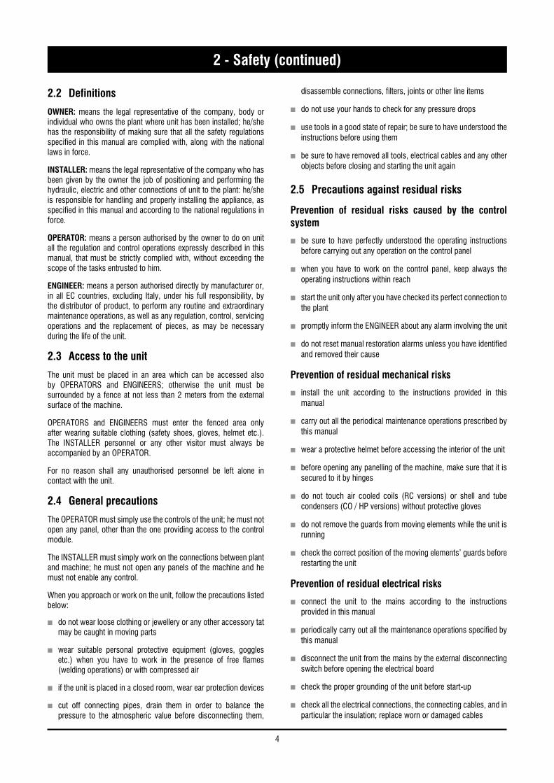
2.2 Definitions
OWNER: means the legal representative of the company, body or individual who owns the plant where unit has been installed; he/she has the responsibility of making sure that all the safety regulations specified in this manual are complied with, along with the national laws in force.
INSTALLER: means the legal representative of the company who has been given by the owner the job of positioning and performing the hydraulic, electric and other connections of unit to the plant: he/she is responsible for handling and properly installing the appliance, as specified in this manual and according to the national regulations in force.
OPERATOR: means a person authorised by the owner to do on unit all the regulation and control operations expressly described in this manual, that must be strictly complied with, without exceeding the scope of the tasks entrusted to him.
ENGINEER: means a person authorised directly by manufacturer or, in all EC countries, excluding Italy, under his full responsibility, by the distributor of product, to perform any routine and extraordinary maintenance operations, as well as any regulation, control, servicing operations and the replacement of pieces, as may be necessary during the life of the unit.
2.3 Access to the unit
The unit must be placed in an area which can be accessed also by OPERATORS and ENGINEERS; otherwise the unit must be surrounded by a fence at not less than 2 meters from the external surface of the machine.
OPERATORS and ENGINEERS must enter the fenced area only after wearing suitable clothing (safety shoes, gloves, helmet etc.). The INSTALLER personnel or any other visitor must always be accompanied by an OPERATOR.
For no reason shall any unauthorised personnel be left alone in contact with the unit.
2.4 General precautions
The OPERATOR must simply use the controls of the unit; he must not open any panel, other than the one providing access to the control module.
The INSTALLER must simply work on the connections between plant and machine; he must not open any panels of the machine and he must not enable any control.
When you approach or work on the unit, follow the precautions listed below:
n do not wear loose clothing or jewellery or any other accessory tat may be caught in moving parts
n wear suitable personal protective equipment (gloves, goggles etc.) when you have to work in the presence of free flames (welding operations) or with compressed air
n if the unit is placed in a closed room, wear ear protection devices
n cut off connecting pipes, drain them in order to balance the pressure to the atmospheric value before disconnecting them,
disassemble connections, filters, joints or other line items
n do not use your hands to check for any pressure drops
n use tools in a good state of repair; be sure to have understood the instructions before using them
n be sure to have removed all tools, electrical cables and any other objects before closing and starting the unit again
2.5 Precautions against residual risks
Prevention of residual risks caused by the control system
n be sure to have perfectly understood the operating instructions before carrying out any operation on the control panel
n when you have to work on the control panel, keep always the operating instructions within reach
n start the unit only after you have checked its perfect connection to the plant
n promptly inform the ENGINEER about any alarm involving the unit
n do not reset manual restoration alarms unless you have identified and removed their cause
Prevention of residual mechanical risks
n install the unit according to the instructions provided in this manual
n carry out all the periodical maintenance operations prescribed by this manual
n wear a protective helmet before accessing the interior of the unit
n before opening any panelling of the machine, make sure that it is secured to it by hinges
n do not touch air cooled coils (RC versions) or shell and tube condensers (CO / HP versions) without protective gloves
n do not remove the guards from moving elements while the unit is running
n check the correct position of the moving elements’ guards before restarting the unit
Prevention of residual electrical risks
n connect the unit to the mains according to the instructions provided in this manual
n periodically carry out all the maintenance operations specified by this manual
n disconnect the unit from the mains by the external disconnecting switch before opening the electrical board
n check the proper grounding of the unit before start-up
n check all the electrical connections, the connecting cables, and in particular the insulation; replace worn or damaged cables
2 - Safety (continued)
5
Engl
ish
n periodically check the board’s internal wiring
n do not use cables having an inadequate section or flying connections, even for limited periods of time or in an emergency
Prevention of other residual risks
n make sure that the connections to the unit conform to the instructions provided in this manual and on the unit’s panelling
n if you have to disassemble a piece, make sure that it has been properly mounted again before restarting the unit
n do not touch the delivery pipes from the compressor, the compressor and any other piping or component inside the machine before wearing protective gloves
n keep a fire extinguisher fir for electrical appliances near the machine
n on the units installed indoor, connect the safety valve of the refrigeration circuit to a piping network that can channel any overflowing refrigerant outside
n remove and leak of fluid inside and outside the unit
n collect the waste liquids and dry any oil spillage
n periodically clean the compressor compartment, to remove any fouling
n do not store flammable liquids near the unit
n do not disperse the refrigerant and the lubricating oil into the environment
n weld only empty pipes; do not approach flames or other sources of heat to refrigerant pipes
n do not bend/hit pipes containing fluids under pressure
2.6 Precautions during maintenance operations
Maintenance operations can be carried out by authorised technicians only.
Before performing any maintenance operations:
n disconnect the unit from the mains with the external disconnecting switch
2 - Safety (continued)
n place a warning sign “do not turn on - maintenance in progress” on the external disconnecting switch
n make sure that on-off remote controls are inhibited
n wear suitable personal protective equipment (helmet, safety gloves, goggles and shoes etc.)
To carry out any measurements or checks which require the activation of the machine:
n work with the electrical board open only for the necessary time
n close the electrical board as soon as the measurement or check has been completed
n for outdoor units, do not carry out any operations in the presence of dangerous climatic conditions (rain, snow, mist etc.)
The following precautions must be always adopted:
n do not scatter the fluids of the refrigeration circuit in the surrounding environment
n when replacing an eprom or electronic cards, use always suitable devices (extractor, antistatic bracelet, etc.)
n to replace a compressor, the evaporator, the condensing coils or any other weighty element, make sure that the lifting equipment is consistent with the weight to be lifted
n in units connected to a air remote condenser, do not access the fan compartment unless you have disconnected the machine by the disconnecting switch on the board and you have placed a warning sign “do not turn on - maintenance in progress”
n contact manufacturer for any modifications to the refrigeration, hydraulic or wiring diagram of the unit, as well as to its control logics
n contact manufacturer if it is necessary to perform very difficult disassembly and assembly operations
n use only original spare parts purchased directly from manufacturer or the official retailers of the companies on the recommended spare parts list
n contact manufacturer if it is necessary to handle the unit one year after its positioning on site or if you wish to dismantle it.

6
2 - Safety (continued)
2.7 Safety labels
Identification of the refrigerant - External door
USARE SOLO
R134aE
RECU
PERA
RE F
LUID
O - N
ON D
ISPE
RDER
E NE
LL’A
MBIE
NTE
- REG
OLAM
ENTO
CEE
N° 3
093/9
4
RECO
VER
- DO
NOT
VENT
- EE
C RE
GULA
TION
N° 3
093/9
4
SPECIAL ESTER OIL
USE ONLY
Electrical warning - Adjacent to the master switch
ATTENZIONE !
Prima di aprire togliere
tensione
CAUTION !
Disconnectelectrical
supply before opening
ACHTUNG !
Vor offnen des gehauses
hauptschalter ausschalten
ATENCION !
Cortar la corrente antes
de abrirel aparato
ATTENTION !
Enlever l’alimentation
electrique avant d’ouvrir
Read the instruction on the electrical board
On the compressor box
WARNING
Circuit drain - Outside, on the right-hand front column
Identification of the unit - Outside, on the right-hand front column
Gravity centre - Base
TENE
RE SU
QUES
TA LI
NEA
GANC
IO DI
SOLL
EVAM
ENTO
KEEP
LIFT
HOOK
ON TH
IS LIN
E
Grounding connection on the electrical board, adjacent to the connection
DO NOT OPEN THE PANEL WHILE UNIT IS RUNNING
ATTENTION! Don’t leave the unit with water inside hydraulic circuit during winter or when it is in stand by.ATTENZIONE! Non lasciare l’unità con acqua nel circuito idraulico durantel’inverno o quando non è funzionante.ATTENTION! Ne laissez pas l’unitè avec de l’eau dans le circuit hydrauliquependant l’hiver ou quand elle ne travaille pas.WARNUNG! Lassen Sie nicht das Wasser in die Schaltung während desWinters oder wenn es nicht funktionient.¡ATENCÍON! No deje el agua en el circuito hidráulico durante el invierno ocuando no esta trabajando.
CODICE PRODOTTO NEUTROPRODUCT CODE
MODELLOMODEL
1115
MO.NO
MATRICOLASERIAL NO.
ANNO DI COSTRUZIONEManuf. Year
REFR. GWPCIRCUIT 1 2 3 4
CHARGE (Kg)
PS (LATO ALTA / LATO BASSA)PS (HIGH / LOW SIDE)
TS (ALTA / BASSA)TS (HIGH / LOW)
ALIM. POTENZAMAIN SUPPLY
CORRENTE DI SPUNTOLRA
CORRENTE A PIENO CARICOFLA
POTENZA ASSORBITAPOWER INPUT
PRESS. MAX ESERCIZIO ACQUAMAX WATER OPERATING PRESSURE
MASSAMASS
SYSTEMAIR S.r.l. Via XXV Aprile 29 20825 BARLASSINA MB ITALIAMADE IN ITALY COD.NO: P35952
MODELLO:MODEL
MATRICOLA:SERIAL NO.
CODICE:PRODUCT CODE
MODELLO:MODEL
MATRICOLA:SERIAL NO.
CODICE:PRODUCT CODE
MODELLO:MODEL
MATRICOLA:SERIAL NO.
CODICE:PRODUCT CODE
bar
°C
V / PH / Hz
(max) A
(max) A
(max) Kw
bar
Kg
ANNO DI COSTRUZIONEManuf. Year
ANNO DI COSTRUZIONEManuf. Year
ANNO DI COSTRUZIONEManuf. Year

7
Engl
ish2 - Safety (continued)
Final Test Certificate - Inside the external door
Warning - Safety valve ventsWarning - High temperature zone adjacent to hot pipes or
components
Start-up warning - Outside the door of the electrical board
Instruction for the lifting
Fitting identification - Adjacent to fittings
EIN - INLETENTRÉE - ENTRATA
AUS - OUTLETSORTIE - USCITA

8
2 - Safety (continued)
2.8 Safety regulations
REFRIGERANT DATA SAFETY DATA: R134a
Toxicity Low
Contact with skin
If sprayed, the refrigerant is likely to cause frost burns. If absorbed by the skin, the danger is very limited; it may cause a slight irritation, and the liquid is degreasing. Unfreeze the affected skin with water.
Remove the contaminated clothes with great care - in the presence of frost burns, the clothes may stick to the skin. Wash with plenty of warm water the affected skin.
In the presence of symptoms such as irritation or blisters, obtain medical attention.
Contact with eyesVapours do not cause harmful effects. The spraying of refrigerant may cause frost burns.
Wash immediately with a proper solution or with tap water for at least 10 minutes, and then obtain medical attention.
IngestionVery unlikely - should something happen, it will cause frost burns.
Do not induce vomiting. Only if the patient is conscious, wash out mouth with water and give some 250 ml of water to drink. Then, obtain medical attention.
Inhalation
R134a: remarkable concentrations in the air may have an anaesthetic effect, up to fainting.
The exposure to considerable amounts may cause irregular heartbeat, up to the sudden death of the patient. Very high concentrations may result in the risk of asphyxia, due to the reduction in the oxygen percentage in the atmosphere. Remove the patient to fresh air and keep warm and at rest.
If necessary, give oxygen. In case of breathing difficulties or arrest, proceed with artificial respiration.
In case of cardiac arrest, proceed with cardiac massage. Then, obtain medical attention.
RecommendationsSemiotics or support therapy is recommended. Cardiac sensitisation has been observed that, in the presence of circulating catecholamines such as adrenalin, may cause cardiac arrhythmia and accordingly, in case of exposure to high concentrations, cardiac arrest.
Prolonged exposure
R134a: a study on the effects of exposure to 50,000 ppm during the whole life of rats has identified the development of benign testicle tumour.
This situation should therefore be negligible for personnel exposed to concentrations equal to or lower than professional levels.
Professional levels R134a: Recommended threshold: 1000 ppm v/v - 8 hours TWA.
Stability R134a: Not specified
Conditions to avoid Do not use in the presence of flames, burning surfaces and excess humidity.
Hazardous reactionsMay react with sodium, potassium, barium and other alkaline metals.
Incompatible substances: magnesium and alloys with magnesium concentrations > 2%.
Hazardous decomposition products R134a: Halogen acids produced by thermal decomposition and hydrolysis.
9
Engl
ish2 - Safety (continued)
2.8 Safety regulations (continued)
REFRIGERANT DATA SAFETY DATA: R134a
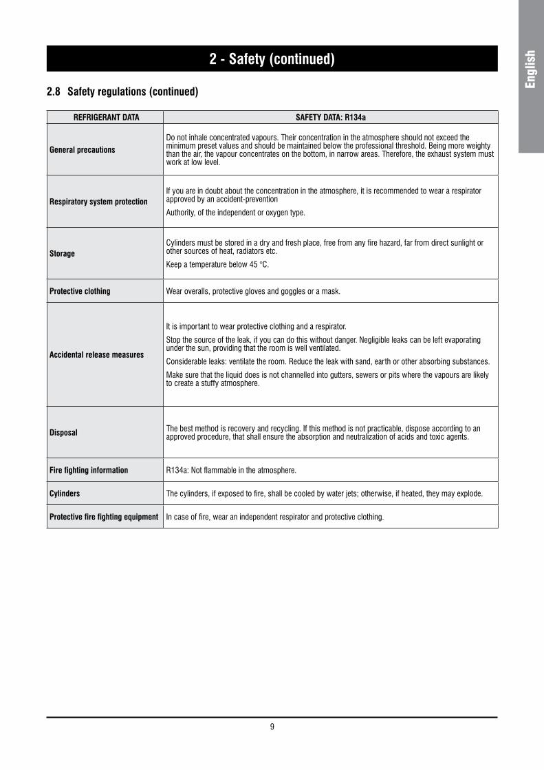
General precautionsDo not inhale concentrated vapours. Their concentration in the atmosphere should not exceed the minimum preset values and should be maintained below the professional threshold. Being more weighty than the air, the vapour concentrates on the bottom, in narrow areas. Therefore, the exhaust system must work at low level.
Respiratory system protectionIf you are in doubt about the concentration in the atmosphere, it is recommended to wear a respirator approved by an accident-prevention
Authority, of the independent or oxygen type.
StorageCylinders must be stored in a dry and fresh place, free from any fire hazard, far from direct sunlight or other sources of heat, radiators etc.
Keep a temperature below 45 °C.
Protective clothing Wear overalls, protective gloves and goggles or a mask.
Accidental release measures
It is important to wear protective clothing and a respirator.
Stop the source of the leak, if you can do this without danger. Negligible leaks can be left evaporating under the sun, providing that the room is well ventilated.
Considerable leaks: ventilate the room. Reduce the leak with sand, earth or other absorbing substances.
Make sure that the liquid does is not channelled into gutters, sewers or pits where the vapours are likely to create a stuffy atmosphere.
Disposal The best method is recovery and recycling. If this method is not practicable, dispose according to an approved procedure, that shall ensure the absorption and neutralization of acids and toxic agents.
Fire fighting information R134a: Not flammable in the atmosphere.
Cylinders The cylinders, if exposed to fire, shall be cooled by water jets; otherwise, if heated, they may explode.
Protective fire fighting equipment In case of fire, wear an independent respirator and protective clothing.
10
2 - Safety (continued)
LUBRICANT OIL DATA SAFETY DATA: POLYESTER OIL (POE)
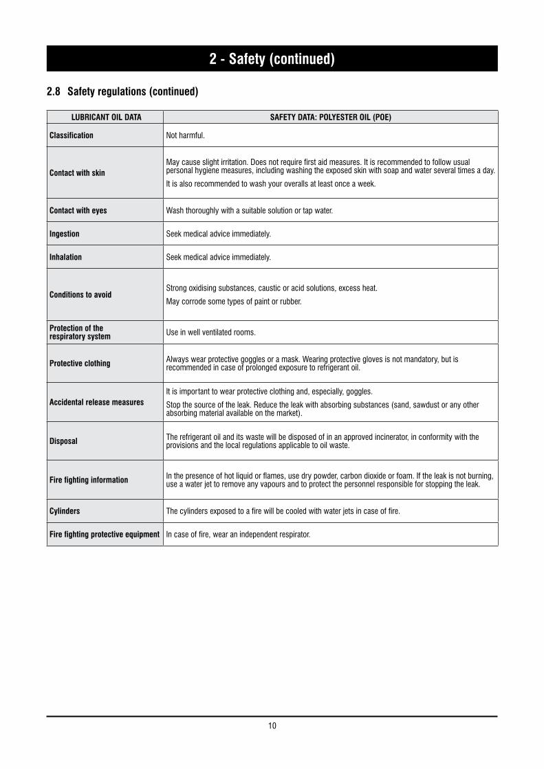
Classification Not harmful.
Contact with skinMay cause slight irritation. Does not require first aid measures. It is recommended to follow usual personal hygiene measures, including washing the exposed skin with soap and water several times a day.
It is also recommended to wash your overalls at least once a week.
Contact with eyes Wash thoroughly with a suitable solution or tap water.
Ingestion Seek medical advice immediately.
Inhalation Seek medical advice immediately.
Conditions to avoidStrong oxidising substances, caustic or acid solutions, excess heat.
May corrode some types of paint or rubber.
Protection of therespiratory system Use in well ventilated rooms.
Protective clothing Always wear protective goggles or a mask. Wearing protective gloves is not mandatory, but is recommended in case of prolonged exposure to refrigerant oil.
Accidental release measuresIt is important to wear protective clothing and, especially, goggles.
Stop the source of the leak. Reduce the leak with absorbing substances (sand, sawdust or any other absorbing material available on the market).
Disposal The refrigerant oil and its waste will be disposed of in an approved incinerator, in conformity with the provisions and the local regulations applicable to oil waste.
Fire fighting information In the presence of hot liquid or flames, use dry powder, carbon dioxide or foam. If the leak is not burning, use a water jet to remove any vapours and to protect the personnel responsible for stopping the leak.
Cylinders The cylinders exposed to a fire will be cooled with water jets in case of fire.
Fire fighting protective equipment In case of fire, wear an independent respirator.
2.8 Safety regulations (continued)
11
Engl
ish3 - Transport, Lifting and Positioning
Refrigerators are supplied assembled (apart from standard antivibrating rubber supports, that will be installed on site). The equipment are full of refrigerant and oil, in the quantity required for a proper operation.
3.1 Inspection
When the unit is delivered, it is recommended to check it carefully and to identify any damage occurred during transportation. The goods are shipped ex-factory, at the buyer’s risk. Check that the delivery includes all the components listed in the order.
In case of damage, note it down on the carrier’s delivery note and issue a claim according to the instructions provided in the delivery note.
In the presence of any serious damage, that does not affect the surface only, it is recommended to inform manufacturer immediately.
Please note that manufacturer may not be held liable for any damage to the equipment during transportation, even though the carrier has been appointed by the factory.
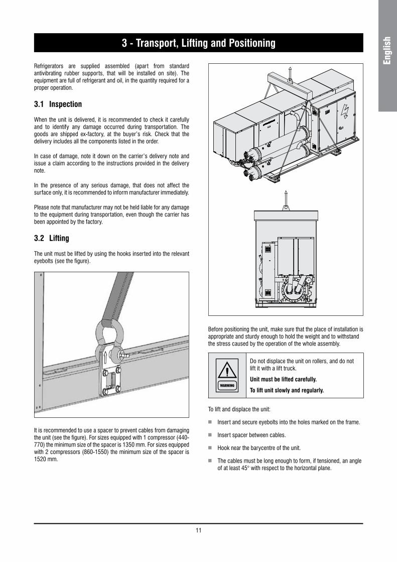
3.2 Lifting
The unit must be lifted by using the hooks inserted into the relevant eyebolts (see the figure).
It is recommended to use a spacer to prevent cables from damaging the unit (see the figure). For sizes equipped with 1 compressor (440-770) the minimum size of the spacer is 1350 mm. For sizes equipped with 2 compressors (860-1550) the minimum size of the spacer is 1520 mm.
Before positioning the unit, make sure that the place of installation is appropriate and sturdy enough to hold the weight and to withstand the stress caused by the operation of the whole assembly.
WARNING
Do not displace the unit on rollers, and do not lift it with a lift truck.
Unit must be lifted carefully.
To lift unit slowly and regularly.
To lift and displace the unit:
n Insert and secure eyebolts into the holes marked on the frame.
n Insert spacer between cables.
n Hook near the barycentre of the unit.
n The cables must be long enough to form, if tensioned, an angle of at least 45° with respect to the horizontal plane.

12
3 - Transport, Lifting and Positioning (continued)
WARNING
During the lifting and handling of the unit, be careful not to damage the electrical board, installed on one side of the unit.
The sides of the unit must be protected by cardboard or plywood sheets.
WARNING
It is recommended not to remove the protective plastic envelope, that should prevent scraps from penetrating into the appliance and any damage to the surfaces, until the unit is ready for operation.
3.3 Anchoring
It is not essential to secure the unit to the foundations, unless in areas where there is a serious risk of earthquake, or if the appliance is installed on the top of a steel frame.
3.4 Storage
When the unit is to be stored before installation, adopt a few precautions to prevent any damage or risk of corrosion or wear:
n plug or seal every single opening, such as water fittings
n do not store the appliance in a room where the temperature exceeds 50 °C for the units using R134a and, if possible, do not expose to direct sunlight
n minimum storage temperature is -25 °C
n it is recommended to store the unit in a roof where traffic is minimized, to prevent the risk of accidental damage
n the unit must not be washed with a steam jet
n take away and leave to the site manager all the keys providing access to the control board
Finally, it is recommended to carry out visual inspections at regular intervals.
WARNING
For lifting operations, use only tools and material fit for this purpose, in accordance with accident-prevention regulations.

13
Engl
ish4 - Installation
4.1 Positioning of the unit
DANGER
Before installing the unit, make sure that the structure of the building and/or the supporting surface can withstand the weight of the appliance. The weights of the units are listed in Chapter 8 of this manual.
These units have been designed for indoor installation on a solid surface. Standard accessories include antivibrating rubber supports, that must be positioned under the base.
When the unit is to be installed on the ground, it is necessary to provide a concrete base, to ensure a uniform distribution of the weights.
As a general rule, no special sub-bases are required. However, if the unit is to be installed on the top of inhabited rooms, it is advisable to rest it on spring shock absorbers (optional), that will minimise the transmission of any vibration to the structures.
To choose the place of installation of the unit, bear in mind to guarantee all the necessary spaces for air circulation and maintenance operations (see Chapter 9).
4.2 Spring Isolator Installation
n Prepare the base, that must be flat and plane.
n Lift the appliance and insert shock absorbers as follows:
14
4 - Installation (continued)
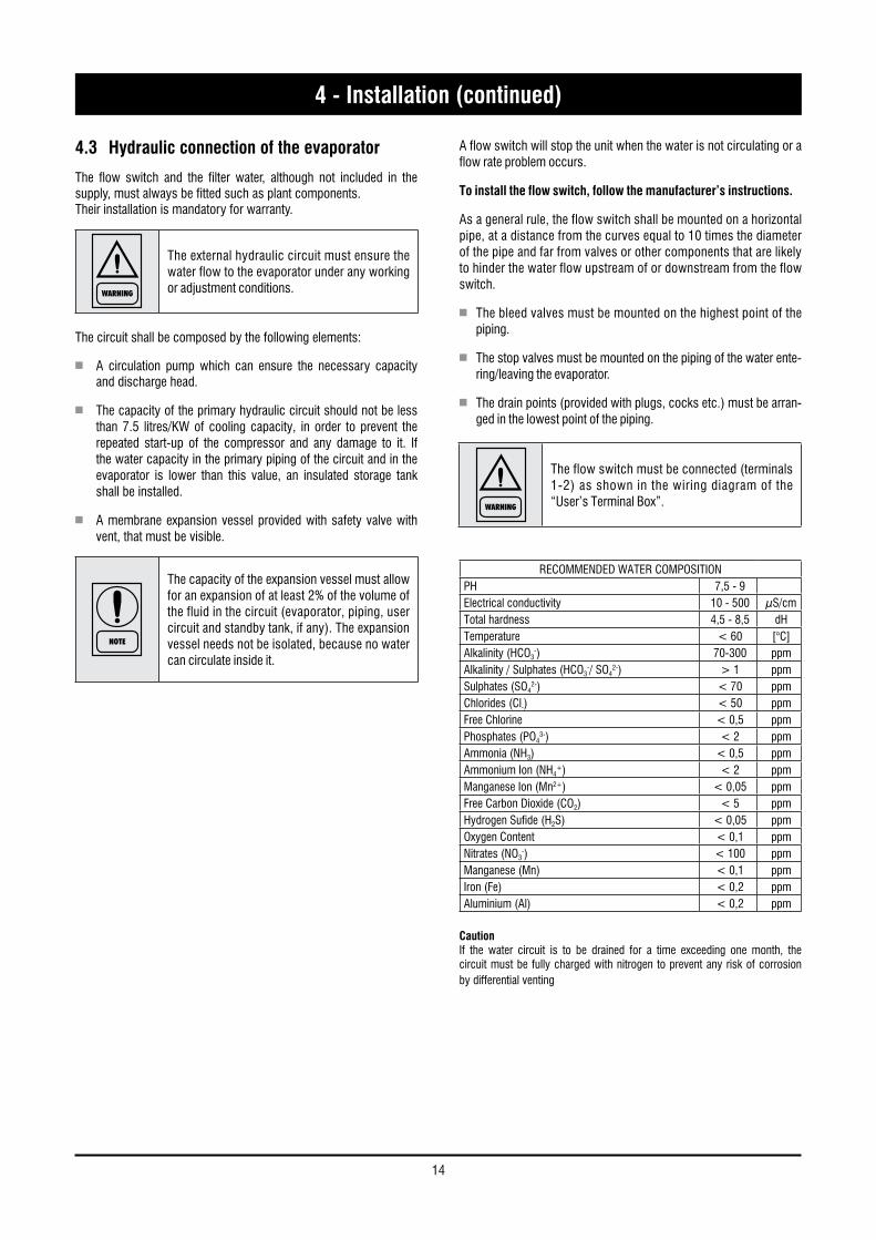
4.3 Hydraulic connection of the evaporator
The flow switch and the filter water, although not included in the supply, must always be fitted such as plant components.Their installation is mandatory for warranty.
WARNING
The external hydraulic circuit must ensure the water flow to the evaporator under any working or adjustment conditions.
The circuit shall be composed by the following elements:
n A circulation pump which can ensure the necessary capacity and discharge head.
n The capacity of the primary hydraulic circuit should not be less than 7.5 litres/KW of cooling capacity, in order to prevent the repeated start-up of the compressor and any damage to it. If the water capacity in the primary piping of the circuit and in the evaporator is lower than this value, an insulated storage tank shall be installed.
n A membrane expansion vessel provided with safety valve with vent, that must be visible.
NOTE
The capacity of the expansion vessel must allow for an expansion of at least 2% of the volume of the fluid in the circuit (evaporator, piping, user circuit and standby tank, if any). The expansion vessel needs not be isolated, because no water can circulate inside it.
A flow switch will stop the unit when the water is not circulating or a flow rate problem occurs.
To install the flow switch, follow the manufacturer’s instructions.
As a general rule, the flow switch shall be mounted on a horizontal pipe, at a distance from the curves equal to 10 times the diameter of the pipe and far from valves or other components that are likely to hinder the water flow upstream of or downstream from the flow switch.
n The bleed valves must be mounted on the highest point of the piping.
n The stop valves must be mounted on the piping of the water ente-ring/leaving the evaporator.
n The drain points (provided with plugs, cocks etc.) must be arran-ged in the lowest point of the piping.
WARNING
The flow switch must be connected (terminals 1-2) as shown in the wiring diagram of the “User’s Terminal Box”.
RECOMMENDED WATER COMPOSITIONPH 7,5 - 9Electrical conductivity 10 - 500 μS/cmTotal hardness 4,5 - 8,5 dHTemperature < 60 [°C]Alkalinity (HCO3
-) 70-300 ppmAlkalinity / Sulphates (HCO3
-/ SO42-) > 1 ppm
Sulphates (SO42-) < 70 ppm
Chlorides (Cl-) < 50 ppmFree Chlorine < 0,5 ppmPhosphates (PO4
3-) < 2 ppmAmmonia (NH3) < 0,5 ppmAmmonium Ion (NH4
+) < 2 ppmManganese Ion (Mn2+) < 0,05 ppmFree Carbon Dioxide (CO2) < 5 ppmHydrogen Sufide (H2S) < 0,05 ppmOxygen Content < 0,1 ppmNitrates (NO3
-) < 100 ppmManganese (Mn) < 0,1 ppmIron (Fe) < 0,2 ppmAluminium (Al) < 0,2 ppm
CautionIf the water circuit is to be drained for a time exceeding one month, the circuit must be fully charged with nitrogen to prevent any risk of corrosion by differential venting

15
Engl
ish4 - Installation (continued)
Then:
n Provide the evaporator with a by-pass circuit equipped with a valve to wash the plant.
n Insulate the piping, to prevent the risk of heat loss.
n Position a filter on the suction side of the evaporator of the heat recovery condenser.
WARNING
Before filling the circuit, it is important to check that it is free from any foreign matter, sand, gravels, rust, welding deposits, waste and other materials that may damage the evaporator.
When cleaning the lines, it is recommended to create a circuit by-pass. It is important to mount a filtering medium (30 mesh) upstream of the chiller.
Standard hydraulic circuit
External water circuit
Connection Diagram
Unit
COMPONENTSI Pressure gauge connection R Drain cockS Gate valve T ThermometerF1 Flow Switch F FilterGA Flexible hoses I1/I2 Pressure gauge connection to measure pressure drop or head pressure
NOTE
If necessary, the water required to fill the circuit must be treated to obtain the requested pH.

16
4 - Installation (continued)
4.5 Hydraulic connection
The water inlet/outlet fittings shall conform to the instructions provided by the plates affixed neat the connection points.
4.4 Hydraulic connection of the condenser
WARNING
The external hydraulic circuit must ensure the water flow to the condenser under any working or adjustment conditions.
The cooling of the units is generally ensured by connecting the condenser to a cooling tower, though the units can be cooled also with well water.
In the presence of a water-cooled condenser, it is necessary to check the flow rate and/or the temperature of the cooling fluid that flows through the condenser, so as to maintain the refrigerant pressure at values that can ensure a satisfactory operation.
When a cooling tower is used, the simplest regulation methods consist of checking the operation or the speed of the fan or the air volume, by means of a damper, once the pilot thermostat has been installed in the basin of the tower.
Alternatively, or if no water from a cooling tower is used, you can adopt a recirculaton system provided with a 3-way valve.
This circuit shall consist of:
n A circulation pump that can ensure the necessary capacity and discharge head.
n A flow meter to turn off the appliance when no water is circulating.
WARNING
The flow meter must be connected in series, as shown in the wiring diagram of the control panel.
To install the flow meter, follow the manufacturer’s instructions.
As a general rule, the flow meter shall be mounted on a horizontal pipe, at a distance from the curves equal to 10 times the diameter of the pipe and far from valves or other components that are likely to hinder the water flow upstream of or downstream from the flow meter.
n The bleed valves must be mounted on the highest point of the piping.
n The stop valves must be mounted on the piping of the water entering/leaving the condenser.
n The discharge points (provided with plugs, cocks etc.) must be arranged in the lowest point of the piping.
Furthermore:
n Provide the condenser with a by-pass circuit, equipped with a shutoff valve.
n Insulate piping, to prevent the risk of heat loss.
n Install a filter on the suction side of the condenser.
n A three-way valve should be installed on-site. It permits to bypass the condenser for correct operation at low return water temperature. The best position is close to the condenser.
To install the flow meter, follow the diagram illustrated in paragraph 4.3.

17
Engl
ish4 - Installation (continued)
4.6 Connection of water temperature sensors (on shell and tube evaporator)
The units are provided with fittings for hydraulic connections between heat exchangers and plant.
Each fitting is complete with sensor well to fasten temperature sensor (BT-IN and BT-OUT). Fittings are supplied separate and must be mounted during the installation of the unit.
OUT
IN
FITTING
FITTING
VICTAULIC JOINT
VICTAULIC JOINT
BT OUT
BT IN
18
4 - Installation (continued)
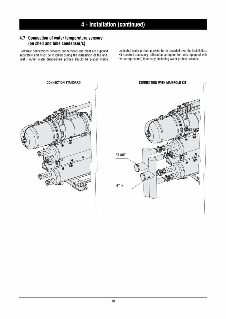
4.7 Connection of water temperature sensors (on shell and tube condenser/s)
Hydraulic connections between condenser/s and plant are supplied separately and must be installed during the installation of the unit. Inlet / outlet water temperature probes should be placed inside
dedicated water probes pockets to be provided over the installation. Kit manifold accessory (offered as an option for units equipped with two compressors) is already including water probes pockets.
BT OUT
CONNECTION STANDARD
BT INGRESSO
CONNECTION WITH MANIFOLD KIT
BT IN

19
Engl
ish4 - Installation (continued)
4.8 Power supply
DANGER
Before carrying out any operations on the electrical system, make sure that the unit is deenergised.
DANGER
It is important that the appliance is grounded.
DANGER
The company in charge of the installation shall conform to the standards applicable to outdoor electrical connections.
The manufacturer may not be held liable for any damage and/or injury caused by failure to comply with these precautions.
The unit conforms to EN 60204-1.
The following connections shall be provided:
n A 3-phase and grounding connection for the power supply circuit.
n The electrical distribution system shall meet the power absorbed by the appliance.
n The disconnecting and magnetothermal switches must be sized to control the starting current of the unit.
n The power supply lines and the insulation devices must be designed in such a way that every line independent.
n It is recommended to install differential switches, to prevent any damage caused by phase drops.
n The fans and compressors are supplied through contactors controlled from the control panel.
n Each motor is provided with an internal safety thermal device and external fuses.
n The power supply cables must be inserted into dedicated openings on the front of the unit, and the will enter the electrical board through holes drilled on the bottom of the board.
4.9 Electrical connections
The unit must be installed on site according to the Machinery Directive 2006/42/EC, Electromagnetic Compatibility Directive 2014/30/EU and the usual procedures and standards applicable in the place of installation.
The unit must not be operated if its installation has not been carried out according to the instructions provided in this manual.
The power supply lines must consist of insulated copper conductors, dimensioned for the maximum absorbed current.
Connection to terminals must be performed according to the diagram of connections (User’s Terminal Box) provided in this manual and according to the wiring diagram which accompanies the unit.
WARNING
Before connecting the power supply lines, check that the available voltage value does not exceed the range specified in the Electric Data (Chapter 8).
For 3-phase systems, check also that the unbalance between the phases does not exceed 2%. To perform this check, measure the differences between the voltage of each phase couple and their mean value during operation.
The maximum % value of these differences (unbalance) must not exceed 2% of the mean voltage.
If the unbalance is unacceptable, contact the Energy Distributor to solve this problem.
WARNING
Supplying the unit through a line whose unbalance exceeds the permissible value will automatically void the warranty.

20
4 - Installation (continued)
Electrical connections

21
Engl
ish5 - Start-Up
WARNING
The unit must be started for the first time by personnel suitably trained by one Authorised Service Centre. Failure to meet this requirement will immediately void the warranty.
NOTE
The operations carried out by authorised personnel are limited to the start-up of the unit, and do not include any other operation on the plant, such as, for example, electrical and hydraulic connections etc.
All the other operations before start-up, including oil pre-heating for at least 12 hours, must be performed by the Installer.
5.1 Preliminary checkThe checks listed below shall be performed before starting the unit and before the arrival of the personnel authorised.
n Check the section of power supply and grounding cables; make sure that terminals are tightened and check the correct operation of contactors, with the main switch open.
n Check that any voltage and phase variation in the power supply does not exceed the prefixed thresholds.
n Connect the contacts of the flow switch and the thermal relay of the pump and of the other devices (if any), to terminals 1-2 and 3-4, respectively.
n Check that the components of the external water circuit (pump, user equipment, filters, power supply tank and reservoir, if any) have been installed properly, and according to the manufacturer’s instructions.
n Check the filling of the hydraulic circuits, and make sure that the fluid circulation is correct, without any trace of leaks and air bubbles. If you use ethylene glycol as antifreeze, check that its percentage is correct.
n Check that the direction of rotation of the pumps is correct, and that fluids have been circulating for at least 12 hours for both pumps. Then, clean the filters on the suction side of the pumps.
n Adjust the liquid distribution network in such a way that the flow rate is within the specified range.
n Check that the water quality is up to the specifications.
n Check that oil heaters, if any, have been turned on at least 12 hours before.
5.2 Start-upStart-up sequence:
n Turn on the Main switch (at least 12 hours before).
n Check that the oil in the compressor has reached the requested temperature (the minimum temperature outside the pan must be approx. 40°C) and that the auxiliary control circuit is energised.
n Check the operation of all the external equipment, and make sure that the control devices of the plant are properly calibrated.
n Start the pump and check that the water flow is correct.
n Set the desired fluid temperature on the control board.
n Start the appliance (see Chapter 6).
n Check the correct direction of rotation of compressors. Compressors cannot compress the refrigerant when they rotate in the opposite direction. To make sure that they are rotating in the correct direction, simply check that, just after the start-up of the compressor, the pressure drops on the LP side and rises on the HP side. Furthermore, if a compressor rotate in the opposite direction, there is a considerable rise in the sound level of the unit, as well as in a dramatic reduction of current absorption compared to normal values. In case of wrong rotation, the compressor can be definitely damaged. Phase monitor is assembled in the unit as a standard to prevent wrong compressors rotation.
n After about 15 minutes of operation check that there are no bubbles, through the sight glass on the liquid line.
WARNING
The presence of bubbles may indicate that a part of the refrigerant charge has been released in one or more points. It is important to remove these leaks before proceeding.
n Repeat the start-up procedure after removing the leaks.
n Check the oil level in the compressor’s sight glass.
5.3 Checking the operation Check the following:
n The temperature of the water entering the evaporator.
n The temperature of the water leaving the evaporator.
n The level of the water flow rate in the evaporator, if possible.
n The temperature of the water entering the condenser.
n The temperature of the water leaving the condenser.
n The level of the water flow rate in the condenser, if possible.
n The current absorption upon the start of the compressor and in case of stabilised operation.
Check that the condensing and evaporation temperatures, during operation at high and low pressure detected by the pressure gauges of the refrigerant, are within the following range:
(On the units not provided with HP/LP pressure gauges for the refrigerant, connect a pressure gauge to the Shrader valves on the refrigeration circuit).
HP sideApprox. 2 to 7 °C above the temperature of condenser leaving water temperature, for 134a units.
LP side Approx. 2 to 7 °C below the temperature of the leaving chilled water, for R134a units.
5.4 Delivery to the customern Train the user according to the instructions provided in Section 6.

22
6 - Control
6 General information
Introduction
This document contains the information and the operating instructions for 1/2 screw compressors of step type.
This information is for the after-sales service and the production operators, for the end-of-line testing.
Main characteristics
– Microprocessor control
– User-friendly keyboard
– Proportional control (RWT)
– Neutral zone control on the leaving water temperature (LWT)
– Access code to enter the Manufacturer’s Level
– Access code to enter the Assistance Level
– Alarm and LED
– Backlighted LCD
– Rotation of the compressor operation
– Night mode (or Low Noise) control
– Counting of the pump/compressors’ hours of operation
– Display of discharge and suction pressure values
– Display of temperature sensor
– History of stored alarms (option)
– RS485 serial port to connect the chiller control to a BMS network.
The following accessories can be also connected:
– Remote Display Terminal
– Wire Remote Control.
– Double set point.
The control system consists of:
a) Main Board. Units are provided with a microprocessor card which is fully programmed by default for the control of a chiller equipped with a HP transducer and a LP transducer for each circuit.
b) EEV controllers (two separate drivers) to the management of the electronic expansion valves.
C) Keyboard & Display Terminal.
The terminal makes it possible to carry out the following operations:
– the initial configuration of the machine
– the change of all the main operating parameters
– the display of the detected alarms
– the display of all the measured quantities
The terminal and the card are connected by a 6-way phone cable.
The connection of the terminal to the basic card is not essential for the normal operation of the controller.
23
Engl
ish6 - Control (continued)
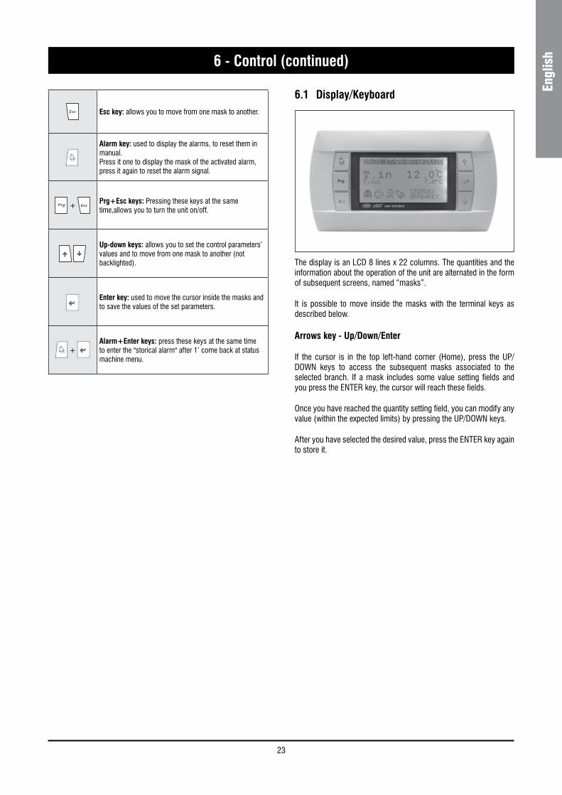
6.1 Display/Keyboard
The display is an LCD 8 lines x 22 columns. The quantities and the information about the operation of the unit are alternated in the form of subsequent screens, named “masks”.
It is possible to move inside the masks with the terminal keys as described below.
Arrows key - Up/Down/Enter
If the cursor is in the top left-hand corner (Home), press the UP/DOWN keys to access the subsequent masks associated to the selected branch. If a mask includes some value setting fields and you press the ENTER key, the cursor will reach these fields.
Once you have reached the quantity setting field, you can modify any value (within the expected limits) by pressing the UP/DOWN keys.
After you have selected the desired value, press the ENTER key again to store it.
Esc key: allows you to move from one mask to another.
Alarm key: used to display the alarms, to reset them in manual.Press it one to display the mask of the activated alarm, press it again to reset the alarm signal.
+
Prg+Esc keys: Pressing these keys at the same time,allows you to turn the unit on/off.
Up-down keys: allows you to set the control parameters’ values and to move from one mask to another (not backlighted).
Enter key: used to move the cursor inside the masks and to save the values of the set parameters.
+ Alarm+Enter keys: press these keys at the same time to enter the "storical alarm" after 1’ come back at status machine menu.

24
6 - Control (continued)
Alarm code Description Notes 1 Main board - EPROM Failure2 Main board - Clock card Failure3 Main board - External air temperature sensor fault4 Main board - Return Water temperature sensor fault (evaporator)5 Main board - Leaving Water temperature Sys 1 sensor fault (evaporator)6 Main board - Leaving Water temperature Sys 2 sensor fault (evaporator)7 Main board - Low pressure sys 1 sensor fault8 Main board - Low pressure sys 2 sensor fault9 Main board - High pressure sys 1 sensor fault
10 Main board - High pressure sys 2 sensor fault11 Main board - Discharge temperature sys 1 sensor fault12 Main board - Discharge temperature sys 2 sensor fault13 Main board - Return Water temperature sensor fault (condenser)14 Main board - Leaving Water temperature sensor fault (condenser)16 Serious alarm (SQZ)17 Flow switch / Plant interlock18 Oil Safety Sys 1 manual reset19 Oil Safety Sys 2 manual reset20 High pressure switch Sys 121 High pressure switch Sys 222 Low pressure Sys 1 switch manual reset23 Low pressure Sys 2 switch manual reset24 Thermal protection compressor 1 Sys 1 manual reset27 Thermal protection compressor 1 Sys 2 manual reset32 Remote condenser Fan Thermal protection Sys 1 (RC version only)34 Remote condenser Fan Thermal protection Sys 2 (RC version only)35 Low refrigerant cutout Sys 1 manual reset36 Low refrigerant cutout Sys 2 manual reset37 Low pressure alarm Sys 1 manual reset38 Low pressure alarm Sys 2 manual reset39 Out of envelope Sys 1 manual reset40 Out of envelope Sys 2 manual reset41 High pressure Sys 1 manual reset42 High pressure Sys 2 manual reset43 High limit discharge temperature Sys1 manual reset44 High limit discharge temperature Sys2 manual reset45 ΔT Water Too High Sys 146 ΔT Water Too High Sys 247 Wrong Water Trend Sys 148 Wrong Water Trend Sys 249 Antifreeze alarm manual reset Sys 150 Antifreeze alarm manual reset Sys 252 Plant pump maintenance53 Compressor 1 Sys 1 maintenance56 Compressor 1 Sys 2 maintenance59 Driver 1 LAN disconneted manual reset60 Driver 2 LAN disconneted manual reset61 EPROM Error Driver 162 EPROM Error Driver 263 Driver 1 S1 Sensor fault 65 Driver 1 S2 Sensor fault67 Driver 2 S1 Sensor fault 68 Driver 2 S2 Sensor fault69 EEV motor Error (Check viring) Sys 170 EEV motor Error (Check viring) Sys 271 Driver 1 Battery alarm
Alarms
25
Engl
ish6 - Control (continued)
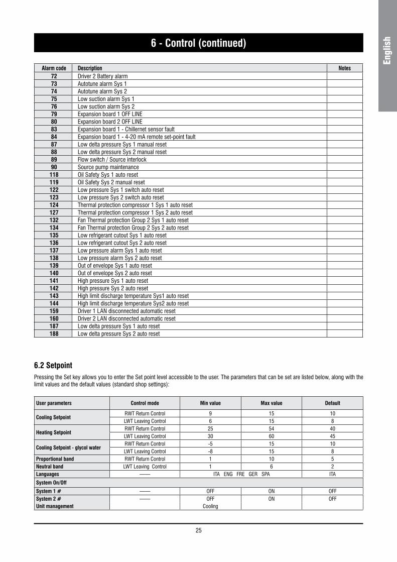
Alarm code Description Notes 72 Driver 2 Battery alarm73 Autotune alarm Sys 174 Autotune alarm Sys 275 Low suction alarm Sys 176 Low suction alarm Sys 279 Expansion board 1 OFF LINE80 Expansion board 2 OFF LINE83 Expansion board 1 - Chillernet sensor fault84 Expansion board 1 - 4-20 mA remote set-point fault87 Low delta pressure Sys 1 manual reset88 Low delta pressure Sys 2 manual reset89 Flow switch / Source interlock90 Source pump maintenance118 Oil Safety Sys 1 auto reset119 Oil Safety Sys 2 manual reset122 Low pressure Sys 1 switch auto reset123 Low pressure Sys 2 switch auto reset124 Thermal protection compressor 1 Sys 1 auto reset127 Thermal protection compressor 1 Sys 2 auto reset132 Fan Thermal protection Group 2 Sys 1 auto reset 134 Fan Thermal protection Group 2 Sys 2 auto reset 135 Low refrigerant cutout Sys 1 auto reset136 Low refrigerant cutout Sys 2 auto reset137 Low pressure alarm Sys 1 auto reset 138 Low pressure alarm Sys 2 auto reset 139 Out of envelope Sys 1 auto reset140 Out of envelope Sys 2 auto reset141 High pressure Sys 1 auto reset142 High pressure Sys 2 auto reset143 High limit discharge temperature Sys1 auto reset144 High limit discharge temperature Sys2 auto reset159 Driver 1 LAN disconnected automatic reset160 Driver 2 LAN disconnected automatic reset187 Low delta pressure Sys 1 auto reset188 Low delta pressure Sys 2 auto reset
6.2 SetpointPressing the Set key allows you to enter the Set point level accessible to the user. The parameters that can be set are listed below, along with the limit values and the default values (standard shop settings):
User parameters Control mode Min value Max value Default
Cooling SetpointRWT Return Control 9 15 10LWT Leaving Control 6 15 8
Heating SetpointRWT Return Control 25 54 40LWT Leaving Control 30 60 45
Cooling Setpoint - glycol waterRWT Return Control -5 15 10LWT Leaving Control -8 15 8
Proportional band RWT Return Control 1 10 5Neutral band LWT Leaving Control 1 6 2Languages —— ITA ENG FRE GER SPA ITA
System On/Off
System 1 # —— OFF ON OFFSystem 2 # —— OFF ON OFFUnit management Cooling

26
6 - Control (continued)
Flow switch
A flow switch must be installed, to prevent the unit working in case of insufficient circulation of the chilled fluid.
WARNING
The electrical flow switch must be carefully installed, according to the instructions given by the Manufacturer.
The electrical flow switch must be installed on the pressing side of the circulation pump for the fluid, just upstream of the heat exchanger’s inlet. The electrical flow switch must be installed in a horizontal straight length of piping, in a position reasonably far (both upstream and downstream) from localized pressure drops (curves, valves etc.).
6.3 Protection and Safety Equipment
Refrigeration system
The units are filled with R134a refrigerant fluid of non hazardous type (group II). Safety device (pressure switch and safety valves) with the sets below indicated are provided on the discharge and suction line of each circuit.
Discharge LinePressure relief valve 22 bar.Pressure switch 19.8 bar for HP/RC/BC version,15.5 bar for CO version.
Suction line Pressure relief valve 14.5 bar.Pressure switch 0.5 bar.
Frost Protection for the Chilled Fluid
If the leaving water temperature drops below 4 °C (standard value for a non-glycol unit) the machine’s antifreeze alarm is activated. If the circulating fluid is water, before the beginning of the cold season it is advisable to drain the circuit to prevent water frosting.
If the circuit cannot be drained, it is essential to avoid de-energizing the unit, so as to permit the activation, when necessary, of the frost protection.
Compressor protection
Compressors are equipped with a heating element to prevent oil dilution, which may result in remarkable risks of failure of compressors.
The windings of the compressors’ motors are provided with a thermal protection.
An accessory kit for thermal protection (ACB) is available, for any overcurrent of compressors, which shall be shop-mounted.

27
Engl
ish7 - Product Description
7.1 Introduction
SyScrew Water EVO units are designed for indoor installation. They can be equipped with one or two circuits (depending on the model) and may be used to cool water to the evaporator and / or to heat water to the condenser. When heating capacity is not the required useful effect, is is necessary to match the unit with a cooling tower or well water in order to reject condenser heat load.
The units are suitable for indoor installation.This series includes the following versions:
7.2 General specifications
The units are supplied complete and provided with all connecting pipes for the refrigerant and internal wiring.
The refrigeration circuit of each unit undergoes a pressure test, is drained, vacuumised, dehydrated and filled with refrigerant, and includes the necessary oil. Once assembled, each unit is subjected to a complete final testing and the correct operation of all refrigeration circuits is checked.
The base and the frame of each unit are made of very thick galvanised sheet, and are secured by screw and stainless bolts. All panels are secured by screw and tropicalised steel bolts, they can be disassembled for easy access to internal components.
All galvanised steel parts are painted with white polyester resin, to ensure the resistance of the unit to corrosion and weather agents over time.
7.3 Compressors
The units are provided with high power, high efficiency and low vibration level semi-hermetic screw compressors (oil injection or external cooling with plate-type exchangers) to reduce the compressor’s discharge temperature (on request for special application).
The capacity control can be both of the step type (as standard) or of the stepless type (on request). It is handled by capacity control solenoid valves, handled by the microprocessor of the appliance.
The motor’s terminals are weatherproof, according to standard IP-54.
7.4 Refrigeration circuits
Units are equipped with one or two independent circuits with screw compressors and shell and tube heat exchanger.
Each refrigerant circuit includes: a service valve for refrigerant filling, shutoff valves for suction lines (on request), as well as for the delivery and liquid lines, an electronic expansion valve, that completely closed (as a solenoid valve) makes it possible to start/stop the compressor, a dehydrating cartridge filter, a sight glass with humidity indicator.
Furthermore, each circuit is equipped with safety devices in accordance with PED 2014/68/EU: high and low pressure switches, safety valves providing protection in case of fire or malfunction of compressors.
VERSION DESCRIPTION
Super Low Noise version (S)Water cooled or air cooled (RC version) chillers operating with R134a refrigerant.
OPTIONS DESCRIPTION
Desuperheater (D) The heat recovery is carried out by a desuperheater mounted on the compressor’s discharge line.
Totaly heat recovery Not available. For information, please contact commercial office.
Available options:
CO versions are equipped with dedicated compressors optimized for low condensing pressure.Special VersionBrine version: units with dedicated evaporators to allow operation with brine (ethylene or propylene) temperature down to -8 °C.

28
7 - Product Description (continued)
7.5 Water heat exchangersEvaporator
The units are provided with a direct-expansion refrigerant/water shell and tube heat exchanger with several refrigeration circuits.
Evaporators are insulated with flexible insulation, based on closed cell synthetic rubber in black color, 9 mm thick, highly resistant to water and to water vapour. A synthetic leather coating, 1.1 mm thick, protects the outer surface.
Condenser
All units are equipped with one or two condensers, one each circuit. Heat exchanger is shell and tube type, arranged for ispection, cleaning and maintenance operation.
Desuperheater
All units are available with desuperheaters (DSH). DSH is refrigerant/water heat exchanger with brazed plates.
DSH is fitted on the compressor discharge pipe and it’s dimensioned to recover about the 10% of total rejected heat. Units with a single compressor are provided with a single heat exchanger, while units with two compressors are provided with two heat exchangers, one each circuit
Total heat recovery condenser
All units are available with total heat recovery condenser (THRC). THRC is refrigerant / water heat exchanger with brazed plates or shell and tube, according to chiller size. THRC is fitted on the compressor discharge line in series with the standard condensing circuit. Heat recovery function is enabled supplying heat recovery exchanger with water. Units with a single compressor are provided with a single heat exchanger, while units with two compressors are provided with two heat exchangers, one each circuit. Heat recovery condensers are insulated with flexible insulation, based on closed cell synthetic rubber in black color, 9 mm thick.
7.6 Electric power supply and control systemAll units are provided with a microprocessor and a “Chiller Control” system.
The electrical connection of the controls and the startup units for the motor are carried out and tested in the factory. The power supply and control components are separate and accessible from different doors.
A door stop disconnecting switch is always mounted on the door of the unit. Protection level is in accordance with IP54 standard.
The power supply compartment includes:
n Master switch
n Network isolator, contactors, compressor fuses
Control panel includes:
n A transformer for auxiliaries, fuses, relay and electronic card, a thermostat for the compressor’s delivery temperature
n The keyboard and the display of the “Chiller-Control” microcomputer, mounted on the door of the control section.
7.7 AccessoriesList of available accessories, provided separately, to be mounted on site by the installer:
Water flow switch
Prevents the operation of the unit when the chilled fluid is insufficient. It is advisablem to install a flow switch, to ensure the correct operation of the unit.
Water filter
Filter to be mounted on the suction side of the water heat exchanger. It is mandatory to install a water filter to remove impurities from the water suplly.
Antivibrating supports (AVM)
Isolating spring supports, equipped with bolts for fastening to the base. They are supplied separated from the unit and must be mounted on site by the customer, at his own expense.
Remote wall terminal
Makes it possible to check the unit through a remote terminal, up to a maximum distance of 400 meters.
Modem GSM
Makes it possible to check the working mode or the switching on/off of the unit via SMS. In case of any alarms, the unit sends an SMS to the user.
RS-485 serial card (for MODBUS or LONWORK or BACNET)
A communication interface makes it possible to control and manage the unit from a local station, with RS485 connection, up to a distance of 1000 m.
It is possible to obtain the remote control and the management, by inserting the control into the management plant of the building.

29
Engl
ish7 - Product Description (continued)
Refrigerant circuit - CO/HP/BC versions
SAFETY / CONTROL DEVICES
A High pressure switch 15.5 bar (CO)19.8 bar (HP/BC)
B Low pressure switch (0.5 bar)
AT High pressure transducer
BT Low pressure transducer
D Suction temperature sensor
E Outlet water temperature sensor
F Inlet water temperature sensor
G PED pressure relief valve HP side (22 bar)
H PED pressure relief valve LP side (14.5 bar)
S Shrader connection (Service only)
Pipe connection with Shrader valve
COMPONENTS
1 Compressor (Screw type)
2 Water cooled condenser
3 Filter drier
4 Electronic expansion valve
5 Globe valve
6 Heat exchanger (Shell & Tube Type)
7 Desuperheater (Optional)
8 Water temperature sensor (HP version only)
9 Sight glass
Note: For reasons of readability, one circuit only is shown.
25
6BT
E
F
G
7
S
S
ATA S
H
B
1
S
5
F
E
A
8
D
9 S
4 3
EXVCONTROL
UNITCONTROL

30
7 - Product Description (continued)
Refrigerant circuit - RC version
34
5
6
E
F
G
7
S
ATA S
H
S
1
S
5
A
DBS BT
9
EXVCONTROL
UNITCONTROL
SAFETY / CONTROL DEVICES
A High pressure switch (19.8 bar)
B Low pressure switch (0.5 bar)
AT High pressure transducer
BT Low pressure transducer
D Suction temperature sensor
E Outlet water temperature sensor
F Inlet water temperature sensor
G PED pressure relief valve HP side (22 bar)
H PED pressure relief valve LP side (14.5 bar)
S Shrader connection (Service only)
Pipe connection with Shrader valve
COMPONENTS
1 Compressor (Screw type)
3 Filter drier
4 Electronic expansion valve
5 Globe valve
6 Heat exchanger (Shell & Tube Type)
7 Desuperheater (Optional)
9 Sight glass

31
Engl
ish
8.1 Pressure drops
Evaporator Pressure drop
8 - Technical Data
ModelNom. Capacity Qnom. Qmax. Qmin. K Dp nom DP max DP min
kW l/h l/h l/h kPa/(l/h)^2 kPa kPa kPa
440 446 76696 127827 54783 7.297E-09 42.9 119.2 21.9490 496 85256 142094 60897 4.149E-09 30.2 83.8 15.4570 573 98502 164170 70359 5.354E-09 52.0 144.3 26.5630 639 109937 183229 78527 5.354E-09 64.7 179.8 33.0700 710 122159 203598 87256 2.021E-09 30.2 83.8 15.4770 789 135759 226266 96971 2.021E-09 37.2 103.5 19.0860 878 151049 251749 107892 1.824E-09 41.6 115.6 21.2920 939 161546 269244 115390 1.824E-09 47.6 132.2 24.3990 1002 172290 287150 123064 1.435E-09 42.6 118.3 21.71070 1075 184901 308168 132072 1.392E-09 47.6 132.2 24.31130 1137 195575 325959 139697 1.392E-09 53.2 147.9 27.21220 1227 211038 351730 150742 7.245E-10 32.3 89.6 16.51280 1289 221624 369374 158303 7.245E-10 35.6 98.8 18.21400 1434 246703 411172 176217 1.020E-09 62.1 172.5 31.71550 1574 270809 451349 193435 1.020E-09 74.8 207.8 38.2
Condenser pressure drops
ModelNom. Capacity Qnom. Qmax. Qmin. K Dp nom DP max DP min
kW l/h l/h l/h kPa/(l/h)^2 kPa kPa kPa
440 530 91178 151964 56987 6.320E-09 52.5 146.0 20.5490 590 101472 169120 63420 4.928E-09 50.7 141.0 19.8570 680 116977 194961 73110 3.997E-09 54.7 151.9 21.4630 760 130648 217746 81655 2.007E-09 34.3 95.2 13.4700 846 145519 242532 90949 2.007E-09 42.5 118.0 16.6770 939 161566 269276 100979 1.958E-09 51.1 142.0 20.0860 522 89857 149761 56160 6.320E-09 51.0 141.8 19.9
920525 90315 150525 56447 6.320E-09 51.6 143.2 20.1592 101844 169741 63653 4.928E-09 51.1 142.0 20.0
990 596 102507 170845 64067 4.928E-09 51.8 143.8 20.2
1070601 103347 172245 64592 4.928E-09 52.6 146.2 20.6678 116541 194234 72838 3.997E-09 54.3 150.8 21.2
1130 676 116249 193749 72656 3.997E-09 54.0 150.1 21.1
1220686 118001 196668 73751 3.997E-09 55.7 154.6 21.7774 133065 221775 83166 3.138E-09 55.6 154.3 21.7
1280 767 131888 219813 82430 3.138E-09 54.6 151.6 21.31400 853 146721 244535 91701 1.958E-09 42.2 117.1 16.51550 935 160884 268140 100552 1.958E-09 50.7 140.8 19.8

32
8 - Technical Data (continued)
Desuperheater pressure drop
(*) Capacity referred to only one circuit.
ModelNom. Capacity Qnom. Qmax. Qmin. K Dp nom DP max DP min
kW l/h l/h l/h kPa/(l/h)^2 kPa kPa kPa
440 34 5927 9878 3704 2.285E-08 0.8 2.2 0.3490 38 6596 10993 4122 2.285E-08 1.0 2.8 0.4570 44 7603 12672 4752 1.380E-08 0.8 2.2 0.3630 49 8492 14154 5308 1.380E-08 1.0 2.8 0.4700 not available770 not available860 34 5841 9734 3650 2.285E-08 0.8 2.2 0.3
92036 6245 10409 3903 2.285E-08 0.9 2.5 0.3
990 39 6663 11105 4164 2.285E-08 1.0 2.8 0.4
107042 7146 11911 4466 1.380E-08 0.7 2.0 0.3
1130 44 7556 12594 4723 1.380E-08 0.8 2.2 0.3
122047 8160 13599 5100 1.380E-08 0.9 2.6 0.4
1280 50 8573 14288 5358 1.380E-08 1.0 2.8 0.41400 not available1550 not available

33
Engl
ish8 - Technical Data (continued)
8.2 Technical data
SyScrew Water EVO CO _ / S 440 490 570 630 700 770 860
Power supply V/Ph/Hz 400 (± 10%) / 3 / 50
Number of refrigerant circuits 1 2
Start-up Type SD
Total capacity steps % 50-75-100 25-50-62- 75-87-100
COMPRESSOR
Number 1 2
Type Screw
INTERNAL HEAT EXCHANGER (EVAPORATOR)
Number 1
Type Shell & tube (Pure counterflow)
Water connections inch 6 6 6 6 8 8 8
EXTERNAL HEAT EXCHANGER (CONDENSER)
Number 1 2
Type Shell & tube
Water connections inch 4 4 5 5 5 5 4
REFRIGERANT
Type R134a
Charge (1) kg 55 61 64 76 78 80 64+64
DESUPERHEATER
Number 1 2
Type PHE
Water connections inch 2”1/2 N.A. 2”1/2
WEIGHT (_ VERSION)
Shipping kg 2509 2538 2701 2807 3185 3252 5124
Operating kg 2690 2725 2918 3040 3523 3597 5579
WEIGHT (S VERSION)
Shipping kg 2703 2732 2895 3001 3379 3446 5511
Operating kg 2884 2919 3112 3234 3717 3791 5966
DIMENSIONS (_ VERSION)
Length mm 3620 3620 4210 4210 4180 4180 4400
Width mm 1350 1350 1350 1350 1350 1350 1520
Height mm 1650 1650 1650 1650 1650 1650 1710
DIMENSIONS (S VERSION)
Length mm 3620 3620 4210 4210 4180 4180 4650
Width mm 1350 1350 1350 1350 1350 1350 1520
Height mm 1750 1750 1750 1750 1750 1750 1770
(1) The refrigerant value are indicative values for standard units. The actual data are indicated on the unit label.
34
8 - Technical Data (continued)
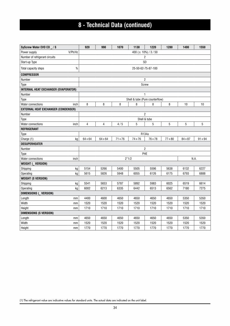
SyScrew Water EVO CO _ / S 920 990 1070 1130 1220 1280 1400 1550
Power supply V/Ph/Hz 400 (± 10%) / 3 / 50
Number of refrigerant circuits 2
Start-up Type SD
Total capacity steps % 25-50-62-75-87-100
COMPRESSOR
Number 2
Type Screw
INTERNAL HEAT EXCHANGER (EVAPORATOR)
Number 1
Type Shell & tube (Pure counterflow)
Water connections inch 8 8 8 8 8 8 10 10
EXTERNAL HEAT EXCHANGER (CONDENSER)
Number 2
Type Shell & tube
Water connections inch 4 4 4 / 5 5 5 5 5 5
REFRIGERANT
Type R134a
Charge (1) kg 64+64 64+64 71+76 74+76 76+78 77+80 84+87 91+94
DESUPERHEATER
Number 2
Type PHE
Water connections inch 2”1/2 N.A.
WEIGHT (_ VERSION)
Shipping kg 5154 5266 5400 5505 5596 5638 6132 6227
Operating kg 5615 5826 5948 6055 6126 6175 6793 6888
WEIGHT (S VERSION)
Shipping kg 5541 5653 5787 5892 5983 6025 6519 6614
Operating kg 6002 6213 6335 6442 6513 6562 7180 7275
DIMENSIONS (_ VERSION)
Length mm 4400 4600 4650 4650 4650 4650 5350 5350
Width mm 1520 1520 1520 1520 1520 1520 1520 1520
Height mm 1710 1710 1710 1710 1710 1710 1710 1710
DIMENSIONS (S VERSION)
Length mm 4650 4650 4650 4650 4650 4650 5350 5350
Width mm 1520 1520 1520 1520 1520 1520 1520 1520
Height mm 1770 1770 1770 1770 1770 1770 1770 1770
(1) The refrigerant value are indicative values for standard units. The actual data are indicated on the unit label.
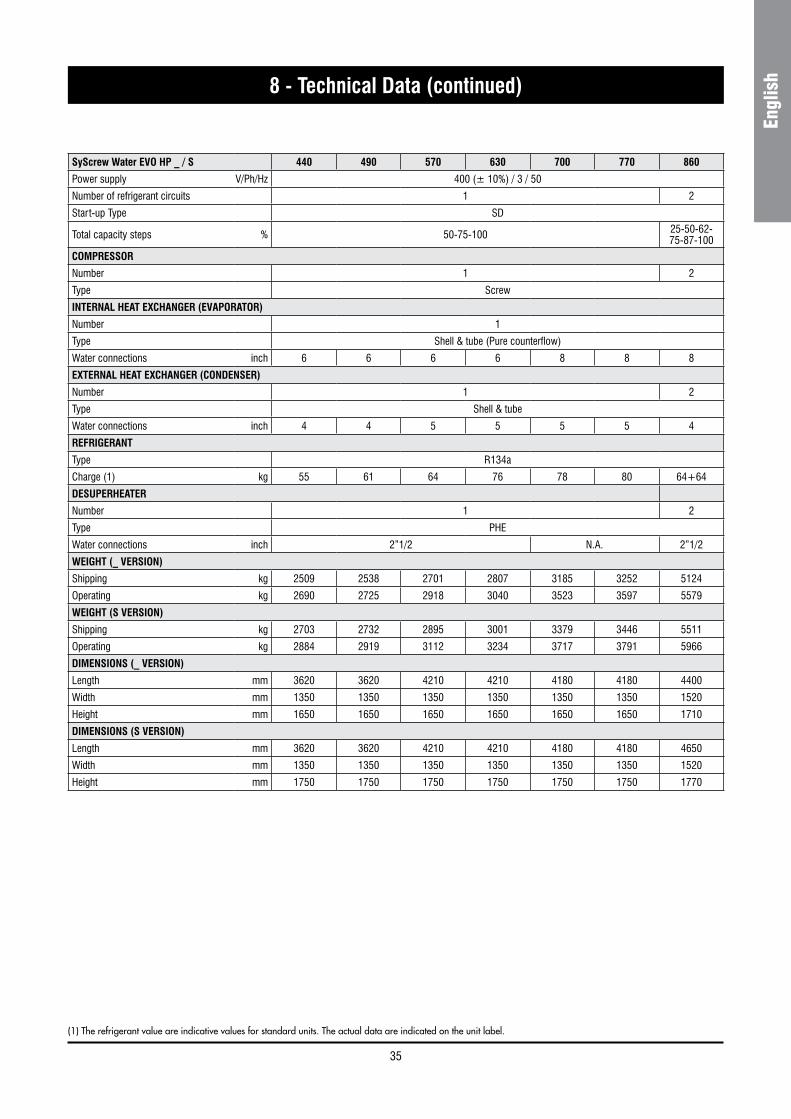
35
Engl
ish8 - Technical Data (continued)
SyScrew Water EVO HP _ / S 440 490 570 630 700 770 860
Power supply V/Ph/Hz 400 (± 10%) / 3 / 50
Number of refrigerant circuits 1 2
Start-up Type SD
Total capacity steps % 50-75-100 25-50-62- 75-87-100
COMPRESSOR
Number 1 2
Type Screw
INTERNAL HEAT EXCHANGER (EVAPORATOR)
Number 1
Type Shell & tube (Pure counterflow)
Water connections inch 6 6 6 6 8 8 8
EXTERNAL HEAT EXCHANGER (CONDENSER)
Number 1 2
Type Shell & tube
Water connections inch 4 4 5 5 5 5 4
REFRIGERANT
Type R134a
Charge (1) kg 55 61 64 76 78 80 64+64
DESUPERHEATER
Number 1 2
Type PHE
Water connections inch 2”1/2 N.A. 2”1/2
WEIGHT (_ VERSION)
Shipping kg 2509 2538 2701 2807 3185 3252 5124
Operating kg 2690 2725 2918 3040 3523 3597 5579
WEIGHT (S VERSION)
Shipping kg 2703 2732 2895 3001 3379 3446 5511
Operating kg 2884 2919 3112 3234 3717 3791 5966
DIMENSIONS (_ VERSION)
Length mm 3620 3620 4210 4210 4180 4180 4400
Width mm 1350 1350 1350 1350 1350 1350 1520
Height mm 1650 1650 1650 1650 1650 1650 1710
DIMENSIONS (S VERSION)
Length mm 3620 3620 4210 4210 4180 4180 4650
Width mm 1350 1350 1350 1350 1350 1350 1520
Height mm 1750 1750 1750 1750 1750 1750 1770
(1) The refrigerant value are indicative values for standard units. The actual data are indicated on the unit label.

36
8 - Technical Data (continued)
SyScrew Water EVO HP _ / S 920 990 1070 1130 1220 1280 1400 1550
Power supply V/Ph/Hz 400 (± 10%) / 3 / 50
Number of refrigerant circuits 2
Start-up Type SD
Total capacity steps % 25-50-62-75-87-100
COMPRESSOR
Number 2
Type Screw
INTERNAL HEAT EXCHANGER (EVAPORATOR)
Number 1
Type Shell & tube (Pure counterflow)
Water connections inch 8 8 8 8 8 8 10 10
EXTERNAL HEAT EXCHANGER (CONDENSER)
Number 2
Type Shell & tube
Water connections inch 4 4 4 / 5 5 5 5 5 5
REFRIGERANT
Type R134a
Charge (1) kg 64+64 64+64 71+76 74+76 76+78 77+80 84+87 91+94
DESUPERHEATER
Number 2
Type PHE
Water connections inch 2”1/2 N.A.
WEIGHT (_ VERSION)
Shipping kg 5154 5266 5400 5505 5596 5638 6132 6227
Operating kg 5615 5826 5948 6055 6126 6175 6793 6888
WEIGHT (S VERSION)
Shipping kg 5541 5653 5787 5892 5983 6025 6519 6614
Operating kg 6002 6213 6335 6442 6513 6562 7180 7275
DIMENSIONS (_ VERSION)
Length mm 4400 4600 4650 4650 4650 4650 5350 5350
Width mm 1520 1520 1520 1520 1520 1520 1520 1520
Height mm 1710 1710 1710 1710 1710 1710 1710 1710
DIMENSIONS (S VERSION)
Length mm 4650 4650 4650 4650 4650 4650 5350 5350
Width mm 1520 1520 1520 1520 1520 1520 1520 1520
Height mm 1770 1770 1770 1770 1770 1770 1770 1770
(1) The refrigerant value are indicative values for standard units. The actual data are indicated on the unit label.

37
Engl
ish8 - Technical Data (continued)
SyScrew Water EVO RC _ / S 440 490 570 630 700 770 860
Power supply V/Ph/Hz 400 (± 10%) / 3 / 50
Number of refrigerant circuits 1 2
Start-up Type SD
Total capacity steps % 50-75-100 25-50-62- 75-87-100
COMPRESSOR
Number 1 2
Type Screw
INTERNAL HEAT EXCHANGER (EVAPORATOR)
Number 1
Type Shell & tube (Pure counterflow)
Water connections inch 6 6 6 6 8 8 8
REMOTE CONDENSER CONNECTIONS
Type To be brazed
Inlet refrigerant connections Circuit 1 inch 1.5/8” 1.5/8” 2.1/8” 2.1/8” 2.1/8” 2.1/8” 1.5/8”
Outlet refrigerant connections Circuit 1 inch 3.1/8” 3.1/8” 3.5/8” 3.5/8” 4.1/8” 4.1/8” 3.1/8”
Inlet refrigerant connections Circuit 2 inch - - - - - - 1.5/8”
Outlet refrigerant connections Circuit 2 inch - - - - - - 3.1/8”
REFRIGERANT
Type R134a
Charge (1) kg 55 61 64 76 78 80 64+64
DESUPERHEATER
Number 1 2
Type PHE
Water connections inch 2”1/2 N.A. 2”1/2
WEIGHT (_ VERSION)
Shipping kg 2159 2169 2285 2305 2676 2716 4425
Operating kg 2302 2312 2456 2476 2952 2992 4804
WEIGHT (S VERSION)
Shipping kg 2353 2363 2479 2499 2870 2910 4812
Operating kg 2496 2506 2650 2670 3146 3186 5191
DIMENSIONS (_ VERSION)
Length mm 3620 3620 4210 4210 4180 4180 4400
Width mm 1350 1350 1350 1350 1350 1350 1520
Height mm 1650 1650 1650 1650 1650 1650 1710
DIMENSIONS (S VERSION)
Length mm 3620 3620 4210 4210 4180 4180 4650
Width mm 1350 1350 1350 1350 1350 1350 1520
Height mm 1750 1750 1750 1750 1750 1750 1770
(1) The refrigerant value are indicative values for standard units. The actual data are indicated on the unit label.

38
8 - Technical Data (continued)
SyScrew Water EVO RC _ / S 920 990 1070 1130 1220 1280 1400 1550
Power supply V/Ph/Hz 400 (± 10%) / 3 / 50
Number of refrigerant circuits 2
Start-up Type SD
Total capacity steps % 25-50-62-75-87-100
COMPRESSOR
Number 2
Type Screw
INTERNAL HEAT EXCHANGER (EVAPORATOR)
Number 1
Type Shell & tube (Pure counterflow)
Water connections inch 8 8 8 8 8 8 10 10
REMOTE CONDENSER CONNECTIONS
Type To be brazed
Inlet refrigerant connections Circuit 1 inch 1.5/8” 1.5/8” 1.5/8” 2.1/8” 2.1/8” 2.1/8” 2.1/8” 2.1/8”
Outlet refrigerant connections Circuit 1 inch 3.1/8” 3.1/8” 3.1/8” 3.5/8” 3.5/8” 3.5/8” 4.1/8” 4.1/8”
Inlet refrigerant connections Circuit 2 inch 1.5/8” 1.5/8” 2.1/8” 2.1/8” 2.1/8” 2.1/8” 2.1/8” 2.1/8”
Outlet refrigerant connections Circuit 2 inch 3.1/8” 3.1/8” 3.5/8” 3.5/8” 3.5/8” 3.5/8” 4.1/8” 4.1/8”
REFRIGERANT
Type R134a
Charge (1) kg 64+64 64+64 71+76 74+76 76+78 77+80 84+87 91+94
DESUPERHEATER
Number 2
Type PHE
Water connections inch 2”1/2 N.A.
WEIGHT (_ VERSION)
Shipping kg 4435 4526 4613 4673 4739 4759 5073 5153
Operating kg 4814 4998 5071 5131 5170 5190 5596 5676
WEIGHT (S VERSION)
Shipping kg 4822 4913 5000 5060 5126 5146 5460 5540
Operating kg 5201 5385 5458 5518 5557 5577 5983 6063
DIMENSIONS (_ VERSION)
Length mm 4400 4600 4650 4650 4650 4650 5350 5350
Width mm 1520 1520 1520 1520 1520 1520 1520 1520
Height mm 1710 1710 1710 1710 1710 1710 1710 1710
DIMENSIONS (S VERSION)
Length mm 4650 4650 4650 4650 4650 4650 5350 5350
Width mm 1520 1520 1520 1520 1520 1520 1520 1520
Height mm 1770 1770 1770 1770 1770 1770 1770 1770
(1) The refrigerant value are indicative values for standard units. The actual data are indicated on the unit label.

39
Engl
ish8 - Technical Data (continued)
8.3 Electrical data - SyScrew Water EVO CO
(*) Power factor correction capacitor option.
_ S Version 440 490 570 630 700 770 860 920 990 1070 1130 1220 1280 1400 1550
Current inputNominal A 141 157 175 203 227 255 278 298 316 334 350 386 414 454 500Maximum A 233 266 306 345 378 411 466 499 532 572 612 651 690 756 822
Power inputNominal kW 84 94 107 120 136 150 167 178 190 203 215 233 245 272 296Maximum kW 132 147 167 186 220 240 264 279 294 314 334 353 372 440 480
Max Start-up current A 318 436 465 586 650 805 551 669 702 731 771 892 931 1028 1216UNIT (aM) FUSES A 250 315 315 400 400 500 630 630 630 630 630 800 800 800 1000Phase WIRE SECTION mm2 120 185 185 240 240 2x185 2x185 2x185 2x185 2x185 2x185 2x240 2x240 2x240 2x300
Model System CircuitCom-
pressorstartmode
Nominal power input
Nominal current input
Maximum power input
Maximum current
input - FLA
Start-up current - LRA
Nominal power factor
Corrected powerfactor*
Carter oil absorbed
power(230 Vac)
(kW) (A) (kW) (A) (A) - - (W)440 1 1 S/D 84 141 132 233 318 0,86 > 0.90 300490 1 1 S/D 94 157 147 266 436 0,87 > 0.90 300570 1 1 S/D 107 175 167 306 465 0,89 > 0.90 300630 1 1 S/D 120 203 186 345 586 0,86 > 0.90 300700 1 1 S/D 136 227 220 378 650 0,86 > 0.90 300770 1 1 S/D 150 255 240 411 805 0,85 > 0.90 300
8601
2S/D 83 139 132 233 318 0,87 > 0.90 300
2 S/D 83 139 132 233 318 0,87 > 0.90 300
9201
2S/D 84 141 132 233 318 0,86 > 0.90 300
2 S/D 94 157 147 266 436 0,87 > 0.90 300
990 1
2S/D 95 158 147 266 436 0,87 > 0.90 300
2 S/D 95 158 147 266 436 0,87 > 0.90 300
10701
2S/D 95 158 147 266 436 0,87 > 0.90 300
2 S/D 108 176 167 306 465 0,89 > 0.90 300
11301
2S/D 107 175 167 306 465 0,89 > 0.90 300
2 S/D 107 175 167 306 465 0,89 > 0.90 300
12201
2S/D 109 177 167 306 465 0,89 > 0.90 300
2 S/D 124 209 186 345 586 0,86 > 0.90 300
12801
2S/D 123 207 186 345 586 0,86 > 0.90 300
2 S/D 123 207 186 345 586 0,86 > 0.90 300
14001
2S/D 136 227 220 378 650 0,86 > 0.90 300
2 S/D 136 227 220 378 650 0,86 > 0.90 300
15501 1 S/D 148 250 240 411 805 0,86 > 0.90 3002 2 S/D 148 250 240 411 805 0,86 > 0.90 300

40
8 - Technical Data (continued)
Electrical data - SyScrew Water EVO HP-RC-BC
_ S Version 440 490 570 630 700 770 860 920 990 1070 1130 1220 1280 1400 1550
Current inputNominal A 166 181 217 242 278 300 330 346 366 403 436 466 488 556 594Maximum A 280 310 320 360 413 447 560 590 620 630 640 680 720 826 894
Power inputNominal kW 100 111 129 145 168 178 197 210 225 244 259 280,9 294 335 352Maximum kW 155 175 204 222 254 277 310 330 350 379 408 426 444 508 554
Max Start-up current A 436 465 586 650 805 917 716 745 775 896 906 970 1010 1218 1364UNIT (aM) FUSES A 315 315 400 400 500 500 630 630 630 800 800 800 800 1000 1000Phase WIRE SECTION mm2 185 185 240 240 2x185 2x185 2x185 2x185 2x185 2x240 2x240 2x240 2x240 2x300 2x300
Model System CircuitCom-
pressorstartmode
Nominal power input
Nominal current input
Maximum power input
Maximum current
input - FLA
Start-up current - LRA
Nominal power factor*
Corrected power
factor**
Carter oil absorbed
power(230 Vac)
(kW) (A) (kW) (A) (A) - - (W)440 1 1 S/D 100 166 144 280 436 0,87 > 0.90 300490 1 1 S/D 111 181 161 310 465 0,89 > 0.90 300570 1 1 S/D 129 217 188 320 586 0,86 > 0.90 300630 1 1 S/D 145 242 212 360 650 0,87 > 0.90 300700 1 1 S/D 168 278 240 413 805 0,87 > 0.90 300770 1 1 S/D 178 300 259 447 917 0,86 > 0.90 300
8601
2S/D 99 165 144 280 436 0,86 > 0.90 300
2 S/D 99 165 144 280 436 0,86 > 0.90 300
9201
2S/D 99 165 144 280 436 0,87 > 0.90 300
2 S/D 111 181 161 310 465 0,89 > 0.90 300
990 1
2S/D 113 183 161 310 465 0,89 > 0.90 300
2 S/D 113 183 161 310 465 0,89 > 0.90 300
10701
2S/D 113 183 161 310 465 0,89 > 0.90 300
2 S/D 131 220 188 320 586 0,86 > 0.90 300
11301
2S/D 130 218 188 320 586 0,86 > 0.90 300
2 S/D 130 218 188 320 586 0,86 > 0.90 300
12201
2S/D 132 220 188 320 586 0,86 > 0.90 300
2 S/D 149 246 212 360 650 0,88 > 0.90 300
12801
2S/D 147 244 212 360 650 0,87 > 0.90 300
2 S/D 147 244 212 360 650 0,87 > 0.90 300
14001
2S/D 168 278 240 413 805 0,87 > 0.90 300
2 S/D 168 278 240 413 805 0,87 > 0.90 300
15501 1 S/D 176 297 259 447 917 0,86 > 0.90 3002 2 S/D 176 297 259 447 917 0,86 > 0.90 300
(*) Data valid for HP version.(**) Power factor correction capacitor option.

41
Engl
ish8 - Technical Data (continued)
8.4 Position of shock adsorbers and weight distribution on supports
SYSCREW WATER CO/HP/BC _
Weight distribution Operatingweight
Shippingweight
P coordinates CG
F1 F2 F3 F4 a b x ykg kg kg kg kg kg mm mm mm mm
440 619 764 581 726 2690 2509 1050 2200 582 1069490 634 773 589 729 2725 2538 1050 2200 579 1064570 683 832 627 776 2918 2701 1050 2200 579 1057630 746 861 659 774 3040 2807 1050 2200 565 1037700 826 1021 740 936 3523 3185 1050 2200 583 1047770 849 1042 756 949 3597 3252 1050 2200 581 1043860 1242 1783 1006 1548 5579 5124 1220 2400 728 1099920 1254 1791 1016 1553 5615 5154 1220 2400 727 1098990 1301 1861 1052 1612 5826 5266 1220 2400 727 10971070 1325 1886 1088 1649 5948 5400 1220 2400 725 11041130 1374 1934 1094 1654 6055 5505 1220 2400 723 1089
1220 1391 1951 1112 1672 6126 5596 1220 2400 722 1091
1280 1413 1970 1117 1674 6175 5638 1220 2400 720 1085
1400 1397 2109 1288 1999 6793 6132 1220 2400 738 11611550 1409 2141 1303 2035 6888 6227 1220 2400 740 1163
SYSCREW WATER CO/HP/BC _ S
Weight distribution Operatingweight
Shippingweight
P coordinates CG
F1 F2 F3 F4 a b x ykg kg kg kg kg kg mm mm mm mm
440 651 829 613 791 2884 2703 1050 2200 590 1071490 666 838 622 794 2919 2732 1050 2200 587 1067570 716 897 659 840 3112 2895 1050 2200 586 1060630 778 926 691 839 3234 3001 1050 2200 573 1041700 858 1086 773 1001 3717 3379 1050 2200 589 1049770 882 1107 789 1014 3791 3446 1050 2200 587 1046860 1309 1910 1073 1674 5966 5511 1220 2400 733 1105920 1321 1918 1083 1680 6002 5541 1220 2400 731 1105990 1368 1988 1119 1739 6213 5653 1220 2400 732 11041070 1392 2013 1155 1776 6335 5787 1220 2400 730 11101130 1440 2061 1160 1781 6442 5892 1220 2400 727 1096
1220 1457 2078 1179 1799 6513 5983 1220 2400 726 1097
1280 1480 2097 1184 1801 6562 6025 1220 2400 725 1092
1400 1400 2299 1291 2190 7180 6519 1220 2400 763 11631550 1412 2332 1306 2226 7275 6614 1220 2400 764 1165

42
8 - Technical Data (continued)
Position of shock adsorbers and weight distribution on supports
SYSCREW WATER RC _
Weight distribution Operatingweight
Shippingweight
P coordinates CG
F1 F2 F3 F4 a b x ykg kg kg kg kg kg mm mm mm mm
440 401 675 476 750 2302 2159 1050 2200 650 1172490 402 678 478 754 2312 2169 1050 2200 650 1171570 426 726 502 802 2456 2285 1050 2200 653 1169630 429 732 506 809 2476 2305 1050 2200 654 1168700 507 890 586 969 2952 2676 1050 2200 661 1159770 513 903 593 983 2992 2716 1050 2200 662 1159860 811 1611 791 1591 4804 4425 1220 2400 813 1190920 810 1613 794 1597 4814 4435 1220 2400 813 1192990 844 1676 823 1655 4998 4526 1220 2400 813 11901070 842 1690 846 1694 5071 4613 1220 2400 814 12021130 865 1727 839 1701 5131 4673 1220 2400 815 1188
1220 866 1736 849 1719 5170 4739 1220 2400 815 1192
1280 874 1749 846 1721 5190 4759 1220 2400 816 1187
1400 823 1775 1023 1975 5596 5073 1220 2400 818 12851550 832 1803 1035 2006 5676 5153 1220 2400 819 1286
SYSCREW WATER RC _ S
Weight distribution Operatingweight
Shippingweight
P coordinates CG
F1 F2 F3 F4 a b x ykg kg kg kg kg kg mm mm mm mm
440 433 740 508 815 2496 2353 1050 2200 654 1166490 435 743 510 818 2506 2363 1050 2200 654 1166570 458 790 535 867 2650 2479 1050 2200 657 1163630 461 797 538 874 2670 2499 1050 2200 657 1163700 540 954 619 1033 3146 2870 1050 2200 663 1155770 546 967 626 1047 3186 2910 1050 2200 664 1155860 878 1738 858 1718 5191 4812 1220 2400 812 1191920 877 1739 861 1723 5201 4822 1220 2400 812 1193990 911 1803 890 1782 5385 4913 1220 2400 812 11911070 908 1817 912 1821 5458 5000 1220 2400 813 12021130 931 1854 905 1828 5518 5060 1220 2400 814 1189
1220 933 1863 915 1845 5557 5126 1220 2400 814 1192
1280 941 1876 913 1848 5577 5146 1220 2400 815 1188
1400 827 1966 1026 2165 5983 5460 1220 2400 842 12801550 835 1994 1038 2196 6063 5540 1220 2400 843 1280

43
Engl
ish8 - Technical Data (continued)
8.5 Dimensional drawings - SyScrew 440-770 Water EVO RC
1 Evaporator water inlet victaulic connection2 Evaporator water outlet victaulic connection3 Liquid connection4 Discharge connection
P1, P2, P3, P4 AVM position
Front view Side view
Top viewBack view
775 275
245
D
ELECTRICAL POWER SUPPLYFROM ELECTRICBOX BOTTOM
3 4
165
0
1350
150
1
050
150
2200 P1
P4P2
P3
4 x 18
B
365
C A
D
1 2 775 275
245
D
ELECTRICAL POWER SUPPLYFROM ELECTRICBOX BOTTOM
3 4
165
0
1350
150
1
050
150
2200 P1
P4P2
P3
4 x 18
B
365
C A
D
1 2
775 275
245
D
ELECTRICAL POWER SUPPLYFROM ELECTRICBOX BOTTOM
3 4
165
0
1350
150
1
050
150
2200 P1
P4P2
P3
4 x 18
B
365
C A
D
1 2 775 275
245
D
ELECTRICAL POWER SUPPLYFROM ELECTRICBOX BOTTOM
3 4
165
0
1350
150
1
050
150
2200 P1
P4P2
P3
4 x 18
B
365
C A
D
1 2
Size A B C D dia 1-2 dia 3 dia 4
440-490 650 2410 560 3620 DN150 (6”) 1 5/8” 3 1/8”
570-630 680 2980 550 4210 DN150 (6”) 2 1/8” 3 5/8”
700-770 720 2860 600 4180 DN150 (6”) 2 1/8” 4 1/8”

44
8 - Technical Data (continued)
Dimensional drawings - SyScrew 440-770 Water EVO RC_S
Front view Side view
Top viewBack view
1 Evaporator water inlet victaulic connection2 Evaporator water outlet victaulic connection3 Liquid connection4 Discharge connection
P1, P2, P3, P4 AVM position
Size A B C D dia 1-2 dia 3 dia 4
440-490 650 2410 560 3620 DN150 (6”) 1 5/8” 3 1/8”
570-630 680 2980 550 4210 DN150 (6”) 2 1/8” 3 5/8”
700-770 720 2860 600 4180 DN150 (6”) 2 1/8” 4 1/8”
175
0
1350
B
365
C A
D
1 2 775 275
245
D
ELECTRICAL POWER SUPPLY FROM ELECTRICBOX BOTTOM
3 4
150
1
50
2200
105
0
P1
P4P2
P3
4 x 18
175
0
1350
B
365
C A
D
1 2 775 275
245
D
ELECTRICAL POWER SUPPLY FROM ELECTRICBOX BOTTOM
3 4
150
1
50
2200
105
0
P1
P4P2
P3
4 x 18
175
0
1350
B
365
C A
D
1 2 775 275
245
D
ELECTRICAL POWER SUPPLY FROM ELECTRICBOX BOTTOM
3 4
150
1
50
2200
105
0
P1
P4P2
P3
4 x 18
175
0
1350
B
365
C A
D
1 2 775 275
245
D
ELECTRICAL POWER SUPPLY FROM ELECTRICBOX BOTTOM
3 4
150
1
50
2200
105
0
P1
P4P2
P3
4 x 18

45
Engl
ish8 - Technical Data (continued)
Dimensional drawings - SyScrew 440-770 Water EVO CO / HP
Front view Side view
Top viewBack view
165
0
1350
E
F
1085
3
4
SIZES 570/770
E
F
200 130
1020 1350
3
4
SIZES 440/490
2200
105
0 1
50
150
P1
P4P2
P3
4 x 18
D B
365
C A
D
1 2
ELECTRICAL POWER SUPPLY FROM ELECTRICBOX BOTTOM
265
165
0
1350
E
F
1085
3
4
SIZES 570/770
E
F
200 130
1020 1350
3
4
SIZES 440/490
2200
105
0 1
50
150
P1
P4P2
P3
4 x 18
D B
365
C A
D
1 2
ELECTRICAL POWER SUPPLY FROM ELECTRICBOX BOTTOM
265
165
0
1350
E
F
1085
3
4
SIZES 570/770
E
F
200 130
1020 1350
3
4
SIZES 440/490
2200
105
0 1
50
150
P1
P4P2
P3
4 x 18
D B
365
C A
D
1 2
ELECTRICAL POWER SUPPLY FROM ELECTRICBOX BOTTOM
265
165
0
1350
E
F
1085
3
4
SIZES 570/770
E
F
200 130
1020 1350
3
4
SIZES 440/490
2200
105
0 1
50
150
P1
P4P2
P3
4 x 18
D B 3
65
C A
D
1 2
ELECTRICAL POWER SUPPLY FROM ELECTRICBOX BOTTOM
265
1 Evaporator water inlet victaulic connection2 Evaporator water outlet victaulic connection3 Condenser water outlet victaulic connection4 Condenser water inlet victaulic connection
P1, P2, P3, P4 AVM position
Size A B C D
440-490 650 2410 560 3620
570 680 2980 550 4210
630 680 2980 550 4210
700-770 720 2860 600 4180
Size E F dia 1-2 dia 3-4
440-490 130 350 DN150 (6”) DN100 (4”)
570 680 2980 DN150 (6”) DN125 (5”)
630 680 2980 DN150 (6”) DN125 (5”)
700-770 720 2860 DN200 (8”) DN125 (5”)
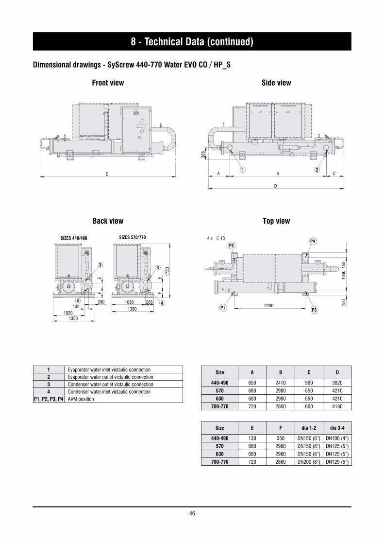
46
8 - Technical Data (continued)
Dimensional drawings - SyScrew 440-770 Water EVO CO / HP_S
Front view Side view
Top viewBack view
175
0
E
F
1085 265
1350
3
4
SIZES 570/770
E
F
200 130
1020 1350
3
4
SIZES 440/490
2200
105
0 1
50
150
P1
P4P2
P3
4 x 18
D B
365
C A
D
1 2
175
0
E
F
1085 265
1350
3
4
SIZES 570/770
E
F
200 130
1020 1350
3
4
SIZES 440/490
2200
105
0 1
50
150
P1
P4P2
P3
4 x 18
D B
365
C A
D
1 2 1
750
E
F
1085 265
1350
3
4
SIZES 570/770
E
F
200 130
1020 1350
3
4
SIZES 440/490
2200
105
0 1
50
150
P1
P4P2
P3
4 x 18
D B
365
C A
D
1 2
175
0
E
F
1085 265
1350
3
4
SIZES 570/770
E
F
200 130
1020 1350
3
4
SIZES 440/490
2200
105
0 1
50
150
P1
P4P2
P3
4 x 18
D B 3
65
C A
D
1 2
1 Evaporator water inlet victaulic connection2 Evaporator water outlet victaulic connection3 Condenser water outlet victaulic connection4 Condenser water inlet victaulic connection
P1, P2, P3, P4 AVM position
Size A B C D
440-490 650 2410 560 3620
570 680 2980 550 4210
630 680 2980 550 4210
700-770 720 2860 600 4180
Size E F dia 1-2 dia 3-4
440-490 130 350 DN150 (6”) DN100 (4”)
570 680 2980 DN150 (6”) DN125 (5”)
630 680 2980 DN150 (6”) DN125 (5”)
700-770 720 2860 DN200 (8”) DN125 (5”)
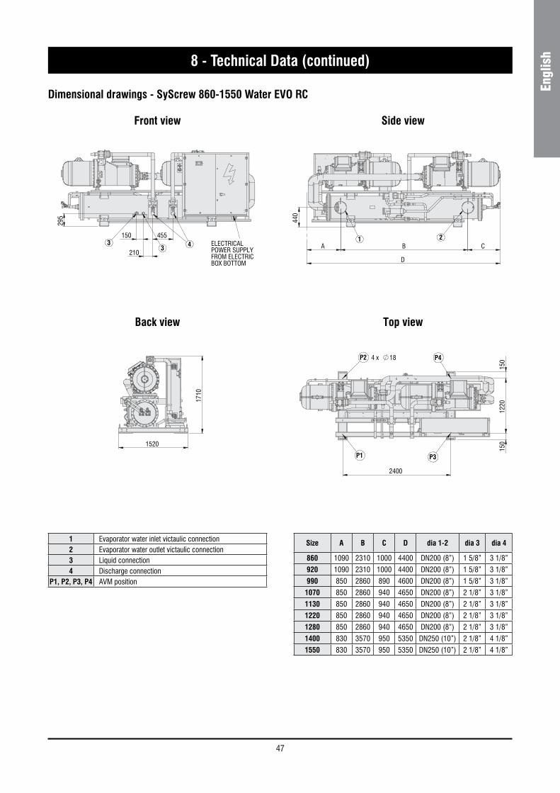
47
Engl
ish8 - Technical Data (continued)
Dimensional drawings - SyScrew 860-1550 Water EVO RC
Front view Side view
Top viewBack view
ELECTRICAL POWER SUPPLY FROM ELECTRICBOX BOTTOM
171
0
1520
150
1
220
150
2400
P2
P3
4 x 18
P1
P4
455
210
150
295
433 B
440
A C
D
1 2ELECTRICAL POWER SUPPLY FROM ELECTRICBOX BOTTOM
171
0
1520
150
1
220
150
2400
P2
P3
4 x 18
P1
P4
455
210
150
295
433 B
440
A C
D
1 2
ELECTRICAL POWER SUPPLY FROM ELECTRICBOX BOTTOM
171
0
1520
150
1
220
150
2400
P2
P3
4 x 18
P1
P4
455
210
150
295
433 B
440
A C
D
1 2ELECTRICAL POWER SUPPLY FROM ELECTRICBOX BOTTOM
171
0
1520
150
1
220
150
2400
P2
P3
4 x 18
P1
P4
455
210
150
295
433 B
440
A C
D
1 2
1 Evaporator water inlet victaulic connection2 Evaporator water outlet victaulic connection3 Liquid connection4 Discharge connection
P1, P2, P3, P4 AVM position
Size A B C D dia 1-2 dia 3 dia 4
860 1090 2310 1000 4400 DN200 (8”) 1 5/8” 3 1/8”
920 1090 2310 1000 4400 DN200 (8”) 1 5/8” 3 1/8”
990 850 2860 890 4600 DN200 (8”) 1 5/8” 3 1/8”
1070 850 2860 940 4650 DN200 (8”) 2 1/8” 3 1/8”
1130 850 2860 940 4650 DN200 (8”) 2 1/8” 3 1/8”
1220 850 2860 940 4650 DN200 (8”) 2 1/8” 3 1/8”
1280 850 2860 940 4650 DN200 (8”) 2 1/8” 3 1/8”
1400 830 3570 950 5350 DN250 (10”) 2 1/8” 4 1/8”
1550 830 3570 950 5350 DN250 (10”) 2 1/8” 4 1/8”

48
8 - Technical Data (continued)
Dimensional drawings - SyScrew 860-1550 Water EVO RC_S
Front view Side view
Top viewBack view
ELECTRICAL POWER SUPPLY FROM ELECTRICBOX BOTTOM
1520
177
0
D
A B C
440
1 2
122
0 1
50
150
2400
P2
P3
4 x 18
P1
P4
455
210
150
295
43 3
ELECTRICAL POWER SUPPLY FROM ELECTRICBOX BOTTOM
1520
177
0
D
A B C
440
1 2
122
0 1
50
150
2400
P2
P3
4 x 18
P1
P4
455
210
150
295
43 3
ELECTRICAL POWER SUPPLY FROM ELECTRICBOX BOTTOM
1520
177
0
D
A B C
440
1 2
122
0 1
50
150
2400
P2
P3
4 x 18
P1
P4
455
210
150
295
43 3 ELECTRICAL POWER SUPPLY FROM ELECTRICBOX BOTTOM
1520
177
0
D
A B C
440
1 2
122
0 1
50
150
2400
P2
P3
4 x 18
P1
P4
455
210
150
295
43 3
1 Evaporator water inlet victaulic connection2 Evaporator water outlet victaulic connection3 Liquid connection4 Discharge connection
P1, P2, P3, P4 AVM position
Size A B C D dia 1-2 dia 3 dia 4
860 1170 2310 1170 4650 DN200 (8”) 1 5/8” 3 1/8”
920 1170 2310 1170 4650 DN200 (8”) 1 5/8” 3 1/8”
990 890 2860 900 4650 DN200 (8”) 1 5/8” 3 1/8”
1070 890 2860 900 4650 DN200 (8”) 2 1/8” 3 1/8”
1130 890 2860 900 4650 DN200 (8”) 2 1/8” 3 1/8”
1220 890 2860 900 4650 DN200 (8”) 2 1/8” 3 1/8”
1280 890 2860 960 4710 DN200 (8”) 2 1/8” 3 1/8”
1400 890 3570 950 5350 DN250 (10”) 2 1/8” 4 1/8”
1550 830 3570 950 5350 DN250 (10”) 2 1/8” 4 1/8”

49
Engl
ish8 - Technical Data (continued)
Dimensional drawings - SyScrew 860-1550 Water EVO CO / HP
Front view Side view
Top viewBack view
ELECTRICAL POWER SUPPLY FROM ELECTRICBOX BOTTOM
171
0
1520
G
E
1175
130 215
F
E
5
6
3
4
SIZES 860/990
E
F
H
G
171
0
1175 130
1240 280
1520
3
4
5
6
SIZES 1070
E
F
H
G
1240 280
1520
171
0
SIZES 1130/1550
3
4
5
6
122
015
0 1
50
2400 P1 P3
P2 P44 x 18
B
440
C
D
A 21ELECTRICAL
POWER SUPPLY FROM ELECTRICBOX BOTTOM
171
0
1520
G
E
1175
130 215
F
E
5
6
3
4
SIZES 860/990
E
F
H
G
171
0
1175 130
1240 280
1520
3
4
5
6
SIZES 1070
E
F
H
G
1240 280
1520
171
0
SIZES 1130/1550
3
4
5
6
122
015
0 1
50
2400 P1 P3
P2 P44 x 18
B
440
C
D
A 21
1 Evaporator water inlet victaulic connection2 Evaporator water outlet victaulic connection3 Condenser water outlet victaulic connection4 Condenser water inlet victaulic connection
P1, P2, P3, P4 AVM position

50
8 - Technical Data (continued)
Dimensional drawings - SyScrew 860-1550 Water EVO CO / HP_S
Front view Side view
Top viewBack view
ELECTRICAL POWER SUPPLY FROM ELECTRICBOX BOTTOM
1520
G
E
1175 130 215
F
E 177
0
5
6
3
4
SIZES 860/990
E
F
H
G
1175 130
1240 280
1520
177
0
3
4
5
6
SIZES 1070
E
F
H
G
1240 280
1520
177
0
SIZES 1130/1550
3
4
5
6
150
1
220
150
2400
P1 P3
P2 P44 x 18
A B
B
C
D
440
21ELECTRICAL POWER SUPPLY FROM ELECTRICBOX BOTTOM
1520
G
E
1175 130 215
F
E 177
0
5
6
3
4
SIZES 860/990
E
F
H
G
1175 130
1240 280
1520
177
0
3
4
5
6
SIZES 1070
E
F
H
G
1240 280
1520
177
0
SIZES 1130/1550
3
4
5
6
150
1
220
150
2400
P1 P3
P2 P44 x 18
A B
B
C
D
440
21
ELECTRICAL POWER SUPPLY FROM ELECTRICBOX BOTTOM
1520
G
E
1175 130 215
F
E 177
0
5
6
3
4
SIZES 860/990
E
F
H
G
1175 130
1240 280
1520
177
0
3
4
5
6
SIZES 1070
E
F
H
G
1240 280
1520
177
0
SIZES 1130/1550
3
4
5
6 1
50
122
0 1
50
2400
P1 P3
P2 P44 x 18
A B
B
C
D
440
21ELECTRICAL POWER SUPPLY FROM ELECTRICBOX BOTTOM
1520
G
E
1175 130 215
F
E 177
0
5
6
3
4
SIZES 860/990
E
F
H
G
1175 130
1240 280
1520
177
0
3
4
5
6
SIZES 1070
E
F
H
G
1240 280
1520
177
0
SIZES 1130/1550
3
4
5
6
150
1
220
150
2400
P1 P3
P2 P44 x 18
A B
B
C
D
440
21
1 Evaporator water inlet victaulic connection2 Evaporator water outlet victaulic connection3 Condenser water outlet victaulic connection4 Condenser water inlet victaulic connection
P1, P2, P3, P4 AVM position

51
Engl
ish8 - Technical Data (continued)
8.6 Service spaces
0.5 MT
2 MT
1 MT
1 MT
3 MT
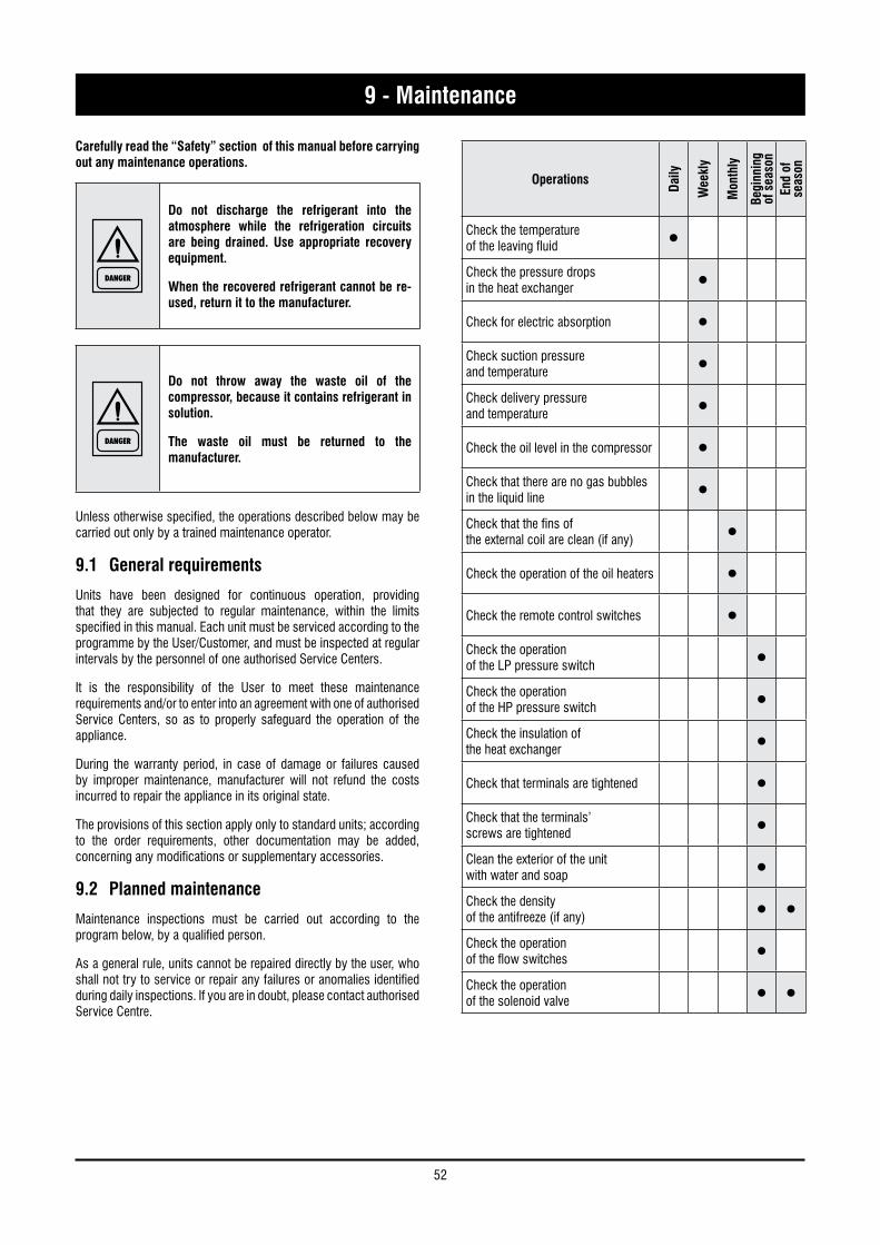
52
Carefully read the “Safety” section of this manual before carrying out any maintenance operations.
DANGER
Do not discharge the refrigerant into the atmosphere while the refrigeration circuits are being drained. Use appropriate recovery equipment.
When the recovered refrigerant cannot be re-used, return it to the manufacturer.
DANGER
Do not throw away the waste oil of the compressor, because it contains refrigerant in solution.
The waste oil must be returned to the manufacturer.
Unless otherwise specified, the operations described below may be carried out only by a trained maintenance operator.
9.1 General requirements
Units have been designed for continuous operation, providing that they are subjected to regular maintenance, within the limits specified in this manual. Each unit must be serviced according to the programme by the User/Customer, and must be inspected at regular intervals by the personnel of one authorised Service Centers.
It is the responsibility of the User to meet these maintenance requirements and/or to enter into an agreement with one of authorised Service Centers, so as to properly safeguard the operation of the appliance.
During the warranty period, in case of damage or failures caused by improper maintenance, manufacturer will not refund the costs incurred to repair the appliance in its original state.
The provisions of this section apply only to standard units; according to the order requirements, other documentation may be added, concerning any modifications or supplementary accessories.
9.2 Planned maintenance
Maintenance inspections must be carried out according to the program below, by a qualified person.
As a general rule, units cannot be repaired directly by the user, who shall not try to service or repair any failures or anomalies identified during daily inspections. If you are in doubt, please contact authorised Service Centre.
9 - Maintenance
Operations
Daily
Wee
kly
Mon
thly
Begi
nnin
g of
sea
son
End
of
seas
on
Check the temperatureof the leaving fluid •Check the pressure dropsin the heat exchanger •Check for electric absorption •Check suction pressureand temperature •Check delivery pressureand temperature •Check the oil level in the compressor •Check that there are no gas bubbles in the liquid line •Check that the fins ofthe external coil are clean (if any) •Check the operation of the oil heaters •Check the remote control switches •Check the operationof the LP pressure switch •Check the operationof the HP pressure switch •Check the insulation ofthe heat exchanger •Check that terminals are tightened •Check that the terminals’screws are tightened •Clean the exterior of the unitwith water and soap •Check the densityof the antifreeze (if any) • •Check the operationof the flow switches •Check the operationof the solenoid valve • •
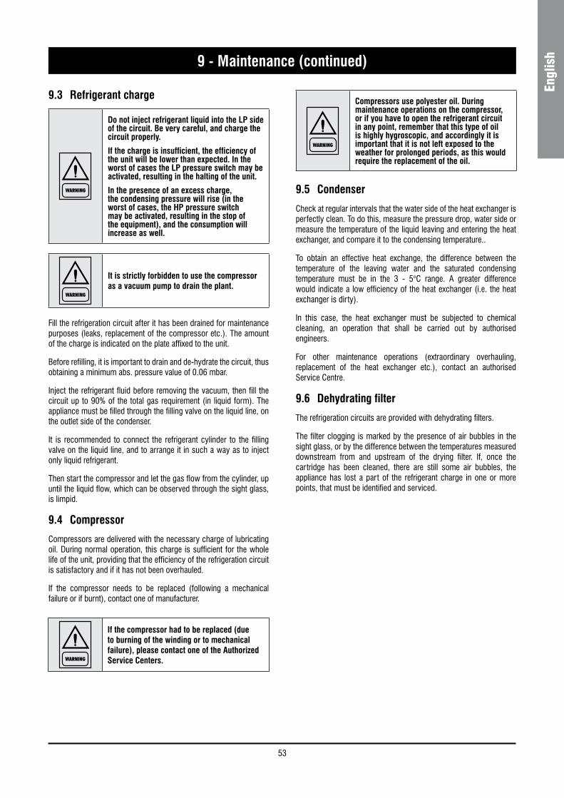
53
Engl
ish
9.3 Refrigerant charge
WARNING
Do not inject refrigerant liquid into the LP side of the circuit. Be very careful, and charge the circuit properly.
If the charge is insufficient, the efficiency of the unit will be lower than expected. In the worst of cases the LP pressure switch may be activated, resulting in the halting of the unit.
In the presence of an excess charge, the condensing pressure will rise (in the worst of cases, the HP pressure switch may be activated, resulting in the stop of the equipment), and the consumption will increase as well.
WARNING
It is strictly forbidden to use the compressor as a vacuum pump to drain the plant.
Fill the refrigeration circuit after it has been drained for maintenance purposes (leaks, replacement of the compressor etc.). The amount of the charge is indicated on the plate affixed to the unit.
Before refilling, it is important to drain and de-hydrate the circuit, thus obtaining a minimum abs. pressure value of 0.06 mbar.
Inject the refrigerant fluid before removing the vacuum, then fill the circuit up to 90% of the total gas requirement (in liquid form). The appliance must be filled through the filling valve on the liquid line, on the outlet side of the condenser.
It is recommended to connect the refrigerant cylinder to the filling valve on the liquid line, and to arrange it in such a way as to inject only liquid refrigerant.
Then start the compressor and let the gas flow from the cylinder, up until the liquid flow, which can be observed through the sight glass, is limpid.
9.4 Compressor
Compressors are delivered with the necessary charge of lubricating oil. During normal operation, this charge is sufficient for the whole life of the unit, providing that the efficiency of the refrigeration circuit is satisfactory and if it has not been overhauled.
If the compressor needs to be replaced (following a mechanical failure or if burnt), contact one of manufacturer.
WARNING
Compressors use polyester oil. During maintenance operations on the compressor, or if you have to open the refrigerant circuit in any point, remember that this type of oil is highly hygroscopic, and accordingly it is important that it is not left exposed to the weather for prolonged periods, as this would require the replacement of the oil.
9.5 Condenser
Check at regular intervals that the water side of the heat exchanger is perfectly clean. To do this, measure the pressure drop, water side or measure the temperature of the liquid leaving and entering the heat exchanger, and compare it to the condensing temperature..
To obtain an effective heat exchange, the difference between the temperature of the leaving water and the saturated condensing temperature must be in the 3 - 5°C range. A greater difference would indicate a low efficiency of the heat exchanger (i.e. the heat exchanger is dirty).
In this case, the heat exchanger must be subjected to chemical cleaning, an operation that shall be carried out by authorised engineers.
For other maintenance operations (extraordinary overhauling, replacement of the heat exchanger etc.), contact an authorised Service Centre.
9.6 Dehydrating filter
The refrigeration circuits are provided with dehydrating filters.
The filter clogging is marked by the presence of air bubbles in the sight glass, or by the difference between the temperatures measured downstream from and upstream of the drying filter. If, once the cartridge has been cleaned, there are still some air bubbles, the appliance has lost a part of the refrigerant charge in one or more points, that must be identified and serviced.
9 - Maintenance (continued)
WARNING
If the compressor had to be replaced (due to burning of the winding or to mechanical failure), please contact one of the Authorized Service Centers.

54
9.7 Sight glass
The sight glass is used for inspecting the refrigerant flow and the humidity % of the refrigerant. The presence of bubbles indicates that the dehydrating filter is clogged or the charge insufficient.
A colour indicator is positioned inside the sight glass. If you compare the colour of the indicator to the scale on the ring of the sight glass, you can calculate the percentage of humidity of the refrigerant. If it is excessive, replace the filter’s cartridge, operate the appliance for 1 day and then check the humidity % again. When the humidity % is within the pre-determined range, no other operations are required. If the humidity % is still too high, replace the dehydrating filter again, start the unit and operate it for another day.
9.8 Electronic expansion valve
The circuit of the unit is equipped with electronic expansion valve.
The valve is calibrated for an overheating of 6 °C.
Procedure to check for overheating:
– Measure the suction pressure with the pressure gauges on the board of the unit o using a pressure gauge connected to the service valve on the suction side.
– From the pressure gauge’s temperature scale, measure the saturated suction temperature (Tsa) which corresponds to the pressure value.
– Using a contact pressure gauge affixed to the outlet fitting of the gas of the evaporator, measure the actual temperature (Tse).
Overheating calculation (S):
S = Tse - Tsa
Overheating is regulated through the expansion valve.
If the electronic expansion valve cannot be regulated, it is probably broken, and shall be replaced. The replacement must be carried out by a Service Centre.
9 - Maintenance (continued)
9.9 Evaporator
Check at regular intervals that the water side of the heat exchanger is perfectly clean. To do this, measure the pressure drop, water side (see Section 8) or measure the temperature of the liquid leaving and entering the heat exchanger, and compare it to the evaporation temperature.
To obtain an effective heat exchange, the difference between the temperature of the leaving water and the saturated evaporating temperature must be in the 2 - 4 °C range. A greater difference would indicate a low efficiency of the heat exchanger (i.e. the heat exchanger is dirty).
In this case, the heat exchanger must be subjected to chemical cleaning, an operation that shall be carried out by authorised engineers.
For other maintenance operations (extraordinary overhauling, replacement of the heat exchanger etc.), contact an authorised Service Centre.

55
Engl
ish
The table below lists the anomalies of operation of the unit, the relevant causes and the corrective measures. For anomalies of any other type or not listed, contact one of authorised Service Centre for technical assistance.
Anomaly Cause Operation
The unit continues to work, but without cooling
Insufficient charge of refrigerant. Refill.
The dehydrating filter is clogged. Replace.
Ice on the suction line Wrong calibration of overheating.Increase overheating.
Check the charge.
Excessive noise
Vibration of lines. Check the clamping brackets, if any.
Whistler emitted by the thermostatic expansion valve.
Refill.
Check the dehydrating filter.
Noisy compressor.Seized bearings; replace the compressor.
Check that the compressor’s locknuts are tightened.
Low oil level in the compressor
One or more gas or oil leaks in the circuit. Identify and remove leaks.
Mechanical failure of the compressor. Request the intervention of a Service Centre.
Anomaly of the oil heater of the compressor’s base.
Check the electric circuit and the resistor of the heater of the motor base, and replace defective components.
One or both compressors are not working
Breaking of the electric circuit. Check the electric circuit and detect any ground dispersions and short circuits. Check fuses.
Intervention of the HP pressure switch.Reset the pressure switch and the control panel and restart the appliance. Identify and remove the cause that enabled the pressure switch.
The fuse of the control circuit is broken. Check for ground dispersions and short circuits. Replace fuses.
Loosened terminals. Check and tighten.
Halt caused by thermal overload of the electric circuit.
Check the operation of check and safety devices. Identify and remove the cause.
Wrong wiring. Check wiring of check and safety devices.
The line voltage is too low.Check voltage. If problems regard the system, solve them. If they are caused by the distribution network, inform the Energy Distributor.
Short-circuit of the compressor’s motor. Check the continuity of the winding.
Seized compressor. Replace the compressor.
Activation of the LP alarm, stop of the unit
Gas leak. Identify and remove the leak.
Insufficient charge. Refill.
Failure of the pressure switch. Replace the pressure switch.
Activation of the HP alarm, stop of the unit
Failure of the pressure switch. Check the operation of the pressure switch, replace it if defective.
The delivery valve is partially closed. Open the valve and replace it, if faulty.
Substances with condensable gases in the circuit. Drain the circuit.
The fan of the condenser is stopped. Check cables and motor. If defective, repair or replace.
The liquid line is too hot Insufficient charge. Identify and remove the cause of the loss of charge and refill.
Frosting of the liquid line
The valve of the liquid line is partially closed. Check that valves are open.
The liquid filter is clogged. Replace the cartridge or the filter.
10 - Troubleshooting

56
11.1 Spare part list
The table below shows the list of spare parts recommended during the first two years of operation.
11.2 Oil for compressors
The compressors are lubricated with Ester oil BSE 170 (Viscosity of 170 St / 40 °C).
11.3 Wiring diagrams
The wiring diagrams are installed inside the doors of the electrical panels of the unit. Any request for wiring diagrams shall be forwarded to manufacturer’s Service Centre.
Component Number
HP pressure switch 2 / 4
LP pressure switch 2 / 4
Gas filter 1 / 2
Electronic expansion valve 1 / 2
Auxiliary relays 2
Compressor’s fuses 3 / 6
Auxiliary fuses 6
Set of compressor contactors 1
Water sensor 2
Electronic card 1
Keyboard 1
Compressor oil resistor 1 / 2
11 - Spare Parts

57
Engl
ish12 - Dismantling, Demolition and Scrapping
DANGER
During the draining of the refrigeration circuits, do not let the refrigerant overflow in the surrounding atmosphere.
The circuit must be drained using suitable recovery equipment.
DANGER
Do not disperse the waste oil of the compressors in the environment, since it contains some dissolved refrigerant.
For the disposal, contact the competent authority for information.
Unless otherwise specified, the maintenance operations listed below may be carried out by any trained maintenance operator.
12.1 Generalities
Open each line that supplies the unit, including the ones of control circuits. Make sure that all disconnecting switches are secured in the off position. The power cables can be disconnected and disassembled. Refer to Chapter 4 for the position of connection points.
Remove all the refrigerant from the refrigeration circuits of the unit and store it in suitable containers, using a recovery unit. If its characteristics have remained the same, the refrigerant can be used again. Contact the competent authority to obtain information about disposal. In NO event shall the refrigerant be discharged into the atmosphere. The oil in each refrigeration circuit must be drained and collected into a suitable container; then it shall be disposes of in conformity with local regulations that apply to the disposal of waste lubricants. Any oil spillage must be recovered and disposed of in like manner.
Isolate the unit’s heat exchangers from the external hydraulic circuits and drain the heat exchange sections of the plant.
DANGER
If no shutoff valves have been provided, it may be necessary to drain the whole plant.
If a glycoled solution or a similar fluid has been used in the hydraulic circuits, or if chemical additives have been added to the circulating water, the circulating fluid MUST be drained in a proper way.
For NO reason shall a circuit containing glycoled water or a similar solution be discharged directly into the drains or surface waters.
After draining operations, the piping of the hydraulic networks can be disconnected and disassembled.
Once they have been disconnected as specified, the packaged units can be disassembled in a single piece. First of all, disassemble the anchoring screws and then lift the unit from the position of installation, and hook it to the lifting points provided, using suitable lifting equipment.
To this end, refer to Chapter 4 for the installation of these appliances, to Chapter 8 for their weights and Chapter 3 for handling.
The units that, once disconnected, cannot be removed in a single piece, must be dismantled on site; in this case, be very careful with the weight and handling of every single component.
It is always advisable to dismantle the units following the installation steps, but in reverse.
DANGER
Some residues of oil, glycoled water or similar solutions may remain in certain parts of the unit. These residues must be recovered and disposed of according to the procedures specified above.
It is very important to ensure that, while a component of the unit is being removed, all the others are properly supported.
DANGER
Use only lifting means of adequate capacity.
Once disassembled, the components of the unit can be disposed of in conformity with current regulations.

58
Notes

59
Engl
ishNotes

60
Notes
As part of our ongoing product improvement programme, our products are subject to change without prior notice. Non contractual photos.Dans un souci d’amélioration constante, nos produits peuvent être modifiés sans préavis. Photos non contractuelles.In dem Bemühen um ständige Verbesserung können unsere Erzeugnisse ohne vorherige Ankündigung geändert werden. Fotos nicht vertraglich bindend.A causa della politica di continua miglioria posta in atto dal costruttore, questi prodotti sono soggetti a modifiche senza alcun obbligo di preavviso. Le foto pubblicate non danno luogo ad alcun vincolo contrattuale.Con objeto de mejorar constantemente, nuestros productos pueden ser modificados sin previo aviso. Fotos no contractuales.
Systemair srlVia XXV Aprile, 2920825 Barlassina (MB) Italy
Tel. +39 0362 680 1Fax +39 0362 680 693
www.systemair.com