CN3163 - USB-Compatible Lithium-Ion Battery Charger with ...
13
CONSONANCE www.consonance-elec.com 1 REV 1.0 Lithium Ion Battery Charger for Solar-Powered Systems CN3163 General Description: The CN3163 is a complete constant-current /constant voltage linear charger for single cell Li-ion and Li Polymer batteries. The device contains an on-chip power MOSFET and eliminates the need for the external sense resistor and blocking diode. An on-chip adaptive cell can adjust charging current automatically based on the output capability of input power supply, so CN3163 is ideally suited for solar powered system. Thermal feedback regulates the charge current to limit the die temperature during high power operation or high ambient temperature. The regulation voltage is internally fixed at 4.2V with 1% accuracy, it can also be adjusted upwards with an external resistor. The charge current can be set externally with a single resistor. When the input supply is removed, the CN3163 automatically enters a low power sleep mode , dropping the battery drain current to less than 3uA. Other features include undervoltage lockout, automatic recharge, battery temperature sensing and charging/termination indicator. The CN3163 is available in a thermally enhanced 8-pin SOP package. Applications: Solar Powered System Digital Still Cameras Bluetooth Applications Portable Devices Chargers Features: Automatic charge current adjustment based on the output capability of input power supply Suitable for Solar-Powered System On-chip Power MOSFET No external Blocking Diode or Current Sense Resistors Required Preset 4.2V regulation voltage with 1% accuracy, upwards adjustable with a resistor Precharge Conditioning for Reviving Deeply Discharged Cells and Minimizing Heat Dissipation During Initial Stage of Charge Continuous Charge Current Up to 1A Constant-Current/Constant-Voltage Operation with Thermal Regulation to Maximize Charge Rate Without Risk of Overheating Automatic Low-Power Sleep Mode When Input Supply Voltage is Removed Status Indication for LEDs or uP Interface C/10 Charge Termination Automatic Recharge Battery Temperature Sensing Available in eSOP8 Package Pb-free, rohs-Compliant and Halogen Free Pin Assignment
-
Upload
khangminh22 -
Category
Documents
-
view
2 -
download
0
Transcript of CN3163 - USB-Compatible Lithium-Ion Battery Charger with ...

CONSONANCE
www.consonance-elec.com 1 REV 1.0
Lithium Ion Battery Charger for Solar-Powered Systems
CN3163
General Description:
The CN3163 is a complete constant-current /constant
voltage linear charger for single cell Li-ion and Li
Polymer batteries. The device contains an on-chip
power MOSFET and eliminates the need for the
external sense resistor and blocking diode. An
on-chip adaptive cell can adjust charging current
automatically based on the output capability of input
power supply, so CN3163 is ideally suited for solar
powered system. Thermal feedback regulates the
charge current to limit the die temperature during
high power operation or high ambient temperature.
The regulation voltage is internally fixed at 4.2V
with 1% accuracy, it can also be adjusted upwards
with an external resistor. The charge current can be
set externally with a single resistor. When the input
supply is removed, the CN3163 automatically enters
a low power sleep mode , dropping the battery drain
current to less than 3uA. Other features include
undervoltage lockout, automatic recharge, battery
temperature sensing and charging/termination
indicator.
The CN3163 is available in a thermally enhanced
8-pin SOP package.
Applications:
Solar Powered System
Digital Still Cameras
Bluetooth Applications
Portable Devices
Chargers
Features:
Automatic charge current adjustment based on
the output capability of input power supply
Suitable for Solar-Powered System
On-chip Power MOSFET
No external Blocking Diode or Current Sense
Resistors Required
Preset 4.2V regulation voltage with 1%
accuracy, upwards adjustable with a resistor
Precharge Conditioning for Reviving Deeply
Discharged Cells and Minimizing Heat
Dissipation During Initial Stage of Charge
Continuous Charge Current Up to 1A
Constant-Current/Constant-Voltage Operation
with Thermal Regulation to Maximize Charge
Rate Without Risk of Overheating
Automatic Low-Power Sleep Mode When Input
Supply Voltage is Removed
Status Indication for LEDs or uP Interface
C/10 Charge Termination
Automatic Recharge
Battery Temperature Sensing
Available in eSOP8 Package
Pb-free, rohs-Compliant and Halogen Free
Pin Assignment
CONSONANCE
www.consonance-elec.com 2 REV 1.0
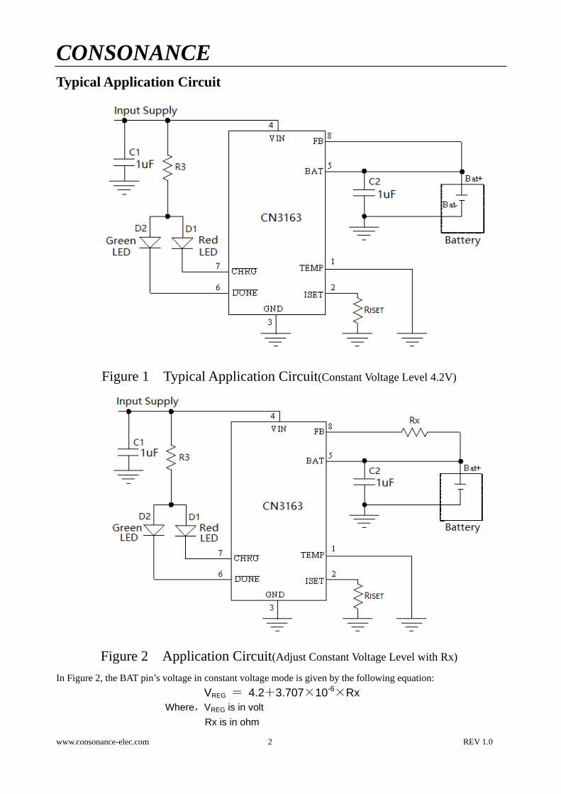
Typical Application Circuit
Figure 1 Typical Application Circuit(Constant Voltage Level 4.2V)
Figure 2 Application Circuit(Adjust Constant Voltage Level with Rx)
In Figure 2, the BAT pin’s voltage in constant voltage mode is given by the following equation:
VREG = 4.2+3.707×10⁻⁶×Rx
Where,VREG is in volt
Rx is in ohm

CONSONANCE
www.consonance-elec.com 3 REV 1.0
Ordering Information:
Part No. Package Shipping Operating Temperature Range
CN3163 eSOP8 Tape and Reel, 4000/Reel -40℃ to +85℃
Block Diagram
Figure 3 Block Diagram

CONSONANCE
www.consonance-elec.com 4 REV 1.0
Pin Description
Pin No. Name Function Description
1 TEMP
Temperature Sense Input. Connecting TEMP pin to NTC thermistor’s
output in Lithium ion battery pack. If TEMP pin’s voltage is below 45% or
above 80% of supply voltage VIN, this means that battery’s temperature is too
high or too low, charging is suspended. If TEMP’s voltage level is between
45% and 80%of supply voltage, battery fault state is released, and charging will
resume.
The temperature sense function can be disabled by grounding the TEMP pin.
2 ISET
Constant Charge Current Setting and Charge Current Monitor Pin. The
charge current is set by connecting a resistor RISET from this pin to GND.
When in precharge mode, the ISET pin’s voltage is regulated to 0.12V. When
in constant charge current mode, the ISET pin’s voltage is regulated to 1.205V.
In all modes during charging, the voltage on ISET pin can be used to measure
the charge current as follows:
ICH = (VISET/RISET)×986
3 GND Ground Terminal (Ground).
4 VIN
Positive Input Supply Voltage. VIN is the power supply to the internal circuit.
When VIN drops to within 10mv of the BAT pin voltage, CN3163 enters low
power sleep mode, dropping BAT pin’s current to less than 3uA.
5 BAT
Battery Connection Pin. Connect the positive terminal of the battery to BAT
pin. BAT pin draws less than 3uA current in sleep mode. BAT pin provides
charge current to the battery and provides regulation voltage.
6
Open-Drain Charge termination Status Output. In charge termination
status, is pulled low by an internal switch; Otherwise pin is in
high impedance state.
7
Open Drain Charge Status Output. When the battery is being charged, the
pin is pulled low by an internal switch, otherwise pin is in high
impedance state.
8 FB
Battery Voltage Sense Input. This Pin can sense the battery voltage; Also the
regulation voltage in constant voltage mode can be adjusted by connecting an
external resistor between FB pin and BAT pin.
Absolute Maximum Ratings
All Terminal Voltage……………-0.3V to 6.5V Maximum Junction Temperature…...150℃
BAT Short-Circuit Duration………...Continuous Operating Temperature…...-40℃ to 85℃
Storage Temperature….............-65℃ to 150℃ Thermal Resistance (SOP8)………….TBD
Lead Temperature(Soldering, 10s)…….....260℃
Stresses beyond those listed under ‘Absolute Maximum Ratings’ may cause permanent damage to the device. These are stress
ratings only and functional operation of the device at these or any other conditions above those indicated in the operational
sections of the specifications is not implied. Exposure to Absolute Maximum Rating Conditions for extended periods may affect
device reliability.

CONSONANCE
www.consonance-elec.com 5 REV 1.0
Electrical Characteristics
(VIN=5V, TA=-40℃ to 85℃, Typical Values are measured at TA=25℃,unless otherwise noted)
Parameters Symbol Test Conditions Min Typ Max Unit
Input Supply Voltage VIN 4.4 6 V
Operating Current IVIN Charge Termination Mode 350 500 660 uA
Undervoltage Lockout Vuvlo VIN falling 2.4 2.65 V
Undervoltage Lockout
Hysteresis Huvlo 0.12 V
Soft Start Time tSS 100 160 220 uS
Regulation Voltage VREG Constant Voltage Mode 4.158 4.2 4.242 V
BAT pin Current
ICC RISET=1.18K, VBAT=3.6V 900 1000 1100 mA
IPRE RISET=1.18K, VBAT=2.4V 75 100 125
ISDBY VBAT=VREG, standby mode 1.8 3.7 7 uA
ISLP VIN=0V, sleep mode 3
Precharge Threshold
Precharge Threshold VPRE Voltage at BAT pin rising 67 70 73 %VREG
Precharge Threshold
Hysteresis HPRE 4.2 %VREG
Charge Termination Threshold
Charge Termination
Threshold Vterm Measure voltage at ISET pin 96 120 144 mV
Recharge Threshold
Recharge Threshold IRECH Charge Current Rises 30% %ICC
Sleep Mode
Sleep Mode Threshold VSLP VIN from high to low, measures
the voltage (VIN-VBAT) 10 mV
Sleep mode Release
Threshold VSLPR
VIN from low to high, measures
the voltage (VIN-VBAT) 60 mV
ISET Pin
ISET Pin Voltage VISET Precharge mode 0.12
V Constant current mode 1.205
TEMP PIN
High Input Threshold VHIGH The voltage at TEMP increases 77.5 80 82.5 %VIN
Low Input Threshold VLOW The voltage at TEMP decreases 42.5 45 47.5 %VIN
TEMP input Current TEMP to VIN or to GND 0.5 uA
Pin
Sink Current IDONE VDONE=0.3V, termination mode 10 mA
Leakage Current VDONE=6V, charge mode 1 uA
Pin
Sink Current ICHRG VCHRG=0.3V, Charge status 10 mA
Leakage Current VCHRG=6V, termination mode 1 uA

CONSONANCE
www.consonance-elec.com 6 REV 1.0
Detailed Description
The CN3163 is a linear battery charger IC designed primarily for charging single cell lithium-ion or
lithium-polymer batteries. Featuring an internal P-channel power MOSFET, the charger uses a
constant-current/constant-voltage to charge the batteries. Continuous charge current can be programmed up to
1A with an external resistor. No blocking diode or sense resistor is required. The on-chip adaptive cell can adjust
charging current automatically based on the output capability of input power supply, so CN3163 is ideally suited
for the solar-powered systems, or the applications that need to charge lithium-ion battery or lithium polymer
battery with an input power supply whose output capability is limited. The open-drain output and
indicates the charger’s status. The internal thermal regulation circuit reduces the programmed charge current if
the die temperature attempts to rise above a preset value of approximately 130℃. This feature protects the
CN3163 from excessive temperature, and allows the user to push the limits of the power handling capability of a
given circuit board without risk of damaging the CN3163 or the external components. Another benefit of
adopting thermal regulation is that charge current can be set according to typical, not worst-case, ambient
temperatures for a given application with the assurance that the charger will automatically reduce the current in
worst-case conditions.
The charge cycle begins when the voltage at the VIN pin rises above the UVLO level, a current set resistor is
connected from the ISET pin to ground. The pin outputs a logic low to indicate that the charge cycle is
ongoing. At the beginning of the charge cycle, if the voltage at FB pin is below 70% of the regulation voltage,
the charger is in precharge mode to bring the cell voltage up to a safe level for charging. The charger goes into
the fast charge constant-current mode once the voltage on the FB pin rises above 70% of the regulation voltage.
In constant current mode, the charge current is set by RISET. When the battery approaches the regulation voltage,
the charge current begins to decrease as the CN3163 enters the constant-voltage mode. When the current drops
to charge termination threshold, the charge cycle is terminated, is pulled low by an internal switch and
pin assumes a high impedance state to indicate that the charge cycle is terminated. The charge termination
threshold is 10% of the current in constant current mode. To restart the charge cycle, just remove the input
voltage and reapply it. The charge cycle can also be automatically restarted if the charge current rises above the
recharge threshold. The on-chip reference voltage, error amplifier and the resistor divider provide regulation
voltage with 1% accuracy which can meet the requirement of lithium-ion and lithium polymer batteries. When
the input voltage is not present, the charger goes into a sleep mode, dropping battery drain current to less than
3uA. This greatly reduces the current drain on the battery and increases the standby time.
The charging profile is shown in the following figure:

CONSONANCE
www.consonance-elec.com 7 REV 1.0
Figure 4 Charging Profile
Application Information
Undervoltage Lockout (UVLO)
An internal undervoltage lockout circuit monitors the input voltage and keeps the charger in shutdown mode
until VIN rises above the undervoltage lockout voltage. The UVLO circuit has a built-in hysteresis of 0.12V.
Sleep mode
There is an on-chip sleep comparator. The comparator keeps the charger in sleep mode if VIN falls below sleep
mode threshold(VBAT+10mv). Once in sleep mode, the charger will not come out of sleep mode until VIN rises
60mv above the battery voltage.
Precharge mode
At the beginning of a charge cycle, if the battery voltage is below 70% of the regulation voltage, the charger
goes into precharge mode , and the charge current is 10% of fast charge current in constant current mode.
Charging Current limited by the Output capability of Input Power Supply
If the output capability of input power supply is less than the charging current set by the resistor at ISET pin,
then the on-chip adaptive cell will begin to function to adjust the charging current based on the output capability
of input power supply. In this case, the charging current may be less than the value set by the resistor at ISET
pin, but it is maximized to the output capability of input power supply on the condition that the input voltage at
VIN pin is no less than 4.4V, which is the minimum operating voltage of CN3163. So the charging current can
be set according to the maximum output capability of input power supply, not the worst case.
Adjusting the regulation voltage in constant voltage mode
The regulation voltage in constant voltage mode can be adjusted by an external resistor connecting between FB
pin and BAT pin as shown in Figure 5:

CONSONANCE
www.consonance-elec.com 8 REV 1.0
Figure 5 Adjusting Regulation Voltage in Constant Voltage Mode
In Figure 5, the regulation voltage in constant voltage mode will be given by the following equation:
VREG = 4.2+3.707×10⁻⁶×Rx
Where,
VREG is in volt
Rx is in ohm
Setting Charge Current
The formula for the battery charge current in constant current mode is:
ICH = 1188V / RISET
Where:
ICH is the charge current in ampere
RISET is the total resistance from the ISET pin to ground in ohm
For example, if 1000mA charge current is required, calculate:
RISET = 1188V/1A = 1.18kΩ
For best stability over temperature and time, 1% metal film resistors are recommended. If the charger is in
constant-temperature or constant voltage mode, the charge current can be monitored by measuring the ISET pin
voltage, and the charge current is calculated as the following equation:
ICH = (VISET / RISET) × 986
Combine Two Power Inputs
Although the CN3163 allows charging from a solar power supply, a wall adapter or a USB port can also be used
to charge Li-Ion/Li-polymer batteries. Figure 6 shows an example of how to combine 2 power inputs. A
P-channel MOSFET, M1, is used to prevent back conducting into the 2nd
power supply when the 1st power
supply is present and Schottky diode, D1, is used to prevent 2nd
power supply loss through the 1kΩ pull-down
resistor.

CONSONANCE
www.consonance-elec.com 9 REV 1.0
Figure 6 Combining 2 Input Power Supply
Battery Temperature Sense
To prevent the damage caused by the very high or very low temperature done to the battery pack, the CN3163
continuously senses battery pack temperature by measuring the voltage at TEMP pin determined by the voltage
divider circuit and the battery’s internal NTC thermistor as shown in Figure 7.
The CN3163 compares the voltage at TEMP pin (VTEMP) against its internal VLOW and VHIGH thresholds to
determine if charging is allowed. In CN3163, VLOW is fixed at (45%×VIN), while VHIGH is fixed at (80%×
VIN). If VTEMP<VLOW or VTEMP>VHIGH, it indicates that the battery temperature is too high or too low and the
charge cycle is suspended. When VTEMP is between VLOW and VHIGH, the charge cycle resumes.
The battery temperature sense function can be disabled by connecting TEMP pin to GND.
Figure 7 Monitoring Battery Temperature

CONSONANCE
www.consonance-elec.com 10 REV 1.0
Selecting R1 and R2 The values of R1 and R2 in Figure 7 can be determined according to the assumed temperature monitor range
and thermistor’s values. The Follows is an example:
Assume temperature monitor range is TL~TH (TL<TH=; the thermistor in battery has negative temperature
coefficient (NTC), RTL is thermistor’s resistance at TL, RTH is the resistance at TH, so RTL>RTH, then at
temperature TL, the voltage at TEMP pin is:
At temperature TH, the voltage at TEMP pin is:
We know, VTEMPL=VHIGH=k2×VIN (k2=0.8)
VTEMPH=VLOW=k1×VIN (k1=0.45)
Then we can have:
R1=21THTL
12THTL
k)kR(R
)k(kRR
R2=)kk(kR)kk(kR
)k(kRR
212TH211TL
12THTL
Likewise, for positive temperature coefficient thermistor in battery, we have RTH>RTL and we can calculate:
R1=21TLTH
12THTL
k)kR(R
)k(kRR
R2=)kk(kR)kk(kR
)k(kRR
212TL211TH
12THTL
We can conclude that temperature monitor range is independent of power supply voltage VIN and it only
depends on R1, R2, RTL and RTH: The values of RTH and RTLcan be found in related battery handbook or
deduced from testing data.
In actual application, if only one terminal temperature is concerned(normally protecting overheating), there is
no need to use R2 but R1. In this case it becomes very simple to calculate R1.
Recharge
After a charge cycle has terminated, if the charge current rises above 30% of the constant charge current, a new
charge cycle will begin automatically.
Constant-Current/Constant-Voltage/Constant-Temperature
The CN3163 use a unique architecture to charge a battery in a constant-current, constant-voltage, constant
temperature fashion as shown in Figure 3. Amplifiers Iamp, Vamp, and Tamp are used in three separate
feedback loops to force the charger into constant-current, constant-voltage, or constant-temperature mode,
respectively. In constant current mode the charge current delivered to the battery equal to 1188V/RISET. If the
power dissipation of the CN3163 results in the junction temperature approaching 130℃, the amplifier Tamp will
begin decreasing the charge current to limit the die temperature to approximately 130℃. As the battery voltage
rises, the CN3163 either returns to constant-current mode or it enters constant voltage mode straight from
constant-temperature mode.

CONSONANCE
www.consonance-elec.com 11 REV 1.0
Open-Drain Status Outputs
The CN3163 have 2 open-drain status outputs: and . is pulled low when the charger is in
charging status, otherwise becomes high impedance. is pulled low if the charger is in charge
termination status, otherwise becomes high impedance.
The open drain status output that is not used should be tied to ground.
VIN Bypass Capacitor
Many types of capacitors can be used for input bypassing(C1 in Figure 1 and 2), Generally, a 1uF ceramic
capacitor, placed in close proximity to VIN and GND pins, works well. In some applications depending on the
power supply characteristics and cable length, it may be necessary to increase the capacitor's value.
If the ceramic capacitor is used as the input supply bypassing purpose, a voltage spike may be created when the
input voltage is applied to the CN3163 via a cable. If the cable is a bit long, the circuit shown in Figure 6 or a
TVS diode from VIN pin to GND should be considered to use to prevent the CN3163 from being damaged by
the voltage spike.
For the consideration of the bypass capacitor, please refer to the Application Note AN102 from our website.
Figure 6 Adding Diode D1 to Suppress Voltage Spike
Stability
A capacitor from BAT pin to GND is required to stabilize the feedback loop, generally the feedback loop is
stable with an 1uF to 22uF ceramic capacitor. If electrolytic capacitor is used, the capacitance can be as high as
100uF.
In constant current mode, the stability is also affected by the impedance at the ISET pin. With no additional
capacitance on the ISET pin, the loop is stable with current set resistors values as high as 50KΩ. However,
additional capacitance on ISET pin reduces the maximum allowed current set resistor. The pole frequency at
ISET pin should be kept above 200KHz. Therefore, if ISET pin is loaded with a capacitance C, the following
equation should be used to calculate the maximum resistance value for RISET:
RISET < 1/(6.28×2×105×C)
CONSONANCE
www.consonance-elec.com 12 REV 1.0
Board Layout Considerations
1. RISET at ISET pin should be as close to CN3163 as possible, also the parasitic capacitance at ISET pin
should be kept as small as possible.
2. The capacitance at VIN pin and BAT pin should be as close to CN3163 as possible.
3. During charging, CN3163’s temperature may be high, the NTC thermistor should be placed far enough to
CN3163 so that the thermistor can reflect the battery’s temperature correctly.
4. It is very important to use a good thermal PC board layout to maximize charging current. The thermal path
for the heat generated by the IC is from the die to the copper lead frame through the package lead(especially
the ground lead) to the PC board copper, the PC board copper is the heat sink. The footprint copper pads
should be as wide as possible and expand out to larger copper areas to spread and dissipate the heat to the
surrounding ambient. Feedthrough vias to inner or backside copper layers are also useful in improving the
overall thermal performance of the charger. Other heat sources on the board, not related to the charger,
must also be considered when designing a PC board layout because they will affect overall temperature rise
and the maximum charge current.
The ability to deliver maximum charge current under all conditions require that the exposed metal pad on
the back side of the CN3163 package be soldered to the PC board ground. Failure to make the thermal
contact between the exposed pad on the backside of the package and the copper board will result in larger
thermal resistance.

CONSONANCE
www.consonance-elec.com 13 REV 1.0
Package Information
Consonance does not assume any responsibility for use of any circuitry described. Consonance reserves the
right to change the circuitry and specifications without notice at any time.