XZERES ARE442 & 442SR Battery Charger Wind Turbine ...
96
7305 Rev A XZERES ARE442 & 442SR Battery Charger Wind Turbine System
-
Upload
khangminh22 -
Category
Documents
-
view
2 -
download
0
Transcript of XZERES ARE442 & 442SR Battery Charger Wind Turbine ...

7305 Rev A
XZERES ARE442 & 442SR
Battery Charger Wind Turbine System

XZERES 442SR Battery Charger Wind Energy System Installation and Operation Manual
PN: 7305 Revision A, XCO 1159 ©2014 XZERES Corporation Page 2
Copyright 2014 by XZERES Corporation
The XZERES Corporation manufactures the XZERES ARE442 and 442SR wind energy system in
the United States.
XZERES ARE442 and 442SR are used interchangeably throughout the Battery Charger Wind
Energy System Installation and Operation Manual; both systems are installed and operated
identically.
The information contained in the XZERES ARE442 and 442SR Battery Charger Wind Energy
System Installation and Operation Manual is subject to change without notice.
XZERES Corporation makes no warranty of any kind with regard to this material. XZERES
Corporation shall not be liable for errors contained herein or for any incidental or consequential
damages in connection with the use of this material. The information contained herein is the
exclusive property of XZERES Corporation and/or its licensors and should not be distributed,
reproduced, or disclosed in whole or in part without the prior written consent of XZERES
Corporation.
The terms and conditions governing the sale and licensing of XZERES Corporation products are set
forth in the written contracts between XZERES and its customers. No representation or other
affirmation of fact contained in this publication shall be deemed to be a warranty or give rise to any
liability of XZERES Corporation whatsoever. This document is for informational and instructional
purposes. XZERES Corporation reserves the right to make changes in specifications and other
information contained in this publication without prior notice, and the reader should, in all cases,
consult XZERES to determine whether any changes have been made.
XZERES Corporation has made every effort to ensure that the information presented in this manual
is accurate. However, XZERES Corporation assumes no responsibility for any errors or omissions.
Users of this information and of other XZERES Corporation products assume full responsibility and
risk.
This document contains confidential information proprietary to XZERES Corporation. Do not
reproduce this document or any information contained within, in whole or in part, without express
written consent of XZERES Corporation.
Trademarks
XZERES Wind is a trademark of XZERES Corporation.
XZERES Corporation
9025 SW Hillman Court
Suite 3126
Wilsonville, OR 97070
www.XZERES.com
Phone: (503) 388-7350
Fax: (503) 212-0109
Support: 1-877-404-9438

XZERES 442SR Battery Charger Wind Energy System Installation and Operation Manual
PN: 7305 Revision A, XCO 1159 ©2014 XZERES Corporation Page 3
This page intentially left blank.

XZERES 442SR Battery Charger Wind Energy System Installation and Operation Manual
PN: 7305 Revision A, XCO 1159 ©2014 XZERES Corporation Page 4
TABLE OF CONTENTS
TABLE OF FIGURES ................................................................................................................... 6
TABLE OF TABLES ..................................................................................................................... 7
1.0 ABOUT THIS MANUAL ..................................................................................................... 8
1.1 Before You Begin: Basics ........................................................................................................................ 9 1.2 Notations Used in This Manual ............................................................................................................. 10 1.3 Who Should Use This Manual ............................................................................................................... 10 1.4 Customer Service and Technical Support ............................................................................................... 10 1.5 Safety Information ............................................................................................................................... 10 1.6 Shutdown and Lockout Procedure ........................................................................................................ 13
2.0 INTRODUCTION .............................................................................................................. 14
2.1 System Description ............................................................................................................................... 17 2.2 System Installation ............................................................................................................................... 18 2.3 Supplied Parts and Hardware ................................................................................................................ 18 2.4 Not Supplied Parts and Hardware ......................................................................................................... 19
3.0 TOWER ASSEMBLY AND FOUNDATION INSTALLATION .......................................... 21
3.1 Install the Foundation .......................................................................................................................... 21 3.2 Assemble the Tower ............................................................................................................................. 23
4.0 ELECTRICAL INSTALLATION ....................................................................................... 25
4.1 Uncrate Electrical Components ............................................................................................................. 25 4.2 Install the Electrical Components and Wiring ........................................................................................ 27 4.3 Electrical Connections........................................................................................................................... 33 4.4 Connect Electrical Components ............................................................................................................. 36 4.5 Tower Wiring ....................................................................................................................................... 39
5.0 TURBINE ASSEMBLY INSTALLATION ......................................................................... 39
5.1 Uncrate and Inspect the Yawhead/ Alternator Assembly ....................................................................... 40 5.2 Mount the Yawhead and Alternator to the Tower Top Plate .................................................................. 43 5.3 Connect the Yawhead Wiring to Tower ................................................................................................. 46 5.4 Uncrate and Inspect the Blades ............................................................................................................. 48 5.5 Install the Tail Boom ............................................................................................................................. 48 5.6 Install the Rotor Blades ........................................................................................................................ 51 5.7 Install the Nose Cone ............................................................................................................................ 54
6.0 RAISE THE TOWER ........................................................................................................ 55
7.0 CONNECT THE SYSTEM WIRING ................................................................................. 56
8.0 SYSTEM START-UP ....................................................................................................... 58
9.0 SYSTEM OPERATION ................................................................................................... 63
9.1 Operating Parameter Display ................................................................................................................ 64 9.2 Operating Fault Condition Display ......................................................................................................... 67 9.3 Regularly Scheduled Maintenance ........................................................................................................ 69

XZERES 442SR Battery Charger Wind Energy System Installation and Operation Manual
PN: 7305 Revision A, XCO 1159 ©2014 XZERES Corporation Page 5
10.0 TROUBLESHOOTING .................................................................................................... 69
10.1 Power Failure: Troubleshooting when the Turbine does not spin ........................................................... 70 10.1.1 Down Tower Faults ............................................................................................................................... 70 10.1.2 Up Tower Faults ................................................................................................................................... 71 10.2 Power Failure: Troubleshooting with a Spinning Turbine ....................................................................... 72 10.3 Other Up Tower Checks ........................................................................................................................ 76
APPENDIX A: 442SR SYSTEM WIRING DIAGRAMS .............................................................. 77
Appendix A1 442SR Turbine Controller Schematic .......................................................................................... 78 Appendix A2 Battery to Turbine Controller Connections Diagram ................................................................... 79 Appendix A3 Yawhead Electrical Box Wiring Diagram ..................................................................................... 80 Appendix A4 Service Disconnect Box Wiring Diagram ..................................................................................... 81 Appendix A5 Wire Conversion Table .............................................................................................................. 82 Appendix A6 Length Conversion Table ........................................................................................................... 82
APPENDIX B: UPDATING FIRMWARE 83
APPENDIX C: WARNING LABEL PLACEMENT 86
APPENDIX D: SERVICE MAINTENANCE LOG ........................................................................ 88
DECOMMISSIONING AND DISPOSAL ..................................................................................... 90
INDEX......................................................................................................................................... 91

XZERES 442SR Battery Charger Wind Energy System Installation and Operation Manual
PN: 7305 Revision A, XCO 1159 ©2014 XZERES Corporation Page 6
TABLE OF FIGURES
Figure 1 Consider Turbulence ..............................................................................................................................9
Figure 2 Typical Tower Warning Label ............................................................................................................... 12
Figure 3 Service Disconnect Box Lockout (Off Position Only) Service Disconnect Switch ...................................... 13
Figure 4 XZERES 442SR Wind Energy System ...................................................................................................... 14
Figure 5 442SR Wind Turbine ............................................................................................................................ 15
Figure 6 442SR Battery Charger One Line Drawing ............................................................................................ 15
Figure 7 XZERES 442SR Battery Charger Electrical System .................................................................................. 16
Figure 8 Typical Monopole Mat Foundation ...................................................................................................... 21
Figure 9 Typical Monopole Pad and Pedestal Foundation ................................................................................... 22
Figure 10 Typical SSL Tower Pad and Pier Foundation ......................................................................................... 22
Figure 11 Monopole and Self-Supporting Lattice Towers .................................................................................... 23
Figure 12 Self-Supporting Lattice Tower Construction ......................................................................................... 24
Figure 13 Electrical Components and Yawhead .................................................................................................. 25
Figure 14 442SR Diversion Load Clearance......................................................................................................... 28
Figure 15 Diversion Load Mounting ................................................................................................................... 29
Figure 16 442SR Diversion Load Dimensions ...................................................................................................... 30
Figure 17 Controller Dimensions ....................................................................................................................... 31
Figure 18 Terminals, Ground and View of Power Out Cover in Place .................................................................... 32
Figure 19 Securing the wires ............................................................................................................................. 32
Figure 20 Back Bracket and Service Disconnect Box ........................................................................................... 33
Figure 21 Board Connections ............................................................................................................................ 34
Figure 22 442SR Cable Schematic ....................................................................................................................... 35
Figure 23 Turbine Controllers to Distribution Panel ............................................................................................ 36
Figure 24 Tower Base to Service Disconnect Box ................................................................................................ 37
Figure 25 Turbine Controller to Service Disconnect Box ...................................................................................... 38
Figure 26 Service Disconnect Control Wiring Diagram ........................................................................................ 38
Figure 27 Exploded View XZERES 442SR Turbine ................................................................................................ 40
Figure 28 Yawhead Shipped with Cowling and Alternator ................................................................................... 41
Figure 29 View Down Top of Yawhead ............................................................................................................... 42
Figure 30 Yawhead Slip Rings ........................................................................................................................... 42
Figure 31 Yawhead/Alternator Liftstrap Rigging ................................................................................................ 44
Figure 32 Tower Top to the Yawhead Flange (illustration shown without alternator) .......................................... 45
Figure 33 Yawhead Bearing Bolts (illustration shown without alternator) .......................................................... 46
Figure 34 Cable Support (Kellems Grip) ............................................................................................................. 47
Figure 35 Blade Crate ....................................................................................................................................... 48
Figure 36 XZERES Turbine Blade ......................................................................................................................... 48
Figure 37 Yaw Lock ............................................................................................................................................ 49
Figure 38 Tail Vane and Boom Installation ........................................................................................................ 50
Figure 39 Mounting Blade Studs to Alternator ................................................................................................... 51
Figure 40 Blade Edges and Rotation Direction ................................................................................................... 52
Figure 41 Nose Cone Mounting Holes on Clamping Plates .................................................................................. 53
Figure 42 Rotor Locked with Nylon Strap ........................................................................................................... 53
Figure 43 Nose Cone Installation ....................................................................................................................... 54

XZERES 442SR Battery Charger Wind Energy System Installation and Operation Manual
PN: 7305 Revision A, XCO 1159 ©2014 XZERES Corporation Page 7
Figure 44 SSL Tower Raising .............................................................................................................................. 55
Figure 45 Tower Grounding System ................................................................................................................... 57
Figure 46 Installer Link...................................................................................................................................... 58
Figure 47 Log in ................................................................................................................................................ 59
Figure 48 Turbine Configuration........................................................................................................................ 59
Figure 49 Battery Charger System Setup window .............................................................................................. 60
Figure 50 Turbine Controller Keypad ................................................................................................................. 61
Figure 51 Turbine Controller Warning Label ...................................................................................................... 63
Figure 52 System Group Location ...................................................................................................................... 73
Figure 53 Turbine Controller Fuses .................................................................................................................... 74
Figure 54 Access Service Disconnect Box Power ................................................................................................. 75
TABLE OF TABLES
Table 1 XZERES 442SR Safety Symbols ............................................................................................................... 12
Table 2 442SR System Specifications ................................................................................................................. 17
Table 3 Installation Tools .................................................................................................................................. 20
Table 4 Minimum Electrical Wire Requirements ................................................................................................ 26
Table 5 Wire Run Distance and Wire Size ........................................................................................................... 27
Table 6 Battery sensors to Turbine Controller Connections ................................................................................. 36
Table 7 Diversion Load to Turbine Controller Connections .................................................................................. 37
Table 8 Service Disconnect Box to Turbine Controller Connections ...................................................................... 37
Table 9 Flange Thickness and Bolt Length.......................................................................................................... 43
Table 10 Turbine Controller Parameters ............................................................................................................ 66
Table 11 Operating Fault .................................................................................................................................. 69
Table 12 Brake Troubleshooting ........................................................................................................................ 71
Table 13 Revision History .................................................................................................................................. 94

XZERES 442SR Battery Charger Wind Energy System Installation and Operation Manual
PN: 7305 Revision A, XCO 1159 ©2014 XZERES Corporation Page 8
1.0 ABOUT THIS MANUAL
Note: Revision History is located at the end of the manual.
The XZERES 442SR Battery Charger Wind Energy System Installation and Operation Manual
describes how to assemble, install, and operate the XZERES 442SR Battery Charger
wind energy system. It includes instructions for installing the turbine on the tower, the
mechanical assembly, the electrical assembly and connection, and operating the
turbine.
This manual contains the following information. The location of each section is in
parentheses.
Before you begin: Basics to assemble and install (Section 1.1)
Who should use this manual (Section 1.3)
Customer service and technical support (Section 1.4)
Safety information (Section 1.5)
System description (Section 2.1)
System specifications (Table 2)
Parts and hardware (Section 2.3 and 2.4)
Required tools (Section 2.5)
Assemble and install the electrical components (Section 4)
Assemble and install the mechanical parts (Section 5)
Install the turbine on the tower (start at Section 5.4)
System operation (Section 9)
Turbine Controller operation and faults (Section 9.2)
Troubleshooting (Section 10)

XZERES 442SR Battery Charger Wind Energy System Installation and Operation Manual
PN: 7305 Revision A, XCO 1159 ©2014 XZERES Corporation Page 9
1.1 Before You Begin: Basics
Many issues are beyond the scope of this manual and need addressing before you
assemble and install the system components. These include, but are not limited to,
the following:
Site assessment
Permits
Grading
Preparing the site in compliance with local codes and regulations
Constructing the tower foundation
Assembling the tower
Constructing or preparing a location for the electronic components
Setting up the utility connection
Figure 1 Consider Turbulence

XZERES 442SR Battery Charger Wind Energy System Installation and Operation Manual
PN: 7305 Revision A, XCO 1159 ©2014 XZERES Corporation Page 10
1.2 Notations Used in This Manual
This manual uses the following types of messages to draw attention to important
information or safety issues.
NOTE: A NOTE is additional information of the subject matter; however, a note
is not a hazard.
CAUTION: A CAUTION is a possible hazard that could result in minor or moderate
injury, or could cause damage to equipment or property.
WARNING: A WARNING is a possible hazard that could result in severe injury or
death.
DANGER: A DANGER is a possible hazard that will result in severe injury or death
if not avoided.
1.3 Who Should Use This Manual
Professional installers, who have received training on the XZERES 442SR system,
should do the assembly and installation described in this manual. The installers
should be familiar with the tools and related hardware associated with these
procedures. The installers are ultimately responsible for their own work.
Owners of an XZERES 442SR system should refer to the following sections for
information about the 442SR and its operation:
Section 1.4 has Customer Service and Technical Support information.
Section 1.5 and Table 1 have safety information and notation for those assembling,
installing, operating, and maintaining the 442SR.
Section 9 has an overview of the basic operation.
1.4 Customer Service and Technical Support
XZERES Corporation can help dealers, installers, and owners with questions
concerning the XZERES 442SR wind energy system.
Customer Service and Technical Support is available from 8:00 a.m. to 5:00 p.m.
Pacific Standard Time. The toll-free number is 1-877-404-9438.
1.5 Safety Information
The XZERES 442SR system can cause serious injury or death if not correctly
assembled and installed. When in operation, the system can cause injury or death
and do damage to property if safety procedures are not followed.
This manual identifies possible hazards that can occur during the assembly, operation,
and maintenance of the system with the appropriate CAUTION, WARNING, or
DANGER note. The symbols in Table 1, and found throughout this manual and on the
XZERES equipment, represent hazards in installing and operating the 442SR system.

XZERES 442SR Battery Charger Wind Energy System Installation and Operation Manual
PN: 7305 Revision A, XCO 1159 ©2014 XZERES Corporation Page 11
Hazard Symbols and Descriptions
Symbol Meaning Description
Electrical Electricity present, possible electric shock or burn hazard
Electrical Earth Ground
Earth ground required, to avoid shock or damage to
equipment connect to a low-resistance earth ground (PE:
protective earth)
Electrostatic Electrostatic sensitive equipment, to avoid damage to
equipment follow proper electrostatic handling practices
Fire Hazard Produces heat, keep clear to avoid fires
Attention Review information on proper procedures
Heavy Object Follow proper lifting methods to avoid possible injury or
equipment damage
Mechanical Pinch-point
Possible to crush or pinch body parts while moving
equipment or lifting objects
Hot Surface Surface hot or can get hot. Touch carefully. Do not place items on it. Keep flammables at a safe distance.
Strike Possible for a person to collide with or to be struck by
moving parts
Lift with Two
Persons
Heavy object, requires two persons to lift or move safely
(continued)

XZERES 442SR Battery Charger Wind Energy System Installation and Operation Manual
PN: 7305 Revision A, XCO 1159 ©2014 XZERES Corporation Page 12
Hazard Symbols and Descriptions (continued)
Symbol Meaning Description
Read
Manuals
Read safety, operation, and service manuals before
beginning work
Lockout Lockout access to electric panels and work areas when
possible
Hard Hat
and Safety
Glasses
Everyone within the work area must wear a hard hat and
safety glasses
Safety
Harness
A safety harness is required for any work above ground
level
Table 1 XZERES 442SR Safety Symbols
Figure 2 Typical Tower Warning Label
NOTE: Installers are responsible to follow all safety and installation instructions in
this manual and ultimately for the quality of their own work.

XZERES 442SR Battery Charger Wind Energy System Installation and Operation Manual
PN: 7305 Revision A, XCO 1159 ©2014 XZERES Corporation Page 13
1.6 Shutdown and Lockout Procedure
ELECTRICAL HAZARDS
WARNING
BEFORE SERVICING THIS TURBINE CONTROLLER ALWAYS:
1) Press the STOP button on the Turbine Controller and wait for the turbine to stop spinning.
2) Place the Controller disconnects located in the Main Power panel in the O position (OFF); Tag and Lockout the circuit breaker (s). Disconnect all wiring between the 48 V Battery bank and the Controller.
3) Place the Service Disconnect Box in the O position (OFF).
4) Open the Service Disconnect Box and place the Service Disconnect Switch in the SERVICE position.
5) Close, Tag and Lockout the Service Disconnect Box.
6) After all power is off, wait five minutes for voltages to dissipate.
7) Verify with a voltmeter that no live circuits exist.
Figure 3 Service Disconnect Box Lockout (Off Position Only) Service Disconnect Switch
NOTE: Only qualified professionals and XZERES trained personnel shall have access to
power and distribution panel.

XZERES 442SR Battery Charger Wind Energy System Installation and Operation Manual
PN: 7305 Revision A, XCO 1159 ©2014 XZERES Corporation Page 14
2.0 INTRODUCTION
The XZERES 442SR is a reliable and efficient wind energy system. It requires little
maintenance because of its rugged design that uses a minimum of moving parts and
solid construction. The system has a large swept area with high-efficiency blades, a
purpose-built alternator, and optimized power electronics that ensure maximum energy
capture over a wide range of wind speeds. Also included in the system are a service
disconnect switch and surge suppressors to protect the system from lightning strikes on
the tower.
Figure 4 is a representation of the 442SR system connected to the Battery Bank.
Figure 4 XZERES 442SR Wind Energy System

XZERES 442SR Battery Charger Wind Energy System Installation and Operation Manual
PN: 7305 Revision A, XCO 1159 ©2014 XZERES Corporation Page 15
Figure 5 is a rendering of the turbine assembly and rotor blades.
Figure 6 and 7 are general system layout schemes.
Figure 5 442SR Wind Turbine
Controller
Load 1
Load 2
Lightning ProtectionIn Yawhead
XZERES 442SR Turbine/Battery Charger Controller
XZERES 442SR Wind Turbine
Diversion Load
Existing Distribution Panel
DC BUS Tap w/ Square D Disconnect
400 Amp
XZERES 442SR Battery
Charger
One Line Drawing
Optional
Customer
Provided
Disconnect(s)
1x___ AWG, ___ ft (Green/Yellow)
Tower Top
Junction
Box
3x_____ AWG, _____ ft (Black)1x_____ AWG, _____ ft (Green/Yellow)
24 VAC Brake Contactor Power2x 14 AWG, _____ ft (Red)
Brake Sensor2x 14 AWG, _____ ft (Yellow)
4x 10 AWG, _______ ft for DL (Black)
1x 10 AWG, _______ ft for PE (Green / Yellow)
2x 14 AWG, _______ ft for TS (Blue / White and Blue)
2x 400 MCM, _____ ft
(Red and Black)Turbine Output3-Phase 0-400 VAC3x____ AWG____ ft (Black) Service
Disconnect Boxw/ Lightning ProtectionNEMA 4X
2x14 AWG, _______ ft (Red)
2x14 AWG, _______ ft (Yellow)
48 V Battery Bank
CustormerLoads
2x 400 MCM, _____ ft
(Red and Black)
1x___ AWG, ___ ft (Green/Yellow)
1x___ AWG, ___ ft (Green/Yellow)
Battery Sense Wires
2x 22 AWG, _______ ft (Red)
4x 22 AWG, _______ ft (Black, Red, Yellow and Brown)
2x 22 AWG, _______ ft (Black)
400 A
Figure 6 442SR Battery Charger One Line Drawing

XZERES 442SR Battery Charger Wind Energy System Installation and Operation Manual
PN: 7305 Revision A, XCO 1159 ©2014 XZERES Corporation Page 16
Tower Top
Junction Box
Thermal
Switch
Ground Rod
At Tower
XZERES 442SR Wind Turbine
Resistive
Brake
Load
texN442SR Battery Charger
Electrical System
Yawhead Electrical Box
3–Phase YAlternator
Class H Insulation
Surge Supp
Yawhead
N. C Contactor
TOWER
Battery Sensor Inputs (voltage, current and temperature)
48V
Battery
LAN
Customer
Distribution
Panel
64 – 44 Vdc
275 A max
XZERES Turbine Controller
Control
Assembly
Power
Supply
Relay
Battery
Charger
Assembly
EMS
XZERES Service Disconnect Box
Junction Box
Optional
3 Ø Short SW
Surge Supp
CB60A
LCD
Up to 300'
conductors
AC – DC
Rectifier
Assembly
Contactor
Diversion
Load
Aux Con
3- Phase 0 – 45 Hz60 Amps max375 Vrms L-L217 Vrms L-N, (307 Vp) max
Diversion and Brake load applied at max voltage
CB
Lock Out
device
Figure 7 XZERES 442SR Battery Charger Electrical System
XZERES 442SR Battery Charger Wind Energy System Installation and Operation Manual
PN: 7305 Revision A, XCO 1159 ©2014 XZERES Corporation Page 17
2.1 System Description
The 442SR system generates power by use of a tower-mounted turbine system, and
consists of the following parts:
Tower Foundation and Tower
Turbine Assembly installed on top of the tower
Customer supplied interconnection wiring, main power panel, and electrical
junction boxes (local codes may require disconnect switches instead of junction
boxes)
Electronic equipment usually installed in a weather protected enclosure near the
battery connection. The Turbine Controller can be installed in an outdoor area but
must not be exposed to direct water spray from hoses, sprinklers, etc.
Table 2 lists the system specifications.
Configuration Three-blade upwind
Over-Speed Control, Electrical Pulse-width modulated Diversion Loading
Rated Power at 25 mph (11 m/s) 10 kW (10,000 watts)
Duty Cycle Continuous
Power Factor 0.95
Maximum Amperage
(Short Circuit Amperage) 130 A
Ground Specification Bonded less than 0.2 ohm (verify during installation)
Rotor Diameter 7.2 m (23.6 ft)
Swept Area of Blades 41 m2 (442 sq ft)
Cut-in Wind Speed 2.2 m/s (5 mph)
Blade Quantity, Construction Three, fiber-reinforced composite
Blade Rotational Speed 0–150 rpm
Alternator Type/Construction Neodymium or samarium–cobalt permanent magnet
Alternator Electrical Output 3-phase, variable voltage (0 - 375 Vrms L-L)
Tower-Top Weight 1043 kg (2300 lb)
Maximum Lateral Thrust 7115 N (1600 lb)
Operating Temperature (Normal environmental conditions)
-10°C to +40°C
Operating Temperature (Extreme environmental conditions)
-20°C to +50°C
Storage/Transportation Temperature 60°C
Humidity 90% RH, non-condensing
Maximum Altitude 2000 m (6562 ft.)
Voltage Required
(Turbine Controller requires external power) 44 - 64 VDC
Table 2 442SR System Specifications

XZERES 442SR Battery Charger Wind Energy System Installation and Operation Manual
PN: 7305 Revision A, XCO 1159 ©2014 XZERES Corporation Page 18
2.2 System Installation
For most installations, XZERES recommends assembling the turbine to the tower
top while the tower is horizontal and supported above the ground. Complete the
tower installation outlined in Section 3 before installing the system.
The installation steps are:
Uncrate and inspect the electronic parts
Mount the electronic parts
Wire the electronic parts
Uncrate and inspect the turbine equipment
Assemble the turbine at the tower top
Connect the wires at the Yawhead Electrical Box and Turbine Top junction box
Raise the tower
Connect the wires at the Tower Base junction box
2.3 Supplied Parts and Hardware
The XZERES 442SR ships to the installation site in two wooden packing crates:
2.3.1 The 442SR Yaw Head Controller crate contains:
Yawhead Assembly – with alternator attached
Diversion Load
Turbine Controller
Service Disconnect Box
Blade-mount Studs (9 studs)
Fastener Kit (Alternator Installation, Blade Installation, Tail Installation,
Yawhead Installation, and Loctite )
Inner and Outer Blade Mount Plates
2.3.2 The 442SR Blade crate contains:
Blade Set (3 blades)
Tail Boom
Tail Vane
NOTE: Some items may be shipped separately. See packing slip for more details.

XZERES 442SR Battery Charger Wind Energy System Installation and Operation Manual
PN: 7305 Revision A, XCO 1159 ©2014 XZERES Corporation Page 19
2.4 Not Supplied Parts and Hardware
Items not supplied by XZERES will need purchasing from other suppliers before you
assemble and install the system. The items needed for a typical installation are
listed below. Local codes and regulations may require additional parts.
2.4.1 Customer supplied installation parts:
Properly sized wire, as described in Section 4.3: Wire lengths must accommodate
the distance from the top of the tower to the Turbine Controller. Wire runs must
connect the junction boxes and then connect to the Turbine Controller without
stress on the wires.
Material for mounting the electronic parts, for example 3/4″ (19 mm) plywood
boards
Electric distribution panel
Electrical connecting hardware (wire nuts, nylon tie-wraps, tape, and so forth)
DC circuit breakers and fuses (400 A breaker and fuses for the Turbine Controller
to Battery circuit).
Conduit for wiring - including underground conduit.
Cable support (Kellems grips or cable support wedges)
Junction boxes for the top and base of the tower, and wherever else needed
Wind Vane and Anemometers
One 5/8 x 11 Yaw Lock bolt at least two inches (50 mm) long
Mating RJ45 connector for Controller. CONEC part number 17-10001. See page 31.
NOTE: See Table 4 in Section 4.1.3 “Minimum Electrical Wire Requirements” and
Tables 5 and 6 in Section 4.1.4 “Power Wire Requirements,” page 27 for wire
sizes and power-wire run lengths. See Figure 26, page 36, and Appendixes A2
through A15, pages 81 to 87, for all wire size requirements.

XZERES 442SR Battery Charger Wind Energy System Installation and Operation Manual
PN: 7305 Revision A, XCO 1159 ©2014 XZERES Corporation Page 20
2.5 Required Tools
The installers need the following tools and equipment.
Tool Description Size or Type
Ratchet for sockets 1/2 inch drive
Extension for ratchet 8 inch
Metric sockets/box wrenches 10, 13, 19, 21, 22, 24, 30 & 32 mm
English sockets/box wrenches 3/4 inch and 15/16 inch
Hex/Allen wrenches 3, 4, 5, 6, 10 mm & 1/8 inch, 3/16 inch
Adjustable wrench 8 inch (opens to 1.25 inch)
Screwdrivers Phillips #2 Blade, 3/16 in. max width blade, 6 inch overall length
Wire strippers 6 AWG (16 mm2) –
16 AWG (1.5 mm2)
Torque wrenches Range: 0.6-343 N-m (0.4-253 ft-lb)
Locking pliers (Vise-Grip)
Hole saw or stepped drill For 1/2 inch (12.7 mm) conduit
Multi-meter Ohmmeter, AC/DC Voltmeter
Mechanical lifting equipment (crane or similar machinery)
Lifting equipment: straps, shackles, cables, etc.
Table 3 Installation Tools
DANGER
The XZERES 442SR wind energy system can produce voltages that can result in serious injury or death.
— Do not touch wiring or electrical connections without verifying that the turbine has come to a complete stop.
— Verify the circuit breakers are turned off, tagged, and locked out.
— Verify the DC power to the Turbine Controller is turned off, tagged, and locked out at the Main Power panel .
— After powering down the system, allow five minutes for the voltage to dissipate.
— Verify with a voltmeter that no live circuits exist.

XZERES 442SR Battery Charger Wind Energy System Installation and Operation Manual
PN: 7305 Revision A, XCO 1159 ©2014 XZERES Corporation Page 21
3.0 TOWER ASSEMBLY AND FOUNDATION INSTALLATION
3.1 Install the Foundation
Many possible foundation types and sizes exist depending on the tower height and
type, site-specific soil conditions, wind speed region, and other factors. The most
common foundation types are described below.
3.1.1 Foundations for Monopole Towers
XZERES Corporation has two standard foundation types for monopole towers. The
first type is a mat foundation, also known as “Type 1.” The second type is a pad
and pedestal foundation, also known as “Type 2.” The installer is responsible for
verifying the local requirements and determining which foundation is appropriate.
The following guidelines will help the foundation type selection.
The mat foundation uses more concrete but less labor, formwork, and
excavation. The mat foundation is often preferred by installers, but not always.
The mat foundation only works for mild climates.
The pad and pedestal foundation type works for mild or cold climates.
The mat foundation works better for the motorized tilt-up monopoles (less
additional concrete).
The largest surface of the foundation is on top and visible on a mat foundation,
but not on a pad and pedestal foundation.
Figure 8 Typical Monopole Mat Foundation
XZERES 442SR Battery Charger Wind Energy System Installation and Operation Manual
PN: 7305 Revision A, XCO 1159 ©2014 XZERES Corporation Page 22
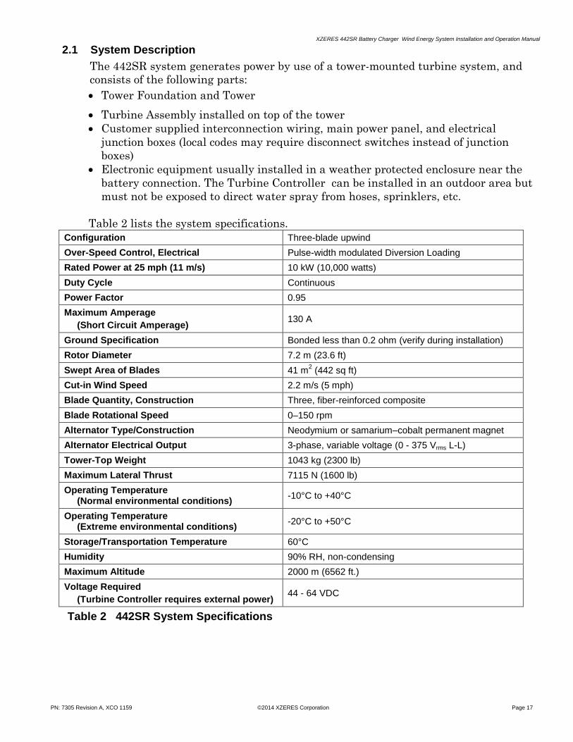
Figure 9 Typical Monopole Pad and Pedestal Foundation
3.1.2 Foundations for Self-supporting Lattice (SSL) Towers
SSL towers usually use a square “pad” type foundation with three individual
round piers that extend above the top of the footing to support each leg of the
tower. Figure 11 shows a typical configuration of this foundation type.
Figure 10 Typical SSL Tower Pad and Pier Foundation
3.1.3 General Foundation Installation Requirements
All foundation types require some excavation. The installer should have a
basic knowledge of the soil at the tower location before excavation, to avoid
unexpected problems. Rocky soil can make excavation difficult, while loose
sand may require formwork—even for the shallow, mat type foundation.
Specific concrete and rebar specifications are shown on the foundation
drawings. The installer must coordinate access to the foundation site, delivery
of the rebar and concrete, formwork, and all labor including subcontractors
necessary to perform the work.

XZERES 442SR Battery Charger Wind Energy System Installation and Operation Manual
PN: 7305 Revision A, XCO 1159 ©2014 XZERES Corporation Page 23
Tower manufacturers recommend that templates for the tower anchor bolts be
installed and carefully braced during the concrete placement. Steel templates are
provided for the bolt circles for both monopole and SSL towers. As a
recommended option for SSL towers, tower manufacturers can provide large
triangular templates that ensure proper placement of the bolt circles for all three
tower legs in relation to each other.
Figure 11 Monopole and Self-Supporting Lattice Towers
3.2 Assemble the Tower
3.2.1 Assembly of Monopole Towers
A monopole tower provided by XZERES Corporation has an installation manual
from the tower manufacturer. The installer shall follow the instructions in the
tower manufacturer’s manual.
Crane-lifted sectional monopole towers are usually assembled on the ground.
After the turbine is installed, the tower is lifted into the vertical position with a
crane while the monopole tower sections are still rigged together. This allows the
pole to be picked with a crane only once. After the tower is vertical and the nuts
at the tower base are tightened, the rigging and crane hook are removed.
Tilt-up type monopole towers, such as a gin-pole system or a ground-controlled
motorized system, do not require a crane. These towers are assembled on the
ground with the turbine and are then raised according to the manual provided by
the manufacturer. Tilt-up towers require certain tools or parts that may be
detached from the tower and used for other similar tilt-up towers. A gin-pole
tower system requires a gin-pole and a winch, while a ground-controlled
motorized tower system requires a motor to operate the system.
3.2.2 Assembly of Self-supporting Lattice (SSL) Towers

XZERES 442SR Battery Charger Wind Energy System Installation and Operation Manual
PN: 7305 Revision A, XCO 1159 ©2014 XZERES Corporation Page 24
An SSL tower provided by XZERES Corporation is delivered to the site
unassembled with the various legs, bolts, and plates. A packing list is
provided that lists all pieces. Each piece must be matched to the packing list
to determine where to place it in the structure.
- The SSL tower usually gets assembled on the ground in 20-ft (6.096 m)
segments.
- The SSL tower pieces are laid out on the ground in the appropriate
locations. The tower is assembled from the bottom to the top. The tower will
need to be supported above the ground in the upper sections since it tapers
to a thinner overall size at the top of the tower.
- A loader or some kind of machine is needed to lift the third tower leg off the
ground so all the bracing can be attached to it.
- Basic tools are required, the most important being a torque wrench for all
the bolts. The bolts may be tightened before or after the tower is lifted.
Figure 12 Self-Supporting Lattice Tower Construction
NOTE: See Section 7.7, page 58, for tower grounding instructions.

XZERES 442SR Battery Charger Wind Energy System Installation and Operation Manual
PN: 7305 Revision A, XCO 1159 ©2014 XZERES Corporation Page 25
4.0 ELECTRICAL INSTALLATION
CAUTION
If defects or damage are found during inspection of any parts or hardware, notify XZERES of the problem. Do not assemble, install, or use any equipment that is damaged or defective.
4.1 Uncrate Electrical Components
XZERES ships the electronic components for the 442SR system to the construction site
in a crate labeled 442SR Yaw Head Controller.
The electronic parts are:
One Turbine Controller
Diversion Load
Service Disconnect Box
Figure 13 Electrical Components and Yawhead
4.1.1 Junction boxes (not supplied)
The 442SR electrical system requires that you install a minimum of two junction
boxes: one at the base of the tower and one at the top of the tower.
4.1.2 Anemometers and Wind Vane (optional, not supplied)
When running cable for the anemometers and the wind vane, use shielded twisted
wire cable (CAT5 or better) to cancel electromagnetic interference (EMI).
Maximum supported length is 1000 ft (305 m).
Mount the anemometer head 24 ft (7.32 m)—1.0 rotor diameter—below the
turbine rotor hub.
Locate the anemometer upwind of the tower, for the prevailing wind direction.
Locate the anemometer at least four tower diameters away from the tower for
monopole towers or two face widths away from the tower for self-supporting
lattice towers.
Ground one end of the shield around the twisted pair at the tower (but not
inside of the Controller) for lightning protection.

XZERES 442SR Battery Charger Wind Energy System Installation and Operation Manual
PN: 7305 Revision A, XCO 1159 ©2014 XZERES Corporation Page 26
4.1.3 Minimum Electrical Wire Requirements
Install all wiring using the wire color system shown in Table 4.
Description Color Wire Specifications
Ground (SR4): Green/Yellow 2 AWG (35 mm2), 600V, 90°C
Diversion Load to Controller:
TS
TSJ
-DL and +DL
Blue/White
Blue
Black
14 AWG (2.5 mm2), 600V, 90°C, UL 1063 & UL 83
14 AWG (2.5 mm2), 600V, 90°C, UL 1063 & UL 83
10 AWG (6 mm2), 600V, 90°C, UL 1659
Tower Top to Tower Base to Building Junction Box to Service Disconnect to Controller:
SR1, SR2, and SR3
SR5 and SR6
SR7 and SR8
Black
Red
Yellow
Refer to Table 5 for wire sizes, 600V, 90°C
Refer to Table 6 for wire sizes, 600V, 90°C
16 AWG (1.5 mm2), 600V, 90°C, UL 1063 & UL 83
Turbine Controller and Distribution Panel:
DC-
DC+
Black
Red
400 MCM (203 mm2), 600V, 90°C, UL 1659
400 MCM (203 mm2), 600V, 90°C, UL 1659
Battery to Turbine Controller:
BAT- and BAT+
LEM V+, LEM V-, LEM OUT and LEM GND THERM- and THERM+
Red
—
Black
22 AWG (0.33 mm2), 600V, 90°C, UL 1063 & UL 83
22 AWG (0.33 mm2), 600V, 90°C, UL 1063 & UL 83
22 AWG (0.33 mm2), 600V, 90°C, UL 1063 & UL 83
Table 4 Minimum Electrical Wire Requirements
NOTE: All splices, wire supports, connections, electrical hardware, wire types, sizes and
colors must meet local codes and requirements.
4.1.4 Power Wire (SR1, SR2, SR3) Requirements
The following table lists the minimum wire gauge of the wire run from the turbine
to the system electronics based on a one-way distance (through the tower and the
junction boxes to the electronics in the building). Verify the wire insulation is
rated for outdoor use and for at least 600 volts. Underground portions must be in
conduit and maintain spacing per 4.1.6.

XZERES 442SR Battery Charger Wind Energy System Installation and Operation Manual
PN: 7305 Revision A, XCO 1159 ©2014 XZERES Corporation Page 27
Distance Minimum Wire Size
United States Europe
0 - 445 feet 6 AWG (13.3 mm2) 33.6 mm2 (2 AWG)
446 - 700 feet 4 AWG (21.1 mm2) 33.6 mm2 (2 AWG)
701 - 1130 feet 2 AWG (33.6 mm2) 33.6 mm2 (2 AWG)
Table 5 Wire Run Distance and Wire Size
NOTE: See Appendix A20, page 92, for a wire conversion table.
4.1.6 Wire Spacing Requirements
When routing wires from the Turbine to the Controller, maintain at least 8
inches of separation between the power wires (SR #1, #2, #3), the brake
control wires (SR #5, #6, #7, #8) and the anemometer/wind vane cable. This is
especially important for long runs because the alternating current waveforms
on the power wires and brake control wires can interfere with proper
measurement of the anemometer and wind-vane signals. This 8-inch spacing
can be a vertical distance to limit the width of the wiring trench in the
ground.
CAUTION
Use only copper wire for electrical connections. The wire type and connections must conform to local codes.
(If desired, you may use aluminum wire from the tower base to the building entrance if you use proper splices at both ends and adjust wire sizes.)
4.2 Install the Electrical Components and Wiring
Install the Turbine Controller and Service Disconnect Box indoors or outdoors. In
either location, do not expose them to direct rain, water spray from hoses or water
sprinklers.
Install the Diversion Load in a sheltered space (or building) that protects it from the
weather (no direct exposure to dripping water, rain, or other moisture). The Diversion
Load may generate up to 18 kW of heat. Locate it in an area that will not overheat
under this condition. Carefully observe the minimum clearances specified later in this
section.
The wire run between the Diversion Load and the Turbine Controller can be up to
300 ft (91.44 m) long.
Mount the heavy wall mounted electrical components to a strong, properly supported
surface. Indoor installations typically use stud mounted plywood or strand board. The
installers must use proper mounting surfaces and fasteners.
NOTE: Mount the control gear between 1.0 m to 1.9 m (3′ 3" to 6′ 3″) above the surface
level. Mount the Main Disconnect handles between 1.0 m to 1.9 m (3′ 3" to 6′ 3″)
from the surface level—a 1.7 m (5′ 7″) upper limit is recommended.

XZERES 442SR Battery Charger Wind Energy System Installation and Operation Manual
PN: 7305 Revision A, XCO 1159 ©2014 XZERES Corporation Page 28
DANGER
Before installing the electrical wiring, turn off the circuit breakers in the Main Power panel that you plan to use. After turning off the breakers, tag and lockout the panel in accordance with your local codes.
Disconnect all wiring between the Battery Bank and the Turbine Controller.
4.2.1 Install Diversion Load
4.2.1.1 Open the crate labeled 442SR Yaw Head/Controller.
CAUTION
The Diversion Load can dissipate as much as 18 kW of heat. The exterior surfaces get hot and the hot air emitted from the Diversion Load must not be restricted. Follow all clearance specifications (see Section 4.2.1.3 for clearances).
Never place objects on or near the Diversion Load.
4.2.1.2 Remove the Diversion Load from the crate and verify it has arrived without
damage. Figure 14 is a picture of the Diversion Load.
Figure 14 442SR Diversion Load Clearance
4.2.1.3 The Diversion Load needs space around it to ensure proper air flow during
operation. It must be mounted at least 60 inches (1.52 m) above the ground.
Verify the following clearances exist around the Diversion Load.
Top: 18 inches (457 mm)
Bottom: 12 inches (305 mm)
Sides: 3 inches (76 mm) to a wall or other surface

XZERES 442SR Battery Charger Wind Energy System Installation and Operation Manual
PN: 7305 Revision A, XCO 1159 ©2014 XZERES Corporation Page 29
4.2.1.4 Orient the diversion load with the field wiring pigtail in the position shown in
Figure 15.
Mount the diversion load with .25" or 6 mm fasteners and washers. The
fastener and mounting surface material combination must achieve a 200 Lb.
minimum pull out strength, per fastener.
Place washers between the diversion load base and the mounting surface
attachment points to compensate for the gap caused by the pem nuts, see
Figure 17.
Connect the pigtail wires to the wires connected to the controller in a
junction box. Mount junction box 3" min to 12" max away from controller. If
pigtail wires are trimmed, re-attach wire identification.
NOTE: To achieve maximum corrosion protection, place a thin Kapton washer
between the base and the meal washers.
NOTE: The .75" EMT female conduit fitting is not grounded.
Figure 15 Diversion Load Mounting
NOTE: Do not mount the Diversion Load on a flammable surface.
Figure 16 shows the Diversion Load dimensions and hole locations.
CAUTION
Do not install the Diversion Load more than 300 ft (91.44 m) from the Turbine Controller.

XZERES 442SR Battery Charger Wind Energy System Installation and Operation Manual
PN: 7305 Revision A, XCO 1159 ©2014 XZERES Corporation Page 30
Figure 16 442SR Diversion Load Dimensions
4.2.2 Install Turbine Controller
NOTE: Choose a location for the Controller and the Service Disconnect Box so you
have easy access to the red STOP button on the Controller and the
disconnect switch on the Service Disconnect Box.
NOTE: The Controller weighs approximately 155 lb. (70 kg). Verify the surface or
bracket that you mount it on and the screws are appropriate for this
weight. Mounting holes are .375 (9.53 mm) diameter. The minimum screw
size must be .312 (8 mm) diameter. Figure 17 shows the Controller’s
dimensions and required clearance area.
4.2.2.1 Remove the Controller from the crate and take it out of its box.
4.2.2.2 Inspect the Controller and verify it arrived without damage.
4.2.2.3 Use the following clearances in mounting the Controller:
Top: 12 inches (305 mm)
Bottom: 36 inches (914 mm)
Power Out Side: 12 inches (305 mm)
Door Open Side: 32 inches (813 mm)
WARNING
The Turbine Controller weighs approximately 155 lb. (56.8 kg). To avoid
injury, use two people to lift or move the Turbine Controller.

XZERES 442SR Battery Charger Wind Energy System Installation and Operation Manual
PN: 7305 Revision A, XCO 1159 ©2014 XZERES Corporation Page 31
Figure 17 Controller Dimensions
4.2.2.4 Refer to Figure 18 bottom view for the name and location of I/O wiring ports.
Remove the rubber washers and fastener from the ports that will be used.
Install conduit and attach conduit connectors to the ports to seal them. Install
and secure wires as specified. Each port is sealed with a rubber washer and
fastener to ensure NEMA 4 enclosure environmental protection. Do not
remove the rubber washers if a port is not used. Leaving an open, unsealed,
port will void the controller warranty.
4.2.2.5 The RJ45 COM port is sealed with a connector. A mating connector should be
used if the controller is installed outdoors. Use CONEC plug kit part number
17-10001.
4.2.2.6 48 VDC Power Out and Ground Connection
These connections are made on the outside of the enclosure. Installing
2.50” (63.5 mm) conduit is optional. If the enclosure is installed outdoors
and conduit is not used, water proof cable must be incorporated.
Use a properly sized compression lug to attach the cable to the power
terminal. The power terminal has a .375” (9.53 mm) diameter threaded
post for compression lug attachment. A nut and washers are supplied with
the power terminal.
Remove the power out cover (four screws) to access the power terminals.
Apply antioxidant compound, Ideal NOALOX® or equivalent, on the power
terminal and compression lug mating surface. See Figure 19.
Insert the compression lug and washers over the power terminal. Apply
Loctite 243 to the nut, and torque to 180 in lbs (20 Nm).

XZERES 442SR Battery Charger Wind Energy System Installation and Operation Manual
PN: 7305 Revision A, XCO 1159 ©2014 XZERES Corporation Page 32
Run properly size ground wire to the ground lug and secure with the set
screw. Torque to 275 in lbs (31 Nm). See Figure 18.
Reattach power out cover. Power out cover must be in place during
operation to avoid exposure to dangerous electrical shock.
Figure 18 Terminals, Ground and View of Power Out Cover in Place
DANGER
The 48 VDC power out cover on the side of the controller must be in place when power is applied to the controller. Dangerous electrical current is present, and poses a severe danger.
Figure 19 Securing the wires

XZERES 442SR Battery Charger Wind Energy System Installation and Operation Manual
PN: 7305 Revision A, XCO 1159 ©2014 XZERES Corporation Page 33
4.2.3 Install Service Disconnect Box
Figure 20 Back Bracket and Service Disconnect Box
4.2.3.1 Mount the Service Disconnect Switch within direct eyesight of the Turbine
Controller. Refer to Figure 8, Page 19.
4.3 Electrical Connections
Wire sizes, colors, specifications, and Power Lead lengths are given in Sections
4.1.3 and 4.1.4, pages 26 and 27. Controller wire connection locations are
illustrated in Figure 21
Figure 23, page 36, shows the electric cable or wire runs. The Turbine Controller
bracket is intended for use with a gutter style conduit installation.

XZERES 442SR Battery Charger Wind Energy System Installation and Operation Manual
PN: 7305 Revision A, XCO 1159 ©2014 XZERES Corporation Page 34
THERM–
THERM+
LEM GND
LEM OUT
LEM V‒
LEM V+
BAT ‒
BAT+ FUSES
F1
F2
Gro
un
d
Re
se
tB
utt
on
S4
Bu
tto
n
J8Pins
Negative
Positiv
e
SR
7
SR
8
2 12 1 V-
SIG V+
Div
ers
ion
L
oa
d 2
Div
ers
ion
L
oa
d 1
+D
L2
+D
L1
-DL
2-D
L1
SR
1
Po
we
r L
ea
d
IGB
T
Pin
s
4 3 2 1
SR
2S
R3
Po
we
r L
ea
dP
ow
er
Le
ad
+DL1TS
-DL1TS
+DL2TS
-DL2TS
SR5
SR6
Brake C
ontrol
Bra
ke S
enso
r
Win
d S
PD
2
Win
d S
PD
1
Fuses
Div
ers
ion
L
oa
d
Figure 21 Board Connections
C
on
tro
ller
Bo
ard
Dau
gh
ter
Bo
ard

XZERES 442SR Battery Charger Wind Energy System Installation and Operation Manual
PN: 7305 Revision A, XCO 1159 ©2014 XZERES Corporation Page 35
Wire from turbine to tower top junction box (5 FT (1.52 M) Length) supplied by XZERES
SR5-SR8: 4x Wire (2 Red & 2 Yellow)
WIND
VANE
Wind Vane & Anemometers (Optional):
7x 24 AWG (0.205 mm2) Wire
(Use shielded twisted pair cable to cancel EMI—CAT5 or better. Ground shield OUTSIDE of controller.)
SR1-SR3: 3X Long AWG/mm2 Wire (Black)
(Refer To Manual For Wire Sizes, Table 5)
SR4: 1x Wire (Green/Yellow)
XZERES 442SR
Wind Turbine
BRAKE
RESISTORS
ANEMOMETER 1
AN
EM
OM
ET
ER
2
YAWHEAD
ELECTRICAL
BOX W/LPS
TOWER
TOP
JUNCTION
BOX
SLIP
RINGS
TOWER BASE
TOWER BASE
JUNCTION BOX
(OPTIONAL)
SR1-SR3:
3X Long AWG/mm2 Wire (Black)
(Refer To Manual For Wire Sizes, Table 5)
SR4: 1x Wire (Green/Yellow)
SR5-SR8: 4X Wire (2 Red & 2 Yellow)
BATTERY
BANK
Wind Vane & Anemometers:
7X 18 AWG (0.823 mm2) Wire
SR
1-S
R3
: 3
X _
L
on
g A
WG
/mm
2
Wire
(B
lack)
SR
5-S
R8
: 4
X 1
4 A
WG
(2
.08
mm
2)
Wire
(2
Re
d &
2 Y
ello
w)
4 X 22 AWG Wire
XZERES SERVICE
DISCONNECT BOX
W/LPS
CUSTOMER
DISTRIBUTION
PANEL
400 MCM Wire (Black)
Equipment supplied by XZERES: Turbine Diversion Load Turbine Controller Service Disconnect Box
All other equipment to be provided by the customer.
All wires to be rated for 600V, 90°C Minimum
Install conduit type:
___________________________________
30
0 F
T (
91
.44
M)
Ma
xim
um
4X Wire For DL (Black)
2X Wire For TS (Blue / White & Blue)
1X 10 AWG (5.26 mm2) Wire For PE
(Green/Yellow)1/0 AWG Minimum (Green Yellow)
DIVERSION LOAD ENCLOSURE
+DL1 –DL1 TS PETSJ+DL2 –DL2
XZERES TURBINE CONTROLLER
400 MCM Wire (Red)
Current Sensor
4 X 22 AWG Wire
Figure 22 442SR Cable Schematic

XZERES 442SR Battery Charger Wind Energy System Installation and Operation Manual
PN: 7305 Revision A, XCO 1159 ©2014 XZERES Corporation Page 36
4.4 Connect Electrical Components
4.4.1 Connect the Distribution panel to the Turbine Controller. See Figure 23 below.
2 POLE 400A2 POLE 400A
48 V Battery48 V Battery
PEPE
XZERES
TURBINE
CONTROLLER
BUILDING PANEL OR SUBPANEL
400 MCM LINE CONDUCTOR (RED)
+
1/0 AWG MINIMUM LINE CONDUCTOR (GREEN/YELLOW)
-PE
400 MCM LINE CONDUCTOR (BLACK)
Customer loadCustomer load
Customer loadCustomer load
2X FUSE 400A2X FUSE 400A
+
-
Figure 23 Turbine Controllers to Distribution Panel
4.4.2 Connect the Battery bank to the Distribution panel.
4.4.2.1 Place the Controller disconnects in the Distribution panel in the O
position (OFF). Tag and lock-out the circuit breaker(s).
4.4.2.3 Connect the 48 V Battery bank to the Distribution panel at connections
shown in Appendix A2, page 79.
CAUTION
Make sure the Battery bank is wired with the correct polarity. Reverse polarity could damage the Turbine Controller.
4.4.3 Connect the Battery sensors outputs to the Turbine Controller. See Figures Appendix
A1-A2 and Table 6 below.
Turbine Controller
THERM- THERM+ LEM GND LEM OUT LEM V- LEM V+ BAT- BAT+
Battery
sensors
THERMISTOR -
THERMISTOR + LEM GND LEM OUT
LEM V- LEM V+ BATTERY- BATTERY +
Table 6 Battery sensors to Turbine Controller Connections

XZERES 442SR Battery Charger Wind Energy System Installation and Operation Manual
PN: 7305 Revision A, XCO 1159 ©2014 XZERES Corporation Page 37
4.4.4 Connect the Diversion Load to the Turbine Controller. See Figure Appendix A1 and
Table 7 below. Turbine Controller
+DL 1 -DL 1 +DL2 -DL2 +DL1TS -DL2TS PE (Ground) SR4
Diversion Load
+DL1
-DL1 +DL2 -DL2 TS TSJ PE
Table 7 Diversion Load to Turbine Controller Connections
4.4.5 Connect the Service Disconnect Box to the Turbine Controller. See Figure Appendix
A4 and Table 8 below, and figures 24, 25, and 26.
Turbine Controller
Slip Ring 1
Slip Ring 2
Slip Ring 3 PE (Ground) SR4
SR5 SR6 SR7 SR8
Service Disconnect Box
SR1 Black
SR2 Black
SR3 Black
SR4 Green/Yellow
SR5 Red
SR6 Red
SR7 Yellow
SR8 Yellow
Table 8 Service Disconnect Box to Turbine Controller Connections
4.4.6 Connect the building junction box (if used) or the tower base junction box and the
Turbine Controller to the Service Disconnect Box.
4.4.6.1 Route the turbine wires from the building junction box to the Service
Disconnect Box.
4.4.6.2 Connect the SR1, SR2, and SR3 turbine wires to the terminal board TB1
(SR1, SR2, and SR3) inside the Service Disconnect Box. See Figures 24
and 26.
Figure 24 Tower Base to Service Disconnect Box
4.4.6.3 Connect the disconnect box to earth ground. See Figure 24.
4.4.6.4 Connect the wires from the Turbine Controller to the circuit breaker
(CB1) in the Service Disconnect Box (SR3, SR2, and SR1). See Figures 25
and 26.

XZERES 442SR Battery Charger Wind Energy System Installation and Operation Manual
PN: 7305 Revision A, XCO 1159 ©2014 XZERES Corporation Page 38
Figure 25 Turbine Controller to Service Disconnect Box
4.4.6.5 Connect the ground (PE) from the Turbine Controller to the ground in
the Service Disconnect Box. See Figure 25.
4.4.6.6 Connect the SR5 and SR6 (Red) wires from the Turbine to the Service
Disconnect Box terminal board TB3. See Figure 26.
4.4.6.7 Connect the corresponding Turbine Controller SR5 and SR6 (Red)
wires to the Service Disconnect Box terminal board TB3. See Figure
26.
Figure 26 Service Disconnect Control Wiring Diagram
4.4.6.8 Connect the SR7 and SR8 (Yellow) wires from the Turbine to the
Service Disconnect Box terminal board TB3. See Figure 26.
4.4.6.9 Connect the corresponding Controller SR7 and SR8 (Yellow) wires to
the Service Disconnect Box terminal board TB3. See Figure 26.

XZERES 442SR Battery Charger Wind Energy System Installation and Operation Manual
PN: 7305 Revision A, XCO 1159 ©2014 XZERES Corporation Page 39
4.4.7 Connect wind-vane and anemometer sensor wires from the shielded twisted-pair
cable (optional components). See Figure 21.
4.4.7.1 Use one twisted pair for anemometer 1, if present.
4.4.7.2 Use one twisted pair for anemometer 2, if present.
4.4.7.3 If a wind-vane is present: on one twisted pair, connect “V+” and “SIG.” On
the other twisted pair, connect “V-“ and “SIG.” This will ensure that the
“SIG” wire has the least resistance and the best balance from positive to
negative.
4.4.8 Route the wires from the building junction box to the tower base. The wires must
be long enough to reach the Tower Base junction box. Coil the extra wire near the
tower foundation. Connect the wires at the building junction box.
NOTE: Your local codes may require installation of disconnect switches in place of the
junction boxes. If you install disconnect switches for the turbine power wires you
must also install an auxiliary contact to disconnect the SR5 wire (Brake Control)
running from the turbine assembly to the Controller.
4.5 Tower Wiring
Complete the following installations on the tower:
4.5.1 Install the junction boxes at the top and the base of the tower.
NOTE: Your local codes may require a disconnect switch at the tower base. If you install
a disconnect switch on the turbine power wires you MUST also install auxiliary
contacts that disconnect the four 14 AWG (2.5 mm2) brake control wires.
NOTE: The wires from the Slip Rings are 5 feet long. Place the Tower Top junction box
where the Slip Ring wires can reach it.
4.5.2 Route the wire from the Tower Base junction box up the tower to the Tower Top
junction box. See Steps 4.1.3 and 4.1.4, pages 26 and 27, for wire size
specifications. Use Kellems grips (or equivalent) as required by wire size, tower
height, and local codes.
5.0 TURBINE ASSEMBLY INSTALLATION
This section describes how to install the 442SR Turbine Assembly in the following order:
1. Install the Yawhead on the Tower.
2. Connect drop wires at Tower Top junction box.
3. Mount Tail Vane on Tail Boom.
4. Install Tail Boom on Yawhead.
5. Install Blades on Alternator.

XZERES 442SR Battery Charger Wind Energy System Installation and Operation Manual
PN: 7305 Revision A, XCO 1159 ©2014 XZERES Corporation Page 40
Yawhead
T
Alternator
uter C
Olamping
P late
Blades
InnerClamping
Plate
Nose
Cone
OuterClamping
Plate
Blade
Studs
TailVane
Outer Tail Boom
Yawhead
Alternator
Figure 27 Exploded View XZERES 442SR Turbine
NOTE: The installers are ultimately responsible for the quality of their own work.
5.1 Uncrate and Inspect the Yawhead/ Alternator Assembly
Uncrate and Inspect the Yawhead/Alternator Assembly. The Yawhead is in the
crate labeled 442SR Yaw Head Controller.
The Yawhead is shipped with the Cowling attached. You will need to remove the
Cowling before you can start working with the Yawhead.
5.1.1 Place the crate on firm level ground. Remove the top and sides of the crate with
the large side that the Yawhead/Alternator Assembly is lag bolted to last. Unload
everything except the Yawhead/Alternator Assembly. Remove the 2 x 4, which is
bolted to the yaw bearing.
5.1.2 Remove both sides of the Cowling from the Yawhead before assembling the
Turbine.
5.1.2.1 Each half of the Cowling is held in place with four M6 x 16 hex cap head
screws (tool: 10 mm socket).

XZERES 442SR Battery Charger Wind Energy System Installation and Operation Manual
PN: 7305 Revision A, XCO 1159 ©2014 XZERES Corporation Page 41
Figure 28 Yawhead Shipped with Cowling and Alternator
5.1.2.2 The Cowlings also attach by a Lanyard (wire rope rig that secures the
Cowling to the Yawhead). To remove the Cowling Lanyard, unscrew the
M6 nut on the M6 hex cap head screw that holds the Lanyard to the
Cowling (tool: 10 mm wrench).
5.1.3 Set the Cowlings in a safe place until after assembling the Turbine to the Tower.
5.1.4 To reattach the Cowling before lifting or tilting up tower and turbine assembly:
5.1.4.1 Looking at the front of the Turbine, attach the left-side Cowling first.
5.1.4.1.1 Attach the Lanyard first (tool: 10 mm wrench).
5.1.4.1.2 Line the Cowling up with the eight screw holes on the Yawhead
brackets.
5.1.4.1.3 Start all of the four M6 x 16 hex cap head screws before tightening (tool:
10 mm socket).
Torque to 17 in. lb. (1.92 N-m).
5.1.4.2 Looking at the front of the Turbine, attach the right-side (with logo) of the
Cowling.
5.1.4.2.1 Attach the Lanyard first (tool: 10 mm wrench).
5.1.4.2.2 Line the Cowling up with the four screw holes on the Yawhead bracket.
5.1.4.2.3 Start all of the four M6 x 16 hex cap head screws before tightening (tool:
10 mm socket).
Torque to 17 in. lb. (1.92 N-m).
5.1.5 Remove the Yawhead top access cover.
5.1.6 Inspect the Brake Resistors.
5.1.6.1 Inspect resistors and wiring to ensure resistors and wiring have not
inadvertently loosened during transit and handling. See Figure 29.
Examine the resistors for damage. If damaged, disconnected, or loose
wires are discovered, contact customer service.

XZERES 442SR Battery Charger Wind Energy System Installation and Operation Manual
PN: 7305 Revision A, XCO 1159 ©2014 XZERES Corporation Page 42
NOTE: DO NOT attempt field repair without prior approval.
Figure 29 View Down Top of Yawhead
5.1.7 Put the Yawhead top access cover back on.
5.1.8 Place three M20-2.5 lifting rings (included in the hardware kit) on the Yawhead
top flange.
5.1.9 Remove the Slip Ring access cover. Inspect slip rings to ensure each brush is
aligned in the proper grooves. Inspect the Slip Rings for damage. See Figure 30.
NOTE: Each ring has a total of four brushes. All 32 brushes should be checked.
5.1.10 Inspect the drop wires for damage to the wire insulation.
5.1.11 Put the Slip Ring access cover back on.
Figure 30 Yawhead Slip Rings

XZERES 442SR Battery Charger Wind Energy System Installation and Operation Manual
PN: 7305 Revision A, XCO 1159 ©2014 XZERES Corporation Page 43
5.1.12 Remove door to access the electrical box. Check all wires with pull test to
ensure all wires remained sufficiently secure during transit and handling.
Ensure all screws are tightened properly. Review wiring diagram (Reference
Appendix A16) inside door panel to ensure all is wired correctly and have not
been tampered with since leaving the factory. Reattach access door.
5.1.13 Check electrical connections from wires below yaw bearing.
5.1.13.1 Measure resistance on the two red wires - SR5-SR6 to ensure the correct
resistance (6-10 ohms).
5.1.13.2 Measure resistance on the two yellow wires – SR7-SR8 to ensure they are
showing OL (Open circuit).
5.1.13.3 Connect 24VAC power supply to SR5-SR6. With 24VAC on SR5-SR6,
measure resistance on the two yellow wires – SR7-SR8 to ensure the correct
resistance (0-10 ohms). Remove power supply from SR5-SR6.
5.1.13.4 Measure resistance between phase wires (SR1-SR2, SR2-SR3, SR1-SR3) to
ensure the correct resistance (1.5-1.8 ohms between each pair of phase wires).
CAUTION
The Yawhead and Alternator weigh approximately 1325 lb (601 kg). Use lifting equipment and exercise extreme caution when lifting and moving the Yawhead and aligning it to the Tower Top Interface Plate.
5.2 Mount the Yawhead and Alternator to the Tower Top Plate
NOTE: XZERES supplies bolts for the standard tower top interface plate thickness of
3/4-inch (19.05 mm). Measure the thickness of your tower top plate. If more than
3/4-inch (19.05 mm) thick, you will need longer bolts per the Table 9. Use only
ASTM F593 Grade B bolts. If you have difficulty locating the proper bolt, please
contact XZERES for help.
Tower Top Flange Thickness
5/8″-11 Mounting Bolt Length
0.75″ (19.05 mm) 2.0″ (50.8 mm)
1.0″ (25.4 mm) 2.5″ (63.5 mm)
1.25″ (31.75 mm) 2.5″ (63.5 mm)
1.5″ (38.1 mm) 2.75″ (69.85 mm)
Table 9 Flange Thickness and Bolt Length

XZERES 442SR Battery Charger Wind Energy System Installation and Operation Manual
PN: 7305 Revision A, XCO 1159 ©2014 XZERES Corporation Page 44
5.2.1 Rig nylon straps and lift the Yawhead (with Alternator attached) to the
approximate height of the Tower Top Interface Plate. See Figure 31.
Figure 31 Yawhead/Alternator Liftstrap Rigging
5.2.2 Apply 1 thread-locking compound, (Loctite 243*) to the threaded ends of the two
5/8″ diameter tapered pins. Install the pins in the inner race of the yaw bearing on
opposite sides of the bolt circle (180° apart). *New models are supplied with
Loctite 243.
5.2.3 Screw the pins in approximately 11 turns. These two pins will serve as guide bolts
when you set the Yawhead to the Tower Top Interface.
5.2.4 Verify the mounting surfaces (yaw bearing inner race and Tower Top Interface
Plate) are clean and nothing can get pinched between the Tower Top Interface
Plate and the Yawhead mounting flange.
NOTE: XZERES supplies bolts for the standard tower top interface plate thickness of
3/4-inch (19.05 mm). Measure the thickness of your tower top plate. If more
than 3/4-inch (19.05 mm) thick, you will need longer bolts per the Table 10. Use
only ASTM F593 C / F593 G bolts. If you have difficulty locating the proper bolt,
please contact XZERES for help.
5.2.5 Using the tapered pins as a guide; align the Yawhead bolt holes to mount to the
Tower Top Interface Plate. See Figure 32.

XZERES 442SR Battery Charger Wind Energy System Installation and Operation Manual
PN: 7305 Revision A, XCO 1159 ©2014 XZERES Corporation Page 45
Figure 32 Tower Top to the Yawhead Flange (illustration shown without alternator)
5.2.6 Apply Loctite 243 to the threaded ends of the 5/8″-11 x (flange thickness length)
bolts with structural washers. Attach the Yawhead to the Tower Top Interface
Plate with these bolts and the washers (Tool: 15/16″ wrench).
NOTE: Leave the tapered pins in place.
5.2.7 Torque the bolts to 156 N-m (115 ft-lb).
5.2.8 Locate the two 5/8″-11 x 2″ bolts and washers. Apply 1 inch
(25 mm) of thread-locking compound, Loctite 243, to the threaded ends of the
bolts. Install the bolts on the top side of the lower yawhead flange (into the holes
where the lag screws were removed).

XZERES 442SR Battery Charger Wind Energy System Installation and Operation Manual
PN: 7305 Revision A, XCO 1159 ©2014 XZERES Corporation Page 46
5.2.9 Torque to 156 N-m (115 ft-lb) (Tool: 15/16″ or 24 mm wrench). See Figure 33.
Figure 33 Yawhead Bearing Bolts (illustration shown without alternator)
5.3 Connect the Yawhead Wiring to Tower
NOTE: Eight wires come off of the slip rings and drop down from the Yawhead: Four
6 AWG (16 mm2) wires and four 14 AWG (2.5 mm2) wires. The wires extend
five feet below the Yawhead and are for connecting to the wires that run
down the tower.
5.3.1 Run the eight wires from the Slip Rings and connect to the Tower Top junction box.
5.3.2 In the Tower Top junction box:
Connect the 6 AWG (16 mm2) power leads from the Slip Rings SR1, SR2, and
SR3 to the Black power leads in the tower cable. Phase sequence is not
important.
Connect the 6 AWG (16 mm2) SR4 wire from the Slip Rings to the Green/Yellow
ground wire in the tower cable.
Connect the 14 AWG (2.5 mm2) wires SR5 and SR6 from the Slip Rings to the
Red SR5 and SR6 wires from the Turbine Controller panel in either order.
Connect the 14 AWG (2.5 mm2) wires SR7 and SR8 from the Slip Rings to the
Yellow SR7 and SR8 wires from the Turbine Controller panel in either order.
5.3.3 Secure and support all cables to the Tower Top junction box according to your local
codes.

XZERES 442SR Battery Charger Wind Energy System Installation and Operation Manual
PN: 7305 Revision A, XCO 1159 ©2014 XZERES Corporation Page 47
CAUTION
During the installation, connect and support all wires in accordance with local codes. Use a junction box near the tower top and cable support grips (Kellems grips). The number of Kellems grips needed is determined by the wire run length and local code requirements.
DANGER
Make sure all wiring and connections are insulated for 600 volts. Inadequate insulation can result in injury or death, and damage to equipment.
5.3.4 Use cable supports to bear the cable weight and to remove tension from the cable.
If the tower is a Monopole, use a Kellems grip or equivalent for each cable running
down the tower.
WARNING
Do not hang cables without support. This can cause wire damage and compromise the splices. Support each cable individually.
Figure 34 Cable Support (Kellems Grip)
5.3.5 Confirm proper electrical connections at base of tower
5.3.5.1 Measure resistance on SR5-SR6 to ensure the correct resistance (6-10 ohms).
5.3.5.2 Measure resistance on SR7-SR8 to ensure they are showing OL (Open circuit).
5.3.5.3 Connect 24VAC power supply to SR5-SR6. With 24VAC on SR5-SR6, measure
resistance on SR7-SR8 to ensure the correct resistance (0-10 ohms). Remove
power supply from SR5-SR6.

XZERES 442SR Battery Charger Wind Energy System Installation and Operation Manual
PN: 7305 Revision A, XCO 1159 ©2014 XZERES Corporation Page 48
5.3.5.4 Measure resistance between phase wires (SR1-SR2, SR2-SR3, SR1-SR3) to
ensure the correct resistance (1.5-1.8 ohms between each pair of phase
wires).
5.3.5.5 Repeat steps 5.3.5.1 through 5.3.5.4 at additional junction boxes as
necessary to validate proper electrical connections.
5.4 Uncrate and Inspect the Blades
5.4.1 Remove the top of the Blade crate.
CAUTION
The Tail Vane weighs approximately 145 lb (65.8 kg), and the Blades weigh approximately 93 lb (42 kg) each. To avoid damage always use two people, one on either end, to lift and move the Tail Vane and the Blades.
Figure 35 Blade Crate
5.4.2 With a person holding each end, remove the Tail Vane and each Blade from the
crate.
5.4.3 Inspect the Blades for any damage. Inspect the Leading Edge, Trailing Edge, the
Blade Root, and the Blade Tip. See Figure 36.
5.4.4 Set the Blades in a safe place until ready to install.
Figure 36 XZERES Turbine Blade
5.5 Install the Tail Boom
NOTE: The Tail Boom (see Figure 35) is shipped underneath the Blades in the blade crate.
Use straps and lifting equipment to remove the assembly from the crate and to
install it on the Yawhead.

XZERES 442SR Battery Charger Wind Energy System Installation and Operation Manual
PN: 7305 Revision A, XCO 1159 ©2014 XZERES Corporation Page 49
CAUTION
The Tail Boom weighs approximately 205 lb (92.5 kg). Do not attempt to move it by hand.
5.5.1 Place a lifting strap around the Tail Boom just forward of the Tail Vane mounting
plates and lift it out of the crate.
5.5.2 Lay the Tail Boom flat on the ground with a 4″ x 4″ (101.6 mm x 101.6 mm) timber
supporting the Tail Vane end of the boom above the ground.
5.5.3 Move the Tail Vane into position with a person lifting each end.
5.5.4 Apply Loctite 243 to the threaded ends of the M20 x 80 mm bolts. Install bolts,
washers, and nuts. Tighten as shown on Figure 38.
5.5.5 Torque to 122 N-m (90 ft-lb).
5.5.6 Install one of the eyebolts off of the top of the yawhead in the front of the alternator
(it only fits one hole). Rotate the eye bolt out to one side and attach a rope or strap.
Use a lifting device to rotate the yawhead and raise the alternator until the
alternator face is vertical.
5.5.7 Insert a 5/8 x 11 Yaw Lock bolt at least two inches (50 mm) long thru the clearance
hole in the tower top flange and into the outer race of the Yawhead Bearing. (The
Yaw Lock bolt is not supplied; however, a Tower Top Plate to Yaw Bearing bolt can
be used.)
WARNING
The weight of the alternator will have a tendency to roll the tower. Make sure the tower is secure. If necessary, support the alternator by blocking.
5.5.8 Torque Yaw Lock bolt to 54 N-m (40 ft-lb). See Figure 37.
Figure 37 Yaw Lock
5.5.8 Lift the Tail Boom assembly with the strap installed around the boom just forward
of the Tail Vane.

XZERES 442SR Battery Charger Wind Energy System Installation and Operation Manual
PN: 7305 Revision A, XCO 1159 ©2014 XZERES Corporation Page 50
5.5.9 Attach the tail vane to the tail boom as shown in Figure 38.
5.5.10 Apply thread-locking compound, Loctite 243 to the threaded ends of the M16 mm
screws. Install screws with washers and tighten as shown on Figure 38.
5.5.11 Torque 16 mm screws to 102 N-m (75 ft-lb) and 20 mm screws to 122 N-m
(90 ft-lb).
Figure 38 Tail Vane and Boom Installation

XZERES 442SR Battery Charger Wind Energy System Installation and Operation Manual
PN: 7305 Revision A, XCO 1159 ©2014 XZERES Corporation Page 51
5.6 Install the Rotor Blades
CAUTION
The Blades for the 442SR are 3.6 meters (11.81 feet) long. Raise the tower high enough to allow for clearance between the Blade tips and the ground. On level ground you will need a minimum three feet (one meter) clearance between the blade mounting face on the Alternator and the ground.
5.6.1 Apply Loctite 243 to the threaded ends of the Blade Studs.
5.6.2 Screw the M24 male threaded side of the nine M24 Blade Studs into the set of
threaded holes on the front (rotor side) of the Alternator rotor. See Figure 39.
5.6.3 Torque the Blade Studs to 339 N-m (250 ft-lb) (Tool: 30 mm wrench).
Hole for M20 lifting eyebolt
Torque all Blade Studs
to 339 N-m (250 ft-lb)
(30 mm wrench)
Figure 39 Mounting Blade Studs to Alternator
CAUTION
Once a Blade is installed on the rotor, the rotor can spin (however, very slowly). Use caution when mounting the Blades to the Alternator. Restrain Blade motion by hand or by using a rope until the Blade installation is complete.

XZERES 442SR Battery Charger Wind Energy System Installation and Operation Manual
PN: 7305 Revision A, XCO 1159 ©2014 XZERES Corporation Page 52
5.6.4 Install each Blade onto the Blade Studs so that the leading edges will rotate
clockwise when viewed from the front of the Alternator. See Figure 40. Raise the
turbine and tower to install three blades; this can be done first or after the first two
blades are installed.
Figure 40 Blade Edges and Rotation Direction
5.6.5 Temporarily install the two outermost M22 x 60 mm bolts on each Blade to hold
them in place.
5.6.6 Apply Loctite 243 to the ends of the three innermost M22 x 60 mm bolts.
5.6.7 Position the Inner Blade Clamping Plate over the three inner Blade Studs.
5.6.8 Secure the Inner Blade Clamping Plate with the M22 bolts and flat washers (Tool:
32 mm wrench).
5.6.9 Torque to 252 N-m (186 ft-lb).
5.6.10 Remove the six outermost bolts and apply Loctite 243.
5.6.11 Position the Outer Blade Clamping Plate over the six outer Blade Studs, use a
strap or leash on outer clamping plate until it is secured with a couple of bolts. See
Figure 41.
5.6.12 Secure the Outer Blade Clamping Plate with the M22 bolts and flat washers (Tool:
32 mm wrench).
5.6.13 Torque to 252 N-m (186 ft-lb).
DANGER
DO NOT allow the turbine to rotate freely with disconnected power
wires. This will cause very high voltages that can result in injury or
death, and can destroy equipment.
5.6.14 Rotate the Blades slightly around the Alternator’s axis to verify the rotor turns
freely.

XZERES 442SR Battery Charger Wind Energy System Installation and Operation Manual
PN: 7305 Revision A, XCO 1159 ©2014 XZERES Corporation Page 53
Figure 41 Nose Cone Mounting Holes on Clamping Plates
5.6.15 The rotor locks electrically when the Service Disconnect Box is in the SERVICE
mode or by shorting phase wires manually if building turbine before electronics are
mounted and wired. However if necessary, mechanically lock the rotor with a rope
or nylon strap tied to a Blade and anchored at the Yawhead.
Figure 42 Rotor Locked with Nylon Strap

XZERES 442SR Battery Charger Wind Energy System Installation and Operation Manual
PN: 7305 Revision A, XCO 1159 ©2014 XZERES Corporation Page 54
NOTE: Mechanically lock the Rotor whenever working on the Brake Resistors, Yawhead
Electrical Box, or disconnecting the Alternator from the Yawhead Electrical Box.
DANGER
Whenever the Brake Resistors or the Alternator is offline, a spinning Rotor can produce dangerous voltage across the Alternator leads.
Avoid this by mechanically locking the Rotor with a rope or nylon strap.
The Rotor also locks and neutralizes electrically by shorting the Alternator leads together. (Put the three Alternator leads—U, V, and W—together with a large wire nut.) Preferably, short the leads at the tower top box. If possible, do not disconnect alternator leads from the Yawhead Electrical Box. If the alternator leads are disconnected from the Yawhead Electrical Box, they must be shorted at that location.
5.7 Install the Nose Cone
5.7.1 Remove the Nose Cone from the Yawhead crate.
5.7.2 Apply Loctite 243 to the threaded ends of the M8 X 16 mm bolts. Install the Nose
Cone and secure with three M8-1.25 x 16 mm bolts, washers and lock washers.
Refer to Figure 47 (Tool: 13 mm wrench).
5.7.3 Torque to 16 N-m (12 ft-lb).
Figure 43 Nose Cone Installation

XZERES 442SR Battery Charger Wind Energy System Installation and Operation Manual
PN: 7305 Revision A, XCO 1159 ©2014 XZERES Corporation Page 55
6.0 RAISE THE TOWER
Check all of the wiring and verify the wires are not pinched or strained, and that the
wires have sufficient slack to raise the tower.
Raise the Tower per the manufacturer’s instructions.
WARNING
Do not climb to release crane and yaw lock until tower is properly secured to foundation.
Remove the Yaw Lock bolt.
WARNING
Do not attach lifting straps or other lifting means to any part of the turbine assembly. Lift the tower/turbine assembly by straps or other lifting means attached to the tower only.
Lifting the tower/turbine assembly from the turbine can damage the Yaw Bearing.
Figure 44 SSL Tower Raising
CAUTION
When raising a Self-supporting Lattice
tower, set your lifting strap or cable about 20
feet (6.1 m) down the tower from the base of
the Yawhead. This will allow clearance to
avoid damaging the Tail or Cowling.
XZERES 442SR Battery Charger Wind Energy System Installation and Operation Manual
PN: 7305 Revision A, XCO 1159 ©2014 XZERES Corporation Page 56
7.0 CONNECT THE SYSTEM WIRING
7.1 Verify the STOP button on the Turbine Controller is in the stopped position.
7.2 Verify all the circuit breakers for the Turbine Controller are turned off and locked out.
7.3 Place the Service Disconnect Box in the O position (OFF).
7.4 Open the Service Disconnect Box and place the Service Disconnect Switch in the
SERVICE mode.
7.5 Close the Service Disconnect Box, tag, and lock the switch in place.
DANGER
DO NOT allow the turbine to rotate with disconnected power wires.
This will cause very high voltages that can result in injury or death,
and can destroy equipment.
7.6 In the Tower Base junction box:
NOTE: The wire nut that shunts the turbine lead wires can be safely removed as long
as the control wires (SR5 and SR6) are not connected or do not have voltage on
them. Without power to the Yawhead Electric Box contactor, the brake is
engaged as long as the alternator remains connected to the Yawhead
Electrical Box.
WARNING
Alternator leads should never be disconnected from yaw box and brake; wire nut should be at tower top box.
Connect the Black power leads from the turbine controller to the Black power
leads (SR1, SR2, and SR3) from the turbine in any order.
Connect the Green/Yellow ground wire (SR4) from the turbine controller and the
Green/Yellow ground wire from the turbine to the ground lug in the terminal
box.
Connect the Red wires (SR5 and SR6) wires from the Turbine to the Red wires
from the Turbine Controller in either order.
Connect the Yellow wires (SR7 and SR8) from the Turbine to the Yellow wires
from the Turbine Controller panel in either order.
NOTE: Your local codes may require a disconnect switch on the turbine power wires
at the tower base. If you install a disconnect switch on the turbine power wires
you MUST also install auxiliary contacts that disconnect the four 14 AWG
(2.5 mm2) brake control wires: SR5, SR6, SR7 and SR8.

XZERES 442SR Battery Charger Wind Energy System Installation and Operation Manual
PN: 7305 Revision A, XCO 1159 ©2014 XZERES Corporation Page 57
7.7 Install a Tower grounding system.
7.7.1 Grounding (Earthing) serves a number of important safety and functional
purposes in a wind turbine installation, including lightning protection, ground
fault protection, proper operation of turbine controller, and proper operation of
household equipment.
Xzeres requires users to install a tower grounding system. The system shall
meet local codes and regulations and be approved by local authorities. Many
factors contribute to good ground system design, the following should be used as
a minimum requirement:
Ground resistivity of 10 Ohms or less
All grounds shall be bonded together with minimum 2 AWG bare copper,
tinned copper, or other approved wire, buried approximately 30" deep
(including tower and existing and new building ground systems).
Minimum of 4 ground rods around the tower base, installed not less than 2
feet from the tower.
Rods shall be spaced a minimum of twice the rod length apart (20 feet for 10
foot ground rods).
Ground rods shall be completely buried, preferable such that the top of the rod
is 30" below the surface of the soil.
Guy wires shall be grounded as well as the tower structure itself, if a guyed
tower is present, each leg of the tower shall be bonded to the ground system in
the case SSL and guyed lattice type towers.
Material list for recommended tower grounding system
2 AWG or 50mm^2 bare copper wire, long enough to circle the footing and
reach the tower.
Minimum of four 5/8" 10.0" long copper clad ground rods.
Six ground rod clamps for monopole towers and 8 for 3 legged towers.
One terminal lug for monopole towers; three terminal lugs for 3 legged towers.
NOTE: This is the minimum requirements for grounding.
Figure 45 Tower Grounding System

XZERES 442SR Battery Charger Wind Energy System Installation and Operation Manual
PN: 7305 Revision A, XCO 1159 ©2014 XZERES Corporation Page 58
8.0 SYSTEM START-UP
WARNING
DO NOT start the turbine until properly installed by a licensed or
trained electrician and approved by the local jurisdictional authority.
XZERES Turbine Controller Operating Instructions
Before starting the system:
Verify all wiring and connections are complete.
Remove any shunts on the power leads.
Open the Service Disconnect Box and place the Service Disconnect Switch in the
OPERATE position.
Close the Service Disconnect Box and place the handle in the position (ON).
Press in the Emergency Stop Button on the controller.
Place the Controller disconnects located in the Main Power panel
in the position (ON).
Refer to Set the Controller Configuration instruction before
proceeding to the next step.
8.1 Set the Controller Configuration
8.1.1. Locate the IP address of the Turbine Controller. (Section 9.1 display IP_ADDRESS
variable on controller display).
8.1.2. Enter the IP address into the URL address bar of a web browser on a computer
connected to the network accessible to the controller.
8.1.3. Click on the INSTALLER link. (Figure 46).
Figure 46 Installer Link
ON
OFF

XZERES 442SR Battery Charger Wind Energy System Installation and Operation Manual
PN: 7305 Revision A, XCO 1159 ©2014 XZERES Corporation Page 59
8.1.4. Log in with username: MyTurbine, Password: m442+SRt (Figure 47).
Figure 47 Log in
8.1.5. Select Turbine Configuration.
Figure 48 Turbine Configuration

XZERES 442SR Battery Charger Wind Energy System Installation and Operation Manual
PN: 7305 Revision A, XCO 1159 ©2014 XZERES Corporation Page 60
8.1.6. The Battery Charger System Setup window will appear (Figure 49).
Figure 49 Battery Charger System Setup window
a. Set the number of anemometers.
b. Set the number of wind vanes.
c. Set Wind Vane Correction (if necessary) so that pointing the wind vane due north
results in a wind direction of 0 degrees.
d. Set the Diversion resistance. All systems should now have 4.4 Ohm diversion
loads. If you received the diversion load that is 6.6 Ohm (13.2 Ohm), please
contact XZERES for upgrade instructions.
e. Click Apply.
f. To start the wind turbine:
1.) Rotate the red STOP button on the Turbine Controller clockwise so it pops
out.
2.) Press the green checkmark next to the display to enable the turbine.
3.) Wait 5 minutes. If there is sufficient wind, the turbine should start on its
own.

XZERES 442SR Battery Charger Wind Energy System Installation and Operation Manual
PN: 7305 Revision A, XCO 1159 ©2014 XZERES Corporation Page 61
4.) If the turbine fails to start, and the wind speed exceeds 8 m/s please see the
troubleshooting section, or contact XZERES technical support at
1-877-404-9438.
The XZERES Turbine Controller has a liquid crystal display (LCD) and buttons for the user
to monitor and control the operation of the turbine. The default display mode is “parameter”
view. You can cycle through the list of viewable parameters by using the left and right
arrow buttons. (See Figure 50.)
When an operating fault occurs, the LCD display switches to the “fault” view and displays
the current fault. While in the “fault” view, you can cycle through the list of previous faults
by using the left and right arrow buttons.
You can toggle between the “fault” view and the “parameter” view by pressing the red “X”
button.
Figure 50 Turbine Controller Keypad
Startup
When the 48 V DC voltage from the Battery bank is applied to the Turbine Controller, the
Controller software version will display for ten seconds:
Once the Controller startup sequence completes, the LCD should display the following
turbine state:
NOTE: If you forget to release the red STOP button, the display will show the following:
Rotate the red STOP button clockwise to release it to get to the Disabled state above.
Press the green “” button in the center of the keypad to get past the Disabled state to the
Stopped state:
NOTE: The display will also jump right to this “Stopped” state if you forgot to have the
red STOP button pressed when applying the 48 V DC voltage.
Turbine_State:
Disabled
BATTERY CHARGER
Revision: nnn NOTE: nnn will be replaced with the actual revision number.
Turbine_State:
ESTOP
Turbine_State:
Stopped

XZERES 442SR Battery Charger Wind Energy System Installation and Operation Manual
PN: 7305 Revision A, XCO 1159 ©2014 XZERES Corporation Page 62
The turbine will then cycle through a 5-minute delay and go to the Enabled state. This
delay helps the unit recover from a prior Hard Fault condition. At this point, the turbine
control is enabled and, if the wind is blowing, the turbine will begin spinning:
NOTE: Pressing the S4 button (see Figure 21, page 34) while in the “Stopped” state will
bypass the 5-minute wait.
As the wind turns the turbine and the DC Bus exceeds 90 volts, the Controller will run a
brief test. During the test, the display will show:
Once the test has completed, the Controller will begin a soft-start operation as the DC
Bus voltage increases to a normal operating level. The LCD should show:
Once the Controller begins delivering power to the battery or any connected load, the
controller will indicate normal operation by showing:
When the winds decrease to a level insufficient to charge the battery, then the Controller
will re-enter the soft-start state and show:
If the DC Bus drops below 90 volts for more than ten minutes, the Controller will re-enter
the Enabled state. The display will then show:
Pressing the STOP button at any time will cause the controller to apply the up-tower
brake, and apply 100% diversion load, to stop and hold the turbine from spinning. When
the STOP button is pressed the Controller will display:
Rotating the STOP button clockwise to release it will go back to the Disabled state shown
at the beginning of this sequence. Pressing the green “” button in the center of the
keypad will re-enable the system.
Turbine State:
ESTOP
Turbine_State:
Enabled
Turbine_State:
Soft Start
Turbine_State:
Running
Turbine_State:
Soft Start
Turbine_State:
Testing
Turbine_State:
Enabled

XZERES 442SR Battery Charger Wind Energy System Installation and Operation Manual
PN: 7305 Revision A, XCO 1159 ©2014 XZERES Corporation Page 63
9.0 SYSTEM OPERATION
Once operating, the 442SR should run without monitoring or other action, except for
routine maintenance.
However, under the following abnormal conditions you must manually shut the turbine
down. Follow the shutdown procedure at the Turbine Controller, Section 1.6 page 13:
If you see or hear any excessive vibration, noise, abnormal operation, or
accidental damage to any system parts.
Extreme wind conditions, wind speeds of 112 kph (70 mph) or greater.
Weather conditions such that ice could be thrown from the blades.
Possible fault conditions that can be cleared with a manual reset are listed in Table 11,
Operating Fault.
ELECTRICAL HAZARDS
WARNING
BEFORE SERVICING THIS TURBINE CONTROLLER ALWAYS:
1) Press the STOP button on the Turbine Controller and wait for the turbine to stop spinning.
2) Place the Controller disconnects located in the Main Power panel in the O position (OFF); Tag and Lockout the circuit breaker (s). Disconnect all wiring between the 48 V Battery bank and the Controller.
3) Place the Service Disconnect Box in the O position (OFF).
4) Open the Service Disconnect Box and place the Service Disconnect Switch in the SERVICE position.
5) Close, Tag and Lockout the Service Disconnect Box.
6) After all power is off, wait five minutes for voltages to dissipate.
7) Verify with a voltmeter that no live circuits exist.
Figure 51 Turbine Controller Warning Label

XZERES 442SR Battery Charger Wind Energy System Installation and Operation Manual
PN: 7305 Revision A, XCO 1159 ©2014 XZERES Corporation Page 64
9.1 Operating Parameter Display
Once the Controller completes its startup sequence, it begins displaying the turbine-
state operating parameter by default:
View other operating parameters by scrolling using the left and right arrow keys.
For example, total hours of turbine operation:
The following parameters are available for display:
Label Description Units
TURBINE_RPM Turbine revolution speed RPM
TURBINE_HOURS Total Turbine Operating Time Hrs
TOTAL_EXP_ENERGY Cumulative Energy Delivered to
Inverters
kWh
TURBINE_STATE Operating State of Turbine Text
FAULT_NUMBER Count of Operating Faults Count of Faults
PDL Power delivered to Diversion Load W
WIND_SPD_1 Wind Speed on Anemometer #1 m/s
WIND_SPD_2 Wind Speed on Anemometer #2 m/s
WIND_DIRECTION Bearing of Wind Vane °
CHARGER_POWER Power delivered to Output Watts
CHARGER_STATE State of Charging Machine Number
IP_ADDRESS Internet Protocol Address Assigned x.x.x.x
BRAKE_ENABLE Up-Tower Brake Enabled on/off
TOTAL_POWER Total Delivered DC Power W
TOTAL_ENERGY Cumulative Energy Production kWh
AC_FREQ Frequency of AC from Alternator Hz
ESTOP STOP Button State on/off
IDC_BUS DC Bus Current A
(continued)
TURBINE_HOURS
84.9 hrs
Turbine_State:
Stopped

XZERES 442SR Battery Charger Wind Energy System Installation and Operation Manual
PN: 7305 Revision A, XCO 1159 ©2014 XZERES Corporation Page 65
Label Description Units
VDC_BUS DC Bus Voltage V
IDC_MAX Maximum DC Current Recorded A
VDC_MAX Maximum DC Bus Voltage Recorded V
HS_TEMP Heat-Sink Temperature C
HS2_TEMP Heat-Sink #2 Temperature C
TOTAL_HS_TEMPSW Count of how many times the Heat Sink
Temp Switch has been opened.
Count
CONTROLLER_HOURS Total operating hours Hrs
DL_TEMP_SWTCH Diversion Load Temperature Switch on/off
DL_HOURS Total Diversion-Load Hours Hrs
IDIVERSION_LOAD Current to Diversion Load A
WS1_MINUTE One-Minute Average of Wind Speed #1 m/s
WS1_STDDEV Standard Deviation of Wind Speed #1 m/s
WS2_MINUTE One-Minute Average of Wind Speed #2 m/s
WS2_STDDEV Standard Deviation of Wind Speed #2 m/s
WS_MAX Maximum Wind Speed Recorded m/s
WIND_DIR_STDDEV Standard Deviation of Wind-Vane
Bearing
°
BATTERY_CURRENT Current going into Battery Amps
BATTERY_VOLTAGE Battery Voltage measured at
Controller
Volts
TERMINAL_VOLTAGE Battery Voltage at Battery itself Volts
AMP_HRS_CHARGE Ampacity of Battery AmpHrs
KWH_CHARGED Number of Kilowatt-Hours sent out kWhrs
BATTERY_TEMP Temperature at battery sensor C
BULK_PHASE_HRS Time spent in bulk charge phase Hrs
ABSORP_PHASE_HRS Time spent in absorption charge phase Hrs
FLOAT_PHASE_HRS Time spent in float charge phase Hrs
OUTPUT_CURRENT Current going out of Charger to
Battery/Load
Amps
PROG_CURRENT Boost Converter Current Setpoint A
(continued)

XZERES 442SR Battery Charger Wind Energy System Installation and Operation Manual
PN: 7305 Revision A, XCO 1159 ©2014 XZERES Corporation Page 66
Label Description Units
PWM_RATIO Diversion Load PWM ratio %
FAN_PWM Heat-Sink Fan PWM Ratio %
TICKS Ticks since controller startup 977Hz Tick
count
V12_RLY 12 Volt Relay Supply V
BRKEN_SENSE Up-Tower Brake Enable Sense on/off
UPTOWER_CONTACTS State of Up-Tower Contactor on/off
DL_FAN Diversion Load Fan Enable on/off
HS_FAN Heat-Sink Fan Enable on/off
HS_TEMP_SWTCH Heat-Sink Temperature Switch on/off
HW_OVLT Hardware Overvoltage Sense State on/off
IAC_PHASE1 AC Phase #1 Current Arms
IAC_PHASE2 AC Phase #2 Current Arms
IAC_PHASE3 AC Phase #3 Current Arms
VAC_PHASE1 AC Phase #1 Voltage Vrms
VAC_PHASE2 AC Phase #2 Voltage Vrms
VAC_PHASE3 AC Phase #3 Voltage Vrms
TOTAL_DL_TEMPSW Count of how many times the Diversion
Load Temp Switch has been opened.
Count
FAC_MAX Maximum Alternator AC Frequency
Recorded
Hz
PROG_POWER Power Setpoint for inverters based on
alternator frequency
W
SPEED_LIMIT Target frequency for AC during
absorption
Hz
CHG_PWR_ONE_MIN Average Charging Power averaged over
one minute
Watts
Table 10 Turbine Controller Parameters

XZERES 442SR Battery Charger Wind Energy System Installation and Operation Manual
PN: 7305 Revision A, XCO 1159 ©2014 XZERES Corporation Page 67
9.2 Operating Fault Condition Display
Operating Faults are divided into two categories: Soft and Hard Faults.
Soft Faults result from transient system conditions that can be remedied by stopping
the turbine for a cool-down period. At the end of a cool-down period the turbine will
automatically re-enable.
Hard Faults are conditions that indicate a fault with the system caused by a failed
component or improper configuration of the system. Hard Faults may require the
attention of a technician to diagnose and correct the underlying problem.
Fault Class
Fault Text Description Procedure
Soft
Soft Overvolt The DC Bus has exceeded the factory set voltage limit.
Turbine is stopped for a 5-minute cool-down period.
(continued)
HSINK OVERTEMP (or) Soft HS Overtemp
The heat-sink for power electronics has exceeded the factory-set temperature limit.
DL OVERTEMP The Diversion Load temperature switch has opened indicating high temperature condition.
F-Max Exceeded The turbine AC frequency has exceeded the factory-set limit indicating a turbine over-speed condition.
I-Max Exceeded DC Bus current has exceeded the factory-set limit.

XZERES 442SR Battery Charger Wind Energy System Installation and Operation Manual
PN: 7305 Revision A, XCO 1159 ©2014 XZERES Corporation Page 68
Fault Class
Fault Text Description Procedure
Hard
UPTOWER FAULT The contactor set in the yawhead electric box has failed to close.
Turbine is stopped and will not restart automatically. A Manual Reset is required. To reset:
1.) Press the STOP button.
2.) Rotate the STOP button clockwise (CW) and the button will pop out.
3.) Press the
button. The system is operational.
(continued)
AC Phase Lost One or more of the AC lines from the alternator is not properly connected
Brake Failure Functional tests of the up-tower brake have failed during the startup of the turbine
HW_OVERVOLTAGE DC Bus voltage has exceeded the limit determined by independent hardware protection circuits.
DLOAD Failure Functional tests of the Diversion Load have failed during the startup of the turbine.
Charger Overvolt The charger boost voltage has exceeded the limit determined by independent hardware protection circuits.

XZERES 442SR Battery Charger Wind Energy System Installation and Operation Manual
PN: 7305 Revision A, XCO 1159 ©2014 XZERES Corporation Page 69
Fault Class
Fault Text Description Procedure
Charger Overcurr The charger input current has exceeded the limit determined by the independent hardware protection circuits.
Charger Fault The battery voltage is too low or the battery sense inputs are not connected.
Table 11 Operating Fault
Manual Reset:
To shut down the turbine, press the STOP button.
To reset the turbine:
1.) Rotate the STOP button clockwise (CW) and the button will pop out.
2.) Press the button. The system is operational.
9.3 Regularly Scheduled Maintenance
XZERES recommends regular maintenance of the 442SR system for optimum
performance. The recommended maintenance interval is three years. Use qualified
technicians to perform the majority of this maintenance. Owners should contact
their XZERES dealer for questions or requests regarding maintenance, inspection,
or adjustments to the system. XZERES recommends that owners maintain a log or
record of all maintenance and service performed on the system. This manual has a
Service Maintenance Log on page 98.
Refer to 7306 Battery Charger Service and Maintenance Manual for specific
scheduled maintenance information.
10.0 TROUBLESHOOTING
XZERES designed, built, and tested your wind turbine system to give years of
trouble free operation. If you have problems, the following section gives some
general troubleshooting suggestions.
Follow all safety requirements.
Feel free to contact XZERES toll free at 1-877-404-9438 for technical support.
If you are not comfortable working on your particular problem, please contact a
qualified professional.

XZERES 442SR Battery Charger Wind Energy System Installation and Operation Manual
PN: 7305 Revision A, XCO 1159 ©2014 XZERES Corporation Page 70
10.1 Power Failure: Troubleshooting when the Turbine does not spin
10.1.1 Down Tower Faults
Check the Diversion Load (an engaged Diversion Load serves as a break on
the Turbine).
1.) Push the Emergency STOP button on the Controller. You may hear the
Controller relay engage (clunk).
2.) If you did not hear the Diversion Load contactor engage, then that may
mean the Diversion Load is engaged.
3.) Rotate Emergency STOP button clockwise so it pops out, and press the
Controller’s CHECK () button on the LCD, wait 5 minutes. You should
hear the Controller relay release (clunk, disengaging the Diversion
Load).
4.) If this cleared the Diversion Load, then the Turbine should return to
spinning, if the wind is sufficient.
Check that the Turbine State is ENABLED.
1.) Put the probes of a voltmeter across the brake wires at SR5 and SR6. See
Figure 24 and Table 12. The voltage should measure between 24 and
28 VAC.
2.) If not, the Controller is bad and you will need to send it to XZERES for
repair.
3.) If the voltage is between 24 and 28 VAC and no indication of an UP
TOWER FAULT on the LCD, then put the probes of a voltmeter at SR7 and
SR8. See Figure 21 and Table 12. The voltage should be 0 VAC.
4.) If not, then the Controller is not working. In that case, try to upgrade the
firmware. See Appendix B. If a firmware upgrade does not help, you will
need to send the Controller to XZERES for repair.
5.) If the voltage at SR7 and SR8 is 0 VAC, then no problem exists with the
Brake Control or the Brake Control wiring.
Turbine state ENABLED:
Uptower Fault
SR5 to SR6 SR7 to SR8
Working Controller 24 VAC 0 VAC
Sense wires are open 24 VAC 24 VAC
Indicate that no power
to Brake
0 VAC 0 VAC Sense wires shorted or Bad LPS
0 VAC 24 VAC

XZERES 442SR Battery Charger Wind Energy System Installation and Operation Manual
PN: 7305 Revision A, XCO 1159 ©2014 XZERES Corporation Page 71
Turbine State STOPPED:
Uptower Fault
SR5 to SR6 SR7 to SR8
Danger! Controller
Broken
24 VAC 24 VAC Brake Sense Wires Open or
Controller not operating
24 VAC 0 VAC Expected
Normal 0 VAC 24 VAC
should generate 0 VAC 0 VAC Sense wires shorted
Bad LPS
Stuck contactor
Table 12 Brake Troubleshooting
10.1.2 Up Tower Faults
WARNING
ELECTRICAL AND MECHANICAL HAZARDS ON
THE TOWER CAN CAUSE INJURY OR DEATH
BEFORE CLIMBING A TOWER ALWAYS:
1) Read the Service and Safety instructions.
2) Follow electrical lockout and tag out procedures.
3) Wear Personal Protection Equipment.
Before Locking the Rotor
1.) Verify that you cannot spin the Turbine by hand.
2.) Examine the Alternator for any obvious signs of damage (foreign
objects stuck between the Rotor and the Alternator, loose magnets,
etc.).
Lock the Rotor and access the Yawhead Electrical Box
Open the Yawhead Top Cover and examine the Brake Resistors.
1.) Verify the wires to the Brake Resistors are not shorted together or
broken (open). Repair as necessary.
2.) Verify the Brake Resistors are not damaged.
3.) Look for signs of sparking between the Brake Resistors and the
Yawhead, the Heat Shield, wires, etc. Repair as necessary.
4.) Look for signs of the Brake Resistors shorting together (foreign
material in the resistors). Repair as necessary.
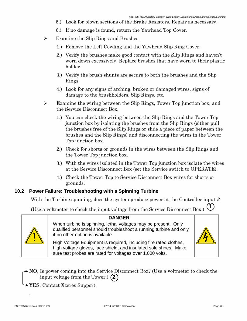
XZERES 442SR Battery Charger Wind Energy System Installation and Operation Manual
PN: 7305 Revision A, XCO 1159 ©2014 XZERES Corporation Page 72
5.) Look for blown sections of the Brake Resistors. Repair as necessary.
6.) If no damage is found, return the Yawhead Top Cover.
Examine the Slip Rings and Brushes.
1.) Remove the Left Cowling and the Yawhead Slip Ring Cover.
2.) Verify the brushes make good contact with the Slip Rings and haven’t
worn down excessively. Replace brushes that have worn to their plastic
holder.
3.) Verify the brush shunts are secure to both the brushes and the Slip
Rings.
4.) Look for any signs of arching, broken or damaged wires, signs of
damage to the brushholders, Slip Rings, etc.
Examine the wiring between the Slip Rings, Tower Top junction box, and
the Service Disconnect Box.
1.) You can check the wiring between the Slip Rings and the Tower Top
junction box by isolating the brushes from the Slip Rings (either pull
the brushes free of the Slip Rings or slide a piece of paper between the
brushes and the Slip Rings) and disconnecting the wires in the Tower
Top junction box.
2.) Check for shorts or grounds in the wires between the Slip Rings and
the Tower Top junction box.
3.) With the wires isolated in the Tower Top junction box isolate the wires
at the Service Disconnect Box (set the Service switch to OPERATE).
4.) Check the Tower Top to Service Disconnect Box wires for shorts or
grounds.
10.2 Power Failure: Troubleshooting with a Spinning Turbine
With the Turbine spinning, does the system produce power at the Controller inputs?
(Use a voltmeter to check the input voltage from the Service Disconnect Box.)
DANGER
When turbine is spinning, lethal voltages may be present. Only qualified personnel should troubleshoot a running turbine and only if no other option is available.
High Voltage Equipment is required, including fire rated clothes, high voltage gloves, face shield, and insulated sole shoes. Make sure test probes are rated for voltages over 1,000 volts.
NO, Is power coming into the Service Disconnect Box? (Use a voltmeter to check the
input voltage from the Tower.)
YES, Contact Xzeres Support.
.
2

XZERES 442SR Battery Charger Wind Energy System Installation and Operation Manual
PN: 7305 Revision A, XCO 1159 ©2014 XZERES Corporation Page 73
Main
Power
Panel
Turbine
Controller
Service
Disconnect
BoxAlternator
Yawhead
Slip
Rings
Yawhead
Electrical
Box
Brake
Resistors
Tower Top
Junction
Box
DOWN
TOWER
UP
TOWER
Diversion
Load
Figure 52 System Group Location
Check the Turbine Controller
To check the Controller for input voltage from the Service Disconnect Box:
1.) Use an AC voltmeter at SR1, SR2, and SR3 of the Controller to Ground.
See Figure 24, page 34.
2.) Touch one of the AC voltmeter probes to SR1 and the other probe to
Ground.
3.) Then move the SR1 probe to SR2 and leave the other probe on the
Ground.
4.) For the third phase, move the SR2 probe to SR3 leaving the other probe
on the Ground.
The voltages should balance (read about the same).
To do a phase to phase check:
1.) Use an AC voltmeter touching a probe to SR1 and the other probe to SR2
2.) Next leave the probe on SR1 and move the SR2 probe to SR3
3.) Last leave a probe on SR3 and move the SR1 probe to SR2
The voltages should balance.
If you find a phase imbalance, no reading on one phase, or no power at all,
Check your power lead wires back to the Service Disconnect Box and, if
necessary, back to the Turbine.
If power at the Turbine Controller is present and balanced at SR1, SR2, and
SR3,
Check the Controller connections. Verify all connections to the Turbine
Controller. (Give every wire a mild tug to verify they are securely connected).
See Figure 21, page 34.
1

XZERES 442SR Battery Charger Wind Energy System Installation and Operation Manual
PN: 7305 Revision A, XCO 1159 ©2014 XZERES Corporation Page 74
Controller Check
Is the Controller Keypad lit with no output power to the Main Panel?
No, check the Controller output with a voltmeter. Read across +
(positive output terminal) and – (negative output terminal) of the
Controller, see Figure 21, page 32.
Is the Controller input voltage between 44 – 66 V?
No, check the voltage output of the Main Power panel.
Is the Main Power panel output 44 – 66 V?
No, fix Controller input power.
Yes, the Controller fuse is blown, verify the power switch is set
to the proper input voltage before replacing. If the fuses are all
good, then the Controller will need returning to XZERES for
repair or replacement.
Yes, check the fuses (see Fuses on Figure 21 or Figure 53). If the
fuses are good, then return the Controller to XZERES for repair or
replacement.
Yes, check the Controller Board fuses (see Fuses on Figure 21 or Figure
53). If the fuses are good, then return the Controller to XZERES for
repair or replacement.
Figure 53 Turbine Controller Fuses
If no power is present at the Turbine Controller,
Check the Service Disconnect Box
Fuse locations, sizes and types: F3B Fuse, 5x20 mm, 400 mA, 250V, Type T
F2A Fuse, 5x20 mm, 2A, 250V, Type T
F1B Fuse, 5x20 mm, 6.3A, 250V, Type T

XZERES 442SR Battery Charger Wind Energy System Installation and Operation Manual
PN: 7305 Revision A, XCO 1159 ©2014 XZERES Corporation Page 75
Figure 54 Access Service Disconnect Box Power
Verify the Turbine is spinning, service switch is in operate position CB1 is in
the “ON” position.
1.) Use an AC voltmeter with probes at terminal board 1 (TB1) to check
Service Disconnect input voltage.
The voltage from SR1 to Ground, SR2 to Ground, and SR3 to Ground
should be balanced (about the same).
2.) If you do not detect voltage and the turbine is spinning, then:
Both the Brake Resistors and Slip Rings are disengaged (this situation is best
left for a qualified professional).
Other up tower parts has failed and will need repair or replacing.
3.) If proper voltage is present at TB1,
Use AC voltmeter probes at circuit breaker 1 (CB1) to check Service
Disconnect output voltage.
The voltage from SR1 to Ground, SR2 to Ground, and SR3 to Ground should
be balanced.
If you still have no output power, then the circuit breaker (CB1) is bad.
Contact XZERES support.
WARNING ELECTRICAL AND MECHANICAL HAZARDS ON
THE TOWER CAN CAUSE INJURY OR DEATH
XZERES 442SR Battery Charger Wind Energy System Installation and Operation Manual
PN: 7305 Revision A, XCO 1159 ©2014 XZERES Corporation Page 76
10.3 Other Up Tower Checks
Check the Brake Resistors (see Figure 33, page 43):
Verify all the wires are connected and show no damage.
Inspect for points of contact or arcing to the Yawhead, to wires, to the heat
shield and all other locations within the Yawhead.
Check the Brake Resistors for correct mounting:
Look for expansion room below the resistor (it should not bind tight at the
bottom connection pin, but should move up and down easily).
Check that the Alternator spins freely:
If the Alternator is frozen or only spins slowly with effort, send the Alternator to
XZERES for repair or replacement.
Check for foreign substances or loose magnets in the turbine.
Remove foreign substances; however, if you find loose magnets, send the
Alternator to XZERES for repair or replacement.
Does the Turbine vibrate excessively?
Check the Blades for damage.
Check the Blades for water intrusions.
Check the bearings for damage or damage to their machine fits. (With the
turbine stopped, see if you can detect any unusual up-and-down or side-
to-side motion of the rotor.)
Do the Blades show signs of cracking?
Replace the Blades.
Does the Nose Cone show signs of cracking?
Replace the Nose Cone.
Disconnect the up tower LPS and verify that the Alternator spins freely. See also
the LPS instructions.
Check that the brake contactors switch state.
This will require Down Tower support and may require disassembling the
sealed contactor box to verify both contactors function. (When engaged, the
BEFORE CLIMBING TOWER ALWAYS:
1) Read the Service and Safety instructions.
2) Follow electrical lockout and tag out procedures.
3) Wear Personal Protection Equipment.

XZERES 442SR Battery Charger Wind Energy System Installation and Operation Manual
PN: 7305 Revision A, XCO 1159 ©2014 XZERES Corporation Page 77
mechanical override will be at the bottom of the contactor; when disengaged,
the mechanical override will be at the top of the contactor.)
NOTE: Alternator winding, bearing, magnet and Turbine Controller problems are not
Field Serviceable.)
10.3.1 Complete the Commissioning Closeout Inspection Checklist, 442SR
(document #4037) and return a copy to Xzeres. The System owner should keep a
copy for their records.
APPENDIX A: 442SR SYSTEM WIRING DIAGRAMS
Appendix A1 442SR Turbine Controller Schematic ....................................... 78
Appendix A2 Battery to Turbine Controller connections diagram ................ 79
Appendix A3 Yawhead Electrical Box Wiring Diagram ................................ 80
Appendix A4 Service Disconnect Box Wiring Diagram ................................. 81
Appendix A5 Wire Conversion Table .............................................................. 82
Appendix A6 Length Conversion Table .......................................................... 82

XZERES 442SR Battery Charger Wind Energy System Installation and Operation Manual
PN: 7305 Revision A, XCO 1159 ©2014 XZERES Corporation Page 78
Appendix A 442SR SYSTEM WIRING DIAGRAMS
XZ
ER
ES
Tu
rbin
e C
on
trolle
r – B
atte
ry
+DL1TS
‒ DL2TS
+DL2TS
‒ DL1TS
BLACK
BLUE
BLUE/WHITE
BLACK
BLACK
BLACK
DIVERSION
LOAD
+DL
‒ DL
+DL
‒ DL
DIVERSION LOAD 2
DIVERSION LOAD 1
SLIP RING 1
SLIP RING 2
SLIP RING 3
SR1
SR2
SR3
PE
XZERES
SERVICE
DISCONNECT
BOX W/LPS
BLACK
BLACK
BLACK
GREEN/YELLOW
GREEN/YELLOW
DIV FAN
DIV FAN
GREEN/YELLOW
GREEN/YELLOW
V‒
SIG
V+
WIND VANE
2211
BR
AK
E S
EN
SO
R
BR
AK
E S
EN
SO
RS
R7
SR
8
BRAKE CTL
BRAKE CTL
SR5
SR6
ANEMOMETER 1
ANEMOMETER 2
RED
RED
YELLOW
YELLOW
WIN
D S
PD
2
WIN
D S
PD
1
BATTERY
SENSE
INPUTS
THERM –
THERM +
LEM GND
LEM OUT
LEM V –
LEM V +
BAT –
BAT +
Appendix A1 442SR Turbine Controller Schematic

XZERES 442SR Battery Charger Wind Energy System Installation and Operation Manual
PN: 7305 Revision A, XCO 1159 ©2014 XZERES Corporation Page 79
‒ +
48V Battery
NTCALUGO3A103G THERMISTOR
SECURED TO TERMINAL
LEM HAS 300-S CURRENT SENSOR
250 mA
BATTERY +BATTERY ‒LEM V +LEM V ‒LEM OUTLEM GNDTHERMISTOR +THERMISTOR ‒
8 CONDUCTOR #22 AWG CABLE
442SR Turbine Controller
Battery‒ +
Customer Distribution Panel
CUSTOMER LOADS
EQUIPMENT BOND CONDUCTOR 1/0 MINIMUM
SINGLE 400 MCM OR DUAL 250 MCM MINIMUM DUAL 400 MCM MAXIMUM
CUSTOMER LOADS
GROUND
PORT
BA
T +
BA
T ‒
LE
M V
+L
EM
V ‒
LE
M O
UT
LE
M G
ND
TH
ER
M +
TH
ER
M ‒
400 A
+
‒
Appendix A2 Battery to Turbine Controller connections diagram

XZERES 442SR Battery Charger Wind Energy System Installation and Operation Manual
PN: 7305 Revision A, XCO 1159 ©2014 XZERES Corporation Page 80
Yawhead Electrical Box Wiring Diagram
BOTTOM OF RESISTORS
TO SR8 ON SLIP RING
1 2
R1
R2
R3
R4
3 4
A1
A2
1R
1R
33 4
R4
R2
2
13
NO
21
NC
A1
14
NO
22
NC
A2
1 2
R1
R2
R3
R4
3 4
A1
A2
1R
1R
33 4
R4
R2
2
13
NO
21
NC
A1
14
NO
22
NC
A2
Contactor 1
T2
TOP OF 1.54Ω RESISTOR
TOP OF 1.54Ω RESISTOR
TOP OF 1.54Ω RESISTOR
T2 FROM ALTERNATOR
V FROM ALTERNATOR
W FROM ALTERNATOR
N FROM ALTERNATOR
TO SR5 ON SLIP RING
LIGHTNINGPROTECTION
SYSTEM
TO GROUND INSIDE YAWHEAD
T1T1 FROM ALTERNATOR
U FROM ALTERNATOR
ALTERNATOR
ALT
ER
NA
TO
R
TH
ER
MA
L S
WIT
CH
6.5"
6.0"
Contactor 2
Black
Black
Black
White
TO SR3 ON SLIP RING
TO SR2 ON SLIP RING
TO SR2 ON SLIP RING
TO SR1 ON SLIP RING
TO SR1 ON SLIP RING
TO SR3 ON SLIP RING
SLIP
RINGS
TO SR6 ON SLIP RING
TO SR7 ON SLIP RING
U SR1
V SR2
W SR3
N N
SR6
Appendix A3 Yawhead Electrical Wiring Diagram

XZERES 442SR Battery Charger Wind Energy System Installation and Operation Manual
PN: 7305 Revision A, XCO 1159 ©2014 XZERES Corporation Page 81
Service Disconnect Box Wiring Diagram
Appendix A4 Service Disconnect Box Wiring Diagram

XZERES 442SR Battery Charger Wind Energy System Installation and Operation Manual
PN: 7305 Revision A, XCO 1159 ©2014 XZERES Corporation Page 82
Appendix A Metric Conversion Tables
INCHES METRIC
AWG Number Ø [Inch] Ø [mm] A [mm²] FRACTIONAL DECIMAL mm
6/0 = 000000 0.580 14.73 170.30 1/64 0.0156 0.3969
5/0 = 00000 0.517 13.12 135.10 1/32 0.0313 0.7938
4/0 = 0000 0.460 11.7 107 1/16 0.0625 1.5875
3/0 = 000 0.410 10.4 85.0 1/8 0.1250 3.1750
2/0 = 00 0.365 9.26 67.4 3/16 0.1875 4.7625
1/0 = 0 0.325 8.25 53.5 1/4 0.2500 6.3500
1 0.289 7.35 42.4 5/16 0.3125 7.9375
2 0.258 6.54 33.6 3/8 0.3750 9.5250
3 0.229 5.83 26.7 7/16 0.4375 11.1125
4 0.204 5.19 21.1 1/2 0.5000 12.7000
5 0.182 4.62 16.8 9/16 0.5625 14.2875
6 0.162 4.11 13.3 5/8 0.6250 15.8750
7 0.144 3.66 10.5 11/16 0.6875 17.4625
8 0.128 3.26 8.36 3/4 0.7500 19.0500
9 0.114 2.91 6.63 13/16 0.8125 20.6375
10 0.102 2.59 5.26 7/8 0.8750 22.2250
11 0.0907 2.30 4.17 15/16 0.9375 23.8125
12 0.0808 2.05 3.31 1 1.0000 25.4000
13 0.0720 1.83 2.62 1 1/4 1.2500 31.7500
14 0.0641 1.63 2.08 1 1/2 1.5000 38.1000
15 0.0571 1.45 1.65 1 3/4 1.7500 44.4500
16 0.0508 1.29 1.31 2 2.0000 50.8000
17 0.0453 1.15 1.04 2 1/4 2.2500 57.1500
18 0.0403 1.02 0.823 2 1/2 2.5000 63.5000
19 0.0359 0.912 0.653 2 3/4 2.7500 69.8500
20 0.0320 0.812 0.518 3 3.0000 76.2000
21 0.0285 0.723 0.410 3 1/2 3.5000 88.9000
22 0.0253 0.644 0.326 4 4.0000 101.6000
23 0.0226 0.573 0.258 4 1/2 4.5000 114.3000
24 0.0201 0.511 0.205 5 5.0000 127.0000
25 0.0179 0.455 0.162 10 10.0000 254.0000
Appendix A5 Wire Conversion Table
20 20.0000 508.0000
30 30.0000 762.0000
40 40.0000 1016.0000
100 100.0000 2540.0000
Appendix A6 Length Conversion Table
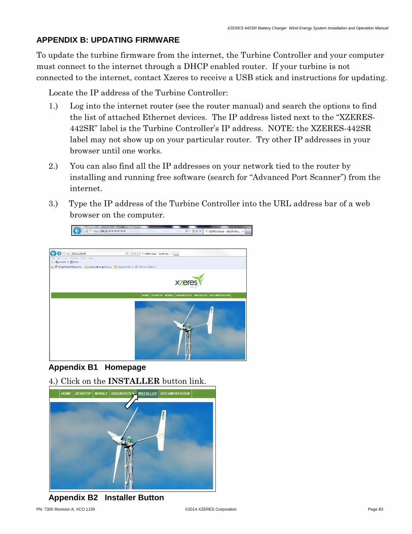
XZERES 442SR Battery Charger Wind Energy System Installation and Operation Manual
PN: 7305 Revision A, XCO 1159 ©2014 XZERES Corporation Page 83
APPENDIX B: UPDATING FIRMWARE
To update the turbine firmware from the internet, the Turbine Controller and your computer
must connect to the internet through a DHCP enabled router. If your turbine is not
connected to the internet, contact Xzeres to receive a USB stick and instructions for updating.
Locate the IP address of the Turbine Controller:
1.) Log into the internet router (see the router manual) and search the options to find
the list of attached Ethernet devices. The IP address listed next to the “XZERES-
442SR” label is the Turbine Controller’s IP address. NOTE: the XZERES-442SR
label may not show up on your particular router. Try other IP addresses in your
browser until one works.
2.) You can also find all the IP addresses on your network tied to the router by
installing and running free software (search for “Advanced Port Scanner”) from the
internet.
3.) Type the IP address of the Turbine Controller into the URL address bar of a web
browser on the computer.
Appendix B1 Homepage
4.) Click on the INSTALLER button link.
Appendix B2 Installer Button

XZERES 442SR Battery Charger Wind Energy System Installation and Operation Manual
PN: 7305 Revision A, XCO 1159 ©2014 XZERES Corporation Page 84
5.) Log in with username: MyTurbine, Password: m442+SRt
Appendix B3 Login Window
a.) Select NO or decline any offer by the browser to save the password.
6.) The installer links window will appear (if not, select INSTALLER again, this will refresh
the screen). Select IP CONFIG / FW UPDATE. Window will appear.
Appendix B4 Installer Links
7.) On the following webpage, click the Check for Software Updates button.

XZERES 442SR Battery Charger Wind Energy System Installation and Operation Manual
PN: 7305 Revision A, XCO 1159 ©2014 XZERES Corporation Page 85
Appendix B5 Check for Software Updates
8.) Depending on the speed and quality of the connection, this may take a few minutes.
If the next screen displays “Controller Updates Available,” click the Update Now button.
Appendix B6 Update Page
If you wish to update later, click the Check Later button and you will return to the
Configuration page (as will clicking the HOME link).
The update could take up to 5 minutes or more. When done, the turbine controller will reboot
and go to the “Stopped” state for 5 minutes before enabling the turbine.

XZERES 442SR Battery Charger Wind Energy System Installation and Operation Manual
PN: 7305 Revision A, XCO 1159 ©2014 XZERES Corporation Page 86
APPENDIX C: WARNING LABEL PLACEMENT
The XZERES 442SR Energy System consists of seven Warning labels. These labels must
always be prominent in their given location. If they ever become damaged or lost, they will
need immediate replacing. Purchase replacement labels from XZERES Corporation or have
them manufactured at your convenience. For the safe operation of this system, these labels
must always occupy a prominent, visible place in the area where they relate.
The Diversion Load Warning Label must always be visible on the Diversion Load to warn of fire or heat related damage.
The Turbine Controller Label must always be visible on the Turbine Controller to warn of potential injury and damage to the energy system. The Danger Label must always be visible on the Turbine Controller Side Cover to warn of the Lethal Current.
The Service Disconnect Box Label must always be on the front cover of the Service Disconnect Box to warn of potential injury and damage to the energy system.
The Yawhead Electrical Box Label must always be on the front cover of the Yawhead Electrical Box to warn of potential injury and damage to the energy system.

XZERES 442SR Battery Charger Wind Energy System Installation and Operation Manual
PN: 7305 Revision A, XCO 1159 ©2014 XZERES Corporation Page 87
Attach the Tower Warning Label at the base of the tower where it will be seen before the tower is climbed.
Attach the Yawhead Warning Label at the base of the Yawhead where it will be seen before work on the Yawhead can be started. If the label cannot be mounted directly to the tower, then mount it on a metal plate and attach the plate to the tower below the Yawhead where it will be seen.
The Rotor Lock Warning Label must always be displayed on the access door of the Yawhead where it will be seen before starting work on the Yawhead Electric Box.
The Turbine Controller Nameplate should be viewable on the side of the Turbine Controller.

XZERES 442SR Battery Charger Wind Energy System Installation and Operation Manual
PN: 7305 Revision A, XCO 1159 ©2014 XZERES Corporation Page 88
APPENDIX D: SERVICE MAINTENANCE LOG
Service and Maintenance Log
Date Reason for Service/ Service Performed
Technician or Service Company
Contact Information
(continued)

XZERES 442SR Battery Charger Wind Energy System Installation and Operation Manual
PN: 7305 Revision A, XCO 1159 ©2014 XZERES Corporation Page 89
Service and Maintenance Log (continued)
Date Reason for Service/ Service Performed
Technician or Service Company
Contact Information
XZERES 442SR Battery Charger Wind Energy System Installation and Operation Manual
PN: 7305 Revision A, XCO 1159 ©2014 XZERES Corporation Page 90
DECOMMISSIONING AND DISPOSAL
With proper care, maintenance, and rebuilding with quality parts, the XZERES Wind
Turbine System could easily surpass the life cycle of a human. Industrial machinery, electric
motors, and generators from 100 years ago are still in use today. Much of the technology in
the XZERES Wind Turbine System follows along these same time proven designs. However,
the XZERES design incorporates all of the advancements of the last 100 years!
For example, the iron lamination that makes up the core of the alternator’s winding uses the
most recent advancements in iron lamination insulation (C-5 coreplate coating). If it had to,
the iron core could endure numerous trips through a burnout oven with negligible core loss.
The magnet wire in the alternator has the most advanced insulation coating possible
(polyurethane). XZERES winds the alternator to meet Class H insulation standards. This
gives the winding a life expectancy in the tens of thousands of hours worth of use at 180°C!
Abuse a wind turbine on this planet would never see. In addition, like standard industrial
machinery, almost all of the components of the turbine can be disposed of by your local
recycling center.
However, in some cases the rotor magnets may require some special disposal handling.
Neodymium Iron Boron (NdFeB) magnets are extremely powerful and can easily injure
someone if not handled correctly. If the magnets are magnetized, and you have the means of
thermally demagnetizing (by taking the magnet to its curie temperature), then you should do
this. Once the magnets are demagnetized, your local recycling center can handle their
disposal. If this is not an option, use some sort of shielding (galvanized steel sheets work
great) to line the boxes or containers used for disposal. A shield will prevent the magnets
from sticking to any trash container.
The Nose Cone, Tail Vane, and Blades are made of fiberglass and designed to an expected life
of 20 years and should far exceed that. Fiberglass is recycled all around the world. Check
with your local recycle center with any questions or concerns. They may require that you chop
or breakup the fiberglass.
The XZERES Turbine Controller, Service Disconnect Box, and Diversion Load likewise carry
a 10-year warranty and a 20-year life expectancy. All decommissioned electronics should
follow local recycling procedures. For information in your area, check with your local recycling
center.
All other materials in your Wind Turbine System should include standard disposal
information or be of a common nature that your local recycling center can assist in their
disposal.

XZERES 442SR Battery Charger Wind Energy System Installation and Operation Manual
PN: 7305 Revision A, XCO 1159 ©2014 XZERES Corporation Page 91
INDEX
A
abnormal conditions 63
alternator 52, 54, 68, 71, 76, 90
electrical output 17
type/construction 17
altitude, maximum 17
amperage, maximum amperage 17
anemometer 19, 25
arrow button 60
arrow key 64
B
battery 17
bearings 76
blade 39, 48, 53, 76, 90
construction 17
edge 52
edge 48
inner and outer blade mount plates 18
inner clamping plate 52
outer clamping plate 52
root 48
rotational speed 17
set 18
studs 18, 51, 52
swept area 17
tip 48
brake control 70
brake resistor 41, 71, 75
brake resistors 54, 76
brushes 72
button 61, 62, 69, 70
check for software updates 84
check later 85
installer 83
S4 61
STOP 61, 62, 69, 70
update now 85
C
cable schematic 35
cable support 19
caution 10
circuit breaker 19, 20, 56
conduit 19
configuration 17
controller 17, 18, 19, 20, 25, 26, 27, 29, 30, 33, 37, 38, 46,
56, 61, 62, 70, 73, 74, 77, 83
cowling 40, 55, 72
D
danger 10
DC bus 62, 67, 68
dealer 10
demagnetizing 90
disabled state 62
diversion load 18, 25, 26, 27, 67, 68, 70, 90
clearance 28
warning label 86
duty cycle 17
E
electrical 11, 25, 27, 33, 36
distribution panel 19
hardware 19
over-speed control 17
electromagnetic interference 25
electrostatic 11
enabled state 62
F
fastener kit 18
fiberglass 90
fire hazard 11
foundation mat 21
pad and pedestal 21, 22
frequency 67
fuse 74
G
ground 11, 26, 38, 46, 56, 73, 75
PE 11
specification 17
guide bolt 44
H
hard faults 67
hard hat 12
hazard symbols 11
heat-sink 67
hole saw 20
homepage 83
humidity 17
I
ice 63
installer 10, 12, 21, 22, 27, 40
IP address 83
J
junction box 19, 25, 26, 37, 39, 46
tower base 18, 56
tower top 72
turbine top 18

XZERES 442SR Battery Charger Wind Energy System Installation and Operation Manual
PN: 7305 Revision A, XCO 1159 ©2014 XZERES Corporation Page 92
K
Kellems grips 19, 39, 47
L
lanyard 41
laptop 83
lightning 14, 25
liquid crystal display 60
local codes 17, 26, 39, 46, 56
lockout 12
Loctite
243 44, 45, 49, 50, 51, 52, 54
Loctite 18
LPS 76
M
magnets 76, 90
main power panel 20, 58, 74
manual reset 63, 68, 69
multi-meter 20
N
neodymium iron boron 90
nose cone 54, 76, 90
note 10
O
ohmmeter 20
operating faults 67
owner 10
P
pinch-point 11
plywood 19, 27
polyurethane 90
power
factor 17
rated 17
R
ratchet 20
recycling 90
revision table 94
rotation direction 52
rotor 51
diameter 17
rotor lock 53
warning label 87
router 83
S
safety 10, 69
glasses 12
harness 12
screwdriver
flat-head 20
Phillips 20
service disconnect 13, 18, 25, 26, 27, 33, 37, 38, 56, 58,
72, 73, 74, 75, 90
switch 33, 56, 58, 72, 86
service disconnect box See service disconnect
service maintenance log 88
shunt 56, 58
shutdown 13
slip rings 39, 42, 46, 72, 75
socket 20
soft faults 67
surge suppressors 14
T
tail
boom 18, 39, 48, 49
boom weight 49
vane 18, 39, 48, 49
Tail 55
tail vane 90
tapered pin 44
technical support 69
temperature 17
thrust, maximum lateral 17
toll-free number 10
tower 39, 55
anchor bolts 23
gin-pole system 23
grounding 24
grounding system 57
monopole 21, 23, 25, 47
self-supporting lattice 22, 23, 25, 55
template 23
tilt-up monopole 23
top weight 17
warning label 12, 87
wiring 39
tower top interface plate 43, 45
turbine 71, 72, 75
turbine controller See controller
turbine-state 64
turbulence 9, 12
U
URL address bar 83
V
vise-grip 20
voltage
required 17
voltmeter 20, 70, 73, 74, 75

XZERES 442SR Battery Charger Wind Energy System Installation and Operation Manual
PN: 7305 Revision A, XCO 1159 ©2014 XZERES Corporation Page 93
W
warning 10
wind vane 19, 25
wire 19, 26
aluminum 27
brake 70
brake control 56
color system 26
conversion table 82
insulation 26
magnet 90
run 19, 26, 27
shielded twisted 25
strippers 20
wrench 20
adjustable 20
hex/Allen 20
torque 20, 24
Y
yaw lock 19, 49, 55
yawhead 40, 53
assembly 18
bearing 49
electric box 56, 68
electrical box 18, 54, 71
electrical box warning label 86
mounting flange 44
sleeve 50
warning label 87

XZERES 442SR Battery Charger Wind Energy System Installation and Operation Manual
PN: 7305 Revision A, XCO 1159 ©2014 XZERES Corporation Page 94
Rev XCO Release
Date Major / Minor
Description
A 1159 3/25/2014 --- Initial release
Table 13 Revision History

XZERES 442SR Battery Charger Wind Energy System Installation and Operation Manual
PN: 7305 Revision A, XCO 1159 ©2014 XZERES Corporation Page 95
This page is left intentionally blank.

XZERES 442SR Battery Charger Wind Energy System Installation and Operation Manual
PN: 7305 Revision A, XCO 1159 ©2014 XZERES Corporation Page 96