
PICDEM USB User's Guide - Microchip Technology
80
2001 Microchip Technology Inc. DS41174A PICDEM™ USB User’s Guide
-
Upload
khangminh22 -
Category
Documents
-
view
0 -
download
0
Transcript of PICDEM USB User's Guide - Microchip Technology

2001 Microchip Technology Inc. DS41174A
PICDEM™ USBUser’s Guide

Note the following details of the code protection feature on PICmicro ® MCUs.
• The PICmicro family meets the specifications contained in the Microchip Data Sheet.• Microchip believes that its family of PICmicro microcontrollers is one of the most secure products of its kind on the market today,
when used in the intended manner and under normal conditions.• There are dishonest and possibly illegal methods used to breach the code protection feature. All of these methods, to our knowl-
edge, require using the PICmicro microcontroller in a manner outside the operating specifications contained in the data sheet.The person doing so may be engaged in theft of intellectual property.
• Microchip is willing to work with the customer who is concerned about the integrity of their code.• Neither Microchip nor any other semiconductor manufacturer can guarantee the security of their code. Code protection does not
mean that we are guaranteeing the product as “unbreakable”.• Code protection is constantly evolving. We at Microchip are committed to continuously improving the code protection features of
our product.
If you have any further questions about this matter, please contact the local sales office nearest to you.
Information contained in this publication regarding deviceapplications and the like is intended through suggestion onlyand may be superseded by updates. It is your responsibility toensure that your application meets with your specifications.No representation or warranty is given and no liability isassumed by Microchip Technology Incorporated with respectto the accuracy or use of such information, or infringement ofpatents or other intellectual property rights arising from suchuse or otherwise. Use of Microchip’s products as critical com-ponents in life support systems is not authorized except withexpress written approval by Microchip. No licenses are con-veyed, implicitly or otherwise, under any intellectual propertyrights.
DS41174A - page ii
Trademarks
The Microchip name and logo, the Microchip logo, PIC, PICmicro,PICMASTER, PICSTART, PRO MATE, KEELOQ, SEEVAL,MPLAB and The Embedded Control Solutions Company are reg-istered trademarks of Microchip Technology Incorporated in theU.S.A. and other countries.
Total Endurance, ICSP, In-Circuit Serial Programming, FilterLab,MXDEV, microID, FlexROM, fuzzyLAB, MPASM, MPLINK,MPLIB, PICC, PICDEM, PICDEM.net, ICEPIC, MigratableMemory, FanSense, ECONOMONITOR, Select Mode, dsPIC,rfPIC and microPort are trademarks of Microchip TechnologyIncorporated in the U.S.A.
Serialized Quick Term Programming (SQTP) is a service markof Microchip Technology Incorporated in the U.S.A.
All other trademarks mentioned herein are property of theirrespective companies.
© 2001, Microchip Technology Incorporated, Printed in theU.S.A., All Rights Reserved.
Printed on recycled paper.
2001 Microchip Technology Inc.
Microchip received QS-9000 quality systemcertification for its worldwide headquarters,design and wafer fabrication facilities inChandler and Tempe, Arizona in July 1999. TheCompany’s quality system processes andprocedures are QS-9000 compliant for itsPICmicro® 8-bit MCUs, KEELOQ® code hoppingdevices, Serial EEPROMs and microperipheralproducts. In addition, Microchip’s qualitysystem for the design and manufacture ofdevelopment systems is ISO 9001 certified.

PICDEM™ USB USER’S GUIDE
Table of Contents
PrefaceIntroduction ................................................................................................ 1
Highlights ................................................................................................... 1
About This Guide ....................................................................................... 1
Warranty Registration ................................................................................ 3
Recommended Reading ............................................................................ 3
The Microchip Internet Web Site ............................................................... 4
Development Systems Customer Notification Service .............................. 5
Customer Support ..................................................................................... 7
Chapter 1. Getting Started with the PICDEM™ USB1.1 Introduction .......................................................................................... 9
1.2 Highlights ............................................................................................. 9
1.3 Unpacking your PICDEM™ USB Kit ................................................... 9
1.4 Running the Default Demonstration .................................................. 10
1.5 Branching Out on Your Own ............................................................. 10
Chapter 2. USB Demonstration Code
2.1 Gameport - USB Translator ............................................................... 13
2.2 PS/2 Keyboard/Mouse - USB Translator ........................................... 17
2.3 Combination Gameport/PS/2/Mouse - USB Translator ..................... 23
2.4 Multi-Function LCD Text Display Example ........................................ 25
Chapter 3. PICDEM™ USB Hardware3.1 Oscillator Support .............................................................................. 31
3.2 Connector Pinout ............................................................................... 32
3.3 Buttons and Jumpers ........................................................................ 36
3.4 Power ................................................................................................ 37
2001 Microchip Technology Inc. DS41174A-page iii

PICDEM™ USB USER’S GUIDE
Chapter 4. Chapter 9 USB Firmware4.1 Introducing the USB Software Interface ............................................39
4.2 Integrating USB Into Your Application ...............................................39
4.3 Interrupt Structure Concerns .............................................................40
4.4 File Packaging ...................................................................................41
4.5 Function Call Reference ....................................................................42
4.6 Behind the Scenes .............................................................................44
4.7 Examples ...........................................................................................45
4.8 Multiple Configuration or Report Descriptors .....................................46
4.9 Optimizing the Firmware ....................................................................47
4.10 Cursor Demonstration ......................................................................48
Chapter 5. Troubleshooting5.1 Introduction ........................................................................................51
5.2 Highlights ...........................................................................................51
5.3 FAQ ...................................................................................................51
Appendix A. PICDEM™ USB SchematicsIntroduction ..............................................................................................53
Highlights .................................................................................................53
Schematics ..............................................................................................54
Appendix B. PS/2 Lookup TablesIntroduction ..............................................................................................61
Scan Codes .............................................................................................61
Command Codes .....................................................................................62
GlossaryIntroduction ..............................................................................................65
Highlights .................................................................................................65
PICDEM™ USB Terms ............................................................................65
Index .......................................................................................................... 73
Worldwide Sales and Service .................................................................. 76
DS41174A-iv 2001 Microchip Technology Inc.

PICDEM™ USB USER’S GUIDE
Preface
IntroductionThis chapter contains general information about this manual and contactingcustomer support.
HighlightsTopics covered in this chapter:
• About this Guide
• Warranty Registration
• Recommended Reading
• The Microchip Internet Web Site
• Development Systems Customer Notification Service
• Customer Support
About This Guide
Document LayoutThis document describes how to use PICDEM™ USB to attach a newperipheral to a PC. The manual layout is as follows:
• Chapter 1: Getting Started with the PICDEM™ USB – WhatPICDEM™ USB is and how it works.
• Chapter 2: PICDEM™ USB Demonstration Code – Provides USBdemonstration code and information on Gameport™, PS/2® Keyboard/Mouse, Combination Gameport/PS/2, and LCD Demo.
• Chapter 3: PICDEM™ USB Hardware – Contains oscillator support,connector pinout, buttons and jumpers, and power information.
• Chapter 4: Chapter 9 USB Firmware – Describes the USB softwareinterface.
• Chapter 5: Troubleshooting – Provides solutions to common prob-lems users may experience with PICDEM™ USB. It also includes FAQon Hardware, PC/Windows® and Macintosh® concerning thePICDEM™ USB.
• Appendix A: Schematics – Provides the schematics for thePICDEM™ USB.
• Appendix B: PS/2 Lookup Tables – Provides scan and commandcode tables for easy reference.
2001 Microchip Technology Inc. DS41174A-page 1

PICDEM™ USB User’s Guide
• Index – Provides a cross-reference listing of terms, features, andsections of this document.
• PICDEM™ USB Worldwide Sales and Service – Lists Microchip salesand service locations and telephone numbers worldwide.
Conventions Used in this GuideThis manual uses the following documentation conventions:
Documentation Conventions
Description Represents Examples
Code (Courier font):
Plain characters Sample code,file names and paths
#define STARTc:\autoexec.bat
Angle brackets:< >
Variables <label>, <exp>
Square brackets [ ] Optional arguments MPASMWIN [main.asm]
Curly brackets andpipe character: |
Choice of mutually exclusivearguments, an OR selection
errorlevel 0|1
Lower case charac-ters in quotes
Type of data "filename"
Ellipses... Used to imply (but not show)additional text that is not rele-vant to the example
list ["list_option.., "list_option"]
0xnnn A hexadecimal number where’n’ is a hexadecimal digit
0xFFFF, 0x007A
Italic characters A variable argument; it can beeither a type of data (in lowercase characters) or a specificexample (in uppercasecharacters)
char isascii (char, ch );
Interface (Arial font):
Underlined, italictext with right arrow
A menu selection from themenu bar
File > Save
Bold characters A window or dialog button toclick
OK, Cancel
Characters in anglebrackets < >
A key on the keyboard <Tab>, <Ctrl-C>
Documents (Arial font):
Italic characters Referenced books MPLAB® IDE User’sGuide
DS41174A-page 2 2001 Microchip Technology Inc.

Preface
UpdatesAll documentation becomes dated, and this user’s guide is no exception.Since the MPLAB IDE, PICDEM™ USB and other Microchip tools areconstantly evolving to meet customer needs, some MPLAB® dialogs and/ortool descriptions may differ from those in this document. Please refer to ourweb site at http://www.microchip.com to obtain the latest documentationavailable.
Warranty RegistrationPlease complete the enclosed Warranty Registration Card and mail itpromptly. Sending in your Warranty Registration Card entitles you to receivenew product updates. Interim software releases are available at the Microchipweb site.
Recommended ReadingThis user’s guide describes how to use PICDEM™ USB. The data sheetscontain current information on programming the specific microcontrollerdevices.
README.USB
For the latest information on using PICDEM™ USB, read the README.USBfile (ASCII text file) included with the PICDEM™ USB software. TheREADME.USBfile contains update information that may not be included in thisdocument.
MPLAB ® IDE User’s Guide (DS51025)
Comprehensive guide that describes installation and features of Microchip’sMPLAB Integrated Development Environment (IDE), as well as the editor andsimulator functions in the MPLAB environment.
MPASM™ User’s Guide with MPLINK™ Linker andMPLIB™ Librarian (DS33014)
Describes how to use Microchip Universal PICmicro® MicrocontrollerAssembler (MPASM™), Linker (MPLINK™), and Librarian (MPLIB™).
Technical Library CD-ROM (DS00161)
This CD-ROM contains comprehensive data sheets for Microchip PICmicro®
MCU devices available at the time of print. To obtain this disk, contact thenearest Microchip Sales and Service location (see back page), or downloadindividual data sheet files from the Microchip web site(http://www.microchip.com).
2001 Microchip Technology Inc. DS41174A-page 3

PICDEM™ USB User’s Guide
Embedded Control Handbook (DS00711)
This handbook consists of several documents that contain a wealth ofinformation about microcontroller applications. To obtain these documents,contact the nearest Microchip Sales and Service location (see back page).
The application notes described in these manuals are also obtainable fromMicrochip Sales and Service locations or from the Microchip web site(http://www.microchip.com).
PICmicro™ Mid-Range MCU Family Reference Manual (DS33023)
This manual explains the general details and operation of the MCU familyarchitecture and peripheral modules. It is designed to complement the devicedata sheets.
Microsoft ® Windows ® Manuals
This manual assumes that users are familiar with Microsoft Windowsoperating system. Many excellent references exist for this software program,and should be consulted for general operation of Windows.
USB Complete
This book is a good introduction to the USB interface and how to use it. It waswritten by Jan Axelson.
PIC16C745/765 Data Book (DS41124)
This book contains everything you ever wanted to know about thePIC16C745/765 and more.
USB IF
The USB IF can be downloaded from www.usb.org, which has all thespecifications for the USB interface. It is a valuable tool. Be sure to downloadthe USBCheck PC tools and register on the USB mailing list.
Microsoft DDK
If you are developing PC drivers for Windows, don’t forget to get the driverdevelopment kit and the professional version of Visual Studio®.
Apple ® USB Software Developer Kit (SDK)
If you are going to develop Mac drivers, go towww.developer.apple.com/SDK/index.html and download the SDKand register on the USB mailing list.
The Microchip Internet Web SiteMicrochip provides online support on the Microchip World Wide Web (WWW)site.
The web site is used by Microchip as a means to make files and informationeasily available to customers. To view the site, the user must have access tothe Internet and a web browser, such as Netscape® Communicator orMicrosoft® Internet Explorer®. Files are also available for FTP download fromour FTP site.
DS41174A-page 4 2001 Microchip Technology Inc.

Preface
Connecting to the Microchip Internet WebsiteThe Microchip web site is available by using your favorite Internet browserto attach to:
http://www.microchip.com
The file transfer site is available by using an FTP program/client to connect to:
ftp://ftp.microchip.com
The web site and file transfer site provide a variety of services. Users maydownload files for the latest Development Tools, Data Sheets, ApplicationNotes, User's Guides, Articles, and Sample Programs. A variety of Microchipspecific business information is also available, including listings of Microchipsales offices, distributors and factory representatives. Other data available forconsideration is:
• Latest Microchip Press Releases
• Technical Support Section with Frequently Asked Questions
• Design Tips
• Device Errata
• Job Postings
• Microchip Consultant Program Member Listing
• Links to other useful web sites related to Microchip Products
• Conferences for Products, Development Systems, TechnicalInformation and more
• Listing of Seminars and Events
Development Systems Customer Notification ServiceMicrochip started the customer notification service to help our customerskeep current on Microchip products with the least amount of effort. Once yousubscribe to one of our list servers, you will receive email notificationwhenever we change, update, revise or have errata related to that productfamily or development tool. See the Microchip web page athttp://www.microchip.com for other Microchip list servers.
The Development Systems list names are:
• Compilers
• Emulators
• Programmers
• MPLAB IDE
• Otools (other tools)
2001 Microchip Technology Inc. DS41174A-page 5

PICDEM™ USB User’s Guide
Once you have determined the names of the lists that you are interested in,you can subscribe by sending a message to:
with the following as the body:
subscribe <listname> yourname
Here is an example:
subscribe programmers John Doe
To UNSUBSCRIBE from these lists, send a message to:
with the following as the body:
unsubscribe <listname> yourname
Here is an example:
unsubscribe programmers John Doe
The following sections provide descriptions of the available DevelopmentSystems lists.
CompilersThe latest information on Microchip C compilers, Linkers and Assemblers.These include MPLAB® C17, MPLAB® C18, MPLINK™ Object Linker (as wellas MPLIB™ Object Librarian), and MPASM™ Assembler.
To SUBSCRIBE to this list, send a message to:
with the following as the body:
subscribe compilers yourname
EmulatorsThe latest information on Microchip In-Circuit Emulators. These includeMPLAB® ICE and PICMASTER® Emulator.
To SUBSCRIBE to this list, send a message to:
with the following as the body:
subscribe emulators yourname
ProgrammersThe latest information on Microchip PICmicro device programmers. Theseinclude PRO MATE® II and PICDEM™ USB.
DS41174A-page 6 2001 Microchip Technology Inc.

Preface
To SUBSCRIBE to this list, send a message to:
with the following as the body:
subscribe programmers yourname
MPLAB IDEThe latest information on Microchip MPLAB IDE, the Windows IntegratedDevelopment Environment for development systems tools. This list is focusedon MPLAB IDE, MPSIM™ Simulator, MPLAB’s Project Manager and generalediting and debugging features. For specific information on MPLABcompilers, linkers and assemblers, subscribe to the COMPILERS list. Forspecific information on MPLAB emulators, subscribe to the EMULATORS list.For specific information on MPLAB device programmers, please subscribe tothe PROGRAMMERS list.
To SUBSCRIBE to this list, send a message to:
with the following as the body:
subscribe mplab yourname
Customer SupportUsers of Microchip products can receive assistance through severalchannels:
• Distributor or Representative
• Local Sales Office
• Field Application Engineer (FAE)
• Corporate Applications Engineer (CAE)
• Hotline
Customers should call their distributor, representative, or field applicationengineer (FAE) for support. Local sales offices are also available to helpcustomers. See the back cover for a listing of sales offices and locations.
Corporate applications engineers (CAEs) may be contacted at(480) 792-7627.
In addition, there is a Systems Information and Upgrade Line. This lineprovides system users a listing of the latest versions of all of Microchip'sdevelopment systems software products. Plus, this line provides informationon how customers can receive any currently available upgrade kits.
The Hotline Numbers are:
1-800-755-2345 for U.S. and most of Canada, and
1-480-792-7302 for the rest of the world.
2001 Microchip Technology Inc. DS41174A-page 7

PICDEM™ USB User’s Guide
NOTES:
DS41174A-page 8 2001 Microchip Technology Inc.
PICDEM™ USB USER’S GUIDE
Chapter 1. Getting Started with the PICDEM™ USB
1.1 IntroductionThe Universal Serial Bus (USB) has become the most accepted way for anynew peripheral to be attached to a PC. The interface is fully supported by allmajor computer manufacturers and most operating systems. Since this inter-face has become more accepted, it has moved out of the consumer market. Itis starting to find its way into data acquisition and industrial markets. Withinthese markets, a large number of PICmicro solutions are looking for a migra-tion path to USB. By providing a USB derivative of the classic PIC16C72/74devices, Microchip encourages you to move your applications into the newworld of USB; and as an addition bonus, the examples provide an opportunityto play games.
1.2 HighlightsThe topics covered in this chapter are:
• Unpacking your PICDEM™ USB
• Running the Default Demonstration
• Branching out on your own
1.3 Unpacking your PICDEM™ USB Kit
1.3.1 Supplied ItemsThe items contained in your PICDEM™ USB box are:
• Microchip USB CD-ROM containing USB support documentation
• PICDEM™ USB Circuit Board with a PIC16C765 installed
• CD-ROM containing MPLAB IDE
• 3 ft. USB A-B cable
• Small box containing a windowed PIC16C745 and PIC16C765
1.3.2 Required ItemsThe items required are:
• PC for running MPLAB IDE
• Visual Basic and/or Visual C++ to modify the PC examples
• PC with USB running Windows® 98 or newer (for the PC examples)
• Macintosh with USB running MacOS X 10.0 or newer (for the Macintoshexamples). The HID examples work with MacOS 8.6 or newer.
• Apple® Project Builder to modify the Macintosh code examples
2001 Microchip Technology Inc. DS41174A-page 9

PICDEM™ USB User’s Guide
• PICSTART® Plus or PRO MATE® II to program the devices
• UV chip eraser to clean the mistakes
• Copy of Apple’s USB DDK so you can use the USB bus monitoringtools on the Macintosh (http://developer.apple.com/hardware/usb/)
• Copy of the USB-IF PC tools (www.usb.org)
1.3.3 Suggested ItemsThe items suggested are:
• USB protocol analyzer such as CATC
• Membership in the USB-IF, Inc. (www.usb.org)
• MPLAB® ICE 2000
1.4 Running the Default DemonstrationIf you have a PC/Macintosh with USB, attach your PICDEM™ USB with thesupplied cable. The LED’s should quickly blink as the PICDEM™ USB identi-fies itself. The EP1 ACT light should start to flicker steadily, and the mousecursor on your computer should start to move in a circle.
Unplug the USB cable and plug a PS/2 mouse into the PS/2 connector. Re-attach the USB cable. You will notice the mouse cursor is no longer moving ina circle, but is responding to the mouse. Unplug the USB cable and plug in aPS/2 keyboard. Re-attach the USB cable. The LED’s flicker and the keyboardis functioning as a USB keyboard.
Regardless of what PS/2 device is attached (or not attached), the EP2 ACTlight will be flashing. This is due to the PICDEM™ USB constantly streaminggameport data to the host, regardless of whether a gaming device is pluggedin or not. You can test the gameport by using the gamepad specified inSection 2.1: Gameport - USB Translator.
This example takes advantage of the existing human interface device (HID)code in the host’s operating system. For a more complex example showinghost driver code, you will have to consult the LCD Demo example.
1.5 Branching Out on Your Own
1.5.1 Developing New USB ApplicationsThe following steps are recommended to develop most new USBapplications.
• Describe the application.
• Create the descriptors.
• Debug the report descriptor with dummy data.
• Develop the rest of the application.
DS41174A-page 10 2001 Microchip Technology Inc.

Getting Started with the PICDEM™ USB
By following these steps, the hardest part of the development can be com-pleted right away on known good hardware (the PICDEM™ USB). After theapplication is communicating to the PC correctly, the application specifichardware and software can be developed.
1.5.1.1 Describing the Application
When you start developing your application, make sure that your data require-ments fit the USB specification. A low speed device is limited to 2 channels ofcommunication (end points), with each channel limited to 800 bytes persecond. The most common mistake is to assume that the entire 1.5 Mbs isavailable for your application.
1.5.1.2 Creating the Descriptors
The most difficult part of any USB application is determining what the devicedescriptors should be. Every USB device communicates its requirements tothe host through a process called enumeration. During enumeration, thedevice descriptors are transferred to the host and the host assigns a uniqueaddress to the device. The descriptors are described in detail in Chapter 9 ofthe USB 2.0 specification. Bundled with the USB tools CD, a descriptor tool isprovided to assist you in creating your own descriptors.
1.5.1.3 Debugging the Report Descriptor
The report descriptor allows HID devices to communicate to the host. Thereport descriptor communicates the exact packet format of your data. This iswhere the PC determines how large your packets will be. Report descriptorsrange from the very specific (a multi-function joystick) to the very generic (aspecialized communications device for your application). Tools are availableto assist you in creating your report descriptors. The descriptor tool, which isbundled in your kit, will have report descriptor capabilities with a future revi-sion. After the report descriptor is written make sure that it is working with thePC by using PC analysis tools. These are available from the USB-IF web sitefor the PC, and Apple Computer for Macintosh machines. Use simplecounters and other dummy data to test report descriptor traffic. After the com-munications link is working, it will be much easier to develop the rest of theapplication.
1.5.1.4 Developing the Rest of the Application
The next step is to add your specific hardware and software. Carefully studythe schematic in this guide and use the same circuitry for the USB connec-tions. The circuitry will never change for this device. When your hardware isbuilt, you can be confident that your communications code will work becauseit was developed on the development system with the same communicationscircuitry.
2001 Microchip Technology Inc. DS41174A-page 11

PICDEM™ USB User’s Guide
NOTES:
DS41174A-page 12 2001 Microchip Technology Inc.

PICDEM™ USB User’s Guide
Chapter 2. USB Demonstration Code
A variety of examples have been provided on the CD-ROM to speed youtowards a successful start with USB. These examples range from the verybasic gameport translator, to a very specialized LCD display. The gameportand PS/2 examples are excellent tools to use, in order to become more famil-iar with report descriptors and basic USB communications. These basicexamples are extremely useful because the OS vendor has already writtengeneric Human Interface Device (HID) drivers. The LCD display exampledoes not have a generic PC driver. In this example, PC software has beenprovided to demonstrate how you can develop your own PC applications tointerface to your device. Example code is provided for PC and Macintosh.
2.1 Gameport - USB Translator
2.1.1 IntroductionThe gameport to USB translator is a simple example that reads a PC game-port and reports the information over USB. Since peripherals for gameportscome in all shapes and sizes, it is important to identify exactly what peripheralis used, in this example -- the Dexxa® 8-button gamepad. Other gamepadscan be used, however, some change to the firmware functions may berequired. The example code will enumerate as a gamepad with 2 axis and 6buttons. PORTA on the PICmicro MCU is used to read the analog voltagesfrom resistors in the direction pad (D-pad) and two of the buttons, whilePORTD reads the switches for the four remaining buttons. Refer toFigure 2.1.
2001 Microchip Technology Inc. DS41174A-page 13

PICDEM™ USB User’s Guide
Figure 2.1: Dexxa ® Gamepad
2.1.2 About the PC GameportThe PC gameport was designed to support 2 joysticks. Each joystick wasintended to have 2 axis and 2 buttons. The gameport was later extended tosupport a MIDI serial interface. The gameport hardware supplied with thePICDEM™ USB does not support the MIDI interface, so those pins havebeen disconnected. Two joysticks are supported, but to simplify the example,only one joystick is used.
2.1.3 Hardware ImplementationThe hardware is supplied on the PICDEM™ USB circuit board. The board iswired with PORTA<3:0> and PORTD<3:0>, connected to the DB-15 connec-tor of the gameport. PORTD<3:0> are the digital inputs for buttons A-D.PORTA<0> and PORTA<1> are the X-Y inputs for the D-pad on the game-pad. PORTA<2> and PORTA<3> are the inputs for buttons E and F (seeAppendix A for the gamepad to PICDEM™ USB schematic). All of the analogpins have a series resistor, a resistor, and capacitor tied to ground. The rea-son for this comes from the way analog pins were originally read by the PC.The PC would clear a capacitor tied to ground at its end and then time howlong it took the capacitor to charge up. The capacitor would charge at a rateproportional to the resistance of a pot, varied by one axis of the joystick, forinstance. This is legacy technology and is not needed when using a PICmicroMCU with an analog-to-digital converter. As a result, the before mentionedcircuitry was put into place in order to obtain an analog output from the D-padof the gamepad and buttons E and F. Another point of confusion developsfrom viewing the analog output of the gamepad with this circuitry in place. The
Note: Although the Dexxa® gamepad has 8 buttons, the code enumer-ates as a 6-button gamepad. This is due to the gamepad havingtwo “special” buttons, that rapidly fire two of the other buttonoutputs.
D-PAD
TA TB
C A B
D
F
E
DS41174A-page 14 2001 Microchip Technology Inc.

USB Demonstration Code
voltage level is not symmetrical around 2.5 volts. You would expect the centerposition of the D-pad’s x-axis, for instance, to output 2.5 volts, the left positionto output 0 volts and the right position to output 5 volts. Ideally it would, butthe circuitry in the gamepad is very simple; besides, this symmetry is notneeded. All that is needed is a lower voltage input into the PICmicro MCUwhen the pad is pressed one direction from center, and a higher voltage inputwhen the pad is pressed in the other direction from center. The circuitry foundon the PICDEM™ USB board amplifies the differences in voltages betweenthese three positions and therefore, gives three very distinct analog-to-digitalreadings.
2.1.4 Gamepad FirmwareThe firmware has four functions. Each function either returns one piece ofinformation concerning the gameport status, or initiates the gameport regis-ters. Refer to Table 2.1.
Table 2.1: Gameport Firmware
2.1.5 Gamepad Report DescriptorThe report descriptor used in this example is for a gamepad with 6 buttons.The minimum and maximum report values for the axis are set to 0 - 255. Thisis to be used with Windows. Some versions don’t seem to handle a range of-127 to 127. The -127 value is translated to 255 and causes extreme move-ment to the right. The range selected works correctly on Windows and onMacintosh. Interestingly, the Macintosh performs a simple filter on the centerof the range. It will filter changes of 1 count to prevent cursor jitter when thestick is centered. This caused problems with a minimum and maximum rangeof 0 - 2. When the range was extended to 0 - 4, it worked much better. In thisexample, the analog input from the D-pad will be converted to digital, filtered,and then sent to the PC via USB. Since this digital value can range from
Note 1: Buttons E and F are connected to analog pins because thegameport has four analog pins and four digital pins. ButtonsA-D use up all the digital pins so the analog pins are the onlyinputs left over. Many joysticks have a multiplexer on buttonnumbers greater than four, in order to achieve the same resultusing just the digital pins.
2: Be very careful when using the LCD interface and the gameporttogether because they share PORTD.
Function Description
ReadXAxis Returns a digital value for the x-axis in W
ReadYAxis Returns a digital value for the y-axis in W
ReadButtons Returns the state of the six buttons in W (bits 0-5correspond to buttons A-F)
InitGameport Initialize the system to use the Gameport
2001 Microchip Technology Inc. DS41174A-page 15

PICDEM™ USB User’s Guide
0 - 255, the descriptor calls for a range of 0 - 255. The descriptor, shownbelow in HEX form, is in the gamepad descriptor file (usb_ch9.asm ).
0x05, 0x01 USAGE_PAGE (Generic Desktop)0x09, 0x05 USAGE (Game Pad)0xA1, 0x01 COLLECTION (Application)0x09, 0x01 USAGE (Pointer)0xA1, 0x00 COLLECTION (Physical)0x09, 0x30 USAGE (X)0x09, 0x31 USAGE (Y)0x15, 0x00 LOGICAL_MINIMUM (0)0x26, 0xFF, 0x00 LOGICAL_MAXIMUM (255)0x75, 0x08 REPORT_SIZE (8)0x95, 0x02 REPORT_COUNT (2)0x81, 0x02 INPUT (Data,Var,Abs)0xC0 END_COLLECTION0x05, 0x09 USAGE_PAGE (Button)0x19, 0x01 USAGE_MINIMUM (Button 1)0x29, 0x06 USAGE_MAXIMUM (Button 6)0x15, 0x00 LOGICAL_MINIMUM (0)0x25, 0x01 LOGICAL_MAXIMUM (1)0x75, 0x01 REPORT_SIZE (1)0x95, 0x06 REPORT_COUNT (6)0x81, 0x02 INPUT (Data,Var,Abs)0x95, 0x02 REPORT_COUNT (2)0x81, 0x03 INPUT (Constant,Var,Abs)0xC0 END_COLLECTION
This report descriptor describes the packet format for the USB data. The datais filled from Least Significant Byte, Least Significant bit through to the MostSignificant Byte, Most Significant bit. The first field found will be the first bit/byte. In the report descriptor above, the first data is 8 bits (the REPORT_SIZEis 8) and it is the X axis (the first USAGEof the physical collection is X). So thefirst byte on the bus will be the X axis value. The second byte will be the Yaxis. The third byte will be button A in bit 0, followed by button B in bit 1, andso on. Because every USB transaction must be in whole number bytes, thedata is padded by one constant report, 2-bits long.
2.1.6 Gameport TranslationTranslating the bits from the physical hardware to the USB buffer is very sim-ple. Because we set the logical minimum and maximum to be 0 to 255, itexactly matches the scaling of the analog-to-digital converter. So first, weconvert the X and Y axis and store the values in the first two buffer locations.Secondly, we read the six buttons and store the values in the third buffer loca-tion in bits 0-5. Lastly, we inform the serial interface engine that data isavailable and wait for the host PC to come pick it up.
DS41174A-page 16 2001 Microchip Technology Inc.

USB Demonstration Code
2.1.7 Vendor/Product IdentificationBesides the report information, the descriptors also contain manufacturingand product identification codes. Microchip has a registered Vendor ID withthe USB IF forum, which identifies Microchip’s Vendor ID as 0x04D8. You areallowed to use this ID for your own testing, but you may not ship any productswith this code without written permission from Microchip. Microchip hasdefined product ID’s for each demonstration code included in this kit. As addi-tional demonstration devices are released, Microchip will ensure that noduplicate ID’s are used.
2.2 PS/2 Keyboard/Mouse - USB Translator
2.2.1 IntroductionThis is the demonstration firmware that is programmed into the PIC16C765and installed on the PICDEM™ USB demonstration board. The PS/2 connec-tor was added so PS/2 mice and keyboards could be translated to USB.Again, this is a straightforward application intended to provide practice withdevice descriptors. The PS/2 interface is a synchronous serial interface withdifferent data protocols for keyboards and mice. Device descriptors in thePICmicro microcontroller allows the unit to report itself as either a keyboard ora mouse. When a mouse is attached to a PS/2 port, it identifies itself as amouse. When the PICmicro MCU receives this identification, it will perform asoft detach from the USB bus and re-attach as a mouse. When the PICmicroMCU identifies the PS/2 device as a keyboard, it will perform a soft detachand re-attach as a keyboard. Using soft detach may be a useful feature inyour application, so you can practice using it with this example.
2.2.2 About the PS/2 PortIBM® originally developed the PS/2 port for use on its PS/2 family of comput-ers. This port is a synchronous serial port clocked by the PS/2 device (key-board/mouse). Generally, PC’s have two PS/2 ports labeled as keyboard ormouse. The PICDEM™ USB only has one PS/2 port. Since the hardware isthe same, either the keyboard or mouse can be used, simply by interpretingthe data correctly.
2.2.3 Hardware ImplementationThe PS/2 port is a 6-pin DIN which only uses 4 pins. The pins are used forpower, ground, clock, and data. Power and ground pins are directly tied to VDD
and VSS. If power management is desired, the power pins must be driven viaswitches from other I/O pins.The clock pin is connected to RC0, while the datapin is connected to RC1. The PS/2 device clocks the host even when it is receiv-ing data. The data pin is used to send and receive data from the keyboard.
Note: It may be necessary to attach 110 kOhm pull-down resistors onRC0 and RC1, in order for auto-detect to work without pressingMCLR between plugging and unplugging PS/2 devices.
2001 Microchip Technology Inc. DS41174A-page 17

PICDEM™ USB User’s Guide
2.2.4 Data FormatThe data is sent via PS/2 one byte at a time, regardless of direction, host-to-device, or vice versa. The data is as follows:
• First comes a START bit (always low), followed by a
• data byte (Least Significant bit to Most Significant bit), then by a
• parity bit (high for an even number of high bits in the data byte and lowfor an odd number), then by a
• STOP bit (always high)
In the case of host-to-device communication, the STOP bit is immediately fol-lowed by an ACK bit (low), which is sent by the device to the host. The bitsare read on the falling edge of the clock for device-to-host communicationand on the rising edge for host-to-device communication. In the IDLE state,the clock and data lines are held high by the device. See Figure 2.2 andFigure 2.3 for device-to-host and host-to-device communication, respectively.
Figure 2.2: Device-to-Host Communication(Data bit Read on Falling Edge of Clock)
Figure 2.3: Host-to-Device Communication(Data bit Read on Rising Edge of Clock)
Clock
Data
DA
TA
DA
TA
DA
TA
DA
TA
DA
TA
DA
TA
DA
TA
PA
R-
ST
OP
DA
TA
STA
R
Clock
Data
DA
TA
DA
TA
DA
TA
DA
TA
DA
TA
DA
TA
DA
TA
PA
R-
ST
OP
DA
TA
STA
R
AC
K
DS41174A-page 18 2001 Microchip Technology Inc.
USB Demonstration Code
2.2.5 KeyboardThe PS/2 keyboard data report format is summarized for every key inAppendix B. Make codes are the byte or bytes that the PS/2 keyboard sendsto the host when a certain key is pressed. Break codes are the bytes that thePS/2 keyboard sends when the user releases a key. If the user does notrelease a specific key for several hundreds of a millisecond, the make codewill be sent repeatedly until the user releases the key. At this point, the breakcode is sent. The Translation to USB, Section 2.2.11, details how thefirmware converts PS/2 keycodes to USB keycodes.
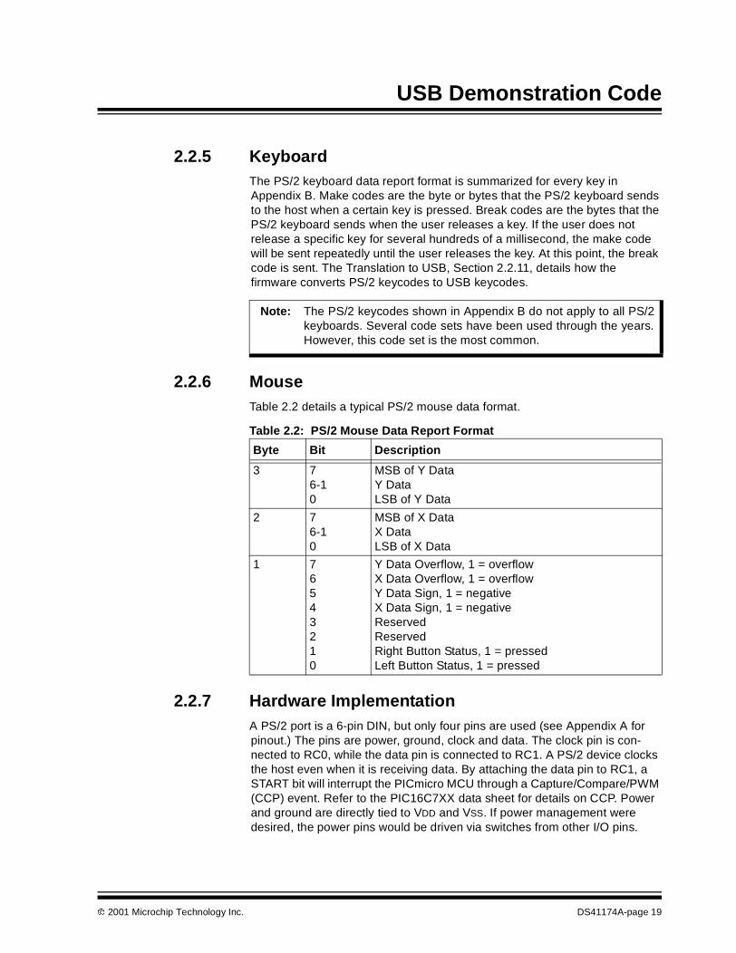
2.2.6 MouseTable 2.2 details a typical PS/2 mouse data format.
Table 2.2: PS/2 Mouse Data Report Format
2.2.7 Hardware ImplementationA PS/2 port is a 6-pin DIN, but only four pins are used (see Appendix A forpinout.) The pins are power, ground, clock and data. The clock pin is con-nected to RC0, while the data pin is connected to RC1. A PS/2 device clocksthe host even when it is receiving data. By attaching the data pin to RC1, aSTART bit will interrupt the PICmicro MCU through a Capture/Compare/PWM(CCP) event. Refer to the PIC16C7XX data sheet for details on CCP. Powerand ground are directly tied to VDD and VSS. If power management weredesired, the power pins would be driven via switches from other I/O pins.
Note: The PS/2 keycodes shown in Appendix B do not apply to all PS/2keyboards. Several code sets have been used through the years.However, this code set is the most common.
Byte Bit Description
3 76-10
MSB of Y DataY DataLSB of Y Data
2 76-10
MSB of X DataX DataLSB of X Data
1 76543210
Y Data Overflow, 1 = overflowX Data Overflow, 1 = overflowY Data Sign, 1 = negativeX Data Sign, 1 = negativeReservedReservedRight Button Status, 1 = pressedLeft Button Status, 1 = pressed
2001 Microchip Technology Inc. DS41174A-page 19
PICDEM™ USB User’s Guide
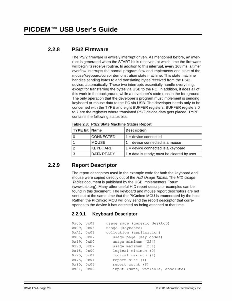
2.2.8 PS/2 FirmwareThe PS/2 firmware is entirely interrupt driven. As mentioned before, an inter-rupt is generated when the START bit is received, at which time the firmwarewill begin its receive routine. In addition to this interrupt, every 168 ms, a timeroverflow interrupts the normal program flow and implements one state of themouse/keyboard/cursor demonstration state machine. This state machinehandles sending bytes to and translating bytes received from the PS/2device, automatically. These two interrupts essentially handle everything,except for transferring the bytes via USB to the PC. In addition, it does all ofthis work in the background while a developer’s code runs in the foreground.The only operation that the developer’s program must implement is sendingkeyboard or mouse data to the PC via USB. The developer needs only to beconcerned with the TYPE and eight BUFFER registers. BUFFER registers 0to 7 are the registers where translated PS/2 device data gets placed. TYPEcontains the following status bits:
Table 2.3: PS/2 State Machine Status Report
2.2.9 Report DescriptorThe report descriptors used in the example code for both the keyboard andmouse were copied directly out of the HID Usage Tables. The HID UsageTables document is published by the USB Implementers Forum(www.usb.org). Many other useful HID report descriptor examples can befound in this document. The keyboard and mouse report descriptors are notsent out at the same time that the PICmicro MCU is enumerated by the host.Rather, the PICmicro MCU will only send the report descriptor that corre-sponds to the device it has detected as being attached at that time.
2.2.9.1 Keyboard Descriptor
0x05, 0x01 usage page (generic desktop)0x09, 0x06 usage (keyboard)0xA1, 0x01 collection (application)0x05, 0x07 usage page (key codes)0x19, 0xE0 usage minimum (224)0x29, 0xE7 usage maximum (231)0x15, 0x00 logical minimum (0)0x25, 0x01 logical maximum (1)0x75, 0x01 report size (1)0x95, 0x08 report count (8)0x81, 0x02 input (data, variable, absolute)
TYPE bit Name Description
0 CONNECTED 1 = device connected
1 MOUSE 1 = device connected is a mouse
2 KEYBOARD 1 = device connected is a keyboard
3 DATA READY 1 = data is ready; must be cleared by user
DS41174A-page 20 2001 Microchip Technology Inc.
USB Demonstration Code
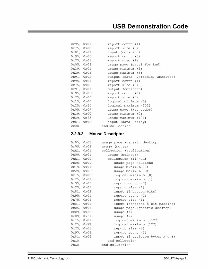
0x95, 0x01 report count (1)0x75, 0x08 report size (8)0x81, 0x01 input (constant)0x95, 0x05 report count (5)0x75, 0x01 report size (1)0x05, 0x08 usage page (page# for Led)0x19, 0x01 usage minimum (1)0x29, 0x05 usage maximum (5)0x91, 0x02 output (data, variable, absolute)0x95, 0x01 report count (1)0x75, 0x03 report size (3)0x91, 0x01 output (constant)0x95, 0x06 report count (6)0x75, 0x08 report size (8)0x15, 0x00 logical minimum (0)0x25, 0x65 logical maximum (101)0x05, 0x07 usage page (key codes)0x19, 0x00 usage minimum (0)0x29, 0x65 usage maximum (101)0x81, 0x00 input (data, array)0xC0 end collection
2.2.9.2 Mouse Descriptor
0x05, 0x01 usage page (generic desktop)0x09, 0x02 usage (mouse)0xA1, 0x01 collection (application)0x09, 0x01 usage (pointer)0xA1, 0x00 collection (linked)0x05, 0x09 usage page (buttons)0x19, 0x01 usage minimum (1)0x29, 0x03 usage maximum (3)0x15, 0x00 logical minimum (0)0x25, 0x01 logical maximum (1)0x95, 0x03 report count (3)0x75, 0x01 report size (1)0x81, 0x02 input (3 button bits)0x95, 0x01 report count (1)0x75, 0x05 report size (5)0x81, 0x01 input (constant 5 bit padding)0x05, 0x01 usage page (generic desktop)0x09, 0x30 usage (X)0x09, 0x31 usage (Y)0x15, 0x81 logical minimum (-127)0x25, 0x7F logical maximum (127)0x75, 0x08 report size (8)0x95, 0x03 report count (2)0x81, 0x06 input (2 position bytes X & Y)0xC0 end collection0xC0 end collection
2001 Microchip Technology Inc. DS41174A-page 21

PICDEM™ USB User’s Guide
2.2.10 Soft DetachThe soft detach command is one of the most useful features on the USBPICmicro MCU. The reason the soft detach command is so useful is that inapplications such as the PS/2 mouse/keyboard example, no special driverhas to be created for the host. Most often for this application, the PICmicroMCU would have two configurations - one for a mouse and the other for akeyboard. A special driver would have to be created for the host that wouldinstruct the PICmicro MCU to change configurations. Furthermore, in order todo this, the host’s driver would have to be able to detect what peripheral isattached. An easy way to avoid difficulty with creating a unique driver for thehost, is to give the PICmicro MCU control over whether it will send the hostmouse or keyboard data. Based on the type of data it will send to the PC, thePICmicro MCU can soft detach and re-enumerate as the peripheral of choice.
In this example, several events precede the implementation of a soft detach.As mentioned before, an interrupt is generated when the data line goes low.This initiates the receive routine, because it is assumed that the data linedropping low is the result of a START bit being sent by the device. However,the data line will also drop if the user disconnects the device. To distinguishbetween these two cases, the firmware starts a timer when the data line goeslow. If the timer times out before the clock line goes high, the device has beendisconnected. Otherwise, the data line going low is the result of a START bit.Once it has been determined that a device has been disconnected, the firm-ware waits for another device to be attached. When the clock and data linesare both high, a device has been attached. At this point, the PICmicro MCUwill ask the device to identify itself (see Appendix B for keyboard and mousecommands). Based on the device’s response, the firmware will know whetherthe newly attached device is a keyboard or mouse and perform a soft detach.
During the soft detach process, several things occur. First, the PICmicro MCUturns off the pull-up resistor to VUSB. The firmware does this by clearing theDEV_ATT bit. Turning the pull-up resistor off, removes the PICmicro MCUfrom the bus. After approximately 50 ms, which is enough time for the host tosee the device disconnect, the firmware sets DEV_ATT and reconnects thePICmicro MCU to the bus. The host then re-enumerates the PICmicro MCU.
2.2.11 Translation to USBIn order to act like a USB mouse or keyboard, the PICmicro MCU has totranslate the PS/2 data format for each device to its USB data format. For themouse, this is very simple. For the keyboard, however, the process is morecomplex.
DS41174A-page 22 2001 Microchip Technology Inc.

USB Demonstration Code
2.2.11.1 Keyboard
Incoming PS/2 data can be one to eight bytes long. No pattern or mathemati-cal expression can be used to convert incoming PS/2 data to a USB keycode.USB keycodes are one byte in length. There is one USB keycode for everykey on the keyboard. A lengthy lookup table is used to implement the transla-tion from PS/2 to USB keycodes. The lookup table is found in filetable_kb.asm of the example firmware. The USB keycodes are shown inSection 9 of the HID Usage Tables document.
2.2.11.2 Mouse
The mouse translation from a PS/2 format to a USB format is very simple. ThePS/2 button states are simply copied into the correct bits in the USB buffer.The data overflow and data sign bits in the first PS/2 byte are not necessaryand are therefore, not transferred to the corresponding USB byte. The X-axisbytes are identical in both the PS/2 and USB data formats. The PS/2 Y-axisbyte is complimented in order to mirror the byte and is then passed into thelast byte of the USB mouse data. This makes three bytes of USB mouse data.You may notice, however, that four bytes are sent to the PC in the examplecode. This is because a mouse is unique, in that it is a boot device and assuch, has a stringent format defined for it. This format requires that four bytesalways be sent, despite the possibility that the last byte may not be neededfor a particular mouse. This fourth byte is reserved for the scrolling wheelfound on some mice.
2.3 Combination Gameport/PS/2/Mouse - USBTranslator
2.3.1 IntroductionThe low speed USB interface has two endpoints. Each endpoint can be con-figured for transmit or receive, but not both. Each endpoint has its own reportdescriptor. This example shows how you can create a combination devicethat provides a completely different interface over two different endpoints. Agamepad is reported on EP2 while EP1 reports a mouse.
2.3.2 Using Multiple EndpointsThere is a hierarchy of descriptors for every USB device. For a HID devicethat uses only one interface, the hierarchy is shown in Figure 2.4. During enu-meration, the host will ask the device for its descriptors with the followingsequence of requests.
1. Get_Device_Descriptor2. Get_Configuration_Descriptor3. Get_Report_Descriptor4. Get_String_Descriptor
2001 Microchip Technology Inc. DS41174A-page 23

PICDEM™ USB User’s Guide
The device will send out its configuration, interface, HID, and endpointdescriptors (in that order), when it receives the Get_Configuration_Descriptorrequest. Therefore, you'll find in the firmware that these descriptors fallbetween the labels Config1 and EndConfig1. In the case of two interfaces,shown in Figure 2.5, the device sends the host the configuration, interface1,HID1, endpoint1, interface2, HID2, and endpoint2 descriptors (in that order),in response to the Get_Configuration_Descriptor request. In this example,interface1 is a mouse that sends data over EP1, and interface2 is a gamepadcommunicating with the host over EP2. Each interface requires its own reportdescriptor.
Figure 2.4: One Interface
Figure 2.5: Two Interfaces
device
configuration
report
interface
HIDendpoint
device
configuration
report1 report2
interface2interface1
endpoint1HID1 HID2endpoint2
DS41174A-page 24 2001 Microchip Technology Inc.
USB Demonstration Code
There is no way to tell what endpoint a report descriptor is associated with bylooking at the report descriptor. In other words, unlike other descriptor types,report descriptors do not have a field that identifies them as a report descrip-tor. Nor do report descriptors have an index number that distinguishes onefrom another. Report descriptors are associated with the appropriate endpointin the firmware with the use of a Report Descriptor Index.
Looking at Figure 2.5 again, you can see that HID1 is associated withendpoint1 and that HID1 specifies that it has a report descriptor. The hostassigns this report descriptor an index value of 0 (this is a zero based array),simply because the HID1 descriptor is the first descriptor sent to the host thatspecifies a report descriptor. Similarly, the host assigns the report descriptorspecified by HID2 an index value of 1. The host keeps track of what descrip-tors branch off a particular interface, therefore, the host is able to deduce thatreport descriptors with indexes 0 and 1 are describing the communication thatwill take place over endpoint1 and endpoint2, respectively. The host will callthese report descriptors with the Get_Report_Descriptor request. As part ofthis request, the host specifies the index number of the descriptor it desires.It's up to the developer to make sure that Report Descriptor 1 is sent to thehost when index 0 is specified in the request, and Report Descriptor 2 is sentto the host when index 1 is specified. To make this process as painless aspossible, the Report Descriptor Index in file descript.asm was created. Inthis index, all that is needed, is for you to list the labels of your report descrip-tors in the order that the corresponding HID descriptors are sent to the host.
2.4 Multi-Function LCD Text Display Example
2.4.1 IntroductionUSB endpoints can be used to send data from the host as well as receivedata from a device. In this example, a simple vendor defined protocol is usedto draw text on the LCD. Additional commands are provided to move the cur-sor around, clear the screen, download custom font characters, send datathrough the serial port, and light LED’s on PORTB. This example does notuse the alphanumeric HID class defined by the USB-IF. This example usedthe second endpoint to provide additional functionality. The second endpointwill receive serial data from the UART and read the analog-to-digitalconverter.
2.4.2 Hardware ImplementationThe hardware is simply the PICDEM™ USB with an LCD character moduleattached to the LCD connector. The LCD control signals are PORTE, while thedata is PORTD. Provision is in place for backlight power on the PICDEM™USB, but backlight control is not provided. If you use an LCD with an LEDbacklight, your board could draw slightly more than 100 mA. Fortunately, cur-rent PC drivers will not shut-down the device for using too much current,unless the current draw from all the USB ports or a hub exceeds 500 mA.Future PC drivers may require additional power management capabilities.
2001 Microchip Technology Inc. DS41174A-page 25

PICDEM™ USB User’s Guide
The LCD module used is a standard 2x16 character module, which uses aHitachi 44780 controller.
2.4.3 LCD Driver FirmwareThe lcd.asm file contains the LCD firmware. For additional information onthe LCD features and command set, consult the documentation for theHitachi 44780 controller. The firmware provides the following functions to therest of the USB application.
Any LCD operation can be performed with these functions. The LCD firmwaresupplied is a linkable file (lcd.asm ).
Table 2.4: LCD Driver Firmware
Command Function
LCDINIT Initializes the LCD in 8-bit mode, clears the screen andhides the cursor.
LCDCLEAR Clears the display and homes the cursor.
LCDHOME Homes the cursor without clearing the display.
LCDEMODE Sets the entry mode of the display.Required entry mode must be set in W.b0 : 0 = no display shift 1 = display shiftb1 : 0 = auto-decrement 1 = auto-incrementb2-7 : not used
LCDDMODE Sets the display control.Required display mode must be set in W.b0 : 0 = cursor blink off 1 = cursor blink onb1 : 0 = cursor off 1 = cursor onb2 : 0 = display off 1 = display on (display data is
intact)b3-7 : not used
LCDSCGA Sets the LCD Character RAM Address to the value in W.This prepares the display to accept font data at the indi-cated address.
LCDSDDA Sets the LCD Data RAM Address to the value in W. Thisprepares the display to accept characters at the indicatedcursor address. It can also be used to move the cursoraround the screen.
LCDADDR Returns the current address in W. Useful for saving thecurrent cursor position before updating the font data.
LCDPUTCHAR Writes the character in W to the current data memoryaddress. Causes a character to be placed on the screen.
LCDPUTCMD Writes the byte in W to the command memory. This isused to implement most of the previous commands. Thiswon’t be used frequently but if you want to use a specificfeature of the display, this is where to look.
DS41174A-page 26 2001 Microchip Technology Inc.

USB Demonstration Code
2.4.4 LCD Report DescriptorThe report descriptor for this example is very simple; a vendor defined usagepage and a vendor defined usage with an 8-byte payload. Two reports aredefined, one for input and one for output. The report formats are identical.
dt 006h, 000h, 0ffh ; USAGE_PAGE (Vendor Defined Page 1)dt 009h, 001h ; USAGE (Vendor Usage 1)dt 0a1h, 001h ; COLLECTION (Application)dt 019h, 001h ; USAGE_MINIMUM (Vendor Usage 1)dt 029h, 008h ; USAGE_MAXIMUM (Vendor Usage 8)dt 015h, 000h ; LOGICAL_MINIMUM (0)dt 026h, 0ffh, 000h ; LOGICAL_MAXIMUM (255)dt 075h, 008h ; REPORT_SIZE (8)dt 095h, 008h ; REPORT_COUNT (8)dt 081h, 002h ; INPUT (Data,Var,Abs)dt 019h, 001h ; USAGE_MINIMUM (Vendor Usage 1)dt 029h, 008h ; USAGE_MAXIMUM (Vendor Usage 8)dt 091h, 002h ; OUTPUT (Data,Var,Abs)dt 0c0h ; END_COLLECTION
2.4.5 USB Command SetThe USB command set implementation is simple. The first byte in the packetis the command byte, while the remaining seven bytes contain data. Thecommand byte has a command number in the low nibble, while the upper nib-ble contains a command modifier. Although six commands are implemented,sixteen commands are available.
Table 2.5: USB Command Set
CommandNumber
Command Name Function
0 Clear Display This command clears the display andhomes the cursor. No additional data isrequired so the data bytes are ignored.
1 Move Cursor This command moves the cursor to theindicated row and column. The row isspecified in the first data byte while thecolumn is specified in the second databyte. The row byte is limited to 2 rows.This code works on a 2x20 LCD. Itshould also work on a 2x16 LCD.Beyond that, expect to modify the code.
2 Write Text This commands writes the N charactersto the current cursor position.
N is the value in the upper nibble of thecommand and cannot exceed 7.
The data is in the 7 data bytes followingthe command.
2001 Microchip Technology Inc. DS41174A-page 27

PICDEM™ USB User’s Guide
3 CGRAM Data This command modifies one of the eightprogrammable characters in the charac-ter generator RAM. The upper nibbledefines which character is to be modi-fied. The remaining 7 bytes contain thedata. The data is formatted as a 5x7 bitarray. The 7 bytes are the 7 rows. Onlythe 5 LSB’s are used in each byte. Thetop row is the first byte.
4 Serial Data This command works the same way asthe Write Text command. The number ofbytes to send is the upper nibble. Thedata is sent through the serial port at28800 8n1.
5 LED Data If the LED’s are not being used by theChapter 9 firmware, you can light theLED’s with the contents of data byte 0.This command simply copies the databyte to PORTB.
6-15 Unused Unused
Table 2.5: USB Command Set (Continued)
CommandNumber
Command Name Function
DS41174A-page 28 2001 Microchip Technology Inc.

USB Demonstration Code
2.4.5.1 Input Commands
The input pipe will send these commands in random order depending onwhen data is present.
Table 2.6: Input Commands
2.4.6 PC Code SupportThe PC code is written with Visual Basic using an ActiveX® control for theUSB interface. The ActiveX control is based on the code in USB Complete byJan Axelson. The PC code interfaces to this example through the windowsHID API. Unfortunately, the HID API’s don’t provide direct access to theendpoints.
CommandNumber
Command Name Function
0 Unused Unused
1 Unused Unused
2 Unused Unused
3 Unused Unused
4 Serial Data Pass up to 7 serial characters back to thehost. Total number of characters is in thehigh nibble. Characters queue until the hostasks for them. Baud rate is 28800 8n1.
5 Unused Unused
6 Unused Unused
7 ADC Data Pass 5 bytes of ADC data. Each bytecomes from a different ADC channel.Channels AN0-AN4 are read.
8-15 Unused Unused
2001 Microchip Technology Inc. DS41174A-page 29

PICDEM™ USB User’s Guide
2.4.7 Macintosh Code SupportMacintosh computers have supported USB since the introduction of the iMac®
and MacOS version 8.6. Operating systems prior to MacOS X are referred toas the "Classic" environment.
2.4.7.1 MacOS 8.6 through 9.1
At this time, no examples are available for the older "Classic" versions of theMacintosh operating system. Consult Apple’s USB software development kitfor help in creating applications for these operating systems.
2.4.7.2 MacOS X
The MacOS X code is based on the simple example code supplied with theUSB DDK from Apple Computer. This example interfaces directly with theUSB layer in the operating system, which bypasses the HID system. Theadvantage to this method is the direct access to the endpoints. Fortunately,this level of access is available from a user program and a kernel level devicedriver is not required.
DS41174A-page 30 2001 Microchip Technology Inc.

PICDEM™ USB User’s Guide
Chapter 3. PICDEM™ USB Hardware
3.1 Oscillator SupportThe PIC16C745/765 can support a few different oscillator options. Regard-less of what oscillator is used, the internal clock must be 24 MHz. This isrequired by the USB Serial Interface Engine (SIE). To assist in running at24 MHz with a low cost oscillator, the HS and EC clock modes are providedwith an internal 4x PLL clock multiplier. This allows 6 MHz oscillators to beused to save cost and EMI. The PICDEM™ USB hardware has the provisionsfor a canned oscillator, a crystal, or resonators. Refer to Figure 3.1.
Figure 3.1: Oscillator/PLL Clock Control
3.1.1 Canned OscillatorAny full size canned oscillator of 6 MHz or 24 MHz can be used. Remove theresonator from the resonator pads to use the oscillator.
3.1.2 ResonatorA 6 MHz or 24 MHz resonator can be used. Pads are available to use resona-tors with internal or external capacitors. The resonator supplied with the kit isa 6 MHz resonator with internal capacitors. If you decide to use a resonatorwith external capacitors, you should select capacitors that will maximize thevoltage swing across the resonator.
ECE4HSH4
ECE4HSH4
OSC2
OSC1 24 MHzFINT
Q ClockGenerator4x PLL
6 MHz
To PIC
To SIE
2001 Microchip Technology Inc. DS41174A-page 31

PICDEM™ USB User’s Guide
3.1.3 CrystalA fundamental cut crystal of 6 MHz or 24 MHz can be used with additionalcapacitors installed in the pads provided. The selection of external capacitorsmust be chosen to maximize the voltage across the crystal.
3.2 Connector PinoutThis board was designed to provide experience with LS HID USB code. Toaccommodate this goal, two popular interfaces have been selected to allowfor HID experimentation, the PS/2 and Gameport. A serial port was added,but it cannot be used at baud rates below 4800 due to the high clock speed.This prevents serial mice from being used. Additional support for LCD andkeypad was added to allow for the support of other popular devices.
3.2.1 Gameport (J4) PinoutsThe PC gameport is typically read through a one-shot multi-vibrator. This con-figuration uses capacitor charge timing to determine the joystick position. Theimplementation for the PICDEM™ USB uses the analog converters to accom-plish the same task. A 50K resistor is used to pull down each analog channel,allowing the ADC to read voltages between 1.25V and 5V. This is not fullrange, but it will allow joystick functions to work. Removing the pull-downresistors will allow the full 5V range of the ADC to be used. Each button inputis pulled to 5V through a 1K resistor. Consult the schematic for additionaldetails.
Figure 3.2: Gameport Pinouts (J4)
192
103
114
125
136
147
158
D-sub female
815
714
613
412
411
310
291
D-sub male
DS41174A-page 32 2001 Microchip Technology Inc.

PICDEM™ USB Hardware
Table 3.1: D-sub 15 Female
3.2.2 PS/2 (J12) PinoutsPS/2 interfaces are all the same, including the mouse and keyboard ports.The interface is a device initiated synchronous serial port. This interface iswired to RC0 and RC1, to allow CCP interrupts to be used to read the serialdata.
Figure 3.3: PS/2 (J12) Pinouts
Pin # PIC Pin Pin Function
1 VDD VDD
2 RD0 Stick 1, Button 1
3 RA0 Stick 1, X axis
4 Vss Ground
5 VSS Ground
6 RA1 Stick 1, Y axis
7 RD1 Stick 1, Button 2
8 VDD VDD
9 RD2 Stick 2, Button 2
10 RA2 Stick 2, Y axis
11 Vss Ground
12 Vss Ground
13 RA3 Stick 2, X axis
14 RD3 Stick 2, Button 1
15 VDD VDD
2 1
4 356
Note: This is the view of the Din6 female connector on the PICDEM™ USB.
2001 Microchip Technology Inc. DS41174A-page 33

PICDEM™ USB User’s Guide
Table 3.2: PS/2 (J12)
3.2.3 RS-232 (J7) PinoutsThe RS-232 connector is a DCE device, just as in a PC. To connect to a PC, a“null modem” device must be used (swap TX and RX). This allows standardPC peripherals to be attached to the PICDEM™ USB without using anyspecial cables. Presumably the USB would be used for any communicationswith the PC.
Figure 3.4: RS-232 (J7) Pinouts
Table 3.3: RS-232 (J7)
Pin # PIC Pin Pin Function
1 RC0 Data
2 No Connect
3 VSS Ground
4 VDD +5V
5 RC1 Clock
6 No Connect
Pin # PIC Pin Pin Function
1 CD
2 RC7 RX
3 RC6 TX
4 DTR
5 Vss GND
6 DSR
7 RTS
8 CTS
9 RI
594837261
DS41174A-page 34 2001 Microchip Technology Inc.

PICDEM™ USB Hardware
3.2.4 LCD (J1) PinoutsThe LCD connector provides support for a standard 14-pin LCD module.These modules are available through many electronics supply houses. Anymodule using a Hitachi 44780A controller should work.
This connector also provides access to the parallel slave port.
Table 3.4: J1 - LCD
3.2.5 Keypad (J10) PinoutsThe keypad connector is for attaching a HEX keypad. Any row/columnstrobbed keypad, with at most 4 rows and columns should work. The pinoutwas chosen to be compatible with most devices but you may have to make aspecial cable.
Table 3.5: J10 - Keypad
Pin # PIC pin Pin Function
1 VSS Ground
2 VDD +5V
3 LCD Contrast
4 PE0 – RD Register Select (H for data, L for instruction)
5 PE1 – WR Read/Write (H for read, L for write)
6 PE2 – CS Enable
7 PD0 – PSP0 Data 0
8 PD1 – PSP1 Data 1
9 PD2 – PSP2 Data 2
10 PD3 – PSP3 Data 3
11 PD4 – PSP4 Data 4
12 PD5 – PSP5 Data 5
13 PD6 – PSP6 Data 6
14 PD7 – PSP7 Data 7
Pin # PIC pin Pin Function
1 PB0 Row Driver
2 PB1 Row Driver
3 PB2 Row Driver
4 PB3 Row Driver
5 PB4 Column Driver
6 PB5 Column Driver
7 PB6 Column Driver
8 PB7 Column Driver
9 No Connect
2001 Microchip Technology Inc. DS41174A-page 35

PICDEM™ USB User’s Guide
3.2.6 USB (J8) PinoutsA standard USB Type B connector was used to allow a USB cable to connectthe PICDEM™ USB to the PC. This is against the USB specification. Techni-cally, only full speed devices are allowed to use the type B connector.
Table 3.6: J8 - USB
3.3 Buttons and Jumpers
3.3.1 S1 - MCLRSwitch 1 is the MCLR line to the PIC16C745/765. This line resets the entiresystem.
3.3.2 S2 - RA4Switch 2 is connected to RA4. This is to allow a general purpose switch inputfor code experiments. Debounce filtering is provided.
3.3.3 J3 - Bus/Self Power SelectionJumper 3 switches the VDD power line from Bus power (VBUS from the USBcable) to Self power (5V from the onboard regulator).
3.3.4 J9 - LED EnableSome applications will want to use PORTB for some purpose other than driv-ing the LED’s. By removing the jumper in J9, the LED’s will be disabled. Thedefault Chapter 9 firmware uses the LED’s to indicate activity at the differentstages of enumeration. To use this firmware mode, you should enable theLED’s.
Pin # PIC pin Pin Function
1 Power
2 D+ USB Signal D+
3 D- USB Signal D-
4 Ground
DS41174A-page 36 2001 Microchip Technology Inc.

PICDEM™ USB Hardware
3.4 Power
3.4.1 Self Power OptionsA power supply is provided to run the PICDEM™ USB from a 9-20VAC/DCpower supply. A transformer is not supplied in the kit because every exampleincluded will run from the bus power.
3.4.2 Bus PowerMost USB peripherals are powered from the 5V available from the USB cable.A minimum of 100 mA is always available. In some situations, a maximum of500 mA can be requested and used.
2001 Microchip Technology Inc. DS41174A-page 37

PICDEM™ USB User’s Guide
NOTES:
DS41174A-page 38 2001 Microchip Technology Inc.

PICDEM™ USB User’s Guide
Chapter 4. Chapter 9 USB Firmware
4.1 Introducing the USB Software InterfaceMicrochip provides a layer of software for the PIC16C745/65, which handlesthe lowest level interface. This software provides a simple Put/Get interfacefor communication so your application won’t have to. Most of the USB pro-cessing takes place in the background through the Interrupt Service Routine.From the application viewpoint, the enumeration process and data communi-cation takes place without further interaction. However, substantial setup isrequired in the form of generating appropriate descriptors.
Figure 4.1: USB Software Interface
4.2 Integrating USB Into Your ApplicationThe latest version of the USB interface software is available on Microchip’sweb site (http://www.microchip.com/).
The interface to the application is packaged in five functions: InitUSB ,PutEP1 , PutEP2 , GetEP1, and GetEP2. InitUSB initializes the USB periph-eral, allowing the host to enumerate the device. Then, for normal data com-munications, the PutEPn functions send data to the host and GetEPnfunctions receive data from the host.
Since the USB depends heavily on the descriptors, a bit of setup work mustbe completed. The descriptors are the software parameters which communi-cate to the host what the device is and how to communicate with it. See USBV1.1 Spec., Section 9.5 for more details.
Main Application
PutEP1
GetEP1
InitUSB
PICmicro MCUUSB
Note: Wherever the command names PutEPn and GetEPn are used, ’n’represents the endpoint number.
2001 Microchip Technology Inc. DS41174A-page 39

PICDEM™ USB User’s Guide
InitUSB enables the USB interrupt so enumeration can begin. The actualenumeration process occurs in the background, driven by the host and Inter-rupt Service Routine. Macro ConfiguredUSB waits until the device is in theCONFIGURED state. The time required to enumerate is completely depen-dent on the host and bus loading.
4.3 Interrupt Structure Concerns
4.3.1 Processor ResourcesMost of the USB processing occurs via the interrupt and thus, is invisible tothe application. However, it still consumes processor resources. Theseinclude ROM, RAM, Common RAM, Stack Levels, and Processor Cycles.This section attempts to quantify the impact on each of these resources andshows ways to avoid conflicts.
These considerations should be taken into account if you write your own Inter-rupt Service Routine: Save W, STATUS, FSR, and PCLATH, which are the fileregisters that may be corrupted by servicing the USB interrupt.
The file usb_main.asm provides a skeleton ISR, which does this for you, andincludes tests for each of the possible ISR bits. This provides a good startingpoint if you haven’t already written your own.
4.3.2 Stack LevelsThe hardware stack on the PICmicro MCU is only eight levels deep. There-fore, the worst case call between the application and ISR can only be eightlevels. The enumeration process requires four levels, so it’s best if the mainapplication inhibits processing until enumeration is complete. Configure-dUSB is a macro that waits until the enumeration process is complete forexactly this purpose. This macro does this by testing the lower two bits ofUSWSTAT (0x197).
4.3.3 ROMThe code required to support the USB interrupt, including Chapter 9 interfacecalls, but excluding the descriptor tables is about 1 kW. The descriptor andstring descriptor tables can each require an additional 256W. The location ofthese descriptors is not restricted, and the linker script may be edited to con-trol the placement of each descriptor’s part. See the Strings and Descriptorssections in the linker script.
4.3.4 RAMWith the exception of Common RAM discussed below, servicing the USBinterrupt requires ~40 bytes of RAM in Bank 2. This leaves all the GeneralPurpose RAM in Bank 0 and Bank 1, while leaving half of Bank 2 available foryour application.
DS41174A-page 40 2001 Microchip Technology Inc.

Chapter 9 USB Firmware
4.3.5 Common RAM UsageThe PIC16C745/765 has 16 bytes of common RAM. They are the last 16addresses in each bank and all refer to the same 16 bytes of memory, withoutregard to which register bank is currently addressed by the RP0, RP1 and IRPbits.
They are particularly useful when responding to interrupts. When an interruptoccurs, the ISR doesn’t immediately know which bank is addressed. Withdevices that don’t support common RAM, the W register must be provided forin each bank. The PIC16C745/765 can save the appropriate registers in Com-mon RAM and not have to waste a byte in each bank for the W register.
4.3.6 Buffer AllocationThe PIC16C745/765 has 64 bytes of Dual Port RAM. Twenty-four bytes areused for the Buffer Descriptor Table (BDT), leaving 40 bytes for buffers.
Endpoint 0 (EP0) IN and OUT need dedicated buffers, since a setup transac-tion can never be NAKed. That leaves three buffers for four possible end-points. However, the USB Spec. requires that low speed devices are onlyallowed 2 endpoints (USB V1.1, paragraph 5.3.1.2), where an endpoint is asimplex connection that is defined by the combination of endpoint number anddirection.
The default configuration allocates individual buffers to EP0 OUT, EP0 IN,EP1 OUT, and EP1 IN. The last buffer is shared between EP2 IN and EP2OUT. Again, the USB Spec. states that low speed devices can only use twoendpoints beyond EP0. This configuration supports most of the possible com-binations of endpoints (EP1 OUT and EP1 IN, EP1 OUT and EP2 IN, EP1OUT and EP2 OUT, EP1 IN and EP2 OUT, EP1 IN and EP2 IN). The onlycombination that is not supported by this configuration is EP2 IN and EP2OUT. If your application needs both EP2 IN and EP2 OUT, the functionUSBReset will need to be edited to give each of these endpoints dedicatedbuffers at the expense of EP1.
4.4 File PackagingThe software interface is packaged into four files, designed to simplify theintegration with your application.
File usb_ch9.asm contains the interface and core functions needed to enu-merate the bus. File descript.asm contains the device, configuration, inter-face, endpoint, and string descriptors. Both of these files must be linked inwith your application.
2001 Microchip Technology Inc. DS41174A-page 41

PICDEM™ USB User’s Guide
File hidclass.asm provides some HID Class specific functions. Currently,only Get_Report_Descriptor is supported. Other class specific functions canbe implemented in a similar fashion. When a get token interrupt determinesthat it’s a class specific command on the basis that ReportType bit 6 is set,control is passed to function ClassSpecific . If you’re working with a differentclass, this is your interface between the core functions and the class specificfunctions.
File usb_main.asm is useful as a starting point on a new application, and asan example of how an existing application needs to service the USB interruptand communicate with the core functions.
4.5 Function Call ReferenceInterface between the Application and Protocol layer takes place in three mainfunctions: InitUSB , PutEPn , and GetEPn (with ’n’ representing the endpointnumber).
4.5.1 Application Layer Function
4.5.1.1 InitUSB
InitUSB should be called by the main program immediately upon power-up. Itenables the USB peripheral and the USB Reset interrupt, and transitions thepart to the powered state to prepare the device for enumeration. At this point,the USB Reset is the only USB interrupt allowed, preventing the part fromresponding to anything on the bus until it’s been reset. The USB Reset inter-rupt initializes the Buffer Descriptor Table (BDT) and transitions the part to thedefault state, where it responds to commands on address zero. When itreceives a Set Address command, the device transitions to the addressedstate and now responds to commands on the new address.
4.5.1.2 PutEPn
PutEPn (Buffer pointer, Buffer size) sends data to the host. The pointer to theblock of data to transmit is in the FSR/IRP, and the block is passed in the Wregister. The endpoint is set with a Set Instruction preceding the function defi-nition. If the IN buffer is available for that endpoint, the block of data is copiedto the buffer. The Data 0/1 bit is then flipped and the OWNS bit is set. A"Buffer Not Available" will occur when it has been previously loaded and thehost has not requested that the USB peripheral transmit it. In this case, afailure code would be returned so the application can try again later.
DS41174A-page 42 2001 Microchip Technology Inc.
Chapter 9 USB Firmware
4.5.1.3 GetEPn
GetEPn (Buffer Pointer) returns data sent from the host. Provided with abuffer pointer in FSR/IRP, if there is a buffer available (data has been receivedfrom the host), the data it is copied to the destination pointed to by FSR/IRP.The endpoint is set with a set instruction preceding the function definition. Ifno data is available, it returns a failure code. Thus, the functions of polling forbuffer ready and copying the data are combined into one function.
4.5.2 Protocol Layer Functions
4.5.2.1 ServiceUSBlnt
ServiceUSBlnt handles all interrupts generated by the USB peripheral. First,it copies the active buffer to common RAM, which provides a quick turn-around on the buffer in dual port RAM. It also avoids having to switch banksduring processing of the buffer.
4.5.2.2 StallUSBEP/UnstallUSBEP
StallUSBEP/UnstallUSBEP sets or clears the STALL bit in the endpoint con-trol register. The STALL bit indicates to the host that user intervention isrequired and until such intervention is made, further attempts to communicatewith the endpoint will not be successful. Once the user intervention has beenmade, UnstallUSBEP will clear the bit, allowing communications to takeplace. These calls are useful in signaling the host that user intervention isrequired. An example of this might be a printer out of paper.
4.5.2.3 SoftDetachUSB
SoftDetachUSB clears the DEV_ATT bit, electrically disconnecting the devicefrom the bus, then reconnecting so it can be re-enumerated by the host. Thisprocess takes approximately 50 ms, to ensure that the host has seen thedevice disconnect and re-attach to the bus.
4.5.2.4 CheckSleep
CheckSleep tests the UCTRL.UIDLE bit if set, indicating that there has beenno activity on the bus for 3 ms. If set, the device can be put to SLEEP, whichputs the part into a Low Power Standby mode until awakened by bus activity.This has to be handled outside the ISR because we need the interrupt towake us from SLEEP, and because the application may not be ready toSLEEP when the interrupt occurs. Instead, the application should periodicallycall this function to poll the bit when the device is in a good place to SLEEP.
2001 Microchip Technology Inc. DS41174A-page 43

PICDEM™ USB User’s Guide
Prior to putting the device to SLEEP, CheckSleep enables the activity inter-rupt so the device will be awakened by the first transition on the bus. ThePICmicro MCU will immediately jump to the ISR, which recognizes the activityinterrupt and then disables the interrupt and resumes processing with theinstruction following the CheckSleep call.
4.5.2.5 ConfiguredUSB
ConfiguredUSB (Macro) continuously polls the enumeration status bits andwaits until the host has configured the device. This should be used after thecall to InitUSB and prior to the first time your application attempts to commu-nicate on the bus.
4.5.2.6 SetConfiguration
SetConfiguration is a callback function that allows your application to associ-ate some meaning to a Set Configuration command from the host. The Chap-ter 9 software stores the value in USB_Curr_Config so it can be reported backon a Get Configuration call. This function is also called passing the new con-figuration into W. This function is called from within the ISR so it should bekept as short as possible.
4.6 Behind the Scenes
4.6.1 InitUSBInitUSB clears the error counters and enables the 3.3V regulator and theUSB Reset interrupt. This implements the requirement to prevent thePICmicro MCU from responding to commands until the device has beenRESET.
The host sees the device and resets the device to begin the enumeration pro-cess. The RESET then initializes the Buffer Descriptor Table (BDT) and End-Point Control Registers, in addition to enabling the remaining USB interruptsources.
The interrupt transfers control to the interrupt vector (address 0x0004). AnyInterrupt Service Routine must preserve the processor state by saving theFSR’s that might change during interrupt processing. We recommend savingW, STATUS, PCLATH, and FSR. W can be stored in Common RAM to avoidbanking issues. Then, the Interrupt Service Routine starts polling the interruptflags to see what triggered the interrupt. The USB interrupts are serviced bycalling ServiceUSBInt , which further tests the USB interrupt sources to deter-mine how to process the interrupt.
DS41174A-page 44 2001 Microchip Technology Inc.

Chapter 9 USB Firmware
Subsequently, the host sends a setup token requesting the device descriptor.The USB Peripheral receives the Setup transaction, places the data portion inthe EP0 out buffer, loads the USTAT register to indicate which endpointreceived the data, and triggers the Token Done (TOK_DNE) interrupt. TheChapter 9 commands interpret the Setup token and sets up the data torespond to the request in the EP0 IN buffer. It then sets the UOWN bit to tellthe SIE there is data available.
Next, the host sends an IN transaction to receive the data from the setuptransaction. The SIE sends the data from the EP0 IN buffer and next sets theToken Done interrupt to notify us that the data has been sent. If there is addi-tional data, the next buffer full is set up in the EP0 IN buffer.
Token processing takes place for the entire enumeration sequence. Thedevice starts in the powered state, transitions to RESET via the Reset inter-rupt, moves to ADDRESSED via the Set Address command, and shifts toCONFIGURED via a Set Configuration command.
The USB peripheral detects several different errors and handles most inter-nally. The USB_ERR interrupt notifies the PIC that an error has occurred. Noaction is required by the PICmicro MCU when an error occurs. Instead, theerrors are simply acknowledged and counted. There is no mechanism to pullthe device off the bus if there are too many errors. If this behavior is desired, itmust be implemented in the application.
The Activity interrupt is left disabled until the USB peripheral detects no busactivity for 3 ms. Then, it suspends the USB peripheral and enables the Activ-ity interrupt. The Activity interrupt subsequently re-activates the USB periph-eral when bus activity resumes, so processing may continue.
4.6.2 CheckSleepCheckSleep is a separate call that takes the bus idle one step further andputs the PICmicro MCU to SLEEP if the USB peripheral has detected noactivity on the bus. This powers down most of the device to minimal currentdraw. This call should be made at a point in the main loop where all otherprocessing is complete.
4.7 ExamplesThis example shows how the USB functions are used. This example first ini-tializes the USB peripheral, which allows the host to enumerate the device.The enumeration process occurs in the background, via an Interrupt ServiceRoutine. This function waits until enumeration is complete. Then, it polls EP1OUT to see if there is any data available. When a buffer is available, it is cop-ied to the IN buffer. Presumably, your application would be more interestingthan Example 4.1.
2001 Microchip Technology Inc. DS41174A-page 45

PICDEM™ USB User’s Guide
Example 4.1: USB Peripheral Demo Program
4.8 Multiple Configuration or Report DescriptorsThe Ch9 firmware makes allowances for the fact that more than one configu-ration or report descriptor may be desired. Allowances for multiple interface,HID, and endpoint descriptors were not made, because they are not needed.These descriptors are all read in with the configuration descriptor, regardlessof how many there are.
; ******************************************************************; Demo program that initializes the USB peripheral, allows the Host; to Enumerate, then copies buffers from EP1OUT to EP1IN.; ******************************************************************Main
pagesel InitUSBcall InitUSB ; Set up everything so we can enumeratepagesel MainConfiguredUSB ; wait here until we have enumerated.
CheckEP1 ; Check Endpoint 1 for an OUT transactionbankisel BUFFER ; point to lower bankspagesel GetEP1movlw BUFFERmovwf FSR ; point FSR to our buffercall GetEP1 ; If data is ready, it will be copied.pagesel CheckEP1btfss STATUS,C ; was there any data for us?goto CheckEP1 ; Nope, check again.
PutBufferbankisel BUFFER ; point to lower bankspagesel PutEP1movlw BUFFERmovwf FSR ; point FSR to our buffermovlw 0x08 ; send 8 bytes to endpoint 1call PutEP1pagesel PutBufferbtfss STATUS,C ; was it successful?goto PutBuffer ; No: try again until successfulpagesel CheckEP1goto CheckEP1 ; Yes: restart loop
end
DS41174A-page 46 2001 Microchip Technology Inc.

Chapter 9 USB Firmware
The host requests the descriptors by specifying the type of descriptor it wantsand an index value. If more than one configuration descriptor exists, it willrequest the first one by specifying an index of zero and the second, by speci-fying an index of one. To make this process as easy as possible for develop-ers, the functions Config_descr_index and Report_descr_index have beencreated in descript.asm . These functions will need to be modified if yourcode has more than one configuration, or more than one report descriptor. Allyou need to do is specify the starting label for additional descriptors in thelookup table for these functions.
4.9 Optimizing the FirmwareThis firmware has been created to provide developers with ready-made USBfunctions, so they don’t have to create these functions for themselves. Mostdevelopers will not utilize all of the functions in the Ch9 firmware. In order tooptimize the program memory, unused functions can be taken out of the firm-ware. The following guidelines are a good place to start the optimization.
4.9.1 USB Status on PORTBThe firmware outputs the status of USB communication on PORTB. This fea-ture is intended for use with the PICDEM™ USB circuit board, which drives anLED with each PORTB pin. The LEDs indicate the following USB status infor-mation: RB0 – powered, RB1 – default, RB2 – addressed, RB3 – configured,RB4 – sleeping, RB5 – EP0 active, RB6 – EP1 active, RB7 – EP2 active.Obviously, these USB status indicators will probably not be used in a finishedproduct by a developer, although they are very helpful during development. Allcode associated with the USB status LEDs can be eliminated from the pro-gram memory by ensuring that SHOW_ENUM_STATUS is not defined at thetop of usb_ch9.asm .
4.9.2 Error CounterSimilar to the USB status LEDs, code exists in the firmware that counts vari-ous errors for debugging purposes. Program memory space can be saved bymaking sure that COUNTERRORS is not defined.
4.9.3 GetEP1, GetEP2, PutEP1, and PutEP2These functions are all macros defined in usb_defs.inc . Instances of eachof these macros occur in usb_ch9.asm . If a developer does not utilize one ormore of these functions, space can be saved by removing the instance(s) notneeded from usb_ch9.asm .
Note: String descriptors also use an index function, string_index (indescript.asm ). This function will need to be modified in thesame manner if your code has a number of strings other than six.
2001 Microchip Technology Inc. DS41174A-page 47
PICDEM™ USB User’s Guide
4.9.4 HID ClassThe HID class is one of several classes suitable for low speed USB. In addi-tion to these other classes, a vendor-defined class can be specified. Should adeveloper use a class other than the HID class, any HID class specific code inthe firmware would be wasting space. The HID class specific code is found inthe file hidclass.asm . In a case where the HID class is not being utilized bya developer, this file and any variables or labels associated with it, should beremoved from the project.
4.10 Cursor DemonstrationMicrochip provides a working USB demonstration. This demonstration has theeffect of moving the cursor in a small circle on the user’s screen. Thefollowing steps will get the demonstration working with an actual part or theMPLAB ICE.
4.10.1 Getting the USB Demonstration to Work on aPIC16C745/65
1. Unzip usbxxxasm.zip to a project folder.
2. Build the project in MPLAB IDE.3. Program a PIC16C745 using a PICSTART Plus or a
PRO MATE II programmer. Make sure the configuration bits areset as follows:
• Oscillator: H4
• Watchdog Timer: Off
• Power-up Timer: Off
• Code Protect: Off
4. Appendix A details the circuit in which to implement thePICmicro MCU. Attach the USB cable to your computer.
5. Provide power to the PICmicro MCU. If you are running Win-dows 98 (with the USB upgrade), Windows NT, or Windows2000, your operating system will detect a new device and installthe necessary drivers automatically. After this occurs, youshould see the cursor rotating in a small circle on your screen.To stop the cursor from rotating, detach the USB cable.
Note: In the file name usbxxxasm.zip, xxx is the version number andmay change without notice.
Note: To program a PIC16C765, you will need to use the linker file andinclude files associated with the PIC16C765. In addition, you willneed to identify the part in the Development mode dialog. See theMPLAB IDE User’s Guide for details.
DS41174A-page 48 2001 Microchip Technology Inc.

Chapter 9 USB Firmware
4.10.2 Getting the USB Demonstration to Work Using theMPLAB ICE
1. Unzip usbxxxasm.zip to a project folder.
2. Build the project in MPLAB IDE.3. Make sure the emulator is set up in the Development Mode
dialog, as follows:
• Tools: MPLAB ICE Emulator
• Clock: Desired Frequency: 24 MHz
• Configuration: Watchdog Timer: None
• Power: Processor Power: From Target Board
4. Appendix A illustrates the circuit in which to implement theMPLAB ICE. Connect the USB cable to your computer. Theexternal oscillator portion of the circuit is optional when usingMPLAB ICE.
5. Run the project on the emulator. If you are running Windows 98(with the USB upgrade), Windows® NT, or Windows® 2000, youroperating system will detect a new device and install the neces-sary drivers automatically. After this occurs, you should see thecursor rotating in a small circle on your screen. To stop the cur-sor from rotating, press F5.
Note: In the file name usbxxxasm.zip, xxx is the version number andmay change without notice.
Note: The firmware is set up to run on a PIC16C745 as the default. Toemulate a PIC16C765, you will need to use the linker file andinclude files associated with the PIC16C765. In addition, you willneed to identify the part in the Development Mode dialog.
2001 Microchip Technology Inc. DS41174A-page 49

PICDEM™ USB User’s Guide
4.10.3 Emulation Tips1. Turn on the emulator. Open the project to initialize the emulator.
If the project is in a mode other than Emulation, follow step 2.2. If your project is already open before you turn the emulator on,
you can initialize it by first, turning the emulator on. Then, go tothe option menu and click Development Mode. Make sure thatthe MPLAB ICE Emulator radio button is selected in the Toolsfolder of the Development Mode dialog. Click OK. The emulatorwill initialize.
3. Be certain the proper processor module and device adaptersare installed.
4. Should you have other problems, please refer to the MPLABICE Users Guide as your first resource.
Note: Be sure to pull D- up to VUSB (via R1) not VDD. For more on whythis is done, see the section Universal Serial Bus: Transceiver,Regulator in the PIC16C745/765 data sheet.
DS41174A-page 50 2001 Microchip Technology Inc.

PICDEM™ USB User’s Guide
Chapter 5. Troubleshooting
5.1 IntroductionThis chapter describes some common problems associated with usingPICDEM™ USB and steps to follow to resolve those problems. It alsoincludes frequently asked questions (FAQ’s) associated with using PICDEM™USB.
5.2 HighlightsHighlights covered in this chapter:
• Common Problems
• FAQ’s
5.3 FAQ
5.3.1 Hardware QuestionsQ: Should I connect V BUS to VUSB?
A: NO, these are completely different voltages. VUSB is a 3.3V power supply,intended to source power to pull-up resistors on D+ or D-. VBUS is a 5V powersupply, intended to power the entire circuit board.
Q: Ok, but can I leave the 220 nF capacitor off of V USB?
A: NO, this capacitor is required to stabilize the VUSB voltage. Make sure youcopy the circuit as drawn in the data book.
5.3.2 PC/Windows QuestionsQ: When I made a descriptor change, why is Windows still showing myold description?
A: Windows stores most of the descriptor information in the registry. It thenmakes the assumption that devices with the same vendor and product IDhave the same descriptor and will load the old descriptor from the registry.This may be fine for consumers, but engineers require different behavior.Before you enumerate with a new registry, simply use regedit to delete allold entries about your device from the registry. If this is slowing you down, usea Macintosh to develop the device descriptors and then switch to Windows todevelop the actual application code. The Macintosh does not have a perma-nent device registry and rereads all the information every time.
2001 Microchip Technology Inc. DS41174A-page 51

PICDEM™ USB User’s Guide
5.3.3 Macintosh QuestionsQ: Where do I go to get example code for Macintosh systems?
A: Going to www.apple.com/usb is a good start.
Q: Why doesn’t the keyboard example work on my Macintosh?
A: You are using a version earlier than MacOS 10.0. The SetIdle and GetIdleare required for versions earlier than MacOS 10.0. These functions are notimplemented yet.
DS41174A-page 52 2001 Microchip Technology Inc.

PICDEM™ USB User’s Guide
Appendix A. PICDEM™ USB Schematics
A.1 IntroductionThis appendix contains schematics associated with PICDEM™ USB.
A.2 HighlightsTopics covered in this appendix:
• PC Peripheral Connectors
• LCD, LED and ICD Connections
• PIC16C745 and Expansion Connector
• PIC16C765 and Oscillator
• Power Supply and USB Connections
• Parts Placement Diagram
2001 Microchip Technology Inc. DS41174A-page 53
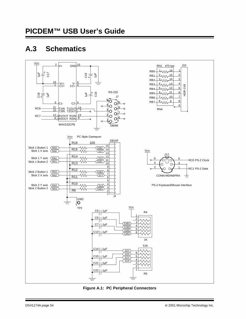
PICDEM™ USB User’s Guide
A.3 Schematics
Figure A.1: PC Peripheral Connectors
VDD
RC7
RC6
16 VCC
5C2-
6V-
9 R2OUT
10 T2IN11 T1IN
12 R1OUT
1 C1+
2 V+
8R2IN
7T2OUT14T1OUT
13R1IN
4C2+
15GND
3 C1-
MAX232CPE
9
8
7
61
2
3
4
5
DB9M
J7 RB6
RB5
RB3
RB2
RB0
RN1 470 typ.
RB7
RB1
RB4
RN4
7
4
1
9
3
5
6
8
2
6 11
3 14
8 9
4 13
5 12
2 15
7 10
1 16
VDD
RD3
RA2
RA1
RA0RD0
RA3
RD1
RD2
1TP2
GND
PC Style GameportDB15F
Stick 2 Button 2
Stick 2 X axis
Stick 1 Y axis
Stick 1 Button 1Stick 1 X axis
Stick 1 Button 2
Stick 2 Button 1
Stick 2 Y axis
RC1
RC0
PS-2 Data
PS-2 Keyboard/Mouse Interface
PS-2 Clock6 5
4
23
1
J12
CONN-MDIN6PRA
RS-232
1µF
C1
7
C18
1µF
C19
1µF
C16
1µF
HD
R-1
X9
J10
VDDS282
S2Y
151413
S2X121110
9
S1B2
S1Y
8765
S1XS1B1
4321
J4
R4
1K
51K
R5
123456
VDD
S281
S1B1S1B2S281S282
C5 .1µF
C6 .1µF
C7 .1µF
C13 .1µF
C14 .1µFS2YS2XS1YS1X
C15 .1µF
C21 .1µF
C22 .1µF
654321
R16 100
R15
R14
R13
R12
R11
R10
R6
DS41174A-page 54 2001 Microchip Technology Inc.

PICDEM™ USB Schematics
Figure A.2: LCD, LED and ICD Connections
10Ω
R3
RB7
RB6
RB3
VDDMCLR 1
2
3
4
6
5
J6
VDD
GND
VDD
GND GND
RD0
RE2
RE1
RE0
RD1
RD2
RD3
RD4
RD5
RD6
RD7
GND
4 RS
5 R/W
6 E
7 DB0 DB1
DB2
10DB3
11DB4
1 VSS
2 VCC
3 VEE12
DB5
13DB6
14DB7
LCD1
REDRN2:A
470
2 1
3 1
14
15
16
17
18
19
RB0
RB1
D3
RB2
RB3
D4
D5
D6
RB5
RB4
D7
RB7
D8
D9
D10
RB6
2 1J9
150 R2
1
LCD_DISPLAY
15 16
17 18
A A K K
9
8
RJ1
1_6P
IN
VDD
ICD (future expansion)
2001 Microchip Technology Inc. DS41174A-page 55

PICDEM™ USB User’s Guide
Figure A.3: PIC16C745 and Expansion Connector
VDD
RA5
RA4
RA2
RA1
MCLR
OSC2
OSC1
RA3
RA0
D+
D-
VUSB
RC7
RC2
RC1
RB7
RB5
RB4
RB2
RB1
RB0RE2
RB1RE0
RA5RB3
RA3RB4
RA2RB6
RA0RB7
RC6
RC0
RB6
RB3
RB0
RE1
RB2
RA4
RB5
RA1
MCLR
8VSS
19VSS
10OSC2
9OSC1
1MCLR
2RA0
3RA1
4RA2
5RA3
6RA4
7RA5
20VDD
22RB1
24RB3
25RB4
26RB5
27RB6
28RB7
23RB2
21RB0
11RC0
12RC1
13RC2
14VUSB
17RC618
RC7
15D-
16D+
PIC16C745 28-PDIP
U3123456789
1011121314151617181920
IDC2X20M
J5:1
VDDRD0
RD1RC1
RC0
RD3RC2RD2
RD4
RD6
RD5
RD7RC7
RC6
2122232425262728293031323334353637383940
IDC2X20M
J5:2
0.1µ
F
C11
DS41174A-page 56 2001 Microchip Technology Inc.
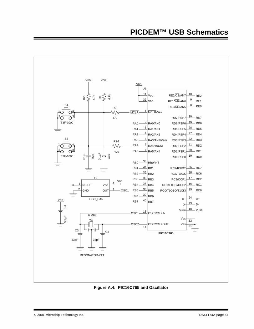
PICDEM™ USB Schematics
Figure A.4: PIC16C765 and Oscillator
VDD
D-
D+
RC0
RC1
RC2
RC6
RC7
RD0
RD1
RD2
RD3
RD4
RD5
RD6
RD7
RE0
RE1
RE2
OSC2
OSC1
RB7
RB6
RB5
RB4
RB3VDD
RB2
RB1
RB0
RA5
RA4
RA3
RA2
RA1
RA0
MCLR
VDD
VUSB
1
2
4
3
S1
B3F-1000
C2
33pF
470
R24
470
R9
Y4
6 MHz
RESONATOR-ZTT
C3
33pF
4VCC
3OUT2 GND
1 NC/OE
Y3
OSC_CAN 40 RB7
37 RB4
34 RB1
7 RA5/AN4
4 RA2/AN2
32 VDD
31VSS
18VUSB
26RC7/RX/DT
20RD1/PSP1
27RD4/PSP4
30RD7/PSP7
9RE1/WR/AN6
13 OSC1/CLKIN
36 RB3
38 RB5
39 RB6
6 RA4/T0CKI
33 RB0/INT
3 RA1/AN1
1 MCLR/VPP
2 RA0/AN0
11 VDD
12VSS
24D+
23D-
17RC2/CCP1
19RD0/PSP0
21RD2/PSP2
29RD6/PSP6
28RD5/PSP5
10RE2/CS/AN7
35 RB2 25RC6/TX/CK
22RD3/PSP3
8RE0/RD/AN5
14OSC2/CLKOUT
16RC1/T1OSI/CCP2
15RC0/T1OSO/T1CKI
5 RA3/AN3/VREF
PIC16C765
U5
VDD
OSC1
VDD
R2
3
4.7k R8
4.7
k
1
2
4
3
S2
B3F-1000
0.1µ
F
C20
0.1µ
F
C10
0.1µ
FC
1
2001 Microchip Technology Inc. DS41174A-page 57

PICDEM™ USB User’s Guide
Figure A.5: Power Supply and USB Connections
1
2
3
4
VBUS
D- 1.5kVUSB
R1
1.5k
R2
Full speed futureexpansion
1
3
2
J2
DJ005B
CR1
W02M 47µ
F
C12
VBUS
VDD
470
R7
Self/Bus Power
1IN3
OUT
U2LM7805
Gre
en
D2
1
3
J3
3PHDR
CO
M2
0.1µ
F
C8
10µF
C9
D+
2
+
+
DS41174A-page 58 2001 Microchip Technology Inc.

PICDEM™ USB Schematics
Figure A.6: Parts Placement Diagram
GameportJ4
D3
D4
D5
D6
D7
D8
D9
D10
RB
0J9
RB
1R
B2
RB
3R
B4
RB
5R
B6
RB
7
Pow
ered
Def
aultA
ddre
ssed C
onfig
uredS
leep
ing E
P0
-A
ct.
EP
1-
Act
. EP
2-
Act
.
US
BC
omm
unic
atio
nS
tatu
s(P
ortB
)
RN
1
Key
pad
J10
LCD
Mod
ule
R21
R22
RN2
LED
Ena
ble
R8
R9
R24
R23
R5
C22
C21
Y3
R1
5
R1
4
R11
R1
0
C10
MC
LR
S1
S2
RA
4
R4
PS-2
J12
C18
C17
C16
C19
J6 ICD
Fut
ure
Use
C6
C7
C5
C13 C
3
C2
Y4C1
U5
U3
PIC16C765
PIC16C745
MC
LRR
B7
RB
6R
B5
RB
4R
B3
RB
2R
B1
RB
0
RA
0R
A1
RA
2R
A3
RA
4R
A5
RE
0R
E1
RE
2
RD
7R
D6
RD
5R
D4
RD
3R
D2
RD
1R
D0
RC
7R
C6
RC
2R
C1
VD
D
GN
D
RC
0V
DD
GN
D
C11
R12
R13
R6
R16
U4
R7
D2
C8
C9
U2
CR
1S
elf
J3B
usJ2
C12
9-20
vA
C/D
C
J8U
SB
R1R
2
Ful
lSpe
edP
ull-
up
TP
3T
P4
C4
GN
DV
+
R3
LCD
Bac
klig
htP
ower
TP
1V
DD
GN
DT
P2
Pro
toty
ping
Are
a
C20
C14 C
15
PIC
DE
MU
SB
+ + + +
+
++
2001 Microchip Technology Inc. DS41174A-page 59

PICDEM™ USB User’s Guide
NOTES:
DS41174A-page 60 2001 Microchip Technology Inc.

PICDEM™ USB User’s Guide
Appendix B. PS/2 Lookup Tables
B.1 IntroductionThis appendix contains tables identifying command and scan codes associ-ated with PICDEM™ USB.
B.2 Scan CodesTable B-1: PS/2 KeycodesKey Make Break Key Make Break Key Make Break
A 1C F0,1C 9 46 F0,46 [ 54 F0,54
B 32 F0,32 ` 0E F0,0E INSERT E0,70 E0,F0,70
C 21 F0,21 - 4E F0,4E HOME E0,6C E0,F0,6C
D 23 F0,23 = 55 F0,55 PG UP E0,7D E0,F0,7D
E 24 F0,24 \ 5D F0,5D DELETE E0,71 E0,F0,71
F 2B F0,2B BKSP 66 F0,6 END E0,69 E0,F0,69
G 34 F0,34 SPACE 29 F0,29 PG DN E0,7A E0,F0,7A
H 33 F0,33 TAB 0D F0,0D U ARROW E0,75 E0,F0,75
I 43 F0,43 CAPS 58 F0,58 L ARROW E0,6B E0,F0,6B
J 3B F0,3B L SHFT 12 F0,12 D ARROW E0,72 E0,F0,72
K 42 F0,42 L CTRL 14 F0,14 R ARROW E0,74 E0,F0,74
L 4B F0,4B L WIN E0,1F E0,F0,1F NUM 77 F0,77
M 3A F0,3A L ALT 11 F0,11 KP / E0,4A F0,4A
N 31 F0,31 R SHFT 59 F0,59 KP * 7C F0,7C
O 44 F0,44 R CTRL E0,14 E0,F0,14 KP - 7B F0,7B
P 4D F0,4D R WIN E0,27 E0,F0,27 KP + 79 F0,79
Q 15 F0,15 R ALT E0,11 E0,F0,11 KP EN E0,5A F0,5A
R 2D F0,2D APPS E0,2F E0,F0,2F KP . 71 F0,71
S 1B F0,1B ENTER 5A F0,5A KP 0 70 F0,70
T 2C F0,2C ESC 76 F0,76 KP 1 69 F0,69
U 3C F0,3C F1 5 F0,05 KP 2 72 F0,72
V 2A F0,2A F2 6 F0,06 KP 3 7A F0,7A
W 1D F0,1D F3 4 F0,04 KP 4 6B F0,6B
X 22 F0,22 F4 0C F0,0C KP 5 73 F0,73
Y 35 F0,35 F5 3 F0,03 KP 6 74 F0,74
Z 1A F0,1A F6 0B F0,0B KP 7 6C F0,6C
0 45 F0,45 F7 83 F0,83 KP 8 75 F0,75
1 16 F0,16 F8 0A F0,0A KP 9 7D F0,7D
2 1E F0,1E F9 1 F0,01 ] 5B F0,5B
3 26 F0,26 F10 9 F0,09 ; 4C F0,4C
4 25 F0,25 F11 78 F0,78 ' 52 F0,52
5 2E F0,2E F12 7 F0,07 , 41 F0,41
6 36 F0,36
PAUSE
E1,14,77E1,F0,14F0,77 NONE
. 49 F0,49
7 3D F0,3D / 4A F0,4A
8 3E F0,3E PRNT E0,12, E0,F0,7C
SCROLL 7E F0,7E SCRN E0,7C E0,F0,12
2001 Microchip Technology Inc. DS41174A-page 61
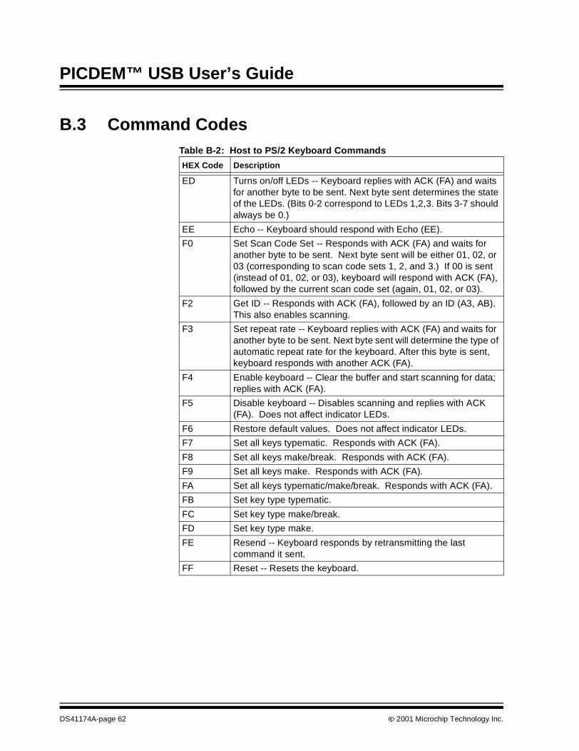
PICDEM™ USB User’s Guide
B.3 Command CodesTable B-2: Host to PS/2 Keyboard Commands
HEX Code Description
ED Turns on/off LEDs -- Keyboard replies with ACK (FA) and waitsfor another byte to be sent. Next byte sent determines the stateof the LEDs. (Bits 0-2 correspond to LEDs 1,2,3. Bits 3-7 shouldalways be 0.)
EE Echo -- Keyboard should respond with Echo (EE).
F0 Set Scan Code Set -- Responds with ACK (FA) and waits foranother byte to be sent. Next byte sent will be either 01, 02, or03 (corresponding to scan code sets 1, 2, and 3.) If 00 is sent(instead of 01, 02, or 03), keyboard will respond with ACK (FA),followed by the current scan code set (again, 01, 02, or 03).
F2 Get ID -- Responds with ACK (FA), followed by an ID (A3, AB).This also enables scanning.
F3 Set repeat rate -- Keyboard replies with ACK (FA) and waits foranother byte to be sent. Next byte sent will determine the type ofautomatic repeat rate for the keyboard. After this byte is sent,keyboard responds with another ACK (FA).
F4 Enable keyboard -- Clear the buffer and start scanning for data;replies with ACK (FA).
F5 Disable keyboard -- Disables scanning and replies with ACK(FA). Does not affect indicator LEDs.
F6 Restore default values. Does not affect indicator LEDs.
F7 Set all keys typematic. Responds with ACK (FA).
F8 Set all keys make/break. Responds with ACK (FA).
F9 Set all keys make. Responds with ACK (FA).
FA Set all keys typematic/make/break. Responds with ACK (FA).
FB Set key type typematic.
FC Set key type make/break.
FD Set key type make.
FE Resend -- Keyboard responds by retransmitting the lastcommand it sent.
FF Reset -- Resets the keyboard.
DS41174A-page 62 2001 Microchip Technology Inc.
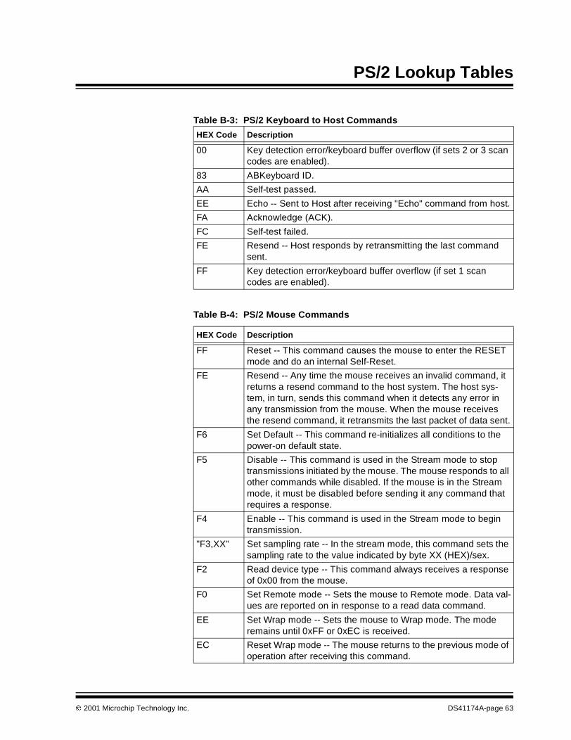
PS/2 Lookup Tables
Table B-3: PS/2 Keyboard to Host Commands
HEX Code Description
00 Key detection error/keyboard buffer overflow (if sets 2 or 3 scancodes are enabled).
83 ABKeyboard ID.
AA Self-test passed.
EE Echo -- Sent to Host after receiving "Echo" command from host.
FA Acknowledge (ACK).
FC Self-test failed.
FE Resend -- Host responds by retransmitting the last commandsent.
FF Key detection error/keyboard buffer overflow (if set 1 scancodes are enabled).
Table B-4: PS/2 Mouse Commands
HEX Code Description
FF Reset -- This command causes the mouse to enter the RESETmode and do an internal Self-Reset.
FE Resend -- Any time the mouse receives an invalid command, itreturns a resend command to the host system. The host sys-tem, in turn, sends this command when it detects any error inany transmission from the mouse. When the mouse receivesthe resend command, it retransmits the last packet of data sent.
F6 Set Default -- This command re-initializes all conditions to thepower-on default state.
F5 Disable -- This command is used in the Stream mode to stoptransmissions initiated by the mouse. The mouse responds to allother commands while disabled. If the mouse is in the Streammode, it must be disabled before sending it any command thatrequires a response.
F4 Enable -- This command is used in the Stream mode to begintransmission.
"F3,XX" Set sampling rate -- In the stream mode, this command sets thesampling rate to the value indicated by byte XX (HEX)/sex.
F2 Read device type -- This command always receives a responseof 0x00 from the mouse.
F0 Set Remote mode -- Sets the mouse to Remote mode. Data val-ues are reported on in response to a read data command.
EE Set Wrap mode -- Sets the mouse to Wrap mode. The moderemains until 0xFF or 0xEC is received.
EC Reset Wrap mode -- The mouse returns to the previous mode ofoperation after receiving this command.
2001 Microchip Technology Inc. DS41174A-page 63

PICDEM™ USB User’s Guide
EB Read data -- This command requests that all data defined in thedata packet format be transmitted. This command is executed ineither Remote or Stream mode. This data is transmitted even ifthere has been no movement since the last report or the switchstatus is unchanged.
EA Set Stream mode -- This command sets the mouse to Streammode.
E9 Status request -- When this command is issued by the system,the mouse responds with a 3-byte status report, same as DataReport.
"E8,XX" Set resolution -- The mouse provides 4 resolutions, selected bythe second byte of the command.
E7 Set scaling 2:1 -- Scaling is used to provide a course/fine track-ing response. At the end of a sample interval in the streammode, the current X and Y data values are converted to newvalues. The sign bits are not involved in the conversion. 2:1scaling is performed only in Stream mode. In response to a readdata command, the current value before conversion is sent.
E6 Reset scaling -- This command restores scaling to 1:1.
Table B-4: PS/2 Mouse Commands (Continued)
HEX Code Description
DS41174A-page 64 2001 Microchip Technology Inc.
PICDEM™ USB USER’S GUIDE
Glossary
IntroductionThis glossary provides a common frame of reference by defining the termsthat follow.
HighlightsThis glossary contains:
• PICSTART Plus Terms
PICDEM™ USB TermsApplication
A set of software and hardware developed by the user, usually designed to bea product controlled by a PICmicro microcontroller.
Assembler Source Code
A text file that is processed by an assembler to produce a one-to-onecorrespondence between assembler instructions and PICmicro machinecode.
Assemble
To translate a user’s “ASM” source text code into machine code.
Breakpoint – Software
An address where execution of the firmware will HALT.
Breakpoint – Hardware
An event whose execution will cause a HALT.
Build
A function that recompiles all the source files for an application.
C Source Code
A program written in the high level language called “C,” and which will beconverted into PICmicro machine code.
Compile
To translate a user’s “C” source text code into machine code.
Configuration Bits
Unique bits programmed to set modes of operation. A configuration bit may ormay not be preprogrammed. For MPLAB ICE, these bits are set in theOptions>Processor Setup dialog.
2001 Microchip Technology Inc. DS41174A-page 65

PICDEM™ USB User’s Guide
Data RAM
General purpose file registers from RAM on the PICmicro device beingemulated. The File Register window displays data RAM.
Download
Download is the process of sending data from the host PC to the emulator orto the target board.
EEPROM
Electrically Erasable Programmable Read Only Memory. A special type ofPROM that can be erased electrically. Data is written or erased one byte at atime. EEPROM retains its contents even when power is turned off.
Emulation
The process of executing software loaded into memory on the emulatorprobe, as if the firmware resided on the microcontroller device underdevelopment.
Emulation Memory
Program memory contained within the emulator.
Emulator
Hardware that performs emulation.
Emulator System
The Microchip Emulator System includes the MPLAB ICE Pod, processormodule, device adapter, cables and the MPLAB software.
Enumeration
Enumeration is the process of a device communicating its requirements to thehost and the host assigning a unique address to the device.
Event
A description of a bus cycle which may include address, data, pass count,external input, cycle type (fetch, R/W) and time stamp.
Export
Send data out of MPLAB IDE in a standardized format.
Extended Microcontroller Mode (PIC17CXX Devices Only)
In Extended Microcontroller mode, on-chip program memory, as well asexternal memory, are available. Execution automatically switches to externalif the program memory address is greater than the internal memory space ofthe PIC17CXX device. Inaccessible memory in Extended Microcontrollermode includes configuration bits, test memory, and boot memory.
External Input Line (MPLAB ICE 2000 Only)
An External Input Signal Logic Probe Line (TRIGIN) for setting an eventbased upon external signals.
DS41174A-page 66 2001 Microchip Technology Inc.

Glossary
External RAM (PIC17CXX Devices Only)
Off-chip Read/Write memory.
File Registers
On-chip general purpose and special function registers.
FLASH
A type of EEPROM where data is written or erased in blocks instead of bytes.
FNOP
Forced No Operation. A forced NOPcycle is the second cycle of a two-cycleinstruction. Since the PICmicro architecture is pipelined, it pre-fetches thenext instruction in the physical address space while it is executing the currentinstruction. However, if the current instruction changes the program counter,this pre-fetched instruction is explicitly ignored, causing a forced NOPcycle.
HALT
The command that stops the emulator. Executing HALT is the same asstopping at a break point. The program counter stops, and the user caninspect and change register values, and single step through code.
HEX Code
A file of executable instructions assembled or compiled from source code intostandard HEX format code. HEX code can be directly converted to objectcode.
High Level Language
A language for writing programs that is of a higher level of abstraction fromthe processor than assembler code. High level languages (such as C) employa compiler to translate statements into machine instructions that the targetprocessor can execute.
ICE
In-Circuit Emulator. MPLAB ICE is Microchip’s In-Circuit Emulator that workswith MPLAB IDE.
IDE
Integrated Development Environment. An application that has multiplefunctions for firmware development. The MPLAB IDE integrates a compiler,an assembler, a project manager, an editor, a debugger, a simulator, and anassortment of other tools within one Windows application. A user developingan application should be able to write code, compile, debug and test anapplication without leaving the MPLAB desktop.
Import
Bring data into the MPLAB Integrated Development Environment (IDE) froman outside source
Mac
Short for Macintosh.
2001 Microchip Technology Inc. DS41174A-page 67

PICDEM™ USB User’s Guide
MacOS
The Macintosh Operating System. Versions 8.6 and higher have USBsupport.
Make Project
A command that rebuilds an application, recompiling only those source filesthat have changed since the last complete compilation.
Microcontroller Mode
One of the possible program memory configurations of the PIC17CXX familyof microcontrollers. In Microcontroller mode, only internal execution isallowed. Thus, only the on-chip program memory is available inMicrocontroller mode. Accessible memory includes: program memory,configuration bits, test memory, and boot memory (FE00h to FFFFh).
Microprocessor Mode
One of the possible program memory configurations of the PIC17CXX familyof microcontrollers. In Microprocessor mode, the on-chip program memory isnot used. The entire 64K program memory is mapped externally. Inaccessiblememory in Microprocessor mode includes configuration bits, test memory,and boot memory.
MPLAB ICE
Microchip’s in-circuit emulator that works with MPLAB IDE.
MPSIM
Microchip’s simulator that works with MPLAB IDE.
MPLAB Software
The name of the main executable program that supports the IDE with anEditor, Project Manager, and Emulator/Simulator Debugger. The MPLABSoftware resides on the PC host. The executable file name is MPLAB.EXE. MPLAB.EXEcalls many other files.
MRU
Most Recently Used. Refers to files and windows available to be selectedfrom MPLAB main pull-down menus.
Non Real-Time
Refers to the processor executing single step instructions, or MPLAB IDEbeing run in Simulator mode.
NOP
No operation.
DS41174A-page 68 2001 Microchip Technology Inc.

Glossary
Object Code
The machine code that is produced from the source code after it is processedby an assembler or compiler. This code will be the memory resident code thatwill run on the PICmicro MCU in the user’s application. Relocatable code iscode produced by MPASM Assembler or MPLAB C17, that can be runthrough MPLINK Object Linker.
Off-Chip Memory
Off-Chip Memory refers to the memory selection option for the PIC17CXXdevice, where memory may reside on the target board, or where all programmemory may be supplied by the emulator. Options > Processor Setup >Hardware provides the Off-Chip Memory selection dialog box.
PC
Any IBM or compatible Personal Computer. MPLAB IDE needs a 486X orbetter machine.
Host
The computer that is serving as master to a USB device. This could be anymachine with a USB interface, including PC’s or Mac’s.
PICmicro MCU
PICmicro MCU refers to the PIC12CXX, PIC14000, PIC16C5X, PIC16CXX,PIC17CXX and PIC18CXX Microchip microcontroller families.
PICMASTER Emulator
The hardware unit that provides tools for emulating and debugging firmwareapplications. This unit contains emulation memory, break point logic,counters, timers, and a trace analyzer among some of its tools. MPLAB ICE isthe newest emulator from Microchip.
Pod
The external emulator box that contains emulation memory, trace memory,event and cycle timers, and trace/break point logic. Occasionally used as anabbreviated name for the MPLAB ICE Emulator.
Power-on Reset Emulation
A software randomization process that writes random values in data RAMareas to simulate uninitialized values in RAM upon initial power application.
Program Counter
A register that specifies the current execution address for emulation andsimulation.
Program Memory
Memory containing the downloaded target application firmware.
Project
A set of source files and instructions to build the object code for anapplication.
2001 Microchip Technology Inc. DS41174A-page 69

PICDEM™ USB User’s Guide
PRO MATE II
A device programmer from Microchip. Can be used with MPLAB IDE orstand-alone.
Prototype System
A term referring to a user's target application, or target board.
PWM Signals
Pulse Width Modulation Signals. Certain PICmicro devices have a PWMperipheral.
Radix
The number base, hex, or decimal, used in selecting an address and forentering data in the Window > Modify command.
Real-Time
When released from the HALT state, the processor runs in Real-Time modeand behaves exactly as the normal chip would behave. In Real-Time mode,the real-time trace buffer is enabled and constantly captures all selectedcycles, and all break logic is enabled. In the emulator, the processor executesin real-time until a valid break point causes a HALT, or until the user halts theemulator.
In the simulator, real-time simply means execution of the microcontrollerinstructions as fast as they can be simulated by the host CPU.
Run
The command that releases the emulator or simulator from HALT, allowing itto run the application code and change or respond to I/O in real-time.
SFR
Special Function Registers of a PICmicro MCU.
Simulator
A software program that models the operation of the PICmicromicroprocessor.
Simulator Stimulus
Data generated to exercise the response of MPSIM Simulator to externalsignals. Often the data is put into the form of a list of actions in a text file.
Single Step
This command steps though code, one instruction at a time with MPSIMSimulator or an emulator. After each instruction, MPLAB IDE updates registerwindows, watch variables, and status displays, so you can analyze and debuginstruction execution.
You can also single step C compiler source code, but instead of executingsingle instructions, MPLAB IDE will execute all assembly level instructionsgenerated by the line of the high level C statement.
DS41174A-page 70 2001 Microchip Technology Inc.

Glossary
Source
Source code, usually a text file of assembly instructions or C code.
Special Function Registers
Registers that control I/O processor functions, I/O status, timers, or othermodes or peripherals.
Stack
“Push-Down” list of calling routines. Each time a PICmicro microcontrollerexecutes a call or responds to an interrupt, the software pushes the returnaddress to the stack. A return command pops the address from the stack.
Step-Into
This command is the same as Single Step. Step-Into (as opposed to Step-Over) follows a CALL instruction into a subroutine.
Step-Over
Step-Over allows you to debug code without stepping into subroutines. Whenstepping over a CALL instruction, the next break point will be set at theinstruction after the CALL. If for some reason, the subroutine gets into anendless loop or does not return properly, the next break point will never bereached.
The Step-Over command is similar to Single Step, except for its handling ofCALL instructions.
Symbol
A label usually produced by an assembler or compiler that refers to machinelocations by function names, variable locations, constant declarations, sourceline number, or other reference to user source code.
System Button
The System Button is located in the upper left corner of Windows and somedialogs. This button usually has “Minimize,” “Maximize,” and “Close.” In someMPLAB windows, additional modes or functions can be found under theSystem Button.
Target
Refers to user hardware.
Target Application
Firmware residing on the target board.
Target Board
The circuitry and programmable device that makes up the target application.
Target Processor
The microcontroller device on the target application board that is beingemulated.
2001 Microchip Technology Inc. DS41174A-page 71

PICDEM™ USB User’s Guide
Template
Lines of text that you build for inserting into your files at a later time. TheMPLAB Editor stores templates in template files.
Tool Bar
A row or column of icons that you can click on to execute MPLAB functions.
Trace
An emulator or simulator function that logs program execution. The emulatorlogs program execution into its trace buffer, which is uploaded to MPLAB’strace window.
Trace Memory
Trace Memory contained within the Emulator. Trace Memory is sometimescalled the Trace Buffer.
Trigger Output
Trigger Output refers to an emulator output signal that can be generated atany address or address range, and is independent of the trace and breakpoint settings. Any number of trigger output points can be set.
Upload
The Upload function transfers data from the emulator to the host PC, or fromthe target board to the emulator.
USB
Universal Serial Bus. A popular bus for connecting peripherals to personalcomputers.
Warning
An alert that is provided to warn you of a situation that would cause physicaldamage to a device, software file, or equipment.
Watchdog Timer
A timer on a PICmicro microcontroller that resets the processor after aselectable length of time.
Watch Variable
A variable that you may monitor during a debugging session. Watch windowscontain a list of watch variables that are updated at each break point.
DS41174A-page 72 2001 Microchip Technology Inc.

PICDEM™ USB USER’S GUIDE
Index
AApplications .................................................... 10
Describing ................................................ 11Integrating USB ........................................ 39
BBreakpoints .................................................... 65Buttons ........................................................... 36
CCodes ............................................................. 61
Command ................................................ 62Host to PS/2 ...................................... 62PS/2 Mouse ....................................... 63PS/2 to Host ...................................... 63
Scan ......................................................... 61PS/2 Keycodes .................................. 61
Components ..................................................... 9Configuration Bits ........................................... 65Cursor Demonstration .................................... 48
MPLAB ICE .............................................. 49PIC16C745/765 ....................................... 48
Customer Support ............................................ 7
DDefault Demonstration .................................... 10Demonstration Code ...................................... 13Descriptors
Creating ................................................... 11Multiple ..................................................... 46Report - Debugging .................................. 11
Development SystemsCompilers ................................................... 6Emulators ................................................... 6MPLAB IDE ................................................ 7Programmers ............................................. 6
Development Systems CustomerNotification Service .............................. 5
Document Conventions .................................... 2Updates ...................................................... 3
EEEPROM ........................................................ 66Emulation ........................................................ 50Emulator System ............................................ 66Endpoints, Multiple ......................................... 23Error Counter .................................................. 47Extended Microcontroller Mode ...................... 66External Input Line .......................................... 66External RAM .................................................. 67
FFunction Call Reference
GetEPn ..................................................... 43PutEPn ..................................................... 42
FunctionsCheckSleep ........................................ 43, 45ConfiguredUSB ........................................ 44InitUSB ............................................... 42, 44ServiceUSBlnt .......................................... 43SetConfiguration ...................................... 44SoftDetachUSB ........................................ 43StallUSBEP/UnstallUSBEP ...................... 43
GGameport ........................................................ 13
Connector Pinout ..................................... 32Hardware Implementation ........................ 14Identification Codes .................................. 17Reading Firmware .................................... 15Translation ............................................... 16USB Translator ......................................... 13
Gameport/PS/2 Combination .......................... 23GetEPn ........................................................... 47Glossary .......................................................... 65
HHID Class ........................................................ 48
2001 Microchip Technology Inc. DS41174A-page 73

PICDEM™ USB User’s Guide
IICE ..................................................................67IDE ..................................................................67Internet Address ...............................................4Interrupt Structure ...........................................40
Buffer Allocation .......................................41File Packaging ..........................................41Function Call Reference ...........................42Processor Resources ...............................40RAM .........................................................40ROM .........................................................40Stack Levels .............................................40
JJumpers ..........................................................36
KKeypad
Connector Pinout ......................................35
LLCD
Connector Pinout ......................................35Hardware Implementation ........................25Macintosh Code Support ..........................30PC Code Support .....................................29PC/Macintosh Identification ......................29Report Descriptor .....................................27USB Command Set ..................................27
LCD Driver Firmware ......................................26LCD Text Display ............................................25
MMicrochip Internet Web Site ..............................4Microcontroller Mode ......................................68Microprocessor Mode .....................................68MPLAB ............................................................68MPLAB ICE .....................................................68MPSIM ............................................................68
OOff-Chip Memory .............................................69Oscillator Support ............................................31
Canned .....................................................31Crystal ......................................................32Resonator .................................................31
PPass Counter ..................................................69PICMASTER ...................................................69Power ..............................................................37
Bus Power ................................................37Self Power ................................................37
Project .............................................................69PS/2 ................................................................17
Connector Pinout ......................................33Firmware ...................................................20Hardware Implementation ........................17
PutEPn ............................................................47
RRecommended Reading ...................................3RS-232
Connector Pinout ......................................34
SSchematics ......................................................54
TText Terminal
USB Command SetInput Commands ................................29
Trace ...............................................................72Troubleshooting ..............................................51
UUSB
Connector Pinout ......................................36Software Interface ....................................39Status on PORTB .....................................47
WWarranty Registration .......................................3WWW Address ..................................................4
DS41174A-page 74 2001 Microchip Technology Inc.

Index
NOTES:
2001 Microchip Technology Inc. DS41174A-page 75

DS41174A-page 76 2001 Microchip Technology Inc.
AMERICASCorporate Office2355 West Chandler Blvd.Chandler, AZ 85224-6199Tel: 480-792-7200 Fax: 480-792-7277Technical Support: 480-792-7627Web Address: http://www.microchip.comRocky Mountain2355 West Chandler Blvd.Chandler, AZ 85224-6199Tel: 480-792-7966 Fax: 480-792-7456
Atlanta500 Sugar Mill Road, Suite 200BAtlanta, GA 30350Tel: 770-640-0034 Fax: 770-640-0307Austin - Analog13740 North Highway 183Building J, Suite 4Austin, TX 78750Tel: 512-257-3370 Fax: 512-257-8526Boston2 Lan Drive, Suite 120Westford, MA 01886Tel: 978-692-3848 Fax: 978-692-3821Boston - AnalogUnit A-8-1 Millbrook Tarry Condominium97 Lowell RoadConcord, MA 01742Tel: 978-371-6400 Fax: 978-371-0050Chicago333 Pierce Road, Suite 180Itasca, IL 60143Tel: 630-285-0071 Fax: 630-285-0075Dallas4570 Westgrove Drive, Suite 160Addison, TX 75001Tel: 972-818-7423 Fax: 972-818-2924DaytonTwo Prestige Place, Suite 130Miamisburg, OH 45342Tel: 937-291-1654 Fax: 937-291-9175DetroitTri-Atria Office Building32255 Northwestern Highway, Suite 190Farmington Hills, MI 48334Tel: 248-538-2250 Fax: 248-538-2260Los Angeles18201 Von Karman, Suite 1090Irvine, CA 92612Tel: 949-263-1888 Fax: 949-263-1338New York150 Motor Parkway, Suite 202Hauppauge, NY 11788Tel: 631-273-5305 Fax: 631-273-5335San JoseMicrochip Technology Inc.2107 North First Street, Suite 590San Jose, CA 95131Tel: 408-436-7950 Fax: 408-436-7955Toronto6285 Northam Drive, Suite 108Mississauga, Ontario L4V 1X5, CanadaTel: 905-673-0699 Fax: 905-673-6509
ASIA/PACIFICAustraliaMicrochip Technology Australia Pty LtdSuite 22, 41 Rawson StreetEpping 2121, NSWAustraliaTel: 61-2-9868-6733 Fax: 61-2-9868-6755China - BeijingMicrochip Technology Consulting (Shanghai)Co., Ltd., Beijing Liaison OfficeUnit 915Bei Hai Wan Tai Bldg.No. 6 Chaoyangmen BeidajieBeijing, 100027, No. ChinaTel: 86-10-85282100 Fax: 86-10-85282104China - ChengduMicrochip Technology Consulting (Shanghai)Co., Ltd., Chengdu Liaison OfficeRm. 2401, 24th Floor,Ming Xing Financial TowerNo. 88 TIDU StreetChengdu 610016, ChinaTel: 86-28-6766200 Fax: 86-28-6766599China - FuzhouMicrochip Technology Consulting (Shanghai)Co., Ltd., Fuzhou Liaison OfficeRm. 531, North BuildingFujian Foreign Trade Center Hotel73 Wusi RoadFuzhou 350001, ChinaTel: 86-591-7557563 Fax: 86-591-7557572China - ShanghaiMicrochip Technology Consulting (Shanghai)Co., Ltd.Room 701, Bldg. BFar East International PlazaNo. 317 Xian Xia RoadShanghai, 200051Tel: 86-21-6275-5700 Fax: 86-21-6275-5060China - ShenzhenMicrochip Technology Consulting (Shanghai)Co., Ltd., Shenzhen Liaison OfficeRm. 1315, 13/F, Shenzhen Kerry Centre,Renminnan LuShenzhen 518001, ChinaTel: 86-755-2350361 Fax: 86-755-2366086Hong KongMicrochip Technology Hongkong Ltd.Unit 901-6, Tower 2, Metroplaza223 Hing Fong RoadKwai Fong, N.T., Hong KongTel: 852-2401-1200 Fax: 852-2401-3431IndiaMicrochip Technology Inc.India Liaison OfficeDivyasree Chambers1 Floor, Wing A (A3/A4)No. 11, O’Shaugnessey RoadBangalore, 560 025, IndiaTel: 91-80-2290061 Fax: 91-80-2290062
JapanMicrochip Technology Japan K.K.Benex S-1 6F3-18-20, ShinyokohamaKohoku-Ku, Yokohama-shiKanagawa, 222-0033, JapanTel: 81-45-471- 6166 Fax: 81-45-471-6122
KoreaMicrochip Technology Korea168-1, Youngbo Bldg. 3 FloorSamsung-Dong, Kangnam-KuSeoul, Korea 135-882Tel: 82-2-554-7200 Fax: 82-2-558-5934SingaporeMicrochip Technology Singapore Pte Ltd.200 Middle Road#07-02 Prime CentreSingapore, 188980Tel: 65-334-8870 Fax: 65-334-8850TaiwanMicrochip Technology Taiwan11F-3, No. 207Tung Hua North RoadTaipei, 105, TaiwanTel: 886-2-2717-7175 Fax: 886-2-2545-0139
EUROPEDenmarkMicrochip Technology Denmark ApSRegus Business CentreLautrup hoj 1-3Ballerup DK-2750 DenmarkTel: 45 4420 9895 Fax: 45 4420 9910FranceArizona Microchip Technology SARLParc d’Activite du Moulin de Massy43 Rue du Saule TrapuBatiment A - ler Etage91300 Massy, FranceTel: 33-1-69-53-63-20 Fax: 33-1-69-30-90-79GermanyArizona Microchip Technology GmbHGustav-Heinemann Ring 125D-81739 Munich, GermanyTel: 49-89-627-144 0 Fax: 49-89-627-144-44Germany - AnalogLochhamer Strasse 13D-82152 Martinsried, GermanyTel: 49-89-895650-0 Fax: 49-89-895650-22ItalyArizona Microchip Technology SRLCentro Direzionale ColleoniPalazzo Taurus 1 V. Le Colleoni 120041 Agrate BrianzaMilan, ItalyTel: 39-039-65791-1 Fax: 39-039-6899883United KingdomArizona Microchip Technology Ltd.505 Eskdale RoadWinnersh TriangleWokinghamBerkshire, England RG41 5TUTel: 44 118 921 5869 Fax: 44-118 921-5820
08/01/01
WORLDWIDE SALES AND SERVICE