Materials Handbook A Concise Desktop Reference Third ...
78
123 François Cardarelli Materials Handbook A Concise Desktop Reference Third Edition
-
Upload
khangminh22 -
Category
Documents
-
view
1 -
download
0
Transcript of Materials Handbook A Concise Desktop Reference Third ...

123
François Cardarelli
Materials HandbookA Concise Desktop ReferenceThird Edition
François Cardarelli
Materials Handbook
A Concise Desktop Reference
3rd Edition

ISBN 978-3-319-38923-3 ISBN 978-3-319-38925-7 (eBook) https://doi.org/10.1007/978-3-319-38925-7
Library of Congress Control Number: 2018940467
© Springer International Publishing AG, part of Springer Nature 2000, 2008, 2018This work is subject to copyright. All rights are reserved by the Publisher, whether the whole or part of the material is concerned, specifically the rights of translation, reprinting, reuse of illus-trations, recitation, broadcasting, reproduction on microfilms or in any other physical way, and transmission or information storage and retrieval, electronic adaptation, computer software, or by similar or dissimilar methodology now known or hereafter developed.The use of general descriptive names, registered names, trademarks, service marks, etc. in this publication does not imply, even in the absence of a specific statement, that such names are exempt from the relevant protective laws and regulations and therefore free for general use.The publisher, the authors and the editors are safe to assume that the advice and information in this book are believed to be true and accurate at the date of publication. Neither the publisher nor the authors or the editors give a warranty, express or implied, with respect to the material contained herein or for any errors or omissions that may have been made.
Printed on acid-free paper
This Springer imprint is published by the registered company Springer International Publish-ing AG, part of Springer Nature.The registered company address is: Gewerbestrasse 11, 6330 Cham, Switzerland
François Cardarelli, President & OwnerElectrochem Technologies & Materials Inc.2037 Aird avenue, Suite 201Montréal (QC) H1V 2V9, Canadawww.electrochem-technologies.com

9.1 Thermocouple Materials – 808
9.2 Resistors and Thermistors – 811
9.3 Electron-Emitting Materials – 816
9.4 Photocathode Materials – 821
9.5 Secondary Emission – 821
9.6 Electrolytes – 821
9.7 Electrode Materials – 824
9.8 Electrochemical Galvanic Series – 869
9.9 Selected Standard Electrode Potentials – 869
9.10 Reference Electrodes Potentials – 869
9.11 Ampacity or Maximum Carrying Current – 876
807 9
Miscellaneous
Electrical Materials
© Springer International Publishing AG, part of Springer Nature 2018 F. Cardarelli, Materials Handbook, https://doi.org/10.1007/978-3-319-38925-7_9

9
9.1 Thermocouple Materials
9.1.1 The Seebeck Effect
In 1821, the Estonian physicist Thomas Johann Seebeck observed that when two wires of dissim-ilar conductors A and B (i.e., metals, alloys, or semiconductors) are joined together at both ends and the two junctions are kept at two different temperatures – that is, cold junction temperature Tc and hot junction temperature Th (. Fig. 9.1) – the temperature differential ΔT = (Th − Tc) produces an electric current that flows continuously through the circuit. This phenomenon was called the Seebeck effect after its discoverer.
When the circuit is open, there appears an electric potential difference called the Seebeck electromotive force, denoted eAB and expressed in volts. This voltage is a complex function of both the temperature difference and the type of conductors [i.e., eAB = F(ΔT, A, B)]. In practice, the Seebeck electromotive force is related to the temperature difference by a polynomial equa-tion, where the polynomial coefficients (i.e., c0, c1, c2, c3, etc.) are empirical constants determined by experiment and that characterize the thermocouple selected:
eAB = c0 + c1�T + c2�T2 + c3�T
3 + c4�T4 + : : : :
However for a small temperature difference, the Seebeck electromotive force can be assumed to be directly proportional to the temperature difference:
eAB = �˛�T = �˛.Th − Tc/;
where the algebraic physical quantity Δα is called the relative Seebeck coefficient or the ther-moelectric power, denoted QAB and expressed in V/k. Thermoelectric power corresponds to the difference between the absolute Seebeck coefficients of the conductors:
�˛ = QAB = ˛A − ˛B:
In practice, the thermoelectric power of a conductor A is usually reported for a temperature difference of 100 °C between the hot and cold junctions and for a fixed second material B. The second material used as the standard is most often pure platinum and less frequently copper or even lead. Hence, the thermoelectric power is reported in modern tables in millivolts versus platinum or millivolts versus copper. Therefore, to convert a thermoelectric power measured with a given scale to another scale, the following simple equations can be used:
QAPt = QACu + QCuPt; with QCuPt = +0:75mV vs Pt .0 − 100ı
C/;
QAPt = QAPb + QPbPt; with QPbPt = +0:44mV vs Pt .0 − 100ı
C/:
. Fig. 9.1 Thermocouple basic circuit
Tc Th
A
B
Chapter 9 • Miscellaneous Electrical Materials808

.
Ta
ble
9.1
The
rmoe
lect
ric p
ower
QA
B of
sel
ecte
d el
emen
ts a
nd c
omm
erci
al a
lloys
(A) v
ersu
s pu
re p
latin
um (B
is P
t) fo
r ΔT
= 10
0 °C
(mV
vs P
t)
AQ
AB
AQ
AB
AQ
AB
AQ
AB
AQ
AB
AQ
AB
AQ
AB
Li+
1.82
Ben.
a.
Al
+0.
39C
+0.
22A
sn.
a.
Sen.
a.
Run.
a.
Na
−0.
20M
g+
0.42
Ga
n. a
.Si
+44
.8Sb
+4.
89Te
+50
.0Rh
+0.
65
K−
0.83
Ca−
0.51
In+
0.69
Ge
+33
.9Bi
−7.
34Cr
n. a
.Pd
−0.
47
Rb+
0.46
Srn.
a.
Tl+
0.58
Sn+
0.42
Vn.
a.
Mo
+1.
45O
sn.
a.
Cs+
0.50
Ban.
a.
Scn.
a.
Pb+
0.44
Nb
n. a
.W
+0.
80Ir
+0.
66
Cu+
0.75
Zn+
0.76
Yn.
a.
Tin.
a.
Ta+
0.41
Fe+
1.98
Pt0.
00
Ag
+0.
73Cd
+0.
91La
n. a
.Zr
+1.
17M
n+
0.70
Ni
−1.
48U
n. a
.
Au
+0.
70H
g+
0.06
Ce+
1.14
Hf
n. a
.Re
n. a
.Co
−1.
33Th
−0.
13
Com
mer
cial
allo
ys (m
V vs
Pt)
: ber
ylliu
m–c
oppe
r (97
.3Cu
-2.7
Be),
+0.
67; y
ello
w b
rass
(70C
u-30
Zn),
+0.
60; n
icke
l–ch
rom
e (8
0Ni-2
0Cr)
, +1.
14; s
tain
less
ste
el (F
e-18
Cr-8
Ni),
+
0.44
; lea
d so
lder
(50S
n-50
Pb),
+0.
46; p
hosp
hor b
ronz
e (9
6Cu-
3.5S
n-0.
3P),
+0.
55; M
anga
nin
(84C
u-12
Mn-
4Ni),
+0.
61; c
onst
anta
n (4
5Ni-5
5Cu)
, −3.
51; A
lum
el (9
5Ni-2
Mn-
2Al),
−1.
29; C
hrom
el (9
0Ni-9
Cr),
+2.
81
n. a
. not
ava
ilabl
e
809 99.1 • Thermocouple Materials

9
The thermoelectric power is commonly in the range of several mV/K for semiconductors and of several μV/K for most metals and alloys (. Table 9.1). On the other hand, for semiconduc-tors, the theoretical thermoelectric power can be assessed by means of the following equation:
QAB = −Cv=3eNe;
where Ne is the electronic density in the conductor and Cv is the molar heat capacity at constant volume.
9.1.2 Thermocouple
A thermocouple is a particular temperature-sensing device consisting, in its simplest design, of two wires made of two dissimilar conductors, A and B, that are joined by two junctions. The cold junction is maintained at a well-known temperature (e.g., the ice point), while the other junction serves as a probe. The electromotive force measured with a high-precision voltmeter is then proportional to the temperature of the hot junction. The signal can even be amplified by the connecting in series of n identical thermocouples (. Fig. 9.2).
The resulting overall electromotive force ΔV is the sum of all the individual electromotive forces of each thermocouple and is easier to measure with accuracy:
�V = QAB�T + QAB�T2 + QAB�T3 + QAB�T4 + : : : + QAB�Tn = QAB
Pk
�Tk:
9.1.3 Properties of Common Thermocouple Materials
See . Tables 9.2–9.4.
. Fig. 9.2 Thermocouples in seriesTh
Tc
μV
Chapter 9 • Miscellaneous Electrical Materials810

. Table 9.2 Standard thermocouple types and common uses
Type Description
J Suitable in reducing, vacuum, or inert atmospheres but limited use in oxidizing atmosphere at high temperature. Not recommended for low temperatures
K Clean and oxidizing atmospheres. Limited use in vacuum or reducing atmospheres. Wide tempera-ture range
S Oxidizing or inert atmospheres. Beware of contamination. For high temperatures
R Oxidizing or inert atmospheres. Beware of contamination. For high temperatures
N Stabler than type K at high temperature
B Oxidizing or inert atmospheres. Beware of contamination. For high temperatures
E Oxidizing or inert atmospheres. Limited use in vacuum or reducing atmospheres. Highest thermo-electric power
C Suitable in reducing, vacuum, or inert atmospheres. Beware of embrittlement. Not suitable for oxidizing atmospheres and not practical below 400 °C
T Suitable in mid-oxidizing, reducing, vacuum, or inert atmospheres. Good for cryogenic applica-tions
9.2 Resistors and Thermistors
Resistors are special conductive metals and alloys, such as Manganin®, each having an accurateand well-known electrical resistivity combined with an extremely low temperature coefficient, and for that reason they are currently used in high-precision electric and electronic instruments and devices such as calibrated resistances, shunts, and rheostats. Two major classes must be distinguished depending on their end use:1. Resistance alloys are special conductive metals and alloys having a uniform and stable elec-
trical resistivity combined with a constant temperature coefficient and a low thermoelectricpower versus copper; Manganin and pure platinum are well-known examples.
2. Heating alloys are metals or alloys having a high electrical resistivity combined with a highmelting point; hence, they are selected as heating elements in resistance furnaces; nickel–chromium is a typical example.
9.2.1 Electrical Resistivity
Electrical resistivity is an intrinsic property of a resistor material that allows the calculation of the electrical resistance, R, expressed in ohms, of a homogeneous conductor with a regular cross-sectional area, A, expressed in square meters, and a length, L, expressed in meters. R is given by the following equation, where the proportionality quantity, ρ, is the electrical resistivity of the material, expressed in ohm meters:
R = �.L=A/:
811 99.2 • Resistors and Thermistors

9
.
Ta
ble
9.3
Phy
sica
l pro
pert
ies
of s
elec
ted
ther
moc
oupl
e m
ater
ials
Thermocouple
type (ANSI)
Metal and alloy
trade names
Average chemi-
cal composition
(wt%)
Junction polarity
Mass density
(ρ/kg · m−3)
Yield strength
0.2% proof (σYS/
MPa) (annealed)
Ultimate tensile
strength (σUTS/
MPa) (annealed)
Elongation (Z/%)
Temperature
range (°C)
Thermoelectric
power (μV · K−1)
Melting range
(°C)
Coefficient of
linear thermal
expansion
(α/10−6 K−1)
Specific heat
capacity
(cp/J · kg−1 · K−1)
Thermal
conductivity
(k/W · m−1· K−1)
Electrical resistiv-
ity (ρ/μΩ · cm)
Temperature co-
efficient of resis-
tance (0–100 °C)
Type
JIro
nFe
JP78
60n.
a.
234
400–
760
50.2
(0 °C
)
1539
11.7
447.
767
.78
9.67
0.00
65
Cons
tant
an45
Ni-5
5Cu
JN88
90n.
a.
552
3212
7014
.939
7.5
22.1
848
.90.
0000
2
Type
KCh
rom
el®
90N
i-9Cr
KP87
30n.
a.
655
27−
270
to
1372
39.4
(0 °C
)
1350
13.1
447.
719
.25
700.
0032
Alu
mel
®95
Ni-2
Mn-
2Al
KN86
00n.
a.
586
3214
0012
.052
329
.71
320.
0018
8
Type
NN
icro
sil®
84.3
Ni-1
4Cr-
1.4S
i-0.1
Mg
NP
8520
415
760
30−
270
to
1260
26.2
(0 °C
)
1410
13.3
15.0
613
093
0.00
011
Nis
il®95
.5N
i-4.4
Si-
0.1M
g
NN
8700
380
655
3514
0012
.126
.61
230
370.
0007
8
Type
TCo
pper
OFH
CCu
(99.
9 w
t%)
TP89
3069
221
46−
200
to
370
38 (0
°C)
1083
16.6
384.
937
6.8
1.74
0.00
43
Cons
tant
an45
Ni-5
5Cu
TN88
90n.
a.
552
3212
7014
.939
7.5
22.1
848
.90.
0000
2
Type
ETo
phel
®90
Ni-1
0Cr
EP87
30n.
a.
670
n. a
.−
200
to
870
58.5
(0 °C
)
1430
13.1
447.
719
.25
700.
0003
2
Cons
tant
an45
Ni-5
4Cu-
1Mn
EN88
9045
055
232
1270
14.9
397.
522
.18
48.9
0.00
002
Type
RPl
atin
um–1
3 rh
odiu
m87
Pt-1
3Rh
RP19
,550
190
331
32−
50 to
1768
11.5
(600
°C)
1860
9.0
n. a
.36
.81
19.6
0.00
16
Plat
inum
PtRN
21,4
5070
166
3817
699.
113
3.9
71.5
410
.40.
0039
3
Type
SPl
atin
um–1
0 rh
odiu
m90
Pt-1
0Rh
SP19
,950
180
317
32−
50 to
1768
10.3
(600
°C)
1830
10.0
n. a
.37
.66
18.9
0.00
17
Plat
inum
PtSN
21,4
5070
166
3817
699.
113
3.9
71.5
410
.40.
0039
3
Type
BPl
atin
um-3
0 rh
odiu
m70
Pt-3
0Rh
BN17
,520
n. a
.51
026
800–
1820
6.0
(600
°C)
1910
n. a
.n.
a.
n. a
.19
.00.
0020
Plat
inum
-6 rh
odiu
m94
Pt-6
RhBP
20,5
10n.
a.
255
3418
10n.
a.
n. a
.n.
a.
17.5
0.00
14
Chapter 9 • Miscellaneous Electrical Materials812

Thermocouple
type (ANSI)
Metal and alloy
trade names
Average chemi-
cal composition
(wt%)
Junction polarity
Mass density
(ρ/kg · m−3)
Yield strength
0.2% proof (σYS/
MPa) (annealed)
Ultimate tensile
strength (σUTS/
MPa) (annealed)
Elongation (Z/%)
Temperature
range (°C)
Thermoelectric
power (μV · K−1)
Melting range
(°C)
Coefficient of
linear thermal
expansion
(α/10−6 K−1)
Specific heat
capacity
(cp/J · kg−1 · K−1)
Thermal
conductivity
(k/W · m−1· K−1)
Electrical resistiv-
ity (ρ/μΩ · cm)
Temperature co-
efficient of resis-
tance (0–100 °C)
Allo
y 19
/20
Allo
y 19
Ni-1
CoP
8900
170
415
350–
1260
n. a
.14
5013
.6n.
a.
508
n. a
.
Allo
y 20
Ni-1
8Mo
N91
0051
589
535
1425
11.9
n. a
.15
165
n. a
.
Pt-M
oPl
atin
um-5
mol
ybde
-
num
Pt-5
Mo
Pn.
a.
n. a
.n.
a.
n. a
.11
00–
1500
2917
88n.
a.
n. a
.n.
a.
n. a
.n.
a.
Plat
inum
-mol
ybde
num
Pt-0
.1M
oN
n. a
.n.
a.
n. a
.n.
a.
1770
n. a
.n.
a.
n. a
.n.
a.
n. a
.
Plat
inel
IPa
lladi
um a
lloy
83Pd
-14P
t-
3Au
Pn.
a.
n. a
.n.
a.
n. a
.n.
a.
41.9
1580
n. a
.n.
a.
n. a
.n.
a.
n. a
.
Gol
d-pa
lladi
um65
Au-
35Pd
Nn.
a.
n. a
.n.
a.
n. a
.14
26n.
a.
n. a
.n.
a.
n. a
.n.
a.
Plat
inel
IIPa
lladi
um a
lloy
55Pd
-31P
t-
14A
u
Pn.
a.
n. a
.n.
a.
n. a
.n.
a.
42.4
1500
n. a
.n.
a.
n. a
.n.
a.
n. a
.
Gol
d-pa
lladi
um65
Au-
35Pd
Nn.
a.
n. a
.n.
a.
n. a
.14
26n.
a.
n. a
.n.
a.
n. a
.n.
a.
W-R
eTu
ngst
enW
P19
,900
n. a
.55
23
0–27
6016
.734
10n.
a.
n. a
.n.
a.
n. a
.0.
0048
Tung
sten
-rhe
nium
W-2
6Re
N19
,700
n. a
.15
1710
3120
n. a
.n.
a.
n. a
.n.
a.
n. a
.
W-R
eTu
ngst
en-r
heni
umW
-3Re
P19
,400
n. a
.12
4110
0–27
6017
.133
60n.
a.
n. a
.n.
a.
9.14
0.00
03
Tung
sten
-rhe
nium
W-2
5Re
N19
,700
n. a
.14
4810
3130
n. a
.n.
a.
n. a
.27
.43
0.00
12
Type
CTu
ngst
en-r
heni
umW
-5Re
P19
,400
n. a
.13
7910
0–27
6019
.5
(600
°C)
3350
n. a
.n.
a.
n. a
.11
.63
n. a
.
Tung
sten
-rhe
nium
W-2
6Re
N19
,700
n. a
.15
1710
3120
n. a
.n.
a.
n. a
.28
.3n.
a.
N n
egat
ive,
n. a
. not
ava
ilabl
e, O
FHC
oxyg
en-f
ree
high
con
duct
ivity
, P p
ositi
ve
.
Ta
ble
9.3
(co
ntin
ued)
813 99.1 • Thermocouple Materials

99.2.2 Temperature Coefficient of Electrical Resistivity
Over a narrow range of temperatures, the electrical resistivity, ρ, varies linearly with temperature according to the following equation:
�.T / = �.T0/Œ1 + ˛.T − T0/�;
where α is the temperature coefficient of electrical resistivity expressed in ohm meters per kelvin (Ω · m · K−1).
The temperature coefficient of electrical resistivity is an algebraic physical quantity (i.e., negative for semiconductors and positive for metals and alloys) defined as follows:
˛ = 1=�0.@�=@T /:
It is important to note that in theory the temperature coefficient of electrical resistivity is dif-ferent from that of the electrical resistance denoted a and defined as follows:
R.T / = R.T0/Œ1 + a.T − T0/�;
. Table 9.4 NIST polynomial equations for thermocouples
Thermo-
couple type
Polynomial equation with NIST coefficients and electromotive force in volts
E TE(°C) = +0.104967248 + 17,189.45282 ΔE − 282,639.0850 ΔE2 + 1.26953395 × 10⁷ ΔE3 − 4.487030846 × 10⁸ ΔE4 + 1.10866 × 10¹⁰ ΔE5 − 1.76807 × 10¹¹ ΔE6 + 1.71842 × 10¹² ΔE7 − 9.19278 × 10¹² ΔE8 + 2.06132 × 10¹³ ΔE9
J TJ(°C) = −0.048868252 + 1.987314503 × 10⁴ ΔE − 2.186145353 × 10⁵ ΔE2 + 1.156919978 × 10⁷ ΔE3 − 2.649175314 × 10⁸ ΔE4 + 2.018441314 × 10⁸ ΔE5
K TK(°C) = +0.226584602 + 2.4152109 × 10⁴ ΔE + 6.72334248 × 10⁴ ΔE2 + 2.210340682 × 10⁶ ΔE3 − 8.609639149 × 10⁸ ΔE4 + 4.83506 × 10¹⁰ ΔE5 − 1.18452 × 10¹² ΔE6 + 1.38690 × 10¹³ ΔE7 − 6.33708 × 10¹³ ΔE8
R TR(°C) = +0.263632917 + 1.79075491 × 10⁵ ΔE − 4.884034137 × 10⁷ ΔE2 + 1.90002 × 10¹⁰
ΔE3 − 4.82704 × 10¹² ΔE4 + 7.62091 × 10¹⁴ ΔE5 − 7.20026 × 10¹⁶ ΔE6 + 3.71496 × 10¹⁸ ΔE7 − 8.03104 × 10¹⁹ ΔE8
S TS(°C) = +0.927763167 + 1.69526515 × 10⁵ ΔE − 3.156836394 × 10⁹ ΔE2 + 8.990730663 ×10⁹ ΔE3 − 1.63565 × 10¹² ΔE4 + 1.88027 × 10¹⁴ ΔE5 − 1.37241 × 10¹⁶ ΔE6 + 6.17501 × 10¹⁷ ΔE7
− 1.56105 × 10¹⁹ ΔE8 + 1.69535 × 10²⁰ ΔE9
T TT(°C) = +0.10086091 + 2.572794369 × 10⁴ ΔE − 7.673458295 × 10⁵ ΔE2 + 7.802559581 × 10⁷
ΔE3 − 9.247486589 × 10⁹ ΔE4 + 6.97688 × 10¹¹ ΔE5 − 2.66192 × 10¹³ ΔE6 + 3.94078 × 10¹⁴ ΔE7
Chapter 9 • Miscellaneous Electrical Materials814
where a = 1/R0(∂R/∂T).Electric resistance, as defined in the previous paragraph, also involves the length and the
cross-sectional area of the conductor, so the dimensional change of the conductor due to tem-perature change must also be taken into account. We know that both dimensional quantities vary with temperature according to their coefficient of linear thermal expansion (αL) and the

coefficient of surface thermal expansion (αS) respectively, in addition to that of electrical re-sistivity. Hence, the exact equation giving the variation of the resistance with temperature is
R = �0Œ1 + ˛.T − T0/�fL0Œ1 + ˛L.T − T0/�g=A0Œ1 + ˛S.T − T0/�:
However, in most practical cases, the two coefficients of thermal expansion are generally much smaller than the temperature coefficient of electrical resistivity. Therefore, if dimensional vari-ations are negligible, the values of the temperature coefficient of electrical resistivity and that of electrical resistance can be assumed to be identical.
However, the exact relationship between the temperature coefficients of electrical resistance and resistivity and the thermal expansion coefficient can be obtained with use of the total dif-ferential of the electrical resistance considered a function of the three variables: R = F(ρ, L, A) as follows:
dR = .@R=@�/d� + .@R=@L/dL − .@R=@A/dA = .L=A/d� + .�=A/dL − .�L=A2/dA:
Thus, dividing the preceding exact differential by an arbitrarily chosen reference resistance, denoted R0, we obtain the relative variation of the electrical resistance:
dR=R0 = d�=�0 + dL=L0 − dA=2A0
Therefore, the relative temperature coefficient is simply obtained:
a = .1=R0/dR=dT = .1=�0/d�=dT + .1=L0/dL=dT − .1=2A0/dA=dT;
where can easily recognize the mathematical equations for the temperature coefficient of elec-trical resistivity (α), the linear thermal expansion coefficient (αL), and the surface thermal ex-pansion coefficient (αS). Hence, we obtain the following straightforward equation:
a = ˛ + ˛L − ˛S=2:
Because for isotropic materials the surface thermal expansion coefficient is exactly twice the linear coefficient, in this particular case only the temperature coefficients of resistance and resistivity are equal.
Sometimes, in practice, electrical engineers use another dimensionless physical quantity to characterize the variations of the electrical resistivity between room temperature and a given operating temperature T, which is simply termed the coefficient of temperature, denoted CT and defined as a dimensionless ratio:
CT = �.T /=�.T0/:
Therefore, the relationship between the temperature coefficient of electrical resistivity and the coefficient of temperature is
˛ = Œ.CT − 1/=.T − T0/�:
815 99.2 • Resistors and Thermistors

9
Example For pure platinum metal, the temperature coefficient of resistivity, α, is 0.003927 K−1. This is why platinum is used extensively in high-precision devices for accurate temperature measurement called resistance temperature detectors (RTD). To calibrate these devices, the temperature coefficient of resistance for a reference resistance, denoted R0, equal to 100 Ω be-tween the ice point (0 °C) and the boiling point of water (100 °C) is adopted internationally as aIEC = 0.00385 K−1 (a RTD of class B according to standard IEC-751/DIN 43760), while in the American standard (ANSI), used mostly in North America, the temperature coefficient of resistance for the same temperature range is aANSI = 0.00392 K−1. In Japan, aJIS = 0.003916 K−1 (JIS-C-1604-81).
See . Tables 9.5–9.7.
9.3 Electron-Emitting Materials
To extract an electron from an atom with kinetic energy K, ionizing energy E (i.e., ther-mal, mechanical, chemical, electrical, or optical) is required that is greater than the binding energy of the electron, B. The kinetic energy released to the ionized electron is given by K = E − B. In a solid, electron extraction implies the provision of electrons with sufficient energy to reach the difference between the Fermi level (i.e., the electrochemical potential of an electron inside the solid crystal lattice) and the surface potential energy at the vacuum level and absolute zero. This energy difference is called the electron work function, denoted WS, and it is expressed in joules (or electronvolts). The thermal emission of electrons, ther-moelectronic or thermoionic emission, is characterized by electrons leaving the surface of a material because of thermal activation. Electrons having sufficient kinetic energy on ac-count of their thermal motion escape from the material surface, so an increase in the tem-perature at the surface of a material will increase the flow of electrons (i.e., electric current). The electric current density, expressed in amperes per square meter (A · m−2), as a function of the absolute temperature of the material surface is given by the Richardson–Dushman equation as follows:
JS = AT2.1 − r/ exp.−WS=kT /;
where A is the Richardson constant (A · m−2 · K−2) and r is the dimensionless reflection co-efficient of the surface for zero applied electric field (i.e., usually negligible). In theory, the Richardson constant would be equal to 1.2 MA · m−2 · K−2, but in practice, because the work function is also a function of temperature, A varies over a wide range. The theoretical value of A is given in quantum theory and is
A = 4�mk2e=h
3:
Electron-emitting materials (commonly referred to as thermoionic emitters) can be classified as pure-metal emitters (e.g., W, Ta), monolayer-type emitters, oxide emitters, chemical-com-pound emitters, and alloy emitters. Thermoionic properties of selected materials are listed in . Table 9.8.
Chapter 9 • Miscellaneous Electrical Materials816

.
Ta
ble
9.5
Res
isto
rs u
sed
in e
lect
rical
and
ele
ctro
nic
devi
ces
(shu
nts
and
rheo
stat
s)
Resistor
material and
composition
Mass density
(ρ/kg · m−3)
Yield strength
(σYS/MPa)
Ultimate
tensile strength
(σUTS/MPa)
Elongation (Z/%)
Thermal
conductivity
(k/W · m−1 · K−1)
Specific heat
capacity
(cp/J · kg−1 · K−1)
Coefficient of
linear thermal
expansion
up to 1000 °C
(α/10−6 K−1)
Electrical
resistivity
(ρ/μΩ · cm)
Temperature
coefficient of
electrical resis-
tivity (0–100 °C)
(α/10−6 K−1)
Maximum
operating tem-
perature (T/°C)
Major uses
Alk
roth
al® 1
4 (9
3.8F
e-15
Cr-
0.7S
i-0.5
Mn)
7280
445–
455
600–
630
2216
460
1512
511
00El
ectr
ical
resi
stan
ce w
ire fo
r low
-tem
pera
ture
appl
icat
ions
Cons
tant
an (4
5Ni-5
4Cu-
1Mn)
8890
450
552
3241
019
.548
.9−
2060
0W
ire-w
ound
pre
cisi
on re
sist
ors,
pot
entio
met
ers,
vol
-
ume-
cont
rol d
evic
es, w
indi
ng h
eavy
-dut
y in
dust
rial
rheo
stat
s, a
nd e
lect
ric m
otor
resi
stan
ces
Kant
hal ®
52
(52N
i-48F
e)82
0034
061
030
1750
010
3733
00Lo
w-r
esis
tivity
mat
eria
l with
a h
igh
tem
pera
ture
coeffi
cien
t of r
esis
tanc
e us
ed in
vol
tage
regu
lato
rs,
timin
g de
vice
s, te
mpe
ratu
re-s
ensi
tive
resi
stor
s, te
m-
pera
ture
-com
pens
atin
g de
vice
s, a
nd lo
w-t
empe
ra-
ture
hea
ting
appl
icat
ions
Kant
hal ®
70
(70N
i-30F
e)84
5034
064
030
1752
015
2135
0060
0
Man
gani
n® (8
4Cu-
12M
n-4N
i)84
1027
562
020
18.7
48.2
15M
ater
ial w
ith lo
w c
oeffi
cien
t of r
esis
tanc
e us
ed in
shun
ts
Man
gani
n ® s
hunt
(86C
u-
10M
n-4N
i)
8420
345
690
18.7
3810
MnL
ow84
1042
0–69
025
43Pr
ecis
ion
elec
tric
al m
easu
ring
appa
ratu
s an
d
resi
stor
s
Nic
hrom
e ® 8
0-20
8300
300–
420
725–
810
3015
460
1810
950
1100
Hea
ters
Resi
stor
allo
y 30
8900
290
640
2530
400
Gen
eral
resi
stan
ce w
ires,
cor
es o
f low
-tem
pera
ture
heat
ers,
resi
stan
ce e
lem
ents
of h
eate
rs fo
r ele
ctric
al
circ
uit b
reak
ers/
fuse
sRe
sist
or a
lloy
1589
0034
069
025
1540
0
Resi
stor
allo
y 10
8900
230
680
2510
400
Resi
stor
allo
y 5
8900
220
440
255
400
817 99.3 • Electron-Emitting Materials

9
Class
Resistor material and
composition
Density (ρ/kg · m−3)
Yield strength
(σYS/MPa)
Ultimate tensile
strength (σUTS/MPa)
Elongation (Z/%)
Thermal conductivity
(k/W · m−1 · K−1)
Specific heat capacity
(cp/J · kg−1 · K−1)
Coefficient of linear
thermal expansion up
to 1000 °C (a/10−6 K−1)
Electrical resistivity
(ρ/μΩ · cm)
Temperature coef-
ficient of electrical
resistivity (0–100 °C)
(α/10−5 K−1)
Melting point (°C)
Maximum operating
temperature (°C)
Applications
Med
ium
tem
pera
ture
(up
to 1
400
°C)
Nic
hrom
e® 3
5-20
(42F
e-
35N
i-20C
r-2S
i-1M
n)
7900
450
750
3013
500
1910
423
013
9010
00In
dust
rial f
urna
ces,
hea
ting
elem
ents
of
cook
ing
equi
pmen
t
Nic
hrom
e ® 4
0-20
(40N
i-
38Fe
-20C
r-1M
n-1S
i)
7900
300–
450
650–
750
3013
500
1996
–
105
230
1390
1050
Dom
estic
hea
ting
appl
ianc
es, i
ndus
tria
l
furn
aces
(car
buriz
ing
or s
emire
duci
ng
atm
osph
ere)
Nic
hrom
e ® 6
0-15
(60N
i-
20Fe
-18C
r-1M
n-1S
i)
8200
300–
370
700–
730
30–
35
1348
017
112
110
1390
1150
Indu
stria
l fur
nace
s, e
lect
rical
ly h
eate
d
equi
pmen
t, hi
gh-r
esis
tanc
e an
d po
tent
i-
omet
er re
sist
ors
Nic
hrom
e ® 8
0-20
(78N
i-
20Cr
-1Fe
-1Si
)
8300
300–
420
725–
810
3015
460
1810
950
1400
1200
Indu
stria
l fur
nace
s, e
lect
ric c
ooki
ng
equi
pmen
t, pr
ecis
ion
resi
stor
s (o
xidi
zing
,
redu
cing
, or v
acuu
m a
tmos
pher
e)
Nic
hrom
e ® 7
0-30
(68N
i-
30Cr
-1M
n-1S
i)
8100
425–
430
800–
820
3014
460
1711
850
1380
1250
Indu
stria
l fur
nace
s, p
reci
sion
resi
stor
s
Kant
hal®
AE
(Fe-
22Cr
-
5.3A
l-0.7
Si-0
.4M
n-0.
08C
)
7150
520
720
2011
460
1513
960
1500
1300
Hea
ting
elem
ents
for c
eram
ic g
lass
top
hobs
and
qua
rtz
tube
hea
ters
Kant
hal ®
AF
(Fe-
22Cr
-
5.3A
l-0.7
Si-0
.4M
n-0.
08C
)
7150
475–
500
680–
700
18–
23
1146
015
139
6015
0013
00H
eatin
g el
emen
ts in
indu
stria
l fur
nace
s
and
in e
lect
rical
app
lianc
es
Kant
hal ®
A (F
e-22
Cr-
5.3A
l-0.7
Si-0
.08C
)
7150
550
725
2246
015
139
6015
0013
50
.
Ta
ble
9.6
(co
ntin
ued)
Chapter 9 • Miscellaneous Electrical Materials818

Class
Resistor material and
composition
Density (ρ/kg · m−3)
Yield strength
(σYS/MPa)
Ultimate tensile
strength (σUTS/MPa)
Elongation (Z/%)
Thermal conductivity
(k/W · m−1 · K−1)
Specific heat capacity
(cp/J · kg−1 · K−1)
Coefficient of linear
thermal expansion up
to 1000 °C (a/10−6 K−1)
Electrical resistivity
(ρ/μΩ · cm)
Temperature coef-
ficient of electrical
resistivity (0–100 °C)
(α/10−5 K−1)
Melting point (°C)
Maximum operating
temperature (°C)
Applications
Med
ium
tem
pera
ture
(up
to 1
400
°C)
Kant
hal®
A-1
(Fe-
22Cr
-
5.8A
l-0.7
Si-0
.08C
)
7100
475–
545
680–
780
18–
20
2646
015
145
4015
0014
00H
igh-
tem
pera
ture
furn
aces
for h
eat
trea
tmen
t and
firin
g of
cer
amic
s; o
xidi
zing
and
carb
uriz
ing
atm
osph
eres
Kant
hal ®
APM
(Fe-
22Cr
-
5.8A
l-0.7
Si-0
.4M
n-0.
08C
)
7100
470
680
2026
460
1614
540
1500
1425
Hig
h-te
mpe
ratu
re fu
rnac
es in
ele
ctro
nics
indu
strie
s an
d in
diff
usio
n fu
rnac
es
Hig
h te
mpe
ratu
re
(up
to 1
700
°C)
Silic
on c
arbi
de (S
iC)
3200
284.
799
–
199
2410
1650
Oxi
dizi
ng a
tmos
pher
e
Plat
inum
(Pt)
21,4
5071
.613
29.
19.
8139
2017
7216
00O
xidi
zing
, red
ucin
g, o
r vac
uum
atm
o-
sphe
re
Supe
r hig
h te
mpe
ratu
re
(190
0–30
00 °C
)
Mol
ybde
num
dis
ilici
de
(MoS
i 2)
6240
185
9.2–
13.1
27–3
720
5019
50O
xidi
zing
atm
osph
ere
to m
aint
ain
prot
ec-
tive
silic
a la
yer
Zico
nia,
ytt
ria s
tabi
lized
(ZrO
2-8
mol
% Y
2O3)
1500
–
2000
Seco
ndar
y re
sist
ing
coil
requ
ires
a pr
e-
heat
er to
reac
h 80
0 °C
Mol
ybde
num
(Mo)
10,2
2014
225
15.
435.
243
5026
2120
00Re
duci
ng o
r vac
uum
atm
osph
ere
Tant
alum
(Ta)
16,6
5458
140
6.6
12.4
538
2029
9623
00Re
duci
ng o
r vac
uum
atm
osph
ere
Gra
phite
(C)
1600
1.8
350
709
1.3
910
3650
3000
Redu
cing
or v
acuu
m a
tmos
pher
e
Tung
sten
(W)
19,3
0071
136
4.59
5.65
4800
3413
3000
Redu
cing
or v
acuu
m a
tmos
pher
e
.
Ta
ble
9.6
(co
ntin
ued)
819 99.3 • Electron-Emitting Materials

9
. Table 9.8 Thermoionic properties of selected materials
Material Electron
work function
(WS/eV)
Richardson
constant
(A/kA · m−2 · K−1)
Material Electron work
function
(WS/eV)
Richardson
constant
(A/kA · m−2 · K−1)
Ferrous metals Refractory carbides
Iron (ferrite) 4.5 260 Carbon 5.0 150
Cobalt 5.0 410 TaC 3.14 3
Nickel 4.61 300 TiC 3.35 250
Common nonferrous metals ZrC 2.18 3
Copper 4.65 1200 SiC 3.5 640
Other metals ThC2 3.5 5500
Beryllium 4.98 3000 Refractory borides
Barium 2.52 600 CeB6 2.6 36
Caesium 2.14 1600 LaB6 2.7 290
Platinum group metals ThB6 2.9 5
Osmium 5.93 1,100,000 CaB6 2.9 26
Rhodium 4.98 330 BaB6 3.5 160
Iridium 5.27 1200 Refractory oxides
Platinum 5.65 320 ThO2 2.6 50
Refractory metals (groups IVB, VB, and VIB) CeO2 2.3 10
Titanium 4.53 n. a. La2O3 2.5 9
Zirconium 4.05 3300 Y2O3 2.4 10
Hafnium 3.60 220 BaO-SrO 1.0 10
Niobium 4.19 1200 Uranides
Tantalum 4.25 1200 Uranium 3.27 60
Molybdenum 4.15 550 Thorium 3.38 700
Tungsten 4.55 600
n. a. not available
. Table 9.7 Upper temperature limits (°C) for selected high-temperature resistors in various furnace atmo-spheres
High-temperature
resistor
Ar CO He N2 CO2 NH3 CH4 H2
Graphite 3000 3000 3000 2200 900 2200 3000 2700
Molybdenum 1650 1400 1650 1650 1200 2200 1100 1650
Tantalum 2800 1000 2800 2000 1250 400 900 1000
Tungsten 3000 800 3000 2300 1200 3000 900 3000
Chapter 9 • Miscellaneous Electrical Materials820

9.4 Photocathode Materials
When monochromatic electromagnetic radiation with frequency ν, expressed in hertz, illuminates the surface of a solid, some electrons (i.e., photoelectrons) can be emitted if the incident photon energy, hν, is equal to or greater than the binding energy of the electron in the atom of the solid. Because the energy transfer occurs between photons and electrons, this behavior is called the photoelectric effect. More precisely, Einstein demonstrated in the early twentieth century that the maximum kinetic energy, Kmax, released by electromagnetic radiation to photoelectrons is given by the energy difference between the incident photon energy and the electron binding energy in the atoms of a solid: Kmax = hν − hν0, where B = hν0 is the binding energy of the electron inside the solid, which corresponds to the electron work function in the emitting material (i.e., eΦ). For a given incident radiation energy, the ratio between the number of photoelectrons and the number of incident photons is called the photoelectric quantum yield or efficiency. Owing to magnitude of the binding electronic energies, the photoelectric effect occurs in metals for electromagnetic radiation having a frequency higher than that of near ultraviolet. Even if all solid materials exhibit a photoelectric effect under irradiation by appropriate electromagnetic radiation (e.g., UV, X-rays, gamma rays), the common metals exhibiting the photoelectric effect for low-energy photons and currently used as photocathodes are the alkali and alkaline earth metals and some of their alloys deposited onto an antimony coating. For instance, rhenium metal, with an electronic work func-tion of roughly 5.0 eV, requires at least UV radiation with a wavelength of 248 nm for emission of photoelectrons, while cesium requires only irradiation by visible light with a wavelength of 652 nm or lower. Selected properties of some common photocathode materials are listed in . Table 9.9. As a general rule, photocathode materials are extensively used in photocells and photomultiplier tubes.
It is important to make a clear distinction between the photoelectric effect, which occurs during the extraction of electrons of an atom that are part of a crystal lattice in a solid by incident electromagnetic radiation, and photoemission, which consists of the extraction of electrons (i.e., ionization) of a free atom in a vapor by incident electromagnetic radiation.
9.5 Secondary Emission
When a flux of electrons is incident on a surface of a solid, secondary electrons are produced and emitted in a vacuum. These secondary electrons can be grouped into several types according to their origin: true secondary electrons with a kinetic energy of about 10 eV independent of that of the primary energy, and primary electrons scattered both elastically (i.e., coherent scattering) and inelastically (i.e., incoherent scattering). The dimensionless ratio of secondary electrons to other primary electrons is called the secondary emission coefficient, denoted δ. The secondary emission coefficient reaches a maximum value, δmax, for a definite maximum energy of incident electrons, Emax, and afterward decrease slowly for higher kinetic energies (see . Table 9.10).
9.6 Electrolytes
821 99.6 • Electrolytes
Electrolytes are distinguished from pure electronic conductors by the fact that the passage of an electric current is only ensured by displacement of charged species called ions and hence is accompanied by a transfer of matter. Therefore, electrolytes are entirely ionic electrical conduc-tors without exhibiting any electronic conductivity (i.e., no free electrons). They can be found in

9
the solid state (e.g., fluorite, beta aluminas, yttria-stabilized zirconia, and silver iodide), liquid state (e.g., aqueous solutions, organic solvents, molten salts, and ionic liquids), and gaseous state (e.g., ionized gases and plasmas). The ions (i.e., anions or cations) ensure the proper ionic conductivity by moving under the electrical field imposed by the electrodes. Usually, electrolytes can be grouped into three main classes:1. Pure electrolytes. This class is entirely represented by molten or fused salts (e.g., molten
cryolite, Na3AlF6) and usually requires high temperatures – largely above the melting orliquidus temperature of the salt – to provide sufficient ionic conductivity.
2. Ionic solutions. This class is represented by electrolytic solutions and is also split into twosubclasses according to ionic conductivity and dissociation constant.(a) Strong electrolytes (ionophores). Potassium chloride (KCl) is the main example of the
class of ionophores – that is, pure ionic compounds (solids, liquids, or gases) alreadymade of anions and cations. The dissolution of these ionophores simply involves thedispersion of preexisting ions of the crystal lattice in an appropriate solvent, followedby reorganization of solvent molecules around ions (i.e., the solvation process). Thisphenomenon strongly depends on the relative electric permittivity εr (i.e., formerly thedielectric constant) of the solvent. In ionizing solvents – those, such as water (εr = 78.36at 298.15 K), having a high electric permittivity – the coulombic interaction betweenions is strongly decreased. Hence, ions maintain a certain independence in their dis-placement, and they are totally dissociated (i.e., ionized). By contrast, in inert solvents(e.g., benzene) – those exhibiting the low electric permittivity – ionic entities such as
. Table 9.9 Photocathode metals and alloys
Photocathode materials Electron work function
(WS/eV)
Wavelength (λ/nm) Photoelectric quan-
tum yield
Lithium 2.4 517 10−4
Sodium 2.2 564 10−4
Potassium 2.2 564 10−4
Rubidium 2.1 591 10−4
Cesium 1.9 653 10−4
Calcium 2.9 428 10−4
Strontium 2.7 459 10−4
Barium 2.5 496 10−4
Na3Sb 3.1 400 0.02
K3Sb 2.6 478 0.07
Rb3Sb 2.2 564 0.10
Cs3Sb 2.05 605 0.25
NaK3Sb 2.0 620 0.30
CsNaK3Sb 1.55 800 0.40
The correspondence between the energy of the incident photon expressed in electronvolts and the wave-length expressed in nanometers of the associated electromagnetic radiation is given by the Duane and Hunt relation: λ(nm) = 1239.85207/E(eV)
Chapter 9 • Miscellaneous Electrical Materials822

. Table 9.10 Secondary emission characteristics of selected materials
Material Maximum in-
cident energy
(Emax/eV)
Maximum
secondary
emission coef-
ficient (δmax)
Material Maximum in-
cident energy
(Emax/eV)
Maximum
secondary
emission coef-
ficient (δmax)
Ferrous metals Halides
Iron 200 1.30 CsCl n. a. 6.50
Cobalt 500 1.35 LiF n. a. 5.60
Nickel 450 1.35 NaF n. a. 5.70
Common nonferrous metals NaBr n. a. 6.30
Copper 600 1.28 NaCl 600 6.80
Other metals KCl 1500 8.00
Beryllium 200 0.50 Oxides and sulfides
Barium 300 0.85 BeO 400 8.00
Caesium 400 0.72 MgO 1600 15
Platinum group metals Al2O3 1300 3.00
Palladium 550 1.65 Cu2O 440 1.20
Ruthenium 570 1.40 SiO2 300 2.20
Iridium 700 1.50 ZnS 350 1.80
Platinum 720 1.60 MoS2 n. a. 1.10
Reactive and refractory metals (groups IVB, VB, and VIB)
Titanium 280 0.90 Niobium 350 1.20
Zirconium 350 1.10 Tantalum 600 1.25
Chromium 400 1.10 Molybdenum 350 1.20
Tungsten 650 1.35 Thorium 800 1.10
n. a. not available
pairs or clusters form, losing their freedom. For instance, in a series of solvents of de-creasing permittivity, ions form double, triple, and quadruple associations such as LiBF4 in dimethoxyethane (εr = 7.15 at 298.15 K).
(b) Weak electrolytes. In this case the solute is only partially ionized (e.g., NH4Cl in water).Salts obtained by the neutralization of a weak acid by a strong base (e.g., CH3COO−
Na+), a weak base by a strong acid (e.g., NH4Cl), or a weak acid by a weak base (e.g.,CH3COO−
NH+
4) are typical examples of weak electrolytes.
3. Solid electrolytes. These correspond to solid materials in which the ionic mobility is ensuredby various intrinsic and extrinsic defects and are called solid ion conductors. Common ex-amples are ion-conducting solids with rock salt or halite-type solids with a B1 structure (e.g.,α-AgI), oxygen-conducting solids with a fluorite-type C1 structure (AIIO2), for instance, CaF2and yttria-stabilized zirconia (ZrO2 with 8 mol% Y2O3), or a pyrochlore structure (A2B2O7),
823 99.6 • Electrolytes

9
perovskite-type oxides (AIIBIVO3), La2Mo2O9, or solids with a spinel-type structure such as beta aluminas (NaAl11O17), for which the ionic conduction is ensured by Na+ mobility.
See . Table 9.11.
9.7 Electrode Materials
9.7.1 Electrode Materials for Batteries and Fuel Cells
In power sources (i.e., primary and secondary batteries, and fuel cells) the electrode material of both the cathode and the anode must exhibit a high standard electrode potential, expressed in volts (V). An anode material must be highly electropositive (i.e., reducing), while a cathode material must be highly electronegative (i.e., oxidizing). The second important physical quantity required to select the most appropriate electrode material is its electrochemical equivalence. The electrochemical equivalence of an electrode material expresses the available electric charge stored per unit mass of material, and hence it is expressed in coulombs per kilogram (C · kg−1) or ampere hours per gram (Ah · g−1) and is calculated with the following equation:
Eq = nF=vM;
Chapter 9 • Miscellaneous Electrical Materials824
where n is the number of electrons required to oxidize or reduce the electrode material, F is the Faraday constant (96,485.309 C · mol−1), ν is the dimensionless stoichiometric coefficient of the electrochemical reduction or oxidation, and M is the atomic or molecular mass of the electrode material in kilograms per mole or grams per mole. Sometimes the electrochemical equivalence per unit volume is used, and it is expressed as the electric charge stored per unit volume of material (Ah · m−3); in this particular case, it can be calculated by multiplication of the specific electrochemical equivalence by the density of the electrode material (see . Ta-ble 9.12).
In addition, in primary and rechargeable batteries, apart from the two previous parameters, several technological requirements must be considered when one is selecting the most appro-priate electrode. These requirements are high electrical conductivity, chemical inertness, ease of fabrication, involvement of nonstrategic materials, low cost, and commercial availability. As a general rule, metals and alloys are the major anode materials in batteries, except for the case of hydrogen in fuel cells, while metallic oxides, hydroxides, chlorides, and sulfides are the major anodic materials, except for the case of oxygen in fuel cells.
9.7.2 Intercalation Compounds
Insertion, also called intercalation, is a topotactic reaction that consists of the insertion of a species, atom, or molecule inside the interstitial crystal lattice of a solid host material, with or without charge transfer. Historically, the first intercalation compounds were the graphites (1841), for which the intercalation of cations of alkali metals occurred between the graphene lamellar planes and the hydrogen–palladium system (1866). Later, in 1959, the phenomenon was recorded in lamellar dichalcogenides, and since the 1970s hundreds of new compounds have been reported, several of them now being used in rechargeable batteries such as nickel–metal hydride or lithium batteries.

.
Ta
ble
9.1
1 I
onic
ele
ctric
al c
ondu
ctiv
ity o
f var
ious
ele
ctro
lyte
s
Mo
lte
n o
xid
eIo
nic
co
n-
du
cti
vit
y
(κ/S
· m
−1)
Mo
lte
n-s
alt
ele
c-
tro
lyte
or
eu
tec
tic
mix
ture
(m
elt
te
m-
pe
ratu
re)
Ion
ic c
on
-
du
cti
vit
y
(κ/S
· m
−1)
Aq
ue
ou
s e
lec
-
tro
lyte
Ion
ic c
on
-
du
cti
vit
y
(κ/S
· m
−1)
So
lid
-sta
te i
on
ic c
on
du
cto
rIo
nic
co
n-
du
cti
vit
y
(κ/S
· m
−1)
FeO
(137
0 °C
)12
,200
LiF
(100
0 °C
)92
0H
2O (d
istil
led)
5.5
× 1
0−6
Yttr
ia-s
tabi
lized
zirc
onia
(8–1
0 m
ol%
Y2O
3)0.
2 (8
00 °C
)
TiO
2 (1
850
°C)
10,0
00Li
Cl (8
01 °C
)65
9H
NO
3 (3
1 w
t%)
78.1
00.
3 (9
00 °C
)
MgO
(280
0 °C
)35
00Li
F-N
aF (8
00 °C
)58
0H
Cl (2
0.2
wt%
)76
.15
1.0
(100
0 °C
)
CaO
(258
0 °C
)40
00N
aF (1
000
°C)
494
H2S
O4
(30
wt%
)73
.88
Ceria
-sta
biliz
ed z
ircon
ia0.
6 (1
200
°C)
Al 2
O3
(205
0 °C
)15
00N
aCl (
1000
°C)
416
KOH
(29.
4 w
t%)
54.3
4Fl
uorit
e (C
aF2)
n. a
.
SiO
2 (1
710
°C)
0.1
CaF 2
(150
0 °C
)41
0N
aOH
(15
wt%
)34
.90
Silv
er io
dide
(AgI
)10
(150
°C)
KF (9
80 °C
)39
2Li
OH
(7.5
wt%
)29
.99
Beta
alu
min
as (N
aAl 1
1O17
)3–
5
KOH
(600
°C)
369
KCl (
21 w
t%)
28.1
0Ti
tani
a-ric
h ch
lorid
e sl
ag (1
600
°C)
30
NaO
H (4
50 °C
)32
7K 2
CO3
(30
wt%
)22
.22
Sem
igra
phite
1.12
5 ×
105
Na 2
CO3
(950
°C)
322
NaC
l (26
wt%
)21
.51
CaCl
2 (1
000
°C)
266
CaCl
2 (2
5 w
t%)
17.8
1
KCl (
1200
°C)
265
LiCl
(20
wt%
)16
.76
Na 2
SO4
(105
0 °C
)26
4M
gCl 2
(20
wt%
)14
.02
NaC
l-KCl
(750
°C)
249
Na 2
SO4
(15
wt%
)8.
86
K 2CO
3 (1
000
°C)
232
K 2SO
4 (1
0 w
t%)
8.60
LiCl
-KCl
(520
°C)
197
FeCl
2 (1
4.4
wt%
)8.
43
K 2SO
4 (1
100
°C)
184
MgS
O4
(15
wt%
)4.
80
MgC
l 2 (1
000
°C)
158
FeSO
4 (1
8.97
wt%
)4.
61
NaO
H-K
OH
(178
°C)
43.6
825 99.7 • Electrode Materials

9
In the particular case of lithiation or delithiation of cathode materials used in lithium sec-ondary batteries, the calculation of the electrochemical equivalent involves an additional pa-rameter related to the reaction of intercalation of lithium cations into the crystal lattice of the host cathode materials. Consider the theoretical reversible reaction of intercalation of lithium into a crystal lattice of a solid host material (e.g., oxide, sulfide):
xLi+ + yM + xe
−“ LixMy;
where Li+ represents lithium cations, M represents the solid host cathode material, x and y represent dimensionless stoichiometric coefficients, and x also represents the dimensionless number of electrons exchanged.
Hence, during the lithiation reaction (i.e., charge), x moles of lithium cations are reduced and intercalated into y moles of the solid host material, and a quantity of electricity, xF, must be supplied to the cell. Conversely, during delithiation (i.e., discharge), x moles of lithium cat-ions are produced and a quantity of electricity, xF, is supplied to the external circuit of the cell. Therefore, the quantity of electricity, Q, expressed in coulombs (or ampere hours), delivered following the deintercalation of lithium from a mass, mM, of the solid host material or a mass, mLixMy
, of the final intercalated compound is given by the following relations:
Q = mM.xF=yMM/ = mLixMy.xF=MLixMy
/;
where is mM the mass of the solid host material (kg), mLixMy is the mass of the intercalated
compound (kg), x and y are dimensionless stoichiometric coefficients, MM is the molar mass of the solid host material (kg · mol−1), MLixMy
is the molar mass of the intercalated compounds (kg · mol−1), x is also the dimensionless number of electrons exchanged, and F is the Faraday constant (96,485.309 C · mol−1).
From the preceding equation it is possible to define two types of electrochemical equivalents. The first electrochemical equivalent, denoted Eq(M), is the quantity of electricity consumed per unit mass of the solid host material, M, during the lithiation reaction (i.e., charging) and is defined by the following equation:
Eq.M/ = xF=yMM:
The second electrochemical equivalent, denoted Eq(LixMy), is the quantity of electricity released per unit mass of the intercalated compound, LixMy, during the delithiation reaction (i.e., dis-charging) and is defined by the following equation:
Eq.LixMy/ = xF=MLixMy:
The two electrochemical equivalents of some selected solid host cathode materials and cor-responding intercalated compounds used in rechargeable lithium batteries are presented in . Table 9.13.
Chapter 9 • Miscellaneous Electrical Materials826

.
Ta
ble
9.1
2 E
lect
roch
emic
al e
quiv
alen
ts o
f com
mon
ano
de a
nd c
atho
de m
ater
ials
use
d in
prim
ary
and
seco
ndar
y ce
lls (2
93.1
5 K
and
101.
325
kPa)
Ele
ctr
od
e m
ate
ria
lE
lec
tro
ch
em
ica
l h
alf
-re
ac
tio
nE0 298 (
V v
s S
HE
)M
ra (
12C
= 1
2)
De
nsi
tyb
, c,
d (
kg
· m
−3)
Eq
(A
h ·
kg
−1)
Eq
(A
h ·
dm
−3)
Ano
de m
ater
ials
(n
egat
ive)
Al
Al0
Al3+
+ 3
e−−
1.67
626
.981
538
2699
2980
8043
CaCa
0 C
a2+ +
2e−
−2.
840
40.0
7815
5013
3720
73
CdCd
0 C
d2+ +
2e−
−0.
403
112.
411
8650
477
4125
FeFe
0 F
e2+ +
2e−
−0.
440
55.8
4578
7496
075
58
H2(
g)H
2(g)
2
H+
+ 2
e−0.
000
2.01
594
0.08
426
,590
2234
LiLi
0 L
i+ +
e−
−3.
040
6.94
153
438
6120
62
Mg
Mg0
Mg2+
+ 2
e−−
2.35
624
.305
017
3822
0538
33
Na
Na0
Na+
+ e
−−
2.71
322
.989
770
971
1166
1132
PbPb
0 P
b2+ +
2e−
−0.
126
207.
211
,350
259
2936
ZnZn
0 Z
n2+ +
2e−
−0.
760
65.4
0971
3382
058
46
827 99.7 • Electrode Materials

9
Ele
ctr
od
e m
ate
ria
lE
lec
tro
ch
em
ica
l h
alf
-re
ac
tio
nE0 298 (
V v
s S
HE
)M
ra (
12C
= 1
2)
De
nsi
tyb
, c,
d (
kg
· m
−3)
Eq
(A
h ·
kg
−1)
Eq
(A
h ·
dm
−3)
Cath
ode
mat
eria
ls
(pos
itive
)A
g 2O
Ag+
+ e
−
Ag0
+0.
7991
231.
7358
7200
231
1665
AgO
AgO
+ 2
H+
+ e
−
Ag0 +
H2O
+1.
772
123.
8676
7500
433
3246
Cl2(
g)Cl
2 +
2e−
2
Cl−
+1.
360
70.9
0629
4875
622
29
HgO
HgO
+ 2
H+
+ 2
e−
Hg0 +
H2O
+0.
926
216.
5894
11,1
4024
827
57
I 2(s
)I 2
(s) +
2e−
2
I−+
0.53
5625
3.80
894
4933
212
1045
MnO
2M
nO2
+ 4
H+
+ e
−
Mn3+
+ 2
H2O
+0.
950
86.9
3684
950
8030
815
66
NiO
OH
2NiO
OH
+ 2
H+
+ 2
e−
2N
i(OH
) 2+
0.49
091
.700
1774
0029
221
60
O2(
g)O
2 +
4H
+ +
4e−
2
H2O
+1.
229
31.9
988
1330
3350
4456
PbO
2Pb
O2
+ 4
H+
+ 2
e−
Pb2+
+ H
2O+
1.46
023
9.19
8896
4022
421
60
SO2(
l)2S
O2
+ 2
e−
S2O
2−
4
n. a
.64
.063
813
7041
9n.
a.
SOCl
2(l)
2SO
Cl2
+ 4
e−
S +
SO
2 +
4Cl
−n.
a.
118.
9704
1631
901
1470
V 2O
5VO
+ 2+
2H
+ +
e−
V
O2+
+ H
2O1.
000
181.
880
3350
147
494
n. a
. not
ava
ilabl
e, S
HE
stan
dard
hyd
roge
n el
ectr
ode
a Sta
ndar
d re
lativ
e at
omic
mas
ses
from
Los
s, R
.D. (
2003
) Ato
mic
Wei
ghts
of t
he E
lem
ents
200
1. P
ure
Appl
. Che
m.,
75
(8),
1107
–111
1b D
ensi
ties
of p
ure
elem
ents
from
Car
dare
lli, F
. (20
01) M
ater
ials
Han
dboo
k. A
Con
cise
Des
ktop
Ref
eren
ce. S
prin
ger,
Berli
n H
eide
lber
g N
ew Y
ork
c Den
sitie
s of
inor
gani
c co
mpo
unds
from
Lid
e, D
.R. (
ed.)
(199
7–19
98) C
RC H
andb
ook
of C
hem
istr
y an
d Ph
ysic
s, 78
th e
d. C
RC P
ress
, Boc
a Ra
ton,
FL,
pp.
4–3
5 to
4–9
d Den
sitie
s fo
r ide
al g
ases
cal
cula
ted
with
the
equa
tion
ρ =
PM
/RT
at 2
93.1
5 K
and
101.
325
kPa
.
Ta
ble
9.1
2 (
cont
inue
d)
Chapter 9 • Miscellaneous Electrical Materials828

.
Ta
ble
9.1
3 E
lect
roch
emic
al e
quiv
alen
ts o
f sol
id h
ost m
ater
ials
and
inte
rcal
ated
com
poun
ds fo
r rec
harg
eabl
e lit
hium
bat
terie
s
Ho
st c
ath
od
e
ma
teri
al
Inse
rtio
n r
ea
cti
on
(lit
hia
tio
n/d
eli
thia
tio
n)
E0 298 (
V v
s L
i+)
Mra
De
nsi
tyb
(kg
· m
−3)
(M)
Eq
(L
i xM
y)
(Ah
· k
g−
1)
Eq
(M)
(Ah
· k
g−
1)
Li x
My
M
CLi
+ +
6C
+ e
−
LiC
679
.007
012
.011
2200
339
372
FeS 2
Li+
+ F
eS2
+ e
−
LiF
eS2
126.
9180
119.
9770
5020
211
223
FePO
4Li
+ +
FeP
O4
+ e
−
LiF
ePO
415
7.75
7415
0.81
6416
717
8
Li1.
2V3O
82.
8Li+
+ L
i 1.2
V 3O
8 +
2.8
e−
Li 4
V 3O
830
8.58
3728
9.14
8924
326
0
Li0.
5CoO
20.
5Li+
+ L
i 0.5
CoO
2 +
0.5
e−
LiC
oO2
3.7
97.8
730
94.4
025
137
142
Li0.
5NiO
20.
5Li+
+ L
i 0.5
NiO
2 +
0.5
e−
LiN
iO2
3.5
97.6
332
94.1
627
137
142
Li4T
i 5O
123L
i+ +
Li 4
Ti5O
12 +
3e−
L
i 7Ti
5O12
1.5
484.
9148
464.
0918
167
173
MnO
20.
7Li+
+ M
nO2
+ 0
.7e−
L
i 0.7
MnO
23.
091
.795
686
.936
950
8020
421
6
MoS
20.
8Li+
+ M
oS2
+ 0
.8e−
L
i 0.8
MoS
21.
716
5.62
4816
0.07
2050
6013
013
4
TiS 2
Li+
+ T
iS2
+ e
−
LiT
iS2
2.1
118.
940
112.
999
3370
225
237
V 2O
51.
2Li+
+ V
2O5
+ 1
.2e−
L
i 1.2
V 2O
52.
819
0.20
9218
1.88
0033
5017
017
7
VOx
2.5L
i+ +
VO
x + 2
.5e−
L
i 2.5
VOx
2.3
WO
2Li
+ +
WO
2 +
e−
L
iWO
222
2.77
9821
5.83
8810
,800
120
124
a Sta
ndar
d re
lativ
e at
omic
mas
ses
from
Los
s, R
.D. (
2003
) Ato
mic
Wei
ghts
of t
he E
lem
ents
200
1. P
ure
Appl
. Che
m.,
75
(8),
1107
–111
1b D
ensi
ties
take
n fr
om L
ide,
D.R
. (ed
.) (1
998–
1999
) CRC
Han
dboo
k of
Che
mis
try
and
Phys
ics,
78th
ed.
CRC
Pre
ss, B
oca
Rato
n, F
L, p
p. 4
–35
to 4
–98
829 99.7 • Electrode Materials

9
9.7.3 Electrode Materials for Electrolytic Cells
Today, in modern the chemical-process industry, electrochemistry occupies an important place. Electrochemical processes are widely used in inorganic syntheses.1 They are the only method for preparing and recovering several pure elements (e.g., aluminum, magnesium, alkali and alkaline earth metals, chlorine, and fluorine).2 Furthermore, electrochemistry occupies an im-portant place in hydrometallurgy for electrowinning and electrorefining metals of groups IB (e.g., Cu, Ag, Au), IIB (e.g., Zn, Cd), and IVA (e.g., Sn, Pb).3, 4 In addition, its development also concerns organic synthesis, where some processes reach industrial scale (e.g., Monsanto, Nalco, and Philips processes).5 Apart from electrochemical processes for preparing inorganic and organic compounds, other electrolytic processes are also used in various fields: in extractive hydrometallurgy (e.g., the electrolytic recovery of zinc6), in zinc electroplating (e.g., high-speed electrogalvanizing of steel plates7), in electrodialysis (e.g., the salt-splitting regeneration of sul-furic acid and sodium hydroxide from sodium sulfate waste brines,8, 9 the regeneration of the leaching solutions of uranium ores, the electrolytic regeneration of spent pickling solutions10), and in processes for a cleaner environment, where electrochemistry is used to achieve the elec-trooxidation of organic pollutants (i.e., electrolytic mineralization or electroincineration), and in the removal of hazardous metal cations from liquid waste effluents.11
Electrochemical processes are performed in an electrolytic cell12 (i.e., electrolyzer). The electrolyzer is a reactor vessel, filled with an electrolytic bath or electrolyte, in which the elec-trodes are immersed and electrically connected via bus bars to a power supply. When the electrolyzer is split into two compartments by a separator (e.g., diaphragm, membrane), the electrolyte has two different compositions (i.e., anolyte and catholyte). The electrodes are the main parts of an electrolyzer and consist of the anode (i.e., positive) where the oxidation reaction occurs, while at the cathode (i.e., negative) a reduction reaction occurs. Among the several issues encountered by engineers in the design of an industrial electrochemical reactor, one of them consists in reducing the specific electric energy consumption (i.e., electric energy per unit mass of product). The specific energy consumption can be minimized in two ways: increasing the current efficiency and lowering the operating cell voltage. Other issues in the
1 Srinivasan, V.; Lipp, L. (2003) Report on the electrolytic industries for the year 2002. J. Electrochem. Soc., 150(12), K15–38.
2 Pletcher, D.; Walsh, F.C. (1990) Industrial Electrochemistry, 2nd ed. Chapman & Hall, London.3 Kuhn, A.T. (1977) Electrochemistry of Lead. Academic, London.4 Gonzalez-Dominguez, J.A.; Peters, E.; Dreisinger, D.B. (1991) The refining of lead by the Betts process. J. Appl.
Electrochem., 21(3), 189–202.5 Baizer, M.M.; Lund, H. (1983) Organic Electrochemistry: An Introduction and a Guide, 2nd ed. Marcel Dekker, New
York.6 Karavasteva, M.; Karaivanov, St. (1993) Electrowinning of zinc at high current density in the presence of some
surfactants. J. Appl. Electrochem., 23(7), 763–765.7 Hardee, K.L.; Mitchell, L.K.; Rudd, E.D. (1989) Plat. Surf. Finish., 76(4), 68.8 Thompson, J.; Genders, D. (1992) Process for producing sodium hydroxide and ammonium sulfate from sodium
sulfate. US Patent 5,098,532; March 24, 1992.9 Pletcher, D.; Genders, J.D.; Weinberg, N.L.; Spiegel, E.F. (1993) Electrochemical methods for production of alkali
Chapter 9 • Miscellaneous Electrical Materials830
metal hydroxides without the co-production of chlorine. US Patent 5,246,551; September 21, 1993.10 Schneider, L. (1995) Process and apparatus for regenerating an aqueous solution containing metal ions and
sulfuric acid. US Patent 5,478,448; December 26, 1995.11 Genders, D.; Weinberg, N.L. (eds.) (1992) Electrochemistry for a Cleaner Environment. Electrosynthesis Co., Lan-
caster, NY.12 Wendt, S.; Kreysa, G. (1999) Electrochemical Engineering. Springer, Berlin Heidelberg New York.
design of electrochemical cells are discussed in more detail elsewhere in the literature.13, 14, 15 The overall cell voltage at a given current density, ΔUcell, can be classically described as the following algebraic sum:
�Ucell =P
k.Ea,th − Ec,th/ +
Pk.�a;k − �c;k/ + i
Pk
Rk + �Ut = �Uth + �� + iRtot + �Ut;
where the first term corresponds to the Nernstian theoretical or thermodynamic cell voltage and consists of the algebraic difference between the thermodynamic potentials of the anode and cathode respectively (i.e., Nernst electrode potentials), the second term is the summation of all the electrode overpotentials (e.g., activation, concentration, passivation, etc.), the third term is the summation of all the ohmic drops (e.g., electrolytes, both anolyte and catholyte, separators, connectors, and bus bars), and the cell potential drift is due to the aging of electrodes (e.g., corrosion, deactivation, and passivation) and/or separator materials (e.g., fooling, degradation, and swelling).
Hence, the operating cell voltage could be reduced in several ways.16 First, an appropriate counter electrode reaction minimizes the reversible cell voltage. Second, a narrow interelec-trode gap and electrode–membrane gap in association with a highly conductive electrolyte and separator and highly conductive metals for bus bars, feeders, and connectors diminish the overall ohmic drop. Third, turbulent promoters should be used to enhance convection and hence the mass transfer coefficient so as to reduce the concentration overpotential. Finally, the activation overpotential could be reduced by use of an efficient and appropriate electro-catalyst. The selection of the catalyst is an important problem to solve, particularly in the case of oxygen or chlorine anodes. Theoretical aspects of electrocatalysis are reviewed extensively in more detail by Trasatti.17 Because of the complex behavior of electrodes, the selection of an electrocatalyst for a given process cannot be made simply on the basis of electrochemical kinetic considerations (i.e., exchange current density, Tafel slopes). An experimental approach is compulsory. The prediction of an electrode’s service life requires real standardized tests (i.e., accelerated service-life tests). Several scientific and technical criteria must be considered when the practicing engineer is selecting an appropriate electrode material. Electrode materials must exhibit the following requirements:1. High exchange current density (jo) and a large electron transfer coefficient (α or β) for the
selected electrochemical reaction to decrease the activation overpotential2. Good electronic conductivity to decrease the ohmic drop and the Joule heating3. Good corrosion resistance to both chemical and electrochemical reactions, combined with
no passivating and blistering behavior, leading to abnormal electrode degradation and con-sumption
4. A good set of mechanical properties suited for industrial use (i.e., low density, high tensilestrength, stiffness)
5. Ease of fabrication (i.e., machining, joining, and cleaning) allowing one to obtain clean andintricate shapes
13 Pickett, D.J. (1979) Electrochemical Reactor Design. Elsevier, Amsterdam.14 Rousar, I.; Micka, K.; Kimla, A. (1985) Electrochemical Engineering, Vols. 1 and 2. Elsevier, Amsterdam.15 Hine, F. (1985) Electrode Processes and Electrochemical Engineering. Plenum, New York.16 Couper, A.M.; Pletcher, D.; Walsh, F.C. (1990) Electrode materials for electrosynthesis. Chem. Rev., 90(5), 837–865.17 Trasatti, S. In: Lipkowski, J.; Ross, P.N. (eds.) (1994) The Electrochemistry of Novel Materials. VCH, New York, Chap. 5,
pp. 207–295.
831 99.7 • Electrode Materials

9
6. Low cost combined with commercial availability and a wide variety of products (e.g., rod,sheet, expanded metal)
7. Nonhazardous, nontoxic, and environmentally friendly material.
Chapter 9 • Miscellaneous Electrical Materials832
It is important to note that the combination of criteria 3 and 4 is essential for the dimensional stability of an electrode and its service life.
9.7.3.1 Industrial Cathode Materials
Generally speaking, the selection of a cathode material is easier for the electrochemist or the electrochemical engineer than the selection of an anode material. Given that the most important factor in selecting a cathode material is the overpotential for the evolution of hydrogen, there are a wide range of electronically conductive materials with the desired overpotential for both acid and alkaline electrolytes. For instance, some metals exhibit a high overpotential (e.g., Cd, Pb, Hg), while other materials are characterized by a low overpotential (e.g., Pt, Cu, Ag, platinized C, and Ni). The second most important factor is the stability of the cathode material toward nascent hydrogen gas evolved during the cathodic polarization of the material. Several refractory metals used as cathodes (e.g., Ti, Nb, Ta, Fe, and steels) are prone to hydrogen pickup and hence are extremely sensitive to hydrogen embrittlement, which leads to the blistering or even spalling of the metal, affecting its dimensional stability. Therefore, these metals are not suited for the type of industrial cathodes that must be used in aqueous electrolytes.
Low-Carbon Steel Cathodes
Low-carbon steel exhibits a low hydrogen overpotential and a low cost (US$ 0.65 per kilogram) and can be obtained in a wide variety of mill products. In addition, with its ease of fabrication, joining, and cleaning, it is the standard cathode material in the chlor-alkali industry in either the membrane process or the diaphragm process. If cathodically polarized during shutdowns and carefully handled, it offers an unlimited service life. When the hydrogen overpotential must be decreased, nickel- and cobalt-based coatings can be applied on it by electrochemical or thermal decomposition techniques. Sometimes a Ni-Zn or Ni-Al coating is deposited and the zinc or aluminum is later removed by an alkaline hot leach with 50 wt% NaOH, leaving a Raney nickel catalyst, greatly enhancing the active surface area. Recently, noble metal coatings, combined with the introduction of a catalyst into the electrolyte, have also been reported in the literature.
Aluminum Cathodes
Aluminum metal and, to a lesser extent, aluminum alloys are suitable materials for the man-ufacture of industrial cathodes. Pure aluminum metal has a low density (2690 kg · m−3) and high thermal conductivity (237 W · m−1 · K−1), is a good electrical conductor (2.6548 μΩ · cm), does not form a hydride with nascent hydrogen, and is passivated when polarized anodically. All these characteristics, along with a reasonable average cost of US$ 2.00 per kilogram (for 99.7 wt% Al), are major assets for its wide use, especially in zinc electrowinning.
Industrial applications In zinc electrowinning, zinc is directly plated onto aluminum cathodes, while oxygen is evolved at the Pb-Ag anode. Once the zinc electrodeposit reaches a desired thickness, the aluminum cathodes are removed from the cells, followed by either manual or automatic stripping of the zinc deposit. On the other hand, molten aluminum is used as a liquid cathode during the electrowinning of aluminum in the Hall–Héroult process.
833 99.7 • Electrode Materials
Failure modes In zinc electrowinning, when the cathodes are lifted from the electrolyte, re-moved from the cells, and stripped, some corrosive sulfate electrolyte remains on the surface of the cathodes despite the water rinsing treatment. As a result, the cathodes, especially in the area close to the edges of the cathode, are corroded to various degree, depending on the amount and concentration of the acid in contact with the cathode. Evaporation of the electrolyte is also observed at the surface of the cathode, resulting in precipitation of insoluble zinc sulfate salts and other impurities, causing an increase in the corrosion rate of the aluminum cathode. The overall effect of this corrosion attack can be seen on the smoothness of the aluminum cathode (i.e., patches of rough areas appear at times on the surface of the aluminum). Because of the unevenness in the surface of the cathode and of the presence of impurities, the zinc deposition process is affected, resulting in the formation of rough zinc deposits. Usually, these areas are seen as “puffed” sections of the deposits that, because of their closer proximity to the anode, tend to affect the current distribution in the electrolysis cell. As the zinc electrowinning process is sen-sitive to variations in current density, the uneven current distribution observed with puffed zinc deposits causes a decrease in the current efficiency of zinc deposition. Under these conditions, higher corrosion rates of the Pb-Ag anode are observed that result in an increase in the lead content of the zinc deposits. Another effect of the impurities on the surface of the aluminum cathode is the formation of pinholes on the zinc deposit. This also results in lower current effi-ciency of zinc deposition. A known method of preventing the occurrence of puffed zinc deposits consists of mechanically or manually buffing the aluminum cathodes using metal or plastic brushes. Mechanical buffing is performed with automated machines that apply a scrubbing action at the surface of the cathode. As a result, the surface of the cathode is maintained free of deposited impurities. However, because of the presence of edge strips located at the sides and bottom of the aluminum cathode to prevent electrodeposition of zinc on the sides of the cathode and facilitate the stripping of the deposits, the mechanical buffing machines are not efficient in treating the entire surface of the cathode. Furthermore, mechanical or manual buffing of the af-fected cathodes does not completely remove the deposited impurities and insoluble zinc sulfate salts from the surface of the electrode as the treated areas become affected after about 3 weeks, necessitating rebuffing of the electrode. To facilitate removal of impurities and insoluble zinc sulfate salts from an aluminum cathode used in zinc electrowinning, a chemical treatment has been developed consisting of a mild HCl cleaning and water rinsing.
Titanium Cathodes
Titanium metal is a light metal with nearly half the density of copper (4540 kg · m−3), exhibits an excellent strength-to-density ratio, allowing one to use thinner and lightweight anode plates without sacrificing the mechanical stiffness of the cathode, and has an excellent corrosion resis-tance to various corrosive environments. The only drawbacks of titanium are its high electrical resistivity (42 μΩ · cm) and the high cost of the mill products (e.g., sheet, plate, rods), which can reach US$ 80.00 per kilogram in some cases.
Titanium grades The common titanium grades used in electroplating as cathodes are chemi-cally pure titanium such as ASTM grade 1 or grade 2, while for more demanding applications, especially when corrosion resistance to reducing acid is a requirement, titanium when alloyed with palladium (Ti-0.15Pd), such as ASTM grades 7 and 11, or recently with ruthenium (Ti-0.10Ru), such as ASTM grades 26 and 27, is recommended despite being more expensive than commercially pure titanium.

9
Industrial applications Electrorefining of copper is based on the unsupported process using permanent titanium cathode plates and an associated stripping machine. Electrolytic iron is also electrodeposited from ferrous chloride or ferrous sulfate baths onto titanium cathodes owing to the great ease of removal of the iron plate by mechanical stripping. Usually titanium must be etched with hot 20 wt% HCl or a cold mixture of a fluoronitric mixture (HF–HNO3) before the cathodic electrodeposition is performed so as to remove the passivating rutile layer.
Failure modes Commercially pure titanium metal and its alloys are susceptible to hydrogen pickup,18 and hence are extremely sensitive to embrittlement by nascent hydrogen gas;19 more-over, in corrosive electrolytes the cathode must be polarized cathodically during shutdowns.
Zirconium Cathodes
Zirconium metal (6510 kg · m−3) is denser but exhibits better corrosion resistance and is less prone to hydrogen embrittlement than titanium metal. Moreover, zirconium is highly corrosion resistant in strong alkaline solutions and has good inertness toward organic and inorganic acids.
Zirconium grades The zirconium grade most commonly used in electroplating is Zircadyne® 702.
Nickel Cathodes
Nickel is used extensively as a cathode in alkaline electrolytes because of its immune behavior in strongly alkaline solutions, especially concentrated solutions of NaOH and KOH, and also because it does not form hydride with hydrogen.
Mercury Cathodes
Mercury is the only liquid metal cathode used industrially in aqueous solutions because of its high overpotential for the evolution of hydrogen, which even allows it to electrodeposit alkali and alkaline earth metals from aqueous electrolytes, forming amalgams. For that reason, it was used extensively in the chlor-alkali industry despite being progressively phased out for obvious health, safety, and environmental reasons. Moreover, with an average price of US$ 2000 per UK flask (i.e., 76 lb) in 2006, which corresponds to US$ 16.8 per kilogram, it is an expensive material to use in large quantities such as those required in chlor-alkali plants.
See . Tables 9.14–9.17.
9.7.3.2 Industrial Anode Materials
Although the selection of the suitable material for an anode follows the same pattern as for cathode materials, this step is still a critical issue in the final design of an industrial electrolyzer because of the particular operating conditions that anodes must withstand. Historically, the failure of the anode has often led to the abandonment of some industrial processes. For instance, in aqueous solutions, a major problem arises because the anode is the electrode where the elec-trochemical oxidation occurs; hence, the anode material must withstand harsh conditions due to both the elevated positive potential and the high acidity of the electrolyte. Moreover, traces of impurities in the electrolyte might be an additional source of corrosion and deactivation in some cases. Therefore, the material selection process must always be based on strong knowl-edge of previous methods and clear understanding of the properties of the materials involved,
18 La Conti, A.B.; Fragala, A.R.; Boyack, J.R. (1977) ECS Meeting, Philadelphia, May 1977.19 Bishop, C.R.; Stern, M. (1961) Hydrogen embrittlement of tantalum in aqueous media. Corrosion, 17, 379t–385t.
Chapter 9 • Miscellaneous Electrical Materials834

.
Ta
ble
9.1
4 C
atho
de m
ater
ials
for h
ydro
gen
(H2)
evo
lutio
n in
aci
dic
med
ia
Ov
erv
olt
ag
e
ran
ge
Ca
tho
de
ma
teri
al
Ele
ctr
oly
te
com
po
siti
on
Mo
lari
ty
(C/m
ol
· d
m−
3)
Te
mp
era
-
ture
(°C
)
Ca
tho
dic
Ta
fel
slo
pe
(b c
/mV
·log10j−1
0)
Ex
ch
an
ge
cu
rre
nt
de
n-
sity
de
cim
al
log
ari
thm
(lo
g1
0 j 0
/A ·
cm
−2)
Ab
solu
te v
alu
e
of
ov
erv
olt
ag
e a
t
20
0 A
· m
−2 (η/
mV
)
Extr
alow
hyd
ro-
gen
over
volta
geIri
dium
(Ir)
H2S
O4
0.5
2530
−2.
699
30
Palla
dium
(Pd)
HCl
125
30−
2.50
024
H2S
O4
125
29−
3.20
044
Plat
inum
(Pt)
HCl
125
29−
3.16
143
H2S
O4
225
25−
3.20
038
Rhod
ium
(Rh)
H2S
O4
425
28−
3.20
042
Ruth
eniu
mH
Cl1
2530
−4.
200
75
Low
hyd
roge
n ov
ervo
ltage
Mol
ybde
num
(Mo)
HCl
0.1
2510
4−
6.40
034
3
Tung
sten
(W)
HCl
5.0
2511
0−
5.00
036
3
Nic
kel (
Ni)
HCl
1.0
2510
9−
5.22
238
4
H2S
O4
1.0
2512
4−
5.20
043
4
Silv
er (A
g)H
Cl5.
025
120
−5.
301
432
H2S
O4
1.0
2512
0−
5.40
044
4
Iron
(Fe)
HCl
0.5
2513
3−
5.18
042
5
H2S
O4
0.5
2511
8−
5.65
046
6
Gol
d (A
u)H
Cl0.
125
123
−5.
500
468
H2S
O4
1.0
2511
6−
5.40
043
0
4.0
2513
0−
6.50
062
4
Copp
er (C
u)H
Cl0.
125
120
−6.
823
615
H2S
O4
0.5
2512
0−
7.70
072
0
835 99.7 • Electrode Materials

9
Ov
erv
olt
ag
e
ran
ge
Ca
tho
de
ma
teri
al
Ele
ctr
oly
te
com
po
siti
on
Mo
lari
ty
(C/m
ol
· d
m−
3)
Te
mp
era
-
ture
(°C
)
Ca
tho
dic
Ta
fel
slo
pe
(b c
/mV
·log10j−1
0)
Ex
ch
an
ge
cu
rre
nt
de
n-
sity
de
cim
al
log
ari
thm
(lo
g1
0 j 0
/A ·
cm
−2)
Ab
solu
te v
alu
e
of
ov
erv
olt
ag
e a
t
20
0 A
· m
−2 (η/
mV
)
Hig
h hy
drog
en
over
volta
geN
iobi
um (N
b)H
Cl1
2511
0−
9.00
080
3
H2S
O4
225
120
−8.
400
804
Tita
nium
(Ti)
HCl
125
130
−7.
500
754
H2S
O4
0.5
2513
5−
8.20
087
7
125
119
−8.
150
767
Tin
(Sn)
H2S
O4
425
120
−9.
0087
7
Zinc
(Zn)
HCl
125
120
−10
.800
1092
H2S
O4
225
120
−10
.800
1092
Cadm
ium
(Cd)
H2S
O4
0.25
2513
5−
10.7
6912
25
Lead
(Pb)
HCl
125
117
−12
.900
1311
H2S
O4
0.5
2512
0−
12.7
0013
20
Mer
cury
(Hg)
HCl
125
118
−12
.500
1475
H2S
O4
225
119
−12
.107
1239
η c =
(Ec,
j − E
th) =
bc(
log 1
0 j e
q −
log 1
0 j)
= (l
n10R
T/βn
F)lo
g 10
j eq −
(ln1
0RT/
βnF)
log 1
0 j
.
Ta
ble
9.1
4 (
cont
inue
d)
Chapter 9 • Miscellaneous Electrical Materials836

.
Ta
ble
9.1
5 A
node
mat
eria
ls fo
r oxy
gen
(O2)
evo
lutio
n in
aci
dic
med
ia
Ov
erv
olt
ag
e
ran
ge
An
od
e m
ate
ria
lE
lec
tro
lyte
co
mp
osi
tio
n
Mo
lari
ty (C/
mo
l ·
dm
−3)
Te
mp
era
ture
(°C
)
An
od
ic T
afe
l
slo
pe
(b a
/mV
·
log10j−1
0)a
Ex
ch
an
ge
cu
rre
nt
de
n-
sity
de
cim
al
log
ari
thm
(lo
g1
0 j 0
/A ·
cm
−2)a
Ov
erv
olt
ag
e a
t
20
0 A
· m
−2 (
mV
)
Low
oxy
gen
over
volta
geTa
/Ta 2
O5–
IrO2
H2S
O4
30w
t%3.
7380
52 133
−3.
630
−10
.21
101
Ti–P
d (g
rade
7)/
Ta2O
5–IrO
2
H2S
O4
30w
t%3.
7380
54 164
−4.
53−
8.21
153
Ti/T
iO2–
IrO2
H2S
O4
30w
t%3.
7380
60−
4.88
619
1
Ti (g
rade
2)/
Ta2O
5–IrO
2
H2S
O4
30w
t%3.
7380
51 158
−5.
82−
7.69
210
Med
ium
oxy
gen
over
volta
geTi
/TiO
2–Ru
O2
(DSA
®-Cl
2)H
2SO
41
8066
−7.
900
409
CF3S
O3H
180
65−
8.00
041
0
Ruth
eniu
m-
iridi
umH
2SO
41
8074
−7.
020
400
CF3S
O3H
180
86−
6.63
041
9
Iridi
um (I
r)H
2SO
41
8085
−6.
800
433
CF3S
O3H
180
84−
6.80
042
8
837 99.7 • Electrode Materials

9
Ov
erv
olt
ag
e
ran
ge
An
od
e m
ate
ria
lE
lec
tro
lyte
co
mp
osi
tio
n
Mo
lari
ty (C/
mo
l ·
dm
−3)
Te
mp
era
ture
(°C
)
An
od
ic T
afe
l
slo
pe
(b a
/mV
·
log10j−1
0)a
Ex
ch
an
ge
cu
rre
nt
de
n-
sity
de
cim
al
log
ari
thm
(lo
g1
0 j 0
/A ·
cm
−2)a
Ov
erv
olt
ag
e a
t
20
0 A
· m
−2 (
mV
)
Hig
h ox
ygen
ov
ervo
ltage
α-Pb
O2
H2S
O4
430
45−
15.7
0063
0
Plat
inum
- ru
then
ium
H2S
O4
180
120
−7.
700
710
CF3S
O3H
180
120
−7.
500
670
Plat
inum
- rh
odiu
mH
2SO
41
2511
5−
7.60
067
9
Rhod
ium
(Rh)
HCl
O4
125
125
−7.
520
727
Plat
inum
(Pt)
H2S
O4
180
90−
10.9
0082
8
CF3S
O3H
180
94−
9.80
076
2
HCl
O4
125
110
−9.
000
803
Pt/M
nO2
H2S
O4
0.5
2511
0n.
a.
n. a
.
β-Pb
O2
H2S
O4
430
120
−9.
200
900
PbO
2H
2SO
44
3012
0−
10.0
0099
6
Ti4O
7 (E
bone
x®,
bare
)H
2SO
41
25n.
a.
n. a
.18
00
η a =
(Ea,
j − E
th) =
ba(
log 1
0 j −
log 1
0 j e
q) =
(ln1
0RT/
αnF)
log 1
0 j −
(ln1
0RT/
αnF)
log 1
0 j e
q
n. a
. not
ava
ilabl
ea W
here
ther
e ar
e tw
o va
lues
, the
y re
fer t
o th
e lo
w c
urre
nt d
ensi
ty re
gion
(100
–500
A/m
2 ) and
the
high
cur
rent
den
sity
regi
on (1
000–
50,0
00 A
/m2 )
.
Ta
ble
9.1
5 (
cont
inue
d)
Chapter 9 • Miscellaneous Electrical Materials838

.
Ta
ble
9.1
6 A
node
mat
eria
ls fo
r chl
orin
e (C
l 2) e
volu
tion
Ov
erv
olt
ag
e
ran
ge
An
od
e
ma
teri
al
(wt%
)
Ele
ctr
oly
te
co
mp
osi
tio
n
Mo
lari
ty
(C/m
ol
· d
m−
3)
Tem
pe
ratu
re (
°C)
An
od
ic
Ta
fel
slo
pe
(b a
/
mV
· log10j−1
0)
Ex
ch
an
ge
cu
rre
nt
de
n-
sity
de
ca
dic
lo
ga
rith
m
(lo
g1
0 j 0
/A ·
cm
−2)
An
od
ic o
ve
rvo
lta
ge
at
5 k
A ·
m−
2 (
V)
Low
chl
orin
e ov
erpo
tent
ial
Pt30
-Ir70
NaC
lSa
tura
ted
65n.
a.
n. a
.0.
000
Ti/T
iO2-
RuO
2–Sn
O2
(61:
31:8
)N
aCl
Satu
rate
d65
n. a
.n.
a.
+0.
020
to +
0.06
0
Ti/T
iO2-
RuO
2 (8
3:17
)N
aCl
Satu
rate
d65
n. a
.n.
a.
+0.
025
to +
0.07
6
Ti/T
iO2-
RuO
2 (6
5:35
)H
Cl1
2530
−1.
409
+0.
043
NaC
l5
2010
8−
1.40
9+
0.15
2
Ti/T
a 2O
5–Ru
O2-
IrO2
(89:
6:5)
NaC
lSa
tura
ted
65n.
a.
n. a
.+
0.09
0
Ti/M
nO2
NaC
l6
2520
–110
−4.
000
to −
2.27
3+
0.08
0 to
+0.
250
HCl
120
37−
2.88
61+
0.10
7
Ti/T
a 2O
5–Ru
O2-
IrO2
(79:
11:1
0)N
aCl
Satu
rate
d65
n. a
.n.
a.
+0.
140
839 99.7 • Electrode Materials

9
Ov
erv
olt
ag
e
ran
ge
An
od
e
ma
teri
al
(wt%
)
Ele
ctr
oly
te
co
mp
osi
tio
n
Mo
lari
ty
(C/m
ol
· d
m−
3)
Tem
pe
ratu
re (
°C)
An
od
ic
Ta
fel
slo
pe
(b a
/
mV
· log10j−1
0)
Ex
ch
an
ge
cu
rre
nt
de
n-
sity
de
ca
dic
lo
ga
rith
m
(lo
g1
0 j 0
/A ·
cm
−2)
An
od
ic o
ve
rvo
lta
ge
at
5 k
A ·
m−
2 (
V)
Hig
h ch
lorin
e ov
erpo
tent
ial
Gra
phite
HCl
1880
70−
4.28
6+
0.44
0
Ti/M
nO2-
SnO
2 (5
6:44
)N
aCl
Satu
rate
d65
n. a
.n.
a.
+0.
620
Fe3O
4N
aCl
5.3
2573
−7.
796
+0.
569
NaC
l2
2590
−7.
796
+0.
702
PbO
2N
aCl
625
150–
200
−4.
174
to −
4.09
7+
0.62
6 to
+0.
819
Plat
inum
(Pt)
NaC
l2
8525
0−
4.20
0+
1.05
0
NaC
l2
2529
0−
3.70
0+
1.07
3
NaC
l5
2530
5−
3.70
0+
1.12
9
η a =
(Ea,
j − E
th) =
ba(
log 1
0 j −
log 1
0 j e
q) =
(ln1
0RT/
αnF)
log 1
0 j −
(ln1
0RT/
αnF)
log 1
0 j eq
n. a
. not
ava
ilabl
e
.
Ta
ble
9.1
6 (
cont
inue
d)
Chapter 9 • Miscellaneous Electrical Materials840

. Table 9.17 Practical hydrogen overpotentials (�H2/V) measured in sulfuric acid for various cathode materials polarized under various current densities
Cathode
materials
Hydrogen overpotential
10 A/m2 100 A/m2 1000 A/m2 5000 A/m2 10,000 A/m2
Platinum (platinized)
0.015 0.030 0.040 0.050 0.050
Platinum (smooth)
0.024 0.070 0.290 0.570 0.680
Duriron 0.200 0.290 0.610 0.860 1.020
Palladium 0.120 0.300 0.700 1.000 1.000
Monel 400 0.280 0.380 0.620 0.860 1.070
Gold 0.240 0.390 0.590 0.770 0.800
Tellurium 0.400 0.450 0.480 0.540 0.600
Iron (electro-lytic)
0.400 0.560 0.820 1.260 1.290
Copper (C101) 0.480 0.580 0.800 1.190 1.250
Brass 0.500 0.650 0.910 1.230 1.250
Carbon n. a. 0.700 0.900 1.100 1.170
Nickel 201 0.560 0.750 1.050 1.210 1.240
Zinc 0.720 0.750 1.060 1.200 1.230
Silver 0.470 0.760 0.880 1.030 1.090
Graphite 0.600 0.780 0.980 1.170 1.220
Aluminum 0.560 0.830 1.000 1.240 1.290
Tin 0.860 1.080 1.220 1.240 1.230
Mercury 0.900 1.040 1.070 1.100 1.120
Bismuth 0.780 1.050 1.140 1.210 1.230
Lead 0.520 1.090 1.180 1.240 1.260
Cadmium 0.980 1.130 1.220 1.250 1.250
Electrode potentials measured in a 1 mol/L aqueous solution of H2SO4 at 25 °C
841 99.7 • Electrode Materials
experimental results acquired from accelerated service-life tests performed in the laboratory, and field tests conducted over long periods. The following sections present the most common anode materials available industrially, with a brief historical background, key properties, the techniques for their preparation, their failure modes, and major industrial applications.
9.7.3.2.1 Precious and Noble Metal Anodes
Electrochemists early on observed that noble and precious metals were stiff materials, with good tensile properties and machinability, high electronic conductivity, and exceptional chemical and

9
electrochemical inertness in most corrosive media,20 all combined with intrinsic electrocata-lytic properties.21 Consequently, the first industrial anodes used in electrochemical processes requiring an excellent dimensional stability were made of the noble and precious metals (e.g., Au and Ag), the six platinum group metals (PGMs) (i.e., Ru, Rh, Pd, Os, Ir, and Pt), or their alloys (e.g., 90Pt-10Ir and 90Pt-10Rh)22. Of these, the PGMs, especially platinum and iridium, occupied a particular place owing to their electrochemical inertness and intrinsic electrocata-lytic activity. Platinum is the most appropriate anode material for the preparation of persulfates, perchlorates, and periodates and for the regeneration of cerium(IV). However, the extremely high price of the bulk metal, which reached US$ 1100 per ounce in early 2006, combined with its density (21,450 kg · m−3), has drastically restricted its industrial uses. However, early in the twentieth century there was an attempt to develop an inert anode for oxygen evolution in sulfuric acid based electrolytes. The anode was obtained by the coating of a cheaper base metal with a thin layer of platinum or iridium. These first composite electrodes were patented in 1913 by Stevens.23, 24 A refractory metal such as tungsten or tantalum was electroplated with the thin platinum or iridium layers. The role of the platinum coating was to ensure the electrical conduc-tion of the base metal, even under anodic polarization. Despite its novelty, this bright idea was not industrially developed at that time because it was impossible commercially to obtain these refractory metals, especially their mill products (e.g., plates, rods, sheet, and strips) needed for the manufacture of large industrial anodes. It was not until the 1960s that the first commercial platinized anodes appeared.
Besides the precious metal anodes, early electrochemists used anodes made of two inexpen-sive materials such as lead and carbon-based materials such as graphite. Lead and graphite were the only cheap anode materials that were industrially used up to the 1960s.
9.7.3.2.2 Lead and Lead-Alloy Anodes
Historically, the use of lead anodes resulted first from the widespread use of lead vessels in industrial manufacturing involving corrosive media such as the synthesis of sulfuric acid25 and later from the original studies in the lead–acid battery invented by Gaston Planté in 1859.26
Properties Lead is a common and cheap metal, and the average price for lead of 99.99 wt% purity is US$ 0.980 per kilogram.27 Pure lead exhibits several attractive features, such as good electronic conductivity (20.64 μΩ · cm) and a good chemical and electrochemical corrosion resistance in numerous corrosive and oxidizing environments (e.g., chromates, sulfates, carbonates, and phos-phates).28 This chemical and electrochemical inertness is due to the self-formation of a protective passivating layer. For instance, the corrosion rate of the pure metal in 50 wt% sulfuric acid is 130 μm per year at 25 °C. When the metal undergoes an anodic current density of 1 kA · m−2 in
Chapter 9 • Miscellaneous Electrical Materials842
20 Dreyman, E.W. (1972) Selection of anode materials. Eng. Exp. Stn. Bull. (West Virginia University), 106, 76–83. 21 Cailleret, L.; Collardeau, E. (1894) C.R. Acad. Sci., 830.22 Howe, J.L. (ed.) (1949) Bibliography of the Platinum Metals 1931–1940. Baker, Newark, NJ.23 Stevens, R.H. (1913) Platinum-plated tungsten electrode. US Patent 1,077,894; November 4, 1913.24 Stevens, R.H. (1913) Iridium-plated tungsten electrode. US Patent 1,077,920; November 4, 1913.25 Lunge, G.; Naville, J. (1878) Traité de la grande industrie chimique. Tome I: acide sulfurique et oléum. Masson &
Cie, Paris.26 Planté, G. (1859) Compt. Rend. Acad. Sci., 49, 221.27 Metal Bulletin Weekly, May 8, 2006.28 Greenwood, N.N.; Earnshaw, N. (1984) Chemistry of the Elements. Pergamon, Oxford, p. 435.

60 wt% sulfuric acid, the corrosion rate reaches only 9 mm per year.29, 30 Pavlov31 has shown in acidic sulfate electrolytes that, with an increasing anodic polarization, first an insulating layer of an-glesite (PbSO4) forms between 1.52 and 1.72 V versus the standard hydrogen electrode (SHE), then a brown layer of semiconductive lead dioxide (PbO2) appears. If anodic polarization is increased further, an insulating film of PbO forms, preventing the current from flowing. The lead anode is characterized by a high anodic overpotential for the evolution of oxygen. It is important to note that among the dimorphic forms of PbO2 only plattnerite, with a rutile structure, is electrocatalytic to oxygen evolution (see Sect. 9.7.3.2.4). Because lead is malleable and ductile, with a high density (11,350 kg · m−3), low melting point (327.5 °C), and high coefficient of linear thermal expansion (30 × 10−6 K−1), it exhibits a severe creep phenomenon when electrolysis is conducted well above the ambient temperature. To improve the mechanical properties of pure lead and its corrosion properties, industrial lead anodes are typically made of lead alloys instead of pure lead metal. Moreover, the use of alloying elements usually decreases the melting temperature required to cast new anode slabs. Castability determines the anode integrity, and the temperature interval between the liquidus and solidus temperatures is still an important consideration for anode manufacturers.
Grades of pure lead and lead alloys used in industrial anodes Pure lead grades are called corrod-ing lead and common lead, both containing a minimum of 99.94 wt% Pb, and chemical lead and acid-copper lead, both containing a minimum of 99.90 wt% Pb. Lead of higher specified purity (99.99 wt% Pb) is also available in commercial quantities but is rarely used as anodes. International specifications include ASTM B29 in the USA for grades of pig lead, including fed-eral specification QQ-L-171, German standard DIN 1719, British Standard BS EN 12659:1999, Canadian Standard CSA-HP2, and Australian Standard 1812. Corroding lead exhibits the out-standing corrosion resistance typical of lead and its alloys. Chemical lead is a refined lead with a residual copper content of 0.04–0.08 wt% and a residual silver content of 0.002–0.02 wt% and is particularly desirable in the chemical industries. Copper-bearing lead provides corrosion protection comparable to that of chemical lead in most applications that require high corrosion resistance. Common lead contains higher amounts of silver and bismuth than does corroding lead. In antimonial lead, the antimony content ranges 0.5–25 wt%, but it is usually between 2 and 5 wt%. Antimony imparts greater hardness and strength. Lead–calcium alloys have replaced lead–antimony alloys in a number of applications. These alloys contain 0.03–0.15 wt% Ca. More recently, aluminum has been added to calcium–lead and calcium–tin–lead alloys as a stabilizer for calcium. Adding tin to lead or lead alloys increases hardness and strength, but lead–tin alloys are more commonly used for their good melting, casting, and wetting properties. Tin gives an alloy the ability to wet and bond with metals such as steel and copper; unalloyed lead has poor wetting characteristics. The most common lead alloys used to manufacture industrial anodes together with their electrochemical applications are briefly summarized in . Table 9.18.
Industrial applications For those reasons, and despite the poor electrocatalytic properties of lead and problems related to its toxicity arising with anodic dissolution, today lead anodes are the most common industrial anodes used worldwide for electrowinning of metals from acidic
29 Beck, F. (1971) Lead dioxide-coated titanium anodes. German Patent 2,023,292; May 13, 1971.30 Beck, F.; Csizi, G. (1971) Lead dioxide-titanium compound electrodes. German Patent 2,119,570; April 22, 1971.31 Pavlov, D.; Rogachev, T. (1986) Mechanism of the action of silver and arsenic on the anodic corrosion of lead
and oxygen evolution at the lead/lead oxide (PbO2−x)/water/oxygen/sulfuric acid electrode system. Electrochim. Acta., 31(2), 241–249.
843 99.7 • Electrode Materials

9
. Table 9.18 Lead and lead-alloy anode composition and electrochemical uses
Lead alloy and UNS
numbers
Typical composition
range
Alloying effect Electrochemical use
Pure lead (Pb), “corroding lead”(L50000 to L50099)
> 99.94 wt% Pb n. r. Nickel electrowinning (200 A · m−2)
Lead–silver (Pb–Ag)(L50100 to L50199)
0.25–0.80 wt% Aga (usually 0.5 wt%)
Increases corrosion resistance and oxygen overvoltage
Zinc electrowinning, cobalt electrowinning
Lead–tin (Pb-Sn)[L54000 to L55099]
Usual 5–10 wt% Sn (historically 4 wt% Sn)
Tin increases mechanical strength, forms corro-sion-resistant intermetal-lics, and improves melt fluidity during anode casting
Cobalt electrowinning (500 A · m−2)
Antimonial lead (Pb-Sb)b (hard lead)[L52500 to L53799]
2–6 wt% Sb Antimony lowers oxygen overvoltage, increases stiffness, strength, and creep resistance, extends the freezing range, and lowers the casting tem-perature
Cobalt electrowinning, copper electrowinning (200 A · m−2)
Lead–calcium–tin (Pb-Ca-Sn)(“nonantimonial” lead)(L50700 to L50899)
0.03–0.15 wt% Ca Calcium imparts cor-rosion resistance and minimizes oxygen and hydrogen overpotentials, while it imparts stiffness
Copper electrowinning (500 A · m−2)
n. r. not relevant, UNS Unified Numbering System for Metals and Alloysa Hoffmann, W. (1962) Blei und Bleilegierungen. Springer, Berlin Heidelberg New York; English translation in 1962: Lead and Lead Alloys. Springer, Berlin Heidelberg New Yorkb Mao, G.W.; Larson, J.G.; Rao, G.P. (1969) Effect on small additions of tin on some properties of lead 4.5 wt% antimony alloys. J. Inst. Metal, 97, 343–350
sulfate electrolytes32 (e.g., Zn, Co, Ni) and in hexavalent chromium electroplating.33 The low price of lead anodes compared with titanium-coated electrodes and a service life in the range of 1–3 years are their major advantages. Moreover, the low melting temperature of lead and its alloys makes it possible to recycle in-house spent industrial lead anodes by simply remelting the discarded anodes and casting the recycled molten metal into new anode slabs. Zinc elec-trowinning uses lead–silver because cobalt addition cannot be used. The silver alloy imparts some corrosion resistance to the base lead. Lead-based anodes are used because of their low cost and robustness. The major drawbacks are sludge generation, leading to product quality issues and high oxygen overpotential (i.e., higher power costs). Copper electrowinning uses
32 De Nora, O. (1962) Anodes for use in the evolution of chlorine. British Patent 902,023; July 25, 1962.33 Nidola, A. (1995) Technologie di cromatura galvanica a spessore. Rivista AIFM: Galvanotecnica e nuove finiture, 5,
203–218.
Chapter 9 • Miscellaneous Electrical Materials844

lead–calcium–tin, which is favored to avoid the cost of silver addition. Stabilization of Pb-Ca-Sn anodes is ensured by the careful addition of cobalt(II) as a depolarizer in the electrowinning electrolyte. In the electrolytic production of manganese metal, silver–lead anodes (1 wt% Ag) are used, which results in anode sliming of 0.38–0.45 tonnes per tonne of manganese. Slime of manganese and lead compounds is a process waste that engenders a number of problems:1. Environmental pollution by waste products2. Unproductive raw-material consumption, resulting in an increase in the overall volume of
facilities and capital investments3. High specific energy consumption during preparation of additional quantities of manga-
nese-containing solutions for electrolysis baths4. Unpredictable anode destruction caused by active corrosion along waterlines5. Frequent cleanup of anodes and baths (once every 20–24 days), replacement of diaphragms,
and remelting of anodes
Recent developments Some work is still being conducted to overcome some of the drawbacks of industrial lead anodes. For instance, Permelec Co., a Japanese subsidiary of De Nora, devel-oped a reinforced lead anode for the electrowinning of zinc from sulfate baths. This anode is made of a skin portion formed by a conventional silver–lead alloy and a stiffening reinforcing component made of titanium or zirconium mesh. The reduction in the thickness of the an-odes, which is made possible by the provision of the reinforcing member, results in substantial savings in the amount of silver-bearing lead that is immobilized and a substantial reduction in the mass of the bulk anode. Later, Eltech Systems Corporation introduced its new patented technology,34 known by the brand name Mesh-on-LeadTM (MOL) anode. The MOL anode is a composite structure obtained by attachment of disposable electrocatalytically active titanium mesh to existing lead anodes. Hence, it combines the benefits of a standard lead anode with the power savings of a precious metal oxide coated titanium found typically in dimensionally stable anodes (see Sect. 9.7.3.2.10). The MOL product is still being developed to overcome its major drawback, cost. This new anode is specifically designated for replacement of Pb-Ca-Sn anodes for primary copper electrowinning operations (e.g., solvent extraction and electrowin-ning process). The MOL concept was demonstrated with full-scale anodes at several premier commercial tankhouses. During these demonstrations MOL anodes exhibited numerous per-formance advantages relative to standard Pb-Ca-Sn anodes: they reduced the specific energy consumption because of a lower oxygen evolution overpotential, improved cathode quality, minimized lead-sludge generation, eliminated cobalt addition as a result of a stabilized lead substrate, and increased current efficiency because of reduced short-circuiting.35
Failure modes In acidic sulfate baths, the most common failure mode of lead anodes consists of the formation of a thick solid and intermediate passivating layer of PbSO4 and PbO2 that can grow up to 5 mm thick and that eventually flakes off, leaving patches of freshly exposed surface. This deactivation of the lead anode is accompanied by two major drawbacks of in-dustrial electrolysis: loss of faradic efficiency, usually below 90% for zinc and below 95% for cobalt, and an uneven and dendritic aspect of the electrodeposited metal usually contaminated by traces of lead. Another important failure mode occurs because of the deleterious effect of
845 99.7 • Electrode Materials
34 Brown, C.W.; Bishara, J.I.; Ernes, L.M.; Getsy, A.W.; Hardee, K.L.; Martin, B.L.; Pohto, G.R. (2002) Lead electrode structure having mesh surface. US Patent 6,352,622; March 5, 2002.
35 Moats, M.; Hardee, K.; Brown, Jr., C. (2003) Mesh-on-Lead anodes for copper electrowinning. JOM, 55(7), 46–48

9
manganese(II) cations. The presence of manganous cations as impurities in many electrolyte streams may cause important secondary anodic reactions to occur. During the anodic process, manganous cations (Mn2+) may react at the anode surface to form either soluble permanganate species (MnO
−
4) or insoluble manganese dioxide (MnO2) that passivates the anode surface and
then impedes the proper evolution of oxygen. Eventually, flakes on the anode can detach as slime that contains oxides and/or sulfates, which are the major source of lead contamination in electrowon cathodes. In copper electrowinning, cobalt(II) is often used as a depolarizer for the oxygen evolution reaction. However, cobalt cannot be used during zinc electrowinning because it affects the overall current efficiency.
9.7.3.2.3 Carbon Anodes
History Carbon-based electrode materials (e.g., carbon, semigraphite, and graphite) have been used in various electrochemical technologies since the beginning of electrochemistry, including electroanalysis, energy storage devices, and electrosynthesis. For instance, because of its chem-ical inertness toward hydrochloric acid and hydrogen chloride, graphite was the early anode material selected for HCl electrolysis for production of chlorine gas.36 This process, initially developed in Germany during World War II37 by Holemann and Messner at IG Farben Indus-trie,38, 39 continued to be used in the 1950s by De Nora in a joint venture with Monsanto in the USA40, 41 and by Hoechst in a joint venture with Uhde in Germany.42, 43
Structure As a general rule, carbon-based materials have similar microstructures consisting of a planar network of a six-membered aromatic-forming layered structure with sp2-hybridized carbon atoms trigonally bonded to one another. The crystallite size and extent of microstructural order can differ from material to material (i.e., edge to basal plane ratio), which has important implications for electron transfer kinetics.
Properties Carbon-based electrodes are attractive because carbon is a cheap material with ex-cellent chemical inertness, and it is easy to machine and has a low bulk density (2260 kg · m−3). Furthermore, there is a great diversity of commercially available products (e.g., graphite, pyrolytic, impervious, or glassy) and in several forms (e.g., fibers, cloths, blacks, powders, or reticulated). The graphite variety, despite its anisotropy, high electrical resistivity (1375 μΩ · cm), and extreme brittleness, was once widely used for the electrolysis of brines. Graphite is highly corrosion resistant to concentrated hydrochloric acid even at the high anodic potential required for production of chlorine. Corrosion is not detectable if the concentration of hydrochloric acid is always maintained above 20 wt% during electrolysis. Carbon anodes are also the only appropriate anode material in certain processes where no other materials exhibit both low cost and satisfactory corrosion
Chapter 9 • Miscellaneous Electrical Materials846
36 Isfort, H. (1985) State of the art after 20 years experience with industrial hydrochloric acid electrolysis. DECHEMA Monographien, 98, 141–155.
37 Gardiner, W.C. (1946) Hydrochloric Acid Electrolysis at Wolfen. Field Information Agency, Technical (FIAT) Report No. 832, US Office of Military Government for Germany.
38 Gardiner, W.C. (1947) Hydrochloric acid electrolysis. Chem. Eng., 54(1), 100–101.39 Holemann, H. (1962) The hydrochloric acid electrolysis. Chem. Ing. Techn., 34, 371–376.40 Gallone, P.; Messner, G. (1965) Direct electrolysis of hydrochloric acid. Electrochem. Technol., 3(11–12), 321–326. 41 Messner, G. (1966) Cells for the production of chlorine from hydrochloric acid. US Patent 3,236,760; February 22,
1966.42 Grosselfinger, F.B. (1964) New chlorine source: by-product hydrochloric acid. Chem. Eng., 71(19), 172–174. 43 Donges, E.; Janson, H.G. (1966) Chem. Ing. Techn., 38, 443.

resistance. Several industrial electrolytic processes performed in molten-salt electrolytes continue to use carbon anodes; these processes are the electrowinning of aluminum by the Hall–Héroult process, the electrolytic production of alkali metals (e.g., Na, Li) and alkaline earth metals (e.g., Be, Mg), and the electrolytic production of elemental fluorine. However, the use of carbon anodes in the chlor-alkali process for the production of chlorine gas has now been discontinued because of the replacement by modern and more efficient anodes. In fact, in the 1960s, the improvement of the chlor-alkali processes (e.g., mercury cathode cell and diaphragm cell) required great efforts in research and development. The research was essentially focused on improving graphite anodes, which had some serious drawbacks: first, the nondimensional stability of the carbon anodes during electrolysis led to continuous increases in the interelectrode gap, which caused an ohmic drop; second, they had a high chlorine evolution overpotential; and third, they had a very short service life (i.e., 6–24 months) due to corrosion by the chlorine and the inescapable traces of oxygen, which formed chlorinated hydrocarbons and carbon dioxide. These efforts led to the birth of the third generation of industrial dimensionally stable anodes (see Sect. 9.7.3.2.10).
Failure modes Because of its lamellar structure, graphite severely corrodes because of the interca-lation of anions between graphene planes such as sulfate or perchlorate during anodic discharge, while alkali metal cations and ammonium intercalate when cathodically polarized lead to severe exfoliation of the electrode materials. The degradation of carbon-based materials depends on the electrolyte, the nature of the carbon materials, and the concentration of the intercalating species. Once the graphite particles float on the electrolyte surface, they can lead to serious electrical conti-nuity issues (i.e., short circuit), especially in molten-salt electrolytes that are denser than graphite.
9.7.3.2.4 Lead Dioxide (PbO2)
Structure Lead dioxide exhibits two polymorphic forms: scrutinyite (α-PbO2), with or-thorhombic crystals (a = 497.1 pm, b = 595.6 pm, and c = 543.8 pm) with a density of 9867 kg · m−3, and plattnerite (β-PbO2), with tetragonal crystals (a = 495.25 pm and c = 338.63 pm) having a rutile-type structure and a density of 9564 kg · m−3.
Properties Only plattnerite has attractive features for electrochemical applications, such as low electrical resistivity (40–50 μΩ · cm), good chemical and electrochemical corrosion re-sistance in sulfate media even at low pH, and a high overvoltage for the evolution of oxygen in sulfuric and nitric acid containing electrolytes, while it withstands chlorine evolution in hydrochloric acid. The more electrochemically active phase consists of a nonstoichiometric lead dioxide with the empirical chemical formula PbOn (with 1.4 < n < 2). A review of its preparation is presented by Thangappan et al.44
Preparation Lead dioxide forms on pure lead, in dilute sulfuric acid, when polarized anodically at electrode potentials ranging from +1.5 to +1.8 V versus SHE. Hence, industrially, lead dioxide anodes are prepared by in situ anodization of a pure lead anode conducted at 20 °C. The lead anode and a copper cathode are immersed in an undivided cell containing dilute sulfuric acid (98 g · dm−3) flowing with a rate ranging 5–10 dm3 · min−1, and the electrodeposition is con-ducted galvanostatically by application of an anodic current density of 100 A · m−2 for 30 min. The inherent brittleness of the PbO2 ceramic coating on soft lead can be overcome by anodic
44 Thangappan, R.; Nachippan, S.; Sampath, S. (1970) Lead dioxide-graphite electrode. Ind. Eng. Chem. Prod. Res. Dev., 9(4), 563–567.
847 99.7 • Electrode Materials

9
electrodeposition of lead dioxide onto inert and stiff substrates such as titanium, niobium, tantalum, graphite, and Ebonex®. These supported anodes (i.e., Ti/PbO2 and Ta/PbO2
45) arenow commercially available.46, 47 The anodic electrodeposition of a layer of PbO2 is usually conducted in an undivided cell with a copper cathode and a stationary or flowing electrolyte consisting of dilute sulfuric acid (98 g · dm−3) containing lead(II) nitrate (1 mol · dm−3) and minute amounts of copper(II) nitrate or nickel(II) nitrate. Copper and nickel cations are used as cathodic depolarizers to impede the deleterious electrodeposition of lead on the cathode. Before coating, the metal substrate is sandblasted to increase the roughness and enhance the coating adhesion; this is followed by chemical etching. Etching is conducted, for instance, in boiling concentrated hydrochloric acid for titanium and its alloys or in cold concentrated hydrofluoric acid for niobium and tantalum. Etching removes the passivating layer that is always present on refractory metals. Then lead dioxide is electrodeposited galvanostatically at 200 A · m−2 for several hours to reach anode loadings of several grams per square meter. The PbO2 coating obtained is smooth, dense, hard, uniform, and free of pinholes and adheres to the surface of the substrate material. Sometimes a thin intermediate platinum layer is inserted between the base metal and the PbO2 coating to enhance the service life by preventing the undermining process. Finally, for particular applications requiring bulk ceramic anodes, the electrodeposited lead dioxide can also be crushed, melted, and cast into intricate shapes.
Applications PbO2-based anodes are used for their inertness and low cost and when the oxida-tion should be performed without the competitive evolution of oxygen. PbO2 anodes were once used as a substitute for the conventional graphite and platinum electrodes for regeneration of potassium dichromate and in the production of chlorates and perchlorates.48 These anodes were also extensively used in hydrometallurgy as oxygen anodes for the electroplating of copper and zinc in sulfate baths49, 50, 51 and in organic electrosynthesis for the production of glyoxylic acid from oxalic acid with use of sulfuric acid as a supporting electrolyte.52
Failure modes For lead dioxide supported on lead, the mismatch of strength and thermal ex-pansion between the lead metal substrate and its lead dioxide ceramic coating leads to flaking and spalling with loss of the coating. As mentioned previously, a thin platinum underlayer can delay the catastrophic undermining process induced by the loss of the coating, but usually the use of lead dioxide coated titanium anodes solves this issue but increases capital costs. Another failure mode occurs when manganese(II) cations are present that form insoluble manganese dioxide (MnO2). Eventually, flakes on the anode can detach, entraining the coating and forming slimes at the bottom of the electrolyzer.
45 Pohl, J.P.; Richert, H. (1980) In: Trasatti, S. (ed.) Electrodes of Conductive Metallic Oxides, Part A. Elsevier, Amsterdam, Chap. 4, pp. 183–220.
46 De Nora, O. (1962) Anodes for use in the evolution of chlorine. British Patent 902,023; July 25, 1962.47 Kuhn, A.T. (1976) The electrochemical evolution of oxygen on lead dioxide anodes. Chemistry & Industry, 20,
867–871.48 Grigger, J.C.; Miller, H.C.; Loomis, F.D. (1958) Lead dioxide anode for commercial use. J. Electrochem. Soc., 105,
100–102.49 Engelhardt, V.; Huth, M. (1909) Electrolytic recovery of zinc. US Patent 935,250; September 28, 1909.50 Gaunce, F.S. (1964) Treatment of lead or lead alloy electrodes. French Patent 1,419,356; November 26, 1964.51 Higley, L.W.; Dressel, W.M.; Cole, E.R. (1976) U.S. Bureau of Mines, Report No. R8111.52 Goodridge, F.; Lister, K.; Plimley, R.; Scott, K. (1980) Scale-up studies of the electrolytic reduction of oxalic to
glyoxylic acid. J. Appl. Electrochem., 10(1), 55–60.
Chapter 9 • Miscellaneous Electrical Materials848

9.7.3.2.5 Manganese Dioxide (MnO2)
Manganese dioxide was used for a long time following the work of Huth,53 where hard and dense anodes of MnO2 were obtained by forming a main body of the MnO2 anode and then repeatedly treating this body with Mn(NO3)2 and heating it to decompose the nitrate and form additional MnO2. These anodes were once used extensively in hydrometallurgy for the electrowinning or electroplating of zinc,54 copper, and nickel in sulfate baths. They are prepared by solution impregnation–calcination55 or by anodization in a sulfuric solution containing manganous cations. However, they never been used as widely as lead dioxide anodes owing to their high corrosion rate under extreme conditions (i.e., at high temperature, high pH, and elevated anodic current density). Nevertheless, some improvements have been made to increase their stability. Feige prepared a supported Ti/MnO2 anode made by sintering titanium and lead particles with MnO2.56 De Nora et al. obtained a Ti/MnO2-type anode by the application of the classic painting–thermal decomposition procedure used for the preparation of DSA®.57
9.7.3.2.6 Spinel (AB2O4)- and Perovskite (ABO3)-Type Oxides
Structure It is well known that some ceramic oxides of the inner transition metals (e.g., Mn, Fe, Co, and Ni) with a spinel-type structure (AII
BIII
2O4) or, to a lesser extent, a perovskite-type
structure (AIIBIVO3) are electrical conductors with electrocatalytic activities when doped with lithium, nickel, and cobalt. Moreover, being sufficiently stable in corrosive electrolytes, they were developed as good candidates for the development of oxygen-evolving electrodes. Spinels are ox-ides with the general formula IV(A1−xBx)VI(AxB2−x)O4, where the divalent cations are denoted A (Mg2+, Fe2+, Ni2+, Co2+, and Zn2+) and the trivalent cations are denoted B (Al3+, Fe3+, Cr3+, and V3+). Hence, two types of spinel structure must be distinguished: normal spinels, with x = 0, meaning that all the divalent cations occupy tetrahedral sites; and inverse spinels, with x = 1. Of these, rods of pure magnetite (Fe3O4) or its doped form58 obtained by the casting of molten iron oxides have been used as industrial anodes since 1870. Apart from magnetite and ferrites, today other classes of spinels have been investigated, such as cobaltites and chromites. Because of their better electrocatalytic properties and fewer health and safety issues, cobaltites (e.g., MCo2O4 with M is Mg, Cu, and Zn) are now preferred and are the only ones being developed.
Properties These anodes, despite their good chemical inertness and electrochemical stability under a high positive potential,59, 60 have two main drawbacks: they are brittle, which means a ceramic must be supported on a stiff metal substrate, and they exhibit very high electrical resistivities (27,000 μΩ · cm) with respect to other electrode materials.
53 Huth, M. (1919) Anodes of solid manganese peroxide. US Patent 1,296,188; March 4, 1919.54 Bennett, J.E.; O’Leary, K.J. (1973) Oxygen anodes. US Patent 3,775,284; November 27, 1973.55 Ohzawa, K.; Shimizu, K.; Takasue, T. (1967) Insoluble electrode for electrolysis. US Patent 3,616,302; February 27,
1967.56 Feige, N.G. (1974) Method for producing a coated anode. US Patent 3,855,084; December 17, 1974.57 De Nora, O.; Nidola, O.; Spaziante, P.M. (1978) Manganese dioxide electrodes. US Patent 4,072,586; February 7,
1978.58 Kuhn, A.T.; Wright, P.M. In: Kuhn, A.T. (ed.) (1971) Industrial Electrochemical Processes, Chap. 14. Elsevier, New York.59 Matsumura, Takashi; Itai, R.; Shibuya, M.; Ishi, G. (1968) Electrolytic manufacture of sodium chlorate with mag-
netite anodes. Electrochem. Technol., 6(11–12), 402–404.60 Itai, R.; Shibuya, M.; Matsumura, T.; Ishi, G. (1971) Electrical resistivity of magnetite anodes. J. Electrochem. Soc.,
118(10), 1709–1711.
849 99.7 • Electrode Materials

9
Preparation These oxides are usually produced by the firing of metallic precursors (e.g., nitrates, oxalates) in a moderately oxidizing atmosphere (e.g., steam, or argon–carbon dioxide mixture) at moderate temperatures (700–900 °C). For reinforcement of a brittle ceramic, these oxides can be used supported on a stiff base metal such as titanium.61 Sometimes, such as for PbO2 anodes, a thin intermediate layer of platinum is deposited between the base metal and the magnetite to enhance the service life and delay the undermining process.
9.7.3.2.7 Ebonex® (Ti4O7 and Ti5O9)
Since 1983, the date of the original patent of Hayfield62 from IMI Marston describing a novel semiconductive electrode material that was prepared from substoichiometric oxides of titanium, these ceramics have attracted particular attention in the electrochemical community.63, 64 Soon afterward, the intellectual property related to the suboxides of titanium was purchased by the company Ebonex Technologies Incorporated, which was itself a subsidiary of ICI Americas and commercialized under the name Ebonex®.65 Later, in 1992, the company was renamedAtraverda Ltd. Bulk ceramic electrodes are manufactured in various forms (e.g., plates, tubes, rods, honeycombs, fibers, powders, and pellets) and grades (e.g., vitreous and porous). From a crystallochemical point of view, these ceramics consist of substoichiometric oxides of tita-nium with the Andersson–Magnéli crystal lattice structure66 and the general chemical formula TinO2n−1, where n is an integer equal to or greater than 4 (e.g., Ti4O7, Ti5O9, Ti6O11, Ti7O13, Ti8O15, Ti9O17, and Ti10O19). They are usually prepared by thermal reduction at 1300 °C of pure TiO2 by hydrogen, methane, or carbon monoxide, or a blend of titanium dioxide and titanium metal powder. These oxides all have comparably elevated electronic conductivity sim-ilar to, and in some cases greater than, that of graphite (e.g., 630 μΩ · cm for Ti4O7 compared with 1375 μΩ · cm for graphite). From a corrosion point of view, Ebonex® exhibits an unusualchemical inertness in several corrosive media, such as strong, oxidizing, or reducing mineral acids (e.g., HCl, H2SO4, HNO3, and even HF). The anomalous high resistance to HF, and flu-oride anions, which usually readily attack titania even in dilute solutions, seems to be due to the difference in the lattice structure and the absence of hydrates. Ebonex® has also served asa substrate for electrodeposition with a platinum coating67 and has been used as a platinized anode.68 Such anodes show no major differences from bulk platinum anodes.
Moreover, Pletcher and coworkers succeeded in electroplating coatings of metals such as copper, gold, nickel, palladium, and platinum without any pretreatment of the substrate. In addition, by contrast with titanium, which is highly sensitive to hydrogen embrittlement,
Chapter 9 • Miscellaneous Electrical Materials850
61 Hayes, M.; Kuhn, A.T. (1978) The preparation and behavior of magnetite anodes. J. Appl. Electrochem., 8(4), 327–332.
62 Hayfield, P.C.S. (1983) Electrode material, electrode and electrochemical cell. US Patent 4,422,917; December 27, 1983.
63 Baez, V.B.; Graves, J.E.; Pletcher, D. (1992) The reduction of oxygen on titanium oxide electrodes. J. Electroanal. Chem., 340(1–2), 273–86.
64 Graves, J.E.; Pletcher, D.; Clarke, R.L.; Walsch, F.C. (1991) The electrochemistry of Magneli phase titanium oxide ceramic electrodes. I. The deposition and properties of metal coatings. J. Appl. Electrochem., 21(10), 848–857.
65 Clarke, R.; Pardoe, R. (1992) Applications of ebonex conductive ceramics in effluent treatment. In: Genders, D.; Weinberg, N. (eds.) Electrochemistry for a Cleaner Environment. Electrosynthesis Company, Amherst, NY, pp. 349–363.
66 Andersson, S.; Collén, B.; Kuylienstierna, U.; Magnéli, A. (1957) Acta Chem. Scand., 11, 1641.67 Farndon, E.E.; Pletcher, D.; Saraby-Reintjes, A. (1997) The electrodeposition of platinum onto a conducting ce-
ramic, Ebonex. Electrochimica Acta, 42(8), 1269–1279.68 Farndon, E.E.; Pletcher, D. (1997) Studies of platinized Ebonex electrodes. Electrochimica Acta, 42(8), 1281–1285.

Ebonex® has no tendency to form brittle titanium hydride in contact with nascent hydrogenevolved during cathodic polarization. From an electrochemical point of view, Ebonex® exhibitspoor intrinsic electrocatalytic properties69 and hence has high overpotentials for both hydro-gen and oxygen evolution reactions70 (e.g., oxygen starts to evolve at +2.2 V vs SHE in 0.1 M HClO4).71 This dual behavior allows Ebonex® to be used without restriction either as a cathodeor as an anode. Nevertheless, the use of the bare materials is limited under severe conditions such as high anodic current density because of the irreversible oxidation of Ti4O7 to insulating TiO2. However, the overpotential of the Ebonex® material can be modified by the applicationof electrocatalysts (e.g., RuO2, IrO2) by the painting–thermal decomposition procedure use for the preparation of DSA®. By contrast, coated Ebonex® is capable of operating with traces offluoride anions up to anodic current densities of 4 kA · m−2 in baths where DSA® failed rapidlybecause of the undermining mechanism (e.g., concentrated HCl, HF–HNO3 mixtures, elevated fluoride content). Industrially, Ebonex® is recommended for several applications, including thereplacement of lead anodes in zinc electrowinning, for cathodic protection of steel reinforcing bars (i.e., rebars) in concrete, for in situ electrochemical remediation of contaminated soils, in the purification of drinking water, in the treatment of waste effluents, and as bipolar electrodes in rechargeable batteries and even coated with PbO2 for ozone generation.72 The high cost of Ebonex®, combined with its brittleness, still limits its widespread use. Selected properties ofEbonex® are listed in . Table 9.19.
9.7.3.2.8 Noble-Metal-Coated Titanium Anodes
During the 1950s and 1960s, at the peak of expansion of the American and Russian aircraft and space programs and with the development of nuclear power plants, industrial processes for the production of refractory metals (e.g., Ti, Zr, Hf, Nb, and Ta) reached commercial scale. These processes, such as the Kroll process,73 made reactive metals with a wide range of alloy compositions available for the first time. This development brought several advantages: a reduc-tion in production costs, the standardization of alloy grades, and a great effort in research and development for the use of these metals beyond their original aircraft and nuclear applications. At this stage, all the difficulties associated with preparing anodes of refractory metals coated with precious metals vanished, and the idea invented 40 years before by Stevens reappeared. Hence, niobium- and tantalum-platinized anodes were prepared following the work of Rhoda74 and Rosenblatt75 in 1955. In the latter patent, a layer of platinum was obtained on tantalum by the thermal decomposition of H2PtCl6 in an inert atmosphere. This thermal treatment, which was conducted between 800 and 1000 °C, gave a thin interdiffusion layer of a few micrometers, consisting of an alloy of tantalum and platinum. Furthermore, titanium, now commercially available because of the strong demand for turbine blades in aircraft engines, was studied both
851 99.7 • Electrode Materials
69 Miller-Folk, R.R.; Noftle, R.E.; Pletcher, D. (1989) Electron transfer reactions at Ebonex ceramic electrodes. J. Electroanal. Chem., 274(1–2), 257–261.
70 Pollock, R.J.; Houlihan, J.F.; Bain, A.N.; Coryea, B.S. (1984) Electrochemical properties of a new electrode material, titanium oxide (Ti4O7). Mater. Res. Bull., 19(1), 17–24.
71 Park, S.-Y.; Mho, S.-I.; Chi, E.-O.; Kwon, Y.-U.; Yeo, I.-H. (1995) Characteristics of Ru and RuO2 thin films on the conductive ceramics TiO and Ebonex (Ti4O7). Bull. Kor. Chem. Soc., 16(2), 82–84.
72 Graves, J.E.; Pletcher, D.; Clarke, R.L.; Walsh, F.C. (1992) The electrochemistry of Magneli phase titanium oxide ceramic electrodes. II. Ozone generation at Ebonex and Ebonex/lead dioxide anodes. J. Appl. Electrochem., 22(3), 200–203.
73 Kroll, W.J. (1940) The production of ductile titanium. Trans. Electrochem. Soc., 112, 35–47.74 Rhoda, R.N. (1952) Electroless palladium plating. Trans. Inst. Met. Finish., 36(3), 82–85.75 Rosenblatt, E.F.; Cohn, J.G. (1955) Platinum-metal-coated tantalum anodes. US Patent 2,719,797; October 4, 1955.

9
from a corrosion and an electrochemical point of view at ICI by Cotton.76, 77 The studies showed that the exceptional resistance of titanium to corrosion in seawater was due to the valve action property of its oxide, which allowed the metal to be protected under anodic polarization by an insulating layer of rutile (TiO2). It was only in 1957 that Beer78 at Magneto Special Anodes BV (Netherlands) and Cotton79, 80 with the help of Angell at ICI (UK) showed independently but concurrently that attaching rhodium or platinum at the surface of titanium, either by electroplat-ing or by spot welding, provided sufficient electrical conductivity to the base metal that it could be polarized anodically despite its passivation. It was assumed that anodic current passed through platinum or rhodium metal. These rhodized or platinized titanium bielectrodes were named noble-metal-coated titanium electrodes. During the following decade, noble-metal-coated titanium electrodes were actively developed through a partnership between ICI and Magneto
76 Cotton, J.B. (1958) Anodic polarization of titanium. Chem. & Ind., 3, 492–493.77 Cotton, J.B. (1958) The corrosion resistance of titanium. Chem. Ind., 3, 640–646.78 Beer, H.B. (1960) Precious-metal anode with a titanium core. British Patent 855,107; November 11, 1960.79 Cotton, J.B.; Williams, E.C.; Barber, A.H. (1957) Titanium electrodes plated with platinum-group metals for elec-
trolytic processes and cathodic protection. Electrodes. British Patent 877,901; July 17, 1957.80 Cotton, J.B. (1958) Platinum-faced titanium for electrochemical anodes. A new electrode material for impressed
current cathodic protection. Platinum Metals Rev., 2, 45–47.
. Table 9.19 Miscellaneous properties of Ebonex®. (Data from Atraverda)
Properties (at room temperature
unless otherwise specified)
Bulk ceramic Composite with polymer
Density (ρ/kg · m−3) 3600–4300 2300–2700
Specific heat capacity (cp/J · kg−1 · K−1)
750 n. a.
Thermal conductivity (k/W · m−1 · K−1)
10–20 n. a.
Coefficient of linear thermal expansion (α/10−6 K−1)
6 n. a.
Flexural strength (MPa) 60–180 n. a.
Vickers microhardness (Hv) 230 n. a.
Electrical conductivity (κ/S · m−1) 3000–30,000 100–1000
Temperature range (°C) Up to 250 °C in air or 800 °C (reducing atmosphere)
Up to 250 °C
Oxygen overpotential (V vs SHE)
In H2SO4 (1 mol · dm−3) +1.75
In NaOH (1 mol · dm−3) +1.65
Hydrogen overpotential (V vs SHE)
In H2SO4 (1 mol · dm−3) −0.75
In NaOH (1 mol · dm−3) −0.60
n. a. not available, SHE standard hydrogen electrode
Chapter 9 • Miscellaneous Electrical Materials852

Chemie, with the close contribution of other companies, such as Inco, Engelhard,81, 82 and IMI Kynock.83 Other firms such as W.C. Heraeus,84 Metallgeselschaft,85 and Texas Instruments86 have also worked independently on the subject. The best preparation procedure involves electroplating with platinum or rhodium because the electrodeposition allows smooth and nonporous deposits with a good throwing power without requiring a large amount of platinum.87 The electroplating baths contain a platinum salt such as the so-called P-salt, hexachloroplatinic acid, or sodium hexachloroplatinate(IV).88 The electrocatalytic coating consists of platinum and rhodium present in their metallic forms. However, both rhodium and platinum have high chlorine overvoltage (e.g. 300 mV for Rh and 486 mV for Pt at 10 kA · m−2) and exhibit slight corrosion, with the rate depending on the electrolyte and the nature of the bath impurities (e.g., Cl−, F−, organics).
9.7.3.2.9 Platinized Titanium and Niobium Anodes (70/30 Pt/Ir)
The improvement of the noble-metal-coated-titanium anodes was the starting point of the study and preparation of platinized titanium anodes by the thermal decomposition of a precursor with the pioneering work of, for example, Angell and Deriaz, both from ICI.89, 90 The precursor consisted of a given mixture of hexachloroplatinic acid (H2PtCl6) and hexachloroiridic acid (H2IrCl6) dissolved in an appropriate organic solvent (e.g., linalool, 2-propanol, or ethyl ace-toacetate). Before application of the painting solution, the titanium substrate was thoroughly sandblasted to increase its roughness and chemically etched to remove the passivating layer. The etchants included various chemicals, such as hot concentrated hydrochloric acid, hot 10 wt% oxalic acid, and hot 30 wt% sulfuric acid. After each application the treated piece underwent a long thermal treatment at high temperature in air between 400 and 500 °C. At such tempera-tures thermal oxidation of the underlying titanium substrate is negligible. This original protocol was inspired by Taylor’s work91 used in the 1930s to obtain reflective coatings of platinum on glass for the manufacture of optical mirrors. The thermal decomposition of these particular painting solutions was studied by Hopper92 in 1923 and later by Kuo93 in 1974. Other companies interested in platinized titanium anodes prepared by thermal decomposition were Engelhard94
81 Haley, A.J.; Keith, C.D.; May, J.E. (1969) Two-layer metallic electrodes. US Patent 3,461,058.82 May, J.E.; Haley, A.J. (1970) Electroplating with auxiliary platinum-coated tungsten anodes. US Patent 3,505,178;
April 7, 1970.83 Cotton, J.B.; Hayfield, P.C.S. (1965) Electrodes and methods of making same. British Patent 1,113,421; May 15,
1965.84 Muller, P.; Speidel, H. (1960) New forms of platinum-tantalum electrodes. Metall. 14, 695–696.85 Schleicher, H.W. (1963) Electrodes for electrolytic processes. British Patent 941,177; November 6, 1963.86 Whiting, K.A. (1964) Cladding copper articles with niobium or tantalum and platinum outside. US Patent
3,156,976; November 17, 1964.87 Balko, E.N. (1991) Electrochemical Applications of the Platinum Group: Metal Coated Anodes. In: Hartley, F.R. (ed.)
Chemistry of the Platinum Group Metals: Recent Developments. Elsevier, New York.88 Lowenheim, F.A. (1974) Modern Electroplating, 3rd ed. Wiley, New York.89 Angell, C.H.; Deriaz, M.G. (1961) Improvements in or relating to a method for the production of assemblies
comprising titanium. British Patent 885,819; December 28, 1961.90 Angell, C.H.; Deriaz, M.G. (1965) Improvements in or relating to a method for the production of assemblies
comprising titanium. British Patent 984,973; March 3, 1965.91 Taylor, J.F. (1929) J. Opt. Soc. Am., 18, 138.92 Hopper, R.T. (1923) Ceram. Ind. (June).93 Kuo, C.Y. (1974) Electrical applications of thin-films produced by metallo-organic deposition. Solid State Technol.
17(2), 49–55.94 Anderson, E.P. (1961) Method for preparing anodes for cathodic protection systems. US Patent 2,998,359; Au-
gust 29, 1961.
853 99.7 • Electrode Materials

9
and Ionics.95 After long-term trials, the formulation and procedure were finally optimized. These anodes were initially commercialized in 1968 by IMI Marston under the trade name K-type® or 70/30 Pt/Ir.96 For optimum performance, the commercially pure titanium mustbe of ASTM grade 1 or grade 2 with equiaxed grain sizes ranging between 30 and 50 μm. Theelectrocatalytic coating consists of platinum and rhodium present in their metallic forms eitheras separate phases or as platinum–iridium intermetallic. After thermal decomposition, titaniumis coated with a highly divided mixture of metal oxides consisting essentially of 70 wt% PtOxand 30 wt% IrOx. The common anode loading is 10 g · m−2. Later, Millington97 observed thatniobium, tantalum, and even tungsten98 could also be used as substrates, but they were onlyconsidered by certain suppliers99 when titanium showed deficiencies owing to their greater cost.These anodes were rapidly used in numerous processes requiring a long service life under severeconditions. For example, they were used for the cathodic protection of immersed plants suchas oil rigs, storage tanks, and subterranean pipelines,100, 101 in the electrolytic processes for theproduction of sodium hypochlorite,102 electrodialysis, for regeneration of Ce(IV) in perchloricor nitric acid,103 and for oxidation of sulfuric acid in peroxodisulfuric acid.104 It is interestingto note that De Nora registered a patent on a platinum-coated anode in which the base metalwas a ferrosilicon with some amounts of chromium.105 Other formulations consisted of cladplatinum metal on a copper-clad titanium or niobium core by roll bonding or a sandwich ofplatinum–titanium (or niobium)–copper. This technique, which provides a thick, dense, andimpervious platinum coating, is now commercialized by Anomet in the USA for the cathodicprotection of oil rigs. This continuous research effort, always developed under pressure fromindustry, resulted in the 1960s in a new generation of anodes that are still widely used in allelectrochemical fields and are discussed in the following sections. Nevertheless, although plati-nized titanium electrodes were found to be active, they were still found to be unsatisfactory forchlorine production. It was for this reason that Beer patented a new type of anode, discussedin the next section.
9.7.3.2.10 Dimensionally Stable Anodes (DSA®) for Chlorine Evolution
In the 1960s, Henri Bernard Beer, who worked at Permelec,106and the Italian team of Giuseppe Bianchi, Vittorio De Nora, Patrizio Gallone, and Antonio Nidola started studying the electro-catalytic behavior of mixed metal oxides and nitride coatings for the evolution of chlorine and
95 Tirrel, C.E. (1964) Method for making non corroding electrode. US Patent 3,117,023; January 7, 1964.96 Hayfield, P.C.S.; Jacob, W.R. (1980) In: Coulter, M.O. (ed.) Modern Chlor-Alkali Technology. Ellis Horwood, London,
Chap. 9, pp. 103–120.97 Millington, J.P. (1974) Lead dioxide electrode. British Patent 1,373,611; November 13, 1974.98 May, J.E.; Haley, Jr., A.J. (1970) Electroplating with auxiliary platinum-coated tungsten anodes. US Patent
3,505,178; April 7, 1970.99 Haley, Jr., A.J. (1967) Engelhard Ind. Tech. Bull., 7, 157.100 Cotton, J.B.; Williams, E.C.; Barber, A.H. (1961) Improvements relating to electrodes and uses thereof. British
Patent 877,901; September 20, 1961.101 Anderson, E.P. (1961) Method for preparing anodes for cathodic protection systems. US Patent 2,998,359; Au-
gust 29, 1961.102 Adamson, A.F.; Lever, B.G.; Stones, W.F. (1963) J. Appl. Chem., 13, 483.103 Ibl, N.; Kramer, R.; Ponto, L.; Robertson, P.M. (1979) Electroorganic Synthesis Technology. AIChE Symposium Series
No. 185 75, 45.104 Rakov, A.A.; Veselovskii, V.I.; Kasatkin, E.V.; Potapova, G.F.; Sviridon, V.V. (1977) Zh. Prikl. Khim. 50, 334.105 Bianchi, G.; Gallone, P.; Nidola, A.E. (1970) Composite anodes. US Patent 3,491,014; January 20, 1970.106 Beer, H.B. (1963) Noble metal coated titanium electrode and method for making and using it. US Patent
3,096,272; July 2, 1963.
Chapter 9 • Miscellaneous Electrical Materials854

oxygen.107, 108 These oxides were obtained by the calcination of precursors but in an oxidizing atmosphere (i.e., air or pure oxygen). These RuO2-based anodes or so-called ruthenized tita-nium anodes, composed of titanium metal coated with mixed metal oxides (TiO2-RuO2), have been developed with great success since 1965, the year of Beer’s famous patent.109 At this stage, the selection of ruthenium was based only on the low cost of the metal and its commercial availability. These electrodes were later protected by several patents.110, 111, 112, 113 It was the birth of the activated titanium anode, also called an oxide-coated titanium anode, a designation that is now obsolete and that was modernized in the 1990 to mixed metal oxide anode. These anodes are characterized by a geometrical stability and a constant potential over a long time (more than 2–3 years). It is this dimensional stability in comparison with the graphite anodes that gives them their trade name: dimensionally stable anodes (the acronym DSA® is a trade-mark of De Nora Permelec Ltd). The classic composition of the composite anodes is defined in . Table 9.20.114
As a general rule, these anodes are made from a titanium base metal covered by a rutile layer of TiO2 doped with RuO2 (30 mol%).115, 116 They were used extensively in the industry (e.g., De Nora, Magnetochemie, Permelec, Eltech Systems Corporation, US Filter, and Heraeus), and to-day they are used in all chlor-alkali processes and in chlorate production.117 The dimensionally stable anodes for chlorine evolution are described in the technical literature by the brand names DSA®(RuO2) and DSA®-Cl2, and they enjoyed great success in industry for two reasons: first,ruthenium has the lowest price of all the PGMs and, second, its density is half that of its neigh-bors. Moreover, its electrocatalytic characteristics for the evolution of chlorine are satisfactory. In industrial conditions (2–4 kA · m−2) the service life of these electrodes is more than 5 years. Therefore, today, titanium is the only base metal used for the manufacture of dimensionally stable anodes for chlorine evolution. The contribution of Beer’s discovery to the development of industrial electrochemistry is very important. The reader can also find a complete story of the invention of DSA® as told by the inventor himself and written on the occasion of his receivingthe Electrochemical Society Medal.118
855 99.7 • Electrode Materials
107 Bianchi, G.; De Nora, V.; Gallone, P.; Nidola, A. (1971) Titanium or tantalum base electrodes with applied titanium or tantalum oxide face activated with noble metals or noble metal oxides. US Patent 3,616,445; October 26, 1971.
108 Bianchi, G.; De Nora, V.; Gallone, P.; Nidola, A. (1976) Valve metal electrode with valve metal oxide semi-conduc-tive face. US Patent 3,948,751; April 6, 1976.
109 Beer, H.B. (1966) Electrode and method for making the same. US Patent 3,234,110; February 8, 1966.110 Beer, H.B. (1966) Method of chemically plating base layers with precious metals of the platinum group. US Patent
3,265,526; August 9, 1966.111 Beer, H.B. (1972) Electrode and coating therefor. US Patent 3,632,498; January 4, 1972.112 Beer, H.B. (1973) Electrode having a platinum metal oxide. US Patent 3,711,385; January 13, 1973.113 Beer, H.B. (1973) Electrode and coating therefor. US Patent 3,751,291; August 7, 1973.114 Nidola, A. In: Trasatti, S. (ed.) (1981) Electrodes of Conductive Metallic Oxides. Part B. Elsevier, Amsterdam, Chap. 11,
pp. 627–659.115 Vercesi, G.P.; Rolewicz, J.; Comninellis, C.; Hinden, J. (1991) Characterization of dimensionally stable anodes
DSA-type oxygen evolving electrodes. Choice of base metal. Thermochimica Acta, 176, 31–47.116 Comninellis, Ch.; Vercesi, G.P. (1991) Characterization of DSA-type oxygen evolving electrodes: choice of a coat-
ing. J. Appl. Electrochem., 21(4), 335–345.117 Gorodtskii, V.V.; Tomashpol’skii, Yu.Ya.; Gorbacheva, L.B.; Sadovskaya, N.V.; Percherkii, M.M.; Erdokimov, S.V.;
Busse-Machukas, V.B.; Kubasov, V.L.; Losev, V.V. (1984) Elektrokhimiya, 20, 1045.118 Beer, H.B. (1980) The invention and industrial development of metal anodes. J. Electrochem. Soc., 127, 303C–307C.
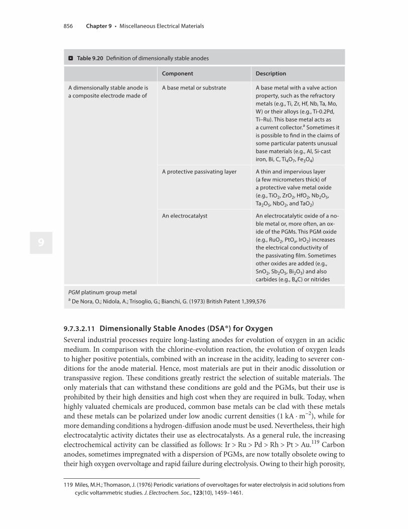
9
9.7.3.2.11 Dimensionally Stable Anodes (DSA®) for Oxygen
Several industrial processes require long-lasting anodes for evolution of oxygen in an acidic medium. In comparison with the chlorine-evolution reaction, the evolution of oxygen leads to higher positive potentials, combined with an increase in the acidity, leading to severer con-ditions for the anode material. Hence, most materials are put in their anodic dissolution or transpassive region. These conditions greatly restrict the selection of suitable materials. The only materials that can withstand these conditions are gold and the PGMs, but their use is prohibited by their high densities and high cost when they are required in bulk. Today, when highly valuated chemicals are produced, common base metals can be clad with these metals and these metals can be polarized under low anodic current densities (1 kA · m−2), while for more demanding conditions a hydrogen-diffusion anode must be used. Nevertheless, their high electrocatalytic activity dictates their use as electrocatalysts. As a general rule, the increasing electrochemical activity can be classified as follows: Ir > Ru > Pd > Rh > Pt > Au.119 Carbon anodes, sometimes impregnated with a dispersion of PGMs, are now totally obsolete owing to their high oxygen overvoltage and rapid failure during electrolysis. Owing to their high porosity,
119 Miles, M.H.; Thomason, J. (1976) Periodic variations of overvoltages for water electrolysis in acid solutions from cyclic voltammetric studies. J. Electrochem. Soc., 123(10), 1459–1461.
. Table 9.20 Definition of dimensionally stable anodes
Component Description
A dimensionally stable anode is a composite electrode made of
A base metal or substrate A base metal with a valve action property, such as the refractory metals (e.g., Ti, Zr, Hf, Nb, Ta, Mo, W) or their alloys (e.g., Ti-0.2Pd, Ti–Ru). This base metal acts as a current collector.a Sometimes it is possible to find in the claims of some particular patents unusual base materials (e.g., Al, Si-cast iron, Bi, C, Ti4O7, Fe3O4)
A protective passivating layer A thin and impervious layer (a few micrometers thick) of a protective valve metal oxide (e.g., TiO2, ZrO2, HfO2, Nb2O5, Ta2O5, NbO2, and TaO2)
An electrocatalyst An electrocatalytic oxide of a no-ble metal or, more often, an ox-ide of the PGMs. This PGM oxide (e.g., RuO2, PtOx, IrO2) increases the electrical conductivity of the passivating film. Sometimes other oxides are added (e.g., SnO2, Sb2O5, Bi2O3) and also carbides (e.g., B4C) or nitrides
PGM platinum group metala De Nora, O.; Nidola, A.; Trisoglio, G.; Bianchi, G. (1973) British Patent 1,399,576
Chapter 9 • Miscellaneous Electrical Materials856

an intercalation phenomenon occurs: the anions penetrate the lattice and expand the structure, leading rapidly to spalling of the electrode.120
Therefore, most of the electrode materials described previously fail rapidly when operating at the high anodic current densities (e.g., 2–15 kA · m−2) imposed by demanding electrochem-ical processes such as high-speed gold plating,121 high-speed electrogalvanizing of steel (e.g., Andritz Ruthner AG technology),122 and zinc electrowinning. On the basis of good results obtained with mixed metallic oxides such as TiO2-RuO2 and Ta2O5-RuO2 for the chlorine re-action and the huge success of DSA® in the chlor-alkali industry, these anodes were optimizedfor the oxygen-evolution reaction. Several compositions of electrocatalysts and base metals were then actively studied. Many metal oxides exhibiting good electronic conductivity, multivalence states, and a low redox potential for the higher oxide versus the lower oxide couple have been reported as promising electrocatalysts. Experimental values for the standard redox potentials of oxide couples are presented in . Table 9.21.
These data show clearly that of the candidate electrocatalysts, iridium, ruthenium, osmium, nickel, and cobalt have lower redox potentials than rhodium, palladium, and platinum. Despite its excellent electrocatalytic activity, ruthenium dioxide (RuO2) is readily oxidized at 1.39 V versus SHE to give off the volatile ruthenium tetroxide (RuO4),123 and it is too sensitive to electrochemical dissolution.124, 125 Osmium was excluded owing to the formation of volatile
120 Jasinski, R.; Brilmyer, G.; Helland, L. (1983) Stabilization of glassy carbon electrodes. J. Electrochem. Soc., 130(7), 1634.
121 Smith, C.G.; Okinaka, Y. (1983) High speed gold plating: anodic bath degradation and search for stable low polarization anodes. J. Electrochem. Soc., 130, 2149–2157.
122 Hampel, J. (1984) Process and apparatus for the continuous electroplating of one or both sides of a metal strip. US Patent 4,469,565; February 22, 1984.
123 Hine, F.; Yasuda, M.; Noda, T.; Yoshida, T.; Okuda, J. (1979) Electrochemical behavior of the oxide-coated metal anodes. J. Electrochem. Soc., 126(9), 1439–1445.
124 Manoharan, R.; Goodenough, J.B. (1991) Electrochim. Acta, 36, 19.125 Yeo, R.S.; Orehotsky, J.; Visscher, W.; Srinivasan, S. (1981) Ruthenium-based mixed oxides as electrocatalysts for
oxygen evolution in acid electrolytes. J. Electrochem. Soc., 128(9), 1900–1904.
. Table 9.21 Standard potentials for several oxide couples. (Tseung, A.C.C.; Jasem, S. (1977) Oxygen evolu-tion on semiconducting oxides. Electrochim. Acta, 22, 31)
Higher/lower oxide couple Standard electrode potential at 298.15 K
(E/V vs SHE)
IrO2/Ir2O3 0.930
RuO2/Ru2O3 0.940
OsO2/OsO4 1.00
NiO2/Ni2O3 1.43
CoO2/Co2O3 1.45
RhO2/Rh2O3 1.73
PtO3/PtO2 2.00
PdO3/PdO2 2.03
SHE standard hydrogen electrode
857 99.7 • Electrode Materials

9
(boiling point 130 °C) and hazardous osmium tetroxide (OsO4), while nickel and cobalt oxides exhibit poor conductivity. Therefore, iridium dioxide (IrO2) is the stablest and most active elec-trocatalyst coating, especially when prepared by the thermal decomposition of iridium chloride precursors (e.g., H2IrCl6, IrCl4). Other studies demonstrated the important selection of the valve metal oxide (e.g., TiO2, Nb2O5, and Ta2O5). De Nora showed that the best formulation was Ta2O5-IrO2.126 Later, Comninellis and coworkers optimized the composition by preparing a coating containing 70 mol% IrO2.127 This product was later developed commercially by Eltech Systems Corporation under the trade name TIR-2000®. These anodes have achieved operationin high-speed electrogalvanizing at current densities as high as 15 kA · m−2 and with service lives exceeding 4300 h.128 In contrast to the coating wear limiting anode life in chlorine, the complex corrosion-passivation mechanism of the substrate beneath the coating is typically the limiting factor for oxygen-evolving anodes. Indeed, during coating preparation the thermal stresses transform the electrocatalyst layer into a typical microcracked structure.129 The gaps between grains facilitate the penetration of the corrosive electrolyte down to the base metal (i.e., undermining process).130, 131, 132 According to Hine et al.,133 by analogy with the anodic deactivation mechanism of PbO2- and MnO2-coated anodes, the failure mode involves the damage of the interface between the electrocatalyst and the base metal, forming a thin layer of insulating rutile. This insulating film decreases the anode active surface area, increasing the local anodic current density. This behavior results in the spalling of the coating. The deactivation can be easily monitored industrially because the operating cell voltage increases continuously up to the limiting potential delivered by the rectifier. At this stage the anode is considered to be deactivated and is returned to the supplier to be refurbished. The costly electrocatalyst coating is then removed from the substrate by chemical stripping. The etching operation is usually per-formed in a molten mixture of alkali metal hydroxides (e.g., NaOH) containing small amounts of an oxidizing salt.134 The precious catalyst is then recovered in the slimes at the bottom of the vessel, while the clean substrate is treated and reactivated by the classic procedure. Usually, the critical parameters that influence the service life of the anode are the anodic current density, the coating preparation, and impurities. Several inorganic and organic pollutants can lead to the dissolution of titanium (e.g., fluoride anions135), scaling (e.g., manganous cations), and the loss of the coating (e.g. organic acids, nitroalcohols). For example, in organic electrosynthesis, the service life of these electrodes ranges 500–1000 h in 1 M sulfuric acid at 60 °C.136 Hence
126 De Nora, O.; Bianchi, G.; Nidola, A.; Trisoglio, G. (1975) Anode for evolution of oxygen. US Patent 3,878,083.127 Comninellis, Ch.; Vercesi, G.P. (1991) Characterization of DSA-type oxygen evolving electrodes: choice of a coat-
ing. J. Appl. Electrochem., 21(4), 335–345.128 Hardee, K.L.; Mitchell, L.K. (1989) The influence of electrolyte parameters on the percent oxygen evolved from
a chlorate cell. J. Electrochem. Soc., 136(11), 3314–3318.129 Kuznetzova, E.G.; Borisova, T.I.; Veselovskii, V.I. (1968) Elektrokhimiya 10, 167.130 Warren, H.I., Wemsley, D., Seto, K. (1975) Inst. Min. Met. Branch Meeting, February 11, 1975, 53.131 Seko, K. (1976) Am. Chem. Soc. Centennial Meeting, New York.132 Antler, M.; Butler, C.A. (1967) J. Electrochem. Technol., 5, 126.133 Hine, F.; Yasuda, M.; Yoshida, T.; Okuda, J. (1978) ECS Meeting, Seattle, May 15, Abstract 447.134 Colo, Z.J.; Hardee, K.L.; Carlson, R.C. (1992) Molten salt stripping of electrode coatings. US Patent 5,141,563;
August 25, 1992.135 Fukuda, K.; Iwakura, C.; Tamura, H. (1980) Effect of heat treatment of titanium substrate on service life of titani-
um-supported iridia electrode in mixed aqueous solutions of sulfuric acid, ammonium sulfate, and ammonium fluoride. Electrochim. Acta, 25(11), 1523–1525.
136 Savall, A. (1992) Electrosynthèse organique. In: Électrochimie 92, L’Actualité Chimique, Special issue, January 1992.
Chapter 9 • Miscellaneous Electrical Materials858

the high cost (US$ 10,000 to US$ 30,000 per square meter) prevents their industrial use in those conditions. In the late 1970s, as a consequence of work done on cathodically modified alloys initially conducted in the 1940s in the former Soviet Union by the Tomashov group, followed in the 1960s by Stern and Cotton137 at ICI, there appeared a titanium–palladium alloy (i.e., ASTM grade 7) in which a small amount of palladium (0.12–0.25 wt% Pd) greatly increased the corrosion resistance in reducing acids. Hence, several patents claimed a substrate made of titanium–palladium for preparing DSA® for oxygen. Nevertheless, despite a certainimprovement, their limited service life led to the abandonment of several industrial projects. Moreover, Cardarelli and coworkers demonstrated that the service life of Ti/Ta2O5-IrO2 an-odes was affected by impurities in commercially pure titanium and by alloying elements in titanium alloys.138 In addition, the influence of other reactive and refractory metals (i.e., Nb, Ta, Zr) as a substrate on the service life has been studied, and Vercesi et al.139 found that the performance of tantalum-based anodes was better than that of titanium-based electrodes. This good behavior was due to the remarkable corrosion resistance of tantalum owing to the valve action property of its passivating and impervious film of anodically formed tantalum pentox-ide. However, the development of a bulk tantalum-based electrode is not practical from the viewpoint of economics. The high price of tantalum (US$ 461 per kilogram) combined with its high density (16,654 kg · m−3), in comparison with titanium metal (4540 kg · m−3), which has a medium-range price (US$ 50 per kilogram), precludes any industrial applications. As a consequence, an anode of tantalum is 35 times more expensive than a titanium anode. Fur-thermore, owing to the high reactivity of titanium versus oxygen above 350 °C, the preparation of tantalum anodes involves great difficulties during the thermal treatment required for the manufacture of electrodes. For these reasons, the tantalum anode does not enjoy widespread industrial use. To decrease the cost, a thin tantalum layer deposited onto a common base metal is a very attractive alternative. This idea appeared for the first time in 1968 in a patent140 registered by the German company Farbenfabriken Bayer and also in 1974 in a proposition by Jeffes in a patent of Allbright & Wilson.141 In this last patent a composite DSA®-Cl2 material was madefrom a steel plate coated with 500 μm of tantalum prepared by chemical vapor deposition. Then the tantalum was coated with RuO2 (steel/Ta/RuO2). Twenty years later, the anodes made according to this process were not industrially developed. However, in 1990, in a European patent142 registered by ICI, Denton and Hayfield described the preparation of oxygen anodes made of a thin tantalum coating deposited onto a common base metal using several techniques. Finally, in 1993, Kumagai et al.143 from DAIKI Engineering in Japan prepared an anode made of a thin intermediate layer of tantalum deposited onto a titanium base metal by sputtering (Ti/Ta/
137 Potgieter, J.H.; Heyns, A.M.; Skinner, W. (1990) Cathodic modification as a means of improving the corrosion resistance of alloys. J. Appl. Electrochem., 20(5), 711–15.
138 Cardarelli, F.; Comninellis, Ch.; Savall, A.; Taxil, P.; Manoli, G.; Leclerc, O. (1998) Preparation of oxygen evolving electrodes with long service life under extreme conditions. J. Appl. Electrochem., 28, 245.
139 Vercesi, G.P.; Rolewicz, J.; Comninellis, C.; Hinden, J. (1991) Characterization of dimensionally stable anodes DSA-type oxygen evolving electrodes. Choice of base metal. Thermochimica Acta, 176, 31–47.
140 Farbenfabriken Bayer Aktiengesellschaft (1968) French Patent 1,516,524.141 Jeffes, J.H.E. (1974) Electrolysis of brine. British Patent 1,355,797; July 30, 1974.142 Denton, D.A.; Hayfield, P.C.S. (1990) Coated anode for an electrolytic process. European Patent 383,412; Au-
gust 22, 1990.143 Kumagai, N.; Jikihara, S.; Samata, Y.; Asami, K.; Hashimoto, A.M. (1993) The effect of sputter-deposited Ta inter-
mediate layer on durability of IrO2-coated Ti electrodes for oxygen evolution. In: Proceeding of the 183rd Joint International Meeting of the Electrochemical Society, 93–30 (Corrosion, Electrochemistry, and Catalysis of Meta-stable Metals and Intermetallics), Abstract 324–33, Honolulu, HI, May 16–21, 1993.
859 99.7 • Electrode Materials

9
Ta2O5-IrO2). To select the most optimized method for deposition of tantalum onto a common substrate, Cardarelli et al.144 comprehensively compared tantalum coating techniques used in the chemical-process industry. Moreover, the same authors developed anodes made from a thin tantalum layer deposited onto a common base metal (e.g. copper, nickel, or stainless steel) coated with an electrocatalytic mixture of Ta2O5 and IrO2 produced by calcination. The performances of these anodes (stainless steel/Ta/IrO2) are identical to the performance obtained with solid tantalum base metal (Ta/IrO2).145
9.7.3.2.12 Synthetic Diamond Electrodes
Structure The use of synthetic semiconductive diamond thin films in electrochemistry was reported in 1993.146 Designations such as diamond-like carbon are now obsolete and so are not used in this book. By contrast with the other carbon allotropes, in diamond each carbon atom is tetrahedrally bonded to four other carbons using sp3-hybridized orbitals.
Properties Diamond has several attractive properties, including the highest Young’s modulus, thermal conductivity, and hardness of all solid materials, high electrical resistance, excellent chemical inertness, high electron and hole mobilities, and a wide optical transparency range (see Sect. 12.5.1). The pure material is a wide bandgap insulator (Eg = 5.5 eV) and offers advantages for electronic applications under extreme environmental conditions. Nevertheless, when doped with boron, the material exhibits p-type semiconductive properties (i.e., IIb-type diamond). Doped diamond thin films can possess electronic conductivity ranging from that of an insulator at low doping levels to that of a good semiconductor for highly doped films (i.e., impurity level more than 1019 atoms per cubic centimeter). For instance, synthetic diamond thin films grown with use of hot-filament or microwave-assisted chemical vapor deposition can be doped to as high as one boron atom per 100 carbon atoms, resulting in films with resistivities of less than 105 μΩ · cm. Boron atoms that are electron acceptors form a band located roughly 0.35 eV above the valence-band edge. At room temperature, some of the valence-band electrons are thermally promoted to this intermediate level, leaving free electrons in the dopant band and holes, or va-cancies, in the valence band to support the flow of current. In addition, boron-doped diamond thin films commonly possess a rough, polycrystalline morphology with grain boundaries at the surface and a small-volume fraction of nondiamond carbon impurity. Hence, the electrical conductivity of the film surface and the bulk is influenced by the boron-doping level, the grain boundaries, and the impurities. Several interesting electrochemical properties distinguish bo-ron-doped diamond thin films from conventional carbon-based electrodes. As a general rule, boron-doped diamond films exhibit voltammetric background currents and double-layer capac-itances up to an order of magnitude lower than for glassy carbon. The residual or background current density in 0.1 M KCl measured by linear sweep voltammetry is less than 50 μA · cm−2 between −1.0 and +1.0 V versus SHE. This indicates that the diamond–electrolyte interface is almost ideally polarizable. The evolution of hydrogen starts at roughly −1.75 V versus SHE. The electrochemical span or working potential window, defined as the potentials at which the anodic and cathodic currents reach 250 μA · cm−2, is 3.5 V for diamond and 2.5 V for glassy
144 Cardarelli, F.; Taxil, P.; Savall, A. (1996) Tantalum protective thin coating techniques for the chemical process industry: molten salts electrocoating as a new alternative. Int. J. Refract. Metals Hard Mater., 14, 365.
145 Cardarelli, F.; Comninellis, C.; Leclerc, O.; Saval, A.; Taxil, P.; Manoli, G. (1997) Fabrication of an anode with en-hanced durability and method for making the same. PCT International Patent Application WO 97/43465A1.
146 Swain, G.; Ramesham, R. (1993) The electrochemical activity of boron-doped polycrystalline diamond thin film electrodes. Anal. Chem., 65(4), 345–351.
Chapter 9 • Miscellaneous Electrical Materials860

carbon. The overpotentials for hydrogen and oxygen evolution reactions are directly related to the nondiamond carbon impurity content. The higher the fraction of nondiamond carbon present, the lower the overpotentials for both these reactions. The double-layer capacitance for boron-doped diamond in 1 M KCl ranges 4–8 μF · cm−2 over a 2-V potential window. There is a general trend toward increasing capacitance with more positive potentials, which is charac-teristic of p-type semiconductor electrode–electrolyte interfaces.147 These capacitance values are comparable in magnitude to those observed for the basal plane of highly oriented pyrolytic graphite and significantly lower than those for glassy carbon (25–35 μF · cm−2). The capaci-tance versus potential profile shape and magnitude for diamond are largely independent of the electrolyte composition and solution pH. On the other hand, boron-doped diamond electrodes have good electrochemical activity without any pretreatment.
Preparation Diamond thin films can be prepared on a substrate from thermal decomposition of dilute mixtures of a hydrocarbon gas (e.g., methane) in hydrogen with use of one of several energy-assisted chemical vapor deposition methods, the most popular being hot-filament and microwave discharge.148, 149 The growth methods mainly differ in the manner in which the gas thermal activation is accomplished. Typical growth conditions are C/H ratios of 0.5–2 vol%, reduced pressure ranging 1.33–13.3 kPa, a substrate temperature between 800 and 1000 °C, and microwave powers of 1–1.3 kW, or filament temperatures of approximately 2100 °C, depending on the method used. The film grows by nucleation at rates in the 0.1 to 1 μm/h range. For the substrates to be continuously coated with diamond, the nominal film thickness must be 1 μm. Wafer diameters of several centimeters can easily be coated in most modern reactors. Boron doping is accomplished from the gas phase by the mixing of a boron-containing gas such as diborane (B2H6) with the source gases, or from the solid state by gasification of a piece of hex-agonal boron nitride.150 Before deposition, the substrate must be pretreated by it being cleaning with a series of solvents, and nucleation sites are provided by the embedding of tiny diamond particles that are polished with a diamond paste. Hydrogen plays an important role in all of the growth methods as it prevents surface reconstruction from a saturated sp3-hybridized diamond microstructure to an unsaturated sp2-hybridized graphite microstructure; it also suppresses the formation of nondiamond carbon impurities, and it prevents several species from forming reactive radicals.
9.7.4 Electrodes for Corrosion Protection and Control
Apart from batteries, fuel cells, and industrial electrolyzers, corrosion protection and control is another field in which electrode materials occupy an important place.
147 Alehashem, S.; Chambers, F.; Strojek, J.W.; Swain, G.M.; Ramesham, R. (1995) New applications of diamond thin film technology in electro chemical systems. Anal. Chem., 67, 2812.
148 Angus, J.C.; Hayman, C.C. (1988) Low-pressure, metastable growth of diamond and “diamondlike” phases. Science 241, 913–921.
149 Argoitia, A.; Angus, J.C.; Ma, J.S.; Wang, L.; Pirouz, P.; Lambrecht, W.R.L. (1994) Pseudomorphic stabilization of diamond on non-diamond substrates. J. Mater. Res., 9, 1849.
150 Vinokur, N.; Miller, B.; Avyigal, Y.; Kalish, R. (1996) Electrochemical behavior of boron-doped diamond electrodes. J. Electrochem. Soc., 143(10), L238–L240.
861 99.7 • Electrode Materials

9
9.7.4.1 Cathodes for Anodic Protection
Anodic protection151 is a modern electrochemical technique for protecting metallic equip-ment used in the chemical-process industry against corrosion and handling highly corrosive chemicals (e.g., concentrated sulfuric and orthophosphoric acids). The technique consists in impressing a very low anodic current (i.e., usually 10 μA · m−2) on a piece of metallic equipment (e.g., tanks, thermowells, columns) to protect them against corrosion. This anodic polarization puts the electrochemical potential of the metal in the passivity region of its Pourbaix diagram (i.e., where the dissolution reaction does not occur), and hence this leads to a negligible corro-sion rate (i.e., less than 25 μm/year). The anodic protection method can be used to protect only metals and alloys exhibiting a passive state (e.g., reactive and refractory metals, stainless steels) against corrosion. Usually, the equipment required is a cathode, a reference electrode, or a power supply. The various cathode materials used in anodic protection are listed in . Table 9.22.
9.7.4.2 Anodes for Cathodic Protection
Cathodic protection is the cathodic polarization of a metal to maintain its immunity in a corrosive environment. There are two ways to achieve an efficient cathodic polarization. The first is a passive protection that consists in connecting electrically the metal to a less noble material that will result in a galvanic coupling of the two materials, which leads to the anodic dissolution of the sacrificial anode (see . Table 9.23). The second method is an active protection that consists in using an impressed current power supply to polarize cathodically the workpiece versus a nonconsumable or inert anode (see . Table 9.24).
9.7.5 Electrode Suppliers and Manufacturers
See . Table 9.25.
151 Riggs, Jr., O.L.; Locke, C.E. (1981) Anodic Protection: Theory and Practice in the Prevention of Corrosion. Plenum, New York.
. Table 9.22 Cathode materials for anodic protection. (From Locke, C.E. (1992) Anodic Protection. In: ASM Metals Handbook, 10th ed. Vol. 9. Corrosion, ASM, Materials Park, OH, pp. 463–465)
Cathode Corrosive chemicals
Hastelloy® C Nitrate aqueous solutions, sulfuric acid
Illium® G Sulfuric acid (78–100 wt%), oleum
Nickel-plated steel Electroless nickel plating solutions
Platinized copper or brass Acids
Silicon-cast iron (Duriron®) ASTM A518 grade 3 Sulfuric acid (89–100 wt%), oleum
Stainless steels (AISI 304, 316L) Nitrate aqueous solutions
Steel Kraft digester liquid
Chapter 9 • Miscellaneous Electrical Materials862
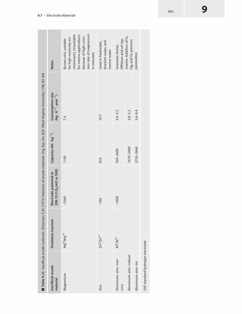
.
Ta
ble
9.2
3 S
acrifi
cial
ano
de m
ater
ials
. (D
reym
an, E
.W. (
1973
) Sel
ectio
n of
ano
de m
ater
ials
. Eng
. Exp
. Stn
. Bul
l. (W
est V
irgin
ia U
nive
rsity
), 1
10
, 83–
89)
Sa
cri
fic
ial
an
od
e
ma
teri
al
Ox
ida
tio
n r
ea
cti
on
Ele
ctr
od
e p
ote
nti
al
at
29
8.1
5 K
(E 0
/mV
vs
SH
E)
Ca
pa
cit
y (
Ah
· k
g−
1)
Co
nsu
mp
tio
n r
ate
(kg
· A
−1 ·
ye
ar−
1)
No
tes
Mag
nesi
umM
g0 /Mg2+
−23
6011
007.
9Bu
ried
soils
, sui
tabl
e fo
r hig
h-re
sist
ivity
en-
viro
nmen
ts. U
nsui
tabl
e fo
r mar
ine
appl
icat
ions
be
caus
e of
hig
h co
rro-
sion
rate
of m
agne
sium
in
sea
wat
er
Zinc
Zn0 /Z
n2+−
760
810
10.7
Use
d in
fres
hwat
er,
brac
kish
wat
er, a
nd
mar
ine
wat
er
Alu
min
um–z
inc–
mer
-cu
ryA
l0 /Al3+
−16
6092
0–26
003.
0–3.
2Se
awat
er, b
rines
. O
ffsho
re a
nd o
il rig
s,
mar
ine.
Add
ition
of I
n,
Hg,
and
Sn
prev
ents
pa
ssiv
atio
n
Alu
min
um–z
inc–
indi
um16
70–2
400
3.6–
5.2
Alu
min
um–z
inc–
tin27
50–2
840
3.4–
9.4
SHE
stan
dard
hyd
roge
n el
ectr
ode
863 99.7 • Electrode Materials

9
.
Ta
ble
9.2
4 I
mpr
esse
d-cu
rren
t ano
de m
ater
ials
. (D
reym
an, E
.W. (
1973
) Sel
ectio
n of
ano
de m
ater
ials
. Eng
. Exp
. Stn
. Bul
l. (W
est V
irgin
ia U
nive
rsity
), 1
10
, 83–
89)
An
od
e m
ate
ria
lC
om
po
siti
on
Ty
pic
al
an
od
ic c
urr
en
t
de
nsi
ty (
A ·
m−
2)
Co
nsu
mp
tio
n r
ate
(g ·
A−
1 ·
ye
ar−
1)
Co
st p
er
un
it s
urf
ace
are
a o
f 1
-mm
-th
ick
an
od
e (
US
$/m
2)
No
tes
Dim
ensi
onal
ly s
tabl
e an
odes
(DSA
®)Ti
/IrO
2
Ti–P
d/IrO
2
Nb/
IrO2
Ta/I
rO2
700–
2000
< 1
9000
15,0
0013
,000
54,0
00
Cath
odic
pro
tect
ion
of
wat
er ta
nk a
nd b
urie
d st
eel s
truc
ture
s
Silic
on–c
ast i
ron
(Dur
iron ®
)Fe
-14.
5Si-4
.0Cr
-0.8
C-1.
50M
n-0.
5Cu-
0.2M
o10
–40
200–
500
500–
1000
Both
goo
d co
rros
ion
and
abra
sion
/wea
r res
is-
tanc
e. U
sed
exte
nsiv
ely
offsh
ore,
on
oil r
igs,
and
in
oth
er m
arin
e te
chno
l-og
y ap
plic
atio
ns
Ebon
ex®
Ti4O
7, T
i 5O
950
(nak
ed)
2000
(IrO
2 co
ated
)n.
a.
2000
–300
0Co
rros
ion
resi
stan
t to
bot
h al
kalin
e an
d ac
id m
edia
. Brit
tle
and
shoc
k-se
nsiti
ve
mat
eria
l. D
ensi
ty
3600
–430
0 kg
· m
−3 .
Cond
uctiv
ity 3
0–30
0 S/
cm
Gra
phite
and
car
bon
Carb
on10
–40
225–
450
Britt
le a
nd s
hock
-sen
-si
tive
mat
eria
ls. U
sed
exte
nsiv
ely
burie
d fo
r ca
thod
ic p
rote
ctio
n of
gr
ound
pip
elin
es
Lead
-allo
y an
odes
Pb-6
Sb-1
Ag/
PbO
216
0–22
045
–90
15–2
0Ca
thod
ic p
rote
ctio
n fo
r eq
uipm
ent i
mm
erse
d in
se
awat
er
Chapter 9 • Miscellaneous Electrical Materials864

An
od
e m
ate
ria
lC
om
po
siti
on
Ty
pic
al
an
od
ic c
urr
en
t
de
nsi
ty (
A ·
m−
2)
Co
nsu
mp
tio
n r
ate
(g ·
A−
1 ·
ye
ar−
1)
Co
st p
er
un
it s
urf
ace
are
a o
f 1
-mm
-th
ick
an
od
e (
US
$/m
2)
No
tes
Plat
iniz
ed ti
tani
um
(K-t
ype
70/3
0)Ti
/70P
tOx-
30IrO
250
0–10
0018
15,0
00Lo
w c
onsu
mpt
ion
rate
, hi
gh a
nodi
c cu
rren
t, bu
t ex
pens
ive
Plat
iniz
ed n
iobi
um a
nd
tant
alum
ano
des
Nb/
Pt–I
r, Ta
/Pt–
Ir50
0–10
001–
640
,000
–60,
000
Low
con
sum
ptio
n ra
te,
high
ano
dic
curr
ent,
but
expe
nsiv
e
Ebon
ex®/
poly
mer
com
posi
teTi
4O7
with
con
duct
ive
poly
mer
bin
der
n. a
.n.
a.
1000
Cath
odic
pro
tect
ion
of
rein
forc
ed s
teel
bar
s in
sal
t-co
ntam
inat
ed
conc
rete
. Den
sity
23
00–2
700
kg ·
m−
3 . Co
nduc
tivity
1–1
0 S/
cm
n. a
. not
ava
ilabl
e
.
Ta
ble
9.2
4 (
cont
inue
d)
865 99.7 • Electrode Materials

9
. Table 9.25 Industrial electrode manufacturers
Electrode supplier Typical products and
brand names
Contact address
Anomet Products Pt/Nb/Cu, Pt/Ti/Cu 830 Boston Turnpike Road, Shrewsbury, MA 01545, USATel.: +1-508-8423069Fax: +1-508-8420847E-mail: [email protected]: ▶ http://www.anometproducts.com/
Anotec Industries High-silicon cast iron anodes for impressed current
5701 Production Way, Langley, BC V3N 4N5, CanadaTel.: +1-604-5141544Fax: +1-604-5141546URL: ▶ http://anotec.com/
Ebonex Technologies Ltd (formerly Atraverda Ltd, Ebonex Technology Inc.)
Andersson–Magnéli phases, Ti4O7, Ebonex®
Units A & B, Roseheyworth Business Park, Abertillery NP13 1SX, UKTel.:+44-1495-294026Fax:+44-1495-294179E-mail: [email protected]: ▶ http://www.ebonex.co.uk/
Chemapol Industries Ti/RuO2, Ti/IrO2 55/A Alli Chamber, Tamarind Lane, Mumbai 400023, IndiaTel.: +91-22-641010Fax: +91-22-653636E-mail: [email protected]
De Nora Elettrodi SpA Ti/RuO2, Ti/IrO2, Nb/RuO2, Ta/IrO2
Via Bistolfi 35, 20134 Milan, ItalyTel.: +39-02-21291Fax: +39-02-2154873E-mail: [email protected]: ▶ http://www.denora.it/
De Nora Tech (formerly Eltech Systems Inc.)
DSA-Cl2 and DSA-O2, TIR® 2000, MOLTM
100 Seventh Avenue, Suite 300, Chardon, OH 44024, USATel.: +1-440-2850300Fax: 1-440-285-0302URL: ▶ http://www.eltechsystems.com
DISA Anodes Ti/RuO2, Ti/IrO2, Nb/RuO2, Ta/IrO2
7 Berg Street, Jeppestown, Johannesburg, South AfricaTel.: +27-11-6145238/+27-11-6145533Fax: +27-11-6140093E-mail: [email protected]: ▶ http://www.disaanodes.co.za
Electrochem Technologies & Materials Inc.
MMO, Ti/RuO2, Ti/IrO2, Nb/RuO2, Ta/IrO2, Ti/PbO2, Ti/MnO2, Ti/SnO2
Head office: 2037 Aird Avenue, Suite 201, Montreal, QC H1V 2V9, CanadaFacilities: 75 Blvd de Mortagne CP 112, Boucherville QC J4B 6Y4, CanadaE-mail: [email protected]: ▶ http://www.electrochem-technologies.com
Chapter 9 • Miscellaneous Electrical Materials866

Electrode supplier Typical products and
brand names
Contact address
Farwest Corrosion Anodic, cathodic protection
1480 West Artesia Blvd, Gardena, CA 90248-3215, USATel.: +1-310-5329524Fax: +1-310-5323934E-mail: [email protected]
Magneto Special Anodes BV(formerly Magneto-Chemie)(acquired by Evoqua in 2016)
MMO, Ti/RuO2, Ti/IrO2, Nb/RuO2, Ta/IrO2
Calandstraat 109, 3125 BA Schiedam, NetherlandsTel.: +31-10-2620788Fax: +31-10-2620201E-mail: [email protected]: ▶ http://www.magneto.nl
NMT Electrodes South Africa
MMO, Ti/RuO2, Ti/IrO2 28 Hillclimb Road, Westmead, Pinetown 3610, South AfricaTel.: +27-31-7006110Fax: +27-31-7006828E-mail: [email protected]: ▶ http://www.nmtelectrodes.com
NMT Electrodes Australia
MMO, Ti/RuO2, Ti/IrO2 Unit 2, 26 Baile Road, Canning Vale, WA 6155, AustraliaTel.: +61-8-92564499Fax: +61-8-92564599E-mail: [email protected]: ▶ http://www.nmtelectrodes.com
Optimum Anode Technologies
MMO, Ti/RuO2, Ti/IrO2, Nb/RuO2, Ta/IrO2
Headquarters: Warren, NJ 07059, USAFacilities: 847 Flynn Road, Camarillo, CA 93012, USATel.: +1-805-4377435Fax: +1-805-4845880URL: ▶ http://www.optimumanodes.com
Republic Anode Fabricators
MMO, Ti/RuO2, Ti/IrO2 5478 Grafton road, Valley City, OH 44280, USATel.: +1-440-5725999Fax: +1-440-5724499URL: ▶ http://www.republicanodes.com
Permascand AB MMO, Ti/RuO2, Ti/IrO2 P.O. Box 42, Ljungaverk, 840 10, SwedenTel.: +46-691-35500Fax: +46-691-33130E-mail: [email protected]: ▶ http://www.permascand.com
EVOQUA Water Technologies(formerly US Filter Cor-poration and previously Electrode Products Inc.)
MMO, Ti/RuO2, Ti/IrO2 2 Milltown Court, Union, NJ 07083, USATel.: +1-908-8516924Fax: +1-908-8516906URL: ▶ www.evoqua.com
. Table 9.25 (continued)
867 99.7 • Electrode Materials

9
Electrode supplier Typical products and
brand names
Contact address
Ti Anode Fabricators (TAF)
MMO, Ti/RuO2, Ti/IrO2 # 48, Noothanchery, Madambakkam, Chennai 600073, IndiaTel.: +91-44-22781149Fax: +91-44-22781362E-mail: [email protected]: ▶ http://www.tianode.com
Titanium Equipment & Anode Manufacturing Company (TEAM)
MMO, Ti/RuO2, Ti/IrO2 TEAM House, Grand Southern Trunk Road, Vandalur, Chennai 600048, IndiaTel.: +91-44-22750323/+91-44-22750324Fax: + 91-44-22750860E-mail: [email protected]: ▶ http://www.team.co.in/
Titaninum Tantalum Products (TiTaN)
MMO, Ti/RuO2, Ti/IrO2, Nb/RuO2, Ta/IrO2
86/1, Vengaivasal Main Road, Gowrivakkam, Chennai 601302, IndiaTel.: +91-44-22781210Fax: +91-44-22780209URL: ▶ http://www.titanindia.com/
Uyemura (Umicore) Platinum anodes coated in molten cyanide baths
Headquarters: 3990 Concours, #425, Ontario, CA 91764, USATel.: +1-909-4665635R&D Center: 240 Town Line Road, Southington, CT 06489, USATel.: +1-860-7934011E-mail: [email protected]
Whizzo Science & Technology Development Co. Ltd
MMO, Ti/RuO2, Ti/IrO2 No. 83 Wencui Road, Shengyang, ChinaTel.: +86-24-24505855Fax: +86-24-24503408Email: [email protected]: ▶ http://www.whizzo.com.cn
MMO mixed metal oxides
. Table 9.25 (continued)
Chapter 9 • Miscellaneous Electrical Materials868

9.8 Electrochemical Galvanic Series
See . Table 9.26.
9.9 Selected Standard Electrode Potentials
See . Table 9.27.
9.10 Reference Electrodes Potentials
Selected electrochemical redox reactions with their standard electrode potentials are listed in . Table 9.28.
. Table 9.26 Galvanic series of metals and alloys in seawater
Corroded end (anodic or least noble)
Magnesium
Magnesium alloys
Zinc
Aluminum alloys 5052, 3004, 3003, 1100, 6053
Cadmium
Aluminum alloys 2117, 2017, 2024
Mild steel (AISI 1018), wrought iron
Cast iron, low-alloy high-strength steel
Chrome iron (active)
Stainless steel, AISI 430 series (active)
Stainless steels AISI 302, 303, 321, 347, 410, and 416 (active)
Ni-resist
Stainless steels AISI 316, 317 (active)
Carpenter 20Cb-3 (active)
Aluminum bronze (CA 687)
Hastelloy® C (active), Inconel® 625 (active), titanium (active)
Lead–tin solders
Lead
Tin
Inconel® 600 (active)
Nickel (active)
869 99.10 • Reference Electrodes Potentials

9
Corroded end (anodic or least noble)
60Ni-15Cr (active)
80Ni-20Cr (active)
Hastelloy® B (active)
Brasses
Copper (CDA 102)
Manganese bronze (CA 675), tin bronze (CA 903, CA 905)
Silicon bronze
Nickel silver
90Cu-10Ni
80Cu-20Ni
Stainless steel 430
Nickel, aluminum, bronze (CA 630, CA 632)
Monel® 400 and K500
Silver solder
Nickel 200 (passive)
60Ni-15Cr (passive)
Inconel® 600 (passive)
80Ni-20Cr (passive)
Cr–Fe (passive)
Stainless steel grades 302, 303, 304, 321, 347 (passive)
Stainless steel grades 316 and 317 (passive)
Carpenter 20 Cb-3 (passive), Incoloy® 825 and Ni-Mo-Cr-Fe alloy (passive)
Silver
Titanium (passive), Hastelloy® C276 (passive), Inconel® 625(passive)
Graphite
Zirconium
Gold
Platinum
Protected end (cathodic or noblest)
. Table 9.26 (continued)
Chapter 9 • Miscellaneous Electrical Materials870

. Table 9.27 Selected electrochemical redox reactions and standard electrode potential E0
Electrochemical reaction Standard
electrode
potential
(V vs SHE)
Electrochemical reaction Standard
electrode
potential
(V vs SHE)
N2(g) + H+ + e− HN3(aq) −3.090 Ti3+ + 3e− Ti(s) −1.210
Li+ + e− Li(s) −3.0401 Mn2+ + 2e− Mn(s) −1.185
N2(g) + 4H2O + 2e− 2NH2OH(aq) + 2OH−
−3.040 Te(s) + 2e− Te2− −1.143
Cs+ + e− Cs(s) −3.026 V2+ + 2e− V(s) −1.130
Rb+ + e− Rb(s) −2.980 Nb3+ + 3e− Nb(s) −1.099
K+ + e− K(s) −2.931 Sn(s) + 4H+ + 4e− SnH4(g) −1.070
Ba2+ + 2e− Ba(s) −2.912 SiO2(s) + 4H+ + 4e− Si(s)+ 2H2O
−0.910
La(OH)3(s) + 3e− La(s) + 3OH− −2.900 B(OH)3(aq) + 3H+ + 3e− B(s) + 3H2O
−0.890
Sr2+ + 2e− Sr(s) −2.899 TiO2+ + 2H+ + 4e− Ti(s) + H2O −0.860
Ca2+ + 2e− Ca(s) −2.868 2H2O + 2e− H2(g) + 2OH− −0.823
Eu2+ + 2e− Eu(s) −2.812 Bi(s) + 3H+ + 3e− BiH3 −0.800
Ra2+ + 2e− Ra(s) −2.800 Zn2+ + 2e− Zn(Hg) −0.7628
Na+ + e− Na(s) −2.710 Zn2+ + 2e− Zn(s) −0.7618
La3+ + 3e− La(s) −2.379 Ta2O5(s) + 10H+ + 10e− 2Ta(s) + 5H2O
−0.750
Y3+ + 3e− Y(s) −2.372 Cr3+ + 3e− Cr(s) −0.740
Mg2+ + 2e− Mg(s) −2.372 [Au(CN)2]− + e− Au(s) + 2CN− −0.600
ZrO(OH)2(s) + H2O + 4e− Zr(s)+ 4OH−
−2.360 Ta3+ + 3e− Ta(s) −0.600
Al.OH/−
4+ 3e− Al(s) + 4OH− −2.330 PbO(s) + H2O + 2e− Pb(s) +
2OH−−0.580
Al(OH)3(s) + 3e− Al(s) + 3OH− −2.310 2TiO2(s) + 2H+ + 2e− Ti2O3(s)+ H2O
−0.560
H2(g) + 2e− 2H− −2.250 Ga3+ + 3e− Ga(s) −0.530
Ac3+ + 3e− Ac(s) −2.200 U4+ + e− U3+ −0.520
Be2+ + 2e− Be(s) −1.85 H3PO2(aq) + H+ + e− P(white) + 2H2O
−0.508
U3+ + 3e− U(s) −1.660 H3PO3(aq) + 2H+ + 2e− H3PO2
(aq) + H2O−0.499
Al3+ + 3e− Al(s) −1.660 H3PO3(aq) + 3H+ + 3e− P(red) + 3H2O
−0.454
Ti2+ + 2e− Ti(s) −1.630 Fe2+ + 2e− Fe(s) −0.440
871 99.10 • Reference Electrodes Potentials

9
. Table 9.27 (continued)
Electrochemical reaction Standard
electrode
potential
(V vs SHE)
Electrochemical reaction Standard
electrode
potential
(V vs SHE)
ZrO2(s) + 4H+ + 4e− Zr(s) + 2H2O
−1.553 2CO2(g) + 2H+ + 2e− H2C2O4(aq)
−0.430
Zr4+ + 4e− Zr(s) −1.450 Cr3+ + e− Cr2+ −0.420
TiO(s) + 2H+ + 2e− Ti(s) + H2O −1.310 Cd2+ + 2e− Cd(s) −0.400
Ti2O3(s) + 2H+ + 2e− 2TiO(s) + H2O
−1.230 GeO2(s) + 2H+ + 2e− GeO(s) + H2O
−0.370
Cu2O(s) + H2O + 2e− 2Cu(s) + 2OH−
−0.360 CO2(g) + 2H+ + 2e− CO(g) + H2O
−0.110
PbSO4(s) + 2e− Pb(s) + SO2−
4
−0.3588 SnO(s) + 2H+ + 2e− Sn(s) + H2O −0.100
PbSO4(s) + 2e− Pb(Hg) + SO2−
4
−0.3505 SnO2(s) + 2H+ + 2e− SnO(s) + H2O
−0.090
Eu3+ + e− Eu2+ −0.350 WO3(aq) + 6H+ + 6e− W(s) + 3H2O
−0.090
In3+ + 3e− In(s) −0.340 P(white) + 3H+ + 3e− PH3(g) −0.063
Tl+ + e− Tl(s) −0.340 HCOOH(aq) + 2H+ + 2e− HCHO(aq) + H2O
−0.030
Ge(s) + 4H+ + 4e− GeH4(g) −0.290 2H+ + 2e− H2(g) (reference) 0.000
Co2+ + 2e− Co(s) −0.280 AgBr(s) + e− Ag(s)+Br− +0.071
H3PO4(aq) + 2H+ + 2e− H3PO3(aq) + H2O
−0.276S4O
2−
6 + 2e− 2S2O2−
3
+0.080
V3+ + e− V2+ −0.260 Fe3O4(s) + 8H+ + 8e− 3Fe(s) + 4H2O
+0.085
Ni2+ + 2e− Ni(s) −0.250 N2(g) + 2H2O + 6H+ + 6e− 2NH4OH(aq)
+0.092
As(s) + 3H+ + 3e− AsH3(g) −0.230 HgO(s) + H2O + 2e− Hg(l) + 2OH−
+0.098
AgI(s) + e− Ag(s) + I− −0.152Cu.NH3/
2+
4 + e− Cu.NH3/
+
2 + 2NH3
+0.100
MoO2(s) + 4H+ + 4e− Mo(s) + 2H2O
−0.150Ru.NH3/
3+
6 + e− Ru.NH3/2+
6
+0.100
Si(s) + 4H+ + 4e− SiH4(g) −0.140 N2H4(aq) + 4H2O + 2e− 2NH
+
4 + 4OH−+0.110
Sn2+ + 2e− Sn(s) −0.130 H2MoO4(aq) + 6H+ + 6e− Mo(s) + 4H2O
+0.110
O2(g) + H+ + e− HO2 · (aq) −0.130 Ge4+ + 4e− Ge(s) +0.120
Chapter 9 • Miscellaneous Electrical Materials872
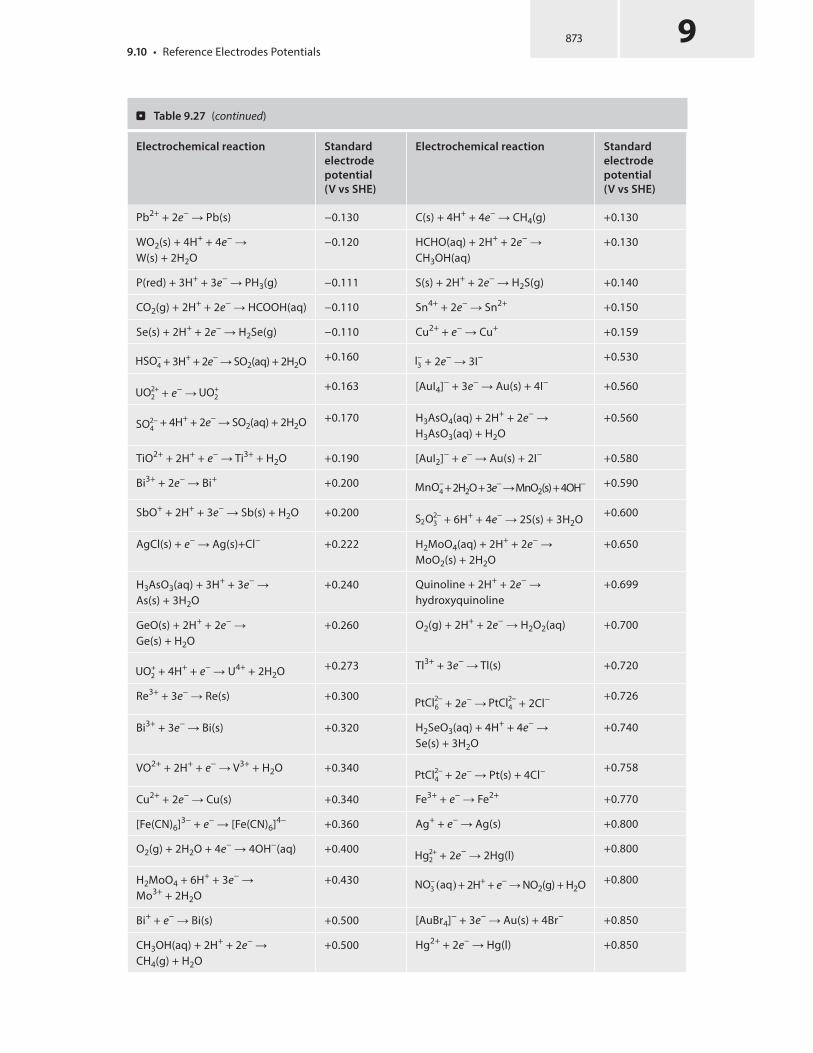
Electrochemical reaction Standard
electrode
potential
(V vs SHE)
Electrochemical reaction Standard
electrode
potential
(V vs SHE)
Pb2+ + 2e− Pb(s) −0.130 C(s) + 4H+ + 4e− CH4(g) +0.130
WO2(s) + 4H+ + 4e− W(s) + 2H2O
−0.120 HCHO(aq) + 2H+ + 2e− CH3OH(aq)
+0.130
P(red) + 3H+ + 3e− PH3(g) −0.111 S(s) + 2H+ + 2e− H2S(g) +0.140
CO2(g) + 2H+ + 2e− HCOOH(aq) −0.110 Sn4+ + 2e− Sn2+ +0.150
Se(s) + 2H+ + 2e− H2Se(g) −0.110 Cu2+ + e− Cu+ +0.159
HSO−
4 + 3H+ + 2e− SO2(aq) + 2H2O +0.160 I−
3 + 2e− 3I− +0.530
UO2+
2 + e− UO+
2
+0.163 [AuI4]− + 3e− Au(s) + 4I− +0.560
SO2−
4 + 4H+ + 2e− SO2(aq) + 2H2O +0.170 H3AsO4(aq) + 2H+ + 2e−
H3AsO3(aq) + H2O+0.560
TiO2+ + 2H+ + e− Ti3+ + H2O +0.190 [AuI2]− + e− Au(s) + 2I− +0.580
Bi3+ + 2e− Bi+ +0.200MnO
−
4+ 2H2O + 3e− MnO2(s) + 4OH− +0.590
SbO+ + 2H+ + 3e− Sb(s) + H2O +0.200S2O
2−
3 + 6H+ + 4e− 2S(s) + 3H2O +0.600
AgCl(s) + e− Ag(s)+Cl− +0.222 H2MoO4(aq) + 2H+ + 2e− MoO2(s) + 2H2O
+0.650
H3AsO3(aq) + 3H+ + 3e− As(s) + 3H2O
+0.240 Quinoline + 2H+ + 2e− hydroxyquinoline
+0.699
GeO(s) + 2H+ + 2e− Ge(s) + H2O
+0.260 O2(g) + 2H+ + 2e− H2O2(aq) +0.700
UO+
2+ 4H+ + e− U4+ + 2H2O +0.273 Tl3+ + 3e− Tl(s) +0.720
Re3+ + 3e− Re(s) +0.300PtCl
2−
6 + 2e− PtCl2−
4 + 2Cl−+0.726
Bi3+ + 3e− Bi(s) +0.320 H2SeO3(aq) + 4H+ + 4e− Se(s) + 3H2O
+0.740
VO2+ + 2H+ + e− V3+ + H2O +0.340PtCl
2−
4+ 2e− Pt(s) + 4Cl−
+0.758
Cu2+ + 2e− Cu(s) +0.340 Fe3+ + e− Fe2+ +0.770
[Fe(CN)6]3− + e− [Fe(CN)6]4− +0.360 Ag+ + e− Ag(s) +0.800
O2(g) + 2H2O + 4e− 4OH−(aq) +0.400Hg
2+
2 + 2e− 2Hg(l) +0.800
H2MoO4 + 6H+ + 3e− Mo3+ + 2H2O
+0.430NO
−
3.aq/ + 2H+ + e− NO2(g) + H2O +0.800
Bi+ + e− Bi(s) +0.500 [AuBr4]− + 3e− Au(s) + 4Br− +0.850
CH3OH(aq) + 2H+ + 2e− CH4(g) + H2O
+0.500 Hg2+ + 2e− Hg(l) +0.850
. Table 9.27 (continued)
873 99.10 • Reference Electrodes Potentials

9
. Table 9.27 (continued)
Electrochemical reaction Standard
electrode
potential
(V vs SHE)
Electrochemical reaction Standard
electrode
potential
(V vs SHE)
SO2(aq) + 4H+ + 4e− S(s) + 2H2O
+0.500 MnO−
4 + H+ + e− HMnO−
4
+0.900
Cu+ + e− Cu(s) +0.520 2Hg2+ + 2e− Hg2+
2
+0.910
CO(g) + 2H+ + 2e− C(s) + H2O +0.520 Pd2+ + 2e− Pd(s) +0.915
I2(s) + 2e− 2I− +0.540 [AuCl4]− + 3e− Au(s) + 4Cl− +0.930
MnO2(s) + 4H+ + e− Mn3+ + 2H2O
+0.950 β-PbO2(s) + 4H+ + 2e− Pb2+ + 2H2O
+1.460
[AuBr2]− + e− Au(s) + 2Br− +0.960 α-PbO2(s) + 4H+ + 2e− Pb2+ + 2H2O
+1.468
Br2(l) + 2e− 2Br− +1.066 2BrO−
3 + 12H+ + 10e− Br2(l) + 6H2O +1.480
Br2(aq) + 2e− 2Br− +1.0872ClO
−
3 + 12H+ + 10e− Cl2(g) + 6H2O +1.490
IO−
3 + 5H+ + 4e− HIO(aq) + 2H2O +1.130 MnO−
4 + 8H+ + 5e− Mn2+ + 4H2O +1.510
[AuCl2]− + e− Au(s) + 2Cl− +1.150 HO2 · + H+ + e− H2O2(aq) +1.510
HSeO−
4+ 3H+ + 2e−
H2SeO3(aq) + H2O
+1.150 Au3+ + 3e− Au(s) +1.520
Ag2O(s) + 2H+ + 2e− 2Ag(s) + H2O
+1.170 NiO2(s) + 4H+ + 2e− Ni2+ + 2OH−
+1.590
ClO−
3 + 2H+ + e− ClO2(g) + H2O +1.180 2HClO(aq) + 2H+ + 2e− Cl2(g) + 2H2O
+1.630
Pt2+ + 2e− Pt(s) +1.188 Ag2O3(s) + 6H+ + 4e− 2Ag+ + 3H2O
+1.670
ClO2(g) + H+ + e− HClO2(aq) +1.190 HClO2(aq) + 2H+ + 2e− HClO(aq) + H2O
+1.670
2IO−
3+ 12H+ + 10e− I2(s) + 6H2O +1.200 Pb4+ + 2e− Pb2+ +1.690
ClO−
4 + 2H+ + 2e− ClO−
3 + H2O +1.200MnO
−
4+ 4H+ + 3e− MnO2(s) + 2H2O +1.700
O2(g) + 4H+ + 4e− 2H2O +1.230 H2O2(aq) + 2H+ + 2e− 2H2O +1.780
MnO2(s) + 4H+ + 2e− Mn2+ + 2H2O
+1.230 AgO(s) + 2H+ + e− Ag+ + H2O +1.770
Tl3+ + 2e− Tl+ +1.250 Co3+ + e− Co2+ +1.820
Cl2(g) + 2e− 2Cl− +1.360 Au+ + e− Au(s) +1.830
Cr2O−
7 + 14H+ + 6e− 2Cr3+ + 7H2O +1.330BrO
−
4+ 2H+ + 2e− BrO−
3+ H2O +1.850
CoO2(s) + 4H+ + e− Co3+ + 2H2O
+1.420HSO
−
5 + 2H+ + 2e− HSO−
4 + H2O +1.850
Chapter 9 • Miscellaneous Electrical Materials874
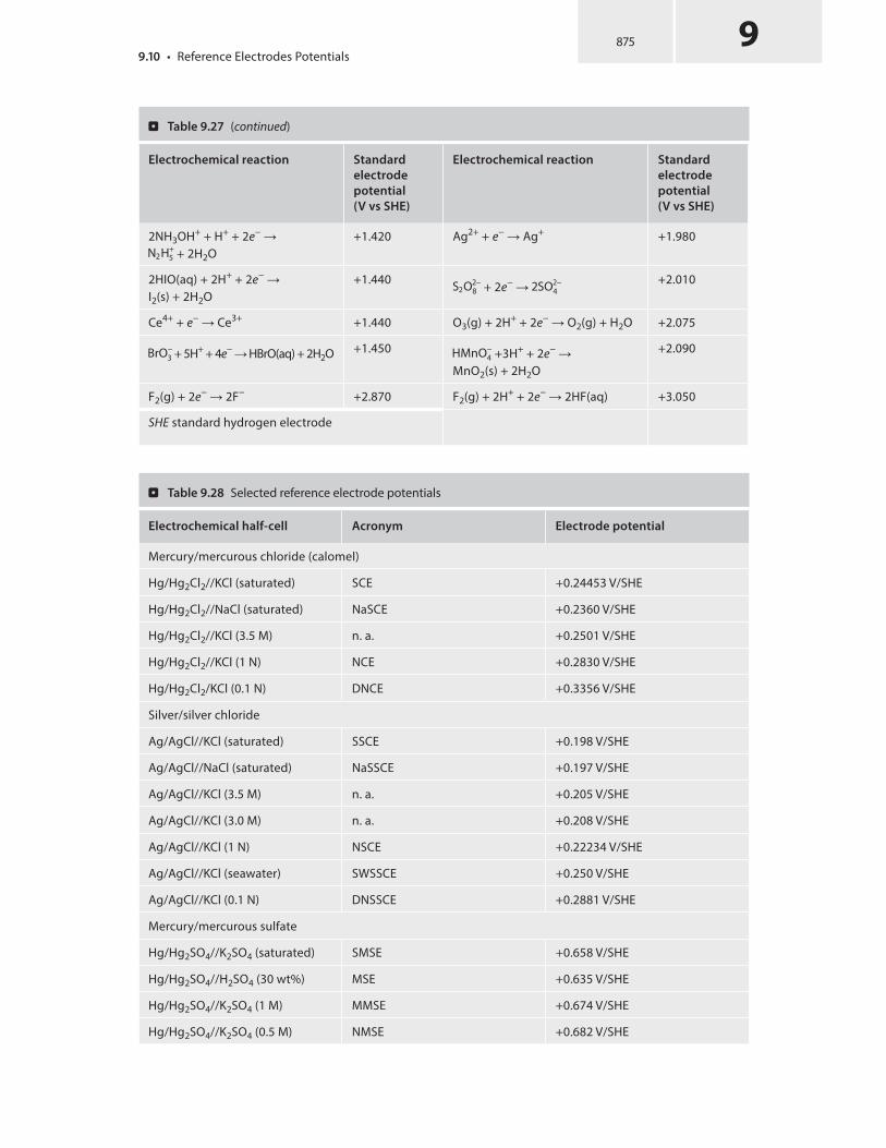
Electrochemical reaction Standard
electrode
potential
(V vs SHE)
Electrochemical reaction Standard
electrode
potential
(V vs SHE)
2NH3OH+ + H+ + 2e− N2H
+
5 + 2H2O+1.420 Ag2+ + e− Ag+ +1.980
2HIO(aq) + 2H+ + 2e− I2(s) + 2H2O
+1.440S2O
2−
8 + 2e− 2SO2−
4
+2.010
Ce4+ + e− Ce3+ +1.440 O3(g) + 2H+ + 2e− O2(g) + H2O +2.075
BrO−
3 + 5H+ + 4e− HBrO(aq) + 2H2O +1.450HMnO
−
4 +3H+ + 2e− MnO2(s) + 2H2O
+2.090
F2(g) + 2e− 2F− +2.870 F2(g) + 2H+ + 2e− 2HF(aq) +3.050
SHE standard hydrogen electrode
. Table 9.27 (continued)
. Table 9.28 Selected reference electrode potentials
Electrochemical half-cell Acronym Electrode potential
Mercury/mercurous chloride (calomel)
Hg/Hg2Cl2//KCl (saturated) SCE +0.24453 V/SHE
Hg/Hg2Cl2//NaCl (saturated) NaSCE +0.2360 V/SHE
Hg/Hg2Cl2//KCl (3.5 M) n. a. +0.2501 V/SHE
Hg/Hg2Cl2//KCl (1 N) NCE +0.2830 V/SHE
Hg/Hg2Cl2/KCl (0.1 N) DNCE +0.3356 V/SHE
Silver/silver chloride
Ag/AgCl//KCl (saturated) SSCE +0.198 V/SHE
Ag/AgCl//NaCl (saturated) NaSSCE +0.197 V/SHE
Ag/AgCl//KCl (3.5 M) n. a. +0.205 V/SHE
Ag/AgCl//KCl (3.0 M) n. a. +0.208 V/SHE
Ag/AgCl//KCl (1 N) NSCE +0.22234 V/SHE
Ag/AgCl//KCl (seawater) SWSSCE +0.250 V/SHE
Ag/AgCl//KCl (0.1 N) DNSSCE +0.2881 V/SHE
Mercury/mercurous sulfate
Hg/Hg2SO4//K2SO4 (saturated) SMSE +0.658 V/SHE
Hg/Hg2SO4//H2SO4 (30 wt%) MSE +0.635 V/SHE
Hg/Hg2SO4//K2SO4 (1 M) MMSE +0.674 V/SHE
Hg/Hg2SO4//K2SO4 (0.5 M) NMSE +0.682 V/SHE
875 99.10 • Reference Electrodes Potentials

9
Electrochemical half-cell Acronym Electrode potential
Silver/silver sulfate
Ag/Ag2SO4//K2SO4 (saturated) SSSE +0.690 V/SHE
Ag/2SO4//H2SO4 (1 M) MSSE +0.710 V/SHE
Ag/2SO4//H2SO4 (0.5 M) NSSE +0.720 V/SHE
Mercury/mercuric oxide
Hg/HgO//KOH (20 wt%) MOE +0.098 V/SHE
Hg/HgO//NaOH (1 M) NaMOE +0.140 V/SHE
Hg/HgO//NaOH (0.1 M) +0.165 V/SHE
Copper/copper sulfate
Cu/CuSO4 (saturated) SCSE +0.316 V/SHE
DNCE decinormal calomel electrode, DNSSCE decinormal silver–silver chloride electrode, MMSE molar mer-cury sulfate electrode, MOE mercuric oxide electrode, MSE mercury sulfate electrode, MSSE molar standard silver sulfate electrode, NaMOE sodium mercuric oxide electrode, NaSCE sodium calomel electrode, NCE normal calomel electrode, NMSE normal mercury sulfate electrode, NSSCE normal silver–silver chloride elec-trode, NSSE normal silver sulfate electrode, SCE standard calomel electrode, SCSE standard copper sulfate electrode, SHE standard hydrogen electrode, SMSE standard mercury sulfate electrode, SSCE silver–silver chloride electrode, SSSE standard silver sulfate electrode, SWSSCE seawater silver–silver chloride electrode
9.11 Ampacity or Maximum Carrying Current
. Table 9.28 (continued)
Chapter 9 • Miscellaneous Electrical Materials876
The maximum carrying current of an electrical conductor in the form of a wire or cable is called either the current rating or the ampacity by electrical engineers. Ampacities are closely related to the maximum temperature elevation the wire or cable can sustain without its elec-trical resistivity being affected and without the insulating material that forms the protective sheath being damaged. Therefore, the ampacity of a given conductor strongly depends on the intrinsic properties of the constituting material, such as its electrical resistivity, its thermal conductivity, its specific heat capacity, and its temperature of fusion, and also external factors, such as the nature of the insulating sheath materials and the type of external cooling (e.g., natural or forced cooling) provided.
The calculation of ampacities is extremely important for sizing the current collectors in the secondary circuit of a transformer as a large electric current of several thousand amperes circulates.
Primarily for reasons of safety, and mostly on the basis of practice and experiments, electri-cal engineers have developed guidance for selection of the proper wire or cable to carry safely an electric current and have established certain standards for electrical wiring, such as those specified in the National Electrical Code in the USA. Typical National Electrical Code wire am-pacity tables will show allowable maximum currents for different sizes and applications of wire.
Although the melting point of copper theoretically imposes a limit on wire ampacity, the materials commonly used for insulating conductors melt at temperatures far below the melting point of copper, and so practical ampacity ratings are based on the thermal limits of the insulation. Voltage dropped as a result of excessive wire resistance is also a factor in

sizing conductors for their use in circuits, but this consideration is better assessed through more complex means. It is not the intention in this handbook to disclose the ampacities of all types of conductors but the intention is rather to provide the reader with practical rules to evaluate the ampacities of bare copper conductors such as those used in electrochemical and electrothermal equipment.
For instance, for bare copper wires or cables, the adopted value for a maximum carry-ing current is given as 1 A for a wire with a cross section of 700 cmil (i.e., a wire diameter of 0.0265 in); that is, a maximum current density of 2.82 A/mm2.
However, if the copper wire or cable is water-cooled, the ampacity can be increased up to 1 A for a wire with a cross section of 438.5 cmil (i.e., a wire of diameter 0.021 in); that is, until a maximum current density of 4.50 A/mm2.
For large graphite electrodes such as those used in electric arc furnaces, the maximum carrying current adopted is usually 285 kA/m2 (or 0.28 A/mm2). See also . Table 9.29.
9.11.1 Maximum Frequency for Penetration
The depth of penetration (i.e., skin effect) produced by an alternating electric current circulating in a wire is given by the following equation.
ı = .�= �0�rf /1/2
;
where δ is the depth of penetration in meters, μ0 is the permeability of a vacuum in henries per meter, μr is the relative magnetic permeability, and f is the frequency in hertz.
Therefore, the maximum frequency to reach the core of the wire having a diameter D is given by
f = 4�=. �0�rD2/:
For a bare and pure copper wire with diameter D, electrical resistivity of 1.7241 mW · cm, and a magnetic permeability of 4π × 10−7 H/m, the maximum frequency is given by
f = 0:017469=D2:
. Table 9.29 Ampacities of conductors
Conductor type Maximum ampacity (kA/m2) Empirical equationa
Self-baking Søderberg electrodes 40–50 I = Ck(Rac/Rdc)−0.5D3/2
Prebaked carbon electrode 60
Graphite electrodes 280 I = 170D1/2
Copper bus bars (air-cooled) 2820
Copper bus bars (water-cooled) 4500
a I is total electric current in kiloamperes, Ck is the electrode load factor (ranging 50–65 kA · m2/3), Rac andRdc are the electrical resistances in milliohms for alternating current and direct current respectively, and D is the outer diameter in meters
877 99.11 • Ampacity or Maximum Carrying Current

9
The ampacities, maximum frequencies, and linear resistance of pure copper wires for different American wire gauges are given . Table 9.30.
9.11.2 Maximum Current and Cable Temperature
When a long wire of outer diameter D and length L, both in meters, made of a conducting metal or alloy with electrical resistivity ρe (Ω · m), mass density ρm (kg/m3), specific heat capacity cp (J · kg−1 · K−1), and spectral emissivity ε is in thermal equilibrium with its surroundings at a temperature Ts (in kelvins), as soon an electric current I (in amperes), circulates through the circuit, Joule heating increases the wire temperature, while the wire exchanges heat with the surroundings concurrently by conduction, convection, and radiation.
When the steady state is reached, the wire exhibits the maximum temperature for the given electric current. The equation that governs the maximum temperature of the wire due to the passage of current as a function of the previous physical quantities and also based on the con-vection heat transfer coefficient is given by the overall energy balance per unit time; that is, the overall rate of energy change equals the energy produced within the system (i.e., Joule heating) less the rate of energy absorbed by the system less the rate of energy leaving the system due to losses by conduction, convection, and radiation:
dE=dt = dE=dt .in/ − dE=dt .out/ + S:
The rate at which energy is produced is mainly due to Joule heating, RI2, with the electrical resistance for a cylindrical body given by R = ρe(4L/πD2), the rate at which energy is lost by convection follows Newton’s convection equation, hπLD(T − Ts), and the rate at which energy is lost by radiation is given by the Stefan–Boltzmann equation, εσπLD(T4 − T 4
s).
The overall energy balance per unit time is given by the following equation:
dE=dt = �m.�LD2=4/cpd.T − T0/=dt = RI
2 − h�LD.T − Ts/ − "��LD.T4 − T
4
s/:
Therefore, the temperature change per unit time is given by the following equation:
dT=dt = Œ�e.4L=�D2/I
2 − h�LD.T − Ts/ − "��LD.T4 − T
4
s/�=Œ�m.�LD
2=4/cp�:
These equations can be solved by numerical integration.For most practical situations, once the steady state is reached, the right term becomes zero,
and the temperature of the wire is maximum for the given current:
�e.4=�2D
2/I
2 = hD.Tmax − Ts/ + "�D.T4
max− T
4
s/:
To be even more rigorous, the temperature dependence of the resistivity for metals, ρe(T) = ρe[1 + α(Tmax − Ts)], must be considered. Then it is possible to rewrite the equation in the steady-state condition as follows:
�eŒ1 + ˛.Tmax − Ts/�.4=�2D
2/I
2 = hD.Tmax − Ts/ + "�D.T4
max− T
4
s/:
Chapter 9 • Miscellaneous Electrical Materials878

. Table 9.30 Ampacities of electrical wire
AWG Conduc-
tor outer
diameter
(in)
Con-
ductor
diameter
(mm)
Linear
resistance
(Ω/1000 ft)
Linear re-
sistance
(Ω/km)
Maxi-
mum am-
pacity for
chassis
wiring (A)
Maxi-
mum
ampacity
for power
transmis-
sion (A)
Maxi-
mum
frequen-
cy 100%
depth
0000 0.4600 11.6840 0.049 0.16072 380 302 125 Hz
000 0.4096 10.4038 0.0618 0.202704 328 239 160 Hz
00 0.3648 9.2659 0.0779 0.255512 283 190 200 Hz
0 0.3249 8.2525 0.0983 0.322424 245 150 250 Hz
1 0.2893 7.3482 0.1239 0.406392 211 119 325 Hz
2 0.2576 6.5430 0.1563 0.512664 181 94 410 Hz
3 0.2294 5.8268 0.197 0.64616 158 75 500 Hz
4 0.2043 5.1892 0.2485 0.81508 135 60 650 Hz
5 0.1819 4.6203 0.3133 1.027624 118 47 810 Hz
6 0.1620 4.1148 0.3951 1.295928 101 37 1100 Hz
7 0.1443 3.6652 0.4982 1.634096 89 30 1300 Hz
8 0.1285 3.2639 0.6282 2.060496 73 24 1650 Hz
9 0.1144 2.9058 0.7921 2.598088 64 19 2050 Hz
10 0.1019 2.5883 0.9989 3.276392 55 15 2600 Hz
11 0.0907 2.3038 1.26 4.1328 47 12 3200 Hz
12 0.0808 2.0523 1.588 5.20864 41 9.3 4150 Hz
13 0.0720 1.8288 2.003 6.56984 35 7.4 5300 Hz
14 0.0641 1.6281 2.525 8.282 32 5.9 6700 Hz
15 0.0571 1.4503 3.184 10.44352 28 4.7 8250 Hz
16 0.0508 1.2903 4.016 13.17248 22 3.7 11 kHz
17 0.0453 1.1506 5.064 16.60992 19 2.9 13 kHz
18 0.0403 1.0236 6.385 20.9428 16 2.3 17 kHz
19 0.0359 0.9119 8.051 26.40728 14 1.8 21 kHz
20 0.0320 0.8128 10.15 33.292 11 1.5 27 kHz
21 0.0285 0.7239 12.8 41.984 9 1.2 33 kHz
22 0.0254 0.6452 16.14 52.9392 7 0.92 42 kHz
23 0.0226 0.5740 20.36 66.7808 4.7 0.729 53 kHz
24 0.0201 0.5105 25.67 84.1976 3.5 0.577 68 kHz
25 0.0179 0.4547 32.37 106.1736 2.7 0.457 85 kHz
26 0.0159 0.4039 40.81 133.8568 2.2 0.361 107 kHz
879 99.11 • Ampacity or Maximum Carrying Current
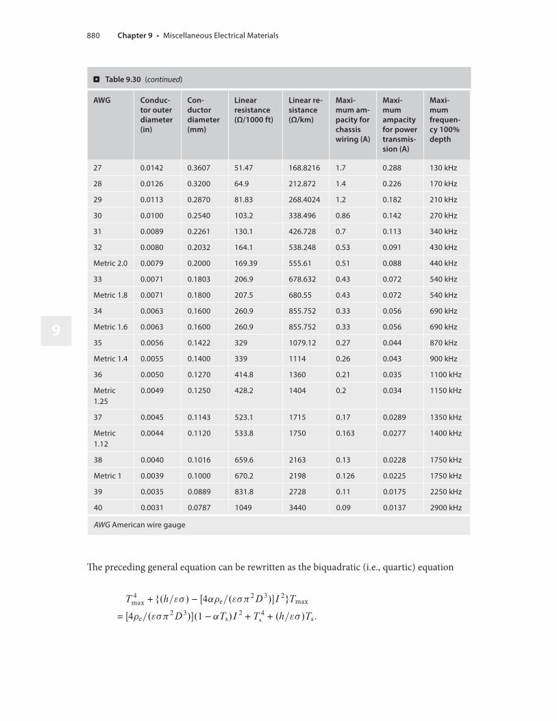
9
AWG Conduc-
tor outer
diameter
(in)
Con-
ductor
diameter
(mm)
Linear
resistance
(Ω/1000 ft)
Linear re-
sistance
(Ω/km)
Maxi-
mum am-
pacity for
chassis
wiring (A)
Maxi-
mum
ampacity
for power
transmis-
sion (A)
Maxi-
mum
frequen-
cy 100%
depth
27 0.0142 0.3607 51.47 168.8216 1.7 0.288 130 kHz
28 0.0126 0.3200 64.9 212.872 1.4 0.226 170 kHz
29 0.0113 0.2870 81.83 268.4024 1.2 0.182 210 kHz
30 0.0100 0.2540 103.2 338.496 0.86 0.142 270 kHz
31 0.0089 0.2261 130.1 426.728 0.7 0.113 340 kHz
32 0.0080 0.2032 164.1 538.248 0.53 0.091 430 kHz
Metric 2.0 0.0079 0.2000 169.39 555.61 0.51 0.088 440 kHz
33 0.0071 0.1803 206.9 678.632 0.43 0.072 540 kHz
Metric 1.8 0.0071 0.1800 207.5 680.55 0.43 0.072 540 kHz
34 0.0063 0.1600 260.9 855.752 0.33 0.056 690 kHz
Metric 1.6 0.0063 0.1600 260.9 855.752 0.33 0.056 690 kHz
35 0.0056 0.1422 329 1079.12 0.27 0.044 870 kHz
Metric 1.4 0.0055 0.1400 339 1114 0.26 0.043 900 kHz
36 0.0050 0.1270 414.8 1360 0.21 0.035 1100 kHz
Metric 1.25
0.0049 0.1250 428.2 1404 0.2 0.034 1150 kHz
37 0.0045 0.1143 523.1 1715 0.17 0.0289 1350 kHz
Metric 1.12
0.0044 0.1120 533.8 1750 0.163 0.0277 1400 kHz
38 0.0040 0.1016 659.6 2163 0.13 0.0228 1750 kHz
Metric 1 0.0039 0.1000 670.2 2198 0.126 0.0225 1750 kHz
39 0.0035 0.0889 831.8 2728 0.11 0.0175 2250 kHz
40 0.0031 0.0787 1049 3440 0.09 0.0137 2900 kHz
AWG American wire gauge
. Table 9.30 (continued)
The preceding general equation can be rewritten as the biquadratic (i.e., quartic) equation
T4
max+ f.h="�/ − Œ4˛�e=."��
2D
3/�I
2gTmax
= Œ4�e=."��2D
3/�.1 − ˛Ts/I
2 + T4
s+ .h="�/Ts:
Chapter 9 • Miscellaneous Electrical Materials880

Then in the simplified form, it becomes
T4
max+ .A − BI
2/Tmax = CI
2 + T4
s+ ATs;
with the constants A = (h/εσ), B = [4αρe/(εσπ2D3)], and C = [4ρe/(εσπ2D3)](1 − αTs).Let us consider a chemically pure titanium wire slightly oxidized with a mass density of
4540 kg · m−3, spectral emissivity of 0.80, electrical resistivity of 56 μΩ · cm with a temperature coefficient 5.42 × 10⁻⁵ K−1, and an outer diameter of 2.38 mm in a surrounding atmosphere at 293.15 K with a natural convection heat transfer coefficient of 20 W · m−2 · K−1. With a circu-lating current of 25, 50, and 100 A, we can then determine the two maximum temperatures of the wire by solving the following biquadratic equation by successive iterations:
T4
max+ .4:41 � 10
8 − 2 � 104I
2/Tmax = 3:65 � 10
8I
2 + 7:83 � 109:
The results are reported in . Table 9.31.
9.11.3 Fusing Current
From the previous equation, assuming that for a maximum temperature equal to the tempera-ture of fusion (i.e., melting point) of the metal or alloy, the corresponding current is called the fusing current, Ifusing (in amperes), and it is obtained from
T4
fusion− T
4
s− A.Tfusion − Ts/ = .BTfusion + C /I
2
fusing;
I2
fusing= ŒT
4
fusion− T
4
s− A.Tfusion − Ts/�=.BTfusion + C /:
As the two constants B and C are a function of D−3, we can see that the fusing current is then a function of D3/2.
I2
fusing= .."��
2=4�e/fŒT
4
fusion− T
4
s− .h="�/.Tfusion − Ts/�=.2 − ˛Ts/g/D
3
Ifusing
= .."��2=4�e/fŒT
4
fusion− T
4
s− .h="�/.Tfusion − Ts/�=.2 − ˛Ts/g/
1/2D
3/2
This dependence was obtained empirically from experiments that were conducted by H.W. Preece in 1884, and it is given in its simplest form as
Ifusing = k � D3/2
. Table 9.31 Biquadratic equations and maximum temperature for a chemically pure titanium wire
Electric current (I/A) Biquadratic equation Maximum temperature
100T4
max + 2.40 × 10⁸ Tmax = 3.66 × 10¹² Tmax = 1352 K = 1079 °C
50T4
max+ 3.91 × 10⁸ Tmax = 9.21 × 10¹¹ Tmax = 873 K = 600 °C
25T4
max + 4.28 × 10⁸ Tmax = 2.36 × 10¹¹ Tmax = 455 K = 182 °C
881 99.11 • Ampacity or Maximum Carrying Current