Materials Chemistry B - RSC Publishing
14
This is an Accepted Manuscript, which has been through the Royal Society of Chemistry peer review process and has been accepted for publication. Accepted Manuscripts are published online shortly after acceptance, before technical editing, formatting and proof reading. Using this free service, authors can make their results available to the community, in citable form, before we publish the edited article. We will replace this Accepted Manuscript with the edited and formatted Advance Article as soon as it is available. You can find more information about Accepted Manuscripts in the Information for Authors. Please note that technical editing may introduce minor changes to the text and/or graphics, which may alter content. The journal’s standard Terms & Conditions and the Ethical guidelines still apply. In no event shall the Royal Society of Chemistry be held responsible for any errors or omissions in this Accepted Manuscript or any consequences arising from the use of any information it contains. Accepted Manuscript Journal of Materials Chemistry B www.rsc.org/materialsB
-
Upload
khangminh22 -
Category
Documents
-
view
1 -
download
0
Transcript of Materials Chemistry B - RSC Publishing

This is an Accepted Manuscript, which has been through the Royal Society of Chemistry peer review process and has been accepted for publication.
Accepted Manuscripts are published online shortly after acceptance, before technical editing, formatting and proof reading. Using this free service, authors can make their results available to the community, in citable form, before we publish the edited article. We will replace this Accepted Manuscript with the edited and formatted Advance Article as soon as it is available.
You can find more information about Accepted Manuscripts in the Information for Authors.
Please note that technical editing may introduce minor changes to the text and/or graphics, which may alter content. The journal’s standard Terms & Conditions and the Ethical guidelines still apply. In no event shall the Royal Society of Chemistry be held responsible for any errors or omissions in this Accepted Manuscript or any consequences arising from the use of any information it contains.
Accepted Manuscript
Journal of Materials Chemistry B
www.rsc.org/materialsB

ARTICLE Journal of Materials Chemistry B
This journal is © The Royal Society of Chemistry 20xx J. Mater. Chem. B, 2015, 00, 1-3 | 1
Please do not adjust margins
Please do not adjust margins
a. Department of Materials Science and Technology of Polymers, MESA+ Institute for
Nanotechnology, University of Twente, P.O. Box 217, 7500 AE Enschede, The
Netherlands, E-mail: [email protected] b. Department of Complex Tissue Regeneration, MERLN Institute for Technology
Inspired Regenerative Medicine, Maastricht University, P.O. Box 616, 6200 MD
Maastricht, The Netherlands c. Laboratory for Surface Science and Technology (LSST), Department of Materials,
ETH Zürich, Vladimir-Prelog-Weg 5, CH-8093 Zürich, Switzerland
Received 00th January 20xx,
Accepted 00th January 20xx
DOI: 10.1039/x0xx00000x
www.rsc.org/
Mimicking Natural Cell Environments: Design, Fabrication and
Application of Bio-Chemical Gradients on Polymeric Biomaterial
Substrates
Edmondo M. Benettia,c, Michel Klein Gunnewieka, Clemens A. van Blitterswijkb, G. Julius Vancsoa, Lorenzo Moronib
Gradients of biomolecules on synthetic, solid substrates can efficiently mimic the natural, graded variation of properties by
the extracellular matrix (ECM). Such gradients represent accessible study boards for the understanding of cellular
activities, and they also provide functional supports for tissue engineering (TE). This review describes the most relevant
methods to produce 2-dimensional (2D) as well as 3-dimensional (3D) gradient supports for cell manipulations, and also
addresses the response of cells from different origins when seeded on these constructs. The fabrication strategies
summarized encompass the combination of polymer and surface chemistry, micro- and nano-engineering construction
strategies and biotechnological approaches. This multidisciplinary scheme has enabled the design and the realization of
diverse, synthetic supports as cellular environments, spanning from the first gradient self-assembled monolayer (SAM) to
multilayers, and hybrid constructs mimicking the complexity of natural tissue environments. The standing challenge is
bringing these advances in supports’ fabrication to a dynamic functioning in space and time, towards the successful
imitation of the most complex bio-chemical system ever studied: our body.
Introduction
Current research activities in the development of polymeric
biomaterials are progressing towards the design of two-
dimensional (2D) and three-dimensional (3D) supports
presenting a gradual variation of biochemical composition
and/or physico-chemical properties. This trend is principally
driven by the need of closely mimicking the natural variation
of extra-cellular matrix (ECM) characteristics including spatial
definition of the behavior of seeded cells on the synthetic
supports.1, 2
Scaffolds of various compositions and presenting
gradient properties have the capability of triggering several
biological processes like cell migration via haptotaxis3 and
durotaxis4. Alternatively, gradient-containing supports can be
applied to closely reproduce the physical properties of the
natural tissue counterparts, simultaneously hosting tissue-
(re)forming cells, like in the case of gradient hydrogel supports
replacing damaged parts of bone-cartilage joints.1, 5
In both these cases, the engineering and fabrication of
synthetic ECMs encompass the spatial variation of at least one
support’s characteristic, either chemical (e.g. protein
concentration6, 7
or hydrophilicity8), physical (e.g. matrix
stiffness9) or morphological (porosity
10).
The design of 2D platforms presenting bio-chemical gradients
have largely relied on the controlled surface deposition of
proteins by physisorption or covalent attachment, and often
included the application of (macro)molecular “spacers”, such
as self-assembled monolayers (SAMs) or polymer brushes on
inorganic surfaces.2, 11
In contrast, 3D supports featuring
gradient compositions 12-14 have been mainly fabricated
starting from hydrogel materials, using poly(ethylene glycol)
(PEG) derivatives, for instance, and decorating the synthetic
matrix with biomolecules or specific cellular cues via controlled
loading. 14, 15 16, 17 Additionally, 3D porous scaffolds for TE
formulations have been developed by a number of diverse
fabrications, to yield controlled and gradual variations of
macro, micro and nanoporosities. The so-created
morphological gradients regulated the settlement of cells, the
diffusion of nutrients and the removal of cellular waste
products during cell proliferation and differentiation, also
providing a progressive variation of mechanical properties
within the whole support.18-22
In this review, we firstly focus on the most relevant strategies
to synthesize 2D gradients, concentrating on the applications
of polymer adlayers and brushes to trigger the controlled
surface functionalization of various biomolecules. Secondly,
we report the latest advances in engineering and fabricating
3D hydrogel and porous supports presenting gradients of
composition and/or physical properties. The application of
both 2D and 3D constructs for studying the response of cells
from different origins and for the support-mediated
regeneration of tissues is finally reported.
2D Protein Gradients Supported by SAMs and
Polymer Brushes
The first example of an unidirectional chemical gradient on a
silicon oxide surface was presented in 1992 by Chaudhury and
Whitesides, who exploited vapour deposition of different
silane-based adsorbates to create SAMs featuring gradient-like
surface concentrations of hydrophobic species.23
Inspired by
these pioneering fabrications, several mixed SAM
compositions were subsequently employed as platforms for
the formation of surface gradients of adsorbed proteins on
gold substrates. For instance, Tirrell et al. reported the
Page 1 of 13 Journal of Materials Chemistry B
Jour
nalo
fMat
eria
lsC
hem
istr
yB
Acc
epte
dM
anus
crip
t

ARTICLE Journal of Materials Chemistry B
2 | J. Mater. Chem. B, 2015, 00, 1-3 This journal is © The Royal Society of Chemistry 20xx
Please do not adjust margins
Please do not adjust margins
preparation of a surface concentration gradient of
hydrophobic, protein-adhesive thiol species. By this method, a
first SAM was uniformly deposited on Au, followed by the
electrochemistry-assisted desorption of the constituting thiol
species, which could be spatially controlled through the
application of a decaying potential window across the
functionalized substrate.24
The so-obtained surface gradient of
thiol coverage was subsequently “back-filled” with biopassive,
oligoethylene glycol-bearing thiols, finally yielding a gradual
variation of the bio-adhesive character across the surface.24-27
On this SAM, protein adsorption could be spatially controlled
along the gradient, enabling the fabrication of a unidirectional
variation of protein surface density.28, 29
More recently, Bonifazi et al.30
fabricated gradients of SAMs by
varying the exposure time of single Au substrates in solution
mixtures of peptide-exposing thiol ligands, featuring the cell-
migration stimulating factor Ile-Gly-Asp-Gln (IGDQ), and bio-
inert thiol species.31
The so-formed gradient mixed monolayers
were subsequently applied to investigate the migratory
behavior of metastatic breast cancer cells compared to human
dermal fibroblasts. An individual rather than a collective
cancer cell migration was thus highlighted, suggesting the
coexistence of “stationary” and “migrating” cell phenotypes.
SAMs presenting a gradual variation of chemical composition
on silicon oxide and gold substrates were also applied for the
subsequent surface-initiated polymerization (SIP) to form
polymer-brush, grafting-density gradients (Figure 1).32-36
The
fabrication of these polymeric supports typically relied on the
preliminary formation of a SAM of initiator adsorbates
presenting a gradient coverage across a single substrate
(Figure 1a). Subsequent SIP (Figure 1b) produced a graded
variation of polymer grafting density along the sample,
obtaining layers of grafts progressively shifting their
conformation from low-density mushrooms towards high-
density brushes (Figure 1c).37-39
Similar polymer brush platforms were successfully employed
to study protein and cell adhesion, and to dissect the influence
of brush-design parameters on bio-adhesion.40-45
A relevant
example was provided by poly(2-hydroxyethyl methacrylate)
(PHEMA) grafts presenting a gradual variation of grafting
densities and chain lengths, which were extensively applied as
biointerfaces by the group of Genzer.46, 47
Orthogonal double
gradients of both PHEMA grafting density and brush molar
mass were fabricated by applying mixed initiator SAMs
showing a gradual variation of initiator coverages along one
substrate direction, coupled with a progressive increase in the
applied polymerization time (by varying substrate-
polymerization solution contact time) (Figure 1d) along the
direction orthogonal to the first gradient. The so-created brush
platforms were subsequently incubated in fibronectin (FN)
solutions, demonstrating how thick and dense PHEMA brushes
significantly inhibited the adsorption of this protein, while, for
a given grafted chain-length, a progressive increase of
adsorbed FN could be obtained by gradually decreasing the
grafting density of PHEMA films. Hence, the PHEMA brush
orthogonal gradients translated into surface gradients of
physisorbed FN and were finally tested for monitoring the
adhesion of MCT3T-E1 cells, which promptly responded to the
bi-directional variation of surface coverage by adhesive cues,
displaying a progressive change of cell number and spreading
area along the substrate.
The functionalization of biomaterial surfaces by grafted-from,
gradient polymer brushes has been not only devoted to study
and prevent the adsorption of proteins, but also to create cell-
adhesive interfaces, which can trigger in a spatially-defined
way specific cellular responses. Thickness gradients of
thermoresponsive poly-N-(isopropylacrylamide) (PNIPAM)
brushes, fabricated following the Genzer’s method, were
applied for studying the adhesion of human liver cancer cells
(HepG2) above the lower critical solution temperature (LCST)
of PNIPAM, and their subsequent detachment below LCST.48
The so-fabricated gradient brushes allowed a spatial
modulation of the reversibility of cell adhesion. Namely, for a
specific range of PNIPAM brush thicknesses across the
gradient, HepG2 cells were shown to promptly adhere at
temperatures above 37°C, and nearly quantitatively detach at
24°C.
Figure 1. (a) Preparation of a SIP initiator gradient by controlled deposition on silicon
oxide surfaces. (b) Surface-grafted polymer brushes presenting a gradient in grafting
densities are subsequently formed by SI-ATRP. (c) Schematic illustrating grafted
polymer conformations in the mushroom and brush regimes, and the mushroom-to-
brush transition. Adapted with permission of Springer, reference 49. (d) Schematic of
the setup for the fabrication of surface grafted polymer brushes with a gradient in
molecular weight. Adapted with permission from reference 50. Copyright 2003
American Chemical Society.
Page 2 of 13Journal of Materials Chemistry B
Jour
nalo
fMat
eria
lsC
hem
istr
yB
Acc
epte
dM
anus
crip
t
Journal of Materials Chemistry B ARTICLE
This journal is © The Royal Society of Chemistry 20xx J. Mater. Chem. B, 2015, 00, 1-3 | 3
Please do not adjust margins
Please do not adjust margins
The application of polymer brush gradients for tuning cell
attachment was recently investigated by the groups of Benetti,
Vancso and Moroni, which fabricated poly(oligoethylene
glycol)methacrylate (POEGMA) brush platforms presenting a
gradual variation of tethered-chain length (brush thickness)
and bearing cell-adhesive FN units to regulate the mechanisms
of settlement by human mesenchymal stem cells (hMSCs).51
In this study, the variation of POEGMA brush thickness within
the 10-60 nm range along a single substrate was achieved by
surface-initiated atom transfer radical polymerization (SI-
ATRP) from initiator-functionalized poly-ε-caprolactone (PCL)
surfaces, and by gradually varying the exposure time of the
initiating substrates to the polymerization medium.
Subsequent functionalization of the POEGMA brushes by FN,
produced cell-adhesive platforms presenting constant protein
coverage, grafting density and solvent content but also
displaying a progressive variation of brush-tether length. This
translated into a gradient of frictional dissipation and brush
lateral deformability along the surface, where thicker brushes
could be more laterally deformed and showed higher friction,
as measured by lateral force microscopy (LFM), while thinner
ones showed reduced shear deformability and lower frictional
dissipation. The gradual variation of these properties was
demonstrated to alter the adhesion and spreading of hMSCs,
which responded to the modulation of the dissipative
character by POEGMA-FN adducts. Following a direct
relationship, hMSCs area progressively decreased with the
increasing of POEGMA brush lateral deformability (expressed
as maximum brush lateral strain), indicating that the
dissipative character of brush-cue adducts and cell spreading
are synergistically correlated.52-55
The different strengths of
cell adhesion along the brush gradient were also reflected by a
variation of the morphology and distribution of focal adhesion
complexes (FAs) across the cell membranes.
Figure 2. Immunofluorescence micrographs showing the vinculin-associated FA
complexes for hMSCs attached on 10-20 (a), 30-40 (b) and 50-60 (c) nm-thick POEGMA
brushes functionalized with FN. The FA points were stained by FITC (green) and the cell
nucleus by DAPI (blue). (d) Average FA area and (e) average FA aspect ratio. * denotes
statistical significant differences between the assigned and the non-assigned
topographies (p < 0.05). Adapted with permission from reference 51. Copyright 2015
Wiley-VCH Verlag GmbH & Co.
As displayed in Figure 2, on thinner brushes larger and
oriented FAs were delocalized over the whole cell membrane.
With increasing brush thickness, smaller FAs were increasingly
concentrated at the periphery of the membrane. Hence, a
gradual variation of brush parameters was demonstrated to
regulate the adhesion and spreading of stem cells. These
findings additionally suggested that brush gradients could be
effectively applied in more complex preparations with the aim
of directing cell proliferation and, ultimately, differentiation.
Following an alternative preparation of brush films, based on a
grafting-to method, the group of Spencer applied poly(L-
lysine)-graft-PEG graft-copolymers (PLL-g-PEG) to form thin
PEG-brush layers on titanium oxide (TiO2) surfaces.56
Due to
the electrostatic interactions between the positively charged
PLL backbones and the negatively charged TiO2 surface, and by
varying the exposure time of the adsorbing polymer solutions
along the substrate, a gradient in surface density of adsorbed
copolymer was easily obtained. This translated into a gradual
variation of PEG surface density, which was expressed as
concentration of EG-units across the formed gradient, ranging
from 0 to around 17 EG-units·nm-2
. These platforms were
subsequently applied to spatially control the adsorption of
bovine serum albumin (BSA) and fibrinogen (Fgn).57
Although
the adsorption of both these proteins gradually decreased
with increasing EG density, quantitative inhibition of Fgn
adsorption required higher PEG coverage (EG-units=12.8 ± 0.6
nm-2
) compared to BSA (EG-units=8.3 ± 0.8 nm-2
). These
differences in adsorption behavior between BSA and Fgn were
attributed to the lower energy cost for Fgn to adhere between
PEG chains (or on film defects), provided by the distinctive
morphology of this coil-like protein, capable of undergoing
secondary adsorption on too thin or not uniform brush films.58
The remarkable advantage of this brush gradient fabrication
strategy, compared to the already reported grafting-from
methods, is represented by its easy and reproducible dip-and-
rinse process and the possibility to coat large surfaces in a
controlled fashion. Additionally, structured PLL-g-PEG films can
be applied not only on metal oxide surfaces but also on glass
and silicon oxide substrates.59, 60
Microfluidic- Assisted Fabrication of 2D Gradients
on Hydrogel Substrates
As hydrogel supports has been often applied as highly versatile
platforms for regulating the settlement of cells and studying
their behavior in response to chemical or physical stimuli,61, 62
the surface engineering of these substrates has progressively
gained increasing impact in the development of biomaterials.
Novel surface modification/functionalization strategies
exploiting microfluidic devices to deposit (bio)chemical species
in a spatially controlled fashion have recently emerged as
powerful alternatives compared to the commonly applied
“static” solution treatments.
Particularly, the formation of lamellar flows of protein
solutions inside microchannels63, 64 was successfully applied to
physically or chemically deposit proteins and other
Page 3 of 13 Journal of Materials Chemistry B
Jour
nalo
fMat
eria
lsC
hem
istr
yB
Acc
epte
dM
anus
crip
t
ARTICLE Journal of Materials Chemistry B
4 | J. Mater. Chem. B, 2015, 00, 1-3 This journal is © The Royal Society of Chemistry 20xx
Please do not adjust margins
Please do not adjust margins
biomolecules onto hydrogel surfaces placed in contact with
the flow (Figure 3a,b).63-67
Gradient of adsorbed proteins on
poly(dimethylsiloxane) (PDMS) substrates were similarly
fabricated by exploiting the progressive depletion of protein
concentration in the fluid channel,63, 68
which finally yielded
surface concentration gradients of biomolecules with typical
extensions ranging from sub-micrometer to several
centimetres in lengths (Figure 3c).69
Following a similar
approach, yet employing multichannel devices, patterns of
different proteins could be formed, finally obtaining multiple
gradient arrays and double gradients featuring two different
protein species on glass supports, as shown in Figure 3d.68
Protein gradients on hydrogels can be fabricated also along the
width of microchannels by injecting two or more protein
solutions into a fluidic-based system composed of alternated
splitting and mixing units.64, 70, 71
When two inlets were used,
one containing a protein solution and the second just a buffer
solution, a single gradient of one protein was formed between
the walls. Alternatively, the addition of a solution of a second
protein through an additional inlet allowed the fabrication of
hydrogels featuring concentration gradients of two different
proteins.72
The designing of microfluidic devices presenting
three or more inlets additionally enabled the fabrication of
more complex, multiple-protein concentration profiles.64
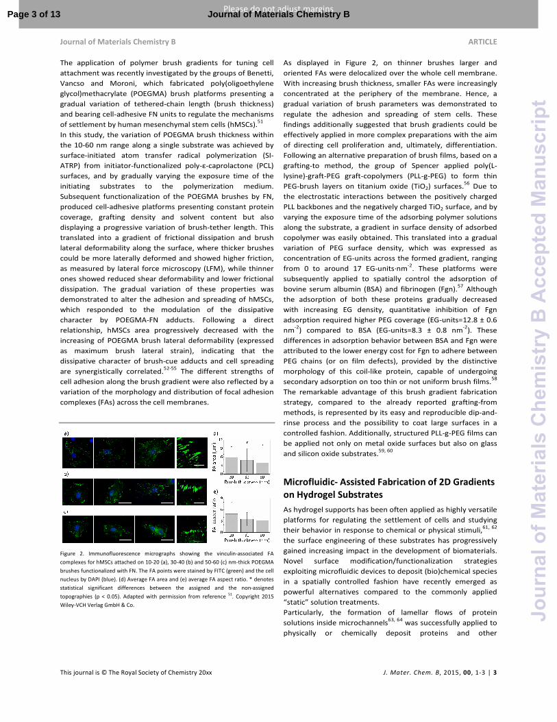
Figure 3. (a) A microfluidic gradient generator setup and (b) a schematic design of a
gradient-generating microfluidic network using three inlets. Adapted with permission
from reference 64. Copyright 2000 American Chemical Society.. (c) Fluorescence
micrographs depicting an example of the fabricated gradients at different backward-
flow times. Adapted with permission from reference 69. Copyright 2010 Wiley-VCH
Verlag GmbH & Co. (d) Counter-propagating gradient of BSA (orange-red) and collagen
(green) with pre-exposure of PDMS to BSA. Adapted with permission from reference 68.
Copyright 2003 American Chemical Society.
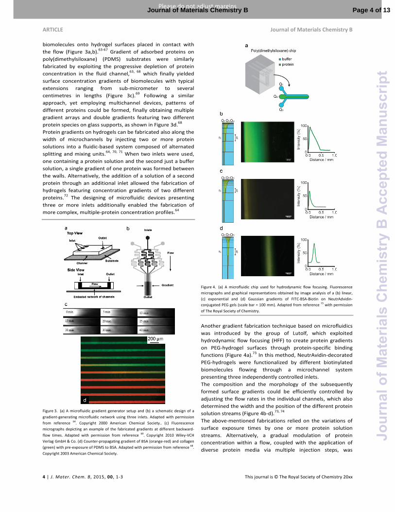
Figure 4. (a) A microfluidic chip used for hydrodynamic flow focusing. Fluorescence
micrographs and graphical representations obtained by image analysis of a (b) linear,
(c) exponential and (d) Gaussian gradients of FITC-BSA-Biotin on NeutrAdvidin-
conjugated PEG gels (scale bar = 100 mm). Adapted from reference 73 with permission
of The Royal Society of Chemistry.
Another gradient fabrication technique based on microfluidics
was introduced by the group of Lutolf, which exploited
hydrodynamic flow focusing (HFF) to create protein gradients
on PEG-hydrogel surfaces through protein-specific binding
functions (Figure 4a).73 In this method, NeutrAvidin-decorated
PEG-hydrogels were functionalized by different biotinylated
biomolecules flowing through a microchannel system
presenting three independently controlled inlets.
The composition and the morphology of the subsequently
formed surface gradients could be efficiently controlled by
adjusting the flow rates in the individual channels, which also
determined the width and the position of the different protein
solution streams (Figure 4b-d).73, 74
The above-mentioned fabrications relied on the variations of
surface exposure times by one or more protein solution
streams. Alternatively, a gradual modulation of protein
concentration within a flow, coupled with the application of
diverse protein media via multiple injection steps, was
Page 4 of 13Journal of Materials Chemistry B
Jour
nalo
fMat
eria
lsC
hem
istr
yB
Acc
epte
dM
anus
crip
t
Journal of Materials Chemistry B ARTICLE
This journal is © The Royal Society of Chemistry 20xx J. Mater. Chem. B, 2015, 00, 1-3 | 5
Please do not adjust margins
Please do not adjust margins
employed to design complex protein patterns and gradients on
similar hydrogel surfaces.75
73-75
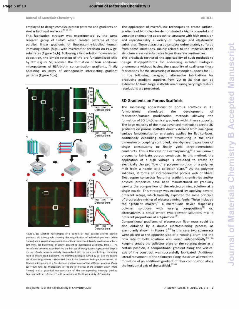
This fabrication strategy was experimented by the same
research group of Lutolf, which created patterns of four
parallel, linear gradients of fluorescently-labelled human
immunoglobulin (hIgG) with micrometer precision on PEG gel
substrates (Figure 5a,b). Following a first solution flow-assisted
deposition, the simple rotation of the pre-functionalized chip
by 90° (Figure 5c) allowed the formation of four additional
micropatterns of BSA-biotin concentration gradients, finally
obtaining an array of orthogonally intersecting gradient
patterns (Figure 5d,e).
Figure 5. (a) Stitched micrographs of a pattern of four parallel arrayed protein
gradients. (b) Micrographs showing the magnification of individual gradients (white
frames) and a graphical representation of their respective intensity profiles (scale bar =
100 mm). (c) Patterning of arrays presenting overlapping gradients. Step 1: The
microfluidic device is assembled and the first set of four gradients is patterned. Step 2:
the microfluidic device is partially disassembled with the patterned hydrogel remaining
fixed to ensure good alignment. The microfluidic chip is turned by 90° and the second
set of parallel gradients is deposited. Step 3: the patterned hydrogel is recovered. (d)
Stitched micrographs of a four-by-four gradient array of two different proteins. (Scale
bar = 900 mm). (e) Micrographs of regions of interest of the gradient array (white
frames) and a graphical representation of the corresponding intensity profiles.
Reproduced from reference 74 with permission of The Royal Society of Chemistry.
The application of microfluidic techniques to create surface-
gradients of biomolecules demonstrated a highly powerful and
versatile engineering approach to structure with high precision
and reproducibility a variety of hydrogel and elastomeric
substrates. These attracting advantages unfortunately suffered
from some limitations, mainly related to the impossibility to
structure areas on substrates larger than few centimetres.
This drawback restricted the applicability of such methods to
design study-platforms for addressing isolated biological
phenomena without having the capability of scaling-up these
fabrications for the structuring of macroscopic supports for TE.
In the following paragraph, alternative fabrications for
producing gradient supports from 2D to 3D that can be
extended to build large scaffolds maintaining very high feature
resolutions are presented.
3D Gradients on Porous Scaffolds
The increasing applications of porous scaffolds in TE
formulations stimulated the development of
fabrication/surface modification methods allowing the
formation of 3D (bio)chemical gradients within these supports.
The large majority of the most advanced methods to create 3D
gradients on porous scaffolds directly derived from analogous
surface functionalization strategies applied for flat surfaces,
additionally expanding substrate structuring in the third
dimension or coupling controlled, layer-by-layer depositions of
single constituents to finally yield three-dimensional
constructs. This is the case of electrospinning,22
a well-known
process to fabricate porous constructs. In this method, the
application of a high voltage is exploited to create an
electrically charged flow of a polymer solution or a polymer
melt from a nozzle to a collector plate.76
As the polymer
solidifies, it forms an interconnected porous web of fibers.
Electrospun constructs featuring gradient chemistries and/or
physical properties have been manufactured by gradually
varying the composition of the electrospinning solution at a
single nozzle. This strategy was explored by applying several
different setups, which basically exploited the same principle
of progressive mixing of electrospinning feeds. These included
the “gradient maker”,77
a microfluidic device dispensing
polymer solutions with varying compositions78
or,
alternatively, a setup where two polymer solutions mix in
different proportions at a T-junction.79
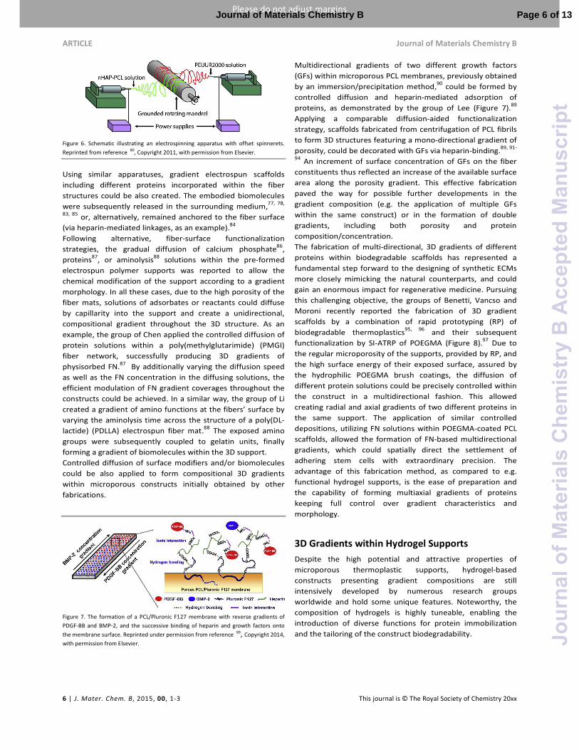
Compositional gradients of electrospun fiber mats could be
also obtained by a double electrospinning process, as
exemplarily shown in Figure 6.80
In this case two spinnerets
were placed at the opposite side of a rotating drum and the
flow rate of both solutions was varied independently.81, 82
Keeping steady the collector plate or the rotating drum at a
certain position, a compositional gradient along the vertical
axis of the construct was successfully fabricated. Additional
lateral movement of the spinneret along the drum allowed the
formation of an additional gradient of fiber composition along
the horizontal axis of the scaffold.83, 84
Page 5 of 13 Journal of Materials Chemistry B
Jour
nalo
fMat
eria
lsC
hem
istr
yB
Acc
epte
dM
anus
crip
t
ARTICLE Journal of Materials Chemistry B
6 | J. Mater. Chem. B, 2015, 00, 1-3 This journal is © The Royal Society of Chemistry 20xx
Please do not adjust margins
Please do not adjust margins
Figure 6. Schematic illustrating an electrospinning apparatus with offset spinnerets.
Reprinted from reference 80, Copyright 2011, with permission from Elsevier.
Using similar apparatuses, gradient electrospun scaffolds
including different proteins incorporated within the fiber
structures could be also created. The embodied biomolecules
were subsequently released in the surrounding medium,77, 78,
83, 85 or, alternatively, remained anchored to the fiber surface
(via heparin-mediated linkages, as an example).84
Following alternative, fiber-surface functionalization
strategies, the gradual diffusion of calcium phosphate86
,
proteins87
, or aminolysis88
solutions within the pre-formed
electrospun polymer supports was reported to allow the
chemical modification of the support according to a gradient
morphology. In all these cases, due to the high porosity of the
fiber mats, solutions of adsorbates or reactants could diffuse
by capillarity into the support and create a unidirectional,
compositional gradient throughout the 3D structure. As an
example, the group of Chen applied the controlled diffusion of
protein solutions within a poly(methylglutarimide) (PMGI)
fiber network, successfully producing 3D gradients of
physisorbed FN.87
By additionally varying the diffusion speed
as well as the FN concentration in the diffusing solutions, the
efficient modulation of FN gradient coverages throughout the
constructs could be achieved. In a similar way, the group of Li
created a gradient of amino functions at the fibers’ surface by
varying the aminolysis time across the structure of a poly(DL-
lactide) (PDLLA) electrospun fiber mat.88
The exposed amino
groups were subsequently coupled to gelatin units, finally
forming a gradient of biomolecules within the 3D support.
Controlled diffusion of surface modifiers and/or biomolecules
could be also applied to form compositional 3D gradients
within microporous constructs initially obtained by other
fabrications.
Figure 7. The formation of a PCL/Pluronic F127 membrane with reverse gradients of
PDGF-BB and BMP-2, and the successive binding of heparin and growth factors onto
the membrane surface. Reprinted under permission from reference 89, Copyright 2014,
with permission from Elsevier.
Multidirectional gradients of two different growth factors
(GFs) within microporous PCL membranes, previously obtained
by an immersion/precipitation method,90
could be formed by
controlled diffusion and heparin-mediated adsorption of
proteins, as demonstrated by the group of Lee (Figure 7).89
Applying a comparable diffusion-aided functionalization
strategy, scaffolds fabricated from centrifugation of PCL fibrils
to form 3D structures featuring a mono-directional gradient of
porosity, could be decorated with GFs via heparin-binding.89, 91-
94 An increment of surface concentration of GFs on the fiber
constituents thus reflected an increase of the available surface
area along the porosity gradient. This effective fabrication
paved the way for possible further developments in the
gradient composition (e.g. the application of multiple GFs
within the same construct) or in the formation of double
gradients, including both porosity and protein
composition/concentration.
The fabrication of multi-directional, 3D gradients of different
proteins within biodegradable scaffolds has represented a
fundamental step forward to the designing of synthetic ECMs
more closely mimicking the natural counterparts, and could
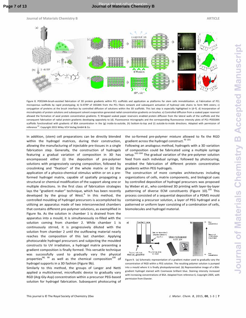
gain an enormous impact for regenerative medicine. Pursuing
this challenging objective, the groups of Benetti, Vancso and
Moroni recently reported the fabrication of 3D gradient
scaffolds by a combination of rapid prototyping (RP) of
biodegradable thermoplastics95, 96
and their subsequent
functionalization by SI-ATRP of POEGMA (Figure 8).97
Due to
the regular microporosity of the supports, provided by RP, and
the high surface energy of their exposed surface, assured by
the hydrophilic POEGMA brush coatings, the diffusion of
different protein solutions could be precisely controlled within
the construct in a multidirectional fashion. This allowed
creating radial and axial gradients of two different proteins in
the same support. The application of similar controlled
depositions, utilizing FN solutions within POEGMA-coated PCL
scaffolds, allowed the formation of FN-based multidirectional
gradients, which could spatially direct the settlement of
adhering stem cells with extraordinary precision. The
advantage of this fabrication method, as compared to e.g.
functional hydrogel supports, is the ease of preparation and
the capability of forming multiaxial gradients of proteins
keeping full control over gradient characteristics and
morphology.
3D Gradients within Hydrogel Supports
Despite the high potential and attractive properties of
microporous thermoplastic supports, hydrogel-based
constructs presenting gradient compositions are still
intensively developed by numerous research groups
worldwide and hold some unique features. Noteworthy, the
composition of hydrogels is highly tuneable, enabling the
introduction of diverse functions for protein immobilization
and the tailoring of the construct biodegradability.
Page 6 of 13Journal of Materials Chemistry B
Jour
nalo
fMat
eria
lsC
hem
istr
yB
Acc
epte
dM
anus
crip
t
Journal of Materials Chemistry B ARTICLE
This journal is © The Royal Society of Chemistry 20xx J. Mater. Chem. B, 2015, 00, 1-3 | 7
Please do not adjust margins
Please do not adjust margins
Figure 8. POEGMA-brush-assisted fabrication of 3D protein gradients within PCL scaffolds and application as platforms for stem cells immobilization. a) Fabrication of PCL
microporous scaffolds by rapid prototyping; b) SI-ATRP of OEGMA from the PCL fibers network and subsequent activation of hydroxyl side chains to form NHS esters; c)
conjugation of proteins at the brush interface by controlled diffusion of solutions within the 3D scaffolds. This last step is especially highlighted in (d–f). d) Incorporation of
microdroplets of protein solutions and subsequent solvent evaporation generated radial concentration gradients on brushes. e) Controlled diffusion from a soaked paper reservoir
allowed the formation of axial protein concentration gradients. f) Wrapped soaked paper reservoirs enabled protein diffusion from the lateral walls of the scaffolds and the
consequent fabrication of radial protein gradients developing oppositely to (d). Fluorescence micrographs and the corresponding fluorescence intensity plots of PCL–POEGMA
scaffolds functionalized with gradients of BSA concentration in the (g) inside-to-outside, (h) bottom-to-top and (i) outside-to-inside directions. Adapted with permission of
reference 97. Copyright 2015 Wiley-VCH Verlag GmbH & Co.
In addition, (stem) cell preparations can be directly blended
within the hydrogel matrices, during their construction,
allowing the manufacturing of injectable pre-tissues in a single
fabrication step. Generally, the construction of hydrogels
featuring a gradual variation of composition in 3D has
encompassed either (i) the deposition of pre-polymer
solutions with progressively varying composition, followed by
crosslinking and “fixation” of the whole matrix or (ii) the
application of a physico-chemical stimulus within or on a pre-
formed hydrogel matrix, capable of spatially propagating a
structural or chemical modification of the support along one or
multiple directions. In the first class of fabrication strategies
lays the “gradient maker” technique, which has been recently
developed by the group of West.6 In this method, the
controlled moulding of hydrogel precursors is accomplished by
utilizing an apparatus made of two interconnected chambers
that contains different pre-polymer solutions, as exemplified in
Figure 9a. As the solution in chamber 1 is drained from the
apparatus into a mould, it is simultaneously re-filled with the
solution coming from chamber 2. While chamber 1 is
continuously stirred, it is progressively diluted with the
solution from chamber 2 until the outflowing material nearly
reaches the composition of this last chamber. Applying
photocurable hydrogel precursors and subjecting the moulded
constructs to UV irradiation, a hydrogel matrix presenting a
gradient composition is finally formed. This versatile technique
was successfully used to gradually vary the physical
properties98, 99
as well as the chemical composition100
of
hydrogel supports in a 3D fashion (Figure 9b).
Similarly to this method, the groups of Langer and Netti
applied a multichannel, microfluidic device to gradually vary
RGD (Arg-Gly-Asp) concentration within a precursor PEG-based
solution for hydrogel fabrication. Subsequent photocuring of
the so-formed pre-polymer mixture allowed to fix the RGD
gradient across the hydrogel construct.70
101
Following an analogous method, hydrogels with a 3D variation
of composition could be fabricated using a multiple syringe
setup.102-104
The gradual variation of the pre-polymer solution
feed from each individual syringe, followed by photocuring,
enabled the fabrication of different protein concentration
gradients within PEG hydrogels.
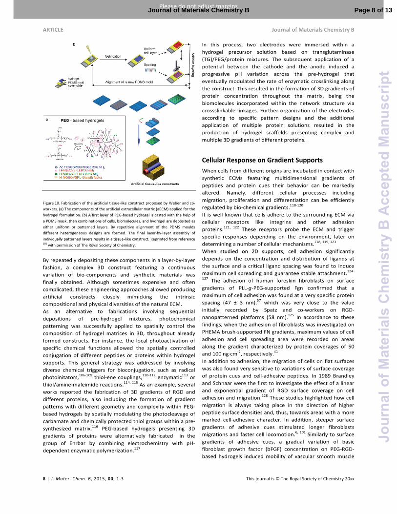
The construction of more complex architectures including
organizations of cells, matrix components, and biological cues
by controlled deposition of hydrogel precursors was proposed
by Weber et al., who combined 3D printing with layer-by-layer
patterning of diverse ECM constituents (Figure 10).105
This
process consisted of a sequential deposition of a PDMS mould
containing a precursor solution, a layer of PEG hydrogel and a
patterned or uniform layer consisting of a combination of cells,
biomolecules and hydrogel material.
Figure 9. (a) Schematic representation of a gradient maker used to gradually vary the
concentration of RGD within a PEG solution. The resulting polymer solution is pumped
into a mould where it is finally photopolymerized. (b) Representative image of a BSA-
gradient hydrogel stained with Coomassie brilliant blue. Staining intensity increased
with increasing concentrations of BSA. Adapted from reference 6, Copyright 2005, with
permission from Elsevier.
Page 7 of 13 Journal of Materials Chemistry B
Jour
nalo
fMat
eria
lsC
hem
istr
yB
Acc
epte
dM
anus
crip
t
ARTICLE Journal of Materials Chemistry B
8 | J. Mater. Chem. B, 2015, 00, 1-3 This journal is © The Royal Society of Chemistry 20xx
Please do not adjust margins
Please do not adjust margins
Figure 10. Fabrication of the artificial tissue-like construct proposed by Weber and co-
workers. (a) The components of the artificial extracellular matrix (aECM) applied for the
hydrogel formulation. (b) A first layer of PEG-based hydrogel is casted with the help of
a PDMS mask, then combinations of cells, biomolecules, and hydrogel are deposited as
either uniform or patterned layers. By repetitive alignment of the PDMS moulds
different heterogeneous designs are formed. The final layer-by-layer assembly of
individually patterned layers results in a tissue-like construct. Reprinted from reference 105 with permission of The Royal Society of Chemistry.
By repeatedly depositing these components in a layer-by-layer
fashion, a complex 3D construct featuring a continuous
variation of bio-components and synthetic materials was
finally obtained. Although sometimes expensive and often
complicated, these engineering approaches allowed producing
artificial constructs closely mimicking the intrinsic
compositional and physical diversities of the natural ECM.
As an alternative to fabrications involving sequential
depositions of pre-hydrogel mixtures, photochemical
patterning was successfully applied to spatially control the
composition of hydrogel matrices in 3D, throughout already
formed constructs. For instance, the local photoactivation of
specific chemical functions allowed the spatially controlled
conjugation of different peptides or proteins within hydrogel
supports. This general strategy was addressed by involving
diverse chemical triggers for bioconjugation, such as radical
photoinitators,106-109 thiol-ene couplings,110-112 enzymatic113 or
thiol/amine-maleimide reactions.114, 115 As an example, several
works reported the fabrication of 3D gradients of RGD and
different proteins, also including the formation of gradient
patterns with different geometry and complexity within PEG-
based hydrogels by spatially modulating the photocleavage of
carbamate and chemically protected thiol groups within a pre-
synthesized matrix.116 PEG-based hydrogels presenting 3D
gradients of proteins were alternatively fabricated in the
group of Ehrbar by combining electrochemistry with pH-
dependent enzymatic polymerization.117
In this process, two electrodes were immersed within a
hydrogel precursor solution based on transglutaminase
(TG)/PEG/protein mixtures. The subsequent application of a
potential between the cathode and the anode induced a
progressive pH variation across the pre-hydrogel that
eventually modulated the rate of enzymatic crosslinking along
the construct. This resulted in the formation of 3D gradients of
protein concentration throughout the matrix, being the
biomolecules incorporated within the network structure via
crossslinkable linkages. Further organization of the electrodes
according to specific pattern designs and the additional
application of multiple protein solutions resulted in the
production of hydrogel scaffolds presenting complex and
multiple 3D gradients of different proteins.
Cellular Response on Gradient Supports
When cells from different origins are incubated in contact with
synthetic ECMs featuring multidimensional gradients of
peptides and protein cues their behavior can be markedly
altered. Namely, different cellular processes including
migration, proliferation and differentiation can be efficiently
regulated by bio-chemical gradients.118-120
It is well known that cells adhere to the surrounding ECM via
cellular receptors like integrins and other adhesion
proteins.121, 122
These receptors probe the ECM and trigger
specific responses depending on the environment, later on
determining a number of cellular mechanisms.118, 119, 123
When studied on 2D supports, cell adhesion significantly
depends on the concentration and distribution of ligands at
the surface and a critical ligand spacing was found to induce
maximum cell spreading and guarantee stable attachment.124-
127 The adhesion of human foreskin fibroblasts on surface
gradients of PLL-g-PEG-supported Fgn confirmed that a
maximum of cell adhesion was found at a very specific protein
spacing (47 ± 3 nm),57
which was very close to the value
initially recorded by Spatz and co-workers on RGD-
nanopatterned platforms (58 nm).125
In accordance to these
findings, when the adhesion of fibroblasts was investigated on
PHEMA brush-supported FN gradients, maximum values of cell
adhesion and cell spreading area were recorded on areas
along the gradient characterized by protein coverages of 50
and 100 ng·cm-2
, respectively.41
In addition to adhesion, the migration of cells on flat surfaces
was also found very sensitive to variations of surface coverage
of protein cues and cell-adhesive peptides. In 1989 Brandley
and Schnaar were the first to investigate the effect of a linear
and exponential gradient of RGD surface coverage on cell
adhesion and migration.128
These studies highlighted how cell
migration is always taking place in the direction of higher
peptide surface densities and, thus, towards areas with a more
marked cell-adhesive character. In addition, steeper surface
gradients of adhesive cues stimulated longer fibroblasts
migrations and faster cell locomotion.6, 101
Similarly to surface
gradients of adhesive cues, a gradual variation of basic
fibroblast growth factor (bFGF) concentration on PEG-RGD-
based hydrogels induced mobility of vascular smooth muscle
Page 8 of 13Journal of Materials Chemistry B
Jour
nalo
fMat
eria
lsC
hem
istr
yB
Acc
epte
dM
anus
crip
t

Journal of Materials Chemistry B ARTICLE
This journal is © The Royal Society of Chemistry 20xx J. Mater. Chem. B, 2015, 00, 1-3 | 9
Please do not adjust margins
Please do not adjust margins
cells (VSMCs). Specifically, VSCMs showed an aligned
morphology and moved in the direction of increasing bFGF
concentration.7 In a similar way, the application of a gradient
of GF concentration throughout a loosely crosslinked agarose-
based hydrogel, with increasing protein concentration from
the outer surface towards the core of the structure, stimulated
the migration of neural precursor cells (NPCs) inside the
construct. 114, 129-131
Cells cultured within 3D supports showed different and more
complex mechanisms of migration when compared to planar
substrates.132, 133
Especially within hydrogel-based ECMs the
composition and concentration of biological cues in
combination with the physical properties of the polymer
matrix (e.g. degree of crosslinking) were found crucial
parameters determining the motility of cells.134
As an example,
Kyburz et al. showed that hydrogels with low crosslink density
(0.18 ± 0.02 mM) and high RGD concentration (1 mM CRGDS)
allowed relatively high migration rates (17.6 ± 0.9 µm·h-1
).135
Alternatively, electrospun scaffolds based on poly(lactide-co-
glycolide) (PLGA) and featuring a unidirectional gradient of
fiber-encapsulated bFGF, directed the migration and
stimulated the differentiation of mouse dermal fibroblasts in a
spatially defined manner.85
The “depth” of cell migration
through the fibrous support was determined by the steepness
of the concentration gradient of bFGF. Additionally, when
these supports were applied in vivo, the morphology of the
protein gradient within the fibers also regulated the density of
the subsequently formed blood vessels (Figure 11).
Synthetic ECMs presenting different gradients of biochemical
cues were also applied to spatially control the osteogenic
differentiation of seeded cells within bone/cartilage
implants.136
Similar supports were designed by the group of Li,
who decorated a poly(DL-lactide) (PDLLA) electrospun
construct with a gradient of gelatin and hydroxyapatite (HAP).
Subsequent incubation of the gradient scaffolds with pre-
osteoblasts, MC-3T3 E1, demonstrated how cell viability as
well as cell density could be spatially modulated according to
the gradual variation of gelatin concentration.88
In addition,
both alkaline phosphatase (ALP) activity and collagen type-I
expression by MC-3T3 E1 showed a similar trend, indicating
that the extent of osteogenic differentiation was regulated in
response of the HAP gradient across the scaffold.
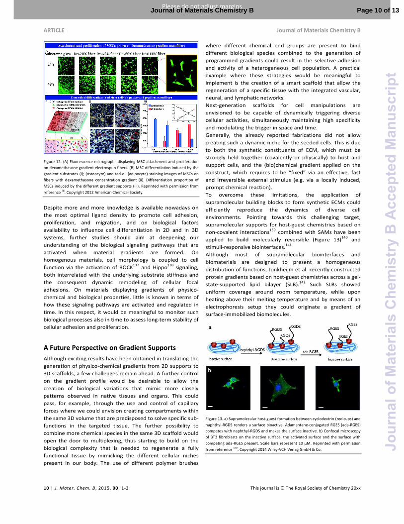
Applying a similar designing concept, Zhang et al. fabricated an
electrospun PLGA scaffold containing a dexamethasone (Dex)
gradient within the fibrous construct by complementing the
electrospinning polymer solution with a variable concentration
of Dex.78
Hence, the local variation in Dex release at different
volumes within the scaffold directed the differentiation of
subsequently incubated mesenchymal stem cells (MSCs)
(Figure 12). At positions of higher Dex concentration across the
support adipogenesis was favoured, while volumes
characterized by lower Dex content displayed a tendency by
MSCs to undergo osteogenic differentiation (Figure 12).
Figure 11. (A) Number of cells at different depths from the scaffold surface after 14
days of culture (*p < 0.01, **p < 0.001) quantified for NG0.1 and NG0.7 (uniform
scaffolds fabricated with injection rates of 0.1 and 0.7 ml·h-1
, respectively, from a 150
µg·ml-1
bFGF solution) and for G150 and G300 (gradient scaffolds fabricated by
gradually varying the injection rate from 0.7 and 0.1 ml·h-1
from a 150 or 300 µg·ml-1
bFGF solution, respectively). (B) Number of vessels within the different scaffolds after
10 and 20 days of subcutaneous implantation (*p < 0.01, **p < 0.001). (C) Blood vessels
within the different scaffolds after 10 days of implantation. The functional vessels that
contain well-defined lumens and blood cells are indicated by green arrows. Scale bar =
50 μm. Reprinted with permission from reference 85. Copyright 2012 American
Chemical Society.
Two interpenetrating gradients of different growth factors
were alternatively applied across porous PCL/pluronicF127
membranes, previously fabricated by Lee and coworkers
exploiting the “diffusion method”.89
Namely, platelet-derived
growth factor-b (PDGF-BB) and bone morphogenetic protein 2
(BMP-2) were deposited by heparin-mediated binding to form
a double gradient of protein concentration at the exposed
surface of the microporous support (Figure 14).
Adipose stem cells (ASCs) cultured within these constructs
showed an upregulation of different tenogenic markers at
membrane sections loaded with higher concentrations of
PDGF-BB, while different osteogenic markers were
progressively upregulated moving towards regions of the
scaffold presenting higher concentrations of BMP-2. The
spatially resolved differentiation of ASCs could be clearly
recorded by the selective staining with antibodies against
tenomodulin (for tenogenesis) and bone sialoprotein
(osteogenesis).
Page 9 of 13 Journal of Materials Chemistry B
Jour
nalo
fMat
eria
lsC
hem
istr
yB
Acc
epte
dM
anus
crip
t
ARTICLE Journal of Materials Chemistry B
10 | J. Mater. Chem. B, 2015, 00 , 1-3 This journal is © The Royal Society of Chemistry 20xx
Please do not adjust margins
Please do not adjust margins
Figure 12. (A) Fluorescence micrographs displaying MSC attachment and proliferation
on dexamethasone gradient electrospun fibers. (B) MSC differentiation induced by the
gradient substrates (i); (osteocyte) and red-oil (adipocyte) staining images of MSCs on
fibers with dexamethasone concentration gradient (ii). Differentiation proportion of
MSCs induced by the different gradient supports (iii). Reprinted with permission from
reference 78. Copyright 2012 American Chemical Society.
Despite more and more knowledge is available nowadays on
the most optimal ligand density to promote cell adhesion,
proliferation, and migration, and on biological factors
availability to influence cell differentiation in 2D and in 3D
systems, further studies should aim at deepening our
understanding of the biological signaling pathways that are
activated when material gradients are formed. On
homogenous materials, cell morphology is coupled to cell
function via the activation of ROCK137
and Hippo138
signaling,
both interrelated with the underlying substrate stiffness and
the consequent dynamic remodeling of cellular focal
adhesions. On materials displaying gradients of physico-
chemical and biological properties, little is known in terms of
how these signaling pathways are activated and regulated in
time. In this respect, it would be meaningful to monitor such
biological processes also in time to assess long-term stability of
cellular adhesion and proliferation.
A Future Perspective on Gradient Supports
Although exciting results have been obtained in translating the
generation of physico-chemical gradients from 2D supports to
3D scaffolds, a few challenges remain ahead. A further control
on the gradient profile would be desirable to allow the
creation of biological variations that mimic more closely
patterns observed in native tissues and organs. This could
pass, for example, through the use and control of capillary
forces where we could envision creating compartments within
the same 3D volume that are predisposed to solve specific sub-
functions in the targeted tissue. The further possibility to
combine more chemical species in the same 3D scaffold would
open the door to multiplexing, thus starting to build on the
biological complexity that is needed to regenerate a fully
functional tissue by mimicking the different cellular niches
present in our body. The use of different polymer brushes
where different chemical end groups are present to bind
different biological species combined to the generation of
programmed gradients could result in the selective adhesion
and activity of a heterogeneous cell population. A practical
example where these strategies would be meaningful to
implement is the creation of a smart scaffold that allow the
regeneration of a specific tissue with the integrated vascular,
neural, and lymphatic networks.
Next-generation scaffolds for cell manipulations are
envisioned to be capable of dynamically triggering diverse
cellular activities, simultaneously maintaining high specificity
and modulating the trigger in space and time.
Generally, the already reported fabrications did not allow
creating such a dynamic niche for the seeded cells. This is due
to both the synthetic constituents of ECM, which must be
strongly held together (covalently or physically) to host and
support cells, and the (bio)chemical gradient applied on the
construct, which requires to be “fixed” via an effective, fast
and irreversible external stimulus (e.g. via a locally induced,
prompt chemical reaction).
To overcome these limitations, the application of
supramolecular building blocks to form synthetic ECMs could
efficiently reproduce the dynamics of diverse cell
environments. Pointing towards this challenging target,
supramolecular supports for host-guest chemistries based on
non-covalent interactions139
combined with SAMs have been
applied to build molecularly reversible (Figure 13)140
and
stimuli-responsive biointerfaces.141
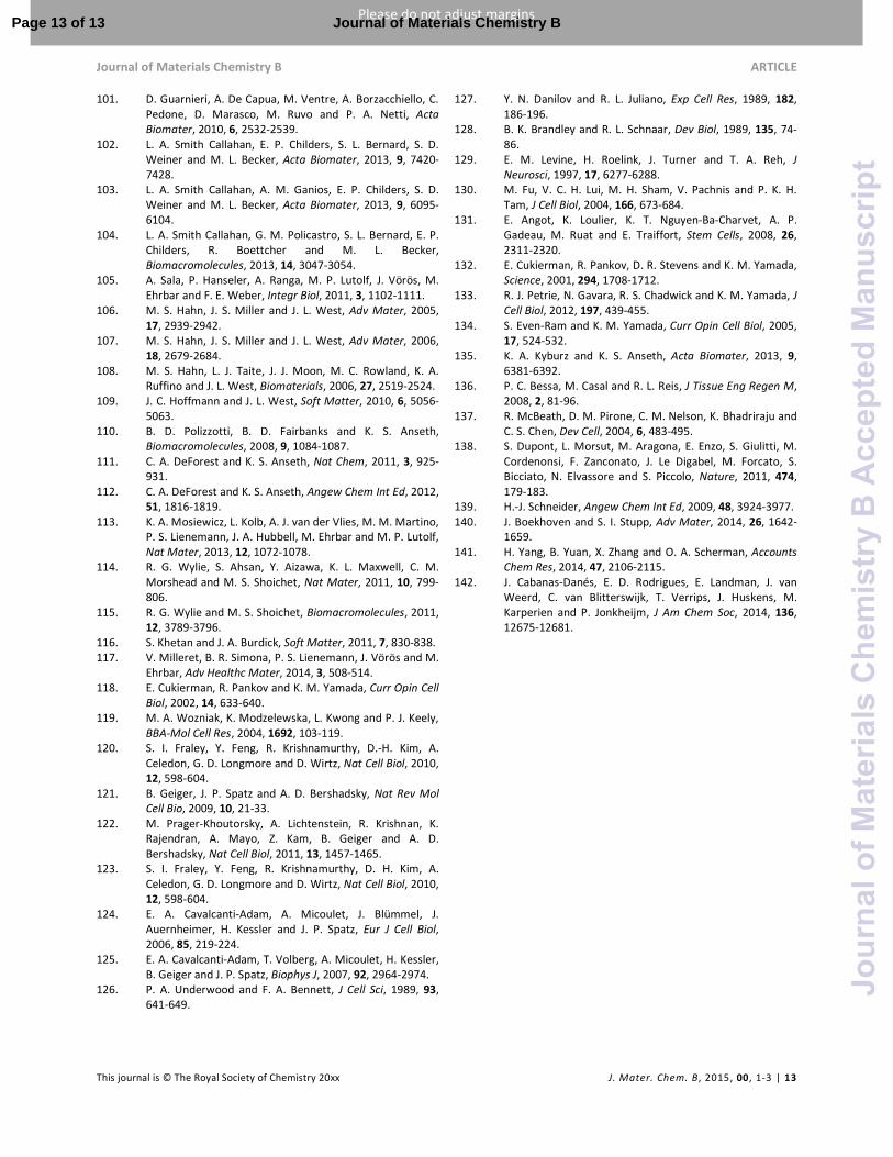
Although most of supramolecular biointerfaces and
biomaterials are designed to present a homogeneous
distribution of functions, Jonkheijm et al. recently constructed
protein gradients based on host-guest chemistries across a gel-
state-supported lipid bilayer (SLB).142
Such SLBs showed
uniform coverage around room temperature, while upon
heating above their melting temperature and by means of an
electrophoresis setup they could originate a gradient of
surface-immobilized biomolecules.
Figure 13. a) Supramolecular host-guest formation between cyclodextrin (red cups) and
naphthyl-RGDS renders a surface bioactive. Adamantane-conjugated RGES (ada-RGES)
competes with naphthyl-RGDS and makes the surface inactive. b) Confocal microscopy
of 3T3 fibroblasts on the inactive surface, the activated surface and the surface with
competing ada-RGES present. Scale bars represent 10 μM. Reprinted with permission
from reference 140
. Copyright 2014 Wiley-VCH Verlag GmbH & Co.
Page 10 of 13Journal of Materials Chemistry B
Jour
nalo
fMat
eria
lsC
hem
istr
yB
Acc
epte
dM
anus
crip
t

Journal of Materials Chemistry B ARTICLE
This journal is © The Royal Society of Chemistry 20xx J. Mater. Chem. B, 2015, 00, 1-3 | 11
Please do not adjust margins
Please do not adjust margins
Despite these first attempts to design constructs that can
function as supramolecular analogues of ECMs, further efforts
need to be devoted in engineering synthetic 3D matrices which
can efficiently host cell preparations and determine their fate
in a spatially defined way. The fundamental advantages of the
building mechanisms already proposed on flat surfaces could
be adapted to a number of fabrications among the ones we
have described in the previous paragraphs.
In addition, already tested platforms, such as bio-printed
hydrogels, could be enriched by specific functions that allow
host-guest interactions between the support and several
complemented cues. From this starting point, the application
of sophisticated gradient-forming fabrications (e.g. by
employing the gradient maker) or external physical stimuli
(e.g. via electrochemistry) could easily enable the formation of
supramolecular gradients within the so-designed 3D scaffolds.
The combination of supramolecular chemistry and the most
advanced scaffold fabrication techniques would introduce the
next-generation TE constructs, displaying spatial chemical
diversity and tunable characteristics within the same matrix.
Acknowledgements
This work was financially supported by the MESA+ Institute for
Nanotechnology of the University of Twente, by the
Technology foundation STW (STW, 11135) and by the Swiss
National Foundation (SNSF “Ambizione” PZ00P2-148156).
References
1. A. Seidi, M. Ramalingam, I. Elloumi-Hannachi, S.
Ostrovidov and A. Khademhosseini, Acta Biomater, 2011, 7, 1441-1451.
2. J. Genzer, Ann Rev Mater Res, 2012, 42, 435-468. 3. S. B. Carter, Nature, 1967, 213, 256-260. 4. S. V. Plotnikov and C. M. Waterman, Curr Opin Cell Biol,
2013, 25, 619-626. 5. N. Castro, S. A. Hacking and L. Zhang, Ann Biomed Eng,
2012, 40, 1628-1640. 6. S. A. DeLong, A. S. Gobin and J. L. West, J Control Release,
2005, 109, 139-148. 7. S. A. DeLong, J. J. Moon and J. L. West, Biomaterials, 2005,
26, 3227-3234. 8. S. B. Kennedy, N. R. Washburn, C. G. Simon Jr and E. J.
Amis, Biomaterials, 2006, 27, 3817-3824. 9. A. J. Engler, S. Sen, H. L. Sweeney and D. E. Discher, Cell,
2006, 126, 677-689. 10. J. M. Sobral, S. G. Caridade, R. A. Sousa, J. F. Mano and R.
L. Reis, Acta Biomater, 2011, 7, 1009-1018. 11. S. Morgenthaler, C. Zink and N. D. Spencer, Soft Matter,
2008, 4, 419-434. 12. N. A. Alcantar, E. S. Aydil and J. N. Israelachvili, J Biomed
Mater Res, 2000, 51, 343-351. 13. I. Banerjee, R. C. Pangule and R. S. Kane, Adv Mater, 2011,
23, 690-718. 14. A. Jain and S. K. Jain, Crit Rev Ther Drug Carrier Syst, 2008,
25, 403-447.
15. F. M. Veronese and G. Pasut, Drug Discov Today, 2005, 10, 1451-1458.
16. S. Zalipsky, Adv Drug Deliver Rev, 1995, 16, 157-182. 17. J. Zhu, Biomaterials, 2010, 31, 4639-4656. 18. D. W. Hutmacher, Biomaterials, 2000, 21, 2529-2543. 19. S. J. Hollister, Nat Mater, 2005, 4, 518-524. 20. Q. P. Pham, U. Sharma and A. G. Mikos, Tissue Eng, 2006,
12, 1197-1211. 21. K. Rezwan, Q. Z. Chen, J. J. Blaker and A. R. Boccaccini,
Biomaterials, 2006, 27, 3413-3431. 22. T. J. Sill and H. A. von Recum, Biomaterials, 2008, 29,
1989-2006. 23. M. K. Chaudhury and G. M. Whitesides, Science, 1992,
256, 1539-1541. 24. R. H. Terrill, K. M. Balss, Y. Zhang and P. W. Bohn, J Am
Chem Soc, 2000, 122, 988-989. 25. Q. Wang and P. W. Bohn, J Phys Chem B, 2003, 107,
12578-12584. 26. S. T. Plummer and P. W. Bohn, Langmuir, 2002, 18, 4142-
4149. 27. J. C. Love, L. A. Estroff, J. K. Kriebel, R. G. Nuzzo and G. M.
Whitesides, Chem Rev, 2005, 105, 1103-1170. 28. S. T. Plummer, Q. Wang, P. W. Bohn, R. Stockton and M.
A. Schwartz, Langmuir, 2003, 19, 7528-7536. 29. Q. Wang and P. W. Bohn, Thin Solid Films, 2006, 513, 338-
346. 30. V. Corvaglia, R. Marega, F. De Leo, C. Michiels and D.
Bonifazi, Small, 2016, 12, 321-329. 31. S. Morgenthaler, S. Lee, S. Zürcher and N. D. Spencer,
Langmuir, 2003, 19, 10459-10462. 32. T. Wu, K. Efimenko, P. Vlček, V. Šubr and J. Genzer,
Macromolecules, 2003, 36, 2448-2453. 33. S. Edmondson, V. L. Osborne and W. T. S. Huck, Chem Soc
Rev, 2004, 33, 14-22. 34. X. Wang, H. Tu, P. V. Braun and P. W. Bohn, Langmuir,
2006, 22, 817-823. 35. R. Barbey, L. Lavanant, D. Paripovic, N. Schuwer, C.
Sugnaux, S. Tugulu and H. A. Klok, Chem. Rev., 2009, 109, 5437-5527.
36. T. Wu, P. Gong, I. Szleifer, P. Vlček, V. Šubr and J. Genzer, Macromolecules, 2007, 40, 8756-8764.
37. P. G. De Gennes, Macromolecules, 1980, 13, 1069-1075. 38. W. J. Brittain and S. Minko, J. Polym. Sci. Pol. Chem., 2007,
45, 3505-3512. 39. T. Wu, K. Efimenko and J. Genzer, J Am Chem Soc, 2002,
124, 9394-9395. 40. Y. Mei, T. Wu, C. Xu, K. J. Langenbach, J. T. Elliott, B. D.
Vogt, K. L. Beers, E. J. Amis and N. R. Washburn, Langmuir, 2005, 21, 12309-12314.
41. Y. Mei, J. T. Elliott, J. R. Smith, K. J. Langenbach, T. Wu, C. Xu, K. L. Beers, E. J. Amis and L. Henderson, J Biomed
Mater Res A, 2006, 79A, 974-988. 42. T. Ren, S. Yu, Z. Mao, S. E. Moya, L. Han and C. Gao,
Biomacromolecules, 2014, 15, 2256-2264. 43. S. Choi, B. C. Choi, C. Xue and D. Leckband,
Biomacromolecules, 2013, 14, 92-100. 44. K. Vasilev, A. Mierczynska, A. L. Hook, J. Chan, N. H.
Voelcker and R. D. Short, Biomaterials, 2010, 31, 392-397. 45. J. Wu, Z. Mao and C. Gao, Biomaterials, 2012, 33, 810-
820. 46. R. R. Bhat, B. N. Chaney, J. Rowley, A. Liebmann-Vinson
and J. Genzer, Adv Mater, 2005, 17, 2802-2807.
Page 11 of 13 Journal of Materials Chemistry B
Jour
nalo
fMat
eria
lsC
hem
istr
yB
Acc
epte
dM
anus
crip
t
ARTICLE Journal of Materials Chemistry B
12 | J. Mater. Chem. B, 2015, 00 , 1-3 This journal is © The Royal Society of Chemistry 20xx
Please do not adjust margins
Please do not adjust margins
47. M. R. Tomlinson and J. Genzer, Chem Commun, 2003, 9, 1350-1351.
48. L. Li, Y. Zhu, B. Li and C. Gao, Langmuir, 2008, 24, 13632-13639.
49. R. Bhat, M. Tomlinson, T. Wu and J. Genzer, in Surface-
Initiated Polymerization II, ed. R. Jordan, Springer Berlin Heidelberg, 2006, vol. 198, ch. 60, pp. 51-124.
50. M. R. Tomlinson and J. Genzer, Macromolecules, 2003, 36, 3449-3451.
51. M. Klein Gunnewiek, S. N. Ramakrishna, A. Di Luca, G. J. Vancso, L. Moroni and E. M. Benetti, Adv Mater Interf, 2015, DOI: 10.1002/admi.201500456, n/a-n/a.
52. B. Trappmann, J. E. Gautrot, J. T. Connelly, D. G. T. Strange, Y. Li, M. L. Oyen, M. A. Cohen Stuart, H. Boehm, B. Li, V. Vogel, J. P. Spatz, F. M. Watt and W. T. S. Huck, Nat Mater, 2012, 11, 642-649.
53. N. Huebsch, P. R. Arany, A. S. Mao, D. Shvartsman, O. A. Ali, S. A. Bencherif, J. Rivera-Feliciano and D. J. Mooney, Nat Mater, 2010, 9, 518-526.
54. A. P. Kourouklis, R. V. Lerum and H. Bermudez, Biomaterials, 2014, 35, 4827-4834.
55. S. Tugulu, P. Silacci, N. Stergiopulos and H.-A. Klok, Biomaterials, 2007, 28, 2536-2546.
56. S. Morgenthaler, C. Zink, B. Städler, J. Vörös, S. Lee, N. D. Spencer and S. G. P. Tosatti, Biointerphases, 2006, 1, 156-165.
57. J. Pei, H. Hall and N. D. Spencer, Biomaterials, 2011, 32, 8968-8978.
58. A. Halperin, Langmuir, 1999, 15, 2525-2533. 59. M. Müller, S. Lee, H. Spikes and N. Spencer, Tribol Lett,
2003, 15, 395-405. 60. J. W. Lussi, D. Falconnet, J. A. Hubbell, M. Textor and G.
Csucs, Biomaterials, 2006, 27, 2534-2541. 61. M. Jaspers, M. Dennison, M. F. J. Mabesoone, F. C.
MacKintosh, A. E. Rowan and P. H. J. Kouwer, Nat
Commun, 2014, 5. 62. S. T. K. Raja, T. Thiruselvi, A. B. Mandal and A. Gnanamani,
Sci Rep, 2015, 5, 15977. 63. I. Caelen, A. Bernard, D. Juncker, B. Michel, H.
Heinzelmann and E. Delamarche, Langmuir, 2000, 16, 9125-9130.
64. N. L. Jeon, S. K. W. Dertinger, D. T. Chiu, I. S. Choi, A. D. Stroock and G. M. Whitesides, Langmuir, 2000, 16, 8311-8316.
65. R. C. Gunawan, E. R. Choban, J. E. Conour, J. Silvestre, L. B. Schook, H. R. Gaskins, D. E. Leckband and P. J. A. Kenis, Langmuir, 2005, 21, 3061-3068.
66. S. Kim, H. J. Kim and N. L. Jeon, Integr Biol, 2010, 2, 584-603.
67. A. G. Toh, Z. P. Wang, C. Yang and N.-T. Nguyen, Microfluid Nanofluid, 2014, 16, 1-18.
68. K. A. Fosser and R. G. Nuzzo, Anal Chem, 2003, 75, 5775-5782.
69. J. He, Y. Du, J. L. Villa-Uribe, C. Hwang, D. Li and A. Khademhosseini, Adv Funct Mater, 2010, 20, 131-137.
70. J. A. Burdick, A. Khademhosseini and R. Langer, Langmuir, 2004, 20, 5153-5156.
71. X. Jiang, Q. Xu, S. K. W. Dertinger, A. D. Stroock, T.-m. Fu and G. M. Whitesides, Anal Chem, 2005, 77, 2338-2347.
72. R. C. Gunawan, J. Silvestre, H. R. Gaskins, P. J. A. Kenis and D. E. Leckband, Langmuir, 2006, 22, 4250-4258.
73. S. Allazetta, S. Cosson and M. P. Lutolf, Chem Commun, 2011, 47, 191-193.
74. S. Cosson, S. Allazetta and M. P. Lutolf, Lab Chip, 2013, 13, 2099-2105.
75. S. Cosson, S. A. Kobel and M. P. Lutolf, Adv Funct Mater, 2009, 19, 3411-3419.
76. D. H. Reneker and A. L. Yarin, Polymer, 2008, 49, 2387-2425.
77. Handarmin, G. J. Y. Tan, B. Sundaray, G. T. Marcy, E. L. K. Goh and S. Y. Chew, Drug Deliv. and Transl. Res., 2011, 1, 147-160.
78. X. Zhang, X. Gao, L. Jiang and J. Qin, Langmuir, 2012, 28, 10026-10032.
79. H. G. Sundararaghavan and J. A. Burdick, Biomacromolecules, 2011, 12, 2344-2350.
80. S. Samavedi, C. Olsen Horton, S. A. Guelcher, A. S. Goldstein and A. R. Whittington, Acta Biomater, 2011, 7, 4131-4138.
81. W. Bonani, D. Maniglio, A. Motta, W. Tan and C. Migliaresi, J Biomed Mater Res B, 2011, 96B, 276-286.
82. S. Samavedi, S. A. Guelcher, A. S. Goldstein and A. R. Whittington, Biomaterials, 2012, 33, 7727-7735.
83. W. Bonani, A. Motta, C. Migliaresi and W. Tan, Langmuir, 2012, 28, 13675-13687.
84. F. Du, H. Wang, W. Zhao, D. Li, D. Kong, J. Yang and Y. Zhang, Biomaterials, 2012, 33, 762-770.
85. X. Guo, C. G. Elliott, Z. Li, Y. Xu, D. W. Hamilton and J. Guan, Biomacromolecules, 2012, 13, 3262-3271.
86. X. Li, J. Xie, J. Lipner, X. Yuan, S. Thomopoulos and Y. Xia, Nano Lett, 2009, 9, 2763-2768.
87. J. Shi, L. Wang, F. Zhang, H. Li, L. Lei, L. Liu and Y. Chen, ACS Appl Mater Interfaces, 2010, 2, 1025-1030.
88. B. Zou, Y. Liu, X. Luo, F. Chen, X. Guo and X. Li, Acta
Biomater, 2012, 8, 1576-1585. 89. H. K. Min, S. H. Oh, J. M. Lee, G. I. Im and J. H. Lee, Acta
Biomater, 2014, 10, 1272-1279. 90. S. H. Oh, J. H. Kim, J. M. Kim and J. H. Lee, J Biomater Sci
Polym Ed, 2006, 17, 1375-1387. 91. S. H. Oh, I. K. Park, J. M. Kim and J. H. Lee, Biomaterials,
2007, 28, 1664-1671. 92. S. H. Oh, T. H. Kim, G. I. Im and J. H. Lee,
Biomacromolecules, 2010, 11, 1948-1955. 93. T. Kim, S. Oh, E. Kwon, J. Lee and J. Lee, Macromol. Res.,
2013, 21, 878-885. 94. S. H. Oh, T. H. Kim and J. H. Lee, Biomaterials, 2011, 32,
8254-8260. 95. L. Moroni, J. R. de Wijn and C. A. van Blitterswijk, J Biomed
Mater Res A, 2005, 75A, 957-965. 96. L. Moroni, J. R. de Wijn and C. A. van Blitterswijk,
Biomaterials, 2006, 27, 974-985. 97. M. Klein Gunnewiek, A. Di Luca, H. Z. Bollemaat, C. A. van
Blitterswijk, G. J. Vancso, L. Moroni and E. M. Benetti, Adv
Healthc Mater, 2015, 4, 1169-1174. 98. K. Chatterjee, S. Lin-Gibson, W. E. Wallace, S. H. Parekh, Y.
J. Lee, M. T. Cicerone, M. F. Young and C. G. Simon Jr, Biomaterials, 2010, 31, 5051-5062.
99. S. Nemir, H. N. Hayenga and J. L. West, Biotechnol Bioeng, 2010, 105, 636-644.
100. X. Wang, E. Wenk, X. Zhang, L. Meinel, G. Vunjak-Novakovic and D. L. Kaplan, J Control Release, 2009, 134, 81-90.
Page 12 of 13Journal of Materials Chemistry B
Jour
nalo
fMat
eria
lsC
hem
istr
yB
Acc
epte
dM
anus
crip
t
Journal of Materials Chemistry B ARTICLE
This journal is © The Royal Society of Chemistry 20xx J. Mater. Chem. B, 2015, 00, 1-3 | 13
Please do not adjust margins
Please do not adjust margins
101. D. Guarnieri, A. De Capua, M. Ventre, A. Borzacchiello, C. Pedone, D. Marasco, M. Ruvo and P. A. Netti, Acta
Biomater, 2010, 6, 2532-2539. 102. L. A. Smith Callahan, E. P. Childers, S. L. Bernard, S. D.
Weiner and M. L. Becker, Acta Biomater, 2013, 9, 7420-7428.
103. L. A. Smith Callahan, A. M. Ganios, E. P. Childers, S. D. Weiner and M. L. Becker, Acta Biomater, 2013, 9, 6095-6104.
104. L. A. Smith Callahan, G. M. Policastro, S. L. Bernard, E. P. Childers, R. Boettcher and M. L. Becker, Biomacromolecules, 2013, 14, 3047-3054.
105. A. Sala, P. Hanseler, A. Ranga, M. P. Lutolf, J. Vörös, M. Ehrbar and F. E. Weber, Integr Biol, 2011, 3, 1102-1111.
106. M. S. Hahn, J. S. Miller and J. L. West, Adv Mater, 2005, 17, 2939-2942.
107. M. S. Hahn, J. S. Miller and J. L. West, Adv Mater, 2006, 18, 2679-2684.
108. M. S. Hahn, L. J. Taite, J. J. Moon, M. C. Rowland, K. A. Ruffino and J. L. West, Biomaterials, 2006, 27, 2519-2524.
109. J. C. Hoffmann and J. L. West, Soft Matter, 2010, 6, 5056-5063.
110. B. D. Polizzotti, B. D. Fairbanks and K. S. Anseth, Biomacromolecules, 2008, 9, 1084-1087.
111. C. A. DeForest and K. S. Anseth, Nat Chem, 2011, 3, 925-931.
112. C. A. DeForest and K. S. Anseth, Angew Chem Int Ed, 2012, 51, 1816-1819.
113. K. A. Mosiewicz, L. Kolb, A. J. van der Vlies, M. M. Martino, P. S. Lienemann, J. A. Hubbell, M. Ehrbar and M. P. Lutolf, Nat Mater, 2013, 12, 1072-1078.
114. R. G. Wylie, S. Ahsan, Y. Aizawa, K. L. Maxwell, C. M. Morshead and M. S. Shoichet, Nat Mater, 2011, 10, 799-806.
115. R. G. Wylie and M. S. Shoichet, Biomacromolecules, 2011, 12, 3789-3796.
116. S. Khetan and J. A. Burdick, Soft Matter, 2011, 7, 830-838. 117. V. Milleret, B. R. Simona, P. S. Lienemann, J. Vörös and M.
Ehrbar, Adv Healthc Mater, 2014, 3, 508-514. 118. E. Cukierman, R. Pankov and K. M. Yamada, Curr Opin Cell
Biol, 2002, 14, 633-640. 119. M. A. Wozniak, K. Modzelewska, L. Kwong and P. J. Keely,
BBA-Mol Cell Res, 2004, 1692, 103-119. 120. S. I. Fraley, Y. Feng, R. Krishnamurthy, D.-H. Kim, A.
Celedon, G. D. Longmore and D. Wirtz, Nat Cell Biol, 2010, 12, 598-604.
121. B. Geiger, J. P. Spatz and A. D. Bershadsky, Nat Rev Mol
Cell Bio, 2009, 10, 21-33. 122. M. Prager-Khoutorsky, A. Lichtenstein, R. Krishnan, K.
Rajendran, A. Mayo, Z. Kam, B. Geiger and A. D. Bershadsky, Nat Cell Biol, 2011, 13, 1457-1465.
123. S. I. Fraley, Y. Feng, R. Krishnamurthy, D. H. Kim, A. Celedon, G. D. Longmore and D. Wirtz, Nat Cell Biol, 2010, 12, 598-604.
124. E. A. Cavalcanti-Adam, A. Micoulet, J. Blümmel, J. Auernheimer, H. Kessler and J. P. Spatz, Eur J Cell Biol, 2006, 85, 219-224.
125. E. A. Cavalcanti-Adam, T. Volberg, A. Micoulet, H. Kessler, B. Geiger and J. P. Spatz, Biophys J, 2007, 92, 2964-2974.
126. P. A. Underwood and F. A. Bennett, J Cell Sci, 1989, 93, 641-649.
127. Y. N. Danilov and R. L. Juliano, Exp Cell Res, 1989, 182, 186-196.
128. B. K. Brandley and R. L. Schnaar, Dev Biol, 1989, 135, 74-86.
129. E. M. Levine, H. Roelink, J. Turner and T. A. Reh, J
Neurosci, 1997, 17, 6277-6288. 130. M. Fu, V. C. H. Lui, M. H. Sham, V. Pachnis and P. K. H.
Tam, J Cell Biol, 2004, 166, 673-684. 131. E. Angot, K. Loulier, K. T. Nguyen-Ba-Charvet, A. P.
Gadeau, M. Ruat and E. Traiffort, Stem Cells, 2008, 26, 2311-2320.
132. E. Cukierman, R. Pankov, D. R. Stevens and K. M. Yamada, Science, 2001, 294, 1708-1712.
133. R. J. Petrie, N. Gavara, R. S. Chadwick and K. M. Yamada, J Cell Biol, 2012, 197, 439-455.
134. S. Even-Ram and K. M. Yamada, Curr Opin Cell Biol, 2005, 17, 524-532.
135. K. A. Kyburz and K. S. Anseth, Acta Biomater, 2013, 9, 6381-6392.
136. P. C. Bessa, M. Casal and R. L. Reis, J Tissue Eng Regen M, 2008, 2, 81-96.
137. R. McBeath, D. M. Pirone, C. M. Nelson, K. Bhadriraju and C. S. Chen, Dev Cell, 2004, 6, 483-495.
138. S. Dupont, L. Morsut, M. Aragona, E. Enzo, S. Giulitti, M. Cordenonsi, F. Zanconato, J. Le Digabel, M. Forcato, S. Bicciato, N. Elvassore and S. Piccolo, Nature, 2011, 474, 179-183.
139. H.-J. Schneider, Angew Chem Int Ed, 2009, 48, 3924-3977. 140. J. Boekhoven and S. I. Stupp, Adv Mater, 2014, 26, 1642-
1659. 141. H. Yang, B. Yuan, X. Zhang and O. A. Scherman, Accounts
Chem Res, 2014, 47, 2106-2115. 142. J. Cabanas-Danés, E. D. Rodrigues, E. Landman, J. van
Weerd, C. van Blitterswijk, T. Verrips, J. Huskens, M. Karperien and P. Jonkheijm, J Am Chem Soc, 2014, 136, 12675-12681.
Page 13 of 13 Journal of Materials Chemistry B
Jour
nalo
fMat
eria
lsC
hem
istr
yB
Acc
epte
dM
anus
crip
t