Master Plan - Santa Clara City
104
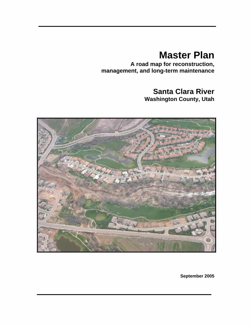
Master Plan A road map for reconstruction, management, and long-term maintenance Santa Clara River Washington County, Utah September 2005
-
Upload
khangminh22 -
Category
Documents
-
view
0 -
download
0
Transcript of Master Plan - Santa Clara City
Master Plan A road map for reconstruction,
management, and long-term maintenance
Santa Clara RiverWashington County, Utah
September 2005

Master PlanA road map for reconstruction,
management, and long-term maintenance
Santa Clara RiverWashington County, UT
Submitted to:
Washington County Water Conservancy District
136 North 100 East, Suite 1St. George, UT 84770
Prepared by:Natural Channel Design, Inc.
3410 S. Cocopah Dr.
Flagstaff, AZ 86001
September 2005

Santa Clara River Master PlanWashington County, Utah
Natural Channel Design, Inc. iFlagstaff, AZ
TABLE OF CONTENTS
Table of Contents i
Figures and Tables iii
SECTION 1: INTRODUCTIONProject Description/Objectives 1-1
Project Approach 1-1
How to Use This Report 1-3
Frequently Asked Questions 1-4
SECTION 2: ASSESSMENTProject Area 2-1
Basin Description 2-2
Hydrology 2-2
Technical Approach 2-5
Technical Assessment 2-6
Mechanisms of Channel Change 2-7
Geomorphic Assessments 2-9
Regional Geomorphic Data 2-14
Conclusions 2-17
Channel Templates 2-17
Meander pattern 2-19
Post-flood Structural Erosion Control 2-20
Hydraulic Assessments 2-22
Design Channel Templates 2-22
Between NRCS dikes 2-23
Areas behind NRCS dikes 2-25
SECTION 3. RECOMMENDATIONSSummary 3-1
Nature of Rivers 3-2
Effects of Channel Modification 3-3
Role of Riparian Vegetation 3-4
Living with a River 3-5
Guiding Principles 3-7
Elevations rise away from channel 3-7
Roughness increases away from channel 3-8
Transitions should be gradual 3-10
Channel Reconstruction 3-11
Channel features 3-11
Channel Alignment 3-12
Appropriate Land Uses 3-12
Channel Templates 3-13
Magotsu Creek/Moody Wash -Gunlock Dam 3-13
Gunlock Dam-Virgin River confluence 3-14
Areas Between NRCS Dikes 3-15
Revegetation 3-18
Santa Clara River Master PlanWashington County, Utah
Natural Channel Design, Inc. iiFlagstaff, AZ
General Strategies 3-18
Areas without NRCS dikes 3-20
Areas with NRCS dikes 3-19
Planting Recommendations 3-21
Stabilization Strategies 3-26
Bioengineering Practices 3-26
Structural Practices 3-29
Terrace Stabilization 3-35
Maintenance 3-36
Removal of Exotic Species 3-36
Channel capacity 3-38
SECTION 4: SPECIFIC AREA MAPS/RECOMMENDATIONSGeneral Guidelines 4-1
Magotsu Creek-Moody Wash – Gunlock Reservoir
Magotsu Creek-Moody Wash – Gunlock Town 4-1
Town of Gunlock 4-2
Gunlock Reservoir – Santa Clara/St. George
Shivwitts Reservation 4-3
Three-mile area 4-3
Santa Clara – St. George
Reach 1 – City limits to Diversion 4-4
Reach 2 – Diversion to Sunbrook G.C. 4-4
Reach 3 – Sunbrook G.C. to Dixie Drive 4-5
Reach 4 – Dixie Drive to Olive Grove 4-5
Reach 5 – Olive Grove to Tonoquint Park 4-5
Reach 6 – Tonoquint Park to Virgin River confluence 4-6
Index of Maps
Town of Gunlock Maps 1 & 2
Shivwitts Reservation Maps 3 & 4
Three-mile area Maps 5& 6
Santa Clara – St. George
Reach 1 – City limits to Diversion Maps 7 & 8
Reach 2 – Diversion to Sunbrook G.C. Maps 9 & 10
Reach 3 – Sunbrook G.C. to Dixie Drive Maps 11 & 12
Reach 4 – Dixie Drive to Olive Grove Maps 12 & 13
Reach 5 – Olive Grove to Tonoquint Park Maps 13 & 14
Reach 6 – Tonoquint Park to Virgin River confluence Map 15
SECTION 5: IMPLEMENTATIONCoordination 5-1
Implementation timelines 5-1
Native plant nurseries 5-1
Regulatory Permitting 5-2
Revegetation Projects 5-2
Long-term Maintenance 5-2
Public Outreach/education 5-3
Priority Areas 5-3
References 5-4
Santa Clara River Master PlanWashington County, Utah
Natural Channel Design, Inc. iiiFlagstaff, AZ
LIST OF FIGURES
Figure 1-1. Location Map 1-2
Figure 2-1. Map of River Sections 2-1
Figure 2-2. Reconstruction of January 2005 flood flows 2-4
Figure 2-3. Debris blockage 2-7
Figure 2-4. Overbank flows 2-8
Figure 2-5. Survey sites in Santa Clara/St. George Section 2-11
Figure 2-6. Rivers Edge Reference Reach 2-13
Figure 2-7. Gubler Reference Reach 2-13
Figure 2-8. Regional Curve; So. Utah sites 2-14
Figure 2-9. Channel Template; no dikes 2-18
Figure 2-10. Meander pattern characteristics 2-19
Figure 2-11. NRCS rock Stabilization design 2-20
Figure 2-12. Dikes after construction 2-21
Figure 2-13. Alluvial features/vegetation between dikes 2-21
Figure 2-14. Channel-floodplain-terrace in no dike sections 2-22
Figure 2-15. NRCS dikes with and without alluvium & vegetation 2-23
Figure 2-16. Alternative setbacks behind NRCS dikes 2-25
Figure 3-1. Alternating bars in constructed canal 3-2
Figure 3-2. Meander pattern in Walla Walla River 3-2
Figure 3-3. Natural vs. “Designed” channels 3-3
Figure 3-4. Riparian Planting Zones 3-4
Figure 3-5. Areas of use 3-5
Figure 3-6. Appropriate channel/floodplain elevations 3-7
Figure 3-7. Appropriate roughness 3-8
Figure 3-8. Incorrect roughness 3-9
Figure 3-9. Terrace Vegetation 3-9
Figure 3-10. Incorrect transitions 3-10
Figure 3-11. Magotsu Creek/Moody Wash -Gunlock Dam Channel Template 3-13
Figure 3-12. Gunlock Dam-Virgin River confluence 3-14
Figure 3-13. Channel template between NRCS dikes 3-15
Figure 3-14. Channel templates behind NRCS dikes 3-16
Figure 3-15. Strategies for large areas behind NRCS dikes 3-17
Figure 3-16. Riparian revegetation in areas without dikes 3-19
Figure 3-17. Riparian revegetation in areas with dikes 3-20
Figure 3-18. Plantings between dikes 3-22
Figure 3-19. Plantings behind dikes 3-23
Figure 3-20. Bioengineering Practices 3-27
Figure 3-21. Stream bank slope stability 3-29
Figure 3-22. Toe Rock 3-30
Figure 2-23. Live Stakes 3-31
Figure 3-24. Joint planting 3-32
Figure 3-25. Root wads 3-33
Figure 3-26. Stream barbs/rock vanes 3-34
Figure 3-27. Terrace stabilization 3-35
Figure 3-28. Riparian Vegetation Maintenance 3-38
Santa Clara River Master PlanWashington County, Utah
Natural Channel Design, Inc. ivFlagstaff, AZ
LIST OF TABLES
Table 2-1. Annual Peak Flows; Santa Clara River 2-2
Table 2-2. Santa Clara River Flood Frequencies 2-3
Table 2-3. January 2005 peak flows 2-4
Table 2-4. Summary of Gunlock surveys 2-10
Table 2-5. Pre- & Post-flood Gunlock channel data 2-10
Table 2-6. Summary of Santa Clara/St. George surveys 2-10
Table 2-7. Pre- & Post-flood Santa Clara/St. George channel data 2-11
Table 2-8. Channel Template data 2-18
Table 2-9. Meander pattern values 2-19
Table 2-10. Roughness coefficients used for hydraulic modeling 2-22
Table 2-11. Stages and mean velocities for non-dike channel templates 2-23
Table 2-12. Stage-discharge-mean velocities in NRCS dikes 2-24
Table 2-13. Velocities-depths behind NRCS dikes 2-25
Table 3-1. Channel template for Magotsu Creek/Moody Wash – Gunlock Dam 3-13
Table 3-2. Channel template for Gunlock Dam- Virgin River confluence 3-14
Table 3-3. Channel template between NRCS dikes 3-15
Santa Clara River Master PlanWashington County, Utah
Natural Channel Design, Inc. 1 - 1Flagstaff, AZ
SECTION 1: INTRODUCTION
PROJECT DESCRIPTION/OBJECTIVESA large flood event occurred on the Santa Clara and Virgin Rivers in January 2005 (Figure 1-1).
These floods caused considerable damage to property and infrastructure. While flooding was a
problem for areas along both rivers, the primary damage was the result of large lateral erosion
that resulted in the loss of homes, roads, utility infrastructure, and private lands. Damage was
most severe along the Santa Clara River in the communities of Gunlock, Santa Clara, and St.
George. Although the January 2005 floods were very powerful hydrologic studies suggest that
larger flood events can be expected in the future. In response to this community emergency, the
county and city governments combined resources to prepare this Master Plan for the region.
The study objectives are to:
1) Assist in the assessment, planning and prioritization of geomorphic and engineering
strategies in coordination with NRCS and other technical agencies to assist in the
effective and timely implementation of flood repair and stream bank stabilization along
the Santa Clara River and
2) Develop a Master Plan that will assist city and county governments in managing
development, guide additional stabilization, and provide long-term maintenance along the
Santa Clara River in order to minimize risk of lateral erosion, flooding, and property
damage from future floods.
The primary goal of the Master Plan is to minimize the risk of flooding and bank erosion along
the Santa Clara and Virgin Rivers. Aesthetics, reestablishment of riparian vegetation, and wildlife
habitat are additional goals of the project. The Master Plan recommends specific protocols for the
reestablishment of stream channel, floodplain, and terrace features; revegetation of the riparian
areas for stability and wildlife; address appropriate future land use along the rivers; and
recommend a long-term maintenance program to ensure project objectives are achieved.
This is not a formal FEMA study to establish regulation of the 100-year floodplain. The Master
Plan is primarily concerned with the risk of loss of property due to bank erosion. A separate
FEMA study to determine post-flood 100-year floodplain boundaries will be conducted
separately. The Master Plan is based on the premise that floods of greater magnitudes will occur
in the future and local governments and landowners should be prepared.
The Master Plan extends along the Santa Clara River from its confluence with Magotsu
Creek/Moody Wash to the confluence with the Virgin River. The plan was prepared by Natural
Channel Design, Inc., J. E. Fuller Hydrology and Geomorphology, and Rosenberg Associates
under contract with the Washington County Water Conservancy District. Project sponsors in
include Washington County, cities of Santa Clara and St. George, Washington County Water
Conservancy District, and Virgin River Resource Management and Recovery Program.
STUDY APPROACHThis study uses an empirical approach to understanding the physical and biological elements of
the Santa Clara and Virgin River systems. Sometimes called the geomorphic approach, the study
examines the dimension, pattern, and profile of relatively stable stream reaches to identify
mechanisms for instability and stable channel parameters. Because virtually every channel section
was altered to some extent during the recent floods, survey data collected regionally in other
streams throughout the region is also used to establish stable, reference information.

Santa Clara River Master PlanWashington County, Utah
Natural Channel Design, Inc. 1 - 2Flagstaff, AZ
Figure 1-1. Location Map. Santa Clara and Virgin Rivers in SW Utah.
Gunlock
St. George
Santa Clara
UTAH
ARIZONA
NORTH
Santa Clara River Master PlanWashington County, Utah
Natural Channel Design, Inc. 1 - 3Flagstaff, AZ
For this study, a number of post-flood cross-sections were surveyed in stream reaches that
received relatively moderate erosion. These surveys were compared with pre-flood cross-sections
to develop an understanding of pre-flood conditions. Pre- and post-flood photos were evaluated to
understand the effects of the flooding and the causes of the damage. From this information
channel/floodplain/terrace dimension, meander pattern, and vegetation composition were
characterized.
It should be clear that the assessment and understanding of any natural system has an inherent
level of uncertainly. Large flood events result in erosion and deposition in any alluvial system.
The recommendations included in this study should be implemented with the understanding that
the measures are designed to minimize rather than eliminate the future risk of flooding and
erosion.
HOW TO USE THIS REPORTThe master plan is designed to provide guidance to city and county government officials and staff
as well as private landowners in the restoration of the Santa Clara River. The information within
the plan should provide a road map to reconstructing lands within the river corridor. The report is
divided into the following sections:
SECTION 1: INTRODUCTION
SECTION 2: ASSESSMENT
Introduction/Geomorphic Assessment:
• Provides background information on the project area, technical assessment, and
development of Master Plan recommendations.
SECTION 3: RECOMMENDATIONS
Guiding Principles:
• This section describes the general guiding principles for restoration or rehabilitation of
the river corridor. Topics include physical features, revegetation strategies, bank
stabilization, appropriate land uses, and maintenance efforts.
Channel Reconstruction/revegetation Practices:
• Specific recommendations for channel-floodplain-terraces reconstruction, bank
stabilization, revegetation, and maintenance.
Bank Stabilization – Bioengineering/structural Practices:
• Specific recommendations for removal of exotic species and revegetation of the Santa
Clara River for long-term stability.
SECTION 4: REACH MAPS/RECOMMENDATIONS
SECTION 5: IMPLEMENTATION
This section describes the tasks and timelines to successfully implement the Master Plan.
This manual provides guidance for private and public landowners in the short- and long-term
reconstruction and restoration of the Santa Clara and Virgin Rivers. However, implementation of
these recommendations generally requires permitting from the Army Corps of Engineers and the
Utah State Engineers Office. Do not initiate any activities within the riparian corridor without
notifying these agencies and obtaining necessary permits.
Army Corps of Engineers Utah State Engineers Office
Attn: Grady McNure Attn: Chuck Williamson
321 North Mall Drive, Suite L101 1594 W. North Temple, Suite 220
St. George, UT 84790 Salt Lake City, UT 84114
435-986-3979 801-538-7467
Santa Clara River Master PlanWashington County, Utah
Natural Channel Design, Inc. 1 - 4Flagstaff, AZ
FREQUENTLY ASKED QUESTIONS
What does the Master Plan contain?
The Master Plan should be considered a “road map” to restoring and maintaining stream
stability along the Santa Clara River. It should be understood that all stream channels are
dynamic, changing with large and small flow events. Erosion and deposition will continue along
the river, the objective of the Master Plan is to minimize the potential for large bank erosion.
Minimization of erosion implies stabilization while not going to the extent (except where
necessary) to harden streambanks. This plan preserves physical and biological stream processes
while preserving wildlife habitats,maintaining aesthetics, and protecting life and property.
Does the Master Plan delineate the 100-year floodplain?
No, the Master Plan is to minimize the potential for large lateral erosion during future flood
events. A separate study is underway to delineate the regulatory 100-year floodplain.
Do I need any regulatory permits to work on the river?
Yes. Any significant work within the river corridor, especially by mechanical means requires
permitting from the Utah State Engineers Office, the Army Corps of Engineers, and/or the local
city/county agencies. However, the Master Plan is intended to streamline this process
significantly. Always check with these entities before beginning activities.
Can I improve wildlife habitat while protecting my property.
Yes. The reestablishment of native vegetation as described in the Master Plan will create a
continuous corridor of riparian habitat to benefit wildlife.
When is the best time to implement the Master Plan on my property?
Construction activities should be implemented during periods when water levels are low, there is
a minimum risk of high flows, and that mimimizes disturbance to aquatic and riparian wildlife. In
addition, bare pole plantings of willow and cottonwood are much more successful if planted
during the dormant season. For these reasons, late fall and winter are the recommended work
periods.
Will the NRCS dikes protect my property from all floods and erosion?
The NRCS dikes were designed and constructed to protect properties from floods equal to the
magnitude of the January 2005 floods. While there was considerable property damage from that
flood, hydrologic analyses suggest higher flood events can be expected. These floods will overtop
the dikes, flooding areas above and behind them. However, the dikes are structurally designed to
withstand large flood events and should reduce catastrophic lateral bank erosion.
Can I rebuild my home behind the NRCS dikes?
In general the answer is yes. However, there may be specific properties in sections where the
width between dikes is very narrow and/or are on the outside of relatively sharp meanders that
require additional engineering analyses and protection for the upper banks. A site specific review
and analysis should be conducted before rebuilding or reclaiming land behind NRCS dikes.
Santa Clara River Master PlanWashington County, Utah
Natural Channel Design, Inc. 1 - 5Flagstaff, AZ
What should be constructed behind the dikes?
The areas behind dikes should be raised to elevations greater than the dikes tops. Guidelines are
included in the Master Plan. Where the areas behind dikes are relatively very large, the amount
of fill necessary may be cost prohibitive. In these areas some fill should be added and the areas
should be divided into cells to limit the ability of the river to flow uninhibited behind the dikes.
How can I create access to the river between dikes?
The rock dikes present a steep and difficult barrier to the river. However, the dikes should not
limit access to the river by local landowners. Stairways made of wood, steel, or ungrouted rock
can be used to provide a path to the river. Stairways should not be permanently attached to the
dikes and can be cabled to swing away during the infrequent high flow event. However, no
concrete or other “hard” structures should be constructed within the dikes. These structures
could deflect flows and increase the risk of erosion.
Can I reestablish my agricultural lands in terraces?
Generally the answer is yes. The low and high terrace areas can be used effectively as
agricultural fields. These areas will periodically flooded but, with proper vegetation along the
banks and on the terraces, erosion potential will be minimized.
How can I protect my property against future bank erosion?
In those areas where no dikes or other structural control, a variety of options are available. In
many areas native vegetation and proper channel-floodplain-terrace elevation and dimension
will be adequate. In areas where erosion potential is greater, the Master Plan includes a variety
of bioengineering and structural options.
How can I make sure saltcedar doesn’t become established?
The best strategy for reducing the amount of saltcedar establishment is to plant native riparian
plant species. Given an equal start these plants have been successful in out competing saltcedar
and other non-native species.
How can I maintain or increase capacity of the river to carry flood flows?
In general the January 2005 floods significantly increased the flow capacity of the Santa Clara
River. However, one of the primary mechanisms of large lateral erosion identified in the Master
Plan was debris blockage in relatively vegetation choked channels. As a result a long-term
maintenance program is recommended to keep a 100-foot wide path clear of large woody (tree
species) vegetation along the central channel. The maintenance should initially be completed
manually.

Santa Clara River Master PlanWashington County, Utah
Natural Channel Design, Inc. 1 - 6Flagstaff, AZ
Santa Clara River Master PlanWashington County, Utah
Natural Channel Design, Inc. 2- 1Flagstaff, AZ
SECTION 2: ASSESSMENTPROJECT AREAThe Master Plan covers approximately 30 miles of the Santa Clara River in southwestern Utah.
The project area was divided into 3 sections (Figure 2-1).
Santa Clara River
• Gunlock Section 1 – Confluence of Magotsu Creek/Moody Wash to Gunlock Reservoir –
~8.1 miles
• Shivwitts Section 2 - Gunlock Reservoir to Santa Clara City. - ~14.0 miles
• Santa Clara-St. George Section 3 – Santa Clara City to Virgin River confluence - ~8.4 miles
Several of these areas were further divided into smaller units (reaches) to facilitate assessment
and recommendations.
Figure 2-1. Map of Project River Sections along Santa Clara River
Santa Clara River Master PlanWashington County, Utah
Natural Channel Design, Inc. 2- 2Flagstaff, AZ
BASIN DESCRIPTIONThe Santa Clara River is both fed by a large watershed. The catchment area at Gunlock is
approximately 270 square miles and at St. George over 500 square miles. Two relatively small
reservoirs are located on the Santa Clara, Baker Reservoir (1,160 acre-feet) and Gunlock
Reservoir (10,884 acre-feet). These reservoirs are managed to store water for agricultural and
domestic uses; not for flood control. As such the reservoirs can be expected to be relatively full
during wet periods and provide little relief from extreme flooding. Due to their size, these
reservoirs probably have the greatest effect on medium-sized floods that could be expected to
periodically scour vegetation and clear channels. Both reservoirs were full and overflowing
during the January 2005 floods. There are a number of diversions along the Santa Clara to
provide water for agricultural purposes. These diversions primarily affect low flows and are not
significant during flood flows.
HYDROLOGYFlooding is not uncommon on the Santa Clara River. Flood flows are produced by storm events
and can occur in any season. Table 2-1 presents annual instantaneous peak flows for stream gages
on the Santa Clara River at Gunlock and St. George.
Table 2-1. Annual peak flows; Santa Clara River. Stream gages have not operated continuously onthe Santa Clara River.
Santa Clara Santa Clara Santa Clara Santa Clara@ Gunlock @ St. George @ Gunlock @ St. George
YEAR (cfs) (cfs) YEAR (cfs) (cfs)1951 * 1270 1977 783 *
1952 * 521 1978 324 *1953 * 3240 1979 2620 *1954 * 520 1980 2810 *1955 * 4200 1981 74 *1956 * 1070 1982 199 *1957 * * 1983 1560 *1958 * * 1984 484 1601959 * * 1985 47 551960 * * 1986 25 192
1961 * * 1987 44 12501962 * * 1988 154 9901963 * * 1989 56 17401964 * * 1990 174 6841965 * * 1991 370 13601966 ** ** 1992 496 14601967 * * 1993 959 5291968 * * 1994 134 6000
1969 * * 1995 2830 3971970 73 * 1996 59 48601971 183 * 1997 2030 8491972 335 * 1998 889 3461973 902 * 1999 118 4711974 1360 * 2000 681 2171975 273 * 2001 200 491976 658 * 2002 154 53
2003 65 *2004 1520 *
* No gage in operation. Data not available.** A large flood was generated from high rain on snow in 1966 but not recorded.
Santa Clara River Master PlanWashington County, Utah
Natural Channel Design, Inc. 2- 3Flagstaff, AZ
FREQUENCY OF FLOODING
Flood flows are commonly characterized using a flood frequency analysis. This statistical
analysis commonly ranks peak annual floods into a probability or recurrence interval. A flood
with a 10-year recurrence interval means a flow of this magnitude or greater can be expected to
occur approximately every 10 years, or 10 times in 100 years. Another way of looking at it is in
terms of probability. A 10-year flood has a 10% chance of occurring every year. A 25-year flood
has only a 4% chance of occurring in any one year. Small floods occur frequently and have high
probabilities and low recurrence intervals. Larger floods are less frequent and have lower
probabilities and higher recurrence intervals. Floods can be generally placed into 4 classes based
on their magnitude and probability.
Common floods (1 – 5-year recurrence interval):
These floods have a high probability (20% - 90%) of occurring in any year. These floods
have relatively small magnitudes and are considered to be critical in eroding and creating
bars, transporting sediment, extending meander, and generally doing morphological work.
Moderate Floods (5 – 20-year recurrence interval):
These floods are less common but larger in magnitude. They have a 5% - 20% probability
of occurring in any year. In the southwest these floods can have relatively large flood peaks
and can produce significant erosion especially in unstable systems or channels with
relatively low stability.
Large Floods (20 - 50-year recurrence interval):
These floods are unusual, having a less than 2% to 5% probability of occurring in any year.
But they are very powerful and can be expected to produce significant and unpredictable
bank and channel erosion and property damage.
Extreme Floods (50-year or greater recurrence interval):
These “once in a lifetime” events significantly alter channels and floodplains in
unpredictable ways and produce enormous property and infrastructure damage especially in
urban areas.
Peak discharge estimates (cubic feet per second) for indicated recurrence intervals computed by
the United States Geological Survey (USGS) are shown in Table 2-2. The values were calculated
using a weighted estimate using two standard methods for determining flow frequencies; regional
regression models and flood frequency analysis of the gaging record. The data is provisional and
Table 2-2. Santa Clara Flood Frequencies1
Recurrence Interval (years)
USGS gage site 2 5 10 25 50 100Santa Clara @ Gunlock 320 1,010 1,880 3,600 5,410 7,680Santa Clara @ St. George 640 1,980 3,560 6,540 9,490 13,000
Table 2-3. January 2005 peak flows; Santa Clara & Virgin Rivers
Estimated Approx.Gage Site Peak Flow Recurrence Interval
Santa Clara River at Gunlock, UT ~5,200 cfs ~50 yearsSanta Clara River at St. George, UT ~6,200 cfs ~25 yearsVirgin River at Virgin, UT ~11,800 cfs ~20 yearsVirgin River at Bloomington, UT
2~21,000 cfs >25 years
1Source: Flood in Virgin River basin, Southwestern Utah, January 9-11, 2005. U.S Geological Survey
URL:http://ut.water.usgs.gov/FLOODING/Virgin_flood.html2 Short flow record creates uncertainty in infrequent high flood magnitudes estimates.
Santa Clara River Master PlanWashington County, Utah
Natural Channel Design, Inc. 2- 4Flagstaff, AZ
subject to revision. Peak flows during the January 2005 flood have been estimated by USGS and
are presented in Table 2-3.
Based on the classes described above, the Santa Clara River flood flows of January 2005 would
be considered “extreme” at Gunlock and “large” at Santa Clara-St. George. The Virgin River
flows of January 2005 would be considered “moderate to large” at Virgin and St. George-
Bloomington. It should be noted that the stream flow data on the Virgin River at Bloomington,
UT is limited and the recurrence interval for infrequent flow events (i.e., 50-year, 100-year
floods) may not be accurate. Nevertheless the January 2005 flood was large.
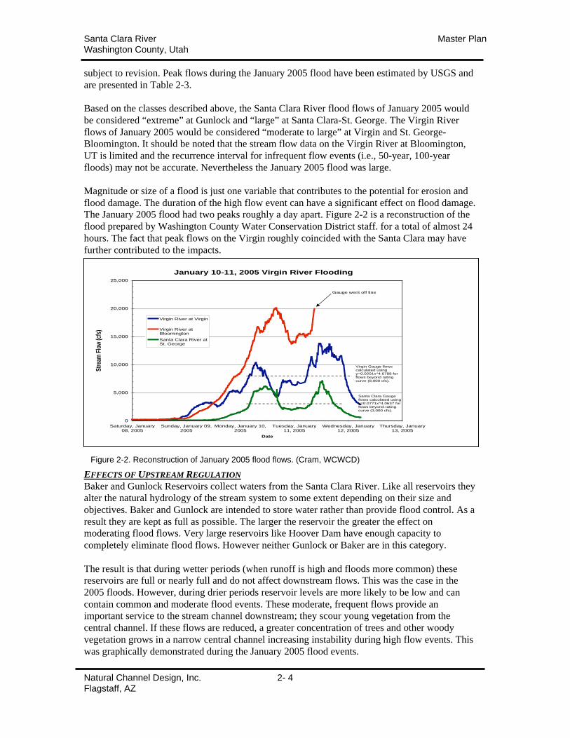
Magnitude or size of a flood is just one variable that contributes to the potential for erosion and
flood damage. The duration of the high flow event can have a significant effect on flood damage.
The January 2005 flood had two peaks roughly a day apart. Figure 2-2 is a reconstruction of the
flood prepared by Washington County Water Conservation District staff. for a total of almost 24
hours. The fact that peak flows on the Virgin roughly coincided with the Santa Clara may have
further contributed to the impacts.
EFFECTS OF UPSTREAM REGULATION
Baker and Gunlock Reservoirs collect waters from the Santa Clara River. Like all reservoirs they
alter the natural hydrology of the stream system to some extent depending on their size and
objectives. Baker and Gunlock are intended to store water rather than provide flood control. As a
result they are kept as full as possible. The larger the reservoir the greater the effect on
moderating flood flows. Very large reservoirs like Hoover Dam have enough capacity to
completely eliminate flood flows. However neither Gunlock or Baker are in this category.
The result is that during wetter periods (when runoff is high and floods more common) these
reservoirs are full or nearly full and do not affect downstream flows. This was the case in the
2005 floods. However, during drier periods reservoir levels are more likely to be low and can
contain common and moderate flood events. These moderate, frequent flows provide an
important service to the stream channel downstream; they scour young vegetation from the
central channel. If these flows are reduced, a greater concentration of trees and other woody
vegetation grows in a narrow central channel increasing instability during high flow events. This
was graphically demonstrated during the January 2005 flood events.
January 10-11, 2005 Virgin River Flooding
0
5,000
10,000
15,000
20,000
25,000
Saturday, January08, 2005
Sunday, January 09,2005
Monday, January 10,2005
Tuesday, January11, 2005
Wednesday, January12, 2005
Thursday, January13, 2005
Date
Str
eam
Flo
w (c
fs)
Virgin River at Virgin
Virgin River atBloomington
Santa Clara River atSt. George
Gauge went off line
Santa Clara Gauge flows calculated using y=0.0771x^4.0637 for flows beyond rating curve (3,000 cfs).
Virgin Gauge flows calculated using y=0.0201x^4.6789 for flows beyond rating curve (8,000 cfs).
Figure 2-2. Reconstruction of January 2005 flood flows. (Cram, WCWCD)
Santa Clara River Master PlanWashington County, Utah
Natural Channel Design, Inc. 2- 5Flagstaff, AZ
TECHNICAL APPROACHNATURE OF RIVERSA stream adjusts its size, slope, and sinuosity to accommodate typical stream flows and to move
sediment through the system. Generally speaking, a stream is constantly dissipating energy as it
moves downstream. In a low gradient channel, bars, meanders and a broad floodplain are
important features for dissipating excess energy. If unable to expend this energy the channel is
inherently unstable and prone to lateral and/or vertical erosion, especially during large flow
events.
Stream channels are created and maintained by moderate, frequent flood events with return
intervals in the range of one to two years (Moody et al 2003). In many gravel bed streams, this
flow has been shown to carry the greatest amount of sediment over time (Andrews, 1980) and is
considered the stream forming flow, channel maintenance flow or bankfull flow. The stability of
any natural channel is dependent on an appropriate dimension, pattern, and profile of the bankfull
channel and associated floodplain (Leopold, Wolman, & Miller, 1964). A natural channel
approach to design seeks to identify the stable geomorphic dimensions of a channel and
incorporate those into designs to meet specific objectives. Closely matching the central
tendencies of the natural channel results in a design that works with the existing channel rather
than against it. The approach achieves greater success at less maintenance cost.
ROLE OF RIPARIAN VEGETATIONThe banks of both the Virgin and Santa Clara Rivers are composed of sandy, easily erodible soils.
Bank stability is increased dramatically by the colonization of riparian vegetation. This is
especially obvious in the Santa Clara River. A 1997 stability study of the Santa Clara River found
little historic meander along the river and attributed it to the stable vegetation (Fuller 1997).
Riparian vegetation provides critical benefits to the physical stream system. Vegetation rooting
provides additional strength to erodible banks. Equally important the vegetation increases
roughness or resistance to flow along the channel and banks slowing flow velocities and
dissipating energy. The species and distribution of vegetation is largely dependent on two critical
variables; soil moisture and disturbance. Flooding is the driver for both of these variables. As a
result both soil moisture and disturbance are highest closest to the stream channel and decrease
laterally moving away and up. Plants adapted to varying degrees of soil moisture and disturbance
thrive along zones running parallel to the stream channel.

Santa Clara River Master PlanWashington County, Utah
Natural Channel Design, Inc. 2- 6Flagstaff, AZ
TECHNICAL ASSESSMENTThe floods of January 2005 produced significant channel change to virtually all project reaches of
the Santa Clara and Virgin Rivers. However, changes varied in degree and extent from reach to
reach. In general, the Santa Clara River experienced lateral erosion and limited associated
flooding.
Channel widening is a predictable result of the high velocities and depths of large flood flows but
the extent of lateral erosion was excessive in many places along the Santa Clara River. These
areas of excessive erosion were largely focused in areas with substantial human infrastructure
resulting in large economic damages. Property losses were greatest in the communities of
Gunlock, Santa Clara, and St. George where roads, bridges, agricultural fields, and homes were
undercut and/or completely destroyed. Despite the damage, the Santa Clara flood was not an
extreme flow event in the communities of Santa Clara and St. George. The 25-year return interval
suggests that equal or larger flood events can be expected in the future.
Despite the extent of erosion and damage, not all stream reaches experienced severe erosion or
flooding. Within these relatively stable reaches geomorphic change was limited to moderate
widening and local scour of alluvium and vegetation. On the Santa Clara River these reaches
were identified in areas above Gunlock town and within Santa Clara-St. George boundaries.
These reaches were compared to other reaches with greater instability to complete the following
tasks.
Geomorphic Assessments
• Identify mechanisms or erosion/flooding
• Identify/survey stable stream reference reaches
• Evaluate regional channel morphology data
• Create channel dimension templates based on evaluations of reference reaches and
regional data
• Evaluate velocities and depths of template channel, floodplain, terraces
Recommendations
• Create a set of guiding principles for stream stability to address erosion mechanisms
• Prepare channel template recommendations
• Prepare revegetation strategy recommendations
• Prepare bioengineering bankstability recommendations
• Prepare structural bank stability recommendations
• Prepare recommendations for specific stream reaches
• Develop recommendations for management and long-term maintenance
A combination of field observations, geomorphic surveys, aerial photographs, regional
geomorphologic data, anecdotal evidence, and hydraulic analyses will be used complete these
tasks.
Santa Clara River Master PlanWashington County, Utah
Natural Channel Design, Inc. 2- 7Flagstaff, AZ
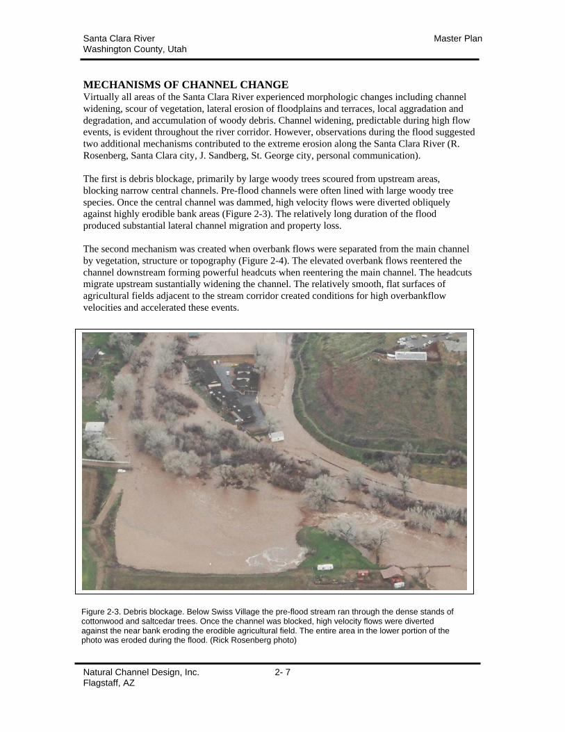
MECHANISMS OF CHANNEL CHANGEVirtually all areas of the Santa Clara River experienced morphologic changes including channel
widening, scour of vegetation, lateral erosion of floodplains and terraces, local aggradation and
degradation, and accumulation of woody debris. Channel widening, predictable during high flow
events, is evident throughout the river corridor. However, observations during the flood suggested
two additional mechanisms contributed to the extreme erosion along the Santa Clara River (R.
Rosenberg, Santa Clara city, J. Sandberg, St. George city, personal communication).
The first is debris blockage, primarily by large woody trees scoured from upstream areas,
blocking narrow central channels. Pre-flood channels were often lined with large woody tree
species. Once the central channel was dammed, high velocity flows were diverted obliquely
against highly erodible bank areas (Figure 2-3). The relatively long duration of the flood
produced substantial lateral channel migration and property loss.
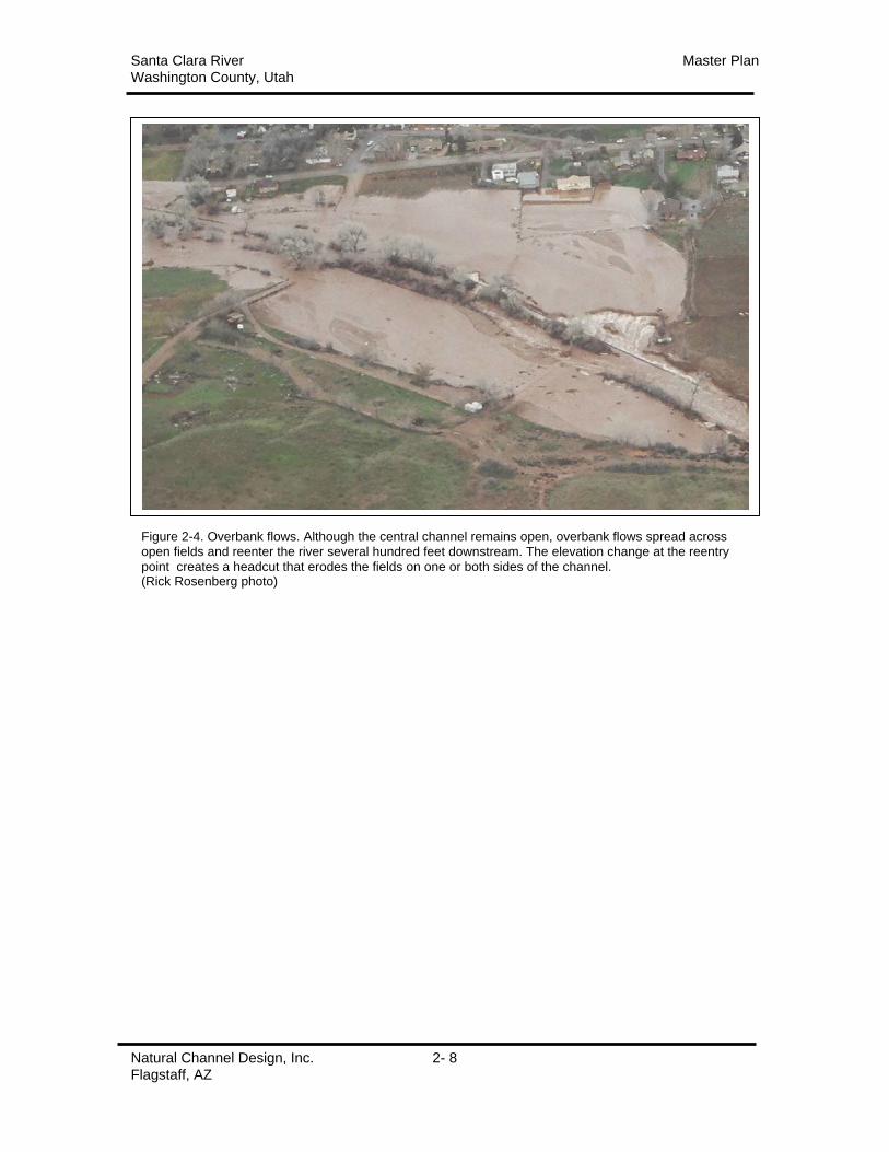
The second mechanism was created when overbank flows were separated from the main channel
by vegetation, structure or topography (Figure 2-4). The elevated overbank flows reentered the
channel downstream forming powerful headcuts when reentering the main channel. The headcuts
migrate upstream sustantially widening the channel. The relatively smooth, flat surfaces of
agricultural fields adjacent to the stream corridor created conditions for high overbankflow
velocities and accelerated these events.
Figure 2-3. Debris blockage. Below Swiss Village the pre-flood stream ran through the dense stands ofcottonwood and saltcedar trees. Once the channel was blocked, high velocity flows were divertedagainst the near bank eroding the erodible agricultural field. The entire area in the lower portion of thephoto was eroded during the flood. (Rick Rosenberg photo)
Santa Clara River Master PlanWashington County, Utah
Natural Channel Design, Inc. 2- 8Flagstaff, AZ
Figure 2-4. Overbank flows. Although the central channel remains open, overbank flows spread acrossopen fields and reenter the river several hundred feet downstream. The elevation change at the reentrypoint creates a headcut that erodes the fields on one or both sides of the channel.(Rick Rosenberg photo)
Santa Clara River Master PlanWashington County, Utah
Natural Channel Design, Inc. 2- 9Flagstaff, AZ
GEOMORPHIC ASSESSMENTSFIELD VISITS
Field visits were made to all sections of the project reach immediately following the flood event
and again a month following the event. The entire length of stream channel was walked in areas
of critical concern (Gunlock, Santa Clara, St. George cities). Bank composition, existing and
scoured vegetation composition/distribution, debris blockages, channel & floodplain
width/elevations, and general observations were recorded during these visits.
AERIAL PHOTOGRAPHS:
Washington County commissioned aerial photographs of the project area immediately after the
January 2005 flood event. These photographs were compared with pre-flood aerials (2002) to
assess changes in channel alignment, channel widening, meander patterns, pre-and post-flood
vegetation composition and distribution, and extreme channel avulsion.
GEOMORPHIC SURVEYS (PRE- & POST-FLOOD):
Field observations, aerial photos, and anecdotal evidence were used to identify stable reaches
along the Santa Clara River in the Gunlock and Santa Clara/St. George sections. Although
channel widening, local scour and deposition, and vegetation removal were common in these
reaches, lateral channel movement was limited to the existing riparian corridor and little property
was lost.
Surveys of channel morphology were completed at 17 sites within these stable reaches (Figure 2-
5). A set of three cross-sections were surveyed at each site from the extent of flooding on each
bank. Alluvial features (channel, floodplain, and terraces) were identified. Longitudinal profiles
were created at each site to evaluate channel slope and elevation. Pre-flood topographic maps
were used to create unaltered cross-sections and profiles to assess changes. Because no stable
reaches were located in the town of Gunlock, a separate longitudinal profile was surveyed to
evaluate channel elevation change.
Alluvial channels are constructed of distinct physical features.
• Channel: a central, active, or bankfull channel that carries moderate flows and transports
bedload sediments;
• Geomorphic floodplain: an adjacent level surface created by the river in the current climate
and inundated by moderate, frequent flood events. For this study, the vertical extent of this
feature is twice maximum channel (bankfull) depth;
• Low Terrace: this feature extends to an elevation above the floodplain and is flooded less
frequently. For this study, this feature extends to an elevation 3 times maximum channel
(bankfull) depth; and
• High Terrace: this feature is rarely inundated and vegetated with a mixture of obligate and
facultative riparian species. For this study, this feature extends to an elevation 4 times
maximum channel (bankfull) depth.
Channel bed elevations; channel width and cross-sectional area; floodplain/terrace widths; and
depth/lateral extent of the 2005 flooding were evaluated at each site and summarized in Tables 2-
4, 2-5, 2-6 & 2-7.

Santa Clara River Master PlanWashington County, Utah
Natural Channel Design, Inc. 2- 10Flagstaff, AZ
Table 2-6. Summary of Santa Clara/St. George Surveys
• Channel flowline elevation remained relatively stable through the flood. Theexceptions were incisions of 5-6 feet in the area immediately above Swiss Village inupper Santa Clara city. This incision may have been resulted from high velocity flowsthrough the narrow channel at Swiss Village. No similar downcutting was recorded in
downstream survey sites.
• Pre-flood central channel averaged ~44 feet in width. Floodplains averaged 70 feet,low terraces 215 feet, and high terraces 350 feet.
• Erosion and scour widened channels at virtually all cross-sections, a common result oflarge floods. Widening was greatest at the channel and floodplain elevations withincreases of 146% and 98% respectively. Low terrace widths increased only 29% andhigh terraces remained relatively stable.
• The stage of the January 2005 flood waters ranged from 9 – 12 feet in depth andextended laterally 300 – 500 feet in width.
Table 2-4. Summary of Gunlock Surveys
• Channel flowline elevation remained relatively stable through the flood. Theexceptions were local incisions of 3-4 feet immediately below major tributaries.
• Pre-flood central channel averaged 54 feet in width. Floodplains averaged 86 feet, lowterraces 140 feet, and high terraces 165 feet.
• Erosion and scour widened channels at virtually all cross-sections, a common result oflarge floods. Widening was greatest at the channel and floodplain elevations with
increases of 50% and 17% respectively. Terrace widths increased only slightly or notat all.
• The stage of the January 2005 flood waters ranged from 6 – 9 feet in depth andextended laterally 85 - 200 feet in width.
Table 2-5. Pre- & Post Flood Channel data; Gunlock Reach
Widths (feet)Channel Floodplain Low Terrace High TerracePre- Post- Pre- Post- Pre- Post- Pre- Post-
Set 1 - XS 2 24 59 34 71 78 84 100 102Set 2 - XS 2 38 73 86 80 104 103 124 112
Set 3 - XS 2 75 75 90 100 133 115 120Set 3 - XS 3 60 90 105 128 161Set 4 - XS 1 60 95 90 120 150 195 206 201Set 4 XS 4 66 91 113 107 230 230 233 237
min 24 59 34 71 78 84 100 102max 75 95 113 128 230 230 233 237
Average 53.8 80.5 86.3 101.0 139.0 148.0 165.8 154.4
% change 50% 17% 6% -7%
Santa Clara River Master PlanWashington County, Utah
Natural Channel Design, Inc. 2- 11Flagstaff, AZ
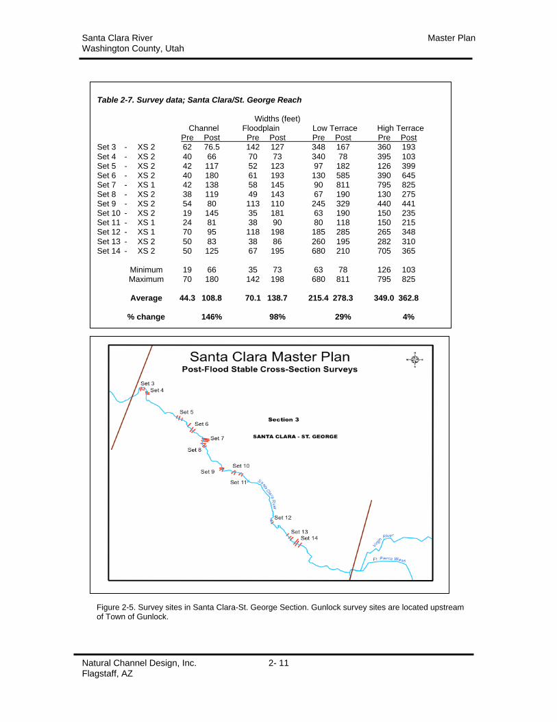
Figure 2-5. Survey sites in Santa Clara-St. George Section. Gunlock survey sites are located upstreamof Town of Gunlock.
Table 2-7. Survey data; Santa Clara/St. George Reach
Widths (feet)Channel Floodplain Low Terrace High Terrace
Pre Post Pre Post Pre Post Pre PostSet 3 - XS 2 62 76.5 142 127 348 167 360 193
Set 4 - XS 2 40 66 70 73 340 78 395 103Set 5 - XS 2 42 117 52 123 97 182 126 399Set 6 - XS 2 40 180 61 193 130 585 390 645Set 7 - XS 1 42 138 58 145 90 811 795 825Set 8 - XS 2 38 119 49 143 67 190 130 275Set 9 - XS 2 54 80 113 110 245 329 440 441Set 10 - XS 2 19 145 35 181 63 190 150 235Set 11 - XS 1 24 81 38 90 80 118 150 215Set 12 - XS 1 70 95 118 198 185 285 265 348
Set 13 - XS 2 50 83 38 86 260 195 282 310Set 14 - XS 2 50 125 67 195 680 210 705 365
Minimum 19 66 35 73 63 78 126 103Maximum 70 180 142 198 680 811 795 825
Average 44.3 108.8 70.1 138.7 215.4 278.3 349.0 362.8
% change 146% 98% 29% 4%
Santa Clara River Master PlanWashington County, Utah
Natural Channel Design, Inc. 2- 12Flagstaff, AZ
STABLE REFERENCE REACHES:
To aid in the development of channel/floodplain/terrace recommendations. Field observations,
aerial photos, and anecdotal evidence were used to identify stable reaches on the Santa Clara
River. Although channel widening, local scour and deposition, and vegetation removal were
common in these reaches, lateral channel movement was limited to the existing riparian corridor
and little property was lost. In the Gunlock Section, these areas were located above Gunlock
town.
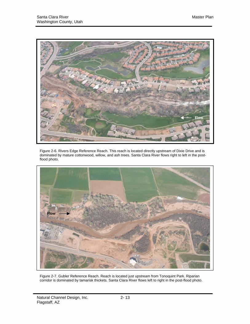
Two reference reaches were identified in the Santa Clara-St. George Section. The first is located
immediately upstream of Dixie Drive along Rivers Edge Drive (Figure 2-6). A second reference
reach was identified along the Gubler property upstream of Tonoquint Park (Figure 2-7). Stream
channels widened in both reaches during the flood but floodplain and terrace dimensions
remained relatively constant. The stream maintained its pre-flood alignment in both reaches
through the flood although most of the pre-flood underbrush in the floodplain and low terraces
was removed by the flood waters.
The reaches share several characteristics that contributed to their stability. Stream banks rise in
elevation as distances increase away from the central channel increases. The riparian corridors in
each reach are relatively consistent in width and well vegetated in both reaches. An evaluation of
cross-sections within the reaches surveyed post-flood suggest that the width of flooding ranged
from 300 – 400 feet. Corridor width in the Rivers Edge reach averages 380 feet and is dominated
by mature cottonwood and willow trees. The Gubler reach averages over 500 feet in width and is
dominated by dense tamarisk thickets.
Santa Clara River Master PlanWashington County, Utah
Natural Channel Design, Inc. 2- 13Flagstaff, AZ
Figure 2-6. Rivers Edge Reference Reach. This reach is located directly upstream of Dixie Drive and isdominated by mature cottonwood, willow, and ash trees. Santa Clara River flows right to left in the post-flood photo.
Figure 2-7. Gubler Reference Reach. Reach is located just upstream from Tonoquint Park. Ripariancorridor is dominated by tamarisk thickets. Santa Clara River flows left to right in the post-flood photo.
Flow
Flow
Santa Clara River Master PlanWashington County, Utah
Natural Channel Design, Inc. 2- 14Flagstaff, AZ
REGIONAL GEOMORPHIC DATA
Surveys of the pre-flood channels in the Santa Clara and Virgin Rivers were limited to
interpolating morphology from topographic maps used in previous FEMA studies. While
valuable, the pre-flood data has an inherent level of error. To reinforce these assessments,
morphologic data from 41 regional channel sites were also evaluated. These sites represented
low-gradient gravel-sand bed channels located in southern Utah. A listing of the site data is
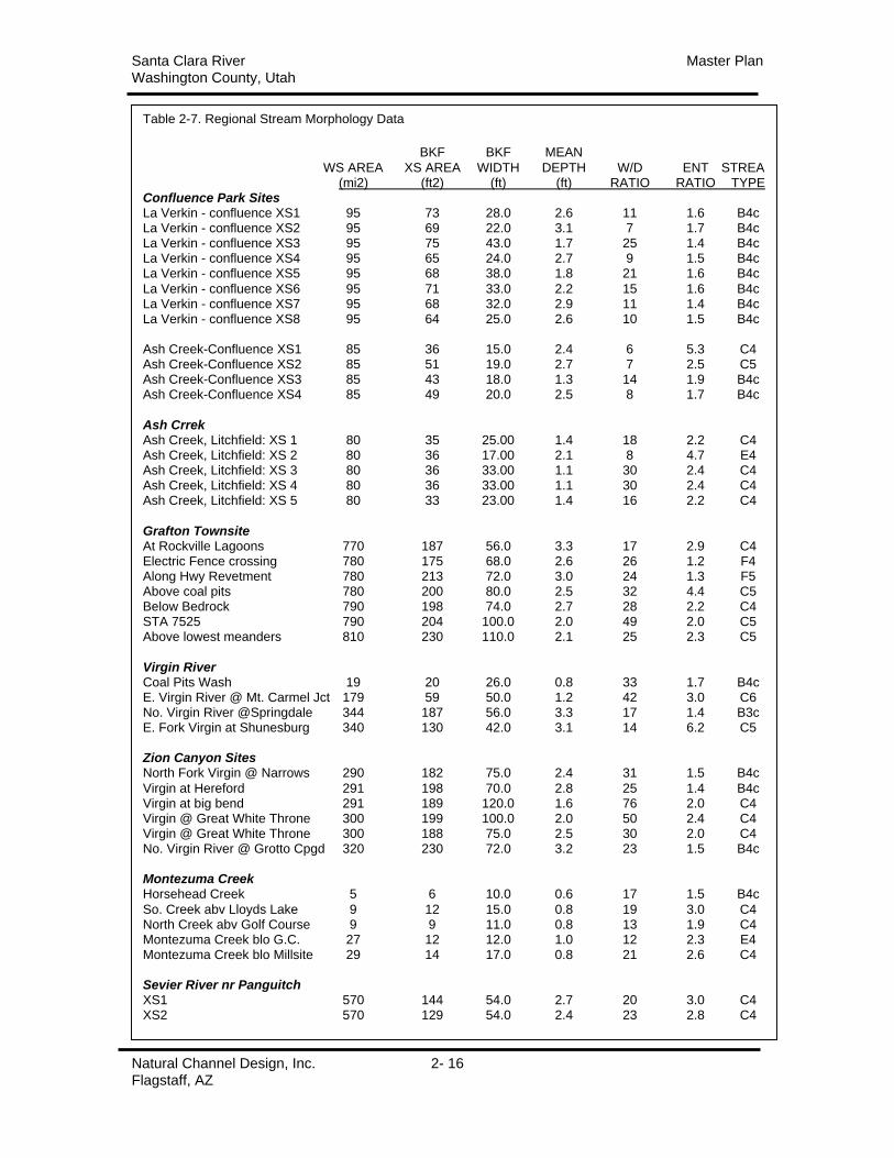
presented in Table 2-8.
In order to characterize stream channel morphology, a common reference point must be
established. This common reference point provides a consistent, accurate measurement of width,
depth and other physical channel, floodplain, and terraces features. The concept of “bankfull
stage” was developed by Luna Leopold and others in the USGS to provide this common point.
Bankfull stage is defined as the point of incipient flooding or geomorphic floodplain elevation.
The geomorphic floodplain is a level area adjacent to the steam, created in the current climate,
and overtopped by moderate, frequent flow events. Research in the southwestern U.S. has
confimed the ability to consitently and accurately identify bankfull stage in the field and suggests
that the feature is commonly overtopped by 1 – 2 year flow events (Moody et al 2003).
The bankfull or active channel below bankfull stage has the primary function of transporting
sediment in the fom of bedload. The floodplain and terrace areas above bankfull elevation carry
high flows and disappate energy. The systematic measurement of natural stream channels using
bankfull stage as a common point has identified a number of useful patterns. One of the strongest
is the strong correlation between cross-sectional area of the bankfull channel and watershed area.
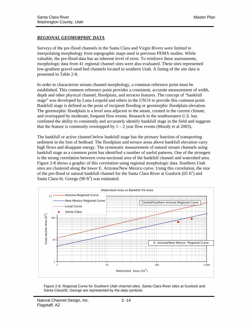
Figure 2-8 shows a graphic of this correlation using regional morphologic data. Southern Utah
sites are clustered along the lower E. Arizona/New Mexico curve. Using this correlation, the size
of the pre-flood or natural bankfull channel for the Santa Clara River at Gunlock (65 ft2) and
Santa Clara-St. George (90 ft2) was estimated.
Watershed Area vs Bankfull XS-Area
1
10
100
1,000
1 10 100 1,000
Watershed Area (mi2)
Cro
ss-s
ecti
on A
rea (
ft2)
Arizona Regional Curve
New Mexico Regional Curve
Local Curve
Santa Clara
Central/Southern Arizona Regional Curve
E. Arizona/New Mexico Regional Curve
Figure 2-8. Regional Curve for Southern Utah channel sites. Santa Clara River sites at Gunlock andSanta Clara/St. George are represented by the data symbols.
Santa Clara River Master PlanWashington County, Utah
Natural Channel Design, Inc. 2- 15Flagstaff, AZ
The Natural Channel Classification System (Rosgen 1996) was developed to incorporate the
concept of bankfull stage and is widely used by stream practitioners throughout the west. This
classification uses several dimensionless morphological parameters to describe the channel and
floodplain. These delineative criteria include:
• Width/Depth Ratio: Defined as the channel width at bankfull stage divided by mean depth at thesame point. This criteria describes the shape of the channel and the associated sediment transportcompetence.
• Entrenchment Ratio: Defined as the width of the floodplain (measured at an elevation twice bankfulldepth) divided by bankfull channel width. The criteria describes the ability of a channel to spreadacross an adjacent floodplain surface.
• Sinuosity: Defined as stream length divided by valley length. This criteria describes the relativedegree of meander.
• Slope: Defined as the fall in elevation divided by the distance of a stream segment.
• Bed/Bank Materials: The median particle (D50) of the bankfull channel.
Santa Clara River is well-vegetated low-gradient, meandering gravel bed stream with a well-
developed floodplain. The stream would be classified as a C4 channel.
The Virgin River is a well-vegeted low-gradient, meandering sand bed stream with a well-
developed floodplain. The stream would be classified as a C5 channel.
All regional channel sites (Table 2-7) are low gradient, gravel/sand streams. The mean values for
Width/Depth Ratio and Entrenchment Ratio are 26.5 and 2.5 respectively for these channels.
Because these values are dimensionless they are not limited by scale.
Santa Clara River Master PlanWashington County, Utah
Natural Channel Design, Inc. 2- 16Flagstaff, AZ
Table 2-7. Regional Stream Morphology Data
BKF BKF MEAN
WS AREA XS AREA WIDTH DEPTH W/D ENT STREA(mi2) (ft2) (ft) (ft) RATIO RATIO TYPE
Confluence Park SitesLa Verkin - confluence XS1 95 73 28.0 2.6 11 1.6 B4cLa Verkin - confluence XS2 95 69 22.0 3.1 7 1.7 B4cLa Verkin - confluence XS3 95 75 43.0 1.7 25 1.4 B4cLa Verkin - confluence XS4 95 65 24.0 2.7 9 1.5 B4cLa Verkin - confluence XS5 95 68 38.0 1.8 21 1.6 B4c
La Verkin - confluence XS6 95 71 33.0 2.2 15 1.6 B4cLa Verkin - confluence XS7 95 68 32.0 2.9 11 1.4 B4cLa Verkin - confluence XS8 95 64 25.0 2.6 10 1.5 B4c
Ash Creek-Confluence XS1 85 36 15.0 2.4 6 5.3 C4Ash Creek-Confluence XS2 85 51 19.0 2.7 7 2.5 C5Ash Creek-Confluence XS3 85 43 18.0 1.3 14 1.9 B4cAsh Creek-Confluence XS4 85 49 20.0 2.5 8 1.7 B4c
Ash CrrekAsh Creek, Litchfield: XS 1 80 35 25.00 1.4 18 2.2 C4Ash Creek, Litchfield: XS 2 80 36 17.00 2.1 8 4.7 E4Ash Creek, Litchfield: XS 3 80 36 33.00 1.1 30 2.4 C4Ash Creek, Litchfield: XS 4 80 36 33.00 1.1 30 2.4 C4Ash Creek, Litchfield: XS 5 80 33 23.00 1.4 16 2.2 C4
Grafton Townsite At Rockville Lagoons 770 187 56.0 3.3 17 2.9 C4Electric Fence crossing 780 175 68.0 2.6 26 1.2 F4Along Hwy Revetment 780 213 72.0 3.0 24 1.3 F5Above coal pits 780 200 80.0 2.5 32 4.4 C5Below Bedrock 790 198 74.0 2.7 28 2.2 C4STA 7525 790 204 100.0 2.0 49 2.0 C5Above lowest meanders 810 230 110.0 2.1 25 2.3 C5
Virgin RiverCoal Pits Wash 19 20 26.0 0.8 33 1.7 B4cE. Virgin River @ Mt. Carmel Jct 179 59 50.0 1.2 42 3.0 C6No. Virgin River @Springdale 344 187 56.0 3.3 17 1.4 B3cE. Fork Virgin at Shunesburg 340 130 42.0 3.1 14 6.2 C5
Zion Canyon SitesNorth Fork Virgin @ Narrows 290 182 75.0 2.4 31 1.5 B4c
Virgin at Hereford 291 198 70.0 2.8 25 1.4 B4cVirgin at big bend 291 189 120.0 1.6 76 2.0 C4Virgin @ Great White Throne 300 199 100.0 2.0 50 2.4 C4Virgin @ Great White Throne 300 188 75.0 2.5 30 2.0 C4No. Virgin River @ Grotto Cpgd 320 230 72.0 3.2 23 1.5 B4c
Montezuma CreekHorsehead Creek 5 6 10.0 0.6 17 1.5 B4c
So. Creek abv Lloyds Lake 9 12 15.0 0.8 19 3.0 C4North Creek abv Golf Course 9 9 11.0 0.8 13 1.9 C4Montezuma Creek blo G.C. 27 12 12.0 1.0 12 2.3 E4Montezuma Creek blo Millsite 29 14 17.0 0.8 21 2.6 C4
Sevier River nr PanguitchXS1 570 144 54.0 2.7 20 3.0 C4XS2 570 129 54.0 2.4 23 2.8 C4
Santa Clara River Master PlanWashington County, Utah
Natural Channel Design, Inc. 2- 17Flagstaff, AZ
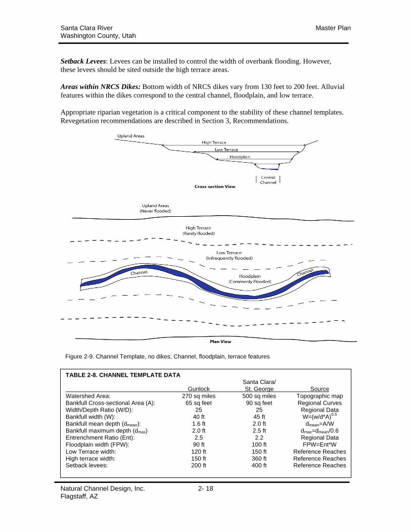
CONCLUSIONSCHANNEL TEMPLATESA set of channel templates were created that describe the widths and depths of alluvial features
for Santa Clara River sections. These templates are based on an evaluation of regional channel
morphology, hydrology, and surveys of stable stream reaches where erosion was minimized
(Table 2-8). The dimensions of channel, floodplain, and terraces are designed to carry the water
and sediment of the stream while minimizing velocities and risk of lateral erosion. These channel
templates are based on the naturally stable forms for each stream and will be maintained by flows
over time as each stream recovers from the January 2005 flooding. They provide the framework
to be used to guide all repair, reconstruction, and maintenance projects.
Cross-section templates are divided into 4 areas: central channel, floodplain, low terrace, and high
terrace (Figure 2-9). All areas are subject to periodic flooding; the higher areas less frequently
than those nearer the channel. The bankfull channels are larger and floodplain-terraces wider in
Santa Clara-St. George to accommodate larger flood events.
Every stream channel has 3 primary functions; carry water and sediment of the watershed and
dissipate energy. To achieve these functions, distinct physical features are constructed by the
stream. These alluvial features are channel, floodplain, and terraces. The width of terraces will be
constrained in areas with NRCS dikes on both banks. Alluvial features should be included within
these armored reaches to maintain sediment transport and stability created by riparian vegetation.
Channel: The stream channel represents the center of the stream. Commonly called active or
bankfull channel, this feature carries base flows and moderate, frequent flood events. The primary
function of the channel is to successfully transport sediment. In adequate size and shape of the
channel can reduce or alter sediment transport and increase instability. In addition the channel
experiences the highest flow velocities and depths and transports the greatest portion of sediment
through the system. The channel bed is generally coarser, composed of more resistant sands,
gravels, or cobbles.
Geomorphic Floodplain: The geomorphic floodplain is defined as a level feature adjacent to the
stream channel, created by the stream and overtopped by moderate, frequent flow events. The
floodplain is flooded annually or every couple of years. Disturbance is naturally high due to the
common flooding and the surface is relatively close to ground water ensuring good soil moisture.
This low feature should not be confused with the 100-year floodplain identified for regulatory
purposes. The channel and floodplain are inundated by common floods and should remain clear
of all human activities.
Low and High Terraces: Terraces are generally old floodplains abandoned when channel
elevations are lowered by erosion. These surfaces can also be created by alluvial bars deposited
during high flow events. Terraces and high bars lie at higher elevations. As a result they are
flooded less often and have lower levels of disturbance and soil moisture.
• Low terraces can be expected to be flooded by moderate floods and can be used for trails
and other infrastructure that can withstand periodic flooding and does not interfere with
riparian vegetation.
• High terraces are flooded by high and extreme floods but can be used for agricultural
and recreational uses. However, appropriate roughness should be maintained.
Santa Clara River Master PlanWashington County, Utah
Natural Channel Design, Inc. 2- 18Flagstaff, AZ
Setback Levees: Levees can be installed to control the width of overbank flooding. However,
these levees should be sited outside the high terrace areas.
Areas within NRCS Dikes: Bottom width of NRCS dikes vary from 130 feet to 200 feet. Alluvial
features within the dikes correspond to the central channel, floodplain, and low terrace.
Appropriate riparian vegetation is a critical component to the stability of these channel templates.
Revegetation recommendations are described in Section 3, Recommendations.
Figure 2-9. Channel Template, no dikes; Channel, floodplain, terrace features
TABLE 2-8. CHANNEL TEMPLATE DATASanta Clara/
Gunlock St. George Source
Watershed Area: 270 sq miles 500 sq miles Topographic mapBankfull Cross-sectional Area (A): 65 sq feet 90 sq feet Regional CurvesWidth/Depth Ratio (W/D): 25 25 Regional DataBankfull width (W): 40 ft 45 ft W=(w/d*A)
0.5
Bankfull mean depth (dmean): 1.6 ft 2.0 ft dmean=A/WBankfull maximum depth (dmax) 2.0 ft 2.5 ft dmax=dmean/0.6Entrenchment Ratio (Ent): 2.5 2.2 Regional DataFloodplain width (FPW): 90 ft 100 ft FPW=Ent*W
Low Terrace width: 120 ft 150 ft Reference ReachesHigh terrace width: 150 ft 360 ft Reference ReachesSetback levees: 200 ft 400 ft Reference Reaches
Santa Clara River Master PlanWashington County, Utah
Natural Channel Design, Inc. 2- 19Flagstaff, AZ
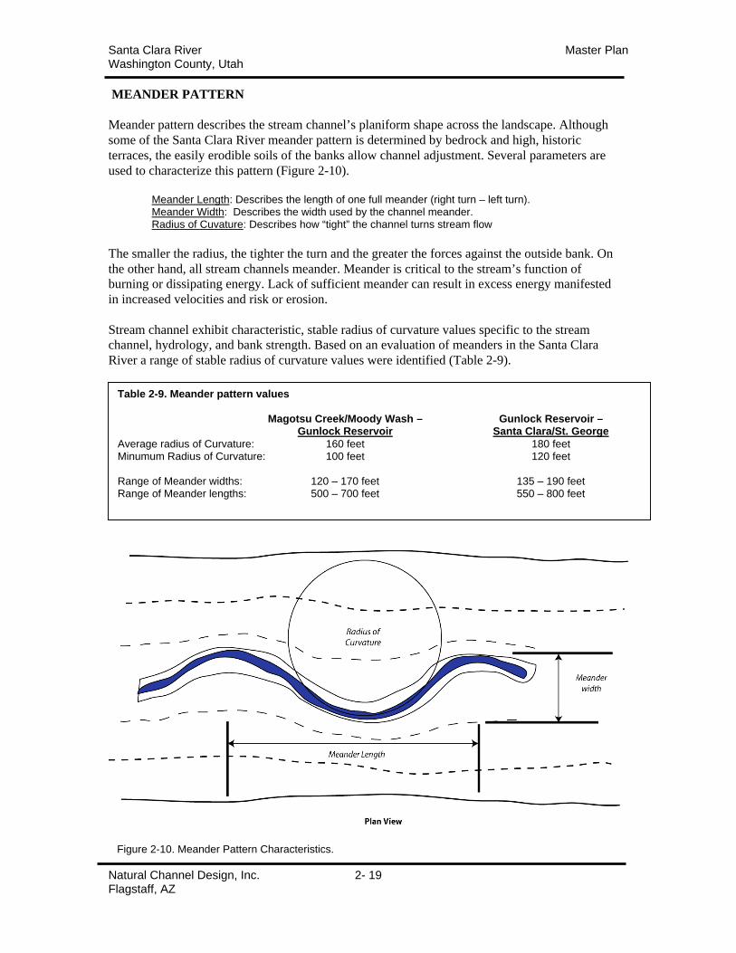
MEANDER PATTERN
Meander pattern describes the stream channel’s planiform shape across the landscape. Although
some of the Santa Clara River meander pattern is determined by bedrock and high, historic
terraces, the easily erodible soils of the banks allow channel adjustment. Several parameters are
used to characterize this pattern (Figure 2-10).
Meander Length: Describes the length of one full meander (right turn – left turn).Meander Width: Describes the width used by the channel meander.Radius of Cuvature: Describes how “tight” the channel turns stream flow
The smaller the radius, the tighter the turn and the greater the forces against the outside bank. On
the other hand, all stream channels meander. Meander is critical to the stream’s function of
burning or dissipating energy. Lack of sufficient meander can result in excess energy manifested
in increased velocities and risk or erosion.
Stream channel exhibit characteristic, stable radius of curvature values specific to the stream
channel, hydrology, and bank strength. Based on an evaluation of meanders in the Santa Clara
River a range of stable radius of curvature values were identified (Table 2-9).
Figure 2-10. Meander Pattern Characteristics.
Table 2-9. Meander pattern values
Magotsu Creek/Moody Wash – Gunlock Reservoir –Gunlock Reservoir Santa Clara/St. George
Average radius of Curvature: 160 feet 180 feetMinumum Radius of Curvature: 100 feet 120 feet
Range of Meander widths: 120 – 170 feet 135 – 190 feetRange of Meander lengths: 500 – 700 feet 550 – 800 feet
Santa Clara River Master PlanWashington County, Utah
Natural Channel Design, Inc. 2- 20Flagstaff, AZ
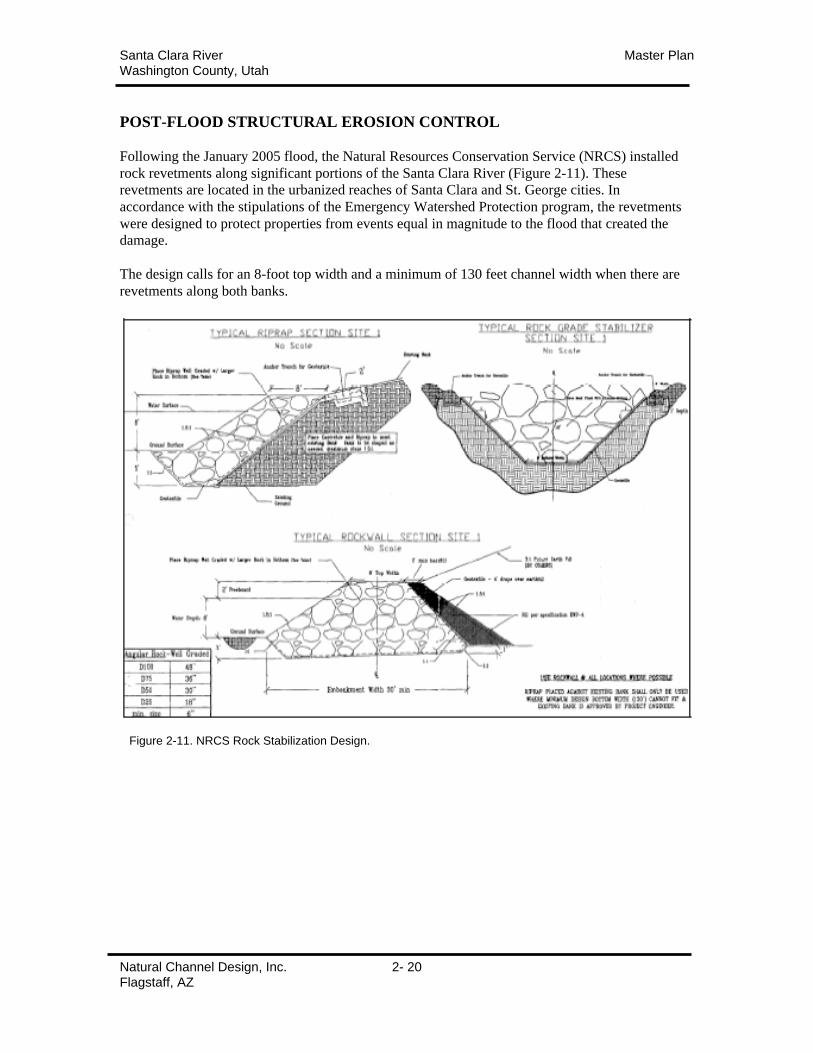
POST-FLOOD STRUCTURAL EROSION CONTROL
Following the January 2005 flood, the Natural Resources Conservation Service (NRCS) installed
rock revetments along significant portions of the Santa Clara River (Figure 2-11). These
revetments are located in the urbanized reaches of Santa Clara and St. George cities. In
accordance with the stipulations of the Emergency Watershed Protection program, the revetments
were designed to protect properties from events equal in magnitude to the flood that created the
damage.
The design calls for an 8-foot top width and a minimum of 130 feet channel width when there are
revetments along both banks.
Figure 2-11. NRCS Rock Stabilization Design.
Santa Clara River Master PlanWashington County, Utah
Natural Channel Design, Inc. 2- 21Flagstaff, AZ
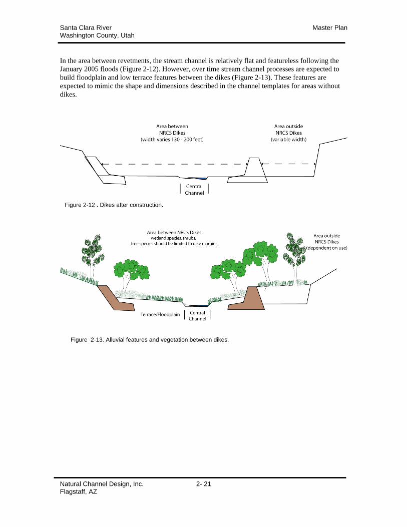
In the area between revetments, the stream channel is relatively flat and featureless following the
January 2005 floods (Figure 2-12). However, over time stream channel processes are expected to
build floodplain and low terrace features between the dikes (Figure 2-13). These features are
expected to mimic the shape and dimensions described in the channel templates for areas without
dikes.
Figure 2-12 . Dikes after construction.
Figure 2-13. Alluvial features and vegetation between dikes.
Santa Clara River Master PlanWashington County, Utah
Natural Channel Design, Inc. 2- 22Flagstaff, AZ
HYDRAULIC ASSESSMENTSStage discharge relationships were modeled for transition (straight) sections of each channel
template using the WinXSPro, a cross-section analyzer developed by the Bureau of Land
Management and USDA Forest Service. Each channel was assumed to have fully developed
alluvial features and riparian vegetation.
Roughness Coefficients
The Central Channel was assumed to have minimum vegetation and moderate roughness as a
function of substrate and bedforms. The Floodplain and Low Terrace were assumed to be densely
vegetated with willow and cottonwood as described in the revegetation strategy section. The High
Terrace was assumed to be partially vegetated with large trees and periodic hedgerows as
described in the revegetation strategies section. Roughness coefficients (Mannings n) are listed in
Table 2-10. These coefficients may be conservative as considerable amounts of vegetation can be
expected to be removed during extreme floods.
AREAS WITH NO NRCS DIKES
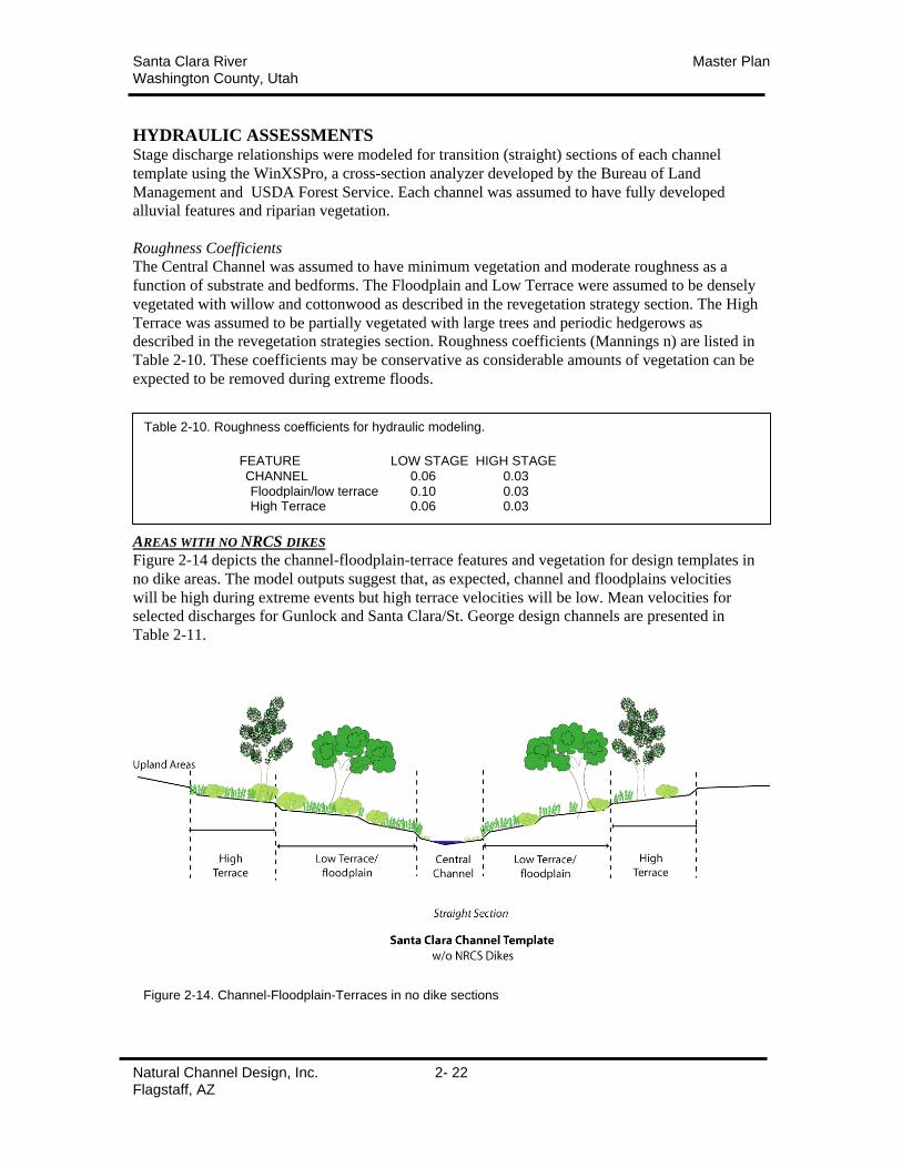
Figure 2-14 depicts the channel-floodplain-terrace features and vegetation for design templates in
no dike areas. The model outputs suggest that, as expected, channel and floodplains velocities
will be high during extreme events but high terrace velocities will be low. Mean velocities for
selected discharges for Gunlock and Santa Clara/St. George design channels are presented in
Table 2-11.
Figure 2-14. Channel-Floodplain-Terraces in no dike sections
Table 2-10. Roughness coefficients for hydraulic modeling.
FEATURE LOW STAGE HIGH STAGECHANNEL 0.06 0.03Floodplain/low terrace 0.10 0.03High Terrace 0.06 0.03
Santa Clara River Master PlanWashington County, Utah
Natural Channel Design, Inc. 2- 23Flagstaff, AZ
AREAS WITH NRCS DIKES
The design height of the dikes is 8 feet. The dikes were designed to contain an 8,500 cfs flow
with 2 feet of freeboard. However, as discussed previously, floodplain/low terrace features and
appropriate riparian vegetation can be expected to naturally form within the dikes. These features
are expected to mimic pre-flood conditions in dimension and extent. Not only would continual
removal of the alluvium and vegetation be very costly but it would reduce channel stability. The
geomorphic floodplain and other alluvial features are essential to adequate sediment transport
over time. Without them, sediment deposition and scour during large floods will be unpredictable.
The lack of vegetation will decrease soil strength and raise water velocities and increase the threat
of scour at the base of the dikes. In additional this sediment/vegetation removal would negatively
impact wildlife habitats and aesthetics without.
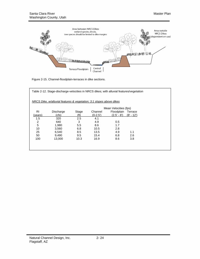
Figure 2-15 depicts the channel-floodplain-terrace that are expected to form between the dikes.
Native vegetation can be planted or will colonize the alluvium. Reconstruction will speed the
natural processes and increase stability. Stages, discharges, and velocities were modeled using the
WinXSPro software for NRCS dike design sections with alluvial forms and vegetation (Table 2-
12).
With the alluvium and vegetation the January 2005 flood flow just overtop the dikes. Upper
banks must be designed to withstand forces during higher flows. All modeling results should be
considered approximate due to the many variables and assumptions inherent in the exercise.
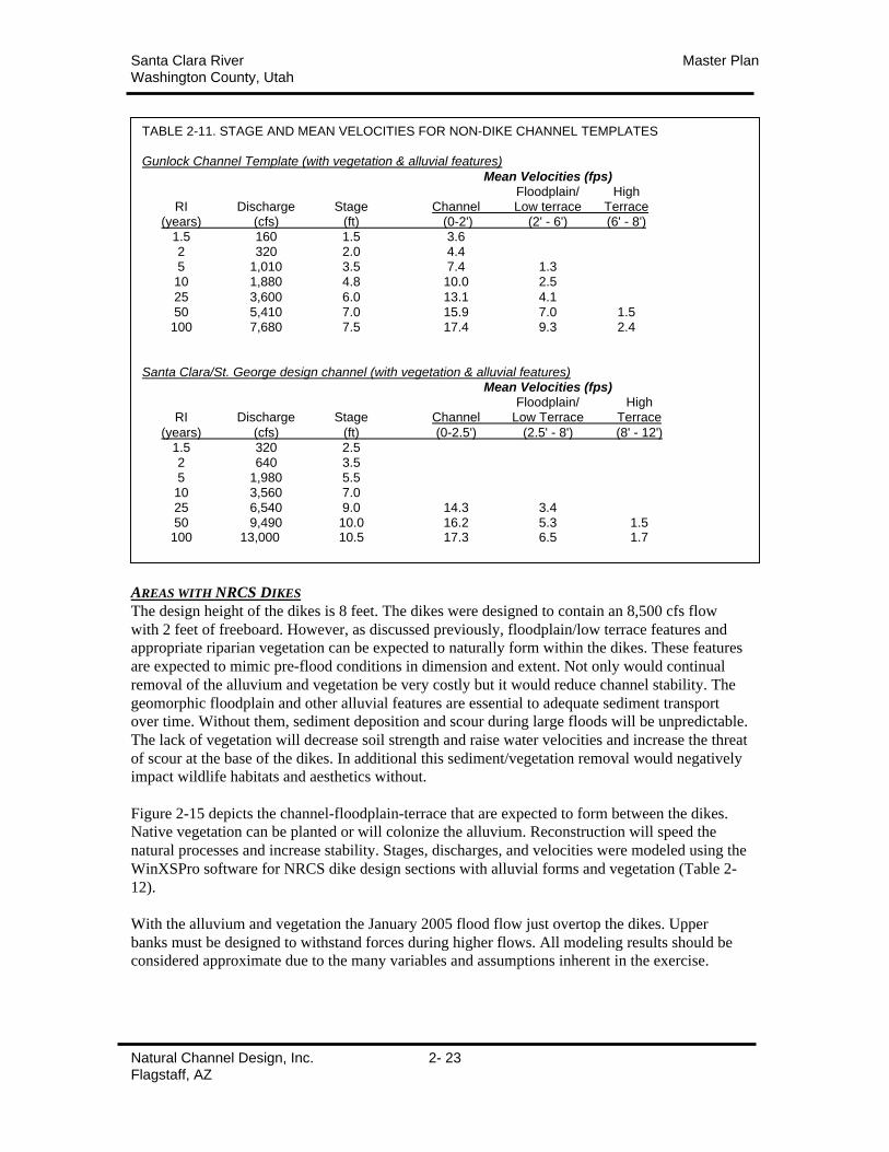
TABLE 2-11. STAGE AND MEAN VELOCITIES FOR NON-DIKE CHANNEL TEMPLATES
Gunlock Channel Template (with vegetation & alluvial features)
Mean Velocities (fps)Floodplain/ High
RI Discharge Stage Channel Low terrace Terrace(years) (cfs) (ft) (0-2') (2' - 6') (6' - 8')
1.5 160 1.5 3.62 320 2.0 4.45 1,010 3.5 7.4 1.310 1,880 4.8 10.0 2.5
25 3,600 6.0 13.1 4.150 5,410 7.0 15.9 7.0 1.5100 7,680 7.5 17.4 9.3 2.4
Santa Clara/St. George design channel (with vegetation & alluvial features)Mean Velocities (fps)
Floodplain/ HighRI Discharge Stage Channel Low Terrace Terrace
(years) (cfs) (ft) (0-2.5') (2.5' - 8') (8' - 12')1.5 320 2.52 640 3.55 1,980 5.510 3,560 7.025 6,540 9.0 14.3 3.450 9,490 10.0 16.2 5.3 1.5100 13,000 10.5 17.3 6.5 1.7
Santa Clara River Master PlanWashington County, Utah
Natural Channel Design, Inc. 2- 24Flagstaff, AZ
Table 2-12. Stage-discharge-velocities in NRCS dikes; with alluvial features/vegetation
NRCS Dike, w/alluvial features & vegetation; 3:1 slopes above dikes
Mean Velocities (fps)RI Discharge Stage Channel Floodplain Terrace
(years) (cfs) (ft) (0-2.5') (2.5' - 8') (8' - 12')1.5 320 2.5 4.12 640 3 4.9 0.55 1,980 5.5 8.6 1.710 3,560 6.8 10.5 2.825 6,540 8.5 13.5 4.9 1.150 9,490 9.5 15.4 6.8 2.6100 13,000 10.3 16.9 8.6 3.8
Figure 2-15. Channel-floodplain-terraces in dike sections.
Santa Clara River Master PlanWashington County, Utah
Natural Channel Design, Inc. 2- 25Flagstaff, AZ
AREAS BEHIND NRCS DIKES
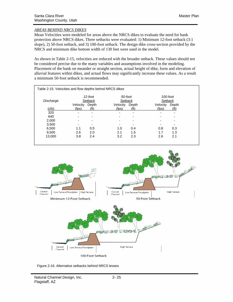
Mean Velocities were modeled for areas above the NRCS dikes to evaluate the need for bank
protection above NRCS dikes. Three setbacks were evaluated: 1) Minimum 12-foot setback (3:1
slope), 2) 50-foot setback, and 3) 100-foot setback. The design dike cross-section provided by the
NRCS and minimum dike bottom width of 130 feet were used in the model.
As shown in Table 2-15, velocities are reduced with the broader setback. These values should not
be considered precise due to the many variables and assumptions involved in the modeling.
Placement of the bank on meander or straight section, actual height of dike, form and elevation of
alluvial features within dikes, and actual flows may significantly increase these values. As a result
a minimum 50-foot setback is recommended.
Figure 2-16. Alternative setbacks behind NRCS levees
Table 2-15. Velocities and flow depths behnd NRCS dikes
12-foot 50-foot 100-foot
Discharge Setback Setback SetbackVelocity Depth Velocity Depth Velocity Depth
(cfs) (fps) (ft) (fps) (ft) (fps) (ft)320 - - - - - -640 - - - - - -
2,000 - - - - - -3,500 - - - - - -6,500 1.1 0.5 1.0 0.4 0.8 0.3
9,500 2.6 2.0 2.1 1.5 1.7 1.313,000 3.8 2.4 3.2 2.3 2.6 2.1

Santa Clara River Master PlanWashington County, Utah
Natural Channel Design, Inc. 2- 26Flagstaff, AZ
Santa Clara River Master PlanWashington County, Utah
Natural Channel Design, Inc. 3- 1Flagstaff, AZ
SECTION 3: RECOMMENDATIONS
SUMMARYGENERAL RECOMMENDATIONS
• Guiding Principles should guide all reconstruction, management, and maintenance of the
Santa Clara River.
o Elevation should rise with distance away from the central channel
o Roughness (resistance to flow) should increase with distance away from the
channel.
o Transitions including meanders and terrace constrictions should be smooth and
gradual.
• Channel alignments should remain in the post-flood alignments unless landowners on
both banks agree to alter it. New alignments should be consistent with the Guiding
Principles and channel/floodplain/terrace templates and constructed accordingly.
• Channel templates should be used for all reconstruction of the stream channel.
• To the extent possible, all parts of the riparian area should be revegetated with native
riparian species consistent with recommendations.
• A long-term maintenance plan should be adopted to remove large woody stems (>2-inch
diameter at breast height or DBH) from the channel and floodplain (approx. 100 feet
width) to reduce the risk of future debris flows.
AREAS BEHIND NRCS DIKES
• Areas behind dikes should be filled to the level of the dike and slope upward to the
existing banks. These areas should be revegetated and managed in accordance with the
Master Plan guidelines.
• Where large areas of erosion (meanders) behind the dikes are not filled, dikes should be
constructed to divide the low area into cells. Culverts should connect the cells to equalize
water levels.
• All structures should have a 50-foot minimum setback from the top of dikes. In areas
where existing houses are nearer, the upper banks should be protected by appropriate
rock armoring.
ADDITIONAL STABILIZATION MEASURES
• Bioengineering
o A variety of cost-effective bioengineering practices are available to stabilize
stream banks.
• Structural
o A variety of cost-effective structural practices are available to further stabilize
stream banks.
EXOTIC SPECIES REMOVAL
• Existing programs to remove tamarisk and other exotic species should continued.
• The best strategy for minimizing the colonization of tamarisk in the flood disturbance
areas is to replant with native riparian species. There is no need for large-scale herbicide
application prior to replanting.
• When thickets are removed (Tonoquint Park), they should be removed in bands parallel
to the stream beginning at the stream margin. Areas should be replanted with native
vegetation. Thickets on the terraces should not be removed unless another method of
roughness can be utilized to slow overbank flows.
Santa Clara River Master PlanWashington County, Utah
Natural Channel Design, Inc. 3- 2Flagstaff, AZ
NATURE OF RIVERS
An alluvial stream channel is a product of watershed processes. Its purpose is to successfully
transport water and sediment originating in the watershed. A stream channel adjusts its size,
slope, and sinuosity to accommodate a range of stream flows and to move sediment through the
system. Generally speaking, a stream is also constantly dissipating energy as it moves
downstream. In a low gradient channel, bars, meanders and a broad floodplain are important
features for dissipating excess energy. If unable to expend this energy the channel is inherently
unstable and prone to lateral and/or vertical erosion, especially during large flow events.
A stream creates a set of physical features (central or bankfull channel, geomorphic floodplain,
low & high terraces) to accomplish the transport of water and sediment. Each feature provides an
essential purpose. The central or bankfull channel transports the majority of sediment load along
the channel bottom. The geomorphic floodplain lies adjacent to the central channel and is
overtopped by moderate, frequent flow events. Low and high terraces are abandoned floodplains
or bars created by infrequent, large flood events. The floodplain and terraces spread high flows
dissipating energy and slowing velocities. The geomorphic floodplain should not be confused
with the regulatory 100-year floodplain. The 100-year floodplain is not an alluvial feature but the
lateral extents inundated during a 100-year flood event. Generally, channel, geomorphic
floodplain, and terraces all lie within the 100–year floodplain.
In the southwest as in other regions, the channel and geomorphic floodplain are created and
maintained by moderate, frequent flood events with return intervals in the range of one to two
years (Moody et al 2003). In many gravel bed streams, this flow has been shown to carry the
greatest amount of sediment over time (Andrews, 1980) and is considered the stream forming
flow, channel maintenance flow or bankfull flow.
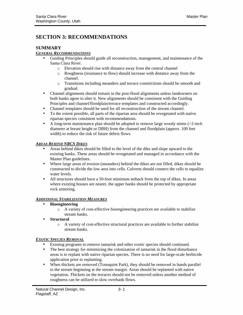
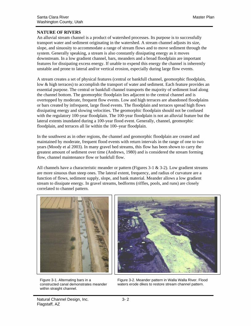
All channels have a characteristic meander or pattern (Figures 3-1 & 3-2). Low gradient streams
are more sinuous than steep ones. The lateral extent, frequency, and radius of curvature are a
function of flows, sediment supply, slope, and bank material. Meander allows a low gradient
stream to dissipate energy. In gravel streams, bedforms (riffles, pools, and runs) are closely
correlated to channel pattern.
Figure 3-1. Alternating bars in aconstructed canal demonstrates meanderwithin straight channel.
Figure 3-2. Meander pattern in Walla Walla River. Floodwaters erode dikes to restore stream channel pattern.
Santa Clara River Master PlanWashington County, Utah
Natural Channel Design, Inc. 3- 3Flagstaff, AZ
The stability of any natural channel is dependent on an appropriate dimension, pattern, and profile
of the bankfull channel and associated floodplain (Leopold, Wolman, & Miller, 1964). The
Master Plan has attempted to identify the stable geomorphic dimensions of the Santa Clara River
and incorporate those into designs to meet specific project objectives. Closely matching the
central tendencies of the natural channel results in a design that works with the existing stream
processes rather than against it reducing erosion and maintenance cost.
EFFECTS OF CHANNEL MODIFICATION
Because a stream channel is dynamic, modifications often create responses in channel function.
Sometimes the responses are inconsistent with the original objectives.
Straightening
Often stream channels are straightened in an effort to increase sediment transport, utilize
additional lands or decrease lateral movement. However, the loss of meander increases stream
power raising the potential for the stream to erode banks in an effort to dissipate energy. In
addition, the stream’s natural tendency to restore its characteristic meander pattern will also
contribute to stream bank erosion. Without armoring, the stream channel will simply return to its
pre-modified condition (Figure 3-2).
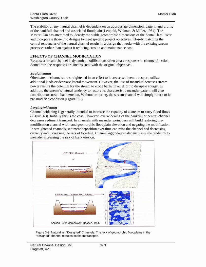
Levying/widening
Channel widening is generally intended to increase the capacity of a stream to carry flood flows
(Figure 3-3). Initially this is the case. However, overwidening of the bankfull or central channel
decreases sediment transport. In channels with meander, point bars will build restoring pre-
modification channel width and geomorphic floodplain elevation and negating the modification.
In straightened channels, sediment deposition over time can raise the channel bed decreasing
capacity and increasing the risk of flooding. Channel aggradation also increases the tendency to
meander increasing the risk of bank erosion.
Figure 3-3. Natural vs. “Designed” Channels. The lack of geomorphic floodplains in the“designed” channel reduces sediment transport.
Applied River Morphology. Rosgen, 1996
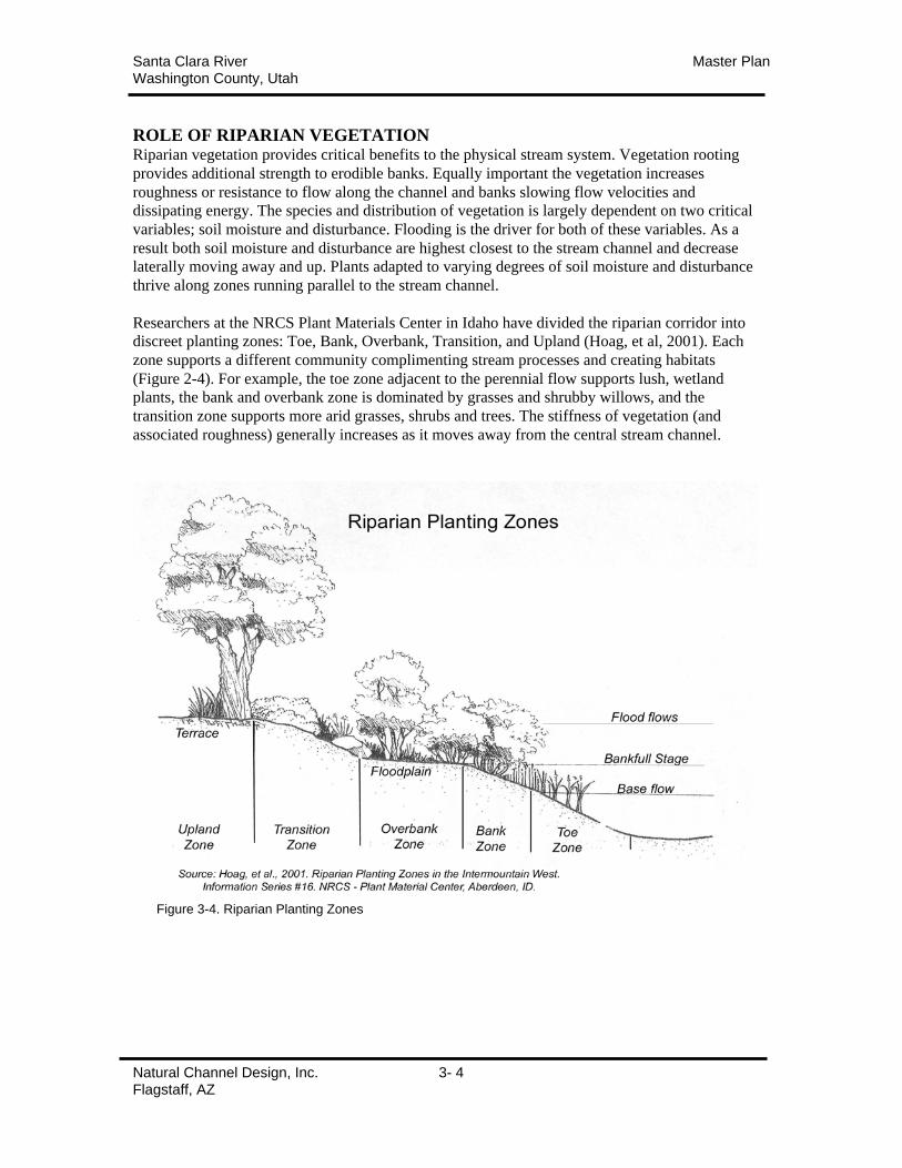
Santa Clara River Master PlanWashington County, Utah
Natural Channel Design, Inc. 3- 4Flagstaff, AZ
ROLE OF RIPARIAN VEGETATIONRiparian vegetation provides critical benefits to the physical stream system. Vegetation rooting
provides additional strength to erodible banks. Equally important the vegetation increases
roughness or resistance to flow along the channel and banks slowing flow velocities and
dissipating energy. The species and distribution of vegetation is largely dependent on two critical
variables; soil moisture and disturbance. Flooding is the driver for both of these variables. As a
result both soil moisture and disturbance are highest closest to the stream channel and decrease
laterally moving away and up. Plants adapted to varying degrees of soil moisture and disturbance
thrive along zones running parallel to the stream channel.
Researchers at the NRCS Plant Materials Center in Idaho have divided the riparian corridor into
discreet planting zones: Toe, Bank, Overbank, Transition, and Upland (Hoag, et al, 2001). Each
zone supports a different community complimenting stream processes and creating habitats
(Figure 2-4). For example, the toe zone adjacent to the perennial flow supports lush, wetland
plants, the bank and overbank zone is dominated by grasses and shrubby willows, and the
transition zone supports more arid grasses, shrubs and trees. The stiffness of vegetation (and
associated roughness) generally increases as it moves away from the central stream channel.
Figure 3-4. Riparian Planting Zones
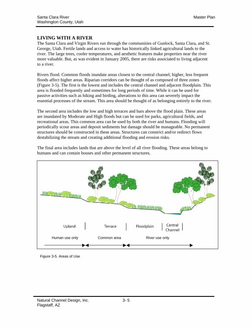
Santa Clara River Master PlanWashington County, Utah
Natural Channel Design, Inc. 3- 5Flagstaff, AZ
LIVING WITH A RIVERThe Santa Clara and Virgin Rivers run through the communities of Gunlock, Santa Clara, and St.
George, Utah. Fertile lands and access to water has historically linked agricultural lands to the
river. The large trees, cooler temperatures, and aesthetic features make properties near the river
more valuable. But, as was evident in January 2005, there are risks associated to living adjacent
to a river.
Rivers flood. Common floods inundate areas closest to the central channel; higher, less frequent
floods affect higher areas. Riparian corridors can be thought of as composed of three zones
(Figure 3-5). The first is the lowest and includes the central channel and adjacent floodplain. This
area is flooded frequently and sometimes for long periods of time. While it can be used for
passive activities such as hiking and birding, alterations to this area can severely impact the
essential processes of the stream. This area should be thought of as belonging entirely to the river.
The second area includes the low and high terraces and bars above the flood plain. These areas
are inundated by Moderate and High floods but can be used for parks, agricultural fields, and
recreational areas. This common area can be used by both the river and humans. Flooding will
periodically scour areas and deposit sediments but damage should be manageable. No permanent
structures should be constructed in these areas. Structures can constrict and/or redirect flows
destabilizing the stream and creating additional flooding and erosion risks.
The final area includes lands that are above the level of all river flooding. These areas belong to
humans and can contain houses and other permanent structures.
Figure 3-5. Areas of Use
Human use only River use onlyCommon area
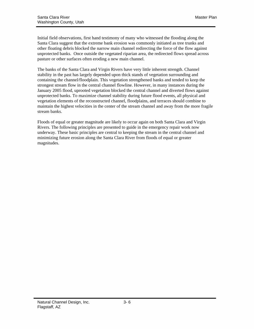
Santa Clara River Master PlanWashington County, Utah
Natural Channel Design, Inc. 3- 6Flagstaff, AZ
Initial field observations, first hand testimony of many who witnessed the flooding along the
Santa Clara suggest that the extreme bank erosion was commonly initiated as tree trunks and
other floating debris blocked the narrow main channel redirecting the force of the flow against
unprotected banks. Once outside the vegetated riparian area, the redirected flows spread across
pasture or other surfaces often eroding a new main channel.
The banks of the Santa Clara and Virgin Rivers have very little inherent strength. Channel
stability in the past has largely depended upon thick stands of vegetation surrounding and
containing the channel/floodplain. This vegetation strengthened banks and tended to keep the
strongest stream flow in the central channel flowline. However, in many instances during the
January 2005 flood, uprooted vegetation blocked the central channel and diverted flows against
unprotected banks. To maximize channel stability during future flood events, all physical and
vegetation elements of the reconstructed channel, floodplains, and terraces should combine to
maintain the highest velocities in the center of the stream channel and away from the more fragile
stream banks.
Floods of equal or greater magnitude are likely to occur again on both Santa Clara and Virgin
Rivers. The following principles are presented to guide in the emergency repair work now
underway. These basic principles are central to keeping the stream in the central channel and
minimizing future erosion along the Santa Clara River from floods of equal or greater
magnitudes.
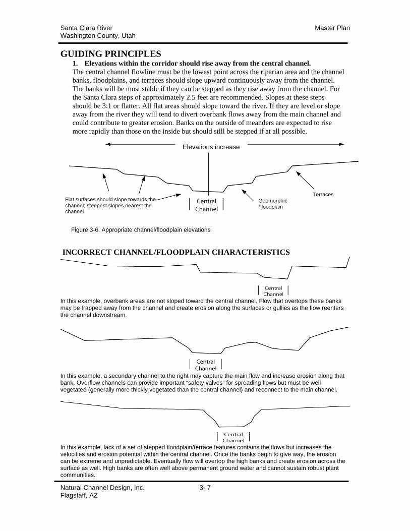
Santa Clara River Master PlanWashington County, Utah
Natural Channel Design, Inc. 3- 7Flagstaff, AZ
GUIDING PRINCIPLES1. Elevations within the corridor should rise away from the central channel.
The central channel flowline must be the lowest point across the riparian area and the channel
banks, floodplains, and terraces should slope upward continuously away from the channel.
The banks will be most stable if they can be stepped as they rise away from the channel. For
the Santa Clara steps of approximately 2.5 feet are recommended. Slopes at these steps
should be 3:1 or flatter. All flat areas should slope toward the river. If they are level or slope
away from the river they will tend to divert overbank flows away from the main channel and
could contribute to greater erosion. Banks on the outside of meanders are expected to rise
more rapidly than those on the inside but should still be stepped if at all possible.
INCORRECT CHANNEL/FLOODPLAIN CHARACTERISTICS
In this example, overbank areas are not sloped toward the central channel. Flow that overtops these banksmay be trapped away from the channel and create erosion along the surfaces or gullies as the flow reenters
the channel downstream.
In this example, a secondary channel to the right may capture the main flow and increase erosion along thatbank. Overflow channels can provide important “safety valves” for spreading flows but must be wellvegetated (generally more thickly vegetated than the central channel) and reconnect to the main channel.
In this example, lack of a set of stepped floodplain/terrace features contains the flows but increases thevelocities and erosion potential within the central channel. Once the banks begin to give way, the erosioncan be extreme and unpredictable. Eventually flow will overtop the high banks and create erosion across thesurface as well. High banks are often well above permanent ground water and cannot sustain robust plantcommunities.
Flat surfaces should slope towards thechannel; steepest slopes nearest thechannel
GeomorphicFloodplain
Terraces
Elevations increase
Figure 3-6. Appropriate channel/floodplain elevations
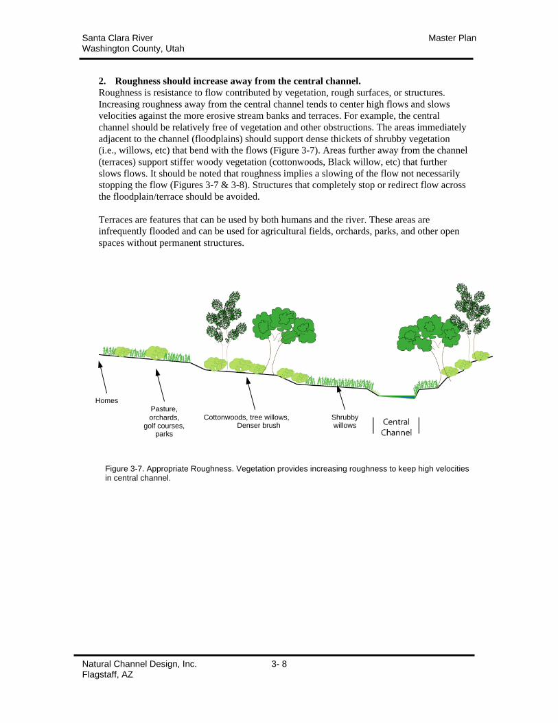
Santa Clara River Master PlanWashington County, Utah
Natural Channel Design, Inc. 3- 8Flagstaff, AZ
2. Roughness should increase away from the central channel.
Roughness is resistance to flow contributed by vegetation, rough surfaces, or structures.
Increasing roughness away from the central channel tends to center high flows and slows
velocities against the more erosive stream banks and terraces. For example, the central
channel should be relatively free of vegetation and other obstructions. The areas immediately
adjacent to the channel (floodplains) should support dense thickets of shrubby vegetation
(i.e., willows, etc) that bend with the flows (Figure 3-7). Areas further away from the channel
(terraces) support stiffer woody vegetation (cottonwoods, Black willow, etc) that further
slows flows. It should be noted that roughness implies a slowing of the flow not necessarily
stopping the flow (Figures 3-7 & 3-8). Structures that completely stop or redirect flow across
the floodplain/terrace should be avoided.
Terraces are features that can be used by both humans and the river. These areas are
infrequently flooded and can be used for agricultural fields, orchards, parks, and other open
spaces without permanent structures.
Shrubbywillows
Cottonwoods, tree willows,Denser brush
Pasture,
orchards,golf courses,
parks
Homes
Figure 3-7. Appropriate Roughness. Vegetation provides increasing roughness to keep high velocitiesin central channel.

Santa Clara River Master PlanWashington County, Utah
Natural Channel Design, Inc. 3- 9Flagstaff, AZ
Figure 3-8. Incorrect Roughness. Dense stiff vegetation chokes channel. Smooth surface of pasturecreates high velocities and erosion.
Pasture or park
Figure 3-9. Terrace vegetation. Terrace areas used for pastures, orchards, parks or other areas withshort, smooth surfaces increase erosional flow velocities. Vegetative buffers or hedgerows should beestablished to slow flows and redirect toward the river (top of figure).
Narrow, dense thickets of vegetation and/or levees parallel to the river should be avoided. Thesefeatures trap erosional flows and inhibit return to the river (bottom of figure).
CORRECT TERRACE PLANTINGS
INCORRECT TERRACE PLANTINGS
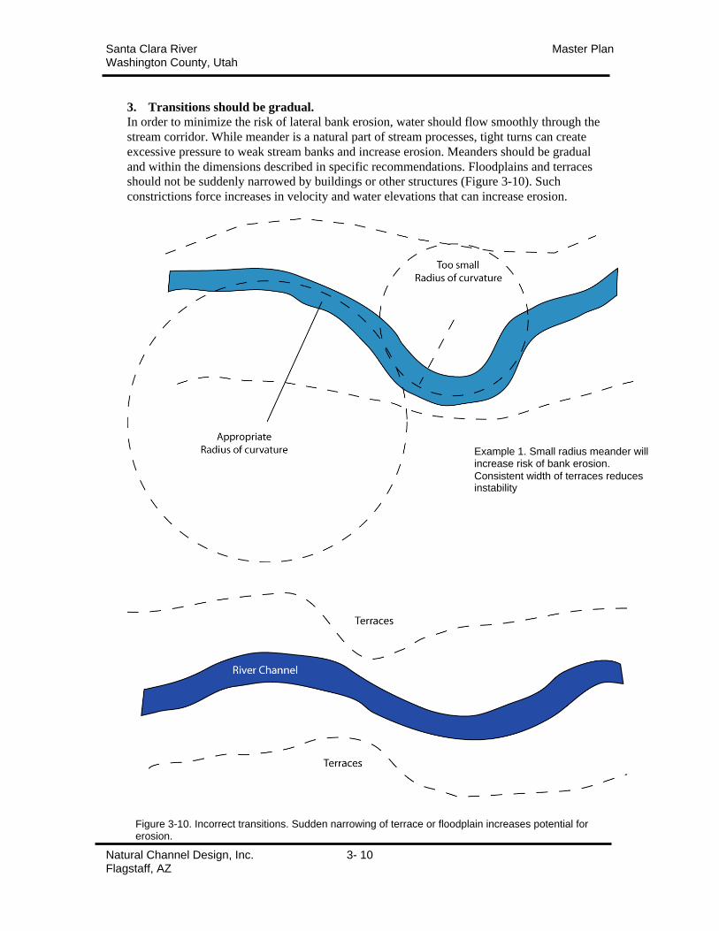
Santa Clara River Master PlanWashington County, Utah
Natural Channel Design, Inc. 3- 10Flagstaff, AZ
3. Transitions should be gradual.
In order to minimize the risk of lateral bank erosion, water should flow smoothly through the
stream corridor. While meander is a natural part of stream processes, tight turns can create
excessive pressure to weak stream banks and increase erosion. Meanders should be gradual
and within the dimensions described in specific recommendations. Floodplains and terraces
should not be suddenly narrowed by buildings or other structures (Figure 3-10). Such
constrictions force increases in velocity and water elevations that can increase erosion.
Example 1. Small radius meander willincrease risk of bank erosion.
Consistent width of terraces reducesinstability
Figure 3-10. Incorrect transitions. Sudden narrowing of terrace or floodplain increases potential forerosion.
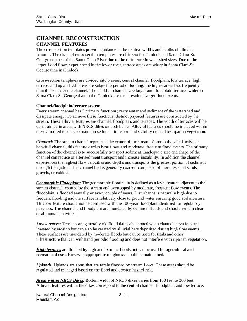
Santa Clara River Master PlanWashington County, Utah
Natural Channel Design, Inc. 3- 11Flagstaff, AZ
CHANNEL RECONSTRUCTIONCHANNEL FEATURESThe cross-section templates provide guidance in the relative widths and depths of alluvial
features. The channel cross-section templates are different for Gunlock and Santa Clara-St.
George reaches of the Santa Clara River due to the difference in watershed sizes. Due to the
larger flood flows experienced in the lower river, terrace areas are wider in Santa Clara-St.
George than in Gunlock.
Cross-section templates are divided into 5 areas: central channel, floodplain, low terrace, high
terrace, and upland. All areas are subject to periodic flooding; the higher areas less frequently
than those nearer the channel. The bankfull channels are larger and floodplain-terraces wider in
Santa Clara-St. George than in the Gunlock area as a result of larger flood events.
Channel/floodplain/terrace system
Every stream channel has 3 primary functions; carry water and sediment of the watershed and
dissipate energy. To achieve these functions, distinct physical features are constructed by the
stream. These alluvial features are channel, floodplain, and terraces. The width of terraces will be
constrainted in areas with NRCS dikes on both banks. Alluvial features should be included within
these armored reaches to maintain sediment transport and stability created by riparian vegetation.
Channel: The stream channel represents the center of the stream. Commonly called active or
bankfull channel, this feature carries base flows and moderate, frequent flood events. The primary
function of the channel is to successfully transport sediment. Inadequate size and shape of the
channel can reduce or alter sediment transport and increase instability. In addition the channel
experiences the highest flow velocities and depths and transports the greatest portion of sediment
through the system. The channel bed is generally coarser, composed of more resistant sands,
gravels, or cobbles.
Geomorphic Floodplain: The geomorphic floodplain is defined as a level feature adjacent to the
stream channel, created by the stream and overtopped by moderate, frequent flow events. The
floodplain is flooded annually or every couple of years. Disturbance is naturally high due to
frequent flooding and the surface is relatively close to ground water ensuring good soil moisture.
This low feature should not be confused with the 100-year floodplain identified for regulatory
purposes. The channel and floodplain are inundated by common floods and should remain clear
of all human activities.
Low terraces: Terraces are generally old floodplains abandoned when channel elevations are
lowered by erosion but can also be created by alluvial bars deposited during high flow events.
These surfaces are inundated by moderate floods but can be used for trails and other
infrastructure that can withstand periodic flooding and does not interfere with riparian vegetation.
High terraces are flooded by high and extreme floods but can be used for agricultural and
recreational uses. However, appropriate roughness should be maintained.
Uplands: Uplands are areas that are rarely flooded by stream flows. These areas should be
regulated and managed based on the flood and erosion hazard risk.
Areas within NRCS Dikes: Bottom width of NRCS dikes varies from 130 feet to 200 feet.
Alluvial features within the dikes correspond to the central channel, floodplain, and low terrace.
Santa Clara River Master PlanWashington County, Utah
Natural Channel Design, Inc. 3- 12Flagstaff, AZ
CHANNEL ALIGNMENTGenerally, it is recommended that post-flood channel alignments be maintained in their post-
flood location (see maps in Section 4). The post-flood alignments follow the lowest point in the
stream corridor. Substantial shifts in alignment will entail large volumes of earthmoving and
revegetation. However, in many places the river has eroded significant private property. In these
cases the existing alignment may differ significantly from the pre-flood channel. In cases where
adjacent property owners agree to realign the stream channel, realignment should incorporate the
qualitative and quantitative principles described in this plan. Regardless of the alignment,
appropriate channel/floodplain/terrace dimension and meander as described in the Master Plan is
essential to long-term channel stability.
APPROPRIATE LAND USESHuman uses vary on these alluvial surfaces depending on the risk of flooding. The following are
recommended uses for each.
Channel
Pedestrian use primarily. These areas can also be utilized by livestock. However, management is
required to ensure that the integrity of the riparian plant community is not impacted.
Geomorphic Floodplain
Pedestrian use primarily. These areas can also be utilized by livestock. However, management is
required to ensure that the integrity of the riparian plant community is not impacted.
Low Terrace
Agricultural fields that can be flooded periodically. Constructed pedestrian/bike trails & bridges,
recreation areas (parks, golf courses) without habitable infrastructure. Human uses should be
carefully integrated with the vegetation to maintain resistance to flow (roughness) as described in
the guiding principles.
High Terrace
Agricultural fields, constructed pedestrian/bike trails, recreation areas (parks, golf courses) with
some hard infrastructure such as picnic tables, shades, playground equipment. Human uses should
be carefully integrated with the vegetation to maintain resistance to flow (roughness) as described
in the guiding principles.
Uplands:
Uplands are areas that are rarely flooded by stream flows. These areas should be regulated and
managed based on the flood and erosion risk.
Areas within NRCS Dikes:
Use should be limited to pedestrian/bike/golf trails and associated bridges within the dikes. Rock
riprap or other structural revetments may be installed when necessary to protect trails, bridges and
other infrastructure. Trail bridges should be designed to “break away” during flow events and
should not constrict flow area by more than 10% or deflect flows against dikes. Human uses
should be carefully integrated with the vegetation to maintain resistance to flow (roughness) as
described in the guiding principles.
Areas behind NRCS Dikes:
These areas should be treated as High or Low Terraces depending on the elevation of the land and
its risk of flooding.
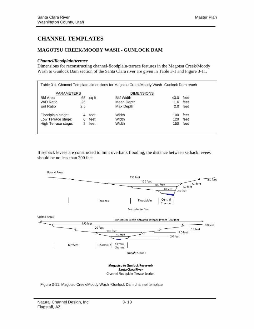
Santa Clara River Master PlanWashington County, Utah
Natural Channel Design, Inc. 3- 13Flagstaff, AZ
CHANNEL TEMPLATES
MAGOTSU CREEK/MOODY WASH - GUNLOCK DAM
Channel/floodplain/terrace
Dimensions for reconstructing channel-floodplain-terrace features in the Magotsu Creek/Moody
Wash to Gunlock Dam section of the Santa Clara river are given in Table 3-1 and Figure 3-11.
If setback levees are constructed to limit overbank flooding, the distance between setback levees
should be no less than 200 feet.
Table 3-1. Channel Template dimensions for Magotsu Creek/Moody Wash -Gunlock Dam reach
PARAMETERS DIMENSIONSBkf Area 65 sq ft Bkf Width 40.0 feetW/D Ratio 25 Mean Depth 1.6 feet
Ent Ratio 2.5 Max Depth 2.0 feet
Floodplain stage: 4 feet Width 100 feetLow Terrace stage: 6 feet Width 120 feetHigh Terrace stage: 8 feet Width 150 feet
Figure 3-11. Magotsu Creek/Moody Wash -Gunlock Dam channel template
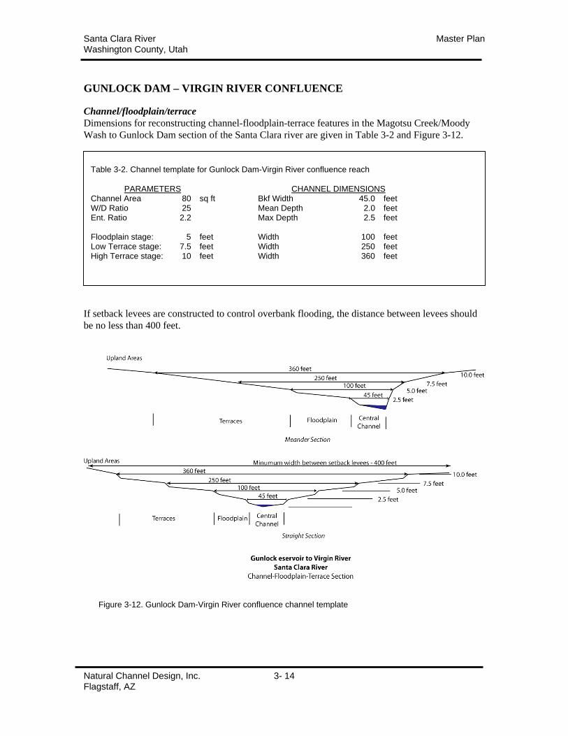
Santa Clara River Master PlanWashington County, Utah
Natural Channel Design, Inc. 3- 14Flagstaff, AZ
GUNLOCK DAM – VIRGIN RIVER CONFLUENCE
Channel/floodplain/terrace
Dimensions for reconstructing channel-floodplain-terrace features in the Magotsu Creek/Moody
Wash to Gunlock Dam section of the Santa Clara river are given in Table 3-2 and Figure 3-12.
If setback levees are constructed to control overbank flooding, the distance between levees should
be no less than 400 feet.
Table 3-2. Channel template for Gunlock Dam-Virgin River confluence reach
PARAMETERS CHANNEL DIMENSIONSChannel Area 80 sq ft Bkf Width 45.0 feetW/D Ratio 25 Mean Depth 2.0 feetEnt. Ratio 2.2 Max Depth 2.5 feet
Floodplain stage: 5 feet Width 100 feetLow Terrace stage: 7.5 feet Width 250 feetHigh Terrace stage: 10 feet Width 360 feet
Figure 3-12. Gunlock Dam-Virgin River confluence channel template
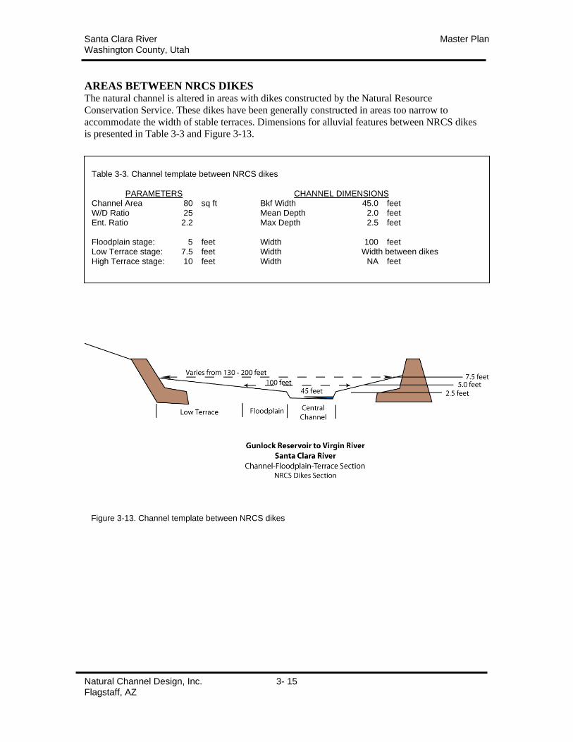
Santa Clara River Master PlanWashington County, Utah
Natural Channel Design, Inc. 3- 15Flagstaff, AZ
AREAS BETWEEN NRCS DIKESThe natural channel is altered in areas with dikes constructed by the Natural Resource
Conservation Service. These dikes have been generally constructed in areas too narrow to
accommodate the width of stable terraces. Dimensions for alluvial features between NRCS dikes
is presented in Table 3-3 and Figure 3-13.
Table 3-3. Channel template between NRCS dikes
PARAMETERS CHANNEL DIMENSIONSChannel Area 80 sq ft Bkf Width 45.0 feetW/D Ratio 25 Mean Depth 2.0 feetEnt. Ratio 2.2 Max Depth 2.5 feet
Floodplain stage: 5 feet Width 100 feetLow Terrace stage: 7.5 feet Width Width between dikesHigh Terrace stage: 10 feet Width NA feet
Figure 3-13. Channel template between NRCS dikes

Santa Clara River Master PlanWashington County, Utah
Natural Channel Design, Inc. 3- 16Flagstaff, AZ
AREAS BEHIND NRCS DIKES
NARROW AREASAreas behind NRCS dikes should be filled and revegetated whenever possible to minimize the
risk of erosion. Based on the velocities and depth information generated from the hydraulic
modeling, it is recommended that all structure and infrastructure be setback a minimum of 50 feet
from the top of the NRCS dikes. The areas should be stabilized using strategies described in the
Master Plan. Setback areas can be sloped or stepped up in one or more low terraces.
In areas where the minimum setback is not available, rock should be used to provide additional
erosion protection to banks.
Figure 3-14. Setbacks in areas outside NRCS dikes
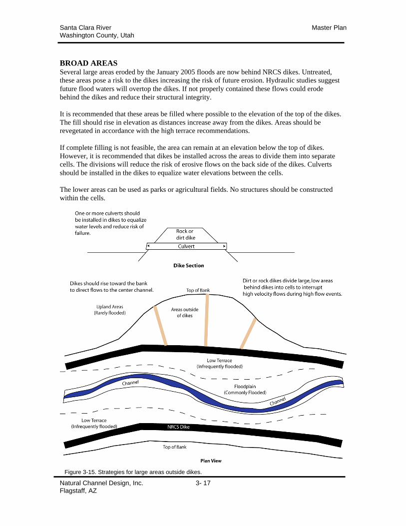
Santa Clara River Master PlanWashington County, Utah
Natural Channel Design, Inc. 3- 17Flagstaff, AZ
BROAD AREASSeveral large areas eroded by the January 2005 floods are now behind NRCS dikes. Untreated,
these areas pose a risk to the dikes increasing the risk of future erosion. Hydraulic studies suggest
future flood waters will overtop the dikes. If not properly contained these flows could erode
behind the dikes and reduce their structural integrity.
It is recommended that these areas be filled where possible to the elevation of the top of the dikes.
The fill should rise in elevation as distances increase away from the dikes. Areas should be
revegetated in accordance with the high terrace recommendations.
If complete filling is not feasible, the area can remain at an elevation below the top of dikes.
However, it is recommended that dikes be installed across the areas to divide them into separate
cells. The divisions will reduce the risk of erosive flows on the back side of the dikes. Culverts
should be installed in the dikes to equalize water elevations between the cells.
The lower areas can be used as parks or agricultural fields. No structures should be constructed
within the cells.
Figure 3-15. Strategies for large areas outside dikes.
Santa Clara River Master PlanWashington County, Utah
Natural Channel Design, Inc. 3- 18Flagstaff, AZ
REVEGETATION –
GENERAL STRATEGIESRiparian vegetation is a critical component in the channel stability and the reduction of bank
erosion on the Santa Clara River. As described earlier, riparian plants combine with the physical
features of the channel/floodplain/terrace to slow flows, reduce hydraulic forces, and stabilize
bank materials. Plant species have specific characteristics specially adapted to provide stability.
Because of this, specific plant communities are located. Dense, tough roots of rush and sedge
species strengthen the soil. Supple woody species of willow and baccharis bend with the flows to
slow velocities as well as stabilize soils. Rigid trees and shrubs further slow flows. Plant
communities must be located in zones with appropriate soil moisture and disturbance.
Plant community characteristics should follow the guiding principle that roughness or resistance
to flow should increase moving away from the channel itself. This principle encourages the
highest velocities remain in the central channel rather than the more erodible banks. The
following describes the plant types for each of the alluvial features described in the preceding
section.
Channel (Toe/Bank Zones): Well rooted herbaceous plants, emergent wetland species,
supple, shrubby woody species. Periodic removal of woody tree species may be
necessary to reduce resistance to flow (roughness) in the floodplain.
Floodplain (Lower Overbank Zone): Supple woody species. Periodic removal of woody
tree species may be necessary to reduce resistance to flow (roughness) in the floodplain.
Low Terrace (Upper Overbank Zone): Supple, shrubby woody species as well as willow,
ash, cottonwood, box elder tree species. Vegetation composition should be carefully
integrated with human uses to maintain resistance to flow (roughness) as described in the
guiding principles.
High Terrace (Transition Zone): High terraces can support a wide variety of native and
cultivated vegetation depending on the use. However, if the vegetation cover is relatively
low resistance to flow, revegetation guidelines including the installation and maintenance
of hedgerows or low berms aligned at right angles or angled downstream to the stream
flow to provide increased resistance to flow across these surfaces. Levees or hedgerows
should never be placed parallel to stream flow. Bare ground should be avoided.
Hedgerows: In the high terrace and upland areas riparian vegetation is naturally more
sparse due to greater distances from ground water. In addition many of these areas will be
utilized for non-structural human uses. Agricultural fields, orchards, pastures, parks, and
golf courses are generally composed of vegetation with low flow resistance (roughness).
In order to slow overland flows and divert them back to the river, a series of hedgerows
should be installed perpendicular to stream flow. These hedgerows can consist of dense
hedges of stiff, shrubby plant species (native species, ornamental species, grape arbors).
Hedges should be dense or planted in multiple rows. Hedgerow features can also be
created by constructing low berms (1-2 feet) of rock or compacted soil. Soil berms should
be planted to stabilize soils. (See structural stabilization: Terraces)
UPLAND AREAS: It is recommended that upland areas be vegetated consistent with
high terrace recommendations.
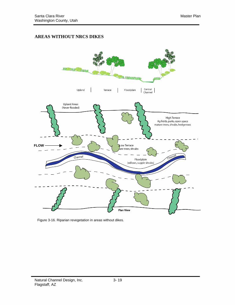
Santa Clara River Master PlanWashington County, Utah
Natural Channel Design, Inc. 3- 19Flagstaff, AZ
AREAS WITHOUT NRCS DIKES
Figure 3-16. Riparian revegetation in areas without dikes.
FLOW
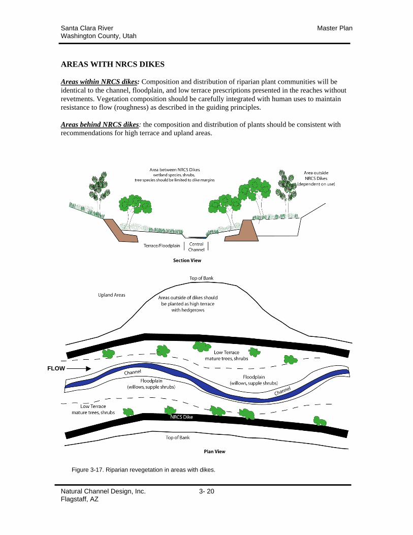
Santa Clara River Master PlanWashington County, Utah
Natural Channel Design, Inc. 3- 20Flagstaff, AZ
AREAS WITH NRCS DIKES
Areas within NRCS dikes: Composition and distribution of riparian plant communities will be
identical to the channel, floodplain, and low terrace prescriptions presented in the reaches without
revetments. Vegetation composition should be carefully integrated with human uses to maintain
resistance to flow (roughness) as described in the guiding principles.
Areas behind NRCS dikes: the composition and distribution of plants should be consistent with
recommendations for high terrace and upland areas.
Figure 3-17. Riparian revegetation in areas with dikes.
FLOW
Santa Clara River Master PlanWashington County, Utah
Natural Channel Design, Inc. 3- 21Flagstaff, AZ
PLANTING RECOMMENDATIONSAppropriate composition, distribution, and density of riparian vegetation will be essential to
maximizing stream stability and minimizing erosion risk. Specific plant communities should be
established or maintained on alluvial features as described below.
(The following recommendations are adapted from NRCS-Plant Materials Center field report,
Hoag & Ogle.)
CHANNEL AREA
(Toe and Bank zone)
These zones experience high soil moisture conditions and high stream scour. Plants must have
well developed root systems and be able to tolerate a wide range of soil moistures.
creeping spikerush (Eleocharis palustris)
sedge species – Not many here, most common would probably be porcupine sedge (C.
hystercina)
Baltic rush (Juncus balticus)
Coyote willow (Salix exigua), mule’s fat (Baccharis viminea) and seep willow (Baccharis
salicifolia) can be planted or naturally come in at the top of the bank because they have very
flexible stems so when water hits them in a flood situation, they will lay down, allow the water to
continue down the channel with some reduced erosive potential, and once the water is gone they
come right back up to full height.
knotgrass (Paspalum distichum) (sometimes called vine mesquite but is not a vine but really a
native grass). Knotgrass can tolerate high salinity and a waterlogged environment. It has no
tolerance of shade. It sometimes can be troublesome by blocking irrigation ditches. Knotgrass
reproduces from rhizomes, stolons, and seeds. It can be easily established by sowing stolons in
damp holes. If planted in water, knotgrass will remain green throughout the year.
In backwater wetland areas where high flood water could spread, consider planting herbaceous
plugs of creeping spikerush (Eleocharis palustris), hardstem bulrush (Scirpus acutus), and
threesquare bulrush (Scirpus pungens).
Planting herbaceous plugs is expensive. However, natural regeneration is going to be much
slower, weedy species will find suitable places to quickly invade, and the specific species that are
hoped for may not naturally show up for a number of years. An alternative to planting the entire
area would be to plant patches that are more or less perpendicular to the streamflow. Seed areas
in between the patches (caution: seeding wetland plants has limited establishment success).
Cottonwoods or large shrub species such as Gooding willow or saltcedar should not be allowed in
this area. Woody species such as coyote willow that have flexible stems and good root systems
are the most desirable in this zone. As the larger species get established in this zone, consider
removing them as they get to 2-3 inches in diameter or larger.
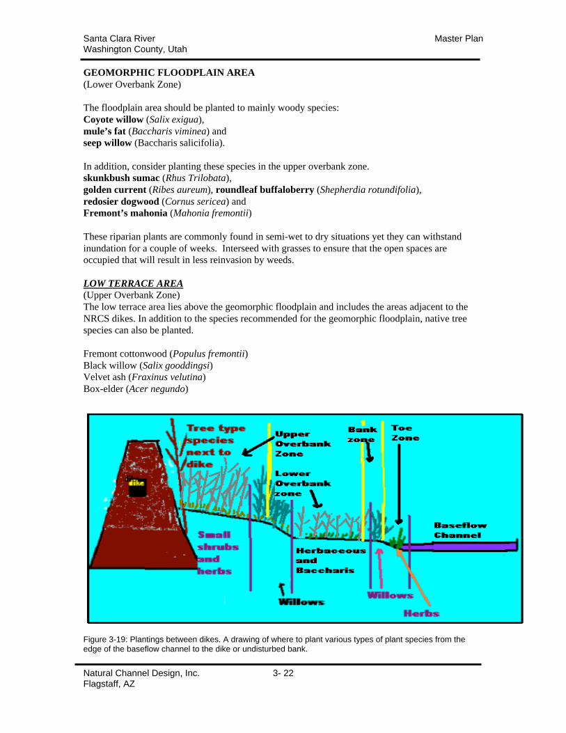
Santa Clara River Master PlanWashington County, Utah
Natural Channel Design, Inc. 3- 22Flagstaff, AZ
GEOMORPHIC FLOODPLAIN AREA
(Lower Overbank Zone)
The floodplain area should be planted to mainly woody species:
Coyote willow (Salix exigua),
mule’s fat (Baccharis viminea) and
seep willow (Baccharis salicifolia).
In addition, consider planting these species in the upper overbank zone.
skunkbush sumac (Rhus Trilobata),
golden current (Ribes aureum), roundleaf buffaloberry (Shepherdia rotundifolia),
redosier dogwood (Cornus sericea) and
Fremont’s mahonia (Mahonia fremontii)
These riparian plants are commonly found in semi-wet to dry situations yet they can withstand
inundation for a couple of weeks. Interseed with grasses to ensure that the open spaces are
occupied that will result in less reinvasion by weeds.
LOW TERRACE AREA
(Upper Overbank Zone)
The low terrace area lies above the geomorphic floodplain and includes the areas adjacent to the
NRCS dikes. In addition to the species recommended for the geomorphic floodplain, native tree
species can also be planted.
Fremont cottonwood (Populus fremontii)
Black willow (Salix gooddingsi)
Velvet ash (Fraxinus velutina)
Box-elder (Acer negundo)
Figure 3-19: Plantings between dikes. A drawing of where to plant various types of plant species from theedge of the baseflow channel to the dike or undisturbed bank.
Santa Clara River Master PlanWashington County, Utah
Natural Channel Design, Inc. 3- 23Flagstaff, AZ
HIGH TERRACE AREA
(Upper overbank & Transition Zones)
The high terrace includes drier areas removed from the soil moisture from base stream flows.
This are generally requires supplemental irrigation to get started though, once established, many
native plants can survive. In many areas the high terrace will be utilized as pasture, parks, golf
courses, or other non-native uses. Individual plantings will vary greatly in these areas depending
on the use.
In areas where native vegetation is desired the following hardy native shrubs thrive in arid
conditions.
Four-wing salt bush (Atriplex canescens)
Quailbush (Atriplex lentiformis)
Between the dike and the bank
The area between the dikes and the streambank will vary in size. Generally it will be about 15-20
ft. This is the perfect place to plant cottonwood species and Gooding willow that will provide
both shade and water quality improvement benefits. These can be planted with poles that are
harvested from local trees and large shrubs along the river. The procedure is to cover the dike
with a 1- 3 ft layer of good topsoil. Angle the poles from the bottom of the hole to at least 1 ft
over the top of the dike. The same should be done at the streambank side. Place cottonwood
poles on the streambank side and willow poles on the dike side. Lay them on the topsoil about 3-
4 ft apart. Depending upon the percent establishment success, they can be thinned as they
mature. Fill in with good quality topsoil. Place an irrigation pipe in the middle of the fill to water
the poles as needed. An engineer can determine the size of the pipe and the holes that should be
in it to effectively water the plants when they attain a mature size.
Plant a dryland seeding mix (see Condition 3 species list below) in between the poles to provide
competition with weeds.
Figure 3-19: Plantings outside dikes. A drawing of how to plant the 15-20 ft area between the dike and the bank.Supplemental irrigation will be necessary for long-term survival of the cottonwoods and willows.
Santa Clara River Master PlanWashington County, Utah
Natural Channel Design, Inc. 3- 24Flagstaff, AZ
HIGH TERRACE GROUP - vegetative alternatives for the riparian transition and upland planting
zones
Condition 1 – Irrigation Available Long Term (irrigated fields)
These areas are used primarily for pasture and should be planted to aggressive species with deep-
strong roots with good upland weed and erosion control characteristics.
Recommended Irrigated Pasture Species and Seeding Rates
(Bulk seeding rates will be higher)(PLS = Pure Live Seed)(Critical Area Planting Rates)
(Recommend using an Entophyte free variety of tall fescue to avoid fescue foot disease)
CULTIVAR SPECIES PLS RATE DESIRED PER ACRE ACRES NEEDED
tall fescue 10 100 10 0
0 0
An area of 35-50 ft from dike into upland should be treated with a planting of dense shrubs and
trees.
Near dike shrub species might include coyote willow and skunkbush (squawbush) sumac
(squawbush) and tree species might include Gooding willow, Fremont cottonwood, velvet ash
and box elder.
Condition 2 – Irrigation Available Long Term (settings between homes and rock dikes)
These areas are used primarily as a buffer transition zone between the dikes and homes. They
should be planted to species with deep root systems that have good upland weed and erosion
control characteristics. We do not recommend planting common sod grass species such as
creeping red fescues, bentgrasses or Kentucky bluegrass in this zone. In addition we do not
recommend these areas be mowed and treated as an extension of the homeowner’s back yards
because this will reduce the general vegetative roughness of the area and reduce the erosion
control – sediment trapping characterizes for future site protection.
Recommended Irrigated Species and Seeding Rates
(Bulk seeding rates will be higher)(PLS = Pure Live Seed)(Critical Area Planting Rates)
(Recommend using an Entophyte free variety of tall fescue to avoid fescue foot disease)
FULL % MIX RATE LBS PLS
CULTIVAR SPECIES PLS RATE DESIRED PER ACRE ACRES NEEDED
tall fescue 10 30 3 0
orchardgrass 8 40 3.2 0
mammoth wildrye 15 30 4.5
An area of 35-50 feet from dike into upland should be treated with a planting of dense shrubs and
trees.
Near dike shrub species might include coyote willow and skunkbush sumac (squawbush) and tree
species might include Gooding willow, Fremont cottonwood, velvet ash and box elder.
Santa Clara River Master PlanWashington County, Utah
Natural Channel Design, Inc. 3- 25Flagstaff, AZ
Condition 3 – Dryland or Rangeland Areas
These areas are generally found away from homes and irrigated pasture areas. They are
characterized by the fact they generally do not have supplemental irrigation available and could
be considered the most common condition found in the transition and upland zones. These areas
would be considered transitional native riparian areas and rangelands. Many of these areas are
being or may soon be subject to urbanization (new home sites, parks, golf courses, etc.). It is
recommended that no permanent structures be allowed in this transition zone.
These upland areas are subject to very low natural rainfall conditions which average about 5-6 in
of mean annual precipitation. Many of these areas are in damaged condition due to high flood
flows that caused scouring of soils and vegetation and significant sedimentation depending on
location. Many of these areas are expected to recover to a desired condition without planting.
Areas that were completely destroyed and will be reconstructed by filling with native soils will
require planting and seeding. A very drought tolerant native species mix is recommended for this
area. It is also recommended that when possible a temporary supplemental irrigation system be
installed to irrigate these plantings for 1-2 growing seasons to ensure species establishment. Once
plantings are established, this temporary system can be removed. Species are well established
when they begin to grow reproductive stems (i.e. plants begin to produce seed).
The upland seed mix shall contain Indian ricegrass (Achnatherum hymenoides), mesa dropseed
(Sporobolus flexuosus), knotgrass (Paspalum distichum), four-wing saltbush (Atriplex
canescens), quailbush (Atriplex lentiformis) and desert almond (Prunus fasciculata) seeded at a
rate of 8 lbs. pure live seed (PLS) per acre.
In areas where supplemental irrigation is not possible, this seeding mix should be planted with the
understanding that plant establishment will be significantly reduced.
These areas may or may not be located near dikes. Whether they are near dikes or not, an area of
35-50 ft from dike or similar area into upland should be treated with a planting of dense shrubs
and trees.
Near dike shrub species might include coyote willow and skunkbush sumac (squawbush) and tree
species might include Gooding willow, Fremont cottonwood, velvet ash and box elder.
One other consideration under this condition may be to plant deep potted shrubs that were started
under greenhouse or nursery conditions. These are shrubs planted in PVC pots that are 2-3 ft deep
thus allowing a longer-deeper root system that is more likely to establish and survive in very
dry/droughty locations. Research on the development of this technique has been conducted at Los
Lunas, NM, Plant Materials Center (PMC). Contact Greg Fenchel at Los Lunas PMC, (505) 865-
4684 for more information on this technology.
Santa Clara River Master PlanWashington County, Utah
Natural Channel Design, Inc. 3- 26Flagstaff, AZ
STABILIZATION STRATEGIES
BIOENGINEERING PRACTICESBioengineering is the use of native plant materials and associated “soft” structures to stabilize
stream banks, floodplains, and terraces.
Brush Revetment: Brush or trees are secured to the streambanks to slow excessive erosion by diverting
the current away from the bank edge’s. The revetment also traps sediment from the stream andsloughing streambank and provides cover for fish habitat. The revetment material does not need tosprout (most species used will not). Always plant live willows or other quickly sprouting speciesbehind the revetment to provide permanent cover and roots.
Pole Planting: Pole plantings are cuttings from willow (Salix spp.) or cottonwood (Populus spp.) used torevegetate eroding streambanks. These cuttings will sprout and take root, stabilizing the streambankwith a dense matrix of roots.
Post Planting: Post plantings use large diameter cuttings from cottonwood (Populus spp.) or willow (Salixspp.) to revegetate eroding streambanks and reservoir and lake edges. By using a stinger, posts maybe planted into existing rip-rap. A stinger is a large metal punch bar mounted on a backhoe. Thesecuttings will sprout and take root, thus stabilizing the streambank with a dense matrix of roots.
Brush Mattress: This technique uses a mat of willow cuttings along the slope of an eroding streambank.The cut ends of the willows are placed in a trench at the toe of the slope and are anchored with awattle. A grid of wire and wooden stakes is used to secure the mat to the slope. The willow cuttings
will sprout and take root, thus stabilizing the streambank with a dense matrix of roots.
Fiberschines: This technique uses a coconut-fiber roll product to protect the streambank by stabilizing thetoe of the slope and by trapping sediment from the sloughing streambank. Cuttings and herbaceousriparian plants are planted into the fiberschine and behind it. By the time the fiberschine decomposes,riparian vegetation will have stabilized the streambank.
Brush Layer: This technique uses bundles of willow cuttings (Salix spp.) in buried trenches along the slope
of an eroding streambank. This willow "terrace" is used to reduce the length of slope of thestreambank. The willow cuttings will sprout and take root, thus stabilizing the streambank with adense matrix of roots. Some toe protection such as a wattle, fiberschine, or rock may be necessarywith this technique.
Brush Trench: This technique uses bundles of willow cuttings (Salix spp.) in a buried trench along the topof an eroding streambank. This willow "fence" filters runoff before it enters the stream and is a goodmethod for alleviation of piping problems. The willow cuttings will sprout and take root, thus stabilizing
the streambank with a dense matrix of roots. This technique should be used in combination with toeand mid-bank protection methods such as wattles, fiberschines, brush revetment, brush mattress,rock., etc.
Vertical Bundles: This technique uses bundles of willow cuttings (Salix spp.) placed in vertical trenchesalong an eroding streambank. The willow cuttings will sprout and take root, thus stabilizing thestreambank with a dense matrix of roots. Revetment and/or erosion control fabric should be used toprotect the bundles until they have become established. This technique is good for areas withfluctuating water levels.
Source: The Practical Steambank Bioengineering Guide, Gary Bentrup and J. Chris Hoag.
USDA-Natural Resources Conservation Service, Plant Materials Center. Aberdeen, Idaho. 1998.

Santa Clara River Master PlanWashington County, Utah
Natural Channel Design, Inc. 3- 27Flagstaff, AZ
Brush Trench Vertical Bundles
Figure 2-20. Bioengineering Practices.Source: The Practical Steambank Bioengineering Guide, Gary Bentrup and J. Chris Hoag.USDA-Natural Resources Conservation Service, Plant Materials Center. Aberdeen, Idaho. 1998
Brush Revetment Pole Plantings
Post Plantings Brush Mattress
Fiberschines Brush Layers
Santa Clara River Master PlanWashington County, Utah
Natural Channel Design, Inc. 3- 28Flagstaff, AZ
TECHNICAL REFERENCES:The best resource for planting native vegetation to reduce bank erosion is the USDA-NRCS Plant
Materials Center in Aberdeen, Idaho. A sample of their technical publications are listed below:
• Bentrup, G. and J.C. Hoag. 1998. The Practical Streambank Bioengineering Guide.
USDA-NRCS Aberdeen Plant Materials Center, Aberdeen, ID. May 1998. 151p. (3.5
MB) (ID# 116)
• Hoag, J.C. and J. Fripp. 2002. Streambank Soil Bioengineering Field Guide for Low
Precipitation Areas. USDA-NRCS Aberdeen Plant Materials Center and the USDA-
NRCS National Design, Construction and Soil Mechanics Center, Aberdeen, ID.
December, 2002. 64p. (6.65 MB) (ID# 3883)
• Hoag, J.C. 1993. Technical Note 23: How to plant willows and cottonwoods for riparian
rehabilitation. USDA-NRCS, Boise, ID. ID-TN23, Sept. 1993. 15p. (37 KB) (ID# 1043)
• Hoag, J.C. 2003. Technical Note 13: Harvesting, Propagaing, and Planting Wetland
Plants. USDA-NRCS Aberdeen Plant Materials Center, Boise, ID. TN-13, Dec. 2003.
11p. (653 KB) (ID# 5160)
• Ogle, D., J.C. Hoag, and J. Scianna. 2000. Technical Note 32: Users guide to description,
propagation and establishment of native shrubs and trees for Riparian Areas in the
Intermountain West. USDA-NRCS, Boise, ID and Bozeman, MT. ID-TN32, Feb. 2000.
22p. (573 KB) (ID# 2251)
• Hoag, J.C. 2003. Technical Note 42: Willow Clump Plantings. USDA-NRCS Aberdeen
Plant Materials Center, Boise, ID. TN-42, Dec. 2003. 8p. (1.6 MB) (ID# 5159)
• Hoag, J.C., F.E. Berg, S. K. Wyman, and R.W. Sampson. 2001. Riparian/Wetland Project
Information Series No. 16: Riparian Planting Zones in the Intermountain West. USDA-
NRCS Aberdeen Plant Materials Center, Aberdeen, ID. Mar. 2001. 24p. (2.2 MB) (ID#
1084)
These and more technical publications can be obtained at:
http://www.plant-materials.nrcs.usda.gov/idpmc/riparian.html
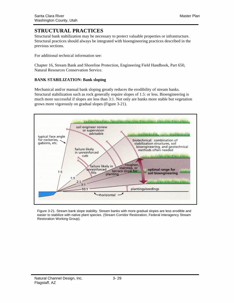
Santa Clara River Master PlanWashington County, Utah
Natural Channel Design, Inc. 3- 29Flagstaff, AZ
STRUCTURAL PRACTICESStructural bank stabilization may be necessary to protect valuable properties or infrastructure.
Structural practices should always be integrated with bioengineering practices described in the
previous sections.
For additional technical information see:
Chapter 16, Stream Bank and Shoreline Protection, Engineering Field Handbook, Part 650,
Natural Resources Conservation Service.
BANK STABILIZATION: Bank sloping
Mechanical and/or manual bank sloping greatly reduces the erodibility of stream banks.
Structural stabilization such as rock generally require slopes of 1.5: or less. Bioengineering is
much more successful if slopes are less than 3:1. Not only are banks more stable but vegetation
grows more vigorously on gradual slopes (Figure 3-21).
Figure 3-21. Stream bank slope stability. Stream banks with more gradual slopes are less erodible andeasier to stabilize with native plant species. (Stream Corridor Restoration, Federal Interagency StreamRestoration Working Group).

Santa Clara River Master PlanWashington County, Utah
Natural Channel Design, Inc. 3- 30Flagstaff, AZ
BANK STABILIZATION: Toe Rock
Toe rock is a structural practice using properly sized and graded angular rock to stabilize the toe
of the bank (Figure 3-22). These practices are generally only necessary on the outside of a
meander. Rock is installed to the floodplain elevation (Gunlock: 4-feet, Santa Clara-St. George:
5-feet) to allow flows to spread across the active floodplain. Rock sizing/grading, scour depth,
and tie back requirements should be determined for the specific site using appropriate NRCS or
other engineering procedures. Bioengineering practices should be installed along the bank above
the toe rock.
Figure 3-30. Toe Rock. This structural practice is generally installed along the outside of a meander bend toreduce the risk of lateral erosion.
Source: Chapter 16, Stream Bank and ShorelineProtection, Engineering Field Handbook, Part 650, NaturalResources Conservation Service.
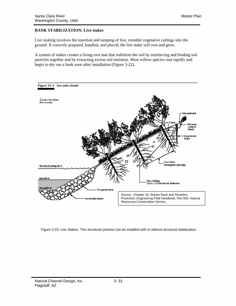
Santa Clara River Master PlanWashington County, Utah
Natural Channel Design, Inc. 3- 31Flagstaff, AZ
BANK STABILIZATION: Live stakes
Live staking involves the insertion and tamping of live, rootable vegetative cuttings into the
ground. If correctly prepared, handled, and placed, the live stake will root and grow.
A system of stakes creates a living root mat that stabilizes the soil by reinforcing and binding soil
particles together and by extracting excess soil moisture. Most willow species root rapidly and
begin to dry out a bank soon after installation (Figure 3-22).
Figure 3-23. Live Stakes. This structural practice can be installed with or without structural stabilization.
Source: Chapter 16, Stream Bank and Shoreline
Protection, Engineering Field Handbook, Part 650, NaturalResources Conservation Service.
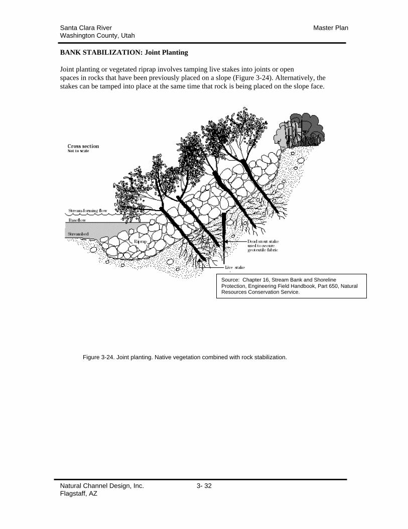
Santa Clara River Master PlanWashington County, Utah
Natural Channel Design, Inc. 3- 32Flagstaff, AZ
BANK STABILIZATION: Joint Planting
Joint planting or vegetated riprap involves tamping live stakes into joints or open
spaces in rocks that have been previously placed on a slope (Figure 3-24). Alternatively, the
stakes can be tamped into place at the same time that rock is being placed on the slope face.
Figure 3-24. Joint planting. Native vegetation combined with rock stabilization.
Source: Chapter 16, Stream Bank and Shoreline
Protection, Engineering Field Handbook, Part 650, NaturalResources Conservation Service.
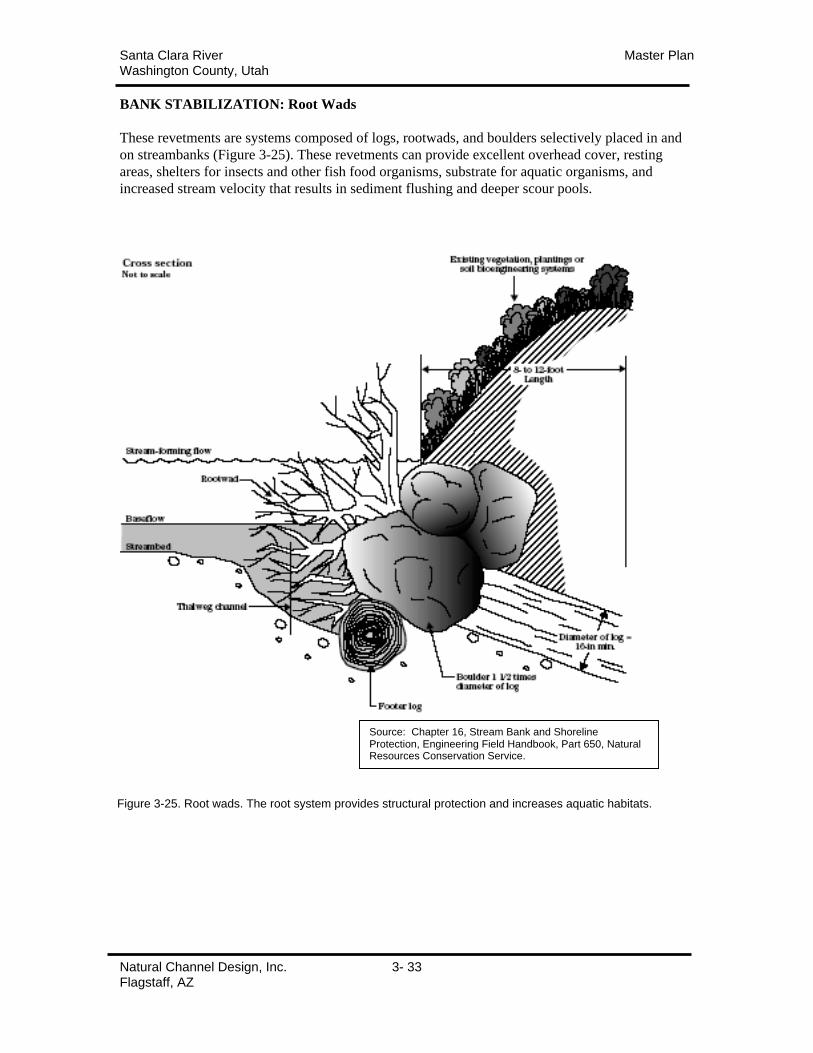
Santa Clara River Master PlanWashington County, Utah
Natural Channel Design, Inc. 3- 33Flagstaff, AZ
BANK STABILIZATION: Root Wads
These revetments are systems composed of logs, rootwads, and boulders selectively placed in and
on streambanks (Figure 3-25). These revetments can provide excellent overhead cover, resting
areas, shelters for insects and other fish food organisms, substrate for aquatic organisms, and
increased stream velocity that results in sediment flushing and deeper scour pools.
Source: Chapter 16, Stream Bank and ShorelineProtection, Engineering Field Handbook, Part 650, NaturalResources Conservation Service.
Figure 3-25. Root wads. The root system provides structural protection and increases aquatic habitats.
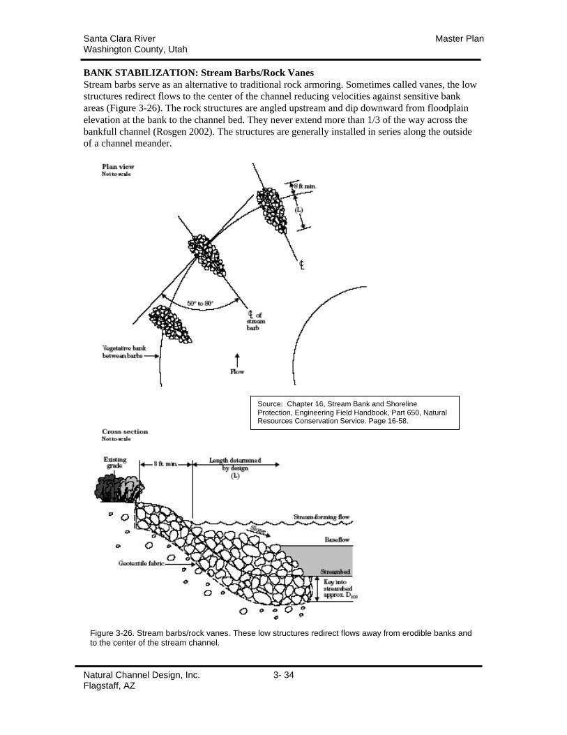
Santa Clara River Master PlanWashington County, Utah
Natural Channel Design, Inc. 3- 34Flagstaff, AZ
BANK STABILIZATION: Stream Barbs/Rock Vanes
Stream barbs serve as an alternative to traditional rock armoring. Sometimes called vanes, the low
structures redirect flows to the center of the channel reducing velocities against sensitive bank
areas (Figure 3-26). The rock structures are angled upstream and dip downward from floodplain
elevation at the bank to the channel bed. They never extend more than 1/3 of the way across the
bankfull channel (Rosgen 2002). The structures are generally installed in series along the outside
of a channel meander.
Source: Chapter 16, Stream Bank and Shoreline
Protection, Engineering Field Handbook, Part 650, NaturalResources Conservation Service. Page 16-58.
Figure 3-26. Stream barbs/rock vanes. These low structures redirect flows away from erodible banks andto the center of the stream channel.
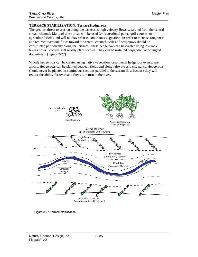
Santa Clara River Master PlanWashington County, Utah
Natural Channel Design, Inc. 3- 35Flagstaff, AZ
TERRACE STABILIZATION: Terrace Hedgerows
The greatest threat to erosion along the terraces is high velocity flows separated from the central
stream channel. Many of these areas will be used for recreational parks, golf courses, or
agricultural fields and will not have dense, continuous vegetation. In order to increase roughness
and redirect overbank flows toward the central channel, series of hedgerows should be
constructed periodically along the terraces. These hedgerows can be created using low rock
levees or well-rooted, stiff woody plant species. They can be installed perpendicular or angled
downstream (Figure 3-27).
Woody hedgerows can be created using native vegetation, ornamental hedges, or even grape
arbors. Hedgerows can be planted between fields and along fairways and city parks. Hedgerows
should never be planted in continuous sections parallel to the stream flow because they will
reduce the ability for overbank flows to return to the river.
Figure 3-27 Terrace stabilization
Santa Clara River Master PlanWashington County, Utah
Natural Channel Design, Inc. 3- 36Flagstaff, AZ
MAINTENANCE:
REMOVAL OF EXOTIC PLANT SPECIESEfforts have been underway for some period to eradicate saltcedar or tamarisk (Tamarix
ramosissima) from the Santa Clara River corridor. Because saltcedar has the reputation for
aggressively colonizing disturbed riparian areas, the minimization of tamarisk colonization
following the January 2005 flooding is a prime objective of the Master Plan.
Recent research suggests that saltcedar does not have a competitive edge over native riparian
species such as Coyote willow (Salix exigua) and cottonwood (Populus fremontii) with respect to
seedling growth and establishment, at least under natural spring flood conditions (Glenn & Nagler
2005). However if sufficient seed bank for the native species is not available, the aggressive
saltcedar seed dispersal strategy can be very successful. In cases where large scale disturbance of
riparian areas occurs, through large flood events or mechanical removal of dense monotypic
stands of exotic vegetation, active revegetation with native riparian species can substantially
reduce the invasion of saltcedar and other exotics (Taylor & McDaniel 2004).
An exotic species strategy was created based on this information and the assessments of experts
(Chris Hoag, NRCS-PMC; Fred Phillips, Fred Phillips Consulting; Curt Deuser, NPS-Exotic
Removal Team) who evaluated the area.
GENERAL RECOMMENDATIONS
The exotic species strategy consists of three elements:
1) Minimize saltcedar recolonization through mechanical, chemical, or manual means,
2) Enhance the reestablishment of native species through aggressive revegetation and
3) Systematic/strategic removal of existing saltcedar and revegetation with native species.
• Focus on areas that have already been cleared and/or have valuable stands of native
vegetation that are threatened by tamarisk
• Construct a reliable source of mass cottonwood and willow poles by creating some flood
irrigated cells on the outer edge of the floodplain that can be planted with very dense
cottonwood/willow trees and then cut down every year to have a sustainable supply of
cuttings for restoration.
• Complete soil sampling and revegetation design for areas prior to saltcedar removal so there
is a follow up plan to get native vegetation established as quickly as possible after site
clearing.
• Develop community based education/volunteer programs that include volunteer planting
days, weeding areas and educational events.
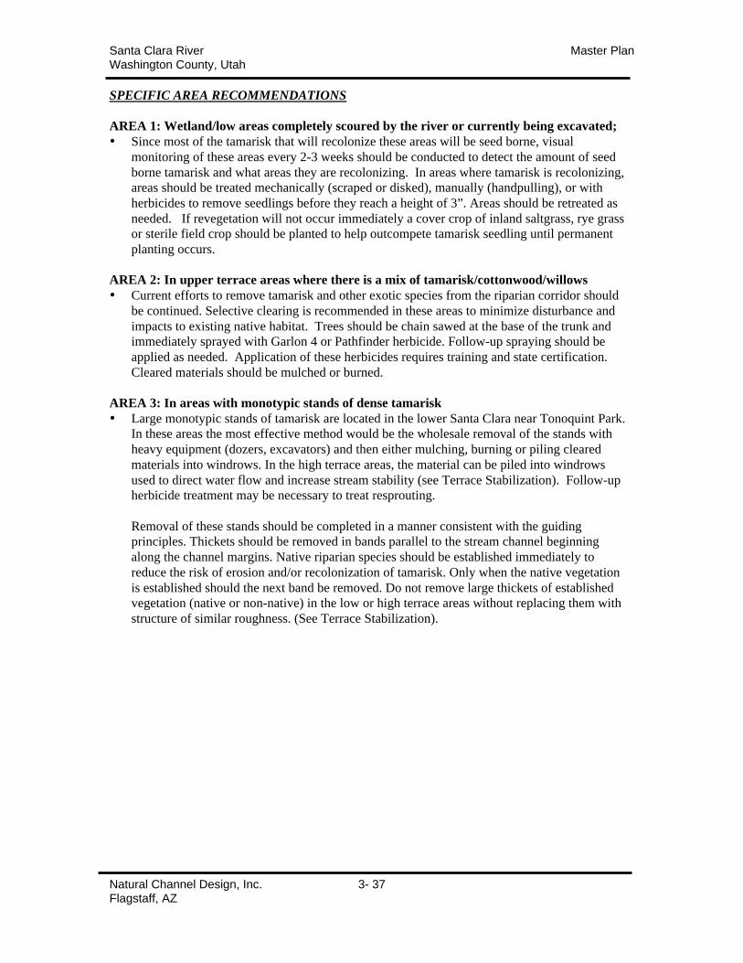
Santa Clara River Master PlanWashington County, Utah
Natural Channel Design, Inc. 3- 37Flagstaff, AZ
SPECIFIC AREA RECOMMENDATIONS
AREA 1: Wetland/low areas completely scoured by the river or currently being excavated;
• Since most of the tamarisk that will recolonize these areas will be seed borne, visual
monitoring of these areas every 2-3 weeks should be conducted to detect the amount of seed
borne tamarisk and what areas they are recolonizing. In areas where tamarisk is recolonizing,
areas should be treated mechanically (scraped or disked), manually (handpulling), or with
herbicides to remove seedlings before they reach a height of 3”. Areas should be retreated as
needed. If revegetation will not occur immediately a cover crop of inland saltgrass, rye grass
or sterile field crop should be planted to help outcompete tamarisk seedling until permanent
planting occurs.
AREA 2: In upper terrace areas where there is a mix of tamarisk/cottonwood/willows
• Current efforts to remove tamarisk and other exotic species from the riparian corridor should
be continued. Selective clearing is recommended in these areas to minimize disturbance and
impacts to existing native habitat. Trees should be chain sawed at the base of the trunk and
immediately sprayed with Garlon 4 or Pathfinder herbicide. Follow-up spraying should be
applied as needed. Application of these herbicides requires training and state certification.
Cleared materials should be mulched or burned.
AREA 3: In areas with monotypic stands of dense tamarisk
• Large monotypic stands of tamarisk are located in the lower Santa Clara near Tonoquint Park.
In these areas the most effective method would be the wholesale removal of the stands with
heavy equipment (dozers, excavators) and then either mulching, burning or piling cleared
materials into windrows. In the high terrace areas, the material can be piled into windrows
used to direct water flow and increase stream stability (see Terrace Stabilization). Follow-up
herbicide treatment may be necessary to treat resprouting.
Removal of these stands should be completed in a manner consistent with the guiding
principles. Thickets should be removed in bands parallel to the stream channel beginning
along the channel margins. Native riparian species should be established immediately to
reduce the risk of erosion and/or recolonization of tamarisk. Only when the native vegetation
is established should the next band be removed. Do not remove large thickets of established
vegetation (native or non-native) in the low or high terrace areas without replacing them with
structure of similar roughness. (See Terrace Stabilization).
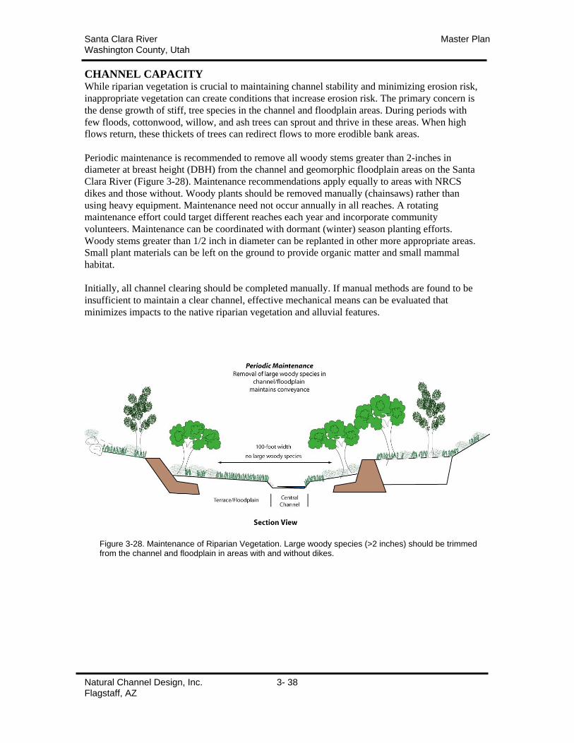
Santa Clara River Master PlanWashington County, Utah
Natural Channel Design, Inc. 3- 38Flagstaff, AZ
CHANNEL CAPACITYWhile riparian vegetation is crucial to maintaining channel stability and minimizing erosion risk,
inappropriate vegetation can create conditions that increase erosion risk. The primary concern is
the dense growth of stiff, tree species in the channel and floodplain areas. During periods with
few floods, cottonwood, willow, and ash trees can sprout and thrive in these areas. When high
flows return, these thickets of trees can redirect flows to more erodible bank areas.
Periodic maintenance is recommended to remove all woody stems greater than 2-inches in
diameter at breast height (DBH) from the channel and geomorphic floodplain areas on the Santa
Clara River (Figure 3-28). Maintenance recommendations apply equally to areas with NRCS
dikes and those without. Woody plants should be removed manually (chainsaws) rather than
using heavy equipment. Maintenance need not occur annually in all reaches. A rotating
maintenance effort could target different reaches each year and incorporate community
volunteers. Maintenance can be coordinated with dormant (winter) season planting efforts.
Woody stems greater than 1/2 inch in diameter can be replanted in other more appropriate areas.
Small plant materials can be left on the ground to provide organic matter and small mammal
habitat.
Initially, all channel clearing should be completed manually. If manual methods are found to be
insufficient to maintain a clear channel, effective mechanical means can be evaluated that
minimizes impacts to the native riparian vegetation and alluvial features.
Figure 3-28. Maintenance of Riparian Vegetation. Large woody species (>2 inches) should be trimmedfrom the channel and floodplain in areas with and without dikes.
Santa Clara River Master PlanWashington County, Utah
Natural Channel Design, Inc. 4- 1Flagstaff, AZ
SECTION 4: SPECIFIC REACH MAPS/RECOMMENDATIONS
GENERAL GUIDELINESThe following general guidelines should be used in prioritizing areas for treatment and in
determining appropriate
• Channel alignments on the maps are approximate and can be modified to accommodate
property boundary, land reclamation, right-of-way, and other considerations. However,
transitions should be gradual and meander pattern (radius of curvature, meander width,
meander length) should be consistent with the Master Plan values. Floodplain and terrace
elevations should be maintained low enough to allow high flows to spread and dissipate
energy.
• Structural protection (rock riprap, levees, or similar) should be limited to valuable
infrastructure threatened by stream flows.
• In general, structural protection should be installed only on the outside of a meander bend
adjacent to the infrastructure to be protected. Geomorphic floodplains and terraces should
be preserved.
• Channel, floodplain, and terrace widths should be protected and maintained to allow
dissipation of high flow energies.
• All treated areas should be replanted with native riparian vegetation as described in the
Santa Clara Master Plan.
MAGOTSU CREEK/MOODY WASH – GUNLOCK RESERVOIRMAGOTSU CREEK/MOODY WASH – GUNLOCK TOWN (NO MAP)
This reach is generally undeveloped, rural and dominated by public lands. The riparian corridor is
well vegetated with native species. Although considerable local scour occurred throughout the
reach, the channel is expected to heal naturally. There are several areas where infrastructure
and/or private lands may require additional protection. Gunlock Springs, the Gunlock waterline,
county roads and bridges, and private agricultural lands should be protected as needed.
a) All protection should be designed and installed in accordance with the Master Plan
guidelines. Structural bank protection should be primarily limited to the outside of
meanders. Floodplains and pointbars along the inside of meanders should be maintained
to allow high flows to spread energies reducing velocities. Specific area
recommendations are given below.
b) Roads, bridges, and other transportation infrastructure should be protected where
threatened. Structural protection should be engineered with adequate rock sizing,
thickness, and scour depth. Where there is space available, low toe rock should be
installed to the height of the geomorphic floodplain (2-3 feet above channel bed) and 25 –
30 feet away from the road leaving a narrow gradually rising geomorphic floodplain. The
toe rock protects the bank from erosion but does not prevent flooding. This floodplain
area should be replanted with riparian vegetation to reduce flow velocities along the
roadway.
c) The channel at Gunlock springs should be protected by structural toe rock along the base
of the bank. The spring area received only minor damage during the January 2005 flood.
However, toe protection reduces the threat of future erosion. The Gunlock waterline
should be protected with structure where it is threatened by stream flows.
Santa Clara River Master PlanWashington County, Utah
Natural Channel Design, Inc. 4- 2Flagstaff, AZ
d) Agricultural fields should generally be protected with toe rock and bioengineering
practices using native willows and cottonwoods. Structural protection should be limited
to the outside of meander bends.
GUNLOCK TOWN (MAPS 1&2)The Town of Gunlock experienced significant lateral erosion during the January 2005 flood. The
road and water pipeline was damaged upstream of town and substantial areas of agricultural lands
were eroded along the east bank of the river. Flows were concentrated in a narrow channel
downstream of the town where the county bridge was overtopped and damaged. The channel bed
elevation is affected by backwater effects from Gunlock Reservoir downstream. The riparian
corridor is wide in this area and flooding was limited to properties along the narrow channel
above the county bridge downstream of town.
The stream channel has been relocated to allow emergency repairs to the road and water line and
a gravel levee installed to protect town properties. More substantial structural protection will be
needed along the road and pipeline to reduce the long-term threat of lateral erosion. Agricultural
fields can also be reclaimed if desired and protected with structural toe protection. However, the
wide pre-flood corridor should be maintained and replanted with riparian vegetation as described
in the Master Plan.
a) The county road and pipeline should be protected structurally to reduce the risk of future
lateral erosion. All treated areas should be replanted with riparian vegetation.
b) Structural protection for homes and other town properties should be installed along the
right (west) bank. The levees should be set back sufficiently to maintain the broad pre-
flood riparian corridor.
c) Agricultural fields on both sides of the stream can be reclaimed consistent with the
recommendations in the Master Plan. If fill is added to reclaim areas, the elevations
should not limit flows from spreading during high flows. In general bioengineering
practices using native willow and cottonwood can provide cost effective long-term
protection and toe can be used to protect critical areas.
d) Homes and road along the narrow channel upstream of the county bridge should be
protected to a level to reduce the threat of lateral erosion and the potential for flooding.
e) Dredging of the reservoir delta downstream of the county bridge should be continued.
Santa Clara River Master PlanWashington County, Utah
Natural Channel Design, Inc. 4- 3Flagstaff, AZ
GUNLOCK RESERVOIR – SANTA CLARA/ST. GEORGE
Much of the length of the Santa Clara River between Gunlock Reservoir and Santa Clara City is
undeveloped public lands. These areas experienced limited damage are expected to recover
naturally from the January 2005 flood. However, county roads, private agricultural lands, and St.
George City water wells were damaged or threatened during the flooding. These areas should be
protected as necessary. Structural toe protection may be appropriate along the outside of meander
bends and where infrastructure value warrants the expense. All treated areas should be
reestablished in all treated areas to provide additional long-term bank stability.
Recommendations for specific areas are described below.
SHIVWITTS RESERVATION (MAPS 3&4)
Significant erosion of agricultural fields within the Shivwitts Reservation occurred during the
January 2005 flood.
• The county and state roads and bridges should be protected structurally to reduce the risk
of future lateral erosion. All treated areas should be replanted with riparian vegetation.
• Agricultural fields can be reclaimed consistent with the recommendations in the Master
Plan. If fill is added to reclaim areas, the elevations should not limit flows from spreading
during high flows. In general bioengineering practices using native willow and
cottonwood can provide cost effective long-term protection and toe can be used to protect
critical areas.
THREE-MILE AREA (MAPS 5&6)
Private properties in the Three-mile area were damaged during the January 2005 flood.
Significant lateral erosion occurred on the outside of all meander bends. The stream channel can
be largely restored to pre-flood alignments if so desired. Where the channel is realigned,
structural toe protection will likely be required to minimize the risk of erosion of the
unconsolidated fill. Low areas in the eroded meanders and behind structural protection should be
filled to floodplain elevation to the extent possible. If the areas cannot be filled, cells should be
created (berms perpendicular to the river) as described in the Master Plan.
Where desired the outside of meander bends can be protected in place using structural and/or
bioengineering practices. It is recommended that the riparian vegetation be reestablished in all
areas to provide additional long-term bank protection.
The inside of meander bends (point bars) need not be protected structurally. The elevations of
these areas should be maintained low enough to allow high flows to spread and dissipate energy.
The stream corridor should not be narrowed beyond pre-flood widths.
Santa Clara River Master PlanWashington County, Utah
Natural Channel Design, Inc. 4- 4Flagstaff, AZ
SANTA CLARA – ST. GEORGE SECTIONREACH 1. SANTA CLARA CITY LIMITS TO DIVERSION (MAPS 7&8)
a) Historic diversion structure on BLM lands above Rosenbruck property is at risk of failure
from bank erosion. Measures should be taken to reinforce the right side of the structure.
b) The majority of this property is located on the inside of a meander bend and not subjected
to erosion stresses. However, toe rock and bioengineering can be installed to protect the
upstream portion of this property. The agricultural fields are high terraces and were
overtopped during the January 2005 flood. Flood waters trapped eroded in the
downstream sections. To minimize future impacts; install hedgerows of vegetation across
the fields to redirect waters back to river and reslope banks and remove levee along river
to allow waters to return to river.
c) Revegetate section with native vegetation to stabilize channel.
d) Protect waterline on outside of meander with structural protection upstream of NRCS
levees. Agricultural fields on point bar on inside of meander bend should be treated as in
(b) above.
e) The narrow channel at Swiss Village will produce high velocities during future flood
events increasing the risk of erosion on both sides of the river. If waters overtop the
NRCS levees, it could threaten the state highway and other property downstream.
Additional engineering analysis is recommended.
f) If the eroded meander is to be reclaimed, the stream channel can be realigned and
stabilized with structural means. The area behind the levee should be filled to floodplain
elevation if possible and treated as a low terrace per the Master Plan guidelines.
g) This wide area should be revegetated per the Master Plan. Agricultural fields can be
reclaimed if desired. If high terraces are utilized as agricultural fields, hedgerows should
be planted and maintained to redirect future high flows back into the river. If a low-water
crossing is planned it should be sited in a straight (transition) section and should conform
to the channel template cross-section. Channel alignment is approximate and can be
modified to meet local objectives.
REACH 2. DIVERSION TO SUNBROOK GOLF COURSE (MAPS 9&10)
a) The main sewer line has been repaired and protected by a rock levee immediately below
the diversion site. The area behind the levee should be filled and/or divided into cells as
described in the Master Plan. Areas along the stream should be replanted with native
vegetation.
b) These largely agricultural properties received little lateral erosion. However, the channel
widened through the reach. Floodplain and low terraces areas can be reshaped and
revegetated. High terrace areas are occupied by corrals and pastures. Hedgerows should
be planted or constructed to redirect future high flows back to river.
c) Although these properties are being protected by NRCS levees, areas behind the
structures should be treated as low and high terraces. Filled areas should slope upward
away from the channel and be planted with hedgerows to redirect future high flows back
to the river.
d) This meander may require toe rock to stabilize the outside bank. The ag fields should be
contoured so that future high flows are redirected back to the river. A setback levee could
be constructed to limit the flooding of adjacent fields. The setback levee should be
protected by bioengineering or structure.
e) Low toe rock could be installed to reduce the risk of erosion of agricultural fields along
the south bank.
Santa Clara River Master PlanWashington County, Utah
Natural Channel Design, Inc. 4- 5Flagstaff, AZ
f) Vegetation or structural hedgerows should be installed behind the NRCS levees to
redirect future overland flows back to the river. Areas on the stream side of the levee
should be replanted with native vegetation.
REACH 3. SUNBROOK GOLF COURSE TO DIXIE DRIVE (MAPS 11&12)
a) Upper part of Sunbrook Golf Course will require structural toe protection along outside
of bends to minimize risk of future erosion. Appropriate bioengineering should be added
to augment structural protection. Floodplains and low terraces should be replanted.
Hedgerows should be installed or topography modified to redirect future high flows back
into the river.
b) Middle of golf course should be replanted with riparian vegetation consistent with Master
Plan and course layout.
c) River along Rivers Edge Drive should be replanted with riparian vegetation consistent
with Master Plan.
REACH 4. DIXIE DRIVE TO OLIVE GROVE (MAPS 12 &13)
a) The unprotected areas around Mathis Park should be resloped and revegetated with
riparian vegetation consistent with Master Plan.
b) Areas behind NRCS levees should be filled or broken into cells and replanted as
described in the Master Plan.
c) Channel and floodplain areas within the NRCS levees should be shaped and replanted
with native vegetation consistent with the Master Plan.
d) Areas behind NRCS levees should be filled or broken into cells and replanted as
described in the Master Plan.
REACH 5. OLIVE GROVE TO TONOQUINT PARK (MAPS 13 &14)
a) Areas behind NRCS levees should be filled or broken into cells and replanted as
described in the Master Plan.
b) Channel and floodplain areas should be shaped and replanted with native vegetation
consistent with the Master Plan.
c) Vegetative and/or structural hedgerows should be installed in high terrace areas to
redirect future high flows back into river.
d) Tamarisk thickets should be removed and replanted with native vegetation. Areas along
stream should be treated initially.
e) Vegetative and/or structural hedgerows should be installed in high terrace areas to
redirect future high flows back into river. Setback levees could be constructed to limit
flooding and redirect flows to river. Levees should maintain minimum corridor width
consistent with Master Plan.
Santa Clara River Master PlanWashington County, Utah
Natural Channel Design, Inc. 4- 6Flagstaff, AZ
REACH 6. TONOQUINT PARK TO VIRGIN RIVER CONFLUENCE (MAP 15)
a) Vegetative and/or structural hedgerows should be installed in high terrace areas to
redirect future high flows back into river. Setback levees could be constructed to limit
flooding and redirect flows to river. Levees should maintain minimum corridor width
consistent with Master Plan.
b) Channel, floodplains, and terraces should be reshaped and planted with riparian
vegetation consistent with Master Plan. Structural toe rock may be required along outside
of meander bends to reduce the risk of future erosion.
c) Channel, floodplains, and terraces should be reshaped and planted with riparian
vegetation consistent with Master Plan. Structural toe rock may be required along outside
of meander bends to reduce the risk of future erosion.
d) Channel, floodplains, and terraces should be reshaped and planted with riparian
vegetation consistent with Master Plan. Structural toe rock may be required along outside
of meander bends to reduce the risk of future erosion.

Santa C
lara M
aster Plan
a.MAIN
650
.
Channel A
lignment
µ0250
50
0125
Fee
t
Map 1
Gunlock R
each A
Typic
al C
hannel
Alig
nm
ent
San
ta C
lara
M
aste
r P
lan
a.
b. c.
d.
e.
MAIN
LOWER SAND COVE
BO
WLE
R
650
LAK
EVIE
W
MCGREGOR
BONNIE
.
Cha
nnel
Alig
nmen
t
µ0
250
50
0125
Fee
t
Map
2
Gun
lock
Rea
ch B
Typic
al C
hannel
Alig
nm
ent
Santa C
lara M
aster Plan
GU
NLO
CK
OLD
HI G
HW
AY
91
LOWER SAND COVE
.
Channel A
lignment
µ0250
50
0125
Fee
t
Map 3
Shivw
its Section
Agriculture Fields
Reach A
Typic
al C
hannel
Alig
nm
ent
San
ta C
lara
M
aste
r P
lan
GU
NLO
CK
OLD
HIG
HW
AY 9
1
.
Cha
nnel
Alig
nmen
t
µ0
250
50
0125
Fee
t
Map
4
Shi
vwit
s S
ecti
onA
gric
ultu
re F
ield
sR
each
B
Typic
al C
hannel
Alig
nm
ent
Santa C
lara M
aster Plan
3 MILE
AN
AS
AZ
I
OLD
HIG
HW
AY 91
.
Channel A
lignment
µ0250
50
0125
Fee
t
Map 5
Shivw
its Section
3 Mile A
reaR
each A
Typic
al C
hannel
Alig
nm
ent
San
ta C
lara
M
aste
r P
lan
AN
ASAZI
3 MILE
.
Cha
nnel
Alig
nmen
t
µ0
250
50
0125
Fee
t
Map
6
Shi
vwit
s S
ecti
on3
Mile
Are
aR
each
B
Typic
al C
hannel
Alig
nm
ent
Santa C
lara M
aster Plan
a.
b.
.
Channel A
lignment
µ0250
50
0125
Fee
t
Map 7
Santa C
lara - St G
eorgeR
each 1A
NR
CS
Levees
As o
f June 2
005
Exte
nts
of
Rip
aria
n C
orrid
or
Typic
al C
hannel
Alig
nm
ent
San
ta C
lara
M
aste
r P
lan
c.d.
e. f.
g.
SANTA CLARA
TR
UM
AN
GUBLER
QUAIL
TAMARISK
RAINBOW
HA
MB
LIN
CR
ES
TV
IEW
SNOW CANYON
RIMDE
SE
RT
DA
WN
STUCKI
CH
AP
EL
COLTON
RE
D R
OC
K
WITTWER
GATES
NOT IN USE
BIR
D
COTTONWOOD
HA
SS
ELL
FE
RN
ELIU
S
GA
TE
S
.
Cha
nnel
Alig
nmen
t
µ0
250
50
0125
Fee
t
Map
8
San
ta C
lara
- S
t G
eorg
eR
each
1B
NR
CS
Levees
As o
f June 2
005
Exte
nts
of
Rip
ari
an C
orr
idor
Typic
al C
hannel
Alig
nm
ent
Santa C
lara M
aster Plan
a.
b.
c.
VIN
EYAR
D
SAN
TA C
LAR
A
OLD FARM
CIR
CLE
HEIGHTS
AR
RO
WH
EAD
RIVER FRONT
AR
CH
VERNONS
PE
AC
H
CO
TTO
NW
OO
D
RIVERWOOD
RIV
ER
VALLE
Y PA
RK
SO
MER
SET
CHAPARRAL
SANTA CLARA
HEIGHTS
.
Channel A
lignment
µ0250
50
0125
Fee
t
Map 9
Santa C
lara - St G
eorgeR
each 2A
NR
CS
Levees
As o
f June 2
005
Exte
nts
of
Rip
aria
n C
orrid
or
Typic
al C
hannel
Alig
nm
ent
San
ta C
lara
M
aste
r P
lan
c.
d.
e.
f.
MA
LA
GA
ARRO
WHEAD
CYNTHIA
CO
NC
OR
D
REISLING
VIN
EY
AR
D CLAUDE
HA
FE
N
LAVA FLOW
ROBERT
RIVER FRONT
MIC
HAEL
CA
TA
WB
A
LEG
RAN
DE
LOST C
REE
K
CIN
DE
RBLACK ROCK
ME
AD
OW
VIE
W
RE
ISL
ING
LAVA FLOW
.
Cha
nnel
Alig
nmen
t
µ0
250
50
0125
Fee
t
Map
10
San
ta C
lara
- S
t G
eorg
eR
each
2B
NR
CS
Levees
As o
f June 2
005
Exte
nts
of
Rip
ari
an C
orr
idor
Typic
al C
hannel
Alig
nm
ent
Santa C
lara M
aster Plan
a.
b.
c.
SU
NB
RO
OK
COUNTRY
EMERAUD
MO
NT
ER
EY
RIV
ER
S E
DG
E40
PR
IVATE
STO
NE
BR
IDG
E
CA
NY
ON
RID
GE
RIO
LO
BO
SO
NO
MA
DE
SE
RT
SP
RIN
GS
2620
SA
N M
AR
CU
S
2740
LOST CREEK
CRYSTAL LAKES
LAQUINTA
VE
RS
AIL
LE
S
NO
RM
AN
DY
BO
X C
AN
YO
N
PR
IVATE
EMERAUD
PR
IVA
TE
PR
IVATE
PR
IVA
TE
PRIVATE
PRIVATE
.
Channel A
lignment
µ0250
50
0125
Fee
t
Map 11
Santa C
lara - St G
eorgeR
each 3A
NR
CS
Levees
As o
f June 2
005
Exte
nts
of
Rip
aria
n C
orrid
or
Typic
al C
hannel
Alig
nm
ent
San
ta C
lara
M
aste
r P
lan
c.
a.
b.
DIXIE
VALLEY VIEW
570
90
10S
TO
NE
BR
IDG
E
1790
1870
PRIV
ATE
PARKSIDE G
REEN VALLEY
530
70
SU
NB
RO
OK
1840
RIV
ERS E
DG
E
TREBRUK
AVALLON
INDIAN HILLS
1360
BROO
K VIE
W
CH
ATE
AU
1490
PE
BB
LE
CR
EE
K
WO
OD
SVIE
W
CHAPEL
VIEW
MATH
IS P
AR
K
BR
IDG
E P
OIN
TE
RO
SE GAR
DEN
MEAD
OW
VIE
W
BU
RG
AN
DY
VILLA F
RANCHE
LAS HURDES
PRIVATE
PRIVATE
PRIVATE
PR
IVATE
BRIDG
E PO
INTE
PRIVATE
PRIVATE
PRIVATE
PRIVATE
PR
IVAT
E
PRIVATE
PR
IVATE
PRIVATE
PRIVATE
PRIVATE
PRIVATE
PRIVATE
PRIV
ATE
PRIVATE
PRIVATE
PRIVATE
PRIV
ATE
PRIVATE
PRIVATE
PR
IVATE
PRIVATE
PRIVATE
PR
IVATE
.
Cha
nnel
Alig
nmen
t
µ0
250
50
0125
Fee
t
Map
12
San
ta C
lara
- S
t G
eorg
eR
each
3B
, 4A
NR
CS
Levees
As o
f June 2
005
Exte
nts
of
Rip
ari
an C
orr
idor
Typic
al C
hannel
Alig
nm
ent
Santa C
lara M
aster Plan
c.
d.
a.
b
DIX
IE
IND
IAN
HIL
LS
560
590
1240
PR
IVA
TE
1360
960
PARK
1080
PARK SO
UTH
PARK W
EST
740
PA
RK
EA
ST
1400
CAN
YON VIEW
PARK N
ORTH
PIN
E B
RO
OK
SHADY SPRINGS
PARKHURST
GREE
N TR
EE
PR
IVA
TE
PRIVATE
SHADY SPRINGS
PR
IVATE
PR
IVA
TE
PRIVATE
PRIVATE
PRIVATE
PRIVATE
PINE BROOK
PR
IVATE
PR
IVA
TE
PR
IVAT
E
PRIVATE
PR
IVATE
PR
IVA
TE
PR
IVAT
E
.
Channel A
lignment
µ0250
50
0125
Fee
t
Map 13
Santa C
lara - St G
eorgeR
each 4B, 5A
NR
CS
Levees
As o
f June 2
005
Exte
nts
of
Rip
aria
n C
orrid
or
Typic
al C
hannel
Alig
nm
ent
San
ta C
lara
M
aste
r P
lan
b.
c.
d.
e.
a.DIX
IE
INDIAN HILLS
1600
PRIV
ATE
TONAQ
UIN
T CEM
ETE
RY
.
Cha
nnel
Alig
nmen
t
µ0
250
50
0125
Fee
t
Map
14
San
ta C
lara
- S
t G
eorg
eR
each
5B
NR
CS
Levees
As o
f June 2
005
Exte
nts
of
Rip
ari
an C
orr
idor
Typic
al C
hannel
Alig
nm
ent
Santa C
lara M
aster Plan
a.b.
c.
d.
2025
HIL
TO
N
INTERSTATE 15
DIXIE
TONAQUINT
INDIA
N H
ILLS
1600
1700
BLACK RIDGE
OFF RAMP
HE
RIT
AG
E
CONVENTION CENTER
PRIVATE
510
BALBOA
FAIRWAY HILLS
2080
LAVA POINTE
SOUTHGATE HILLS
BU
NK
ER
PR
IVATE
2025
PR
IVATE
HILTON
PRIVATE
PR
IVA
TE
HIL
TO
N
OFF RAMP
.
Channel A
lignment
µ0250
50
0125
Fee
t
Map 15
Santa C
lara - St G
eorgeR
each 6
NR
CS
Levees
As o
f June 2
005
Exte
nts
of
Rip
aria
n C
orrid
or
Typic
al C
hannel
Alig
nm
ent
Santa Clara River Master PlanWashington County, Utah
Natural Channel Design, Inc. 5 - 1Flagstaff, AZ
SECTION 5: IMPLEMENTATIONCOORDINATION:Coordination will be a critical part of successful implementation of the Master Plan. The most
obvious entities to serve the coordination role are city, tribal, and county governments. The
individual cities of Gunlock, Santa Clara, and St. George and Washington County are already
deeply involved in the support and development of the Plan. However, some level of overall
coordination is also recommended. Washington County Water Conservancy District has been
very effective at providing that service throughout the development of the Master Plan and is a
good candidate for implementation as well.
A direct source that landowners can tap for technical assistance will be invaluable. This will be
especially important in the first few months while priority projects are underway and until the
plan components are understood. The Technical Contact should have a local presence and the
technical understanding of the master plan.
IMPLEMENTATION TIMELINES:A minimum 5-year implementation period should be expected. Long-term maintenance will be
ongoing. The following is a partial list of implementation tasks and their timing.
Year 1 Tasks:
Public outreach: education, workshops
Incorporate Plan into appropriate city/county ordinances
Coordinate with regulatory permitting agencies
Assist local landowners in restoration of priorities areas
Establish native plant “bare root” nurseries
Implement Pilot project
Out-year Tasks:
Public outreach: Establish annual “river days”
Implement projects
Establish native plant “container” nursery
Maintain “bare root” nurseries
Conduct maintenance program
NATIVE PLANT NURSERIESAn ongoing supply of native plant materials will be needed over the multi-year timeline of the
Master Plan. Wild sources are limited will not provide adequate native plant materials for
restoration of the Santa Clara River. However, local nurseries can be established on fallow
agricultural lands with irrigation or riparian areas with sufficient soil moisture to support plants.
Willows, cottonwoods, and other “bare root” plants can be established from cuttings. These
species are important for revegetation and can be harvested locally and readily cultivated
provided adequate water is available. Several “bare root” nurseries should be established to
minimize transportation expenses. Cuttings are harvested at the end of each growing season for
use in revegetation efforts. The most effective time for planting bare pole cuttings is fall or
winter.
Native plants that do not grow from cuttings will also be needed. These “container” plants can be
cultivated in a dedicated nursery or contracted with local private plant nurseries.

Santa Clara River Master PlanWashington County, Utah
Natural Channel Design, Inc. 5 - 2Flagstaff, AZ
REGULATORY PERMITTINGThe effectiveness of the master plan is greatly increased if it can be coordinated with the
regulatory requirements. An integrated permitting program should be created within the
responsibilities of the following agencies:
Army Corps of EngineersUtah State Engineers OfficeUS Fish and Wildlife ServiceUtah Department of Natural ResourcesCity and county agencies
In an ideal situation, the programmatic permit would minimize the regulatory oversight for
individual projects provided they comply with the guidelines of the Master Plan. However,
regulatory responsibility of individual agencies must be satisfied. A programmatic permit is
uncommon and will take time to complete and implement.
REVEGETATION PROJECTSRevegetation should be considered a multi-year effort. Initial efforts should be directed at those
properties with willing landowners. Coordination will be necessary between regulatory agencies,
governmental units, and local landowners. Efforts should be scheduled in the dormant seasons for
successful revegetation.
Pilot Project: A pilot project should be planned for the fall of 2005. A successful effort in the
first year will be important to acceptance of the plan by local landowners. A pilot project should
include a sizeable reach of river (1,000 + feet). The project could be conducted on public lands
but would have greater impact on local landowners if constructed on private lands. The site
should be identified by mid-summer in order to coordinate earthwork and regulatory permitting.
Because native plant materials will not be available from local nurseries in the first year, it is
recommended that materials be obtained from local wild stands or commercial sources. One
potential source is the state nursery in Las Vegas. Additional local wild sources should be
identified. Implementation should be scheduled for November and could be integrated with a 2 to
3 day public workshop.
Individual projects: The master plan allows individual projects to be implemented when willing
landowners, funding, and needs come together. A programmatic permitting process, readily
available plant supplies, and the master plan guidelines will facilitate implementation and
minimize the need for coordination.
LONG-TERM MAINTENANCEAn annual maintenance program should be established to facilitate the removal of exotic species
(tamarisk) and maintaining the clear stream channel. Channel clearing requires the manual
removal of all woody stems with a diameter greater than 2 inches from a 100 –foot swath along
the central channel. An annual effort, coordinated with volunteers from the communities, could
treat a section of stream channel. Specific reaches are estimated to need woody stem removal
only every 4-5 years. Channel maintenance should be initially conducted using only manual
labor. If this proves ineffective, mechanical means minimizing disturbance can be considered.
Exotic plant removal should be coordinated by federal, State, county, or city agencies. Herbicide
application must be by a licensed individual.
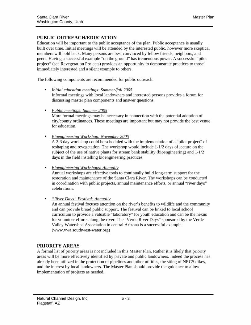
Santa Clara River Master PlanWashington County, Utah
Natural Channel Design, Inc. 5 - 3Flagstaff, AZ
PUBLIC OUTREACH/EDUCATIONEducation will be important to the public acceptance of the plan. Public acceptance is usually
built over time. Initial meetings will be attended by the interested public, however more skeptical
members will hold back. Many persons are best convinced by fellow friends, neighbors, and
peers. Having a successful example “on the ground” has tremendous power. A successful “pilot
project” (see Revegetation Projects) provides an opportunity to demonstrate practices to those
immediately interested and a silent example to others.
The following components are recommended for public outreach.
• Initial education meetings: Summer/fall 2005
Informal meetings with local landowners and interested persons provides a forum for
discussing master plan components and answer questions.
• Public meetings: Summer 2005
More formal meetings may be necessary in connection with the potential adoption of
city/county ordinances. These meetings are important but may not provide the best venue
for education.
• Bioengineering Workshop: November 2005
A 2-3 day workshop could be scheduled with the implementation of a “pilot project” of
reshaping and revegetation. The workshop would include 1-1/2 days of lecture on the
subject of the use of native plants for stream bank stability (bioengineering) and 1-1/2
days in the field installing bioengineering practices.
• Bioengineering Workshops: Annually
Annual workshops are effective tools to continually build long-term support for the
restoration and maintenance of the Santa Clara River. The workshops can be conducted
in coordination with public projects, annual maintenance efforts, or annual “river days”
celebrations.
• “River Days” Festival: Annually
An annual festival focuses attention on the river’s benefits to wildlife and the community
and can provide broad public support. The festival can be linked to local school
curriculum to provide a valuable “laboratory” for youth education and can be the nexus
for volunteer efforts along the river. The “Verde River Days” sponsored by the Verde
Valley Watershed Association in central Arizona is a successful example.
(www.vwa.southwest-water.org)
PRIORITY AREASA formal list of priority areas is not included in this Master Plan. Rather it is likely that priority
areas will be more effectively identified by private and public landowners. Indeed the process has
already been utilized in the protection of pipelines and other utilities, the siting of NRCS dikes,
and the interest by local landowners. The Master Plan should provide the guidance to allow
implementation of projects as needed.
Santa Clara River Master PlanWashington County, Utah
Natural Channel Design, Inc. 5 - 4Flagstaff, AZ
REFERENCES:Andrews, E.D., 1980. Effective and bankfull discharges of streams in the Yampa River Basin,
Colorado and Wyoming. J. Hydrol., 46.
CH2MHill, and JE Fuller/Hydrology & Geomorphology, Inc., 1996. River Stability Study: Virgin
River, Santa Clara River and Ft. Pearce Wash, City of St. George, UT.
Glenn, Edward P. and Pamela L. Nagler 2005. Comparative ecophysiology of Tamarix
ramosissima and native trees in western U.S. riparian zones. Journal of Arid Environments 61
(2005) 419-446. Elsevier.
Hardy, T, P. Panja, and D. Mathias 2005, WinXSPro; a Channel Cross-section Analyzer , USDA
Forest Service, Rocky Mt. Research Station. Ft. Collins, CO.
Hoag, J. Chris, Forrest E. Berg, Sandra K. Wyman, Robert W. Sampson, 2001. Riparian Planting
Zones in the Intermountain West. Riparian/Wetland Project Information Series No. 16.
NRCS Plant Materials Center, Aberdeen, ID.
Hoag, J. Chris and Dan Ogle, 2005. Washington County EWP Trip Report. NRCS-Plant Material
Center, Aberdeen, ID.
Leopold, L.B., M. G. Wolman, and J. P. Miller, 1964. Fluvial Processes in Geomorphology.
Freeman, San Francisco, CA.
Moody, Tom. Mark Wirtanen, & Stephanie Yard, 2003. Regional Relationships of Natural
Channels of the Arid Southwest. Natural Channel Design, Inc. Flagstaff, AZ.
Rosenberg, Rick, 2005. Personal communication.
Rosgen, D.L., 1996. Applied River Morphology. Wildland Hydrology, Ft. Collins, CO.
Rosgen, D.L., 2002. The Cross-vane, W-Weir and J-Hook Vane Structures. Their Description,
Design, and Application for Stream Stabilization and River Restoration. Wildland Hydrology,
Ft. Collins, CO.
Sandberg, Jay, 2005. Personal communication.
Taylor, John P., and Kirk C. McDaniel 2004. Revegetation strategies After Saltcedar (Tamarix
spp.) Control in Headwaters, Transitional, and Depositional Watershed Areas. Weed
Technology, Volume 18:1278-1282.
USDA Natural Resources Conservation Service, 1996. Streambank and Shoreline Protection.
Chapter 16 – Engineering Field Handbook.
USDA Natural Resources Conservation Service, 1998. The Practical Streambank Bioengineering
Guide. Plant Materials Center, Aberdeen, Idaho.
U.S. Geological Survey 1981. Guidelines for determining flood flow frequency, Bulletin # 17B,
Hydrology Subcommittee, Interagency Advisory Committee on Water Data, Geological
Survey, U.S. Department of the Interior.