MARINE FOULING AND ITS PREVENTION
391
Marine Fouling and Its Prevention, Contribution No. 580 from the Woods Hole Oceanographic Institute Copyright 1952 by U. S. Naval Institute, Annapolis, Maryland George Banta Publishing Co., Menasha, WI MARINE FOULING AND ITS PREVENTION PREPARED FOR BUREAU OF SHIPS, NAVY DEPARTMENT BY WOODS HOLE OCEANOGRAPHIC INSTITUTION WOODS HOLE, MASSACHUSETTS DATA LIBRARY . WOODS HOLE OCEANiOGKAPHIC JN$mtmO& UNITED STATES NAVAL INSTITUTE ANNAPOLIS, MARYLAND 1952
-
Upload
khangminh22 -
Category
Documents
-
view
1 -
download
0
Transcript of MARINE FOULING AND ITS PREVENTION
Marine Fouling and Its Prevention,Contribution No. 580 from the Woods Hole Oceanographic Institute
Copyright 1952 by U. S. Naval Institute, Annapolis, Maryland George Banta Publishing Co., Menasha, WI
MARINE FOULING AND ITS PREVENTION
PREPARED FOR
BUREAU OF SHIPS, NAVY DEPARTMENT
BY
WOODS HOLE OCEANOGRAPHIC INSTITUTION
WOODS HOLE, MASSACHUSETTS
DA TA LIBRARY. WOODS HOLE OCEANiOGKAPHIC JN $m tm O &
UNITED STATES NAVAL INSTITUTE ANNAPOLIS, MARYLAND
1952

Marine Fouling and Its Prevention,Contribution No. 580 from the Woods Flole Oceanographic Institute
Copyright 1952 by U. S. Naval Institute, Annapolis, Maryland George Banta Publishing Co., Menasha, WI
M a r i n e F o u l in g a n d I t s P r e v e n t io n
Contribution No. 580 from the Woods Hole Oceanographic Institution
C o p y r i g h t 1952BY
U. S. N a v a l I n s t i t u t e A n n a p o l i s , M a r y l a n d
P r i n t e d i n t h e U n it e d S t a t e s o f A m e r ic a G e o r g e B a n t a P u b l i s h i n g C o m p a n y , M e n a s h a , W is c o n s in
Marine Fouling and Its Prevention,Contribution No. 580 from the Woods Hole Oceanographic Institute
Copyright 1952 by U. S. Naval Institute, Annapolis, Maryland George Banta Publishing Co., Menasha, WI
D e d i c a t e d t o
REAR ADM IRAL H E N R Y WILLIAMS, U. S. NAVY, RETIRED
IN TRIBUTE TO HIS VISION IN CAUSING SCIENTIFIC RESEARCH TO BE APPLIED TO THE
IMPROVEMENT OF THE SHIPBOTTOM PAINTS OF THE UNITED STATES NAVY
Marine Fouling and Its Prevention,Contribution No. 580 from the Woods Hole Oceanographic Institute
Copyright 1952 by U. S. Naval Institute, Annapolis, Maryland George Banta Publishing Co., Menasha, WI
MARINE FOULING AND ITS PREVENTION
Marine Fouling and Its Prevention,Contribution No. 580 from the Woods Flole Oceanographic Institute
Copyright 1952 by U. S. Naval Institute, Annapolis, Maryland George Banta Publishing Co., Menasha, WI
Table of ContentsPREFACE
PART I. PROBLEMS OF FOULING
C h a p t e r 1
The Effects of Fouling................................................................................................................................................ 3
C h a p t e r 2
Ship Resistance............................................................................................................................................................. 21
PART II. BIOLOGY OF FOULING C h a p t e r 3
The Fouling Community........................................................................................................................................... 37
C h a p t e r 4
Temporal Sequences and Biotic Successions....................................................................................................... 42
C h a p t e r 5
The Seasonal Sequence....................................................................................................................................... ■ ■ • 48
C h a p t e r 6
Quantitative Aspects of Fouling............................................................................................................................. 77
C h a p t e r 7
Geographical Distribution......................................................................................................................................... 91
Ch a p t e r 8
Relations to Local Environments................................ 102
C h a p t e r 9
The Principal Fouling Organisms........................................................................................................................... 118
C h a p t e r 10
Species Recorded from Fouling................................................. 165
PART III. PREVENTIO N OF FOULING
C h a p t e r 11
The History of the Prevention of Fouling.......................................................................................................... 211
C h a p t e r 12
The Invention of Protective D evices.................................................................................................................... 224
C h a p t e r 13
Factors Influencing the Attachment and Adherence of Fouling Organisms............................................ 230
C h a p t e r 14
The Prevention of Fouling with T oxics............................................................................................................... 241
C h a p t e r 15
The Physical Chemistry of Compounds of Copper and Mercury and Their Interactions with Sea W ater................................................... 264
C h a p t e r 16Mechanism of Release of Toxics from P aints..................................................................................................... 277
ix

X M A R I N E FOULING A N D I T S P R E V E N T I O N
C h a p t e r 17The Dissolution of the Matrix and Its Ingredients. .................................................................................. 302
C h a p t e r 18
Characteristics of Antifouling Coatings................................................................................................................ 313
C h a p t e r 19
The Design of Antifouling P ain ts........................................................................................................................... 323
C h a p t e r 20
The Testing of Antifouling Paints......................................................................................................................... 331
C h a p t e r 21
The Fouling of Metallic Surfaces........................................................................................................................... 349
C h a p t e r 22
Interaction of Antifouling Paints and Steel........................................................................................................ 365
IN D E X

Marine Fouling and Its Prevention,Contribution No. 580 from the Woods Hole Oceanographic Institute
Copyright 1952 by U. S. Naval Institute, Annapolis, Maryland George Banta Publishing Co., Menasha, WI
PREFACEThis monograph is the outcome of investiga
tions made by the staff of the Woods Hole Oceanographic Institution for the Bureau of Ships, N avy Department, during the years 1940-1946. Although rapid progress in the improvement of antifouling paints was being made by the Navy paint laboratories at the time the work was initiated, it was the belief of the Bureau that scientific knowledge of the fouling process, and of the way in which protective coatings acted, was inadequate. We were consequently instructed to explore the fundamental basis on which preventive techniques must rest, rather than to attempt directly to improve existing paint formulations. At the same time every opportunity was afforded to our staff to become familiar with current problems and the means being employed to solve them. On the termination of the work it has seemed desirable to collect the results of our experience and to review them in relation to the total existing knowledge of the subject.
Interest in the problems of fouling brings together an odd assortment of bedfellows. There are included the operators of vessels, naval architects arid engineers, paint manufacturers, and all those concerned with the maintenance of ships and various underwater installations. Understanding of the phenomena requires the diverse talents of the biologist, chemist, and physicist. I t has not been easy to prepare a book suitable for an audience with such varied viewpoints and technical preparation. Each chapter has been written with some particular group of readers primarily in view. In some cases the aim has been to meet the requirements of specialists by reviewing the technical details of a part of their subject; in others the intent has been to inform specialists of one sort about pertinent matters with which they may not be familiar.
For example, Chapter 9, “The Characteristics of the Principal Fouling Organisms,” is designed to inform those unfamiliar with marine biology about the creatures which contribute to fouling. The following chapter, “Species Recorded from Fouling,” on the other hand, is intended for the professional biologist and may have little interest to others. The reader’s indulgence is invited in respect to this lack of unity in presentation. It is hoped that each will be able to skip judiciously those chapters unsuited to his needs.
The investigations at Woods Hole were initiated
under the direction of Dr. Selman A. Waksman at a time when interest centered on the role of bacterial and other slime films in influencing the subsequent development of fouling. After 1941 the work was guided by Dr. Alfred C. Redfield. Dr. Bostwick H. Ketchum was responsible for the actual conduct of the investigations throughout. Dr. Ketchum was greatly assisted, especially in the theoretical interpretation of the action of antifouling paints, by Dr. John D. Ferry. Dr. Louis W. Hutchins, assisted by the cooperation of the Coast Guard and the Bureau of Ordnance, conducted extensive field studies of the distribution of fouling organisms. In 1942 a testing station was established at the Marine Laboratory of the University of Miami, at Miami Beach. This station was conducted under the successive direction of Dr. Charles M. Pomerat, Dr. F. G. Walton Smith, and Mr. Charles M. Weiss. Special credit is due to Mr. Weiss for conducting the greater part of the experiments made at Miami. He is also responsible for most of the photographs illustrating this volume.
The following have collaborated on the various aspects of the work: Eleanor Adcock, Catharine G. Ayers, J. C. Ayers, Ruth S. Billard, D . D. Bonnet, Jean Bryant, D. E. Carritt, E. S. Castle,G. L. Clarke, M. W. Davidson, E. S. Deevey, Jr., Georgianna B. Deevey, Dorcas H. Delabarre, W. T. Edmondson, Barbara M ott Ferry, Mary F. Goffin, M. Hotchkiss, H. J. Humm, Helen S. Hutchins, W. M. Ingram, D. B. Johnstone, D. Jean Keen, G. F. Kelly, F. B. Laidlaw, G. L. Lee, R. G. Lunz, Jr., R. A. McLean, M. A. Miller, I. M. Newell, Elizabeth D . Orr, Zoé Ann Orr, J. Parker, Gale G. Pasley, Jr., Barbara B. Perkins,A. Phelps, C. E. Renn, Beatrice B. Reynolds,D. M. Reynolds, G. A. Riley, H. D. Russell, Margaret Scharff, G. T. Scott, A. Svihla, D. E. Todd, H. J. Turner, Sylvia A. Weare, Grace L. Winter, and D. J. Zinn.
The interest and support of Rear Admiral J. W. Fowler, under whose cognizance our studies were initiated, Rear Admiral T. A. Solberg, CaptainH. A. Ingram, Captain Logan McKee, CommanderA. E. MacGee, Lieutenant Commander E. F. Carlston, Mr. D. P. Graham, and Dr. Scott P. Ewing of the Bureau of Ships, are gratefully acknowledged.
The paint laboratories of the N avy Yards at Norfolk and Mare Island, of the Naval Research
V II
viii M A R I N E FOULING A N D I T S P R E V E N T I O N
Laboratory, and of the Bakelite Corporation provided many of the experimental formulations used in our studies. The interest and suggestions of the personnel of these laboratories have been most stimulating. Especial acknowledgment is made for encouragement and assistance from Captain A. S. Pitre, Mr. N. E. Adamson, Dr. A. L. Alexander, Mr. A. J. Wieth, Mr. V. H. Turkington, and Mr. John Saroyan. Mr. Arthur E. Burns, Jr., has actively participated in the development of the interpretations of the action of antifouling paints. He has also made available data, which were previously unreported, for inclusion in Chapters 16 and 18, and his suggestions concerning these chapters have been most valuable.
Valuable information on the fouling of underwater installations has been made available by the underwater ordnance sections of the Bureau of Ordnance and by the Office of Chief of Naval Operations. Particular acknowledgment is due to Commander C. J. Fish, whose interest was instrumental in arranging for a survey of the fouling occurring on coastal navigation buoys.
The text of this book has been prepared jointly by several members of the staff of the Woods Hole Oceanographic Institution, none of whom can claim complete credit for any particular part. The major labor of collecting and assembling material for the different chapters has fallen somewhat as follows:
Chapters 1 and 2—A. C. Redfield and L. W. Hutchins
3, 4, 5, 6—A. C. Redfield andE. S. Deevy, Jr.
7 and 8—L. W. Hutchins
Chapter 9—J. C. Ayers andH. J. Turner
10—L. W. Hutchins 11 and 12— F. B. Laidlaw 13 and 14— B. H. Ketchum
15— J. D. Ferry16—J. D. Ferry and
B. H. Ketchum17— David Todd and
B. H. Ketchum18, 19, 20— B. H. Ketchum 21 and 22— A. C. Redfield.
Final editing has been shared by Dr. Redfield and Dr. Ketchum, assisted in the preparation of the manuscript by Miss D. Jean Keen, Mrs. Vivien Brown, Mrs. Florence Melior, and Miss Lois Vaetsch. The index was prepared by Mrs. Frederick C. Fuglister.
In addition to many of those previously mentioned, the following have read and commented upon various parts of the manuscript: Lieutenant- Commander M. V. Brewington, Dr. W. F. Clapp, Professor K. S. M. Davidson, Mr. R. Devoluy, Mr. R. J. Eckart, Dr. A. C. Elm, Mr. C. M. Jackson, Mr. F. L. LaQue, Dr. J. J. Mattiello, Professor S. E. Morison, Captain H. E. Saunders, and Dr. G. H. Young. Without wishing to involve them in any responsibility for the present publication, appreciation is here expressed for their helpful interest and advice.
C o l u m b u s O’D. I s e l i n , Director Woods Hole Oceanographic Institution
Woods Hole, Massachusetts December 1, 1947
M arine Fouling and Its Prevention,Contribution No. 580 from the W oods Hole Oceanographic Institute
Copyright 1952 by U. S. Naval Institute, A nnapolis, M aryland George B anta Publishing Co., M enasha, W I
PART I
PROBLEMS OF FOULING
M arine Fouling and Its Prevention,Contribution No. 580 from the W oods Hole Oceanographic Institute
Copyright 1952 by U. S. Naval Institute, Annapolis, M aryland George Banta Publishing Co., M enasha, W I
CHAPTER 1
The Effects of FoulingFouling results from the growth of animals and
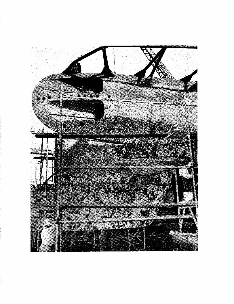
plants on the surface of submerged objects. Its most widely known effect is on the efficiency of propulsion of ships, but there are many other ways in which it produces difficulties. Thus the fouling of the underbody of flying boats may result in their inability to get off the water. Growths may interfere with the mechanisms which actuate mines and reduce the efficiency of underwater acoustic devices. The drag of currents on fouled cables may cause mines to “dip” below their intended depth, and similar difficulties are encountered in maintaining defensive nets. Fouling gives serious trouble when it occurs in pipes and conduits used to conduct water both in ships and in industrial installations on shore. The growth may have undesirable effects as the result of destruction of the protective coatings intended to reduce corrosion, and may indeed increase the corrosion of unprotected metal itself.
In a limited number of cases, the tendency for submerged objects to foul may be put to advantage as is the case in the shellfish industry. In mine warfare the fouling may act as camouflage, making the mine less visible. It may be possible by examining the fouling on a derelict mine to determine its point of origin and the time it has been submerged or afloat. The accumulation of slime and fouling on metallic surfaces may protect them from the erosive effects of sea water at high velocity.
These and other similar phenomena are discussed in the present chapter.
THE FOULING OF SHIPSThe fouling of ships results in a reduction of
speed, an increased cost in fuel, and losses in time and money in applying the necessary remedial measures. The immediate effect is due to an increase in the resistance to movement of the hull through the water— a phenomenon known as frictional resistance. Since frictional resistance is the basic phenomenon on which the most important aspects of the fouling problem depend, and since it is a matter of some intricacy, the technicalities of the subject are treated in the following chapter, which summarizes some of the more comprehensive experimental data available. For present purposes, it will serve to point out that the accumulation of fouling may readily reduce the
speed of the ship by several knots; and in the case of war vessels and other types of ships in which extreme speed is essential, its occurrence may result in the loss of advantages for which great sacrifice has been made.
As the result of experience over a number of years, the British Admiralty makes an allowance for design purposes for an increase of frictional resistance of per cent per day out of dock in temperate waters and of per cent per day in tropical waters. The result of this assumed rate on speed and fuel consumption at the end of six months for various types of ships in temperate waters is given in Table 1. In tropical waters such results would be expected at the end of three months (20). In the United States N avy the Rules for Engineering Competition in effect prior to the war allowed for 3 per cent increase in fuel consumption per month (J).
T a b l e 1. Effect of Fouling after Six Months out of Dock in Temperate Waters
(Frictional resistance assumed to increase per cent per day)
Percentage Increase in Loss of Fuel Consumption* to
Standard M axim um M aintain a Speed of Displacement S p e e d - - - - - - - - - - - - - - - - - - - - - - - - - - - - - - - -
Type of Ship Tons Knots 10 Knots 20 KnotsBattleship 35,000 11 45 40Aircraft carrier 23,000 l i 45 40Cruiser 10,000 H 50 45Destroyer 1,850 2 50 35
* These figures are based on-the fuel consumptions for propulsion only, i.e. auxiliaries are not included.
Naturally these effects will depend not only on the waters in which the ships operate but also upon the efficiency of the antifouling paints employed. Since the British Admiralty utilizes paints which are obtained from a variety of manufacturers, it seems probable that the estimations given in Table 1 are applicable to vessels coated with the commercially available paints. Great improvements have been made in the coatings employed by . the United States Navy, and it is reported that during the recent war in the Pacific it was found unnecessary to make allowances for fouling in estimating fuel requirements.
In addition to the direct expense of the increased fuel consumption required to drive a fouled ship at a given speed and the increased wear and tear on machinery which this may entail, the expense of docking the vessel periodically for cleaning the
3
4 M A R I N E FOULING A N D I T S P R E V E N T I O N
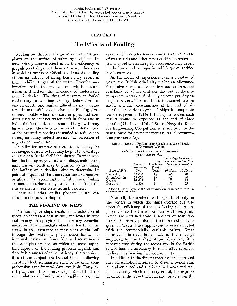
bottom is great. The cost of placing a vessel in dry Visscher stated in 1928 tha t these costs in the casedock or on a marine railway, cleaning, and paint- of a large vessel such as the Leviathan or Majesticing the bottom varies from $1,000 to $15,000, de- were approximately $100,000 (35). This estimate
F i g u r e 1. Above: U.S.S. Tippecanoe. P a in ted with N avy formula 15RC. h o t plastic antifouling pain t. Tw enty-eight m onths waterborne. Official U. S.Twelve m onths waterborne. (Below): U .S .S . Angusta. Pain ted w ith N avy N avy photographs.
pending on the size of the vessel, according to Adamson (1). The charges incurred by an 18,000- ton passenger liner, docked during 1940 in the San Francisco area, amounted to $4,400. This ship is docked and repainted every nine months (4).
did not include the loss of income incurred during the period while the ship was out of service. The time spent in dry dock varies from three days to three weeks or more. For a group of over 200 ships listed by Visscher the average is seven or eight
T H E EFFECTS OF FOULING 5
days. Visscher stated that over $100,000,000 was spent annually by United States shipping interests alone, because of fouling.
Any improvement in the technology of protecting ships from fouling which permits the extension of the period between dockings will lead to importan t savings in time and expense. Prior to the war, vessels assigned to operating units of the fleet were docked for underwater painting at intervals of approximately nine months (18). Under wartime conditions the activity of the ships was so great and they were docked so frequently that little time was lost for the sake of maintaining the bottoms in good condition. Under peacetime conditions, naval vessels spend a large part of their time in port, where they are subject to severe fouling. Improvements in the antifouling coatings which prolong the period between dockings will lead to substantial savings. This is true also of commercial vessels, especially freighters which may spend considerable periods in port.
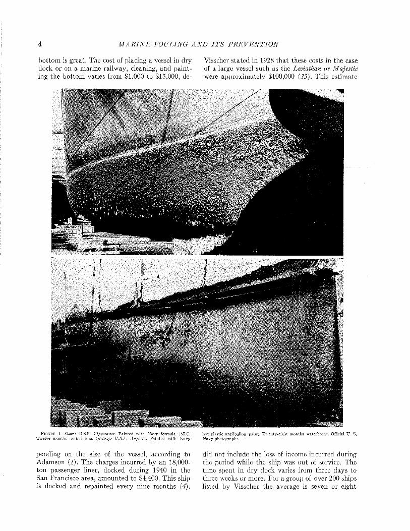
The improved protection provided by modern paints is illustrated by Figures 1 and 2. Figure 1 (above) shows the heavy fouling which developed in twelve months on a ship coated with the prewar standard antifouling paint 15RC. A ship protected with the modern hot plastic coating, which remained practically clean while waterborne twenty- eight months, is shown for comparison below. Figure 2 shows the clean condition of a patch of modern hot plastic paint in comparison to the fouling developed in seventeen months on the remainder of the hull which was painted with the older formulation.
The improvement in protective coatings for ships’ bottom s due to recent work by the Bureau of Ships has led to the following accomplishments :
a. Vessels can remain out of dry dock as long as eighteen months with inconsequential reduction in speed or increase in fuel consumption due to fouling. I t is consequently unnecessary to dock ships more frequently for painting than is required for repairs to hull and submerged fittings.
b. D ry docks have been more available for battle damage repairs due to the reduced routine docking load.
c. The demands for fuel by the fleet are perhaps 10 per cent less than formerly.
d. Fewer tankers are needed to service the fleet.e. The corrosion of ships’ hulls is noticeably re
duced.A variety of additional savings in time and
money have been realized by improvements in the
F i g u r e 2 . Comparison of fouling on old N avy form ulation Í5RC (left), and modern ho t plastic antifouling pain t (righi), after 17 m onths w aterborne. Official U. S. N avy photograph.
technology of the manufacture of paints and the preparation of the hull for painting (14).
The tendency of ships to foul is related to the type of service in which they are employed, and, particularly, to the resulting time spent in port. This follows from the fact discussed in Chapter 13 tha t the larvae of many fouling organisms have difficulty in attaching to submerged surfaces when the velocity of the water across the surface exceeds about one knot. A t greater speeds than this, the growth of some organisms previously attached is also supressed, particularly if they have not been long established, and a t high speeds the a ttached organisms m ay be washed away bodily.
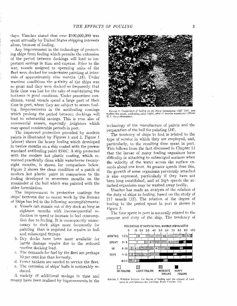
Visscher has made an analysis of the relation of the duty of ships to fouling, based on the study of 217 vessels (35). The relation of the degree of fouling to the period spent in port is shown in Figure 3.
The time spent in port is naturally related to the purpose and duty of the ship. The tendency of
P E R C E N T A G E OF SHI P S (A C T U A L N U M B E R IN B R A C K E T S )0 10 20 30 40 50 60 70 80 90 100
M O N T H S 1-2 'A
S P E N T 3 - 5
IN 6 - 1 0
P O R T 11-15
1 6 - 2 0
p m m mNO FOULING L I G H T FOULING .MODERATE HEAVY
FOULING FOULING
F i g u r e 3 . Relation between the degree of fouling and the am ount of tim e spent in po rt between dry dockings. From Visscher (3 5 ) .

6 M A R I N E FOULING A N D I T S P R E V E N T I O N
ships of different types to foul is illustrated in Figure 4. Passenger vessels appear less liable to foul than freighters, as might be expected from their more active service and greater speed. Among naval vessels, destroyers and cruisers have
t y p e : o fSHIP
PASSENGER
DESTROYER
FREIGHTERS
CRUISERS
C O L L IE R S
OUT OF COMMISSION
BATTLESHIPS
LIG H T-SH IPS
PER C ENT OF NUMBER OF SHIPS IN E A C H GROUP
0 IO 2 0 3 0 4 0 5 0 6 0 7 0 8 0 9 0 100m m
□NO LIGHT MODERATE HEAVY
FOULING FOULING FOULING FOULING
F i g u r e 4. Relation between type and duty of ship and the amount of fouling, disregarding the factor of time. From Visscher (35).
a greater immunity than carriers and battleships, which, in time of peace, like ships out of commission and lightships, spend the greater portion of their time moored or at dock.
The time required for ships to foul depends on the efficacy of the protective coating, which is sooner or later destroyed either by the solvent action of sea water, the physical breakdown of the paint film, or by corrosion. After the paint is damaged, fouling may develop rapidly and cover the unprotected surface completely within a few weeks. It is estimated that as much as 200 tons of fouling may be removed from a ship’s bottom at a single docking (I).
Few of the ships examined by Visscher remained clean for a period longer than nine months, and all became at least moderately fouled by the end of sixteen to eighteen months, as may be seen from Figure 5, These data are based on ships protected with the paints available some twenty years ago. There is little doubt that ships with the better coatings now available would show a substantial improvement.
The tendency to foul varies greatly with the waters in which ships ply. Fouling can attach only at such times as the organisms are infecting the water with their zoospores or larvae. Its growth varies with the temperature of the water. These biological phenomena are discussed in detail in
subsequent chapters. It is generally considered that fouling is most severe in tropical waters, where growth is rapid and where there is little seasonal interruption of the reproductive processes. In temperate latitudes heavy fouling may occur in summer, but during the cold winter period little growth develops.
In fresh water few fouling organisms occur and these are chiefly plants which attach close to the water line. Ships which can be moored in fresh water consequently enjoy a partial immunity. It is sometimes suggested that vessels should be taken into fresh water to kill off the fouling. This is only a partial measure, since the shells of barnacles and some other fouling organisms are firmly attached and adhere to the bottom even though their occupants are dead.
The only method of preventing fouling which is successful with modern ships is the use of toxic paints. Because of biological considerations the demands put on such paints differ from time to time and from place to place, and different coatings have sometimes been proposed for ships in various services. Vessels used in temperate waters, subject to fouling for only a part of each year, may be protected adequately with a relatively poor paint, effective for only six or eight months, provided they are docked annually and start the fouling season with a fresh coating. Little is to be
TIME
IN 0 -3
MONTHS 4-6
SINCE 7-9;.
LA S T 10-12
PREVIOUS 13-15
D RY- 16-18
DOCKING 19-21
PERCENTAGE OF SHIPS IN EACH GROUP 0 10 2 0 3 0 4 0 5 0 6 0 70 8 0 9 0 100
12
i3 « » ia ra9 v ///////////////^
m m mœsmsm
□CLEAN LIGHTLY
F O U L E DMO DERATELY HEAVILY
F O U L E D F O U L E D
F i g u r e 5. Relation between amount of fouling and amount of time between dry dockings. From Visscher (35).
gained by such economies, however, since the cost of the coating is only a small part of the expense of docking and repainting. Effective paints are not necessarily expensive paints. A paint which is effective under the most severe conditions of fouling will be effective in preventing growth under any condition. The superior underwater coatings now
THE EFFECTS OF FOUL ING 7
used by the N avy have been developed in response to a demand for paints which would completely prevent the growth of fouling under the most severe conditions and for the greatest possible period.
N A V IG A T IO N B U O Y SMoored structures such as buoys are even more
subject to fouling than ships, since they remain permanently in coastal waters where fouling organisms abound, and since the fouling is not washed away by rapid motion through the water. The tidal currents to which such structures are often exposed appear to favor the growth of the fouling, which finds an opportunity to attach during periods of slack water even where the currents are strong.
The population which grows on moored structures is frequently different from that observed on ships. I t contains a larger proportion of mussels and the soft-bodied forms liable to be removed from ships a t high speed. In temperate waters, mussels constitute the major fouling on buoys, although these shellfish are not usually observed on ships unless they lie idle in harbor.
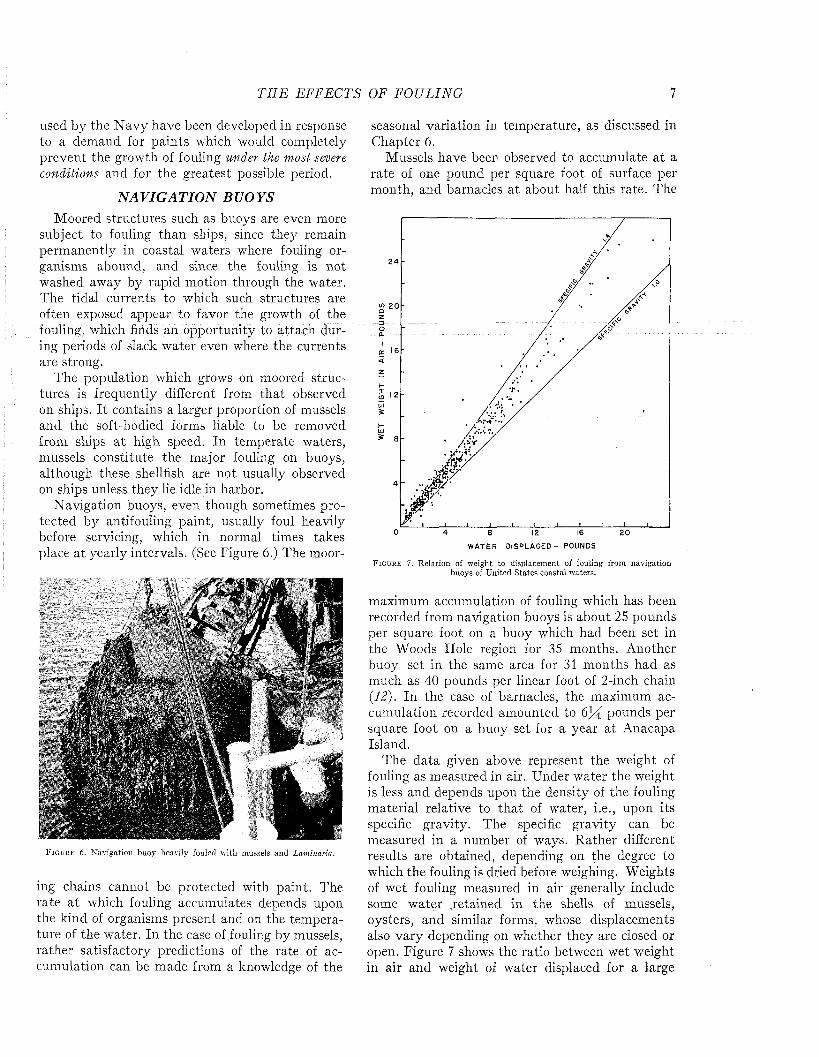
Navigation buoys, even though sometimes protected by antifouling paint, usually foul heavily before servicing, which in normal times takes place a t yearly intervals. (See Figure 6.) The moor-
F i g u r e 6 . (Navigation buoy heavily fouled with mussels and Laminaria.
ing chains cannot be protected with paint. The rate a t which fouling accumulates depends upon the kind of organisms present and on the temperature of the water. In the case of fouling by mussels, rather satisfactory predictions of the rate of accumulation can be made from a knowledge of the
seasonal variation in temperature, as discussed in Chapter 6.
Mussels have been observed to accumulate a t a rate of one pound per square foot of surface per month, and barnacles a t about half this rate. The
2 4
m 20
o 4 8 12 16 20W A T E R D I S P L A C E D - P O U N D S
F i g u r e 7 . R elation of weight to displacem ent of fouling from navigation buoys of U nited S tates coastal waters.
maximum accumulation of fouling which has been recorded from navigation buoys is about 25 pounds per square foot on a buoy which had been set in the Woods Hole region for 35 months. Another buoy set in the same area for 31 months had as much as 40 pounds per linear foot of 2-inch chain (12). In the case of barnacles, the maximum accumulation recorded amounted to pounds per square foot on a buoy set for a year a t Anacapa Island.
The data given above represent the weight of fouling as measured in air. Under water the weight is less and depends upon the density of the fouling material relative to th a t of water, i.e., upon its specific gravity. The specific gravity can be measured in a number of ways. Rather different results are obtained, depending on the degree to which the fouling is dried before weighing. Weights of wet fouling measured in air generally include some water retained in the shells of mussels, oysters, and similar forms, whose displacements also vary depending on whether they are closed or open. Figure 7 shows the ratio between wet weight in air and weight of water displaced for a large
8 M A R I N E FOULING A N D I T S P R E V E N T I O N
number of samples of fouling from buoys of United States coastal waters, and adequately represents all commonly encountered types of fouling except th a t dominated by oysters. A specific gravity of1.4 seems to be a proper allowance for engineering estimates. The total weight will depend, of course on the locality and duration of exposure. Separate measurements of various fouling organisms show th a t only shelled forms have any significant weight under water. Mussel fouling has a specific gravity of about 1.3; acorn barnacles and rock oysters
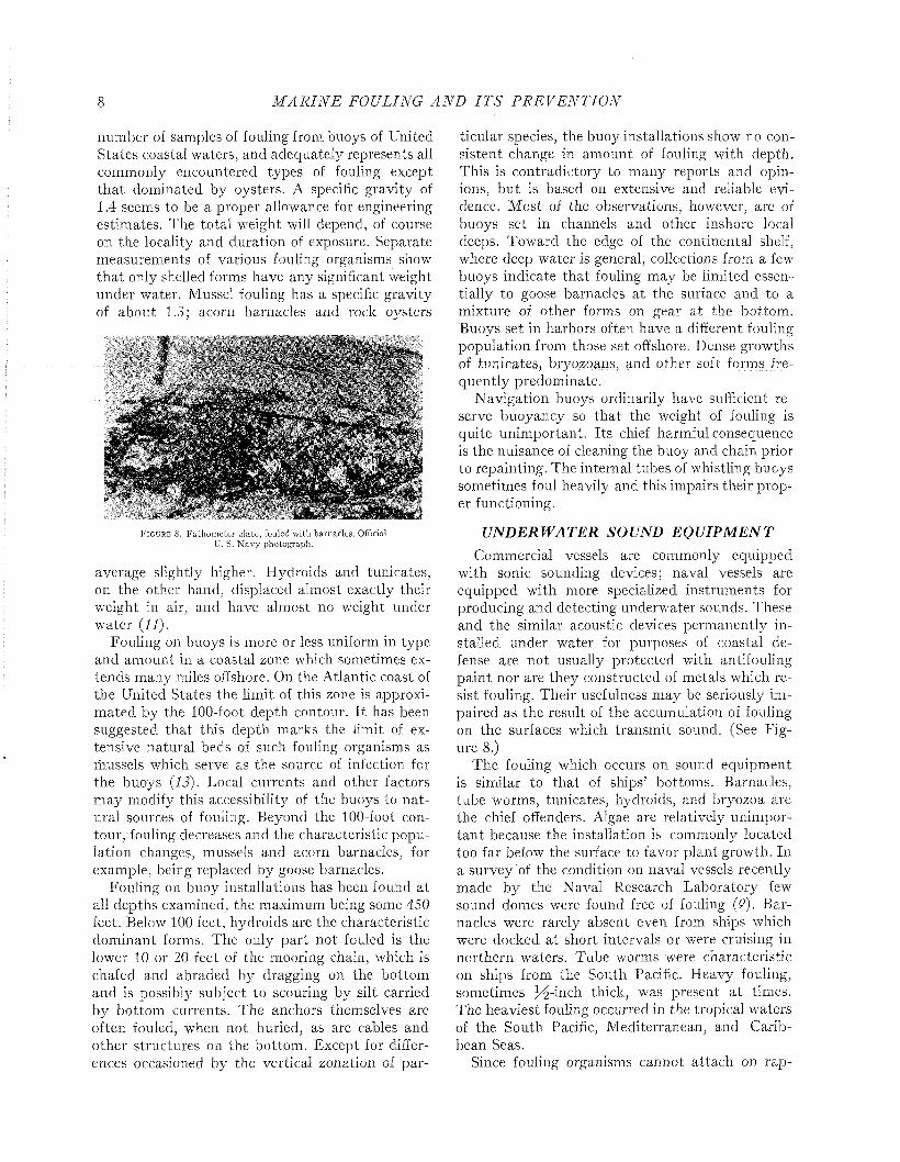
F i g u r e 8. F athom eter plate, fouled with barnacles. Official U. S. N avy photograph.
average slightly higher. Hydroids and tunicates, on the other hand, displaced almost exactly their weight in air, and have almost no weight under water (11).
Fouling on buoys is more or less uniform in type and amount in a coastal zone which sometimes extends many miles offshore. On the Atlantic coast of the United States the limit of this zone is approxim ated by the 100-foot depth contour. I t has been suggested that this depth marks the limit of extensive natural beds of such fouling organisms as mussels which serve as the source of infection for the buoys (13). Local currents and other factors may modify this accessibility of the buoys to na tural sources of fouling. Beyond the 100-foot contour/fouling decreases and the characteristic population changes, mussels and acorn barnacles, for example, being replaced by goose barnacles.
Fouling on buoy installations has been found at all depths examined, the maximum being some 450 feet. Below 100 feet, hydroids are the characteristic dominant forms. The only part not fouled is the lower 10 or 20 feet of the mooring chain, which is chafed and abraded by dragging on the bottom and is possibly subject to scouring by silt carried by bottom currents. The anchors themselves are often fouled, when not buried, as are cables and other structures on the bottom. Except for differences occasioned by the vertical zonation of par
ticular species, the buoy installations show no consistent change in amount of fouling with depth. This is contradictory to many reports and opinions, bu t is based on extensive and reliable evidence. M ost of the observations, however, are of buoys set in channels and other inshore local deeps. Toward the edge of the continental shelf, where deep water is general, collections from a few buoys indicate that fouling may be limited essentially to goose barnacles a t the surface and to a mixture of other forms on gear at the bottom. Buoys set in harbors often have a different fouling population from those set offshore. Dense growths of tunicates, bryozoans, and other soft forms frequently predominate.
Navigation buoys ordinarily have sufficient reserve buoyancy so that the weight of fouling is quite unimportant. Its chief harmful consequence is the nuisance of cleaning the buoy and chain prior to repainting. The internal tubes of whistling buoys sometimes foul heavily and this impairs their proper functioning.
U N D E R W A T E R SO UN D E Q U IP M E N TCommercial vessels are commonly equipped
with sonic sounding devices; naval vessels are equipped with more specialized instruments for producing and detecting underwater sounds. These and the similar acoustic devices permanently installed under water for purposes of coastal defense are not usually protected with antifouling paint nor are they constructed of metals which resist fouling. Their usefulness may be seriously impaired as the result of the accumulation of fouling on the surfaces which transm it sound. (See Figure 8.)
The fouling which occurs on sound equipment is similar to that of ships’ bottoms. Barnacles, tube worms, tunicates, hydroids, and bryozoa are the chief offenders. Algae are relatively unimportan t because the installation is commonly located too far below the surface to favor plant growth. In a survey of the condition on naval vessels recently made by the Naval Research Laboratory few sound domes were found free of fouling (9). Barnacles were rarely absent even from ships which were docked at short intervals or were cruising in northern waters. Tube worms were characteristic on ships from the South Pacific. Heavy fouling, sometimes jdrinch thick, was present a t times. The heaviest fouling occurred in the tropical waters of the South Pacific, Mediterranean, and Caribbean Seas.
Since fouling organisms cannot attach on rap
T H E EFFECTS OF FOULING 9
idly moving surfaces, and since their growth is inhibited or they may be torn free by water currents of high velocity, fouling is especially prevalent on ships lying to for long periods, on training school ships and barges, and on stationary installations.
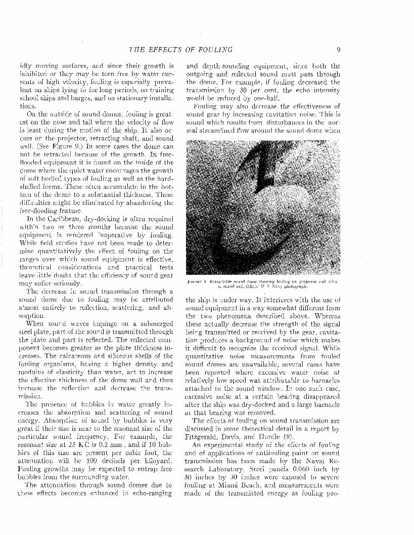
On the outside of sound domes, fouling is greatest on the nose and tail where the velocity of flow is least during the motion of the ship. I t also occurs on the projector, retracting shaft, and sound well. (See Figure 9.) In some cases the dome can not be retracted because of the growth. In free- flooded equipment it is found on the inside of the dome where the quiet water encourages the growth of soft-bodied types of fouling as well as the hard- shelled forms. These often accumulate in the bottom of the dome to a substantial thickness. These difficulties might be eliminated by abandoning the free-flooding feature.
In the Caribbean, dry-docking is often required within two or three months because the sound equipment is rendered inoperative by fouling. While field studies have not been made to determine quantitatively the effect of fouling on the ranges over which sound equipment is effective, theoretical considerations and practical tests leave little doubt that the efficiency of sound gear may suffer seriously.
The decrease in sound transmission through a sound dome due to fouling may be attributed almost entirely to reflection, scattering, and absorption.
When sound waves impinge on a submerged steel plate, part of the sound is transm itted through the plate and part is reflected. The reflected component becomes greater as the plate thickness increases. The calcareous and siliceous shells of the fouling organisms, having a higher density and modulus of elasticity than water, act to increase the effective thickness of the dome wall and thus increase the reflection and decrease the transmission.
The presence of bubbles in water greatly increases the absorption and scattering of sound energy. Absorption of sound by bubbles is very great if their size is near to the resonant size of the particular sound frequency. For example, the resonant size a t 25 KC is 0.2 mm., and if 10 bubbles of this size are present per cubic foot, the attenuation will be 100 decibels per kiloyard. Fouling growths may be expected to entrap free bubbles from the surrounding water.
The attenuation through sound domes due to these effects becomes enhanced in echo-ranging
and depth-sounding equipment, since both the outgoing and reflected sound m ust pass through the dome. For example, if fouling decreased the transmission, by 30 per cent, the echo intensity would be reduced by one-half.
Fouling may also decrease the effectiveness of sound gear by increasing cavitation noise. This is sound which results from disturbances in the normal streamlined flow around the sound dome when
F i g u r e 9 . R etractable sound dome showing fouling on projector and sides of sound well. Official Ü. S. N avy photograph.
the ship is under way. I t interferes with the use of sound equipment in a way somewhat different from the two phenomena described above. Whereas these actually decrease the strength of the signal being transm itted or received by the gear, cavitation produces a background of noise which makes it difficult to recognize the received signal. While quantitative noise measurements from fouled sound domes are unavailable, several cases have been reported where excessive water noise at relatively low speed was attributable to barnacles attached to the sound window. In one such case, excessive noise at a certain bearing disappeared after the ship was dry-docked and a large barnacle a t tha t bearing was removed.
The effects of fouling on sound transmission are discussed in some theoretical detail in a report by Fitzgerald, D ads, and Hurdle (P).
An experimental study of the effects of fouling and of applications of antifouling paint on sound transmission has been made by the Naval Research Laboratory. Steel panels 0.060 inch by 30 inches by 30 inches were exposed to severe fouling at Miami Beach, and measurements were made of the transm itted energy as fouling pro
10 M A R I N E FOULING A N D I T S P R E V E N T I O N
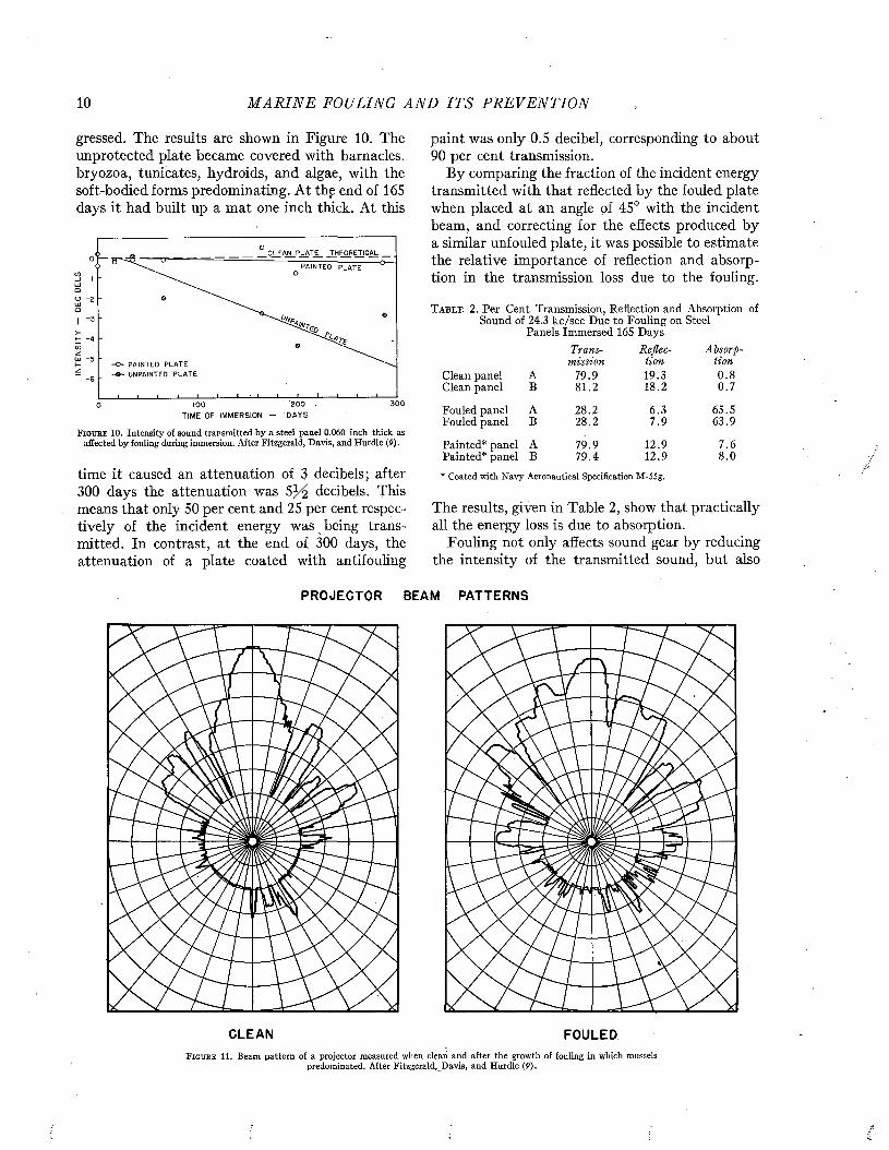
gressed. The results are shown in Figure 10. The unprotected plate became covered with barnacles, bryozoa, tunicates, hydroids, and algae, with the soft-bodied forms predominating. At the end of 165 days it had built up a mat one inch thick. At this
CLEAN PLATE THEORETICAL0PAINTED PLATE
mO - 2 UJo
■3
>I 4ui -5 H -O - PAINTED PLATE
-© - UNPAINTED PLATEz•6
300'2001000T I M E O F I M M E R S IO N - D A Y S
F i g t j b e 10. Intensity of sound transmitted by a steel panel 0.060 inch thick as affected by fouling during immersion. After Fitzgerald, Davis, and Hurdle (P) .
time it caused an attenuation of 3 decibels; after 300 days the attenuation was decibels. This means that only 50 per cent and 25 per cent respectively of the incident energy was being transmitted. In contrast, at the end of 300 days, the attenuation of a plate coated with antifouling
paint was only 0.5 decibel, corresponding to about 90 per cent transmission.
By comparing the fraction of the incident energy transmitted with that reflected by the fouled plate when placed at an angle of 45° with the incident beam, and correcting for the effects produced by a similar unfouled plate, it was possible to estimate the relative importance of reflection and absorption in the transmission loss due to the fouling.
T a b l e 2 . Per Cent Transmission, Reflection and Absorption of Sound of 2 4 .3 kc/sec Due to Fouling on Steel
Panels Immersed 165 DaysTrans- Re flee- Absorp-
mission lion lionClean panel A 79.9 19.3 0 .8Clean panel B 81.2 18.2 0 .7
Fouled panel A 28.2 6 .3 65.5Fouled panel B 28.2 7 .9 63.9
Painted* panel A 79.9 12.9 7.6Painted* panel B 79.4 12.9 8 .0
* Coated with N avy Aeronautical Specification M-55g.
The results, given in Table 2, show that practically all the energy loss is due to absorption.
Fouling not only affects sound gear by reducing the intensity of the transmitted sound, but also
PROJECTOR BEAM PATTERNS
CLEAN FOULEDF i g u r e 11. Beam pattern of a projector measured when clean and after the growth of fouling in which mussels
predominated. After Fitzgerald, Davis, and Hurdle (P).
T H E EFFECTS OF FOULING 11
modifies the field pattern of a projector. Figure 11 shows the field pattern of a projector measured before and after the accumulation of a heavy growth in which mussels predominated.
Underwater sound equipment tends to foul because the exposed surfaces are usually constructed of metals which do not resist fouling, or because, if toxic materials such as copper or its alloys are employed, they are inactivated by galvanic effects resulting from coupling with iron structures. Usually the surfaces of sound equipm ent are not protected with antifouling paint, either through disregard of the difficulties which may arise from fouling or for fear tha t the paint coating will interfere with the operation of the equipment.
The effect of coatings of antifouling paint on sound transmission have been studied, using sound varying in frequency. The result, shown in Figure 12, indicates that the use of a special coating developed at the Naval Research Laboratory for the purpose produces no essential change in the sound
80
70
40
O C L E A N P L A T E
• N R L S P E C I A L CO A T IN G
□ S T A N D A R D H O T P L A S T I C
30
-D- -Q"20 2 2 24 28 30 3626 32 34 38 40
FREQUENCY — K C / S E C .
F i g u r e 12. Transm ission of sound of varying frequency through steel plates, uncoated, pain ted w ith a special coating (N avy A eronautical specification M-559) and with s tandard hot plastic shipbottom paint. A fter Fitzgerald, Davis, and H urdle (P).
transmission of a steel panel. ■ The standard hot plastic shipbottom paint, on the other hand, reduces the sound transmission very greatly. This effect is attributed to the presence of air occluded in the coating.
S A L T W A T E R PIPE S Y S T E M SPipes and conduits used to distribute salt water
in vessels, industrial plants, and aquaria provide favorable places for fouling organisms to grow. Flow is interfered with due to the decreased size of the channel and the increased roughness of the surface. There is always danger th a t the systems
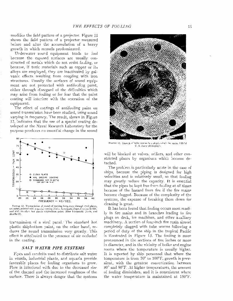
F i g u r e 13. Growth of tube worms in a ship’s 4-inch fire main. Official U . S. N avy photograph.
will be blocked at valves, orifices, and other constricted places by organisms which become detached.
The problem is particularly acute in the case of ships, because the piping is designed for high velocities and is relatively small, so that fouling may greatly reduce the capacity. I t is essential tha t the pipes be kept free from fouling at all times because of the hazard from fire if the fire mains become clogged. Because of the complexity of the systems, the expense of breaking them down for cleaning is great.
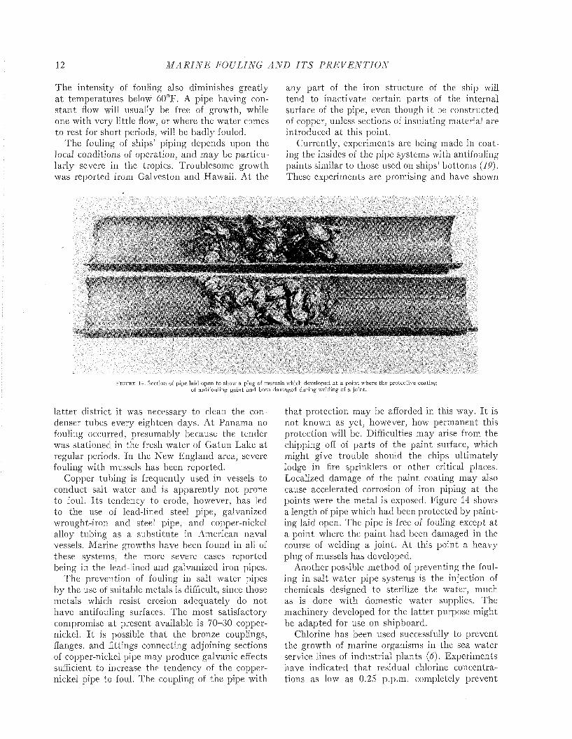
I t has been found tha t fouling occurs most readily in fire mains and in branches leading to fire plugs on deck, ice machines, and other auxiliary machinery. A section of four-inch fire main almost completely clogged with tube worms following a period of duty of the ship in the tropical Pacific is illustrated in Figure 13. The fouling is more pronounced in the sections of five inches or more in diameter, and in the vicinity of boiler and engine rooms where the temperature is usually higher. I t is reported by ship personnel that where the temperature is from 70° to 100°F, growth is prevalent, with the greatest concentration between 80° and 90°F. A t higher temperatures, the amount of fouling diminishes, and it is nonexistent where the water tem perature is maintained at 150°F.
12 M A R I N E FOULING A N D I T S P R E V E N T I O N
The intensity of fouling also diminishes greatly a t temperatures below 60°F. A pipe having constan t flow will usually be free of growth, while one with very little flow, or where the water comes to rest for short periods, will be badly fouled.
The fouling of ships’ piping depends upon the local conditions of operation, and may be particularly severe in the tropics. Troublesome growth was reported from Galveston and Hawaii. At the
any part of the iron structure of the ship will tend to inactivate certain parts of the internal surface of the pipe, even though it be constructed of copper, unless sections of insulating material are introduced at this point.
Currently, experiments are being made in coating the insides of the pipe systems with antifouling paints similar to those used on ships’ bottoms (19). These experiments are promising and have shown
F i g u r e 14. Section of pipe laid open to show a plug of mussels which developed a t a point where the protective coating of antifouling pain t had been dam aged during welding of a joint.
latter district it was necessary to clean the condenser tubes every eighteen days. A t Panama no fouling occurred, presumably because the tender was stationed in the fresh water of Gatun Lake at regular periods. In the New England area, severe fouling with mussels has been reported.
Copper tubing is frequently used in vessels to conduct salt water and is apparently not prone to foul. Its tendency to erode, however, has led to the use of lead-lined steel pipe, galvanized wrought-iron and steel pipe, and copper-nickel alloy tubing as a substitute in American naval vessels. Marine growths have been found in all of these systems, the more severe cases reported being in the lead-lined and galvanized iron pipes.
The prevention of fouling in salt water pipes by the use of suitable metals is difficult, since those metals which resist erosion adequately do not have antifouling surfaces. The most satisfactory compromise a t present available is 70-30 copper- nickel. I t is possible that the bronze couplings, flanges, and fittings connecting adjoining sections of copper-nickel pipe may produce galvanic effects sufficient to increase the tendency of the copper- nickel pipe to foul. The coupling of the pipe with
that protection may be afforded in this way. I t is not known as yet, however, how permanent this protection will be. Difficulties may arise from the chipping off of parts of the paint surface, which might give trouble should the chips ultimately lodge in fire sprinklers or other critical places. Localized damage of the paint coating may also cause accelerated corrosion of iron piping at the points were the metal is exposed. Figure 14 shows a length of pipe which had been protected by painting laid open. The pipe is free of fouling except at a point where the paint had been damaged in the course of welding a joint. At this point a heavy plug of mussels has developed.
Another possible method of preventing the fouling in salt water pipe systems is the injection of chemicals designed to sterilize the water, much as is done with domestic water supplies. The machinery developed for the latter purpose might be adapted for use on shipboard.
Chlorine has been used successfully to prevent the growth of marine organisms in the sea water service lines of industrial plants (6). Experiments have indicated th a t residual chlorine concentrations as low as 0.25 p.p.m. completely prevent
T H E EFF ECTS OF FOULING 13
fouling in flowing salt water lines. Unfortunately, the quantities of water circulated through a ship are so large that treatm ent to even this small concentration is difficult. The use of compressed chlorine gas on shipboard is prohibited. Electrolytic generation of chlorine requires bulky equipm ent and presents other technical difficulties. The use of chemical sources such as calcium hypochlorite involves a considerable storage and maintenance problem. Finally it has been found that even these small concentrations of chlorine greatly increase the corrosion of steel piping (34). Such corrosive effects are thought to be due to the elimination of protective coatings of slime by the chlorine, rather than to any direct chemical effect by the small concentrations of chlorine.
Experiments have indicated that sodium penta- chlorphenate, sold under various trade names such as Santobrite and Dowicide, might be preferable to chlorine for use on shipboard. The introduction of sodium pentachlorphenol in concentrations of 1 p.p.m. completely prevented the fouling of steel pipes, without increasing the rate of corrosion. Recent tests conducted in collaboration with the Boston Navy Yard have led to the development of suitable equipment for treating salt water lines of vessels with this material. A product sold as Nalco 21 M has sufficient solubility in sea water to be adapted to the purpose. The chief disadvantage is the added maintenance and supply problem, and the irritating character of the material, which must be handled with some care.
Power stations, oil refineries, and other users of sea water for industrial purposes may be greatly inconvenienced by the growth of fouling organisms in their water circuits. The growth reduces the carrying capacity of the conduits by increasing the frictional resistance as well as by reducing the pipe line diameter. The growth of sponges in a 60-inch pipe has been known to reduce the Hazen Williams coefficient by 35 per cent. The growths continue to accumulate until they are so great that they may be torn loose and swept into screens, tube sheets, or pumps. The resultant stoppage may allow pressures to accumulate in the systems to the breaking point. When used for fire service, the sudden rush of water has loosened the fouling which has blocked valves, hydrants, and nozzles, and even completely shut off the water supply with disastrous results ( 6)-
In addition to the inefficiencies of operation and the hazards caused by fouling growths, expense arises from the necessity of closing down parts of the system for cleaning. As much as 266 tons of
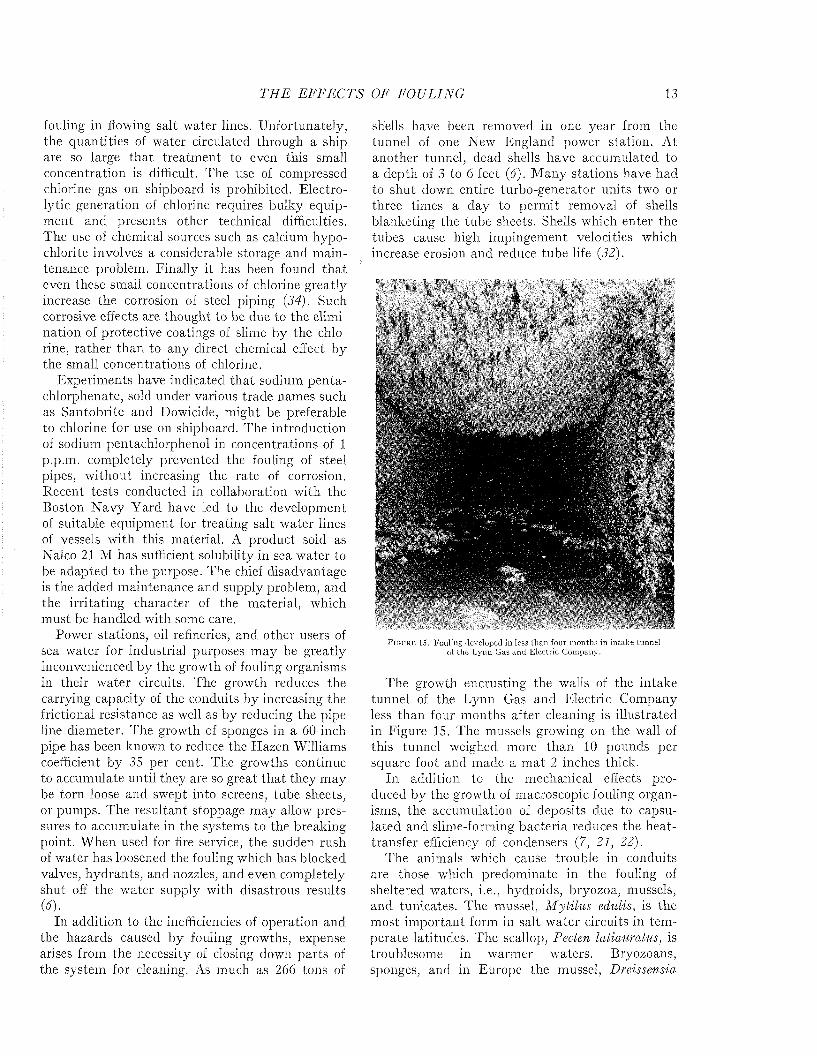
shells have been removed in one year from the tunnel of one New England power station. At another tunnel, dead shells have accumulated to a depth of 3 to 6 feet (6). M any stations have had to shut down entire turbo-generator units two or three times a day to permit removal of shells blanketing the tube sheets. Shells which enter the tubes cause high impingement velocities which increase erosion and reduce tube life (32).
i
F i g u r e 15. Fouling developed in less than four m onths in in take tunnel of the Lynn Gas and Electric Company.
The growth encrusting the walls of the intake tunnel of the Lynn Gas and Electric Company less than four months after cleaning is illustrated in Figure 15. The mussels growing on the wall of this tunnel weighed more than 10 pounds per square foot and made a m at 2 inches thick.
In addition to the mechanical effects produced by the growth of macroscopic fouling organisms, the accumulation of deposits due to capsu- lated and slime-forming bacteria reduces the heat- transfer efficiency of condensers (7, 21, 22).
The animals which cause trouble in conduits are those which predominate in the fouling of sheltered waters, i.e., hydroids, bryozoa, mussels, and tunicates. The mussel, Mytilus edulis, is the most im portant form in salt water circuits in tem perate latitudes. The scallop, Pecten latiauratus, is troublesome in warmer waters. Bryozoans, sponges, and in Europe the mussel, Dreissensia
14 M A R I N E FOULING A N D I T S P R E V E N T I O N
polymorpha, are responsible for blocking fresh water lines. The algae give little trouble except in sunlit portions of the installations.
Numerous methods have been suggested for preventing the fouling of industrial circuits, but few meet the essential requirements of being economical to install and operate, and of effectively eliminating the fouling without interrupting the operation of the plant.
Screens fine enough to exclude the larvae are impractical because they clog too readily with silt and detritus.
The organisms could be killed by suffocation only by shutting down frequently and allowing the water to stagnate until its oxygen content is exhausted.
High water velocities might be employed effectively to reduce fouling where such velocities can be maintained without undue cost of pumping, but fouling might still occur if temporary interruptions or localized areas of redúced velocity permitted the attachment of larvae. Fouling so established would be in danger of being torn loose and swept into critical structures such as pumps or condensers unless these were protected by suitable catch basins.
Fresh water might be used to kill off the organisms of salt water circuits, but this would be effective only if the treatment were continued for some time, since many shelled forms such as the mussel can resist adverse conditions by closing their shells. The remains of fouling killed in this way would be apt to clog critical structures.
Antifouling paints cannot be economically applied because they must be renewed frequently. In addition to the cost of their application and the shutdown time required, it would be very difficult to secure a sufficiently clean and dry surface for the successful renewal of the coatings. Some plants have used coal-oil, gas-oil-drip, kerosene, and similar oily products for control. Some control is obtained above the low water level, since the walls become coated with these materials and become unsuited to the attachment of the fouling. No control is obtained below the low water line, however.
The earliest method of control attempted on plant scale was heating the circulating water. The circulating water can be throttled until the desired heat exchange is obtained at the condensers. By reversing the circulation in the system, all parts may be subjected alternately to the heated water. Successful control of mussel fouling was obtained by heating the water to about 90°F for
a period of twelve hours. The treatment must be repeated at monthly intervals during the spawning season to kill the mussels before their shells reach sizes that would be harmful. The cost of operating such a system can be extremely high because of the fuel consumed in heating the water. Installation costs are also increased, because the system and, particularly, the pumps must be designed for reverse flow. It is only for plants having waste heat available that the cost is not prohibitive (31).
A variety of methods of controlling fouling by introducing poisonous materials into the water have been attempted or considered. Active poisons such as cyanide are rejected because of the danger to human life. Treatment with sulphuric acid has been tried by a private firm at the Leith Docks and was partially successful, but was abandoned because of the severe corrosion which resulted. T obe effective, sulphuric acid must be added in a proportion of 150 p.p.m. so as to reduce the pH to 3. The cost of the acid required is itself prohibitive, irrespective of the corrosive damage.
The most successful and economical method of treatment is with chlorine. Power stations scattered along the Atlantic coast from Massachusetts to Texas have controlled fouling by this means. Although experiments indicate that continuous treatment with chlorine residuals of 0.25 p.p.m. is adequate to prevent fouling, experience at plant scale indicates that residuals of 0.5 to 1.0 p.p.m. are required. Economies can be had by employing intermittent treatment, provided it is frequent enough to prevent larvae which enter the system between applications from developing shells. Adult mussels can close their shells and resist the action of the poison for several days, and prolonged treatment is consequently required when it is desired to kill mussels which have become established. Further economy may be had by omitting the treatment at those seasons when the larvae are absent from the water.
In a 25,000 Kw station, marine fouling can be controlled by the use of chlorine at a cost of about $3.50 per day during the fouling season. More than this amount is saved in increased efficiency of the installation and in the reduction in cost of cleaning (6).
DESTRUCTIVE EFFECTSIn addition to interfering with the function of
the structures on which it grows, fouling may accelerate the corrosion of their metallic surfaces or
T H E EFFECTS OF FOULING 15
injure the paint coatings intended to protect them from rusting.
I t has been argued that a heavy m at of fouling may actually protect the surface from corrosion by preventing the renewed access of sea water or of the oxygen which is required for rusting. This view is supported by the clean appearance of the steel and the absence of red rust when the fouling is scraped away. Friend noted tha t the shell fauna did not appear to affect corrosion of metals appreciably while living, bu t tha t dead organisms stimulated local corrosion, leaving more or less circular patches of damage (10). When individual
but not with calcareous tube worms or algae. LaQue and Clapp did not observe pitting associated with barnacles or bryozoa which were known to be alive, and suggest that it is only when they die tha t conditions are favorable for excessive p itting. This observation has been confirmed by Mr.C. M. Weiss a t Miami. He observed pitting only under the shells of barnacles which were dead, not under the encrusting bryozoa or other forms which grew on the panels.
The pitting frequently shows a radial pattern or concentric rings which reflect the structure and growth characteristic of the barnacle base. Some-
-V
« s s '
'‘i , f
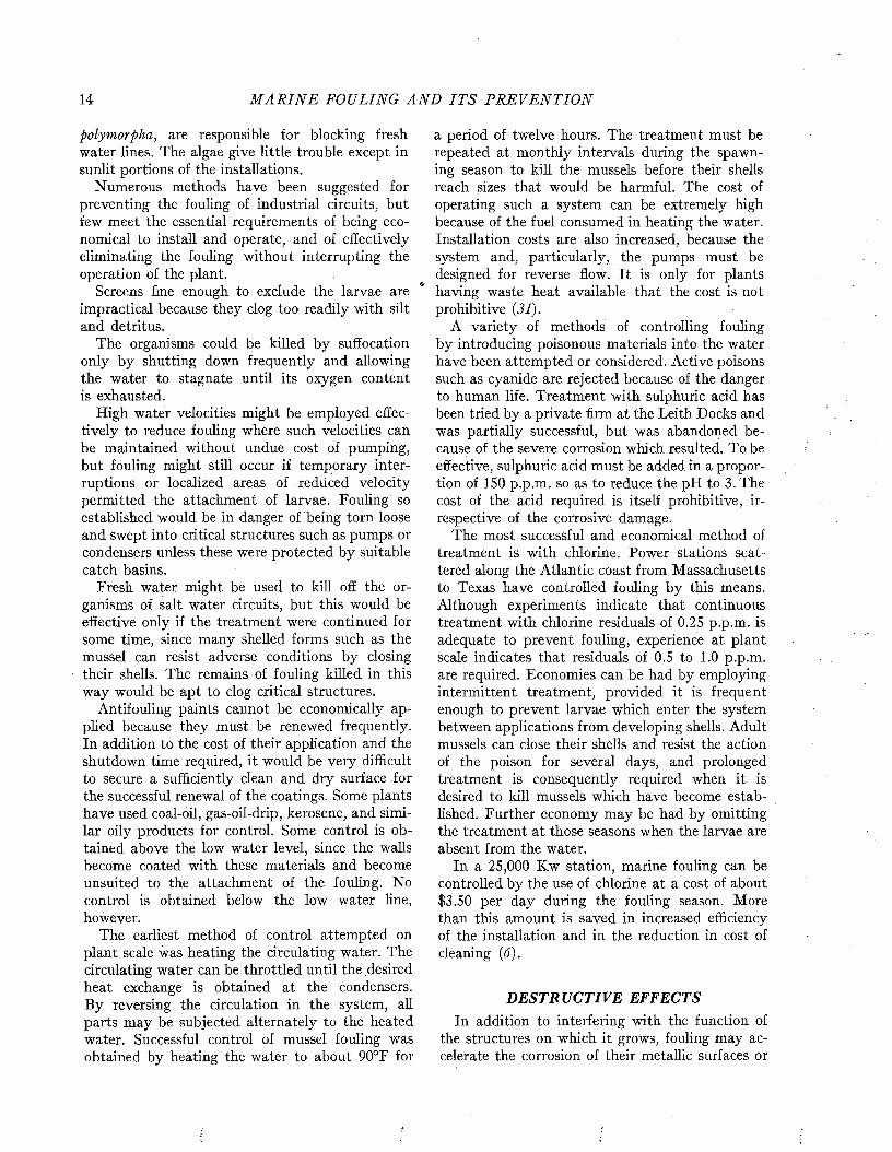
X 'K , ccri JF i g u r e 16. Localized corrosion of nickel beneath the bases of barnacles. {Left) Fouled condition of the panel after one m onth’s
exposure. {Right) P its in the m etal revealed by rem oval of three of the barnacles.
organisms become covered up and smothered by their neighbors, localized corrosion is caused. An example of this action is illustrated in Figure 16. Passive and marginally passive alloys, such as stainless steel and nickel alloys, in which the surrounding surfaces of the metal remain relatively smooth, show particularly clearly the localized corrosion which occurs under fouling organisms.
LaQue and Clapp have observed quite noticeable pitting of nickel-copper alloys within 11 days after the fouling appeared (16). P its 1.3 mm. deep may develop in 26 days in an alloy containing about 85 per cent nickel and 15 per cent copper. The action is confined to alloys containing 50 per cent copper or less, which foul readily. Unlike most metals the rate of weight loss of these alloys increases during the period of exposure to sea water, a result attributed to the corrosion induced by the fouling. I t was observed tha t these effects were associated with barnacles and filamentous bryozoa,
times the central area stands up as a prominence of uncorroded metal, a t other times it is more deeply corroded than the outer area. After the organism has become detached, the pitted area may continue to corrode, with the result that its characteristic pattern is destroyed.
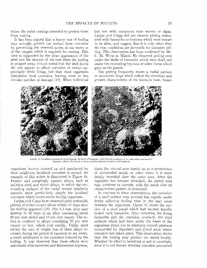
In contrast to these observations, the corrosion of a steel surface may proceed less rapidly under firmly adhering fouling than in the bare areas between the organisms. Figure 17 shows the surface of a steel panel which had become heavily fouled with barnacles. After removing the living barnacles and the corrosion products, the steel surfaces which had been under the bases of the organisms stand out as relatively smooth plateaus surrounded by depressed and pitted areas where corrosion has taken place. This observation shows tha t the fouling may protect the metal locally. W hether its effect is beneficial or not is uncertain, since it is not known whether corrosion proceeded
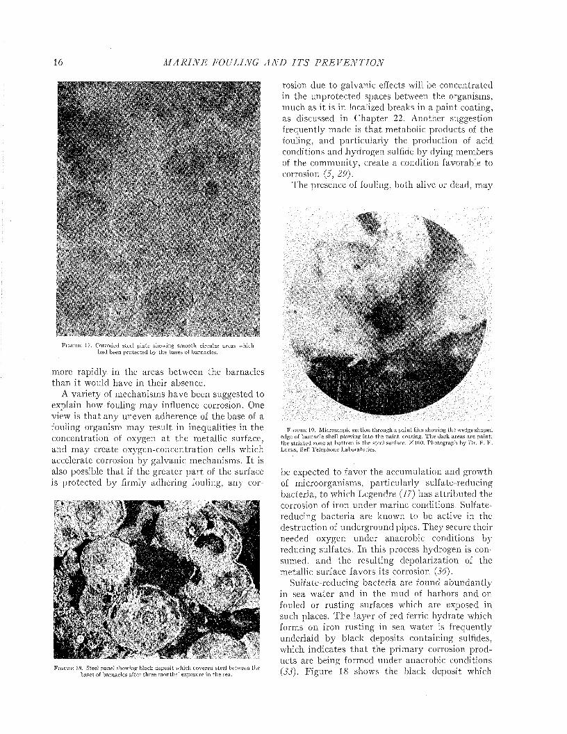
16 M A R I N E FOULING A N D I T S P R E V E N T I O N
F i g u r e 17. Corroded steel plate showing sm ooth circular areas which had been protected by the bases of barnacles.
more rapidly in the areas between the barnacles than it would have in their absence.
A variety of mechanisms have been suggested to explain how fouling may influence corrosion. One view is that any uneven adherence of the base of a fouling organism may result in inequalities in the concentration of oxygen at the metallic surface, and may create oxygen-concentration cells which accelerate corrosion by galvanic mechanisms. I t is also possible th a t if the greater part of the surface is protected by firmly adhering fouling, any cor-
F i g u r e 18. Steel panel showing black deposit which covered steel between the bases of barnacles after three m onths’ exposure in the sea.
rosion due to galvanic effects will be concentrated in the unprotected spaces between the organisms, much as it is in localized breaks in a paint coating, as discussed in Chapter 22. Another suggestion frequently made is tha t metabolic products of the fouling, and particularly the production of acid conditions and hydrogen sulfide by dying members of the community, create a condition favorable to corrosion (5, 29).
The presence of fouling, both alive or dead, may
111i
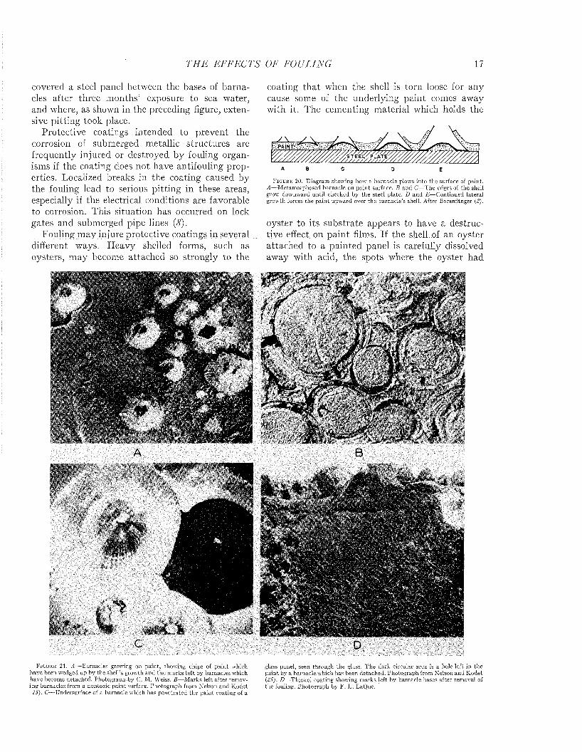
F i g u r e 19. M icroscopic section through a pain t film showing the wedge shaped edge of barnacle shell plowing into the pain t coating. T he dark areas are paint; the s tria ted zone a t bottom is the steel surface. XlOO. Photograph by Dr. F . F . Lucas, Bell Telephone Laboratories.
be expected to favor the accumulation and growth of microorganisms, particularly sulfate-reducing bacteria, to which Legendre (17) has attributed the corrosion of iron under marine conditions. Sulfate- reducing bacteria are known to be active in the destruction of underground pipes. They secure their needed oxygen under anaerobic conditions by reducing sulfates. In this process hydrogen is consumed, and the resulting depolarization of the metallic surface favors its corrosion (36).
Sulfate-reducing bacteria are found abundantly in sea water and in the mud of harbors and on fouled or rusting surfaces which are exposed in such places. The layer of red ferric hydrate which forms on iron rusting in sea water is frequently underlaid by black deposits containing sulfides, which indicates th a t the primary corrosion products are being formed under anaerobic conditions (33). Figure 18 shows the black deposit which
T H E EFFECTS OF FOULING 17
covered a steel panel between the bases of barnacles after three months’ exposure to sea water, and where, as shown in the preceding figure, extensive pitting took place.
Protective coatings intended to prevent the corrosion of submerged metallic structures are frequently injured or destroyed by fouling organisms if the coating does not have antifouling properties. Localized breaks in the coating caused by the fouling lead to serious pitting in these areas, especially if the electrical conditions are favorable to corrosion. This situation has occurred on lock gates and submerged pipe lines (<?).
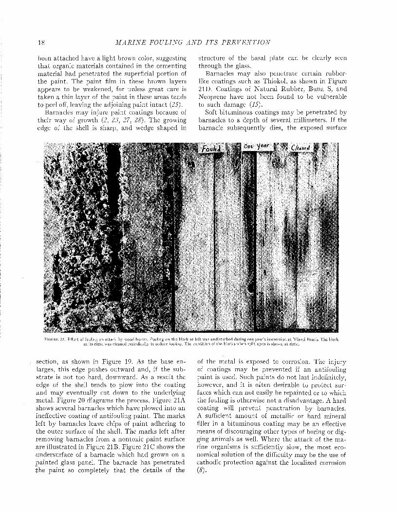
Fouling may injure protective coatings in several different ways. Heavy shelled forms, such as oysters, may become attached so strongly to the
CF i g u r e 21 , A — Barnacles growing on pain t, showing chips of pa in t which
have been wedged up by the shell’s growth and the m arks le ft by barnacles which have become detached. Photograph by C. M . Weiss. B —M arks left after rem oving barnacles from a nontoxic pain t surface. Photograph from Nelson and K odet
25). C— Undersurface of a barnacle which has penetrated the pain t coating of a
coating that when the shell is torn loose for any cause some of the underlying paint comes away with it. The cementing material which holds the
• S T E E L C P L A T E
A 8 C 0 E
F i g u r e 20. D iagram showing how a barnacle plows in to the surface of paint. A —M etam orphosed barnacle on pain t surface. B and C—T he edges of the shell grow downward until checked by the steel plate. D and E — Continued lateral grow th forces the pain t upw ard over the barnacle’s shell. A fter Bärenfänger (2),
oyster to its substrate appears to have a destructive effect on paint films. If the shell of an oyster attached to a painted panel is carefully dissolved away with acid, the spots where the oyster had
Dglass panel, seen through the glass. T he dark circular area is a hole le ft in the pain t by a barnacle which has been detached. P hotograph from Nelson and K odet (25). D—Thiokol coating showing m arks left by barnacle bases after removal of the fouling. Photograph by F . L. LaQue.
18 M A R I N E FOULING A N D I T S P R E V E N T I O N
been attached have a light brown color, suggesting th a t organic materials contained in the cementing material had penetrated the superficial portion of the paint. The paint film in these brown layers appears to be weakened, for unless great care is taken a thin layer of the paint in these areas tends to peel off, leaving the adjoining paint intact (25).
Barnacles may injure paint coatings because of their way of growth (2, 23, 27, 28). The growing edge of the shell is sharp, and wedge shaped in
structure of the basal plate can be clearly seen through the glass.
Barnacles may also penetrate certain rubberlike coatings such as Thiokol, as shown in Figure 21D. Coatings of N atural Rubber, Buna S, and Neoprene have not been found to be vulnerable to such damage (15).
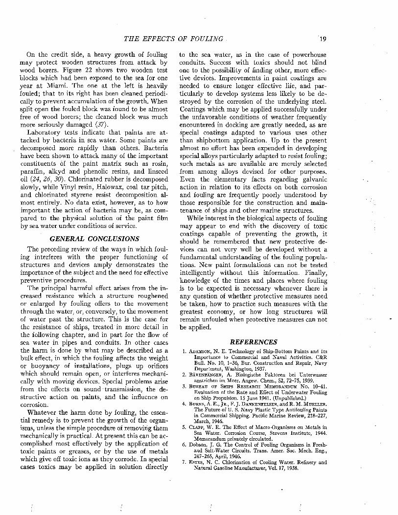
Soft bituminous coatings may be penetrated by barnacles to a depth of several millimeters. If the barnacle subsequently dies, the exposed surface
F i g u r e 22. Effect oí fouling on a ttack by wood borers. Fouling on the block a t left was undisturbed during one yea r’s im mersion a t M iami Beach. T he block a t its right was cleaned periodically to reduce fouling. T h e condition of the blocks when split open is shown a t right.
section, as shown in Figure 19. As the base enlarges, this edge pushes outward and, if the substrate is not too hard, downward. As a result the edge of the shell tends to plow into the coating and m ay eventually cut down to the underlying metal. Figure 20 diagrams the process. Figure 21A shows several barnacles which have plowed into an ineffective coating of antifouling paint. The marks left by barnacles leave chips of paint adhering to the outer surface of the shell. The marks left after removing barnacles from a nontoxic paint surface .are illustrated in Figure 21B. Figure 21C shows the undersurface of a barnacle which had grown on a painted glass panel. The barnacle has penetrated the paint so completely that the details of the
of the metal is exposed to corrosion. The injury of coatings may be prevented if an antifouling paint is used. Such paints do not last indefinitely, however, and it is often desirable to protect surfaces which can not easily be repainted or to which the fouling is otherwise not a disadvantage. A hard coating will prevent penetration by barnacles. A sufficient amount of metallic or hard mineral filler in a bituminous coating m ay be an effective means of discouraging other types of boring or digging animals as well. Where the attack of the marine organisms is sufficiently slow, the most economical solution of the difficulty may be the use of cathodic protection against the localized corrosion (*)•
THE EFFECTS OF FOULING 19
On the credit side, a heavy growth of fouling may protect wooden structures from attack by wood borers. Figure 22 shows two wooden test blocks which had been exposed to the sea for one year at Miami. The one at the left is heavily fouled; that to its right has been cleaned periodically to prevent accumulation of the growth. When split open the fouled block was found to be almost free of wood borers; the cleaned block was much more seriously damaged (37).
Laboratory tests indicate that paints are attacked by bacteria in sea water. Some paints are decomposed more rapidly than others. Bacteria have been shown to attack many of the important constituents of the paint matrix such as rosin, paraffin, alkyd and phenolic resins, and linseed oil (24, 26, 30). Chlorinated rubber is decomposed slowly, while Vinyl resin, Halowax, coal tar pitch, and chlorinated styrene resist decomposition almost entirely. No data exist, however, as to how important the action of bacteria may be, as compared to the physical solution of the paint film by sea water under conditions of service.
GENERAL CONCLUSIONSThe preceding review of the ways in which foul
ing interferes with the proper functioning of structures and devices amply demonstrates the importance of the subject and the need for effective preventive procedures.
The principal harmful effect arises from the increased resistance which a structure roughened or enlarged by fouling offers to the movement through the water, or, conversely, to the movement of water past the structure. This is the case for the resistance of ships, treated in more detail in the following chapter, and in part for the flow of sea water in pipes and conduits. In other cases the harm is done by what may be described as a bulk effect, in which the fouling affects the weight or buoyancy of installations, plugs up orifices which should remain open, or interferes mechanically with moving devices. Special problems arise from the effects on sound transmission, the destructive action on paints, and the influence on corrosion.
Whatever the harm done by fouling, the essential remedy is to prevent the growth of the organisms, unless the simple procedure of removing them mechanically is practical. At present this can be accomplished most effectively by the application of toxic paints or greases, or by the use of metals which give off toxic ions as they corrode. In special cases toxics may be applied in solution directly
to the sea water, as in the case of powerhouse conduits. Success with toxics should not blind one to the possibility of finding other, more effective devices. Improvements in paint coatings are needed to ensure longer effective life, and particularly to develop systems less likely to be destroyed by the corrosion of the underlying steel. Coatings which may be applied successfully under the unfavorable conditions of weather frequently encountered in docking are greatly needed, as are special coatings adapted to various uses other than shipbottom application. Up to the present almost no effort has been expended in developing special alloys particularly adapted to resist fouling; such metals as are available are merely selected from among alloys devised for other purposes. Even the elementary facts regarding galvanic action in relation to its effects on both corrosion and fouling are frequently poorly understood by those responsible for the construction and maintenance of ships and other marine structures.
While interest in the biological aspects of fouling may appear to end with the discovery of toxic coatings capable of preventing the growth, it should be remembered that new protective devices can not very well be developed without a fundamental understanding of the fouling populations. New paint formulations can not be tested intelligently without this information. Finally, knowledge of the times and places where fouling is to be expected is necessary whenever there is any question of whether protective measures need be taken, how to practice such measures with the greatest economy, or how long structures will remain unfouled when protective measures can not be applied.
REFERENCES1. A d a m s o n , N. E. Technology of Ship-Bottom Paints and Its
Importance to Commercial and Naval Activities. C&R Bull. No. 10, 1-36, Bur. Construction and Repair, Navy Department, Washington, 1937.
2. B ä r e n f ä n g e r , A. Biologische Faktoren bei Unterwasseranstrichen im Meer. Angew. Chem., 52, 72-75, 1939.
3 . B u r e a u o f S h i p s R e s e a r c h M e m o r a n d u m N o . 1 0 -4 1 .Evaluation of the Rate and Effect of Underwater Fouling on Ship Propulsion. 15 June 1941. (Unpublished.)
4. B u r n s , A. E., J r . , F. J. D a n n e n f e l s e r , and R. M. M u e l l e r .. The Future of U. S. Navy Plastic Type Antifouling Paints in Commercial Shipping. Pacific Marine Review, 218-227, March, 1946.
5. C l a p p , W. E. The Effect of Macro-Organisms on Metals inSea Water. Corrosion Course, Stevens Institute, 1944. Memorandum privately circulated.
6. Dobson, J. G. The Control of Fouling Organisms in Fresh-and Salt-Water Circuits. Trans. Amer. Soc. Mech. Eng., 247-265, April, 1946.
7. E s t e s , N. C. Chlorination of Cooling Water. Refinery andNatural Gasoline Manufacturer, Vol. 17, 19 3 8 .

Marine Fouling and Its Prevention,Contribution No. 580 from the Woods Flole Oceanographic Institute
Copyright 1952 by U. S. Naval Institute, Annapolis, Maryland George Banta Publishing Co., Menasha, WI
CHAPTER 2
Ship ResistanceThe theory of ship resistance has been elabo
rated by naval architects as a means of predicting ship performance from preliminary experiments with models. A full discussion of this theory or of the technique of testing the resistance of models or of full-scale ships by trial runs is beyond the scope of the present volume. However, since the data bearing on the effects of fouling and of protective coatings on the efficiency of ships during oper- ration are expressed in the terms of this theory and were obtained by these techniques, it is necessary to present an elementary account of these matters. For a more complete treatment, standard works such as those of Taylor (24), Davidson (7), Saunders and Pitre (18, 20, 21) may be consulted.
The resistance offered by a ship to movement through water may be resolved into two principal components: frictional resistance and residual resistance. The frictional resistance arises from frictional forces set up by the flow of water along the surface of the hull, and is consequently influenced by fouling and the coatings of paint used for its prevention. The residual resistance is due to pressures developed in pushing the water aside, and arises from the form of the hull.
William Froude first recognized that the residual resistance of a model could be scaled up to give the residual resistance of the full-scale ship by use of the principle of similitude developed by Newton. The frictional resistance, however, follows laws of its own and can not be so treated. Froude consequently studied the frictional resistance of towed planks in order to determine empirically the relations between frictional resistance, length, surface area, and speed. Armed with this information, it is possible to estimate the frictional resistance of a model. This value is subtracted from the total resistance of the model to obtain its residual resistance. The residual resistance is then scaled up to give that of the full-sized ship. The frictional resistance, calculated for the full scale from the plank tests, is added to give the total resistance of the ship. This is the fundamental procedure in all model testing.
The total resistance of a ship to motion may be measured by trial runs over measured courses made both before and after fouling has occurred. The influence öf fouling on the relation of speed to propulsive force can be measured in a direct and
convincing way. This method is unavoidably expensive, since a full-sized ship must be kept available over a protracted period. It does not lend itself to the full analysis of the nature of the resistance unless supplemented by tests on “planks” which determine the frictional resistance separately.
Plank tests are conducted by towing long, thin plates in tanks. The resistance offered by such structures may be assumed to be due almost entirely to frictional forces and may be related directly to the roughness of the surface or to its fouled condition. This method of study is indirect in that the results can be applied to actual ships only with the aid of theoretical calculations supplemented by towing data on ship models or full-scale ships. Its relative simplicity and lower cost commends it, however, for detailed studies on the effects of surface roughness which may characterize painted, corroded, or fouled bottoms.
For the purposes of the paint technologist, effective information can be obtained without the complete solution of the resistance problem required by the naval architect. Reliable and simple procedures for estimating the relative frictional resistance of variously treated surfaces will be of value in guiding his technique, even though they do not supply data adequate for the needs of the ship designer.
The plank tests may be likened to the panel tests used in evaluating the protective action of coatings. Their value to the paint technician lies in the ease with which comparative evaluations can be made, not in the precision with which they foretell the performance of ships in sevice. The tests by trial run, on the other hand, like the service tests of paint coatings, give a direct measure of the phenomena in question.
THE TOTAL RESISTANCE OF SHIPSThe force required to propel a ship at any
given speed may be measured by trial runs over a standard course in which the ship is self-propelled or is towed by another vessel. To obtain reliable results, an exacting technique must be followed in which a series of observations are made at each fixed speed, during which the vessel alternates its direction over the course in order to neutralize the effects of current. The trials should be run in quiet waters, since the state of the sea can not 'be
21
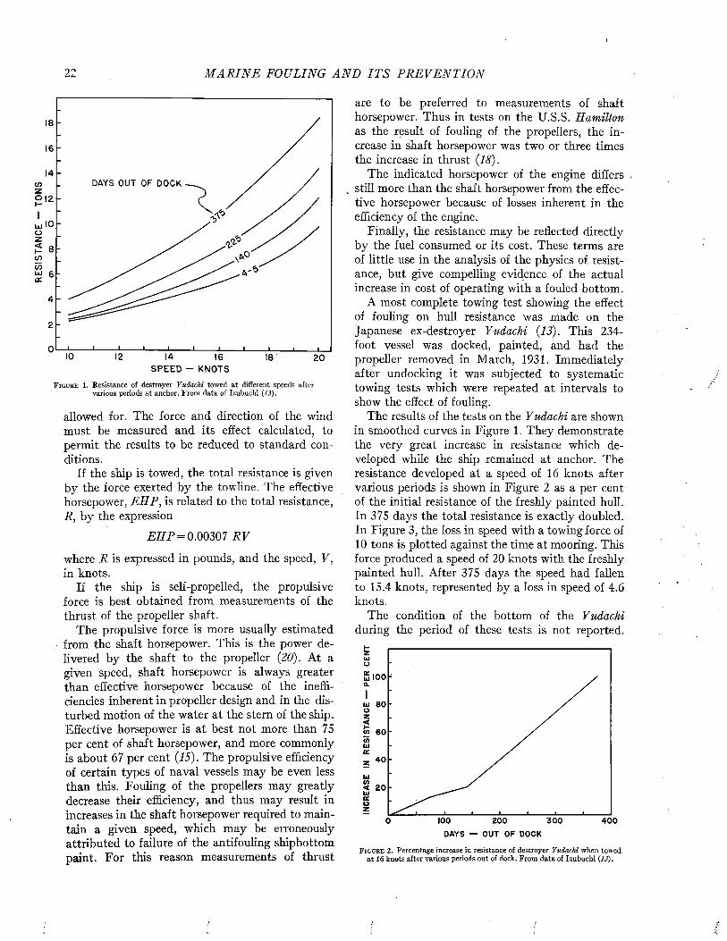
RES
ISTA
NC
E -
TO
NS
22 M A R I N E FOULING A N D I T S P R E V E N T I O N
18
16
14
IO
8
6
4
2
0 IO 12 14 16 18 20S PEED - KNOTS
F i g u r e 1. Resistance of destroyer Yudachi towed at different speeds after various periods at anchor. From data of Izubuchi (13).
allowed for. The force and direction of the wind must be measured and its effect calculated, to permit the results to be reduced to standard conditions.
If the ship is towed, the total resistance is given by the force exerted by the towline. The effective horsepower, EHP, is related to the total resistance, R, by the expression
E H P = 0.00307 RV
where R is expressed in pounds, and the speed, V, in knots.
If the ship is self-propelled, the propulsive force is best obtained from measurements of the thrust of the propeller shaft.
The propulsive force is more usually estimated from the shaft horsepower. This is the power delivered by the shaft to the propeller (20). At a given speed, shaft horsepower is always greater than effective horsepower because of the inefficiencies inherent in propeller design and in the disturbed motion of the water at the stern of the ship. Effective horsepower is at best not more than 75 per cent of shaft horsepower, and more commonly is about 67 per cent (15). The propulsive efficiency of certain types of naval vessels may be even less than this. Fouling of the propellers may greatly decrease their efficiency, and thus may result in increases in the shaft horsepower required to maintain a given speed, which may be erroneously attributed to failure of the antifouling shipbottom paint. For this reason measurements of thrust
are to be preferred to measurements of shaft horsepower. Thus in tests on the U.S.S. Hamilton as the result of fouling of the propellers, the increase in shaft horsepower was two or three times the increase in thrust (18).
The indicated horsepower of the engine differs still more than the shaft horsepower from the effective horsepower because of losses inherent in the efficiency of the engine.
Finally, the resistance may be reflected directly by the fuel consumed or its cost. These terms are of little use in the analysis of the physics of resistance, but give compelling evidence of the actual increase in cost of operating with a fouled bottom.
A most complete towing test showing the effect of fouling on hull resistance was made on the Japanese ex-destroyer Yudachi (13). This 234- foot vessel was docked, painted, and had the propeller removed in March, 1931. Immediately after undocking it was subjected to systematic towing tests which were repeated at intervals to show the effect of fouling.
The results of the tests on the Yudachi are shown in smoothed curves in Figure 1. They demonstrate the very great increase in resistance which developed while the ship remained at anchor. The resistance developed at a speed of 16 knots after various periods is shown in Figure 2 as a per cent of the initial resistance of the freshly painted hull. In 375 days the total resistance is exactly doubled. In Figure 3, the loss in speed with a towing force of 10 tons is plotted against the time at mooring. This force produced a speed of 20 knots with the freshly painted hull. After 375 days the speed had fallen to 15.4 knots, represented by a loss in speed of 4.6 knots.
The condition of the bottom of the Yudachi during the period of these tests is not reported.
¡5 loo
111 8 0
« eo
4 0
< 20
o 100 200 3 0 0 4 0 0
DAYS — OUT OF DOCK
F i g u r e 2. Percentage increase in resistance of destroyer Yudachi when towed at 16 knots after various periods out of dock. From data of Izubuchi (13).
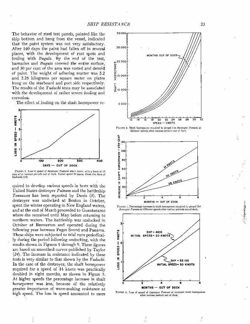
S H I P R E S I S T A N C E 23
The behavior of steel test panels, painted like the ship bottom and hung from the vessel, indicated that the paint system was not very satisfactory. After 140 days the paint had fallen off in several places, with the development of rust spots and fouling with Bugula. By the end of the test, barnacles and Bugula covered the entire surface, and 30 per cent of the area was rusted and devoid of paint. The weight of adhering matter was 5.2 and 2.28 kilograms per square meter on plates hung on the starboard and port side respectively. The results of the Yudachi tests may be associated with the development of rather severe fouling and corrosion.
The effect of fouling on the shaft horsepower re-
sV)
O 4 z*I 3 a 1Ü Uio. 9 </> £-zCO I COo
100 200 3 0 00 4 0 0
DAYS — OUT OF DOCK
F i g u r e 3 . Loss in speed of destroyer Yudachi when towed with a force of 10 tons after various periods out of dock. Initial speed 2 0 knots. From the data of Izubuchi (id).
quired to develop various speeds in tests with the United States destroyer Putnam and the battleship Tennessee has been reported by Davis (8). The destroyer was undocked at Boston in October, spent the winter operating in New England waters, and at the end of March proceeded to Guantanamo where she remained until M ay before returning to northern waters. The battleship was undocked in October at Bremerton and operated during the following year between Puget Sound and Panama. These ships were subjected to trial runs periodically during the period following undocking, with the results shown in Figures 4 through 9. These figures are based on smoothed curves published by Taylor (24). The increase in resistance indicated by these tests is very similar to that shown by the Yudachi. In the case of the destroyer, the shaft horsepower required for a speed of 14 knots was practically doubled in eight months, as shown in Figure 5. At higher speeds the percentage increase in shaft horsepower was less, because of the relatively greater importance of wave-making resistance at high speed. The loss in speed amounted to more
30 000
25 ooo
MONTHS OUT OF DOCK-
20 000
£ 1 5 0 0 0
w 10 000
5 000
12 14 16 18 20 22 24 26 28 30 32S P E E D — KN OT S
F i g u r e 4. Shaft horsepower required to propel the destroyer Putnam at different speeds after various periods out of dock.
120
100
X 60
20
MONTHS — OUT OF DOCK
F i g u r e 5 . Percentage increase in shaft horsepower required to propel the destroyer Putnam at different speeds after various periods out of dock.
3
S HP ■ 4 1 0 0 ^INITIAL S P E E D - 2 0 KNOTS
2
C^__SHP * 22100 INITIAL SPEED - 3 0 KNOTS
84 60 2MONTHS — OUT OF DOCK
F i g u r e 6 . Loss of speed of destroyer Pulnam at constant shaft horsepower after various periods out of dock.

24 M A R I N E FOULING A N D I T S P R E V E N T I O N
30 000
25 000 DAYS OUT OF DOCK-
- vJa'-’ •?£ s>
0 15 000
£ IO 000
5 000
12 13 14 15 16 17 18 19 20S P E E D — KNOTS
F i g u r e 7. Shaft horsepower required to propel the battleship Tennessee at different speeds after various periods out of dock.
50
30
20
0 100 200 300DAYS — OUT OF DOCK
F i g u r e 8. Percentage increase in shaft horsepower required to propel the battleship Tennessee at a speed of 15 knots after various periods out of dock.
3
coHOZ
*2IoUJUJa.co
cocoo-i
200 3000 100
DAYS — OUT OF DOCK
F ig u r e 9. Loss in speed of battleship Tennessee at 23,500 shaft horsepower after various periods out of dock. The initial speed with clean bottom was 20 knots.
than 3 knots at a shaft horsepower which initially yielded 20 knots as shown in Figure 6. It was slightly less at higher speeds. The results with the battleship were somewhat less severe. In these tests and those on the Yudachi the general rate of increase in resistance was about ^ per cent per day. The condition of the bottom of these ships at the end of the period is not recorded.
Davis (8) has attempted to relate the development of excess shaft horsepower required to the development of fouling as controlled by the season and area of operation, as suggested in Figure 10.
While these quantitative tests support the many
T R IA L D A T E S
7000
5000
3000
1000
TIME UNDOCKED
F ig u r e 10. Increase in shaft horsepower required to propel the destroyer Putnam at various speeds in relation to season and area of operation. After D avis (<?).
estimates of the severity of the effects of fouling on ship resistance which appear in the literature, it should be borne in mind that they probably represent the results of rather severe failure of the paint coatings. The paints used fifteen years ago were not to be depended on for more than six months. With the improved coatings now available, much less severe effects are to be expected. During the service in the recent war, fouling of the bottoms of active war vessels did not present a serious problem.
THE FRICTIONAL RESISTANCE OF SHIPS
T heoretical F orm ulationAccording to the theory of ship resistance de
veloped by William Froude, the total resistance, R t, of a vessel moving at the surface of water is the sum of two components: (1) the frictional resistance, Rf, and (2) the residual resistance, Rr.
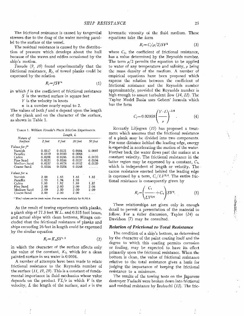
S H I P R E S I S T A N C E 25
The frictional resistance is caused by tangential stresses due to the drag of the water moving parallel to the surface of the vessel.
The residual resistance is caused by the distribution of pressure which develops about the hull because of the waves and eddies occasioned by the ship’s motion.
Froude (9, 10) found experimentally that the frictional resistance, Rf, of towed planks could be expressed by the relation
R f = f S V n U)
in which ƒ is the coefficient of frictional resistance S is the wetted surface in square feet V is the velocity in knots m is a number nearly equal to 2.
The values of both ƒ and n depend upon the length of the plank and on the character of the surface, as shown in Table 1.
T a b l e 1. William Froude’s Plank Friction ExperimentsLength , L
Nature ofSurface 2 feet 8 feet 20 feet 50 feei
Values fo r f*Varnish. 0.0117 0.0121 0.0104 0.0097Paraffin 0.0119 0.0100 0.0088Calico 0.0281 0.0196 0.0184 0.0170Fine Sand 0.0231 0.0166 0.0137 0.0104Medium Sand 0.0257 0.0178 0.0152 0.0139Coarse Sand 0.0314 0.0204 0.0168
Values fo r nVarnish 2.00 1.85 1.85 1.83Paraffin 1.95 1.94 1.93Calico 1.93 1.92 1.89 F 87Fine Sand 2.00 2.00 2.00 2.06Medium Sand 2.00 2.00 2.00 2.00Coarse Sand 2.00 2.00 2.00
* The ƒ values are for fresh water. For sea water multiply by 64/62.4.
As the result of towing experiments with planks, a plank ship of 77.3 feet W.L. and 0.525 foot beam, and actual ships with clean bottoms, Hiraga concluded that the frictional resistance of planks and ships exceeding 26 feet in length could be expressed by the similar equation
Ri = K ^ V 1 (2)
in which the character of the surface affects only the value of the constant, K iy which for a clean painted surface in sea water is 0.0104.
A number of attempts have been made to relate frictional resistance to the Reynolds number of the surface (11,19, 29). This is a constant of fundamental importance in fluid mechanics whose value depends on the product VL/v in which V is the velocity, L the length of the surface, and v is the
kinematic viscosity of the fluid medium. These equations take the form
R f = Cf(p/2)SV2 (3)
where C¡, the coefficient of frictional resistance, has a value determined by the Reynolds number. The term p/2 permits the equation to be applied to water of any temperature and salinity, p being the mass density of the medium. A number of empirical equations have been proposed which express the relation between the coefficient of frictional resistance and the Reynolds number approximately, provided the Reynolds number is high enough to assure turbulent flow (14, 22). The Taylor Model Basin uses Gebers’ formula which has the form
¡ V L \ “1/8 C /= 0.020581------- ) . (4)
Recently Liljegren (15) has proposed a treatment which assumes that the frictional resistance of a plank may be divided into two components. For some distance behind the leading edge, energy is expended in accelerating the motion of the water. Further back the water flows past the surface at a constant velocity. The frictional resistance in the latter region may be expressed by a constant, C2, which is independent of length or velocity. The excess resistance exerted behind the leading edge is expressed by a term, C j / A F 3/4. The entire frictional resistance is consequently given by
R f = \ — - — |-C2 J5F 2. (5)\Z F 3/4 /
These relationships are given only in enough detail to permit a presentation of the material to follow. For a fuller discussion, Taylor (24) or Davidson (7) may be consulted.
R elation o f F rictional to T o ta l R esistanceThe condition of a ship’s bottom, as determined
by the character of the paint coating itself and the degree to which this coating permits corrosion or fouling, may be expected t o . have its effect primarily upon the frictional resistance. When the bottom is clean, the value of frictional resistance relative to the total resistance gives a basis for judging the importance of keeping the frictional resistance to a minimum.
The results of the towing tests on the Japanese destroyer Yudachi were broken down into frictional and residual resistance by Izubuchi (13). The fric
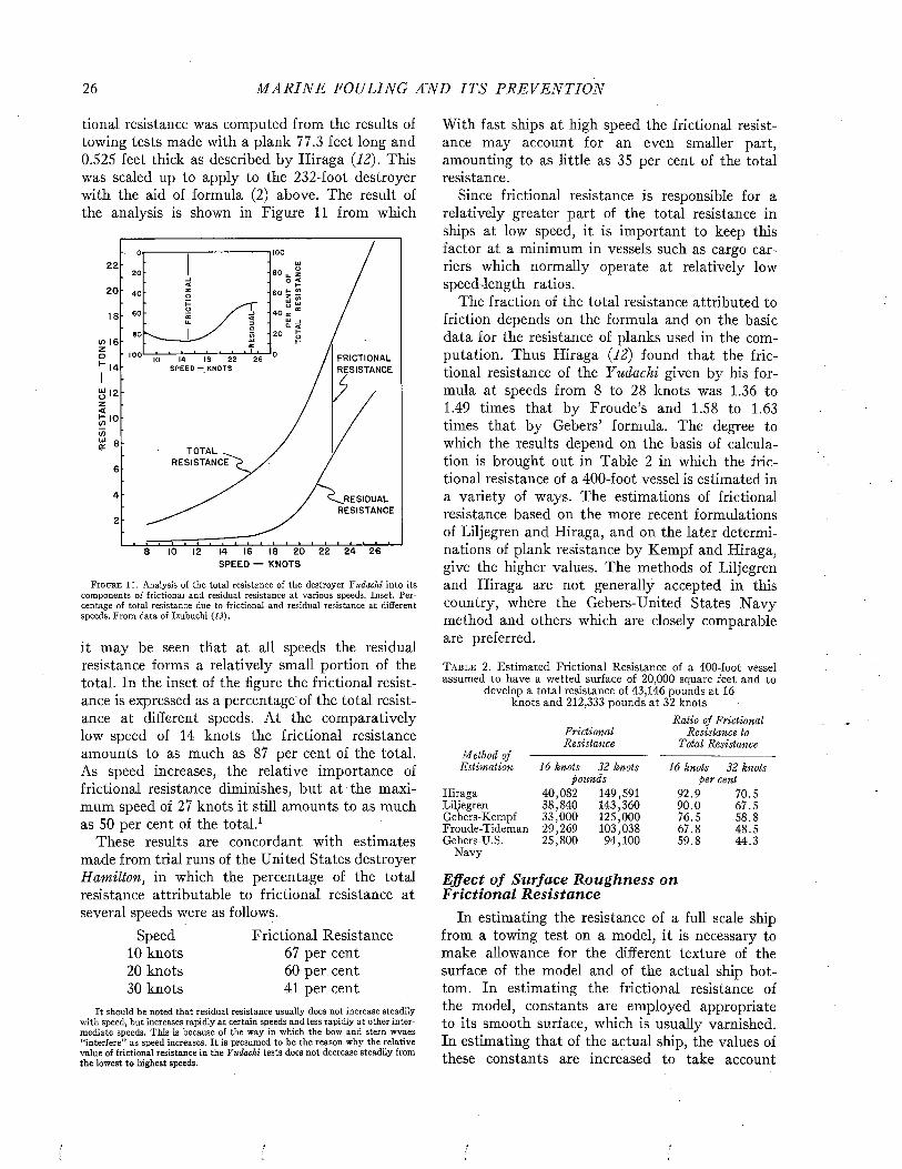
26 M A R I N E FOULING Ä N D I T S P R E V E N T I O N
tional resistance was computed from the results of towing tests made with a plank 77.3 feet long and 0.525 feet thick as described by Hiraga (12). This was scaled up to apply to the 232-foot destroyer with the aid of formula (2) above. The result of the analysis is shown in Figure 11 from which
22
20
a. i
FRICTIONALRESISTANCE
22 26
TOTAL ^ RESISTANCE
^RESID U A LRESISTANCE
8 IO 12 14 16 18 2 0 2 2 2 4 2 6SP E E D — KNOTS
F i g u r e 11 . Analysis of the total resistance of the destroyer Yudachi into its components of frictional and residual resistance at various speeds. Inset. Percentage of total resistance due to frictional and residual resistance at different speeds. From data of Izubuchi (13).
it may be seen that at all speeds the residual resistance forms a relatively small portion of the total. In the inset of the figure the frictional resistance is expressed as a percentage'of the total resistance at different speeds. At the comparatively low speed of 14 knots the frictional resistance amounts to as much as 87 per cent of the total. As speed increases, the relative importance of frictional resistance diminishes, but at the maximum speed of 27 knots it still amounts to as much as 50 per cent of the total.1
These results are concordant with estimates made from trial runs of the United States destroyer Hamilton, in which the percentage of the total resistance attributable to frictional resistance at several speeds were as follows.
Speed Frictional Resistance10 knots 67 per cent20 knots 60 per cent30 knots 41 per cent
It should be noted that residual resistance usually does not increase steadilywith speed-, but increases rapidly at certain speeds and less rapidly at other intermediate speeds. This is because of the way in which the bow and stern wvaes “interfere” as speed increases. I t is presumed to be the reason why the relative value of frictional resistance in the Yudachi tests does not decrease steadily from the lowest to highest speeds.
With fast ships at high speed the frictional resistance may account for an even smaller part, amounting to as little as 35 per cent of the total resistance.
Since frictional resistance is responsible for a relatively greater part of the total resistance in ships at low speed, it is important to keep this factor at a minimum in vessels such as cargo carriers which normally operate at relatively low speed-length ratios.
The fraction of the total resistance attributed to friction depends on the formula and on the basic data for the resistance of planks used in the computation. Thus Hiraga (12) found that the frictional resistance of the Yudachi given by his formula at speeds from 8 to 28 knots was 1.36 to 1.49 times that by Froude’s and 1.58 to 1.63 times that by Gebers’ formula. The degree to which the results depend on the basis of calculation is brought out in Table 2 in which the frictional resistance of a 400-foot vessel is estimated in a variety of ways. The estimations of frictional resistance based on the more recent formulations of Liljegren and Hiraga, and on the later determinations of plank resistance by Kempi and Hiraga, give the higher values. The methods of Liljegren and Hiraga are not generally accepted in this country, where the Gebers-United States Navy method and others which are closely comparable are preferred.
T a b l e 2. Estimated Frictional Resistance of a 400-foot vessel assumed to have a wetted surface of 20,000 square feet and to
develop a total resistance of 43,146 pounds at 16 knots and 212,333 pounds at 32 knots
Ratio of Frictional Frictional Resistance toResistance Total Resistance
16 knots 32 knots 16 knots 32 knotspounds per cent
40,082 149,591 92.9 70.538,840 143,360 90.0 67.533,000 125,000 76.5 58.829,269 103,038 67.8 48.525,800 94,100 59.8 44.3
Method of Estimation
HiragaLiljegrenGebers-KempfFroude-TidemanGebers-U.S.
Navy
Effect o f Surface R oughness on F rictional R esistance
In estimating the resistance of a full scale ship from a towing test on a model, it is necessary to make allowance for the different texture of the surface of the model and of the actual ship bottom. In estimating the frictional resistance of the model, constants are employed appropriate to its smooth surface, which is usually varnished. In estimating that of the actual ship, the values of these constants are increased to take account

S H I P R E S IS T A N C E 27
T a b l e 3. Tideman’s Constants for Frictional Resistance.*For use in the equation R /= f S V n where R j is in pounds, S is in square feet and V is in knots. The values for varnished
surface are from Froude. The constants are for sea water; for fresh water multiply by 62.4/64Length of Surface
Nature of Surface
Values for f Varnish Iron bottom
Clean and painted Copper or Zinc Sheathed
Smooth, in good condition Rough, in bad condition
Values for n Varnish Iron bottom
Clean and painted Copper or Zinc Sheathed
Smooth, in good condition Rough, in bad condition
* As adopted by the International Congress of Model Basin Superintendents. Paris, 1935. For complete table see Davidson (7).
10 20 50 100 200 500
0.011579 0.010524
0.011240 0.010570 0.00991 0.00970 0.00944 0.00904
0.010000 0.009900 0.00976 0.00966 0.00943 0.009260.014000 0.013500 0.01250 0.01200 0.01170 0.01136
1.8250 1.8250
1.8530 1.8434 1.8357 1.8290 1.8290 1.8290
1.9175 1.9000 1.8300 1.8270 1.8270 1.82701.8700 1.8610 1.8430 1.8430 1.8430 1.8430
of its roughness, or a correction factor is employed to allow for its effect. It is also necessary to use constants applicable to the greater lengths of modern ships.
Froude’s original studies on the frictional resistance of towed planks included observations on surfaces artificially roughened to various degrees. The values of the constants of equation (1) obtained with these surfaces are given in Table 1. Both constants, n and ƒ, increase with the roughness of the surface. Neglecting the effect of n, which is important chiefly in defining the effect of velocity on the resistance, and focusing attention on the values of ƒ, it may be noted that with 50-foot planks, the surface roughened with medium sand develops a resistance about 40 per cent greater than the smooth varnish surface. With shorter planks the difference is even greater.
An extended table of constants deduced from Froude’s data was prepared by Tideman and served for many years as the basis of estimating the frictional resistance of ships from equation (1). Table 3 contains a selection of Tideman’s constants and those of Froude which serve to illustrate the magnitude of the allowances which have been made for the actual roughness of clean ships’ bottoms.
The United States Experimental Model Basin adopted coefficients of frictional resistance proposed by Gebers which are employed with equation (3) and which vary with the Reynolds number. A partial list of these values is given in Table 4. These values are for a smooth surface. In applying them to full-sized vessels it has been the practice to make an allowance for roughness by multiplying the ship’s calculated frictional resistance by an appropriate factor. Its value is varied as may be considered desirable to suit vessels built with flush
or lapped plating. The factor ranges from 1.14 for a 400-foot cargo vessel to 1.22 for a 900-foot battle cruiser (20).
T a b l e 4. Geber’s Coefficients of Frictional Resistance.*For use in equation Rf = C f(p /2 )S V 2 where R¡ is in pounds, C¡ is dimensionless, p is in pounds per cubic foot divided by 32.2 feet
per second, 5 is in square feet and V is in feet per secondReynolds number C¡
S X IO6 2.992 X IO“31 X IO7 2.744 X IO“35 X IO7 2.242 X IO'31 X 10s 2.060 X IO“35 X IO8 1.676 X IO“31 X IO9 1.544 X IO“35 X IO9 1.256 X IO“3
* For complete table see Davidson (7).
Kempi (14) has developed a Roughness Coefficient, Ck, to express the effect of roughness on frictional resistance. The values of this coefficient were determined by towing tests with 252-foot pontoon variously roughened, and are given in Table 5, Thèse values are to be added to smooth surface coefficients, given in Table 4, in applying equation (3); i.e.
R , = (Cf+C>)(p/2)SV*.
T a b l e 5. Kempf’s Roughness Coefficients (Ck)
Surface Ck1. Plane, smooth surface of steel plates, with new
paint but without rivets, butts, and straps.Average roughness about 0.012-inch. 0 .10 X IO-3
2. Same as 1, but with butts 0.79-inch high,spaced every 16.4 feet. 0 .40 X IO-3
3. Old copper-sheathed hull. 0.75 X 10~34. New hull with new paint in normal condition
with rivets, butts, and straps. 0.75 X IO-35. Normal hull surface like 4, but after 22 years
of service, newly painted but with roughening 0.75 X IO-3from rust.
6. Plane surface with sand particles 0.03944nch in diameter, covering 100 per cent of area.
(about) 1 .0 X IO-37. Plane surface with barnacles 0.118 to 0.157-
inch high, covering 25 per cent of area.(about) 3 .0 X IO-3
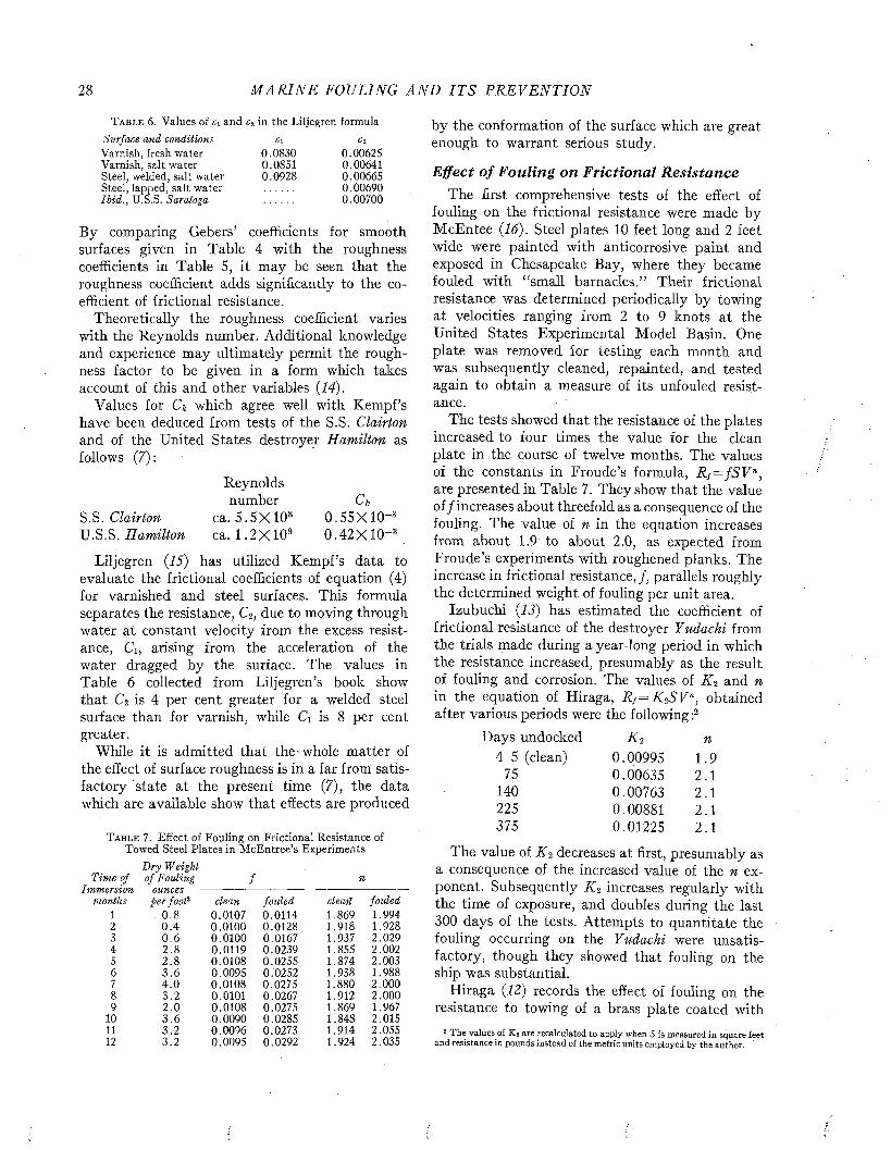
28 M A R I N E FOULING A N D I T S P R E V E N T I O N
T a b l e 6 . Values of ci and c2 in the Liljegren formulaSurface and conditions c¡ c¡Varnish, fresh water 0.0830 0.00625Varnish, salt water 0.0851 0.00641Steel, welded, salt water 0.0928 0.00665Steel, lapped, salt water 0.00690Ib id ., U.S.S. Saratoga 0.00700
By comparing Gebers’ coefficients for smooth surfaces given in Table 4 with the roughness coefficients in Table 5, it may be seen that the roughness coefficient adds significantly to the coefficient of frictional resistance.
Theoretically the roughness coefficient varies with the Reynolds number. Additional knowledge and experience may ultimately permit the roughness factor to be given in a form which takes account of this and other variables (14).
Values for Ck which agree well with Kempf’s have been deduced from tests of the S.S. Clairton and of the United States destroyer Hamilton as follows (7) :
Reynoldsnumber Ck
S.?!. Clairton ca. 5 .5 X 1 0 8 0 .5 5 X 1 0 -3U.S.S .H am ilton ca. 1 .2 X 1 0 9 0 .4 2 X 1 0 -3
Liljegren (15) has utilized Kempf’s data to evaluate the frictional coefficients of equation (4) for varnished and steel surfaces. This formula separates the resistance, C2, due to moving through water at constant velocity from the excess resistance, Cj, arising from the acceleration of the water dragged by the surface. The values in Table 6 collected from Liljegren’s book show that C2 is 4 per cent greater for a welded steel surface than for varnish, while Ci is 8 per cent greater.
While it is admitted that the-whole matter of the effect of surface roughness is in a far from satisfactory state at the present time (7), the data which are available show that effects are produced
T a b l e 7 . Effect of Fouling on Frictional Resistance of Towed Steel Plates in McEntree’s Experiments
Time of Immersion
months
D ry Weight of Fouling ƒ n
ounces per foot* clean fouled cleait fouled
1 . 0 .8 0.0107 0.0114 1.869 1.9942 0 .4 0.0100 0.0128 1.918 1.9283 0 .6 0.0100 0.0167 1.937 2.0294 2.8 0.0119 0.0239 1.855 2.0025 2 .8 0.0108 0.0255 1.874 2.0036 3 .6 0.0095 0.0252 1.938 1.9887 4 .0 0.0108 0.0275 1.880 2.0008 3.2 0.0101 0.0267 1.912 2,0009 2.0 0.0108 0.0275 1.869 1.967
10 3 .6 0.0090 0.0285 1.848 2.01511 3.2 0.0096 0.0273 1.914 2.05512 3.2 0.0095 0.0292 1.924 2.035
by the conformation of the surface which are great enough to warrant serious study.
Effect o f Fouling on F rictional R esistanceThe first comprehensive tests of the effect of
fouling on the frictional resistance were made by McEntee (16). Steel plates 10 feet long and 2 feet wide were painted with anticorrosive paint and exposed in Chesapeake Bay, where they became fouled with “small barnacles.” Their frictional resistance was determined periodically by towing at velocities ranging from 2 to 9 knots at the United States Experimental Model Basin. One plate was removed for testing each month and was subsequently cleaned, repainted, and tested again to obtain a measure of its unfouled resistance.
The tests showed that the resistance of the plates increased to four times the value for the clean plate in the course of twelve months. The values of the constants in Froude’s formula, Rs= fS V n, are presented in Table 7. They show that the value of ƒ increases about threefold as a consequence of the fouling. The value of n in the equation increases from about 1.9 to about 2.0, as expected from Froude’s experiments with roughened planks. The increase in frictional resistance, ƒ, parallels roughly the determined weight of fouling per unit area.
Izubuchi (13) has estimated the coefficient of frictional resistance of the destroyer Yudachi from the trials made during a year-long period in which the resistance increased, presumably as the result of fouling and corrosion. The values of K 2 and n in the equation of Hiraga, Rs = K 2S V n, obtained after various periods were the following :2
D ays undocked k 2 n4-5 (clean) 0.00995 1.9
75 0.00635 2.1140 0.00763 2.1225 0.00881 2.1375 0.01225 2.1
The value of K 2 decreases at first, presumably as a consequence of the increased value of the n exponent. Subsequently K 2 increases regularly with the time of exposure, and doubles during the last 300 days of the tests. Attempts to quantitate the fouling occurring on the Yudachi were unsatisfactory, though they showed that fouling on the ship was substantial.
Hiraga (12) records the effect of fouling on the resistance to towing of a brass plate coated with
2 The values of K 2 are recalculated to apply when S is measured in square feet and resistance in pounds instead of the metric units employed by the author.
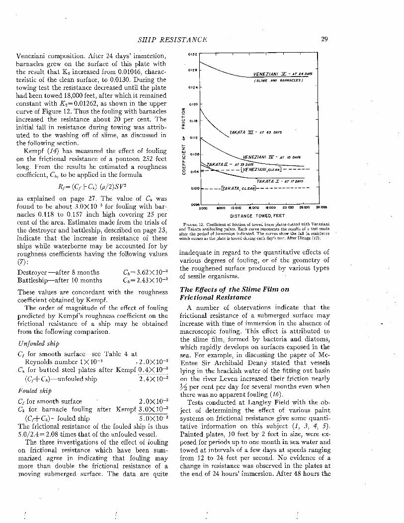
S H I P R E S I S T A N C E 29
Veneziani composition. After 24 days’ immersion, barnacles grew on the surface of this plate with the result that K 2 increased from 0.01046, characteristic of the clean surface, to 0.0130. During the towing test the resistance decreased until the plate had been towed 18,000 feet, after which it remained constant with K o= 0.01262, as shown in the upper curve of Figure 12. Thus the fouling with barnacles §increased the resistance about 20 per cent. The oinitial fall in resistance during towing was attributed to the washing off of slime, as discussed in the following section.
Kempi (14) has measured the effect of fouling on the frictional resistance of a pontoon 252 feet long. From the results he estimated a roughness coefficient, Ck, to be applied in the formula
Rf = ( C f+ C k) ( p / 2 ) S F 2
as explained on page 27. The value of Ck was found to be about 3.OX IO-3 for fouling with barnacles 0.118 to 0.157 inch high covering 25 per cent of the area. Estimates made from the trials of the destroyer and battleship, described on page 23, indicate that the increase in resistance of these ships while waterborne may be accounted for by roughness coefficients having the following values(7):Destroyer— after 8 months C* = 3.62X 10~3Battleship— after 10 months 61*= 2.43X IO-3
These values are concordant with the roughness coefficient obtained by Kempi.
The order of magnitude of the effect of fouling predicted by Kempf’s roughness coefficient on the frictional resistance of a ship may be obtained from the following comparison.
Unfouled ship
C/ for smooth surface— see Table 4 atReynolds number 1X IO-8 < 2 .0 X IO-3
Ck for butted steel plates after Kempi 0 .4 X 1 0 -3 (C/+C*)— unfouled ship 2 .4 X 1 0 -3
Fouled ship
Cf for smooth surface 2. OX IO-3Ck for barnacle fouling after Kempi 3 .OX 10~3
(C /+ Ck)— fouled ship 5. OX IO"3The frictional resistance of the fouled ship is thus 5 .0 /2 .4 = 2.08 times that of the unfouled vessel.
The three investigations of the effect of fouling on frictional resistance which have been summarized agree in indicating that fouling may more than double the frictional resistance of a moving submerged surface. The data are quite
0132
0128V E N E Z IA N I J L - a t 2 4 d a y s
( S L I M E A N D B A R N A C L E S )
0124
0120
TAKATA U L - A T 63 D A Y S
0108' ^ ^ V E N E Z / A N I Æ - a t t o d a y s
- A T 3 3 D A Y S ----------------- :----------------------------
[ V E N E Z IANI t C L E a n ] --------------------0104
T A K A T A X - A T 17 D A YS
0100
009622 000 26000 30 00018 00016 0006000 IO 0002000
DISTANCE TOWED, FEET
F ig u r e 12. Coefficient of friction of towed brass plates coated with Veneziani and Takata antifouling paints. Each curve represents the results of a test made after the period of immersion indicated. The curves show the fall in resistance which occurs as the plate is towed during each day’s test. After Hiraga (12).
inadequate in regard to the quantitative effects of various degrees of fouling, or of the geometry of the roughened surface produced by various types of sessile organisms.
The Effects o f th e S lim e F ilm on F rictional R esistance
A number of observations indicate that the frictional resistance of a submerged surface may increase with time of immersion in the absence of macroscopic fouling. This effect is attributed to the slime him, formed by bacteria and diatoms, which rapidly develops on surfaces exposed in the sea. For example, in discussing the paper of Mc- Entee Sir Archibald Denny stated that vessels lying in the brackish water of the fitting out basin on the river Leven increased their friction nearly
Per cent per day for several months even when there was no apparent fouling (16).
Tests conducted at Langley Field with the object of determining the effect of various paint systems on frictional resistance give some quantitative information on this subject (1, 3, 4, 5). Painted plates, 10 feet by 2 feet in size, were exposed for periods up to one month in sea water and towed at intervals of a few days at speeds ranging from 12 to 24 feet per second. No evidence of a change in resistance was observed in the plates at the end of 24 hours’ immersion. After 48 hours the
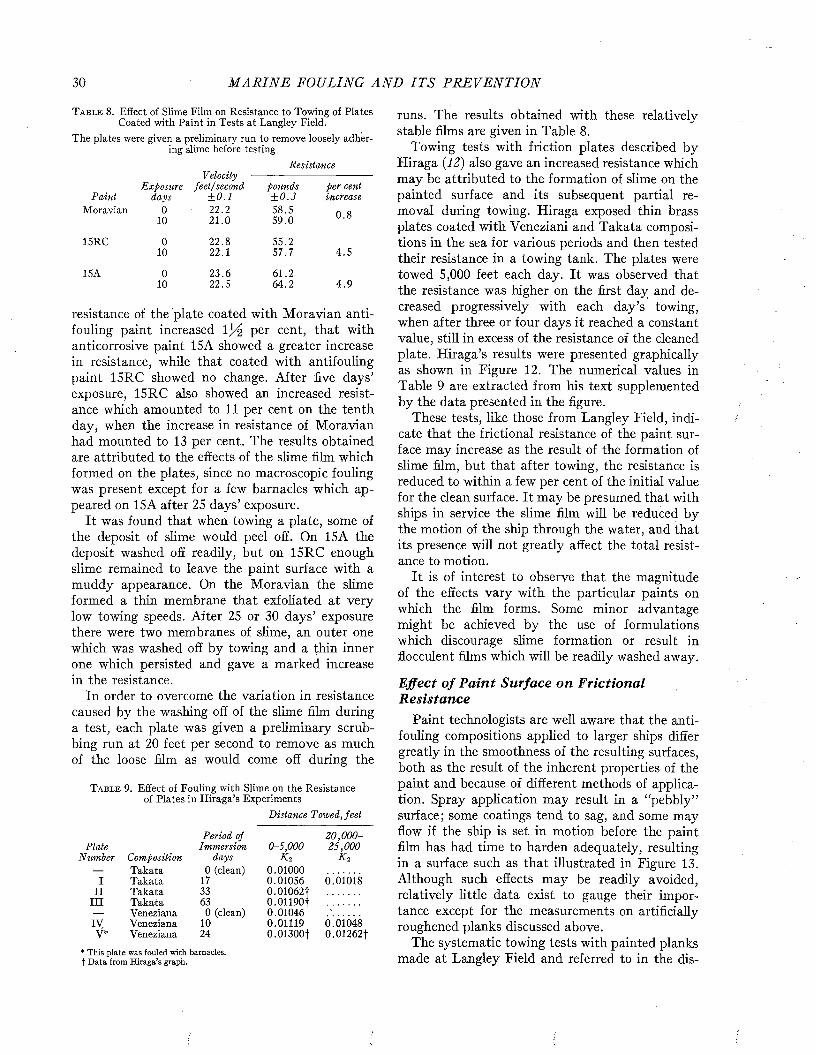
30 M A R I N E FOULING A N D I T S P R E V E N T I O N
T a b l e 8. Effect of Slime Film on Resistance to Towing of Plates Coated with Paint in Tests at Langley Field.
The plates were given a preliminary run to remove loosely adhering slime before testing.
Resistance
ExposureVelocity
feet/'second pounds per centP ain t days ± 0 .1 ± 0 .3 increase
Moravian 0 2 2 .2 58.5 0 .810 21.0 59.0
15RC 0 22.8 55.210 22.1 57.7 4 .5
15A 0 23.6 61.210 22.5 64.2 4 .9
resistance of the plate coated with Moravian antifouling paint increased \ x/¿ per cent, that with anticorrosive paint 15A showed a greater increase in resistance, while that coated with antifouling paint 15RC showed no change. After five days’ exposure, 15RC also showed an increased resistance which amounted to 11 per cent on the tenth day, when the increase in resistance of Moravian had mounted to 13 per cent. The results obtained are attributed to the effects of the slime film which formed on the plates, since no macroscopic fouling was present except for a few barnacles which appeared on 15A after 25 days’ exposure.
It was found that when towing a plate, some of the deposit of slime would peel off. On 15A the deposit washed off readily, but on 15RC enough slime remained to leave the paint surface with a muddy appearance. On the Moravian the slime formed a thin membrane that exfoliated at very low towing speeds. After 25 or 30 days’ exposure there were two membranes of slime, an outer one which was washed off by towing and a thin inner one which persisted and gave a marked increase in the resistance.
In order to overcome the variation in resistance caused by the washing off of the slime film during a test, each plate was given a preliminary scrubbing run at 20 feet per second to remove as much of the loose film as would come off during the
T a b l e 9 . Effect of Fouling with Slime on the Resistanceof Plates in Hiraga’s Experiments
Distance Towed, fee t
Period of 2 0 ,0 0 0 -Plate Immersion 0-5 ,000 2 5 ,000
Number Composition days k 2 k 2— Takata 0 (clean) 0.01000
I Takata 17 0.01056 0.01018II Takata 33 0.01062t
III Takata 63 0 .01190f— Veneziana 0 (clean) 0.01046IV Veneziana 10 0.01119 0.01048V* Veneziana 24 0.01300t 0.01262t
* This plate was fouled with barnacles, f Data from Hiraga’s graph.
runs. The results obtained with these relatively stable films are given in Table 8.
Towing tests with friction plates described by Hiraga (12) also gave an increased resistance which may be attributed to the formation of slime on the painted surface and its subsequent partial removal during towing. Hiraga exposed thin brass plates coated with Veneziani and Takata compositions in the sea for various periods and then tested their resistance in a towing tank. The plates were towed 5,000 feet each day. It was observed that the resistance was higher on the first day and decreased progressively with each day’s towing, when after three or four days it reached a constant value, still in excess of the resistance of the cleaned plate. Hiraga’s results were presented graphically as shown in Figure 12. The numerical values in Table 9 are extracted from his text supplemented by the data presented in the figure.
These tests, like those from Langley Field, indicate that the frictional resistance of the paint surface may increase as the result of the formation of slime film, but that after towing, the resistance is reduced to within a few per cent of the initial value for the clean surface. It may be presumed that with ships in service the slime film will be reduced by the motion of the ship through the water, and that its presence will not greatly affect the total resistance to motion.
It is of interest to observe that the magnitude of the effects vary with the particular paints on which the film forms. Some minor advantage might be achieved by the use of formulations which discourage slime formation or result in flocculent films which will be readily washed away.
Effect o f P a in t Surface on F rictional R esistance
Paint technologists are well aware that .the antifouling compositions applied to larger ships differ greatly in the smoothness of the resulting surfaces, both as the result of the inherent properties of the paint and because of different methods of application. Spray application may result in a “pebbly” surface; some coatings tend to sag, and some may flow if the ship is set in motion before the paint film has had time to harden adequately, resulting in a surface such as that illustrated in Figure 13. Although such effects may be readily avoided, relatively little data exist to gauge their importance except for the measurements on artificially roughened planks discussed above.
The systematic towing tests with painted planks made at Langley Field and referred to in the dis-
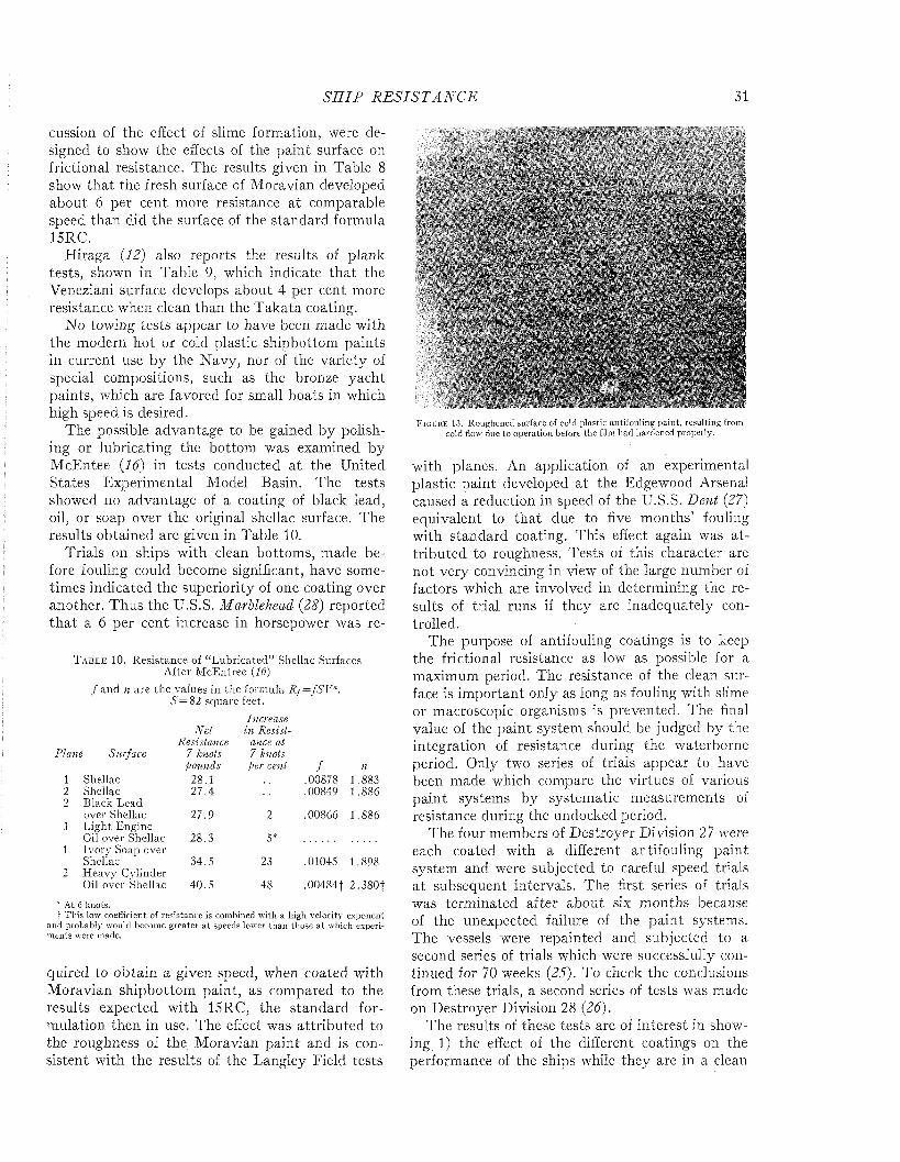
S H I P R E S I S T A N C E 31
cussion of the effect of slime formation, were designed to show the effects of the paint surface on frictional resistance. The results given in Table 8 show that the fresh surface of Moravian developed about 6 per cent more resistance a t comparable speed than did the surface of the standard formula 15RC.
Hiraga (12) also reports the results of plank tests, shown in Table 9, which indicate that the Veneziani surface develops about 4 per cent more resistance when clean than the Takata coating.
No towing tests appear to have been made with the modern hot or cold plastic shipbottom paints in current use by the Navy, nor of the variety of special compositions, such as the bronze yacht paints, which are favored for small boats in which high speed is desired.
The possible advantage to be gained by polishing or lubricating the bottom was examined by McEntee (lá) in tests conducted at the United States Experimental Model Basin. The tests showed no advantage of a coating of black lead, oil, or soap over the original shellac surface. The results obtained are given in Table 10.
Trials on ships with clean bottoms, made before fouling could become significant, have sometimes indicated the superiority of one coating over another. Thus the U.S.S. Marblehead (28) reported th a t a 6 per cent increase in horsepower was re-
T a b l e 10. Resistance of “L ubricated” Shellac Surfaces After M cEntree (16)
ƒ and n are the values in the formula R /= fS V " .S = 82 square feet.
Plane Surface
N et Resistance
7 knots pounds
Increase in Resist
ance at 7 knots
per cent ƒ n1 Shellac 28.1 .00878 1.8832 Shellac 27.4 00849 1.8862 Black Lead
over Shellac 27.9 2 00866 1.8861 L ight Engine
Oil over Shellac 28.3 5*1 Ivory Soap over
Shellac 34.5 23 01045 1.8982 H eavy Cylinder
Oil over Shellac 40.5 48 00484t 2 ,380f
* At 6 knots.t This low coefficient of resistance is combined with a highi velocity exponent
and probably would become g reater a t speeds lower than those a t which experim ents were made.
quired to obtain a given speed, when coated with M oravian shipbottom paint, as compared to the results expected with 15RC, the standard formulation then in use. The effect was attributed to the roughness of the Moravian paint and is consistent with the results of the Langley Field tests
- f.
t. *
. f' >WgSim3Ê% imËg&tsm
F i g u r e lo . Roughened surface of cold plastic antifouling paint, resulting from cold flow due to operation before the film had hardened properly.
with planes. An application of an experimental plastic paint developed at the Edgewood Arsenal caused a reduction in speed of the U.S.S. Dent (27) equivalent to tha t due to five m onths’ fouling with standard coating. This effect again was a ttributed to roughness. Tests of this character are not very convincing in view of the large number of factors which are involved in determining the results of trial runs if they are inadequately controlled.
The purpose of antifouling coatings is to keep the frictional resistance as low as possible for a maximum period. The resistance of the clean surface is im portant only as long as fouling with slime or macroscopic organisms is prevented. The final value of the paint system should be judged by the integration of resistance during the waterborne period. Only two series of trials appear to have been made which compare the virtues of various paint systems by systematic measurements of resistance during the undocked period.
The four members of Destroyer Division 27 were each coated with a different antifouling paint system and were subjected to careful speed trials a t subsequent intervals. The first series of trials was terminated after about six months because of the unexpected failure of the paint systems. The vessels were repainted and subjected to a second series of trials which were successfully continued for 70 weeks (25). To check the conclusions from these trials, a second series of tests was made on Destroyer Division 28 (26).
The results of these tests are of interest in showing 1) the effect of the different coatings on the performance of the ships while they are in a clean
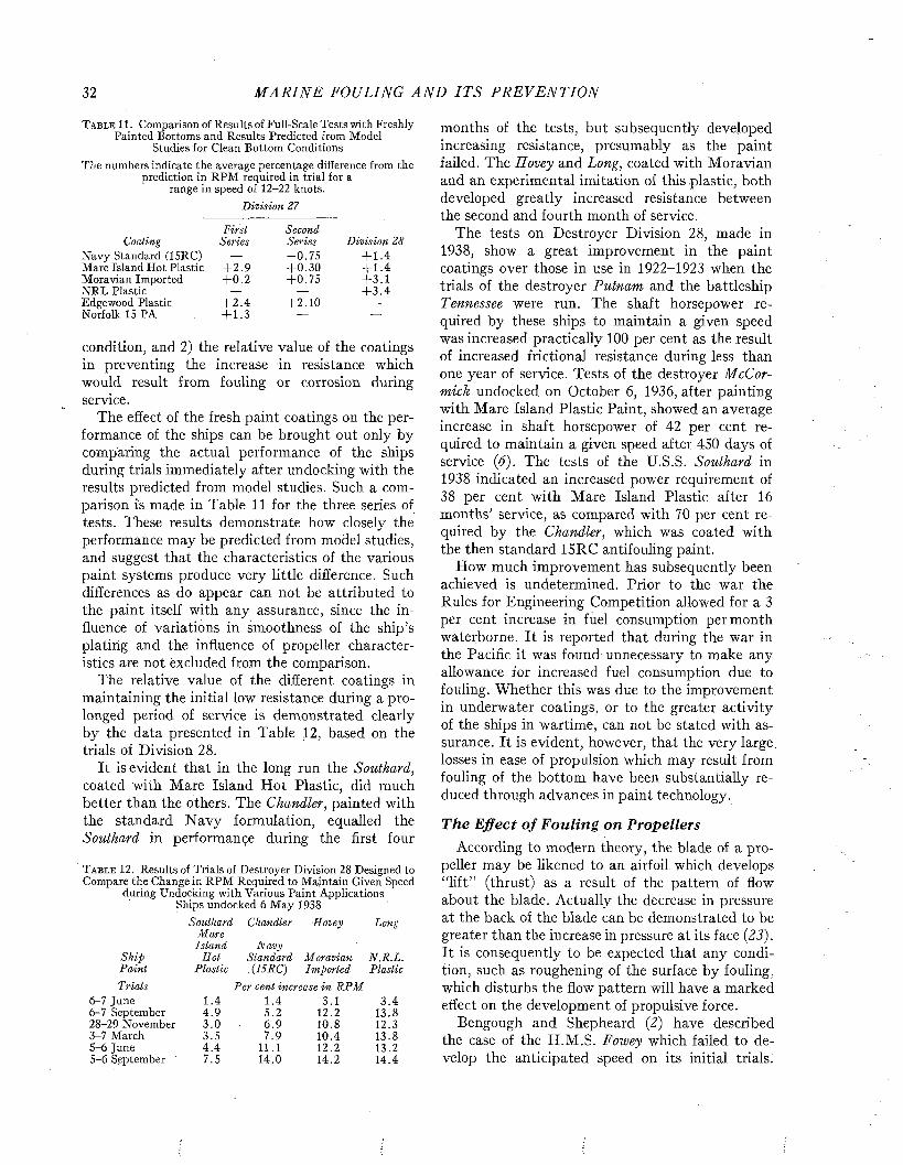
32 M A R I N E FOULING A N D I T S P R E V E N T I O N
T a b l e 11. Comparison of Results of Full-Scale Tests with Freshly Painted Bottoms and Results Predicted from Model
Studies for Clean Bottom ConditionsThe numbers indicate the average percentage difference from the
prediction in RPM required in trial for a range in speed of 12-22 knots.
D ivision 27
First SecondSeries Series D ivision 28
— - 0 .7 5 + 1.4+ 2 .9 + 0 .3 0 + 1 .4+ 0 .2 + 0 .7 5 + 3 .1
— — + 3 .4+ 2 .4 + 2 .1 0 —
+ 1.3 — —
Coaling Navy Standard (15RC) Mare Island Hot Plastic Moravian Imported NRL Plastic Edgewood Plastic Norfolk 15 PA
condition, and 2) the relative value of the coatings in preventing the increase in resistance which would result from fouling or corrosion during service.
The effect of the fresh paint coatings on the performance of the ships can be brought out only by comparing the actual performance of the ships during trials immediately after undocking with the results predicted from model studies. Such a comparison is made in Table 11 for the three series of tests. These results demonstrate how closely the performance may be predicted from model studies, and suggest that the characteristics of the various paint systems produce very little difference. Such differences as do appear can not be attributed to the paint itself with any assurance, since the influence of variations in smoothness of the ship’s plating and the influence of propeller characteristics are not excluded from the comparison.
The relative value of the different coatings in maintaining the initial low resistance during a prolonged period of service is demonstrated clearly by the data presented in Table 12, based on the trials of Division 28.
It is evident that in the long run the Southard, coated with Mare Island H ot Plastic, did much better than the others. The Chandler, painted with the standard N avy formulation, equalled the Southard in performançe during the first four
T a b l e 12. Results of Trials of Destroyer Division 28 Designed to Compare the Change in RPM Required to Maintain Given Speed
during Undocking with Various Paint Applications Ships undocked 6 May 1938
Southard Chandler Hovey Long M are
Island N avy Ship S o t S tandard M oravian N .R .L .P ain t P lastic X I SRC) Im ported Plastic
Tria ls P er cent increase in R P M6-7 June 6-7 September 28-29 November 3-7 March 5-6 June 5-6 September
1.4 1.4 3.1 3 .44 .9 5.2 12.2 13.83 .0 6.9 10.8 12.33.5 7.9 10.4 13.84 .4 11.1 12.2 13.27.5 14.0 14.2 14.4
months of the tests, but subsequently developed increasing resistance, presumably as the paint failed. The Hovey and Long, coated with Moravian and an experimental imitation of this plastic, both developed greatly increased resistance between the second and fourth month of service.
The tests on Destroyer Division 28, made in 1938, show a great improvement in the paint coatings over those in use in 1922-1923 when the trials of the destroyer Putnam and the battleship Tennessee were run. The shaft horsepower required by these ships to maintain a given speed was increased practically 100 per cent as the result of increased frictional resistance during less than one year of service. Tests of the destroyer McCormick undocked on October 6, 1936, after painting with Mare Island Plastic Paint, showed an average increase in shaft horsepower of 42 per cent required to maintain a given speed after 450 days of service (6). The tests of the U.S.S. Southard in 1938 indicated an increased power requirement of 38 per cent with Mare Island Plastic after 16 months’ service, as compared with 70 per cent required by the Chandler, which was coated with the then standard 15RC antifouling paint.
How much improvement has subsequently been achieved is undetermined. Prior to the war the Rules for Engineering Competition allowed for a 3 per cent increase in fuel consumption per month waterborne. It is reported that during the war in the Pacific it was found unnecessary to make any allowance for increased fuel consumption due to fouling. Whether this was due to the improvement in underwater coatings, or to the greater activity of the ships in wartime, can not be stated with assurance. It is evident, however, that the very large, losses in ease of propulsion which may result from fouling of the bottom have been substantially reduced through advances in paint technology.
The Effect o f Fouling on PropellersAccording to modern theory, the blade of a pro
peller may be likened to an airfoil, which develops “lift” (thrust) as a result of the pattern of flow about the blade. Actually the decrease in pressure at the back of the blade can be demonstrated to be greater than the increase in pressure at its face (23). It is consequently to be expected that any condition, such as roughening of the surface by fouling, which disturbs the flow pattern will have a marked effect on the development of propulsive force.
Bengough and Shepheard (2) have described the case of the H.M.S. Fowey which failed to develop the anticipated speed on its initial trials.
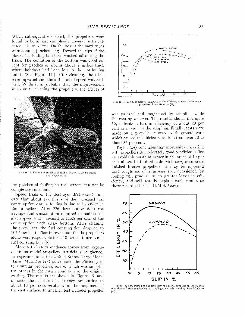
S H I P R E S I S T A N C E 33
When subsequently docked, the propellers were found to be almost completely covered with calcareous tube worms. On the bosses the hard tubes were about 1 | inches long. Toward the tips of the blades the fouling had been washed off during the trials. The condition of the bottom was good except for patches of worms about 2 inches thick where holidays had been left in the antifouling paint. (See Figure 14.) After cleaning, the trials were repeated and the anticipated speed was realized. While it is probable tha t the improvement was due to cleaning the propellers, the effects of
F i g u r e 14. Fouling of propeller of H .M .S. Foivcy. A fter Bengough and Shepheard (2).
the patches of fouling on the bottom can not be completely ruled out.
Speed trials of the destroyer McCormick indicate tha t about two-thirds of the increased fuel consumption due to fouling is due to its effect on the propellers. After 226 days out of dock the average fuel consumption required to maintain a given speed had increased to 115.8 per cent of the consumption with clean bottom. After cleaning the propellers, the fuel consumption dropped to 105.5 per cent. Thus in seven months the propellers alone were responsible for a 10 per cent increase in fuel consumption (6).
More satisfactory evidence comes from experiments on model propellers, artificially roughened. In experiments a t the United States Navy Model Basin, M cEntee (17) determined the efficiency of four similar propellers, one of which was smooth, the others in the rough condition of the original casting. The results are shown in Figure 15, and indicate th a t a loss of efficiency amounting to about 10 per cent results from the roughness of the cast surface. In another test a model propeller
F i g u r e 15. Effect of surface roughness on the efficiency of four similar mode propellers. After M cEntee (17).
was painted and roughened by stippling while the coating was wet. The results, shown in Figure 16, indicate a loss in efficiency of about 20 per cent as a result of the stippling. Finally, tests were made on a propeller covered with ground cork which caused the efficiency to drop from over 70 to about 35 per cent.
Taylor (24) concludes that most ships operating with propellers in moderately good condition suffer an avoidable waste of power in the order of 10 per cent above tha t obtainable with new, accurately finished bronze propellers. I t may be supposed tha t roughness of a grosser sort occasioned by fouling will produce much greater losses in efficiency, and will readily explain such results as those recorded for the H.M.S. Fowey.
SMOOTH70
60
STIPPLED50
40
30
U. 20 u_UJ
IO
IO 20 30 40 50 60
S L I P IN %F i g u r e 16. Comparison of the efficiency of a model propeller in the smooth
condition and after roughening bv stippling a wet paint coating. After M cEntee (17).
34 M A R I N E FOULING A N D I T S P R E V E N T I O N
REFERENCES1. B e e r y , T. D. Investigation in the N.A.C.A. tank of the
effect of immersion in salt water on the resistance of plates coated with different shipbottom paints, Summer of 1939. Supplementary Memorandum Report, National Advisory Committee for Aeronautics. C&R C-S19-l(3), 5. August 10,1939.
2. B e n g o t j g h , G. D., and V. G. S h e p h e a r d . The Corrosion andFouling of Ships. The Marine Corrosion Sub-committee of the Iron and Steel Institute and the British Iron and Steel Federation. April 15, 1943.
3. B e n s o n , J. M., J. W. E b e r t , J r . , and T. D. B e e r y . Investigation in the N.A.C.A. tank of the effect of immersion in salt water on the resistance of plates coated with different shipbottom paints. Memorandum Report, National Advisory Committee for Aeronautics. C&R C-S19-l(3), 3. November 3, 1938.
4 . B u r e a u o e C o n s t r u c t io n a n d R e p a i r . F o u l in g t e s t s o ffriction plates. Memorandum for file (by P. W. Snyder). September 24, 1938.
5. B u r e a u o e C o n s t r u c t i o n a n d R e p a i r . I n v e s t i g a t i o n o ffrictional resistance of plates painted with three shipbottom systems. Memorandum for file (D. P. Graham). January 2, 1940.
6. B u r e a u o f S h ip s R e s e a r c h M e m o r a n d u m N o. 10-41(by H. F. Smith). Evaluation of the Rate and Effect of Underwater Fouling on Ship Propulsion. 15 June 1941.
7. D a v i d s o n , K e n n e t h S. M. Principles of Naval Architecture.Chap. II, Resistance and Powering. Vol. II, 52-118. Soc. Nav. Arch, and Marine Eng., 1942.
8. D a v i s , H. F. D. The Increase in SHP and RPM due toFouling. Jour. Am. Soc. Nav. Eng., 42, 155-166, 1930.
9. F r o u d e , W i l l i a m . Experiments on the Surface-FrictionExperienced by a Plane Moving Through Water. Report of the British Association for the Advancement of Science, 1872.
10. F r o u d e , W i l l i a m . Report to the Lords Commissioners of theAdmiralty on Experiments for the Determination of the Frictional Resistance of Water on a Surface Under Various Conditions. Report of the British Association for the Advancement of Science, 1874.
11. G e b e r s , F. Des Aehnlichkeitsgesetz bei im Wasser geradlinigfortbewegter Platten. Schiffbau, 22, 1919.
12. H i r a g a , Y u z u r u . Experimental Investigations on the Resistance of Long Planks and Ships. Zosen Kiokai, 55, 159- 199, December 1934.
13. I z u b u c h i , T. Increase in Hull Resistance Through Shipbottom Fouling. Zosen Kiokai, 55, December 1934. In Japanese (Translation by Lt. C. M. Spinks, U.S.N.R., on file Research Branch, Bureau of Ships).
14. K e m p f , G. A Study of Ship Performance in Smooth and RoughWater. Trans. Soc. Nav. Arch, and Mar. Eng., 44, 195— 227, 1936.
15. L i l j e g r e n , C. O. Naval Architecture as Art and Science.Cornell Maritime Press, 1943.
16. M c E n t e e , W i l l i a m . Variation of Frictional Resistance ofShips with Condition of Wetted Surface. Trans. Soc. Nav. Arch, and Mar. Eng., 23, 37-42, 1915.
17. M c E n t e e , W i l l i a m . Notes from Model Basin. Trans. Soc.Nav. Arch, and Mar. Eng., 24, p. 85, 1916.
18. P i t r e , A. S. Full-Scale Test for Determining UnderwaterPaint Resistance to Fouling. Suggestions Regarding Method and Procedure. C&R S19-l(3), 14, Washington, September 1935.
19. P r a n d t l , L. Ergebnisse der Aerodynamischen Versuchsanstalt zu Goettingen. Vol. 3, 1927.
20. S a u n d e r s , H. E. The Prediction of Speed and Power of Shipsby Methods in Use at the United States Experimental Model Basin Washington. C&R Bull. No. 7. Bur. Constr. and Repair, Navy Dept., Washington; 1933.
21. S a u n d e r s , H. E., C o m m a n d e r (CC), and A. S. P i t r e , L t .C o m d r . (CC). Full-Scale Trials on a Destroyer. Trans. Soc. Nav. Arch, and Mar. Eng., 41, 243-295, 1933.
22. S c h o e n h e r r , K. E. Resistance of Flat Surfaces MovingThrough a Fluid. Trans. Soc. Nav. Arch, and Mar. Eng., 279-313, 1932.
23. S c h o e n h e r r , K. E. Principles of Naval Architecture. Chap.III, Propulsion and Propellers. Vol. II, 119-196, The Soc.
. Nav. Arch, and Mar. Eng., New York, 1942.24. T a y l o r , D. W. The Speed and Power of Ships. Third edition.
Washington, 1943.25. U.S. F l e e t , D e s t r o y e r s B a t t l e F o r c e . Final report of
second series of tests. Underwater Paint Tests, DD 27 (ex-12). Commander Destroyers, Battle Force to Chief of Naval Operations. 9 June 1938. (Unpublished.)
26. U.S. F l e e t , D e s t r o y e r s B a t t l e F o r c e . Final report ofUnderwater Paint Tests, DD 28. Commander Destroyers, Battle Force to Chief of Naval Operations. 23 February1940. (Unpublished).
27. U.S.S. Dent. Reduction in speed after application of Edge-wood Arsenal plastic paints (B-3 and C-323). Letter to Bureau of Construction and Repair, January 26, 1938. C&R S19-l-(3), 21, May 24, 1938.
28. U.S.S. Marblehead. Tests of the effect of Moravian paint onsteaming performances. Letter to Naval Operations, October 16, 1934. C&R S19-l-(3), 12, December 19, 1934.
29. V. K a r m a n , T. Ueber Laminare und Turbulente Reibung.Abhandlungen aus dem Aerodynamischen Institut Aachen. Volume 1.
M arine F ou ling and Its Prevention,Contribution N o . 580 from the W oods H o le O ceanographic Institute
C opyright 1952 b y U . S. N ava l Institute, A nnapolis, M aryland G eorge B anta P u b lish in g C o ., M enasha, WI
PART II
BIOLOGY OF FOULING
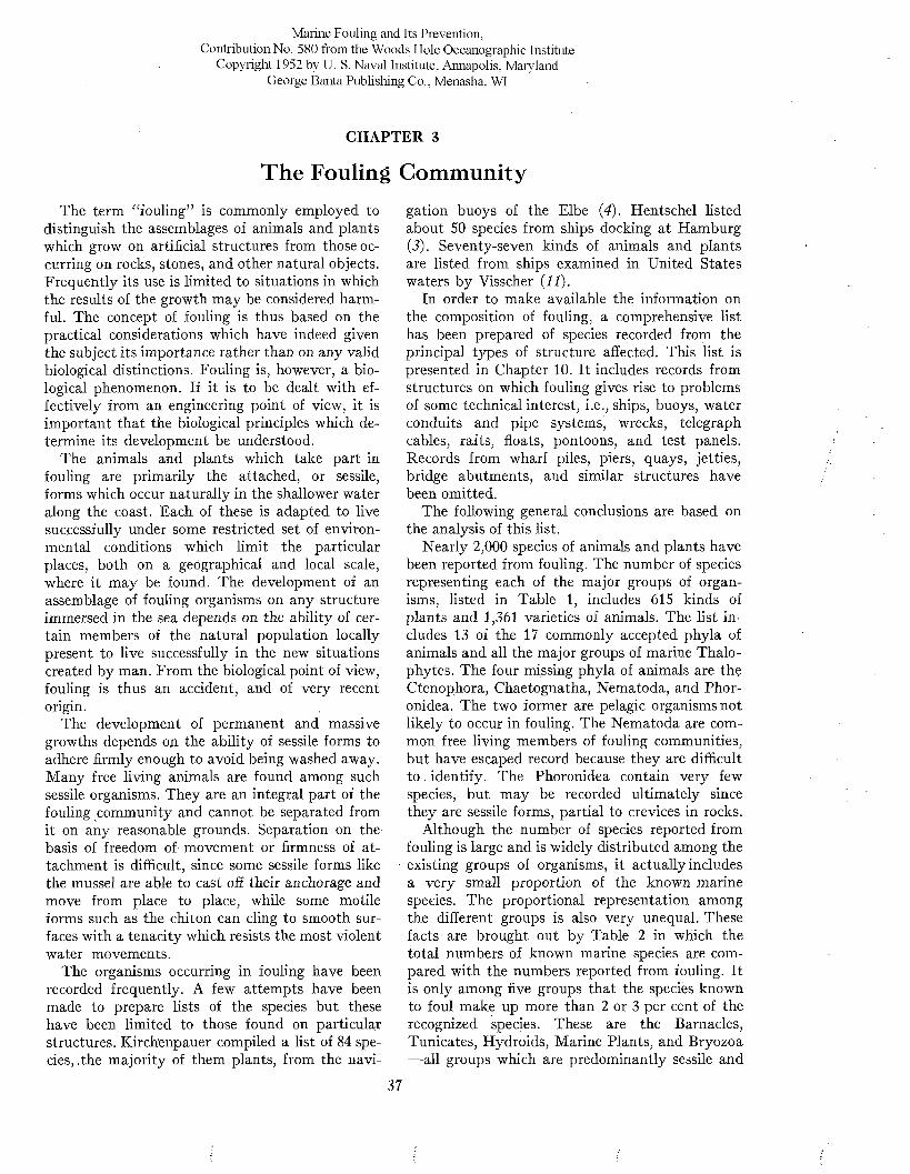
Marine Fouling and Its Prevention,Contribution No. 580 from the Woods Hole Oceanographic Institute
Copyright 1952 by U. S. Naval Institute, Annapolis, Maryland George Banta Publishing Co., Menasha, WI
CHAPTER 3
The Fouling CommunityThe term “fouling” is commonly employed to
distinguish the assemblages of animals and plants which grow on artificial structures from those occurring on rocks, stones, and other natural objects. Frequently its use is limited to situations in which the results of the growth may be considered harmful. The concept of fouling is thus based on the practical considerations which have indeed given the subject its importance rather than on any valid biological distinctions. Fouling is, however, a biological phenomenon. If it is to be dealt with effectively from an engineering point of view, it is important that the biological principles which determine its development be understood.
The animals and plants which take part in fouling are primarily the attached, or sessile, forms which occur naturally in the shallower water along the coast. Each of these is adapted to live successfully under some restricted set of environmental conditions which limit the particular places, both on a geographical and local scale, where it may be found. The development of an assemblage of fouling organisms on any structure immersed in the sea depends on the ability of certain members of the natural population locally present to live successfully in the new situations created by man. From the biological point of view, fouling is thus an accident, and of very recent origin.
The development of permanent and massive growths depends oji the ability of sessile forms to adhere firmly enough to avoid being washed away. Many free living animals are found among such sessile organisms. They are an integral part of the fouling community and cannot be separated from it on any reasonable grounds. Separation on the basis of freedom of movement or firmness of attachment is difficult, since some sessile forms like the mussel are able to cast off their anchorage and move from place to place, while some motile forms such as the chiton can cling to smooth surfaces with a tenacity which resists the most violent water movements.
The organisms occurring in fouling have been recorded frequently. A few attempts have been made to prepare lists of the species but these have been limited to those found on particular structures. Kirchenpauer compiled a list of 84 species, ,the majority of them plants, from the navi
gation buoys of the Elbe (4). Hentschel listed about 50 species from ships docking at Hamburg (J). Seventy-seven kinds of animals and plants are listed from ships examined in United States waters by Visscher {11).
In order to make available the information on the composition of fouling, a comprehensive list has been prepared of species recorded from the principal types of structure affected. This list is presented in Chapter 10. It includes records from structures on which fouling gives rise to problems of some technical interest, i.e., ships, buoys, water conduits and pipe systems, wrecks, telegraph cables, rafts, floats, pontoons, and test panels. Records from wharf piles, piers, quays, jetties, bridge abutments, and similar structures have been omitted.
The following general conclusions are based on the analysis of this list.
Nearly 2,000 species of animals and plants have been reported from fouling. The number of species representing each of the major groups of organisms, listed in Table 1, includes 615 kinds of plants and 1,361 varieties of animals. The list includes 13 of the 17 commonly accepted phyla of animals and all the major groups of marine Thalo- phytes. The four missing phyla of animals are the Ctenophora, Chaetognatha, Nematoda, and Phor- onidea. The two former are pelagic organisms not likely to occur in fouling. The Nematoda are common free living members of fouling communities, but have escaped record because they are difficult to identify. The Phoronidea contain very few species, but may be recorded ultimately since they are sessile forms, partial to crevices in rocks.
Although the number of species reported from fouling is large and is widely distributed among the existing groups of organisms, it actually includes a very small proportion of the known marine species. The proportional representation among the different groups is also very unequal. These facts are brought out by Table 2 in which the total numbers of known marine species are compared with the numbers reported from fouling. It is only among five groups that the species known to foul make up more than 2 or 3 per cent of the recognized species. These are the Barnacles, Tunicates, Hydroids, Marine Plants, and Bryozoa — all groups which are predominantly sessile and
37
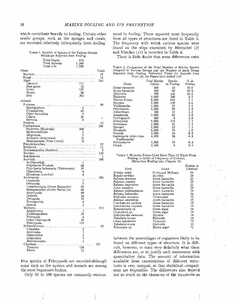
38 M A R I N E FOULING A N D I T S P R E V E N T I O N
which contribute heavily to fouling. Certain other sessile groups, such as the sponges and corals, are recorded relatively infrequently from fouling.
T a b l e 1. Number of Species of the Various Groups Which are Reported from Fouling
Total PlantsTotal Animals Total List
PlantsBacteria..........................................Fungi...............................................Algae................................................
Diatoms Blue green Green Brown Red
Anim alsProtozoa.........................................
Mastigophora Foraminifera Other Sarcodina Ciliata Suctoria
Porifera...........................................Coelenterata..................................
Hydrozoa (Hydroids)HydrocorallinaeAlcgonariaActinaria (Anemones) Madreporaria (True Corals)
Platyhelminthes...........................Nemertea. . ... . . '..........................Trochelminthes (Rotifers)Bryozoa.........................................Brachiopoda..................................Annelida.
6141,3441,958
11132
12788
205
543
339
9
26015
12
Tolals 37 14
563
Archiannelids 1Polychaeta Errantia 44Polychaeta Sedentaria (Tubeworms) 55Oligochaeta 4Hirudinea (Leeches) 4
Arthropoda...................................................Copepoda 7Ostracoda 5Lepadomorpha (Goose Barnacles) 50Balanomorpha (Acorn Barnacles) 60Amphipoda 60Isopoda 24Decapoda 76Pycnogonida 8Insecta 2
Mollusca.............................. .......................Amphinema 3Nudibranchiata 32Pteropoda 4Other Gastropoda 59Pelecypoda 121
Echinodermata..........................................Crinoidea 3Asteroidea 7Ophiuroidea 3Echinoidea 5Holothuroidea 1
Chordata.......................................................Tunicata 116Pisces 11
99
33286
12 11
, 5 139
1 108
292
212
19
127
Few species of Pelecypods are recorded although some such as the oysters and mussels are among the most important foulers.
Only 50 to 100 species are commonly encoun
tered in fouling. Those reported most frequently from all types of structures are listed in Table 3. The frequency with which various species were found on the ships examined by Hentschel (J) and Visscher (11) is recorded in Table 4.
There is little doubt that some differences exist
T a b l e 2. Comparison of the Total Number of Marine Species Assigned to Various Groups, and the Number of Each Group Reported from Fouling. Estimated Totals for Animals from
Pratt (8), for Plants from ZoBell (12)
Total M arine Species % inGroup Species in Fouling Fouling
Goose barnacles 200 50 25.0Acorn barnacles 300 60 20.0Tunicates 700 116 16.6Hydroids 3,000 260 8.7Marine Plants 8,000 614 7.7Bryozoa 3,000 139 4 .6Nudibranchs 1,000 32 3 .2Polychaetes 3,500 99 2.8Nemerteans 500 11 2.2Amphipods 3,000 60 2 .0Pycnogonids 400 8 2 .0Pelecypods 9,000 115 1.3Anemones 1,000 12 1.2Sponges 3,000 33 1.1Decapods 8,000 76 1.0Isopods 3,000 24 0 .8Gastropods (other than 4,900 58 0 .8
Nudibranchs)Echinoderms 4,800 19 0 .4Corals 2,500 8 0.3
T a b l e 3. Nineteen Forms Cited More Than 12 Times FromFouling, in Order of Frequency of Citation.
(Data from Fouling List, Chapter 10)Number oj
Form Group CitationsM ytilus edulis Pelecypod Molluscs 34Bugula neritina Bryozoa 24Balanus eburneus Acorn barnacles 23Balanus crenatus Acorn barnacles 22Balanus improvisus Acorn Barnacles 21Lepas anatifera Goose barnacles 20Balanus tintinnabulum Acorn barnacles 18Balanus balanoides Acorn barnacles 16H ydroides norvegica Tubeworms 15Balanus amphitrite Acorn barnacles 15Conchoderma auritum Goose barnacles 15Conchoderma virgatum Goose barnacles 14Enteromorpha sp. Green algae 14Cladophora sp. Green algae 14Schizoporella unicornis Bryozoa 14Tubularia larynx Hydroids 14Ciona intestinalis Tunicates 13Tubularia crocea Hydroids 12Ectocarpus sp. Brown algae 11
between the assemblages of organisms likely to be found on different types of structure. It is difficult, however, to state very definitely what these differences are, or to justify such statements with quantitative data. The amount of information available from examinations of different structures is very unequal, so that statistical comparisons are impossible. The differences also depend not so much on the character of the structures as
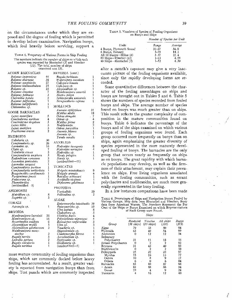
THE FOULING C O M M U N I T Y 39
on the circumstances under which they are exposed and the degree of fouling which is permitted to develop before examination. Navigation buoys, which foul heavily before servicing, support a
T a b l e 4 . Frequency o f Various Forms in Ship FoulingThe numbers indicate the number of ships on which each
species was reported by Hentschel (3) and Visscher (11). The total number of ships
examined was 131.ACORN BARNACLES
Balanus im provisus 44BRYOZOA (cont.)
Bugula turbinata 1Balanus eburneus 34 W atersipora cucullata 1Balanus am phitrite 27 Callopora lineata 1Balanus tintinnabulum 25 Callopora sp. 1Balanus sp. 25 Alcyonidium sp. 1Balanus crenatus 7 M embranipora savartii 1Balanus psittacus 3 Electra pilosa 1Chelonibia patula 2 Schizoporella unicornis. 1Balanus perforatus 1 Scrupocellaria reptans 1Balanus tulipiform is Chthamalus sp.
11 MOLLUSCS
GOOSE BARNACLESA nom ia ephippium M ytilu s edulis
3118
Lepas anserifera 5 Ostrea elongata 7Conchoderma auritum 4 Ostrea sp. 4Conchoderma virgatum 3 M ytilu s pictus 2Lepas h illii . 3 Nudibranchs 2Lepas anatifera 3 Ostrea parasitica 1Poecilasma crassa 2 Anom ia fidenas 1
HYDROIDSAnom ia sp. Teredo navalis
11
Tubularia sp. Cam panularia sp.
3026 ANNELIDS
Laomedea sp. 16 Hydroides hexagonis 8C lytia sp. 7 Hydroides norvegica 4Tubularia crocea 5 Hydroides sp. 1Campanularia amphora 3 Nereis pelagica 1Eudendrium ramosum 3 Nereis sp. 1Laomedea geniculata 2 (unidentified— 11)Laomedea sargassi Campanularia portium
11 TUNICATES
Campanularia verticellata 1 M olgula manhattensis 9Bougainvillia carolinensis 1 M olgula arenata 4Perigonimus jo n sii 1 Botryllus schlosseri 1Podocoryne sp. 1 Ascidiella virginea 1Plumularidae 1 Diplosoma gelatinosa 1(unidentified—5)
ANEMONESPROTOZOA
Vorticellids 10M etridium sp. 8 Folliculina sp. 2Sagartia sp. 3
ALGAECORALS Enteromorpha intestinalis 39
Astrangia sp. 1 Enteromorpha sp. 19
BRYOZOAUlva lactuca Cladophora sp.
85
M embranipora lacroixii 25 Ulothrix flacca 4Membranipora sp. 16 Polysiphonia nigrescens 4Bowerbankia caudata 6 Ectocarpus confervoides 3Alcyonidium m ytili 5 Ulva sp. 3Alcyonidium gelatinosum 3 Vaucheria sp. 1Membranipora mono Stigeoclonium sp. 1
stachys 3 Chaetomorpha fibrosa 1Bugula turrita 3 Acrochaetium sp. 1Lepralia pertusa 2 Syphonales sp. 1Bugula avicularia 1 Oscillatoria sp. 1Bugula neritina 1 (unidentified—1)
more mature community of fouling organisms than ships, which are commonly docked before heavy fouling has accumulated. As a result, greater variety is reported from navigation buoys than from ships. Test panels which are commonly inspected
T a b l e 5. Numbers of Species of Fouling Organisms on Buoys and Ships
Number of Species per U nit
Units Range Average4 Buoys, Plymouth Sound 31-37 34.06 Buoys, Estuary 5-19 14.3All 10 Buoys—Milne (6) 5-37 22.483 Ships—Visscher (11) 1-13 4.1848 Ships—Hentschel (3) 1-12 4.39
after a month’s exposure may give a very inaccurate picture of the fouling organisms available, since only the rapidly developing forms are recorded.
Some quantitative differences between the character of the fouling assemblages on ships and buoys are brought out in Tables 5 and 6. Table 5 shows the numbers of species recorded from fouled buoys and ships. The average number of species found on buoys was much greater than on ships. This result reflects the greater complexity of composition in the mature communities found on buoys. Table 6 indicates the percentage of the buoys and of the ships examined on which various groups of fouling organisms were found. Each group occurred more frequently on buoys than on ships, again emphasizing the greater diversity of species represented in the more maturely developed fouling of buoys. The barnacles are the only group that occurs nearly as frequently on ships as on buoys. The great rapidity with which barnacle populations may develop, as well as the firmness of their attachment, may explain their prevalence on ships. Free living organisms associated with the fouling communities, such as errant polychaetes and nudibranchs, are much more generally represented in the buoy fouling.
In a few instances comparisons have been made
T a b l e 6. Percentages of Ships and Navigation Buoys Fouled by Various Groups. Ship data from Hentschel and Visscher; Buoy data from American Waters. The Numbers Represent the Per Cent of the Ships or Buoys Examined on which Representatives
of Each Group were Found.Ships
Hentschel Visscher A ll ships BuoysGroup (48 ships) (83 ships) (131) (373)
Algae 79 33 50 94Hydroids 63 49 54 99Anemones 0 12 12 54Sedentary
Polychaetes 31 11 18 53Errant Polychaetes 0 2 2 93Bryozoa 31 45 40 83Nudibranchs 0 2 2 58Pelecypods 25 22 23 97
Mytilus 15 16 15 77Ostrea 10 8 9 17Others 6 0 6 84
Barnacles 83 89 87 98- Acorn 83 88 86 94
Goose 19 4 9 24T unicates 4 16 12 40
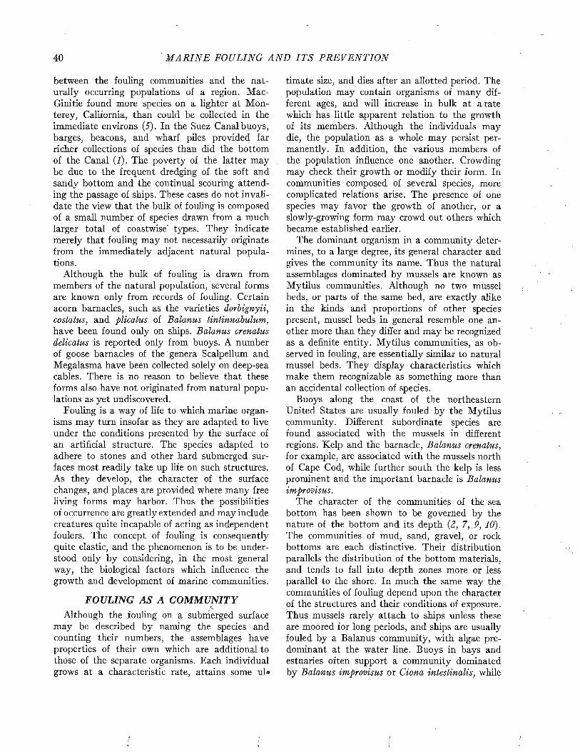
40 M A R I N E FOULING A N D I T S P R E V E N T I O N
between the fouling communities and the naturally occurring populations of a region. Mac- Ginitie found more species on a lighter at Monterey, California, than could be collected in the immediate environs (5). In the Suez Canal buoys, barges, beacons, and wharf piles provided far richer collections of species than did the bottom of the Canal (I). The poverty of the latter may be due to the frequent dredging of the soft and sandy bottom and the continual scouring attending the passage of ships. These cases do not invalidate the view that the bulk of fouling is composed of a small number of species drawn from a much larger total of coastwise types. They indicate merely that fouling may not necessarily originate from the immediately adjacent natural populations.
Although the bulk of fouling is drawn from members of the natural population, several forms are known only from records of fouling. Certain acorn barnacles, such as the varieties dorbignyii, costatus, and plicatus of Balanus tintinnabulum, have been found only on ships. Balanus crenatus delicatus is reported only from buoys. A number of goose barnacles of the genera Scalpellum and Megalasma have been collected solely on deep-sea cables. There is no reason to believe that these forms also have not originated from natural populations as yet undiscovered.
Fouling is a way of life to which marine organisms may turn insofar as they are adapted to live under the conditions presented by the surface of an artificial structure. The species adapted to adhere to stones and other hard submerged surfaces most readily take up life on such structures. As they develop, the character of the surface changes, and places are provided where many free living forms may harbor. Thus the possibilities of occurrence are greatly extended and may include creatures quite incapable of acting as independent foulers. The concept of fouling is consequently quite elastic, and the phenomenon is to be understood only by considering, in the most general way, the biological factors which influence the growth and development of marine communities.
FOULING AS A COM M UNITYLAlthough the fouling on a submerged surface
may be described by naming the species and counting their numbers, the assemblages have properties of their own which are additional to those of the separate organisms. Each individual grows at a characteristic rate, attains some ul»
timate size, and dies after an allotted period. The population may contain organisms of many different ages, and will increase in bulk at arate which has little apparent relation to the growth of its members. Although the individuals may die, the population as a whole may persist permanently. In addition, the various members of the population influence one another. Crowding may check their growth or modify their form. In communities composed of several species, more complicated relations arise. The presence of one species may favor the growth of another, or a slowly-growing form may crowd out others which became established earlier.
The dominant organism in a community determines, to a large degree, its general character and gives the community its name. Thus the natural assemblages dominated by mussels are known as Mytilus communities. Although no two mussel beds, or parts of the same bed, are exactly alike in the kinds and proportions of other species present, mussel beds in general resemble one another more than they differ and may be recognized as a definite entity. Mytilus communities, as observed in fouling, are essentially similar to natural mussel beds. They display characteristics which make them recognizable as something more than an accidental collection of species.
Buoys along the coast of the northeastern United States are usually fouled by the Mytilus community. Different subordinate species are found associated with the mussels in different regions. Kelp and the barnacle, Balanus crenatus, for example, are associated with the mussels north of Cape Cod, while further south the kelp is less prominent and the important barnacle is Balanus improvisus.
The character of the communities of the sea bottom has been shown to be governed by the nature of the bottom and its depth (2, 7, 9, 10). The communities of mud, sand, gravel, or rock bottoms are each distinctive. Their distribution parallels the distribution of the bottom materials, and tends to fall into depth zones more or less parallel to the shore. In much the same way the, communities of fouling depend upon the character of the structures and their conditions of exposure. Thus mussels rarely attach to ships unless these are moored for long periods, and ships are usually fouled by a Balanus community, with algae predominant at the water line. Buoys in bays and estuaries often support a community dominated by Balanus improvisus or Ciona intestinalis, while
T H E FOULING C O M M U N I T Y 41
those moored well off shore are fouled with goose barnacles. Buoy anchors often support a community which is different from that on structures suspended directly above the bottom. The M ytilus community is generally confined to the buoy and chain, and is replaced on the anchor by barnacles.
It may be seen that fouling is not a well defined entity. The assemblage of organisms to be found on an exposed structure depends upon the species naturally present at the site of exposure and upon their ability to attach and grow on its surface. The characteristics and the activity of the structure contribute to this selection. In addition the reproductive habits of the different species will determine which organisms appear first on structures exposed at different seasons. The interactions of the various kinds which may appear simultaneously or in succession modify the assemblage and determine the character of the community which finally emerges.
These varied factors, which must be taken into account in order to understand the communities of organisms which are found on artificial structures, will be considered in the chapters which follow.
REFERENCES1. Fox, M. Zoological Results of the Cambridge Expedition to
Suez Canal, 1924. General Results. Trans. Zoological Soc. London, 22, 1-64, 1926.
2. G i s l e n , T. Epibioses of the Gullmar Fjord. I, II. Kristine-bergs Zoologiska Station 1877-1927 ; Skriftser., K. Sv'ensk. Vetenskapsakad., No. 3, 1-123; No. 4, 1-380, 1930.
3. H e n t s c h e l , E. Der Bewuchs an Seeschiffen. Int. Rev. ges.Hydrog. Hydrob. 11, No. 3, 4, 238-264, 1923.
4. K i r c h e n p a u e r , J. U. Die Seetonnen der Elbmundung. Ab-handl. a.d. Gebiete d. Naturwiss. her. v. d. naturwiss Ver. in Hamburg, 4, No. 4, 1-59, 1862.
5 . M a c G i n i t i e , G . E . Littoral Marine Communities. Amer.Midland Nat. 21, No. 1, 28-55, 1939.
6. M i l n e , A. The Ecology of the Tamar Estuary. IV. The Distribution of the Fauna on Buoys. Jour. Marine Biol. Assoc. U.K. (n.s.) 24, 69-87, 1940.
7. P e t e r s e n , C. G. J . A Preliminary Result of the Investigations on the Valuation of the Sea. Rep. Danish Biol. Sta., 23, 29-32, 1915.
8. P r a t t , H. S. A Manual of the Common Invertebrate AnimalsExclusive of Insects. Revised Edition, P. Blakiston’s Son & Co., Inc., Philadelphia, 1935.
9. S h e l e o e d , V. E. Geographic Extent and Succession in PacificNorth American Intertidal (Balanus) Communities. Pub. Puget Sd. Biol. Sta., 7, 217-223, 1930.
10. S h e l f o r d , V. E . , A. O. W e e s e , L. A. R i c e , D. I. R a s m u s s e n ,and A. M a c L e a n . Some Marine Biotic Communities of the Pacific Coast of North America. Part I. General Survey of the Communities. Ecol. Mon., 5, 249-354, 1935.
11. V i s s c h e r , J. P. Nature and Extent of Fouling of Ships’Bottoms. Bull. Bur. Fisheries, 43, 193-252, 1927.
12. Z o B e l l , C. E. Marine Microbiology. Chronica Botanica Co.,Waltham, 1946.
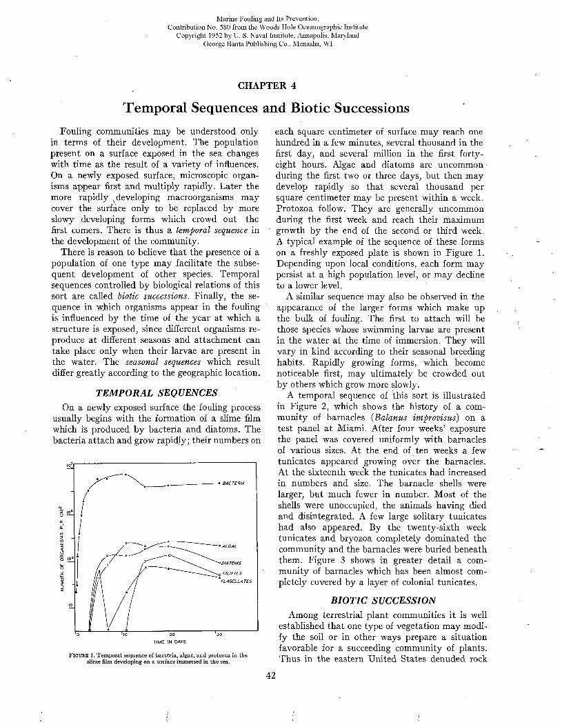
Marine Fouling and Its Prevention,Contribution No. 580 from the Woods Flole Oceanographic Institute
Copyright 1952 by U. S. Naval Institute, Annapolis, Maryland George Banta Publishing Co., Menasha, WI
CHAPTER 4
Temporal Sequences and Biotic SuccessionsFouling communities may be understood only
in terms of their development. The population present on a surface exposed in the sea changes with time as the result of a variety of influences. On a newly exposed surface, microscopic organisms appear first and multiply rapidly. Later the more rapidly x developing macroorganisms may cover the surfàce only to be replaced by more slowy developing forms which crowd out the first comers. There is thus a temporal sequence in the development of the community.
There is reason to believe that the presence of a population of one type may facilitate the subsequent development of other species. Temporal sequences controlled by biological relations of this sort are called biotic successions. Finally, the sequence in which organisms appear in the fouling is influenced by the time of the year at which a structure is exposed, since different organisms reproduce at different seasons and attachment can take place only when their larvae are present in the water. The seasonal sequences which result differ greatly according to the geographic location.
TEMPORAL SEQUENCESOn a newly exposed surface the fouling process
usually begins with the formation of a slime film which is produced by bacteria and diatoms. The bacteria attach and grow rapidly; their numbers on
- • B A C T E R IA
N5oCLtfl 2 - <£>Z<oo 10
— * A L G A E
OCCUJCD F L A G E L L A T E S
TIME IN DAYS
F i g u r e 1. Temporal sequence of bacteria, algae, and protozoa in the slime film developing on a surface itnmersed in the sea.
each square centimeter of surface may reach one hundred in a few minutes, several thousand in the first day, and several million in the first forty- eight hours. Algae and diatoms are uncommon during the first two or three days, but then may develop rapidly so that several thousand per square centimeter may be present within a week. Protozoa follow. They are generally uncommon during the first week and reach their maximum growth by the end of the second or third week. A typical example of the sequence of these forms on a freshly exposed plate is shown in Figure 1. Depending upon local conditions, each form may persist at a high population level, or may decline to a lower level.
A similar sequence may also be observed in the appearance of the larger forms which make up the bulk of fouling. The first to attach will be those species whose swimming larvae are present in the water at the time of immersion. They will vary in kind according to their seasonal breeding habits. Rapidly growing forms, which become noticeable first, may ultimately be crowded out by others which grow more slowly.
A temporal sequence of this sort is illustrated in Figure 2, which shows the history of a community of barnacles (Balanus improvisus) on a test panel at Miami. After four weeks’ exposure the panel was covered uniformly with barnacles of various sizes. At the end of ten weeks a few tunicates appeared growing over the barnacles. At the sixteenth week the tunicates had increased in numbers and size. The barnacle shells were larger, but much fewer in number. Most of the shells were unoccupied, the animals having died and disintegrated. A few large solitary tunicates had also appeared. By the twenty-sixth week tunicates and bryozoa completely dominated the community and the barnacles were buried beneath them. Figure 3 shows in greater detail a community of barnacles which has been almost completely covered by a layer of colonial tunicates.
BIOTIC SUCCESSIONAmong terrestrial plant communities it is well
established that one type of vegetation may modify the soil or in other ways prepare a situation favorable for a succeeding community of plants. Thus in the eastern United States denuded rock
42
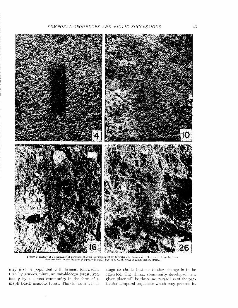
T E M P O R A L SEQUENCES A N D BIO TIC SUCCESSIONS 43
M
8P5Ï
1
■ ¿4
< « í * i* -'
F i g u r e 2. H isto ry of a com m unity of barnacles, showing its replacem ent by tun ica tes and bryozoans in the course of one half year. N um bers indicate the duration of exposure in weeks. Photos by C. M . Weiss a t M iam i Beach, Florida.
m ay first be populated with lichens, followed in turn by grasses, pines, an oak-hickory forest, and finally by a climax community in the form of a maple-beach-hemlock forest. The climax is a final
stage so stable tha t no further change is to be expected. The climax community developed in a given place will be the same, regardless of the particular temporal sequences which may precede it.
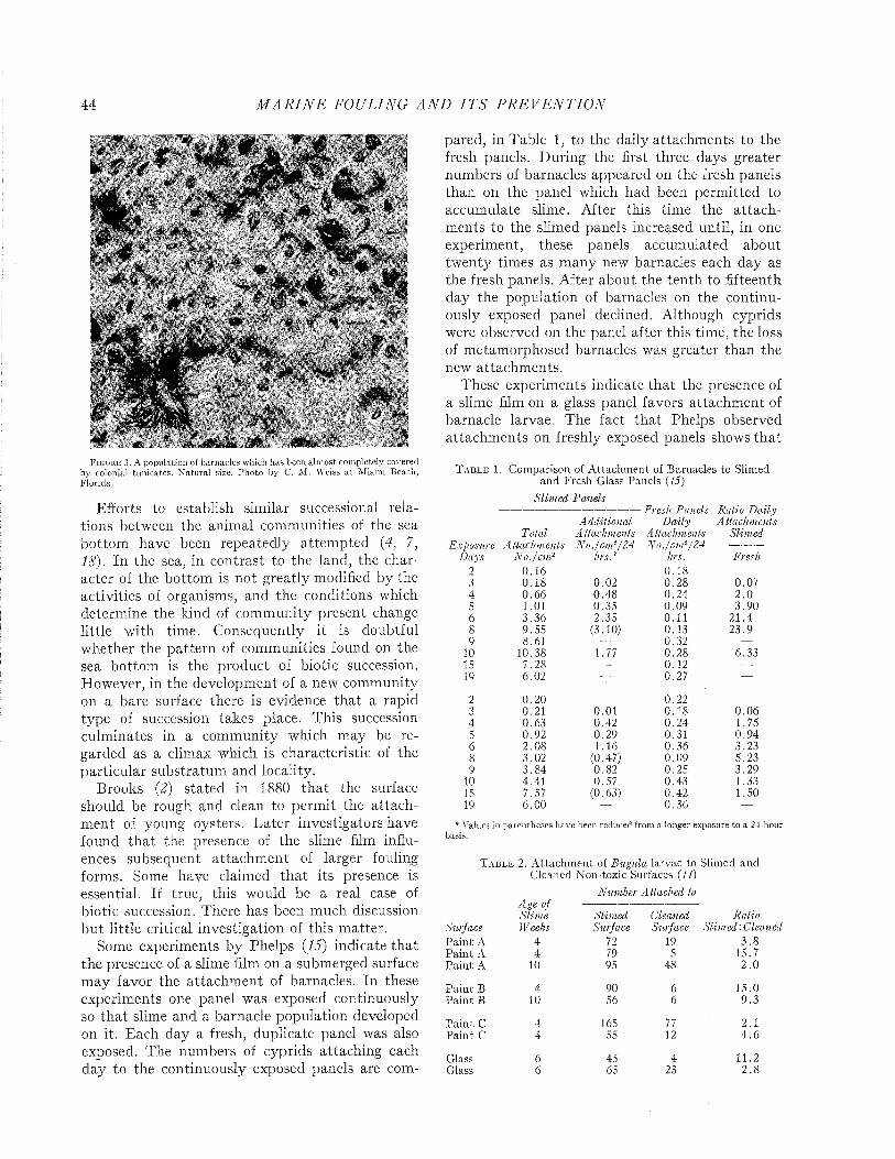
44 M A R I N E FOULING A N D I T S P R E V E N T I O N
F i g u r e 3. A population of barnacles which has been alm ost completely covered by colonial tunicates. N atural size. P hoto by C. M . Weiss a t M iam i Beach, Florida.
Efforts to establish similar successional relations between the animal communities of the sea bottom have been repeatedly attem pted (4, 7, 18). In the sea, in contrast to the land, the character of the bottom is not greatly modified by the activities of organisms, and the conditions which determine the kind of community present change little with time. Consequently it is doubtful whether the pattern of communities found on the sea bottom is the product of biotic succession. However, in the development of a new community on a bare surface there is evidence tha t a rapid type of succession takes place. This succession culminates in a community which may be regarded as a climax which is characteristic of the particular substratum and locality.
Brooks (2) stated in 1880 th a t the surface should be rough and clean to permit the attachm ent of young oysters. Later investigators have found tha t the presence of the slime film influences subsequent attachm ent of larger fouling forms. Some have claimed th a t its presence is essential. If true, this would be a real case of biotic succession. There has been much discussion but little critical investigation of this m atter.
Some experiments by Phelps {15) indicate that the presence of a slime film on a submerged surface may favor the attachm ent of barnacles. In these experiments one panel was exposed continuously so tha t slime and a barnacle population developed on it. Each day a fresh, duplicate panel was also exposed. The numbers of cyprids attaching each day to the continuously exposed panels are com
pared, in Table 1, to the daily attachments to the fresh panels. During the first three days greater numbers of barnacles appeared on the fresh panels than on the panel which had been perm itted to accumulate slime. After this time the a ttachments to the slimed panels increased until, in one experiment, these panels accumulated about twenty times as many new barnacles each day as the fresh panels. After about the tenth to fifteenth day the population of barnacles on the continuously exposed panel declined. Although cyprids were observed on the panel after this time, the loss of metamorphosed barnacles was greater than the new attachm ents.
These experiments indicate that the presence of a slime film on a glass panel favors attachm ent of barnacle larvae. The fact tha t Phelps observed attachm ents on freshly exposed panels shows tha t
T a b l e 1. Comparison of A ttachm ent of Barnacles to Slimed and Fresh Glass Panels (15)
S lim ed Panels ---------------------------------------- Fresh Panels Ratio D a ily
A dditional D aily A ttachmentsTotal A ttachments Attachm ents Slim ed
x posare A ttachments N o ./c m 2/ 24 N o ./c m 2- / 24D ays N o ./c m 2 hrs.* hrs. Fresh
2 0.16 0.183 0.18 0.02 0.28 0.074 0.66 0.48 0.24 2 .05 1.01 0.35 0.09 3.906 3.36 2.35 0.11 21.48 9.55 (3.10) 0.13 23.99 8.61 — 0.32 —
10 10.38 1.77 0.28 6.3315 7.28 — 0.12 —19 6.02 ~r 0.27 —
2 0.20 0.223 0.21 0.01 0.18 0.064 0.63 0.42 0.24 1.755 0.92 0.29 0.31 0.946 2.08 1.16 0.36 3.238 3.02 (0.47) 0.09 5.239 3.84 0.82 0.25 3.29
10 4.41 0.57 0.43 1.3315 7.57 (0.63) 0.42 1.5019 6.00 — 0.36 —
* Values in parentheses have been reduced from a longer exposure to a 24-hour basis.
T a b l e 2. A ttachm ent of B ugula larvae to Slimed and Cleaned Non-toxic Surfaces (11)
N um ber A ttached toAge of Slim e Slim ed Cleaned Ratio
Surface Weeks Surface Surface S lim ed . C leiP ain t A 4 72 19 3 .8P ain t A 4 79 5 15.7P ain t A 10 95 48 2 .0
P ain t B 4 90 6 15.0P ain t B 10 56 6 9 .3
P a in t C 4 165 77 2.1Paint C 4 55 12 4 .6
Glass 6 45 4 11.2Glass 6 65 23 2 .8
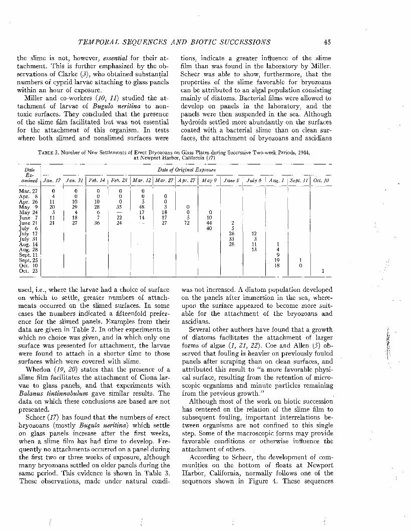
TEM PORAL SEQ UENCES A N D BIOTIC SUCCESSIONS 45
the slime is not, however, essential for their attachment. This is further emphasized by the observations of Clarke (3), who obtained substantial numbers of cyprid larvae attaching to glass panels within an hour of exposure.
Miller and co-workers {10, 11) studied the attachment of larvae of Bugula neritina to nontoxic surfaces. They concluded that the presence of the slime film facilitated but was not essential for the attachment of this organism. In tests where both slimed and nonslimed surfaces were
tions, indicate a greater influence of the slime film than was found in the laboratory by Miller. Scheer was able to show, furthermore, that the properties of the slime favorable for bryozoans can be attributed to an algal population consisting mainly of diatoms. Bacterial films were allowed to develop on panels in the laboratory, and the panels were then suspended in the sea. Although hydroids settled more abundantly on the surfaces coated with a bacterial slime than on clean surfaces, the attachment of bryozoans and ascidians
T a b l e 3. Number of New Settlements of Erect Bryozoans on Glass Plates during Successive Two-week Periods, 1944,at Newport Harbor, California {17)
Date Date of Original ExposureE x
amined Jan . 17 Jan. 31 F A . 14 Feb. 28 M ar. 12 M ar. 27 A pr. 27 M ay 9 June 8 J u ly 6 Aug. 1 Sept. 11 Oct. 10
Mar. 27 0 0 0 0 0Apr. 8 4 0 0 0 0 0Apr. 26 11 10 10 0 5 0M ay 9 20 29 28 35 48 3 0M ay 24 5 4 6 — 17 18 0 0June 7 11 18 7 22 14 17 5 10June 21 21 27 36 24 — 27 72 44 2July 6 40 5July 17 28 12July 31 33 3Aug. 14 28 11 1Aug. 28 13 4Sept. 11 9Sept. 25 19 1Oct. 10 18 0Oct. 23 1
used, i.e., where the larvae had a choice of surface on which to settle, greater numbers of attachments occurred on the slimed surfaces. In some cases the numbers indicated a fifteenfold preference for the slimed panels. Examples from their data are given in Table 2. In other experiments in which no choice was given, and in which only one surface was presented for attachment, the larvae were found to attach in a shorter time to those surfaces which were covered with slime.
Whedon {19, 20) states that the presence of a slime film facilitates the attachment of Ciona larvae to glass panels, and that experiments with Balanus tintinnabulum gave similar results. The data on which these conclusions are based are not presented.
Scheer {17) has found that the numbers of erect bryozoans (mostly Bugula neritina) which settle on glass panels increase after the first weeks, when a slime film has had time to develop. Frequently no attachments occurred on a panel during the first two or three weeks of exposure, although many bryozoans settled on older panels during the same period. This evidence is shown in Table 3. These observations, made under natural condi-
was not increased. A diatom population developed on the panels after immersion in the sea, whereupon the surface appeared to become more suitable for the attachment of the bryozoans and ascidians.
Several other authors have found that a growth of diatoms facilitates the attachment of larger forms of algae {1, 21, 22). Coe and Allen (5) observed that fouling is heavier on previously fouled panels after scraping than on clean surfaces, and attributed this result to “a more favorable physical surface, resulting from the retention of microscopic organisms and minute particles remaining from the previous growth.”
Although riiost of the work on biotic succession has centered on the relation of the slime film to subsequent fouling, important interrelations between organisms are not confined to this single step. Some of the macroscopic forms may provide favorable conditions or otherwise influence the attachment of others.
According to Scheer, the development of communities on the bottom of floats at Newport Harbor, California, normally follows one of the sequences shown in Figure 4. These sequences
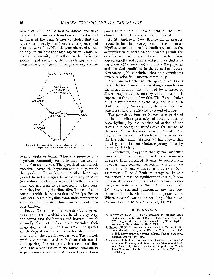
46 M A R I N E FOULING A N D I T S P R E V E N T I O N
were observed under natural conditions, and since most of the forms were found on some surfaces at all times of the year, Scheer concludes that the succession is nearly if not entirely independent of seasonal variations. Mussels were observed to settle only on surfaces bearing a bryozoan, Ciona, or Styela community. Together with Saxicava, sponges, and ascidians, the mussels appeared in measurable quantities only on plates exposed for
CLEAN SURFACE
BACTERIA ALGAE ,
HV DROIDS
It-A BALANUS
BRYOZOANSSERPULIDS CIONA
STYELASPONGES
MYTILUS
F i g u r e 4. Sequences of dominant organisms on surfaces exposed in Newport Harbor, California. From Scheer (17).
twenty weeks or longer. Thus the presence of a bryozoan community seems to favor the attachment of mussel larvae. The growth of the mussels effectively covers the bryozoan community, which then perishes. Barnacles, on the other hand, appeared to settle irregularly without any relation to the duration of exposure, and thus their attachment did not seem to be favored by other communities, including the slime film. This conclusion contrasts with the observations of Phelps. Scheer considers that the Mytilus community represented a climax in the float-bottom associations of Newport Harbor.
Hewatt (7) removed the mussels (M. californianus) from an intertidal area in Monterey Bay, and found that the limpets and barnacles which normally lived at higher levels extended their range downward into the bare area. The species which depend on mussel beds for shelter were absent from the area for over a year. The mussels gradually returned, and with them their associated species, eliminating the barnacles and limpets. The reconstitution of the mussel community required more than two and one-half years. Com
pared to the rate of development of the plant climax on land, this is a very short period.
At St. Andrews, New Brunswick, in seasons favorable for the development of the Balanus- Mytilus association, surface conditions such as the accumulation of shells on the beaches permit the establishment of heavy sets of mussels. These spread rapidly and form a surface layer that kills the clams (M ya arenaria) and alters the physical and chemical conditions in the subsurface layers. Newcombe (14) concluded that this constitutes true succession in a marine community
According to Hatton (6), the sporelings of Fucus have a better chance of establishing themselves in the moist environment provided by a carpet of Enteromorpha than when they settle on bare rock exposed to the sun at low tide. The Fucus chokes out the Enteromorpha eventually, and is in turn choked out by Ascophyllum, the attachment of which is similarly facilitated by a mat of Fucus.
The growth of Balanus balanoides is inhibited in the immediate proximity of fucoids, such as Ascophyllum, by the mechanical action of the waves in rubbing the fronds over the surface of the rock (8). In this way fucoids can control the habitat to the extent of excluding the barnacles. On the other hand, Hatton (6) has shown that growing barnacles can eliminate young Fucus by “nipping their feet.”
In conclusion, it appears that several authentic cases of biotic succession in sedentary communities have been described. It must be pointed out, however, that seasonal succession will dominate the picture in many cases, so that true biotic succession will be difficult to recognize. In this connection it may be significant that a high proportion of the evidence for biotic succession comes from the Pacific coast of North America (5, 7, 17, 21), where seasonal phenomena are less pronounced than elsewhere in the temperate zone. Where seasonal variations are large, biotic succession may not be obvious (P, 12, 13, 16).
REFERENCES1. B o k e n h a m , N. A. H. The Colonization of Denuded Rock
Surfaces in the Intertidal Region of the Cape Peninsula. (With a general comment on the results, by T. A. Stephenson.) Ann. Natal Mus., 9, 47-81, 1938.
2. B r o o k s , W. K. Development of the American Oyster. Studiesfrom the Biol. Lab., Johns Hopkins Univ., No. 4, 1880; 1-106. Early study for oyster culture. Second part gives detailed embryology. 1880.
3. C l a r k e , G. L. The Effectiveness of Various Toxics and theCourse of Poisoning and Recovery in Barnacles and Mussels. Paper 11, Sixth Semi-Annual Report from Woods Hole Oceanographic Inst, to Bureau of Ships, 1943. (Unpublished.)
T E M P O R AL SEQ UE NCES A N D BIOTIC SUCCESSIONS 47
4. C l e m e n t s , F. E., and V. E. S h e l e o r d . Bio-Ecology. NewYork, John Wiley & Sons, vii plus 425 pp., 1939.
5. C o e , W. R., and W. E. A l l e n . Growth of Sedentary MarineOrganisms on Experimental Blocks and Plates for Nine Successive Years at the Pier of the ScrippS Institution of Oceanography. Bull. Scripps Inst. Oceanog., Tech. Ser., 4, 101-136, 1937.
6. H a t t o n , H . Essais de bionomie explicative sur quelquesespeces intercotidales d’Algues et d’Animaux. Ann. Inst. Oceanog., N.S., 17, 241-348, 1938.
7. H e w a t t , W. G. Ecological Succession in the M ytilu s californianus Habitat as Observed in Monterey Bay, Cal. Ecol., 16, 244-251, 1935.
8. K i t c h e n s , J. A. An Introduction to the Ecology of IntertidalRock Surfaces on the Coast of Argyll. Trans. Roy. Soc. Edinburgh, 53, Part II, No. 15, 351-374, 1935.
9. M c D o u g a l l , K. D. Sessile Marine Invertebrates at Beaufort,N.C. Ecol. Mon., 13, 321-374, 1943.
10. M i l l e r , M. A. Toxic Effects of Copper on Attachment andGrowth of Bugula neritina. Biol. Bull., 90, 122-140, 1946.
11. M i l l e r , M. A., and E. E. C u p p . Development of BiologicalAccelerated Tests (Progress Report). Biological Laboratory, Naval Fuel Depot, San Diego, Cal., Annual Report for 1941-1942, Vol. II, 1942. (Unpublished.)
1 2 . M o o r e , H. B. The Colonization of a New Rocky Shore atPlymouth. Jour. Anim. Ecol., 8, 29-38, 1939.
13. M o o r e , H. B., and N! G. S p r o s t o n . Further Observations onthe Colonization of a New Rocky Shore at Plymouth. Ibid., 9, 319-327, 1940.
14. N e w c o m b e , C. L. Certain Environmental Factors of a Sand
Beach in the St. Andrews Region, New Brunswick, with a Preliminary Designation of the Intertidal Communities. Jour. Ecol., 22, 334^355, 1935.
15. P h e l p s , A. Observations on Reactions of Barnacle Larvaand Growth of Metamorphosed Forms at Beaufort, N . C., June 1941 to September 1941. Paper 7, Fourth Semi- Annual Report from Woods Hole Oceanographic Inst, to Bureau of Ships, 1942. (Unpublished.)
16. P y e f i n c h , K. A. The Intertidal Ecology of Bardsey Island,North Wales, with Special Reference to the Recolonization of Rock Surfaces, and the Rock-pool Environment. Jour. Anim. Ecol., 12, 82-108, 1943.
17. S c h e e r , B. T. The Development of Marine Fouling Communities. Biol. Bull., 89, 103-121, 1945.
18. S h e l e o r d , V. E., A. O. W e e s e , L. A. R i c e , D. I. R a s m u s s e n , ,and A. M a c L e a n . Some Marine Biotic Communities of the Pacific Coast of North America. Part I. General Survey of the Communities. Ecol. Mon., 5, 249-354, 1935.
19. W h e d o n , W. F. Investigations Pertaining to the Fouling ofShips’ Bottoms. Biological Laboratory, Naval Fuel Depot, San Diego, Cal. Semi-Annual Report for 1937-1938, December, 1937. (Unpublished.)
20. W h e d o n , W. F. Ib id ., Semi-Annual Report for 1938-1939,June, 1939. (Unpublished.)
21. W i l s o n , O. T. Some Experimental Observations of MarineAlgal Succession. Ecol., 6, 303-311, 1925.
22. Y e n d o , K. On the Cultivation of Seaweeds, with SpecialAccounts of their Ecology. Econ. Proc. Roy. Dublin Soc., 2, No. 7, 105-122, 1914.

Marine Fouling and Its Prevention,Contribution No. 580 from the Woods Hole Oceanographic Institute
Copyright 1952 by U. S. Naval Institute, Annapolis, Maryland George Banta Publishing Co., Menasha, WI
CHAPTER 5
The Seasonal SequenceIn regions where marked seasonal changes in
temperature occur, the reproduction and growth of many organisms are completely suppressed during the winter period. In tropical climates the seasonal changes in conditions are relatively small, and fouling may continue without interruption throughout the year. Yet even under such conditions the individual species which attach to a freshly exposed surface vary from month to month, as illustrated in Figure 1.
The interpretation of the seasonal attachment of fouling is complicated by the fact that the reproductive process has an inherent rhythm imposed by the time required for the maturation of the sex products of the adult, the development of the larvae to the stage of attachment, and the growth of the attached organisms to the point where they are ready to reproduce the next generation. These processes are all influenced by the environment. The cycle may be interrupted when conditions are unfavorable, and be resumed again when a favorable environment is restored. As a result, attachment may be determined by conditions at some previous period, and may not correlate exactly with the condition of the water at the time when it occurs.
Many species pass the winter in the adult stage, which is stimulated to reproductive activity with the coming of spring. Time is required, however, for the sex products to mature to the condition in which fertilization takes place. In some organisms, such as Bugula, the larval stage is short and attachment follows spawning almost immediately. In others the larval period may be considerable. In the mussel, for example, the larvae do not settle until one to three months after spawning begins (46). Some forms pass the winter in a premature stage. Balanus balanoides, for example, breeds in the fall of the year at Plymouth but retains the young within the mantle cavity until the following spring, when they are discharged and attach after a short period as free-swimming larvae.
When the development of favorable conditions starts the breeding cycle in the spring, it continues during the summer in a way which varies with the species. Some attach almost continuously throughout the season; others vary in abundance in a way which suggests that successive generations are coming to maturity. The number of generations
which can be produced in a single season varies with the time required for the species to grow to maturity and with the length of the period in which suitable conditions persist. In temperate regions, slowly developing forms may be able to produce but a single generation in the course of the short summer. In warmer regions development is more rapid and many generations may be produced each year. Actually very little is known of the ages at which marine organisms attain maturity, or how they vary in different situations. Table 1 summarizes some of the data which apply to fouling.
The breeding period is controlled by the special habits of reproduction and development in each species and by the annual fluctuations in temperature and other conditions. The latter vary in intensity and duration according to the location; consequently, the season of attachment can only be specified exactly by considering each species and locality separately. The seasonal breeding behavior of fouling organisms may be divided into a number of categories which are useful in summarizing the phenomena.1 These are:
Type 1. Attachment continuous throughout the year without definite seasonal fluctuation.
Type 2. Attachment continuous, but with increased frequency during a definite portion of the year.
Type 3. Attachment limited to some definite portion of the year.
Type 4. Attachment occurring at two separated periods of the year.
A given species may conform to a different type in different parts of its range.
EFFECT OF TEMPERATURE ON SEASONAL BREEDING
BEHAVIORTemperature appears to be the principal condi
tion limiting the geographical distribution of marine animals, and determining their periods of breeding. Adult organisms can frequently survive under extremes of temperature which are unfavorable for reproduction. Consequently a species may
1 These categories are derived from a classification of the breeding behavior of marine animals in tropical waters proposed by Paul (32). The categories given apply more generally. Paul includes a fifth category of breeding which is discontinuous and depends upon the phases of the moon. N o important fouling organisms are known to exhibit this type of breeding behavior.
48
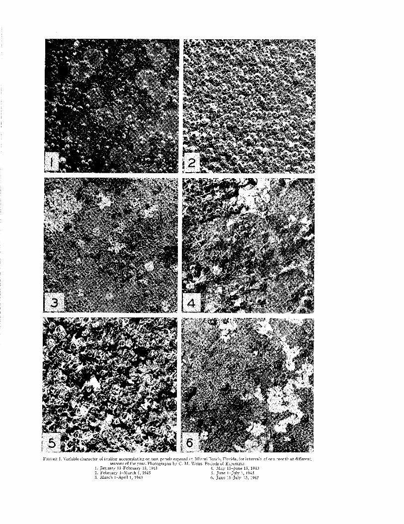
F i g u r e 1. Variable character of fouling accum ulating on test panels exposed a t M iam i Beach, F lorida, for intervals of one m onth a t different, seasons of the year. Photographs by C. M . Weiss. Periods of Exposure:
1. Jan u ary 15-February 15, 1945 4. M ay 15-June 15, 19432. February 1-M arch 1, 1945 5. June 1-Ju ly 1, 19453. M arch 1-April 1, 1943 6. Ju n e 15-July 15, 1943
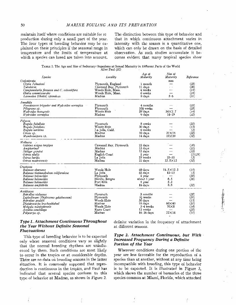
50 M A R I N E FOULING A N D I T S P R E V E N T I O N
maintain itself where conditions are suitable for reproduction during only a small part of the year. The four types of breeding behavior may be explained on these principles if the seasonal range in temperature and the limits of temperature at which a species can breed are taken into account.
The distinction between this type of behavior and that in which continuous attachment varies in intensity with the season is a quantitative one, which can only be drawn on the basis of detailed observation. As such studies accumulate it becomes evident that many tropical species show
T a b l e 1. The Age and Size of Sedentary Organisms at Sexual Maturity in Different Parts of the WorldAfter Paul (32)
Age at Size atSpecies Locality M aturity M aturity Reference
Coelenterata mmClytia Johnstoni Plymouth, England 1 month — (28)Tubularia Cawsand Bay, Plymouth 11 days — (30)Campanularia flexuosa and C. calceolifera Woods Hole, Mass. 4 weeks — (14)Obelia commissuralis Woods Hole, Mass. 6 weeks — (14)Laomedea (Obelia) spinulosa Madras 8 days 5-6 (31)
AnnelidaPomatoceros triqueter and Hydroides norvegica Plymouth 4 months — (28)Filograna sp. Plymouth 101 weeks — (28)Hydroides hexagonis Woods Hole 59 days 54X 2.7 (14)Hydroides norvegica Madras 9 days LD19 (32)
Polyzoa Bugula flabellata
Bugula neritina Crisia sp. M embranipora sp.
Plymouth Woods Hole La Jolla, Calif. Madras Madras
8 weeks 30 days
6 weeks 10 days 14 days
21X1419X19
(28)(13)
(3)(32)(32)
Mollusca Galvina exigua tergipes A mphorina?
Ostrea edulis Ostrea lurida Ostrea madrasensis
Cawsand Bay, Plymouth 22 daysMadras 13 daysMadras 15 daysEnglish Coast 1 yearLa Jolla 23 weeksMadras 21 days
25-3512.5X12
(30)(31)(33)
(5)(29) (3)
(32)
CrustaceaBalanus eburneus Woods Hole 60 days 14.5X 12.5 (14)Balanus tintinnabulum californicus La Jolla 65 days 12-13 (3)Balanus balanoides Plymouth 1 year — (28)Balanus balanoides Herdla, Bergen about 1 year 6.5 (36)Balanus balanoides Port Erin 1 year 5.3Balanus amphitrite Madras 16 days 8 .8 (32)
A scidiacea Botryllus violaceusLeptoclinum (Diplosoma gelatinosum) Botryllus gouldii Diandrocarpa brackenhielmi Molgula manhattensis A scidia conchilega Polycarpa sp.
Type 1. A tta ch m e n t C on tinuous T hroughout th e Y ear W ith o u t D efin ite Seasonal F luctuations
This type of breeding behavior is to be expected only where seasonal conditions vary so slightly that the normal breeding rhythms are uninfluenced by them. Such conditions are most likely to occur in the tropics or at considerable depths. There are no data on breeding seasons in the latter situation. It is commonly supposed that reproduction is continuous in the tropics, and Paul has indicated that several species conform to this type of behavior at Madras, as shown in Figure 2.
Plymouth 3 months — (28)Plymouth 31 weeks — (28)Woods Hole 30 days — (13)Madras 18 days 60X40 (31)Woods Hole 3-4 weeks 70X8 (14)Essex Coast 15 weeks — (28)Madras 16-26 days 22X14 (31)
definite variation in the frequency of attachment at different seasons.
Type 2. A tta ch m e n t C on tinuous, b u t W ith Increased Frequency During a D efin ite P ortion o f th e Year
Wherever conditions during one portion of the year are less favorable for the reproduction of a species than at another, without at any time being incompatible with breeding, this type of behavior is to be expected. It is illustrated in Figure 3, which shows the number of barnacles of the three species common at Miami, Florida, which attached
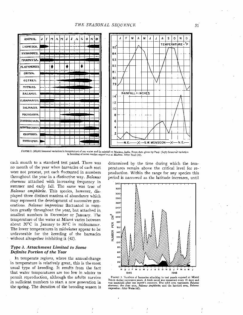
THE S EA S O N A L SEQ UENCE 51
A N IM A L J F M A M J J A S 0 N D
LAOMEDEA.
HYDROIDES.
M A R PH Y SA.
PLATYNEREIS. ♦ ♦ ♦C R ISIA .
O S T R E A . ► - . . . .
MYTILUS. ► - . . .
BA LAN U S.
CLIBANARIUS.
SALM ACIS.
POLYCARPA.
DIANDROCARPA.
ACENTROGOBIUS.
CLUPEIDS.
THERAPON. ► ■
TEMPERATURE- F8 5
8 4
8 3
8 2
8 0
7 9
RAINFALL-- INCHES
■X— S.W. MONSOON X N.E. N.Er
F id u m 2. {Righi) Seasonal variation in temperature of sea water and in rainfall at Madras, India. From data given by Paul. {Left) Seasonal variationin breeding of some marine organisms at Madras. After Paul {32).
each month to a standard test panel. There was no month of the year when barnacles of each sort were not present, yet each fluctuated in numbers throughout the year in a distinctive way. Balanus eburneus attached with increasing frequency in summer and early fall. The same was true of Balanus amphitrite. This species, however, displayed three distinct maxima of abundance which may represent the development of successive generations. Balanus improvisus fluctuated in numbers greatly throughout the year, but attached in smallest numbers in December or January. The temperature of the water at Miami varies between about 20°C in January to 30°C in midsummer. The lower temperatures in midwinter appear to be unfavorable for the breeding of the barnacles without altogether inhibiting it (42).
Type 3. A tta c h m e n t L im ited to Som e D efin ite P ortion o f th e Year
In temperate regions, where the annual change in temperature is relatively great, this is the most usual type of breeding. It results from the fact that water temperatures are too low in winter to permit reproduction, although the adults survive in sufficient numbers to start a new generation in the spring. The duration of the breeding season is
determined by the time during which the temperatures remain above the critical level for reproduction. Within the range for any species this period is narrowed as the latitude increases, until
340
320-
300-
280-
260*
240-
2 2 0 -
2O 2 00 -
CE 'SOLD160-
c r□ 140-CO
120-
100-80-
60-
40-
2 0 -
N D J F M A M J J A S O N O J F M A M J
1945 1946Figure 3. Numbers of barnacles attaching to test panels exposed at Miami
Beach during successive years. A fresh panel was immersed every 15 days and was examined after one month’s exposure. The solid area represents Balanus eburneus; the clear area, Balanus amphitrite; and the hatched area, Balanus improvisus. After Weiss (42).
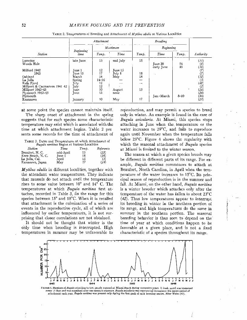
52 M A R I N E FOULING A N D I T S P R E V E N T I O N
T a b l e 2 . Temperatures of Breeding and Attachment of M ytilus edulis at Various Localities
Station
Attachment Breeding
AuthorityBeginning
time
M axim um
Temp.
Beginning
Temp. Time Time Temp.
Lamoine late June 13 end July 15 Ul)Woods Hole June 20 14 (8)
early June 15 U0)Milford 1942 June 1 12 June 15 (7)
1943 June IS 17 July 1 18 (7)Oakland March 14 May 18 (12)La Jolla Spring 14-16 — — (3)Kola Fjord July 12 — — (48)Millport & Caernarvon 1941-42 July 12 — — 0)Millport 1942-43 June 10 August 13 (26)Plymouth 1942-43 June 13 none (26)Plymouth Jan.-March 8-10 (46)Kanazawa January 10 May 17 (24)
at some point the species cannot maintain itself.The sharp onset of attachment in the spring
suggests that for each species some characteristic temperature may exist which is associated with the time at which attachment begins. Table 2 presents some records for the time of attachment of
T a b l e 3 . Dates and Temperatures at which Attachment of Bugula neritina Begins at Various Localities
Station Time Temp. ReferenceBeaufort, N . C. mid-April 15 (23)Kure Beach, N . C. June 1 18 (34)La Jolla, Cal. April 15 (3)Kanazawa, Japan May 17 (24)
M ytilus edulis in different localities, together with the attendant water temperatures. They indicate that mussels do not attach until the temperature rises to some value between 10° and 14° C. The temperatures at which Bugula neritina first attaches, recorded in Table 3, fix the range for this species between 15° and 18°C. When it is recalled that attachment is the culmination of a series of events in the reproductive cycle, all of which are influenced by earlier temperatures, it is not surprising that closer correlations are not obtained.
It should not be thought that winter is the only time when breeding is interrupted. High temperatures in summer may be unfavorable to
reproduction, and may permit a species to breed only in winter. An example is found in the case of Bugula avicularia. At Miami, this species stops attaching in June when the temperature or the water increases to 29° C, and fails to reproduce again until November when the temperature falls below 23°C. Figure 4 shows the regularity with which the seasonal attachment of Bugula species at Miami is limited to the winter season.
The season at which a given species breeds may be different in different parts of its range. For example, Bugula neritina commences to attach at Beaufort, North Carolina, in April when the temperature of the water increases to 15°C. Its principal season of reproduction is in the summer and fall. At Miami, on the other hand, Bugula neritina is a winter breeder which attaches only after the temperature of the water has fallen to about 23°C (42). Thus low temperatures appear to interrupt its breeding in winter in the northern portion of its range, and high temperatures do the same in summer in the southern portion. The seasonal breeding behavior is thus seen to depend on the time of year at which conditions happen to be favorable at a given place, and is not a fixed characteristic of a species throughout its range.
30
20
y '0
1944 19461943 1945
F i g u r e 4 . Numbers of Bugula attaching to test panels exposed at Miami Beach during successive years. A fresh panel was immersed every 15 days and was examined after one month’s exposure. Bugula avicularia was represented throughout the entire period of
attachment each year. Bugula neritina was present only during the first peak of each breeding season. After Weiss (42).
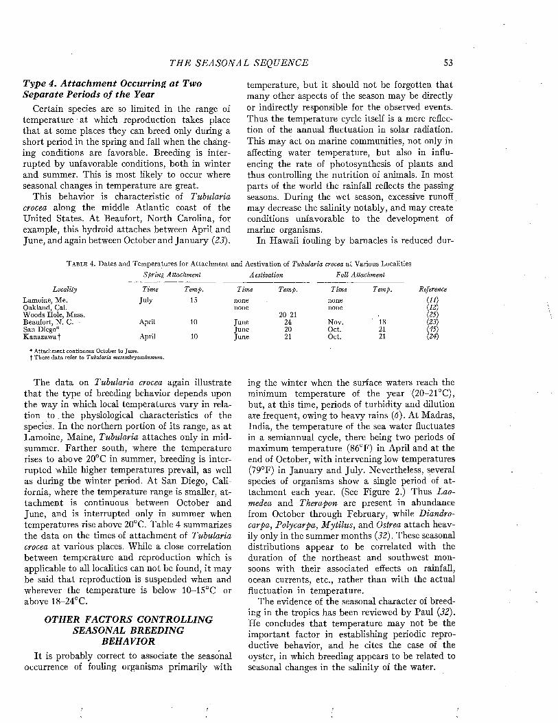
TH E S EA S O N A L SEQUENCE 53
T ype 4. A tta ch m e n t O ccurring a t Two S epara te Periods o f th e Year
Certain species are so limited in the range of temperature at which reproduction takes place that at some places they can breed only during a short period in the spring and fall when the changing conditions are favorable. Breeding is interrupted by unfavorable conditions, both in winter and summer. This is most likely to occur where seasonal changes in temperature are great.
This behavior is characteristic of Tubularia crocea along the middle Atlantic coast of the United States. At Beaufort, North Carolina, for example, this hydroid attaches between April and June, and again between October and January (23).
temperature, but it should not be forgotten that many other aspects of the season may be directly or indirectly responsible for the observed events. Thus the temperature cycle itself is a mere reflection of the annual fluctuation in solar radiation. This may act on marine communities, not only in affecting water temperature, but also in influencing the rate of photosynthesis of plants and thus controlling the nutrition of animals. In most parts of the world the rainfall reflects the passing seasons. During the wet season, excessive runoff may decrease the salinity notably, and may create conditions unfavorable to the development of marine organisms.
In Hawaii fouling by barnacles is reduced dur-
T a b l e 4 . Dates and Temperatures for Attachment and Aestivation of Tubularia crocea at Various Localities Spring Attachment Aestivation Fall Attachment
Locality Time Temp. Time Temp. Time T emp.
Lamoine, Me. July IS none noneOakland, Cal. none noneWoods Hole, Mass. 20-21Beaufort, N. C. April 10 June 24 Nov. 18San Diego* June 20 Oct. 21Kanazawai April 10 June 21 Oct. 21
Reference
u o( 12 )(25)(23) (45)(24)
* Attachment continuous October to June, f These data refer to Tubularia mesembryanthemum.
The data on Tubularia crocea again illustrate that the type of breeding behavior depends upon the way in which local temperatures vary in relation to . the physiological characteristics of the species. In the northern portion of its range, as at Lamoine, Maine, Tubularia attaches only in midsummer. Farther south, where the temperature rises to above 20°C in summer, breeding is interrupted while higher temperatures prevail, as well as during the winter period. At San Diego, California, where the temperature range is smaller, attachment is continuous between October and June, and is interrupted only in summer when temperatures rise above 20°C. Table 4 summarizes the data on the times of attachment of Tubularia crocea at various places. While a close correlation between temperature and reproduction which is applicable to all localities can not be found, it may be said that reproduction is suspended when and wherever the temperature is below 10-15°C or above 18-24° C.
OTHER FACTORS CONTROLLING SEASONAL BREEDING
BEHAVIORIt is probably correct to associate the seasonal
occurrence of fouling organisms primarily with
ing the winter when the surface waters reach the minimum temperature of the year (20-21°C), but, at this time, periods of turbidity and dilution are frequent, owing to heavy rains (6). At Madras, India, the temperature of the sea water fluctuates in a semiannual cycle, there being two periods of maximum temperature (86°F) in April and at the end of October, with intervening low temperatures (79°F) in January and July. Nevertheless, several species of organisms show a single period of attachment each year. (See Figure 2.) Thus Laomedea and Therapon are present in abundance from October through February, while Diandrocarpa, Polycarpa, M ytilus, and Ostrea attach heavily only in the summer months (32). These seasonal distributions appear to be correlated with the duration of the northeast and southwest monsoons with their associated effects on rainfall, ocean currents, etc., rather than with the actual fluctuation in temperature.
The evidence of the seasonal character of breeding in the tropics has been reviewed by Paul (32). He concludes that temperature may not be the important factor in establishing periodic reproductive behavior, and he cites the case of the oyster, in which breeding appears to be related to seasonal changes in the salinity of the water.
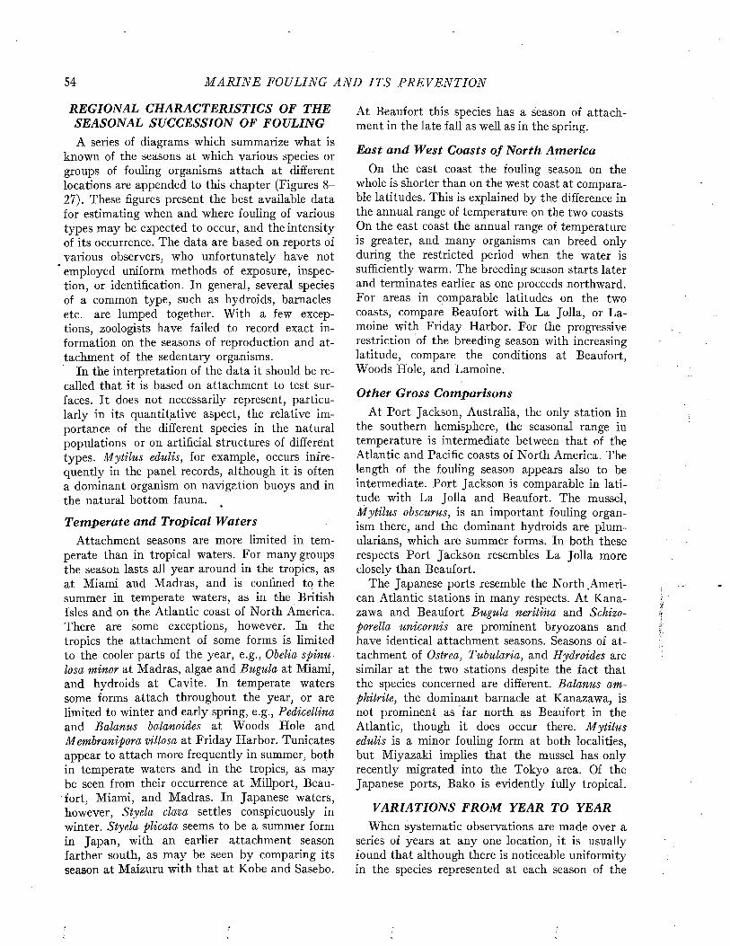
54 M A R I N E FOULING A N D I T S P R E V E N T I O N
REGIONAL CHARACTERISTICS OF THE SEASONAL SUCCESSION OF FOULINGA series of diagrams which summarize what is
known of the seasons at which various species or groups of fouling organisms attach at different locations are appended to this chapter (Figures 8 - 27). These figures present the best available data for estimating when and where fouling of various types may be expected to occur, and the intensity of its occurrence. The data are based on reports of various observers, who unfortunately have not employed uniform methods of exposure, inspection, or identification. In general, several species of a common type, such as hydroids, barnacles etc. are lumped together. W ith a few exceptions, zoologists have failed to record exact information on the seasons of reproduction and attachment of the sedentary organisms.
In the interpretation of the data it should be recalled that it is based on attachment to test surfaces. It does not necessarily represent, particularly in its quantitative aspect, the relative importance of the different species in the natural populations or on artificial structures of different types. Mytilus edulis, for example, occurs infrequently in the panel records, although it is often a dominant organism on navigation buoys and in the natural bottom fauna.
T em pera te and Tropical W atersAttachment seasons are more limited in tem
perate than in tropical waters. For many groups the season lasts all year around in the tropics, as at Miami and Madras, and is confined to the summer in temperate waters, as in the British Isles and on the Atlantic coast of North America. There are some exceptions, however. In the tropics the attachment of some forms is limited to the cooler parts of the year, e.g., Obelia spinulosa minor at Madras, algae and Bugula at Miami, and hydroids at Cavite. In temperate waters some forms attach throughout the year, or are limited to winter and early spring, e.g., Pedicellina and Balanus balanoides at Woods Hole and Membranipora villosa at Friday Harbor. Tunica tes appear to attach more frequently in summer, both in temperate waters and in the tropics, as may be seen from their occurrence at Millport, Beaufort, Miami, and Madras. In Japanese waters, however, Styela clava settles conspicuously in winter. Styela plicata seems to be a summer form in Japan, with an earlier attachment season farther south, as may be seen by comparing its season at Maizuru with that at Kobe and Sasebo.
At Beaufort this species has a season of attachment in the late fall as well as in the spring.
E ast an d W est Coasts o f N orth Am ericaOn the east coast the fouling season on the
whole is shorter than on the west coast at comparable latitudes. This is explained by the difference in the annual range of temperature on the two coasts On the east coast the annual range of temperature is greater, and many organisms can breed only during the restricted period when the water is sufficiently warm. The breeding season starts later and terminates earlier as one proceeds northward. For areas in comparable latitudes on the two coasts, compare Beaufort with La Jolla, or Lamoine with Friday Harbor. For the progressive restriction of the breeding season with increasing latitude, compare the conditions at Beaufort, Woods Hole, and Lamoine.
O ther Gross C om parisonsAt Port Jackson, Australia, the only station in
the southern hemisphere, the seasonal range in temperature is intermediate between that of the Atlantic and Pacific coasts of North America. The length of the fouling season appears also to be intermediate. Port Jackson is comparable in latitude with La Jolla and Beaufort. The mussel, M ytilus obscurus, is an important fouling organism there, and the dominant hydroids are plumu lariae, which are summer forms. In both these respects Port Jackson resembles La Jolla more closely than Beaufort.
The Japanese ports resemble the North.American Atlantic stations in many respects. At Kanazawa and Beaufort Bugula neritina and Schizoporella unicornis are prominent bryozoans and have identical attachment seasons. Seasons of attachment of Ostrea, Tubularia, and Hydroides are similar at the two stations despite the fact that the species concerned are different. Balanus amphitrite, the dominant barnacle at Kanazawa, is not prominent as far north as Beaufort in the Atlantic, though it does occur there. M ytilus edulis is a minor fouling form at both localities, but Miyazaki implies that the mussel has only recently migrated into the Tokyo area. Of the Japanese ports, Bako is evidently fully tropical.
VARIATIONS FROM YEAR TO YEARWhen systematic observations are made over a
series of years at any one location, it is usually found that although there is noticeable uniformity in the species represented at each season of the
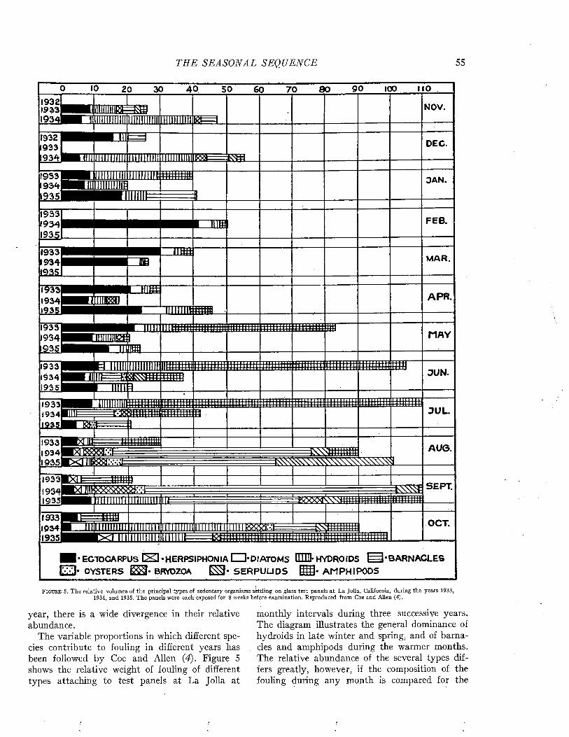
TH E SEA SO N A L SEQ UENCE 55
7 0 80 9 0 IOP n o
FEB.
MAR.
H illi :* : IIÏÏTÏÏD
M AYI I »
tTTH tW
S E PT .* i i i i : * a ; s * s siiiiiiiiiiiiiiniiiiiiiiiii
OCT.mii lassa:-: X’lTI I t 1 I ITT*^IIIIIIIIU IIIIIIIIIIIII
ECTOCARPUS ISI*HERPSIPHONI A O -D IA T O M S Em* HYDRO IDS BARNACLES OYSTERS ES3- BRYOZOA JS3* SE R P U U D S AMPHIPODS
F i g u r e 5. The relative volumes of the principal types of sedentary organisms settling on glass test panels at La Jolla, California, during the years 1933, 1934, and 1935. The panels were each exposed for 8 weeks before examination. Reproduced from Coe and Allen (4).
year, there is a wide divergence in their relative abundance.
The variable proportions in which different species contribute to fouling in different years has been followed by Coe and Allen (4). Figure 5 shows the relative weight of fouling of different types attaching to test panels at La Jolla at
monthly intervals during three successive years. The diagram illustrates the general dominance of hydroids in late winter and spring, and of barnacles and amphipods during the warmer months. The relative abundance of the several types differs greatly, however, if the composition of the fouling during any month is compared for the
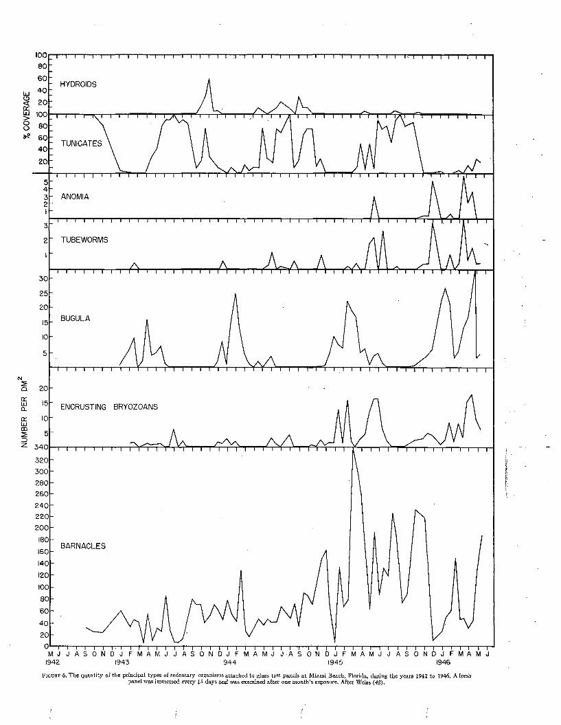
1008 0
6 0
4 0
201008 0
6 0
4 0
20
5432I
3
2I
3 0
2 5
20
15
IO
5
20
15
IO
5
3 4 0
3 2 0
3 0 0
2 8 0
2 6 0
2 4 0
220200
180
160
140
1201008 0
6 0
4 0
200I
IS
Fit
i—i—i—i—i—i—i—i—i—i—i—i—i—i—i—i—i—i—r -T' i—i—i—i—i—i—i—i—i—i—i—i—i—i—i—i—i—r i—r—i—i—i—r-1—i—i—i—r
HYDROIDS
TUNICATES
ANOMIA
TUBEWORMS
BUGULA
ENCRUSTING BRYOZOANS
BARNACLES
t—i—i—i—i—i—r~i—i—i—n —i—i—i—i—m —i—i—i—i—i—i—i—i—i—i—m —i—i—i—i—i—i—i—i—i—i—i—i—i—i—i—i—i—i—r12 1943 1944 1945 1946
ir e 6. The quantity of the principal types of sedentary organisms attached to glass test panels at Miami Beach, Florida, during the years 1942 to 1946. A fresh panel was immersed every 15 days and was examined after one month’s exposure. After Weiss (42).
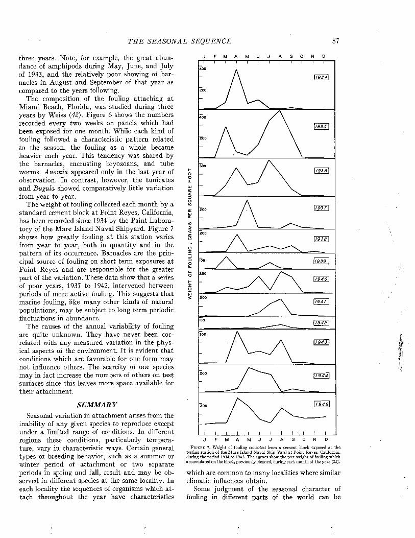
THE S EA S O N A L SEQUENCE 57
three years. Note, for example, the great abundance of amphipods during May, June, and July of 1933, and the relatively poor showing of barnacles in August and September of that year as compared to the years following.
The composition of the fouling attaching at Miami Beach, Florida, was studied during three years by Weiss (42). Figure 6 shows the numbers recorded every two weeks on panels which had been exposed for one month. While each kind of fouling followed a characteristic pattern related to the season, the fouling as a whole became heavier each year. This tendency was shared by the barnacles, encrusting bryozoans, and tube worms. Anomia appeared only in the last year of observation. In contrast, however, the tunicates and Bugula showed comparatively little variation from year to year.
The weight of fouling collected each month by a standard cement block at Point Reyes, California, has been recorded since 1934 by the Paint Laboratory of the Mare Island Naval Shipyard. Figure 7 shows how greatly fouling at this station varies from year to year, both in quantity and in the pattern of its occurrence. Barnacles are the principal source of fouling on short term exposures at Point Reyes and are responsible for the greater part of the variation. These data show that a series of poor years, 1937 to 1942, intervened between periods of more active fouling. This suggests that marine fouling, like many other kinds of natural populations, may be subject to long term periodic fluctuations in abundance.
The causes of the annual variability of fouling are quite unknown. They have never been correlated with any measured variation in the physical aspects of the environment. It is evident that conditions which are favorable for one form may not influence others. The scarcity of one species may in fact increase the numbers of others on test surfaces since this leaves more space available for their attachment.
SU M M A R YSeasonal variation in attachment arises from the
inability of any given species to reproduce except under a limited range of conditions. In different regions these conditions, particularly temperature, vary in characteristic ways. Certain general types of breeding behavior, such as a summer or winter period of attachment or two separate periods in spring and fall, result and may be observed in different species at the same locality. In each locality the sequences of organisms which attach throughout the year have characteristics
J F M A M J J A S O N D
400
200
400
1193 S I
200
300I-ooL.
LJa:<DO<0crUiQ_
¡ 9 3 6
200
200
oz
1 / 9 3 9
L.0H1 O
200
1 9 4 0
2001 9 4 1
100/ 9 4 2
300
11 9 4 3
200
300
DF M A M J J A S O NJF i g u r e 7. Weight of fouling collected from a cement block exposed at the
testing station of the Mare Island Naval Ship Yard at Point Reyes, California, during the period 1934 to 1945. The curves show the wet weight of fouling which accumulated on the block, previously cleaned, during each month of the year (22).
which are common to many localities where similar climatic influences obtain.
Some judgment of the seasonal character of fouling in different parts of the world can be
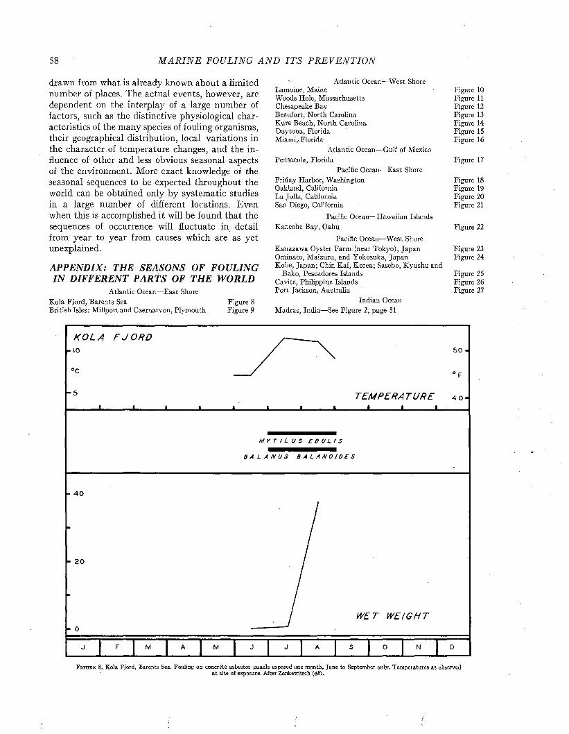
58 M A R I N E FOULING A N D I T S P R E V E N T I O N
drawn from what is already known about a limited number of places. The actual events, however, are dependent on the interplay of a large number of factors, such as the distinctive physiological characteristics of the many species of fouling organisms, their geographical distribution, local variations in the character of temperature changes, and the influence of other and less obvious seasonal aspects of the environment. More exact knowledge of the seasonal sequences to be expected throughout the world can be obtained only by systematic studies in a large number of different locations. Even when this is accomplished it will be found that the sequences of occurrence will fluctuate in detail from year to year from causes which are as yet unexplained.
APPENDIX: THE SEASONS OF FOULING IN DIFFERENT PARTS OF THE WORLD
Atlantic Ocean—East Shore Kola Fjord, Barents Sea Figure 8British Isles: Millport and Caernarvon, Plymouth Figure 9
Atlantic Ocean—West Shore Lamoine, Maine Figure 10Woods Hole, Massachusetts Figure 11Chesapeake Bay Figure 12Beaufort, North Carolina Figure 13Kure Beach, North Carolina Figure 14Daytona, Florida Figure 15Miami,.Florida Figure 16
Atlantic Ocean—Gulf of Mexico Pensacola, Florida Figure 17
Pacific Ocean—East Shore Friday Harbor, Washington Figure 18Oakland, California Figure 19La Jolla, California Figure 20San Diego, California Figure 21
Pacific Ocean—Hawaiian Islands Kaneohe Bay, Oahu Figure 22
Pacific Ocean—West Shore Kanazawa Oyster Farm (near Tokyo), Japan Figure 23Ominato, Maizuru, and Yokosuka, Japan Figure 24Kobe, Japan; Chin Kai, Korea; Sasebo, Kyushu and
Bako, Pescadores Islands Figure 25Cavite, Philippine Islands Figure 26Port Jackson, Australia Figure 27
Indian Ocean Madras, India—See Figure 2, page 51
N O L A F J O R D io
°c
- 5
5 0 -
T E M P E R A T U R E 4 o- I_______I_______I______
MYTI LUS EDULIS
B A L A N U S B A L A N O I D E S
- 4 0
20
- 0WET WE I GH T
F i g u r e 8. Kola Fjord, Barents Sea. Fouling on concrete asbestos panels exposed one month, June to September only. Temperatures as observedat site of exposure. After Zenkewitsch (4SI.
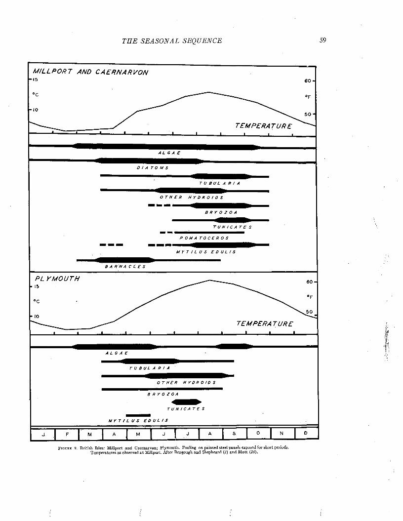
THE S EA S O N A L SEQUENCE
« ----- 1---- ■ 1 1
A L G A E
M I L L P O R T AND C A E R N A R V O N15 6 0 -
T E M P E R A T U R E
DIA TOMS
T U B U L A R I A
O T H E R H Y D R O I D S
BRYOZOA
TUN/ CATES
P O M A T O C E R 0 S
MYTI LUS EDULIS
BARNA CLES
PL y M O U T H15
■ *T E M P E R A T U R E I________I________L
ALGAE
T U B U L A R I A
0 T H E R H Y D R 0 I D S
B R Y 0 Z O A
TUNICA TES
MYTI LUS EDULIS
M
F i g u r e 9. British Isles: Millport and Caernarvon; Plymouth. Fouling on painted steel panels exposed for short periods. Temperatures as observed a t Millport. After Bengough and Shepheard (2) and M ott (26).
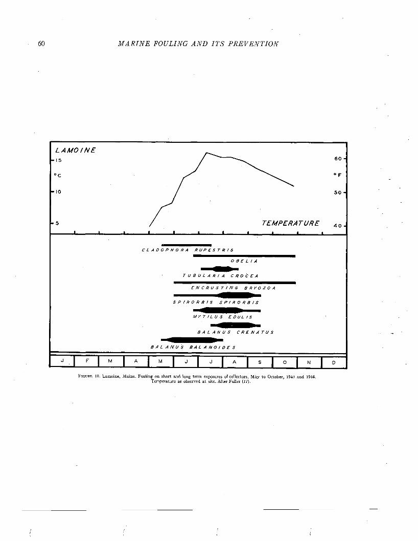
M A R I N E FOULING A N D I T S P R E V E N T I O N
L A M O I N E• 15
0 C
• IO
6 0 ■
° F
5 0 ■
TE MP E RA T UR E L - ■ L . . I
4 0 •
C L A D O P H O R A R U P E S T R I S
OBELIA
T U B U L A R I A C R O C E A
E N C R U S T I N G B R Y O Z O A
S P I R O R B I S S P I R O R B I S
M Y T I L U S E D U L I S
B A L A N U S C R E N A T U S
B A L A N U S B A L A N O I D E S
F I M I A 1 M I J i J I A 1 S I ° I "F i g u r e 10. Lamoine, Maine. Fouling on short and long term exposures of collectors, M ay to October, 1943 and 1944.
Temperature as observed at site. After Fuller (11).
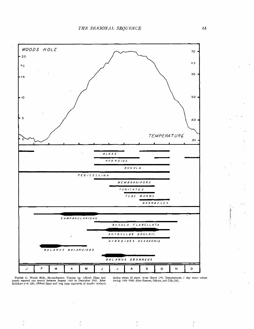
T E E S EA S O N A L SEQ UENCE 61
WO OD S H O L E 70 -
TEMPERA T U R E
H Y D R O ! D S
BUG ULA
P E D I C E L L I N A
M E M B R A N I P O R A
T U N I C A T E S
TUBE WORMS
B A R N A C L E S
C A M P A N U L A R I D A E
B A L A N U S B A L A N O I D E S
B U G U L A F L A B E L L A T A
B O T R Y L L U S G O U L D I I .
H Y D R O I D E S H E X A G O N I S
B A L A N U S E B U R N E U S
F i g u r e 11, Woods Hole, Massachusetts. Fouling on: (Above) Glass test during about 10 years. After Grave (14). Temperatures: 5 day mean valuespanels exposed one month between August 1 94 0 to December 1 9 4 1 . After during 1 9 0 2 -1 9 0 6 . After Sumner, Osburn, and Cole (38).Ketchum el al. (20). (Below) Short and long term exposures of wooden surfaces

62 M A R I N E FOULING A N D I T S P R E V E N T I O N
C H E S A P E A K E B AY8 0
2 5
7 020
6 0
5 0
T E M P E R A T U R E 4 0
N O R F O L KA L G A E
W E T WEI GHT/ YORK TOWN
1200
9 0 0
6 0 0
N ORFOLK
3 0 0 1944
F i g u r e 12. Chesapeake Bay. Fouling on glass panels exposed one month. (Above) Occurrences recorded at Norfolk, Virginia, October 1940 to January 1942. After Ketchum el al. (20). (Below) W et weight of fouling accumulating each month on glass panels at Norfolk, September 1941 to August 1942, after Wharton
(43), and at Hampton Roads and Yorktown, Virginia, in 1944, after Norfolk N avy Yard (27). Temperature: mean monthly values at Solomon’s Island, Maryland, 1938-1942, from U. S. Coast and Geodetic Survey (40).

THE S E A S O N A L SEQUENCE 63
B E A U F O R T 8 0 -
“ 2 5 ° F
° C7 0 -
- 2 0
/6 0 -
- 1 5
r 10 /
TEMPERA T U R E
V o
" 5 i i i i i i i i 1 1 1 4 0 -
M / C R O C Í O N A P R O L t F E R A
R E N I E R A T U B I F E R A
P E N N A R I A . T I A R E L L A
T U B U L A R I A C R O C E A
BUGULA NERI TI NA
S C H I Z O P O R E L L A U N I C O R N I S
S TYELA PLI CATA
M O L G U L A M A N H A T T E N S I S
P H A L L U S I A H Y G O M I A N A
P E R O P H O R A V I R I D I S
H Y D R O I D E S H E X A G O N / S
OSTREA VI RGI NI CA
C H T H A M A L U S F R A G I L I S
B A L A N U S I M P R O V I S U S
B A L A N U S E B U R N E U S
J 1F M «
“ J ! * 8 ° - DF i g u r e 1 3 . Beaufort, North Carolina. Fouling on wooden and glass surfaces February 1 9 4 2 , by Ketchum el al. (20), Temperatures are mean monthly values
exposed for short and long periods between February 1 9 4 1 and February 1 9 4 2 , at Piver’s Island, 1 9 1 4 - 1 9 2 8 , from McDougall, after Gutsell.by McDougall (23), and on glass panels one month between November 1 9 4 0 and
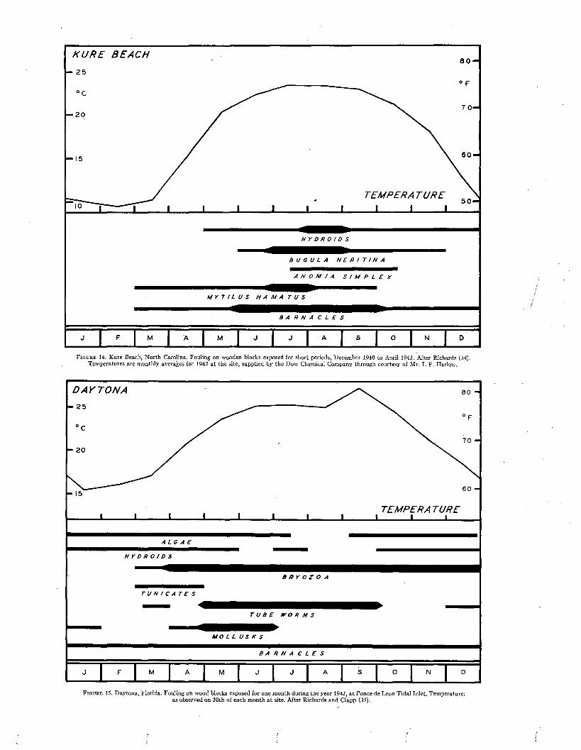
K U R E B E A C H
TEMPERA T U R E
B U G U L A N E R I T I N A
ANOMI A S I MP L E X
M Y T I L U S H A M A T U S
B A R N A C L E S
J F M J A M J J A „I - S . .0 N D
F i g u r e 14. Kure Beach, North Carolina. Fouling on wooden blocks exposed for short periods, December 1940 to April 1943. After Richards (34). Temperatures are monthly averages for 1942 at the site, supplied by the Dow Chemical Company through courtesy of Mr. I. F. Harlow.
D A Y T O N A
TEMPERA TURE
HYDROIDS
B R Y O Z O A
T U B E W O R M S
M O L L U S K S
B A R N A C L E S
J F M A M J J A S 0 ■ 1 " .
T U N I C A T E S
F i g u r e 15. Daytona, Florida. Fouling on wood blocks exposed for one month during the year 1942, at Ponce de Leon Tidal Inlet. Temperature: as observed on 20th of each month at site. After Richards and Clapp (35).

THE SEA SO N A L SEQ UENCE
M I A M I
• 20 T E M P E R A T U R E_______I_______I_______I_______ I_______ I_______I_______ I_______I_______ I_______ I_______L
E N C R U S T I N G B R Y O Z O A
TUN / CATES
B A R N A C L E S
J F M A M J J A S 0 N J D
F i g u r e 16. Miami, Florida. Fouling on glass panels immersed every 15 days and exposed for one month, 1942 to 1945, at Miami Beach and Tahiti Beach. After Weiss (42). Temperatures: mean monthly values at Miami Beach, 1940 to 1942, from U. S. Coast and Geodetic Survey (40).
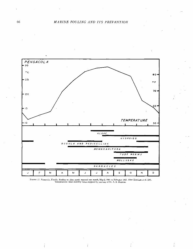
M A R I N E FOULING A N D I T S P R E V E N T I O N
P E N S A C O L3 0
8 0
2 5
7 020
60
TEMPERA T UR E5 0
A L G A E
M E - M B R A N / P O R A
M O L L U S K S
F i g u r e 17. Pensacola, Florida. Fouling on glass panels exposed one month, March 1941 to February 1942 . After Ketchum el al. (20). Temperatures: mean monthly values supplied by courtesy of Dr. A. E. Hopkins.
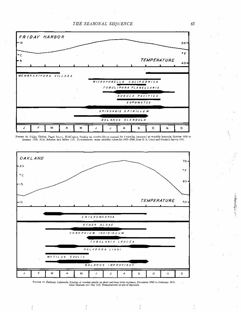
TH E SEA SO N A L SEQ UENCE 67
F R I D A Y H A R B O R ■io
c- 5 TEMPERA T U R E
■ « «
5 0 -
M E M B R A N I P O R A V I L L O S A
M I C R O P O R E L L A C A L I F O R N I C A
T U B U L I P O R A F L A B E L L A R I S
B U G U L A P A C I F I C A
E U P O M A T U S
S P I R O R B I S S P I R I L L U M
B A L A N U S G L A N D U L A
j F j M A j M j J J j A j S j 0
F ig u r e 18. Friday Harbor, Puget Sound, Washington. Fouling on wooden blocks exposed for 3 months, immersed at monthly intervals, October 1928 to January 1930. After Johnson and Miller ( /# ). Temperatures: mean monthly values for 1 9 3 5 -1 9 4 0 , from U. S. Coast and Geodetic Survey (39).
O A K L A N D
20
■ I 0 T E M P E R A T U R E I_______ i_______u
5 0
E N T E R O M O R P H A
OTHER ALGAE
C O R O P H I U M I N S I D I O S U M
T U B U L A R I A C R O C E A
P O L Y D O R A L I G N I
M Y T / L U S E D U L I S
B A L A N U S I M P R O V I S U S
J F M A M J J A S 0 N D
F i g u r e 19. Oakland, California. Fouling of wooden panels on short and long term exposure, December 1940 to February 1942. After Graham and Gay (12). Temperatures: at site of exposure.
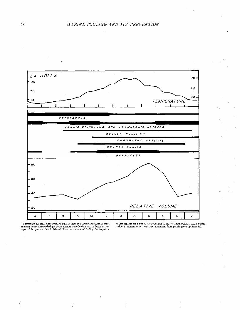
68 M A R I N E FOULING A N D I T S P R E V E N T I O N
L A J O L L A
TEMPERA T U R E I I_______I
O B E L I A D I C H O T O M A A N D P L U M U L A R I A S E T A C E A
B U G U L A N E R I T I N A
E U P O M A T U S G R A C I L I S
OSTREA LURIDA
BARNA CLES
- 4 0
- 20 R E L A T I V E VOL UME
F i g u r e 2 0 . La Jolla, California. Fouling on glass and concrete surfaces on short plates exposed for 8 weeks. After Coe and Allen ( 4 ) . Temperatures: mean weeklyand long term exposure during 9 years. Results from October 1932 to October 1935 values at exposure site 1 9 2 5 -1 9 4 0 . Estimated from graphs given by Allen (2).reported in greatest detail. {Below) Relative volume of fouling developed on
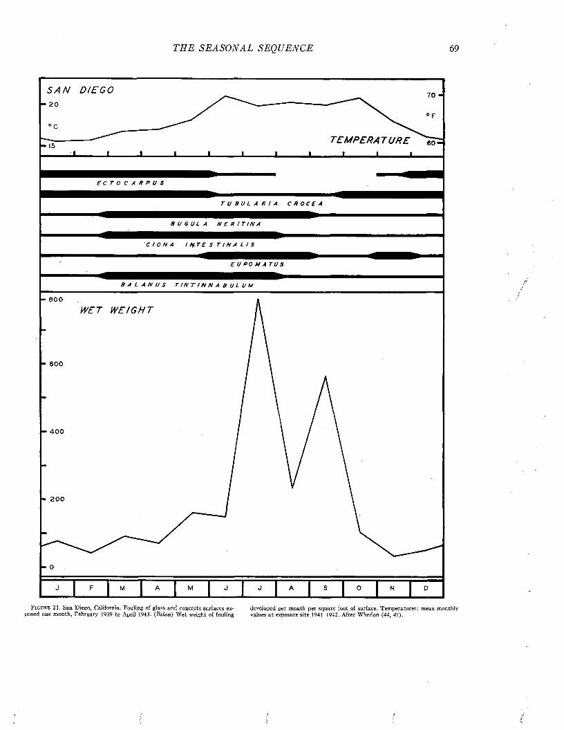
T H E SEA SO N A L SEQ UENCE 69
S A N DI EGO - 20
- 15J ________L
T E M P E R A T U R E 1 5
E C T O C A R P U S
T U B U L A R I A C R O C E A
B U G U L A N E R I T I N A
C I O N A I N T E S T I N A L I S
E U P O M A T U S
B A L A N U S T I N T I N N A B U L U M
- 8 0 0
- 4 0 0
- 200
- 0
WET W E I G H T
J F 1 M | A M J J A . 1 o 1 M 1 P
F i g u r e 2 1 . San Diego, California. Fouling of glass and concrete surfaces ex- developed per month per square foot of surface. Temperatures: mean monthlyposed one month, February 1939 to April 1943 . (Below) Wet weight of fouling values at exposure site 1 9 4 1 -1 9 4 2 . After Whedon (44, 45).
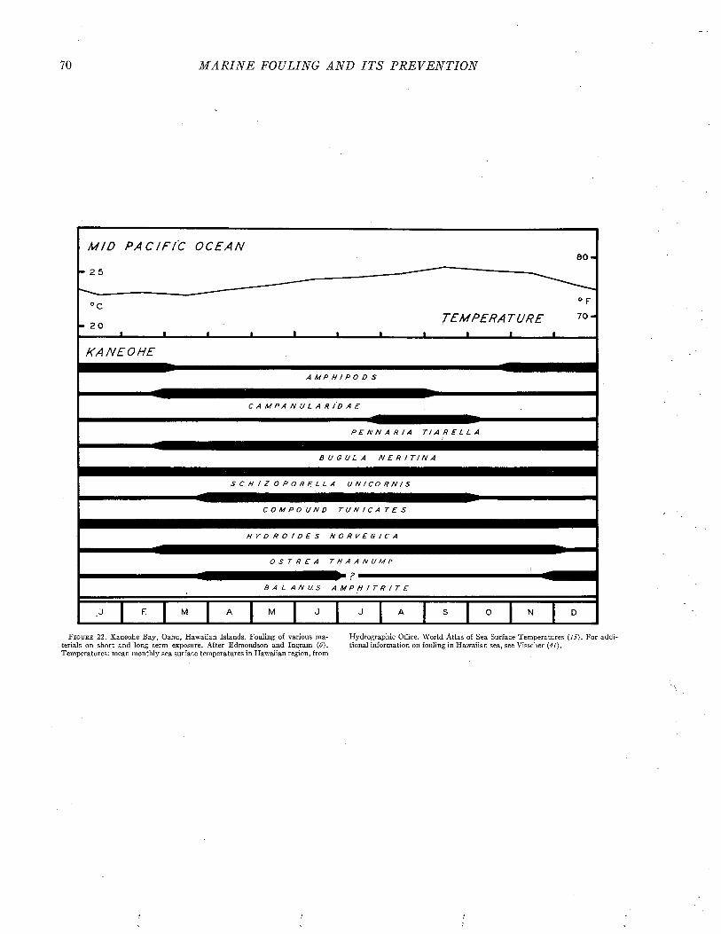
70 M A R I N E FOULING A N D I T S P R E V E N T I O N
M I D P A C I F I C O C E A N
■ 2 5
8 0 -
° C
20_l_
T E M P E R A T U R E
° F
7 0 -
K A N E O H E
A M P H ! P O D S
C A M P A N U L A R / D A E
P E N N A R I A T I A R E L L A
B U G U L A N E R I T I N A
S C H I Z O P O R E L L A U N I C O R N I S
C O M P O U N D T U N / C A T E S
H Y D R O I D E S N O R V E G I C A
OSTREA THAANUMI•
B A L A N U S A M P H I T R I T E
F i g u r e 2 2 . Kaneohe Bay, Oahu, Hawaiian Islands. Fouling of various ma- Hydrographic Office. World Atlas of Sea Surface Temperatures (15). For addi-terials on short and long term exposure. After Edmondson and Ingram (ú). tional information on fouling in Hawaiian sea, see Visscher (41).Temperatures: mean monthly sea surface temperatures in Hawaiian region, from
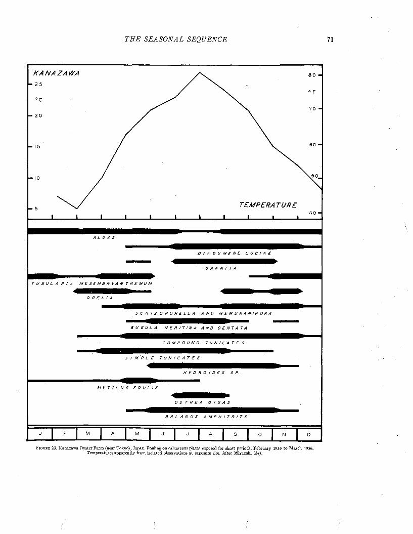
TH E S E A S O N A L SEQUENCE
K A N A Z A W A
TEMPERA T U R E
D I A D U M E N E L U C I A E
G R A N T I A
T U B U L A R I A M E S E M B R Y A N T H E M U M
O B E L I A
S C H I Z O P O R E L L A A N D M E M B R A N I P O R A
B U G U L A N E R I T I N A A N D D E N T A T A
C O M P O U N D T U N I C A T E S
S I M P L E T U N I C A T E S
H Y D R O I D E S S P .
MYTI LUS EDULIS
OSTREA GI GAS
M
B A L A N U S A M P H I T R I T E
F i g u r e 23. Kanazawa Oyster Farm (near Tokyo), Japan. Fouling on calcareous plates exposed for short periods, February 1935 to March 1936. Temperatures apparently from isolated observations at exposure site. After Miyazaki (24).
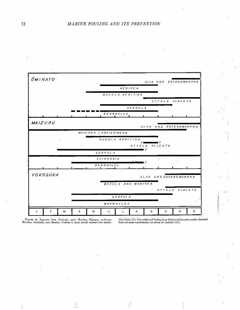
72 M A R I N E FOULING A N D I T S P R E V E N T I O N
O M I N A T O
-L.
U L V A A N D E N T E R O M O R P H A
MENIPEA
B U G U L A N E R I T I N A
STYELA CLAVATA
S E R P U L A
J __________ LB A R N A C L E S
J __________ I__________ L *- -I-
M A / Z U R UU L V A A N D E N T E R O M O R P H A
M E N I P E A L O N G I S P I N O S A
BUGULA NERI TI NA? ?
S T Y E L A P L I C A T A
S E R P U L A
S P I R O R B I S
J __________ LB A R N A C L E S
-I_______I I__ » « J __________ L.
Y O K O S U K A U L VA A N D E N T E R O M O R P H A
B U G U L A A N D M E N I P E A
STYELA CLAVA TA
S E R P UL A
B A R N A C L E S
J F M A M J J A S 0 N 1 D IF i g u r e 24. Japanese Area. Ominato, north Honshu; Maizuru, northwest After Saito (37). Dry weights of fouling from these localities, presumably obtained
Honshu; Yokosuka, east Honshu. Fouling of glass panels exposed one month. from the same experiments, are given by Izubuchi {17).
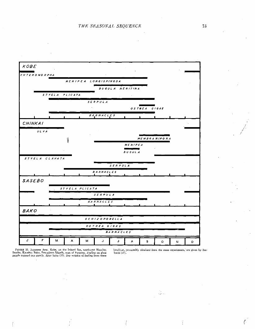
TH E S EA S O N A L SEQUENCE
K O B E
E N T E R O M O R P H A
M E N I P E A L O N G I S P I N O S A
B U G U L A N E R I T I N A
STYELA PLICATA
SERPULA0 S T R E A G I G A S
B A R N A C L E SI I______ I______ I______ i______ I______ I______ I______ I______ LCHI NK A /
M E M B R A N I P O R A
M E N I P E A
B U G U L A
S T Y E L A C L A V A T A
S E R P U L A
B A R N A C L E S I - M I— , —, I j, I_______> »
S A S E B O
S T Y E L A P L I C A T A
S E R P U L A
B A R N A C L E SI I---------- I I I « t_______I_______I I
B A K O
S C H I Z O P O R E L L A
O S T R E A G I G A S
B A R N A C L E S
F i g u r e 25. Japanese Area. Kobe, on the Inland Sea, southwest Honshu; localities, presumably obtained from the same experiments,'are given bySasebo, Kyushu; Bako, Pescadores Islands, west of Formosa. Fouling on glass buchi (17).panels exposed one month. After Saito (37). Dry weights of fouling from these
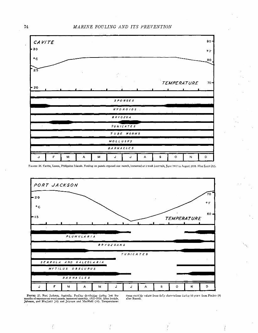
74 M A R I N E FOULING A N D I T S P R E V E N T I O N
C A V! TE30
20
00
TEMPERA T U R E ?o -i
S P O N G E S
H Y D R 0 / D S
B R Y O Z O A
T U N 1 C A T E S
T U B E W O R M S
M O L L U S K S
B A R N A C L E S
J F M A J M J J A S 0 N D
F i g u k e 2 6 . Cavite, Luzon, Philippine Islands. Fouling on panels exposed one month, immersed at 2 week intervals, June 1937 to August 1938. After Lunz (21).
P O R T J A C K S O N
- 2 0
° C
• 15 T E M P E R A T U R E J_________I________ L.
P L U M U L A R / A
3 R y O Z O A N S
TUNICA TES
S E R P U L A A N D G A L E O L A R I A
M Y T I L U S O B S C U R U S
BARNA CLES
J J F J M A M J J J J A S 0 1 N 1 D
F i g u r e 2 7 . Port Jackson, Australia. Fouling developing during first few mean monthly values from daily observations during 10 years from Fischer (0)months of exposure on wood panels, immersed monthly, 1932-1934. After Iredale, after Russell.Johnson, and M acNeill (16) and Johnson and MacNeill (IP). Temperatures:
THE S EA S O N A L SEQUENCE 75
REFERENCES1. A l l e n , W. E. Twenty Years’ Statistical Studies on Marine
Plankton Dinoflagellates oí Southern California. Amer. Midi. Nat., 26, 603-635, 1941.
2. B e n g o u g h , G. D., and V. G. S h e p h e a r d . The Corrosion andFouling of Ships. Marine Corrosion Subcommittee of the Iron and Steel Institute and the British Iron and Steel Federation, Paper No. 1, 15 April, 1943.
3. C o e , W. R. Season of Attachment and Rate of Growth ofSedentary Marine Organisms at the Pier of the Scripps Institution of Oceanography, La Jolla, California. Bull. Scripps Inst. Oceanogr., Tech. Ser. 3, 37-86, 1932.
4. C o e , W. R., and W. E. A l l e n . Growth of Sedentary MarineOrganisms on Experimental Blocks and Plates for Nine Successive Years at the Pier of the Scripps Institution of Oceanography. Bull. Scripps Inst. Oceanogr., Tech. Ser. 4, 101-136, 1937.
5. D o d d , J. M., and others. Maturity and Fecundity of One-year old English Native Oysters, Ostrea edulis. Nature, 139, 108-109, 1937.
6. E d m o n d s o n , C. H., and W. M. I n g r a m . Fouling Organismsin Hawaii. Occ. Papers, Bernice P. Bishop Mus., 14, 251—
300, 1939.7. E n g l e , J. B., and V. L. L o o s a n o f f . On Season of Attach
ment of Larvae of M ytilus edulis. Linn. Ecol., 25, 433-440, 1944.
8 . F i e l d , I. A. Biology and Economic Value o f t h e Sea Mussel,M ytilu s edulis. Bull. U. S. Bur. Fish., 38, 127-259, 1922.
9. F i s c h e r , P. H. Notes sur les peuplements littoraux d’Australie. I. Influence des courants chauds sur la vie littorale en Australie temperee. Mem. Soc. Biogeogr., 7, 279-388, 1940.
10. F i s h , C. J. Seasonal Distribution of the Plankton of theWoods Hole Region. Bull. U. S. Bur. Fish., 41, 91-179, 1925.
11. F u l l e r , J. L. Season of Attachment and Growth of Sedentary Marine Organisms at Lamoine, Maine. Ecol., 27, 150-158, 1946.
12. G r a h a m , H. W., and H. G a y . Season of Attachment andGrowth of Sedentary Marine Organisms at Oakland, California. Ecol., 26, 375-386,1945.
13. G r a v e , B. H. The Natural History of Bugula flabellata atWoods Hole, Mass. Including the Behavior and Attachment of the Larva. Jour. Morph., 49, 355-383, 1930.
14. G r a v e , B. H. Rate of Growth, Age at Sexual Maturity, andDuration of Life of Certain Sessile Organisms at Woods Hole, Massachusetts. Biol. Bull., Vol. LXV, No. 3, 1933.
15. Hydrographic Office. World Atlas of Sea Surface Temperatures, Washington, U. S. Navy Hydrographic Office, No. 225, 1944.
16. I r e d a l e , T., R. A. J o h n s o n , and F. A. M a c N e i l l . Destruction of Timber by Marine Organisms in the Port of Sydney. Sydney Harbor Trust, Sydney, 148 pp., 1932.
17. I z u b u c h i , T. Increase in Hull Resistance Through Ship-bottom Fouling. Zosen Kiokai, 55, December 1934. In Japanese (Translation by Lt. C. M. Spinks, U.S.N.R., on file Research Branch, Bureau of Ships). 1934.
18. J o h n s o n , M. W., and R. C. M i l l e r . The Seasonal Settlementof Shipworms. Barnacles, and Other Wharf-pile Organisms at Friday Harbor, Washington. Univ. Wash. Pub. in Oceanogr., 2, 1-18, 1935.
19. J o h n s o n , R. A., and F. A. M a c N e i l l . Destruction of Timberby Marine Organisms in the Port of Sydney. Supplementary Report No. 2. Maritime Services Board of New South Wales, Sydney, 92 plus xxii pp., 1941.
20. K e t c h u m , B. H., C. M. W e i s s , G. K e l l y , D. M. R e y n o l d s ,and J. P a r k e r . The Seasonal Incidence of Fouling at Various Locations along the Atlantic Coastline 1940-1941. W.H.O.I., 5th Semi-annual Report to the Bureau of Ships, 14 August 1942, Paper 6, 1942. (Unpublished.)
21. L u n z , G. R. Periodicity of Fouling Growths at Cavite,
Philippine Islands, and at Guantanamo Bay, Cuba. Report to the Bureau of Construction and Repair, 13 June 1940. Buships File reference S19-l(3), 2.
22. Mare Island Naval Shipyard. Letter to Bureau of Ships,March 18, 1946.
23. M c D o u g a l l , K. D. Sessile Marine Invertebrates at Beaufort,North Carolina. Ecol. Mon., 13, 321-374, 1943.
24. M iy a z a k i , I. On Fouling Organisms in the Oyster Farm.Bull. Jap. Soc. Sei. Fisheries, 6, 223-232, 1938.
25. M o o r e , J. A. The Role of Temperature in Hydranth Formation in Tubularia. Biol. Bull., 76, 104M07, 1939.
26. M o t t , J. C. Report on the Seasonal Settlement of Fouling atVarious Exposure Stations. Corrosion Committee, Marine Corrosion Sub-Committee; British Iron and Steel Institute N 17/44, October, 1944.
27. Norfolk Naval Shipyard. Research in Shipbottom Paints,Calendar Year 1944. 31 December 1944. (Unpublished.)
28. O r t o n , J. H. A Preliminary Account of a Contribution to anEvaluation of the Sea. Jour. Mar. Biol. Assn., U.K., n.s., 10, 312-326, 1914.
29. O r t o n , J. H. An Oyster Spat (1921) with Mature Male SexProducts. Nature, 108, p . 500, 1921.
30. O r t o n , J. H. Experiments in the Sea on the Growth-in-hibitive and Preservative Value of Poisonous Paints and Other Substances. Jour. Mar. Biol. Assn., U.K., n.s., 16, 373-452, 1929.
31. P a u l , M. D. Sexual Maturity of Some Sedentary Organismsin the Madras Harbour. Curr. Sei., 5, 478-479, 1937.
32. P a u l , M. D. Studies on the Growth and Breeding of CertainSedentary Organisms in the Madras Harbour. Proc. Indian Acad. Sei., 15B, 1-42, 1942.
33. R a o , K. V. Structure, Habits, and Early Development of aNew Species of Stiliger Ehrenberg. Rec. Ind. Mus., 39, 435-464, 1937.
34. R ic h a r d s , B. R. A Study of the Marine Borers and FoulingOrganisms at Wilmington, N. C. William F. Clapp Laboratories, Duxbury, Massachusetts, Lab. Bull. No. 12, 28 May 1943. (Unpublished.)
35. R ic h a r d s , B. R., and W. F. C l a p p . A Preliminary Report onthe Fouling Characteristics of Ponce de Leon Tidal Inlet, Daytona Beach, Florida. Jour. Mar. Res., 5, 189-195, 1944.
36. R u n n s t r o m , S. Zur biologie und entwicklung von Balanusbalanoides (Linné). Bergens Mus. Âarbok for 1924-25, No. 5, 46 pp., 1925.
37. S a it o , T. Researches in Fouling Organisms of the Ship’sBottom. Zosen Kiokai (Journ. Jap. Soc. Naval Arch.), 47, 13-64 (in Japanese; official translation on file Woods Hole Oceanographic Institution), 1931.
38. S u m n e r , F. G., R. C. O s b u r n , and L. J. C o l e . A BiologicalSurvey of the Wâters of Woods Hole and Vicinity. Bull. U. S. Bur. Fish., 31, parts I, II, 860 pp., 1911.
39. U. S. Coast and Geodetic Survey. Water Temperatures, Coastand Geodetic Survey Tide Stations, Pacific Coast, TW-2, April, 1941.
40. U. S. Coast and Geodetic Survey. Surface Water Temperatures, Coast and Geodetic Survey Tide Stations, Atlantic and Gulf Coasts. TW-1 (revised), January, 1944.
41. V i s s c h e r , J. P. Report of Fouling Experiments at PearlHarbor Navy Yard, Honolulu, T. H. Bureau of Ships Library R-8; and Fouling of Ships’ Bottoms, Pearl Harbor, 1935-36. Bureau of Ships Library, R-12 to R-21 inclusive, 1937.
42. W e i s s , C. M. The Seasonal Occurrence of Sedentary MarineOrganisms in Biscayne Bay, Florida. Ecology, 29, No. 2, 153-172, 1948.
43. W h a r t o n , G. W. Report of the Biologist, Norfolk Navy Yard,June 1941-August 1942. (Unpublished.)
44. W h e d o n , W. F. Investigations Pertaining to the Fouling ofShips’ Bottoms. Biological Laboratory, Naval Fuel Depot, San Diego, Cal., Semi-Annual Report for 1937-1938, December, 1937. (Unpublished.)
V

76 M A R I N E FOULING A N D I T S P R E V E N T I O N
45. W h e d o n , W. F. Seasonal Incidence of Fouling at San Diego,Biological Laboratory, Naval Fuel Depot, San Diego, Cal., Annual Report for 1942-1943, 1943.
46. W h i t e , K. M. Mytilus. Liverpool Marine Biological Committee, Memoirs on Typical British Marine Plants and Animals, 177 pp., 1937.
47. Y o u n g , R. T. Spawning and Setting Season of the Mussel,M ytilus californianus. Ecology, 27, 354—363, 1946.
48. Z e n k e w i t s c h , L. A. Some Observations on Fouling in Ekate-rininskaya Bay (Kola Fjord, Barents Sea). Bull, de la Soc. des Nat., Moscow, Sect. Biol., n.s., 44, 103-112. (Russian, with English summary), 1935.
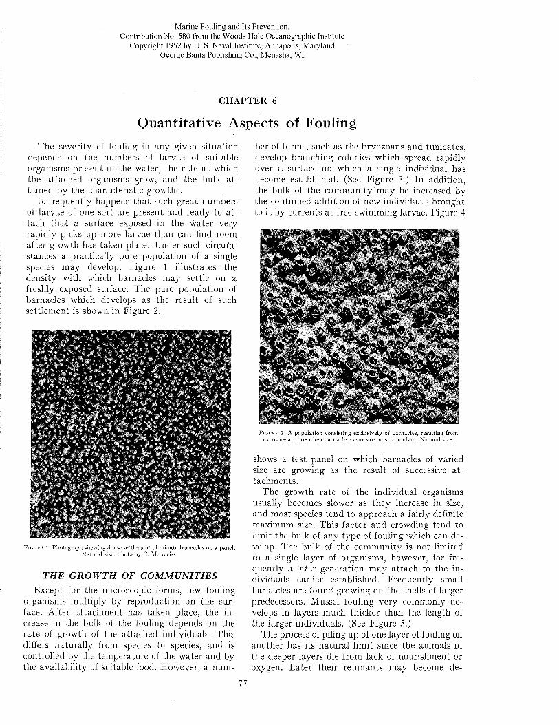
Marine Fouling and Its Prevention,Contribution N o. 580 from the W oods Hole Oceanographic Institute
Copyright 1952 by U. S. Naval Institute, Annapolis, Maryland George Banta Publishing Co., Menasha, WI
CHAPTER 6
Quantitative Aspects of FoulingThe severity of fouling in any given situation
depends on the numbers of larvae of suitable organisms present in the water, the rate a t which the attached organisms grow, and the bulk a ttained by the characteristic growths.
I t frequently happens tha t such great numbers of larvae of one sort are present and ready to a ttach tha t a surface exposed in the water very rapidly picks up more larvae than can find room after growth has taken place. Under such circumstances a practically pure population of a single species may develop. Figure 1 illustrates the density with which barnacles may settle on a freshly exposed surface. The pure population of barnacles which develops as the result of such settlem ent is shown in Figure 2.
M
F i g u r e 1. P hotograph showing dense settlem ent of m inute barnacles on a panel. N atu ra l size. Photo by C. M . Weiss.
T HE G R O W T H OF C O M M U N IT IE SExcept for the microscopic forms, few fouling
organisms multiply by reproduction on the surface. After attachm ent has taken place, the increase in the bulk of the fouling depends on the rate of growth of the attached individuals. This differs naturally from species to species, and is controlled by the temperature of the water and by the availability of suitable food. However, a num
ber of forms, such as the bryozoans and tunicates, develop branching colonies which spread rapidly over a surface on which a single individual has become established. (See Figure 3.) In addition, the bulk of the community may be increased by the continued addition of new individuals brought to it by currents as free swimming larvae. Figure 4
s«« .*
m ,W '
S ? « J 5 K 3 ä S « g 3 *F i g u r e 2. A population consisting exclusiveljr of barnacles, resulting from
exposure a t tim e when barnacle la rvae are m ost abundan t. N atu ra l size.
shows a test panel on which barnacles of varied size are growing as the result of successive a ttachments.
The growth rate of the individual organisms usually becomes slower as they increase in size, and most species tend to approach a fairly definite maximum size. This factor and crowding tend to limit the bulk of any type of fouling which can develop. The bulk of the community is not limited to a single layer of organisms, however, for frequently a later generation m ay attach to the individuals earlier established. Frequently small barnacles are found growing on the shells of larger predecessors. Mussel fouling very commonly develops in layers much thicker than the length of the larger individuals. (See Figure 5.)
The process of piling up of one layer of fouling on another has its natural lim it since the animals in the deeper layers die from lack of nourishment or oxygen. Later their rem nants may become de-
77
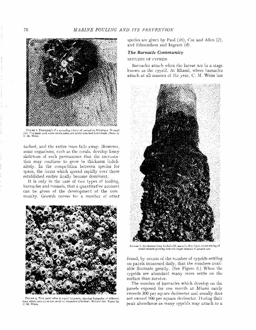
78 M A R I N E FO ULING A N D I T S P R E V E N T I O N
F i g u r e 3. Photograph of a spreading colony of encrusting bryozoans. N a tu ra l size. T h e small dark spots on the panel are newly a ttached individuals. P hoto C. M . Weiss.
tached, and the entire mass falls away. However, some organisms, such as the corals, develop limey skeletons of such permanence tha t the encrustation may continue to grow in thickness indefinitely. In the competition between species for space, the forms which spread rapidly over those established earlier finally become dominant.
I t is only in the case of two types of fouling, barnacles and mussels, that a quantitative account can be given of the development of the comm unity. Growth curves for a number of other
F i g u r e 4 . T e st panel after 4 weeks* exposure, showing barnacles of different sizes which develop as the resu lt of successive infections. N a tu ra l size. P hoto by C. M . Weiss.
species are given by Paul (16), Coe and Allen (2), and Edmondson and Ingram (4).
The Barnacle CommunitySETTLING OE CYPRIDS
Barnacles attach when the larvae are in a stage known as the cyprid. At Miami, where barnacles attach at all seasons of the year, C. M. Weiss has
F i g u r e 5. N avigation buoy fouled with mussels, showing a recent setting of small mussels growing over the larger mussels of greater age.
found, by counts of the number of cyprids settling on panels immersed daily, th a t the numbers available fluctuate greatly. (See Figure 6.) When the cyprids are abundant many more settle on the surface than survive.
The number of barnacles which develop on the panels exposed for one m onth a t Miami rarely exceeds 300 per square decimeter and usually does not exceed 100 per square decimeter. During their peak abundance as many cyprids may attach to a
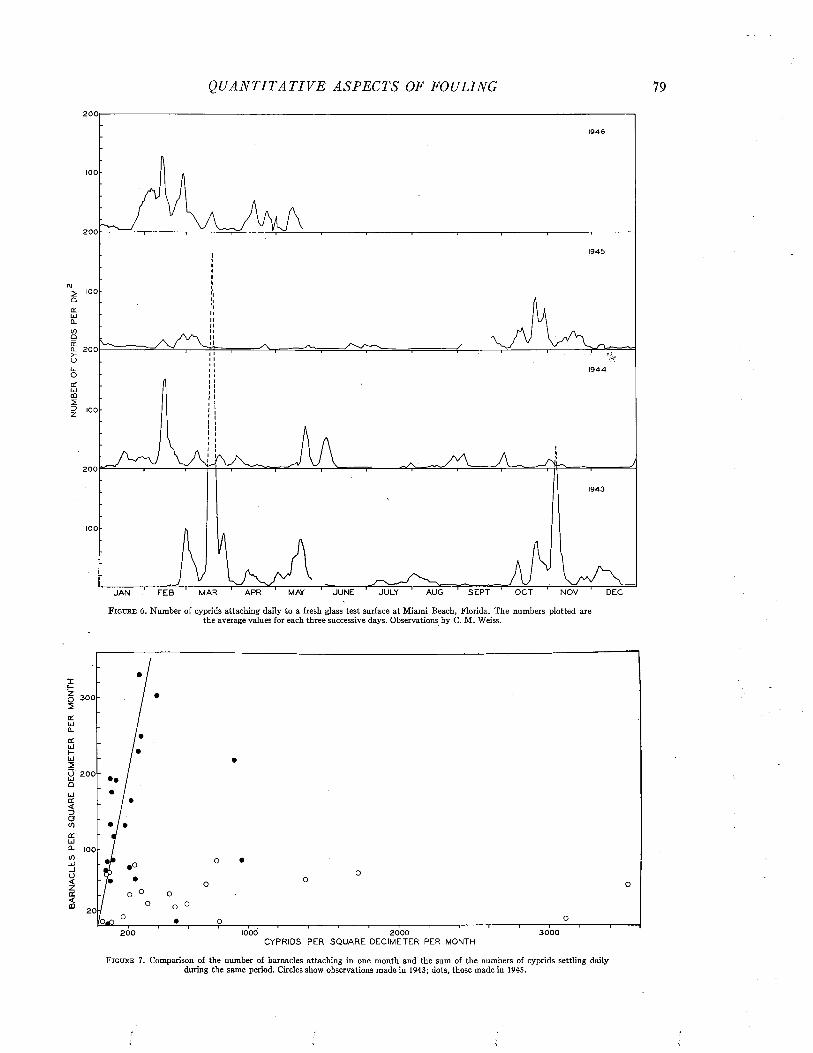
Q U A N T I T A T I V E A SP E C T S OF FOULING
2001946
100
200
1945
100
Q_ 200
1944
100
200
1943
100
JUN E JULY AUG S E P T OC T NOV DECFE B MAR APR MAYJ A N
F i g u r e 6. Number of cyprids attaching daily to a fresh glass test surface at Miami Beach, Florida. The numbers plotted are the average values for each three successive days. Observations by C. M . Weiss.
300
O 200 ••
100
20
30 0 0200 1000 2000CYPRIDS P E R S Q U A R E DECIMETER PER MONTH
F i g u r e 7. Comparison of the number of barnacles attaching in one month and the sum of the numbers of cyprids settling daily during the same period. Circles show observations made in 1943; dots, those made in 1945.
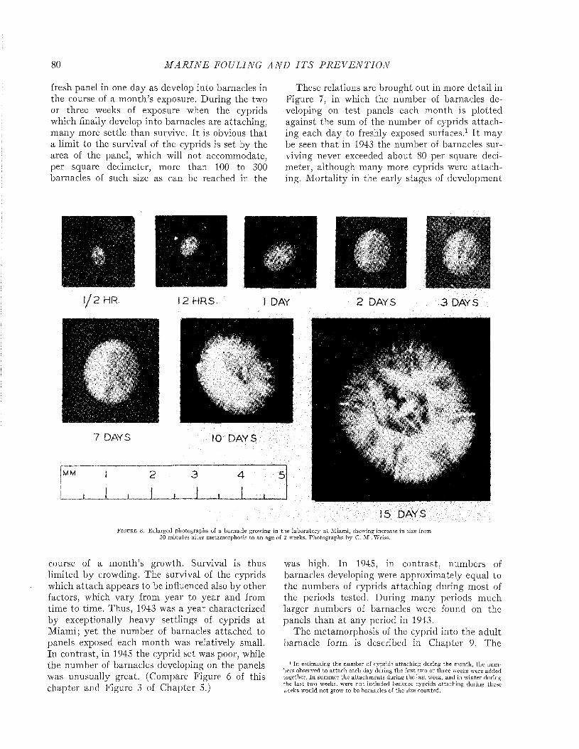
80 M A R I N E FOULING A N D I T S P R E V E N T I O N
fresh panel in one day as develop into barnacles in the course of a m onth’s exposure. During the two or three weeks of exposure when the cyprids which finally develop into barnacles are attaching, m any more settle than survive. I t is obvious that a lim it to the survival of the cyprids is set by the area of the panel, which will not accommodate, per square decimeter, more than 100 to 300 barnacles of such size as can be reached in the
These relations are brought out in more detail in Figure 7, in which the number of barnacles developing on test panels each month is plotted against the sum of the number of cyprids attaching each day to freshly exposed surfaces.1 I t may be seen tha t in 1943 the number of barnacles surviving never exceeded about 80 per square decimeter, although many more cyprids were a ttaching. M ortality in the early stages of development
12 HRS 2 DAYS 3 DAYS
7 DAYS
!5 DAYS
F i g u r e 8 . Enlarged photographs of a barnacle growing in the laborato ry a t M iam i, showing increase in size from 30 m inutes after metam orphosis to an age of 2 weeks. Photographs by C. M . Weiss.
course of a m onth’s growth. Survival is thus limited by crowding. The survival of the cyprids which attach appears to be influenced also by other factors, which vary from year to year and from time to time. Thus, 1943 was a year characterized by exceptionally heavy settlings of cyprids a t Miami; yet the number of barnacles attached to panels exposed each m onth was relatively small. In contrast, in 1945 the cyprid set was poor, while the number of barnacles developing on the panels was unusually great. (Compare Figure 6 of this chapter and Figure 3 of Chapter 5.)
was high. In 1945, in contrast, numbers of barnacles developing were approximately equal to the numbers of cyprids attaching during most of the periods tested. During many periods much larger numbers of barnacles were found on the panels than a t any period in 1943.
The metamorphosis of the cyprid into the adult barnacle form is described in Chapter 9. The
1 In estim ating the num ber of cyprids attaching during the m onth, the num bers observed to a tta ch each day during the first two or three weeks were added together. In sum m er the attachm ents during the la st week, and in w inter during the la st two weeks, were not included because cyprids attaching during these weeks would n o t grow to be barnacles of the size counted.
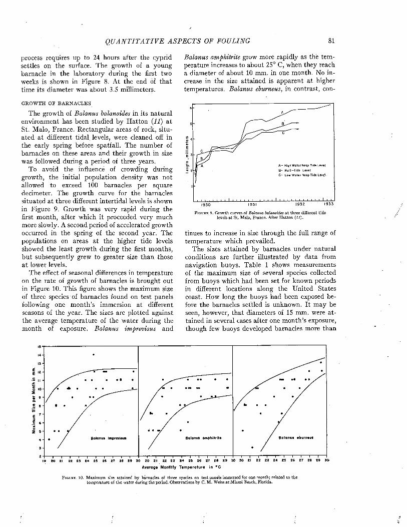
Q U A N T I T A T I V E A S P E C T S OF FOULING 81
process requires up to 24 hours after the cyprid settles on the surface. The growth of a young barnacle in the laboratory during the first two weeks is shown in Figure 8. At the end of that time its diameter was about 3.5 millimeters.
GROWTH OF BARNACLES
The growth of Balanus balanoides in its natural environment has been studied by Hatton (11) at St. Malo, France. Rectangular areas of rock, situated at different tidal levels, were cleaned off in the early spring before spatfall. The number of barnacles on these areas and their growth in size was followed during a period of three years.
To avoid the influence of crowding during growth, the initial population density was not allowed to exceed 100 barnacles per square decimeter. The growth curve for the barnacles situated at three different intertidal levels is shown in Figure 9. Growth was very rapid during the first month, after which it proceeded very much more slowly. A second period of accelerated growth occurred in the spring of the second year. The populations on areas at the higher tide levels showed the least growth during the first months, but subsequently grew to greater size than those at lower levels.
The effect of seasonal differences in temperature on the rate of growth of barnacles is brought out in Figure 10. This figure shows the maximum size of three species of barnacles found on test panels following one month’s immersion at different seasons of the year. The sizes are plotted against the average temperature of the water during the month of exposure. Balanus improvisus and
Balanus amphitrite grow more rapidly as thè temperature increases to about 25° C, when they reach a diameter of about 10 mm. in one month. No increase in the size attained is apparent at higher temperatures. Balanus eburneus, in contrast, con-
W01e
E
A - High W ater Neap Tide LevelB - Holf —fid e LevelC - Low W oter Neop Tide Leve,I.
1933193219311930
F i g u r e 9. Growth curves of Balanus balanoides at three different tide levels at St. Malo, France. After Hatton (11).
tinues to increase in size through the full range of temperature which prevailed.
The sizes attained by barnacles under natural conditions are further illustrated by data from navigation buoys. Table 1 shows measurements of the maximum size of several species collected from buoys which had been set for known periods in different locations along the United States coast. How long the buoys had been exposed before the barnacles settled is unknown. It may be seen, however, that diameters of 15 mm. were attained in several cases after one month’s exposure, though few buoys developed barnacles more than
EEC
jCCo2«&«NV)E3E‘5o2
B o l a n u s e b u r n e u sB a la n u s a m p h i t r i t eB o lo n u s im p ro v is u s
A v erag e M onth ly T e m p e r a tu r e ¡n ° C
F i g u r e 10. Maximum size attained by barnacles of three species on test panels immersed for one month; related to the temperature of the water during the period. Observations by C. M . Weiss at Miami Beach, Florida.
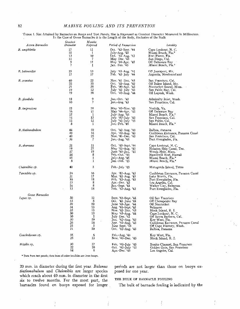
82 M A R I N E FOULING A N D I T S P R E V E N T I O N
T a b l e 1. Size Attained by Barnacles on Buoys and Test Panels. Size is Expressed as Greatest Diameter Measured in Millimeters. In the Case of Goose Barnacles it is the Length of the Body, Exclusive of the Stalk
Acorn BarnaclesGreatest
DiameterMonthsExposed Period of Immersion Locality
B . amphitrite 17 11 Oct. ’43-Sept. ’44 July-Aug. ’45 Oct. ’42-Aug. ’43
Cape Lookout, N . C.IS 1 Miami Beach, Fia.*13 10 Fort Pierce, Fia.11 7 M ay-Dee. ’43 San Diego, Cal.9 11 May ’44^Apr. ’45
Jan.-Feb. ’45Off Delaware Bay
7 1 Miami Beach, Fia.*
B . balanoides 25 13 July ’43-Aug. ’44 Off Jonesport, Me.17 17 Feb. ’43-July ’44 Argentia, Newfoundland
B . crenatus 40 25 Nov. ’41-Dec. ’43 San Francisco, Cal.25 10 Oct. ’41-Aug. ’42 Off Baker Island, Me.21 38 Feb. ’40-Apr. ’43 Nantucket Sound, Mass.19 12 July ’42-July ’43 San Pablo Bay, Cal.19 10 Oct. ’43-Aug. ’44 Off Lapush, Wash.
B . glandula 18 9 Jan.-Oct. ’43 Admiralty Inlet, Wash.10 7 Jan.-Aug. ’43 San Francisco, Cal.
B . improvisus 23 18 May ’42-Nov. ’43 May ’44r-Apr. ’45 July-Aug. ’45 July ’42-July ’43
Norfolk, Va.16 11 Off Delaware Bay15 1 Miami Beach, Fia.*14 12 San Francisco, Cal.12 12 July ’42-July ’43
Jan.-Feb. ’45San Pablo, Cal.
8 1 Miami Beach, Fia.*
B. tintinnabulum 44 10 Oct. ’42-Aug. ’43 Balboa, Panama40 16 Apr. ’42-Aug. ’43 Caribbean Entrance, Panama Canal40 25 Nov. ’41-Dec. ’43 San Francisco, Cal.
' 36 7 Jan.-Aug. ’43 Port Everglades, Fia.
B. eburneus 21 11 Oct. ’43-Sept. ’44 Cape Lookout, N . C.19 27 M ay ’41-Aug. ’43 Houston Ship Canal, Tex.17 19 June ’43-Jan. ’45 Woods Hole, Mass.16 8 Feb.-Oct. ’43 Nawiliwili Reef, Hawaii15 1 July-Aug. ’45 Miami Beach, Fia.*
8 1 Jan.-Feb. ’45 Miami Beach, Fia.*
Chelonibia sp. 40 5 Feb.-July ’43 Matagorda Island, Texas
Tetraclita sp. 24 16 Apr. ’42-Aug. ’43 Caribbean Entrance, Panama Canal21 17 Mar. ’42-Aug. ’43 Lake Worth, Fia.16 18 Feb. ’42-Aug. ’43 Port Everglades, Fia.IS 8 Apr.-Dec. ’43 Los Angeles, Cal.14 8 Jan.-Sept. ’43 Walker Cay, Bahamas13 18 Feb. ’42-Aug. ’43 Port Everglades, Fia.
Goose BarnaclesLepas sp. 50 12 Sept. ’43-Sept. ’44 Off San Francisco
43 8 Oct. ’43-June ’44 Off Chesapeake Bay39 10 June ’43-Apr. ’44
Aug. ’42-Sept. ’43Off Nantucket
34 13 Bahamas33 13 Nov. ’42-Dec. ’43 Block Island, R. I.30 15 May ’43-Aug. ’44 Cape Lookout, N . C.30 5 July-Dee. ’43 Off Santa Barbara, Cal.30 19 Jan. ’42-Aug. ’43 Key West, Fia.26 16 Apr. ’42-Aug. ’43 Caribbean Entrance, Panama Canal25 3 June-Sept. ’43
Oct. ’42-Aug. ’43Off Cape Flattery, Wash.
21 10 Balboa, Panama
Conchoderma sp . 35 6 Feb.-Aug. ’43 Key West, Fia.25 13 Nov. ’42-Dec. ’43 Block Island, R. I.
M itella sp. 30 17 Feb. ’42-July ’43 Bonito Channel, San Francisco22 10 Oct. ’42-July ’43
Apr.-Dec. ’43Golden Gate, San Francisco
14 8 Los Angeles, Cal.* D ata from test panels; data from all other localities are from buoys.
20 mm. in diameter during the first year. Balanus tintinnabulum and Chelonibia are larger species which reach about 40 mm. in diameter in the first six to twelve months. For the most part, the barnacles found on buoys exposed for longer
periods are not larger than those on buoys exposed for one year.
THE BULK OF BARNACLE FOULING
The bulk of barnacle fouling is indicated by the
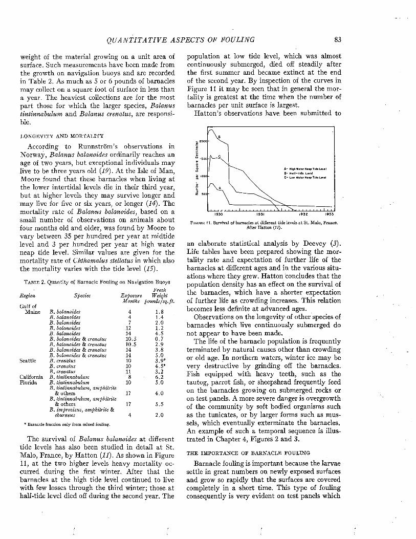
Q U A N T I T A T I V E A S P E C T S OF FOULING 83
weight of the material growing on a unit area of surface. Such measurements have been made from the growth on navigation buoys and are recorded in Table 2. As much as 5 or 6 pounds of barnacles may collect on a square foot of surface in less than a year. The heaviest collections are for the most part those for which the larger species, Balanus tintinnabulum and Balanus crenatus, are responsible.
LONGEVITY AND MORTALITY
According to Runnström’s observations in Norway, Balanus balanoides ordinarily reaches an age of two years, but exceptional individuals may live to be three years old (19). At the Isle of Man, Moore found that these barnacles when living at the lower intertidal levels die in their third year, but at higher levels they may survive longer and may live for five or six years, or longer (14). The mortality rate of Balanus balanoides, based on a small number of observations on animals about four months old and older, was found by Moore to vary between 35 per hundred per year at midtide level and 3 per hundred per year at high water neap tide level. Similar values are given for the mortality rate of Chthamalus stellatus in which also the mortality varies with the tide level (15).
T a b l e 2. Quantity of Barnacle Fouling on Navigation BuoysFresh
Region Species Exposure WeightMonths pounds/sq.ft.
Gulf ofMaine B . balanoides 4 1.8
B . balanoides 4 1.4B . balanoides 7 2 .0B . balanoides 12 1.2B . balanoides 14 4.5B . balanoides & crenatus 10.5 0.7B . balanoides & crenatus 10.5 2.9B . balanoides & crenatus 14 3.8B . balanoides & crenatus 14 5.0
Seattle B . crenatus 10 3.9*B . crenatus 10 4.5*B . crenatus 11 3 .2
California B . tintinnabulum 8 6.2Florida B . tintinnabulum
B . tintinnabulum, amphitrite10 5 .0
& others B . tintinnabulum, amphitrite
17 4 .0
& others B . im provisus, amphitrite &
17 5.5
eburneus 4 2 .0
* Barnacle fraction only from mixed fouling.
The survival of Balanus balanoides at different tide levels has also been studied in detail at St. Malo, France, by Hatton (11). As shown in Figure 11, at the two higher levels heavy mortality occurred during the first winter. After that the barnacles at the high tide level continued to live with few losses through the third winter; those at half-tide level died off during the second year. The
population at low tide level, which was almost continuously submerged, died off steadily after the first summer and became extinct at the end of the second year. By inspection of the curves in Figure 11 it may be seen that in general the mortality is greatest at the time when the number of barnacles per unit surface is largest.
H atton’s observations have, been submitted to
2000
■ » » » ■ i » » I i » » » i • i » » » * I i > I » »1930 1931 1932 1933
F i g u r e 11. Survival of barnacles at different tide levels at St. Malo, France.After Hatton (11).
an elaborate statistical analysis by Deevey (3). Life tables have been prepared showing the mortality rate and expectation of further life of the barnacles at different ages and in the various situations where they grew. Hatton concludes that the population density has an effect on the survival of the barnacles, which have a shorter expectation of further life as crowding increases. This relation becomes less definite at advanced ages.
Observations on the longevity of other species of barnacles which live continuously submerged do not appear to have been made.
The life of the barnacle population is frequently terminated by natural causes other than crowding or old age. In northern waters, winter ice may be very destructive by grinding off the barnacles. Fish equipped with heavy teeth, such as the tautog, parrot fish, or sheepshead frequently feed on the barnacles growing on submerged rocks or on test panels. A more severe danger is overgrowth of the community by soft bodied organisms such as the tunicates, or by larger forms such as mussels, which eventually exterminate the barnacles. An example of such a temporal sequence is illustrated in Chapter 4, Figures 2 and 3.
THE IMPORTANCE OE BARNACLE FOULING
Barnacle fouling is important because the larvae settle in great numbers on newly exposed surfaces and grow so rapidly that the surfaces are covered completely in a short time. This type of fouling consequently is very evident on test panels which
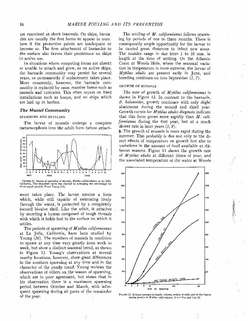
84 M A R I N E FOULING A N D I T S P R E V E N T I O N
are examined at short intervals. On ships, barnacles are usually the first forms to appear in numbers if the protective paints are inadequate or become so. The firm attachment of barnacles to the surface also favors their persistence on ships in active use.
In situations where competing forms are absent or unable to attach and grow, as on active ships, the barnacle community may persist for several years, or permanently if replacement takes place. More commonly, however, the barnacle community is replaced by more massive forms such as mussels and tunicates. This often occurs on fixed installations such as buoys, and on ships which are laid up in harbor.
The Mussel C o m m u n i t ySPAWNING AND SETTLING
The larvae of mussels undergo a complete metamorphosis into the adult form before attach-
Z 80-
1943 1944 1945
F i g u r e 12. Season of spawning of mussels, Mytilus californianus, at La Jolla California. The smoothed curve was charted by averaging the percentages for three-month periods. From Young (26).
ment takes place. The larvae assume a form which, while still capable of swimming freely through the water, is protected by a completely formed bivalve shell. Like the adult, it attaches by secreting a byssus composed of tough threads with which it holds fast to the surface on which it settles.
The periods of spawning of M ytilus californianus at La Jolla, California, have been studied by Young (26). The numbers of mussels in condition to spawn at any time vary greatly from week to week, but show a distinct seasonal trend, as shown in Figure 12. Young’s observations at several nearby locations, however, show great differences in the numbers spawning at any time and in the character of the yearly trend. Young reviews the observations of others on the season of spawning, which are in poor agreement, but states that in his observation there is a maximum spawning period between October and March, with infrequent spawning during all parts of the remainder of the year.
The settling of M . californianus follows spawning by periods of one to three months. There is consequently ample opportunity for the larvae to be carried great distances to infect new areas. The mussles range in size from 1 to 10 mm. in length at the time of settling. On the Atlantic Coast at Woods Hole, where the seasonal variation in temperature is more extreme, the larvae of Mytilus edulis are present early in June, and breeding continues on into September (5, 7).
GROWTH OF MUSSELS
The rate of growth of M ytilus californianus is shown in Figure 13. In contrast to the barnacle, B. balanoides, growth continues with only slight abatement during the second and third year. Growth curves for M ytilus edulis diegensis indicate that this form grows more rapidly than M . californianus during the first year, but at a much slower rate in later years (I, 8).¡$,j The growth of mussels is more rapid during the summer. This probably is due not only to the direct effects of temperature on growth but also to variations in the amount of food available at different seasons. Figure 14 shows the growth rate of M ytilus edulis at different times of year, and the associated temperature of the water at Woods
>60
■160160
140140
■120120
100- 100
60 >60
60 •60
40 •40
20 20
M, ---- "'r'GH'r' —36
AGE IN MONTHS
F i g u r e 13. Average increase in length, volume, weight of shell, and of dry tissues during growth of Mytilus californianus. From Fox and Coe (8)

Q U A N T I T A T I V E A SP E C T S OF FOULING 85
Hole where the observations were made. Figure 15 shows similar data for M . californianus growing at La Jolla, California (17). It may be noted
fouling increases in bulk with time of exposure. Figure 16 shows the weight of fouling observed on a large number of buoys, plotted against the time
ÛT.e1
6 30
5 25
^ N4 20
2
J F M A M J J A S O N D
15 tCLE
oO
6 30
5 2 5
4 2 0
3
2
J F M A M J J A S O N D
F i g u r e 1 4 . Growth rate of M ytilus edulis and sea water temperatures at Woods Hole, Massachusetts. Growth rates after Richards (17); temperatures after Sumner, Osburn and Cole (21).
F i g u r e 15. Growth rate of Mytilus californianus and sea water temperature at La Jolla, California. Growth rates after Richards (17); témperatures from U. S. Coast and Geodetic Survey (22).
24
° 20
4
• GULF OF MAINE
X WOODS HOLE AR EA
O SAN FRANCISCO BAY
0 IO 20 30 40 50
MON T H S E X P OS U R E
F i g u r e 16. Weight of fouling dominated by mussels on navigation buoys related to time of exposure. After Hutchins and Deevey (12).
that the seasonal variation in growth rate is much greater at Woods Hole, where the temperature fluctuates greatly in the course of the year. The growth curves do not follow the temperature cycle very exactly. This may indicate that some factor other than temperature, such as the nutrient supply, is influencing the growth rate.
THE BULK OF MUSSEL FOULING
Observations on the M ytilus communities which grow on navigation buoys show how this type of
during which the buoy had been set. The maximum rate of accumulation is 11 pounds per square foot per year, and the maximum weight recorded is nearly 26 pounds per square foot. There is much variation, and the average values are less than half of these maximum values (12).
The variation in the rate of fouling of buoys may be attributed to several causes, chief of which are the time of year at which the buoy was set and the temperature of the water throughout the period of exposure. On the Atlantic coast, buoys

86 M A R I N E FOULING A N D I T S P R E V E N T I O N
set during the winter do not begin to accumulate mussels until some time in spring when the water becomes sufficiently warm to favor attachment. Once established, the growth of the mussels is very much more rapid in the summer. The increase in
c3OCL
t 6X
UJ
4
2
0 100 200 300 400 500 600E X P O S U R E ^ M O N T H - D E G R E E S
F i g u r e 17. Weight of mussel fouling related to month-degrees of exposure. After Hutchins and Deevey (12).
fouling has been found to be related to the product of the duration of exposure and the average temperature in excess of 32° F during this period. This product is expressed as month-degrees and is symbolized by r 32. When the data from the East Coast buoys are plotted against the month-degrees of exposure, Figure 17 is obtained.
From these data an empirical equation has been developed from which the weight of fouling (in air), M a, may be predicted from the seasonal temperature of the water as follows:
M a= -0 .1 8 + 0 .0 1 9 r 32
Figure 17 indicates that variations from the prediction of about 50 per cent are to be expected. A number of alternate equations, based on different assumed values for the minimal temperature at which growth will occur, were tried but did not significantly improve the correlation.
From the foregoing equation it is possible to estimate from hydrographic data the expected
T a b l e 3 . Estimated Yearly Accumulation of Mussel FoulingM ean Yearly Month- Estimated
Location Temperature degrees Fouling°F per Year lb s ./sq .f t ./y r .
Mount Desert Rock 44.7 152 2.72Boston Lightship 48.3 196 3.55Fire Island Lightship 52.9 251 4.61Winter Quarter Lightship 57.5 306 5.65
rate of accumulation of mussel fouling at different places along the coast. Such estimates are given in Table 3, which shows that very substantial differences are to be expected because of the characteristic temperatures of the water in different localities.
A secondary cause for variation in the rate of increase in M ytilus fouling appears to be the strength of the tidal currents in which the buoys are set. A limited number of buoys examined by Hutchins and Deevey were fouled very much more heavily than those entered in Figure 1'7. These were located in positions where mean tidal currents stronger than one knot occur. The rate of increase in the fouling on these buoys and on a number of -others which fouled at normal rates is entered in Table 4, together with the mean tidal
T a b l e 4 . Relation of Rate of Increase of Mussel Fouling to Velocity of Tidal Currents in the Woods Hole Region.
Calculations Based on Data of Hutchins and Deevey (12)
M eanNam e of Buoy Current Rate of
K nots Increase*Chatham Lighted Whistle #6 1.02 0.055Bearse Shoal Lighted Gong #6 1.34 0.047Old Man Ledge #3 — t 0.044Pollack Rip Lighted Whistle PR 1.23 0.033Quicks Hole Bell #1 1.62 0.032Nantucket Bar Bell 1.02 0.027Naushon Lighted Bell #20 1.48 0.026Fifteen Foot Shoal #9 0.95 0.024Buzzards Bay Lighted Bell #7 0.28 0.019Gong beside following entry 0.29 0.016Buzzards Bay Traffic Lighted Buoy #6 0.29 0.014Block Island Sound Approach Lighted Bell V 0.41 0.013
All Atlantic Coast Buoys—average — 0.019
* Rate of increase in pounds per square foot per month-degree. t Tidal current exceptionally strong in this area. N o current data available.
current characterizing their location. The table indicates that the rate of fouling is correlated with the strength of the tidal current. Presumably this is because the rapid flow of water improves the nutrient condition to which the mussels are exposed.
Unlike most fouling organisms, mussels are able to move about after they have become attached to a surface. As a result, those which settle on spots which are crowded can move into more favorable positions. New generations of mussels frequently attach to the shells of the larger individuals which have become established earlier. (See Figure 5.) If there is room they tend to occupy the spaces between the larger mussels ; if not, they build up an outer layer of shells attached to those growing beneath. Thus the layer of fouling may become much thicker than the length of the largest mussels. Mussel fouling on navigation buoys
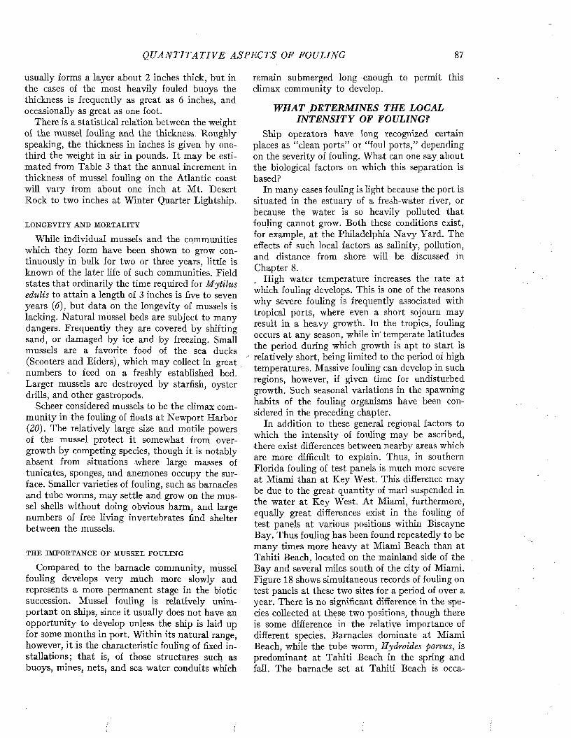
Q U A N T I T A T I V E A SP E C T S OF FOULING 87
usually forms a layer about 2 inches thick, but in the cases of the most heavily fouled buoys the thickness is frequently as great as 6 inches, and occasionally as great as one foot.
There is a statistical relation between the weight of the mussel fouling and the thickness. Roughly speaking, the thickness in inches is given by one- third the weight in air in pounds. It may be estimated from Table 3 that the annual increment in thickness of mussel fouling on the Atlantic coast will vary from about one inch at M t. Desert Rock to two inches at Winter Quarter Lightship.
LONGEVITY AND MORTALITY
While individual mussels and the communities which they form have been shown to grow continuously in bulk for two or three years, little is known of the later life of such communities. Field states that ordinarily the time required for M ytilus edulis to attain a length of 3 inches is five to seven years (6), but data on the longevity of mussels is lacking. Natural mussel beds are subject to many dangers. Frequently they are covered by shifting sand, or damaged by ice and by freezing. Small mussels are a favorite food of the sea ducks (Scooters and Eiders), which may collect in great numbers to feed on a freshly established bed. Larger mussels are destroyed by starfish, oyster drills, and other gastropods.
Scheer considered mussels to be the climax community in the fouling of floats at Newport Harbor (20). The relatively large size and motile powers of the mussel protect it somewhat from overgrowth by competing species, though it is notably absent from situations where large masses of tunicates, sponges, and anemones occupy the surface. Smaller varieties of fouling, such as barnacles and tube worms, may settle and grow on the mussel shells without doing obvious harm, and large numbers of free living invertebrates find shelter between the mussels.
THE IMPORTANCE OE MUSSEL FOULING
Compared to the barnacle community, mussel fouling develops very much more slowly and represents a more permanent stage in the biotic succession. Mussel fouling is relatively unimportant on ships, since it usually does not have an opportunity to develop unless the ship is laid up for some months in port. Within its natural range, however, it is the characteristic fouling of fixed installations; that is, of those structures such as buoys, mines, nets, and sea water conduits which
remain submerged long enough to permit this climax community to develop.
WHAT DETERMINES THE LOCAL IN TE N SITY OF FOULING?
Ship operators have long recognized certain places as “clean ports” or “foul ports,” depending on the severity of fouling. What can one say about the biological factors on which this separation is based?
In many cases fouling is light because the port is situated in the estuary of a fresh-water river, or because the water is so heavily polluted that fouling cannot grow. Both these conditions exist, for example, at the Philadelphia Navy Yard. The effects of such local factors as salinity, pollution, and distance from shore will be discussed in Chapter 8.
High water temperature increases the rate at which fouling develops. This is one of the reasons why severe fouling is frequently associated with tropical ports, where even a short sojourn may result in a heavy growth. In the tropics, fouling occurs at any season, while in' temperate latitudes the period during which growth is apt to start is
" relatively short, being limited to the period of high temperatures. Massive fouling can develop in such regions, however, if given time for undisturbed growth. Such seasonal variations in the spawning habits of the fouling organisms have been considered in the preceding chapter.
In addition to these general regional factors to which the intensity of fouling may be ascribed, ■there exist differences between nearby areas which are more difficult to explain. Thus, in southern Florida fouling of test panels is much more severe at Miami than at Key West. This difference may be due to the great quantity of marl suspended in the water at Key West. At Miami, furthermore, equally great differences exist in the fouling of test panels at various positions within Biscayne Bay. Thus fouling has been found repeatedly to be many times more heavy at Miami Beach than at Tahiti Beach, located on the mainland side of the Bay and several miles south of the city of Miami. Figure 18 shows simultaneous records of fouling on test panels at these two sites for a period of over a year. There is no significant difference in the species collected at these two positions, though there is some difference in the relative importance of different species. Barnacles dominate at Miami Beach, while the tube worm, Hydroides parvus, is predominant at Tahiti Beach in the spring and fall. The barnacle set at Tahiti Beach is occa
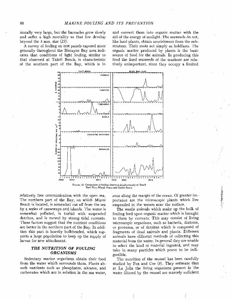
88 M A R I N E FOULING A N D I T S P R E V E N T I O N
sionally very large, but the barnacles grow slowly and suffer a high mortality so that few develop beyond the 3 mm. size (23).
A survey of fouling on test panels exposed more generally throughout the Biscayne Bay area indicates that conditions of light fouling, similar to that observed at Tahiti Beach, is characteristic of the southern part of the Bay, which is in
and convert them into organic matter with the aid of the energy of sunlight. The seaweeds do not, like land plants, obtain nourishment from the substratum. Their roots act simply as holdfasts. The organic matter produced by plants is the basic source of food for the animals. In producing this food the fixed seaweeds of the seashore are relatively unimportant, since they occupy a limited
BEACH BOAT SLIPS
HYDROIDS
TUBEWORMS
I ^ I ( BUGULA
1 9 4 2 1 9 4 3 1 9 4 4 1 9 4 2 1 94 3 1 9 4 4
F i g u r e 1 8 . Comparison of fouling observed simultaneously at Beach Boat Slips, Miami Beach and Tahiti Beach.
relatively free communication with the open sea. The northern part of the Bay, on which Miami Beach is located, is somewhat cut off from the sea by a series of causeways and islands. The water is somewhat polluted, is turbid with suspended detritus, and is moved by strong tidal currents. These factors suggest that the nutrient conditions are better in the northern part of the Bay. In addition this part is heavily bulkheaded, which supports a large population to keep up the supply of larvae for new attachment.
THE NUTRITION OF FOULING ORGANISMS
Sedentary marine organisms obtain their food from the water which surrounds them. Plants absorb nutrients such as phosphates, nitrates, and carbonates which are in solution in the sea water,
zone along the margin of the ocean. Of greater im portance are the microscopic plants which live suspended in the waters near the surface.
The sessile animals which make up the bulk of fouling feed upon organic matter which is brought to them by currents. This may consist of living microscopic organisms, such as bacteria, diatoms, or protozoa, or of detritus which is composed of fragments of dead animals and plants. Different animals have different methods of collecting this material from the water. In general they are unable to select the kind of material ingested, and may take in many particles which prove to be indigestible.
The nutrition of the mussel has been carefully studied by Fox and Coe (8). They estimate that at La Jolla the living organisms present in the water filtered by the mussel are scarcely sufficient
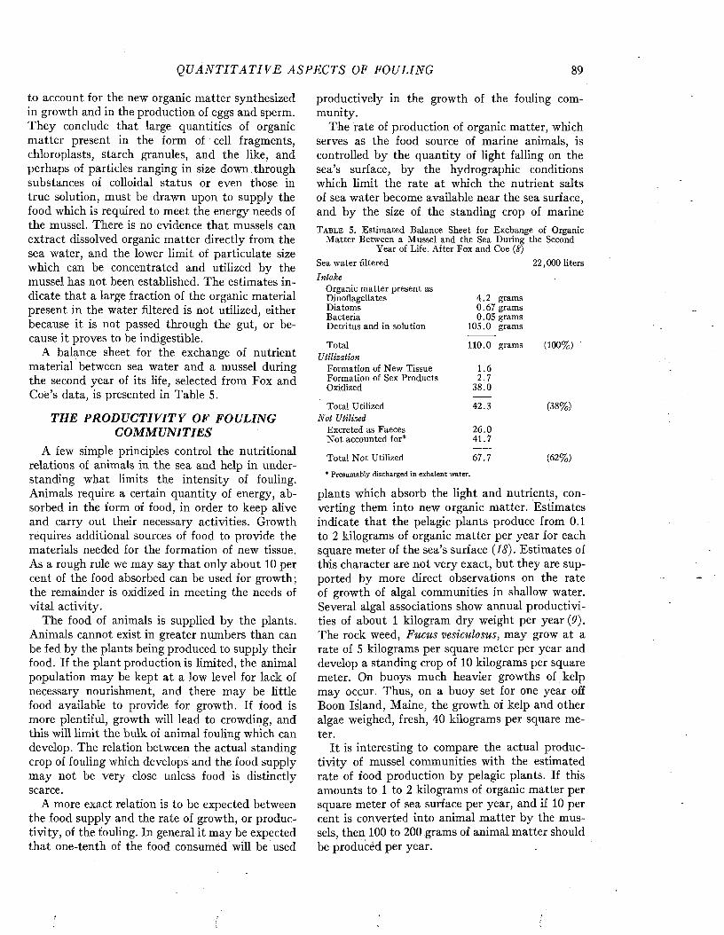
Q U A N T I T A T I V E ASPECTS OF FOULING 89
to account for the new organic matter synthesized in growth and in the production of eggs and sperm. They conclude that large quantities of organic matter present in the form of cell fragments, chloroplasts, starch granules, and the like, and perhaps of particles ranging in size down through substances of colloidal status or even those in true solution, must be drawn upon to supply the food which is required to meet the energy needs of the mussel. There is no evidence that mussels can extract dissolved organic matter directly from the sea water, and the lower limit of particulate size which can be concentrated and utilized by the mussel has not been established. The estimates indicate that a large fraction of the organic material present in the water filtered is not utilized, either because it is not passed through the gut, or because it proves to be indigestible.
A balance sheet for the exchange of nutrient material between sea water and a mussel during the second year of its life, selected from Fox and Coe’s data, is presented in Table 5.
THE PRODUCTIVITY OF FOULING COMMUNITIES
A few simple principles control the nutritional relations of animals in the sea and help in understanding what limits the intensity of fouling. Animals require a certain quantity of energy, absorbed in the form of food, in order to keep alive and carry out their necessary activities. Growth requires additional sources of food to provide the materials needed for the formation of new tissue. As a rough rule we may say that only about 10 per cent of the food absorbed can be used for growth; the remainder is oxidized in meeting the needs of vital activity.
The food of animals is supplied by the plants. Animals cannot exist in greater numbers than can be fed by the plants being produced to supply their food. If the plant production is limited, the animal population may be kept at a low level for lack of necessary nourishment, and there may be little food available to provide for growth. If food is more plentiful, growth will lead to crowding, and this will limit the bulk of animal fouling which can develop. The relation between the actual standing crop of fouling which develops and the food supply may not be very close unless food is distinctly scarce.
A more exact relation is to be expected between the food supply and the rate of growth, or productivity, of the fouling. In general it may be expected that one-tenth of the food consumed will be used
productively in the growth of the fouling community.
The rate of production of organic matter, which serves as the food source of marine animals, is controlled by the quantity of light falling on the sea’s surface, by the hydrographic conditions which limit the rate at which the nutrient salts of sea water become available near the sea surface, and by the size of the standing crop of marineT a b l e 5. Estimated Balance Sheet for Exchange of Organic
Matter Between a Mussel and the Sea During the Second Year of Life. After Fox and Coe (8)
Sea water filtered 22,000 litersIntake
Organic matter present asDinoflagellates 4 .2 gramsDiatoms 0.67 gramsBacteria 0.05 gramsDetritus and in solution 105.0 grams
Total 110.0 gramsU tilization
Formation of New Tissue 1.6Formation of Sex Products 2 .7Oxidized 38.0
Total Utilized 42.3N ot Utilized
Excreted as Faeces 26.0N ot accounted for* 41.7
Total N ot Utilized 67.7
* Presumably discharged in exhalent w ater.
(100%)
(38%)
(62%)
plants which absorb the light and nutrients, converting them into new organic matter. Estimates indicate that the pelagic plants produce from 0.1 to 2 kilograms of organic matter per year for each square meter of the sea’s surface (18). Estimates of this character are not very exact, but they are supported by more direct observations on the rate of growth of algal communities in shallow water. Several algal associations show annual productivities of about 1 kilogram dry weight per year (9). The rock weed, Fucus vesiculosus, may grow at a rate of 5 kilograms per square meter per year and develop a standing crop of 10 kilograms per square meter. On buoys much heavier growths of kelp may occur. Thus, on a buoy set for one year off Boon Island, Maine, the growth of kelp and other algae weighed, fresh, 40 kilograms per square meter.
It is interesting to compare the actual productivity of mussel communities with the estimated rate of food production by pelagic plants. If this amounts to 1 to 2 kilograms of organic matter per square meter of sea surface per year, and if 10 per cent is converted into animal matter by the mussels, then 100 to 200 grams of animal matter should be producéd per year.
90 M A R I N E FOULING A N D I T S P R E V E N T I O N
Uncultivated mussel beds in the British Isles are reported to produce about 1.09 kilograms of mussels per square meter per year, or about 40 grams of organic matter. Cultivated beds produce as much as 150 grams of organic matter (6). These figures are consequently quite in line with the productivity estimated from the plant production.
Mussel fouling on buoys, in conduits, and on ships frequently yields much higher figures for productivity, however. The average increase in weight of mussel fouling on buoys on the Maine coast is about 13 kilograms per square meter per year; off Virginia it is 28 kilograms. Mussels growing in the salt water intake tunnels of a powerhouse at Lynn, Massachusetts, have been observed to grow in weight to 64 kilograms per square meter in 21 weeks. On test blocks the accumulation of general mixed fouling over monthly periods had the following average values :San D iego, California 25 kg/m 2/year (25) Port Reyes, California 7.4 kg/m 2/year (13) Norfolk, Virginia 13.2 kg/m 2/year (24)
Ships rarely are permitted to develop maximum crops of fouling. Lightships, however, provide noteworthy records as follows :Elbe Lightships 40 kg/m 2 in 11 monthsNew York Lightships 23.5 kg/m 2 in 15 monthsNew York Lightships 21.6 kg/m 2 in 16 months
When such figures as those quoted above are translated into production of organic matter and compared with the food supply available per square meter of sea surface, it is evident that the communities growing on fouled structures avail themselves of much more organic matter than is produced, on the average, in the volume of water which they occupy. Two considerations may serve to explain this finding. In the first place the fouling communities consume large quantities of food brought to them from other parts of the sea where there is no great quantity of animals to consume the food matter locally produced. This is why currents favor the growth of fouling. In the second place fouling growth may occur in specialized localities where the production of organic matter by plants is much greater than average, or even where land and fresh water may contribute to the detritus utilized by the marine animals of the fouling community.
REFERENCES1. Coe, W. R. Nutrition and Growth of the California Bay-
mussel (M ytilu s diegensis). J. Exp. Zool., 99, 1-14, 1945.
2. C o e , W. R., and W. E. A l l e n . Growth of Sedentary MarineOrganisms on Experimental Blocks and Plates for Nine Successive Years at the Pier of the Scripps Institution of Oceanography. Bull. Scripps Inst. Oceanogr., Tech. Ser., 4, 101-136, 1937.
3 . D e e v e y , E. S., J r . Life Tables for Natural Populations ofAnimals. Quart. Rev. Biol., 22, No. 4, 283-314, 1947.
4. E d m o n d s o n , C. H., and W. M. I n g r a m . Fouling Organisms inHawaii. Occ. Papers, Bernice P. Bishop Mus., 14, 251-300,1939.
5. F i e l d , I. A. The Food Value of Sea Mussels. Bull. Bur.Fisheries 29, 87-128, 1911.
6. F i e l d , I. A. Biology and Economic Value of the Sea Mussel,M ytilu s edulis. Bull. U. S. Bur. Fish., 38, 127-259, 1922.
7. F i s h , C. J. Seasonal Distribution o f the Plankton of theWoods Hole Region. Bull. Bur. Fish., 41, 91-179, 1925.
8. Fox, D. L., and W. R. C o e . Biology of the California Sea-mussel (M ytilus californianus). II. Nutrition, Metabolism, Growth and Calcium Deposition. J. Exp. Zool., 93, 205- 249, 1943.
9. G i s l e n , T. Epibioses of the Gullmar Fjord. I, II. Kristinebergs Zoologiska Station 1877-1927; Skriftser., K. Svensk. Vetenskapsakad., No. 3, 1-123; No. 4, 1-380, 1930.
10. H a r d in g , C . M o llu s c s , M u s s e l s , W h e lk s , e t c . , U s e d f o r F o o dor Bait. Internat. Fisheries Exhibition, London, 1883. The Fisheries Exhibition Literature, 4, part 3, 23 pp., 1884.
11. H a t t o n , H . Essais de bionomie explicative sur quelquesespeces intercotidales d’Algues et d’Animaux. Ann. Inst. Oceanog., n.s., 17, 241-348, 1938.
12. H u t c h i n s , L. W., and E. S. D e e v e y , J r . Estimation andPrediction of the Weight and Thickness of Mussel Fouling on Buoys. Interim Report No. 1 for 1944, Woods Hole Oceanographic Institution to Bureau of Ships, April 19, 1944. (Unpublished).
13. Mare Island Naval Shipyard. Letter to Bureau of Ships,March 18, 1946.
14. M o o r e , H. B. The Biology of Balanus balanoides. I. GrowthRate and Its Relation to Size, Season and Tidal Level. Jour. Mar. Biol. Assoc., n.s., 19, 851-868, 1934.
15. M o o r e , H. B. and J. A. K i t c h i n g . The Biology of Chthamalus stellatus Poli. Jour. Mar. Biol. Assoc, of the U. K., 23, 521-541, 1939.
16. P a u l , M. D. Studies on the Growth and Breeding of CertainSedentary Organisms in the Madras Harbour. Proc. Indian Acad. Sei., 15B, 1-42, 1942.
17. R i c h a r d s , O. W. Comparative Growth of M ytilu s californ ianus at La Jolla, California, and M ytilus edidis at Woods Hole, Massachusetts. Ecology, 27, 370-372, 1946.
18. R i l e y , G. A. Factors Controlling Phytoplankton Populationson Georges Bank. Jour. Mar. Res., 6, No. 1, 54-73, 1946.
19. R u n n s t r ö m , S. Zur biologie und entwicklung von Balanusbalanoides (Linne). Bergens Mus. Âarbok for 1924-25, No. 5, 46 pp., 1925.
20. S c h e e r , B. T. The Development of Marine Fouling Communities. Biol. Bull., 89, 103-121, 1945.
21. S u m n e r , F. G., R. C. O s b u r n , and L. J. C o l e . A BiologicalSurvey of the Waters of Woods Hole and Vicinity. Bull. U. S. Bur. Fish., 31, parts I, II, 860 pp., 1911.
22. U. S. Coast and Geodetic Survey. Water Temperatures,Coast and Geodetic Survey Tide Stations, Pacific Coast. TW-2, April, 1941.
23. W e i s s , C. M. The Seasonal Occurrence of Sedentary MarineOrganisms in Biscayne Bay, Florida. Ecology, 29, No. 2, 153-172, 1948.
24. W h a r t o n , G. W. Report of the Biologist, Norfolk NavyYard, June 1941-August 1942. (Unpublished).
25. W h e d o n , W. F. Seasonal Incidence of Fouling at San Diego.Biological Laboratory, Naval Fuel Depot, San Diego, Cal., Annual Report for 1942-1943, 1943. (Unpublished).
26. Y o u n g , R. T. Spawning and Setting Season of the Mussel,M ytilu s californianus. Ecology, 2 7 , 354 r-363 , 1946 .
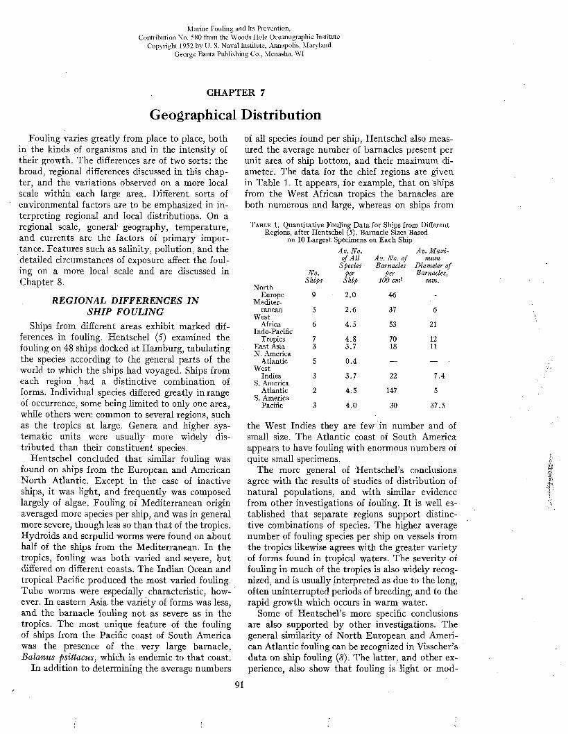
Marine Fouling and Its Prevention,Contribution No. 580 from the Woods Flole Oceanographic Institute
Copyright 1952 by U. S. Naval Institute, Annapolis, Maryland George Banta Publishing Co., Menasha, WI
CHAPTER 7
Geographical DistributionFouling varies greatly from place to place, both
in the kinds of organisms and in the intensity of their growth. The differences are of two sorts: the broad, regional differences discussed in this chapter, and the variations observed on a more local scale within each large area. Different sorts of environmental factors are to be emphasized in interpreting regional and local distributions. On a regional scale, general geography, temperature, and currents are the factors of primary importance. Features such as salinity, pollution, and the detailed circumstances of exposure affect the fouling on a more local scale and are discussed in Chapter 8.
REGIONAL DIFFERENCES IN SHIP FOULING
Ships from different areas exhibit marked differences in fouling. Hentschel (5) examined the fouling on 48 ships docked at Hamburg, tabulating the species according to the general parts of the world to which the ships had voyaged. Ships from each region had a distinctive combination of forms. Individual species differed greatly in range of occurrence, some being limited to only one area, while others were common to several regions, such as the tropics at large. Genera and higher systematic units were usually more widely distributed than their constituent species.
Hentschel concluded that similar fouling was found on ships from the European and American North Atlantic. Except in the case of inactive ships, it was light, and frequently was composed largely of algae. Fouling of Mediterranean origin averaged more species per ship, and was in general more severe, though less so than that of the tropics. Hydroids and serpulid worms were found on about half of the ships from the Mediterranean. In the tropics, fouling was both varied and severe, but differed on different coasts. The Indian Ocean and tropical Pacific produced the most varied fouling. Tube worms were especially characteristic, however. In eastern Asia the variety of forms was less, and the barnacle fouling not as severe as in the tropics. The most unique feature of the fouling of ships from the Pacific coast of South America was the presence of the very large barnacle, Balanus psittacus, which is endemic to that coast.
In addition to determining the average numbers
of all species found per ship, Hentschel also measured the average number of barnacles present per unit area of ship bottom, and their maximum diameter. The data for the chief regions are given in Table 1. It appears, for example, that on ships from the West African tropics the barnacles are both numerous and large, whereas on ships from
T a b l e 1. Quantitative Fouling Data for Ships from Different Regions, after Hentschel (5). Barnacle Sizes Based
on 10 Largest Specimens on Each Ship
No.
Av. No. of A ll
Species per
Av. No. of Barnacles
per
Av. M ax imum
Diameter of Barnacles,
Ships Ship 100 cm2 mm.North
Europe 9 2 .0 46 —Mediter
ranean 5 2.6 37 6West
Africa 6 4.5 53 21Indo-Pacific
Tropics 7 4 .8 70 12East Asia 3 3.7 18 11N. America
Atlantic 5 0 .4 — —West
Indies 3 3 .7 22 7.4S. America
Atlantic 2 4 .5 147 5S. America
Pacific 3 4 .0 30 37.5
the West Indies they are few in number and of small size. The Atlantic coast of South America appears to have fouling with enormous numbers of quite small specimens.
The more general of H entscheli conclusions agree with the results of studies of distribution of natural populations, and with similar evidence from other investigations of fouling. It is well established that separate regions support distinctive combinations of species. The higher average number of fouling species per ship on vessels from the tropics likewise agrees with the greater variety of forms found in tropical waters. The severity of fouling in much of the tropics is also widely recognized, and is usually interpreted as due to the long, often uninterrupted periods of breeding, and to the rapid growth which occurs in warm water.
Some of Hentschel’s more specific conclusions are also supported by other investigations. The general similarity of North European and American Atlantic fouling can be recognized in Visscher’s data on ship fouling (8). The latter, and other experience, also show that fouling is light or mod-
91

M A R I N E FOULING A N D I T S P R E V E N T I O N
F i g u r e 1. Examples of different types of fouling on buoys in American w aters. D, Goose barnacles, w ith light growth of algae and am phipod tubes, K ey W estA , K elp and mussels, Newfoundland. B , H eavy mussel fouling off Delaware Bay. E , M ussels and kelp outside San Francisco, F, Balanus linlinnabulum, a largeC, M ixed fouling, including barnacles, algae, and rock oysters, near Beaufort. tropical barnacle, C atalina Island, Southern California.
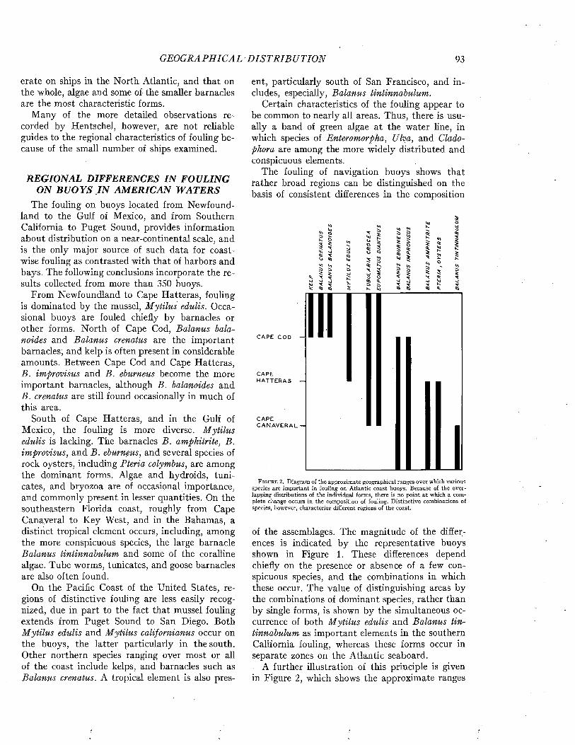
GEOGRAPHICAL D I S T R I B U T IO N 93
erate on ships in the North Atlantic, and that on the whole, algae and some of the smaller barnacles are the most characteristic forms.
Many of the more detailed observations recorded by Hentschel, however, are not reliable guides to the regional characteristics of fouling because of the small number of ships examined.
REGIONAL DIFFERENCES IN FOULING ON BU O YS IN AMERICAN WATERS
The fouling on buoys located from Newfoundland to the Gulf of Mexico, and from Southern California to Puget Sound, provides information about distribution on a near-continental scale, and is the only major source of such data for coastwise fouling as contrasted with that of harbors and bays. The following conclusions incorporate the results collected from more than 350 buoys.
From Newfoundland to Cape Hatteras, fouling is dominated by the mussel, M ytilus edulis. Occasional buoys are fouled chiefly by barnacles or other forms. North of Cape Cod, Balanus balanoides and Balanus crenatus are the important barnacles, and kelp is often present in considerable amounts. Between Cape Cod and Cape Hatteras, B. improvisus and B. eburneus become the more important barnacles, although B. balanoides and B. crenatus are still found occasionally in much of this area.
South of Cape Hatteras, and in the Gulf of Mexico, the fouling is more diverse. M ytilus edulis is lacking. The barnacles B. amphitrite, B. improvisus, and B. eburneus, and several species of rock oysters, including Pteria colymbus, are among the dominant forms. Algae and hydroids, tuni- cates, and bryozoa are of occasional importance, and commonly present in lesser quantities. On the southeastern Florida coast, roughly from Cape Canaveral to Key West, and in the Bahamas, a distiiict tropical element occurs, including, among the more conspicuous species, the large barnacle Balanus tintinnabulum and some of the coralline algae. Tube worms, tunica tes, and goose barnacles are also often found.
On the Pacific Coast of the United States, regions of distinctive fouling are less easily recognized, due in part to the fact that mussel fouling extends from Puget Sound to San Diego. Both M ytilus edulis and Mytilus californianus occur on the buoys, the latter particularly in the south. Other northern species ranging over most or all of the coast include kelps, and barnacles such as Balanus crenatus. A tropical element is also pres
ent, particularly south of San Francisco, and includes, especially, Balanus tintinnabulum.
Certain characteristics of the fouling appear to be common to nearly all areas. Thus, there is usually a band of green algae at the water line, in which species of Enteromorpha, Ulva, and Cladophora are among the more widely distributed and conspicuous elements.
The fouling of navigation buoys shows that rather broad regions can be distinguished on the basis of consistent differences in the composition
C A P E c o d —
C A P EH A T T E R A S —
C A P EC A N A V E R A L —
F i g u r e 2. Diagram of the approximate geographical ranges over which various species are important in fouling on Atlantic coast buoys. Because of the overlapping distributions of the individual forms, there is no point at which a complete change occurs in the composition of fouling. D istinctive combinations of species, however, characterize different regions of the coast.
of the assemblages. The magnitude of the differences is indicated by the representative buoys shown in Figure 1. These differences depend chiefly on the presence or absence of a few conspicuous species, and the combinations in which these occur. The value of distinguishing areas by the combinations of dominant species, rather than by single forms, is shown by the simultaneous occurrence of both M ytilus edulis and Balanus tintinnabulum as important elements in the southern California fouling, whereas these forms occur in separate zones on the Atlantic seaboard.
A further illustration of this principle is given in Figure 2, which shows the approximate ranges
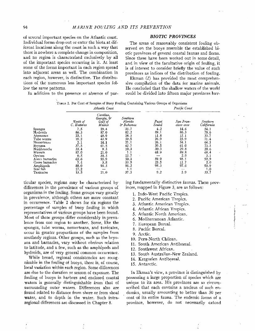
94 M A R I N E FOULING A N D I T S P R E V E N T I O N
of several important species on the Atlantic coast. Individual forms drop out or enter the biota at different locations along the coast in such a way that there is nowhere a complete change in composition, and no region is characterized exclusively by all of the important species occurring in it. At least some of the forms important in each region spread into adjacent areas as well. The combination in each region, however, is distinctive. The distributions of the numerous less important species follow the same patterns.
In addition to the presence or absence of par-
BIOTIC PROVINCESThe areas of reasonably consistent fouling ob
served on the buoys resemble the established biotic provinces of general coastal faunas and floras. Since these have been worked out in some detail, and in view of the facultative origin of fouling, it is of interest to consider briefly the value of such provinces as indices of the distribution of fouling.
Ekman (2) has provided the most comprehensive compilation of the data for marine animals. He concluded that the shallow waters of the world could be divided into fifteen major provinces hav-
T a b l e 2. Per Cent of Samples of Buoy Fouling Containing Various Groups of OrganismsA tlantic Coast Pacific Coast
North of
Carolina, Georgia, &
G ulf ofSouthern
Florida Puget San Fran SouthernC. Hatteras Mexico ár Bahamas Sound cisco area California
Sponges 7.5 29.4 35.7 4 .2 14.6 54.1Hydroids 86.3 87.0 82.2 89.1 86.3 78.6Anemones 23.1 48.9 24.3 11.8 15.1 33.7Tube worms 10.2 43.9 59.5 26.9 23.9 71.4Nemerteans 2.1 14.1 21.1 26.1 54.1 64.3Bryozoa 37.5 61.5 42.7 39.5 61.0 73.5Nudibranchs 33 .4 9.5 10.3 30.3 29.8 28.6Mussels 87.0 21.0 1.1 68.9 89.8 68.4Oysters 0 .5 38.5 15.7 — 2.9 3.1Acorn barnacles 63.6 93.9 50.3 89.9 95.1 92.9Goose barnacles 7 .4 3 .8 33.5 23.5 11.7 2.0Amphipods 88.0 93.5 96.2 98.3 97.6 93.9Star fish 17.2 — 1.1 — — 1.0Tunicates 13.5 21.0 37.3 9.2 5 .9 33.7
ticular species, regions may be characterized by differences in the prevalence of various groups of organisms in the fouling. Some groups vary greatly in prevalence, although others are more constant in occurrence. Table 2 shows for six regions the percentage of samples of buoy fouling in which representatives of various groups have been found. M ost of these groups differ considerably in prevalence from one region to another. Some, like the sponges, tube worms, nemerteans, and tunicates, occur in greater proportions of the samples from southerly regions. Other groups, such as the bryozoa and barnacles, vary without obvious relation to latitude, and a few, such as the amphipods and hydroids, are of very general common occurrence.
While broad, regional consistencies are recognizable in the fouling of buoys, there is, of course, local variation within each region. Some differences are due to the duration or season of exposure. The fouling of buoys in harbors and enclosed coastal waters is generally distinguishable from that of surrounding outer waters. Differences also are found related to distance from shore or from shoal water, and to depth in the water. Such intra- regional differences are discussed in Chapter 8.
ing fundamentally distinctive faunas. These provinces, mapped in Figure 3, are as follows:
1. Indo-West Pacific Tropics.2. Pacific American Tropics.3. Atlantic American Tropics.4. Atlantic African Tropics.5. Atlantic North American.
Mediterranean Atlantic.European Boreal.Pacific Boreal.Arctic.Peru-North Chilean.South American Antiboreal.Southwest African.South Australian-New Zealand.Kerguelen Antiboreal.
6 .7.8 .
9.10.1 1 .
1 2 .
13.14.15. Antarctic.
In Ekman’s view, a province is distinguished by possessing a large proportion of species which are unique to its area. His provinces are so circumscribed that each contains a nucleus of such endemics, usually amounting to better than 50 per cent of its entire fauna. The endemic forms of a province, however, do not necessarily extend

GEOGRAPHICAL D I S T R I B U T I O N 95
throughout it. The Indo-West Pacific Tropics and others of the large provinces can be subdivided, accordingly, on the grounds of the more restricted distributions of smaller aggregations of the contained endemic species.
Boundaries of the provinces are generally located at points where pronounced changes in the biota are found; i.e., where the ranges of a number
practical problems. Thus, a-number of species which commonly dominate fouling and determine its character, range over several Ekman provinces or have distributions not particularly well represented by any province or combination of provinces. Among these wider ranging forms are Balanus crenatus and M ytilus edulis, which are circum- global in northern waters, and Balanus amphitrite,
140 1120 1160 1160 1120 leoleo.180 140
80
60
MED! f EFMiANEAN— A T L Á Ñ p C
40
1120 1160 1Ï2Ö” 140"W neo|40 ■|40 leo
F i g u r e 3 . Map of the 15 major shallow-water faunal provinces recognized by Ekman (2), drawn on the basis of his discussions.Adjacent provinces overlap in a number of instances.
of species begin or end. The margins of the provinces may overlap, giving a small area in which species characteristic of two adjacent provinces are found. Such an overlap exists between Cape Hat- teras and Florida, Cape Hatteras marking the northern limit of many tropical forms, while many of the boreo-temperate species extend south as far as eastern Florida.
The use of biotic provinces such as Ekman’s to predict fouling expectancy meets with several difficulties. One reason is that practical considerations place extremely unequal importance on individual fouling species. General biogeography, in contrast, tends to give equal weight to all forms, or to emphasize particular species for reasons having no relation to fouling, with the result that biogeographic provinces often are not applicable to
B. tintinnabulum, and Bugula neritina, circum- global in the tropics and warmer waters. The distributions of these species often give a better indication of fouling conditions than can be afforded by provincial biogeography. The differences suggested by provincial boundaries, though biologically valid, may be realized only in the-case of species of comparatively little practical consequence. The prevalence of M ytilus edulis and Balanus crenatus on fixed installations throughout northern waters provides a similarity that outweighs other differences for many practical purposes.
The apparent distinctions between fouling of various types of structures, furthermore, make it necessary to consider the geographical aspects of fouling separately for each sort of problem. Very
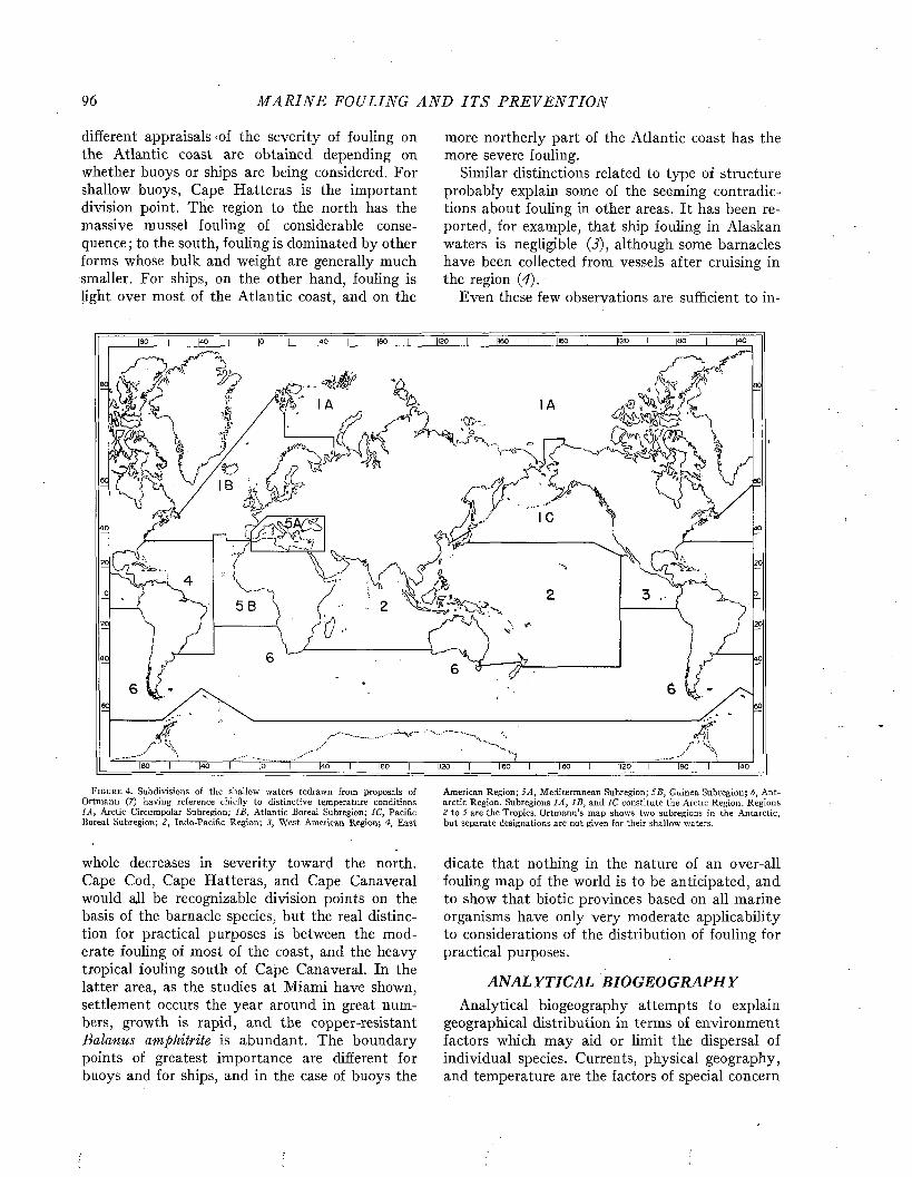
96 M A R I N E FOULING A N D I T S P R E V E N T I O N
different appraisals -of the severity of fouling on the Atlantic coast are obtained depending on whether buoys or ships are being considered. For shallow buoys, Cape Hatteras is the important division point. The region to the north has the massive mussel fouling of considerable consequence ; to the south, fouling is dominated by other forms whose bulk and weight are generally much smaller. For ships, on the other hand, fouling is light over most of the Atlantic coast, and on the
F ig u r e 4. Subdivisions of the shallow waters redrawn from proposals of Ortmann (7) having reference chiefly to distinctive temperature conditions 1A, Arctic Circumpolar Subregion; IB, Atlantic Boreal Subregion; 1C, Pacific Boreal Subregion; 2, Indo-Pacific Region; 3, West American Region; 4, East
whole decreases in severity toward the north. Cape Cod, Cape Hatteras, and Cape Canaveral would ajl be recognizable division points on the basis of the barnacle species, but the real distinction for practical purposes is between the moderate fouling of most of the coast, and the heavy tropical fouling south of Cape Canaveral. In the latter area, as the studies at Miami have shown, settlement occurs the year around in great numbers, growth is rapid, and the copper-resistant Balanus amphitrite is abundant. The boundary points of greatest importance are different for buoys and for ships, and in the case of buoys the
more northerly part of the Atlantic coast has the more severe fouling.
Similar distinctions related to type of structure probably explain some of the seeming contradictions about fouling in other areas. It has been reported, for example, that ship fouling in Alaskan waters is negligible (3), although some barnacles have been collected from vessels after cruising in the region (4).
Even these few observations are sufficient to in-
American Region; SA, Mediterranean Subregion; SB, Guinea Subregion; 6, Antarctic Region. Subregions 1A, IB , and 1C constitute the Arctic Region. Regions 2 to 5 are the Tropics. Ortmann’s map shows two subregions in the Antarctic, but separate designations are not given for their shallow waters.
dicate that nothing in the nature of an over-all fouling map of the world is to be anticipated, and to show that biotic provinces based on all marine organisms have only very moderate applicability to considerations of the distribution of fouling for practical purposes.
ANALYTICAL BIOGEOGRAPHYAnalytical biogeography attempts to explain
geographical distribution in terms of environment factors which may aid or limit the dispersal of individual species. Currents, physical geography, and temperature are the factors of special concern
[120
w"|40 leo" ligo leo 140
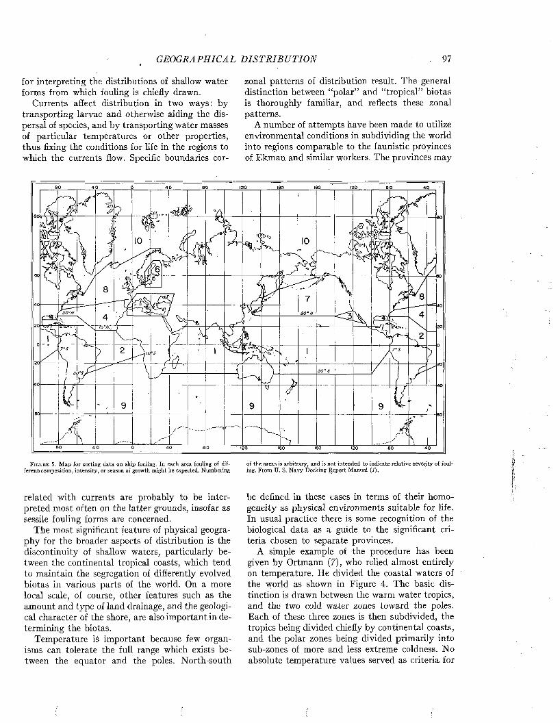
GEOGRAPHICAL D I S T R I B U T I O N 97
for interpreting the distributions of shallow water forms from which fouling is chiefly drawn.
Currents affect distribution in two ways: by transporting larvae and otherwise aiding the dispersal of species, and by transporting water masses of particular temperatures or other properties, thus fixing the conditions for life in the regions to which the currents flow. Specific boundaries cor-
F i g u r e 5 . M ap for sorting data on ship fouling. In each area fouling of different» composition, intensity , or season of growth m ight be expected. N umbering
related with currents are probably to be interpreted most often on the latter grounds, insofar as sessile fouling forms are concerned.
The most significant feature of physical geography for the broader aspects of distribution is the discontinuity of shallow waters, particularly between the continental tropical coasts, which tend to maintain the segregation of differently evolved biotas in various parts of the world. On a more local scale, of course, other features such as the amount and type of land drainage, and the geological character of the shore, are also important in determining the biotas.
Temperature is important because few organisms can tolerate the full range which exists between the equator and the poles. North-south
zonal patterns of distribution result. The general distinction between “polar” and “tropical” biotas is thoroughly familiar, and reflects these zonal patterns.
A number of attempts have been made to utilize environmental conditions in subdividing the world into regions comparable to the faunistic provinces of Ekman and similar workers. The provinces may
of the areas is arbitrary, and is not intended to indicate relative severity of fouling. From U. S. N avy Docking R eport M anual (1).
be defined in these cases in terms of their homogeneity as physical environments suitable for life. In usual practice there is some recognition of the biological data as a guide to the significant criteria chosen to separate provinces.
A simple example of the procedure has been given by Ortmann (7), who relied almost entirely on temperature. He divided the coastal waters of the world as shown in Figure 4. The basic distinction is drawn between the warm water tropics, and the two cold water zones toward the poles. Each of these three zones is then subdivided, the tropics being divided chiefly by continental coasts, and the polar zones being divided primarily into sub-zones of more and less extreme coldness. No absolute temperature values served as criteria for
40
20
3 0 ° S
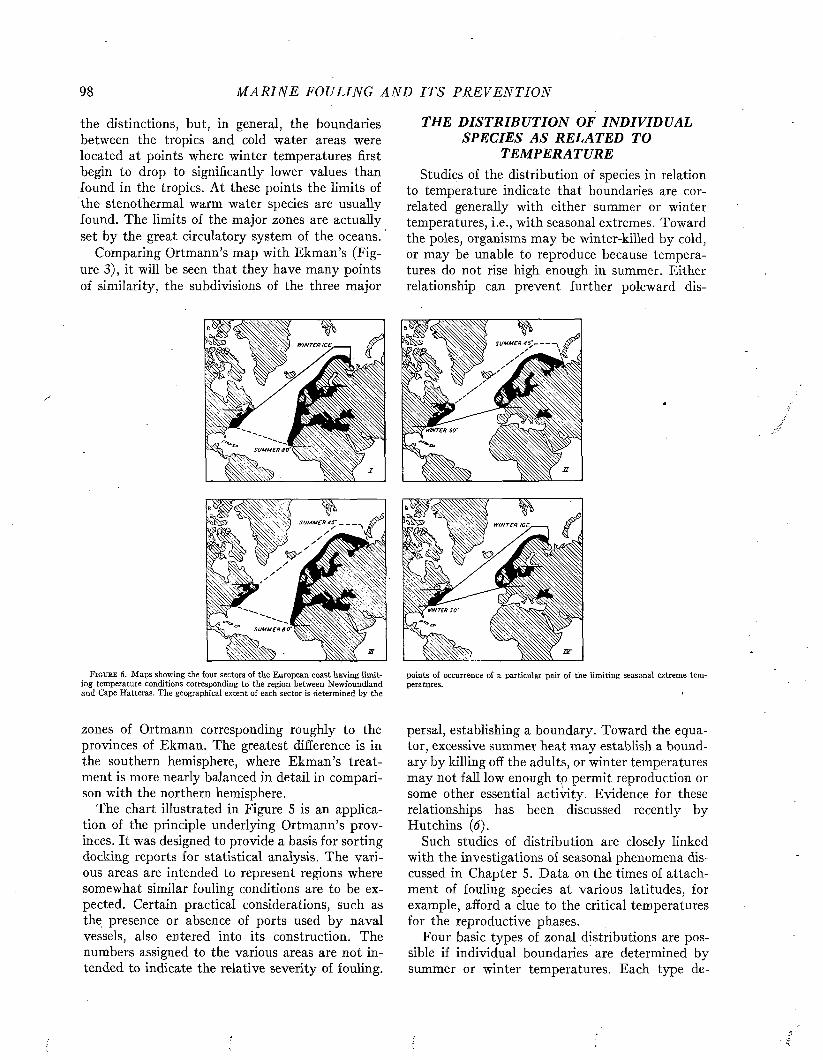
98 M A R I N E FOULING A N D I T S P R E V E N T I O N
the distinctions, but, in general, the boundaries between the tropics and cold water areas were located at points where winter temperatures first begin to drop to significantly lower values than found in the tropics. At these points the limits of the stenothermal warm water species are usually found. The limits of the major zones are actually set by the great circulatory system of the oceans.
Comparing Ortmann’s map with Ekman’s (Figure 3), it will be seen that they have many points of similarity, the subdivisions of the three major
THE DISTRIBUTION OF INDIVIDUAL SPECIES AS RELATED TO
TEMPERATUREStudies of the distribution of species in relation
to temperature indicate that boundaries are correlated generally with either summer or winter temperatures, i.e., with seasonal extremes. Toward the poles, organisms may be winter-killed by cold, or may be unable to reproduce because temperatures do not rise high enough in summer. Either relationship can prevent further poleward dis-
W IN TE R ICE
SU M M E R M - V W
%
SU M M E R 4 5
SU M M E R 9 0
SU M M E R 4 5 ' ------
F i g u r e 6 . Maps showing the four sectors of the European coast having limiting temperature conditions corresponding to the region between Newfoundland and Cape Hatteras. The geographical extent of each sector is determined by the
points of occurrence of a particular pair of the limiting seasonal extreme temperatures.
zones of Ortmann corresponding roughly to the provinces of Ekman. The greatest difference is in the southern hemisphere, where Ekman’s treatment is more nearly balanced in detail in comparison with the northern hemisphere.
The chart illustrated in Figure 5 is an application of the principle underlying Ortmann’s provinces. It was designed to provide a basis for sorting docking reports for statistical analysis. The various areas are intended to represent regions where somewhat similar fouling conditions are to be expected. Certain practical considerations, such as the presence or absence of ports used by naval vessels, also entered into its construction. The numbers assigned to the various areas are not intended to indicate the relative severity of fouling.
persal, establishing a boundary. Toward the equator, excessive summer heat may establish a boundary by killing off the adults, or winter temperatures may not fall low enough to permit reproduction or some other essential activity. Evidence for these relationships has been discussed recently by Hutchins (6).
Such studies of distribution are closely linked with the investigations of seasonal phenomena discussed in Chapter 5. Data on the times of attachment of fouling species at various latitudes, for example, afford a clue to the critical temperatures for the reproductive phases.
Four basic types of zonal distributions are possible if individual boundaries are determined by summer or winter temperatures. Each type de-

GEOGRAPHICAL D I S T R I B U T IO N 99
pends on the particular combination of seasonal conditions producing the northern and southern limits, as follows:
Type of Northern SouthernD istribution L im it L im it
1. Too cold in winter Too warm in summer2. Too cold in summer Too warm in winter3. Too cold in summer Too warm in summer4. Too cold in winter Too warm in winter
Distinctive geographical distributions result from the four types, and in this fact lies the great importance of recognizing more than one kind of
tures of the Newfoundland-Cape Hatteras stretch occur at four separate places instead of only two. Thus the 50° temperature characteristic of Cape Hatteras in winter is found in Brittany, but the 80° summer temperature occurs far to the south, in West Africa. Similarly, the summer and winter Newfoundland temperatures occur at separate points in northern Europe. As a result, four different areas of the European coast correspond to the Newfoundland-Cape Hatteras sector, each corresponding in respect to one particular pair of
160 ,20 ]140100 [Í00 [140 •ISO [ to o
60 60
60 60
40
45' WINTER20 20
20 20
40 40
60
BALANUS BALANOIDES
80
100 60 >20 '60 '140■too 480
F i g u r e 7. Representative records showing the distribution of the barnacle isotherm of the monthly mean of 45° F at the time of minimum temperaturesBalanus balanoides. The southern boundary is closely approximated by the in winter. After Hutchins (6).
zonation. The maps in Figure 6 illustrate the point by showing the sections of the European coast which provide similar temperature conditions to those found between Newfoundland and Cape Hatteras. At Newfoundland there is ice in winter, and a monthly mean temperature of 45°F in summer. At Cape Hatteras a winter monthly mean of 50° occurs, while the summer temperature is 80°. Because the annual range of temperature at any point in Europe is much less than on the American coast, these limiting tempera-
seasonal extremes defining its northern and southern limits: No portion of the European coast, on the other hand, has temperatures corresponding in all details with those between Newfoundland and Cape Hatteras.
Essentially similar results are reached in comparing any two coasts, since the temperature conditions on one are almost never duplicated exactly on the other. In general, however, the distinctive geographical features of distribution introduced by correlation with seasonal temperatures are most
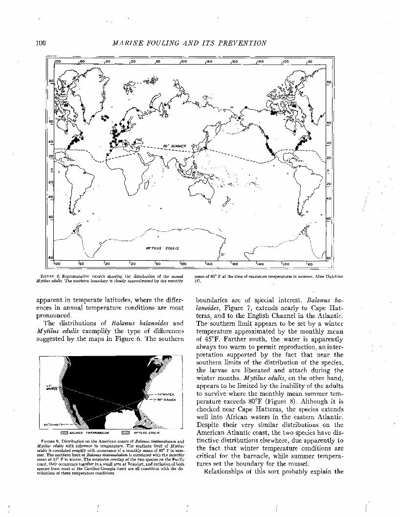
100 M A R I N E FOULING A N D I T S P R E V E N T I O N
,100 60 20 20 100 160 140 100140
60 60
60
40 406 0 ' SUMMER
20 20
'20 20
40 40
60 60
>60'100 20 20 60 100 140 leo 140 100 60
mean of 80° F at the time of maximum temperatures in summer. After Hutchins (* ) . '
boundaries are of special interest. Balanus balanoides, Figure 7, extends nearly to Cape H atteras, and to the English Channel in the Atlantic. The southern limit appears to be set by a winter temperature approximated by the monthly mean of 45°F. Farther south, the water is apparently always too warm to permit reproduction, an interpretation supported by the fact that near the southern limits of the distribution of the species, the larvae are liberated and attach during the winter months. M ytilus edulis, on the other hand, appears to be limited by the inability of the adults to survive where the monthly mean summer temperature exceeds 80°F (Figure 8). Although it is checked near Cape Hatteras, the species extends well into African waters in the eastern Atlantic. Despite their very similar distributions on the American Atlantic coast, the two species have distinctive distributions elsewhere, due apparently to the fact that winter temperature conditions are critical for the barnacle, while summer temperatures set the boundary for the mussel.
Relationships of this sort probably explain the
F i g u r e 8 . Representative records showing the distribution of the mussel Mytilus edulis. The southern boundary is closely approximated by the monthly
apparent in temperate latitudes, where the differences in annual temperature conditions are most pronounced.
The distributions of Balanus balanoides and Mytilus edulis exemplify the type of differences suggested by the maps in Figure 6. The southern
55*W1NTER
6 0 * SUMMER
6 0 'S U M M E R -
V 77A B A LANU S TINTINNABULUM M YT IL U S S O U L /S
F i g u r e 9. Distribution on the American coasts of Balanus tintinnabulum and Mytilus edulis with reference to temperature. The southern limit of M ytilus edulis is correlated roughly with occurrence of a monthly mean of 80° F in summer. The northern limit of Balanus linlinnabalum is correlated with the monthly mean of 55° F in winter. The extensive overlap of the two species on the Pacific coast, their occurrence together in a small area at Beaufort, and exclusion of both species from most of the Carolina-Georgia coast are all consistent with the distributions of these temperature conditions.
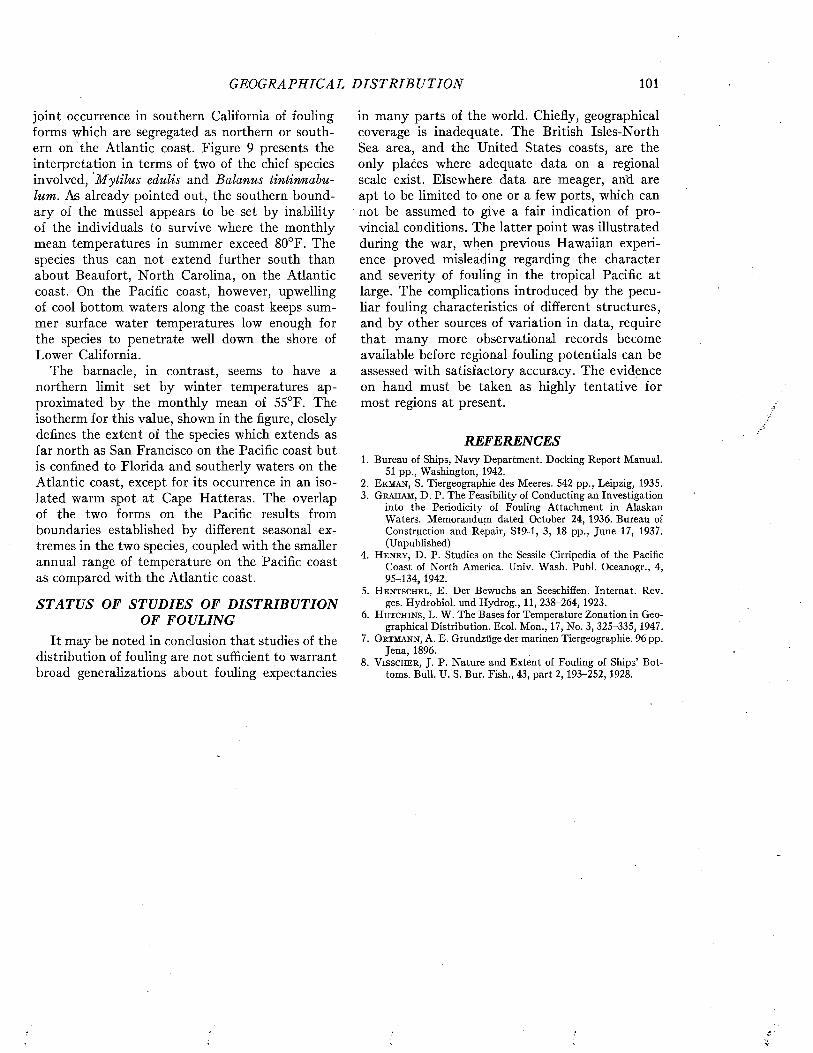
GEOGRAPHICAL D I S T R I B U T I O N 101
joint occurrence in southern California of fouling forms which are segregated as northern or southern on the Atlantic coast. Figure 9 presents the interpretation in terms of two of the chief species involved, M ytilus edulis and Balanus tintinnabulum. As already pointed out, the southern boundary of the mussel appears to be set by inability of the individuals to survive where the monthly mean temperatures in summer exceed 80°F. The species thus can not extend further south than about Beaufort, North Carolina, on the Atlantic coast. On the Pacific coast, however, upwelling of cool bottom waters along the coast keeps summer surface water temperatures low enough for the species to penetrate well down the shore of Lower California.
The barnacle, in contrast, seems to have a northern limit set by winter temperatures approximated by the monthly mean of 55°F. The isotherm for this value, shown in the figure, closely defines the extent of the species which extends as far north as San Francisco on the Pacific coast but is confined to Florida and southerly waters on the Atlantic coast, except for its occurrence in an isolated warm spot at Cape Hatteras. The overlap of the two forms on the Pacific results from boundaries established by different seasonal extremes in the two species, coupled with the smaller annual range of temperature on the Pacific coast as compared with the Atlantic coast.
STATUS OF STUDIES OF DISTRIBUTION OF FOULING
It may be noted in conclusion that studies of the distribution of fouling are not sufficient to warrant broad generalizations about fouling expectancies
in many parts of the world. Chiefly, geographical coverage is inadequate. The British Isles-North Sea area, and the United States coasts, are the only places where adequate data on a regional scale exist. Elsewhere data are meager, arid are apt to be limited to one or a few ports, which can not be assumed to give a fair indication of provincial conditions. The latter point was illustrated during the war, when previous Hawaiian experience proved misleading regarding the character and severity of fouling in the tropical Pacific at large. The complications introduced by the peculiar fouling characteristics of different structures, and by other sources of variation in data, require that many more observational records become available before regional fouling potentials can be assessed with satisfactory accuracy. The evidence on hand must be taken as highly tentative for most regions at present.
REFERENCES1. Bureau of Ships, Navy Department. Docking Report Manual.
51 pp., Washington, 1942.2. E k m a n , S. Tiergeographie des Meeres. 542 pp., Leipzig, 1935.3. G r a h a m , D. P. The Feasibility of Conducting an Investigation
into the Periodicity of Fouling Attachment in Alaskan Waters. Memorandum dated October 24, 1936. Bureau of Construction and Repair, S19-1, 3, 18 pp., June 17, 1937. (Unpublished)
4. H e n r y , D. P. Studies on the Sessile Cirripedia of the PacificCoast of North America. Univ. Wash. Puhi. Oceanogr., 4, 95-134, 1942.
5. H e n t s c h e l , E. Der Bewuchs an Seeschiffen. Internat. Rev.ges. Hydrobiol. und Hydrog., 11, 238-264, 1923.
6. H u t c h i n s , L. W. The Bases for Temperature Zonation in Geographical Distribution. Ecol. Mon., 17, No. 3, 325-335, 1947.
7. O r t m a n n , A. E. Grundzüge der marinen Tiergeographie. 96 pp.Jena, 1896.
8. V i s s c h e r , J. P. Nature and Extent of Fouling of Ships’ Bottoms. Bull. U. S. Bur. Fish., 43, part 2, 193-252, 1928.
Marine Fouling and Its Prevention,Contribution No. 580 from the Woods Flole Oceanographic Institute
Copyright 1952 by U. S. Naval Institute, Annapolis, Maryland George Banta Publishing Co., Menasha, WI
CHAPTER 8
Relations to Local EnvironmentsMarked differences exist between the fouling in
different parts of the same general region, such as the open coast and the harbors, or even in different parts of the same harbor. The local factors responsible occur in similar patterns in many different regions. They produce differences in fouling of two sorts: those which distinguish estuaries, harbors and other enclosed waters from the open coast, and those related to depth and distance from shore along the coast.
FOULING IN HARBORS, BAYS, AND OTHER ESTUARIES
The varied fauna and flora which may occur in different parts of the same estuary are illustrated by the fouling found on navigation buoys in San Francisco Bay. Near the Golden Gate, where the open sea is near at hand, the conspicuous elements in the fouling are mussels and kelp. Further within the Bay the kelp disappears, but heavy mussel fouling persists. At greater distances from the sea, mussels may persist but hydroids become more conspicuous, Iparticularly on the underside of the buoys. In San Pablo Bay, the mussels occur only in patches on the deeper parts of the buoys and mooring chains, while hydroids and barnacles become dominant. At the confluence of the San Joaquin and Sacramento Rivers, fouling is limited to an algal scum.
These changes in the local character of fouling in San Francisco Bay are illustrated in Figure 1.
In a detailed study of fouling on buoys at Plymouth, England, Milne (26) also observed that a number of forms were found only on buoys in the Sound and outer waters, while others were limited to the estuary. Some, however, were common to parts of the Sound and estuary. The distribution of the individual species at Plymouth is illustrated in Figure 2. Similar observations have been made for the fouling of buoys in the Elbe (19) and of floating structures in the Liverpool area (10).
The variation in fouling at different places within an estuary must be due to differences in the characteristics of the water in different places. Three factors of the environment which singly or in combination may be responsible for many differences in the character of the fouling are the salinity of the water, pollution, and the prevalence of silt.
Salin ityAn estuary receives sea water at the mouth, and
fresh water at the head. Mixing of the two takes place in the intermediate reaches, establishing a gradient. The salt concentration of the coastal sea water varies with the region, but is usually between 3.0 and 3.5 per cent. At any one station in an estuary, salinity usually increases from the surface to the bottom. Where river discharge is great or mixing is poor, a sharply defined layer of nearly fresh water may occur at the surface.
Salinity is recognized as the most important factor controlling the occurrences of organisms in estuaries. Comparatively few species are able to tolerate the entire range of conditions available in such places. The organisms therefore exhibit restrictions in both horizontal and vertical distribution, correlated with the distribution of salinity.
Most of the common fouling forms are unable to withstand low salinities, and therefore do not appear in fouling on structures exposed well inside the estuaries of rivers or in similar places. The tolerances of different species vary, however, and a few marine forms are able to survive even in nearly fresh water. Thus, among the barnacles common in American waters, Balanus tintinnabulum and B. amphitrite never invade very brackish localities, though they are common on coastwise installations. Other species, such as B. balanoides, penetrate somewhat further. Finally, there are two species, B. eburneus and B. improvisus, also common along the coast, which are able to withstand extreme variations in salinity (29), often being found in water fresh enough to drink. The marine bryozoan Bowerbankia gracilis, has been taken in the headwaters of Chesapeake Bay (28), and in similar nearly fresh localities (17). Several other marine bryozoans also penetrate to extreme dilutions.
Ships which are habitually moored in fresh water between trips to sea enjoy some protection from fouling. The frequently suggested practice of taking seagoing vessels into fresh water to remove the fouling has little to recommend it, since this does not remove the adherent shells of such organisms as barnacles, and some species may not be killed by such treatment.
Some species of fouling are unable to survive in fully marine situations, and appear to be limited
102
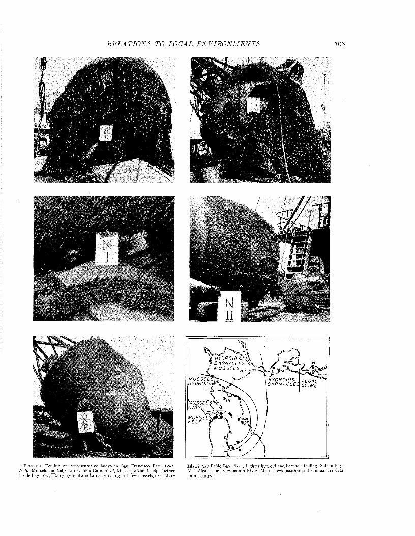
R E L A T I O N S TO LOCAL E N V I R O N M E N T S 103
F i g u r e 1. Fouling on representative buoys in San Francisco Bay', 1943. N-10, M ussels and kelp near Golden Gate. N-14, M ussels w ithout kelp, further inside Bay7. A7- / , H eavy hydroid and barnacle fouling with few mussels, near M are
H Y D R O l D S S ® B A R N A C L E S . M U S S E L S „ ,
MUßSECS'Sb ONLYv
M U S S E L S J K K E L P P
Island, San Pablo Bay. N - l l , L ighter hydroid and barnacle fouling, Suisun Bay. N-6, Algal scum, Sacram ento River. M ap shows position and summarizes data for all buoys.
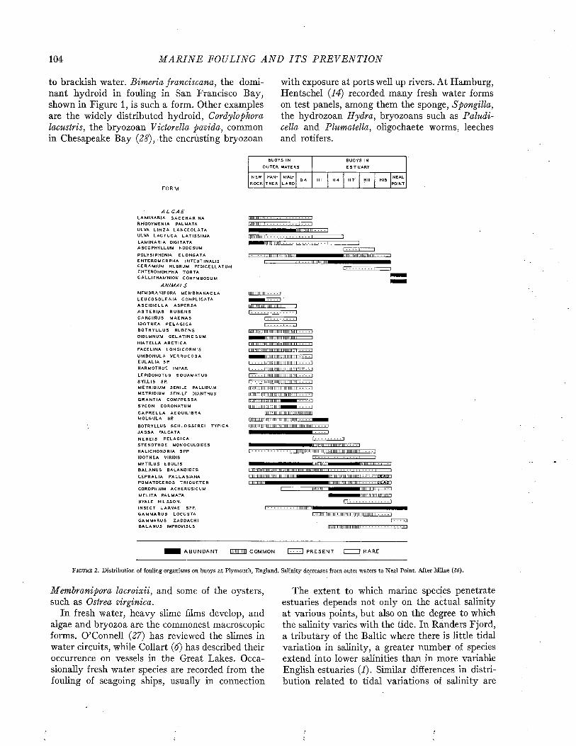
104 M A R I N E FOULING A N D I T S P R E V E N T I O N
to brackish water. Bimeria franciscana, the dominant hydroid in fouling in San Francisco Bay, shown in Figure 1, is such a form. Other examples are the widely distributed hydroid, Cordylophora lacustris, the bryozoan Victorella pavida, common in Chesapeake Bay {28), the encrusting bryozoan
with exposure at ports well up rivers. At Hamburg, Hentschel {14) recorded many fresh water forms on test panels, among them the sponge, Spongilla, the hydrozoan Hydra, bryozoans such as Paludicella and Plumatella, oligochaete worms, leeches and rotifers.
BUOYS IN
O U T E R WAT E RS
B U OYS IN
E S T U A R Y
N EW
ROCK
P AN
T H E R
MAL
L A R DD 4 HI H 4 H 7' HU HIS
NEAL
POI NT
A L GA EL A M I N A R I A S A C C H A R I N A R H O D Y M E N I A P AL MAT A UL VA L I N Z A L A N C E O L A T A ULVA L A C T U C A L A T I S S I M A L A M I N A R I A DI GI T AT A A S C O P H Y L L U M N O D O S U M
P O L Y S I P H O N I A E L O N G A T A E N T E R O M O R P H A I N T E S T I N A L I S C E R A M I U M R U B R U M P E D I C E L L A T U M E N T E R O M O R P H A T O R T A C A L L I T H A M N I O N C O R Y M B O S U M
ANIMALSM E M B R A N I P O R A M E M B R A N A C E A L E U C O S O L E N I A C O M P L I C A T A A S C I D I E L L A A S P E R S A A S T E R I A S R U B E N S C A R C I N U S M A E N A S I D O T H E A P E L A G I C A B O T R Y L L U S R U B E N S D I D E MN U M G E L A T I N O S U M H I A T E L L A A R C T I C A
F A C E L I N A L O N G I C O R N I S
U M B O N U L A V E R R U C O S A E U L A L I A S P H A R M O T H O E I MP AR
L E P I D O N O T U S S Q U A M A T U S S Y L L I S SP.M E T R I D I U M S E N I L E P A L L I DUM ME T R I D I U M S E N I L E D I A N T H U S G R A N T I A C O M P R E S S A
S Y C O N C O R O N A T U M
C A P R E L L A A E Q U I L I B R A M O L G U L A S P
B O T R Y L L U S S C H L O S S E R E I T Y P I C A J A S S A F AL CAT A
N E R E I S P E L A G I C A S T E N O T H O E M O N O C U L O I D E S H A L I C H O N D R I A SPP.I D O T H E A VIRIDIS
M Y T I L U S E D U L I S B A L A N U S B A L A N O I D E S
L E P R A L I A P A L L A S I A N A P O M A T O C E R O S T R I Q U E T E R C O R O P H I U M A C H E R U S I C U M
ME L I T A P A L M A T A
HYALE N I L S S O N I I N S E C T L A R V A E SPP.
G A M M A R U S L O C U S T A G A M M A R U S Z A D D A C H I B A L A N U S I MP ROVI S US
I A B U N D A N T 1)111111111 COM M ON
F i g u r e 2 . Distribution of fouling organisms on buoys at Plymouth, England. Salinity decreases from outer waters to Neal Point. After Milne (2 tf).
Membranipora lacroixii, and some of the oysters, such as Ostrea virginica.
In fresh water, heavy slime films develop, and algae and bryozoa are the commonest macroscopic forms. O’Connell {27) has reviewed the slimes in water circuits, while Collart (6) has described their occurrence on vessels in the Great Lakes. Occasionally fresh water species are recorded from the fouling of seagoing ships, usually in connection
The extent to which marine species penetrate estuaries depends not only on the actual salinity at various points, but also on the degree to which the salinity varies with the tide. In Randers Fjord, a tributary of the Baltic where there is little tidal variation in salinity, a greater number of species extend into lower salinities than in more variable English estuaries (I). Similar differences in distribution related to tidal variations of salinity are

R E L A T IO N S TO LOCAL E N V I R O N M E N T S 105
observed when the occurrence of several bryozoans in Chesapeake Bay and in an estuary tributary to Long Island Sound is compared (17).
In estuaries there are usually marked changes in salinity resulting from seasonal differences in precipitation and fresh water run-off. Variation is also occasioned by wet and dry years. These variations in salinity give rise to sequences of expansion and contraction of the areas occupied by the organisms. The mean annual salinity at a point is therefore a poor guide to fouling expectancy in most estuaries. It is probable, in fact, that the distribution of species in an estuary as related to salinity is fully as complex, on a local scale, as the general distribution of organisms in relation to temperature. Examples of seasonal invasions have been described for the teredo in San Francisco Bay (15), and cases involving fouling were found by Milne in his investigations at Plymouth (26).
Salinity, like temperature, affects the growth of marine species in addition to limiting distribution. Commonly the rate of growth of marine forms is slower in brackish water than in sea water, and the ultimate size attained may also be less (4). Table 1 shows the maximum sizes attained by several molluscs in waters of different salinity in the Baltic area. Each species was progressively smaller as the sea water became more dilute. In the salinity gradient of the Kiel Canal, M ytilus edulis was found to reach sexual maturity at about the same age throughout, but specimens in the high salinity at the North Sea end were nearly twice as large as those in the low salinities near Kiel Bight.
Molluscs and other shelled forms tend to have thinner shells where the salinity is low (21, 22, 30). Some encrusting bryozoa are less calcareous, and less well attached to the substrate, in brackish waters (3, 31).
All species are not influenced by salinity in similar ways. Brine shrimps of the genus Artemia are larger at low concentrations than at higher ones (2). Federighi has claimed a similar size-salinity relationship in the snail Urosalpinx cinerea (8). In contrast to Borg’s observation that an encrusting membraniporoid bryozoan in the Baltic has smaller zooids at lower salinities (3), a closely related American species has been demonstrated to develop larger individuals under such conditions, both in nature and under laboratory conditions (16).
Pollu tionPollution may be defined as any addition to nat
ural waters resulting from human activity. It may include anything from domestic sewage to complex
industrial wastes, or simple substances such as sawdust, oil well brines, and petroleum by-products. Pollution, in short, is diverse in character, and has no single effect. A pollutant may be harmful either directly through toxic effects, or indirectly as through depletion of oxygen. Some contaminants may be beneficial to living things by enriching the nutrient supply. The net effect on fouling in any given instance may be a balance between two or more such actions.
In habors and estuaries, pollution is most apparent near the outfalls of sewers and the points
T a b l e 1. Maximum Size in Millimeters for Six Species of Molluscs Collected at Locations of Differing
Salinity in the Baltic AreaLocation
Salin ityNorth K iel Baltic G ulf of G ulf of
Sea Bight Sea Finland Bothnia3 3 % o Cn
oo 1 2 7 c 7 ° /* / OO 5 - 6 7 co
M ytilu s27edulis 110 50 21
M yaarenaria 100 55* 3 6 .5
Cardiumedule 4 4 22 18
Tellinabaltica 28 17 1 5 -1 9
Littorinalittorea 32 27
Buccinumundatum 120 58
* Size of 70 mm. rarely reached in this locality.
of discharge of industrial wastes. Strong gradients of pollution commonly occur near such points of contamination, and depend on the general character of the local tidal circulation. As the harbor mouth is approached, the general state of pollution decreases as the proportions of clean water from the open sea increase. The upper reaches of an estuary may be polluted more or less than the harbor area, depending on whether the river itself is severely contaminated or not.
Some evidence suggests that domestic sewage can materially accelerate growth, providing'other circumstances are suitable. Organic detritus is believed to constitute an important food supply for sedentary forms (9), so that the pollutants may have direct value as well as acting possibly through more complex food chains. It is familiar that oysters and other shellfish frequently flourish under conditions of extreme pollution.
Reports of adverse effects of pollution on fouling are not uncommon. Oil and grease pollution suppressed fouling of test panels at stations in the Hampton Roads area of Chesapeake Bay (35). Fouling of water mains of a ship based on Honolulu Harbor was reduced when the mooring area
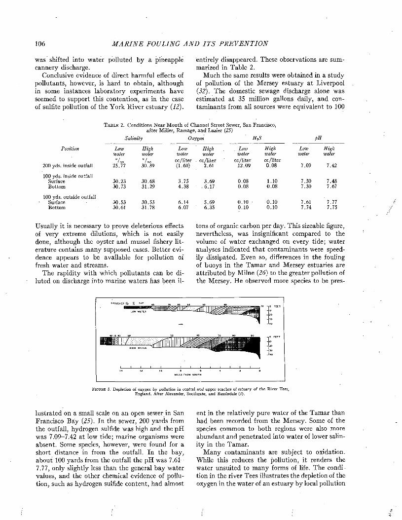
106 M A R I N E FOULING A N D I T S P R E V E N T I O N
was shifted into water polluted by a pineapple cannery discharge.
Conclusive evidence of direct harmful effects of pollutants, however, is hard to obtain, although in some instances laboratory experiments have seemed to support this contention, as in the case of sulfite pollution of the York River estuary (12).
entirely disappeared. These observations are summarized in Table 2.
Much the same results were obtained in a study of pollution of the Mersey estuary at Liverpool (32). The domestic sewage discharge alone was estimated at 35 million gallons daily, and contaminants from all sources were equivalent to 100
T a b l e 2. Conditions Near Mouth of Channel Street Sewer, San Francisco, after Miller, Ramage, and Lazier (25)
H 2SSalin ity pH
Position Low High Low High Low High Low Highwater water water water water water water water
200 yds. inside outfall° // OO
25.77° // OO
30.39cc /liter (1.60)
cc/Iiter2.61
cc/Iiter12.09
cc/liter 0.08 7.09 7.42
100 yds. inside outfallSurface 30.23 30.68 3.75 3.69 0.08 1.10 7.50 7.48Bottom 30.73 31.29 4.38 . 6.17 0.08 0.08 7.50 7.67
100 yds. outside outfallSurface 30.53 30.53 6.14 5.69 0 .10 0.10 7.61 7.77Bottom 30.61 31.78 6.07 6.35 0.10 0.10 7.74 7.75
Usually it is necessary to prove deleterious effects of very extreme dilutions, which is not easily done, although the oyster and mussel fishery literature contains many supposed cases. Better evidence appears to be available for pollution of fresh water and streams.
The rapidity with which pollutants can be diluted on discharge into marine waters has been il-
tons of organic carbon per day. This sizeable figure, nevertheless, was insignificant compared to the volume of water exchanged on every tide; water analyses indicated that contaminants were speedily dissipated. Even so, differences in the fouling of buoys in the Tamar and Mersey estuaries are attributed by Milne (26) to the greater pollution of the Mersey. He observed more species to be pres-
DISSOLVED 0¿ "/, SAT.
LOW WATER
60 70 60 M
L 1 I I I I I I . _1 IMILES PROM MOUTH
F i g u r e 3. Depletion of oxygen by pollution in central and upper reaches of estuary of the R iver Tees, England. A fter Alexander, Southgate, and Bassindale (1).
lustrated on a small scale on an open sewer in San Francisco Bay (25). In the sewer, 200 yards from the outfall, hydrogen sulfide was high and the pH was 7.09-7.42 at low tide; marine organisms were absent. Some species, however, were found for a short distance in from the outfall. In the bay, about 100 yards from the outfall the pH was 7.61- 7.77, only slightly less than the general bay water values, and the other chemical evidence of pollution, such as hydrogen sulfide content, had almost
ent in the relatively pure water of the Tamar than had been recorded from the Mersey. Some of the species common to both regions were also more abundant and penetrated into water of lower salinity in the Tamar.
Many contaminants are subject to oxidation. While this reduces the pollution, it renders the water unsuited to many forms of life. The condition in the river Tees illustrates the depletion of the oxygen in the water of an estuary by local pollution

R E L A T IO N S TO LOCAL E N V I R O N M E N T S 107
and the movement of the depleted water with the tide (Figure 3). The river water is fully saturated with oxygen. The upper estuary receives extensive pollution and the oxygen concentration falls to 50 per cent saturation. Sea water saturated with oxygen enters the estuary along the bottom, and mixes with the surface water in such a way that the effects of pollution are most apparent in the upper layers, and have largely disappeared by the time the mouth of the estuary is reached.
Observations on occasion have suggested that low oxygen and low salinity together tend to reinforce each other as critical factors. It is thought that lower values of either alone can be tolerated than in combination, possibly because at low salinities organisms must do more work in osmoregulation. Such relationships have been reported for several types of organisms, and supporting physiological evidence has been advanced. Krogh (20), however, who has reviewed the data critically, states that no conclusive case has been demonstrated.
S il t and o ther Suspended M a tte rSilt and other suspended matter is usually found
in enclosed coastal waters such as harbors and bays. The settling-out of suspended matter may smother sessile organisms, or may produce substrates unsuited for the attachment of many forms. This phenomenon has been noted when test panels are exposed in a horizontal position (5, 11). On the other hand, careful studies of the effects of silt on oysters, incidental to dredging operations in which considerable silt was stirred up, failed to show any significant effect on the oysters (23). This held true even for oysters in special cages hung under the dredges, where exposure to turbid water was maximum.
The fouling on buoys in the western Gulf of Mexico is characteristically heavily impregnated and compacted with silt. The fouling itself is generally light or moderate in bulk by comparison with that on buoys along the Carolina coast where the fauna is similar. Whether this is due to the silt, however, is not known.
Silt has been thought to interfere with the food assimilation of animals which filter water through sieves or ciliary mechanisms. The available evidence, however, does not support the idea that the distribution of animals in silty regions is limited by such effects. The numbers of species of organisms having such feeding mechanisms, and of organisms having other types, are about the same at various points in the turbidity gradients of the Tamar, Tees, and Tays estuaries (1, 26).
The presence of silt reduces the penetration of light, and may thus restrict the vertical distribution of algae. Milne found that on buoys in the upper Tamar estuary where silt concentration was highest, the zones of algal growth near the sea surface were narrowed and restricted. Measurements of the intensity of light below the sea surface supported the interpretation that the depth to which the algae grew was controlled by the effect of silt concentration on the penetration of light.
FOULING IN RELATION TO DISTANCE FROM SHORE
A change in both the kind and intensity of fouling is found in passing from coastal to oceanic situations. While many species occur in coastwise waters, fioatsam picked up at sea tends to be fouled, if at all, chiefly by goose barnacles. Although these are sometimes present in considerable numbers, they do not generally constitute severe fouling as judged by inshore standards. Larvae of. the greater number of potential fouling species do not reach floating objects far from shore.
The change in the character of fouling on going offshore is illustrated by three representative buoys of a series extending seaward from the entrance of Chesapeake Bay for about 65 miles, or nearly to the edge of the continental shelf. On a buoy 20 miles from shore, in 70 feet of water, shown in Figure 4, a heavy accumulation of mussels was found. This is characteristic of inshore waters north of Cape Hatteras. The mussels also extended down the mooring chain in a uniform mat, nearly to the bottom. On a second buoy, 30 miles from shore, where the depth was 90 feet, the fouling was patchy, and continuous mussel fouling on the chain extended only to about 30 feet. (See Figure 5.) Below this the fouling consisted mostly of. patches of sponges and hydroids, and was much less severe than the fouling of the buoy nearer shore. On a buoy 60 miles from shore, in 186 feet of water, the mussel fouling gave way almost entirely to goose barnacles and algae (Figure 6). The very few mussels present constituted only an insignificant element in the fouling. Aside from one or two links lightly overgrown by a sponge, the chain of this buoy was without fouling. Similar fouling was found on all buoys of this series more than 50 miles from shore.
Similar observations have been made in other series of buoys extending well offshore from Delaware Bay and Block Island. The common goose barnacle on these offshore buoys was Lepas anatifera. Sometimes they were accompanied by algae and hydroids, and in the case of the buoys off
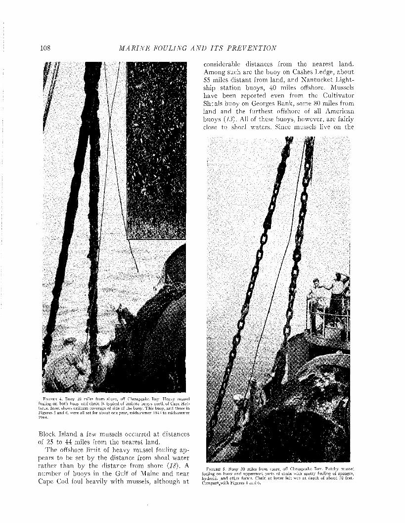
108 M A R I N E FOULING A N D I T S P R E V E N T I O N
S
F i g u r e 4. Buoy 20 miles from shore, off Chesapeake Bay. H eavy mussel fouling on both buoy and chain is t j rpical of inshore buoys north of Cape H a tteras. In se t shows uniform coverage of side of the buoy. This buoy, and those in F igures 5 and 6, were all set for abou t one year, m idsum mer 1943 to midsummer 1944.
Block Island a few mussels occurred at distances of 25 to 44 miles from the nearest land.
The offshore limit of heavy mussel fouling appears to be set by the distance from shoal water rather than by the distance from shore (18). A number of buoys in the Gulf of Maine and near Cape Cod foul heavily with mussels, although at
considerable distances from the nearest land. Among such are the buoy on Cashes Ledge, about 55 miles distant from land, and N antucket Lightship station buoys, 40 miles offshore. Mussels have been reported even from the Cultivator Sh: ais buoy on Georges Bank, some 80 miles from land and the furthest offshore of all American buoys (13). All of these buoys, however, are fairly close to shoci waters. Since mussels live on the
F i g u r e 5 . Buoy 3 0 miles from shore, off Chesapeake Bay. P a tch y mussel fouling on buoy and upperm ost parts of chain with spotty fouling of sponges, hydroid, and other forms. Chain a t lower left was a t depth of abou t 70 feet- Compare^with Figures 4 and 6.
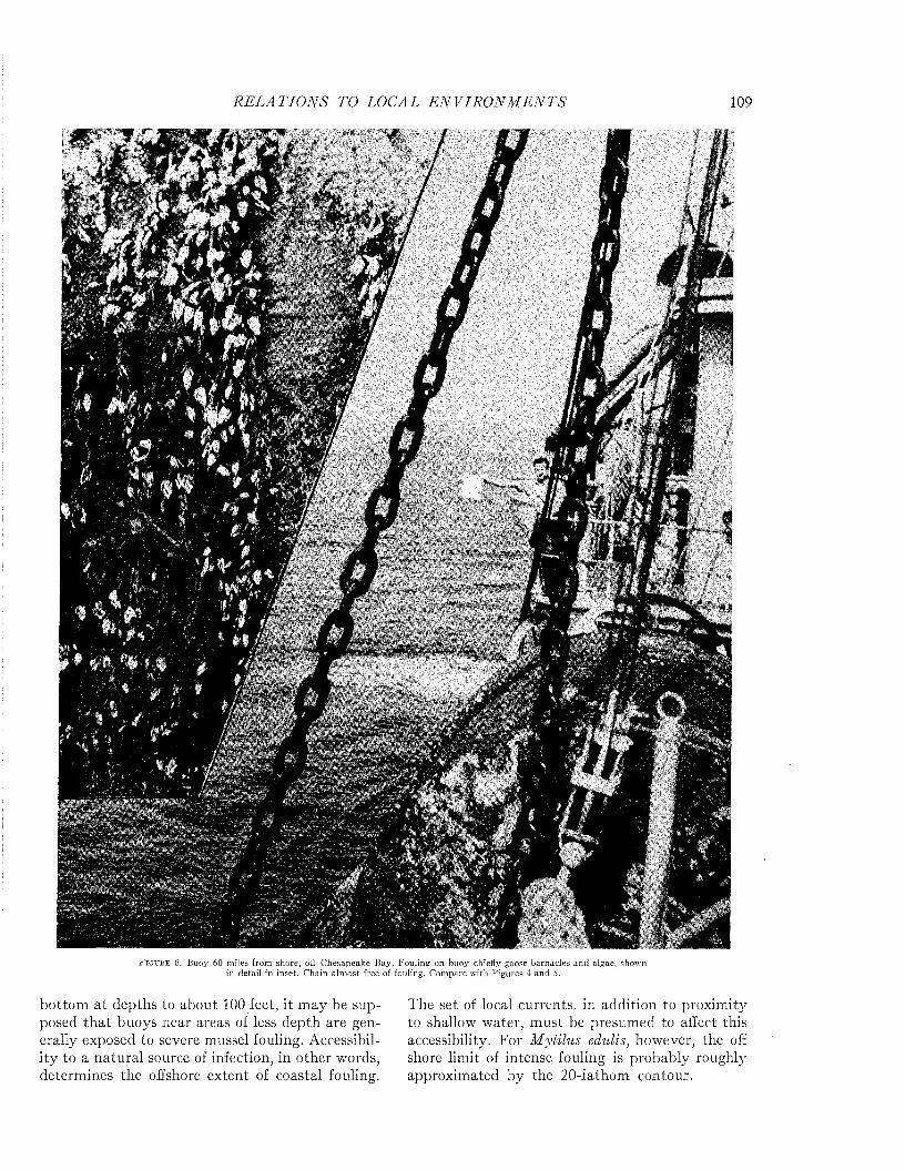
R E L A T I O N S TO LOCAL E N V I R O N M E N T S 109
/
I
1i
%
F i g u r e 6. Buoy 60 miles from shore, off Chesapeake Bay. Fouling on buoy chiefly goose barnacles and algae, shown in detail in inset. Chain alm ost free of fouling. Compare w ith Figures 4 and 5.
bottom at depths to about 100 feet, it may be supposed th a t buoys near areas of less depth are generally exposed to severe mussel fouling. Accessibility to a natural source of infection, in other words, determines the offshore extent of coastal fouling.
The set of local currents, in addition to proximity to shallow water, m ust be presumed to affect this accessibility. For Mytilus edulis, however, the off shore limit of intense fouling is probably roughly approximated by the 20-fathom contour.
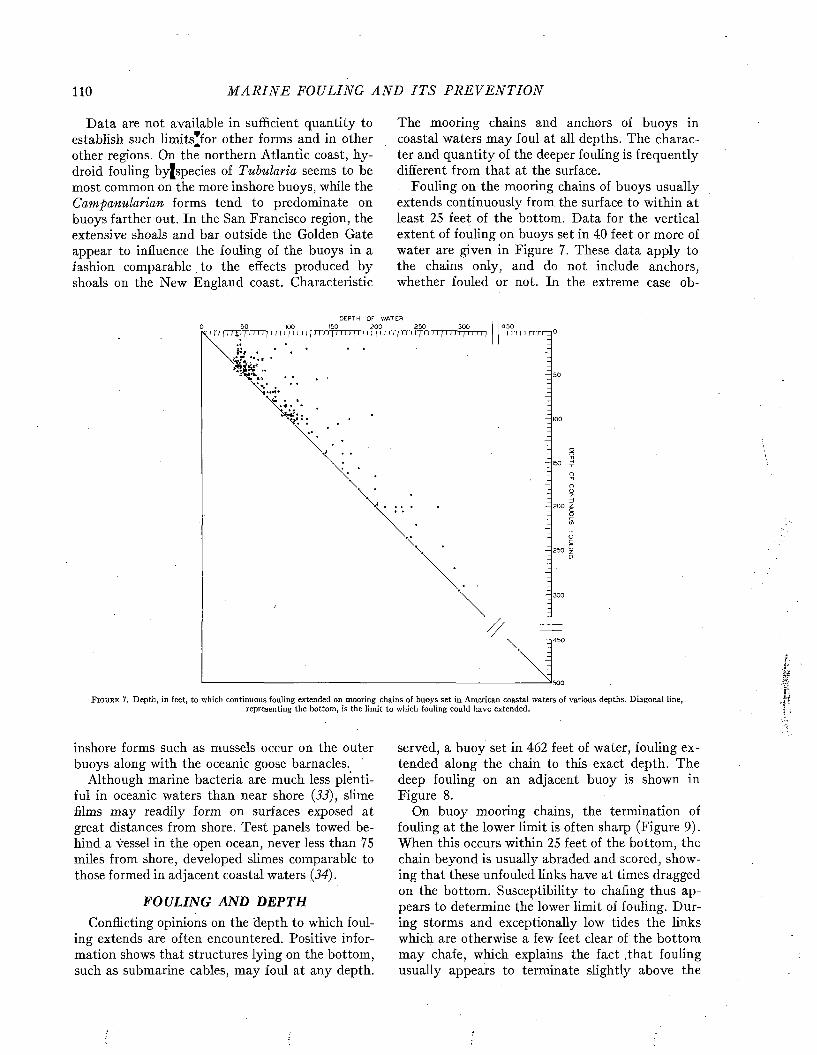
110 M A R I N E FOULING A N D I T S P R E V E N T I O N
Data are not available in sufficient quantity to establish such limits*for other forms and in other other regions. On the northern Atlantic coast, hydroid fouling byjspecies of Tubularia seems to be most common on the more inshore buoys, while the Campanularian forms tend to predominate on buoys farther out. In the San Francisco region, the extensive shoals and bar outside the Golden Gate appear to influence the fouling of the buoys in a fashion comparable to the effects produced by shoals on the New England coast. Characteristic
The mooring chains and anchors of buoys in coastal waters may foul at all depths. The character and quantity of the deeper fouling is frequently different from that at the surface.
Fouling on the mooring chains of buoys usually extends continuously from the surface to within at least 25 feet of the bottom. Data for the vertical extent of fouling on buoys set in 40 feet or more of water are given in Figure 7. These data apply to the chains only, and do not include anchors, whether fouled or not. In the extreme case ob-
DEPTH OF
F i g u r e 7. D epth, in feet, to which continuous fouling extended on mooring chains of buoys set in American coastal w aters of various depths. D iagonal line,representing the bottom , is the lim it to which fouling could have extended.
inshore forms such as mussels occur on the outer buoys along with the oceanic goose barnacles.
Although marine bacteria are much less plentiful in oceanic waters than near shore (33), slime films may readily form on surfaces exposed at great distances from shore. Test panels towed behind a vessel in the open ocean, never less than 75 miles from shore, developed slimes comparable to those formed in adjacent coastal waters (34).
FOULING AND DEPTHConflicting opinions on the depth to which foul
ing extends are often encountered. Positive information shows that structures lying on the bottom, such as submarine cables, may foul at any depth.
served, a buoy set in 462 feet of water, fouling extended along the chain to this exact depth. The deep fouling on an adjacent buoy is shown in Figure 8.
On buoy mooring chains, the termination of fouling at the lower limit is often sharp (Figure 9). When this occurs within 25 feet of the bottom, the chain beyond is usually abraded and scored, showing that these unfouled links have at times dragged on the bottom. Susceptibility to chafing thus appears to determine the lower limit of fouling. During storms and exceptionally low tides the links which are otherwise a few feet clear of the bottom may chafe, which explains the fact .that fouling usually appears to terminate slightly above the
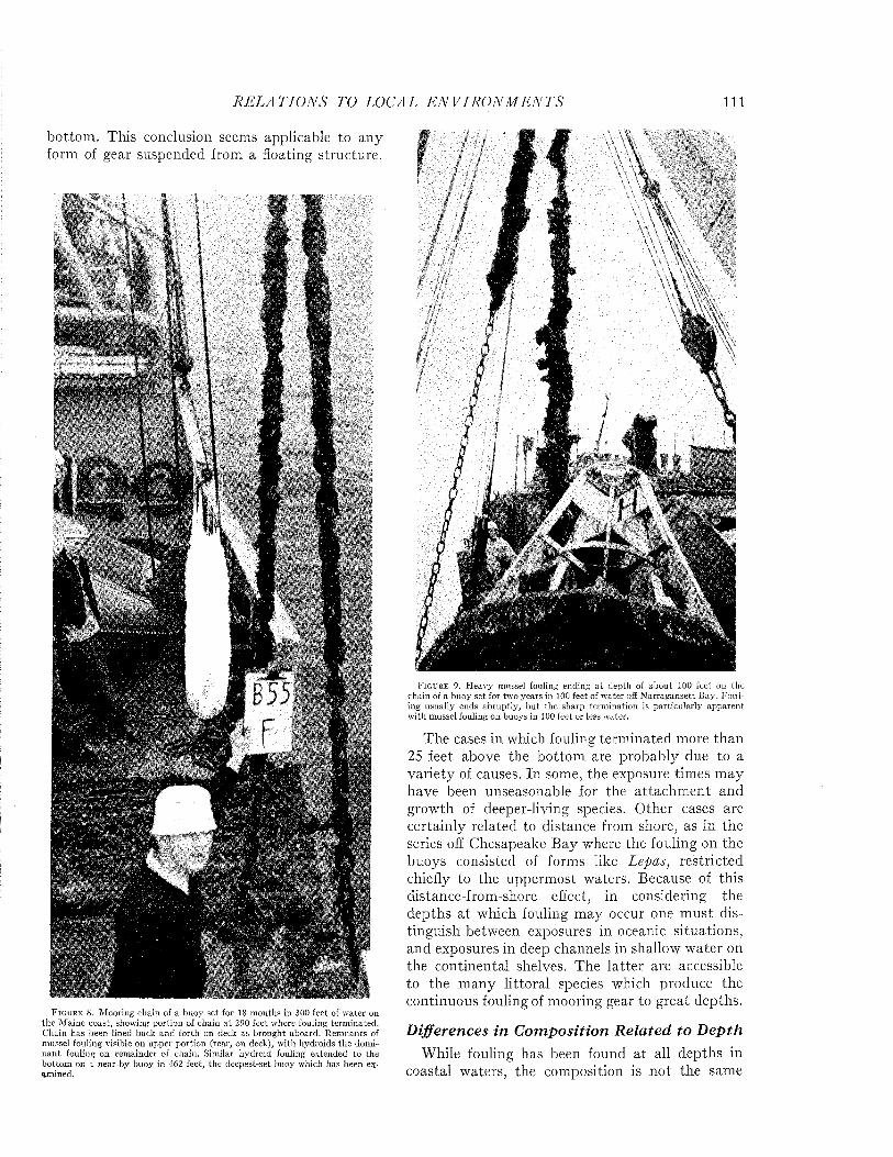
R E L A T I O N S TO LOCAL E N V I R O N M E N T S 111
bottom . This conclusion seems applicable to any form of gear suspended from a floating structure.
F i g u r e 8. M ooring chain of a buoy set for 18 m onths in 300 feet of w ater on the M aine coast, showing portion of chain a t 290 feet where fouling term inated. Chain has been lined back and forth on deck as brought aboard. Rem nants of mussel fouling visible on upper portion (rear, on deck), w ith hydroids the domin a n t fouling on rem ainder of chain. Similar hydroid fouling extended to the bottom on a near-by buoy in 462 feet, the deepest-set buoy which has been examined.
F i g u r e 9. H eavy mussel fouling ending a t depth of abou t 100 feet on the chain of a buoy set for two years in 100 feet of w ater off N arragansett Bay. F ou ling usually ends abruptly , b u t the sharp term ination is particu larly apparent w ith mussel fouling on buoj's in 100 feet or less water.
The cases in which fouling terminated more than 25 feet above the bottom are probably due to a variety of causes. In some, the exposure times may have been unseasonable for the attachm ent and growth of deeper-living species. Other cases are certainly related to distance from shore, as in the series off Chesapeake Bay where the fouling on the buoys consisted of forms like Lepas, restricted chiefly to the uppermost waters. Because of this distance-from-shore effect, in considering the depths a t which fouling may occur one m ust distinguish between exposures in oceanic situations, and exposures in deep channels in shallow water on the continental shelves. The latter are accessible to the many littoral species which produce the continuous fouling of mooring gear to great depths.
Differences in C om posit ion R e la ted to D ep thWhile fouling has been found at all depths in
coastal waters, the composition is not the same
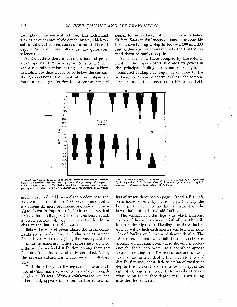
112 M A R I N E FOULING A N D I T S P R E V E N T I O N
throughout the vertical column. The individual species have characteristic depth ranges, which result in different combinations of forms at different depths. Some of these differences are quite conspicuous.
At the surface there is usually a band of green algae, species of Enteromorpha, Ulva, and Cladophora generally predominating. This zone seldom extends more than a foot or so below the surface, though occasional specimens of green algae are found at much greater depths. Below the band of
nearer to the surface, not being numerous below 50 feet. Balanus tintinnabulum may be responsible for massive fouling to depths between 100 and 200 feet. Other species dominant near the surface extend down to various depths.
At depths below those occupied by these dominants of the upper waters, hydroids are generally the principal fouling. In some cases hydroid- dominated fouling has begun at or close to the surface, and extended continuously to the bottom. The chains of the buoys set in 462 feet and 300
A B
I f * 1 1 iF i g u r e 1 0 . Vertical distributions of various species of barnacles on American
buoys. The diagrams show for each depth zone the percentage of samples in which the species occurred. Calculations restricted to samples from the known geographical ranges of the individual species. A, Lepas anatifera; B, L. anserif
era; C, Balanus glandula; D , B. cariosus; E, B. balanoides; F, B. improvisus; G, B. amphitrite; H, B. tintinnabulum; I, B„ crenatus (East Coast only); J, B. eburneus; K., B. balanus; L, B. nubilus; M, B, hameri.
green algae, red and brown algae predominate and may extend to depths of 100 feet or more. Kelps are among the more prominent of dominant brown algae. Light is important in limiting the vertical penetration of all algae. Other factors being equal, a given species will occur at greater depths in clear water than in turbid water.
Below the zone of green algae, the usual dominants are animals. The particular species present depend partly on the region, the season, and the duration of exposure. Other factors also seem to influence the vertical distribution, among them the distance from shore, as already described. Thus, the mussels extend less deeply on more offshore buoys.
On inshore buoys in the regions of mussel fouling, M ytilus edulis commonly extends to a depth of about 100 feet. M ytilus californianus, on the other hand, appears to be confined to somewhat
feet of water, described on page 110 and in Figure 8, were fouled chiefly by hydroids, particularly the lower part. There are no data at present on the lower limits of such hydroid fouling.
The variation in the depths at which different species of barnacles characteristically settle is illustrated by Figure 10. The diagrams show the frequency with which,each species was found in samples of fouling on buoys at different depths. The 13 species of barnacles fall into characteristic groups, which range from those showing a preference, for the surface water, to those which appear to avoid settling near the sea surface and concentrate at the greater depth. Intermediate types of distribution may show little selection of particular depths throughout the entire range, or may, in the case of B. eburneus, concentrate heavily at somewhat below-the-surface depths without extending into the deeper water.
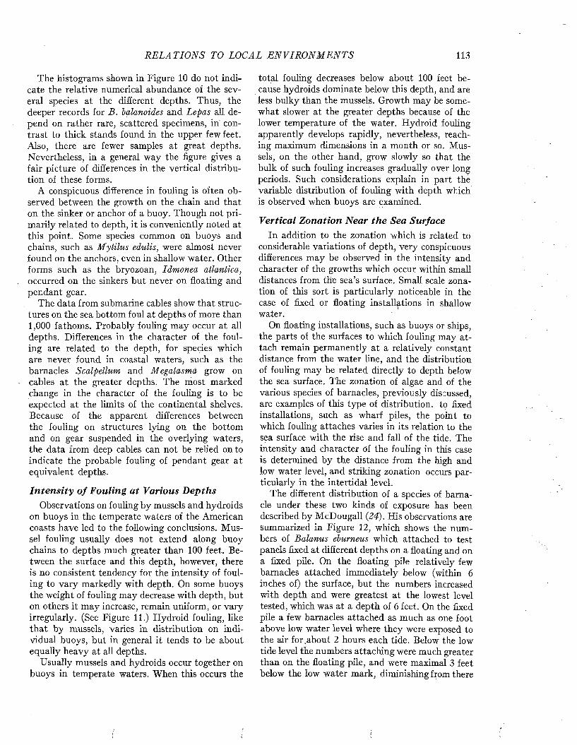
R E L A T I O N S TO LOCAL E N V I R O N M E N T S 113
The histograms shown in Figure 10 do not indicate the relative numerical abundance of the several species at the different depths. Thus, the deeper records for B. balanoides and Lepas all depend on rather rare, scattered specimens, in contrast to thick stands found in the upper few feet. Also, there are fewer samples at great depths. Nevertheless, in a general way the figure gives a fair picture of differences in the vertical distribution of these forms.
A conspicuous difference in fouling is often observed between the growth on the chain and that on the sinker or anchor of a buoy. Though not primarily related to depth, it is conveniently noted at this point. Some species common on buoys and chains, such as M ytilus edulis, were almost never found on the anchors, even in shallow water. Other forms such as the bryozoan, Idmonea atlantica, occurred on the sinkers but never on floating and pendant gear.
The data from submarine cables show that structures on the sea bottom foul at depths of more than 1,000 fathoms. Probably fouling may occur at all depths. Differences in the character of the fouling are related to the depth, for species which are never found in coastal waters, such as the barnacles Scalpellum and Megalasma grow on cables at the greater depths. The most marked change in the character of the fouling is to be expected at the limits of the continental shelves. Because of the apparent differences between the fouling on structures lying on the bottom and on gear suspended in the overlying waters, the data from deep cables can not be relied onto indicate the probable fouling of pendant gear at equivalent depths.
In te n s i ty o f Fouling a t Various D epthsObservations on fouling by mussels and hydroids
on buoys in the temperate waters of the American coasts have led to the following conclusions. M ussel fouling usually does not extend along buoy chains to depths much greater than 100 feet. Between the surface and this depth, however, there is no consistent tendency for the intensity of fouling to vary markedly with depth. On some buoys the weight of fouling may decrease with depth, but on others it may increase, remain uniform., or vary irregularly. (See Figure 11.) Hydroid fouling, like that by mussels, varies in distribution on individual buoys, but in general it tends to be about equally heavy at all depths.
Usually mussels and hydroids occur together on buoys in temperate waters. When this occurs the
total fouling decreases below about 100 feet because hydroids dominate below this depth, and are less bulky than the mussels. Growth may be somewhat slower at the greater depths because of the lower temperature of the water. Hydroid fouling apparently develops rapidly, nevertheless, reaching maximum dimensions in a month or so. Mussels, on the other hand, grow slowly so that the bulk of such fouling increases gradually over long periods. Such considerations explain in part the variable distribution of fouling with depth which is observed when buoys are examined.
Vertical Zonation Near the Sea SurfaceIn addition to the zonation which is related to
considerable variations of depth, very conspicuous differences may be observed in the intensity and character of the growths which occur within small distances from the sea’s surface. Small scale zonation of this sort is particularly noticeable in the case of fixed or floating installations in shallow water.
On floating installations, such as buoys or ships, the parts of the surfaces to which fouling may attach remain permanently at a relatively constant distance from the water line, and the distribution of fouling may be related directly to depth below the sea surface. The zonation of algae and of the various species of barnacles, previously discussed, are examples of this type of distribution, to fixed installations, such as wharf piles, the point to which fouling attaches varies in its relation to the sea surface with the rise and fall of the tide. The intensity and character Of the fouling in this case is determined by the distance from the high and low water level, and striking zonation occurs particularly in the intertidal level.
The different distribution of a species of barnacle under these two kinds of exposure has been described by McDougall (24). His observations are summarized in Figure 12, which shows the numbers of Balanus eburneus which attached to test panels fixed at different depths on a floating and on a fixed pile. On the floating pile relatively few barnacles attached immediately below (within 6 inches of) the surface, but the numbers increased with depth and were greatest at the lowest level tested, which was at a depth of 6 feet. On the fixed pile a few barnacles attached as much as one foot above low water level where they were exposed to the air for .about 2 hours each tide. Below the low tide level the numbers attaching were much greater than on the floating pile, and were maximal 3 feet below the low water mark, diminishing from there

114 M A R I N E FOULING A N D I T S P R E V E N T I O N
W E I G H T , POUNDS PER SQUARE FOOT
,0 i .2
I -LJU IL.
If-CLUJQ
5 0
100
150
2 0 0
2 5 0
3 0 0
3 5 0
4 0 0
4 5 0
|Th
; H
î H1
l H '
; H
H
1H1H| h
1i Hf H
n n
F i g u r e 11 . Intensity o f fouling at various depths on selected buoys on which fouling extended to the bottom. Greatest differences in intensity as related to depth depend on changes in the species present. I , Barnacles and hydroids, Maine coast, June ’43-October ’44. II, Goose barnacles and hydroids, Block Island, November ’42-December ’43. I I I , Barnacles, mussels, and hydroids,
downward. The reasons for this difference in distribution are not clear. McDougall suggested that the larvae were concentrated about 6 feet below the surface, and that attachment occurred chiefly at high tide when they would be at the depth of 3 feet below low water mark on the fixed pile. This agrees with other observations on barnacle attachment. The reason for the greater attachment to the fixed pile is not explained however. The precise results obtained doubtless depend on local conditions. It will be recalled that on navigation buoys this species of barnacle occurs with maximum frequency at depths of between 8 and 16 feet, as shown in Figure 10.
Maine, March ’44-October ’44. IV , Mussels and hydroids, Maine, June ’43- August ’44. V, Mussels and hydroids, New York, August ,42-November '43. VI, Mussels, Narragansett Bay, June ’42-June ’44 (this buoy is the one shown in Figure 9). B, barnacles; G, goose barnacles; H, hydroids; M, mussels.
Vertical zonation in the intertidal zone has been widely studied. It is very conspicuous along rocky shores and on wharf pilings. Some forms, such as species of Chthamalus are largely or wholly restricted to the intertidal region. Others extend into it to greater or lesser degrees, depending on their abilities to withstand exposure to air, direct sunlight, and similar factors. The differences in vertical distribution of a variety of species in the intertidal zone on the coast of England are shown in Figure 13 (7). The breadth of such zones and their distance above low water level may be expected to vary with the range of the tide and other local factors, such as the exposure to wave ae-
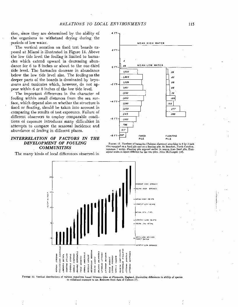
R E L A T IO N S TO LOCAL E N V I R O N M E N T S 115
tion, since they are determined by the ability of the organisms to withstand drying during the periods of low water.
The vertical zonation on fixed test boards exposed at Miami is illustrated in Figure 14. Above the low tide level the fouling is limited to barnacles which extend upward in decreasing abundance for 6 to 8 inches or about to the one-third tide level. The barnacles decrease in abundance below the low tide level also. The fouling on the deeper parts of the boards is dominated by bryo- zoans and tunicates which, however, do not appear within 6 or 8 inches of the low tide level.
The important differences in the character of fouling within small distances from the sea surface, which depend also on whether the structure is fixed or floating, should be taken into account in comparing the results of test exposures. Failure of different observers to employ comparable conditions of exposure introduces many difficulties in attempts to compare the seasonal incidence and abundance of fouling in different places.
INTERRELATION OF FACTORS IN THE DEVELOPMENT OF FOULING
COMMUNITIESThe many kinds of local differences observed in
. 1 ,3 8 5
1,329
1,401
1,553
1,433
M E A N H I G H W A T E R
M E A N L O W W A T E R
66
F I X EDPI L E
FLO A T IN G
P I L E
F i g u r e 1 2 . Numbers of barnacles {Balanus eburneus) attaching to 6 by 3 inch tiles mounted on a fixed pile and on a floating pile. At Beaufort, North Carolina, exposure 7 weeks. Floating pile exposed earlier in season than fixed pile. Horizontal scales in figure different for the two piles. After McDougall {24).
HIGHCST HIGH SPRINGS
M EAN HIGH SP R IN G S
MEAN HIGH N EA PS
L O W E ST LOW NEAPS
— M EAN SE A LEV EL
L O W E ST LOW N E A P S
MEAN LOW NEAPS
MEAN LOW SPRINGS CHART DATUM
LO W EST LOW SPRIN G S
£ S¥ $
i i
F i g u r e 1 3 . V e r t i c a l d i s t r i b u t i o n s o f v a r i o u s o r g a n i s m s f o u n d b e t w e e n t i d e s a t P l y m o u t h , E n g l a n d , i l l u s t r a t i n g d i f f e r e n c e s i n a b i l i t y o f s p e c i e sto withstand exposure to air. Redrawn from data of Colman (7).

116 M A R I N E FOULING A N D I T S P R E V E N T I O N
F i g u r e 14. V ertical distribution of fouling on test boards exposed a t M iam i Beach, F lorida. Card shows Jevel of low tide, above which fouling was lim ited to barnacles.
fouling are so varied and so complex in their combined effects, that much more investigation is needed before a full understanding of them will be possible. I t can be seen, however, th a t the developm ent of a given fouling community on a particular exposure follows a selective process. Of all the fouling species in the world, only a small num ber indigenous to the region of exposure will have access to the unit. Further restrictions among these will be imposed by the season. The selection is still more narrowed by the innumerable local conditions such as the salinity, the composition, color, orientation, toxicity, and other characteristics of the exposed surface itself. The dominant species which first become established may finally impose biotic restrictions on the development of the few forms which have not been eliminated by the preceding conditions.
The variation in detail which is possible through the operation of local and biotic factors is enor
mous. Only a beginning has been made on its analysis. Fortunately, the complexity of the local variations is somewhat offset by their accessibility for study, and progress in understanding them therefore can be expected.
REFEREN CES1. A l e x a n d e r , W. B., B. A. S o u t h g a t e , and R .B a s s i n d a l e . A
Survey of the River Tees. P a r t I I , T he E stuary Chemical and Biological. D ept. Sei. Indust. Res., W ater Pollution Res., Tech. Paper No. 5, London, 1933.
2. B o n d , R. M. Observations on A rtem ia “franciscana” Kellog,especially on the Relation of Environm ent to Morphology. In t. Rev. gesam. Hydrob. u Hydrog., 28, 117-125, 1933.
3. B o r g , F. On Some Species of M em branipora. Ark. f. Zool.,22A, 4, 1-35, 1931.
4 . B r a n d t , D. Die Fauna der Ostsee, inbesondere die der KielerBucht. Verhandl. Deutsch. Zool. Gesell, auf d. 7-en Jahres- versamm. in Kiel, 10-34, 1897.
5. C o e , W. R., and W. E . A l l e n . Growth of Sedentary MarineOrganisms on Experim ental Blocks and Plates for Nine Successive Years a t the Pier of the Scripps Institu tion of Oceanography. Bull. Scripps Inst. Oceanogr., Tech. Ser., 4, No. 4, 101-136, 1937.
6. C o l l a r t , N. M. Cleaner B ottom s—Faster Ships. MarineEngineering, 41, p. 124, 1936.
7. C o l m a n , J. The N ature of the In tertid al Zonation of Plantsand Animals. Jour. M ar. Biol. Assoc., U.K., 18, 435-476, 1933.
8. F e d e r i g i i i , H. Studies on the Oyster Drill (U rosalpinx cinerea,Say). Bull. Bur. Fish., 47, 85-115, 1931.
9. Fox , D e n i s L., and W. R . C o e . Biology of the CaliforniaSea-mussel (M ytilu s ca lifornianus). II . N utrition, M etabolism, Growth and Calcium Deposition. J. Exp. Zool., 93, 205-249, 1943.
10. F r a s e r , J. H. The Fauna of Fixed and Floating Structures inthe Mersey E stuary and Liverpool Bay. Proc. Trans. Liverpool Biol. Soc., 51, 1—21, 1938.
11. F u l l e r , J. Season of A ttachm ent and Growth of SedentaryOrganisms a t Lamoine, M aine. Ecology, 27, 150-158, 1946.
12. G a l t s o f e , P. S., W. A. C h ip m a n , A. D. H a s l e r , and J. B.E n g l e . Prelim inary R eport on the Cause of the Decline of the Oyster In d u stry of the York River, Va., and the Effects of Pulp-mill Pollution on Oysters. U. S. Bur. Fish., Investigational Rept. No. 37, 1-42, 1938.
13. G r a y , G. M. Buoy Collecting 1937-1940. Unpublished M anuscript, M arine Biological Laborator}' Library, Woods Hole, 1940.
14. H e n t s c h e l , E. Biologische Untersuchungen über den tierischen und pflanzlichen Bewuchs im Ham burger Hafen. M itteilungen aus dem Naturhistorischen Zoologischen M useum in Ham burg, 33, 1-176, 1916.
15. H i l l , C. L., and C. A. K o f o i d (ed.) M arine Borers and TheirRelation to M arine Construction on the Pacific Coast. Final Report, San Francisco B ay M arine Piling Committee, San Francisco, 1927.
16. H u t c h i n s , L. W. Salinity and the Growth of the BryozoanConopeum, reticulum (Linné). Anat. Rec., Suppl., 78, p. 102,1940.
17. H u t c h i n s , L. W. An A nnotated Check-list of the Salt-waterBryozoa of Long Island Sound. Trans. Conn. Acad. Arts Sei., 36, 533-551, 1945.
18. H u t c h i n s , L. W., and E. S. D e e v e y , J r . E stim ation andPrediction of the W eight and Thickness of Mussel Fouling on Buoys. Iterim R eport I for 1944 from the Woods Hole Oceanographic Institu tion to the Bureau of Ships, April 19, 1944. (Unpublished)
19. K i r c h e n p a u e r , J. U. Die Seetonnen der Elbmundung.Abhandl. a.d. Gebiete d. Naturw iss. her. v.d. naturwiss. Ver. Ham burg., 4, No. 4, 1-59, 1862.
R E L A T IO N S TO LOCAL E N V I R O N M E N T S 117
20. K r o g h , Ä. Osmotic Regulation in Aquatic Animals. Cambridge University Press, 1939.
21. L o p p e n s , K. Sur une variété de Membranipora membranaceaL. et sur quelques animaux marins vivant dans l ’eau saûmatre. Ann. Soc. Roy. Zool. Malacol. Belgique, 38, 142- 143, 1903.
22. L o p p e n s , K. La variabilité chez Cardium edule. Ann. Soc.Roy. Zool. Malacol. Belgique, 54, 33-67, 1923.
23. L u n z , R. G. J r ., Oyster Culture with Reference to DredgingOperations in South Carolina. Mimeogr. Rept., War Dept., Corps of Eng., U.S. Eng. Off., Charleston, S.C., January, 1938.
24. M cD o u g a l l , K. D. Sessile Marine Invertebrates at Beaufort,North Carolina. Ecol. Monogr., 13, 323-374, 1943.
25. M il l e r , R. C., and W. D. R a m a g e , and E. L. L a z i e r , A Studyof Physical and Chemical Conditions in San Francisco Bay, especially in Relation to the Tides. Univ. of Calif. Publ. Zool., 31, 1927.
26. M i l n e , A. The Ecology of the Tamar Estuary. IV. The Distribution of the Fauna and Flora on Buoys. Jour. Mar. Biol. Assoc., n.s., 24, 69-87, 1940.
27. O ’C o n n e l l , W. J. Characteristics of Micro-biological D eposits in Water Circuits. Am. Petroleum Institute, Proc. of Eleventh Midyear Meeting, Tulsa, Okla., Sec. 3, Refining, 66-83, 1941.
28. O s b u r n , R. C. A Survey of the Bryozoa of Chesapeake Bay.Dept. Res. and Educ., State of Maryland, Bd. Nat. Resources Publ., 63, 1-59, 1944.
29. P i l s b r y , H. A. The Sessile Barnacles (Cirripedia) Containedin the Collections of the U.S. National Museum, including A Monograph of the American Species. Bull. U.S. Nat. Mus., 93, 1-366, 1916.
30. P u r c h o n , R. D. The Effect of the Environment upon theShell of Cardium edule. Proc. Malacol. Soc., 23, No. 5, 25- 267, 1939.
31. R o b e r t s o n , A. Report on a Collection of Bryozoa from theBay of Bengal and other Eastern Seas. Records Indian Mus., 22, 33-65, 1921.
32. S o u t h g a t e , B. A., and others. Estuary of the River Mersey.Dept. Sei. Indust. Res., Water Pollution Research, Tech. Paper No. 7, London, 1938.
33. W a k s m a n , S. A. The Role of Bacteria in the Cycle of Life inthe Sea. Scientific Monthly, 38, 35-49, 1934.
34. W a k s m a n , S. A., et al. Observations on the Film Acquired bySubmerged Surfaces. Report from the Woods Hole Oceanographic Institution to the Bureau of Ships Covering the Period June 10, 1939 to June 30, 1940. U.S. Navy Project S19(3)R1. (Unpublished)
35. W h a r t o n , G. W., Jr. Report of the Biologist, Norfolk NavyYard, June 1941-August 1942, 1942. (Unpublished)

Marine Fouling and Its Prevention,Contribution No. 580 from the Woods Hole Oceanographic Institute
Copyright 1952 by U. S. Naval Institute, Annapolis, Maryland George Banta Publishing Co., Menasha, WI
CHAPTER 9
The Principal Fouling OrganismsThe purpose of this chapter is to present an ele
m entary account of the principal organisms found in fouling communities in order tha t those untrained in zoology may observe fouling with greater understanding. I t contains an account of the appearance, habits, mode of dispersal, and relative importance of these forms.
The descriptions are intended only to enable practical workers to recognize the commoner organisms by the name of the group to which they
an introduction to the scientific literature will find references a t the end of the chapter. When identification to the scientific name is essential, specimens should be sent to the United States National Museum, Washington, D. C., or to a museum of natural history where they can be classified by experts.
M IC R O SC O P IC F O U L IN G O R G A N IS M SThe microscopic fouling organisms include bac-
'1 vri
AF i g u r e 1. Photom icrographs of siime film organisms. A . A type of bacteria from a bacterial slime film. From Dobson (5 ) . B. A dia tom slime film.
belong. In the case of the barnacles, the more common N orth American species are described in sufficient detail to indicate how species may be identified, bu t the descriptions are inadequate to permit the inexperienced worker to classify barnacles to the species with certainty. The identification and naming of the species of all fouling organisms are beyond the scope of this work.
Three manuals, prepared to assist dockyard workers in reporting the conditions of ship bottoms, which describe and illustrate fouling organisms in an even more elementary way, are listed as References 96, 97, and 98.
Persons desiring more complete descriptions or
teria, diatoms, protozoa, and rotifers. The bacteria and diatoms produce slime films which form promptly on submerged surfaces. The protozoa are commonly associated with these films though they take no part in their production. The successive changes in these populations on a submerged surface are shown in Figure 1, Chapter 4. I t is characteristic tha t the early multiplication of bacteria is followed by the development of diatoms and protozoa in the slime.
In addition to the living forms in slime films, organic and inorganic detritus, mud, sand, and other particulate materials suspended in sea water become incorporated in the film, A common type
118
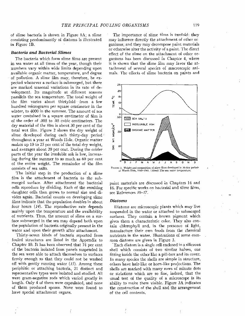
THE P R I N C I P A L FOULING OR GA NISMS 119
of slime bacteria is shown in Figure 1A; a slime consisting predominantly of diatoms is illustrated in Figure IB.
B acteria an d B acterial S lim esThe bacteria which form slime films are present
in sea water at all times of the year, though their numbers vary within wide limits depending upon available organic matter, temperature, and degree of pollution. A slime film may, therefore, be expected whenever a surface is submerged, but there are marked seasonal variations in its rate of development. Its magnitude at different seasons parallels the sea temperature. The total weight of the film varies about thirtyfold—from a few hundred micrograms per square centimeter in the winter, to 4000 in the summer. The amount of sea water contained in a square centimeter of film is of the order of .005 to .05 cubic centimeters. The dry material of the film is about 30 per cent of the total wet film. Figure 2 shows the dry weight of slime developed during each thirty-day period throughout a year at Woods Hole. Organic matter makes up 10 to 25 per cent of the total dry weight, and averages about 20 per cent. During the colder parts of the year the insoluble ash is low, increasing during the summer to as much, as 60 per cent of the entire weight. The remainder of the film consists of sea salts.
The initial step in the production of a slime film is the attachment of bacteria to the submerged surface. After attachment the bacterial cells reproduce by dividing. Each of the resulting daughter cells then grows to normal size and divides again. Bacterial counts on developing slime films indicate that the population doubles in about four hours (14). The reproductive rate depends mainly upon the temperature and the availability of nutrients. Thus, the amount of slime on a surface submerged in the sea may depend both upon the population of bacteria originally present in the water and upon their growth after attachment.
Thirty-seven kinds of bacteria reported from fouled structures are listed in the Appendix to Chapter 10. It has been observed that 74 per cent of the bacteria isolated from panels suspended in the sea were able to attach themselves to surfaces firmly enough so that they could not be washed off with gently running water (15). Among these periphitic or attaching bacteria, 21 distinct and representative types were isolated and studied. All were gram-negative rods which varied greatly in length. Only 4 of them were capsulated, and none of them produced spores. None were found to have special attachment organs.
The importance of slime films is twofold: they may influence directly the attachment of other organisms; and they may decompose paint materials or otherwise alter the activity of a paint. The direct effect of the slime on the attachment of other organisms has been discussed ín Chapter 4, where it is shown that the slime film may favor the attachment of several species of macroscopic animals. The effects of slime bacteria on paints and
25-1--------------------------------------------------------------- :-----------------------
20' --------U 15- / \o / \2 IO / \uj / \
17/M S E A S A L T S
I I I N S O L U A B L E A S H
f e t i a O R G A N I C M A T T E R
W M /W tlJ? .
F i g u r e 2. Weight and composition of slime films developed in 30-day periods at Woods Hole, 1940-1941. (Above),T he sea water temperature.
paint materials are discussed in Chapters 14 and 16. For specific works on bacterial and slime films, see References 10-17.
D iatom sDiatoms are microscopic plants which may live
suspended in the water or attached to submerged surfaces. They contain a brown pigment which gives them a characteristic color. They also contain chlorophyll and, in the presence of light, manufacture their own foods from the chemical nutrients in the water. Illustrations of some common diatoms are given in Figure 3.
Each diatom is a single cell enclosed in a siliceous shell which consists of two similar halves, one fitting inside the other like a pill-box and its cover. In many species the shells are simple in structure, others have hair-like or horn-like projections. The shells are marked with many rows of minute dots or striations which are so fine, indeed, that the usual test of the quality of a microscope is its ability to make them visible. Figure 3A indicates the construction of the shell and the arrangement of the cell contents.
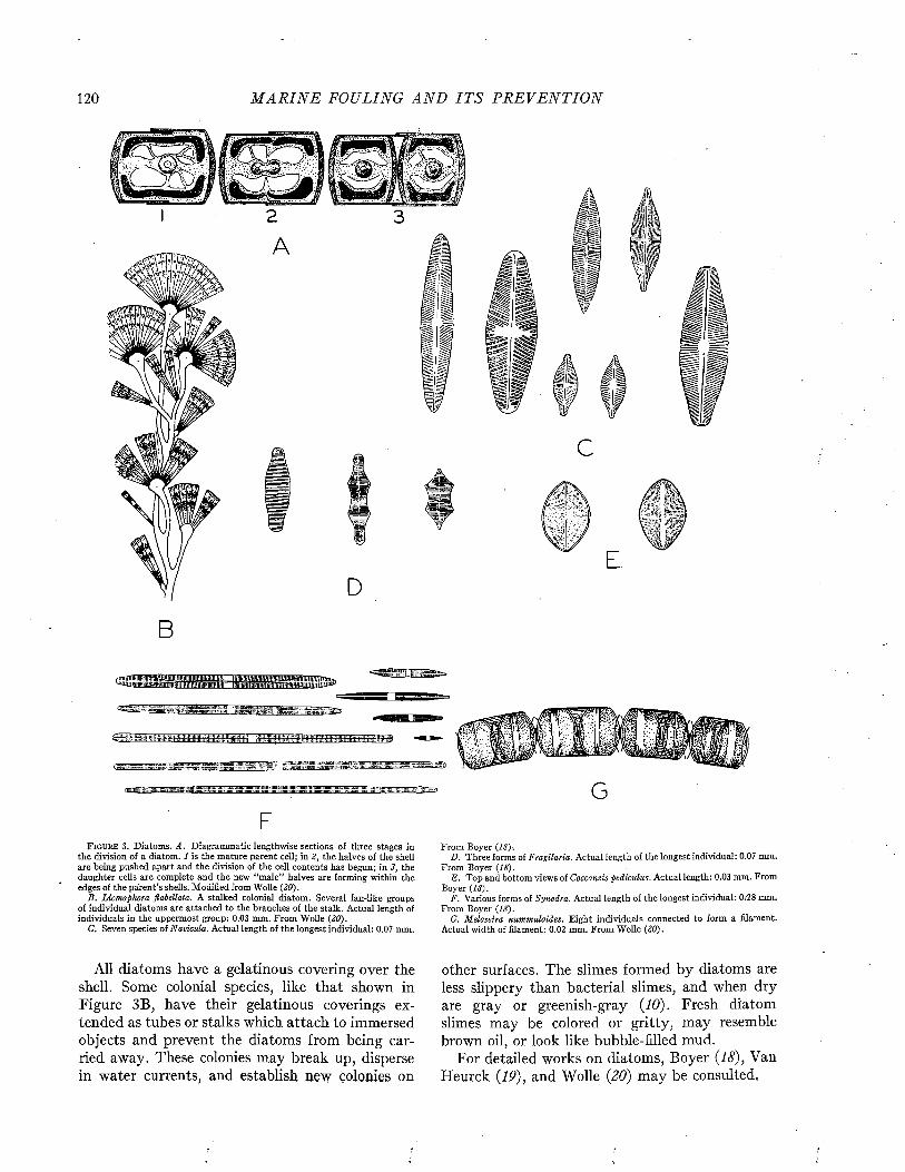
120 M A R I N E FOULING A N D I T S P R E V E N T I O N
A
C
E.D
B
iflimiHwtfflfflîinni
minuiwBiiiaiiiiTaiPHnHKiiniiniiTiiniwiB
GF
F i g u r e 3. Diatoms. A. Diagrammatic lengthwise sections of three stages in the division of a diatom. 1 is the mature parent cell; in 2, the halves of the shell are being pushed apart and the division of the cell contents has begun; in 3, the daughter cells are complete and the new “male” halves are forming within the edges of the parent’s shells. Modified from Wolle (20).
B . Licmophora flabellata. A stalked colonial diatom. Several fan-like groups of individual diatoms are attached to the branches of the stalk. Actual length of individuals in the uppermost group; 0.03 mm. From Wolle (20).
C. Seven species of Navicula. Actual length of the longest individual: 0.07 mm.
From Boyer (18) .D. Three forms of Fragilaria. Actual length of the longest individual: 0.07 mm.
From Boyer (18).E. Top and bottom views of Cocconeis pediculus. Actual length: 0.03 mm. From
Boyer (18).F. Various forms of Synedra. Actual length of the longest individual: 0/28 mm.
From Boyer (18).G. Meloseira nummuloides. Eight individuals connected to form a filament.
Actual width of filament: 0.02 mm. From Wolle (20).
All diatoms have a gelatinous covering over the shell. Some colonial species, like that shown in Figure 3B, have their gelatinous coverings extended as tubes or stalks which attach to immersed objects and prevent the diatoms from being carried away. These colonies may break up, disperse in water currents, and establish new colonies on
other surfaces. The slimes formed by diatoms are less slippery than bacterial slimes, and when dry are gray or greenish-gray (10). Fresh diatom slimes may be colored or gritty, may resemble brown oil, or look like bubble-filled mud.
For detailed works on diatoms, Boyer (18), Van Heurck (19), and Wolle (20) may be consulted,

THE P R I N C I P A L FOULING ORG AN ISM S 121
P rotozoaProtozoa are single-celled animals which range
in size from .002 millimeters to several centimeters in the greatest dimension. Their minute size and their failure to form massive colonies render them unimportant as fouling organisms. Figure 4 shows some characteristic protozoa. A few species possess a stalk by which they attach. Others, like Euplotes, Figure 4E, are free-living and move about rapidly. Both types become established on or in slime films within a few days. They multiply rapidly and; in a well established slime, comprise a significant part of the population (14). They also grow on macroscopic fouling organisms.
References 2, 6, 7, 39, 40, 41 contain accounts of protozoa.
R otifersRotifers have bodies which are roughly club-
shaped and which attach temporarily by the narrower end. The rotifer “shell” is transparent, and the internal organs can be clearly seen through it (Fig. 41). A few genera build tubes in which they live (Fig. 4K).
Rotifers have been reported from some test panels in nearly fresh water at Hamburg, and one marine species has been found on a Pacific Coast lightship. (See Appendix, Chapter 10.)
References 1, 2, 3, 7, 8, 67, deal with this group in greater detail.
M ACROSCOPIC FOULING ORGANISM SThe macroscopic fouling organisms include all
those in which the individuals, or the colonial masses formed by them, are large enough to be recognized by the unaided eye under practical conditions. They consist primarily of forms which live attached to submerged surfaces and make up the bulk of the fouling mass, though numerous free-living creatures inhabit the interstices of the mass and are considered members of the fouling community.
The following key is useful in distinguishing some of the more important groups. The page numbers given in the key indicate where these groups are discussed.I . Organisms with hard, often limy shells:
A. Coiled or twisted tubular shells.................... Annelids p. 139B. Cone-shaped shells attached directly to the hull, or
shells with a long muscular stalk Barnacles p. 121C. Flat, spreading, granular discs or patches. . Bryozoa p. 141D. Paired shells, such as clams, mussels, oysters, etc...
Molluscs p. 131II. Organisms without shells:
A. Green, brown, or red filaments or leaflike structures,generally near water line...................................Algae p. 155
B. Branching tree-shaped growths, the branches notexpanded at the tips.....................................Bryozoa p. 141
C. Straight or branching growths, each thread terminating in an expanded tip ........................Hydroids p. 144
D. Rounded soft spongy masses.........................Tunicates p. 147
The names applied to fouling organisms by dockyard workers vary widely with the locality. In general, however, there is fairly consistent usage of the terms “grass,” “moss,” “barnacles,” and “clams.” “ Grass” usually indicates stringy growths of algae, hydroids, or bryozoa, while “moss” is commonly applied to fluffy masses formed by members of these groups. The term “barnacles” is usually used accurately, though in a few localities it is applied to all hard-shelled forms. “Clams” is rather widely used to denote goose barnacles. “Coral patches” includes a greater variety of fouling than any other term. It is applied to encrusting bryozoa (Figures 26B and 27C), barnacle bases left in place (Figure 26C), masses of tube worms (Figure 24D -F ), and true corals (Figure 33A -D ). The last two are also called “corals.” Other terms are applied to organisms causing important problems in localized areas; for example, in Chesapeake Bay a stolonate bryozoan which forms dense short carpets over practically all immersed objects (Figure 27D) is referred to as “sheep’s wool” or “sheep’s wool moss.” In the New England region the broad-leafed green alga, Ulva (Figure 44F) is sometimes called “green weed,” all other large algae merely being called “weeds.”
A rthropodsThe arthropods include all organisms with a
chitinous external skeleton and joined appendages. In many groups the skeleton is hardened by calcareous deposits.
b a r n a c l e s (Cirripedia)Barnacles are the most familiar of the arthro
pods found on ship bottoms. In their adult form they are encased in hard calcareous shells and are permanently attached to surfaces which are completely submerged or periodically wetted (See Figure 5). The opening of the shell can be closed by two moveable covers, the opercular plates (Figure 8A). They feed by extending their legs through this opening of the shell and sweeping the adjacent water for food (Figure 5C).
Barnacles were thought to be molluscs until studies of their development showed that the larval stages are similar to those of crabs and lobsters. After the larva has attached, the body form changes and the typical barnacle characteristics appear.
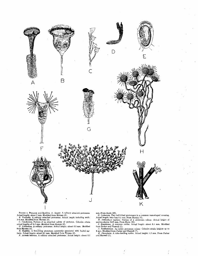
F i g u r e 4. Protozoa and Rotifers. A . Stentor. A solitary attached protozoan. Actual length: about 2 mm. Modified from Hyman (6).
B. Vorticella. 4 solitary attached protozoan. Actual length including stalk: 3-4 mm. Modified from Hyman (6).
C. Carchesium. Portion of an attached colony of protozoa. Colonies attain actual lengths o f 4-5 mjn. Modified from Hyman (6).
D. Folliculina.. A solitary protozoan. Actual height: about 0.5 mm. Modified from Hyman (6). . ...I.
Ê. Euplotes. A free-living protozoan commonly associated with fouled sur faces. Actual length: about 0.1 mm. Modified from Hyman (6).
F. Acineta tuberosa. A solitary attached protozoan. Actual height: about 0.1
mm. From Kudo (40).G. Cothurnia. Two individual protozoans in a common vase-shaped covering.
Actual length: less than 0.1 mm. From Hyman (6).3 . Anthophysa vegetans. Portion of a protozoan colony. Actual height of
portion shown: 0.35 mm. From Kudo (40).I . Brachionus. A common rotifer. Actual length: about 0.3 mm. Modified
from Parker and Haswell (7).J . Zoothamnium. An entire protozoan colony. Colonies attain heights up to
8 mm. Modified from Parker and Haswell (7).K . Floscularia. A tube-dwelling rotifer. Actual height: 1.5 mm. From Parker
and Haswell (?).
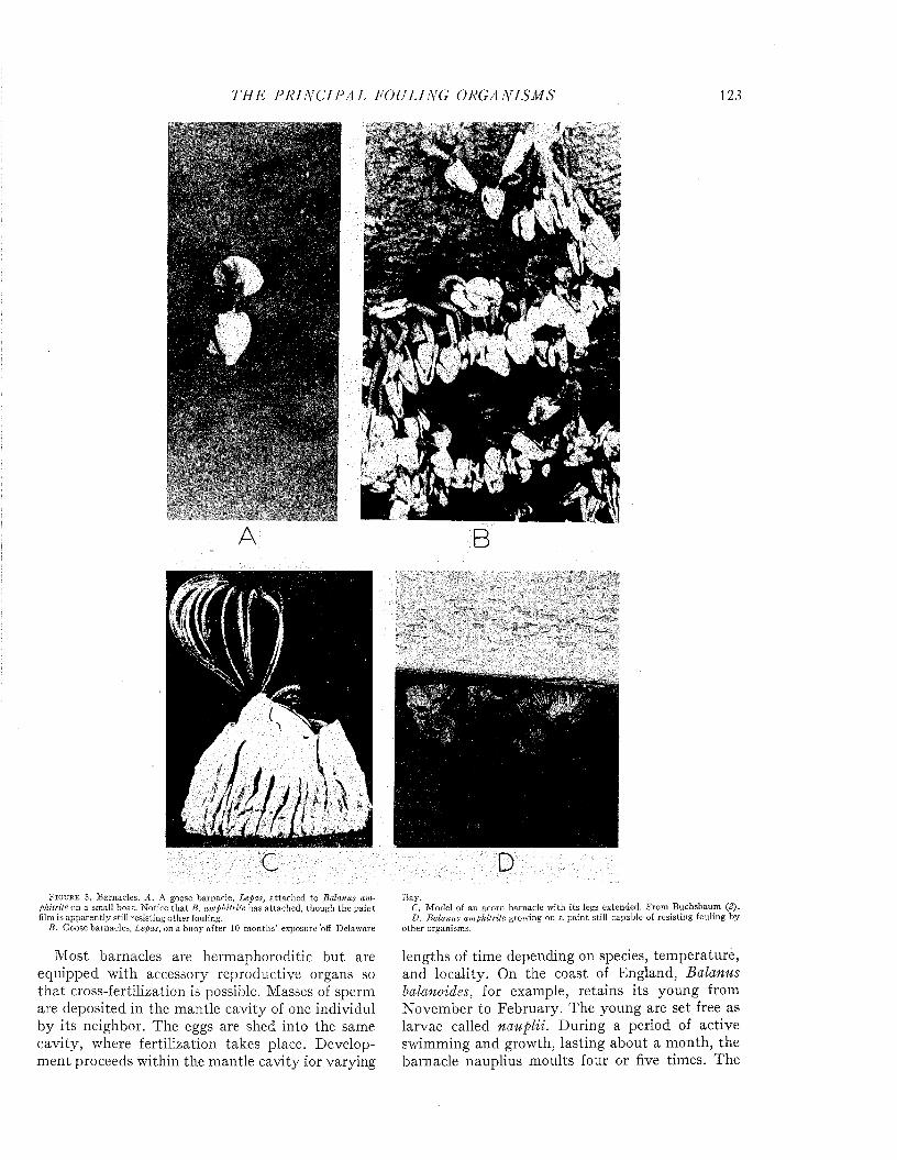
T H E P R I N C I P A L FOULING O R G A N IS M S 123
Ú
y
F i g u r e 5 . Barnacles. A . A goose barnacle, Lepas, a ttached to Balanus am phitrite on a small boat. N otice th a t B. amphitrite has attached, though the pain t film is apparen tly still resisting o ther fouling.
B. Goose barnacles, Lepas, on a buoy after 10 m onths’ exposure'off Delaware
Most barnacles are hermaphoroditic but are equipped with accessory reproductive organs so that cross-fertilization is possible. Masses of sperm are deposited in the mantle cavity of one individul by its neighbor. The eggs are shed into the same cavity, where fertilization takes place. Developm ent proceeds within the mantle cavity for varying
Bay.C. M odel of an acorn barnacle w ith its legs extended. F rom Buchsbaum (2).D. Balanus amphitrite growing on a pa in t still capable of resisting fouling by
o ther organisms.
lengths of time depending on species, temperature, and locality. On the coast of England, Balanus balanoides, for example, retains its young from November to February. The young are set free as larvae called nauplii. During a period of active swimming and growth, lasting about a month, the barnacle nauplius moults four or five times. The
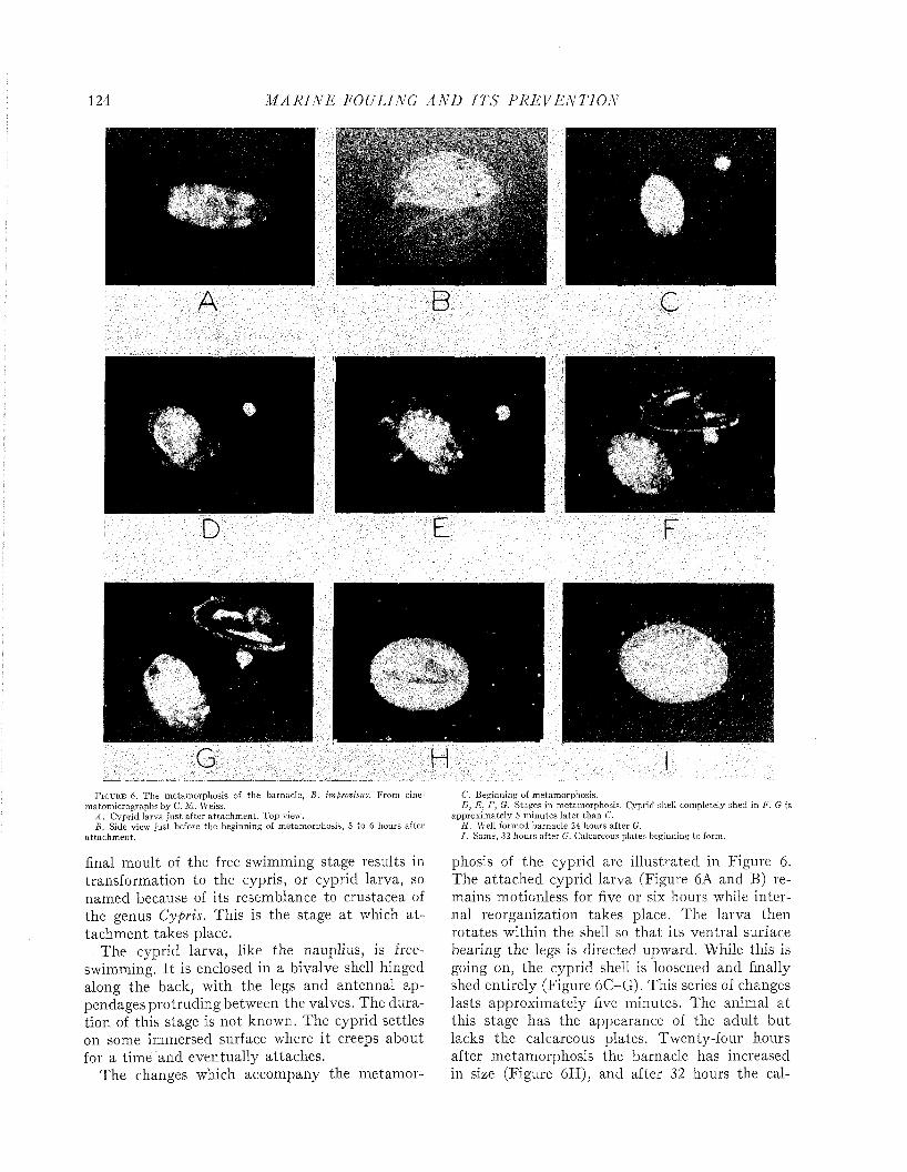
124 M A R I N E FOULING A N D I T S P R E V E N T I O N
$D
F i g u r e 6 . T he m etam orphosis of the barnacle, B. improvisus. From cine- m atom icrographs by C. M . Weiss.
A . Cyprid larva ju s t after a ttachm ent. Top view.B. Side view ju s t before the beginning of m etam orphosis, 5 to 6 hours after
a ttachm ent.
final moult of the free-swimming stage results in transformation to the cypris, or cyprid larva, so named because of its resemblance to crustacea of the genus Cypris. This is the stage a t which a ttachm ent takes place.
The cyprid larva, like the nauplius, is free- swimming. I t is enclosed in a bivalve shell hinged along the back, with the legs and antennal appendages protruding between the valves. The duration of this stage is not known. The cyprid settles on some immersed surface where it creeps about for a time and eventually attaches.
The changes which accompany the metamor
C. Beginning of metamorphosis.D, E , F, G. Stages in metam orphosis. Cyprid shell completely shed in F. G is
approxim ately 5 m inutes la ter than C.H. Well form ed barnacle 24 hours after G.I . Same, 32 hours after G. Calcareous plates beginning to form.
phosis of the cyprid are illustrated in Figure 6. The attached cyprid larva (Figure 6A and B) remains motionless for five or six hours while internal reorganization takes place. The larva then rotates within the shell so tha t its ventral surface bearing the legs is directed upward. While this is going on, the cyprid shell is loosened and finally shed entirely (Figure 6C-G). This series of changes lasts approximately five minutes. The animal a t this stage has the appearance of the adult but lacks the calcareous plates. Twenty-four hours after metamorphosis the barnacle has increased in size (Figure 6H), and after 32 hours the cal-
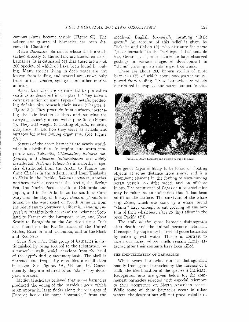
TI IE P R I N C I P A L FOULING O R G A N IS M S 125
careous plates become visible (Figure 61). The subsequent growth of barnacles has been discussed in Chapter 6.
Acorn Barnacles. Barnacles whose shells are a ttached directly to the surface are known as acorn barnacles. I t is estimated (8) th a t there are about 300 species, of which 63 have been found in fouling. M any species living in deep water are not known from fouling, and several are known only from turtles, whales, sponges, and other marine animals.
Acorn barnacles are detrimental to protective coatings as described in Chapter 1. They have a corrosive action on some types of metals, producing definite pits beneath their bases (Chapter 1, Figure 21). They protrude from surfaces, increasing the skin friction of ships and reducing the carrying capacity of sea water pipe lines (Figure 7). They add weight to floating objects, reducing buoyancy. In addition they serve as attachm ent surfaces for other fouling organisms. (See Figure 5A.)
Several of the acorn barnacles are nearly worldwide in distribution. In tropical and warm tem perate seas Tetraclita, Chthamalus, Balanus amphitrite, and Balanus tintinnabulum are widely distributed. Balanus balanoides is a northern species distributed from the Arctic to France and Cape Charles in the Atlantic, and from Unalaska to Sitka in the Pacific. Balanus crenatus, another northern species, occurs in the Arctic, the Bering Sea, the N orth Pacific south to California and Japan, and in the Atlantic as far south as Cape M ay and the Bay of Biscay. Balanus glandula is found on the west coast of N orth America from the Aleutians to Southern California. Balanus improvisus inhabits both coasts of the Atlantic: Scotland to France on the European coast, and Nova Scotia to Patagonia on the American coast. I t is also found on the Pacific coasts of the United States, Ecuador, and Colombia, and in the Black and Red Seas.
Goose Barnacles. This group of barnacles is distinguished by being secured to the substratum by a muscular stalk, which develops from the head of the cypris during metamorphosis. The shell is flattened and frequently resembles a small clam in shape. See Figures 5A, 5B and 13. Consequently they are referred to as “clams” by dockyard workers.
Medieval scholars believed th a t goose barnacles produced the young of the bernickle geese which often appear in large flocks along the seacoasts of Europe; hence the name “barnacle,” from the
medieval English barnakytte, meaning “little goose.” An account of this belief is given by Ricketts and Calvin (9), who attribute the name “goose barnacle” to the “writings of tha t amiable liar, Gerard . . . ” , who claimed to have observed goslings in various stages of development in “clams” growing on a submerged tree trunk.
There are about 200 known species of goose barnacles (<7), of which about one-quarter are reported from fouling. These barnacles are widely distributed in tropical and warm temperate seas.
•>rn barnacles and mussels in ship’s fire main.
The genus Lepas is likely to be found on floating objects a t some distance from shore, and is a prominent element in the fouling of slow-moving ocean vessels, on drift wood, and on offshore buoys. The occurrence of Lepas on a beached mine may be taken as an indication tha t it has been adrift on the surface. PTe survivors of the whale ship Essex, which was sunk by a whale, found “clams” large enough to eat growing on the bottom of their whaleboat after 25 days afloat in the open Pacific (83).
The stalk of the goose barnacle disintegrates after death, and the animal becomes detached. Consequently ships m ay be freed of goose barnacles by entering fresh water. This is in contrast to acorn barnacles, whose shells remain firmly a ttached after their contents have been killed.
THE IDEN TIFICA TIO N OF BARNACLES
While acorn barnacles can be distinguished readily from goose barnacles by the absence of a stalk, the identification of the species is intricate. Recognition aids are given below for the commonest barnacles selected with especial reference to their occurrence on N orth American coasts. While some of these barnacles occur in other waters, the descriptions will not prove reliable in
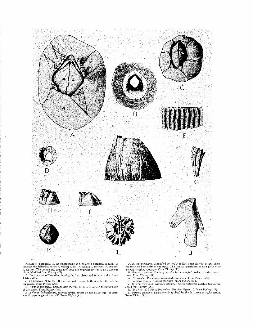
K L JF i g u r e 8. Barnacles. A . An enlargement of a balanoid barnacle, labelled to
indicate the following parts: 1, radius; 2, ala; 3, carina; 4, rostrum ; 5, tergum; 6, scutum . T h e tergum and scutum of each side together are called an opercular plate. M odified from Pilsbry {85).
B . B ottom view of Tetraclita, showing the four plates and tubu lar walls. From Pilsbry (85).
C. Chthamalus. N ote th a t the carina and rostrum both underlap the adjoining plates. F rom Pilsbry (85).
D. Balanus balanoides, Bottom view showing the lack of ribs on the inner sides of the p lates. F rom Pilsbry (85).
E . Balanus tintinnabulum, showing typical ridges on the plates and the horizontal upper edges of the radii. F rom Pilsbry (85).
F. B. tintinnabulum. M agnified portion of radius, ou ter side downward, showing teeth on both sides of the septa. T h e in te rna 'partitions of each p late show a similar toothed structure. From Pilsbry (85).
G. Balanus crenatus. The long slender form adopted under crowded conditions. From Pilsbry (85).
H . B . crenatus. T h e normal truncated eone shape. From Pilsbry (85).I . Common form of Balanus eburneus. F rom P ilsbry (85).J . In te rnal view of B. eburneus tergum . T h e characteristic notch is the deeper
one, From Pilsbry (85).K . T op view of Balanus improvisus. See also F igure 10. From Pilsbry (85).L. Balanus glandula. This species Ís typified by the dark area on each scutum .
From Pilsbry (85).

THE P R I N C I P A L FOULING ORGA NISMS 127
distinguishing such specimens. More comprehensive guides for identification are given by Darwin (79), Pilsbry (84, 85), Hoek (82), Henry (81), and Gruvel (80). Pyefinchi (87) gives methods for the identification of certain barnacle larvae.
Acorn Barnacles. The shell of these barnacles is composed of 4, 6, or 8 calcareous upright plates, a sub-circular base which may be membranous or calcareous, and two opercular plates which close the orifice. Each opercular plate is made up of two parts, a tergum and a scutum. Figure 8A shows these parts and others discussed below.
The plates composing the barnacle’s sides overlap each other, and the edges of each, plate are tapered so that the overlapping takes place without increase in thickness. The manner in which the plates overlap is a characteristic of primary value in identifying barnacles. So also are the shapes of the terga and scuta, and the nature of the overlapping and the underlapping parts.
Before the identification of a barnacle is attempted, it should be cleaned so that all the individual plates are clearly seen and their manners of meeting the neighboring plates are visible.
The first step in identification consists of counting the side plates. In most barnacles there are six. Some, however, have only four such plates, more or less fused together, which can best be distinguished on the inside of the shell. These belong to the genus Tetraclita (Figure 8B), which is further characterized by extremely porous walls.
F i g u r e 9. A . Diagram of the arrangement of the plates of Chthamalus. C. Carina; R. Rostrum. Modified from Pilsbry {85).
B . Diagram of the plate arrangement of Balanus. C. Carina; R. Rostrum. Modified from Pilsbry {85).
If the barnacle has six plates in its side walls, the next detail considered is the manner in which these plates overlap. If the end plates, the carina and rostrum, both underlap the adjoining side plates in the manner indicated in Figure 9A, the barnacle belongs to the genus Chthamalus (Figure 8C). With the exception of one Hawaiian species, all
members of this genus are small, seldom exceeding 12 to 15 millimeters in diameter.
Should the edges of the rostrum overlap, and the edges of the carina underlap the adjoining plates, as in Figure 9B, the barnacle belongs to the family Balanidae, whose type-genus, Balanus, includes most of the common and important fouling barnacles of the world.
Balanus balanoides has no vertical ribs on the inside surfaces of the plates (Figure 8D). Its base is membranous and almost invariably remains attached to the surface. Detached barnacles of this species are difficult to identify. In crowded conditions this species grows in a slender club-shape. It is found in shallow waters and in the intertidal zone. Large individuals reach about 25 millimeters in diameter.
Most of the other species of barnacles which commonly occur in fouling on the American coasts have calcareous bases. Balanus amphitrite (Figure 5A and D) can be recognized by radial tubes in the base and by the absence of tubes in the radii. Translucent greyish or purple stripes on its side plates extend upward from the base to the orifice. This species is tropical and sub-tropical. It is more resistant to copper paints than other barnacles of American waters. Therefore, within its range, it is usually the first to attach to a failing antifouling surface.
Balanus tintinnabulum (Figure 8E and F) is one of the largest and moát easily recognized acorn barnacles. It may reach a diameter of 2-2.5 inches. The scuta, terga, and side plates range in color from pink to black, often in striped patterns. Care must be taken not to confuse young B. tintinnabulum with B. amphitrite. The radii of tin- innabulum have teeth on both sides of the septa (Figure 8F) ; those of amphitrite have teeth on only one side of the septa. This may be seen by separating two plates and examining the adjoining edges with a lens. The radii of tintinnabulum are wide and their upper edges are horizontal. A further characteristic of the species is the heavily ridged nature of its terga and scuta. Under crowded conditions the base turns upward and an elongated shape is assumed. The species is found from the low tide mark to depths of about 30 fathoms.
Balanus improvisus (Figures 8K and 10) may be
F ig u r e 10. Sketch of B. improvisus to show the narrow smooth-edged radii and high alae. From Pilsbry {85).

128 M A R I N E FOULING A N D I T S P R E V E N T I O N
identified by the tight joint at the junction of the tergum and scutum, the diamond-shaped orifice, and by the characteristic way in which its side plates overlap. The radii are thin, narrow, and of a translucent grey color. When seen from above they taper to a razor edge. Each radius typically has a smooth oblique upper edge, while the ala which it overlaps usually rises to a rounded peak behind and above the radius.
In Balanus crenatus, the Notched Acorn (Figures 8G -H and 11), the radii and alae both tend to be
F i g u r e 11. Sketch of B. crenatus, showing notches between plates due to the steep slopes of the radii and alae. Redrawn from Crowder (4).
narrow. Both slope downward at an angle of about 45 degrees so that the orifice is surrounded by a crown of tooth-like projections. The radii are chalky white and are usually narrow, in some instances so narrow as to be only a uniform ribbon along the edge of the plate. The upper edges of the radii are rough and jagged. The base plate is very thin and usually remains on the substrate when the specimen is removed. When crowded conditions prevail, this species, also, develops a long slender shape (Figure 8G),.
Balanus eburneus, the Ivory Barnacle (Figures 81 and 12), is most easily recognized by its tergum.
F i g u r e 12. Sketch of B. eburneus, showing the wide radii whose jagged upper edges slope about 45°. The color of the radii is the same as that of the rest of the plates. From Pilsbry {85).
On the bottom edge of the tergum, mature individuals have a deep notch situated on the side away from the scutum (Figure 8J). The radii are wide and are not chalky white. In American waters this species occurs from low tide to about 20 fathoms, and on the Atlantic coast only. Mature specimens may reach a diameter of about 30 millimeters.
Balanus glandula (Figure 8L), a common species along the west coast of the United States, is easily recognized by the presence of a translucent band or spot near the center of each scutum. This band or spot is conspicuous because of underlying black
material which shows through. Individuals reach about 15 millimeters in diameter.
Goose Barnacles. Many of the more familiar goose barnacles belong to the genus Lepas (Figure 13A). The body of Lepas is surrounded by five plates and resembles a clam in shape. The stalk of this animal is narrower than the thickness of the body and has no scales or spines on its surface.
The occurrence of Lepas is limited primarily to low latitudes, though it sometimes extends into temperate regions. It generally occurs near the surface, although there are a few records of isolated specimens on buoy chains at depths of 30 feet and more. It is responsible for most of the fo u lin g on objects several miles from shore.
In Scalpellum (Figure 13E and F), the stalk has scales or spines on its surface and is as wide as the body, or nearly so. The shell is composed of 12 to 15 calcareous plates which do not meet but are connected by bands of material similar to that of the stalk. Scalpellum characteristically is a deep water genus. There are about 140 species (84), of which 23 have been reported from fouling on telegraph cables and one from a wreck.
The genus Mitella (Figure 13B) is characterized by a shell composed of from 18 to over 100 plates. It is common in the Pacific and has also been reported from France.
The genus Conchoderma contains two species of goose barnacles whose body plates, except the terga and scuta, are buried in a layer of fleshy material continuous with the stalk. The stalk, which is almost as thick as the body where the two meet, usually tapers from there to the point of attachment. C. virgatum (Figure 13C) may be recognized by its greyish color and by six longitudinal dark bands. C. auritum (Figure 13D) is a uniform dark brown and has a pair of prominent ear-like lobes at the free end of the body. Both species have been widely reported.
O ther A rthropodsIsopods, amphipods, crabs, shrimps, insects,
and pycnogonids, are found as free-living members of fouling communities.
Isopods and Amphipods. Both have segmented bodies and eyes which are situated on the surface of the head, not elevated upon stalks. The forward segments of the shell are separate, which distinguishes them from other arthropods in which these segments fuse into a single plate surrounding the thorax. The various genera exhibit many differences, but the characteristics given above are common to all.
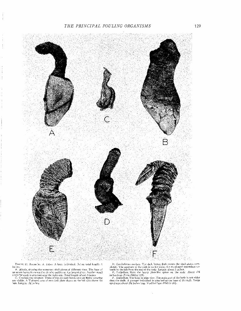
T H E P R I N C I P A L FOULING O R G A N ISM S 129
B
D
E FF i g u r e 13. Barnacles. A . Lepas. A large individual. A ctual to ta l length: 4
inches.B. Mitella, showing the numerous shell p la tes of different sizes. T h e base of
an acorn barnacle causes the circular outline on the largest plate. A nother small acorn barnacle is a ttached near the righ t side. T otal length: abou t 3 inches.
C. Conchoderma virgatum. T hree of the six dark bands and the fleshy covering are visible. A Y -shaped area of one shell p la te shows on the left side above the legs. Length: iM inches.
D. Conchoderma auritum. T h e dark brown flesh covers the shell plates comp le te ^ . T h e aperture of the shell is on the right; the ear-shaped appendage extends to the left from the end of the body. Length : abou t 3 inches.
E . Scalpellum. N ote the heavy plate-like spines on the stalk. A bout 3lÁ inches long. F rom P ilsbry (84).
F. Scalpellum. T h e body in edge-view. T h e m ain p a r t of the body is n o t wider than the stalk . A younger individual is a ttached a t the base of the stalk . Large specimen: abou t 3H inches long. M odified from Pilsbry {84).
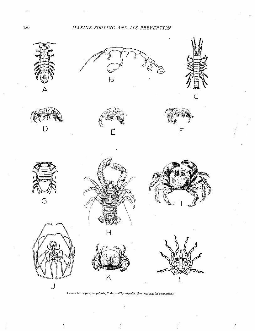
130 M A R I N E FOULING A N D I T S P R E V E N T I O N
F i g u r e 14. Isopods, Amphipods, Crabs, and Pycnogonids. (See next page for description.)
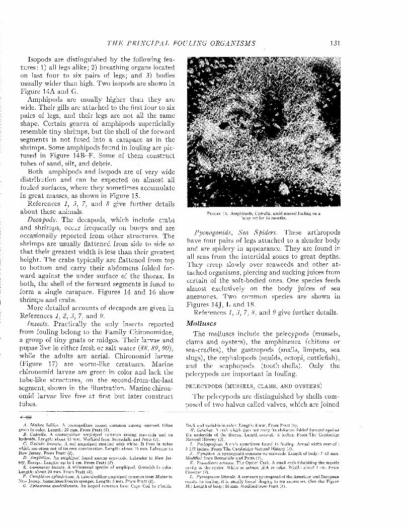
T H E P R I N C I P A L FOULING O R G A N IS M S 131
Isopods are distinguished by the following features: 1) all legs alike; 2) breathing organs located on last four to six pairs of legs; and 3) bodies usually wider than high. Two isopods are shown in Figure 14A and G.
Amphipods are usually higher than they are wide. Their gills are attached to the first four to six pairs of legs, and their legs are not all the same shape. Certain genera of amphipods superficially resemble tiny shrimps, bu t the shell of the forward segments is not fused into a carapace as in the shrimps. Some amphipods found in fouling are pictured in Figure 14B-F. Some of them construct tubes of sand, silt, and debris.
Both amphipods and isopods are of very wide distribution and can be expected on alm ost all fouled surfaces, where they sometimes accumulate in great masses, as shown in Figure 15.
References 1, 3, 7, and 8 give further details about these animals.
Decapods. The decapods, which include crabs and shrimps, occur frequently on buoys and are occasionally reported from other structures. The shrimps are usually flattened from side to side so th a t their greatest width is less than their greatest height. The crabs typically are flattened from top to bottom and carry their abdomens folded forward against the under surface of the thorax. In both, the shell of the forward segments is fused to form a single carapace. Figures 14 and 16 show shrimps and crabs.
More detailed accounts of decapods are given in References 1, 2, 3, 7, and 9.
Insects. Practically the only insects reported from fouling belong to the Family Chironomidae, a group of tiny gnats or midges. Their larvae and pupae live in either fresh or salt water {88, 89, 90), while the adults are aerial. Chironomid larvae (Figure 17) are worm-like creatures. Marine chironomid larvae are green in color and lack the tube-like structures, on the second-from-the-last segment, shown in the illustration. Marine chironomid larvae live free a t first bu t later construct tubes.
A . Idothea baltica. A cosmopolitan isopod common am ong seaweed. Often green in color. Length: 20 mm. From P ra t t (<?).
B . Caprella. A cosmopolitan am phipod com mon am ong seaweeds and on hydroids. Length : abou t 15 mm. M odified from Borradaile and P o tts ( /) .
C. Unicola irrorata. A red am phipod m ottled w ith white. I t lives in tubes which are often n o t of its own construction. Length : abou t 15 mm. Labrador to N ew Jersey . F rom P ra t t (8).
D. Amphithoe. An am phipod found am ong seaweeds. Labrador to New. Je rsey, Europe. L ength : up to 1 cm. F rom P ra t t (8).
E . Gammarus locusta. A w idespread species of amphipod. Greenish in color. Length: ab o u t 20 mm. From P ra tt (#).
F. Corophium cylindricum. A tube-dwelling am phipod common from M aine to New Jersey. Sometimes lives in sponges. Length: 5 mm. From P ra tt (8).
G. Sphaeroma quadridentata. An isopod com mon from Cape Cod to Florida.
F i g u r e 15. Amphipods, Caprella, am id mussel fouling on a buoy set for 14 months.
Pycnogonids, Sea Spiders. These arthropods have four pairs of legs attached to a slender body and are spidery in appearance. They are found in all seas from the intertidal zones to great depths. They creep slowly over seaweeds and other a ttached organisms, piercing and sucking juices from certain of the soft-bodied ones. One species feeds almost exclusively on the body juices of sea anemones. Two common species are shown in Figures 14J, L and 18.
References 1, 3, 7, 8, and 9 give further details.Molluscs
The molluscs include the pelecypods (mussels, clams and oysters), the amphinema (chitons or sea-cradles), the gastropods (snails, limpets, sea slugs), the cephalopods (squids, octopi, cuttlefish), and the scaphopods (tooth-shells). Only the pelecypods are im portant in fouling.
PELECYPODS (M USSELS, CLAMS, AND OYSTERS)
The pelecypods are distinguished by shells composed of two halves called valves, which are joined
D ark and variable in color. Length: 8 mm. From P ra tt {8).II. Galathea. A crab which does no t carry its abdom en folded forward against
the underside of the thorax. Length over-all: 6 inches. From T h e Cambridge N atural H istory (J).
I . Pachygrapsus. A crab sometimes found in fouling. Actual w idth over-all: 5 1/2 inches. From T h e Cam bridge N atu ral H istory (J).
J . Nymphon. A pvcnogonid common on seaweeds. Length of body: 7-15 mm. Modified from Borradaile and P o tts ( /) .
K . Pinnotheres ostreum. T h e O yster Crab. A small crab inhabiting the m antle cavity of the oyster. W hite or salmon pink in color. W idth: abou t 1 cm. From Crowder (4).
L. Pycnogonum littorale. A common pycnogonid of the American and European coasts. In fouling, it is usually found clinging to sea anemones. (See also Figure 18.) Length of body: 16 mm. M odified from P ra tt (£).

132 M A R I N E FOULING A N D I T S P R E V E N T I O N
F i g u r e 16. Crabs and Shrimps. A . Carcinides maenas. T h e Green Crab. M aine to New Jersey. A ctual w idth of body: 7 cm. Color green m ottled w ith yellow. From Crowder (4).
B . Ilya s coarctatus. T he Toad Crab. G reenland to Virginia and in the N orth Pacific. Actual w idth of body: 6.5 cm. Color reddish, brownish or olive. From Crowder (4).
C. Spirontocaris. T he T ransparent Shrimp. A ctual length, exclusive of antennae: 4 cm. A Pacific form. From R icketts and Calvin (9).
D. Paho-monetes. T he Common Shrimp or Glass Praw n. Length about 4 cm, A cosmopolitan form. Body translucent w ith some brownish spots. From Crowder
( 4) .E . Cancer irroratus. T h e Rock Crab. T h e Jonah Crab, C. borealis, a larger
bu t very similar crab, reaches a w idth of 15 cm. and occurs in fouling from Nova Scotia to Florida. From Crowder (4).
F. Libinia. A Spider Crab. An inhab itan t of m ud banks and mollusc beds, it sometimes is taken am ongst fouling on moored objects or fixed installations. W idth of body: up to 6 cm. F rom Crowder (4).
G. A Spider Crab fouled by barnacles and hydroids.11. Pugettia. A Pacific Spider Crab. D ark olive green in color. W idth: 9 cm.
From R icketts and Calvin (P).
along part of one edge by a tough elastic ligament. Near this edge, each valve has a pronounced shoulder called the umbo. Beside the umbo and below the ligament are a series of interlocking
ridges and teeth which keep the valves in alignment. The ligament may be visible externally, or m ay be out of sight between the valve margins so tha t the shell m ust be opened before it can be seen.
F i g u r e 17. Chironomus larva from freshw ater. M arine chironomid larvae lack th e two pairs of tubular structures on the second-from -the-last (right)seg- m ent. From Johannsen and Thom sen {89).
F i g u r e 18. Pycnogonum- littorale, a sea spider. (See also Figure 14L.) F rom Crowder {4).
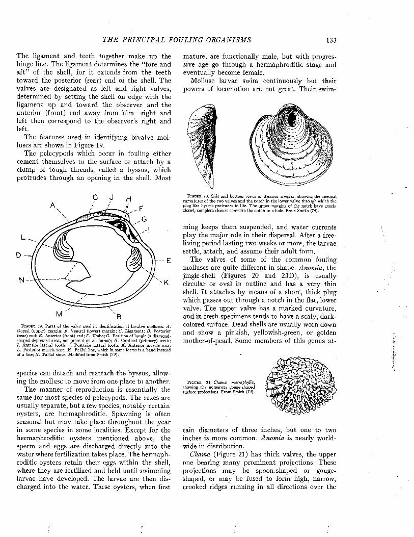
TH E P R I N C I P A L FOULING ORGA NISMS 133
The ligament and teeth together make up the hinge line. The ligament determines the “fore and aft” of the shell, for it extends from the teeth toward the posterior (rear) end of the shell. The valves are designated as left and right valves, determined by setting the shell on edge with the ligament up and toward the observer and the anterior (front) end away from him— right and left then correspond to the observer’s right and left.
The features used in identifying bivalve molluscs are shown in Figure 19.
The pelecypods which occur in fouling either cement themselves to the surface or attach by a clump of tough threads, called a byssus, which protrudes through an opening in the shell. Most
N -
-- E
K
F i g u r e 19. Parts of the valve used in identification of bivalve molluscs. A.' Dorsal (upper) margin; B. Ventral (lower) margin; C. Ligament; D. Posterior (rear) end; E. Anterior (front) end; F. Umbo; G. Position of lunule (a diamondshaped depressed area, not present on all forms); E . Cardinal (primary) teeth; I . Anterior lateral tooth; J. Posterior lateral tooth; K . Anterior muscle scar; L . Posterior muscle scar; M . Palliai line, which in some forms is a band instead of a line; N . Palliai sinus. Modified from Smith (74).
species can detach and reattach the byssus, allowing the mollusc to move from one place to another.
The manner of reproduction is essentially the same for most species of pelecypods. The sexes are usually separate, but a few species, notably certain oysters, are hermaphroditic. Spawning is often seasonal but may take place throughout the year in some species in some localities. Except for the hermaphroditic oysters mentioned above, the sperm and eggs are discharged directly into the water where fertilization takes place. The hermaphroditic oysters retain their eggs within the shell, where they are fertilized and held until swimming larvae have developed. The larvae are then discharged into the water. These oysters, when first
mature, are functionally male, but with progressive age go through a hermaphroditic stage and eventually become female.
Mollusc larvae swim continuously but their powers of locomotion are not great. Their swim-
F i g u r e 20. Side and bottom views of Anomia simplex, showing the unequal curvatures of the two valves and the notch in the lower valve through which the plug-like byssus protrudes in life. The upper margins of the notch have nearly closed, complete closure converts the notch to a hole. From Smith (74).
ming keeps them suspended, and water currents play the major role in their dispersal. After a free- living period lasting two weeks or more, the larvae settle, attach, and assume their adult form.
The valves of some of the common fouling molluscs are quite different in shape. Anomia, the jingle-shell (Figures 20 and 23D), is usually circular or oval in outline and has a very thin shell. It attaches by means of a short, thick plug which passes out through a notch in the flat, lower valve. The upper valve has a marked curvature, and in fresh specimens tends to have a scaly, dark- colored surface. Dead shells are usually worn down and show a pinkish, yellowish-green, or golden mother-of-pearl. Some members of this genus at-
F i g u r e 2 1 . Chama macrophylla, showing the numerous gouge-shaped surface projections. From Smith (74).
tain diameters of three inches, but one to two inches is more common. Anomia is nearly worldwide in distribution.
Chama (Figure 21) has thick valves, the upper one bearing many prominent projections. These projections may be spoon-shaped or gougeshaped, or may be fused to form high, narrow, crooked ridges running in all directions over the
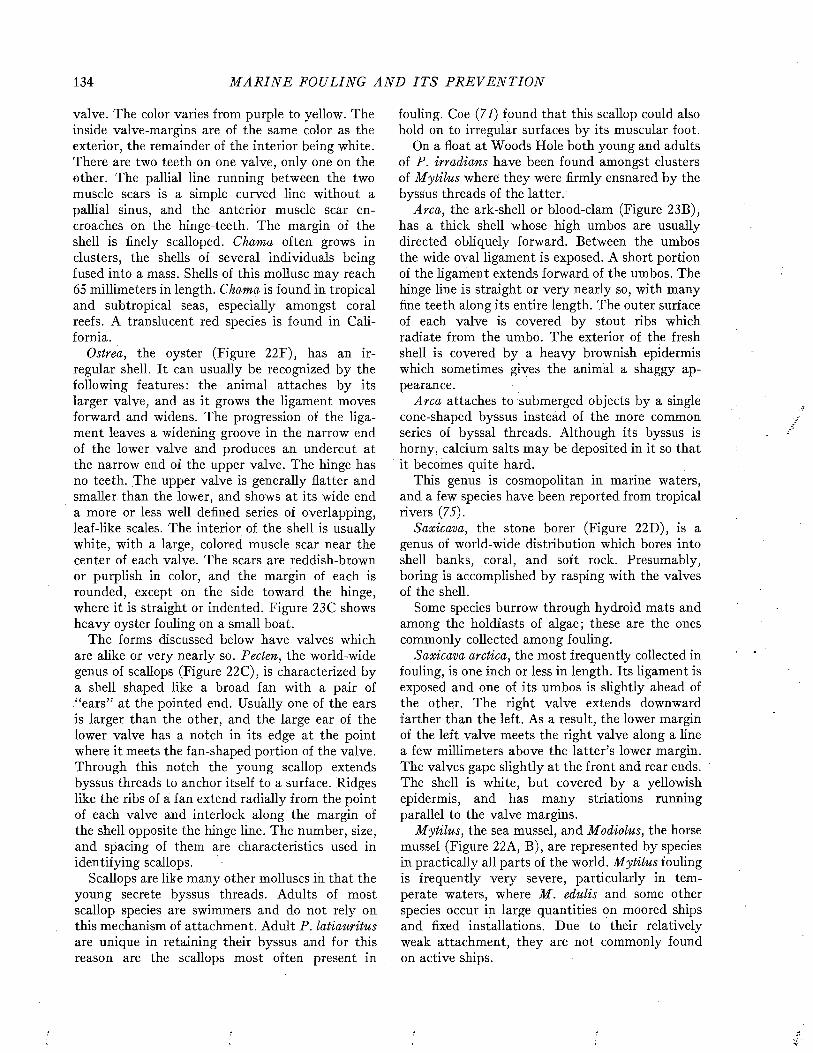
134 M A R I N E FOULING A N D I T S P R E V E N T I O N
valve. The color varies from purple to yellow. The inside valve-margins are of the same color as the exterior, the remainder of the interior being white. There are two teeth on one valve, only one on the other. The palliai line running between the two muscle scars is a simple curved line without a palliai sinus, and the anterior muscle scar encroaches on the hinge-teeth. The margin of the shell is finely scalloped. Chama often grows in clusters, the shells of several individuals being fused into a mass. Shells of this mollusc may reach 65 millimeters in length. Chama is found in tropical and subtropical seas, especially amongst coral reefs. A translucent red species is found in California.
Ostrea, the oyster (Figure 22F), has an irregular shell. It can usually be recognized by the following features: the animal attaches by its larger valve, and as it grows the ligament moves forward and widens. The progression of the ligament leaves a widening groove in the narrow end of the lower valve and produces an undercut at the narrow end of the upper valve. The hinge has no teeth. The upper valve is generally flatter and smaller than the lower, and shows at its wide end a more or less well defined series of overlapping, leaf-like scales. The interior of the shell is usually white, with a large, colored muscle scar near the center of each valve. The scars are reddish-brown or purplish in color, and the margin of each is rounded, except on the side toward the hinge, where it is straight or indented. Figure 23C shows heavy oyster fouling on a small boat.
The forms discussed below have valves which are alike or very nearly so. Pecten, the wo rid-wide genus of scallops (Figure 22C), is characterized by a shell shaped like a broad fan with a pair of “ears” at the pointed end. Usually one of the ears is larger than the other, and the large ear of the lower valve has a notch in its edge at the point where it meets the fan-shaped portion of the valve. Through this notch the young scallop extends byssus threads to anchor itself to a surface. Ridges like the ribs of a fan extend radially from the point of each valve and interlock along the margin of the shell opposite the hinge line. The number, size, and spacing of them are characteristics used in identifying scallops.
Scallops are like many other molluscs in that the young secrete byssus threads. Adults of most scallop species are swimmers and do not rely on this mechanism of attachment. Adult P. latianritus are unique in retaining their byssus and for this reason are the scallops most often present in
fouling. Coe (71) found that this scallop could also hold on to irregular surfaces by its muscular foot.
On a float at Woods Hole both young and adults of P. irradians have been found amongst clusters of M ytilus where they were firmly ensnared by the byssus threads of the latter.
Arca, the ark-shell or blood-clam (Figure 23B), has a thick shell whose high umbos are usually directed obliquely forward. Between the umbos the wide oval ligament is exposed. A short portion of the ligament extends forward of the umbos. The hinge line is straight or very nearly so, with many fine teeth along its entire length. The outer surface of each valve is covered by stout ribs which radiate from the umbo. The exterior of the fresh shell is covered by a heavy brownish epidermis which sometimes gives the animal a shaggy appearance.
Arca attaches to submerged objects by a single cone-shaped byssus instead of the more common series of byssal threads. Although its byssus is horny, calcium salts may be deposited in it so that it becomes quite hard.
This genus is cosmopolitan in marine waters, and a few species have been reported from tropical rivers (75).
Saxicava, the stone borer (Figure 22D), is a genus of world-wide distribution which bores into shell banks, coral, and soft rock. Presumably, boring is accomplished by rasping with the valves of the shell.
Some species burrow through hydroid mats and among the holdfasts of algae; these are the ones commonly collected among fouling.
Saxicava arctica, the most frequently collected in fouling, is one inch or less in length. Its ligament is exposed and one of its umbos is slightly ahead of the other. The right valve extends downward farther than the left. As a result, the lower margin of the left valve meets the right valve along a line a few millimeters above the latter’s lower margin. The valves gape slightly at the front and rear ends. The shell is white, but covered by a yellowish epidermis, and has many striations running parallel to the valve margins.
Mytilus, the sea mussel, and Modiolus, the horse mussel (Figure 22A, B), are represented by species in practically all parts of the world. M ytilus fouling is frequently very severe, particularly in temperate waters, where M . edulis and some other species occur in large quantities on moored ships and fixed installations. Due to their relatively weak attachment, they are not commonly found on active ships.
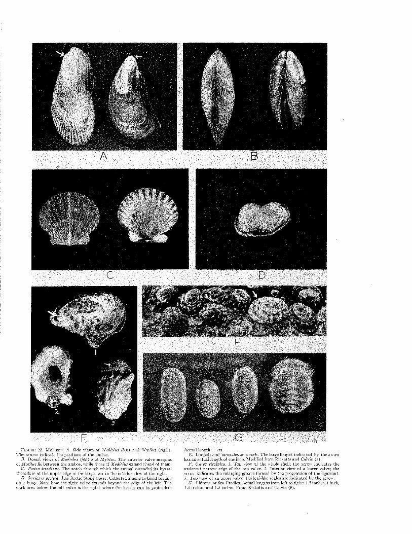
F i g u r e 2 2 . M olluscs. A . Side views of Modiolus (left) and M ytilus (right). T h e arrows indicate the positions of the umbos.
B. D orsal views of M odiolus (left) and M ytilus. T he anterior valve margins of M ytilus lie between the umbos, while those of Modiolus extend ahead of them .
C. Pecten irradians. T he notch through which the animal extended its bjrssal th reads is a t the upper edge of the larger ear in the interior view a t the right.
D. Saxicava arctica. T h e Arctic Stone Borer. Collected among hybroid fouling on a buoy. N ote how the righ t valve extends beyond the edge of the left. T he dark area below the left valve is the notch where the byssus can be protruded.
A ctual length: 1 cm.E . Lim pets and barnacles on a rock. T he large lim pet indicated by the arrow
has an ac tual length of one inch. M odified from R icketts and Calvin (9).F. Ostrea virginica. 1. Top view of the whole shell; the arrow indicates the
undercu t narrow edge of the top valve. 2. In terio r mew of a lower valve; the arrow indicates the enlarging groove formed by the progression of the ligament. 3. T op view of an upper valve; the leaf-like scales are indicated by the arrow.
G. Chitons, or Sea Cradles. Actual lengths from left to right: 1.5 inches, 1 inch,1.4 inches, and Í.5 inches, From R icketts and Calvin (9).
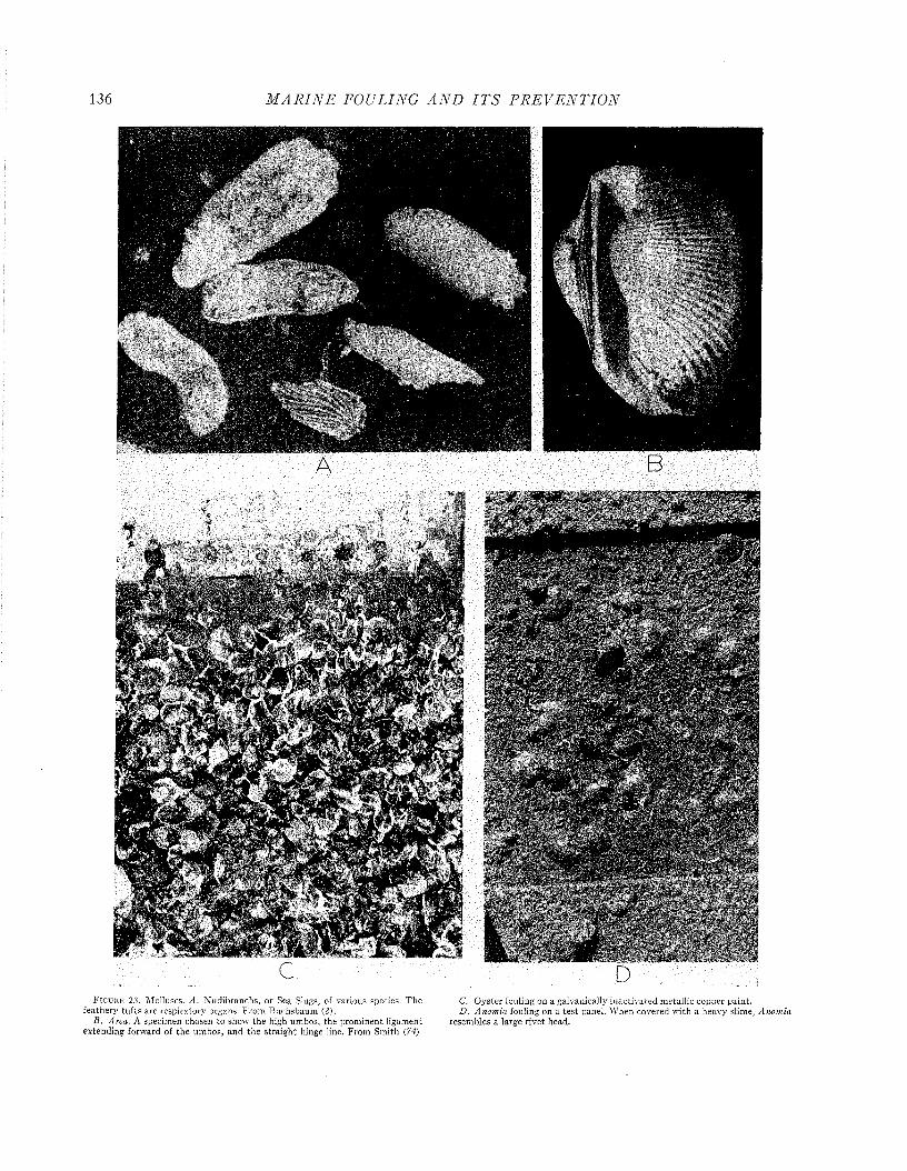
136 M A R I N E FOU LING A N D I T S P R E V E N T I O N
* "PW. ^ - .<
:r-X ^ ‘ Z''■'■■■.■ - 1*
B i Æ f
F i g u r e 23. Molluscs. A . N udibranchs, or Sea Slugs, of various species. T h e C . O yster fouling on a galvanically inactivated m etallic copper pain t,feathery tu fts are respiratory organs. From Buchsbaum (2). D. Anom ia fouling on a te st panel. W hen covered with a heavy slime, A
B . Arca. A specimen chosen to show the high umbos, the prom inent ligam ent resem bles a large rivet head, extending forward of the umbos, and the straigh t hinge line. From Smith {74)
i-V
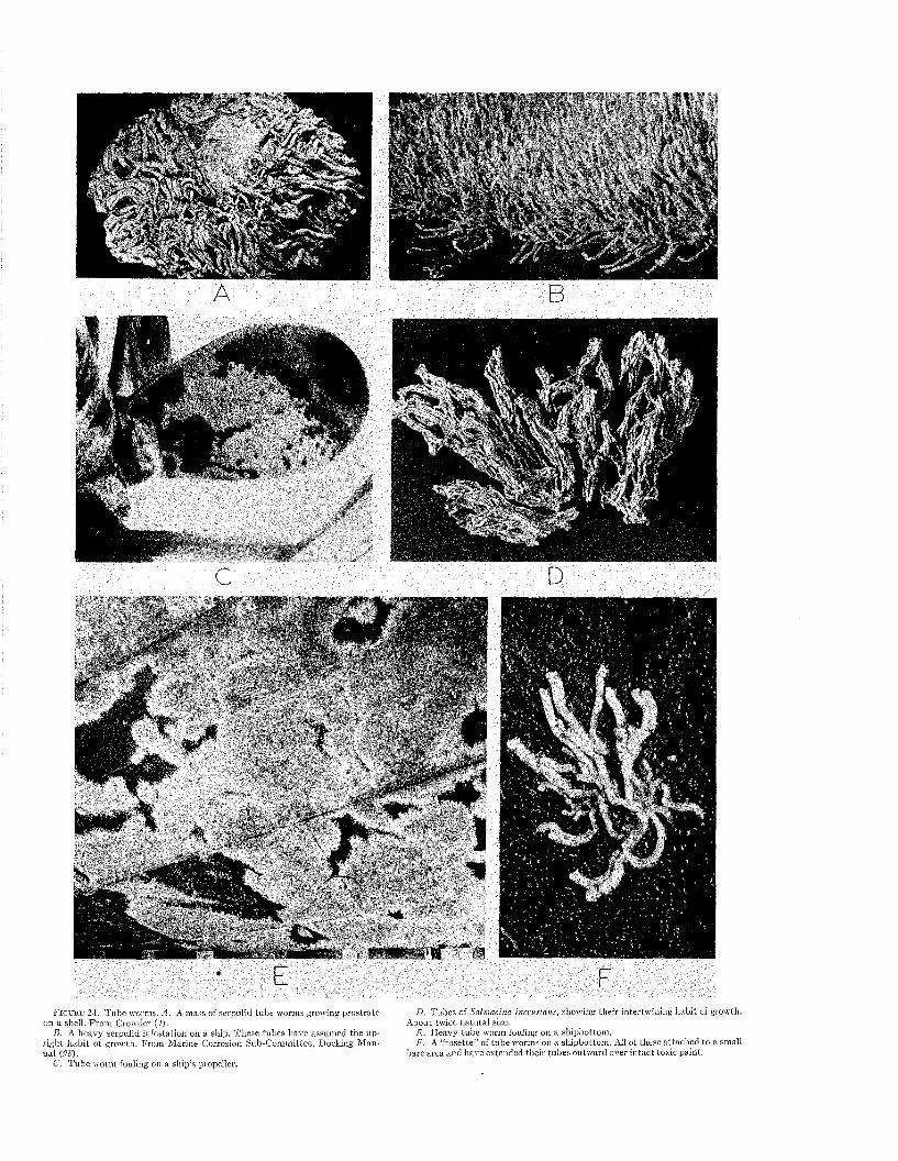
F i g u r e 2 4 . Tube worms. A. A mass o f serpulid tube worms growing p rostrate on a shelJ. From Crowder (4).
B. A heavy serpulid infestation on a ship. T hese tubes have assumed the uprigh t h ab it of grow th. From M arine Corrosion Sub-Com m ittee, Docking M anual {98).
C. T ube worm fouling on a ship’s propeller.
D. Tubes of Salmacina incrustans, showing their intertw ining hab it of growth. A bout twice natu ral size.
E . H eavy tube worm fouling on a shipbottom .F. A “rosette” of tube worms on a shipbottom . All of these a ttached to a small
bare area and have extended the ir tubes outw ard over in tac t toxic paint.

/
*
■ p F
F
stad i
G
A
F i g t j r f , 25. Worms. A. A sabeliid worm tube. I t is composed of fine sand grains and of shell fragm ents cemented together w ith a leathery m aterial. Slightly enlarged. M odified from M cIntosh (68).
B . T ubes of Hydroides norvegica on a scallop shell. A bout na tu ra l size. From M cIntosh (68).
C. Tubes of Pomatoceros triqueter on a pebble. Less than na tu ra l size. From M cIntosh (68).
D . M ale Nereis pelagica in its swarming (reproductive) phase. From M cIntosh (68).
E . A scaleworm. About natu ral size. F rom M cIn tosh (68).F. T h e flatworm, Stylochus, a common fouling genus. Slightly enlarged. P'rom
Crowder (4).G. Chaetogaster, an oligochaete present in_ fouling in rare instances. Actual
length less than 5 mm. From Schm arda (69).II . A nem ertean worm. From M cIntosh (68).I , J , K . Leeches. I and J are top and bottom views respectively of the same
leech. From K ukenthal (67).
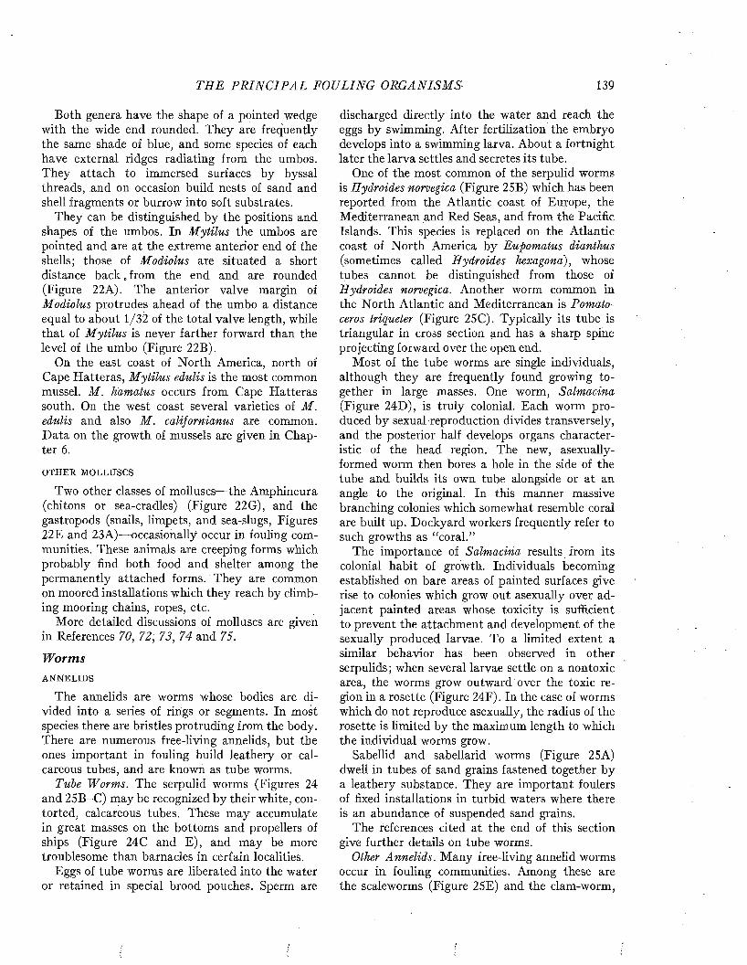
TH E P R I N C I P A L FOULING ORGANISMS• 139
Both genera have the shape of a pointed wedge with the wide end rounded. They are frequently the same shade of blue, and some species of each have external ridges radiating from the umbos. They attach to immersed surfaces by byssal threads, and on occasion build nests of sand and shell fragments or burrow into soft substrates.
They can be distinguished by the positions and shapes of the umbos. In M ytilus the umbos are pointed and are at the extreme anterior end of the shells; those of Modiolus are situated a short distance b ack , from the end and are rounded (Figure 22A). The anterior valve margin of Modiolus protrudes ahead of the umbo a distance equal to about 1/32 of the total valve length, while that of M ytilus is never farther forward than the level of the umbo (Figure 22B).
On the east coast of North America, north of Cape Hatteras, M ytilus edulis is the most common mussel. M . Hamatus occurs from Cape Hatteras south. On the west coast several varieties of M. edulis and also M . californianus are common. Data on the growth of mussels are given in Chapter 6.
OTHER MOLLUSCS
Two other classes of molluscs— the Amphineura (chitons or sea-cradles) (Figure 22G), and the gastropods (snails, limpets, and sea-slugs, Figures 22E and 23A)— occasionally occur in fouling communities. These animals are creeping forms which probably find both food and shelter among the permanently attached forms. They are common on moored installations which they reach by climbing mooring chains, ropes, etc.
More detailed discussions of molluscs are given in References 70, 72, 73, 74 and 75.
W orm sANNELIDS
The annelids are worms whose bodies are divided into a series of rings or segments. In most species there are bristles protruding from the body. There are numerous free-living annelids, but the ones important in fouling build leathery or calcareous tubes, and are known as tube worms.
Tube Worms. The serpulid worms (Figures 24 and 25B-C) may be recognized by their white, contorted, calcareous tubes. These may accumulate in great masses on the bottoms and propellers of ships (Figure 24C and E), and may be more troublesome than barnacles in certain localities.
Eggs of tube worms are liberated into the water or retained in special brood pouches. Sperm are
discharged directly into the water and reach the eggs by swimming. After fertilization the embryo develops into a swimming larva. About a fortnight later the larva settles and secretes its tube.
One of the most common of the serpulid worms is Hydroides norvegica (Figure 25B) which has been reported from the Atlantic coast of Europe, the Mediterranean and Red Seas, and from the Pacific Islands. This species is replaced on the Atlantic coast of North America by Eupomatus dianthus (sometimes called Hydroides hexagona), whose tubes cannot be distinguished from those of Hydroides norvegica. Another worm common in the North Atlantic and Mediterranean is Pomatoceros triqueter (Figure 25C). Typically its tube is triangular in cross section and has a sharp spine projecting forward over the open end.
M ost of the tube worms are single individuals, although they are frequently found growing together in large masses. One worm, Salmacina (Figure 24D), is truly colonial. Each worm produced by sexual reproduction divides transversely, and the posterior half develops organs characteristic of the head region. The new, asexually- formed worm then bores a hole in the side of the tube and builds its own tube alongside or at an angle to the original. In this manner massive branching colonies which somewhat resemble coral are built up. Dockyard workers frequently refer to such growths as “coral.”
The importance of Salmacina results from its colonial habit of growth. Individuals becoming established on bare areas of painted surfaces give rise to colonies which grow out asexually over adjacent painted areas whose toxicity is sufficient to prevent the attachment and development of the sexually produced larvae. To a limited extent a similar behavior has been observed in other serpulids; when several larvae settle on a nontoxic area, the worms grow outward over the toxic region in a rosette (Figure 24F). In the case of worms which do not reproduce asexually, the radius of the rosette is limited by the maximum length to which the individual worms grow.
Sabellid and sabellarid worms (Figure 25A) dwell in tubes of sand grains fastened together by a leathery substance. They are important foulers of fixed installations in turbid waters where there is an abundance of suspended sand grains.
The references cited at the end of this section give further details on tube worms.
Other Annelids. Many free-living annelid worms occur in fouling communities. Among these are the scaleworms (Figure 25E) and the clam-worm,

140 M A R I N E FOULING A N D I T S P R E V E N T I O N
\ & V ' ■
x E O :'i N.iTi- * *
■ \ V M u s a e i X .« w ; C \* *■ .*vr„"'■ ' * V * ^ ’
E
F i g u r e 2 6 . B ryozoa.^!. T est panels fouled with colonies of encrusting bryozoa. rosion Sub-Committee, Docking M anual (PS).B . Colony of encrusting bryozoa, showing its honeycomb-like appearance.
See also Figure 27B. From M arine Corrosion, Sub-Committee, Docking M anual {98).
C. Barnacle bases, showing the typical concentric circles and radiating lines on them . Stolonate bryozoans are visible a t the lower righ t of F. which distinguish them from colonies of encrusting bryozoa. From M arine Cor-
D. An erect bryozoan of the genus Bugula.E . S tolonate bryozoa.F. G. Colonies of encrusting bryozoa w ith colonies of erec t bryozoa growing
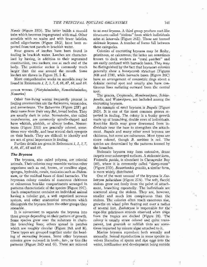
THE P R I N C I P A L FOULING ORGA NISMS '141
Nereis (Figure 25D). The latter builds a mucoid tube which becomes impregnated with mud. Other annelids with no scales and with fewer bristles, called oligochaetes (Figure 25G), have been reported from/test panels in brackish water.
Four genera of leeches have been found in fouling in brackish water. Leeches are characterized by having, in addition to their segmented construction, two suckers, one at each end of the body. The posterior sucker is commonly much larger than the one around the mouth. Some leeches are shown in Figure 25, I-K .
More comprehensive works on annelids may be found in References 1 , 2 , 3 , 7, 8, 66, 67, 68, and 69.
o t h e r w o r m s . (Platyhelminthes, Nemathelminthes, Nemertea)
Other free-living worms frequently present in fouling communities are the flatworms, nematodes, and nemerteans. The flatworms (Figure 25F) get their name from their very flat, broad bodies. They are usually dark in color. Nematodes, also called roundworms, are commonly spindle-shaped and have whitish, pinkish, or silvery bodies. Nemerteans (Figure 25H) are generally colored, sometimes very vividly, and bear several dark eyespots on their heads. They are difficult to identify and are not of great importance in fouling.
Further details are given in References 1, 2 , 3 , 7, 8, 66, 67, 68 and 69.
The BryozoaThe bryozoa, also called polyzoa, are colonial
animals. Their colonies may resemble various other organisms such as red, brown, or coralline algae, sponges, hydroids, corals, tunicates such as Didemnum, or the residual bases of dead barnacles. The bryozoan colony consists of numerous chitinous or calcareous box-like compartments arranged in patterns characteristic of the species (Figure 27C). Each compartment contains an individual animal having a tubular gut, a well organized nervous system, and other anatomical structures which distinguish the bryozoa from the other groups they resemble.
It is convenient to separate the bryozoa into three groups depending on their pattern of growth. Some species grow over the substrate in chainlike branching lines; others spread in patches which are roughly circular (Figure 26A and B). These types are grouped together under the heading of encrusting bryozoa. Some other bryozoan colonies grow outward in bush-, fan-, or tree-like patterns (Figure 26D and G). These are referred
to as erect bryozoa. A third group produce root-like structures called “stolons” from which individuals arise at intervals (Figure 26E). These are termed stolonate bryozoa. A number of forms fall between these categories.
Colonies of encrusting bryozoa may be fleshy, gelatinous, or calcareous; the latter are sometimes known to dock workers as “coral patches” and are easily confused with barnacle bases. They may be distinguished by the fact that bryozoan colonies generally show a honeycomb structure (Figures 26B and 27B), while barnacle bases (Figure 26C) have an arrangement of concentric rings about a definite central spot and usually also have continuous lines radiating outward from the central spot.
The genera, Cryptosula, Membranipora, Schizoporella, and Watersipora, are included among the encrusting bryozoa.
An example of erect bryozoa is Bugula (Figure 26D). It is one of the most common genera reported in fouling. The colony is a bushy growth made up of branching, double rows of individuals. Root-like fibrils may grow downward from individuals near thé base to strengthen the attachment. Bugula and many other erect bryozoa are chitinous, but some are calcareous. Most types are straw colored, though B. neritina is red. The species are determined by the patterns formed by the branches.
Stolonate bryozoa may form extensive, dense carpets over submerged surfaces. A stolonate form, Victorella pavida, is abundant in Chesapeake Bay (60), where it is commonly called “sheep-moss” (Figure 27D). Bowerbankia gracilis, a similar form, is more widely distributed.
One of the most unusual of the bryozoa is Zoobotryon pellucidum (Figure 27A). The soft, flaccid stolons grow out freely from the point of attachment, branching repeatedly. The individuals are scattered along the stolons. They are, however, smaller and much less conspicuous than the stolons. The colonies often reach enormous size, growths on wharf piles floating out over a radius of several feet. Zoobotryon is responsible for the rope-like gelatinous strands observed when ships from the tropics are docked (Figure 28). The colony is usually straw colored and quite transparent, but greenish or reddish tints are sometimes imparted by minute algae attached to it.
Marine bryozoa reproduce both sexually and asexually. Sexual reproduction in some species involves liberation of sperm and ripe eggs into the water, fertilization and development being outside
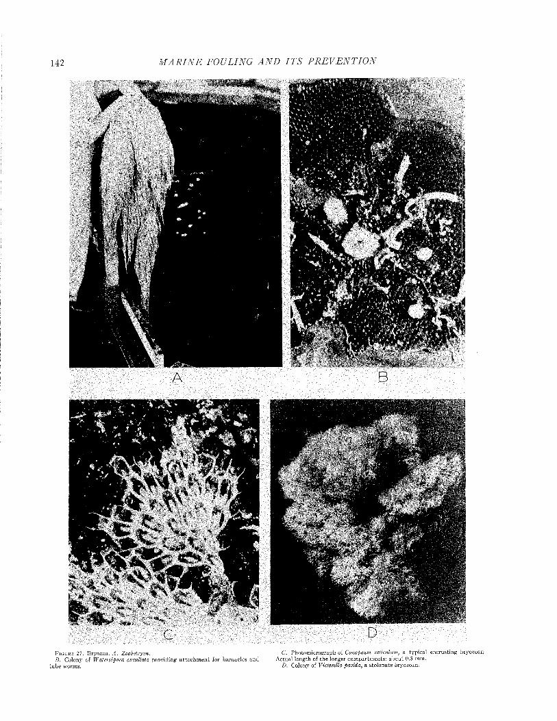
M A R I N E FOULING A N D I T S P R E V E N T I O N
F i g u r e 2 7 . Bryozoa. A . Zoobotryon. C. Photom icrograph o f Conopeum reticulum, a typical encrustingB . Colony of Watersipora cucullata providing a ttach m en t for barnacles and A ctual length of the longer com partm ents: abou t 0.5 m m .
tube worms. D. Colony of Victorella pavida, a stolonate bryozoan.
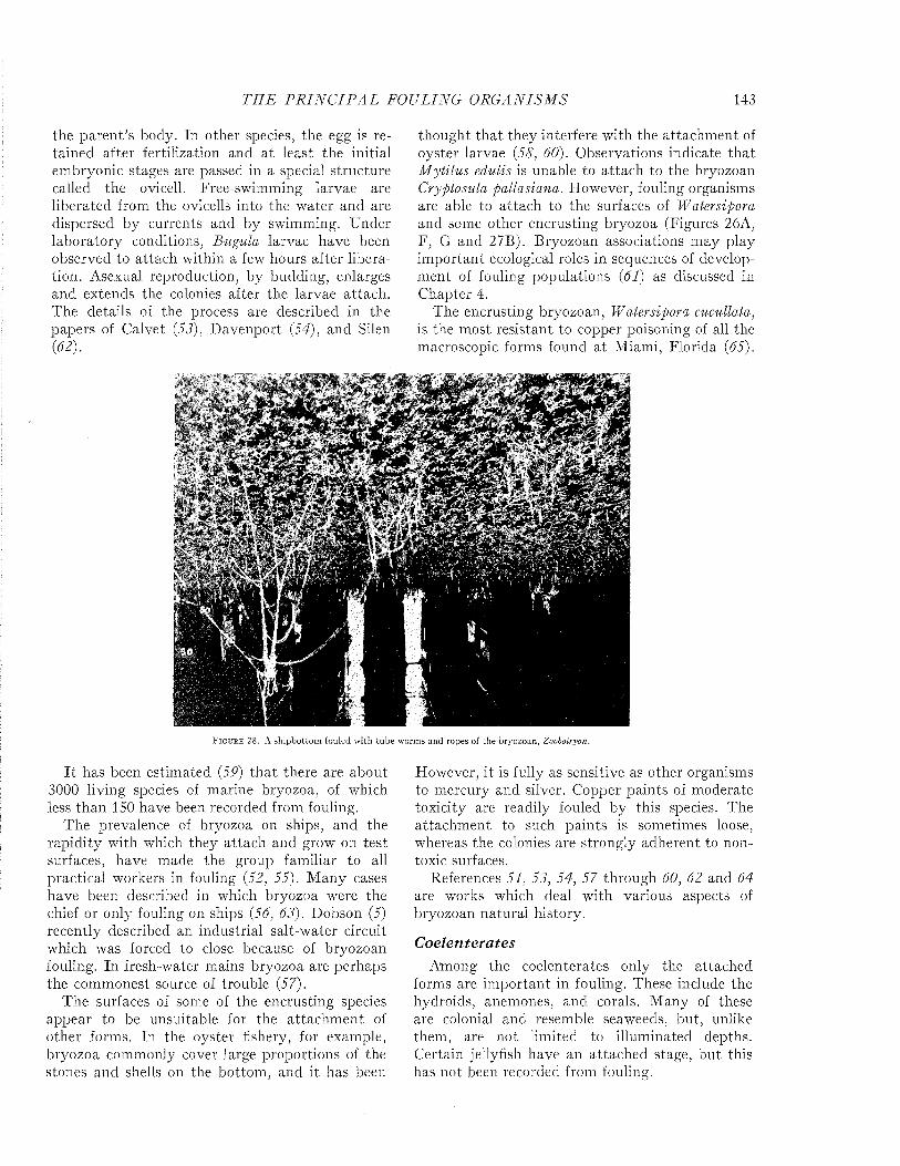
T H E P R I N C I P A L FOULING O R G A N ISM S 143
the paren t’s body. In other species, the egg is retained after fertilization and at least the initial embryonic stages are passed in a special structure called the ovicell. Free-swimming larvae are liberated from the ovicells into the water and are dispersed by currents and by swimming. Under laboratory conditions, Bugula larvae have been observed to attach within a few hours after liberation. Asexual reproduction, by budding, enlarges and extends the colonies after the larvae attach. The details of the process are described in the papers of Calvet (53), Davenport (54), and Silen (62).
thought tha t they interfere with the attachm ent of oyster larvae (58, 60). Observations indicate tha t M ytilus edulis is unable to attach to the bryozoan Cryptosula pallasiana. Flowever, fouling organisms are able to attach to the surfaces of Watersipora and some other encrusting bryozoa (Figures 26A, F, G and 27B). Bryozoan associations may play im portant ecological roles in sequences of development of fouling populations (61) as discussed in Chapter 4.
The encrusting bryozoan, Watersipora cucullata, is the most resistant to copper poisoning of all the macroscopic forms found at Miami, Florida (65).
mm
«
F i g u r e 28 . A s h ip b o t to m fo u le d w i th t u b e w o r m s a n d ro p e s o f t h e b r y o z o a n , Zoobotryon.
I t has been estimated (59) th a t there are about 3000 living species of marine bryozoa, of which less than 150 have been recorded from fouling.
The prevalence of bryozoa on ships, and the rapidity with which they attach and grow on test surfaces, have made the group familiar to all practical workers in fouling (52, 55). M any cases have been described in w'hich bryozoa were the chief or only fouling on ships (56, 63). Dobson (5) recently described an industrial salt-water circuit which was forced to close because of bryozoan fouling. In fresh-water mains bryozoa are perhaps the commonest source of trouble (57).
The surfaces of some of the encrusting species appear to be unsuitable for the attachm ent of other forms. In the oyster fishery, for example, bryozoa commonly cover large proportions of the stones and shells on the bottom, and it has been
However, it is fully as sensitive as other organisms to mercury and silver. Copper paints of moderate toxicity are readily fouled by this species. The attachm ent to such paints is sometimes loose, whereas the colonies are strongly adherent to nontoxic surfaces.
References 51, 53, 54, 57 through 60, 62 and 64 are works which deal with various aspects of bryozoan natural history.
C oelen teratesAmong the coelenterates only the attached
forms are im portant in fouling. These include the hydroids, anemones, and corals. M any of these are colonial and resemble seaweeds, but, unlike them, are not limited to illuminated depths. Certain jellyfish have an attached stage, but, this has not been recorded from fouling.
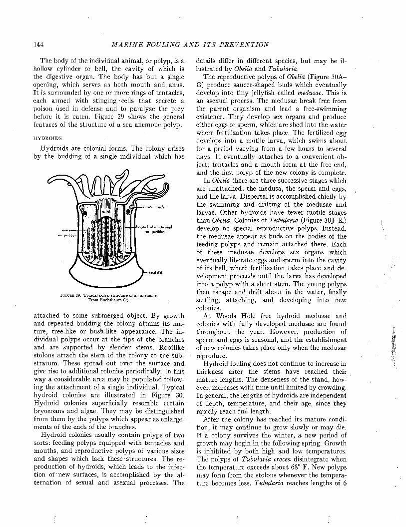
144 M A R I N E FOULING A N D I T S P R E V E N T I O N
The body of the individual animal, or polyp, is a hollow cylinder or bell, the cavity of which is the digestive organ. The body has but a single opening, which serves as both mouth and anus. It is surrounded by one or more rings of tentacles, each armed with stinging cells that secrete a poison used in defense and to paralyze the prey before it is eaten. Figure 29 shows the general features of the structure of a sea anemone polyp.
HYDROIDS
Hydroids ace colonial forms. The colony arises by the budding of a single individual which has
F i g u r e 29. Typical polyp structure of an anemone. From Buchsbaum (2).
attached to some submerged object. By growth and repeated budding the colony attains its mature, tree-like or bush-like appearance. The individual polyps occur at the tips of the branches and are supported by slender stems. Rootlike stolons attach the stem of the colony to the substratum. These spread out over the surface and give rise to additional colonies periodically. In this way a considerable area may be populated following the attachment of a single individual. Typical hydroid colonies are illustrated in Figure 30. Hydroid colonies superficially resemble certain bryozoans and algae. They may be distinguished from them by the polyps which appear as enlargements of the ends of the branches.
Hydroid colonies usually contain polyps of two sorts: feeding polyps equipped with tentacles and mouths, and reproductive polyps of various sizes and shapes which lack these structures. The reproduction of hydroids, which leads to the infection of new surfaces, is accomplished by the alternation of sexual and asexual processes. The
details differ in different species, but may be illustrated by Obelia and Tubularia.
The reproductive polyps of Obelia (Figure 30A- G) produce saucer-shaped buds which eventually develop into tiny jellyfish called medusae. This is an asexual process. The medusae break free from the parent organism and lead a free-swimming existence. They develop sex organs and produce either eggs or sperm, which are shed into the water where fertilization takes place. The fertilized egg develops into a motile larva, which swims about for a period varying from a few hours to several days. It eventually attaches to a convenient object; tentacles and a mouth form at the free end, and the first polyp of the new colony is complete.
In Obelia there are three successive stages which are unattached: the medusa, the sperm and eggs, and the larva. Dispersal is accomplished chiefly by the swimming and drifting of the medusae and larvae. Other hydroids have fewer motile stages than Obelia. Colonies of Tubularia (Figure 30J-K) develop no special reproductive polyps. Instead, the medusae appear as buds on the bodies of the feeding polyps and remain attached there. Each of these medusae develops sex organs which eventually liberate eggs and sperm into the cavity of its bell, where fertilization takes place and development proceeds until the larva has developed into a polyp with a short stem. The young polyps then escape and drift about in the water, finally settling, attaching, and developing into new colonies.
At Woods Hole free hydroid medusae and colonies with fully developed medusae are found throughout the year. However, production of sperm and eggs is seasonal, and the establishment of new colonies takes place only when the medusae reproduce.
Hydroid fouling does not continue to increase in thickness after the stems have reached their mature lengths. The denseness of the stand, however, increases with time until limited by crowding. In general, the lengths of hydroids are independent of depth, temperature, and their age, since they rapidly reach full length.
After the colony has reached its mature condition, it may continue to grow slowly or may die. If a colony survives the winter, a new period of growth may begin in the following spring. Growth is inhibited by both high and low temperatures. The polyps of Tubularia crocea disintegrate when the temperature exceeds about 68° F. New polyps may form from the stolons whenever the temperature becomes less. Tubularia reaches lengths of 6
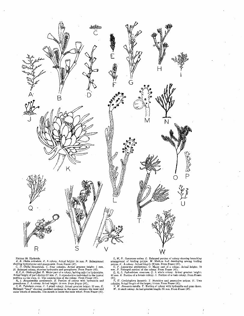
F i g u r e 30. Hydroids.A, B . Obelia articulata. A . A colony. Actual height: 54 mm. B. Enlargement
showing hydrothecae and gonophores. From Fraser (45).C, D. Obelia'bicuspidata. C. Four colonies. Actual greatest height: 5 mm.
D. Enlarged colony, showing hydranths and gonophores. From Fraser (45).E , F, G. Obelia griffini. E . Major part of a colony, lacking only the hydrorhiza.
Actual height of part shown: 27 mm. F. A reproductive individual in the typical position on the stem. G. The construction of the colony. From Fraser (45).
H , I . Bougainvillia carolinensis. H. Portion of colony with hydranths and gonophores. I . A colony. Actual height: 26 mm. From Fraser (45).
J , K . Tubularia crocea. J . A small colony. Actual greatest height: 23 mm. K . Enlarged “head” showing modified medusae in the space between the inner and outer whorls of tentacles. The mouth is inside the inner whorl. From Fraser (45).
L, M , N . Syncoryne exima. L: Enlarged portion of colony showing branching arrangement of feeding polyps. M . Medusa bud developing among feeding polyps. N . A colony. Actual length: 50 mm. From Fraser (45).
0 , P. Lytocarpus philippinus. 0 . Major part of a colony. Actual height: 71 mm. P . Enlarged portion of the colony. From Fraser (45).
Q, R, S . Eudendrium ramosum. Q. A whole colony. Actual greatest height: 43 mm. R. Portion of a female colony. S. Portion of a male colony. From Fraser (45).
T, U. Cordylophora lacustris.’ T. Nutritive and generative polyps. U. Two colonies. Actual length of the larger; 19 mm. From Fraser (45).
V, W . Pennaria tiarella. V. Portion of colony with hydranths and gono ihore.W . A small colony. Actual greatest length: 56 mm. From Fraser (45).
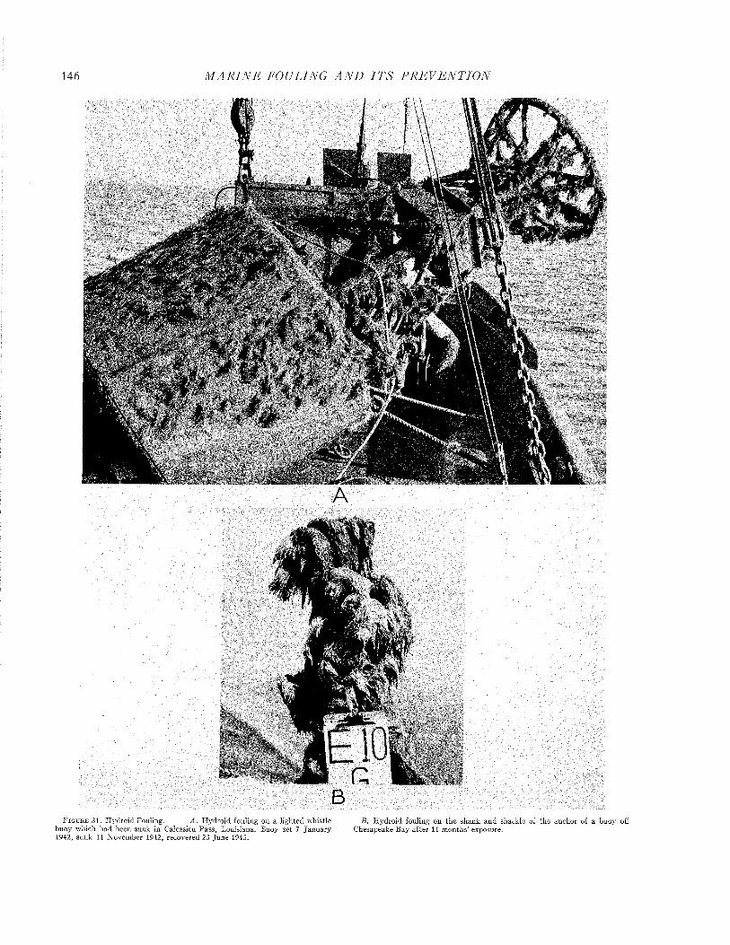
146 M A R I N E FOULING A N D I T S P R E V E N T I O N
N* i, >fc -V ' %k ><£?** . .*> /■■■ 'i'B.1*'<%«T> s k'-■c » V<- i ,i X i / : 5 « * * *
4 wr
i
ElO ■H H
■ H l
F i g u r e 31. H ydroid Fouling. ^4. H ydroid fouling on a lighted w histle B . H ydroid fouling on the shank and shackle of the anchor of a buoy 1buoy which had been sunk in Calcasieu Pass, Louisiana. Buoy set 7 January Chesapeake Bay after 11 m onths’ exposure.1942, sunk 11 N ovem ber 1942, recovered 23 June 1943.
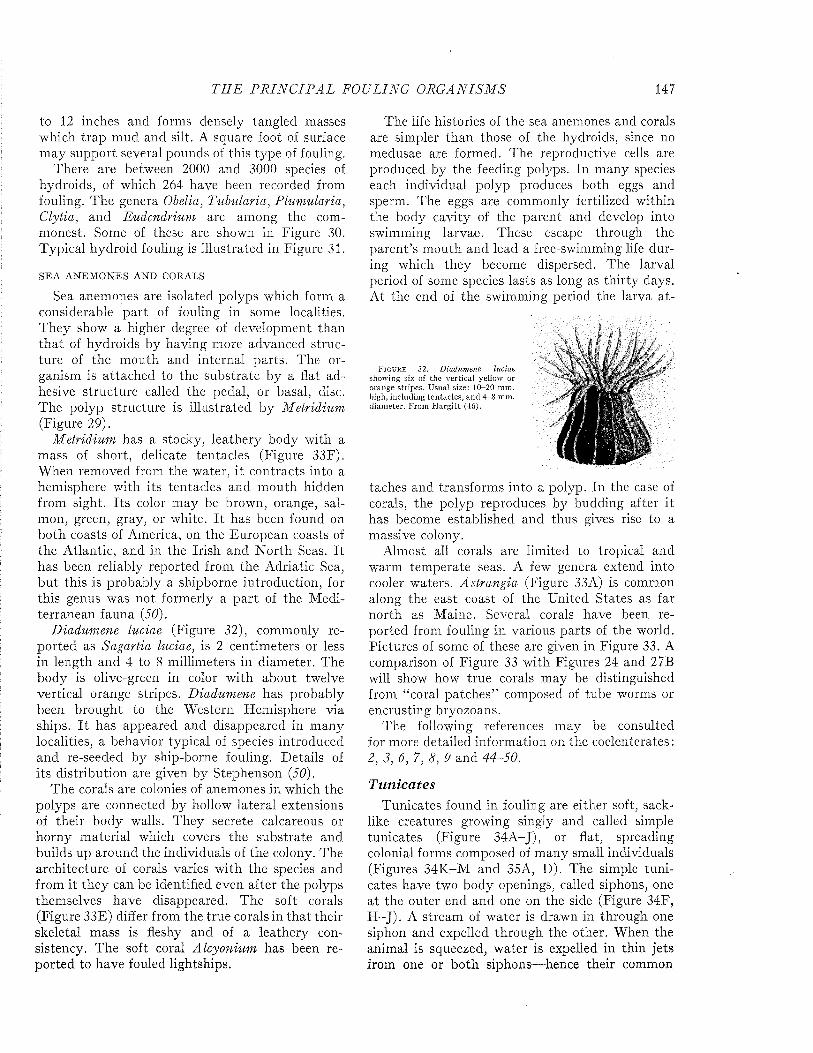
T H E P R I N C I P A L FOULING O R G A N IS M S 147
to 12 inches and forms densely tangled masses which trap mud and silt. A square foot of surface may support several pounds of this type of fouling.
There are between 2000 and 3000 species of hydroids, of which 264 have been recorded from fouling. The genera Obelia, Tubularia, Plumularia, Clytia, and Eudendrium are among the commonest. Some of these are shown in Figure 30. Typical hydroid fouling is illustrated in Figure 31.
SEA ANEM ONES AND CORALS
Sea anemones are isolated polyps which form a considerable part of fouling in some localities. They show a higher degree of development than th a t of hydroids by having more advanced structure of the m outh and internal parts. The organism is attached to the substrate by a flat adhesive structure called the pedal, or basal, disc. The polyp structure is illustrated by Metridium (Figure 29).
Metridium has a stocky, leathery body with a mass of short, delicate tentacles (Figure 33F). When removed from the water, it contracts into a hemisphere with its tentacles and m outh hidden from sight. Its color may be brown, orange, salmon, green, gray, or white. I t has been found on both coasts of America, on the European coasts of the Atlantic, and in the Irish and N orth Seas. I t has been reliably reported from the Adriatic Sea, bu t this is probably a shipborne introduction, for this genus was not formerly a part of the Mediterranean fauna (50).
Diadumene luciae (Figure 32), commonly reported as Sagartia luciae, is 2 centimeters or less in length and 4 to 8 millimeters in diameter. The body is olive-green in color with about twelve vertical orange stripes. Diadumene has probably been brought to the Western Hemisphere via ships. I t has appeared and disappeared in many localities, a behavior typical of species introduced and re-seeded by ship-borne fouling. Details of its distribution are given by Stephenson (50).
The corals are colonies of anemones in which the polyps are connected by hollow lateral extensions of their body walls. They secrete calcareous or horny m aterial which covers the substrate and builds up around the individuals of the colony. The architecture of corals varies with the species and from it they can be identified even after the polyps themselves have disappeared. The soft corals (Figure 33E) differ from the true corals in tha t their skeletal mass is fleshy and of a leathery consistency. The soft coral Alcyonium has been reported to have fouled lightships.
The life histories of the sea anemones and corals are simpler than those of the hydroids, since no medusae are formed. The reproductive cells are produced by the feeding polyps. In many species each individual polyp produces both eggs and sperm. The eggs are commonly fertilized within the body cavity of the parent and develop into swimming larvae. These escape through the parent’s mouth and lead a free-swimming life during which they become dispersed. The larval period of some species lasts as long as thirty days. At the end of the swimming period the larva at-
F i g u r e 3 2 . Diadumene luciae showing six of the vertical yellow or orange stripes. Usual size: 1 0 -2 0 mm. high, including tentacles, and 4-8 mm. diam eter. From H arg itt (46).
taches and transforms into a polyp. In the case of corals, the polyp reproduces by budding after it has become established and thus gives rise to a massive colony.
Almost all corals are limited to tropical and warm temperate seas. A few genera extend into cooler waters. Astrangia (Figure 33A) is common along the east coast of the United States as far north as Maine. Several corals have been reported from fouling in various parts of the world. Pictures of some of these are given in Figure 33. A comparison of Figure 33 with Figures 24 and 27B will show how true corals may be distinguished from “coral patches” composed of tube worms or encrusting bryozoans.
The following references may be consulted for more detailed information on the coelenterates : 2, 3, 6, 7, 8, 9 and 44-50.
TunicatesTunicates found in fouling are either soft, sack
like creatures growing singly and called simple tunicates (Figure 34A-J), or flat, spreading colonial forms composed of many small individuals (Figures 34K-M and 35A, D). The simple tunicates have two body openings, called siphons, one at the outer end and one on the side (Figure 34F, H -J). A stream of water is drawn in through one siphon and expelled through the other. When the animal is squeezed, water is expelled in thin jets from one or both siphons-—-hence their common
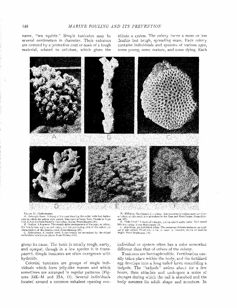
148 M A R I N E FOULING A N D I T S P R E V E N T I O N
name, “sea squirts.” Simple tunicates may be several centimeters in diameter. Their exteriors are covered by a protective coat or tunic of a tough m aterial, related to cellulose, which gives the
stitute a system. The colony forms a more or less flexible but tough, spreading mass. Each colony contains individuals and systems of various ages, some young, some mature, and some dying. Each
*
F i g u r e 33. Coelenterates.A . Astrangia danae. A clump of the coral showing the ra ther w ide b u t shallow
cups in which the polyps were seated. This coral is found from Florida to Cape Cod. I t has also been found in Casco Bajr, M aine. F rom H arg itt (46),
B . Oculina. A fragm ent. T he steeply spiral arrangem ent of the cups, or calices, the tw enty-four septa in each calyx, and the pro truding rim s of the calices are characteristic of this tropical coral. From Hickson (47).
C. Siderastraea. A tropical coral, i t can usually be recognized by the ridged walls which separate its calices. From Hickson (47).
D. Millepora. One branch of a colony. T he two sizes of surface pores are charac teristic of this coral; i t is ab undan t in the E a st and W est Indies. From H ickson (47).
E . “Soft Coral.” A series of colonies, photographed under w ater. Each round lobe is a colony. From Buchsbaum (2).
F. M etridium. An individual polyp. T he numerous delicate tentacles are typ ical of this anim al. Usual size: 5 cm. or more in diameter, 10 cm. or more in height. From Stephenson (5(9).
group its name. The tunic is usually rough, warty, and opaque, though in a few species it is transparent. Simple tunicates are often overgrown with hydroids.
Colonial tunicates are groups of single individuals which form jelly-like masses and which sometimes are arranged in regular patterns (Figures 34K-M and 35A, D). Several individuals located around a common exhalent opening con-
individual or system often has a color somewhat different than tha t of others of the colony.
Tunicates are hermaphroditic. Fertilization usually takes place within the body, and the fertilized egg develops into a long-tailed larva resembling a tadpole. The “tadpole” swims about for a few hours, then attaches and undergoes a series of changes during which the tail is absorbed and the body assumes its adult shape and structure. In
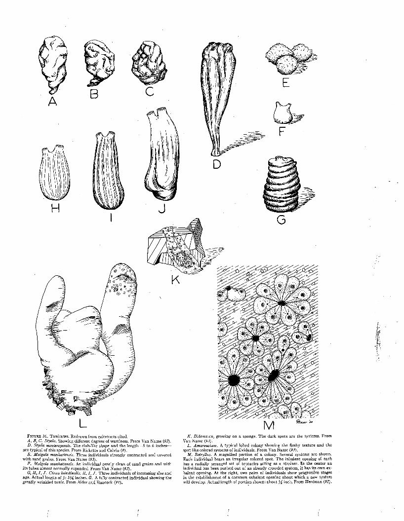
LF i g u r e 34. Tunicates. Redrawn from references cited.A, B, C. Styela. Showing different degrees of wartiness. From Van Name (93).D. Styela montereyensis. The club-like shape and the length— 5 to 6 inches—
are typical of this species. From Ricketts and Calvin (9).E . Molgula manhattensis. Three individuals strongly contracted and covered
with sand grains. From Van Name (93).F, Molgula manhattensis. An individual nearly clean of sand grains and with
its tubes almost normally expanded. From Van Name (93).G, H, I , J . Ciona intestinalis. II, I, J . Three individuals of increasing size and
age. Actual length of J: 334 inches. G. A fully contracted individual showing the greatly wrinkled tunic. From Alder and Hancock (91).
K . Didemnum, growing on a sponge. The dark spots are the systems. From Van Name (93).
L. Amaroucium. A typical lobed colony showing the fleshy texture and the spot-like colored systems of individuals. From Van Name (93).
M . Botryllus. A magnified portion of a colony. Several systems are shown. Each individual bears an irregular colored spot. The inhalent opening of each has a radially arranged set of tentacles acting as a strainer. In the center an individual has been pushed out of an already crowded system, it has its own exhalent opening. At the right, two pairs of individuals show progressive stages in the establishment of a common exhalent opening about which a new system will develop. Actual length of portion shown: about l/ i inch. From Herdman (92).

150 M A R I N E FOULING A N D I T S P R E V E N T I O N
A' m ;î t .
H t* -
• • „•• • » * ■ .:«*•
F i g u r e 35. Tunicates./ i . Colonial tunicates, showing the arrangem ent of the systems.B. Heavy fouling by simple tunicates. These animals a ttach with only m oder
ate firmness and m any are swept off when the vessel gets under way.
UC. A cluster of Styela growing on a sash-weight used as a sinker for test-panels
a t Beaufort, N orth Carolina.D. A colonial tunicate growing on a group of barnacles and Anom ia on a failing
painted panel a t M iam i Beach.

TH E P R I N C I P A L FOULING ORGA NISMS 151
addition to sexual reproduction, the colonial species propagate by budding. The offspring in some species remain permanently connected to the parent by horizontal branches. In others the branches become severed ; each separate individual then, by further budding, establishes a new system.
The simple tunicates reproduce mostly by sexual means. Since there is little budding, there are usually no true colonies of connected individuals, though some species, grow in clusters (Figure 35B, C).
Over 700 valid species of tunicates have been described. One hundred and eighteen species have been reported in fouling.
THE SIMPLE TUNICATES
Styela (Figures 34A-Ç and 35 C) is an egg- shaped tunicate which is attached by its narrower end. Its outer surface is leathery, rough, and opaque ; generally it is deeply wrinkled, with most of the wrinkles running lengthwise. Both its siphons have 4 lobes on their margins. The colors range from whitish to dirty browns. Styela seldom exceeds two inches in length, though S. montereyensis (Figure 34D) of the Pacific coast attains lengths of five or six inches. This genus is widely known from all parts of the world.
Molgula (Figure 34E, F) is globular in shape. The tunic is translucent but ordinarily covered with sand grains or bits of detritus. When found on buoys or ships its tunic is usually incompletely covered, since in these locations it does not have access to as much sand, etc., as when growing on piles, stones, and algae. Molgula frequently grows in clusters.
The siphons of Molgula are tubes of unequal length. They arise close together and curve away from each other. When the animal is disturbed, the tubes are almost completely retracted into the body. The aperture of the short tube is guarded by six lobes; that of the other by four lobes. Only one species exceeds two inches in diameter. The others are less than If inches.
Ciona (Figure 34G-J) is an elongated, sub- cylindrical, flabby tunicate. It tapers from the attachment toward the free end. The siphons are short tubes, close together on the free end. In living specimens the margins of the apertures are bright yellow and each bears a circle of red spots. These colors usually fade in preserved specimens. One aperture has 8 lobes, the other 6 lobes. The tunic is smooth and translucent, allowing the greenish-yellow color of the internal organs to
show plainly. Ciona has a remarkable ability to contract; its upper parts can be withdrawn into the lower parts like a finger of a glove. When removed from the water it contracts and wrinkles markedly. Its contracted condition is shown in Figure 34G.
Ciona attains a length of three to four inches. It occurs on rocks, shells, and the roots of algae, from the intertidal zone to deep water. Ships, buoys, floats, and test panels have been fouled by this tunicate. It is widely distributed on both coasts of North America and in the Arctic. It also occurs in Europe and Asia.
THE COLONIAL TUNICATES
Amaroucium (Figure 34L), the sea pork, is a massive, fleshy colonial tunicate with a smooth surface. The systems are of complex arrangement with the orange-red individuals showing through the greyish or flesh-colored tunic. It is frequently washed up on beaches where it is sometimes mistaken for ambergris.
Didemnum (Figure 34K) forms very thin encrusting colonies of whitish, yellow, or pinkish color. The tunic is often so densely crowded with minute calcareous spicules as to render the colony hard, brittle, and opaque.
Species of Didemnum are numerous in warm seas. There are two Arctic and three Antarctic species. Didemnum is very common on test panels, where it overgrows other fouling organisms.
The botryllid tunicates (Figure 34M) include the genera Botryllus and Botrylloides which are of almost world-wide distribution. They can be distinguished from each other only by dissection of the individual animal. Both genera form colonies ranging from thin encrusting types to thick fleshy masses. The tunic is transparent and gelatinous, covering purple or black tissues. The systems are oval or elongated, and are variously colored with shades of blue, yellow, green, brown or purple. The colonies are strikingly handsome.
References 1, 2, 3, 7, 9, 91, 92 and 93 give further details on tunicates.
SpongesTo the naked eye, a living sponge is a slimy,
varicolored mass. The sponge body is porous, though most of the pores are microscopic in size. Each sponge has one or more relatively large openings in its surface. If crushed, many sponges emit a strong putrid odor, somewhat like rotting fish, or sometimes, rotten eggs.
A few sponges are strikingly colored, ranging
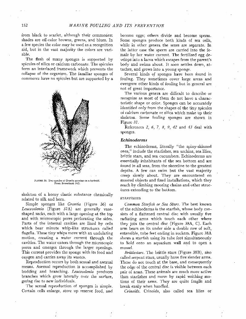
152 M A R I N E FOULING A N D I T S P R E V E N T I O N
from black to scarlet, although their commonest shades are off-color browns, greens, and blues. In a few species the color may be used as a recognition aid, but in the vast majority the colors are variable.
The flesh of many sponges is supported by spicules of silica or calcium carbonate. The spicules form an interlaced framework which prevents the collapse of the organism. The familiar sponges of commerce have no spicules but are supported by a
m
F i g u r e 3 6 . Two species of Grantia growing on a hydroid. From Bowerbank {42).
skeleton of a horny elastic substance chemically related to silk and horn.
Simple sponges like Grantia (Figure 36) or Leucosolenia (Figure 37A) are generally vaseshaped sacks, each with a large opening at the top and with microscopic pores perforating the sides. Parts of the internal cavities are lined by cells which bear minute whip-like structures called flagella. These tiny whips move with an undulating motion, creating a water current through the cavities. The water enters through the microscopic pores and emerges through the larger openings. This current provides the sponge with its food and oxygen and carries away its wastes.
Reproduction occurs by both sexual and asexual means. Asexual reproduction is accomplished by budding and branching. Leucosolenia produces branches which grow laterally over the surface, giving rise to new individuals.
The sexual reproduction of sponges is simple. Certain cells enlarge, store up reserve food, and
become eggs; others divide and become sperm. Some sponges produce both kinds of sex cells, while in other genera the sexes are separate. In the latter case the sperm are carried into the female by her water current. The fertilized egg develops into a larva which escapes from the parent’s body and swims about. It soon settles down, attaches, and grows into a young sponge.
Several kinds of sponges have been found in fouling. They sometimes cover large areas and overgrow other kinds of fouling but in general are not of great importance.
The various genera are difficult to describe or recognize as most of them do not have a characteristic shape or color. Sponges can be accurately identified only from the shapes of the tiny spicules of calcium carbonate or silica which make up their skeleton. Some fouling sponges are shown in Figure 37.
References 2, 6, 7, 8, 9, 42 and 43 deal with sponges.
Echinoderm sThe echinoderms, literally “the spiny-skinned
ones,” include the starfishes, sea urchins, sea lilies, brittle stars, and sea cucumbers. Echinoderms are essentially inhabitants of the sea bottom and are found in all seas, from the shoreline to the greatest depths. A few can swim but the vast majority creep slowly about. They are encountered on moored objects and fixed installations, which they reach by climbing mooring chains and other structures extending to the bottom.
STARFISHES
Common Starfish or Sea Stars. The best known of the echinoderms is the starfish, whose body consists of a flattened central disc with usually five radiating arms which touch each other where they join the central disc (Figure 38A, C). Each arm bears on its under side a double row of soft, extensible, tube feet ending in suckers. Figure 38A shows a starfish using its tube feet simultaneously to hold onto an aquarium wall and to open a mussel.
Brittlestars. The brittle stars (Figure 38B), also called serpent stars, usually have five slender arms. These do not touch at the base, and consequently the edge of the central disc is visible between each pair of arms. These animals are much more active than starfishes and move by rapid writhing motions of their arms. They are quite fragile and break easily when handled.
Crinoids. Crinoids, also called sea lilies or
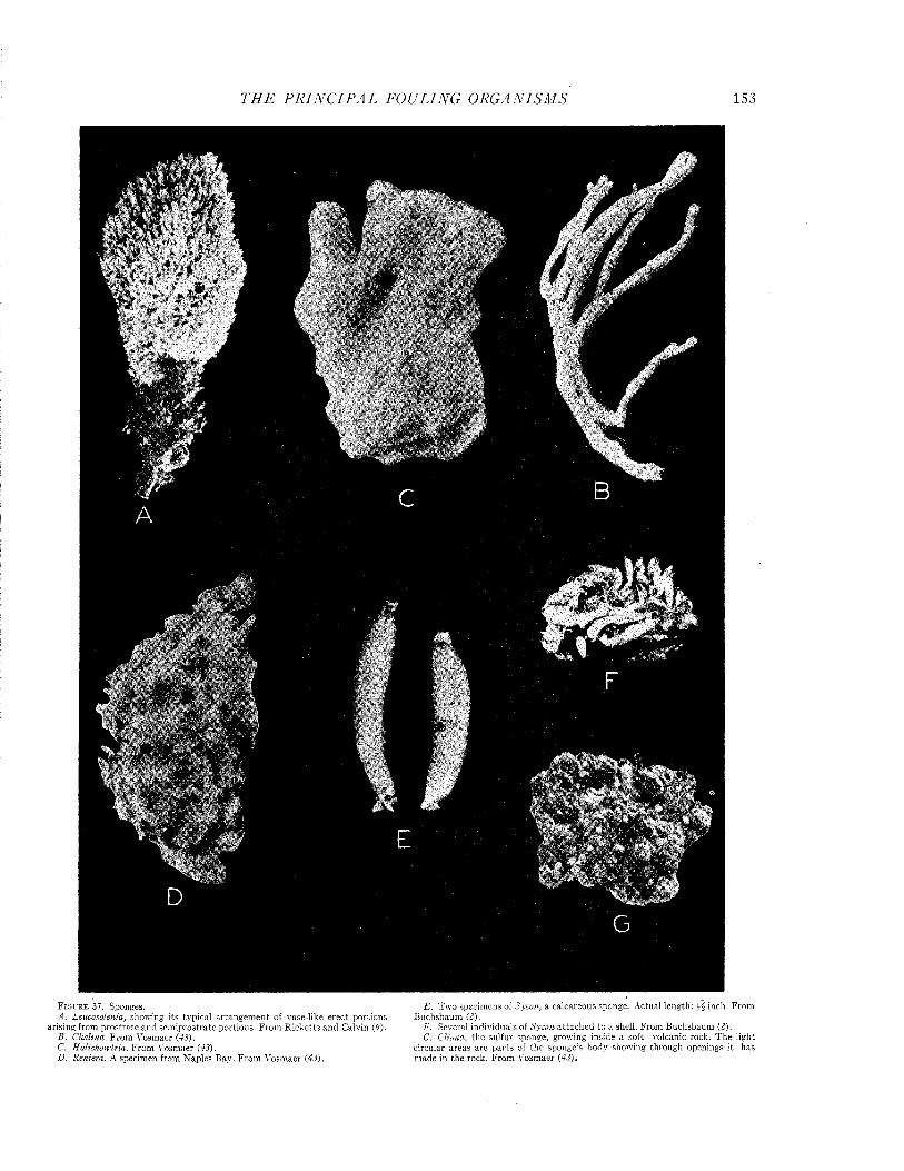
T H E P R I N C I P A L FOULING O R G A N IS M S 153
F i g u r e 37 Sponges E - T " '° specimens of Sycon, a calcareous sponge. Actual length: h i inch. FromA . Leucosolenia, showing its typical arrangem ent of vase-like erec t portions Buchsbaum (2). ,. . . , ,, p Pnchshaum Í? 1
arising from prostrate and sem iprostrate portions. From R icketts and Calvin (9). I'. Several individua s o V ■ . . , voicanfc rock T hé lw htn r ; , 1411 G- Cliona, the sulfur sponge, growing inside a so tt volcanic rock, m e n n tC. F rom V o siL er (43). circular areas a re parts of th e sponge’s body showing through openings , t hasD. Reniera. A specimen from Naples Bay. From Vosmaer (43). made m the rock. From Vosmaer (43).
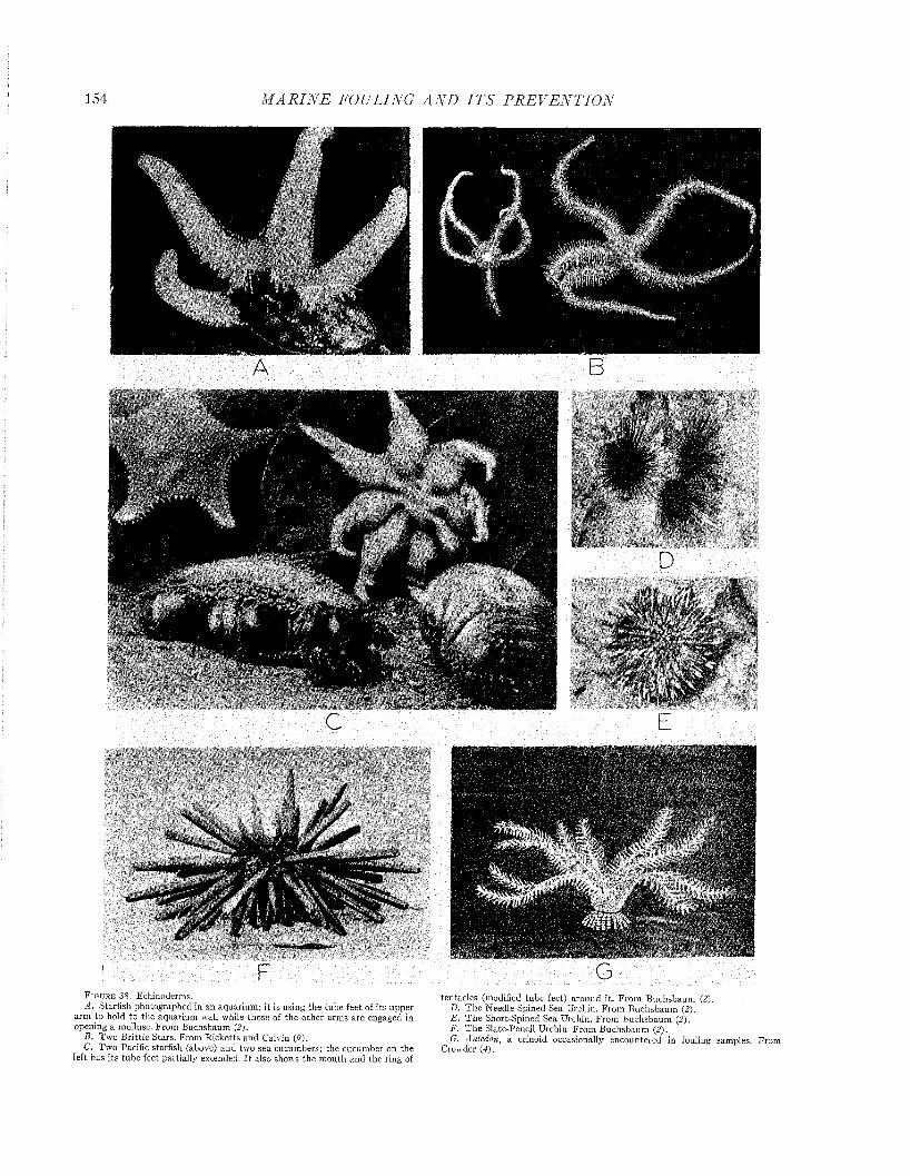
154 M A R I N E FOULING A N D I T S P R E V E N T I O N
F GF i g u r e 38, Echinoderms.A . Starfish photographed in an aquarium ; i t is using the tube feet of its upper
arm to hold to the aquarium wall while those of the o ther arm s are engaged in opening a mollusc. From Buchsbaum (2).
B . Tw o B rittle Stars. From R icketts and Calvin (P).C. Two Pacific starfish (above) and two sea cucumbers; the cucumber on the
left has its tube feet partially extended. I t aiso shows the m outh and the ring of
tentacles (modified tube feet) around it. F rom B uchsbaum (2).D. T he Needle-Spined Sea Urchin. F rom B uchsbaum (2).E . T h e Short-Spined Sea Urchin. From B uchsbaum (2).F. T h e Slate-Pencil Urchin. From B uchsbaum (2).G. Antedon, a crinoid occasionally encountered in fouling samples. From
Crowder (4),

T H E P R I N C I P A L FOULING O R G A N ISM S 155
feather stars, have five arms, each branched and rebranched several times. Each branch and subbranch has two rows of fine branchlets along its sides presenting a feathery appearance. Young crinoids are attached to the bottom by a stalk which is retained by the adults in some species but is lost in others.
The crinoid most frequently reported in fouling is Antedon (Figure 38G). I t passes through an attached stage, but as it nears m aturity the stalk is absorbed and replaced by several slender, curved, moveable outgrowths called cirri. This animal can swim by means of its arms or attach i tself temporarily by its cirri.
Sea Cucumbers. The sea cucumber (Figure 38C), an elongated bag-like animal, reveals its relationship to other echinoderms by having five rows of tube feet similar to those of the starfish. The leathery, cylindrical body has no spines, and its calcareous skeleton has been reduced to isolated plates scattered throughout the muscular body wall. The m outh is situated at one end and is surrounded by a ring of soft, many-branched tentacles.
Sea Urchins. Sea Urchins (Figure 38D-F) have hard, bun-shaped bodies covered by movable spines attached to the shell by ball-and-socket joints. Among the spines, are the typical five double rows of tube feet. M ost sea urchins have five large pointed teeth, which protrude from the m outh and meet in a sharp point.
References 1, 2, 3, 7, 8, 76, 77 and 78 deal with echinoderms.
FishesSeveral genera of fishes have been found in
samples of fouling. These are mostly small forms which probably find both food and shelter amongst the fouling population. Blennies (Figures 39 and 40) are the commonest. They are generally small, active fishes and probably contribute little to the general effects of the fouling.
Certain fishes of the Sea-Bream group have an indirect effect on fouling and corrosion. Because of this they deserve mention here, although they are never taken in fouling samples. These fish feed on barnacles, tearing them from the surface, fracturing the paint film, and exposing the underlying surface to other fouling and to corrosion.
Remoras (Figure 41), also called shark-suckers, have been reported (94) to attach temporarily to ship hulls.
References 3, 94 and 95 deal with fishes.
AlgaeAlgae include such aquatic plants as sea weeds
and diatoms. All algae contain the green pigment, chlorophyll, by means of which they manufacture their own foods. Since light is necessary for this
/• ' '
F i g u r e 39. A blenny, one of the small fishes which are frequently taken among fouling samples. From Jordan and Everm ann (95).
F i g u r e 4 0 . A b le n n y c l in g in g to a t e s t p a n e l .
F i g u r e 41. Remora brachyptera, the shark sucker. T h e dorsal fin is modified into a suction cup. This fish usually attaches to sharks b u t also steals rides on ships and is occasionally taken in fouling samples. From Jordan and Everm ann (95).
process, they do not foul dark or shaded surfaces and are usually restricted to the vicinity of the water line.
These plants are classified as blue-green, green, red, or brown algae on the basis of their predominant color. N ot all species are typical in this respect, so morphological characters are used as the basis of accurate identification.
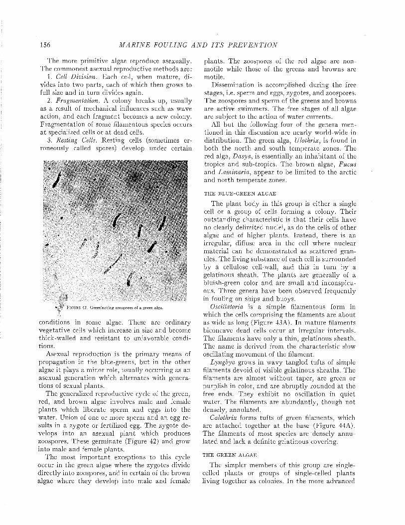
156 M A R I N E FOULING A N D I T S P R E V E N T I O N
The more primitive algae reproduce asexually. The commonest asexual reproductive methods are :
1. Cell Division. Each cell, when mature, divides into two parts, each of which then grows to full size and in turn divides again.
2. Fragmentation. A colony breaks up, usually as a result of mechanical influences such as wave action, and each fragment becomes a new colony. Fragmentation of some filamentous species occurs a t specialized cells or a t dead cells.
3. Resting Cells. Resting cells (sometimes erroneously called spores) develop under certain
I
conditions in some algae. These are ordinary vegetative cells which increase in size and become thick-walled and resistant to unfavorable conditions.
Asexual reproduction is the primary means of propagation in the blue-greens, but in the other algae it plays a minor role, usually occurring as an asexual generation which alternates with generations of sexual plants.
The generalized reproductive cycle of the green, red, and brown algae involves male and female plants which liberate sperm and eggs into the water. Union of one or more sperm and an egg results in a zygote or fertilized egg. The zygote develops into an asexual plant which produces zoospores. These germinate (Figure 42) and grow into male and female plants.
The most im portant exceptions to this cycle occur in the green algae where the zygotes divide directly into zoospores, and in certain of the brown algae where they develop into male and female
1 M!
r / >• / .
s
fillF i g u r e 4 2 . Germinating zoospores of a green alga.
plants. The zoospores of the red algae are non- motile while those of the greens and browns are motile.
Dissemination is accomplished during the free stages, i.e. sperm and eggs, zygotes, and zoospores. The zoospores and sperm of the greens and browns are active swimmers. The free stages of all algae are subject to the action of water currents.
All but the following four of the genera mentioned in this discussion are nearly world-wide in distribution. The green alga, Ulothrix, is found in both the north and south temperate zones. The red alga, Dasya, is essentially an inhabitant of the tropics and sub-tropics. The brown algae, Fucus and Laminaria, appear to be limited to the arctic and north temperate zones.
THE BLU E-G REEN ALGAE
The plant body in this group is either a single cell or a group of cells forming a colony. Their outstanding characteristic is that their cells have no clearly delimited nuclei, as do the cells of other algae and of higher plants. Instead, there is an irregular, diffuse area in the cell where nuclear material can be demonstrated as scattered granules. The living substance of each cell is surrounded by a cellulose cell-wall, and this in turn by a gelatinous sheath. The plants are generally of a bluish-green color and are small and inconspicuous. Three genera have been observed frequently in fouling on ships and buoys.
Oscillatoria is a simple filamentous form in which the cells comprising the filaments are about as wide as long (Figure 43A). In mature filaments biconcave dead cells occur a t irregular intervals. The filaments have only a thin, gelatinous sheath. The name is derived from the characteristic slow oscillating movement of the filament.
Lyngbya grow:s in wavy tangled tufts of simple filaments devoid of visible gelatinous sheaths. The filaments are almost without taper, are green or purplish in color, and are abruptly rounded at the free ends. They exhibit no oscillation in quiet water. The filaments are abundantly, though not densely, annulated.
Calothrix forms tufts of green filaments, which are attached together a t the base (Figure 44A). The filaments of most species are densely annulated and lack a definite gelatinous covering.
THE GREEN ALGAE
The simpler members of this group are singlecelled plants or groups of single-celled plants living together as colonies. In the more advanced
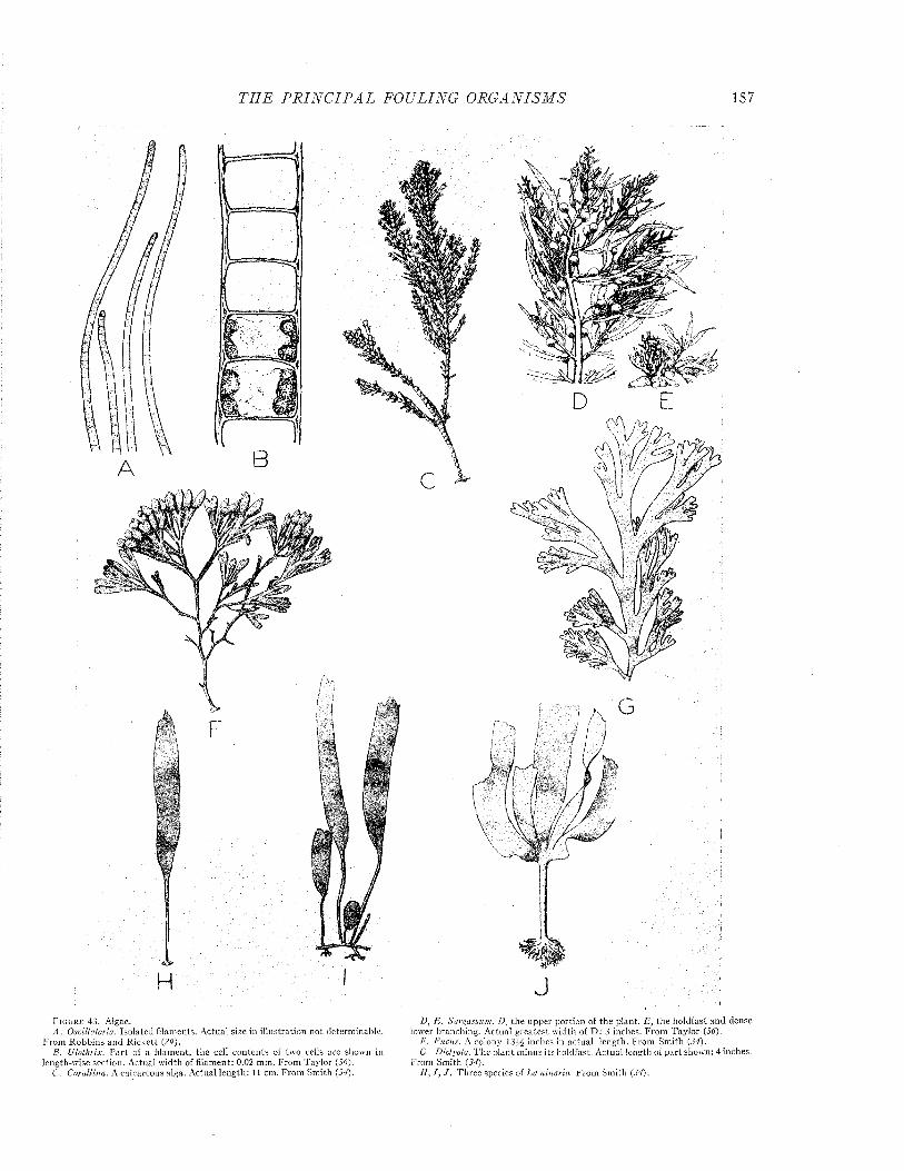
T H E P R I N C I P A L FOULING O R G A N IS M S 157
A
p
JF i g u r e 43. Algae.A . Oscillatoria. Isolated filaments. Actual size in illustration not determinable.
From R obbins and R ickett (29).B. Ulothrix. P a r t of a filament, the cell contents of two cells are shown in
length-wise section. Actual w idth of filament: 0.02 mm. From Taylor (34).C. Corallina. A calcareous alga. A ctual length : l í cm. From Smith (34).
D, E. Sargassum. D , the upper portion of the plant. E , the holdfast and dense lower branching. Actual greatest w idth of D : 3 inches. From Taylor (36).
I'. Fucus. A colony 1314 inches in ac tual length. F rom Sm ith (34).Cr. Dictyota. T he plan t m inus its holdfast. A ctual length of p a rt shown: 4 inches,
From Sm ith (34).H, I , J . Three species of Laminaria From Smith (34).
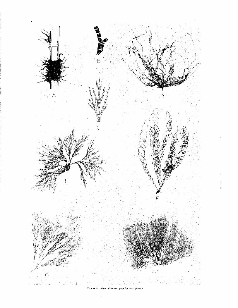
F i g u r e 4 4 . Algae. (See next page f o r description.)
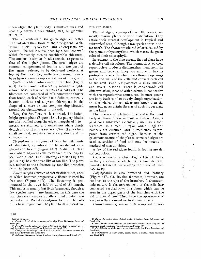
TH E P R I N C I P A L FOULING ORGA NISMS 159
green algae the plant body is multi-cellular and generally forms a filamentous, flat, or globular structure.
The cell contents of the green algae are better differentiated than those of the blue-greens. Well- defined nuclei, cytoplasm, and chloroplasts are present. The cell is surrounded by a cellulose wall which frequently attains considerable thickness. The nucleus is similar in all essential respects to that of the higher plants. The green algae are common components of fouling and are part of the “grass” referred to by dockyard workers. A few of the most frequently encountered genera have been chosen as representatives of this group.
Ulothrix is filamentous and unbranched (Figure 43B). Each filament attaches by means of a light- colored basal cell which serves as a holdfast. The filaments are composed of cells somewhat shorter than broad, each of which has a definite, centrally located nucleus and a green chloroplast in the shape of a more or less complete ring situated around the circumference of the cell.
Ulva, the Sea Lettuce, is a broad, flat-leafed, bright green plant (Figure 44F). Its papery blades are often ruffled along the edges. Lengths of 1 to meters are attained, and sometimes whole plants detach and drift on the surface. Ulva attaches by a small holdfast, and its stem is very short and inconspicuous.
Cladophora is composed of branched filaments of elongated, cylindrical or barrel-shaped cells placed end to end (Figure 44C). A distinct, clear area where adjacent cells meet each other may be seen with a lens. The branching exhibited by this genus may be either tree-like or fan-like. The plant is attached to the substrate by root-like branches from the lower cells.
Enteromorpha consists of soft flexible tubes, each of which becomes progressively flatter toward its free end (Figure 44D). The flattening is pronounced in the outer half or third of the length. This genus is usually but little branched, though a few species have many branches. In this case the branches are arranged radially around a cylindrical central stem. Root-like outgrowths from the cells of its basal region hold the plant to its substratum.
F i g u r e 44. Algae.A . Calothrix. A tuft of filaments on another alga. From Weber-van Bosse and
Foslie (35).B. Polysiphonia. An enlarged portion of the stem in which “siphons” or ver- •
tical tiers of cells can be seen. From Johnstone and Croall (27).C. Cladophora. An enlarged branch with the typical clear areas between the
cells. From Johnstone and Croall (27).D. Enteromorpha. Actual height: 5 inches. From Johnstone and Croall (27).
THE RED ALGAE
The red algae, a group of over 300 genera, are mostly marine plants of wide distribution. They attain their greatest development in tropical and subtropical seas, although a few species grow in the far north. The characteristic red color is caused by the pigment phycoerythrin, which masks the green color of their chlorophyll.
In contrast to the blue-greens, the red algae have a definite cell structure. The nonmotility of their reproductive products distinguishes them from the greens and browns. They are unique in having protoplasmic strands which pass through openings in the end walls of the cells and connect each cell to the next. Each cell possesses a single nucleus and several plastids. There is considerable cell differentiation, most of which occurs in connection with the reproductive structures. In most genera the body itself is of relatively simple organization. On the whole, the red algae are larger than the green but never attain the size of such brown algae as the kelps.
The presence of gelatinous material in the plant body is characteristic of most red algae. Agar, a gelatinous substance extensively used as a food stabilizer, as a medium upon which fungi and bacteria are cultured, and in medicines, is prepared from certain red algae. Because of the gelatinous nature of the plants, some red algae are used as articles of food and may be bought in markets of coastal cities.
A few of the red algae found in fouling are described below.
Dasya is much-branched (Figure 44E). It has a feathery appearance which results from delicate, hair-like filaments borne along the branches from base to tip.
Polysiphonia is also branched and feathery (Figure 44B, G). Its fine filaments, however, are confined to the tips of the branches. A characteristic feature is the arrangement of the cells into connected vertical rows or siphons which can be seen in the upper parts of the branches with the aid of a hand lens. They have the appearance of very exactly arranged vertical tiers of cells.
Callithamnion grows in tufts composed of sev-
E. Dasya. An entire plant. Actual width: 3 inches. From Johnstone and Croall (27).
F. Ulva. Several blades attached to a common substrate. Actual length of this specimen: about 6 inches. From Johnstone and Croall (27).
G. Polysiphonia. A whole plant, actual length: 6 inches. From Johnstone and Croall (27).
H. Callithamnion. A whole plant, actual height: 2 inches. From Johnstone and Croall (27).

160 M A R I N E FOULING A N D I T S P R E V E N T I O N
eral upright steins (Figure 44H). The stems branch repeatedly, which, in some species at least, gives each branch a fluffy appearance.
Ceramium has a prostrate and an erect portion. The erect portion is cylindrical, and the stem and branches are usually banded with the transverse light and dark red bands. The terminal branchlets of each branch bend toward each other like tongs.
Corallina is recognized by its calcified, encrusting base from which arise branched, jointed, flexible stems (Figure 43 C). The branching is predominately featherlike, practically every segment of the major branches bearing an opposite pair of branchlets. Each segment of the stem and of the main branches is calcified, flattened, and widened between the joints. The joints between segments are not calcified and are flexible.
Gracilaria has several erect branches, each ending in a single apical cell. The branches arise from a prostrate stem. They are cylindrical or sub- cylindrical and have a fleshy or cartilaginous texture. The central portion of the stem, if cut across, can be seen to be of large, colorless, angular cells. These are surrounded by a series of smaller cells which contain the red coloring matter.
THE BROWN ALGAE
The brown algae are marine plants of wide distribution. They attain their greatest development in colder seas. The characteristic color of these plants, varying from a dark brown to an olive green, is due to the presence of a brown pigment which more or less masks the ever-present chlorophyll. The brown color, and the presence of two laterally attached cilia on each zoospore, sperm, and egg, distinguish this group from both the green and the red algae.
There is! great diversity in structure among the various members of the group. Ectocarpus, Laminaria, and Fucus are good examples of this. Simpler forms like Ectocarpus form tufts of branching filaments which resemble the more complex green algae. The kelps, such as Laminaria, are enormous plants whose complicated bodies suggest, in their degree of differentiation, those of the higher plants. The kelp plant consists of a holdfast, a long slender stem, and a widened leaf-like blade. The stem may be hollow or be provided with a distinct, enlarged air bladder. The blade may be simple in outline or deeply cleft. The kelps vary in size from small plants a few feet in length to giant forms reaching lengths of 500 feet or more. At high tide the blades float on the surface of the water, buoyed up by air contained in the hollow stems or in the bladders.
These plants live at least two years. Their blades generally become torn and frayed by the action of the waves but are renewed by a ring of growing cells located at the junction of the blade and stem. Increase in diameter of the stem is made possible by the presence of a zone of dividing and growing cells. This layer develops new rings of tissue which resemble the annual rings of gfowth observed in the higher plants.
Another group of brown algae, the “rock weeds,” is common along rocky coasts in the north temperate zone. Fucus is the best known of this group. It grows attached to rocks at the shore line where it is alternately exposed and submerged by the tides.
A few of the brown algae common in fouling are described and illustrated as examples.
Ectocarpus is one of the best known of the simpler brown algae. It grows as a series of branching filaments, each of which consists of a single row of cells. The branches often terminate in colorless hairs. Each filament has an erect part and a prostrate portion which serves as a holdfast. The entire plant consists of a tuft of branched filaments attached by their prostrate portions to a rock or other object. Elongated, elliptical reproductive organs occupying the positions of lateral branchlets are typical of this genus.
Dictyota (Figure 43 G) is a flattened plant growing either unbranched with a row of large cells along each edge, or dichotomously branched with a conspicuous, lens-shaped cell at the tip of each branch.
The rockweed, or bladder-wrack, Fucus (Figure 43F), is a common member of fouling populations from eastern North America and Northern Europe It is found chiefly in intertidal locations but also fouls permanently submerged objects. It consists of a holdfast organ, a cylindrical stem, and several brown, flattened, branching blades which all lie in one plane. Each branch has a distinct rib running up its center. A mature plant attains a length of about 12 inches. At the end of each branch are air-filled swellings which serve as floats. Its floats, its branching form, and light dots which are scattered over the swollen branchtips are the distinctive characters.
Sargassum, the gulfweed or Sargasso weed, is a relative of Fucus. It consists of a holdfast organ, a branched stem, and leaf-life blades with berrylike bladders interspersed among the blades (Fig- 'ure 43D, E). Its main branches are much longer than the stem, and each is pinnately branched like a feather.

F i g u r e 45. Kelp Fouling.A . K elp fouling on the tube of a whistle buojr, off Bolinas Bay, California.
17 m onths’ exposure.B. Stems of kelp near end of spout of a whistle buoy in F renchm an Bay,
M aine. Buoy set 14 m onths.
C. Kelp fouling on a buoy chain. Argentia, Newfoundland, buoy after 2 years’ exposure.
D. K elp and mussel fouling on a buoy and chain. Schoodie P oin t, M aine, 14 m onths after setting.
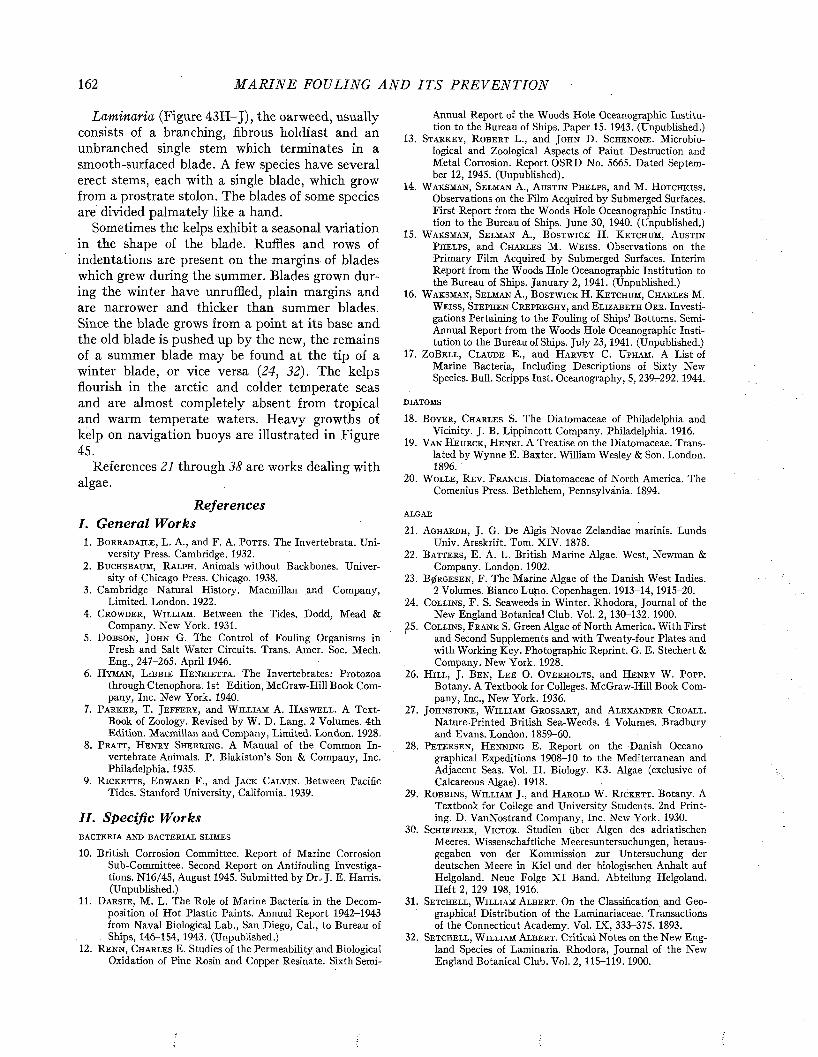
162 M A R I N E FOULING A N D I T S P R E V E N T I O N
Laminaria (Figure 43H -J), the oarweed, usually consists of a branching, fibrous holdfast and an unbranched single stem which terminates in a smooth-surfaced blade. A few species have several erect stems, each with a single blade, which grow from a prostrate stolon. The blades of some species are divided palmately like a hand.
Sometimes the kelps exhibit a seasonal variation in the shape of the blade. Ruffles and rows of indentations are present on the margins of blades which grew during the summer. Blades grown during the winter have unruffled, plain margins and are narrower and thicker than summer blades. Since the blade grows from a point at its base and the old blade is pushed up by the new, the remains of a summer blade may be found at the tip of a winter blade, or vice versa (24, 32). The kelps flourish in the arctic and colder temperate seas and are almost completely absent from tropical and warm temperate waters. Heavy growths of kelp on navigation buoys are illustrated in Figure 45.
References 21 through 38 are works dealing with algae.
ReferencesI. G eneral W orks
1. B o r r a d a il e , L. A., and F. A. P o t t s . The Invertebrata. University Press. Cambridge. 1932.
2. B u c h s b a u m , R a l p h . Animals without Backbones. University of Chicago Press. Chicago. 1938.
3. Cambridge Natural History. Macmillan and Company,Limited. London. 1922.
4. C r o w d e r , W il l i a m . Between the Tides. Dodd, Mead &Company. New York. 1931.
5 . D o b s o n , J o h n G. The Control of Fouling Organisms inFresh and Salt Water Circuits. Trans. Amer. Soc. Mech. Eng., 247-265. April 1946.
6. H y m a n , L i b b i e H e n r i e t t a . The Invertebrates: Protozoathrough Ctenophora. 1st Edition, McGraw-Hill Book Company, Inc. New York. 1940.
7. P a r k e r , T. J e f f e r y , and W il l ia m A. H a s w e l l . A Text-Book of Zoology. Revised by W. D. Lang. 2 Volumes. 4th Edition. Macmillan and Company, Limited. London. 1928.
8. P r a t t , H e n r y S h e r r i n g . A Manual of the Common Invertebrate Animals. P. Blakiston’s Son & Company, Inc. Philadelphia. 1935.
9. R i c k e t t s , E d w a r d F., and J a c k C a l v in . Between PacificTides. Stanford University, California. 1939.
II. Specific W orksb a c t e r i a a n d b a c t e r i a l s l im e s
10. British Corrosion Committee. Report of Marine CorrosionSub-Committee. Second Report on Antifouling Investigations. N16/45, August 1945. Submitted by Dr. J. E. Harris. (Unpublished.)
11. D a r s i e , M. L. The Role of Marine Bacteria in the Decomposition of Hot Plastic Paints. Annual Report 1942-1943 from Naval Biological Lab., San Diego, Cal., to Bureau of
. Ships, 146-154, 1943. (Unpublished.)12. R e n n , C h a r l e s E. Studies of the Permeability and Biological
Oxidation of Pine Rosin and Copper Resinate. Sixth Semi-
Annual Report of the Woods Hole Oceanographic Institution to the Bureau of Ships. Paper 15. 1943. (Unpublished.)
13. S t a r k e y , R o b e r t L., and J o h n D. S c h e n o n e . Microbiological and Zoological Aspects of Paint Destruction and Metal Corrosion. Report OSRD No. 5665. Dated September 12, 1945. (Unpublished).
14. W a k s m a n , Se l m a n A., A u s t i n P h e l p s , and M. H o t c h k is s .Observations on the Film Acquired by Submerged Surfaces. First Report from the Woods Hole Oceanographic Institution to the Bureau of Ships. June 30, 1940. (Unpublished.)
15. W a k s m a n , S e l m a n A., B o s t w ic k H. K e t c h u m , A u s t i n
P h e l p s , and C h a r l e s M. W e i s s . Observations on the Primary Film Acquired by Submerged Surfaces. Interim Report from the Woods Hole Oceanographic Institution to the Bureau of Ships. January 2, 1941. (Unpublished.)
16. W a k s m a n , Se l m a n A., B o s t w ic k H. K e t c h u m , C h a r l e s M.W e i s s , S t e p h e n C r e p r e g h y , and E l iz a b e t h O r r . Investigations Pertaining to the Fouling of Ships’ Bottoms. Semi- Annual Report from the Woods Hole Oceanographic Institution to the Bureau of Ships. July 23, 1941. (Unpublished.)
17. Z oB e l l , C l a u d e E., and H a r v e y C. U p h a m . A List ofMarine Bacteria, Including Descriptions of Sixty New Species. Bull. Scripps Inst. Oceanography, 5, 239-292. 1944.
d ia t o m s
18. B o y e r , C h a r l e s S. The Diatomacea? of Philadelphia andVicinity. J. B. Lippincott Company. Philadelphia. 1916.
19. V a n H e u r c k , H e n r i . A Treatise on the Diatomaceae. Translated by Wynne E. Baxter. William Wesley & Son. London. 1896.
20. W o l l e , R e v . F r a n c i s . Diatomaceae of North America. TheComenius Press. Bethlehem, Pennsylvania. 1894.
ALGAE
21. A g h a r d h , J. G. De Algis Novae Zelandiae marinis. LundsUniv. Arsskrift. Tom. XIV. 1878.
22. B a t t e r s , E. A. L. British Marine Algae. West, Newman &Company. London. 1902.
23. B0RG ESEN , F. The Marine Algae of the Danish West Indies.2 Volumes. Bianco Luino. Copenhagen. 1913-14, 1915-20.
24. C o l l in s , F. S. Seaweeds in Winter. Rhodora, Journal of theNew England Botanical Club. Vol. 2, 130-132. 1900.
25. C o l l in s , F r a n k S. Green Algae of North America. With Firstand Second Supplements and with Twenty-four Plates and with Working Key. Photographic Reprint. G. E. Stechert & Company. New York. 1928.
26. H i l l , J. B e n , L e e O. O v e r h o l t s , and H e n r y W. P o p p .Botany. A Textbook for Colleges. McGraw-Hill Book Company, Inc., New York. 1936.
27. J o h n s t o n e , W il l ia m G r o s s a r t , and A l e x a n d e r C r o a l l .Nature-Printed British Sea-Weeds. 4 Volumes. Bradbury and Evans. London. 1859-60.
28. P e t e r s e n , H e n n i n g E. Report on the Danish Oceanographical Expeditions 1908-10 to the Mediterranean and Adjacent Seas. Vol. II. Biology. K3. Algae (exclusive of Calcareous Algae). 1918.
29. R o b b i n s , W il l ia m J., and H a r o l d W. R ic k e t t . Botany. ATextbook for College and University Students. 2nd Printing. D. VanNostrand Company, Inc. New York. 1930.
30. S c h if f n e r , V ic t o r . Studien über Algen des adriatischenMeeres. Wissenschaftliche Meeresuntersuchungen, heraus- gegaben von der Kommission zur Untersuchung der deutschen Meere in Kiel und der biologischen Anhalt auf Helgoland. Neue Folge X I Band. Abteilung Helgoland. Heft 2, 129-198, 1916.
31. S e t c h e l l , W i l l i a m A l b e r t . On the Classification and Geographical Distribution of the Laminariaceae. Transactions of the Connecticut Academy. Vol. IX , 333-375. 1893.
32. Se t c h e l l , W il l ia m A l b e r t . Critical Notes on the New England Species of Laminaria. Rhodora, Journal of the New England Botanical Club. Vol. 2, 115-119. 1900.

THE P R I N C I P A L FOULING ORGANISM S 163
3 3 . S e t c h e l l , W il l ia m A l b e r t . Tahitian Algae Collected b yW. A. Setchell, C. B. Setchell, and H. E. Parks. University of California Publications in Botany. Vol. 12, 61-142. University of California Press, Berkeley, California. 1926.
34. S m i t h , G i l b e r t M. Marine Algae of the Monterey Peninsula,California. Stanford University Press, Stanford University, California. 1943.
35. S v e d e l i u s , N e l s . The Seasonal Alternation of Generations ofCeramium corticatulum in the Baltic. Nova Acta Societatis Scientiarum Upsaliensis. Volumen Extra Ordinem Editum1927. Upsala. 1927.
36. T a y l o r , W il l ia m R a n d o l f . The Marine Algae of theNortheastern Coast of North America. University of Michigan Press. Ann Arbor. 1937.
37. W e b e r - v a n B o s s e , A. Liste des Algues du Siboga-Expeditie.Monographie 59. Four Volumes. E. J. Brill. Leiden. 1913, 1921, 1923, 1928.
38. W e b e r -v a n B o s s e , A. and M. F o s l i e . The Corallinaceae ofthe Siboga-Expedition. Monographie 61, Livre 18. E J. Brill. Leiden. 1904.
p r o t o z o a
39. C a l k i n s , G a r y N. The Biology of the Protozoa. 2nd Edition,Lea & Febiger. Philadelphia. 1933.
40. K u d o , R ic h a r d R o k s a b r o . Protozoology. Charles C Thomas.Springfield, Illinois. 1939.
4 1 . W e n y o n , C. M. Protozoology. 2 Volumes. William Wood andCompany. New York. 1926.
s p o n g e s
4 2 . B o w e r b a n k , J . S. A monograph of th e B r i t i s h Spongiadae. 4Volumes. London. 1864, 1866, 1874, 1882.
43. V o s m a e r , G. C. J. The Sponges of the Naples Bay, Poriferaincalcaria. 3 Volumes, comprising volumes 3 and 5 of Capita Zoologica. Martinus Nijhoffi The Hague. 1932-1933, 1933-1935.
COELENTERATES
4 4 . F r a s e r , C. M cL e a n . Hydroids of t h e Pacific Coast of Canadaand the United States. University of Toronto Press. Toronto. 1937.
45. F r a s e r , C. M cL e a n . Hydroids of the Atlantic Coast ofNorth America. University of Toronto Press. Toronto. 1944.
46. H a r g i t t , C h a r l e s W. The Anthozoa of the Woods HoleRegion. Bulletin of the Bureau of Fisheries. Vol. 32, 225- 254. 1912.
47. H ic k s o n , S i d n e y J. An Introduction to the Study of RecentCorals. University Press. Manchester, England. 1924.
48. J a d e r h o l m , E l o e . Northern and Arctic Invertebrates in the ,Collection of the Swedish State Museum. IV. Hydroiden. Almquist & Wiksells Boktryckeri-A-B. Upsala & Stockholm. 1909.
49. P y e f i n c h , K. A., and F. S. D o w n in g . Notes on the generalbiology of Tubularia larynx. Ellis & Solander. Jour. Mar. Biol. Assoc, of the U.K. Vol. 28, 21-43. 1949.
50. S t e p h e n s o n , T. A. The British Sea Anemones. Vol. II.Dulau & Company, Limited. London. 1935.
b r y o z o a
51. A l l m a n , G. J. A Monograph of the Fresh-Water Polyzoa,Including All the Known Species, both British and Foreign. For the Ray Society. London. 1856.
52. B a k e r , G. S. Ship Efficiency and Economy. Charles Birchall& Sons Ltd. Liverpool. 1942.
53. C a l v e t , L. Contribution a l’histoire naturelle des Bryozoaires ectoproctes marins. Trav. Inst. Zool. Univ. Montpellier. Mem. 8. 1900.
54. D a v e n p o r t , C. B. Observations on Budding in Paludicellaand Some Other Bryozoa. Bull. Mus. Comp. Zool. Harvard. Vol. 22, 1-114. 1891.
55. E d m o n d s o n , C. H., and W. M. I n g r a m . Fouling Organismsin Hawaii. Occas. Papers Bernice P. Bishop Mus. Honolulu, Vol. 14, 251-300. 1940.
56. G r a h a m , D. P. Inspection of Moravian Paints on the Dahl-gren. Memorandum for File, July 28, 1934, Bureau of Ships (C and R), S19-l-(3 )/ll/A ug. 9, 1934. 1934.
57. H a r m e r , S. F. The Polyzoa of Waterworks. Proc. Zool. Soc.426-457. London. 1913.
58. H u t c h i n s , L. W. An Annotated Check-list of the Salt-waterBryozoa of Long Island Sound. Trans. Connecticut Acad. Arts Sei., 36, 533-551. 1945.
59. M a r c u s , E. Bryozoa. In: E. W. Junk, Tabulae Biologicae,Vol. 6 (suppl.), 311-327. 1930.
60. O s b u r n , R. C. A Survey of the Bryozoa of Chesapeake Bay.Department of Research and Education, State of Maryland, Board of Natural Resources. Publication No. 63. 1944
61. Sc h e e r , B. T. The Developmentof Marine Fouling Communities. Biol. Bull., 89, 103-121. 1945.
62. S i l e n , L. Zur Kenntnis des Polymorphismus der Bryozoan.Die Avicularien der Cheilostomata Anasca. Zool. Bidrag Uppsala., 17, 149-366. 1938.
63. V i s s c h e r , J. P. Nature and Extent of Fouling of Ships’ Bottoms. Bull. U. S. Bur. Fish., 43, 193-252. 1929.
64. W a t e r s , A. W. Ancestrulae and Frontal of CheilostomatousBryozoa. V. Ann. Mag. Nat. Hist., 9, 425-439. 1926.
65. W e i s s , C. M., and B. Hi K e t c h u m . Service Test Applicationsof Antifouling Paints to Wood Bottom Vessels in the Miami Region (Series 3). Interim Report X II for 1945 to the Bur. of Ships from the Woods Hole Oceanographic Institution, November 30, 1945. (Unpublished.)
a n n e l id s , o t h e r w o r m s , r o t if e r s
66. B o u r n e , A. G. On the Naidiform Oligochaeta. Quart. Jour.Microscopic Science, 32, p. 335. 1891.
67. K u k e n t h a l , W i l l y . Handbuch der Zoologie. Walter deGruyter and Company. Leipzig. 1934.
68. M cI n t o s h , W. C. A Monograph of the British Annelids. 4Volumes. Dulau and Company, Limited. London. 1873- 1923.
69. S c h m a r d a , L u d w ig K. Neue Wirbellose Thiere. WilhelmEngelmann. Leipzig. 1861.
MOLLUSCS
70. B a k e r , F r a n k C o l l in s . Shells of Land and Water. A FamiliarIntroduction to the Study of the Mollusks. A. W. Mumford. Chicago. 1903.
71. C o e , W e s l e y R. Season of Attachment and Rate of Growthof Sedentary Marine Organisms at the Pier of the Scripps Institution of Oceanography, La Jolla, California. Bull. Scripps Inst, of Oceanography. Technical Series, 3, No. 3, 37-86. 1932.
72. H u t t o n , F r e d e r ic k W o l l a s t o n . Catalogue of the MarineMollusca of New Zealand, with Diagnoses of the Species. G. Didsbury, Government Printer. Wellington. 1873.
73. J a c k s o n , R o b e r t T r a c y . Phylogeny of the Pelecypoda, theAviculidae and Their Allies. Memoirs of the Boston Society of Natural History. Vol. IV, No. VIII. 1890.
74. S m it h , M a x w e l l . East Coast Marine Shells. 3rd Edition,Revised. Edwards Brothers, Inc. Ann Arbor. 1945.
75. W o o d w a r d , S. P. Manual of the Mollusca: A Treatise onRecent and Fossil Shells. 2nd Edition. Virtue Brothers & Company. London. 1866.
e c h in o d e r m s
76. C l a r k , H. L. Echinoderms of the Woods Hole Region. Bulletin U. S. Fish. Com., 22, p. 543. 1902.
77. F i s h e r , W. K. Asteroidea of the North Pacific and AdjacentWaters. Bulletin 76. U. S. Nat. Mus. Parts 1-3. 1911-1930.
78. V e r r il l , A. E. Distribution of the Echinoderms of Northeastern America. Amer. Jour. Sei., 49, p. 127. 1895.
164 M A R I N E FOULING A N D I T S P R E V E N T I O N
BARNACLES
79. D a r w i n , C h a r l e s R o b e r t . A Monograph on the SubclassCirripedia, the Balanidae, the Verrucidae. London. 1854.
80. G r u v e l , A. Monographie des Cirrhipedes ou Theocostraces.Paris. 1905.
81. H e n r y , D o r a P r i a u l x . Notes on Some Pedunculate Barnacles from the North Pacific. Proceedings of United States National Museum, Smithsonian Institution, 88, 225-36.1940.
82. H o e k , P. P. C. The Cirripedia of the Siboga Expedition.Siboga-Expeditie, Monographie 31b. E. J. Brill. Leyden. 1913.
83. H o w l a n d , C h e s t e r S c o t t . Ninety Days in a Whaleboat.Yachting. Vol. 76, No. 3, p. 40. 1944.
84. P il s b r y , H e n r y A. The Barnacles (Cirripedia) Contained inthe Collections of the U. S. National Mus., Bulletin 60 of the U. S. National Museum, Smithsonian Institution. Government Printing Office. Washington. October 8, 1907.
85. P il s b r y , H e n r y A. The Sessile Barnacles (Cirripedia) Contained in the Collections of the U. S. National Mus., Including a Monograph of the American Species. Bull. 93 of the U. S. National Museum, Smithsonian Institution. Government Printing Office. Washington. July 31, 1916.
86. P y e e i n c h , K. A. Notes on the biology of Cirripedes. Jour.Mar. Biol. Assoc, of the U.K. Vol. 27, 464-503. 1948.
87. P y e e i n c h , K. A. Methods of identification of the larvae ofBalanus balanoides (L.), B. crenatus (Brug.) and Verruca stroemia (O. F. Muller). Jour. Mar. Biol. Assoc, of the U.K. Vol. 27, 451-463. 1948.
INSECTS
88. Connecticut Geological and Natural History Survey. BulletinNo. 63. A Fishery Survey of Important Connecticut Lakes. State of Connecticut Public Document No 47. Hartford.1941.
89. J o h a n n s e n , O. A., and L il l i a n C. T h o m s e n . Aquatic Diptera. Parts IV and V. Part IV. Chironomidae; Subfamily Chironominaè. Part V. Ceratopogonidae. Cornell Uni
versity Agricultural Experiment Station: Memoir 210. 1937.90. S a u n d e r s , L. G. Some Marine Insects of the Pacific Coast of
Canada. Annals Entomological Soc. of Amer., 21, 521-545.1928.
TUNICATES
91. A l d e r , J o s h u a , and A l b a n y H a n c o c k . The British TunicataVolume II. Edited by John Hopkinson. For the Ray Society. Adlard and Son. London. 1907.
92. H e r d m a n , E. C a t h e r i n e . Liverpool Marine Biology Committee Memoirs on Typical British Marine Plants & Animals. XXVI. Botryllus. The University Press of Liverpool, Ltd. 1924.
93. V a n N a m e , W il l a r d G. The North and South AmericanAscidians. Bulletin of the American Museum of Natural History, 84, New York. 1945.
e is h e s
94. G u d g e r , E. W. The Myth of the Ship-Holder: Studies inEcheneis or Remora—I. Annals and Mag. Natural History, Ser. 9, Vol. II. October 1918.
95. J o r d a n , D a v id S t a r r , and B a r t o n W a r r e n E v e r m a n n .The Fishes of North and Middle America. Bull. U. S. Nat. Mus. No. 47. 4 Volumes. Government Printing Office, Washington. 1896-1900.
III. D ocking M anuals96. Bureau of Ships. Docking Report Manual. Guide to Fouling
Organisms and Instruction Regarding the Docking Report. Bureau of Ships, Navy Department, Washington. 1942.
97. Bureau of Ships. Docking Report Manual. Instructions Regarding the Docking Report and Guide to Fouling Organisms. Bureau of Ships, Navy Department, Washington. 1944.
98. Marine Corrosion Sub-Committee, Iron and Steel Institute.Fouling of Ships’ Bottoms: Identification of Marine Growths. Paper No. 14/1944 of the Corrosion Committee. Richard Clay and Company Ltd. Bungay, Suffolk. 1944.
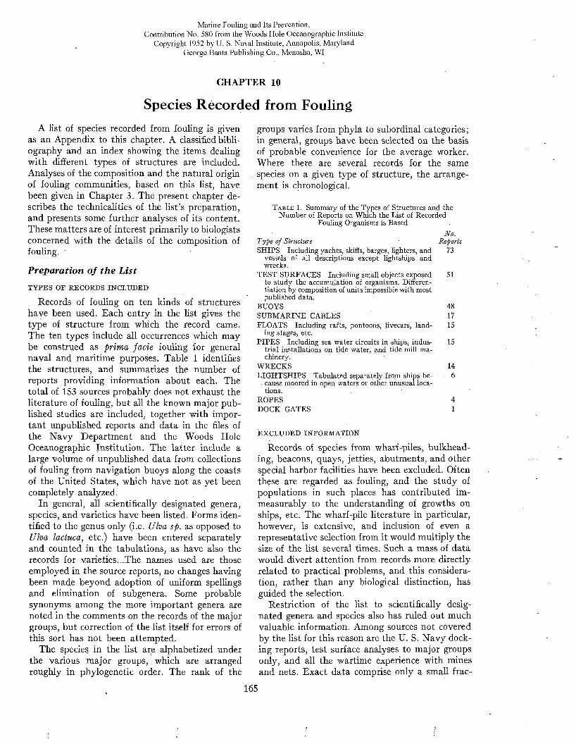
Marine Fouling and Its Prevention,Contribution No. 580 from the Woods Flole Oceanographic Institute
Copyright 1952 by U. S. Naval Institute, Annapolis, Maryland George Banta Publishing Co., Menasha, WI
CHAPTER 10
Species Recorded from FoulingA list of species recorded from fouling is given
as an Appendix to this chapter. A classified bibliography and an index showing the items dealing with different types of structures are included. Analyses of the composition and the natural origin of fouling communities, based on this list, have been given in Chapter 3. The present chapter describes the technicalities of the list’s preparation, and presents some further analyses of its content. These matters are of interest primarily to biologists concerned with the details of the composition of fouling.
Preparation o f th e L ist
TYPES OF RECORDS INCLUDED
Records of fouling on ten kinds of structures have been used. Each entry in the list gives the type of structure from which the record came. The ten types include all occurrences which may be construed as prima facie fouling for general naval and maritime purposes. Table 1 identifies the structures, and summarizes the number of reports providing information about each. The total of 153 sources probably does not exhaust the literature of fouling, but all the known major published studies are included, together with important unpublished reports and data in the files of the N avy Department and the Woods Hole Oceanographic Institution. The latter include a large volume of unpublished data from collections of fouling from navigation buoys along the coasts of the United States, which have not as yet been completely analyzed.
In general, all scientifically designated genera, species, and varieties have been listed. Forms identified to the genus only (i.e. Ulva sp. as opposed to Ulva lactuca, etc.) have been entered separately and counted in the tabulations, as have also the records for varieties. The names used are those employed in the source reports, no changes having been made beyond adoption of uniform spellings and elimination of subgenera. Some probable synonyms among the more important genera are noted in the comments on the records of the major groups, but correction of the list itself for errors of this sort has not been attempted.
The species in the list are alphabetized under the various major groups, which are arranged roughly in phylogenetic order. The rank of the
groups varies from phyla to subordinal categories; in general, groups have been selected on the basis of probable convenience for the average worker. Where there are several records for the same species on a given type of structure, the arrangement is chronological.
T a b l e 1. Summary of the Types of Structures and the Number of Reports on Which the List of Recorded
Fouling Organisms is BasedNo.
T ype of Stm cture ReportsSHIPS Including yachts, skiffs, barges, lighters, and 73
vessels of all descriptions except lightships and wrecks.
TEST SURFACES Including small objects exposed to study the accumulation of organisms. Differentiation by composition of units impossible with most published data.
BUOYSSUBMARINE CABLESFLOATS Including rafts, pontoons, livecars, land
ing stages, etc.PIPES Including sea water circuits in ships, indus
trial installations on tide water, and tide-mill machinery.
WRECKSLIGHTSHIPS Tabulated separately from ships be
cause moored in open waters or other unusual locations.
ROPESDOCK GATES
EXCLUDED INFORMATION
Records of species from wharf-piles, bulkhead- ing, beacons, quays, jetties, abutments, and other special harbor facilities have been excluded. Often these are regarded as fouling, and the study of populations in such places has contributed immeasurably to the understanding of growths on ships, etc. The wharf-pile literature in particular, however, is extensive, and inclusion of even a representative selection from it would multiply the size of the list several times. Such a mass of data would divert attention from records more directly related to practical problems, and this consideration, rather than any biological distinction, has guided the selection.
Restriction of the list to scientifically designated genera and species also has ruled out much valuable information. Among sources not covered by the list for this reason are the U. S. N avy docking reports, test surface analyses to major groups only, and all the wartime experience with mines and nets. Exact data comprise only a small frac
51
481715
15
146
41
165
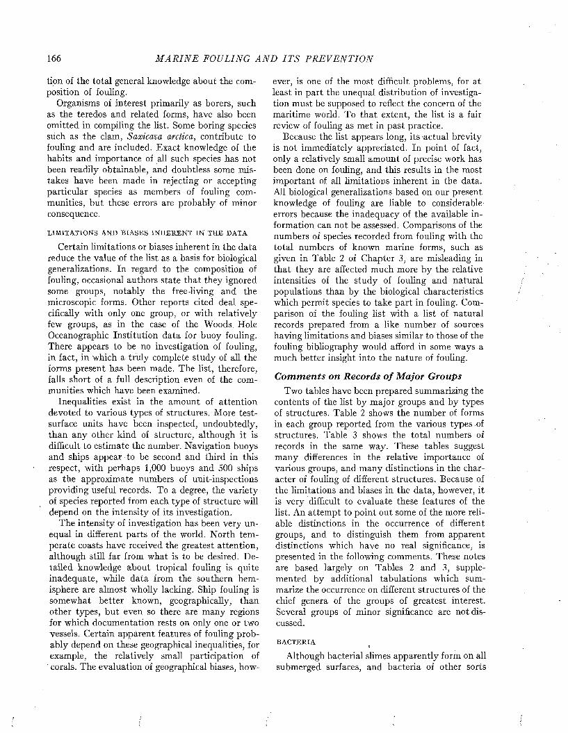
166 M A R I N E FOULING A N D I T S P R E V E N T I O N
tion of the total general knowledge about the composition of fouling.
Organisms of interest primarily as borers, such as the teredos and related forms, have also been omitted in compiling the list. Some boring species such as the clam, Saxicava arctica, contribute to fouling and are included. Exact knowledge of the habits and importance of all such species has not been readily obtainable, and doubtless some mistakes have been made in rejecting or accepting particular species as members of fouling communities, but these errors are probably of minor consequence.
LIMITATIONS AND BIASES INHERENT IN THE DATA
Certain limitations or biases inherent in the data reduce the value of the list as a basis for biological generalizations. In regard to the composition of fouling, occasional authors state that they ignored some groups, notably the free-living and the microscopic forms. Other reports cited deal specifically with only one group, or with relatively few groups, as in the case of the Woods Hole Oceanographic Institution data for buoy fouling. There appears to be no investigation of fouling, in fact, in which a truly complete study of all the forms present has been made. The list, therefore, falls short of a full description even of the communities which have been examined.
Inequalities exist in the amount of attention devoted to various types of structures. More test- surface units have been inspected, undoubtedly, than any other kind of structure, although it is difficult to estimate the number. Navigation buoys and ships appear to be second and third in this respect, with perhaps 1,000 buoys and 500 ships as the approximate numbers of unit-inspections providing useful records. To a degree, the variety of species reported from each type of structure will depend on the intensity of its investigation.
The intensity of investigation has been very unequal in different parts of the world. North temperate coasts have received the greatest attention, although still far from what is to be desired. D etailed knowledge about tropical fouling is quite inadequate, while data from the southern hemisphere are almost wholly lacking. Ship fouling is somewhat better known, geographically, than other types, but even so there are many regions for which documentation rests on only one or two vessels. Certain appárent features of fouling probably depend on these geographical inequalities, for example, the relatively small participation of corals. The evaluation of geographical biases, how
ever, is one of the most difficult problems, for at least in part the unequal distribution of investigation must be supposed to reflect the concern of the maritime world. To that extent, the list is a fair review of fouling as met in past practice.
Because the list appears long, its -actual brevity is not immediately appreciated. In point of fact, only a relatively small amount of precise work has been done on fouling, and this results in the most important of all limitations inherent in the data. All biological generalizations based on our present knowledge of fouling are liable to considerable errors because the inadequacy of the available information can not be assessed. Comparisons of the numbers of species recorded from fouling with the total numbers of known marine forms, such as given in Table 2 of Chapter 3, are misleading in that they are affected much more by the relative intensities of the study of fouling and natural populations than by the biological characteristics which permit species to take part in fouling. Comparison of the fouling list with a list of natural records prepared from a like number of sources having limitations and biases similar to those of the fouling bibliography would afford in some ways a much better insight into the nature of fouling.
C om m en ts on Records o f M ajor GroupsTwo tables have been prepared summarizing the
contents of the list by major groups and by types of structures. Table 2 shows the number of forms in each group reported from the various types of structures. Table 3 shows the total numbers of records in the same way. These tables suggest many differences in the relative importance of various groups, and many distinctions in the character of fouling of different structures. Because of the limitations and biases in the data, however, it is very difficult to evaluate these features of the list. An attempt to point out some of the more reliable distinctions in the occurrence of different groups, and to distinguish them from apparent distinctions which have no real significance, is presented in the following comments. These notes are based largely on Tables 2 and 3, supplemented by additional tabulations which summarize the occurrence on different structures of the chief genera of the groups of greatest interest. Several groups of minor significance are not discussed.
BACTERIA
Although bacterial slimes apparently form on all submerged surfaces, and bacteria of other sorts
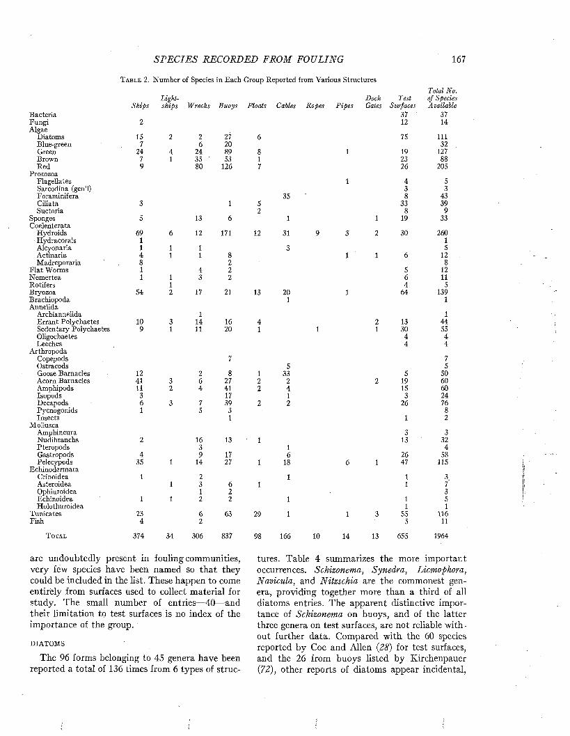
S P E C IE S RECORDED FROM FOULING 167
Table 2. Number of Species in Each Group Reported from Various StructuresTotal N
Light Dock Test of SpedShips ships Wrecks Buoys Floats Cables Ropes P ipes Gates Surfaces Availab
Bacteria 37 37Fungi 2 12 14Algae
Diatoms 15 2 2 27 6 75 111Blue-green 7 6 20 32Green 24 4 24 89 8 1 19 127Brown 7 1 35 53 1 23 88Red 9 80 126 7 26 205
ProtozoaFlagellates 1 4 5Sarcodina (gen’l) 3 3Foraminifera 35 8 43Ciliata 3 1 5 33 39Suctoria 2 8 9
Sponges 5 13 6 1 1 19 33Coelenterata
Hydroids 69 6 12 171 12 31 9 3 2 30 260Hydracorals 1 1Alcyonaria 1 1 1 3 5Actinaria 4 1 1 8 1 1 6 12Madreporaria 8 2 8
Flat Worms 1 4 2 5 12Nemertea 1 1 3 2 6 11Rotifers 1 4 5Bryozoa 54 2 17 21 13 20 1 64 139Brachiopoda 1 1Annelida
Archiannelida 1 1Errant Polychaetes 10 3 14 16 4 2 13 44Sedentary Polychaetes 9 1 11 20 1 1 1 30 55Oligochaetes 4 4Leeches 4 4
ArthropodaCopepods 7 7Ostracods 5 5Goose Barnacles 12 2 8 1 33 5 50Acorn Barnacles 41 3 6 27 2 2 2 19 60Amphipods 11 2 4 41 2 4 15 60Isopods 3 17 1 3 24Decapods 6 3 7 39 2 2 26 76Pycnogonids 1 5 3 8Insects 1 1 2
MolluscaAmphineura 3 3Nudibranchs 2 16 13 1 13 32Pteropods 3 1 4Gastropods 4 9 17 6 26 58Pelecypods 35 1 14 27 1 18 6 1 47 115
EchinodermataCrinoidea 1 2 1 1 3Asteroidea 1 3 6 1 1 7Ophiuroidea 1 2 3Echinoidea 1 1 2 2 1 1 5Holothuroidea 1 1
Tunicates 23 6 63 29 1 1 3 55 116Fish 4 2 5 11
T otal 374 34 306 837 98 166 10 14 13 655 1964
are undoubtedly present in fouling communities, very few species have been named so that they could be included in the list. These happen to come entirely from surfaces used to collect material for study. The small number of entries— 40— and their limitation to test surfaces is no index of the importance of the group.
DIATOMS
The 96 forms belonging to 45 genera have been reported a total of 136 times from 6 types of struc
tures. Table 4 summarizes the more important occurrences. Schizonema, Synedra, Licmophora, Navicula, and Nitzschia are the commonest genera, providing together more than a third of all diatoms entries. The apparent distinctive importance of Schizonema on buoys, and of the latter three genera on test surfaces, are not reliable without further data. Compared with the 60 species reported by Coe and Allen (28) for test surfaces, and the 26 from buoys listed by Kirchenpauer (72), other reports of diatoms appear incidental,
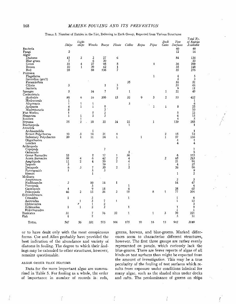
168 M A R I N E FOULING A N D I T S P R E V E N T I O N
T able 3. Number of Entries in the List, Referring to Each Group, Reported from Various StructuresTotal 1\
Light Dock Test of E ntrShips ships Wrecks Buoys Floats Cables Ropes P ipes Gales Surfaces A vailal
Bacteria 40 40Fungi 2 12 14Algae
Diatoms 15 2 2 27 6 84 136Blue-green 7 6 20 33Green 35 4 27 98 8 1 36 209Brown 10 1 39 62 1 35 148Red 10 88 136 7 35 276
ProtozoaFlagellates 1 4 5Sarcodina (gen’l) 3 3Foraminifera 35 16 51Ciliata 3 1 5 35 44Suctoria 2 9 11
Sponges 5 14 7 1 1 21 49Coelenterata
Hydroids 88 6 16 200 13 32 9 3 2 53 422Hydracorals 1 1Alcyonaria 1 1 1 3 6Actinaria 4 1 1 9 1 1 8 25Madreporaria .8 2 10
Flat Worms 1 5 2 5 13Nemertea 1 1 3 2 6 13Rotifers 1 4 5Bryozoa 75 2 18 22 14 22 1 129 283Brachiopoda 1 1Annelida
Archiannelida 1 1Errant Polychaetes 10 3 14 21 4 2 18 72Sedentary Polychaetes 20 1 11 24 1 1 1 57 116Oligochaetes 4 4Leeches 4 4
ArthropodaCopepods 7 7Ostracods 5 5Goose Barnacles 53 2 17 1 36 6 115Acorn Barnacles 88 4 6 42 2 4 2 65 213Amphipods 11 2 4 50 2 4 21 94Isopods 3 19 1 4 27Decapods 6 3 7 50 2 2 26 96Pycnogonids 1 5 3 9Insects 1 1 2
MolluscaAmphinema 3 3Nudibranchs 2 16 14 1 14 47Pteropods 3 1 4Gastropods 4 9 18 6 28 65Pelecypods 46 2 15 34 2 19 8 1 77 204
EchinodermataCrinoidea 1 3 1 1 6Asteroidea 1 3 7 1 1 13Ophiuroidea j 1 2 3Echinoidea 1 1 2 2 1 1 8Holothuroidea 1 1
Tunicates 31 7 76 32 1 1 3 70 221Fish 4 2 5 11
Total 547 36 331 975 104 175 10 16 13 942 3149
greens, browns, and blue-greens. Marked differences seem to characterize different structures, however. The first three groups are rather evenly represented on panels, which curiously lack the blue-greens. There are fewer reports of algae of all kinds on test surfaces than might be expected from the amount of investigation. This may be a true pecularity of the fouling of test surfaces which results from exposure under conditions inimical for many algae, such as the shaded sites under docks and rafts. The predominance of greens on ships
or to have dealt only with the most conspicuous forms. Coe and Allen probably have provided the best indication of the abundance and variety of diatoms in fouling. The degree to which their findings may be extended to other structures, however, remains questionable.
ALGAE OTHER THAN DIATOMS
Data for the more important algae are summarized in Table 5. For fouling as a whole, the order of importance in number of records is: reds,
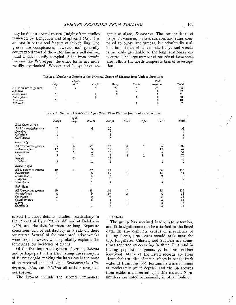
S P E C IE S RECORDED FRO M FOULING 169
may be due to several causes. Judging irom studies reviewed by Bengough and Shepheard {13), it is at least in part a real feature of ship fouling. The greens are conspicuous, however, and generally congregated toward the water line in a well defined band which is easily sampled. Aside from certain browns like Ectocarpus, the other forms are more readily overlooked. Wrecks and buoys have re
genus of algae, Ectocarpus. The low incidence of kelps, Laminaria, on test surfaces and ships compared to buoys and wrecks, is undoubtedly real. The importance of kelp on the buoys and wrecks is probably ascribable to the long, stationary exposures. The large number of records of Laminaria also reflects the north-temperate bias of investigation.
T a b l e 4. Number of Entries of the Principal Genera of Diatoms from Various StructuresLight- Test
Ships ship Wrecks Buoys Floats Surfaces TotalAll 45 recorded genera 15 2 2 27 6 84 136Synedra 4 2 6 12Schizonema 1 1 8 1 11Licmophora 1 1 8 10Navicula 1 9 10Nitzschia 1 6 7
T a b l e 5. Number of Entries for Algae Other Than Diatoms from Various Structures Lighl-
Ships ships Wrecks Buoys Floats P ipes Tests TotalBlue-Green AlgaeAll 17 recorded genera 7 6 20 33lyn g b ya 1 5 6Calothrix 1 3 4Oscillatoria 1 3 4Green AlgaeAll 37 recorded genera 35 4 27 98 8 1 36 209Enteromorpha 12 1 5 18 1 12 49Cladophora 7 1 6 16 1 6 37Ulva 5 2 4 3 1 8 23Solenia 2 17 19Ulothrix 3 1 1 1 6Brown Algae 'All 43 recorded genera 10 1 39 62 1 35 148Ectocarpus 7 8 15 1 13 44Laminaria 1 4 8 2 15Dictyota 1 1 6 1 9Sytosiphon 1 4 3 8Red AlgaeAll 93 recorded genera 10 88 136 7 35 276Polysiphonia 4 9 19 2 4 38Ceramium 2 6 9 5 22Callithamnion 1 6 2 1 2 12D asya 9 1 2 12Gracilaria 1 8 2 11
ceived the most detailed studies, particularly in the reports of Lyle {80, 81, 82) and of Delabarre {150), and the lists for them are long. Exposure conditions will be satisfactory as a rule on these structures. Several of the more productive wrecks were deep, however, which probably explains the somewhat low incidence of greens.
Of the five important genera of greens, Solenia and perhaps part of the Ulva listings are synonyms of Enteromorpha, making the latter easily the most often reported genus of algae. Enteromorpha, Cladophora, Ulva, and Ulothrix all include conspicuous species.
The browns include the second commonest
PROTOZOA
The group has received inadequate attention, and little significance can be attached to the listed data. In any complete census of prevalence of fouling forms, protozoans should rank near the top. Flagellates, Ciliates, and Suctoria are sometimes reported as occurring in slime films, and in fouling populations generally, but are seldom identified. Many of the listed records are from HentschePs studies of test surfaces in nearly fresh water at Hamburg {56). Foraminifera are common at moderately great depths, and the 34 records from cables are interesting in this respect. Foraminifera are noted occasionally in other fouling.
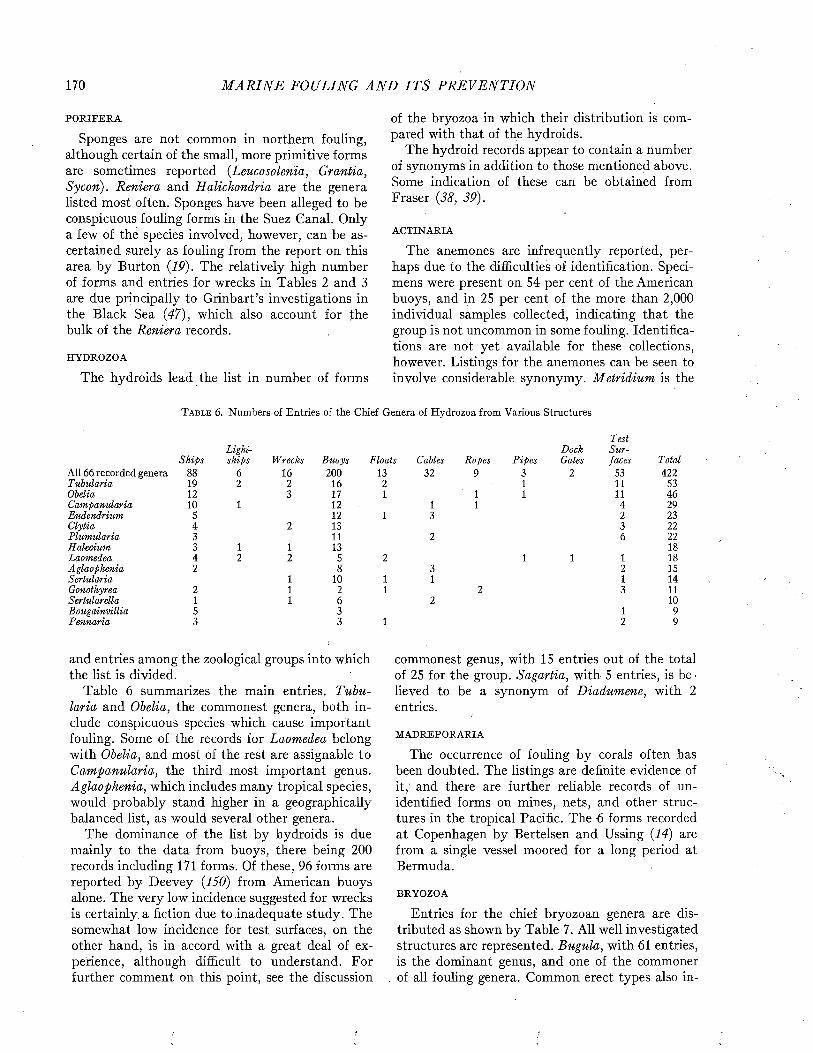
170 M A R I N E FOULING A N D I T S P R E V E N T I O N
PORIFERA
Sponges are not common in northern fouling, although certain of the small, more primitive forms are sometimes reported (Leucosolenia, Grantia, Sycon). Reniera and Halichondria are the genera listed most often. Sponges have been alleged to be conspicuous fouling forms in the Suez Canal. Only a few of the species involved, however, can be ascertained surely as fouling from the report on this area by Burton (19). The relatively high number of forms and entries for wrecks in Tables 2 and 3 are due principally to Grinbart’s investigations in the Black Sea (47), which also account for the bulk of the Reniera records.
HYDROZOA
The hydroids lead the list in number of forms
of the bryozoa in which their distribution is compared with that of the hydroids.
The hydroid records appear to contain a number of synonyms in addition to those mentioned above. Some indication of these can be obtained from Fraser (38, 39).
ACTINARIA
The anemones are infrequently reported, perhaps due to the difficulties of identification. Specimens were present on 54 per cent of the American buoys, and in 25 per cent of the more than 2,000 individual samples collected, indicating that the group is not uncommon in some fouling. Identifications are not yet available for these collections, however. Listings for the anemones can be seen to involve considerable synonymy. Metridium is the
T a b l e 6. Numbers of Entries of the Chief Genera of Hydrozoa from Various Structures
Light- DockTestSur-
Ships ships Wrecks Buoys Floats Cables Ropes P ipes Gates faces TotalAll 66 recorded genera 88 6 16 200 13 32 9 3 2 53 422Tubularia 19 2 2 16 2 1 11 53Obelia 12 3 17 1 1 1 11 46Campanularia 10 1 12 1 1 4 29Eudendrium S 12 1 3 2 23Clytia 4 2 13 3 22Plum ularia 3 11 2 6 22Halecium 3 1 1 13 18Laomedea 4 2 2 5 2 1 1 1 18Aglaophenia 2 8 3 2 15Sertularia 1 10 1 1 1 14Gonothyrea 2 1 2 1 2 3 11Sertularella 1 1 6 2 10Bougainvillia 5 3 1 9Pennaria 3 3 1 2 9
and entries among the zoological groups into which the list is divided.
Table 6 summarizes the main entries. Tubularia and Obelia, the commonest genera, both include conspicuous species which cause important fouling. Some of the records for Laomedea belong with Obelia, and most of the rest are assignable to Campanularia, the third most important genus. Aglaophenia, which includes many tropical species, would probably stand higher in a geographically balanced list, as would several other genera.
The dominance of the list by hydroids is due mainly to the data from buoys, there being 200 records including 171 forms. Of these, 96 forms are reported by Deevey (150) from American buoys alone. The very low incidence suggested for wrecks is certainly a fiction due to inadequate study. The somewhat low incidence for test surfaces, on the other hand, is in accord with a great deal of experience, although difficult to understand. For further comment on this point, see the discussion
commonest genus, with 15 entries out of the total of 25 for the group. Sagartia, with 5 entries, is believed to be a synonym of Diadumene, with 2 entries.
MADREPORARIA
The occurrence of fouling by corals often has been doubted. The listings are definite evidence of it, and there are further reliable records of unidentified forms on mines, nets, and other structures in the tropical Pacific. The 6 forms recorded at Copenhagen by Bertelsen and Ussing (14) are from a single vessel moored for a long period at Bermuda.
BRYOZOA
Entries for the chief bryozoan genera are distributed as shown by Table 7. All well investigated structures are represented. Bugula, with 61 entries, is the dominant genus, and one of the commoner of all fouling genera. Common erect types also in-
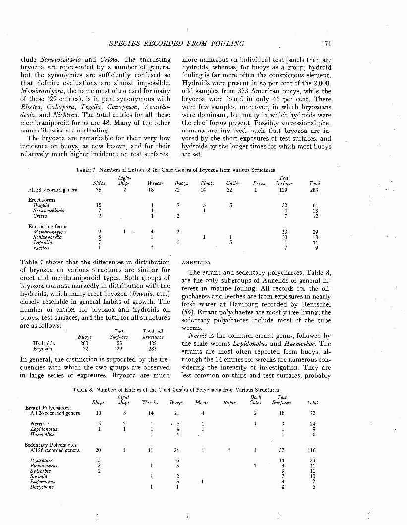
S P E C IE S RECORDED FROM FOULING 171
elude Scrupocellaria and Crisia. The encrusting bryozoa are represented by a number of genera, but the synonymies are sufficiently confused so that definite evaluations are almost impossible. Membranipora, the name most often used for many of these (29 entries), is in part synonymous with Electra, Callopora, Tegella, Conopeum, Acanthodesia, and Nichtina. The total entries for all these membraniporoid forms are 48. Many of the other names likewise are misleading.
The bryozoa are remarkable for their very low incidence on buoys, as now known, and for their relatively much higher incidence on test surfaces.
more numerous on individual test panels than are hydroids, whereas, for buoys as a group, hydroid fouling is far more often the conspicuous element. Hydroids were present in 85 per cent of the 2,000- odd samples from 373 American buoys, while the bryozoa were found in only 46 per cent. There were few samples, moreover, in which bryozoans were dominant, but many in which hydroids were the chief forms present. Possibly successional phenomena are involved, such that bryozoa are favored by the short exposures of test surfaces, and hydroids by the longer times for which most buoys are set.
T a b l e 7. Numbers of Entries of the Chief Genera of Bryozoa from Various StructuresLight Test
Ships ships Wrecks Buoys Floats Cables P ipes Surfaces TotalAll 58 recorded genera 75 2 18 22 14 22 1 129 283
Erect JormsBugula 15 1 7 3 3 32 61Scrupocellaria 7 1 . 1 4 13Crisia 2 1 2 7 12
Encrusting formsM embranipora 9 1 4 2 13 29Schizoporella 5 1 1 1 10 18Lepralia 7 1 5 1 14Electra 1 1 7 9
Table 7 shows that the differences in distribution of bryozoa on various structures are similar for erect and membraniporoid types. Both groups of bryozoa contrast markedly in distribution with the hydroids, which many erect bryozoa (Bugula, etc.) closely resemble in general habits of growth. The number of entries for bryozoa and hydroids on buoys, test surfaces, and the total for all structures are as follows :
Test Total, allBuoys Surfaces structures
Hydroids 200 53 422Bryozoa 22 129 283
In general, the distinction is supported by the frequencies with which the two groups are observed
large series of exposures. Bryozoa are muchm
ANNELIDA
The errant and sedentary polychaetes, Table 8, are the only subgroups of Annelids of general interest in marine fouling. All records for the oli- gochaetes and leeches are from exposures in nearly fresh water at Hamburg recorded by Hentschel (56). Errant polychaetes are mostly free-living; the sedentary polychaetes include most of the tube worms.
Nereis is the common errant genus, followed by the scale worms Lepidonotus and Harmothoe. The errants are most often reported from buoys, although the 14 entries for wrecks are numerous considering the intensity of investigation. They are less common on ships and test surfaces, probably
T a b l e 8. Numbers of Entries of the Chief Genera of Polychaeta from Various StructuresLight Dock Test
Ships ships Wrecks Buoys Floats Ropes Gates Surfaces TotalErrant Polychaetes
All 26 recorded genera 10 3 14 21 4 2 18 72
Nereis ' 5 2 1 - 5 1 1 9 24Lepidonotus 1 1 1 4 1 1 9Harmothoe 1 4 1 6
Sedentary PolychaetesAll 26 recorded genera 20 1 11 24 1 1 1 57 116
Hydroides 13 6 14 33Pomatoceros 3 1 3 1 3 11Spirorbis 2 9 11Serpula 1 2 7 10Eupomatus 3 1 3 7Dasychone 1 1 4 6

172 M A R I N E FOULING A N D I T S P R E V E N T I O N
because these do not so often accumulate the dense fouling mats that seem to be the favored habitats of many errant species. A few of the annelids classified as errant build tubes, such as the genus Eteone, 2 species of which have been found on test surfaces.
Hydroides is the most often reported genus of tube worms. The four entries for H. hexagona, however, probably should be added to Eupomatus dianthus. Several widespread genera which are locally important in fouling do not place high in the list, among them Salmacina. The leading sedentary forms are the calcareous-tubed types which are found particularly on hard substrates. Parchment- or silt-tubed forms, such as Dasychone, also attach and in some localities are not un-
Among goose barnacles, Lepas and Conchoderma are mainly responsible for records from exposures near the surface; while Scalpellum and Megalasma account for most records from greater depths as from cables. Lepas and Conchoderma, furthermore, show a definite tendency to occur more often on exposures away from shore. Ships have the largest number of entries, buoys next, and only a few reports mention either genus on test surfaces. These observations probably reflect correctly the distributions found in nature.
Among the acorn barnacles, Balanus is the dominant genus. Indeed, of all the organisms responsible for fouling it is the genus reported most often.
The data in Table 9 show the greatest number
T a b l e 9. Numbers of Entries of the Genera of Barnacles from Various Structures Lieht- Dock Test
Ships ships Wrecks Buoys Floats Cables Gates Surfaces TotalGoose Barnacles
All 9 recorded genera 53 2 17 1 36 6 115
Lepas 28 1 9 1 3 42Conchoderma 23 6 3 32Scalpellum 1 24 25Megalasma 9 9Heteralepas 1 1 2M itella 1 1 2Oxynaspis 2 2A natifa 1 1Poecilasma 1 1
Acorn BarnaclesAll 5 recorded genera 88 4 6 42 2 4 2 65 213
Balanus 80 4 6 37 2 4 2 61 196Chthamalus 3 1 3 7T etr actita 4 2 ÖChelonibia I ■ 1 1 3Verruca 1 1
common. The types which normally build tubes in burrows in sand or mud, such as Arenicola and Chaetopterus, are distinct rarities in fouling.
Although about equivalent numbers of errant and sedentary forms, 44 and 55, are recorded from fouling, the sedentary species are reported more frequently, the total entries being 72 and 116. The difference is most marked for test surfaces, for which there are 57 sedentary entries but only 18 errant. Ships exhibit a similar, but less pronounced difference between the two. The ability of the tube worms to attach to unfouled surfaces, and their formation of firmly adherent tubes, are possible reasons for these differences between the errant and sedentary forms.
BARNACLES
Table 9 gives the complete data for the distribution of the entries of the genera of barnacles among various types of structures.
of acorn barnacle entries for ships, with somewhat smaller numbers for test surfaces and buoys. This probably is related largely to the number of reports dealing with each type of structure (see Table 1). Acorn barnacles are often the chief forms present on ships and test panels, but in comparing the numbers of barnacle entries with those of other groups on these structures it should be remembered that the barnacles are frequently the only forms identified sufficiently to be included in the list, so far as panel and ship fouling is concerned.
The acorn barnacles exhibit considerable specialization of habitat. Balanus is the only widespread genus common on hard substrates in waters of shallow and moderate depth, so that its outstanding importance among the genera of barnacles occurring in fouling is not surprising. Chthamalus is principally intertidal, and most species are markedly restricted geographically. Tetraclita comprises shallow water forms as well as inter
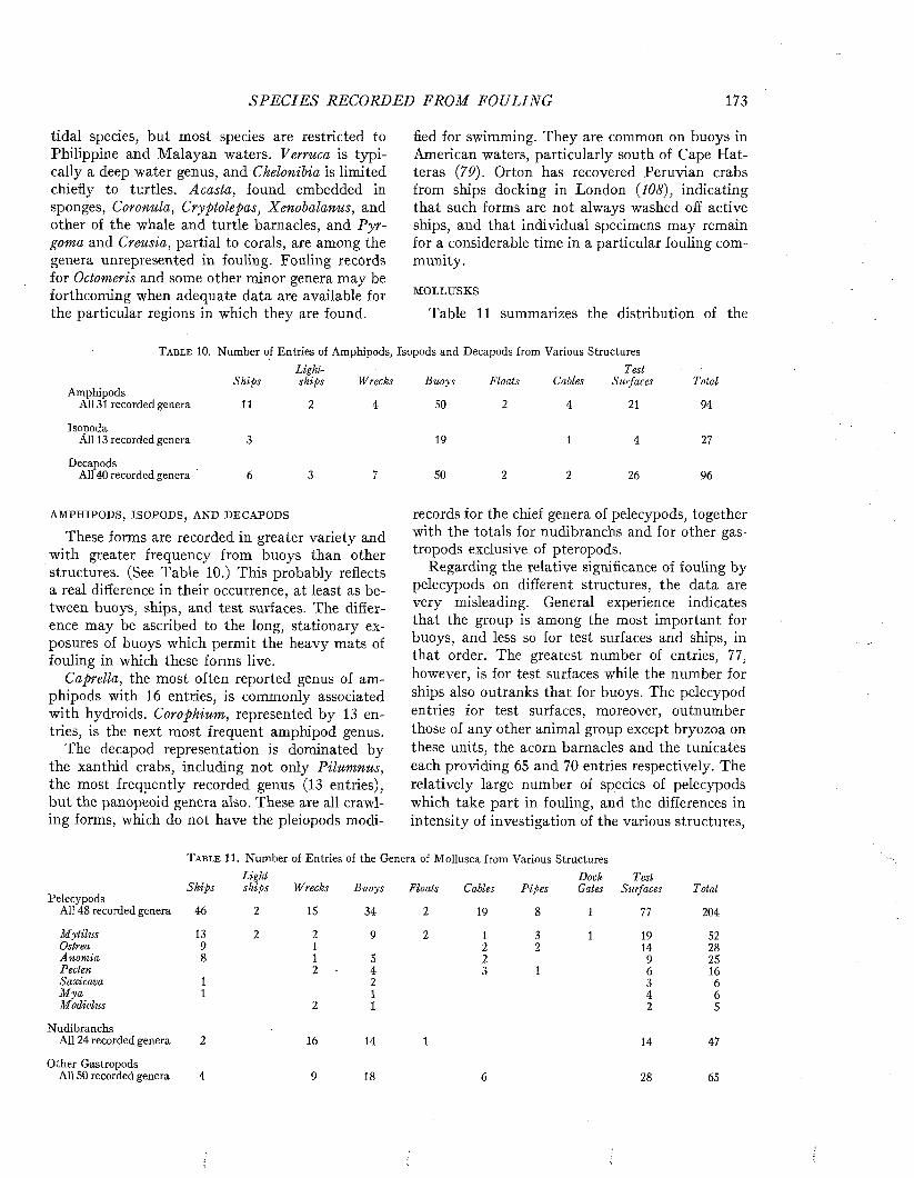
S P E C IE S RECORDED FROM FOULING 173
tidal species, but most species are restricted to Philippine and Malayan waters. Verruca is typically a deep water genus, and Chelonibia is limited chiefly to turtles. Acasta, found embedded in sponges, Coronula, Cryptolepas, Xenobalanus, and other of the whale and turtle barnacles, and P yrgoma and Creusia, partial to corals, are among the genera unrepresented in fouling. Fouling records for Octomeris and some other minor genera may be forthcoming when adequate data are available for the particular regions in which they are found.
fled for swimming. They are common on buoys in American waters, particularly south of Cape Hat- teras {79). Orton has recovered Peruvian crabs from ships docking in London {108), indicating that such forms are not always washed off active ships, and that individual specimens may remain for a considerable time in a particular fouling community.
MOLLUSKS
Table 11 summarizes the distribution of the
T a b l e 10. Number of Entries of Amphipods, Isopods and Decapods from Various Structures
AmphipodsAll 31 recorded genera
Isopoda All 13 recorded genera
Decapods All 40 recorded genera
ShipsLightships Wrecks Buoys Floats Cables
TestSurfaces Total
11 2 4 SO 2 4 21 94
3 19 1 4 27
6 3 7 50 2 2 26 96
AMPHIPODS, ISOPODS, AND DECAPODS
These forms are recorded in greater variety and with greater frequency from buoys than other structures. (See Table 10.) This probably reflects a real difference in their occurrence, at least as between buoys, ships, and test surfaces. The difference may be ascribed to the long, stationary exposures of buoys which permit the heavy mats of fouling in which these forms live.
Caprella, the most often reported genus of amphipods with 16 entries, is commonly associated with hydroids. Corophium, represented by 13 entries, is the next most frequent amphipod genus.
The decapod representation is dominated by the xanthid crabs, including not only Pilumnus, the most frequently recorded genus (13 entries), but the panopeoid genera also. These are all crawling forms, which do not have the pleiopods modi-
records for the chief genera of pelecypods, together with the totals for nudibranchs and for other gastropods exclusive of pteropods.
Regarding the relative significance of fouling by pelecypods on different structures, the data are very misleading. General experience indicates that the group is among the most important for buoys, and less so for test surfaces and ships, in that order. The greatest number of entries, 77, however, is for test surfaces while the number for ships also outranks that for buoys. The pelecypod entries for test surfaces, moreover, outnumber those of any other animal group except bryozoa on these units, the acorn barnacles and the tunicates each providing 65 and 70 entries respectively. The relatively large number of species of pelecypods which take part in fouling, and the differences in intensity of investigation of the various structures,
T a b l e 11. Number of Entries of the Genera of Mollusca from Various StructuresLight- Dock T esi
Ships ships Wrecks Buoys Floats Cables P ipes Gates Surfaces TotalPelecypods
All 48 recorded genera 46 2 15 34 2 19 8 1 77 204
M ytilus 13 2 2 9 2 1 3 1 19 52Ostrea 9 1 2 2 14 28Anom ia 8 1 5 2 9 25Pecten 2 4 3 1 6 16Saxicava 1 2 3 6M ya 1 1 4 6Modiolus 2 1 2 5
NudibranchsAll 24 recorded genera 2 16 14 1 14 47
Other GastropodsAll 50 recorded genera 4 9 18 6 28 65

174 M A R I N E FOULING A N D I T S P R E V E N T I O N
apparently combine in giving a somewhat distorted impression of the importance of pelecypod fouling when estimated only from the number of entries. Many of the test surface and ship records refer to species which were not common. The pelecypods from the American buoys have not been identified except for a few of special interest, furthermore, which is undoubtedly the chief reason the buoy figures appear low compared to those for some other groups.
The pelecypods which are listed most frequently in fouling have adults with byssus attachments or shells cemented directly to the substrate. Examples of the first include mussels such as M ytilus,
species. The number of entries for floats is also very large compared to those for other groups, but this arises largely from the fact that a high proportion of the fouling records in Van Nam e’s monograph (144) are from floats.
The chief genera of tunicates do not exhibit such striking differences in prevalence on different structures as do those of many other groups. No particular explanation of this can be advanced. Of the genera in Table 12, Botryllus, Didemnum, and Botrylloides are encrusting colonial types, while the rest are simple. Phallusia is synonymous with Ascidia, and the entries for these genera should be combined in estimating frequencies of occurrence.
T a b l e 12. Number of Entries of the Chief Genera of Tunicates from Various StructuresDock T est
Ships Wrecks Buoys Floats Cables P ipes Gales Surfaces TotalAll 35 recorded genera 31 7 76 32 1 1 3 70 221
Botryllus 7 9 4 1 4 25Molgula 5 8 1 1 7 22Styela 2 5. 4 11 22Ciona 5 1 4 3 4 17A scidia 1 1 5 3 5 15Ascidiella 5 3 3 1 1 2 15Didemnum 1 5 2 5 13Diplosoma 3 2 2 4 11Botrylloides 1 2 1 6 10
Modiolus, Modiolaria, Brachidontes, and Botula, all belonging to the family Mytilidae, as well as some closely related forms like Anomia, Pteria, and Pecten latiauritus. The oysters (Ostrea) are the most conspicuous examples of the second type.
The nudibranchs and other gastropods are remarkable in that there are no special genera prominently associated with fouling. The very low incidence of both on ships is probably real. Relative to other groups, their occurrence on other structures also is infrequently recorded, but this may be partly because gastropods are ignored in many investigations. Eggs of these forms may be expected to be present much more often than reported.
TUNICATES
-Data for the distribution of the chief genera of tunicates are given in Table 12.
The low frequency of records from ships, compared to buoys and test surfaces, probably represents a real characteristic of their occurrence. Tunicates are seldom dominant on ships unless these have been moored for long periods, but are quite common on buoys and test surfaces, particularly when exposed in harbor waters. The larger number of entries from buoys and test surfaces is due chiefly to the greater variety of forms reported, rather than to marked prevalence of one or two
Van Name (144) should be consulted for other synonyms.
A PPENDIX : LIST OF SPECIES RECORDED FROM FOULING
The following list shows for each species reported the types of structures on which it has been found and the references for the occurrences.
An alphabetical list of references follows to which is added an index showing all the items dealing with each type of structure.
P L A N T K IN G D O M BacteriaAchromobacter aquamarinus
t e s t s u r f a c e s : ZoBell & Upham (153).Achromobacter marinoglulinosus
t e s t s u r e a c e s : ZoBell & Allen (152).Achromobacter membranoformis
t e s t s u r f a c e s : ZoBell & Allen (152).A chromobacter stationis
t e s t s u r f a c e s : ZoBell & Upham (153).Bacillus subtilis
t e s t s u r f a c e s : Herpin & Duliscouet (61).Bacterium albolactus
t e s t s u r f a c e s : Hilen (63); Angst (4).Bacterium atterimus
t e s t s u r f a c e s : Hilen (62).Bacterium circumlaus
t e s t s u r f a c e s : Hilen (62).Bacterium globigii
t e s t s u r f a c e s : Angst (4).Bacterium graviolens
t e s t s u r f a c e s : Angst (4).Bacterium mycoides
t e s t s u r f a c e s : Hilen (63).
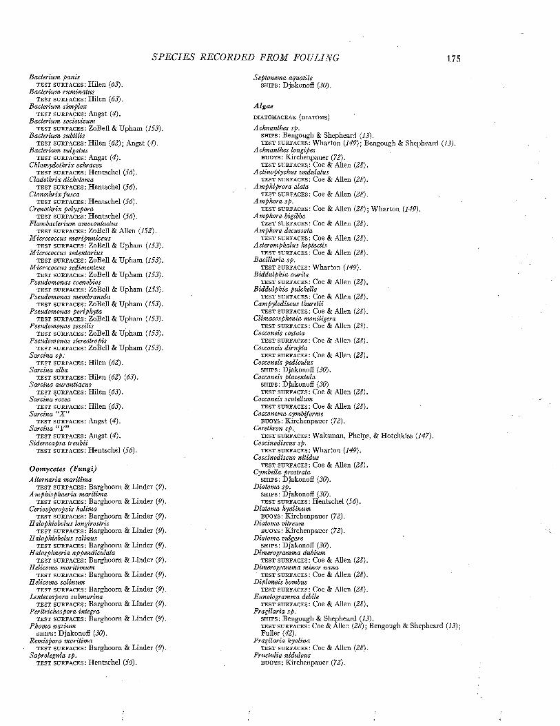
SP ECIES RECORDED FROM FOULING 175
Bacterium panist e s t s u r f a c e s : Hilen (63).
Bacterium ruminatust e s t s u r f a c e s : Hilen (63).
Bacterium sim plext e s t s u r f a c e s : Angst (4).
Bacterium sociovivumt e s t s u r f a c e s : ZoBell & Upham (153).
Bacterium subtilist e s t s u r f a c e s : Hilen (62) ; Angst (4).
Bacterium vulgatust e s t s u r f a c e s : Angst (4).
Chlamydothrix ochracea t e s t s u r f a c e s : Hentschel (Jó).
Cladothrix dichotomat e s t s u r f a c e s : Hentschel (56).
Clonothrix fuscat e s t s u r f a c e s : Hentschel (56).
Crenothrix polysporat e s t s u r f a c e s : Hentschel (J6).
Flavobacterium amocontactust e s t s u r f a c e s : ZoBell & Allen (152).
Micrococcus maripuniceus t e s t s u r f a c e s : ZoBell & Upham (153).
Micrococcus sedentariust e s t s u r f a c e s : ZoBell & Upham (153).
Micrococcus sedimenteust e s t s u r f a c e s : ZoBell & Upham (153).
Pseudomonas coenobiost e s t s u r f a c e s : ZoBell & Upham (153).
Pseudomonas membranulat e s t s u r f a c e s : ZoBell & Upham (153).
Pseudomonas periphytat e s t s u r f a c e s : ZoBell & Upham (153).
Pseudomonas sessilist e s t s u r f a c e s : ZoBell & Upham (153).
Pseudomonas stereotropist e s t s u r f a c e s : ZoBell & Upham (153).
Sarcina sp: t e s t s u r f a c e s : Hilen (62).
Sarcina albat e s t s u r f a c e s : Hilen (62) (63).
Sarcina aurantiacust e s t s u r f a c e s : Hilen (63).
Sarcina roseat e s t s u r f a c e s : Hilen (63).
Sarcina “X ” t e s t s u r f a c e s : Angst (4).
Sarcina “ Y ”t e s t s u r f a c e s : Angst (4).
Siderocapsa treubiit e s t s u r f a c e s : Hentschel (56).
Oomycetes (Fungi)Alternaria m aritim a
t e s t s u r f a c e s : Barghoorn & Linder (P) Am phisphaeria m aritim a
t e s t s u r f a c e s : Barghoorn & Linder (P) Ceriosporopsis halima
t e s t s u r f a c e s : Barghoorn & Linder (P) Halophiobolus longirostris
t e s t s u r f a c e s : Barghoorn & Linder (P) Halophiobolus salinus
t e s t s u r f a c e s : Barghoorn & Linder (P) Halosphaeria appendiculata
t e s t s u r f a c e s : Barghoorn & Linder (P) Helicoma m aritimum
t e s t s u r f a c e s : Barghoorn & Linder (P) Helicoma salinum
t e s t s u r f a c e s : Barghoorn & Linder (P) Lentecospora submarina
t e s t s u r f a c e s : Barghoorn & Linder (P) Peritrichospora integra
t e s t s u r f a c e s : Barghoorn & Linder (P) Phoma navium
s h i p s : Djakonoff (30).Remispora m aritim a
t e s t s u r f a c e s : Barghoorn & Linder (P) Saprolegnia sp.
t e s t s u r f a c e s : Hentschel (56).
Septonema aquatile s h i p s : Djakonoff (30).
AlgaeDIATOMACEAE (DIATOMS)
Achnanthes sp.s h i p s : B e n g o u g h & S h e p h e a r d ( 13) .
t e s t s u r f a c e s : W h a r t o n ( 149) ; B e n g o u g h & S h e p h e a r d ( 13) .
A chnanthes longipesb u o y s : K i r c h e n p a u e r ( 72) .
TEST SURFACES.: C o e & A lle n ( 28) .
Actinoptychus undulatus t e s t s u r f a c e s : C o e & A lle n (28) .
Am phiprora alata t e s t s u r f a c e s : C o e & A lle n (28) .
Amphora sp.TEST s u r f a c e s : C o e & A lle n (28) ; W h a r t o n ( 149) .
Amphora bigibba t e s t s u r f a c e s : C o e & A lle n ( 28) .
Amphora decussatat e s t s u r f a c e s : C o e & A lle n ( 28) .
Asteromphalus heptactist e s t s u r f a c e s : C o e & A lle n ( 28) .
Bacillaria sp. t e s t s u r f a c e s : W h a r t o n ( 149) .
Biddulphia auritat e s t s u r f a c e s : C o e & A lle n ( 28) .
Biddulphia pulchellat e s t s u r f a c e s : C o e & A lle n ( 28) .
Campylodiscus thuretii t e s t s u r f a c e s : C o e & A lle n (28 ) .
Climacosphenia moniligerat e s t s u r f a c e s : C o e & A lle n (28) .
Cocconeis costata t e s t s u r f a c e s : C o e & A lle n (28) .
Cocconeis diruptat e s t s u r f a c e s : C o e & A lle n ( 28) .
Cocconeis pediculus s h i p s : D ja k o n o f f ( 30) .
Cocconeis placentula s h i p s : D ja k o n o f f ( 30)
t e s t s u r f a c e s : C o e & A lle n ( 28) .
Cocconeis scutellumt e s t s u r f a c e s : C o e & A lle n ( 28) .
Cocconema cymbiformeb u o y s : K i r c h e n p a u e r ( 72) .
Corethron sp..t e s t s u r f a c e s : W a k s m a n , P h e lp s , & H o tc h k i s s ( 147) .
Coscinodiscus sp. t e s t s u r f a c e s : W h a r t o n ( 149) .
Coscinodiscus nitidust e s t s u r f a c e s : C o e & A lle n (28 ) .
Cymbella prostrata s h i p s : D ja k o n o f f ( 30) .
Diatoma sp. s h i p s : D ja k o n o f f ( 30) .
t e s t s u r f a c e s : H e n ts c h e l (J6).Diatoma hyalinum
b u o y s : K i r c h e n p a u e r ( 72) .
Diatoma vitreumb u o y s : K i r c h e n p a u e r ( 72) .
Diatoma vulgares h i p s : D ja k o n o f f ( 30) .
Dimerogramma dubiumt e s t s u r f a c e s : C o e & A lle n (28) .
Dimerogramma minor nanat e s t s u r f a c e s : C o e & A lle n (28) .
Diploneis bombus t e s t s u r f a c e s : C o e & A lle n ( 28) .
Eunotogramma debilet e s t s u r f a c e s : C o e & A lle n ( 28) .
Fragilaria sp.s h i p s : B e n g o u g h & S h e p h e a rd ( 13) .
t e s t s u r f a c e s : C o e & A lle n ( 28 ) ; B e n g o u g h & S h e p h e a rd ( 13) ;
F u l le r ( 42) .
Fragilaria hyalinat e s t s u r f a c e s : C o e & A lle n (28) .
Frustulia nidulousb u o y s : K i r c h e n p a u e r ( 72) .

176 M A R I N E FOULING A N D I T S P R E V E N T I O N
Gomphonema sp. t e s t s u r f a c e s : Hentschel (56) .
Gomphonema intricatum vibrio s h ip s : Djakonoff ( 30) .
Gomphonema lanceolatum insignis s h ip s : Djakonoff ( 30) .
Gomphonema olivaceum s h ip s : Djakonoff ( 30) .
Grammatophora sp. t e s t s u r f a c e s : Waksman, Phelps, & Hotchkiss ( 147) .
Grammatophora angulosa t e s t s u r f a c e s : Coe & Allen ( 28) .
Grammatophora marina l i g h t s h i p s : Kirchenpauer ( 72) .
b u o y s : Kirchenpauer ( 72) .
f l o a t s : J. H. Fraser ( 40) .
t e s t s u r f a c e s : Coe & Allen (28) .
Homoeocladia germanica s h ip s : Djakonoff ( 30) .
H yalosira delicatulab u o y s : Kirchenpauer ( 72) .
Licmophora sp.w r e c k s : Herpin ( 59) .
f l o a t s : Scheer ( 130) .
t e s t s u r f a c e s : Coe & Allen ( 28) ; Miyazaki ( 90) ; Scheer ( 130) .
Licmophora abbreviatat e s t s u r f a c e s : Coe & Allen ( 28) .
Licmophora californicat e s t s u r f a c e s : Coe & Allen ( 28) .
Licmophora debilist e s t s u r f a c e s : Coe & Allen ( 28) .
Licmophora ehrenbergiit e s t s u r f a c e s : Coe & Allen ( 28) .
Licmophora flabellatat e s t s u r f a c e s : Coe & Allen ( 28 ) .
Mastogloia sp.t e s t s u r f a c e s : Coe & Allen ( 28) .
M elosira sp.t e s t s u r f a c e s : Wharton ( 149) .
M elosira moniliformist e s t s u r f a c e s : Miyazaki ( 90) .
M elosira nummuloides f l o a t s : J. H. Fraser ( 40) .
M elosira salinab u o y s : Kirchenpauer ( 72) .
M elosira varianss h ip s : Djakonoff ( 30) .
Micromega ramosissimum b u o y s : Kirchenpauer ( 72) .
Navicula sp.s h ip s : Djakonoff (30) .
t e s t s u r f a c e s : Coe & Allen ( 28) ; Miyazaki ( 90) .
Navicula arenariat e s t s u r f a c e s : Coe & Allen ( 28) .
Navicula complanatat e s t s u r f a c e s : Coe & Allen (28) .
Navicula funiculatat e s t s u r f a c e s : Coe & Allen ( 28) .
Navicula grevilleit e s t s u r f a c e s : Coe & Allen ( 28) .
Navicula inflexa t e s t s u r f a c e s : Coe & Allen ( 28) .
Navicula lyrat e s t s u r f a c e s : Coe & Allen ( 28) .
Navicula ramocissimat e s t s u r f a c e s : Nelson & Kodet ( 93) .
Nitzschia sp.t e s t s u r f a c e s : Coe & Allen ( 28) ; Waksman, Phelps, & Hotchkiss ( 147) .
Nitzschia bilobata minort e s t s u r f a c e s : Coe & Allen ( 28) .
Nitzschia closteriumt e s t s u r f a c e s : Coe & Allen (28).
N itzschia longissima t e s t s u r f a c e s : Coe & Allen (28).
N itzschia sigma f l o a t s : J. H. Fraser ( 40) .
Nitzschia sigma intercedens t e s t s u r f a c e s : Coe & Allen (28) .
Opephora pacifica t e s t s u r f a c e s : Coe & Allen (28).
Pleurosigma sp. t e s t s u r f a c e s : Coe & Allen (28).
Pleurosigma affine t e s t s u r f a c e s : Coe & Allen (28).
Pleurosigma ibericum t e s t s u r f a c e s : Coe & Allen (28).
Pleurosigma intermedium nubecula t e s t s u r f a c e s : Coe & Allen (28).
Podosphenia gracilis l i g h t s h i p s : Kirchenpauer (72). b u o y s : Kirchenpauer (72).
Podosphenia hyalinab u o y s : Kirchenpauer (72).
Pseudoeunotia doliolus t e s t s u r f a c e s : Coe & Allen (28).
Raphoneis surirella t e s t s u r f a c e s : Coe & Allen (28).
Rhabdonema adriaticumt e s t s u r f a c e s : Coe & Allen (28).
Rhabdonema minutumt e s t s u r f a c e s : Coe & Allen (28).
Rhipidophora crystallina b u o y s : Kirchenpauer (72).
Rhipidophora elongata b u o y s : Kirchenpauer (72).
Rhipidophora oceanica flabellata b u o y s : Kirchenpauer (72).
Rhipidophora oedipusb u o y s : Kirchenpauer (72).
Rhoicosphenia sp.t e s t s u r f a c e s : Hentschel (56).
Rhoicosphenia curvata s h i p s : Djakonoff (JO).
Schizonema sp.s h i p s : Bengough & Shepheard (13). w r e c k s : Herpin (59).t e s t s u r f a c e s : Bengough & Shepheard (13).
Schizonema araneosumb u o y s : Kirchenpauer (72).
Schizonema bryopsisb u o y s : Kirchenpauer (72).
Schizonema capitatumb u o y s : Kirchenpauer (72).
Schizonema humileb u o y s : Kirchenpauer (72).
Schizonema rutilansb u o y s : Kirchenpauer (72).
Schizonema sordidumb u o y s : Kirchenpauer (72).
Schizonema tenellumb u o y s : Kirchenpauer (72).
Schizonema virideb u o y s : Kirchenpauer (72).
Striatella delicatula t e s t s u r f a c e s : Coe & Allen (28).
Striatella unipunctata t e s t s u r f a c e s : Coe & Allen (28)
Surirella sp.t e s t s u r f a c e s : Coe & Allen (28).
Synedra sp.t e s t s u r f a c e s : Coe & Allen (28); Waksman, Phelps, & Hotchkiss (147).
Synedra affinisb u o y s : Kirchenpauer (72). f l o a t s : J. H. Fraser (40). t e s t s u r f a c e s : Lignau (78).
Synedra coronatab u o y s : Kirchenpauer (72).
Synedra fasciculatab u o y s : Kirchenpauer (72).
Synedra fulgens t e s t s u r f a c e s : Coe & Allen (28).
Synedra gracilisb u o y s : Kirchenpauer (72).
Synedra tabulataf l o a t s : J. H. Fraser (40).
Synedra ulnat e s t s u r f a c e s : Hentschel (Jó).
Synedra undulata t e s t s u r f a c e s : Coe & Allen (28).
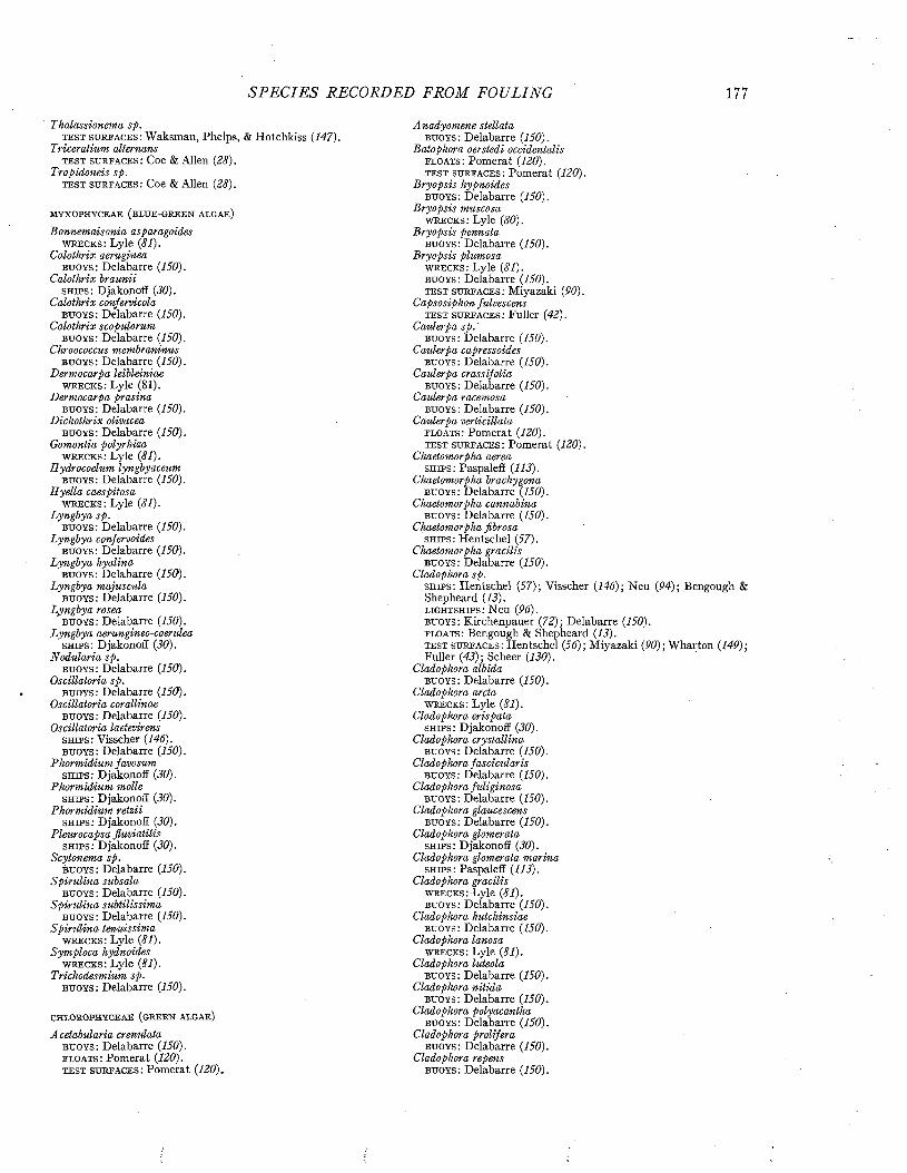
S P E C IE S RECORDED FROM FOULING 177
Thalassionema sp. t e s t s u r e a c e s : Waksman, Phelps, & Hotchkiss (147).
Triceratium alternans t e s t s u r e a c e s : Coe & Allen (28).
Tropidoneis sp. t e s t s u r f a c e s : Coe & Allen (28).
m y x o p h y c e a e (b l u e -g r e e n a l g a e )
Bonnemaisonia asparagoides w r e c k s : Lyle (81).
Calothrix aerugineab u o y s : Delabarre (150).
Calothrix brauniis h i p s : Djakonoff (30).
Calothrix confervicola b u o y s : Delabarre (150).
Calothrix scopulorum b u o y s : Delabarre (150).
Chroococcus membraninus b u o y s : Delabarre (150).
Dermocarpa leibleiniae w r e c k s : Lyle (81).
Dermocarpa prasinab u o y s : Delabarre (150).
Dichothrix olivaceab u o y s : Delabarre (150).
Gomontia polyrhiza w r e c k s : Lyle (81).
Rydrocoelum lyngbyaceum b u o y s : Delabarre (150).
H yella caespitosa w r e c k s : Lyle (81).
Lyngbya sp.b u o y s : Delabarre (150).
Lyngbya confervoides b u o y s : Delabarre (150).
Lyngbya hyalina b u o y s : Delabarre (150).
Lyngbya majusculab u o y s : Delabarre (150).
Lyngbya roseab u o y s : Delabarre (150).
Lyngbya aerungineo-coerulea s h i p s : Djakonoff (30).
Nodularia sp.b u o y s : Delabarre (150).
Oscillatoria sp.b u o y s : Delabarre (150).
Oscillatoria corallinae b u o y s : Delabarre (150).
Oscillatoria laetevirens s h i p s : Visscher (146). b u o y s : Delabarre (150).
Phorm idium favosum s h i p s : Djakonoff (30).
Phorm idium molles h i p s : Djakonoff (30).
Phormidium retziis h i p s : Djakonoff (30).
Pleurocapsa fluviatilis s h i p s : Djakonoff (30).
Scytonema sp.b u o y s : Delabarre (150).
Spiru lina subsalab u o y s : Delabarre (150).
Spiru lina subtilissima b u o y s : Delabarre (150).
Spiru lina tenuissima w r e c k s : Lyle (81).
Sym ploca hydnoides w r e c k s : Lyle (81).
Trichodesmium sp. b u o y s : Delabarre (150).
c h l o r o p h y c e a e (g r e e n a l g a e )
Acetabularia crenulata b u o y s : Delabarre (150). f l o a t s : Pomerat (120). t e s t s u r f a c e s : Pomerat (120).
A nadyomene stellatab u o y s : Delabarre (150).
Batophora oerstedi occidentalis f l o a t s : Pomerat (120). t e s t s u r f a c e s : Pomerat (120).
B ryopsis hypnoidesb u o y s : Delabarre (150).
B ryopsis muscosa w r e c k s : Lyle (80).
B ryopsis pennatab u o y s : Delabarre (150).
B ryopsis plumosa w r e c k s : Lyle (81). b u o y s : Delabarre (150). t e s t s u r f a c e s : Miyazaki (90).
Capsosiphon fulvescens t e s t s u r f a c e s : Fuller (42).
Caulerpa sp . ' b u o y s : Delabarre (150).
Caulerpa capressoides b u o y s : Delabarre (150).
Caulerpa crassifolia b u o y s : Delabarre (150).
Caulerpa racemosa b u o y s : Delabarre (150).
Caulerpa verticillata f l o a t s : Pomerat (120). t e s t s u r f a c e s : Pomerat (120).
Chaetomorpha aerea s h i p s : Paspaleff (113).
Chaetomorpha brachygona b u o y s : Delabarre (150).
Chaetomorpha cannabina b u o y s : Delabarre (150).
Chaetomorpha fibrosa s h ip s : Hentschel (57).
Chaetomorpha gracilis b u o y s : Delabarre (150).
Cladophora sp.s h i p s : Hentschel (57); Visscher (146)- Neu (94); Bengough & Shepheard (13). l ig h t s h ip s : Neu (96).b u o y s : Kirchenpauer (72); Delabarre (150). f l o a t s : Bengough & Shepheard (13).t e s t s u r f a c e s : Hentschel (56); Miyazaki (90); Wharton (149); Fuller (43); Scheer (130).
Cladophora albida b u o y s : Delabarre (150).
Cladophora arcta w r e c k s : Lyle (81).
Cladophora crispata s h i p s : Djakonoff (30).
Cladophora crystallina b u o y s : Delabarre (150).
Cladophora fascicularis b u o y s : Delabarre (150).
Cladophora fidiginosa b u o y s : Delabarre (150).
Cladophora glaucescens b u o y s : Delabarre (150).
Cladophora glomerata s h i p s : Djakonoff (30).
Cladophora glomerata marina s h i p s : Paspaleff (113).
Cladophora gracilis w r e c k s : Lyle (81). b u o y s : Delabarre (150).
Cladophora hutchinsiae b u o y s : Delabarre (150).
Cladophora lanosa w r e c k s : Lyle (81).
Cladophora luteola b u o y s : Delabarre (150).
Cladophora n itida b u o y s : Delabarre (150).
Cladophora polyacantha b u o y s : Delabarre (150).
Cladophora prolifera b u o y s : Delabarre (150).
Cladophora repens b u o y s : Delabarre (150).
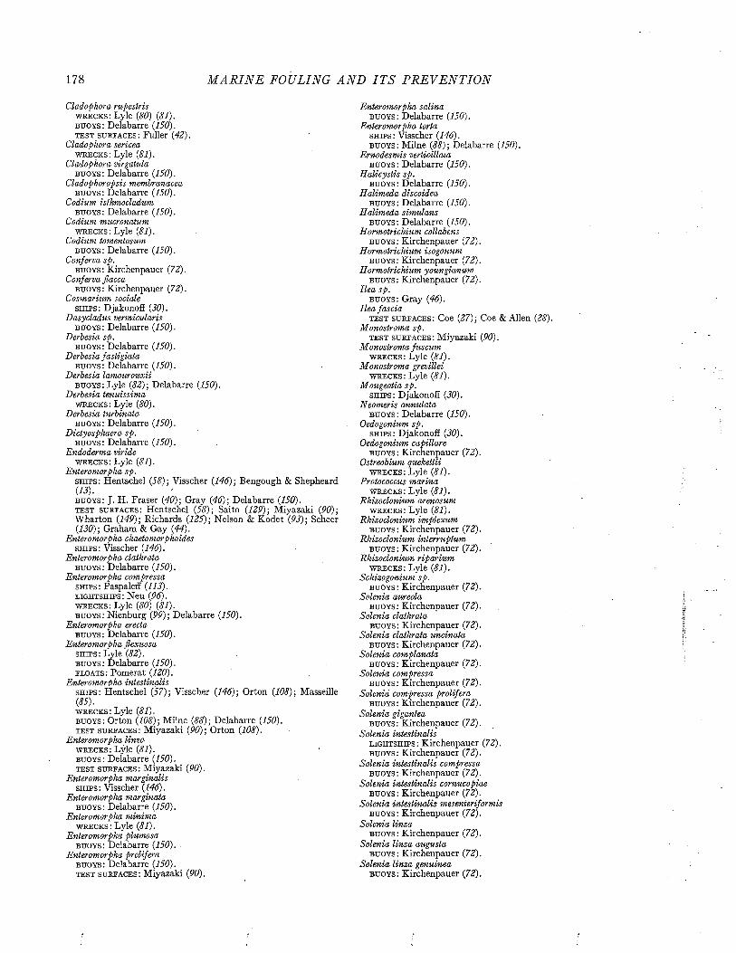
178 M A R I N E FOULING A N D I T S P R E V E N T I O N
Cladophora rupestris w r e c k s : Lyle (80) (81). b u o y s : Delabarre (150). t e s t s u r e a c e s : Fuller (42).
Cladophora sericea w r e c k s : Lyle (81).
Cladophora virgatula b u o y s : Delabarre (150).
Cladophoropsis membranacea b u o y s : Delabarre (150).
Codium isthmocladum b u o y s : Delabarre (150).
Codium mucronatum w r e c k s : Lyle (81).
Codium tomentosum b u o y s : Delabarre (150).
Conferva sp. b u o y s : Kirchenpauer (72).
Conferva flacca b u o y s : Kirchenpauer (72).
Cosmarium sociale s h i p s : Djakonoff (30).
Dasycladus vermicularis b u o y s : Delabarre (150).
Derbesia sp.b u o y s : Delabarre (150).
Derbesia fastigiatab u o y s : Delabarre (150).
Derbesia lamourouxiib u o y s : Lyle (82); Delabarre (150).
Derbesia tenuissima w r e c k s : Lyle (80).
Derbesia turbinatab u o y s : Delabarre (150).
Dictyosphaera sp. b u o y s : Delabarre (150).
Endoderma viride w r e c k s : Lyle (81).
Enteromorpha sp.s h ip s : Hentschel (58) ; Visscher (146) ; Bengough & Shepheard (13).b u o y s : J. H. Fraser (40); Gray (46); Delabarre (150). t e s t s u r e a c e s : Hentschel (58)-, Saito (12P); Miyazaki (90); Wharton (149); Richards (125); Nelson & Kodet (93); Scheer (130); Graham & Gay (44).
Enteromorpha chaetomorphoides s h i p s : Visscher (146).
Enteromorpha clathrata b u o y s : Delabarre (150).
Enteromorpha compressa s h i p s : Paspaleff (113). l ig h t s h ip s : Neu (96). w r e c k s : Lyle (80) (81). b u o y s : Nienburg (99); Delabarre (150).
Enteromorpha erectab u o y s : Delabarre (150).
Enteromorpha flexuosa s h i p s : Lyle (82). b u o y s : Delabarre (150). e l o a t s : Pomerat (120).
Enteromorpha intestinaliss h i p s : Hentschel (57); Visscher (146); Orton (108); Masseille(85).w r e c k s : Lyle (81).b u o y s : Orton (108); Milne (88); Delabarre (150). t e s t s u r f a c e s : Miyazaki (90); Orton (108).
Enteromorpha linza w r e c k s : Lyle (81). b u o y s : Delabarre (150). t e s t s u r f a c e s : Miyazaki (90).
Enteromorpha marginalis s h i p s : Visscher (146).
Enteromorpha marginata b u o y s : Delabarre (150).
Enteromorpha m inima w r e c k s : Lyle (81).
Enteromorpha plumosa b u o y s : Delabarre (150). .
Enteromorpha prolifera b u o y s : Delabarre (150). t e s t s u r f a c e s : Miyazaki (90).
Enteromorpha salina b u o y s : Delabarre (150).
Enteromorpha torta s h i p s : Visscher (146). b u o y s : Milne (88); Delabarre (150).
Ernodesmis verticillata b u o y s : Delabarre (150).
H alicystis sp. b u o y s : Delabarre (150).
Halimeda discoideab u o y s : Delabarre (150).
H alimeda simulansb u o y s : Delabarre (150).
Hormotrichium collabens b u o y s : Kirchenpauer (72).
Hormotrichium isogonum b u o y s : Kirchenpauer (72).
Hormotrichium youngianum b u o y s : Kirchenpauer (72).
Ilea sp. b u o y s : Gray (46).
Ilea fasciat e s t s u r f a c e s : Coe (27); Coe & Allen (28).
Monostroma sp.t e s t s u r f a c e s : Miyazaki (90).
M onostroma fuscum w r e c k s : Lyle (81).
Monostroma grevillei w r e c k s : Lyle (81).
Mougeotia sp. s h i p s : Djakonoff (30).
Neomeris annulata b u o y s : Delabarre (150).
Oedogonium sp.s h i p s : Djakonoff (30).
Oedogonium capillareb u o y s : Kirchenpauer (72).
Ostreobium quekettii w r e c k s : Lyle (81).
Protococcus marina w r e c k s : Lyle (81).
Rhizoclonium arenosum w r e c k s : Lyle (81).
Rhizoclonium implexum b u o y s : Kirchenpauer (72).
Rhizoclonium interruptum b u o y s : Kirchenpauer (72).
Rhizoclonium riparium w r e c k s : Lyle (81).
Schizogonium sp.b u o y s : Kirchenpauer (72).
Solenia aureolab u o y s : Kirchenpauer (72).
Solenia clathratab u o y s : Kirchenpauer (72).
Solenia clathrata uncinata b u o y s : Kirchenpauer (72).
Solenia complanatab u o y s : Kirchenpauer (72).
Solenia compressab u o y s : Kirchenpauer (72).
Solenia compressa prolifera b u o y s : Kirchenpauer (72).
Solenia giganteab u o y s : Kirchenpauer (72).
Solenia intestinalisl ig h t s h ip s : Kirchenpauer (72). b u o y s : Kirchenpauer (72).
Solenia intestinalis compressa b u o y s : Kirchenpauer (72).
Solenia intestinalis cornucopiae b u o y s : Kirchenpauer (72).
Solenia intestinalis mesenteriformis b u o y s : Kirchenpauer (72).
Solenia linzab u o y s : Kirchenpauer (72).
Solenia linza augustab u o y s : Kirchenpauer (72).
Solenia linza genuineab u o y s : Kirchenpauer (72).
SP EC IE S RECORDED FROM FOULING 179
Solenia linza lanceolata b u o y s : Kirchenpauer (72).
Solenia linza sp iralisb u o y s : Kirchenpauer (72).
Solenia olivaceal ig h t s h ip s : Kirchenpauer (72). b u o y s : Kirchenpauer (72).
Spongomorpha arcta b u o y s : Delabarre (150).
Spongomorpha spinescens b u o y s : Delabarre (150).
Stigeoclonium sp.s h i p s : Hentschel (57).
Stigeoclonium iemte s h i p s : Djakonoff (30).
Ulothrix sp. s h i p s : Bengough & Shepheard (13). t e s t s u r e ac e s : Bengough & Shepheard (13).
Ulothrix flacca s h i p s : Visscher (146). w r e c k s : Herpin (59). b u o y s : Delabarre (150).
Ulothrix zonata s h i p s : Djakonoff (JO).
Ulva sp.s h i p s : Hentschel (57); Neu (94); Bengough & Shepheard (13). e l o a t s : Bengough & Shepheard (13).t e s t s u r e a c e s : Iredale, Johnson, & McNeill (67); Johnson, McNeill, & Iredale (71); Johnson & McNeill (70); Wharton (149).
Ulva lactuca s h i p s : Visscher (146); Paspaleff (113). w r e c k s : Lyle (81). b u o y s : Milne (88); Delabarre (150). f l o a t s : Fuller' (42). t e s t s u r f a c e s : Fuller (42).
Ulva lactuca latissima w r e c k s : Lyle (JO).
Ulva lactuca rigida f l o a t s : Pomerat (120).
Ulva latissima p i p e s : Dobson (31). t e s t s u r f a c e s : Orton (108).
Ulva linza b u o y s : Milne (88).
Ulva pertusa t e s t s u r f a c e s : Saito (129); Miyazaki (90).
Valonia macrophysa b u o y s : Delabarre (150).
Valonia ventricosa b u o y s : Delabarre (150).
Vaucheria sp. s h i p s : Visscher (146). w r e c k s : Lyle (81) ; Herpin (59). b u o y s : Delabarre (150). t e s t s u r f a c e s : Graham & Gay (44).
Vaucheria littorea b u o y s : Kirchenpauer (72).
p h a e o p h y c e a e (b r o w n a l g a e )
Acinetospora pusilla w r e c k s : Lyle (81).
Agarum cribrosumb u o y s : Delabarre (150).
A laria esculenta w r e c k s : Lyle (81). b u o y s : Delabarre (150).
Ascophyllum nodosum w r e c k s : Herpin (59). b u o y s : Milne (88).
Asperococcus echinatus w r e c k s : Lyle (81). b u o y s : Delabarre (150).
Castagnea howei b u o y s : Delabarre (150).
Chorda filum b u o y s : Delabarre (150).
Chordaria flagelliformis w r e c k s : Lyle (81). b u o y s : Delabarre (150).
Colpomenia sinuosa t e s t s u r f a c e s : Coe (27) ; Coe & Allen (28) .
Desmarestia aculeata w r e c k s : Lyle ( 81) .
Desmarestia viridis t e s t s u r f a c e s : Miyazaki ( 90) .
D ictyopteris sp. b u o y s : Delabarre ( 150) .
D ictyopteris polypodiodes b u o y s : Delabarre ( 150) .
Dictyosiphon foeniculaceus l i g h t s h i p s : Neu ( 96) .
w r e c k s : Lyle ( 81) .
D ictyota sp. \s h i p s : Bengough & Shepheard ( 13) .
b u o y s : Delabarre ( 150) .
t e s t s u r f a c e s : Bengough & Shepheard ( 13) .
D ictyota bartayresii b u o y s : Delabarre ( 150) .
D ictyota cervicornisb u o y s : Delabarre ( 150) .
D ictyota dichotoma w r e c k s : Lyle ( 81) .
b u o y s : Delabarre ( 150) .
D ictyota divaricatab u o y s : Delabarre ( 150) .
Dictyota pardalis b u o y s : Delabarre ( 150) .
Ectocarpus sp.s h i p s : Visscher ( 146) ; Paspaleff ( 113) ; Bengough & Shepheard (13) .w r e c k s : Herpin ( 59) .
b u o y s : Gray ( 46) ; Delabarre ( 150) .
f l o a t s : Scheer ( 130) .
t e s t s u r f a c e s : Johnson, McNeill, & Iredale ( 71) ; Johnson & M cNeill ( 70) ; Scheer ( 130) ; Graham & Gay ( 44 ) .
Ectocarpus arctuss h i p s : Paspaleff ( 113) .
Ectocarpus confervoidess h i p s : Hentschel (57) ; Paspaleff ( 113) .
w r e c k s : Lyle ( 81) .
b u o y s : Gray ( 46) ; Delabarre ( 150) .
t e s t s u r f a c e s : Coe ( 27) ; Coe & Allen (28) .
Ectocarpus cylindricus t e s t s u r f a c e s : Coe ( 27) ; Coe & Allen (28) .
Ectocarpus duchassaignianus b u o y s : Delabarre ( 150) .
Ectocarpus fasciculatus w r e c k s : Lyle ( 81) .
Ectocarpus ferrugineusb u o y s : Kirchenpauer ( 72) .
Ectocarpus gracillimus b u o y s : Kirchenpauer ( 72) .
Ectocarpus granulosus w r e c k s : Lyle ( 81) .
b u o y s : Delabarre ( 150) .
t e s t s u r f a c e s : Coe ( 27 ) ; Coe & Allen ( 28) .
Ectocarpus granulosoides t e s t s u r f a c e s : Scheer ( 130) .
. Ectocarpus hincksiae w r e c k s : Lyle ( 81) .
Ectocarpus irregularis s h i p s : Paspaleff ( 113) .
Ectocarpus littoralisb u o y s : Kirchenpauer ( 72) .
Ectocarpus mitchellae t e s t s u r f a c e s : Coe ( 27 ) ; Coe & Allen (28) .
Ectocarpus paradoxus b u o y s : D e la b a r r e ( 150) .
Ectocarpus penicillatus b u o y s : D e la b a r r e ( 150) .
Ectocarpus sandrianus w r e c k s : Lyle ( 81) .
b u o y s : Delabarre ( 150) .
Ectocarpus secundatus b u o y s : Kirchenpauer ( 72) .
Ectocarpus siliculosus w r e c k s : Lyle (81). b u o y s : Kirchenpauer ( 72) .
180 M A R I N E FOULING A N D I T S P R E V E N T I O N
Ectocarpus terminalis w r e c k s : Lyle (81). b u o y s : Delabarre (150).
Egregia laevigatat e s t s u r f a c e s : Coe (27); Coe & Allen (28).
Eisevia bicyclist e s t s u r f a c e s : Miyazaki (90).
Elachista fucicola w r e c k s : Lyle (81).
Fvicus sp. s h i p s : Visscher (146).
Fucus platycarpus w r e c k s : Herpin (59). b u o y s : Gray (46).
Fucus serratusw r e c k s : Lyle (81); Herpin (59).
Fucus vesiculosus w r e c k s : Lyle (81).
H alidrys siliquosa w r e c k s : Lyle (80).
Homoeostroma latifoliumt e s t s u r f a c e s : Miyazaki (90).
Hydroclathrus clathratust e s t s u r e ac e s : Coe (27); Coe & Allen (28).
Isthmoplea sp.b u o y s : Delabarre (150).
Laminaria sp. b u o y s : Gray (46).
Laminaria aghardhiib u o y s : Gray (46); Delabarre (150).
Lam inaria digitataw r e c k s : Lyle (80) (81).b u o y s : Milne (88); Delabarre (150).t e s t s u r f a c e s : Orton (108).
Laminaria saccharina s h i p s : Orton (108). w r e c k s : Beaumont (10); Lyle (81). b u o y s : Orton (108); Milne (88); Delabarre (150). t e s t s u r f a c e s : Orton (108).
Leathesia difformis w r e c k s : Lyle (81).t e s t s u r f a c e s : Coe (27); Coe & Allen (28).
Lithoderma fatiscens w r e c k s : Lyle (81).
Lithosiphon laminariae w r e c k s : Lyle (81).
Mesogloia divaricatab u o y s : Delabarre (150).
M yrionema sp .b u o y s : Delabarre (150).
M yrionema vulgare w r e c k s : Lyle (81).
M yriotricha filiform is w r e c k s : Lyle (81).
Neurocarpus ju s tii b u o y s : Delabarre (150).
Neurocarpus plageogammus b u o y s : Delabarre (150).
P adina vickersiaeb u o y s : Delabarre (150).
Petalonia fascia b u o y s : Delabarre (150).
P hyllitis fasciab u o y s : Kirchenpauer (72); Nienburg (99).
Punctaria sp. b u o y s : Gray (46).
Punctaria latifoliab u o y s : Delabarre (150). t e s t s u r f a c e s : Fuller (42).
Punctaria plantaginea w r e c k s : Lyle (81).
Pylaiella litoralis w r e c k s : Lyle (81). b u o y s : Delabarre (150).
Pylaiella litoralis longifructus w r e c k s : Lyle (81).
Saccorhiza bulbosa w r e c k s : Lyle (81).
Sargassum enervet e s t s u r f a c e s : Miyazaki (90).
Sargassum filicinumt e s t s u r f a c e s : Miyazaki (90).
Sargassum filipendula b u o y s : Delabarre (150).
Sargassum horneri t e s t s u r f a c e s : Miyazaki (90).
Sargassum natans b u o y s : Delabarre (150).
Sargassum polyceratium b u o y s : Delabarre (150).
Sargassum polyceratium ovatum , b u o y s : Delabarre (150).
Scytosiphon sp. b u o y s : Gray (46). t e s t s u r f a c e s : Scheer (130).
Scytosiphon lomentaria w r e c k s : Lyle (81).b u o y s : Kirchenpauer (72); Nienburg (99); Delabarre (150). t e s t s u r f a c e s : Coe (27); Coe & Allen (28).
Sorocarpus uraeformis b u o y s : Delabarre (150).
Sphaularia sp.b u o y s : Delabarre (150).
Sphaularia cirrhosaw r e c k s : Lyle (80) (81).
Sphaularia cirrhosa fusca w r e c k s : Lyle (81).
U ndaria pinnatafida t e s t s u r f a c e s : Miyazaki (90).
Zonaria varigatab u o y s : Delabarre (150).
RHODOPHYCEAE (RED ALGAE)
Acanthophora delilei s h i p s : Lyle (82).
Acanthophora spinifera b u o y s : Delabarre (150).
Acrochaetium sp.s h i p s : Visscher (146). b u o y s : Delabarre (150).
Acrochaetium dufourii b u o y s : Delabarre (150).
A crochaeiium flexuosum b u o y s : Delabarre (150).
Acrochaetium sargassi b u o y s : Delabarre (150).
Acrochaetium virgatidum b u o y s : Delabarre (150).
Agardhiella tenerab u o y s : Delabarre (150).
Agardhinula browneae b u o y s : Delabarre (150).
A mphiroa fragilissim a b u o y s : Delabarre (150).
Am phiroa tribulusb u o y s : Delabarre (150).
Antithamnion sp.b u o y s : Delabarre (150).
Antithamnion americanum b u o y s : Delabarre (150).
Antitham nion cruciatum w r e c k s : Lyle (81).
Antitham nion plumulaw r e c k s : Lyle (81); Herpin (59).
Antithamnionella sarniensis w r e c k s : Lyle (80).
Asterocystis ramosab u o y s : Delabarre (150).
Bangia sp. b u o y s : Nienburg (99).
Brogniartella byssoides w r e c k s : Lyle (81).
Bryocladia cuspidata b u o y s : Delabarre (150).
Bryothamnion triquetrum b u o y s : Delabarre (150).
Callithamnion sp.t e s t s u r f a c e s : Wharton (149).
Callithamnion byssoides w r e c k s : Lyle (81).

S P E C I E S RECORDED FROM FOULING
b u o y s : Delabarre (150). f l o a t s : Pomerat (120). t e s t s u r f a c e s : Pomerat (120).
Callithamnion corymbosum s h i p s : Paspaleff (113). w r e c k s : Herpin (59). b u o y s : Milne (88).
Callithamnion hookeri w r e c k s : Lyle (80).
Callithamnion polyspermum w r e c k s : Lyle (81).
Callithamnion roseum w r e c k s : Lyle (81).
Callithamnion tetragonum w r e c k s : Lyle (80).
Callocolax neglectus w r e c k s : Lyle (81).
Callophyllis laciniata w r e c k s : Lyle (81).
Calosiphonia verticillifera b u o y s : Delabarre (150).
Ceramium sp.s h i p s : Bengough & Shepheard (13).b u o y s : Nienburg (99); Delabarre (150).t e s t s u r f a c e s : Coe (27); Coe & Allen (28); Bengough &Shepheard (13); LaQue & Clapp (76).
Ceramium circinnatum w r e c k s : Lyle (81).
Ceramium deslongchampsii w r e c k s : Lyle (80). b u o y s : Delabarre (150).
Ceramium diaphanum w r e c k s : Lyle (81).
Ceramium fastigiatum b u o y s : Delabarre (150).
Ceramium flabelligerum w r e c k s : Lyle (80).
Ceramium floridanum b u o y s : Delabarre (150).
Ceramium rubrums h i p s : Paspaleff (113). w r e c k s : Lyle (80) (81).b u o y s : Miine (88); Gray (46); Delabarre (150). t e s t s u r f a c e s : Miyazaki (90).
Ceramium tenuissimum b u o y s : Delabarre (150).
Centroceras clavulatum b u o y s : Delabarre (150).
Champia parvula w r e c k s : Lyle (81). b u o y s : Delabarre (150). t e s t s u r f a c e s : Miyazaki (90).
Chantransia caespitosa w r e c k s : Lyle (81).
Chantransia chalybea s h i p s : Djakonoff (30).
Chantransia daviesii w r e c k s : Lyle (81).
Chantransia hallandica w r e c k s : Lyle (81).
Chantransia virgatula w r e c k s : Lyle (80) (81). _
Chantransia virgatula luxurians w r e c k s : Lyle (81).
Chantransia virgatula secundata w r e c k s : Lyle (81).
Chondria dasyphylla b u o y s : Delabarre (150).
Chondria floridanab u o y s : Delabarre (150).
Chondrus sp . b u o y s : Gray (46). t e s t s u r f a c e s : Miyazaki (90).
Choreonema thuretii w r e c k s : Lyle (81).
Chrysemenia agardhii b u o y s : Delabarre (150).
Chrysemenia enteromorpha b u o y s : Delabarre (150).
Chrysemenia halymenioides b u o y s : Delabarre (150).
Chrysemenia pyriform is b u o y s : Delabarre (150).
Chrysemenia uvaria b u o y s : Delabarre (150).
Chylocladia kaliformis w r e c k s : Lyle (81).
Compsothamnion gracillimum w r e c k s : Lyle (81).
Conchocelis rosea w r e c k s : Lyle (81).
Corallina cubensisb u o y s : Delabarre (150).
Corallina gracilis t e s t s u r f a c e s : Coe (27); Coe & Allen (28).
Corallina officinalis b u o y s : Delabarre (150).
Corallina squamata w r e c k s : Lyle (81).
Crouania attenuata b u o y s : Delabarre (150).
Cruriopsis sp. b u o y s : Delabarre (150).
Cruriopsis ensis b u o y s : Delabarre (150).
Cryptonemia crenulata b u o y s : Delabarre (150).
Cystoclonium purpureum w r e c k s : Lyle (81). b u o y s : Gray (46).
Dasya sp. b u o y s : Delabarre (150). t e s t s u r f a c e s : Wharton (149).
Dasya arbuscula b u o y s : Delabarre (150).
Dasya corymbiferab u o y s : Delabarre (150).
Dasya crouania b u o y s : Delabarre (150).
Dasya harreyi b u o y s : Delabarre (150).
Dasya mollis b u o y s : Delabarre (150).
, Dasya pedicellatab u o y s : Delabarre (150). f l o a t s : Pomerat (120). t e s t s u r f a c e s : Pomerat (120).
Dasya ramosissimab u o y s : Delabarre (150).
Dasya rigidulab u o y s : Delabarre (150).
Delesseria alataw r e c k s : Lyle (80) (81).
Delesseria hypoglossum b u o y s : Delabarre (150).
Delesseria involvens b u o y s : Delabarre (150).
Delesseria ruscifolia w r e c k s : Lyle (81).
Delesseria sanguinea w r e c k s : Lyle (81).
Delesseria sinuosa lingulata w r e c k s : Lyle (81).
Digenia simplexb u o y s : Delabarre (150).
Dilsea edulisw r e c k s : Lyle (81).
Dumontia sp.b u o y s : Delabarre (150).
Eacheuma acanthocladum b u o y s : Delabarre (150).
Epilithon membranacetim w r e c k s : Lyle (81).
Erythrocladia irregtdaris w r e c k s : Lyle (81).
Erythrotrichia bertholdii w r e c k s : Lyle (81).
Erythrotrichia carnea w r e c k s : Lyle (81). b u o y s : Delabarre (150).
Euthora cristata w r e c k s : Lyle (81).
182 M A R I N E FOULING A N D I T S P R E V E N T I O N
Falkenbergia hillebrandii b u o y s : Delabarre (150).
Furcellaria fastigiata w r e c k s : Lyle (81).
Gelidium sp. t e s t s u r e a c e s : Wharton (149).
Gelidium corneum w r e c k s : Lyle (81). b u o y s : Lyle (82) ; Delabarre (150).
Gelidium rigidumb u o y s : Delabarre (150).
Gigartina spinosa t e s t s u r f a c e s : Coe (27) ; Coe & Allen (28).
Goniotrichum alsidii b u o y s : Delabarre (150).
Gracilaria sp. b u o y s : Delabarre (150).
Gracilaria blodgettii b u o y s : Delabarre (150).
Gracilaria compressa b u o y s : Delabarre (150).
Gracilaria confervoides w r e c k s : Lyle (80) (81). b u o y s : Delabarre (150). t e s t s u r f a c e s : Miyazaki (90).
Gracilaria cornea b u o y s : Delabarre (150).
Gracilaria cylindrica b u o y s : Delabarre (150).
Gracilaria feroxb u o y s : Delabarre (150).
Gracilaria filicinat e s t s u r f a c e s : Miyazaki (90).
Gracilaria lacinulata b u o y s : Delabarre (150).
Grateloupia sp. t e s t s u r f a c e s : Miyazaki (90).
Grateloupia filicinab u o y s : Delabarre (150).
Grateloupia gibbesii b u o y s : Delabarre (150).
Griffithsia flosculosa w r e c k s : Lyle (80).
Griffithsia globiferab u o y s : Delabarre (150).
Grinnellia americana o b u o y s : Delabarre (150).
Gymnogongrus sp. b u o y s : Delabarre (150).
Gymnothamnion elegans b u o y s : Delabarre (150).
Halosaccion sp.b u o y s : Delabarre (150).
Halymenia floridana b u o y s : Delabarre (150).
Herposiphonia pectin-vene'is b u o y s : Delabarre (150).
Herposiphonia verticellatat e s t s u r f a c e s : Coe (27); Coe & Allen (28).
Heterosiphonia gibbesii b u o y s : Delabarre (150). f l o a t s : Pomerat (120). t e s t s u r f a c e s : Pomerat (120).
B eterosiphonia japonicat e s t s u r f a c e s : Miyazaki (90).
Heterosiphonia plumosa w r e c k s : Lyle (81).
H ypnea sp. t e s t s u r f a c e s : Coe (27); Coe & Allen (28)
Hypnea cervicornisb u o y s : Delabarre (150).
Hypnea cornutab u o y s : Delabarre (150).
H ypnea musciformisb u o y s : Lyle (82) ; Delabarre (150).
Jan ia adhaeransb u o y s : Delabarre (150).
Jan ia capillaceab u o y s : Delabarre (150).
Jan ia micarthrodia b u o y s ; Lyle (82).
Jan ia rubensb u o y s : Delabarre (150).
K y lin ia scapae w r e c k s : Lyle (81).
Laurencia sp.w r e c k s : Lyle (80).
Laurencia corallopsis b u o y s : Delabarre (150).
Laurencia intricatab u o y s : Delabarre (150).
Laurencia microcladia b u o y s : Delabarre (150).
Laurencia obtusab u o y s : Delabarre (150).
Laurencia pinnatifida w r e c k s : Lyle (81).
Laurencia poiteib u o y s : Delabarre (150). f l o a t s : Pomerat (120). t e s t s u r f a c e s : Pomerat (120).
Liagora pinnata b u o y s : Delabarre (150).
Lomentaria articulata w r e c k s : Lyle (80) (81).
Lomentaria catenatat e s t s u r f a c e s : Miyazaki (90).
Lomentaria clavellosa w r e c k s : Lyle (81).
Lomentaria rosea w r e c k s : Lyle (81).
Lomentaria uncinata b u o y s : Delabarre (150).
Lophocladia trichoclados b u o y s : Delabarre (150).
Lophosiphonia villumt e s t s u r f a c e s : Scheer (130).
Melobesia lejolisii w r e c k s : Lyle (81).
Nitophyllum sp. b u o y s : Delabarre (150).
Nitophyllum laceratum w r e c k s : Lyle (81).
Odonthalia dentata w r e c k s : Lyle (81). b u o y s : Delabarre (150).
Peyssonnelia sp.b u o y s : Delabarre (150).
Peyssonnelia dubyi w r e c k s : Lyle (81).
Phycodris rubens b u o y s : Delabarre (150).
Phyllophora tra illii w r e c k s : Lyle (81).
Pleonosporium borreri w r e c k s : Lyle (81).
Plocamium coccineum w r e c k s : Lyle (81).
P lum aria elegansw r e c k s : Lyle (80) (81).
P lum aria pectinatab u o y s : Delabarre (150).
Polysiphonia sp.s h ip s : Visscher (146); Bengough & Shepheard (13). b u o y s : Gray (46); Delabarre (150). f l o a t s : Bengough & Sehpheard (13).t e s t s u r f a c e s : Miyazaki (90); Wharton (149); LaQue & Clapp (76).
Polysiphonia atro-rubescens w r e c k s : Lyle (81).
Polysiphonia brodiaei w r e c k s : Lyle (81).
Polysiphonia denudata b u o y s : Delabarre (150). •
Polysiphonia elongata w r e c k s : Lyle (81). b u o y s : Nienburg (99); Milne (88).
Polysiphonia exilisb u o y s : Delabarre (150).
Polysiphonia ferulacea b u o y s : Delabarre (150). f l o a t s : Pomerat (120). t e s t s u r f a c e s : Pomerat (120).
SP EC IE S RECORDED FROM FOULING
Polysiphonia fibrillosab u o y s : Gray (46); Delabarre (150)
‘ Polysiphonia harveyib u o y s : Delabarre (150).
Polysiphonia harveyi olneyi b u o y s : Delabarre (150).
Polysiphonia havenensis b u o y s : Delabarre (150).
Polysiphonia macrocarpa w r e c k s : Lyle (81). b u o y s : Delabarre (150).
Polysiphonia nigra w r e c k s : Lyle (80).
Polysiphonia nigrescens s h i p s : Visscher (146). w r e c k s : Lyle (80) (81). b u o y s : Delabarre (150).
Polysiphonia subtilissim a b u o y s : Delabarre (150).
Polysiphonia urceolata w r e c k s : Lyle (81). b u o y s : Delabarre (150).
Polysiphonia variegatab u o y s : Gray (46); Delabarre (150)
Polysiphonia violacea s h i p s : Visscher (146). w r e c k s : Lyle (81). b u o y s : Gray (46).
Porphyra linearis w r e c k s : Lyle (80).
Porphyra umbilicalis w r e c k s : Lyle (81).
Porphyra vulgarisb u o y s : Delabarre (150).
Porphyropsis coccinea w r e c k s : Lyle (81).
Pterosiphonia bipinnatat e s t s u r f a c e s : Scheer (130).
Pterosiphonia parasitica w r e c k s : Lyle (81).
Ptilota plumosa w r e c k s : Lyle (81).
Punctalia sp.t e s t s u r f a c e s : Miyazaki (90).
Rhabdonia ramosissima b u o y s : Delabarre (150).
Rhodochorton sp.b u o y s : Delabarre (150).
Rhodochorton floridulum w r e c k s : Lyle (81).
Rhodomela lycopodioides w r e c k s : Lyle (81).
Rhodomela subfusca w r e c k s : Lyle (81).
Rhodophyllis appendiculata w r e c k s : Lyle (81).
Rhodophyllis bifida w r e c k s : Lyle (81).
Rhodymenia palmata w r e c k s : Lyle (80) (81). b u o y s : Milne (88).
Rhodymenia palm ata marginifera w r e c k s : Lyle (81).
Rhodymenia palmetta b u o y s : Delabarre (150). .
Seirospora occidentalis b u o y s : Delabarre (150).
Spermothamnion sp.b u o y s : Delabarre (150).
Spyrid ia aculeatab u o y s : Lyle (82); Delabarre (150).
Spyrid ia filamentosab u o y s : Delabarre (150). f l o a t s : Pomerat (120). t e s t s u r f a c e s : Pomerat (120).
Trailliella intricata w r e c k s : Lyle (81).
W ildm annia umbilicalis b u o y s : Lyle (82).
Wrangelia argus Bu o y s : Delabarre (150),
W urdm annia setacea b u o y s : Delabarre (150).
A N IM A L K IN G D O M ProtozoaMASTIGOPHORA
Am phim onas globosap i p e s : Marine Biological Assoc. (84).
A nthophysa vegetanst e s t s u r f a c e s : Hentschel (56).
Codonosiga botrytis t e s t s u r f a c e s : Hentschel (56).
Distephanus sp.TEST s u r f a c e s : Waksman, Phelps, & Hotchkiss (147).
Exuviaella sp.t e s t s u r f a c e s : Waksman, Phelps, & Hotchkiss (147).
s a r c o d in a (g e n e r a l )
Actinosphaerium sp.t e s t s u r f a c e s : Hentschel (56).
Actinophrys sp.t e s t s u r f a c e s : Hentschel (56).
Hyalodiscus limax t e s t s u r f a c e s : Hentschel (56).
s a r c o d in a (f o r a m in if e r a )
Anom alina coronatac a b l e s : Jeffreys & Norman (68).
B ulim ina buchianac a b l e s : Jeffreys & Norman (68).
B ulim ina punctatac a b l e s : Jeffreys & Norman (68).
Cornuspira foliacea involvensc a b l e s : Jeffreys & Norman (68).
Cornuspira involvenst e s t s u r f a c e s : Coe (27); Coe & Allen (28).
Cristellaria rotulatac a b l e s : Jeffreys & Norman (68).
Discorbina globularisc a b l e s : Jeffreys & Norman (68).
Discorbis isabelleanat e s t s u r f a c e s : Coe (27); Coe & Allen (28).
Globigerina bulloidesc a b l e s : Jeffreys & Norman (68).
Globigerina conglomeratat e s t s u r f a c e s : Coe (27); Coe & Allen (28).
Globigerina inflatac a b l e s : Jeffreys & Norman (68).
Lagena lyelliic a b l e s : Jeffreys & Norman (68).
Lagena marginatac a b l e s : Jeffreys & Norman (68).
Nodosaria scalarisc a b l e s : Jeffreys & Norman (68).
Operculina ammonoidesc a b l e s : Jeffreys & Norman (68).
Orbulina universac a b l e s : Jeffreys & Norman (68).
Patellina corrugatat e s t s u r f a c e s : Coe (27); Coe & Allen (28).
Planorbulina haidingeriic a b l e s : Jeffreys & Norman (68).
Planulina arim inensisc a b l e s : Jeffreys & Norman (68).
P lanulina ornata t e s t s u r f a c e s : Coe (27); Coe & Allen (28).
Polymorphina compressac a b l e s : Jeffreys & Norman (68).
Polymorphina lacteac a b l e s : Jeffreys & Norman (68).
Polytrem a miniaceumc a b l e s : Jeffreys & Norman (68).
Pulvinulina canariensisc a b l e s : Jeffreys & Norman (68).
Pulvinulina elegansc a b l e s : Jeffreys & Norman (68).
Pulvinulina menardiic a b l e s : Jeffreys & Norman (68).
184 M A R I N E FOULING A N D I T S P R E V E N T I O N
Pulvinulina michelinianac a b l e s : J e f f r e y s & N o r m a n ( 68) .
Pulvinulina repandac a b l e s : J e f f r e y s & N o r m a n ( 68) .
Quinqueloculina lamarckiana t e s t su p E A C E s: C o e (2 7 ) ; C o e & A lle n (28).
Quinqueloculina subrotundac a b l e s : J e f f r e y s & N o r m a n ( 68) .
Rotalina orbicularis c a b l e s : J e f f r e y s & N o r m a n ( 68) .
Textularia abbreviata c a b l e s : J e f f r e y s & N o r m a n ( 68) .
Texhdaria agglutinans c a b l e s : J e f f r e y s & N o r m a n ( 68) .
Textularia pygmaea c a b l e s : J e f f r e y s & N o r m a n ( 68) .
Textularia sagittula c a b l e s : J e f f r e y s & N o r m a n ( 68) .
Tretomphalus bulloides t e s t s u b e ac e s : C o e (2 7 ) ; C o e & A l le n (28).
Triloculina circularis t e s t s u r e ac e s : C o e (2 7 ) ; C o e & A lle n (28).
Triloculina trigonula angulata c a b l e s : J e f f r e y s & N o r m a n ( 68) .
Truncatulina lobatula c a b l e s : J e f f r e y s & N o r m a n ( 68) .
Truncatulina refulgens c a b l e s : J e f f r e y s & N o r m a n ( 68) .
Uvigerina angulosa c a b l e s : J e f f r e y s & N o r m a n ( 68) .
Uvigerina irregularis c a b l e s : J e f f r e y s & N o r m a n ( 68) .
Valvulina conica c a b l e s : J e f f r e y s & N o r m a n ( 68) .
c il ia t a
A spidisca sp. t e s t s u r e ac e s : H e n t s c h e l (56).
Carchesium polypinum t e s t s u r f a c e s : H e n t s c h e l (56).
Colpidium sp. t e s t s u r f a c e s : H e n ts c h e l (56).
Cothurnia cristallina t e s t s u r f a c e s : H e n t s c h e l (56).
Cothurnia ingenita f l o a t s : J . H . F r a s e r (40).
Cothurnia m aritim a f l o a t s : J . H . F r a s e r (40).
E pistylis sp. t e s t s u r f a c e s : H e n t s c h e l (56).
E pistylis plicatilis t e s t s u r f a c e s : H e n t s c h e l (56).
E pistylis umbellariat e s t s u r e a c e s : H e n t s c h e l (56).
Euplotes sp.t e s t s u r f a c e s : W a k s m a n , P h e lp s , & H o tc h k i s s (147).
Folliculina sp.s h i p s : V is s c h e r (146).
Folliculina ampulla t e s t s u r f a c e s : O r to n (108).
Lionotus ansert e s t s u r f a c e s : H e n t s c h e l (56).
Loxodes sp. t e s t s u r f a c e s : H e n t s c h e l (56).
Loxophyllum sp. t e s t s u r f a c e s : W a k s m a n , P h e lp s , & H o tc h k i s s (147).
Opercularia nutans t e s t s u r f a c e s : H e n ts c h e l (56).
Ophrydium versatilet e s t s u r f a c e s : H e n t s c h e l (56).
Ophryoglena atrat e s t s u r f a c e s : H e n t s c h e l (56).
Oxytricha sp.t e s t s u r f a c e s : H e n t s c h e l (56).
Platycola sp. t e s t s u r f a c e s : F u l l e r (42).
Spirostomum sp.t e s t s u r f a c e s : H e n t s c h e l ( J ó ) .
Stentor coeruleust e s t s u r f a c e s : H e n t s c h e l (56).
Stentor polymorphus t e s t s u r f a c e s : Hentschel (56).
Stentor roeselit e s t s u r f a c e s : Hentschel (Jó).
Stichotricha sp. t e s t s u r f a c e s : Hentschel (56).
Stilonychia sp.t e s t s u r f a c e s : Hentschel (Jó).
Tintinnidium sp. t e s t s u r f a c e s : Hentschel (Jó).
Tintinopsis sp. CLt e s t s u r f a c e s : Waksman, Phelps, & Hotchkiss (147).
Trachelius ovum t e s t s u r f a c e s : Hentschel (Jó).
Vaginicola decumbens t e s t s u r f a c e s : Hentschel (Jó).
Vaginicola longicollis t e s t s u r f a c e s : Hentschel (Jó).
Vorticella sp. s h i p s : Hutchins (150).t e s t s u r f a c e s : Hentschel (56); Waksman, Phelps, & Hotchkiss (147).
Vorticella campanula t e s t s u r f a c e s : Hentschel (Jó).
Vorticella citrina t e s t s u r f a c e s : Hentschel (Jó).
Vorticella marina f l o a t s : J. H. Fraser (40).
Vorticella sertularum f l o a t s : J. H. Fraser (40).
Zoothamnium sp.s h i p s : Hutchins (150).t e s t s u r f a c e s : Hentschel (56); Scheer (130).
Zoothamnium arbusculat e s t s u r f a c e s : Hentschel (56).
Zoothamnium marinum b u o y s : J. H. Fraser (40). f l o a t s : J. H. Fraser (40).
s u c t o r ia
Acineta grandist e s t s u r f a c e s : Hentschel (Jó).
Acineta tuberosa f l o a t s : J. H. Freser (40). uj; Lt e s t s u r f a c e s : Fuller (41) (42).
Dendrosoma radianst e s t s u r f a c e s : Hentschel (Jó).
Ephelota sp.t e s t s u r f a c e s : Scheer (130).
Ephelota gemmipara f l o a t s : J. H. Fraser (40).
Metacineta mystacinat e s t s u r f a c e s : Hentschel (56).
Tokophrya quadripartita t e s t s u r f a c e s : Hentschel (Jó).
Trichophrya epistylidis t e s t s u r f a c e s : Hentschel (56).
Trichophrya rotunda t e s t s u r f a c e s : Hentschel (56).
p o r if e r a (s p o n g e s )
Chalina oculataw r e c k s : Forrest & Chrichton (37).
Desmacidon fruticosumw r e c k s : Forrest & Chrichton (37).
E lysia viridisw r e c k s : Herpin (JP).
E phydatia fluviatilist e s t s u r f a c e s : Hentschel (56).
E phydatia mullerit e s t s u r f a c e s : Hentschel (56).
Esperella lorenzii w r e c k s : Grinbart (47).
Euspongia sp.s h i p s : Bertelsen & Ussing (14).
Grantia sp. b u o y s : Gray (46).t e s t s u r f a c e s : Coe (27); Miyazaki (90).

S P E C IE S RECORDED FROM FOULING
Grantia compressas h ip s : Marine Biological Association (84). w r e c k s : Herpin (59). b u o y s : Milne (88).
Halichondria sp.s h ip s : Bengough & Shepheard (13). b u o y s : Milne (88); Gray (46).t e s t s u r f a c e s : Orton (108); Bengough & Shepheard (13).
Halichondria paniceaw r e c k s : Forrest & Chrichton (37).d o c k g a t e s : Alexander, Southgate, & Bassindale (2).t e s t s u r f a c e s : Orton (108).
H alisarca d ijardin i w r e c k s : Grinbart (47).
Hymeniacidon sanguineum t e s t s u r f a c e s : Orton (107).
Isodictya funalisc a b l e s : Jeffreys & Norman (68).
Leucandra fistulosa t e s t s u r f a c e s : Orton (108).
Leucetta losangelensist e s t s u r f a c e s : Coe & Allen (28).
Leucosolenia sp.s h ip s : Hutchins (150).b u o y s : Gray (46).t e s t s u r f a c e s : Orton (108).
Leucosolenia complicata b u o y s : Milne (88).
Microciona proliferat e s t s u r f a c e s : McDougall (86).
M ycale dendyit e s t s u r f a c e s : Burton (19).
M yxilla incrustans t e s t s u r f a c e s : Burton (19).
Reniera sp.t e s t s u r f a c e s : Miyazaki (90).
Reniera boutschinski w r e c k s : Grinbart (47).
Reniera densaw r e c k s : Grinbart (47).
Reniera inflata w r e c k s : Grinbart (47).
Reniera informis w r e c k s : Grinbart (47).
Reniera pallida w r e c k s : Grinbart (47).
Reniera spinosella s h ip s : Burton (19). t e s t s u r f a c e s : Burton (19).
Reniera tubiferat e s t s u r f a c e s : McDougall (86).
Rhabdodermella nuttingit e s t s u r f a c e s : Coe & Allen (28).
Spongilla frag ilis t e s t s u r f a c e s : Hentschel (56).
Spongilla lacustris t e s t s u r f a c e s : Hentschel (56).
Sycon coronatumw r e c k s : Herpin (59); Forrest & Chrichton (37).b u o y s : Milne (88).t e s t s u r f a c e s : Orton (108).
Coelenteratah y d r o z o a (h y d r o id s )
A bietinaria greenei b u o y s : Deevey (150).
Acryptolaria exsertac a b l e s : Jeffreys & Norman (68).
Acryptolaria pulchella b u o y s : Deevey (150).
Aglaophenia acacia c a b l e s : Quelch (124).
Aglaophenia dichotoma b u o y s : Broch (18).
Aglaophenia diagensis b u o y s : Deevey (150).
Aglaophenia lale-carinata b u o y s : Deevey (150).
Aglaophenia marginata s h i p s : Ritchie (127). b u o y s : Stechow (134).
Aglaophenia myriophyllumc a b l e s : Jeffreys & Norman (68).
Aglaophenia perpusilla b u o y s : Deevey (150).
Aglaophenia pluma s h i p s : Neu (94). b u o y s : Billard (16); Broch (18).
A glaophenia struthionides b u o y s : Deevey (150).t e s t s u r f a c e s : Coe (27) ; Coe & Allen (28).
Aglaophenia tubiliferac a b l e s : Jeffreys & Norman (68).
Antennella avalonia b u o y s : Deevey (150).
Antennella curvitheca b u o y s : Deevey (150).
Antennella gracilis c a b l e s : Hargitt (51).
Antennella quadriaurita b u o y s : Deevey (150).
Antennella secundaria b u o y s : Deevey (150). c a b l e s : Bedot (12).
Antennularia irregidaris c a b l e s : Quelch (124).
Antennularia pinnatab u o y s : C. M. Fraser (39).
Antennularia profunda c a b l e s : Quelch (124).
Bim eria fransciscana b u o y s : Leloup (77); Deevey (150).
B im eria gracilisb u o y s : Deevey (150).
B im eria humilisb u o y s : Deevey (150).
Bim eria pusillab u o y s : Deevey (150).
Bim eria robustaf l o a t s : C. M. Fraser (38).
Bim eria tennella b u o y s : Deevey (150).
Bim eria tunicatab u o y s : Deevey (150).
Bougainvillia sp.s h i p s : Paspaleff (113).
Bougainvillia carolinensis s h i p s : Visscher (146). b u o y s : Deevey (150).
Bougainvillia inaequalis b u o y s : Deevey (150).
Bougainvillia longicirra s h i p s : Stechow (136). b u o y s : Deevey (150).
Bougainvillia ramosa t e s t s u r f a c e s : Orton (108).
Bougainvillia ramosa muscus s h i p s : Billard (16).
Bougainvillia rugosa s h e p s : Stechow (136).
Calycella syringa b u o y s : Deevey (150).
Calyptospadix cerulea s h i p s : C. M. Fraser (39).
Campanularia sp. s h i p s : Visscher (146). l ig h t s h ip s : Neu (96). b u o y s : Gray (46).
Cam pam daria amphora s h i p s : Visscher (146).
Campanularia angulata s h ip s : Stechow (136).
Campanularia brevithecata r o p e s : Thornely (139).
Campanularia calceolifera s h i p s : C. M. Fraser (39). t e s t s u r f a c e s : Grave (45).
Campanularia caliculata b u o y s : Stechow (134).
186 M A R I N E FOULING A N D I T S P R E V E N T I O N
Campanularia flexuosa b u o y s : Gray {46); Deevey {150). t e s t s u r f a c e s : Grave (45).
Campanularia gelatinosa b u o y s : Deevey (150).t e s t s u r f a c e s : Coe (27); Coe & Allen (28).
Campanularia groenlandica b u o y s : C. M. Fraser (38).
Campanularia hummelincki b u o y s : Deevey (150).
Campanularia integra b u o y s : Kramp (73); Deevey (150).
Campanularia marginata b u o y s : Deevey (150). c a b l e s : C. M. Fraser (39).
Campanularia mutabilis s h ip s : Ritchie (127).
Cam pam daria neglecta b u o y s : Deevey (150).
Campanularia noliformis s h ip s : Leloup (77).
Campanularia portium s h ip s : Visscher (146).
Campanularia ptychocyathus s h ip s : Ritchie (127).
Campanularia raridentata s h ip s : Stechow (136).
Campanularia verticellata s h ip s : Visscher (146).
Campanularia volubilis b u o y s : Deevey (150).
Cam panulina forskalea b u o y s : Deevey (150).
Cam pam dina humilis s h ip s : Bale (8).
Campanulina repens r o p e s : Marine Biological Assoc. (84).
Cam pam dina rugosa b u o y s : Deevey (150).
Ceratella crosslandi s h ip s : Thornely (140).
Cladocoryne floccosa c a b l e s : Hargitt (51).
C lytia sp.s h ip s : Hentschel (57). b u o y s : Gray (46).t e s t s u r f a c e s : Coe (27) ; Coe & Allen (28).
C lytia attenuatab u o y s : Deevey (150).
Clytia coronata b u o y s : Deevey (150).
Clytia cylindrica b u o y s : Deevey (150).
Clytia edwardsi b u o y s : Deevey (150).
Clytia elsae-oswaldaes h ip s : C. M. Fraser (39). b u o y s : Deevey (150).
C lytia fragilis b u o y s : Deevey (150).
C lytia geniculata s h ip s : Ritchie (127).
C lytia inconspicua b u o y s : Deevey (150).
C lytia johnstonis h ip s : Beaumont (10).w r e c k s ': Beaumont (10); Forrest & Chrichton (37).b u o y s : Deevey (150).t e s t s u r f a c e s : Orton (108).
C lytia longicyatha b u o y s : Deevey (150).
C lytia macrothecab u o y s : Deevey (150).
C lytia raridentatab u o y s : Deevey (150).
C lytia universitatis b u o y s : Deevey (150).
Cordylophora albicolab u o y s : Kirchenpauer (72).
Cordylophora lacustriss h ip s : Hincks (64); Allman (3).
b u o y s : Deevey (150).t e s t s u r f a c e s : Hentschel (56).
Coryne vaginatas h i p s : Beaumont (10). b u o y s : Beaumont (10).
Coryne vanbenedenii f l o a t s : J! H. Fraser (40).
Cuspidella costata b u o y s : Deevey (150).
Cuspidella grandis b u o y s : Deevey (150).
Cuspidella humilis s h i p s : Ritchie (127); Kramp (73). b u o y s : Deevey (150).
Dendrocoryne misakinensis w r e c k s : Stechow (134).
D iphasia alatac a b l e s : Jeffreys & Norman (68).
D iphasia digitalisb u o y s : Deevey (150).
D iphasia mutulata f l o a t s : Thornely (140).
D iphasia pinasterc a b l e s : Jeffreys & Norman (68); Quelch (124).
D iphasia rosaceab u o y s : Deevey (150).r o p e s : Marine Biological Assoc. (84).
Dynamena pum ilab u o y s : Marine Biological Assoc. (84).
Ectopleura dumortieri b u o y s : Deevey (150).
Ectopleura grandis b u o y s : Deevey (150).
Eucopella caliculata b u o y s : Deevey (150).
Eudendrium sp.s h i p s : Hincks (64); Visscher (146); Paspaleff (113) b u o y s : Gray (46).
Eudendrium album b u o y s : Deevey (150).
Eudendrium annulatum c a b l e s : Quelch (124).
Eudendrium attenuatum c a b l e s : Hargitt{5 1 ).
Eudendrium capillareb u o y s : C. M. Fraser (38); Deevey (150).
Eudendrium carneumt e s t s u r f a c e s : McDougall (86).
Eudendrium dispar b u o y s : Deevey (150).
Eudendrium eximium b u o y s : Deevey (150).
Eudendrium hargittib u o y s : C. M. Fraser (39); Deevey (150).
Eudendrium racemosum macronatum b u o y s : Billard (16).
Eudendrium rameum f l o a t s : Torrey (142). c a b l e s : Jeffreys & Norman (68). t e s t s u r f a c e s : Coe & Allen (28).
Eudendrium ramosums h i p s : Visscher (146); Neu (94). b u o y s : Deevey (150).
Eudendrium tenellum b u o y s : Deevey (150).
Eudendrium tenue b u o y s : Deevey (150).
Filellum serpens s h i p s : Ritchie (127). b u o y s : Deevey (150).
Filellum serratum b u o y s : Deevey (150).
Gonothyrea sp.s h i p s : Paspaleff (113).
Gonothyrea clarki t e s t s u r f a c e s : Graham & Gay (44).
Gonothyrea gracilis b u o y s : Deevey (150).
Gonothyrea longicyatha f l o a t s : Thornely (139). r o p e s : Thornely (139).
SP EC IE S RECORDED FROM FOULING 187
Gonothyrea loveni s h ip s : Orton (108).w r e c k s : Marine Biological Assoc. (84).b u o y s : Stammer (133).r o p e s : Purchon (123).t e s t s u r e a c e s : Orton (108)-, Grave (45).
Grammaria abietina b u o y s : C. M. Fraser (38).
Halecium annulatum b u o y s : Deevey (150).
Halecium beanii s h ip s :. Ritchie (127). b u o y s : Deevey (150).
Halecium bermudense s h i p s : Stechow (136). b u o y s : Deevey (150).
Halecium corrugatum ,b u o y s : Deevey (150).
Halecium curvicaule b u o y s : Deevey (150).
Halecium halecinum minor s h i p s : Leloup (77). b u o y s : Leloup (77).
Halecium haleciumw r e c k s : Forrest & Chrichton (37).
Halecium insolens b u o y s : Deevey (150).
Halecium muricatumb u o y s : C. M. Fraser (38).
Halecium nanum b u o y s : Deevey (150).
Halecium nudulatuml ig h t s h ip s : Billard (15).
Halecium pygmaeum b u o y s : Deevey (150).
Halecium sessile b u o y s : Deevey (150).
Halecium tenelhimb u o y s : C. M. Fraser (38); Deevey (150).
Hebella cylindrica b u o y s : Deevey (150).
Hebella pocillumb u o y s : Deevey (150).
H ydra sp.t e s t s u r f a c e s : Hentschel (56).
Hydractinia echinata b u o y s : Deevey (150).
H ydractinia m illeri b u o y s : Deevey (150).
H ydractinia polycarpa b u o y s : Deevey (150).
Hydranthea australis r o p e s : Thornely (139).
Idiella pristisb u o y s : Deevey (150).
Kirchenpaueria halecioides b u o y s : Billard (16).
Lafoea adhaerens b u o y s : Deevey (150).
Lafoea dumosaw r e c k s : Forrest & Chrichton (37). b u o y s : Deevey (150).
Lafoea fruticosab u o y s : C. M. Fraser (38).
Lafoea gracillimab u o y s : C. M. Fraser (38).
Lafoea tenellula c a b l e s : Quelch (124).
Lafoea venustab u o y s : Deevey (150).
Lafoeina tenuis b u o y s : Deevey (150). '•
Laomedea sp. l ig h t s h ip s : Neu (94).
Laomedea dichotomal ig h t s h ip s : Kirchenpauer (72).
Laomedea flexuosaWRECKSjjMarine Biological Assoc. (84); Herpin (59). b u o y s : Kirchenpauer (72); Marine Biological Assoc. (84). f l o a t s : j l H. Fraser (40).
Laomedea gelatinosa s h i p s : Stimpson (137).b u o y s : Kirchenpauer (72); J. H. Fraser (40). f l o a t s : J. H. Fraser (40). p i p e s : Philbert (117).d o c k g a t e s : Alexander, Southgate, & Bassindale (2).
Laomedea geniculata s h i p s : Hentschel (57).
Laomedea longissimab u o y s : Kirchenpauer (72).
Laomedea sargassi s h i p s : Hentschel (57).
Laomedea spinulosa minor s h i p s : Leloup (77). t e s t s u r f a c e s : Paul (114).
ly tocarpu s sp.c a b l e s : Hargitt (51).
Lytocarpus auritus c a b l e s : Bale (7).
Lytocarpus philippinus b u o y s : Deevey (150).
Margelis sp. b u o y s : Gray (46).
M argelis carolinensis b u o y s : Gray (46).
Monostaechas quadridens b u o y s : Deevey (150).
Nemertesia antennina c a b l e s : Bedot (12).
Nemertesia belini c a b l e s : Bedot (12).
Nemertesia ramosaw r e c k s : Forrest & Chrichton (37).
Obelia sp. s h i p s : Visscher (146). b u o y s : Gray (46). t e s t s u r f a c e s : Miyazaki (90).
Obelia articulatab u o y s : Deevey (150). t e s t s u r f a c e s : Fuller (42).
Obelia bicuspidata b u o y s : Deevey (150).
Obelia commissuralis s h i p s : Visscher (146).t e s t s u r f a c e s : Grave (45); McDougall (86).
Obelia dichotomas h i p s : Ritchie (127); C. M. Fraser (39).b u o y s : Stechow (135); BiJlard (16); C. M. Fraser (39); Deevey(150).p i p e s : Philbert (117).t e s t s u r f a c e s : Coe (27); Coe & Allen (28); Scheer (130); Fuller (43).
Obelia dubiab u o y s : Deevey (150).
Obelia flabellata w r e c k s : Verrili & Smith (145); C. M. Fraser (39).
Obelia gelatinosas h i p s : Visscher (146).
Obelia geniculatas h ip s : Beaumont (10) ; Vanhoffen (143) ; Orton (108) ; Bengough& Shepheard (13).w r e c k s : Beaumont (10).b u o y s : Orton (108); Deevey (150).f l o a t s : C. M. Fraser (39).t e s t s u r f a c e s : Orton (108); Coe & Allen (28); Bengough & Shepheard (13).
Obelia griffinib u o y s : Deevey (150).
Obelia hyalinab u o y s : Deevey (150).
Obelia longissima s h i p s : Kramp (73).b u o y s : Kramp (73); Orton (108); Deevey (150).
Obelia oxydentata s h i p s : Stechow (135) (136). b u o y s : Deevey (150).
Obelia plicatab u o y s : C. M. Fraser (38).
Obelia serrulata r o p e s : Thornely (139).
188 M A R I N E FOULING A N D I T S P R E V E N T I O N
Opercularella laceratas h i p s : Marine Biological Assoc. (84).d o c k g a t e s : Alexander, Southgate, & Bassindale (2).
Opercularella pum ila b u o y s : Deevey (150).
Oplorhiza parvula b u o y s : Deevey (150).
Orthopyxis caliculata t e s t s u r e a c e s : Coe (27); Coe & Allen (28).
Orthopyxis everta t e s t s u r e ac e s : Coe (27) ; Coe & Allen (28).
Pennaria cavolinii s h e p s : Ritchie (127).
Pennaria disticha australis s h i p s : Billard (16). b u o y s : Billard (16).
Pennaria tiarella s h i p s : Stechow (136). b u o y s : Gray (46); Deevey (150). f l o a t s : C. M. Fraser (39).t e s t s u r e a c e s : Edmondson & Ingram (34); McDougall (86).
Perigonimus jo n sii s h ip s : Visscher (146).
Perigonimus serpens b u o y s : Marine Biological Assoc. (84). r o p e s : Marine Biological Assoc. (84).
P lum ularia sp.t e s t s u r f a c e s : Johnson & McNeill (70).
P lum ularia delicatula c a b l e s : Quelch (124).
Plum ularia dendritica b u o y s : Deevey (150).
P lum ularia diaphana b u o y s : Deevey (150).
P lum ularia halecioides s h i p s : Ritchie (127); Leloup (77). b u o y s : Stechow (134) (136).
Plum ularia inermis b u o y s : Deevey (150).
Plum ularia lagenifera b u o y s : Deevey (150).
P lum ularia margaretta b u o y s : Deevey (150).
P lum ularia pinnatat e s t s u r e a c e s : Orton (108).
P lum ularia setacea s h i p s : Bengough & Shepheard (13). b u o y s : Stechow (136); Broch (18); Deevey (150). t e s t s u r e a c e s : Orton (108); Coe (27); Coe & Allen (28); Bengough & Shepheard (13).
P lum ularia tenella b u o y s : Gray (46).
Plum ularia variabilis c a b l e s : Quelch (124).
Podocoryne sp.s h i p s : Visscher (146).
Podocoryne carnea b u o y s : Deevey (150).
Polyplum aria flabellata c a b l e s : Bedot (12).
Scapus tubuliferc a b l e s : Jefireys & Norman (68).
Schizotricha tenellab u o y s : Gray (46); Deevey (150).
Sertularella sp. s h i p s : Hutchins (150).
Sertularella gayic a b l e s : Jeffreys & Norman (68).
Sertularella pinnata b u o y s : Deevey (150).
Sertularella polyzoniasw r e c k s : Forrest & Chrichton (37).b u o y s : Deevey (150).c a b l e s : Jeffreys & Norman (68).
Sertularella rugosa b u o y s : Deevey (150).
Serhdarella tanneri b u o y s : Deevey (150).
Sertularella tenella b u o y s : Deevey (150).
Sertularella tricuspidata b u o y s : Deevey (150).
Sertularia sp.t e s t s u r f a c e s : Phelps (116).
Sertularia argenteab u o y s : Kirchenpauer (72).
Sertularia dalmasi b u o y s : Deevey (150).
Sertularia exiguab u o y s : Deevey (150).
Sertularia flowersi b u o y s : Deevey (150).
S ertularia furcatab u o y s : Deevey (150).
Sertularia inflatab u o y s : Deevey (150).
Sertularia mirflmaf l o a t s : Thornely (140).
Sertularia operculata w r e c k s : Lyle (80). b u o y s : Marine Biological Assoc. (84).
Sertularia sigmagonangia c a b l e s : Hargitt (51).
Sertularia stookeyi b u o y s : Deevey (150).
Sertularia subtilis b u o y s : Deevey (150).
Sertularia turbinata b u o y s : Deevey (150).
Silicularia roseac a b l e s : Hargitt (51).
Soleniopsis dendriformis s h ip s : Ritchie (127).
Streptocaulus pulcherrimus c a b l e s : Quelch (124).
Syncoryne eximiab u o y s : Deevey (150).r o p e s : Marine Biological Assoc. (84).
Syncoryne mirabilis b u o y s : Deevey (150).
Syncoryne sarsi b u o y s : Bedot (11).
Synthecium moldivense f l o a t s : Thornely (140).
Thamnocnidia tubularoides s h ip s : Agassiz (1).
Thuiaria argentea b u o y s : Deevey (150).
Thuiaria articulatac a b l e s : Jeffreys & Norman (68).
Thuiaria carica b u o y s : Deevey (150).
Thuiaria cupressina b u o y s : Deevey (150).
T huiaria latiuscula b u o y s : Deevey (150).
Thuiaria sim ilis b u o y s : C. M.' Fraser (38); Deevey (150).
Thuiaria tenera b u o y s : Deevey (150).
Thyroscyphus ramosus b u o y s : Deevey (150).
Trichydra pudica b u o y s : Marine Biological Assoc. (84).
Tubidaria sp. s h ip s : Hentschel (57); Visscher (146); Orton (108). b u o y s : Gray (46).t e s t s u r f a c e s : Iredale, Johnson, & McNeill (67); Richards (125) ; Fuller (43); Mosher (92).
Tubularia calamaris l i g h t s h i p s : Kirchenpauer (72). b u o y s : Kirchenpauer (72).
Tubularia coronata b u o y s : Kirchenpauer (72).
Tubularia couthouyi s h ip s : Visscher (146). b u o y s : Gray (46).
Tubularia crocea s h ip s : Vanhoffen (143); Visscher (146); Marine Biological Assoc. (84); C. M. Fraser (39).
SPEC IE S RECORDED FROM FOULING
b u o y s : Marine Biological Assoc. (84); Gray (46); Deevey (150). p ip e s : Dobson (31).t e s t s u r f a c e s : Fuller (41) (42); McDougall (86); Graham & Gay (44).
Tubularia humilis s h ip S : Ritchie (127).
Tubularia indivisa s h ip s : Beaumont (10). b u o y s : Beaumont (10); Deevey (150). f l o a t s : Hincks (64); J. H. Fraser (40).
Tubularia larynx s h ip s : Hincks (64) ; Orton (108) ; Bengough & Shepheard (13). l i g h t s h i p s : J. H. Fraser (40). w r e c k s : Beaumont (10); Forrest & Chrichton (37). b u o y s : Kirchenpauer (72); Bedot (11); Orton (108); Marine Biological Assoc. (84); J. H. Fraser (40); Deevey (150). t e s t s u r f a c e s : Orton (108); Bengough & Shepheard (13).
Tubularia mesembryanthemum s h ip s : Stechow (134) ; Hargitt (52). t e s t s u r f a c e s : Miyazaki (90).
Tubularia polycarpa s h ip s : Allman (3).
Tributaria ralphii s h ip s : Bale (6).
Tubularia solitaria s h ip s : Ritchie (127).
Tubularia spectabilis s h ip s : C. M. Fraser (39).
T urritopsis fascicularis b u o y s : Deevey (150).
Turritopsis nutricola s h ip s : Stechow (136). b u o y s : Deevey (150).
Zanclea implexab u o y s : Deevey (150).
Zygophylax profunda c a b l e s : Quelch (124).
HYDROCORALLINAE
M illepora alcicorniss h ip s : Bertelsen & Ussing (14).
ALCYONARIA (SOFT CORALS)
Alcyonium digitatuml i g h t s h i p s : J. H. Fraser (40). w r e c k s : Forrest & Chrichton (37).
Caryophyllia arcuatac a b l e s : Milne-Edwards (89).
Caryophyllia electricac a b l e s : Milne-Edwards (89).
Cladocera arbuscula s h ip s : Duerdan (32).
Thalassiotrochus telegraphicus c a b l e s : Milne-Edwards (89).
ACTINARIA (SEA ANEMONES)
A ctin ia mesembryanthemum b u o y s : Kirchenpauer (72).
Actinoloba dianthus t e s t s u r f a c e s : Orton (108).
A iptasia diaphana b u o y s : Carlgren (24).
Diadumene luciaes h i p s : Marine Biological Assoc. (84). t e s t s u r f a c e s : Miyazaki (90).
M etridium sp . vs h i p s : Visscher (146). b u o y s : Gray (46); Hutchins (150). p i p e s : Hutchins (150).t e s t s u r f a c e s : Richards (125); Mosher (92).
M etridium dianthus b u o y s : Gray (46). t e s t s u r f a c e s : Fuller (41) (42).
M etridium senilel i g h t s h i p s : J. H. Fraser (40). w r e c k s : Forrest & Chrichton (37). b u o y s : J. H . Fraser (40).
M etridium senile dianthus b u o y s : Milne (88).d o c k g a t e s : Alexander, Southgate, & Bassindale (2)
M etridium senile pallidum b u o y s : Milne (88).
Sagartia sp.b u o y s : Gray (46).t e s t s u r f a c e s : Graham & Gay (44).
Sagartia luciaes h ip s : Visscher (146).
Sagartia viduata s h ip s : Orton (108). t e s t s u r f a c e s : Orton (108).
m a d r e p o r a r ia (t r u e c o r a l s)
Acabaria erythraea s h ip s : Dean (29). b u o y s : Dean (29).
Astrangia sp.s h ip s : Visscher (146). b u o y s : Gray (46).
Isophyllia fragiliss h ip s : Bertelsen & Ussing (14).
M adracis decactiss h ip s : Bertelsen & Ussing (14).
Maeandra labyrinthiformiss h ip s : Bertelsen & Ussing (14).
Octocorallia sp. s h ip s : Bertelsen & Ussing (14).
Oculina diffusas h ip s : Bertelsen & Ussing (14).
Siderastraea radianss h ip s : Bertelsen & Ussing (14).
Platyhelminthes (Flat W orms)Discocelia japonica
t e s t ' s u r f a c e s : Miyazaki (90).Leptoplana tremellaris
w r e c k s : Beaumont (10).Microstomum lineare
t e s t s u r f a c e s : Hentschel (56).Opisthogenia tentaculata
s h ip s : Palombi (112).Plagiostoma girardi
w r e c k s : Beaumont (10).Plagiostoma vittatum
w r e c k s : Herpin (59); Beaumont (10).P lanaria sp.
b u o y s : Kirchenpauer (72).Prosthiostomum sipunculus
t e s t s u r f a c e s : Miyazaki (90).Stylochus ijim ai
t e s t s u r f a c e s : Miyazaki (90).Stylochus suesensis
b u o y s : Palombi (112).Thysanzoon brocchii
t e s t s u r f a c e s : Miyazaki (90).Vorticeros auriculatum
w r e c k s : Beaumont (10).
NemerteaAm phiporus bimaculatus
t e s t s u r f a c e s : Coe & Allen (28).Am phiporus im parispinosus
t e s t s u r f a c e s : Coe & Allen (28).Emplectonema gracile
t e s t s u r f a c e s : Coe & Allen (28).Lineus sp .
l i g h t s h i p s : J. H. Fraser (40). b u o y s : J. H. Fraser (40).
Lineus pardalist e s t s u r f a c e s : Coe & Allen (28).
Lineus pictifronst e s t s u r f a c e s : Coe & Allen (28).
Paranemertes perigrinat e s t s u r f a c e s : Coe & Allen (28).
Tetrastemma sp. b u o y s : Gray (46).

190 M A R I N E FOULING A N D I T S P R E V E N T I O N
Tetrastemma dorsale s h i p s : Beaumont (10). w r e c k s : Beaumont (10).
Tetrastemma melanocephalum w r e c k s : Beaumont (10).
Tetrastemma vermiculatum w r e c k s : Beaumont (10).
RotiferaBranchionus sp.
t e s t s u r f a c e s : Hentschel (5 d ) .Diurella pacifica
l i g h t s h i p s : Kuntz (75).Melicerta ringens
t e s t s u r f a c e s : Hentschel (56).Oecistes sp.
t e s t s u r f a c e s : Hentschel (56).Rotifer vulgaris
t e s t s u r f a c e s : Hentschel (56).
BryozoaAcanthodesia denticulata
f l o a t s : Hastings (54).Acanthodesia serrata
b u o y s : Hastings (54).Acanthodesia tenuis
t e s t s u r f a c e s : Pomerat & Reiner (121); McDougall (86).Aetea anguina
s h i p s : Hutchins (150). b u o y s : Hutchins (150).
Aetea truncatat e s t s u r f a c e s : Edmondson & Ingram (34).
Alcyonidium sp.s h i p s : Hentschel (57).b u o y s : Gray (46).t e s t s u r f a c e s : Fuller (42).
A lcyonidium gelatinosum s h i p s : Visscher (146).
A lcyonidium m ytili s h i p s : Visscher (146).
A m athia sp .s h i p s : Edmondson & Ingram (34).t e s t s u r f a c e s : Edmondson & Ingram (34).
A m athia brasiliensis s h i p s : Hastings (53). t e s t s u r f a c e s : Hastings (53).
Am athia distanss h i p s : Hutchins (150).
Anguinella palmata s h i p s : Visscher (146). t e s t s u r f a c e s : McDougall (86).
Bowerbankia caudata s h i p s : Visscher (146).
Bowerbankia graciliss h i p s : Visscher (146); Hutchins (150). b u o y s : Hutchins (66).
Bowerbankia imbricata f l o a t s : J. H. Fraser (40).
Bugula sp.s h i p s : Herpin (60); Bengough & Shepheard (13). t e s t s u r f a c e s : Johnson & McNeill (70); Bengough & Shepheard (13); Richards (125); Richards & Clapp (126); Mosher (92).
Bugula avicularias h i p s : Hentschel (57); Hutchins (150); Weiss (150). w r e c k s : Forrest & Chrichton (37). b u o y s : Hastings (54). f l o a t s : Pomerat (120).t e s t s u r f a c e s : Hastings (53); Iredale, Johnson, & McNeill (67); McDougall (86); Weiss (150).
Bugula caraibica s h i p s : Osburn (110).
Bugula cucullifera b u o y s : Gray (46).
Bugula dentatat e s t s u r f a c e s : Miyazaki (90).
Bugula eburnea t e s t s u r f a c e s : Coe (27).
Bugula flabellata s h i p s : Orton (108).
b u o y s : Orton (108).t e s t s u r f a c e s : Orton (108); Grave (45); Fuller (41); Richards (125); Richards & Clapp (126).
Bugula gracilis uncinatac a b l e s : Osburn (109); Sumner, Osburn, & Cole (138).
Bugula johnstoniae c a b l e s : Hutchins (150).
Bugula murrayana b u o y s : Gray (46).
Bugula neritinas h ip s : Osburn (110); Hentschel (57); Waters (148); Hastings(53); Edmondson (33); Weiss (150).b u o y s : Hastings (54).f l o a t s : Pomerat (120); Scheer (130).t e s t s u r f a c e s : Saito (129); Iredale, Johnson, & McNeill (67); Coe (27) ; Coe & Allen (28) ; Miyazaki (90) ; Edmondson & Ingram (34) ; Pomerat & Reiner (121) ; Richards (125) ; McDougall(86) ; Edmondson (33) ; Richards & Clapp (126) ; LaQue & Clapp (76); Scheer (130); Miller (87); Weiss (150).
Bugula turbinatas h ip s : Hentschel (57).
Bugula turritas h ip s : Visscher (146).b u o y s : Gray (46).t e s t s u r f a c e s : Phelps (116).
Bugula uncinatab u o y s : Hutchins (150).
Buskia armatab u o y s : Hutchins (dó).
Callopora sp.s h ip s : Hentschel (57).
Callopora craticula t e s t s u r f a c e s : Fuller (43).
Callopora lineatas h ip s : Hentschel (57).
Catenaria lafontii f l o a t s : Hastings (54). t e s t s u r f a c e s : Edmondson & Ingram (34).
Cellaria d ifu sa t e s t s u r f a c e s : Coe (27); Coe & Allen (28).
Cellaria mandibulata t e s t s u r f a c e s : Coe (27); Coe & Allen (28).
Cellularia sp.s h ip s : Orton (108); Bengough & Shepheard (13). b u o y s : Orton (108).t e s t s u r f a c e s : Orton (108); Bengough & Shepheard (13).
Conopeum reticulum b u o y s : Hutchins (66).
Crisia sp. s h ip s : Visscher (146). w r e c k s : Lyle (80). t e s t s u r f a c e s : Paul (114).
Crisia eburnea b u o y s : Gray (46); Hutchins (150). t e s t s u r f a c e s : , Coe & Allen (28).
Crisia elongatas h ip s : Hutchins (150).
Crisia franciscana t e s t s u r f a c e s : Coe (27).
f v i c*j n novm r n / ln f n
TEST s u r f a c e s : Hastings (53); Coe (27); Coe & Allen (28).Crisia pacifica■ TEST SURFACES : Coe (27).Crisulipora occidentalis
f l o a t s : Scheer (130). t e s t s u r f a c e s : Coe (27); Scheer (130).
Cryptosula pallasiana f l o a t s : Scheer (130). p ip e s : Hutchins (150).t e s t s u r f a c e s : Richards (125); Richards & Clapp (126).
Diastopora obeliac a b l e s : Jeffreys & Norman (68).
Diastopora patinaw r e c k s : Forrest & Chrichton (37).
Electra sp.t e s t s u r f a c e s : Mosher (92).
Electra bellula bicornis w r e c k s : Hastings (54).
Electra crustulentat e s t s u r f a c e s : Richards (125); Richards & Clapp (126).
Electra hastingsaet e s t s u r f a c e s : Pomerat & Reiner (121).
S P E C IE S RECORDED FROM FOULING 191
Electra, monostachyst e s t s u r f a c e s : Richards & Clapp (126).
—Electra pilosas h i p s : Hentschel (57).t e s t s u r f a c e s : Fuller (42) (43).
Entalophora sp.c a b l e s : Hutchins (150).
Eschara rosaceac a b l e s : Jeffreys & Norman (68).
Eucratea chelataw r e c k s : Marine Biological Assoc. (84). t e s t s u r f a c e s : 'Coe (27) ; Coe & Allen (28).
Eucratea clavatat e s t s u r f a c e s : Scheer (130).
Flustra pilosal i g h t s h i p s : Kirchenpauer (72).
H ippodiplosia americana b u o y s : Hastings (54).
H ippoporina pertusa s h i p s : Hentschel (57).
H ippothoa catenulariac a b l e s : Jeffreys & Norman (68).
Hippothoa divaricatac a b l e s : Jeffreys & Norman (68).
Hippothoa divaricata carinata c a b l e s : Jeffreys & Norman (68).
Hippothoa hyalinac a b l e s : Sumner, Osburn, & Cole (138).t e s t s u r f a c e s : Coe (27); Coe & Allen (28); Fuller (42) (43).
Holoporella albirostrist e s t s u r f a c e s : Iredale, Johnson, & McNeill (67).
Holoporella aperta s h i p s : Hastings (53). f l o a t s : Scheer (130). t e s t s u r f a c e s : Hastings (53).
Holoporella brunnea f l o a t s : Hastings (54).
Holoporella vaganst e s t s u r f a c e s : Pomerat (120).
Idmonea atlanticac a b l e s : Jeffreys & Norman (68).
Lepralia sp.s h i p s : Paspaleff (113).
Lepralia audouinii s h i p s : Osburn (110).
Lepralia brongniartiic a b l e s : Jeffreys & Norman (68).
Lepralia ciliatac a b l e s : Jeffreys & Norman (68).
Lepralia cucullata s h i p s : Osburn (110).
Lepralia innominatac a b l e s : Jeffreys & Norman (68).
Lepralia microstomac a b l e s : Jefferys & Norman (de?).
Lepralia otto-muelleriana s h i p s : Waters (148).
Lepralia pallasianas h i p s : Waters (148); Purchon (123). b u o y s : Milne (88).
Lepralia pertusas h i p s : Visscher (146).
Lepralia ventricosac a b l e s : Jeffreys & Norman (68).
Lepralia vestita australist e s t s u r f a c e s : Iredale, Johnson, & McNeill (67).
Lichenopora radiatat e s t s u r f a c e s : Coe (27) ; Coe & Allen (28).
Lichenopora verrucariat e s t s u r f a c e s : Fuller (43).
M embranipora sp.s h i p s : Visscher (146); Neu (94); Paspaleff (113). b u o y s : Gray (46).t e s t s u r f a c e s : Orton (108); Miyazaki (90); Phelps (116); Paul (114).
M embranipora denticulataw r e c k s : Lignau (78); Grinbart (47). t e s t s u r f a c e s : Lignau (78).
M embranipora lacroixiis h e p s : Hentschel (57); Visscher (146).
M embranipora lineata s h i p s : Visscher (146)■
w r e c k s : Forrest & Chrichton (37). t e s t s u r f a c e s : Sai to (129).
Membranipora membranacea s h ip s : Osburn (110). l i g h t s h i p s : Neu (96). b u o y s : Milne (88).t e s t s u r f a c e s : Coe (27); Coe & Allen (28).
Membranipora monostachys sh e p s : Visscher (146).
Membranipora pilosa w r e c k s : Lyle (80).
Membranipora savartii s h ip s : Hentschel (57).
Membranipora tehuelchat e s t s u r f a c e s : Coe (27); Coe & Allen (28); Scheer (130).
Membranipora tuberculatat e s t s u r f a c e s : Pomerat (120); Scheer (130).
Membraniporella nitidaw r e c k s : Forrest & Chrichton (37).
M enipea longispinosat e s t s u r f a c e s : Sai to (129).
M enipea occidentalist e s t s u r f a c e s : Coe (27); Coe & Allen (28).
Microporella violaceaw r e c k s : Forrest & Chrichton (37).
Mucronella variolosaw r e c k s : Forrest & Chrichton (37).
N ichtina tuberculata w r e c k s : Hastings (54).
Nolella gigantia c a b l e s : Hutchins (150).
Paludicella sp. t e s t s u r f a c e s : Hentschel (56).
Pedicellina cernua f l o a t s : J. H. Fraser (40). t e s t s u r f a c e s : Hutchins (150).
Petraliella bisinuatac a b l e s : Hutchins (150).
Pherusa tubulosas h ip s : Masseille (85).
Plumatella fungosa t e s t s u r f a c e s : Hentschel (56).
Plumatella repenst e s t s u r f a c e s : Hentschel (56).
Reteporellina marsupiata c a b l e s : Hutchins (150).
Rhynchozoon nudum t e s t s u r f a c e s : Edmondson & Ingram (34).
Rhynchozoon tumulosum f l o a t s : Scheer (130).
Salicornaria farciminoidesc a b l e s : Milne-Edwards (89); Jeffreys & Norman (68).
Savignyella lafontii s h ip s : Osburn (110).
Schizoporella biapertac a b l e s : Sumner, Osburn, & Cole (138).
Schizoporella linearisw r e c k s : Forrest & Chrichton (37).
Schizoporella unicorniss h ip s : Osburn (110); Hentschel (57); Waters (148); Hastings (53) ; Edmondson (33). f l o a t s : Scheer (130).t e s t s u r f a c e s : Hastings (53) ; Saito (129) ; Edmondson & Ingram (34); McDougall (86); Richards (125); Edmondson (33); Richards & Clapp (126); Weiss (150).
Schizoporella venochrost e s t s u r f a c e s : Saito (129); Miyazaki (90).
Scruparia sp . s h ip s : Neu (94).
Scrupocellaria sp. s h ip s : Neu (94).
Scrupocellaria bertholletii s h ip s : Hastings (53). t e s t s u r f a c e s : Hastings (53).
Scrupocellaria cervicornis s h ip s : Osburn (110).
Scrupocellaria diegensis f l o a t s : Scheer (130).t e s t s u r f a c e s : Coe (27); Coe & Allen (28); Scheer (130).
Scrupocellaria jo llo isii s h ip s : Hastings (53).
192 M A R I N E FOULING A N D I T S P R E V E N T I O N
Scrupocellaria reptans s h ip s : Hentschel (57).
Scrupocellaria scabra s h ip s : Hutchins { 150) .
Scrupocellaria scrupea s h ip s : Masseille {85) .
Scrupocellaria scruposaw r e c k s : Forrest & Chrichton {37 ) .
Sm ittia collifera t e s t s u r f a c e s : Coe (27); Coe & Allen { 28) .
Sm ittia egyptiaca s h ip s : Hastings { 53) .
t e s t s u r f a c e s : Hastings { 53) .
Sm ittia reticulata w r e c k s : Forrest & Chrichton (57). t e s t s u r f a c e s : Coe (27 ) ; Coe & Allen ( 28) .
Sm ittia landsborovii w r e c k s : Forrest & Chrichton ( 37) .
Synnotum aviculare s h ip s : Hastings ( 53) .
Tegella unicornis t e s t s u r f a c e s : Fuller ( 43) .
Thalamoporella rozieri californiensis t e s t s u r f a c e s : Coe (27 ) ; Coe & Allen ( 28) .
Triticella elongata b u o y s : Hutchins (66).
Tubulipora serpens w r e c k s : Forrest & Chrichton (57).
Umbonella verrucosa s h e p s : Masseille ( 85) .
b u o y s : Milne (88). t e s t s u r f a c e s : Orton ( 108) .
Victorella pavida s h ip s : Osburn ( 111) .
Watersipora cucullata s h ip s : Hentschel (57); Hutchins ( 150) ; Weiss ( 150) .
t e s t s u r f a c e s : Pomerat ( 120) ; Weiss ( 150) .
Zoobotryon pellucidums h ip s : Neu ( 94) ; Edmondson & Ingram ( 34 ) .
t e s t s u r f a c e s : Coe (27) ; Coe & Allen ( 28) ; Edmondson & Ingram ( 34 ) ; Pomerat ( 120) .
BrachiopodaTerebratula caputserpentis
c a b l e s : Jeffreys & Norman (68).
Annelida (True Worms)a r c h ia n n e l id a
Ctenodrilus serratus w r e c k s : Herpin ( 59) .
p o l y c h a e t a e r r a n t ia
Autolytus edwardsi w r e c k s : Herpin ( 59) .
Autolytus prolifer f l o a t s : J. H. Fraser ( 40) .
Branchiomana disparoculatum t e s t s u r f a c e s : Coe ( 27) ; Coe & Allen (28) .
Cirratulus cirratus w r e c k s : Herpin ( 59) .
Eulalia sp. b u o y s : Gray ( 46) ; Milne ( 88) .
Eunice antennata b u o y s : Fauvel (36) .
Exogone gemnifera w r e c k s : Herpin ( 59) .
Fabricia sabella w r e c k s : Herpin ( 59) .
Glycera sp. s h ip s : Visscher ( 146) .
Halosydna brevisetosat e s t s u r f a c e s : Coe (27) ; Coe & Allen (28 ) .
Halosydna gelatinosaw r e c k s : Forrest & Chrichton (57).
Halosydna insigniss h ip s : MacGinitie (83) .
Harmothoe sp. b u o y s : Gray (46) .
Harmothoe boholensis b u o y s : Fauvel (36).
Harmothoe imbricata w r e c k s : Forrest & Chrichton (57). b u o y s : J. H. Fraser (40). t e s t s u r f a c e s : Miyazaki (90).
Harmothoe im par b u o y s : Milne (88).
Hesione pantherina b u o y s : Fauvel (36).
Hesione reticulata t e s t s u r f a c e s : Miyazaki (90).
Lagisca extenuata w r e c k s : Forrest & Chrichton (57). d o c k g a t e s : Alexander, Southgate, & Bassindale (2).
Lepidonotus sp . 'b u o y s : Gray (46).
Lepidonotus squamatus s h ip s : Purchon (123). l i g h t s h i p s : J. H. Fraser (40). w r e c k s : Forrest & Chrichton (57). b u o y s : J. H. Fraser (40); Gray (46); Milne (88). f l o a t s : J. H. Fraser (40). t e s t s u r f a c e s : Fuller (42).
Lysidice ninettaw r e c k s : Herpin (59).
M agalia perornata w r e c k s : Herpin (59).
M arphysa sp. b u o y s : Gray (46).
Nereis sp. s h ip s : MacGinitie (83). b u o y s : Kirchenpauer (72). t e s t s u r f a c e s : Richards (125).
Nereis agassizit e s t s u r f a c e s : Coe (27); Coe & Allen (28).
Nereis costaes h ip s : Fauvel (36). b u o y s : Fauvel (36).
Nereis coutierei s h ip s : Fauvel (36).
Nereis cultriferat e s t s u r f a c e s : Miyazaki (90).
Nereis latescenst e s t s u r f a c e s : Coe (27); Coe & Allen (28).
Nereis pelagicas h ip s : Visscher (146).l i g h t s h i p s : J. H. Fraser (40).w r e c k s : Forrest & Chrichton (57).b u o y s : J. H. Fraser (40); Gray (46); Milne (88).f l o a t s : J. H. Fraser (40).d o c k g a t e s : Alexander, Southgate, & Bassindale (2). t e s t s u r f a c e s : Miyazaki (90).
Nereis succineal i g h t s h i p s : Neu (96).
Nereis vexillosat e s t s u r f a c e s : Coe (27); Coe & Allen (28).
Nereis zonata persica s h ip s : Fauvel (36).
Odontosyllis ctenostoma w r e c k s : Herpin (59).
Phyllodoce sp. b u o y s : Gray (46). t e s t s u r f a c e s : Miyazaki (90).
Platynereis dum erilii w r e c k s : Herpin (59).
Polynoe gymnonotat e s t s u r f a c e s : Miyazaki (90).
Polynoe squamatus b u o y s : Gray (46).
Procerastea halleziana f l o a t s : Marine Biological Assoc. (84).
Pseudonereis anomalia s h ip s : Fauvel (36).
Syllis sp. b u o y s : Milne (88).
Syllis variegata s h ip s : Fauvel (36).
Typosyllis variegata w r e c k s : Herpin (59).

SP EC IE S RECORDED FROM FOULING 193
POLYCHAETA SEDENTARIA (TUBE WORMS AND RELATIVES)
Am phitrite sp. b u o y s : Gray ( 46) .
t e s t s u r f a c e s : Miyazaki ( 90) .
A mphiirite johnstonib u o y s : J. H. Fraser (40).
Am phitrite ornata b u o y s : Gray ( 46) .
Arenicola marinaw r e c k s : Herpin ( 59) .
Capitella capitata w r e c k s : Herpin ( 59) .
Capitellides giardi w r e c k s : Herpin ( 59) .
Chaetopterus sp. t e s t s u r f a c e s : Coe ( 27) ; Coe & Aiien ( 28) .
Chaetopterus variopedatusw r e c k s : Forrest & Chrichton ( 37) .
Crucigera websteri b u o y s : Turner ( 150) .
Dasychone sp. t e s t s u r f a c e s : Richards ( 125) .
Dasychone bairdit e s t s u r f a c e s : Hentschel ( 58) .
Dasychone bombyxw r e c k s : Forrest & Chrichton (37 ) .
Dasychone conspersat e s t s u r f a c e s : Pomerat ( 120) ; Walton Smith ( 150) .
Dasychone lucullana b u o y s : Potts ( 122) .
Eteone californicat e s t s u r f a c e s : Graham & Gay ( 44) .
Eteone lighti t e s t s u r f a c e s : Graham & Gay ( 44 ) .
Eupomatus sp. b u o y s : Turner ( 150) .
Eupomatus dianthus b u o y s : Turner ( 150) .
Eupomatus elegantulus b u o y s : Turner ( 150) .
Eupomatus gracilis f l o a t s : Scheer ( 130) .
t e s t s u r f a c e s : Coe ( 27) ; Coe & Allen ( 28) ; Scheer ( 130) .
Galeolaria sp. t e s t s u r f a c e s : Johnson & McNeill (70).
Galeolaria caespitosat e s t s u r f a c e s : Iredale, Johnson & McNeill ( 67) .
Hydroides sp.s h ip s : Visscher ( 146) ; Hutchins ( 150) .
b u o y s : Gray ( 46) .
t e s t s u r f a c e s : Miyazaki ( 90) ; Phelps ( 116) ; Pomerat & Reiner ( 121) ; Pomerat ( 120) .
Hydroides bispinosa b u o y s : Turner ( 150) .
Hydroides hexagona s h ip s : Visscher ( 146) .
t e s t s u r f a c e s : Grave ( 45) ; Wharton ( 149) ; McDougall ( 86) .
Hydroides lunuliferas h ip s : Fauvel (35); Edmondson (33) .
b u o y s : Potts ( 122) .
t e s t s u r f a c e s : Edmondson & Ingram ( 34) ; Edmondson ( 33) .
Hydroides norvegicas h ip s : Hentschel (57) ; Potts ( 122) ; Orton ( 108) ; Masseille ( 85) ;
Edmondson & Ingram (34 ) ; Bengough & Shepheard ( 13) ; Edmondson ( 33) ; Turner ( 150) .
b u o y s : Potts ( 122) ; Orton ( 108) .
t e s t s u r f a c e s : Orton ( 108) ; Edmondson & Ingram (34) ; Paul ( 114) ; Bengough & Shepheard ( 13) ; Edmondson ( 33) .
Hydroides parvusb u o y s : Turner ( 150) .
Mercierella enigmatica s h ip s : Purchon ( 123) .
O ridia armandiw r e c k s : Herpin ( 59) .
Parasabella sp. b u o y s : Gray ( 46) .
Parasabella microplhalmia b u o y s : Gray ( 46) .
Polydora ciliatat e s t s u r f a c e s : Orton ( 108) ; Fuller ( 42) ( 43) .
Polydora ligni t e s t s u r f a c e s : Graham & Gay (44).
P olym nia nebulosaw r e c k s : Forrest & Chrichton (37).
Pomatoceros sp.t e s t s u r f a c e s : Miyazaki (90).
Pomatoceros triqueter s h ip s : Orton (108); Herpin (60); Bengough & Shepheard (13). w r e c k s : Forrest & Chrichton (37). b u o y s : Orton (108); Milne (88); Turner (150). d o c k g a t e s : Alexander, Southgate, & Bassindale (2). t e s t s u r f a c e s : Orton (108); Bengough & Shepheard (13).
Protula tubulariaw r e c k s : Forrest & Chrichton (37).
Pygospio elegansr o p e s : Purchon (123).
Sabella sp.t e s t s u r f a c e s : Orton (108).
Sabella pavoninal i g h t s h i p s : J. H. Fraser (40). w r e c k s : Forrest & Chrichton (37). t e s t s u r f a c e s : Orton (108).
Sabellaria sp. t e s t s u r f a c e s : Wharton (149).
Sabellaria vulgarist e s t s u r f a c e s : McDougall (86).
Salmacina dysteri b u o y s : Potts (122).t e s t s u r f a c e s : Edmondson & Ingram (34).
Salmacina incrustans b u o y s : Turner (150).
Serpula sp. b u o y s : Gray (46); Turner (150).t e s t s u r f a c e s : Saito (129); Iredale, Johnson & McNeill (67); Nelson & Kodet (93); LaQue & Clapp (76).
Serpula columbiana t e s t s u r f a c e s : Coe (27); Coe & Allen (28).
Serpula vermicularis w r e c k s : Forrest & Chrichton (37). t e s t s u r f a c e s : Orton (108).
Spirographis spallanzanii s h ip s : Neu (94).
Spirorbis sp. s h ip s : Neu (94).t e s t s u r f a c e s : Hentschel (58); Saito (129); Coe (27); Coe & Allen (28) ; Miyazaki (90) ; Edmondson & Ingram (34) ; Pomerat (120) .
Spirorbis pagenstecheri s h ip s : Masseille (85).
Spirorbis spirillumt e s t s u r f a c e s : Fuller (42).
Spirorbis spirorbist e s t s u r f a c e s : Fuller (43).
Terebella ehrenbergi b u o y s : Potts (122).
Thelepus sp. t e s t s u r f a c e s : Miyazaki (90).
o l ig o c h a e t a
Aeolosoma sp.t e s t s u r f a c e s : Hentschel (56).
Chaetogaster diaphanust e s t s u r f a c e s : Hentschel (56).
Dero sp.t e s t s u r f a c e s : Hentschel (56).
S tylaria lacustrist e s t s u r f a c e s : Hentschel (56).
HIRUDINEA (l e e c h e s )
Glossosiphonia sp.t e s t s u r f a c e s : Hentschel (56).
Helobdella sp.t e s t s u r f a c e s : Hentschel (56).
Herpobdella sp.t e s t s u r f a c e s : Hentschel (56).
Piscicola sp.t e s t s u r f a c e s : Hentschel (56).
194 M A R I N E FOULING A N D I T S P R E V E N T I O N
ArthropodaCOPEPODA
Alteutha interrupta b u o y s : Marine Biological Assoc. {84).
Harpacticus flexus b u o y s : Marine Biological Assoc. {84).
Harpacticus gracillis b u o y s : Marine Biological Assoc. {84).
Idya furcata b u o y s : Marine Biological Assoc. {84).
Laophonte strömi b u o y s : Marine Biological Assoc. {84).
Parathalestris clausi b u o y s : Marine Biological Assoc. {84).
Thalestris longimana b u o y s : Marine Biological Assoc. {84).
o s t r a c o d a
Cytheropteron nodosum c a b l e s : J e f f r e y s & N o r m a n { 68) .
Loxoconcha multifora c a b l e s : J e f f r e y s & N o r m a n { 68) .
Paradoxostoma ensiforme c a b l e s : J e f f r e y s & N o r m a n { 68) .
Paradoxostoma variabile c a b l e s : J e f f r e y s & N o r m a n { 68) .
Sclerochilus contortus c a b l e s : J e f f r e y s & N o r m a n { 68) .
CIRRIPEDIA (b a r n a c l e s )
l e p a d o m o r p h a (g o o s e b a r n a c l e s )
A natifa laeviss h ip s : K i r c h e n p a u e r { 72) .
Conchoderma sp. s h i p s : B e n g o u g h & S h e p h e a rd { 13) .
t e s t s u r e a c e s : B e n g o u g h & S h e p h e a rd { 13) .
Conchoderma auritum s h i p s : V e r r i l i & S m i t h { 145) ; P i l s b r y { 118) ; G r u v e l { 48) ; C h i l to n (2 5 ) ; J e n n in g s { 69)-, H e n t s c h e l ( 5 7 ) ; K r ü g e r { 74) ; V is s c h e r { 146) ; O r to n { 108) ; M a r in e B io lo g ic a l A ss o c . { 84) ; W h a r t o n { 149) .
b u o y s : P i l s b r y { 118) ; O r to n { 108) ; N e w e ll { 150) .
t e s t s u r f a c e s : O r to n { 108) .
Conchoderma virgatum s h i p s : V e r r i l i & S m i t h { 145) ; P i l s b r y { 118) ; C h i l to n (2 5 ) ; J e n n in g s { 69) ; H e n t s c h e l ( 5 7 ) ; K r ü g e r { 74) ; V is s c h e r { 146) ; O r to n { 108) ; M a r in e B io lo g ic a l A ss o c . { 84) ; W h a r t o n { 149) .
b u o y s : A n n a n d a l e (5 ) ; O r to n { 108) ; N e w e ll { 150) . <
t e s t s u r f a c e s : O r to n { 108) .
Heteralepas cornuta b u o y s : N e w e l l { 150) .
H eteralepas japonica c a b l e s : N i l s s o n - C a n te l l { 103) .
Lepas sp.f l o a t s : P o m e r a t { 120) .
Lepas anatiferas h i p s : V e r r i l i & S m i t h { 145) ; B e a u m o n t { 10) ; G r u v e l { 48 ) ;
J e n n in g s { 69) ; H e n t s c h e l ( 5 7 ) ; V is s c h e r { 146) ; O r to n { 108) ;
S a i to { 129) ; M a r in e B io lo g ic a l A ss o c . { 84) ; N e u { 94) ; B e r t e l s e n & U s s in g { 14) ; W h a r t o n { 149) ; B e n g o u g h & S h e p h e a rd { 13) .
w r e c k s : B e a u m o n t { 10) .
b u o y s : S te c h o w { 134) ; O r to n { 108) ; M a r in e B io lo g ic a l A sso c . { 84) ; N e w e l l { 150) .
t e s t s u r f a c e s : O r to n { 108) ; B e n g o u g h & S h e p h e a r d { 13) .
Lepas anserifera s h i p s : V e r r i l i & S m i t h { 145) ; H e n t s c h e l ( 5 7 ) ; K r ü g e r { 74) ;
V is s c h e r { 146) .
b u o y s : A n n a n d a l e (5 ) ; N e w e ll { 150) .
Lepas australis s h i p s : C h i l to n (2 5 ) ; J e n n in g s { 69) .
Lepas fascicularis s h ip s : V e r r i l i & S m i th { 145) . .
Lepas hilliis h i p s : G r u v e l { 48) ; C h i l to n (2 5 ) ; J e n n in g s { 69) ; H e n t s c h e l (5 7 ) ; V is s c h e r { 146) ; O r to n { 108) .
b u o y s : O r to n { 108) ; N e w e l l { 150) .
t e s t s u r f a c e s : O r to n { 108) .
Lepas pectinatas h i p s : Verrili & Smith {145); Krüger {74).
Lepas pectinata pacifica b u o y s : Newell {150).
Megalasma carinatum c a b l e s : Caiman {21).
Megalasma gigasc a b l e s : Caiman {21); Nilsson-Cantell {101).
Megalasma hamatumc a b l e s : Caiman {21); Nilsson-Cantell {101).
Megalasma minus c a b l e s : Caiman {21).
Megalasma orientale c a b l e s : Caiman {21).
Megalasma pilsbryi c a b l e s : Caiman {21).
Megalasma striatum c a b l e s : Caiman {21).
M itella mitella s h ip s : Saito {129).
M itella polymerus b u o y s : Newell {150).
Oxynaspis celatac a b l e s : Nilsson-Cantell {103).
O xynaspis pidchrac a b l e s : Nilsson-Cantell {102).
Poecilasma crassa s h ip s : Visscher {146).
Scalpellum acutum c a b l e s : Caiman (20).
Scalpellum alcockianumc a b l e s : Caiman (20); Nilsson-Cantell {101).
Scalpellum annandalii c a b l e s : Caiman (20).
Scalpellum bengalense c a b l e s : Caiman (20).
Scalpellum ecaudatum c a b l e s : Caiman-(20).
Scalpellum elongatumc a b l e s : Nilsson-Cantell {101).
Scalpellum gibberumw r e c k s : Nilsson-Cantell {104).
Scalpellum gruvelianumc a b l e s : Nilsson-Cantell {100).
Scalpellum gruvelii c a b l e s : Caiman (20).
Scalpellum ju d d ic a b l e s : Caiman (20).
Scalpellum laccadivicum c a b l e s : Caiman (20).
Scalpellum novae-zelandiae c a b l e s : Caiman (20).
Scalpellum nudipes c a b l e s : Caiman (20).
Scalpellum portoricanum c a b l e s : Caiman (20).
Scalpellum projectumc a b l e s : Nilsson-Cantell {100).
Scalpellum persona c a b l e s : Caiman (20).
Scalpellum reginac a b l e s : Caiman (20).
Scalpellum regulus c a b l e s : Caiman (20).
Scalpellum retrieveric a b l e s : Nilsson-Cantell {100).
Scalpellum rubrum c a b l e s : Caiman (20).
Scalpellum sororc a b l e s : Nilsson-Cantell {100).
Scalpellum trispinosum c a b l e s : Caiman (20).
Scalpellum velutinum c a b l e s : Caiman (20).
Scalpellum wood-masonic a b l e s : Nilsson-Cantell {101).
b a l a n o m o r p h a (a c o r n b a r n a c l e s )
Balanus sp.s h ip s : Visscher {146); Orton {108); Bertelsen & Ussing {14).
S P EC IE S RECORDED FROM FOULING 195
w r e c k s : Lignau (78). b u o y s : Orton (108).t e s t s u r e a c e s : Lignau (78); Orton (108); Iredale, Johnson & McNeill (67).
Balanus amaryllis s h ip s : Hoek (dJ); Pilsbry (119).
Balanus am aryllis euamaryllis c a b l e s : Nilsson-Cantell (101) (102) (103).
Balanus amphitrites h ip s : Hoek (65) ; Pilsbry (119) ; Hentschel (57) ; Visscher (146) ; Marine Biological Assoc. (84); Neu (94); Edmondson & Ingram (34); Wharton (149).t e s t s u r f a c e s : Edmondson & Ingram (34); Phelps (116); Paul (114); Richards (125); Richards & Clapp (126); Edmondson (33) ; Graham & Gay (44).
Balanus amphitrite albicostatust e s t s u r f a c e s : Saito (129); Miyazaki (90).
Balanus amphitrite communis s h ip s : Neu (94) (98). t e s t s u r f a c e s : Miyazaki (PO).
Balanus amphitrite denticulata s h ip s : Broch (17). b u o y s : Broch (17).
Balanus amphitrite hawaiiensis s h ip s : Edmondson & Ingram (34). t e s t s u r f a c e s : Edmondson & Ingram (34).
Balanus amphitrite inexpectatus b u o y s : Newell (150).
Balanus amphitrite niveuss h ip s : Pilsbry (119); Weiss (150). b u o y s : Newell (150).t e s t s u r f a c e s : Saito (129); Pomerat (120); McDougall (86); Walton Smith (132); Weiss (150).
Balanus amphitrite poecilosculpta c a b l e s : Nilsson-Cantell (102).
Balanus amphitrite stutsburi s h ip s : Krüger (74).
Balanus amphitrite venustus t e s t s u r f a c e s : Neu (98).
Balanus balanoidess h ip s : Verrili & Smith (145); Neu (94); Bengough & Shepheard (13).l i g h t s h i p s : Neu (96).b u o y s : Pilsbry (119); J. H. Fraser (40); Milne (88); Gray (46); Newell (IJO).d o c k g a t e s : Alexander, Southgate, & Bassindale (2).t e s t s u r f a c e s : Grave (45); Zenkewitsch (151); Bengough &Shepheard (13); Fuller (42) (43); Mosher (92).
Balanus balanus b u o y s : Newell (150).
Balanus calidusb u o y s : Newell (150).
Balanus cariosusb u o y s : Newell (150).
Balanus crenatuss h ip s : Verrili & Smith (145); Pilsbry (119); Hentschel (57); Visscher (146); Chilton (26); Masseille (85); Henry (55) ; Bengough & Shepheard (13). l i g h t s h i p s : Neu (96); J. H. Fraser (40). w r e c k s : Forrest & Chrichton (37).b u o y s : Kirchenpauer (72); Pilsbry (119); Neu (PJ); J. H. Fraser (40); Gray (46); Newel] (150). f l o a t s : J. H. Fraser (40).d o c k g a t e s : Alexander, Southgate, & Bassindale (2).t e s t s u r f a c e s : Bengough & Shepheard (13); Fuller (43);Mosher (92).
Balanus crenatus delicatus b u o y s : Pilsbry (119).
ti n 1 n a/i a t c
s h ip s : Verrili & Smith (145); Hoek (65); Pilsbry (119); Visscher(146); Neu (98); Wharton (149).b u o y s : Verrili & Smith (145); Gray (46); Newell (150).t e s t s u r f a c e s : Grave (45); Neu (97) (98); Phelps (116); Fuller(41) (42); Pomerat & Reiner (121); McDougall (86); Richards(125); Richards & Clapp (126); LaQue & Clapp (76); Mosher(92); Walton Smith (132); Weiss (150).
Balanus flosb u o y s : Pilsbry (119).
Balanus glandula s h ip s : Henry (55).
b u o y s : Newell (150).t e s t s u r f a c e s : Coe & Allen (28).
Balanus hameris h ip s : Visscher (146).w r e c k s : Forrest & Chrichton (37).b u o y s : Newell (150).
Balanus improvisuss h ip s : Pilsbry (119); Krüger (74); Visscher (146); Stammer (133); Paspalefi (113); Wharton (149); Henry (55). l i g h t s h i p s : Neu (96). w r e c k s : Grinbart (47). b u o y s : Neu (PJ); Milne (88); Newell (150). t e s t s u r f a c e s : Neu (97); Phelps (116); Richards (125); McDougall (86) ; Richards & Clapp (126) ; Mosher (92) ; Graham & Gay (44); Walton Smith (132); Weiss (150).
Balanus improvisus assim ilis s h ip s : Neu (98).
Balanus improvisus communis s h ip s : Neu (98).
Balanus nigrescens s h ip s : Krüger (74).
Balanus nubiliss h ip s : MacGinitie (83); Henry (55). b u o y s : Newell (IJO).
Balanus perforatuss h ip s : Hentschel (57) ; Visscher (146). t e s t s u r f a c e s : Orton (108).
Balanus porcatusw r e c k s : Forrest & Chrichton (37).
Balanus psittacuss h ip s : Hentschel (57).
Balanus tintinnabidums h ip s : Verrili & Smith (145) ; Chilton (25) ; Hoek (6J) ; Hentschel (57); Visscher (146); Orton (108); Marine Biological Assoc. (84); Wharton (149); Bengough & Shepheard (13).
. b u o y s : Orton (108); Gray (46); Newell (150). f l o a t s : Scheer (130).t e s t s u r f a c e s : Hentschel (58); Orton (108); Saito (129); Bengough & Shepheard (13); Scheer (130).
Balanus tintinnabulum antillensis s h ip s : Pilsbry (119). b u o y s : Newell (15Ó).
Balanus tintinnabulum californicus s h ip s : MacGinitie (83); Henry (55). b u o y s : Newell (150).t e s t s u r f a c e s : Coe (27); Coe & Allen (28).
Balanus tintinnabulum coccopoma s h ip s : Pilsbry (119); Henry (JJ). b u o y s : Newell (150).
Balanus tintinnabulum concinnus w r e c k s : Pilsbry (119).
Balanus tintinnabulum costatus s h ip s : Pilsbry (119).
Balanus tintinnabulum dorbignyii s h ip s : Pilsbry (119).
Balanus tintinnabulum occdtor s h ip s : Pilsbry (HP).
Balanus tintinnabulum plicatus s h ip s : Pilsbry (119).
Balanus tintinnabulum spinosus s h ip s : Pilsbry (119).
Balanus tintinnabulum tintinnabulum s h ip s : Pilsbry (119).
Balanus tintinnabulum volcano s h ip s : Pilsbry (119).
Balanus tintinnabulum zebra. s h ip s : Gruvel (48); Pilsbry (119).Balanus trigonus
s h ip s : Pilsbry (119); Newell (150). b u o y s : Newell (150).
Balanus tulipiform is s h ip s : Visscher (146).
Balanus vinaceus b u o y s : Newell (150).
Chelonibia patula s h ip s : Hentschel (57). b u o y s : Newell (150).
Chelonibia testudinaria t e s t s u r f a c e s : Edmondson & Ingram (34\.
Chthamalus sp. s h ip s : Hentschel (57).
196 M A R I N E FOULING A N D I T S P R E V E N T I O N
Chthamalus dentatus s h ip s : Hoek (65).
Chthamalus fissus t e s t s u r f a c e s : Coe & Allen (28).
Chthamalus fragilis s h ip s : Visscher (146). b u o y s : Newell (150). t e s t s u r f a c e s : McDougall (86).
Chthamalus stellatus t e s t s u r f a c e s : Richards (125).
Tetraclita coerulescens s h ip s : Hoek (65).
Tetraclita radiata s h ip s : Hoek (65); Pilsbry (IIP).
Tetraclita squamosa patellaris s h ip s : Pilsbry (IIP).
Tetraclita squamosa rubescens b u o y s : Newell (150).
Tetraclita squamosa stalactifera b u o y s : Newell (150).
v e r r u c o m o r p h a
Verruca sp. b u o y s : Newell (150).
AMPHIPODA
Aegina phasmac a b l e s : Jeffreys & Norman (68).
Aeginella sp. b u o y s : Miller (150).
Allorchestes angustus b u o y s : Miller (150).
Ampithoe sim ulans b u o y s : Miller (150).
Ampithoe valida b u o y s : Miller (150).
A m pithopsis latipesc a b l e s : Jeffreys & Norman (68).
Aoroides californica b u o y s : Miller (150).
Caprella sp. b u o y s : Gray (46).
Caprella acutifrons b u o y s : Miller (150). t e s t s u r f a c e s : Miyazaki (PO).
Caprella aequilibra w r e c k s : Marine Biological Assoc. (84). b u o y s : Marine Biological Assoc. (84); Milne (88); Miller (150). t e s t s u r f a c e s : Coe & Allen (28).
Caprella alaskana b u o y s : Miller (150).
Caprella geometría b u o y s : Gray (46).
Caprella kennerlyi b u o y s : Miller (150).
Caprella linearis b u o y s : Kirchenpauer (72).
Caprella scaurat e s t s u r f a c e s : Coe (27); Coe & Allen (28); Miyazaki (PO).
Caprella septentrionalis b u o y s : Gray (46).
Chelura terebrans s h ip s : Orton (108). w r e c k s : Herpin (5P). b u o y s : Orton (108). t e s t s u r f a c e s : Orton (108).
Corophium sp.t e s t s u r f a c e s : Miyazaki (PO); Richards (125); Mosher (P2); Graham & Gay (44).
Corophium acherusicum b u o y s : Purchon (123); Milne (88).
Corophium baconi t e s t s u r f a c e s :. Coe & Allen (28).
Corophium bonellii b u o y s : Miller (150).
Corophium crassicorne w r e c k s : Herpin (5P).
Corophium insidiosum b u o y s : Purchon (123). t e s t s u r f a c e s : Graham & Gay (44).
Corophium spinicorne b u o y s : Miller (150). t e s t s u r f a c e s : Graham & Gay (44).
Elasmopus pectenicrus s h ip s : Schellenberg (131).
Elasmopus rapaxs h ip s : Schellenberg (131).
Erichthonius brasiliensis s h ip s : Schellenberg (131). f l o a t s : Scheer (130). t e s t s u r f a c e s : Coe & Allen (28).
Erichthonius disjunctust e s t s u r f a c e s : Edmondson & Ingram (34).
Gammarellus homari b u o y s : Purchon (123).
Gammaropsis erythrophthalmus c a b l e s : Jeffreys & Norman (68).
Gammarus sp. b u o y s : Gray (46).
Gammarus locusta l i g h t s h i p s : Neu (P6).b u o y s : Purchon (123); J. H. Fraser (40); Milne (88). f l o a t s : J. H. Fraser (40).
Gammarus zaddachi l i g h t s h i p s : Neu (P o t e s t s u r f a c e s : Hentschel (56).
Grubia filosa s h ip s : Schellenberg (131). b u o y s : Schellenberg (131).
Hyale nilssonib u o y s : Milne (88).
Ischyrocerus anguipes b u o y s : Miller (150).
Jassa falcatas h ip s : Orton (108).w r e c k s : Marine Biological Assoc..(84).b u o y s : Orton (108) ; Marine Biological Assoc. (84) ; J. H. Fraser (40); Milne (88).t e s t s u r f a c e s : Orton (108); Coe & Allen (28).
Jassa marmorata b u o y s : Gray (44); Miller (150).
Lembos concavus t e s t s u r f a c e s : Edmondson & Ingram (34).
Lembos leptocheiruss h ip s : Schellenberg (131).
Leucothoe furinas h ip s : Schellenberg (131). b u o y s : Schellenberg (131).
Maera inaequipesb u o y s : Schellenberg (131).
M elita dentata <b u o y s : Miller (150).
M elita fresnelliis h ip s : Schellenberg (131). b u o y s : Schellenberg (131).
M elita n itida b u o y s : Miller (150). .
M elita palmata b u o y s : Milne (88). -
Metopa sp. b u o y s : Miller (150).
Neopleustes pugettensis b u o y s : Miller (150).
Orchestia littoreab u o y s : Kirchenpauer (72).
Pleonexes gammaroidesb u o y s : Marine Biological Assoc. (84).
Podocerus sp. b u o y s : Miller (150).
Podocerus brasiliensiss h ip s : Schellenberg (131).
Podocerus spongicolust e s t s u r f a c e s : Coe & Allen (28).
Podocerus variegatusb u o y s : J. H. Fraser (40).
Probolium sp.c a b l e s : Jeffreys & Norman (68).
SP EC IE S RECORDED FROM FOULING
Stenothoe gallensiss h ip s : Schellenberg (131).
Stenothoe monoculoides b u o y s : Milne (88).
Stenothoe validab u o y s : Schellenberg (131).
Sym pleustes glabert e s t s u r f a c e s : Coe & Allen (28).
Unicola irrorata - 'c.'C.U. 0b u o y s : Gray (46).
ISOPODA
Arcturella damnoniensisb u o y s : Marine Biological Assoc. (84).
Cilicaea sculpta b u o y s : Miller (150).
Cirolana sp.b u o y s : Gray (46).
Cymodoce spinosa s h ip s : Omer-Cooper (106).
Cymodoce tuberculata s h ip s : Chilton (25).
Dynamenella benedicti b u o y s : Miller (150).
Exosphaeroma oregonensis b u o y s : Miller (150).
Idotea balticab u o y s : Purchon (123); Gray (46).
Idotea pelagicab u o y s : Milne (88).
Idotea phosphorea b u o y s : Gray (46).
Idotea viridisb u o y s : Purchon (123); Milne (88).
Janiropsis kincaidi b u o y s : Miller (150).
M unna sp .c a b l e s : Jeffreys & Norman (68).
Pentidotea resecata b u o y s : Miller (150).
Pentidotea stenops b u o y s : Miller (150).
Pentidotea wosnesenskii b u o y s : Miller (150).
Sphaeroma sp.t e s t s u r f a c e s : Miyazaki (90).
Sphaeroma walkeris h l p s : Omer-Cooper (106).
Synidotea sp.b u o y s : Miller (150).
Synidotea harfordit e s t s u r f a c e s : Coe (27); Coe & Allen (28).
Synidotea hirtipesb u o y s : Omer-Cooper (106).
Synidotea laticauda b u o y s : Miller (150).
T anais sp. b u o y s : Miller (150).
Tanais normani t e s t s u r f a c e s : Coe & Allen (28).
d e c a p o d a (c r a b s , s h r im p s , e t c .)
Acanthonyx petiveriib u o y s : G. B. Deevey (150).
Actaea rufopunctata nodosa b u o y s : G. B. Deevey (150).
Brachynotus longitarsist e s t s u r f a c e s : Miyazaki (90).
Brachynotus penicillatust e s t s u r f a c e s : Miyazaki (90).
Brachynotus sanguineust e s t s u r f a c e s : Miyazaki (90).
Cancer borealisB u o y s : Gray (46); G. B. Deevey (150).
Cancer gibbosust e s t s u r f a c e s : Miyazaki (90).
Cancer irroratus b u o y s : G. B. Deevey (150).
Cancer pagurus l i g h t s h i p s : J. H. Fraser (40). w r e c k s : Forrest & Chrichton (37). t e s t s u r f a c e s : Orton (108).
Carcinus moenasw r e c k s : Grinbart (47). b u o y s : Milne (88). f l o a t s : J. H. Fraser (40). t e s t s u r f a c e s : Orton (108).
Charybdis sp. t e s t s u r f a c e s : Miyazaki (90).
Charybdis sexdentatat e s t s u r f a c e s : Miyazaki (90).
Crangon vulgarisb u o y s : Kirchenpauer (72).
Ebalia tuberosac a b l e s : Jeffreys & Norman (68).
E pialtus productust e s t s u r f a c e s : Coe & Allen (28).
Eupanopeus texana b u o y s : Gray (46).
Galathea dispersac a b l e s : Jeffreys & Norman (68).
Galathea nexaw r e c k s : Forrest & Chrichton (37).
Heteractaea ceratopusb u o y s : G. B. Deevey (150).
Heteropanope vauquelini s h ip s : Caiman (22).
H yas araneusb u o y s : G. B. Deevey (150).
H yas coarctatusw r e c k s : Forrest & Chrichton (37). b u o y s : Gray (46); G. B. Deevey (150)
H ippoly te pusiola b u o y s : Gray (46).
Inachoides tuberculatust e s t s u r f a c e s : Coe & Allen (28).
Latreutes mucronatust e s t s u r f a c e s : Miyazaki (90).
Latreutes platirostrist e s t s u r f a c e s : Miyazaki (90).
Leander serratust e s t s u r f a c e s : Orton (108).
Leander serrifert e s t s u r f a c e s : Miyazaki (90).
Leander squilla w r e c k s : Grinbart (47).
Leptodius agassizii b u o y s : Lunz (79); G. B. Deevey (150)
Libin ia dubiab u o y s : G. B. Deevey (150).
L ibin ia emarginatab u o y s : G. B. Deevey (150).
M enippe sp. t e s t s u r f a c e s : Miyazaki (90).
M enippe convexat e s t s u r f a c e s : Miyazaki (90).
M enippe mercenaria b u o y s : Lunz (79); G. B. Deevey (150)
Metopograpsus messor s h ip s : Caiman (22).
M ithrax corypheb u o y s : G. B. Deevey (150).
Nautilograpsus minutus s h ip s : Orton (108).
Neopanope texana b u o y s : Gray (46).
Neopanope texana nigrodigita b u o y s : Lunz (79).
Neopanope texana sayib u o y s : Lunz (79); G. B. Deevey (150)
Neopanope texana texanab u o y s : Lunz (79); G. B. Deevey (150)
Pachygrapsus crassipesb u o y s : G. B. Deevey (150).
Pachygrapsus transversuss h ip s : Bertelsen & Ussing (14). b u o y s : G. B. Deevey (150).
Panopeus sp. b u o y s : Gray (46).
198 M A R I N E FOULING A N D I T S P R E V E N T I O N
Panulirus japonicus t e s t s u r f a c e s : Miyazaki (PO).
Pelia sp. b u o y s : Gray (46).
Pelia muticab u o y s : Gray (46); G. B. Deevey (150).
Percnon gibbesi b u o y s : G. B. Deevey (150).
Pilum noides perlatus s h ip s : Orton (IOS).
P ilum nus dasypodusb u o y s : Lunz (79); G. B. Deevey (150).
Pilumnus floridanus b u o y s : Lunz (79).
P ilum nus hirtellusl i g h t s h i p s : J. H. Fraser (40). w r e c k s : Grinbart (47).
Pilum nus lacteus b u o y s : Lunz (79); G. B. Deevey (150).
P ilum nus longleyi b u o y s : G. B. Deevey (150).
P ilum nus oahuensist e s t s u r f a c e s : Edmondson & Ingram (34).
P ilum nus pannosus b u o y s : Lunz (79); G. B. Deevey (150).
P ilum nus savignyi s h ip s : Caiman (22).
P ilum nus sayi b u o y s : Lunz (79).
Pinnotheres sp.t e s t s u r f a c e s : Richards (125).
Pinnotheres maculatus b u o y s : Gray (46); G. B. Deevey (150).
Pinnotheres ostreum b u o y s : Gray (46).
Plagusia dentipest e s t s u r f a c e s : Miyazaki (90).
Plagusia depressab u o y s : G. B. Deevey (150).
Porcellana longicornisl i g h t s h i p s : J. H. Fraser (40). t e s t s u r f a c e s : Orton (108).
Portunus arcuatusf l o a t s : J. H. Fraser (40).
Portunus puberw r e c k s : Forrest & Chrichton (37).
Pugettia sp.t e s t s u r f a c e s : Miyazaki (PO).
Pugettia minort e s t s u r f a c e s : Miyazaki (90).
Pugettia productab u o y s : G. B. Deevey (150).
Pugettia quadridenst e s t s u r f a c e s : Miyazaki (90).
Rhithropanopeus harrisii b u o y s : Lunz (79).
Spirontocaris sp. b u o y s : Gray (46).
Spirontocaris japonicat e s t s u r f a c e s : Miyazaki (90).
Spirontocaris rectirostrist e s t s u r f a c e s : Miyazaki (90).
Thalamita poissonii b u o y s : Caiman (22).
p y c n o g o n id a (s e a s p id e r s )
Ammonthea echinataw r e c k s : Beaumont (10).
Anoplodactylus petiolatus w r e c k s : Beaumont (10).
Anoplodactylus portus b u o y s : Caiman (23).
Anoplodactylus saxatilis s h ip s : Caiman (23). b u o y s : Caiman (23).
Pallene sp. b u o y s : Gray (46).
Phoxichilidium femoratum w r e c k s : Forrest & Chrichton (37).
Phoxichilus spinosusw r e c k s : Beaumont (10).
Pycnogonum littoralew r e c k s : Forrest & Chrichton (37).
in s e c t a
Anisolabis m aritim a b u o y s : Gray (46).
Chironomus sp.t e s t s u r f a c e s : Hentschel (56).
MolluscaAMPHINEURA (CHITONS; SEA CRADLES)
Acanthochiton rubrolineatat e s t s u r f a c e s : Miyazaki (90).
Chaetopleura apiculata t e s t s u r f a c e s : Grave (45).
Ischnochiton comptaet e s t s u r f a c e s : Miyazaki (90).
g a st r o p o d a
n u d ib r a n c h i a t a ( s e a s l u g s )
Aeolis sp.b u o y s : Gray (46).t e s t s u r f a c e s : Miyazaki (90).
Ancula cristata f l o a t s : J. H. Fraser (40).
Archidoris britannica w r e c k s : Forrest & Chrichton (37).
Coryphella lineataw r e c k s : Beaumont (10).
Coryphellina nigrolineata b u o y s : O’Donoghue (105).
Cratena aurantia w r e c k s : Forrest & Chrichton (37). b u o y s : Marine Biological Assoc. (84).
Dendrodoris nigrat e s t s u r f a c e s : Miyazaki (90).
Dendrodoris rubra nigromaculata t e s t s u r f a c e s : Miyazaki (90).
Dendronotus sp. b u o y s : Gray (46).
Dendronotus arborescens w r e c k s : Beaumont (10). b u o y s : Gray (46). t e s t s u r f a c e s : Fuller (42).
Dendronotus frondosus s h ip s : Orton (108). t e s t s u r f a c e s : Orton (108).
Doris sp.b u o y s : Gray (46).
Doris japonicat e s t s u r f a c e s : Miyazaki (90).
Doto coronata w r e c k s : . Beaumont (10). b u o y s : Gray (46).
Duvaucelia plebeia w r e c k s : Forrest & Chrichton (37).
Eubranchus exiguusw r e c k s : Forrest & Chrichton (37). b u o y s : Marine Biological Assoc. (84).
Eubranchus pallidusb u o y s : Marine Biological Assoc. (84).
Facelina coronataw r e c k s : Beaumont (10).
Facelina drummondi w r e c k s : Beaumont (10). t e s t s u r f a c e s : Orton (108).
Facelina longicornisb u o y s : Marine Biological Assoc. (84); Milne (88)
Flabellina iodineat e s t s u r f a c e s : Coe (27); Coe & Allen (28).
Galvina exiguaw r e c k s : Beaumont (10). t e s t s u r f a c e s : Orton (108).
S P EC IE S RECORDED FROM FOULING
Galvina pictaw r e c k s : Beaumont (10). t e s t s u r f a c e s : Orton (108).
Idu lia coronataw r e c k s : Forrest & Chrichton (37). b u o y s : Marine Biological Assoc. (84).
Lamellidoris bilamellata w r e c k s : Beaumont (10).
L im aportia nigraw r e c k s : Herpin (59).
M ontagua sp.b u o y s : Gray (46).
M usculus oahuust e s t s u r f a c e s : Edmondson & Ingram (34).
Polycera quadrilineata s h ip s : Beaumont (10). w r e c k s : Beaumont (10).
Plurabranchaea novaezealandiae t e s t s u r f a c e s : Miyazaki (90).
Sphaerostoma hombergiiw r e c k s : Forrest & Chrichton (37).
Tergipes despectus b u o y s : Marine Biological Assoc. (84). t e s t s u r f a c e s : Orton (108).
p t e r o p o d a
Cavolina aurantiacaw r e c k s : Beaumont (10).
Cavolina gymnotaw r e c k s : Verrili & Smith (145).
Cavolina olivaceaw r e c k s : Beaumont (10).
S p iria lis retroversus jeffreysic a b l e s : Jeffreys & Norman (68).
g a s t r o p o d a — o t h e r s (s n a il s , l im p e t s , e t c .)
Acmaea testudinalist e s t s u r f a c e s : Fuller (42).
Aletes squamigerusTEST SURFACES : Coe (27) ; Coe & Allen (28).
A nachis avara b u o y s : Gray (46).
A nachis sim ilis b u o y s : Gray (46).
A ncylus sp.t e s t s u r f a c e s : Hentschel (56).
A s tyris lunatab u o y s : Gray (46).
A ty s semistriatat e s t s u r f a c e s : Edmondson & Ingram (34).
Bithynia sp.t e s t s u r f a c e s : Hentschel (56).
B ittium sp.b u o y s : Gray (46).
Calliostoma zizyphinum conuloide w r e c k s : Forrest & Chrichton (37).
Cerithiolum reticulatum w r e c k s : Grinbart (47).
Cerithiopsis terebralis b u o y s : Gray (46).
Concholepas peruviana s h ip s : Orton (108). t e s t s u r f a c e s : Orton (108).
Crepidula sp.b u o y s : Gray (46).
Crepidula aculeatat e s t s u r f a c e s : Edmondson & Ingram (34).
Crepidula fornicata s h ip s : Visscher (146). b u o y s : Gray (46).
Crepidula plana b u o y s : Gray (46).
Crucibulum spinosumt e s t s u r f a c e s : Coe (27) ; Coe & Allen (28).
Cyclostrema nitensc a b l e s : Jeffreys & Norman (68).
Cypraea europaeaw r e c k s : Beaumont (10).
Emarginula reticulata mulleriw r e c k s : Forrest & Chrichton ((37).
Fissurella sp.s h ip s : Bertelsen & Ussing (14).
Fusus lamellaris c a b l e s : Milne-Edwards (89).
Haminoea cymbalum t e s t s u r f a c e s : Miyazaki (90).
Helcion pellucida t e s t s u r f a c e s : Orton (108).
H ydrobia ventrosaw r e c k s : Grinbart (47).
Lacuna vincta b u o y s : Gray (46).
Littorina scabra t e s t s u r f a c e s : Edmondson & Ingram (34)
Lymnaea ovatat e s t s u r f a c e s : Hentschel (56).
Margarita sp. b u o y s : Gray (46).
Melanella aciculatat e s t s u r f a c e s : Edmondson & Ingram (34)
M onodonta limbatac a b l e s : Milne-Edwards (89).
N assarius incrassatusw r e c k s : Forrest & Chrichton (37).
Odostomia bisuturalis b u o y s : Gray (46).
Patella cernicat e s t s u r f a c e s : Paul (114).
Patella vulgata t e s t s u r f a c e s : Orton.(lOS).
Patelloida virgineaw r e c k s : Forrest & Chrichton (37).
Peristerina chlorostomat e s t s u r f a c e s : Edmondson & Ingram (34)
Philine japonica t e s t s u r f a c e s : Miyazaki (90).
Physa sp.t e s t s u r f a c e s : Hentschel (56).
Plocamopherus tilesiit e s t s u r f a c e s : Miyazaki (90).
Pseudobornella orientalist e s t s u r f a c e s : Miyazaki (90).
Rapana thomasiana t e s t s u r f a c e s : Miyazaki (90).
Rissoa solutac a b l e s : Jeffreys & Norman (68).
Skenea planorbis b u o y s : Gray (46).
Thais clavigera t e s t s u r f a c e s : Miyazaki (90).
Thais lapillis b u o y s : Gray (46).
Tricolia pullus s h ip s : Marine Biological Assoc. (84). b u o y s : Marine Biological Assoc. (84).
Triforis incisus t e s t s u r f a c e s : Edmondson & Ingram (34)
Triforis perversa c a b l e s : Jeffreys & Norman (68).
Trivia monacha monacha w r e c k s : Forrest & Chrichton (37).
Trochus erythraeus b u o y s : Tomlin (141).
Trochus milligranus c a b l e s : Jeffreys & Norman (68).
Urosalpinx sp. b u o y s : Gray (46).
Urosalpinx cinerea b u o y s : Verrili & Smith (145) ; Gray (46). t e s t s u r f a c e s : Richards (125).
Valvata sp. t e s t s u r f a c e s : Hentschel (56).
Velutina velutina w r e c k s : Forrest & Chrichton (37).
Viviparus sp. t e s t s u r f a c e s : Hentschel (56).
200 M A R I N E FOULING A N D I T S P R E V E N T I O N
PELECYPODA (MUSSELS, OYSTERS, CLAMS, ETC.)
Anadara subcrenatat e s t s u r f a c e s : Miyazaki (PO).
A nom ia sp. s h ip s : Hentschel (57); Visscher (146). b u o y s : Gray (46).t e s t s u r e a c e s : Wharton (149)-, Mosher (92).
Anom ia aculeata s h ip s : Orton (108). b u o y s : Orton (108)-, Gray (46). t e s t s u r e a c e s : Orton (108).
Anom ia ephippium s h ip s : Hentschel (57); Visscher (146). w r e c k s : Forrest & Chrichton (37).
A nomia ephippium aculeatac a b l e s : Jeffreys & Norman (68).
A nom ia ephippium squamulac a b l e s : Jeffreys & Norman (68).
A nom ia glabra b u o y s : Gray (46).
A nom ia fidenass h ip s : Hentschel (57).
A nom ia lischkei t e s t s u r f a c e s : Miyazaki (90).
Anom ia nobiliss h ip s : Edmondson & Ingram (34); Edmondson (33). t e s t s u r f a c e s : Edmondson (55).
A nom ia simplex b u o y s : Gray (46)t e s t s u r f a c e s : Richards (125); Pomerat (120); Richards & Clapp (126); Fuller (43).
Arca sp.t e s t s u r f a c e s : Richards (125).
A rca domingensiss h ip s : Bertelsen & Ussing (14).
A rca noaes h ip s : Bertelsen & Ussing (14).
A rca transversa b u o y s : Gray (46).
A rca umbonatas h ip s : Bertelsen & Ussing (14).
Astarte triangularis c a b l e s : Jeffreys & Norman (68).
Avicula hirundoc a b l e s : Jeffreys & Norman (68).
A xinus cyclodiusc a b l e s : Jeffreys & Norman (68).
Barnea sp .b u o y s : Gray (46).
Botula diegensist e s t s u r f a c e s : Coe (27); Coe & Allen (28).
Brachidontes senhausit e s t s u r f a c e s : Miyazaki (90).
Brachidontes variabilis s h ip s : Tomlin (141). b u o y s : Tomlin (141).
Cardium edule w r e c k s : Grinbart (47).
Cardium edule maeotica s h ip s : Paspaleff (113).
Cardium minimum c a b l e s : Jeffreys & Norman (68).
Cardium pinnulatumt e s t s u r f a c e s : Fuller (42).
Chama circinatas h ip s : Hutchins (150).
Chama macrophyllas h ip s : Bertelsen & Ussing (14).
Chione cancellatap ip e s : Hutchins (150).
Chironia japonica t e s t s u r f a c e s : Miyazaki (90).
Chironia porculus t e s t s u r f a c e s : Miyazaki (90).
Chlamys distortaw r e c k s : Forrest & Chrichton (57).
Chlamys nipponensis t e s t s u r f a c e s : Miyazaki (90).
Chlamys tigerinaw r e c k s : Forrest & Chrichton (57).
Circe m inima c a b l e s : Jeffreys & Norman (68).
Corbula swiftiana p ip e s : Hutchins (150).
Cumingia tellinoides t e s t s u r f a c e s : Grave (45).
Dreissena polymorpha s h ip s : Djakonoff (30). t e s t s u r f a c e s : Hentschel (56).
Gouldia mactracea b u o y s : Gray (46).
Hiatella arctica b u o y s : Milne (88).
Hiatella gallicanaw r e c k s : Forrest & Chrichton (57).
Hiatella orientalist e s t s u r f a c e s : Miyazaki (PO).
K ellia suborbicularis w r e c k s : Forrest & Chrichton (57). c a b l e s : Jeffreys & Norman (68).
L im a basilanica t e s t s u r f a c e s : Miyazaki (90).
L im a loscombii c a b l e s : Jeffreys & Norman (68).
L im a subauriculatac a b l e s : Jeffreys & Norman (60).
Lithophagus nigra s h ip s : Bertelsen & Ussing (14).
M actra solida ellipticac a b l e s : Jeffreys & Norman (68).
Malleus anatinus s h ip s : Tomlin (141).
Malleus regulab u o y s : Tomlin (141).
M odiolaria coenobita b u o y s : Tomlin (141).
M odiolaria ehrenbergi b u o y s : Tomlin (141).
M odiolaria marmorata s h ip s : Bertelsen & Ussing (14).
M odiolus confusus t e s t s u r f a c e s : Iredale, Johnson, & McNeill (67).
M odiolus demissus t e s t s u r f a c e s : McDougall (86).
M odiolus modiolus w r e c k s : Forrest & Chrichton (57). b u o y s : Gray (46).
M odiolus phaseolinusw r e c k s : Forrest & Chrichton (57).
M onia patelliformis w r e c k s : Forrest & Chrichton (57).
M onia squama w r e c k s : Forrest & Chrichton (57).
M ya sp. s h ip s : Visscher (146).
M ya arenaria b u o y s : Gray (46).t e s t s u r f a c e s : Miyazaki (90); Fuller (41) (42); Graham & Gay (44).
M ytilus sp. t e s t s u r f a c e s : Neu (97); Mosher (92).
M ytilus californianus s h ip s : MacGinitie (83). t e s t s u r f a c e s : Coe (27); Coe & Allen (28).
A / f l l / i D l C fin Ult c
s h ip s : Hentschel (57); Visscher (146); Orton (108); Marine Biological Assoc. (84); Neu (94); MacGinitie (83); Bengough & Shepheard (13).l i g h t s h i p s : Neu (96); J. H. Fraser (40). w r e c k s : Forrest & Chrichton (57).b u o y s : Kirchenpauer (72); Petersen (115); Orton (108); Marine Biological Assoc. (84); J. H. Fraser (40); Milne (88); Gray (46) ; Hutchins (150). f l o a t s : J. H. Fraser (40); Scheer (130). p ip e s : Ritchie (128); Dobson (31); Hutchins (150). d o c k g a t e s : Alexander, Southgate, & Bassindale (2). t e s t s u r f a c e s : Orton (108); Coe (27); Coe & Allen (28); Zenkewitsch (151); Miyazaki (90); Fuller (41) (42) (43); Bengough & Shepheard (13); Nelson & Kodet (93); Graham & Gay (44).
S P E C IE S RECORDED FROM FOULING
M ytilus edulis galloprovincialis s h ip s : Paspaleff (113).
M ytilus edulis pellucidum buoys: Gray (46). ’
M ytilus exustuss h ip s : Bertelsen & Ussing (14).
M ytilus galloprovincialis s h ip s : Masseille (85).
, w r e c k s : Grinbart (47).M ytilus hamatus
s h ip s : Visscher (146). b u o y s : Hutchins (150).t e s t s u r f a c e s : Richards (125) ; Richards & Clapp (126).
M ytilus obscurus t e s t s u r f a c e s : Iredale, Johnson, & McNeill (67).
M ytilu s phaseolinus c a b l e s : Jeffreys & Norman (68).
M ytilus pictus s h ip s : Hentschel (57).
M ytilus viridis t e s t s u r f a c e s : Paul (114).
Ostrea sp.s h ip s : Hentschel (57); Bertelsen & Ussing (14). w r e c k s : Grinbart (47). p ip e s : Hutchins (150).TEST s u r f a c e s : Phelps (116); Wharton (149); Richards (125).
Ostrea cochlearc a b l e s : Milne-Edwards (89); Jeffreys & Norman (68).
Ostrea edulis s h ip s : Neu (94).
Ostrea elongatas h ip s : Visscher (146).
Ostrea gigast e s t s u r f a c e s : Saito (129); Miyazaki (90).
Ostrea lacerata s h ip s : Hutchins (150).
Ostrea lamelosas h ip s : Paspaleff (113).
Ostrea luridat e s t s u r f a c e s : Coe (27); Coe & Allen (28).
Ostrea madrasensist e s t s u r f a c e s : Paul (114).
Ostrea parasiticas h ip s : Hentschel (57).
Ostrea plicatura t e s t s u r f a c e s : Saito (129).
Ostrea sandvichensiss h ip s : Edmondson & Ingram (34) ; Edmondson (33). t e s t s u r f a c e s : Edmondson (33).
Ostrea thaanumit e s t s u r f a c e s : Edmondson & Ingram (34).
Ostrea virginicap ip e s : Dobson (31).t e s t s u r f a c e s : McDougall (86) ; Nelson & Kodet (93) ; Richards & Clapp (126).
Pecten sp. t e s t s u r f a c e s : Scheer (130).
Pecten circularis t e s t s u r f a c e s : Coe (27); Coe & Allen (28).
Pecten ilandians b u o y s : Gray (46).
Pecten irradians b u o y s : Gray (46).
Pecten latiauratus b u o y s : Hutchins (150). p ip e s : Dobson (31).t e s t s u r f a c e s : Coe (27) ; Coe & Allen (28).
Pecten magellanica b u o y s : Gray (46).
Pecten opercularisw r e c k s : Milne-Edwards (89); Beaumont (10). c a b l e s : Jeffreys & Norman (68). t e s t s u r f a c e s : Orton (108).
Pecten sim ilisc a b l e s : Jeffreys & Norman (68).
Pecten testaec a b l e s : Milne-Edwards (89).
Perna sp.t e s t s u r f a c e s : Pomerat (120).
Petricola pholadiformis b u o y s : Gray (46).
Pholas gunnellus b u o y s : Gray (46).
Pinctada nebulosas h ip s : Edmondson & Ingram (34).t e s t s u r f a c e s : Edmondson & Ingram (34).
Pinctada vulgaris b u o y s : Tomlin (141).
Plicatula ramosas h ip s : Bertelsen & Ussing (14).
Protothaca jedaensis t e s t s u r f a c e s : Miyazaki (90).
Pteria colymbus b u o y s : Hutchins (150).
Saxicava sp.b u o y s : Gray (46).t e s t s u r f a c e s : Scheer (130).
Saxicava arctica s h ip s : MacGinitie (83). b u o y s : Gray (46).
Saxicava pholadis t e s t s u r f a c e s : Coe (27); Coe & Allen (28).
Sphaerium sp. t e s t s u r f a c e s : Hentschel (56).
Spondylus sp. s h ip s : Bertelsen & Ussing (14).
Tellina pusilla c a b l e s : Jeffreys & Norman (68).
Trapezium japonicum t e s t s u r f a c e s : Miyazaki (90).
Venerupis philippinarum t e s t s u r f a c e s : Miyazaki (90).
Venus ovata c a b l e s : Jeffreys & Norman (68).
Volsella barbata t e s t s u r f a c e s : Miyazaki (90).
Echinodermatac r in o id e a (s e a l il i e s , f e a t h e r s t a r s )
Antedon bifidas h ip s : Marine Biological Assoc. (84).w r e c k s : Beaumont (10); Forrest & Chrichton (37).
Antedon petasus w r e c k s : Forrest & Chrichton (37).
Antedon rosaceac a b l e s : Jeffreys & Norman (68). t e s t s u r f a c e s : Orton (108).
a s t e r o id e a ( s t a r f i s h ; s e a s t a r s )
Asteracanthium rubensb u o y s : Kirchenpauer (72).
A sterias forbesii b u o y s : Gray (46).
Asterias littoralis b u o y s : Gray (46).
Asterias rubensl i g h t s h i p s : J. H. Fraser (40). w r e c k s : Forrest & Chrichton (37). b u o y s : J. H. Fraser (40); Milne (88). f l o a t s : J. H. Fraser (40). '
Asterias vulgaris b u o y s : Gray (46). t e s t s u r f a c e s : Fuller (41).
Henricia sanguinolentaw r e c k s : Forrest & Chrichton (37). b u o y s : Gray (46).
Leptasterias mulleriw r e c k s : Forrest & Chrichton (37).
o p h iu r o id e a (b r it t l e s t a r s ; s e r p e n t s t a r s )
Ophiopholis aculeata b u o y s : Gray (46).
Ophiothrix fragilisw r e c k s : Forrest & Chrichton (37).
Ophiothrix savignyib u o y s : Mortensen (91).
202 M A R I N E FOULING A N D I T S P R E V E N T I O N
ECHINOIDEA (SEA URCHINS)
Echinocyamus angulosus c a b l e s : Jeffreys & Norman (68).
Echinus esculentus w r e c k s : Forrest & Chrichton (37). b u o y s : Kirchenpauer (72).
Echinus m iliaris s h ip s : Orton (108). t e s t s u r f a c e s : Orton (108).
Psammechinus m iliarisl i g h t s h i p s : J. H. Fraser (40). w r e c k s : Forrest & Chrichton (37).
Strongylocentrotus drobachensis b u o y s : Gray (46).
HOLOTHUROIDEA (SEA CUCUMBERS)
Stichopus japonicust e s t s u r f a c e s : Miyazaki (90).
Tunicata (Sea Squirts)A maroucium sp .
b u o y s : Zinn (150).Amaroucium bermudae
b u o y s : Zinn (150).Amaroucium californicum
f l o a t s : Van Name (144). t e s t s u r f a c e s : Coe (27); Coe & Allen (28).
Amaroucium constellatum b u o y s : Gray (46); Zinn (150).
Amaroucium glabrum b u o y s : Zinn (150).
A scidia sp.b u o y s : Zinn (150).
A scid ia californicat e s t s u r f a c e s : Coe (27); Coe & Allen (28).
A scidia callosa b u o y s : Zinn (150).
A scid ia ceratodesf l o a t s : Van Name (144).
A scidia curvata b u o y s : Zinn (150).
A scid ia hygomianaf l o a t s : Pomerat (120). t e s t s u r f a c e s : Pomerat (120).
A scidia interrupta b u o y s : Zinn (150). f l o a t s : Pomerat (120). t e s t s u r f a c e s : Pomerat (120).
' A scidia mentidaw r e c k s : Forrest & Chrichton (37).
A scid ia nigrab u o y s : Zinn (150).t e s t s u r f a c e s : Weiss (150).
A scid ia ovalis s h ip s : Van Name (144).
Ascidiella sp.s h ip s : Bengough & Shepheard (13).t e s t s u r f a c e s : Bengough & Shèpheard (13).
Ascidiella aspersas h ip s : Orton (108); Marine Biological Assoc. (84); Paspaleff (113).w r e c k s : Beaumont (10); Forrest & Chrichton (37).b u o y s : Orton (108); Marine Biological Assoc. (84); Milne (88).f l o a t s : Marine Biological Assoc. (84).d o c k g a t e s : Alexander, Southgate, & Bassindale (2).t e s t s u r f a c e s : Orton (108).
Ascidiella scabraw r e c k s : Forrest & Chrichton (37).
Ascidiella virginea s h ip s : Hentschel (57).
Boltenia sp.t e s t s u r f a c e s : Johnson & McNeill (70).
Boltenia echinataw r e c k s : Forrest & Chrichton (37). b u o y s : Zinn (150).
Boltenia ovifera b u o y s : Zinn (150).
Botrylloides sp.t e s t s u r f a c e s : Iredale, Johnson, & M cNeill (67).
Botrylloides aurantiumt e s t s u r f a c e s : Miyazaki (90).
Botrylloides diegense f l o a t s : Van Name (144). t e s t s u r f a c e s : Coe (27); Coe & Allen (28).
Botrylloides leachid o c k g a t e s : Alexander, Southgate, & Bassindale (2).
Botrylloides nigrum b u o y s : Zinn (150). f l o a t s : Pomerat (120).
. t e s t s u r f a c e s : Pomerat (120).Botrylloides rubrum
t e s t s u r f a c e s : Orton (108).Botryllus sp.
b u o y s : Gray (46); Zinn (150). t e s t s u r f a c e s : Mosher (92).
Botryllus arenata s h ip s : Visscher (146).
Botryllus castaneusf l o a t s : J. H. Fraser (40).
Botryllus gouldii s h ip s : Verrili & Smith (145). t e s t s u r f a c e s : Grave (45).
Botryllus niger b u o y s : Harant (50).
Botryllus nigrums h ip s : Visscher (146).
Botryllus planus b u o y s : Zinn (150). f l o a t s : Pomerat (120). t e s t s u r f a c e s : Pomerat (120).
Botryllus rubens b u o y s : Milne (88).
Botryllus schlosseris h ip s : Visscher (146) ; Paspaleff (113) ; Van Name (144). b u o y s : Milne (88); Zinn (150). f l o a t s : Van Name (144).d o c k g a t e s : Alexander, Southgate, & Bassindale (2).
Botryllus violaceus s h ip s : Orton (108).b u o y s : Orton (108); J. H. Fraser (40). f l o a t s : J. H. Fraser (40). t e s t s u r f a c e s : Orton (108).
Ciona sp.s h ip s : Bengough & Shepheard (13). b u o y s : Gray (46).t e s t s u r f a c e s : Bengough & Shepheard (13).
Ciona intestinaliss h ip s : Visscher (146); Orton (108); Marine Biological Assoc.(84); Masseille (85).w r e c k s : Forrest & Chrichton (37).b u o y s : Orton (108); Zinn (150).f l o a t s : Marine Biological Assoc. (84) ; Scheer (130) ; Van Name (144).t e s t s u r f a c e s : Orton (108); Miyazaki (90); Scheer (130).
Ciona tenellab u o y s : Gray (46).
Clavelina lepadiformis w r e c k s : Herpin (59).
Clavelina oblonga b u o y s : Zinn (150).
Clione sp.t e s t s u r f a c e s : Iredale, Johnson, & McNeill (67).
Corella willmeriana f l o a t s : Van Name (144).
Culeolus suhmi c a b l e s : Van Name (144).
Cynthia sp. b u o y s : Gray (46).
Diandrocarpa brackenhielmi t e s t s u r f a c e s : Paul (114).
D idemmtm albidumb u o y s : Gray (46); Zinn (150).
Didemnum candidum s h ip s : Harant (50). b u o y s : Harant (50); Zinn (150). f l o a t s : Pomerat (120). t e s t s u r f a c e s : Pomerat (120).
SP EC IE S RECORDED FROM FOULING 203
Didemnum candidum lutarium f l o a t s : Pomerat (120). t e s t s u r f a c e s : Pomerat (120).
Didemnum carnidentumt e s t s u r f a c e s : Coe (27); Coe & Allen (28).
Didemnum gelatinosum b u o y s : Milne (88).
Didemnum lutarium t e s t s u r f a c e s : McDougall ( id ) .
Diplosoma sp.s h ip s : Bengough & Shepheard (13). t e s t s u r f a c e s : Bengough & Shepheard (13)
Diplosoma gelatinosum s h ip s : Orton (108). b u o y s : Orton (108). t e s t s u r f a c e s : Orton (108).
Diplosoma gelatinosum koelderi s h ip s : Hentschel (57).
Diplosoma macdonaldi b u o y s : Zinn (150). f l o a t s : Pomerat (120). t e s t s u r f a c e s : Pomerat (120).
Diplosoma m itsukuriit e s t s u r f a c e s : Miyazaki (90).
Diplosoma pizonif l o a t s : Van Name (144).
D istalpia bermudensis b u o y s : Zinn (150).
D istalpia occidentalis t e s t s u r f a c e s : Coe (27) ; Coe & Allen (28).
Ecteinascidia conklini f l o a t s : Pomerat (120). t e s t s u r f a c e s : Pomerat (120).
Ecteinascidia tortugensis f l o a t s : Pomerat (120). t e s t s u r f a c e s : Pomerat (120).
Ecteinascidia turbinata f l o a t s : Pomerat (120). t e s t s u r f a c e s : Pomerat (120).
Eudistoma sp.b u o y s : Zinn (150).
Eudistoma capsulatum b u o y s : Zinn (150).
Eudistoma clarum b u o y s : Zinn (150).
Eudistoma convexum f l o a t s : Pomerat (120). t e s t s u r f a c e s : Pomerat (120).
Eudistoma olivaceum b u o y s : Zinn (150).
Euherdmannia claviformist e s t s u r f a c e s : Coe (27); Coe & Allen (28).
Halocynthia johnsoni f l o a t s : Scheer (130).
. Halocynthia pyriform is b u o y s : Zinn (150).
Hartmeyeraria sp. b u o y s : Zinn (150).
Leptoclinum albidum b u o y s : Gray (46).
Leptoclinum albumt e s t s u r f a c e s : Miyazaki (90).
Lissoclinum fragile b u o y s : Zinn (150).
Microcosmus exasperatus b u o y s : Zinn (150). f l o a t s : Pomerat (120). t e s t s u r f a c e s : Pomerat (120).
Microcosmus helleri b u o y s : Zinn (150).
Molgula sp. b u o y s : Gray (46); Milne (88); Zinn (150). t e s t s u r f a c e s : Mosher (92).
Molgula ampulloides s h ip s : Orton (108). t e s t s u r f a c e s : Orton (108).
- M olgula arenatas h ip s : Visscher (146).
M olgula lucidat e s t s u r f a c e s : Wharton (149).
- Molgula manhattensiss h ip s : Visscher (146); Van Name (144). b u o y s : Gray (46); Zinn (150). f l o a t s : Van Name (144). p ip e s : Dobson (31).t e s t s u r f a c e s : Grave (45); McDougall (86).
Molgula occidentalis b u o y s : Zinn (150).
M olgula provisionalis b u o y s : Zinn (150).
Molgula siphonalis b u o y s : Zinn (150).
Molgula tubiferas h ip s : J. H. Fraser (40).
Molgula verruciferat e s t s u r f a c e s : Coe (27); Coe & Allen (28).
Morchellium argusb u o y s : Marine Biological Assoc. (84). t e s t s u r f a c e s : Orton (108).
Paramolgula guttula b u o y s : Zinn (150).
Perophora annectanst e s t s u r f a c e s : Coe & Allen (28).
Perophora bermudensis b u o y s : Zinn (150).
Perophora viridis b u o y s : Zinn (150). t e s t s u r f a c e s ' : McDougall (86).
Phallusia arabica s h ip s : Harant (50).
Phallusia hygomiana t e s t s u r f a c e s : McDougall (56).
Phallusia nigras h ip s : Harant (50).
Polyandrocarpa floridana b u o y s : Zinn (150).
Polyandrocarpa maxima b u o y s : Zinn (150).
Polyandrocarpa tincta b u o y s : Zinn (150).
Polycarpa sp.t e s t s u r f a c e s : Paul (114).
Polycarpa obtecta b u o y s : Zinn (150).
Polyclinum sp. b u o y s : Zinn (150).
Polyclinum aurantiumb u o y s : Marine Biological Assoc. (84).
Polyclinum constellatum f l o a t s : Pomerat (120). t e s t s u r f a c e s : Pomerat (120).
Polyclinum saturnium b u o y s : Harant (50).
P yu ra sp. b u o y s : Zinn (150).
P yura vittata b u o y s : Zinn (150).
Styela sp. b u o y s : Zinn (150).t e s t s u r f a c e s : Iredale, Johnson, & McNeill (67).
Styela barnhartif l o a t s : Van Name (144); Scheer (130). t e s t s u r f a c e s : Scheer (130).
Styela clavat e s t s u r f a c e s : Saito (129); Miyazaki (90).
Styela montereyensist e s t s u r f a c e s : Coe (27); Coe & Allen (28).
Styela partita s h ip s : Van Name (144). b u o y s : Gray (46); Zinn (150). f l o a t s : Pomerat (120). t e s t s u r f a c e s : Pomerat (120).
Styela plicata s h ip s : Van Name (144). b u o y s : Zinn (150). f l o a t s : Pomerat (120).TEST SURFACES: Saito (129); Miyazaki (90); McDougall (86); Pomerat (120).
Styela rustica b u o y s : Zinn (150).
204 M A R I N E FOULING A N D I T S P R E V E N T I O N
Symplegma viride b u o y s : Zinn (150). f l o a t s : Pomerat (120). t e s t s u r f a c e s : Pomerat (120).
Pisces (Fish)Blennius sp.
s h ip s : Bertelsen & Ussing (14).Blennius yatabei
t e s t s u r f a c e s : Miyazaki (90).Carassius carassius
w r e c k s : Grinbart (47).Enedrias nebulosus
t e s t s u r f a c e s : Miyazaki (90).Hypleurochilus sp.
s h ip s : Bertelsen & Ussing (14).Leptecheneis naucrates
s h ip s : Gudger (49).Mesogobius batrachocephalus
w r e c k s : Grinbart (47).Petroscirtes elegans
t e s t s u r f a c e s : Miyazaki (90).Remora brachyptera
s h ip s : Gudger (49).Tridentiger bifasciatus
t e s t s u r f a c e s : Miyazaki (90).Vellitor centropomus
t e s t s u r f a c e s : Miyazaki (90).
REFERENCES1. A g a s s iz , A . Illustrated Catalogue of the Museum of Com
parative Zoology, at Harvard College. No. II. North American Acalephae. 1865.
2. A l e x a n d e r , W. B., B. A . S o u t h g a t e , and R. B a s s i n d a l e .Survey of the River Tees, Part II. The Estuary Chemical and Biological. Department of Scientific and Industrial Research, Water Pollution Research, Technical Paper No. 5, London. 1935.
3. A l lm a n , G. J. A Monograph of the Gymnoblastic or Tubu-larian Hydroids. 2 Vols., London, for the Ray Society, Robert Hardwicke, 1871, 1872.
4. A n g s t , E. C. The Fouling of Ship Bottoms by Bacteria. Enclosure with Letter, Puget Sound to Bur. C & R, Nov. 26, 1923. 10 pp. Filed C & R 13-61 6, Dec. 31, 1923, and Bur. Ships Libr., J 226. 1923.
5. A n n a n d a l e , N. The Rate of Growth in Conchoderma andLepas. Rec. Indian Mus. (Calcutta) 3, p. 295. 1909.
6. B a l e , W. M. Catalogue of the Australian Hydroid Zoophytes.Sidney, 1884.
7. B a l e , W. M. Further Notes on Australian Hydroids II.Proc. Roy. Soc. Victoria (n.s.), 26, 114-147. 1914.
8. B a l e , W. M. Report on Some Hydroids from the New Zealand Coast, with Notes on New Zealand Hydroida Generally, Supplementing Farquhar’s List. Trans. Proc. New Zealand Inst., 55, 225-268. 1924.
9. B a r g h o o r n , E. S., and D. H. L in d e r . Marine Fungi: TheirTaxonomy and Biology. Farlowia 1, No. 3, 395-467. 1944.
10. B e a u m o n t , W. I. The Fauna and Flora of Valencia Harbouron the West Coast of Ireland. VII.' Report on the Results of Dredging and Shore-Collecting in: Browne, E. T., and others: Proc. Roy. Irish Acad., 5, No. 3, 754-798. 1900.
11. B e d o t , M. Notes sur les Hydroides de RoscofE. Arch. Zool.Expér. et Gén., 46, No. 6, 201-228. 1911.
12. B e d o t , M. Hydroides provenant des campagnes des yachtsHirondelle e t Princesse-Alice (1887-1912). I. Plumularidae. Res. Camp. Sei. Albert I, Prince de Monaco, 60, 1-73. 1921.
13. B e n g o u g h , G. D., and V. G. S h e p h e a r d . The Corrosion andFouling of Ships. Jour. Inst. Iron & Steel, 147, 339-451. 1943.
14. B e r t e l s e n , E., and H. U s s in g . Marine Tropical AnimalsCarried to the Copenhagen Sydhavn on a Ship from the Bermudas. Vidensk. Medd. Dansk Naturh. Foren K0b. 100, 237-245. 1936.
15. B i l l a r d , A. Note sur deux espèces d’Hydroïdes du littorald’Ostende. Ann. Soc. Roy. Zool. Malacol. Belg., 52, 135- 139. 1921.
16. B i l l a r d , A. Zoological Results of the Cambridge Expedition to the Suez Canai, 1924. IV. Rapport sur les Hydroides. Trans. Zool. Soc. London, 22, No. 1, 85-104.1926.
17. B r o c h , H. Zoological Results of the Cambridge Expeditionto the Suez Canai, 1924. VII. Report on the Crustacea Cirripedia. Trans. Zool. Soc. London, 22, No. 2, 133-137.1927.
18. B r o c h , H. Zur Kenntnis der Adriatischen Hydroidenfaunavon Split. Skr. Norsk. Vidensk. Akad. Oslo, Mat.-Naturv. Klasse, 1933, No. 4, 1-115. 1933.
19. B u r t o n , M. Zoological Results of the Cambridge Expedition to the Suez Canal, 1924. III. Report on the Sponges. Trans. Zool. Soc. London, 22, No. 1, 71-83. 1926.
20. C a lm a n , W. T. On Barnacles of the Genus Scalpellum fromDeep-Sea Telegraph-Cables. Ann. Mag. Nat. Hist., Ser. 9, 1, 96-124. 1918.
21. C a lm a n , W. T. On Barnacles of the Genus Megalasma fromDeep-Sea Telegraph-Cables. Ann. Mag. Nat. Hist., Ser. 9, 4, 361-374. 1919.
22. C a lm a n , W. T. Zoological Results of the Cambridge Expedition to the Suez Canal, 1924. X III. Report on the Crustacea Decapoda (Brachyura). Trans. Zool. Soc. London, 22, No. 2, 211-219. 1927.
23. C a lm a n , W. T. Zoological Results of the Cambridge Expedition to the Suez Canal, 1924. XXVIII. Report on the Pycnogonida. Trans. Zool. Soc. London, 22, No. 3, 403- 410. 1927.
24. C a r l g r e n , O. Zoological Results of the Cambridge Expedition to the Suez Canal, 1924. X X X I. Report on the Ac- tinaria and Ceriantharia. Trans. Zool. Soc. London, 22, No. 4, 443-445. 1927.
25. C h i l t o n , C. Note on the Dispersal of Marine Crustacea byMeans of Ships. Trans. Proc. New Zealand Inst., 43, 131-133.1911.
26. C h i l t o n , C. Note on Two Northern Cirripedes Recordedfrom New Zealand. New Zealand Jour. Sei. Techn. 3, p.53. 1920.
27. C o e , W. R. Season of Attachment and Rate of Growth ofSedentary Marine Organisms at the Pier of the Scripps Institution of Oceanography, La Jolla, California. Bull. Scripps Inst. Ocean. (Tech. Ser.), 3, No. 3, 37-87. 1932.
28. C o e , W. R., and W. E. A l l e n . Growth of Sedentary MarineOrganisms on Experimental Blocks and Plates for Nine Successive Years at the Pier of the Scripps Institution of Oceanography. Bull. Scripps Inst. Ocean. (Tech. Ser.), 4, No. 4, 101-136. 1937.
29. D e a n , L. M. I. Zoological Results of the Cambridge Expedition to the Suez Canal, 1924. XX XVII. Report on the Alcyonaria. Trans. Zool. Soc. London, 22, No. 6, 707-712. 1929.
30. D j a k o n o f f , F. F. Einige Beobachtungen über den Bewuchsan den Dampfern der unteren Wolga. Arbeiten der biol. Wolga-Stat., 8, 135-156. 1925.
31. D o b s o n , J. G. The Control of Fouling Organisms in Fresh-and Salt-Water Circuits. Trans. Amer. Soc. Mech. Eng., 68, No. 3, 247-265. 1946.
32. D u e r d e n , J. E. West Indian Madreporarian Polyps. Mem.National Acad. Sei., 8, 399-649. 1902.
33. E d m o n d s o n , C. H. Incidence of Fouling in Pearl Harbor.Occas. Papers Bernice P. Bishop Mus. Honolulu, Hawaii, 18, No. 1, 1-35. 1944.
34. E d m o n d s o n , C. H., and W. M. I n g r a m . Fouling Organismsin Hawaii. Occas. Papers Bernice P. Bishop Mus. Honolulu, Hawaii, 14, No. 14, 251-300. 1939.
35. F a u v e l , P. Faune de France: XVI. Polychètes Sédentaires.Paris, Lechevalier. 1927.
36. F a u v e l , P. Zoological Results of the Cambridge Expeditionto the Suez Canal, 1924. X X IX . Rapport sur les Annélides
S P EC IE S RECORDED FROM FOULING 205
Polychètes Errantes. Trans. Zool. Soc. London, 22, No. 4, 411-439. 1927.
37. F o r r e s t , J. E., and M. I. C h r ic h t o n . Notes ConcerningSome Animals Obtained from Three German Warships Recently Salved at Scapa Flow, Orkney. Scottish Naturalist 1938, No. 229, 3-8. 1938.
38. F r a s e r , C. McL. Hydroids of the Pacific Coast of Canada andthe United States. University of Toronto Press. 1937.
39. FR a s e r , C. McL. Hydroids of the Atlantic Coast of NorthAmerica. University of Toronto Press. 1944.
40. F r a s e r , J. H. The Fauna of Fixed and Floating Structuresin the Mersey Estuary and Liverpool Bay. Proc. Trans. Liverpool Biol. Soc., 51, 1-21. 1938.
41. F u l l e r , J. L. Observations on the Growth of Sessile Organisms on the Maine Coast During the Summer of 1942 Manuscript, Report to Woods Hole Oceanographic Institution. 1942. (see No. 43).
42. F u l l e r , J. L. The Occurrence and Growth of Sessile Organisms at Lamoine, Maine. Manuscript, Report to Woods Hole Oceanographic Institution. 1944. (see No. 43).
43. F u l l e r , J. L. Season of Attachment and Growth of Sedentary Marine Organisms at Lamoine, Maine. Ecology, 27, No. 2, 150-158. 1946. (Includes most data from Nos. 41,42.)
44. G r a h a m , H. W., and H. G a y . Season at Attachment andGrowth of Sedentary Marine Organisms at Oakland, California. Ecology, 26, No. 4, 375-386. 1945.
45. G r a v e , B. H. Rate of Growth, Age at Sexual Maturity, andDuration of Life of Certain Sessile Organisms, at Woods Hole, Massachusetts. Biol. Bull., 65, No. 3, 375-386. 1933.
46. G r a y , G. M. Buoy Collecting 1937-1940. “Our FloatingPopulation.” Manuscript: Marine Biological Laboratory Library, Woods Hole. 1940.
47 G r i n b a r t , S. B. Organisms Growing on Boats Sunk in the Black Sea. (With English Summary.) Trudy Odes’kogo Derzhavnogo Universititu, Biol., 2, 49-55. 1937.
48. G r u v e l , A. Die Cirripedien der Deutschen Siidpolar-Ex-pedition, 1901-1903. Deutsche Siidpolar-Exped., Zool., 11, 195-229. 1910.
49. G u d g e r , E. W. The M yth of the Ship-holder: Studies inEcheneis or Remora.—I. Ann. Mag. Nat. Hist., Ser. 9, 2, 271-307. 1918.
50. H arant, H . Zoological R esults of the Cambridge Expedition to the Suez Canal, 1924. XXIV. Rapport sur les Tuniciers. Trans. Zool. Soc. London, 22, No. 3, 365-373. 1927.
51. H a r g it t , C. W. Hydroids of the Philippine Islands. Philippine Jour. Sei., 24, No. 4, 467-505. 1924.
52. H a r g it t , C. W. Some Hydroids of South China. Bull. Mus.Comp. Zool., 67, No. 16, 491-520.1927.
53. H a s t in g s , A. B. Zoological Results of the Cambridge Expedition to the Suez Canal, 1924. X X . Report on the Polyzoa. Trans. Zool. Soc. London, 22, No. 3, 331-354. 1927.
54. H a s t in g s , A. B. Cheilostomatous Polyzoa from the Vicinityof the Panama Canal Collected by Dr. C. Crossland on the Cruise of the S. Y. St. George. Proc. Zool. Soc. London, 1929, 697-740. 1929.
55. H e n r y , D . P. Studies on the Sessile Cirripedia of the PacificCoast of North America. Univ. Wash. Publ. Oceanogr. 4, No. 3, 95-134. 1942.
56. H e n t s c h e l , E. Biologische Untersuchungen über den tierischen und pflanzlichen Bewuchs im Hamburger Hafen. Mitt. Naturhist. Zool. Mus. Hamburg, 33, 1-176. 1916.
57. H e n t s c h e l , E. Der Bewuchs an Seeschiffen. Inter. Rev. ges.Hydrobiol. u. Hydrogr. 11, No. 3/4, 238-264. 1923.
58. H e n t s c h e l , E. Das Werden und Vergehen des Bewuchsesan Schiffen. M itt. Naturhist. Staatsinst. Zool. Mus. Hamburg, 41, 1-51. 1925.
59. H e r p i n , R. La Flore et la Faune d’un Vieux Bateau. Bull.Inst. Oceanogr. Monaco, 682, 1-16. 1935.
60. H e r p i n , R. Les époques de fixation des organismes animaux
déterminant la salissure des coques de bateux. C. R. Acad. Sei. Paris, 204, 1142-1143. 1937.
61. H e r p i n , R., and R. D u l i s c o u e t . Le rôle d’une membranemicrobienne dans l’efficacité des peintures destinées à protéger les carènes de bateaux contre les organismes encrassants. C. R. Acad. Sei. Paris, 207, 193-195. 1938.
62. H i l e n , E. J. Report on Bacteriological Analysis of SlimeFormed on Glass Slides Exposed in Tank of Ocean Tap Water. Enclosure with Letter from Puget Sound to Bur. C & R, Feb. 1, 1923. Filed C & R 13-61, 4, Feb. 16, 1923.
63. H il e n , E. J. Report on a Bacteriological Study of OceanSlime. Enclosure with Letter from Puget Sound to Bur. C & R, Nov. 26, 1923, 1 p. Filed C & R 13-61, 6, Dec. 31, 1923.
64. H in c k s , T. A History of the British Hydroid Zoophytes.2 Vols. London, John Van Voorst. 1868.
65. H o e k , P. P. C. The Cirripedia of the Siboga Expedition.Siboga Exped., Monogr. 31, Livre 67. 1913.
66. H u t c h i n s , L. W. An Annotated Check-List of the Sait-Water Bryozoa of Long Island Sound. Trans. Conn. Acad. Arts Sei., 36, 533-551. 1945.
67. I r e d a l e , T., R. A. J o h n s o n , and F. A. M cN e i l l . Destruction of Timber by Marine Organisms in the Port of Sydney. Sydney Harbor Trust. 1932.
68. J e f f r e y s , J. G., and A. M. N o rm a . Submarine-CableFauna. Ann. Mag. Nat. Hist., Ser. 4, 15, 169-176. 1875.
69. J e n n i n g s , L. S. Pedunculate Cirripedia of New Zealand andNeighboring Islands. Trans. Proc. New Zealand Inst., 47, 285-293. 1915.
70. J o h n s o n , R. A., and F. A. M cN e i l l . Destruction of Timberby Marine Organisms in the Port of Sydney. Supplementary Report No. 2. Maritime Services Board of New South Wales. 1941.
71. J o h n s o n , R. A., F. A. M cN e i l l , and T. I r e d a l e . Destruction of Timber by Marine Organisms in the Port of Sydney. Supplementary Report No. 1. Maritime Services Board of New South Wales. 1936.
72. K ir c h e n p a u e r , J. U. Die Seetonnen der Elbmundung. EinBeitrag zur Thier- und Pflanzen-Topographie. Abhandl.a. d. Gebiete d. Naturwiss. her. v. d. naturwiss. Ver. in Hamburg, 4, No. 4, 1-59. 1862.
73. K r a m p , P. L. Marine Hydrozoa, a. Hydroida. Zoology ofIceland. 2, No. 5a, 1-82. 1938.
74. K r ü g e r , P. Cirripedia Thoracica der Dänischen Gewässer.Vidensk. Medd. Dansk Naturh. Foren. K0b., 84, 11-16.1927.
75. K u n t z , E. The Rotatoria of Washington. Unpublished MS.Thesis, Univ. of Washington. 1942.
76. L a Q u e , F. L., and W. F. C l a p p . Relationships Between Corrosion and Fouling of Copper Nickel Alloys in Sea Water. Unpublished Manuscript. 1944.
77. L e l o u p , E. Une collection d’Hydropolypes appartenantl’lndian Museum de Calcutta. Rec. Indian Mus. 34, 131— 170. 1932.
78. L i g n a u , N. G. Über den Bewuchs von Seeorganismen imHafen von Odessa. (Russian, German Summary.) Gidro- biologicheskii Zhurnal, 4, 1-10. 1925.
79. L u n z , G. R., J r . Xanthidae (Mud Crabs) of the Carolinas.Charleston Museum Leaflet No. 9. 1937.
80. L y l e , L. Marine Algae Found on a Salvaged Ship. Jour.Botany, 64, 184-186. 1926.
81. L y l e , L. Marine Algae of Some German Warships in ScapaFlow and of the Neighboring Shores. Jour. Linn. Soc. Botany, 48, 231-257. 1929.
82. L y l e , L. Algae of the Suez Canal. Jour. Botany, 68, 327-333. 1930.
83. M a c G i n i t i e , G. E. Littoral Marine Communities. Amer.Midland Nat., 21, No. 1, 28-55. 1939.
84. Marine Biological Association. Plymouth Marine Fauna.2nd edition, Plymouth, 1931.
85. M a s s e i l l e , H. Notes sur la Salissure et les Procédés d’En-tretien des Carènes Immergées. Voir Peintures Pigments
206 M A R I N E FOULING A N D I T S P R E V E N T I O N
Vernis n° d’Aout 1937. Peintures, 14, No. 10, 204-209.1937.
86 . M c D o u g a l l , K . D . Sessile Marine Invertebrates o f Beaufort, North Carolina. Ecol. Monogr., 13, No. 3, 321-374. 1943.
87. M il l e r , M. A. Toxic Effects of Copper on Attachment andGrowth of Bugula neritina. Biol. Bull., 90, No. 2, 122-140. 1946.
88. M i l n e , A. The Ecology of the Tamar Estuary. IV. The Distribution of the Fauna and Flora on Buoys. Jour. Marine Biol. Assoc. U. K. (n.s.), 24, 69-87. 1940.
89. M i l n e -E d w a r d s , A. Observations sur l’Existence de DiversMollusques et Zoophytes a des Très Grandes Profondeurs dans la Mer Méditerranée. Ann. Sei. Nat. Zool., 15, Ser. 4, 149-157. 1861.
90. M iy a z a k i , I. On Fouling Organisms in the Oyster Farm.Bull. Jap. Soc. Sei. Fish., 6, 223-232. 1938.
91. M o r t e n s e n , T. Zoological Results of the Cambridge Expedition to the Suez Canal, 1924. VI. Report on the Echinoderms. Trans. Zool. Soc. London, 22, No. 1, 117—131. 1926.
92. M o s h e r , L. M. Marine Borers and Fouling Organisms andTheir Prevalence in the Vicinity of Bethlehem Shipyard Properties. Bethlehem Steel Co., Shipbuilding Division, Central Tech. Department, Quincy, Mass. Research Report 22, 21 May 1945.
93. N e l s o n , T. C., and E. R. K o d e t . Paint Destruction andMetal Corrosion—Zoological Aspects. OSRD Report 4512. 1944.
94. N e u , W. Untersuchungen über den Schiffsbewuchs. Intern.Rev. gesam. Hydrobiol. und Hydrogr., 27, 105-119. 1932.
95. N e u , W. Das Vorkommen von Balanus improvisus Darwinauf Helgoländer Seetonnen. Zool. Anz., 99, 143-149. 1932.
96. N e u , W. Qualitative und quantitative Bewuchsuntersuchungen am Elbe-Feuerschiff Bürgermeister Bartels 1932. Arch, für Hydrobiol., 25, 383-393. 1933.
97. N e u , W. Balanus eburneus Gould und Balanus improvisusDarwin als Bewuchs äusgehängter Platten im Goldenen Horn von Istanbul. Zool. Anz., 112, 92-95. 1935.
98. N e u , W. Bemerkungen über einige balanomorphe Cirripediender Istanbuler Gewässer. Zool. Anz., 125, 209-219. 1939.
99. N i e n b u r g , W. Die Besiedelung des Felsstrandes und derKlippen von Helgoland. Teil II. Die Algen. Wiss. Meere- sunt., Abt. Helgoland. N.F., 15, No. 19, 1—15. 1930.
100. N il s s o n -C a n t e l l , C. A. New and Interesting Species ofScalpellum from a Telegraph Cable Near the Coast of North Chile. Jour. Linn. Soc. London, Zool., 37, No. 250, 61-78. 1930.
101. N il s s o n -C a n t e l l , C. A. Cirripedes from the Indian Oceanand Malay Archipelago in the British Museum (Natural History), London. Ark. Zool., 23A, No. 18, 1-12. 1932.
102. N il s s o n -C a n t e l l , C. A. Indo-Malayan Cirripedes in theRaffles Museum, Singapore. Bull. RafHes Mus., 9, 42-73. 1934.
103. N il s s o n -C a n t e l l , C. A. On a Second Collection of Indo-Malayan Cirripedes from the Raffles Museum. Bull. Raffles Mus., 13, 93-96. 1937.
104. N il s s o n -C a n t e l l , C. A. Thoracic Cirripedes Collected in1925-1936. Discovery Reports 18, 223-238. 1939.
105. O’Donoghue, C. H. Zoological Results of the CambridgeExpedition to the Suez Canal, 1924. XXXVIII.' Report on the Opisthobranchiata. Trans. Zool. Soc. London, 22, No. 6, 713-841. 1929.
106. O m e r -C o o p e r , J. Zoological Results of the Cambridge Expedition to the Suez Canal, 1924. X II. Report on' the Crustacea Tanaidacea and Isopoda. Trans. Zool. Soc. London, 22, No. 2, 201-209. 1927.
107. O r t o n , J. H. Sea Temperature, Breeding and Distributionin Marine Animals. Jour. Mar. Biol. Assoc. U. K. (n.s.), 12, 339-366. 1920.
108. O r i o n , J. H. Experiments in the Sea on the Growth-In-hibitive and Preservative Value of Poisonous Paints and
Other Substances. Jour. Mar. Biol. Assoc. U. K. (n.s.), 16, 373-452. 1930.
109. O s b u r n , R. C. The Bryozoa of the Woods Hole Region.Bull. U. S. Bur. Fish., 30, Doc. No. 760, 205-266. 1912.
110. O s b u r n , R. C. The Bryozoa of the Tortugas Islands, Florida.Carnegie Inst, of Wash. Publ., 182, 181-222. 1914.
111. O s b u r n , R. C. A Survey of the Bryozoa of Chesapeake Bay.Department of Research and Education, State of Maryland, Board of Natural Resources, Publ., 63, 1-59.' 1944.
112. P a l o m b i , A. Zoological Results of the Cambridge Expeditionto the Suez Canal, 1924. XXXIV. Report of the Turbellaria. Trans. Zool. Soc. London, 22, No. 5, 579-631. 1928.
113. P a s p a l e p f , G. S. Hydrobiologische Untersuchungen überden Golf von Varna. 2. Schiffsbodenbewachsung. Trudove na Chernomorskata Biologichna Stantsiia V’Vama, 4, 1-10. 1935.
114. P a u l , M. D. Studies on the Growth and Breeding of CertainSedentary Organisms in the Madras Harbour. Proc. Indian Acad. Sei., 15B, No. 1, 1-42. 1942.
115. P e t e r s e n , C. G. J. Valuation of the Sea. II. The AnimalCommunities of the Sea-Bottom and Their Importance for Marine Zoogeography. Rep. Danish Biol. Sta., 21, 3-44.1913.
116. P h e l p s , A. Observations on Fouling on Test Panels at PortAransas, Texas. Report to the Bureau of Ships, January 25, 1941-May 31, 1941. Dated June 30, 1941. Filed Bur. Ships, S19-l-(3). 1941.
117 P h il b e r t , M. Liste préliminaire des Hydraires récoltés dans la région de Saint-Servan. Bull. Lab. Marit. St. Servan, 14, 19-28. 1935.
118. P il s b r y , H. A. The Barnacles (Cirripedia) Contained in theCollections of the U. S. National Museum. Bull. U S. Nat. Mus., 60, 1-119. 1907.
119. P il s b r y , H. A. The Sessile Barnacles (Cirripedia) Containedin the Collections of the U. S. National Museum; Including a Monograph of the American Species. Bull. U. S. Nat. Mus., 93, 1-366. 1916.
120. P o m e r a t , C. M. Notes on Fouling Organisms, Florida Area,1942-1943. Manuscript Report to Woods Hole Oceanographic Institution. 1943.
121. P o m e r a t , C. M., and E. R. R e i n e r . The Influence of Surface Angle and of Light on the Attachment of Barnacles and Other Sedentary Organisms. Biol. Bull., 8 2 , No. 1, 14r-25. 1942 .
122. P o t t s , F. A. Zoological Results of the Cambridge Expedi-tion to the Suez Canal, 1924. X X XVI. Report on the Annelids (Sedentary Polychaets). Trans. Zool. Soc. London, 22, No. 5, 693-705. 1928.
123. P u r c h o n , R. D. Studies on the Biology of the Bristol Channel. II. An Ecological Study of the Beach and the Dock at Portishead. Proc. Bristol Nat. Soc., 8, No. 4, 311-329.1938.
124. Q u e l c h , J. J. On Some Deep-sea and Shallow-water Hydrozoa. Ann. Mag. Nat. Hist., Ser. 5, 16, 1-20, 156. 1885.
125. R ic h a r d s , B. R. A Study of the Marine Borers and FoulingOrganisms at Wilmington, N. C. William F. Clapp Laboratories/Laboratory Bull. No. 12 (mimeogr.), May 28, 1943.
126. R ic h a r d s , B. R., and W. F. C l a p p . A Preliminary Report onthe Fouling Characteristics of Ponce de Leon .Tidal Inlet, Daytona Beach, Florida. Jour. Mar. Res., 5, No. 3, 189- 195. 1944.
127. R it c h i e , J. On Collections of the Cape Verde Islands MarineFauna, Made by Cyril Crossland, M.A. (Cantab.), B.Sc. (Lond.), F.Z.S., of St. Andrews University, July to September, 1904. The Hydroids. Proc. Zool. Soc. London, 1907, 488-514. 1907.
128. R it c h i e , J. Reports on the Prevention of the Growth ofMussels in Submarine Shafts and Tunnels at Westbank Electric Station, Portobello. Trans. Roy. Scot. Soc. Arts, 19 (29 Dec. 1921), 1-20. 1927.
129. S a it o , T. Researches in Fouling Organisms of the Ship’sBottom. (In Japanese; English Translation available

SP EC IE S RECORDED FROM FOULING 207
W. H. O. I.) Zosen Kiokai (J. Soc. Naval Arch.), 47, 13-64. 1931.
130. Sc h e e r , E. T. The Development of Marine Fouling Communities. Biol. Bull. 89, No. 1, 103-121. 1945.
131. Sc h e l l e n b e r g , A. Zoological Results of the CambridgeExpedition to the Suez Canal, 1924. XXXV. Report on the Amphipoda. Trans. Zool. Soc. London, 22, No. 5, 633-692. 1928.
132. Sm it h , F. G. W a l t o n . Effect of Water Currents upon theAttachment and Growth of Barnacles. Biol. Bull., 90, No. 1, 51-70. 1946.
133. S t a m m e r , H. J. Die Fauna der Ryckmündung, eine Brackwasserstudie. Zeit. Morph. Ökol. Tiere, 11, 36—101. 1928.
134. S t e c h OW, E. Flydroiden der Münchener ZoologischenStaatssammlung, Zool. Jahrb., Abt. Syst., Geog., Biol., 32, No. 4, 333-378. 1912.
135. St e c h o w , E. Zur Kenntnis neuer oder seltener Hydroid-polypen, meist Campanulariden, aus Amerika und Norwegen. Zool. Anz., 45, 120-136. 1914.
136. St e c h o w , E. Zur Kenntnis der Hydroidenfauna des M ittelmeeres, Amerikas und anderer Gebiete, nebst Angaben über einige Kirchenpauer’sche Typen von Plumulariden. Zool. Jahrb., Abt. Syst., Geog., Biol., 42, No. 1-3, 1-172. 1919.
137. S t im p s o n , W. Synopsis of the Marine Invertebrata of GrandManan : or the Region about the Mouth of the Bay of Fundy, New Brunswick. Smithsonian Contributions to Knowledge. Washington, U. S. Printing Office. 1853.
138. S u m n e r , F. B., R. C. O s b u r n , and L. J. C o l e . A BiologicalSurvey of the Waters of Woods Hole and Vicinity. Part II, Section III. A Catalogue of the Marine Fauna. Bull. U. S. Bur. Fish., 31, No. 2, 549-794. 1913.
139. T h o r n e l y , L. R. The Hydroid Zoophytes Collected by Dr.Willey in the Southern Seas. Zool. Res. (Willey), 4, 451- 458. 1899.
140. T h o r n e l y , L. R. Reports on the Marine Biology of theSudanese Red Sea. X . Hydroida Collected by Mr. C. Crossland from October 1904 to May 1905. Jour. Linn. Soc. London, Zool., 31, No. 204, 80-85. 1908.
141. T o m l in , J. R. L e B. Zoological Results of the CambridgeExpedition to the Suez Canal, 1924. XVIII. Report on the Mollusca (Amphineura, Gastropoda, Scaphopoda, Pelecypoda). Trans. Zool. Soc. London, 22, No. 3, 291-320. 1927.
142. T o r r e y , H. B. The Hydroida of the Pacific Coast of NorthAmerica. Univ. California Puhi. Zool., 1, No. 1, 1-104.1902.
143. V a n h ö e e e n , E. Die Hydroiden der Deutschen Südpolar-Expedition, 1901-1903. Deutsche Südpol. Exped., 1901-1903, 11, (Zool. 3), 269-340. 1910.
144. V a n N a m e , W. G. The North and South American Ascidians.Bull. Amer. Mus. Nat. Hist., 84, 1-476. 1945.
145. V e r r il l , A. E., and S. I. S m it h . Report upon the Invertebrate Animals of Vineyard Sound and Adjacent Waters, with an Account of the Physical Features of the Region. Extract from Report of U. S. Comm. Fish and Fisheries, 1871-1872, 295-754. 1873.
146. V i s s c h e r , J. P. Nature and Extent of Fouling of Ships’ Bottoms. Bull. U. S. Bur. Fish., 43, No. 2, Document No. 1031, 193-252. 1928.
147. W a k s m a n , S. A., A. P h e l p s , and M. H o t c h k is s . Observations on the Film Acquired by Submerged Surfaces. U. S. N. Project 519-(3) RI. Report of Investigations on Project of Fouling of Ships’ Bottoms, Period Covering June 10, 1939 to June 30, 1940. 1940.
148. W a t e r s , A. W. Ancestrulae and Frontal of CheilostomatousBryozoa.—Part IV. Ann. Mag. Nat. Hist., 17, Ser. 9, 425-439. 1926.
149. W h a r t o n , G. W., J r . Report of the Biologist, Norfolk NavyYard. June 1941-August 1942. 1942.
150. Woods Hole Oceanographic Institution. Unpublished datafrom navigation buoys, test surfaces, ships, water circuits, and other structures. Determinations chiefly: Algae, D. H. Delabarre; Hydroids, E. S. Deevey, Jr.; Barnacles, I. M. Newell; Tunicates, D. J. Zinn; Amphipods and Isopods, M. A. Miller; Crabs, G. B. Deevey; Tube Worms, H. J. Turner; Bryozoa and miscellaneous others, L. W. Hutchins. Also, miscellaneous records in some groups, C. M. Weiss, and F. G. Walton Smith.
151. Z e n k e w it c h , L. A. Some Observations on Fouling in Ekater-ininskaya Bay (Kola Fjord, Barents Sea). (Russian, English summary.) Bull. Soc. Nat. Moscow, Sect. Biol, (n.s.), 44, No. 3, 103-112. 1935.
152. Z oB e l l , C. E., and E. C. A l l e n . The Significance of MarineBacteria in the Fouling of Submerged Surfaces. Jour. Bact., 29, No. 3, 239-251. 1935.
153. Z oB e l l , C. E., and II. C. U p k a m . A List of Marine BacteriaIncluding Descriptions of Sixty New Species. Bull. Scripps Inst. Oceanog. (Tech. Ser.), 5, No. 2, 239-292. 1944.
Index to the References, showing item s dealing with each of the types of structures fouled.s h i p s : 1, 3, 6, 8, 10, 13, 14, 16, 17, 19, 22, 23, 25, 26, 29, 30, 32,
33, 34, 35, 36, 39, 40, 48, 49, 50, 52, 53, 55, 57, 58, 60, 64, 65, 69, 72, 73, 74, 77, 82, 83, 84, 85, 94, 98, 106, 108, 110, 111, 112, 113, 118, 119, 122, 123, 127, 129, 131, 133, 134, 135, 136, 137, 140, 141, 143, 144, 145,146, 148, 149, 150.
l i g h t s h i p s : 15, 40, 72, 75, 94, 96.w r e c k s : 10, 37, 39, 47, 54, 59, 78, 80, 81, 84, 104, 119, 134, 145. f l o a t s : 13, 38, 39, 40, 42, 54, 64, 84, 120, 130, 139, 140, 142, 144. b u o y s : 5, 10, 11, 16, 17, 18, 23, 24, 29, 36,'38, 39, 40, 46, 50, 54,
66, 72, 73, 77, 79, 82, 84, 88, 91, 95, 99, 105, 106, 108, 112, 115, 118, 119, 122, 123, 131, 133, 134, 135, 136, 141, 145, 150.
c a b l e s : 7, 12, 20, 21, 39, 51, 68, 89, 100, 101, 102, 103, 109, 124, 138, 144, 150.
p i p e s : 31, 84, 117, 128, 150. g a t e s : 2.r o p e s : 84, 123, 124, 139.t e s t s u r f a c e s : 4, 9, 13, 19, 27, 28, 33, 34, 41, 42, 43, 44, 45, 53,
56, 58, 61, 62, 63, 67, 70, 71, 76, 78, 86, 87, 90, 92, 93, 97, 98, 107, 108, 114, 116, 120, 121, 125, 126, 129, 130, 132, 147, 149 150, 151, 152,153.
Marine Fouling and Its Prevention,Contribution No. 580 from the Woods Hole Oceanographic Institute
Copyright 1952 by U. S. Naval Institute, Annapolis, Maryland George Banta Publishing Co., Menasha, WI
PART III
PREVENTION OF FOULING

M arin e F o u lin g an d Its P reven tion ,C o n trib u tio n N o. 580 from the W oods H o le O cean o g ra p h ic In stitu te
C o p y rig h t 1952 b y U . S. N av a l In s titu te , A nnapo lis , M ary la n d G eo rg e B an ta P u b lish in g C o ., M en ash a , W I
CHAPTER 11
The History of the Prevention of FoulingThe effects of fouling have only recently been
subject to systematic scientific inquiry. Its seriousness, however, has been recognized from very ancient times. Although written records of the treatment of ship bottoms as early as the 5th century B. C. have been found, the search for an anti- fouling surfacé undoubtedly began with even earlier ships about which we have little information.
Historically, the development of these surfaces falls readily into three parts: (1) the repeated introduction and use of metallic sheathing, culmina ting in the discovery of copper sheathing as an effective antifouling surface; (2) the invalidation of the use of metallic copper on iron hulls because of galvanic effects, which followed the development of iron ships; and (3) the eventually successful efforts to devise antifouling paints that, in the case of iron or steel hulls, could be applied over an anticorrosive coating.
Numerous other antifouling devices were continually being tried or suggested. In periods of peace, the tendency has been to use the current antifouling system regardless of its efficiency. Periods of war have always intensified experimental investigation.
E A R LY SHIPBOTTOM SURFACESThe history of both ships and sea power is older
than written records, some of the great maritime nations of the ancient world being known to us only through the records of a later period. But even the earliest records, although they say little or nothing about shipbottom treatment, tell of large fleets and big ships, of long voyages and naval battles. We can assume, therefore, that fouling was a problem to ancient ships even though we do not know what measures were taken against it.
The early ships and fleets were larger, and the voyages longer, than is generally realized. Ancient Egyptian ships were sometimes 160 feet long (23) and traded as far as the land of Punt (Somaliland) (22, 77). The Phoenicians in 1000 B. C. were reputed to have circumnavigated Africa, voyaged to Cornwall in Britain for tin, and as early as the 6th century B. C. explored the west coast of Europe (60, 73). Early sea fights involved fleets of hundreds, and sometimes thousands, of ships (52, 85, 93). While the warships of the ancient world were
often intended to be beached, or even transported overland, the merchant ships were not and were correspondingly larger (22, 93). An Egyptian corn ship at Piraeus in Roman times was described by Lucian (66) as “ 180 feet long, over a quarter of that in width, and 44 feet from deck to keel;1 with a crew like a small army, and carrying as much corn as would feed every soul in Attica for a year”.
The earliest mention of fouling that we have found is a casual reference to it in connection with the Echeneis or Remora; the fabled “ship-stop- per”. This comparatively small fish, mentioned by Aristotle as early as the 4th century B. C., is credited by both ancient and modern writers with being able to slow down ships going at full speed, or even to stop them entirely as if they were tied to one spot in the ocean. In commenting on this belief, Plutarch (82) pointed out that fouling rather than the Echeneis might be responsible. He stated that it was usual to scrape the weeds, ooze, and filth from the ships’ sides to make them go more easily through the water. In 1559 Laevinus Lem- nius (64) wrote “shell-fish and a little fish called Echeneis stick so fast that they will stop ships, and hinder their courses, therefore our men use to rub them off with sharp brushes, and scrape them away with irons that are crooked for the purpose, ' that the ship being tallowed and careened well and smoothly may sail the faster”.2
The ancient Phoenicians and Carthaginians were said to have used pitch and possibly copper sheathing on their ships’ bottoms (69). Wax, tar, and asphaltum also have been used from very early times (21, 55, 77, 95). We can not be certain of the purpose of these surfaces even in later times when written records exist. While it is probable that some of them were at least in part an attempt to prevent fouling, they may also have been applied for water-tightness, to achieve a smooth surface, for structural strength, or, particularly in the case of metallic sheathing, as protection against ship worms.
There is a record of the use of arsenic and sulfur mixed with oil in 412 B. C. (27). The Greeks are known to have used tar or wax, and, at least as
1 This ship, the Goddess Isis , was not unusually large (23) ; other Roman corn ships were up to 200 feet long (53). As a comparison, the U.S.S. Constitution was 174 feet 10 inches on the main deck (43).
3 See Gudger (46) for a full discussion of this subject.
211
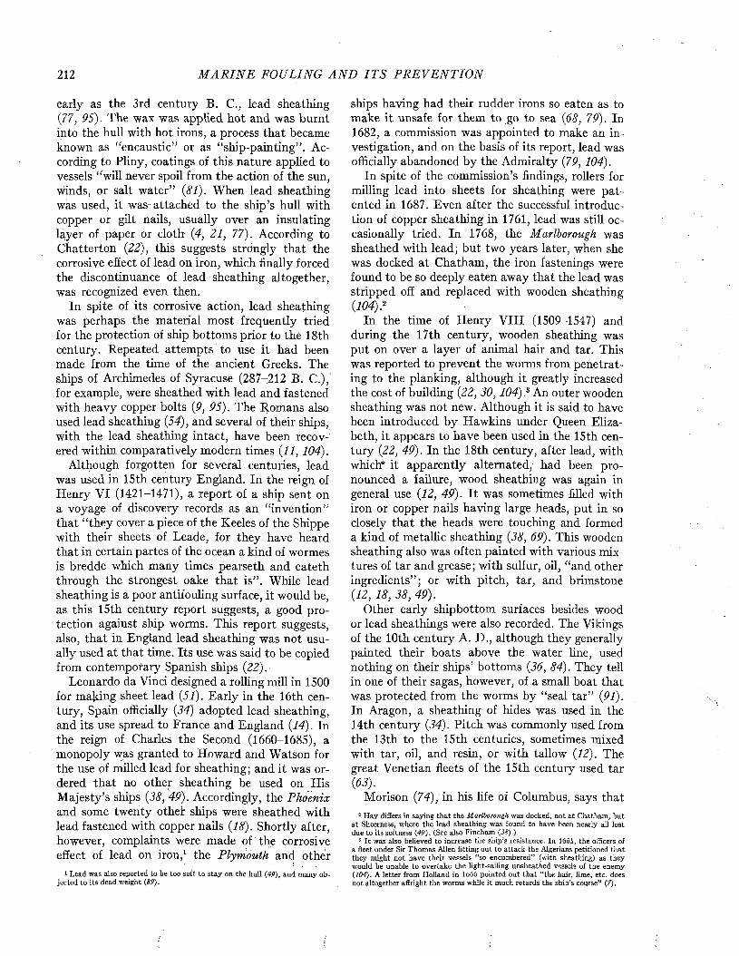
212 M A R I N E FOULING A N D I T S P R E V E N T I O N
early as the 3rd century B. C., lead sheathing (77, 95). The wax was applied hot and was burnt into the hull with hot irons, a process that became known as “encaustic” or as “ship-painting” . According to Pliny, coatings of this nature applied to vessels “will never spoil from the action of the sun, winds, or salt water” (81). When lead sheathing was used, it was attached to the ship’s hull with copper or gilt nails, usually over an insulating layer of paper or cloth- (4, 21, 77). According to Chatterton (22), this suggests strdngly that the corrosive effect of lead on iron, which finally forced the discontinuance of lead sheathing altogether, was recognized even then.
In spite of its corrosive action, lead sheathing was perhaps the material most frequently tried for the protection of ship bottoms prior to the 18th century. Repeated attempts to use it had been made from the time of the ancient Greeks. The ships of Archimedes of Syracuse (287-212 B. C.), for example, were sheathed with lead and fastened with heavy copper bolts (9, 95). The Romans also used lead sheathing (54), and several of their ships, with the lead sheathing intact, have been recovered within comparatively modern times (11, 104).
Although forgotten for several centuries, lead was used in 15th century England. In the reign of Henry VI (1421-1471), a report of a ship sent on a voyage of discovery records as an “invention” that “they cover a piece of the Keeles of the Shippe with their sheets of Leade, for they have heard that in certain partes of the ocean a kind of wormes is bredde which many times pearseth and eateth through the strongest oake that is” . While lead sheathing is a poor antifouling surface, it would be, as this 15th century report suggests, a good protection against ship worms. This report suggests, also, that in England lead sheathing was not usually used at that time. Its use was said to be copied from contemporary Spanish ships (22).
Leonardo da Vinci designed a rolling mill in 1500 for making sheet lead (51). Early in the 16th century, Spain officially (34) adopted lead sheathing, and its use spread to France and England (14). In the reign of Charles the Second (1660-1685), a monopoly was granted to Howard and Watson for the use of milled lead for sheathing; and it was ordered that no other sheathing be used on His M ajesty’s ships (38, 49). Accordingly, the Phoenix and some twenty other ships were sheathed with lead fastened with copper nails (18). Shortly after, however, complaints were made of the corrosive effect of lead on iron,1 the Plymouth and other
1 Lead was also reported to be too soft to stay on the hull (49), and many objected to its dead weight (89).
ships having had their rudder irons so eaten as to make it unsafe for them to go to sea (68, 79). In 1682, a commission was appointed to make an investigation, and on the basis of its report, lead was officially abandoned by the Admiralty (79, 104).
In spite of the commission’s findings, rollers for milling lead into sheets for sheathing were patented in 1687. Even after the successful introduction of copper sheathing in 1761, lead was still occasionally tried. In 1768, the Marlborough was sheathed with lead; but two years later, when she was docked at Chatham, the iron fastenings were found to be so deeply eaten away that the lead was stripped off and replaced with wooden sheathing(104).2
In the time of Henry V III (1509-1547) and during the 17th century, wooden sheathing was put on over a layer of animal hair and tar. This was reported to prevent the worms from penetrating to the planking, although it greatly increased the cost of building (22, 30,104) ,3 An outer wooden sheathing was not new. Although it is said to have been introduced by Hawkins under Queen Elizabeth, it appears to have been used in the 15th century (22, 49). In the 18th century, after lead, with which" it apparently alternated, had been pronounced a failure, wood sheathing was again in general use (12, 49). It was sometimes filled with iron or copper nails having large heads, put in so closely that the heads were touching and formed a kind of metallic sheathing (38, 69). This wooden sheathing also was often painted with various mixtures of tar and grease; with sulfur, oil, “and other ingredients” ; or with pitch, tar, and brimstone (12, 18, 38, 49).
Other early shipbottom surfaces besides wood or lead sheathings were also recorded. The Vikings of the 10th century A. D., although they generally painted their boats above the water line, used nothing on their ships’ bottoms (36, 84). They tell in one of their sagas, however, of a small boat that was protected from the worms by “seal tar” (91). In Aragon, a sheathing of hides was used in the 14th century (34). Pitch was commonly used from the 13th to the 15th centuries, sometimes mixed with tar, oil, and resin, or with tallow (12). The great Venetian fleets of the 15th century used tar (63).
Morison (74), in his life of Columbus, says that2 Hay differs in saying that the Marlborough was docked, not at Chatham, but
at Sheerness, where the lead sheathing was found to have been nearly all lost due to its softness (49). (See also Fincham (38).)
3 I t was also believed to increase the ship’s resistance. In 16ó¿, the officers of a fleet under Sir Thomas Allen fitting out to attack the Algerians petitioned that they might not have their vessels “so encumbered” (witn sheathing) as they would be unable to overtake the light-sailing unsheathed vessels of the enemy (104). A letter from Holland in loóó pointed out that “ the hair, lime, etc. does not altogether affright the worms while it much retards the ship’s course” (7).
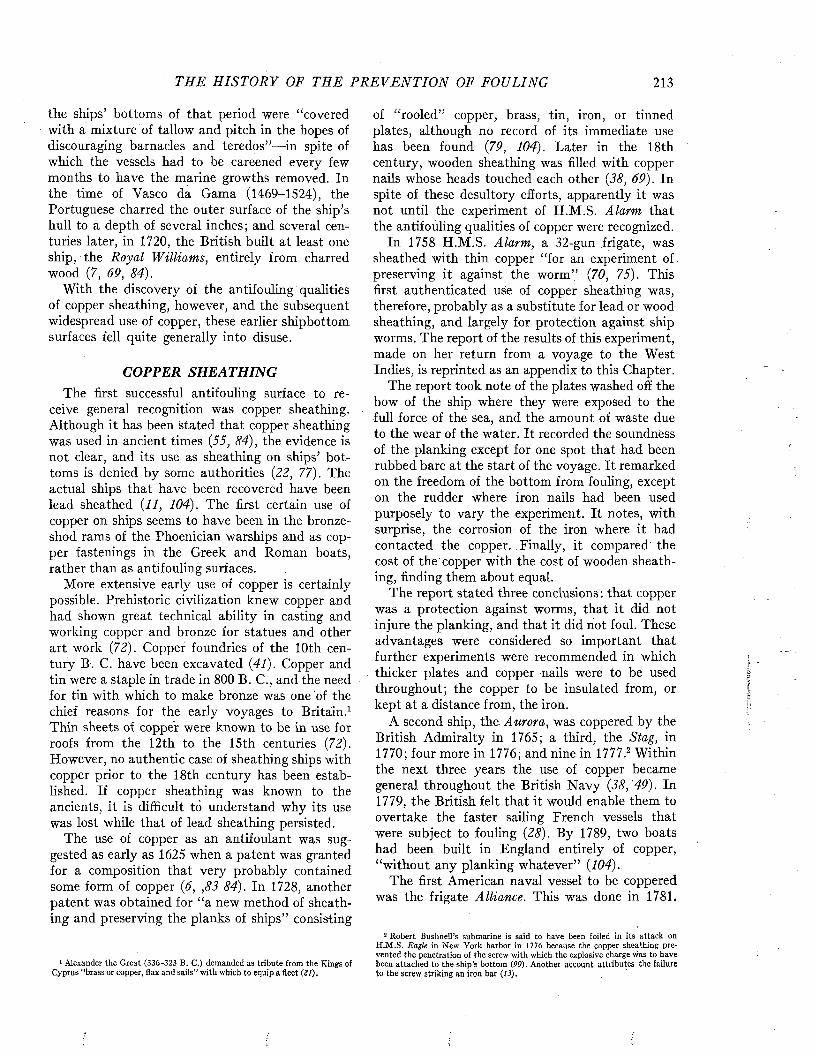
TH E H IS T O R Y OF THE P R E V E N T I O N OF FOULING 213
the ships’ bottoms of that period were “covered with a mixture of tallow and pitch in the hopes of discouraging barnacles and teredos”—in spite of which the vessels had to be careened every few months to have the marine growths removed. In the time of Vasco da Gama (1469-1524), the Portuguese charred the outer surface of the ship’s hull to a depth of several inches; and several centuries later, in 1720, the British built at least one ship, the Royal Williams, entirely from charred wood (7, 69, 84).
With the discovery of the antifouling qualities of copper sheathing, however, and the subsequent widespread use of copper, these earlier shipbottom surfaces fell quite generally into disuse.
COPPER SHEATHINGThe first successful antifouling surface to re
ceive general recognition was copper sheathing. Although it has been stated that copper sheathing was used in ancient times (55, 84), the evidence is not clear, and its use as sheathing on ships’ bottoms is denied by some authorities (22, 77). The actual ships that have been recovered have been lead sheathed (11, 104). The first certain use of copper on ships seems to have been in the bronze- shod rams of the Phoenician warships and as copper fastenings in the Greek and Roman boats, rather than as antifouling surfaces.
More extensive early use of copper is certainly possible. Prehistoric civilization knew copper and had shown great technical ability in casting and working copper and bronze for statues and other art work (72). Copper foundries of the 10th century B. C. have been excavated (41). Copper and tin were a staple in trade in 800 B. C., and the need for tin with which to make bronze was one of the chief reasons for the early voyages to Britain.1 Thin sheets of copper were known to be in use for roofs from the 12th to the 15th centuries (72). However, no authentic case of sheathing ships with copper prior to the 18th century has been established. If copper sheathing was known to the ancients, it is difficult to understand why its use was lost while that of lead sheathing persisted.
The use of copper as an antifoulant was suggested as early as 1625 when a patent was granted for a composition that very probably contained some form of copper (6, ,83 84). In 1728, another patent was obtained for “a new method of sheathing and preserving the planks of ships” consisting
1 Alexander the Great (336-323 B. C.) demanded as tribute from the Kings ofCyprus “brass or copper, flax and sails” with which to equip a fleet (21).
of “rooled” copper, brass, tin, iron, or tinned plates, although no record of its immediate use has been found (79, 104). Later in the 18th century, wooden sheathing was filled with copper nails whose heads touched each other (38, 69). In spite of these desultory efforts, apparently it was not until the experiment of H.M.S. Alarm that the antifouling qualities of copper were recognized.
In 1758 H.M.S. Alarm, a 32-gun frigate, was sheathed with thin copper “for an experiment of. preserving it against the worm” (70, 75). This first authenticated use of copper sheathing was, therefore, probably as a substitute for lead or wood sheathing, and largely for protection against ship worms. The report of the results of this experiment, made on her return from a voyage to the West Indies, is reprinted as an appendix to this Chapter.
The report took note of the plates washed off the bow of the ship where they were exposed to the full force of the sea, and the amount of waste due to the wear of the water. It recorded the soundness of the planking except for one spot that had been rubbed bare at the start of the voyage. It remarked on the freedom of the bottom from fouling, except on the rudder where iron nails had been used purposely to vary the experiment. It notes, with surprise, the corrosion of the iron where it had contacted the copper. Finally, it compared the cost of the copper with the cost of wooden sheathing, finding them about equal.
The report stated three conclusions : that copper was a protection against worms, that it did not injure the planking, and that it did not foul. These advantages were considered so important that further experiments were recommended in which thicker plates and copper nails were to be used throughout; the copper to be insulated from, or kept at a distance from, the iron.
A second ship, the Aurora, was coppered by the British Admiralty in 1765; a third, the Stag, in 1770; four more in 1776; and nine in 1777.2 Within the next three years the use of copper became general throughout the British Navy (38, 49). In 1779, the British felt that it would enable them to overtake the faster sailing French vessels that were subject to fouling (28). By 1789, two boats had been built in England entirely of copper, “without any planking whatever” (104).
The first American naval vessel to be coppered was the frigate Alliance. This was done in 1781.
2 Robert Bushnelli submarine is said to have been foiled in its attack on H.M .S. Eagle in New York harbor in 1776 because the copper sheathing prevented the penetration of the screw with which the explosive charge was to have been attached to the ship’s bottom (90). Another account attributes the failure to the screw striking an iron bar (13).
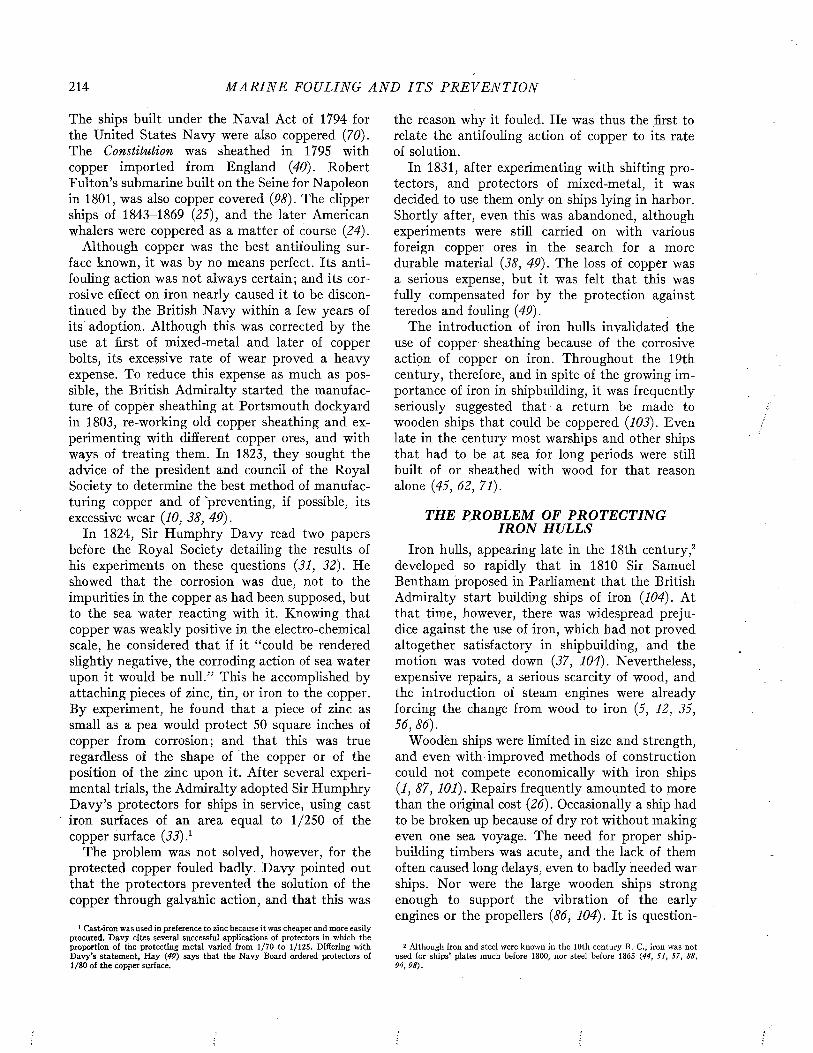
214 M A R I N E FOULING A N D I T S P R E V E N T I O N
The ships built under the Naval Act of 1794 for the United States N avy were also coppered {70). The Constitution was sheathed in 1795 with copper imported from England {40). Robert Fulton’s submarine built on the Seine for Napoleon in 1801, was also copper covered {98). The clipper ships of 1843-1869 {25), and the later American whalers were coppered as a matter of course {24).
Although copper was the best antifouling surface known, it was by no means perfect. Its antifouling action was not always certain; and its corrosive effect on iron nearly caused it to be discontinued by the British N avy within a few years of its adoption. Although this was corrected by the use at first of mixed-metal and later of copper bolts, its excessive rate of wear proved a heavy expense. To reduce this expense as much as possible, the British Admiralty started the manufacture of copper sheathing at Portsmouth dockyard in 1803, re-working old copper sheathing and experimenting with different copper ores, and with ways of treating them. In 1823, they sought the advice of the president and council of the Royal Society to determine the best method of manufacturing copper and of 'preventing, if possible, its excessive wear {10, 38, 49).
In 1824, Sir Humphry D avy read two papers before the Royal Society detailing the results of his experiments on these questions {31, 32). He showed that the corrosion was due, not to the impurities in the copper as had been supposed, but to the sea water reacting with it. Knowing that copper was weakly positive in the electro-chemical scale, he considered that if it “could be rendered slightly negative, the corroding action of sea water upon it would be null.” This he accomplished by attaching pieces of zinc, tin, or iron to the copper. By experiment, he found that a piece of zinc as small as a pea would protect 50 square inches of copper from corrosion; and that this was true regardless of the shape of the copper or of the position of the zinc upon it. After several experimental trials, the Admiralty adopted Sir Humphry D avy’s protectors for ships in service, using cast iron surfaces of an area equal to 1/250 of the copper surface {33) }
The problem was not solved, however, for the protected copper fouled badly. D avy pointed out that the protectors prevented the solution of the copper through galvahic action, and that this was
1 Cast-iron was used in preference to zinc because i t was cheaper and more easily procured. D avy cites several successful applications of protectors in which the proportion of the protecting metal varied from 1/70 to 1/125. Differing with D avy’s statement, H ay (49) says that the N avy Board ordered protectors of1/80 of the copper surface.
the reason why it fouled. He was thus the first to relate the antifouling action of copper to its rate of solution.
In 1831, after experimenting with shifting protectors, and protectors of mixed-metal, it was decided to use them only on ships lying in harbor. Shortly after, even this was abandoned, although experiments were still carried on with various foreign copper ores in the search for a more durable material {38, 49). The loss of copper was a serious expense, but it was felt that this was fully compensated for by the protection against teredos and fouling {49).
The introduction of iron hulls invalidated the use of copper sheathing because of the corrosive action of copper on iron. Throughout the 19th century, therefore, and in spite of the growing importance of iron in shipbuilding, it was frequently seriously suggested that a return be made to wooden ships that could be coppered {103). Even late in the century most warships and other ships that had to be at sea for long periods were still built of or sheathed with wood for that reason alone {45, 62, 71).
THE PROBLEM OF PROTECTING IRO N HULLS
Iron hulls, appearing late in the 18th century,2 developed so rapidly that in 1810 Sir Samuel Bentham proposed in Parliament that the British Admiralty start building ships of iron {104). At that time, however, there was widespread prejudice against the use of iron, which had not proved altogether satisfactory in shipbuilding, and the motion was voted down {37, 104). Nevertheless, expensive repairs, a serious scarcity of wood, and the introduction of steam engines were already forcing the change from wood to iron (5, 12, 35, 56,86).
Wooden ships were limited in size and strength, and even with improved methods of construction could not compete economically with iron ships {1, 87, 101). Repairs frequently amounted to more than the original cost {26). Occasionally a ship had to be broken up because of dry rot without making even one sea voyage. The need for proper shipbuilding timbers was acute, and the lack of them often caused long delays, even to badly needed war ships. Nor were the large wooden ships strong enough to support the vibration of the early engines or the propellers {86, 104). I t is question-
2 Although iron and steel were known in the 10th century B. C., iron was not used for ships’ plates much before 1800, nor steel before 1865 (44, 51, 57, 88, 96, 98).

THE H I S T O R Y OF TH E P R E V E N T I O N OF FOULING 215
able whether any of them could run their engines at full speed without serious results.1
In spite of this, it was not until the middle of the century that the terrible destruction caused to wooden ships by explosive shells at Sinope in 1853, and the success of the French armored floating batteries at Kinburn in 1855, finally proved to the Admiralty the necessity for iron ships (14). But aside from prejudice, there were two serious objections to the use of iron hulls : corrosion and fouling(SO).
Early in the history of iron ships, it was found that copper sheathing could not be used because its electrolytic action corroded the hull dangerously (10, 79). Among many similar cases, H.M .S. Jackal foundered at Greenock from the corrosion having eaten through her plates, apparently unnoticed; and H.M .S. Triton, in 1862, had her plates corroded to such paper thinness that, according to her commander, she was only kept from foundering by her fouling; practically sailing home on her barnacles (104).
Although fouling was by no means a new problem, its importance was so emphasized by the greater speeds, and by the substitution of costly and bulky fuel for sails, that many have felt that fouling became an important problem only with the introduction of iron ships. A man-of-war on commission in foreign waters for an extended period might become so fouled as to be almost unmanageable and unseaworthy before she came home and could be cleaned. The most extreme example reported was an iron whaler on the African coast, only six months out from England. Even though she had been cleaned every month with brooms and ropes, she wa.s not safe, as she could neither sail nor steer, owing to her heavy fouling. So great did the problem become that in 1847 the Admiralty contemplated the total disuse of iron ships, and actually commenced the sale of all the iron ships then in the Navy. They were deterred, however, by the impossibility of meeting naval requirements with any other material (<?, 104).
As a consequence of having invalidated the use of copper sheathing for an antifouling surface, the adoption of the iron hull started search for some less harmful metallic sheathing, and for some way of insulating copper sheathing from the iron hull.
Zinc, the only metal that could be used to place the plates of the ship in an electro-negative condi-
1 As late as 1864, at the Institute of Naval Architects, Admiral Halsted described the flagship, undergoing an engine test at Sheerness, as shaking and trembling so that the master shipwright ran out, shouting, “For God’s sake stop those engines as you’ll drive the stern posts out of the ship” (48).
tion, was tried repeatedly as sheathing. It was claimed that when in contact with the iron hull of a ship, electrolysis increased the exfoliation of the zinc sufficiently to prevent fouling, and at the same time protected the ships’ plates from corrosion (29). Although zinc sheathing achieved some standing as a substitute for copper, experience showed that it sometimes became brittle and wasted away too fast to be of real value (16, 65, 67,79).
Muntz metal, sheet lead, galvanized iron, and nickel were tried, as well as alloys of lead and antimony, and of zinc and tin. Other metals or metallic alloys were suggested, and combinations of metals, such as iron scales covered with lead and copper, sheets of lead and antimony painted with mercury, or zinc plates coated.with tin. Many of these sheathings presumably never passed beyond the experimental stage.2
Nonmetallic sheathings were also tried or suggested. These surfaces included felt, canvas, and rubber; ebonite, cork, and paper. They also included various forms of glass, enamels, glazes, and tiles. Cement was frequently used, but more as a protection against corrosion than for fouling.
For insulating copper sheathing from the iron hull of the ship, felt soaked in tar was often used; and sometimes cork, rubber, or plain brown paper. At one time, warships were built in a composite fashion, i.e., wooden planks were put on iron frames. While various other considerations led to this development, the practice was favored also because such ships could be coppered safely (71, 92). About 1862, this system was replaced by wooden sheathing put on over the metal hull. This was wedged between ridges on the hull, or bolted on in various ways, and then coppered. The wooden sheathing served only as an insulation. Although it was reported to have been satisfactory during the Spanish-American war (1898-99), and was used in both the British and the United States Navies, this method was too expensive for general use (10, 92).
A second and more important effect of the introduction of iron hulls, however, was to renew interest in the use of antifouling compositions. This eventually led to the development of the modern paint systems which have replaced copper sheathing almost altogether, except when special needs warrant the extra expense.
2 The invention of these many substitutes for copper sheathing is reviewed in the following chapter.
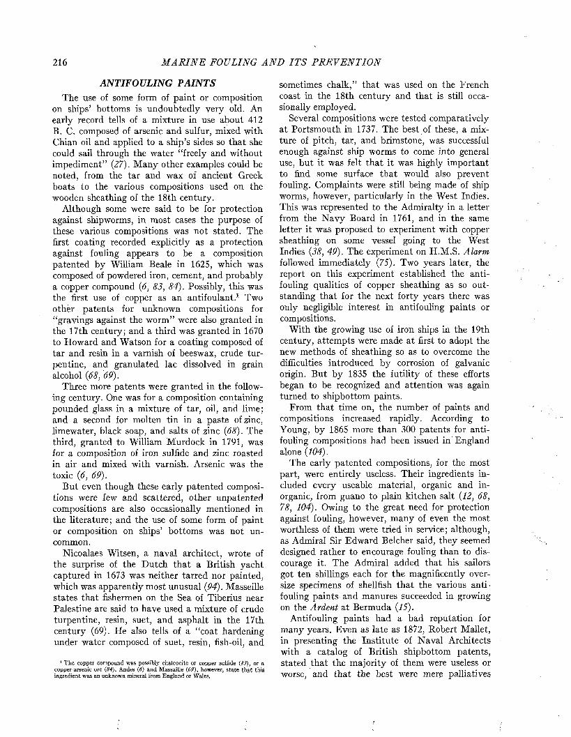
216 M A R I N E FOULING A N D I T S P R E V E N T I O N
ANTIFOULING PAINTSThe use of some form of paint or composition
on ships’ bottoms is undoubtedly very old. An early record tells of a mixture in use about 412 B. C. composed of arsenic and sulfur, mixed with Chian oil and applied to a ship’s sides so that she could sail through the water “freely and without impediment” (27). Many other examples could be noted, from the tar and wax of ancient Greek boats to the various compositions used on the wooden sheathing of the 18th century.
Although some were said to be for protection against shipworms, in most cases the purpose of these various compositions was not stated. The first coating recorded explicitly as a protection against fouling appears to be a composition patented by William Beale in 1625, which was composed of powdered iron, cement, and probably a copper compound (6, 83, 84). Possibly, this was the first use of copper as an antifoulant.1 Two other patents for unknown compositions for “gravings against the worm” were also granted in the 17th century; and a third was granted in 1670 to Howard and Watson for a coating composed of tar and resin in a varnish of beeswax, crude turpentine, and granulated Iac dissolved in grain alcohol (68, 69).
Three more patents were granted in the following century. One was for a composition containing pounded glass in a mixture of tar, oil, and lime; and a second for molten tin in a paste of zinc, limewater, black soap, and salts of zinc (68). The third, granted to William Murdock in 1791, was for a composition of iron sulfide and zinc roasted in air and mixed with varnish. Arsenic was the toxic (6, 69).
But even though these early patented compositions were few and scattered, other unpatented compositions are also occasionally mentioned in the literature; and the use of some form of paint or composition on ships’ bottoms was not uncommon.
Nicoalaes Witsen, a naval architect, wrote of the surprise of the Dutch that a British yacht captured in 1673 was neither tarred nor painted, which was apparently most unusual (94). Masseille states that fishermen on the Sea of Tiberius near Palestine are said to have used a mixture of crude turpentine, resin, suet, and asphalt in the 17th century (69). He also tells of a “coat hardening under water composed of suet, resin, fish-oil, and
1 The copper compound was possibly chalcocite or copper sulfide (83), or a copper-arsenic ore (84). Andes (6) and Massaille (69), however, state that this ingredient was an unknown mineral from England or Wales,
sometimes chalk,” that was used on the French coast in the 18th century and that is still occasionally employed.
Several compositions were tested comparatively at Portsmouth in 1737. The best of these, a mixture of pitch, tar, and brimstone, was successful enough against ship worms to come into general use, but it was felt that it was highly important to find some surface that would also prevent fouling. Complaints were still being made of ship worms, however, particularly in the West Indies. This was represented to the Admiralty in a letter from the N avy Board in 1761, and in the same letter it was proposed to experiment with copper sheathing on some vessel going to the West Indies (38, 49). The experiment on H.M.S. Alarm followed immediately (75). Two years later, the report on this experiment established the antifouling qualities of copper sheathing as so outstanding that for the next forty years there was only negligible interest in antifouling paints or compositions.
With the growing use of iron ships in the 19th century, attempts were made at first to adopt the new methods of sheathing so as to overcome the difficulties introduced by corrosion of galvanic origin. But by 1835 the futility of these efforts began to be recognized and attention was again turned to shipbottom paints.
From that time on, the number of paints and compositions increased rapidly. According to Young, by 1865 more than 300 patents for antifouling compositions had been issued in England alone (104).
The early patented compositions, for the most part, were entirely useless. Their ingredients included every useable material, organic and inorganic, from gua.no to plain kitchen salt (12, 68, 78, .104). Owing to the great need for protection against fouling, however, many of even the most worthless of them were tried in service; although, as Admiral Sir Edward Belcher said, they seemed designed rather to encourage fouling than to discourage it. The Admiral added that his sailors got ten shillings each for the magnificently oversize specimens of shellfish that the various antifouling paints and manures succeeded in growing on the Ardent at Bermuda (15).
Antifouling paints had a bad reputation for many years. Even as late as 1872, Robert Mallet, in presenting the Institute of Naval Architects with a catalog of British shipbottom patents, stated that the majority of them were useless or worse, and that the best were mere palliatives
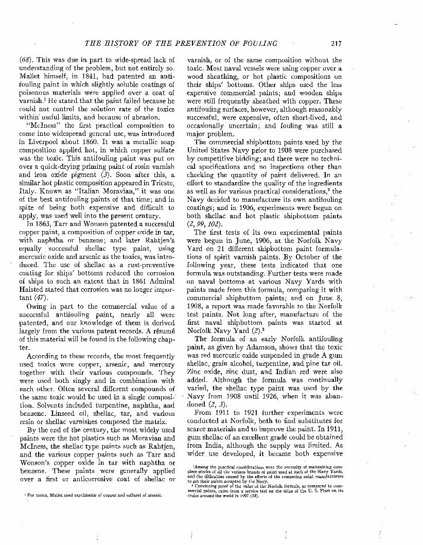
TH E H I S T O R Y OF THE P R E V E N T I O N OF FOULING 217
{68). This was due in part to wide-spread lack of understanding of the problem, but not entirely so. Mallet himself, in 1841, had patented an antifouling paint in which slightly soluble coatings of poisonous materials were applied over a coat of varnish.1 He stated that the paint failed because he could not control the solution rate of the toxics within useful limits, and because of abrasion.
“M clness” the first practical composition to come into widespread general use, was introduced in Liverpool about 1860. It was a metallic soap composition applied hot, in which copper sulfate was the toxic. This antifouling paint was put on over a quick-drying priming paint of rosin varnish and iron oxide pigment (3). Soon after this, a similar hot plastic composition appeared in Trieste, Italy. Known as “Italian Moravian,” it was one of the best antifouling paints of that time; and in spite of being both expensive and difficult to apply, was used well into the present century.
In 1863, Tarr and Wonson patented a successful copper paint, a composition of copper oxide in tar, with naphtha or benzene; and later Rahtjen’s equally successful shellac type paint, using mercuric oxide and arsenic as the toxics, was introduced. The use of shellac as a rust-preventive coating for ships’ bottoms reduced the corrosion of ships to such an extent that in 1861 Admiral Halsted stated that corrosion was no longer important {47).
Owing in part to the commercial value of a successful antifouling paint, nearly all were patented, and our knowledge of them is derived largely from the various patent records. A résumé of this material will be found in the following chapter.
According to these records, the most frequently used toxics were copper, arsenic, and mercury together with their various compounds. They were used both singly and in combination with each other. Often several different compounds of the same toxic would be used in a single composition. Solvents included turpentine, naphtha, and benzene. Linseed oil, shellac, tar, and various resin or shellac varnishes composed the matrix.
B y the end of the century, the most widely used paints were the hot plastics such as Moravian and M clness, the shellac type paints such as Rahtjen, and the various copper paints such as Tarr and Wonson’s copper oxide in tar with naphtha or benzene. These paints were generally applied over a first or anticorrosive coat of shellac or
1 For toxics, M allet used oxychloride of copper and sulfuret of arsenic.
varnish, or of the same composition without the toxic. Most naval vessels were using copper over a wood sheathing, or hot plastic compositions on their ships’ bottoms. Other ships used the less expensive commercial paints; and wooden ships were still frequently sheathed with copper. These antifouling surfaces, however, although reasonably successful, were expensive, often short-lived, and occasionally uncertain; and fouling was still a major problem.
The commercial shipbottom paints used by the United States N avy prior to 1908 were purchased by competitive bidding; and there were no technical specifications and no inspections other than checking the quantity of paint delivered. In an effort to standardize the quality of the ingredients as well as for various practical considerations,2 the N avy decided to manufacture its own antifouling coatings; and in 1906, experiments were begun on both shellac and hot plastic shipbottom paints (2, 99,102).
The first tests of its own experimental paints were begun in June, 1906, at the Norfolk N avy Yard on 21 different shipbottom paint formulations of spirit varnish paints. By October of the following year, these tests indicated that one formula was outstanding. Further tests were made on naval bottoms at various N avy Yards with paints made from this formula, comparing it with commercial shipbottom paints; and on June 8, 1908, a report was made favorable to the Norfolk test paints. N ot long after, manufacture of the first naval shipbottom paints was started at Norfolk N avy Yard (2):3
The formula of an early Norfolk antifouling paint, as given by Adamson, shows that the toxic was red mercuric oxide suspended in grade A gum shellac, grain alcohol, turpentine, and pine tar oil. Zinc oxide, zinc dust, and Indian red were also added. Although the formula was continually varied, the shellac type paint was used by the N avy from 1908 until 1926, when it was abandoned {2, 3).
From 1911 to 1921 further experiments were conducted at Norfolk, both to find substitutes for scarce materials and to improve the paint. In 1911, gum shellac of an excellent grade could be obtained from India, although the supply was limited. As wider use developed, it became both expensive
5 Among the practical considerations were the necessity of maintaining complete stocks of all the various brands of paint used at each of the N avy Yards, and the difficulties caused by the efforts of the competing paint manufacturers to get their paints accepted by the Navy.
3 Convincing proof of the value of the Norfolk formula, as compared to commercial paints, came from a service test on the ships of the XJ. S. Fleet on its cruise around the world in 1907 (58).
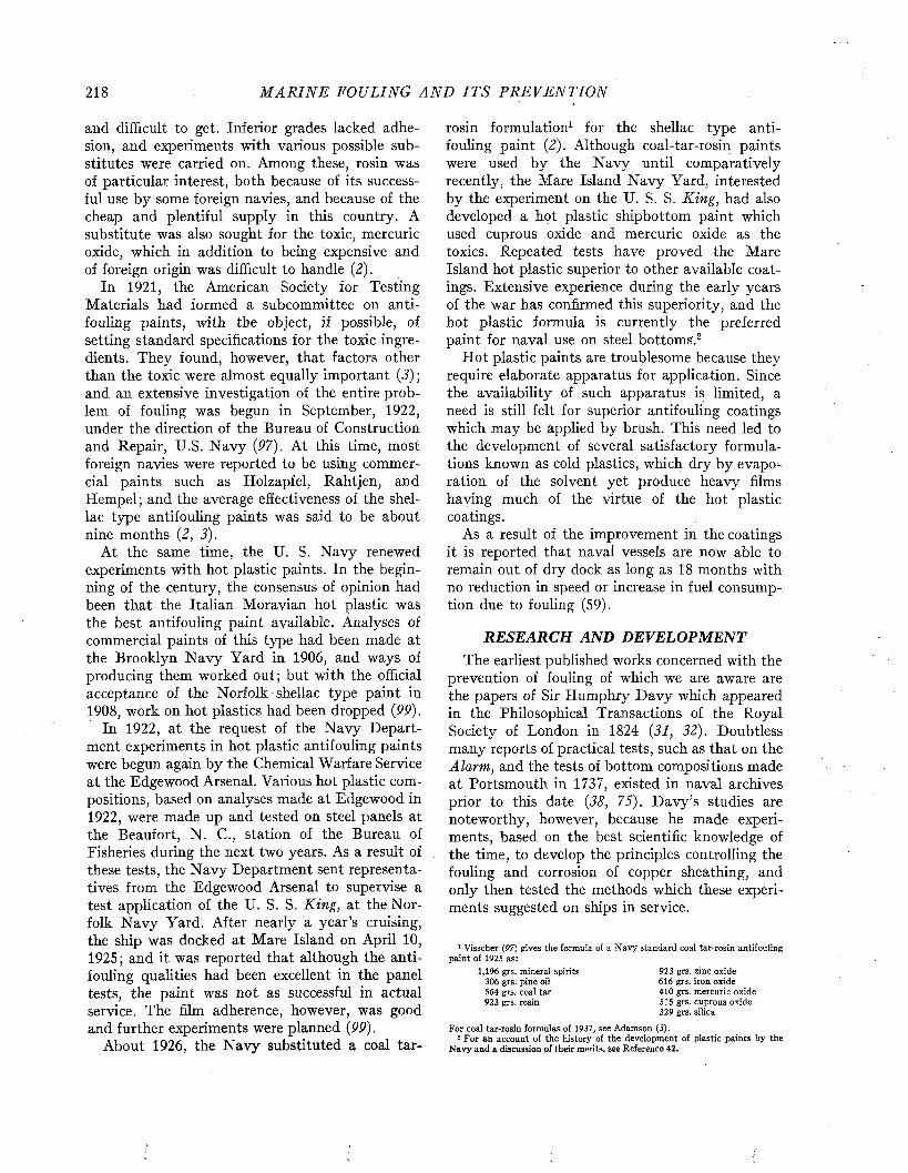
218 M A R I N E FOULING A N D I T S P R E V E N T I O N
and difficult to get. Inferior grades lacked adhesion, and experiments with various possible substitutes were carried on. Among these, rosin was of particular interest, both because of its successful use by some foreign navies, and because of the cheap and plentiful supply in this country. A substitute was also sought for the toxic, mercuric oxide, which in addition to being expensive and of foreign origin was difficult to handle (2).
In 1921, the American Society for Testing Materials had formed a subcommittee on antifouling paints, with the object, if possible, of setting standard specifications for the toxic ingredients. They found, however, that factors other than the toxic were almost equally important (3) ; and an extensive investigation of the entire problem of fouling was begun in September, 1922, under the direction of the Bureau of Construction and Repair, U.S. N avy (97). At this time, most foreign navies were reported to be using commercial paints such as Holzapfel, Rahtjen, and Hempel; and the average effectiveness of the shellac type antifouling paints was said to be about nine months (2, 3).
At the same time, the U. S. N avy renewed experiments with hot plastic paints. In the beginning of the century, the consensus of opinion had been that the Italian Moravian hot plastic was the best antifouling paint available. Analyses of commercial paints of this type had been made at the Brooklyn N avy Yard in 1906, and ways of producing them worked out; but with the official acceptance of the Norfolk shellac type paint in 1908, work on hot plastics had been dropped (99).
In 1922, at the request of the N avy Department experiments in hot plastic antifouling paints were begun again by the Chemical Warfare Service at the Edgewood Arsenal. Various hot plastic compositions, based on analyses made at Edgewood in 1922, were made up and tested on steel panels at the Beaufort, N . C., station of the Bureau of Fisheries during the next two years. As a result of these tests, the N avy Department sent representatives from the Edgewood Arsenal to supervise a test application of the U. S. S .K in g , at the Norfolk N avy Yard. After nearly a year's cruising, the ship was docked at Mare Island on April 10, 1925; and it was reported that although the antifouling qualities had been excellent in the panel tests, the paint was not as successful in actual service. The film adherence, however, was good and further experiments were planned (99).
About 1926, the N avy substituted a coal tar-
rosin formulation1 for the shellac type antifouling paint (2). Although coal-tar-rosin paints were used by the N avy until comparatively recently, the Mare Island N avy Yard, interested by the experiment on the U. S. S. King , had also developed a hot plastic shipbottom paint which used cuprous oxide and mercuric oxide as the toxics. Repeated tests have proved the Mare Island hot plastic superior to other available coatings. Extensive experience during the early years of the war has confirmed this superiority, and the hot plastic formula is currently the preferred paint for naval use on steel bottoms.2
Hot plastic paints are troublesome because they require elaborate apparatus for application. Since the availability of such apparatus is limited, a need is still felt for superior antifouling coatings which may be applied by brush. This need led to the development of several satisfactory formulations known as cold plastics, which dry by evaporation of the solvent yet produce heavy films having much of the virtue of the hot plastic coatings.
As a result of the improvement in the coatings it is reported that naval vessels are now able to remain out of dry dock as long as 18 months with no reduction in speed or increase in fuel consumption due to fouling (59).
RESEARCH AND DEVELOPMENTThe earliest published works concerned with the
prevention of fouling of which we are aware are the papers of Sir Humphry D avy which appeared in the Philosophical Transactions of the Royal Society of London in 1824 (31, 32). Doubtless many reports of practical tests, such as that on the Alarm, and the tests of bottom compositions made at Portsmouth in 1737, existed in naval archives prior to this date (38, 75). D avy’s studies are noteworthy, however, because he made experiments, based on the best scientific knowledge of the time, to develop the principles controlling the fouling and corrosion of copper sheathing, and only then tested the methods which these experiments suggested on ships in service.
1 Visscher (97) gives the formula of a N avy standard coal tar-rosin antifouling paint of 1925 as:
1,196 grs. mineral spirits 923 grs. zinc oxide306 grs. pine oil 616 grs. iron oxide564 grs. coal tar 410 grs. mercuric oxide923 grs. resin 515 grs. cuprous oxide
329 grs. silica
For coal tar-rosin formulas of 1937, see Adamson (5).2 For an account of the history of the development of plastic paints by the
N avy and a discussion of their merits, see Reference 42.

THE H I S T O R Y OF TH E P R E V E N T I O N OF FOULING 219
No man of D avy’s scientific stature has since concerned himself with the fouling problem, and for more than three-quarters of a century no one approached the problem from the scientific angle followed by Davy. It is interesting to note in passing that a generation later another great English scientist, Charles Darwin, became the authority on barnacles and thus contributed valuable knowledge of the subject without apparently becoming concerned with its practical aspects.
The development of antifouling compositions during the 19th century appears to have been strictly empirical. The publications of this period consist of general discussions based on the experience of practical men: naval officers, naval architects, and shipbuilders. There was some speculation on how fouling is prevented, but never any controlled experiment designed to test principles or theories. The paints themselves were developed privately as proprietary products. How much systematic investigation underlay the patented or secret formulations is not recorded.
When paint research was first undertaken by the Navy, in 1906, the data available consisted largely of records of submersion tests which compared one commercial paint with another. Very little was known about the formulae. In starting tests, it was necessary to try many combinations of ingredients, and through a process of substitutions, eliminations, and alterations finally to arrive at formulae which would produce satisfactory paints (2). Some additional information was obtained by analyzing paints of commercial origin which showed promise (IP, 20, 99), but because of the nature of paint ingredients the knowledge to be gained in this way was limited. Performance on panel test and in service remained the only guide to performance, and no means of judging the cause of failure was at hand.
The trial and error method of research gradually led to formulations which became more and more complicated, since each component which was introduced into a promising formulation tended to be carried along into subsequent modifications. In 1939 this tendency was reversed by an experiment conducted jointly by the Mare Island N avy Yard and W. F. Whedon of the Scripps Oceanographic Institution at La Jolla, in which the currently accepted hot plastic formulation was broken down into a series of simplified mixtures of its components (100). The object was to determine which ingredients were really essential. The outcome was the demonstration that the mercury and Paris
green present in the original formula added nothing to its antifouling characteristics. The tendency to simplification which this experiment initiated is illustrated by a comparison of the composition of formula for a standard N avy paint of 1925, given as a footnote on page 218, which contained nine components, with the present standard wood bottom formula, 16X, which has only five specified ingredients.
Prompted by a desire to obtain more fundamental knowledge of how to prevent fouling, the N avy arranged, from time to time, for biological investigations. This work supplied valuable information on the toxicity of potential paint ingredients to marine organisms, on the nature of the fouling population, its rate of growth, its seasonal and geographical incidence, and the relation of the service in which ships are employed to their tendency to foul (17, 97). Similar studies were also conducted in Germany at the Laboratorium für Bewuchsforschung in Cuxhaven, in Turkey, Russia, and Japan (76), and in England (39, 80).
The proposal that slimes, produced by bacteria and diatoms on submerged surfaces, had an important bearing on subsequent fouling aroused much interest and led to investigations which culminated in the establishment of the Naval Biological Laboratory at San Diego, and also initiated work at the Woods Hole Oceanographic Institution.
While this earlier biological work provided useful background knowledge that was requisite to intelligent attack on the problem, the idea that it would produce some unthought-of method of circumventing fouling proved illusory. However, the study of slimes led indirectly to two important results. First, the variability in the tendency of various paint surfaces to slime, and an apparent relation between slime formation and fouling, focused attention on the question of what property of the paint is responsible for its antifouling action. Second, experiments which were made to study the tendency of slimes to accumulate copper led to the development of techniques for measuring the rate at which copper or other toxics are given off by the paint surface. These methods, in turn, appear to have provided the answer to the above mentioned question: the antifouling action of currently successful shipbottom paints depends upon the rate of solution of the toxic material (61).
Armed with a definite physical objective, the problem of formulating antifouling coatings can now proceed in a more rational manner. What needs to be discovered is how to formulate so as
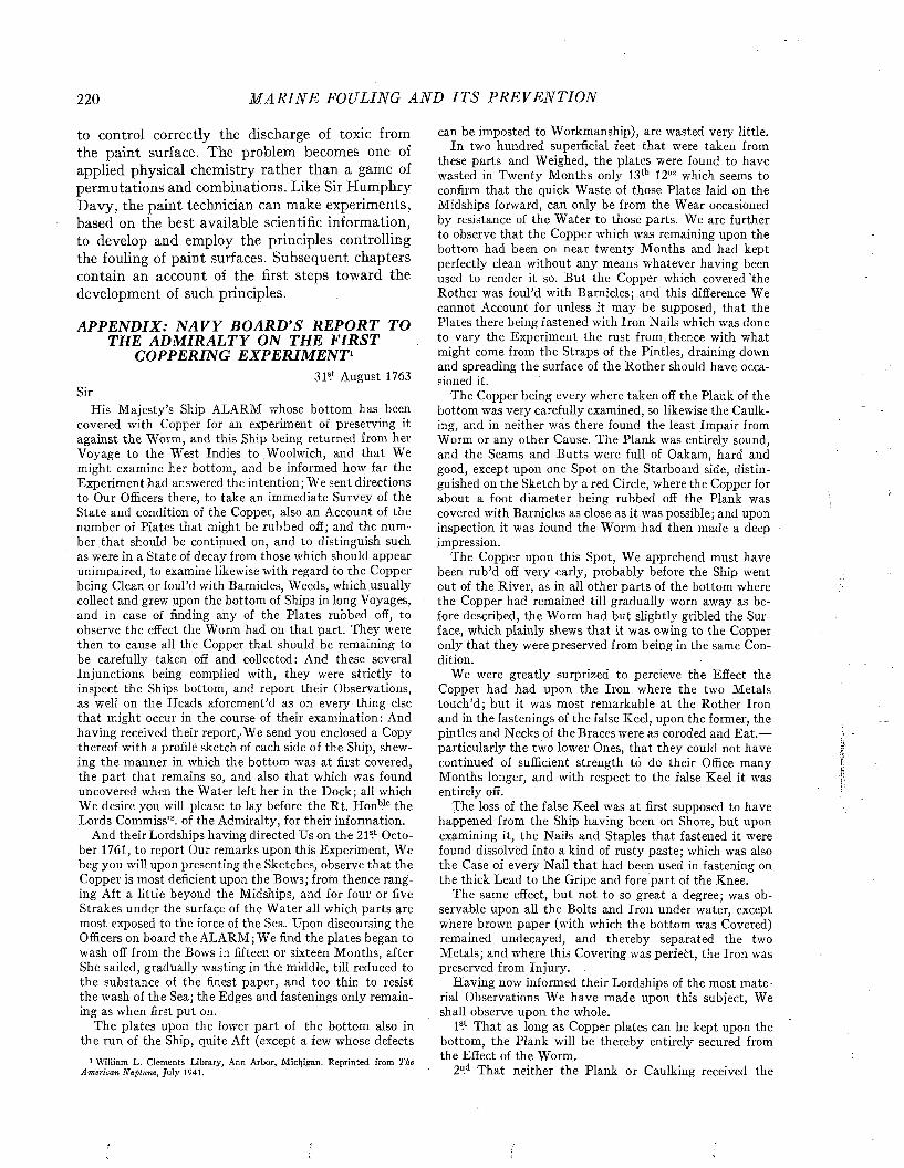
220 M A R I N E FOULING A N D I T S P R E V E N T I O N
to control correctly the discharge of toxic from the paint surface. The problem becomes one of applied physical chemistry rather than a game of permutations and combinations. Like Sir Humphry Davy, the paint technician can make experiments, based on the best available scientific information, to develop and employ the principles controlling the fouling of paint surfaces. Subsequent chapters contain an account of the first steps toward the development of such principles.
APPENDIX: N A VY BOARD’S REPORT TO THE AD M IRALTY ON THE FIRST
COPPERING EXPERIMENT1SI5.1 August 1763
SirHis M ajesty’s Ship ALARM whose bottom has been
covered with Copper for an experiment of preserving it against the Worm, and this Ship being returned from her Voyage to the West Indies to .Woolwich, and tha t We might examine her bottom, and be informed how far the Experiment had answered the intention; We sent directions to Our Officers there, to take an immediate Survey of the S tate and condition of the Copper, also an Account of the number of Plates tha t might be rubbed off; and the num ber tha t should be continued on, and to distinguish such as were in a State of decay from those which should appear unimpaired, to examine likewise with regard to the Copper being Clean or foul’d with Barnicles, Weeds, which usually collect and grew upon the bottom of Ships in long Voyages, and in case of finding any of the Plates rubbed off, to observe the effect the Worm had on th a t part. They were then to cause all the Copper th a t should be remaining to be carefully taken off and collected: And these several Injunctions being complied with, they were strictly to inspect the Ships bottom, and report their Observations, as well on the Heads aforement’d as on every thing else th a t might occur in the course of their examination: And having received their report,/We send you enclosed a Copy thereof with a profile sketch of each side of the Ship, shewing the manner in which the bottom was at first covered, the part tha t remains so, and also th a t which was found uncovered when the W ater left her in the Dock; all which We desire you will please to lay before the Rt. Honb.le the Lords Commiss1"8. of the Admiralty, for their information.
And their Lordships having directed Us on the 2 P i October 1761, to report Our remarks upon this Experiment, We beg you will upon presenting the Sketches, observe th a t the Copper is most deficient upon the Bows; from thence ranging Aft a little beyond the Midships, and for four or five Strakes under the surface of the W ater all which parts are most exposed to the force of the Sea. Upon discoursing the Officers on board the ALARM; We find the plates began to wash off from the Bows in fifteen or sixteen Months, after She sailed, gradually wasting in the middle, till reduced to the substance of the finest paper, and too thin to resist the wash of the Sea; the Edges and fastenings only remaining as when first put on.
The plates upon the lower p art of the bottom also in the run of the Ship, quite Aft (except a few whose defects
1 William L. Clements Library, Ann Arbor, Michigan. Reprinted from The American Neptune, July 1941.
can be imposted to Workmanship), are wasted very little.In two hundred superficial feet th a t were taken from
these parts and Weighed, the plates were found to have wasted in Twenty M onths only 13lb 12oz which seems to confirm tha t the quick W aste of those Plates laid on the Midships forward, can only be from the Wear occasioned by resistance of the W ater to those parts. We are further to observe tha t the Copper which was remaining upon the bottom had been on near twenty M onths and had kept perfectly clean without any means whatever having been used to render it so. B ut the Copper which covered ’the Rother was foul’d with Barnicles; and this difference We cannot Account for unless it may be supposed, tha t the Plates there being fastened with Iron Nails which was done to vary the Experiment the rust from, thence with what might come from the Straps of the Pintles, draining down and spreading the surface of the Rother should have occasioned it.
The Copper being every where taken off the Plank of the bottom was very carefully examined, so likewise the Caulking, and in neither was there found the least Im pair from Worm or any other Cause. The Plank was entirely sound, and the Seams and B utts were full of Oakam, hard and good, except upon one Spot on the Starboard side, distinguished on the Sketch by a red Circle, where the Copper for about a foot diam eter being rubbed off the Plank was covered with Barnicles as close as it was possible; and upon inspection it was found the Worm had then made a deep impression.
The Copper upon this Spot, We apprehend must have been rub’d off very early, probably before the Ship went out of the River, as in all other parts of the bottom where the Copper had remained till gradually worn away as before described, the Worm had but slightly gribled the Surface, which plainly shews th a t it was owing to the Copper only tha t they were preserved from being in the same Condition.
We were greatly surprized to percieve the Effect the Copper had had upon the Iron where the two Metals touch’d; but it was most remarkable a t the Rother Iron and in the fastenings of the false Keel, upon the former, the pintles and Necks of the Braces were as coroded and E at.— particularly the two lower Ones, tha t they could not have continued of sufficient strength to do their Office many Months longer, and with respect to the false Keel it was entirely off.
The loss of the false Keel was a t first supposed to have happened from the Ship having been on Shore, but upon examining it, the Nails and Staples tha t fastened it were found dissolved into a kind of rusty paste; which was also the Case of every Nail th a t had been used in fastening on the thick Lead to the Gripe and fore p art of the Knee.
The same effect, but not to so great a degree; was observable upon all the Bolts and Iron under water, except where brown paper (with which the bottom was Covered) remained undecayed, and thereby separated the two M etals; and where this Covering was perfect, the Iron was preserved from Injury.
Having now informed their Lordships of the most m aterial Observations We have made upon this subject, We shall observe upon the whole.
1SI T hat as long as Copper plates can be kept upon the bottom, the P lank will be thereby entirely secured from the Effect of the Worm.
2D.d T hat neither the Plank or Caulking received the
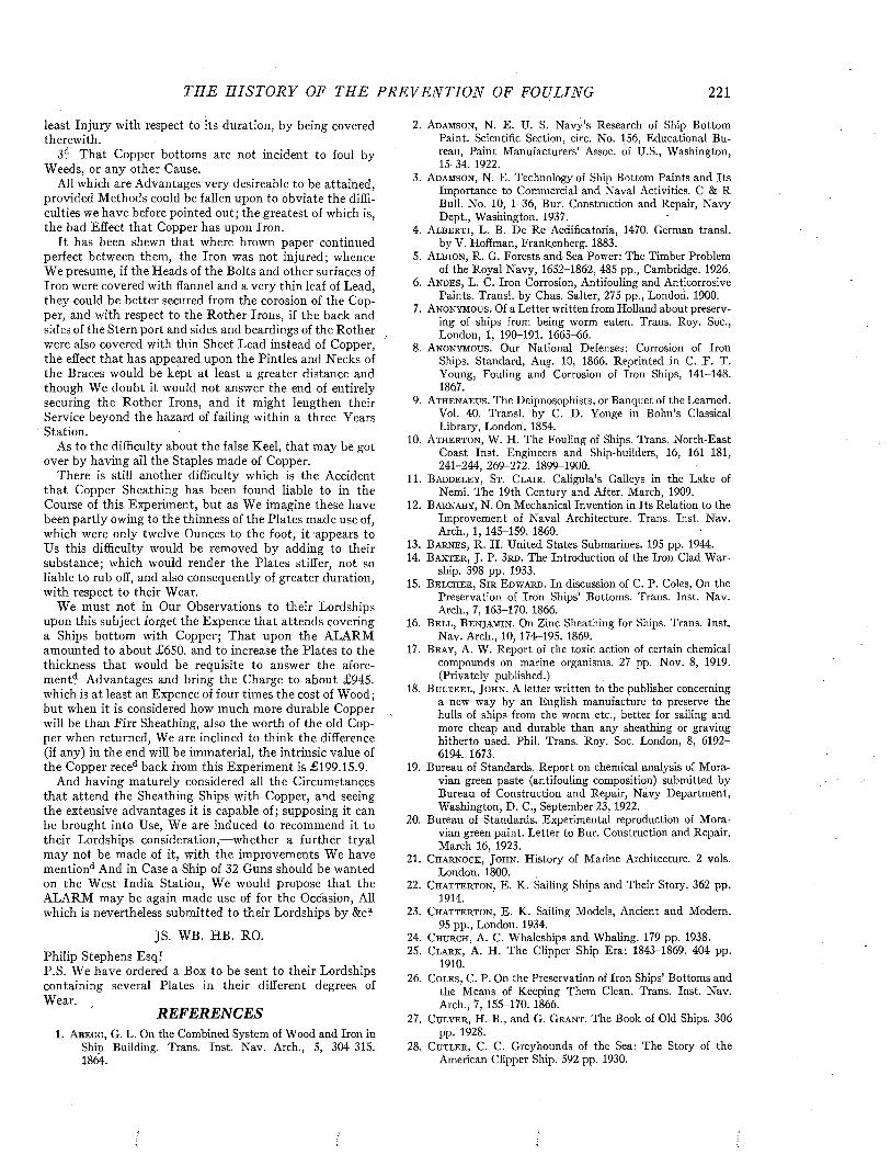
THE H I S T O R Y OF THE P R E V E N T I O N OF FOULING 221
least Injury with respect to its duration, by being covered therewith.
3d T hat Copper bottoms are not incident to foul by Weeds, or any other Cause.
All which are Advantages very desireable to be attained, provided Methods could be fallen upon to obviate the difficulties we have before pointed out; the greatest of which is, the bad Effect tha t Copper has upon Iron.
I t has been shewn tha t where brown paper continued perfect between them, the Iron was not injured; whence We presume, if the Heads of the Bolts and other surfaces of Iron were covered with flannel and a very thin leaf of Lead, they could be better secured from the corosion of the Copper, and with respect to the Rother Irons, if the back and sides of the Stern port and sides and beardings of the Rother were also covered with thin Sheet Lead instead of Copper, the effect th a t has appeared upon the Pintles and Necks of the Braces would be kept a t least a greater distance and though We doubt it. would not answer the end of entirely securing the Rother Irons, and it might lengthen their Service beyond the hazard of failing within a three Years Station.
As to the difficulty about the false Keel, th a t may be got over by having all the Staples made of Copper.
There is still another difficulty which is the Accident th a t Copper Sheathing has been found liable to in the Course of this Experiment, but as We imagine these have been partly owing to the thinness of the Plates made use of, which were only twelve Ounces to the foot, it appears to Us this difficulty would be removed by adding to their substance; which would render the Plates stiffer, not so liable to rub off, and also consequently of greater duration, with respect to their Wear.
We must not in Our Observations to their Lordships upon this subject forget the Expence th a t attends covering a Ships bottom with Copper; T hat upon the ALARM amounted to about £650. and to increase the Plates to the thickness th a t would be requisite to answer the afore- m entd Advantages and bring the Charge to about £945. which is a t least an Expence of four times the cost of Wood ; b u t when it is considered how much more durable Copper will be than F irr Sheathing, also the worth of the old Copper when returned, We are inclined to think the difference (if any) in the end will be immaterial, the intrinsic value of the Copper reced back from this Experiment is £199.15.9.
And having maturely considered all the Circumstances th a t attend the Sheathing Ships with Copper, and seeing the extensive advantages it is capable of; supposing it can be brought into Use, We are induced to recommend it to their Lordships consideration,—whether a further tryal m ay not be made of it, with the improvements We have mentiond And in Case a Ship of 32 Guns should be wanted on the West India Station, We would propose th a t the ALARM may be again made use of for the Occasion, All which is nevertheless submitted to their Lordships by &c?
JS. WB. HB. RO.Philip Stephens EsqfP.S. We have ordered a Box to be sent to their Lordships containing several Plates in their different degrees of Wear.
REFERENCES1. A b e g g , G. L. On the Combined System of Wood and Iron in
Ship Building. Trans. Inst. Nav. Arch., 5, 304-315. 1864.
2. A d a m s o n , N. E. U. S. Navy’s Research of Ship BottomPaint. Scientific Section, circ. No. 156, Educational Bureau, Paint Manufacturers’ Assoc, of U.S., Washington, 15-34. 1922.
3. A d a m s o n , N. E. Technology of Ship Bottom Paints and ItsImportance to Commercial and Naval Activities. C & R Bull. No. 10, 1-36, Bur. Construction and Repair, Navy Dept., Washington. 1937.
4. A l b e r t i , L. B. De Re Aedificatoria, 1470. German transi.by V. Hoffman, Frankenberg. 1883.
5. A l b io n , R. G. Forests and Sea Power: The Timber Problemof the Royal Navy, 1652-1862, 485 pp., Cambridge. 1926.
6. A n d e s , L. C. Iron Corrosion, Antifouling and AnticorrosivePaints. Transi, by Chas. Salter, 275 pp., London. 1900.
7. A n o n y m o u s . Of a Letter written from Holland about preserving of ships from being worm eaten. Trans. Roy. Soc., London, 1, 190-191. 1665-66.
8. A n o n y m o u s . Our National Defenses: Corrosion of IronShips. Standard, Aug. 10, 1866. Reprinted in C. F. T. Young, Fouling and Corrosion of Iron Ships, 141-148. 1867.
9. A t h e n a e u s . The Deipnosophists, or Banquet of the Learned.Vol. 40. Transi, by C. D. Yonge in Bohn’s Classical Library, London. 1854.
10. A t h e r t o n , W. H. The Fouling of Ships. Trans. North-EastCoast Inst. Engineers and Ship-builders, 16, 161-181, 241-244, 269-272. 1899-1900.
11. B a d d e l e y , St. C l a i r . Caligula’s Galleys in the Lake ofNemi. The 19th Century and After. March, 1909.
12. B a r n a b y , N. On Mechanical Invention in Its Relation to theImprovement of Naval Architecture. Trans. Inst. Nav. Arch., 1, 145-159. 1860.
13. B a r n e s , R. H. United States Submarines. 195 pp. 1944.14. B a x t e r , J. P. 3 r d . The Introduction of the Iron Clad War
ship. 398 pp. 1933.15. B e l c h e r , S i r E d w a r d . In discussion of C. P. Coles, On the
Preservation of Iron Ships’ Bottoms. Trans. Inst. Nav. Arch., 7, 163-170. 1866.
16. B e l l , B e n j a m i n . On Zinc Sheathing for Ships. Trans. Inst.Nav. Arch., 10, 174M95. 1869.
17. B r a y , A. W. Report of the toxic action of certain chemicalcompounds on marine organisms. 27 pp. Nov. 8, 1919. (Privately published.)
18. B u l t e e l , J o h n . A l e t t e r w r i t t e n t o t h e p u b l i s h e r c o n c e rn in ga new way by an English manufacture to preserve the hulls of ships from the worm etc., better for sailing and more cheap and durable than any sheathing or graving hitherto used. Phil. Trans. Roy. Soc. London, 8, 6192- 6194. 1673.
19. Bureau of Standards. Report on chemical analysis of Moravian green paste (antifouling composition) submitted by Bureau of Construction and Repair, Navy Department, Washington, D. C., September 23, 1922.
20. Bureau of Standards. Experimental reproduction of Moravian green paint. Letter to Bur. Construction and Repair. March 16, 1923.
21 . C h a r n o c k , J o h n . History of Marine Architecture. 2 vols.London. 1800.
22. C h a t t e r t o n , E. K. Sailing Ships and Their Story. 362 pp.1914.
23. C h a t t e r t o n , E. K. Sailing Models, Ancient and Modem.95 pp., London. 1934.
24. C h u r c h , A. C. Whaleships and Whaling. 179 pp. 1938.25. Clark , A. H. The Clipper Ship Era: 1843-1869. 404 pp.
1910.26. C o l e s , C. P. On the Preservation of Iron Ships’ Bottoms and
the Means of Keeping Them Clean. Trans. Inst. Nav. Arch., 7, 155-170. 1866.
27. C u l v e r , H. B., and G. G r a n t . The Book of Old Ships. 306p p . 1928.
28. C u t l e r , C. C. Greyhounds of the Sea: The Story of theAmerican Clipper Ship. 592 pp. 1930.
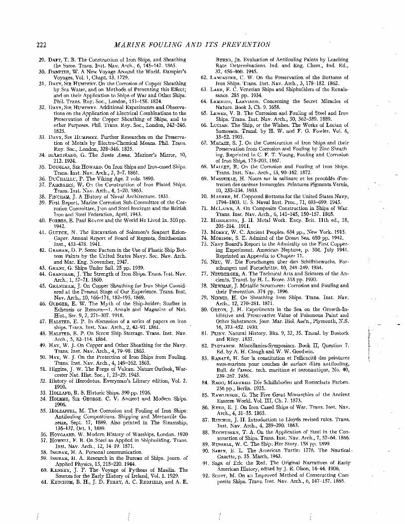
222 M A R I N E FOULING A N D I T S P R E V E N T I O N
29. D a f t , T. B. The Construction of Iron Ships, and Sheathingthe Same. Trans. Inst. Nav. Arch., 6, 145-147. 1865.
3 0 . D a m p i e r , W. A New Voyage Around the World. Dampier’sVoyages, Vol. 1, Chapt. 13. 1729.
31. D a v y , S i r H u m p h r y . On the Corrosion of Copper Sheathingby Sea Water, and on Methods of Preventing this Effect; and on their Application to Ships of War and Other Ships. Phil. Trans. Roy. Soc., London, 151-158. 1824.
3 2 . D a v y , S i r H u m p h r y . Additional Experiments and Observations on the Application of Electrical Combinations to the Preservation of the Copper Sheathing of Ships, and to other Purposes. Phil. Trans. Roy. Soc., London, 242-246. 1825.
3 3 . D a v y , S i r H u m p h r y . Further Researches on the Preservation of Metals by Electro-Chemical Means. Phil. Trans. Roy. Soc., London, 328-346. 1825.
34. d i A r t i ñ a n o , G. The Santa Anna. Mariner’s Mirror, 10,212. 1924.
3 5 . D o u g l a s , S i r H o w a r d . On Iron Ships and Iron-cased Ships.Trans. Inst. Nav. Arch., 2, 2-7. 1861.
36. D u C h a i l l u , P. The Viking Age. 2 vols. 1890.3 7 . F a i r b a i r n , W. On the Construction of Iron Plated Ships.
Trans. Inst. Nav. Arch., 4, 1-20. 1863.38. F in c h a m , J. A History of Naval Architecture. 1851.39. First Report, Marine Corrosion Sub-Committee of the Cor
rosion Committee, Iron and Steel Institute and the British Iron and Steel Federation. April, 1943.
40. F o r b e s , E. Paul Revere and the World He Lived In. 510 p p .1942.
41. G l u e c k , N. The Excavation of Solomon’s Seaport Ezion-Gaper. Annual Report of Board of Regents, Smithsonian Inst., 453-478. 1941.
42. G r a h a m , D. P. Some Factors in the Use of Plastic Ship Bottom Paints by the United States Navy. Soc. Nav. Arch, and Mar. Eng. November, 1947.
43. G r a n t , G. Ships Under Sail. 2 5 pp. 1939.44. G r a n t h a m , J. The Strength of Iron Ships. Trans. Inst. Nav.
Arch., 1, 57-71. 1860.45. G r a n t h a m , J. On Copper Sheathing for Iron Ships Consid
ered at the Present Stage of Our Experience. Trans. Inst. Nav. Arch., 10, 166-174, 182-195. 1869.
46. G u d g e r , E. W. The M yth of the Ship-holder: Studies inEcheneis or Remora— 1. Annals and Magazine of Nat. Hist., Ser. 9, 2, 271-307. 1918.
47. H a l s t e d , E. P. In discussion of a series of papers on ironships. Trans. Inst. Nav. Arch., 2, 42-91. 1861.
48. H a l s t e d , E. P. On Screw Ship Steerage. Trans. Inst. Nav.Arch., 5, 82-114. 1864.
49. H a y , W. J. On Copper and Other Sheathing for the Navy.Trans. Inst. Nav. Arch., 4, 79-98. 1863.
50. H a y , W. J. On the Protection of Iron Ships from Fouling.Trans. Inst. Nav. Arch., 4, 149-162. 1863.
51. Higgins, J. W. The Forge of Vulcan. Nature Outlook, Worcester Nat. Hist. Soc., 1, 23-29. 1943.
52. History of Herodotus. Everyman’s Library edition, Vol. 2.19 1 0 .
53 . H o l l a n d , R. S. Historic Ships. 390 pp. 1926.54. H o l m e s , S i r G e o r g e . C. V. Ancient and Modern Ships.
1906.55. H o l z a p f e l , M. The Corrosion and Fouling of Iron Ships:
Antifouling Compositions. Shipping and Mercantile Gazette, Sept. 17, 1889. Also printed in The Steamship, 136-137. Oct. 1, 1889.
56. H o v g a a r d , W. Modem History of Warships. London. 19205 7 . H o w e l l , F. B. On Steel as Applied in Shipbuilding. Trans.
Inst. Nav. Arch., 12, 14^19. 1871.58. I n g r a m , H. A. Personal communication.5 9 . I n g r a m , H. A. Research i n the Bureau of Ships. Journ. of
Applied Physics, 15, 215-220. 1944.60. K e n n e y , J. F. The Voyage of Pytheas of Masilia. The
Sources for the Early History of Ireland, Vol. 1. 1929.61. K e t c h u m , B. H., J. D. F e r r y , A. C. R e d f i e l d , and A. E.
B u r n s , J r . Evaluation of Antifouling Paints by Leaching Rate Determinations. Ind. and Eng. Chem., Ind. Ed., 37, 456-460. 1945.
62. L a n c a s t e r , C. W. On the Preservation of the Bottoms ofIron Ships. Trans. Inst. Nav. Arch., 3, 178-182. 1862.
63. L a n e , F. C. Venetian Ships and Shipbuilders of the Renaissance. 285 pp. 1934.
64. L e m n i u s , L a e v i n u s . Concerning the Secret Miracles ofNature. Book 3, Ch. 9. 1658.
65. L e w e s , V. B. The Corrosion and Fouling of Steel and IronShips. Trans. Inst. Nav. Arch., 30, 362-389. 1889.
66. L u c i a n . The Ship, or the Wishes. The Works of Lucian ofSamosata. Transi, by H. W. and F. G. Fowler. Vol. 4, 33-52. 1905.
67. M a c k ie , S. J. On the Construction of Iron Ships and theirPreservation from Corrosion and Fouling by Zinc Sheathing. Reprinted in C. F. T. Young, Fouling and Corrosion of Iron Ships, 173-203. 1867.
68. M a l l e t , R. On the Corrosion and Fouling of Iron Ships.Trans. Inst. Nav. Arch., 13, 90-162. 1872.
69. M a s s e i l l e , H. Notes sur la sallisure et les procédés d’entretien des carènes Immergées. Peintures Pigments Vernis, 10, 232-234. 1933.
70. M a u r e r , M. Coppered Bottoms for the United States Navy,1794^1803. U. S. Naval Inst. Proc., 71, 693-699. 1945.
71. M cL a i n e , A. On Composite Construction in Ships of War.Trans. Inst. Nav. Arch., 6, 141-145, 150-157. 1865.
72. M id d l e t o n , J. H. Metal Work. Ency. Brit. 11th ed., 18,205-214. 1911.
73. M o r e y , W. C. Ancient Peoples. 634 pp., New York. 1915.74. M o r is o n , S. E. Admiral of the Ocean Sea. 680 pp. 1942.75. Navy Board’s Report to the Admiralty on the First Copper
ing Experiment. American Neptune, p. 304. July 1941. Reprinted as Appendix to Chapter 11.
76. N e u , W. Die Forschungen über den Schiffsbewuchs. Forschungen und Fortschritte, 10, 248-249. 1934.
77. N e u b e r g e r , A. The Technical Arts and Sciences of the Ancients. Transi, by H. L. Brose. 518 pp. 1930.
78. N e w m a n , J. Metallic Structures: Corrosion and Fouling andtheir Prevention. 374 pp. 1896.
79. N i n n i s , H. On Sheathing Iron Ships. Trans. Inst. Nav.Arch., 12, 270-281. 1871.
80. O r t o n , J. H. Experiments in the Sea on the Growth-In-hibitive and Preservative Value of Poisonous Paint and Other Substances. Jour. Mar. Biol. Ass’n., Plymouth, N.S. 16, 373—452. 1930.
81. P l i n y . Natural History. Bks. 9, 32, 35. Transi, by Bostockand Riley. 1857.
82. P l u t a r c h . Miscellanies-Symposiacs. Book II, Question 7.Ed. by A. H. Clough and W. W. Goodwin.
83. R a b a t é , H. Sur la constitution et l’efficacité des peinturessous-marines pour couches de surface dites antifouling, Bull, de l’assoc. tech. maritime et aéronautique, No. 40, 239-267. 1936.
84. R a g g , M a n f r e d . Die Schiffsboden und Rostschutz Farben.256 pp., Berlin. 1925.
85. R a w l i n s o n , G. The Five Great Monarchies of the AncientEastern World. Vol. III, Ch. 7. 1873.
86. R e e d , E. J. On Iron Cased Ships of War. Trans. Inst. Nav.Arch., 4, 31-55. 1863.
87. R it c h i e , J. H. Introduction to Lloyds revised rules. Trans.Inst. Nav. Arch., 4, 289-290. 1863.
88. R o c h u s s e n , T. A. On the Application of Steel in the Construction of Ships. Trans. Inst. Nav. Arch., 7, 57-64. 1866.
89. R u s s e l l , W. C. The Ship: Her Story. 158 pp. 1899.90. S a b i n , E. L. The American Turtle: 1776. The Nautical-
Gazette, p. 35. March, 1943.91. Saga of Eric the Red. The Original Narratives of Early
American History, edited by J. E. Olson, 14^44. 1906.92. S c o t t , M. On an Improved Method of Constructing Com
posite Ships. Trans. Inst. Nav. Arch., 6, 147-157. 1865.
THE H IS T O R Y OF T H E P R E V E N T I O N OF FOULING 223
93. Sh e p a r d , A. M a c C . Sea Power in Ancient History. 286 pp.,Boston. 1924.
94. T ’H o o e t , C. G. The First Yachts of 1660. Mariner’s Mirror,5, 116. 1919.
95. T o r r , C. Ancient Ships. 139 pp., Cambridge. 1894.96. T u r n e r , T. Corrosion of Iron and Steel. Metallurgy of Iron,
p. 413, 3rd ed., 463 pp., London. 1908.97. V i s s c h e r , J . Nature and Extent of Fouling of Ships’ Bot
toms. Bull. Bur. Fish., 43, 193-252. 1927.98. W a t t s , S ir P h i l l i p . Ship. Ency. Brit. 11th ed., 24, 860-
920. 1911.99. W e h m h o f f , B. L., A. M. J o r d a n , and H. C. K n i g h t . Hot
Plastic Ship Bottom Paints. Chem. Warfare Service, 15, 675-680. 1929.
100. W h e d o n , W. F. Investigations Pertaining to the Fouling ofShips’ Bottoms. Annual Report for 1939 to research section, BuShips. June 29, 1939.
101. W h i t e , J. On an Improved Method of Building DiagonalShips. Trans. Inst. Nav. Arch., 1, 112-120. 1860.
102. W il l ia m s , H. Notes on Fouling of Ships’ Bottoms and theEffect on Fuel Consumption. Jour. Am. Soc. Nav. Engineers, 35, 357-374. 1923.
103. W il l ia m s , H. Paints for Ships. Ind. Eng. Chem., 23, 1340-1343. 1931.
104. Y o u n g , C. F. T. The Fouling and Corrosion of Iron Ships;Their Causes and Means of Prevention with the Mode of Application to Existing Ironclads. 212 pp., London, 1867.
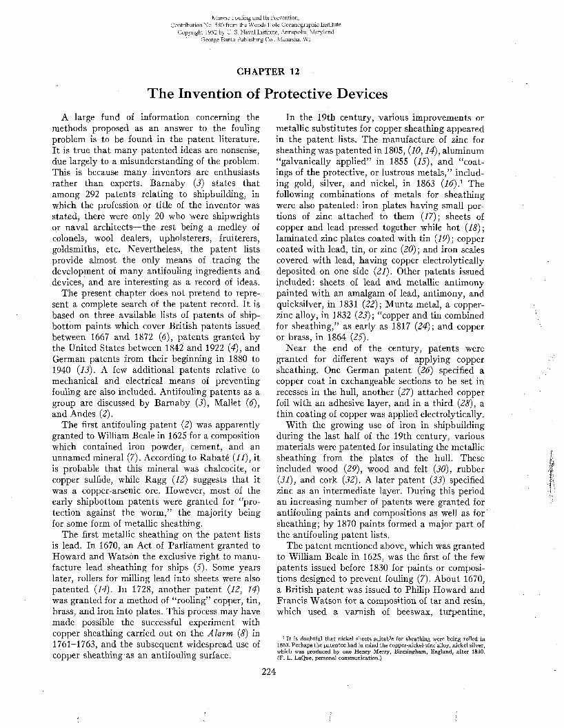
Marine Fouling and Its Prevention,ContributionNo. 580 from the Woods Hole Oceanographic Institute
Copyright 1952 by U. S. Naval Institute, Annapolis, Maryland George Banta Publishing Co., Menasha, WI
CHAPTER 12
The Invention of Protective DevicesA large fund of information concerning the
methods proposed as an answer to the fouling problem is to be found in the patent literature. It is true that many patented ideas are nonsense, due largely to a misunderstanding of the problem. This is because many inventors are enthusiasts rather than experts. Barnaby (3) states that among 292 patents relating to shipbuilding, in which the profession or title of the inventor was stated, there were only 20 who were shipwrights or naval architects— the rest being a medley of colonels, wool dealers, upholsterers, fruiterers, goldsmiths, etc. Nevertheless, the patent lists provide almost the only means of tracing the development of many antifouling ingredients and devices, and are interesting as a record of ideas.
The present chapter does not pretend to represent a complete search of the patent record. It is based on three available lists of patents of ship- bottom paints which cover British patents issued between 1667 and 1872 (6), patents granted by the United States between 1842 and 1922 (4), and German patents from their beginning in 1880 to 1940 (13). A few additional patents relative to mechanical and electrical means of preventing fouling are also included. Antifouling patents as a group are discussed by Barnaby (3), Mallet (6), and Andes (2).
The first antifouling patent (2) was apparently granted to William Beale in 1625 for a composition which contained iron powder, cement, and an unnamed mineral (7). According to Rabaté (11), it is probable that this mineral was chalcocite, or copper sulfide, while Ragg (12) suggests that it was a copper-arsenic ore. However, most of the early shipbottom patents were granted for “protection against the worm,” the majority being for some form of metallic sheathing.
The first metallic sheathing on the patent lists is lead. In 1670, an Act of Parliament granted to Howard and Watson the exclusive right to manufacture lead sheathing for ships (5). Some years later, rollers for milling lead into sheets were also patented (14). In 1728, another patent (12, 14) was granted for a method of “rooling” copper, tin, brass, and iron into plates. This process may have made possible the successful experiment with copper sheathing carried out on the Alarm (8) in 1761-1763, and the subsequent widespread use of copper sheathing as an antifouling surface.
In the 19th century, various improvements or metallic substitutes for copper sheathing appeared in the patent lists. The manufacture of zinc for sheathing was patented in 1805, (10,14), aluminum “galvanically applied” in 1855 (15), and “coatings of the protective, or lustrous metals,” including gold, silver, and nickel, in 1863 (16)} The following combinations of metals for sheathing were also patented: iron plates having small portions of zinc attached to them (17); sheets of copper and lead pressed together while hot (18) ; laminated zinc plates coated with tin (19) ; copper coated with lead, tin, or zinc (20); and iron scales covered with lead, having copper electrolytically deposited on one side (21). Other patents issued included: sheets of lead and metallic antimony painted with an amalgam of lead, antimony, and quicksilver, in 1831 (22); Muntz metal, a copper- zinc alloy, in 1832 (23); “copper and tin combined for sheathing,” as early as 1817 (24); and copper or brass, in 1864 (25).
Near the end of the century, patents were granted for different ways of applying copper sheathing. One German patent (26) specified a copper coat in exchangeable sections to be set in recesses in the hull, another (27) attached copper foil with an adhesive layer, and in a third (28), a thin coating of copper was applied electrolytically.
With the growing use of iron in shipbuilding during the last half of the 19th century, various materials were patented for insulating the metallic sheathing from the plates of the hull. These included wood (29), wood and felt (30), rubber (31), and cork (32). A later patent (33) specified zinc as an intermediate layer. During this period an increasing number of patents were granted for antifouling paints and compositions as well as for sheathing; by 1870 paints formed a major part of the antifouling patent lists.
The patent mentioned above, which was granted to William Beale in 1625, was the first of the few patents issued before 1830 for paints or compositions designed to prevent fouling (7). About 1670, a British patent was issued to Philip Howard and Francis Watson for a composition of tar and resin, which used a varnish of beeswax, turpentine,
1 It is doubtful that nickel sheets suitable for sheathing were being rolled in 1863. Perhaps the patentee had in mind the copper-nickel-zincalloy, nickel silver, which was produced by one Henry Merry, Birmingham, England, after 1830. (F. L. LaQue, personal communication.)
224
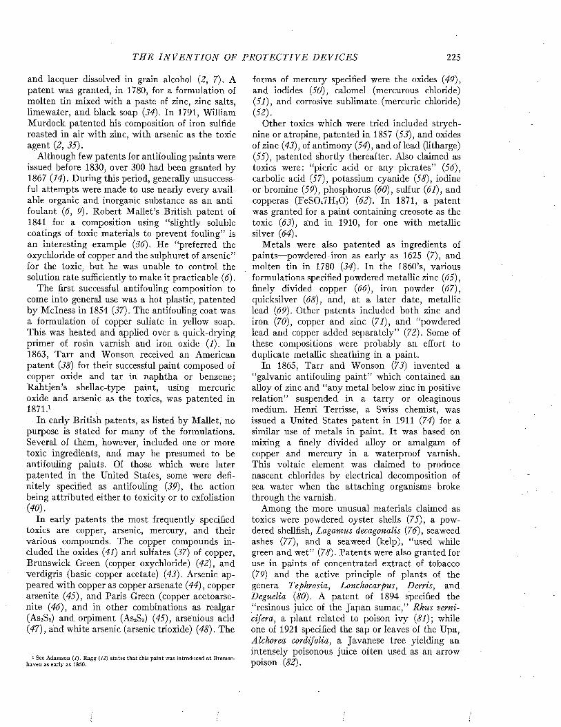
THE I N V E N T I O N OF P R O T E C T I V E DEVICES 225
and lacquer dissolved in grain alcohol (2, 7). A patent was granted, in 1780, for a formulation of molten tin mixed with a paste of zinc, zinc salts, limewater, and black soap (34). In 1791, William Murdock patented his composition of iron sulfide roasted in air with zinc, with arsenic as the toxic agent (2, 35).
Although few patents for antifouling paints were issued before 1830, over 300 had been granted by 1867 (14). During this period, generally unsuccessful attempts were made to use nearly every available organic and inorganic substance as an anti- foulant (6, 9). Robert M allet’s British patent of 1841 for a composition using “slightly soluble coatings of toxic materials to prevent fouling” is an interesting example (36). He “preferred the oxychloride of copper and the sulphuret of arsenic” for the toxic, but he was unable to control the solution rate sufficiently to make it practicable (6).
The first successful antifouling composition to come into general use was a hot plastic, patented by M clness in 1854 (37). The antifouling coat was a formulation of copper sulfate in yellow soap. This was heated and applied over a quick-drying primer of rosin varnish and iron oxide (1). In 1863, Tarr and Wonson received an American patent (38) for their successful paint composed of copper oxide and tar in naphtha or benzene; Rahtjen’s shellac-type paint, using mercuric oxide and arsenic as the toxics, was patented in 1871.1
In early British patents, as listed by Mallet, no purpose is stated for many of the formulations. Several of them, however, included one or more toxic ingredients, and may be presumed to be antifouling paints. Of those which were later patented in the United States, some were definitely specified as antifouling (39), the action being attributed either to toxicity or to exfoliation (40).
In early patents the most frequently specified toxics are copper, arsenic, mercury, and their various compounds. The copper compounds included the oxides (41) and sulfates (37) of copper, Brunswick Green (copper oxychloride) (42), and verdigris (basic copper acetate) (43). Arsenic appeared with copper as copper arsenate (44), copper arseni te (45), and Paris Green (copper acetoarse- nite (46), and in other combinations as realgar (As2S2) and orpiment (As2S3) (45), arsenious acid (47), and white arsenic (arsenic trioxide) (48). The
1 See Adamson (I). Ragg (12) states that this paint was introduced at Bremerhaven as early as 1860.
forms of mercury specified were the oxides (49), and iodides (50), calomel (mercurous chloride)(51), and corrosive sublimate (mercuric chloride)(52).
Other toxics which were tried included strychnine or atropine, patented in 1857 (53), and oxides of zinc (43), of antimony (54), and of lead (litharge) (55), patented shortly thereafter. Also claimed as toxics were: “picric acid or any picrates” (56), carbolic acid (57), potassium cyanide (58), iodine or bromine (59), phosphorus (60), sulfur (61), and copperas (FeSO^HîO) (62). In 1871, a patent was granted for a paint containing creosote as the toxic (63), and in 1910, for one with metallic silver (64).
Metals were also patented as ingredients of paints—powdered iron as early as 1625 (7), and molten tin in 1780 (34). In the 1860’s, various formulations specified powdered metallic zinc (65), finely divided copper (66), iron powder (67), quicksilver (68), and, at a later date, metallic lead (69). Other patents included both zinc and iron (70), copper and zinc (71), and “powdered lead and copper added separately” (72). Some of these compositions were probably an effort to duplicate metallic sheathing in a paint.
In 1865, Tarr and Wonson (73) invented a “galvanic antifouling paint” which contained an alloy of zinc and “any metal below zinc in positive relation” suspended in a tarry or oleaginous medium. Henri Terrisse, a Swiss chemist, was issued a United States patent in 1911 (74) for a similar use of metals in paint. It was based on mixing a finely divided alloy or amalgam of copper and mercury in a waterproof varnish. This voltaic element was claimed to produce nascent chlorides by electrical decomposition of sea water when the attaching organisms broke through the varnish.
Among the more unusual materials claimed as toxics were powdered oyster shells (75), a powdered shellfish, Lagamus decagonalis (76), seaweed ashes (77), and a seaweed (kelp), “used while green and wet” (78). Patents were also granted for use in paints of concentrated extract of tobacco (79) and the active principle of plants of the genera Tephrosia, Lonchocarpus, Derris, and Deguelia (80). A patent of 1894 specified the “resinous juice of the Japan sumac,” Rhus verni- cif era, a plant related to poison ivy (81); while one of 1921 specified the sap or leaves of the Upa, Alchorea cordifolia, a Javanese tree yielding an intensely poisonous juice often used as an arrow poison (82).
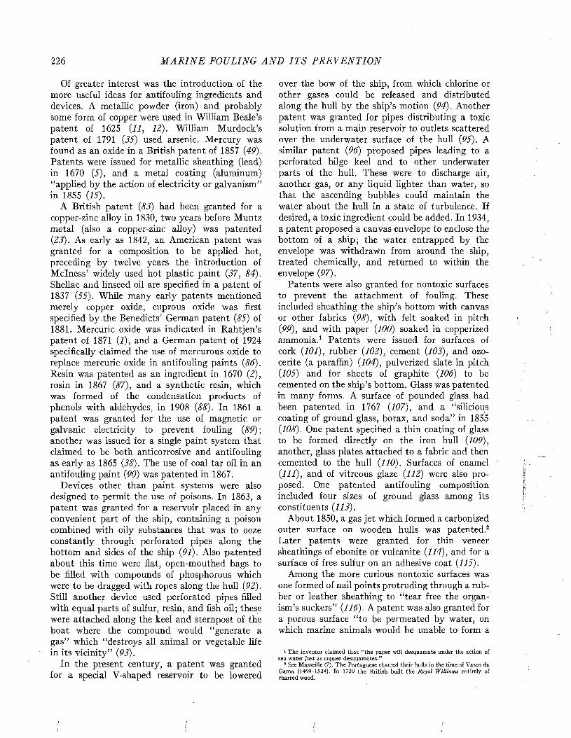
226 M A R I N E FOULING A N D I T S P R E V E N T I O N
Of greater interest was the introduction of the more useful ideas for antifouling ingredients and devices. A metallic powder (iron) and probably some form of copper were used in William Beale’s patent of 1625 (11, 12). William Murdock’s patent of 1791 (35) used arsenic. Mercury was found as an oxide in a British patent of 1857 (49). Patents were issued for metallic sheathing (lead) in 1670 (5), and a metal coating (aluminum) “applied by the action of electricity or galvanism” in 1855 (15).
A British patent (83) had been granted for a copper-zinc alloy in 1830, two years before Muntz metal (also a copper-zinc alloy) was patented (23). As early as 1842, an American patent was granted for a composition to be applied hot, preceding by twelve years the introduction of M clness’ widely used hot plastic paint (37, 84). Shellac and linseed oil are specified in a patent of 1837 (55). While many early patents mentioned merely copper oxide, cuprous oxide was first specified by the Benedicts’ German patent (85) of 1881. Mercuric oxide was indicated in Rahtjen’s patent of 1871 (1), and a German patent of 1924 specifically claimed the use of mercurous oxide to replace mercuric oxide in antifouling paints (86). Resin was patented as an ingredient in 1670 (2), rosin in 1867 (87), and a synthetic resin, which was formed of the condensation products of phenols with aldehydes, in 1908 (88). In 1861 a patent was granted for the use of magnetic or galvanic electricity to prevent fouling (89) ; another was issued for a single paint system that claimed to be both anticorrosive and antifouling as early as 1865 (38). The use of coal tar oil in an antifouling paint (90) was patented in 1867.
Devices other than paint systems were also designed to permit the use of poisons. In 1863, a patent was granted for a reservoir placed in any convenient part of the ship, containing a poison combined with oily substances that was to ooze constantly through perforated pipes along the bottom and sides of the ship (91). Also patented about this time were flat, open-mouthed bags to be filled with compounds of phosphorous which were to be dragged with ropes along the hull (92). Still another device used perforated pipes filled with equal parts of sulfur, resin, and fish oil; these were attached along the keel and sternpost of the boat where the compound would “generate a gas” which “destroys all animal or vegetable life in its vicinity” (93).
In the present century, a patent was granted for a special V-shaped reservoir to be lowered
over the bow of the ship, from which chlorine or other gases could be released and distributed along the hull by the ship’s motion (94). Another patent was granted for pipes distributing a toxic solution from a main reservoir to outlets scattered over the underwater surface of the hull (95). A similar patent (96) proposed pipes leading to a perforated bilge keel and to other underwater parts of the hull. These were to discharge air, another gas, or any liquid lighter than water, so that the ascending bubbles could maintain the water about the hull in a state of turbulence. If desired, a toxic ingredient could be added. In 1934, a patent proposed a canvas envelope to enclose the bottom of a ship; the water entrapped by the envelope was withdrawn from around the ship, treated chemically, and returned to within the envelope (97).
Patents were also granted for nontoxic surfaces to prevent the attachment of fouling. These included sheathing the ship’s bottom with canvas or other fabrics (98), with felt soaked in pitch (99), and with paper (100) soaked in copperized ammonia.1 Patents were issued for surfaces of cork (101), rubber (102), cement (103), and ozocerite (a paraffin) (104), pulverized slate in pitch(105) and for sheets of graphite (106) to be cemented on the ship’s bottom. Glass was patented in many forms. A surface of pounded glass had been patented in 1767 (107), and a “silicious coating of ground glass, borax, and soda” in 1855 (108). One patent specified a thin coating of glass to be formed directly on the iron hull (109), another, glass plates attached to a fabric and then cemented to the hull (110). Surfaces of enamel (111), and of vitreous glaze (112) were also proposed. One patented antifouling composition included four sizes of ground glass among its constituents (113).
About 1850, a gas jet which formed a carbonized outer surface on wooden hulls was patented.2 Later patents were granted for thin veneer sheathings of ebonite or vulcanite (114), and for a surface of free sulfur on an adhesive coat (115).
Among the more curious nontoxic surfaces was one formed of nail points protruding through a rubber or leather sheathing to “tear free the organism’s suckers” (116). A patent was also granted for a porous surface “to be permeated by water, on which marine animals would be unable to form a
1 The inventor claimed that “the paper will desquamate under the action of sea water just as copper desquamates.”
2 See Masseille (7). The Portuguese charred their hulls in the time of Vasco da Gama (1469-1524). In 1720 the British built the Royal W illiams entirely of charred wood.
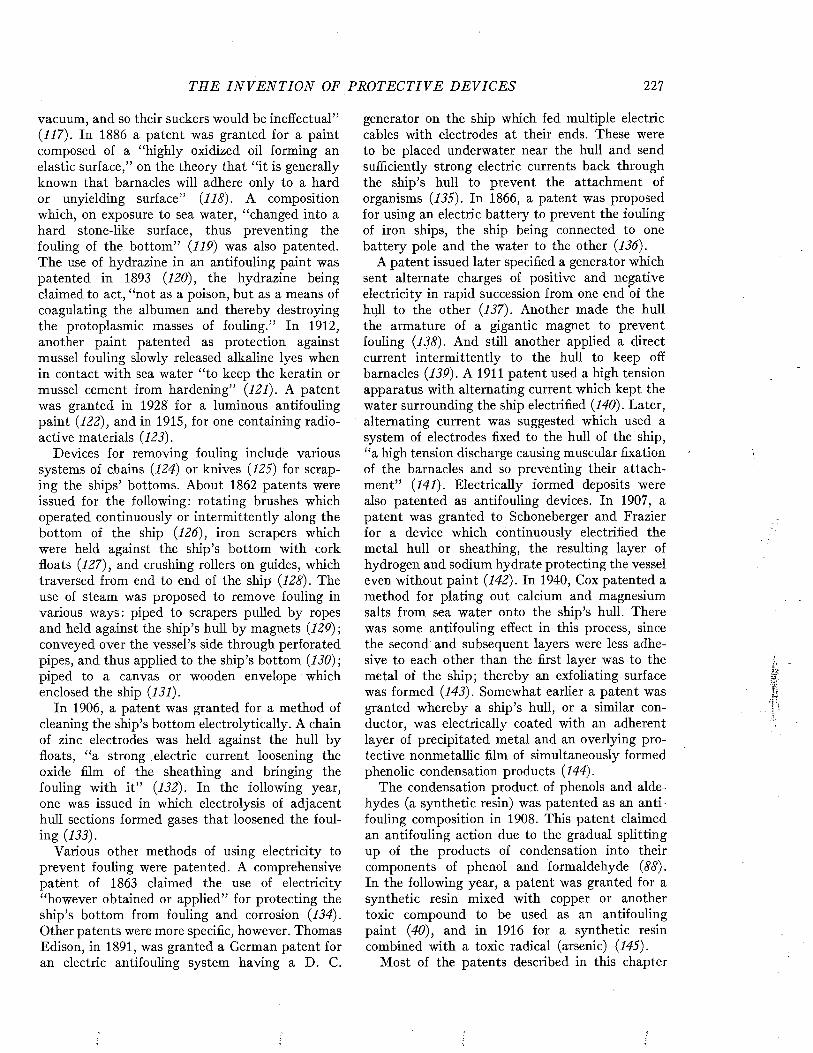
T H E I N V E N T I O N OF P R O T E C T IV E D E V ICE S 227
vacuum, and so their suckers would be ineffectual” (117). In 1886 a patent was granted for a paint composed of a “highly oxidized oil forming an elastic surface,” on the theory that “it is generally known that barnacles will adhere only to a hard or unyielding surface” (118). A composition which, on exposure to sea water, “changed into a hard stone-like surface, thus preventing the fouling of the bottom” (119) was also patented. The use of hydrazine in an antifouling paint was patented in 1893 (120), the hydrazine being claimed to act, “not as a poison, but as a means of coagulating the albumen and thereby destroying the protoplasmic masses of fouling.” In 1912, another paint patented as protection against mussel fouling slowly released alkaline lyes when in contact with sea water “to keep the keratin or mussel cement from hardening” (121). A patent was granted in 1928 for a luminous antifouling paint (122), and in 1915, for one containing radioactive materials (123).
Devices for removing fouling include various systems of chains (124) or knives (125) for scraping the ships’ bottoms. About 1862 patents were issued for the following: rotating brushes which operated continuously or intermittently along the bottom of the ship (126), iron scrapers which were held against the ship’s bottom with cork floats (127), and crushing rollers on guides, which traversed from end to end of the ship (128). The use of steam was proposed to remove fouling in various ways: piped to scrapers pulled by ropes and held against the ship’s hull by magnets (129)-, conveyed over the vessel’s side through perforated pipes, and thus applied to the ship’s bottom (130) ; piped to a canvas or wooden envelope which enclosed the ship (131).
In 1906, a patent was granted for a method of cleaning the ship’s bottom electrolytically. A chain of zinc electrodes was held against the hull by floats, “a strong electric current loosening the oxide film of the sheathing and bringing the fouling with it” (132). In the following year, one was issued in which electrolysis of adjacent hull sections formed gases that loosened the fouling (133).
Various other methods of using electricity to prevent fouling were patented. A comprehensive patent of 1863 claimed the use of electricity “however obtained or applied” for protecting the ship’s bottom from fouling and corrosion (134). Other patents were more specific, however. Thomas Edison, in 1891, was granted a German patent for an electric antifouling system having a D. C.
generator on the ship which fed multiple electric cables with electrodes at their ends. These were to be placed underwater near the hull and send sufficiently strong electric currents back through the ship’s hull to prevent the attachment of organisms (135). In 1866, a patent was proposed for using an electric battery to prevent the fouling of iron ships, the ship being connected to one battery pole and the water to the other (136).
A patent issued later specified a generator which sent alternate charges of positive and negative electricity in rapid succession from one end of the hull to the other (137). Another made the hull the armature of a gigantic magnet to prevent fouling (138). And still another applied a direct current intermittently to the hull to keep off barnacles (139). A 1911 patent used a high tension apparatus with alternating current which kept the water surrounding the ship electrified (140). Later, alternating current was suggested which used a system of electrodes fixed to the hull of the ship, “a high tension discharge causing muscular fixation of the barnacles and so preventing their attachm ent” (141). Electrically formed deposits were also patented as antifouling devices. In 1907, a patent was granted to Schoneberger and Frazier for a device which continuously electrified the metal hull or sheathing, the resulting layer of hydrogen and sodium hydrate protecting the vessel even without paint (142). In 1940, Cox patented a method for plating out calcium and magnesium salts from sea water onto the ship’s hull. There was some antifouling effect in this process, since the second and subsequent layers were less adhesive to each other than the first layer was to the metal of the ship; thereby an exfoliating surface was formed (143). Somewhat earlier a patent was granted whereby a ship’s hull, or a similar conductor, was electrically coated with an adherent layer of precipitated metal and an overlying protective nonmetallic film of simultaneously formed phenolic condensation products (144).
The condensation product of phenols and aldehydes (a synthetic resin) was patented as an antifouling composition in 1908. This patent claimed an antifouling action due to the gradual splitting up of the products of condensation into their components of phenol and formaldehyde (88). In the following year, a patent was granted for a synthetic resin mixed with copper or another toxic compound to be used as an antifouling paint (40), and in 1916 for a synthetic resin combined with a toxic radical (arsenic) (145).
Most of the patents described in this chapter
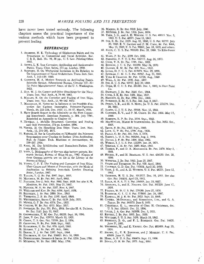
228 M A R I N E FOULING A N D I T S P R E V E N T I O N
have never been tested seriously. The following chapters assess the practical importance of the various methods which have been proposed to prevent fouling.
REFERENCES1. A d a m s o n , N. E. Technology of Shipbottom Paints and Its
Importance to Commercial and Naval Activities. Bur. C & R, Bull. No. 10, 38 pp., U. S. Gov. Printing Office. 1937.
2. A n d e s , L. E. Iron Corrosion; Antifouling and AnticorrosivePaints. Trans. Chas. Saltes, 275 pp. London. 1900.
3. B a r n a b y , N. On Mechanical Invention in Its Relation tothe Improvement of Naval Architecture. Trans. Inst. Nav. Arch. 1, 145-159. 1860.
4. G a r d n e r , H. A. Modern Research on Antifouling Paints.Scientific Section, Educational Bureau, Circular 157; 35- 72; Paint Manufacturers’ Assoc, of the U. S. Washington. 1922.
5. H a y , W. J. On Copper and Other Sheathings for the Navy.Trans. Inst. Nav. Arch., 4, 79-98. 1863.
6. M a l l e t , R. On the Corrosion and Fouling of Iron Ships.Trans. Inst. Nav. Arch., 13, 90-162. 1872.
7. M a s s e i l l e , H. Notes sur la Salissure et les Procédés d’entretien des Carènes Immergées. Peintures-Pigments- Vernis, 10, 232-234, Dec. 1933: 11, 54-57. March, 1934.
8. Navy Boards Report to the Admiralty on the First Coppering Experiment. American Neptune, p. 304. July 1941. Reprinted as Appendix to Chapter 11.
9. N e w m a n , J. Metallic Structures: Corrosion and Foulingand their Prevention. 374 pp. London. 1896.
10. N i n n i s , H. On Sheathing Iron Ships. Trans. Inst. Nav.Arch., 12, 270-281. 1871.
11. R a b a t é , H. Sur la Constitution et l’Efficacité des PeinturesSous-marines pour Couches de Surface Dites Antifouling. Bull, de l’Assoc. Tech. Maritime et Aéronautique, 40, 239-267. 1936.
12. R a g g , M. Die Schiffsboden und Rostschutz-Farben. 256pp. Berlin. 1925.
13. V o g e , L. Bibliography of German ship bottom patents. Research Section, Bureau of Ships 14 pp., 1942. (Copies of these German patents are on file in the Library of the Bureau of Ships.)
14. Y o u n g , C. F. T. The Fouling and Corrosion of Iron Ships;Their Causes and Means of Prevention, with the Mode of Application to Existing Iron-clad s. London Drawing Assoc., London. 1867.
15. T a y l o r , T . G. Br. Pat. 1997. Sept., 1855.16. M it c h e l l , W. Br. Pat. 841. April, 1863.17. P attison, S i r G. Brit. Pat. 5692, Sept. 1828. See also E. H.
Monkton, Br. Pat. 1503. May 21, 1867.18. N e w t o n , W. E. Br. Pat. 3107. Nov. 4, 1867.19. W il l ia m s and K a y . Br. Pat. 6594. April, 1834.20. B e t t e l e y , J. Br. Pat. 2880. Nov., 1863.21. T h o m p s o n , J. B. Br. Pat. 1195. April, 1866.22. W e t t e r s t e d t , Baron C. Br. Pat. 6129. July, 1831.23. M u n t z , G. F. Br. Pat. 6374. Dec., 1832.24. C o l l in s , W. Br. Pat. 4115. May, 1817.25. S i n i b a l d i . Br. Pat. 351. Feb., 1864. See also H. A. Dufrene,
Br. Pat. 2142. July 23, 1867.26. G r u m b a c h e r , F. M. Ger. Pat. 88558. Sept. 26, 1896.27. Je b e , P. Ger. Pat. 129753. March 13, 1902.28. C r a n e , T. S. Ger. Pat. 72709. Jan. 2, 1894.29. G r i f f i t h s , R. Br. Pat. 2638. Sept., 1862.3 0 . R i t h e r d o n , E. Br. Pat. 9 7 0 . April, 1865 .31. H u g h e s , T. J. Br. Pat. 451. Feb., 1864.32. D e n n e , T . J . B r . Pat. 2387. Sept., 1864.33. H a u s m a n n , M. Ger. Pat. 206821. Feb. 16, 1909.34. D o n n i t iio r n e , S h e r s o n & S m it h . Br. Pat. 1256. June, 1780.35. M u r d o c k , W. Br. Pat. 1802. May, 1791.
36. M a l l e i , R. Br. Pat. 9018. July, 1841.37. M cI n e s s , J. Br. Pat. 1356. June, 1854.38. T a r r , J. G., and A. H. W o n s o n . U. S. Pat. 40515. Nov. 3,
1863. U. S. Pat. 48221. June 13, 1865.39. S im , R. Br. Pat. 2529. Aug. 12, 1868; U. S. Pat. 92757. July
20, 1869. E. V. Gardner and P. M. Crane, Br. Pat. 1464, May 13, 1869; U. S. Pat. 98862, Jan. 18, 1870, and others.
40. E l l is , C. U. S. Pat. 944420. Dec. 28, 1909. To Ellis-FosterCo.
41. W a r d , P. Br. Pat. 2359. Oct. 1856.42. P r e n t i s s , E. F. U. S. Pat. 142117. Aug. 26, 1873.43. C o o k , T. E. Br. Pat. 1194. Dec., 1852.44. B o w k e r , J. U. S. Pat. 103290. May 24, 1870.45. G l o v e r , R. M. Br. Pat. 855. Nov., 1852.46. L u c a s , D. F. U. S. Pat. 615079. Nov. 29, 1898.47. S p o o n e r , C. M. U. S. Pat. 49567. Aug. 22, 1865.48. Y u l e & C h a n t e r . Br. Pat. 12726. Aug., 1849.49. W a l l , A. Br. Pat. 2198. Aug., 1857.50. S im , R. U. S. Pat. 92757. July 20, 1869.51. D o r r , H. C. U. S. Pat. 331383. Dec. 1, 1885; to Dorr Paint
Co.52. D a n n a t t , J. Br. Pat. 2645. Oct., 1864.53. C o o k , J. E. Br. Pat. 1481. May, 1857.54. H a l l e t t , G. Br. Pat. 2984. Dec., 1860.55. R o b in s o n , E. M. U. S. Pat. 346. Aug. 8, 1837.56. P e r c y , S. R., and H. A. M o t t , J r . U. S. Pat. 251279. Dec.
20, 1881.57. E a m e s , C. J. U. S. Pat. 59568. Nov. 13, 1866.58. G a r d n e r , E. V., and P. M. C r a n e . Br. Pat. 1464. May 13,
1869.59. R o b e r t s , R. P. Br. Pat. 2316. Sept., 1865.60. M a c M il l a n , M a s o n & S c a r b o r o u g h . Br. Pat. 2653. Oct.,
1865.61. S m it h , R. Br. Pat. 2303. Sept., 1860.62. L o c k , G. P. Br. Pat. 1796. Aug., 1858.63. P h a l p , O. Br. Pat. 301. Feb. 3, 1871.64. S c h o t t , L. U. S. Pat. 966366. Aug. 2, 1910.65. J o u v i n , J. P. Br. Pat. 1466. May, 1862.66. W y m a n , I. J. U. S. Pat. 111295. Jan. 24, 1871.67. S p e n c e r , T. H. Br. Pat. 1489. May, 1865.68. T a y s e n , P., and D. R. M a c g r e g o r . Br. Pat. 1470. May 5, ■
1868.69. H e l b ig , P., and H. B e r t l i n g . U. S. Pat. 439150. Oct. 28,
1890.70. W e b s t e r , J. Br. Pat. 1845. June 25, 1867.71. E v a n s and T h o m p s o n . Br. Pat. 928. April, 1864.72. C o l e m a n , G. D. Ger. Pat. 110054. April 20, 1900.73. T a r r , J. G., and A. H. W o n s o n . U. S. Pat. 48221. June 13,
1865.74. T e r r i s s e , H. U. S. Pat. 1012177. Dec. 19, 1911. See also
Ger. Pat. 246154. April 23, 1912.75. Sa a l e , H. E. A. IL S. Pat. 356505. Jan. 25-, 1887.76. A s a k a w a , S., and K. N o s a w a . Ger. Pat. 397220. June 17,
1924.77. F o l g e r , W. D. U. S. Pat. 179180. June 27, 1876.78. B u r n h a m , G. L. U. S. Pat. 575800. Jan. 26, 1897.79. K e n d a l l , H. J. B. Br. Pat. 2923. Sept. 23, 1868.80. C o o p e r , M cD o u g a l l , and R o b e r t s o n , L t d ., and G. A.
F r e a k . Br. Pat. 393375. June 8, 1933.81. C h r is t m a n , K. L., executrix of Chas. H. Christman, dec.
U. S. Pat. 531610. Dec. 25, 1894.82. L il l i e , J. A. Ger. Pat. 345058. Dec. 3, 1921.83. R e v e r e , J. Br. Pat. 5892. Jan., 1830.84. W il l ia m s , S. U. S. Pat. 2498. March 18, 1842.85. B e n e d ic t , B. G., and F. L. B e n e d ic t . Ger. Pat. 14428.
June 21, 1881.86. W e i n b e r g , M., and K. K r o e l l . Ger. Pat. 401009. Aug. 25,
1924.87. B r o w n , G., E. E. B u r n h a m , and J. M o r r is c . U. S. Pat.
65639. June 11, 1867.88. H o r n , A. P. U. S. Pat. 898476. Sept. 15, 1908.89. B o v il l , G. H. Br. Pat. 1975. Aug., 1861.
TH E I N V E N T I O N OF P R O T E C T I V E DEVICES 229
90. C o l t o n , H. E. U. S. Pat. 69185. Sept. 24, 1867.91. E l l is e n , A. Br. Pat. 2847. Nov., 1863.92. M o n k t o n , E. H. Br. Pat. 15 0 3 . May 21, 1867.93. Sm it h , R. Br. Pat. 2076. June 27, 1868: described by Mallet
(6).94. V a n M e t e r , J. W. U. S. Pat. 1430773. Oct. 3, 1922.95. Br. Pat. 267824. March 24, 1927.96. B r a m m e r , F. G. U. S. Pat. 2138831. Dec. 6, 1938.97. K e l l e y , V. H. U. S. Pat. 1973813. Sept. 18, 1934.98. B a i n e , W. P. Br. Pat. 3023. Dec., 1861.99. W il l ia m s , T. R. Br. Pat. 5791. May, 1829.
100. Sc o f e e r n , J. Br. Pat. 1380. April 27, 1868. U. S. Pat.86104. Jan. 19, 1869.
101. C a s s e l l , J. H. Br. Pat. 1414. April 30,1868.102. R e a d , D. U. S. Pat. 90022, May 11, 1869.103. J o h a n n s e N, A. U. S. Pat. 669993. March 19, 1901.104. C h e s e b r o u g h , R. A. U . S. Pat. 447941. March 10, 1891.105. D o d s o n , A. J. Br. Pat. 397. Feb., 1862.106. C o h e n , B. S. Br. Pat. 1567. June, 1865.107. S m it h , J. Br. Pat. 887. Dec., 1767.108. G r e e n h o w , T. M. Br. Pat. 1182. May, 1855.109. L e e t c h and M a y h e w . Br. Pat. 2100. July, 1862.110. B r o w n , W a y and E v a n s . Br. Pat. 1468. June, 1864.111. O a k d e n , J., and J. P i c k i n . Br. Pat. 1118. April 15, 1867.112. D e L a v e n a n t , C. Br. Pat. 3288. Nov. 12, 1867.113. D e v e y , M. H. U. S. Pat. 754054. March 8, 1904.114. H e n s o n , H. Br. Pat. 1135. May, 1864.115. B e l l , R. Ger. Pat. 169407. April 2, 1906.1 16 . S t e i n h a l , H. M. Ger. Pat. 8 5 1 8 8 . Jan. 2 3 , 1896 .117. G r a y , J. Br. Pat. 1395. April 29, 1868.1 1 8 . H o a r d , J. W., and F. R. H o a r d . U. S. Pat. 3 3 4 0 1 9 . Jan 12,
1886.
119. M a r s d e n , G. C. U. S. Pat. 341760. May 11, 1886.120. P f l u g , L. U. S. Pat. 496895. May 9, 1893.121. L ie b r ic h , E. U. S. Pat. 1043051. Oct. 29, 1912.122. Br. Pat. 299228. Oct. 25, 1928. See E. Perry: A Study of the
Preventive Effect of Light Colors on the Fouling of Ships’ Bottoms: Paint and Prod. Mgr. Jan. 1932.
123. C o m s t o c k , D. F. U. S. Pat. 1123687. Jan. 5, 1915.124. Ger. Pat. 8856.125. Ger. Pat. 5763.126. G r a y , J. Br. Pat. 2190. Aug., 1862.127. J o n e s , C. P. Br. Pat. 2748. Sept. 30, 1867.128. P a r k , D. B. Br. Pat. 1917. June 23, 1869.129. M a s o n , D. U. S. Pat. 635938. Oct. 31, 1899.130. St e a r t , J. Br. Pat. 1439. May 19, 1870.131. F a r l e y , J. W. U. S. Pat. 632919. Sept. 12, 1899.132. F r a z ie r , G. W. U. S. Pat. 820105. May 6, 1906.133. P a r t e e , W. A., and J. C. W h a r t o n . U. S. Pat. 843357. Feb.
5, 1907.134. B a g g s , J. Br. Pat. 2295. Sept., 1863.135. E d i s o n , T. A. Ger. Pat. 57293. July 1,1891.136. P ig g o t t , W. P. Br. Pat. 1209. April, 1866.137. H a r r is o n , Ci W. Br. Pat. 1347. May 11, 1870.138. C a b e l l , S. G. U. S. Pat. 468741. Feb. 9, 1892.139. D e l i u s , G., and C. F. T a t r o . XJ. S. Pat. 1021734. March 26,
1912.140. J a m e s , J. E. U. S. Pat. 994405. June 6, 1911.141. W i l k i e , J. B. U. S. Pat. 1467890. Sept. 11, 1923.142. S c h o n e b e r g e r , J. H., and G. W. F r a z ie r . U. S. Pat.
872759. Dec. 3, 1907.143. Cox, G. C. U. S. Pat. 2200469. 1940.144. T o w n s e n d , C. P. U. S. Pat.. 1146214. July 13, 1915.145. H e in e m a n n , A. U. S. Pat. 1176056. March 21, 1916.
Marine Fouling and Its Prevention,Contribution No. 580 from the Woods Hole Oceanographic Institute
Copyright 1952 by U. S. Naval Institute, Annapolis,"Maryland George Banta Publishing Co., Menasha, WI
CHAPTER 13
Factors Influencing the Attachment and Adherence of Fouling Organisms
M any suggestions for the control of fouling are based on an appreciation of the physiology and distribution of fouling organisms. All too often, however, they are vague and give the engineer little aid in designing structures or determining whether special methods of control are necessary. It is the purpose of this chapter to describe the physiology of the fouling larvae so that the tendency of a surface to become fouled may be appreciated, to review the factors which influence the attachment of fouling, and to assess their practical value.
The several factors which determine the tendency of a surface to foul when exposed in the sea may be divided into two main groups: 1) those which determine the numbers of larvae coming into contact with the exposed surface, and 2) those which limit the ability of these larvae to attach to the surface and grow. The physiology of the organism determines its reaction to changes in the environment, and must be understood in order to evaluate the relative importance of these factors.
The numbers of larvae coming into contact with an exposed surface depend upon the geographical location, the season of the year, the type of service for which the installation is employed, and the texture, orientation, and color of the surface. The tendency of the surface to form slime films and the degree to which the surface is wet by sea water may also have significant influences. All of these factors are, to a large extent, predetermined by engineering considerations and frequently are not subject to control or modification. Practical prevention of fouling depends upon modifications of the surface so that it repels or kills the organisms which come in contact with it. Among such surface modifications, frequently recommended, are the application of electricity and the use of exfoliating or toxic paints. Only the toxic paints have given satisfactory results, and this aspect of the control of fouling is discussed in the following chapter.
GEOGRAPHICAL AND SEASONAL DISTRIBUTION
The seasonal and geographical distribution of fouling organisms has been discussed in Chapters
5 to 7. The geographical location determines whether a structure will be subject to intense fouling attachment, and must be appreciated in order to foretell whether special methods for the control of fouling will be necessary.
There are tremendous differences in the numbers of larvae of fouling organisms present in the water in different geographical areas, and also in any given area at different times of year. Most of the coast of the United States is in the temperate zone where marked seasonal variations in the amount of fouling occur. It is possible, in some places, that methods of control will be required during the summer months, but may be unnecessary in the fall or winter months because larvae are not present in the water or are not attaching to surfaces. It is impossible to predict the intensity of fouling solely from general considerations of distribution, since local variations are of considerable importance. Studies of each location are, therefore, necessary to determine whether special methods of control are required.
Geographical and seasonal considerations are likewise of great importance in selecting a location for the testing of antifouling surfaces or for investigation of the biology of fouling. It is futile to test antifouling surfaces under conditions of poor fouling attachment. Tests made under thèse conditions may appear to indicate that a surface would prevent fouling for a considerable period of time, when, if exposed to intense fouling, the same surface would foul immediately. Fouling attaches throughout the year at various locations in southern Florida and southern California, and tests made at such places give a more accurate picture of the effectiveness of the surface and of the duration of its effective life.
The concept, held by many investigators, that antifouling paints should be designed for use in certain waters is unsound. If true, it would be necessary to test all paints under as many conditions as possible. Paints which are effective under severe fouling conditions are effective wherever they may be exposed. Those which are reputed to be effective in one place but unsatisfactory in other areas are invariably borderline paints which foul anywhere when the intensity of fouling becomes high. The testing station should,
230
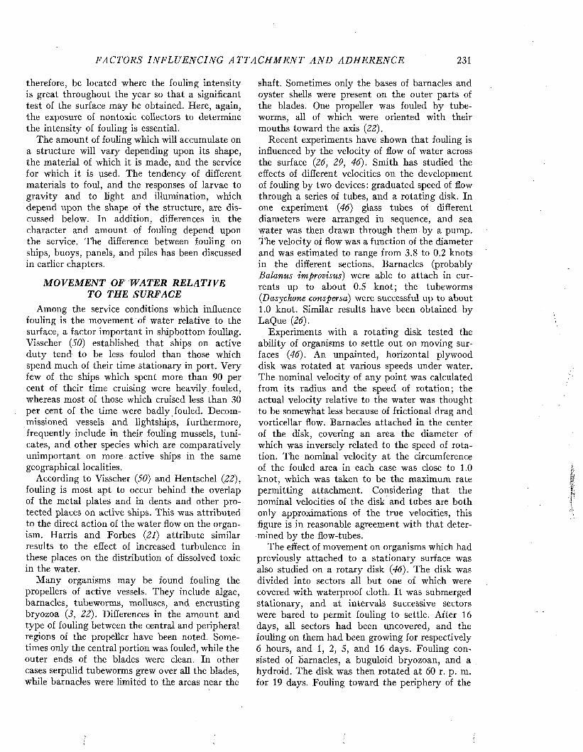
FACTORS I N F L U E N C IN G A T T A C H M E N T A N D A D H E R E N C E 231
therefore, be located where the fouling intensity is great throughout the year so that a significant test of the surface may be obtained. Here, again, the exposure of nontoxic collectors to determine the intensity of fouling is essential.
The amount of fouling which will accumulate on a structure will vary depending upon its shape, the material of which it is made, and the service for which it is used. The tendency of different materials to foul, and the responses of larvae to gravity and to light and illumination, which depend upon the shape of the structure, are discussed below. In addition, differences in the character and amount of fouling depend upon the service. The difference between fouling on ships, buoys, panels, and piles has been discussed in earlier chapters.
MOVEMENT OF WATER RELATIVE TO THE SURFACE
Among the service conditions which influence fouling is the movement of water relative to the surface, a factor important in shipbottom fouling. Visscher (50) established that ships on active duty tend to be less fouled than those which spend much of their time stationary in port. Very few of the ships which spent more than 90 per cent of their time cruising were heavily fouled, whereas most of those which cruised less than 30 per cent of the time were badly fouled. Decommissioned vessels and lightships, furthermore, frequently include in their fouling mussels, tuni- cates, and other species which are comparatively unimportant on more active ships in the same geographical localities.
According to Visscher (50) and Hentschel (22), fouling is most apt to occur behind the overlap of the metal plates and in dents and other protected places on active ships. This was attributed to the direct action of the water flow on the organism. Harris and Forbes (21) attribute similar results to the effect of increased turbulence in these places on the distribution of dissolved toxic in the water.
Many organisms may be found fouling the propellers of active vessels. They include algae, barnacles, tubeworms, molluscs, and encrusting bryozoa (3, 22). Differences in the amount and type of fouling between the central and peripheral regions of the propeller have been noted. Sometimes only the central portion was fouled, while the outer ends of the blades were clean. In other cases serpulid tubeworms grew over all the blades, while barnacles were limited to the areas near the
shaft. Sometimes only the bases of barnacles and oyster shells were present on the outer parts of the blades. One propeller was fouled by tubeworms, all of which were oriented with their mouths toward the axis (22).
Recent experiments have shown that fouling is influenced by the velocity of flow of water across the surface (26, 29, 46). Smith has studied the effects of different velocities on the development of fouling by two devices: graduated speed of flow through a series of tubes, and a rotating disk. In one experiment (46) glass tubes of different diameters were arranged in sequence, and sea water was then drawn through them by a pump. The velocity of flow was a function of the diameter and was estimated to range from 3.8 to 0.2 knots in the different sections. Barnacles (probably Balanus improvisus) were able to attach in currents up to about 0.5 knot; the tubeworms (Dasychone conspersa) were successful up to about 1.0 knot. Similar results have been obtained by LaQue (26).
Experiments with a rotating disk tested the ability of organisms to settle out on moving surfaces (46). An unpainted, horizontal plywood disk was rotated at various speeds under water. The nominal velocity of any point was calculated from its radius and the speed of rotation; the actual velocity relative to the water was thought to be somewhat less because of frictional drag and vorticellar flow. Barnacles attached in the center of the disk, covering an area the diameter of which was inversely related to the speed of rotation. The nominal velocity at the circumference of the fouled area in each case was close to 1.0 knot, which was taken to be the maximum rate permitting attachment. Considering that the nominal velocities of the disk and tubes are both only approximations of the true velocities, this figure is in reasonable agreement with that determined by the flow-tubes.
The effect of movement on organisms which had previously attached to a stationary surface was also studied on a rotary disk (46). The disk was divided into sectors all but one of which were covered with waterproof cloth. It was submerged stationary, and at intervals successive sectors were bared to permit fouling to settle. After 16 days, all sectors had been uncovered, and the fouling on them had been growing for respectively 6 hours, and 1, 2, 5, and 16 days. Fouling consisted of barnacles, a buguloid bryozoan, and a hydroid. The disk was then rotated at 60 r. p. m. for 19 days. Fouling toward the periphery of the
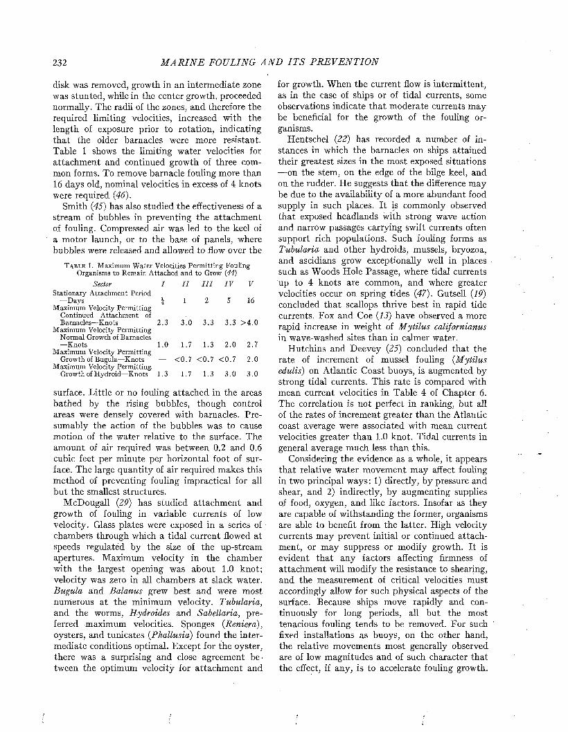
232 M A R I N E FOULING A N D I T S P R E V E N T I O N
disk was removed, growth in an intermediate zone was stunted, while in the center growth, proceeded normally. The radii of the zones, and therefore the required limiting velocities, increased with the length of exposure prior to rotation, indicating that the older barnacles were more resistant. Table 1 shows the limiting water velocities for attachment and continued growth of three common forms. To remove barnacle fouling more than 16 days old, nominal velocities in excess of 4 knots were required (46).
Smith (45) has also studied the effectiveness of a stream of bubbles in preventing the attachment of fouling. Compressed air was led to the keel of a motor launch, or to the base of panels, where bubbles were released and allowed to flow over the
T a b l e 1. Maximum Water Velocities Permitting Fouling Organisms to Remain Attached and to Grow (44)
Sector I I I I I I I V VStationary Attachment Period
—Days j 1 2 5 16Maximum Velocity Permitting
Continued Attachment ofBarnacles—Knots 2 .3 3 .0 3 .3 3 .3 > 4 .0
Maximum Velocity Permitting Normal Growth of Barnacles—Knots 1.0 1.7 1.3 2 .0 2.7
Maximum Velocity PermittingGrowth of Bugula—Knots — < 0 .7 < 0 .7 < 0 .7 2.0
Maximum Velocity Permitting,Growth of Hydroid—Knots 1.3 1.7 1.3 3 .0 3 .0
surface. Little or no fouling attached in the areas bathed by the rising bubbles, though control areas were densely covered with barnacles. Presumably the action of the bubbles was to cause motion of the water relative to the surface. The amount of air required was between 0.2 and 0.6 cubic feet per minute per horizontal foot of surface. The large quantity of air required makes this method of preventing fouling impractical for all but the smallest structures.
McDougall (29) has studied attachment and growth of fouling in variable currents of low velocity. Glass plates were exposed in a series of chambers through which a tidal current flowed at speeds regulated by the size of the up-stream apertures. Maximum velocity in the chamber with the largest opening was about 1.0 knot; velocity was zero in all chambers at slack water. Bugula and Balanus grew best and were most numerous at the minimum velocity. Tubularia, and the worms, Hydroides and Sabellaria, preferred maximum velocities. Sponges (Reniera), oysters, and tunicates (Phallusia) found the intermediate conditions optimal. Except for the oyster, there was a surprising and close agreement between the optimum velocity for attachment and
for growth. When the current flow is intermittent, as in the case of ships or of tidal currents, some observations indicate that moderate currents may be beneficial for the growth of the fouling organisms.
Hentschel (22) has recorded a number of instances in which the barnacles on ships attained their greatest sizes in the most exposed situations — on the stem, on the edge of the bilge keel, and on the rudder. He suggests that the difference may be due to the availability of a more abundant food supply in such places. It is commonly observed that exposed headlands with strong wave action and narrow passages carrying swift currents often support rich populations. Such fouling forms as Tubularia and other hydroids, mussels, bryozoa, and ascidians grow exceptionally well in places such as Woods Hole Passage, where tidal currents up to 4 knots are common, and where greater velocities occur on spring tides (47). Gutsell (19) concluded that scallops thrive best in rapid tide currents. Fox and Coe (13) have observed a more rapid increase in weight oí Mytilus californianus in wave-washed sites than in calmer water.
Hutchins and Deevey (25) concluded that the rate of increment of mussel fouling (Mytilus edulis) on Atlantic Coast buoys, is augmented by strong tidal currents. This rate is compared with mean current velocities in Table 4 of Chapter 6. The correlation is not perfect in ranking, but all of the rates of increment greater than the Atlantic coast average were associated with mean current velocities greater than 1.0 knot. Tidal currents in general average much less than this.
Considering the evidence as a whole, it appears that relative water movement may affect fouling in two principal ways: 1) directly, by pressure and shear, and 2) indirectly, by augmenting supplies of food, oxygen, and like factors. Insofar as they are capable of withstanding the former, organisms are able to benefit from the latter. High velocity currents may prevent initial or continued attachment, or may suppress or modify growth. It is evident that any factors affecting firmness of attachment will modify the resistance to shearing, and the measurement of critical velocities must accordingly allow for such physical aspects of the surface. Because ships move rapidly and continuously for long periods, all but the most tenacious fouling tends to be removed. For such fixed installations as buoys, on the other hand, the relative movements most generally observed are of low magnitudes and of such character that the effect, if any, is to accelerate fouling growth.
FACTORS I N F L U E N C I N G A T T A C H M E N T A N D A D H E R E N C E 233
There is general agreement in attributing this better growth to the increased supply of food and oxygen, and the more effective removal of metabolic wastes.
TEXTURE OF THE SURFACEThere has always been an effort to produce
paints with a smooth surface in order to keep the frictional resistance of the ship to a minimum. It has been postulated that barnacles will be unable to attach to perfectly smooth surfaces (33), and this has been suggested as a means of preventing fouling.
Wharton (55) has calculated that the pressure developed by the vacuum cup on the antennae of the cyprid barnacles is of the order of one dyne. He postulates that the cup would be least effective on a surface having projections less than 15 microns, but more than 0.1 micron in size, since these would permit water to flow into the cup, thus breaking the suction. The ultimate attachment of the barnacle, however, is by means of a cemented bond, and moderately rough surfaces should increase the strength of this bond.
The texture of the surface does indeed affect the amount of fouling which may attach under comparable conditions. Coe and Allen (6) found that cement blocks were generally more densely populated with fouling forms than wood. Pomerat and Weiss (38) studied the attachment of barnacles and other fouling forms to various types of surfaces at Miami, Florida, and found that smooth, non- porous, non-fibrous surfaces, especially if also hard, were relatively poor collectors of sedentary organisms. The surface most heavily fouled was asbestos board, with 980 barnacles on an area of one square foot after three months’ immersion. The most heavily fouled wooden surface had 748 barnacles per square foot. Under the same conditions, celluloid and methacrylate plastics collected only 11 barnacles, and smooth glass only 16. Glass panels with roughened surfaces were more densely fouled. The results of their exposures, given in Table 2, show that the quantity of fouling on different types of surfaces, simultaneously exposed, varies greatly. In designing experiments to study other factors which may influence attachment, it is necessary to use the same type of surface throughout.
The smoothness of the surface does not seem to offer any promise for the prevention of fouling. Though it may contribute to the success of certain preparations, it alone is not adequate to provide complete protection.
T a b l e 2 . Effect of Composition of Surface on Fouling All materials were applied to, or mounted on, wood unless other
wise noted. Exposed at South Dock, Belle Isle, Miami Beach, Florida, January 9, 1943 to April 9, 1943.
After Pomerat and Weiss (38).
Weight of Fouling*
Composition of Wet D ry Number*of
BarnaclesSurface Grams Grams
PlasticsPlasticel 24 12 124Isobutyl Methacrylatef 15 7 70Formica 7 3 11Luci te 6 2 41Celluloid 4 2 11
GlassPrestlite 57 25 176Pentecor 46 25 148Sandblasted 24 7 46Smooth 5 2 16
P ain ts b" IngredientsAsphaltum 121 34 768Asphaltum Varnish 68 14 256Anticorrosive (42A) 48 11 156Spar Varnish 45 7 304N avy Grey 42 6 150Paraffin 11 6 59
WoodsGum (60 days soaked) Dade Co. Pine
452 133 686
(60 days soaked) 395 121 748Gum (unsoaked) 250 44 222Madeira 174 84 358Dade Co. Pine (unsoaked) 144 27 125Teak 144 89 306Greenheart 77 41 342Soft Pine 58 12 184Balsa 3 2 5
MetalsSteel 224 43 88Nickel 43 11 126Lead 31 51 396Galvanized Iron 3 1 6Monel 2 1 6Zinc 1 — 0
MiscellaneousAsbestos 284 66 980Masonite i in.
(heat tempered) 138 32 594Linoleum 80 23 193Sole Leather 3)2 12 66Canvas #10 5 2 7
* Corrected to an area of 144 square inches, t Applied to glass panel.
EFFECT OF G R A V IT YNumerous experiments have shown that many
organisms, including the larvae of fouling organisms, react in a definite way to the force of gravity. For the fouling organisms this is shown by the relative intensity of fouling on panels hung in the sea at various angles.- In general, the underside of a horizontal surface accumulates more fouling than surfaces exposed at any other angle. This response was found for the larvae of the Pacific Coast oyster Ostrea lurida by Hopkins (24). This larva swims with its dorsal or attaching sur
234 M A R I N E FOULING A N D I T S P R E V E N T I O N
face upwards, and Hopkins concluded that they were thus more able to attach to the underside of an exposed surface, since they reached it in the proper position.
Other organisms also accumulate most heavily on the underside of exposed surfaces, as shown by the data in Table 3 (29, 37). M ost of the organisms observed were present in greatest numbers on the undersides of plates which were horizontal or at an
T a b l e 3. Populations of Fouling Organisms Collected on Panels Exposed at Various Angles in the Sea
The orientation is as follows. 0° (under side horizontal plate), 45° (under side 45° plate), 90° (vertical plate, both sides
averaged), Í3S° (upper side 45° plate), 180°(upper side horizontal plate)
Numbers Attached to Plates Suspended at Various Angles
Organism 0° 45° 90° 135° 180° Reference
Acanthodesiatenuis
Electrahastingseae
BarnaclesBivalvesHydroids
Balanuseburneus
Bugula841 426 293 183 42 2
neritinaHydroides
446 298 34 9 2 2
hexagonusPhallusia
776 204 96 30 10 2
hygomianaPerophora
63 28 0 0 0 2
viridesSabellaria
212 S 1 17 3 2
vulgaris 2 22 40 321 390 2
1 Pomerat & Reiner {37) at Pensacola, Florida. Exposure for 23 days. Numbers are for an area of 60 square inches.
2 McDougall {29) at Beaufort, North Carolina. Exposed 88 days. Numbers are for area of 48 square inches.
angle of 45°. In contrast, the distribution of the polychaete Sabellaria vulgaris at Beaufort was just the opposite of the other forms. McDougall (29) states that the larvae of this species are apparently specially adapted to survive under conditions of heavy sedimentation. Although Table 3 indicates that Balanus eburneus is most apt to settle on the undersides of horizontal and 45° surfaces, Pomerat and Reiner (37) found that this distribution was not invariable. In many of their exposures this barnacle was nearly equally distributed on surfaces at all angles. When the larvae attaching in any brief interval were counted, approximately equal populations were found on the top and bottom of the horizontal plates. The further accumulation of larvae on the bottom increased steadily, whereas the population on the top surface in
165 125 7 3 6 1
32 51 3 3 0 1217 23 19 ■ 4 5 1165 26 1 0 2 1
11 4 1 1 2 1
creased more slowly and irregularly. At Beaufort, McDougall found that the top surface of the horizontal panel (180°) was generally covered with a layer of sediment, which might make it difficult for the cyprid larvae to attach or survive.
It can be concluded from these observations that most organisms accumulate more heavily on the underside of an exposed surface, perhaps because of a geo tropic response. This effect, combined with the response of the larvae to light, probably accounts for the heavier animal fouling observed on the areas of ships between the bilges.
LIGH T AND ILLUMINATION
The larvae of fouling organisms are sensitive to light, and many of them tend to accumulate on darker surfaces. This reaction results in a distribution of organisms similar to that produced by gravity, since the underside of structures is also the most shaded. The plant forms, on the other hand, require light for photosynthesis, and accumulate on lighter colored surfaces in regions where the illumination is adequate for their growth. The tunicate larvae are negatively phototropic when attaching (16, 17). The larvae of Bugula are positively phototropic when first released, but become negative prior to attachment (31, 57, 58). Riley has shown that these larvae are stimulated to attach earlier than normal in dilute copper solutions, and they may then attach while still positively phototropic (39). The cyprid larvae of barnacles are also positively phototropic at first, and are most sensitive to green light (530- 545p /jl.) when different wave lengths are tested at equal intensities (51). At the time of attachment they are negative to light, and tend to move to darker areas and settle with the head end away from the source of illumination (29, 49).
Under natural conditions the greatest fouling is generally found on the least illuminated or darker colored surfaces. McDougall (29) observed that, when a series of boxes were illuminated through glass plates of various sizes, the larvae of most species tended to attach most abundantly in the two darker chambers. The Pelecypoda and the sponge, Reneira, however, did not accumulate most heavily in the two darker chambers. These observations are reproduced in Table 4,
Visscher (50) observed in experiments with unglazed colored tiles that the lighter colors always developed srnaller populations of fouling; in some experiments the population was only one-third that which developed on darker surfaces. Results

FACTORS I N F L U E N C I N G A T T A C H M E N T A N D A D H E R E N C E 235
with glazed tiles were contradictory, which was attributed to the reflection of light from the surface. Edmondson and Ingram (11) found that the white and green colors were more effective in discouraging attachment than the darker ones, when various paints and colored glass were exposed at Hawaii. Little difference, however, is observed, regardless of the color, after two or three months’ exposure.
Pomerat and Reiner (37) experimented with black, clear, and opal glass panels at Pensacola,
It has been questioned whether the effects described above result from a true phototropic response in which the organism is guided away from the surface by the direction of the light, or whether the larva is inhibited from attachment by the general intensity of illumination. Whitney (60) and Schallek (41) maintain that, under normal aquatic conditions, light is diffused and has only a small directional component. In a diffused light, reaching the organism with equal intensity from all directions, no phototropism could occur. In an
T a b l e 4 . Numbers of Organisms Attaching in Chambers of a Light Box in Which the Illumination Progressively Decreased from Chamber No. 1 to No. 6. Exposed May 10 to August 29, 1941. After McDougall (29).
Chamber Balanus Bugula Schizoporella Hydroides Sabellaria RenieraNumbers eburneus neritina unicornis hexagonus vulgaris Pelecypoda tubifera
1 173 426 11 958 64 461 112 154 339 4 1,016 48 216 173 248 541 13 892 68 260 184 46 570 19 1,146 64 ' 211 235 219 837 30 1,436 64 248 156 318 696 23 2,072 144 374 20
Florida. About twice as many barnacles were found on the black plates as on the opal or clear plates. These experiments were extended by determining attachment on moonless nights between 9 p .m . and 3 a .m . During this period of minimum illumination, remarkably similar numbers were found on the three kinds of glass. The total attachm ent to four plates (27.2 sq. in. each) in four of these nighttime experiments was 341 on black, 393 on opal, and 394 on clear glass.
Phelps (36) exposed panels under conditions which partially differentiated between the effects of gravity and of light. Some panels were suspended horizontally under a covered barge, where visual observations of the panels in situ showed that there was more light on the bottom of the panels than on the top. More barnacles were found attached to the top of these painted panels, and equal numbers of larvae attached to the top and bottom of the glass panels. These results indicate that when the effects of light and gravity are opposed, the organisms react primarily to light. When the clear glass panels were hung under the barge at night, however, more cyprids collected on the underside than on the top. When light was at a minimum, therefore, the organisms reacted to gravity. Panels exposed at the side of the barge during daylight collected more barnacles on the bottom of both glass and painted panels. The undersurface of these panels was also the more shaded, and the relations to light and to gravity are supplementary. These results are summarized in Table 5.
attempt to study this problem Gregg exposed black and opal glass panels which were surrounded by borders of black, opal, or transparent glass. The numbers of cyprid larvae attaching showed no correlation with the degree of contrast between the collector and the background. A decrease in the intensity of general illumination in the area occupied by the collector was found to increase the attachment. Gregg (18) suggested that “shading” acts as a stimulus which brings about favorable physiological conditions for the subsequent attachment of barnacle larvae.
Weiss (53) has extended these observations by studying the diurnal variation in attachment and the effect of artificial illumination at night on the attachment. He employed glass plates coated on the backside with a dark red paint. Greater numbers of larvae attached during the daylight hours than during the previous and succeeding nights. Artificial illumination of the panels exposed at night increased the numbers of barnacles attaching, so that the normal diurnal variation was nullified. This increase in numbers of attachments was found at light intensities of 0.03 foot-candles or more.
T a b l e 5. Numbers of Cyprids Attaching per sq. cm. to the Top and Bottom Surfaces of Horizontal Glass Panels and
of Steel Panels Painted with 15 RC, Hung Alongside and Under a Covered Barge (36)
Alongside Barge Under Barge
Surface Top Bottom Top BottomGlass .068 .202 .121 .125Painted Steel .262 .629 .770 .549
236 M A R I N E FOULING A N D I T S P R E V E N T I O N
The contrast between the dark collecting surface and the diffuse illumination coming from the surrounding water may give rise to a true phototropic response. In the absence of light at night, the number of cyprids attaching may depend solely on their chance encounters with the surface. When the water appears more luminous than the surface, during daylight or because of artificial illumination, the cyprids may be attracted to the darker area by a true negative phototropic response, and accumulate there in greater numbers.
It has been suggested that the response to illumination could be utilized as a method for the prevention of fouling. While a dark surface accumulates more fouling than a light one, it is also true that the lighter surfaces do not prevent fouling. Visscher (50) and Edmondson and Ingram (11) showed that the lighter colors became as densely fouled in time as the darker, though they foul less when initially exposed. Realizing that the color would have little effect on the numbers of larvae attaching at night, Perry (34, 35) suggested the use of luminous paints which would glow at night and thus prevent attachment at all times. Young (61), however, has exposed luminous paints in the sea and finds them ineffective. Although the color theory of preventing fouling has had great popular appeal, it has found little practical application, because it does not work.
THE USE OF ELECTRICITYVarious suggestions have been made for the use
of electricity in protecting steel ships from both corrosion and fouling. Baggs (2) took out an early patent which covered the use of electricity, however applied, for this purpose. Several more recent patents have been allowed, the most interesting of which is that of Cox (7). This patent claims that the surfaces of steel ships can be made cathodic to protect them from corrosion. Deposits form on the surface under these conditions, and it is claimed that, as these break off, all of the attached fouling will be removed.
An extensive study of the application of electric currents to bare iron and other metals was conducted at Miami by Castle (5), who observed that fouling developed rapidly on cathodes to which current densities of 10-300 milliamperes per square foot were applied. Fouling was delayed on coatings formed by current densities in excess of 300 milliamperes per square foot. The delay or prevention of fouling by the high current densities was attributed to the rapid formation and flaking or sloughing of the deposits formed on the surface.
Castle found no evidence that either a continuous or alternating current kept the larvae away from the electrodes or prevented their attachment. He found no feasible method for electrocuting fouling organisms after attachment, or for preventing their attachment by electrical means. Direct currents of the greatest density obtainable from storage batteries, current from the secondary of an induction coil (the so-called Harvard inductorium), 115-volt 60-cycle alternating current, and the current from the secondary of a 5000-volt transformer delivering 30 milliamperes, were all ineffective in killing barnacles when applied for durations up to 15 minutes. The method of applying sufficient currents to form heavy deposits which could be sloughed at intervals was considered too expensive to be practical.
Harkins (20) has suggested that a surface carrying a negative static charge would result in a poor bond with the barnacle cement. This was based on the observation that the fronds of seaweeds do not ordinarily become fouled. He has overlooked, however, the occurrence of bryozoans, hydroids, and some barnacles, such as Balanus algicola, on seaweeds. Sargassum is commonly heavily encrusted with growths. Certain species of algae, further, are found growing only on other algae. Extracts of algae have been used in antifouling paints with consistently poor results (14, 15, 40).
WETTING OF THE SURFACEIt has been frequently observed that paraffin,
petrolatum, and various wax or grease surfaces do not become fouled rapidly. This action has been attributed to the hydrophobic or nonwettable character of such surfaces, or to the fact that the organisms can not obtain a secure footing on such a surface (12, 42).
Scheer (43) studied the effect of adding various wetting agents to petrolatum, and found that some of these, particularly sulfonated aliphatic compounds, improved the antifouling action of the petrolatum even though they increased the degree by which the surfaces wet with water.
In a study of the prevention of fouling by waxy or non-wetting surfaces, the Naval Research Laboratory (32) prepared 25 compositions employing three samples of petrolatum of different boiling points, a Stearin Pitch Lubricant,1 and a hot plastic paint vehicle,2 each mixed with various proportions of wetting agents. Weldwood panels were coated with these compositions and exposed
1 This contained Stearin Pitch, caustic soda, and mineral oil.2 This vehicle contained rosin, pine oil, cumarone-indene resin, and ceresein
amorphous wax.
FACTORS I N F L U E N C I N G A T T A C H M E N T A N D A D H E R E N C E 237
for fouling tests at Miami Beach, Florida. None of the compositions showed any significant antifouling properties, and all were soft, sloughing from the panels and exposing in some cases large areas of bare wood. The experiment was discontinued after 30 days’ exposure because all of the panels were completely fouled. Similar compositions using a petrolatum base were exposed by investigators of Mellon Institute (30) at Daytona Beach, Florida, on primed steel panels. After six months’ exposure it was concluded that the compositions have little or no effect on fouling by barnacles and filamentous bryozoa,, but did diminish the attachm ent or adhesion of molluscs, encrusting bryozoa, and hydroids, when compared to a nontoxic paint control. None of the wetting agents or even penta- chlorophenol, which is a toxic agent, improved the performances over that given by petrolatum alone. The physical condition of the coatings was very poor, with much of the composition lost after six months’ exposure, and with serious corrosion of the steel panels being evident. Tests of petrolatum at Kure Beach, North Carolina, by LaQue (26) demonstrated considerable suppression of fouling when exposed from November to May. Lanolin and some petrolatum base grease were, however, fouled in the same time.
The evidence available indicates that the waxy or oily surfaces may be effective in preventing the attachment of fouling for a short period of time. This action appears to be erratic and may be the result of the chemical nature of some of the ingredients, or of the unsubstantial character of the surface, rather than of the hydrophobic properties of the surface.
EXFOLIATIONAn exfoliating surface may be defined as one
which disintegrates by loss of particles which are of more than molecular size (i.e., not by solution of ingredients). Such a surface is unsubstantial and offers the organisms an insecure footing. It has frequently been suggested that any fouling organisms which attempt to attach will be sloughed off because of the physical disintegration of the surface. Paints designed to resist fouling in this way would be the underwater counterparts of the chalking house-paints which remain clean by a similar mechanism.
The evaluation of exfoliation as a means of preventing fouling is difficult, since, though there has been much discussion, very few paints have been made and tested to prove its worth. The paints which prevent fouling and have been claimed to do
so by exfoliation all contain some toxic ingredient which may be the effective antifouling agent.
The theoretical explanation of the mechanism by which an exfoliating surface might function has been presented by Wharton (54). I t is based upon the two stages of the attachment of larval barnacles. The first step of attachment is the adhesion of the antennae to the surface. This is first accomplished by means of a vacuum cup arrangement, later supplemented by the secretion of a cement. For some time the antennal attachment is the only method for holding the barnacle to the surface. In the final attachment, however, the calcareous plates become cemented directly to the surface. Wharton postulates that, as the barnacle grows, some pressure may be great enough to pull loose the antennal attachment before the plates become firmly cemented. If the surface is hard and has a loosely adhering surface layer, the barnacle may thus be sloughed off. If the surface is soft, the barnacle is able to penetrate the paint and obtain a firm attachment to the underlying structure, even though the surface layer adheres loosely. If the surface is hard and has no loosely adhering surface layer, the barnacle can maintain its attachment to the outer surface.
This, ingenious explanation of the action of exfoliating paints may apply in the case of the acorn barnacle. It is difficult to see how a similar explanation could be applied to the various other important fouling forms.
Wharton (54) has devised methods for determining whether or not a paint exfoliates. The most ingenious of these involved placing a piece of transparent s:otch tape on the dried paint surface. If some of the paint or surface deposit is removed with the tape, the paint is classified as exfoliating. It was found that it generally takes two or three weeks of soaking in the sea to develop the-exfoliating surface. In tests of 378 paints, 300 were found to have exfoliating surfaces, and most of these, 282, gave satisfactory antifouling performance. The non-exfoliating paints were almost equally divided between satisfactory and unsatisfactory performance. All of the satisfactory paints, however, contained toxic ingredients, and may have been effective for this reason (see Chapter 14).
Young and his collaborators (62) have attempted to test the importance of exfoliation by making a series of paints containing no toxic, in which the content of the pigment, barytes, varied. One paint contained no pigment; the pigment: volume ratio of the others increased up to 6:1. This variation, with a “corresponding observable
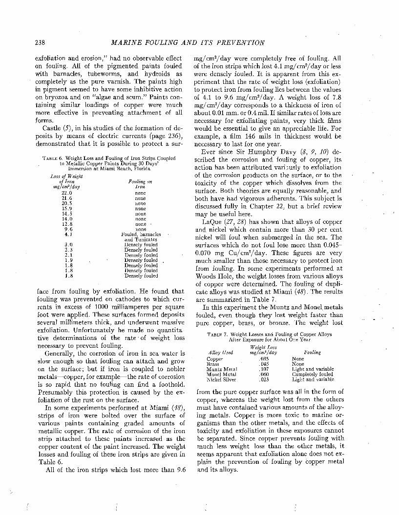
238 M A R I N E FOULING A N D I T S P R E V E N T I O N
exfoliation and erosion,” had no observable effect on fouling. All of the pigmented paints fouled with barnacles, tubeworms, and hydroids as completely as the pure varnish. The paints high in pigment seemed to have some inhibitive action on bryozoa and on “algae and scum.” Paints containing similar loadings of copper were much more effective in preventing attachment of all forms.
Castle (5), in his studies of the formation of deposits by means of electric currents (page 236), demonstrated that it is possible to protect a sur-
T a b l e 6. Weight Loss and Fouling of Iron Strips Coupled to Metallic Copper Paints During 30 Days’
Immersion at Miami Beach, FloridaLoss of Weight
of Iron m g/cm*/day
22.0 21.620.5 15.914.5 14.0 12.89 .64.1
3 .0 2.32.1 1.9 1.8 1.8 1.8
Fouling on Iron none none none none none none none - none
Fouled, barnacles and Tunicates Densely fouled Densely fouled Densely fouled Densely fouled , Densely fouled Densely fouled Densely fouled
face from fouling by exfoliation. He found that fouling was prevented on cathodes to which currents in excess of 1000 milliamperes per square foot were applied. These surfaces formed deposits several millimeters thick, and underwent massive exfoliation. Unfortunately he made no quantitative determinations of the rate ' of weight loss necessary to prevent fouling.
Generally, the corrosion of iron in sea water is slow enough so that fouling can attach and grow on the surface; but if iron is coupled to nobler metals— copper, for example— the rate of corrosion is so rapid that no fouling can find a foothold. Presumably this protection is caused by the exfoliation of the rust on the surface.
In some experiments performed at Miami (48), strips of iron were bolted over the surface of various paints containing graded amounts of metallic copper. The rate of corrosion of the iron strip attached to these paints increased as the copper content of the paint increased. The weight losses and fouling of these iron strips are given in Table 6.
All of the iron strips which lost more than 9.6
m g/cm 2/d a y were completely free of fouling. All of the iron strips which lost 4.1 m g/cm 2/d a y or less were densely fouled. It is apparent from this experiment that the rate of weight loss (exfoliation) to protect iron from fouling lies between the values of 4.1 to 9.6 m g/cm 2/d ay . A weight loss of 7.8 m g/ cm2/d a y corresponds to a thickness of iron of about 0.01 mm. or 0.4 mil. If similar rates of loss are necessary for exfoliating paints, very thick films would be essential to give an appreciable life. For example, a him 146 mils in thickness would be necessary to last for one year.
Ever since Sir Humphry D avy (<?, 9, 10) described the corrosion and fouling of copper, its action has been attributed variously to exfoliation of the corrosion products on the surface, or to the toxicity of the copper which dissolves from the surface. Both theories are equally reasonable, and both have had vigorous adherents. This subject is discussed fully in Chapter 22, but a brief review may be useful here.
LaQue (27, 28) has shown that alloys of copper and nickel which contain more than 30 per cent nickel will foul when submerged in the sea. The surfaces which do not foul lose more than 0.045-0.070 mg Cu/cm2/d ay . These figures are very much smaller than those necessary to protect iron from fouling. In some experiments performed at Woods Hole, the weight losses from various alloys of copper were determined. The fouling of duplicate alloys was studied at Miami (48). The results are summarized in Table 7.
In this experiment the Muntz and Monel metals fouled, even though they lost weight faster than pure copper, brass, or bronze. The weight lost
T a b l e 7. Weight Losses and Fouling of Copper Alloys After Exposure for About One Year
A lloy Used Copper BrassMuntz Metal Monel Metal Nickel Silver
Weight Loss m g/cm ï/day
.035
.045
.107
.060
.023
FoldingNoneNoneLight and variable Completely fouled Light and variable
from the pure copper surface was all in the form of copper, whereas the weight lost from the others must have contained various amounts of the alloying metals. Copper is more toxic to marine organisms than the other metals, and the effects of toxicity and exfoliation in these exposures cannot be separated. Since copper prevents fouling with much less weight loss than the other metals, it seems apparent that exfoliation alone does not explain the prevention of fouling by copper metal and its alloys.

FACTORS I N F L U E N C I N G A T T A C H M E N T A N D A D H E R E N C E 239
The results of the tests of exfoliation indicate that, whereas fouling can be completely prevented by this process, it is a wasteful mechanism and would require very thick applications in order to afford prolonged protection. The fact that no paints have been discovered which prevent fouling by this mechanism alone indicates that it has not been found very useful by the paint technologist in the design and formulation of antifouling paints.
SLIM E OR PR IM A R Y FILM SA surface exposed in the sea becomes coated
within a few days with a thin gelatinous or slimy film. These films are formed by bacteria and diatoms, and include considerable amounts of organic and inorganic detritus (23, 52, 56, 63-67). Several investigators have suggested that the presence of the slime film influences the subsequent attachment of macroscopic fouling forms. Information has accumulated which indicates that the presence of the slime film on nontoxie surfaces is favorable for the attachment of fouling organisms. This is discussed in Chapter 4.
The slime film was first studied in relation to the control of fouling by Bray (4), who exposed a large series of paints and observed that they slimed to markedly different degrees. Those paints which formed the heaviest slimes ultimately became the most fouled. Several later investigators have claimed a correlation between the amount of slime film and the tendency of surfaces to foul (23, 56- 59), but the evidence for any such correlation is not convincing. Adamson (1) pointed out that different types of slimes form on different paints, and stated that the gelatinous slimes seem to discourage attachment, whereas the silty, granular slimes permit- attachment.
ZoBell (67) studied the attachment of barnacle larvae to glass panels and concluded that the slime formed a beneficial substrate for their attachment. He suggested that the slime might favor fouling in a variety of ways: by enmeshing the larvae; by discoloring glazed or bright surfaces; by serving as a source of food; by protecting the organisms from the toxic constituents of poisonous paints; by increasing the alkalinity and thus favoring deposition of calcareous cements; or by influencing the potential of the surface.
On antifouling surfaces the slime has been stated variously to favor, to interfere with, or to have no effect on the attachment of fouling forms. Much of the confusion has resulted from the use of a variety of different paints having different toxic properties. In the early investigations it was
impossible to differentiate between the contribution of the slime and the toxicity of the surface. With the development of the leaching rate technique as an independent measure of toxicity, it became apparent that the slime film might contribute to the effectiveness of an antifouling paint by influencing its toxicity. This is discussed in detail in the next chapter, which includes other investigations of the toxicity of metallic poisons to organisms.
REFERENCES1. A d a m s o n , N. E. Technology of Ship Bottom Paints and Its
Importance to Commercial and Naval Activities. Bureau Construction and Repair Bull. No. 10, XJ. S. Govt. Printing Office. 1937.
2. B a g g s , J. British Patent 2295. September, 1863.3. B e n g o u g h , G. D., and V. G. S h e p h e a r d . The Corrosion and
Fouling of Ships. Jour. Inst. Iron & Steel, 147, 339-451. 1943.
4. B r a y , A. W. L. A Preliminary Investigation into the Foulingof Ships’ Bottoms by Marine Growth. Bureau Construction and Repair, U. S. Navy Dept., 1923. (Unpublished.)
5. C a s t l e , E. S. Electrical Control of Marine Fouling. Ind. andEng. Chem., 43, 901-904. 1951.
6. C o e , W. R., and W. E. A l l e n . Growth of Sedentary MarineOrganisms on Experimental Blocks and Plates for Nine Successive Years at the Pier of the Scripps Institution of Oceanography. Bull. Scripps Inst. Oceanog., Tech. Ser., 4, 101-136. 1937.
7. Cox, G. C. Anticorrosive and Antifouling Coating and Methodof Application. U. S. Patent 2,200,469. 1940.
8. D a v y , S i r H u m p h r y . On the Corrosion of Copper Sheathingby Sea Water, and on Methods of Preventing this Effect; and on their Application to Ships of War and other Ships. Phil. Trans. Roy. Soc. London, 114, 151-158. 1824.
9. D a v y , S i r H u m p h r y . Additional Experiments and Observations on the Application of Electrical Combinations to the Preservation of the Copper Sheathing of Ships, and to Other Purposes. Phil. Trans. Roy. Soc. London, 114, 242-246. 1824.
10. D a v y , S ir H u m p h r y . Further Researches on the Preservation of Metals by Electro-chemical Means. Phil. Trans. Roy. Soc. London, 115, 328-346. 1825.
11. E d m o n d s o n , C. H., and W. H. I n g r a m . Fouling Organisms inHawaii. Bernice P. Bishop Mus., Occas. Papers 14 (14), 251-300. 1939.
12. Fox, D. L. Personal Communication.13. Fox, D. L., and W. R. C o e . Biology of the California Sea
Mussel (M ytilus californianus). II, Nutrition, Metabolism, Growth and Calcium Deposition. J. Exp. Zool., 93, 205- 249. 1943.
14. G a r d n e r , H. A. Letter to Bureau of Yards and Docks, July27, 1934; August 23, 1934; November 7, 1934. (Unpublished.)
15. G a r d n e r , H. A. Letter to Bureau of Construction and Repair.Report on Brief Exposure of Paints, January 4, 1935. (Unpublished.)
16. G r a v e , C. A. Continuation of Study on the Influence of Lighton the Behavior and IVJetamorphosis of the Larvae of Ascidians. Yearbook Carnegie Inst. Wash., 27, 273-275;28, 284-286. 1928-1929.
17. G r a v e , C. A. Notes o n the Culture o f Eight Species o f Ascidians, 560-564 in Culture Methods for-Invertebrate Animals. Comstock Publ. Co., Inc., Ithaca, N . Y. 1937.
18. G r e g g , J. H. Background Illumination as a Factor in theAttachment of Barnacle Cyprids. Biol. Bull., 88, 44 -49. 1945.
240 M A R I N E FOULING A N D I T S P R E V E N T I O N
19. G u t s e l l , J. S. Natural History of the Bay Scallop. Bull.U. S. Bur. Fish., 46, 569-632. 1930.
20. H a r k i n s , H. H. Theory of Fouling. Letter to Bureau ofShips. July 22, 1941. (Unpublished.)
21. H a r r is , J. E., and W. A. D. F o r b e s . Under-water Paints andthe Fouling of Ships, with Reference to the Work of the Marine Corrosion Sub-committee of the Iron and Steel Institute and the Admiralty Corrosion Committee. Inst. Nav. Arch., London. April 12, 1946.
22. H e n t s c h e l , E. Der Berwichs an Seeschiffen. Int. Rev. Hy-drobiol. Hydrogr., 11, 238-264. 1923.
23. H e r p i n , R., and R. D u l i s c o u e t . Le rôle d’une membranemicrobienne dans l’efficacité des peintures destinées à protéger les carènes de bateaux contre les organismes encrassants. Compt. rend. Acad. Sei. (Paris), 207, 193-195. 1938.
24. H o p k in s , A. E. Factors Influencing the Spawning and Settingof Oysters in Galveston Bay, Texas. Bull. U. S. Bur. Fish., 47, 57-83. 1931.
25. H u t c h i n s , L. W., and E. S. D e e v e y , J r . Estimation andPrediction of the Weight and Thickness of Mussel Fouling on Buoys. Interim Report I for 1944 from Woods Hole Oceanographic Inst, to Bureau of Ships. 1944. (Unpublished.)
26. L a Q u e , F. L. Personal Communication. 1945.2 7 . L a Q u e , F . L . Bio-fouling Characteristics of Some Common
Metals and Alloys. Report Prepared for the N.D.R.C. Advisory Committee on Marine Coatings and Corrosion. January 2, 1945. (Unpublished.)
28. L a Q u e , F. L., and W. F. C l a p p . Relationships between Corrosion and Fouling of Copper Nickel Alloys in Sea Water. Trans. Electrochemical Soc., 87, 165-184. 1945.
29. M cD o u g a l l , K. D. Sessile Marine Invertebrates at Beaufort,N . C. Ecol. Mon., 13, 321-374. 1943.
30. Mellon Inst. (Norman Ellis). Antifouling Studies for ScrippsInstitution. Special Report, Stoner-Mudge, Inc. Industrial Fellowship No. 258-10. February, 1945. (Unpublished.)
31. M il l e r , M. A. Toxic Effects of Copper on Attachment andGrowth of Bugula neritina. Biol. Bull., 90, 122-140. 1946.
32. Naval Research Laboratory (R. L. Benemelis). Report on aStudy of Non-Toxic Composition for the Prevention of Fouling. (N.R.L. Report #P-2444, Problem #P-90). January 26, 1945. (Unpublished.)
33. O s h im a , S. Research on Antifouling Paints Containing NoMercury. VI-VIII, J. Soc. Chem. Ind. Japan, 38, 170B. 1935.
34. P e r r y , E. The Fouling of Ships’ Bottoms. Pacific MarineReview, 28, 202-203; 244-245. 1931.
35. P e r r y , E. A Study of thé Preventive Effect of Light Colorson the Fouling of Ships’ Bottoms. Paint and Varnish Production Manager, 7, 10-16. 1932.
36. P h e l p s , A. Observations on Reactions of Barnacle Larvae andGrowth of Metamorphosed Forms at Beaufort, N. C., June, 1941, to Sept., 1941. Paper 7, Fourth Report from Woods Hole Oceanographic Inst, to Bureau of Ships. March 27, 1942. (Unpublished.)
37. P o m e r a t , C. M., and E. R. R e i n e r . The Influence of Surface Angle and of Light on the Attachment of Barnacles and Other Sedentary Organisms. Biol. Bull., 82, 14-25. 1942.
38. P o m e r a t , C. M., and C. M. W e i s s . The Influence of Textureand Composition of Surface on the Attachment of Sedentary Marine Organisms. Biol. Bull., 91, 57-65. 1946.
39. R i l e y , G. A. The Toxicity of Heavy Metals to Fouling Organisms. Paper 12, Sixth Report from Woods Hole Oceanographic Inst, to Bureau of Ships. May 1, 1943. (Unpublished.)
40. San Diego. Reports on Exposure of Paints Submitted byH. A. Gardner. January 4-M ay 5, 1935.
41. S c h a l l e k , W. The Reaction of Certain Crustacea to Directand Diffuse Light. Biol. Bull., 84, 98-105. 1943.
42. S c h e e r , B. T. Personal Communications.43. S c h e e r , B. T., and D. L. Fox. Attachment of Sedentary
Marine Organisms to Petrolatum Surfaces. Proc. Soc. Exp. Biol, and Med., 65, 92-95. 1947.
44. Sm it h , F. G. W. The Effect of Water Currents upon Growthof Fouling Organisms Subsequent to Attachment. Interim Report III for 1945 from Woods Hole Oceanographic Inst, to Bureau of Ships. February 19, 1945. (Unpublished.)
45. Sm it h , F. G. W. Mechanical Control of Ship-Bottom Foulingby Means of Air Bubbles. Quart. Jour. Fia. Acad. Sei., 9, Nos. 3-4, 153-161. 1946.
46. S m it h , F. G. W.Effectof Water Currents upon the Attachmentand Growth of Barnacles. Biol. Bull., 90, 51-70. 1946.
47. Su m n e r , F. B., R. C. O s b u r n , and L. J. C o l e . A BiologicalSurvey of the Waters of Woods Hole and Vicinity. Bull. U. S. Bur. Fish., 31, 5-442. 1911.
48. Unpublished Results of Tests Conducted at Miami. These aredescribed in Chapter 22.
49. V i s s c h e r , J. P. Reactions of the Cyprid Larvae of Barnaclesat the Time of Attachment. Biol. Bull., 54, 327-335. 1928.
50. V is s c h e r , J. P. Nature and Extent of Fouling of Ships’Bottoms. Bull. Bur. Fish., 43, 2, 193-252. 1928.
51. V is s c h e r , J. P., and R. H. L u c e . Reactions of the CypridLarvae of Barnacles to Light, with Special Reference to Spectral Colors. Biol. Bull., 54, 336-350. 1928.
52. W a k s m a n , S. A., and Collaborators. Reports from WoodsHole Oceanographic Institution to Bureau of Ships, 1940-1942.
53. W e i s s , C. M. The Effect of Illumination and Stage of Tideon the Attachment of Barnacle Cyprids. Biol. Bull., 93, 240-249. 1947.
54. W h a r t o n , G. W. Report of the Biologist. Norfolk NavyYard. June, 1941-August, 1942.
55. W h a r t o n , G. W. The Primary Attachment of Balanus eburneus. Progress Report of the Biologist, Norfolk Navy Yard. April 19, 1943. (Unpublished.)
56. W h e d o n , W. F. La Jolla Investigations. 1937-1941. NavalBiological Laboratory Investigations. 1941-1943. Reports to Bureau of Ships.
57. W h e d o n , W. F. Investigations Pertaining to the Fouling ofShips’ Bottoms. Semi-Annual Report for 1941-1942 from Naval Biological Lab., San Diego, Cal., to Bureau of Ships. April 30, 1942.
58. W h e d o n , W. F., and Collaborators. Investigations Pertaining to the Fouling of Ships’ Bottoms. Annual Report 1941- 1942 from Naval Biological Lab., San Diego, Cal., to Bureau of Ships. October 24, 1942.
59. W h e d o n , W. F. Investigations Pertaining to the Fouling ofShips’ Bottoms. Annual Report 1942-1943 from Naval Biological Lab., San Diego, Cal., to Bureau of Ships. June, 1943.
60. W h i t n e y , L. V. The Angular Distribution of CharacteristicDiffuse Daylight in Natural Waters. Jour. Mar. Res., 4. 122-131. 1941.
61. Y o u n g , G. H. Personal Communication.62. Y o u n g , G. H., W. K.. S c h n e i d e r , and G. W. Se a g r e n . Anti
fouling Paints—Effect of Inert Pigment on Antifouling Action. Ind. Eng. Chem., 36, 1130-1132. 1944.
63. Z oB e l l , C. E. The Sequence of Events in the Fouling ofSubmerged Surfaces. Fed. Paint Varn. Prod. Clubs, No. 178, 379-385. 1938.
64. Z oB e l l , C. E. The Biological Approach to the Preparationof Antifouling Paints. Scientific Section, National Paint, Varnish and Lacquer Assoc., Circ. 588, 149-163. 1939.
65. Z oB e l l , C. E. The Role of Bacteria in the Fouling of Submerged Surfaces. Biol. Bull., 77, p. 302. 1939.
66. Z oB e l l , C. E. Primary Film Formation by Bacteria andFouling. Collecting Net, 14, 105-106. 1939.
67. Z oB e l l , C. E. Fouling of Submerged Surfaces and PossiblePreventive Procedures. The Biological Approach to the Preparation of Antifouling Paints. Paint, Oil and Chemical Review, 101, 74r-77. 1939
M arine Fouling and Its Prevention, ContributionNo. 580 from the W oods Hole Oceanographic Institute
Copyright 1952 by U. S. N aval Institute, Annapolis, Maryland George Banta Publishing Co., Menasha, WI
CHAPTER 14
The Prevention of Fouling w ith ToxicsThe common antifouling paints contain copper,
mercury, or arsenic compounds in various combinations. It is the toxicity of these materials which prevents fouling. Toxic action implies that some ingredient of the paint is poisonous to the organisms and must either repel their larvae at the time of attachment or kill them before they can attach permanently and grow. Many investigators have recognized that the toxic must be free to dissolve from the paint in order to be absorbed by the attaching organism.
Copper sheathing was the first extensively used antifouling surface. The first well authenticated application of metallic copper sheathing was in 1763 (55), and this early experiment is described in Chapter 11. It was clearly shown by Sir Humphry D avy {16,17) that when metallic copper is coupled to zinc or iron it fails to prevent fouling. When so coupled, the copper does not dissolve in sea water, and no toxic solution is present to kill or repel the organisms.
The first authentic record of the inclusion of a toxic in a paint in order to prevent fouling is a patent issued to William Beale in 1625 (5). Mallet {34) patented an antifouling paint in 1841 in which slightly soluble coatings of poisonous materials were applied. These paints failed because he was unable to control the solution rate. Young {71) clearly stated the dilemma which confronts the formulator of an antifouling paint, which is that an insoluble toxic will be ineffective and a soluble toxic will be washed away to leave an exhausted surface. This dilemma has been resolved by learning how to produce paints from which the toxic dissolves just fast enough to prevent fouling, yet slowly enough to last for several years.
The evaluation of the toxic theory of antifouling action requires investigation of the following questions:
1. Are the salts of heavy metals commonly used in antifouling paints really toxic to fouling organisms? What concentrations are lethal? How do they act?
2. Do these metallic salts dissolve in sea water, and is the rate of solution from the paint adequate to maintain a lethal concentration at the paint surface?
3. Is the prevention of fouling by toxic antifouling paints related to the loss of toxics from the paint?
Later chapters of the book will be devoted to some of these questions, but a brief review of the salient points will be presented here so that an evaluation of the toxic theory of antifouling action can be made.
THE A C T IO N OF T O X IC S ON O R G A N IS M S
Several metallic salts have been reported to be toxic to marine organisms or to their larvae. The concentration at which they are lethal depends both upon the metal tested and upon the organism used. The toxicities of various metallic salts, tested in five different ways, are shown in Table1. Silver, copper, and mercury are rated as highly toxic in all of these tests. Among these three metals, both copper and mercury have proved very effective in antifouling paints. Silver has not been extensively tested, probably because of its excessive cost.
These tests all rate copper as being somewhat more effective than mercury. This experience has not been universally confirmed when salts of these metals are used in antifouling paints. Adamson (I, 3) found that mercury was somewhat more effective than copper, and Pyefinch and M ott {47) found mercury about twice as toxic as copper to the free-swimming cyprid larvae. In general, however, these two metals and their salts have consistently given good results in antifouling paints.
In addition to copper and mercury, salts of zinc, iron, arsenic, and lead have been commonly used in the formulation of paints. Among these, zinc shows evidence of some toxicity but appears to be only about one-fifth as toxic as copper or mercury. The remainder of these salts are even less toxic than zinc.
An example of the effectiveness of various materials in antifouling paints may be taken from an experiment performed by the Naval Research Laboratory. Ten pigments were added to a matrix to give the same volume loading, and the resulting paints were exposed at Miami Beach, Florida. All of the copper and mercury pigments were effective for periods of ten to fifteen months. The paints pigmented with iron powder, zinc dust, zinc oxide, Celite, and Bentonite were more than 50 per cent covered with fouling during the first or second month of exposure. These results, summarized in Table 2, are in complete agreement with the toxicity results quoted above.
241

242 M A R I N E FOULING A N D I T S P R E V E N T IO N
T a b l e 1. Comparative Toxicity to Marine Fouling Organisms of Various Metals in Sea Water SolutionsClarke1 R iley2 R iley3 R ileyi
Lethal to M ussel Lethal to Survival TimeBarnacles Attachment '
Parket* Fouling
on Metal
M etal Tes ted
SilverCompound
Ag-fSCL
2 days m g/l. 0 .4
5 days m g/l. 0.2
50%m g/l.
0.2
A llm g/l.
0 .5
2 hr. m g/l.
0.1
5 hr.m g/l.
0.5 m g/l. hours
0 .4
1.0 m g/l. hours 6 weeks
0 .4
Copper Basic CupricCarbonateCuCl,CuCitrateCuTartrateMetal
0.41
0.600.58 0.17
0 .7 1.0 0.5+ < 0.5 3.7
0
Mercury HgCh 1.0 0.5 0 .9 2 .0 1.0 0.5 4 .0 2.0
Mang mese KMnO,M nS04
0 .98 .0
2.010++ 10+ N /2
Zinc Z n(N 03)2Metal
32 8 5 .0 15.0 10+ 5 22.50.2
Iron FeSO<Metal
5 .010
Arsenic As20 3Alkaline
13 40 10++ 10+ N /2 40
Tin SnCl2Metal
156
Cadmium CdSCh 30 50
Chromium K2Cr20 7 20 10++ 10+ FN FN
Lead PbS04Metal
4010
Aluminum Metal 10
1 References 13, 14. Table gives the concentration of the metal used which killed all barnacles tested in the indicated period.2 Reference 50. Table gives the concentration which prevents the attachment of 50% and 100% of the mussels tested.3 Reference 50. Table gives the concentration which kills all Bugula tested in two and five hours.4 Reference 50. Table gives the time of survival of Bugula in solutions containing 0.5 and 1.0 mg/1. Test conducted for 48 hours; N /2 =half normal at end of test;
FN =few normal at end of test.6 Reference 43. Amount of fouling on various metals after 6 weeks’ exposure in Eel Pond, Woods Hole, Mass. 0 =no fouling; 10=com pletely fouled.
Arsenic has been used frequently in antifouling paints but the results have generally been negative (1, 2, 20). Both arsenic and lead are materials
T a b l e 2 . Times fo r the Attachment of Fouling to Paints Containing Various Pigments
Time in Months to Fall to a Fouling Resistance Rating2 o f
Pigm ent Used1 90% 80% 50%Cu20Copper flake
11 12 1314 14 15
Copper powder 13 15 —
HgO 12 12 15Hg2Cl2 4-8 10-13 —
Iron powder 1 1 1Zinc dust 1 1 1ZnO 1 1 2Celite 1 1 2Bentonite 1 1 1
1 At a pigment loading of 12% by weight in a vehicle consisting of 87% rosin, 12% methyl abietate, 1% Pliolite by weight.
2 Fouling resistance as used here and later in this chapter is measured on 8"X10" panels (500 sq. cm. per side) and is defined as follows: A rating of 95 means that larvae have attached, but no forms are matured. Solitary adult organisms reduce the fouling resistance below 95% one per cent for each individual; colonial forms are judged on the per cent surface area covered. Thus a panel on which five barnacles are growing rates 90%. If 10% of the area is covered with encrusting bryozoans, and five barnacles are present, the panel rates 80%, etc.
which one might expect to be effective toxics because of their action on human beings. Metallic lead probably fails to prevent fouling because a very insoluble deposit forms on its surface when exposed in sea water. Arsenic (As20 3) was found to be ineffective against barnacles by Harris (20). Wehmhoff, Jordan, and Knight (61) found arsenic trioxide ineffective in hot plastic paints, but Paris Green was said to be an effective toxic. Adamson (1) states that arsenic trioxide and orpiment were tried and gave negative results, and Paris Green alone did not prevent fouling. Harris (20) attributes the low effectiveness of Paris Green to its small content of copper.
Copper, mercury, and zinc are also toxic to the bacteria which form the slime him on a surface submerged in the sea. Their toxicity was tested on pure cultures of these periphytic bacteria by placing the cells in solutions containing various amounts of the toxic. The per cent of the strains which were able to live when transferred after 3 to
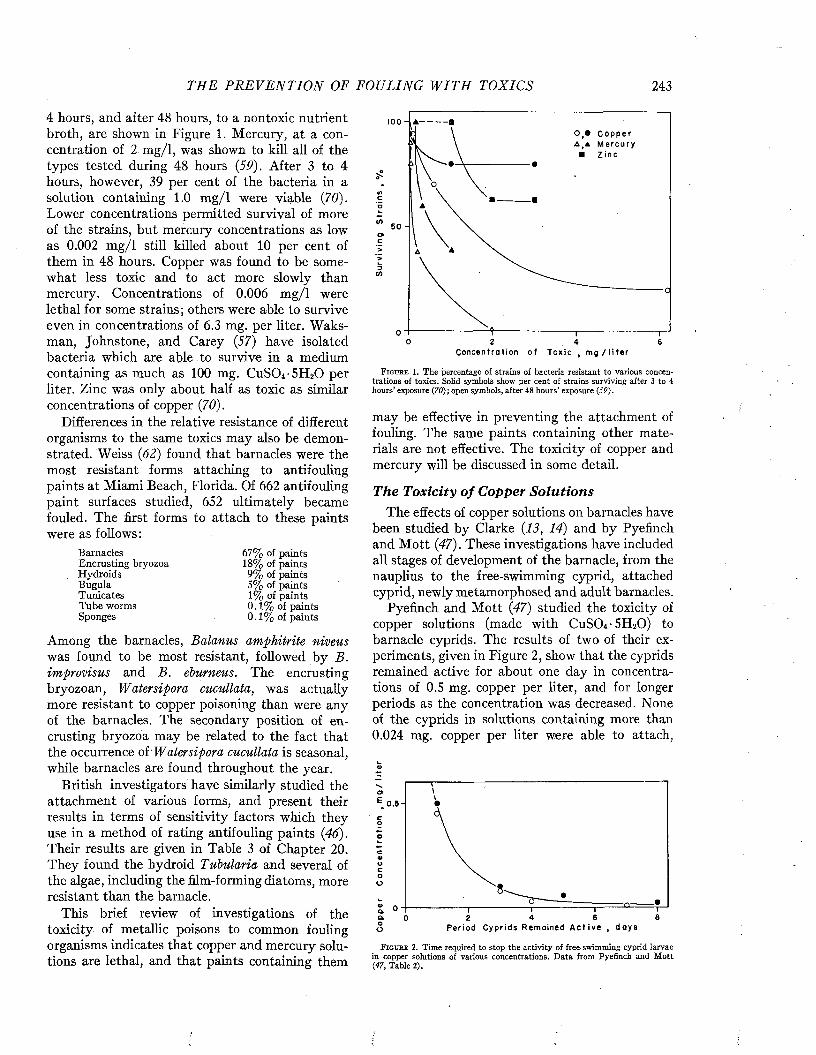
THE P R E V E N T I O N OF FOULING W I T H TOXICS 243
4 hours, and after 48 hours, to a nontoxic nutrient broth, are shown in Figure 1. Mercury, at a concentration of 2 m g/l, was shown to kill all of the types tested during 48 hours (59). After 3 to 4 hours, however, 39 per cent of the bacteria in a solution containing 1.0 m g /l were viable (70). Lower concentrations permitted survival of more of the strains, but mercury concentrations as low as 0.002 m g/l still killed about 10 per cent of them in 48 hours. Copper was found to be somewhat less toxic and to act more slowly than mercury. Concentrations of 0.006 m g/l were lethal for some strains; others were able to survive even in concentrations of 6.3 mg. per liter. Waks- man, Johnstone, and Carey (57) have isolated bacteria which are able to survive in a medium containing as much as 100 mg. CuS04 • 5H20 per liter. Zinc was only about half as toxic as similar concentrations of copper (70).
Differences in the relative resistance of different organisms to the same toxics may also be demonstrated. Weiss (62) found that barnacles were the most resistant forms attaching to antifouling paints at Miami Beach, Florida. Of 662 antifouling paint surfaces studied, 652 ultimately became fouled. The first forms to attach to these paints were as follows:
BarnaclesEncrusting bryozoa Hydroids Bugula Tunica tes Tube worms Sponges
Among the barnacles, Balanus amphitrite niveus was found to be most resistant, followed by B. improvisus and B. eburneus. The encrusting bryozoan, Watersipora cucullata, was actually more resistant to copper poisoning than were any of the barnacles. The secondary position of encrusting bryozoa may be related to the fact that the occurrence of'Watersipora cucullata is seasonal, while barnacles are found throughout the year.
British investigators have similarly studied the attachment of various forms, and present their results in terms of sensitivity factors which they use in a method of rating antifouling paints (46). Their results are given in Table 3 of Chapter 20. They found the b y droid Tubularia and several of the algae, including the film-forming diatoms, more resistant than the barnacle.
This brief review of investigations of the toxicity of metallic poisons to common fo u lin g organisms indicates that copper and mercury solutions are lethal, and that paints containing them
ozO 64
C o n c e n t r a t i o n o f T o x i c t m g / l i t e r
F i g u r e 1. The percentage of strains of bacteria resistant to various concentrations of toxics. Solid symbols show per cent of strains surviving after 3 to 4 hours* exposure (70); open symbols, after 48 hours’ exposure (59).
may be effective in preventing the attachment of fouling. The same paints containing other materials are not effective. The toxicity of copper and mercury will be discussed in some detail.
The T oxicity o f Copper S o lu tion sThe effects of copper solutions on barnacles have
been studied by Clarke (13, 14) and by Pyefinch and M ott (47). These investigations have included all stages of development of the barnacle, from the nauplius to the free-swimming cyprid, attached cyprid, newly metamorphosed and adult barnacles.
Pyefinch and M ott (47) studied the toxicity of copper solutions (made with CuSO-v 5H20 ) to barnacle cyprids. The results of two of their experiments, given in Figure 2, show that the cyprids remained active for about one day in concentrations of 0.5 mg. copper per liter, and for longer periods as the concentration was decreased. None of the cyprids in solutions containing more than 0.024 mg. copper per liter were able to attach,
4)
o
c0)ucoO
oQ.a 82 4 6
P e r i o d C y p r i d s R e m a i n e d A c t i v e , d a y s0
F i g u r e 2. Time required to stop the activity of free-swimming cyprid larvae in copper solutions of various concentrations. Data from Pyefinch and M ott (47, Table 2).
67% of paints 18% of paints 9% of paints 5% of paints 1% of paints 0.1% of paints 0.1% of paints
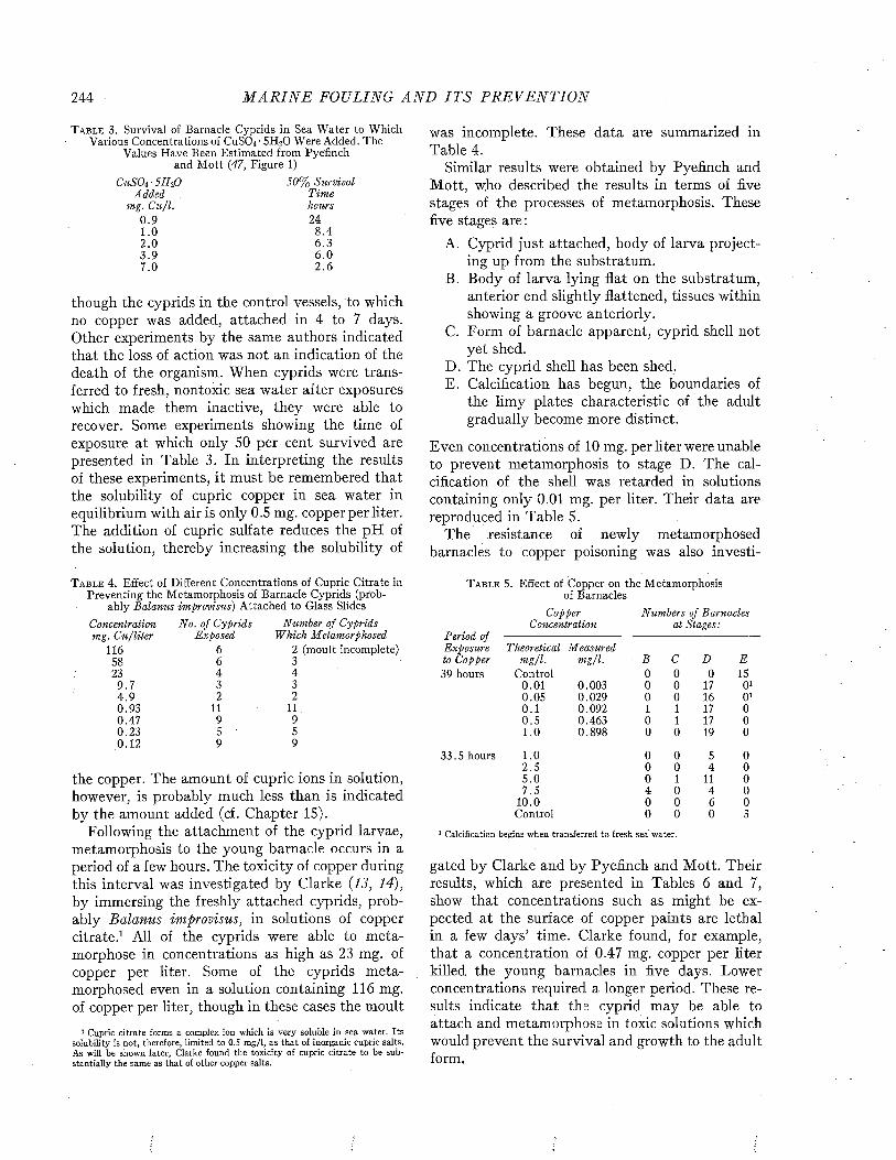
244 M A R I N E FOULING A N D I T S P R E V E N T I O N
T a b l e 3 . Survival of Barnacle Cyprids in Sea Water to Which Various Concentrations of CuSO, ■ 5 H2O Were Added. The
Values Have Been Estimated from Pyefinch and M ott (47, Figure 1)
CuSOi ■ 5HiO 50% SurvivalAdded Time
mg. C u /l. hours0.9 241.0 8 .42.0 6.33.9 6 .07.0 2 .6
though the cyprids in the control vessels, to which no copper was added, attached in 4 to 7 days. Other experiments by the same authors indicated that the loss of action was not an indication of the death of the organism. When cyprids were transferred to fresh, nontoxic sea water after exposures which made them inactive, they were able to recover. Some experiments showing the time of exposure at which only 50 per cent survived are presented in Table 3. In interpreting the results of these experiments, it must be remembered that the solubility of cupric copper in sea water in equilibrium with air is only 0.5 mg. copper per liter. The addition of cupric sulfate reduces the pH of the solution, thereby increasing the solubility of
T a b l e 4. Effect of Different Concentrations of Cupric Citrate in Preventing the Metamorphosis of Barnacle Cyprids (prob
ably Balanus improvisus) Attached to Glass SlidesConcentration No. of Cyprids Number of Cyprids mg. C u /liler Exposed Which Metamorphosed
116 6 2 (moult incomplete)58 6 323 4 4
9 .7 3 34 .9 2 20.93 11 110.47 9 90.23 5 50.12 9 9
the copper. The amount of cupric ions in solution, however, is probably much less than is indicated by the amount added (cf. Chapter 15).
Following the attachment of the cyprid larvae, metamorphosis to the young barnacle occurs in a period of a few hours. The toxicity of copper during this interval was investigated by Clarke (13, 14), by immersing the freshly attached cyprids, probably Balanus improvisus, in solutions of copper citrate.1 All of the cyprids were able to metamorphose in concentrations as high as 23 mg. of copper per liter. Some of the cyprids metamorphosed even in a solution containing 116 mg. of copper per liter, though in these cases the moult
1 Cupric citrate forms a complex ion which is very soluble in sea water. Its solubility is not, therefore, limited to 0.5 m g/l, as that of inorganic cupric salts. As will be shown later, Clarke found the toxicity of cupric citrate to be substantially the same as that of other copper salts.
was incomplete. These data are summarized in Table 4.
Similar results were obtained by Pyefinch and Mott, who described the results in terms of five stages of the processes of metamorphosis. These five stages are:
A. Cyprid just attached, body of larva projecting up from the substratum.
B. Body of larva lying flat on the substratum, anterior end slightly flattened, tissues within showing a groove anteriorly.
C. Form of barnacle apparent, cyprid shell not yet shed.
D. The cyprid shell has been shed.E. Calcification has begun, the boundaries of
the limy plates characteristic of the adult gradually become more distinct.
Even concentrations of 10 mg. per liter were unable to prevent metamorphosis to stage D. The calcification of the shell was retarded in solutions containing only 0.01 mg. per liter. Their data are reproduced in Table 5.
The resistance of newly metamorphosed barnacles to copper poisoning was also investi-
T a b l e 5. Effect of Copper on the Metamorphosis of Barnacles
CopperConcentration
Numbers of Barnacles at Stages:
Period ofExposure Theoretical Measuredto Copper m g/l. m g/l. B c D E39 hours Control 0 0 0 15
0.01 0.003 0 0 17 O10.05 0.029 0 0 16 O10.1 0.092 1 1 17 00 .5 0.463 0 1 17 01.0 0.898 0 0 19 0
33.5 hours 1.0 0 0 5 02.5 0 0 4 05 .0 0 1 11 07.5 4 0 4 0
10.0 0 0 6 0Control 0 0 0 3
1 Calcification begins when transferred to fresh sea water.
gated by Clarke and by Pyefinch and Mott. Their results, which are presented in Tables 6 and 7, show that concentrations such as might be expected at the surface of copper paints are lethal in a few days’ time. Clarke found, for example, that a concentration of 0.47 mg. copper per liter killed the young barnacles in five days. Lower concentrations required a longer period. These results indicate that the cyprid may be able to attach and metamorphose in toxic solutions which would prevent the survival and growth to the adult form.
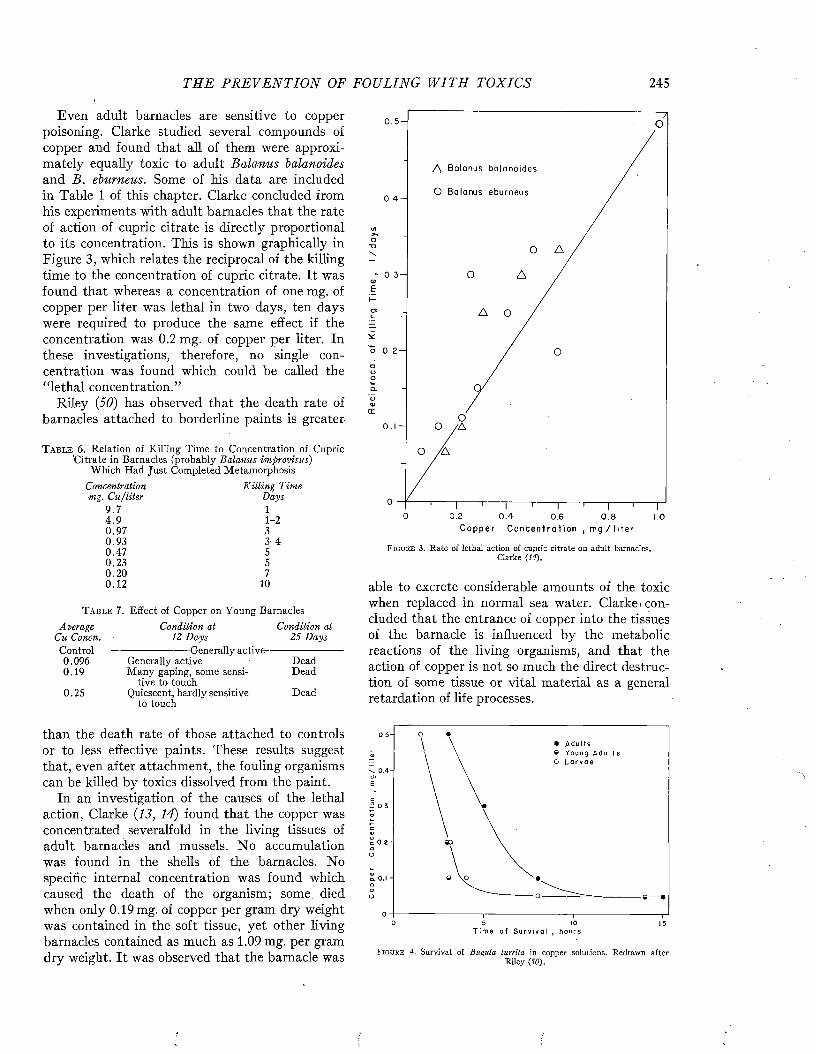
TH E P R E V E N T I O N OF FOULING W I T H TOXICS 245
Even adult barnacles are sensitive to copper poisoning. Clarke studied several compounds of copper and found that all of them were approximately equally toxic to adult Balanus balanoides and B. eburneus. Some of his data are included in Table 1 of this chapter. Clarke concluded from his experiments with adult barnacles that the rate of action of cupric citrate is directly proportional to its concentration. This is shown graphically in Figure 3, which relates the reciprocal of the killing time to the concentration of cupric citrate. It was found that whereas a concentration of one mg. of copper per liter was lethal in two days, ten days were required to produce the same effect if the concentration was 0.2 mg. of copper per liter. In these investigations, therefore, no single concentration was found which could be called the “lethal concentration.”
Riley (50) has observed that the death rate of barnacles attached to borderline paints is greater
T a b l e 6. Relation of Killing Time to Concentration of Cupric Citrate in Barnacles (probably Balanus improvisus)
Which Had Just Completed MetamorphosisConcentration K illin g Timemg. C u/liter Days
9 .7 14 .9 1-20.97 30 .93 3-40 .47 50 .23 50 .20 70 .1 2 10
T a b l e 7. Effect of Copper on Young BarnaclesAverage Condition at Condition at
Cu Concn. 12 D ays 25 DaysC o n t r o l ------------------------Generally-active---------------------0.096 Generally active Dead0.19 Many gaping, some sensi- Dead
tive to touch0.25 Quiescent, hardly sensitive Dead
to touch
than the death rate of those attached to controls or to less effective paints. These results suggest that, even after attachment, the fouling organisms can be killed by toxics dissolved from the paint.
In an investigation of the causes of the lethal action, Clarke (13, 14) found that the copper was concentrated severalfold in the living tissues of adult barnacles and mussels. N o accumulation was found in the shells of the barnacles. No specific internal concentration was found which caused the death of the organism; some died when only 0.19 mg. of copper per gram dry weight was contained in the soft tissue, yet other living barnacles contained as much as 1.09 mg. per gram dry weight. It was observed that the barnacle was
0 . 5 -
A B a l a n u s b a l a n o i d e s
O B a l a n u s e b u r n e u s0 . 4 -
u>o■o\
Q>£
c
o
oooQ.oa>
a :
0 0 .2 0 . 4 0.6 0 .8 1.0C
F i g u r e 3. Rate of lethal action of cupric citrate on adult barnacles. Clarke (14).
able to excrete considerable amounts of the toxic when replaced in normal sea water. Clarke, concluded that the entrance of copper into the tissues of the barnacle is influenced by the metabolic reactions of the living organisms, and that the action of copper is not so much the direct destruction of some tissue or vital material as a general retardation of life processes.
0.5-
° 0.3-
0 .2 - «D
0 5 10 15f SiT
F i g u r e 4. Survival of Bugula turrita in copper solutions. Redrawn after Riley (50).
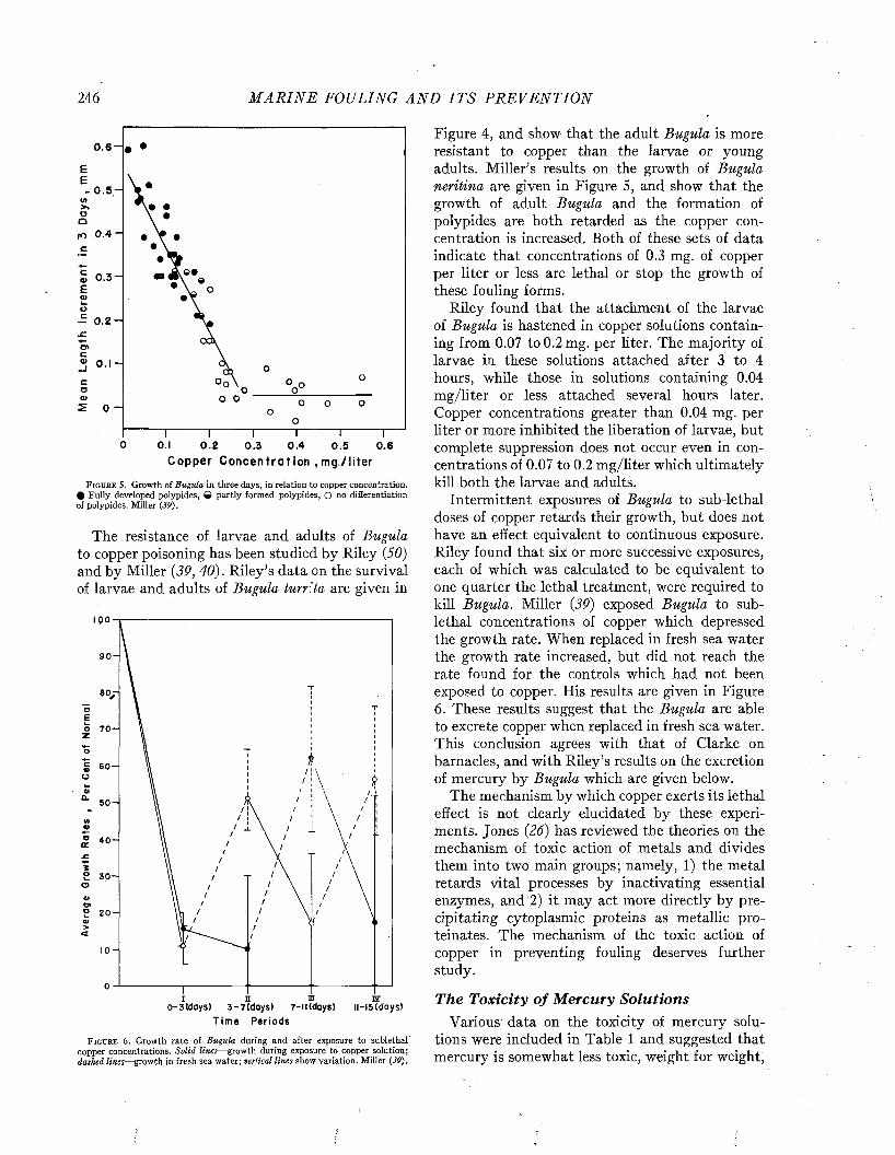
246 M A R I N E FOULING A N D I T S P R E V E N T I O N
0 . 6 -
0 . 5 -
fO 0 .4 -
0 . 3 -
- 0 . 2 -
Ol_1
0 -
0.1 0 . 2 0 .3
Copper Concentration , mg./liter0 .4 0.60 .5
F i g u r e 5. Growth of Bugula in three days, in relation to copper concentration. # Fully developed polypides, Q partly formed polypides, O no differentiation of polypides. Miller (39).
The resistance of larvae and adults of Bugula to copper poisoning has been studied by Riley (50) and by Miller (39y 40). R iley’s data on the survival of larvae and adults of Bugula turrita are given in
100
90-
80-
o 7 0 -
60-
/750-
40-
2 2 0 -
10-
I TL m 3Zo-3tdoys) 3-7(days) 7-ii(days) 11-15 (days)
T i m e P e r i o d s
F i g u r e 6. Growth rate of Bugula during and after exposure to sublethal copper concentrations. Solid lines—growth during exposure to copper solution; dashed lines—growth in fresh sea water; vertical lines show variation. Miller (39).
Figure 4, and show that the adult Bugula is more resistant to copper than the larvae or young adults. Miller’s results on the growth of Bugula neritina are given in Figure 5, and show that the growth of adult Bugula and the formation of polypides are both retarded as the copper concentration is increased. Both of these sets of data indicate that concentrations of 0.3 mg. of copper per liter or less are lethal or stop the growth of these fouling forms.
Riley found that the attachment of the larvae of Bugula is hastened in copper solutions containing from 0.07 to 0.2 mg. per liter. The majority of larvae in these solutions attached after 3 to 4 hours, while those in solutions containing 0.04 m g/liter or less attached several hours later. Copper concentrations greater than 0.04 mg. per liter or more inhibited the liberation of larvae, but complete suppression does not occur even in concentrations of 0.07 to 0.2 m g/liter which ultimately kill both the larvae and adults.
Intermittent exposures of Bugula to sub-lethal doses of copper retards their growth, but does not have an effect equivalent to continuous exposure. Riley found that six or more successive exposures, each of which was calculated to be equivalent to one quarter the lethal treatment, were required to kill Bugula. Miller (39) exposed Bugula to sub- lethal concentrations of copper which depressed the growth rate. When replaced in fresh sea water the growth rate increased, but did not reach the rate found for the controls which had not been exposed to copper. His results are given in Figure 6. These results suggest that the Bugula are able to excrete copper when replaced in fresh sea water. This conclusion agrees with that of Clarke on barnacles, and with Riley’s results on the excretion of mercury by Bugula which are given below.
The mechanism by which copper exerts its lethal effect is not clearly elucidated by these experiments. Jones (26) has reviewed the theories on the mechanism of toxic action of metals and divides them into two main groups; namely, 1) the metal retards vital processes by inactivating essential enzymes, and 2) it may act more directly by precipitating cytoplasmic proteins as metallic pro- teinates. The mechanism of the toxic action of copper in preventing fouling deserves further study.
The T oxicity o f M ercury Solu tionsVarious data on the toxicity of mercury solu
tions were included in Table 1 and suggested that mercury is somewhat less toxic, weight for weight,

THE P R E V E N T I O N OF FOULING W I T H TOXICS 247
than copper to adult barnacles, mussels, and Bugula. Pyefinch and M ott (47) found that mercury was somewhat more toxic than copper to the free-swimming larvae of barnacles. Some of their data on the survival times of barnacle cyprid larvae in mercury solutions are reproduced in Figure 7.
Riley (50) has studied the reactions of Bugula to mercury solutions and found that the rate of accumulation in the tissues is proportional to the concentration of mercury in solution up to about0.5 mg/1. The amount accumulated was estimated both by an analysis of the amount removed from solution and of the amount absorbed by the organism. The amount removed from solution was always somewhat greater than the amount recovered in the tissues, which was attributed to the excretion of mercury in a form which was not measured by the analytical technique.
Riley used two criteria for the death of the organisms exposed to mercury solutions. One of
T a b l e 8. Mercury Present in Tissues of Bugula at Time of Death Estimated by Complete Loss of Motion or Failure to
Recover When Transferred to Fresh Sea Water_________Concentration N o Recovery Loss of Motion
of Hg in Hg. in _ Hg. inSolution Tim e T issues T im e Tissues
m g/g m g/gm g/l. hours dry wt. hours dry wi.1.0 1.5 0.62 2 .5 0.94o .s 2 .6 0.67 3.75 0.830 .3 4 .4 0.71 7 0.840.1 14 0.68 24 0.740.05 28 0.66 36 0.86
these was the failure of the organism to recover when transferred to fresh sea water; the other was the complete loss of motion. The rate of accumulation of mercury during the period required to observe these two was also found to be approximately proportional to the mercury concentration as shown by Figure 8. The total amount accumulated was in both cases very nearly constant. An average of about 0.67 mg/gram dry weight of tissues was required to prevent recovery, and an average of about 0.84 mg/gram dry weight was required to cause complete loss of motion, regardless of the concentration of mercury in the test solution used. R iley’s results, showing the times necessary to produce these effects, and the amounts of mercury accumulated, are given in Table 8.
Riley concluded that: 1) the amount of toxic present in the tissues at the time of death is constant regardless of the concentration in the exposure bath; 2) the rate of accumulation of mercury is a linear function of the concentration of the
20
\
coD
0c4>OCoO
4120
T i m e f o r 5 0 % S u r v i v a l , h ou rs
F igu re 7. Survival of free-swimming barnacle cyprid larvae in sea water containing various amounts of mercuric chloride. Redrawn after Pyefinch & M ott (47).
toxic solution; 3) it follows from 1 and 2 that the rate of action of the toxic is directly proportional to its concentration, except at high concentrations where an avoidance reaction was observed; 4) excretion of mercury occurs both during and after exposure. The total amount excreted, subsequent to sub-lethal exposures, is roughly proportional to the amount of toxic accumulated. M ost of it is excreted in combined form. It is excreted rapidly when the tissues have absorbed more than half the lethal dosage. Below this content it is removed slowly.
The T oxicity o f C om bined Copper and M ercury So lu tions
It has been frequently suggested that mixtures
* 0 .5 -
-oCT>NO*6 0 .4 -
co
o
uo<
° 0 .2 - 4>atra>0>oa>><
0 0 .5 1.0M e r c u r y C o n c e n t r a t i o n , m g / l i t e r
F i g u r e 8 . Average rate of accumulation of mercury by Bugula during the period required for the complete loss of motion, O , and that required to prevent recovery in fresh sea water, Riley (50).

248 M A R I N E FOULING A N D I T S P R E V E N T I O N
1.0 O ,A. % At t achmen t of Mussels
“ 0 .8 -
o~ 0 .6 -
oo 0 .4 -
\ O\
O No A t t a ch m en t © 50 % A t to ch m en t ® 100 % A t t a c h m e n t
\
\\
\
\ O
o
o
\\
\\
0.2-O. \\
\ \\
\ \-V1 I-----
0 .5 1.0 1.5 2 .0Merc u ry C o n c e n t r a t i o n , m g / l l t e r
1.0-
» 0 .8 -
o- 0 .6 -
o 0 .4 O
lO.Z-
\ B. S u rv iv a l T i m e s of B u g u l a \ O 2 hou rs
\ © 2 - 5 h o u r s* 5 — 15 h ou r s• > I 5 h o u r s
\\
\\
\»© «©
\\
9 9 9 9
\\
\ \\ \
\\
\\
® \ 8- 9 ------ ,-------- © -
\\
\\
\-*l-----" I • -----1----------- T-----------T0 0 . 2 0 . 4 0 . 6 0 .8 1 .0
M e r c u r y C o n c e n t r a t i o n , m g / l i t e r
F i g u r e 9. The toxicities of solutions containing both copper and mercury. A gives the percentage of mussels able to attach. B gives the survival times of Bugula. The dashed lines indicate what might be expected if the toxicities are additive. The amount by which the appropriate points deviate from these lines indicates the deviation from strictly additive results. Redrawn after Riley (50).
of copper and mercury are more effective than either used alone. Investigations of the response of mussels and Bugula performed by Riley (50) suggest that the toxicity of mercury and of copper towards these forms is a strictly additive phenomenon proportional to the toxicities of the two ions. Thus, a half lethal dose of copper mixed with a half lethal dose of mercury gives just as toxic a solution as an appropriately stronger dose of either copper or mercury alone. Riley’s observations are given in Figure 9, in which mixtures
giving equivalent results are indicated. Pyefinch and M ott {47) studied the effects of copper and mercury mixtures on the survival of free-swimming barnacle larvae. They concluded that the addition of a small amount of mercury was most effective when added to a sub-lethal copper concentration. Hunter {24) and Barnes and Stanbury (9) describe experiments in which the combined action of copper and mercury was greater than would be expected on a strictly additive basis. Further studies of the toxicities of such mixtures would be desirable.
Paints containing various combinations of copper and mercury toxics in the same matrix were exposed at Miami Beach, Florida. The results are shown in Table 9. All of the paints of this series were effective for periods of 13 months or more. The various proportions of mercury and copper had little or no effect on the duration of satisfactory paint performance.
Alexander and Benemelis {4) describe more extensive results with similar paints. Various proportions of mercury and copper toxics were used to produce paints with equal pigment volumes. The substitution of a mercury toxic for an equal volume of copper toxic frequently produced a much more effective paint. Substitution of copper flake or copper powder for part of the cuprous oxide in some formulations also produced more effective paints, and substitution of some zinc
T a b l e 9. Times for the Attachment of Fouling to Paints Containing Mixtures of Copper and Mercury Compounds
Time in Months to Fall to a Fouling Resistance Rating of
Pigments and Their Proportions*
Cu20 84, HgO 16 Cu20 67, HgO 33 Cu20 33, HgO 67
CuF1 84, HgO 16 CuF1 67, HgO 33 CuF1 33, HgO 67
CuP2 84, HgO 16 CuP2 67, HgO 33 CuP2 33, HgO 67
Cu20 84, Hg2Cl2 16 Cu,0 67, Hg2Cl2 33 Cu20 33, Hg2Cl2 67
CuF1 84, Hg2Cl2 16 CuF1 67, Hg2Cl2 33 CuF1 33, Hg2Cl2 67
CuP2 84, Hg2Cl2 16 CuP2 67, Hg2Cl2 33 CuP2 33, Hg2Cl2 67* The compositions of the paints are given in Table 2, which shows the effective
ness of the paints containing only one pigment.1 CuF =copper flake.2 CuP = copper powder,
90% 80% 50%6-8 13 1513 15 1613 14 15
S 6 1612-14 15 16
is 15 16
15 15 1612-14 15 —
14 15 16
11 11 1211 12 1416 17 —
14 16 —14 — —16 — —
14 16 —16 — —
>1 6 mo. — —
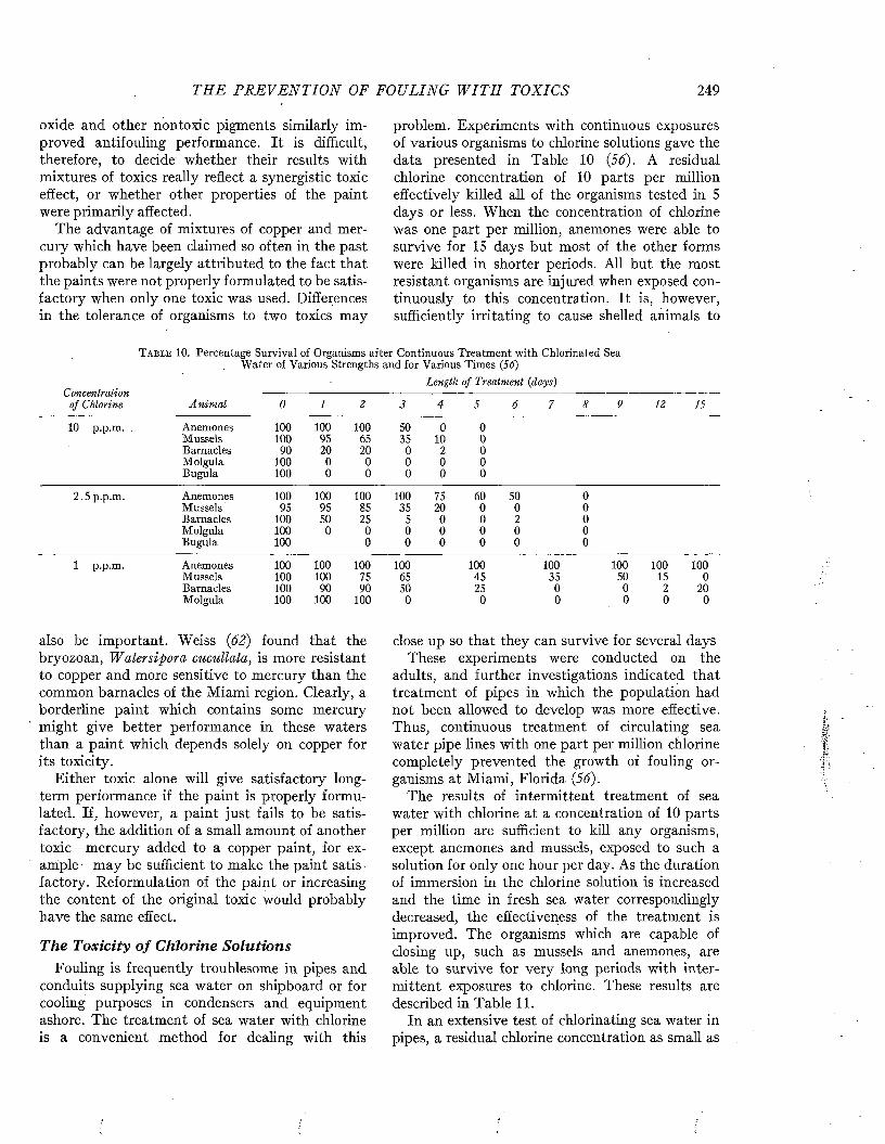
THE P R E V E N T I O N OF FOULING W I T H TOXICS 249
oxide and other nontoxic pigments similarly improved antifouling performance. It is difficult, therefore, to decide whether their results with mixtures of toxics really reflect a synergistic toxic effect, or whether other properties of the paint were primarily affected.
The advantage of mixtures of copper and mercury which have been claimed so often in the past probably can be largely attributed to the fact that the paints were not properly formulated to be satisfactory when only one toxic was used. Differences in the tolerance of organisms to two toxics may
problem. Experiments with continuous exposures of various organisms to chlorine solutions gave the data presented in Table 10 (56). A residual chlorine concentration of 10 parts per million effectively killed all of the organisms tested in 5 days or less. When the concentration of chlorine was one part per million, anemones were able to survive for 15 days but most of the other forms were killed in shorter periods. All but the most resistant organisms are injured when exposed continuously to this concentration. It is, however, sufficiently irritating to cause shelled animals to
T a b l e 10. Percentage Survival of Organisms after Continuous Treatment with Chlorinated Sea Water of Various Strengths and for Various Times (56)
Length uf Treatment (days)
of Chlorine A nim al 0 1 2 3 4 5 6 7 8 9 12 15
10 p.p.m. . Anemones 100 100 100 50 0 0Mussels 100 95 65 35 10 0Barnacles 90 20 20 0 2 0Molgula 100 0 0 0 0 0Bugula 100 0 0 0 0 0
2.5 p.p.m. Anemones 100 100 100 100 75 60 50 0Mussels 95 95 85 35 20 0 0 0Barnacles 100 50 25 5 0 0 2 0Molgula 100 0 0 0 0 0 0 0Bugula 100 0 0 0 0 0 0
1 p.p.m. Anemones 100 100 100 100 100 100 100 100 100Mussels 100 100 75 65 45 35 50 15 0Barnacles 100 90 90 50 25 0 0 2 20Molgula 100 100 100 0 0 0 0 0 0
also be important. Weiss (62) found that the bryozoan, Watersipora cucullata, is more resistant to copper and more sensitive to mercury than the common barnacles of the Miami region. Clearly, a borderline paint which contains some mercury might give better performance in these waters than a paint which depends solely on copper for its toxicity.
Either toxic alone will give satisfactory longterm performance if the paint is properly formulated. If, however, a paint just fails to be satisfactory, the addition of a small amount of another toxic—mercury added to a copper paint, for example— may be sufficient to make the paint satisfactory. Reformulation of the paint or increasing the content of the original toxic would probably have the same effect.
The Toxicity o f Chlorine So lu tionsFouling is frequently troublesome in pipes and
conduits supplying sea water on shipboard or for cooling purposes in condensers and equipment ashore. The treatment of sea water with chlorine is a convenient method for dealing with this
close up so that they can survive for several daysThese experiments were conducted on the
adults, and further investigations indicated that treatment of pipes in which the population had not been allowed to develop was more effective. Thus, continuous treatment of circulating sea water pipe lines with one part per million chlorine completely prevented the growth of fouling organisms at Miami, Florida (56).
The results of intermittent treatment of sea water with chlorine at a concentration of 10 parts per million are sufficient to kill any organisms, except anemones and mussels, exposed to such a solution for only one hour per day. As the duration of immersion in the chlorine solution is increased and the time in fresh sea water correspondingly decreased, the effectiveness of the treatment is improved. The organisms which are capable of closing up, such as mussels and anemones, are able to survive for very long periods with intermittent exposures to chlorine. These results are described in Table 11.
In an extensive test of chlorinating sea water in pipes, a residual chlorine concentration as small as
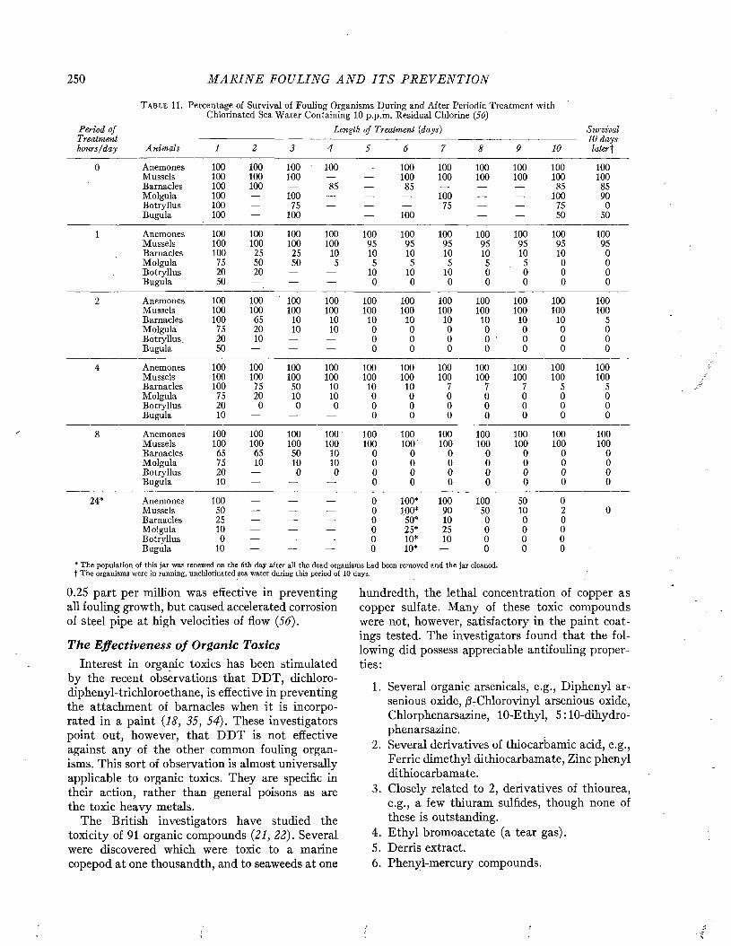
250 M A R I N E FOULING A N D I T S P R E V E N T I O N
Period of
T a b l e 11. Percentage of Survival of Fouling Organisms During and After Periodic Treatment with Chlorinated Sea Water Containing 10 p.p.m. Residual Chlorine (56)
Length of Treatment (days) Survivali Tvaimtnirhours/day Anim als 1 2 3 4 5 6 7 8 9 10
io aays laterf
0 Anemones 100 100 100 100 — 100 100 100 100 100 100Mussels 100 100 100 — — 100 100 100 100 100 100Barnacles 100 100 — 00 in — 85 — — — 85 85Molgula 100 — 100 — — — 100 — — 100 90Botryllus 100 — 75 — — — 75 — — 75 0Bugula 100 — 100 — — 100 — — — 50 50
1 Anemones 100 100 100 100 100 100 100 100 100 100 100Mussels 100 100 100 100 95 95 95 95 95 95 95Barnacles 100 25 25 10 10 10 10 10 10 10 0Molgula 75 50 50 5 5 5 5 5 5 0 0Botryllus 20 20 — — 10 10 10 0 0 0 0Bugula 50 — — — 0 0 0 0 0 0 0
2 Anemones 100 100 100 100 100 100 100 100 100 100 100Mussels 100 100 100 100 100 100 100 100 100 100 100Barnacles 100 65 10 10 10 10 10 10 10 10 5Molgula 75 20 10 10 0 0 0 0 0 0 0Botryllus. 20 10 — — 0 0 0 0 ■ 0 0 0Bugula 50 — — — 0 0 0 0 0 0 0
4 Anemones 100 100 100 100 100 100 100 100 100 100 100Mussels 100 100 100 100 100 100 100 100 100 100 100Barnacles 100 75 50 10 10 10 7 7 7 5 5Molgula 75 20 10 10 0 0 0 0 0 0 0Botryllus 20 0 0 0 0 0 0 0 0 0 0Bugula 10 — — — 0 0 0 0 0 0 0
8 Anemones 100 100 100 100 100 100 100 100 100 100 100Mussels 100 100 100 100 100 100 100 100 100 100 100Barnacles 65 65 50 10 0 0 0 0 0 0 0Molgula 75 10 10 10 0 0 0 0 0 0 0Botryllus 20 — 0 0 0 0 0 0 0 0 0Bugula 10 — — — 0 0 0 0 0 0 0
24* Anemones 100 — — — 0 100* 100 100 50 0Mussels 50 — — — 0 100* 90 50 10 2 0Barnacles 25 — — — 0 50* 10 0 0 0Molgula 10 — — — 0 25* 25 0 0 0Botryllus 0 — — — 0 10* 10 0 0 0Bugula 10 — — — 0 10* — 0 0 0
* The population of this jar was renewed on the 6th day after all the dead organisms had been removed and the jar cleaned, t The organisms were in running, unchlorinated sea water during this period of 10 days.
0.25 part per million was effective in preventing all fouling growth, but caused accelerated corrosion of steel pipe at high velocities of flow (56).
The Effectiveness o f Organic ToxicsInterest in organic toxics has been stimulated
by the recent observations that D D T , dichloro- diphenyl-trichloroethane, is effective in preventing the attachment of barnacles when it is incorporated in a paint (18, 35, 54). These investigators point out, however, that D D T is not effective against any of the other common fouling organisms. This sort of observation is almost universally applicable to organic toxics. They are specific in their action, rather than general poisons as are the toxic heavy metals.
The British investigators have studied the toxicity of 91 organic compounds (21, 22). Several were discovered which were toxic to a marine copepod at one thousandth, and to seaweeds at one
hundredth, the lethal concentration of copper as copper sulfate. Many of these toxic compounds were not, however, satisfactory in the paint coatings tested. The investigators found that the following did possess appreciable antifouling properties:
1. Several organic arsenicals, e.g., Diphenyl ar- senious oxide, /3-Chlorovinyl arsenious oxide, Chlorphenarsazine, 10-Ethyl, 5 :10-dihydro- phenarsazine.
2. Several derivatives of thiocarbamic acid, e.g., Ferric dimethyl dithiocarbamate, Zinc phenyl dithiocarbamate.
3. Closely related to 2, derivatives of thiourea, e.g., a few thiuram sulfides, though none of these is outstanding.
4. Ethyl bromoacetate (a tear gas).5. Derris extract.6. Phenyl-mercury compounds.
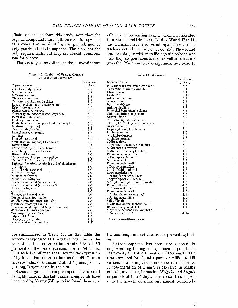
THE P R E V E N T I O N OF FOULING W I T H TOXICS 251
Their conclusions from this study were that the organic compound must both be toxic to copepods at a concentration of IO-5 grams per ml. and be only poorly soluble in naphtha. These are not the only requirements, but they are almost a sine qua non for success.
The toxicity observations of these investigators
T a b l e 12 . Toxicity of Various Organic Poisons After Harris (21)
Organic PoisonToxic Cone.
i-logvs)2 :4 Di-isobutyl phenol 8.2Nitroso m-cresol 8.24-Nitroso o-cresol 8.2Chlorophenarsazine , 8 .0Tetramethyl thiuram disulfide 8.0?Di-p-dimethylamino benzophenone 8.0Ethyl bromoacetate 8 .0Phenyl mercury nitrate 8 .0p-dimethylaminopheny] isothiocyanate 7.0Pyrethrum (stabilized) 7.0Diphenyl arsenic acid 6 .8Pentachlorophenol (copper Pyridine complex) 6 .84-nitroso l:naphthol 6 .8Trichlorovinyl arsine 6.7Phenyl mercury acetate 6.7Acridine 6 .6Pentachlorophenol 6.2p-'dimethylaminophenyl thiocyanate 6.2Derris extract 6.1F erric dimethyl dithiocarbamate 6 .0Zinc phenyl dithiocarbamate 6 .0Di-o-tolyl thiourea 6 .0Tetramethyl thiuram monosulfide 6 .0Tetraethyl thiuram monosulfide 6 .03-phenyl 5-methyl tetrahydro 1 :3 :5-thiadiazine
2-thione 6.02:4:6 Trichlorophenol 6 .0p-Chlor m-xylenol 6 .0Monochlor thymol 6 .0Monochlor isothymol 6 .0Pentachlorophenol (copper salt) 6 .0Pentachlorophenol (mercury salt) 6 .0Aminozoa toluene 6 .0Quinoline 6 .0Thiocyano benzthiazole 5 .9Diphenyl arsenious oxide ftS'-dichloro vinyl arsenious oxide
5.85 .8
p-nitroso dimethyl aniline 5 .8Benzene azo-ß-naphthol (copper complex) 5 .74 : chloro 2:6 dinitro phenol 5 .6Zinc isopropyl xanthate 5.5Diphenyl thiourea 5.5Dodecyl thiocyanate 5.5Phenyl methyl nitrosamine 5.5?
are summarized in Table 12. In this table the toxicity is expressed as a negative logarithm to the base 10 of the concentration required to kill 50 per cent of the test organisms used in 24 hours. This scale is similar to that used for the expression of hydrogen ion concentrations as the pH. Thus, a toxicity index of 6 means that IO“6 grams per ml. (1.0 mg/1) were toxic in the test.
Several organic mercury compounds are rated as highly toxic in this list. Similar compounds have been used by Young (72), who has found them very
effective in preventing fouling when incorporated in a varnish vehicle paint. During World War II, the German Navy also tested organic mercurials, such as methyl mercuric chloride (25). They found that the danger with metallic organic poisons was that they are poisonous to men as well as to marine growths. More complex compounds, not toxic to
T a b l e 12— (Continued
Organic PoisonToxic Cone,
{ - l o g io)N -N amyl benzyl cyclohexylamine 5.5Tetraethyl thiuram disulfide 5 .4Phenothiazine 5 .4Carbazole 5 .4 .p-Dichlorobenzene 5 .4o-cresotic acid 5 .4Nicotine abietate 5 .4Aniline disulfide 5.3N-methyl benzthiazole thione 5 .3Chloronaphthalene (mixed) 5.3Salicy] anilide 5.2ß-Chlorovinyl arsenious oxide 5.010-Ethyl 5:10 dihydrophenarsazine 5.0Arsenobenzene 5.0Isopropyl phenyl carbamate 5.0Diphenylamine 5.0p-iodonitrobenzene 5 .0m-dinitrobenzene 5.0o-Nitroanisole 5 .0o-hydrozy benzene azo /3-naphthol 5 .0p-Nitrobenzyl cyanide 5 .04 :Amino 1:2 azonaphthalene 4 .8Phenyl arsenious oxide 4.7Selenodiphenylamine 4.7Nitrosophenol 4 .7Phenyl arsenic acid1 4 .6p-Bromo acetanilide 4 .62:4:5 Trichlorophenol 4 .6a-nitronaphthalene 4.5o-Nitrophenyl arsenic acid 4.0Copper diphenyl arsenate 4.0Methyl dimethyl dithiocarbamate 4 .0Phonoztellurine 4 .0p-Chloro acetanilide 4 .0Phenyl arsenic acid1 4 .0 -p-Aminophenyl arsenic acid 4 .0 -p-Amino acetanilide 4 .0 -Sulfanilimide 4 .0 -p-Dimethylamino azobenzene 4 .0 -Benzene azo-ß-naphtho] 4 .0 -p-hydrozy benzene azo ß-naphthol
(copper complex) 4 .0 -
1 Samples from different sources.
the painters, were not effective in preventing fouling.
Pentachlorophenol has been used successfully in preventing fouling in experimental pipe lines. Its toxicity in Table 12 was 6.2 (0.63 mg/1). The times required for 10 and 1 part per million to kill various marine organisms are shown in Table 13. A concentration of 1 mg/1 is effective in killing mussels, anemones, barnacles, Molgula, and Bugula in periods of 1 to 4 days. This concentration permits the growth of slime but almost completely
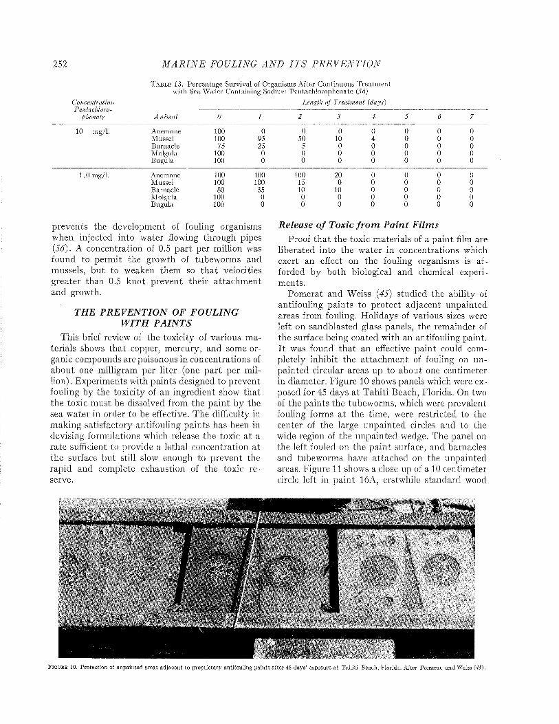
252 M A R I N E FOULING A N D I T S P R E V E N T I O N
Concentration
T a b l e 13. Percentage Survival of Organisms After Continuous T reatm ent with Sea W ater Containing Sodium Pentachlorophenate (56)
Length o f Treatment (days)j. orviu vtti'Ui u-
phenale A nim ai 0 I 2 3 4 5 6 7
10 mg/1. Anemone 100 0 0 0 0 0 0 0Mussel 100 95 50 10 4 0 0 0Barnacle 75 25 5 0 0 0 0 0Molgula 100 0 0 0 0 0 0 0Bugula 100 0 0 0 0 0 0 0
1.0 mg/1. Anemone 100 100 100 20 0 0 0 0Mussel 100 100 15 0 0 0 0 0Barnacle 80 35 10 10 0 0 0 0Molgula 100 0 0 0 0 0 0 0Bugula 100 0 0 0 0 0 0 0
prevents the development of fouling organisms when injected into water flowing through pipes (56). A concentration of 0.5 part per million was found to permit the growth of tubeworms and mussels, but to weaken them so th a t velocities greater than 0.5 knot prevent their attachm ent and growth.
THE P R E V E N T IO N OF F O U L IN G W IT H P A IN T S
This brief review of the toxicity of various materials shows that copper, mercury, and some organic compounds are poisonous in concentrations of about one milligram per liter (one part per million). Experiments with paints designed to prevent fouling by the toxicity of an ingredient show that the toxic must be dissolved from the paint by the sea water in order to be effective. The difficulty in making satisfactory antifouling paints has been in devising formulations which release the toxic a t a rate sufficient to provide a lethal concentration at the surface but still slow enough to prevent the rapid and complete exhaustion of the toxic reserve.
R elease o f Toxic f r o m P a in t F ilm sProof tha t the toxic materials of a paint film are
liberated into the water in concentrations which exert an effect on the fouling organisms is afforded by both biological and chemical experiments.
Pom erat and Weiss (45) studied the ability of antifouling paints to protect adjacent unpainted areas from fouling. Holidays of various sizes were left on sandblasted glass panels, the remainder of the surface being coated with an antifouling paint. I t was found th a t an effective paint could completely inhibit the attachm ent of fouling on unpainted circular areas up to about one centimeter in diameter. Figure 10 shows panels which were exposed for 45 days a t Tahiti Beach, Florida. On two of the paints the tubeworms, which were prevalent fouling forms at the time, were restricted to the center of the large unpainted circles and to the wide region of the unpainted wedge. The panel on the left fouled on the paint surface, and barnacles and tubeworms have attached on the unpainted areas. Figure 11 shows a close-up of a 10 centimeter circle left in paint 16A, erstwhile standard wood
X l v - ! , s i ' x f wH IV 1 «. * * ^
-------
F i g u r e 10. Protection of unpainted areas ad jacen t to proprie tary antifouling paints after 45 days’ exposure a t T ahiti Beach, F lorida. A fter Pom erat and Weiss (45).
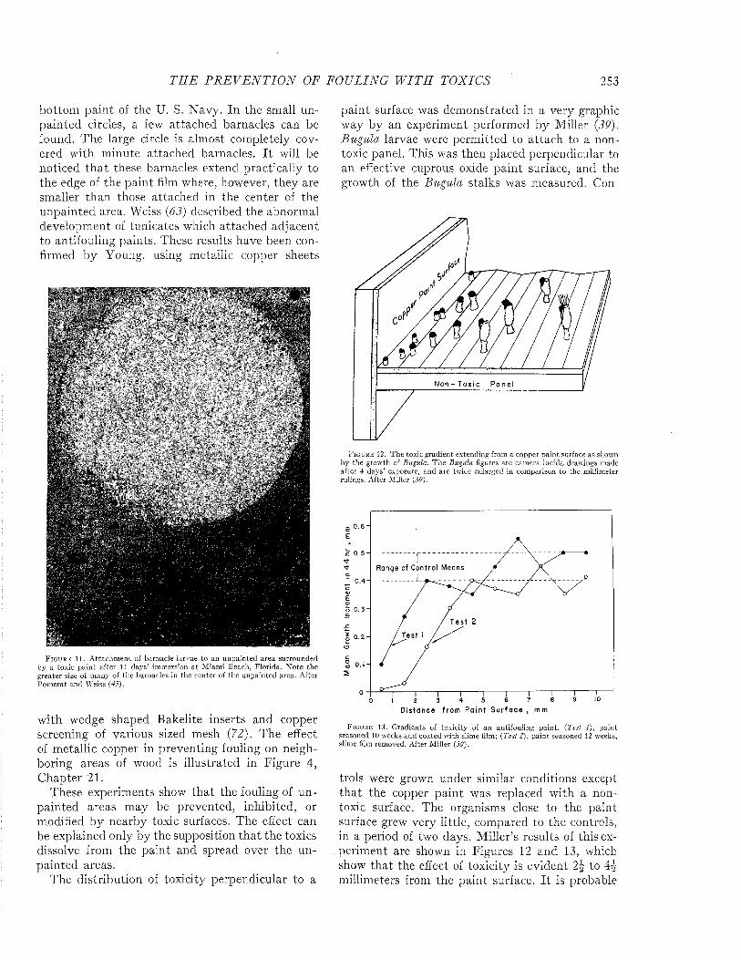
T H E P R E V E N T I O N OF FO ULING W I T H TO XIC S 253
bottom paint of the U. S. Navy. In the small unpainted circles, a few attached barnacles can be found. The large circle is almost completely covered with minute attached barnacles. I t will be noticed th a t these barnacles extend practically to the edge of the paint film where, however, they are smaller than those attached in the center of the unpainted area. Weiss (63) described the abnormal development of tunicates which attached adjacent to antifouling paints. These results have been confirmed by Young, using metallic copper sheets
F i g u r e 11. A ttachm en t of barnacle larvae to an unpainted area surrounded by a toxic pa in t after 11 days’ immersion a t M iam i Beach, F lorida. N ote the g reater size of m any of the barnacles in the center of the unpainted area. A fter P om erat and Weiss (45).
with wedge shaped Bakelite inserts and copper screening of various sized mesh (72). The effect of metallic copper in preventing fouling on neighboring areas of wood is illustrated in Figure 4, Chapter 21.
These experiments show that the fouling of unpainted areas may be prevented, inhibited, or modified by nearby toxic surfaces. The effect can be explained only by the supposition that the toxics dissolve from the paint and spread over the unpainted areas.
The distribution of toxicity perpendicular to a
paint surface was demonstrated in a very graphic way by an experiment performed by Miller (39). Bugula larvae were perm itted to attach to a nontoxic panel. This was then placed perpendicular to an effective cuprous oxide paint surface, and the growth of the Bugula stalks was measured. Con-
N o n - T o x i c P a n e
F ig u r e 12. T he toxic gradient extending from a copper pa in t surface as shown by the growth of Bugula. T h e Bugula figures are cam era lucida drawings made after 4 days’ exposure, and are twice enlarged in com parison to the millimeter rulings. A fter M iller (39).
££
Range of C o n t r o l Means
0 .4 -c£a>o
T e s t 2
T e s t II 0 . 2 -oo
D i s t a n c e f r o m P a i n t S u r f a c e , m m
F i g u r e 13. G radients of toxicity of an antifouling pain t. (Test 1), paint seasoned 10 weeks and coated with slime film; (Test 2), pain t seasoned 12 weeks, slime film removed. A fter M iller (39).
trois were grown under similar conditions except tha t the copper paint was replaced with a nontoxic surface. The organisms close to the paint surface grew very little, compared to the controls, in a period of two days. Miller’s results of this experiment are shown in Figures 12 and 13, which show that the effect of toxicity is evident 2\ to millimeters from the paint surface. I t is probable

254 M A R I N E FOULING A N D I T S P R E V E N T I O N
that this distance is greater than would be observed under normal exposure conditions, where the water is in more active circulation.
The comparative toxicity of paints has been estimated by various biological tests. The most direct of these measures the tendency for fouling organisms or their larvae to attach directly to the paint surface. Tests of the toxicity of leachates from paints, which give additional evidence that the toxics act while in solution, have also been made.
One of the attachment tests described by McLean (38) uses the edible mussel, Mytilus edulis. Where available, this mussel can be removed in
T a b l e 14. Loss of Weight and of Cuprous Oxide from a Series of Cold Plastic Paints Containing Graded Amounts of Cuprous
Oxide during Two Months of Soaking in the SeaLoss of CihO Loss of Fouling
Original Weight Resistance1CuiO% m g/cm 2 Hg/cm2/d a y m g/cm 2 %
1.4 0.016 0.27 1.30 02 .S 0.112 1.87 2 .84 05.3 0.150 2.50 0.97 0
10.5 0.384 6.40 1.25 6015.6 0.712 11.9 2.32 10021.8 0.589 9 .8 2.27 10028.1 0.665 11.1 1.17 10040.5 0.932 15.5 2.04 100
1 At Tahiti Beach, Florida, after two months’ immersion.
large quantities from rocks, piles, buoys, or other submerged surfaces. When they are replaced in sea water they will re-attach to a surface by spinning new byssus threads. McLean studied the attachment of these organisms to various toxic paints. He found that all of the mussels would attach to a plain or sandblasted glass surface. None of the mussels attached to satisfactory antifouling paints, though they moved across them. Observations of the mussels on satisfactory paints showed that the foot was extended and that the byssus might be attached momentarily in order to move, but in general the surface had a distinctly repellent effect which was attributed to its toxicity.
Nelson and Kodet (41) determined the time for the immobilization of a diatom (Navicula ramocis- sima) when placed in washings from a toxic panel. Dilution of the washings permitted continued motility for greater periods of time. The mud snail, Nassa, was found to be very sensitive to the toxic, and was killed even when the washings from a panel were diluted in 7.2 liters of water.
The larvae of Bugula have been used by Miller (39, 40) and by Riley (50) in studies of the toxicities of various paints. This larva is a free-swimming form which can be collected by placing the gravid adult in a beaker of sea water in the labora
tory. The larvae are liberated early on the following morning with remarkable regularity, so that experiments may be planned in advance. The larvae were collected and either placed in a cup which was painted on the inside and contained sea water, or in a beaker in which a painted slide was suspended. The number of larvae attached to the paint surface was taken as an indication of the toxicity of the surface. On nontoxic paints all of the larvae were able to attach to the paint and to grow after attachment. On more effective antifouling paints fewer of the larvae attached, and those which did attach grew at a reduced rate, if at all. These experiments show clearly that a toxic paint may act in either of two ways. It may repel the larva so that it never becomes attached to the paint surface, or, if the organism does attach, the toxic may prevent its growth and development to the mature state. These results can be interpreted only on the basis of the toxic or irritant action of some paint ingredient.
Bray (10) investigated the toxicity of solutions of various metallic salts in sea water and compared these results with the toxicity of sea water leachates from small painted panels. He found that the more effective paints gave leachates which were highly toxic to the nauplius larvae of the barnacle.
Various chemical means of measuring the loss of toxic from paint films have been tried. Orton (42) determined the copper and mercury content of various paints after prolonged soaking in the sea when the paints were just beginning to become fouled. He found that the percentage content of copper in these paints was considerably less than the original concentration. He correlated the failure of the paint film with the concentration of toxic remaining in the paint at the time of failure. Edmondson and Ingram (19) also observed that the copper content of paints decreased after prolonged soaking in the sea. It' is apparent that in these experiments the toxic materials were preferentially soluble in sea water, and were leached out at a proportionately faster rate than the other paint materials.
The determination of the total weight lost from a paint film during immersion in the sea permits comparison with the data on exfoliation presented in Chapter 13. Numerous experiments have been performed in which panels coated with a known weight of paint of known copper content were im mersed in the sea for various times. The weight and analysis after immersion gives the loss of weight and of cuprous oxide. Typical results are given in Table 14, which show that the total loss

TH E P R E V E N T I O N OF FOULING W I T H TOXICS 255
T a b l e 15 . The Leaching Rates of Cold Plastic Paints Containing Graded Amounts of Cuprous Oxide {30)
Copper Leaching Rale, ß g /cm?/ day After Soaking C l l n O -----------------------------------------------------------------------------------------------------------------------
Content1 0 1 mo. 2 mos. 3 mos. 4 mos. 5 mos. 6 mos. 8 mos.0 .4 1.1 1.0' 0 .6 ' 1.3' 0 .3 ' 0 .6 ' 6.1 ' 0 .6 '1.23 2 .9 1.2' 0.9 ' 1.7' 0 .6 ' 0 .6 ' 0 .3 ' 0 .9 '2.23 5 .0 1.3' 0 .9 ' 3 .1 ' 0 .9 ' 0 .9 ' 1 .2' —4.64 17.8 3.9 ' 1.6' 2 .4 ' 1.9' 2 .8 ' 2.5 ' 1.2'9.3 25.0 7.5 4 .7 ' 4 .4 ' 1.9' 3 .7 ' 7.1 ' 3 .3 '
13.8 27.4 14.1 11.3 10.0 10.5 lo s t ------19.2 40.6 19.3 11.3 8 .8 8.1 10.1 8 .0 8.124.8 51.5 27.7 12.5 9 .5 12.2 12.3 9 .8 9 .030.0 55.1 28.5 13.4 9 .7 10.3 13.8 14.4 13.836.0 57.4 30.2 11.6 10.9 12.0 14.4 14.7 14.150.7 47.2 44.3 21.0 14.2 15.6 20.2 18.7 17.7
1 As % dry weight of the paint film. The pigment volume was maintained constant by the substitution of magnesium silicate. 1 Paint fouled when exposed the indicated time at Tahiti Beach, Florida.
of weight does not determine the fouling resistance of these paints (31, 32). Their effectiveness is related to the rate of liberation of the copper, which was released from the effective paints at rates of9.8 to 15.5 micrograms/cm2/day. The weight loss of all of the paints was 1-2 m g/cm 2 during the two month period, or 0.020-0.039 m g/cm 2/day. LaQue has shown that the fouling of copper and copper alloys is also related to the rate of loss of copper (33). These results are discussed in detail in Chapter 21.
The rate of loss of toxics from a paint can also be determined by measuring the amount dissolved in sea water in which a painted panel has been soaked for a short period of time. The method for determining such leaching rates has been worked out for paints containing copper (23, 29, 30, 36, 37, 59) and mercury (49, 51-53). In practically all cases the effectiveness of the paint in preventing fouling is directly related to the leaching rate of the principle toxic ingredient. The method for determining leaching rates is described in Chapter 20.
The leaching rates of all paints which have been investigated change during a period of immersion in the sea. It is necessary, consequently, to determine the leaching rate at frequent intervals in order to determine how it changes with time, and how soon the value decreases below the minimum critical value. Curves showing the changes in leaching rate of several paints after immersion in the
sea are given in Chapter 16. The leaching rate determination is an indication of the toxicity of the paint film only at the time the determination is made. It is of no value in predicting the effectiveness of the paint at some future date.
Fouling in R ela tion to th e Leaching R ateConsiderable data are available to show the cor
relation between leaching rates and the fouling resistance of the paint. Table 15 shows the leaching rates of a group of eleven paints after various periods of immersion in the sea (30). These paints all had the same vehicle composition, but the cuprous oxide content of the formulation varied from about 50 per cent of the dry weight to less than one per cent. Magnesium silicate was substituted in equal volume for the amount of cuprous oxide removed in every case. The six paints containing the greatest amounts of cuprous oxide were effective in preventing fouling. All of these had copper leaching rates greater than 8 jag/cm2/day. The five paints which contained less than 10 per cent cuprous oxide became fouled during the first two months of exposure at Tahiti Beach, Florida, and all of these paints had leaching rates less than 7.1 /xg/cm2/d ay at the time of fouling.
Although the efficiency of a paint is related to the toxic content of the film, an amount of copper which is adequate in one composition may be inadequate in another formulation. Table 16 shows
T a b l e 16. Leaching Rates of Paints in Which Various Resins Were Substituted for Rosin in the Navy Department Specification 52 P-61 Type Paints. All of the Paints Contained 52% by Weight Cuprous Oxide in the Dry Film {30)
Copper Leaching Rate, ßg/cm ^/day After Soaking
Resin Used 0W. W. Rosin 30.0Unesterified Albertoi #1 33.3Unesterified Albertoi #2 32.1Ester Gum 30.3Esterified Albertoi 5 .7Coumarone Indene 25.6
1 mo. 2 mos. 3 mos.18.0 16.2 13.520.4 17.1 13.811.1 10.5 —
3 .4' 5 .5 ' 4 .2 '0 .9 ' 0 .0 ' —
4 .0 ' 2 .1 ' 2.1 '
4 mos. 5 mos. 6 mos.14.1 16.2 15.816.5 18.0 18.89 .6 10.8 9 .82.7 ' 0 .9 ' 0 .9 '3.3 ' 0 .0 ' —4.2' — 1.5'
' Paint fouled when exposed the indicated time at Tahiti Beach, Florida.
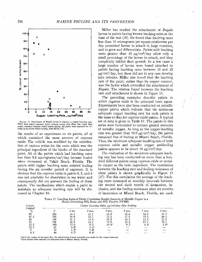
256 M A R I N E FOULING A N D I T S P R E V E N T I O N
100
9 0 -
70-
u° 5 0 - <
Ö 40-- >a-> 3 0 - 58
20 -
10-
952 0 2 5 90 4 010 1550Copper Leoctiing Rate , pg/cm2/doy
F i g u r e 1 4 . Attachment of Bugula larvae in relation to copper leaching rate. Filled data points represent paint surfaces coated with slime 61m. Clear data points represent surfaces wiped before testing. All paints were seasoned for ten weeks in sea water before testing. After Miller {39).
the results of an experiment on six paints, all of which contained the same amount of cuprous oxide. The vehicle was modified by the substitution of various resins for the rosin which was the principal ingredient of the binder of the standard paint. All of the paints which had leaching rates less than 9.6 micrograms/cm2/d ay became fouled when immersed at Tahiti Beach, Florida. The paints with higher leaching rates resisted fouling during the six months’ period of exposure. It is obvious that the cuprous oxide in paints 4, 5, and 6 was not available for dissolution in sea water and consequently did not prevent the fouling of these paints. The mechanisms which enable a paint to maintain an adequate leaching rate will be discussed in Chapter 16.
Miller has studied the attachment of Bugula larvae to paints having known leaching rates at the time of the test (39). He found that leaching rates less than 10 micrograms per square centimeter per day permitted larvae to attach in large numbers, and to grow and differentiate. Paints with leaching rates greater than 10 ¿ug/cm2/d a y allow only a small percentage of the larvae to attach, and they completely inhibit their growth. In a few cases a large number of larvae were found attached to paints having leaching rates between 10 and 15 ßg /cm2/day, but these did not in any case develop into colonies. Miller also found that the leaching rate of the paint, rather than its copper content, was the factor which controlled the attachment of Bugula. The relation found between the leaching rate and attachment is shown in Figure 14.
The preceding examples describe paints in which cuprous oxide is the principal toxic agent. Experiments have also been conducted on metallic copper paints which indicate that the minimum adequate copper leaching rate for such paints is the same as that for cuprous oxide paints. A typical set of data is given in Table 17. The paints in this series were formulated to contain graded amounts of metallic copper. As long as the copper leaching rate was greater than 10.9 /xg/cm2/day, the paints remained free of fouling at Miami Beach, Florida. Thus, the minimum adequate leaching rate of both cuprous oxide and metallic copper antifouling paints appears to be about 10 ß g / cm2/7day.
The evaluation of the minimum adequate leaching rate has been conducted on more than a hundred different paints using cuprous oxide or metallic copper as the toxic ingredient. The correlation between the leaching rate and fouling resistance of these paints is shown graphically in Figure 15 (27). For this correlation the average of the leaching rates measured at monthly intervals between the second and sixth month of immersion, inclusive, and the fouling resistance after six months of immersion at Miami Beach, Florida, are used.
T a b l e 17. Leaching Rates of Paints Containing Graded Amounts of Metallic Copper in a Matrix Containing 50% Rosin and 50% Vinylite (VYHH)
CopperContent
Copper Leaching Rates, ¡ig/cm?/ day After Soaking
% 0 1 mo. 2 mos. 3 mos. 4 mos. 5 mos. 6 mos.90 256 19.1 11.5 13.8 19.6 16.0 24.267.5 190 19.0 11.7 13.3 17.4 15.4 20.245 160 21.3 13.6 13.8 16.4 12.6 12.231 134 21.5 12.7 13.9 12.5 11.1 16.422.5 100 15.0 8.2 10.9' 9.2 ' 8 .8 ' 5.8'13.5 67 4.8 ' 3.3 ' — — — . —
9 55 1.9' 1 .0' — — — —
4 .5 46 0.7' 0 .4 ' — — — —
1 As % dry weight of the paint film. N o substitution of inert materials was made for the copper removed. 'Paint fouled when exposed the indicated time at Miami Beach, Florida.
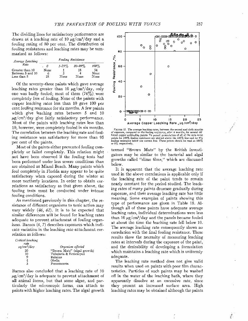
THE P R E V E N T I O N OF FOULING W I T H TOXICS 257
The dividing lines for satisfactory performance are drawn at a leaching rate of 10 /xg/cm2/d ay and a fouling rating of 80 per cent. The distribution of fouling resistances and leaching rates may be summarized as follows:
Average Leaching Rate
Greater than 10 Between 5 and 10 Less than 5
Fouling Resistance
. 0 None
6 25
1 -7 9 %13
None
8 0 -9 9 %184
None
100%54
NoneNone
Of the seventy-three paints which gave average leaching rates greater than 10 /xg/cm2/day, only one was badly fouled; most of them (74%) were completely free of fouling. None of the paints with copper leaching rates less than 10 gave 100 per cent fouling resistance for six months. A few paints which give leaching rates between 5 and 10 /xg/cm2/d a y give fairly satisfactory performance. M ost of the paints with leaching rates less than 10, however, were completely fouled in six months. The correlation betwëen the leaching rate and fouling resistance was satisfactory for more than 95 per cent of the paints.
Most of the paints either prevented fouling completely or failed completely. This relation might not have been observed if the fouling tests had been performed under less severe conditions than are obtained at Miami Beach. Many paints which foul completely in Florida may appear to be quite satisfactory when exposed during the winter at more northerly locations. In order to obtain correlations as satisfactory as that given above, the fouling tests must be conducted under intense fouling conditions.
As mentioned previously in this chapter, the resistance of different organisms to toxic action may vary widely (46, 62). It is to be expected that similar differences will be found for leaching rates adequate to prevent attachment of fouling organisms. Barnes (6, 7) describes exposures which indicate variation in the leaching rate-attachment correlation as follows :
Critical leaching rate
U g/cm l/day 20 10 9 4 3
“Brown M ats” (algal growth)Tubularia & EctocarpusBalanusObeliaPomotoceros
Barnes also concluded that a leaching rate of 10 Hg/cm2/d a y is adequate to prevent attachment of all animal forms, but that some algae, and particularly the microscopic forms, can attach to paints with higher leaching rates. The algal growth
100 -
CD
8 0O
4>Oc 6 0 -oCA*10O)oco> 4 0 “ c
2 0 -
o - emgjpsrpap o oo
2 50 5 15 2 0IOAverage Copper Leaching Rate , pg/cm /day
F i g u r e 15. The average leaching rates, between the second and sixth months of exposure, compared to the fouling resistance, after 6 months, for several different copper antifouling paints. To permit presentation of all of the data some points for 100% fouling resistance are plotted above the 100% line and for 0% fouling resistance below the correct line. These points should be read as 1 0 0 % or 0% respectively.
termed “Brown M ats” by the British investigators may be similar to the bacterial and algal growths called “slime films,” which are discussed below.
It is apparent that the average leaching rate used in the above correlations is applicable only if the leaching rate of the paint tends to remain nearly constant for the period studied. The leaching rates of many paints decrease gradually during exposure, and their average leaching rate has little meaning. Some examples of paints showing this type of performance are given in Table 18. Although all of these paints have adequate average leaching rates, individual determinations were less than 10 jug/cm2/d ay and the panels became fouled at about the time the leaching rate fell below 10. The average leaching rate consequently shows no correlation with the final fouling resistance. These results show the necessity of measuring leaching rates at intervals during the exposure of the paint, and the desirability of developing a formulation which maintains a leaching rate which is uniformly adequate.
The leaching rate method does not give valid results when used on paints with poor film characteristics. Particles of such paints may be washed off in the water of the leaching bath, where they apparently dissolve at an excessive rate, since they present an increased surface area. High leaching rates may be obtained although the paints
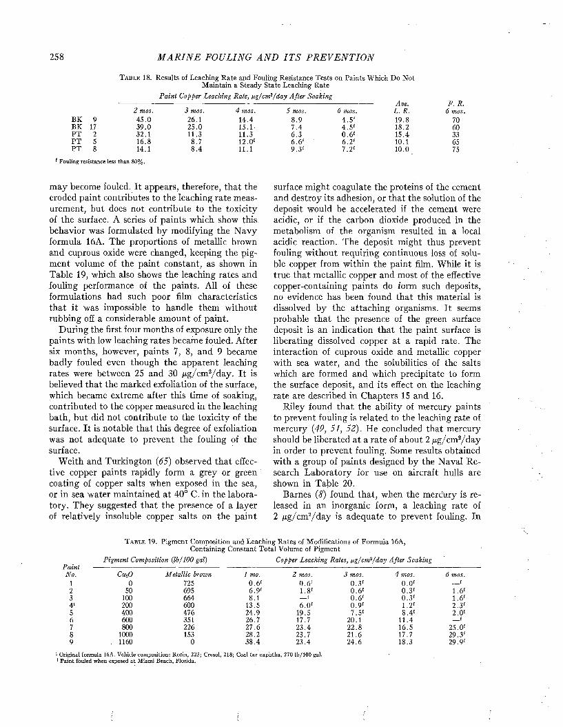
258 M A R I N E FOULING A N D I T S P R E V E N T I O N
T a b l e 18. Results of Leaching Rate and Fouling Resistance Tests on Paints Which Do Not Maintain a Steady State Leaching Rate
P ain t Copper Leaching Rate, ¡j.g/cm ?/day After SoakingAve. F. R.
2 mos. 3 mos. 4 mos. J mos. 6 mos. L. R. 6 mos.BK 9 45.0 26.1 14.4 8 .9 4 .5 ' 19.8 70BK 17 39.0 25.0 15.1 7.4 4 .5 ' 18.2 60PT 2 32.1 11.3 11.3 6.3 0 .6 ' 15.4 33PT S 16.8 8.7 12.0' 6.6 ' 6.2 ' 10.1 65PT 8 14.1 8 .4 11.1 9.3' 7.2' 10.0 75
' Fouling resistance less than 80%.
may become fouled. It appears, therefore, that the eroded paint contributes to the leaching rate measurement, but does not contribute to the toxicity of the surface. A series of paints which show this, behavior was formulated by modifying the N avy formula 16A. The proportions of metallic brown and cuprous oxide were changed, keeping the pigment volume of the paint constant, as shown in Table 19, which also shows the leaching rates and fouling performance of the paints. All of these formulations had such poor film characteristics that it was impossible to handle them without rubbing off a considerable amount of paint.
During the first four months of exposure only the paints with low leaching rates became fouled. After six months, however, paints 7, 8, and 9 became badly fouled even though the apparent leaching rates were between 25 and 30 ßg/cm 2/ day. It is believed that the marked exfoliation of the surface, which became extreme after this time of soaking, contributed to the copper measured in the leaching bath, but did not contribute to the toxicity of the surface. It is notable that this degree of exfoliation was not adequate to prevent the fouling of the surface.
Weith and Turkington (65) observed that effective copper paints rapidly form a grey or green coating of copper salts when exposed in the sea, or in sea water maintained at 40° C. in the laboratory. They suggested that the presence of a layer of relatively insoluble copper salts on the paint
surface might coagulate the proteins of the cement and destroy its adhesion, or that the solution of the deposit would be accelerated if the cement were acidic, or if the carbon dioxide produced in the metabolism of the organism resulted in a local acidic reaction. The deposit might thus prevent fouling without requiring continuous loss of soluble copper from within the paint film. While it is true that metallic copper and most of the effective copper-containing paints do form such deposits, no evidence has been found that this material is dissolved by the attaching organisms. It seems probable that the presence of the green surface deposit is an indication that the paint surface is liberating dissolved copper at a rapid rate. The interaction of cuprous oxide and metallic copper with sea water, and the solubilities of the salts which are formed and which precipitate to form the surface deposit, and its effect on the leaching rate are described in Chapters 15 and 16.
Riley found that the ability of mercury paints to prevent fouling is related to the leaching rate of mercury (49, 51, 52). He concluded that mercury should be liberated at a rate of about 2 ¡xg/cm2/day in order to prevent fouling. Some results obtained with a group of paints designed by the Naval Research Laboratory for use on aircraft hulls are shown in Table 20.
Barnes (8) found that, when the mercury is released in an inorganic form, a leaching rate of 2 ß g /cm2/d a y is adequate to prevent fouling. In
T a b l e 19. Pigment Composition and Leaching Rates of Modifications of Formula 16A, Containing Constant Total Volume of Pigment
Pigment Composition ( lb /100 gal) Copper Leaching Rates, fxg/cm2/d a y After SoakingPaintNo. c«..o M etallic brown 1 mo. 2 mos. 3 mos. 4 mos. 6 mos.
1 0 725 0.6' 0 .6 ' 0 .3 ' 0.0 ' __f2 50 695 6.9' 1.8' 0 .6 ' 0 .3 ' 1.6'3 100 664 8.1 __r 0 .6 ' 0.3 ' 1.6'4' 200 600 13.5 6.0 ' 0 .9 ' 1.2' 2.3'5 400 476 24.9 19.5 7.5' 8.4' 2.0 '6 600 351 26.7 17.7 20.1 11.4 __f7 800 226 27.6 23.4 22.8 16.5 25.0'8 1000 153 28.2 23.7 21.6 17.7 29.3'9 1160 0 38.4 23.4 24.6 18.3 29.9'
1 Original formula 16A. Vehicle composition: Rosin, 225; Cresol, 218; Coal tar naphtha, 270 lb/100 gal. r Paint fouled when exposed at Miami Beach, Florida.
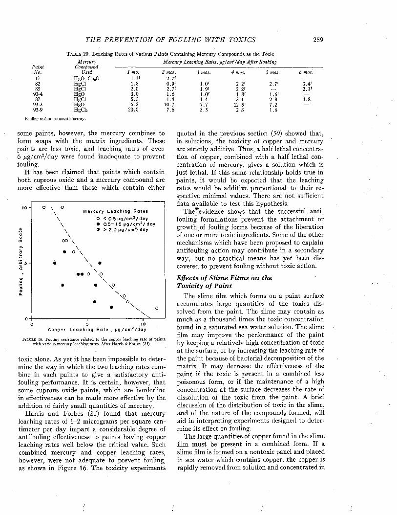
THE P R E V E N T I O N OF FOULING W I T H TOXICS 259
T a b l e 20. Leaching Rates of Various Paints Containing Mercury Compounds as the ToxicM ercury M ercury Leaching Rates, ßg/cm 2/d a y After Soaking
P ain t Compound ------------------------------------------------------------------------------------------------------No. Used 1 mo. 2 mos. 3 mos. 4 mos. 5 mos. 6 mos.17 HgO, CU2O l . l f 2 .7 f82 HgCl 1.8 0 .9 ' 1.0' 2.2 ' 2.7' 3 .4 '85 HgCl 2.0 2.7' 1.9' 2.2 ' — 2.1'
93-4 HgO 3.0 1.6 1.0' 1.8' 1.6' —
87 HgCl 5.5 1.4 1.4 3.1 2.8 3 .893-3 HgO 5.2 10.7 7.7 12.5 7.2 —
93-9 HgClî 20.0 7.6 3 .5 2.3 1.6 —
Fouling resistance unsatisfactory.
some paints, however, the mercury combines to form soaps with the matrix ingredients. These paints are less toxic, and leaching rates of even 6 ß g /cm2/d ay were found inadequate to prevent fouling.
It has been claimed that paints which contain both cuprous oxide and a mercury compound are more effective than those which contain either
io
O < 0 . 5 ( j g / c m 2 / d a y • 0 . 5 - 1.5 | i g / c m 2 / d a y ® > 2 . 0 p g / c m 2/ d a y
ooCO OO \> s
o
<• • O
3Oli_
05
C o p p e r L e a c h i n g R a t e ,o
F i g u r e 16. Fouling resistance related to the copper leaching rate of paints with various mercury leaching rates. After Harris & Forbes (23).
toxic alone. As yet it has been impossible to determine the way in which the two leaching rates combine in such paints to give a satisfactory antifouling performance. It is certain, however, that some cuprous oxide paints, which are borderline in effectiveness can be made more effective by the addition of fairly small quantities of mercury.
Harris and Forbes (23) found that mercury leaching rates of 1-2 micrograms per square centimeter per day impart a considerable degree of antifouling effectiveness to paints having copper leaching rates well below the critical value. Such combined mercury and copper leaching rates, however, were not adequate to prevent fouling, as shown in Figure 16. The toxicity experiments
quoted in the previous section (50) showed that, in solutions, the toxicity of copper and mercury are strictly additive. Thus, a half lethal concentration of copper, combined with a half lethal concentration of mercury, gives a solution which is just lethal. If this same relationship holds true in paints, it would be expected that the leaching rates would be additive proportional to their respective minimal values. There are not sufficient data available to test this hypothesis.
The^evidence shows that the successful antifouling formulations prevent the attachment or growth of fouling forms because of the liberation of one or more toxic ingredients. Some of the other mechanisms which have been proposed to explain antifouling action may contribute in a secondary way, but no practical means has yet been discovered to prevent fouling without toxie action.
Effects o f S lim e F ilm s on the Toxicity o f P ain t
The slime film which forms on a paint surface accumulates large quantities of the toxics dissolved from the paint. The slime may contain as much as a thousand times the toxic concentration found in a saturated sea water solution. The slime film may improve the performance of the paint by keeping a relatively high concentration of toxic at the surface, or by increasing the leaching rate of the paint because of bacterial decomposition of the matrix. It may decrease the effectiveness of the paint if the toxic is present in a combined less poisonous form, or if the maintenance of a high concentration at the surface decreases the rate of dissolution of the toxic from the paint. A brief discussion of the distribution of toxic in the slime, and of the nature of the compounds formed, will aid in interpreting experiments designed to determine its effect on fouling.
The large quantities of copper found in the slime film must be present in a combined form. If a slime film is formed on a nontoxic panel and placed in sea water which contains copper, the copper is rapidly removed from solution and concentrated in
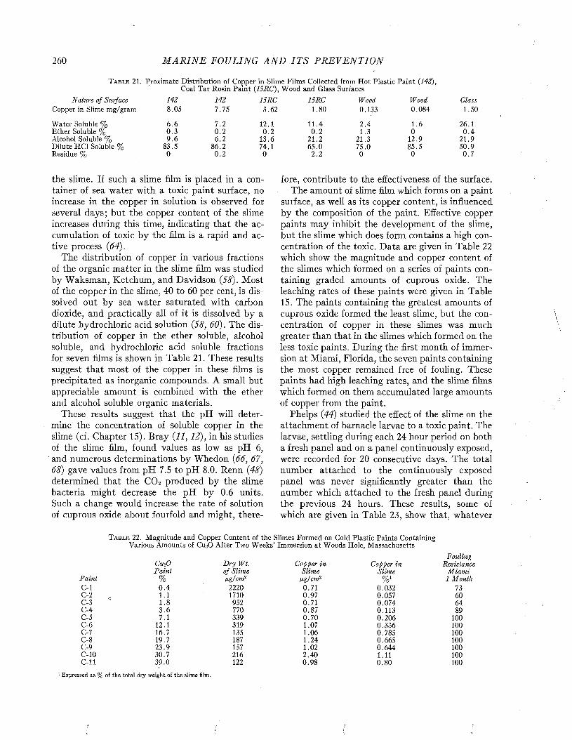
260 M A R I N E FOULING A N D I T S P R E V E N T I O N
T a b l e 21. Proximate Distribution of Copper in Slime Films Collected from Hot Plastic Paint (142), Coal Tar Rosin Paint (15RC), Wood and Glass Surfaces
Nature of Surface 142 142 15RC 15RC Wood Wood GlassCopper in Slime mg/gram 8.05 7.75 3.62 1.80 0.133 0.084 1.50
Water Soluble % 6 .6 7.2 12.1 11.4 2.4 1.6 26.1Ether Soluble % 0.3 0 .2 0.2 0 .2 1.3 0 0 .4Alcohol Soluble % 9.6 6.2 13.6 21.2 21.3 12.9 21.9Dilute HC1 Soluble % 83.5 86.2 74.1 65.0 75.0 85.5 50.9Residue % 0 0.2 0 2.2 0 0 0 .7
the slime. If such a slime film is placed in a container of sea water with a toxic paint surface, no increase in the copper in solution is observed for several days; but the copper content of the slime increases during this time, indicating that the accumulation of toxic by the film is a rapid and active process (64).
The distribution of copper in various fractions of the organic matter in the slime film was studied by Waksman, Ketchum, and Davidson (58). Most of the copper in the slime, 40 to 60 per cent, is dissolved out by sea water saturated with carbon dioxide, and practically all of it is dissolved by a dilute hydrochloric acid solution (58, 60). The distribution of copper in the ether soluble, alcohol soluble, and hydrochloric acid soluble fractions for seven films is shown in Table 21. These results suggest that most of the copper in these films is precipitated as inorganic compounds. A small but appreciable amount is combined with the ether and alcohol soluble organic materials.
These results suggest that the pH will determine the concentration of soluble copper in the slime (cf. Chapter 15). Bray (11, 12), in his studies of the slime film, found values as low as pH 6, and numerous determinations by Whedon (66, 67, 68) gave values from pH 7.5 to pH 8.0. Renn (48) determined that the C 0 2 produced by the slime bacteria might decrease the pH by 0.6 units. Such a change would increase the rate of solution of cuprous oxide about fourfold and might, there
fore, contribute to the effectiveness of the surface.The amount of slime film which forms on a paint
surface, as well as its copper content, is influenced by the composition of the paint. Effective copper paints may inhibit the development of the slime, but the slime which does form contains a high concentration of the toxic. Data are given in Table 22 which show the magnitude and copper content of the slimes which formed on a series of paints containing graded amounts of cuprous oxide. The leaching rates of these paints were given in Table15. The paints containing the greatest amounts of cuprous oxide formed the least slime, but the concentration of copper in these slimes was much greater than that in the slimes which formed on the less toxic paints. During the first month of immersion at Miami, Florida, the seven paints containing the most copper remained free of fouling. These paints had high leaching rates, and the slime films which formed on them accumulated large amounts of copper from the paint.
Phelps (44) studied the effect of the slime on the attachment of barnacle larvae to a toxic paint. The larvae, settling during each 24 hour period on both a fresh panel and on a panel continuously exposed, were recorded for 20 consecutive days. The total number attached to the continuously exposed panel was never significantly greater than the number which attached to the fresh panel during the previous 24 hours. These results, some of which are given in Table 23, show that, whatever
T a b l e 22. Magnitude and Copper Content of the Slimes Formed on Cold Plastic Paints Containing Various Amounts of CuaO After Two Weeks’ Immersion at Woods Hole, Massachusetts
CthO D ry Wt. Copper in Copper inFouling
ResistanceP ain i of Slim e Slime Slime M iam i
Pain t % ßg/cm 2 ßg/cm 2 Vo1 1 MonthC-l 0 .4 2220 0.71 0.032 73C-2 1.1 1710 0.97 0.057 60C-3 1.8 952 0.71 0.074 64C-4 3 .6 770 0.87 0.113 89C-5 7.1 339 0.70 0.206 100C-6 12.1 319 1.07 0.336 100C -l 16.7 135 1.06 0.785 100C-8 19.7 187 1.24 0.665 100C-9 23.9 157 1.02 0.644 100C-10 30.7 216 2.40 1.11 100C -ll 39.0 122 0.98 0.80 100
: Expressed as % of the total dry weight of the slime film.

T H E P R E V E N T I O N OF FOULING W I T H TOXICS 261
the explanation may be, the continuously exposed panels weré more resistant than fresh panels to the attachment of cyprids. Although the concentration of toxic in the slime film was not measured in Phelps’ experiments, copper concentrations of 0.35 to 0.86 mg. of copper per ml., and 0.025 to 0.115 mg. of mercury per ml. of the slime on this paint were found in other exposures at Beaufort (28).
Experiments on the attachment and growth of Bugula larvae have confirmed and extended these general observations (39, 40, 66, 68). These tests were made on painted panels which were seasoned in sea water in the laboratory for various periods to permit the development of slimes. The panels were then exposed to larvae of Bugula after the removal of the slime film from some of the panels. From these experiments the authors concluded that the influence of the slime film on toxic paints was slight, since very few larvae were able to attach to slimed or cleaned surfaces. In most cases the presence of the slime film either made no difference or else increased slightly the attachment of the Bugula larvae to the effective paints. No growth of Bugula occurred on any of the effective surfaces, regardless of the presence or absence of the slime film. The copper content of the slime films was
T a b l e 23. Comparison of Attachment of Barnacles to Fresh and to Slimed Antifouling Paint Panels (44)
Paint 15RC Exposed at Beaufort, N . C.Slim ed
Fresh PanelsExposure Panels Total Total
D ays N o/cm 2/d a y N o/cm 2 N o/cm 22 2.24 2 .243 1.26 3.50 2.524 0.86 4.36 1.805 1.81 6.17 1.136 2.75 8.92 0.897 2.48 11.40 0.778 2.41 13.81 0.68
10 1.94 15.75 0.7515 0.77 16.52 0.4519 0.97 17.49 0.63
of the slime on the paint surface may diminish the leaching rate from the paint. Experiments by Whedon (69) and Riley (51) indicate that the slime does, in most cases, decrease the amount of toxic escaping to the surrounding sea water. These effects of the slime film are discussed in Chapter 16.
The extensive investigations of slime films have not resulted in any significant correlation between the amount of slime or its physical properties and the ability of the surface to prevent fouling, except insofar as the most effective toxic paints both decrease the amount of slime and prevent the attachment of fouling. The most important property of
T a b l e 24. Attachment and Growth of Bugula Larvae to Paints Containing Graded Amounts of Cuprous Oxide After Exposure for Four Weeks in Sea Water to Permit Development of the Slime
% Attachment- Growth (mm.)
CthO in Slime Slime Slime Slime Copper inP ain t P ain t % Present Removed Present Removed Slim e1
— 0 76 39 1.4 1.2 —
5C 7.1 62 81 0 .9 0.7 1.441C 16.7 13 17 0.2 0 .2 6.399C 23.9 2 8 0.2 0.2 6.40
10C 30.7 3 4 0.2 0.2 6.73
1 Expressed as % of organic matter.
also determined, and large attachments and good growth were observed only on the paints which produced slimes containing little copper. When the copper content of the slime was above 6 per cent, very little attachment was observed. An example of the data on which these conclusions were based is given in Table 24. This experiment used paints similar to those described in Table 22.
The matrix ingredients of the paints studied may also affect the nature of the slime film which forms on the surface. Renn (48) and Darsie (15) have shown that the bacteria of the slime can decompose rosin and other related paint ingredients. The utilization of a paint component by the slime bacteria may result in more rapid breakdown of the paint film, and can thus result in the more rapid release of the toxic of the paint. The presence
the slime appears to be its content of the toxics which it derives from the paint film, and the effect the slime may have on the leaching rate of the paint.
REFERENCES1. A d a m s o n , N. E. U. S. Navy’s Research of Ship Bottom Paint.
Scientific Section. Circular No. 156, Educational Bureau, Paint Manufacturers’ Assoc, of the U. S., Washington. 1922.
2. A d a m s o n , N. E. Technology of Ship Bottom Paints and TheirImportance to Commercial and Naval Activities. Drugs, Oils and Paint, 4 9 , 3 7 0 -3 7 2 ; 4 1 0 - 4 1 1 ; 4 5 4 -4 6 3 ; 494 r-496 . 1934 . 50 , 1 8 -2 0 . 1935 .
3. A d a m s o n , N. E. Technology of Ship Bottom Paints and ItsImportance to Commercial and Naval Activities. Bureau Construction and Repair Bull. No. 10, U. S. Gov’t Printing Office. 1937.
4 . A l e x a n d e r , A. L., and R. L. B e n e m e l i s . Antifouling Paints.Studies in Multiple Pigmentation. Ind. Eng. Chem., 41 , 1532-1535. 1949.

262 M A R I N E FOULING A N D I T S P R E V E N T I O N
5. A n d e s , L. E. Iron Corrosion; Antifouling and AnticorrosivePaints. Trans. Chas. Saltes, 275 pp. London. 1900.
6. B a r n e s , H. Studies on Anti-Fouling Compositions. Part IV.The Relationship between Leaching Rate, Copper Loss, and Anti-Fouling Performance, under Raft and Service Conditions. Jour, of the Iron and Steel Institute, 175-185. June, 1948.
7. B a r n e s , H. Studies on Anti-Fouling Compositions. Part V.The Behaviour of Mercuric Oxide in Some Anti-Fouling Compositions with Special Reference to the Leaching-Rate Test. Jour, of the Iron and Steel Institute, 177-184. October, 1948.
8. B a r n e s , H. The Leaching Rate and Behaviour of Anti-Fouling Compositions. Jour, of Oil and Colour Chemists’ Assoc., 31, 455-461. 1948.
9. B a r n e s , H., and F. A. S t a n b u r y . The Toxic Action of Copper and Mercury Salts both Separately and When Mixed on the Harpacticid Copepod, Nitocra spinipes (Boeck). Jour. Exper. Biol., 25, 270-275. 1948.
10. B r a y , A. W. L. Report of the Toxic Action of Certain Chemical Compounds on Marine Organisms. Washington Univ., St. Louis, Mo., 27 pp. Nov. 8, 1919.
11. R r a y , A. W. L. Third Report on the Investigation into theFouling of Ships’ Bottoms by Marine Growths. Bureau of Construction and Repair. 1924. (Unpublished.)
12. B r a y , A. W. L. Fourth Report on the Fouling of Ships’ Bottoms. Bureau of Construction and Repair. Feb. 9, 1926. (Unpublished.)
13. C l a r k e , G. L. The Effectiveness of Various Toxics and theCourse of Poisoning and Recovery in Barnacles and Mussels. Paper 11, Sixth Report from Woods Hole Oceanographic Inst, to Bureau of Ships. May 1, 1943. (Unpublished.)
14. C l a r k e , G. L. Poisoning and Recovery in Barnacles andMussels. Biol. Bull., 92, 73-91. January, 1947.
15. D a r s i e , M. L. The Role of Marine Bacteria in the Decomposition of Hot Plastic Paints. Annual Report 1942- 1943 from Naval Biological Lab., San Diego, California, to Bureau of Ships, 146-154. 1943. (Unpublished.)
16. D a v y , S i r H u m p h r y . On the Corrosion of Copper Sheathingby Sea Water, and on Methods of Preventing this Effect; and on Their Application to Ships of War and Other Ships. Phil. Trans. Roy. Soc. London, 114, 151-158. 1824.
17. D a v y , S i r H u m p h r y . Additional Experiments and Observations on the Application of Electrical Combinations to the Preservation of the Copper Sheathing of Ships, and to Other Purposes. Phil. Trans. Roy. Soc. London, 114, 242- 246. 1824.
18. D im m ic k , R. E. Science Supplement 10, Science, 102. August3, 1945.
19. E d m o n d s o n , C. H., and W. H. I n g r a m . Fouling Organisms inHawaii. Bernice P. Bishop Mus., Occas. Papers 14 (14), 251-300. 1939.
20. H a r r i s , J. E. Antifouling Investigations. First Report of theMarine Corrosion Sub-Committee, Section C. Journ. Iron and Steel Institute, 339-451. 1943.
21. H a r r i s , J. E. Experiments on Antifouling Coatings Containing Organic Poisons. Report, Corrosion Committee, Marine Corrosion Sub-Committee, N2/44. Jan. 1944. (Unpublished.)
22. H a r r i s , J. E. Second Report on Antifouling Investigations,Corrosion Committee, Marine Corrosion Sub-Committee, N16/45. (Unpublished.)
23. H a r r i s , J. E., and W. A. D. F o r b e s . Under-water Paintsand the Fouling of Ships, with Reference to the Work of the Marine Corrosion Sub-Committee of the Iron and Steel Institute and the Admiralty Corrosion Committee. Inst. Naval Architects, London. April 12, 1946. (Unpublished.)
24. H u n t e r , W. The Poisoning of Marinogammarus marinus byCupric Sulphate and Mercuric Chloride. Jour. Exper. Biol., 26, 113-124. 1949.
25. I n g r a m , H. A. Technical Report No. 482-45, U. S. NavalTechnical Mission in Europe. 1945. (Unpublished.)
26. J o n e s , J. R. E. The Effect of Ionic Copper on the OxygenConsumption of Ganemorus palex and Polycelis negra. Jour. Exp. Biol., 18, 153-161. 1941-42.
27. K e t c h u m , B. H. Action of Antifouling Paints. V. The Use ofGlycine Solutions as an Accelerated Test of the Availability of Toxic. Ind. Eng. Chem., 40, 249-253. 1948.
28. K e t c h u m , B. H., and M. W. D a v id s o n . The Copper Contentof Slime Films. Paper 5, Fourth Report from Woods Hole Oceanographic Inst, to Bureau of Ships. March 27, 1942. (Unpublished.)
29. K e t c h u m , B. H., J. D. F e r r y , G. K e l l y , and J. P a r k e r .Preliminary Report on Study of Leaching Rate Method. Paper 1, Fifth Report from Woods Hole Oceanographic Inst, to Bureau of Ships. August 14, 1942. (Unpublished.)
30. K e t c h u m , B. H., J. D. F e r r y , A. C. R e d f i e l d , and A. B u r n s .The Evaluation of Antifouling Paints by Leaching Rate Determinations. Ind. Eng. Chem., Ind. Ed., 39, 456-460. 1945.
31. K e t c h u m , B. H., L. W. H u t c h i n s , and B. M o t t . Preliminary Report on Methods for Differentiating between Copper Lost by Solution from the Paint Film and by Erosion. Paper 1, Sixth Report from Woods Hole Oceanographic Inst, to Bureau of Ships. May 1, 1943. (Unpublished.)
32. K e t c h u m , B. H., D. T o d d , J. P a r k e r , and B. R e y n o l d s .Variations in the Proportions of Soluble to Insoluble Resins and Their Effect on Loss of Toxic and Matrix from a Paint. Paper 5, Seventh Report from Woods Hole Oceanographic Inst, to Bureau of Ships. April 20, 1944. (Unpublished.)
33. L a Q u e , F. L. Relationships between Corrosion and Foulingof Copper Nickel Alloys in Sea Water. Trans. Electrochem. Soc., 87, 165-184. 1945.
34. M a l l e t , R. On the Corrosion and Fouling of Iron Ships.Trans. Inst. Nav. Arch., 13, 90-162. 1872.
35. M a r c h a n d , J. F. D D T as a Marine Antifouling Agent. Science, 104, 74r-75. 1946.
36. Mare Island Paint Laboratory. (A. E. Burns, Jr.) ProgressReport on Leaching Rate Experiments Conducted at Mare Island Paint Laboratory. Jan. 15, 1942. (Unpublished.)
37. Mare Island Paint Laboratory. (A. E. Burns, Jr.) Correlation of Leaching Rates with Fouling Resistance of Various Paints. Presented at Ship Fouling Conference, Mare Island Navy Yard. Sept., 1942. (Unpublished.)
38. M cL e a n , R. A. The Attachment of Various MacroscopicForms to Toxic and Non-Toxic Surfaces under Laboratory Conditions. Paper 9, Fourth Report from Woods Hole Oceanographic Inst, to Bureau of Ships. March 27, 1942. (Unpublished.)
39. M il l e r , M. A. Toxic Effects of Copper on Attachment andGrowth of Bugula neritina. Biol. Bull., 90, 122-140. 1946.
40. M il l e r , M. A., and E. E. C u p p . Development of BiologicalAccelerated Tests. Annual Report for 1941-42 to Bureau of Ships from the Naval Biological Laboratory, Section 3, 54^116. October, 1942. (Unpublished.)
41. N e l s o n , T. C., and E. R. K o d e t . Paint Destruction andMetal Corrosion—Zoological Aspects. O.S.R.D. Report No. 4512. Dec. 27, 1944. (Unpublished.)
42. O r i o n , J. H. Experiments in the Sea on the Growth-Inhib-itive and Preservation Value of Poisonous Paints and Other Substances. J. Marine Biol. Áss. U.K., N.S., 16, 373-452. 1929-1930.
43. P a r k e r , G. H. The Growth of Marine Animals on Submerged Metals. Biol. Bull., 47, 127-142. 1924.
44. P h e l p s , A. Observations on Reactions of Barnacle Larvaeand Growth of Metamorphosed Forms at Beaufort, N. C., June, 1941, to Sept., 1941. Paper 7, Fourth Report from Woods Hole Oceanographic Inst, to Bureau of Ships. March 27, 1942. (Unpublished.)
TH E P R E V E N T I O N OF FOULING W I T H TOXICS 263
45. P o m e r a t , C. M., and C. M. W e i s s . On the Influence of ToxicPaints on the Fouling of Adjacent Unpainted Areas. Paper 10, Sixth Report from Woods Hole Oceanographic Inst, to Bureau of Ships. May 1, 1943. (Unpublished.)
46. P y e f in c h , K. A. Methods of Assessment of Antifouling Compositions. Jour. Iron & Steel Inst. No. 11, 229-243. 1945.
47. P y e f in c h , K. A., and J. C. M o t t . The Effect of Copper andMercury on the Young Stages,of Barnacles. Report N13/44 of the Marine Corrosion Sub-Committee of the Corrosion Committee to British Admiralty. August, 1944. (Unpublished.)
48. R e n n , C. E. The Metabolism of the Slime Film and Its Relation to the pH Value of the Slime. Paper 3, Fourth Report from Woods Hole Oceanographic Inst, to Bureau of Ships. March 27, 1942. (Unpublished.)
49. R il e y , G. A. Progress Report on Mercury Leaching RateMethod. Paper 4, Fifth Report from Woods Hole Oceanographic Inst, to Bureau of Ships. August 14, 1942. Progress Report on Leaching Rates of Mercury Paints. Paper 8, Sixth Report from Woods Hole Oceanographic Institution to Bureau of Ships. M ay 1, 1943. (Unpublished.)
5 0 . R i l e y , G. A. The Toxicity o f Heavy Metals to Fouling Organisms. Paper 12, Sixth Report from Woods Hole Oceanographic Inst, to Bureau of Ships. M ay 1, 1943. (Unpublished.)
51. R il e y , G. A. Note on the Effect, of Loss of Mercury fromthe Leaching Bath and of Slime Films on Leaching ofMercury Paints. Paper 9, Seventh Report from Woods Hole Oceanographic Inst, to Bureau of Ships. April 20, 1944. (Unpublished.)
52. R i l e y , G. A. Leaching Tests on Paints Containing Mercury.Paper 13, Seventh Report from Woods Hole Oceanographic Inst, to Bureau of Ships. April 20, 1944. (Unpublished.)
53. R il e y , G. A., and A. C. R e d f ie l d . The Leaching Rate ofPaints Containing Various Mercury Compounds. Paper 10, Seventh Report from Woods Hole Oceanographic Inst, to Bureau of Ships. April 20, 1944. (Unpublished.)
54. S e a g r e n , G. W., M. H. S m it h , and G. H. Y o u n g . The Comparative Antifouling Efficacy of DD T. Science, 102, 425- 426. 1945.
55. St e p h e n s , P h i l i p , E s q . Navy Boards Report to the Admiralty on the First Coppering Experiment, August 31, 1763. Wm. L. Clements Library, Ann Arbor, Mich. Reprinted, The American Neptune, July, 1941 and Appendix to Chapter 11.
56. T ü r n e r , H. J., J r ., D. M. R e y n o l d s , and A. C. R e d f ie l d .Chlorine and Sodium Pentachlorophenate as Fouling Preventives in Sea Water Conduits. Ind. Eng. Chem., 40, 450-453. 1948..
57. W a k s m a n , S. A., D. B. J o h n s t o n e , and C. L. C a r e y . TheEffect of Copper upon the Development of Bacteria in Sea Water, and the Isolation of Specific Bacteria. Sears Found. Jour. Mar. Res., 5, 136-152. 1943.
58. W a k s m a n , S. A., B. H. K e t c h u m , and M. W. D a v id s o n .The Nature of the Organic Matter, and the Distribution of Copper in the Various Organic Fractions of the Slime
Film. Paper 4, Fourth Report from Woods Hole Oceanographic Inst, to Bureau of Ships. March 27, 1942. (Unpublished.)
59. W a k s m a n , S. A., B. H. K e t c h u m , A. P h e l p s , and C. M.W e i s s . Observations on the Primary Film Acquired bv Submerged Surfaces. Second Report from Woods Hole Oceanographic Inst, to Bureau of Ships. Jan. 2,1941, July 23,1941. (Unpublished.)
60. W a k s m a n , S. A., B. H. K e t c h u m , and C. M. W e i s s . Copperand Mercury Relationships between Paint, Slime Film, and Sea Water. Third Report from Woods Hole Oceanographic Inst, to Bureau of Ships. July 23, 1941. (Unpublished.)
61. W e h m h o f f , B. L., A. M. J o r d o n , and H. C. K n i g h t . HotPlastic Ship Bottom Paints. Chem. Warfare, 15, 675-680. 1929.
62. W e i s s , C. M. The Comparative Tolerances of Some FoulingOrganisms to Copper and Mercury. Biol. Bull., 93, 56-63. 1947.
63. W e i s s , C. M. The Abnormal Development of TunicatesAttached to Glass Surfaces Adjacent to Antifouling Paints. Ecology, 29, 215-218. 1948.
64. W e i s s , C. M., and B. H. K e t c h u m . The Accumulation of Copper by Slime Films Formed on Non-Toxic Surfaces. Paper
■ 6, Fourth Report from Woods Hole Oceanographic Inst, to Bureau of Ships. March 27, 1942. (Unpublished.)
65. W e i t h , A. J., and V. H. T u r k in g t o n . Protective Coatingsfor Ship Bottoms and Naval Aircraft. Progress Report for November, 1942, N.D.R.C. Assignment OEMsr-211. See also: Studies of Anticorrosive and Antifouling Coating Systems for Ship Bottoms. Bakelite Corporation, Research & Development Department, Bloomfield, N . J. Terminal Report to N.D.R.C., O.S.R.D. No. 6649. Jan. 15, 1946.
66. W h e d o n , W. F. Investigations Pertaining to the Fouling ofShips’ Bottoms. Semi-Annual Report for 1941-1942 from Naval Biological Lab., San Diego, Cal., to Bureau of Ships. April 30, 1942. (Unpublished.)
67. W h e d o n , W. F., and Collaborators. Investigations Pertaining to the Fouling of Ships’ Bottoms. Annual Report 1941— 1942 from Naval Biological Lab., San Diego, Cal., to Bureau of Ships. October 24, 1942. (Unpublished.)
68. W h e d o n , W. F. Investigations Pertaining to the Fouling ofShips’ Bottoms. Annual Report 1942-1943 from Naval Biological Lab., San Diego, Cal., to Bureau of Ships. June,1943. (Unpublished.)
69. W h e d o n , W. F. Annual Report for 1942-1943. BiologicalLab., Naval Fuel Depot, San Diego, Cal. 1943. (Unpublished.)
70. W h e d o n , W. F., R. T. T s c h u d y , and J. C. H in d m a n . Investigations Pertaining to the Fouling of Ships’ Bottoms. Annual Report for 1940-1941 from Scripps Inst. Oceanography to Bureau of Ships. December 5, 1941. (Unpublished.)
71. Y o u n g , C. F. T. The Fouling and Corrosion of Iron Ships;Their Causes and Means of Prevention, with the Mode of
p Application to Existing Iron-Clads. London Drawing Assoc., London, 1867.
72. Y o u n g , G. H. Personal Communication.
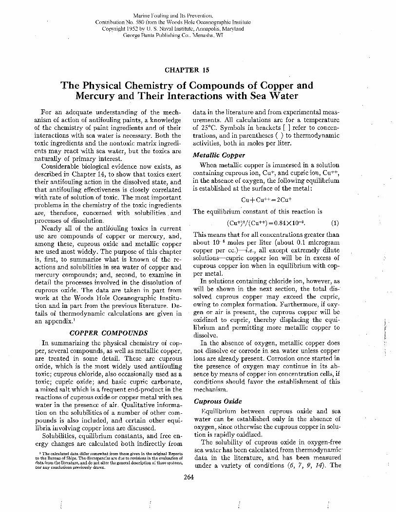
Marine Fouling and Its Prevention,Contribution No. 580 from the Woods Hole Oceanographic Institute
Copyright 1952 by U. S. Naval Institute, Annapolis, Maryland George Banta Publishing Co., Menasha, WI
CHAPTER 15
The Physical Chemistry of Compounds of Copper and Mercury and Their Interactions w ith Sea Water
For an adequate understanding of the mechanism of action of antifouling paints, a knowledge of the chemistry of paint ingredients and of their interactions with sea water is necessary. Both the toxic ingredients and the nontoxic matrix ingredients may react with sea water, but the toxics are naturally of primary interest.
Considerable biological evidence now exists, as described in Chapter 14, to show that toxics exert their antifouling action in the dissolved state, and that antifouling effectiveness is closely correlated with rate of solution of toxic. The most important problems in the chemistry of the toxic ingredients are, therefore, concerned with solubilities and processes of dissolution.
Nearly all of the antifouling toxics in current use are compounds of copper or mercury, and, among these, cuprous oxide and metallic copper are used most widely. The purpose of this chapter is, first, to summarize what is known of thé reactions and solubilities in sea water of copper and mercury compounds; and, second, to examine in detail the processes involved in the dissolution of cuprous oxide. The data are taken in part from work at the Woods Hole Oceanographic Institution and in part from the previous literature. D etails of thermodynamic calculations are given in an appendix.1
COPPER COMPOUNDSIn summarizing the physical chemistry of cop
per, several compounds, as well as metallic copper, are treated in some detail. These are cuprous oxide, which is the most widely used antifouling toxic; cuprous chloride, also occasionally used as a toxic; cupric oxide; and basic cupric carbonate, a mixed salt which is a frequent end-product in the reactions of cuprous oxide or copper metal with sea water in the presence of air. Qualitative information on the solubilities of a number of other compounds is also included, and certain other equilibria involving copper ions are discussed.
Solubilities, equilibrium constants, and free energy changes are calculated both indirectly from
1 The calculated data differ somewhat from those given in the original Reports to the Bureau of Ships. The discrepancies are due to revisions in the evaluation of data from the literature, and do not alter the general description of these systems, nor any conclusions previously drawn.
data in the literature and from experimental measurements. All calculations are for a temperature of 25°C. Symbols in brackets [ ] refer to concentrations, and in parentheses ( ) to thermodynamic activities, both in moles per liter.
M etallic CopperWhen metallic copper is immersed in a solution
containing cuprous ion, Cu+, and cupric ion, Cu++, in the absence of oxygen, the following equilibrium is established at the surface of the metal :
Cu + C u + + = 2 C u +
The equilibrium constant of this reaction is
(C u+)2/(C u+ + )= 0 .84X 10-< ¡. ( l)
This means that for all concentrations greater than about IO“6 moles per liter (about 0.1 microgram copper per cc.)— i.e., all except extremely dilute solutions— cupric copper ion will be in excess of cuprous copper ion when in equilibrium with copper metal.
In solutions containing chloride ion, however, as will be shown in the next section, the total dissolved cuprous copper may exceed the cupric, owing to complex formation. Furthermore, if oxygen or air is present, the cuprous copper will be oxidized to cupric, thereby displacing the equilibrium and permitting more metallic copper to dissolve.
In the absence of oxygen, metallic copper does not dissolve or corrode in sea water unless copper ions are already present. Corrosion once started in the presence of oxygen may continue in its absence by means of copper ion concentration cells, if conditions should favor the establishment of this mechanism.
Cuprous OxideEquilibrium between cuprous oxide and sea
water can be established only in the absence of oxygen, since otherwise the cuprous copper in solution is rapidly oxidized.
The solubility of cuprous oxide in oxygen-free sea water has been calculated from thermodynamic data in the literature, and has been measured under a variety of conditions (6 , 7, 9, 14). The
264
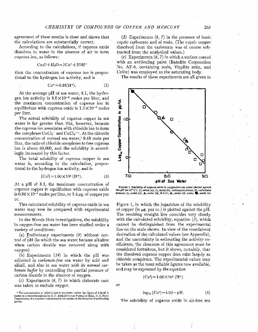
C H E M I S T R Y OF COMPOUN DS OF COPPER A N D M E R C U R Y 265
agreement of these results is close and shows that the calculations are substantially correct.
According to the calculations, if cuprous oxide dissolves in water in the absence of air to form cuprous ion, as follows:
C u20 + H 20 = 2 C u + + 2 0 H -
then the concentration of cuprous ion is proportional to the hydrogen ion activity, and is
Cu+ = 0 .1 8 (H + ). (2)
At the average pH of sea water, 8.1, the hydrogen ion activity is 8.0 X IO-9 moles per liter, and the maximum concentration of cuprous ion in equilibrium with cuprous oxide is 1.5 X IO-9 moles per liter.
The actual solubility of cuprous copper in sea water is far greater than this, however, because the cuprous ion associates with chloride ion to form the complexes CuCl2~ and CuCl3— . At the chloride concentration of normal sea water,1 0.48 mole per liter, the ratio of chloride complexes to free cuprous ion is about 60,000, and the solubility is accordingly increased by this factor.
The total solubility of cuprous copper in sea water is, according to the calculation, proportional to the hydrogen ion activity, and is
[Cu1] = 1 .0 6 X 1 0 “ (H + ). (3)
At a pH of 8.1, the maximum concentration of cuprous copper in equilibrium with cuprous oxide is 0.84 X IO-4 moles per liter, or 5.4 gg. of copper per cc.
This calculated solubility of cuprous oxide in sea water may now be compared with experimental measurements.
In the Woods Hole investigations, the solubility in oxygen-free sea water has been studied under a variety of conditions:
(a) Preliminary experiments (P) without control of pH (in which the sea water became alkaline when carbon dioxide was removed along with oxygen).
(b) Experiments (14) in which the pH was adjusted in carbonate-free sea water by acid and alkali, and also in sea water with its normal carbonate buffer by controlling the partial pressure of carbon dioxide in the absence of oxygen.
(c) Experiments (6, 7) in which elaborate care was taken to exclude oxygen.
1 The concentration of chloride ion in sea water varies; the figure of 0.48 M is based on a recommendation by A. C. Redfield to the Bureau of Ships, U. S. N avy Department, of a standard concentration for studies of the behavior of antifouling paints.
(d) Experiments (6, 7) in the presence of basic cupric carbonate and of rosin. (The cupric copper dissolved from the carbonate was of course subtracted from the analytical values.)
(e) Experiments (6, 7) in which a surface coated with an antifouling paint (Bakelite Corporation No. AF-6, containing rosin, Vinylite resin, and Celite) was employed as the saturating body.
The results of these experiments are all given in
O
° 1.0
_l
7 .0 8-0 9 .0pH of Seo Woter
F i g u r e 1. Solubility of cuprous oxide in oxygen-free sea water plotted against the pH (at 25° C.)! series (a); O , series (b), carbonates absent, 0 , carbonates present;'A , series (c); A , series (d), B.C.C.; A , series (d), rosin; series (e).
Figure 1, in which the logarithm of the solubility of copper (in gg. per cc.) is plotted against the pH. The resulting straight line coincides very closely with the calculated solubility, equation (J), which cannot be distinguished from the experimental line on the scale shown. In view of the roundabout derivation of the calculated values (see Appendix), and the uncertainty in estimating the activity coefficients, the closeness of this agreement must be considered fortuitous, but it shows, certainly, that the dissolved cuprous copper does exist largely as chloride complexes. The experimental values may be taken as the most reliable figures now available, and may be expressed by the equation
[Cu1] = 1.08 X IO4 (H+)
or
logio [Cu1] = 4.03 —pH. (4)
The solubility of cuprous oxide in air-free sea
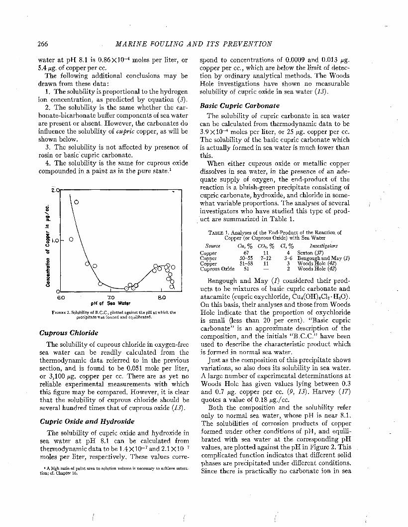
266 M A R I N E FOULING A N D I T S P R E V E N T I O N
water at pH 8.1 is 0.86 X l0 ~ 4 moles per liter, or 5.4 jug. of copper per cc.
The following additional conclusions may be drawn from these data:
1. The solubility is proportional to the hydrogen ion concentration, as predicted by equation (J).
2. The solubility is the same whether the carbonate-bicarbonate buffer components of sea water are present or absent. However, the carbonates do influence the solubility of cupric copper, as will be shown below.
3. The solubility is not affected by presence of rosin or basic cupric carbonate.
4. The solubility is the same for cuprous oxide compounded in a paint as in the pure state.1
Z.Oi
1.0
o
8.07 . 06.0pH of Seo Wafer
F i g u r e 2 . Solubility o f B .C .C ., plotted against the pH at which the precipitate was formed and equilibrated.
Cuprous Chloride
The solubility of cuprous chloride in oxygen-free sea water can be readily calculated from the thermodynamic data referred to in the previous section, and is found to be 0.051 mole per liter, or 3,100 ßg. copper per cc. There are as yet no reliable experimental measurements with which this figure may be compared. However, it is clear that the solubility of cuprous chloride should be several hundred times that of cuprous oxide {13).
Cupric Oxide an d H ydroxide
The solubility of cupric oxide and hydroxide in sea water at pH 8.1 can be calculated from thermodynamic data to be 1.4 X IO-7 and 2.1 X IO-7 moles per liter, respectively. These values corre-
1 A high ratio of paint area to solution volume is necessary to achieve saturation; c f . Chapter 16.
spond to concentrations of 0.0009 and 0.013 jug. copper per cc., which are below the limit of detection by ordinary analytical methods. The Woods Hole investigations have shown no measurable solubility of cupric oxide in sea water {13).
Basic C upric CarbonateThe solubility of cupric carbonate in sea water
can be calculated from thermodynamic data to be3.9 X IO“4 moles per liter, or 25 ßg. copper per cc. The solubility of the basic cupric carbonate which is actually formed in sea water is much lower than this.
When either cuprous oxide or metallic copper dissolves in sea water, in the presence of an adequate supply of oxygen, the end-product of the reaction is a bluish-green precipitate consisting of cupric carbonate, hydroxide, and chloride in somewhat variable proportions. The analyses of several investigators who have studied this type of product are summarized in Table 1.
T a b l e 1. Analyses of the End-Product of the Reaction of Copper (or Cuprous Oxide) with Sea Water
Source Cu, % CO2 , % Cl, % InvestigatorsCopper 67 11 4 Sexton (37)Copper 50-55 7-12 3-6 Bengough and May (1)Copper 51-58 11 3 Woods Hole (42)Cuprous Oxide 51 — 2 Woods Hole (42)
Bengough and M ay {!) considered their products to be mixtures of basic cupric carbonate and atacamite (cupric oxychloride, Cu4(0 H )6Cl2-H20 ). On this basis, their analyses and those from Woods Hole indicate that the proportion of oxychloride is small (less than 20 per cent). “Basic cupric carbonate” is an approximate description of the composition, and the initials “B.C.C.” have been used to describe the characteristic product which is formed in normal sea water.
Just as the composition of this precipitate shows variations, so also does its solubility in sea water. A large number of experimental determinations at Woods Hole has given values lying between 0.3 and 0.7 ßg. copper per cc. {9, 13). Harvey {17) quotes a value of 0.18 ßg./cc.
Both the composition and the solubility refer only to normal sea water, whose pH is near 8.1. The solubilities of corrosion products of copper formed under other conditions of pH, and equilibrated with sea water at the corresponding pH values, are plotted against the pH in Figure 2. This complicated function indicates that different solid phases are precipitated under different conditions. Since there is practically no carbonate ion in sea
C H E M I S T R Y OF COM POUN DS OF COPPER A N D M E R C U R Y 267
water (30) acid to pH 7.5, the portion of the curve at lower pH values probably does not represent the solubility of a carbonate at all. It agrees approximately with the calculated solubility of cupric oxide. N o data for the compositions of products formed under these conditions have been reported.
The fact that cupric copper attains a concentration of about 0.5 ¡Xg. per cc. in normal sea water, whereas a cupric ion activity of one-thirtieth this value should result in precipitation of hydroxide, calls for some comment. Cupric copper may exist as a complex ion; calculations rule out ammonia complexes, but chloride complexes may be possible, even though their effect in increasing solubility be far less than in the case of cuprous copper. Certain other solubility products involving divalent ions in sea water are also considerably larger than values estimated on the basis of activity coefficients measured in simple systems (40).
On the other hand, sea water equilibrated with B.C.C. may be supersaturated with respect to hydroxide. The solubility of B.C.C. decreases after aging under sea water. One sample aged for a year was found to have a solubility of less than 0.1 ßg. copper per cc. It contained 58 per cent of Cu and 14 per cent of Cl— close to the values for atacamite (57 per cent Cu and 16 per cent Cl). This suggests a slow conversion to a less soluble precipitate which may be the oxychloride. Rooksby and Chirnside (35) have identified atacamite by X-ray spectroscopy in the corrosion products of copper after three weeks’ immersion in sea water.
S olu b ilities o f O ther C om poundsThe solubilities of several other copper com
pounds in sea water have been roughly estimated(5). Expressed as ßg. per cc., they are as follows: cuprous iodide, 15; cuprous sulfide, 4; cupric phosphide, 117; cupric derivative of acetyl acetone, 31; cupric derivative of n-caproic acid, 300.
Equilibria w ith C itra teIn the presence of citrate ion, the solubility of
cupric copper in sea water is enormously increased, owing to the formation of a very stable complex ion. Sodium cupric citrate (a crystalline salt whose copper content corresponds to the formula NaCuC6HB0 7) has a solubility in sea water of at least 176,000 ßg. copper per cc. (7, 13). It is a convenient material for biological studies which may require copper concentrations exceeding the solubility of B.C.C.
Equilibria w ith M ercury, Zinc, an d IronIn the use of copper or cuprous oxide as an anti
fouling toxic, the question may arise as to whether certain reactions occur with other metals or compounds present in the system. These include mercuric oxide, often used as an additional toxic; metallic zinc, used as a pigment in some paints; and metallic iron, as the substrate. Thermodynamic calculations predict that certain reactions will tend spontaneously to take place, as follows :
1. Cuprous oxide will tend to react with mercuric oxide to form metallic mercury and cupric oxide. Thus, both toxics are converted to less soluble forms (see below for solubilities of mercury compounds1) .
2. Zinc will tend to react with cuprous oxide, with cupric ion in equilibrium with B.C.C., and even with cupric oxide, to form zinc hydroxide and metallic copper.
3. Iron will tend to react with cuprous oxide, with cupric ion in equilibrium with B.C.C., and even with cupric oxide, to form ferrous or ferric hydroxide and metallic copper.
E quilibria w ith B acteria l S lim esAntifouling paints, like many other surfaces,
often develop slimy coatings when immersed in sea water. This slime results from bacterial action and contains, among other things, salts of poly- uronic acids.
Sodium alginate (a polymannuronic acid), which has been investigated as a simplified model of the more complex bacterial slime, forms compounds of copper which are sufficiently stable so that cupric ions are taken up even from quite dilute solutions. For example, a sodium alginate solution, equilibrated with a saturated solution of B . C. C. (enclosed in a cellophane bag to avoid mixing the viscous alginate with B.C.C. precipitate), combined with about 2 mg. copper per gram of alginate. Under similar conditions, bacterial slimes grown in sea water were able to combine with nearly 100 mg. copper per gram of organic matter in the slime (10). Other experiments which demonstrate the combination of copper with organic matter in sea water are quoted by Harvey (17).
Slime films formed on surfaces of antifouling paints also contain large amounts of copper, in agreement with the above result. It is difficult, however, to distinguish between copper combined
1 In the preparation of certain hot plastic paints, containing both cuprous oxide and mercuric oxide, the formation of metallic mercury at elevated temperatures has been observed (26).
268 M A R I N E FOULING A N D I T S P R E V E N T I O N
with the organic matter and copper present as occluded B.C.C. precipitate or even particles of eroded paint. In any case, it seems likely that any combined copper will have a far lower solubility than B.C.C., and that the amounts bound will be small compared with the total dissolved from the paint during the period of film growth. Hence the film should play a minor role in the dissolution process, provided that it offers no resistance to the diffusion of reactants to and reaction products away from the toxic surface.
D iscussion and S u m m ary
The solubilities of the most important compounds of copper, in sea water of normal chlorinity (17.0 parts per thousand, or 0.48 M) and normal
T a b l e 2. Solubilities of Copper Compounds in Sea Water at pH 8.1
SolubilityCompound
Moles per I.
ßg. Cu per ml.Source
Cupric citrate >176,000 ExperimentalCuprous chloride11 0.051 3,100 CalculatedCuprous oxide“ 8 .6X 10-6 5 .4 ExperimentalB.C.C. 8 X10-» 0.5 ExperimentalAged B.C.C.b < io -« < 0 .1 ExperimentalCompounds with
slimes low ExperimentalCupric hydroxide 2 .1 X 1 0 -’ 0.013 CalculatedCupric oxide 1.4X10-* 0.0009 Calculated
a In oxygen-free sea water. b Aged in sea water for one year.
pH (8.1) are given in Table 2. They cover a very wide range.
It is of interest that both cuprous oxide andB.C.C. have solubilities in the range where dissolved copper is toxic to adult barnacles within a reasonable time (2 , 33), though that of B.C.C. is only barely above the toxic threshold (cf. Chapter 14). The extremely low solubilities of cupric oxide and hydroxide may be correlated with their ineffectiveness as antifouling toxics, whereas the high solubilities of cupric citrate and cuprous chloride suggest that either of these compounds might be an effective toxic but might dissolve so rapidly as to be wasted unless the rate is suitably controlled by the structure and composition of the paint in which it is compounded. The problems involved in such control are discussed in Chapter16.
M ERCURY COMPOUNDS
Certain compounds of mercury have found wide use as antifouling toxics. Among these are mer-
curous chloride, mercuric oxide, mercuric chloride, and mercurous sulfide. Less is known of the chemistry of their interactions with sea water than in the case of the more common copper compounds, but the following information has been reported.
M ercurous Chloride (13, 14)Mercurous chloride is decomposed in the pres
ence of other chlorides, and therefore presumably in sea water, with the formation of mercuric chloride and metallic mercury. The concentration of mercuric mercury in equilibrium with sea water is calculated to be 0.3 ßg. mercury per cc. The amounts dissolved as determined experimentally are of this order of magnitude, but depend upon the amount of solid phase present in a complicated manner which requires further study. Mercurous chloride has a measurable solubility in toluene (about 0.2 ßg. mercury per cc.), and hence probably in many paint vehicles.
M ercuric Oxide (13,14)The solubility of mercuric oxide has been meas
ured only at a pH considerably alkaline to that of normal sea water. At pH 9.7 it is about 400 ßg. mercury per cc. The solubility at pH 8.1 has been calculated from thermodynamic data as 78,000 ßg. mercury per cc. This enormous solubility is associated with the formation of the weak salt HgCl2.
M ercuric Chloride (13, 14)The solubility of mercuric chloride in sea water
is also enormous, being approximately 200,000 ßg. mercury per cc. Because of its nonpolar character, it also dissolves readily in organic solvents, including paint diluents. Its solubility in toluene is about 3,200 ßg. mercury per cc. (
M ercurous Sulfide (34)The solubility of mercurous sulfide has been
estimated as 1 ßg. mercury per cc.
DiscussionMercurous chloride and sulfide have solubilities
of the same magnitude as cuprous oxide; the saturated solutions are toxic but do not greatly exceed the toxic threshold (2, 33). Mercuric oxide and chloride are so highly soluble that, in order to use them economically as antifouling toxics, their solution rates would have to be carefully controlled by proper specifications of the composition of the paint.
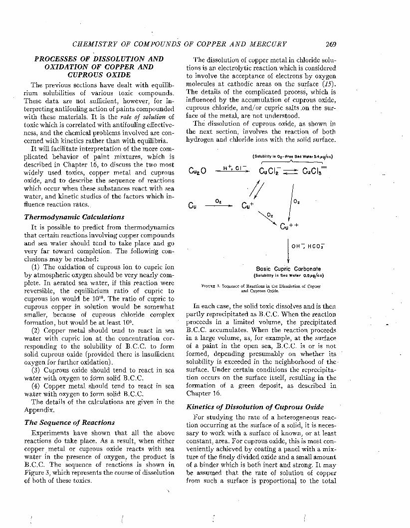
C H E M I S T R Y OF CO M PO U N D S OF COPPE R A N D M E R C U R Y 269
PROCESSES OF DISSOLUTION AND O XIDATIO N OF COPPER AND
CUPROUS OXIDEThe previous sections have dealt with equilib
rium solubilities of various toxic compounds. These data are not sufficient, however, for interpreting antifouling action of paints compounded with these materials. It is the rate of solution of toxic which is correlated with antifouling effectiveness, and the chemical problems involved are concerned with kinetics rather than with equilibria.
It will facilitate interpretation of the more complicated behavior of paint mixtures, which is described in Chapter 16, to discuss the two most widely used toxics, copper metal and cuprous oxide, and to describe the sequence of reactions which occur when these substances react with sea water, and kinetic studies of the factors which influence reaction rates.
T h erm odyn am ic C alculationsIt is possible to predict from thermodynamics
that certain reactions involving copper compounds and sea water should tend to take place and go very far toward completion. The following conclusions may be reached :
(1) The oxidation of cuprous ion to cupric ion by atmospheric oxygen should be very nearly complete. In aerated sea water, if this reaction were reversible, the equilibrium ratio of cupric to cuprous ion would be IO10. The ratio of cupric to cuprous copper in solution would be somewhat smaller, because of cuprous chloride complex formation, but would be at least IO5.
(2) Copper metal should tend to react in sea water with cupric ion at the concentration corresponding to the solubility of B.C.C. to form solid cuprous oxide (provided there is insufficient oxygen for further oxidation).
(3) Cuprous oxide should tend to react in sea water with oxygen to form solid B.C.C.
(4) Copper metal should tend to react in sea water with oxygen to form solid B.C.C.
The details of the calculations are given in the Appendix.
The Sequence o f R eactionsExperiments have shown that all the above
reactions do take place. As a result, when either copper metal or cuprous oxide reacts with sea water in the presence of oxygen, the product is B.C.C. The sequence of reactions is shown in Figure 3, which represents the course of dissolution of both of these toxics.
The dissolution of copper metal in chloride solutions is an electrolytic reaction which is considered to involve the acceptance of electrons by oxygen molecules at cathodic areas on the surface (15). The details of the complicated process, which is influenced by the accumulation of cuprous oxide, cuprous chloride, and/or cupric salts .on the surface of the metal, are not understood.
The dissolution of cuprous oxide, as shown in the next section, involves the reaction of both hydrogen and chloride ions with the solid surface.
(Solubility in O g -F re e S ea Water 5 .4 jig /c c ) _______________A________________f
Cu20 - H+,CI~> CuCI2- ^ CuCI3=
o h - ; H O O T
Ba si c Cupric C a r b o na t e(S o lub ility In S o a W a te r 0 .5 j i g /c c )
F i g u r e 3 . Sequence of Reactions in the Dissolution of Copper and Cuprous Oxide.
In each case, the solid toxic dissolves and is then partly reprecipitated as B.C.C. When the reaction proceeds in a limited volume, the precipitated B.C.C. accumulates. When the reaction proceeds in a large volume, as, for example, at the surface of a paint in the open sea, B.C.C. is or is not formed, depending presumably on whether its solubility is exceeded in the neighborhood of the surface. Under certain conditions the reprecipitation occurs on the surface itself, resulting in the formation of a green deposit, as described in Chapter 16.
K in etics o f D isso lu tion o f Cuprous OxideFor studying the rate of a heterogeneous reac
tion occurring at the surface of a solid, it is necessary to work with a surface of known, or at least constant, area. For cuprous oxide, this is most conveniently achieved by coating a panel with a mixture of the finely divided oxide and a small amount of a binder which is both inert and strong. It may be assumed that the rate of solution of copper from such a surface is proportional to the total
\
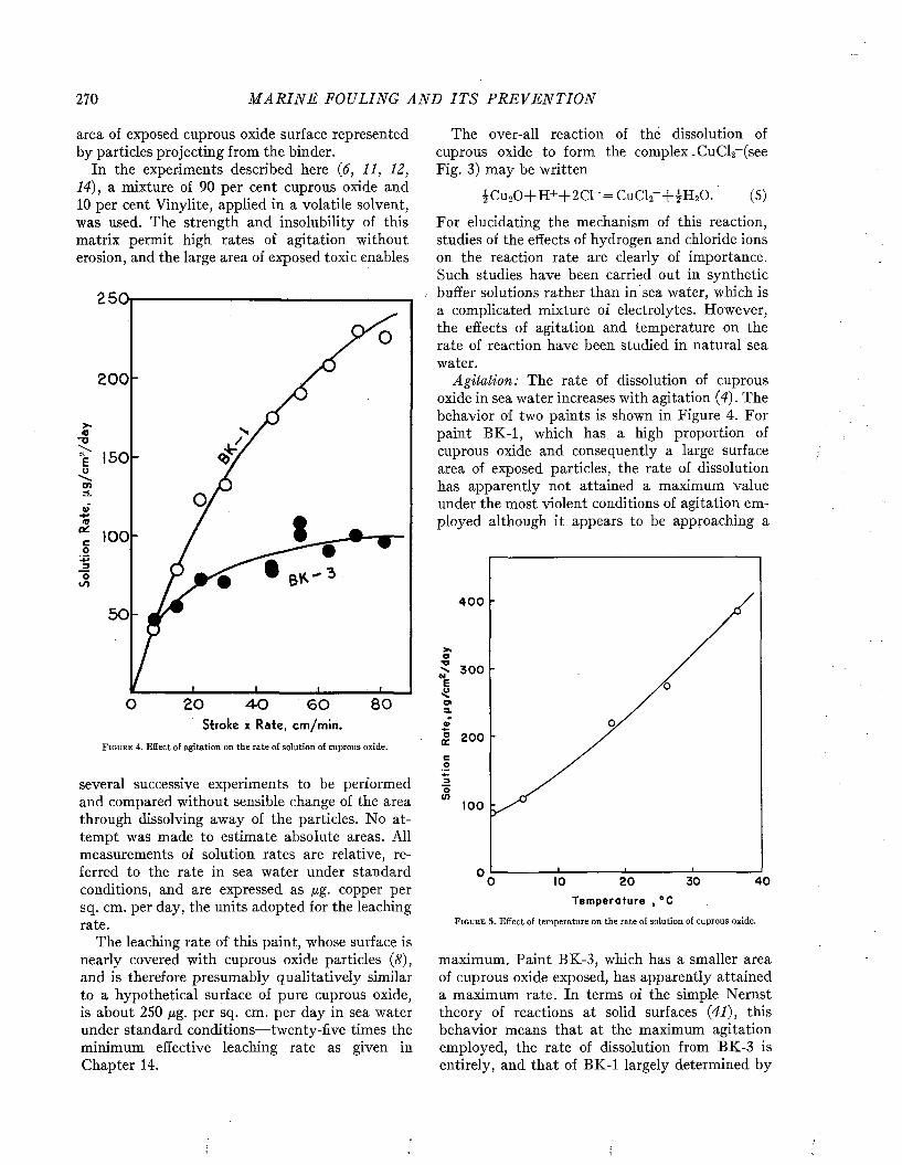
270 M A R I N E FOULING A N D I T S P R E V E N T I O N
area of exposed cuprous oxide surface represented by particles projecting from the binder.
In the experiments described here (6, 11, 12, 14), a mixture of 90 per cent cuprous oxide and 10 per cent Vinylite, applied in a volatile solvent, was used. The strength and insolubility of this matrix permit high rates of agitation without erosion, and the large area of exposed toxic enables
250,
200
<0-o 150uond.w
■4-»m% l o oo
50
20 8 0O 4 - 0 6 0Stroke x Rate, cm/min.
F i g u r e 4. Effect of agitation on the rate of solution of cuprous oxide.
several successive experiments to be performed and compared without sensible change of the area through dissolving away of the particles. No attempt was made to estimate absolute areas. All measurements of solution rates are relative, referred to the rate in sea water under standard conditions, and are expressed as ßg. copper per sq. cm. per day, the units adopted for the leaching rate.
The leaching rate of this paint, whose surface is nearly covered with cuprous oxide particles (8), and is therefore presumably qualitatively similar to a hypothetical surface of pure cuprous oxide, is about 250 ßg. per sq. cm. per day in sea water under standard conditions— twenty-five times the minimum effective leaching rate as given in Chapter 14.
The over-all reaction of thé dissolution of cuprous oxide to form the complex .CuCl2~(see Fig. 3) may be written
iC u20 + H + + 2 C l-= C u C lr+ JH 20 . (5)
For elucidating the mechanism of this reaction, studies of the effects of hydrogen and chloride ions on the reaction rate are clearly of importance. Such studies have been carried out in synthetic buffer solutions rather than in sea water, which is a complicated mixture of electrolytes. However, the effects of agitation and temperature on the rate of reaction have been studied in natural sea water.
Agitation: The rate of dissolution of cuprous oxide in sea water increases with agitation (4). The behavior of two paints is shown in Figure 4. For paint BK-1, which has a high proportion of cuprous oxide and consequently a large surface area of exposed particles, the rate of dissolution has apparently not attained a maximum value under the most violent conditions of agitation employed although it appears to be approaching a
4 0 0
3 0 0
200
100
o4 020 3 0
T em perature , °CF i g u r e 5 . Effect o f t e m p e r a t u r e o n t h e r a t e o f s o l u t i o n o f c u p r o u s o x i d e .
maximum. Paint BK-3, which has a smaller area of cuprous oxide exposed, has apparently attained a maximum rate. In terms of the simple Nernst theory of reactions at solid surfaces (41), this behavior means that at the maximum agitation employed, the rate of dissolution from BK-3 is entirely, and that of BK-1 largely determined by
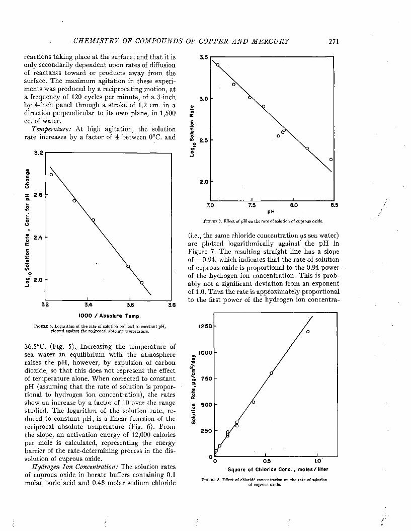
C H E M I S T R Y OF COM POUN DS OF COPPE R A N D M E R C U R Y 271
reactions taking place at the surface; and that it is only secondarily dependent upon rates of diffusion of reactants toward or products away from the surface. The maximum agitation in these experiments was produced by a reciprocating motion, at a frequency of 120 cycles per minute, of a 3-inch by 4-inch panel through a stroke of 1.2 cm. in a direction perpendicular to its own plane, in 1,500 cc. of water.
Temperature: At high agitation, the solution rate increases by a factor of 4 between 0°C. and
3 .2
? 2.0
3.2 3.4 3.6 3.8
1000 / Absolute Temp.
F i g u r e 6. Logarithm of the rate of solution reduced to constant pH, plotted against the reciprocal absolute temperature.
36.5°C. (Fig. 5). Increasing the temperature of sea water in equilibrium with the atmosphere raises the pH, however, by expulsion of carbon dioxide, so that this does not represent the effect of temperature alone. When corrected to constant pH (assuming that the rate of solution is proportional to hydrogen ion concentration), the rates show an increase by a factor of 10 over the range studied. The logarithm of the solution rate, reduced to constant pH, is a linear function of the reciprocal absolute temperature (Fig. 6). From the slope, an activation energy of 12,000 calories per mole is calculated, representing the energy barrier of the rate-determining process in the dissolution of cuprous oxide.
Hydrogen Ion Concentration: The solution rates of cuprous oxide in borate buffers containing 0.1 molar boric acid and 0.48 molar sodium chloride
3.5
3 .0
oIKcp
3
2.0
8.57.0 7.5 8.0pH
F i g u r e 7 . Effect of pH on the rate of solution of cuprous oxide.
(i.e., the same chloride concentration as sea water) are plotted logarithmically against the pH in Figure 7. The resulting straight line has a slope of —0.94, which indicates that the rate of solution of cuprous oxide is proportional to the 0.94 power of the hydrogen ion concentration. This is probably not a significant deviation from an exponent of 1.0. Thus the rate is approximately proportional to the first power of the hydrogen ion concentra-
1 2 5 0 -
1000>»o•oE
7 5 0
ooc5 0 0co
2 5 0
0.5 LOSquare of Chloride Cone. , m o le s /li te r
F i g u r e 8. Effect of chloride concentration on the rate of solution of cuprous oxide.
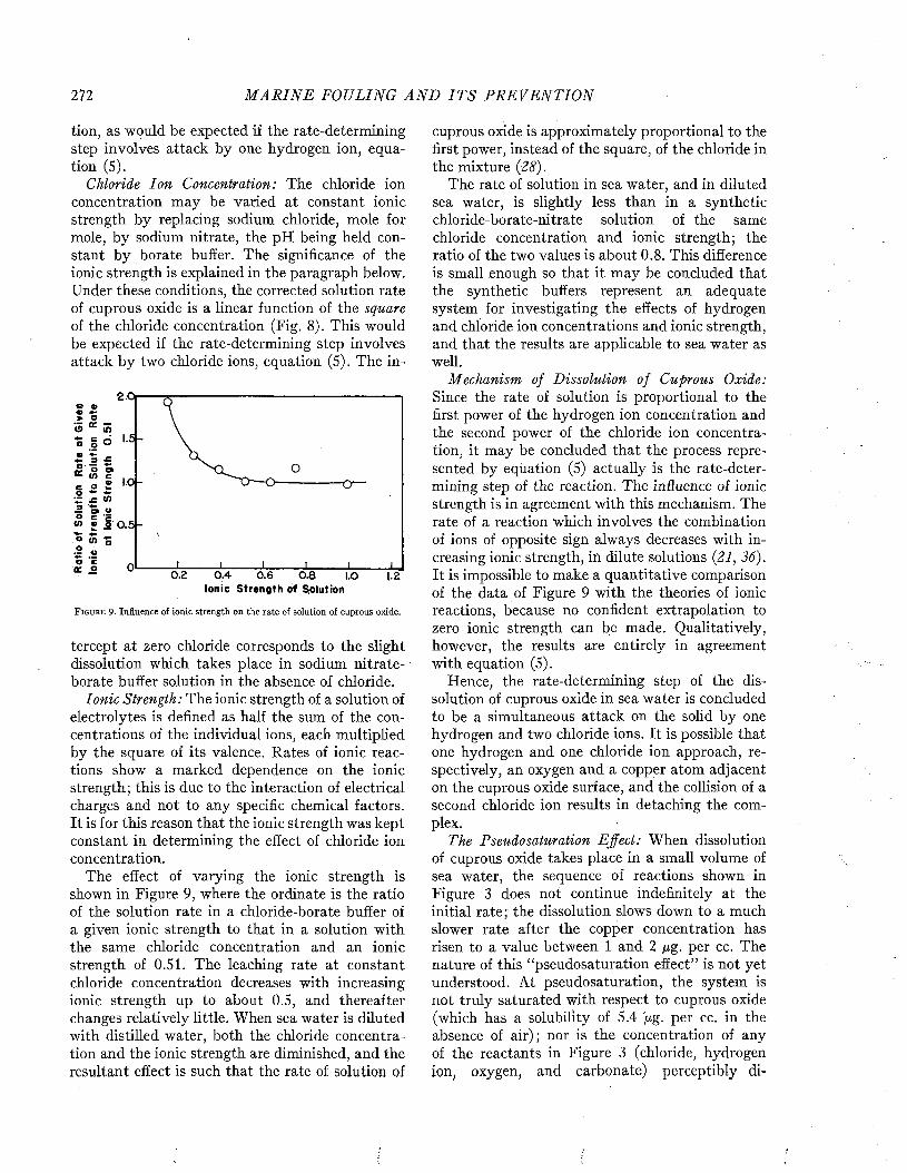
272 M A R I N E FOULING A N D I T S P R E V E N T I O N
tion, as would be expected if the rate-determining step involves attack by one hydrogen ion, equation (5).
Chloride Ion Concentration: The chloride ion concentration may be varied at constant ionic strength by replacing sodium chloride, mole for mole, by sodium nitrate, the pH being held constant by borate buffer. The significance of the ionic strength is explained in the paragraph below. Under these conditions, the corrected solution rate of cuprous oxide is a linear function of the square of the chloride concentration (Fig. 8). This would be expected if the rate-determining step involves attack by two chloride ions, equation (5). The in-
2.0i
^ 0 9" - « l e
■ o —
S £ <0
i V a</> e o 0.5 -
0.2 0 .4Ionic Strength of Solution
0.80.6 1.0
F i g u r e 9. Influence of ionic strength on the rate of solution of cuprous oxide.
tercept at zero chloride corresponds to the slight dissolution which takes place in sodium nitrate- borate buffer solution in the absence of chloride.
Ionic Strength: The ionic strength of a solution of electrolytes is defined as half the sum of the concentrations of the individual ions, each multiplied by the square of its valence. Rates of ionic reactions show a marked dependence on the ionic strength; this is due to the interaction of electrical charges and not to any specific chemical factors. It is for this reason that the ionic strength was kept constant in determining the effect of chloride ion concentration.
The effect of varying the ionic strength is shown in Figure 9, where the ordinate is the ratio of the solution rate in a chloride-borate buffer of a given ionic strength to that in a solution with the same chloride concentration and an ionic strength of 0.51. The leaching rate at constant chloride concentration decreases with increasing ionic strength up to about 0.5, and thereafter changes relatively little. When sea water is diluted with distilled water, both the chloride concentration and the ionic strength are diminished, and the resultant effect is such that the rate of solution of
cuprous oxide is approximately proportional to the first power, instead of the square, of the chloride in the mixture (28).
The rate of solution in sea water, and in diluted sea water, is slightly less than in a synthetic chloride-borate-nitrate solution of the same chloride concentration and ionic strength; the ratio of the two values is about 0.8. This difference is small enough so that it may be concluded that the synthetic buffers represent an adequate system for investigating the effects of hydrogen and chloride ion concentrations and ionic strength, and that the results are applicable to sea water as well.
Mechanism of Dissolution of Cuprous Oxide: Since the rate of solution is proportional to the first power of the hydrogen ion concentration and the second power of the chloride ion concentration, it may be concluded that the process represented by equation (5) actually is the rate-determining step of the reaction. The influence of ionic strength is in agreement with this mechanism. The rate of a reaction which involves the combination of ions of opposite sign always decreases with increasing ionic strength, in dilute solutions (21, 36). It is impossible to make a quantitative comparison of the data of Figure 9 with the theories of ionic reactions, because no confident extrapolation to zero ionic strength can be made. Qualitatively, however, the results are entirely in agreement with equation (5).
Hence, the rate-determining step of the dissolution of cuprous oxide in sea water is concluded to be a simultaneous attack on the solid by one hydrogen and two chloride ions. It is possible that one hydrogen and one chloride ion approach, respectively, an oxygen and a copper atom adjacent on the cuprous oxide surface, and the collision of a second chloride ion results in detaching the complex.
The Pseudosaturation Effect: When dissolution of cuprous oxide takes place in a small volume of sea water, the sequence of reactions shown in Figure 3 does not continue indefinitely at the initial rate; the dissolution slows down to a much slower rate after the copper concentration has risen to a value between 1 and 2 /xg. per cc. The nature of this “pseudosaturation effect” is not yet understood. At pseudosaturation, the system is not truly saturated with respect to cuprous oxide (which has a solubility of 5.4 '/xg' per cc. in the absence of air); nor is the concentration of any of the reactants in Figure 3 (chloride, hydrogen ion, oxygen, and carbonate) perceptibly di
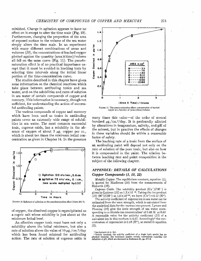
C H E M I S T R Y OF COM POUN DS OF COPPER A N D M E R C U R Y 273
minished. Change in agitation appears to have no effect on it except to alter the time scale (.Fig. 10). Furthermore, changing the proportion of the area of exposed surface to the volume of the sea water simply alters the time scale. In an experiment with many different combinations of areas and volumes (20), the concentrations of leached copper plotted against the quantity (area X time) /volum e all fell on the same curve (Fig. 11). The pseudosaturation effect is of no practical importance except that it must be avoided in leaching tests by selecting time intervals along the initial linear portion of the time-concentration curve.
The studies described in this chapter have given some information on the chemical reactions which take place between antifouling toxics and sea water, and on the solubilities and rates of solution in sea water of certain compounds of copper and mercury. This information is necessary, though not sufficient, for understanding the action of successful antifouling paints.
The various compounds of copper and mercury which have been used as toxics in antifouling paints cover an extremely wide range of solubilities in sea water. The most common successful toxic, cuprous oxide, has a solubility in the absence of oxygen of about 5 ßg. copper per cc., which is about ten times the minimum lethal concentration as given in Chapter 14. In the presence
0 n ex-
/ °
O Agitation 120 s tc /m in ,0 .6 c m .• Agitation 7 5 s tr /m in ., 0 .1 cm.,
time sc a le multiplied by0.32
l i l i
Time in HoursF ig u r e 10. Influence of agitation on the pseudosaturation effect (Paint BK-5).
of oxygen, the dissolved copper is reprecipitated as a cupric salt whose solubility is just about at the minimum lethal level.
An effective copper toxic must have not only a solubility above the lethal minimum, but also a rate of solution above the value of 10 qg./cm .2/d ay which has been found minimal for antifouling action. The rate of solution of cuprous oxide is
OON»O»a.e
'S 0.8j>oMM
o 0.6
AREA In c m 1
- 3 9- 7 81 5 5
5 0 .4 0 - -< j - _© - -
- — 6 2 0 — 1 0 3 0 — 2 0 6 0
0.2
0 2 3
( A r e a X T i m e ) / V o lu m e
F i g u r e 11. The pseudosaturation effect: concentration of leached copper as a function of (area X time)/volume.
many times this value— of the order of several hundred pg./cm .2/day. It is profoundly affected by alterations in temperature, salinity, and pH of the solvent, but in practice the effects of changes in these variables should lie within a reasonable factor of safety.
The leaching rate of a toxic from the surface of an antifouling paint will depend not only on the rate of solution of the pure toxic, but also on how it is compounded in the paint. The relation between leaching rate and paint composition is the subject of the following chapter.
APPENDIX: DETAILS OF CALCULATIONS Copper C om pounds (3, 15, 22)
M etallic Copper. The equilibrium constant, equation (1), is quoted by M aclnnes (26) from the measurements of Heinerth (18).
Cuprous Oxide. The solubility product (Cu+)(OH_) is given by Latimer (22) as 1.2 X IO-15. Taking the ion product (22) (H+XOH-) as 1.0X10“ 14, we have (Cu+)=0.12 (H+).
The activity coefficient of cuprous ion in sea water can be estimated from the ionic strength, which is calculated from the analytical data for the various ions present. Lyman and Fleming (24) give the ionic strength of sea water corresponding to a chloride ion concentration1 of 0.48 M. as 0.63. A reasonable value for the activity coefficient (23) of a univalent ion in this medium is 0.67. Accordingly2 the concentration of cuprous ion is 0.18 (H+), as stated in equation (2).
1 See footnote on p. 265.2 Strictly speaking, the activity coefficient of a single ionic species has no
physical meaning; this treatment implies certain conventions regarding the definition of pH, which are discussed in Reference 26, pp. 271 ff.
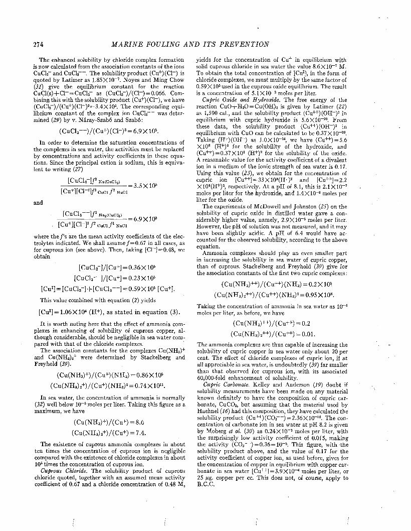
274 M A R I N E FOULING A N D I T S P R E V E N T I O N
The enhanced solubility by chloride complex formation is now calculated from the association constants of the ions CuCl2~ and CuCl3 . The solubility product (Cu+)(C1~) is quoted by Latimer as 1.85 X IO-7 . Noyes and Ming Chow(31) give the equilibrium constant for the reaction C uC l(s)+ C l- = CuCl2- as (C u C lr ) / (C r ) = 0.066. Combining, this with the solubility product (Cu+)(C1~), we have (CuC12_)/(C u+)(C1~)2=3.4X 10⁵. The corresponding equilibrium constant of the complex ion CuCl3 was determined (29 ) by v. Náray-Szabó and Szabó:
(CuCl3— )/(Cu+)(Cl-)3 = 6 .9X l05.
In order to determine the saturation concentrations of the complexes in sea water, the activities must be replaced by concentrations and activity coefficients in these equations. Since the principal cation is sodium, this is equivalent to writing (27)
[CuCU-]/2 N a(CuC l2) , 3 X 1 0 .
[Cu+][C]-2] /2c u c i /2 Naci
and
[CuCl3 ] f N a2(CuCl3) ,---------------------------------= 6.9 X 10&
, [Cu+][C1_P p CuCl ƒ * N aC l
where the ƒ’s are the mean activity coefficients of the electrolytes indicated. We shall assume ƒ = 0 .6 7 in all cases, as for cuprous ion (see above). Then, taking [Cl- ] = 0.48, we obtain
[CuCl2~]/[Cu+] = 0.36X IO6 [CuCl3 ]/[Cu+] = 0.23 X IO6
[Cu1] = [CuCl*-] + [CuCl,— ] = 0.59X10⁵ [Cu+],
This value combined with equation (2) yields
[CuI]=1.06X 10⁴ (H+), as stated in equation (3).
I t is worth noting here tha t the effect of ammonia complexes in enhancing of solubility of cuprous copper, although considerable, should be negligible in sea w ater compared with tha t of the chloride complexes.
The association constants for the complexes Cu(NH3)+ and Cu(NH3)2+ were determined by Stackelberg and Freyhold (39).
(Cu(NH3)+)/(C u+)(NH3) =0.86X 10⁶ (Cu(NH3)2+)/(C u+)(NH3)2 = 0.74 X IO11.
In sea water, the concentration of ammonia is normally(3 2 ) well below IO-5 moles per liter. Taking this figure as a maximum, we have
(Cu(NH3)+)/(C u+) = 8.6 (Cu(NH 3)2+)/(C u+) = 7.4.
The existence of cuprous ammonia complexes in about ten times the concentration of cuprous ion is negligible compared with the existence of chloride complexes in about IO5 times the concentration of cuprous ion.
Cuprous Chloride. The solubility product of cuprous chloride quoted, together with an assumed mean activity coefficient of 0.67 and a chloride concentration of 0.48 M,
y i e l d s f o r t h e c o n c e n t r a t i o n o f C u + i n e q u i l i b r i u m w i t h s o l i d c u p r o u s c h l o r i d e i n s e a w a t e r t h e v a l u e 8 . 6 X 1 0 - 7 M . T o o b t a i n t h e t o t a l c o n c e n t r a t i o n o f [ C u 1] , i n t h e f o r m o f c h l o r i d e c o m p l e x e s , w e m u s t m u l t i p l y b y t h e s a m e f a c t o r o f 0 .5 9 X IO 5 u s e d i n t h e c u p r o u s o x i d e e q u i l i b r i u m . T h e r e s u l t i s a c o n c e n t r a t i o n o f 5 . 1 X IO - 2 m o l e s p e r l i t e r .
Cupric Oxide and Hydroxide. T h e f r e e e n e r g y o f t h e r e a c t i o n C u 0 + H 20 = C u ( 0 H ) 2 i s g i v e n b y L a t i m e r (22) a s 1 ,5 9 0 c a l . , a n d t h e s o l u b i l i t y p r o d u c t ( C u + + ) ( O H - ) 2 in e q u i l i b r i u m w i t h c u p r i c h y d r o x i d e i s 5 .6 X 1 0 -2 0 . F r o m t h e s e d a t a , t h e s o l u b i l i t y p r o d u c t ( C u + + ) ( O H - ) 2 i n e q u i l i b r i u m w i t h C u O c a n b e c a l c u l a t e d t o b e 0 . 3 7 X 1 0 -2 0 . T a k i n g ( H + ) ( O H _ ) a s 1 . 0 X 1 0 -1 4 , w e h a v e ( C u + + ) = 5 .6 X 1 0 8 ( H + ) 2 f o r t h e s o l u b i l i t y o f t h e h y d r o x i d e , a n d ( C u + + ) = 0 . 3 7 X 1 0 8 ( H + ) 2 f o r t h e s o l u b i l i t y o f t h e o x i d e . A r e a s o n a b l e v a l u e f o r t h e a c t i v i t y c o e f f i c i e n t o f a d i v a l e n t i o n i n a m e d i u m o f t h e i o n i c s t r e n g t h o f s e a w a t e r i s 0 .1 7 . U s i n g t h i s v a l u e (23), w e o b t a i n f o r t h e c o n c e n t r a t i o n o f c u p r i c i o n [ C u + + ] = 3 3 X 1 0 8( H + ) 2 a n d [C u + + ] = 2 .2 X 1 0 8( H + ) 2, r e s p e c t i v e l y . A t a p H o f 8 .1 , t h i s i s 2 . I X IO - 7 m o l e s p e r l i t e r f o r t h e h y d r o x i d e , a n d 1 . 4 X 1 0 - 8 m o l e s p e r l i t e r f o r t h e o x id e .
T h e e x p e r i m e n t s o f M c D o w e l l a n d J o h n s t o n (25) o n t h e s o l u b i l i t y o f c u p r i c o x i d e i n d i s t i l l e d w a t e r g a v e a c o n s i d e r a b l y h i g h e r v a l u e , n a m e l y , 2 . 9 X 1 0 - 6 m o l e s p e r l i t e r . H o w e v e r , t h e p H o f s o l u t i o n w a s n o t m e a s u r e d , a n d i t m a y h a v e b e e n s l i g h t l y a c i d i c . A p H o f 6 . 4 w o u l d h a v e a c c o u n t e d f o r t h e o b s e r v e d s o l u b i l i t y , a c c o r d i n g t o t h e a b o v e e q u a t i o n .
A m m o n i a c o m p l e x e s s h o u l d p l a y a n e v e n s m a l l e r p a r t i n i n c r e a s i n g t h e s o l u b i l i t y i n s e a w a t e r o f c u p r i c c o p p e r , t h a n o f c u p r o u s . S t a c k e l b e r g a n d F r e y h o l d (3 P ) g i v e f o r t h e a s s o c i a t i o n c o n s t a n t s o f t h e f i r s t t w o c u p r i c c o m p l e x e s :
( C u ( N H 3) + + ) / ( C u + + ) ( N E S ) = 0 . 2 X 1 0 *
( C u ( N H 3) 2+ + ) / ( C u + + ) ( N E O 2 = 0 . 9 5 X 1 0 s .
T a k i n g t h e c o n c e n t r a t i o n o f a m m o n i a i n s e a w a t e r a s IO - 6 m o l e s p e r l i t e r , a s b e f o r e , w e h a v e
( C u ( N H 3) + + ) / ( C u + + ) = 0 . 2
( C u ( N H , ) , + + ) / ( C u + + ) = 0 . 0 1 .
T h e a m m o n i a c o m p l e x e s a r e t h u s c a p a b l e o f i n c r e a s i n g t h e s o l u b i l i t y o f c u p r i c c o p p e r i n s e a w a t e r o n l y a b o u t 2 0 p e r c e n t . T h e e f f e c t o f c h l o r i d e c o m p l e x e s o f c u p r i c i o n , i f a t a l l a p p r e c i a b l e i n s e a w a t e r , i s u n d o u b t e d l y (39) f a r s m a l l e r t h a n t h a t o b s e r v e d f o r c u p r o u s i o n , w i t h i t s a s s o c i a t e d 6 0 ,0 0 0 - f o l d e n h a n c e m e n t o f s o l u b i l i t y .
Cupric Carbonate. K e l l e y a n d A n d e r s o n (19) d o u b t i f s o l u b i l i t y m e a s u r e m e n t s h a v e b e e n m a d e o n a n y m a t e r i a l k n o w n d e f i n i t e l y t o h a v e t h e c o m p o s i t i o n o f c u p r i c c a r b o n a t e , C u C 0 3, b u t a s s u m i n g t h a t t h e m a t e r i a l u s e d b y H a e h n e l (16) h a d t h i s c o m p o s i t i o n , t h e y h a v e c a l c u l a t e d t h e s o l u b i l i t y p r o d u c t ( C u H " ) ( C 0 3 ) = 2 . 3 6 X 1 0 ~ 10. T h e c o n c e n t r a t i o n o f c a r b o n a t e i o n i n s e a w a t e r a t p H 8 .2 i s g i v e n b y M o b e r g et al. ( 3 0 ) a s 0 . 2 4 X 1 0 ~ 3 m o l e s p e r l i t e r , w i t h t h e s u r p r i s i n g l y l o w a c t i v i t y c o e f f i c i e n t o f 0 .0 1 5 , m a k i n g t h e a c t i v i t y ( C 0 3 ) = 0 . 3 6 = IO - 5 . T h i s f i g u r e , w i t h t h es o l u b i l i t y p r o d u c t a b o v e , a n d t h e v a l u e o f 0 .1 7 f o r t h e a c t i v i t y c o e f f i c i e n t o f c o p p e r i o n , a s u s e d b e f o r e , g i v e s f o r t h e c o n c e n t r a t i o n o f c o p p e r i n e q u i l i b r i u m w i t h c o p p e r c a r b o n a t e i n s e a w a t e r [ C u + + ] = 3 . 9 X 1 0 - 4 m o l e s p e r l i t e r , o r 2 5 ßg. c o p p e r p e r c c . T h i s d o e s n o t , o f c o u r s e , a p p l y t o B . C . C .
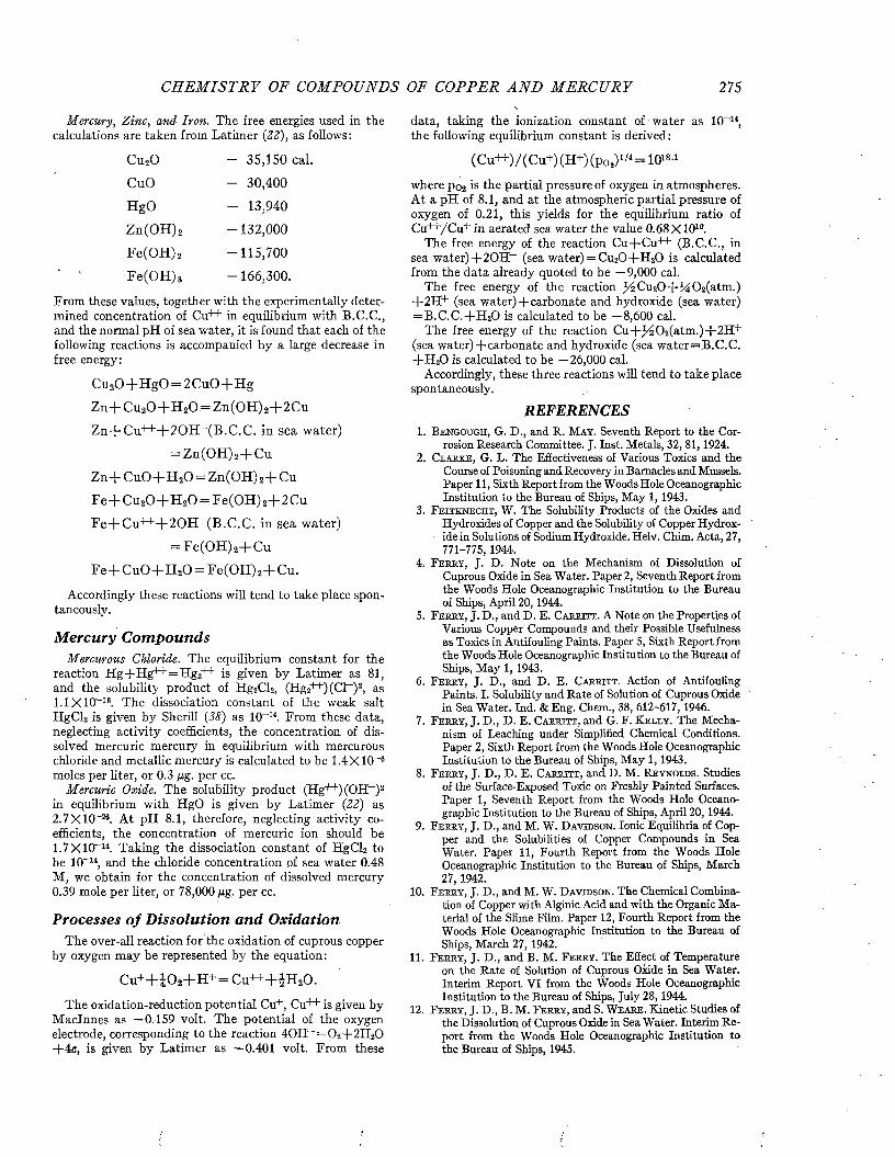
C H E M I S T R Y OF COM POUN DS OF COPP ER A N D M E R C U R Y 275
M ercury, Z inc, and Iron. The free energies used in the calculations are taken from Latim er (22), as follows:
Cu20 — 35,150 cal.
CuO - 30,400HgO - 13,940Zn(OH)2 -132,000Fe(OH)2 -115,700
Fe(OH)3 -166,300.
From these values, together with the experimentally determined concentration of 01++ in equilibrium with B.C.C., and the normal pH of sea water, it is found tha t each of the following reactions is accompanied by a large decrease in free energy:
Cu20 + HgO = 2 CuO+ HgZn-(- Cu20 + H 20 = Zn(0H)ü+2CuZ n+C u+++20H _(B.C.C. in sea water)
= Zn(OH)2+ CuZ n + C u 0 + H 20 = Zn(OH) 2+C uF e+ C u 20 + H ,0 = F e(0H )2+2C uFe+C u+++ 2 0 H - (B.C.C. in sea water)
= Fe(OH)2+ C uF e + C u 0 + H 20 = F e(0H )2+C u.
Accordingly these reactions will tend to take place spontaneously.
M ercury C om poundsM ercurous Chloride. The equilibrium constant for the
reaction H g + H g ++= H g 2++ is given by Latimer as 81, and the solubility product of Hg2Cl2, (Hg2++) (Cl- )2, as 1.1X10⁻¹⁸. The dissociation constant of the weak salt HgClü is given by Sherill (38) as IO-14. From these data, neglecting activity coefficients, the concentration of dissolved mercuric mercury in equilibrium with mercurous chloride and metallic mercury is calculated to be 1.4X10⁻⁶ moles per liter, or 0.3 ßg. per cc.
M ercuric Oxide. The solubility product (Hg++)(OH- )2 in equilibrium with HgO is given by Latim er (22) as 2.7X10⁻²⁶. A t pH 8.1, therefore, neglecting activity coefficients, the concentration of mercuric ion should be1.7 X IO-14. Taking the dissociation constant of HgCl2 to be 1(T14, and the chloride concentration of sea water 0.48 M, we obtain for the concentration of dissolved mercury0.39 mole per liter, or 78,000 ¡xg. per cc.
Processes o f D isso lu tion an d O xidationThe over-all reaction for the oxidation of cuprous copper
by oxygen m ay be represented by the equation:
C u + + i0 2+ H + = Cu+ + + |H 20 .
The oxidation-reduction potential Cu+, Cu++ is given by M aclnnes as —0.159 volt. The potential of the oxygen electrode, corresponding to the reaction 40H - = 0 2+ 2 H 20 +4e, is given by Latim er as —0.401 volt. From these
data, taking the ionization constant of water as 10 14, the following equilibrium constant is derived :
(Cu++)/(C u+)(H+)(po2)1/4= IO18-1
where po2 is the partial pressure of oxygen in atmospheres. A t a pH of 8.1, and a t the atmospheric partial pressure of oxygen of 0.21, this yields for the equilibrium ratio of Cu++/Cu+ in aerated sea water the value 0.68X10¹⁰.
The free energy of the reaction Cu+C u++ (B.C.C., in sea w ate r)+ 2 0 H - (sea water) = Cu20 + H 20 is calculated from the data already quoted to be —9,000 cal.
The free energy of the reaction )^C u20 + l d 0 2(atm.) + 2H + (sea water)-(-carbonate and hydroxide (sea water) = B .C .C .+ H 20 is calculated to be —8,600 cal.
The free energy of the reaction C u + /^ 0 2(atm .)+ 2H + (sea water)-(-carbonate and hydroxide (sea w ater=B .C .C . + H 20 is calculated to be —26,000 cal.
Accordingly, these three reactions will tend to take place spontaneously.
REFERENCES1. B e n g o u g h , G. D., and R. M a y . Seventh Report to the Cor
rosion Research Committee. J. Inst. Metals, 32, 81,1924.2. C l a r k e , G. L. The Effectiveness of Various Toxics and the
Course of Poisoning and Recovery in Barnacles and Mussels. Paper 11, Sixth Report from the Woods Hole Oceanographic Institution to the Bureau of Ships, May 1, 1943.
3 . F e it k n e c h t , W. The Solubility Products of the Oxides andHydroxides of Copper and the Solubility of Copper Hydroxide in Solutions of Sodium Hydroxide. Helv. Chim. Acta, 27, 771-775,1944.
4. F e r r y , J. D. Note on the Mechanism of Dissolution ofCuprous Oxide in Sea Water. Paper 2, Seventh Report from the Woods Hole Oceanographic Institution to the Bureau of Ships, April 20, 1944.
5. F e r r y , J. D ., and D . E. C a r r i t i . A Note on the Properties ofVarious Copper Compounds and their Possible Usefulness as Toxics in Antifouling Paints. Paper 5, Sixth Report from the Woods Hole Oceanographic Institution to the Bureau of Ships, May 1, 1943.
6 . F e r r y , J. D ., and D . E. C a r r it t . Action of AntifoulingPaints. I. Solubility and Rate of Solution of Cuprous Oxide in Sea Water. Ind. & Eng. Chem., 38, 612-617, 1946.
7. F e r r y , J. D ., D. E. C a r r it t , and G. F. K e l l y . The Mechanism of Leaching under Simplified Chemical Conditions. Paper 2, Sixth Report from the Woods Hole Oceanographic Institution to the Bureau of Ships, M ay 1, 1943.
8. F e r r y , J. D ., D . E. C a r r it t , and D. M. R e y n o l d s . Studiesof the Surface-Exposed Toxic on Freshly Painted Surfaces. Paper 1, Seventh Report from the Woods Hole Oceanographic Institution to the Bureau of Ships, April 20, 1944.
9. F e r r y , J. D ., and M. W. D a v id s o n . Ionic Equilibria of Copper and the Solubilities of Copper Compounds in Sea Water. Paper 11, Fourth Report from the Woods Hole Oceanographic Institution to the Bureau of Ships, March 27, 1942.
10. F e r r y , J. D ., and M. W. D a v id s o n . The Chemical Combination of Copper with Alginic Acid and with the Organic Material of the Slime Film. Paper 12, Fourth Report from the Woods Hole Oceanographic Institution to the Bureau of Ships, March 27, 1942.
11. F e r r y , J. D ., and B. M. F e r r y . The Effect of Temperatureon the Rate of Solution of Cuprous Oxide in Sea Water. Interim Report VI from the Woods Hole Oceanographic Institution to the Bureau of Ships, July 28, 1944.
12. F e r r y , J. D ., B. M. F e r r y , and S. W e a r e . Kinetic Studies ofthe Dissolution of Cuprous Oxide in Sea Water. Interim Report from the Woods Hole Oceanographic Institution to the Bureau of Ships, 1945.
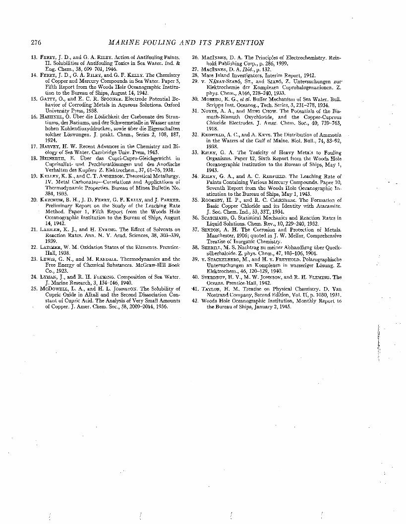
276 M A R I N E FOULING A N D I T S P R E V E N T I O N
13. F e r r y , J. D., and G. A. R i l e y . Action of Antifouling Paints.II. Solubilities of Antifouling Toxics in Sea Water. Ind. & Eng. Chena., 38, 699-701, 1946.
14. F e r r y , J. D., G. A. R il e y , and G. F. K e l l y . The Chemistryof Copper and Mercury Compounds in Sea Water. Paper 5, Fifth Report from the Woods Hole Oceanographic Institution to the Bureau of Ships, August 14, 1942.
15. G a t t y , O., and E. C. R. S p o o n e r . Electrode Potential Behavior of Corroding Metals in Aqueous Solutions. Oxford University Press, 1938.
16. H a e h n e l , O. Über die Löslichkeit der Carbonate des Strontiums, des Bariums, und der Schwermetalle in Wasser unter hohen Kohlendioxyddrucken, sowie über die Eigenschaften solcher Löswungen. J. prakt. Chem., Series 2, 108, 187, 1924.
17. H a r v e y , H. W. Recent Advances in the Chemistry and Biology of Sea Water. Cambridge Univ. Press, 1945.
18. H e i n e r t h , E. Über das Cupri-Cupro-Gleichgewicht inCuprisulfat- und Perchloratlösungen und des Anodische Verhalten des Kupfers Z. Elektrochem., 37, 61-76, 1931.
19. K e l l e y , K. K., and C. T. A n d e r s o n . Theoretical Metallurgy.IV. Metal Carbonates—Correlations and Applications of Thermodynamic Properties. Bureau of Mines Bulletin No. 384, 1935.
20. K e t c h u m , B. H., J. D. F e r r y , G. F. K e l l y , and J. P a r k e r .Preliminary Report on the Study of the Leaching Rate Method. Paper 1, Fifth Report from the Woods Hole Oceanographic Institution to the Bureau of Ships, August 14, 1942.
21. L a i d l e r , K. J., and H. E y r in g . The Effect of Solvents onReaction Rates. Ann. N. Y. Acad. Sciences, 38, 303-339, 1939.
22. L a t i m e r , W. M. Oxidation States of the Elements. Prentice-Hall, 1938.
23. L e w i s , G. N., and M. R a n d a l l . Thermodynamics and theFree Energy of Chemical Substances. McGraw-Hill Book Co., 1923.
24. L y m a n , J., and R. H. F l e m in g . Composition of Sea Water.J. Marine Research, 3, 134-146, 1940.
25. M cD o w e l l , L. A., and H. L. J o h n s t o n . The Solubility ofCupric Oxide in Alkali and the Second Dissociation Constant of Cupric Acid. The Analysis of Very Small Amounts of Copper. J. Amer. Chem. Soc., 58, 2009-2014, 1936.
26. M a c I n n e s , D. A. The Principles of Electrochemistry. Reinhold Publishing Corp., p. 286, 1939.
27. M a c I n n e s , D. A. Ib id ., p . 132.28. Mare Island Investigators, Interim Report, 1942.29. V. N á r a y -S z a b ó , S t ., a n d Sz a b ó , Z . U n t e r s u c h u n g e n z u r -
Elektrochemie der Komplexen Cuprohalogenanionen. Z. phys. Chem., A l 66, 228-240, 1933.
30. M o b e r g , E. G., ei al. Buffer Mechanism of Sea Water. Bull.Scripps Inst. Oceanog., Tech. Series, 3, 231-278, 1934.
31. N o y e s , A. A., and M i n g C h o w . The Potentials of the Bismuth-Bismuth Oxychloride, and the Copper-Cuprous Chloride Electrodes. J. Amer. Chem. Soc., 40, 739-763, 1918.
32. R e d f e e l d , A. C., and A. K e y s . The Distribution of Ammoniain the Waters of the Gulf of Maine. Biol. Bull., 74, 83-92, 1938.
33. R i l e y , G. A. The Toxicity of Heavy Metals to FoulingOrganisms. Paper 12, Sixth Report from the Woods Hole Oceanographic Institution to the Bureau of Ships, May 1, 1943.
34. R i l e y , G. A., a n d A. C. R e d f i e l d . T h e L e a c h in g R a t e ofPaints Containing Various Mercury Compounds. Paper 10, Seventh Report from the Woods Hole Oceanographic Institution to the Bureau of Ships, May 1, 1943.
35. R o o k s b y , H. P., and R. C. C h i r n s i d e . The Formation ofBasic Copper Chloride and its Identity with Atacamite. J. Soc. Chem. Ind., 53, 33T, 1934.
36. S c a t c h a r d , G. Statistical Mechanics and Reaction Rates inLiquid Solutions. Chem. Rev., 10, 229-240, 1932.
37. Se x t o n , A. H. The Corrosion and Protection of Metals.Manchester, 1906; quoted in J. W. Melior, Comprehensive Treatise of Inorganic Chemistry.
38. S h e r i l l , M. S. Nachtrag zu meiner Abhandlung über Queck-silberhaloide. Z. phys. Chem., 47, 103-106, 1904.
39. v. S t a c k e l b e r g , M., and H. v. F r e y h o l d . PolarographischeUntersuchungen an Komplexen in -yrasseriger Lösung. Z. Elektrochem., 46, 120-129, 1940.
40. S v e r d r u p , H. V., M. W. J o h n s o n , and R. H. F l e m i n g . TheOceans. Prentice-Hall, 1942.
'41. T a y l o r , H. M. Treatise on Physical Chemistry. D. Van Nostrand Company, Second Edition, Vol. II, p. 1030, 1931.
42. Woods Hole Oceanographic Institution, Monthly Report to the Bureau of Ships, January 2, 1945.
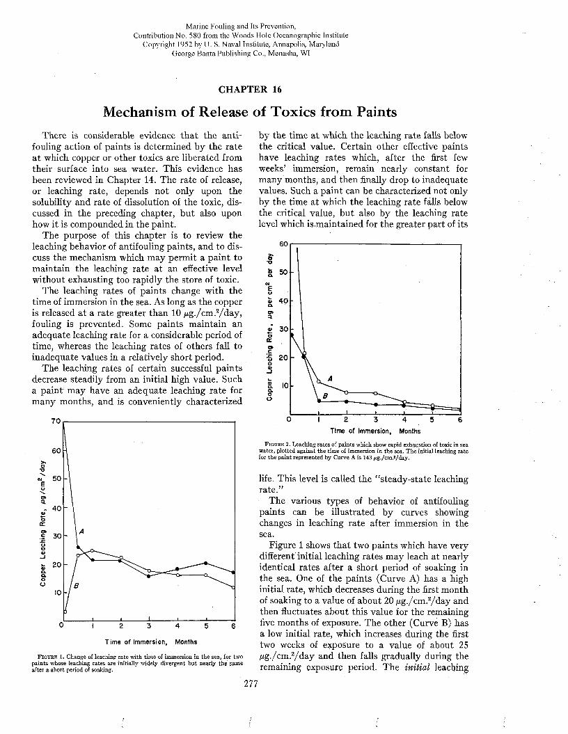
Marine Fouling and Its Prevention,Contribution No. 580 from the Woods Flole Oceanographic Institute
Copyright 1952 by U. S. Naval Institute, Annapolis, Maryland George Banta Publishing Co., Menasha, WI
CHAPTER 16
Mechanism of Release of Toxics from PaintsThere is considerable evidence that the anti
fouling action of paints is determined by the rate at which copper or other toxics are liberated from their surface into sea water. This evidence has been reviewed in Chapter 14. The rate of release, or leaching rate, depends not only upon the solubility and rate of dissolution of the toxic, discussed in the preceding chapter, but also upon how it is compounded in the paint.
The purpose of this chapter is to review the leaching behavior of antifouling paints, and to discuss the mechanism which may permit a paint to maintain the leaching rate at an effective level without exhausting too rapidly the store of toxic.
The leaching rates of paints change with the time of immersion in the sea. As long as the copper is released at a rate greater than 10 jug./cm.2/d ay , fouling is prevented. Some paints maintain an adequate leaching rate for a considerable period of time, whereas the leaching rates of others fall to inadequate values in a relatively short period.
The leaching rates of certain successful paints decrease steadily from an initial high value. Such a paint may have an adequate leaching rate for many months, and is conveniently characterized
7 0
6 0
5 0
- 4 0
by the time at which the leaching rate falls below the critical value. Certain other effective paints have leaching rates which, after the first few weeks’ immersion, remain nearly constant for many months, and then finally drop to inadequate values. Such a paint can be characterized not only by the time at which the leaching rate falls below the critical value, but also by the leaching rate level which is .maintained for the greater part of its
6 0
O*o& 5 0 -
ME ’ o« 4 0 “o.o»3.
¿ 3 0oa:o»c•§ 20oa>-J0)a.a .oO
0 2 3 4 5 6
Time of Immersion, Months
Figure 1. Change of leaching ra te w ith tím e of immersion in the sea, for two pain ts whose leaching rates are initially widely divergent b u t nearly th e same after a sho rt period of soaking.
Time of Immersion, Months
Figure 2. Leaching rates of paints which show rapid exhaustion of toxic in sea water, plotted against the time of immersion in the sea. The initial leaching rate for the paint represented by Curve A is 143 jug./cm.2/day.
life. This level is called the “steady-state leaching rate.”
The various types of behavior of antifouling paints can be illustrated by curves showing changes in leaching rate after immersion in the sea.
Figure 1 shows that two paints which have very different initial leaching rates may leach at nearly identical rates after a short period of soaking in the sea. One of the paints (Curve A) has a high initial rate, which decreases during the first month of soaking to a value of about 20 /¿g./cm.2/day and then fluctuates about this value for the remaining five months of exposure. The other (Curve B) has a low initial rate, which increases during the first two weeks of exposure to a value of about 25 jug./cm.2/d a y and then falls gradually during the remaining exposure period. The initial leaching
277
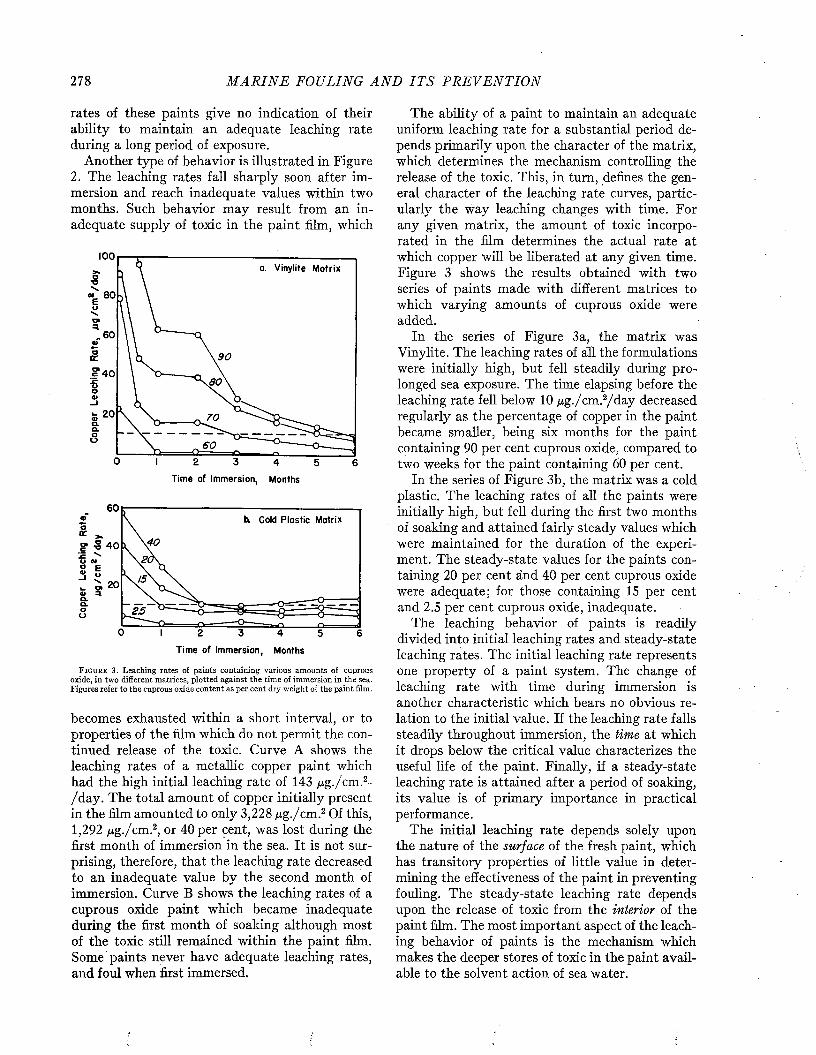
278 M A R I N E FOULING A N D I T S P R E V E N T I O N
rates of these paints give no indication of their ability to maintain an adequate leaching rate during a long period of exposure.
Another type of behavior is illustrated in Figure2. The leaching rates fall sharply soon after immersion and reach inadequate values within two months. Such behavior may result from an inadequate supply of toxic in the paint film, which
100a. Vinylite Matrix
« 8 0
. 6 0
9 0
£ 4 0 80
_i
70
6 0
Time of Immersion, Months
6 0h. Cold Plastic Matrix
4 0s
OJEu
a.a.2 5
-o~~
Time of Immersion, Months
F i g u r e 3. Leaching rates of paints containing various amounts of cuprous oxide, in two different matrices, plotted against the time of immersion in the sea. Figures refer to the cuprous oxide content as per cent dry weight of the paint film.
becomes exhausted within a short interval, or to properties of the film which do not permit the continued release of the toxic. Curve A shows the leaching rates of a metallic copper paint which had the high initial leaching rate of 143 ^g./'cm.2- / day. The total amount of copper initially present in the film amounted to only 3,228 jug./cm.2 Of this, 1,292 jug./cm.2, or 40 per cent, was lost during the first month of immersion in the sea. It is not surprising, therefore, that the leaching rate decreased to an inadequate value by the second month of immersion. Curve B shows the leaching rates of a cuprous oxide paint which became inadequate during the first month of soaking although most of the toxic still remained within the paint film. Some paints never have adequate leaching rates, and foul when first immersed.
The ability of a paint to maintain an adequate uniform leaching rate for a substantial period depends primarily upon the character of the matrix, which determines the mechanism controlling the release of the toxic. This, in turn, defines the general character of the leaching rate curves, particularly the way leaching changes with time. For any given matrix, the amount of toxic incorporated in the film determines the actual rate at which copper will be liberated at any given time. Figure 3 shows the results obtained with two series of paints made with different matrices to which varying amounts of cuprous oxide were added.
In the series of Figure 3a, the matrix was Vinylite. The leaching rates of all the formulations were initially high, but fell steadily during prolonged sea exposure. The time elapsing before the leaching rate fell below 10 jug./cm.2/day decreased regularly as the percentage of copper in the paint became smaller, being six months for the paint containing 90 per cent cuprous oxide, compared to two weeks for the paint containing 60 per cent.
In the series of Figure 3b, the matrix was a cold plastic. The leaching rates of all the paints were initially high, but fell during the first two months of soaking and attained fairly steady values which were maintained for the duration of the experiment. The steady-state values for the paints containing 20 per cent ánd 40 per cent cuprous oxide were adequate; for those containing 15 per cent and 2.5 per cent cuprous oxide, inadequate.
The leaching behavior of paints is readily divided into initial leaching rates and steady-state leaching rates. The initial leaching rate represents one property of a paint system. The change of leaching rate with time during immersion is another characteristic which bears no obvious relation to the initial value. If the leaching rate falls steadily throughout immersion, the time at which it drops below the critical value characterizes the useful life of the paint. Finally, if a steady-state leaching rate is attained after a period of soaking, its value is of primary importance in practical performance.
The initial leaching rate depends solely upon the nature of the surface of the fresh paint, which has transitory properties of little value in determining the effectiveness of the paint in preventing fouling. The steady-state leaching rate depends upon the release of toxic from the interior of the paint film. The most important aspect of the leaching behavior of paints is the mechanism which makes the deeper stores of toxic in the paint available to the solvent action of sea water.

M E C H A N I S M OF REL EA SE OF TOXICS FROM P A I N T S 279
INITIAL LEACHING RATESA surface freshly coated with antifouling paint
is covered with irregularities where the particles of toxic project from the solidified matrix. Depending upon the degree of dispersion of the pigment, the protruding toxic may be in the form of individual toxic particles, or of aggregates which are considerably larger.
Since paint vehicles wet the pigments suspended in them, it might be expected that each projecting toxic particle would be covered by a very thin layer of matrix. Actually, most antifouling paints begin to leach immediately, or at least within a few minutes, after immersion in sea water, so that any such skin of matrix must ordinarily be too thin to interfere with the dissolution of the toxic, or is rapidly removed after immersion. It is only in the case of certain compositions, particularly those applied as melts rather than with solvents, that a matrix skin delays the dissolution of toxic particles. This behavior will be discussed in more detail below.
In the typical antifouling paint, leaching begins at once when the fresh surface is immersed in sea water, and the protruding toxic particles begin to dissolve. The initial leaching rate at this moment depends on two factors: (A) the intrinsic rate of solution of the toxic at the prevailing temperature, salinity, and pH; and (B) the area of toxic exposed. These two factors will be discussed separately. Although the treatment is applicable for any toxic, it is given here specifically for cuprous oxide, and the experimental data refer to cuprous oxide paints.
The In trin sic R a te o f S o lu tionThe dependence of the rate of solution of cuprous
oxide upon different physical and chemical variables has already been described in Chapter 15. It is useful to review these data briefly.
1. The rate of solution is proportional to the hydrogen ion concentration.
2. The rate of solution is proportional to the square of the chloride ion concentration (at constant ionic strength).
3. As the ionic strength is increased, at constant chloride concentration, the rate of solution at first decreases, and then changes relatively little.
(These first three variables need not be considered when the solvent is normal sea water, since the pH, chlorinity, and ionic strength are fixed.)
4. The rate of solution increases with temperature, following the Arrhenius equation. In the neighborhood of 20°C. the increase amounts to three per cent per degree.
5. Relative values of the rate of solution can be measured only if the agitation of the solvent past the surface is high enough so that diffusion has a negligible effect in limiting the rate of solution.
The Area o f Exposed ToxicThe above discussion of the rate of solution of
cuprous oxide concerns relative values only. The absolute value of the intrinsic rate of solution, or rate per unit area of exposed toxic, is practically impossible to measure, because that area cannot be accurately determined, or even estimated. The measured leaching rate is calculated on the basis of the geometrical area of the paint surface considered as a plane. It may be in general either greater or less than the intrinsic rate of solution, depending on whether the actual area of toxic is greater or less than the geometrical surface area. The actual area may be greater because of protruding particles and surface irregularities, or less because part of the surface is covered by matrix.
The rate of dissolution of toxic into a given volume of solvent is proportional to the geometrical area of the paint (Chapter 15, Figure 11). It is natural to assume that, similarly, on a microscopic scale, the measured leaching rate is proportional to the actual area of toxic exposed. If this is true, we should expect the relation
aL = k — (1)
A
where L is the measured leaching rate, k the intrinsic rate of solution (i.e., the leaching rate of a plane surface of pure cuprous oxide), a the actual area of toxic exposed, and A the geometrical area of the surface considered as a plane.
The concept of exposed toxic particles projecting from a matrix surface is illustrated in Figure 4.
MATRIXs u r f a c e !
F i g u r e 4. Illustration of the concept of surface-exposed toxic. The black circles represent toxic particles exposed on the surface and immediately available for
. dissolution.
The surface-exposed area, a, is the sum of the individual exposed areas, some large, some small, depending on the extent of protrusion. In practice, of course, the cuprous oxide particles have irregular shapes and vary in size, instead of being uniform spheres as shown.
In soluble matrix paints it has been found that
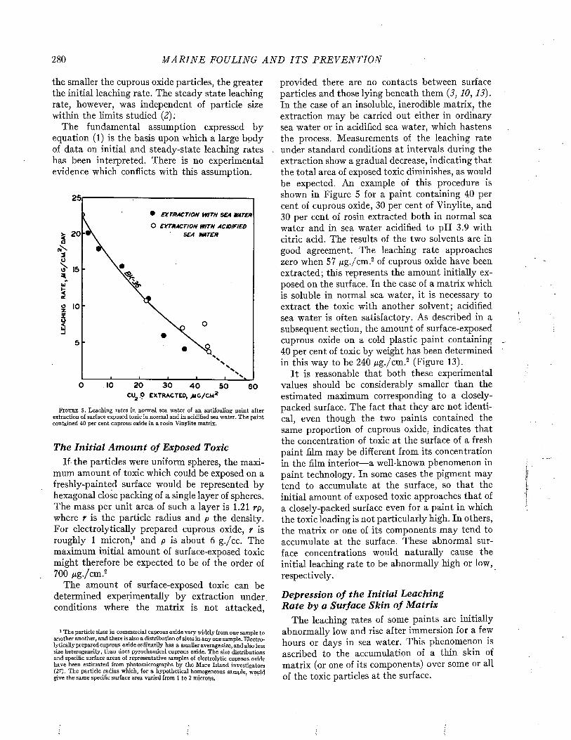
280 M A R I N E FOULING A N D I T S P R E V E N T I O N
the smaller the cuprous oxide particles, the greater the initial leaching rate. The steady state leaching rate, however, was independent of particle size within the limits studied (2);
The fundamental assumption expressed by equation (1) is the basis upon which a large body of data on initial and steady-state leaching rates has been interpreted. There is no experimental evidence which conflicts with this assumption.
25
• E X T R A C T I O N W I T H S E A W A T E R
O E X T R A C T I O N W I T H A C ID IF IE D
S E A W A T E R> 20
0 IO 20 3 0 4 0 50 60cu2 9 e x t r a c t e d , >u g / cm 2
F i g u r e S . Leaching rates in normal sea water of an antifouling paint after extraction of surface exposed toxic in normal and in acidified sea water. The paint contained 40 per cent cuprous oxide in a rosin Vinylite matrix.
The In itia l A m o u n t o f Exposed ToxicIf- the particles were uniform spheres, the maxi
mum amount of toxic which could be exposed on a freshly-painted surface would be represented by hexagonal close packing of a single layer of spheres. The mass per unit area of such a layer is 1.21 rp, where r is the particle radius and p the density. For electrolytically prepared cuprous oxide, r is roughly 1 micron,1 and p is about 6 g./cc. The maximum initial amount of surface-exposed toxic might therefore be expected to be of the order of 700 Mg-/cm.2
The amount of surface-exposed toxic can be determined experimentally by extraction under, conditions where the matrix is not attacked,
1 The particle sizes in commercial cuprous oxide vary widely from one sample to another another, and there is also a distribution of sizes in any one sample. Electrolytically prepared cuprous oxide ordinarily has a smaller average size, and also less size heterogeneity, than does pyrochemical cuprous oxide. The size distributions and specific surface areas of representative samples of electrolytic cuprous oxide have been estimated from photomicrographs by the Mare Island investigators (27). The particle radius which, for a hypothetical homogeneous sample, Roulei give the same specific surface area varied from 1 to 2 microns.
provided there are no contacts between surface particles and those lying beneath them (3, 10, 13). In the case of an insoluble, inerodible matrix, the extraction may be carried out either in ordinary sea water or in acidified sea water, which hastens the process. Measurements of the leaching rate under standard conditions at intervals during the extraction show a gradual decrease, indicating that the total area of exposed toxic diminishes, as would be expected. An example of this procedure is shown in Figure 5 for a paint containing 40 per cent of cuprous oxide, 30 per cent of Vinylite, and 30 per cent of rosin extracted both in normal sea water and in sea water acidified to pH 3.9 with citric acid. The results of the two solvents are in good agreement. The leaching rate approaches zero when 57 pg./cm.2 of cuprous oxide have been extracted; this represents the amount initially exposed on the surface. In the case of a matrix which is soluble in normal sea water, it is necessary to extract the toxic with another solvent; acidified sea water is often satisfactory. As described in a subsequent section, the amount of surface-exposed cuprous oxide on a cold plastic paint containing 40 per cent of toxic by weight has been determined in this way to be 240 pg./cm.2 (Figure 13).
It is reasonable that both these experimental values should be considerably smaller than the estimated maximum corresponding to a closely- packed surface. The fact that they are not identical, even though the two paints contained the same proportion of cuprous oxide, indicates that the concentration of toxic at the surface of a fresh paint film may be different from its concentration in the film interior— a well-known phenomenon in paint technology. In some cases the pigment may tend to accumulate at the surface, so that the initial amount of exposed toxic approaches that of a closely-packed surface even for a paint in which the toxic loading is not particularly high. In others, the matrix or one of its components may tend to accumulate at the surface. These abnormal surface concentrations would naturally cause the initial leaching rate to be abnormally high or low, respectively.
D epression o f th e In itia l Leaching R a te by a Surface Skin o f M atrix
The leaching rates of some paints are initially abnormally low and rise after immersion for a few hours or days in sea water. This phenomenon is ascribed to the accumulation of a thin skin of matrix (or one of its components) over some or all of the toxic particles at the surface.

M E C H A N I S M OF R E L E A S E OF TOXICS FROM P A I N T S 281
The likelihood of the presence of a matrix skin on a freshly painted surface was discussed by Ragg (29) in 1925. Unlike many previous authors, he was convinced that the skin was ordinarily removed soon after immersion. He showed that a panel coated with a paint compounded of varnish and cuprous thiocyanate did not release toxic into sea water, but that by exposure to agitated or flowing sea water the surface was unsealed and the toxic was permitted to dissolve.
In recent investigations, the effects of a surface skin, or a low surface concentration of toxic, have been noted particularly in the case of hot plastic paints. Here the skin is believed to be formed dur-
T a b l e 1. Leaching Rates* of H ot Plastic Paints
Treatment of Surface
Leaching Rate after Immersion in the Sea
0 wk. I wk. 2 wks. 1 mo. 2 mos.None 1.7 9 .2 13.4 17.5Buffed 33.9 14.3 10.3None 2.8 20.9 16.1 9 .4Buffed 48.3 19.3 12.9 12.3
* Mg./cm.2/day
ing the solidification of the melt. It can be removed by sandpapering or buffing, with consequent rise in the initial leaching rate. Examples of low initial leaching rates of hot plastic paints and the effect of buffing are given in Table 1, which shows also that the normal leaching rate is regained rather slowly by soaking in sea water. The abnormally low initial leaching rate can be raised if the paint is applied dissolved in a solvent instead of a melt (without otherwise changing its composition).
That the surface skin on fresh coatings of hot plastic paints is composed largely of the paraffin which such paints contain is indicated by visual examination and also by the wetting behavior of the surface. The contact angle between water and air at the paint surface (15) is about 101°, close to that of paraffin (I), 105°. As a hot plastic paint is soaked for several days in sea water, the contact angle falls to about 15°, representing a marked improvement in the degree of wetting of the surface (15).
In other cases, the surface skin of matrix seems to be removed much more rapidly by sea water, so that its presence is inferred only from an abnormally low leaching rate for the first hour or so after immersion. For example, Table 2 gives leaching rates for paint 16X (containing cuprous oxide, Celite, rosin, and Hercolyn) calculated for the first and second hours of immersion. The leaching rate is low at first, and almost doubles after one hour’s immersion. This behavior is characteristic of paint 16X (as well as some cold plastics), sug-
T i3 l e 2. Leaching Rates* of Paint 16XCuprous Oxide Period Period
Sample Panel No. 0 -1 hr. 1 -2 hr.87 A 32 8087 B 24 6288 A 32 4688 B 30 50
* Mg-/cm.2/day
gesting that the Hercolyn-rosin mixture forms a thin skin which is removed very soon after immersion in sea water.
Significance o f th e In itia l Leaching R ateThe leaching rate of a freshly exposed cuprous
oxide paint can be either abnormally high or abnormally low. If there is accumulation of toxic in the surface, the initial leaching rate will be high and will drop after the surface excess has dissolved. This is the interpretation of Curve A in Figure 1. If there is a surface skin of matrix, or an abnormally low surface concentration of toxic, the initial leaching rate will be low and will rise after the skin has been removed, until a steady-state rate is established. This is the interpretation of Curve B in Figure 1.
When there is no toxic available for dissolution except that originally exposed on the surface, the behavior shown in Figure 2 is found. In general, this may result either from a matrix which is insoluble, impermeable, and inerodible, or from an extremely thin paint film in which there is only one layer of toxic particles so that all of the toxic present is exposed at the surface.
The transitory nature of the initial leaching rate may be emphasized by noting the ratio of the mass of surface-exposed toxic to the initial leaching rate. This ratio gives the time the toxic would last if the initial rate persisted. In the Vinylite paint described in Figure 5, it is (57 ¿¿g-/cm .2) / (22 jug./cm.2/day), or about 2 1/2 days. Clearly, the original surface-exposed toxic is exhausted rapidly. If, therefore, a paint is to continue to leach over a period of months, it must do so through dissolution of toxic particles deep in thé interior of the paint.
The initial leaching rate is thus never a criterion of the performance of a paint in service. However, measurements of initial leaching rates are useful for studying the phenomena of surface accumulation and of matrix skin formation. Another possible application of initial leaching rate measurements is in the testing of toxic samples; comparative measurements of the rates of solution of different lots of cuprous oxide may be made by compounding them under carefully controlled conditions in the same matrix.
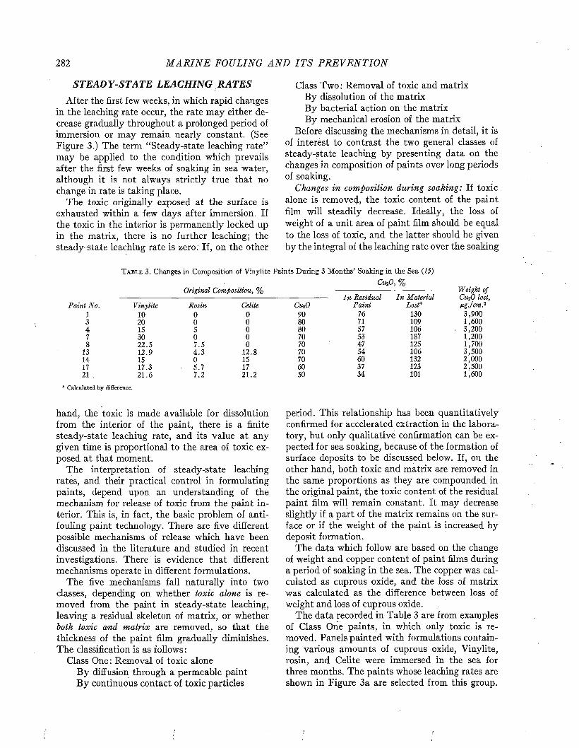
282 M A R I N E FOULING A N D I T S P R E V E N T I O N
STEADY-STATE LEACHING RATES
After the first few weeks, in which rapid changes in the leaching rate occur, the rate may either decrease gradually throughout a prolonged period of immersion or may remain nearly constant. (See Figure 3.) The term “Steady-state leaching rate” may be applied to the condition which prevails after the first few weeks of soaking in sea water, although it is not always strictly true that no change in rate is taking place.
The toxic originally exposed at the surface is exhausted within a few days after immersion. If the toxic in the interior is permanently locked up in the matrix, there is no further leaching; the steady-state leaching rate is zero. If, on the other
Class Two: Removal of toxic and matrix By dissolution of the matrix By bacterial action on the matrix By mechanical erosion of the matrix
Before discussing the mechanisms in detail, it is of interest to contrast the two general classes of steady-state leaching by presenting data on the changes in composition of paints over long periods of soaking.
Changes in composition during soaking: If toxic alone is removed, the toxic content of the paint film will steadily decrease. Ideally, the loss of weight of a unit area of paint film should be equal to the loss of toxic, and the latter should be given by the integral of the leaching rate over the soaking
T a b l e 3 . Changes in Composition of Vinylite Paints During 3 Months’ Soaking in the Sea (15)
Cu¡0, %Original Composition, % Weight of
In Residual In M aterial CuzO lost,P a in i No. Vinylite Rosin Celite CuíO P ain t Lost* Ug./cm.2
1 10 0 0 9 0 76 130 3 ,9 0 03 2 0 0 0 8 0 71 109 1 ,6 0 04 15 5 0 8 0 57 1 0 6 . 3 ,2 0 07 3 0 0 0 70 53 187 1 ,2 0 08 2 2 .5 7 .5 0 70 4 7 125 1 ,7 0 0
13 1 2 .9 4 . 3 1 2 .8 70 5 4 1 0 6 3 ,5 0 014 15 0 15 70 6 0 132 2 ,0 0 017 1 7 .3 ■ 5 .7 17 6 0 3 7 123 2 ,5 0 021 2 1 .6 7 .2 2 1 .2 50 3 4 101 1 ,6 0 0
* Calculated by difference.
hand, the toxic is made available for dissolution from the interior of the paint, there is a finite steady-state leaching rate, and its value at any given time is proportional to the area of toxic exposed at that moment.
The interpretation of steady-state leaching rates, and their practical control in formulating paints, depend upon an understanding of the mechanism for release of toxic from the paint interior. This is, in fact, the basic problem of antifouling paint technology. There are five different possible mechanisms of release which have been discussed in the literature and studied in recent investigations. There is evidence that different mechanisms operate in different formulations.
The five mechanisms fall naturally into two classes, depending on whether toxic alone is removed from the paint in steady-state leaching, leaving a residual skeleton of matrix, or whether both toxic and matrix are removed, so that the thickness of the paint film gradually diminishes. The classification is as follows :
Class One: Removal of toxic aloneB y diffusion through a permeable paint B y continuous contact of toxic particles
period. This relationship has been quantitatively confirmed for accelerated extraction in the laboratory, but only qualitative confirmation can be expected for sea soaking, because of the formation of surface deposits to be discussed below. If, on the other hand, both toxic and matrix are removed in the same proportions as they are compounded in the original paint, the toxic content of the residual paint film will remain constant. It may decrease slightly if a part of the matrix remains on the surface or if the weight of the paint is increased by deposit formation.
The data which follow are based on the change of weight and copper content of paint films during a period of soaking in the sea. The copper was calculated as cuprous oxide, and the loss of matrix was calculated as the difference between loss of weight and loss of cuprous oxide.
The data recorded in Table 3 are from examples of Class One paints, in which only toxic is removed. Panels painted with formulations containing various amounts of cuprous oxide, Vinylite, rosin, and Celite were immersed in the sea for three months. The paints whose leaching rates are shown in Figure 3a are selected from this group.

M E C H A N I S M OF R EL E A S E OF TOXICS FROM P A I N T S 283
Table 3 gives the original composition of each paint, and also the cuprous oxide contents of the residual paint after soaking and of the portion of the paint which was lost in the sea.
The values for weight of cuprous oxide lost show that extraction of toxic has extended past the surface layer (which amounts to not more than about 700 pg. per cm.2 for particles 1 micron in radius), and therefore that dissolution is taking place from the paint interior. The losses amount to from one-third to one-half of the original paint weights. The cuprous oxide content of the residual paint is in every case much lower than that of the original, showing preferential extraction of toxic. The cuprous oxide content calculated for the material lost is in every case at least 100 per cent, indicating that cuprous oxide alone has been removed. The values greater than 100 per cent are probably occasioned by deposit formation, which makes the weight loss appear to be less than the loss of cuprous oxide. This is an example of Class One steady-state leaching which involves the removal of toxic alone.
The data presented in Table 4 are from examples
T a b l e 4 . Changes in Composition o f Cold Plastic Paints During 2 Months’ Soaking in the Sea
Content of Cu^O, %
In In In TotalP ain t Original Residual M aterial Weight LostNo. P ain t P ain t Lost* ng. per cm .2C2 1.4 1.4 1.2 1,300C3 2.5 2 .4 3 .9 2,800C6 15.6 13.6 30.7 2,300C7 21.8 21.2 25.6 2,300CIO 40.5 39.9 45.6 2,000
* Calculated by difference.
of Class Two paints, in which both toxic and matrix are removed simultaneously {22). It represents a group of cold plastic paints containing various amounts of cuprous oxide in which the pigment volume was kept constant by substituting magnesium silicate for the omitted toxic. The paints whose leaching rates are shown in Figure 3b are selected from this group. Painted panels were immersed in the sea for two months. Table 4 gives the cuprous oxide contents of the original paint, the residual paint, and the material lost. The total weight losses show that the dissolution has penetrated beyond the surface layer of toxic. The toxic content of the residual paint and that of the material lost (except for No. C6) are fairly close to the original toxic content in each case. This is an example of Class Two steady-state leaching which involves the removal of both toxic and matrix in
approximately the same proportions as in the original paint composition.
A schematic diagram of the two classes of steady-state leaching is shown in Figure 6. The removal of toxic alone leaves a matrix skeleton intact (B), whereas the removal of toxic and matrix reduces the thickness of the paint layer (D).
CLASS ONE STEADY STATE LEACHING. BY
REMOVAL OF TOXIC ONLY
A. F re s h ly -P o in te d S u r f a c e
n A'AA T W A
STEADY STATE LEACHING BY REMOVAL OF TOXIC AND MATRIX
C. F r e s h ly -P a in te d S u r fa c e
B. S te a d y - S ta t e L ea c h in g D. S te a d y -S ta te L ea c h in g
F i g u r e 6. Schematic diagram of the two classes of mechanisms for maintenance of steady-state leaching.
MECHANISM S OF CLASS ONE LEACHING
Two possible mechanisms for removal of toxic from the interior of the paint without loss of matrix are: 1) the diffusion of dissolved toxic through a permeable matrix, and 2) the dissolution of toxic particles which are in continuous contact throughout a paint film.
Diffusion Through Perm eable M atricesSeveral writers {17, 28, 41) have assumed that
the mechanism of diffusion operates generally in antifouling paints, and they have discussed its theory. The hypothetical process involves the permeation of water through the matrix into the paint interior, the dissolution of toxic there, the outward diffusion of dissolved toxic, and its release at the paint surface.
There is no doubt that films prepared from the resins of which antifouling paint matrices are composed are all permeable to water to some extent. The rates of diffusion of water vapor through films of various resins have been measured under condi
284 M A R I N E FOULING A N D I T S P R E V E N T I O N
tions where a gradient of vapor pressure through the film exists (4). For example, Young, Gerhardt, and Schneider (40) measured the rates of water permeability of several different resins commonly used in paint matrices, and found values ranging from 4 to 300 mg. per sq. in. per day on the basis of a film one mil thick. Similar measurements by Elm (9) gave values (on the basis of one mil thickness) of 70 mg. per sq. in. per day for a film prepared from a phenolic resin vehicle, and 210 for one from an alkyd resin vehicle. These values were diminished somewhat (of the order of a factor of one-half) by incorporation of various pigments.
The operation of steady-state leaching through permeation would presumably involve a quite different, sort of process from that studied in the above experiments, however. Instead of diffusion of water vapor along a concentration gradient, we are concerned here with diffusion of salt ions. The transfer of either water molecules or ions through resinous films is probably an activated process (4, 8). It is interpreted as a successive migration on a molecular scale through temporary local voids in the resinous structure which open up from time to time in the course of restricted thermal motions of the resin macro-molecules. The larger the migrating molecule, the greater the energy required to open a passage for it, and the frequency of openings diminishes exponentially with the energy. Since a hydrated salt ion such as the cuprous chloride complex is considerably larger than a water molecule, it might be expected to diffuse more slowly than the latter. At any rate, permeability to water vapor and permeability to ions may be two very different considerations.
There are several sources of experimental evidence that the permeability of some paint matrix films to ions is very small.
Experiments at Woods Hole (5) showed that films of 143E matrix, and of a similar cold plastic matrix termed “rosin vehicle” by the Mare Island Paint Laboratory, with a thickness of about 0.1 mm., were virtually impermeable to cupric chloride and to cupric citrate. Solutions of these salts at concentrations ranging from 10~3 M to 0.5 M were employed, the solution being placed on one side of the film in each case, with sea water on the other side. Tests conducted over a period of a hundred days indicated that the rate of permeation, calculated in leaching rate units, was less than 0.01 jag. per cm.2 per day. In other experiments, surfaces painted with a cupric citrate paint (which had the enormous.leaching rate of 1,300 jag. per cm.2 per day) were covered with layers of
different types of matrix (143E, rosin vehicle, Vinylite, and Vinylite-phenolic resin) and then leached in sea water. The amounts of copper liberated in 280 hours corresponded to leaching rates of 0.1 jag. per cm.2 per day or less. It was concluded that the permeabilities of these matrices to cupric citrate and cupric chloride were quite negligible.
Experiments reported by Elm (P) showed that a film of a gray alkyd finishing paint can function as a semipermeable membrane which is permeable to water but impermeable to salt ions. In these studies, glass panels were painted with a zinc chromate primer (which contains water-soluble electrolytes) and then covered with the finishing paint. They were immersed for periods up to 35 days in water and in sodium chloride solutions. In water, the paint imbibed considerable amounts of fluid and blistered. In sodium chloride solutions, the amount of fluid imbibed decreased progressively with increasing concentration of salt. Thus the paint system apparently acts as an osmotic cell, in which the under side of the paint represents a solution with high osmotic pressure, and the outer film of alkyd finishing paint represents a semipermeable membrane. When the outside of the membrane is in contact with a solution of lower osmotic pressure than that of the interior, water is forced in. But if the osmotic pressure of the outer solution is increased, the osmotic im balance is less and there is less imbibition. Elm concluded that no sodium chloride penetrated to the interior of the paint, and that no soluble electrolytes from the primer escaped to the outer solution; thus the outer film was apparently impermeable to salt ions.
On the other hand, Young, Gerhardt, and Schneider (40) have reported that certain other types of matrix, when employed in antifouling paints, permit the leaching of toxic by diffusion from the interior. Such matrices demonstrated quite high permeabilities to water vapor; a correlation between water vapor permeability and salt ion permeability was inferred, although no direct measurements are yet available to test this suggestion.
It may be concluded that a paint matrix must possess rather specialized properties in order to permit steady-state leaching by diffusion of dissolved toxic through the paint film. Since some matrices which are impermeable to ions can nevertheless be used successfully in antifouling paints, it is clear that other mechanisms can operate to maintain steady-state leaching.
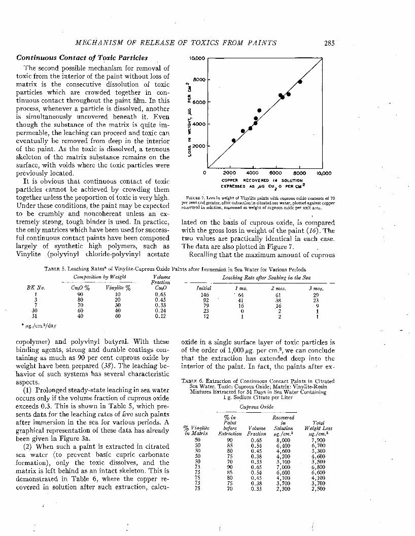
M E C H A N I S M OF R EL E A S E OF TOXICS FROM P A I N T S 285
C on tin u ou s C on tac t o f Toxic P articlesThe second possible mechanism for removal of
toxic from the interior of the paint without loss of matrix is the consecutive dissolution of toxic particles which are crowded together in continuous contact throughout the paint film. In this process, whenever a particle is dissolved, another is simultaneously uncovered beneath it. Even though the substance of the matrix is quite impermeable, the leaching can proceed and toxic can eventually be removed from deep in the interior of the paint. As the toxic is dissolved, a tenuous skeleton of the matrix substance remains on the surface, with voids where the toxic particles were previously located.
It is obvious that continuous contact of toxic particles cannot be achieved by crowding them together unless the proportion of toxic is very high. Under these conditions, the paint may be expected to be crumbly and noncoherent unless an extremely strong, tough binder is used. In practice, the only matrices which have been used for successful continuous contact paints have been composed largely of synthetic high polymers, such as Vinylite (polyvinyl chloride-polyvinyl acetate
10,000
8 0 0 0
0- 6 0 0 0
M 2000
20000 4 0 0 0 6 0 0 0 8 0 0 0 10,000COPPER RECOVERED IN SOLUTION EX PRESSED AS ,UG CUg O PER C M 2
F i g u r e 7 . Loss in weight of Vinylite paints with cuprous oxide contents of 70 per cent and greater, after extraction in citrated sea water, plotted against copper recovered in solution, expressed as weight of cuprous oxide per unit area.
lated on the basis of cuprous oxide, is compared with the gross loss in weight of the paint (16). The two values are practically identical in each case. The data are also plotted in Figure 7.
Recalling that the maximum amount of cuprous
T a b l e 5 . Leaching Rates* of Vinylite-Cuprous Oxide Paints after Immersion in Sea Water for Various PeriodsComposition by Weight Volume
FractionCuiO
Leaching Rate after Soaking in the Sea
B K No. CihO % Vinylite % In itia l 1 mo. 2 mos. 3 mos.1 90 10 0.65 146 ' 64 61 293 80 20 0.45 92 41 38 237 70 30 0.33 79 16 16 9
30 60 40 0.24 23 0 2 131 40 60 0.12 12 1 2 1
' f i g . /cm .2/d a y
copolymer) and polyvinyl butyral. With these binding agents, strong and durable coatings containing as much as 90 per cent cuprous oxide by weight have been prepared (38). The leaching behavior of such systems has several characteristic aspects.
(1) Prolonged steady-state leaching in sea water occurs only if the volume fraction of cuprous oxide exceeds 0.3. This is shown in Table 5, which presents data for the leaching rates of five such paints after immersion in the sea for various periods. A graphical representation of these data has already been given in Figure 3a.
(2) When such a paint is extracted in citrated sea water (to prevent basic cupric carbonate formation), only the toxic dissolves, and the matrix is left behind as an intact skeleton. This is demonstrated in Table 6, where the copper recovered in solution after such extraction, calcu-
oxide in a single surface layer of toxic particles is of the order of 1,000 /xg- per cm.2, we can conclude that the extraction has extended deep into the interior of the paint. In fact, the paints after ex-
T a b l e 6. Extraction of Continuous Contact Paints in Citrated Sea Water. Toxic: Cuprous Oxide; Matrix: Vinylite-Rosin Mixtures Extracted for 34 Days in Sea Water Containing
1 g. Sodium Citrate per Liter
Cuprous Oxide
% in RecoveredP ain t in Total
% V inylite before Volume Solution Weight Lossin M atrix Extraction Fraction fig./cm .2 fig./cm .2
50 90 0.65 8,000 7,90050 85 0.54 6,400 6,70050 80 0.45 4,600 5,30050 75 0.38 4,200 4,60050 70 0.33 3,100 3,50075 90 0.65 7,000 6,80075 85 0.54 6,600 6,60075 80 0.45 4,100 4,10075 75 0.38 3,700 3,70075 70 0.33 2,300 2,500
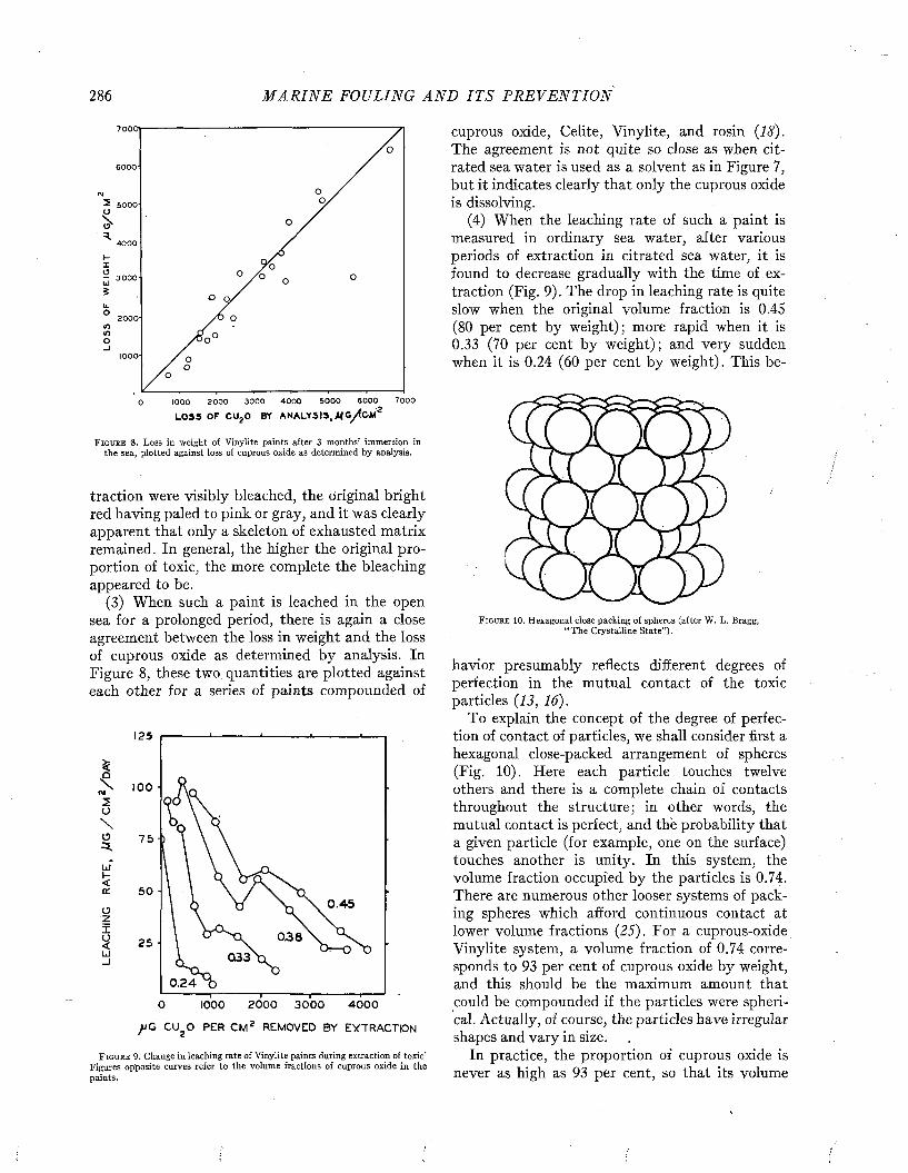
286 M A R I N E FOULING A N D I T S P R E V E N T I O N
70001
6000 '
2 5000 '
4000
3000
2000 -
1000-
7000600050001000 2000 3000 4000
LOSS OF CU?0 BY ANALYSIS.JUC/fcW0
F i g u r e 8. Loss in weight of Vinylite paints after 3 months’ immersion in the sea, plotted against loss of cuprous oxide as determined by analysis.
traction were visibly bleached, the original bright red having paled to pink or gray, and it was clearly apparent that only a skeleton of exhausted matrix remained. In general, the higher the original proportion of toxic, the more complete the bleaching appeared to be.
(3) When such a paint is leached in the open sea for a prolonged period, there is again a close agreement between the loss in weight and the loss of cuprous oxide as determined by analysis. In Figure 8, these two, quantities are plotted against each other for a series of paints compounded of
125
íe
<M5O\o 7 5 -
UJa: 5 0
0 .4 5oZXo<LJ_l
0.382 5 •033
0 .2 4
2 0 0 0 3 0 0 0 4 0 0 00 1000
f J C C U 2 0 p e r c m 2 r e m o v e d b y e x t r a c t i o n
F i g u r e 9. Change in leaching rate of Vinylite paints during extraction of toxic' Figures opposite curves refer to the volume fractions of cuprous oxide in the paints.
cuprous oxide, Celite, Vinylite, and rosin (18). The agreement is not quite so close as when citrated sea water is used as a solvent as in Figure 7, but it indicates clearly that only the cuprous oxide is dissolving.
(4) When the leaching rate of such a paint is measured in ordinary sea water, after various periods of extraction in citrated sea water, it is found to decrease gradually with the time of extraction (Fig. 9). The drop in leaching rate is quite slow when the original volume fraction is 0.45 (80 per cent by weight); more rapid when it is 0.33 (70 per cent by weight); and very sudden when it is 0.24 (60 per cent by weight). This be-
F i g u r e 10. Hexagonal close packing of spheres (after W. L. Bragg,“ The Crystalline State”).
havior presumably reflects different degrees of perfection in the mutual contact of the toxic particles (13, 16).
To explain the concept of the degree of perfection of contact of particles, we shall consider first a hexagonal close-packed arrangement of spheres (Fig. 10). Here each particle touches twelve others and there is a complete chain of contacts throughout the structure; in other words, the mutual contact is perfect, and the probability that a given particle (for example, one on the surface) touches another is unity. In this system, the volume fraction occupied by the particles is 0.74. There are numerous other looser systems of packing spheres which afford continuous contact at lower volume fractions (25). For a cuprous-oxide Vinylite system, a volume fraction of 0.74 corresponds to 93 per cent of cuprous oxide by weight, and this should be the maximum amount that could be compounded if the particles were spherical. Actually, of course, the particles have irregular shapes and vary in size.
In practice, the proportion of cuprous oxide is never as high as 93 per cent, so that its volume
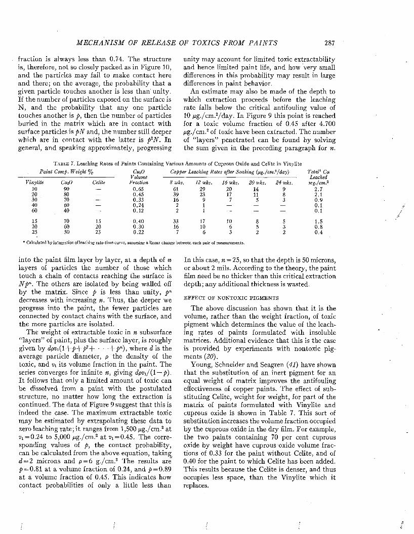
M E C H A N I S M OF R E L E A S E OF TOXICS FROM P A I N T S 287
fraction is always less than 0.74. The structure is, therefore, not so closely packed as in Figure 10, and the particles may fail to make contact here and there; on the average, the probability that a given particle touches another is less than unity. If the number of particles exposed on the surface is N , and the probability that any one particle touches another is p, then the number of particles buried in the matrix which are in contact with surface particles is p N and, the number still deeper which are in contact with the latter is p2N. In general, and speaking approximately, progressing
into the paint film layer by layer, at a depth of n layers of particles the number of those which touch a chain of contacts reaching the surface is N p n. The others are isolated by being walled off by the matrix. Since p is less than unity, p n decreases with increasing n. Thus, the deeper we progress into the paint, the fewer particles are connected by contact chains with the surface, and the more particles are isolated.
The weight of extractable toxic in n subsurface “layers” of paint, plus the surface layer, is roughly given by dp%(l+^+^>2+ • • ■Jr p n), where d is the average particle diameter, p the density of the toxic, and Vi its volume fraction in the paint. The series converges for infinite n, giving dpvi/(l — p). It follows that only a limited amount of toxic can be dissolved from a paint with the postulated structure, no matter how long the extraction is continued. The data of Figure 9 suggest that this is indeed the case. The maximum extractable toxic may be estimated by extrapolating these data to zero leaching rate; it ranges from 1,500 pg./cm .2 at z>i = 0.24 to 5,000 pg./cm .2 at id = 0.45. The corresponding values of p, the contact probability, can be calculated from the above equation, taking d = 2 microns and p = 6 g./cm .3 The results are p = 0.81 at a volume fraction of 0.24, and > = 0.89 at a volume fraction of 0.45. This indicates how contact probabilities of only a little less than
unity may account for limited toxic extractability and hence limited paint life, and how very small differences in this probability may result in large differences in paint behavior.
An estimate may also be made of the depth to which extraction proceeds before the leaching rate falls below the critical antifouling value of 10 pg./cm .2/day. In Figure 9 this point is reached for a toxic volume fraction of 0.45 after 4.700 pg./cm .2 of toxic have been extracted. The number of “layers” penetrated can be found by solving the sum given in the preceding paragraph for n.
Total* Cu Leached mg.j'em.2
2 .72. 10 .90.10.1
1 .50.80 . 4
In this case, n = 25, so that the depth is 50 microns, or about 2 mils. According to the theory, the paint film need be no thicker than this critical extraction depth; any additional thickness is wasted.
E F F E C T O F N O N T O X I C P I G M E N T S
The above discussion has shown that it is the volume, rather than the weight fraction, of toxic pigment which determines the value of the leaching rates of paints formulated with insoluble matrices. Additional evidence that this is the case is provided by experiments with nontoxic pigments (20).
Young, Schneider and Seagren (41) have shown that the substitution of an inert pigment for an equal weight of matrix improves the antifouling effectiveness of copper paints. The effect of substituting Celite, weight for weight, for part of the matrix of paints formulated with Vinylite and cuprous oxide is shown in Table 7. This sort of substitution increases the volume fraction occupied by the cuprous oxide in the dry film. For example, the two paints containing 70 per cent cuprous oxide by weight have cuprous oxide volume fractions of 0.33 for the paint without Celite, and of 0.40 for the paint to which Celite has been added. This results because the Celite is denser, and thus occupies less space, than the Vinylite which it replaces.
T a b l e 7 . Leaching Rates of Paints Containing Various Amounts of Cuprous Oxide and Celite in VinyliteP aint Comp. Weight % CurD Copper Leaching Rates after Soaking (pg./cm?/day)
- - - - - - - - - - - - - - - - - - - - - - - - - - - - - - - - - - - - - - - - - - - - - - V olume - - - - - - - - - - - - - - - - - - - - - - - - - - - - - - - - - - - - - - - - - - - - - - - - - - - - - - - - - - - - - - - - - - - - - - - - - - - - -Vinylite CuiO Celite Fraction 8 wks. 12 wks. 16 wks. 20 wks. 24 wks.
10 90 — 0 .6 5 61 29 2 0 14 92 0 80 — 0 .4 5 3 9 23 17 11 83 0 70 — 0 .3 3 16 9 7 5 34 0 60 — 0 .2 4 2 1 — — —6 0 40 — 0 .1 2 2 1 — - —
15 70 15 0 .4 0 33 17 10 8 52 0 60 2 0 0 .3 0 16 10 6 5 32 5 50 25 0 .2 2 7 6 3 2 2
* Calculated by integration of leaching rate-tim e curve, assuming a linear change between each pair of measurements.
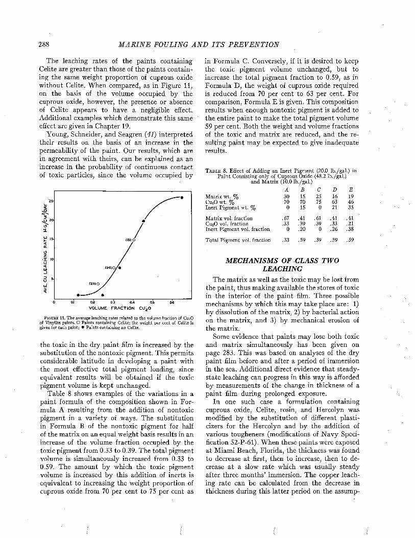
288 M A R I N E FOULING A N D I T S P R E V E N T I O N
The leaching rates of the paints containing Celite are greater than those of the paints containing the same weight proportion of cuprous oxide without Celite. When compared, as in Figure 11, on the basis of the volume occupied by the cuprous oxide, however, the presence or absence of Celite appears to have a negligible effect. Additional examples which demonstrate this same effect are given in Chapter 19.
Young, Schneider, and Seagren (41) interpreted their results on the basis of an increase in the permeability of the paint. Our results, which are in agreement with theirs, can be explained as an increase in the probability of continuous contact of toxic particles, since the volume occupied by
'25-
i) 20
0.2 0.3 0AVOLUME FRACTION CU2 0
05
F ig u r e 11. The average leaching rates related to the volume fraction of Cu»0 of Vinylite paints. O Paints containing Celite; the weight per cent of Celite is given for each paint; • Paints containing no Celite.
the toxic in the dry paint film is increased by the substitution of the nontoxic pigment. This permits considerable latitude in developing a paint with the most effective total pigment loading, since equivalent results will be obtained if the toxic pigment volume is kept unchanged.
Table 8 shows examples of the variations in a paint formula of the composition shown in Formula A resulting from the addition of nontoxic pigment in a variety of ways. The substitution in Formula B of the nontoxic pigment for half of the matrix on an equal weight basis results in an increase of the volume fraction occupied by the toxic pigment from 0.33 to 0.39. The total pigment volume is simultaneously increased from 0.33 to0.59. The amount by which the toxic pigment volume is increased by this addition of inerts is equivalent to increasing the weight proportion of cuprous oxide from 70 per cent to 75 per cent as
in Formula C. Conversely, if it is desired to keep the toxic pigment volume unchanged, but to increase the total pigment fraction to 0.59, as in Formula D , the weight of cuprous oxide required is reduced from 70 per cent to 63 per cent. For comparison, Formula E is given. This composition results when enough nontoxic pigment is added to the entire paint to make the total pigment volume 59 per cent. Both the weight and volume fractions of the toxic and matrix are reduced, and the resulting paint may be expected to give inadequate results.
T a b l e 8 . Effect of Adding an Inert Pigment (2 0 .0 lb./gal.) in Paint Consisting only of Cuprous Oxide (4 8 .2 lb./gal.)
and Matrix (1 0 .0 lb./gal.)A B C D E
Matrix wt. % 30 15 25 16 19Cu20 wt. % 70 70 75 63 46Inert Pigment wt. % 0 15 0 21 35
Matrix vol. fraction .67 .41 .61 .41 .41Cu20 vol. fraction .33 .39 .39 .33 .21Inert Pigment vol. fraction 0 .20 0 .26 .38
Total Pigment vol. fraction .33 .59 .39 .59 .59
MECHANISM S OF CLASS TWO LEACHING
The matrix as well as the toxic may be lost from the paint, thus making available the stores of toxic in the interior of the paint film. Three possible mechanisms by which this may take place are : 1) by dissolution of the matrix, 2) by bacterial action on the matrix, and 3) by mechanical erosion of the matrix.
Some evidence that paints may lose both toxic and matrix simultaneously has been given on page 283. This was based on analyses of the dry paint film before and after a period of immersion in the sea. Additional direct evidence that steady- state leaching can progress in this way is afforded by measurements of the change in thickness of a paint film during prolonged exposure.
In one such case a formulation containing cuprous oxide, Celite, rosin, and Hercolyn was modified by the substitution of different plasti- cizers for the Hercolyn and by the addition of various tougheners (modifications of N avy Specification 52-P-61). When these paints were exposed at Miami Beach, Florida, the thickness was found to decrease at first, then to increase, then to decrease at a slow rate which was usually steady after three months’ immersion. The copper leaching rate can be calculated from the decrease in thickness during this latter period on the assump
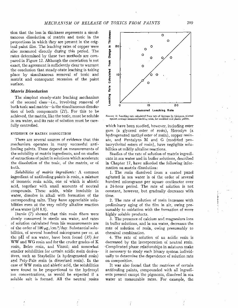
M E C H A N I S M OF R EL E A S E OF TOXICS FROM P A I N T S 289
tion that the loss in thickness represents a simultaneous dissolution of matrix and toxic in the proportions in which they are present in the original paint film. The leaching rates of copper were also measured directly during this period. The rates determined by these two methods are compared in Figure 12. Although the correlation is not exact, the agreement is sufficiently clear to warrant the conclusion that steady-state leaching is taking place by simultaneous removal of toxic and matrix and consequent recession of the paint surface.
M atrix D isso lu tionThe simplest steady-state leaching mechanism
of the second class—i.e., involving removal of both toxic and matrix—is the simultaneous dissolution of both components (21). For this to be achieved, the matrix, like the toxic, must be soluble in sea water, and its rate of solution must be carefully controlled.
E V I D E N C E O E M A T R I X D I S S O L U T I O N
There are several sources of evidence that this mechanism operates in many successful antifouling paints. These depend on measurements of the solubility of matrix ingredients, and on studies of extractions of paint in solutions which accelerate the dissolution of the toxic, of the matrix, or of both.
Solubilities of matrix ingredients: A common ingredient of antifouling paints is rosin, a mixture of isomeric resin acids, one of which is abietic acid, together with small amounts of neutral compounds. These acids, while insoluble in water, dissolve in alkali with formation of the corresponding salts. They have appreciable solubilities even at the very mildly alkaline reaction of sea water (pH 8.1).
Darsie (7) showed that thin rosin fibers were slowly consumed in sterile sea water, and rates of solution calculated from his measurements are of the order of 100 ^g./cm .2/day. Substantial solubilities, of several hundred micrograms per cc. at the pH of sea water, have been found {35) .for WW and W G rosin and for the cruder grades of K rosin, Belro resin, and Vinsol; and somewhat smaller solubilities for certain acidic rosin derivatives, such as Staybelite (a hydrogenated rosin) and Poly-Pale resin (a dimerized rosin). In the case of WW rosin and abietic acid, the solubilities were found to be proportional to the hydroxyl ion concentrations, as would be expected if a soluble salt is formed. All the neutral resins
Mme jcu
20e
ateofOiw■ooo9Ooo«o
CE
•COO4> IO 2 00Measured Leaching Rote
F i g u r e 12. Leaching rate calculated from rate of decrease in thickness, plottedagainst average measured leaching rates, for modified cold plastic paints.
which have been studied, however, including ester gum (a glycerol ester of rosin), Hercolyn (a hydrogenated methyl ester of rosin), copper resínate, and Pentalyns M and G (modified pen- taerythritol esters of rosin), have negligible solubilities at mildly alkaline reactions.
Studies of the rate of solution of matrix ingredients in sea water and in buffer solutions, described in Chapter 17, have afforded the following information on matrix dissolution :
1. The rosin dissolved from a coated panel agitated in sea water is of the order of several hundred micrograms per square centimeter over a 24-hour period. The rate of solution is not constant, however, but gradually decreases with time.
2. The rate of solution of rosin increases with preliminary aging of the film in air, owing presumably to oxidation with the formation of more highly soluble products.
3. The presence of calcium and magnesium ions in buffer solutions, and in sea water, decreases the rate of solution of rosin, owing presumably to chemical combination.
4. The rate of solution of an acidic resin is decreased by the incorporation of neutral resin.
’Complicated phase relationships in mixtures make it necessary to study each binary system individually to determine the dependence of solution rate on composition.
It was also found that the matrices of certain antifouling paints, compounded with all ingredients present except the pigments, dissolved in sea water at measurable rates. For example, the

290 M A R I N E FOULING A N D I T S P R E V E N T I O N
3 0
20
0 100 2 0 0CU2 O EXTRACTED, f t G/CM 2
F i g u r e 13. Surface exhaustion of cold plastic paint (143E) by extraction in sea water acidified to pH 4.
matrix of the cold plastic paint 143E dissolved in running sea water at a rate of about 100 tig./cm.2 /d a y (14).
Successive extractions of paint in acid and in sea water: Having cited the evidence that certain ingredients of paint matrices are soluble, we shall now describe experiments which indicate how this is related to the maintenance of steady-state leaching.
Panels coated with the cold plastic paint 143E were treated with sea water acidified to pH 4 with hydrochloric acid. Under this condition, the surface-exposed cuprous oxide is rapidly dissolved, whereas the solubility of the acidic matrix components is negligible. Accordingly, surface exhaustion of the toxic takes place, just as in the
T able 9. Recovery of the Steady State Leaching Rate of Paint 143E After the Removal of Various Amounts of Surface
Toxic in Sea Water Acidified to pH 4Leaching Rate, ßg./cm .^/day, A fter
D ays in CitnO Soaking in Sea W ater forSea Water R e m o v e d ----------------------------------------------------
at pH 4 ßg ./cm .2 1 hr? 4 hr.b 24 hr?1 41 2.2 4 .7 14.12 64 4 .9 8.9 14.53 74 2 .5 8.1 12.54 83 4 .0 5.6 12.75 116 1.7 3 .47 153 0 2 .0 11.58 172 1.7 2 .2 10.89 172 0 2 .7 12.0
a Calculated on the basis of 1 hour leaching.b Calculated on the basis of 4 hours’ leaching.c Running sea water; calculated on thè basis of 4 hours’ leaching.
insoluble Vinylite paints described on page 280. Leaching rates, measured in ordinary sea water after varying periods of acid extraction, are plotted against the amount of toxic removed, in Figure 13. The resulting curve is similar to those which describe the surface exhaustion of Vinylite paints in sea water (Fig. 5). The leaching rate becomes zero after 240 ¡xg. cuprous oxide per sq. cm. have been removed. This is the right order of magnitude for the quantity of surface-exposed toxic on a freshly-painted surface. Clearly, only the surface toxic has been dissolved, and the mechanism which normally operates in the sea to maintain leaching from the interior of the paint film has not functioned in the acidified solution.
However, after the surface toxic has been exhausted, the ability of this paint to leach at an adequate rate can be rapidly restored by soaking in sea water. Panels which had been leached in the acid sea water (pH 4) were rinsed and returned to normal sea water, and the leaching rates measured after various times. The results of this experiment are given in Table 9. The leaching rates of all of the panels increased during the first four hours of soaking in sea water, and all had reached values between 10.8 and 14.5 ¡ig/cm.2/d a y by the end of 24 hours in sea water.
It is apparent that the exhausted surface has been regenerated by sea water soaking; a new layer of cuprous oxide particles has presumably been uncovered by removing the layer of matrix which remained after the acid treatment. The removal might be attributed either to the solvent action of sea water or to its erosive action in flowing past the surface. Actually, experiments on erosion, described below, indicate that mechanical action is of minor importance, while the significance of dissolution is shown by the following experiments on regeneration in alkaline solution.
Successive extractions of paint in acid sea water and in alkaline tap water: In a procedure developed by the Mare Island investigators (26), freshly painted panels are first extracted in acidified sea water as described above, and then in tap water adjusted with sodium hydroxide to pH 11.5, the leaching rate being measured after each extraction. The acid treatment is carried out for 3 days, in 3 successive changes of solvent, and results in a marked diminution of the leaching rate, attributable to surface exhaustion. The alkaline treatment js carried out for only 3 hours, and results in a substantial increase in the leaching rate (Tables 10 and 11). Evidently a new layer of cuprous oxide particles is uncovered by removal of matrix; the
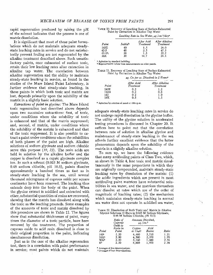
M E C H A N I S M OF R E L E A S E OF TOXICS FROM P A I N T S 291
rapid regeneration produced by raising the pH of the solvent indicates that the process is one of matrix dissolution.
It is significant that most of those paint formulations which do not maintain adequate steady- state leaching rates in service and do not satisfactorily prevent fouling are not regenerated by the alkaline treatment described above. Such unsatisfactory paints, once exhausted of surface toxic, retain their low leaching rates after extraction in alkaline tap water. The correlation between alkaline regeneration and the ability to maintain steady-state leaching in service, as found in the studies of the Mare Island Paint Laboratory, is further evidence that steady-state leaching, in those paints in which both toxic and matrix are lost, depends primarily upon the solubility of the matrix in a slightly basic solution.
Extractions of paint in glycine: The Mare Island toxic regeneration test described above depends upon two successive extractions: first, of toxic, under conditions where the solubility of toxic is enhanced and that of the matrix suppressed; and, second, of matrix, under conditions where the solubility of the matrix is enhanced and that of the toxic suppressed. It is also possible to extract a paint under conditions where the solubilities of both phases of the paint are high. Alkaline solutions of sodium glycinate and sodium chloride serve this purpose (19, 23). The resin acids are held in solution by the alkaline buffer and the copper is dissolved as a cupric glycinate complex ion. In such a solvent (0.025 M sodium glycinate, 0.48 sodium chloride, pH 10.5), paints dissolve approximately a hundred times as fast as in steady-state leaching in the sea, until several thousand micrograms of cuprous oxide per square centimeter have been removed. The leaching thus extends deep into the body of the paint. When the glycine extract is acidified and extracted with ether, substantial quantities of resins are recovered, showing that the matrix has dissolved along with the toxic as the leaching proceeds. Some examples of the amounts of toxic and matrix dissolved by this procedure are shown in Table 12. The figures show that substantial thicknesses of paint, many times the diameter of a toxic particle, have been removed by the treatment. The proportion of cuprous oxide to acid resin dissolved is close to their original proportion in the paint, indicating simultaneous dissolution.
Just as in the case of the alkaline regeneration test, there is a correlation with paint performance in service; most paints which do not maintain
T a b l e 10. Recovery of Leaching Rate of Surface-Exhausted Paint by Extraction in Alkaline Tap Water
Leaching Rate in Sea W ater, ß g ./'em..2/ day’-
P ain t In itiaPA fter A cid Treatment
A fter Alkaline Treatment
143E 40 1.5 24.042-3 40 2 .5 47.542-3A 38 1.5 22.216X 30 14.7 24.5
a Agitation by standard bubbling.b Representative values from measurements on other panels.
T a b l e 11. Recovery of Leaching Rate of Surface-Exhausted Paint by Extraction in Alkaline Tap Water
ßg. Cu per cc. Dissolved in 2 Hours’-
A fter A cid A fter AlkalinePain t Treatment Treatment143E 0.2 1.2142D 0.2 0.8145 0 .2 1.016X 0.5 1.5
a Agitation by rotation of panel at 100 r.p.m.
adequate steady-state leaching rates in service do not undergo rapid dissolution in the glycine buffer. The utility of the glycine solution in accelerated testing procedures is discussed in Chapter 20. It suffices here to point out that the correlation between rate of solution in alkaline glycine and maintenance of steady-state leaching in the sea affords further excellent evidence that the latter phenomenon depends upon the solubility of the matrix in a slightly alkaline solution.
To sum up, we have the following evidence that many antifouling paints of Class Two, which, as shown in Table 4, lose toxic and matrix simultaneously in the same proportions in which they are originally compounded, maintain steady-state leaching rates by dissolution of the matrix: (1) the acidic ingredients which are present in most antifouling paint matrices have substantial solubilities in sea water, and the matrices themselves can' dissolve at rates which are of the order of magnitude of leaching rates; (2) the mechanism which maintains steady-state leaching in normal sea water does not operate in acidified sea water,
T a b l e 12. Dissolution of Both Toxic and Matrix in Alkaline Glycine Solutions (3 Days in 0.025 M Sodium Glycinate,
0.48 M Sodium Chloride, pH 10.5)Ratio of Am ounts Dissolved,Cuprous ßg ./cm .2Oxide toRosin in Copper A cid
P ain i P ain t as CunO Resins Ratio143a 1.20 4,480 3,710 1.2116Xa 2.00 4,500 2,370 1.90WGb 2.50 3,160 1,460 2.16E b 2.50 4,600 1,970 2.34
a Averages of five determinations. b Averages of four determinations.
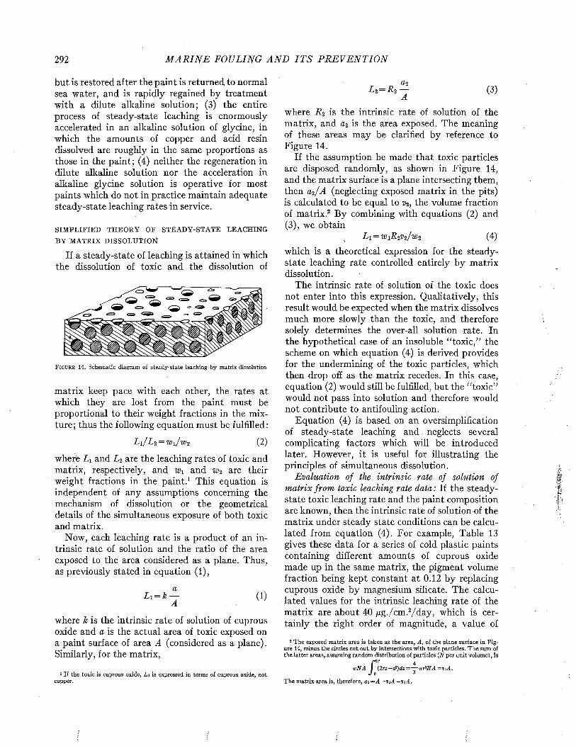
292 M A R I N E FOULING A N D I T S P R E V E N T I O N
but is restored after the paint is returned to normal sea water, and is rapidly regained by treatment with a dilute alkaline solution; (3) the entire process of steady-state leaching is enormously accelerated in an alkaline solution of glycine, in which the amounts of copper and acid resin dissolved are roughly in the same proportions as those in the paint; (4) neither the regeneration in dilute alkaline solution nor the acceleration in alkaline glycine solution is operative for most paints which do not in practice maintain adequate steady-state leaching rates in service.
S I M P L I F I E D T H E O R Y O F S T E A D Y - S T A T E L E A C H I N G
B Y M A T R I X D I S S O L U T I O N
If a steady-state of leaching is attained in which the dissolution of toxic and the dissolution of
F i g u r e 14. Schematic diagram of steady-state leaching by matrix dissolution
matrix keep pace with each other, the rates at which they are lost from the paint must be proportional to their weight fractions in the mixture; thus the following equation must be fulfilled:
Li/Li = wi/wt ( 2 )
where Li and L í are the leaching rates of toxic and matrix, respectively, and w\ and w2 are their weight fractions in the paint.1 This equation is independent of any assumptions concerning the mechanism of dissolution or the geometrical details of the simultaneous exposure of both toxic and matrix.
Now, each leaching rate is a product of an intrinsic rate of solution and the ratio of the area exposed to the area considered as a plane. Thus, as previously stated in equation (1),
L 1 = k ~ (1)A
where k is the intrinsic rate of solution of cuprous oxide and a is the actual area of toxic exposed on a paint surface of area A (considered as a plane). Similarly, for the matrix,
1 If the toxic is cuprous oxide, L i is expressed in terms of cuprous oxide, not copper.
L2 = R2 (3)A
where R 2 is the intrinsic rate of solution of the matrix, and a2 is the area exposed. The meaning of these areas may be clarified by reference to Figure 14.
If the assumption be made that toxic particles are disposed randomly, as shown in Figure 14, and the matrix surface is a plane intersecting them, then a2/ A (neglecting exposed matrix in the pits) is calculated to be equal to v2, the volume fraction of matrix.2 By combining with equations (2) and(3), we obtain
L i = w iR 2v2/ w 2 (4)
which is a theoretical expression for the steady- state leaching rate controlled entirely by matrix dissolution.
The intrinsic rate of solution of the toxic does not enter into this expression. Qualitatively, this result would be expected when the matrix dissolves much more slowly than the toxic, and therefore solely determines the over-all solution rate. In the hypothetical case of an insoluble “toxic,” the scheme on which equation (4) is derived provides for the undermining of the toxic particles, which then drop off as the matrix recedes. In this case, equation (2) would still be fulfilled, but the “toxic” would not pass into solution and therefore would not contribute to antifouling action.
Equation (4) is based on an oversimplification of steady-state leaching and neglects several complicating factors which will be introduced later. However, it is useful for illustrating the principles of simultaneous dissolution.
Evaluation of the intrinsic rate of solution of matrix from toxic leaching rate data: If the steady- state toxic leaching rate and the paint composition are known, then the intrinsic rate of solution of the matrix under steady-state conditions can be calculated from equation (4). For example, Table 13 gives these data for a series of cold plastic paintscontaining different amounts of cuprous oxidemade up in the same matrix, the pigment volume fraction being kept constant at 0.12 by replacing cuprous oxide by magnesium silicate. The calculated values for the intrinsic leaching rate of the matrix are about 40 /¿g./cm.2/day, which is certainly the right order of magnitude, a value of
2 The exposed matrix area is taken as the area, A , of the plane surface in Figure 14, minus the circles cut out by intersections with toxic particles. T he sum of the latter areas, assuming random distribution of particles (N per unit volume), is
r2r 4ttN A I (2rz—& )dz=— tt1%NA =ViA.
J o ^The matrix area is, therefore, a i = A —ViA = v i A .
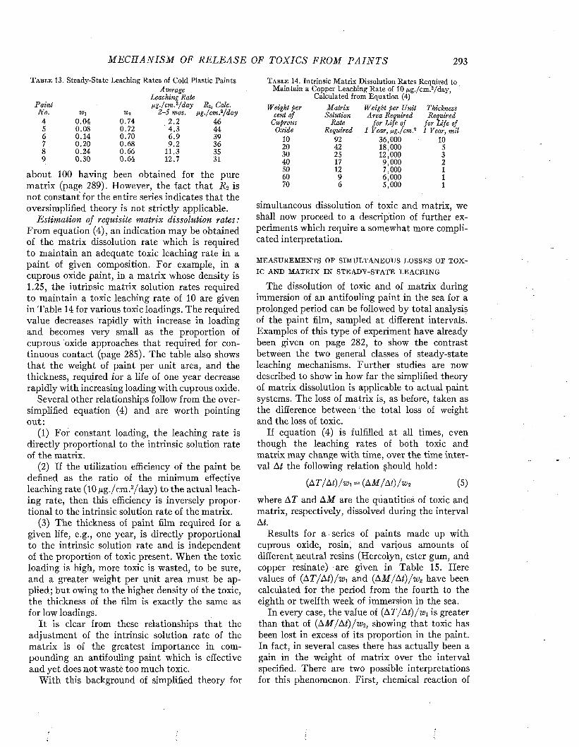
M E C H A N I S M OF REL EA SE OF TOXICS FROM P A I N T S 293
T a b l e 13. Steady-State Leaching Rates of Cold Plastic Paints
P ain i
Average Leaching Rate lig ./cm .z/day R 2, Calc.
N o. W\ 11)2 2 -5 mos. pg ./cm .2/d t4 0.04 0.74 2 .2 465 0.08 0.72 4.3 446 0.14 0.70 6 .9 397 0.20 0.68 9.2 368 0.24 0.66 11.3 359 0.30 0.64 12.7 31
about 100 having been obtained for the pure matrix (page 289). However, the fact that R-¿ is not constant for the entire series indicates that the oversimplified theory is not strictly applicable.
Estimation of requisite matrix dissolution rates: From equation (4), an indication may be obtained of the matrix dissolution rate which is required to maintain an adequate toxic leaching rate in a paint of given composition. For example, in a cuprous oxide paint, in a matrix whose density is 1.25, the intrinsic matrix solution rates required to maintain a toxic leaching rate of 10 are given in Table 14 for various toxic loadings. The required value decreases rapidly with increase in loading and becomes very small as the proportion of cuprous oxide approaches that required for continuous contact (page 285). The table also shows that the weight of paint per unit area, and the thickness, required for a life of one year decrease rapidly with increasing loading with cuprous oxide.
Several other relationships follow from the oversimplified equation (4) and are worth pointing out:
(1) For constant loading, the leaching rate is directly proportional to the intrinsic solution rate of the matrix.
(2) If the utilization efficiency of the paint be defined as the ratio of the minimum effective leaching rate (10 j u g . /cm.2/day) to the actual leaching rate, then this efficiency is inversely proportional to the intrinsic solution rate of the matrix.
(3) The thickness of paint film required for a given life, e.g., one year, is directly proportional to the intrinsic solution rate and is independent of the proportion of toxic present. When the toxic loading is high, more toxic is wasted, to be sure, and a greater weight per unit area must be applied; but owing to the higher density of the toxic, the thickness of the film is exactly the same as for low loadings.
I t is clear from these relationships that the adjustment of the intrinsic solution rate of the matrix is of the greatest importance in compounding an antifouling paint which is effective and yet does not waste too much toxic,
With this background of simplified theory for
T a b l e 14. Intrinsic Matrix Dissolution Rates Required to Maintain a Copper Leaching Rate of 10 ng./cm .2/day,
Calculated from Equation (4)Weight per M atrix Weight per Unit Thickness
cent of Solution A rea Required RequiredCuprous Rate fo r Life of fo r Life of
Oxide Required 1 Year, ßg ./cm .2 1 Year, mil10 92 36,000 1020 42 18,000 530 25 12,000 340 17 9,000 250 12 7,000 160 9 6,000 170 6 5,000 1
simultaneous dissolution of toxic and matrix, we shall now proceed to a description of further experiments which require a somewhat more complicated interpretation.
M E A S U R E M E N T S O P S I M U L T A N E O U S L O S S E S O P T O X
IC A N D M A T R I X I N S T E A D Y - S T A T E L E A C H I N G
The dissolution of toxic and of matrix during immersion of an antifouling paint in the sea for a prolonged period can be followed by total analysis of the paint film, sampled at different intervals. Examples of this type of experiment have already been given on page 282, to show the contrast between the two general classes of steady-state leaching mechanisms. Further studies are now described to show in how far the simplified theory of matrix dissolution is applicable to actual paint systems. The loss of matrix is, as before, taken as the difference between the total loss of weight and the loss of toxic.
If equation (4) is fulfilled at all times, even though the leaching rates of both toxic and matrix may change with time, over the time interval At the following relation should hold:
(AT / A t)/w \= (AM/At)/wz (5)
where AT and AM are the quantities of toxic and matrix, respectively, dissolved during the interval At.
Results for a series of paints made up with cuprous oxide, rosin, and various amounts of different neutral resins (Hercolyn, ester gum, and copper resinate) are given in Table 15. Here values of (AT/AÍ)/wi and (AM / At) / w 2 have been calculated for the period from the fourth to the eighth or twelfth week of immersion in the sea.
In every case, the value of {AT/ At)/wi is greater than that of (A M /A t) /w 2, showing that toxic has been lost in excess of its proportion in the paint. In fact, in several cases there has actually been a gain in the weight of matrix over the interval specified. There are two possible interpretations for this phenomenon. First, chemical reaction of
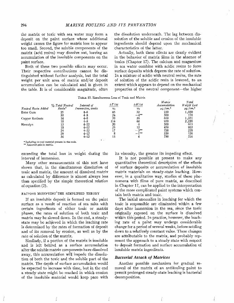
294 M A R I N E FOULING A N D I T S P R E V E N T I O N
the matrix or toxic with sea water may form a deposit on the paint surface whose additional weight causes the figure for matrix loss to appear too small. Second, the soluble components of the matrix (acid resins) may dissolve out, leaving an accumulation of the insoluble components on the paint surface.
Both of these two possible effects may occur. Their respective contributions cannot be distinguished without further analysis, but the total weight per unit area of matrix and/or deposit accumulation can be calculated and is given in the table. It is of considerable magnitude, often
the dissolution underneath. The lag between dissolution of the soluble and erosion of the insoluble ingredients should depend upon the mechanical characteristics of the latter.
Actually, both these effects are clearly evident in the behavior of matrix films in the absence of toxics (Chapter 17). The calcium and magnesium in sea water combine with acidic resins to form surface deposits which depress the rate of solution. In a mixture of acidic with neutral resins, the rate of solution of the acidic resin is lowered, to an extent which appears to depend on the mechanical properties of the neutral component— the higher
T a b l e 15 . Simultaneous Loss of Toxic and Matrix
Neutral Resin Added Ester Gum
Copper Resinate
Hercolyn
* Including neutral m aterial present in the rosin. "* A pparent gain in matrix.
A T /A l A M /A tM atrix Total
'olal Neutral Interval of Accumulation Weight LostResin* Immersion, weeks Wi W2 ug ./cm ? ßg ./cm .2
25 4 - 8 45 32 2 3 0 1 ,0 3 03 0 4 - 8 2 4 _ 4 * * 5 0 0 1 7014 4 h 8 70 3 6 6 1 0 1 ,3 7 118 4 - 8 1 1 4 6 0 9 7 0 2 ,2 2 013 4 - 1 2 2 0 6 5 0 0 6 1 518 4 - 1 2 25 12 4 7 0 9 3 52 4 4 - 1 2 17 - 3 * * 7 2 0 2 2 82 9 4 - 1 2 8 _J** 3 2 0 1 263 6 4 - 1 2 15 6 750 5 1 6
exceeding the total loss in weight during the interval of immersion.
M any other measurements of this sort have shown that, in the simultaneous dissolution of toxic and matrix, the amount of dissolved matrix as calculated by difference is almost always less than specified by the simple theoretical relation of equation (2).
F A C T O R S M O D IF Y IN G * T H E S I M P L I F I E D T H E O R Y
If an insoluble deposit is formed on the paint surface as a result of reaction of sea salts with certain ingredients of either toxic or matrix phases, the rates of solution of both toxic and matrix may be slowed down. In the end, a steady- state may be achieved in which the leaching rate is determined by the rates of formation of deposit and of its removal by erosion, as well as by the rate of solution of the matrix.
Similarly, if a portion of the matrix is insoluble and is left behind as a surface accumulation after the soluble matrix components have dissolved away, this accumulation will impede the dissolution of both the toxic and the soluble part of the matrix. The depth of surface accumulation would be expected to increase with time, but in the end a steady state might be reached in which erosion of the insoluble material would keep pace with
its viscosity, the greater its impeding effect.It is not possible at present to make any
quantitative theoretical description of the effects of surface deposits or accumulation of insoluble matrix materials on steady-state leaching. However, in a qualitative way, studies of these phenomena with films of pure matrix, as described in Chapter 17, can be applied to the interpretation of the more complicated paint systems which contain both matrix and toxic.
The initial anomalies in leaching for which the toxic is responsible are eliminated within a few days after immersion in the sea, since the toxic originally exposed on the surface is dissolved within this period. In practice, however, the leaching rate of a paint may undergo considerable change for a period of several weeks, before settling down to a relatively constant value. These changes are attributable to the matrix, and probably represent the approach to a steady state with respect to deposit formation and surface accumulation of insoluble matrix ingredients.
B acteria l A tta ck o f M atricesAnother possible mechanism for gradual re
moval of the matrix of an antifouling paint to permit prolonged steady-state leaching is bacterial decomposition.
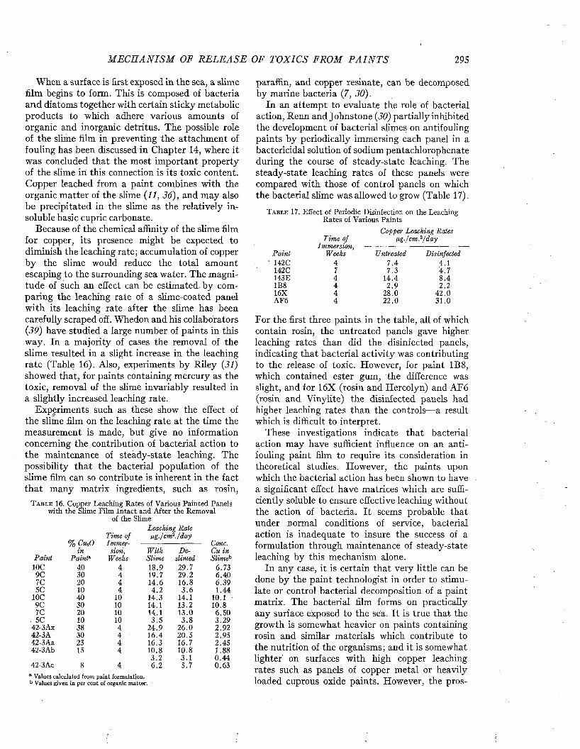
M E C H A N I S M OF R E L E A S E OF TOXICS FROM P A I N T S 295
When a surface is first exposed in the sea, a slime film begins to form. This is composed of bacteria and diatoms together with certain sticky metabolic products to which adhere various amounts of organic and inorganic detritus. The possible role of the slime film in preventing the attachment of fouling has been discussed in Chapter 14, where it was concluded that the most important property of the slime in this connection is its toxic content. Copper leached from a paint combines with the organic matter of the slime (11, 36), and may also be precipitated in the slime as the relatively insoluble basic cupric carbonate.
Because of the chemical affinity of the slime film for copper, its presence might be expected to diminish the leaching rate; accumulation of copper by the slime would reduce the total amount escaping to the surrounding sea water. The magnitude of such an effect can be estimated by comparing the leaching rate of a slime-coated panel with its leaching rate after the slime has been carefully scraped off. Whedon and his collaborators (39) have studied a large number of paints in this way. In a majority of cases the removal of the slime resulted in a slight increase in the leaching rate (Table 16). Also, experiments by Riley (31) showed that, for paints containing mercury as the toxic, removal of the slime invariably resulted in a slightly increased leaching rate.
Experiments such as these show the effect of the slime film on the leaching rate at the time the measurement is made, but give no information concerning the contribution of bacterial action to the maintenance of steady-state leaching. The possibility that the bacterial population of the slime film can so contribute is inherent in the fact that many matrix ingredients, such as rosin,
T a b l e 16 . Copper Leaching Rates of Various Painted Panels with the Slime Film Intact and After the Removal
of the SlimeLeaching Rate
Tim e of ßg./cm 1'./day% Cu-iO Im m er Cone.
in sion, W ith De Cu i nP ain t P ain ia Weeks Slime slimed SlimehIOC 40 4 18.9 29.7 6.739C 30 4 19.7 29.2 6.407C 20 4 14.6 16.8 6.395C 10 4 4.2 3 .6 1.44
IOC 40 10 14.3 14.1 10.1 ■9C 30 10 14.1 13.2 10.81C 20 10 14.1 13.0 6.50
. 5C 10 10 3.5 3 .8 3.2942-3 Ax 38 4 24.9 26.0 2.9242-3A 30 4 16.4 20.5 2.9542-3Aa 23 4 16.3 16.7 2.4542-3Ab 15 4 10.8 10.8 1.88
3 .2 3.1 0.4442-3Ac 8 4 6 .2 5.7 0.63
a Values calculated from pain t formulation. b Values given in per cent of organic m atter.
paraffin, and copper resinate, can be decomposed by marine bacteria (7, 30).
In an attempt to evaluate the role of bacterial action, Renn and Johnstone (30) partially inhibited the development of bacterial slimes on antifouling paints by periodically immersing each panel in a bactericidal solution of sodium pentachlorophenate during the course of steady-state leaching. The steady-state leaching rates of these panels were compared with those of control panels on which the bacterial slime was allowed to grow (Table 17).
T a b l e 17. Effect of Periodic Disinfection on the Leaching Rates of Various Paints
Copper Leaching Rates Tim e of ßg ./cm .2/d a y
I m m e r s i o n , ---------------------------------------------P ain i Weeks Untreated Disinfected142C 4 7 .4 4.1142C 7 7.3 4.7143E 4 14.4 8 .41B8 4 2 .9 2.216X 4 28.0 42.0AF6 4 22.0 31.0
For the first three paints in the table, all of which contain rosin, the untreated panels gave higher leaching rates than did the disinfected panels, indicating that bacterial activity was contributing to the release of toxic. However, for paint 1B8, which contained ester gum, the difference was slight, and for 16X (rosin and Hercolyn) and AF6 (rosin and Vinylite) the disinfected panels had higher leaching rates than the controls— a result which is difficult to interpret.
These investigations indicate that bacterial action may have sufficient influence on an antifouling paint film to require its consideration in theoretical studies. However, the paints upon which the bacterial action has been shown to have a significant effect have matrices which are sufficiently soluble to ensure effective leaching without the action of bacteria. It seems probable that under normal conditions of service, bacterial action is inadequate to insure the success of a formulation through maintenance of steady-state leaching by this mechanism alone.
In any case, it is certain that very little can be done by the paint technologist in order to stimulate or control bacterial decomposition of a paint matrix. The bacterial film forms on practically any surface exposed to the sea. It is true that the growth is somewhat heavier on paints containing rosin and similar materials which contribute to the nutrition of the organisms ; and it is somewhat lighter on surfaces with high copper leaching rates such as panels of copper metal or heavily loaded cuprous oxide paints. However, the pros

296 M A R I N E FOULING A N D I T S P R E V E N T I O N
pect of maintaining steady-state leaching rates by controlling the intensity of bacterial metabolism does not appear to be a promising one.
M echanical Erosion o f M atricesErosion is another mechanism which may main
tain steady-state leaching by gradual removal of
T a b l e 18. Effect of Mechanical Wear upon Matrix Erosion, Panels Rotated at 1,500 R.P.M.
¡xg. Cu per cc. Dissolved, in 2 Hoursa
After A fter AfterA cid 8 krs. 20 hrs.
Treatment W ear Wear0 .10 0.13 0.100 .15 0.13 0.130 .15 0 .14 0.160.30 0 .10 0.09
a Agitation for leaching by rotation of panel at 100 r.p.m.
T a b l e 19. Effect of Wet Abrasion1 upon Matrix Erosionfig. Cu per cc. Dissolved in 2 Hoursb
P ain tAntifoulingPerformance
A fterA cid
TreatmentA fter 50
StrokesA fter 150
Strokes3Z Excellent 0.35 0.32 0.224Z Very Poor 0.10 0.07 0.11
13Z Very Poor 0.10 0.07 0.0916Z Very Poor 0.10 0.07 0.11
a Federal Specification TT-P-88.b Agitation £or leaching by rotation of panel at 100 r.p.m.
T a b l e 20. Decrease in Thickness of Paint 143E During Mechanical Wear, Panels Rotated at 750 R.P.M. 21 Days
Decrease in Thickness from 7 th to 21st D ay, m ils
Drying R adius R adius R adiusN o. of Time, 1-1.5" 3-4.5" 5-6.5"Coats hrs. 8 ft./sec . 25 f t./sec . 38 ft./sec .
1 24 2 .0 2 .2 2 .51 72 1.0 0 .5 0 .53 40 2.3 3 .0 3.23 168 1.0 0 1.5
matrix. It differs from dissolution primarily in that the particles which become detached are of greater size than the molecules set free in dissolution. Mechanical forces associated with friction are commonly considered to be responsible for breaking free the eroding particles. Chemical action must frequently facilitate erosion by disintegrating the structure of the paint surface and thus permitting small particles to become detached more readily.
The loss of particles of paint has also been considered as a possible mechanism for the prevention of fouling by exfoliation (Chapter 13). We are concerned here solely with the role of erosion in maintaining steady-state toxic leaching rates by uncovering the deeper stores of toxic particles.
In an attempt to appraise the importance of erosion of the matrix in uncovering fresh layers of toxic from the interior of paints, the Mare Island investigators extracted the toxic from the surface of typical hot and cold plastic paints and then examined the effects of rather drastic erosive treatments (26). The surface-exposed cuprous oxide was extracted in sea water acidified to pH 4 (cf. p. 290). Leaching rate determinations after four days in this solution showed that the surface had been almost exhausted of toxic. The panels were then bolted on a special jig and rotated at approximately 1,500 r.p.m. in seawater. The velocity of the panel surface was approximately 45 feet per second, but the velocity relative to sea water was somewhat less than this, owing to swirling in the unbafiled container. After eight hours of this treatment, leaching rates were again determined, and were repeated after an additional twelve hours. Very little increase in the leaching rate was observed (Table 18). Additional tests (26) conducted by these investigators included the use of a wet abrasion apparatus,1 which also resulted in no significant increase in the leaching rate (Table 19). The results indicate that for these paints, at least, erosion was not effective in uncovering a fresh layer of toxic particles.
On the other hand, measurements at Miami of the change in thickness of paint 143E under somewhat similar conditions of high surface velocity show that the rate of loss was considerably higher than that calculated from the leaching rate under laboratory conditions (37). Painted discs were rotated at 750 r.p.m. for 21 days in sea water. The thickness measurements are complicated by the swelling of the paint film (cf. p. 288) ; to minimize such complications, the change in thickness from the seventh to the twenty-first day of rotation was taken for comparison. At various distances from the center of rotation, corresponding to various surface velocities, the decrease in thickness ranged from 1 to 3 mils (Table 20). B y contrast, the value calculated on the basis of a leaching rate of 15 jug./cm.2/d a y js only 0.1 mil. Thus a considerable acceleration of paint loss, attributable to erosion, was indicated.
Some of the soft commercial paints undoubtedly erode to considerable extents in active service. M ost paint films suffer gross failure under extreme conditions of friction, as evidenced by flow in the surface layers or by stripping away from the substrate (32, 33, 34). However, up to the point where these visible signs of failure are present, the role
1 Federal Specification TT-P-88. /
AntifoulingP ain t Performance
42-3 Excellent42-4 Poor143E Excellentl-B-10 Very Poor
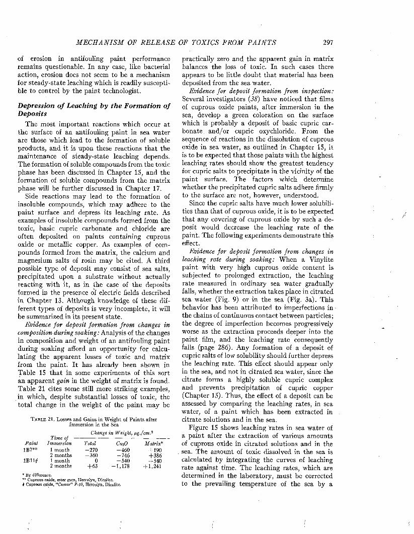
M E C H A N I S M OF R E L E A S E OF TOXICS FROM P A I N T S 297
of erosion in antifouling paint performance remains questionable. In any case, like bacterial action, erosion does not seem to be a mechanism for steady-state leaching which is readily susceptible to control by the paint technologist.
Depression of Leaching by the Formation of Deposits
The most important reactions which occur at the surface of an antifouling paint in sea water are those which lead to the formation of soluble products, and it is upon these reactions that the maintenance of steady-state leaching depends. The formation of soluble compounds from the toxic phase has been discussed in Chapter 15, and the formation of soluble compounds from the matrix phase will be further discussed in Chapter 17.
Side reactions may lead to the formation of insoluble compounds, which may adhere to the paint surface and depress its leaching rate. As examples of insoluble compounds formed from the toxic, basic cupric carbonate and chloride are often deposited on paints containing cuprous oxide or metallic copper. As examples of compounds formed from the matrix, the calcium and magnesium salts of rosin may be cited. A third possible type of deposit may consist of sea salts, precipitated upon a substrate without actually reacting with it, as in the case of the deposits formed in the presence of electric fields described in Chapter 13. Although knowledge of these different types of deposits is very incomplete, it will be summarized in its present state.
Evidence for deposit formation from changes in composition during soaking: Analysis of the changes in composition and weight of an antifouling paint during soaking afford an opportunity for calculating the apparent losses of toxic and matrix from the paint. It has already been shown in Table 15 that in some experiments of this sort an apparent gain in the weight of matrix is found. Table 21 cites some still more striking examples, in which, despite substantial losses of toxic, the total change in the weight of the paint may be
T a b l e 2 1 . L o s s e s a n d G a i n s i n W e i g h t o f P a i n t s a f t e r I m m e r s i o n i n t h e S e a
Change in Weight, ¡ig./cm.2
PaintTime of —
Immersion Total CihO Matrix*1 B 7 * * 1 m o n t h - 2 7 0 - 4 6 0 + 1 9 0
2 m o n t h s - 3 6 0 - 7 4 6 + 3 8 61 B 1 1 # 1 m o n t h 0 - 5 4 0 + 5 4 0
2 m o n t h s + 6 3 - 1 , 1 7 8 + 1 , 2 4 1* By difference.** Cuprous oxide, ester gum, Hercolyn, Dicalite.§ Cuprous oxide, “Cimar” P-Î0, Hercolyn, Dicalite.
practically zero and the apparent gain in matrix balances the loss of toxic. In such cases there appears to be little doubt that material has been deposited from the sea water.
Evidence for deposit formation from inspection: Several investigators (38) have noticed that films of cuprous oxide paints, after immersion in the sea, develop a green coloration on the surface which is probably a deposit of basic cupric carbonate and/or cupric oxychloride. From the sequence of reactions in the dissolution of cuprous oxide in sea water, as outlined in Chapter 15, it is to be expected that those paints with the highest leaching rates should show the greatest tendency for cupric salts to precipitate in the vicinity of the paint surface. The factors which determine whether the precipitated cupric salts adhere firmly to the surface are not, however, understood.
Since the cupric salts have much lower solubilities than that of cuprous oxide, it is to be expected that any covering of cuprous oxide by such a deposit would decrease the leaching rate of the paint. The following experiments demonstrate this effect.
Evidence for deposit formation from changes in leaching rate during soaking: When a Vinylite paint with very high cuprous oxide content is subjected to prolonged extraction, the leaching rate measured in ordinary sea water gradually falls, whether the extraction takes place in citrated sea water (Fig. 9) or in the sea (Fig. 3a). This behavior has been attributed to imperfections in- the chains of continuous contact between particles; the degree of imperfection becomes progressively worse as the extraction proceeds deeper into the paint film, and the leaching rate consequently falls (page 286). Any formation of a deposit of cupric salts of low solubility should further depress the leaching rate. This effect should appear only in the sea, and not in citrated sea water, since the citrate forms a highly soluble cupric complex and prevents precipitation of cupric copper (Chapter 15). Thus, the effect of a deposit can be assessed by comparing the leaching rates, in sea water, of a paint which has been extracted in citrate solutions and in the sea.
Figure 15 shows leaching rates in sea water of a paint after the extraction of various amounts of cuprous oxide in citrated solutions and in the sea. The amount of toxic dissolved in the sea is calculated by integrating the curves of leaching rate against time. The leaching rates, which are determined in the laboratory, must be corrected to the prevailing temperature of the sea by a
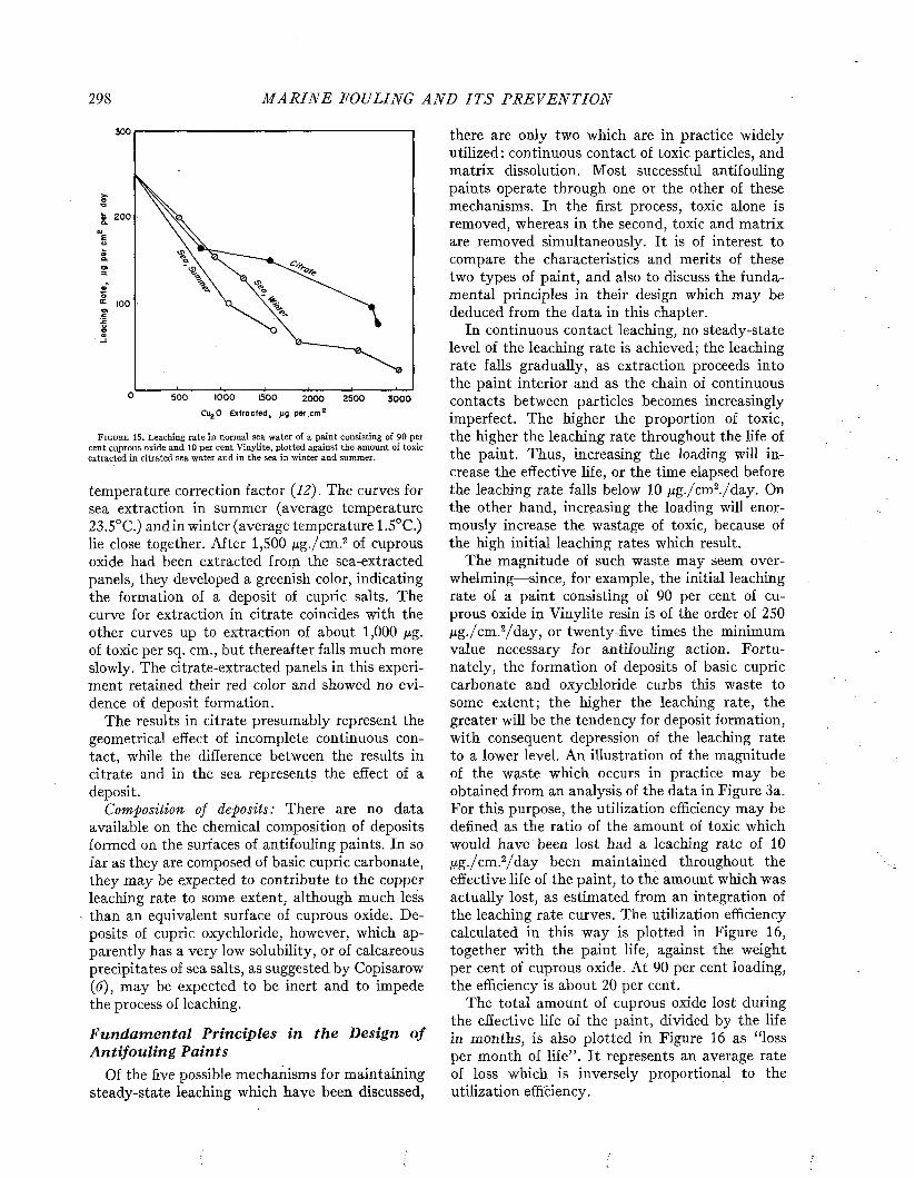
298 M A R I N E FOULING A N D I T S P R E V E N T I O N
300
* 200
100
1000 1500 2000 2500CugO E x tra c te d , / jg p e r .c m 2
500 3 0 0 0
F i g u r e 1 5 . Leaching rate in normal sea water of a paint consisting of 9 0 per cent cuprous oxide and 10 per cent Vinylite, plotted against the amount of toxic extracted in citrated sea water and in the sea in winter and summer.
temperature correction factor (12). The curves for sea extraction in summer (average temperature 23.5°C.) and in winter (average temperature 1.5°C.) lie close together. After 1,500 /ug./cm.2 of cuprous oxide had been extracted from the sea-extracted panels, they developed a greenish color, indicating the formation of a deposit of cupric salts. The curve for extraction in citrate coincides with the other curves up to extraction of about 1,000 jug. of toxic per sq. cm., but thereafter falls much more slowly. The citrate-extracted panels in this experiment retained their red color and showed no evidence of deposit formation.
The results in citrate presumably represent the geometrical effect of incomplete continuous contact, while the difference between the results in citrate and in the sea represents the effect of a deposit.
Composition of deposits: There are no data available on the chemical composition of deposits formed on the surfaces of antifouling paints. In so far as they are composed of basic cupric carbonate, they may be expected to contribute to the copper leaching rate to some extent, although much less than an equivalent surface of cuprous oxide. D eposits of cupric oxychloride, however, which apparently has a very low solubility, or of calcareous precipitates of sea salts, as suggested by Copisarow(6), may be expected to be inert and to impede the process of leaching.
Fundamental Principles in the Design of Antifouling Paints
Of the five possible mechanisms for maintaining steady-state leaching which have been discussed,
there are only two which are in practice widely utilized : continuous contact of toxic particles, and matrix dissolution. M ost successful antifouling paints operate through one or the other of these mechanisms. In the first process, toxic alone is removed, whereas in the second, toxic and matrix are removed simultaneously. It is of interest to compare the characteristics and merits of these two types of paint, and also to discuss the fundamental principles in their design which may be deduced from the data in this chapter.
In continuous contact leaching, no steady-state level of the leaching rate is achieved; the leaching rate falls gradually, as extraction proceeds into the paint interior and as the chain of continuous contacts between particles becomes increasingly imperfect. The higher the proportion of toxic, the higher the leaching rate throughout the life of the paint. Thus, increasing the loading will increase the effective life, or the time elapsed before the leaching rate falls below 10 /jg./cm2./day. On the other hand, increasing the loading will enormously increase the wastage of toxic, because of the high initial leaching rates which result.
The magnitude of such waste may seem overwhelming— since, for example, the initial leaching rate of a paint consisting of 90 per cent of cuprous oxide in Vinylite resin is of the order of 250 jug./cm.2/day, or twenty-five times the minimum value necessary for antifouling action. Fortunately, the formation of deposits of basic cupric carbonate and oxychloride curbs this waste to some extent; the higher the leaching rate, the greater will be the tendency for deposit formation, with consequent depression of the leaching rate to a lower level. An illustration of the magnitude of the waste which occurs in practice may be obtained from an analysis of the data in Figure 3a. For this purpose, the utilization efficiency may be defined as the ratio of the amount of toxic which would have been lost had a leaching rate of 10 /xg./cm.2/d a y been maintained throughout the effective life of the paint, to the amount which was actually lost, as estimated from an integration of the leaching rate curves. The utilization efficiency calculated in this way is plotted in Figure 16, together with the paint life, against the weight per cent of cuprous oxide. At 90 per cent loading, the efficiency is about 20 per cent.
The total amount of cuprous oxide lost during the effective life of the paint, divided by the life in months, is also plotted in Figure 16 as “loss per month of life” . It represents an average rate of loss which is inversely proportional to the utilization efficiency.
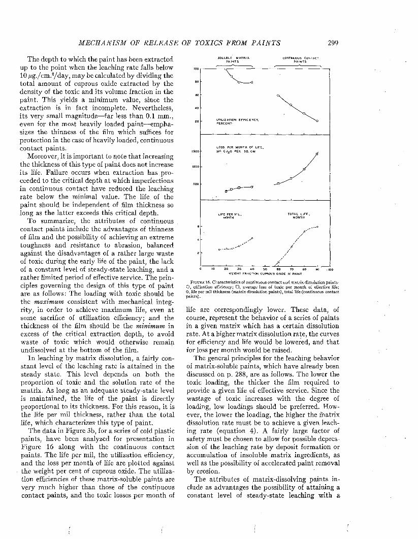
M E C H A N I S M OF R E L E A S E OF TOXICS FROM P A I N T S 299
The depth to which the paint has been extracted up to the point when the leaching rate falls below 10 /xg./cm.2/day, may be calculated by dividing the total amount of cuprous oxide extracted by the density of the toxic and its volume fraction in the paint. This yields a minimum value, since the extraction is in fact incomplete. Nevertheless, its very small magnitude—far less than 0.1 mm., even for the most heavily loaded paint— emphasizes the thinness of the him which suffices for protection in the case of heavily loaded, continuous contact paints.
Moreover, it is important to note that increasing the thickness of this type of paint does not increase its life. Failure occurs when extraction has proceeded to the critical depth at which imperfections in continuous contact have reduced the leaching rate below the minimal value. The life of the paint should be independent of film thickness so long as the latter exceeds this critical depth.
To summarize, the attributes of continuous contact paints include the advantages of thinness of film and the possibility of achieving an extreme toughness and resistance to abrasion, balanced against the disadvantages of a rather large waste of toxic during the early life of the paint, the lack of a constant level of steady-state leaching, and a rather limited period of effective service. The principles governing the design of this type of paint are as follows: The loading with toxic should be the maximum consistent with mechanical integrity, in order to achieve maximum life, even at some sacrifice of utilization efficiency; and the thickness of the film should be the minimum in excess of the critical extraction depth, to avoid waste of toxic which would otherwise remain undissolved at the bottom of the film.
In leaching by matrix dissolution, a fairly constant level of the leaching rate is attained in the steady state. This level depends on both the proportion of toxic and the solution rate of the matrix. As long as an adequate steady-state level is maintained, the life of the paint is directly proportional to its thickness. For this reason, it is the life per mil thickness, rather than the total life, which characterizes this type of paint.
The data in Figure 3b, for a series of cold plastic paints, have been analyzed for presentation in Figure 16 along with the continuous contact paints. The life per mil, the utilization efficiency, and the loss per month of life are plotted against the weight per cent of cuprous oxide. The utilization efficiencies of these matrix-soluble paints are very much higher than those of the continuous contact paints, and the toxic losses per month of
SO LU BLE M A T R IX CONTINUOUS CONTACTP A IN T S P A IN T S
100
8 0
60
4 0
UTILIZATION EFFIC IE N CY ,20
L O SS PER M O N TH OF L IF E , (iG CU 2 0 PE R SO . CMISOO
1000
5 0 0
T O TA L L I F E ,L IFE PER M IL ,
6
4
2
0 IO 2 0 3 0 4 0 SO 6 0 7 0 8 0 90 -1 0 0
F i g u r e 16. Characteristics of continuous contact and matrix dissolution paints- O , utilization efficiency; □ , average loss of toxic per month of effective life; O, life per mil thickness (matrix dissolution paints), total life (continuous contact paints).
life are correspondingly lower. These data, of course, represent the behavior of a series of paints in a given matrix which has a certain dissolution rate. At a higher matrix dissolution rate, the curves for efficiency and life would be lowered, and that for loss per month would be raised.
The general principles for the leaching behavior of matrix-soluble paints, which have already been discussed on p. 288, are as follows. The lower the toxic loading, the thicker the film required to provide a given life of effective service. Since the wastage of toxic increases with the degree of loading, low loadings should be preferred. However, the lower the loading, the higher the matrix dissolution rate must be to achieve a given leaching rate (equation 4). A fairly large factor of safety must be chosen to allow for possible depression of the leaching rate by deposit formation or accumulation of insoluble matrix ingredients, as well as the possibility of accelerated paint removal by erosion.
The attributes of matrix-dissolving paints include as advantages the possibility of attaining a constant level of steady-state leaching with a
300 M A R I N E FOULING A N D I T S P R E V E N T I O N
relatively small waste of toxic— not more than that consistent with a reasonable factor of safety— and the possibility of providing a very long life of active service by employing a thick paint him. In addition, the opportunity of making independent adjustments of two variables— the degree of loading and the matrix dissolution rate— permits far greater flexibility in designing a paint with the desired leaching rate. The disadvantages of matrix- dissolving paints are the greater thicknesses required, and the fact that most soluble matrices are comparatively soft and may not stand up under extreme conditions of erosion. The principles governing the design of this type of paint are quite different from those of the continuous contact type. The loading with toxic should be the minimum which, for a matrix with a given dissolution rate, would provide an adequate steady- state leaching rate with a suitable factor of safety; and to achieve a maximum life, the thickness of the film should be the maximum consistent with economy and mechanical stability.
REFERENCES1 . A d a m , N . K . T h e P h y s i c s a n d C h e m i s t r y o f S u r f a c e s . 2 n d E d . ,
O x f o r d U n i v . P r e s s , 1 9 3 8 .2 . A l e x a n d e r , A . L . , J . B . B a l l e n t i n e , a n d M . 0 . Y e i t e r .
A n t i f o u l i n g P a i n t s . R o l e o f P i g m e n t P a r t i c l e S i z e i n t h e P e r f o r m a n c e o f T o x i c P a i n t s . I n d . E n g . C h e m . 4 1 , 1 7 3 7 — 1 7 4 1 . 1 9 4 9 .
3 . B a r n e s , H . S t u d i e s o n A n t i - f o u l i n g C o m p o s i t i o n s . P a r t V I —T h e l e a c h i n g r a t e d u r i n g t h e e a r l y s t a g e s a n d i t s r e l a t i o n t o t h e s u r f a c e c o n d i t i o n s i n c u p r o u s o x i d e c o m p o s i t i o n s . J . I r o n & S t e e l I n s t . J u n e 1 9 4 9 , 1 7 9 - 1 8 5 , 1 9 4 9 .
4 . B a r r e r , R . M . D i f f u s i o n i n a n d T h r o u g h S o l i d s . C a m b r i d g eU n i v . P r e s s , 1 9 4 1 .
5 . C a r r i t t , D . E . , a n d J . D . F e r r y . T h e P e r m e a b i l i t y o f P a i n tM a t r i c e s t o I o n s . P a p e r 4 , S i x t h R e p o r t f r o m t h e W o o d s H o l e O c e a n o g r a p h i c I n s t i t u t i o n t o t h e B u r e a u o f S h i p s , M a y 1 , 1 9 4 3 .
6 . C o p is a r o w , M . T h e F o u l i n g o f S h i p s . S c i e n c e , 1 0 1 , p . 4 0 6 , 1 9 4 5 .7 . D a r s i e , M . L . , J r . S e c t i o n V , P a r t I I , A n n u a l R e p o r t f o r
1 9 4 2 - 4 3 , B i o l o g i c a l L a b o r a t o r y , N a v a l F u e l D e p o t , S a n D i e g o , 1 9 4 3 .
8. D o t y , P . M ., W . H . A i k e n , a n d H . M a r k . W a te r V a p o rP e r m e a b i l i t y o f O r g a n i c F i l m s . I n d . E n g . C h e m . , A n a l . E d . , 1 6 , 6 8 6 , 1 9 4 4 .
9 . E lm , A . C . A n I n v e s t i g a t i o n o f t h e F u n d a m e n t a l F a c t o r s I n f l u e n c i n g t h e A d h e s i o n o f O r g a n i c C o a t i n g s t o S t e e l S u r f a c e s . P r o g r e s s R e p o r t f o r t h e F i r s t C o n t r a c t P e r i o d , U . S . N a v y P r o j e c t N o . N x s s - 3 5 4 4 4 . J u l y 1 4 , 1 9 4 4 .
1 0 . F e r r y , J . D . , D . E . C a r r i t t , a n d D . M . R e y n o l d s . S t u d i e so f t h e S u r f a c e - E x p o s e d T o x i c o n F r e s h l y P a i n t e d S u r f a c e s . P a p e r 1 , S e v e n t h R e p o r t f r o m t h e W o o d s H o l e O c e a n o g r a p h i c I n s t i t u t i o n t o t h e B u r e a u o f S h i p s , A p r i l 2 0 , 1 9 4 4 .
1 1 . F e r r y , J . D . , a n d M . W . D a v i d s o n . T h e C h e m i c a l C o m b i n a t i o n o f C o p p e r w i t h A l g i n i c A c i d a n d w i t h t h e O r g a n i c M a t e r i a l o f t h e S l i m e F i l m . P a p e r 1 2 , F o u r t h R e p o r t f r o m t h e W o o d s H o l e O c e a n o g r a p h i c I n s t i t u t i o n t o t h e B u r e a u o f S h i p s , M a r c h 2 7 , 1 9 4 2 .
1 2 . F e r r y , J . D . , a n d B . M . F e r r y . T h e E f f e c t o f T e m p e r a t u r eo n t h e R a t e o f S o l u t i o n o f C u p r o u s O x i d e i n S e a W a t e r . I n t e r i m R e p o r t V I f r o m t h e W o o d s H o l e O c e a n o g r a p h i c I n s t i t u t i o n t o t h e B u r e a u o f S h i p s , J u l y 2 8 , 1 9 4 4 .
1 3 . F e r r y , J . D . , a n d B . H . K e t c h u m . A c t i o n o f A n t i f o u l i n gP a i n t s . I I I . M a i n t e n a n c e o f t h e L e a c h i n g R a t e o f A n t i f o u l i n g P a i n t s F o r m u l a t e d w i t h I n s o l u b l e , I m p e r m e a b l e M a t r i c e s . I n d . E n g . C h e m . , 3 8 , 8 0 6 - 8 1 0 , 1 9 4 6 .
14. F e r r y , J . D . , B . H . K e t c h u m , G . S c o t t , B . M o t t , a n d B .R e y n o l d s . D i s s o l u t i o n o f t h e M a t r i x a s a M e c h a n i s m f o r S t e a d y - S t a t e L e a c h i n g . P a p e r 3 , S e v e n t h R e p o r t f r o m t h e W o o d s H o l e O c e a n o g r a p h i c I n s t i t u t i o n t o t h e B u r e a u o f S h i p s , A p r i l 2 0 , 1 9 4 4 .
1 5 . F e r r y , J . D . , B . H . K e t c h u m , a n d C . M . W e i s s . T h e W e t t i n go f P a i n t S u r f a c e s b y S e a W a t e r . P a p e r 1 3 o f t h e F o u r t h R e p o r t f r o m t h e W o o d s H o l e O c e a n o g r a p h i c I n s t i t u t i o n t o t h e B u r e a u o f S h i p s , 1 9 4 2 .
1 6 . F e r r y , J . D . , G . T . S c o t t , a n d B . M o t t . C o n t i n u o u s C o n t a c to f T o x i c P a r t i c l e s a s a M e c h a n i s m f o r S t e a d y - S t a t e L e a c h i n g . P a p e r 4 , S e v e n t h R e p o r t f r o m t h e W o o d s H o l e O c e a n o g r a p h i c I n s t i t u t i o n t o t h e B u r e a u o f S h i p s , A p r i l 2 0 , 1 9 4 4 .
17. H o l z a p f e l , A . C . D e r A n s t r i c h v o n S c h i f f b ö d e n . J a h r b u c hd e r S c h i f f b a u t e c h n i s c h e n G e s e l l s c h a f t , 5 , p . 3 9 8 , 1 9 0 4 .
1 8 . K e t c h u m , B . H . P r e l i m i n a r y R e p o r t o f t h e L e a c h i n g C h a r a c t e r i s t i c s o f T w e n t y - t w o B a k e l i t e F o r m u l a t i o n s . I n t e r i m R e p o r t I I f r o m t h e W o o d s H o l e O c e a n o g r a p h i c I n s t i t u t i o n t o t h e B u r e a u o f S h i p s , M a y 1 8 , 1 9 4 3 .
1 9 . K e t c h u m , B . H . A c t i o n o f A n t i f o u l i n g P a i n t s . V . T h e U s e o fG l y c i n e S o l u t i o n s a s a n A c c e l e r a t e d T e s t o f t h e A v a i l a b i l i t y o f T o x i c . I n d . E n g . C h e m . , 4 0 , 2 4 9 - 2 5 3 , 1 9 4 8 .
2 0 . K e t c h u m , B . H . , a n d J . C . A y e r s . A c t i o n o f A n t i f o u l i n gP a i n t s . V I . E f f e c t o f N o n t o x i c P i g m e n t s o n t h e P e r f o r m a n c e o f A n t i f o u l i n g P a i n t s . I n d . E n g . C h e m . , 4 0 , 2 1 2 4 ^ 2 1 2 7 , 1 9 4 8 .
2 1 . K e t c h u m , B . H . , J . D . F e r r y , a n d A . E . B u r n s , J r . A c t io n o fA n t i f o u l i n g P a i n t s . I V . M a i n t e n a n c e o f t h e L e a c h i n g R a t e o f A n t i f o u l i n g P a i n t s t h r o u g h t h e M e c h a n i s m o f S o l u t i o n o f t h e M a t r i x . I n d . E n g . C h e m . , 3 8 , 9 3 1 - 9 3 6 , 1 9 4 6 .
2 2 . K e t c h u m , B . H . , L . W . H u t c h i n s , a n d B , M o t t . P r e l i m i n a r yR e p o r t o n M e t h o d s f o r D i f f e r e n t i a t i n g B e t w e e n C o p p e r L o s t b y S o l u t i o n f r o m t h e P a i n t F i l m a n d b y E r o s i o n . P a p e r 1 , S i x t h R e p o r t f r o m t h e W o o d s H o l e O c e a n o g r a p h i c I n s t i t u t i o n t o t h e B u r e a u o f S h i p s , M a y 1 , 1 9 4 3 .
2 3 . K e t c h u m , B . H . , D . T o d d , B . R e y n o l d s , a n d B . M o t t .S t u d i e s o f A c c e l e r a t e d M e t h o d s f o r I n v e s t i g a t i n g t h e M a t r i x P r o p e r t i e s o f A n t i f o u l i n g P a i n t s . P a p e r 7 , S e v e n t h R e p o r t f r o m t h e W o o d s H o l e O c e a n o g r a p h i c I n s t i t u t i o n t o t h e B u r e a u o f S h i p s , A p r i l 2 0 , 1 9 4 4 .
2 4 . L u c a s , F . F . M e t h o d s f o r t h e P r e p a r a t i o n o f T r a n s v e r s eS p e c i m e n s o f M u l t i p l e P a i n t C o a t i n g s o n S t e e l P l a t e s f o r M i c r o s c o p i c E x a m i n a t i o n . R e p o r t f r o m B e l l T e l e p h o n e L a b o r a t o r i e s t o B u r e a u o f S h i p s , 1 9 4 6 . ( U n p u b l i s h e d )
2 5 . M a n e g o l d , E . , a n d K . S o l f . Ü b e r K a p i l l a r s y s t e m e , X I X / 9 .D i e s p e z i f i s c h e D u r c h l ä s s i g k e i t u n d d i e H o h l r a u m s t r u k t u r v o n K u g e l p a c k u n g e n u n d K u g e l - b z w . K o r n - S c h ü t t u n g e n .
2 6 . M a r e I s l a n d N a v y Y a r d ( A . E . B u r n s , J r . ) . I n v e s t i g a t i o n s o fM a t r i x E r o s i o n o f A n t i f o u l i n g P a i n t s . I n t e r i m R e p o r t 4 , S e p t e m b e r 1 7 , 1 9 4 3 .
2 7 . M a r e I s l a n d N a v y Y a r d ( Ä . E . B u r n s , J r . ) . A S t u d y o f V a r i o u s F a c t o r s I n f l u e n c i n g t h e P e r f o r m a n c e o f C u p r o u s O x i d e i n A n t i f o u l i n g P a i n t s . T e s t N o . 3 0 9 , F e b r u a r y 5 , 1 9 4 5 .
2 8 . N a v a l R e s e a r c h L a b o r a t o r y . R e p o r t o n P r o g r e s s i n t h e S t u d yo f A n t i f o u l i n g C o m p o s i t i o n s f o r t h e P r o t e c t i o n o f F l y i n g B o a t H u l l B o t t o m s . # P - 1 8 1 5 , N o v e m b e r 2 8 , 1 9 4 1 .
2 9 . R a g g , M . D i e S c h i f f s b o d e n - u n d R o s t s c h u n t z - F a r b e n . p . 1 3 1 ,B e r l i n , 1 9 2 6 .
3 0 . R e n n , C . E . , a n d D . B . J o h n s t o n e . E f f e c t s o f B a c t e r i a l D e c o m p o s i t i o n o f M a t r i x M a t e r i a l s U p o n L e a c h i n g R a t e s o f A n t i f o u l i n g P a i n t s . P a p e r 6 , S e v e n t h R e p o r t f r o m t h e W o o d s H o l e O c e a n o g r a p h i c I n s t i t u t i o n t o t h e B u r e a u o f S h i p s , A p r i l 2 0 , 1 9 4 4 .
3 1 . R i l e y , G . A . N o t e o n t h e E f f e c t o f L o s s o f M e r c u r y f r o m t h eL e a c h i n g B a t h a n d o f S l i m e F i l m s o n L e a c h i n g o f M e r c u r y P a i n t s . P a p e r 9 , S e v e n t h R e p o r t f r o m t h e W o o d s H o l e O c e a n o g r a p h i c I n s t i t u t i o n t o t h e B u r e a u o f S h i p s , A p r i l 2 0 , 19 4 4 .
M E C H A N I S M OF R E L E A S E OF TOXICS FROM P A I N T S 301
3 2 . S m ith , F . G . W . P r e l i m i n a r y N o t e o n t h e U s e o f a R o t a t i n gD i s c a s a n A c c e l e r a t e d T e s t o f R e s i s t a n c e t o E r o s i o n . P a p e r I S , S e v e n t h R e p o r t f r o m t h e W o o d s H o l e O c e a n o g r a p h i c I n s t i t u t i o n t o t h e B u r e a u o f S h i p s , A p r i l 2 0 , 1 9 4 4 .
3 3 . S m ith , F . G . W . T h e U s e o f R o t a t i n g D i s c s i n a n A c c e l e r a t e dM e t h o d o f T e s t i n g E r o s i o n o f A n t i f o u l i n g P a i n t s . I n t e r i m R e p o r t I I f r o m t h e W o o d s H o l e O c e a n o g r a p h i c I n s t i t u t i o n t o t h e B u r e a u o f S h i p s , M a y 5 , 1 9 4 4 .
3 4 . S m ith , F . G . W . , C . M . W e is s , a n d B . H . K e t c h u m . P e r f o r m a n c e o f P a i n t s M a d e t o 1 6 X F o r m u l a t i o n s w i t h A d d e d T o u g h e n e r s . I n t e r i m R e p o r t X I I I f r o m t h e W o o d s H o l e O c e a n o g r a p h i c I n s t i t u t i o n t o t h e B u r e a u o f S h i p s , D e c e m b e r 1 5 , 1 9 4 4 .
3 5 . T o d d , D . T h e S o l u b i l i t y a n d R a t e o f S o l u t i o n o f R o s i n a n dD e r i v a t i v e s o f R o s i n i n A q u e o u s S o l u t i o n s . P a p e r 8 , S e v e n t h R e p o r t f r o m t h e W o o d s H o l e O c e a n o g r a p h i c I n s t i t u t i o n t o t h e B u r e a u o f S h i p s , A p r i l 2 0 , 1 9 4 4 .
3 6 . W e i s s , C . M . , a n d B . H . K e t c h u m . T h e A c c u m u l a t i o n o f C o p p e r b y S l i m e F i l m s F o r m e d o n N o n - T o x i c S u r f a c e s . P a p e r 6 ,
F o u r t h R e p o r t f r o m t h e W o o d s H o l e O c e a n o g r a p h i c I n s t i t u t i o n t o t h e B u r e a u o f S h i p s , M a r c h 2 7 , 1 9 4 2 .
3 7 . W e i s s , C . M . , a n d B . H . K e t c h u m . E f f e c t o f T h i c k n e s s o f A p p l i c a t i o n a n d T i m e B e f o r e M o t i o n T h r o u g h t h e W a t e r o n t h e P e r f o r m a n c e o f 1 4 3 . I n t e r i m R e p o r t V I f r o m t h e W o o d s H o l e O c e a n o g r a p h i c I n s t i t u t i o n t o t h e B u r e a u o f S h i p s , M a r c h 1 7 , 1 9 4 5 .
3 8 . W e i t h , A . J . , a n d V . H . T u r k i n g t o n . R e p o r t o n P r o t e c t i v eC o a t i n g s f o r S h i p B o t t o m s . P r o b l e m N o . N L - B 4 o f D i v i s i o n B , N a t i o n a l D e f e n s e R e s e a r c h C o m m i t t e e , S e c t i o n B - 8 - B . S e r i a l N o . 1 5 9 , J a n u a r y 1 4 , 1 9 4 2 .
3 9 . W h e d o n , W . F . A n n u a l R e p o r t f o r 1 9 4 2 - 4 3 , B i o l o g i c a l L a b o r a t o r y , N a v a l F u e l D e p o t , S a n D i e g o , 1 9 4 3 .
4 p . Y o u n g , G . H . , G . W . G e r h a r d t , a n d W . K . S c h n e id e r . A n t i f o u l i n g P a i n t s . T e s t P r o c e d u r e s a n d G e n e r a l O b s e r v a t i o n s . I n d . E n g . C h e m . , 3 5 , 4 3 2 - 4 3 6 , 1 9 4 3 .
4 1 . Y o u n g , G . H . , W . K . S c h n e i d e r , a n d G . W . S e a g r e n . A n t i f o u l i n g P a i n t s . E f f e c t o f I n e r t P i g m e n t o n A n t i f o u l i n g A c t i o n . I n d . E n g . C h e m . , 3 6 , 1 1 3 0 - 1 1 3 2 , 1 9 4 4 .
M arine Fouling and Its Prevention,Contribution N o. 580 from the W oods H ole Oceanographic Institute
Copyright 1952 by U. S. N aval Institute, A nnapolis, Maryland G eorge Banta Publishing C o., M enasha, WI
CHAPTER 17
The Dissolution of the Matrix and Its IngredientsAlthough the matrix is at least as important as
the toxic, the properties which make certain matrix ingredients useful for the formulation of antifouling paints have often not been recognized. As shown in the previous chapter, some paints depend upon the solubility of a matrix ingredient to maintain an adequate steady-state leaching rate of the toxic. The slowly dissolving matrix eventually exposes toxic particles which lie deep within the paint film, thus permitting them to dissolve and exert their toxic effect on the fouling organisms. Thus the toxic and the matrix dissolve simultaneously, resulting in a gradual decrease in thickness of the film. Since the toxics commonly used dissolve more rapidly than the matrix ingredients, the rate of solution of the latter controls the rate of solution of the entire film. This chapter summarizes the current knowledge concerning the factors affecting the rate at which certain matrix ingredients dissolve in sea water.
For convenience, the factors controlling the solution of matrix materials may be divided into two classes: those arising from the nature of the dissolving medium employed, and those inherent in the matrix film itself. In the first group of factors we must consider the chemical composition of the dissolving solution, such as its alkalinity and the nature of the salts it contains. The second group of factors includes the chemical composition of the matrix film, the proportion and nature of acidic and neutral materials, the number of phases present, and such physical properties as smoothness and hardness. In addition, the time elapsed between the mixing of the paint and its application, the conditions under which the mixture .was prepared, and the age of the paint film itself on the panel or ship bottom may influence the solution rate.
Many acidic resins are soluble in sea water. Their dissolution requires the formation of soluble alkaline salts, and they are not, consequently, soluble in neutral or acid aqueous solutions. Such resins are rendered insoluble if the free acid group of the molecule is neutralized by estérification or by the formation of an insoluble salt or soap. Paint technologists have commented on the acidic nature of natural resins and have suggested modifying them to overcome this “difficulty,” or have even stated that they cannot be used in
paints because of their tendency to react with pigments (1, 8). Y et this very acidity and the resultant solubility in sea water is the principal reason for the satisfactory performance of antifouling paints containing such ingredients.
THE COMPOSITION OF ROSIN AND ITS DERIVATIVES
The use of rosin as a constituent of antifouling paints was patented in 1867 (J), and since that time, because of its availability and cheapness, its use has been constantly expanded. Its only serious competitor has been shellac, another acidic resin from natural sources. But shellac suffers from the drawback that it must be-im ported into the United States, a fact that led the N avy in 1926 to discontinue its use (I). The reason for the effectiveness of rosin was not known until 1943, when investigations at the Mare Island N avy Yard and the Woods Hole Oceanographic Institution simultaneously showed that its virtue depended upon its solubility (5, 9).
Rosin is obtained from the exudation of pine and fir trees, the greater portion of the world’s supply coming from Pinus palustris (the longleaf pine) and Pinus carribea. The fresh gum, or oleoresin, is subjected to steam distillation to remove the low-boiling volatile fraction known as turpentine. The residual material, crude rosin, is a dark amorphous solid at room temperature. It is composed of about 90 per cent of acidic materials, called resin acids, and about 10 per cent of neutral materials that are apparently non-volatile sesqui- and diterpenes. The resin acids all have the empirical formula C20H30O2, and consist of a mixture of substances the nature of which is not yet entirely clear (6). The acids are known to comprise a mixture of the acid-stable d-pimaric acid and a series of acids (levopimaric acid, the sapinic acids, etc.) which are all converted by boiling with mineral acid into abietic acid, a substance that represents a relatively stable stage in a series of complex changes. The formulas of three of these compounds are given on the next page (6).
Methods have been developed for the determination of both d-pimaric acid (11) and levopimaric acid (7) in resin acid mixtures. In the original oleoresin from which rosin is prepared, it has been found that the acid fraction contains 38 per cent
302

D ISSO L U T IO N OF TH E M A T R I X A N D I T S I N G R E D I E N T S 303
C H = C H ;
C H 3 C O O H
\ C H
c h 3\ / c h
d - p i m a r i c a c i d
C H S C O O H
C H 3
l e v o p i m a r i c a c i d
C H ,
~ C H
C H 3
a b i e t i c a c i d
d-pimaric acid and 36 per cent levopimaric acid, the balance consisting entirely of those intermediary acids that are convertible into abietic acid. There is no evidence that any abietic acid exists as such in oleoresin. In commercial rosin the isomerization process probably takes place to some extent during the process of steam distillation, and abietic acid may be present in amounts depending upon the extent of the heat treatment.. Rosin is graded according to its color, and is purified, generally by solvent extraction, for the purpose of removing the color bodies present {10).
The resin acids of rosin contain two carbon- carbon double bonds and one carboxyl group per molecule. The former give rise to the characteristic instability of rosin, while the latter enables rosin to be dissolved in alkali, though the acid itself is quite insoluble in neutral or acid aqueous solutions. The resin acids dissolve in the form of the resínate ion, which is formed by the attack of the hydroxyl ion of the alkali:
r c o o h + o h - - + r c o o - + h 2 o .
The resínate ion will stay in solution as long as there is no substance present that will react with it to form an insoluble compound. In sea water the resínate ion reacts to a certain extent with calcium and magnesium ions to form the corresponding insoluble soaps. This reaction may also take place on solid rosin surfaces, and in this way the rosin becomes at least partially covered with insoluble material, which effectively cuts down the solution rate in sea water.
When the carboxyl group of a resin acid is esterified with a mono- or polyhydroxy alcohol, an alkali-insoluble ester is formed. The esters formed
from rosin and low molecular weight alcohols, such as methyl and ethyl alcohols, are far softer than rosin, while those formed from polyhydroxy alcohols, such as glycol or diethylene glycol, are usually harder and more brittle than rosin.
It should be pointed out that these modified rosins are mixtures, as is the parent substance. In addition, the estérification is never complete, so that the product always contains some acid material. The following compounds are typical rosin esters. The trade name of the material used is given in each case. In these formulas RCOOH is used to represent the resin acid.
M e t h y l A b i e t a t e ( A b a l y n )
R C O O C H 3 T h i s m a t e r i a l i s 9 2 - 9 4 %n e u t r a l a n d i s l i q u i d a t r o o m t e m p e r a t u r e .
G l y c o l d i a b i e t a t e ( F l e x a l y n )
R C O O C H 2— C H 2 O O C R T h i s m a t e r i a l i s 9 4 . 5 %n e u t r a l a n d 4 5 - 5 0 ° C .
s o f t e n s a t
G l y c e r y l t r i a b i e t a t e ( E s t e r G u m )
c h 2 — c h — c h 2 T h i s m a t e r i a l i s 9 4 % n e u t r a l , m e l t s a t a b o u t
0 0 0 100°C.,0 0 0 b r i t t l e .c C CR R R
P e n t a e r y t h r i t o l e s t e r s o f r o s i n ( P e n t a l y n M )
( H O C H 2) 3C C H 2 O O C R
( H O C H 2) 2C ( C H 2 0 0 C R ) 2
H O C H 2 C ( C H 2 O O C R ) 3
C ( C H 2 0 0 C R ) 4
T h i s m a t e r i a l c o n s i s t s o f a m i x t u r e o f a l l f o u r p o s s i b l e r o s i n e s t e r s o f p e n t a e r y t h r i t o l , t h e h i g h e r m o l e c u l a r w e i g h t e s t e r p r e d o m i n a t i n g . I t m e l t s a t 1 6 5 ° C . , a n d i s 9 7 . 5 % n e u t r a l .
The properties of rosin are also changed when the double bonds of the resin acids are modified. The double bonds of abietic acid oxidize readily, as evidenced by the fact that freshly prepared abietic acid becomes quite yellow after a few days. This reaction is represented as follows:
C H 3 C O O H C H 3 C O O H
CH;
J— C HCH3 c h 3— O H
O H
C H
A b i e t i cA c i d
c h 3 c h 3
D i h y d r o x y - a b i e t i c a c i d
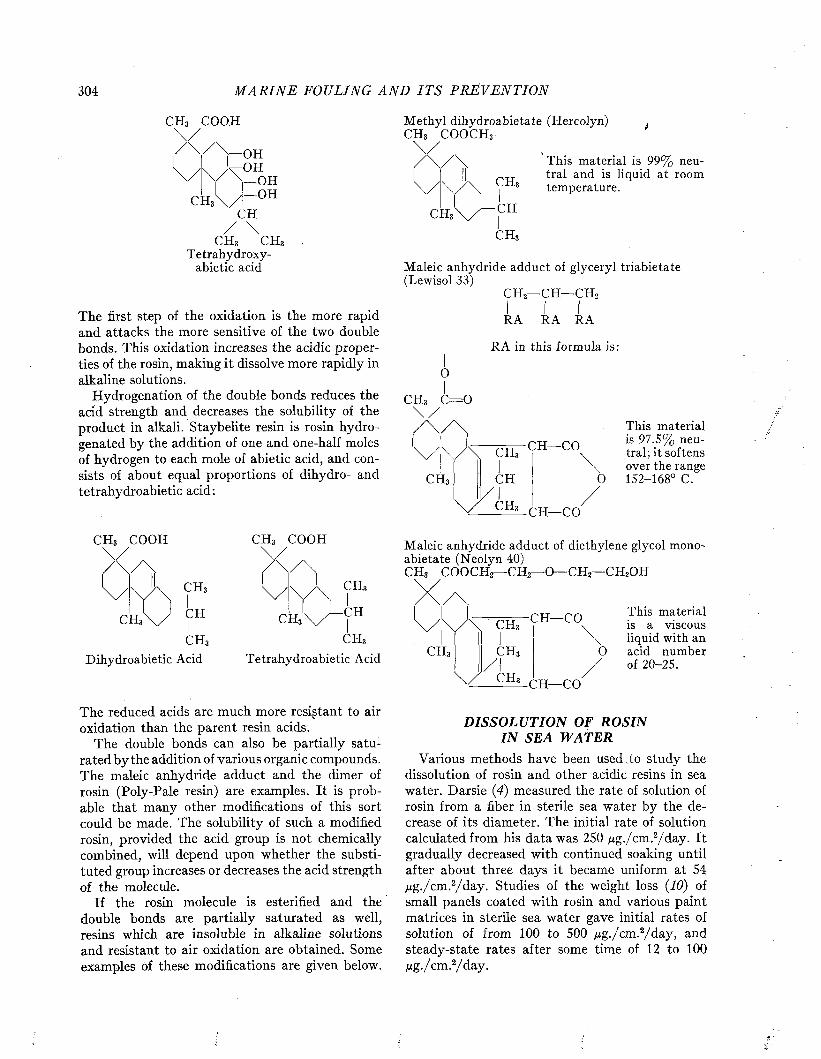
304 M A R I N E FOUL ING A N D I T S P R E V E N T I O N
C H 3 C O O H
— O H^ O H
— O H
C H
c h 3 c h 3T e t r a h y d r o x y -
a b i e t i c a c i d
The first step of the oxidation is the more rapid and attacks the more sensitive of the two double bonds. This oxidation increases the acidic properties of the rosin, making it dissolve more rapidly in alkaline solutions.
Hydrogenation of the double bonds reduces the acid strength and decreases the solubility of the product in alkali. Staybelite resin is rosin hydrogenated by the addition of one and one-half moles of hydrogen to each mole of abietic acid, and consists of about equal proportions of dihydro- and tetrahydroabietic acid:
C H 3 C O O H C H 3 C O O H
C H 3
c h 3
D i h y d r o a b i e t i c A c i d
CH3x
c h 3
T e t r a h y d r o a b i e t i c A c i d
The reduced acids are much more resistant to air oxidation than the parent resin acids.
The double bonds can also be partially saturated by the addition of various organic compounds. The maleic anhydride adduct and the dimer of rosin (Poly-Pale resin) are examples. It is probable that many other modifications of this sort could be made. The solubility of such a modified rosin, provided the acid group is not chemically combined, will depend upon whether the substituted group increases or decreases the acid strength of the molecule.
If the rosin molecule is esterified and the double bonds are partially saturated as well, resins which are insoluble in alkaline solutions and resistant to air oxidation are obtained. Some examples of these modifications are given below.
M e t h y l d i h y d r o a b i e t a t e ( H e r c o l y n )c h 3 c o o c h 3
C U ;
C H 3
'— C H
C H 3
T h i s m a t e r i a l i s 9 9 % n e u t r a l a n d i s l i q u i d a t r o o m t e m p e r a t u r e .
M a l e i c a n h y d r i d e a d d u c t o f g l y c e r y l t r i a b i e t a t e ( L e w i s o l 3 3 )
C H 2— C H — C H 2I I I
R A R A R A
R A i n t h i s f o r m u l a i s :
C H 3 C = 0
c h 3
c h 3
C H/ I
\ / c h 3 ,
- C H — C O
C H — C O
0
T h i s m a t e r i a l i s 9 7 . 5 % n e u t r a l ; i t s o f t e n s o v e r t h e r a n g e 1 5 2 - 1 6 8 ° C .
M a l e i c a n h y d r i d e a d d u c t o f d i e t h y l e n e g l y c o l m o n o - a b i e t a t e ( N e o l y n 4 0 )c h 3 c o o c h 2— c h 2— o — c h 2— c h 2o h
c h 3
c h 3
C H ,/ I
c h 3 ,
C H — C O
C H — C O
\o
T h i s m a t e r i a l i s a v i s c o u s l i q u i d w i t h a n a c i d n u m b e r o f 2 0 - 2 5 .
DISSOLUTION OF ROSIN IN SEA WATER
Various methods have been used to study the dissolution of rosin and other acidic resins in sea water. Darsie (4) measured the rate of solution of rosin from a fiber in sterile sea water by the decrease of its diameter. The initial rate of solution calculated from his data was 250 ß g ./cm.2/day. It gradually decreased with continued soaking until after about three days it became uniform at 54 /ug./cm.yday. Studies of the weight loss (10) of small panels coated with rosin and various paint matrices in sterile sea water gave initial rates of solution of from 100 to 500 //g./cm .2/day, and steady-state rates after some time of 12 to 100 jiig./cm.2/d ay .

D ISSO L U T IO N OF THE M A T R I X A N D I T S I N G R E D IE N T S 305
Calculation of rates of solution in this way from measurements of change in weight or thickness may conceivably be falsified through the loss of material from the rosin surface through other mechanisms than dissolution— abrasion, for example— and through gains in weight due to deposits from the solvent or imbibition. To eliminate this uncertainty, the dissolved rosin can be determined directly by recovering it from the filtered sea water solution by acidification of the solution and extraction with an organic solvent. Using a large volume of flowing solvent and a continuous extraction procedure, substantial amounts of rosin can be recovered. The amounts of rosin, dissolved in a 24-hour period from panels agitated in running sea water, recovered in this way are shown in Table 1. They range from 123 to 1,460
T a b l e 1 . D i s s o l u t i o n o f R o s i n i n R u n n i n g S e a W a t e r f r o m a P a n e l 1 5 5 c m . 2 i n A r e a S t i r r e d a t 8 5 R . P . M . f o r 2 4 H o u r s . T h e
E f f l u e n t S e a W a t e r w a s C o n t i n u o u s l y E x t r a c t e d w i t h C h l o r o f o r m
Drying Time Volume of Sea Total Rosin Rosinof Panel Water Used Dissolved Dissolved
days liters mg. Hg./cm . 21 2 4 . 5 1 9 1 2 32 2 9 . 5 2 1 1 3 56 1 2 . 0 3 7 2 3 97 1 3 . 0 4 9 3 1 6
1 4 1 4 . 0 6 2 4 0 09 3 2 0 . 0 1 7 3 1 1 1 79 9 1 7 . 0 1 7 7 1 1 4 0
1 0 2 2 0 . 7 2 2 6 1 4 6 0
fig. per cm.2 dissolved in a 24-hour period, and thus agree in order of magnitude with the solution rates measured by change in weight or thickness. Following the discussion of steady-state leaching rates in Chapter 16, it is apparent from these data that the rate of dissolution of rosin in sea water would be ample to provide for continuous liberation of the toxic from an antifouling paint with a rosin matrix.
The rosin samples used in this experiment were aged after application to the panels for various periods of time before the test, and the amount dissolved increases with the increasing age of the panel. This effect will be discussed at greater length below.
The decrease in the rate of solution of rosin from a panel after the first day or so in sea water is also shown by direct recovery. Table 2 presents results obtained during 3 successive 24-hour periods of extraction of a panel dried for 14 days, and two extractions from a panel dried for 93 days.
The method of direct recovery by continuous extraction is so time-consuming that most studies of dissolution rates have been carried out in arti-
T a b l e 2 . A m o u n t o f R o s i n D i s s o l v e d D u r i n g S u c c e s s i v e 2 4 H o u r P e r i o d s o f E x t r a c t i o n i n R u n n i n g S e a W a t e r f r o m R o s i n
C o a t e d P a n e l s 1 5 5 c m . 2 i n A r e a R o t a t e d a t 8 5 R . P . M .T h e E f f l u e n t S e a W a t e r w a s C o n t i n u o u s l y E x t r a c t e d
w i t h C h l o r o f o r mDryingTime of Volume of Total Rosin RosinPanel Sea Water Dissolved Dissolveddays Extraction liters mg. ng./cm , 2
1 4 f i r s t 1 4 . 0 6 2 4 0 01 4 s e c o n d 1 9 . 7 3 1 2 0 01 4 t h i r d 2 0 . 0 3 6 2 3 2
9 3 f i r s t 2 0 . 0 1 7 3 1 1 1 79 3 s e c o n d 9 . 5 6 8 4 3 9
ficial solutions in which both the solubilities and the rates of solution of acidic resins are higher than in sea water. The use of artificial solvents also permits variation of composition to determine the effects of such variables as pH and salt concentration, and avoids some of the complications of the mixture of ions occurring in sea water.
Effect of the Composition of the Aqueous Solvent on the Dissolution of Matrix Ingredients
The important properties of the aqueous solvent are its temperature and such chemical properties as the pH and the amount and kind of dissolved salts. In sea water the pH varies within the limits of about 7.5 to 8.2, the higher values being more common. The buffering action of sea water is the result of the presence of carbonate and bicarbonate ions, together with a small amount of borate. The sodium chloride content of sea water is 0.48 mole per liter; magnesium is present in about 0.05, and calcium in about 0.01 mole per liter. As will be seen, all of these constituents have been found to influence the solution rate of rosin.
Effect of pH of the solvent: The solubilities of
T a b l e 3 . T h e S o l u b i l i t i e s o f W W R o s i n a n d A b i e t i c A c i d '" i n A q u e o u s A l k a l i n e S o l u t i o n sEquilibration
Time Solubility LogFinal pH hours ßg./cc. Solubility
R o s i n6 . 9 1 8 2 9 1 . 4 67 . 1 4 1 5 2 1 . 7 27 . 2 5 7 2 5 2 1 . 7 27 . 3 4 5 6 7 1 . 8 37 . 4 1 9 6 2 1 . 7 97 . 5 6 5 6 6 1 . 8 27 . 6 4 5 8 8 1 . 9 48 . 1 1 8 4 3 9 2 . 6 48 . 8 0 2 . 3 1 4 9 4 3 . 1 7
A b i e t i c A c i d7 . 8 0 4 8 5 6 1 . 7 58 . 1 0 7 2 5 1 4 2 . 7 18 . 3 3 2 4 3 8 2 2 . 5 88 . 6 0 7 2 2 0 4 0 3 . 3 18 . 6 8 — 2 2 1 2 3 . 3 49 . 1 7 2 4 3 5 7 8 3 . 5 5
* The abietic acid was prepared from rosin by acid isomerization by Steele’s method (12). Material with a rotation of —45° in alcohol was used. The optical rotation of pure abietic acid is —102° in alcohol.
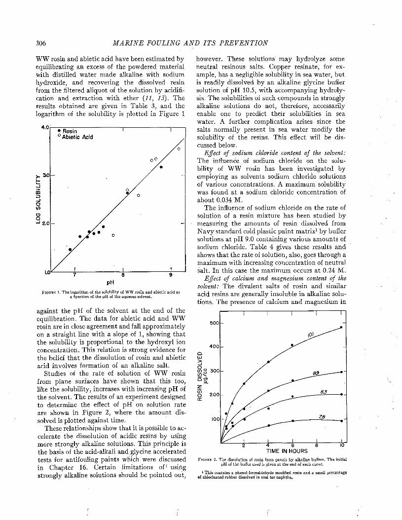
306 M A R I N E FOULING A N D I T S P R E V E N T I O N
WW rosin and abietic acid have been estimated by- equilibrating an excess of the powdered material with distilled water made alkaline with sodium hydroxide, and recovering the dissolved resin from the filtered aliquot of the solution by acidification and extraction with ether (11, 13). The results obtained are given in Table 3, and the logarithm of the solubility is plotted in Figure 1
4 . 0RosihA bietic Acid
3 lO
m
2.0
pH
F i g u r e 1. The logarithm, of the solubility of WW rosin and abietic acid as a function of the pH of the aqueous solvent.
against the pH of the solvent at the end of the equilibration. The data for abietic acid and WW rosin are in close agreement and fall approximately on a straight line with a slope of 1, showing that the solubility is proportional to the hydroxyl ion concentration. This relation is strong evidence for the belief that the dissolution of rosin and abietic acid involves formation of an alkaline salt.
Studies of the rate of solution of WW rosin from plane surfaces have shown that this too, like the solubility, increases with increasing pH of the solvent. The results of an experiment designed to determine the effect of pH on solution rate are shown in Figure 2, where the amount dissolved is plotted against time.
These relationships show that it is possible to accelerate the dissolution of acidic resins by using more strongly alkaline solutions. This principle is the basis of the acid-alkali and glycine accelerated tests for antifouling paints which were discussed in Chapter 16. Certain limitations of using strongly alkaline solutions should be pointed out,
however. These solutions may hydrolyze some neutral resinous salts. Copper resinate, for example, has a negligible solubility in sea water, but is readily dissolved by an alkaline glycine buffer solution of pH 10.5, with accompanying hydrolysis. The solubilities of such compounds in strongly alkaline solutions do not, therefore, necessarily enable one to predict their solubilities in sea water. A further complication arises since the salts normally present in sea water modify the solubility of the resins. This effect will be discussed below.
Effect of sodium chloride content of the solvent: The influence of sodium chloride on the solubility of WW rosin has been investigated by employing as solvents sodium chloride solutions of various concentrations. A maximum solubility was found at a sodium chloride concentration of about 0.034 M.
The influence of sodium chloride on the rate of solution of a resin mixture has been studied by measuring the amounts of resin dissolved from N avy standard cold plastic paint matrix1 by buffer solutions at pH 9.0 containing various amounts of sodium chloride. Table 4 gives these results and shows that the rate of solution, also, goes through a maximum with increasing concentration of neutral salt. In this case the maximum occurs at 0.24 M.
Effect of calcium and magnesium content of the solvent: The divalent salts of rosin and similar acid resins are generally insoluble in alkaline solutions. The presence of calcium and magnesium in
5 0 0
4 0 0Q
c n “ 3 0 0 89Q o»
83200
7.8100
TIME IN HOURSF i g u r e 2. The dissolution of rosin from panels by alkaline buffers. T he initial
pH of the buffer used is given at the end of each curve.
1 This contains a phenol-formaldehyde modified rosin and a small percentage o f chlorinated rubber dissolved in coal ta r naphtha.
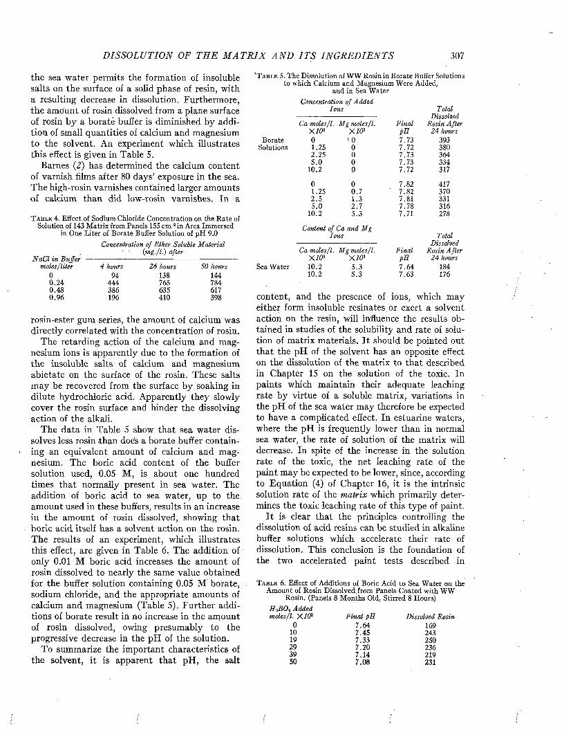
D IS SO LU TIO N OF TH E M A T R I X A N D I T S I N G R E D I E N T S 307
the sea water permits the formation of insoluble salts on the surface of a solid phase of resin, with a resulting decrease in dissolution. Furthermore, the amount of rosin dissolved from a plane surface of rosin by a boratè buffer is diminished by addition of small quantities of calcium and magnesium to the solvent. An experiment which illustrates this effect is given in Table 5.
Barnes (2) has determined the calcium content of varnish films after 80 days’ exposure in the sea. The high-rosin varnishes contained larger amounts of calcium than did low-rosin varnishes. In a
T a b l e 4 . E f f e c t o f S o d i u m C h l o r i d e C o n c e n t r a t i o n o n t h e R a t e o f S o l u t i o n o f 1 43 M a t r i x f r o m P a n e l s 155 c m . 2 i n A r e a I m m e r s e d
i n O n e L i t e r o f B o r a t e B u f f e r S o l u t i o n o f p H 9 . 0Concentration of Ether Soluble Material
(:m g./l . ) after
' T a b l e 5 . T h e D i s s o l u t i o n o f W W R o s i n i n B o r a t e B u f f e r S o l u t i o n s t o w h i c h C a l c i u m a n d M a g n e s i u m W e r e A d d e d ,
a n d i n S e a W a t e r
NaCl m Buffer - moles/liter 4 hours 26 hours 50 hours
0 9 4 1 3 8 1 4 40 . 2 4 4 4 4 7 6 5 7 8 40 . 4 8 3 8 6 6 3 5 6 1 70 . 9 6 1 9 6 4 1 0 3 9 8
rosin-ester gum series, the amount of calcium was directly correlated with the concentration of rosin.
The retarding action of the calcium and magnesium ions is apparently due to the formation of the insoluble salts of calcium and magnesium abietate on the surface of the rosin. These salts may be recovered from the surface by soaking in dilute hydrochloric acid. Apparently they slowly cover the rosin surface and hinder the dissolving action of the alkali.
The data in Table 5 show that sea water dissolves less rosin than does a borate buffer containing an equivalent amount of calcium and magnesium. The boric acid content of the buffer solution used, 0.05 M, is about one hundred times that normally present in sea water. The addition of boric acid to sea water, up to the amount used in these buffers, results in an increase in the amount of rosin dissolved, showing that boric acid itself has a solvent action on the rosin. The results of an experiment, which illustrates this effect, are given in Table 6. The addition of only 0.01 M boric acid increases the amount of rosin dissolved to nearly the same value obtained for the buffer solution containing 0.05 M borate, sodium chloride, and the appropriate amounts of calcium and magnesium (Table 5). Further additions of borate result in no increase in the amount of rosin dissolved, owing presumably to the progressive decrease in the pH of the solution.
To summarize the important characteristics of the solvent, it is apparent that pH, the salt
Concentration of Added Ions Total
Dissolved
B o r a t eS o l u t i o n s
i moles/I. M g moles/I. Final Rosin AfterX 103 X 1 0 3 pH 24 hours0 \0 7 . 7 3 3 9 31 . 2 5 0 7 . 7 2 3 8 02 . 2 5 0 7 . 7 3 3 6 45 . 0 0 7 . 7 3 3 3 4
1 0 . 2 0 7 . 7 2 3 1 7
0 0 7 . 8 2 4 1 71 . 2 5 0 . 7 7 . 8 2 3 7 02 . 5 1 . 3 7 . 8 1 3 3 15 . 0 2 . 7 7 . 7 8 3 1 6
1 0 . 2 5 . 3 7 . 7 1 2 7 8
Content of Ca and Mg Ions
Ca moles/I. M g moles/I. FinalX 10 3 X 1 0 3 pH
S e a W a t e r 1 0 . 2 5 . 3 7 . 6 41 0 . 2 5 . 3 7 . 6 3
Total Dissolved
Rosin A fter 24 hours
1 8 4 1 7 6
content, and the presence of ions, which may either form insoluble résinâtes or exert a solvent action on the resin, will influence the results obtained in studies of the solubility and rate of solution of matrix materials. It should be pointed out that the pH of the solvent has an opposite effect on the dissolution of the matrix to that described in Chapter 15 on the solution of the toxic. In paints which maintain their adequate leaching rate by virtue of a soluble matrix, variations in the pH of the sea water may therefore be expected to have a complicated effect. In estuarine waters, where the pH is frequently lower than in normal sea water, the rate of solution of the matrix will decrease. In spite of the increase in the solution rate of the toxic, the net leaching rate of the paint may be expected to be lower, since, according to Equation (4) of Chapter 16, it is the intrinsic solution rate of the matrix which primarily determines the toxic leaching rate of this type of paint.
It is clear that the principles controlling the dissolution of acid resins can be studied in alkaline buffer solutions which accelerate their rate of dissolution. This conclusion is the foundation of the two accelerated paint tests described in
T a b l e 6 . E f f e c t o f A d d i t i o n s o f B o r i c A c i d t o S e a W a t e r o n t h eA m o u n t o f R o s i n D i s s o l v e d f r o m P a n e l s C o a t e d w i t h W W
R o s i n . ( P a n e l s 8 M o n t h s O l d , S t i r r e d 8 H o u r s )HiBOz Added
'1. X 1 0 3 Final pH Dissolved Rosin0 7 . 6 4 1 6 9
1 0 7 . 4 5 2 4 31 9 7 . 3 3 2 5 02 9 7 . 2 0 2 3 63 9 7 . 1 4 2 1 95 0 7 . 0 8 2 3 1
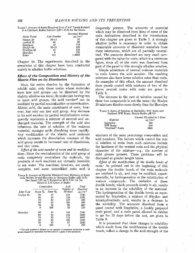
308 M A R I N E FOULING A N D I T S P R E V E N T I O N
T a b l e 7 . A m o u n t o f R e s i n D i s s o l v e d f r o m 3 " X 4 " P a n e l s R o t a t e di n a G l y c i n a t e B u f f e r S o l u t i o n ( p H = 1 0 . 6 ) f o r S i x H o u r s
Dissolved MaterialResin Tested Acid Number ug./cm .2N e o l y n 2 0 1 0 - 1 5 7 0L e w i s o l 3 3 4 0 8 0E s t e r g u m 1 0 1 1 0N e o l y n 4 0 2 0 - 2 5 1 2 0P e n t a l y n M 2 5 1 3 0H e r c o l y n 8 2 5 0R o s i n 1 6 5 > 8 0 0 0
Chapter 16. The experiments described in the remainder of this chapter have been conducted mainly in alkaline buffer solutions.
Effect of the Composition and History of the Matrix Film on its Dissolution
Since the resins dissolve by the formation of soluble salts, only those resins whose molecules have free acid groups can be dissolved by the slightly alkaline sea water, In molecules having two or more acid groups, the acid number2 can be modified by partial neutralization or estérification. Abietic acid, the main constituent of rosin, however, has only one free acid group. Any decrease in its acid number by partial neutralization consequently represents a mixture of neutral and unchanged material. The strength of the acid also influences the rate of solution of the resinous material, stronger acids dissolving more rapidly. Any modification of the abietic acid molecule which increases the dissociation constant of the acid group results in increased rate of dissolution, and vice versa.
Effect of the acid number of rosin and its modifications: Since the neutralization of the acid group of rosin completely neutralizes the molecule, the products of such reactions are virtually insoluble in sea water. The reactions, however, are rarely complete, and some unmodified rosin acid is
T a b l e 8 . A m o u n t o f M a t e r i a l D i s s o l v e d f r o m M i x t u r e s o f R o s i n w i t h N e o l y n 2 0 a n d H e r c o l y n i n G l y c i n a t e B u f f e r ( p H 1 0 . 5 ) .
O n e P a n e l ( 1 5 5 c m . 2) R o t a t e d a t 8 0 R . P . M . f o r S i x H o u r s i n 1 .3 5 L i t e r s o f B u f f e r
Composition Acid TotalNumber of Dissolved
Ester Used Rosin % Ester % M ixture u g ./cm 2N e o l y n 2 0 9 0 1 0 1 4 9 7 7 4 0
8 0 2 0 1 3 4 2 3 9 07 0 3 0 1 1 9 5 8 06 0 - 4 0 1 0 3 5 8 05 0 5 0 8 8 4 6 0
0 1 0 0 1 0 1 2 0
H e r c o l y n 9 0 1 0 1 4 9 7 1 8 08 0 2 0 1 3 4 5 6 8 07 0 3 0 1 1 8 4 9 0 06 0 4 0 1 0 2 3 3 4 05 0 5 0 8 7 2 6 4 0
0 1 0 0 8 2 5 0
2 The acid number is defined as the amount of potassium hydroxide in milli-grams required to neutralize the free acids in 1 gram of the substance.
frequently present. The amounts of material which may be dissolved from films of some of the rosin derivatives described in the introduction of this chapter are given in Table 7. A strongly alkaline buffer is necessary in order to obtain measurable amounts of dissolved materials from these substances, which are all partially neutralized. The amounts dissolved are very small compared with the value for rosin, which is a minimum figure, since all of the rosin was dissolved from part of the panel in this strongly alkaline solution.
Simple admixture of neutral resinous materials to rosin lowers the acid number. The resulting mixtures also have lower solution rates than rosin. As examples of this effect, the amount dissolved from panels coated with mixtures of two of the above neutral resins with rosin are given in Table 8.
The decrease in the rate of solution caused by these two compounds is not the same; the Neolyn 20 mixtures dissolve more slowly than the Hercolyn
T a b l e 9 . g a t e s o f S o l u t i o n o f S t a y b e l i t e , W W R o s i n a n d O x i d i z e d W W R o s i n . B o r a t e B u f f e r p H 9 . 0
Amount Dissolved in 1 Hour Material pg./cm.2
S t a y b e l i t e 2 9 0W W R o s i n 6 3 0“ O x i d i z e d ” R o s i n 3 8 4 0
mixtures of the same percentage composition and acid numbers. The factors which control the rate of solution of rosin from such mixtures include the hardness of the neutral resin and the physical character of the mixture—e.g., the number of solid phases present. These problems will be discussed at greater length below.
Effect of the modification of the double bonds of rosin: As pointed out in the beginning of this chapter the double bonds of the rosin molecule are oxidized in air, and may be modified, experimentally, by hydrogenation or the substitution of various compounds. The oxidation of these double bonds, which proceeds slowly in air, results in an increase in the solubility of the material. The hydrogenation of the double bonds as represented by Staybelite, a mixture of dihydro- and tetrahydroabietic acid, results in a decrease in the solubility. The amounts dissolved from a panel coated with Staybelite, a freshly prepared rosin panel, and a rosin panel allowed to oxidize in air for 75 days before the test, are given in Table 9.
It is presumed that these changes in solubility which result from the modification of the double bonds, reflect a change in the acid strength of the
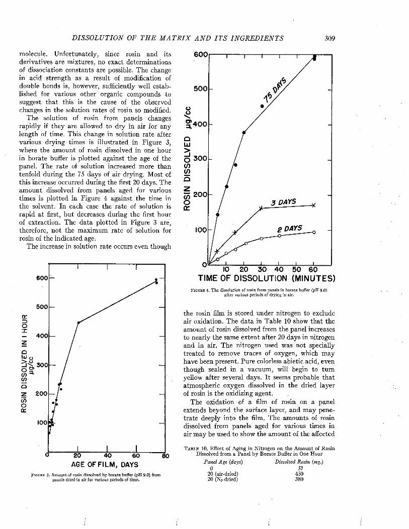
D I S SO L U T IO N OF TH E M A T R I X A N D I T S I N G R E D I E N T S 309
molecule. Unfortunately, since rosin and its derivatives are mixtures, no exact determinations of dissociation constants are possible. The change in acid strength as a result of modification of double bonds is, however, sufficiently well established for various other organic compounds to suggest that this is the cause of the observed changes in the solution rates of rosin so modified.
The solution of rosin from panels changes rapidly if they are allowed to dry in air for any length of time. This change in solution rate after various drying times is illustrated in Figure 3, where the amount of rosin dissolved in one hour in borate buffer is plotted against the age of the panel. The rate of solution increased more than tenfold during the 75 days of air drying. Most of this increase occurred during the first 20 days. The amount dissolved from panels aged for various times is plotted in Figure 4 against the time in the solvent. In each case the rate of solution is rapid at first, but decreases during the first hour of extraction. The data plotted in Figure 3 are, therefore, not the maximum rate of solution for rosin of the indicated age.
The increase in solution rate occurs even though
600
500
400
r K 300 o ?tn ”*• cnoz 200
100
20 40 60AGE OF FILM , DAYS
80
F i g u r e 3 . Amount of rosin dissolved by borate buffer (pH 9 .0 ) from panels dried in air for various periods of time.
600
500
O 300
m 2003 DAYS
2 DAYS100
TIME OF DISSOLUTION (MINUTES)F i g u r e 4. The dissolution of rosin from panels in borate buffer (pH 9.0)
after various periods of drying in air.
the rosin film is stored under nitrogen to exclude air oxidation. The data in Table 10 show that the amount of rosin dissolved from the panel increases to nearly the same extent after 20 days in nitrogen and in air. The nitrogen used was not specially treated to remove traces of oxygen, which may have been present. Pure colorless abietic acid, even though sealed in a vacuum, will begin to turn yellow after several days. It seems probable that atmospheric oxygen dissolved in the dried layer of rosin is the oxidizing agent.
The oxidation of a film of rosin on a panel extends beyond the surface layer, and may penetrate deeply into the film. The amounts of rosin dissolved from panels aged for various times in air may be used to show the amount of the affected
T a b l e 1 0 . E f f e c t o f A g i n g i n N i t r o g e n o n t h e A m o u n t o f R o s i n D i s s o l v e d f r o m a P a n e l b y B o r a t e B u f f e r i n O n e H o u r
Panel Age {days) Dissolved Rosin {mg.)0 5 7
2 0 ( a i r - d r i e d ) 4 5 02 0 ( N j - d r i e d ) 3 8 0
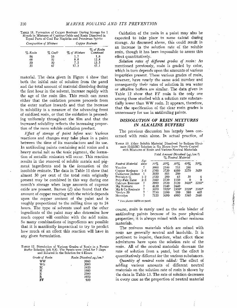
310 M A R I N E FOULING A N D I T S PR E VE N TIO N
T a b l e 1 1 . F o r m a t i o n o f C o p p e r R e s i n a t e D u r i n g S t o r a g e f o r 1 M o n t h i n M i x t u r e s o f C u p r o u s O x i d e a n d R o s i n D i s s o l v e d i n
E q u a l P a r t s o f C o a l T a r N a p h t h a a n d P e t r o l e u m S p i r i t sComposition of M ixture Copper Resinate
% Rosin 8 4 68 5 0 3 3
% Cu-,0 1 6 3 2 5 0 6 7
% of Mixture1 . 78.8 7 . 5
1 7 . 3
% of Rosin Combined
1.8 12.8 1 3 . 5 4 7 . 1
material. The data given in Figure 4 show that both the initial rate of solution from the panel and the total amount of material dissolving during the first hour in the solvent, increase rapidly with the age of the rosin film. This result can mean either that the oxidation process proceeds from the outer surface inwards and that the increase in solubility is a measure of the advancing front of oxidized rosin, or that the oxidation is proceeding uniformly throughout the film and that the increased solubility reflects the increasing proportion of the more soluble oxidation product.
Effect of storage of paint before use: Various reactions and changes may take place in a paint between the time of its manufacture and its use. In antifouling paints containing acid resins and a heavy metal salt as the toxic pigment, the formation of metallic résinâtes will occur. This reaction results in the removal of soluble matrix and pigment ingredients and in the formation of the insoluble resinate. The data in Table 11 show that almost 50 per cent of the total rosin originally present may be combined in this way during one month’s storage when large amounts of cuprous oxide are present. Barnes (2) also found that the amount of copper reacting with the vehicle depends upon the copper content of the paint and is roughly proportional to the milling time up to 24 hours. The type of solvents used and the other ingredients of the paint may also determine how much copper will combine with the acid resins. So many combinations of ingredients are possible that it is manifestly impractical to try to predict how much of an effect this reaction will have in any given formulation.
T a b l e 1 2 . D i s s o l u t i o n o f V a r i o u s G r a d e s o f R o s i n i n a B o r a t e B u f f e r S o l u t i o n ( p H 8 . 8 ) . T h e P a n e l s w e r e D r i e d f o r 7 D a y s
a n d R o t a t e d i n t h e S o l u t i o n f o r 6 H o u r sGrade of Rosin
W W W G M H E B F F
Rosin Dissolved ¡ig./cmr 2 0 6 0 2 0 8 0 1 9 2 0 1 9 0 0 2 3 8 0 1 9 7 0
9 2 0
Oxidation of the rosin in a paint may also be expected to take place to some extent during storage. As discussed above, this could result in an increase in the solution rate of the soluble resin, though it has been impossible to assess this effect quantitatively.
Solution rates of different grades of rosin: As mentioned previously, rosin is graded by color, which in turn depends upon the amounts of various impurities present. These various grades of rosin, however, have nearly the same acid number and consequently their rates of solution in sea water or alkaline buffers are similar. The data given in Table 12 show that FF rosin is the only one among those studied with a solution rate substantially lower than WW rosin. It appears, therefore, that the specification of the clear rosin grades is unnecessary for use in antifouling paints.
DISSOLUTION OF RESIN MIXTURES IN ALKALINE BUFFERS
The previous discussion has largely been concerned with rosin alone. In actual practice, of
T a b l e 1 3 . E t h e r S o l u b l e M a t e r i a l D i s s o l v e d b y S o d i u m G l y c i n a t e ( 0 . 0 2 5 M ) S o l u t i o n i n S i x H o u r s f r o m P a n e l s C o a t e d
w i t h M i x t u r e s o f R o s i n a n d V a r i o u s N e u t r a l M a t e r i a l sTotal Amount Dissolved (jig./cm . 2)
% Neutral MaterialAge
Neutral Material days 10% 20% 30% 40% 50%V i n y l i t e 7 3 9 0 0 2 5 4 0 7 3 5 2 8 0C o p p e r R e s i n a t e 1 - 3 2 7 0 0 3 7 2 0 4 5 8 0 3 2 7 0 3 4 5 0C u m a r o n e I n d e n e 1 2 0 3 0 8 8 5 2 8 0P e n t a l y n G 1 - 2 2 5 5 0 2 8 0 6 5 3 9 6P o l y - P a l e E s t e r 2 - 3 2 6 6 0 2 7 2 0 1 1 5 0 0 0C a l c i u m R e s i n a t e 7 3 9 9 0 3 5 3 0 3 1 2 0 3 4 2 0 * 2 2 5 0 *M g R e s i n a t e 7 4 1 5 0 2 1 4 0 2 4 4 0M g & C a R e s i n a t e 7 3 6 7 0 1 9 2 0 * 2 3 0 0 * 2 2 2 0 * 2 1 6 0 *N e n l y n 2 0 7 7 7 3 0 2 3 8 0 5 8 0 5 8 0 4 6 5H e r c o l y n 7 7 1 2 0 5 6 9 0 4 9 0 0 3 3 4 0 2 6 4 0
* Two phases visible on panel.
course, rosin is rarely used as the sole binder of antifouling. paints because of its poor physical properties; it is always mixed with other resinous materials.
The resinous materials which are mixed with rosin are generally neutral and insoluble. It is pertinent to inquire, therefore, what effect these admixtures have upon the solution rate of the rosin. All of the neutral materials decrease the rate of solution from a panel, but the effect is quantitatively different for the various substances.
Quantity of neutral resin added: The effect of adding various amounts of different neutral materials on the solution rate of rosin is shown by the data in Table 13. The rate of solution decreases in every case as the proportion of neutral material
D I S SO L U T IO N OF TH E M A T R I X A N D I T S IN G R E D IE N T S 311
T a b l e 1 4 . D i s s o l u t i o n o f R o s i n V i n y l i t e M i x t u r e s o f V a r i o u s T h i c k n e s s e s i n G l y c i n a t e B u f f e r ( p H 1 0 . 6 ) . T h e P a n e l s w e r e D r i e d f o r O n e W e e k b e f o r e t h e T e s t , a n d R o t a t e d a t 8 5 R . P . M . i n 1 .3 5 L i t e r s o f S o l u t i o n
Ave. Film Weight
Total Dissolved (jig./cm3) FilmDissolved
Composition No. of Coats m g./cm 3 10 min. 30 min. 1 hr. 2 hr s. 4 hrs. 6 hrs. %1 0 % V i n y l i t e 1 1 0 . 0 1 0 4 0 1 7 1 0 2 3 0 0 2 8 8 0 3 4 8 0 3 9 0 0 3 99 0 % R o s i n 2 1 7 . 7 1 0 6 0 1 4 3 0 1 9 1 0 2 5 6 0 3 2 1 0 3 6 6 0 2 1
4 3 2 . 0 '9 0 0 1 1 2 0 1 6 3 0 2 9 6 0 3 3 8 0 4 1 1 0 1 3
2 1 . 5 % V i n y l i t e 1 5 . 2 9 3 0 1 3 2 0 1 6 3 0 1 9 4 0 2 2 1 0 2 5 2 0 4 87 8 . 5 % R o s i n 2 1 1 . 1 1 1 2 0 1 7 1 0 2 0 8 0 2 5 0 0 3 0 3 0 3 3 6 0 3 0
4 1 8 . 2 1 0 9 0 1 6 5 0 1 8 9 0 2 2 1 0 2 5 9 0 3 0 6 0 1 7
3 0 . 5 % V i n y l i t e 2 1 1 . 3 4 9 6 4 7 0 7 3 5 66 9 . 5 % R o s i n 4 2 5 . 6 4 9 0 5 5 5 8 6 0 3
6 3 8 . 8 4 5 0 6 1 2 8 2 5 2
4 0 . 5 % V i n y l i t e 2 1 2 . 1 3 1 0 2 . 55 9 . 5 % R o s i n 4 2 3 . 6 2 9 0 1 . 2
6 4 0 . 0 2 8 4 0 . 7
is increased. The magnitude of the effect at any given concentration of neutral material, however, varies widely. The solution rates of those mixtures in two phases which were visible on the panel remain high despite considerable additions of neutral material. The liquid Hercolyn also permits high solution rates even when it is present in considerable amounts. It is possible that this is the result of an ability of Hercolyn to flow off the panel as it is uncovered by the dissolving rosin.
Barnes (2) shows that the amount of rosin dissolved in the sea is directly related to the amount of rosin in the mixture. Below about 30 per cent rosin, little or no loss of rosin occurred. Analyses of the residue on the panel indicated that measurable amounts of rosin acids remained in the binder skeleton. In a rosin-Bedesol mixture which originally contained 75 per cent rosin, the concentration of rosin left after 40 days soaking in the sea was somewhat greater than 20 per cent to a depth of 30p. Between 30 and 80/t the concentration gradually increased, and was the same as the original composition at greater depths. Barnes concluded that a portion of the acid resin is readily dissolved, and that the binder skeleton which remains contains about 20 per cent acid resin, which is dissolved much more slowly.
Effect of thickness of film: If a mechanism exists to permit the solution of the soluble material throughout the depth of the film, a partial extraction should dissolve the same amount of soluble material, regardless of the film thickness, provided of course that the film is at least as thick as the depth of extraction. The results .of extraction of mixtures containing approximately 10, 20, 30, and 40 per cent Vinylite in rosin and applied in different thickness are given in Table 14. As the
Vinylite content of the mixtures was increased, the amount of dissolved ether soluble material decreased. For each composition, essentially the same amount of ether soluble material— i.e., rosin acid— was dissolved, regardless of whether one or more coats of the mixture were applied. As a result the percentage of the original film which dissolved decreased as the thickness of the film was increased. The rate of solution fell off as the extraction proceeded into the mixture, but the thickness of the film did not influence the course of extraction over the period of this experiment. For each neutral material studied, a maximum permissible concentration will be found. If the neutral material is added in concentrations greater than this critical value, only very little rosin can be dissolved, and the rate of solution from the
T a b l e 1 5 . A m o u n t o f R o s i n D i s s o l v e d i n G l y c i n a t e B u f f e r i n S i x H o u r s f r o m M i x t u r e s C o n t a i n i n g 2 0 % N e u t r a l M a t e r i a l s
( p H = 1 0 . 6 )
Acid No. Point of Totalof Neutral Neutral Dissolved
Neutral Material Material Material °C. ¡i,g./cm3E s t e r G u m 9 4 0P e n t a l y n X 1 5 1 5 5 1 4 6 0P e n t a l y n G 1 9 ’ 1 3 1 1 7 7 0P e n t a l y n M 2 5 1 6 5 1 8 6 01 5 % M g R o l 0 1 9 2 05 % C a R 2 ƒN e v i l l e G 0 — 2 1 2 0M g R 2 0 — 2 1 4 0N e o l y n 2 0 1 0 - 1 5 7 2 - 7 8 2 3 8 0H y d r o a b i e t y l A l c o h o l 0 3 3 2 7 1 0P e n t a l y n A 1 9 1 1 0 3 0 0 0C a R 2 0 — 3 5 3 0V i n y l i t e 0 — 4 3 2 0C u R 2 0 — 4 3 8 0P o l y - P a l e E s t e r # 1 8 - 1 0 8 0 - 8 5 4 3 5 0F l e x a l y n 5 - 1 0 4 5 - 5 0 4 7 5 0P o l y - P a l e E s t e r # 3 8 — 4 7 6 0L e w i s o l 3 3 4 0 1 5 2 - 1 6 8 4 9 0 0H e r c o l y n 8 L i q u i d 5 5 0 0H y d r o g e n a t e d E t h y l
A b i e t a t e 8 L i q u i d 5 9 0 0N e v i l l e R - 2 9 0 L i q u i d 6 5 5 0N e o l y n 4 0 — — 6 7 5 0
312 M A R I N E FOULING A N D I T S P R E V E N T I O N
mixture will never be sufficient to permit steady- state leaching of the toxic from a paint in which it is used as a matrix.
Effect of the nature of the neutral material: The effect of adding various neutral materials to rosin at a concentration of 20 per cent has been studied with several substances. The results obtained are listed in Table 15 in order of the increasing amount of rosin which can be dissolved from the mixture. It will be noticed that the four resins permitting the greatest solution are liquid. In general, the remaining materials are arranged approximately in order of their softening points. It thus appears that the harder neutral materials have a more pronounced depressing effect on the solubility of rosin than do the softer ones. In other words, plasticizers may be added to paint films in relatively high concentrations without exerting too detrimental an effect on the solubility of the matrix. Tougheners, on the other hand, must be added judiciously in small quantities in order to avoid making the matrix insoluble.
Significance of Matrix SolubilityTo be effective an antifouling paint must con
tain a toxic which is slightly soluble in sea water, compounded in a matrix in such a way that it can be released at an adequate, uniform rate. If the matrix is insoluble, enough toxic must be incorporated to give continuous contact between the toxic particles. If, however, the matrix is soluble in sea water, less of the toxic is required, and the solution of the matrix controls the toxic leaching rate. These mechanisms of release of toxic are discussed in detail in Chapter 16.
The present state of knowledge of matrix ingredients permits qualitative predictions of the solubility in sea water of many matrix mixtures. In general, therefore, the type of paint in which they would be satisfactory can be decided in advance. However, the solution rates to be
expected, and consequently the toxic loading required to give satisfactory results, vary so greatly, depending upon the nature of the neutral material included, that quantitative predictions are as yet untrustworthy. Each combination of matrix ingredients must be studied individually in order to design the paint most - effectively. Chapter 19 discusses the design of antifouling paints in detail.
REFERENCES1 . A d a m s o n , N . E . T e c h n o l o g y o f S h i p - B o t t o m P a i n t s a n d I t s
I m p o r t a n c e t o C o m m e r c i a l a n d N a v a l A c t i v i t i e s . C & R B u l l . # 1 0 , 1 - 3 6 . B u r . C o n s t r . a n d R e p a i r , N a v y D e p t . , W a s h i n g t o n , 1 9 3 7 .
2 . B a r n e s , H . S t u d i e s o n A n t i f o u l i n g C o m p o s i t i o n s . J . I r o n a n dS t e e l I n s t . , 5 8 7 - 6 0 0 , D e c e m b e r , 1 9 4 7 .
3 . B r o w n , G . , E . E . B u r n h a m , a n d J . M o r r i s c . U . S . P a t e n t6 5 6 3 9 , J u n e 1 1 , 1 8 6 7 .
4 . D a r s i e , M . L . T h e R o l e o f M a r i n e B a c t e r i a i n t h e D e c o m p o s i t i o n o f H o t P l a s t i c P a i n t s . A n n u a l R e p o r t 1 9 4 2 - 1 9 4 3 f r o m N a v a l B i o l o g i c a l L a b . , S a n D i e g o , C a l i f . , t o B u r e a u o f S h i p s , 1 4 6 - 1 5 4 , 1 9 4 3 .
5 . F e r r y , J . D . , B . H . K e t c h u m , G . T . S c o t t , B . M o t t , a n dB . R e y n o l d s . D i s s o l u t i o n o f t h e M a t r i x a s a M e c h a n i s m f o r S t e a d y - S t a t e L e a c h i n g . P a p e r 3 , S e v e n t h R e p o r t f r o m t h e W o o d s H o l e O c e a n o g r a p h i c I n s t i t u t i o n t o t h e B u r e a u o f S h i p s , A p r i l 2 0 , 1 9 4 4 .
6. F i e s e r , L . F . C h e m i s t r y o f N a t u r a l P r o d u c t s R e l a t e d toP h e n a n t h r e n e . R e i n h o l d P u b l i s h i n g C o . , N . Y . , 1 9 3 7 .
7 . F l e c k , E . E . , a n d S . P a lk T N . C o n t e n t o f 1 - P i m a r i c A c i d i nP i n e O l e o r e s i n . I m p r o v e d M e t h o d s f o r i t s D e t e r m i n a t i o n . I n d . E n g . C h e m . , A n a l y t i c a l E d . , 1 4 , 1 4 6 - 1 4 7 , 1 9 4 2 .
8 . G a r d n e r , H . A . M o d e r n R e s e a r c h o n A n t i f o u l i n g P a i n t s .S c i e n t i f i c s e c t i o n , C i r c u l a r # 1 5 7 , P a i n t M a n u f a c t u r e r s A s s o c i a t i o n o f t h e U . S . , W a s h i n g t o n , 1 9 2 2 .
9 . M a r e I s l a n d N a v y Y a r d ( A r t h u r E . B u m s , J r . ) . I n v e s t i g a t i o no f M a t r i x E r o s i o n o f A n t i f o u l i n g P a i n t s . I n t e r i m R e p o r t # 4 , S e p t e m b e r 1 7 , 1 9 4 3 . ( U n p u b l i s h e d )
1 0 . P o w e r s , P . O . R o s i n . C h a p t e r 7 i n M a t t i e l l o , P r o t e c t i v e a n dD e c o r a t i v e C o a t i n g s , V o l . 1 . J o h n W i l e y a n d S o n s I n c . , N e w Y o r k , 1 9 4 1 .
1 1 . S a n d e r m a n n , W i l h e l m . T h e A n a l y s i s o f ( n a t u r a l ) r e s i n s a n de s s e n t i a l o i l s . S e i f e n s i e d e r Z e i t u n g , 6 4 , p . 4 0 2 , 1 9 3 7 .
1 2 . S t e e l e , L . L . A b i e t i c A c i d a n d C e r t a i n M e t a l A b i e t a t e s . J .A m e r . C h e m . S o c . , 4 4 , 1 3 3 3 - 1 3 4 1 , 1 9 2 2 .
13. T o d d , D . T h e S o l u b i l i t y a n d R a t e o f S o l u t i o n o f R o s i n a n dD e r i v a t i v e s o f R o s i n i n A q u e o u s S o l u t i o n s . P a p e r 8 , S e v e n t h R e p o r t f r o m t h e W o o d s H o l e O c e a n o g r a p h i c I n s t i t u t i o n t o t h e B u r e a u o f S h i p s , A p r i l 2 0 , 1 9 4 4 .
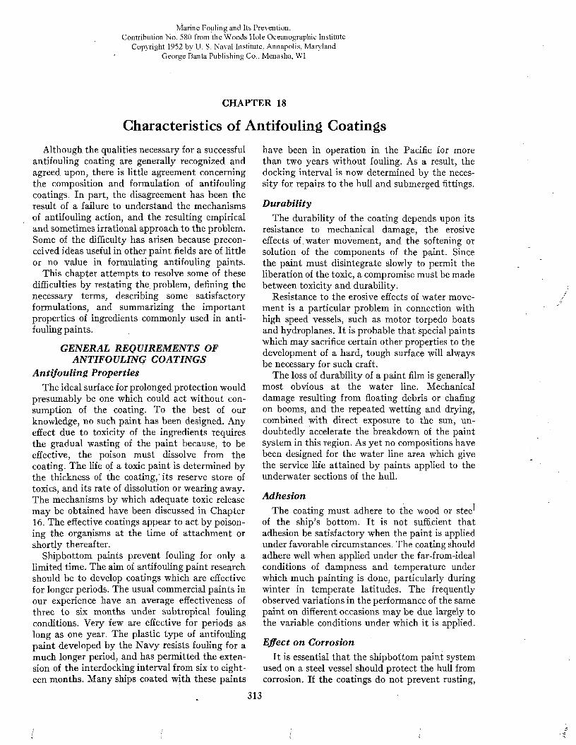
M a r i n e F o u l i n g a n d I t s P r e v e n t i o n ,C o n t r i b u t i o n N o . 5 8 0 f r o m t h e W o o d s H o l e O c e a n o g r a p h i c I n s t i t u t e
C o p y r i g h t 1 9 5 2 b y U . S . N a v a l I n s t i t u t e , A n n a p o l i s , M a r y l a n d G e o r g e B a n t a P u b l i s h i n g C o . , M e n a s h a , W I
CHAPTER 18
Characteristics of Antifouling CoatingsAlthough the qualities necessary for a successful
antifouling coating are generally recognized and agreed upon, there is little agreement concerning the composition and formulation of antifouling coatings. In part, the disagreement has been the result of a failure to understand the mechanisms of antifouling action, and the resulting empirical and sometimes irrational approach to the problem. Some of the difficulty has arisen because preconceived ideas useful in other paint fields are of little or no value in formulating antifouling paints.
This chapter attempts to resolve some of these difficulties by restating the problem, defining the necessary terms, describing some satisfactory formulations, and summarizing the important properties of ingredients commonly used in antifouling paints.
GENERAL REQUIREMENTS OF ANTIFOULING COATINGS
Antifouling PropertiesThe ideal surface for prolonged protection would
presumably be one which could act without consumption of the coating. To the best of our knowledge, no such paint has been designed. Any effect due to toxicity of the ingredients requires the gradual wasting of the paint because, to be effective, the poison must dissolve from the coating. The life of a toxic paint is determined by the thickness of the coating,“ its reserve store of toxics, and its rate of dissolution or wearing away. The mechanisms by which adequate toxic release may be obtained have been discussed in Chapter 16. The effective coatings appear to act by poisoning the organisms at the time of attachment or shortly thereafter.
Shipbottom paints prevent fouling for only a limited time. The aim of antifouling paint research should be to develop coatings which are effective for longer periods. The usual commercial paints in our experience have an average effectiveness of three to six months under subtropical fouling conditions. Very few are effective for periods as long as one year. The plastic type of antifouling paint developed by the N avy resists fouling for a much longer period, and has permitted the extension of the interdocking interval from six to eighteen months. Many ships coated with these paints
have been in operation in the Pacific for more than two years without fouling. As a result, the docking interval is now determined by the necessity for repairs to the hull and submerged fittings.
DurabilityThe durability of the coating depends upon its
resistance to mechanical damage, the erosive effects of water movement, and the softening or solution of the components of the paint. Since the paint must disintegrate slowly to permit the liberation of the toxic, a compromise must be made between toxicity and durability.
Resistance to the erosive effects of water movement is a particular problem in connection with high speed vessels, such as motor torpedo boats and hydroplanes. It is probable that special paints which may sacrifice certain other properties to the development of a hard, tough surface will always be necessary for such craft.
The loss of durability of a paint film is generally most obvious at the water line. Mechanical damage resulting from floating debris or chafing on booms, and the repeated wetting and drying, combined with direct exposure to the sun, undoubtedly accelerate the breakdown of the paint system in this region. As yet no compositions have been designed for the water line area which give the service life attained by paints applied to the underwater sections of the hull.
AdhesionThe coating must adhere to the wood or stee^
of the ship’s bottom. It is not sufficient that adhesion be satisfactory when the paint is applied under favorable circumstances. The coating should adhere well when applied under the far-from-ideal conditions of dampness and temperature under which much painting is done, particularly during winter in temperate latitudes. The frequently observed variations in the performance of the same paint on different occasions may be due largely to the variable conditions under which it is applied.
Effect on CorrosionIt is essential that the shipbottom paint system
used on a steel vessel should protect the hull from corrosion. If the coatings do not prevent rusting,
313

314 M A R I N E FOULING A N D I T S P R E V E N T I O N
the continuity of the paint will be destroyed and fouling of the bared areas will result. At least one coat of primer or anticorrosive paint is applied before the antifouling coating. The effectiveness of this anticorrosive paint may determine, to a large extent, the success of the antifouling material.
The antifouling paint may contribute materially to the protection of the hull from corrosion. This contribution depends primarily on the thickness of the coating and its resistance to the penetration of sea water. Experiments with the N avy paints show that the anticorrosive coating alone (about 2 mils) will prevent corrosion for only a few months. The addition of a coat of the cold plastic antifouling paint (about 5 mils) extends the protection to at least fifteen months, and the use of a thirty mil coat of the hot plastic antifouling paint will prevent serious corrosion for at least thirty months. Thick paint films thus aid in preventing corrosion, in addition to providing the necessary toxic reserve for prolonged prevention of fouling.
The ingredients of the antifouling paint should not accelerate the corrosion of steel. The common toxic pigments, metallic copper, and salts of copper and mercury, tend to accelerate corrosion if they are not adequately separated from the steel hull, as will be discussed in Chapter 22. For this reason it is very desirable that toxics other than these be developed for antifouling coatings.
SmoothnessThe antifouling coating should have a smooth
surface in order to keep the frictional resistance of the vessel to a minimum. The smoothness of the coating will depend upon the behavior of the paint film during drying.
Smoothness is a quality which acquires increased importance where speed is essential. Small racing yachts commonly employ paints which sacrifice much of their antifouling virtue for the sake of a hard, smooth finish. This may be done since it is easy to haul such craft for cleaning at frequent intervals.
The thick coatings which are required to provide prolonged protection against fouling must be carefully formulated to permit easy application, freedom from sagging, and good leveling. If drying is inadequate, a thick coating may tend to flow when the ship gets under way, and thus become rough (see Figure 13, Chapter 2). On the other hand, the viscous paints necessary to give thick coatings have sufficient body to fill up minor irregularities of the ship’s surface.
Ease of ApplicationThe antifouling paint should be designed to
permit its application by either brush or spray equipment, so that vessels may be painted wherever it is convenient to dock them, and by whatever labor is available. The use of modern spray equipment results in great economies of time and in superior applications. Many commercial paints can be sprayed with standard equipment; the N avy has developed methods for spraying both the hot and cold plastic paints. Paints which can be applied by only one of these methods, such as the hot plastic which must be sprayed, are of necessity limited to those dry- docks using the appropriate method of application.
Wide variations in temperature should not seriously alter those properties of the paint which determine the ease of application, since vessels must be painted in all seasons and climates. Many formulations become undesirably thick in cold weather. The paint should be formulated so that readily available solvents are suitable for thinning. It should not eake in th e . container, or body excessively in storage.
Drying TimeBecause the time available for painting is usually
limited by practical considerations, it is essential that the paint dry rapidly. Commercial shipping firms generally restrict the docking periods to one day, part of which is required for cleaning the vessel. As a result, adequate painting is impossible unless the paints dry rapidly. If the time in dock is not too limited, multiple coats may be applied and thus provide the thick coating necessary for prolonged antifouliñg life.
If the paint film does not harden before the ship gets under way, the erosive action of the water may cause it to flow, thus impairing the serviceability of the coating. It has been found that many paints harden under water, so that a stationary period after undocking may aid in preventing excessive erosion or flow of the paint surface.
It has been traditional to float vessels as soon as possible after the application of the final antifouling coat. Tests on several proprietary paints which recommend this indicate that it either has no effect on the fouling resistance of the paint, or actually impairs it. It is probable that this recommendation is . a carry-over from the days of the shellac paints, when water-soluble alcohol was used as the solvent. Its continuation is greatly favored by boat yard and dock owners who are anxious to keep their railways clear.
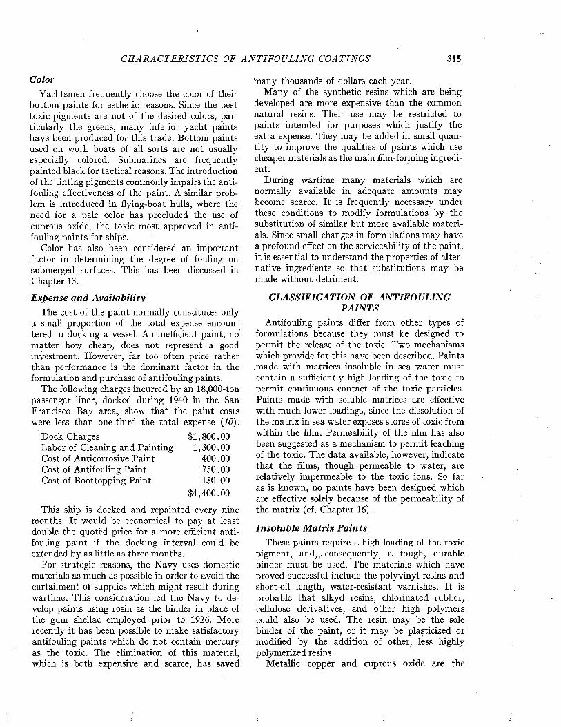
CH AR A C T E R IS T IC S OF A N T I F O U L I N G COATINGS 315
ColorYachtsmen frequently choose the color of their
bottom paints for esthetic reasons. Since the best toxic pigments are not of the desired colors, particularly the greens, many inferior yacht paints have been produced for this trade. Bottom paints used on work boats of all sorts are not usually especially colored. Submarines are frequently painted black for tactical reasons. The introduction of the tinting pigments commonly impairs the antifouling effectiveness of the paint. A similar problem is introduced in flying-boat hulls, where the need for a pale color has precluded the use of cuprous oxide, the toxic most approved in antifouling paints for ships.
Color has also been considered an important factor in determining the degree of fouling on submerged surfaces. This has been discussed in Chapter 13.
Expense and AvailabilityThe cost of the paint normally constitutes only
a small proportion of the total expense encountered in docking a vessel. An inefficient paint, no matter how cheap, does not represent a good investment. However, far too often price rather than performance is the dominant factor in the formulation and purchase of antifouling paints.
The following charges incurred by an 18,000-ton passenger liner, docked during 1940 in the San Francisco Bay area, show that the paint costs were less than one-third the total expense (10).
Dock Charges $1,800.00Labor of Cleaning and Painting 1,300.00Cost of Anticorrosive Paint 400.00Cost of Antifouling Paint 750.00Cost of Boottopping Paint 150.00
$4,400.00
This ship is docked and repainted every nine months. It would be economical to pay at least double the quotèd price for a more efficient antifouling paint if the docking interval could be extended by as little as three months.
For strategic reasons, the Navy uses domestic materials as much as possible in order to avoid the curtailment of supplies which might result during wartime. This consideration led the N avy to develop paints using rosin as the binder in place of the gum shellac employed prior to 1926. More recently it has been possible to make satisfactory antifouling paints which do not contain mercury as the toxic. The elimination of this material, which is both expensive and scarce, has saved
many thousands of dollars each year.Many of the synthetic resins which are being
developed are more expensive than the common natural resins. Their use may be restricted to paints intended for purposes which justify the extra expense. They may be added in small quantity to improve the qualities of paints which use cheaper materials as the main film-forming ingredient.
During wartime many materials which are normally available in adequate amounts may become scarce. It is frequently necessary under these conditions to modify formulations by the substitution of similar but more available materials. Since small changes in formulations may have a profound effect on the serviceability of the paint, it is essential to understand the properties of alternative ingredients so that substitutions may be made without detriment.
CLASSIFICATION OF ANTIFOULING PAINTS
Antifouling paints differ from other types of formulations because they must be designed to permit the release of the toxic. Two mechanisms which provide for this have been described. Paints made with matrices insoluble in sea water must contain a sufficiently high loading of the toxic to permit continuous contact of the toxic particles. Paints made with soluble matrices are effective with much lower loadings, since the dissolution of the matrix in sea water exposes stores of toxic from within the film. Permeability of the film has also been suggested as a mechanism to permit leaching of the toxic. The data available, however, indicate that the films, though permeable to water, are relatively impermeable to the toxic ions. So far as is known, no paints have been designed which are effective solely because of the permeability of the matrix (cf. Chapter 16).
Insoluble Matrix PaintsThese paints require a high loading of the toxic
pigment, and, / consequently, a tough, durable binder must be used. The materials which have proved successful include the polyvinyl resins and short-oil length, water-resistant varnishes. It is probable that alkyd resins, chlorinated rubber, cellulose derivatives, and other high polymers could also be used. The resin may be the sole binder of the paint, or it may be plasticized or modified by the addition of other, less highly polymerized resins.
Metallic copper and cuprous oxide are the
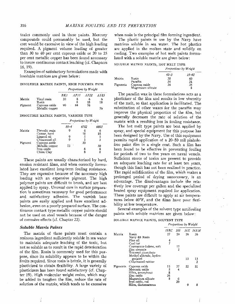
316 M A R I N E FOULING A N D I T S P R E V E N T I O N
toxics commonly used in these paints. Mercury compounds could presumably be used, but the cost would be excessive in view of the high loading required. A pigment volume loading of greater than 30 to 40 per cent cuprous oxide or 20 to 25 per cent metallic copper has been found necessary to insure continuous contact leaching (cf. Chapters 16, 19).
Examples of satisfactory formulations made with insoluble matrices are given below :
I N S O L U B L E M A T R I X P A I N T S , H I G H P O L Y M E R T Y P E
Proportions by Weight
M a t r i x
P i g m e n t
V i n y l r e s i n R o s i nC u p r o u s o x i d e M e t a l l i c c o p p e r
BK1109 0
A F14
8 4
A t<'22 AF236 6
1 8 1 87 6
7 6
I N S O L U B L E M A T R I X P A I N T S , V A R N I S H T Y P E
Proportions by Weight
80-4 6782 6803M a t r i x P h e n o l i c r e s i n 9 6 6
C u m a r , h a r d 1 8 1 8L i n s e e d o i l 9 5 5C h i n a w o o d o i l 9 5 5
P i g m e n t C u p r o u s o x i d e 5 0M e t a l l i c c o p p e r 7 3 5 0I r o n o x i d e 8 8C h i n a C l a y 8 8
These paints are usually characterized by hard, erosion resistant films, and when correctly formulated have excellent long-term fouling resistance. They are expensive because of the necessary high loading with an expensive pigment. The high polymer paints are difficult to brush, and are best applied by spray. Unusual care in surface preparation is sometimes necessary for good performance and satisfactory adhesion. The varnish base paints are easily applied and have excellent adhesion, even on a poorly prepared surface. The continuous contact type metallic copper paints should not be used on steel vessels because of the danger of corrosive effects (cf. Chapter 22).
Soluble Matrix PaintsThe matrix of these paints must contain a
resinous ingredient sufficiently soluble in sea water to maintain adequate leaching of the toxic, but not so soluble as to result in the rapid deterioration of the film. Rosin is commonly used for this purpose, since its solubility appears to be within the limits required. Since rosin is brittle, it is generally plasticized to obtain flexibility. A large variety of plasticizers has been found satisfactory (cf. Chapter 19). High molecular weight resins, which may be added to toughen the film, reduce the rate of solution of the matrix, which tends to be excessive
when rosin is the principal film forming ingredient.The plastic paints in use by the N avy have
matrices soluble in sea water. The hot plastics are applied in the molten state and solidify on cooling. Two examples of hot melt paints formulated with a soluble matrix are given below :S O L U B L E M A T R I X P A I N T S , H O T M E L T T Y P E
Proportions by Weight
42-3 19-92M a t r i x R o s i n 2 8 4 0
P a r a f f i n 3 6 2 4P i g m e n t s C u p r o u s o x i d e 3 6 2 8
M a g n e s i u m s i l i c a t e 8
The paraffin wax in these formulations acts as a plasticizer of the film and results in low viscosity of the melt, so that application is facilitated. The substitution of other waxes for the paraffin may improve the physical properties of the film, but generally decreases the rate of solution of the matrix with a resulting loss in fouling resistance.
The hot melt type paints are best applied by spray, and special equipment for this purpose has been designed by the Navy. Use of this equipment permits rapid application of a 20-50 mil pinhole- free paint film in a single coat. Such a film has been found to be effective in preventing fouling for periods of two to five years on naval vessels. Sufficient stores of toxics are present to provide an adequate leaching rate for at least ten years, though this limit has not been realized in practice. The rapid solidification of the film, which makes a prolonged period of drying unnecessary, is an advantage. The disadvantages include the relatively low coverage per gallon and the specialized heated spray equipment required for application. These paints are difficult to apply at air temperatures below 40°F, and the films have poor flexibility at low temperature.
Several examples of the solvent type antifouling paints with soluble matrices are given below:S O L U B L E M A T R I X P A I N T S , S O L V E N T T Y P E
Proportions by Weight
M a t r i x R o s i nN a v y 4 B R e s i n P i n e o i l C o a l t a rC o u m a r o n e - i n d e n e , s o f t Z i n c s t e a r a t e T r i c r e s y l p h o s p h a t e M e t h y l a b i e t a t e , h y d r o
g e n a t e d C h l o r i n a t e d r u b b e r
P i g m e n t s C u p r o u s o x i d e M e r c u r i c o x i d e S i l i c a , a m o r p h o u s Z i n c o x i d e M a g n e s i u m s i l i c a t e I r o n o x i d e , r e d S i l i c a , d i a t o m a c e o u s
15RC2 7
47
I SS8
2 6
1052 9
122
2 74
620
16X2 6
16X M2 6
1 3
5 2
1 32
5 1
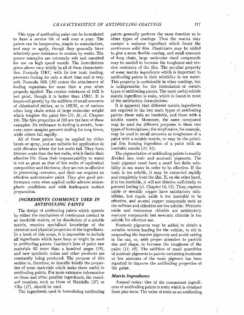
C H AR A C T E R IS T IC S OF A N T IF O U L IN G COATINGS 317
This type of antifouling paint can be formulated to have a service life of well over a year. The paints can be inexpensive, simple to manufacture, and easy to apply, though they generally have relatively poor resistance to erosion by water. The poorer examples are extremely soft and unsuited for use on high speed vessels. The formulations given above vary widely in all of these characteristics. Formula 15RC, with its low toxic loading, prevents fouling for only a short time and is very, soft. Formula 16X (30) resists the attachment of fouling organisms for more than a year when properly applied. The erosion resistance of 16X is not great, though it is better than 15RC. It is improved greatly by the addition of small amounts of chlorinated rubber, as in 16XM, or of various other long chain resins of large molecular weight which toughen the paint film (31, 36; cf. Chapter 19). The film properties of 105 are the best of these examples. Its resistance to fouling is erratic, however; some samples prevent fouling for long times, while others fail rapidly.
All of these paints may be applied by either brush or spray, and are suitable for application in cold climates where the hot melts fail. They form thinner coats than the hot melts, which limits their effective life. Since their impenetrability to water is not as great as that of hot melts of equivalent composition and thickness, they are not so effective in preventing corrosion, and their use requires an effective anticorrosive paint. They give good performance even when applied under adverse atmospheric conditions and with inadequate surface preparation.
INGREDIENTS COMMONLY USED IN ANTIFOULING PAINTS
The design of antifouling paints which operate by either the mechanism of continuous contact in an insoluble matrix, or by dissolution of a soluble matrix, requires specialized knowledge of the chemical and physical properties of the ingredients. In a book of this scope, it is impossible to include all ingredients which have been or might be used in antifouling paints. Gardner’s lists of paint raw materials fill more than a hundred pages (19), and new synthetic resins and other products are constantly being produced. The purpose of this section is, therefore, to describe briefly the properties of some materials which make them useful in antifouling paints. For more extensive information on these and other possible ingredients, the standard treatises, such as those of Mattiello (27) or Ellis (17), should be used.
The ingredients used in formulating antifouling
paints generally perform the same function as in other types of coatings. Thus the matrix may contain a resinous ingredient which forms the continuous solid film. Plasticizers may be added to give a more flexible coating, and small amounts of long chain, large molecular sized compounds may be needed to increase the toughness and erosion resistance of the film. The peculiar property of some matrix ingredients which is important in antifouling paints is their solubility in sea water. This property is undesirable in other coatings, but is indispensable for the formulation of certain types of antifouling paints. The most useful soluble matrix ingredient is rosin, which is found in most of the satisfactory formulations.
It is apparent that different matrix ingredients are required in the two main types of antifouling paints: those with an insoluble, and those with a soluble matrix. Moreover, the same compound may be used for different purposes in these two types of formulations; the vinyl resins, for example, may be used in small amounts as tougheners of a paint with a soluble matrix, or may be the principal film forming ingredient of a paint with an insoluble matrix (31, 41).
The pigmentation-of antifouling paints is readily divided into toxic and nontoxic pigments. The toxic pigment must have a small but finite solubility in sea water in order to be effective. If the toxic is too soluble, it may be extracted rapidly and completely from the film. If, on the other hand, it is too insoluble, it will not dissolve sufficiently to prevent fouling (cf. Chapter 14, 15). Thus, cuprous oxide or metallic copper have satisfactory solubilities, but cupric oxide is too insoluble to be effective, and several copper compounds such as the sulfates and chlorides are too soluble. Mercuric oxide and mercurous chloride are satisfactory mercury compounds but mercuric chloride is too soluble for effective use.
Nontoxic pigments may be added to obtain a suitable volume loading for the vehicle, to aid in suspending the heavier pigments and avoid caking in the can, or, with proper attention to particle size and shape, to increase the toughness of the paint (11, 18). The addition of small quantities of nontoxic pigments to paints containing moderate or low amounts of the toxic pigment has been reported to improve the antifouling properties of the paint.
Matrix IngredientsNatural resins: One of the commonest ingredi
ents of antifouling paints is rosin which is obtained from pine trees. The value of rosin as an antifouling
318 M A R I N E FOULING A N D I T S P R E V E N T I O N
paint component was established by empirical formulation. Its function as a soluble matrix ingredient has only recently been recognized (cf. Chapters 16, 17).
Commercial rosin is classified by color, which is largely determined by the amount and types of impurities present.1 In the highly pigmented antifouling paints, the color of the rosin used is of little importance, though the lighter grades are often specified. Actual tests show that all grades of gum rosin and all grades of wood rosin except FF and B have suitable solubilities.
There are many other natural resins, differing widely in properties, which have been tried in antifouling paints. None of them is more satisfactory than rosin, though shellac has been extensively used. Since the latter is imported from India, its use was discontinued in 1926 by the United States N avy in favor of domestic materials. Yacca gum was introduced by Adamson as a partial substitute for gum shellac (2). This material is less acid than rosin, and consequently less soluble in sea water.
Treated natural resins: The properties of the treated natural resins vary widely, and some are available which are useful in each category of paint ingredients (i.e., resin, plasticizer, toughener). Many of the treated resins are neutral and therefore insoluble in sea water.
Ester gum, the glyceryl tri-ester of rosin, is nearly neutral and insoluble in sea water. Its substitution for all of the rosin of an effective antifouling formulation generally makes the paint unsatisfactory, since it excludes the water from the toxic materials. Its use in smaller quantities may improve the performance of the coating by stopping the excessive wasting which occurs in paints containing large amounts of rosin.
The rosin salts of divalent cations form the so- called hardened rosins, which are practically insoluble in sea water. Copper resinate has been suggested frequently for use in antifouling paints (75, 77, 26, 28, 37). The negligible solubility in sea water makes it of little value as a toxic agent, but in some formulations it is useful as a plasticizer. Copper resinate is formed in all paints containing both rosin and copper compounds. This reaction renders insoluble a portion of both the matrix and the toxic. If formed in too great quantities, the antifouling properties of the paint may be destroyed.
1 These are in order of increasing color X , WW, W G, N , M , K , I , H , G, F , E, D , B . Tw elve color standards have been developed by th e N aval Stores industry. T h e prim ary standards fo r comparison are % inch glass cubes adapted by the Bureau of Chem istry and Soils, U. S. D epartm ent of A g ricu ltu re* ^ , 35) .
The hydrogenated rosin esters, such as hydrogenated methyl or ethyl abietate, give liquid resins which have been useful as plasticizers in antifouling paint films.' Modified rubber resins, such as chlorinated and
cyclicized rubber (17, 38), have been found usëful as toughening agents for antifouling paints. Chlorinated synthetic rubber has also been used successfully (29). They are generally added in very small proportions (less than 5 per cent of the dry film), but some paints have been made in which the modified rubber is a large part of the binder. Modified rubber films are extremely resistant to both acid and alkali, and are completely insoluble in the slightly alkaline sea water.
Synthetic resins: A great variety of synthetic resins is available, but only a few have been used in antifouling paints. It is probable that many more are now being tested in various industrial laboratories.
The alkyd resins are reaction products of poly- hydric alcohols (glycol, glycerol, etc.) with poly- basic acids (chiefly phthalic, also maleic, succinic, etc.). The alkyds used in the paint industry are generally modified with the fatty acids obtained from linseed or soy-bean oils. This improves their solubility in the common paint solvents, and the product gains some of the properties of the oil employed.
Alkyd resins have been used extensively in preparing paint coatings. In the underwater paint field, their use has been largely restricted to the anticorrosives and primers. They have not been used as the binder of continuous contact paints. Their inclusion in the proper proportions in rosin base, soluble matrix type paints may give desirable film characteristics.
The coumarone resins are reaction products of coumarone and indene. They are completely neutral and insoluble in sea water. Five different grades are recognized, ranging in melting point from 5° to 160°C (17, 22). The softer grades have been used as plasticizers in antifouling paints, and the harder grades have been mixed with rosin or with drying oils to form the binder.
Phenolic resins, modified with rosin, have been used in hot melts and solvent type antifouling paints. Frequently, phenol and formaldehyde, together with lead acetate as a catalyst, are reacted in the presence of rosin during the varnish cook. The resin obtained is less soluble in sea water than rosin alone. The use of rosin esters in place of the rosin, though common in the manufacture of varnishes where water resistance is desirable, is generally not satisfactory for antifouling coatings.
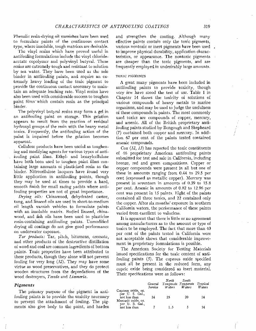
C H A R A C T E R IS T IC S OF AN T IF O U L IN G COATINGS 319
Phenolic resin-drying oil varnishes have been used to formulate paints of the continuous contact type, where insoluble, tough matrices are desirable.
The vinyl resins which have proved useful in antifouling formulations include the vinyl chloride- acetate copolymer and polyvinyl butyral. These resins are extremely tough and resistant to solution by sea water. They have been used as the sole binder in antifouling paints, and require an extremely heavy loading of the toxic pigment to provide the continuous contact necessary to maintain an adequate leaching rate. Vinyl resins have also been used with considerable success to toughen paint films'which contain rosin as the principal binder.
The polyvinyl butyral resins may form a gel in an antifouling paint on storage. This gelation appears to result from the reaction of residual hydroxyl groups of the resin with the heavy metal toxics. Frequently, the antifouling action of the paint is impaired before the gelation becomes apparent.
Cellulose products have been useful as toughening and modifying agents for various types of antifouling paint films. Ethyl- and benzylcellulose have both been used to toughen paint films containing large amounts of plasticized rosin as the binder. Nitrocellulose lacquers have found very little application in antifouling paints, though they may be used at times to provide a hard, smooth finish for small racing yachts where antifouling properties are not of great importance.
Drying oils: China wood, dehydrated castor, tung, and linseed oils are used in short-to-medium oil length varnish vehicles to formulate paints with an insoluble matrix. Bodied linseed, china- wood, and fish oils have been used to plasticize rosin-containing antifouling paints. Unmodified drying oil coatings do not give good performance on underwater exposure.
Tar products: Tar, pitch, bitumens, creosote, and other products of the destructive distillation of wood and coal are common ingredients of bottom paints. Toxic properties have been attributed to these products, though they alone will not prevent fouling for very long (32). They may have some virtue as wood preservatives, and they do protect wooden structures from the depredations of the wood destroyers, Teredo and Limnoria.
PigmentsThe primary purpose of the pigment in anti
fouling paints is to provide the toxicity necessary to prevent the attachment of fouling. The pigments also give body to the paint, and harden
and strengthen the coating. Although many effective paints contain only the toxic pigments, various nontoxic or inert pigments have been used , to improve physical durability, application characteristics, or appearance. The nontoxic pigments ■ are cheaper than the toxic pigments, and are frequently employed in undesirably large amounts.
T O X I C P I G M E N T S
A great many pigments have been included in antifouling paints to provide toxicity, though very few have stood the test of use. Table 1 in Chapter 14 shows the toxicity of solutions of various compounds of heavy metals to marine organisms, and may be used to judge the usefulness of these compounds in paints. The most commonly used toxics are compounds of copper, mercury, and arsenic. All of the British proprietary antifouling paints studied by Bengough and Shepheard(7) contained both copper and mercury. In addition 67 per cent of the paints tested contained arsenic compounds.
Cox (12, 13) has reported the toxic constituents of 46 proprietary American antifouling paints submitted for test and sale in California, including bronze, red and green compositions. Copper or copper compounds were present in all but one of these in amounts ranging from 0.44 to 29.5 per cent (expressed as metallic copper). Mercury was present in seventeen in amounts of 0.39 to 15.8 per cent. Arsenic in amounts of 0.82 to 12.96 per cent was present in 15 paints. Eight of the paints contained all three toxics, and 22 contained only the copper. After six months’ exposure in southern California waters, the performance of these paints varied from excellent to valueless.
It is apparent that there is little or no agreement among manufacturers as to the amount or type of toxics to be employed. The fact that more than 40 per Cent of the paints tested in California were not acceptable shows that considerable improvement in proprietary formulations is possible.
The American Society for Testing Materials issued specifications for the toxic content of antifouling paints (5). The cuprous oxide specified must all be present in the reduced form, any cupric oxide being considered as inert. material. Their specifications were as follows:
GeneralNorth .
T emperaleSouth
T emperale T ropicalService Waters Waters Waters
C u p r o u s o x i d e , o z . p e r U . S . G a l . , n o t l e s s t h a n 1 4 2 5 2 0 1 4
M e r c u r i c o x i d e , o z . p e r U . S . G a l . , n o t l e s s t h a n 7 1 . 5 5 1 4

320 M A R I N E FOULING A N D I T S P R E V E N T I O N
These specifications require that both copper and mercury be used as toxics in antifouling paints, and do not take into account the matrix constituents, which are at least as important as the toxic. It is also probable that the toxic content of the dried paint film is more important than the content per gallon, since different spreading rates can be obtained by manipulating the vehicle and solvents. Recent investigations indicate that these required amounts are too low. Young and Schneider (43) have found that metallic copper or cuprous oxide loadings of 6 lb./gal. were necessary in insoluble oil varnish vehicles.
Copper pigments: Several types of copper pigments have been used, and the success of paints made with them is largely dependent upon their solubility in sea water (cf. Chapter 15). Pigments with little or no solubility, such as cupric oxide, do not dissolve sufficiently to provide the necessary toxicity. Those which are too soluble, such as copper sulfate or chloride, may dissolve out of the paint film too rapidly, thus exhausting the film of its store of toxics, leading to rapid failure.
Cuprous oxide is a very effective toxic and is present in the common red copper bottom paints. It is used as the only pigment in some effective formulations. Since it can be obtained in very small particle sizes, it also acts as an effective bodying agent. Light, inert pigments, such as magnesium silicate and diatomaceous silica, are frequently added to the paint to avoid the caking of cuprous oxide on storage.
Metallic copper flake or powder is used in the commercial “bronze” paints. Since this material is very reactive with some vehicles, it is often packaged separately in two-compartment cans, to be mixed immediately before application. Metallic copper may be used in paste form to facilitate mixing. When applied over steel, effective primers must be used to avoid excessive corrosion. Tuwiner and Dodge (39) report the effective use of a metallic copper paint on a steel ship.
Basic copper carbonate has been tried in antifouling paints, but its composition is so variable that reproducible coatings are difficult to obtain. Practically the only recommendation for this pigment is that it is green, and can, therefore, be used in green bottom paints so much in demand by yachtsmen. Copper thiocyanate, sometimes called white copper, has been tried because of its adaptability to colored paints, but has been found less effective than cuprous oxide or metallic copper.
Paris green might be expected to be very effective because it contains both copper and arsenic.
Wehmhoff, Jordan, and Knight found it satisfactory in a hot plastic formulation (40). Adamson states that it requires fortification with copper or mercury salts in order to prevent fouling (1). Harris attributes its action entirely to the copper which it contains, and rates it as much less effective than metallic copper or cuprous oxide (20).
Young and Schneider (43) tested other copper- containing compounds, including the arsenite, oxychloride, oleate, linoleate, naphthenate, penta- chlorophenate, and tetrachlorophenate, in two different vehicles. None of these was as effective as copper or cuprous oxide. They concluded that only compounds capable of releasing copper ions have utility as antifouling agents.
Mercury pigments: On the basis of the minimum leaching rate determinations, mercury is about five times as effective, weight for weight, in antifouling paints as copper (cf. Chapter 14). In certain formulations, however, it has been found to be only two to three times as effective as copper in preventing fouling (20). Since mercury pigments are almost ten times as expensive as the common copper compounds, even these advantages are inadequate to make the use of mercury economical. Mercury compounds are valuable in producing the lighter colored paints necessary for aircraft and prized by yachtsmen.
Mercuric oxide is quite soluble in sea water, and is very effective in maintaining an adequate leaching rate and in preventing fouling. Mercurous chloride is less soluble and has not been used so frequently, but has been successfully employed in antifouling paints for flying-boat hulls (4, 28). Mercuric chloride has an enormous solubility in sea water, and films made with this material tend to become exhausted rapidly.
Organic mercurial compounds have received some attention and offer some promise as effective antifouling agents (42). Their solutions are slightly more toxic than those of inorganic mercury compounds (33). The increased expense of these organic mercurial compounds is, however, reported to more than offset any advantage they might have.
Arsenic compounds: Arsenic has been detected in 67 per cent of a group of British proprietary paints (7, 20) and in 33 per cent of a group of American proprietary paints (12, 13). Several controlled experiments suggest that it has little or no effectiveness as an antifouling agent. Bray showed that Paris green, copper arsenite, arsenic pentasulfide, and diphenyl arsenious oxide were not very toxic to barnacle nauplii. Arsenic mixed
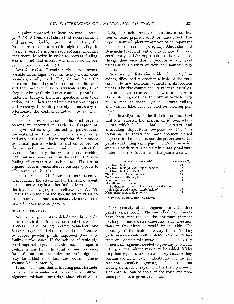
CH AR A CT E R IS T ICS OF A N T I F O U L I N G COATINGS 321
in a paint appeared to have no special value (8, 9, 16). Adamson (1) states that arsenic trioxide and arsenic trisulfide were not effective, the former probably because of its high solubility. In the same tests, Paris green required supplementing with mercuric oxide in order to prevent fouling. Harris found that arsenic was ineffective in preventing barnacle fouling (20).
Organic toxics: Organic toxics have several possible advantages over the heavy metal compounds generally used. They do not have the corrosion stimulating action of the metallic salts, and their use would be of strategic value, since they may be synthesized from commonly available materials. Many of them are specific in their toxic action, rather than general poisons such as copper and mercury.' It would probably be necessary to reformulate the coating completely to use them effectively.
The toxicities of almost a hundred organic poisons are recorded in Table 12, Chapter 14. To give satisfactory antifouling performance, the material must be toxic to marine organisms, and only slightly soluble in naphtha. When added to normal paints, which depend on copper for the toxic action, an organic poison may affect the paint medium, may change the copper leaching rate, and may even result in decreasing the antifouling effectiveness of such paints. The use of organic toxics in cementiferous coatings appears to offer some promise (21).
The insecticide, D D T , has been found effective in preventing the attachment of barnacles, though it is not active against other fouling forms such as the bryozoans, algae, and molluscs (14, 25, 34). This is an example of the specific action of an organic toxic which makes it unsuitable unless fortified with more general poisons.
N O N T O X I C P I G M E N T S
Addition of pigments which do not have a demonstrable toxic action may contribute to the effectiveness of the coating. Young, Schneider, and Seagren (44) concluded that the addition of barytes to copper powder paints improved their antifouling performance. If the volume of toxic pigment required to give adequate protection against fouling is less than the total volume necessary for optimum film properties, nontoxic pigments may be added to obtain the proper pigment volume (cf. Chapter 19).
It has been found that antifouling paint formulations can be extended with a variety of nontoxic pigments without impairing their effectiveness
(3, 23). For each formulation, a critical concentration of toxic pigment must be maintained. The type of nontoxic pigment appears to be important in some formulations (3, 6, 23). Alexander and Benemelis (3) found that zinc oxide gave the most consistently satisfactory result in their vehicles, though they were able to produce equally good paints with a variety of toxic and nontoxic pigments.
Adamson (2) lists zinc oxide, zinc dust, iron oxides, silica, and magnesium silicate as the most commonly used nontoxic pigments in shipbottom paints. The zinc compounds are more frequently a part of the anticorrosive, but may also be used in the antifouling coatings. In addition to these, pigments such as chrome green, chrome yellow, and various lakes may be used for' coloring purposes.
The investigators of the British Iron and Steel Institute reported the analysis of 47 proprietary paints which included both anticorrosive and antifouling shipbottom compositions (7). The following list shows the most commonly used pigments in these paints, and the proportion of the paints containing each pigment. Red iron oxide and zinc oxide were used most frequently and were major constituents of most of the paints tested.
Non Toxic Pigments*R e d I r o n O x i d eR e d I r o n O x i d e p l u s w h i t i n g o r b a r y t e s R e d I r o n O x i d e a n d Z n O Z i n c O x i d e , Z n S a n d b a r y t e s Z n O a l o n e o r w i t h b a r y t e s A l u m i n u m p o w d e r M i s c e l l a n e o u s m i x t u r e s
( Z n d u s t , r e d o r w h i t e l e a d , c a l c i u m s u l f a t e o rp h o s p h a t e a n d v a r i o u s c o m b i n a t i o n s )
N o n e o t h e r t h a n t o x i c p i g m e n t s
* List from reference 7, after J. C. Hudson.
The quantity of the pigments in antifouling paints varies widely. No controlled experiments have been reported on the optimum pigment loading for underwater exposures, and investigations in this direction would be valuable. The quantity of the toxic necessary for antifouling performance should first be determined by fouling tests or leaching rate experiments. The quantity of nontoxic pigments needed to give any particular total pigment volume may then be added. Many proprietary paints are unsatisfactory because they contain too little toxic, undoubtedly because the common extender pigments, such as the iron oxides, are much cheaper than the toxic pigments. The cost in 1944 of some of the toxic and nontoxic pigments is given as follows :
Frequency % 23
6 23 19 9 4
134
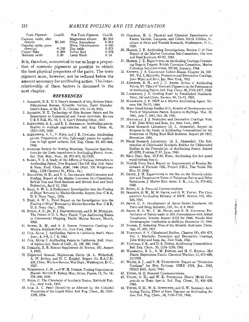
322 M A R I N E FOULING A N D I T S P R E V E N T I O N
Toxic Pigments Cost/lb. Non Toxic Pigments Cost/lb.C u p r o u s o x i d e , e l e c
t r o l y t i c $ 0 . 2 4 0C u p r o u s o x i d e , p y r o -
c h e m i c a l 0 . 2 2 0C o p p e r f l a k e 0 . 4 0 0M e r c u r i c o x i d e 2 . 0 0
M a g n e s i u m s i l i c a t e $ 0 . 0 1 0S i l i c a , A m o r p h o u s 0 . 0 1 4S i l i c a , D i a t o m a c e o u s 0 . 0 3 0Z i n c o x i d e 0 . 0 7 5I n d i a n R e d 0 . 0 7 8L a m p B l a c k 0 . 1 0
It is, therefore, economical to use as large a proportion of nontoxic pigments as possible to obtain the best physical properties of the paint. The toxic pigment must, however, not be reduced below the amount necessary for antifouling action. The interrelationship of these factors is discussed in the next chapter.
REFERENCES1 . A d a m s o n , N . E . U . S . N a v y ’s R e s e a r c h o f S h i p B o t t o m P a i n t .
E d u c a t i o n a l B u r e a u , S c i e n t i f i c S e c t i o n , P a i n t M a n u f a c t u r e r ’s A s s o c , o f t h e U . S . , C i r c u l a r 1 5 6 , 1 5 - 3 4 , 1 9 2 2 .
2 . A d a m s o n , N . E . T e c h n o l o g y o f S h i p B o t t o m P a i n t s a n d I t sI m p o r t a n c e t o C o m m e r c i a l a n d N a v a l A c t i v i t i e s . B u r e a u C & R B u l l . N o . 1 0 , U . S . G o v ’t P r i n t i n g O f f i c e , 1 9 3 7 .
3 . A l e x a n d e r , A . L . , a n d R . L . B e n e m e l i s . A n t i f o u l i n g p a i n t s .S t u d i e s i n m u l t i p l e p i g m e n t a t i o n . I n d . E n g . C h e m . 4 1 , 1 5 3 2 - 1 5 3 5 , 1 9 4 9 .
4 . A l e x a n d e r , A . L . , P . K in g , a n d J . E . C o w l i n g . A n t i f o u l i n gp a i n t s . P r e p a r a t i o n o f t h i n , l i g h t w e i g h t p a i n t s f o r a p p l i c a t i o n t o h i g h s p e e d s u r f a c e s . I n d . E n g . C h e m . 4 0 , 4 6 1 - 4 6 4 , 1 9 4 8 .
5 . A m e r i c a n S o c i e t y f o r T e s t i n g M a t e r i a l s . T e n t a t i v e S p e c i f i c a t i o n s f o r t h e T o x i c I n g r e d i e n t s i n A n t i f o u l i n g P a i n t s . A m e r . S o c . T e s t . M a t . , P r o c . , 2 8 , 8 7 2 - 8 7 3 , 1 2 / 1 9 2 8 .
6 . B a b e l , V . S . A S t u d y o f t h e E f f e c t s o f V a r i o u s E x t e n d e r s i nA n t i f o u l i n g P a i n t s . N e w E n g l a n d C l u b O f f . D i g . F e d . P a i n t & V a r n . P r o d . C l u b s , # 2 4 0 , 1 9 4 4 ( P u b l . 7 0 4 W e i g h t m a n B l d g . , 1 5 2 4 C h e s t n u t S t . , P h i l a . , P a . ) .
7 . B e n g o u g h , G . D . , a n d V . G . S h e p h e a r d . H u l l C o r r o s i o n a n dF o u l i n g . R e p o r t o f t h e M a r i n e C o r r o s i o n S u b - C o m m i t t e e , B r i t i s h I r o n a n d S t e e l I n s t i t u t e a n d B r i t i s h I r o n a n d S t e e l F e d e r a t i o n , A p r i l 1 5 , 1 9 4 3 .
8 . B r a y , A . W . L . A P r e l i m i n a r y I n v e s t i g a t i o n i n t o t h e F o u l i n go f S h i p s ’ B o t t o m s b y M a r i n e G r o w t h s . R e p o r t , B u r . C & R , U . S . N a v y D e p t . , 1 9 2 4 .
9 . B r a y , A . W . L . T h i r d R e p o r t o n t h e I n v e s t i g a t i o n i n t o t h eF o u l i n g o f S h i p s ’ B o t t o m s b y M a r i n e G r o w t h s . B u r . C & R , U . S . N a v y D e p t . , 1 9 2 4 .
1 0 . B u r n s , A . E . , J r . , F . J . D a n n e n f e l s e r , a n d R . M . M u e l l e r .T h e F u t u r e o f U . S . N a v y P l a s t i c T y p e A n t i f o u l i n g P a i n t s i n C o m m e r c i a l S h i p p i n g . P a c i f i c M a r i n e R e v i e w , M a r c h , 1 9 4 6 .
1 1 . B u r n s , R . M . , a n d A . E . S c h u i i . P r o t e c t i v e C o a t i n g s f o rM e t a l s . R e i n h o l d P u b . C o . , N e w Y o r k , 1 9 3 9 .
1 2 . C o x , A l v i n J . A n t i f o u l i n g P a i n t s i n C a l i f o r n i a . N a t ’l . P a i n tJ o u r . , 4 , 5 - 8 ; 5 , 7 - 8 , 1 9 4 3 . '
1 3 . C o x , A l v i n J . A n t i f o u l i n g P a i n t s i n C a l i f o r n i a . B u l l . D e p t .o f A g r i c u l t u r e , S t a t e o f C a l i f . , 3 2 , 1 8 8 - 2 0 0 , 1 9 4 3 .
1 4 . D im m ic k , R . E . S c i e n c e S u p p l e m e n t 1 0 , S c i e n c e , 1 0 2 , A u g u s t3 , 1 9 4 5 .
1 5 . E d g e w o o d A r s e n a l , S h i p b o t t o m P a i n t s ( B . L . W e h m h o f f ,A . M . J o r d a n , a n d H . C . K n i g h t ) . R e p o r t N o . E . A . C . D . 4 3 3 , C h e m . W a r f a r e S e r v i c e , W a r D e p t . , W a s h i n g t o n , D . C . , 1 9 2 7 .
1 6 . E d m o n d s o n , C . H . , a n d W . H . I n g r a m . F o u l i n g O r g a n i s m s i nH a w a i i . B e r n i c e P . B i s h o p M u s . , O c c a s . P a p e r s , 1 4 , N o . 1 4 : 2 5 1 - 3 0 0 , 1 9 3 9 .
1 7 . E l l i s , C . T h e C h e m i s t r y o f S y n t h e t i c R e s i n s . R e i n h o l d P u b .C o . , N e w Y o r k , 1 9 3 5 .
1 8 . E lm , A . C . P a i n t D u r a b i l i t y a s A f f e c t e d b y t h e C o l l o i d a lP r o p e r t i e s o f t h e L i q u i d P a i n t . I n d . E n g . C h e m . , 2 6 , 1 2 4 5 - 1 2 5 0 , 1 9 3 4 .
1 9 . G a r d n e r , H . A . P h y s i c a l a n d C h e m i c a l E x a m i n a t i o n o fP a i n t s , V a m i s h , L a c q u e r s , a n d C o l o r s . N i n t h E d i t i o n , I n s t i t u t e o f P a i n t a n d V a r n i s h R e s e a r c h , W a s h i n g t o n , D . C . , 1 9 3 9 .
2 0 . H a r r i s , J . E . A n t i f o u l i n g I n v e s t i g a t i o n s . S e c t i o n C o f F i r s tR e p o r t o f t h e M a r i n e C o r r o s i o n S u b - C o m m i t t e e , T h e I r o n a n d S t e e l I n s t i t u t e , 6 7 - 8 2 , 1 9 4 3 .
2 1 . H a r r i s , J . E . E x p e r i m e n t s o n A n t i f o u l i n g C o a t i n g s C o n t a i n i n g O r g a n i c P o i s o n s . B r i t i s h C o r r o s i o n C o m m i t t e e , M a r i n e C o r r o s i o n S u b - C o m m i t t e e , N 2 / 4 4 , J a n u a r y , 1 9 4 4 .
2 2 . K e n n e y , J . A . C o u m a r o n e I n d e n e R e s i n s . C h a p t e r 1 4 , 3 6 0 -3 9 1 , V o l . I , M a t t i e l l o , P r o t e c t i v e a n d D e c o r a t i v e C o a t i n g s , J o h n W i l e y a n d S o n s , I n c . N e w Y o r k , 1 9 4 1 .
2 3 . K e t c h u m , B . H . , a n d J . C . A y e r s . A c t i o n o f A n t i f o u l i n gP a i n t s . V I . E f f e c t o f N o n t o x i c P i g m e n t s o n t h e P e r f o r m a n c e o f A n t i f o u l i n g P a i n t s . I n d . E n g . C h e m . 40, 2124r-2127, 1948.
2 4 . L o c k w o o d , J . E . G r a d i n g R o s i n b y E s t a b l i s h e d S t a n d a r d s .P a i n t , O i l a n d C h e m . R e v i e w , 9 4 , 1 2 - 1 3 , 1 9 3 2 .
2 5 . M a r c h a n d , J . F . D D T a s a M a r i n e A n t i f o u l i n g A g e n t . S c i e n c e 1 0 4 , 7 4 ^ 7 5 , 1 9 4 6 .
2 6 . M a r e I s l a n d G r o u p S t u d i e s I I G , R e s u l t s o f D e v e l o p m e n t a n dT e s t s o f S h i p b o t t o m P a i n t s . R e p o r t s t o B u S h i p s : M a r . 1 8 , 1 9 4 1 , J u l y 7 , 1 9 4 1 , O c t . 2 0 , 1 9 4 1 .
2 7 . M a t t i e l l o , J . J . P r o t e c t i v e a n d D e c o r a t i v e C o a t i n g s . V o l s .I - I V . J o h n W i l e y a n d S o n s , I n c . N e w Y o r k , 1 9 4 1 .
2 8 . N a v a l R e s e a r c h L a b o r a t o r y ( A . L . A l e x a n d e r ) . R e p o r t o nP r o g r e s s i n t h e S t u d y o f A n t i f o u l i n g C o m p o s i t i o n s f o r t h e P r o t e c t i o n o f F l y i n g B o a t H u l l B o t t o m s . R e p o r t # P - 1 8 1 5 , N o v e m b e r , 1 9 4 1 .
2 9 . N a v a l R e s e a r c h L a b o r a t o r y . ( A . L . A l e x a n d e r ) . T h e S u b s t i t u t i o n o f C h l o r i n a t e d S y n t h e t i c R u b b e r f o r C h l o r i n a t e d R u b b e r i n t h e F o r m u l a t i o n o f A n t i f o u l i n g P a i n t s . R e p o r t # P - 2 5 5 8 , P r o b l e m P - 5 2 . J u n e , 1 9 4 5 .
3 0 . N a v y D e p t . S p e c . 5 2 - P - 6 1 . P a i n t , A n t i f o u l i n g ( f o r l o w s p e e dw o o d - b o t t o m b o a t s ) .
3 1 . N o r f o l k N a v y Y a r d . R e p o r t o n I m p r o v e m e n t o f E r o s i o n R e s i s t a n c e o f F o r m u l a 1 6 X , P r o j e c t 3 - H - l , T e s t S e r i a l 3 9 2 . M a y 2 2 , 1 9 4 4 .
3 2 . O r t o n , J . H . E x p e r i m e n t s i n t h e S e a o n t h e G r o w t h - i n h i b i -t i v e a n d P r e s e r v a t i v e V a l u e o f P o i s o n o u s P a i n t s a n d O t h e r S u b s t a n c e s . J . M a r i n e B i o l . A s s o c . U . K . , n . s . , 1 6 , 3 7 3 - 4 5 2 , 1 9 3 0 .
3 3 . R i l e y , G . A . P e r s o n a l C o m m u n i c a t i o n s .3 4 . S e a g r e n , G . W . , M . H . S m ith , a n d G . H . Y o u n g . T h e C o m
p a r a t i v e A n t i f o u l i n g E f f i c a c y o f D D T . S c i e n c e 1 0 2 , 4 2 5 - 4 2 6 , 1 9 4 5 .
3 5 . S m ith , C . E . D e v e l o p m e n t o f N a v a l S t o r e s S t a n d a r d s . O i lP a i n t a n d D r u g R e p o r t e r , 1 2 3 , N o . 6 , 9 , 1 9 3 3 .
3 6 . S m it h , F . G . W . , C . M . W e i s s , a n d B . H . K e t c h u m . P e r f o r m a n c e o f P a i n t s m a d e t o 1 6 X F o r m u l a t i o n s w i t h A d d e d T o u g h e n e r s . I n t e r i m R e p o r t X I I I f o r 1 9 4 4 . W o o d s H o l e O c e a n o g r a p h i c I n s t i t u t i o n t o B u S h i p s , D e c e m b e r 1 5 , 1 9 4 4 .
3 7 . S t u b b s , E . I n d u s t r i a l U s e s o f t h e M e t a l l i c R é s i n â t e s . C h e m .A g e , 3 7 , 4 2 9 , 1 9 3 7 .
3 8 . T o r t o r i c i , P . V . C h l o r i n a t e d R u b b e r . C h a p t e r 1 8 b , 4 5 9 - 4 7 5 ,V o l . I , M a t t i e l l o , P r o t e c t i v e a n d D e c o r a t i v e C o a t i n g s , J o h n W i l e y a n d S o n s , I n c . N e w Y o r k , 1 9 4 1 .
3 9 . T u w i n e r , S . B . , a n d D . A . D o d g e . A n t i f o u l i n g C o m p o s i t i o n s .I n d . E n g . C h e m . , 3 3 , 1154r-1156, 1941.
4 0 . W e h m h o f f , B . L . , A . M . J o r d a n , a n d H . C . K n i g h t . H o tP l a s t i c S h i p b o t t o m P a i n t s . C h e m i c a l W a r f a r e , 1 5 , 6 7 5 - 6 8 0 , 1 2 / 1 9 2 9 .
4 1 . W e i t h , A . J . , a n d V . H . T u r k i n g t o n . R e p o r t o n “ P r o t e c t i v eC o a t i n g s ” f o r S h i p B o t t o m s . O S R D # 3 2 4 , J a n . 1 9 4 2 , O S R D # 6 5 1 , A p r i l , 1 9 4 2 .
4 2 . Y o u n g , G . H . P e r s o n a l C o m m u n i c a t i o n s .4 3 . Y o u n g , G . H . , a n d W . K . S c h n e i d e r . H e a v y M e t a l C o m
p o u n d s a s T o x i c A g e n t s . I n d . E n g . C h e m . , 3 5 , 4 3 6 - 4 3 8 , 1 9 4 3 .
4 4 . Y o u n g , G . H . , W . K . S c h n e i d e r , a n d G . W . S e a g r e n . A n t i f o u l i n g P a i n t y , E f f e c t o f I n e r t P i g m e n t o n A n t i f o u l i n g A c t i o n . I n d . E n g . C h e m . , 3 6 , 1 1 3 0 - 1 1 3 2 , 1 9 4 4 .

M a r i n e F o u l i n g a n d I t s P r e v e n t i o n ,C o n t r i b u t i o n N o . 5 8 0 f r o m t h e W o o d s F l o l e O c e a n o g r a p h i c I n s t i t u t e
C o p y r i g h t 1 9 5 2 b y U . S . N a v a l I n s t i t u t e , A n n a p o l i s , M a r y l a n d G e o r g e B a n t a P u b l i s h i n g C o . , M e n a s h a , W I
CHAPTER 19
The Design of Antifouling PaintsThe properties requisite for satisfactory per
formance of antifouling paints include durability, adhesion, smoothness, and ease of application as well as the ability to prevent the attachment or growth of fouling organisms. This chapter will attempt to define, insofar as is possible, how paints may be designed to have these desirable qualities. In many cases the influence of the paint ingredients on the properties of the film is not fully understood, and the design of improved formulations is thereby handicapped.
It must be emphasized that both the physical quality of the paint film and the antifouling properties are essential for the best performance. In the present state of the art, paints can be designed which do not foul so long as the physical integrity of the paint film is maintained. Further advances in the development of such paints will result from improvement in strength, toughness, and adhesion. The effects of paint ingredients on the antifouling properties are currently more clearly understood than are their effects on physical properties. Consequently, this chapter may appear to give undue emphasis to the toxicity of the paint. Since, however, paints may now be designed with the appropriate toxicity, it seems probable that rapid improvement in the knowledge and understanding of the effects of ingredients on the physical properties will be forthcoming.
Most, if not all, of the effective antifouling paints act because of one or the other of two mechanisms which have been described in Chapter 16. One group of paints, characterized by a high loading of toxic pigment and a tough, impermeable, insoluble matrix, maintains an adequate leaching rate because the toxic particles are in continuous contact throughout the dried paint film. The other group, characterized by lower loadings of the toxic pigment and the presence of rosin or another soluble ingredient in the matrix, maintains a satisfactory leaching rate because the matrix dissolves away, uncovering the stores of toxic within the film. The principles in the design of these two types of paint are entirely different and will be discussed in turn.
PAINTS WITH INSOLUBLE MATRICESTo give satisfactory performance, paints with
insoluble matrices must contain the maximum
loading of toxic consistent with the mechanical integrity of the paint film. The greater the loading of toxic, the more perfect the contact between particles and the longer the life of the paint. These high loadings, however, lead to a waste of toxic because of excessively high copper leaching rates during the early stages of immersion. As extraction proceeds, only that toxic which lies in chains of particles in contact and extending originally from the surface inward can be dissolved. The chance that a given particle is in such a chain decreases progressively with its distance from the surface. As the chains of particles dissolve away, a depth is ultimately reached where the continued solution of toxic is at an inadequate rate to prevent fouling. It follows that, for each such paint, a critical thickness may be determined beyond which adequate leaching will not continue. It is consequently impossible to extend the life of continuous contact paints by increasing the thickness of the film beyond this critical depth.
The VehicleThe strength and integrity of the paint depend
upon the resinous ingredients of the vehicle. Paints containing polyvinyl resins and high loadings of toxic have been developed by investigators at the Bakelite Corporation (2) and short- to-medium oil length varnish vehicles have been used by Young and his collaborators (10, 11). Probably many other high molecular weight synthetic resins would also be successful.
In paints using the vinyl resins it is unnecessary to use other resinous ingredients. Tougheners are not required, since the principal resinous ingredient itself is tough; plasticizers for this type of matrix have not been extensively studied. The use of rosin with polyvinyl resins increases the leaching rates by considerable amounts, and generally extends, by a month or more, the period during which adequate rates are maintained. It is possible that the solubility of the rosin contributes to the availability of the toxic. Rosin may be substituted for as much as 75 per cent of the polyvinyl resins in the matrix without decreasing the durability of the paint appreciably.
PigmentationToxic loading: In developing a paint with an in
soluble matrix, the first experiment required is one
323
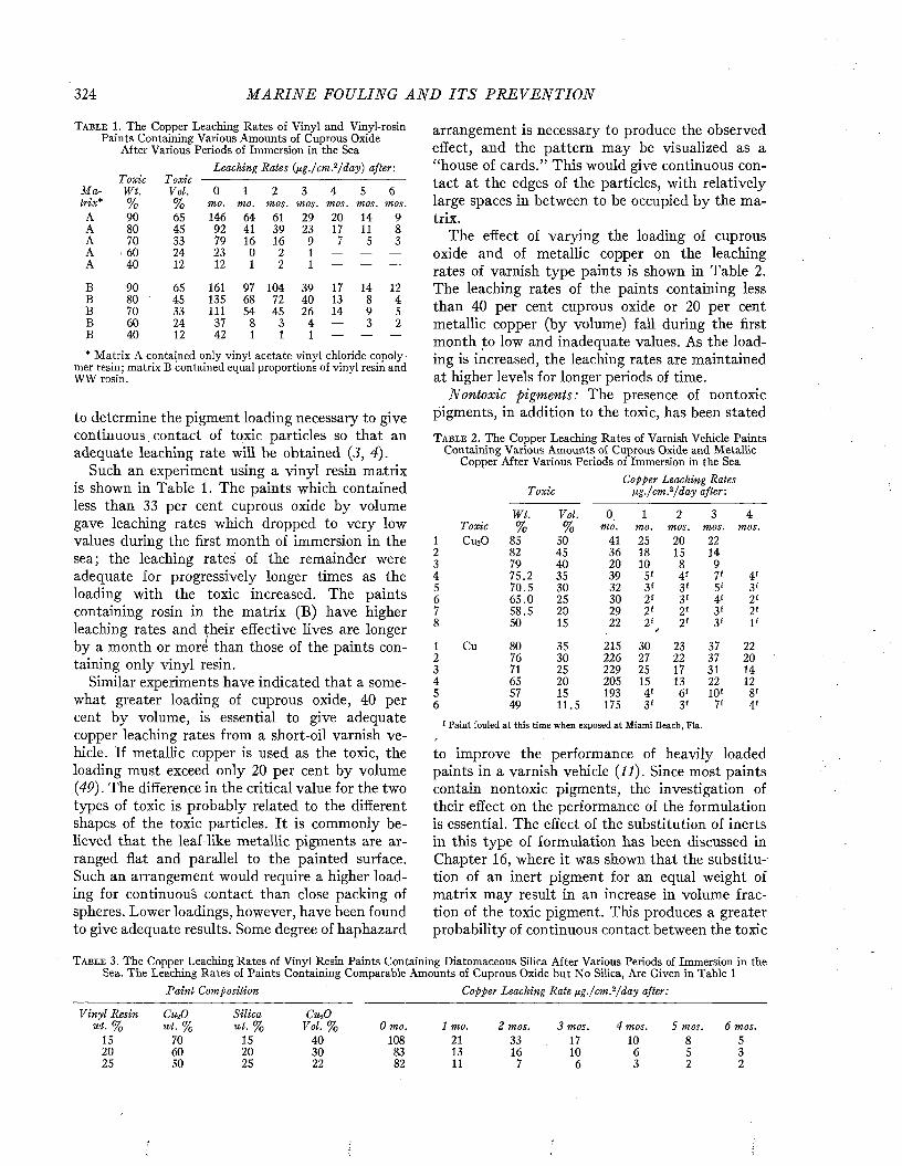
M A R I N E FOULING A N D I T S P R E V E N T I O N324
T a b l e 1. T h e C o p p e r L e a c h i n g R a t e s o f V i n y l a n d V i n y l - r o s i n P a i n t s C o n t a i n i n g V a r i o u s A m o u n t s o f C u p r o u s O x i d e
A f t e r V a r i o u s P e r i o d s o f I m m e r s i o n i n t h e S e aLeaching Rates (jj.g./cm?/day) after-.
M aToxicWt.
ToxicVol. 0 1 2 3 4 5 6
trix* % % mo. mo. mos. mos. mos. mos. mos.A 90 65 146 64 61 29 20 14 9A 80 45 92 41 39 23 17 11 8A 70 33 79 16 16 9 7 5 3A ■ 60 24 23 0 2 1 — — —
A 40 12 12 1 2 1 — — —
B 90 65 161 97 104 39 17 14 12B 80 45 135 68 72 40 13 8 4B 70 33 l i i 54 45 26 14 9 5B 60 24 37 8 3 4 — 3 2B 40 12 42 1 1 1 — — —
* M a t r i x A c o n t a i n e d o n l y v i n y l a c e t a t e - v i n y l c h l o r i d e c o p o l y -m e r r e s i n ; m a t r i x B c o n t a i n e d e q u a l p r o p o r t i o n s o f v i n y l r e s i n a n d W W r o s i n .
to determine the pigm ent loading necessary to give continuous contact of toxic particles so that an adequate leaching rate w ill be obtained (3, 4).
Such an experiment using a v in yl resin matrix is shown in Table 1. The paints which contained less than 33 per cent cuprous oxide by volume gave leaching rates which dropped to very low values during the first m onth of immersion in the 1sea; the leaching rates of the remainder were \adequate for progressively longer times as the 4loading w ith the toxic increased. The paints ^containing rosin in the m atrix (B) have higher 7leaching rates and their effective lives are longer 8by a m onth or more than those of the paints con- 1taining only v inyl resin. 3
Similar experiments have indicated that a some- 4what greater loading of cuprous oxide, 40 per 5cent by volume, is essential to give adequate copper leaching rates from a short-oil varnish vehicle. If metallic copper is used as the toxic, the loading must exceed only 20 per cent by volume (49). The difference in the critical value for the two types of toxic is probably related to the different shapes of the toxic particles. It is commonly believed that the leaf-like metallic pigments are arranged flat and parallel to the painted surface.Such an arrangement would require a higher loading for continuous contact than close packing of spheres. Lower loadings, however, have been found to give adequate results. Some degree of haphazard
arrangement is necessary to produce the observed effect, and the pattern may be visualized as a “house of cards.” This would give continuous contact at the edges of the particles, with relatively large spaces in between to be occupied by the matrix.
The effect of varying the loading of cuprous oxide and of metallic copper on the leaching rates of varnish type paints is shown in Table 2. The leaching rates of the paints containing less than 40 per cent cuprous oxide or 20 per cent metallic copper (by volume) fall during the first month to low and inadequate values. As the loading is increased, the leaching rates are maintained at higher levels for longer periods of time.
Nontoxic pigments: The presence of non toxic pigments, in addition to the toxic, has been stated
T a b l e 2 . T h e C o p p e r L e a c h i n g R a t e s o f V a r n i s h V e h i c l e P a i n t s C o n t a i n i n g V a r i o u s A m o u n t s o f C u p r o u s O x i d e a n d M e t a l l i c
C o p p e r A f t e r V a r i o u s P e r i o d s o f I m m e r s i o n i n t h e S e aCopper Leaching Rates
Toxic ng-/cm?/day after:
W t. Vol. 0 . 1 2 3 4% % mo. mo. mos. mos. mos.
85 50 41 25 20 2282 45 36 18 15 1479 40 20 10 8 975.2 35 39 5' 4f 7' 4'70.5 30 32 3' 3' 5' 3'65.0 25 30 2f 3f 4' 2'58.5 20 29 2f 2' 3f 2'50 15 22 2' r 2' 3f 1'
80 35 215 30 23 37 2276 30 226 27 22 37 2071 25 229 25 17 31 1465 20 205 15 13 22 1257 15 193 4' 6' 10' 8'49 11.5 175 3' 3f 7' 4'
' Paint fouled at this time when exposed at Miami Beach, Fia.
to improve the performance of heavily loaded paints in a varnish vehicle ( l í ) . Since most paints contain nontoxic pigments, the investigation of their effect on the performance of the formulation is essential. The effect of the substitution of inerts in this type of formulation has been discussed in Chapter 16, where it was shown that the substitution of an inert pigment for an equal weight of matrix may result in an increase in volume fraction of the toxic pigment. This produces a greater probability of continuous contact between the toxic
T a b l e 3 . T h e C o p p e r L e a c h i n g R a t e s o f V i n y l R e s i n P a i n t s C o n t a i n i n g D i a t o m a c e o u s S i l i c a A f t e r V a r i o u s P e r i o d s o f . I m m e r s i o n i n t h e S e a . T h e L e a c h i n g R a t e s o f P a i n t s C o n t a i n i n g C o m p a r a b l e A m o u n t s o f C u p r o u s O x i d e b u t N o S i l i c a , A r e G i v e n i n T a b l e 1
Paint Composition Copper Leaching Rate ¡ig./cm^/day after:
Vinyl Resin CtbO Silica CrciOwt. % wt. % wt. % V o l.% 0 mo. 1 mo. 2 mos. 3 mos. 4 mos. 5 mos. 6 mos.
15 70 15 40 108 21 33 17 10 8 520 60 20 30 83 13 16 10 6 5 325 50 25 22 82 11 7 6 3 2 2
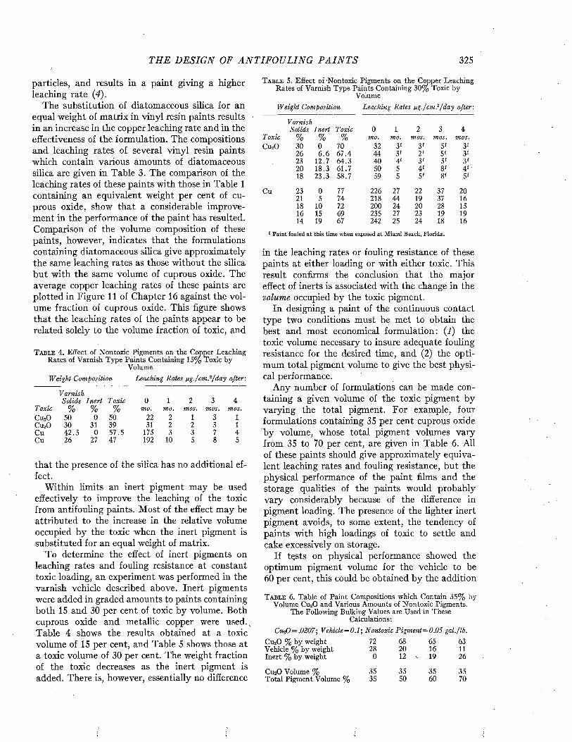
THE DESIGN OF A N T I F O U L I N G P A I N T S 325
particles, and results in a paint giving a higher leaching rate (4).
The substitution of diatomaceous silica for an equal weight of matrix in vinyl resin paints results in an increase in the copper leaching rate and in the effectiveness of the formulation. The compositions and leaching rates of several vinyl resin paints which contain various amounts of diatomaceous silica are given in Table 3. The comparison of the leaching rates of these paints with those in Table 1 containing an equivalent weight per cent of cuprous oxide, show that a considerable improvement in the performance of the paint has resulted. Comparison of the volume composition of these paints, however, indicates that the formulations containing diatomaceous silica give approximately the same leaching rates as those without the silica but with the same volume of cuprous oxide. The average copper leaching rates of these paints are plotted in Figure 11 of Chapter 16 against the volume fraction of cuprous oxide. This figure shows that the leaching rates of the paints appear to be related solely to the volume fraction of toxic, and
T a b l e 4 . E f f e c t o f N o n t o x i c P i g m e n t s o n t h e C o p p e r L e a c h i n gR a t e s o f V a r n i s h T y p e P a i n t s C o n t a i n i n g 1 5 % T o x i c b y
V o l u m eWeight Composition Leaching Rates pg./cm ?/day after :
VarnishSolids Inert T oxic 0 1 2 3 4
Toxic % % % mo. mo. mos. mos. mos.C u 20 50 0 50 22 2 1 3 1C u 20 3 0 31 3 9 31 2 2 3 1C u 4 2 .5 0 5 7 .5 175 3 3 7 4C u 2 6 27 47 192 10 5 8 5
that the presence of the silica has no additional effect.
Within limits an inert pigment may be used effectively to improve the leaching of the toxic from antifouling paints. Most of the effect may be attributed to the increase in the relative volume occupied by the toxic when the inert pigment is substituted for an equal weight of matrix.
To determine the effect of inert pigments on leaching rates and fouling resistance at constant toxic loading, an experiment was performed in the varnish vehicle described above. Inert pigments were added in graded amounts to paints containing both 15 and 30 per cent of toxic by volume. Both cuprous oxide and metallic copper were used. Table 4 shows the results obtained at a toxic volume of 15 per cent, and Table 5 shows those at a toxic volume of 30 per cent. The weight fraction of the toxic decreases as the inert pigment is added. There is, however, essentially no difference
T a b l e 5 . E f f e c t o f - N o n t o x i c P i g m e n t s o n t h e C o p p e r L e a c h i n g R a t e s o f V a r n i s h T y p e P a i n t s C o n t a i n i n g 3 0 % T o x i c b y
V o l u m eWeight Composition Leaching Rates ng ./cm l/day after:
VarnishSolids Inert T oxic 0 1 2 3 4
T oxic % % % mo. mo. mos. mos. mos.C u 20 3 0 0 70 32 3 f 3 ' 5 ' 3 f
2 6 6 . 6 6 7 .4 4 4 3 ' 2 ' 5 f 3 f23 1 2 .7 6 4 .3 4 0 4 f 3 ' 5 ' 3 '2 0 1 8 .3 6 1 .7 50 5 4 ' 8 f 4 f18 2 3 .3 5 8 .7 59 5 5 ' 8 1 5 '
C u 23 0 77 2 2 6 27 22 37 2 021 5 7 4 2 1 8 4 4 19 37 1618 10 72 2 0 0 24 2 0 28 1516 15 69 2 35 27 23 19 1914 19 67 242 25 2 4 18 16
f Paint fouled at this time when exposed at Miami Beach, Florida.
in the leaching rates or fouling resistance of these paints at either loading or with either toxic. This result confirms the conclusion that the major effect of inerts is associated with the change in the volume occupied by the toxic pigment.
In designing a paint of the continuous contact type two conditions must be met to obtain the best and most economical formulation: (1) the toxic volume necessary to insure adequate fouling resistance for the desired time, and (2) the optimum total pigment volume to give the best physical performance.
Any number of formulations can be made containing a given volume of the toxic pigment by varying the total pigment. For example, four formulations containing 35 per cent cuprous oxide by volume, whose total pigment volumes vary from 35 to 70 per cent, are given in Table 6. All of these paints should give approximately equivalent leaching rates and fouling resistance, but the physical performance of the paint films and the storage qualities of the paints would probably vary considerably because of the difference in pigment loading. The presence of the lighter inert pigment avoids, to some extent, the tendency of paints with high loadings of toxic to settle and eake excessively on storage.
If tçsts on physical performance showed the optimum pigment volume for the vehicle to be 60 per cent, this could be obtained by the addition
T a b l e 6 . T a b le o f P a i n t C o m p o s i t i o n s w h i c h C o n t a i n 3 5 % b y V o l u m e C u 20 a n d V a r i o u s A m o u n t s o f N o n t o x i c P i g m e n t s .
T h e F o l l o w i n g B u l k i n g V a l u e s a r e U s e d i n T h e s e C a l c u l a t i o n s :
CuíO = .0207; Vehicle = 0.1; Nontoxic Pigm ent:= 0.05 gal. /lb.C u 20 % b y w e i g h t 72 68 65 63V e h i c l e % b y w e i g h t 2 8 2 0 16 11I n e r t % b y w e i g h t 0 12 -, 19 2 6
C u 20 V o l u m e % 35 35 3 5 35T o t a l P i g m e n t V o l u m e % 35 5 0 6 0 70
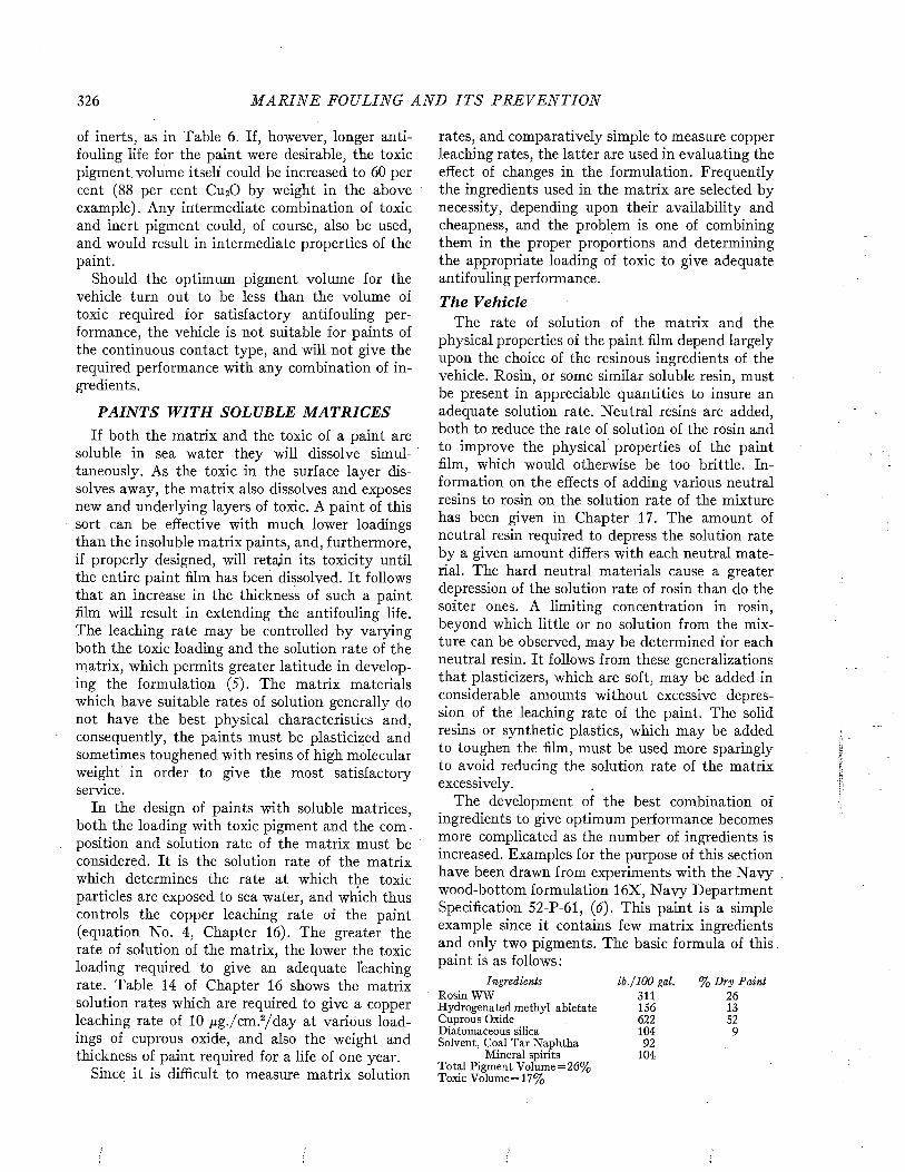
326 M A R I N E FOULING A N D I T S P R E V E N T I O N
of inerts, as in Table 6 . If, however, longer antifouling life for the paint were desirable, the toxic pigment volume itself could be increased to 60 per cent (88 per cent Cu20 by weight in the above example). Any intermediate combination of toxic and inert pigment could, of course, also be used, and would result in intermediate properties of the paint.
Should the optimum pigment volume for the vehicle turn out to be less than the volume of toxic required for satisfactory antifouling performance, the vehicle is not suitable for paints of the continuous contact type, and will not give the required performance with any combination of ingredients.
PAINTS WITH SOLUBLE MATRICESIf both the matrix and the toxic of a paint are
soluble in sea water they will dissolve simultaneously. As the toxic in the surface layer dissolves away, the matrix also dissolves and exposes new and underlying layers of toxic. A paint of this sort can be effective with much lower loadings than the insoluble matrix paints, and, furthermore, if properly designed, will retain its toxicity until the entire paint film has been dissolved. It follows that an increase in the thickness of such a paint film will result in extending the antifouling life. The leaching rate may be controlled by varying both the toxic loading and the solution rate of the matrix, which permits greater latitude in developing the formulation (5). The matrix materials which have suitable rates of solution generally do not have the best physical characteristics and, consequently, the paints must be plasticized and sometimes toughened with resins of high molecular weight in order to give the most satisfactory service.
In the design of paints with soluble matrices, both the loading with toxic pigment and the composition and solution rate of the matrix must be considered. It is the solution rate of the matrix which determines the rate at which the toxic particles are exposed to sea water, and which thus controls the copper leaching rate of the paint (equation No. 4, Chapter 16). The greater the rate of solution of the matrix, the lower the toxic loading required to give an adequate leaching rate. Table 14 of Chapter 16 shows the matrix solution rates which are required to give a copper leaching rate of 10 /xg./cm.2/d ay at varidus loadings of cuprous oxide, and also the weight and thickness of paint required for a life of one year.
Since it is difficult to measure matrix solution
rates, and comparatively simple to measure copper leaching rates, the latter are used in evaluating the effect of changes in the formulation. Frequently the ingredients used in the matrix are selected by necessity, depending upon their availability and cheapness, and the problem is one of combining them in the proper proportions and determining the appropriate loading of toxic to give adequate antifouling performance.
The VehicleThe rate of solution of the matrix and the
physical properties of the paint film depend largely upon the choice of the resinous ingredients of the vehicle. Rosin, or some similar soluble resin, must be present in appreciable quantities to insure an adequate solution rate. Neutral resins are added, both to reduce the rate of solution of the rosin and to improve the physical properties of the paint film, which would otherwise be too brittle. Information on the effects of adding various neutral resins to rosin on the solution rate of the mixture has been given in Chapter 17. The amount of neutral resin required to depress the solution rate by a given amount differs with each neutral material. The hard neutral materials cause a greater depression of the solution rate of rosin than do the softer ones. A limiting concentration in rosin, beyond which little or no solution from the mixture can be observed, may be determined for each neutral resin. It follows from these generalizations that plasticizers, which are soft, may be added in considerable amounts without excessive depression of the leaching rate of the paint. The solid resins or synthetic plastics, which may be added to toughen the film, must be used more sparingly to avoid reducing the solution rate of the matrix excessively.
The development of the best combination of ingredients to give optimum performance becomes more complicated as the number of ingredients is increased. Examples for the purpose of this section have been drawn from experiments with the Navy wood-bottom formulation 16X, N avy Department Specification 52-P-61, (6). This paint is a simple example since it contains few matrix ingredients and only two pigments. The basic formula of th is . paint is as follows :
Ingredients lb ./100 gal. % Dry PaintR o s i n W W 3 1 1 2 6H y d r o g e n a t e d m e t h y l a b i e t a t e 1 5 6 1 3C u p r o u s O x i d e 6 2 2 5 2D i a t o m a c e o u s s i l i c a 1 0 4 9S o l v e n t , C o a l T a r N a p h t h a 9 2
M i n e r a l s p i r i t s 1 0 4T o t a l P i g m e n t V o l u m e = 2 6 %T o x i c V o l u m e = 1 7 %
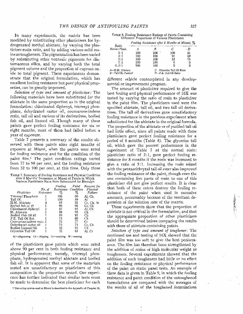
TH E D E SIG N OF A N T IF O U L IN G P A I N T S 327
In many experiments, the matrix has been modified by substituting other plasticizers for hydrogenated methyl abietate, by varying the plas- ticizer-rosin ratio, and by adding various solid resins as tougheners. The pigmentation has been varied by substituting other nontoxic pigments for diatomaceous silica, and by varying both the total pigment volume and the proportion of cuprous oxide to total pigment. These experiments demonstrate that the original formulation, which has excellent fouling resistance but poor physical properties, can be greatly improved.
Selection of type and amount of plasticizer: The following materials have been substituted for the abietate in the same proportion as in the original formulation: chlorinated diphenyl, tricresyl phosphate, dehydrated castor oil, coumarone-indene resin, tali oil and various of its derivatives, bodied fish oil, and linseed oil. Though many of these paints gave perfect fouling resistance for six or eight months, most of them had failed before a year of exposure.
Table 7 presents a summary of the results observed with these paints after eight months of exposure at Miami, when the paints were rated for fouling resistance and for the condition of the paint film.1 The paint condition ratings varied from 77 to 98 per cent, and the fouling resistance from 52 to 100 per cent, at this time. Only three
T a b l e 7 . Summary of Fouling Resistance and Physical Condition after 8 Months’ Immersion at Miami of Paints in Which Various Plasticizers Have Been Substituted for Hercolyn
Fouling P ain t Reasons forNo. of Resistance Condition Physical
P lasticizer Exposures % % FailureTricresyl Phosphate 1 100 90 AÍ, Ch,Tail Oil 1 100 89 AÍH.M . Abietate 4 95 92 Cr, Ch, WBodied fish oil #1 1 90 98 Cr, ChChlorinated diphenyl 2 87 95 AI, ChM. Abietate 1 88 95 ChBodied Fish Oil #2 1 83 95 ChP.E. Tail Oil Est. 1 75 80 ChCoumarone-indene resin 1 76 77 CrDehydrated castor oil 1 75 75 Cr, ChBodied Linseed Oil 1 53 95 ChGlycerine Tali Oil 1 52 83 AI, Cr
Al=alligatoring C h=chipping Cr=cracking W =wearing
of the plasticizers gave paints which were rated above 90 per cent in both fouling resistance and physical performance; namely, tricresyl phosphate, hydrogenated methyl abietate and bodied fish oil. I t is apparent that some of the materials tested are unsatisfactory as plasticizers of this composition in the proportion tested. Our experience has further indicated that similar tests must be made to determine the best plasticizer for each
1 The rating system used at Miami is described in the Appendix of Chapter 20.
T a b l e 8. Fouling Resistance Ratings of Paints Containing Difference Proportions of Various Plasticizers
Fouling Resistance after 8 M onths at M iam i, %Raha -----
Rosin'. Plast. A B C D5:1 100 100 ' 100 813:1 100 100 91 692:1 100 100 52 751:1 100 100 0 0
0 .5 :1 100 100 0 0A—H.M . Abietate B—Tail Oil, Purified
C— Glycerine Tail Oil Ester D—P.E. Tali Oil Ester
different vehicle contemplated in any developmental or improvement program.
The amount of plasticizer required to give the best fouling and physical performance of 16X was tested by varying the ratio of rosin to plasticizer in the paint film. The plasticizers used were the specified abietate, tail oil, and two tali oil derivatives. The tali oil derivatives gave unsatisfactory fouling resistance in the previous experiment when substituted for the abietate in the original formula. The proportion of the abietate or of purified tail oil had little effect, since all paints made with these plasticizers gave perfect fouling resistance for a period of 8 months (Table 8). The glycerine tail oil, which gave the poorest performance in the experiment of Table 7 at the normal rosin: plasticizer ratio of 2:1, gave perfect fouling resistance for 8 months if the rosin was increased to give a ratio of 5:1. Increasing the rosin mixed with the pentaerithrytal tail oil ester also improved the fouling resistance of the paint, though even the one containing five parts of rosin to one of this plasticizer did not give perfect results. It is clear that both of these esters destroy the fouling resistance of the paint when used in excessive amounts, presumably because of the resultant depression of the solution rate of the matrix.
These experiments show that the proportion of abietate is not critical in the formulation, and that the appropriate proportion of other plasticizers should be determined before comparing the results with those of abietate-containing paints.
Selection of type and amount of toughener: The continued use and testing of 16X showed that the paint film was too soft to give the best performance. The. film has therefore been strengthened by the addition of resins of high molecular weight as tougheners. Several experiments showed that the addition of such tougheners had little or no effect on the fouling resistance or physical performance of the paint on static panel tests. An example of these data is given in Table 9, in which the fouling resistance and paint condition of the untoughened formulations are compared with the averages of the results of all of the toughened formulations
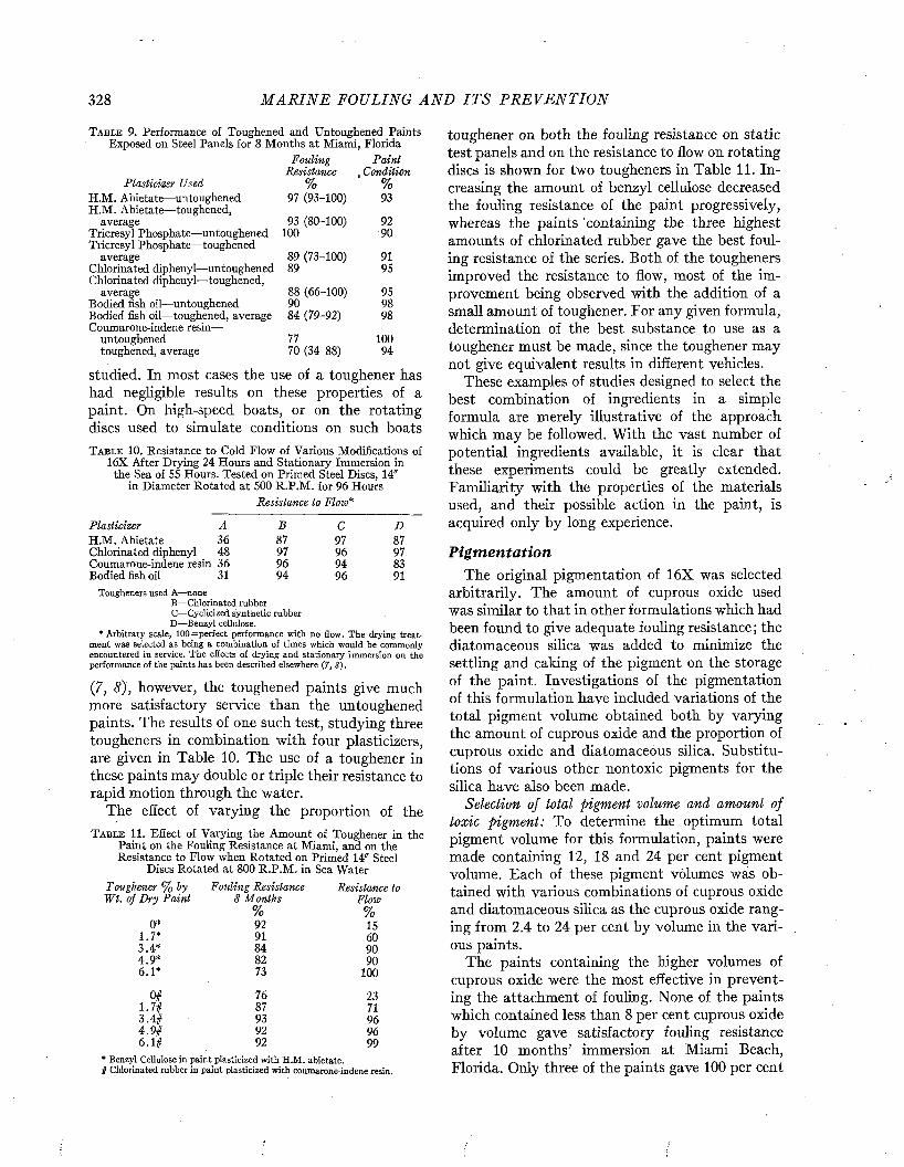
328 M A R I N E FOULING A N D I T S P R E V E N T I O N
T a b l e 9 . Performance of Toughened and Untoughened Paints Exposed on Steel Panels for 8 Months at Miami, Florida
Fouling P ain tResistance , Condition
Plasticizer Used % %H.M. Abietate—untoughened 97 (93-100) 93H.M. Abietate—toughened,
average 93 (80-100) 92Tricresyl Phosphate—untoughened 100 90Tricresyl Phosphate—toughened
89 (73-100)average 91Chlorinated diphenyl—untoughened 89 95Chlorinated diphenyl—toughened,
average 88 (66-100) 95Bodied fish oil—untoughened 90 98Bodied fish oil— toughened, average 84 (79-92) 98Coumarone-indene resin—
untoughened 77 100toughened, average 70 (34-88) 94
studied. In most cases the use of a toughener has had negligible results on these properties of a paint. On high-speed boats, or on the rotating discs used to simulate conditions on such boatsT a b l e 10. Resistance to Cold Flow of Various Modifications of
16X After Drying 24 Hours and Stationary Immersion in the Sea of 55 Hours. Tested on Primed Steel Discs, 14"
in Diameter Rotated at 500 R.P.M . for 96 Hours Resistance to Flow*
Plasticizer A B C DH.M. Abietate 36 87 97 87Chlorinated diphenyl 48 97 96 97Coumarone-indene resin 36 96 94 83Bodied fish oil 31 94 96 91
Tougheners used A—noneB—Chlorinated rubber C— Cyclicized synthetic rubber D —Benzyl cellulose.
* Arbitrary scale, 100=perfect performance with no flow. The drying treatment was selected as being a combination of times which would be commonly encountered in service. The effects of drying and stationary immersion on the performance of the paints has been described elsewhere (7, 8).
(7, 8), however, the toughened paints give much more satisfactory service than the untoughened paints. The results of one Such test, studying three tougheners in combination with four plasticizers, are given in Table 10. The use of a toughener in these paints may double or triple their resistance to rapid motion through the water.
The effect of varying the proportion of theT a b l e 11. Effect of Varying the Amount of Toughener in the
Paint on the Fouling Resistance at Miami, and on the Resistance to Flow when Rotated on Primed 14" Steel
Discs Rotated at 800 R.P.M . in Sea WaterToughener % by Fouling Resistance Resistance toW t. of D ry P ain t 8 M onths Flow
% %0* 92 15
1.7* 91 603.4* 84 904.9* 82 906.1* 73 100
0# 76 231.7# 87 713.4# 93 964.9# 92 966.1# 92 99
* Benzyl Cellulose in paint plasticized with H .M . abietate.# Chlorinated rubber in paint plasticized with coumarone-indene resin.
toughener on both the fouling resistance on static test panels and on the resistance to flow on rotating discs is shown for two tougheners in Table 11. Increasing the amount of benzyl cellulose decreased the fouling resistance of the paint progressively, whereas the paints containing the three highest amounts of chlorinated rubber gave the best fouling resistance of the series. Both of the tougheners improved the resistance to flow, most of the improvement being observed with the addition of a small amount of toughener. For any given formula, determination of the best substance to use as a toughener must be made, since the toughener may not give equivalent results in different vehicles.
These examples of studies designed to select the best combination of ingredients in a simple formula are merely illustrative of the approach which may be followed. With the vast number of potential ingredients available, it is clear that these experiments could be greatly extended. Familiarity with the properties of the materials used, and their possible action in the paint, is acquired only by long experience.
P igm en ta tionThe original pigmentation of 16X was selected
arbitrarily. The amount of cuprous oxide used was similar to that in other formulations which had been found to give adequate fouling resistance; the diatomaceous silica was added to minimize the settling and caking of the pigment on the storage of the paint. Investigations of the pigmentation of this formulation have included variations of the total pigment volume obtained both by varying the amount of cuprous oxide and the proportion of cuprous oxide and diatomaceous silica. Substitutions of various other nontoxic pigments for the silica have also been made.
Selection of total pigment volume and amount of toxic pigment: To determine the optimum total pigment volume for this formulation, paints were made containing 12, 18 and 24 per cent pigment volume. Each of these pigment volumes was obtained with various combinations of cuprous oxide and diatomaceous silica as the cuprous oxide ranging from 2.4 to 24 per cent by volume in the various paints.
The paints containing the higher volumes of cuprous oxide were the most effective in preventing the attachment of fouling. None of the paints which contained less than 8 per cent cuprous oxide by volume gave satisfactory fouling resistance after 10 months’ immersion at Miami Beach, Florida. Only three of the paints gave 100 per cent

TH E DESIGN OF A N T I F O U L I N G P A I N T S 329
fouling resistance at this time, and these contained 18, 19.2, and 24 per cent cuprous oxide by volume. Lower toxic pigment volumes gave progressively poorer results, as shown in Table 12. The presence or absence of diatomaceous silica appears to have a negligible influence on the fouling resistance of the formulation.
As the total pigment volume of this formulation is increased, the physical condition of the paint appears to improve slightly. Thus, the average condition of the paint film, after 10 months’ immersion, for pigment volumes of 12, 18, and 24 per cent, are 80, 86, and 88 per cent, respectively. There is no evidence that the proportion of silica to cuprous oxide has any influence on the physical performance of the paint in any of the groups containing the same pigment volume.
Type of nontoxic pigment: Babel (2) has shown that a wide variety of nontoxic pigments give satisfactory results in a copper antifouling paint. Others, however, which included talc, clay, mica, and surface-treated precipitated calcium carbonate, showed less promise. Similar results have been found in our experiments with 16X.
The effect of substituting various nontoxic pigments for diatomaceous silica in the 16X formulation was investigated in another experiment. Several extender pigments were found to give better physical performance and better fouling resistance than the silica after six months of immersion. Zinc oxide, Venetian red, and Indian red all gave 100 per cent fouling resistance during the first 6 months of exposure, compared to a fouling resistance of 90 per cent for the paint containing the silica. Only one of the extenders was appreciably poorer than the silica, namely, precipitated chalk. With the exception of precipitated chalk all of the extenders tested gave somewhat better physical performance than the silica during the 6 months’ exposure. The results of this experiment are summarized in Table 13.
To investigate whether a combination of two extender pigments would have more virtue than one alone, zinc oxide was substituted for various amounts of the extender pigments used in the previous experiment. Its presence appeared to have beneficial effects only when combined with precipitated chalk which, as shown above, gave poor results when used alone. In the other paints there was no consistent indication that the presence of zinc oxide was beneficial.
With regard to the appropriate pigmentation of 16XM, these experiments show that a pigment volume of 24 per cent and a toxic volume of 16
Miami Beach, FloridaCuvO Fouling P ain t
Volume, % * Resistance % Condition12 80 759 .6 75 828 75 806 84 854 ' ** **2 .4 ** **
18 100 9014.4 91 8212 83 829 35 906 ** **3 .6 ** **
24 100 8819.2 100 9116 (16XM) 93 8512 94 908 85 884.8 0 88
T a b l e 12 . Fouling Resistance and Condition of the Antifouling Paint Film of Paints Containing Various Amounts of Silica
and Cuprous Oxide after 10 Months’ Immersion at
Total Pigm ent Volume, %
12
18
2 4
* Rem ainder of pigm ent is diatomaceous silica.** Test terminated after 7 months because of severe fouling on the panel.
per cent or more give the best results. A paint containing 24 per cent cuprous oxide by volume is satisfactory but probably wasteful. The silica may be increased to as much as one-third of the total pigment without detriment to the performance of this paint. Though diatomaceous silica is satisfactory it does not appear to be as good as magnesium silicate, Venetian red, Indian red, zinc oxide, or barytes. It is appreciably better than precipitated chalk.
The various experiments described show that the original formula 16X can be greatly improved. Although its resistance to fouling is excellent, its physical properties are too poor for prolonged service on fast boats. The resistance to water erosion can be improved greatly by adding a toughening agent to the film. Changes in the composition of the pigment may also improve both the physical and antifouling properties of the paint.
The experiments presented in this chapter are merely illustrative of the types of investigation necessary to study a formulation. A brief review of the principal questions which require investigation may be useful.T a b l e 13 . Effect of Substituting Various Pigments for Diatoma
ceous Silica on the Fouling Resistance and Condition of the Antifouling Paint Film After Exposure for Six Months
at Miami Beach, Florida
Pigm ent Used Diatomaceous silica Magnesium silicate Venetian red Indian red Zinc Oxide BarytesPrecipitated Chalk
Fouling Resistance %9 093
100100100
9 550
P ain t Condition %8 5
1009 08 9 889 0 8 4

330 M A R I N E FOULING A N D I T S P R E V E N T I O N
In the design of a paint with an insoluble matrix it is necessary to determine: 1.) the volume loading of toxic required to insure adequate leaching rates, and 2.) the optimum pigment volume for adequate physical performance. The vehicle used must be tough enough to form an adequate binder for the volume of pigment required.
In the design of a paint with a soluble matrix, the volume of toxic required to insure adequate leaching rates will vary inversely with the rate of solution of the matrix. For any given paint the volume of toxic and the total pigment volume to give optimum results must be determined. To select the matrix composition, variations in the proportion of soluble resin to insoluble resins should be studied. An increase of plasticizers will cause less decrease in the rate of solution of the matrix than will an equal increase of harder materials used to toughen the film. Appropriate juggling of these three constituents will give a matrix of any desired solution rate, within limits, and the pigment content of each matrix will vary accordingly.
REFERENCES1. B a b e l , V. S. A Study of the Effects of Various Extenders in
Antifouling Paints. New England Club Off. Dig. Fed. Paint & Varn. Prod. Clubs, #240, 1944 (Publ. 704 Weight- man Bldg., 1524 Chestnut St., Phila., Pa.).
2. Bakelite Corporation, Research and Development Department. Studies of Anti-Corrosive and Anti-Fouling Coating Systems for Shipbottoms. Terminal Report to N.D.R.C. OSRD No. 6649, April 5, 1946. (Unpublished)
3. F e r r y , J. D ., and B. H. K e t c h u m . Action of AntifoulingPaints. III. Maintenance of the Leaching Rate of Antifouling Paints Formulated with Insoluble, Impermeable Matrices. Ind. Eng. Chem., 38, 806-810, August, 1946.
4. K e t c h u m , B. H., and J. C. A y e r s . Action of AntifoulingPaints. VI. Effect of Nontoxic Pigments on the Performance of Antifouling Paints. Ind. Eng. Chem., 40, 2124-2127, 1948.
5 . K e t c h u m , B . H ., J . D. F e r r y , a n d A. E . B u r n s , J r . Actionof Antifouling Paints. IV. Maintenance of Leaching Rate of AF Paints Formulated with Soluble Matrices. Ind. Eng. Chem., 38, p. 931, September, 1946.
6. Navy Department Spec. 52-P-61, Paint, Antifouling (for low-speed wood-bottom boats).
7. S m ith , F/G . W., C. M. W e i s s , and B. H. K e t c h u m . The Performance of Paints made to 16X Formulations with Added Tougheners. Interim Report X II from Woods Hole Oceanographic Institution to the Bureau of Ships, Dec. 15, 1944. (Unpublished)
8. W e i s s , C. M., and B . H . K e t c h u m . Effect of Thickness ofApplication and Time Before Motion Through the Water on the Performance of 143. Interim Report VI from Woods Hole Oceanographic Institution to Bureau of Ships, March 17, 1945. (Unpublished)
9. Woods Hole Oceanographic Institution. Monthly Progress Reports to Bureau of Ships dated September 8, 1945; October 15, 1945. (Unpublished)
10. Y o u n g , G. H., and W. K. S c h n e i d e r . Heavy Metal Compounds as Toxic Agents. Ind. Eng. Chem., 35, 436-438,1943.
11. Y o u n g , G. H ., W. K. S c h n e i d e r , a n d G. W. S e a g r e n . Antifouling Paints, Effect of Inert Pigment on Antifouling Action. Ind. Eng. Chem., 36, 1130-1132, 1944.
/

Marine Fouling and Its Prevention,Contribution No. 580 from the Woods Hole Oceanographic Institute
Copyright 1952 by U. S. Naval Institute, Annapolis, Maryland George Banta Publishing Co., Menasha, WI
CHAPTER 20
The Testing of Antifouling PaintsTests are applied to antifouling paints for two
different purposes. The paint chemist uses them as a guide in designing and improving his formulations. The ship owner needs them to determine whether specifications are met in an acceptable way. A different program of testing is required depending upon which of these objectives is desired. This chapter will attempt to define the purposes and virtues of the various test procedures used, and to point out the precautions and conditions which must be observed in order to obtain useful results. The Appendix presents directions for some tests which have been developed recently and are not adequately described in other publications. Other tests, well known to the paint industry and described elsewhere, are also necessary for the complete study of paints.
The problem most frequently confronting the paint chemist is the modification or improvement of a standard formulation. Chemical technology is constantly producing new materials which may be used to advantage. Changes of composition may be required because of cost or availability of certain ingredients. During periods of war this problem becomes acute because of shortages which develop in materials previously used. The modification of a formulation may affect its physical, chemical, or biological characteristics, and the testing program should be designed to survey these properties, and to eliminate the more unsatisfactory paints by relatively simple procedures. The more time consuming, expensive, and elaborate tests which require exposure in the sea should be applied only to formulations which preliminary tests indicate will give adequate performance.
The character of a paint depends upon the proportions of the several ingredients it contains. A large number of experimental formulations are required in order to define the characteristics of any given combination of ingredients accurately. The greater the number of ingredients, the larger the number of possible variations. The properties of the paint may be changed systematically either by varying the proportion of one ingredient to all the others, or by varying the proportions of two ingredients, leaving the others unchanged. To insure a complete test of the combination, and to determine the limits of effectiveness, each com
ponent should be varied to the point where it gives unsatisfactory results. The less satisfactory formulations are successively eliminated as each test or group of tests is completed.
The preliminary tests should eliminate those formulations which may be expected to give poor physical performance and those which will not release the toxic embedded within the paint film. These include the accelerated laboratory tests and can be performed on large numbers of paints with little expenditure of time and effort. The paints which give the best results on the preliminary tests are submitted to selective survey tests. These determine, under natural marine conditions, the length of time the paint will maintain an adequate rate of toxic release and prevent the attachment of fouling. Its adhesion and other physical properties are also defined by these tests. The results may explain the reasons for the failure of the less satisfactory paints, and suggest the kind of modification required to obtain the best formulation. The conditions of application which will give optimum performance of the few best formulations may then be studied in order to determine the precautions which must be observed to avoid failures and unsatisfactory results. The performance of the paint should finally be compared to that of similar paints, or ones previously used, on the type of vessel and under the conditions for which it is designed.
If the object of the tests is merely to determine whether a given paint meets specifications, or is more satisfactory than the paints in use, many of these tests may be omitted. The panel test, to determine the ability of the paint to prevent fouling, and service tests, to compare the performance of the paint with that of its predecessor, are the most useful. If results are required quickly, or if several paints are under consideration, the accelerated chemical tests will be useful in eliminating the copper paints which release toxic too slowly.
PRELIM INARY ELIMINATION TESTSThese tests are applied to the entire group of
formulations and eliminate those which will be unsatisfactory because of poor physical qualities or inability to release sufficient toxic to prevent
331
332 M A R I N E FOULING A N D I T S P R E VE N T IO N
fouling. They do not eliminate the wasteful paints which release toxic too rapidly with a resultant short life. They include accelerated laboratory tests which can be performed quickly on a large number of samples.
Physical TestsThe physical tests include determinations of
flexibility, hardness, and adhesion. All of the paints should be adjusted to a similar viscosity so that uniform ease and thickness of application may be obtained. These tests are adequately described in standard works and will not be reviewed here (14).
Chem ical TestsAccelerated chemical tests have been developed
which eliminate many unsatisfactory formulations of copper paints. They are designed to determine whether a paint is capable of releasing the toxic embedded within the film. The tests are based on the assumption that the dissolution of paint ingredients is accelerated in artificial aging solutions in the laboratory in a way related to the rate of dissolution in the sea. Acid solutions, or ones containing a substance which will form a soluble copper complex, are used to accelerate the dissolution of copper or cuprous oxide; alkaline solutions are used to accelerate the dissolution of the matrix. The theory of toxic release upon which these tests are based is discussed in Chapter 16. Two such accelerated tests have been developed for paints containing copper as the toxic. They are not applicable to paints which depend upon other materials for their toxicity.
The Acid-Alkali TestThis test was designed by investigators of the
Mare Island Naval Shipyard (6), and depends upon two successive extractions of a paint film applied to a panel. The first of these extractions is in sea water acidified to pH 4 with hydrochloric acid. Under these conditions the cuprous oxide exposed on the paint surface is dissolved rapidly, but the dissolution of the matrix is negligible. After the exhaustion of the surface-exposed toxic, the leaching rate in sea water is determined. The panel is then transferred to a bath containing tap water adjusted to pH 10.5 with sodium hydroxide. In this alkaline solution the soluble components of the matrix dissolve rapidly and thus uncover stores of cuprous oxide which were originally buried within the paint film. After the panel has
been rinsed, the copper leaching rate in sea water is measured again.
Comparison of the leaching rates after the successive treatments with the acid and alkaline solutions indicate whether the matrix has been dissolved by the alkaline solution.
1.) If the leaching rates in sea water are low after both the acid and alkaline treatments, the matrix of the paint was not soluble in the alkaline solution, and will not dissolve in sea water. This indicates that the paint will not maintain an adequate leaching rate in the sea. These formulations may be eliminated from the further tests, since experience shows that they are invariably unsatisfactory.
2.) If the leaching rate in sea water is low after the acid extraction and high after the alkaline treatment, the matrix of the paint was dissolved by the alkaline solution. This indicates that the paint will permit continuous extraction of the toxic by sea water and should be tested further.
3.) If the leaching rate in sea water is high after the acid treatment the release of the toxic does not depend on the solubility of the matrix. This indicates, however, that the toxic is available and suggests that the paint may be effective because of some other mechanism. A permeable paint, one with toxic particles in continuous contact, or one with a matrix whose solubility is unaffected by the pH of the solvent may behave in this way. These paints must be tested further to determine their effectiveness.
The details of the acid-alkali test are given in the Appendix of this chapter.
Glycine TestSodium glycinate at pH 10.5 rapidly dissolves
both copper or cuprous oxide and a soluble matrix simultaneously (19, 23). The high pH accelerates the rate of solution of the matrix ingredients; the dissolved copper is kept in solution as copper glycinate complex. A paint capable of liberating copper at an adequate rate in the sea will liberate several thousand micrograms per square centimeter during three days in this solution, irrespective of whether the release of toxic depends on a soluble matrix or continuous contact of toxic particles. The acceleration factor is about one hundredfold, so that three days’ extraction in sodium glycinate is equivalent to almost a year of extraction in the sea.
The results of the test can be evaluated by determining the amounts of copper and of matrix dissolved in the glycine solution. The copper can be
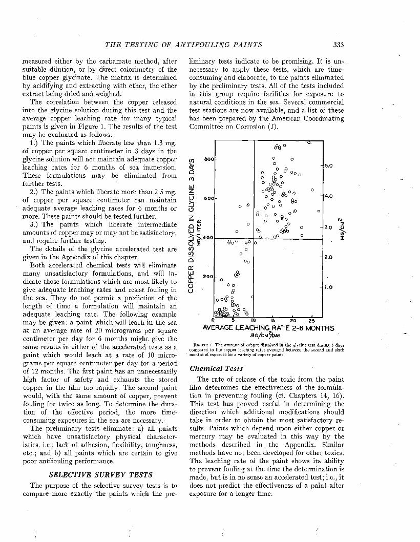
TH E T E ST IN G OF A N T I F O U L I N G P A I N T S 333
measured either by the carbamate method, after suitable dilution, or by direct colorimetry of the blue copper glycinate. The matrix is determined by acidifying and extracting with ether, the ether extract being dried and weighed.
The correlation between the copper released into the glycine solution during this test and the average copper leaching rate for many typical paints is given in Figure 1. The results of the test may be evaluated as follows:
1.) The paints which liberate less than 1.3 mg. of copper per square centimeter in 3 days in the glycine solution will not maintain adequate copper leaching rates for 6 months of sea immersion. These formulations may be eliminated from further tests.
2.) The paints which liberate more than 2.5 mg. of copper per square centimeter can maintain adequate average leaching rates for 6 months or more. These paints should be tested further.
3.) The paints which liberate intermediate amounts of copper may or may not be satisfactory, and require further testing.
The details of the glycine accelerated test are given in the Appendix of this chapter.
Both accelerated chemical tests will eliminate many unsatisfactory formulations, and will indicate those formulations which are most likely to give adequate leaching rates and resist fouling in the sea. They do not permit a prediction of the length of time a formulation will maintain an adequate leaching rate. The following example may be given: a paint which will leach in the sea at an average rate of 20 micrograms per square centimeter per day for 6 months might give the same results in either of the accelerated tests as a paint which would leach at a rate of 10 micrograms per square centimeter per day for a period of 12 months. The first paint has an unnecessarily high factor of safety and exhausts the stored copper in the him too rapidly. The second paint would, with the same amount of copper, prevent fouling for twice as long. To determine the duration of the effective period, the more time- consuming exposures in the sea are necessary.
The preliminary tests eliminate: a) all paints which have unsatisfactory physical characteristics, i.e., lack of adhesion, flexibility, toughness, etc.; and b) all paints which are certain to give poor antifouling performance.
SELECTIVE SU RVEY TESTSThe purpose of the selective survey tests is to
compare more exactly the paints which the pre
liminary tests indicate to be promising. It is unnecessary to apply these tests, which are time- consuming and elaborate, to the paints eliminated by the preliminary tests. All of the tests included in this group require facilities for exposure to natural conditions in the sea. Several commercial test stations are now available, and a list of these has been prepared by the American Coordinating Committee on Corrosion (1).
if)kQmLdzobo
eoo
6 0 0
aLd
5oif)if)a a:LdCLa.Ou
a: ui t> 400 2
2 0 0
o .cp9 °
- O o o
° o ƒ ° O o° 8 o °
Q O
0
i
°° ? 3 > * 0 ° ° _
° O g o o 0 °
8 o o e 0 , 9
» ° 8 : » .o
°°$
o c
____
_1
loooCD 00
O
o o
. oO 0
<?o o # !
% % 1 . 1 . 1
5 .0
4 .0
«M3 .0 . 5
o' 5
2.0
1.0
,0 5 IO 15 2 0 2 5
AVERAGE LEACHING RATE 2-6 MONTHS
F i g u r e 1. The amount of copper dissolved in the glycine test during 3 days compared to the copper leaching rates averaged between the second and sixth months of exposure for a variety of copper paints.
Chem ical TestsThe rate of release of the toxic from the paint
film determines the effectiveness of the formulation in preventing fouling (cf. Chapters 14, 16). This test has proved useful in determining the direction which additional modifications should take in order to obtain the most satisfactory results. Paints which depend upon either copper or mercury may be evaluated in this way by the methods described in the Appendix. Similar methods have not been developed for other toxics. The leaching rate of the paint shows its ability to prevent fouling at the time the determination is made, but is in no sense an accelerated test; i.e., it does not predict the effectiveness of a paint after exposure for a longer time.
334 M A R I N E FOULING A N D I T S P R E V E N T I O N
As stated in Chapter 14, a copper leaching rate of 10 micrograms per square centimeter per day has been found adequate to prevent fouling (3, 19, 21). Mercury leaching rates in excess of 2.0 micrograms per square centimeter per day are adequate, (28, 29, 30). Barnes (4) finds that when the mercury is released as a soap, which may be formed in some paints, leaching rates of 6 /¿g./cm.2/d a y may be inadequate to prevent attachment of fouling.
The change of leaching rate with time can be measured most easily by periodic determinations of the rate of release of the toxic in the laboratory under controlled conditions, using panels soaked in the sea between determinations (21, 29, 30). This procedure requires fairly convenient seaside facilities so that the panels can be brought into the laboratory without drying and without too long a period in a stagnant tank of sea water. Soaking the panels in a limited volume of sea water is not comparable to soaking in the sea because of the excessive concentration of toxic or matrix ingredients that will ultimately develop under these conditions. If convenient seaside facilities are not available, an average estimate of the leaching rate of the paint can be obtained by analyzing the toxic remaining on the panel after various periods of exposure (22, 28). Several painted panels can be immersed in the sea at any location, successive specimens being removed, dried, and returned to the laboratory at intervals for analysis. To give significant results, the paint must lose an appreciable proportion of its toxic during the exposure. With a paint containing a large reserve of toxic, this may require a long period of immersion, during which time the leaching rate may change greatly. The paint analysis technique is, therefore, not always satisfactory as a method for determining the leaching rate.
M ost antifouling paints which fail to prevent fouling do so either because the toxic is bound within the film and no adequate mechanism for its release is provided, or because of exhaustion of the toxic in the film. The paints in the former group will have been eliminated by the preliminary tests. Even the best antifouling paints are effective only for a finite period of time, after which they release toxic more slowly and are liable to foul. The duration of the effective life of a paint is determined by the rate of release of toxic and by the available store of toxic within the film. The best paints have a nearly constant leaching rate which is high enough to prevent fouling with a reasonable factor of safety, but not so high as to cause the
premature exhaustion of the surface. These characteristics are indicated by the leaching rate test.
Barnes (3) has compared the results of leaching rate tests with the loss of cuprous oxide from raft- exposed panels and service applications. The rate of loss under service conditions was greatest. The leaching rate test indicated 60 per cent, and the panel test 50 per cent, of the actual loss of toxic observed in service. Such results must reflect the erosion of the paint surface as a result of the activity of the ships. Paints with different resistances to erosion would be expected to give different proportions among the three tests.
The leaching rate test should always be conducted simultaneously with tests of fouling resistance of the paints. The results of these two tests can then be accurately correlated.
B iologica l T es tsThe panel test of the resistance of paints to
fouling is perhaps the oldest of the tests applied. It continues to be one of the most important and valuable, provided it is performed under proper conditions. It evaluates the formulation in two important ways : the ability of the paint to prevent fouling, and the physical performance of the paint film or system when exposed to natural conditions in the sea.
In order to give useful results, panels must be exposed in a location where the larvae of fouling organisms are present in the water throughout the year. Nontoxic control surfaces must be submerged simultaneously in order to evaluate the intensity of fouling, which must be known to evaluate the results. If the intensity of fouling at the test location is low for several months of the year, an unsatisfactory paint might appear to be effective for a considerable time. If this same paint were immersed under conditions of high intensity fouling, it might foul immediately. All of the paints which are effective under severe conditions, on the other hand, are invariably effective under less severe conditions. These considerations require that the location of the testing service be in a tropical or subtropical area. The seasonal occurrence and intensity of fouling at various locations are described in Chapter 5.
In contrast to the panel tests, the leaching rate tests can be performed in a location or at a time at which the intensity of fouling is low. This is actually an advantage, since the unsatisfactory paints do not become fouled and their leaching rates can be measured more accurately.
Several methods of rating panels for resistance
TH E TEST IN G OF A N T I F O U L I N G P A I N T S 335
to fouling and for physical performance have been devised. All of these methods probably give equivalent and satisfactory results, provided ratings are made by the same observers for each series. Intercomparison of the various systems is difficult since none of them depends entirely upon objective measurements. The biological fluctuations between places and from time to time are so great that the results may vary considerably even with the same paint. The only valid direct comparisons of paint performance are those for exposures in the same location at the same time.
Generally, the paints either completely prevent attachment or fail completely shortly after attachment starts. Under conditions of continuous high intensity fouling, the length of time a formulation gives complete or nearly complete protection from fouling attachment is probably the most useful criterion. The panels should, however, be rated periodically in order to determine the trend of changes in effectiveness.
Two types of rating systems are in use, the direct and the weighted rating. The direct ratings may assess the number of individuals attached or the percentage of surface area covered. The weighted ratings attempt to give different penalties depending upon the type of organism found. The weighting may be based upon the importance of the various organisms to ship resistance or other practical considerations, or on their tolerance for the toxic used. Since we do not have adequate data on either of these points, the weighted ratings are more subjective than the direct ratings. They always exaggerate the effect of differences in the composition of the fouling community present at the test site. Thus, if barnacles are rated most severely, a test location where barnacles are rare would inevitably give a better rating for a paint than a location where barnacles are present in large numbers.
The physical condition of the paint film is rated on the basis of blistering, cracking, checking, alligatoring, or adhesion failure. This is generally based upon the area of the panel affected by the type of failure observed. If the paint is applied to steel over a suitable anticorrosive system, ratings are also given for the prevention of corrosion and the performance of the anticorrosive coating.
The methods of exposure and a description and evaluation of several rating systems are given in the Appendix to this chapter.
As a result of the selective survey tests, a few of the formulations are chosen for additional study. For a given type of formulation these should not
exceed half a dozen paints. Sometimes only the most promising paint is selected for further test. The selected paints are studied to determine the optimum conditions of application and exposure.
CONDITIONS OF APPLICATIONThe results of tests to determine the optimum
conditions of application culminate in the directions for use which are provided the consumer to insure that he will obtain the best performance the paint is capable of giving. Investigations of the optimum drying time prior to immersion, the optimum thickness of application, and the effect of the conditions of the surface on the adhesion of the paint are made. If carried out extensively these tests can be extremely time-consuming. Certain generalizations can be made which may simplify the investigations.
1. Thickness of application: Increasing the thickness of coatings which operate because of a soluble matrix will prolong their effective life. When applied over steel, the prevention of corrosion invariably improves as the paint film thickness is increased. The primary disadvantage of increasing the film thickness is that longer drying is necessary to permit the evaporation of the solvent. This may prolong the time in dock, especially if multiple coats are to be applied. Furthermore, the thicker the film, the more difficult it is to prevent sagging and other physical failures of the paint.
2. Drying time: The importance of drying time as a factor influencing the fouling resistance of a paint has probably beeny unduly emphasized. The conditions under which the paint is dried may be more important than the actual time of drying. Direct sunlight, for example, may result in the formation of a skin on the paint surface which sometimes retards the leaching of copper for a short period. With modern paints it is not necessary to undock the vessel immediately after the application of the antifouling coating. Prompt undocking generally does no serious harm and has the advantage that it frees the dock quickly. The paint must, however, be given sufficient time to harden adequately before the ship gets under way. Otherwise, cold flow of the paint film will result (34). Hardening will continue either during drying in air or during stationary immersion in the sea. The hardening period must be lengthened as the thickness of the paint film is increased.
3. Surface preparation: The problem of surface preparation for the application of shipbottom paints is similar to those problems which arise with

336 M A R I N E FO ULI NG A N D I T S P R E V E N T I O N
any protective coating. Some paint systems give the best results if the ship is cleaned to the bare hull; others appear to benefit if applied over old, firmly adhering paint films.
The evaluation of the experiments performed in this category may utilize any of the tests mentioned above. Both the leaching rate and panel tests have been used. The ability of the paint to resist cold flow can be tested by accelerated methods. One of these, designed by the Norfolk Naval Shipyard (25), uses a cylinder which is rotated in the sea with a surface speed of about 29 knots. Discs rotated under water at a peripheral speed of 30 knots have been used at Miami (32, 34). Both of these tests are described in the Appendix.
SERVICE TESTSThe selection of the best formulation must al
ways depend upon the performance of the paint on the type of vessel and under the conditions of service for which it is designed. Such service tests are the most expensive and time-consuming of all. Two methods are commonly used in designing and executing the service tests. One of these compares two paints on the same vessel by applying them to opposing sections of the hull of the ship. Thus, the port bow and starboard quarter are coated with one paint, and the starboard bow and port quarter with the comparison paint. This system provides large areas which are easily painted, eliminates positional effects which are dependent upon the normal docking or mooring position of the vessel, and gives four junctions where the paint performances may be directly compared. In order to get a statistically dependable result, several vessels must be used. This has the advantage of testing the paint under different conditions of service and exposure.
The application of several patches of two or more test paints or systems permits several different comparisons on the same vessel. All of the applications, however, are submitted to the same conditions of exposure, and several vessels must be used if exposure and service are also to be evaluated. To obtain the most useful results, the patches should be as large as possible while still giving an adequate number of comparisons. The application of a patch test uses less of the experimental paints, but requires careful supervision, and this frequently results in more careful preparation of the surface where these tests are applied. The bow and quarter test, on the other hand, is
generally no more difficult to apply and requires little more supervision than an over-all application of a single paint or system.
Since the service tests must be waterborne for considerable periods before the results can be observed, and since they are relatively expensive to apply, they are not useful in studying a large number of paints. AH of the unsatisfactory formulations should have been eliminated on one count or another before service tests are attempted. This applies, whether the object is to aid in the development of a new formulation or the determination of the best formulation for a given service. Generally not more than two paints should be compared in any service test or group of tests, and it is obvious that reasonable assurance should be had that the new paint is as good as, or better than, its predecessor before these tests are undertaken.
The use of the selected paint in standard procedure and service may be considered the final test for an antifouling paint. Adequate means of comparing the results obtained with those of similar or previously used paints should be provided. This requires the inspection of the ship at each docking period, and the comparison of successive reports.
APPENDIX Acid-Alkali Accelerated Leaching Test (6)
The paint is first extracted for 4 days in sea water acidified to pH 4.0 with hydrochloric acid in order to remove surface available copper. After washing, the copper leaching rate in sea water is determined. The panel is then stirred in a bath of tap w ater adjusted to pH 10.S with sodium hydroxide, and another leaching rate in sea water measured after appropriate washing with tap water.
I. Panels: A ground glass panel (7.5X10 cm.) is painted on both sides and dried for 4 hours.
II. A cidified sea water extraction: The painted panel is immersed in a beaker containing 1 , 0 0 0 ml. of sea water acidified to pH 4.0 with hydrochloric acid. The pH is determined with a glass electrode pH meter. The acidified sea water is replaced daily, and the extraction is continued for 4 days, or until little additional solution of copper occurs (cf. Fig. 13, Chapter 16).
I II . Leaching rate determ ination: The panels are rinsed in tap water, then in sea water. Each panel is then attached to a shaft of the rotating device illustrated in Figure 2, where it is held in a slot in a rubber stopper by rubber bands. A beaker containing 1,500 ml. of sea water is moved into position so th a t the panel is completely submerged. A water jacket, through which tap water at 25°C. is circulated, surrounds the beaker. The motor, geared to rotate the panels a t 100 r.p.m., is then started. The amount of copper dissolved in the sea water during one hour is meas-
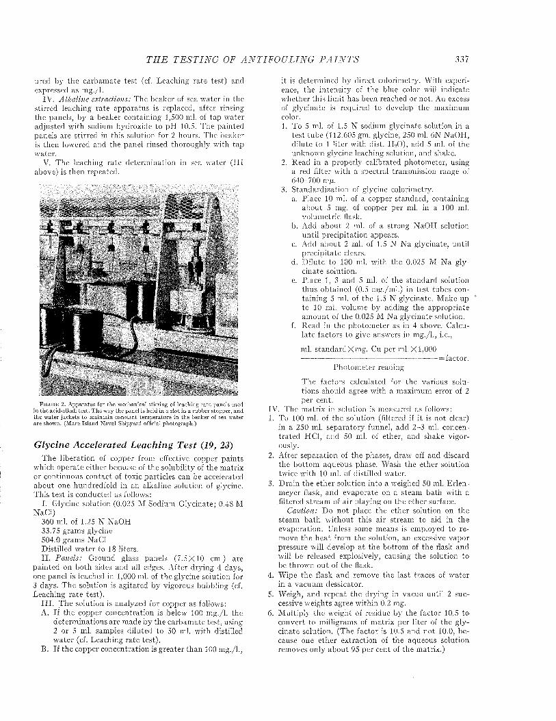
T H E T E S T I N G OF A N T IF O U L IN G P A I N T S 337
ured by th e carbam ate te s t (cf. L eaching ra te test) and expressed as m g./I.
IV . A lka line extractions: T he beaker of sea w ater in the stirred leaching ra te appara tu s is replaced, a fter rinsing th e panels, b y a beaker containing 1,500 ml. of tap w ater ad justed w ith sodium hydroxide to p H 10.5. T he pain ted panels are stirred in th is solution for 2 hours. T he beaker is then low ered and the panel rinsed thoroughly w ith tap w ater.
V. T he leaching ra te de term ination in sea w ater ( I I I above) is then repeated.
F i g u r e 2 . A pparatus for the m echanical stirring of leaching ra te panels used in the acid-alkali te st. T h e w ay the panel is held in a slot in a rubber stopper, and the w ater jackets to m ain tain constant tem peratu re in th e beaker of sea water are shown. (M are Island N aval Shipyard official photograph.)
Glycine Accelerated Leaching Test (19, 23)T he libera tion of copper from effective copper pa in ts
which operate either because of the solubility of the m atrix or continuous con tac t of toxic partic les can be accelerated ab o u t one hundredfold in an alkaline solution of glycine. T h is te s t is conducted as follows:
I. G lycine solution (0.025 M Sodium G lycinate: 0.48 M N aC l)
360 ml. of 1.25 N N aO H 33.75 gram s glycine 504.0 gram s N aC l D istilled w ate r to 18 liters.I I . Panels: G round glass panels (7 .5X 10 cm.) are
pa in ted on bo th sides and all edges. A fter d rying 4 days, one panel is leached in 1,000 ml. of th e glycine solution for 3 days. T he solution is ag ita ted by vigorous bubbling (cf. Leaching ra te test).
I I I . T he solution is analyzed for copper as follows :A. I f th e copper concentration is below 100 m g./I. the
dete rm ina tions are m ade by th e carbam ate test, using 2 or 5 ml. sam ples d ilu ted to 50 ml. w ith distilled w a te r (cf. Leaching ra te tes t).
B. I f th e copper concentration is g rea te r th a n 100 m g ./l.,
it is determ ined by d irect colorim etry. W ith experience, the in ten sity of th e blue color will indicate w hether th is lim it has been reached or not. An excess of g lycinate is required to develop the m axim um color.1. To 5 ml. of 1.5 N sodium glycinate solution in a
te s t tu b e (112.605 gm. glycine, 250 ml. 6N N aO H , d ilu te to 1 lite r w ith dist. H 20 ) , add 5 ml. of the unknow n glycine leaching solution, and shake.
2. R ead in a property calibrated photom eter, using a red filter w ith a spectral transm ission range of 640-700 trfi.
3. S tandard iza tion of glycine colorim etry.a. P lace 10 ml. of a copper standard , containing
abou t 5 mg. of copper per ml. in a 100 ml. volum etric flask.
b. Add ab o u t 2 ml. of a strong N aO H solution un til p rec ip ita tion appears.
c. A dd ab o u t 2 ml. of 1.5 N N a glycinate, un til p rec ip ita te clears.
d. D ilu te to 100 ml. wuth the 0.025 M N a gly- cinate solution.
e. P lace 1, 3 and 5 ml. of the standard solution thus obtained (0.5 m g ./m l.) in tes t tubes contain ing 5 ml. of the 1.5 N glycinate. M ake up to 10 ml. volum e by adding the appropriate am oun t of th e 0.025 M N a g lycinate solution.
f. R ead in the pho tom eter as in 4 above. C alcula te fac to rs to give answers in m g ./l., i.e.,
ml. s tan d a rd X m g . Cu per m l .X I ,000 -------------------------------------------------------- = faCtor.
P ho tom eter reading
T he fac to rs calculated for th e various solutions should agree w ith a m axim um error of 2 p e r cent.
IV. T he m atrix in solution is m easured as follows:1. To 100 ml. of the solution (filtered if it is no t clear)
in a 250 ml. sep a ra to ry funnel, add 2-3 ml. concentra ted HC1, and 50 ml. of ether, and shake v igorously.
2. A fter separa tion of th e phases, drawr off and discard the bo ttom aqueous phase. W ash th e ether solution tw ice wuth 10 ml. of distilled wrater.
3. D ra in th e e th e r solution in to a wmighed 50 ml. E rlen- m ever flask, and evapora te on a steam b a th wuth a .filtered s tream of air p laying on th e e ther surface.
Caution: D o n o t place th e e ther solution on the steam b a th w ith o u t th is a ir stream to aid in th e evaporation . Unless some m eans is employed to rem ove th e h e a t from th e solution, an excessive vapor pressure will develop a t th e bo ttom of th e flask and will be released explosively, causing th e solution to be throw n o u t of the flask.
4. W ipe th e flask and rem ove the las t traces of w a te r in a vacuum dessicator.
5. W eigh, and repea t th e d rying in vacuo un til 2 successive w eights agree w ith in 0.2 mg.
6. M ultip ly th e w eight of residue by the factor 10.5 to convert to m illigram s of m atrix per lite r of th e g lycinate solution. (T he fac to r is 10.5 and n o t 10.0, because one e th e r ex traction of the aqueous solu tion rem oves only ab o u t 95 per cent of th e m atrix .)
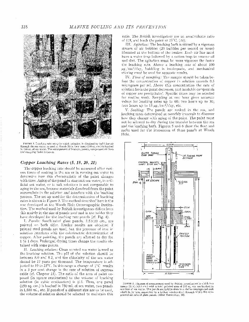
338 M A R I N E FO ULING A N D I T S P R E V E N T I O N
F i g u r e 3. Leaching rate setup in which agitation is obtained by bubbling air through the sea water, as used a t Woods Hole. One panel (150 sq. cm.) is leached in 750 cc. of sea w ater. T h e arrangem ent of beakers, panels, compressed air lines and sampling flasks is shown.
Copper Leaching Rates (5, 18, 20, 21)T he copper leaching ra te should be m easured after v a ri
ous tim es of soaking in the sea or in running sea w ater to determ ine how this characteristic of th e p a in t changes w ith tim e. Aging of the panel in stag n an t sea w ater, in a r t ificial sea w ater, or in salt solutions is n o t com parable to aging in the sea, because m ateria ls dissolved from the pa in t accum ulate in the solution and in terfere w ith the leaching process. T he set-up used for the determ ination of leaching ra tes is shown in Figure 3. T he m ethod described here is the one developed a t the W oods H ole O ceanographic In s titu tion. T he m ethod used by B ritish investigators differs from th is m ainly in the size of panels used and in th e holder they have developed for th e leaching ra te panels (cf. Fig. 4).
I . Panels: Sandblasted glass panels, 7 .5X 10 cm., are p a in ted on bo th sides. Sim ilar resu lts are obtained if prim ed steel panels are used, b u t th e presence of iron in solution interferes w ith the colorim etric de term ination of copper. A fter pain ting , the panels are allowed to d ry for 1 to 4 days. Prolonged drying tim es change th e resu lts obtained w ith some paints.
I I . Leaching solution: Clean aerated sea w ater is used as the leaching solution. T he p H of the solution should be betw een 8.0 and 8.2, and the chlorin ity of th e sea w ater should be 17 p a rts per thousand. T he tem p era tu re is ad justed to 19 to 23°C. In this range a change of 1°C. results in a 3 p e r cent change in th e ra te of solution of cuprous oxide (cf. C hap ter 15). T he ratio of the area of p a in t exposed (in square centim eters) to the volum e of leaching solution (in cubic centim eters) is 1:5. T hus, one panel (150 sq. cm.) is leached in 750 ml. of sea w ater, two panels in 1,500 ml., etc. If panels of a different size are to be used, th e volum e of solution should be selected to m ain ta in this
ratio . T he B ritish investigators use an area: volum e ratio of 1:8, and leach the p a in t a t 25°C. (18).
I I I . Agitation: T he leaching bath is stirred by a vigorous stream of air bubbles (20 bubbles per second or more) liberated a t the b o ttom of th e beaker. E ach a ir line m ust have a w ater tra p followed by a cotton tra p to rem ove oil and d irt. T he ag ita tion m ust be m ore vigorous the faster the leaching rate. A bove a leaching ra te of abou t 100 ¿ig./cnV /day, bubbling is inadequate , and m echanical stirring m ust be used for accura te results.
IV. Tim e of sam pling: T he sam ple should be taken before the concentration of copper in solution exceeds 0.5 m icrogram per ml. A bove th is concentration the ra te of solution from the p a in t decreases, and insoluble com pounds of copper are p rec ip ita ted . Specific tim es m ay be selected for routine work. Sam pling a t one hour gives accurate values for leaching ra tes up to 60; two hours up to 30; four hours up to 15 /xg./cm 2/d a y , etc.
V. Soaking: T he panels are soaked in the sea, and leaching ra tes determ ined a t m on th ly intervals to discover how they change w ith aging of th e pain t. T he p a in t m ust no t be allowed to d ry during th e transfer betw een the sea and th e leaching b a th . F igures 5 and 6 show the float and racks used for th e im m ersion of these panels a t Woods Hole.
G L A 35 TUBING BUM BORE — /./?. TUBING FROM
b l o w e n
C E N T R A L H e o D E N S H A F T Z IC M P IA .'
SLIDINGF I T
S C M
CONK C O R K
AfMM
RIGHT ANGLED BEMO TUBING EXTENDS 2 . 5 0 3
-I0 .5C M '
F i g u r e 4. D iagram of arrangem ent used by B ritish investigators in which two panels (1 1 X 7 X0.3 cm.) w ith a to ta l pain ted area of 250 sq. cm. are leached in one liter of sea w ater. T h e panels are held in slots in a shellac-im pregnated cork which is, in tu rn , supported by a hollow' wmoden shaft through ivhich the compressed air tube of glass passes. (After K enw orthy, 18).
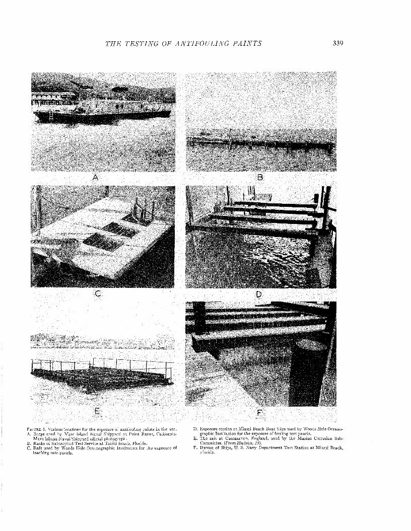
TI IE T E S T I N G OF A N T IF O U L IN G P A I N T S 339
A
WÊ&MmÊiîSgæ æiiâ
F i g u r e 5. Various locations for the exposure of antifouling pain ts in the sea.A. Barge used by M are Island N aval Shipyard a t P o in t Reyes, California.
M are Is lan d N aval Shipyard official photograph.B . R acks of Subtropical T est Service a t T ah iti Beach, F lorida.C. R a ft used by Woods Hole Oceanographic In s titu tio n for the expsoure of
leaching ra te panels.
D . Exposure station a t M iam i Beach B oat Slips used by Woods Hole Oceanographic In s titu tion for the exposure of fouling te st panels.
E . T h e ra f t a t C aernarvon, E ngland, used by th e M arine Corrosion Sub- Com m ittee. (From H udson , 16).
F . Bureau of Ships, U. S. N avy D epartm en t T est S tation a t M iam i Beach, Florida.
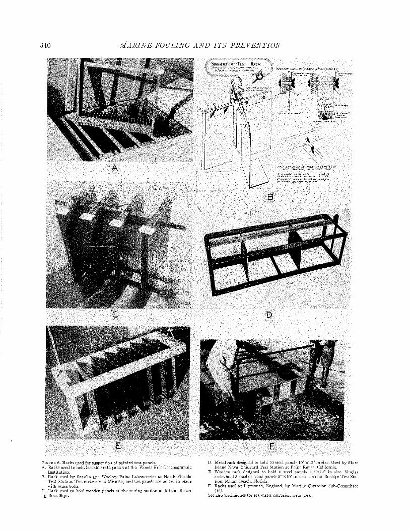
340 M A R I N E FOULING A N D I T S P R E V E N T I O N
i
S u b m e r s io n T e s t Ra c k
4-
ccr/0JV V /£W OP P A M il ArTXCHMfTA77
IM f “Sm*f i *
B
D
' 'i' i®
i
F i g u r e 6. R acks used for suspension of pain ted te s t panels.A. R acks used to hold leaching ra te panels a t the Woods Hole O ceanographic
In s titu tion .B. Rack used by Sapolin and Woolsey P a in t Laboratories a t N orth F lorida
T e st S tation. T h e racks a te of M icarta , and the panels are bolted in place w ith brass bolts.
C. Rack used to hold wooden panels a t the testing station a t M iam i Beach B oat Slips.
D . M eta l rack designed to hold 10 steel panels 10"X12" in size. Used by M are Island N aval Shipyard T est Station a t P o in t Reyes, California.
E. Wooden rack designed to hold 6 steel panels 10"X12" in size. Similar racks hold 8 steel or wood panels 8" X 10" in size. Used a t Buships T est S tation , M iam i Beach, F lorida.
F . Racks used a t P lym outh, England, b y M arine Corrosion Sub-Com m ittee (16).
See also Techniques for sea w ater corrosion tests (24).

THE T E ST IN G OF A N T IF O U L IN G P A I N T S 341
VI. C alculation of leaching rates: The leaching rate is calculated from, the copper concentration by the following equation:
The dilute solution should be prepared fresh each time a standardization is performed,
c. Calculate the factor as follows:
L.R. = m g./l. X-Volume (ml.)
A rea (cm .2) X T im e (hrs.)
For the standard panels and volume this becomes:
120
-X 24 .
L.R. = mg./l. X —;Time (hrs.)
= ,ug./cm.2/day
VII. Copper determ ination— carbamate method: The diethyl dithiocarbam ate colorimetric method described by Callan and Henderson (7) and Coulson (8) is used with only slight modifications.
1. A 50 ml. aliquot of the leaching solution is placed in a 100 ml. volumetric flask. The solution should contain between 0.3 and 2.0 mg. of copper per liter.
2. Add small piece of red litmus paper, 0.5 ml. of a 50% citric acid solution, and 10 to 12 drops of N H 4OH until the solution is neutralized, then add 3 more drops of N H 4OH.
3. Add 2 ml. of the carbamate reagent, (0.1% aqueous solution), and 1 0 ml. of amyl acetate (amyl alcohol or carbon tetrachloride can also be used to extract the copper carbamate complex).
4. Stopper and shake for 5 minutes or longer until all the color is in the acetate layer.
5. Add distilled water to raise the acetate into neck of flask and draw off the acetate layer down to about
inch from water. Filter (to remove water) into a test tube.
6 . Measure copper content in a colorimeter or properly standardized photometer as soon as possible, because the color changes in light, and the evaporation of the acetate will increase the concentration of the colored material. We have used a Klett-Summerson photoelectric colorimeter. For solutions containing between0.3 and 2.0 m g./l., a green filter (No. 54, approximate spectral range 520-580 millimicrons) was used. For solutions containing less than 0.4 m g./l., a blue filter (No. 42, approximate spectral range 400-465 millimicrons) gives more accurate results.
7. Standardization, calculation of factors:a. A strong copper sulfate solution (Cu = 5 mg./ml.)
is made by dissolving a weighed am ount of pure copper m etal in nitric acid, and boiling with two additions of sulfuric acid (to remove nitrates) until white fumes appear. D ilute with about 10 volumes of water and boil again until white fumes appear. D ilute the solution to a known volume, and compare the concentration with any previous standard both by titration with thiosulfate and by the colorimetric method. Record the concentration on the flask in mg./ml. This standard is made in large batches ( 2 liters) and stored in sealed glass containers each one of which contains about 2 0 0 ml.
b. D ilute the standard copper solution (5 mg. Cu per ml.) to obtain a solution containing 0 . 0 1 mg. Cu per ml. Place 5 and 10 ml. samples of this diluted solution in 1 0 0 ml. volumetric flasks, dilute to about 50 ml., and continue steps 1 to 6 above.
ml. of standard X mg. Cu per ml. Photometer reading
= factor (ƒ).
The factor should be calculated separately for each solution, and should agree with all others with an error not greater than 2%. The average factor is used. When calculating copper in terms of mg./l. the above factor should be multiplied by the d ilu - . tion factor. Thus, if a 50 ml. sample is used, 20X /X photom eter reading gives the result in mg. Cu per liter.
d. The calibration must be checked weekly, and also whenever any change in the photom eter (bulb, filters, tubes, etc.) is made.
V III. M ercury determ ination— dithizone method:1 The analysis depends on the reaction of mercury with dithizone (diphenylthiocarbazone) which changes from its normal green to a bright orange color. T itration volumes for the unknown may be compared with those of standards run simultaneously, or the change in color may be measured photometrically (Winkler, 35). The method described below is the one developed by Barnes (2).
1. An aliquot of 92 ml. of the leaching solution is placed in a 250 ml. separatory funnel, 2 ml. 25% by volume H NO 3 added. After shaking, add 1 ml. hydroxylamine hydrochloride, and shake.
2. Add 5 ml. of 10% cobalticyanide solution, shake, and allow to stand 10 minutes. This forms a copper complex, stable in acid solutions, and prevents interference with the analysis.
3. Add 10 ml. of dithizone solution and shake for 1 minute a t approximately four shakes per second. The dithizone is purified by repeated extraction with ammonia (Sandell, 31). A stock solution containing 1
g./l. in chloroform m ay be stored in a refrigerator. This is diluted fiftyfold just before use, giving a final strength of approximately 2 0 mg./l.
4. Insert a roll of filter paper in the stem of the funnel, and draw off the chloroform layer into the photometer cell.
5. Determine transmission in a properly calibrated photometer, using a blue-green filter. Barnes (2) used an Ilford 603 filter in a Spekker Photoelectric Absorptiometer. The reading must be taken rapidly since the color changes when exposed to intense light. The volumes for solution and dithizone m ust be strictly observed, both for unknowns and for standards, in order to obtain the same equilibrium conditions for the dithizone-mercury reaction and for the extraction of the products.
The copper leaching rate measured in this way is characteristic of the paint and is an indication of the am ount of toxic exposed on the paint surface a t the time the determination is made. Variations in the conditions of the test will influence the determined leaching rate value. The most im portant variables include the size of the panels relative to the volume of the leaching solution, the rate of agitation of the bath, and the pH , temperature, and chloride content
1 Barnes (2) describes a method by which both copper and mercury are estimated with dithizone.
342 M A R I N E FOULING A N D I T S P R E V E N T I O N
of the sea water used. The effect of these variables on the solution rate of cuprous oxide has been discussed in Chapter 15. A brief review of these results, indicating where possible the effect which departures from the standard m ethod have upon the leaching rate of the paint, is included here.
In addition to these variables which influence the rate of solution of the exposed toxic, the tem perature of the sea during the soaking period which precedes the determination also influences the value observed. This is probably because it determines the amount of cuprous oxide exposed on the surface of the paint.
I. A rea of pa in t and volume of solution: The am ount of copper dissolved in the leaching bath a t any given time is directly related to the area of the panel, and inversely related to the volume of the solution. The standard method uses a pain t area of 150 square centimeters in a volume of 750 ml. of sea water {21). Any change in area or volume requires the selection of an appropriate time so th a t the value areaX tim e/volum e remains equal to th a t defined in the standard procedure. The relation between the concentration of copper and the value of this quantity has been presented in Figure 11, Chapter 15.
II. R ate of agitation: Experience has shown tha t agitation by means of a stream of air bubbles is adequate for most leaching rate measurements. If the leaching rate of the paint is greater than about 1 0 0 /ug./cm2/day , bubbling is inadequate, since the rate of solution of the cuprous oxide is limited by diffusion. Figure 4, Chapter 15, presents the relation between the rate of mechanical agitation and the leaching rate of two paints with high leaching rates. Since agitation by bubbling gives an adequate measurem ent of the leaching rate up to values about ten times the minimum essential leaching rate, it is satisfactory for all routine procedures.
I II . Tem perature of leaching hath: The rate of solution of .cuprous oxide increases with an increase in the temperature of the leaching bath. The relation between the solution rate of cuprous oxide and temperature is shown in Figures 5 and 6 of Chapter 15. In the vicinity of 20°C. the change in leaching rate is 3'% per degree {10). I t is recommended th a t the leaching rate be measured a t 2 0 °; if, however, it is necessary to measure it a t a different temperature, the following table of correction factors may be found useful.
T a b l e 1. Factors for Correcting Leaching Rates to Standard Temperature (20°C.)
Temperature of Measurement Factor to Correct L.R. io 20°C.0 2.575 2.06
1 0 1.5515 1 . 2 218 1.072 0 1 . 0 02 2 0.9424 0 . 8 826 0.8228 0.7730 0.73
IV. p H of the leaching bath: The rate of solution of cuprous oxide, and consequently the value obtained for the leaching rate of the paint, is directly proportional to the hydrogen ion concentration {10, 12). This relationship is shown in Figure 7, Chapter 15. The solubility of rosin, a common constituent of the matrix of a paint, on the other hand, is directly proportional to the hydroxyl ion concentration (Figures 1 and 2 , Chapter 17). Variations in the
pH of the sea water will, therefore, have a direct effect on the measured leaching rate, including both the effect on the amount of cuprous oxide exposed on the surface after the period of sea soaking, and on the rate of solution of the cuprous oxide in the leaching bath. If clean aerated sea water is used both for the soaking and for the leaching rate bath, the pH will be found to be generally between 8.0 and 8.2. This variation will have little effect on the determined leaching rate. If, however, the pH of the leaching bath is very different from this range, it should be adjusted.
V. Chloride ion content of the leaching hath: The solution rate of cuprous oxide is a linear function of the square of the chloride ion concentration when measured a t a constant ionic strength (Figure 8 , Chapter 15). In sea water diluted with distilled water, however, the leaching rate is proportional to the chloride ion concentration {10, 11, 13). This condition is commonly encountered with sea water diluted with rain or drainage. The sea water used in the leaching bath should have a chloride ion concentration of 17 parts per thousand as determined by the standard method of titration {26). At this chlorinity the specific gravity is 1.0235 a t 17.5°C., referred to distilled water a t the same temperature. If the chlorinity is greater than this, the solution may be diluted the appropriate amount with distilled water. If suitable sea w ater cannot be obtained, the following artificial solution has been found to give approximately similar results with a cold plastic paint: sodium chloride, 0.48 moles per liter (28.0 g. per liter); sodium bicarbonate, 17 mg. per liter; sodium carbonate, 3 mg. per liter, aerated to reach equilibrium with a tmospheric carbon dioxide {20).
VI. Tem perature o f sea during soaking period: The temperature of the sea water in which the panels are soaked will influence the rate of solution of both the m atrix and the toxic. The net result will be to determine the amount of the toxic exposed on the surface, which, in turn, determines the value of the leaching rate measured in the laboratory under standard conditions. The sea temperature during the soaking period may also influence the formation of surface deposits which have been shown to affect the leaching rate, (Figure 15, Chapter 16). I t is impossible to predict, a priori, w hat the net effect of these changes will be upon the leaching rate of the paint. I t has been found th a t the soaking tem perature has little or no effect on the leaching rate of 143, a Navy cold plastic paint. Both 16X and BK-1, however, give higher leaching rates following a period of soaking in cold water (0°-9.9°C.) than following a period of soaking in warmer water (10°-22°C.). The am ount of variation among individual determinations is, however, greater than the difference observed a t the two extremes of temperature. I t seems probable, therefore, th a t these differences m ay be neglected for practical routine purposes {36).
Barnes (J) has studied the accuracy of leaching rate determinations and found a coefficient of variance of 13.6% for a group of paints studied over an exposure period of 215 days. The variation was less than this for paints which consistently prevented the attachm ent of fouling. The variability arising from laboratory work was found to be comparatively small, and it was concluded that further refinements of the leaching rate technique are unnecessary unless the errors arising from composition, painting and exposure conditions are brought under more adequate control.
THE T E ST IN G OF A N T IF O U L IN G P A I N T S 343
Leaching R a tes by Paint Analysis (22)Analysis of the paint film after various times of soaking
permits the calculation of average leaching rates, and may also give valuable information concerning the rate of disintegration of the entire paint. The process is more laborious and less accurate than the standard method of measuring leaching rates after various times of soaking, b u t may be useful for laboratories located too far from the sea to perm it the convenient testing of paints for the leaching rate, which m ust be done before they have dried. The panels for pain t analysis may be submerged at any of the marine testing stations, washed, air-dried, and returned to the laboratory for analysis. If only the copper content of the film is desired, the paint is digested from the panel (C. below); if m atrix studies are also contemplated, the pain t is dissolved from the panel by pain t solvents (E. below),
A. Several weighed ground-glass panels of any convenient size are painted with each formulation. These are dried to constant weight to determine weight of paint. The am ount of copper on each panel is computed from the analysis of the coating on one of the panels.
B. The remaining panels are immersed in the sea in appropriate racks, and a t various times one is sacrificed for analysis. Before digestion the pain t is soaked in distilled water overnight, to remove sea salts, and is dried to constant weight. The difference between this and the initial weight is the to tal loss of paint.
C. The pain t is digested from the panel as follows:1. The panel is broken and placed in a 500 ml.
K jeldahl flask with 25 ml. of concentrated H 2S 0 4
and a boiling chip.2. W arm carefully and then heat to boiling. The
pain t will char and come off the glass. When the flask is full of sulfuric acid fumes, remove it from the flame and cool in a hood.
3. Add 25 ml. of concentrated H N 0 3(cp) and heat until all brown fumes are gone and white sulfuric acid fumes fill the flask. Cool in hood. If the solution is clear or clear green, the digestion is complete. If the solution is yellowish, muddy, reddish, black, or yellow-green, add another 25 ml. of HNO 3 and boil until the flask is full of white fumes. Continue adding nitric acid in 25 ml. portions and boiling until the solution is clear or green.
4. When the flask is cool, add 50 ml. of distilled water. H eat very gently at first to prevent bum ping, and boil until white sulfuric acid fumes fill the flask. Cool to room temperature. Add 100 ml. of distilled water; heat gently a t first; then boil vigorously for 10 to 15 minutes. This is necessary to get rid of all remaining nitric acid, which interferes with the titration.
5. Cool, dilute to about 200 ml., and filter the solution into a 500 ml. volumetric flask, using No. 40 W hatm an filter paper. Wash, dilute to volume, and shake.
6 . Remove all glass from the Kjeldahl flask (being sure to recover all chips), dry, and weigh. This weight will agree with the original if none of the panel was lost.
D. The copper is determined by titration as follows:1. To 50 ml. of the solution (about 1 gram/1.) in a
250 ml. Erlenmeyer flask, add 10 ml. of K I solution (200 g./l.). This will produce a cloudy, yellow- orange solution, owing to liberation of free iodine.
2. T itrate with sodium thiosulfate (5 g./l.) until the yellow-orange color turns to a creamy color, then add 5 ml. of a 1% starch solution, which will result in a blue-black color. Complete the titration by adding sodium thiosulfate until one drop changes the color from æ pinkish-violet to white.
3. Standardize the thiosulfate against a standard copper solution (about 1 gram/1.), adding 5 ml. of 6 N H 2SO4 before adding the K I solution.
4. Compute final Cu20 by multiplying the weight of paint after exposure by the per cent Cu20 in the digested sample.
5. Interferences with the titration method: Samples containing large amounts of iron, mercury, oxides of nitrogen, ammonia, and acetates, can not be titrated since the end points are not sharp or are too high. The oxides of nitrogen will be removed by the procedure described. Samples containing the other impurities may be diluted and analyzed by the carbamate method.
E. Analysis of paint for both copper and matrix.1. Dissolve the pain t from the panel in a volatile
solvent, (the solvent to be used will depend on the nature and composition of the paint). Evaporate the solvent on a steam bath with a stream of filtered air playing on the surface. D ry in vacuum dessicator to constant weight.
2. Cover dried pain t with about 40 ml. 50% HC1 and 30 ml. ether, stopper and shake vigorously. This will dissolve all the Cu20 and m atrix of most paints. If m atrix ingredients insoluble in ether are used, suitable solvents m ust be selected. Inert pigments will not dissolve and are filtered off.
3. Transfer to separatory funnel and draw off the aqueous phase. Wash the ether twice with distilled water, and add washings to the aqueous portion. Wash the aqueous portion twice with ether, and add to the ether portion.
4. Warm the aqueous solution to remove ether, and dilute to volume. Determine copper as in D above, adding 5 ml. of 6 N H 2S 0 4 before the KI, as is done with the standard copper solutions.
5. D ry the ether residue to constant weight to determine the to ta l matrix.
Panel Testing tThe exposure of painted panels to natural conditions is
both the oldest and one of the most useful techniques available for the study of antifouling paints. Metallic panels were immersed in the sea by Sir H um phry Davy in 1824 in his study of copper for metallic sheathing of wooden vessels ( 9 ) . Since th a t time panel tests have been conducted increasingly, until today m any commercial marine exposure stations are available to the paint chemist (1). In spite of this long experience the advantages of panel tests are still not fully exploited in many cases. This is because adequate controls of the exposures are not always used and the biological factors which determine the usefulness of a testing location are not appreciated.
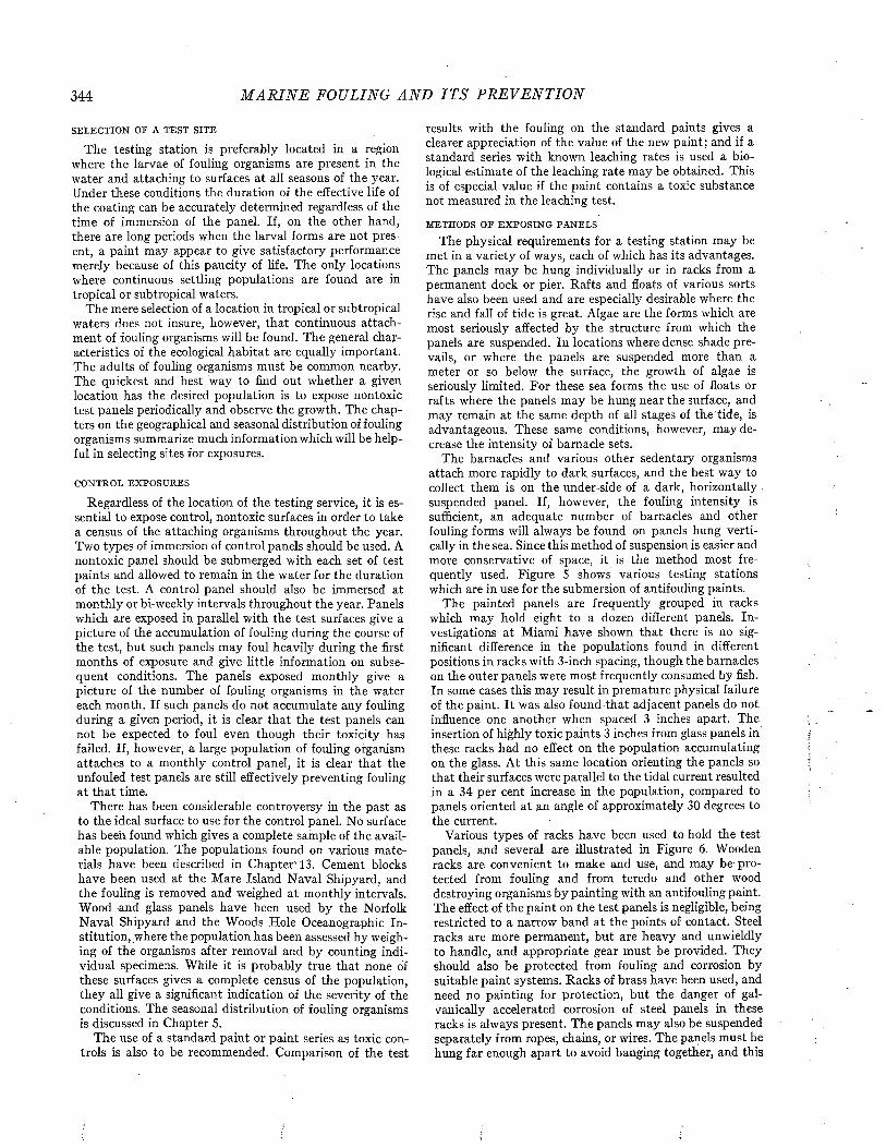
344 M A R I N E FOULING A N D I T S P R E V E N T I O N
SELECTION OE A TEST SITE
The testing station is preferably located in a region where the larvae of fouling organisms are present in the water and attaching to surfaces a t all seasons of the year. Under these conditions the duration of the effective life of the coating can be accurately determined regardless of the time of immersion of the panel. If, on the other hand, there are long periods when the larval forms are not present, a paint may appear to give satisfactory performance merely because of this paucity of life. The only locations where continuous settling populations are found are in tropical or subtropical waters.
The mere selection of a location in tropical or subtropical waters does not insure, however, th a t continuous attachment of fouling organisms will be found. The general characteristics of the ecological hab itat are equally important. The adults of fouling organisms must be common nearby. The quickest and best way to find out whether a given location has the desired population is to expose nontoxic test panels periodically and observe the growth. The chapters on the geographical and seasonal distribution of fouling organisms summarize much information which will be helpful in selecting sites for exposures.
CONTROL EX PO SU RES
Regardless of the location of the testing service, it is essential to expose control, nontoxic surfaces in order to take a census of the attaching organisms throughout the year. Two types of immersion of control panels should be used. A nontoxic panel should be submerged with each set of test paints and allowed to remain in the w ater for the duration of the test. A control panel should also be immersed at monthly or bi-weekly intervals throughout the year. Panels which are exposed in parallel with the test surfaces give a picture of the accumulation of fouling during the course of the test, but such panels m ay foul heavily during the first months of exposure and give little information on subsequent conditions. The panels exposed monthly give a picture of the number of fouling organisms in the water each month. If such panels do not accumulate any fouling during a given period, it is clear th a t the test panels can not be expected to foul even though their toxicity has failed. If, however, a large population of fouling organism attaches to a monthly control panel, it is clear th a t the unfouled test panels are still effectively preventing fouling a t th a t time.
There has been considerable controversy in the past as to the ideal surface to use for the control panel. No surface has been found which gives a complete sample of the available population. The populations found on various m aterials have been described in Chapter' 13. Cement blocks have been used at the Mare Island Naval Shipyard, and the fouling is removed and weighed a t monthly intervals. Wood and glass panels have been used by the Norfolk Naval Shipyard and the Woods Hole Oceanographic In stitution, where the population has been assessed by weighing of the organisms after removal and by counting individual specimens. While it is probably true th a t none of these surfaces gives a complete census of the population, they all give a significant indication of the severity of the conditions. The seasonal distribution of fouling organisms is discussed in Chapter 5.
The use of a standard pain t or pain t series as toxic controls is also to be recommended. Comparison of the test
results with the fouling on the standard paints gives a clearer appreciation of the value of the new paint; and if a standard series with known leaching rates is used a biological estimate of the leaching rate may be obtained. This is of especial value if the paint contains a toxic substance not measured in the leaching test.
METHODS OF E X PO SIN G PA N ELS
The physical requirements for a testing station may be met in a variety of ways, each of which has its advantages. The panels may be hung individually or in racks from a permanent dock or pier. Rafts and floats of various sorts have also been used and are especially desirable where the rise and fall of tide is great. Algae are the forms which are most seriously affected by the structure from which the panels are suspended. In locations where dense shade prevails, or where the panels are suspended more than a meter or so below the surface, the growth of algae is seriously limited. For these sea forms the use of floats or rafts where the panels may be hung near the surface, and may remain a t the same depth of all stages of the tide, is advantageous. These same conditions, however, may decrease the intensity of barnacle sets.
The barnacles and various other sedentary organisms attach more rapidly to dark surfaces, and the best way to collect them is on the under-side of a dark, horizontally suspended panel. If, however, the fouling intensity is sufficient, an adequate number of barnacles and other fouling forms will always be found on panels hung vertically in the sea. Since this method of suspension is easier and more conservative of space, it is the method most frequently used. Figure 5 shows various testing stations which are in use for the submersion of antifouling paints.
The painted panels are frequently grouped in racks which may hold eight to a dozen different panels. In vestigations a t Miami have shown tha t there is no significant difference in the populations found in different positions in racks with 3-inch spacing, though the barnacles on the outer panels were most frequently consumed by fish. In some cases this may result in premature physical failure of the paint. I t was also found th a t adjacent panels do not influence one another when spaced 3 inches apart. The insertion of highly toxic paints 3 inches from glass panels in these racks had no effect on the population accumulating on the glass. A t this same location orienting the panels so tha t their surfaces were parallel to the tidal current resulted in a 34 per cent increase in the population, compared to panels oriented a t an angle of approximately 30 degrees to the current.
Various types of racks have been used to hold the test panels, and several are illustrated in Figure 6 . Wooden racks are convenient to make and use, and may be- protected from fouling and from teredo and other wood destroying organisms by painting with an antifouling paint. The effect of the pain t on the test panels is negligible, being restricted to a narrow band a t the points of contact. Steel racks are more perm anent, bu t are heavy and unwieldly to handle, and appropriate gear must be provided. They should also be protected from fouling and corrosion by suitable pain t systems. Racks of brass have been used, and need no painting for protection, but the danger of gal- vanically accelerated corrosion of steel panels in these racks is always present. The panels may also be suspended separately from ropes, chains, or wires. The panels must be hung far enough apart to avoid banging together, and this
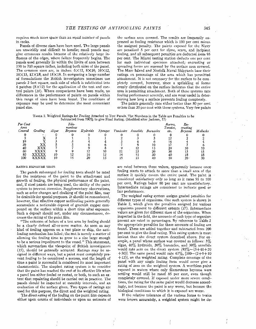
TH E T E ST IN G OF AN T IF O U L IN G P A I N T S 345
requires much more space than an equal number of panels in racks.
Panels of diverse sizes have been used. The large panels are unwieldly and difficult to handle; small panels may give erroneous results because of the relatively large influence of the edges, where failure frequently begins. The panels used generally lie within the limits of area between 150 to 700 square inches, including both sides of the panel. The common sizes are, in inches: 6X12, 8X10, 10X12, 10X15, 12X18, and 18X18. In comparing a large number of formulations the British investigators sometimes use panels 2 feet square, each side of which is subdivided into 6 patches (8 X 1 2 ) for the application of the test and contro l paints (1.6). Where comparisons have been made, no differences in the performance of paints on panels within th is range of sizes have been found. The conditions of exposure may be used to determine the most convenient panel size.
the surface area covered. The results are frequently expressed as fouling resistance which is 1 0 0 per cent minus the assigned penalty. The paints exposed for the Navy are penalized 5 per cent for slime, scum, and incipient fouling, and all subsequent penalties are deducted from 95 per cent. The Miami testing station deducts one per cent for each individual specimen attached; encrusting or spreading forms are assessed by the surface area covered. The Mare Island and Norfolk Naval Shipyards base their ratings on percentage of the area which has permitted attachment. I t is not necessary for the surface to be completely covered, however, since a sprinkling of forms evenly distributed on the surface indicates tha t the entire area is perm itting attachm ent. Both of these systems rate fouling performance severely, and are most useful in determining how long a surface prevents fouling completely.
The paints generally rate either better than 80 per cent or less than 20 per cent with these systems. Very few paints
T a b l e 2 . Weighted Ratings for Fouling Attached to Test Panels. The Numbers in the Table are Penalties to b e Subtracted from 100% to give Final Rating. (Modified after Jackson, 17)
P er Cent Area
Covered Grading Algae
FilamentousBryozoa H ydroids Sponges Tunicales Annelids Barnacles
Borers,Teredos,
etc.
E ncrustingBryozoa M ollusks
0 — 0 0 0 0 0 0 0 0 0 05 X 2 1 1 1 2 3 3 12 2 2
10 X 3 3 4 4 5 6 6 14 4 420 XX 5 5 6 6 7 9 10 17 7 640 XXX 7 7 9 8 9 12 15 20 10 1060 x x x x 9 9 12 10 11 15 20 30 13 1580 x x x x x 10 12 16 12 14 15 30 40 18 18
100 x x x x x 10 15 20 15 15 15 40 50 20 30
R ATIN G E X PO SU R E TESTS
The panels submerged for fouling tests should be rated for the resistance of the pain t to the attachm ent and growth of fouling, the physical performance of the paint, and, if steel panels are being used, the ability of the paint system to prevent corrosion. Supplementary observations, such as color changes and chalking of the paint film, may be desirable for special purposes. I t should be remembered, however, th a t effective copper antifouling paints generally accumulate a noticeable deposit of greenish copper compound on the surface within a short time after exposure. Such a deposit should not, under any circumstances, decrease the rating of the paint film.
“The criterion of failure of a test area by fouling should be a clearly defined all-or-none m atter. As soon as any kind of fouling appears on a test plate or ship, the an tifouling mechanism has failed ; the rest is merely a m atter of allowing the fouling time to grow to a size large enough to be a serious impediment to the vessel.” This statement, which summarizes the viewpoint of British investigators (15), should be generally accepted. Ratings may be assigned in different ways, but a paint m ust completely prevent fouling to be considered a success, and the length of time a pain t is successful is considered its most im portant characteristic. The simplest rating system is to consider th a t the pain t has reached the end of its effective life when a panel has either fouled or rusted, or both, to such an exten t th a t repainting should be carried out in practice. The panels should be inspected a t monthly intervals, and an evaluation of the surface given. Two types of ratings are used for this purpose, the direct and the weighted rating.
The direct rating of the fouling on the pain t film depends either upon counts of individuals or upon an estimate of
are rated between these values, apparently because once- fouling starts to attach to more than a small area of the surface it quickly covers the entire panel. The paint is considered satisfactory only so long as it rates 95 to 100 per cent. Ratings below 80 per cent are unsatisfactory. Interm ediate ratings are considered to indicate good or fair performance.
The weighted rating system assigns graded penalties for different types of organisms. One such system is shown in Table 2, which gives the penalties assigned for various organisms present to different extents (17). Interm ediate values are given for different sizes of the organisms. When inspected in the field, the amounts of each type of organism present are rated in percentages. By reference to Table 2 the appropriate penalties for these amounts of fouling are found. These are added together and subtracted from 100 per cent to give the final rating. This rating system is more lenient than the direct system described above. For example, a panel whose surface was covered as follows: 5% algae, 40% hydroids, 20% barnacles, and 30% annelids would rate zero on the direct system [95% —(5+ 4 0 + 2 0 +30)]. The same panel would rate 67%, [100—(2 + 9 + 1 0 + 12)], on the weighted rating. Complete coverage of the panel with any single fouling form would never give a rating of zero on the weighted system. A worthless paint exposed in waters where only filamentous bryozoa were settling would still be rated 85 per cent, even though completely covered. If exposed under more severe conditions, the rating for the same paint would decrease accordingly, not because the pain t is any worse, but because the biological conditions to which it is exposed are worse.
If the relative tolerance of the various forms to toxics were known accurately, a weighted system might be de-
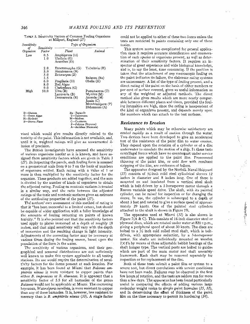
346 M A R I N E FOULING A N D I T S P R E V E N T I O N
T a b l e 3 . Sensitivity Factors of Common Fouling Organisms at Millport, England (27)
Sensitivity T ype of Organismof Sensihvily
Organism Factor P lant Anim alLow 0.5 Amphiprora (D)
1.0 Ulothrix (G) Acanthes (D)
2 .0 Enteromorpha (G) Tubularia (H)3 .0 Hecatonema (B)5 .0 Ectocarpus (B)5.5 Balanus (Ba)6 .0 Fragilaria (D) Obelia (H)8 .0 Red Algae9 .0 Cladophora (G)
High 10.0 Ulva (B) Pomatoceros (T) Laminaria (B) M ytilus (M) Desmarestia (B) Anomia (M)
Jassia (C) Membranipora (P) Didemnum (A)
D —Diatom Ba—BarnacleG— Green Algae T—TubewormH—Hydroid M —MolluscB— Brown Algae C— Crustacea
P—Polyzoa (Bryozoa) A—Ascidian (Tunicate)
vised which would give results directly related to the toxicity of the paint. This information is not available, and, until it is, weighted ratings will give an unwarranted illusion of precision.
The British investigators have assessed the sensitivity of various organisms insofar as it is known, and have assigned them sensitivity factors which are given in Table 3 (27). In inspecting the panels, each fouling form is assessed on a geometrical scale from 0 to 7 on the basis of numbers of organisms settled. Each rating with a value of 1 or more is then multiplied by the sensitivity factor for the organism. These products are added together, and the sum is divided by the number of kinds of organisms to obtain the adjusted rating. Fouling on nontoxic surfaces is treated in a similar way, and the ratio between the adjusted ratings of the toxic and nontoxic surfaces gives an estimate of the antifouling properties of the paint (27).
The” authors’ own assessment of this method of rating is th a t it “has been successful to a limited extent, but should be capable of wider application w ith a fuller knowledge of the amounts of fouling occurring on paints of known to x ic ity . ” I t is also pointed out tha t the sensitivity factors used apply to plates immersed a t a depth of roughly 18 inches, and tha t algal sensitivity will vary with the depth of immersion and the resulting change in light intensity. Adjustments of the correcting factor may be necessary at various times during the fouling season, based upon the population of the form in the water.
The sensitivity of various organisms, and their geographical and seasonal distributions are not sufficiently well known to make this system applicable to all testing stations. I ts use would require the determination of sensitivity factors for the forms present a t each location. For example, it has been found a t Miami th a t B alanus am phitrite niveus is more resistant to copper paints than either B . im provisus or B . eburneus. I t is apparent th a t a sensitivity factor of 5.5 for all barnacles of the genus B alanus would not be applicable a t Miami. The encrusting bryozoan, W atersipora cucullata, is more resistant to copper than any of these barnacles. I t is, however, less resistant to mercury than is B . am phitrite niveus (33). A single factor
could not be applied to either of these two forms unless the tests are restricted to paints containing only one of these toxics.
This system seems too complicated for general application since it requires accurate identification and enumeration of each species of organisms present, as well as determination of their sensitivity factors. I t requires an inspector of great experience and wide biological knowledge, and is, to say the least, time consuming. If the position is taken tha t the attachm ent of any macroscopic fouling on the paint indicates its failure, the elaborate rating systems are unnecessary. A list of the type of fouling present, and a direct rating of the paint on the basis of either numbers or per cent of surface covered, gives as useful information as any of the weighted or adjusted methods. The direct method also gives results which are more nearly comparable between different places and times, provided the fouling intensities are high, since the rating is independent of the kind of organisms present, and depends merely upon the numbers which can attach to the test surfaces.
Resistance to ErosionM any paints which may be otherwise satisfactory are
eroded rapidly as a result of motion through the water. Two devices have been developed to give an accelerated test of the resistance of the paint film to water erosion. They depend upon the rotation of a cylinder or of a disc underwater to simulate the motion of a ship. In these tests centrifugal forces which have no counterpart under service conditions are applied to the paint film. Pronounced thinning of the pain t film, or cold flow with resultant stripping of the film, are evidences of failure.
The apparatus designed by the Norfolk Naval Shipyard (25) consists of p^-inch mild steel cylindrical sleeves 12 inches in diameter and 8 inches long. One of these is mounted on and insulated from a vertical steel shaft which is belt-driven by a 3-horsepower motor through a Reeves variable speed drive. The shaft, with its painted cylinder, can be raised for inspection or for changing the sleeve. In use, the cylinder is submerged to a depth of about 3 feet and rotated to give a surface speed of approximately 29 knots. One of the painted steel cylinders attached to the shaft is shown in Figure 7B.
The apparatus used a t Miami (32) is also shown in Figure 7(A & C). This consists of 14-inch diameter steel or plywood discs, which are rotated under water at 820 r.p.m., giving a peripheral speed of about 30 knots. The discs are bolted to a jS'á-inch cold rolled steel shaft, which is belt- driven, with appropriate reduction, by a 3-horsepower motor. Six shafts are individually mounted on wooden 2X 4’s by means of three adjustable babbit bearings of the shaft hanger type. The vertical posts are bolted to guides which are p art of the main motor and shaft assembly framework. Each shaft may be removed separately for inspection or for replacement of the disc.
Both of these tests submit a paint film or system to a severe test, bu t direct correlations with service conditions have not been made. Failures may be observed in the first few hours of rotation, and the tests are seldom run for more than a few days. The apparatus has been found particularly useful in comparing the effects of adding various large molecular weight resins to simple paint formulae (25, 32), and in determining the effect of thickness of the paint film on the time necessary to perm it its hardening (34).
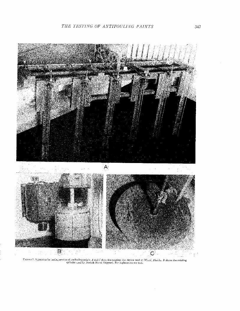
íí'V
1**'',
T H E T E S T I N G OF A N T IF O U L IN G P A I N T S
F i g u r e 7 . A pparatus for testing erosion of antifouling paints. A and C show the ro ta ting disc device used a t M iam i, F lorida. B shows the ro ta tingcylinder used by Norfolk N aval Shipyard. F or explanation see text.
348 M A R I N E FOULING A N D I T S P R E V E N T I O N
REFERENCES1. American Coordinating Committee on Corrosion. (G. H.
Young). Survey of Exposure Test Facilities. Report No. 1. November (1942) (Unpublished).
2. B a r n e s , H. The Estimation in Sea Water Solutions of Microquantities of Mercury in the Presence of Copper by Means of Dithizone. Jour. Mar. Biol. Assoc. U.K., 26, 303-311,1946.
3. B a r n e s , H. Studies on antifouling compositions. Part IV. Therelationship between leaching rate copper loss and antifouling performance under raft and service conditions. J. Iron & Steel Inst., 175-185, June 1948.
4. B a r n e s , H. Studies on antifouling compositions. Part V. Thebehavior of mercuric oxide in some antifouling compositions with special reference to the leaching rate test. J. Iron & Steel Inst., 177-184, Oct. 1948.
5. B a r n e s , H. Antifouling compositions: accuracy of leachingrate determinations. J. Chem. Ind., 68, 305-308, 1949.
6. B u r n s , A. E., J r . Investigation of Matrix Erosion of Antifouling Paints. Interim Report #4, Mare Island Naval Shipyard to Buships, September 17, 1943. (Unpublished).
7. C a l l a n , T., and J. A. R. H e n d e r s o n . A New Reagent for theColorimetric Determination of Minute Amounts of Copper. The Analyst, 54, 650-653, 1929.
8 . C o u l s o n , E. S. Report on Copper. J. Assoc. Off. Agr. Chem.,19, 219-228, 1936. Ib id ., 20, 178-188, 1937.
9. D a v y , S i r H u m p h r y . On the Corrosion of Copper Sheathingby Sea Water, and on Methods of Preventing this Effect; and on their Application to Ships of War and other Ships. Phil. Trans. Roy. Soc. London, 114, 151-158, 1824.
10. F e r r y , J. D., and D. E. C a r r i t t . Action of Antifouling Paints.I. Solubility and Rate of Solution of Cuprous Oxide in Sea Water. Ind. Eng. Chem., 38, 612-617, 1946.
11. F e r r y , J. D., B. M. F e r r y , and S. A. W e a r e . Kinetic Studiesof the Dissolution of Cuprous Oxide in Sea Water. Interim Report IX for 1945 from Woods Hole Oceanographic Inst, to Bureau of Ships. September 1, 1945. (Unpublished).
12. F e r r y , J. D., and G. A. R i l e y . Action of Antifouling Paints.II. Solubilities of Antifouling Toxics in Sea Water. Ind. Eng. Chem., 38, 699-701, 1946.
13. F e r r y , J. D., G. A. R i l e y , and G. F. K e l l y . The Chemistryof Copper and Mercury Compounds in Sea Water. Paper 5, Fifth Report, Woods Hole Oceanographic Inst, to Bureau of Ships. 1942. (Unpublished).
14. G a r d n e r , H. A. Physical and Chemical Examination ofPaints, Varnishes, Lacquers and Colors. Ninth Edition, Institute of Paint and Varnish Research, Washington,D . C. (1939).
15. H a r r i s , J. E. Second Report on Antifouling Investigations.Corrosion Committee, Marine Corrosion Sub-Committee. The Iron and Steel Inst. N16/45, 1945. (Unpublished).
16. H u d s o n , J. C. Raft Tests, Section B of First Report of theMarine Corrosion Sub-Committee of the Corrosion Committee. Journal Iron & Steel Inst. 1943.
17. J a c k s o n , C. M. Personal communication.18. K e n w o r t h y , L. Amended Statement on the “Leaching Rate
Test” of Ships’ Bottom Antifouling Compositions. Corrosion Committee, Marine Corrosion Sub-Committee, The Iron and Steel Inst. N24/45, 1945. (Unpublished).
19. K e t c h u m , B. H. Action of Antifouling Paints. V. The Use ofGlycine Solutions as an Accelerated Test of the Availability of Toxic. Ind. Eng. Chem., 40, 249-253, 1948.
20. K e t c h u m , B. H., J. D. F e r r y , G. K e l l y , and J. P a r k e r .Preliminary Report on Study of the Leaching Rate M ethod.
Paper 1, Fifth Report from Woods Hole Oceanographic Inst, to Bureau of Ships, Aug. 14, 1942. (Unpublished).
21. K e t c h u m , B. H., J. D. F e r r y , A. C. R e d f i e l d , and A. E.B u r n s , J r . Evaluation of Antifouling Paints by Leaching Rate Determinations. Ind. Eng. Chem., 37, 456-460, 1945.
22. K e t c h u m , B. H., L. W. H u t c h i n s , and B. M o t t . PreliminaryReport on Methods for Differentiating Between Copper Lost by Solution from the Paint Film and by Erosion. Paper 1, Sixth Report from Woods Hole Oceanographic Inst, to Bureau of Ships, May 1, 1943. (Unpublished).
23. K e t c h u m , B. H., D. T o d d , B. R e y n o l d s , and B. M o t t .Studies of Accelerated Methods for Investigating the Matrix Properties of Antifouling Paints. Paper 7, Seventh Report from the Woods Hole Oceanographic Institution to Bureau of Ships, April 20, 1944. (Unpublished).
24. L a Q u e , F. L. Sea Water Corrosion Tests. Corrosion Handbook, 1060-1071, John Wiley & Sons, Inc., N. Y., 1948.
25. Norfolk Naval Shipyard. Report on Improvement of ErosionResistance of Formula 16X, Project 3-H -l, Buships Test 392, May 1944. (Unpublished).
26. O x n e r , M e e c z y s l a w . Chloruration par la Methode de Knud-sen. Bull, de la Comm. Internat, pour l’Explor. Scient, de la Mer Mediterranee, No. 3,1920. Also “The Determination of Chlorinity by the Knudsen Method.” A Translation. Woods Hole Oceanographic Institution, Woods Hole, Mass.1946.
27. P y e f i n c h , K. A. Notes on Methods of Assessment of Antifouling Paints, with a Report on Millport Exposures of the Paint Series Prepared at Derby. Corrosion Committee, Marine Corrosion Sub-Committee, the Iron and Steel Inst. N3/45, December, 1944. (Unpublished). See also: Methods of Assessment of Antifouling Compositions. Journal of The Iron and Steel Inst. No. II, 229-243, 1945.
28. R i l e y , G. A. Leaching Tests on Paints Containing Mercury.Paper 13, Seventh Report from Woods.Hole Oceanographic Inst, to Bureau of Ships, April 20, 1944. (Unpublished).
29. R i l e y , G. A. Progress Report on Mercury Leaching RateMethod. Paper 4, Fifth Report from Woods Hole Oceanographic Inst, to Bureau of Ships. August 14, 1942. Progress Report on Leaching Rates of Mercury Paints. Paper 8, Sixth Report from Woods Hole Oceanographic Inst, to Bureau of Ships, May 1, 1943. (Unpublished).
30. R i l e y , G. A., and A. C. R e d f i e l d . The Leaching Rate ofPaints Containing Various Mercury Compounds. Paper 10, Seventh Report from Woods Hóle Oceanographic Inst, to Bureau of Ships, April 20, 1944. (Unpublished).
31. S a n d e l l , E. D. Colorimetric Determination of Traces ofMetals, N. Y. (Chem. Anal. Vol. 3) p. 487, Interscience.1944.
32. S m i t h , F. G. W a l t o n . The Use of Rotatihg Discs in an Accelerated Method of Testing Erosion of Antifouling Paints. Int. Report II for 1944 from Woods Hole Oceanographic Inst, to Bureau of Ships, May 5, 1944. (Unpublished).
33. W e i s s , C. M. The Comparative Tolerances of Some FoulingOrganisms to Copper and Mercury. Biol. Bull. 93, 56-63,1947.
34. W e i s s , C. M., and B. H. K e t c h u m . Effect of Thickness of Application and Time Before Motion Through.the Water on the Performance of 143. Interim Report No. VI for 1945, Woods Hole Oceanographic Inst, to Bureau of Ships, March,1945. (Unpublished).
35. W i n k l e r , W. O. Report on Mercury. Jour. Assoc. Off. Agr.Chem. 22, 341-346, 1939. Ibid., 23, 310-313, 1940.
36. Woods Hole Oceanographic Inst. Progress Report to Bureauof Ships, dated June 1, 1946. (Unpublished).
Marine Fouling and Its Prevention,Contribution No. 580 from the Woods Flole Oceanographic Institute
Copyright 1952 by U. S. Naval Institute, Annapolis, Maryland George Banta Publishing Co., Menasha, WI
CHAPTER 21
The Fouling of Metallic SurfacesSheathing with copper appears to have been the
first adequate method of preventing the fouling of ships’ bottoms, and was also the most successful technique employed for this purpose. The use of lead sheathing by the ancients, which was also current at the time copper sheathing was introduced, was doubtless intended as a protection against borers or for other purposes, since lead gives practically no antifouling protection.
The first record of the use of copper sheathing is found in the Navy Board’s report to the Admiralty on H is M ajesty’s Ship Alarm, which, in 1761, returned from a twenty month’s voyage to the West Indies (21). This report, which is reprinted in the Appendix to Chapter 11, showed that the ship’s bottom had remained clean during this period. It was noted that the copper covering the rudder had fouled with barnacles, which was accounted for by the fact that the plates there had been fastened with iron nails “to vary the experim ent,” and it was thought that the rust from these nails had drained down and spread over the surface so as to occasion the fouling. The effect which the copper had upon the iron where the two metals touched was also noted with surprise, for it was found that the rudder iron, the fastenings of the false keel, the pintles, etc., were corroded and eaten. Thus, in the earliest extant account of a copper-sheathed ship we find recorded two great limitations of copper sheathing, namely, the corrosion of adjacent iron parts and the inactivation of the copper as a nonfouling surface under this
’ association.The sheathing on the bows of the Alarm was
wasted away by the erosive action of the sea so that only the edges and fastenings remained as first put on. The life of the copper sheathing of sailing vessels was, in general, about four or five years, so that the upkeep of the bottom was a considerable expense. In spite of this difficulty, copper remained the approved method of treating ships’ bottoms until the use of iron in the construction of ships became prevalent, when the galvanic corrosion of iron induced by the copper plating led to great difficulties. It was necessary to insulate the hull from the sheathing by means of a wood backing or in some other way. The procedure was expensive and, though done with great care, the insulation was never perfect. Danger al
ways existed that damage to the insulation would expose a small area of the ship’s plating to very severe corrosion. In spite of this difficulty, United States battleships and many cruisers of foreign powers were sheathed with wood and copper as late as 1900, the antifouling virtues of the method having been amply demonstrated during the Spanish-American war (1).
The expense and difficulty of insulating copper sheathing stimulated the development of antifouling paints. As these became effective, the economy and ease of application of such coatings gradually caused the disuse of copper sheathing even on small wooden vessels. Now the employment of metallic sheathing is usually restricted to the protection of wood hulls from the abrasive action of ice and the like, or to situations where the superior protection against the worm warrants the initial expense.
It is reported that in The Netherlands Navy, where copper sheathing is used as a protection against worms in East Indian waters, 50 per cent of the sheathing must be replaced annually. Sheathing is not only damaged by grounding but is torn away by the seas and by high speed operation. Consequently, it is not recommended for speeds over 15 knots, and is unsuited to modern highspeed vessels.
At the time of the introduction of iron into the construction of ships’ hulls, zinc sheathing was seriously suggested as a substitute for copper (4). Zinc sheets were tried on several ships, notably the Italian battleship Italia (I), but did not prove a great success. While its use may have served to protect the iron hull from corrosion, it can have had little value as an antifouling surface. This fact, coupled with the difficulty and expense of attaching the zinc plates to the steel hull, evidently led to its early abandonment.1
Alloys of copper, particularly M untz or yellow metal, have been employed as substitutes for copper in sheathing wood bottoms because of economy and the greater resistance of these alloys to erosion. Muntz metal is not a very effective antifouling surface, and it is found to be an advantage to use antifouling paint over the sheathing.
1 Zinc coatings, applied directly by galvanizing, are currently used in the construction of light Naval vessels to reduce corrosion within the bilges. Antifouling paints are applied over the outer galvanized surface of the ships’ plates.
349
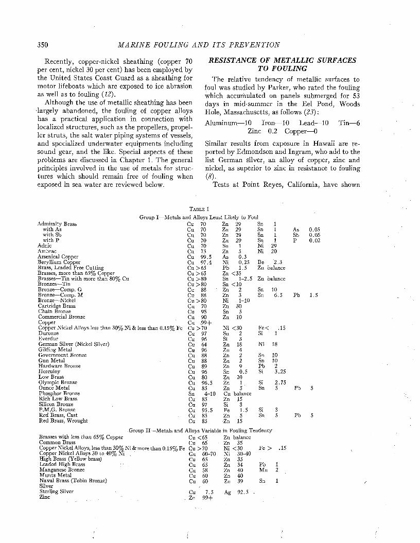
350 M A R I N E FOULING A N D I T S P R E V E N T I O N
Recently, copper-nickel sheathing (copper 70 per cent, nickel 30 per cent) has been employed by the United States Coast Guard as a sheathing for motor lifeboats which are exposed to ice abrasion as well as to fouling (12).
Although the use of metallic sheathing has been largely abandoned, the fouling of copper alloys has a practical application in connection with localized structures, such as the propellers, propeller struts, the salt water piping systems of vessels, and specialized underwater equipments including sound gear, and the like. Special aspects of these problems are discussed in Chapter 1. The general principles involved in the use of metals for structures which should remain free of fouling when exposed in sea water are reviewed below.
RESISTANCE OF METALLIC SURFACES TO FOULING
The relative tendency of metallic surfaces to foul was studied by Parker, who rated the fouling which accumulated on panels submerged for 53 days in mid-summer in the Eel Pond, Woods Hole, Massachusetts, as follows (23) :Aluminum— 10 Iron— 10 Lead— 10 Tin— 6
Zinc— 0.2 Copper—0
Similar results from exposure in Hawaii are reported by Edmondson and Ingram, who add to the list German silver, an alloy of copper, zinc and nickel, as superior to zinc in resistance to fouling (8) .
Tests at Point Reyes, California, have shown
Group I—MiAdmiralty Brass
with As with Sb with P
Adnic AmbracArsenical Copper Beryllium Copper Brass, Leaded Free Cutting Brasses, more than 65% Copper Brasses—Tin with more than 80% Cu Bronzes—Tin Bronze—Comp. G Bronze—Comp. M Bronze—Nickel Cartridge Brass Chain Bronze Commercial Bronze CopperCopper Nickel Alloys less than 30% N i & less than 0.15% Fe Duronze EverdurGerman Silver (Nickel Silver)Gilding Metal Government Bronze Gun Metal Hardware Bronze Herculoy Low Brass Olympic Bronze Ounce Metal Phosphor Bronze Rich Low Brass Silicon Bronze P.M.G. Bronze Red Brass, Cast Red Brass, Wrought
T a b l e 1
and Alloys Least Likely to FoulCu 70 Zn 2 9 Sn 1Cu 70 Zn 2 9 Sn 1 As 0 .0 5Cu 70 Zn 29 Sn 1 Sb 0 .0 5Cu 70 Zn 2 9 Sn 1 P 0 .0 2Cu 70 Sn 1 Ni 29Cu 75 Zn 5 Ni 2 0Cu 9 9 .5 As 0 .3Cu 9 7 .4 Ni 0 .2 5 Be 2 . 3Cu > 6 5 Pb 1 .5 Zn balanceCu > 6 5 Zn < 3 5Cu > 8 0 Sn 1 - 2 .5 Zn balanceCu > 8 0 Sn < 1 0Cu 88 Zn 2 Sn 10Cu 88 Zn 3 Sn 6 . 5 Pb 1 .5Cu > 8 0 Ni 1 - 1 0Cu 7 0 Zn 30Cu 95 Sn 5Cu 90 Zn 10Cu . 9 9 +
: Cu > 7 0 Ni < 3 0 F e< .1 5Cu 97 Sn 2 Si 1Cu 96 Si 3Cu 6 4 Zn 18 Ni 18Cu 96 Zn 4Cu 88 Zn 2 Sn 10Cu 88 Zn 2 Sn 10Cu 8 9 Zn 9 Pb 2Cu 9 6 Sn 0 . 5 Si 3 .2 5Cu 8 0 Zn 20Cu 9 6 .5 Zn 1 Si 2 .7 5Cu 85 Zn 5 Sn 5 Pb 5Sn 4 - 1 0 Cu balanceCu 85 Zn 15Cu 97 Si 3Cu 9 5 .5 Fe 1 .5 Si 3Cu 85 Zn 5 Sn 5 Pb 5Cu 85 ■Zn 15
Brasses with less than 65% Copper Common Brass
Group II—Metals and Alloys Variable in Fouling TendencyCu <65 Zn balanceCu 65 Zn 35
Copper Nickel Alloys, less than 30% N i&more than 0.15% Fe Cu > 7 0 N i <30 Fe > .15Copper Nickel Alloys 30 to 40% Ni . Cu 60-70 N i 30-40High Brass (Yellow brass) Cu 65 Zn 35Leaded High Brass ; / Cu 65 Zn 34Manganese Bronze Cu 58 Zn 40Muntz Metal Cu 60 Zn 40Naval Brass (Tobin Bronze) Cu 60 Zn 39SilverSterling Silver Cu 7.5 Ag 92.5Zinc’ Zn 99 +
PbMn
Sn
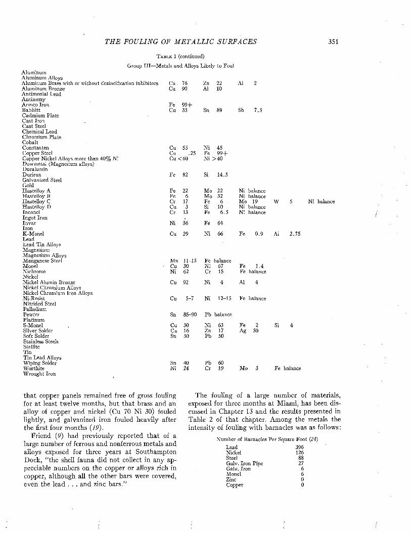
THE FOULING OF M E T A L L I C SUR FA C E S 351
Aluminum Aluminum Alloys
T a b l e 1 (c o n tin u e d )
Group III—Metals and Alloys Likely to Foul
Aluminum Brass with or without dezincification inhibitors Cu 76 Zn 22 Al 2Aluminum Bronze Cu 90 AÍ 10Antimonial LeadAntinomyArmco Iron Fe 9 9 +Babbitt Cu 35 Sn 89 Sb 7.5Cadmium PlateCast IronCast SteelChemical LeadChromium PlateCobaltConstanten Cu 55 Ni 45Copper Steel Cu .25 Fe 9 9 +Copper Nickel Alloys more than 40% Ni Cu <60 Ni > 4 0Dowmetal (Magnesium alloys)DuraluminDuriron Fe 82 Si 14.5Galvanized SteelGoldHastelloy A Fe 22 Mo 22 Ni balanceHastelloy B Fe 6 Mo 32 Ni balanceHastelloy C Cr 17 Fe 6 Mo 19Hastelloy D Cu 3 Si 10 Ni balanceInconel Cr 13 Fe 6.5 Ni balanceIngot Iron .
Invar Ni 36 Fe 64IronK-Monel Cu 29 Ni 66 Fe 0 .9LeadLead Tin AlloysMagnesiumMagnesium AlloysManganese Steel Mn 11-15 Fe balanceMonel Cu 30 Ni 67 Fe 1.4Nichrome Ni 62 Cr 15 Fe balanceNickelNickel Alumin Bronze Cu 92 Ni 4 Al 4Nickel Chromium AlloysNickel Chromium Iron AlloysNi-Resist Cu 5-7 Ni 12-15 Fe balanceNitrided SteelPalladiumPewterPlatinumS-MonelSilver SolderSoft SolderStainless SteelsStelliteTinTin Lead Alloys Wiping Solder Worthite Wrought Iron
W
AÍ
Ni balance
2.75
Sn 85-90 Pb balance
Cu 30 Ni 63 Fe 2 Si 4Cu 16 Zn 17 Ag 50Sn 50 Pb 50
SnNi
4024
PbCr
6019 Mo Fe b a la n c e
that copper panels remained free of gross fouling for at least twelve months, but that brass and an alloy of copper and nickel (Cu 70 N i 30) fouled lightly, and galvanized iron fouled heavily after the first four months {19).
Friend (9) had previously reported that of a large number of ferrous and nonferrous metals and alloys exposed for three years at Southampton Dock, “the shell fauna did not collect in any appreciable numbers on the copper or alloys rich in copper, although all the other bars were covered, even the lead . . . and zinc bars.”
The fouling of a large number of materials, exposed for three months at Miami, has been discussed in Chapter 13 and the results presented in Table 2 of that chapter. Among the metals the intensity of fouling with barnacles was as follows :
Number of Barnacles Per Square Foot {24)
Lead 396Nickel 126Steel 88Galv. Iron Pipe 27Galv. Iron 6Monel 6Zinc 0Copper 0
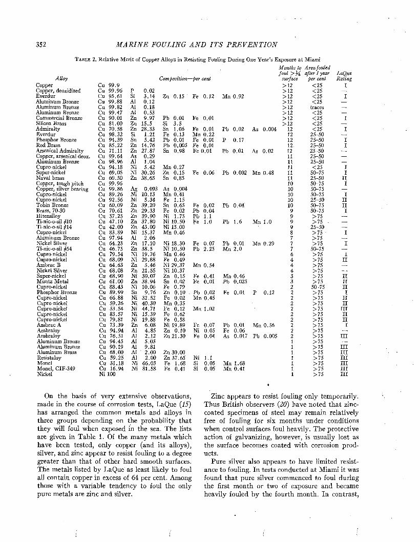
352 M A R I N E FOULING A N D I T S P R E V E N T I O N
T a b l e 2. Relative Merit of Copper Alloys in Resisting Fouling During One Year’s Exposure at MiamiMonths to Area fouled fou l > after 1 year LaQue
Copper Cu 99.9 >12 <25 ICopper, deoxidized Cu 99.96 P 0.02 >12 <25 —
Everdur Cu 95.61 Si 3 .14 Zn 0.15 Fe 0.12 Mn 0.92 >12 <25 IAluminum Bronze Cu 99.88 AÍ 0.12 >12 < 25 —
Aluminum Bronze Cu 99.82 AÍ 0.18 >12 traces —
Aluminum Bronze Cu 99.47 AÍ 0.53 >12 <25 —
Commercial Bronze Cu 90.01 Zn 9.97 Pb 0.01 Fe 0.01 >12 <25 ISilicon Brass Cu 81.00 Zn 15.5 Si 3 .5 >12 <25 —
Admiralty Cu 70.58 Zn 28.33 Sn 1.06 Fe 0.01 Pb 0.02 As 0.004 12 <25 IEverdur Cu 98.32 Si 1.21 Fe 0.13 Mn 0.22 12 25-50 —
Phosphor Bronze Cu 94.39 Sn 5.42 Pb 0.01 Fe 0.01 P 0.17 12 25-50 IRed Brass Cu 85.22 Zn 14.76 Pb 0.005 Fe 0.01 12 25-50 IArsenical Admiralty Cu 71.11 Zn 27.87 Sn 0.98 Fe 0.01 Pb 0.01 As 0.02 12 25-50 —
Copper, arsenical deox. Cu 99.64 As 0.29 11 25-50 —
Aluminum Bronze Cu 98.96 AÍ 1.04 11 25-50 —
Cupro-nickel Cu 94.18 Ni 5.42 Mn 0.27 11 <25 ISuper-nickel Cu 69.05 Ni 30.26 Zn 0.15 Fe 0.06 Pb 0.002 Mn 0.48 11 50-75 INaval brass Cu 60.50 Zn 38.65 Sn 0.85 11 25-50 IICopper, tough pitch Cu 99.96 10 50-75 ICopper, silver bearing Cu 99.86 Ag 0.093 As 0.004 10 50-75 —
Cupro-nickel Cu 89.26 Ni 10.13 Mn 0.41 10 50-75 ICupro-nickel Cu 92.56 N i 5.34 Fe 1.15 10 25-50 IITobin Bronze Cu 60.09 Zn 39.20 Sn 0.65 Fe 0.02 Pb 0.04 10 50-75 IIBrass, 70-30 Cu 70.61 Zn 29.33 Fe 0.02 Pb 0.04 9 50-75 IHitensiloy Cu 57.25 Zn 39.90 Ni 1.75 Pb 1.1 9 > 7 5 —
Ti-nic-o-sil #10 Cu 47.10 Zn 37.80 Ni 10.50 Fe 1.0 Pb 1.6 Mn 1.0 9 > 75 - — .
Ti-nic-o-sil #14 Cu 42.00 Zn 43.00 Ni 15.00 9 25-50 —
Cupro-nickel Cu 83.89 Ni 15.37 Mn 0.46 8 > 7 5 • IAluminum Bronze Cu 97.94 Al 2.06 7 > 75 —
Nickel Silver Cu 64.23 Zn 17.10 Ni 18.30 Fe 0.07 Pb 0.01 Mn 0.29 7 > 75 ITi-nic-o-sil #54 Cu 46.75 Zn 38.5 Ni 10.50 Pb 2.25 Mn 2.0 7 50-75 —
Cupro-nickel Cu 79.54 Ni 19.76 Mn 0.46 6 >75 ICupro-nickel Cu 68.09 Ni 29.88 Fe 0.49 4 >75 IIAmbrac B Cu 64.63 Zn 5.46 Ni 29.37 Mn 0.54 4 >75 —
Nickel Silver Cu 68.08 Zn 21.55 Ni 10.37 4 > 7 5 —
Super-nickel Cu 68.90 Ni 30.07 Zn 0.15 Fe 0.41 Mn 0.46 3 > 7 5 IIMuntz Metal Cu 61.00 Zn 38.94 Sn 0.02 Fe 0.01 Pb 0.025 3 >75 IICupro-nickel Cu 88.43 Ni 10.06 Fe 0.79 2 50-75 IIPhosphor Bronze Cu 89.99 Sn 9.76 Zn 0.10 Pb 0.02 Fe 0.01 P 0.12 2 >75 ICupro-nickel Cu 66.88 Ni 32.52 Fe 0.02 Mn 0.45 2 >7 5 IICupro-nickel Cu 59.26 Ni 40.30 Mn 0.35 2 >7 5 IICupro-nickel Cu 53.54 Ni 44.71 Fe 0.12 Mn 1.02 2 >75 IIICupro-nickel Cu 83.57 Ni 15.39 Fe 0.62 2 > 7 5 IICupro-nickel Cu 79.81 Ni 19.88 Fe 0.58 2 >7 5 IIAmbrac A Cu 73.39 Zn 6.08 Ni 19.89 Fe 0.07 Pb 0.01 Mn 0.56 2 > 7 5 IAmbraloy Cu 94.94 AI 4.85 Zn 0.10 Ni 0.05 Fe 0.06 2 >75 — .
Ambraloy Cu 76.51 Al 2.12 Zn 21.30 Fe 0.04 As 0.017 Pb 0.005 2 >75 IIIAluminum Bronze Cu 94.45 Al 5.05 1 >75 —
Aluminum Bronze Cu 90.19 Al 9.81 1 >75 IIIAluminum Brass Cu 68.00 Al 2.00 Zn 30.00 1 > 7 5 IIIResistaloy Cu 59.25 Al 2.00 Zn 37.65 Ni 1.1 1 >7 5 IIIMonel Cu 31.18 Ni 66.03 Fe 1.68 Si 0.05 Mn 1.68 1 >7 5 IIIMonel, CIF-349 Cu 16.94 Ni 81.58 Fe 0.41 Si 0.05 Mn 0.41 1 >7 5 IIINickel Ni 100 1 >75 III
On the basis of very extensive observations, made in the course of corrosion tests, LaQue (25) has arranged the common metals and alloys in three groups depending on the probability that they will foul when exposed in the sea. The lists are given in Table 1. Of the many metals which have been tested, only copper (and its alloys), silver, and zinc appear to resist fouling to a degree greater than that of other hard smooth surfaces. The metals listed by LaQue as least likely to foul all contain copper in excess of 64 per cent. Among those with a variable tendency to foul the only pure metals are zinc and silver.
Zinc appears to resist fouling only temporarily. Thus British observers (20) have noted that zinc- coated specimens of steel may remain relatively free of fouling for six months under conditions when control surfaces foul heavily. The protective action of galvanizing, however, is usually lost as the surface becomes coated with corrosion products.
Pure silver also appears to have limited resistance to fouling. In tests conducted at Miami it was found that pure silver commenced to foul during the first month or two of exposure and became heavily fouled by the fourth month. In contrast,
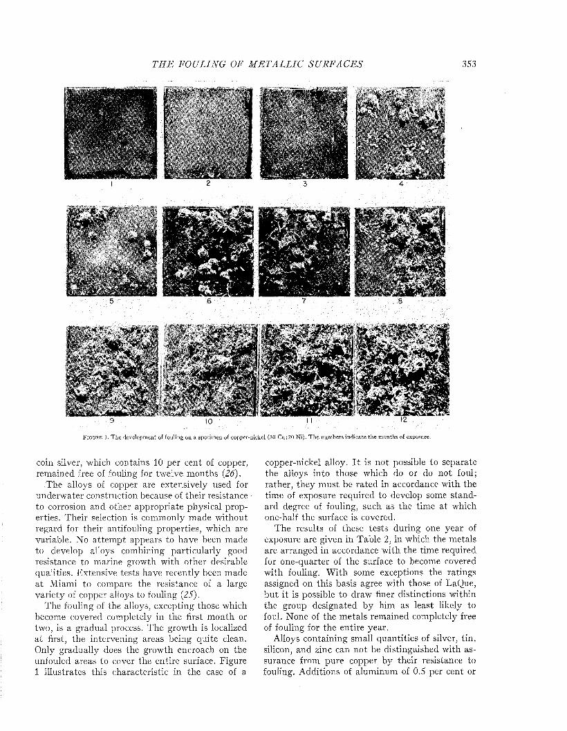
T H E FOULING OF M E T A L L I C S U R F A C E S 353
F i g u r e 1. T he development of fouling on a specimen of copper-nickel (30 Cu : 20 N i) . T h e num bers ind icate th e m onths of exposure.
coin silver, which contains 10 per cent of copper, remained free of fouling for twelve months (26).
The alloys of copper are extensively used for underwater construction, because of their resistance to corrosion and other appropriate physical properties. Their selection is commonly made without regard for their antifouling properties, which are variable. No attempt appears to have been made to develop alloys combining particularly good resistance to marine growth with other desirable qualities. Extensive tests have recently been made at Miami to compare the resistance of a large variety of copper alloys to fouling (25).
The fouling of the alloys, excepting those which become covered completely in the first month or two, is a gradual process. The growth is localized at first, the intervening areas being quite clean. Only gradually does the growth encroach on the unfouled areas to cover the entire surface. Figure 1 illustrates this characteristic in the case of a
copper-nickel alloy. It is not possible to separate the alloys into those which do or do not foul; rather, they must be rated in accordance with the time of exposure required to develop some standard degree of fouling, such as the time at which one-half the surface is covered.
The results of these tests during one year of exposure are given in Table 2, in which the metals are arranged in accordance with the time required for one-quarter of the surface to become covered with fouling. W ith some exceptions the ratings assigned on this basis agree with those of LaQue, but it is possible to draw finer distinctions within the group designated by him as least likely to foul. None of the metals remained completely free of fouling for the entire year.
Alloys containing small quantities of silver, tin, silicon, and zinc can not be distinguished with assurance from pure copper by their resistance to fouling. Additions of aluminum of 0.5 per cent or
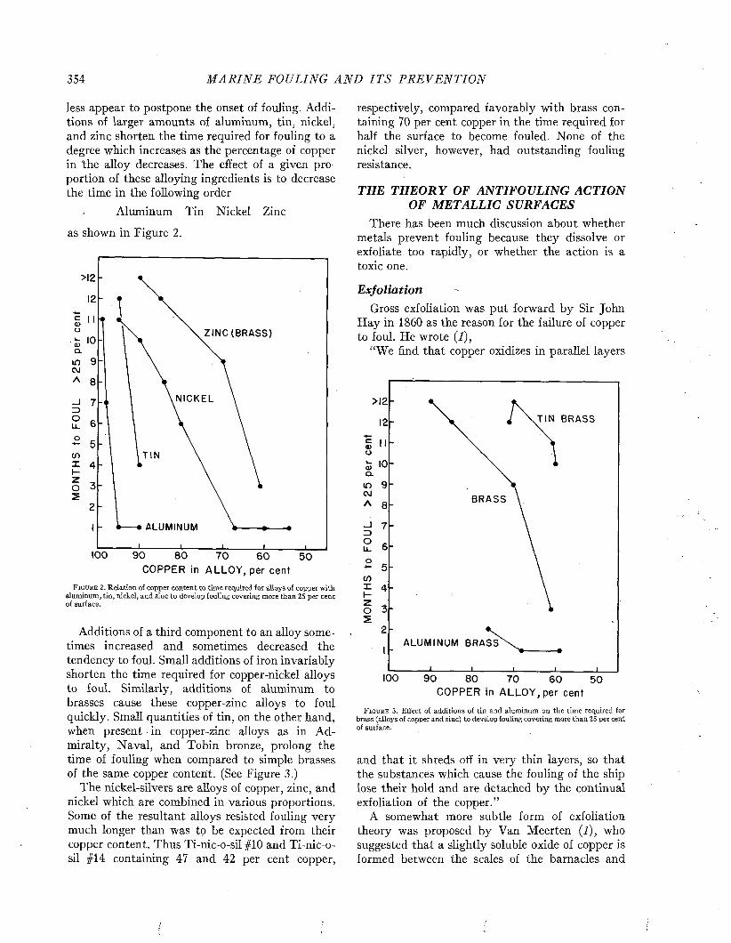
354 M A R I N E FOULING A N D I T S P R E V E N T I O N
less appear to postpone the onset of fouling. Additions of larger amounts of aluminum, tin, nickel, and zinc shorten the time required for fouling to a degree which increases as the percentage of copper in the alloy decreases. The effect of a given proportion of these alloying ingredients is to decrease the time in the following order
Aluminum Tin Nickel Zinc
as shown in Figure 2.
>12
ZINC (BRASS)
cu
NICKEL
TINcn
ALUMINUM
100 90 80 70 60 50C O P P E R in A L L O Y , p e r c e n t
F i g u r e 2 . Relation of copper content to time required for alloys of copper with aluminum, tin, nickel, and zinc to develop fouling covering more than 25 per cent of surface.
Additions of a third component to an alloy sometimes increased and sometimes decreased the tendency to foul. Small additions of iron invariably shorten the time required for copper-nickel alloys to foul. Similarly, additions of aluminum to brasses cause these copper-zinc alloys to foul quickly. Small quantities of tin, on the other hand, when present in copper-zinc alloys as in Admiralty, Naval, and Tobin bronze, prolong the time of fouling when compared to simple brasses of the same copper content. (See Figure 3.)
The nickel-silvers are alloys of copper, zinc, and nickel which are combined in various proportions. Some of the resultant alloys resisted fouling very much longer than was to be expected from their copper content. Thus Ti-nic-o-sil #10 and Ti-nic-o- sil #14 containing 47 and 42 per cent copper,
respectively, compared favorably with brass containing 70 per cent copper in the time required for half the surface to become fouled. None of the nickel silver, however, had outstanding fouling resistance.
THE TH EORY OF ANTIFOULING ACTION OF METALLIC SURFACES
There has been much discussion about whether metals prevent fouling because they dissolve or exfoliate too rapidly, or whether the action is a toxic one.
ExfoliationGross exfoliation was put forward by Sir John
H ay in 1860 as the reason for the failure of copper to foul. He wrote (7),
“We find that copper oxidizes in parallel layers
>12
TIN BRASS
incu
BRASS
4 -
ALUMINUM BRASS
100 90 80 70 60 50C O P P E R in A L L O Y , p e r c e n t
F i g u r e 3 . Effect of additions of tin and aluminum on the time required for brass (alloys of copper and zinc) to develop fouling covering more than 25 per cent of surface.
and that it shreds off in very thin layers, so that the substances which cause the fouling of the ship lose their hold and are detached by the continual exfoliation of the copper.”
A somewhat more subtle form of exfoliation theory was proposed by Van Meerten (7), who suggested that a slightly soluble oxide of copper is formed between the scales of the barnacles and
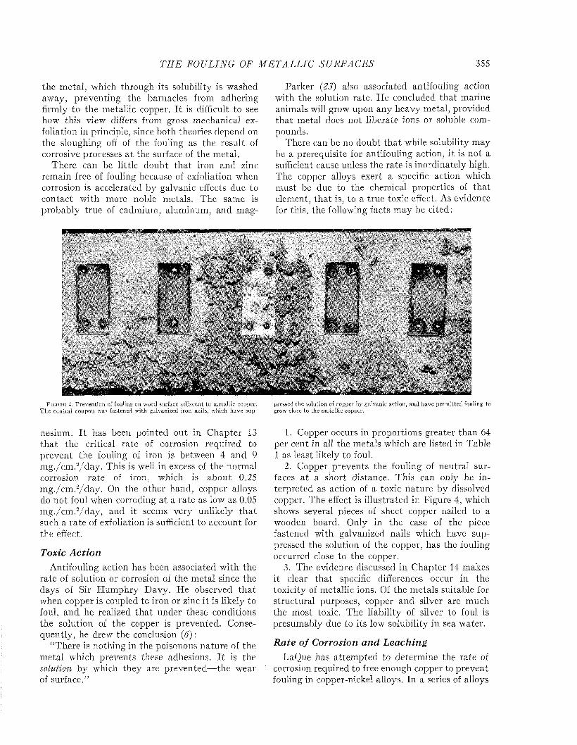
T H E FOULING OF M E T A L L I C SU R F A C E S 355
the metal, which through its solubility is washed away, preventing the barnacles from adhering firmly to the metallic copper. I t is difficult to see how this view differs from gross mechanical exfoliation in principle, since both theories depend on the sloughing off of the fouling as the result of corrosive processes a t the surface of the metal.
There can be little doubt tha t iron and zinc remain free of fouling because of exfoliation when corrosion is accelerated by galvanic effects due to contact with more noble metals. The same is probably true of cadmium, aluminum, and mag-
Parker (23) also associated antifouling action with the solution rate. He concluded that marine animals will grow upon any heavy metal, provided that metal does not liberate ions or soluble compounds.
There can be no doubt tha t while solubility may be a prerequisite for antifouling action, it is not a sufficient cause unless the rate is inordinately high. The copper alloys exert a specific action which m ust be due to the chemical properties of that element, tha t is, to a true toxic effect. As evidence for this, the following facts may be cited:
F i g u r e 4. P reven tion of fou1mg on wood surface ad jacen t to m etallic copper. pressed the solution of copper by galvanic action, and have perm itted fouling toT h e central coupon was fastened with galvanized iron nails, which have sup- grow close to the m etallic copper.
nesium. I t has been pointed out in Chapter 13 th a t the critical rate of corrosion required to prevent the fouling of iron is between 4 and 9 m g./cm .2/day . This is well in excess of the normal corrosion rate of iron, which is about 0.25 m g./cm .2/d ay . On the other hand, copper alloys do not foul when corroding at a rate as low as 0.05 m g./cm .2/d ay , and it seems very unlikely th a t such a rate of exfoliation is sufficient to account for the effect.
Toxic A ctionAntifouling action has been associated with the
rate of solution or corrosion of the m etal since the days of Sir Hum phry Davy. He observed tha t when copper is coupled to iron or zinc it is likely to foul, and he realized tha t under these conditions the solution of the copper is prevented. Consequently, he drew the conclusion (6) :
“There is nothing in the poisonous nature of the metal which prevents these adhesions. I t is the solution by which they are prevented—the wear of surface.”
1. Copper occurs in proportions greater than 64 per cent in all the metals which are listed in Table 1 as least likely to foul.
2. Copper prevents the fouling of neutral surfaces a t a short distance. This can only be interpreted as action of a toxic nature by dissolved copper. The effect is illustrated in Figure 4, which shows several pieces of sheet copper nailed to a wooden board. Only in the case of the piece fastened with galvanized nails which have suppressed the solution of the copper, has the fouling occurred close to the copper.
3. The evidence discussed in Chapter 14 makes it clear tha t specific differences occur in the toxicity of metallic ions. Of the metals suitable for structural purposes, copper and silver are much the most toxic. The liability of silver to foul is presumably due to its low solubility in sea water.
R ate o f Corrosion and LeachingLaQue has attem pted to determine the rate of
corrosion required to free enough copper to prevent fouling in copper-nickel alloys. In a series of alloys
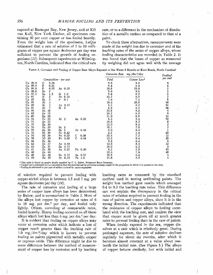
356 M A R I N E FOULING A N D I T S P R E V E N T I O N
exposed at Barnegat Bay, New Jersey, and at Kill van Kull, New York Harbor, all specimens containing 50 per cent copper or less fouled heavily. From the weight loss of the specimens, LaQue estimated that a rate of solution of 7 to 10 milligrams of copper per square decimeter per day was sufficient to prevent the growth of fouling organisms {12). Subsequent experiments at Wilmington, North Carolina, indicated that the critical rate
rate, or to a difference in the mechanism of dissolution of a metallic surface as compared to that of a paint.
To check these alternatives, measurements were made of the weight loss due to corrosion and of the leaching rates of the series of copper alloys, whose fouling characteristics are recorded in Table 2. It was found that the losses of copper as measured by weighing did not agree well with the average
T a b l e 3. Corrosion and Fouling of Copper Base Alloys Exposed to Sea Water 8 Months at Kure Beach, North Carolina1
Corrosion Rate m g ./d m ? /d a y Fouling3
Composition —per cent Total Copper Loss2 per cent
Cu 99.9 O 0.04 9.8 9.8 4Cu 99.9 P 0.01 9 .4 9 .4 6Cu 99.9 P 0.02 As 0.33 10.8 10.8 2Cu 98.0 Sn 2 9.6 9 .6 2Cu 97.5 Sn 1.5 Si 1.0 9 .4 9.2 2Cu 97 Si 3 Fe 0.10 10.2 9 .9 2Cu 95 Sn 5 P 0.1 7.6 7.2 8Cu 95 AÍ 5 10.6 10.0 66Cu 95 AI 5 As 0.25 6.5 6.2 82Cu 91 Al 7 Si 2 6.8 6.2 64Cu 90 Zn 10 10.8 9 .6 4Cu 85 Zn 15 10.2 8.8 8Cu 80 Zn 20 11.0 8.8 16Cu 76 Zn 22 Al 2 As 0.02 4.5 3 .4 92Cu 75 Zn 25 10.8 8.2 8Cu 70 Zn 30 12.0 8 .4 2Cu 70 Zn 29 Sn 1 10.1 7 .0 2Cu 70 Zn 29 Sn 1 As 0.04 9 .0 6 .4 1Cu 70 Ni 30 Fe 0.42 2 .2 1 .6 62Cu 70 Ni 30 Fe 0.03 C 0.08 10.4 7.2 12Cu 70 Ni 30 Fe 0.02 C 0.04 13.5 9 .4 20Cu 66 Zn 34 9.8 6 .4 8Cu 63 Zn 37 As 0.10 12.8 8.1 32Cu 62 Zn 37 Sn 0.75 10.0 6.2 5Cu 61 Zn 38 As 0.21 Pb 0.30 9.2 5.8 45Cu 60 Zn 40 12.6 7.6 48Cu 60 Zn 39 Sn 0.75 As 0.07 10.8 6 .4 4Cu 59 Zn 39 Sn 0.75 Fe 1.0 11.6 6.8 8
1 This table is based on graphs kindly supplied by C. L. Bulow, Bridgeport Brass Company.2 Copper loss is estimated on the assumption that the material lost by corrosion contains copper in the proportion in which it is present in the alloy.3 Fouling is estimated as per cent of surface covered by macro-organisms.
of solution required to prevent fouling with copper-nickel alloys is between 4.5 and 7 mg. per square decimeter per day {14).
The rate of corrosion and fouling of a large series of copper base alloys has been determined by Bulow, and is summarized in Table 3. Most of the alloys lost copper by corrosion at rates of 6 to 10 mg. per dm.2 per day, and fouled only lightly. Others, corroding at comparable rates, fouled heavily. H eavy fouling occurred on all those alloys which lost less than 6 mg. per dm.2 per day.
It is evident that fouling on copper alloys may occur at corrosion rates which indicate a loss of copper much greater than ‘ the leaching rate of 1.0 m g./dm .2/d a y which is known to prevent fouling on paints pigmented with metallic copper or cuprous oxide. This difference might be due to some difference between the method of measure- ' ment of copper loss by corrosion and by leaching
leaching rates as measured by the standard method used in testing antifouling paints. The weight loss method gave results which averaged 0.4 to 0.3 the leaching rate value. This difference can not explain the discrepancy in the critical rates of solution required to prevent fouling in the case of paints and copper alloys, since it is in the wrong direction. The experiments indicated that the resistance of copper alloys to fouling correlated with the leaching rate, and confirm the view that copper must be given off at much greater rates to prevent fouling than in the case of paints.
When freshly exposed in the sea, copper dissolves at a rate which is relatively great. During prolonged exposure, the rate of solution declines regularly for about six months, after which it becomes almost constant at a value about one- tenth the initial rate. (See Figure 5.) The alloys of copper behave similarly, but with initial and
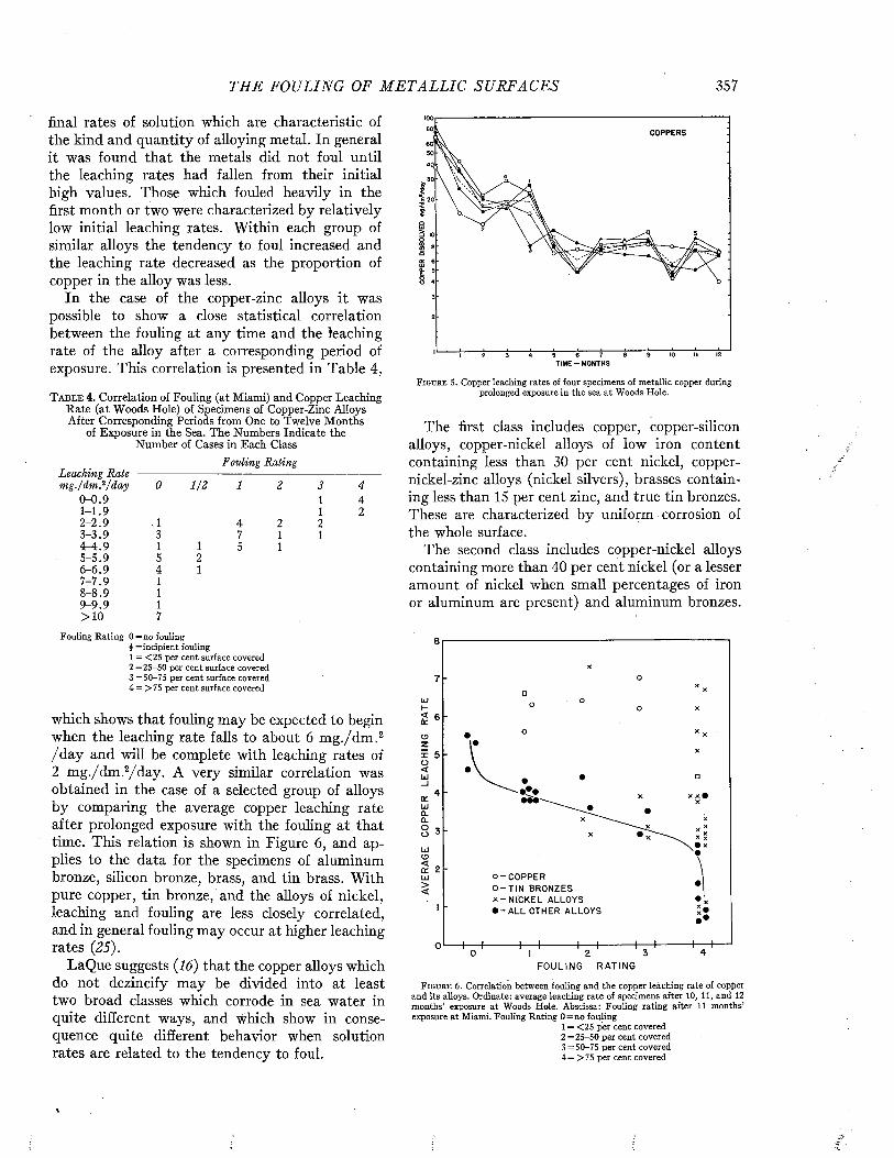
TH E FOULING OF M E T A L L I C SURFACES 357
final rates of solution which are characteristic of the kind and quantity of alloying metal. In general it was found that the metals did not foul until the leaching rates had fallen from their initial high values. Those which fouled heavily in the first month or two were characterized by relatively low initial leaching rates. Within each group of similar alloys the tendency to foul increased and the leaching rate decreased as the proportion of copper in the alloy was less.
In the case of the copper-zinc alloys it was possible to show a close statistical correlation between the fouling at any time and the leaching rate of the alloy after a corresponding period of exposure. This correlation is presented in Table 4,
T a b l e 4 . Correlation of Fouling (at Miami) and Copper Leaching Rate (at Woods Hole) of Specimens of Copper-Zinc Alloys After Corresponding Periods from One to Twelve Months
of Exposure in the Sea. The Numbers Indicate the Number of Cases in Each Class
Fouling RatingLeaching Rate -m g ./d m f/d a y 0 1 /2 1 2 3 4
0 - 0 . 9 1 41 - 1 .9 1 22 - 2 . 9 A 4 2 23 - 3 . 9 3 7 1 1T - 4 .9 1 1 5 15 - 5 . 9 5 26 - 6 . 9 4 17 - 7 . 9 18 - 8 . 9 19 - 9 . 9 1> 1 0 7
Fouling R a tin g 0 = n o foulingi = in c ip ien t fouling1 = < 2 5 per cen t surface covered2 = 2 5 -5 0 per cen t surface covered3 = 5 0 -7 5 per cen t surface covered4 = > 7 5 per cen t surface covered
which shows that fouling may be expected to begin when the leaching rate falls to about 6 m g./dm .2 /d a y and will be complete with leaching rates of 2 m g./dm .2/day. A very similar correlation was obtained in the case of a selected group of alloys by comparing the average copper leaching rate after prolonged exposure with the fouling at that time. This relation is shown in Figure 6, and applies to the data for the specimens of aluminum bronze, silicon bronze, brass, and tin brass. With pure copper, tin bronze/and the alloys of nickel, leaching and fouling are less closely correlated, and in general fouling may occur at higher leaching rates (25).
LaQue suggests (16) that the copper alloys which do not dezincify may be divided into at least two broad classes which corrode in sea water in quite different ways, and which show in consequence quite different behavior when solution rates are related to the tendency to foul.
COPPERS
T I M E -M O N T H S
F i g u r e 5 . Copper leaching rates of four specim ens of m etallic copper during prolonged exposure in th e sea a t W oods H ole.
The first class includes copper, copper-silicon alloys, copper-nickel alloys of low iron content containing less than 30 per cent nickel, copper- nickel-zinc alloys (nickel silvers), brasses containing less than 15 per cent zinc, and true tin bronzes. These are characterized by uniform corrosion of the whole surface.
The second class includes copper-nickel alloys containing more than 40 per cent nickel (or a lesser amount of nickel when small percentages of iron or aluminum are present) and aluminum bronzes.
lii
OzXo<UJ_l
(XLu jCLCLOOU Jo < a: ui > <
o - C O P P E R □ - T I N B R O N Z ES X - N I C K E L ALLOYS • - A L L O THER A LLO Y S
F O U L I N G R A T I N G
F i g u r e 6 . Correlation betw een fouling and th e copper leaching rate o f copper and its alloys. Ordinate: average leach ing rate of specim ens after 10, 11, and 12 m on th s’ exposure a t W oods H ole. Abscissa: Foulin g rating after 11 m onths’ exposure a t M iam i. Foulin g R ating 0 = n o fou ling
1 = < 2 5 per cen t covered2 = 2 5 -5 0 per cen t covered3 = 5 0 -7 5 per cen t covered4 = > 7 5 per cent covered
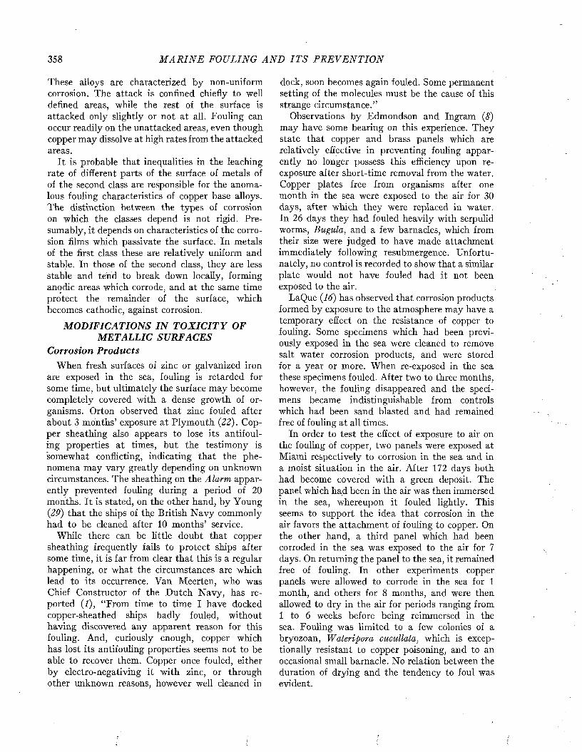
358 M A R I N E FOULING A N D I T S P R E V E N T I O N
These alloys are characterized by non-uniform corrosion. The attack is confined chiefly to well defined areas, while the rest of the surface is attacked only slightly or not at all. Fouling can occur readily on the unattacked areas, even though copper may dissolve at high rates from the attacked areas.
It is probable that inequalities in the leaching rate of different parts of the surface of metals of of the second class are responsible for the anomalous fouling characteristics of copper base alloys. The distinction between the types of corrosion on which the classes depend is not rigid. Presumably, it depends on characteristics of the corrosion films which passivate the surface. In metals of the first class these are relatively uniform and stable. In those of the second class, they are less stable and tend to break down locally, forming anodic areas which corrode, and at the same time protect the remainder of the surface, which becomes cathodic, against corrosion.
MODIFICATIONS IN T O X IC IT Y OF METALLIC SURFACES
Corrosion ProductsWhen fresh surfaces of zinc or galvanized iron
are exposed in the sea, fouling is retarded for some time, but ultimately the surface may become completely covered with a dense growth of organisms. Orton observed that zinc fouled after about 3 months’ exposure at Plymouth (22). Copper sheathing also appears to lose its antifouling properties at times, but the testimony is somewhat conflicting, indicating that the phenomena may vary greatly depending on unknown circumstances. The sheathing on the Alarm apparently prevented fouling during a period of 20 months. It is stated, on the other hand, by Young (29) that the ships of th,e British N avy commonly had to be cleaned after 10 months’ service.
While there can be little doubt that copper sheathing frequently fails to protect ships after some time, it is far from clear that this is a regular happening, or what the circumstances are which lead to its occurrence. Van Meerten, who was Chief Constructor of the Dutch Navy, has reported (I), “From time to time I have docked copper-sheathed ships badly fouled, without having discovered any apparent reason for this fouling. And, curiously enough, copper which has lost its antifouling properties seems not to be able to recover them. Copper once fouled, either by electro-negativing it with zinc, or through other unknown reasons, however well cleaned in
dock, soon becomes again fouled. Some permanent setting of the molecules must be the cause of this strange circumstance.”
Observations by Edmondson and Ingram (8) may have some bearing on this experience. They state that copper and brass panels which are relatively effective in preventing fouling apparently no longer possess this efficiency upon reexposure after short-time removal from the water. Copper plates free from organisms after one month in the sea were exposed to the air for 30 days, after which they were replaced in water. In 26 days they had fouled heavily with serpulid worms, Bugula, and a few barnacles, which from their size were judged to have made attachment immediately following resubmergence. Unfortunately, no control is recorded to show that a similar plate would not have fouled had it not been exposed to the air.
LaQue (16) has observed that corrosion products formed by exposure to the atmosphere may have a temporary effect on the resistance of copper to fouling. Some specimens which had been previously exposed in the sea were cleaned to remove salt water corrosion products, and were stored for a year or more. When re-exposed in the sea these specimens fouled. After two to three months, however, the fouling disappeared and the specimens became indistinguishable from controls which had been sand blasted and had remained free of fouling at all times.
In order to test the effect of exposure to air on the fouling of copper, two panels were exposed at Miami respectively to corrosion in the sea and in a moist situation in the air. After 172 days both had become covered with a green deposit. The panel which had been in the air was then immersed in the sea, whereupon it fouled lightly. This seems to support the idea that corrosion in the air favors the attachment of fouling to copper. On the other hand, a third panel which had been corroded in the sea was exposed to the air for 7 days. On returning the panel to the sea, it remained free of fouling. In other experiments copper panels were allowed to corrode in the sea for 1 month, and others for 8 months, and were then allowed to dry in the air for periods ranging from 1 to 6 weeks before being reimmersed in the sea. Fouling was limited to a few colonies of a bryozoan, Wateripora cucullata, which is exceptionally resistant to copper poisoning, and to an occasional small barnacle. No relation between the duration of drying and the tendency to foul was evident.
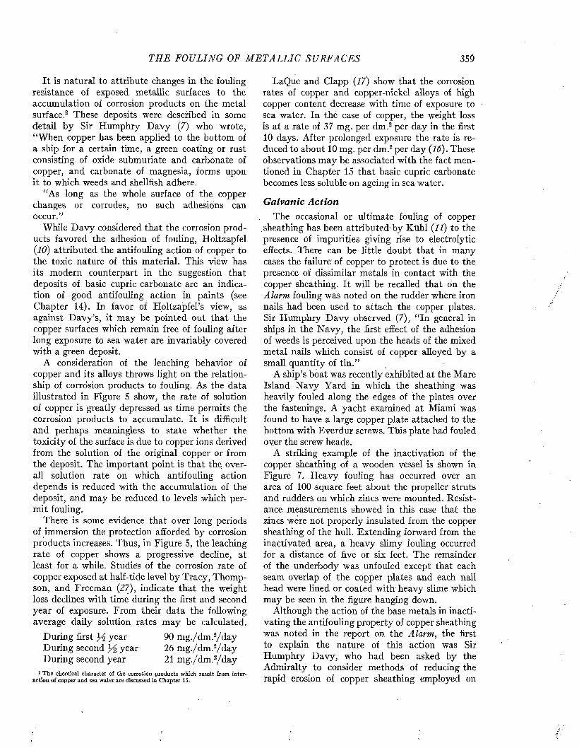
T H E FOULING OF M E T A L L I C SUR FA C E S 359
It is natural to attribute changes in the fouling resistance of exposed metallic surfaces to the accumulation of corrosion products on the metal surface.2 These deposits were described in some detail by Sir Humphry D avy (7) who wrote, “When copper has been applied to the bottom of a ship for a certain time, a green coating or rust consisting of oxide submuriate and carbonate of copper, and carbonate of magnesia, forms upon it to which weeds and shellfish adhere.
“As long as the whole surface of the copper changes or corrodes, no such adhesions can occur.”
While D avy considered that the corrosion products favored the adhesion of fouling, Holtzapfel (10) attributed the antifouling action of copper to the toxic nature of this material. This view has its modern counterpart in the suggestion that deposits of basic cupric carbonate are an indication of good antifouling action in paints (see Chapter 14). In favor of Holtzapfel’s view, as against D avy’s, it may be pointed out that the copper surfaces which remain free of fouling after long exposure to sea water are invariably covered with a green deposit.
A consideration of the leaching behavior of copper and its alloys throws light on the relationship of corrosion products to fouling. As the data illustrated in Figure 5 show, the rate of solution of copper is greatly depressed as time permits the corrosion products to accumulate. It is difficult and perhaps meaningless to state whether the toxicity of the surface is due to copper ions derived from the solution of the original copper or from the deposit. The important point is that the; overall solution rate on which antifouling action depends is reduced with the accumulation of the deposit, and may be reduced to levels which permit fouling.
There is some evidence that over long periods of immersion the protection afforded by corrosion products increases. Thus, in Figure 5, the leaching rate of copper shows a progressive decline, at least for a while. Studies of the corrosion rate of copper exposed at half-tide level by Tracy, Thompson, and Freeman (27), indicate that the weight loss declines with time during the first and second year of exposure. From their data the following average daily solution rates may be calculated.
During first % year 90 m g./dm .2/d a yDuring second year 26 m g./dm .2/d ayDuring second year 21 m g./dm .2/d a y
2 T h e chem ical character of the corrosion products w hich resu lt from interaction o f copper and sea water are discussed in Chapter 15.
LaQue and Clapp (17) show that the corrosion rates of copper and copper-nickel alloys of high copper content decrease with time of exposure to sea water. In the case of copper, the weight loss is at a rate of 37 mg. per dm.2 per day in the first 10 days. After prolonged exposure the rate is reduced to about 10 mg. per dm.2 per day (16). These observations may be associated with the fact mentioned in Chapter 15 that basic cupric carbonate becomes less soluble on ageing in sea water.
Galvanic ActionThe occasional or ultimate fouling of copper
sheathing has been attributed by Kühl (11) to the presence óf impurities giving rise to electrolytic effects. There can be little doubt that in many cases the failure of copper to protect is due to the presence of dissimilar metals in contact with the copper sheathing. It will be recalled that on the Alarm fouling was noted on the rudder where iron nails had been used to attach the copper plates. Sir Humphry D avy observed (7), “In general in ships in the Navy, the first effect of the adhesion of weeds is perceived upon the heads of the mixed metal nails which consist of copper alloyed by a small quantity of tin.”
A ship’s boat was recently exhibited at the Mare Island N avy Yard in which the sheathing was heavily fouled along the edges of the plates over the fastenings. A yacht examined at Miami was found to have a large copper plate attached to the bottom with Everdur screws. This plate had fouled over the screw heads.
A striking example of the inactivation of the copper sheathing of a wooden vessel is shown in Figure 7. Heavy fouling has occurred over an area of 100 -square feet about the propeller struts and rudders on which zincs were mounted. Resistance measurements showed in this case that the zincs were not properly insulated from the copper sheathing of the hull. Extending forward from the inactivated area, a heavy slimy fouling occurred for a distance of five or six feet. The remainder of the underbody was unfouled except that each seam overlap of the copper plates and each nail head were lined or coated with heavy slime which may be seen in the figure hanging down.
Although the action of the base metals in inactivating the antifouling property of copper sheathing was noted in the report on the Alarm, the first to explain the nature of this action was Sir Humphry Davy, who had been asked by the Admiralty to consider methods of reducing the rapid erosion of copper sheathing employed on
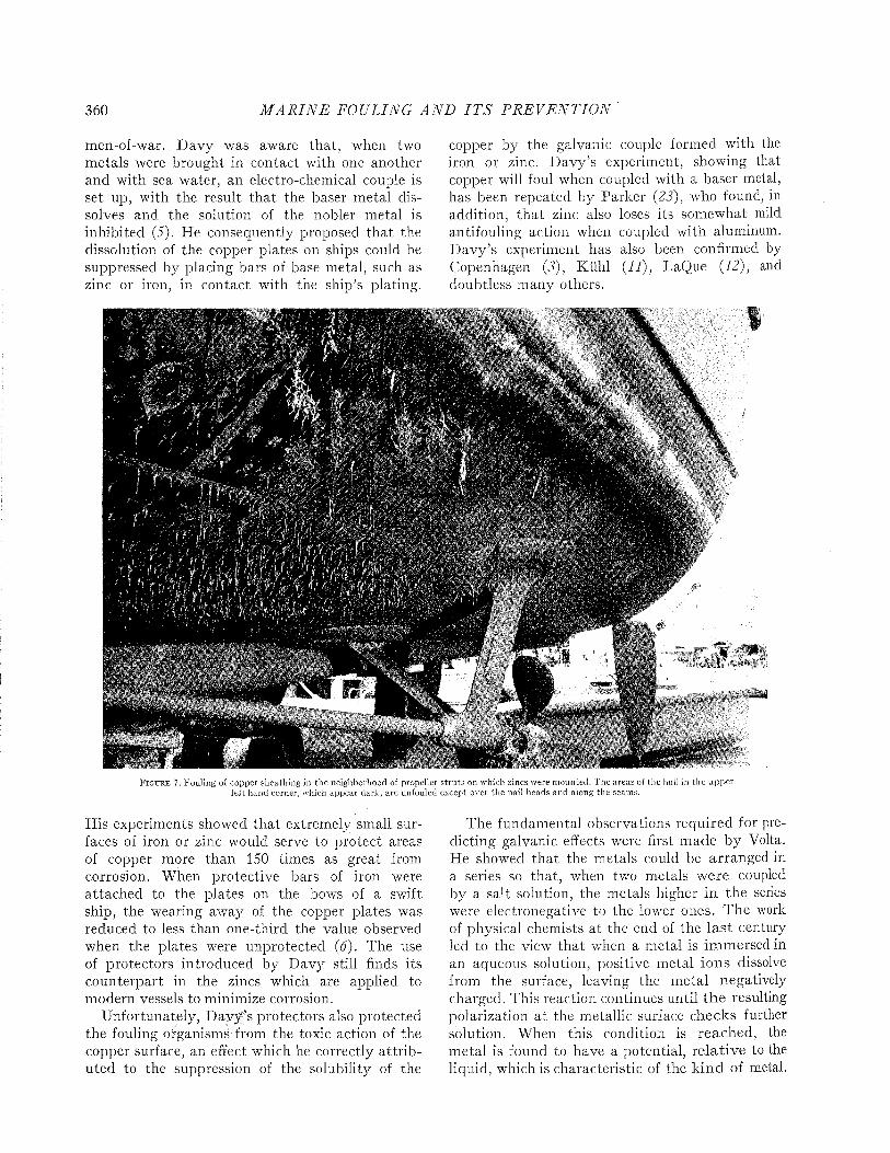
360 M A R I N E FOULING A N D I T S P R E V E N T I O N
men-of-war. Davy was aware that, when two m etals were brought in contact with one another and with sea water, an electro-chemical couple is set up, with the result tha t the baser metal dissolves and the solution of the nobler metal is inhibited (5). He consequently proposed tha t the dissolution of the copper plates on ships could be suppressed by placing bars of base metal, such as zinc or iron, in contact with the ship’s plating.
copper by the galvanic couple formed with the iron or zinc. D avy’s experiment, showing that copper will foul when coupled with a baser metal, has been repeated by Parker (23), who found, in addition, tha t zinc also loses its somewhat mild antifouling action when coupled with aluminum. D avy’s experiment has also been confirmed by Copenhagen (3), Kühl (IJ), LaQue (12), and doubtless many others.
i ß
%
F i g u r e 7. Fouling of copper sheathing in the neighborhood of propeller s tru ts on which zincs were m ounted. T he areas of the hull in the up p er le ft hand corner, which appear dark, are unfouled except over the nail heads and along the seams.
His experiments showed that extremely small surfaces of iron or zinc would serve to protect areas of copper more than 150 times as great from corrosion. When protective bars of iron were attached to the plates on the bows of a swift ship, the wearing away of the copper plates was reduced to less than one-third the value observed when the plates were unprotected (6). The use of protectors introduced by Davy still finds its counterpart in the zincs which are applied to modern vessels to minimize corrosion.
Unfortunately, D avy’s protectors also protected the fouling organisms from the toxic action of the copper surface, an effect which he correctly a ttrib uted to the suppression of the solubility of the
The fundamental observations required for predicting galvanic effects were first made by Volta. He showed that the metals could be arranged in a series so that, when two metals were coupled by a salt solution, the metals higher in the series were electronegative to the lower ones. The work of physical chemists a t the end of the las t century led to the view that when a metal is immersed in an aqueous solution, positive metal ions dissolve from the surface, leaving the m etal negatively charged. This reaction continues until th e resulting polarization at the metallic surface checks further solution. When this condition is reached, the m etal is found to have a potential, relative to the liquid, which is characteristic of the k ind of metal.

THE FOULING OF M E T A L L I C SU RFACES 361
The order of these potentials agrees with the position of the metal in the galvanic series, and it may be assumed as a first approximation that the strength of a galvanic couple will be equal to the difference in potential of the two metals which form the couple.
It is undoubtedly true that the couples which exist on ships’ bottoms, due to the juxtaposition of copper sheathing and nails and other hardware, depart rather widely from these ideal conditions, since equilibrium is doubtless rarely reached between the metal and the sea water. Otherwise, the metal would not continue to corrode. Also, the reaction products formed at the surface between sea water constituents and metals modify the conditions at the surface greatly.
T a b l e 5 . Galvanic Series in Sea Water After LaQue and Cox (IS)
Magnesium, magnesium alloys Zinc, galvanized steel, galvanized wrought iron Aluminum S2SH, 4S, 3S, 2S, 53S-T, alelad CadmiumAluminum A17S-T, 17S-T, 24S-T Mild steel, wrought iron, cast iron Ni-Resist13% chromium stainless steel type 410 (active)Lead tin solder 50-50Stainless steel 18-8 type 304, 18-8-3 type 316 (active)Lead, tinMuntz metal, manganese bronze, Naval brass Nickel (active), inconel (active)Yellow brass, Admiralty brass, aluminum bronze, red brass, cop
per, silicon bronze, ambrac, copper nickel 70-30, comp. G- bronze, comp. M-bronze
Nickel (passive), inconel (passive)MonelStainless steel 18-8 type 304, 18-8-3 type 316 (passive)
LaQue and Cox (18) have made a careful study of the potentials existing between a variety of metals and flowing sea water. Their results show that in a general way the potentials observed under this condition follow the same order as the potentials of metals in equilibrium with solutions of their own salts. The values of the potentials observed, however, were somewhat different and showed a striking change with time. In general, the potentials became more positive during the first month and then returned to their original values, and in some cases became even more negative. Different metals varied in the intensity and regularity of these effects, as is shown in Figure 8. In spite of this difficulty, LaQue and Cox have grouped the commoner metals in a series of increasing potentials as shown in Table 5. Within each group the members may change places depending on conditions of exposure. The range of variation in potential as commonly observed is shown in Figure 9.
1000n.uMMZ£0 WftOUMJJf0*
200 20
40018030 60 90
TIME FROM START OF TEST1500 120
~ TESTOFDAYS
F i g u r e 8. P otentials of m etals in flowing sea w ater. Selected curves m odified after LaQ ue (12).
From these results it may be seen that the various alloys of copper do not differ greatly in the ranges of their potentials, and it is probable tfcat these alloys may be coupled without inducing serious corrosion. This fact is commonly taken into account in the construction of vessels and equipment to be exposed to salt water. On the other hand, it is quite evident that small differences in potential can exist between these metals, provided the state of activity of the coupled members does not vary in the same way. At present there appear to be no measurements to show the potentials which actually exist with such permanent couples in sea water.
Experiments have been conducted in Miami with a view to determining whether the coupling of metals which differ only slightly in position in
1200
1100
|l0 0 0 \ 900 ? 800 3 loo I 600 ? 500
A ïd1 500J 200
£ f'J loo
“ 200
Ï 500 J 400
500600
è - i - i ï_.g i « . gKi—I—:s—i-R -
— n
" J :
- i —
F i g u r e 9. P oten tia ls of m etals and alloys in flow ing sea water. From L aQ ue and C ox (18).

362 M A R I N E FOULING A N D I T S P R E V E N T I O N
the galvanic series, would lead to the inactivation of the antifouling properties of copper and its alloys. This experiment was arranged so that 6 by 18-inch plates of Muntz metal, soft copper, brass, and nickel-silver were coupled each with 6 by 6- inch plates of one of a number of metals chosen so as to cover a wide range of potentials. These plates were exposed to the sea at Miami for 12 months. Zinc, galvanized iron, and aluminum completely inactivated the various copper alloys, as was to be expected. These metals differ in potential from the copper alloys by more than 200 millivolts. Lead did not produce or increase fouling of any of the copper alloys.
Stainless steel, Monel, and brass appeared to increase the fouling which occurred on Muntz metal and nickel-silver. There was no clear evidence that the smaller pieces of inconel, nickel, nickel-silver, or Muntz metal influenced the antifouling action of the larger pieces of any of the metals. However, when the influence of the larger pieces on the fouling of the smaller was examined, it was found that Muntz metal caused light fouling on copper and increased the fouling on nickel-silver. There was some evidence that Muntz metal and nickel-silver inactivated the brass.
The experiment also brought out the interesting fact that the resistance to fouling of small pieces of M untz metal was improved when coupled to larger pieces of nickel-silver or brass. The same effect was observed with a small piece of nickel- silver when coupled with larger pieces of copper. Neither of these fouled in twelve months, though uncoupled specimens fouled after the first few months of exposure.
While the results of this experiment were not sufficiently clear cut to permit arranging the several alloys in a series which would enable predictions to be made as to which metal would influence another, they indicate that metals closely associated in the electro-chemical grouping shown in Table 5 may, nevertheless, influence the fouling resistance of one another when coupled. Three factors may be discerned which appear to determine whether one metal inactivates another. These are:
1. electro-chemical potential2. relative size of the two coupled surfaces3. inherent solution rate
The influence of electro-chemical potential is evident in the action of zinc, iron, and aluminum. The observations that Muntz metal influenced or
was influenced by other copper alloys may be associated in part with the fact that it is slightly more electronegative than the others. The increased antifouling action produced by coupling Muntz metal with copper is particularly interesting since it indicates that galvanic action has increased the solution rate of Muntz metal, as it should on electro-chemical grounds.
The influence of the relative area of the coupled members is in agreement with the well established facts of corrosion. It is known that the corrosion of iron when coupled to copper is proportional to the ratio of the area of copper to that of iron (13).
The influence of the inherent solution rate of the metal is particularly important in the inactivation of antifouling surfaces, since a fairly definite solution rate determines whether the fouling does or does not occur. It is noteworthy that the metals which were most definitely influenced by coupling to other alloys are M untz metal and nickel-silver, both of which fouled lightly when coupled with themselves. Apparently, these metals give off copper nearly at the critical rate. Obviously, the lower the natural rate of solution from the metallic surface, the less potential difference is required to suppress solution to below the critical level. This matter can be formulated in a quantitative manner.
Theoretically, the rate of solution of an anodal surface is proportional to the current density across the surface. Copper dissolves at a rate of 28.4 mg. per day per milliampere, assuming the product is Cu++ (or 56.8 mg. per day per milliampere, assuming Cu+ to be the product). Presumably, the solution rate is decreased in the same ratio at the cathode. It is not clear whether the product is Cu++ or Cu+, or on what conditions their ratio depend. However, some rather rough experiments with copper/iron couples in sea water, made by G. T. Scott, have indicated that applied potentials increase the rate of solution of the copper by about 35 mg. per cm.2 per day for each milliampere per cm.2 when the copper is the anode. When the current flowing through a couple as the result of its inherent electromotive force was decreased by introducing resistance between the electrodes, it was found that the solution rate of the copper cathode increased about 35 mg. per dm.2 per day for each milliampere per cm.2 drop in the galvanic current.
This result is of interest because it indicates what very small current densities are required to suppress the solution of* copper from a surface. Copper has a solution rate of about 0.07 mg. per
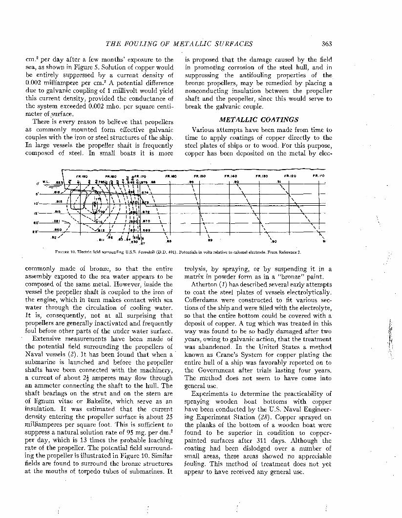
TH E FOULING OF M E T A L L I C SU RFACES 363
cm.2 per day after a few months’ exposure to the sea, as shown in Figure 5. Solution of copper would be entirely suppressed by a current density of 0.002 milliampere per cm.2 A potential difference due to galvanic coupling of 1 millivolt would yield this current density, provided the conductance of the system exceeded 0.002 mho. per square centimeter of surface.
There is every reason to believe that propellers as commonly mounted form effective galvanic couples with the iron or steel structures of the ship. In large vessels the propeller shaft is frequently composed of steel. In small boats it is more
is proposed that the damage caused by the field in promoting corrosion of the steel hull, and in suppressing the antifouling properties of the bronze propellers, may be remedied by placing a nonconducting insulation between the propeller shaft and the propeller, since this would serve to break the galvanic couple.
METALLIC COATINGSVarious attempts have been made from time to
time to apply coatings of copper directly to the steel plates of ships or to wood. For this purpose, copper has been deposited on the metal by elec-
F R . I 'OFR. 190 FR. I$ 0
W.L. .91
. 6 7 4 y
S IS 6 7 8
. 6 7 08 0 *-
. 6 8 0 / . 6 6 9
. 6 2 ✓ .6 8. 6 9 . 9 0
F i g u r e 10. Electric field surrounding XJ.S.S. Farenholi (D .D . 491). P otentia ls in vo lts relative to calom el electrode. From Reference 2.
commonly made of bronze, so that the entire assembly exposed to the sea water appears to be composed of the same metal. However, inside the vessel the propeller shaft is coupled to the iron of the engine, which in turn makes contact with sea water through the circulation of cooling water. It is, consequently, not at all surprising that propellers are generally inactivated and frequently foul before other parts of the under water surface.
Extensive measurements have been made of the potential field surrounding the propellers of Naval vessels (2). It has been found that when a submarine is launched and before the propeller shafts have been connected with the machinery, a current of about 2 | amperes may flow through an ammeter connecting the shaft to the hull. The shaft bearings on the strut and on the stern are of lignum vitae or Bakelite, which serve as an insulation. It was estimated that the current density entering the propeller surface is about 25 milliamperes per square foot. This is sufficient to suppress a natural solution rate of 95 mg. per dm.2 per day, which is 13 times the probable leaching rate of the propeller. The potential field surrounding the propeller is illustrated in Figure 10. Similar fields are found to surround the bronze structures at the mouths of torpedo tubes of submarines. It
trolysis, by spraying, or by suspending it in a matrix in powder form as in a “bronze” paint.
Atherton (I) has described several early attempts to coat the steel plates of vessels electrolytically. Cofferdams were constructed to fit various sections of the ship and were filled with the electrolyte, so that the entire bottom could be covered with a deposit of copper. A tug which was treated in this way was found to be so badly damaged after two years, owing to galvanic action, that the treatment was abandoned. In the United States a method known as Crane’s System for copper plating the entire hull of a ship was favorably reported on to the Government after trials lasting four years. The method does not seem to have come into general use.
Experiments to determine the practicability of spraying wooden boat bottoms with copper have been conducted by the U.S. Naval Engineering Experiment Station (28). Copper sprayed on the planks of the bottom of a wooden boat were found to be superior in condition to copper- painted surfaces after 311 days. Although the coating had been dislodged over a number of small areas, these areas showed no appreciable fouling. This method of treatment does not yet appear to have received any general use.
364 M A R I N E FOULING A N D I T S P R E V E N T I O N
The application of metallic copper in powder or flake form as a paint has been considered in the chapters dealing with paints. The tendency of such coatings to accelerate corrosion, and to become inactivated by galvanic action, will be discussed in the following chapter.
REFERENCES1. A t h e r t o n , W. H .'The Fouling of Ships. Trans. Northeast
Coast Engineers and Shipbuilders, 16, 161-175, 1900.2. Bureau of Ships Research Memorandum. Galvanic Corrosion
of Ships’ Hulls. 15 November 1943.3. C o p e n h a g e n , W. J. The Film Potential Values of Copper,
Brass-Steel-Zinc, in Sea Water with a Note on Marine Growth. Trans. Electro-chem. Soc., 73, 251-259, 1938.
4. D a p t , T. B. The Construction of Iron Ships, and Sheathingthe Same. Trans. Inst. Nav. Arch., 6, 145-147, 1865.
5. D a v y , S i r H u m p h r y . On the Corrosion of Copper Sheathingby Sea Water, and on Methods of Preventing this Effect; and on Their Application to Ships of War and Other Ships. Phil. Trans. Roy. Soc. London, 151-158, 1824.
6. D a v y , S i r H u m p h r y . Additional Experiments and Observations on the Application of Electrical Combinations to the Preservation of the Copper Sheathing of Ships, and to Other Purposes. Phil. Trans. Roy. Soc. London, 242-243, 1824.
7. D a v y , S i r H u m p h r y . Further Researches on the Preservationof Metals by Electro-chemical Means. Phil. Trans. Roy. Soc. London, 328-346, 1825.
8. E d m o n d s o n , C. H., and W. H. I n g r a m . Fouling Organisms inHawaii. Bernice P. Bishop Museum, Occas. Papers, 14, 251-300, 1939.
9. F r i e n d , J. N. The Relative Corrodibilities of Ferrous andNon-Ferrous Metals and Alloys. Jour. Inst, of Metals, 48, p. 109, 1932.
10. H o l t z a p f e l , M. The Corrosion a n d Fouling of Ships. Antifouling Composition. The Steamship, p. 136, Oct. 1, 1889.
11. K ü h l , H. Verhinderung des Anwuchses an Schiffen. Schiffbau, 37, 224-226, 1936.
12. L a Q u e , F. L. The Behavior of Nickel Copper Alloys in SeaW ater. Jour. Am. Soc. Nav. Eng., 53, 29-64, 1941.
13. L a Q u e , F. L. International Nickel Co. Experiments to StudyDistribution of Galvanic Corrosion from a Line Contact and the Effects, of Relative Areas of Anode and Cathode on Such Corrosion. May 1943. Memorandum privately circulated.
14. L a Q u e , F. L. International Nickel Co. Relationship BetweenCorrosion and Fouling of Copper-Nickel Alloys in Sea Water. October 1944. Memorandum privately circulated.
15. L a Q u e , F. L. Behavior of Metals and Alloys in Sea Water.Corrision Handbook, 383-430. John Wiley & Sons, Inc., New York, 1948.
16. L a Q u e , F. L. Personal communication.17. L a Q u e , F. L., and W. F. C la p p . Relationship between Corro
sion and Fouling of Copper-Nickel Alloys in Sea Water. Trans. Electro-chem. Soc., April 16, 1945.
18. L a Q u e , F. L., and G. L. Cox. Some Observation^) of the Potentials of Metals and Alloys in Sea Water. Proc. Am. Soc. for Testing Materials, 40, 1-20, 1940.
19. Mare Island Navy Yard. Quarterly Report on Results ofDevelopment and Tests of Shipbottom Paints. Letter to Bur. C. and R., Aug. 15, 1938.
20. Marine Corrosion Sub-Committee of the Corrosion Committee, The Iron and Steel Institute and the British Iron and Steel Federation. First Report, April 1943.
21. Navy Board’s Report to the Admiralty on the First CopperingExperiment. American Neptune, p. 304, July 1941. Reprinted as Appendix to Chap ter 11.
22. O r t o n , J. H. Experiments in the Sea on the Growth-inhibitiveand Preservative Value of Poisonous Paint and other Substances. Jour. Marine Biol. Ass’n., Plymouth, N.S., 16, 373- 452,.1930.
23. P a r k e r , G. H. The Growth of Marine Animals on Submerged Metals. Biol. Bull., 47, 127-142, 1924.
24. P o m e r a t , C. M., and C. M. W e i s s . The Influence of Textureand Composition of Surface on the Attachment of Sedentary Marine Organisms. Biol. Bull., 91, 57-65, 1946.
25. R e d f i e l d , A. C., C. M. W e i s s , and J. C. A y e r s . Fouling andCorrosion of Copper Base Alloys. Interim Report No. 1 from the Woods Hole Oceanographic Inst, to Bureau of Ships, February 1947.
26. R e d f i e l d , A. C., and C. M. W e i s s . The Resistance of Metallic Silver to Marine Fouling. Biol. Bull., 94, 25-28, 1948.
27. T r a c y , A. W., D. H. T h o m p s o n , and J. R. F r e e m a n , J r . TheAtmospheric Corrosion of Copper. Proc. Am. Soc. for Testing Materials, 1943.
28. U. S. Naval Engineering Experiment Station. Report on Experiment to Determine the Practicability of Metal Spraying Wooden Boat Bottoms with Copper. Report No. 4772-D, M ay 20, 1936.
29. Y o u n g , C. F. T. The Fouling and Corrosion of Iron Ships;Their Causes and Means of Prevention with the Mode of Application to the Existing Ironclads. 212 pp., London, 1867.

Marine Fouling and Its Prevention,Contribution No. 580 from the W oods Flole Oceanographic Institute
Copyright 1952 by U. S. Naval Institute, Annapolis, Maryland George Banta Publishing Co., Menasha, WI
CHAPTER 22
Interaction of Antifouling Paints and SteelThe chief impetus for the development of anti
fouling paints came from the tendency of copper sheathing to corrode iron or steel hulls through galvanic action. Quite naturally suspicion has existed that copper and mercury paints may also accelerate the corrosion of ships’ plates through some similar action. Atherton (2) stated that metallic copper, when introduced into antifouling compositions, sometimes does great injury to ships’ plates, although paints of this type answer the purpose very well when used on small wooden yachts.
When metallic copper is in contact with iron or zinc, the solution of the copper and the attendant antifouling action is suppressed by galvanic action. Since the inhibition of antifouling action of copper is complementary to the increased corrosion of the baser metal in a galvanic couple, it is reasonable to expect that any corrosive action of the paint may also be accompanied by a destruction of the antifouling properties of the composition.
The present chapter contains a discussion of the available information on these two aspects of the interaction between antifouling paints and metallic structures. No attempt is made to consider the subject of anticorrosive coatings more generally.1
ACCELE RATE D C O R R O S IO N DUE TO PA IN T
The corrosive effects of copper paints have been investigated by Young, Seagren, Schneider, and Zehner (17). They exposed primed and unprimed steel panels coated with various paints containing either metallic copper or cuprous oxide to the sea for several months. The coatings were previously scribed diagonally. In one experiment in which a paint containing metallic copper was compared with one in which barytes was substituted for the toxic, it was found after eight months’ immersion that there was somewhat more severe attack under the former, and this was increased on the unprimed panel.
1 T h e m aterial in this chapter was collected a t the request of th e Advisory Com m ittee on M arine Coatings and Corrosion, and issued in substantially its present form as a report by Section II , N .D .R .C . (12). Acknowledgm ent is m ade to Stoner-M udge, In c ., M ultip le Industrial Fellow ship in P rotective C oatings at M ellon In stitu te for the preparation for the Com m ittee of a report (0) on Accelerated Corrosion o f Steel C oated with A ntifouling P aints in w h ich experim ents b y D rs. G. H . Y ou ng and G. W. Seagren are sum marized. O ther previously un published observations h ave been m ade available b y the B ak elite Corporation, working under con tract w ith D ivision II , N .D .R .C ., and b y D r. F . L . LaQ ue of th e International N ickel Co.
In other experiments, the unprimed panels showed much more severe pitting than the primed panels, but, in general, the distribution and severity of pitting under the paint coating away from the scribe marks appeared to be substantially independent of the toxic concentration and even of its type. The scribe marks were much more heavily pitted than the surfaces protected by paint. The depth of corrosion along the scribe mark was generally much greater in the unprimed than in the primed specimens. In both cases the corrosive action, as indicated by the depth of the scribed marks after four months’ exposure, increased roughly in proportion to the concentration of copper in the dry paint film, as the figures in Table 1 show.
T a b l e 1. Effect of Presence of Primer, and Type and Concentration of Copper Pigment on Corrosion at
Interruptions of Paint SurfaceAverage Scribe Depth— mils
Copper inPigm ent Prim ed Unprimed
Weight % Panels Panels68 5.2 18.043 3.3 5.214.5 2.1 0.7
55 4 .4 14.538.5 5.3 9 .412 2 .7 3 .6
38 4 .4 7.233.5 1.4 5.222 1.7 4 .5
Cu powder
Cu paste*
Cu.C
* Propietary m etallic copper pigm ent— Phelps D odge Corporation. § CuîO and ZnO in equal proportions.
These experiments appear to demonstrate that copper paints accelerate corrosion, at least at localized bare areas of steel. The attack was actually as severe with cuprous oxide paints as with those containing metallic copper, when the per cent of copper in the paints was comparable.
Similar experiments have been conducted by the Woods Hole Oceanographic Institution at Miami Beach, using a series of modifications of the metallic copper paint AF23. One series of panels was painted with coatings in which the percentage of metallic copper was progressively reduced. The other series was coated with paints in which cuprous oxide was substituted for metallic copper so as to give the same quantities of copper as those present in the corresponding members of the first series. The paints were applied to steel
365
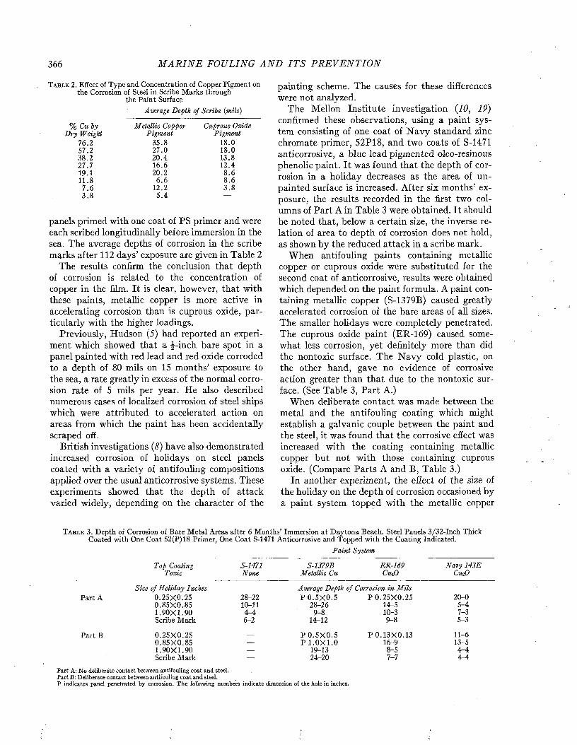
366 M A R I N E FOULING A N D I T S P R E V E N T I O N
T a b l e 2. Effect of Type and Concentration of Copper Pigment on the Corrosion of Steel in Scribe Marks through
the Paint SurfaceAverage Depth of Scribe (mils)
% Cu by D ry Weight
76.257.238.227.7 19.111.8
7 .6 3 .8
Metallic Copper Pigm ent
35.827.0 20.4 16.6 20.2
6.6 12.25.4
Cuprous Oxide Pigm ent
18.0 18.0 13.8 12.4 8.6 8.6 3 .8
panels primed with one coat of PS primer and were each scribed longitudinally before immersion in the sea. The average depths of corrosion in the scribe marks after 112 days’ exposure are given in Table 2
The results confirm the conclusion that depth of corrosion is related to the concentration of copper in the film. It is clear, however, that with these paints, metallic copper is more active in accelerating corrosion than is cuprous oxide, particularly with the higher loadings.
Previously, Hudson (5) had reported an experiment which showed that a f-inch bare spot in a panel painted with red lead and red oxide corroded to a depth of 80 mils on 15 months’ exposure to the sea, a rate greatly in excess of the normal corrosion rate of 5 mils per year. He also described numerous cases of localized corrosion of steel ships which were attributed to accelerated action on areas from which the paint has been accidentally scraped off.
British investigations (8) have also demonstrated increased corrosion of holidays on steel panels coated with a variety of antifouling compositions applied over the usual anticorrosive systems. These experiments showed that the depth of attack varied widely, depending on the character of the
painting scheme. The causes for these differences were not analyzed.
The Mellon Institute investigation {10, 19) confirmed these observations, using a paint system consisting of one coat of N avy standard zinc chromate primer, 52P18, and two coats of S-1471 anticorrosive, a blue lead pigmented oleo-resinous phenolic paint. I t was found that the depth of corrosion in a holiday decreases as the area of unpainted surface is increased. After six months’ exposure, the results recorded in the first two columns of Part A in Table 3 were obtained. It should be noted that, below a certain size, the inverse relation of area to depth of corrosion does not hold, as shown by the reduced attack in a scribe mark.
When antifouling paints containing metallic copper or cuprous oxide were substituted for the second coat of anticorrosive, results were obtained which depended on the paint formula. A paint containing metallic copper (S-1379B) caused greatly accelerated corrosion of' the bare areas of all sizes. The smaller holidays were completely penetrated. The cuprous oxide paint (ER -169) caused somewhat less corrosion, yet definitely more than did the nontoxic surface. The N avy cold plastic, on the other hand, gave no evidence of corrosive action greater than that due to the nontoxic surface. (See Table 3, Part A.)
When deliberate contact was made between the metal and the antifouling coating which might establish a galvanic couple between the paint and the steel, it was found that the corrosive effect was increased with the coating containing metallic copper but not with those containing cuprous oxide. (Compare Parts A and B, Table 3.)
In another experiment, the effect of the sizé of the holiday on the depth of corrosion occasioned by a paint system topped with the metallic copper
T a b l e 3. Depth of Corrosion of Bare Metal Areas after 6 Months’ Immersion at Daytona Beach. Steel Panels 3/32-Inch Thick Coated with One Coat 52(P)18 Primer, One Coat S-1471 Anticorrosive and Topped with the Coating Indicated.
Top Coaling T oxic
P ain t System
S-1471None
S-1379B Metallic Cu
ER -169Cu-,0
N avy 143E CuiO
Sise of H oliday Inches A ver age Depth of Corrosion in M ilsPart A 0 .25X 0 .25 28-22 P 0 .5 X 0 .5 P 0 .2 5 X 0 .2 5 20-0
0 .8 5 X 0 .8 5 10-11 28-26 14-5 5-41 .90X 1 .90 4-4 9-8 10-3 7-3Scribe Mark 6-2 14-12 9-8 5-3
Part B 0 .25X 0 .25 _ P 0 .5 X 0 .5 P 0 .1 3X 0 .13 11-60 .85X 0 .85 — P 1 .0 X 1 .0 16-9 13-51 .90X 1 .90 — 19-13 8-5 4-4Scribe Mark — 24-20 7-7 4-4
P art A: N o deliberate con tact between antifouling co a t and steel.P art B : D elib erate con tact betw een antifouling c o a t and steel.P ind icates panel penetrated b y corrosion. T h e follow ing num bers ind icate dim ension of the hole in inches.
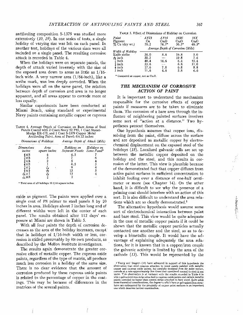
I N T E R A C T I O N OF A N T IF O U L IN G P A I N T S A N D S T E E L 367
antifouling composition S-1379 was studied more extensively (10, 19). In one series of tests, a single holiday of varying size was left on each panel. In another test, holidays of the various sizes were all included on a single panel. The resulting corrosive attack is recorded in Table 4.
When the holidays were on separate panels, the depth of attack varied inversely with the size of the exposed area down to areas as little as 1 /16- inch wide. A very narrow area (1/64-inch), like a scribe mark, was less deeply corroded. When the holidays were all on the same panel, the relation between depth of corrosion and area is no longer apparent, and all areas appear to corrode more or less equally.
Similar experiments have been conducted at Miami Beach, using standard or experimental N avy paints containing metallic copper or cuprous
T a b l e 4 . Average Depth of Corrosion on Bare Areas of Steel Panels Coated with 2 Coats Navy 52 P18, 1 Coat Stoner-
Mudge ER-173, and 1 Coat S-1379 Copper Metal Antifouling Paint. Area of Panel: 6X12 inches
Dimensions of Holidays Average Depth of Attack {Mils)
Dimensions Area H olidays on H olidays oninches square inches Separate Panels Same Panel*
1X 8 4 4.5 71X8 3 7 61X 8 2 5 4ÍX 8 1 6.5 3I X | i16 9 4ÎX J 116 13 5
A X I 116 13 400XH2 I8 2 —
* T ota l area of all holidays 10 3 /1 6 square inches.
oxide as pigment. The paints were applied over a single coat of P8 primer to steel panels 8 by 10 inches in area. Holidays about 7 inches long and of different widths were left in the center of each panel. The results obtained after 112 days’ exposure at Miami are shown in Table 5.
W ith all four paints the depth of corrosion decreases as the area of the holiday increases, except that in holidays of 1/16-inch width or less, corrosion is stifled presumably by its own products, as described by the Mellon Institute investigators.
The results again demonstrate the greater corrosive effect of metallic copper. The cuprous oxide paints, regardless of the type of matrix, all produce much less corrosion in a holiday of the same size. There is no clear evidence that the amount of corrosion produced by these cuprous oxide paints is related to the percentage of copper in the coatings. This may be because of differences in the matrices of the several paints.
T a b l e 5. Effect of Dimensions of Holiday on CorrosionP ain t ' A F 23 A F 14 143E 16 XPigment Cu Cu20 Cu20 Cu20% Cu (dry wt.) 76.2 74.7* 36.3* 46.3*
Average Depth of Corrosion {Mils)W idth of H oliday -------------------------------------------------------------Knife scribe 36 .0 8 .8 16.8 5 .0A inch 30.2 — 19.8 7 .6
I inch 40 .4 14.6 6 .4 13.4i inch 33 .6 — 6 .8 11.0i inch 17.6 7 .8 6 .8 8 .81 inch 11.6 4 .6 3 .8 6 .6
* Com puted as copper, n o t as CmO.
THE MECHANISM OF CORROSIVE ACTION OF PAINT
It is important to understand the mechanism responsible for the corrosive effects of copper paints if measures are to be taken to eliminate them. The corrosion of a bare area through the influence of neighboring painted surfaces involves some sort of “action at a distance.” Two hypotheses present themselves.
One hypothesis assumes that copper ions, dissolving from the paint, diffuse across the surface and are deposited as metallic copper by electrochemical displacement on the exposed steel of the holidays (18). Localized galvanic cells are set up between the metallic copper deposited on the holiday and the steel, and this results in corrosion of the latter. This view is plausible because of the demonstrated fact that copper diffuses from active paint surfaces in sufficient concentration to inhibit fouling over a distance of one-half centimeter or more (see Chapter 14). On the other hand, it is difficult to see why the presence of a priming coat should interfere with an action of this sort. It is also difficult to understand the area relations which are so clearly demonstrated.2
The alternative hypothesis would assume some sort of electrochemical interaction between paint and bare steel. This view would be quite adequate in the case of metallic copper paints if it could be shown that the metallic copper particles actually contacted one another and the steel, so as to develop a bimetallic couple. It would have the advantage of explaining adequately the area relations, for it is known that in a copper/iron couple the galvanic activity is limited by the area of the cathode (13). This would be represented by the
2 Y oung and Seagren (IS) h a v e advanced in support of th is hypothesis the observation th at steel coupons attached to w ood panels painted with m etallic copper and cuprous oxide paints, but carefully insulated from the paint surface, corrode a t a rate approxim ately five tim es th a t considered norm al to steel in sea water. T h is observation is a t variance w ith the results recorded in T ab le 6 in which galvanized iron strips attached to cuprous oxide paints and certain m etallic paints corroded no faster than control strips attached to bare wood. Q uite aside from theoretical considerations, th e degree to which bare or galvanized iron structures are endangered by th e proxim ity of copper paint surfaces is an im portant one which deserves further exam ination.
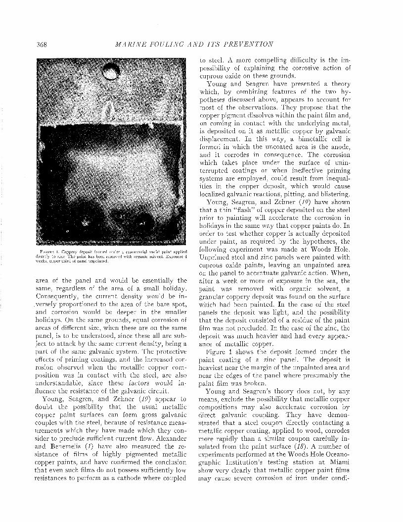
368 M A R I N E FOULING A N D I T S P R E V E N T I O N
F i g u r e 1. Coppery deposit formed under a commercial yach t pa in t applied directly to zinc. T he pain t has been removed w ith organic solvent. Exposure 4 weeks, upper th ird of panel unpainted.
area of the panel and would be essentially the same, regardless of the area of a small holiday. Consequently, the current density would be inversely proportioned to the area of the bare spot, and corrosion would be deeper in the smaller holidays. On the same grounds, equal corrosion of areas of different size, when these are on the same panel, is to be understood, since these all are subject to attack by the same current density, being a part of the same galvanic system. The protective effects of priming coatings, and the increased corrosion observed when the metallic copper composition was in contact with the steel, are also understandable, since these factors would influence the resistance of the galvanic circuit.
Young, Seagren, and Zehner (19) appear to doubt the possibility tha t the usual metallic copper paint surfaces can form gross galvanic couples wi-th the steel, because of resistance measurements which they have made which they consider to preclude sufficient current flown Alexander and Benemelis (I) have also measured the resistance of films of highly pigmented metallic copper paints, and have confirmed the conclusion th a t even such films do not possess sufficiently low resistances to perform as a cathode where coupled
to steel. A more compelling difficulty is the impossibility of explaining the corrosive action of cuprous oxide on these grounds.
Young and Seagren have presented a theory which, by combining features of the two hypotheses discussed above, appears to account for most of the observations. They propose tha t the copper pigment dissolves within the paint film and, on coming in contact with the underlying metal, is deposited on it as metallic copper by galvanic displacement. In this way, a bimetallic cell is formed in which the uncoated area is the anode, and it corrodes in consequence. The corrosion which takes place under the surface of uninterrupted coatings or when ineffective priming systems are employed, could result from inequalities in the copper deposit, which would cause localized galvanic reactions, pitting, and blistering.
Young, Seagren, and Zehner (IP) have shown that a thin “flash” of copper deposited on the steel prior to painting will accelerate the corrosion in holidays in the same way tha t copper paints do. In order to test whether copper is actually deposited under paint, as required by the hypotheses, the following experiment was made at Woods Hole. Unprimed steel and zinc panels were painted with cuprous oxide paints, leaving an unpainted area on the panel to accentuate galvanic action. When, after a week or more of exposure in the sea, the paint was removed with organic solvent, a granular coppery deposit was found on the surface which had been painted. In the case of the steel panels the deposit was light, and the possibility that the deposit consisted of a residue of the paint film was not precluded. In the case of the zinc, the deposit was much heavier and had every appearance of metallic copper.
Figure 1 shows the deposit formed under the paint coating of a zinc panel. The deposit is heaviest near the margin of the unpainted area and near the edges of the panel where presumably the paint film was broken.
Young and Seagren’s theory does not, by any means, exclude the possibility th a t metallic copper compositions may also accelerate corrosion by direct galvanic coupling. They have demonstrated tha t a steel coupon directly contacting a metallic copper coating, applied to wood, corrodes more rapidly than a similar coupon carefully insulated from the paint surface {18). A number of experiments performed at the Woods Hole Oceanographic Institution’s testing station at Miami show very clearly tha t metallic copper paint films may cause severe corrosion of iron under condi
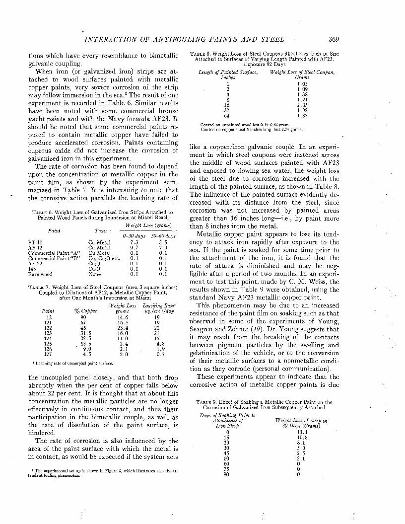
I N T E R A C T I O N OF A N T IF O U L IN G P A I N T S A N D STEEL 369
tions which have every resemblance to bimetallic galvanic coupling.
When iron (or galvanized iron) strips are attached to wood surfaces painted with metallic copper paints, very severe corrosion of the strip may follow immersion in the sea.3 The result of one experiment is recorded in Table 6. Similar results have been noted with some commercial bronze yacht paints and with the N avy formula AF23. It should be noted that some commercial paints reputed to contain metallic copper have failed to produce accelerated corrosion. Paints containing cuprous oxide did not increase the corrosion of galvanized iron in this experiment.
The rate of corrosion has,been found to depend upon the concentration of metallic copper in the paint film, as shown by the experiment summarized in Table 7. It is interesting to note that the corrosive action parallels the leaching rate of
T a b l e 6. Weight Loss of Galvanized Iron Strips Attached to Painted Wood Panels during Immersion at Miami Beach
Weight Loss {grams)
0 -30 days 30 -60 daysP ain t T oxic
PT 10 Cu Metal 7.3 3 .5AF 12 Cu Metal 9.7 7.0Commercial Paint “A” Cu Metal 0.1 0.1Commercial Paint “B ” Cu, Cu20 etc. 0.1 0 .1AF 22 Cu20 0.1 0.1143 CuoO 0.1 0.1Bare wood None 0.1 0.1
T a b l e 7 . Weight Loss of Steel Coupons (area 3 square inches) Coupled to Dilutions of AF12, a Metallic Copper Paint,
after One Month’s Immersion at MiamiWeight Loss Leaching Rate*
P ain t % Copper grams fig./c m ? /12 90 14.6 19
121 67 16.5 19122 45 23 .4 21123 31.5 16.0 21124 22.5 11.0 15125 13.5 2 .4 4 .8126 ' 9 .0 2.1 1.9127 4 .5 2 .0 0.7
* Leaching rate of uncoupled paint surface.
the uncoupled panel closely, and that both drop abruptly when the per cent of copper falls below about 22 per cent. It is thought that at about this concentration the metallic particles are no longer effectively in continuous contact, and thus their participation in the bimetallic couple, as well as the rate of dissolution of the paint surface, is hindered.
The rate of corrosion is also influenced by the area of the paint surface with which the metal is in contact, as would be expected if the system acts
3 T h e experim ental se t up is show n in F igure 3, w h ich illustrates also the atten dant fouling phenom ena.
T a b l e 8. Weight Loss of Steel Coupons S fX lX r g Inch in Size Attached to Surfaces of Varying Length Painted with AF23.
Exposure 92 DaysLength of Pain ted Surface, Weight Loss of Steel Coupon,
Inches Grams1 1 .0 52 1 .0 94 1 .3 88 1 .2 1
16 2 .0 532 1 .9 26 4 1 .3 7
Control on unpainted wood lo st 0 .35-0 .64 gram. Control on copper sheet 5 inches long lo st 2.74 grams.
like a copper/iron galvanic couple. In an experiment in which steel coupons were fastened across the middle of wood surfaces painted with AF23 and exposed to flowing sea water, the weight loss of the steel due to corrosion increased with the length of the painted surface, as shown in Table 8. The influence of the painted surface evidently decreased with its distance from the steel, since corrosion was not increased by painted areas greater than 16 inches long—i.e., by paint more than 8 inches from the metal.
Metallic copper paint appears to lose its tendency to attack iron rapidly after exposure to the sea. If the paint is soaked for some time prior to the attachment of the iron, it is found that the rate of attack is diminished and may be negligible after a period of two months. In an experiment to test this point, made by C. M. Weiss, the results shown in Table 9 were obtained, using the standard N avy AF23 metallic copper paint.
This phenomenon may be due to an increased resistance of the paint film on soaking such as that observed in some of the experiments of Young, Seagren and Zehner {19). Dr. Young suggests that it may result from the breaking of the contacts between pigment particles by the swelling and gelatinization of the vehicle, or to the conversion of their metallic surfaces to a nonmetallic condition as they corrode (personal communication).
These experiments appear to indicate that the corrosive action of metallic copper paints is due
T a b l e 9. Effect of Soaking a Metallic Copper Paint on the Corrosion of Galvanized Iron Subsequently Attached
D ays of Soaking P rior lo Attachment of
Iron Strip 0
IS 3 0 3 0 45 6 0 60 75 90
Weight Loss of S trip in 30 D ays (Grams)
13.110.88.15 . 02 .52. 1 000
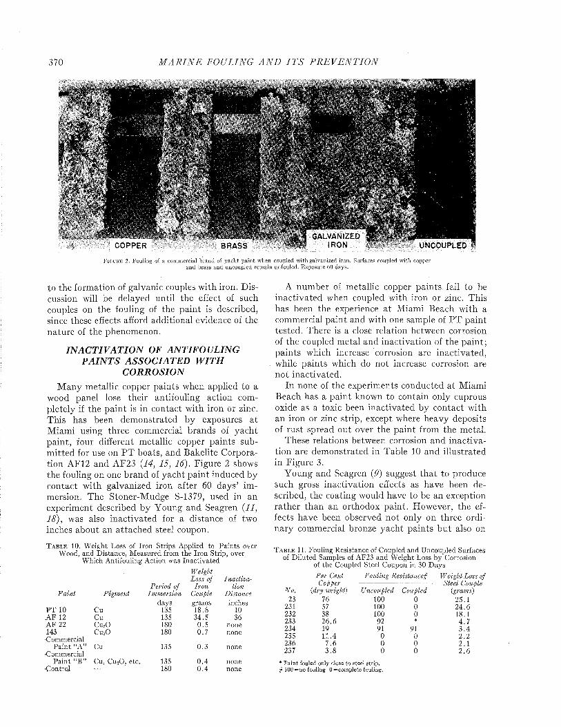
370 M A R I N E FOULING A N D I T S P R E V E N T I O N
m
GALVANIZED IRON UNCOUPLEDCOPPER BRASS
F i g u r e 2. Fouling of a commercial brand of yacht pa in t when coupled with galvanized iron. Surfaces coupled with copper and brass and uncoupled rem ain unfouled. Exposure 60 days.
to the formation of galvanic couples with iron. Discussion will be delayed until the effect of such couples on the fouling of the paint is described, since these effects afford additional evidence of the nature of the phenomenon.
I N A C T I V A T I O N OF AN T IF O U L IN G P A I N T S ASSO C IA TED W I T H
C O R R O S I O NM any metallic copper paints when applied to a
wood panel lose their antifouling action completely if the paint is in contact with iron or zinc. This has been demonstrated by exposures a t Miami using three commercial brands of yacht paint, four different metallic copper paints subm itted for use on PT boats, and Bakelite Corporation AF12 and AF23 (14, 15, 16). Figure 2 shows the fouling on one brand of yacht paint induced by contact with galvanized iron after 60 days’ immersion. The Stoner-Mudge S-1379, used in an experiment described by Young and Seagren (11, 18), was also inactivated for a distance of two inches about an attached steel coupon.
T a b l e 10. Weight Loss of Iron Strips Applied to Paints over- Wood, and Distance, Measured from the Iron Strip, over
Which Antifouling Action was InactivatedWeightLoss of Inactiva
Period of Iron tionPaint Pigment Immersion Couple Distance
days grams inchesP T 10 Cu 135 18.8 10A F 12 Cu 135 34.5 36A F 22 Cu20 180 0 .5 none143 Cu20 180 0.7 none■Commercial
Paint “A” Cu 135 0.3 noneCommercial
Paint “B ” Cu, Cu20 , etc. 135 0 .4 noneControl — 180 0.4 none
A number of metallic copper paints, fail to be inactivated when coupled with iron or zinc. This has been the experience at Miami Beach with a commercial paint and with one sample of P T paint tested. There is a close relation between corrosion of the coupled metal and inactivation of the paint; paints which increase corrosion are inactivated, while paints which do not increase corrosion are not inactivated.
In none of the experiments conducted at Miami Beach has a paint known to contain only cuprous oxide as a toxic been inactivated by contact with an iron or zinc strip, except where heavy deposits of rust spread out over the paint from the metal.
These relations between corrosion and inactivation are demonstrated in Table 10 and illustrated in Figure 3.
Young and Seagren (9) suggest th a t to produce such gross inactivation effects as have been described, the coating would have to be an exception rather than an orthodox paint. However, the effects have been observed not only on three ordinary commercial bronze yacht paints bu t also on
T a b l e 11. Fouling Resistance of Coupled and Uncoupled Surfaces of Diluted Samples of AF23 and Weight Loss by Corrosion
of the Coupled Steel Coupon in 30 DaysPer Cent Fouling Resistancejf Weight Loss ofCopper Steel Couple
No. {dry weight) Uncoupled Coupled (grams)23 76 100 0 25.1
231 57 100 0 24.6232 38 100 0 18.1233 26.6 92 * 4 .7234 19 91 91 3 .4235 11.4 0 0 2 .2236 7 .6 0 0 2.1237 3 .8 0 0 2 .6
* P a in t fouled only close to steel strip.# i 0 0 —no fouling 0= com plete fouling.
I N T E R A C T I O N OF A N T I F O U L I N G P A I N T S A N D S T E E L 371
F i g u r e 3 . Inactiva tion of antifouling action of metallic copper paints, PTlO and AF12 when coupled to galvanized iron. N o inactivation occurs w ith the cuprous oxide pain ts AF22 and 1 4 3 E or w ith Commercial P a in t “ B” . Commercial
Taint “ A” fouled w hether coupled or not. Exposure 91 days. U, uncoupled B, bare wood, C, coupled.
AF23, a paint at one time used by the Navy, and on a number of paints, such as PT10, submitted by the industry for use on high-speed wooden vessels.
The occurrence of inactivation can be shown to be associated with high pigment loading. Table
11 shows the result of an experiment in which the relative proportions of pigment and binder were varied, with the result that both corrosion and inactivation of the antifouling action dropped abruptly when the per cent of copper in the dry paint film was reduced to about 25 per cent. A
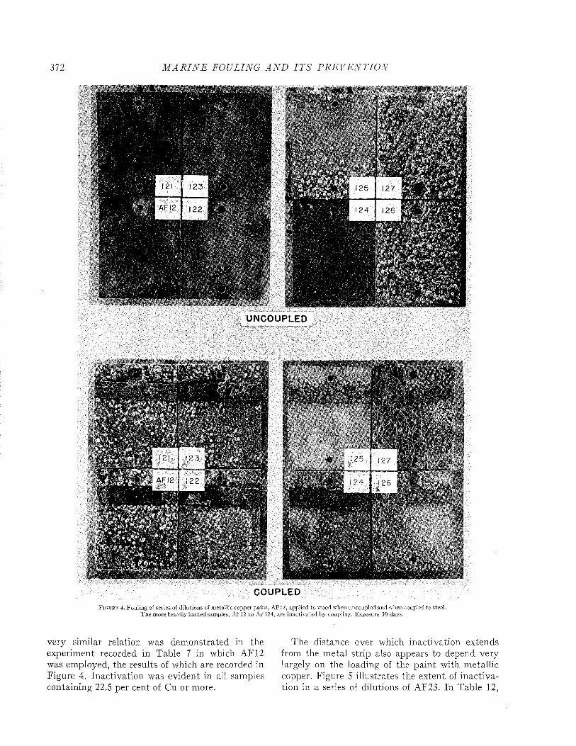
3 72 M A R I N E FOULING A N D I T S P R E V E N T I O N
A F 12
UNCOUPLED
AFI2
CO UP LEDF i g u r e 4 . Fouling of series of dilutions of metallic copper pain t, AF12, applied to wood when uncoupled and when coupled to steel.
T he more heavily loaded samples, AF12 to A FÍ24, are inactivated by coupling. Exposure 30 days.
very similar relation was demonstrated in the experiment recorded in Table 7 in which AF12 was employed, the results of which are recorded in Figure 4. Inactivation was evident in all samples containing 22.5 per cent of Cu or more.
The distance over which inactivation extends from the metal strip also appears to depend very largely on the loading of the paint with metallic copper. Figure 5 illustrates the extent of inactivation in a series of dilutions of AF23. In Table 12,
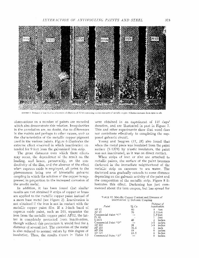
I N T E R A C T I O N OF A N T IF O U L IN G P A I N T S A N D S T E E L 373
F i g u r e 5. D istance of inactivation of a series of dilutions of AF23 containing various am ounts of metallic copper. D ilution increases from righ t to left.
observations on a number of paints are recorded which also demonstrate this relation. Irregularities in the correlation are, no doubt, due to differences in the m atrix and perhaps to other causes, such as the characteristics of the metallic copper pigment used in the various paints. Figure 6 illustrates the extreme effect observed in which inactivation extended for 9 feet from the galvanized iron strip.
The great distances over which these effects may occur, the dependence of the result on the loading, and hence, presumably, on the conductivity of the film, and the absence of the effect when cuprous oxide is employed, all point to the phenomenon being one of bimetallic galvanic coupling in which the solution of the copper is suppressed in proportion to the increased corrosion of the anodic metal.
In addition, it has been found tha t similar results are not obtained if strips of copper or brass are applied to the metallic copper paint instead of a more base metal (see Figure 2). Inactivation is not obtained if the iron is not in contact with the metallic copper paint film. If a 2-inch band of cuprous oxide paint, such as 143, separates the iron from the metallic copper paint AF12, the la tter is completely protected from inactivation, though without this protection it would foul for a distance of several feet. The corrosion of the metal is also reduced to normal values by this degree of insulation. Thus, the results shown in Table 13
were obtained in an experiment of 115 days’ duration, and. are illustrated in part in Figure 7. This and other experiments show that wood does not contribute effectively to completing the supposed galvanic circuit.
Young and Seagren (11,. 18) also found that when the metal piece was insulated from the paint surface (S-1379) by plastic insulators, the paint was not inactivated, as it was on direct contact.
When strips of iron or zinc are attached to metallic paints, the surface of the paint becomes darkened in the immediate neighborhood of the metallic strip on exposure to sea water. The darkened area gradually extends to some distance depending on the galvanic activity of the paint and the composition of the metallic strip. Figure 8 illustrates this effect. Darkening has just commenced about the iron coupon, but has spread for
T a b l e 12. Metallic Copper Content and Distance of Inactivation by Galvanic Coupling
Paint % CuDistance of Inactivation
AF 12 90 9 feetAF 23 76 2. 5 feetCommercial Paint “C” — 1. 5 feetP t 10 — 1 footS-1471 40 2 inchesCommercial Paint “D ” — > 8 inchesAF 232 38 > 8 inchesAF 233 26.6 1 inchAF 234 19 0 inchesAF 125 13.5 0 inchesCommercial Paint “A” — 0 inches
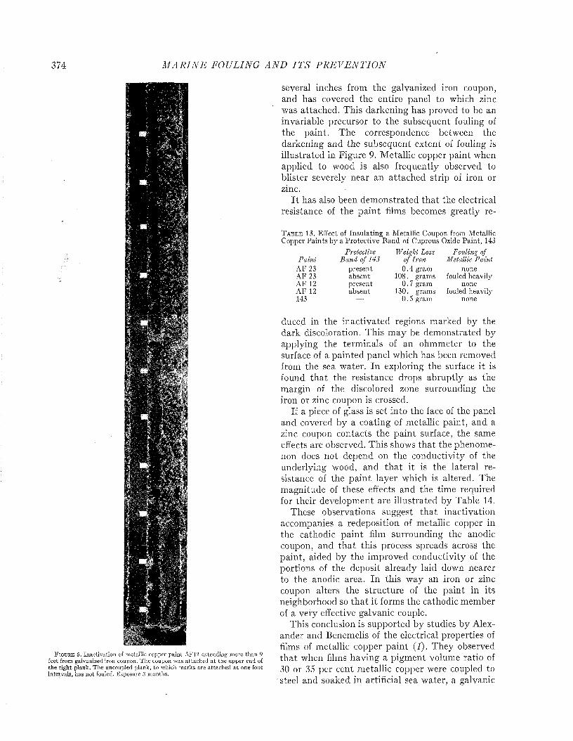
374 M A R I N E FOULING A N D I T S P R E V E N T I O N
F i g u r e 6. Inactivation of metallic copper pain t AF12 extending m ore than 9 feet from galvanized iron coupon. T he coupon was a ttached a t the upper end of th e r igh t plank. T h e uncoupled plank, to which m arks are attached a t one-foot in tervals, has no t fouled. Exposure 3 m onths.
several inches from the galvanized iron coupon, and has covered the entire panel to which zinc was attached. This darkening has proved to be an invariable precursor to the subsequent fouling of the paint. The correspondence between the darkening and the subsequent extent of fouling is illustrated in Figure 9. Metallic copper paint when applied to wood is also frequently observed to blister severely near an attached strip of iron or zinc.
I t has also been demonstrated tha t the electrical resistance of the paint films becomes greatly re-
T a b l e 13 . Effect of Insulating a Metallic Coupon from Metallic Copper Paints by a Protective Band of Cuprous Oxide Paint, 143
Protective Weight Loss Folding ofPaint Band of 143 of Iron Metallic Paini
AF 23 present 0 .4 gram noneAF 23 absent 108. grams fouled heavilyAF 12 present 0.7 gram noneAF 12 absent 130. grams fouled heavil}'143 — 0. S gram none
duced in the inactivated regions marked by the dark discoloration. This may be demonstrated by applying the terminals of an ohmmeter to the surface of a painted panel which has been removed from the sea water. In exploring the surface it is found th a t the resistance drops abruptly as the margin of the discolored zone surrounding the iron or zinc coupon is crossed.
If a piece of glass is set into the face of the panel and covered by a coating of metallic paint, and a zinc coupon contacts the paint surface, the same effects are observed. This shows tha t the phenomenon does not depend on the conductivity of the underlying wood, and th a t it is the lateral resistance of the paint layer which is altered. The magnitude of these effects and the time required for their development are illustrated by Table 14.
These observations suggest tha t inactivation accompanies a redeposition of metallic copper in the cathodic paint film surrounding the anodic coupon, and th a t this process spreads across the paint, aided by the improved conductivity of the portions of the deposit already laid down nearer to the anodic area. In this way an iron or zinc coupon alters the structure of the paint in its neighborhood so th a t it forms the cathodic member of a very effective galvanic couple.
This conclusion is supported by studies by Alexander and Benemelis of the electrical properties of films of metallic copper paint (I). They observed tha t when films having a pigment volume ratio of 30 or 35 per cent metallic copper were coupled to steel and soaked in artificial sea water, a galvanic
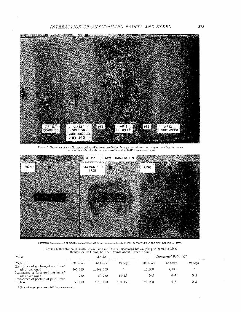
I N T E R A C T I O N OF A N T IF O U L IN G P A I N T S A N D S T E E L 375
‘ »WM«ir u
AF 12 ED w m COUPON
SURROUNDED BY 143
AF12 COUPLED
AF 12 UNCOUPLED
IRON
Paint
F i g u r e 7 . P rotection of m etallic copper pain t, AF12 from inactivation by a galvanized iron coupon by surrounding the coupon with an area pain ted w ith the cuprous oxide coating 143E. Exposure 60 days.
A" A I-
Din- NT"' 4kIRON
»j r
- .
■Mil— i
F i g u r e 8. Discoloration of metallic copper pa in t AF23 surrounding coupons of iron, galvanized iron and zinc. Exposure 5 days.
T a b l e 14. Resistance of Metallic Copper Paint Films Discolored by Coupling to Metallic Zinc. Resistance, in Ohms, between Points about 1 Inch Apart.
Commercial Paini “C”A F 2 3
ExposureResistance of unchanged portion of
paint over wood Resistance of discolored portion of
paint over wood Resistance of portion of paint over
glass* N o unchanged pain t areas left for measurem ent.
24 hours 48 hours 10 days 24 hours 48 hours 10 days
3-5,000 1,5-2,500 * 15,000 5,000 *
250 50-250 10-25 0-5 0-5 0-5
50,000 5-10,000 100-150 70,000 0-5 0-5

Ml
LLI
AM
PS
376 M A R I N E FOULING A N D I T S P R E V E N T I O N
A
15 DAYS3 0 DAYS
F i g u r e 9 . D iscoloration of metallic copper pa in t AF23 preceding inactivation of antifouling action b y coupling to galvanized iron.
WITH AGITATION AND AERATIONWITHOUT AGITATION S AERATION
2 5 5 0 75 100 125 150 175 2 0 0 2 2 5 2 5 0 2 7 5 3 0 0 3 2 5 3 5 0 3 7 5
\ ----------- WITH AERATION AND AGITATION------------WITHOUT AERATION 8 AGITATION
ƒ....\
\/ — / N11
' V /
I
1 x i1
1 ^
- 4HOURS I M M E R S E D
F i g u r e 10. Galvanic cu rren t from copper-steel couple (above) and from m eta llic copper paint-steel couple (below). From Alexander and Benemeljs ( ;) ,
current developed which increased markedly after an initial period when little or no current flowed. Figure 10 shows the current produced by such a couple during immersion, and also that produced by a similar couple of copper and steel. At the time of its maximum development the current produced by the paint-steel couple is as great or greater than tha t of the copper-steel couple. The resistance of the paint films was also shown to decrease during coupling to values characteristic of good conductors. This change in resistance did not occur if the paint films were soaked without being coupled to steel, and is evidently the result of some change produced in the paint as the result of coupling. These phenomena did not occur in films having a pigment-volume ratio of 25 per cent or less, which is close to the limit mentioned on a previous page below which inactivation of antifouling action does not occur.
Alexander and Benemelis conclude that, when placed in the role of a cathode, the copper particles of a metallic copper paint undergo some change in their position relative to each other, either because a breakdown occurs in the resistance of intervening barrier insulators formed by envelopes of the matrix, or because copper passes into solution and redeposits according to the theory of Young, Seagren and Zehner (19). Below

I N T E R A C T I O N OF A N T I F O U L I N G P A I N T S A N D S T E E L 377
a critical value of the pigment-volume ratio, the distance between the majority of the pigment particles is so great th a t the insulating properties of the organic matrix are not disturbed by the applied potential, and no significant change occurs in the resistance of the film. Above this critical value, when the paint is coupled with steel, nullification of the antifouling properties and an acceleration of the rate of corrosion of the steel should follow.
W hatever the nature of the change in the paint film may be which results from coupling a metallic copper paint with steel, it is very difficult to believe th a t the phenomenon of inactivation described above can depend on any mechanism other than an electrochemical one. When the phenomena relative to corrosion and inactivation are considered together, it seems quite clear th a t the severe corrosive reactions which result when metallic copper paints are in direct contact with steel are also the result of the formation of bimetallic galvanic couples.
EFFECT OF C O R R O S I O N O N THE F O U L I N G RESISTA N CE OF
C U P R O U S O X ID E P A I N T SA report of the British Corrosion Committee
(<?) concludes th a t the behavior of an antifouling composition is indissolubly connected with that of the protective paint beneath it, and can only be fully satisfactory when the latter prevents any rusting of the steel. This is in accord with the experience of all those who have conducted extensive panel tests with antifouling paints. Young and Seagren (Ç) state tha t antifouling efficiency over unprimed steel is almost always poor, and tha t over nonmetallic surfaces antifouling action is nearly always better than over corrodable metal surfaces, even though these are primed in the conventional manner.
I t is not easy to determine whether the fouling which accompanies the corrosion of a badly protected steel surface results merely from the opportunities which are afforded by the interruption of the antifouling coating when the underlying metal corrodes away, or whether the corrosion products have some direct action in inhibiting the antifouling action of the toxics in the paint.
Where metallic copper paints are involved, it is reasonable to believe th a t bimetallic galvanic cells are formed between the steel and the metallic copper pigment if the undercoating is absent or inadequate. These depress the solution of the copper and lead to fouling. This effect is il-
F i g u r e Í1. Fouling of a series of dilutions of metallic copper pain t, AF12, ap plied to steel over a single coat of P8 prim er. Exposure 30 days. N ote th a t the m ore heavily loaded samples, AF12 to AF122, are inactivated . Compare Figure 4 for controls on wood panels.
lustrated in Figure 11, \yhich shows the fouling of a series of dilutions of AJF12, applied to steel over a single coat of P8 primer, after one m onth’s exposure a t Miami. The copper contents of these paints are recorded in Table 7, and their fouling when applied to wood, coupled or uncoupled, is illustrated in Figure 4. The more heavily loaded coatings AF12, 121, 122, have fouled heavily, just as they did when applied to wood and coupled to steel. The less heavily loaded coatings AF123 and 124 have retained some fouling resistance. The most dilute coatings, AF125, 126, 127, fouled from inadequate toxicity, as they did when applied to wood without coupling. The result of this experim ent parallels that of the coupled wood application so closely as to leave little doubt tha t the failure of the heavily loaded coatings is a ttribu table to galvanic action.
Where cuprous oxide paints are involved, this simple explanation will not hold. I t is conceivable th a t if dissolved copper plates out under the paint film, as discussed on page 368 above, localized
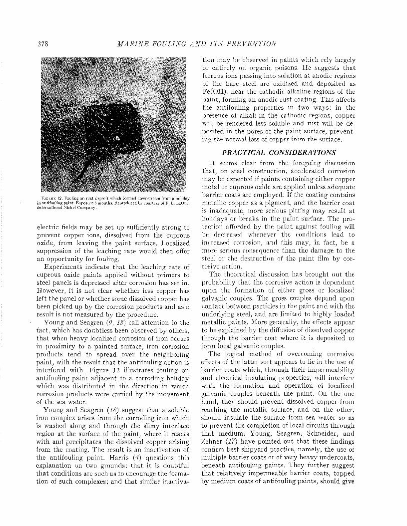
378 M A R I N E FOULING A N D I T S P R E V E N T I O N
F i g u r e 12. Fouling on ru s t deposit which formed downstream from a holiday in antifouling paint. Exposure 5 m onths. Reproduced b jr courtesy of F. L. LaQue, In te rnationa l N ickel Company.
electric fields may be set up sufficiently strong to prevent copper ions, dissolved from the cuprous oxide, from leaving the paint surface. Localized suppression of the leaching rate would then offer an opportunity for fouling.
Experiments indicate tha t the leaching rate of cuprous oxide paints applied without primers to steel panels is depressed after corrosion has set in. However, it is not clear whether less copper has left the panel or whether some dissolved copper has been picked up by the corrosion products and as a result is not measured by the procedure.
Young and Seagren (9, 18) call attention to the fact, which has doubtless been observed by others, th a t when heavy localized corrosion of iron occurs in proximity to a painted surface, iron corrosion products tend to spread over the neighboring paint, with the result th a t the antifouling action is interfered with. Figure 12 illustrates fouling on antifouling paint adjacent to a corroding holiday which was distributed in the direction in which corrosion products were carried by the movement of the sea water.
Young and Seagren (18) suggest that a soluble iron complex arises from the corroding iron which is washed along and through the slimy interface region at the surface of the paint, where it reacts with and precipitates the dissolved copper arising from the coating. The result is an inactivation of the antifouling paint. Harris (4) questions this explanation on two grounds: tha t it is doubtful th a t conditions are such as to encourage the formation of such complexes; and that similar inactiva
tion may be observed in paints which rely largely or entirely on organic poisons. He suggests tha t ferrous ions passing into solution at anodic regions of the bare steel are oxidized and deposited as Fe(OH)3 near the cathodic alkaline regions of the paint, forming an anodic rust coating. This affects the antifouling properties in two ways: in the presence of alkali in the cathodic regions, copper will be rendered less soluble and rust will be deposited in the pores of the paint surface, preventing the normal loss of copper from the surface.
P R A C T I C A L C O N S ID E R A T IO N SI t seems clear from the foregoing discussion
that, on steel construction, accelerated corrosion may be expected if paints containing either copper metal or cuprous oxide are applied unless adequate barrier coats are employed. If the coating contains metallic copper as a pigment, and the barrier coat is inadequate, more serious pitting may result at holidays or breaks in the paint surface. The protection afforded by the paint against fouling will be decreased whenever the conditions lead to increased corrosion, and this may, in fact, be a more serious consequence than the damage to the steel or the destruction of the paint film by corrosive action.
The theoretical discussion has brought out the probability tha t the corrosive action is dependent upon the formation of either gross or localized galvanic couples. The gross couples depend upon contact between particles in the paint and with the underlying steel, and are limited to highly loaded metallic paints. More generally, the effects appear to be explained by the diffusion of dissolved copper through the barrier coat where it is deposited to form local galvanic couples.
The logical method of overcoming corrosive effects of the latter sort appears to lie in the use of barrier coats which, through their impermeability and electrical insulating properties, will interfere with the formation and operation of localized galvanic couples beneath the paint. On the one hand, they should prevent dissolved copper from reaching the metallic surface, and on the other, should insulate the surface from sea water so as to prevent the completion of local circuits through th a t medium. Young, Seagren, Schneider, and Zehner (17) have pointed out tha t these findings confirm best shipyard practice, namely, the use of multiple barrier coats or of very heavy undercoats, beneath antifouling paints. They further suggest th a t relatively impermeable barrier coats, topped by medium coats of antifouling paints, should give
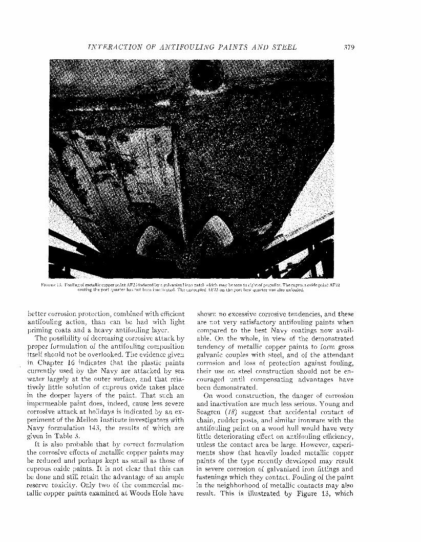
I N T E R A C T I O N OF A N T IF O U L IN G P A I N T S A N D S T E E L 379
F i g u r e 13. Fouling of metallic copper pain t AF23 induced by a galvanize.! iron patch which may be seen to righ t of propeller. The cuprous oxide paint AF22 coating the po rt quarter has not been inactivated. T he uncoupled AF23 on the po rt bow quarter was also unfouled.
better corrosion protection, combined with efficient antifouling action, than can be had with light priming coats and a heavy antifouling layer.
The possibility of decreasing corrosive attack by proper formulation of the antifouling composition itself should not be overlooked. The evidence given in Chapter 16 indicates tha t the plastic paints currently used by the Navy are attacked by sea water largely a t the outer surface, and tha t relatively little solution of cuprous oxide takes place in the deeper layers of the paint. T hat such an impermeable paint does, indeed, cause less severe corrosive a ttack at holidays is indicated by an experiment of the Mellon Institu te investigators with Navy formulation 143, the results of which are given in Table 3.
I t is also probable th a t by correct formulation the corrosive effects of metallic copper paints may be reduced and perhaps kept as small as those of cuprous oxide paints. I t is not clear that this can be done and still retain the advantage of an ample reserve toxicity. Only two of the commercial metallic copper paints examined a t Woods Hole have
shown no excessive corrosive tendencies, and these are not very satisfactory antifouling paints when compared to the best Navy coatings now available. On the whole, in view of the demonstrated tendency of metallic copper paints to form gross galvanic couples with steel, and of the attendant corrosion and loss of protection against fouling, their use on steel construction should not be encouraged until compensating advantages have been demonstrated.
On wood construction, the danger of corrosion and inactivation are much less serious. Young and Seagren (18) suggest tha t accidental contact of chain, rudder posts, and similar ironware with the antifouling paint on a wood hull would have very little deteriorating effect on antifouling efficiency, unless the contact area be large. However, experiments show that heavily loaded metallic copper paints of the type recently developed may result in severe corrosion of galvanized iron fittings and fastenings which they contact. Fouling of the paint in the neighborhood of metallic contacts may also result. This is illustrated by Figure 13, which
380 M A R I N E FOULING A N D I T S P R E V E N T I O N
shows an area of the hull of a torpedo retriever which had been painted with AF23. The painted surface of the wood planking has fouled over the entire quarter of the bottom to which a galvanized iron plate had been applied to repair damage to the planking.
If the fittings and fastenings are of bronze or brass, m if they are protected by a coat of cuprous oxide paint applied so that contact between the fitting and the metallic paint is avoided, these effects will not take place. The disadvantages of attempting such protection must be weighed against the supposed advantage of using the metallic pigment.
THE USE OF PAINT TO PROTECT GALVANIC ALLY COUPLED
METALSWhen it' is necessary to expose dissimilar metals
in contact under sea water, the corrosive effects of the resulting galvanic couples may be reduced by the usé of protective coatings. LaQue (6, 7) has recorded the effect of painting either or both members of a couple consisting of steel and copper. The following was found to be the order of preference in the application of the paint :
1st choice— Paint both the copper and the steel.2nd choice— Paint the copper and leave the steel
bare.3rd choice—Leave both metals bare.4th choice— Paint the steel and leave the copper
bare.
The reason for not painting the steel, if the copper is not painted, is that imperfections in the paint coating may lead to severe localized attack which, on the whole, is more harmful than the uniformly distributed corrosion which occurs on bare steel.
In additional experiments, it was found that if the steel member of a copper/steel couple was painted with an adequate anticorrosive system, the antifouling action of the copper was no longer inactivated, and the copper remained free of fouling. It was also possible to prevent fouling on the copper member of a couple by painting it with an adequate barrier coat topped off with a metallic copper paint. That is to say, the inactivating action of the steel on the copper member did not extend through the barrier coat to influence the overlying metallic copper paint. The practice of painting Muntz metal sheathing with antifouling paint may have justification in this principle.
BLISTERING OF PAINT FILMS B Y ELECTROLYTIC REACTIONS
The discussion of the acceleration of corrosion has emphasized the importance of local electrolytic processes resulting from interaction between copper paints and the underlying steel when adequate barrier coats are not present. A report from the Bakelite Corporation (3) points out that blistering can be induced by coupling a painted steel panel with either copper or zinc. With a zinc coupling, the steel is cathodic and becomes the site of hydrogen liberation accompanied by increased hydroxyl ion concentration. The steel beneath the blisters is found to be bright and clean. With .a copper coupling, the steel is anodic and severe corrosion occurs in isolated imperfections in the paint film. Blisters are not formed as readily, but when present they are filled with rust. On several uncoupled panels, both types of blisters were observed to be present as little as J inch apart. This illustrates the effects produced by local electrolytic cells, and shows that greater activity may exist at small, isolated points.
Since blistering, arising from electrolytic processes, is thought to be a frequent cause of paint failure, especial attention should be given to developing anticorrosive coatings which discourage such effects. The Bakelite report (3) recommends the use of steel panels to which small pieces of zinc or copper are coupled to test the resistance of barrier coats to conditions which produce electrolytic blistering.
REFERENCES1. A l e x a n d e r , A. L., and R. L. B e n e m e l i s . Antifouling Paints:
Inactivation of Highly Pigmented Antifouling Films Applied to Steel. Ind. and Eng. Chem., 39, 1028-1032, 1947.
2. A t h e r t o n , W. H. The Fouling of Ships. Trans. NortheastCoast Engineers and Shipbuilders, 16, 161-175, 1900.
3. Bakelite Corporation. Progress Report on Methods of Studying Corrosion and Blistering Tendencies of Underwater Coatings. Report OSRD No. 3066, Division 11, N.D.R.C., Jan. 3, 1944. (Unpublished).
4. H a r r i s , J. E. Letter to the Editor: Anomalous Inactivationof Heavy Metal Antifouling Paints. Nature, 156, p. 206, August 18, 1945.
5. H u d s o n , J. C. The Corrosion of Iron and Steel, New York,1940.
6. International Nickel Company Development and ResearchDivision. Report on Specimens Removed from Sea Water Tests “at Kure Beach, N. C., in May, 1942 . 6. Report of Tests to Study Effects of Paint Coatings on Distribution and Intensity of Galvanic Effects in Sea Water. F. L. LaQue, May, 1943. (Unpublished).
7. International Nickel Company Development and ResearchDivision. Report on Specimens Removed from Sea Water Tests at Kure Beach, N . C., May, 1943. Effects of Paints on the Extent and Distribution of Galvanic Corrosion in Sea Water. F. L. LaQue, May, 1944. (Unpublished).
8. Marine Corrosion Sub-Committee of the Corrosion Commit-
I N T E R A C T I O N OF A N T I F O U L I N G P A I N T S A N D S T EE L 381
tee, the Iron and Steel Institute and the British Iron and Steel Federation. First Report, April, 1943.
9. Mellon Institute Special Report on Accelerated Corrosion'of Steel Coated with Antifouling Paints: Status Report 1. George H. Young and G. W. Seagren, October 25, 1944. (Unpublished.)
10. Mellon Institute Special Report on General AntifoulingStudies, Project M-.152C-fa. Series V, Report No. 2 Final Report. G. W. Seagren, December 4, 1944. (Unpublished).
11. Mellon Institute Special Report on General AntifoulingStudies, Project M-152C-fa. Series Y, Report II Final Report. G. W. Seagren, August 18, 1944. (Unpublished.)
12. R e d f i e l d , A. C. Interaction of Antifouling Paints and Steel.Report from the Advisory Committee on Marine Coatings and Corrosion, Section 11, N.D.R.C., June, 1945. (Unpublished) .
13. W e s l e y , W. A. Controlling Factors in Galvanic Corrosion.Proc. Amer. Soc. for Testing Materials, 40, 1940.
14. Woods Hole Oceanographic Institution. Interim Report No.V for 1944; Preliminary Observations on the Properties of
AF23, C. M. Weiss, July 3.1, 1944. (Unpublished).15. Woods Hole Oceanographic Institution. Monthly Progress
Report on the Investigation of the Prevention of Fouling. May 1, 1944, pp. 7-9. V. Inhibition of Antifouling Action of Metallic Copper Paints by Galvanic Action. (Unpublished.)
16. Woods Hole Oceanographic Institution. Monthly ProgressReport on the Investigation of the Prevention of Fouling. August 1, 1944, p. 1. I. Physical Chemistry of Antifouling Paints. (Unpublished.)
17. Y o u n g , G. H., G. W. S e a g r e n , W. L. S c h n e i d e r , and J. C.Z e h n e r . Antifouling Paints. Ind. and Eng. Chem., 36, 341- 344, 1944.
18. Y o u n g , G. H., G. W. S e a g r e n . Anomalous Inactivation ofHeavy Metal Antifouling Paints. Nature, 155, 715-717, 1945.
19. Y o u n g , G. H., G. W. S e a g r e n , and J. C. Z e h n e r . Antifouling Paints: Mechanism of Accelerated Corrosion under Antifouling Compositions Applied to Steel. Ind. and Eng. Chem., 37, 461-464, 1945.
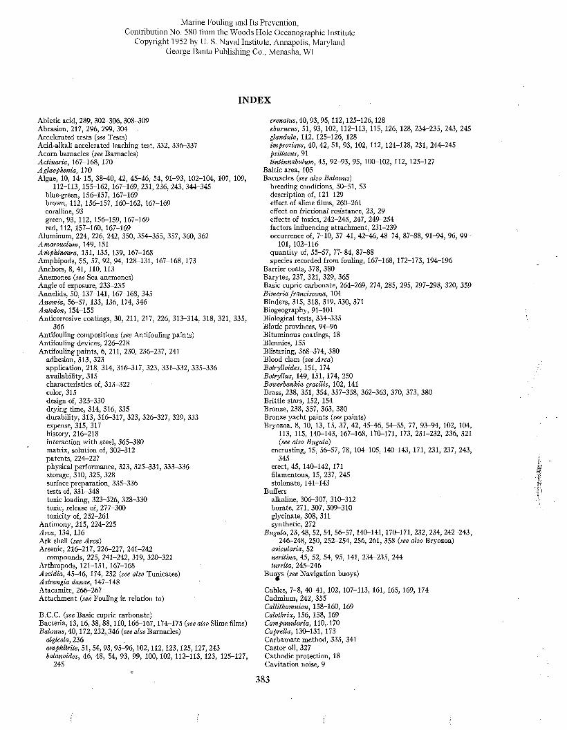
Marine Fouling and Its Prevention,Contribution No. 580 from the Woods Hole Oceanographic Institute
Copyright 1952 by U. S. Naval Institute, Annapolis, Maryland George Banta Publishing Co., Menasha, WI
INDEX
Abietic acid, 289, 302-306, 308-309 Abrasion, 217, 296, 299, 304 .Accelerated tests {see Tests)Acid-alkali accelerated leaching test, 332, 336-337 Acorn barnacles (see Barnacles)A ctinaria, 167-168, 170 Aglaophenia, 170Algae, 10, 14-15, 38-40, 42, 45-46, 54, 91-93, 102-104, 107, 109,
112-113, 155-162, 167-169, 231, 236, 243, 344-345 blue-green, 156-157, 167-169 brown, 112, 156-157, 160-162, 167-169 coralline, 93green, 93, 112, 156-159, 167-169 red, 112, 157-160, 167-169
Aluminum, 224, 226, 242, 350, 354-355, 357, 360, 362 Amaroucium, 149, 151 A m phinem a, 131, 135, 139, 167-168 Amphipods, 55, 57, 92, 94, 128-131, 167-168, 173 Anchors, 8, 41, 110, 113 Anemones {see Sea anemones)Angle of exposure, 233-235 Annelids, 50, 137-141, 167-168, 345 Anomia, 56-57, 133, 136, 174, 346 Antedon, 154-155Anticorrosive coatings, 30, 211, 217, 226, 313-314, 318, 321, 335,
366Antifouling compositions {see Antifouling paints)Antifouling devices, 226-228 Antifouling paints, 6, 211, 230, 236-237, 241
adhesion, 313, 323application, 218, 314, 316-317, 323, 331-332, 335-336availability, 315characteristics of, 313-322color, 315design of, 323-330drying time, 314, 316, 335durability, 313, 316-317, 323, 326-327, 329, 333expense, 315, 317history, 216-218interaction with steel, 365-380matrix, solution of, 302-312patents, 224^227physical performance, 323, 325-331, 333-336 storage, 310, 325, 328 surface preparation, 335-336 tests of, 331-348 toxic loading, 323-326, 328-330 toxic, release of, 277-300 toxicity of, 252-261
Antimony, 215, 224-225 Arca, 134, 136 Ark shell {see Arca)Arsenic, 216-217, 226-227, 241-242
compounds, 225, 241-242, 319, 320-321 Arthropods, 121-131, 167-168 A scidia, 45-46, 174, 232 {see also Tunicates)Astrangia danae, 147-148Atacamite, 266-267Attachment {see Fouling in relation to)
B.C.C. {see Basic cupric carbonate)Bacteria, 13,16, 38, 88,110,166-167,174-175 {see also Slime films) Balanus, 40,172, 232,346 {see also Barnacles)
algicola, 236amphitrite, 51,54, 93,95-96,102,112,123,125,127, 243 balanoides, 46, 48, 54, 93, 99, 100, 102, 112-113, 123, 125-127,
245
crenatus, 40,93,95,112,125-126,128eburneus, 51, 93, 102, 112-113, 115, 126, 128, 234-235, 243, 245 glandula, 112, 125-126, 128improvisus, 40, 42, 51, 93, 102, 112, 124-128, 231, 244-245 psittacus, 91tintinnabulum, 45, 92-93, 95, 100-102, 112, 125-127
Baltic area, 105 Barnacles {see also Balanus)
breeding conditions, 50-51, 53 description of, 121-129 effect of slime films, 260-261 effect on frictional resistance, 23, 29 effects of toxics, 242-245, 247, 249-254 factors influencing attachment, 231-239 occurrence of, 7-10, 37-41, 42-46, 48-74, 87-88, 91-94, 96, 99-
101, 102-116 quantity of, 55-57, 77-84, 87-88 species recorded from fouling, 167-168, 172-173, 194-196
Barrier coats, 378, 380 Barytes, 237, 321, 329, 365Basic cupric carbonate, 264-269, 274, 285, 295, 297-298, 320, 359B im eria franciscana, 104Binders, 315, 318, 319, 330, 371Biogeography, 91-101Biological tests, 334-335Biotic provinces, 94-96Bituminous coatings, 18Blennies, 155Blistering, 368-374, 380Blood clam {see Arca)Botrylloides, 151, 174Botryllus, 149, 151, 174, 250Bowerbankia gracilis, 102, 141Brass, 238, 351, 354, 357-358, 362-363, 370, 373, 380Brittle stars, 152, 154Bronze, 238, 357, 363, 380Bronze yacht paints {see paints)Bryozoa, 8, 10, 13, 15, 37, 42, 45-46, 54^55, 77, 93-94, 102, 104,
113, 115, 140-143, 167-168, 170-171, 173, 231-232, 236, 321 {see also Bugula)
encrusting, 15, 56-57, 78, 104-105, 140-143, 171, 231, 237, 243, 345
erect, 45, 140-142, 171 filamentous, 15, 237, 245 stolonate, 141-143
Buffers alkaline, 306-307, 310-312 borate, 271, 307, 309-310 glycinate, 308, 311 synthetic, 272
Bugula, 23,48, 52, 54, 56-57,140-141,170-171, 232, 234, 242-243, 246-248, 250, 252-254, 256, 261, 358 {see also Bryozoa)
avicularia, 52neritina, 45, 52, 54, 95, 141, 234-235, 244 turrita, 245-246
Buo^s {see Navigation buoys)
Cables, 7-8, 40-41, 102, 107-113, 161, 165, 169, 174Cadmium, 242, 355Callithamnion, 158-160, 169Calothrix, 156, 158, 169Campanularia, 110,. 170Caprella, 130-131, 173Carbamate method, 333, 341Castor oil, 327Cathodic protection, 18Cavitation noise, 9
383
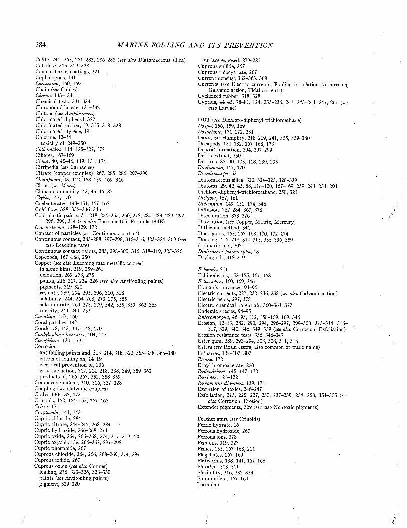
384 M A R I N E FOULING A N D I T S P R E V E N T IO N
Celite, 241, 265, 281-282, 286-288 (see also Diatomaceous silica)Cellulose, 315, 319, 328Cementiferous coatings, 321Cephalopods, 131Ceramium, 160, 169Chain (see Cables)Chama, 133-134 Chemical tests, 331-334 Chironomid larvae, 131-132 Chitons {see Amphineura)Chlorinated diphenyl, 327 Chlorinated rubber, 19, 315, 318, 328 Chlorinated styrene, 19 Chlorine, 12-14
toxicity of, 249-250 Chthamalus, 114, 125-127, 172 Ciliates, 167-169 Ciona, 40, 45-46, 149, 151, 174 Cirripedia {see Barnacles)Citrate (copper complex), 267, 285, 286, 297-299 Cladophora, 93, 112, 158-159, 169, 346 Clams {see M yra)Climax community, 43, 45-46, 87 Clytia, 147, 170Coelenterates, 143-151, 167-168 Cold flow, 328, 335-336, 346Cold plastic paints, 31, 218, 254-255, 260, 278, 280, 283, 289, 292,
296, 299, 314 {see also Formula 105, Formula 143E) Conchoderma, 128-129, 172 Contact of particles {see Continuous contact)Continuous contact, 285-288, 297-298, 315-316, 323-324, 369 {see
also Leaching rate)Continuous contact paints, 285, 298-300, 316, 318-319, 325-326 Copepods, 167-168, 250Copper {see also Leaching rate metallic copper)
in slime films, 219, 259-261 oxidation, 269-273, 275paints, 216-217, 224-226 {see also Antifouling paints) pigments, 319-320 resínate, 289, 294-295, 306, 310, 318 solubility, 244, 264-268, 273-275, 355 solution rate, 269-273, 279, 342, 355, 359, 362-363 toxicity, 24-1-249, 253
Corallina, 157, 160 Coral patches, 147 Corals, 78, 143, 147-148, 170 Cordylophora lacustris, 104, 145 Corophium, 130, 173 Corrosion
antifouling paints and, 313-314, 316, 320, 355-358, 365-380 effects of fouling on, 14^19 electrical prevention of, 236 galvanic action, 212, 214-218, 238, 349, 359-363 products of, 266-267, 352, 358-359
Coumarone indene, 310, 316, 327-328 Coupling {see Galvanic couples)Crabs, 130-132, 173Crinoids, 152, 154-155, 167-168Crisia, 171Cryptosula, 141, 143Cupric chlotide, 284Cupric citrate, 244-245, 268, 284Cupric hydroxide, 266-268, 274Cupric oxide, 264, 266-268, 274, 317, 319-320Cupric oxychloride, 266-267, 297-298Cupric phosphide, 267Cuprous chloride, 264, 266, 268-269, 274, 284 Cuprous iodide, 267 Cuprous oxide {see also Copper)
leading, 278, 323-326, 328-330 paints (see Antifouling paints) pigment, 319-320
surface exposed, 279-281 Cuprous sulfide, 267 Cuprous thiocyanate, 267 Current density, 362-363, 368Currents {see Electric currents, Fouling in relation to currents,
Galvanic action, Tidal currents)Cyclicized rubber, 318, 328Cyprids, 44-45, 78-81, 124, 233-236, 241, 243-244, 247, 261 {see
also Larvae)
D D T {see Dichloro-diphenyl-trichloroethane)Dasya, 156, 159, 169 Dasychone, 171-172, 231Davy, Sir Humphry, 218-219, 241, 355, 359-360Decapods, 130-132, 167-168, 173Deposit formation, 294, 297-299Derris extract, 250Detritus, 88, 90, 105, 118, 239, 295Diadumene, 147, 170Diandrocarpa, 53Diatomaceous silica, 320, 324-325, 328-329Diatoms, 29, 42, 45, 88, 118-120, 167-169, 239, 243, 254, 294Dichloro-diphenyl-trichloroethane, 250, 321Dictyota, 157, 161Didemnum, 149, 151, 174, 346Diffusion, 282-284, 367, 378Discoloration, 373-376Dissolution {see Copper, Matrix, Mercury)Dithizone method, 341Dock gates, 165, 167-168, 170, 172-174Docking, 4D6, 218, 314-315, 335-336, 359d-pimaric acid, 302Dreissensia polymorpha, 13Drying oils, 318-319
Echeneis, 211Echinoderms, 152-155, 167, 168 Ectocarpus, 160, 169, 346 Ekman’s provinces, 94^96Electric currents, 227, 230, 236, 238 {see also Galvanic action) Electric fields, 297, 378 Electro-chemical potentials, 360-363, 377 Endemic species, 94-95 Enteromorpha, 46, 93, 112, 158-159, 169, 346 Erosion, 12-13, 282, 290, 294, 296-297, 299-300, 313-314, 316-
317, 329, 340, 346, 349, 359 {see also Corrosion, Exfoliation) Erosion resistance tests, 336, 346-347 Ester gum, 289, 293-294, 303, 308, 311, 318 Esters {see Rosin esters, also common or trade name)Estuaries, 102-107, 307 Eteone, 172Ethyl bromoacetate, 250 Eudendrium, 145, 147, 170 Euplotes, 121-122 Eupomatus dianthus, 139, 171 Excretion of toxics, 246-247Exfoliation, 215, 225, 227, 230, 237-239, 254, 258, 354r-355 {see
■also Corrosion, Erosion)Extender pigments, 329 {see also Nontoxic pigments)
Feather stars {see Crinoids)Ferric hydrate, 16 Ferrous hydroxide, 267 Ferrous ions, 378 Fish oils, 319, 327 Fishes, 155, 167-168, 211 Flagellates, 167-169 Flatworms, 138, 141, 167-168 Flexalyn, 303, 311 Flexibility, 316, 332-333 Foraminifera, 167-169 Formulae
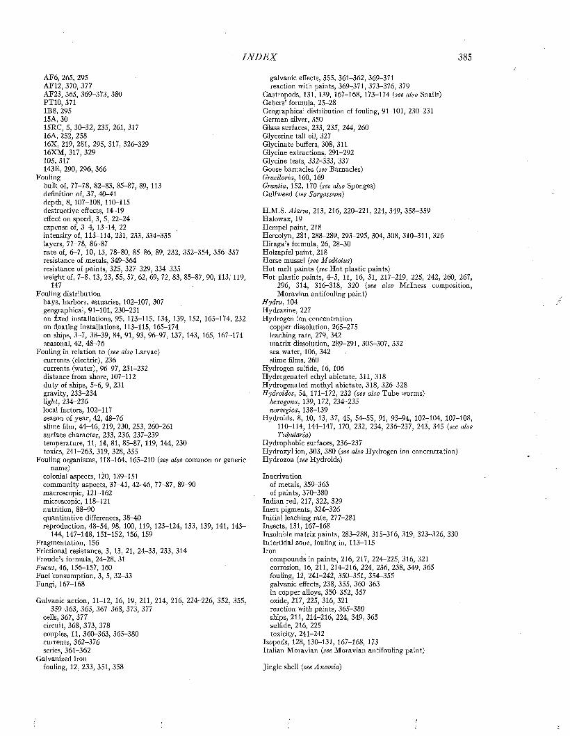
I N D E X 385
AF6, 265, 295 AF12, 370, 377 AF23, 365, 369-373, 380 PTIO, 371 1B8, 295 15A, 3015RC, 5, 30-32, 235, 261, 317 16A, 252, 25816X, 219, 281, 295, 317, 326-329 16XM, 317, 329 105, 317143E, 290, 296, 366
Foulingbulk of, 77-78, 82-83, 85-87, 89, 113definition of, 37, 40-41depth, 8, 107-108, 110-115destructive effects, 14—19effect on speed, 3, 5, 22-24expense of, 3-4, 13-14, 22intensity of, 113-114, 231, 233, 334-335layers, 77-78, 86-87rate of, 6-7, 10, 13, 78-80, 85-86, 89, 232, 352-354, 356-357 resistance of metals, 349-364 resistance of paints, 325, 327-329, 334-335 weight of, 7-8, 13, 23, 55, 57, 62, 69, 72, 83, 85-87, 90, 113, 119,
147Fouling distribution
bays, harbors, estuaries, 102-107, 307 geographical, 91-101, 230-231on fixed installations, 95, 113-115, 134, 139, 152, 165-174, 232 on floating installations, 113-115, 165-174 on ships, 3-7, 38-39, 84, 91, 93, 96-97, 137, 143, 165, 167-174 seasonal, 42, 48-76
Fouling in relation to (see also Larvae) currents (electric), 236 currents (water), 96-97, 231-232 distance from shore, 107-112 duty of ships, 5-6, 9, 231 gravity, 233-234 light, 234-236 local factors, 102-117 season of year, 42, 48-76 slime film, 44-46, 219, 230, 253, 260-261 surface character, 233, 236, 237-239 temperature, 11, 14, 81, 85-87, 119, 144, 230 toxics, 241-263, 319, 328, 355
Fouling organisms, 118-164, 165-210 (see also common or generic name)
colonial aspects, 120, 139-151community aspects, 37-41, 42-46, 77-87, 89-90macroscopic, 121-162microscopic, 118-121nutrition, 88-90quantitative differences, 38-40reproduction, 48-54, 98, 100, 119, 123-124, 133, 139, 141, 143-
144, 147-148, 151-152, 156, 159 Fragmentation, 156Frictional resistance, 3, 13, 21, 24-33, 233, 314Froude’s formula, 24-28, 31Fucus, 46, 156-157, 160Fuel consumption, 3, 5, 32-33Fungi, 167-168
Galvanic action, 11-12, 16, 19, 211, 214, 216, 224^226, 352, 355, 359-363, 365, 367-368, 373 , 377
cells, 367, 377 circuit, 368, 373, 378 couples, 11, 360-363, 365-380 currents, 362-376 series, 361-362
Galvanized iron fouling, 12, 233, 351, 358
galvanic effects, 355, 361-362, 369-371 reaction with paints, 369-371, 373-376, 379
Gastropods, 131, 139, 167-168, 173-174 (see also Snails)Gebers’ formula, 25-28Geographica] distribution cf fouling, 91-101, 230-231German silver, 350Glass surfaces, 233, 235, 244, 260Glycerine tali oil, 327Glycinate buffers, 308, 311Glycine extractions, 291-292Glycine tests, 332-333, 337Goose barnacles (see Barnacles)Gracilaria, 160, 169Grantia, 152, 170 (see also Sponges)Gulfweed (see Sargassum)
H.M.S. Alarm, 213, 216, 220-221, 224, 349, 358-359 Halowax, 19 Hempel paint, 218Hercolyn, 281, 288-289, 293-295, 304, 308, 310-311, 326 Hiraga’s formula, 26, 28-30 Holzapfel paint, 218 Horse mussel (see Modiolus)Hot melt paints (see Hot plastic paints)Hot plastic paints, 4-5, 11, 16, 31, 217-219, 225, 242, 260, 267,
296, 314, 316-318, 320 (see also M clness composition, Moravian antifouling paint)
H ydra, 104 Hydrazine, 227 Hydrogen ion concentration
copper dissolution, 265-275 leaching rate, 279, 342 matrix dissolution, 289-291, 305-307, 332 sea water, 106, 342 slime films, 260
Hydrogen sulfide, 16, 106 Hydrogenated ethyl abietate, 311, 318 Hydrogenated methyl abietate, 318, 326-328 Hydroides, 54, 171-172, 232 (see also Tube worms)
hexagona, 139, 172, 234-235 norvegica, 138-139
Hydroids, 8, 10, 13, 37, 45, 54-55, 91, 93-94, 102-104, 107-108, 110-114, 144-147, 170, 232, 234, 236-237, 243, 345 (see also T ubidaria)
Hydrophobic surfaces, 236-237Hydroxyl ion, 303, 380 (see also Hydrogen ion concentration) Hydrozoa (see Hydroids)
Inactivationof metals, 359-363 of paints, 370-380
Indian red, 217, 322, 329 Inert pigments, 324r-326 Initial leaching rate, 277-281 Insects, 131, 167-168Insoluble matrix paints, 283-288, 315-316, 319, 323-326, 330Intertidal zone, fouling in, 113-115Iron
compounds in paints, 216, 217, 224—225, 316, 321 corrosion, 16, 211, 214-216, 224, 236, 238, 349, 365 fouling, 12, 241-242, 350-351, 354-355 galvanic effects, 238, 355, 360-363 in copper alloys, 350-352, 357 oxide, 217, 225, 316, 321 reaction with paints, 365-380 ships, 211, 214-216, 224, 349, 365 sulfide, 216, 225 toxicity, 241-242
Isopods, 128, 130-131, 167-168, 173 Italian Moravian (see Moravian antifouling paint)
Jingle shell (see Anomia)
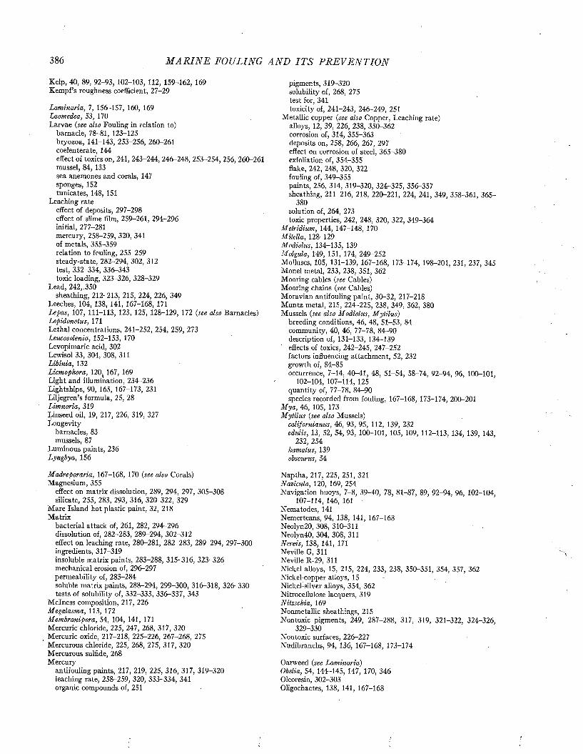
386 M A R I N E FOULING A N D I T S P R E V E N T I O N
Kelp, 40, 89, 92-93, 102-103, 112, 159-162, 169 Kempf’s roughness coefficient, 27-29
Laminaria, 7, 156-157, 160, 169 Laomedea, 53, 170Larvae (see also Fouling in relation to)
barnacle, 78-81, 123-125 bryozoa, 141-143, 253-256, 260-261 coelenterate, 144effect of toxics on, 241, 243-244, 246-248, 253-254, 256, 260-261 mussel, 84, 133 sea anemones and corals, 147 sponges, 152 tunicates, 148, 151
Leaching rate effect of deposits, 297-298 effect of slime film, 259-261, 294-296 initial, 277-281 mercury, 258-259, 320, 341 of metals, 355-359 relation to fouling, 255-259 steady-state, 282-294, 302, 312 test, 332-334, 336-343 toxic loading, 323-326, 328-329
Lead, 242,.350 sheathing, 212-213, 215, 224, 226, 349
Leeches, 104, 138, 141, 167-168, 171Lepas, 107, 111-113, 123, 125, 128-129, 172 {see also Barnacles) Lepidonotus, 171Lethal concentrations, 241-252, 254, 259, 273leucosolenia, 152-153, 170Levopimaric acid, 302Lewisol 33, 304, 308, 311Libinia, 132Licmophora, 120( 167, 169 Light and illumination, 234-236 Lightships, 90, 165, 167-173, 231 Liljegren’s formula, 25, 28 Limnoria, 319Linseed oil, 19, 217, 226, 319, 327 Longevity
barnacles, 83 mussels, 87
Luminous paints, 236 Lyngbya, 156
M adreporaria, 167-168, 170 {see also Corals)Magnesium, 355
effect on matrix dissolution, 289, 294, 297, 305-308 silicate, 255, 283, 293, 316, 320-322, 329
Mare Island hot plastic paint, 32, 218 Matrix
bacterial attack of, 261, 282, 294-296dissolution of, 282-283, 289-294, 302-312effect on leaching rate, 280-281, 282-283, 289-294, 297-300ingredients, 317-319insoluble matrix paints, 283-288, 315-316, 323-326 mechanical erosion of, 296-297 permeability of, 283-284soluble matrix paints, 288-294, 299-300, 316-318, 326-330 tests of solubility of, 332-333, 336-337, 343
M clness composition, 217, 226 Megalasma, 113, 172 Membranipora, 54, 104, 141, 171 Mercuric chloride, 225, 247, 268, 317, 320 Mercuric oxide, 217-218, 225-226, 267-268, 275 Mercurous chloride, 225, 268, 275, 317, 320 Mercurous sulfide, 268 Mercury
antifouling paints,.217, 219, 225, 316, 317, 319-320 leaching rate, 258-259, 320, 333-334, 341 organic compounds of, 251
pigments, 319-320 solubility of, 268, 275 test for, 341toxicity of, 241-243, 246-249, 251
Metallic copper {see also Copper, Leaching rate) alloys, 12, 39, 226, 238, 350-362 corrosion of, 314, 355-363 deposits on, 258, 266, 267, 297 effect on corrosion of steel, 365-380 exfoliation of, 354^355 flake, 242, 248, 320, 322 fouling of, 349-355paints, 256, 314, 319-320, 324-325, 356-357 sheathing, 211-216, 218, 220-221, 224, 241, 349, 358-361, 365-
380solution of, 264, 273toxic properties, 242, 248, 320, 322, 349-364
Metridium, 144, 147-148, 170 M itella, 128-129 Modiolus, 134-135, 139 Molgula, 149, 151, 174, 249-252Molluscs, 105, 131-139, 167-168, 173-174, 198-201, 231, 237, 345 Monel metal, 233, 238, 351, 362 Mooring cables {see Cables)Mooring chains {see Cables)Moravian antifouling paint, 30-32, 217-218 Muntz metal, 215, 224-225, 238, 349, 362, 380 Mussels {see also Modiolus, M ytilus)
breeding conditions, 46, 48, 51-53, 84 community, 40, 46, 77-78, 84-90 description of, 131-133, 134-139 effects of toxics, 242-245, 247-252 factors influencing attachment, 52, 232 growth of, 84-85occurrence, 7-14, 40-41, 48, 51-54, 58-74, 92-94, 96, 100-101,
102-104, 107-114, 125 quantity of, 77-78, 84-90species recorded from fouling, 167-168, 173-174, 200-201
M ya, 46, 105, 173 M ytilus {see also Mussels)
californianus, 46, 93, 95, 112, 139, 232 edulis, 13, 52, 54, 93, 100-101, 105, 109, 112-113, 134, 139, 143,
232, 254 hamatus, 139 obscurus, 54
Naptha, 217, 225, 251, 321 Navicula, 120, 169, 254Navigation buoys, 7-8, 39-40, 78, 81-87, 89, 92-94, 96, 102-104,
107-114, 146, 161 Nematodes, 141Nemerteans, 94, 138, 141, 167-168 Neolyn20, 308, 310-311 Neolyn40, 304, 308, 311 Nereis, 138, 141, 171 Neville G, 311 Neville R-29, 311Nickel alloys, 15, 215, 224, 233, 238, 350-351, 354, 357, 362Nickel-copper alloys, 15 -Nickel-silver alloys, 354, 362Nitrocellulose lacquers, 319Nitzschia, 169Nonmetallic sheathings, 215Nontoxic pigments, 249, 287-288, 317, 319, 321-322, 324-326,
329-330 Nontoxic surfaces, 226-227 Nudibranchs, 94, 136, 167-168, 173-174
Oarweed {see Laminaria)Obelia, 54, 144r-145, 147, 170, 346 Oleoresin, 302-303 Oligochaetes, 138, 141, 167-168

I N D E X 387
Opercular plates, 121, 126 Ophiuroidea, 167-168 Organic toxics, 250-252, 321, 378 Ortmann’s zones, 96-98 Oscillatoria, 156-157, 169 Ostracods, 167-168Ostrea, 104, 134^135, 173-174, 233 (see also Oysters)Oxidation, 106, 269-273, 275, 303-304, 308-310, 378 Oxygen, 106-107Oysters, 8, 17, 38, 44, 51, 94, 104-105, 107, 134, 136, 143, 232
(see also Ostrea, Rock oysters)
Paints (see Anticorrosive coatings, Antifouling paints, Protective coatings)
Paludicella, 104Panel tests, 334-335, 343-346Paraffin, 233, 236, 281, 295, 316Paris Green, 219, 225, 242, 320-321Patents, 224-229Pecten, 13, 134-135, 173-174, 232Pedicellina, 54Pelagic plants, 89Pelecypods, 131-139, 167-168,173-174, 234^235 (see also Mussels,
Oysters)Pentachlorophenol, 237, 251 Pentalyn, 289, 303, 308, 310-311 Permeability of paint, 283-284, 288 Petrolatum, 236-237pH (see Hydrogen ion concentration, Hydroxyl ion)Phallusia, 174, 232, 234 Phenyl-mercury compounds, 250 Phototropism, 234^-236 Physical tests, 332Pigment volume, 248, 328-330, 371, 374, 376-377 Pigments
ncntoxic, 249, 287-288, 317, 319, 321-322, 324-326, 329-330 toxic, 314, 315-316, 317, 319-320, 325-326, 328-329
Pipe systems (see Salt water pipe systems)Pitch, 211-213, 216, 226, 319Pitting, 15, 17, 365, 368, 378 (see also Corrosion)Plasticizers, 312, 316-318, 323, 326-328, 330 Plumatella, 104 Plum ularia, 54, 147, 170 Plymouth, England, 102, 104, 115 Pollution, 87, 105-107, 119 Poly-Pale resin, 289, 304, 310, 311 Polycarpa, 53Polychaetes, 167-168, 171-172, 234 Polyps, 144^147 Polysiphonia, 158-159, 169 Polyvinyl butyral, 285, 319 Polyvinyl resins, 315, 319, 323 Polyzoa (see Bryozoa)Pomatoceros, 138-139, 171, 346 'Porifera, 170Potentials (see Electro-chemical potentials)Precipitated chalk, 329Preliminary elimination tests, 331-333Primers and priming, 318, 320, 365-368, 377-378Propellers, 22, 32-33, 137, 139, 231, 350, 359-360, 363Propulsive force, 22, 32Protective coatings, 5-6, 17-19, 24-25, 30-32, 313-322 (see also
Anticorrosive coatings, Antifouling paints)Protozoa, 42,118,121-122,167-169 Provinces (see Biotic provinces)Pseudosaturation effect, 272-273 P teria (see Rock oysters)Pteropods, 167-168Putnam , U. S. destroyer, 23-24, 29Pycnogonids, 130-132, 167-168
Quartering test, 336
Rahtjen’s paint, 217-218, 225-226Rating systems, 335, 345-346Red iron oxide, 321Red lead, 366Red oxide, 366Remora, 155 , 211Reniera, 153, 170, 232, 234-235 (see also Sponges)Residual resistance, 21, 25-26Resins, 212, 216-217, 224, 226, 283-284, 289, 291, 306, 308, 310-
312, 315-317, 326-327, 330, 346 (see also Rosin) acid, 289, 291-292, 294, 302, 306-307, 310 (see also Abietic acid) alkyd, 19, 284, 315, 318 natural, 302, 317-318 neutral, 293-294, 308, 326 phenolic, 19, 284 rubber, 318synthetic, 227, 315, 318-319, 323 vinyl, 316-317, 319, 324-325 Vinylite, 265, 298, 324
Reynolds number, 25, 27 Rock oysters, 8, 92-93 Ropes, 167-168, 170-171 Rosin (see also Resins)
and solubility of cuprous oxide, 265-266 as paint ingredient, 315-319, 323-324, 326-327 bacterial attack on, 19, 261, 282, 294^296 dissolution of, 302-312 esters, 303, 308, 318, 327in antifouling paints, 217-218, 225, 255-256, 280-282, 284, 286,
288-289, 293, 295 Rotating discs, 328, 340, 346 Rotifers, 104, 121-122, 167-168Roughness coefficient (see Kempf’s roughness coefficient)Rubber, 18, 224, 226 (see also Chlorinated rubber, Cyclicized
rubber)Rust, 370, 377-378, 380
Sabellarid worms, 138-139, 232, 234-235 Sabellid worms, 138-139 Salmacina, 137, 139, 172Salt water pipe systems, 11-14, 87, 90, 125, 143, 165, 167-171,
173-174, 249, 350 Sargassum, 157, 160 Saxicava, 134^135 Scaleworms, 138-139, 171 Scallops, 13, 134-135, 173-174, 232 Scalpellum, 113, 128-129, 172 Schizonema, 167, 169 Schizoporella, 54, 141, 235 Scrupocellaria, 171Sea anemones, 94, 143-144, 147, 170, 249-252Sea bream, 155Sea cradles (see Amphineura)Sea cucumbers, 154-155 Sea lilies (see Crinoids)Sea spiders, 130-132 Sea stars (see Starfish)Sea urchins, 154^155Sea water conduits (see Salt water pipe systems)Seasonal breeding behavior, 48-53, 57, 79 (see also Fouling in
relation to)Seasonal conditions, 46, 48-74, 98-100, 230-231 Sedentary polychaetes, 167-168, 171-172 Selective survey tests, 331, 333-335 Sensitivity factor, 346 Serpent stars (see Brittle stars)Serpulid worms, 91, 137-139, 231, 358 Sewage, 105-106 Shaft horsepower, 22-24, 31-32 Shark suckers, 155Sheathing (see Lead, Metallic copper, Wooden sheathing, Zinc) Shellac, 226, 302, 318
388 M A R I N E FOULING A N D I T S P R E V E N T I O N
Sheilae type paints, 217-218, 314 (see also Rahtjen’s paint)Ship fouling, 3-7, 38-39, 84, 91, 93, 96-97, 137, 143, 165, 167-174 Ship worms, 211-216 (see also Teredos)Shrimps, 105, 131-132 Siderastraea, 148Silica, 316, 321-322, 329 (see also Celite, Diatomaceous silica) Silver, 224-225, 241-242, 350, 352-353 Slime films (see also Bacteria)
composition of, 118-121, 166-169, 239 copper in, 219, 259-260 effect of toxics on, 242, 251 fouling and, 44-46, 219, 230, 253, 260-261 frictional resistance and, 29-30 leaching rate and, 256, 259-261 matrix and, 19, 261, 282, 294^296
Snails, 105, 254 Sodium alginate, 267 Sodium pentachlorophenate, 13, 252 Soft coral, 147-148 Solenia, 169Solubility {see Copper, Matrix, Mercury)Soluble matrix paints, 288-294, 299-300, 316-318, 326-330 Sound domes, 8-11, 350 Sound transmission, 9-11Spawning and settling, 77-81, 84 {see also Fouling)Sponges, 46,94,104,107-108,151-153,167-168,170, 232, 243, 345
{see also Reniera)Starfish, 94, 152, 154Staybelite, 289, 303, 308Steady-state leaching rate, 277-300, 302, 311Stearin pitch lubricant, 236Steel, 351 {see also Corrosion)Styela, 54, 149-151, 174 Suctoria, 167-169Sulfonated aliphatic compounds, 236 Surface characteristics
effect on fouling, 230-239 effect on surface resistance, 26-28, 30-33
Takata composition, 30-31 Tail oil, 327Tar, 211-212, 217, 224-225, 319 Temperature
effect on fouling, 81, 84—85, 96-101, 119 of leaching bath, 336, 338, 342 seasonal variations, 58-74
Temporal sequences, 42-43, 46, 54^57, 83, 87 Tennessee, U. S. battleship, 23-24, 29 Teredos, 211-216, 319, 345 Tests
acid-alkali, 332, 336-337 biological, 334-335, 343-346 carbamate, 333, 341 chemical, 331-334 dithizone, 341erosion resistance, 336, 346-347 glycine, 332-333, 337 leaching rate, 332-334, 336-343 panel, 334-335, 343-346 physical, 332preliminary elimination, 331-333 selective survey, 331, 333-335 service, 336
Tetraclita, 125-127, 172 Therapon, 51, 53 Thiokol, 17-18 Thiourea derivatives, 250 Tidal currents, 7-8, 86, 88, 232
Tide levels, 81, 83, 113-116 Tideman’s constants, 27 Ti-nic-o-sil, 354Tin, 214-216, 224-225, 242, 350, 354 Total resistance, 21-26 Tougheners, 312, 317-319, 323, 326-330 Toxic paints {see Antifouling paints)Toxicity, 241-261
comparative, 241-243 copper, 241-249, 253 index, 250mercury, 241-243, 246-249, 251 organic compounds, 250-252, 321, 378
Toxics, 216-219, 225-226, 237 prevention of fouling with, 241-261 release from paints, 277-301 tests for, 331-340 use in paints, 313-322, 323-330
Tricresyl phosphate, 316, 327-328Tube worms, 8, 11, 15, 33, 57, 87-88, 91, 93-94, 137-143, 171-172,
231, 243, 252 {see also Hydroides)Tubularia, 53-54, 93, 110, 144-145, 147, 170, 232, 243, 346 Tung oil, 319Tunica tes {see also Ascidia)
description of, 147-151 effect on barnacles, 83-84 effect on mussels, 87 factors influencing attachment, 234-243 occurrence of, 8, 10, 13, 37-39, 42-44, 56-74, 93-94, 115, 231 species recorded from fouling, 167-168, 174
Ulothrix, 156t157, 159, 169, 346 Ulva, 93, 112, 158-159, 169, 346 Underwater sound equipment, 8-11 Utilization efficiency, 298-299
Varnish, 216-217, 225, 315, 318-319, 323-325 {see also Matrix) Varnish type paints, 316, 324-325 Vehicle {see Matrix)Venetian red, 329 Veneziani composition, 30-31 Victorella pavida, 104, 141-142 Vinylite, 256, 270, 278, 280, 282, 284-287 Vinylite paints, 281, 284-286, 288, 290, 297, 324
W atersipora, 141-143, 243, 249, 358Wax, 211-212, 216, 236, 316Wood borers, 18-19 {see also Lim noria, Teredos)Wood bottom paints {see Formula 16A, Formula 16X)Wooden sheathing, 212-217, 349 Wooden ships, 214, 217, 363, 379Worms, 137-141 {see also Annelids, Sabellid worms, Serpulid
worms)Wrecks, 165, 167-174
Yacca gum, 318 Yudachi, 22-28
Zinc, 217, 224 chromate, 284fouling resistance, 350-354, 358 galvanic effects, 359-360, 362, 368, 370, 373-375, 380 oxide, 217, 225, 241, 248, 321-322, 329 reactions with copper, 267, 275 sheathing, 215, 349 toxicity of, 241-243
Zoobotryon, 141-143