Marine Catalog
160
1 Marine Catalog 2019
-
Upload
khangminh22 -
Category
Documents
-
view
2 -
download
0
Transcript of Marine Catalog

1
Marine Catalog
2019

2

3
Coo
ling
Prod
ucts
Coo
ling
Acc
esso
ries
Inte
grat
ed S
olut
ions
Roof
& S
hadi
ng
Heating products
Welcome to Webasto marine 4
What’s new? 6
We are here to help develop your business 8
Heating products 11
Accessories for 38
heating systems
Table of contents
Cooling products Cooling products 70
Accessories for 108
cooling systems
Integrated solutions 134
Roof & Shading Solutions 143
Hea
ting
Acc
esso
ries
Hea
ting
Prod
ucts

4
Dear Customers, Dear Partners,
Our Webasto marine team would like to thank you again for your periodical feedback on our products and for sharing your future
needs. This unique customer-supplier cooperation brings an immense value to us and is one of the main input for our future product
roadmaps. Your ideas to improve comfort on board, your needs to simplify your systems, your suggestions to facilitate installations
and ease diagnosis, even from a remote location are indeed systematically studied with high attention. Our engineering teams have
the duty to develop innovative technological solutions to match or to surpass your expectations.
Our long-term innovation-based growth strategy is based on this partnership approach. Our commitment to innovation has been
making up our great success over the last years and hopefully for many more years to come. We do hope that the numerous new
products which are once again being launched in this catalog will match your initial expectations and enhance our complete on board
climate solutions with many additional benefits valued by your own customers.
In this new marine catalog 2019, we keep on with our innovation pace not only by introducing several new products in our climate
control range but also by launching a complete new range of shading solutions, complementary to our leading roof systems.
You will discover in the following pages our new BlueCool V77T which expands our range of variable speed chillers and opens
multiple combination opportunities with our award-winning bestseller BlueCool V50 unit. As with any unit in our standardized
BlueCool Air-conditioning solution range, the BlueCool V77T unit benefits from the BlueCool MyTouch customizable display, the CAN
bus connectivity and the BlueCool Expert installation/diagnosis tool. All BlueCool A-series Air handlers benefit now from the optional
Ultimate Cabin Control combining in one box a high performance silencer and a multiple-device networking capability.
On the heating side, we can highlight the introduction of theThermo Pro 120/150 water heaters. They come with state-of-the-art
technology and unique features to tackle the higher capacity heating segments. They can of course easily be integrated with our
chillers into our BlueComfort solutions.
Welcome to Webasto Marine

5
The Folding Shade 2500 and the Rolling Shade 2500 are our first answer to your repetitive requests to get high quality shading
solutions from Webasto. Potential is high in combination with our marine roof wide product offering . More will come after we
collect your first field experiences next year. Call us!
The purpose of this catalog is not only to give you a complete, practical insight into our large marine product portfolio but also
to enable you to build complete climate solutions adapted to the demands of your customers for heating, cooling, light and fresh
air on board. Should you require a custom-made solution for a special project, our engineering teams also have the capability to
develop customized products to support you. Just get in touch with us!
International service and consistent quality of support are an essential part of our customer excellence programs. The marine
catalog is only one element of the complete set of tools and services with which we systematically provide to every Webasto
marine partner. Please don’t hesitate to register for our technical training sessions, to request access to our dealer portal, to
download our diagnosis and calculation tools, our product information and marketing materials. We are here to support your
business so that your customers can enjoy the same high quality service with our products worldwide. Our financial strength, our
unique product portfolio, our large international dealer network and our understanding of your key strategic challenges for the
future have positioned us as your supplier of choice when it comes to complete comfort solutions.
We would like to thank you again for your continuous feedback and your trust in our products. Your success is our success!
Your Webasto Marine Team

6
What’s new?
The new marine catalog provides you with detailed information on our core
products as well as on our added-value accessories. You can then build safe
applications and deliver fast, professional assistance to your own customers.
As every year, Webasto brings you great new products:
Extension of BlueCool V-Series Two new capacities of 64 and 77 kBTU / h extend
the successful V-Series range
Unique hybrid concept with two independent
refrigerant circuits inside
Innovative hybrid control logic is able to reduce cooling
capacity output by 89% down to 8,5 kBTU / h to ensure
stable cooling operation.
Super silent operation with little noise variations and
sound cover housing
Condensate free operation
3 ECO modes with adjustable amperage draw allowing
the unit to adapt to varying situations, e.g. high amp.
consumers active or limited shore power supply
230 V / 50 Hz or 240 V / 60 Hz compatible for worldwide
application
MyTouch as standard user interface with clear text display
New Ultimate Cabin Control for BlueCool A-Series Ultra silent blower operation due to PWM control
Innovative Master-Slave integration allows to connect
multiple units together
Individually adjustable 5 step fan speed
Compatible to all BlueCool A-Series air handlers
Meets highest EMC requirements of EN 60945
One MyTouch display can operate all connected cabin controls
New BlueCool MyTouch New Touch display control unit as standard for all
BlueCool A/C series
Intuitive operation thanks to simple symbols and
a clearly organized control menu in ten languages
Three digital designs allow to customize the user menu
Upload of own logo or photograph as standby image
New functions such as a timer, error messages with
descriptions, display of operating values and a configuration
of the standby display
Compatible with Vimar Eikon, Eikon Evo and other
cover plates
BlueCool MyTouchUltimate Cabin Control for BlueCool A-Series
BlueCool V-Series
7
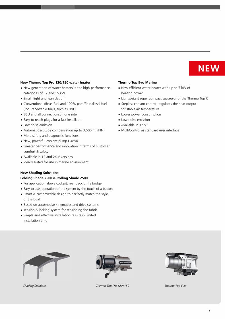
New Thermo Top Pro 120/150 water heater New generation of water heaters in the high-performance
categories of 12 and 15 kW
Small, light and lean design
Conventional diesel fuel and 100% paraffinic diesel fuel
(incl. renewable fuels, such as HVO
ECU and all connectionson one side
Easy to reach plugs for a fast installation
Low noise emission
Automatic altitude compensation up to 3,500 m NHN
More safety and diagnostic functions
New, powerful coolant pump U4850
Greater performance and innovation in terms of customer
comfort & safety
Available in 12 and 24 V versions
Ideally suited for use in marine environment
New Shading Solutions:
Folding Shade 2500 & Rolling Shade 2500 For application above cockpit, rear deck or fly bridge
Easy to use, operation of the system by the touch of a button
Smart & customizable design to perfectly match the style
of the boat
Based on automotive kinematics and drive systems
Tension & locking system for tensioning the fabric
Simple and effective installation results in limited
installation time
Thermo Top Evo Marine New efficient water heater with up to 5 kW of
heating power
Lightweight super compact successor of the Thermo Top C
Stepless coolant control, regulates the heat output
for stable air temperature
Lower power consumption
Low noise emission
Available in 12 V
MultiControl as standard user interface
NEW
Thermo Top Pro 120 / 150 Thermo Top EvoShading Solutions

8
Webasto quote generator All the Webasto expertise at your finger tips
Accurate quotations documented professionally
Quick response to your customer requests
Fresh air calculation included
Accurate calculation of the cooling or heating demand
The Webasto quote generator also exists for
professional roof quotations
Dealer portal http://dealers.webasto.com Easy access to complete Webasto documentation Powerful search and download tools Login-protected access to technical data
and applications
Marine website webasto-marine.com Quick and appealing product guide International dealer locator Multi-lingual access Marine configurator
We are here to help develop your business

9
Marine training program and technical guidelines
Powerful product training – also web-training Regular updates on new features Various modules adapted to audience Important guidelines for safe application engineering CAD model downloads
Marketing documentation and materials Marine marketing materials: product brochures,
flyers, advertising templates, banners
Marine animations
Product data sheets
Dealer packages
18 19
Hea
ting
Prod
ucts
Technical specifications
Air Top 2000 ST
EC approval mark e1*2001/56*0022*_
Heating power (kW) Heating power (BTU/h)
0.9 – 2.0 3,000 – 7,000
Fuel, Fuel consumption (l/h) Fuel, Fuel consumption (gal/h)
Diesel, 0.12 – 0.24 Diesel, 0.03 – 0.06
Rated voltage (V) 12
Rated power consumption (W) 14 – 29
Rated current at 12 V (A) 1.2 – 2.4
Air Flow against 0.5 mbar (m3/h) Air Flow against 0.5 mbar (cfm)
93 55
Dimensions L x W x H (mm) Dimensions L x W x H (inch)
311 x 120 x 121 12.2 x 4.7 x 4.7
Weight (kg) Weight (lbs)
2.6 5.73
Diameter air outlet (mm) Diameter air outlet (inch)
60 2.36
Diameter exhaust (mm) Diameter exhaust (inch)
22 0.87
The advantages of the
Air Top 2000 ST: ■ Quiet comfort
■ Smallest heater on the market
■ Excellent heat output
■ Optimal economy
■ Available as a complete
installation kit for quick and
simple retrofitting
For small boats with only one main cabin, one non-closable outlet is fully sufficient.
For this boat with two cabins and one head compartment one hot air outlet for each cabin is recommended. The main air duct should go into the salon and be non-closable.
Air Top 2000 ST – quiet comfortThe quiet heater – the smallest air heater on the market. It offers excellent heat
output and optimal economy.
Air heatersAir Top 2000 ST
Scopes of delivery Order number9009780GAir Top 2000 ST Marine 12 V Diesel
The Marine heater kits include high quality stainless steel
parts and accessories, long wiring harness, external
temperature sensor and a noise suppression support for the
dosing pump.
1
2
3
4
5
Air distributionFor the distribution of the hot air in your boat you need
hoses, distributors and outlets. Please compose your air
distribution system individually.
Fuel supplyFor the installation of the heater in the engine compartment
the fuel supply system has to be fire-resistant according to EN
ISO 7840. Please order the adequate components additionally
(fuel lines, fuel supply kit, rubber hose, fuel pump protection).
Exhaust systemDepending on the installation position and length of the
exhaust pipe you may need a condensation water drain and
an exhaust pipe insulation additionally.
Accessories (optional)For extension of your heater system you find comfort control
elements as well as other installation and system components
in the accessories section.
Item Qty Description
1 1 heater 12 V
2 1 grille, clips open Ø 60
3 1 heater control element
4 1 panel with ventilation switch
5 1 metering pump
6 1 support for metering pump EPDM
7 1 wiring harness with fuse holder 12 / 24 V
8 1 wiring harness (metering pump) 7,000 lg
9 1 gasket
10 1 exhaust gas reducing bush 22 / 24
11 1 exhaust silencer, leakproof Ø 24; 1,800 lg
12 1 exhaust through hull
13 1 fuel hose: 5,000 lg
14 5 rubber fuel hose
15 1 combustion air silencer Ø 22; 800 lg
16 1 protecting cap
17 1 tank extracting device
18 1 fuel filter
19 1 heater bracket stainless steel
20 temperature sensor, external, 2.5 m
1 bag (with mech. mounting hardware) consisting of:
21 10 hose clamp (stainless) Ø 14
22 1 pipe clip Ø 30
23 1 hose clamp Ø 26 – 28
24 1 hose clamp (stainless) Ø 16 – 27
25 17 cable tie
26 2 angle bracket
12
6
518
14
2117
13
11
23
1015
16
22
20
9
24
2
1 19 25 26
8
73
4
Page header indicates which part and
type of information you reached within
each product section:
Product overview, scopes of delivery,
accessories, etc.
Colored labels
give you direct
access to the
product range
Page indication for fast access to accessories, etc.
This catalog has been designed to help you in defininga complete comfort solution for boats and yachts.

10

11
Heating products
Which heater for your boat? 12
Air heaters 14
Product overview 15
Application concept 16
Selection tool 17
Air Top 2000 STC 18
Air Top Evo 40 20
Air Top Evo 55 22
Water heaters 24
Product overview 25
Application concept 28
Selection tool 29
Thermo Top Evo / Thermo Pro 50 Eco 30
Thermo Pro 90 / Thermo Pro 90 Chiller 32
Thermo Top Pro 120 /150 34
Isotemp hot water boilers 36
Hea
ting
Prod
ucts
12
Which heater for your boat?
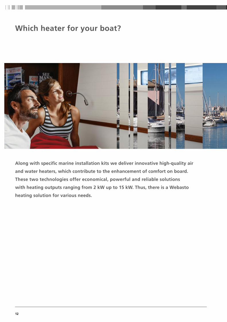
Along with specific marine installation kits we deliver innovative high-quality air
and water heaters, which contribute to the enhancement of comfort on board.
These two technologies offer economical, powerful and reliable solutions
with heating outputs ranging from 2 kW up to 15 kW. Thus, there is a Webasto
heating solution for various needs.

13
Short heating-up times thanks to effective output
Available as a complete installation kit for quick
and simple retrofitting
Dehumidification of the cabins
Silent operation
Ideal for sailing and motor boats up to 45 feet
Constant coziness thanks to an electronic thermostat
Low operating costs
Practical ventilation function
Meet current requirements and standards relating
to boats
Simple to install
Compact, space-saving design
Air heaters Water heaters
or
Heating comfort just like at home
Even distribution of warmth by means of radiators
Hot water for the shower and galley
Silent operation
Space-saving installation in the engine room
Excellent possibilities for combining with
Webasto BlueCool air-conditioning systems
Separate temperature control in every cabin
Low fuel consumption
Compact design
Preheating of the engine possible to avoid cold starts
Meet current requirements and standards relating to boats
Robust aluminum casing, resistant to high temperature or salt
Hea
ting
Prod
ucts

14
Air heaters
Robust composite casing, resistant to high temperature or salt
Fresh-air or recirculated air-intake
Very low electrical power and fuel consumption
Sealed control electronics and connectors withstand marine environment
High air flow output due to powerful radial blower
Precise electronic temperature control system maintains a constant cabin temperature through stepless modulation
Quiet operation
Available as an upgrade on all Webasto Air Top Evo heaters
Multi mode operation to match your individual heating power demands:
ECO mode for reduced electrical power consumption
Boost mode for maximum heating power output
Ventilation mode to provide fresh and cool air to your cabins on a hot day
Easy connection of Webasto Telestart and Thermocall possible
Elegant design and easy operation
Greater comfort with our innovative Webasto App:
Run your air heater easily with a smartphone
3 Heaters in 1 with the MultiControl!
Continuous heating power output provides exactly the heating energy needed
15
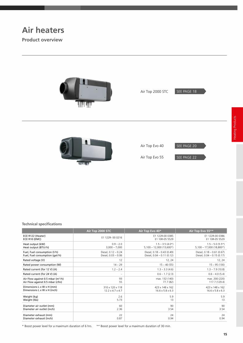
Technical specifications
Air Top 2000 STC Air Top Evo 40* Air Top Evo 55**
ECE R122 (Heater)ECE R10 (EMC)
E1 122R- 00 0216E1 122R-00 0385
E1 10R-05 5529 E1 122R-00 0386
E1 10R-05 5529
Heat output (kW)Heat output (BTU / h)
0.9 – 2.0 3,000 – 7,000
1.5 – 3.5 (4.0*)5,100 – 12,000 (13,600*)
1.5 – 5.0 (5.5*)5,100 – 17,000 (18,800*)
Fuel, Fuel consumption (l / h)Fuel, Fuel consumption (gal / h)
Diesel, 0.12 – 0.24Diesel, 0.03 – 0.06
Diesel, 0.18 – 0.43 (0.49)Diesel, 0.04 – 0.11 (0.12)
Diesel, 0.18 – 0.61 (0.67)Diesel, 0.04 – 0.15 (0.17)
Rated voltage (V) 12 12, 24 12, 24
Rated power consumption (W) 14 – 29 15 – 40 (55) 15 – 95 (130)
Rated current (for 12 V) (A) 1.2 – 2.4 1.3 – 3.3 (4.6) 1.3 – 7.9 (10.8)
Rated current (for 24 V) (A) – 0.6 – 1.7 (2.3) 0.6 – 4.0 (5.4)
Air Flow against 0.5 mbar ( m3 / h ) Air Flow against 0.5 mbar ( cfm )
9355
max. 132 (140)77.7 (82)
max. 200 (220)117.7 (129.4)
Dimensions L x W x H (mm)Dimensions L x W x H (inch)
310 x 120 x 11812.2 x 4.7 x 4.7
423 x 148 x 16216.6 x 5.8 x 6.3
423 x 148 x 16216.6 x 5.8 x 6.3
Weight (kg)Weight ( lbs )
2.65.73
5.913
5.913
Diameter air outlet (mm)Diameter air outlet (inch)
602.36
903.54
903.54
Diameter exhaust (mm)Diameter exhaust (inch)
220.87
240.94
240.94
* Boost power level for a maximum duration of 6 hrs. ** Boost power level for a maximum duration of 30 min.
Air heaters
Air Top 2000 STC
Air Top Evo 40
Air Top Evo 55
SEE PAGE 18
SEE PAGE 20
Product overview
SEE PAGE 22
Hea
ting
Prod
ucts

16
A Space-saving and inconspicuous installation
B Intake for fresh air from outside
C Outlets for even distribution of warm air
D Safe and clean: the fuel system
E Combustion-air intake
F Stainless steel exhaust
G Controls – simple and logical to use
Air heatersApplication concept
C
C
C
CC
G
DB
A
F
E

17
1. Select the length corresponding to your boat.
2. From there, trace a line to the left until you come to the line corresponding to the waters
in which you plan to operate.
3. From there, trace a line vertically downwards until you come to the line corresponding to
the season in which you plan to operate.
4. From there, trace a line to the right: You find the line corresponding to your type of boat in the
upper section and then trace a line vertically downwards – that´s the recommended system.
What’s the best air heating system for my boat?
Air heatersSelection tool
Hea
ting
Prod
ucts
ce

18
Technical specifications
Air Top 2000 STC
EC approval mark E1 122R- 00 0216
Heating power ( kW ) Heating power ( BTU / h )
0.9 – 2.0 3,000 – 7,000
Fuel, Fuel consumption ( l / h ) Fuel, Fuel consumption ( gal / h )
Diesel , 0.12 – 0.24 Diesel , 0.03 – 0.06
Rated voltage ( V ) 12
Rated power consumption ( W ) 14 – 29
Rated current at 12 V ( A ) 1.2 – 2.4
Air Flow against 0.5 mbar ( m3/ h ) Air Flow against 0.5 mbar ( cfm )
93 55
Dimensions L x W x H ( mm ) Dimensions L x W x H ( inch )
310 x 120 x 118 12.2 x 4.7 x 4.7
Weight ( kg ) Weight ( lbs )
2.6 5.73
Diameter air outlet ( mm ) Diameter air outlet ( inch )
60 2.36
Diameter exhaust ( mm ) Diameter exhaust ( inch )
22 0.87
The new advantages of the
Air Top 2000 STC marine kits New split marine wiring harness
with two branches to battery
and cabin control
Two ports for diagnosis and
MultiControl
Low noise dosing pump
with PWM operation
New external temperatur
sensor with new design
Transparent fuel hose for
easy inspection (not in U.S)
Easy combination with
new MultiControl
Easy to service and maintain,
diagnostic capability
Full W-bus compatibility
of the heater
Improved combustion
air silencer reduces noise level
For small boats with only one main cabin, one non-closable outlet is fully sufficient.
For this boat with two cabins and one head compartment one hot air outlet for each cabin is recommended. The main air duct should go into the salon and be non-closable.
Air Top 2000 STC – quiet comfortThe quiet heater – the smallest air heater on the market.
It offers excellent heat output and optimal economy.
Air heaters Air Top 2000 STC

19
Scopes of delivery Order number 9032164C
9034777C
Air Top 2000 STC Marine 12 V Diesel with standard heater control element
Air Top 2000 STC Marine 12 V Dieselwith MultiControl
The Marine heater kits include high quality stainless steel
parts and accessories, external temperature sensor and
effective combustion and exhaust air silencers .
1
2
3
4
5
Air distributionFor the distribution of the hot air in your boat you need
hoses, distributors and outlets. Please compose your air
distribution system individually.
Fuel supplyFor the installation of the heater in the engine compartment
the fuel supply system has to be fire-resistant according to
EN ISO 7840. Please order the adequate components additionally
(fuel lines, fuel supply kit, rubber hose, fuel pump protection).
Exhaust systemDepending on the installation position and length of the
exhaust pipe you may need a condensation water drain and
an exhaust pipe insulation additionally.
Accessories (optional)For extension of your heater system you find comfort control
elements as well as other installation and system components
in the accessories section.
Item Qty Description
1 1 Heater 12 V
2 1 Grille, clips open Ø 60
3 1 Heater control element
3a 1 MultiControl
4 1 Temperature sensor, external 2.5 m
5 1 Metering pump
6 1 Support for metering pump EPDM
7 1 Wiring harness with fuse holder 12 / 24 V
8 1 Wiring harness (metering pump) 7,000 lg
9 1 Gasket
10 1 Exhaust gas reducing bush 22 / 24
11 1 Exhaust silencer, leakproof Ø 24; 1,800 lg
12 1 Exhaust through hull
13 1 Transparent fuel hose: 5,000 lg
14 5 Rubber fuel hose
15 1 Combustion air intake hose 300 lg
16 1 Combustion air intake silencer
17 1 Tank extracting device
18 1 Fuel filter
19 1 Heater bracket stainless steel
20 Vibration damper for fuel hose
1 Bag (with mech. mounting hardware) consisting of:
21 10 Hose clamp (stainless) Ø 14
22 1 Pipe clip Ø 30
23 1 Hose clamp Ø 26 – 28
24 1 Hose clamp (stainless) Ø 16 – 27
25 17 Cable tie
26 2 Angle bracket
6
18
14
2117
13
1112
205
20
23
1015
16
22
4
9
24
2
1 19 25 26
8
73
3a
Hea
ting
Prod
ucts

20
The advantages of the
Air Top Evo 40: 4.0 kW power for fast heating
Very low electrical power
consumption due to new
Intelligent Blower Control
New flame detection through
exhaust gas temperature sensor
Automatic cold start function
for quick warm-up
Improved air intake silencer
Vibration dampers for fuel line
Compatible to new MultiControl
digital user interface
Very silent operation due to
lower blower speed and silent
fuel pump (DP42)
Each cabin and head compartment has its own air outlet. One outlet should be non-closable. The temperature sensor as well as the main air outlet is in the salon. The fresh air is taken in via the rear locker from outside.
In motor boats, the heater is usually placed in the engine compartment. The fresh air has to be taken in from outside the engine room. Special attention needs to be paid to a fire-resistant fuel supply system. One of the outlets should be non-closable.
Air heaters Air Top Evo 40
Air Top Evo 40 – the smart multi mode heaterHigh-output, compact and quiet, the heater is ideally suited for the most rigorous
requirements. It can be upgraded with the new multi mode control panel to offer
additional operation modes depending on individual heating requirements.
Technical specifications
Air Top Evo 40*
EC approval mark ECE R122 ( Heating ) E1 000385
EC approval mark ECE R10 ( EMC ) E1 035529
Heating power ( kW ) Heating power ( BTU / h )
1.5 – 3.5 (4.0*) 5,100 – 12,000 (13,600*)
Fuel, Fuel consumption ( l / h ) Fuel, Fuel consumption ( gal / h )
Diesel 0.18 – 0.43 (0.49) Diesel 0.04 – 0.11 (0.12)
Rated voltage ( V ) 12, 24
Rated power consumption ( W ) 15 – 40 (55)
Rated current at 12 V ( A ) 1.3 – 3.3 (4.6)
Rated current at 24 V ( A ) 0.6 – 1.7 (2.3)
Air Flow against 0.5 mbar ( m3/ h ) Air Flow against 0.5 mbar ( cfm )
140 82.4
Dimensions L x W x H ( mm ) Dimensions L x W x H ( inch )
423 x 148 x 162 16.6 x 5.8 x 6.3
Weight ( kg ) Weight (lbs)
5.9 13
Diameter air outlet ( mm ) Diameter air outlet ( inch )
90 3.54
Diameter exhaust ( mm ) Diameter exhaust ( inch )
24 0.94
* Boost power level for a maximum duration of 6 hrs.
What is the Intelligent Blower
Control?
Thanks to the control of more
parameters (more sensors), the
heating regulation can now
disconnect, to a certain extent, the
heating output from the blower
speed, resulting in:
A lower electrical consumption
and lower noise on regular
operation (lower motor speed
for same heat output).
A higher heat output availability
for applications with higher
back pressure.

21
Scopes of delivery 1
2
3
4
5
Order number 9029249A Air Top Evo 40 Marine 12 V Diesel with standard heater control element
9029250A Air Top Evo 40 Marine 24 V Dieselwith standard heater control element
9036994A Air Top Evo 40 Marine 12 V Diesel
with MultiControl
9036995A Air Top Evo 40 Marine 24 V Diesel
with MultiControl
The Marine heater kits include high quality stainless steel
parts and accessories, long wiring harness, external
temperature sensor and effective combustion and exhaust
air silencers.
Air distributionFor the distribution of the hot air in your boat you need
hoses, distributors and outlets. Please compose your air
distribution system individually.
Fuel supplyFor the installation of the heater in the engine compartment
the fuel supply system has to be fire-resistant according to
EN ISO 7840. Please order the adequate components additionally
(fuel lines, fuel supply kit, rubber hose, fuel pump protection).
Exhaust system (optional)Depending on the installation position and length of the
exhaust pipe you may need a condensation water drain and
an exhaust pipe insulation additionally.
Accessories (optional)For extension of your heater system you find comfort control
elements as well as other installation and system components
in the accessories section.
Item Qty Description
1 1 Heater 12 or 24 V
2 1 Grille
3a 1 Standard heater control element
4 1 MultiControl
5 1 Metering pump 12 or 24 V
6 1 Support for metering pump EPDM
7 1 Wiring harness (heater); 9,500 lg
8 1 Wiring harness (metering pump) 7,000 lg
9 1 Gasket
10 1 Exhaust silencer leakproof 1,800 lg
11 1 Hose clamp Ø 28 – 35
12 1 Exhaust through hull
13 1 Transparent fuel hose 12 V: 5,000 lg; 24 V: 8,000 lg
14 5 Rubber fuel hose
15 1 Combustion air intake hose 300 lg
16 1 Combustion air intake silencer
17 1 Tank extracting device
18 1 Fuel filter
19 1 Heater bracket stainless steel
20 1 Temperature sensor, external 2.5 m
21 2 Vibration damper for fuel hose
1 Bag (with mech. mounting hardware) consisting of:
22 10 Hose clamp (stainless steel) Ø 14
23 1 Hose clamp Ø 16 – 27 (combustion air)
24 2 Hose clamp Ø 26 – 28 (exhaust)
25 1 Pipe clip (stainless steel) Ø 30
26 17 Cable tie
27 2 Angle bracket
4
272619
3a
20
71
2
9
2325
1516
1110
13
24
8
12
215
21
2218
14
2217
6
Hea
ting
Prod
ucts

22
The advantages of the
Air Top Evo 55: 5.5 kW power for fast heating
Very low electrical power
consumption due to new
Intelligent Blower Control
New flame detection through
exhaust gas temperature sensor
Automatic cold start function
for quick warm-up
Improved air intake silencer
Vibration dampers for fuel line
Compatible to new MultiControl
digital user interface
Very silent operation due to
lower blower speed and silent
fuel pump (DP42)
Each of this five cabin yacht has an individual air outlet. The air duct to the salon as well as the front should have at least 80 mm Ø to ensure a good air flow and one of the outlets should be non-closable. The fresh air is taken in via the rear locker from outside.
With the heater in the engine compartment, the fuel supply system must be designed to be fire-resistant. The air outlet to the salon has to be non- closable. Air outlets for the other cabins or the head compartment may be closable to enable individual heat regulation.
Air heaters Air Top Evo 55
Air Top Evo 55 – for extreme conditionsExtremely powerful, compact and quiet, this heater ensures a comfortable climate
for larger yachts even under the harshest conditions, and satisfies the most
demanding requirements. It can be upgraded with the new multi mode user interface
to offer additional operation modes depending on individual heating requirements.
Two Air Top heaters can be combined into one system for increased heating demand
(up to 11 kW). The whole system can be operated via one central user interface.
Technical specifications
Air Top Evo 55*
EC approval mark ECE R122 ( Heating ) E1 000385
EC approval mark ECE R10 ( EMC ) E1 035529
Heating power ( kW ) Heating power ( BTU / h )
1.5 – 5.0 (5.5*) 5,100 – 17,000 (18,800*)
Fuel, Fuel consumption ( l / h ) Fuel, Fuel consumption ( gal / h )
Diesel 0.18 – 0.61 (0.67) Diesel 0.04 – 0.15 (0.17)
Rated voltage ( V ) 12, 24
Rated power consumption ( W ) 15 – 95 (130)
Rated current at 12 V ( A ) 1.3 – 7.9 (10.8)
Rated current at 24 V ( A ) 0.6 – 4.0 (5.4)
Air Flow against 0.5 mbar ( m3/ h ) Air Flow against 0.5 mbar ( cfm )
220 129
Dimensions L x W x H ( mm ) Dimensions L x W x H ( inch )
423 x 148 x 162 16.6 x 5.8 x 6.3
Weight ( kg ) Weight ( lbs )
5.9 13
Diameter air outlet ( mm ) Diameter air outlet ( inch )
90 3.54
Diameter exhaust ( mm ) Diameter exhaust ( inch )
24 0.94
* Boost power level for a maximum duration of 30 min.
What is the Intelligent
Blower Control?
Thanks to the control of more
parameters (more sensors), the
heating regulation can now
disconnect, to a certain extent,
the heating output from the
blower speed, resulting in:
A lower electrical consumption
and lower noise on regular
operation (lower motor speed
for same heat output).
A higher heat output availability
for applications with higher
back pressure.

23
Scopes of delivery 1
2
3
4
5
Order number 9029256A Air Top Evo 55 Marine 12 V Dieselwith standard heater control element
9029257A Air Top Evo 55 Marine 24 V Dieselwith standard heater control element
9036996A Air Top Evo 55 Marine 12 V Diesel with MultiControl
9036998A Air Top Evo 55 Marine 24 V Diesel with MultiControl
The Marine heater kits include high quality stainless steel
parts and accessories, long wiring harness, external
temperature sensor and effective combustion and exhaust
air silencers.
Air distributionFor the distribution of the hot air in your boat you need
hoses, distributors and outlets. Please compose your air
distribution system individually.
Fuel supplyFor the installation of the heater in the engine compartment
the fuel supply system has to be fire-resistant according to
EN ISO 7840. Please order the adequate components additionally
(fuel lines, fuel supply kit, rubber hose, fuel pump protection).
Exhaust system (optional)Depending on the installation position and length of the
exhaust pipe you may need a condensation water drain and
an exhaust pipe insulation additionally.
Accessories (optional)For extension of your heater system you find comfort control
elements as well as other installation and system components
in the accessories section.
Item Qty Description
1 1 Heater 12 or 24 V
2 1 Grille
3a 1 Standard heater control element
4 1 MultiControl
5 1 Metering pump 12 or 24 V
6 1 Support for metering pump EPDM
7 1 Wiring harness (heater); 9,500 lg
8 1 Wiring harness (metering pump) 7,000 lg
9 1 Gasket
10 1 Exhaust silencer leakproof 1,800 lg
11 1 Hose clamp Ø 28 – 35
12 1 Exhaust through hull
13 1 Fuel hose 12 V: 5,000 lg; 24 V: 8,000 lg
14 5 Rubber fuel hose
15 1 Combustion air intake hose 300 lg
16 1 Combustion air intake silencer
17 1 Tank extracting device
18 1 Fuel filter
19 1 Heater bracket stainless steel
20 1 Temperature sensor, external 2.5 m
21 2 Vibration damper for fuel hose
1 Bag (with mech. mounting hardware) consisting of:
22 10 Hose clamp (stainless steel) Ø 14
23 1 Hose clamp Ø 16 – 27 (combustion air)
24 2 Hose clamp Ø 26 – 28 (exhaust)
25 1 Pipe clip (stainless steel) Ø 30
26 17 Cable tie
27 2 Angle bracket
Hea
ting
Prod
ucts
4
272619
3a
20
71
2
9
2325
1516
1110
13
24
8
12
215
21
2218
14
2217
6

24
Water heaters
Meets current Marine requirements and standards
Heating comfort just like at home
Can be used to heat your hot sanitary water
Low fuel consumption
Space-saving installation in the engine room
Even distribution of warmth by means of radiators or blowers
Automatic overheat protection
Compact design
Excellent possibilities for combining with Webasto BlueCool air-conditioning systems
Thermo Pro 90: The renowned
Greater comfort with our innovative
Webasto ThermoCall App.
Run your water or air heater easily
with a smartphone.

25
Water heaters
Thermo Top Evo
Thermo Pro 50 Eco
Thermo Pro 90
Thermo Top Pro 120 / 150
SEE PAGE 30
SEE PAGE 32
SEE PAGE 34
Product overview
Hea
ting
Prod
ucts
NEW
NEW
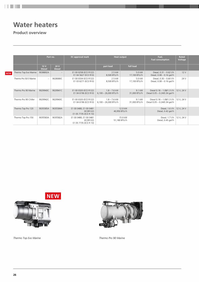
26
Part no. EC approval mark Heat output Fuel,Fuel consumption
Rated Voltage
12 VDiesel
24 VDiesel
part load full load
Thermo Top Evo Marine 9038892A – E1 00 0258 (ECE R122)E1 04 5627 (ECE R10)
2.5 kW 8,500 BTU / h
5.0 kW17,100 BTU / h
Diesel, 0.31 – 0.62 l / hDiesel, 0.08 – 0.16 gal / h
12 V
Thermo Pro 50 E Marine – 9028080C E1 00 0334 (ECE R122)E1 03 6271 (ECE R10)
2.5 kW 8,500 BTU / h
5.0 kW17,100 BTU / h
Diesel, 0.30 – 0.60 l / hDiesel, 0.08 – 0.16 gal / h
24 V
Thermo Pro 90 Marine 9029940C 9029941C E1 00 0320 (ECE R122)E1 04 6196 (ECE R10)
1.8 – 7.6 kW 6,100 – 26,000 BTU / h
9.1 kW31,000 BTU / h
Diesel 0.18 – 1.08/1.3 l / h Diesel 0.05 – 0.24/0.34 gal / h
12 V, 24 V
Thermo Pro 90 Chiller 9029942C 9029943C E1 00 0320 (ECE R122)E1 04 6196 (ECE R10)
1.8 – 7.6 kW 6,100 – 26,000 BTU / h
9.1 kW31,000 BTU / h
Diesel 0.18 – 1.08/1.3 l / h Diesel 0.05 – 0.24/0.34 gal / h
12 V, 24 V
Thermo Top Pro 120 9035585A 9035584A E1 00 0480, E1 00 0481 (ECER122)
E1 05 7735 (ECE R 10)
12.0 kW 40,950 BTU / h
Diesel, 1.6 l / h Diesel, 0.42 gal / h
12 V, 24 V
Thermo Top Pro 150 9035583A 9035582A E1 00 0480, E1 00 0481 (ECER122)
E1 05 7735 (ECE R 10)
15.0 kW51,180 BTU / h
Diesel, 1.7 l / hDiesel, 0.45 gal / h
12 V, 24 V
Thermo Top Evo Marine Thermo Pro 90 Marine
Water heaters Product overview
NEW
NEW

27
Rated power consumption
Flow rate of circulating pumps
Dimensions heater (L x W x H)
Dimensions control unit with mounting
(L x W x H)
Weight heater incl. fuel pump
part load full load
12 W2.7 amps
33 W3.5 amps
500 l / h against 0.14 bar2.2 gal / min.
218 x 91 x 147 mm8.6 x 3.6 x 5.8 inch
68 x 48 x 15 mm2.7 x 1.9 x 0.6 inch
2.1 kg4.6 lbs
28 W1.2 amps
46 W1.9 amps
500 l / h against 0.14 bar2.2 gal / min.
218 x 91 x 144 mm8.6 x 3.6 x 5.7 inch
– 2.5 kg5.3 lbs
20 – 83 W3.0 – 6.9 amps at 12 V1.5 – 3.5 amps at 24 V
90 W7.5 amps at 12 V3.8 amps at 24 V
700 l / h against 0.3 bar3.1 gal / min.
352 x 131 x 232 mm 13.9 x 5.2 x 9.1 inch
134 x 53 x 90 mm 5.3 kg11.7 lbs
20 – 83 W3.0 – 6.9 amps at 12 V1.5 – 3.5 amps at 24 V
90 W7.5 amps at 12 V3.8 amps at 24 V
700 l / h against 0.3 bar3.1 gal / min.
352 x 131 x 188 mm 13.9 x 5.2 x 7.4 inch
134 x 53 x 90 mm 4.9 kg10.8 lbs
80 W 6.7 amps at 12 V3.3 amps at 24 V
1,500 l / h against 0.56 bar 6.6 gal / min.
470 x 200 x 200 mm 18.5 x 7.9 x 7.9 inch
– 11.7 kg25.7 lbs
100 W8.3 amps at 12 V4.2 amps at 24 V
1,500 l / h against 0.56 bar 6.6 gal / min.
470 x 200 x 200 mm 18.5 x 7.9 x 7.9 inch
– 11.7 kg25.7 lbs
Thermo Top Pro 120 / 150
Hea
ting
Prod
ucts

28
Water heatersApplication concept
A Space-saving and inconspicuous installation in the engine room
B Boiler for heating hot water – for extra comfort
C One radiator for each cabin allows an individual temperature control
D Controls – simple and logical to use
E Circulating pump
F Fresh water tank
G Stainless steel exhaust
A
E
G
B
C
C
C
D
F
C

29
ce
Thermo Pro 90 Thermo Top Pro 150
Thermo Top Pro 120
1. Select the length corresponding to your boat.
2. From there, trace a line to the left until you come to the line corresponding to the waters in
which you plan to operate.
3. From there, trace a line vertically downwards until you come to the line corresponding to the
season in which you plan to operate.
4. From there, trace a line to the right: Select the line corresponding to your type of boat in the
lower section and then trace a line vertically downwards – that’s the recommended system.
What’s the best water heating system for my boat?
Water heatersSelection tool
Hea
ting
Prod
ucts

30
Thermo Top water heatersThis compact 5 kW unit is ideal for the majority of marine applications. Compact
design, variable temperature control, service friendly technology and low noise levels.
The advantages of
water heaters: Heating comfort just like at
home
Even distribution of warmth
by means of radiators
Hot water for the shower
and galley
Silent operation
Space-saving installation
in the engine room
Excellent possibilities for
combining with Webasto
BlueCool air-conditioning
systems
Separate temperature control
in every cabin
Low fuel consumption
Compact design
Preheating of the engine
possible to avoid cold starts
Meet current requirements
and standards relating to boats
Robust aluminum casing,
resistant to high temperature
or salt
The Thermo Top Evo is placed in the locker compartment of the boat. Radiators are used to heat up the boat, because electrical autonomy in this size of boat is often very important and radiators do not consume electricity of the battery.
The Thermo Top Evo in the engine compartment is able to heat the entire boat. Each cabin has individually sized convectors to match the heating requirements.
Water heaters Thermo Top Evo / Thermo Pro 50 Eco
Technical specifications
Thermo Top Evo Thermo Pro 50 Eco
EC approval mark ECE R122 (Heating) E1 00 0258 ECE R10 (EMV) E1 04 5627
ECE R122 (Heating) E1 00 0334ECE R10 (EMV) E1 03 6271
Heating power ( kW ) Heating power ( BTU / h )
5.0 17,100
5.017,100
Fuel Fuel consumption ( l / h ) Fuel Fuel consumption (gal / h)
Diesel , 0.31 – 0.62 Diesel , 0.08 – 0.16
Diesel , 0.3 – 0.6 Diesel , 0.08 – 0.16
Rated voltage ( V ) 12 24
Rated power consumption ( W ) Rated power consumption ( amps )
12 – 33 2.7 – 3.5
28 – 461.2 – 1.9
Flow rate of circulating pump (against 0.14 bar) ( l / h ) Flow rate of circulating pump (against 0.14 bar) ( gal / min. )
500 2.2
500 2.2
Flow rate of circulating pump (against 0.10 bar) ( l / h ) Flow rate of circulating pump (against 0.10 bar) ( gal / min. )
–900
4
Dimensions L x W x H ( mm ) Dimensions L x W x H (inch)
218 x 91 x 147 8.6 x 3.6 x 5.8
218 x 91 x 144 8.6 x 3.6 x 5.7
Weight ( kg ) Weight ( lbs )
2.14.6
2.55.3
NEW

31
1
2
3
4
5
Order number
9038892A Thermo Top Evo Marine 12 V Diesel
9028080C Thermo Pro 50 Eco Marine 24 V Diesel
Water systemFor the distribution of heat in your boat you may need extra
hoses, valves, expansion tank, convectors, air handlers etc.
Please compose your water system individually.
Fuel supplyFor the installation of the heater in the engine compartment
the fuel supply system has to be fire-resistant according to
EN ISO 7840. Please order the adequate components additionally
(fuel lines, fuel supply kit, rubber hose, fuel pump protection).
Exhaust systemDepending on the installation position and length of the
exhaust pipe you may need a condensation water drain and
an exhaust pipe insulation additionally.
Accessories (optional)For extension of your heater system you find comfort control
elements as well as other installation and system components
in the accessories section.
Scopes of delivery
Item SOD Description
1 Heater
2 Coolant Pump U4847 with fixation
3 Heater bracket
4 MultiControl with bracket
5 Wiring harness
6 Exhaust reducer
7 Exhaust silencer
8 Exhaust trough hull
9 Combustion air pipe
10 Air Intake silencer
11 Fuel pump DP42 with fixation
12 Fuel hose
13 Tank extracting device
14 Coolant connection piece
15 Coolant hose
Mounting parts
1
115
10
1514
12
9
613
3
2
4
8
7
Hea
ting
Prod
ucts
NEW

32
Thermo Pro 90 Marine – state-of-the art controller and easy serviceThis device is ideal for daily use: infinitely variable power adjustment,
high heat output, compact dimensions, service-friendly technology and an
extremely low noise level.
Thermo Pro 90 Chiller – the heater for integration into an A/C system
If you want to build a BlueComfort system with a Thermo 90 heater, use the
Thermo Pro 90 Chiller version. It comes with a special electronic control unit
and without the water pump which is not needed.
The advantages of the
Thermo Pro 90: Ideal for daily use
Infinitely variable power
adjustment
High heat output
Compact dimensions
Service friendly technology
Extremely low noise level
This 44’ sailing yacht uses convectors for all cabins to heat the boat. Convectors are noiseless and do not consume any electrical power off the battery, therefore resulting in a very high electrical autonomy.
In this 40’ motor yacht electrical fan blowers are used to heat up the boat. They are very compact and may be easily installed in small spaces, blowing hot air through air ducts into each cabin. The windscreen has a separate blower to demist and defrost.
Water heaters Thermo Pro 90/Thermo Pro 90 Chiller
Technical specifications
Thermo Pro 90
Heating power ( kW ) Heating power ( BTU / h )
1.8 – 7.6 kW; boost mode 9.1 6,100 – 26,000 BTU / h; boost mode 31,000
Fuel, Fuel consumption, partial/full load/boost ( l / h ) Fuel, Fuel consumption, partial/full load/boost (gal / h)
Diesel 0.18 – 1.08 / 1.3 Diesel 0.05 – 0.24 / 0.34
Rated voltage (V) 12, 24
Rated power consumption ( W ) 20 – 83 (90 Boost), 3.0 – 6.9 amps (7.5 Boost) at 12 V, 1.5 – 3.5 amps (3.8 Boost) at 24 V
Flow rate of circulating pump (against 0.3 bar) ( l / h ) Flow rate of circulating pump (against 0.3 bar) ( gal / min. )
700 3.1
Dimensions L x W x H ( mm ) Dimensions L x W x H (inch)
352 x 131 x 232 13.9 x 5.2 x 9.1
Weight ( kg ) Weight ( lbs )
5.3 11.7
33
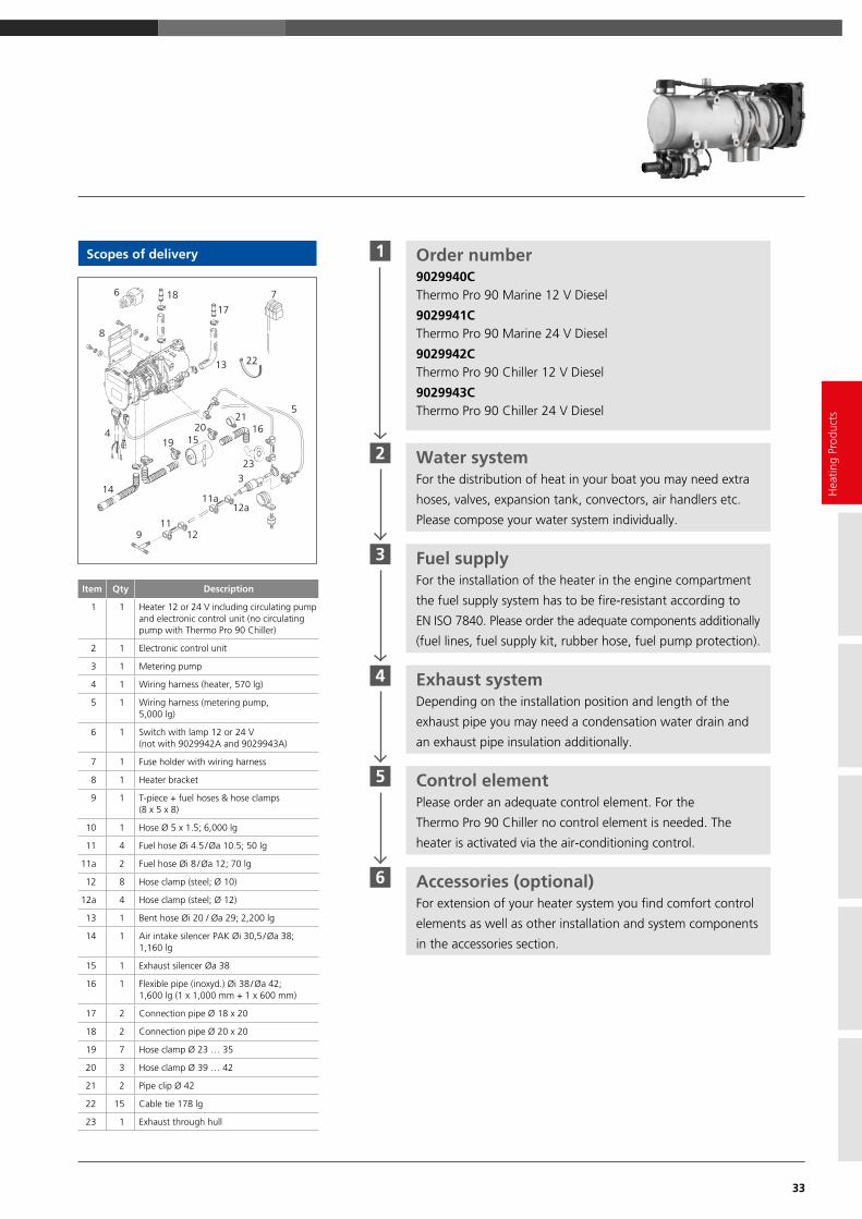
Scopes of delivery 1
2
3
4
5
6
Order number 9029940C Thermo Pro 90 Marine 12 V Diesel
9029941C Thermo Pro 90 Marine 24 V Diesel
9029942C Thermo Pro 90 Chiller 12 V Diesel
9029943C Thermo Pro 90 Chiller 24 V Diesel
Water systemFor the distribution of heat in your boat you may need extra
hoses, valves, expansion tank, convectors, air handlers etc.
Please compose your water system individually.
Fuel supplyFor the installation of the heater in the engine compartment
the fuel supply system has to be fire-resistant according to
EN ISO 7840. Please order the adequate components additionally
(fuel lines, fuel supply kit, rubber hose, fuel pump protection).
Exhaust systemDepending on the installation position and length of the
exhaust pipe you may need a condensation water drain and
an exhaust pipe insulation additionally.
Control elementPlease order an adequate control element. For the
Thermo Pro 90 Chiller no control element is needed. The
heater is activated via the air-conditioning control.
Accessories (optional)For extension of your heater system you find comfort control
elements as well as other installation and system components
in the accessories section.
Item Qty Description
1 1 Heater 12 or 24 V including circulating pump and electronic control unit (no circulating pump with Thermo Pro 90 Chiller)
2 1 Electronic control unit
3 1 Metering pump
4 1 Wiring harness (heater, 570 lg)
5 1 Wiring harness (metering pump, 5,000 lg)
6 1 Switch with lamp 12 or 24 V (not with 9029942A and 9029943A)
7 1 Fuse holder with wiring harness
8 1 Heater bracket
9 1 T-piece + fuel hoses & hose clamps (8 x 5 x 8)
10 1 Hose Ø 5 x 1.5; 6,000 lg
11 4 Fuel hose Øi 4.5 / Øa 10.5; 50 lg
11a 2 Fuel hose Øi 8 / Øa 12; 70 lg
12 8 Hose clamp (steel; Ø 10)
12a 4 Hose clamp (steel; Ø 12)
13 1 Bent hose Øi 20 / Øa 29; 2,200 lg
14 1 Air intake silencer PAK Øi 30,5 / Øa 38; 1,160 lg
15 1 Exhaust silencer Øa 38
16 1 Flexible pipe (inoxyd.) Øi 38 / Øa 42; 1,600 lg (1 x 1,000 mm + 1 x 600 mm)
17 2 Connection pipe Ø 18 x 20
18 2 Connection pipe Ø 20 x 20
19 7 Hose clamp Ø 23 … 35
20 3 Hose clamp Ø 39 … 42
21 2 Pipe clip Ø 42
22 15 Cable tie 178 lg
23 1 Exhaust through hull
22
717
186
8
13
2116
23
1520
194
14
911
12
11a12a
3
5
Hea
ting
Prod
ucts

34
Greater performance and innovation in terms of customer comfort & safety The Thermo Top Pro 120 and Thermo Top Pro 150 constitute a new generation of
water heaters in the high-performance categories of 12 and 15 kW. The powerful
heaters are each available in 12 and 24 V versions and are ideally suited for use in
marine environment.
The advantages of the
Thermo Top Pro 120/150: Small, light and lean design
Conventional diesel fuel and
100% paraffinic diesel fuel
(incl. renewable fuels,
such as HVO
ECU and all connections
on one side
Easy to reach plugs for a
fast installation
Low noise emission
More safety and diagnostic
functions
New, powerful coolant
pump U4850
Water heaters Thermo Top Pro 120/150
Technical specifications
Thermo Top Pro 120 Thermo Top Pro 150
EC approval mark E1 00 0480, E1 00 0481 E1 00 0480, E1 00 0481
Heating power ( kW ) Heating power ( BTU / h )
12.040,950
15.0 51,180
Fuel, Fuel consumption ( l / h ) Fuel, Fuel consumption (gal / h)
Diesel , 1.6Diesel, 0.42
Diesel , 1.7 Diesel , 0.45
Rated voltage ( V ) 12, 24 12, 24
Rated power consumption ( W ) 80 6.7 amps at 12 V3.3 amps at 24 V
100 8.3 amps at 12 V
4.2 amps at 24 V
Flow rate of circulating pump (against 0.15 bar) ( l / h ) Flow rate of circulating pump (against 0.15 bar) ( gal / min. )
1,500 6.6
1,500 6.6
Dimensions L x W x H ( mm ) Dimensions L x W x H ( inch )
470 x 200 x 200 23 x 8.1 x 9
470 x 200 x 20023 x 8.1 x 9
Weight ( kg ) Weight ( lbs )
11.7 25.7
11.7 25.7
In this 64’ sailing yacht the heater is installed in the technical compartment. Mainly convectors are used as heat exchangers. Fan blowers are only used in cabins with space restrictions or where quick heating up or air circulation is required.
The heater in this 50’ motor yacht provides heating for both decks. A combination of convectors and fan blowers is used.

35
Scopes of delivery 1
3
2
4
5
6
Order number 9035585A Thermo Top Pro 120, 12 V Diesel
9035584A Thermo Top Pro 120, 24 V Diesel
9035583A Thermo Top Pro 150, 12 V Diesel
9035582A Thermo Top Pro 150, 24 V Diesel
Water systemFor the distribution of heat in your boat you may need extra
hoses, valves, expansion tank, convectors, air handlers etc.
Please compose your water system individually.
Installation kit9035492A
Installation kit 12 V Standard
9035160A
Installation kit 24 V Standard
Fuel supplyPlease compose the adequate system components for your
boat individually. For the installation of the heater in the
engine compartment the fuel supply system has to be
fire- resistant according to EN ISO 7840.
Exhaust systemPlease order exhaust hose, the exhaust silencer and skin
fitting additionally. Depending on the installation position
and length of the exhaust pipe you may need a condensation
water drain and an exhaust pipe insulation additionally.
Accessories (optional)For extension of your heater system you find comfort control
elements as well as other installation and system components
in the accessories section.
Hea
ting
Prod
ucts
* For marine application additional exhaust system components necessary
Contents Scope of delivery/Installation kit
Part SOD IK Description 1 Heater
2 Coolant pump 4850
3 Splash guard
4 Bracket coolant pump
5 Mounting material fuel
6 Wiring harness coolant pump
7 Wiring harness vehicle,
vehicle fan, fuse holder
8 Exhaust flex pipe*
9 Mounting material exhaust*
10 Coolant hose
11 Mounting material coolant
12 Fuel hose
13 Fuel filter
14 Mounting material fuel filter
15 Mounting material heater
16 Mounting material electric
1
9 8
716
2
4
1110
156
512
3
13 14
36
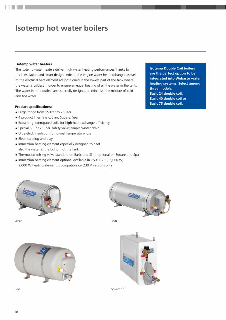
Isotemp water heaters
The Isotemp water heaters deliver high water heating performances thanks to
thick insulation and smart design. Indeed, the engine water heat exchanger as well
as the electrical heat element are positioned in the lowest part of the tank where
the water is coldest in order to ensure an equal heating of all the water in the tank.
The water in- and outlets are especially designed to minimize the mixture of cold
and hot water.
Isotemp hot water boilers
Isotemp Double Coil boilers are the perfect option to be integrated into Webasto water heating systems. Select among three models: Basic 24 double coil, Basic 40 double coil or Basic 75 double coil.
Product specifications: Large range from 15 liter to 75 liter
4 product lines: Basic, Slim, Square, Spa
Extra long, corrugated coils for high heat exchange efficiency
Special 6.0 or 7.0 bar safety valve; simple winter drain
Ultra-thick insulation for lowest temperature loss
Electrical plug and play
Immersion heating element especially designed to heat
also the water at the bottom of the tank
Thermostat mixing valve standard on Basic and Slim; optional on Square and Spa
Immersion heating element optional available in 750; 1,200; 2,000 W;
2,000 W heating element is compatible on 230 V versions only
Square 16 Spa
SlimBasic

37
Hea
ting
Prod
ucts
■ Standard n Optional – Not available
Type Order number Volume(l)
L x diameter D(mm)
Weight(kg)
Max. pressure
Valve Immersion heater
Standard safety
without mixing valve
LK safety without mixing valve
LK safety with
mixing valve
230 V750 W
230 V 1200 W
230 V 2000 W
115 V 750 W
115 V1200 W
Basic
Basic 24 602431B000003 24 470 x 395 12.5 7 – – – – n –
Basic 30 603031B000003 30 535 x 395 13.5 7 – – – – n –
Basic 40 604031B000003 40 640 x 395 15.5 7 – – n – n n
Basic 50 605031B000003 50 760 x 395 17 7 – – n n n n
Basic 75 607531B000003 75 1,050 x 395 24.5 7 – – n n n n
Basic Double Coil
Basic 24 Double Coil 602431BD00003 24 470 x 395 13 7 – – – – n –
Basic 40 Double Coil 604031BD00003 40 640 x 395 16 7 – – n – n n
Basic 75 Double Coil 607531BD00003 75 1,050 x 395 25 7 – – n n n n
Slim
Slim 15 601531S000003 15 520 x 295 9 7 – – – – n –
Slim 20 602031S000003 20 645 x 295 10.5 7 – – n – n n
Slim 25 602531S000003 25 765 x 295 12 7 – – n n n n
Spa
SPA 15 6P1531SPA0100 15 450 x 310 7.5 6 – – – – n –
SPA 15 LK MV 6P1531SPA0003 15 450 x 310 8 6 – – – – n –
SPA 20 6P2031SPA0100 20 550 x 310 9 6 – – – – n –
SPA 20 LK MV 6P2031SPA0003 20 550 x 310 9.5 6 – – – – n –
SPA 25 6P2531SPA0100 25 650 x 310 10 6 – – n – n n
SPA 25 LK MV 6P2531SPA0003 25 650 x 310 10.5 6 – – n – n n
SPA 30 6P3031SPA0100 30 535 x 390 12 6 – – – – n –
SPA 30 LK MV 6P3031SPA0003 30 535 x 390 12 6 – – – – n –
SPA 40 6P4031SPA0100 40 640 x 390 14 6 – – n – n n
SPA 40 LK MV 6P4031SPA0003 40 640 x 390 14 6 – – n – n n
Square Dimension L x H x W (mm)
Square 16 LK 601631QX00000 16 400 x 180 x 560 15 5 – – – – – –
Square 16 LK MV 601631QX00003 16 400 x 180 x 560 15.5 5 – – – – – –

38
39
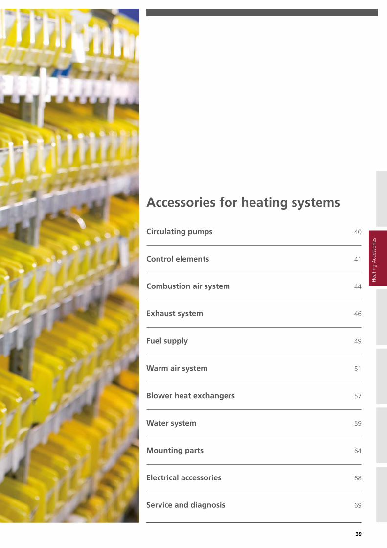
Accessories for heating systems
Circulating pumps 40
Control elements 41
Combustion air system 44
Exhaust system 46
Fuel supply 49
Warm air system 51
Blower heat exchangers 57
Water system 59
Mounting parts 64
Electrical accessories 68
Service and diagnosis 69
Hea
ting
Acc
esso
ries

40
Technical features These circulating pumps are suitable for hot water circulation. They are not designed for sea water use.
Circulating pumps
Technical data
Model overview U4850 U4847 Econ U4840 Aquavent
5000 5000 S 6000 S/6000 SC Nominal voltage ( V ) 12 / 24 12 / 24 24 24
Max rated power consumption ( W ) 67 28 29 104 210
Volume flow ( l / h ) 1,500(against 0.56 bar)
500 (against 0.14 bar)
700 (against 0.34 bar)
5,000 (against 0.2 bar)
5,000 (against 0.2 bar)
6,000 (against 0.4 bar)
Dimensions L x W x H ( mm ) 118 x 80 x 80 95 x 65 x 85 (130° connection
piece)
134 x 53 x 90 249 x 100 x 105 229 x 110 x 115
Water connection , Ø ( mm ) 20 38
Weight ( kg ) 0.66 0.3 0.4 2.1 2.2 2.4
Pump model Kit U4850 incl. fastening
material
U4847 Econ U4840 U4814 (AMP) U4854 (AMP 6.2)
U4856.01 (AMP 6.3) with stand
Order number 12 V Included SOD Thermo Top Pro
120 / 150
9002514B 1321930A 9810032A n.a. n.a.
Order number 24 V Included SOD Thermo Top Pro
120 / 150
98237B 1321932A 9810033A 9810179B 1311280B
Volume flow with water/glycolmixture (50:50) 20 °C
Flow resistancewhen the pump is stationary
Rated power consumption
0,80
0,70
0,60
0,50
0,40
0,30
0,200,100,00
l / h0 1000 2000 3000 4000 5000 6000 7000 8000
∆ p (bar)
0,80
0,70
0,60
0,50
0,40
0,30
0,200,100,00
l / h0 1000 2000 3000 4000 5000 6000 7000 8000
∆ p (bar)
0,900,800,700,600,500,400,300,200,100,00
0 1000 2000 3000 4000 5000 6000 7000 8000
∆ p (bar)
l / h
U4850 U4847 Econ U4840
Aquavent 5000 Aquavent 5000 S Aquavent 6000 SC
0,20 2
0,18 1,8
12 V
24 V
0,16 1,6
0,14 1,4
0,12 1,2
0,10 1
0,08 0,8
0,06 0,60,04 0,40,02 0,20,00 0
I (A)
0 100 200 300 400 500 600 700 800 900 1000 1100
∆ p (bar)
l / h
0,4422,2
0,401,80,361,60,321,40,281,20,2410,200,80,160,60,120,40,080,20,04
0,00 00 200 400 600 800 1000 1200 1400 1600 1800 2000 2200
I (A)
∆ p (bar)
l / h
24 V
0,800,700,600,500,400,300,200,100,00
l / h0 500 1000 1500 2000 2500
∆ p (bar)
0,901,00
8,007,006,005,004,003,002,001,000,00
9,0010,00
41
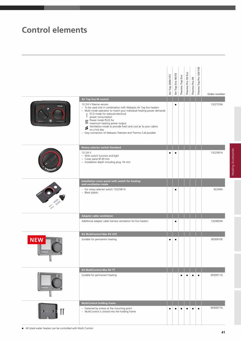
Control elements
Air
To
p 2
000
STC
Air
To
p E
vo 4
0/ 55
Ther
mo
To
p E
vo
Ther
mo
Pro
50
Eco
Ther
mo
Pro
90
Ther
mo
Top
Pro
120/
150
Order number
Air Top Evo M control
12 / 24 V Marine version – To be used only in combination with Webasto Air Top Evo heaters – Multi mode operation to match your individual heating power demands
ECO mode for reduced electrical power consumption Power mode PLUS for maximum heating power output Ventilation mode to provide fresh and cool air to your cabins on a hot day
– Easy connection of Webasto Telestart and Thermo Call possible
n 1322720A
Rotary selector switch Standard
12 / 24 V – With switch function and light – Cover panel Ø 49 mm – Installation depth including plug: 55 mm
n n 1322581A
Installation cover panel with switch for heating and ventilation mode
– For rotary selector switch 1322581A – Black plastic
n 92240A
Adapter cable ventilation
Additional adapter cable harness ventilation for Evo heaters n 1320829A
Kit MultiControl Mar RV ATE
Suitable for permanent heating n n 9030910E
Kit MultiControl Mar RV TT
Suitable for permanent heating n n n n 9030911D
MultiControl holding frame
– Fastened by screws at the mounting point – MultiControl is clicked into the holding frame
n n n n n n 9030077A
NEWH
eatin
g A
cces
sorie
s
n All listed water heaters can be controlled with Multi Control.

42
Air
To
p 2
000
STC
Air
To
p E
vo 4
0/ 55
Ther
mo
To
p E
vo
Ther
mo
Pro
50
Eco
Ther
mo
Pro
90
Ther
mo
Top
Pro
120/
150
Order number
Kit UniControl
W-bus compatible Webasto air- and water heaters– 12 / 24 V– Downward compatible with pre-selection timer 1531– Quick start button– Switch input (for analog push button)– Instrument lighting (Kl.58)– Ignition plus (terminal 15, for ad hoc continous heating)– ADRIncluding wiring harness adapter UniControl – 9034555A
n n n n n n 9034520B
Kit UniControl 1531
W-bus compatible Webasto air- and water heaters– 12 / 24 V– Downward compatible with pre-selection timer 1531– Quick start button– Switch input (for analog push button)– Instrument lighning (terminal 58)– Ignition plus (terminal 15, for ad hoc continous heating)– ADRIncluding adapter cable timer 1531 – 9034596A
n n n n n n 9034521B
Wiring harness adapter Unicontrol
Connection cable UniControl– 10-pole (UniControl) to 4-pole standard plug– Cable length 0.13 m
n n n n n 9034555A
Adapter cable timer 1531
Adapter cable for replacement of pre-selection timer 1531– 10-pole (UniControl) to 12-pole connector of
presection timer 1531– Cable length 0.2 m
n n n n n 9034596A
Expansion kit UniControl
Expansion cable for additional wiring (e.g.switching input, terminal 15)– 5 single wires with one-sided crimped flat connector– Flat connectors can be pinned into the still vacant slots of the 10-pole
UniControl plug– Including 5 butt connectors– Cable lenght 3 m
n n n n n 9034597A
Installation frame kit, short
– For UniControl, standard / combination digital timer and space thermostat, 3 position controller
– Suitable for Unitimer– With installation materials
n n n n n 474630
Installation kit, long
– For UniControl, standard / combination digital timer and space thermostat, 3 position controller
– With installation materials
n n n n n 476404
Control elements
n All listed water heaters can be controlled with Multi Control.

43
Control elements
* Connection adaptation on request.
Hea
ting
Acc
esso
ries
Air
To
p 2
000
STC
Air
To
p E
vo 4
0/ 55
Ther
mo
To
p E
vo
Ther
mo
Pro
50
Eco
Ther
mo
Pro
90
Ther
mo
Top
Pro
120/
150
Order number
Remote control Telestart T91 Holiday with continuous heating function
12 V – With check-back signal. Incl. 1 handheld transmitter with battery,
receiver, self- adhesive window antenna and Y adapter
n n n n n n 9018150C
Telestart T 100 HTM radio remote control
– Including 1 hand-held transmitter with battery, receiver, self-adhesive window antenna, ESV adapter and temperature sensor HTM
– Automatic heating time calculation
n n n n n n 1314637A
Remote control by phone ThermoCall TC4
Kit ThermoCall TC4 Entry – Incl. GSM module, cable harness, pushbutton – Operation via app for iOS and Android
n n n n n n 9032129A
Kit ThermoCall TC4 Advanced – Incl. GSM module, cable harness, GSM antenna, pushbutton – With HTM management – Operation via app for iOS and Android
n n n n n n 9032141A
Rocker switch ON / OFF
– 12 / 24 V – Dimensions: 23 x 23 mm (drilling hole 20 mm) – LED to indicate heater operation – Incl. wiring harness and information sheet with installation notes
n n n n 9032550A

44
Combustion air system
Air
To
p 2
000
STC
Air
To
p E
vo 4
0/ 55
Ther
mo
To
p E
vo
Ther
mo
Pro
50
Eco
Ther
mo
Pro
90
Ther
mo
Top
Pro
120/
150
Order number
Di
Flexible pipe
Di = 18 , L = 1,000 , APGA-A n 1319593A
Di = 22 , L = 20,000 , PAK n n 1321565A
Di = 25 , L = 5,000 , PAK n 1321587A
Di = 30 , L = 5,000 , PAK n 1321557A
Di45
200
410
Air intake silencer, set
Di = 22 , L = 410 , with mounting parts n 1313514A
Air intake silencer
Di = 22 , L = 800 , PAK , without penetration protection cap n 1322455A
Di = 25 , L = 650 , AK / PAKL , with penetration protection cap n 1319924A
Di = 30 , L = 1,160 , PAK / PAKL , without penetration protection cap
n 1319607A
Air intake silencer
D1a = 24 , D2a = 52 , L = 138 , plastic , complete with 300 mm flexible pipe, D1a = 24 mm
n 9025956A
Di Combustion air elbow
Di = 22 n 1320144A
Di = 25 n 1320278A
Plastic

45
Combustion air system
Hea
ting
Acc
esso
ries
Air
To
p 2
000
STC
Air
To
p E
vo 4
0/ 55
Ther
mo
To
p E
vo
Ther
mo
Pro
50
Eco
Ther
mo
Pro
90
Ther
mo
Top
Pro
120/
150
Order number
Di
Hose clamp
Di = 16 ... 27 , 10 pieces n n n 9015918A
Di = 23 ... 35 , 20 pieces n n 1320271A
W = 9 , SW = 7 , stainless steel , bolt head with hexagon and slot
Di
Hose clamp
Di = 40 ... 47 n 1320158A
SW = 8 , W = 14.3 , steel corrosion-resistant , bolt head with hexagon and cross-head slot
Di
Pipe clip
Di = 25 , W = 15 , stainless steel n n 1320045A
Di = 29 , W = 15 , steel zinc coated / rubber , rubber-coated pipe clip, fastening hole 6.4 mm , 5 pieces
n 1320235A
Di = 33 , W = 15 , stainless steel , 6.5 mm fastening hole n 1320064A

46
Exhaust system
Air
To
p 2
000
STC
Air
To
p E
vo 4
0/ 55
Ther
mo
To
p E
vo
Ther
mo
Pro
50
Eco
Ther
mo
Pro
90
Ther
mo
Top
Pro
120/
150
Order number
Da
Di
Flexible exhaust pipe (INOX), two-ply
Di = 22 , Da = 26 , L = 1,000 with end cap n n n 1322414A
Di = 24 , Da = 28 , L = 10,000 n 1321523A
Di = 38 , Da = 41 , L = 5,000 n n 1321540A
Di = 41 , Da = 38 , L = 10,000 n n 1321541A
Di = 38 , Da = 41 , L = 20,000 n n 1321539A
Stainless steel
Heat protection hose
Di = 70 , L = 1,250 n n n n n n 9016230B
Di = 72 , L = 1,700 n n n n n n 9016231B
Di = 70 , L = 1,850 n n n n n n 1320830A
Da = 120 , fiberglass
Flexible heat protection pipe
Di = 28 , Da = 32.5 , GA-A (aluminium foil and aluminium coated glass fabric)
n n n 1321601A
Di = 45 , Da = 48.5 , GA2- A (aluminium and aluminium coated glass fabric)
n n n 1321602C
L = 10,000
Da
Di
Flexible heat protecion pipe
Di = 28 , Da = 38 , L = 324 , with cover, non-flammable, interior resis-tant to temperatures up to 500 °C
n n n 1319670A
Da
Di Exhaust muffler
Di = 24 , L = 1,800 n n n n 1322001A
Di = 38 , L = 1,000 n n 1321823A
Outside with partial fiberglass insulation
Da
DiL
Exhaust gas reducing bush
Di = 22 , Da = 24 , L = 40 , stainless steel n 1320382A
Exhaust silencer
Da = 38 , L = 270 , W = 130 , stainless steel n n 1321397A

47
Exhaust system
Air
To
p 2
000
STC
Air
To
p E
vo 4
0/ 55
Ther
mo
To
p E
vo
Ther
mo
Pro
50
Eco
Ther
mo
Pro
90
Ther
mo
Top
Pro
120/
150
Order number
Insulation sleeve for exhaust silencer
Glas fiber heat protection, 550 x 440 mm , with snap fastener , for part 1321397A
n n 9028104A
Elbow
Di = 24 , L = 110 , stainless steel , with condensation water drain
n 1320378A
Di 97
Elbow
Di = 24 , L = 110 , stainless steel , without condensation water drain
n 1320383A
Connection pipe
Da = 24 , L = 50 , M6 , stainless steel , without condensation water drain
n 1319937A
Da = 24 , L = 65 , steel , with anti- corrosion protection and condensate drain
n 1319935A
Da = 38 , L = 65 , stainless steel , for exhaust muffler 1320841A and 1320895A, with condensation water drain
n n 1320959A
Da
Di Exhaust pipe
Di = 38 , Da = 38 , stainless steel n n 1319380A
Condensation water drain
L = 128 , M10 x 1 connection thread , copper , for exhaust connecting pipe 1319935A , with mounting parts
n 92621A
Through hull double walled straight
Da = 24 n n 1320363A
Da = 38 n n n 1320983A
Da = 70 3393270A
Stainless steel
Through hull double walled bended
Da = 24 n n n 1320364A
Da = 38 n n n 1320365A
Stainless steel
Hea
ting
Acc
esso
ries

48
Exhaust system
Air
To
p 2
000
STC
Air
To
p E
vo 4
0/ 55
Ther
mo
To
p E
vo
Ther
mo
Pro
50
Eco
Ther
mo
Pro
90
Ther
mo
Top
Pro
120/
150
Order number
Di
Hose clamp
Di = 39 ... 42 , W = 13.5 , thread M8, steel corrosion-resistant , for flexible exhaust pipe , with screw
n n 1320194A
Di
Hose clamp
Di = 24 ... 26 , with carriage bolt n n n 1320165A
Di = 26 ... 28 , nut, welded n 1320220A
W = 16 , thread M6 , stainless steel , for flexible exhaust pipe
B
Insulating lagging
L = 50,000 , W = 60 , E-glass , white , usage temperature 450 °C, 550 °C for short periods, 2 mm thick
n n n n n n 1320357A

49
Fuel supply
Air
To
p 2
000
STC
Air
To
p E
vo 4
0/ 55
Ther
mo
To
p E
vo
Ther
mo
Pro
50
Eco
Ther
mo
Pro
90
Ther
mo
Top
Pro
120/
150
Order number
Da
650
60
25
Tank extracting device, riser pipe
Di = 2.6 , Da = 5 n n n 1320399A
Da = 8 n 1319372A
L = 650 , steel zinc coated , 90° extractor connection piece, only for installation in metal tanks
458
Da
6,5
Tank extracting device, riser pipe
Di = 2.5 , Da = 5 , L = 409 , thread M6 , stainless steel , 90° extractor connection piece for mounting in tank fitting, suitable for plastic tank and metal tank
n n n n n 1322632A
Tank extracting device, riser pipe
Da = 6 , L = 630 , steel zinc coated , with sealing n 1322830B
H
L Fuel extractor, T-piece
L = 50 , H = 26 , 6 x 5 x 6 n n n n n 1319300A
L = 50 , H = 28 , 8 x 5 x 8 n n n n n 1319301A
L = 50 , H = 28 , 8 x 6 x 8 n 1320531A
Copper
M14 x 1,5
M14 x 1,5
80
135
Holder with housing for interchangeable filter
L = 135 , H = 80 , M14 x 1.5 connection thread , light metal
n 1319291A
Interchangeable filter
For holder 1319291A n 1320031A
Hea
ting
Acc
esso
ries

50
Fuel supply
Air
To
p 2
000
STC
Air
To
p E
vo 4
0/ 55
Ther
mo
To
p E
vo
Ther
mo
Pro
50
Eco
Ther
mo
Pro
90
Ther
mo
Top
Pro
120/
150
Order number
Connecting parts (bag)
Steel zinc coated , for soldered joints . Contents: double connection piece, union nuts, ring seals and sealing cone
n 1320539A
Da = 5 60
26
Fuel filter
Da = 5 , plastic , transparent
n n n n n 1319466A
Flexible heat protection pipe
L = 20,000 n n n n n n 1321584B
L = 5,000 n n n n n n 1321585B
Di = 14.5 , Da = 16.5 , GA-A (aluminium foil and aluminium coated glass fabric)
Dosing pump mounting
Very quiet mounting , bag of 1 piece n n n n 1320193A
Fuel line decoupling kit
Di = 4.5 , Da = 10.5 , bag with two 90° elbows n n 9026570B
Fuel supply systems wich are installed in the engine room of a boat need to be fire resistand according to EN ISO 7840.Please select th required parts from the items listed below.
Mini Jacket fuel pump protector
Protection device for fuel pumps with mufflers , required by ISO 7840 if the fuel system is installed in engine rooms
n n 1319522A
Metal fuel line kit for boats
Di = 2.0 , Da = 5 , L = 5,000 , EN ISO 7840, with screw fasteners, hoses and clips
n n n n n 66958B
Fuel line for boats
Di = 2.0 , Da = 5 , L = 5,000 , stainless steel n n n n n 1320860A
Fuel hose for boats
Di = 5 , Da = 15 , L = 50 n n n n n 1320857A

51
Warm air system
Air
To
p 2
000
STC
Air
To
p E
vo 4
0/ 55
Order number
Louvre plate
L = 190 , H = 170 , aluminium n n 1319269A
Screen
Di = 60 , plastic , black , for intake and outlet openings of heater n 1320163A
Di = 90 n 1310581A
Ducting
Di
Flexible pipe
Di = 60 , L = 25,000 APK , black n n 1311892C
Di = 60 , L = 10,000 APK , black n n 1322083C
Di = 60 , L = 2,000 APK , black n n 1321574B
Di = 60 , L = 5,000 APK , black n n 1321575C
Di = 80 , L = 25,000 APK , black n 1311893C
Hose specifikation
APK: Aluminium, Paper, Plastic –black, with white Webasto logo
PAHK: Paper, Aluminium, High ridgidity Aluminium, Plastic –black, with white Webasto logo
PAK: Paper, Aluminium, Plastic –black, with white Webasto logo
PAPK: Paper, Aluminium, Paper, Plastic –grey, with red and blue Webasto logo, extra strong 4 layer design
Di = 80 , L = 10,000 APK , black n 1321718C
Di = 80 , L = 2,000 APK , black n 1321576C
Di = 80 , L = 5,000 APK , black n 1321577B
Di = 90 , L = 25,000 APK , black n 1311894C
Di = 90 , L = 10,000 APK , black n 1321719C
Di = 90 , L = 2,000 APK , black n 1321578C
Di = 90 , L = 5,000 APK , black n 1321579C
Di = 60 , L = 3,000 PAHK , black n n 1321511A
Di = 60 , L = 25,000 , PAPK , grey n n 1311898C
Di = 60 , L = 10,000 , PAPK , grey n n 1321727C
Di = 60 , L = 2,000 , PAPK , grey n n 1321504A
Di = 60 , L = 5,000 , PAPK , grey n n 1321505A
Di = 80 , L = 25,000 , PAPK , grey n 1311900C
Di = 80 , L = 10,000 , PAPK , grey n 1321729B
Di = 80 , L = 2,000 , PAPK , grey n 1321582B
Di = 80 , L = 5,000 , PAPK , grey n 1321583B
Di = 80 , L = 10,000 , PAK , black n 1322147B
Di = 90 , L = 25,000 , PAPK , grey n 1311902C
Di = 90 , L = 10,000 , PAPK , grey n 1321731C
Di = 90 , L = 2,000 , PAPK , grey n 1321506B
Di = 90 , L = 5,000 , PAPK , grey n 1321508A
Di
Insulated hoses
Di = 80 n 1321515A
Di = 90 n 1321517A
L = 12,000 , PAK
Air Intake
Hea
ting
Acc
esso
ries

52
Warm air system
Distributor Air
To
p 2
000
STC
Air
To
p E
vo 4
0/ 55
Order number
Console
For mounting flexible pipes with corresponding hose clip n n 1321044A
Distributor
Da
DaDa
Distributor Y-unit
Da = 55 n 1319416A
Da = 80 n 1319212A
Plastic , black
Distributor Y-unit
D1a = 80 , D2a = 55 , to be used in the secondary flow only n 1320753A
D1a = 60 , D2a = 60 n 1320814A
D1a = 90 , D2a = 80 n 1320375A
D1a = 90 , D2a = 90 n 1320470A
D1a = 80 , D2a = 60 n 1320471A
Plastic , black
Da
Da
Da L
T-unit
Da = 60 n n 1320474A
Da = 90 n 1320473A
L = 110 , 90 ° , plastic , black
DaDi
T-unit
Di = 60 , Da = 60 , 90 ° , with thread n n 1320476A
Di = 60 , Da = 90 , 90 ° , with thread n 1320475A
Plastic , black
Da
End Cap
Da = 60 n n 1320477A
Da = 90 n 1319870A
Plastic , black
D2aD1a
D1a
L
Junction fitting
D1a = 60 , L = 145 n n 1320472A
D1a = 90 , L = 146 n 1320707A
D2a = 60 , 45 ° , plastic , black
Ducting

53
Warm air system
n High temperature resistance from -40 °C up to +140 °C
n PA6.6 GF30 glass fibre reinforced synthetic material
n Super easy fitting, no need for tools or screws
n Multiple combination possibilities to suit any application
Webasto provides perfectly fitting, high quality components
for an easy installation and high flexibility.
Quick-fit Hot Air Ducting System (HADS):
Air
To
p 2
000
STC
Air
To
p E
vo 4
0/ 55
Order number
D1a
D2a
D3a
4560
60172
L
Junction fitting
D1a = 80 , D2a = 60 , D3a = 60 , L = 350 , to be used in the secondary flow only! n 1319314A
D1a = 80 , D2a = 80 , D3a = 60 , L = 350 n 1320645A
D1a = 80 , D2a = 80 , D3a = 80 , L = 370 , 45 ° , steel corrosion-resistant n 1319315A
Distributor
Da = 55 , L = 95 n 1319224A
Da = 80 , L = 124 n 1319214A
Plastic , black , with remote control flap valve
L
Control cable
L = 850 n n 1320785A
L = 1,500 n n 1320786A
For Distributor 1319224A und 1319214A , with grip and outer sleeve
Clamp
For Bowden Cable 1320785A und 1320786A n n 1319688A
Hea
ting
Acc
esso
ries
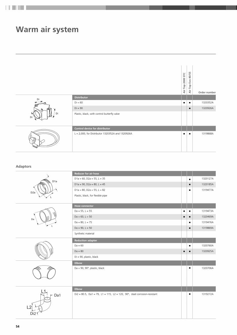
54
Air
To
p 2
000
STC
Air
To
p E
vo 4
0/ 55
Order number
Di
Di
Di
Distributor
Di = 60 n n 1320352A
Di = 90 n 1320926A
Plastic , black , with control butterfly valve
Control device for distributor
L = 2,000 , for Distributor 1320352A and 1320926A n n 1319868A
Adaptors
D1a
D2a
L
Reducer for air hose
D1a = 60 , D2a = 55 , L = 35 n 1320127A
D1a = 90 , D2a = 80 , L = 45 n 1320185A
D1a = 80 , D2a = 55 , L = 82 n 1319477A
Plastic , black , for flexible pipe
Da
L
Hose connector
Da = 55 , L = 55 n n 1319473A
Da = 60 , L = 50 n n 1320469A
Da = 80 , L = 75 n 1319476A
Da = 90 , L = 50 n 1319869A
Synthetic material
Reduction adapter
Da = 60 n 1320760A
Da = 80 n n 1320925A
Di = 90 , plastic , black
Elbow
Da = 90 , 90 ° , plastic , black n 1320706A
Da1
Di2
Elbow
Di2 = 80.5 , Da1 = 79 , L1 = 115 , L2 = 120 , 90 ° , steel corrosion-resistant n 1319272A
Warm air system

55
Air
To
p 2
000
STC
Air
To
p E
vo 4
0/ 55
Order number
Da2 Wall feed-through
Da = 60 n n 1320923A
Da = 90 n 1320924A
Plastic , black
Da
Di
B
Adaptor ring
Di = 55 , Da = 60 , for outlet 1320812A n n 1320224A
Di = 70 , Da = 80 , for outlet 1319946A n 1320040A
W = 17 , plastic , black
Outlets
Air Outlet, closeable
Da = 60 , black n n 1320206A
Da = 60 , white n n 1320207A
Da = 60 , grey n n 1320937A
Da = 90 , black n 1320355A
Da = 90 , white n 1320713A
Da = 90 , grey n 1320714A
L = 30, plastic, outlet closeable, bag with wall feed through
Air Outlet
Da = 60 , black n n 1320934A
Da = 60 , white n n 1320935A
Da = 60 , grey n n 1320936A
Da = 90 , black n 1320932A
Da = 90 , white n 1320711A
Da = 90 , grey n 1320712A
L = 30, plastic, straight air flow, bag with wall feed through
Air outlet, 45 °
Da = 60 , black n n 1320204A
Da = 60 , white n n 1320205A
Da = 60 , grey n n 1320933A
Da = 90 , black n 1320709A
Da = 90 , white n 1320710A
Da = 90 , grey n 1320354A
L = 30, plastic, 45°, bag with wall feed through
Da1 Union nut for outlet
Da = 60 n n 1320922A
Da = 90 n 1320468A
L = 60 , plastic , black
Warm air system
Hea
ting
Acc
esso
ries

56
Air
To
p 2
000
STC
Air
To
p E
vo 4
0/ 55
Order number
D1a
D2aL
Air outlet
D1a = 55 n 1320812A
D1a = 70 , use for secondary flow only n 1319946A
D2a = 100 , L = 65 , plastic , black , closable, with bushing
Air outlet
D1a = 60 , D2a = 92 n 1322405A
Silencer
Di
Da
317
Air ducting silencer
Di = 90 , Da = 122 , L = 317 , plastic n 1320996A
Air ducting silencer
Di = 90 , L = 600 , aluminium / plasic n 1321734A
Warm air system

57
The blower modules are the ideal combination for Webasto water heaters. Thanks to their powerful blowers, the cabins of boats
and yachts can be heated up quickly. Most models have an adjustable blower speed to fine-tune the air flow according to individual
needs. In addition to their compact dimensions they ensure an easy installation.
The blower speed control is the perfect match for all blower heat exchangers. It provides temperature regulated automatic blower
speed control or manual 5-speed blower regulation. With a variable temperature setting, everybody can find his perfect
comfort climate.
Florida 3 – extra-silent single speed 3 kW model with very low power consumption
Madeira 4 – Lightweight and variable 4 kW model, 3 blower speeds, choice of air outlet
BB8 – Powerful 8 kW model with 3-speed blower regulation and robust metal casing
BB4 – Compact 2,5 kW model with 3-speed blower regulation and metal casing
Blower speed control – temperature-regulated blower speed control for the blower modules Florida 5 without controls, BB4, BB8. With separate mounting also possible for Madeira 4 and Madeira 8.
Madeira 8 – Lightweight and variable 7,3 kW model, 3 blower speeds, choice of air outlet
Florida 5 – Compact 3-speed 5 kW model with blower speed and heat output regulation
Florida 5 – Compact 3-speed 5 kW model without controls
Whisperer – Very compact and silent 1.8 kW model with single speed axial fan
Blower speed control
The product range
Scopes of delivery
Control element
Electronic PWM module
Temperature sensor (5 meters)
Blower heat exchangers
Hea
ting
Acc
esso
ries

58
Blower heat exchangers
Model Order number Colour Voltage (V)
Heat output at Q100
(kW)
Air flow at free
discharge (m3 / h)
Water connection
diam. (mm)
Electrical power
consumption (W)
DimensionsW x H x D
(mm)
Weight(kg)
Florida 3 No Noise 3200740A light grey 12 3 120 16 12 269 x 198 x 141 1.4
3200741A light grey 24 3 120 16 12 269 x 198 x 141 1.4
Florida 5 with controls 3200679A light grey 12 5.2 285 16 120 269 x 198 x 218 2
3200680A light grey 24 5.2 285 16 120 269 x 198 x 218 2
Florida 5 without controls 3200681A light grey 12 5.2 285 16 120 269 x 198 x 218 2
3200682A light grey 24 5.2 285 16 120 269 x 198 x 218 2
Whisperer 3200673A Inox (front) 12 1.8 120 16 8.4 210 x 210 x 125 1.2
3200674A Inox (front) 24 1.8 120 16 8.4 210 x 210 x 125 1.2
BB4 71174000 blue 12 2.5 190 16 38 310 x 150 x 150 3.5
71174500 blue 24 2.5 190 16 38 310 x 150 x 150 3.5
BB8 3395977A blue 12 8 525 16 65 480 x 170 x 305 12
3395978A blue 24 8 525 16 65 480 x 170 x 305 12
Madeira 4 71174550 light grey and dark grey
12 4.6 200 16 70 275 x 115 x 203 1.8
71174552 light grey and dark grey
24 4.6 200 16 70 275 x 115 x 203 1.8
Madeira 8 71174554 light grey and dark grey
12 7.3 300 16 150 376 x 115 x 250 3.1
71174556 light grey and dark grey
24 7.3 300 16 150 376 x 115 x 250 3.1
Outlet versions
Air grille 90 x 90 mm* 3396524A black
Air hose connector diam. 55 mm*
3396525A black
* When ordering the Madeira 4 or Madeira 8, please specify the type and amount of desired air outlets. Madeira 4 requires 2 and Madeira 8 requires 4 outlets.
Control elements
Blower speed control 3391288B 12 / 24 123 x 80 x 40 0.4
* Please refer to pictures of Madeira 4 and Madeira 8 for example of air grille and hose connectors, see previous page.

59
Accessories: Water system
Water system
For the complete overview of Hep2O parts please refer to the water system section for BlueCool accessories in this catalog.
Hea
ting
Acc
esso
ries
Webasto offers a wide range of high-quality Hep2O products.
n Cabling ability – Hep2O provides faster, safer and more cost effective installation
n Less jointing – Hep2O flexible polybutylene pipe system requires less jointing,
thus saves time and materials
n Joint security – the Hep2O push-fit piping offers reliable jointing and safe assembly
n High resistance to impact and vibration – solder free, and the Hep2O system is
extremely strong and resistant to denting and accidental damage from impact
or vibration
n Corrosion free – Hep2O completely eliminates electrolytic corrosion and is
highly resistant against aggressive salt-water and other corrosive media

60
Water system
Ther
mo
To
p E
vo
Ther
mo
Pro
50
Eco
Ther
mo
Pro
90
Ther
mo
Top
Pro
120/
150
Order number
Da
L
Check valve
Da = 15 , L = 104 n n n n 1320240A
Da = 15 , L = 104 n n n n 1320239A
Da = 18 , L = 90 n n n n 1319250A
Da = 18 , L = 100 n n n n 1319484A
Plastic , without leak hole
L
42
Da1
Da1
Da2Da2
Check valve
D1a = 18 , D2a = 18 , L = 146 , plastic , black , with leak hole n n n n 1319486A
D1a = 20 , D2a = 20 , L = 162 , brass , with leak hole n n n n 1319595A
D1a = 18 , D2a = 18 , L = 146 , plastic , black , without leak hole
n n n n 1319485A
H = 42
Da
Di
23
r25
18
Molded hose
Di = 18 , Da = 25 , 90 ° n n n 1319418A
Da
Di
r
L1
L2
Molded hose
Di = 18 , Da = 25 , r = 25 , L1 = 18 , L2 = 18 n n n n 1319401A
Di = 20 , Da = 27 , r = 23.5 , L1 = 88 , L2 = 64 n n n n 1319623A
180 °
Da
Di
H
L1
L2 Molded hose
Di = 15 , Da = 25 , L1 = 580 , L2 = 17 , H = 75 , 180 ° n n n n 1320790A
Di = 18 , Da = 25 , L1 = 580 , 180 ° n n n n 1319421A
Di = 18 , Da = 25 , L1 = 1,100 , L2 = 17 , H = 75 n n n n 1322496A
Di = 20 , Da = 29 , L1 = 89 , L2 = 20 , H = 98 n n n n 1319761A
Da
Di
20
L
Molded hose
Di = 18 , Da = 25 , L = 110 n n n 1322493A
Di = 20 , Da = 27 , L = 70 n n n 1321031A
Di = 20 , Da = 27 , L = 190 n n n 1322473A

61
Ther
mo
To
p E
vo
Ther
mo
Pro
50
Eco
Ther
mo
Pro
90
Ther
mo
Top
Pro
120/
150
Order number
Da
Di
L1
L290°
Molded hose
Di = 15 , Da = 22 , L1 = 1,020 , L2 = 50 n n n n 1320789A
Di = 18 , Da = 25 , L1 = 125 , L2 = 90 n n n n 1320907A
Di = 18 , Da = 25 , L1 = 500 , L2 = 48 n n n n 1319953A
Di = 18 , Da = 27 , L1 = 1,020 , L2 = 50 n n n n 1320794A
Di = 20 , Da = 27 , L1 = 70 , L2 = 57 n n n n 1319839A
Di = 20 , Da = 27 , L1 = 130 , L2 = 57 n n n n 1320147A
Di = 20 , Da = 27 , L1 = 187 , L2 = 47 n n n n 1319952A
Di = 20 , Da = 27 , L1 = 360 , L2 = 47 n n n n 1320961A
Di = 20 , Da = 27 , L1 = 615 , L2 = 57 n n n n 1320197A
Di = 22 , Da = 29 , L1 = 225 , L2 = 57 n n n n 1320911A
Di = 22 , Da = 29 , L1 = 1,020 , L2 = 50 n n n n 1320842A
90 °
Da
Di L
Hose
Di = 15 , Da = 22 , L = 2,400 n n 1320300A
Di = 18 , Da = 25 , L = 58 n n n 1321789A
Di = 18 , Da = 27 , L = 2,000 n n n 1319379A
Di = 20 , Da = 27 , L = 380 n n 1320960A
Connecting pipe
D = 15 , L = 75 n n n n 1319279A
Brass
D1a
D2a
63
Connecting pipe
D1a = 15 , D2a = 20 n n 1321000A
D1a = 17 , D2a = 20 , L = 63 n n n 1320143A
D1a = 18 , D2a = 18 n n n 9006211A
D1a = 18 , D2a = 20 n n n n 9005819C
D1a = 18 , D2a = 22 , L = 63 n n n 1320155A
D1a = 20 , D2a = 20 n n n 1320342A
D1a = 20 , D2a = 22 , L = 63 n n n 1319594A
Black , plastic
D1a
D2a
D1a
75
T-piece
D1a = 15 , D2a = 15 , steel corrosion-resistant n n n n 1319289A
D1a = 18 , D2a = 15 , steel corrosion-resistant n n n n 1320532A
D1a = 18 , D2a = 18 , plastic, black n n n n 1321001A
D1a = 20 , D2a = 10 , steel corrosion-resistant n n n n 1319846A
D1a = 20 , D2a = 15 , steel corrosion-resistant n n n n 1319290A
D1a = 20 , D2a = 20 , brass n n n n 1319602A
L = 75
Water system
Hea
ting
Acc
esso
ries

62
Ther
mo
To
p E
vo
Ther
mo
Pro
50
Eco
Ther
mo
Pro
90
Ther
mo
Top
Pro
120/
150
Order number
Da
Da
Da
5,8
75
T-piece with restrictor
Da = 20 n n n n 1319817A
Da
Da
Da
4,0
75
T-piece
Da = 18 , L = 75 , steel corrosion-resistant , with restrictor, restrictor diameter 4 mm
n n n n 1319800A
Da
Da
Da
75
Connection pipe
Da = 18 , L = 75 , steel corrosion-resistant n n n n 1319266A
Connecting piece
Da = 19 n 1320792A
Da
Da
Da
H
Solenoid valve
Da = 18 , L = 84 , W = 55 , H = 101 , 12 V , metal / plastic , plastic casing , 3 / 2-way, open without power , bag with electrical mounting parts
n n n n 9014606A
Da 75
Connecting pipe
Da = 15 n n n 1319221A
Da = 18 n n n n 1319219A
Da = 20 n n n 1320989A
Steel corrosion-resistant , with bleeder valve
D1a
75 D1a
D2a30
37,5
T-piece with bleed valve
D1a = 18 , D2a = 15 n n n 1320600A
Water system

63
Ther
mo
To
p E
vo
Ther
mo
Pro
50
Eco
Ther
mo
Pro
90
Ther
mo
Top
Pro
120/
150
Order number
Da
L
Check valve
Da = 18 , L = 90 , steel / brass n n n 1319429A
Da = 20 , L = 120 , plastic , black n n n 1319554A
Without leak hole
Rubber ring (anti-chafing device)
Di = 25.5 , Da = 45 , EPDM-50 , red , not permitted for exhaust systems n n n n 1312780A
Di = 22 , Da = 46 , not for exhaust system , chafing guard n n n n 1320191A
Di = 20.5 , Da = 40 , elastomer , black , not permitted for exhaust systems n n n n 1312785A
L = 20
Di
L
Woven protection hose
Di = 26 ... 30 , L = 1,500 , polyester , chafing guard for polyester water hoses n n n n 1322409A
290
230
Expansion tank
8 l , preset pressure 0,5 bar , total volume of system: max. 157 l n n n n 1320545A
Header tank
L = 252 , H = 343 , vertical n n n 9024038A
L = 343 , H = 252 , horizontal n n n 9024039A
W = 120 , 5 l , net content 3 liter, made of polypropylene for high temperature resistance , tank kit includes 3 stainless steel mounting brackets
Header tank
D = 120 , 10 l n n n n 79289500
H = 300
Water system
Hea
ting
Acc
esso
ries

64
Mounting parts
Air
To
p 2
000
ST C
Air
To
p E
vo 4
0/ 55
Ther
mo
To
p E
vo
Ther
mo
Pro
50
Eco
Ther
mo
Pro
90
Ther
mo
Top
Pro
120/
150
Order number
100156
120
Heater bracket
Stainless steel n 1320921A
Heater bracket
Stainless steel , suitable for various installation options n n 1319936A
Mounting bracket
Stainless steel n n n n n n 1320264A
steel zinc coated , 10 pieces n n n n n n 1320232A
L = 46 , W = 25 , D = 26
Mounting strip
Stainless steel n n n n n n 1319818A
Steel zinc coated , 10 pieces n n n n n n 9007918A
L = 100 , W = 25
Hose strip
L = 178 , B = 5.3 , bag of 30 pieces n n n n n n 1322447A
Hose strip
1 piece n n n n n n 1320222A
10 pieces n n n n n n 9007917A
L = 400 , B = 7.6
Anti-vibration mount
L = 53 , M6 thread , not suitable for fastening heaters , 5 pieces
n 1320270A

65
Mounting parts
Air
To
p 2
000
ST C
Air
To
p E
vo 4
0/ 55
Ther
mo
To
p E
vo
Ther
mo
Pro
50
Eco
Ther
mo
Pro
90
Ther
mo
Top
Pro
120/
150
Order number
Anti-vibration mount
Da = thread M6 n n n 9023020A
Da = thread M8 n 1319553A
L = 34 , not suitable for fastening heaters , 5 pieces
Spacer nut
L = 15 n n n n n n 1320256A
L = 20 n n n n n n 1320241A
L = 30 n n n n n n 1320083A
L = 40 n n n n n n 1319517A
SW = 17 , full-length M6 thread , steel corrosion-resistant
Spacer bushing
L = 5 n n n n n n 1320498A
L = 8 n n n n n n 1320499A
L = 10 n n n n n n 1320496A
L = 15 n n n n n n 1320090A
L = 20 n n n n n n 1320088A
L = 30 n n n n n n 1320089A
L = 40 n n n n n n 1319533A
Di = 8 , Da = 20 , aluminium
Mounting / fastening bracket
Di = 86 , L = 111 , B = 25 n n n n n n 1319317A
Di
Hose clip
Di = 32 ... 39 , stainless steel n n n n n n 1321732A
Di = 40 ... 47 , steel corrosion-resistant n n n n n n 1320158A
Di = 48 ... 55 , steel corrosion-resistant n n n n n n 1320159A
Di = 60 ... 80 , steel corrosion-resistant n n n n n n 9026066A
Di = 70 ... 90 , steel corrosion-resistant n n n n n n 1320223A
Di = 72 ... 79 , steel corrosion-resistant n n n n n n 1320160A
Di = 80 ... 87 , steel corrosion-resistant n n n n n n 1320162A
Di = 90 ... 100 , steel corrosion-resistant n n n n n n 1320085A
Di = 98 ... 120 , steel corrosion-resistant n n n n n n 1320161A
W = 14.3 , SW = 8 , bolt head with hexagon and slot
Hea
ting
Acc
esso
ries

66
Mounting parts
Air
To
p 2
000
ST C
Air
To
p E
vo 4
0/ 55
Ther
mo
To
p E
vo
Ther
mo
Pro
50
Eco
Ther
mo
Pro
90
Ther
mo
Top
Pro
120/
150
Order number
Di
Hose clip
Di = 16 ... 24 n n n n n n 1320502A
Di = 40 ... 60 n n n n n n 1320746A
Di = 70 ... 90 n n n n n n 1320086A
Di = 80 ... 95 n n n n n n 9023950A
Steel
Di
Pipe clamp
Di = 39 ... 42 , W = 13.5 , M8 thread , steel corrosion-resistant , for flexible exhaust pipe , with screw
n 1320194A
Di
Hose clamp
Di = 16 – 27 , stainless steel n n n n n n 9015918A
Di = 28 – 35 , stainless steel n n n n n n 1320271A
Di = 16 – 24 , chromium steel n n n n n n 1320248A
Di = 40 – 50 , chromium steel n n n n n n 1321064A
Di
Pipe clip
Di = 25 , W = 15 , stainless steel n n n n n n 1320045A
Di = 33 , W = 15 , stainless steel , 6.5 mm fastening hole
n n n n n n 1320064A
Di = 38 , W = 20 , stainless steel n n n n n n 1320129A
Di = 42 , W = 12 , stainless steel , 5.2 mm fastening hole
n n n n n n 1319693A
Di = 42 , W = 15 , stainless steel , 6.5 mm fastening hole , 5 pieces
n n n n n n 1320276A
Di = 52 , W = 15 , steel zinc coated , 6.5 mm fastening hole , 5 pieces
n n n n n n 1320265A

67
Air
To
p 2
000
ST C
Air
To
p E
vo 4
0/ 55
Ther
mo
To
p E
vo
Ther
mo
Pro
50
Eco
Ther
mo
Pro
90
Ther
mo
Top
Pro
120/
150
Order number
Di
Pipe clip
Di = 5 , stainless steel / rubber , rubber-coated pipe clip, 5.2 mm fastening hole
n n n n n n 1320195A
Di = 29 , W = 15 rubber-coat
n n n n n n 1320235A
Di = 34 , W = 20 rubber-coat
n n n n n n 1320236A
Di = 38 , W = 15 rubber-coat
n n n n n n 1320402A
Di
Hose clip
Di = 8 , steel corrosion-resistant , 20 pieces n n n n n n 1320244A
Di = 9 , steel corrosion-resistant n n n n n n 1320492A
Di = 14 , steel corrosion-resistant , 20 pieces n n n n n n 1320245A
Di = 12, steel corrosion-resistant, 20 pieces n n n n n n 1320246A
Di = 14 , stainless steel , 10 pieces n n n n n 1320249A
W = 9 , SW = 7 , bolt head with hexagon and cross-head slot
Mounting parts
Hea
ting
Acc
esso
ries
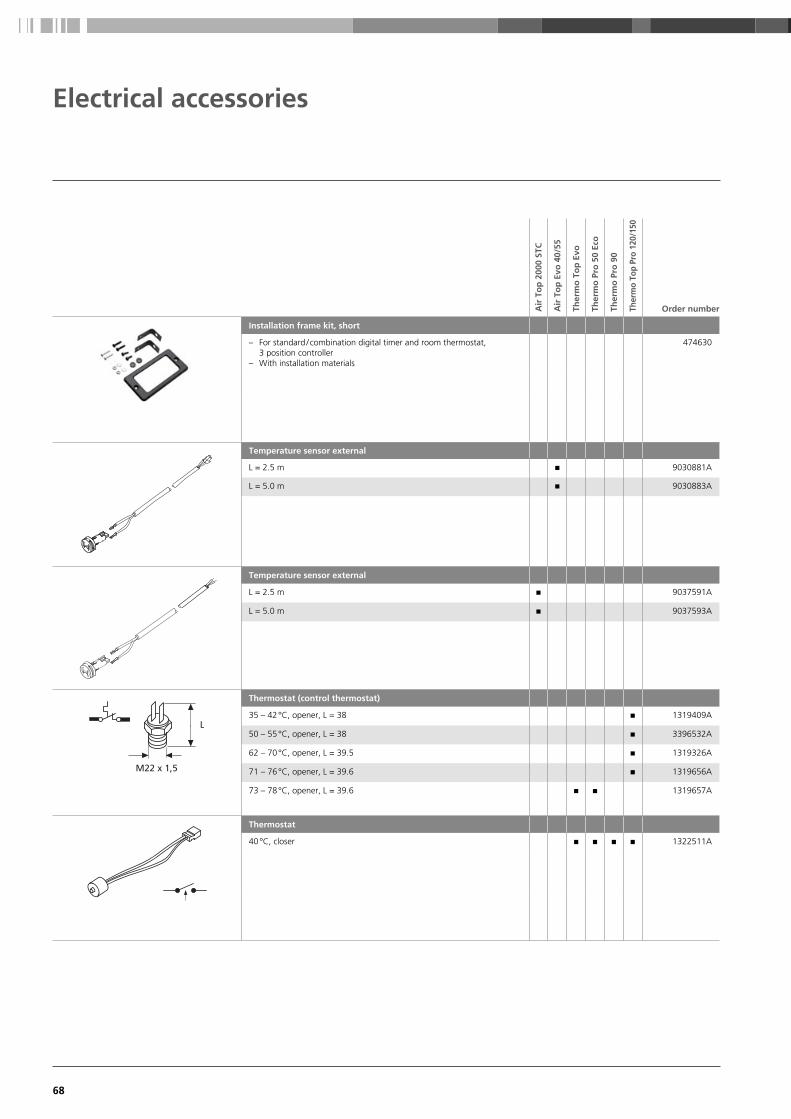
68
Electrical accessories
Air
To
p 2
000
STC
Air
To
p E
vo 4
0/ 55
Ther
mo
To
p E
vo
Ther
mo
Pro
50
Eco
Ther
mo
Pro
90
Ther
mo
Top
Pro
120/
150
Order number
Installation frame kit, short
– For standard / combination digital timer and room thermostat, 3 position controller
– With installation materials
474630
Temperature sensor external
L = 2.5 m n 9030881A
L = 5.0 m n 9030883A
Temperature sensor external
L = 2.5 m n 9037591A
L = 5.0 m n 9037593A
L
M22 x 1,5
Thermostat (control thermostat)
35 – 42 °C, opener, L = 38 n 1319409A
50 – 55 °C, opener, L = 38 n 3396532A
62 – 70 °C, opener, L = 39.5 n 1319326A
71 – 76 °C, opener, L = 39.6 n 1319656A
73 – 78 °C, opener, L = 39.6 n n 1319657A
Thermostat
40 °C , closer n n n n 1322511A

69
Webasto provides a complete set of diagnosis tools to service and repair its heaters. The diagnosis module includes
a hardware unit and various connecting adaptors for each heater model. For more details and the latest diagnosis visit
our dealer portal at: http://dealers.webasto.com
Screenshots from Webasto diagnosis software
Heater diagnosis module
Service and diagnosis
Air
To
p 2
000
ST C
Air
To
p E
vo 4
0/ 55
Ther
mo
To
p C
/E
Ther
mo
Pro
50
Eco
Ther
mo
To
p E
vo
Ther
mo
Pro
90
Ther
mo
Top
Pro
120/
150
Ther
mo
S 2
30/3
00/3
50/ 4
00
Order number
PC Diagnosis Kit
For Windows operating system , USB and serial port n n n n n n n n 1320920A
Hea
ting
Acc
esso
ries

70

71
Cooling products
Which is the right air-conditioning system for your boat? 72
BlueCool self-contained units 76
Product overview 77
Application concept 78
Application guidelines 79
BlueCool S-Series 80
BlueCool chiller systems 82
Product overview 83
Application concept 84
Application guidelines 85
BlueCool V-Series 86
BlueCool C-Series 88
BlueCool P-Series 90
BlueCool Q-Series 98
Blue Cool Air handlers 100
BlueCool A-Series 102
Coo
ling
Prod
ucts

72
Which is the right air-conditioning system for your boat?
Our large product portfolio from compact air-conditioning systems
up to large chiller systems leaves no wish unfulfilled. With our wide
power range we provide cooling capacities from 6,000 BTU/h up
to 1,500,000 BTU/h.

73
■ Perfect solution for vessels
with one to three cabins
■ Very compact
■ Easy to retrofit
■ Extremely efficient
BlueCool self-contained units BlueCool chiller systems BlueCool air handlers
or +
■ Large power range to fit any
size of
boat or superyacht
■ Best in marine A/C: Ability
to provide adequate cooling
wherever it is needed
■ Ideal basis for our integrated
BlueComfort solutions
■ Modular concept enables
greatest possible flexibility
■ Uses minimal space in cabins
since air handlers are smaller
than self-contained units
■ Three construction forms
Compact, Slimline and Low
Profile feature an especially
compact, slim and flat design of
the A-Series
Coo
ling
Prod
ucts

74
Category 1
portlights only, cabin(s) all below deck [400 BTU/m3]
region:normal cold hot
Volume of the rooms 4,000 3,000 5,000
[m3]* 8,000 6,000 10,000
10 12,000 9,000 15,000
20 16,000 12,000 20,000
30 20,000 15,000 25,000
40 24,000 18,000 30,000
50 28,000 21,000 35,000
60 32,000 24,000 40,000
70 36,000 27,000 45,000
80 40,000 30,000 50,000
90 44,000 33,000 55,000
100 48,000 36,000 60,000
110 52,000 39,000 65,000
120 56,000 42,000 70,000
130 60,000 45,000 75,000
140 64,000 48,000 80,000
150 68,000 51,000 85,000
160 72,000 54,000 90,000
170 76,000 57,000 95,000
180 80,000 60,000 100,000
190
200
Example: You own a yacht and would like to aircondition a room of 5 m (length) x 5 m (width) x 2 m (height).
Step 1
Step 2 Step 4
Step 3
Step 1: Define the category of the cabin Category 2Determine the category of the cabin. We give an example for a cabin with an
average glass area, for example a deck saloon.
Step 2: Define the net volume 40 m3
Determine the net volume of the room (5 m x 5 m x 2 m = 50 m3; subtract 20 % for
furniture in the room; 50 m3 – 10 m3 = 40 m3; If you want to air condition the whole boat,
please calculate the sum of your rooms.
Step 3: Define your climate region Normal regionDetermine the climate region where you spend most of your time. For example the
Mediterrean Sea is a “normal region” in the climate category.
Step 4: Identify your cooling requirements 20,000 BTU/hResult: You need an air conditioning system with a 20,000 BTU / h cooling capacity.
Step 5: Decide between a self-contained and chiller system BlueCool S20Depending on the demands you can decide on a self-contained or chiller system with
a cooling capacity of 20,000 BTU / h.
How to choose the right air-conditioner
For precise BTU calculations, please
use our Marine specification and
calculation tool, available on the
dealer portal at
http://dealers.webasto.com

75
Category 1
portlights only, cabin(s) all below deck (400 BTU/m3)
region:normal cold hot
Volume of the rooms
L x W x H (m3)
10 4,000 3,000 5,000
20 8,000 6,000 10,000
30 12,000 9,000 15,000
40 16,000 12,000 20,000
50 20,000 15,000 25,000
60 24,000 18,000 30,000
70 28,000 21,000 35,000
80 32,000 24,000 40,000
90 36,000 27,000 45,000
100 40,000 30,000 50,000
110 44,000 33,000 55,000
120 48,000 36,000 60,000
130 52,000 39,000 65,000
140 56,000 42,000 70,000
150 60,000 45,000 75,000
160 64,000 48,000 80,000
170 68,000 51,000 85,000
180 72,000 54,000 90,000
190 76,000 57,000 95,000
200 80,000 60,000 100,000
Category 3
glass area above average, saloon above deck (600 BTU/m3)
region:normal cold hot
Volume of the rooms
L x W x H (m3)
10 6,000 4,500 7,500
20 12,000 9,000 15,000
30 18,000 13,500 22,500
40 24,000 18,000 30,000
50 30,000 22,500 37,500
60 36,000 27,000 45,000
70 42,000 31,500 52,500
80 48,000 36,000 60,000
90 54,000 40,500 67,500
100 60,000 45,000 75,000
110 66,000 49,500 82,500
120 72,000 54,000 90,000
130 78,000 58,500 97,500
140 84,000 63,000 105,000
150 90,000 67,500 112,500
160 96,000 72,000 120,000
170 102,000 76,500 127,500
180 108,000 81,000 135,000
190 114,000 85,500 142,500
200 120,000 90,000 150,000
Category 2
average glass area, cabins partly below deck (500 BTU/m3)
region:normal cold hot
Volume of the rooms
L x W x H (m3)
10 5,000 3,750 6,250
20 10,000 7,500 12,500
30 15,000 11,250 18,750
40 20,000 15,000 25,000
50 25,000 18,750 31,250
60 30,000 22,500 37,500
70 35,000 26,250 43,750
80 40,000 30,000 50,000
90 45,000 33,750 56,250
100 50,000 37,500 62,500
110 55,000 41,250 68,750
120 60,000 45,000 75,000
130 65,000 48,750 81,250
140 70,000 52,500 87,500
150 75,000 56,250 93,750
160 80,000 60,000 100,000
170 85,000 63,750 106,250
180 90,000 67,500 112,500
190 95,000 71,250 118,750
200 100,000 75,000 125,000
Category 4
very large glass areas, saloon and wheel house above deck (750 BTU/m3)
region:normal cold hot
Volume of the rooms
L x W x H (m3)
10 7,500 5,625 9,375
20 15,000 11,250 18,750
30 22,500 16,875 28,125
40 30,000 22,500 37,500
50 37,500 28,125 46,875
60 45,000 33,750 56,250
70 52,500 39,375 65,625
80 60,000 45,000 75,000
90 67,500 50,625 84,375
100 75,000 56,250 93,750
110 82,500 61,875 103,125
120 90,000 67,500 112,500
130 97,500 73,125 121,875
140 105,000 78,750 131,250
150 112,500 84,375 140,625
160 120,000 90,000 150,000
170 127,500 95,625 159,375
180 135,000 101,250 168,750
190 142,500 106,875 178,125
200 150,000 112,500 187,500
For extreme climatic conditions such as the Persian Gulf with sea-water temperatures of 32 °C and air temperatures of 40 °C, you have to add 25 to 30 % onto the calculated figure. On BlueCool P-Series units it is also recommended that the condenser is increased in size.
The right cooling capacity
Coo
ling
Prod
ucts

76
High-efficiency compressors for extra-low power consumption
Movable fixation brackets for flexible
installation
Epoxy paint
Extra-deep condensation tray, thermally insulated on the outside
270 degree rotatable blower
Stainless steel tray
Dedicated De-Icing sensor
Standing water avoided by low positioned drains
BlueCool self-contained units
BlueCool S-Series
The BlueCool S-Series: ■ Fully 50 / 60 Hz compatible (230 V)
■ Suitable for worldwide usage
■ Very high efficiency, using R410a refrigerant
■ Continuous operation even under tropical conditions
■ USB diagnosis for easy servicing and parameter setting
■ Quiet operation
■ Robust design
■ Soft start devices available as an option
■ Vibration absorber kits available as an option
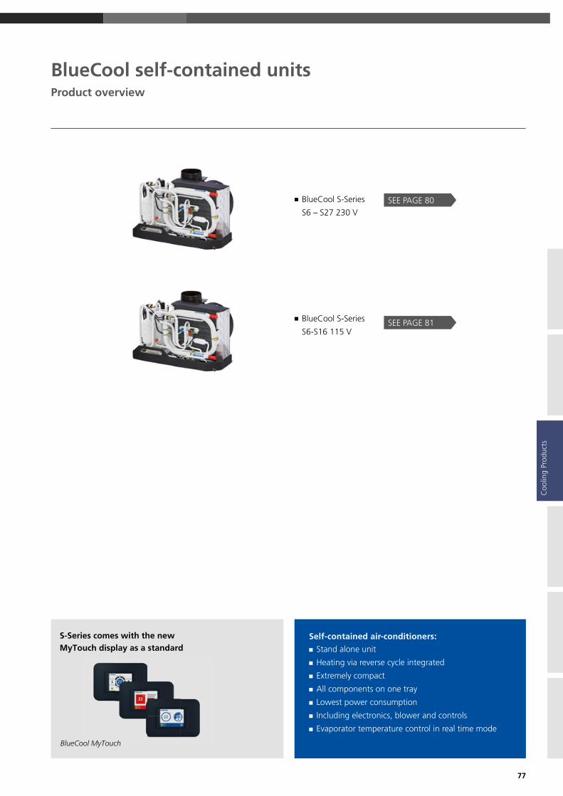
77
■ BlueCool S-Series
S6 – S27 230 V
■ BlueCool S-Series
S6-S16 115 V
SEE PAGE 80
SEE PAGE 81
Self-contained air-conditioners: ■ Stand alone unit
■ Heating via reverse cycle integrated
■ Extremely compact
■ All components on one tray
■ Lowest power consumption
■ Including electronics, blower and controls
■ Evaporator temperature control in real time mode
BlueCool self-contained unitsProduct overview
S-Series comes with the new MyTouch display as a standard
BlueCool MyTouch
Coo
ling
Prod
ucts

78
Webasto BlueCool self-contained air-conditioning units have one hermetically encapsulated compressor. The refrigerant circuit
includes not only the compressor but also a condenser, a throttle element (capillary tube) as well as an evaporator. Self-contained
units are extremely compact. All components (compressor, condenser, evaporator and blower) required for cooling a cabin,
a salon, a lounge or another room are mounted on a stainless steel tray. Webasto self-contained units are available in different
power ratings. This means you are sure to find the ideal system for the specific needs of almost all room sizes requiring cooling
in a yacht.
Webasto BlueCool self-contained units
BlueCool self-contained unitsApplication concept
Installation of a BlueCool self-contained unit is quite simple: Each cabin has its own self-contained unit A providing cool air to this cabin. It is controlled by an air control unit B which is also located in this cabin. The generated heat is transferred into the sea via the sea water circuit I to N .
I
N
K
J
ME
A
C
B
F
H
G
D
L
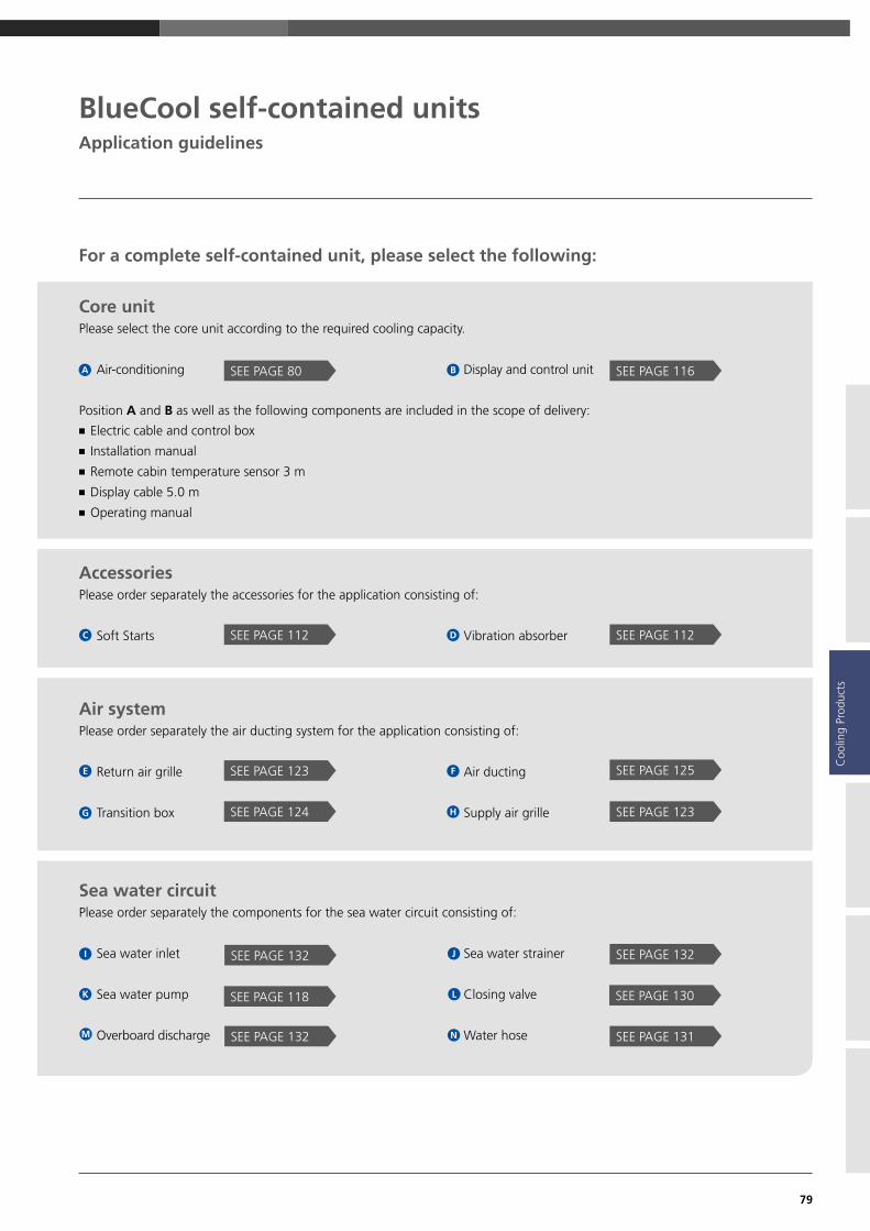
79
For a complete self-contained unit, please select the following:
BlueCool self-contained unitsApplication guidelines
A B
■ Electric cable and control box
■ Installation manual
■ Remote cabin temperature sensor 3 m
■ Display cable 5.0 m
■ Operating manual
SEE PAGE 80 SEE PAGE 116
E F
HG
SEE PAGE 123
SEE PAGE 124 SEE PAGE 123
SEE PAGE 125
C DSEE PAGE 112 SEE PAGE 112
SEE PAGE 132 SEE PAGE 132
SEE PAGE 118 SEE PAGE 130
SEE PAGE 132 SEE PAGE 131
I
LK
J
M N
Core unitPlease select the core unit according to the required cooling capacity.
Air-conditioning Display and control unit
Position A and B as well as the following components are included in the scope of delivery:
AccessoriesPlease order separately the accessories for the application consisting of:
Soft Starts Vibration absorber
Air systemPlease order separately the air ducting system for the application consisting of:
Return air grille Air ducting
Transition box Supply air grille
Sea water circuitPlease order separately the components for the sea water circuit consisting of:
Sea water inlet Sea water strainer
Sea water pump Closing valve
Overboard discharge Water hose
Coo
ling
Prod
ucts
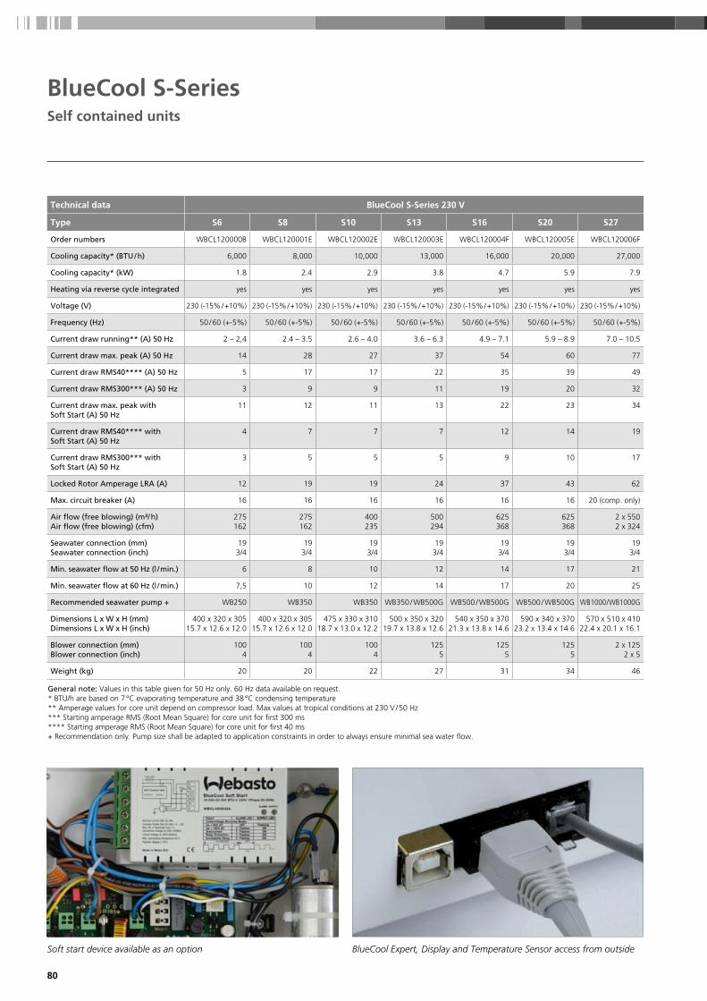
80
BlueCool S-SeriesSelf contained units
Technical data BlueCool S-Series 230 V
Type S6 S8 S10 S13 S16 S20 S27
Order numbers WBCL120000B WBCL120001E WBCL120002E WBCL120003E WBCL120004F WBCL120005E WBCL120006F
Cooling capacity* (BTU / h) 6,000 8,000 10,000 13,000 16,000 20,000 27,000
Cooling capacity* (kW) 1.8 2.4 2.9 3.8 4.7 5.9 7.9
Heating via reverse cycle integrated yes yes yes yes yes yes yes
Voltage (V) 230 (-15% / +10%) 230 (-15% / +10%) 230 (-15% / +10%) 230 (-15% / +10%) 230 (-15% / +10%) 230 (-15% / +10%) 230 (-15% / +10%)
Frequency (Hz) 50 / 60 (+-5%) 50 / 60 (+-5%) 50 / 60 (+-5%) 50 / 60 (+-5%) 50 / 60 (+-5%) 50 / 60 (+-5%) 50 / 60 (+-5%)
Current draw running** (A) 50 Hz 2 – 2,4 2.4 – 3.5 2.6 – 4.0 3.6 – 6.3 4.9 – 7.1 5.9 – 8.9 7.0 – 10.5
Current draw max. peak (A) 50 Hz 14 28 27 37 54 60 77
Current draw RMS40**** (A) 50 Hz 5 17 17 22 35 39 49
Current draw RMS300*** (A) 50 Hz 3 9 9 11 19 20 32
Current draw max. peak with Soft Start (A) 50 Hz
11 12 11 13 22 23 34
Current draw RMS40**** with Soft Start (A) 50 Hz
4 7 7 7 12 14 19
Current draw RMS300*** with Soft Start (A) 50 Hz
3 5 5 5 9 10 17
Locked Rotor Amperage LRA (A) 12 19 19 24 37 43 62
Max. circuit breaker (A) 16 16 16 16 16 16 20 (comp. only)
Air flow (free blowing) (m³/ h)Air flow (free blowing) (cfm)
275162
275162
400235
500294
625368
625368
2 x 5502 x 324
Seawater connection (mm)Seawater connection (inch)
193/4
193/4
193/4
193/4
193/4
193/4
193/4
Min. seawater flow at 50 Hz (l / min.) 6 8 10 12 14 17 21
Min. seawater flow at 60 Hz (l / min.) 7,5 10 12 14 17 20 25
Recommended seawater pump + WB250 WB350 WB350 WB350 / WB500G WB500 / WB500G WB500 / WB500G WB1000/WB1000G
Dimensions L x W x H (mm)Dimensions L x W x H (inch)
400 x 320 x 30515.7 x 12.6 x 12.0
400 x 320 x 30515.7 x 12.6 x 12.0
475 x 330 x 31018.7 x 13.0 x 12.2
500 x 350 x 32019.7 x 13.8 x 12.6
540 x 350 x 37021.3 x 13.8 x 14.6
590 x 340 x 37023.2 x 13.4 x 14.6
570 x 510 x 41022.4 x 20.1 x 16.1
Blower connection (mm)Blower connection (inch)
1004
1004
1004
1255
1255
1255
2 x 1252 x 5
Weight (kg) 20 20 22 27 31 34 46
General note: Values in this table given for 50 Hz only. 60 Hz data available on request.* BTU/h are based on 7 °C evaporating temperature and 38 °C condensing temperature ** Amperage values for core unit depend on compressor load. Max values at tropical conditions at 230 V / 50 Hz *** Starting amperage RMS (Root Mean Square) for core unit for first 300 ms **** Starting amperage RMS (Root Mean Square) for core unit for first 40 ms + Recommendation only. Pump size shall be adapted to application constraints in order to always ensure minimal sea water flow.
Soft start device available as an option BlueCool Expert, Display and Temperature Sensor access from outside

81
BlueCool S-SeriesSelf contained units
Technical data BlueCool S-Series 115 V
Type S6 S8 S10 S13 S16
Order No. 2510139B 2510140B 2510141B 2510142B 2510143B
Cooling capacity* (BTU / h) 6,000 8,000 10,000 13,000 16,000
Cooling capacity* (kW) 1.8 2.4 2.9 3.8 4.7
Heating via reverse cycle integrated Yes Yes Yes Yes Yes
Voltage (V) 115 (-15% / +10%) 115 (-15% / +10%) 115 (-15% / +10%) 115 (-15% / +10%) 115 (-15% / +10%)
Frequency (Hz) 60 (+-5%) 60 (+-5%) 60 (+-5%) 60 (+-5%) 60 (+-5%)
Current draw running** (A) 60 Hz 3.6 – 5.5 4.5 – 6.1 5.6 – 7.9 7.6 – 11 8.0 – 15.7
Current draw max. peak (A) 60 Hz 39 54 55 70 89
Current draw RMS40**** (A) 60 Hz 25 35 36 47 59
Current draw RMS300*** (A) 60 Hz 19 20 21 30 35
Locked Rotor Amperage LRA (A) 27 34 37 57 70
Max. circuit breaker (A) 16 16 16 16 25 (compressor only)
Air flow (free blowing) (m³ / h)Air flow (free blowing) (cfm / h)
275162
275162
350206
430253
650382
Seawater connection (mm)Seawater connection (inch)
193 / 4
193 / 4
193 / 4
193 / 4
193 / 4
Minimal Seawater flow (l / min.) 60 Hz 6 8 10 12 14
Recommended seawater pump 60 Hz +
WB250 WB350 WB350 WB350WB500G
WB500WB500G
Dimensions L x D x H (mm)Dimensions L x D x H (inch)
405 x 320 x 30515.9 x 12.6 x 12.0
405 x 320 x 30515.9 x 12.6 x 12.0
480 x 335 x 31518.9 x 13.2 x 12.4
510 x 350 x 325 20.1 x 13.8 x 12.8
550 x 350 x 370 21.7 x 13.8 x 14.6
Blower connection (mm)Blower connection (inch)
1004
1004
1004
125 5
125 5
Weight (kg) 18 18 20 25 29
S6 – S20
H
LDW
S27
L
H
DW
Coo
ling
Prod
ucts
* BTU / h are based on 7 °C evaporating temperature and 38 °C condensing temperature ** Amperage values for core unit depend on compressor load. Max values at tropical conditions at 115 V / 60 Hz *** Starting amperage RMS (Root Mean Square) for core unit for first 300 ms **** Starting amperage RMS (Root Mean Square) for core unit for first 40 ms + Recommendation only. Pump size shall be adapted to application constraints in order to always ensure minimal sea water flow.
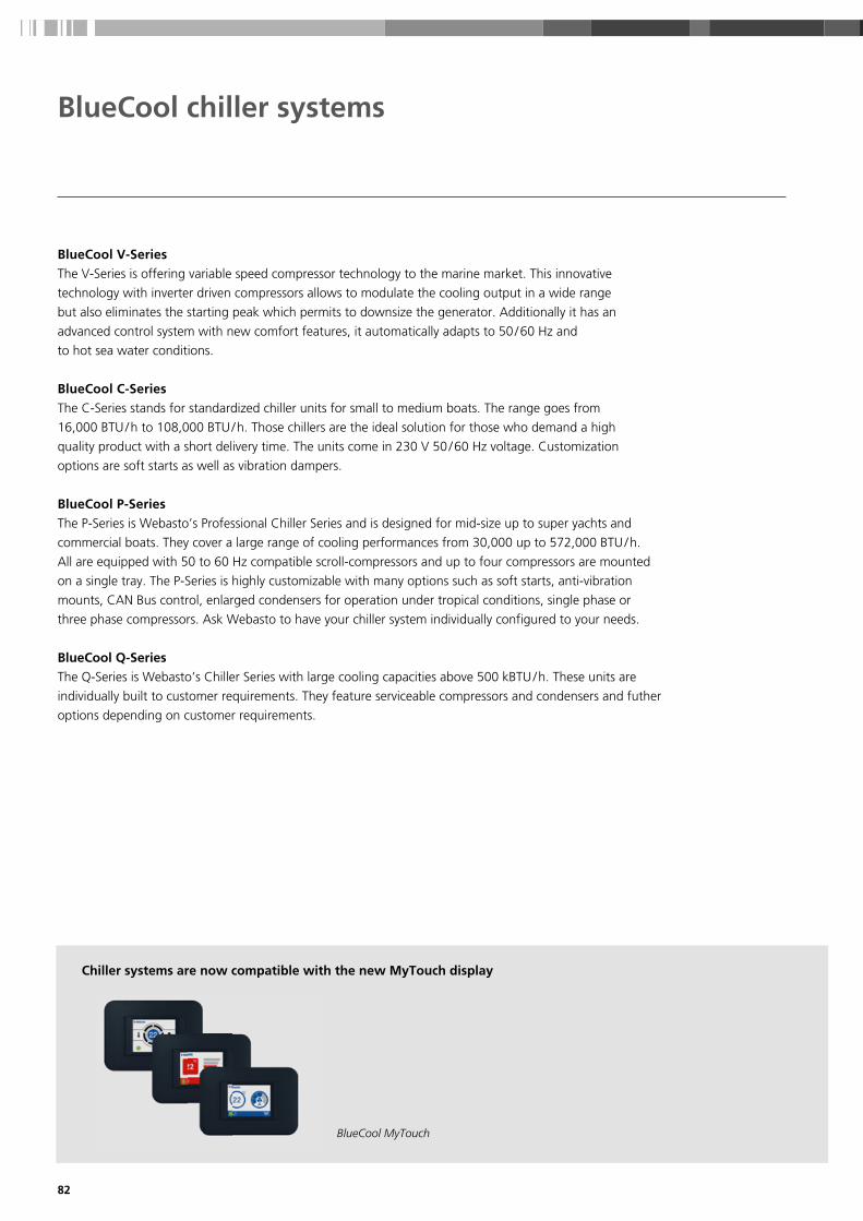
82
BlueCool chiller systems
BlueCool V-SeriesThe V-Series is offering variable speed compressor technology to the marine market. This innovative
technology with inverter driven compressors allows to modulate the cooling output in a wide range
but also eliminates the starting peak which permits to downsize the generator. Additionally it has an
advanced control system with new comfort features, it automatically adapts to 50 / 60 Hz and
to hot sea water conditions.
BlueCool C-SeriesThe C-Series stands for standardized chiller units for small to medium boats. The range goes from
16,000 BTU / h to 108,000 BTU / h. Those chillers are the ideal solution for those who demand a high
quality product with a short delivery time. The units come in 230 V 50 / 60 Hz voltage. Customization
options are soft starts as well as vibration dampers.
BlueCool P-SeriesThe P-Series is Webasto’s Professional Chiller Series and is designed for mid-size up to super yachts and
commercial boats. They cover a large range of cooling performances from 30,000 up to 572,000 BTU / h.
All are equipped with 50 to 60 Hz compatible scroll-compressors and up to four compressors are mounted
on a single tray. The P-Series is highly customizable with many options such as soft starts, anti-vibration
mounts, CAN Bus control, enlarged condensers for operation under tropical conditions, single phase or
three phase compressors. Ask Webasto to have your chiller system individually configured to your needs.
BlueCool Q-SeriesThe Q-Series is Webasto’s Chiller Series with large cooling capacities above 500 kBTU / h. These units are
individually built to customer requirements. They feature serviceable compressors and condensers and futher
options depending on customer requirements.
Chiller systems are now compatible with the new MyTouch display
BlueCool MyTouch

83
SEE PAGE 90
SEE PAGE 98
BlueCool chiller systems
SEE PAGE 88
SEE PAGE 86 ■ BlueCool V-Series
V50 M, V64 T, V77 T
■ BlueCool C-Series
C16 M to C108 Q
■ BlueCool P-Series
P30 M to P572 Q
■ BlueCool Q-Series
Product overview
Coo
ling
Prod
ucts
NEW

84
Whenever three or more independent volumes in a yacht need to be air-conditioned, it becomes worth considering a central
chiller system. To distribute cooling capacity over several independently operating air handlers from one single central cooling unit,
the most flexible and simple solution is to install a chilled water circulation system between the central unit and the air handlers.
This mixed water / glycol circuit is maintained at approx. +4 °C. All Webasto chiller units are equipped with high efficiency
multi-plate heat exchangers.
Chiller air-conditioning systems
BlueCool chiller systemsApplication concept
For larger boats with several cabins a chiller system is the best choice. The chiller A / C unit A is typically placed in the engine room providing chilled water / glycol to all cabins via the chilled water circuit N to S . In each cabin one or several air handlers T are fitted depending on cooling capacity and space requirements. The Digital Control Panel B controls the A / C system itself. For each cabin one Control Panel U is needed to individually control the air handler in this cabin. As a result you get full temperature control in each cabin providing maximum comfort on board.
CB
A
LM
G
V
IK
N
OH
X
U
W
T
Y
E
F
J
Z
S

85
For a complete chiller system, please select the following:
Application guidelines
BlueCool chiller systems
D
CB
■ Electric cable and control box ■ Installation manual ■ Operating manual
SEE PAGE 86 – 99
SEE PAGE 114
SEE PAGE 112 SEE PAGE 112
SEE PAGE 112
SEE PAGE 116
SEE PAGE 116
F
SEE PAGE 132 SEE PAGE 132
SEE PAGE 118 SEE PAGE 130
SEE PAGE 132 SEE PAGE 131
K
I
M
SEE PAGE 118 SEE PAGE 126
SEE PAGE 141
SEE PAGE 130
SEE PAGE 127
SEE PAGE 130
O
R
SEE PAGE 102
SEE PAGE 123
SEE PAGE 125
SEE PAGE 124
SEE PAGE 131
SEE PAGE 116
SEE PAGE 123Y
U
V
Core unitPlease select the core unit according to the required cooling capacity, the available voltage and whether cool only or heating via
reverse cycle is needed.
� Air-conditioning unit
Position A as well as the following components are included in the scope of delivery:
Control elements for core unit Please select the control elements for the core unit separately:
MyTouch display Display cable
Remote air temperature sensor
Accessories for V- and C-Series:Please order separately the accessories for the V- and C-Series core unit:
■ Soft Starts Vibration absorber kits
■ Silent block kits
Sea water circuitPlease order separately the components for the sea water circuit consisting of:
■ Sea water inlet Sea water strainer
■ Sea water pump Closing valve
■ Overboard discharge Water hose
Chilled water circuitPlease add the required components for the chilled water circuit consisting of:
■ Circulation pump Piping or hosing system
■ 3-way valve (optional) with insulation
■ Turn ball valve Expansion tank
■ T-pieces
Cabin accessories necessary for each single cabinPlease add for every single cabin the following components and accessories:
■ Air handler Cabin control (Control
Supply air grille Panel, display cable, temperature
■ Air ducting sensor and control box)
■ Transition box Return air grille ■ Water hoses for
condensation drain
A
E
G
H
J
L
N
P
Q
S
T
W
Z
X
Coo
ling
Prod
ucts

86
BlueCool V-Series Variable speed chiller
V50 Mwithout electronic box
V64 T and V77 T
Fully 50/ 6 0 Hz compatible
Highly efficient variable speed BLDC compressor
Condensate free chiller system on a single tray
Wide power modulation range from 8,500 to
50,000 BTU / h
Active cooled external inverter heat sink
Super quiet operation
All water connections on one side
External mounting fixture, allows mounting of optional silent blocks
Long-lasting epoxy paint
Detachable electronic box
NEW

87
BlueCool V-SeriesVariable speed chiller
Technical data BlueCool V-Series
Type V50 M V64 T V77 T
Order No. WBCL1203001C WBCL1203003B WBCL1203002B
Cooling capacity* (BTU / h) 8,500 – 50,000 8,500 – 64,000 8,500 – 77,000
Cooling capacity* (kW) 2.5 – 14.6 2.5 – 18.7 2.5 – 22.6
Heating via reverse cycle integrated yes yes yes
Voltage (V) 230 (-15% / +10%) 230 (-15% / +10%) 230 (-15% / +10%)
Frequency ++ (Hz) 50 / 60 (+-5%) 50 / 60 (+-5%) 50 / 60 (+-5%)
Current draw running** (A) 2.5 – 15* (max. 17) 2.5 – 23.8 (max. 25) 2.5 – 24 (max. 26.5)
Current draw Start (A) 2.5 2.5 2.5
Current draw Eco 1 Mode (A) 2.5 – 8* (max. 12) 2.5 – 15* (max. 17) 2.5 – 15* (max. 17)
Current draw Eco 2 Mode (A) 2.5 – 5* (max. 8) 2.5 – 8* (max. 12) 2.5 – 8* (max. 12)
Current draw Eco 3 Mode (A) – 2.5 – 5* (max. 8) 2.5 – 5* (max. 8)
Chilled water connection (mm), (Inch) 251’’
321 1/4” F BST
321 1/4” F BST
Min. chilled water flow (l/min.) 35 45 52
Seawater connection (mm), (Inch) 251’’ M BST
321 1/4” F BST
321 1/4” F BST
Min. seawater flow (l/min.) 38 50 57
Dimensions unit L x D x H (mm), (Inch) 567 x 340 x 510 22.3 x 13.4 x 20.1
760 x 560 x 51029.9 x 22.0 x 20.1
760 x 560 x 51029.9 x 22.0 x 20.1
Dimensions unit incl. silent block L x D x H (mm), (Inch) 590 x 378 x 54823.2 x 14.9 x 21.6
760 x 560 x 55029.9 x 22.0 x 21.7
760 x 560 x 55029.9 x 22.0 x 21.7
Dimension electronic box L x D x H (mm), (Inch) 560 x 190 x 465 22.0 x 7.5 x 18,3
560 x 190 x 465 22.0 x 7.5 x 18,3
560 x 190 x 465 22.0 x 7.5 x 18.3
Dimension chiller L x D x H (mm), (Inch) 607 x 530 x 51023.9 x 20.8 x 20.1
760 x 750 x 51029.9 x 29.5 x 20.1
760 x 750 x 51029.9 x 29.5 x 20.1
Dimensions unit incl. silent block + box L x D x H (mm), (Inch) 620 x 570 x 548 24.4 x 22.4 x 21.6
760 x 750 x 55029.9 x 29.5 x 21.7
760 x 750 x 55029.9 x 29.5 x 21.7
Ambient temperature limit (°C) 60 60 60
Sound level unit (dB/A) (measured) 49.2 48.5 48.5
Refrigerant charge R410A (g) 892 892 + 770 892 + 770
Weight core unit (kg) 47 90 90
Weight electronic box (kg) 15 15 15
Min. sea water temp. heating (°C) 6 6 6
Max. sea water temp. cooling (°C) 35 35 35
* Based on 7 °C evaporating temperature and 38 °C condensing temperature ** Amperage values for core unit depend on compressor load. Max values at tropical conditions at 230 V / 50 Hz++ BlueCool V-Series systems are tested and approved by Webasto for 50 / 60 Hz operation
The BlueCool V-Series: ■ New V64 T and V77 T with innovative hybrid control logic
■ Large power modulation range: 8,500 up to 77,000 BTU
■ Unique hybrid concept reduces output by 89% during part load operation.
■ Variable speed BLDC compressors controlled by inverter technology
■ Zero electrical starting peak ■ Super quiet operation with little noise variations and sound cover housing
■ High system availability via dynamic control of HP / LP boundary conditions
■ Preventive maintenance monitoring system
■ Condensate free operation ■ Easy installation and maintenance
■ Low service and operation costs ■ Light and compact ■ Integrates Webasto s BlueCool Expert diagnosis and set up tool
■ Up to 3 ECO modes with adjustable amperage draw
■ 230 V 50 Hz or 240 V 60 Hz compatible for worldwide application
■ MyTouch as standard user interface with clear text display
Now compatible with the new MyTouch display
BlueCool MyTouch
Coo
ling
Prod
ucts

88
BlueCool C-Series
Technical data BlueCool C-Series
Type C16 M C20 M C27 M C32 T C40 T C55 T C81 R C108 Q
Order numbers WBCL1205001E WBCL1205002D WBCL1205003D WBCL1207001E WBCL1207002D WBCL1207003D WBCL1207004D WBCL1207005D
Cooling capacity* (BTU / h) 16,000 20,000 27,000 32,000 40,000 55,000 81,000 108,000
Cooling capacity* (kW) 4.7 5.9 7.9 9.4 11.7 16.1 23.7 31.7
Heating via reverse cycle integrated yes yes yes yes yes yes yes yes
Voltage (V) 230 (-15% / +10%)
230 (-15% / +10%)
230 (-15% / +10%)
230 (-15% / +10%)
230 (-15% / +10%)
230 (-15% / +10%)
230 (-15% / +10%)
230 (-15% / +10%)
Frequency ++ (Hz) 50 / 60 (+-5%) 50 / 60 (+-5%) 50 / 60 (+-5%) 50 / 60 (+-5%) 50 / 60 (+-5%) 50 / 60 (+-5%) 50 / 60 (+-5%) 50 / 60 (+-5%)
Current draw running** (A) 4.4 – 6.0 6.9 – 8.0 8.6 – 9.2 8.8 – 12.0 13.8 – 16.0 17.2 – 18.4 25.8 – 27.6 34.4 – 36.8
Current draw Start max. peak (A)50 Hz
54 60 77 60 68 87 97 107
Current draw RMS40**** (A) 50 Hz
35 39 49 41 47 59 69 79
Current draw RMS300*** (A) 50 Hz
19 20 32 25 28 42 52 62
Current draw Start max. peak with Soft Start (A) 50 Hz
22 22 34 28 30 44 54 64
Current draw RMS40**** with Soft Start (A) 50 Hz
12 14 18 18 22 28 38 48
Current draw RMS300 with Soft Start (A) 50 Hz
9 10 17 15 18 27 37 47
Locked Rotor Amperage LRA (A) (comp. only)
37 43 54 37 43 54 54 54
Max. circuit breaker (A) 16 16 20 2 x 16 2 x 16 2 x 20 3 x 20 4 x 20
Chilled water connection (mm)Chilled water connection (inch)
25
1
25
1
25
1
25
1
25
1
25
1
32
1 1/4
–
1 1/4 F BST
Minimal chilled water flow (l / min.) 13 16 19 26 32 38 57 76
Recommended chilled water pump WB500 WB500 WB1000 WB1000 WB1500 WB1500 WB2000 WB3500
Seawater connection (mm)Seawater connection (inch)
19
3/4
19
3/4
19
3/4
19
3/4
25
1
25
1
32
1 1/4
–
1 1/4 F BST
Minimal seawater flow at 50 Hz (l / min.)
14 17 21 28 34 42 63 84
Minimal seawater flow at 60 Hz (l / min.)
17 20 25 34 41 50 75 100
Recommended seawater pumpWB500 /
WB500GWB500 /
WB500GWB1000 WB1000
WB1500 /WB1000G
WB1500 /WB2000
WB2000 /WB2500G
WB3000G
Dimensions L x W x H (mm)Dimensions L x W x H (inch)
390 x 290 x 355
15.4 x 11.4 x 14.0
440 x 330 x 360
17.3 x 13.0 x 14.0
440 x 330 x 395
17.3 x 13.0 x 15.6
590 x 410 x 500
23.2 x 16.1 x 19.7
590 x 410 x 500
23.2 x 16.1 x 19.7
590 x 410 x 550
23.2 x 16.1 x 21.7
870 x 430 x 575
33.5 x 16.9 x 22.6
860 x 640 x 600
33.9 x 22.4 x 23.6
Weight (kg) 34 37 45 65 70 86 119 173
Min. sea water temp. Heating (°C) 6 6 6 6 6 6 6 6
Max. sea water temp. Cooling (°C) 35 35 35 35 35 35 35 35
General note: Values in this table given for 50 Hz only. 60 Hz data available on request.* BTU / h are based on 7 °C evaporating temperature and 38 °C condensing temperature** Amperage values for core unit depend on compressor load. Max values at tropical conditions at 230 V / 50 Hz*** Starting amperage RMS (Root Mean Square) for core unit for first 300 ms**** Starting amperage RMS (Root Mean Square) for core unit for first 40 ms+ Recommendation only. Pump size shall be adapted to application constraints in order to always ensure minimal
sea water flow.++ BlueCool C-Series systems are tested and approved by Webasto for 50 / 60 Hz operation
L
H
DW
MonoC16 M – C27 M
Ultra compact chiller

89
BlueCool C-Series
The BlueCool C-Series: ■ Improved performance and up to 15 % higher efficiency
■ Continuous cooling capacity even in tropical conditions
■ Even more compact design
■ New improved electronics for easy installation
and diagnosis via USB cable
■ Optional CAN-Bus for optimized adaptation to boat
systems
■ Compressor noise is reduced by up to 25 %
■ Easy sea water and chilled water connections at one side
■ Strong stainless steel tray and condensate drain
■ High quality Epoxy paint protection
■ Vibration absorber and Silent block available as an
option
■ Soft start devices available as an option
Staged compressor
set up
Polished stainless steel encasing
Extremely compact dimensions
Lifting points
Long-lasting epoxy paint
All water connections on one side
High-efficiency
heat exchanger
Pre-mounted chiller systems on a single tray
Condensers sized for tropical conditions
Now compatible with the new MyTouch display
BlueCool MyTouch
Coo
ling
Prod
ucts
Ultra compact chiller

90
BlueCool P-SeriesProfessional Chiller Series
The professional BlueCool P-Series: ■ Professional chiller system for medium to large boats and super yachts
■ Highly customizable chiller series with large range of 30,000 – 572,000 BTU / h
to adapt to cooling demand
■ Successor of our BlueCool Premium scroll compressor range for high reliability
■ Multiple compressor units with independent cooling circuits for high availability
■ Range extension with 8 new models
■ Improved electronics – new electronic box with easier access to
components – new PCB with increased circuit protection, now also fulfilling
highest EMC standards EN 60945 – the electronic box has been slightly
enlarged so that softstarts can be easily integrated into this box
■ BlueCool Expert tool for service, configuration, application tuning, diagnosis
and system setup comes as a standard free of charge
■ Optional CAN-Bus for integration into boats central monitoring systems
■ Unique Thermostatic Advance Function for power output continuously adapted
to cooling demand
■ Redesigned trays for easier mounting of silent blocks to reduce vibrations
■ Electrical systems can be upgraded to customer needs with PRO box or fulfilling
MCA requirements
BlueCool P-Series
All water connections on one side
Scroll compressors 50/60 Hz compatible
Pre-mounted chiller systems on a single tray
Optional silent blocks effectively reduce vibrations
Long-lasting epoxy paint
Polished stainless steel encasing
High-efficiency heat exchangers
Sea water manifold can be flexibly positioned
Enlarged condensers available for tropical conditions
Now compatible with the new MyTouch display
BlueCool MyTouch

91
BlueCool P-SeriesConfiguration options
Configure your chiller system in 6 main steps:
Product options for BlueCool P-SeriesThe BlueCool P-Series is highly customizable to the demands of shipyards and national legislation. In addition to a wide range
of cooling capacities, many options can be selected to customize the chiller to your needs. For further options, please contact
the sales support team at Webasto.
Option 1: VoltageAll P-Series chillers are available as 400 V / 3-phase version. On most models 208 V / 3-phase or 230 V / single phase is available
as well.
Option 2: Cool only versionFor regions where heating is not required some units are available as cool only version.
Option 3: Tropical versionFor high sea water temperatures > 32 °C, a tropical chiller version with enlarged condensers shall be selected to avoid high
pressure cut-outs. Option is highly recommended whenever the boat may travel in regions where sea water temperatures may
be above 32 °C.
Option 4: Soft startIn order to reduce the amperage draw at compressor start a soft start may be chosen as an option.
■ Soft start devices are reducing the amperage peak at compressor start up to 53 % ■ Soft start models are available for 400 V 3-phase as well as 230 V single phase ■ The peak reduction allows to better size the power generator and it frees capacities
for other electrical consumers ■ Light flickering is reduced ■ Circuit breakers and cables sizes do not have to be oversized ■ The soft starts fit into the standard electrical box if no further electrical accessories
are chosen ■ If the soft starts are selected during the chiller configuration process they come
already installed and tested as part of the electronic box
Coo
ling
Prod
ucts

92
Option 5: Electrical upgradesIn the standard configuration, the chiller comes with a standard electrical box which allows to operate the chiller. Webasto
offers a wide variety of electrical options which enhance the operation and service comfort or ease the electrical installation.
Some options may be required to comply with national standards or requirements coming from the boat’s classification society.
Depending on the amounts of options chosen the larger PRO box or even a box compliant to MCA standards will be used.
Each box will be individually configured to your needs.
BlueCool P-SeriesConfiguration options
Standard Box Pro Box MCA Box
Housing
Material Galvanized steel, expoxy painted Mild steel, powder coated Mild steel, powder coated
IP class IP21 IP66 / NEMA 4, 12, 13 / IK 10 IP66 / NEMA 4, 12, 13 / IK 10
Color White RAL 7035 RAL 7035
Opening / closing Screws Locking mechanism Locks with removable handle
Components included
Chiller electronic card ■ ■ ■
Relays for compressors, chilled water and sea water pump ■ ■ ■
Terminal block connectors ■ ■ ■
Compressor Soft starts n n n
Motor protective relays and circuit breakers for compressors and pumps
– ■ ■
Circuit breaker for chiller electronic card – ■ ■
Only one power supply needed for entire unit – ■ ■
Halogen free cables – n ■
Cable harness length: 2 m ■ ■ ■
Increased cable harness length: 5 m / 10 m / 15 m n n n
Chilled water pump: redundancy selector for two pumps – n n
Sea water pump: redundancy selector for two pumps – n n
Power ON lamp – n ■
Pilot lamps for pumps and / or compressors – n ■
Digital display integrated at the front door – n n
Compressor running counter – n n
Main switch – – ■
Emergency stop – – ■
Pushbutton to test pilot lamps – – ■
Door locking mechanism in open position – n ■
Ampere gauge – – n
Option 6: Silent blocksSilent blocks may be mounted between the chiller unit and the hull of the boat to reduce structural born vibrations being
transferred from the chiller unit into the boat.
■ The silent blocks very effectively reduce vibrations into the hull of the boat by up to 50 % ■ Silent blocks are mounted below the base plate of the A/C unit ■ High performance damping elements specially designed for the vibration frequency
and the weight of each unit ■ Marine grade with corrosion resistant materials ■ Integrated rip-off protection ■ If the silent blocks are selected during the chiller configuration process they come
already mounted onto the A/C unit ■ Please ask for the specific height increase of your unit as the silent block type varies with the size of the units
■ Standard n Optional – Not available

93
BlueCool P-SeriesProject assistance and support
A chiller system always needs to be customized to each boat in order to meet the demands of shipyards, owners, classification
societies and national legislation. We support you in this process with our expertise and the tools we have developed for this.
Specification and quotation toolThis tool should be used for all A/C projects to
■ Precisely calculate the cooling and heating demand for
each cabin depending on boat characteristics, performance
requirements and usage conditions ■ Determine the fresh air requirements of larger boats ■ Select your bill of material from the entire product portfolio ■ Summarize technical data of the chosen key components
As a result the chiller and air handlers are correctly sized to the
individual demand of each boat.
Chiller configurator toolThis tool is used by Webasto to
■ Select the available options for a chiller unit, see Options 1, 2,
3, 6 on previous pages ■ Select the available electrical options, see Options 4 and 5 on
previous pages
As a result your chiller and electronic box will receive an
individual part number which is uniquely used for your project.
Engineering supportOur project engineers support you in various phases of a
project delivering to you
■ A/C system concepts ■ Piping diagrams ■ Electrical wiring schematics ■ On-site support to understand and determine the optimal
A/C configuration
Installation and commissioning supportOur project engineers can support you on demand during the
installation and commissioning phase of your project with
■ Technical support to answer your questions ■ On-site support and audit ■ Check of your installation ■ Support during system commissioning
Model OD ID Part numberD15 15 mm 12 mm WBCL002510D22 22 mm 18 mm WBCL002511D28 28 mm 23 mm WBCL002512
WEBASTO - EASYPIPES
Coo
ling
Prod
ucts

94
BlueCool P-Series
BlueCool P-Series Mono chiller
Type P30 M P36 M P42 M P48 M P60 M P72 M P84 M P96 M P112 M P126 M P143 M
Cooling capacity* (BTU / h) 30,000 36,000 42,000 48,000 60,000 72,000 84,000 96,000 112,000 126,000 143,000
Cooling capacity* (kW) 8.7 10.5 12.3 14 17.6 21.1 24.6 28.1 32.8 36.9 41.8
Frequency (Hz)***** 50 / 60 50 / 60 50 / 60 50 / 60 50 / 60 50 / 60 50 / 60 50 / 60 50 / 60 50 / 60 50/ 60
Current draw running** (A) for 230 V 1-phase 6.8 8 9.4 12 – – – – – – –
Current draw running** (A) for 400 V 3-phase 2.9 3.5 4.1 5.1 5.9 6.5 8.4 10 11 12 13
Current draw running** (A) for 208 V 3-phase 5.0 6.1 6.9 8.5 – 13 24 – – – –
Current draw running FLA**** (A) for 230 V 1-phase
15 17 23 24 – – – – – – –
Current draw running FLA**** (A) for 400 V 3-phase
5.1 5.6 7 10 11 12 15 16 17 20 22
Current draw running FLA**** (A) for 208 V 3-phase
10 11 14 19 25 27 25 – – – –
Locked Rotor Amperage LRA (A)for Single compressor 230 V 1-phase
61 76 100 114 – – – – – – –
Locked Rotor Amperage LRA (A)for Single compressor 400 V 3-phase
32 40 46 50 59 74 101 95 111 118 118
Locked Rotor Amperage LRA (A)for Single compressor 208 V 3-phase
70 83 95 98 139 172 179 – – – –
Min. chilled water flow (l / min.) 25 30 33 38 50 60 66 76 88 104 117
Min. seawater flow (l / min.) 19 22 27 30 38 46 56 64 68 82 93
Recommended seawater pump+ WB1000 WB1000 WB1000WB1500
WB1000WB1500
WB1500 WB2500GWB3000G
WB2500GWB3000G
WB2500GWB3000G
WB3000GWB3500
WB3000GWB3500
WB3000GWB3500
Dimensions (L x W x H) (mm) 425 x 506 x 547
425 x 506 x 547
425 x 506 x 547
425 x 506 x 547
560 x 610 x 602
560 x 610 x 727
560 x 610 x 727
560 x 615 x 727
560 x 811 x 727
560 x 811 x 827
560 x 845 x 827
Dimensions (L x W x H) (inch) 16.7 x 19.9 x 21.5
16.7 x 19.9 x 21.5
16.7 x 19.9 x 21.5
16.7 x 19.9 x 21.5
22 x 24 x 23.7
22 x 24 x 28.6
22 x 24 x 28.6
22 x 24.2 x 28.6
22 x 31.9 x 28.6
22 x 31.9 x 32.6
22 x 33.3 x 32.6
Dimensions (L x W x H) (mm) tropical 425 x 506 x 547
425 x 506 x 547
425 x 506 x 547
425 x 506 x 547
560 x 610 x 602
560 x 610 x 727
560 x 610 x 727
560 x 615 x 727
560 x 811 x 727
560 x 811 x 827
560 x 845 x 827
Dimensions (L x W x H) (inch) tropical 16.7 x 19.9 x 21.5
16.7 x 19.9 x 21.5
16.7 x 19.9 x 21.5
16.7 x 19.9 x 21.5
22 x 24 x 23.7
22 x 24 x 28.6
22 x 24 x 28.6
22 x 24.2 x 28.6
22 x 31.9 x 28.6
22 x 31.9 x 32.6
22 x 33.3 x 32.6
Weight (kg) 55 66 68 70 75 80 85 90 100 110 125
Available options
230 V / 1-phase n n n n – – – – – – –
208 V / 3-phase n n n n n n n – – – –
Reverse Cycle Heating ■ ■ ■ ■ ■ ■ ■ ■ ■ ■ ■
Cool Only version – – – – – – – – – – –
Tropicalized version n ■ n ■ n ■ n n n ■ n
Soft Start 400 V / 230 V / 208 V n / n / – n / n / – n / n / – n / – / – n / – / – n / – / – n / – / – n / – / – n / – / – n / – / – n / – / –Upgrade box / MCA Box n n n n n n n n n n n
Silent Block n n n n n n n n n n n
General note: Values in this table given for 50 Hz only. 60 Hz data available on request.* BTU / h are based on 7 °C evaporating temperature and 38 °C condensing temperature. ** Amperage values for core unit at nominal conditions at 50 Hz. **** FLA (Full Load Amperage) is the current draw at maximum conditions.+ Recommendation only. Pump size shall be adapted to application constraints in order to always ensure minimal sea water flow.++ BlueCool P-Series systems are tested and approved by Webasto for 50 / 60 Hz operation.■ Standard n Option – Not available
Professional Chiller Series

95
BlueCool P-Series
BlueCool P-Series Twin chiller
Type P60 T P72 T P84 T P96 T P120 T
Cooling capacity* (BTU / h) 60,000 72,000 84,000 96,000 120,000
Cooling capacity* (kW) 17.6 21.1 24.6 28.1 35.2
Frequency (Hz) 50 / 60 50 / 60 50 / 60 50 / 60 50 / 60
Current draw running** (A) for 230 V 1-phase 14 16 19 25 –
Current draw running** (A) for 400 V 3-phase 5.8 7.1 8.1 10 12
Current draw running** (A) for 208 V 3-phase 10 12 14 17 33
Current draw running FLA**** (A) for 230 V 1-phase
30 35 46 47 –
Current draw running FLA**** (A) for 400 V 3-phase
10 11 14 20 22
Current draw running FLA**** (A) for 208 V 3-phase
20 22 27 37 50
Locked Rotor Amperage LRA (A)for Single compressor 230 V 1-phase
61 76 100 114 –
Locked Rotor Amperage LRA (A)for Single compressor 400 V 3-phase
32 40 46 50 59
Locked Rotor Amperage LRA (A)for Single compressor 208 V 3-phase
70 83 95 98 139
Min. chilled water flow (l / min.) 50 60 66 76 100
Min. seawater flow (l / min.) 38 46 56 64 80
Recommended seawater pump+ WB1500WB2000
WB2500GWB3000G
WB2500GWB3000G
WB2500GWB3000G
WB3000GWB3500
Dimensions (L x W x H) (mm) 560 x 660 x 600 560 x 694 x 625 560 x 694 x 625 560 x 683 x 675 560 x 790 x 675
Dimensions (L x W x H) (inch) 22 x 26 x 23.6 22 x 27.3 x 24.6 22 x 27.3 x 24.6 22 x 26.9 x 26.6 22 x 31.1 x 26.6
Dimensions (L x W x H) (mm) tropical 560 x 660 x 625 560 x 694 x 625 560 x 694 x 625 560 x 683 x 675 560 x 790 x 725
Dimensions (L x W x H) (inch) tropical 22 x 26 x 24.6 22 x 27.3 x 24.6 22 x 27.3 x 24.6 22 x 26.9 x 26.6 22 x 31.1 x 28.5
Weight (kg) 90 95 100 130 160
Available options
230 V / 1-phase n n n n –
208 V / 3-phase n n n n n
Reverse Cycle Heating ■ ■ ■ ■ ■
Cool Only version – – – – –
Tropicalized version n ■ n ■ n
Soft Start 400 V / 230 V / 208 V n / n / – n / n / – n / n / – n / – / – n / – / –Upgrade box / MCA Box n n n n n
Silent Block n n n n n
The BlueCool P-Series: ■ Wide product range for medium and large size boats
■ Scroll compressors for heavy duty applications
■ Low starting surge through staged compressor starts
■ 208 V, 230 V and 400 V systems available
■ Many customization options with different electronics,
tropical versions, vibration dampingand many other features
■ Fully independent refrigerant circuits in multiple compressor
units provide high system availability
■ Power output continuously adapted to cooling demand
■ Very robust stainless steel design for heavy duty use
General note: Values in this table given for 50 Hz only. 60 Hz data available on request.* BTU / h are based on 7 °C evaporating temperature and 38 °C condensing
temperature. ** Amperage values for core unit at nominal conditions at 50 Hz.**** FLA (Full Load Amperage) is the current draw at maximum conditions.+ Recommendation only. Pump size shall be adapted to application
constraints in order to always ensure minimal sea water flow.++ BlueCool P-Series systems are tested and approved by Webasto
for 50 / 60 Hz operation.■ Standard n Option – Not available
Coo
ling
Prod
ucts
Professional Chiller Series

96
BlueCool P-Series
BlueCool P-Series Triple chiller
Type P126 R P144 R P180 R P216 R P252 R
Cooling capacity* (BTU/h) 126,000 144,000 180,000 216,000 252,000
Cooling capacity* (kW) 37 42.2 52.8 63.3 73.8
Frequency (Hz) 50 / 60 50 / 60 50 / 60 50 / 60 50 / 60
Current draw running** (A) for 230 V 1-phase 28 37 – – –
Current draw running** (A) for 400 V 3-phase 12 15 18 20 25
Current draw running** (A) for 208 V 3-phase 21 26 50 38 72
Current draw running FLA **** (A) for 230 V 1-phase
69 71 – – –
Current draw running FLA **** (A) for 400 V 3-phase
21 30 33 36.3 45
Current draw running FLA **** (A) for 208 V 3-phase
40 56 75 81 76
Locked Rotor Amperage LRA (A) for Single compressor 230 V 1-phase
100 114 – – –
Locked Rotor Amperage LRA (A) for Single compressor 400 V 3-phase
46 50 59 74 101
Locked Rotor Amperage LRA (A) for Single compressor 208 V 3-phase
95 98 139 172 179
Min. chilled water flow (l / min.) 104 115 138 158 180
Min. seawater flow (l / min.) 82 92 106 125 145
Recommended seawater pump+ WB3000GWB3500
WB3000GWB3500
WB5500 WB5500 WB5500
Dimensions (L x W x H) (mm) 640 x 1,250 x 765 640 x 1,250 x 765 640 x 1,250 x 765 640 x 1,250 x 840 640 x 1,250 x 840
Dimensions (L x W x H) (inch) 25.2 x 49.2 x 30.1 25.2 x 49.2 x 30.1 25.2 x 49.2 x 30.1 25.2 x 49.2 x 33.1 25.2 x 49.2 x 33.1
Dimensions (L x W x H) (mm) tropical 640 x 1,250 x 765 640 x 1,250 x 765 640 x 1,250 x 840 640 x 1,250 x 840 640 x 1,250 x 840
Dimensions (L x W x H) (inch) tropical 25.2 x 49.2 x 30.1 25.2 x 49.2 x 30.1 25.2 x 49.2 x 33.1 25.2 x 49.2 x 33.1 25.2 x 49.2 x 33.1
Weight (kg) 180 190 210 250 260
Available options
230 V / 1-phase n n – – –
208 V / 3-phase n n n n n
Reverse Cycle Heating ■ ■ ■ ■ ■
Cool Only version n n n n n
Tropicalized version n ■ n ■ n
Soft Start 400 V / 230 V / 208 V n / n / – n / – / – n / – / – n / – / – n / – / –Upgrade box / MCA Box n n n n n
Silent Block n n n n n
General note: Values in this table given for 50 Hz only. 60 Hz data available on request.* BTU / h are based on 7 °C evaporating temperature and 38 °C condensing temperature ** Amperage values for core unit at nominal conditions at 50 Hz **** FLA (Full Load Amperage) is the current draw at maximum conditions+ Recommendation only. Pump size shall be adapted to application constraints in order to always ensure minimal sea water flow.++ BlueCool P-Series systems are tested and approved by Webasto for 50 / 60 Hz operation.■ Standard n Option – Not available
Professional Chiller Series

97
Webasto engineers can quote custom manufactured
chiller systems upon request. Please contact us for a
tailored solution to fit your individual needs.
BlueCool P-Series
BlueCool P-Series Quattro chiller
Type P120 Q P144 Q P168 Q P192 Q P240 Q P288 Q P336 Q P384 Q P448 Q P504 Q P572 Q
Cooling capacity* (BTU / h) 120,000 144,000 168,000 192,000 240,000 288,000 336,000 384,000 448,000 504,000 572,000
Cooling capacity* (kW) 35 42.2 49.2 56.2 70 85 99 112 132 148 168
Frequency (Hz) 50 / 60 50 / 60 50 / 60 50 / 60 50 / 60 50 / 60 50 / 60 50 / 60 50 / 60 50 / 60 50 / 60
Current draw running** (A) for 230 V 1-phase
27 32 38 49 – – – – – – –
Current draw running** (A) for 400 V 3-phase
12 14 16 21 23 26 34 40 43 49 53
Current draw running** (A) for 208 V 3-phase
20 24 28 34 66 51 95 – – – –
Current draw running FLA**** (A) for 230 V 1-phase
59 69 92 94 – – – – – – –
Current draw running FLA **** (A) for 400 V 3-phase
20 22 28 40 44 48 60 64 67 78 89
Current draw running FLA **** (A) for 208 V 3-phase
41 44 54 74 100 108 100 – – – –
Locked Rotor Amperage LRA (A)for Single compressor 230 V 1-phase
61 76 100 114 – – – – – – –
Locked Rotor Amperage LRA (A)for Single compressor 400 V 3-phase
32 40 46 50 59 74 101 95 111 118 118
Locked Rotor Amperage LRA (A)for Single compressor 208 V 3-phase
70 83 95 98 139 172 179 – – – –
Min. chilled water flow (l / min.) 100 115 132 161 175 220 245 275 310 360 420
Min. seawater flow (l / min.) 80 92 100 115 140 162 180 200 240 270 325
Recommended seawater pump+ WB3000GWB3500
WB5500 WB55500 WB5500 WB5500 WB5500WB7400
WB5500WB7400
WB7400 WB7400WB9800
WB7400WB9800
WB7400WB9800
Dimensions (L x W x H) (mm) 1,390 x 560 x 640
1,390 x 560 x 665
1,715 x 560 x 850
1,715 x 560 x 850
1,715 x 560 x 850
1,715 x 560 x 850
1,715 x 560 x 850
2,030 x 635 x 843
2,030 x 635 x 918
2,030 x 635 x 1,067
2,030 x 635 x 1,068
Dimensions (L x W x H) (inch) 54.7 x 22 x 25.2
54.7 x 22 x 26.2
67.5 x 22 x 33.5
67.5 x 22 x 33.5
67.5 x 22 x 33.5
67.5 x 22 x 33.5
67.5 x 22 x 33.5
79.9 x 25 x 33.2
79.9 x 25 x 36.1
79.9 x 25 x 42
79.9 x 25 x 42
Dimensions (L x W x H) (mm) tropical
1,390 x 560 x 665
1,390 x 560 x 665
1,390 x 560 x 665
1,390 x 560 x 715
1,390 x 560 x 765
1,715 x 560 x 850
1,715 x 560 x 850
2,030 x 635 x 843
2,030 x 635 x 1,068
2,030 x 635 x 1,068
2,030 x 635 x 1,068
Dimensions (L x W x H) (inch) tropical
54.7 x 22 x 26.2
54.7 x 22 x 26.2
54.7 x 22 x 26.2
54.7 x 22 x 28.1
54.7 x 22 x 30.1
67.5 x 22 x 33.5
67.5 x 22 x 33.5
79.9 x 25 x 33.2
79.9 x 25 x 42
79.9 x 25 x 42
79.9 x 25 x 42
Weight (kg) 190 210 285 307 339 350 350 450 670 670 725
Available options
230 V / 1-phase n n n n – – – – – – –
208 V / 3-phase n n n n n n n – – – –Reverse Cycle Heating ■ ■ ■ ■ ■ ■ ■ ■ ■ ■ ■
Cool Only version n n n – n n n n n n n
Tropicalized version n ■ n ■ n ■ n n n ■ n
Soft Start 400 V / 230 V / 208 V n / n / – n / n / – n / n / – n / – / – n / – / – n / – / – n / – / – n / – / – n / – / – n / – / – n / – / –Upgrade box / MCA Box n n n n n n n ■ ■ ■ ■
Silent Block n n n n n n n n n n n
General note: Values in this table given for 50 Hz only. 60 Hz data available on request.* BTU / h are based on 7 °C evaporating temperature and 38 °C condensing temperature ** Amperage values for core unit at nominal conditions at 50 Hz**** FLA (Full Load Amperage) is the current draw at maximum conditions
+ Recommendation only. Pump size shall be adapted to application constraints in order to always ensure minimal sea water flow.
++ BlueCool P-Series systems are tested and approved by Webasto for 50 / 60 Hz operation.■ Standard n Option – Not available
DH
L
W
Coo
ling
Prod
ucts
Professional Chiller Series
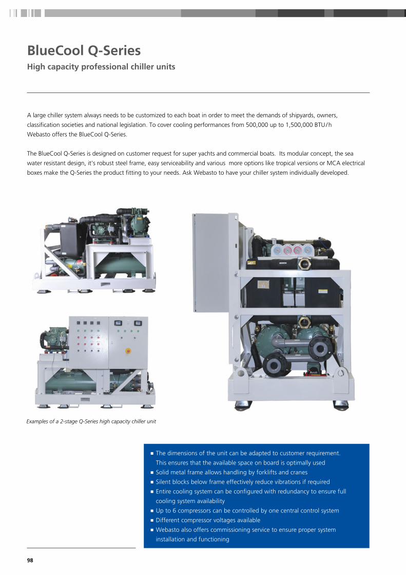
98
BlueCool Q-SeriesHigh capacity professional chiller units
A large chiller system always needs to be customized to each boat in order to meet the demands of shipyards, owners,
classification societies and national legislation. To cover cooling performances from 500,000 up to 1,500,000 BTU / h
Webasto offers the BlueCool Q-Series.
The BlueCool Q-Series is designed on customer request for super yachts and commercial boats. Its modular concept, the sea
water resistant design, it’s robust steel frame, easy serviceability and various more options like tropical versions or MCA electrical
boxes make the Q-Series the product fitting to your needs. Ask Webasto to have your chiller system individually developed.
■ The dimensions of the unit can be adapted to customer requirement.
This ensures that the available space on board is optimally used
■ Solid metal frame allows handling by forklifts and cranes
■ Silent blocks below frame effectively reduce vibrations if required
■ Entire cooling system can be configured with redundancy to ensure full
cooling system availability
■ Up to 6 compressors can be controlled by one central control system
■ Different compressor voltages available
■ Webasto also offers commissioning service to ensure proper system
installation and functioning
Examples of a 2-stage Q-Series high capacity chiller unit

99
BlueCool Q-SeriesHigh capacity professional chiller units
■ High capacity chillers as project based development
■ Modular concept allows to combine multiple units into
one integrated system
■ Easy maintainable semi-hermetic compressor
■ Heat exchanger tubes with highly efficient tube
geometry and anti-fouling profile on the coolant side
■ Detachable end cover of tube condenser to permit
mechanical cleaning of the pipes
■ Several customer specific options available such as
gauges, redundancy controls, CAN bus interfaces etc.
■ Optional 100% pump-down capacity for making circuit
repairs without recovering the refrigerant
Technical data BlueCool Q-Series
Cooling capacity (BTU / h) range 500 – 1,500 kBTU / h
Cooling capacity (kW) range 147 – 440
Voltage (V) 360 – 690
Frequency (Hz) 50 / 60
Refrigerant types R134a, R407c,F1234yf
Min. sea water temp. Heating (°C) 6
Max. sea water temp. Cooling (°C)* 35
* Higher temperature on request
Project based development
737T-RP-460 V-R407c
Coo
ling
Prod
ucts

100
BlueCool A-Series Instant Drain system
Exclusive Instant Drain condensate management system ■ Constant multidirectional high angle slope design of condensate pan for
immediate drainage
■ Anti splash condensate management
■ “No drip design” with complete capsuled heat exchanger through additional
side plates and improved insulation
Completely thermally insulated on the outside
Quick installation system
Constant multidirectionalhigh angle slope design
of condensate pan forimmediate drainage
“No drip design” withcomplete capsuledheat exchanger
Movable fixationbrackets for flexibleinstallation
360 degreerotatable blower
Polished stainlesssteel and aluminum encasing
New BlueCool A-Series
Quick installation system
Constant multidirectional
er
nlessminum
Smart design: constant
multi-directional slope.
Extra high condensate pan walls
for Low profile models.

101
Coo
ling
Prod
ucts
BlueCool A-Series
EHM – Electric heat module
Flow control valve
Cabin Controls
One or more air handler(s) in each cabin are fitted to
generate the required cooling capacities individually in
each room. Webasto provides an completely new
designed air handler portfolio in 3 different layouts with
a performance range from 4,000 – 36,000 BTU / h
to suit all sizes and space requirements of your boat.
The electric heat module EHM ensures cabin heating
independent from chiller operation. It is easily installed
in-line into the air duct of the A-Series air handlers and
provides 600 – 1800 W capacity to enable heating in
selective cabins while chiller is in cooling mode.
The flow control valve allows the chilled water to bypass
the heat exchanger of the A-Series when needed.
The comfort on boards is increased while directing the
chilled water only to those cabins with cooling / heating
demand. Continuous blower operation is possible to
reduce noise variations in cabins.
Choose between New Ultimate Cabin Control with Ultra
silent blower operation and master-slave integration or
Standard Cabin Control. Both available as complete kits
with all necessary components.
Webasto offers a new range of air handlers to fit any demand on capacity or space
limitations. The new modular concept makes the A-Series adaptable to individual
requirements and the exclusive Webasto Instant Drain condensate management system
ensures immediate drainage. New accessories like the Ultimate Cabin Control, MyTouch
display, electric heat modules or flow control valves can fine-tune your applications.
Air handlers: BlueCool A-SeriesModular system to fit any demand NEW

102
BlueCool A-SeriesModular air handler system
Model Compact
A4 Compact A6 Compact A9 Compact A12 Compact A18 Compact A24 Compact A36 Compact
Order numbers WBCL1209009A WBCL1209010A WBCL1209011A WBCL1209012A WBCL1209013A WBCL1209014A WBCL1209015A
Capacity (BTU / h) ** 4,000 6,000 9,000 12,000 18,000 24,000 36,000
Capacity (kW) ** 1.2 1.9 2.8 3.6 5.6 7.2 10.7
Voltage (V) 230 (-15% / +10%) 230 (-15% / +10%) 230 (-15% / +10%) 230 (-15% / +10%) 230 (-15% / +10%) 230 (-15% / +10%) 230 (-15% / +10%)
Frequency (Hz) 50 / 60 (+-5%) 50 / 60 (+-5%) 50 / 60 (+-5%) 50 / 60 (+-5%) 50 / 60 (+-5%) 50 / 60 (+-5%) 50 / 60 (+-5%)
Air flow (m³ / h) * 230 380 420 560 750 1120 1550
Air flow (cfm) * 135 224 247 330 441 659 912
Ø Blower connection (mm) 100 (round) 125 (round) 125 (round) 150 (oval) 150 (oval) 2 x 150 (oval) 2 x 150 (oval)
Ø Blower connection (inch) 4 (round) 5 (round) 5 (round) 6 (oval) 6 (oval) 2 x 6 (oval) 2 x 6 (oval)
Weight (kg) 6 7 9 10 12 16 21
Weight (lbs) 13.2 15.4 18.7 22 26.5 35.3 46.3
Current draw running (A) 0.6 0.5 0.6 0.7 1 1.3 2.1
Ø Chilled water connection 3/4'' 3/4'' 3/4'' 3/4'' 3/4'' 3/4'' 3/4''
Dimensions H x W x L (mm) 287 x 249 x 381 287 x 280 x 411 312 x 291 x 456 312 x 279 x 491 362 x 281 x 581 362 x 301 x 636 487 x 302 x 701
Dimensions H x W x L (inch) 11.3 x 9.8 x 15 11.3 x 11 x 16.2 12.3 x 11.5 x 18 12.3 x 11 x 19.3 14.3 x 11.1 x 22.9 14.3 x 11.9 x 25 19.2 x 11.9 x 27.6
Dimensions with valve H x W x L (mm) 287 x 249 x 381 287 x 280 x 411 312 x 291 x 456 312 x 279 x 491 362 x 281 x 581 362 x 301 x 636 487 x 302 x 701
Dimensions with valve H x W x L (inch) 11.3 x 9.8 x 15 11.3 x 11 x 16.2 12.3 x 11.5 x 18 12.3 x 11 x 19.3 14.3 x 11.1 x 22.9 14.3 x 11.9 x 25 19.2 x 11.9 x 27.6
Minimum chilled water flow (l / min.) 4 7 10 9 13 21 31
Number of blowers 1 1 1 1 1 2 2
Max. ambient temperature (°C) 50 50 50 50 50 50 50
Pressure loss chilled water (bar) 0.07 0.12 0.15 0.14 0.16 0.13 0.34
Number of condensate drains 2 2 2 2 2 2 2
Ø Condensate drain (mm) 16 16 16 16 16 16 16
Compact Low ProfileSlimline
* With 2 m of air duct, one 90° bend, air outlet grille at 230 V, 50 Hz ** Intake air of 32 °C / 47 % rh, water inlet temperature of 5 °C and at 230 V, 50 Hz
H
WL
H
W
L
H
WL

103
BlueCool A-SeriesModular air handler system
■ Three possible shapes to cope with any installation
demand: Compact, Slimline and Low profile
■ New modular system with various options
■ Innovative Webasto Instant Drain system for smart
management of condensate
■ High quality stainless steel condensate tray
■ High performance with high cooling capacity and
high air flow
■ Super Silent with
– flexible vibration isolation mounts
– larger ducts to reduce noise from air speed
■ Oversized heat exchanger tested under tropical
conditions
■ Rotatable blower
Model Slimline Low Profile
A6 Slimline A9 Slimline A12 Slimline A18 Slimline A6 Low Profile A9 Low Profile A12 Low Profile A18 Low Profile
Order numbers WBCL1209001A WBCL1209002A WBCL1209003A WBCL1209004A WBCL1209005A WBCL1209006A WBCL1209007A WBCL1209008A
Capacity (BTU / h) ** 6,000 9,000 12,000 18,000 6,000 9,000 12,000 18,000
Capacity (kW) ** 1.9 2.8 3.6 5.6 1.9 2.8 3.6 5.6
Voltage (V) 230 (-15% / +10%)
230 (-15% / +10%)
230 (-15% / +10%)
230 (-15% / +10%)
230 (-15% / +10%)
230 (-15% / +10%)
230 (-15% / +10%)
230 (-15% / +10%)
Frequency (Hz) 50 / 60 (+-5%) 50 / 60 (+-5%) 50 / 60 (+-5%) 50 / 60 (+-5%) 50 / 60 (+-5%) 50 / 60 (+-5%) 50 / 60 (+-5%) 50 / 60 (+-5%)
Air flow (m³ / h) * 380 420 560 750 380 420 560 750
Air flow (cfm) * 224 247 330 441 224 247 330 441
Ø Blower connection (mm) 125 (round) 125 (round) 150 (oval) 150 (oval) 125 (round) 125 (round) 150 (oval) 150 (oval)
Ø Blower connection (inch) 5 (round) 5 (round) 6 (oval) 6 (oval) 5 (round) 5 (round) 6 (oval) 6 (oval)
Weight (kg) 7 9 10 12 10 11 13 16
Weight (lbs) 15.4 19.8 22 26.5 21.6 24.3 28.7 35.3
Current draw running (A) 0.5 0.6 0.7 1.1 0.5 0.6 0.7 1.1
Ø Chilled water connection 3/4'' 3/4'' 3/4'' 3/4'' 3/4'' 3/4'' 3/4'' 3/4''
Dimensions H x W x L (mm) 588 x 217 x 411 611 x 217 x 456 619 x 217 x 494 666 x 218 x 581 205 x 437 x 582 205 x 482 x 606 205 x 516 x 614 205 x 599 x 661
Dimensions H x W x L (inch) 23.1 x 8.5 x 16.2 24.1 x 8.5 x 18 24.4 x 8.5 x 19.4 26.2 x 8.6 x 22.9 8.1 x 17.2 x 22.9 8.1 x 19 x 23.9 8.1 x 20.3 x 24.2 8.1 x 23.6 x 26
Dimensions with valve H x W x L (mm) 588 x 217 x 479 611 x 217 x 524 619 x 217 x 559 666 x 218 x 649 205 x 487 x 582 205 x 532 x 606 205 x 567 x 614 230 x 657 x 661
Dimensions with valve H x W x L (inch) 23.1 x 8.5 x 18.9 24.1 x 8.5 x 20.6 24.4 x 8.5 x 22 26.2 x 8.6 x 25.6 8.1 x 19.2 x 22.9 8.1 x 20.9 x 23.9 8.1 x 22.3 x 24.2 9.1 x 25.9 x 26
Minimum chilled water flow (l / min.) 7 10 9 13 7 10 9 13
Number of blowers 1 1 1 1 1 1 1 1
Max. ambient temperature (°C) 50 50 50 50 50 50 50 50
Pressure loss chilled water (bar) 0.12 0.15 0.14 0.16 0.12 0.15 0.14 0.16
Number of condensate drains 2 2 2 2 2 2 2 2
Ø Condensate drain (mm) 16 16 16 16 16 16 16 16
The MyTouch display is included in the A-Series Cabin Control Kit
BlueCool MyTouch
Coo
ling
Prod
ucts

104
BlueCool A-SeriesEHM – Electric heat module
■ Electric heat modules ensure cabin heating
independent of chiller operation
■ They are easily installed in-line into air duct of the
A-Series air handlers
■ EHM is directly connected to A-Series electronics
so no separate controls are needed
■ EHM further increase the comfort on board by:
– enabling heating in selective cabins while chiller is in
cooling mode
– enable heating while chiller is switched off
– increasing the heat output of air handlers if
extra high heat demand is needed
■ EHM can easily be retrofitted to existing A-Series
■ EHM is preinsulated to prevent condensation on the
outside. It also comes with 2 stainless steel mounting
brackets for wall mounting
■ When using EHM a flow control valve also needs
to be fittedEHM – Electric heat module
Standard application, check on minimum airflow in technical data. Only for secondary ducts with smaller diameter, check on minimum airflow in technical data.
Type EHM600W-100 mm -230 V -50/60 Hz
EHM900W-125 mm -230 V -50/60 Hz
EHM1200W-150 mm -230 V -50/60 Hz
EHM1800W-150 mm -230 V -50/60 Hz
Order numbers WBCL1209100A WBCL1209101A WBCL1209102A WBCL1209103A
Capacity (W) 600 900 1,200 1,800
Dimensions (L x W x H) (mm) 370 x 100 x 170 370 x 125 x 195 370 x 150 x 220 370 x 150 x 220
Dimensions (L x W x H) (inch) 14.6 x 3.9 x 6.7 14.6 x 4.9 x 7.7 14.6 x 5.9 x 8.7 14.6 x 5.9 x 8.7
Ø Hose connection (mm) 100 125 150 150
Ø Hose connection (inch) 4 5 6 6
Voltage (V) 230 (-15% / +10%) 230 (-15% / +10%) 230 (-15% / +10%) 230 (-15% / +10%)
Frequency (Hz) 50 / 60 (+-5%) 50 / 60 (+-5%) 50 / 60 (+-5%) 50 / 60 (+-5%)
Current draw running (A) 3 4 5 8
Max. supply air temperature (°C) 40 40 40 40
Cut off temperature safety switch (°C) 60 60 60 60
Pressure loss air (Pa) 60 60 60 60
Min. air flow (m³/ h) to ensure full heat output
60 80 120 180
Weight (kg) 2.2 2.6 2.8 3
Compatibility A4 Compact A6 Compact, Slimline,
Low Profile
A9 Compact, Slimline,
Low Profile
A12 Compact, Slimline,
Low Profile
A18 Compact, Slimline,
Low Profile
A24 Compact A36 Compact
EHM600W
EHM900W – – –
EHM1200W – – –
EHM1800W – – – – –
H
W
L

105
BlueCool A-SeriesFlow control valve
■ The flow control valve acts as a 3/2-way valve allowing the chilled water to
bypass the heat exchanger of the A-Series when needed
■ Easy screw connection to all A-Series units, no soldering needed
■ Easy electrical connection to A-Series electronics
■ 90° elbows in the Slimline / Low profile kit enable an extra flat installation
■ The flow control further increases the comfort on board by:
– directing the chilled water only to those cabins with
cooling/heating demand
– prevent inadvertent heating when air handler is switched off –
no chimney effect
– prevents condensate build-up and thus mold on heat exchangers
of air handlers which are switched off
– continuous blower operation is possible thus reducing noise
variations in cabins
■ Valve needs to be fitted if EHM is installed to prevent simultaneous
heating and cooling
Flow control valvefor Slimline and Low Profile
Flow control valvefor Compact
Valve with motor actuator Kit Motor Valve Slimline / Low profileA-Series with 90° elbow
Kit Motor Valve Compact A-Series
Order numbers WBCL151004B WBCL151003B
Valve with thermal actuator* Kit Therm Valve Slimline / Low profileA-Series with 90° elbow
Kit Therm Valve CompactA-Series
Order numbers 2510181A 2510182A
Coo
ling
Prod
ucts
* Valves with thermal actuator are suitable for A-Series model from A4 up to A18. Due to their longer activation time they are not suitable to be operated in permanent blower mode.
NEW

106
BlueCool A-SeriesUltimate Cabin Control – Ultra silent blower operation
New Ultimate Cabin Control ■ Ultra silent blower operation due to PWM control
■ Innovative Master-Slave integration allows to
connect multiple units together
■ Individually adjustable 5-step fan speed
■ Compatible to all BlueCool A-Series air handlers
■ Meets the highest EMC requirements of IEC / EN 60945
■ One MyTouch display can operate all connected
cabin controls
2. Control of a network of Air Handlers via „Master-Slave integration“
One Ultimate Cabin Control box is already capable to control several air handlers with a max. total amperage of 3.15 A.
For larger cabins requiring more air handlers, one single BlueCool My Touch user interface can control
up to 15 Ultimate Cabin Control devices networked together in a “Master-Slave integration”.
1. High performance Silencer
Standard Cabin Control: Phase-cutting principle
The standard Cabin Control kit uses the phase-cutting principle
with triacs to control the blower motor speed. This chops the
incoming sine wave and thus creates electrical bursts which
hit the blower motor and cause mechanical noises such as
humming and vibration, particularly in low blower speed levels.
NEW
Ultimate Cabin Control – the 2 in 1 solution to provide very silent blower operation
and to control a network of BlueCool A-Series air handlers.
Ultimate Cabin Control: PWM for blower speed control
The new Ultimate Cabin Control uses pulse width modulation (PWM)
to operate the AC-driven blower motor. With such fast pulses in
a frequency of 10 to 16 kHz the amperage reaching the blower
motor is very smooth and thus does not cause any humming noise
or vibrations in low blower speeds. It also allows to run the blower
in very low speed levels to marginalize air flow noise. The Ultimate
Cabin Control can be used with all Blue Cool A-Series air handlers.
Master-Slave network
Air
flow
Air
flow
Lower air flowresults in less airflow noise
Humming noise
No Humming noiseat low speed levels
Blower speed level5 4 3 2 1 Blower speed level5 4 3 2 1

107
Coo
ling
Prod
ucts
BlueCool A-SeriesCabin Control Kits
Cabin Control for BlueCool A-Series ■ Complete kits available including all necessary components
■ Pre-configured for all BlueCool A-Series
■ Integrates Webasto s BlueCool Expert Tool diagnosis and set up tool
■ MyTouch as standard user interface with clear text display
■ Optional CAN-Bus for optimized adaptations to boat systems
Cabin Controls for BlueCool A-Series Order number
Ultimate Cabin Control Kit 2510197A
Kit includes: Electrical box with controller card, MyTouch display with Webasto cover plate, display cable 5 m, air temperature sensor 3 m. Max. switching current 3,15 A.
Will be the “Master” unit in a Master-Slave configuration
Order number
Ultimate Cabin Control 2510198A
Includes: Electrical box with controller card. Max. switching current 3,15 A.
Shall be configured as “Slave” unit in a Master-Slave configuration
Order number
Cabin Control Kit A-Series WBCL151002C
Includes: Electrical box with controller card, MyTouch display with Webasto cover plate, display cable 5 m, air temperature sensor 3 m. Max. switching current 2 x 3,15 A.

108

109
Accessories for cooling systems
Fresh air and air extraction units 110
Blower modules and air flow regulators 111
Accessories for S-, V- and C-Series 112
BlueCool Expert Tool 113
Air-conditioning control elements 114
Controls 116
Self-priming pumps 118
Pumps 119
Air system 122
Water system 127
Coo
ling
Acc
esso
ries

110
■ Regulate fresh-air entry into the vessel by temperature differential outside / inside
and combined air extraction control
■ Basic regulation by adjustable temperature differential outside / inside with
programmable extreme limits and short cycle limits
■ 2-stage integrated reheat (AC electrical) provided
■ Electronic controller provides two separate blower outlets: one for fresh-air input
and one for extraction air out. Different speed settings possible for both outlets.
All speed settings including the maximum speed completely re-programmable.
A manual control for the speed is possible
■ Special flow regulators allow easy and precise balancing of outputs per volume
■ Integrated Solenoid 3-way valve control
■ Special start-up procedure to eliminate residual moisture in system
■ Three temperature read-outs:
– Outside air temperature
– Chilled water circuit temperature
– Treated air input temperature
■ Air flow regulators to be specified according to application
Features and functioning principles
H2
H1
L
Model Performance Air flow Electronic heating capacity
Length L Height H1 Height H2 Depth D Weight Order number
Extract 900 – 900 m³ / h530 cfm
– 515 mm20.3 inch
435 mm17.1 inch
––
585 mm23 inch
18 kg40 lbs
WBCL000216
Extract 1800 – 1,800 m³ / h1,060 cfm
– 515 mm20.3 inch
435 mm17.1 inch
––
615 mm24.2 inch
21 kg46 lbs
WBCL000219
Model Performance Air flow Electronic heating capacity
Length L Height H1 Height H2 Depth D Weight Order number
Fresh Air 24 24,000 BTU / h7 kW
900 m³ / h530 cfm
2 x 1,000 W 700 mm27.6 inch
430 mm16.9 inch
540 mm21.3 inch
585 mm23 inch
35 kg77 lbs
WBCL005241B
Fresh Air 24 SP 24,000 BTU / h7 kW
1,800 m³ / h1,060 cfm
2 x 1,000 W 700 mm27.6 inch
430 mm16.9 inch
540 mm21.3 inch
585 mm23 inch
35 kg77 lbs
WBCL005242B
Fresh Air 48 48,000 BTU / h14 kW
1,800 m³ / h1,060 cfm
4 x 1,000 W 850 mm33.5 inch
512 mm20.2 inch
565 mm22.2 inch
925 mm36.41 inch
45 kg100 lbs
WBCL005240B
Fresh Air 2 x 24 48,000 BTU / h14 kW
1,800 m³ / h1,060 cfm
2 x 1,000 W 940 mm37 inch
490 mm19.3 inch
570 mm22.4 inch
620 mm24.4 inch
48 kg106 lbs
WBCL000218B
Fresh air and air extraction units
Fresh air unit
Air extraction unit

111
■ Provide fresh air to or extract air from the cabins ■ Special fan design provides a high air flow at low noise ■ Low electrical power consumption ■ Removable engine body allows easy maintenance ■ Speed controllable motor, two speed, Class B, IP44
Inline blower modules
Model Ø D of ducting Air flow limit Order number
Air Flow Regulator 15 80 mm, 3.1 inch 15 m3 / h, 8.5 cfm WBCL005243
Air Flow Regulator 30 80 mm, 3.1 inch 30 m3 / h, 17.5 cfm WBCL005244
Air Flow Regulator 45 80 mm, 3.1 inch 45 m3 / h, 26.5 cfm WBCL005245
Air Flow Regulator 60 80 mm, 3.1 inch 60 m3 / h, 35 cfm WBCL005246
Air Flow Regulator 90 100 mm, 4 inch 90 m3 / h, 53 cfm WBCL005247
Air Flow Regulator 120 125 mm, 5 inch 120 m3 / h, 70.5 cfm WBCL005248
Air Flow Regulator 160 125 mm, 5 inch 160 m3 / h, 94 cfm WBCL005249
■ Independent regulation of desired fresh- / extract air flow ■ Eliminates the influence of alternating back pressure, caused
by e.g. blocked air filters ■ Continuous air flow ensures high comfort inside the cabin ■ No electrical or pneumatic wiring ■ Direct insertion into the air duct, which allows an easy
application
Air flow regulators
Model X A Ø B C Ø D E F G H
250 188 303 176 115 97 100 90 80 60
350 188 258 176 115 123 100 90 80 60
Model Speed level
Speed (r.p.m.)
Electrical power consumption
Air flow at free
discharge
Maximumoperating
temperature
Sound pressure level*
(dB(A))
Power supply
Ø Duct Weight Order number
Inline extractor blower 160
II 2,500 20 W 180 m3/ h, 106 cfm 40 24 ~230 V50 Hz
100 mm4 inch
1.4 kg3.1 lbs
WBCL010152A
I 2,200 12 W 140 m3/ h, 82 cfm 40 21
Inline extractor blower 250
II 2,200 24 W 240 m3/ h, 141 cfm 40 31 ~230 V50 Hz
100 mm4 inch
2.0 kg4.4 lbs
WBCL010157A
I 1,850 18 W 180 m3/ h, 106 cfm 40 26
Inline extractor blower 350
II 2,250 30 W 360 m3/ h, 212 cfm 40 33 ~230 V50 Hz
125 mm5 inch
2.0 kg4.4 lbs
WBCL010158A
I 1,900 22 W 280 m3/ h, 165 cfm 40 28
Inline extractor blower 500
II 2,500 50 W 580 m3/ h, 341 cfm 60 33 ~230 V50 Hz
150 mm6 inch
2.7 kg5.9 lbs
WBCL010229A
I 1,900 44 W 430 m3/ h, 253 cfm 60 29
* Sound pressure level radiated at 3 meters at free air conditions with rigid ducts at the inlet and at the outlet.
Blower modules and air flow regulators
Model 160 Model 250 & 350
Coo
ling
Acc
esso
ries

112
Accessories for S-, V- and C- Series
Description Order number
Silent Blocks for C32 T, C40 T, C55 T, V50 M, V66 T and V77 T. WBCL1207041A
Silent Blocks for C81 R and C108 Q WBCL1207042A
BlueCool Silent block kits
■ Solution for C-Series with Twin, Triple and Quattro compressors as well as for the V50 M
■ One complete kit with all necessary parts is supplied
■ Reduction of 50 % of vibrations transmitted to the hull ■ High performance damping elements specially designed for the vibration frequency and the weight of each unit
■ All absorbers can easily be retrofitted and mounted below the condensate tray. One complete kit with all necessary parts is supplied
■ The height of the unit will be increased by only 14 mm
Description Order number
Vibration Absorber Kit S-Series; S6, S8, S10 WBCL120075A
Vibration Absorber Kit S-Series; S13 – S27 WBCL120076A
Vibration Absorber Kit C-Series; C16 M – C27 M WBCL120078A
BlueCool Vibration absorber kits
■ Reduction of electrical starting peak up to 70 % ■ For all BlueCool single-phase compressors ■ Fully 50 / 60 Hz compatible for worldwide application ■ Self-adjusting software adapts to compressor type and frequency input
■ Monitors supply voltage and protects against low voltage and locked rotor
■ Easy to install and to retrofit in BlueCool electrical boxes
Description Order number
BlueCool Soft Start 5,000 – 13,000 BTU / h, 230 V, single-phase, 50 – 60 Hz WBCL050931B
BlueCool Soft Start 16,000 – 20,000 BTU / h, 230 V, single-phase, 50 – 60 Hz WBCL050932B
BlueCool Soft Start 24,000 – 42,000 BTU / h, 230 V, single-phase, 50 – 60 Hz WBCL050933B
BlueCool Soft Start
■ Reduction of starting peak up to 53 % ■ Fully 50 / 60 Hz compatible for worldwide application ■ Two soft start models cover 3-phase scroll compressors from 21 – 143 kBTU / h
■ Self-adjusting software, soft start automatically adapts to compressor
■ Monitors supply voltage and protects against overvoltage, overcurrent and locked rotor
■ Rated operational voltage: 340 – 440 VACrms, 50 / 60 Hz
Description Order number
Soft Start 21 – 96 kBTU, 400 V, 3-phase, 50 – 60 Hz WBCL050945A
Soft Start 112 – 143 kBTU, 400 V, 3-phase, 50 – 60 Hz WBCL050946A
Soft Start 3-phase, 400 V
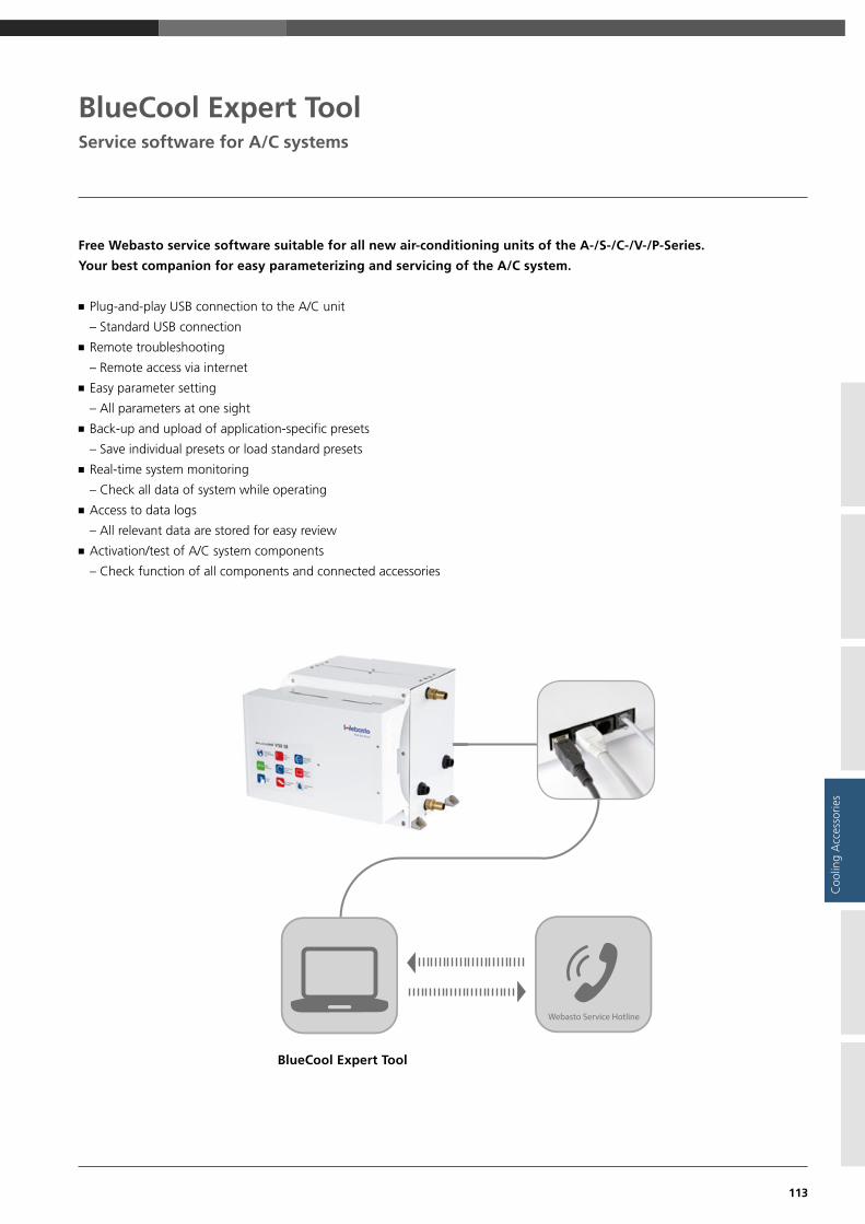
113
BlueCool Expert Tool
Free Webasto service software suitable for all new air-conditioning units of the A-/S-/C-/V-/P-Series.
Your best companion for easy parameterizing and servicing of the A/C system.
■ Plug-and-play USB connection to the A/C unit
– Standard USB connection
■ Remote troubleshooting
– Remote access via internet
■ Easy parameter setting
– All parameters at one sight
■ Back-up and upload of application-specific presets
– Save individual presets or load standard presets
■ Real-time system monitoring
– Check all data of system while operating
■ Access to data logs
– All relevant data are stored for easy review
■ Activation/test of A/C system components
– Check function of all components and connected accessories
BlueCool Expert Tool
Coo
ling
Acc
esso
ries
Service software for A/C systems

114
Air conditioning control elementsBlueCool MyTouch
The BlueCool MyTouch display is the new standard display for
all new BlueCool A/C Series and is part of a complete electronic
control system including the A/C controller card and connecting
cables / sensors.
■ Standard display for all BlueCool A/C units
■ Full color, high resolution, interactive touch display
■ Individual customizable Multi Design Touch Display
with 3 different user designs
■ Intuitive icons and menus
■ 3 different menu levels with
■ Easy intuitive operation for end customer
■ Advanced settings for crew member
■ Complete parameter access for technician with clear
text message
Customizable to many cover plate systems like ■ Vimar Eikon
■ Vimar Eikon EVO
■ Vimar Plana
■ Btcino Axolute
3 different software designs and Webasto cover plate

115
Air conditioning control elementsBlueCool MyTouch
Coo
ling
Acc
esso
ries
Easy temperature selection with actual cabin temperature (left) and adjustable target temperature (right)
Failure codes show up in clear text
Individual picture can be uploaded to be used as Stand-by screen
Easy navigation through display settingsmenu with clear text in 10 languages
System settings menu is code protected to prevent unwanted changes
113
7
7968
45
28
93107
5973

116
Blu
eCo
ol
S-Se
ries
Blu
eCo
ol
C-,
V-,
P-S
erie
s
Blu
eCo
ol
A-S
erie
s
Order number
MyTouch Display n WBCL151002C
Cabin Control Kit A-SeriesIncludes: electrical box with controller card, MyTouch display with Webasto cover plate, display cable 5 m, remote air temperature sensor 3 m, max. switching current: 2 x 3.15 A
n* WBCL151000B
Ultimate Cabin Control KitIncludes: electrical box with controller card, MyTouch display with Webasto cover plate, display cable 5 m, remote air temperature sensor 3 m, max. switching current: 3.15 AWill be the “Master” unit in a Master-Slave configuration
n* 2510197A
Ultimate Cabin Control Includes: Electrical box with controller card, max. switching current: 3.15 AShall be configured as “Slave” unit in a Master-Slave configuration
n 2510198A
Display cable MyTouch 5 m n n WBCL151001A
Display cable MyTouch 10 m n n n WBCL151005A
Can also be used to create the “Master-Slave” network between Ultimate Cabin Control units
Coupling for display cable MyTouchCan be used to extend MyTouch display cables
n n n WBCL151006A
Remote air temperature sensor with 3 m cable n** WBCL000813B
Remote air temperature sensor with 6 m cable n n** n WBCL000810B
Remote air temperature sensor with 12 m cable n n** n WBCL000812B
BlueCool CAN-Bus module n n n WBCL1203091A
Electronic silencer:to be mounted afterwards for significant reduction of humming noise at low blower speedssuitable for 4.5 to 6,000 BTU / h
n WBCL010160C
Electronic silencer:to be mounted afterwards for significant reduction of humming noise at low blower speedssuitable for 9 to 12,000 BTU / h
n WBCL010161C
Electronic silencer:to be mounted afterwards for significant reduction of humming noise at low blower speedssuitable for 16 to 24,000 BTU / h
n WBCL010162C
Relay box for 2 units – one pump – 230 V n n WBCL001127C
Relay box for 3 units – one pump – 230 V n n WBCL001128C
Relay box for 4 units – one pump – 230 V n n WBCL001129C
Relay box for 2 units – one pump – 115 V n n WBCL001182B
Relay box for 3 units – one pump – 115 V n n WBCL001183B
Controls
Already included in scope of delivery n Mandatory accessory n Optional accessory* A-Series air handler may also be connected to chiller control directly. In this case no cabin control kit is needed.** Required if chiller shall run in automatic mode or if air handlers are connected to the chiller electronics.
MyTouch Controls

117
Blu
eCo
ol
Fres
hA
ir
Order number
Digital Control Panel including Bezel n WBCL000833D
Fresh Air control kit V3 230 V, 4.5 m display cable, for 24,000 BTU / h* n WBCL000217G
Fresh Air control kit V3 230 V, 4.5 m display cable, for 48,000 BTU / h* n WBCL000221G
Display cable between A/C control unit and digital control panel – 4.5 m n WBCL000815B
Display cable between A/C control unit and digital control panel – 6 m n WBCL000808B
Display cable between A/C control unit and digital control panel – 12 m n WBCL000809B
Display cable between A/C control unit and digital control panel – 20 m n WBCL000805
Remote air temperature sensor with 3 m cable n WBCL000813B
Remote air temperature sensor with 6 m cable n WBCL000810B
Remote air temperature sensor with 12 m cable n WBCL000812B
CANbus interface n WBCL010127A
Controls
Already included in scope of delivery n Mandatory accessory n Optional accessory* Includes: electrical box with controller card, digital control panel with bezel, display cable.
Coo
ling
Acc
esso
ries
Digital Controls

118
Model DimensionsL x W x H
Max. output Running power consumption
Connection in, out
Weight Order number115 V
Order number230 V
Order number400 V
Self priming pumps 50/60 Hz
WB200 • * 195 x 130 x 130 mm7.7 x 5.2 x 5.2 inch
12 / 3.2 (l / min.)3.2 / 0.9 (gpm)
25 W0.2 amps (230 V)
5 / 8”, 16 mm 1.2 kg2.7 lbs
– WBCL001103B –
Self priming bronze pumps 50/60 Hz
WB500G 254 x 120 x 185 mm 10,0 x 4,7 x 7,3 inch
18 (l / min.)4.7 (gpm)
250 W1.2 amps (230 V)
G 1/ 2” FG 1/ 2” F
6.2 kg WBCL001306A WBCL001305A –
WB1000G 260 x 120 x 143 mm10.3 x 4.8 x 5.7 inch
60 (l / min.)15.8 (gpm)
370 W1.7 amps (230 V)
G 3 / 4” FG 3 / 4” F
6.5 kg14.4 lbs
WBCL001307A WBCL001092A –
WB3800G 410 x 215 x 230 mm 16.1 x 8.5 x 9.1 inch
120 (l / min.) 1200 W5.8 amps (230 V)
G 1 1/4” F 21 kg – WBCL001094A –
Self priming pumps 50 Hz
WB8000* 592 x 215 x 302 mm 23.4 x 8.5 x 11.9 inch
500 (l / min.) 132 (gpm)
1,600 W 2.9 amps (400 V)
G 2” FG 2” F
19 kg41.9 lbs
– – WBCL001164A
WB10500* 592 x 215 x 302 mm 23.4 x 8.5 x 11.9 inch
667 (l / min.)176 (gpm)
3,000 W 5.3 amps (400 V)
G 2” FG 2” F
21 kg46.3 lbs
– – WBCL001165A
Model WB200 Model WB500G/1000G/2800G Model WB8000 / 10500
• Contains straight hose nipple 5 / 8”, 16 mm and 90° adaptor for hose nipple * Can only be used for sea water cooling, not for chilled water circulation
Self-priming pumps
For a stable operation of A/C systems it is essential to have a robust sea water flow in order to cool the condenser and avoid high
pressure cut outs of the A/C unit. The sea water pump has to provide this water flow through the A/C unit.
As soon as a significant amount of air is being sucked into the sea water circuit most standard circulation pumps do not have the
technical capability to evacuate these air bubbles once they enter into the pump chamber. As a result, the sea water flow stops
and the A/C system will shut off. Self priming pumps do have this capability to evacuate these air bubbles from the pump chamber
thus ensuring a continuous A/C operation. Therefore they are the best choice for all those boats and applications where there is a
certain risk that air bubbles might enter via the through hull fitting.
Please note that even though the sea water intake fitting is mounted below the sea water line it may happen during heeling,
high boat speed or during reversing the boat that air is being sucked into the sea water intake. For such applications it is highly
recommended to use self priming sea water pumps instead of standard circulation pumps.
The pump models WB500G, WB1000G and WB3800G have to be pre-filled before the first start-up and after long downtimes.
L
I – D
W
H
O – D

119
Model DimensionsL x W x H
Max. output ***
Running power consumption
Connection in, out
Weight Order number115 V
Order number230 V
Order number400 V
Magnetic Drive Pumps 50/60 Hz
WB250 180 x 95 x 109 mm 7.1 x 3.7 x 4.3 inch
16 (l / min.) 4.2 (gpm)
26 W, 0.36 amps (115 V) 0.18 Amps (230 V)
Ø 14 mmØ 14 mm
1.6 kg3.3 lbs
WBCL001301 WBCL001104A –
179 x 95 x 114 mm 7.1 x 3.7 x 4.3 inch
16 (l / min.) 4.2 (gpm)
26 W 0.2 Amps (230 V)
G 3 / 4” M G 3 / 4” M
1.6 kg3.3 lbs
– WBCL010799B* –
WB350 209 x 106 x 105 mm 8.2 x 4.2 x 4.2 inch
27 (l / min.) 7.1 (gpm)
40 W, 0.48 Amps (115 V) 0.24 Amps (230 V)
Ø 18 mmØ 17 mm
2 kg4.4 lbs
WBCL001302A WBCL001105A –
203 x 106 x 107 mm 8.1 x 4.2 x 4.2 inch
27 (l / min.) 7.1 (gpm)
45 W 0.24 Amps (230 V)
G 3 / 4” MG 3 / 4” M
2 kg 4.4 lbs
– WBCL0010800A* –
WB500 248 x 120 x 130 mm 9.8 x 4.8 x 5.2 inch
32 (l / min.) 8.4 (gpm)
60 W 0.4 Amps (230 V)
G 3 / 4” MG 3 / 4” M
3.5 kg 7.8 lbs
2510180A WBCL001101A –
248 x 120 x 130 mm 9.8 x 4.8 x 5.2 inch
32 (l / min.) 8.4 (gpm)
60 W 0.4 Amps (230 V)
G 3 / 4” MG 3 / 4” M
3.5 kg 7.8 lbs
– WBCL0010810A* –
WB1000 250 x 120 x 130 mm 9.9 x 4.8 x 5.2 inch
45 (l / min.)11.8 (gpm)
90 W, 1 Amps (115 V) 0.52 Amps (230 V)
G 3 / 4” MG 3 / 4” M
3.9 kg 8.6 lbs
WBCL001303A WBCL001106A –
WB1500 258 x 130 x 155 mm 10.2 x 5.2 x 6.1 inch
86 (l / min.)22.7 (gpm)
235 W 1.21 Amps (230 V)
G1” MG1” M
6 kg 13.2 lbs
WBCL001304 WBCL001107A –
WB2000 322 x 156 x 175 mm 12.7 x 6.2 x 6.9 inch
115 (l / min.)30.3 (gpm)
345 W1.93 Amps (230 V)
G 1” MG 1” M
8,5 kg 18.8 lbs
– WBCL001108A –
Magnetic Drive Pumps 50/60 Hz
WB3500 423.5 x 149 x 210 mm16.7 x 5.9 x 8.3 inch
280 (l / min.)74 (gpm)
370 W, 2.4 Amps (230 V) 1.1 Amps (400 V)
G 1 1/ 2” M1 1/ 2” M
14 kg 30,9 lbs
– WBCL001109A WBCL001111A
WB5500 473 x 160 x 249 mm18.9 x 6.3 x 9.8 inch
320 (l / min.)84.6 (gpm)
750 W, 4 Amps (230 V) 1.8 Amps (400 V)
G 1 1/ 2” M1 1/ 2” M
22 kg 48.5 lbs
– WBCL001110A WBCL001112A
WB7400 478.5 x 260 x 274 mm 20.1 x 10.3 x 10.8 inch
450 (l / min.)118.8 (gpm)
1,500 W, 7.1 Amps (230 V) 3.1 Amps (400 V)
G 2” MG 1 1/ 2” M
25 kg 55.2 lbs
– WBCL010121A WBCL001138
WB9800 478.5 x 260 x 274 mm 22.1 x 10.3 x 10.8 inch
520 (l / min.)137.4 (gpm)
2,200 W4.5 Amps (400 V)
G 2” MG 1 1/ 2” M
32 kg 70.5 lbs
– – WBCL001139A
Bronze Pump 50 Hz
WB7500** 382 x 190 x 250 mm 15.1 x 7.5 x 9.9 inch
400 (l / min.) 105.7 (gpm)
2,000 W4.5 Amps (400 V)
G 2” FG 1 1/ 4” F
23 kg50.7 lbs
– – WBCL001136
Bronze Pump 60 Hz
WB7500** 382 x 190 x 250 mm 15.1 x 7.5 x 9.9 inch
400 (l/min.)105.7 (gpm)
2,000 W 4.5 Amps (400 V)
G 2” FG 1 1/ 4” F
23 kg50.7 lbs
– – WBCL001137A
Bronze Pumps 50/60 Hz
WB2500G 303 x 154 x 161 mm 11.9 x 6.1 x 6.4 inch
80 (l / min.) 21.1 (gpm)
550 W2.5 Amps (230 V)
G 1” FG 1” F
9 kg19.9 lbs
– WBCL001170A –
WB3000G 303 x 174 x 181 mm 11.9 x 6.9 x 7.2 inch
125 (l / min.) 33 (gpm)
1,100 W, 4.9 Amps (230 V)2.8 Amps (400 V)
G 1” FG 1” F
10 kg22.1 lbs
– WBCL001171A WBCL001172A
WB5500G 380 x 193 x 240 mm15 x 7.6 x 9.5 inch
250 (l / min.)66 (gpm)
1,500 W, 6.7 Amps (230 V)4.5 Amps (400 V)
G 1 1/ 2” FG 1 1/ 2” F
17 kg37.5 lbs
– WBCL001173A WBCL001174A
WB250 to WB1000 WB3500 to 9800 WB1500 to WB2000 WB2500G to 5500G
* White painted version with threaded hose connections ** Can only be used for chilled water circulation, not for sea water cooling. *** Effective water output varies with back pressure. Please respect the pump curves on the next pages in order to ensure the minimum water flows required for your applications.Note: F = Female thread in inch M = Male thread in inch
Pumps
Coo
ling
Acc
esso
ries

120
50 Hz water pump curves
Graphic 1 50 Hz up to 100 l / min.
1 WB250
2 WB350
3 WB500
4 WB500G
5 WB1000
6 WB1000G
7 WB1500
8 WB2500G
Graphic 2 50 Hz up to 300 l / min.
1 WB2000
2 WB3000G
3 WB3800G
4 WB4000
5 WB3500
6 WB5600
7 WB5500G
Graphic 3 50 Hz up to 700 l / min.
1 WB5500
2 WB8000
3 WB7400
4 WB7500
5 WB9800
6 WB10500
–––– Centrifugal ----- Self-priming
Q (gpm)
Q (l/min.)
0
0 10 20 30 40 50 60 70 80 90 100
5 10 15 20 25
Hea
d (
m)
p (
kPa)
0 0
20
40
60
80
100
120
140
160
180
2
4
6
8
10
12
14
16
18
8
7
6
5
4
31
2
–––– Centrifugal ----- Self-priming
Q (gpm)
Q (l/min.)
00000 100 200 300 400 500 600 700
0 20 40 60 80 100 120 140 160 180
Hea
d (
m)
p (
kPa)
0 0
5 50
10 100
15 150
20 200
25 250
30 300
35 350
65
4
31
2
Pumps
–––– Centrifugal ----- Self-priming
Q (gpm)
Q (l/min.)
0 10 20 30 40 50 60 70 80 90
0 50 100 150 200 250 300 350
Hea
d (
m)
p (
kPa)
0
5
10
15
20
25
0
50
100
150
200
250
7
6
5
3
1
2
4

121
■ The Head (m) stated in the pump curves (Graphic 1 – 5) represents the equivalent pressure drop between
inlet and outlet of the pump. This pressure drop equals the total back pressure of the sea water system from
sea water entry to overboard discharge. Please do not confuse it with the position of the pump position
below the water line. ■ Depending on pressure drop the effective water flow through the pump and thus the sea water system
varies significantly. ■ Always ensure that the minimum sea water flow through the A/C unit is respected. It should be measured
during each commissioning of the sytem. ■ Operating the pumps outside the limits of the pump curves may result in motor overload or cavitation.
These cases are excluded from Webasto warranty.
60 Hz water pump curves
Graphic 4 60 Hz up to 100 l / min.
1 WB250
2 WB350
3 WB500
4 WB500G
5 WB1000
6 WB1000G
7 WB1500
8 WB2500G
Q (gpm)
Q (l/min.)0
0 5 10 15 20 25
10 20 30 40 50 60 70 80 90 100
Hea
d (
m)
p (
kPa)
0 0
5 50
10 100
15 150
20 200
25 250
–––– Centrifugal ----- Self-priming
1 2 35
7
6
84
Pumps
Coo
ling
Acc
esso
ries
Graphic 5 60 Hz up to 700 l / min.
1 WB2000
2 WB3500
3 WB3000G
4 WB5500
5 WB7400
6 WB5500G
7 WB7500
8 WB9800
Q (gpm)
Q (l/min.)0 100 200 300 400 500 600
0 20 40 60 80 100 120 140 160
Hea
d (
m)
p (
kPa)
0 0
5 50
10 100
15 150
20 200
25 250
30 300
35 350
–––– Centrifugal ----- Self-priming
12 3 5
4
7
8
69

122
Functioning principals
Capacity BlueCool A/C component
Duct sizeS-Series
(mm)
Duct sizeA-Series
(mm)
Supply air grill(cm2)
Recommended supply air grill
(“)
Return air grill(cm2)
Recommended return air grill
(“)
4,000 BTU / h – 100 150 8 x 4 325 12 x 5
6,000 BTU / h – 125 190 10 x 4 490 11 x 8
8,000 – 10,000 BTU / h 100 – 125 125 235 12 x 4 490 11 x 8
12,000 – 13,000 BTU / h 125 – 150 150 250 10 x 5 550 14 x 7
16,000 – 20,000 BTU / h 125 – 150 150 390 12 x 6 800 14 x 10
24,000 BTU / h – 2 x 150 2 x 250 2 x 10 x 5 1,000 14 x 12
27,000 BTU / h 2 x 150 – 650 2 x 12 x 6 1,600 2 x 14 x 10
36,000 BTU / h – 2 x 150 2 x 380 2 x 12 x 6 1,600 2 x 14 x 10
Minimum air grille sections
To obtain acceptable noise levels at maximal blower speed levels the requirements for grille and ducts
sections should be observed. The size of the transition box behind the supply air-grille is also important.
Blower outlets
90° turns with flexible ducts directly from blower outlets should
be avoided at all costs as they introduce severe restrictions in
the air-flow. All WB blowers (except on 24,000 BTU / h models)
can be rotated through 45° steps to obtain a straight-line
outlet from the blower. This facility should be used whenever
possible.
Return grille offset
It should be avoided to place a return air grille directly
opposite the finned coil surface of an air handler, because
this will allow propagation of direct blower-motor noise
through the grille. The grille should be offsetted to chicane
the return air to the coil inlet. Direct noise propagation
will be reduced in a significant manner.
Air system
Duct type
To avoid accidental crushing, flexible air-ducts should be of
high quality with sufficiently strong steel spiral reinforcement.
Spiral type ducts should be extended to their maximum length
for the best interior smoothness. For very long duct sections
smooth bore ducts (in PVC for example) should be preferred.
This offers better smoothness than flexible spiral type ducting
and hence reduces internal friction. For very short lengths
non-insulated ducts can be used. For greater lengths it is
advisable to use insulated type ducts to avoid condensation
on the outside of the air-ducts.
Big luxury yacht
In general requirements for megayachts and big luxury vessels
are even more stringent than the table here above. These
special requirements can be obtained from Webasto on request.

123
Suffix Wood type Decription
0 Teak Asian Teak
1 Cherry American Cherry
2 Mahogany Honduran Mahogany
4 Oak American white Oak
Note: Teak versions on stock. Other wood options may have longer lead times or extra shipping costs.
Air grille* Model L1 (mm) L2 (mm) W1 (mm) W2 (mm) Order number
8 x 4 TS (supply air) 202 230 100 128 WBCL004000XA
10 x 4 TS 252 281 100 128 WBCL004001XA
12 x 4 TS 304 332 100 128 WBCL004002XA
10 x 5 TS 252 281 125 152 WBCL004018XA
12 x 5 TS 304 332 125 152 WBCL004004XA
12 x 6 TS 304 332 152 179 WBCL0040240A
Wedge type supply air grille* Model L1 (mm) L2 (mm) W1 (mm) W2 (mm) Order number
10 x 5 WGT (supply air) – 280 – 150 WBCL004023XA
Air grille, closeable* Model L1 (mm) L2 (mm) W1 (mm) W2 (mm) Order number
8 x 4 TSC (supply air) 202 230 100 128 WBCL004005XA
10 x 4 TSC 252 281 100 128 WBCL004019XA
12 x 4 TSC 304 332 100 128 WBCL004006XA
10 x 5 TSC 252 281 125 152 WBCL004022XA
12 x 5 TSC 304 332 125 152 WBCL004025XA
Air grille with filter* Model L1 (mm) L2 (mm) W1 (mm) W2 (mm) Order number
12 x 5 TR (return air) 304 332 125 152 WBCL004020XA
11 x 8 TR 280 306 204 230 WBCL004017XA
14 x 7 TR 177 205 355 381 WBCL004007XA
12 x 10 TR 304 332 254 281 WBCL004021XA
14 x 10 TR 354 382 254 281 WBCL004008XA
14 x 12 TR 354 382 304 332 WBCL004009XA
Air grille (ABS) Model L1 (mm) L2 (mm) W1 (mm) W2 (mm) Order number
10 x 4 PS (ABS, supply air) 242 280 92 128 WBCL004030A
12 x 4 PS 292 332 92 128 WBCL004031A
10 x 5 PS 242 280 115 152 WBCL004032A
10 x 6 PS 242 280 138 174 WBCL004033A
Air grille (ABS) with filter Model L1 (mm) L2 (mm) W1 (mm) W2 (mm) Order number
10 x 8 PR (ABS, return air) 242 281 190 232 WBCL004076A
10 x 10 PR 242 281 242 281 WBCL004077A
12 x 12 PR 292 332 292 332 WBCL004078A
14 x 10 PR 342 382 242 281 WBCL004080A
14 x 12 PR 342 382 292 332 WBCL004081A
Round, adjustable plastic grille Model Order number
Black, 100 mm – WBCL004090A
Walnut brown, 100 mm – WBCL004091A
White, 100 mm – WBCL004092A
Off-white, 100 mm – WBCL004093A
White, 75 mm – WBCL004094A
White, 75 mm with hose ring – WBCL004095A
Black, 75 mm with hose ring – WBCL004096A
Black, 75 mm – WBCL004097
* Note: All teak grilles can be supplied in other wood qualities on demand. Please see table listing the special suffixes to the chosen grille item code in accordance with the wood type preference.
Air system
In order to customise the wooden air grilles, please choose from the following wood options:
Example: WBCL0040040 = Teak air grille 12 x 5 WBCL0040042 = Mahogany air grille 12 x 5
Coo
ling
Acc
esso
ries

124
T-piece (inside, D2 direct to A/C unit) Model D1 / D2 / D3 (mm) L x H (mm) Order number
100 / 100 F / 100 100 / 100 F/ 100 220 x 185 – WBCL001549A
100 / 125 F / 100 125 / 100 F / 100 220 x 185 – WBCL001560A
125 / 125 F / 100 125 / 125 F / 100 220 x 185 – WBCL001550A
125 / 125 F / 125 125 / 125 F / 125 220 x 185 – WBCL001555A
T-piece (outside, D2 connected to hose) Model D1 / D2 / D3 (mm) L x H (mm) Order number
100 / 100 M / 100 100 / 100 M / 100 220 x 185 – WBCL001551A
100 / 125 M / 100 100 / 125 M / 100 220 x 185 – WBCL001552A
Y-piece (inside, D2 direct to A/C unit) Model D1 / D2 / D3 (mm) L x H (mm) Order number
100 / 125 F / 100 100 / 125 F / 100 269 x 213 – WBCL001576A
100 / 125 F / 125 100 / 125 F / 125 269 x 213 – WBCL001577A
Y-piece (outside, D2 connected to hose) Model D1 / D2 / D3 (mm) L x H (mm) Order number
100 / 100 M / 100 100 / 110 M / 100 250 x 200 – WBCL001578A
100 / 125 M / 100 100 / 125 M / 100 269 x 213 – WBCL001574A
100 / 125 M/ 125 100 / 125 M/ 125 269 x 213 – WBCL001575A
125 / 150 M / 125 125 / 150 M / 125 280 x 220 – WBCL001580A
150 / 150 M / 150 150 / 150 M / 150 280 x 220 – WBCL001581A
Hose adapter Model D1 / D2 / D3 (mm) L x H (mm) Order number
3” x 4” 106 x 70 106 x 70 – WBCL001579A
90 degree elbow-piece, D2 connected to A/C unit Model D1 / D2 (mm) L x H (mm) Order number
100 M / 100 F 100 M / 100 F 173 x 172 – WBCL001572A
125 M/ 125 F 125 M/ 125 F 194 x 198 – WBCL001573A
90 degree elbow-piece, D2 connected to hose Model D1 / D2 (mm) L x H (mm) Order number
100 M / 100 M 100 M / 100 M 170 x 170 – WBCL001570A
125 M / 125 M 125 M / 125 M 195 x 195 – WBCL001571A
Standard transition box Model L x H (mm) W (mm) Order number
8 x 4” – 252 x 130 150 WBCL001501A
10 x 4” – 304 x 130 150 WBCL001502A
12 x 4” – 352 x 130 150 WBCL001503A
12 x 5” – 352 x 130 180 WBCL001505A
10 x 5” – 304 x 130 180 WBCL001506A
12 x 6” – 352 x 130 200 WBCL001507A
10 x 6“ – 304 x 130 200 WBCL001508A
Standard hose rings Model D (mm) W (mm) Order number
HR4 – 100 100 – 134 WBCL002502
HR5 – 125 125 – 150 WBCL002503
HR6 – 150 150 – 170 WBCL002504A
HR7 – 178 175 – 200 WBCL002509A
Oval hose rings Model D x W2 (mm) L x H (mm) W1 (mm) Order number
HO4 – 100* 120 x 55 170 100 WBCL002505A
HO5 – 125* 150 x 65 195 110 WBCL002506A
HO6 – 150* 180 x 72 228 120 WBCL002507A
HO7 – 175* 200 x 84 255 140 WBCL002508A
Transition box, round entry Model D (mm) L x H (mm) W (mm) Order number
8 x 4LN / 100* 100 250 x 130 150 WBCL001520A
10 x 4LN / 100* 100 305 x 130 150 WBCL001521A
12 x 4LN / 100* 100 360 x 130 150 WBCL001522A
10 x 5LN / 125* 125 304 x 130 180 WBCL001523A
F = Female M = Male* Equivalent diameter of air ducting in mm
Air system

125
* Equivalent diameter of air ducting in mm.
Air system
Transition box, lateral oval entry Model D x W2 (mm) L x H (mm) W (mm) Order number
W2
D
8 x 4LT / OV100* 120 x 55 250 x 130 155 WBCL001510A
10 x 4LT / OV100* 120 x 55 305 x 130 155 WBCL001530A
10 x 4LT / OV125* 150 x 65 305 x 130 155 WBCL001529A
12 x 4LT / OV125* 150 x 65 305 x 130 180 WBCL001528A
Transition box, back oval entry Model D x W2 (mm) L x H (mm) W (mm) Order number
W2
D
8 x 4AR / OV100* 120 x 55 250 x 180 155 WBCL001524A
10 x 4AR / OV100* 120 x 55 305 x 180 155 WBCL001525A
10 x 4AR / OV125* 150 x 65 305 x 180 155 WBCL001531A
10 x 5AR / OV125* 150 x 65 305 x 180 180 WBCL001526A
10 x 6AR / OV125* 150 x 65 305 x 180 205
Y-piece Model D / D1 / D2 (mm) L x H (mm) Order number
D1
D2
D
YAS100 100 / 100 / 100 320 x 255 – WBCL001562A
YAS125 125 / 125 / 125 360 x 300 – WBCL001563A
YAS100 / 80 / 80 100 / 80 / 80 380 x 300 – WBCL001548A
Webasto EasyDuct – Insulated flexible air ducts Model (mm) D (mm) L (m) Order number
80 IN = 80; A = 90 L = 6 – WBCL007463A
102 IN = 102; A = 112 L = 6 – WBCL007464A
127 IN = 127; A = 137 L = 6 WBCL007465A
152 IN = 152; A = 162 L = 6 WBCL007472A
Standard flexible air ducts Model (mm) D (mm) L (m) Order number
Cflex 102 102 10 – WBCL001804B
Cflex 127 127 10 – WBCL001805B
Cflex 150 152 10 WBCL001806B
Insulated flexible air ducts Model D (mm) L (m) Order number
D
CflexIso 102 102 10 – WBCL001807B
CflexIso 127 127 10 – WBCL001808B
CflexIso 152 152 10 WBCL001809B
Tubular hose insulation Model D (mm) L (m) Order number
D
Isosleeve 102 102 10 – WBCL001810
Isosleeve 127 127 10 – WBCL001811
Isosleeve 152 152 10 – WBCL001812
Extra silent insulated air ducts D (mm) L (m) Order number
high-temperature resistance up to 80° C
special noise reducing inner layer
internal spiral reinforcement
– 102 10 – WBCL010155A
– 127 10 – WBCL010156A
160 10 WBCL010206A
Coo
ling
Acc
esso
ries
NEW
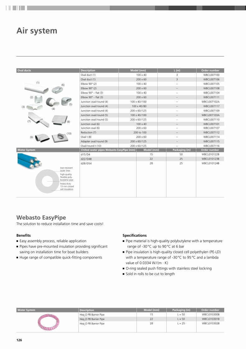
126
Water System Description Model (mm) Packaging (m) Order number
Hep2O PB Barrier Pipe 15 L = 50 WBCL010300B
Hep2O PB Barrier Pipe 22 L = 50 WBCL010301B
Hep2O PB Barrier Pipe 28 L = 25 WBCL010302B
Oval ducts Description Model (mm) L (m) Order number
(1)(6)
(5)
(4)
(2)
(3)
(7) (8)
(10)(9)
Oval duct (1) 100 x 40 3 WBCL007100
Oval duct (1) 200 x 60 3 WBCL007106
Elbow 90° (2) 100 x 40 – WBCL007105
Elbow 90° (2) 200 x 60 – WBCL007108
Elbow 90° – flat (3) 100 x 40 – WBCL007104
Elbow 90° – flat (3) 200 x 60 – WBCL007111
Junction oval / round (4) 100 x 40 / 100 – WBCL007102A
Junction oval / round (4) 100 x 40 / 80 – WBCL007117
Junction oval / round (4) 200 x 60 / 125 – WBCL007109
Junction oval / round (5) 100 x 40 / 100 – WBCL007103A
Junction oval / round (5) 200 x 60 / 125 – WBCL007110
Junction oval (6) 100 x 40 – WBCL007101
Junction oval (6) 200 x 60 – WBCL007107
Reduction (7) 200 to 100 – WBCL007112
Oval t (8) 200 x 60 – WBCL007114
Adapter oval / round (9) 200 x 60 / 125 – WBCL007115
Oval / round t (10) 200 x 60 / 125 – WBCL007116
The solution to reduce installation time and save costs!
Benefits ■ Easy assembly process, reliable application ■ Pipes have pre-mounted insulation providing significant
saving on installation time for boat builders ■ Huge range of compatible quick-fitting components
Specifications ■ Pipe material is high-quality polybutylene with a temperature
range of -30 °C up to 90 °C at 6 bar ■ Pipe insulation is high-quality closed cell polyethylen (PE-LD)
with a temperature range of -30 °C to 95 °C and a lambda
value of 0.0334 W / (m · K) ■ O-ring sealed push fittings with stainless steel lockring ■ Sold in rolls to be cut to length
Webasto EasyPipe
Air system
Water System Chilled water pipes Webasto EasyPipe (mm) Model (mm) Packaging (m) Order number
d15 / D4 15 50 WBCL010122B
d22 / D48 22 25 WBCL010123B
d28 / D54 28 25 WBCL010124B
tear-resistant outer liner
high-quality flexible poly- butylene pipe
heavy-duty 13 mm closed cell insulation

127
Description Model (mm) Packaging (pieces) Order number
Hep2O Straight Connector 15 15 10 WBCL010307B
Hep2O Straight Connector 22 22 10 WBCL010308B
Hep2O Straight Connector 28 28 10 WBCL010309B
Hep2O PB Elbow 90° 15 15 10 WBCL010325B
Hep2O PB Elbow 90° 22 22 10 WBCL010326B
Hep2O PB Elbow 90° GY 28 28 10 WBCL010327B
Hep2O PB Tee 90° 15 15 x 15 x 15 10 WBCL010337B
Hep2O PB Tee 90° 22 22 x 22 x 22 10 WBCL010338B
Hep2O PB Tee 90° GY 28 28 x 28 x 28 10 WBCL010342B
Hep2O PB Tee 90° 22 x 22 x 15 22 x 22 x 15 5 WBCL010339B
Hep2O PB Tee 90° 22 x 15 x 22 22 x 15 x 22 5 WBCL010340B
Hep2O PB Tee 90° 22 x 15 x 15 22 x 15 x 15 5 WBCL010341B
Hep2O PB Tee 90° 28 x 15 28 x 15 x 28 5 WBCL010343B
Hep2O PB Tee 90° 28 x 28 x 22 28 x 28 x 22 5 WBCL010344B
Hep2O PB Tee 90° 28 x 22 x 28 28 x 22 x 28 5 WBCL010345B
Hep2O Pb Tee Reduced Both Ends W 22 x 15 – WBCL010700A
Hep2O Pb Tee Reduced Both Ends W 28 x 15 – WBCL010701A
Hep2O Hepkey Plus 15 – – WBCL010702A
Hep2O Hepkey Plus 22 – – WBCL010703A
Hep2O Hepkey Plus 28 – – WBCL010704A
Hep2O Silicone Lubricant Spray 400 ml Aerosol Can Hep2O Fittings
– – WBCL010705A
Water system
Coo
ling
Acc
esso
ries

128
Description Model (mm) Packaging (pieces) Order number
Hep2O reducer 22 x 15 S/SP 22 x 15 10 WBCL010379B
Hep2O reducer 28 x 22 S/SP 28 x 22 10 WBCL010380B
Hep2O Straight Tap Connector 15 x 1/2’’ 15 x 1 / 2” 10 WBCL010316B
Hep2O Straight Tap Connector 15 x 3/4’’ 15 x 3 / 4” 5 WBCL010317B
Hep2O Straight Tap Connector 22 x 3/4’’ 22 x 3 / 4” 5 WBCL010318B
Hep2O Bent Tap Connector 15 x 1/2’’ 15 x 1 / 2” 10 WBCL010328B
Hep2O Brass Female Adapt 15 x 1/2’’ 15 x 1 / 2” 10 WBCL010310B
Hep2O Brass Female Adapt 22 x 3/4’’ 22 x 3 / 4” 10 WBCL010312B
Hep2O Brass Female Adapt 28 x 1’’ 28 x 1” 10 WBCL010314B
Hep2O Brass Male Adapt 15 x 1/2’’ 15 x 1 / 2” 10 WBCL010311B
Hep2O Brass Male Adapt 22 x 3/4’’ 22 x 3 / 4” 10 WBCL010313B
Hep2O Brass Male Adapt 28 x 1’’ 28 x 1” 10 WBCL010315B
Hep2O Brass Spgt Adapt 15 x 1/2’’ Female 15 x 1 / 2” 10 WBCL010319B
Hep2O Brass Spgt Adapt 22 x 3/4’’ Female 22 x 3 / 4” 10 WBCL010321B
Hep2O Brass Spgt Adapt 28 x 1’’ Female 28 x 1” 10 WBCL010323B
Hep2O Brass Spgt Adapt 15 x 1/2’’ Male 15 x 1 / 2” 10 WBCL010320B
Hep2O Brass Spgt Adapt 22 x 3/4’’ Male 22 x 3 / 4” 10 WBCL010322B
Hep2O Brass Spgt Adapt 28 x 1’’ Male 28 x 1” 10 WBCL010324B
Hep2O Brass Ball Valve 15 15 5 WBCL010353B
Hep2O Brass Ball Valve 22 22 5 WBCL010354B
Hep2O Shut off valve Hot/Cold 15 15 5 WBCL010375B
Water system

129
Description Model (mm) Packaging (pieces) Order number
Hep2O Cold Forming Bend Fixture 15 15 5 WBCL010335B
Hep2O Cold Forming Bend Fixture 22 22 5 WBCL010336B
Hep2O Pipe Support Sleeve 15 15 10 WBCL010362B
Hep2O Pipe Support Sleeve 22 22 10 WBCL010364B
Hep2O Pipe Support Sleeve 28 28 5 WBCL010366B
Hep2O Pipe cutter 10 – 28 Standard – 1 WBCL010373B
Hep2O Pipe cutter 10 – 28 Professional – 1 WBCL010374B
Water system
Important Note:
ALL Hep2O FITTINGS ARE PRE-LUBRICATED – NO ADDITIONAL
LUBRICATION REQUIRED.
If the fitting is demounted and remade, the use of Hep2O Silicone
Lubricant Spray (HX200) is recommended.
HX200 is the only lubricant recommended for use with Hep2O.
Coo
ling
Acc
esso
ries

130
Expansion tank Order number
(1) (2) (3)
Model 2,5 liter (1) WBCL002030
Model 8 liter (2) WBCL002031B
Automatic air bleeder (3) for chiller circuits, 3 / 8” = 15 mm WBCL002035A
TA Hydronics flow regulators Order number
Model STAD-15 – diameter 15 mm (5 / 8”) WBCL002100
Model STAD-20 – diameter 20 mm (3 / 4”) WBCL002101
Model STAD-25 – diameter 25 mm (1”) WBCL002102
3-Way valve Order number
(1)
3-Way valve 25 mm (1”) without fitting (1) WBCL009433
3-Way valve 15 mm (5 / 8”) without fitting (1) WBCL009434
3-Way valve 20 mm (3 / 4”) without fitting (1) WBCL009432
Turn ball valve Order number
1 / 4 Turn ball valve – diameter 12 mm WBCL002015A
1 / 4 Turn ball valve – diameter 15 mm WBCL002016A
1 / 4 Turn ball valve – diameter 20 mm WBCL002017A
1 / 4 Turn ball valve – diameter 25 mm WBCL002018A
Water system
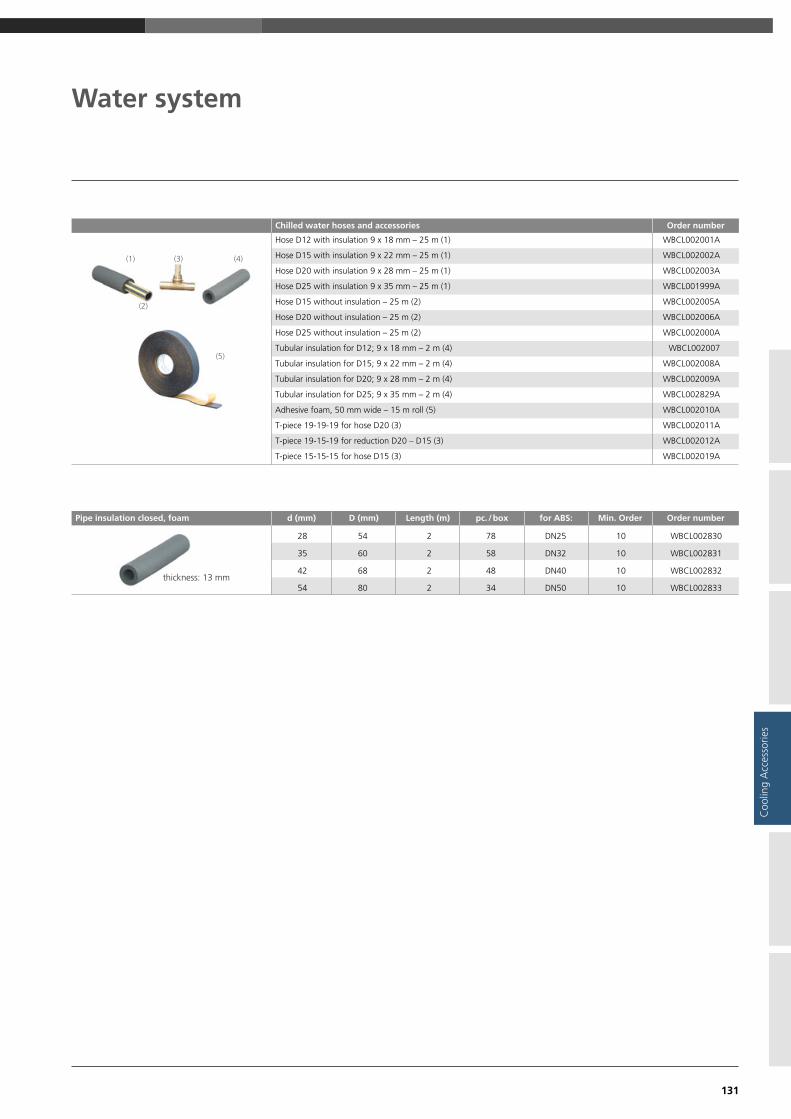
131
Chilled water hoses and accessories Order number
(1)
(2)
(5)
(3) (4)
Hose D12 with insulation 9 x 18 mm – 25 m (1) WBCL002001A
Hose D15 with insulation 9 x 22 mm – 25 m (1) WBCL002002A
Hose D20 with insulation 9 x 28 mm – 25 m (1) WBCL002003A
Hose D25 with insulation 9 x 35 mm – 25 m (1) WBCL001999A
Hose D15 without insulation – 25 m (2) WBCL002005A
Hose D20 without insulation – 25 m (2) WBCL002006A
Hose D25 without insulation – 25 m (2) WBCL002000A
Tubular insulation for D12; 9 x 18 mm – 2 m (4) WBCL002007
Tubular insulation for D15; 9 x 22 mm – 2 m (4) WBCL002008A
Tubular insulation for D20; 9 x 28 mm – 2 m (4) WBCL002009A
Tubular insulation for D25; 9 x 35 mm – 2 m (4) WBCL002829A
Adhesive foam, 50 mm wide – 15 m roll (5) WBCL002010A
T-piece 19-19-19 for hose D20 (3) WBCL002011A
T-piece 19-15-19 for reduction D20 – D15 (3) WBCL002012A
T-piece 15-15-15 for hose D15 (3) WBCL002019A
Water system
Pipe insulation closed, foam d (mm) D (mm) Length (m) pc. / box for ABS: Min. Order Order number
thickness: 13 mm
28 54 2 78 DN25 10 WBCL002830
35 60 2 58 DN32 10 WBCL002831
42 68 2 48 DN40 10 WBCL002832
54 80 2 34 DN50 10 WBCL002833
Coo
ling
Acc
esso
ries

132
Sea water strainer Order number
model 1160
model 1164
model 1162
G 3 / 4” model 1160, height 105 mm, nickel-plated brass WBCL010109A
G 1” model 1164, height 144 mm, nickel-plated bronze WBCL010110A
G 1 1 / 4” model 1164, height 178 mm, nickel-plated bronze WBCL010111A
G 1” model 1162, height 151 mm, nickel-plated bronze WBCL010112A
G 1 1 / 4” model 1162, height 176 mm, nickel-plated bronze WBCL010113A
Screen filter element for model 1160 WBCL010268A
Sea-water strainer, 16 – 20 mm, with two nipples Order number
Screen
Capacity in US gallons 350 / 1,000 US gallons / h
Capacity in liters 25 / 50 l / min.
Suitable for pump models WB250 – WB350 / 1000
H = 140 mm
W = 100 mm
D = diameter inlet / outlet 5 / 8” – 16 mm WBCL001151A
D = diameter inlet / outlet 3 / 4” – 20 mm WBCL001152A
Screen-filter element 1,000 Microns WBCL001154
Sea-water strainer, 25 mm, with two nipples Order number
Screen
Capacity in US gallons 1,000 US gallons / h
Capacity in liters 50 l / min.
Suitable for pump models WB1000 to 2000
H = 290 mm
W = 144 mm
D = diameter inlet/outlet 1.25” – 32 / 40 mm
1” – 25 mm WBCL001153A
Screen-filter element 1,000 Microns WBCL001155
Through-hull kits 16, 20, 25 mm Order number
plastic overboard discharge
through-hull fitting
90° reinforced plastic valve
bronze discharge (5)
nickel plated valve
(4)
(1)(2)
(3)
Capacity in US gallons 350 / 1,000 – 25 / 50 l / min.
Suitable for pump models WB250 – WB350 / 1000
D = diameter inlet / outlet, 5 / 8” – 16 mm kit, 1 / 2” – 16
D = diameter inlet / outlet, 3 / 4” – 20 mm kit, 3 / 4” – 20
5 / 8” – 16 mm – 1 plastic valve (1 + 2 + 3) WBCL001125A
3 / 4” – 20 mm – 1 plastic valve (1 + 2 + 3) WBCL001126C
5 / 8” – 16 mm + 2 x 90° plastic valve (1 + 3 + 5) WBCL001123C
3 / 4” – 20 mm + 2 x 90° plastic valve (1 + 3 + 5) WBCL001124A
Kit 5 / 8” – 16 mm – 1 nickel plated valve (1 + 4 + 2) WBCL001175A
Kit 3 / 4” – 20 mm – 1 nickel plated valve (1 + 4 + 2) WBCL001176A
Kit 5 / 8” – 16 mm – 2 nickel plated valves / bronze exit (1 + 4 + 5) WBCL001177A
Kit 3 / 4” – 20 mm – 2 nickel plated valves / bronze exit (1 + 4 + 5) WBCL001178A
Kit 1” – 25 mm – 1 nickel plated valve / plastic exit (1 + 4 + 2) WBCL001179A
Water system

133
Air bleeder t-piece for chilled water system Order number
Model 1000S (for pump WB1000): t-piece 3 / 4”, diameter shut-off valve outlet 1 / 2” – 16 mm
WBCL001121A
Model 2000S (for pumps WB1500-2500): t-piece 1”, diameter shut-off valve outlet 3 / 4” – 20 mm
WBCL001122A
Chilled Water Circuit A/C Calorifiers Order number
With safety thermostat
Model 15 kW; 400 V; L = 1,015 mm; H = 200 mm; weight = 11 kg WBCL002121
Model 30 kW; 400 V; L = 1,590 mm; H = 200 mm; weight = 19 kg WBCL002123
Air bleeder for seawater pumps Order number
Model 350R (for pumps WB250 and WB350): t-piece 3 / 4”, diameter supply and outlet 1 / 2” – 16 mm
WBCL001118A
Model 1000R (for pump WB1000): t-piece 3 / 4”, diameter supply and outlet 3 / 4” – 20 mm
WBCL001119A
Model 2000R (for pumps WB1500 – 2500): t-piece 1”, diameter supply and outlet 3 / 4” – 20 mm
WBCL001120A
Water system
Webasto can provide all accessories for pressurized systems. Please contact us for further details.
Coo
ling
Acc
esso
ries

134

135
Integrated solutions
Integrated solutions 136
BlueComfort Premium 138
Application concept 138
Application guidelines 139
Basic integration 140
DeLuxe integration 141
Inte
grat
ed S
olut
ions

136
Webasto BlueComfort solutions combine an air-conditioning unit and a water heating unit into
one integrated system. This allows yacht owners and sailors to expand the boating season as people
can chose between heating and cooling at the push of a button.
Most air-conditioning systems have a reverse cycle function to enable heating with the A/C system.
However, this requires mild sea water temperatures for efficient heating. Below 6 °C sea water temperature
the heat cycle becomes inefficient. To gain total autonomy from environmental conditions, an integrated
water heater is the perfect solution.
■ Integration of a chiller A/C unit and a diesel-operated water heater into one system
■ Comfort like at home in any weather condition
■ Modular concept allowing multiple configurations
■ Full range of solutions for any size of boat
BlueComfort Premium
Integrated solutions
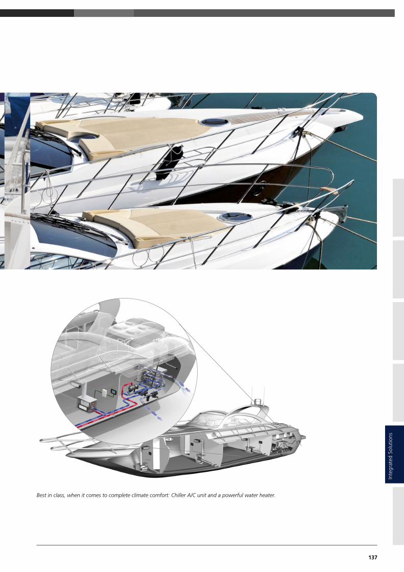
137
Best in class, when it comes to complete climate comfort: Chiller A/C unit and a powerful water heater.
Inte
grat
ed S
olut
ions

138
A Chiller A / C unit
B Cabin Control
C Heater
D Air Handler
E Sea Water Pump
BlueComfort PremiumApplication concept
D
B
C
A
E

139
For a complete BlueComfort Premium system, please combine the following:
1. Chiller air-conditioner
■ Electric cable and control box ■ Operating manual ■ Installation manual
Heater
Chiller air-conditioning cooling capacity
BTU/h 12,000 24,000 32,000 40,000 48,000 60,000
kW 3.5 7.0 9.3 11.7 14.0 17.6
Thermo Pro 50 Thermo Pro 120
Core unitPlease select the core unit according to the required cooling capacity, the available voltage and whether cool only or heating via
reverse cycle is needed.� Air-conditioning unit
Position A as well as the following components are included in the scope of delivery:
Control elements for core unit
Please select the control elements for the core unit separately:
■ MyTouch Display � Display cable
� Remote air temperature sensor
Sea water circuit
Please order separately the components for the sea water circuit consisting of:
� Sea water inlet � Sea water strainer
� Sea water pump � Closing valve
� Overboard discharge � Water hose
Chilled water circuitPlease add the required components for the chilled water circuit consisting of:
� Circulation pump � Piping or hosing system
■ 3-way valve (optional) with insulation
■ Turn ball valve � Expansion tank
Cabin accessories necessary for each single cabin
Please add for every single cabin the following components and accessories:
� Air handler � Cabin control (Air control,
■ Supply air grille display cable, temperature
■ Air ducting sensor and control box)
■ Transition box � Return air grille
■ Water hoses for condensation drain
2. Water heaterSelect the right heater according to the table below or more accurately as a results of the calculation in the specification tool.
Thermo Pro 90 Thermo Pro 150
SEE PAGE 122 SEE PAGE 128
SEE PAGE 144
SEE PAGE 134 SEE PAGE 134
SEE PAGE 106 SEE PAGE 120
SEE PAGE 127
SEE PAGE 129
SEE PAGE 128
SEE PAGE 135
SEE PAGE 127
Application guidelines
BlueComfort Premium
SEE PAGE 118
SEE PAGE 136 SEE PAGE 136
SEE PAGE 122 SEE PAGE 134
SEE PAGE 136 SEE PAGE 135
SEE PAGE 120
SEE PAGE 120
SEE PAGE 88–105
Inte
grat
ed S
olut
ions
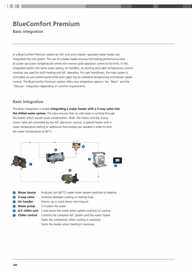
140
In a BlueComfort Premium system an A/C unit and a diesel - operated water heater are
integrated into one system. The use of a water heater ensures full heating performance even
at cooler sea water temperatures where the reverse cycle operation comes to its limits. In this
integrated system the same water piping, air handlers, air ducting and cabin temperature control
modules are used for both heating and A/C operation. For user friendliness, the main system is
controlled via one control panel while each cabin has an individual temperature and blower speed
control. The BlueComfort Premium system offers two integration options: the “Basic” and the
“DeLuxe“ integration depending on comfort requirements.
The Basic integration is simply integrating a water heater with a 3-way valve into
the chilled water system. The valve ensures that no cold water is running through
the heater which would cause condensation. Both, the heater and the 3-way
motor valve are controlled by the A/C electronic control. A special heater with a
lower temperature setting or additional thermostats are needed in order to limit
the water temperature to 60 °C.
Basic integration
BlueComfort PremiumBasic integration
C
A
D
E
F
B
Water heater Produces hot (60 °C) water when system switches to heating
3-way valve Switches between cooling or heating loop
Air handler Warms up or cools down returning air
Water pump Circulates the water
A/C chiller unit Cools down the water when system switches to cooling
Chiller control Controls the complete A/C system and the water heater
Starts the compressor when cooling is necessary
Starts the heater when heating is necessary
A
B
C
D
E
F

141
The DeLuxe integration has all the features of the Basic integration but additionally allows
the integration of a water boiler as well as further fan blowers or radiators into the system.
It therefore provides the highest comfort in heating and sanitary water supply. The mixing valve
limits the water temperature in the A/C loop to 60 °C. A summer / winter switch allows
heating of the boiler in summer while the A/C system is cooling the cabins at the same time.
DeLuxe integration
BlueComfort accessories
For the chilled water system, the following key components are needed as well:
3-way motor valve Basic Integration DeLuxe Integration
Thermo Pro 90 Chiller use 3 / 4” motor valve WBCL000776 Thermo Pro 90 chiller use 3 / 4” motor valve WBCL000776
3-way motorized valve 1”, 230 V, special for BlueComfort applications WBCL000777B
Thermostatic mixing valve Basic Integration DeLuxe Integration
Thermo Pro 90 use 3 / 4” mixing valve
BlueComfort PremiumDeLuxe integration
Water heater Produces hot (approx. 80 °C) water when system switches to heating
Water pump Circulates the water
A/C chiller unit Cools down the water when system switches to cooling
Chiller control Controls the complete A/C system and the water heater
Starts the compressor when cooling is necessary
Starts the heater when heating is necessary
Air handler Warms up or cools down returning air
3-way valve Switches between cooling or heating loop
Water boiler Heats up the sanitary water
Blowers or radiators can optionally be used in areas with extra high heating demand
(e. g. windscreen for demisting)
Summer/ Allows separate boiler operation in summer mode
Winter switch
A
B
C
D
E
F
G
H
I
For a perfect integration
Webasto recommends Isotemp
double coil boilers. Visit
www.indelwebastomarine.comH
G
A
I
C
B
FE
D
Inte
grat
ed S
olut
ions

142

143
Roof & Shading Solutions
Webasto marine roofs 144
Marine engineering and technical services 145
A roof solution for every boat 146
20-Series specifications 148
40-Series specifications 149
60-Series customization possibilities 150
80-/100-Series customization possibilities 151
150-Series II customization possibilities 152
BlueSky Hatch: Unique, electrical sliding hatch 153
The finishing touch – custom roof blinds 154
Hercules blind customization possibilities 155
New Marine Shading Solutions 165
Roof
& S
hadi
ng

144
Webasto offers a wide range of roof solutions, whether you are looking for a standard
roof size with easy installation or a more customizable platform for your individual needs.
As our customer you will additionally benefit from our technological leadership and
knowledge brought over from our experience in the automotive sunroof industry.
Webasto marine roofs
Our standard solutions Webasto engineering services
Comfortable ready-to-go-platforms.These are very economical solutions for more light and
fresh air on board with a robust and proven construction.
Our pre-mounted solution includes all necessary hardware
allowing super quick and easy installation.
Compliment your roof with our elegant
shading solution.Together with Oceanair, Webasto has developed an
elegant shading solution to compliment their range of
large roof systems. Uniquely, this combined blind and
flyscreen solution is UV resistant and fully marinized for
life on the water.
Add value to your boats and your brand image
by developing your own roof system with us.We create unique, exclusive roof systems that match
your exact specifications. Our phased project approach
guarantees you limited risks, a possible exit at any stage
and of course joint teams and know-how transfer.
Take comfort in knowing that you are involved in every
stage, and have the opportunity to use our engineering
and manufacturing capabilities for high quality results.

145
Marine engineering and technical services
Service ■ We ensure a global network with over 50 locations throughout the world via our subsidiaries, representatives and
authorized service network
■ We guarantee an international warranty and customer support based on our commissionings
■ We offer global trainings and technical guidelines
■ We guarantee a fast availability of spare parts
■ We are at your location with our dedicated marine service team
Quality ■ We benefit from the high automotive standards and related advanced technologies
■ We deliver personalized solutions for individual customer needs
■ We provide fully tested, pre-assembled and ready-to-be-mounted solutions
■ We supply added-value accessories
■ Our solutions are highly engineered
Competence ■ Our teams are made up of marine specialists and technical experts
■ We can support our customers with any kind of commissioning
■ Our innovations are the result of open communications and close partnership with our customers
Webasto has 30 years’ experience in advanced automotive roof systems which we apply to marine: kinematics, advanced
materials, water management and sealing systems. We turn your ideas into reality and guarantee high quality and outstanding
product know-how. Phased project approach and joint teams enable know-how transfer to your engineers.
Add value to your boat and brand image
■ Unique, exclusive roof systems to match your exact specifications
■ Phased project approach: limited risk, possible exit at any stage
■ Joint teams and know-how transfer
■ Customer involved at every stage
■ Opportunity to use Webasto engineering skills and manufacturing capabilities for high quality results
The success of our projects is based on three fundamental elements
■ Product visualization: Translate ideas into visual concepts. Phased project approach allows frequent evaluation and
limits the customers’ risk.
■ Product development: Translate visual into technical concept. Joint teams require strong customer involvement
(marketing, R & D, manufacturing).
■ Product validation: Prepare drawing package for suppliers and assembly. Highly valuable know-how transfer ensures
best outcome of the project investments at every stage.
Roof
& S
hadi
ng

146
The 20-Series
A very economical manual or electrical sliding roof for more
light and fresh air on board. The roof is fully tested and pre-
assembled including all necessary hardware allowing quick and
easy installation.
■ Standard roof with large opening
■ Watertight sealing
■ Robust and proven construction
■ Manual or electrical operation
■ Stepless locking system
Economical and robust roof for more light on board
© M
ust
ang
The 60-Series
This series offers multiple customization options for a
perfect fit. The roof is delivered fully tested, pre-assembled
and ready-to-be-mounted at the shipyard thus resulting in
significant cost saving for the boat builder.
■ Customizable roof system
■ Watertight sealing
■ Robust and proven construction
■ Electrical operation
■ Smooth automotive style mechanism
The easy, ready-to-be mounted solution
© J
ean
nea
u
The 40-Series
This roof platform offers a sleek, low profile design to be
able to fit in smaller boats. The roof is electrical operated,
extremely quiet, and is delivered fully assembled, tested
and ready to be installed.
■ Attractive design with safety glass
■ Watertight sealing
■ Fast and simple installation
■ Robust and quality-tested design
■ Optional fixed glass panel for panoramic views
Standard electric marine sliding sunroof
A roof solution for every boatRoof references

147
The 80- & 100-Series
A completely dedicated roof solution whereby application
engineering and a close cooperation with the shipyard is
required. The roof is delivered fully tested, pre-assembled
and ready-to-be-mounted.
■ Fully integrated roof design
■ Watertight sealing
■ Very large dimensions and opening
■ Selection of different panel materials
■ Double curved solution is possible
Roof design for extra large glass and composite panels
© A
bso
lute
The BlueSky
This electrical sliding sunroof is designed for smaller boats
and features a modern full acrylic panel. The panel is made
from 2 shells for improved insulation and very light weight.
The aluminium motor cover ensures a perfect interior finish
and simple and fast installation.
■ Double shell insulated panel
■ Electrical operation
■ Modern and ultra light weight panel
■ High end interior finish
■ Watertight sealing
■ Robust and proven constructionInnovative light weight electrical sliding roof
The 150-Series
A perfect solution for demanding roof projects. The fully
integrated roof consists of a moving and a fixed panel.
The panels are fully flush and the double curvature allows
extra ordinary design possibilities.
■ Fully integrated roof design
■ Watertight sealing
■ Selection of different panel materials
■ Extra large dimensions and opening
■ Sliding panel is tilting at rear and front side
Exclusive double-curvature roof models
© C
ran
chi
Roof
& S
hadi
ng
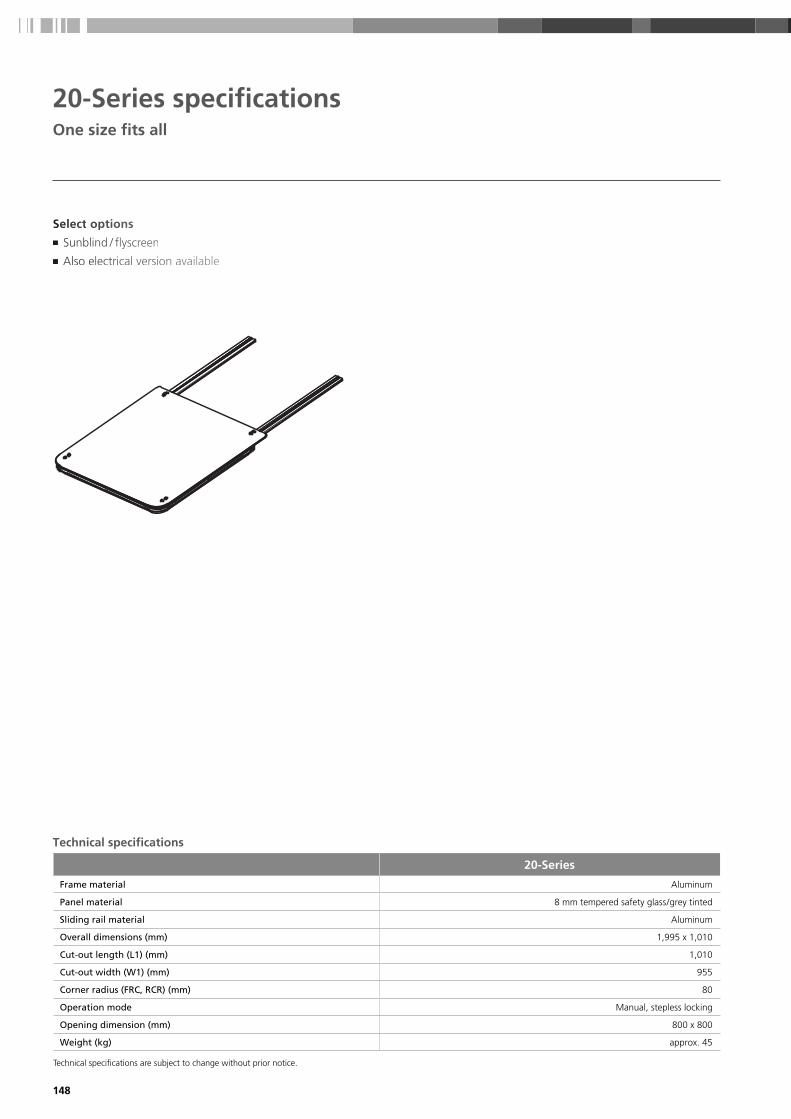
148
20-Series specificationsOne size fits all
20-Series
Frame material Aluminum
Panel material 8 mm tempered safety glass/grey tinted
Sliding rail material Aluminum
Overall dimensions (mm) 1,995 x 1,010
Cut-out length (L1) (mm) 1,010
Cut-out width (W1) (mm) 955
Corner radius (FRC, RCR) (mm) 80
Operation mode Manual, stepless locking
Opening dimension (mm) 800 x 800
Weight (kg) approx. 45
Seellecttt oppptionnns■ Sunbbblinddd / flyyyscreeeen
■ AAlso eleecctricccal veeersiooon avvvailabbble
Technical specifications are subject to change without prior notice.
Technical specifications

149
40-Series specificationsA perfect fit
Technical specifications are subject to change without prior notice.
Select options ■ Fixed panel
■ Sunblind / flyscreen
■ Motor cover
Technical specifications
40-Series
Frame material Aluminum
Panel material 8 mm tempered safety glass/grey tinted
Sliding rail material Aluminum
Overall dimensions 1,665 x 1,379 mm (1,865 x 1,379 with fixed panel)
Cut-out length (L1) (mm) 915
Cut-out width (W1) (mm) 1,320
Corner radius (FRC, RCR) (mm) 80
Cross radius (R2) (mm) 7,620
Front radius (R3) (mm) 2,032
Operation mode Electrical 12 V DC
Opening dimension (mm) 624 x 1,172
Weight (kg) approx. 65
Roof
& S
hadi
ng

150
Maximum cut-out size dimensions for our customized roofs
Max. lenghtL1 (mm)
Max. widthW1 (mm)
Corner curvatureR1 (mm)
Min. cross curvatureR2 (mm)
Figure 1 Roof without cross beam 1,100 1,100 80 7,500
Figure 2 Roof with cross beam in sliding direction
1,100 1,800 80 7,500
Figure 3 Roof with cross beam perpendicular to sliding direction
1,500 1,100 80 7,500
Figure 3Figure 2Figure 1
60-Series customization possibilities
5 steps to customize your roof
1
3
2
5
4
Seeeleeect roooff typppe:
■ ToToTop mmouuunt
■ Flllushhh intttegraaateddd
DDDefffinee dimmmensssionsss:
■ Leeengggth
■ WWWidttth
■ CCCurvvvatuure
Seeeleeect pannnel ddeesiggn:
■ AAAcryylic
■ GGGlassss
■ Sandddwiccch
Seeeleeect frammme ffiinishhh:
■ AAAnoddizinnng
■ PPPowwdder coaatting
Seeeleeect opttiionss:
■ MMMotoor ccooverrr
■ Fiiixeddd paaanel
■ Sunbbblinddd/flyysscreeeen
■ 2224 VVV DCCC (1222 V DDDC isss staanndarrrd)
Technical specifications

151
Dimension code Description Glass GRP Sandwich
W1 Maximum width 2,750 2,750 2,750
L1 Maximum length 1,900 2,400 1,900
R2 Minimum cross radius 7,500 7,500 7,500
R3 Minimum front radius 2,500 2,500 2,500
R4 Minimum length radius N.A. 5,000 N.A.
FCR Front corner radius Mitred or R = 80 Mitred or R = 80 Mitred or R = 80
RCR Rear corner radius Mitred or R = 80 Mitred or R = 80 Mitred or R = 80
Remark: All dimensions are in mm Maximum dimension of glass and GRP panel is defined by maximum weight of 80 / 100 kg Glass panel and Sandwich panel only have a cross radius (single bended) Glass panel and Sandwich panel have fixed radius of: 7,500; 10,000; 15,000; 30,000 mm
80-/100-Series customization possibilities
5 steps to customize your roof
1
3
2
5
4
Seeeleect pannnel ddesiggn:
■ GGGlassss
■ GGGRP
■ SSaandddwiccch
Seeeleect rooff shaaape::
■ SSqquaaare
■ DDD-shhapeee
DDeffinee dimmmensssionsss:
■ LeLeengggth
■ WWidttth
■ CCCurvvvatuurres
Seeeleect desiign:
■ GGGlassss cooolor
■ Frrammme ccoolorr
Seeeleect oopttiionss:
■ Fiixeddd paanel
■ SSunbbblinddd/flyysscreeen
■ 224 VVV DCCC (1222 V DDDC isss staandarrrd)
Technical specifications
Roof
& S
hadi
ng

152
150-Series II customization possibilities
Full flush & extra large solution
1
3
2
Seeeleeect pannnel ddeesiggn:
■ GGGlassss
■ GGGRP
■ Sandddwiccch
Define dimensions:
■ Length (total system app. 4,000 mm)
■ Width (total system app. 2,500 mm)
■ Curvatures
Technical specifications:
■ Frame Stainless steel construction. Laser cut & welded
■ Seal Inside seal fixed to GRP Hard Top for 100 % water tightness
■ Mechanism Tilting and sliding mechanism fixed to frame parts. Mechanism
is including fixation brackets for the panel
■ Drive system 24 V DC motor fixed onto the frame part and connected to mechanism
■ Panel Front and rear panel
■ Manual override Special key to operate the roof manually (e.g. in case of power failure)
Please refer to our separate marine roof brochure
for an overview of our roof references.
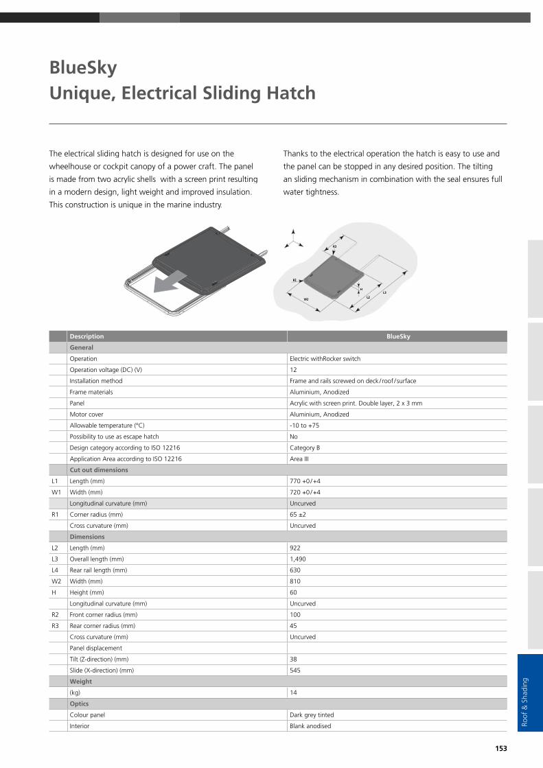
153
Roof
& S
hadi
ng
BlueSkyUnique, Electrical Sliding Hatch
The electrical sliding hatch is designed for use on the
wheelhouse or cockpit canopy of a power craft. The panel
is made from two acrylic shells with a screen print resulting
in a modern design, light weight and improved insulation.
This construction is unique in the marine industry.
Thanks to the electrical operation the hatch is easy to use and
the panel can be stopped in any desired position. The tilting
an sliding mechanism in combination with the seal ensures full
water tightness.
Description BlueSky
General
Operation Electric withRocker switch
Operation voltage (DC) (V) 12
Installation method Frame and rails screwed on deck / roof / surface
Frame materials Aluminium, Anodized
Panel Acrylic with screen print. Double layer, 2 x 3 mm
Motor cover Aluminium, Anodized
Allowable temperature (°C) -10 to +75
Possibility to use as escape hatch No
Design category according to ISO 12216 Category B
Application Area according to ISO 12216 Area III
Cut out dimensions
L1 Length (mm) 770 +0 / +4
W1 Width (mm) 720 +0 / +4
Longitudinal curvature (mm) Uncurved
R1 Corner radius (mm) 65 ±2
Cross curvature (mm) Uncurved
Dimensions
L2 Length (mm) 922
L3 Overall length (mm) 1,490
L4 Rear rail length (mm) 630
W2 Width (mm) 810
H Height (mm) 60
Longitudinal curvature (mm) Uncurved
R2 Front corner radius (mm) 100
R3 Rear corner radius (mm) 45
Cross curvature (mm) Uncurved
Panel displacement
Tilt (Z-direction) (mm) 38
Slide (X-direction) (mm) 545
Weight
(kg) 14
Optics
Colour panel Dark grey tinted
Interior Blank anodised

154
Sky screen pleated for 20-Series/Blue Sky ■ Perfect fit: Dedicated dimension for 20-Series and available
in 2 colours.
■ Integrated flyscreen: Allows for cabin ventilation whilst
keeping the insects out.
■ UV protection: Essential overhead shading from direct
sunlight, providing energy efficient light and temperature
control.
■ Quick and easy to install: Pre-assembled, surface mount,
robust aluminium frame with concealed mounting holes.
Hercules blind ■ Robust: Use of intermediate bars leaves for a cordless
and safe open aperture.
■ Large dimensions: Designed to complement Webasto’s wide
range of roof systems.
■ Integrated flyscreen: Allows for cabin ventilation whilst
keeping the insects out.
■ UV protection: Essential overhead shading from direct
sunlight, providing energy efficient light and temperature
control.
■ Fully customizable: System is offered in various configuration
possibilities and colours.
■ Quick and easy to install: Full frame system, pre-assembled
before installation.
The finishing touch – custom roof blinds

155
Section A-A
Stackheight
Stackheight
35 mm(1 3/8”)
AA
Hercules blind customization possibilities
1
3
2
Select frame design:
■ Blind & flyscreen – Double ended
■ Blind & flyscreen – Single ended
■ Blind only – Single ended
■ Flyscreen only – Single ended
Select fabric colour:
■ White
■ Ivory
■ Straw
■ Beige
Define dimensions:
■ Drop (max. 2,800 mm)
■ Width (max. 2,400 mm)
■ Curvature (min. 7,500 mm)
D-shape solutions■ In case a rectangular shape is not feasible in the interior design a dedicated D-shape solution can be offered.
■ The fabric types and colours of a D-shape solution are the same as for the rectangular version.
■ The exact shape and dimensions of a D-shape solution will be defined during the application development.
■ A D-shape solution requires a much earlier boat design consideration of the stowage area.
Powered HerculesStarting from 2018 a powered upgrade for the Hercules blind can be provided. Powered blinds are
the perfect choice for hard to reach, difficult to access areas. They also provide luxurious effortless comfort.
■ Operation by Radio remote control and / or wall switch can be used
■ 12 VDC or 24 VDC
■ Frame can also be curved to follow the contour of the roof
Three steps to customize your blind
A joint development by Webasto and
Roof
& S
hadi
ng
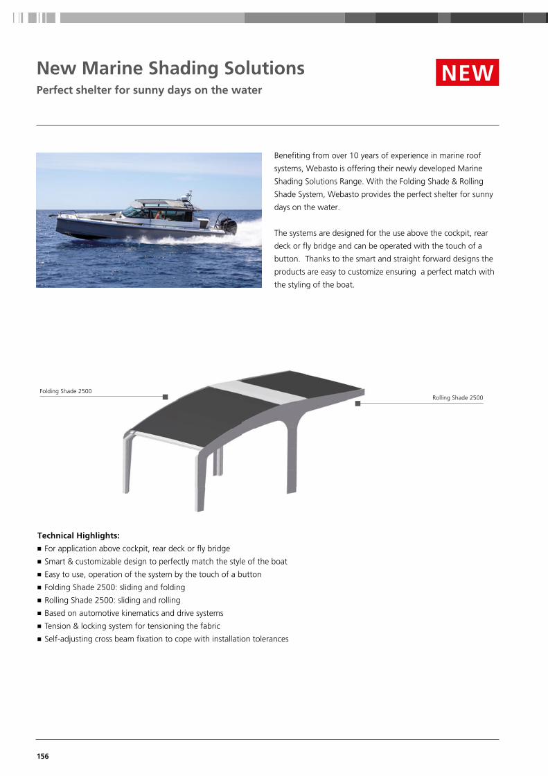
156
Benefiting from over 10 years of experience in marine roof
systems, Webasto is offering their newly developed Marine
Shading Solutions Range. With the Folding Shade & Rolling
Shade System, Webasto provides the perfect shelter for sunny
days on the water.
The systems are designed for the use above the cockpit, rear
deck or fly bridge and can be operated with the touch of a
button. Thanks to the smart and straight forward designs the
products are easy to customize ensuring a perfect match with
the styling of the boat.
New Marine Shading SolutionsPerfect shelter for sunny days on the water
Technical Highlights: ■ For application above cockpit, rear deck or fly bridge
■ Smart & customizable design to perfectly match the style of the boat
■ Easy to use, operation of the system by the touch of a button
■ Folding Shade 2500: sliding and folding
■ Rolling Shade 2500: sliding and rolling
■ Based on automotive kinematics and drive systems
■ Tension & locking system for tensioning the fabric
■ Self-adjusting cross beam fixation to cope with installation tolerances
NEW
Folding Shade 2500Rolling Shade 2500

157
Roof
& S
hadi
ng
New Marine Shading SolutionsTechnical details
General Folding Shade 2500 Rolling Shade 2500
Description
Operation Electric with Rocker switch Electric with Rocker switch
Operation voltage 12 VDC 12 VDC
Installation method Rails, cross beam & fabric are screwed and mounted from the top. Drive system screwed from the bottom.
Complete system is mounted from the top
Materials used Rails and cross beams are aluminium, anodized. Sliders are plastic and stainless steel
Rails and cross beams are aluminium, anodized Sliders are plastic and stainless steel
Fabric material outside Sunbrella, type: Plus, different colors possible Sunbrella, type: Plus, different colors possible
Fabric material inside Dickson, type: Velum, different colors possible N.A.
Allowable temperature (°C) -10 to +75 -10 to +75
Dimensions
L1 Length (mm) Maximum outside dimension is: 2,750 Maximum outside dimension is: 2,000
W1 Width (mm) Maximum outside dimension is: 2,500 Maximum outside dimension is: 2,500
Longitudinal curvature (mm) Minimal 10,000 Straight
Cross curvature (mm) Minimal 10,000 Minimal 10,000
Remark Curvature combination between longitudinal and cross direction to be evaluated per application
Folding Shade 2500

158
Nomenclature
In order to define descriptive technical abbreviations for our air-conditioner and our air handler units, Webasto introduced a
special nomenclature for the price list.
Air-conditioning units nomenclature
Air-conditioning model abbreviations:
C = Chiller (BlueCool C-Series)
S = Self-Contained (BlueCool S-Series)
P = Professional Chiller (BlueCool P-Series)
A = Air handler (BlueCool A-Series)
Example: C55T-R-230V-REV-R410A = Chiller 55,000 Twin Rotary compresssor 230 V reversible refrigerant R410A
C 55 T -R -230 V -REV -R410A C-Series 55,000 BTU / h Twin Rotary comp Voltage REV = reverse cycle refrigerant
Example: S6-R-230V-REV-R410a = Self-Contained 6,000 230 V reversible
S 6 -R -230 V -REV -R410A Selfcontained 6,000 BTU / h Rotary compressor Voltage REV = reverse cycle refrigerant
Example: P60M-S-400V-REV-R407C = P-Series Chiller 60,000 Mono Scroll 400 V reversible refrigerant R407C
P 60 M -S -400 V -REV -R407CP-Series 60,000 BTU / h Mono S = Scroll comp. Voltage REV = reverse cycle refrigerant
COOL = Cool only
Example: A12 Compact -230V -50/60Hz = A-Series Air handler Compact type 12,000 kBTU/h 230 V; 50 Hz and 60 Hz
A 12 Compact -230 V -50/60 HzA-Series 12,000 BTU / h Compact type Voltage Frequency

159
Iden
t.-N
r. M
K60
1830
• 1
1/18
• E
rror
s an
d om
issi
ons
exce
pted
• P
rint
ed in
Ger
man
y •
© W
ebas
to T
herm
o &
Com
fort
SE
2018
Webasto Thermo & Comfort SEP.O. Box 141082199 GilchingGermany webasto-marine.com
l Gilching Headquarters Webasto Locations
Since its foundation in 1901 the Webasto group has continued to set new technological standards
in the original equipment and aftermarket sector. Today, we are one of the 100 biggest suppliers
in the automotive industry worldwide. We develop and produce roof, convertible as well as heating,
cooling and ventilation systems. Our products help provide a better atmosphere on the road, more
comfort and security, as well as increased efficiency for cars, commercial and special vehicles,
motor homes and boats. An outstanding network of production facilities and dealers guarantees
high-quality products, installation standards and services worldwide.