MARES — Navigation, Control and On-board Software
12
17 MARES – Navigation, Control and On-board Software Aníbal Matos and Nuno Cruz Universidade do Porto Portugal 1. Introduction Autonomous underwater vehicles (AUVs) are an emerging technology with applications in very different fields, such as military, homeland defence, underwater surveys, environment monitoring, and oceanographic studies (Griffiths, 2003). Although the use of AUVs in some of these fields is already well established, there is still a great research effort in areas related to the design and operation of these vehicles. The Ocean Systems Group at FEUP (Faculty of Engineering at the University of Porto) and ISR – Porto (Institute for Systems and Robotics – Porto) conducts research activities in marine robotics and has accumulated expertise in the utilization of AUVs and in the development of particular subsystems. This chapter addresses the design of the navigation and control systems of the MARES AUV (Cruz & Matos, 2008), a state-of-the-art small size AUV developed by the authors and already demonstrated at sea operations in 2007. The implementation of these systems in the vehicle on-board software is also discussed. Fig. 1. MARES AUV ready for an open sea mission.
-
Upload
independent -
Category
Documents
-
view
3 -
download
0
Transcript of MARES — Navigation, Control and On-board Software

17
MARES – Navigation, Control and On-board Software
Aníbal Matos and Nuno Cruz Universidade do Porto
Portugal
1. Introduction Autonomous underwater vehicles (AUVs) are an emerging technology with applications in very different fields, such as military, homeland defence, underwater surveys, environment monitoring, and oceanographic studies (Griffiths, 2003). Although the use of AUVs in some of these fields is already well established, there is still a great research effort in areas related to the design and operation of these vehicles. The Ocean Systems Group at FEUP (Faculty of Engineering at the University of Porto) and ISR – Porto (Institute for Systems and Robotics – Porto) conducts research activities in marine robotics and has accumulated expertise in the utilization of AUVs and in the development of particular subsystems. This chapter addresses the design of the navigation and control systems of the MARES AUV (Cruz & Matos, 2008), a state-of-the-art small size AUV developed by the authors and already demonstrated at sea operations in 2007. The implementation of these systems in the vehicle on-board software is also discussed.
Fig. 1. MARES AUV ready for an open sea mission.

Underwater Vehicles
316
2. MARES AUV MARES, or Modular Autonomous Robot for Environment Sampling (Fig. 1), is a 1.5m long AUV, designed and built by the Ocean Systems Group. The vehicle can be programmed to follow predefined trajectories, while collecting relevant data with the onboard sensors. MARES can dive up to 100m deep, and unlike similar-sized systems, has vertical thrusters to allow for purely vertical motion in the water column. Forward velocity can be independently defined, from 0 to 2 m/s. Major application areas include pollution monitoring, scientific data collection, sonar mapping, underwater video or mine countermeasures. MARES configuration can change significantly according to the application scenario, so that it is difficult to define what is a standard configuration. In table 1 we summarize the main characteristics of the AUV version that was demonstrated at sea in November 2007.
Length 1.5 m Diameter 20 cm Weight in air 32 kg Depth rating 100 m Propulsion 2 horizontal + 2 vertical thrusters Horizontal velocity 0-2 m/s, variable Energy Li-Ion batteries, 600 Wh Autonomy/Range about 10 hrs / 40 km
Table 1. MARES main characteristics.
2.1 Mechanical All mechanical parts were designed using Solidworks® CAD software (Fig. 2) and machined from polyacetal in a local machine shop, with small parts in aluminium and stainless steel. Polyacetal is a high performance polymer, with a high degree of rigidity and mechanical strength that makes it an excellent weight-saving metal replacement. It is completely corrosion proof and it is readily available in a wide range of sizes of tubes and rods, at reasonable prices.
Fig. 2. MARES CAD model.
The vehicle hull evolves around a central watertight cylinder, where all electronic boards are installed, with the battery packs located at the bottom to lower the center of mass. To
MARES – Navigation, Control and On-board Software
317
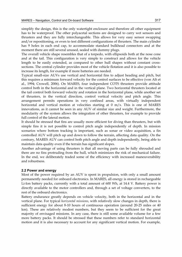
simplify the design, this is the only watertight enclosure and therefore all other equipment has to be waterproof. The other polyacetal sections are designed to carry wet sensors and thrusters and they are fully interchangeable. This allows for very easy sensor swapping and/or repositioning, or even to test different configurations of thrusters. The main cylinder has 9 holes in each end cap, to accommodate standard bulkhead connectors and at the moment there are still several unused, sealed with dummy plugs. The overall vehicle shape resembles that of a torpedo, with ellipsoids both at the nose cone and at the tail. This configuration is very simple to construct and allows for the vehicle length to be easily extended, as compared to other hull shapes without constant cross-sections. The central cylinder provides most of the vehicle flotation and it is also possible to increase its length, for example if more batteries are needed. Typical small-size AUVs use vertical and horizontal fins to adjust heading and pitch, but this requires a minimum forward velocity for the control surfaces to be effective (von Alt et al., 1994; Crowell, 2006). On MARES, four independent COTS thrusters provide attitude control both in the horizontal and in the vertical plane. Two horizontal thrusters located at the tail control both forward velocity and rotation in the horizontal plane, while another set of thrusters, in the vertical direction, control vertical velocity and pitch angle. This arrangement permits operations in very confined areas, with virtually independent horizontal and vertical motion at velocities starting at 0 m/s. This is one of MARES innovations, as it cannot be seen in any AUV of similar size and weight. Furthermore, the modularity of the system allows the integration of other thrusters, for example to provide full control of the lateral motion. It should be stressed that fins are usually more efficient for diving than thrusters, but with simple fins it is not possible to control pitch angle independently of depth. In mission scenarios where bottom tracking is important, such as sonar or video acquisition, a fin controlled AUV will pitch up and down to follow the terrain, affecting data quality. On the contrary, MARES AUV can control both pitch angle and depth independently, being able to maintain data quality even if the terrain has significant slopes. Another advantage of using thrusters is that all moving parts can be fully shrouded and there are no fins protruding from the hull, which minimizes the risk of mechanical failure. In the end, we deliberately traded some of the efficiency with increased maneuverability and robustness.
2.2 Power and energy Most of the power required by an AUV is spent in propulsion, with only a small amount permanently needed for onboard electronics. In MARES, all energy is stored in rechargeable Li-Ion battery packs, currently with a total amount of 600 Wh, at 14.4 V. Battery power is directly available to the motor controllers and, through a set of voltage converters, to the rest of the onboard electronics. Battery endurance greatly depends on vehicle velocity, both in the horizontal and in the vertical plane. For typical horizontal missions, with relatively slow changes in depth, there is sufficient energy for about 8-10 hours of continuous operation (around 20-25 miles or 40 km). These are relatively modest numbers, but they seem to be sufficient for the great majority of envisaged missions. In any case, there is still some available volume for a few more battery packs. It should be stressed that these numbers refer to standard horizontal motion and it is also necessary to account for any significant vertical motion. For example,

Underwater Vehicles
318
the vehicle can hover almost motionless in the water column, at a specific depth, but still requiring some small amount of power to provide depth corrections. In this case, the total endurance will be longer in time but relative to a shorter horizontal range.
2.3 Computational system The onboard computational system is based on a PC104 stack (Fig. 3), with a power supply board, a main processor board, and additional boards to interface with peripherals, such as health monitoring systems, actuation devices, and navigation and payload sensors. A flash disk is used to store both the onboard software and also the data collected during operations.
Fig. 3. MARES on-board computer.
2.4 Payload The modularity of the vehicle allows for a simple integration of different payload sensors, involving three sub-tasks: mechanical installation, electronics interfacing and software. Mechanically, a new sensor may be installed in a dedicated section of the hull, if it is relatively small. Alternatively, it can be externally attached to the vehicle body, since there are many fixing points available. In any case, it is important to verify the weight of the sensor (and adapter) in the water, to compensate with extra flotation if necessary. Naturally, the overall vehicle trim has also to be adjusted, particularly in the case of bulky or heavy payloads. Most of the payload sensors transported by the AUV need energy and a communications link with the onboard computer. MARES has several spare connectors on both end caps of the main electronics compartment, that can be wired to provide power and receive data from these sensors. At the same time, the computational system has spare communication ports, easily configurable according to the payload specs. As far as software is concerned, the integration of a new payload sensor requires the development of a dedicated software module, known as a device driver. Device drivers establish a communication link between the sensor and the onboard software core, allowing for the configuration of the sensor as well as data logging.
MARES – Navigation, Control and On-board Software
319
Naturally, these tasks are greatly reduced after the first time the sensor is tested. Since then, it becomes very simple to swap payload, just by integrating the proper set: sensor, electronics and software.
3. Navigation The design of the navigation system of an AUV has to take into account several issues such as desired positioning and attitude accuracy, size, weight, and power consumption of available sensors and systems, and also overall cost. Available technologies include inertial navigation systems, digital compasses, tilt sensors, pressure cells, acoustic positioning systems, Doppler based velocity meters. The MARES navigation package was selected taking into account the above mentioned issues but also the envisaged missions and application scenarios.
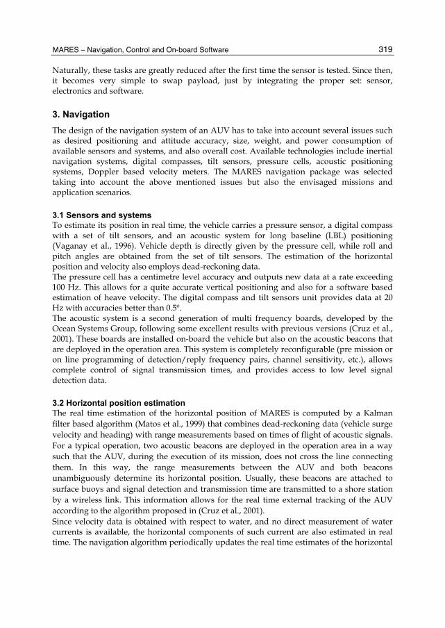
3.1 Sensors and systems To estimate its position in real time, the vehicle carries a pressure sensor, a digital compass with a set of tilt sensors, and an acoustic system for long baseline (LBL) positioning (Vaganay et al., 1996). Vehicle depth is directly given by the pressure cell, while roll and pitch angles are obtained from the set of tilt sensors. The estimation of the horizontal position and velocity also employs dead-reckoning data. The pressure cell has a centimetre level accuracy and outputs new data at a rate exceeding 100 Hz. This allows for a quite accurate vertical positioning and also for a software based estimation of heave velocity. The digital compass and tilt sensors unit provides data at 20 Hz with accuracies better than 0.5º. The acoustic system is a second generation of multi frequency boards, developed by the Ocean Systems Group, following some excellent results with previous versions (Cruz et al., 2001). These boards are installed on-board the vehicle but also on the acoustic beacons that are deployed in the operation area. This system is completely reconfigurable (pre mission or on line programming of detection/reply frequency pairs, channel sensitivity, etc.), allows complete control of signal transmission times, and provides access to low level signal detection data.
3.2 Horizontal position estimation The real time estimation of the horizontal position of MARES is computed by a Kalman filter based algorithm (Matos et al., 1999) that combines dead-reckoning data (vehicle surge velocity and heading) with range measurements based on times of flight of acoustic signals. For a typical operation, two acoustic beacons are deployed in the operation area in a way such that the AUV, during the execution of its mission, does not cross the line connecting them. In this way, the range measurements between the AUV and both beacons unambiguously determine its horizontal position. Usually, these beacons are attached to surface buoys and signal detection and transmission time are transmitted to a shore station by a wireless link. This information allows for the real time external tracking of the AUV according to the algorithm proposed in (Cruz et al., 2001). Since velocity data is obtained with respect to water, and no direct measurement of water currents is available, the horizontal components of such current are also estimated in real time. The navigation algorithm periodically updates the real time estimates of the horizontal

Underwater Vehicles
320
Fig. 4. Surface buoy attached to an acoustic beacon.
position of the vehicle (x, y) and of the water current (cx, cy) at a 20 Hz rate, according to the following dynamic system,
00
sincos
==
+ψ=+ψ=
y
x
y
x
cc
cvycvx
(1)
At the same time, the associated error covariance matrix is updated. Whenever a new range measurement is obtained by the vehicle, the state variables and the error covariance matrix are corrected accordingly. This is accomplished by an iterative procedure based on the extended Kalman filter algorithm (Gelb, 1994), since range measurements are related to the state variables of the filter by the nonlinear relationship
222 )()()( iiii zzyyxxr −+−+−= (2)
where (x, y, z) is the 3D position of the AUV, (xi, yi, zi) is the 3D position of beacon i, and ri is the predicted range measurement. Fig. 5 presents the range measurements between the AUV and two navigation beacons during an autonomous operation. It shows erroneous measurements caused multipath propagation of acoustic waves, as well as intervals of time when there are no measurements from at least one of the beacons, typically due to adverse propagation conditions. In order to increase the accuracy of the horizontal positioning, a validation mechanism is used to maximize the probability of rejecting those erroneous measurements. Even in ideal propagation conditions, and neglecting error sources associated with the electronics of the transmission and reception acoustic boards, acoustic range measurements are directly affected by the sound speed in water. This, is turn, depends on the characteristics of the medium (temperature, salinity, pressure), and variations as high as 2%

MARES – Navigation, Control and On-board Software
321
are not unusual. It is therefore mandatory to determine the sound speed in the operation area and adjust range measurements accordingly. This can be done either by comparing range measurements close to the surface with DPGS based distance measurements, or by measuring the most relevant water characteristics with a CTD (conductivity, temperature, and depth) sensor. These calibration procedures allow horizontal position accuracies about 1 to 2 meters with respect to the positions of the beacons.
0 100 200 300 400 500 600 700 8000
50
100
150
200
250
time [s]
rang
e [m
]
Fig. 5. Acoustic range measurements.
All MARES navigation data is stored in the flash disk carried by the vehicle, and real time GPS positioning data from the surface buoys attached to the acoustic beacons is transmitted to a shore station where it is also stored. This allows the post processing of all navigation data by a smoothing algorithm, therefore improving the accuracy of the vehicle positioning (Matos et al., 2003) and the space location of collected payload data.
4. Control The general dynamic model of an underwater vehicle follows the 6 degrees of freedom template presented in (Fossen, 1994). It is a complete model that takes into account all the forces and moments acting on a submerged body, but for which it is not easy to design adequate controllers. Typically, AUVs evolve according to two dimensional motions, either in the vertical or in the horizontal plane. Therefore, the traditional approach for the control of theses vehicles is based on mode decoupling (Healey & Lienard, 1993). Following such approach, the MARES control system is organized into four basic controllers: surge, heading, pitch and depth. The first two determine the horizontal motion of the vehicle and their outputs are combined to obtain the actuation for the horizontal thrusters. The outputs of the pitch and depth controllers are combined to provide the actuation for the vertical thrusters. Each one of the four basic controllers can operate in either closed or open loop mode.

Underwater Vehicles
322
4.1 Controllers At the lowest level, all four controllers are assumed independent. Surge is controlled by the common mode of horizontal thrusters, heading is controlled by the differential mode of these thrusters, while depth is controlled by the common mode of vertical thrusters, and pitch by their differential mode. In this approach, the couplings between modes are treated as external disturbances, which must be taken into account when designing decoupled feedback controllers. This typically results in a small reduction of performance, which is largely balanced by the simplicity of the design and by the modularity of the approach. Each one of these controllers can operate in different modes, ranging from a pure open loop operation to more complex structures with more than one feedback loop, as follows: Surge:
• Open loop — input is a direct common mode command for the horizontal thrusters
• Velocity loop — input is a surge velocity reference Heading:
• Open loop — input is a direct differential mode command for the horizontal thrusters
• Velocity loop — input is a heading rate reference • Position loop — input is a heading reference • Line tracking loop — input is a directed horizontal line reference
Depth: • Open loop — input is a direct common mode command for the vertical
thrusters • Velocity loop — input is a heave velocity reference • Position loop — input is a depth reference
Pitch: • Open loop — input is a direct differential mode command for the vertical
thrusters • Velocity loop — input is a pitch rate reference • Position loop — input is a pitch reference
4.2 Mission plan and elemental maneuvers The autonomous operation of MARES is defined by a mission plan. Besides configuring a large set of variables that affect the vehicle behaviour (such as controller gains, maximum operating depth, operating frequencies of the acoustic systems, etc.), the mission plan also includes a set of elemental maneuvers that the vehicle should execute in sequence. Each maneuver prescribes the behaviour all the four basic controllers (therefore defining the vehicle motion). It also defines its end condition, and a timeout for safety reasons. Besides some maneuvers that are mainly used for debugging purposes, the basic MARES maneuvers are: • dive – a downwards maneuver, typically executed at the start of a mission or in depth
transitions; • surface – an upwards maneuver, typically executed at the end of a mission or in depth
transitions; • hovering – a maneuver that stops the vehicle at the current position; • gotoxy – a horizontal plane maneuver that drives the vehicle along a straight line.
MARES – Navigation, Control and On-board Software
323
The possibility of independently defining each basic controller allows for very different vehicle behaviours, making the operation of MARES very flexible. For example, a pure vertical motion can be easily obtained by a dive maneuver with a closed loop pitch with zero reference, and a zero surge command; a combined vertical and horizontal motion can be achieved with a dive maneuver with a closed loop pitch with a negative (downward looking) reference and an appropriate surge command. Furthermore, each basic controller is already prepared to accept inputs defined by external processes. This allows for the implementation of unconventional guidance strategies which can be based on payload data collected in real time.
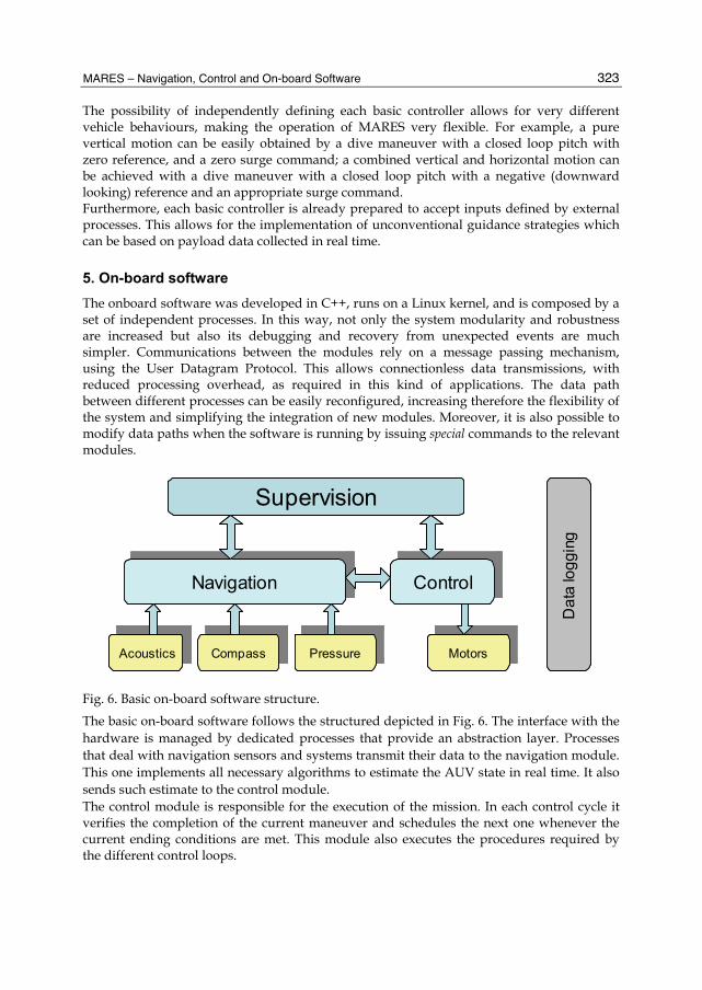
5. On-board software The onboard software was developed in C++, runs on a Linux kernel, and is composed by a set of independent processes. In this way, not only the system modularity and robustness are increased but also its debugging and recovery from unexpected events are much simpler. Communications between the modules rely on a message passing mechanism, using the User Datagram Protocol. This allows connectionless data transmissions, with reduced processing overhead, as required in this kind of applications. The data path between different processes can be easily reconfigured, increasing therefore the flexibility of the system and simplifying the integration of new modules. Moreover, it is also possible to modify data paths when the software is running by issuing special commands to the relevant modules.
AcousticsAcoustics CompassCompass PressurePressure MotorsMotors
NavigationNavigation ControlControl
Supervision
Dat
a lo
ggin
g
AcousticsAcoustics CompassCompass PressurePressure MotorsMotors
NavigationNavigation ControlControl
Supervision
Dat
a lo
ggin
g
Fig. 6. Basic on-board software structure.
The basic on-board software follows the structured depicted in Fig. 6. The interface with the hardware is managed by dedicated processes that provide an abstraction layer. Processes that deal with navigation sensors and systems transmit their data to the navigation module. This one implements all necessary algorithms to estimate the AUV state in real time. It also sends such estimate to the control module. The control module is responsible for the execution of the mission. In each control cycle it verifies the completion of the current maneuver and schedules the next one whenever the current ending conditions are met. This module also executes the procedures required by the different control loops.

Underwater Vehicles
324
A supervision module continuously monitors the behaviour of the vehicle and aborts the autonomous operation if safety margins are exceeded or unexpected events occur. This module can also be used to configure the whole software of the vehicle. For that purpose, it establishes a communication link with a shore control station whenever the vehicle is at the surface. A black box data logging system registers all information related to the vehicle operation on the flash disk. The information includes raw data from the navigation sensors and systems, health monitoring data, processed navigation data and control data. This black box system is also prepared to register payload data. Payload sensors and systems are typically controlled by additional dedicated modules. In general, these modules interact with the supervision module, for configuration and communication with the control station, and also with the data logger. Additional modules implementing sensor based control strategies or other advanced features are easily integrated with the basic software structure. Besides programming and installing the new module, it is only necessary to redefine data paths, assuring that required sensor data is also sent to the new module, and that the new module sends its output data to the control module. The operation of such new module is then configured in the mission plan.
6. Conclusions The first MARES water tests were conducted in a local pool in late 2006. Those tests served to validate the integrity of the system, adjust buoyancy and trim, and test simple maneuvers. During the first semester of 2007 a set of tests took place in a reservoir in the Douro river, with a maximum depth of 20 meters and about 200 meters wide. These tests allowed the fine tuning of motion control parameters as well as the final adjustments on the acoustic navigation system.
Fig. 7. Salinity map close to the sewage outfall diffuser.

MARES – Navigation, Control and On-board Software
325
MARES was first demonstrated at sea in November of 2007. This demonstration mission took place in the neighbourhood of a sewage outfall located 2 km off the Portuguese coast at Foz do Arelho. MARES was equipped with a Seabird Fastcat 49 CTD and collected 16 samples/second of CTD data for about one hour. Upon vehicle recovery, CTD data was analyzed to infer the location of the sewage plume in the vicinity of the diffuser. Fig. 7 shows a salinity map produced from CTD data, and although the salinity signature was very weak, it was also very consistent. This demonstrated the potential for detecting minute anomalies with the onboard CTD, which was the main objective for this mission at sea. The success of the demonstration mission at sea proved that the initial requirements and the design decisions contributed to the development of an operational vehicle that can be effectively used in real application scenarios. One of the major advantages of the MARES AUV, when compared with other AUVs of similar size, is the ability to independently control the motion in the vertical and in the horizontal planes. This allows for some new primitives of motion, such as commanding the vehicle to be completely motionless in the water column (for example, waiting for some triggering event), or diving and emerging vertically, which greatly simplifies its launching and recovery.
7. References Crowell, J. (2006), Small AUV for Hydrographic Applications, Proc. MTS/IEEE Oceans’06,
Boston, USA, Sept. 2006 Cruz, N.; Madureira, L., Matos, A.; Pereira, F. (2001), A Versatile Acoustic Beacon for
Navigation and Remote Tracking of Multiple Underwater Vehicles, Proc. MTS/IEEE Oceans’01, Honolulu, HI, USA, Nov. 2001
Cruz, N.; Matos, A. (2008), The MARES AUV – A Modular Autonomous Robot for Environment Sampling, Proc. MTS/IEEE Oceans’08 Quebec, Quebec, Canada, Sept. 2008
Fossen, T. (1994). Guidance and Control of Ocean Vehicles, John Wiley & Sons Ltd., ISBN 0471941131
Gelb, A. (1974). Applied Optimal Estimation, MIT Press, ISBN 0471941131 Griffiths, G. (2003), Technology and Applications of Autonomous Underwater Vehicles, Taylor
and Francis, ISBN 0415301548 Healey, A.; Lienard, D. (1993), Multivariable sliding mode control for autonomous diving
and steering of unmanned underwater vehicles, IEEE Jornal of Oceanic Engineering, vol. 18, no. 3, July 1993
Matos, A.; Cruz, N.; Pereira, F. ( 2003), Post Mission Trajectory Smoothing for the Isurus AUV, Proc. MTS/IEEE Oceans’03, San Diego, CA, USA, Sept. 2003
Matos, A.; Cruz, N.; Pereira, F. (1999), Development and Implementation of a Low-Cost LBL Navigation System for an AUV, Proc. MTS/IEEE Oceans’99, Seattle, WA, USA, Sept. 1999
Vaganay, J.; Leonard, J.; Bellingham, J. (2006), Outlier Rejection for Autonomous Acoustic Navigation, Proc. IEEE Int. Conf. on Robotics and Automation, Minneapolis, MN, USA, April 1996

Underwater Vehicles
326
von Alt, C.; Allen, B.; Austin, T.; Stokey, R. (1994), Remote Environmental Measuring Units, Proc. IEEE Symp. AUV Techn. AUV’94, Cambridge, MA, USA, July 1994