Manual of Design Standards for City Streets, Stormwater ...
100
City of Longwood Manual of Standards for City Streets, Stormwater Systems and Subdivisions
-
Upload
khangminh22 -
Category
Documents
-
view
0 -
download
0
Transcript of Manual of Design Standards for City Streets, Stormwater ...

City of Longwood Manual of Standards for City Streets, Stormwater Systems and Subdivisions

CITY OF LONGWOOD
Department of Public Works Streets/Fleet Division
MANUAL OF DESIGN STANDARDS
For
CITY STREETS, STORMWATER SYSTEMS AND SUBDIVISIONS

ORDINANCE NO. 01-1597
AN ORDINANCE ADOPTING THE CITY OF LONGWOOD, FLORIDA, MANUAL OF DESIGN STANDARDS FOR CITY STREETS, STORMWATER SYSTEMS AND SUBDIVISIONS; PROVIDING FOR SEVERABILITY; PROVIDING FOR REPEAL OF CONFLICTING ORDINANCES; AND EFFECTIVE DATE.
WHEREAS, cities have home rule authority; and
WHEREAS, cities can adopt certain regulations as part of their home rule authority; and
WHEREAS, the City of Longwood has determined that the adoption of a Manual of Design Standards for City Streets, Stormwater Systems and Subdivisions is in the best interest of the City.
NOW, THEREFORE, BE IT ORDAINED BY THE CITY COMMISSION OF THE CITY OF LONGWOOD, FLORIDA THAT:
SECTION 1: The attached document entitled “City of Longwood Manual of Design Standards for City Streets, Stormwater Systems and Subdivisions” is hereby made part of this ordinance and adopted by reference.
SECTION 2: The Manual of Design Standards shall apply to all development activity within the City.
SECTION 3: Severability Clause: Should any provision or section of this ordinance or the Manual of Design Standards adopted by reference and attached to this ordinance be held by a court of competent jurisdiction to be unconstitutional and invalid, such decision shall not affect the validity of this ordinance or the Manual of Design Standards as a whole, or any part thereof other than the part so declared to be unconstitutional or invalid.
SECTION 4: All other ordinances or parts of ordinances in conflict with this ordinance or the Manual of Design Standards adopted by reference be hereby repealed.
SECTION 5: This ordinance shall take effect immediately upon its passage and adoption.

TABLE OF CONTENTS
CHAPTER NO. TITLE PAGE NO.
1 Title and Intent 1
5 Paving and Drainage - General
Telecommunications Service Carriers, and Cable TV or Other Signal Installations
Telephone Service Corporations
2 General Provisions 2 - 11
3 Definitions and Standards 12 - 15
4 Permits, Fees and Bonds 16 - 18
Requirements 19 - 31
6 Roads and Streets Technical Requirements 32 - 48
7 Stormwater Technical Requirements 49 - 60
8 Subdivision Planning 61 - 63
9 Installations for Inter-Exchange 64 - 67
10 Installations By or For Local-Exchange 68 - 71
11 Installation of Wireless Facilities 72 - 73
12 Electric Power Installations 74 - 77
13 Natural Gas Installations 78 - 81
14 Construction Standards and Details Index 82

CHAPTER 1
TITLE AND INTENT
1. TITLE
This document shall be known as "Design Standards for City Streets, Stormwater Systems and Subdivisions", and may be referred to as the "Public Works Manual", as is done hereinafter.
The right-of-ways under the City of Longwood jurisdiction are all public right-of-ways within the incorporated areas of Seminole County, with the exception of those designated as state roads under the Functional Classification system.
2. INTENT
2.1 The intent of this Public Works Manual is to provide for the safe and orderly use and development of the public right-of-ways under the City of Longwood jurisdiction, to the end that the needs and interests of the public are served as fully and efficiently as possible. The regulations embodied herein have been made as broad as possible to serve as standards of quality to maintain the necessary uniformity in the utilization of the public traffic corridors. The City Administrator shall make interpretation of all questions concerning the intent of these regulations.
2.2 Any permit issued prior to the effective date of this Public Works Manual shall be valid on the terms under which it was issued, except that such permit shall be subject to the provisions of Chapter 4, Section 2 of this document.
3. APPLICATION TO EXISTING FACILITIES
3.1 With the exception of conditions described in Section 3.2 below, the provisions of this Public Works Manual do not apply to existing facilities in the public rights-of-way, but do apply to any alteration, extension or maintenance performed upon them from the effective date of these regulations, forward.
3.2 Where roads are being constructed or reconstructed to City standards, existing utilities within the right-of-way which conflict with the proposed construction or are inconsistent with current published or adopted standards may have to be modified or relocated to meet the new requirements pursuant to Florida statutes. These changes, if required, shall be made in accordance with the latest adopted version of this Public Works Manual.
1
CHAPTER 2
GENERAL PROVISIONS
1. PERMITS REQUIRED
1.1 A permit is required for all construction in public right-of-ways under the City of Longwood jurisdiction. Such permits shall only be issued from the Department of Public Works, by authority of the City Administrator, in accordance with the City of Longwood Administrative Code. This is not intended to preclude other permits and approvals that may be required by other agencies for other aspects of the work.
1.2 No Construction Before Permit
Except as provided hereinafter, no construction shall be started until a permit for the proposed installation has been granted by the Department of Public Works. Violation is a misdemeanor, punishable as provided by law.
1.2.1 Minor construction or maintenance work, such as installation of water meters (up to 2"), cable splice pits (not in or within two feet of a roadway) street light or traffic signal maintenance, or similar types of work may be done without permit or prior notice to the Department of Public Works. This is not to be construed as including cable replacement or any other type of facility upgrading or rehabilitation involving excavation, except for splice pits as mentioned above.
1.2.2 For work inside of existing manholes within the right-of-way, permission shall be obtained from the Department of Public Works.
1.3 Emergency Work
None of the above permit procedures shall apply to emergency repair work in public right-of-ways. Emergency repair work is defined, for the purposes of this document, as that which must be done immediately upon discovery, in order to safeguard the public from immediate danger to life or limb, to safeguard public health or welfare or to restore interrupted utility services. In the event of an emergency as defined above, repair work may be started without a permit upon verbal notification being given to the Department of Public Works. If the Department of Public Works offices are closed, then notification must be given as early as possible on the next regular work day. After the emergency repair is completed and the right-of-way is restored, a record drawing must be submitted to the Department of Public Works, unless
2

2.
2.1
2.2
2.3
GENERAL REQUIREMENTS
otherwise provided hereinafter, within ten working days. Work that can be scheduled ahead of time will not be considered emergency work.
Availability of Approved Plans and Permit
A set of plans for the project, bearing the Department of Public Work's approval stamp must be located on the job-site whenever work is in progress. When applicable, a Department of Public Works right of way permit must also be available at the site when work is in progress.
Ownership of Facilities
All facilities within public right-of-way must be owned and maintained by a public service utility or franchisee or by a political entity competent to function within the State of Florida, and shall remain the liability of the last operating entity until removed. This section shall not apply to facilities required to be left in place by the Department or Public Works.
Underground Facilities
Underground facilities in public right-of-ways, to the extent practicable, shall be installed within a designated area for public utilities adjacent to the right-of- way line, as shown in Chapter 14 of this document, City of Longwood Construction Standards and Details, Detail D1. An area of 10-feet width, minimum, shall be reserved for the use of public service utilities or franchisees. Where existing right-of-ways or other limitations render this designated area
within the right-of-way insufficient to accommodate all required facilities, a 10-feet easement adjacent to and outside the public right- of-way, shall be dedicated for this purpose.
All underground and in-ground facilities in public right-of-ways shall be designed and installed so as to safely sustain any vehicular loads that might be placed upon them.
2.3.1 Prior to placing any underground facility in the public right-of-way, unless otherwise approved by the Department of Public Works, the permittee shall remove all muck and other deleterious material to a point not less than four feet below, and not less than four feet on either side of the facility's intended location. If so doing would endanger an existing facility, contractor shall de-muck only that area which can be done without endangerment.
2.3.2 The requirements of Section 2.3.1., above, shall not be mandatory for direct burial cables or conduits for cables, but any cable or conduits for
3
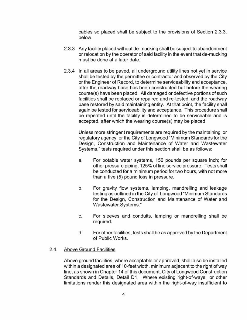
cables so placed shall be subject to the provisions of Section 2.3.3. below.
2.3.3 Any facility placed without de-mucking shall be subject to abandonment or relocation by the operator of said facility in the event that de-mucking must be done at a later date.
2.3.4 In all areas to be paved, all underground utility lines not yet in service shall be tested by the permittee or contractor and observed by the City or the Engineer of Record, to determine serviceability and acceptance, after the roadway base has been constructed but before the wearing course(s) have been placed. All damaged or defective portions of such facilities shall be replaced or repaired and re-tested, and the roadway base restored by said maintaining entity. At that point, the facility shall again be tested for serviceability and acceptance. This procedure shall be repeated until the facility is determined to be serviceable and is accepted, after which the wearing course(s) may be placed.
Unless more stringent requirements are required by the maintaining or regulatory agency, or the City of Longwood “Minimum Standards for the Design, Construction and Maintenance of Water and Wastewater Systems,” tests required under this section shall be as follows:
a. For potable water systems, 150 pounds per square inch; for other pressure piping, 125% of line service pressure. Tests shall be conducted for a minimum period for two hours, with not more than a five (5) pound loss in pressure.
b. For gravity flow systems, lamping, mandrelling and leakage testing as outlined in the City of Longwood “Minimum Standards for the Design, Construction and Maintenance of Water and Wastewater Systems.”
c. For sleeves and conduits, lamping or mandrelling shall be required.
d. For other facilities, tests shall be as approved by the Department of Public Works.
2.4. Above Ground Facilities
Above ground facilities, where acceptable or approved, shall also be installed within a designated area of 10-feet width, minimum adjacent to the right of way line, as shown in Chapter 14 of this document, City of Longwood Construction Standards and Details, Detail D1. Where existing right-of-ways or other limitations render this designated area within the right-of-way insufficient to
4

accommodate all required facilities, a 10-feet easement adjacent to and outside the public right-of-way, shall be dedicated for this purpose.
2.5 Utilities Crossings Under Existing Pavements
All underground utilities crossings of paved roads shall be made by "jack and bore,” “flow moling,” or directional drilling, unless an alternate method is approved by the Department of Public Works. Proposed open cuts shall be shown on the drawings submitted for approval. When a pipe or conduit is driven through the earth under pavement, driving shall be done in such a manner as will leave no voids in the underlying earth.
2.5.1 Extraction of pipe or conduit from beneath any roadway, generally, is prohibited. In extreme situations, where pipe must be removed, the roadway must be trenched and later restored in accordance with all applicable provisions of this Public Works Manual.
2.6 Notice Required
Forty-eight (48) hours minimum notice must be given to the Department of Public Works prior to the start of construction, and when scheduling any required tests and/or inspections.
2.7 Inspections, Tests and Certifications
All inspections and tests necessary to insure construction in conformity with the plans and specifications as approved by the Department of Public Works, shall be made by or under the direct supervision of the Engineer of Record or his representative, (other engineer registered and having a current and valid license, in the appropriate discipline, with the State of Florida.)
The Engineer of Record or his representative shall carefully observe and/or inspect all portions of the permitted installation sufficiently to determine that the contractor has substantially complied with all approved plans and specifications related thereto, and the Engineer of Record shall so certify to the City of Longwood at the completion of the work. Subsequent to the Engineer of Record certification:
2.7.1 Signs, pavement markings and signalization will be reviewed and shall be acceptable to the Department of Public Works.
2.7.2 Inspection of street lighting shall be performed by the maintaining agency.
2.8 Supervision of Construction
5

The permittee shall keep sufficient competent supervision on the site while work is in progress to ensure that the work is being performed properly and in a safe and orderly manner.
2.9 Performance of Tests
No labor, material or equipment required for testing of facilities shall be furnished by the Department of Public Works, except as noted hereinafter. Tests shall be performed by individuals or organizations qualified and appropriately certified, and shall be performed in the presence of the Engineer of Record, or designated representative, and a Department of Public Works representative. If the Department of Public Works does not witness a properly scheduled test, the certification of the Engineer of Record will be accepted.
2.10 Reports
All reports relating to construction progress, tests or other matters which may be required by the Department of Public Works, the Public Utilities Division, the Seminole County Public Health Unit or the Engineer of Record shall be provided to the Department of Public Works without charge.
2.11 Interruption and Restoration of Services
Adequate provision shall be made for the safe, continuous operation of any utilities, drainage facilities or water courses encountered during construction, unless other approved arrangements have been made. The operators of all such services and all structures altered or damaged during construction shall be notified immediately, and all such services and structures shall be satisfactorily restored upon completion of work.
2.12 Disposal of Water from Excavations
Water from excavations resulting from de-watering and pumping operations, or as otherwise encountered, shall be disposed of in a manner which will cause no health hazard, flooding or nuisance to the surrounding waters, or violate any environmental ordinances or requirements. The method of handling and disposing of such water shall be in accordance with applicable regulations of all agencies having jurisdiction. Groundwater shall be maintained at a level of two feet below the bottom of all excavations until backfilling is complete.
2.13 Maintenance of Traffic
When working in public right-of-ways, a maintenance of traffic plan shall be developed in accordance with the following standards:
6

Florida Department of Transportation Manual of Uniform Minimum Standards For Design, Construction and Maintenance of Streets and Highways. (Green Book).
Florida Department Of Transportation Standard Specifications for Road and Bridge Construction.
Florida Department of Transportation Roadway and Traffic Design Standards
US Department of Transportation, Federal Highway Administration, Manual On Uniform Traffic Control Devices for Streets and Highways
Strict adherence shall be maintained throughout the construction period. Temporary measures must be taken, where necessary, to provide a minimum of one lane of traffic in each direction on each affected road at all times, unless specific permission is obtained from the City Administrator to depart from this requirement. Where such departure is approved, the requesting individual or organization shall notify police, fire and emergency vehicles, the school district and U.S. Mail Service of the location and time of all street closures. Otherwise, access to each home and place of business or assembly abutting the affected right-of-way shall be maintained.
The right-of-way must be maintained in a safe condition, suitable for driving until the permitted work is complete and the right-of-way is restored and accepted for maintenance by the Department of Public Works.
The provisions of this section shall be in effect under all weather conditions, twenty four hours per day, every day, from the commencement of work until final acceptance by the Department of Public Works, except in time of emergency, when the provisions of Section 1.3 of this chapter shall apply.
2.14 Job Site Safety
All permitted work in right-of-ways must be done in strict accordance with the provisions of the Occupational Safety and Health Administration (OSHA) regulations, and all other applicable codes.
2.15 Removal of Pavement, Driveways, Sidewalks, Curbs and Gutters
Edges of permanent pavement shall be pre-cut straight, clean and square beyond any damaged base area, including well point locations. Utility cuts in existing pavements shall be restored as indicated elsewhere in these standards. When the removal of sidewalks, curbs or gutters is necessary for construction, they shall be removed in full sections or a minimum of five feet in length, and all broken edges cut smooth by use of a suitable power saw or other appropriate means.
7

2.16 Disposition of Excavated Materials
Broken pavement and other debris, shall be removed from the site as soon as practical, unless otherwise directed by the Department of Public Works. Excavated materials shall not be stockpiled in the right-of-way during construction without specific approval of the Department of Public Works. All excess materials shall be removed from the work site and disposed of legally by the permittee at his own expense.
2.17 Sheeting, Bracing and Shoring
Sheeting, bracing and shoring shall be used as required to support the sides of the excavation and to prevent any movements which can in any way alter the grade or injure the facility being installed, diminish the width of excavation or otherwise injure or delay the work or endanger personnel, adjacent pavements or other structures. Safety procedures shall be followed and adequate protection shall be furnished to all personnel as required by OSHA and other appropriate health and safety standards. All sheeting or bracing which is not to be left in place shall be cut off at a level of one foot above the top of the installed facility and removed in a manner that will not endanger the work, personnel or adjacent structures.
2.18 Traffic and Utility Controls
Excavation for pipe, structures or cable laying operations shall be conducted in a manner that will cause the least interruption to traffic and existing utilities. To the extent possible, fire hydrants, valve boxes, fire and police call boxes and other utility controls shall be left unobstructed and accessible during the construction period. When such obstruction is unavoidable, it must be held to the minimum, and the affected parties given sufficient notice to allow other provisions to be made.
2.19 Backfill, Embankment and Compaction
2.19.1 Earth Materials. Earth materials for backfill and embankment shall be clean earth fill comprised of sand, sand and clay, gravel crushed rock or other materials from Groups A-1, A-2 or A-3, AASHTO classification, and shall be free from organic matter and vegetation, debris, large clods of earth or stones, and shall be acceptable to the Department of Public Works.
2.19.2 Flowable Fill. Where approved, or required by, the Department of Public Works, ready-mixed flowable fill consisting of portland cement, aggregates, water and mineral admixtures may be used for beddings, encasements for pipes and for general backfill applications for trenches,
8

as an alternate to compacted earth fill. Materials and placement shall comply with Section 121 of FDOT Standard Specifications for Road and Bridge Construction, latest edition. Design information and information on materials shall be provided to the Department of Public Works.
2.19.3 Crushed Concrete. Where approved by the Department of Public Works, recycled crushed concrete may be used as an alternate material to granular material for road base in trench crossings. Prior to use, gradation and Proctor Test data shall be submitted and approved by the Engineer of Record and the Department of Public Works. Gradation of crushed concrete materials shall comply with the specifications for granular materials. Gradation analyses shall be taken at intervals determined by the Engineer of Record, and approved by the Department of Public Works, or if changing the source of the material, to evaluate the uniformity of materials. Compaction requirements shall be the same as required for granular materials.
2.19.4 Roadways, Driveways, Sidewalks, Curbs and Gutters. Backfill shall be placed evenly and carefully around and over the pipe in six (6) inch layers, maximum, and each layer shall be thoroughly compacted, up to one (1) foot above crown of the pipe. From a point one (1) foot above the top of the pipe, fill shall be placed in layers not to exceed eight (8) inches loose thickness and compacted by mechanical compaction equipment to 98% of the maximum density at optimum moisture content, as determined by AASHTO T-180/ASTM D-1557 (Modified Proctor), and tested, before placing succeeding layers. Density tests shall be taken in each lane and shoulders of roadways at intervals of 500 feet or less. Fill in swale areas outside pavement and shoulders, and unpaved ditches shall not be compacted by mechanical means.
2.19.5 Trenches. In trenches, except those covered in Section 2.19.6. or where flowable fill is used, backfill shall be placed evenly and carefully around and over the pipe in six (6) inch layers, maximum, and each layer shall be thoroughly compacted, up to one (1) foot above crown of the pipe. Compaction of the remaining trench shall depend upon the location of the trench. Under roadways, driveways, sidewalks, curbs and gutters, up to the pavement base or foundation the trench shall be back-filled in layers not exceeding eight (8) inches, loose measure, with each layer being compacted to 98% as determined by AASHTO T-180/ASTM D-1557 and tested at intervals of 100 feet maximum before placing succeeding layers. Trenches in swale areas shall be compacted in eight (8) inch layers to 95% of maximum density, as measured by AASHTO T-180/ASTM D-1557. Trenches under unimproved areas shall be placed in layers not to exceed two (2) feet thickness and compacted to match the density of the surrounding soils.
9

2.19.6 Narrow Trenches. Narrow trenches, not greater than six (6) inches in width, containing not more than two, three (3) inch cables or one, four (4) inch pipe or conduit may be backfilled with clean sand to a point two (2) inches above the cable or conduit. The remainder of the trench shall be filled to a point three (3) inches below the finished roadway surface with a l:10 mixture of portland cement and sand, placed wet and allowed to set overnight. The top three inches of the trench may be filled with sand when the concrete is wet. The sand shall be removed on the following day and the permanent asphalt patch placed and rolled in.
2.19.7 Structures. Backfill and embankments under structures other than those listed in Section 2.19.4 above shall be placed in six (6) inch layers and compacted to a minimum of 98% of the maximum density as determined by AASHTO T-180/ASTM D-1557. Density tests shall be taken every twelve (12) inches.
2.19.8 Unimproved Areas. Backfill or embankment in areas which are unimproved, and are intended to remain unimproved, shall be placed in layers not to exceed two (2) feet thickness and compacted to match the density of the surrounding soils.
2.20 Detection Aids
After non-metallic utilities have been installed, and during backfilling operations, approved electro-magnetic location devices or metallic tape, as required by the City's "Manual of Standards for Design, Construction and Maintenance for Water and Sewage Systems", shall be placed over the utility, at a depth of 12-inches below final grade. A metallic cable or pull-wire installed within the conduit at time of construction or as otherwise approved, shall satisfy this requirement.
2.21 Restoration of Right-of-Way
2.21.1The entire work area utilized for the performance of any permitted work shall be restored by the permittee to the condition that existed before work began except as required by the nature of the permitted work.
2.21.2 Paved sections shall conform in type, shape, elevation and texture with adjacent paved areas and shall be of at least equal quality. Design mixes for flexible pavements shall be subject to approval by the Department of Public Works. All damaged or undermined areas of existing pavement, not previously removed, shall be removed and restored in the specified manner. Where pavement is removed for installation, maintenance or removal of any underground facility, restoration shall be in accordance with applicable requirements of this
10

Public Works Manual. Equipment shall not travel over loose rock fragments or other hard material lying on sections of pavement which are not to be removed.
2.21.3 Swale areas, medians, sidewalks, driveways, etc., shall be restored in kind to a condition equal to or better than that which was disturbed.
2.21.4 All benchmarks and permanent reference survey markers disturbed during the course of construction shall be replaced at an equal or better level of precision, at the permittee's expense, by a professional land surveyor registered and properly licensed by the State of Florida.
2.22 Record Drawings
Upon completion of construction and prior to final inspection or commencement of any bonded maintenance period, the Engineer of Record shall furnish to the City of Longwood Department of Public Works, two (2) sets of record drawings certified in conformity with all applicable Florida statutes.
2.23 Abandoned Facilities
All exposed facilities and such underground facilities as may be designated by the Department of Public Works that are abandoned within public right-of-ways shall be removed by the owner of the facility unless other provisions are approved by the Department of Public Works. Any abandoned facility allowed to remain in the right-of-way shall continue to be the responsibility of the owner or operator by whom last used. Such owner or operator shall be liable for all costs arising from the presence of the abandoned facility in the right-of-way. This section does not apply to facilities required to remain in place by the Department of Public Works.
2.24 Review or Revision of City Standards
Any request for review or revision of these standards shall be made to the City Administrator in writing, stating the item to be considered and setting forth the objections and suggestions for revision. The Administrator shall respond in writing as soon as possible thereafter, but in any event, within 60 days after receipt of such request.
11

CHAPTER 3
DEFINITIONS AND STANDARDS
1. DEFINITIONS
1.1 Whenever the following terms, or pronouns in place of them, appear in these standards, the intent and meaning shall be construed as follows:
Administrator, or City Administrator
The City Administrator of the City of Longwood, or his designated representative
Commission
The City Commission of Longwood, Florida.
Contractor
The duly qualified person, firm or corporation responsible to the permittee for the construction of the permitted work.
City
City of Longwood, Florida, a political subdivision of the State of Florida within which these standards apply, and in whose area of jurisdiction the work is to be performed.
City Inspector
An authorized representative of the Department of Public Works, or other agency of the City of Longwood.
Developer
The Owner, agent or employee engaged in the process of development.
Engineer
Engineer of Record (or his representative), registered and having a current and valid license under Chapter 471, Florida Statutes, who will certify the engineering aspects of a project to the Department of Public Works.
12

Resident Project Representative
An authorized representative of the Engineer of Record.
Permittee
Any duly authorized individual, organization, or employee who is a qualified applicant to whom a permit is issued for work within public right-of-ways and who is responsible for compliance of all permit conditions and this Public Works Manual.
Public Works Manual
This document, titled "Manual of Standards for Design, Construction and Maintenance for City Streets". This manual establishes standards applicable to public right-of-ways under the City of Longwood jurisdiction.
Qualified Applicant
Any current County franchisee or utility regulated by the Florida Public Service Commission.
Any person, firm or corporation currently licensed to work in the County and certified by the County Central Examining Board for Engineered Construction Trades or by the State Construction Industry Licensing Board or qualified by a "currently certified officer of the firm or corporation to perform the class(es) of work in the public right-of-ways for which a permit is being sought.
Any developer, as defined above, on whose property improvements are to be constructed for dedication to the Public.
Any political subdivision of the State of Florida.
Right-of-Way
Land dedicated, deeded, used, or to be used for a street, alley, walkway, boulevard, drainage facility, access for ingress or egress, or other purpose by the public, certain designated individuals, or governing bodies. [Florida Statute, Chapter 177, Section 177.031 (16)]. Easements for roads and related purposes shall be considered as right-of-way.
Proposed Right-of-Way
Land, usually in a subdivision, to be developed prior to dedications and, upon completion, to be dedicated to the Public, pursuant to an agreement between the developer and the City.
13

2.
2.1
2.2
2.3
2.4
Sub-Contractor
A person, firm or corporation duly qualified, having a contract with the contractor.
Traffic Control Manual
The State of Florida, Manual on Traffic Control and Safe Practices For Street and Highway Construction, Maintenance and Utility Operations.
Green Book
The State of Florida, Department of Transportation "Minimum Standards For Design, Construction and Maintenance of Streets & Highways".
Utility
For purposes of this document, any water, sewer, gas, drainage, sprinkler or culvert pipe and any electric power, telephone, signal, communication, or cable T.V. conduit or cable, or operator thereof, serving the public, shall be considered a Utility.
Utility Inspector
An authorized field representative of any utility serving the area where work is performed.
The standards included in this document are intended to supplement, not supersede the requirements otherwise set forth herein, and in every case, the latest revision shall apply.
In addition to the provisions of the referenced standards stated to be mandatory, all recommendations, in the referenced standards shall also be considered mandatory.
The referenced standards shall apply only to those portions of this document in which the referenced standards appear. Where the referenced standards appear to regulate other topics specifically covered by this document, such regulations shall not apply.
Only those portions of the referenced standards shall apply, that are directly related to the purpose(s) of the sub-section(s) of this document in which they
14
STANDARDS

are referenced. Where portions of referenced documents concern other, extraneous matters, such portions shall not be mandatory.
2.5 Where the method of installation of materials or equipment is not specified in this document, the installation shall be in accordance with the manufacturer’s technical recommendations or specifications.
3. APPROVALS
Where any term such as "approved", "or equal", "accepted", or "permitted" appears in this document, it shall be construed to mean "by" or "in the judgment of" the "Department of Public Works", unless specifically noted otherwise.
15

1.
1.1
1.2
1.3
PROCEDURE FOR OBTAINING A PERMIT
CHAPTER 4
PERMITS, FEES AND BONDS
Construction Drawing Review
A minimum of six (6) complete sets of construction drawings for the proposed work, signed and sealed by an engineer (Engineer of Record), registered and having a current and valid license under Chapter 471, Florida Statutes, shall be submitted to the Department of Public Works for review and approval, unless otherwise specified hereinafter.
As soon as circumstances allow, normally within thirty (30) days, the Permittee or Engineer of Record will be advised, in writing, of the completeness of the construction drawings and what, if any, items should be revised. If necessary, one copy of each drawing noting all required revisions shall be returned to the applicant with an explanatory letter. One set of approved drawings will be returned to the Engineer of Record.
When the construction drawings are approved, application for a permit to construct may be made. Construction drawing approvals shall be void after one year unless a Department of Public Works permit to construct the approved facilities is in effect.
In the event that applicable standards, regulations or laws change, subsequent to construction drawing approval, but prior to permit issuance, revised plans must be submitted for approval under the new requirements.
Permits will be issued to qualified applicants only. Necessary application forms will be available at the Department of Public Works offices. Forms are to be completed, signed and submitted, together with appropriate fees and bonds. The application, when signed and dated by the issuing agent for the City, shall constitute the permit to construct, only after the applicant has also obtained approvals of all other agencies having jurisdiction, and provided copies of said approvals to the City. Issuance of the City permit will be withheld until copies of all other approvals are provided.
No permit will be issued for work in any right-of-way until the required fees have been paid, and all required Performance and Maintenance Bonds have been posted. Construction shall not commence within any right-of-way until permittee has obtained all necessary approvals and permits and has provided copies of same to the Department of Public Works.
16

1.4 Plan approval is based upon the information contained on the approved construction plans and the permit application. Subsequent minor revisions may be indicated upon approved prints, but such changes must be signed and dated by representatives of the Engineer of Record and the Department of Public Works, prior to the contractor proceeding with the revision.
1.5 City plan approvals and permits notwithstanding, all installations in public right-of-ways shall be in accordance with requirements of FDOT. "Green Book".
2. PERMIT EXPIRATION
2.1 Permits will become invalid one year after construction plan approval if work has not begun on permitted project, unless an extension is granted by the City Administrator.
2.2 Permits will become invalid upon suspension of work in excess of 90 days on any permitted work, unless an extension has been granted by the City Administrator.
2.3 If permittee wishes to begin, continue, or resume work after permit expiration, a new permit must be obtained with all current conditions and regulations having to be met including new plan approval. A new permit fee will be charged for the uncompleted portion only.
2.4 Permits will expire upon completion of the permitted work and acceptance of the installation, including restoration of the right-of-way by the owner, operator, all regulatory agencies involved, and the Department of Public Works.
3. FEES AND BONDS
3.1 Plan review fees shall be as established by the City of Longwood Code of Ordinances.
3.2 The Construction Permit fee, Performance and Maintenance Bond and any other applicable charges, when required, shall be determined by the City Administrator. Fee and bond amounts shall be based upon rates and conditions as approved by the City Commission, and upon the work to be permitted including right-of-way restoration, as determined by the Department of Public Works.
3.3 Permit fees and other applicable fees and charges may be paid in the form of cash or check. Checks should be payable to the City of Longwood.
3.4 Performance and Maintenance Bonds may be posted in the form of cash, Certified Checks, Irrevocable Letters of Credit or Surety Bonds. Said bonds shall be irrevocable and shall indemnify the Longwood City Commission
17

against costs of restoring or maintaining the public right-of-way due to or arising from failure of the permittee to properly complete the work, to pay fully for labor, material or equipment supplied for the project, or for a failure in the right-of-way related to the permitted installation, for a period of one year after the permitted work is complete and accepted by the Department of Public Works. The Bond or Irrevocable Letter of Credit form must be acceptable to the City of Longwood
18

CHAPTER 5
PAVING AND DRAINAGE - GENERAL REQUIREMENTS
1. PERMITS
Permits for construction, modification or maintenance of roadways, sidewalks, drainage or related facilities shall be granted only after the following requirements have been met:
1.1 Paving and drainage plans must have been reviewed and be deemed complete by the Department of Public Works prior to approval.
1.2 All required permits have been obtained from the St. John’s River Water Management District, Florida Department of Environmental Protection, Florida Department of Transportation, U. S. Environmental Protection Agency, U.S. Corps of Engineers and any/all other agencies having permitting jurisdiction over the proposed work. Approval or acceptance by the City of Longwood of the proposed facilities does not imply acceptance of any other agency.
1.3 The provisions of Chapter 4 of this document.
2. FEES
2.1 Fees will be charged in accordance with the provisions of Chapter 4, Section 3.1.
2.2 No security shall be required for driveway connections to paved roadways
3. PLANS AND SPECIFICATIONS
3.1 All plans shall be submitted on white prints with blue or black lines. In addition to the proposed project they shall show all existing facilities as well as all other planned facilities in sufficient detail to permit assessment of the compatibility of the proposed work and the existing systems.
3.2 Plans must be submitted on 24" x 36" sheets, except that for small projects plans may be submitted on legal size paper, provided that scale requirements are met and only one sheet is required.
3.3 Any general area layout shall be prepared at a scale of 300 feet or less to the inch. Detailed plans shall be prepared at a scale of 20 feet or less to the inch. (40 feet or less for subdivisions). Design drawings for arterial and collector roads shall include both plans and profiles. Design drawings for local roads
19

need not include roadway profiles. When profiles are drawn, they shall be to the same horizontal scale as the plan.
3.4 The names and boundaries of all abutting subdivisions shall be shown, giving the plat book and page number of the recordation.
3.5 Areas not platted shall be shown as acreage, and the Section, Township and Range shall be noted.
3.6 Dimensions of right-of-ways widths shall be indicated.
3.7 All plans shall show suitable legends.
3.8 New pavement shall be indicated by notes and/or light shading.
3.9 Cross-sections and/or typical sections of proposed road and drainage construction, shall show dimensions, materials and purposes of all existing (to remain) facilities as well as all proposed facilities within the right-of-way.
3.10 The public roadways proposed in the plans shall be designed in accordance with the "Manual of Uniform Minimum Standards for Design, Construction and Maintenance for Streets and Highways, State of Florida, " unless otherwise approved by the City Administrator.
4. CONFLICT MANHOLES
All conflict manholes must have approval of the appropriate State or County reviewing agencies before being permitted by the Department of Public Works, and must be constructed as shown in the Construction Details. This shall apply to field changes as well as conflict structures proposed in the design of the project in question.
5. HOT BITUMINOUS MIXTURES
5.1 Weather Limitations
5.1.1 Limitations of Laying Operations: General: The mixture shall be spread only when the surface upon which it is to be laid has been previously prepared, is intact, firm and properly cured, and is dry. Unless otherwise approved by the Department of Public Works, no mixture shall be spread that cannot be finished and compacted during daylight hours.
5.1.2 Temperature: The mixture shall be spread only when the air temperature (the temperature in the shade away from artificial heat) is above 40 degrees F and is not dropping.
20

5.1.3 Wind: The mixture shall not be spread when the wind is blowing to such an extent that proper and adequate compaction cannot be maintained or when sand, dust, etc. are being deposited on the surface being paved, to the extent that the bond between layers will be diminished.
5.2 Preparation of Asphalt Cement: The asphalt cement shall be heated in advance of the mixing operations, to within a range of 270 degrees F to 350 degrees F. Heating within these limits shall be constant and wide fluctuations of temperature during the day's production will not be permitted.
5.3 Preparation of Aggregates
5.3.1 Stockpiles: Each aggregate component shall be placed in an individual stockpile, which shall be separated from the adjacent stockpiles, either by space or by a system of bulkheads. The intermingling of different materials in stockpiles shall be prevented at all times.
5.3.2 Prevention of segregation: In the event that the method used for stockpiling coarse aggregate results in segregation of the aggregate, stockpiles shall be built up in layers not higher than four feet, with each layer completely in place before the next is started. Stockpiles shall not be formed by depositing material in one place or by forming cones.
5.3.3 Blending of Aggregates: Blending or proportioning from railroad cars will not be permitted. All aggregates shall be stockpiled prior to blending or placing in the cold hoppers. All aggregates to be blended or proportioned shall be placed in separate bins at the hopper and proportioned by means of securely positioned calibrated gates or other approved devices.
5.3.4 Mineral Filler: If mineral filler is required in the mix it shall be fed or weighed-in separately from the other aggregates.
5.4 Preparation of Mixtures
5.4.1 Aggregates: The dried aggregates and mineral filler (if required), prepared in the manner previously described, and combined in batches to meet the job mix formula by weighing each separate bin size, shall be conveyed to the empty mixer.
5.4.2 Bitumen: The hot asphalt cement, accurately measured, shall be introduced into the mixer simultaneously with, or after, the hot aggregates. Mixing shall continue until the mixture is thoroughly uniform, with all particles fully coated.
5.4.3 Mixing Time: The mixing time shall begin when the measuring devices for both the asphalt and the aggregates indicate that all the material is
21
in the mixer, and shall continue until the material begins to leave the mixing unit. The mixing time will vary in relation to the nature of the aggregates and the capacity of the mixer, but shall in no case be less than 35 seconds.
5.4.4 Continuous Mixing: The dried aggregate and mineral filler (if required), prepared as specified and proportioned to meet the job mix formula by volumetric measurements, shall be introduced into the mixer in synchronization with the accurate feeding of the hot asphalt cement. The rate of flow of material to the pugmill shall be such that the maintained depth of the mix will not exceed the tips of the paddles when in the upright position. Mixing shall be sufficient to produce a thoroughly and uniformly coated mixture.
5.4.5 Drum Mixing: The aggregates and mineral filler (if required), prepared or specified and proportioned to meet the job mix formula, shall be introduced into the drum mixer with the accurate feeding of asphalt cement. The rate of flow of material to the drum shall be such that the manufacturer's mixing capacity shall not be exceeded. Mixing shall be sufficient to produce a thoroughly and uniformly coated mixture.
5.4.6 Mixing Temperature: The ingredients of the mix shall be heated and combined in such a manner as to produce a mixture which shall be at a temperature, when discharged from the pugmill or hot storage (surge) bin, within 25 degrees F of the design temperature, and within the temperature limits specified in Section 5.2.
5.4.7 Contractor's Responsibility for Mixture Requirements: The responsibility for producing a homogeneous mixture, free from excess moisture and with no segregated materials, and meeting all requirements of the specifications for the mixture, including compliance with the design limits, shall lie entirely with the Contractor. These requirements shall also apply to all mixes used from a hot storage or surge bin, both before and after storage. No mix shall be stored overnight.
5.5 Transportation of the Mixture: The mixture shall be transported in tight vehicles previously cleaned of all foreign material and each load shall be covered. The inside surface of the truck bodies shall be thinly coated with soapy water or an approved emulsion containing not over 5% oil, but no excess of either shall be used. Kerosene, gasoline or similar products shall not be used. After the truck bodies are coated and before any mixture is placed therein, they shall be raised so that all excess liquids will be drained out.
5.6 Coating Materials
22

5.6.1 Prime Coat: The material used for prime coat shall be cut-back asphalt, Asphalt Grade RC-70 or RC-250, meeting the requirements of AASHTO M81-751, Emulsified Asphalt Grades SS-1 or CSS-1, SS-1H or CSS-1H, diluted in equal proportion with water and meeting the requirements of AASHTO M140-7O, or other types and grades of bituminous material which may be called for in approved plans. The Contractor may select any of the specified bituminous materials for use, unless the approved plans indicate use of a specific material. Types and grades of bituminous material other than those specified above may be allowed if it can be shown that the alternate material will properly perform the function of prime coat material.
5.6.2 Tack Coat: The material used for tack coat shall be undiluted Emulsified Asphalt Grades RS-1 or RS-2, unless some other specific material is called for by the approved plans. RS-1 and RS-2 shall be heated to a temperature range of between 140 degrees F and 180 degrees F. RS-1 may be modified by the addition of up to 3% naphtha during the winter months to improve handling of the material.
5.6.3 Tack Coat Required: A tack coat, as specified in 5.6.2, will be required on the following surfaces:
a. Between hot bituminous base courses and surface courses. b. On primed bases which have become excessively dirty and
cannot be cleaned. c. In areas where the prime coat has cured to the extent that it has
lost bonding effect. d. On old pavements to be patched or leveled.
5.6.4 Tack Coat Optional: A tack coat will be required on the following surfaces only when so directed by the Engineer of Record:
a. Freshly primed bases. b. Surface treatment. c. Other surfaces shown on the approved plans.
5.7 Preparation of Application Surfaces
5.7.1 Cleaning: Prior to the laying of the mixture, the surface of the base of pavement to be covered shall be cleaned of all loose and deleterious material by the use of power brooms, supplemented by hand brooming as necessary.
5.7.2 Patching and Leveling Courses: Where a surface course is constructed on an existing pavement or old base which is irregular, and wherever so indicated in the approved plans, the existing surface shall be brought to
23

proper grade and cross section by the application of patching or leveling courses.
5.7.3 Application Over Surface Treatment: Where a surface course is to be placed over a newly constructed surface treatment, all loose material shall be swept from the paving area and disposed of by the Contractor.
5.7.4 Coating Surfaces of Contacting Structures: All structures which will be in actual contact with the asphalt mixture, with the exception of the vertical faces of existing pavements and curbs or curb and gutter, shall be provided with a uniform coating of asphalt cement to provide a closely bonded, watertight joint.
5.8 Placing Mixture
5.8.1 Requirements Applicable to All Types:
a. Alignment of Edges: All asphaltic concrete mixtures (including leveling courses), other than adjacent to curb and gutter or other true edges, shall be laid by the string line method, to assure obtaining an accurate, uniform alignment of the pavement edge.
b. Temperature of Spreading: The temperature of the mixture at the time of spreading shall be within 25 degrees F of the temperature set by the Engineer of Record, which temperature shall be between 270 degrees F and 350 degrees F, unless otherwise directed.
c. Rain and Surface Conditions: Any mixture caught in transit by sudden rain may be laid only at the Contractor's risk. Should such mixture prove unsatisfactory, it shall be removed and replaced with satisfactory mixture at the Contractor's expense. In no case shall the mixture be laid while rain is falling or when there is water on the surface to be covered.
d. Number of Crews Required: For each paving machine being operated, the Contractor will be required to use a separate crew, each crew operating as a full unit.
e. Checking Depth of Layer: The depth of each layer shall be checked at frequent intervals, not to exceed 25 feet. Any deviation from the required thickness, in excess of the allowable tolerance, shall be immediately corrected.
f. Hand spreading: In limited areas where the use of the spreader is impossible or impracticable, the mixture may be spread and finished by hand.
24

g. Straight-edging and Back-patching: straight-edging and back-patching shall be done after initial compaction has been obtained and while the material is still hot.
5.8.2 Requirements Applicable Only to Surface Courses
a. Spreading and Finishing: Upon arrival, the mixture shall be dumped into the approved mechanical spreader and immediately spread and struck-off to the full width required, and to such loose depth for each course that, when the work is completed, the required weight of mixture per square yard, or the specified thickness, will be obtained. An excess amount of mixture shall be carried ahead of the screed at all times. Hand raking shall be done behind the machine as required.
b. Thickness of Layers: Where a surface course is to be constructed to a thickness greater than two inches, it shall be constructed in approximately equal layers and no layer shall be more than two inches in thickness when compacted. Each layer shall be thoroughly compacted and shall conform to the requirements of these specifications before an additional layer is placed.
c. Laying Width: If necessary due to traffic requirements, the mixture shall be laid in strips in such manner as to provide for the passage of traffic. Where the road is closed to traffic, the mixture may be laid to the full width, by machines traveling in echelon.
d. Correcting Defects: Before any rolling is started the surface shall be checked, any irregularities adjusted, and all drippings, fat sandy accumulations from the screed, and fat spots from any source shall be removed and replaced with satisfactory material. No skin patching shall be done. When a depression is to be
corrected while the mixture is hot, the surface shall be well scarified before the addition of fresh mixture.
5.8.3 Requirements Applicable Only to Leveling Courses
a. Patching Depressions: Before any leveling course is spread, all depressions in the existing surface more than one inch deep shall be filled by spot patching with leveling course mixture and then thoroughly compacted.
b. Work Adjacent to Bridge Ends: On resurfacing projects where the roadway joins an existing bridge and where necessary to
25

insure that a bump will not be created by the overlay, before any surfacing is placed adjacent to the bridge, a portion of the existing pavement shall be bladed off, in order that a smooth transition between the new surfacing and the bridge end may be effected.
c. Spreading Leveling Courses: The leveling shall be placed by the use of a paving machine, in good condition and appropriate for the project to be undertaken. Other types of leveling devices may be used, subject to prior approval by the Engineer of Record, with the concurrence of the Department of Public Works.
d. Rate of Application: When the total amount of leveling course material to be applied exceeds 50 pounds per square yard, it shall be applied in separate courses, with the average spread not to exceed 50 lbs. per square yard. When Type S-III Asphaltic Concrete is used for leveling, the average spread for each leveling course shall not be less than 50 pounds per square, nor more than 75 pounds per square yard. Unless otherwise indicated the quantity shown in the plans for leveling represents an average for the entire job. The rate of application of leveling may be increased or decreased, as necessary, at locations designated by the Engineer of Record. Where widening construction is specified in connection with leveling, the Engineer of Record may require that approximately fifty percent of the leveling be placed prior to the widening operation.
e. Placing Leveling Over Existing Concrete Pavement: For leveling course to be applied over broken existing concrete pavement (with or without old asphaltic surface), the first course of the leveling shall be placed as soon after the cracking and reseating of the concrete as is practicable, but not later than two days after the cracking operations on any section. The remainder of the surfacing shall follow in the normal sequence of operations.
f. Removal of Excess Joint Material: Where leveling is placed over concrete pavement or concrete deck-slab bridges, all excess joint filler at the cracks and joints shall be removed flush with the existing concrete prior to placing the leveling course.
5.9 Compacting Mixture
5.9.1 Provisions Applicable to All Types:
26
a. Equipment and Sequence: For each paving or leveling train in operation, the Contractor shall furnish a separate set of rollers, with their operators. The rolling shall be done in the following sequence, with the equipment as shown, unless otherwise permitted by the Engineer of Record, with the concurrence of the Department of Public Works.
(1) Seal rolling, using tandem steel rollers weighing 5 to 12 tons, and following as close behind the spreaders as is possible without pick-up, undue displacement or blistering of the material.
(2) Rolling with self propelled pneumatic-tired rollers, following as close behind the seal rolling as the mix will permit. The roller shall cover every portion of the surface with at least five passes.
(3) Final rolling with the 5 to 12 ton tandem steel rollers, to be done after the seal rolling and pneumatic-tired rolling have been completed, but before the pavement temperature has dropped below 175 degrees F.
b. Compaction at Crossovers, Intersection, etc: When a separate paving machine is being used to pave the crossovers, the compaction of the crossovers may be done by one 5 to 10 ton tandem steel roller. If crossovers, intersections and acceleration and deceleration lanes are placed with the main run of paving, a traffic roller shall also be used in the compaction of these areas.
5.9.2 Rolling Procedures
The initial rolling shall be longitudinal. When the lane being placed is adjacent to a previously placed lane, the center joint shall be pinched or rolled, prior to the rolling of the rest of the lane.
After the rolling or pinching of the center joint, the rolling shall continue across the mat by overlapping each previous roller path by at least one-half the width of the roller wheel. The motion of the roller shall be slow enough to avoid displacement of the mixture, and any displacement shall be corrected at once by the use of rakes, and the addition of fresh mixture if required. Final rolling shall be continued until all roller marks are eliminated.
a. Speed of Rolling: Rolling with the self-propelled, pneumatic-tired rollers shall proceed at a speed of 6 to 10 miles per hour, and the area covered by each roller shall not be more than 4,000 square
27

yards per hour, except that for Type S Asphaltic Concrete, this maximum rate of coverage shall be 3,000 square yards per hour.
b. Number of Pneumatic tired Rollers Required: A sufficient number of self-propelled pneumatic-tired rollers shall be used to assure that the rolling of the surface for the required number of passes will not delay any other phase of the laying operation nor result in excessive cooling of the mixture before the rolling is complete. In the event that the rolling falls behind, the laying operation shall be discontinued until the rolling operations are sufficiently caught up.
c. Compaction of Areas Inaccessible to Rollers: Areas which are inaccessible to a roller (such as areas adjacent to curbs, headers, gutters, bridges, manholes, etc.,) shall be compacted by the use of hand tamps or other satisfactory means.
d. Rolling Patching and Leveling Courses: Self-propelled pneumatic-tired rollers shall be used for the rolling of all patching and leveling courses.
e. Correcting Defects: The rollers shall not be allowed to deposit gasoline, oil or grease onto the pavement, and any areas damaged by such deposits shall be removed and replaced as directed by the Engineer of Record. While rolling is in progress, the surface shall be tested continuously and all discrepancies corrected to comply with the surface requirements. All drippings, fat or lean areas and defective construction of any description shall be removed and replaced. Depressions which develop before the completion of the rolling, shall be remedied by loosening the mixture and adding new mixture to bring the depressions to a true surface. Should any depression remain after the final compaction has been obtained, the full depth of the mixture shall be removed and replaced with sufficient new mixture to form a true and even surface. All high spots, high joints and honeycomb shall be corrected as directed by the Engineer of Record. Any mixture remaining unbonded after rolling shall be removed and replaced. Any mixture which becomes loose or broken, mixed or coated with dirt or in any way defective, prior to laying the wearing course, shall be removed and replaced with fresh mixture, which shall be immediately compacted to conform with the surrounding area. Areas of defective surface may be repaired by the use of indirect heat. No method of repair involving open-flame heaters shall be used.
f. Provisions Applicable to Shoulder Pavement Only: Shoulder pavements wider than three feet shall be compacted by the use of equipment of the type required for other asphaltic concrete pavements. Compaction of asphaltic concrete three feet or less in
28

width, shall be done by the use of tandem steel rollers not exceeding 12 tons in weight. Other compaction in such restricted widths shall be by the use of any type of rubber-tired equipment the Contractor may elect to use, approved by the Engineer of Record, with the concurrence of the Department of Public Works.
5.9.3 Density Required for Asphaltic Concrete Pavement: After final compaction, the density shall be at least 96% of the laboratory compacted density of the paving mixture for that day's production.
5.10 Joints
5.10.1 Transverse Joints: Placing of the mixture shall be as continuous as possible and the roller shall not pass over the unprotected end of the freshly laid mixture except when the laying operation is to be discontinued long enough to permit the mixture to become chilled. When the laying operation is thus interrupted, a transverse joint shall be constructed by cutting back on the previous run to expose the full depth of the mat.
5.10.2 Longitudinal Joints: Where only a portion of the width of pavement is to be laid and opened to traffic, longitudinal joints shall be formed by rolling the exposed edge of the strip first laid. When the adjacent strip is constructed, the Engineer of Record may require the edge of the mixture in place to be trimmed back to expose an unsealed or granular vertical surface. Where the strip first laid is closed to traffic, the edge shall not be sealed but shall be left vertical and the adjacent strip placed against it without trimming.
5.10.3 General: When fresh mixture is laid against the exposed edges of joints (trimmed or formed as provided above), it shall be placed in close contact with the exposed edge so that an even, well-compacted joint will be produced after rolling.
5.11 Surface Requirements
5.11.1 Checking with Rolling Straightedge: The final surface course of all pavements will be required to be checked by the rolling straightedge, in accordance with the following provisions. As soon as the rolling has been completed and the surface has hardened sufficiently to be walked on, the entire surface shall be checked with a rolling straightedge, set to indicate any surface irregularities in excess of 3/16 inch. The rolling straightedge shall have an effective length of 15 feet and its design shall meet the approval of the Engineer of Record. The rolling straightedge and labor for its operation shall be supplied by the Contractor. The straightedge shall be applied in lines parallel to the centerline, at least twice for each pass of the spreader. Straight-edging
29

shall be extended across all joints. Any irregularities in excess of 3/16 inch shall be corrected by removing and replacing the defective sections or by overlaying with surface material, as directed by the Engineer of Record. Straight-edging of paved shoulders will not be required unless so directed by the Engineer of Record.
5.11.2 Manual Straightedge: A 15-foot manual straightedge shall be furnished by the Contractor and shall be available at all times on the work. The Contractor shall designate an employee whose duty it is to handle the straightedge in checking the compacted surfaces under the direction of the Engineer of Record, or if requested by a representative of the Department of Public Works.
5.11.3 Permissible Variations from True Surface: The finished surface shall not vary more than 3/16 inch from the straightedge applied parallel to the centerline of the pavement. Any surface irregularities exceeding such limits shall be corrected in accordance with the requirements.
5.11.4 Texture of Finished Surface: The finished surface shall be of uniform texture and compaction. The surface shall have no pulled, torn or loosened portions, and shall be free of sand streaks, sand spots or ripples. These requirements shall also apply to any areas where it is necessary to apply hand work.
5.11.5 Any areas in which the surface does not meet the above requirements for texture, sand streaks, ripples, pulled or loosened portions, or for uniformity of compaction; or does not meet the straight-edging requirements, shall be corrected at the Contractor's expense. Such corrections may be made either by replacing the surface course (to full depth) or by overlaying with the type of asphaltic concrete mixture being placed. Within the longitudinal limits where such defective areas occur, such corrections shall be made for the full width of the roadway and for longitudinal distances in both directions beyond such defective areas in accordance with the following:
(a) If the correction is made by replacing of the full thickness, it shall extend to at least 50 feet each side of the defective area.
(b) If the Contractor elects to effect the correction by overlaying, the overlay shall consist of at least 100 pounds of mixture per square yard, at the defective section and shall taper uniformly down from the full thickness of such weight, to zero thickness, feathered, at the end of a minimum length of 50 feet each side of the defective area.
(c) The transverse thickness at any section shall be such as to provide the design cross section.
30

5.12 Protection of Finished surface: Sections of newly compacted asphaltic concrete which are to be covered by additional courses shall be kept clean until the successive course is laid.
Upon completion of the finished pavement, no dumping of any material directly on the pavement will be permitted. When shoulders are constructed after completion of the final surface, blade graders operating adjacent to the pavement during shoulder construction shall have a two inch by eight inch (or larger) board (or other attachment providing essentially the same results) attached to their blades in such manner that it extends below the blade edge, in order to protect the pavement surface from damage by the grader blade. Vehicular traffic shall not be permitted on any pavement which has not set sufficiently to prevent rutting or other distortion.
5.13 Other Requirements: All requirements outlined above may be supplemented by, substituted for or modified by the Florida Department of Transportation "Standard Specifications for Road and Bridge Construction," latest edition, at the discretion of the Engineer of Record, with the concurrence of the City Administrator, acting through the Department of Public Works.
31

CHAPTER 6
ROADS AND STREETS - TECHNICAL REQUIREMENTS
1. STREETS AND ROADWAYS
1.1 Design Criteria
1.1.1 Design Standards
As a minimum, roads and/or streets and related facilities shall be designed in accordance with the latest editions of the "Manual of Minimum Standards for Design, Construction and Maintenance for Streets & Highways" (Green Book), “Flexible Pavement Design Manual", "Standard Specifications for Road and Bridge Construction," “Roadway and Traffic Design Standards” and the Utility Accommodation Guide, as published by the State of Florida Department of Transportation, except as modified herein.
1.2 Construction Criteria
Construction materials and methods shall meet the requirements of the latest edition of the Florida Department of Transportation "Standard Specifications for Road and Bridge Construction" and supplements, except as modified herein, and the provisions of Chapter 2 of this document.
1.2.l Temporary Facilities
Temporary facilities, unrelated to any ongoing construction in a right-of-way, and intended to provide an essential service for a period of time not to exceed one year, may be constructed in a right-of-way, contingent upon Department of Public Works approval of project plans and specifications, and issuance of a Department of Public Works Right-of-Way Permit. There will be no relaxation of safety requirements, but lighter duty construction will be allowed, where public interests will not suffer.
1.2.2 In cases where temporary facilities must be constructed to provide or maintain an essential feature around portions of a public right-of-way for public safety or convenience during construction, such temporary facility must be clearly drawn in sufficient detail on standard size drafting sheets, and submitted to the Department of Public Works for review and approval prior to implementation.
32

1.3 Typical sections
Sketches of proposed typical sections, indicating design speed, shall be submitted to the Department of Public Works for approval prior to beginning the preparation of plans, and shall show or note all existing conditions or facilities that might influence a proper engineering evaluation of the proposed project.
1.4 Safety Criteria
Minimum safety criteria for design of roads and streets in the City of Longwood shall be in accordance with FDOT requirements.
1.5 Roadways Adjacent and Parallel to Waterways
The following policy is to be implemented in the design of all roadway construction involving lakes and canals when it is necessary for such waterways to exist adjacent and parallel to the roadway.
For purposes of the policy, a canal is considered to be an open ditch with the side slope adjacent to the roadway 4:1 or steeper and/or with a seasonal water depth in excess of three feet for extended periods of time (24 hours or more). When the roadway slope and the canal side slope adjacent to the roadway is 6:1 or flatter, the minimum distance to the canal may be measured from the edge of the through travel lane to the water surface at the point where the depth is in excess of three feet for 24 hours or more. The berm between the roadway front slope and canal slope is not required for this condition.
1.5.1 Minimum Distance to Lakes/Canals
The distance from the outside edge of the through travel lane to the top of the lake/canal side slope nearest the road, will be no less than 60 feet for highways with design speeds of 50 miles per hour (MPH) or greater. For highways with design speeds less than 50 MPH, this minimum distance may be reduced to 50 feet for rural highways or 40 feet for urban (curb and gutter) highways. When a new lake/canal or roadway alignment is required, at less than the ultimate cross-section, distances greater than these above should be provided, if possible, to accommodate possible future improvements to roadway (widening, etc.).
1.5.2 Roadways on Fill Sections
A flat berm (maximum 10:1 slope) of width no less than 20 feet will be provided between the toe of the roadway front slope and the top of the lake/canal side slope nearest the roadway. This minimum berm width
33

applies to all types of highways, both rural and urban (curb and gutter) construction, regardless of the distance from roadway front slope to the top of the lake/canal side slope.
1.5.3 Roadways in Cut Sections or with Adjacent Ditches
A minimum of 15 feet will be provided between the inside edge of the roadside ditch bottom and the top of the lake/canal side slope nearest the road.
1.5.4 Installation of Protection
Installation of guardrail, or other approved protective devices, is recommended throughout all areas where it is impracticable (by the determination of the City Administrator) to meet the above minimum criteria. For canals located on the outside of curves sharper than 2 degrees, greater offset widths or construction of guardrail should be considered.
When guardrail is required for canal protection, it will normally be placed at or near the edge of the clear recovery area. The distance from the outside edge of the shoulder to the face of guardrail should, in all cases, be greater than 12 feet when guardrail is not constructed at the edge of the shoulder. The roadway front slope back of guardrail may be steepened to 2:1.
1.5.5 Guardrail
Guardrail materials and installation shall be in accordance with “Florida Department of Transportation Roadway and Traffic Design Standards, “ Index No 400.
1.5.6 Handrail
Handrail shall be painted dark green. Materials and installation shall be in accordance with “Florida Department of Transportation Roadway and Traffic Design Standards, “ Index No 520.
1.6 Flexible Pavement Design
Flexible pavement design shall be in accordance with the criteria established in the "FDOT Flexible Pavement Design Manual", latest edition. Road design by this method requires calculation of a structural number, which is obtained by multiplying the FDOT (AASHTO) structural coefficient by the thickness of each layer of material, then adding the resultants in accordance with the FDOT Flexible Pavement Design Manual: (SN = a1D1+a2D2+. . .anDn). Minimum
34

Structural Number (SN), as calculated from the referenced design manual, shall be as follows:
Residential Structural Number
ArterialCollector Local
3.54 2.98 2.23
Industrial 2.98
Commercial 2.98
The Engineer of Record shall provide the flexible pavement design calculations to the Department of Public Works with all road plans, plus a copy of all Limerock Bearing Ratio (LBR) test reports.
Table 1, taken from the FDOT design manual provides layer coefficients for use in the calculations, along with the referenced FDOT Standard Specifications section for the various layers.
Any deviations or deficiencies from the design which may occur in the construction of the road shall be corrected by construction or re-construction to obtain the minimum structural number (i.e.: additional asphaltic concrete surface course, etc.), only as approved by the City Administrator. The Engineer of Record shall submit measurements of the actual constructed road section, along with calculations of the structural number of the proposed remedial work.
35
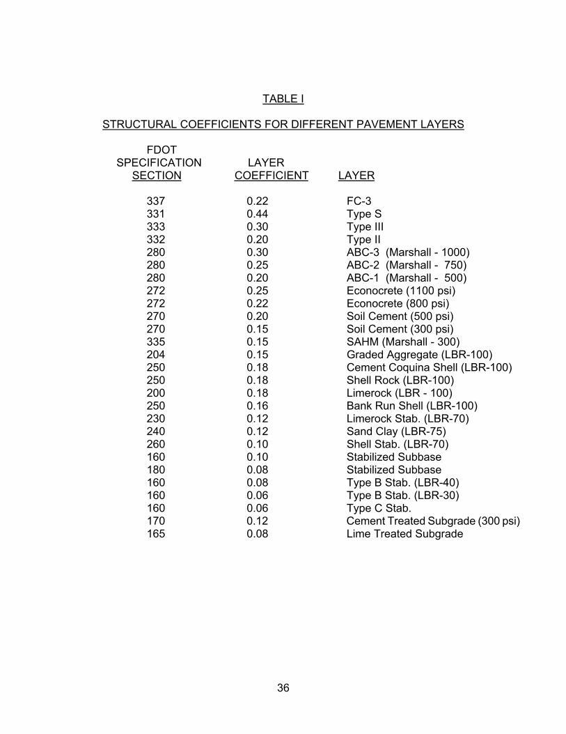
TABLE I
STRUCTURAL COEFFICIENTS FOR DIFFERENT PAVEMENT LAYERS
FDOT SPECIFICATION LAYER
SECTION COEFFICIENT LAYER
337 0.22 FC-3 331 0.44 Type S 333 0.30 Type III 332 0.20 Type II 280 0.30 ABC-3 (Marshall - 1000) 280 0.25 ABC-2 (Marshall - 750) 280 0.20 ABC-1 (Marshall - 500) 272 0.25 Econocrete (1100 psi) 272 0.22 Econocrete (800 psi) 270 0.20 Soil Cement (500 psi) 270 0.15 Soil Cement (300 psi) 335 0.15 SAHM (Marshall - 300) 204 0.15 Graded Aggregate (LBR-100) 250 0.18 Cement Coquina Shell (LBR-100) 250 0.18 Shell Rock (LBR-100) 200 0.18 Limerock (LBR - 100) 250 0.16 Bank Run Shell (LBR-100) 230 0.12 Limerock Stab. (LBR-70) 240 0.12 Sand Clay (LBR-75) 260 0.10 Shell Stab. (LBR-70) 160 0.10 Stabilized Subbase 180 0.08 Stabilized Subbase 160 0.08 Type B Stab. (LBR-40) 160 0.06 Type B Stab. (LBR-30) 160 0.06 Type C Stab. 170 0.12 Cement Treated Subgrade (300 psi)
165 0.08 Lime Treated Subgrade
36

The coefficients presented in Table 1 are based on the FDOT “Flexible Pavement Design Manual for New Construction and Pavement Rehabilitation, April 1, 1993 (revised August 26, 1993)”
In addition to the minimum structural number, flexible pavement design shall also incorporate the minimum layer depths outlined in the following paragraphs. Both structural number and minimum layer depth criteria shall be met.
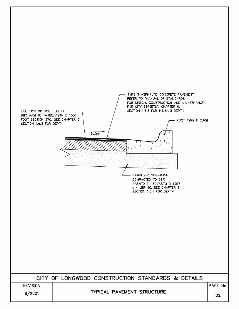
1.6.1 Stabilized Subgrade
The entire width of the right-of-way shall be demucked before construction of the roadbed begins, to a minimum depth of 12 inches. No material of FDOT Class A-5, A-7 or A-8 will be allowed. All material supporting the roadway and shoulders shall have a minimum LBR of 40, unless otherwise approved by the City Administrator, and alternate materials/layer depths are provided to obtain the required minimum structural number. The subgrade shall be compacted to 98% of maximum dry density as determined by AASHTO T-180 (Modified Proctor), to the below listed minimum depths. Stabilization and subgrade treatment materials and construction shall be in compliance with FDOT Standard Specifications for Road and Bridge Construction, latest edition.
Residential Minimum Depth (Inches)
ArterialCollector Local
12 12 8
Industrial 12
Commercial 12
37

Testing for the subgrade bearing capacity and compaction shall be conducted at intervals no greater than five hundred feet and shall be staggered to the left, right and on the centerline of the roadway. There shall also be no less than one test on each street. Tests shall be reviewed by the Engineer of Record.
1.6.2 Base Course
Subject to the approval of the Department of Public Works, base material may be either soil cement or limerock. Where a new base is to be constructed over an existing roadway, the existing pavement shall be removed. The material may be re-used in the bottom 4 inches of the new base after crushing, so as to pass through a 3-1/2 inch sieve. All base shall be primed, as required in Chapter 5. Minimum depth of base shall be as follows:
Residential Minimum Depth (Inches)
Arterial 12 Collector 8-1/2 Local 6-1/2
Industrial 8-1/2
Commercial 8-1/2
1.6.2.1 Soil Cement
Soil cement base, where approved by the Department of Public Works shall be installed with materials and constructed in accordance with FDOT Standard Specifications for Road and Bridge Construction, latest edition. Soil cement shall have a minimum seven day compressive strength of 300 pounds per square inch (psi) for mixed in place base or 500 psi for plant mix or when intended for use as a layer coefficient of 0.20 for flexible pavement base. The design mix shall be prepared by a testing laboratory and submitted to the Department of Public Works after review by the Engineer of Record.
Soil cement shall be compacted to a density of not less than 98% of maximum dry density as determined by AASHTO T-134 under all paved areas within the traveled roadway. Outside the traveled roadway, compaction shall be not less than 95% as determined by AASHTO T-134. Soil cement base shall have test cores taken after seven days to verify thickness and compressive strength. Average core thickness shall not deviate from the design thickness by more than one inch in excess, nor
38
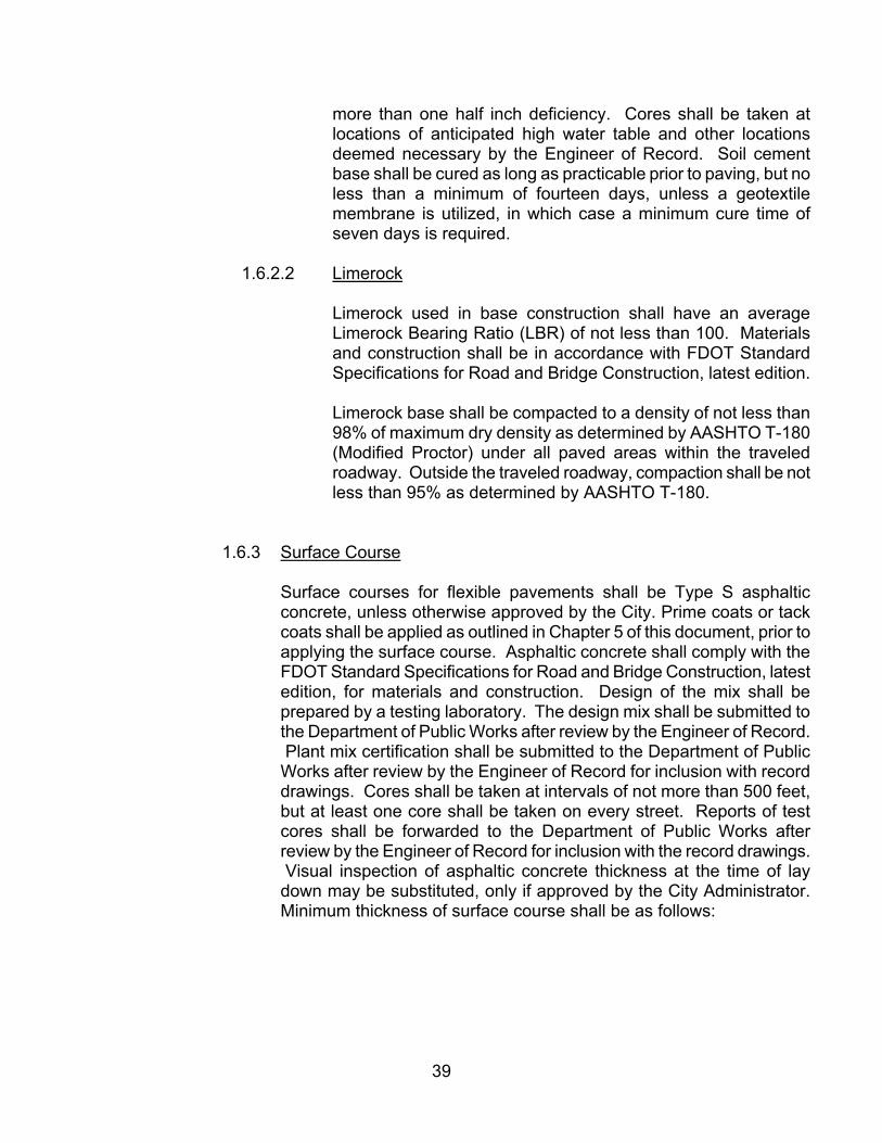
more than one half inch deficiency. Cores shall be taken at locations of anticipated high water table and other locations deemed necessary by the Engineer of Record. Soil cement base shall be cured as long as practicable prior to paving, but no less than a minimum of fourteen days, unless a geotextile membrane is utilized, in which case a minimum cure time of seven days is required.
1.6.2.2 Limerock
Limerock used in base construction shall have an average Limerock Bearing Ratio (LBR) of not less than 100. Materials and construction shall be in accordance with FDOT Standard Specifications for Road and Bridge Construction, latest edition.
Limerock base shall be compacted to a density of not less than 98% of maximum dry density as determined by AASHTO T-180 (Modified Proctor) under all paved areas within the traveled roadway. Outside the traveled roadway, compaction shall be not less than 95% as determined by AASHTO T-180.
1.6.3 Surface Course
Surface courses for flexible pavements shall be Type S asphaltic concrete, unless otherwise approved by the City. Prime coats or tack coats shall be applied as outlined in Chapter 5 of this document, prior to applying the surface course. Asphaltic concrete shall comply with the FDOT Standard Specifications for Road and Bridge Construction, latest edition, for materials and construction. Design of the mix shall be prepared by a testing laboratory. The design mix shall be submitted to the Department of Public Works after review by the Engineer of Record. Plant mix certification shall be submitted to the Department of Public
Works after review by the Engineer of Record for inclusion with record drawings. Cores shall be taken at intervals of not more than 500 feet, but at least one core shall be taken on every street. Reports of test cores shall be forwarded to the Department of Public Works after review by the Engineer of Record for inclusion with the record drawings. Visual inspection of asphaltic concrete thickness at the time of lay
down may be substituted, only if approved by the City Administrator. Minimum thickness of surface course shall be as follows:
39

Residential Minimum Depth (Inches)
Arterial 2-1/4 Collector 2 Local 1-1/2
Industrial 2
Commercial 2
1.7 Portland Cement Concrete Pavement Design
Portland cement concrete pavement may be constructed where indicated on City approved construction plans. Lines, grades, thickness and typical cross sections shall be shown on the plans. Design shall be in accordance with the FDOT “Standard Specifications for Road and Bridge Construction,” latest edition, and recommendations of the Portland Cement Association. Design mix shall be prepared by a testing laboratory, and shall be reviewed by the Engineer of Record prior to forwarding to the Department of Public Works for inclusion with record drawings. Concrete pavement shall be designed for a minimum 28 day compressive strength of 3000 psi. Concrete cylinders shall be made for every 50 cubic yards, but no less frequent than one set for each day's placement. Construction, including placement, jointing and curing shall be carried out in accordance with the FDOT standard specifications. Minimum thickness of concrete pavement shall be as follows:
Minimum Concrete Thickness (Inches)
Residential Arterial 6
Collector 6 Local 6
Industrial 7
Commercial 6
1.8 Shoulders
All shoulders shall have an eight feet width stabilized to an LBR value of at least 40. The minimum depth of the stabilized shoulder shall be eight inches. All shoulders shall be compacted to 98% of maximum density as determined by AASHTO T-180.
40

1.9 Curb/Gutter
Curb and gutter shall be constructed of portland cement concrete and shall conform to the FDOT Standard Index for the type selected. Sections shall be shown on the construction plans and are subject to the approval of the Department of Public Works. Materials and construction shall be in compliance with the FDOT Standard Specifications.
All curbs and gutters shall be installed on a foundation of stabilized subgrade having a minimum LBR ratio of 40, which has been compacted to a minimum density of 98% of maximum density as determined by AASHTO T-180 and extending 6 inches (min.) beyond the edges of the concrete.
1.10 Medians
Medians where required, shall be constructed of portland cement, patterned concrete, or with brick pavers, with planting beds, landscaping and irrigation systems, in accordance with the Public Works Manual, or as modified by any access management agreements between the City of Longwood and FDOT or Seminole County. Plans and sections, along with materials, colors and patterns of the concrete, shall be shown on construction plans and submitted to the City for approval by the City Administrator.
1.11 Swales
Bottoms of swales, measured from top of turf, shall be at least 4 inches below the edge of adjoining pavement, and shall be adequately sized to carry the volume of runoff when designed in accordance with approved storm drainage criteria.
1.12 Drainage
All drainage work within public right-of-ways shall be in accordance with City of Longwood Department of Public Works requirements, and State of Florida Department of Transportation "Utility Accommodation Guide", except as modified herein, and in Chapter 2 of this document.
1.12.1 Unless otherwise approved by the City Administrator, drainage pipe installations under roadways, in present or planned paved areas shall be of reinforced concrete, conforming to ASTM Standard C-301. The minimum size pipe to be used shall be 15 inches diameter. Mitered or flared end sections shall be provided, designed and constructed in accordance with the appropriate FDOT Standard Index.
1.12.2 Drainage pipe for unpaved areas or for crossing under roadways may be of reinforced concrete, or other materials as approved by the Department of Public Works.
41

1.12.3 All drainage pipe in the public right-of-way shall have a minimum of 18 inches of cover, unless otherwise approved by the City Administrator.
1.12.4 No swaled driveways will be permitted within City right-of-ways. Driveways shall be provided with drainage pipe, constructed with mitred end sections or concrete headwalls.
1.12.5 Drainage manholes shall be not less than four feet inside dimension between opposing walls and shall meet the requirements of ASTM Standard C-478. Walls shall be not less than 6 inches thick.
1.12.6 All other drainage structures including inlets, endwalls, culverts, flumes, etc. shall be provided, designed and constructed in accordance with the appropriate FDOT standard index.
1.12.7 Fencing for retention ponds shall be black, vinyl coated, chain link, except as otherwise required by the City’s Land Development Code.
1.13 Sidewalks
Sidewalks shall be portland cement concrete, a minimum of 4 inches thick, and 5 feet wide, minimum. Where extending across driveways, sidewalks shall have a minimum thickness of 6 inches. Sawed contraction joints shall be a minimum of 1-1/2 inches deep. Expansion joints shall be provided between the sidewalk and curbing, driveways and all other fixed objects. Sidewalks shall have a transverse slope of 1/4" per foot toward the swale or gutter and shall be given a transverse broom finish. Handicapped ramps shall be installed wherever sidewalks meet upright curbs, and as otherwise required by the Americans With Disabilities Act (ADA). Any necessary obstruction shall be placed so as to maintain the maximum clear width. Sidewalks shall be maintained by the owners of the abutting properties. Alternate materials and methods of construction may be considered by the Department of Public Works for temporary installations. Special surface treatments such as pavers, tile, etc., may be considered by the Department of Public Works upon request of the Developer or Engineer of Record.
Sidewalks shall be constructed on at least one side of internal subdivisions. Where sidewalk is to be constructed on only one side of the street, the City will designate the side. At intersections with existing streets, sidewalks shall be extended to the right of way at rural roadway sections, or to the back of curb of existing roadways at urban sections. Curb cuts and handicap ramps shall be provided when connecting to existing urban sections.
In situations where improvements are planned for existing roadways which would result in damage or require removal of sidewalks; or where it can be demonstrated that significant damage is likely to occur due to subsequent
42

building construction on the project for which the sidewalk is to be installed, at the discretion of and with the prior approval of the City Administrator, installation may be deferred, subject to the Developer posting with the City, a "Sidewalk Performance Bond" in a format acceptable to the City.
1.14 Grassing/Seeding/Mulching/Sodding/Fertilizing
Whenever a suitable length of roadway or adjacent areas have been graded, they shall be grassed and mulched across the full right-of-way, outside the limits of pavement, at the earliest practical time, and in all cases, before the final paving course. Except for areas adjacent to established turf, grass seed may be used, unless otherwise agreed between the Developer and the Department of Public Works. In the areas adjacent to established turf, sod of the same type of grass shall be installed. In areas where erosion and/or growing conditions may be a problem and for a minimum of 2 feet around all structures and the back of all curbs, solid sod of the same type as the adjacent turf areas shall also be installed. The Developer shall maintain the grass, including watering and mowing until a good stand of grass is established and the project is accepted. It is the intent of this document that areas to be grassed have a growing stand of grass for a period of at least one year after completion/acceptance of the project. All grassed areas shall be mowed at least once prior to acceptance of the project.
1.15 Restoration
The entire work area utilized for the performance of any permitted work shall be restored by the permittee as described in Chapter 2, Section 2.22.
1.16 Record Drawings & Certifications
One reproducible set, two blue line copies and one electronic copy, in a format acceptable to the City, of complete record drawings (“as-builts”) shall be submitted to the Department of Public Works prior to final acceptance by the City. Each individual sheet shall be clearly marked "Record Drawing", dated and signed and sealed by the Engineer of Record. These drawings must show all changes from the approved construction plans, including, but not limited to invert elevations, grade changes, as well as finished base elevations and offsets at centerline, edge of median and edge of pavement, plus elevations of bottom of swale or flow line of gutter, top of curb and right-of-way line, at high and low points, intersections and breaks in grade. Elevations shall be verified and shown at intervals not to exceed 300 feet measured along the profile grade line. All high point and low point elevations shall be shown.
43

Compaction must be verified by an independent certified engineering testing laboratory by making field density tests of each layer of compacted material at prescribed intervals before the succeeding layer is placed. Test reports and record drawings must be submitted to the Department of Public Works before final acceptance.
1.17 Final Inspection and Acceptance
After construction is completed and all certifications, record drawings and other required documents have been submitted to, and accepted by, the Department of Public Works, but before the one-year bonded maintenance period begins, the permittee shall request a final inspection of the project. The Department of Public Works, the Engineer of Record and all other interested parties shall jointly perform such inspections as necessary for the Department of Public Works to determine the acceptability of the project for maintenance by the City. Following the inspection, any noted defects shall be corrected by the permittee, after which the Department of Public Works and other maintaining agencies, will issue a notice of acceptance. This will mark the start of the one-year warrantee period.
2. PAVEMENT MARKING/SIGNING/SIGNALIZATION
2.1 Pavement Markings - General The design and construction of pavement marking systems shall be in accordance with the following standards:
U.S. Department of Transportation, Federal Highway Administration - Manual on Uniform Traffic Control Devices for Streets and Highways, latest edition.
Florida DOT - Manual of Uniform Minimum Standards for Design, Construction and Maintenance for Streets and Highways, latest edition.
Florida DOT - Standard Specifications for Road and Bridge Construction, latest edition.
Florida DOT - Roadway and Traffic Design Standards.
American Association of State Highway and Transportation Officials (AASHTO) - A Policy on Geometric Design of Highways and Streets.
2.1.1 Pavement Marking Plan
Pavement marking and signing plans shall be submitted to the Department of Public Works for review and approval as part of the construction plans for development where street or road construction is included. These plans shall show all new markings including tie-ins to existing markings. Removals of existing markings shall also be shown.
44
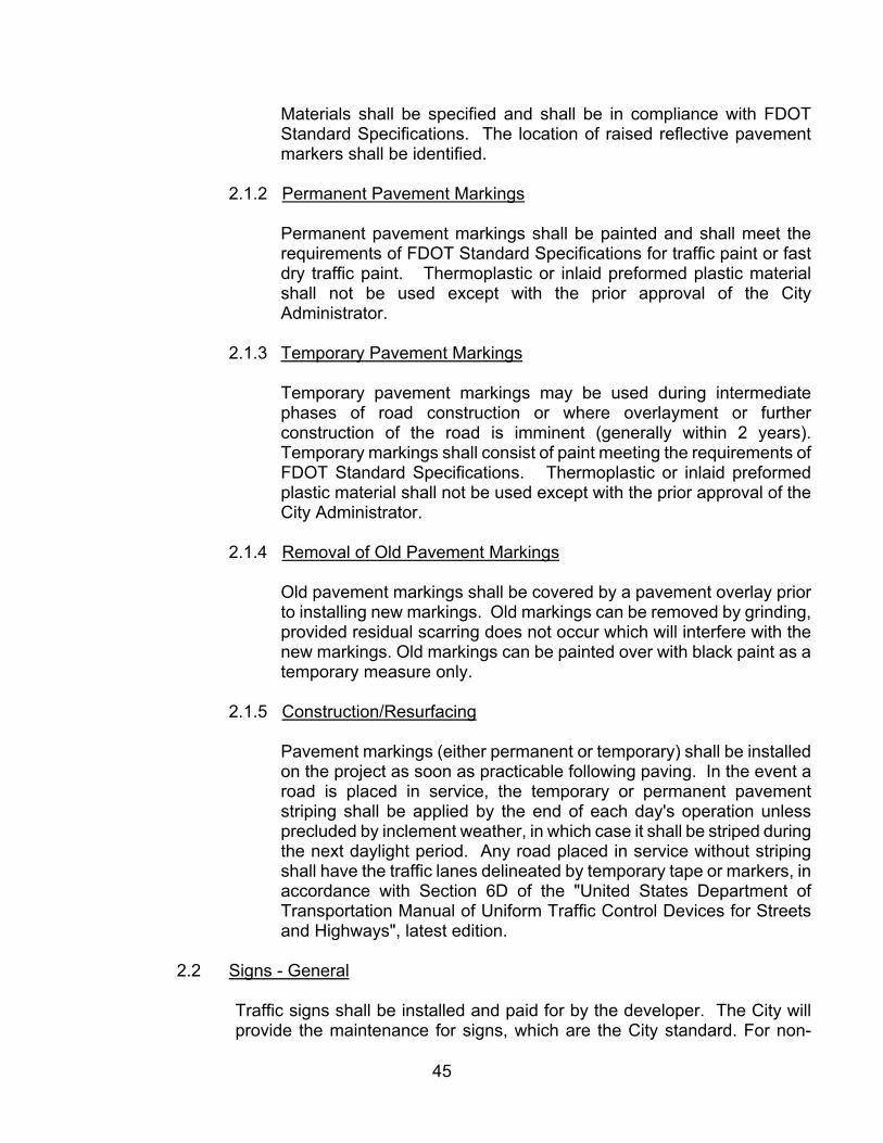
Materials shall be specified and shall be in compliance with FDOT Standard Specifications. The location of raised reflective pavement markers shall be identified.
2.1.2 Permanent Pavement Markings
Permanent pavement markings shall be painted and shall meet the requirements of FDOT Standard Specifications for traffic paint or fast dry traffic paint. Thermoplastic or inlaid preformed plastic material shall not be used except with the prior approval of the City Administrator.
2.1.3 Temporary Pavement Markings
Temporary pavement markings may be used during intermediate phases of road construction or where overlayment or further construction of the road is imminent (generally within 2 years). Temporary markings shall consist of paint meeting the requirements of FDOT Standard Specifications. Thermoplastic or inlaid preformed plastic material shall not be used except with the prior approval of the City Administrator.
2.1.4 Removal of Old Pavement Markings
Old pavement markings shall be covered by a pavement overlay prior to installing new markings. Old markings can be removed by grinding, provided residual scarring does not occur which will interfere with the new markings. Old markings can be painted over with black paint as a temporary measure only.
2.1.5 Construction/Resurfacing
Pavement markings (either permanent or temporary) shall be installed on the project as soon as practicable following paving. In the event a road is placed in service, the temporary or permanent pavement striping shall be applied by the end of each day's operation unless precluded by inclement weather, in which case it shall be striped during the next daylight period. Any road placed in service without striping shall have the traffic lanes delineated by temporary tape or markers, in accordance with Section 6D of the "United States Department of Transportation Manual of Uniform Traffic Control Devices for Streets and Highways", latest edition.
2.2 Signs - General
Traffic signs shall be installed and paid for by the developer. The City will provide the maintenance for signs, which are the City standard. For non-
45

standard signs, the developer or appropriate homeowners association shall pay for maintenance. The developer or the appropriate homeowners association shall also pay the costs for the subsequent conversion of non-standard signs to the City standard.
Design and construction of traffic signs shall be in accordance with the "FDOT Standard Specifications" and "FDOT Roadway and Traffic Design standards Manual on Uniform Traffic Control Devices".
2.2.1 Signing Plans
Signing plans shall be submitted, with paving marking plans, to the Department of Public Works for review, as part of the construction plans for development where street or road construction is included. These plans shall show all new signs and all existing signs, which are designated to remain.
2.2.2 Materials
All "STOP", "YIELD", "DO NOT ENTER", and "WRONG WAY" signs and street name signs shall be fabricated entirely with high intensity reflective sheeting. Other signs shall be fabricated using engineering grade materials.
2.2.3 Maintenance of Signs During Construction
"STOP" and "YIELD" signs shall be maintained during construction. All temporary signs shall conform to the same specifications as permanent signs.
2.2.4 Design of Supports
Shop drawings and quantities for overhead sign structures, special designs for ground sign structures, and large guide sign panels, shall be submitted to the Department or Public Works after review by the Engineer of Record.
Minimum vertical clearances for overhead signs shall be as detailed in Florida Department of Transportation's "Traffic Operations Standards".
2.3 Traffic signals
2.3.1 Materials
All materials and workmanship shall meet the requirements of the "USDOT Manual on Uniform Traffic Control Devices for Streets and Highways", "Institute of Transportation Engineers", the "National
46

Electrical Code", "Underwriters Laboratories, Inc.", "Industrial Control Standards of National Electrical Manufacturers Association", "International Municipal Signal Association" and applicable FDOT standards and specifications.
2.3.2 Signal Poles
Except where otherwise approved by the City of Longwood, traffic signals shall be mounted on mast arms meeting he requirements of FDOT Series 1700 and shall be dark green in color.
2.3.3 Pole Foundations
Foundation installations shall be back-filled and compacted to a firm, stable condition equal to or greater than that of the surrounding soil. Where applicable, the pole base shall be finished flush with the adjoining sidewalk so as to allow an obstruction free walking surface.
2.3.4 Pole Locations
Poles, generally, shall be located at the right-of-way lines (back of the sidewalk).
2.3.5 Pole Position Adjustments
Pole positions and conduit routing may be adjusted as approved by the Department of Public Works to prevent conflicts with utility and drainage structures not indicated on plans.
2.3.6 Minimum Pole Heights
All signal poles shall have a minimum height adequate to provide a 17 foot Low Point Center for bottom of signal head, and not more than 19 feet.
2.3.7 Grounding
All poles, controllers, detector cabinets and pull boxes, and other elements of the installation shall be grounded by installing either a ground rod assembly or a ground rod array.
2.3.9 Signal Heads
A minimum of two signal heads for each approach for vehicular traffic shall be provided. Pedestrian signals, push buttons, and signs shall be provided on all corners. Vehicular signals shall be installed with drop pipes and disconnect hangers.
47

2.3.10 Controller and BC4T Cabinet
All "T" intersections shall have a four phase full actuated controller in a BC4T cabinet and all 4-way intersections shall have an eight-phase full actuated controller in a BC4T cabinet, unless otherwise specified by the Department of Public Works.
2.3.11 Vehicle Inductive Loop Detectors
Vehicle inductive loop detectors shall be 5 feet wide by 40 feet long, with 10 feet extending in front of STOP bar in a quadrapole pattern of 1-2-1 winding, unless otherwise specified by the Department of Public Works.
2.3.12 Shop Drawings
Manufacturer's descriptive literature and technical data which fully describes the types of signal equipment proposed for use, shall be forwarded to the Department of Public Works after review by the Engineer of Record.
2.3.13 Record Drawings
Record drawings shall be submitted for all traffic control devices, indicating deviations from the approved construction plans. Drawings shall be submitted to the Department of Public Works after review, dating, signing and sealing by the Engineer of Record.
3. BIKE PATHS/LANES
3.1 Design Criteria
Design of bike paths/bike lanes shall comply with the requirements/guidelines of the Federal Highway Administration, the Florida Department of Transportation, and the "Manual on Uniform Traffic Control Devices" (MUTCD). Alternate materials and methods of construction will be considered for temporary installations. Striping and signage shall be as set forth in the MUTCD and FDOT Standard Specifications. Paths shall be painted with paint meeting the requirements of FDOT Standard Specifications for traffic paint or fast dry traffic paint. Paint color shall be approved by the City of Longwood.
48

CHAPTER 7
STORMWATER TECHNICAL REQUIREMENTS
1. REQUIRED FEATURES
1.1 A stormwater management system shall be designed and installed for the development that will contain features to provide for:
1.1.1 Pollution Abatement
Pollution abatement will be accomplished by retention, or detention with filtration in accordance with St. Johns River Water Management District (SJRWMD) criteria.
1.1.2 Protection from Flooding
Protection from flooding will be accomplished by a design which will provide that:
a. The post-development peak rate of discharge permitted from the site will not exceed the predevelopment peak rate of discharge from the site during a 25-year frequency/24-hour duration storm event.
b. All residential structures are to be flood free and all commercial and industrial structures are to be either flood free or flood-proofed.
1.1.3 No Positive Outfall
When a positive outfall is not available, the site shall be designed to retain 100-year frequency/24-hour duration storm on-site
2. DISPOSITION OF RUNOFF
2.1 All development will be required to pretreat the required volume of runoff for pollution abatement purposes. Pretreatment of this volume of runoff is defined as retention (no surface discharge) or detention with filtration (surface discharge) prior to release.
2.2 Off-site easements for stormwater management facilities will be required when either of the following conditions exists:
2.2.1 The discharge is into any man-made facility for which the City does not have either a drainage easement for right-of-way; or
49

2.2.2 The discharge is into a natural system such that the rate or character (i.e., sheetflow vs. concentrated flow) of the flow at the property line has been changed. The easement will be required to a point at which natural conditions are duplicated.
3. DEVELOPMENT WITHIN AREAS OF SPECIAL FLOOD HAZARD
3.1 All developments within areas of special flood hazard as delineated on the Federal Emergency Management Agency (FEMA) flood insurance rate maps (FIRM) or as determined by the City Engineer shall comply with the following requirements:
3.1.1 Establish, to the satisfaction of the City Engineer, the elevation of the base flood (100-year flood). The elevation as approved by the City Engineer shall be clearly identified on the subdivision lot grading plans. Supporting calculations to determine the Normal High Water Elevation (NHWE) and 100-year flood elevation must be submitted for review and approval by the City Engineer.
3.1.2. Set the minimum finished floor elevation at least one (1) foot above the elevation of the base flood.
3.1.3 For commercial or industrial developments, flood proofing may be substituted in lieu of elevating the finished floor.
3.1.4 Provide compensating storage for all flood water displaced by development below the elevation of the one-hundred-year flood.
4. DRAINAGE DESIGN REQUIREMENTS
4.1 Drainage Map
The Engineer of Record shall include in the subdivision construction plans a master drainage map showing all existing and proposed features. The map is to be prepared on a twenty-four (24) inch by thirty-six (36) inch sheet on a scale not to exceed one (1) inch equals two hundred (200) feet. Listed below are the features that are to be included on the drainage map.
4.1.1 Drainage bounds, including all offsite areas draining to the proposed subdivision.
4.1.2 Sufficient topographical information with elevations to verify the location of all ridges, streams, etc. (one-foot contour intervals).
4.1.3 Notes indicating sources of high water data.
50

4.1.4 Drainage features, including location of inlets, swales, ponding areas, and flow arrows.
4.1.5 Delineation of drainage sub-areas.
4.1.6 Identification of retention/detention areas and ingress/egress areas thereto.
4.1.7 General type of soils (obtain from soil survey of Seminole County.
4.1.8 Flood hazard classification.
4.1.9 Description of current ground cover and/or land use.
4.1.10 NHWE designation for all surface water bodies.
4.1.11 All storm sewer pipes and sizes.
4.2 Subsoil Investigation
A subsoil report shall be prepared by a geotechnical engineer. A minimum of two (2) borings will be taken per retention/detention area.
4.3 Stormwater Calculations
Stormwater calculations for retention/detention areas, including design high water elevations for the 25-year frequency, 24-hour duration and 100-year frequency/24-hour duration storm events, shall include the following:
4.3.1 Storm sewer tabulation including, but not limited to, the following:
a. Location and types of structures. b. Types and lengths of line. c. Drainage and sub-area tributary to each structure. d. Runoff coefficient per sub-area. e. Time of concentration to structure. f. Hydraulic gradient for the 10-year storm. g. Estimated receiving water (tailwater) elevation with sources of
information, if available. h. Diameters of pipe. i. Outlet and other pipe velocities.
4.3.2 Drainage plans including, but not limited to, the following:
a. Cross-section of retention/detention facilities. b. Typical swale, ditch or canal sections. c. Drainage right-of-ways.
51

d. Typical fencing detail. e. A note on the design plans that an erosion control plan will be
approved by the City Engineer prior to the pre-construction conference.
4.4 Routing Calculations
Include the following:
4.4.1 Identify the location of all storage areas and hydraulic structures on the basin map.
4.4.2 A schematic drawing (i.e., nodal diagram) showing the interconnection of the hydrologic/hydraulic network.
4.4.3 Stage vs. storage/area/time calculations with references and methodology.
4.4.4 Hydrologic parameters required to calculate the hydrograph such as drainage area, time of concentration, run-off coefficient and runoff curve number.
4.4.5 Peak stage, peak outflow, and peak velocity results for the simulated design storm event, including all computer printouts of input and output.
4.4.6 Additional information that the City Engineer deems necessary.
5. GENERAL DESIGN CRITERIA
5.1 Methods of Computing Runoff Volume and Peak Rate of Discharge
The design method used to establish runoff volume and peak rate of discharge shall be by current techniques. In order to provide for reasonable measures of consistency, the following methods of computation are encouraged to be used:
5.1.1 Basins or sub-basins (for pipe network analysis). The rational formula may be used to determine peak discharges by the formula Q= CIA, where:
Q = Peak Discharge in cubic feet per second (CFS) I = Intensity of rainfall derived from FDOT rainfall charts and the
time of concentration for the basin. A = Area contributing in acres. C = Runoff coefficient.
5.1.2 Basins or sub-basins (for pond routing). Hydrograph(s) should be developed by the United States Department of Agriculture (U.S.D.A.)
52

Soil Conservation Service’s Unit-Hydrograph method or by the modified Santa Barbara Urban Hydrograph method. The current Soil Survey of Seminole County, Florida published by the United States Department of Agriculture Soil Conservation Service or site-specific data submitted by a geotechnical engineer shall be referred to for the proper use of soils classification when calculating runoff curve numbers.
6. DESIGN STORM
6.1 The following minimum design storms shall apply:
Facility Design Storm
Cross drains, storm sewers 10-year Roadside swales for drainage internal 10-year to the development Detention basins 25-year Retention basins (no positive outfall) 100-year
7. STORM DURATION AND RAINFALL INTENSITY
7.1 The following guidelines are for use in the design of the stormwater management system. For the rational method, time of concentration (TC) will dictate the rainfall intensity. Rainfall intensities for the rational method are to be obtained from the Florida Department of Transportation Rainfall Curves for Zone 7. TC values are to be obtained from the Federal Highway Administration Kinematic Wave Formula for sheet or overland flows, and from the Manning Equation for concentrated flows (i.e., gutter flow, ditch flow, pipe flow, etc.)
7.2 Rainfall distributions for the above are to be in accordance with the St. Johns River Water Management District.
8. RETENTION, DETENTION FACILITIES
8.1 Pollution Abatement Volume Recovery Rate
The pollution abatement volume recovery rate shall be as required by the St. Johns River Water Management District.
8.2 Design Criteria for Detention Facilities to Reduce Peak Rate of Discharge for 25-year Frequency/24-hour Duration Storm
The detention pond will be sized to limit the peak rate of discharge from the developed site to that discharge generated prior to development. Supporting calculations shall be submitted and will contain, as a minimum, runoff hydrographs for the pre-developed site and the post-developed site, and a
53

8.3
8.4
9.
discharge hydrograph after routing through the proposed detention facility. All routing calculations to be submitted must consider the tailwater of the receiving facility. If the receiving facility is an existing storm sewer, the Hydraulic Gradient Line (HGL) elevation of this receiving facility can be assumed at one-half (1/2) foot below its crown of pipe elevation unless a detailed study of the existing system indicates otherwise.
8.2.1 Credit for seepage to further reduce the peak rate of discharge will not be allowed.
8.2.2 A minimum of fifty (50) percent of the total volume of water required to attenuate the peak discharge of the facility in excess of the pollution abatement volume must be evacuated within 24-hours. The remaining fifty (50) percent must be evacuated within an additional seventy-two (72) hours.
8.2.3 The outflow structure shall be designed to skim floating debris, oil, and grease from an elevation six (6) inches below elevation of inflow into the structure to an elevation of six (6) inches above the design high water level of the pond and shall cover all directions of inflow to the outfall structure. The design of this control system shall make adequate provision to minimize erosion.
Design Criteria Where a Positive Outfall is Not Available
When a positive outfall is not available or discharge into a lake without a positive outfall is proposed, the pond design shall retain the one-hundred (100) year frequency/twenty-four (24) hour duration storm event. The pond shall be designed without using infiltration during the storm event. The pond shall be designed to completely evacuate a one-hundred (100) year frequency/twenty-four (24)-hour duration storm by natural seepage or positive bleed down within fourteen (14) days. Final design seepage rates will be determined by a geotechnical engineer. All necessary calculations to support the above shall be submitted to the City Engineer.
Design criteria for offsite drainage
Offsite areas which drain to or across a site proposed for development must be accommodated in the stormwater management plans for the development. The stormwater management system for the development must be capable of conveying existing offsite flows through or around the development. The estimation of the offsite flows must be done separately from the estimation of onsite post development flows (i.e., separate offsite and onsite hydrographs must be computed due to the typically significant differences in land use characteristics).
54
OPEN DRAINAGE FACILITIES

9.1 Right-of-Way and Easement
9.1.1 Outfall ditches and canals shall have sufficient right of way for each facility plus an unobstructed maintenance berm on one (1) or both sides.
9.1.2 Ponds shall have sufficient area to allow for installation plus an unobstructed maintenance berm around the perimeter of the pond.
9.2 Maintenance Berms
The minimum requirement for maintenance berms is as follows:
Ditch or Canal Top Width Minimum Maintenance
Berm Required
Less than 16 feet Greater than 16 feet
20 feet on one side 20 feet both sides
Ponds
With fencing Without fencing
20 feet around pond perimeter 5 feet around pond perimeter
9.3 Grading
Areas adjacent to open drainage ways and ponds shall be graded to preclude the entrance of stormwater except to planned locations. Parcels or lots adjacent to canals shall not be pitched so that runoff from the site enters the canal directly.
9.4 Side Slopes
The maximum side slopes for open drainage facilities shall be as follows:
Maximum Side Slopes Open Drainageways (Horizontal/Vertical Ratio)
Less than or equal to four (4) feet deep 3:1 Over four (4) feet deep 2:1
Ponds
With fencing six (6) feet high Greater than 4:1 Without fencing 4:1
55

9.5 Bottom Width
The minimum bottom width for ponds and open drainage ways shall be four (4) feet.
9.6 Tailwater
All stormwater ponds shall be designed taking into consideration the tailwater of the receiving facility. In the case where the detention pond discharges to a canal or other water body, the following sources of information may be utilized to determine and acceptable tailwater for routing flows from the pond:
9.6.1 Studies and reports approved by the City with stage-time-discharge data for canal or waterways to be utilized.
9.6.2 Where detailed stage-time-discharge information is not available, the City Engineer may allow the following:
a. The use of FEMA floodplain information. b. A normal depth based on the cross-sectional data of the
receiving body. c. An average of the elevation of the existing water level and the
elevation of the high water mark on the canal or receiving water body.
d. Two (2) feet above the established conservation line. e. A detailed drainage study.
9.7 Erosion Protection
Open drainage facilities shall be protected from erosion as follows:
Side slopes and berms Sod Bottom Grass and mulch
9.8 Fencing
Open drainage facilities shall be fenced as follows:
9.8.1 Ponds, if required, six foot black vinyl chain link along right of way around perimeter, including maintenance berms.
9.8.2 Canals: Six-foot black vinyl chain link along canal easements or right of way where lots abut canals.
9.9 Berms Constructed of Fill
56

Where berms are proposed, the design shall be certified by the geotechnical engineer. The geotechnical engineer shall also certify that construction has been completed as designed.
10. HYDRAULIC DESIGN CRITERIA
10.1. Design Storm Frequency
The design storm frequency to be utilized for the design of pavement drainage shall set the hydraulic gradient line at six (6) inches below gutter for a ten (10) year frequency storm.
10.2 Runoff Determination
The peak rates of runoff for which the pavement drainage system must be designed shall be determined by the rational method. The time of concentration, individual drainage areas and rainfall intensity amounts shall be submitted as part of the drainage plans. A separate Rational Runoff Coefficient ( C) shall be determined for the specific contributing area to each inlet/catch basin within the proposed storm sewer system. A composite C value shall be computed for each contributing area based on an individual C value of 0.9 for the estimated impervious portion of the actual area and an individual C value of 0.2 for the remaining previous (grassed) portion of the actual area.
10.3 Stormwater Spread into Traveled Lane
Inlets shall be located at all low points, intersections and along continuous grades to prevent the spread of water from exceeding tolerable limits. The acceptable tolerable limits for roadways is defined as approximately one-half the traveled lane width.
10.4 Maximum Inlet Interception Rates
Bypass flow is limited to a maximize of one (1) cfs. Off-site flows from impervious areas of more than one-half (0.5) acre shall be intercepted prior to the right-of-way line. No part of an inlet structure shall be located within an intersection curb radius or in front of the access to the retention pond.
10.5 Low Point Inlets
All inlets at low points (sumps) shall be designed to intercept one hundred (100) percent of the design flow without exceeding the allowable spread of water onto the traveled lanes as defined above.
11. STORM SEWER DESIGN
57

11.1 Design Discharges
Storm sewer system design is to be based upon a 10-year frequency event and shall be designed to handle the flows from the contributory area within the proposed subdivision.
11.2 Minimum Pipe Size
The minimum size of pipe to be used in storm sewer systems is fifteen (15) inches. Designs shall be based upon six (6)-inch increments in sizes above eighteen (18) inches.
11.3 Pipe Grade
All storm sewers shall be designed and constructed to produce a minimum velocity of two and one-half feet per second (fps) when flowing full. No storm sewer system or portion thereof will be designed to produce velocities in excess of twenty (20) fps for reinforced concrete pipe or 10 fps for metal pipe, and these maximums shall only be used when these outlet ends have sufficient erosion protection and/or energy dissipates.
11.4 Maximum Lengths of Pipe
The following maximum runs of pipe shall be used when spacing access structures of any type.
Pipe Size (inches) Maximum (feet)
15 18 24 to 36 42 and larger
200 300 400 500
11.5 Design Tailwater
All storm sewer systems shall be designed taking into consideration the tailwater of the receiving facility. In the case where the detention pond is the receiving facility, the design tailwater level can be estimated from the information generated by routing through the pond the hydrograph resulting from a ten (10)-year frequency storm of duration equal to that used in designing the pond. The design tailwater level can be assumed to be the ten (10)-year pond level corresponding to the time at which peak inflow occurs from the storm sewer into the pond. In lieu of the above detailed analysis, a simpler design tailwater estimated can be obtained by averaging the established twenty-five (25)-year design high water elevation for the pond and
58

the pond bottom elevation for “dry bottom” ponds or the normal water elevation for “wet bottom” ponds.
11.6 Hydraulic Gradient Line Computations
The hydraulic gradient line for the storm sewer system shall be computed taking into consideration the design tailwater on the system and the energy losses associated with entrance into and exit from the system, friction through the system, and turbulence n the individual manholes/catch-basins/junction boxes within the system. The energy losses associated with the turbulence in the individual manholes are minor for an open channel or gravity storm sewer system and can typically be overcome by adjusting (increasing) the upstream pipe invert elevations in a manhole by a small amount. However, the energy losses associated with the turbulence in the individual manholes can be significant for a pressure or surcharged storm sewer system and must be accounted for in establishing a reasonable hydraulic gradient line.
12. CULVERT DESIGN
12.1 Minimum Pipe Size
The minimum sizes of pipes to be used for culvert installations under roadways shall be eighteen (18) inches. The minimum size of pipes to be used for driveway crossings shall be fifteen (15) inches. Mitered end sections shall be provided on all pipes.
12.2 Maximum Pipe Grade
The maximum slope allowable shall be a slope that produces ten (10) fps velocity within the culvert barrel. Erosion protection and/or energy dissipates may be required to properly control entrance and outlet velocities.
12.3 Maximum Length of Culverts
The maximum length of culvert conveyance structure without access shall be as allowed in Paragraph 11.4.
59

12.4 Design Tailwater
All culvert installations shall be designed taking into consideration the tailwater of the receiving facility.
12.5 Allowable Headwater
The allowable headwater for a culvert installation should be set by the designer for an economical installation. When endwalls are used, the headwater should not exceed the top of the endwall at the entrance. If the tope of the endwall is inundated, special protection of the roadway embankment and/or ditch slope may be necessary for erosion protection.
60

CHAPTER 8
SUBDIVISION PLANNING
1. OBJECTIVES
The objectives of the City of Longwood in subdivision planning are to promote health, safety and welfare in enhancing the quality of life for its residents. This dictates a safe and efficient access and traffic circulation system. The following principles are to be considered in accomplishing these objectives:
1.1 Adequate Vehicular and Pedestrian Access
Adequate vehicular and pedestrian access shall be provided for all parcels. Street widths, sidewalk placement, patterns of streets and number of intersections shall take into consideration both safety and efficiency of access to abutting parcels. Every parcel shall abut an approved private street, an approved access easement, or a street dedicated to, and accepted by the City for maintenance.
1.2 Minimization of Traffic Movements Through Local Streets
Through traffic shall be discouraged through the use of discontinuities in local street patterns by offsetting local street intersections and by channeling or controlling street medians along peripheral major or collector streets. This will reduce the amount and speed of traffic, thereby making local streets more safe and amenable to residents.
1.3 Logic and Consistency in Street Numbering and Naming
A consistent and logical pattern shall be developed to simplify local street naming and numbering, to assist visitors in locating addresses and facilitate access by emergency vehicles, delivery vehicles, etc.
1.4 Efficient Traffic Circulation and Development Patterns
Driveways, intersection placement and access shall be controlled so that no parcels require direct access to major or collector streets. Provisions shall be provided for continuing existing principal streets from adjoining areas through new subdivisions. Where streets are extended to subdivision boundaries and abut either undeveloped adjoining land, or connect to collector or arterial roads, the location of the subdivision street shall be coordinated with the City Administrator to facilitate future street development in adjoining areas, for overall efficiency of traffic flow and for safety considerations of future intersections.
61

1.5 Design for Purpose Intended
Local streets shall not be overdesigned or overbuilt (i.e., extra width, higher speed, etc.,) to a degree which will detract from the residential character and which will encourage higher use and higher traffic speed. The use of curvilinear alignment and discontinuities is encouraged to minimize speeds in excess of 30 MPH and discourage through traffic.
1.6 Minimum of Intersections
Intersections shall be kept to the minimum number practicable, particularly between local streets and collector or arterial roads, to reduce accident potential. Consistent with other requirements, "T" intersections are preferable to four way, or cross type intersections. Streets shall be arranged to intersect as closely as possible to right angles. In no case shall streets intersect at an angle of less than 75 degrees.
2. PLANNING AND DESIGN CRITERIA
2.1 Local Streets
2.1.1 Maximum length of a cul-de-sac shall be 1200 feet, unless otherwise approved by the City Administrator. Minimum paved radius shall be 36-feet.
2.1.2 Local streets shall intersect with other local streets to the maximum extent practicable, and in no case with more than one collector or arterial road.
2.1.3 Loop roads, cul-de-sacs and curvilinear streets shall be considered in the planning and design.
2.2 Collector Streets
2.2.1 No direct access shall be provided to a collector street from a residential lot.
2.2.2 Collector/arterial streets shall connect to only one collector or arterial road.
2.2.3 Residential dwellings shall face away from collector/arterial streets ( i.e., collector/arterial street to side or rear lot line).
62

2.3 Commercial Sites
Commercial sites shall conform to these standards in regard to roadway improvements, rights of way, sidewalks, driveways and all other requirements outlined for residential subdivisions, as appropriate.
63

CHAPTER 9
INSTALLATIONS FOR INTER-EXCHANGE TELECOMMUNICATIONS SERVICE AND CABLE TV OR OTHER SIGNAL INSTALLATIONS
1. GENERAL
1.1 All telephone, cable T.V., or other signal lines in City rights-of-way shall be installed underground. No aerial installations shall be permitted.
1.2 The construction, maintenance, repair or removal of any underground installations of telephone, cable T.V., or other signal carrying lines in the public rights-of-way shall not commence prior to issuance of a permit from the Department of Public Utilities, by authority of the City Administrator, except as provided in Chapter 2, Sections 1.2.1 and 1.3.
1.3 All companies intending to provide telephone, cable T.V., or other signal lines shall be required to register with the City of Longwood and shall comply with the City’s Right of Way Use Ordinance, Number 01-1576, as amended.
2. PERMIT REQUIREMENTS
2.1 Notwithstanding, the requirements of Chapter 4, Section 1.3, plans submitted for approval need not be signed or sealed by an engineer certified in the State of Florida if prepared by a City of Longwood franchisee for work to be done on or for franchisee's own system. All other portions of Chapter 1 through 4 shall be met prior to issuance of any permit.
3. PLANS AND SPECIFICATIONS
3.1 All plans shall be submitted on white prints with blue or black lines. In addition to the proposed project, they shall show all existing facilities as well as all planned facilities sufficiently to permit assessment of the compatibility of the proposed work with the existing systems. Plans must be submitted on 24" x 36" sheets. Small projects may be submitted on legal size paper, provided that scale requirements are met and only one sheet is required.
3.2 The general layout sheets shall be on a scale of 300 feet or less to the inch. Detailed plans shall be on a scale 50 feet or less to the inch.
3.3 Dimensions of rights-of-way widths shall be indicated. All plans shall show suitable legends.
64

3.4 The detailed plans shall show proposed cable, conduit and/or duct sizes, approximate locations of manholes and poles, right-of-way and easement widths, and dimensioned offsets of the proposed facilities from property lines.
3.5 Existing pavements shall be indicated by dimensions, notes and/or light shading.
3.6 When locations of other utilities cannot be determined, this shall be indicated by notes.
3.7 All street names shall be shown.
3.8 The identity of the operating utility company or franchisee shall be indicated on the plans.
3.9 For maintenance work requiring a permit, a sketch indicating locations, right-of-way layout, proposed work area and the nature of the work must be submitted to the Department of Public Utilities for permitting.
3.10 For emergency work, a record drawing must be submitted to the Department of Public Utilities within ten working days after the work is done, with information thereon as per Section 3.9, above.
3.11 Record drawings of underground drawings will be furnished to the Department of Public Utilities upon request.
4. STANDARDS
Telephone and cable television or other signal carrying systems constructed in the public rights-of-way shall be in accordance with the following standards, and regulations, and in strict accordance with the manufacturer's recommendations as modified by these Standards.
4.1 National Electric Safety Code.
4.2 Federal Communications Commission
4.3 United States Department of Transportation "Manual of Uniform Traffic Control Devices".
4.4 State of Florida Department of Transportation's "Utility Accommodation Guide".
5. CONDUIT
5.1 Steel conduit shall be minimum Schedule 40, hot dip galvanized after threading, conforming to AWWA C-201 or C-202, and ANSI C-80-1.
65

5.2 PVC conduit shall conform to ASTM F-512 with minimum wall thickness of Series DR-35.
5.3 Concrete encasement shall be cast with 3000 psi concrete, and shall have 3" minimum wall thickness.
6. INSTALLATIONS
The provisions of Chapters l through 4 of this document shall apply, in addition to the following requirements:
6.1 Cover
Telephone, television or other signal carrying cable installed in an existing or planned paved area in any public right-of-way, shall be placed in approved steel, concrete or plastic conduit and shall have a minimum of 30" cover.
6.2 Location
In general, and where practicable, all underground cable T.V., telephone or other signal carrying cable installations shall be in accordance with the Standards and Details included in the Appendix (as applicable).
6.3 Crossings
All underground crossings of paved roadways shall be made by the bore and jack method, if possible.
Underground crossings of paved roadways shall not be accomplished by jetting or the use of air or water in direct contact with the earth. Pipe driving shall leave no voids in the underlying earth. This does not prohibit the use of air hammers for driving.
6.4 Extraction of Pipe From Bore
The extraction of pipe from beneath any roadway generally is prohibited, unless approved in writing by the Department of Public Utilities. In extreme situations, where pipe must be removed, the roadway must be trenched and later restored in accordance with the Standards and Details included in the Appendix (as applicable).
7. TESTING
Testing of telephone, cable T.V. or other signal carrying facilities, will not be required by the Department of Public Utilities. Testing of backfill, compaction and roadway restoration shall be as per Chapter 2, Sections 2.19 and the Standards and Details included in the Appendix (as applicable).
66

8. ABANDONED FACILITIES
The provisions of Chapter 2, Section 2.23 shall apply.
9. RECORD DRAWINGS
The provisions of Chapter 2, Section 2.22 notwithstanding, record drawings (“as-builts”) shall be furnished to the Department of Public Utilities.
67

CHAPTER 10
INSTALLATIONS BY OR FOR LOCAL-EXCHANGE TELEPHONE SERVICE CORPORATIONS
1. GENERAL
1.1 All installations of telephone lines in City right-of-way shall be underground. No aerial installations shall be permitted.
1.2 The construction, maintenance, repair or removal of underground installation of telephone lines in public right-of-way, requiring excavation, shall not commence prior to issuance of a permit from the Department of Public Utilities, by authority of the City Administrator, except as provided in Chapter 2, Sections 1.2.1 and 1.3 of this document.
1.3 All companies intending to install telephone lines shall be required to register with the City of Longwood and shall comply with the City’s Right of Way Use Ordinance, Number 01-1576, as amended.
2. PERMIT REQUIREMENTS
2.1 Notwithstanding the requirements of Chapter 4, Section 1.1, plans submitted for approval need not be signed or sealed by an engineer certified in the State of Florida, if prepared by the operating utility, and may be submitted with the permit application. All other portions of Chapters 1 through 4 shall be met prior to issuance of any permit.
2.2 No fees or bonds required under Chapter 4 shall be payable by any local exchange Telephone Service Corporation for work done pursuant to this chapter if work is performed by said corporation's own forces, but bonds will be required if the work is performed by a contractor. Plans and permit applications may be submitted simultaneously.
3. PLANS AND SPECIFICATIONS
3.1 All plans shall be submitted on white prints with blue or black lines. In addition to the proposed project, they shall show all existing facilities as well as all planned facilities sufficiently to permit assessment or the compatibility of the proposed work with the existing systems. Plans must be submitted on sheets no larger than 24 x 36 inches. Small projects may be submitted on legal size paper, provided that scale requirements are met and only sheet is required.
68
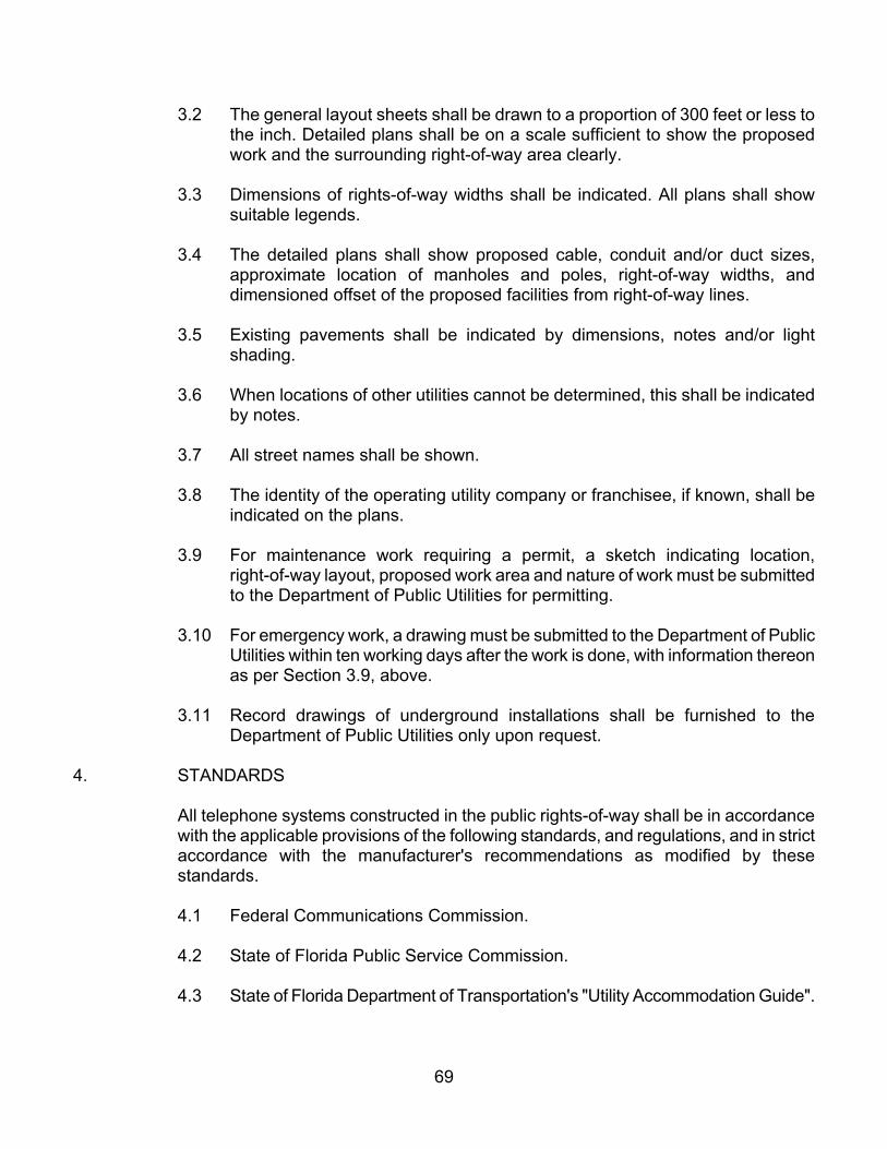
3.2 The general layout sheets shall be drawn to a proportion of 300 feet or less to the inch. Detailed plans shall be on a scale sufficient to show the proposed work and the surrounding right-of-way area clearly.
3.3 Dimensions of rights-of-way widths shall be indicated. All plans shall show suitable legends.
3.4 The detailed plans shall show proposed cable, conduit and/or duct sizes, approximate location of manholes and poles, right-of-way widths, and dimensioned offset of the proposed facilities from right-of-way lines.
3.5 Existing pavements shall be indicated by dimensions, notes and/or light shading.
3.6 When locations of other utilities cannot be determined, this shall be indicated by notes.
3.7 All street names shall be shown.
3.8 The identity of the operating utility company or franchisee, if known, shall be indicated on the plans.
3.9 For maintenance work requiring a permit, a sketch indicating location, right-of-way layout, proposed work area and nature of work must be submitted to the Department of Public Utilities for permitting.
3.10 For emergency work, a drawing must be submitted to the Department of Public Utilities within ten working days after the work is done, with information thereon as per Section 3.9, above.
3.11 Record drawings of underground installations shall be furnished to the Department of Public Utilities only upon request.
4. STANDARDS
All telephone systems constructed in the public rights-of-way shall be in accordance with the applicable provisions of the following standards, and regulations, and in strict accordance with the manufacturer's recommendations as modified by these standards.
4.1 Federal Communications Commission.
4.2 State of Florida Public Service Commission.
4.3 State of Florida Department of Transportation's "Utility Accommodation Guide".
69

4.4 State of Florida Department of Transportation's "Manual on Traffic Control and Safe Practices".
4.5 National Electric Safety Code.
5. CONDUIT
5.1 Steel conduit shall be minimum schedule 40, hot dip galvanized after threading, conforming to A.N.S.I. C80.1, or black iron conforming to ASTM Standard A53.
5.2 PVC conduit shall meet or exceed ASTM F-512, with minimum wall thickness of Series DR-35.
6. INSTALLATIONS
The provisions of Chapter 1 through 4 of this document shall apply, in addition to the following requirements:
6.1 Cover
All underground telephone cable installed in a present or planned paved area (excluding driveway connections and other swale pavement) in any public right-of-way shall be carried in approved steel or plastic conduit. Telephone cable and conduit shall have a minimum of 30" cover.
6.2 Location
In general, all underground telephone installations shall be in accordance with Detail No. 1 in the Appendix, to the extent practicable.
6.3 Crossing
All underground crossings of paved roadways shall be made by the bore and jack method, if possible.
Underground crossings of paved roadways shall not be accomplished by jetting or the use of air or water in direct contact with earth. Pipe driving shall leave no voids in the underlying earth. This does not prohibit the use of air hammers for driving.
6.4 Extraction of Pipe from Bore
The extraction of pipe from beneath any roadway generally is prohibited, except where approved in writing by the Department of Public Utilities. In extreme situations, where pipe must be removed, the roadway must be
70

trenched and later restored in accordance with the Standards and Details in the Appendix (as applicable).
7. TESTING
Testing of telephone facilities will not be required by the Department of Public Utilities. Testing of backfill, compaction and roadway restoration, however, shall be as per
Chapter 2, Sections 2.19, 2.21 and the Standards and Details in the Appendix (as applicable).
8. ABANDONED FACILITIES
The provisions of Chapter 2, Section 2.23 shall apply.
9. RECORD DRAWINGS
The provisions of Chapter 2, Section 2.22 notwithstanding, record drawings (“as-builts”) shall be furnished to the Department of Public Utilities.
71
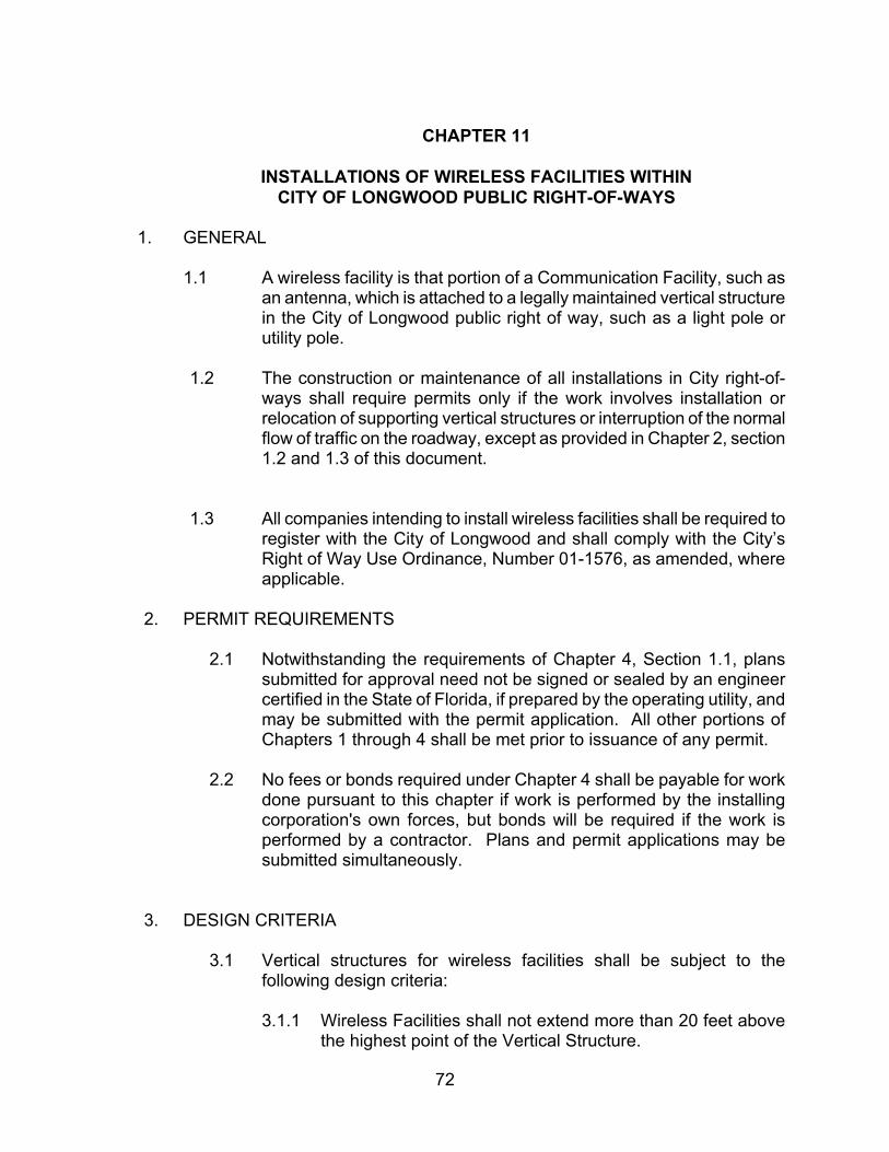
CHAPTER 11
INSTALLATIONS OF WIRELESS FACILITIES WITHIN CITY OF LONGWOOD PUBLIC RIGHT-OF-WAYS
1. GENERAL
1.1 A wireless facility is that portion of a Communication Facility, such as an antenna, which is attached to a legally maintained vertical structure in the City of Longwood public right of way, such as a light pole or utility pole.
1.2 The construction or maintenance of all installations in City right-of- ways shall require permits only if the work involves installation or relocation of supporting vertical structures or interruption of the normal flow of traffic on the roadway, except as provided in Chapter 2, section 1.2 and 1.3 of this document.
1.3 All companies intending to install wireless facilities shall be required to register with the City of Longwood and shall comply with the City’s Right of Way Use Ordinance, Number 01-1576, as amended, where applicable.
2. PERMIT REQUIREMENTS
2.1 Notwithstanding the requirements of Chapter 4, Section 1.1, plans submitted for approval need not be signed or sealed by an engineer certified in the State of Florida, if prepared by the operating utility, and may be submitted with the permit application. All other portions of Chapters 1 through 4 shall be met prior to issuance of any permit.
2.2 No fees or bonds required under Chapter 4 shall be payable for work done pursuant to this chapter if work is performed by the installing corporation's own forces, but bonds will be required if the work is performed by a contractor. Plans and permit applications may be submitted simultaneously.
3. DESIGN CRITERIA
3.1 Vertical structures for wireless facilities shall be subject to the following design criteria:
3.1.1 Wireless Facilities shall not extend more than 20 feet above the highest point of the Vertical Structure.
72

3.1.2 Wireless Facilities that are attached to a Vertical Structure located in Public Rights of Way, that is fifteen feet or less in width and is located adjacent to real property used as a single family residence shall be flush mounted to the Vertical Structure.
3.1.3 Wireless Facilities shall not have any type of lighted signal, lights or illuminations unless required by an applicable federal, state or local rule, regulation or law.
3.1.4 Wireless Facilities shall comply with any applicable Federal Communications Commission Emissions Standards.
3.1.5 Design, construction and installation of such Wireless Facilities shall comply with any applicable local building codes.
3.1.6 No commercial advertising shall be allowed on such Wireless Facilities.
3.1.7 Any accessory equipment and related housing in the public right-of-ways that are used in conjunction with a Wireless Facility shall comply with any applicable local rules, regulations, ordinances or laws governing the placement and design of such equipment.
3.2 Vertical structures, such as towers, whose sole purpose is to serve as a mounting device for antennae, are expressly prohibited from being placed in the Public Rights of Way, unless applicable zoning and land use laws and regulations allow such structures to be placed within the zoning district in which such Public Rights of Way are located, or to which they are adjacent.
4. STANDARDS
All Wireless Facilities constructed in the public right-of-ways shall be in accordance with the applicable provisions of the following standards, and regulations, and in strict accordance with the manufacturer's recommendations as modified by these standards.
4.1 Federal Communications Commission.
4.2 State of Florida Public Service Commission.
4.3 National Electric Safety Code.
73

CHAPTER 12
ELECTRIC POWER INSTALLATIONS
1. APPLICATION OF STANDARDS TO EXISTING FACILITIES
1.1 Notwithstanding the provisions of Chapter 1 through 4 hereof, the provisions of this Public Works Manual do not apply to existing facilities in the public rights- of-way, but shall apply to any major alteration or extension performed upon them and the conditions and manner of prosecuting work on them, of any size or type, from the effective date of this Public Works Manual forward.
1.2 Where roads are being constructed or reconstructed to City standards, existing electric utility facilities conflicting with the proposed construction within the right-of-way or inconsistent with current published or adopted standards may have to be modified or relocated to meet the new requirements. These changes, if required, will have to be made in accordance with the latest adopted standards.
2. PERMITS
2.1 Aerial Installations
The construction of all aerial installations of electric power lines in City right-of-ways shall require permits only if the work involves installation of supporting poles or interruption of the normal flow of traffic on the roadway due to excavations for new installations in the right-of-way.
2.2 Underground Installations
The construction and/or excavations for any underground installations of electric power lines in the public right-of-ways shall not commence prior to issuance of permit from the Department of Public Works.
2.3 No permit shall be required for maintenance or emergency repair work necessary for the continuity of electric service.
3. PERMIT REQUIREMENTS
3.1 Notwithstanding the provisions of Chapter 4, Section 1.1, plans submitted for approval need not be signed or sealed by an engineer certified in the State of Florida, if prepared by franchisee. All applicable portions of Chapters 1 through 4 shall be met prior to issuance of any permit except that only 3 sets of drawings shall be required.
74

3.2 No fees or bonds required under the provisions of Chapter 4 shall be payable by franchisees for work done pursuant to this Chapter if work is performed by franchisee's forces, but bonds will be the work is done by a contractor. Plans and permit applications may be submitted simultaneously.
4. PLANS AND SPECIFICATIONS
4.1 All plans shall be submitted on white prints with blue or black lines. In addition to the proposed project, they shall show all existing facilities as well as all planned facilities sufficiently to permit assessment of the compatibility of the proposed work with the existing systems. Plans must be submitted on sheets no larger than 24 x 36 inches. Small projects may be submitted on legal size paper, provided that scale requirements are met and only one sheet is required.
4.2 The general layout sheets shall be on a scale of 300 feet or less to the inch. Detailed plans shall be on a scale sufficient to show the proposed work and the surrounding right-of-way areas clearly.
4.3 Dimensions of right-of-ways widths shall be indicated. All plans shall show suitable legends.
4.4 The detailed plans shall show proposed cable, conduit or duct sizes, approximate locations of manholes and poles, right-of-way widths, and dimensioned offset of the proposed facilities from the right-of-way lines.
4.5 Existing pavements shall be indicated by dimensions, notes and/or light shading, if applicable.
4.6 When locations of other utilities cannot be determined, this shall be indicated by notes.
4.7 All street names shall be shown.
4.8 The identity of the operating utility company or franchisee, if known, shall be indicated on the plans.
4.9 The provisions of Chapter 2, Section 1.3 notwithstanding, a record sketch only need be submitted to the Department of Public Works within ten working days after the work is done for emergency work involving excavation of pavement. This sketch shall indicate location, right-of-way layout, work area and nature of work performed.
4.10 For emergency work involving excavation of pavement, a record sketch must be submitted to the Department of Public Works within ten working days after the work is done, indicating location, right-of-way layout, work area and nature of work performed.
75

4.11 Record drawings (“as-builts”) of underground installations shall be furnished to the Department of Public Works.
5. STANDARDS
All electric power systems constructed in the public right-of-ways shall be in accordance with the applicable provisions of the following standards and regulations, and in strict accordance with the manufacturer's recommendations as modified by these standards.
5.1 National Electric safety Code.
5.2 State of Florida Public Service Commission.
5.3 State of Florida Department of Transportation's "Utility Accommodation Guide".
5.4 State of Florida Department of Transportation's "Manual on Traffic Control and Safe Practices".
6. CONDUIT
6.1 Steel conduit shall be hot dip galvanized after threading, conforming to ANSI C 80.1.
6.2 PVC conduit shall conform to ASTM F-512.
6.3 Concrete duct banks shall be cast with 3000 p.s.i. concrete, and shall provide a minimum envelope of 3 inches.
7. INSTALLATIONS
Except where stated otherwise in this Chapter, the provisions of Chapter 1 through 4 of this document shall apply, in addition to the following requirements.
7.1 Cover
All underground electric power cable installed in any public right-of-way shall be carried in approved steel or plastic conduit, and shall have a minimum of 36" cover.
7.2 Location
In general, all underground electric power installations shall be in accordance with the Standards and Details in the Appendix (as applicable).
76

7.3 Crossings
All underground crossing of paved roadways shall be made by the bore and jack method, if possible.
Underground crossings of paved roadways shall not be accomplished by jetting or the use of air or water in direct contact with the earth. Pipe driving shall leave no voids in the underlying earth. This does not prohibit the use of air hammers for driving.
7.4 Extraction of Pipe from Bore
The extraction of pipe from beneath any roadway is prohibited except where approved, in writing, by the Department of Public Works. In extreme situations, where pipe must be removed, the roadway must be trenched and later restored in accordance with the Standards and Details in the Appendix (as applicable).
8. TESTING
Testing of electric power facilities will not be required by the Department of Public Works. Testing of backfill, compaction and roadway restoration, however, shall be as per Chapter 2, Sections 2.19, 2.21 and Standards and Details in the Appendix (as applicable).
9. ABANDONED FACILITIES
Any abandoned facility in the right-of-way shall continue to be the responsibility of the owner or operator by whom last used. This section will not apply to facilities required to be left in place by the Department of Public Works.
77

CHAPTER 13
NATURAL GAS INSTALLATIONS
1. APPLICATION OF STANDARDS TO EXISTING FACILITIES
1.1 Notwithstanding the provisions of Chapter 1 through 4 hereof, the provisions of this Public Works Manual do not apply to existing facilities in the public right-of-ways, but shall apply to any major alteration or extension performed upon them and the conditions and manner of prosecuting work on them, of any size or type, from the effective date of this Public Works Manual forward.
1.2 Where roads are being constructed or reconstructed to City standards, existing natural gas facilities conflicting with the proposed construction within the right-of-way or inconsistent with current published or adopted standards may have to be modified or relocated to meet the new requirements. These changes, if required, will have to be made in accordance with the latest adopted standards.
2. PERMITS
2.1 Franchise
Any utility company proposing to offer natural gas service within the City of Longwood must first apply for, and enter into, a franchise agreement with the City before installing transmission or distribution facilities in the public right-of- way.
2.2 Underground Installations
The construction and/or excavations for any underground installations of natural gas lines in the public right-of-ways shall not commence prior to issuance of a permit from the Department of Public Works.
2.3 No permit shall be required for maintenance or emergency repair work necessary for the continuity of natural gas service.
3. PERMIT REQUIREMENTS
3.1 Notwithstanding the provisions of Chapter 4, Section 1.1, plans submitted for approval need not be signed or sealed by an engineer certified in the State of Florida, if prepared by franchisee. All applicable portions of Chapters 1 through 4 shall be met prior to issuance of any permit except that only 3 sets of drawings shall be required.
78
3.2 No fees or bonds required under the provisions of Chapter 4 shall be payable by franchisees for work done pursuant to this Chapter if work is performed by franchisee's forces, but bonds will be the work is done by a contractor. Plans and permit applications may be submitted simultaneously.
4. PLANS AND SPECIFICATIONS
4.1 All plans shall be submitted on white prints with blue or black lines. In addition to the proposed project, they shall show all existing facilities as well as all planned facilities sufficiently to permit assessment of the compatibility of the proposed work with the existing systems. Plans must be submitted on sheets no larger than 24 x 36 inches. Small projects may be submitted on legal size paper, provided that scale requirements are met and only one sheet is required.
4.2 The general layout sheets shall be on a scale of 300 feet or less to the inch. Detailed plans shall be on a scale sufficient to show the proposed work and the surrounding right-of-way areas clearly.
4.3 Dimensions of right-of-ways widths shall be indicated. All plans shall show suitable legends.
4.4 The detailed plans shall show proposed pipe and casing sizes, right-of-way widths, and dimensioned offset of the proposed facilities from the right-of-way lines.
4.5 Existing pavements shall be indicated by dimensions, notes and/or light shading, if applicable.
4.6 When locations of other utilities cannot be determined, this shall be indicated by notes.
4.7 All street names shall be shown.
4.8 The identity of the operating utility company or franchisee, if known, shall be indicated on the plans.
4.9 The provisions of Chapter 2, Section 1.3 notwithstanding, a record sketch only need be submitted to the Department of Public Works within ten working days after the work is done for emergency work involving excavation of pavement. This sketch shall indicate location, right-of-way layout, work area and nature of work performed.
4.10 For emergency work involving excavation of pavement, a record sketch must be submitted to the Department of Public Works within ten working days after the work is done, indicating location, right-of-way layout, work area and nature of work performed.
79

4.11 Record drawings (“as-builts”) of underground installations shall be furnished to the Department of Public Works.
5. STANDARDS
All natural gas systems constructed in the public right-of-ways shall be in accordance with the applicable provisions of the following standards and regulations, and in strict accordance with the manufacturer's recommendations as modified by these standards.
5.1 American Gas Association
5.2 National Electric Safety Code.
5.3 State of Florida Public Service Commission.
5.4 State of Florida Department of Transportation's "Utility Accommodation Guide".
5.5 State of Florida Department of Transportation's "Manual on Traffic Control and Safe Practices".
6. CASINGS
Gas mains crossing streets shall be installed in appropriately sized casings unless it is demonstrated to the satisfaction of the Department of Public Works that such installation would adversely affect the effectiveness of cathodic protection. Additionally, it shall be demonstrated to the satisfaction of the Department of Public Works that stresses on mains, which are installed under streets without a casing, are within allowable and acceptable limits. Casing installation shall be as set forth in Section 7.3 below.
7. INSTALLATIONS
Except where stated otherwise in this Chapter, the provisions of Chapter 1 through 4 of this document shall apply, in addition to the following requirements.
7.1 Cover
All underground natural gas lines installed in any public right-of-way shall be carried in approved steel or plastic lines, and shall have a minimum of 36" cover.
80
7.2 Location
In general, all underground natural gas installations shall be in accordance with the Standards and Details in the Appendix (as applicable).
7.3 Crossings
All underground crossing of paved roadways shall be made by the bore and jack method or by directional drilling.
Underground crossings of paved roadways shall not be accomplished by jetting or the use of air or water in direct contact with the earth. Pipe driving shall leave no voids in the underlying earth. This does not prohibit the use of air hammers for driving services.
7.4 Extraction of Pipe from Bore
The extraction of pipe from beneath any roadway is prohibited except where approved, in writing, by the Department of Public Works. In extreme situations, where pipe must be removed, the roadway must be trenched and later restored in accordance with the Standards and Details in the Appendix (as applicable).
8. TESTING
Testing of natural gas facilities will not be required by the Department of Public Works. Testing of backfill, compaction and roadway restoration, however, shall be as per Chapter 2, Sections 2.19, 2.21 and Standards and Details in the Appendix (as applicable).
9. ABANDONED FACILITIES
Any abandoned facility in the right-of-way shall continue to be the responsibility of the owner or operator by whom last used. This section will not apply to facilities required to be left in place by the Department of Public Works.
81

CHAPTER 14
CONSTRUCTION STANDARDS AND DETAILS INDEX
1. Construction Standards & Details
Detail use criteria – the details provided are for sole use on projects which will be owned by the City of Longwood. The modification of any detail is expressly prohibited without the written consent of the City Administrator. Use of the details on projects other than those owned by the City is also strictly prohibited.
DRAWING TITLE NUMBER
TYPICAL STREET SECTION D1 TYPICAL PAVMENT STRUCTURE D2 UPRIGHT/BARRIER CURB D3 RESIDENTIAL SIDEWALK/DRIVEWAY D4 LANE SEPARATION DETAILS D5 TYPICAL LANDSCAPE MEDIAN SECTIONS D6 TYPICAL DETAILS FOR CROSSWALKS AND DECORATIVE PAVEMENT D7 INTERSECTION WITH VALLEY GUTTER D8 CURB DRAINAGE INLET D9 STORM SEWER MANHOLE D10 MITERED END SECTION D11 TRENCH REPAIR DETAILS – UNPAVED AREAS D12 TRENCH REPAIR DETAILS – PAVED AREAS D13 TRENCH REPAIR DETAILS – PAVED AREAS WITH FLOWABLE FILL D14
82