section 8-01 construction stormwater pollution prevention
105
SECTION 8-01 CONSTRUCTION STORMWATER POLLUTION PREVENTION PAGE 8 - 1 DIVISION 8 MISCELLANEOUS CONSTRUCTION SECTION 8-01 CONSTRUCTION STORMWATER POLLUTION PREVENTION 8-01.1 DESCRIPTION Section 8-01 describes required submittals and work consisting of furnishing, installing, maintaining, removing, and disposing of construction stormwater and erosion controls, tree, vegetation and soil protection, and pollutant prevention and countermeasures. These controls shall prevent erosion and scour, treat sediment laden water for acceptable discharge, and prevent conveyance of pollutants and sediment into surface waters, drainage systems, and environmentally critical areas. The Construction Stormwater and Erosion Control Plan (CSECP), the Tree, Vegetation and Soil Protection Plan (TVSPP), the Spill Plan (SP) and the Temporary Discharge Plan (TDP) described in this Section shall apply Best Management Practices (BMP’s) that contain elements to protect water quality and downstream resources. 8-01.2 MATERIALS Materials shall meet the requirements of the following Sections: RipRap and Quarry Spall 9-13 Erosion Control Materials 9-14 Geotextile 9-37 Unless the Contract specifies otherwise, erosion control geotextile shall be permanent erosion control, high survivability. 8-01.3 CONSTRUCTION REQUIREMENTS 8-01.3(1) GENERAL Work involving construction stormwater pollution prevention within The City of Seattle limits shall comply with this Section and Sections 1-05.13(3), 1-07.15 and 1-07.5. Work involving erosion and sedimentation control not within the City of Seattle limits shall also comply with the requirements of the local jurisdiction. If applicable, Stormwater Pollution Prevention Plan (SWPPP) requirements of a National Pollutant Discharge Elimination System (NPDES) construction permit, local jurisdiction, or both shall be addressed in the Construction Stormwater and CSECP and the TDP. The Contractor’s Work and Project Site conditions shall ensure elements are in place to protect water quality and to protect downstream resources. These elements shall cover aspects of general water quality protection strategies consisting of: limiting Project Site impacts, protecting the public drainage system and water bodies, preventing erosion and sedimentation, and managing activities and potential pollutant sources. The elements of water quality and downstream resource protection are: 1) Define and field identify clearing limits and environmentally critical areas (CSECP & TVSPP) 2) Retain top layer of soil (TVSPP) 3) Establish construction access (CSECP) 4) Protect downstream properties and receiving waters (CSECP & TDP) 5) Prevent erosion and sediment transport from the site (CSECP) 6) Prevent erosion and sediment transport from the site by vehicles. (CSECP) 7) Stabilize soils (CSECP) 8) Protect slopes (CSECP) 9) Protect storm drains (CSECP) 10) Stabilize channels and outlets (CSECP) 11) Control pollutants (CSECP, TDP, SP & others as applicable) 12) Control dewatering 13) Maintain BMPs (ALL) 14) Inspect BMPs (ALL) 15) Execute Construction Stormwater Control Plan. (CSECP) 16) Minimize open trenches (CSECP) _________________________________________________________________________________ 2014 Edition City Of Seattle Standard Specifications For Road, Bridge And Municipal Construction
-
Upload
khangminh22 -
Category
Documents
-
view
0 -
download
0
Transcript of section 8-01 construction stormwater pollution prevention

SECTION 8-01 CONSTRUCTION STORMWATER POLLUTION PREVENTION PAGE 8 - 1
DIVISION 8 MISCELLANEOUS CONSTRUCTION
SECTION 8-01 CONSTRUCTION STORMWATER POLLUTION PREVENTION
8-01.1 DESCRIPTION
Section 8-01 describes required submittals and work consisting of furnishing, installing, maintaining, removing, and disposing of construction stormwater and erosion controls, tree, vegetation and soil protection, and pollutant prevention and countermeasures. These controls shall prevent erosion and scour, treat sediment laden water for acceptable discharge, and prevent conveyance of pollutants and sediment into surface waters, drainage systems, and environmentally critical areas.
The Construction Stormwater and Erosion Control Plan (CSECP), the Tree, Vegetation and Soil Protection Plan (TVSPP), the Spill Plan (SP) and the Temporary Discharge Plan (TDP) described in this Section shall apply Best Management Practices (BMP’s) that contain elements to protect water quality and downstream resources. 8-01.2 MATERIALS
Materials shall meet the requirements of the following Sections:
RipRap and Quarry Spall 9-13
Erosion Control Materials 9-14
Geotextile 9-37
Unless the Contract specifies otherwise, erosion control geotextile shall be permanent erosion control, high survivability.
8-01.3 CONSTRUCTION REQUIREMENTS
8-01.3(1) GENERAL
Work involving construction stormwater pollution prevention within The City of Seattle limits shall comply with this Section and Sections 1-05.13(3), 1-07.15 and 1-07.5. Work involving erosion and sedimentation control not within the City of Seattle limits shall also comply with the requirements of the local jurisdiction.
If applicable, Stormwater Pollution Prevention Plan (SWPPP) requirements of a National Pollutant Discharge Elimination System (NPDES) construction permit, local jurisdiction, or both shall be addressed in the Construction Stormwater and CSECP and the TDP.
The Contractor’s Work and Project Site conditions shall ensure elements are in place to protect water quality and to protect downstream resources. These elements shall cover aspects of general water quality protection strategies consisting of: limiting Project Site impacts, protecting the public drainage system and water bodies, preventing erosion and sedimentation, and managing activities and potential pollutant sources.
The elements of water quality and downstream resource protection are:
1) Define and field identify clearing limits and environmentally critical areas (CSECP & TVSPP)
2) Retain top layer of soil (TVSPP)
3) Establish construction access (CSECP)
4) Protect downstream properties and receiving waters (CSECP & TDP)
5) Prevent erosion and sediment transport from the site (CSECP)
6) Prevent erosion and sediment transport from the site by vehicles. (CSECP)
7) Stabilize soils (CSECP)
8) Protect slopes (CSECP)
9) Protect storm drains (CSECP)
10) Stabilize channels and outlets (CSECP)
11) Control pollutants (CSECP, TDP, SP & others as applicable)
12) Control dewatering
13) Maintain BMPs (ALL)
14) Inspect BMPs (ALL)
15) Execute Construction Stormwater Control Plan. (CSECP)
16) Minimize open trenches (CSECP)
_________________________________________________________________________________ 2014 Edition City Of Seattle Standard Specifications For Road, Bridge And Municipal Construction
PAGE 8 - 2 SECTION 8-01 CONSTRUCTION STORMWATER POLLUTION PREVENTION
17) Phase the project (ALL; should also be shown in CPM Schedule, see Section 1-08.3)
18) Install permanent flow control and water quality facilities
To the degree possible, the Contractor shall coordinate this temporary Work with permanent drainage and erosion control Work the Contract requires. The Engineer may require additional temporary control measures if it appears pollution or erosion may result from weather, the nature of the Materials, or progress on the Work. The Engineer may also require erosion control Work to be done with or immediately after grading. Sediment control devices and BMPs shall be installed prior to any ground disturbing activity.
8-01.3(2) CONSTRUCTION STORMWATER POLLUTION PREVENTION SUBMITTALS
Required submittals for Construction Stormwater Pollution Prevention are:
a. CSECP
b. TVSPP
c. SP
d. TDP
The submittals described in this section shall be submitted as individual plan(s) for review by the Engineer. Updates, phasing and locations shall be coordinated between all plans. The Contractor shall allow 10 Working Days for review of the CSECP, the TVSPP, the SP, and the TDP in accordance with section 1-05.3.
8-01.3(2)A CONSTRUCTION STORMWATER AND EROSION CONTROL PLAN (CSECP)
The Construction Stormwater and Pollution Prevention submittals shall include a CSECP. When a conceptual CSECP has been developed by the Engineer and included in the Contract, the Contractor shall consider these Drawings “for information only” unless details or Drawing contain elements noted as “required”. The Contractor may propose alternative, modify, or adopt the Engineer’s conceptual CSECP elements to reflect the Contractor’s means and methods. The Contractor’s means and methods shall coordinate with any required elements in the Engineer’s CSECP.
If a conceptual CSECP does not exist in the Contract, the Contractor shall develop all elements of the CSECP.
The Contractor shall refer to SPU Director’s Rule 2009-004, the Construction Stormwater Control Technical Requirements Manual for guidance on the CSECP. Checklists for Selecting Construction BMPs are included in this manual. The Contractor shall provide a schedule for CSECP implementation, including installation, maintenance, phasing and removal of each control and incorporate it into the Contractor’s CPM Schedule (See Section 1-08.3).
The CSECP shall cover all areas of the Contractor’s Work and may affect areas outside of the Project Site limits (including disposal sites, haul roads, all nearby property, streams, and other bodies of water).
The CSECP submittal shall include, but not be limited to, one or more of the following:
1) Describe with Shop Drawings of sufficient scale and detail showing the Project Site, and the locations and types of temporary erosion and sediment controls.
2) As necessary, show by a series of time sequence Shop Drawings, how construction stormwater and erosion control best management practices (BMPs) are to be installed, maintained, removed and coordinated with the Work and the CPM Schedule. Describe how non-work areas will be identified and protected;
3) Describe how stormwater from non-work areas will be kept separate from stormwater in the work area;
4) Describe the details and continuing maintenance of entrance and exit equipment wash areas;
5) Show locations of existing inlets and catch basins within 500 feet downslope of the Work, and describe how they will be protected;
6) When stormwater is to be concentrated and collected, show locations with cross-sections as applicable and describe control details of proposed ditch, berm, culvert, pipe, sediment basin, basin outfall, scour control, inlet, catch basin, drain, bypass, subsurface drain and related features and coordinate with the TDP.
7) Describe locations for and protections and covering practices for stockpile, muck, and related deposits;
8) Describe the controls to prevent sediment, debris, and other pollutants from entering surface waters and drainage features;
9) Provide Manufacturer’s Certificate of Compliance, certified laboratory test reports, catalog cuts, samples, and other information providing adequate description of Supplies and Material proposed for Construction Stormwater and Erosion Control applications;
10) The name of the Certified Erosion and Sediment Control Lead (CESCL), or Certified Professional in Erosion and Sediment Control (CPESC), including contact information. If the Work is of such a magnitude that it requires additional help, describe the qualifications of additional help, any on-site training that may be necessary, and frequency and type of reporting to the CESCL;
_________________________________________________________________________________ 2014 Edition City Of Seattle Standard Specifications For Road, Bridge And Municipal Construction

SECTION 8-01 CONSTRUCTION STORMWATER POLLUTION PREVENTION PAGE 8 - 3
11) A schedule of typical inspections ensuring timely maintenance and repair of erosion control BMPs; minimum once per week and within 24 hours of a significant precipitation event.
12) Identify and provide timelines for submitting permit required or related documentation; may reference submittal control document; see section 1-05.3.
13) Provide details of seed mix, amendment, mulch, and protections for placing and establishing temporary seeded erosion control areas;
14) In areas where exposed erodible soil exceeds 4000 square feet or may be unprotected for more than 2 Calendar Days, describe the controls and the proposed monitoring to ensure runoff from the site shall not become non-compliant;
15) Identify the method for concrete washouts. Concrete washouts shall be used to contain concrete and liquids when the chutes of concrete mixers, hoppers of concrete pumps, and other tools with waste concrete are rinsed out after delivery. The washout facilities shall:
a. consolidate solids for easier disposal and prevent runoff of liquids,
b. prevent wash water from leaching into the ground and from contaminating groundwater,
c. prevent wash water from migrating to a storm drain, and
d. prevent solids from clogging storm drain pipes.
16) Provide details of other construction stormwater and erosion control measures as may be used in the Work.
The Contractor shall provide at a designated location at the Project Site the current (or copies of the current) CSECP.
8-01.3(2)B TREE, VEGETATION AND SOIL PROTECTION PLAN (TVSPP)
The Construction Stormwater and Pollution Prevention submittals shall include a TVSPP.
The Contractor shall develop, implement, maintain and regularly update a Project Site specific TVSPP including all materials, equipment, and labor to be used, for the duration of the Contact. The TVSPP shall show the location of BMPs related to the protection of existing (not designated for removal) and new, trees (including roots), vegetation, and soil.
Locations of “specific protective measures” to ensure preservation of trees, vegetation, and soil within the tree dripline (zone B –see Standard Plan 133) or within the defined areas are required for the following:
a. All areas marked as “Do Not Disturb” on the Drawings with work back of the face of the curb and within 5-feet of marked areas.
b. Trees identified by the note “Protect Tree" on the Drawings, or if not identified on the Drawings, all trees with work back of the face of the curb and within zone B of the tree; and at locations identified by the Engineer at the time of field review of the TVSPP.
c. Vegetation identified by the note “Protect Landscaping”, “Protect Vegetation” “Protect Shrub ”, etc. on the Drawings, or if not identified on the Drawings, all vegetation with work back of the face of the curb and within 5-feet of the vegetation; and at locations identified by the Engineer at the time of field review of the TVSPP.
d. Roots identified by the note “Protect Roots” on the Drawings, or if not identified on the Drawings, all roots visible or obvious within zone B of a tree; and at locations identified by the Engineer at the time of field review of the TVSPP.
e. Roots within zone B of a tree encountered during excavation except when within roadway surfacing section, driveway surfacing section, sidewalk surfacing section, utility prisms, and within 1-foot of improvement structures geometrics (such as retaining walls, bridge abutments, pole foundations, etc…). A utility prism is the volume centered about the utility equal to the trench width in both vertical and horizontal dimensions. Utility prisms are not defined for conduit.
f. Other areas to be protected as determined by the Contractor and shown in the Contractor’s TVSPP.
Back of the face of the curb excludes work in the roadway. Work includes all Contractor operations as well as the actual area of work indicated in the Contract.
The TVSPP shall address the following “specific protective measures” unless otherwise approved by the Engineer in writing:
1. For a., b., and c. above: if the duration of construction operations at the affected location is less than or equal to 30 Calendar Days, a four (4)-foot– six (6)-inch high PVC pipe frame with orange safety fencing attached on all sides as shown in the Standard Plan 132b shall be used about the perimeter unless otherwise approved per the TVSPP. If duration of construction operations at the affected location is greater than 30 Calendar Days, a four (4)-foot– six (6)-inch to six (6)-foot high chain link fence as shown in the Standard Plan 132a shall be used about the perimeter unless otherwise approved per the TVSPP.
_________________________________________________________________________________ 2014 Edition City Of Seattle Standard Specifications For Road, Bridge And Municipal Construction
PAGE 8 - 4 SECTION 8-01 CONSTRUCTION STORMWATER POLLUTION PREVENTION
2. For d. above; apply a 6 inch layer of Arborist Wood Chip Mulch (AWCM) to retain moisture, control erosion and protect surface roots. See section 8-01.3(6)C.
3. For e. above; apply AWCM and/or burlap watered daily to ensure constant hydration of roots during period of exposure.
4. For d. and e. above, apply a minimum 1” steel plate or 4” thick timber planking over 2-3” of AWCM, or minimum ¾” plywood over 6 to 8 inches of AWCM, to protect surface or exposed roots from compaction related to construction operations. Only required where construction operations required encroachment onto unpaved surfaces. Unpaved surfaces exclude temporally unpaved surfaces such as the subgrade for prescribed work where compaction is required.
5. For e. above, excavation or portions thereof shall be exploratory to minimize damage to roots. The TVSPP shall address the method of exploratory excavation to expose roots within specified locations (i.e. by air spade, hand digging, etc.), by which all roots 2” and larger shall be retained and protected if encountered. Where roots 2 inch diameter and larger are discovered, the Contractor shall promptly notify the Engineer. If root pruning is required, see Section 8-02.3(7)A for pruning cuts and methods.
6. For all of the above; no storage of equipment or material shall be allowed within the areas marked on Drawings as “Do Not Disturb Area" or within the dripline (zone B) of a tree unless “specific protective measures” per the TVSPP approved by the Engineer are in place.
The TVSPP shall also address the following general protective measures unless otherwise approved by the Engineer in writing:
1. If canopy/clearance pruning is required, to achieve up to “standard vertical clearances” the Contractor shall notify the Engineer at least 15 Working Days in advance to allow pruning by the Owner or private property owner. The Engineer may require this canopy/clearance pruning to be performed by the Contractor in accordance with 1-04.4. “Standard vertical clearances” here within shall be considered 14-feet for roadway, 10-feet for bicycle paths, 8-feet for sidewalks, and as specified in the Contract.
2. Where pruning of canopy for construction clearance above “standard vertical clearances” is not allowed; temporary tie-up of low limbs or alternative construction methods shall be used.
3. Where canopy/clearance pruning above “standard vertical clearances” is approved by the Engineer, the Contractor shall be responsible for this pruning and all associated costs.
4. If the Contractor performs canopy/clearance pruning, The Contractor shall provide credentials confirming current ISA certification of pruning technician and/or current certification of a tree care company performing the work. See Section 8-02.3(7)A for pruning requirements. A canopy/clearance plan including credentials or certification may be submitted separate from the TVSPP. A separate "TVSPP-canopy/clearance pruning" submitted shall be submitted at least 5 Working Days in advance in accordance with section 1-05.3. If Pruning is performed at both the Owner and Contractor cost as described here within, the cost will be prorated.
5. Where construction activity involves the operation of equipment or redirection of traffic from established travel lanes within the dripline (Zone B) of tree, the Contractor shall depict these conditions on the TVSPP.
6. The removal of all protective measures installed over grass or groundcover and underlying soil proposed to be retained in an undisturbed condition in unpaved planting strips or open areas shall be removed in a timely manner to minimize impact to understory vegetation.
7. Soil management/protective measures shall include eradication of ivy and other invasive weed species detrimental to the preservation of trees, prior to placement of AWCM in all areas to be protected from disturbance.
8. Excavation or tunneling of any kind within the “Critical Root Zone” (Zone A) of a tree requires approval by the Engineer. The Contractor shall provide at least 2 Working Days advance written notice for review and shall not proceed without approval from the Engineer.
9. Excavation or portions thereof excluded from “specific protective measures” but within zone B of a tree shall be performed with enough care as to minimize damage to roots. In all excavations, if roots 2” and larger are encounter, the excavation at the root location shall stop and the Contractor shall promptly notify the Engineer. If root pruning is required, see Section 8-02.3(7)A for pruning cuts and methods.
10. Trees shall be protected from exhaust heat; exhaust deflection panels may be required on some equipment to prevent burning of foliage and branches of trees to be retained.
See Standard Plans 132a, and 132b, for additional tree protection guidance. See Standard Plan 133 for tree/root zones A, B, and C.
Alteration of the TVSPP and protection measures shall be allowed only as deemed necessary by the Engineer. In order to accommodate actual construction details and to coordinate with the requirement of Standard Plans 132a and 132b, the fence at the dripline required on Standard Plan no. 133 may be moved to a location closer to the tree, if approved by the Engineer.
_________________________________________________________________________________ 2014 Edition City Of Seattle Standard Specifications For Road, Bridge And Municipal Construction

SECTION 8-01 CONSTRUCTION STORMWATER POLLUTION PREVENTION PAGE 8 - 5
The Contractor’s schedule for installation of protective measures shall be shown in the Contractor Critical Path Schedule and applicable weekly look-ahead schedules. The Engineer’s review of the TVSPP shall involve a joint field review. Conflicts between protection measures and Work required under the Contract shall be brought to the attention of the Engineer during the joint field review of TVSPP. The TVSPP shall be accepted prior to any mobilization. On larger projects, the TVSPP may be submitted by phases, when specified or approved by the Engineer.
8-01.3(2)C SPILL PLAN
The Construction Stormwater and Pollution Prevention submittals shall include a Spill Plan (SP).
In accordance with section 1-07.15(1) and applicable laws, the Contractor shall prepare a project specific construction prevention, control and countermeasures SP to be used for the duration of the project. The Contractor shall develop, implement, maintain and regularly update a Project Site specific SP, including all materials, equipment, and labor to be used, for the duration of the project.
The SP shall be approved by the Engineer prior to the commencement of any Project Site construction activities. The Contractor shall maintain a copy of the SP at the Project Site, including any necessary updates as the Work progresses.
The SP shall be updated by the Contractor throughout project construction so that the written plan reflects actual site conditions and practices. The Contractor shall update the SP Plan at least annually and maintain a copy of the updated SP on the Project Site. All project employees shall be trained in spill prevention and containment, and shall know where the SP and spill response kits are located and have immediate access to them.
If hazardous materials are encountered or spilled during construction, the Contractor shall do everything possible to control and contain the material until appropriate measures can be taken. The Contractor shall supply and maintain spill response kits of appropriate size within close proximity to hazardous materials and equipment.
The Contractor shall implement the spill prevention measures identified in the SP before performing any of the following:
1. Placing materials or equipment in staging or storage areas.
2. Refueling, washing, or maintaining equipment.
3. Stockpiling contaminated materials.
The SP shall set forth the following information in the following order:
1. Responsible Personnel
Identify the name(s), title(s), and contact information for the personnel responsible for implementing and updating the plan, including the Spill Prevention and Response Lead (per 1-05.13(3)C) and all spill responders.
2. Spill Reporting
List the names and telephone numbers of the federal, State, and local agencies the Contractor shall notify in the event of a spill. The Contractor shall also notify the Engineer.
3. Project Site Information
Describe the following items:
A. The project scope of work.
B. The Project Site location and boundaries.
C. The drainage pathways from the Project Site.
D. Nearby waterways and sensitive areas and their distances from the Project Site.
4. Potential Spill Sources
Describe each of the following for all potentially hazardous materials brought or generated on-site (including materials used for equipment operation, refueling, maintenance, or cleaning):
A. Name of material and its intended use.
B. Estimated maximum amount on-site at any one time.
C. Location(s) (including any equipment used below the ordinary high water line) where the material will be staged, used, and stored and the distance(s) from nearby waterways and sensitive areas.
D. Decontamination location and procedure for equipment that comes into contact with the material.
E. Disposal procedures.
5. Pre-Existing Contamination
_________________________________________________________________________________ 2014 Edition City Of Seattle Standard Specifications For Road, Bridge And Municipal Construction

PAGE 8 - 6 SECTION 8-01 CONSTRUCTION STORMWATER POLLUTION PREVENTION
Describe any pre-existing contamination and contaminant sources (such as buried pipes or tanks) in the project area that are described in the Contract documents. Identify equipment and work practices that will be used to prevent the release of contamination.
6. Spill Prevention and Response Training
Describe how and when all personnel (including refueling contractors and Subcontractors) will be trained in spill prevention, containment and response in accordance with the Spill Plan. Describe how and when all spill responders will be trained in accordance with WAC 296-824.
7. Spill Prevention
Describe the following items:
A. Spill response kit contents and location(s).
B. Security measures for potential spill sources.
C. Secondary containment practices and structures for hazardous materials.
D. Methods used to prevent stormwater from contacting hazardous materials.
E. Site inspection procedures and frequency.
F. Equipment and structure maintenance practices.
G. Daily inspection and cleanup procedures that ensure all equipment used below the ordinary high water line is free of all external petroleum based products.
H. Refueling procedures for equipment that cannot be moved from below the ordinary high water line.
8. Spill Response
Outline the response procedures the Contractor will follow for each scenario listed below. Include a description of the actions the Contractor shall take and the specific, on-site, spill response equipment that shall be used to assess the spill, secure the area, contain and eliminate the spill source, and clean up and dispose of spilled and contaminated material.
A. A spill of each type of hazardous material at each location identified in 4, above.
B. Stormwater that has come into contact with hazardous materials.
C. A release or spill of any pre-existing contamination and contaminant source described in 5, above.
D. A release or spill of any unknown pre-existing contamination and contaminant sources (such as buried pipes or tanks) encountered during project Work.
E. A spill occurring during Work with equipment used below the ordinary high water line (if applicable)
If the Contractor will use a Subcontractor for spill response, provide contact information for the Subcontractor under item 1 (above), identify when the Subcontractor will be used, and describe actions the Contractor shall take while waiting for the Subcontractor to respond.
9. Project Site Map
Provide a map showing the following items:
A. Site location and boundaries.
B. Site access roads.
C. Drainage pathways from the site.
D. Nearby waterways and sensitive areas.
E. Hazardous materials, equipment, and decontamination areas identified in 4, above.
F. Pre-existing contamination or contaminant sources described in 5, above.
G. Spill prevention and response equipment described in 7 and 8, above.
10. Spill Report Forms
Provide a copy of the spill report form(s) that the Contractor will use to document the release and cleanup.
An environmental spill shall be considered a release of contaminant or any material that may be hazardous, or dangerous, or harmful to the environment. In addition to the requirements specified in Section 1-07.5(2), the Contractor shall take precautions to assure that contaminants are under control and prevented from release. Contaminants anticipated for use in performing the Work (such as fuel, hydraulic oil, asphalt sealer, pesticide, lubricant, paint, etc.) shall be stored, handled, transported, used, and disposed of in accordance with each product’s Material Safety Data Sheet (MSDS), manufacturer’s recommendations, and applicable law, code, and regulation. Equipment (valves, pumps, switches, etc.) and Supplies (hose, containers, connections, etc.) shall be maintained at all times in good operating condition, leak proof, and shall be routinely
_________________________________________________________________________________ 2014 Edition City Of Seattle Standard Specifications For Road, Bridge And Municipal Construction
SECTION 8-01 CONSTRUCTION STORMWATER POLLUTION PREVENTION PAGE 8 - 7
inspected for leaks and releases, and immediately repaired or replaced when needed. MSDS information for each potential contaminant at the Project Site shall be maintained on the Project Site in a location that is readily accessible.
Should an environmental spill occur, the Contractor shall immediately contain the spill, and shall make the notifications per Section 1-07.28, and as described in the Contractor’s approved Spill Plan. This Contract information shall be posted using the Emergency Response for the SP Plan form. The form shall be provided upon request.
In addition to immediate verbal notification, the Contractor shall submit written documentation (spill report) for all releases of hazardous material to the Engineer within 24 hours of initial discovery of the release. The Consultant shall submit a written update of the spill report, including documentation of the response and cleanup of the release, to the Engineer within 5 business days of completion of the cleanup.
In addition, the Contractor shall follow any instruction provided by the Engineer or any agency having the authority to direct cleanup activities at the project site.
8-01.3(2)D TEMPORARY DISCHARGE PLAN
The Construction Stormwater and Pollution Prevention submittals shall include a TDP.
The Contractor shall develop, implement, maintain and regularly update a Project Site specific TDP. The TDP shall include all materials, equipment, and labor to be used, for the duration of the project for water management in accordance with all Owner provided and Contractor obtained permits that identify flow rates, quantity and quality controls of concentrated and collected temporary discharges of groundwater, and process water and stormwater to the drainage and sewer system (or land, if applicable). See related sections, 1-05.13(3) Construction Stormwater Pollution Prevention Coordination, 1-07.6 Permits, and dewatering specifications.
The TDP shall incorporate requirements limiting flow rate, quantity and quality of the proposed discharge, record keeping and reporting to meet the most restrictive of the following (if applicable);
a. A National Pollutant Discharge Elimination System (NPDES) construction permit,
b. A King county Industrial Discharge Permit,
c. Side Sewer Permit for Temporary Discharge, and
d. Other applicable permits
The TDP shall include, but is not limited to:
a. A schematic flow diagram from collection or generation of water to an approved point of discharge at the drainage and sewer system that includes any detention, settling, or treatment, flow restrictions, measurement equipment and location, quality sampling equipment and location.
b. Site layout drawing showing the above, which may be incorporated into the CSECP described in 8-01.3(2)A.
c. Description of any weather related permit restrictions and the Contractor’s planned response
d. Description of all flow measuring equipment and any manufacturer recommended calibration and maintenance (if applicable)
e. Sample(s) measurement report and a schedule for recording and reporting all flow measurements (if applicable)
f. Description of all sampling and measuring equipment for turbidity, total settleable solids, chlorine and pH and manufacturer recommended calibration and maintenance
g. Description of sampling equipment and procedures for all other pollutants that will be sent to an approved laboratory (if applicable)
h. Sample(s) discharge quality report and a schedule for recording and reporting all quality measurements (if applicable)
8-01.3(2)E DEWATERING PLAN
The Construction Stormwater Pollution Prevention Submittals may include a Dewatering Plan per Section 2-08.3.
8-01.3(3) MAINTAINING CSECP and TVSPP CURRENT During the course of the Work, the Contractor and Construction Stormwater Pollution Prevention Coordinator and the
Tree, Vegetation and Soil Protection Lead (see Section 1-05.13(3)) shall be prepared to discuss with the Engineer the status of the Construction Stormwater and Erosion Control Plan (CSECP) and the Tree, Vegetation and Soil Protection Plan (TVSPP) controls in-progress and future controls as they relate to the Work, to the progress schedule, to permits, to Change Order(s), and as may be required in the Contract.
Significant addition of Work, the encountering of unexpected ground water, the occurrence of a slide, or changes in the Contractor’s method of operation may require significant modifications to the CSECP or TVSPP. When revisions to the current CSECP or TVSPP are required, the Contractor and applicable lead(s) shall be update the CSECP, TVSPP, or both
_________________________________________________________________________________ 2014 Edition City Of Seattle Standard Specifications For Road, Bridge And Municipal Construction
PAGE 8 - 8 SECTION 8-01 CONSTRUCTION STORMWATER POLLUTION PREVENTION
and shall submit the updated plan(s) to the Engineer within 5 Working Days unless the Engineer agrees to other arrangements.
The Contractor’s Certified Erosion and Sediment Control Lead (CESCL) and TVSPP Lead shall verify all BMPs are being followed least once every calendar week and within 24-hours of runoff events in which stormwater discharges from the site. Inspections of temporarily stabilized, inactive sites may be reduced to once every calendar month. The CSWPP Inspection Form shall be completed for each inspection and a copy shall be submitted to the Engineer no later than the end of the next Working Day following the inspection. Separate inspection may be performed and submitted for the CSECP and the TVSPP.
8-01.3(4) AUTHORITY OF CONSTRUCTION STORMWATER POLLUTION PREVENTION COORDINATOR
See Section 1-05.13(3).
8-01.3(5) EROSION CONTROL SEEDING
8-01.3(5)A GENERAL
1. Stormwater Pollution Prevention. The application of seed, fertilizer, lime, mulch, tackifier, and other amendments shall be in accordance with Section 8-02, as may be required in the Contract, and as indicated in the construction stormwater pollution prevention submittals,
2. Fertilizers Used Adjacent To Surface Waters. Where the application of erosion control seeding is within, near, or may contribute to runoff entering into streams, surface waters, and environmental critical areas, all fertilizers shall be a slow release formulation.
8-01.3(5)B CULTIVATION
Soil surfaces disturbed, compacted or exposed to erosion shall be prepared prior to seeding by cultivation to incorporate amendments to produce an 8-inch minimum depth of homogeneous mixture containing 5% organic matter suitable for seeding (See Section 8-02).
Clearing, grubbing, grading, removal of debris and delineation of areas to be excluded from cultivation shall be completed by the Contractor and inspected by the Engineer prior to cultivation. Exposed soil surfaces within areas excluded from cultivation shall be topdressed with 1” of amended soil for seeding or mulched as directed by the Engineer.
1. Cultivation Tools. Cultivating may be by rototiller, farm disc, harrow, or other equipment approved by the Engineer. 2. Travel on Slopes. On slopes or grades, cultivating shall follow the contours or be done at right angles to the natural
flow of water. Where the slope grade is relatively steep, including but not limited to areas identified as Environmentally Critical Areas, the Contractor shall submit a cultivating plan to the Engineer for review at least 2 Working Days in advance. When near streams and other bodies of water, including but not limited to Environmentally Critical Areas, designated Wetlands, Wildlife Corridors, and Fish and Wildlife Habitat Conservation Areas cultivating shall be done reasonably parallel to the water bodies’ boundaries and shall gradually transition with distance from the water to slope or grade cultivating.
3. Protection of Trees. Cultivation within the drip line of existing trees, shown as “Zone B” on Standard Plan no. 133, is excluded from areas unless otherwise directed by the Engineer.
8-01.3(5)C COMPACTION
After cultivation and before seeding, cultivated areas shall be compacted for a depth of 4 inches to not less than 80% and not more than 85% as maximum dry density, as determined by the method specified in Section 2-11.
1. Slopes. On slopes, and as the grade may permit, equipment shall make a series of passes that compact parallel strips following the contour. Where parallel to the contour sequencing of compaction cannot be accomplished, the Contractor shall follow the contour to the maximum extent feasible. Finish Grade Adjacent to Hardscape. Soil to be seeded that is adjacent to curb, sidewalk, driveway, walking path, pavement, and other improved surface for pedestrian or vehicular traffic, shall be at least one inch below the finished grade of the improved surface.
8-01.3(5)D SEEDING
Unless the Contract specifies otherwise, areas shall be seeded immediately following cultivation and compaction.
1. Conditions. Seeding, fertilizing, and mulching shall be performed at times when environmental conditions are conducive to satisfactory growth. Seeding shall not be done during windy weather that would interfere with uniform distribution of seed or mulch, when the ground is frozen, or when the ground is excessively wet or dry as determined by the Engineer. If environmental conditions are not conducive to satisfactory growth, the Contractor shall install an alternative cover method until environmental conditions improve.
2. Application Rate. Seed of the mix type specified shall be placed at the rate of application for the seed mix as specified in Section 9-14.2, unless otherwise specified.
3. Method. The application of seed, fertilizer, mulch, and other identified amendment in the construction stormwater pollution prevention submittals shall be a single operation for all seed applications. Seeding shall be applied by the following methods, as applicable:
_________________________________________________________________________________ 2014 Edition City Of Seattle Standard Specifications For Road, Bridge And Municipal Construction
SECTION 8-01 CONSTRUCTION STORMWATER POLLUTION PREVENTION PAGE 8 - 9
(a) Hydroseeding: A hydro-seeder may be used that utilizes water as the carrying agent, and can acceptably handle fertilizer, mulch, and other amendment as identified. The hydro-seeder shall have an operating and feed capacity sufficient to agitate, keep in suspension, and mix the required mixture of seed, water, and amendment into a homogeneous slurry. Distribution and discharge lines shall be sized to prevent blockage and binding, and shall allow for uniformity in required application rates. Spray nozzles shall be designed to provide a uniform and consistent slurry application.
(b) Seeding With Blower-Applied Compost: A pneumatic blower device equipped with a computer-calibrated seed injection system may be used to apply a mixture of seed, compost, and other amendment as needed. The blower device shall have an operating and feed capacity sufficient to uniformly mix and apply the specified growing medium and seed.
(c) Small area applications: Areas of a size not economical for hydro-seeding methods shall be seeded by hand or by small-scale equipment or both. The Contractor shall provide the proposed method for applying seed or seed mixture to the Engineer at least 2 Working Days in advance.
8-01.3(5)E HYDRO-SEEDING
For hydro-seeding applications, seed, fertilizer, mulch, and other identified amendment shall be applied in one application provided that:
1. Fertilizer. The amount of fertilizer added to the seed mixture shall produce the specified rates in 9-14.3(1)for all
ingredients. The fertilizer shall be placed in the hydro-seeder tank no more than 30 minutes prior to application; 2. Mulch. Unless the CSECP indicates otherwise, wood cellulose fiber mulch shall be added to the seed mixture to act
as a buffer. The mulch can substitute as a tracer; however, the rate of mulch application shall not exceed 250 pounds per acre; and
3. Tracer: The seed mixture shall have a tracer added to aid in uniform application by visual means. If not wood cellulose fiber mulch, the tracer shall not be harmful to the environment.
8-01.3(5)F SEEDING WITH BLOWER-APPLIED COMPOST
For blower applications, seed, fertilizer, mulch, and other identified amendment shall be applied in one application provided that:
1. Compost. Compost shall meet the definitions in 9-14.4(8). 2. Fertilizer. The amount of fertilizer added shall be adjusted allowing for the nutrients provided in compost. 3. Equipment Calibration. Prior to application of the growing medium and seed, the Contractor shall ensure that the
pneumatic blower has been properly calibrated to apply the specified amount of seed. 4. Conditions. Seeding shall not be done when winds interfere with uniform application.
8-01.3(5)G ESTABLISHMENT PERIOD AND MAINTENANCE
The seeding establishment period for temporary erosion control seeding shall begin on the Day the seed is applied and shall continue for the greater of 90 Days or as identified in the Construction Stormwater Pollution Prevention submittals. The Contractor shall perform the following maintenance during this establishment period:
1. Exclude Traffic. Protect seeded areas from vehicle and pedestrian traffic. 2. Prevent Erosion. Employ other erosion and sediment control measures to protect seeded areas. 3. Repairs. Sixty (60) Days after seeding, seeded areas exhibiting no germination or germination insufficient to provide
90% coverage, damaged by traffic, covered by sediment or eroded; shall be repaired as needed. Repair may include all of the following required to remediate: removal of sediment, regrading, reseeding, refertilizing, and remulching.
4. Repaired areas shall be re-inspected 30 Days after repair is completed to ensure establishment with a minimum of 90% coverage.
5. Seeding applications that do not meet establishment and coverage requirements after 90 days shall be subject to a supplementary establishment period(s) of 30 days until requirements are met.
8-01.3(6) EROSION CONTROL MULCHING
8-01.3(6)A GENERAL
1. Material. When the Construction Stormwater and Erosion Control Plan indicates a separate mulch application for an area in addition to seeding, “Mulch” material shall be coarse compost applied as described in 8-01.3(6)F Compost Blanket, unless otherwise specified in the Contract.
2. Application. If Compost mulch cannot be applied along with seed using blower equipment per 8-01.3(5)F, then mulching shall immediately follow the seeding, unless otherwise specified by the Engineer.
3. Areas not accessible by mulching equipment shall be mulched by approved hand methods.
8-01.3(6)B STRAW MULCH
1. Application Method. Straw mulch erosion control application shall be with a forced air mulch spreader. In spreading straw mulch, the spreader shall not cut or break the straw stalks into lengths less than 2 inches. Where a forced air
_________________________________________________________________________________ 2014 Edition City Of Seattle Standard Specifications For Road, Bridge And Municipal Construction
PAGE 8 - 10 SECTION 8-01 CONSTRUCTION STORMWATER POLLUTION PREVENTION
equipment mulch application is providing unacceptable results, the Contractor shall employ other application methods such as hand spreading and raking.
2. Application Depth. Straw mulch coverage shall have a minimum thickness of 2 inches. 3. Maintenance. Should the straw mulch coverage expose at any time bare ground of more than 50% in any 100
square foot area, then the Contractor shall promptly remulch the exposed area to full coverage of the thickness required.
8-01.3(6)C ARBORIST WOOD CHIP MULCH
1. Arborist Wood Chip Mulch or approved equal as described in Section 9-14.4(4) shall be the Material used to meet erosion control and tree /vegetation protection requirements unless otherwise specified in the Contract.
2. Application Method. Wood chip mulch erosion control application shall be with a forced air mulch spreader, or by a delivery method that does not disturb the surface to be protected, followed by hand-raking to obtain uniform coverage and clearance around tree trunks. Where a forced air equipment mulch application is indicated as providing unacceptable results, the Contractor shall employ manual or other application methods such as hand spreading and raking.
3. Depth. AWCM should be applied to provide a 2-inch minimum thickness coverage. 4. Clearance around trees. Mulch shall be raked or manually cleared 6 to 8 inches from the trunk(s) of each tree, to
prevent damage from rot or rodents. 5. Maintenance. Should the wood chip mulch coverage expose at any time bare ground of more than 50% in any 100
square foot area, the Contractor shall promptly remulch the exposed area to full coverage of the thickness required.
8-01.3(6)D BARK MULCH
1. Application Method. Bark mulch as described in 9-14.4(3) shall be the material used to meet erosion control and tree / vegetation protection requirements. Application with a pneumatic blower device, or by a delivery method that does not disturb the surface to be protected, followed by hand raking to obtain uniform coverage and clearance around tree trunks. Where a bark mulch spreader application is providing unacceptable results, the Contractor shall employ other application methods such as hand spreading and raking.
2. Depth. Bark mulch should be applied to provide a 2-inch minimum thickness coverage. 3. Clearance around trees. Mulch shall be raked or manually cleared 6 to 8 inches from the trunk(s) of each tree, to
prevent damage from rot or rodents. 4. Maintenance. Should the bark mulch coverage expose at any time bare ground of more than 50% in any 100 square
foot area, then the Contractor shall promptly remulch the exposed area to full coverage of the thickness required.
8-01.3(6)E WOOD CELLULOSE FIBER MULCH
1. Application Method. Wood fiber mulch as described in 9-14.4(2) shall be applied using a hydroseeder. Where a hydroseeder application is providing unacceptable results, the Contractor shall employ other methods such as hand spreading and raking.
2. Rate. When used without seeding for the sole purpose of erosion control, the rates of application specified in Section 9-14.4(2) shall be amended as follows:
(a) 70 pounds per 1000 square feet, or 3000 pounds per acre, for areas ranging from level to having a slope of 4H:1V.
(b) 100 pounds per 1000 square feet, or 4000 pounds per acre, for areas having a slope ranging from greater than 4H:1V to as much as 2H:1V.
(c) 120 pounds per 1000 square feet, or 5000 pounds per acre, for areas having a slope greater than 2H:1V.
3. Maintenance. Should the wood cellulose fiber mulch coverage expose at any time bare ground of more than 50% in any 100 square foot area, the Contractor shall promptly remulch the exposed area to full coverage of the thickness required.
8-01.3(6)F COMPOST BLANKET (COMPOST MULCH )
1. Material. Compost mulch for erosion control (i.e. compost blanket) shall consist of coarse compost meeting the requirements of Section 9.14.4(8). Where the compost will later be incorporated into the soil as an amendment for turf areas, the Engineer may specify the use of fine compost instead of coarse compost.
2. Application Method. Compost blanket erosion control application shall be with a blower as specified in 8-01.3(5)E. Where a forced air mulch spreader application is indicated as providing unacceptable results, the Contractor shall employ manual or other methods such as hand spreading and raking, or other mechanical methods if approved by the Engineer.
3. Rate. Coverage applications shall have a minimum thickness of 2 inches, and a maximum thickness of 4 inches. 4. Maintenance. Should the compost blanket mulch coverage at any time expose bare ground of more than 25% in
any 100 square foot area, the Contractor shall promptly re-mulch the exposed area to full coverage of thickness required.
_________________________________________________________________________________ 2014 Edition City Of Seattle Standard Specifications For Road, Bridge And Municipal Construction

SECTION 8-01 CONSTRUCTION STORMWATER POLLUTION PREVENTION PAGE 8 - 11
8-01.3(7) EROSION CONTROL MATTING
8-01.3(7)A GENERAL
1. Material. Erosion control matting may consist of one or more applications of coir, jute, or excelsior matting; per 9-14.4.
2. Application Methods. Erosion control matting shall be installed and secured in accordance with the manufacturer’s recommendations.
3. Seeding With Application. Unless the matting manufacturer recommends otherwise, seeding, with or without amendment or mulch, shall be applied before the placement of matting.
4. Staking. Staking shall be driven flush with grade and shall penetrate the earth by a minimum 12 inches. 5. Maintenance. The Contractor shall timely maintain the integrity of the matting by repairing or replacing as necessary
all improperly anchored, torn, uplifted, and missing matting. Torn or missing matting shall be covered with additional matting overlapping the tear or the exposed area with a minimum 24-inch overlap of all surrounding matting. This patch shall be staked at each corner 3 inches from the edge of patch and along all edges with a spacing not exceeding 12 inches. Uplifted and improperly anchored matting shall be repaired by replacing failed anchors, or by increasing the density of anchors as applicable.
8-01.3(7)B NON-DITCH AND NON-CHANNEL MATTING INSTALLATION
1. Positioning. Matting shall be placed flush with the soil surface with the first matting installed at the lowest elevation. Additional upper elevation matting shall be installed over lower elevation matting with a minimum 6-inch overlap. Matting shall be installed with the long axis of matting parallel to the contour.
2. Anchoring. Unless the matting manufacturer recommends otherwise, the higher elevation edge of matting shall be buried in an anchor trench 6-inches -deep by 12-inches wide with soil firmly tamped against the matting. Upper elevation matting shall be installed over lower elevation matting with an overlap the full width of anchor trench. Before backfilling the anchor trench, staking shall penetrate the matting in the center of the anchor trench. Spacing of staking within the trench shall not exceed three (3) feet. A stake shall be placed through the mat fabric six (6) inches from edges at the corner including if overlapped by another mat. Backfill in the trench shall be tamped firm.
3. Anchoring Within Tree Driplines. Trenching to anchor matting is not allowed within the dripline area of trees, Staking to anchor the upslope edge of matting shall be installed approximately 3 inches from the edge. Spacing of the stakes shall not exceed three (3) feet, except at ends where the stake shall be installed through the mat fabric 6 inches from all edges including when overlapped. Upper elevation fabric installed over lower elevation fabric shall have a minimum 12 inch overlap with staking placed in the overlapping area 3 inches from the upper edge of fabric. Staking. For all width matting fabrics, spacing of stakes within a row shall be three feet or less and spacing between rows of stakes shall be three (3) feet or less. Each long edge of matting fabric, whether overlapped or not, shall be staked three (3) inches from the long edge with stake spacing not exceeding three (3) feet. The fabric ends, the short edge, shall be staked three inches from the end whether overlapped or not, with a minimum 3 stakes along the short edge.
8-01.3(7)C DITCH AND CHANNEL MATTING INSTALLATION
Positioning. Matting installed in ditches and channels shall have the long axis of the matting parallel to the direction of water flow. The first matting installation shall be at the invert of the ditch or channel. Additional matting installation shall be installed overlapping the upper edge of previously placed fabric by at least 12 inches. In the direction of flow, upstream matting shall overlap downstream matting by 12 inches. Matting shall be held in place with ballast by other means capable of withstanding peak flows.
8-01.3(8) PLASTIC COVERING
Stockpiles, areas with no vegetative growth, areas where vegetative growth is to be inhibited, and areas with disturbed soil may be covered with permeable or impermeable black plastic covering. Sandbag or similar ballast shall be placed on the cover in a grid with no less than 5 foot spacing in two right angle directions. At all ends without overlap, ballast shall be placed within 12 inches of the edge and spaced no more than 5 feet along the perimeter.
Clear plastic covering shall cover areas where the growth of vegetation is not to be inhibited.
1. Positioning. With the exception of stockpiles, plastic covering sheets shall be installed with the long axis parallel with slope contours.
2. Anchoring. The upper edge of the fabric shall be placed into a 12-inch wide by 6-inch deep anchor trench and backfilled with native soils tamped into place. Upper slope fabric shall overlap downslope fabric in the anchor trench a minimum of 12 inches. Along the same contour, the ends of new fabric shall overlap in-place fabric a minimum of 24 inches. Within the dripline of trees, excavation of anchor trenches will not be allowed. Rather, ballast shall be placed on the fabric and the overlaps secured by rope tied to anchor stakes upslope of the dripline area.
3. Ballast. In general, ballast shall be placed on the cover using sandbags or similar ballast distributed over the cover in a manner to prevent uplift, slippage, and any other movement of the cover. Spacing of ballast shall be not more than a 10-foot grid in line with and against the long axis of the sheet. All overlaps, edges, and corners shall be ballasted. Uplifted areas shall receive additional ballast resulting in reduced ballast spacing. On steep slopes and where slippage of ballast or ballasted fabric is indicated, the ballast shall be secured in-place by rope tied to upslope anchors firmly set in the earth.
_________________________________________________________________________________ 2014 Edition City Of Seattle Standard Specifications For Road, Bridge And Municipal Construction

PAGE 8 - 12 SECTION 8-01 CONSTRUCTION STORMWATER POLLUTION PREVENTION
4. Repairs. Rips and tears shall be repaired by placing additional covering over the defect with a minimum 24-inch overlap in all directions from the defect. The repair shall be ballasted with spacing in any direction of no more than 5 feet and along all edges and at all corners. Ballast shall be anchored to upslope stakes. Areas where covering has slipped and the underlying surface becomes exposed shall be timely repaired in the same manner as rips and tears.
5. Monitoring of Clear Covering. Clear plastic covering intended to cover a vegetated surface without long term inhibiting effects shall require frequent monitoring ensuring permanent damage is not occurring. Should vegetative degradation be indicated, the Contractor shall amend the cover practice to a condition not detrimental to the vegetation.
8-01.3(9) STRUCTURAL AND BIOMECHANICAL EROSION CONTROLS
8-01.3(9)A EQUIPMENT WASH AREA
Where equipment and vehicular traffic may contribute to the transport of sediment and other debris beyond or within a Project Site, the Contractor shall have in place a stabilized construction wash area to remove sediment, mud, and other debris from tires, equipment and vehicles.
Stabilized construction wash areas shall be in place and ready for operation before the potential for transporting such material occurs.
The wash area shall consist of one or more of the following as the Work requires and as the Contract may require: 1. Graded entrance and exit wash area for all equipment and vehicles. 2. A water trough for each direction. The depth of water in the trough shall be maintained at a level adequate for the size
of equipment and vehicle expected. The length and width of the trough shall be sized to ensure all equipment and vehicles can be acceptably cleaned.
3. Hose, hose brush, long handled brush, and similar Supplies, and adequate labor to acceptably handle the size and volume of traffic.
4. Adequate source of water and means to contain the water within the designated wash area. 5. Regular removal and disposal of sediment and debris. 6. Removal and disposal of non-debris and non-sediment pollutants and contaminants. 7. As may be necessary, an area before and after the wash area of sufficient size with quarry spall or other coarse
aggregate to allow for after-wash drip collection.
8-01.3(9)B ROAD STABILIZATION AND STABILIZED CONSTRUCTION ENTRANCE
Stabilized construction entrances shall be required in locations where traffic leaves the construction site, and moves onto a public road or other paved area, or as shown in the Construction Stormwater and Erosion Control Plan as described in Section 8-01.3(2). The stabilization required shall be adequate for the equipment and vehicular traffic and for the Project Site local condition, local climate, and weather typical for the Contract Time.
Temporary road stabilization measures may be required in areas within and beyond the Project Site, such as access roads, haul roads, subdivision roads, parking areas, staging areas, and other vehicular and equipment traffic routes.
1. Entrances. Stabilized construction entrances consist of a 12-inch (minimum) thick rock pad of quarry spalls placed over geotextile across the full width of vehicle ingress and egress area. The minimum length of stabilized construction entrances shall be 100 feet, unless otherwise approved by the Engineer.
2. Temporary Stabilization. Temporary road stabilization measures may consist of placing and compacting a thickness of quarry spall, a thickness of Mineral Aggregate Type 2 or Type 13, other aggregate, or a combination of these and other Material.
3. Tree Root protection. Where stabilized construction entrances or temporary road construction cannot be aligned to avoid areas within the dripline of trees not identified for removal, the Contractor shall comply with the requirements of Section 1-07.16(2).
4. Maintenance. Stabilized construction entrances shall be maintained in a condition that will prevent tracking or flow of mud onto public Rights-of-Way. Maintenance shall include repairing ruts, tracks, settling, and other failing areas. Such repairs may include placing and compacting additional aggregate. Any quarry spalls loosened from a stabilized construction entrance pad that enter the roadway shall be removed immediately. Settled, broken, rutted and otherwise damaged timber, mulch, and other material within the driplines of trees shall be repaired by increasing the thickness of the material.
5. Removal. Upon completion of the Work, or as may be required to accommodate the Work, stabilized construction entrances and temporary road stabilization measures shall be removed and disposed. Within the dripline of tree, the removal shall be conducted to prevent damage to feeder and surface roots and minimize compaction soils.
8-01.3(10) TEMPORARY SEDIMENT CONTROLS
8-01.3(10)A SILT FENCE (SEDIMENT FENCE OR FILTER FENCE)
Silt fences shall act as a filter to both allow the passage of water through the fence and also to prevent the passage of sediment through, under, or over the fence. Silt fences shall be either in-place before the area is disturbed, or shall be coordinated with beginning soil disturbance activity.
1. Location. Silt fence(s) shall be constructed at locations downstream or downslope of surface runoff areas, and upstream or upslope of surface bodies of waters. Silt fences shall be spaced to account for grade of slope, runoff flow
_________________________________________________________________________________ 2014 Edition City Of Seattle Standard Specifications For Road, Bridge And Municipal Construction

SECTION 8-01 CONSTRUCTION STORMWATER POLLUTION PREVENTION PAGE 8 - 13
rate and velocity, sheeting and rilling, type and relative density of soil(s), rate of sediment loading, expected maintenance type and frequency, and other factors as the Project Site and Work require. Silt fences shall not be placed across or in streams, channels and ditches.
2. Contours. Silt fences shall be located along contours with the ends turned uphill to capture runoff and prevent flow around the end of the fence. Where the installation requires crossing of contours in areas other than at the ends, gravel check dams shall be placed perpendicular to the uphill face of the fence to minimize concentrated flow and erosion along the fence. The gravel check dams shall be approximately 1 foot deep at the fence and shall continue perpendicular to the fence at the same elevation until the top of the check dam intercepts the ground surface. The gravel check dams shall consist of crushed surfacing base course gravel backfill for walls, or shoulder ballast. The gravel check dams shall be spaced at intervals not exceeding 10 feet along the fence where the fence crosses contours. The slope of the fence line where contours are crossed shall not be steeper than 3H:1V.
3. Height. The height of the fence fabric, the geotextile, above ground surface shall be 30-inch minimum and 36 inch maximum.
4. Posts. Posts shall be either wood or steel. Wood posts shall have minimum dimensions of 1-1/4 inch by 1-1/4 inch and shall be white oak or other hardwood resistant to rot, and with no defects. Steel posts shall consist of U, T, L, or C shape posts with a minimum weight of 1.33 pounds per foot, or other steel posts having equivalent or greater strength and bending resistance than those listed in this paragraph. Posts shall be of a length to be installed to a depth and with a spacing to withstand maximum loading for the durations estimated between sediment removals. Unless the Contractor can justify otherwise to the Engineer, posts shall be installed to a minimum 30 inch depth, except as specified below within the dripline of trees, and shall be spaced within a fence line of not greater than six (6) feet. Where required post depth penetration cannot be obtained, the posts shall be secured on the upslope side by bracing or guying to an anchor to prevent overturning.
5. Fabric Attachment. The fence fabric and support backing systems shall be attached on the up-slope side of the posts with staples, wire, hog rings, or other connection device as recommended by the manufacturer, in a manner that does not tear or damage the fabric.
6. Burial. At the bottom of the fence, the fabric and support backing system shall be buried at least 6 inches below the ground surface, and then backfilled with native soils compacted by tamping or other appropriate compaction methods.
7. Protection of Existing Trees and Vegetation. Excavation for installation of silt fence within the dripline of trees, and around other vegetation to be retained, shall not be allowed. Alternative methods necessary to meet functional requirements to retain sediment without excavation within the dripline shall be submitted for approval by the Engineer. Trenchless silt fence installation must be designed and installed to ensure consistent ground contact and stability.
8. Fabric Reinforcement. Fence support backing system, in the form of wire or plastic mesh with maximum mesh spacing of 2 inch by 4 inch and of adequate strength to withstand maximum loading, shall be attached to posts and fabric as recommended by the Supplier. Plastic mesh shall have the same or greater ultraviolet (UV) resistance as the geotextile fabric. All geotextile fabric shall have backing whether exposed or buried.
9. Fabric Continuity and Seams. Fence fabric shall be continuous along any single length of filter fence. Continuous fence is defined as follows:
(a) The geotextile fabric may be sewn together at the point of manufacture or by the Supplier to form a single length of geotextile for a continuous fence application. All sewn seams shall be located at a support post.
(b) Separate geotextile fabric may be installed across posts with a minimum 10 foot overlap where the overlap is supported by no less than three (3) posts with spacing between any posts not greater than 4 feet. Overlapped fabric shall always be secured to support backing.
(c) The Contractor may place 2 posts, one on each side of the overlapped fabric and backing, and twist the overlapped fabric at least 2 complete revolutions before driving the posts into the earth. The overlaps shall extend a minimum one (1) foot beyond the 2 posts before twisting.
(d) Lapped or twisted fabric and backing that slip shall be considered defective and shall be replaced with sewn geotextile. For pre-staked silt fence, laps may be performed in accordance with the manufacturer’s written recommendations.
8-01.3(10)B SEDIMENT REMOVAL
Sediment shall be removed and disposed of when the sediment build-up reaches a height of 6 inches.
8-01.3(10)C DAMAGED FENCE REPAIR
Damaged or improperly functioning silt fence shall be promptly repaired or replaced.
1. Fabric. Rips, tears, holes, and other defects in the geotextile fabric or the backing or both shall be promptly repaired by placing new material(s) over the damaged materials the full width and height of fence including buried or covered fabric and backing, and shall overlap existing fence material(s) a minimum 5 feet each side of the defect. The repaired fence shall be supported by and securely tied to 5 evenly spaced posts .
2. Posts. Broken posts shall be replaced with 2 posts spaced 1 foot on each side of the broken post driven 30 inches into the soil, or braced to upslope anchors. The fabric and backing shall be securely tied to each new post.
3. Lean. Posts that lean greater than 1H:4V shall be replumbed and shall be supported at the top with bracing or guying to an installed upslope anchor.
_________________________________________________________________________________ 2014 Edition City Of Seattle Standard Specifications For Road, Bridge And Municipal Construction

PAGE 8 - 14 SECTION 8-01 CONSTRUCTION STORMWATER POLLUTION PREVENTION
4. Washout. Water or sediment escaping beneath the silt fence shall be repaired by installing new fabric and backing over the existing material extending 3 feet upslope with a minimum 3-foot overlap on both sides. Ballast shall be placed over the surface repair with a minimum 6-inch depth aggregate ballast. New post or posts shall be installed along the leak with spacing not exceeding 2 feet. Impaired Function. Any other conditions that reduce the effectiveness of the silt fence shall require immediate repair and/or replacement.
8-01.3(11) SHEAR BOARDS
1. Location. Shear boards shall be spaced horizontally to allow not greater than a six (6) foot vertical change of grade between boards. Shear board shall be securely nailed to four (4) 2 inch x 4-inch stakes – 1 stake at each end and the remaining stakes spaced evenly between. Stakes shall be driven a minimum 24 inches into the earth and shall extend to the full height of shear board. Maintenance. The Contractor shall timely repair or replace shear boards and stakes exhibiting decay, structural failure, or leaning more than 1H:4V. Frequency of removal of sediment build-up against the board shall be such that build-up does not exceed 1/3 the height of the shear board.
8-01.3 (12) PROTECTION OF THE DRAINAGE AND SEWER SYSTEM
The Contractor shall take measures to prevent blockage of the surface flow path and drainage structures; to prevent the introduction of pollutants, contaminants, sediment, and other material into drainage structures; to promptly clean out material that has entered drainage structures; and to dispose of groundwater, process water and stormwater in accordance with all permits and the Temporary Discharge Plan. See Section 1-07.6 and permit restrictions on discharge quality, quantity and flow rates to maintain the function of the drainage and sewer system. Gutters and drainage structures are to remain functional except when designated for removal on the Drawings, or as approved by the Engineer.
8-01.3 (12)A PREVENT BLOCKAGE OF SURFACE FLOW PATH
The Contractor shall submit a CSECP in accordance with 8-01.3(2) that identifies the surface flow path and all drainage structures within 500 feet downslope of the work. Staging, storage and stockpiles shall be identified on the plan, contained and shall not be placed in the gutter, or block any existing drainage structure. Debris and material that enters the gutter shall be removed by sweeping or vacuuming daily.
8-01.3 (12)B INLET AND CATCH BASIN PROTECTION
1. Application. The Contractor shall submit a CSECP in accordance with 8-01.3(2) that identifies drainage inlets and catch basins within the work zone and within 500 feet downslope of the work. Existing structures with sufficient depth (minimum 12-inches) to allow insertion of a manufactured filter sock shall be identified in the CSECP as “Protect Inlet”. New inlets, catch basins and pipelines shall be protected from sediment and sediment-laden water until site stabilization.
2. Filter socks. Manufactured filter socks shall have a high flow bypass opening oriented towards the pipe outlet of the structure. Excess material that extends beyond the grate shall be trimmed to allow normal flow into the structure. After placement of a filter sock under an inlet or catch basin grate, curb inlet openings may be plugged as approved by the Engineer.
3. Maintenance and Removal. Filter socks shall be cleaned or removed and replaced when sediment has filled one-third of the available storage, or the fill limits recommended by the manufacturer. Filter socks shall be removed within 5 business days after final site stabilization.
8-01.3 (12)C CLEANING INLETS AND CATCH BASINS
1. Application .The Contractor shall submit a CSECP in accordance with 8-01.3(2) that identifies drainage inlets and catch basins within the work zone and within 500 feet downslope of the work. Structures with insufficient depth to meet the requirements of 8-01.3(12)B, shall be identified in the CSECP as “Clean Inlet”.
2. Frequency. Existing inlets and catch basins shall be cleaned when protection is not feasible and when protection measures have failed. Inlets shall be cleaned whenever debris or sediment is visible within the structure. Catch basins shall be cleaned when debris or sediment have filled more than one-half the volume of the structure below the outlet pipe, or is within 18-inches of the outlet pipe invert. Inlets and catch basins may be cleaned by vacuum truck or shovels. Jetting material downstream is not allowed.
8-01.3 (12)D TEMPORARY DISCHARGE OF GROUNDWATER, PROCESS WATER AND STORMWATER
The Contractor shall submit reports on flow rate, quantity and quality controls for groundwater, process water and concentrated and collected stormwater as detailed in the Temporary Discharge Plan. During the course of the Work, the Contractor and temporary discharge lead shall be prepared to discuss with the Engineer the status of temporary discharge controls in-progress and to come as they relate to the Work, to the progress schedule, to permits, and as may be required in the Contract.
8-01.3(13) COMPOST SOCKS, COMPOST BERMS, AND STRAW WATTLES
Compost socks or compost berms shall be used in preference over straw wattles unless otherwise specified.
_________________________________________________________________________________ 2014 Edition City Of Seattle Standard Specifications For Road, Bridge And Municipal Construction

SECTION 8-01 CONSTRUCTION STORMWATER POLLUTION PREVENTION PAGE 8 - 15
8-01.3(13)A COMPOST SOCKS
Compost socks may be used as shown in the CSECP or specified by the Engineer in the following applications: a. As an alternative to silt fence, or in addition to silt fence, to filter out sediment, protect project perimeters, or
channel runoff to treatment, b. As an alternative to earthen dikes at the top or bottom of a slope, to intercept drainage from areas above and
direct it to a stabilized outlet or treatment, c. Around drain inlets as a temporary protection from sediment-laden water, d. As temporary check dams in swales or ditches, or when seeded as permanent check dams where specified e. To contain small temporary pools for pumping, or for settling sediment, f. To filter and neutralize pH of runoff from new cement concrete installations, or to filter water contaminated by oil
or grease.
1. Socks. Compost socks shall consist of mesh fabric tube with a minimum strand thickness of 5 mils, and shall be warranted by the manufacturer as appropriate for use in compost socks. It shall be clean, evenly woven, and free from cuts, tears, and broken or missing yarns. The fabric shall be of a biodegradable type for applications where the sock will be filled planted or seeded to be left on-site. Compost socks shall be at least 8 inches in diameter; larger diameter socks may be required where ponding behind the sock is anticipated or observed.
2. Compost. Socks shall be filled with coarse compost as described in Section 9.14.4(8). 3. Filling. The socks shall be filled on-site by forced-air mulch spreader equipment, and shall be firmly packed yet
flexible. Sections less than 15 feet long may be filled off-site. The sock shall be blown full continuously, if a break is necessary the socks shall be overlapped five (5) feet at their ends and staked in place.
4. Placement. Soil surfaces shall be graded smooth, and the compost filled sock shall be placed directly onto the soil surface. The sock shall then be walked to press it firmly to the surface. 2x2-inch stakes shall be driven through the sock into the soil at intervals of 10 feet, unless otherwise shown in the CSECP or as specified by the Engineer.
5. Placement on Slopes. On slopes, compost socks shall be placed parallel with the contour and perpendicular to runoff or other flow. Ends of socks shall be placed angling upslope to prevent water flowing around.. Socks shall be placed at the top of the slope, and at intervals across the slope to allow not greater than a six (6) foot vertical elevation change between sock rows, or as shown in the CSECP or specified by the Engineer, to prevent concentrated water flows from running down the slope.
6. Maintenance. Compost socks shall be maintained in contact with the soil, and shall be inspected immediately after a runoff producing rainfall to verify soil contact. Removal. Where compost socks are not intended to be left in place to support permanent plantings (e.g. planted with live stakes for slope stabilization efforts), compost socks shall be slit and removed from Project Site, and compost spread for incorporation into the soil.
8-01.3(13)B COMPOST BERMS
Compost berms are triangular cross-section rows of compost that can serve the same functions as compost socks or straw wattles on a temporary basis. The Engineer may specify and approve the temporary use of compost berms for any of the applications described in 8-01.3(13)A Compost Socks.
1. Application. Compost berms shall be applied using a pneumatic blower device or equivalent, to create a uniform cross-section and berm density.
2. Size. Compost berms shall have a 2:1 base to height ratio, with a minimum size of 2 feet wide at base by 1 foot high in cross section. Larger sizes may be specified by Engineer.
3. Compost. The compost used shall be coarse compost as described in Section 9.14.4(8). 4. Time. Compost berms may be used for up to two (2) weeks. Berms may be used longer if seeded and vegetated, or
if backed up by silt fence as shown in the CSECP or specified by the Engineer. 5. Placement on Slopes. On slopes, compost berms shall be placed parallel with the contour and perpendicular to
runoff or other flow. Ends of berms shall be constructed angling upslope to prevent water flowing around. Berms shall be placed at the top of the slope, and at intervals across the slope to allow not greater than a six (6) foot vertical elevation change between berms, or as shown in the CSECP or specified by the Engineer, to prevent concentrated water flows from running down the slope.
6. Maintenance. The compost berm shall be maintained at the specified height, and any breaches or depressions shall be immediately repaired to restore that height.
7. Recycling After Use. After use, the compost may be spread and reused as a compost blanket or for soil amendment.
8-01.3(13)C STRAW WATTLES
1. Trenching. Wattles shall be installed within shallow trenches parallel with the contour and perpendicular to runoff or other flow. A sequence of wattles shall begin at the base of the slope and proceed uphill. Excavated material shall be spread evenly along the upslope side and shall be compacted using hand tamping or similar method. On gradually sloped or on clay and plastic silt type soils, trenches shall be 2 to 3 inches deep. On loose granular soils, in high rainfall areas, or on steep slopes, trenches shall be 3 to 5 inches deep or half the thickness of the wattle, whichever is greater.
2. Spacing. Wattles shall be spaced horizontally to allow not greater than a six (6) foot vertical change of elevation between wattle rows.
_________________________________________________________________________________ 2014 Edition City Of Seattle Standard Specifications For Road, Bridge And Municipal Construction
PAGE 8 - 16 SECTION 8-01 CONSTRUCTION STORMWATER POLLUTION PREVENTION
3. Staking. The wattle shall be installed snugly into the trench, abutting adjacent wattles tightly end to end with minimal overlapping of ends. Wattles shall be staked at each end, and in between at 4-foot maximum centers. Where trench conditions require, pilot holes for the stakes shall be driven through the wattle and into the soil using a straight bar. Stakes shall be driven through the center of the wattle at least 6 inches into the earth leaving 2 to 3 inches of the stake protruding above the wattle.
4. Maintenance. Wattles shall be maintained in contact with the soil in the trench, and shall be inspected immediately after a runoff producing rainfall verifying soil contact.
8-01.3(14) EROSION AND SEDIMENT CONTROL MAINTENANCE
1. Inspection. Construction stormwater and erosion control measures shall be inspected at regular intervals (at least once every calendar week), and within 24 hours following significant runoff producing rainfall events. The various devices shall be inspected for damage, bypass, undercutting, and nonperformance, and shall be promptly repaired.
2. Maintenance. The individual functions and the whole shall be verified performing acceptably and shall be maintained until the site is stabilized, or until they are to be converted as part of a permanent erosion and sediment control when specified in the Contract.
3. Sediment Removal. Sediment buildup shall be removed as specified or more frequent intervals when performance becomes questionable. Debris and contaminated sediment shall be properly disposed.
8-01.3(15) REMOVAL AND REUSE OF TEMPORARY EROSION AND SEDIMENT CONTROLS
1. Removal. When a temporary erosion or sediment control feature is no longer required, the Contractor shall remove the feature. The Contractor shall remove all temporary erosion or sediment control features within 5 Business Days of site stabilization.
2. Reuse. Reuse of a control measure may be acceptable if: a. The measure or device has been thoroughly cleaned of all debris; b. The measure or device is free of tears, holes, or other damage; and c. The measure is verified it can perform as intended.
8-01.3(16) SWEEPING AND WASHING
In addition to the requirements of Section 1-04.11, the Contractor shall ensure that soil, debris, or other material tracked and deposited are removed by sweeping or by washing and properly disposed. In particular, when wet weather is forecast, the On-Site Erosion Control Lead shall verify that all measures are in-place and are functioning effectively and acceptably.
8-01.4 MEASUREMENT
Bid items of Work completed pursuant to the Contract will be measured as provided in Section 1-09.1, Measurement of Quantities, unless otherwise provided for by individual measurement paragraphs herein this Section.
Construction Stormwater Pollution Prevention plans indicated in section 8-01.5 and in the bid form will be measured by lump sum.
8-01.5 PAYMENT
Compensation for the cost necessary to complete the work described in Section 8-01 will be made at the Bid item prices Bid only for the Construction Stormwater Pollution Prevention Bid items listed or referenced as follows:
1. “Construction Stormwater and Erosion Control Plan (CSECP)”, per lump sum.
2. “Tree, Vegetation and Soil Protection Plan (TVSPP)”, per lump sum.
3. “Spill Plan (SP)”, per lump sum.
4. “Temporary Discharge Plan (TDP)”, per lump sum.
The Bid item price for each Construction Stormwater Pollution Prevention Plan indicated above and included in the Bid form shall include all costs for the work required to prepare, submit and update as necessary all Plans described in this Section and to furnish, install, maintain, remove, relocate, restore and dispose of, construction stormwater pollution prevention measures including documentation, inspection, testing, conditions of permits, and, requirements of sections 1-07.15, 1-07.16(2), 8-01, and other Contract provisions.
The Bid item price shall also include all costs for the work required by the: Construction Stormwater and Pollution Prevention Coordinator (CSPPC); Certified Erosion and Sediment Control Lead (CESCL); Tree, Vegetation and Soil Protection Lead (if applicable); Spill Prevention and Response Lead; Temporary Discharge Lead (if applicable) and any other supporting staff as may be necessary. See Section 1-05.13 for descriptions.
Payments for progress estimates will be made in accordance with the lump sum breakdown specified in Section 1-09.3(2) including how this work relates to the Work and to the progress schedule. The lump sum breakdown shall indicate that 20% of each be paid upon approval of the plan (including leads) and 10% retained until all BMPs are removed and all required documentation in accepted; 70% will be paid as work progresses as determined by the Engineer.
_________________________________________________________________________________ 2014 Edition City Of Seattle Standard Specifications For Road, Bridge And Municipal Construction
SECTION 8-01 CONSTRUCTION STORMWATER POLLUTION PREVENTION PAGE 8 - 17
If the Tree, Vegetation and Soil Protection Plan (TVSPP) is not included in the Bid form no plan is required and no separate payment will be made.
If the Temporary Discharge Plan (TDP) is not included in the Bid form and the Contractor chooses to discharge water on-site, a TDP is required and the cost of the TDP and any permits shall be included in applicable Bid items of work; no separate payment will be made for a TDP when not included in the Bid form.
All fines for non-compliance shall be the sole responsibility of the Contractor. No payment shall be made for fines, clean-up or additional stormwater or erosion control measures caused by or resulting from the Contractor’s operations, negligence or omissions.
SECTION 8-02 LANDSCAPE CONSTRUCTION 8-02.1 DESCRIPTION
Work Included. Section 8-02 describes work consisting of preparing soil; and furnishing, planting, and maintaining lawns and planting beds; and furnishing and installing paver blocks, grid blocks, cedar edging, bollards, benches, root barriers and tree grates.
Plant Material. Trees, whips, shrubs, ground covers, seedlings, cuttings, and sod will hereinafter be collectively referred to as, “plants” or “plant Material”.
8-02.2 MATERIALS Materials shall meet the following requirements:
1. Erosion Control and Landscape Materials. Section 9-14 2. Plant Names. Nomenclature for plants and varieties shall be in accordance with the current edition of “Standardized
Plant Names” as prepared by the American Joint Committee on Horticulture Nomenclature. 3. Soil. Planting Soil shall be used unless otherwise specified in the Contract. Section 9-14.1(4)A 4. Seed. The type of seed mix shall be as specified in the Contract or as directed by the Engineer. Section 9-14.2. 5. Compost. Soil amendment (organic matter to be mixed into the soil) shall consist of fine compost meeting the
requirements of Section 9.14.4(8), unless otherwise approved by the Engineer for compatibility with management practices for the site or specified in the Contract.
6. Mulch. Planting mulch for topdressing shall consist of arborist wood chip mulch meeting the requirements of 9-14.4(4) unless otherwise specified in the Contract.
7. Rock Mulch. Topdressing required for tree pits in right of way areas with high pedestrian volume shall be per 8-02.3(9)A
8. Concrete. The concrete mix for wood bollard footings shall be Class 3000 (See Section 6-02.3(2). 9. Vertical Root Barrier. Root barriers shall be an injection molded or extruded modular component made of high-
density polypropylene or polyethylene plastic meeting the requirements of Section 9-14.15. 10. Horizontal Root Barrier. Root Barrier to cover a 4’x4’ area centered 1’below the rootball to meet utility requirements
shall be Copolymer Polypropylene of 0.080”(2.032 mm) thickness, 50% post-consumer recycled plastic, injection molded and ISO 9002 certified.
8-02.3 CONSTRUCTION REQUIREMENTS
8-02.3(1) RESPONSIBILITY DURING CONSTRUCTION
8-02.3(1)A GENERAL
Plant Protection. The Contractor shall prepare soil in compliance with the Tree, Vegetation and Soil Protection Plan (TVSPP) as described in Section 8-01.3(2)B, and shall provide adequate and proper care of all plant Material (both retained and newly installed) and landscape Work, including irrigation, done on the project from the time of installation to the end of the landscape establishment period (see section 8-02.3(12)).
8-02.3(1)B LANDSCAPE CONTRACTOR QUALIFICATIONS
Licensing and Certification. All landscaping shall be performed by a licensed Landscape Contractor registered in the State of Washington. The Contractor shall be qualified for landscaping work through certification by the Washington Association of Landscape Professionals (WALP) or by the Washington State Nursery and Landscape Association (WSNLA).
8-02.3(2) TOPSOIL , PLANTING SOIL, AND TURF AREA SOIL
8-02.3(2)A GENERAL 1. Application. Topsoil, planting soil, turf area soil, compost or fertile mulch shall be evenly spread and incorporated into
subsoil as required in 8-02.3(14) for seeded lawn installation and as identified in 8-02.3(4) for areas to be planted. Conditions. Topsoil, planting soil, turf area soil, compost and/or fertile mulch shall not be placed or worked when the ground or topsoil is frozen, excessively wet or, in the opinion of the Engineer, in a condition detrimental to the Work.
_________________________________________________________________________________ 2014 Edition City Of Seattle Standard Specifications For Road, Bridge And Municipal Construction
PAGE 8 - 18 SECTION 8-02 LANDSCAPE CONSTRUCTION
8-02.3(2)B TOPSOIL TYPE A – (IMPORTED)
1. Source. Topsoil Type A shall be obtained from a source provided by the Contractor meeting the requirements of Section 9-14.1(1).
2. Alternative Sources. Should the Contractor propose a soil not meeting these requirements, the Contractor shall provide a Manufacturer’s Certificate of Compliance stating the proposed substitute soil meets the organic matter requirements of Section 9-14.1(1), n
Alternative Sources. Should the Contractor propose a soil not meeting these requirements, the Contractor shall provide a Manufacturer’s Certificate of Compliance stating the proposed substitute soil meets the organic matter requirements of Section 9-14.1(1), meets regulatory and legal requirements, and shall perform as at least as acceptably as Topsoil Type A. Material taken from the Project Site and used as Reused Amended Site Soil will not be deducted from the Bid item quantities for the respective Bid items.
8-02.3(2)C REUSED AND AMENDED SITE SOIL
Reused and Amended Site Soil shall be native topsoil taken from within the Project Site complying with Section 9-14.1(2), including the requirement to amend it if needed with compost to meet the minimum organic matter specified in Section 9-14.1(2). Reused and Amended Site Soil will not be considered as selected Material as defined in Section 2-10.2(1), and the conditions of Section 2-10.2(1) will not apply.
1. Harvest. When Reused and Amended Site Soil is specified in the Contract, it shall be the Contractor’s responsibility to perform the excavation operations in such a manner that sufficient Material be set aside to satisfy the needs of the project.
2. Amendment. Reused and Amended Site Soil shall be amended with compost meeting requirements of 9-14.4(8), to provide 5% organic matter content for lawn areas, and 10% organic matter content for planting areas, using Loss-On Ignition test method (ASTM D2974 or TMECC 03.07A). Compost amendment may be added at default rates of 22% for turf or 38% for planting beds; or calculated based on tests of the soil and compost, using the Soil Amendment Rate Calculator at http://your.kingcounty.gov/solidwaste/compost-calculator.htm.
3. Disposal of Excess Stockpile. Upon completion of the Work, any topsoil remaining and not required for use on the project shall be disposed, unless the Engineer agrees otherwise.
4. Shortage. Should a shortage of Reused Amended Site Soil occur and the Engineer has determined the Contractor has wasted topsoil Material, the Contractor shall furnish topsoil Type A at no expense to the Owner.
8-02.3(2)D TURF AREA SOIL Turf Area Soil shall meet the requirements of Section 9-14.1(5), and shall be installed in accordance with Section 8-
02.3(4), or as indicated in the Contract.
8-02.3(2)E PLANTING SOIL Unless the Contract specifies otherwise, Planting Soil meeting the requirements of Section 9-14.1(4) shall be installed
in accordance with Section 8-02.3(4).
8-02.3(2)F HIGH PERFORMANCE TURF SOIL High Performance Turf soil shall meet the requirements of Section 9-14.1(6), and shall be installed as specified in the
Contract.
8-02.3(3) PESTICIDES 1. General. All pesticide use within the City of Seattle shall be in accordance with the City of Seattle pesticide reduction
strategy as documented under the keyword “pesticide reduction” on the City of Seattle website www.seattle.gov. 2. Approval. Pesticides proposed for use by the Contractor shall be submitted to the Engineer for review a minimum of
10 Working Days prior to scheduled use. The submittal shall include: a. an MSDS for the product; b. a Manufacturer’s Certificate of Compliance stating the pesticide is appropriate for intended application and
the rate of application; c. the pesticide complies with all law and regulation and is registered in the State of Washington; d. the pesticide is not a soil residual pesticide and is not toxic to landscaping and lawn not to be controlled,
unless the Contract specifies otherwise; and e. the name of the pesticide applicator including a copy of current Washington State pesticide application
license for the intended application. 3. Application. Application of pesticides shall be in accordance with Ch 16-228 WAC and the manufacturer’s
recommendations and shall be carried out by an experienced applicator licensed by the State of Washington for the class of pesticide utilized.
a. The Contractor shall ensure pesticide application is confined to the areas designated. b. Pesticide application will not be allowed during unreasonable wind conditions, when wet conditions exist, or
when wet weather is forecast within 24 hours of pesticide application, unless the pesticide manufacturer allows otherwise as provided in the submittal. The Contractor shall notify the Engineer at least 2 Working Days in advance, the location of the pesticide application.
c. All pesticide or pesticide components shall be delivered to the Project Site in unopened containers and shall comply with the spill prevention and control requirements of Section 1-07.5.
Pesticide application shall be restricted when near surface waters as specified in Section 1-07.5. _________________________________________________________________________________ 2014 Edition City Of Seattle Standard Specifications For Road, Bridge And Municipal Construction

SECTION 8-02 LANDSCAPE CONSTRUCTION PAGE 8 - 19 8-02.3(4) PLANTING AREA PREPARATION
Areas to receive plant Material shall be cleared, grubbed, cultivated and graded to accommodate the Work prior to planting and to provide the optimum conditions for plant and lawn, establishment and growth.
1. General. Planting area preparation shall take into account as applicable, work requiring field inspection and Engineer’s approval within the driplines of trees and other vegetation to be retained; the incorporation of topsoil, planting soil, turf area soil, decomposed organic amendment, fertile mulch, or other amendment; and the finish grade to accommodate the Work.
2. Weed Removal. The Contractor shall have on-site current copies the Washington State Noxious Weed List and Monitor List (http://www.nwcb.wa.gov), and the King County Noxious Weed list (http://dnr.metrokc.gov/wlr/lands/weeds/weedid.htm). All weeds on these lists shall be removed from the area of planting using the Integrated Pest Management method recommended by the King County Noxious Weed Board consistent with the City of Seattle Pesticide Reduction Program. Soil containing roots or seeds of noxious weeds shall be disposed. Weed clearing shall be by non-chemical methods unless the Contract specifies otherwise, or the Contractor requests and receives approval from the Engineer to apply pesticide as specified in Section 8-02.3(3).
3. Subgrade. Subgrade shall be established at level specified on plan. Prior to placement of specified topsoil or amendment, subgrade shall be thoroughly scarified a minimum of 4 inches deep; by ripping, rototilling, plowing or discing. Finished subgrade shall be cleaned of all debris including concrete, stumps, sticks, roots and rocks or lumps larger than 3 inches; and inspected and approved by the Engineer before soil mix is placed.
4. Embankments. The Contract may require certain areas be built-up by embankment construction methodologies as specified in Section 2-04 and 2-10 and 2-11 prior to preparing for planting. Such areas will be identified in the Contract.
5. Topsoil and Compost Amendment. Imported topsoil mixes, per Section 9-14.1, shall be added in two lifts of equal depth. The first topsoil lift shall be thoroughly blended with scarified subsoil, and compacted per 8-02.3(4).7 prior to placement of second lift. Where Reused Amended Site Soil (Section 9-14.1(2) is specified, compost amendment shall be thoroughly incorporated to create a homogenous blend 8” deep. The Contractor shall apply and shape the lifts in such a manner that the planting area has a continuously sloped final surface allowing for drainage from higher elevations to lower outer edges of the planting area. Where possible, ridges and ridge lines shall be the approximate centerpoint, or centerline(s), of the planting area.
6. Lime and Other Amendments. Any amendments, excluding fertilizers to be applied in planting holes and on lawn starter, shall be applied evenly on the soil surface at rates specified by soil test per Section 9-14.1(A), using a calibrated spreader. Lime and other amendments shall be thoroughly blended into the top 8 inches of soil using rototiller.
7. Compaction. The area shall be rolled in 2 directions, the second rolling at right angles to the first. The roller shall be of a standard, waterfilled type to apply 150 to 300 pounds per square foot ground pressure.
8. Conditions. Soils and amendment shall not be placed when the ground is frozen, excessively wet, or in a condition not amenable to acceptable planting area preparation as determined by the Engineer.
9. Finished Grade. The finished grade of planting area included any surface mulch top dressing shall be 1 inch below the finished grade of any surface improvement such as sidewalk and other pedestrian walking area.
8-02.3(5) LAYOUT OF PLANTING
Plants shall be placed at spacings and locations as indicated on the Planting Plan. Plant layout shall be approved by the Engineer prior to installation of any plants. Unapproved plantings shall be removed and replanted at the Contractors expense.
1. Layout. Location layout and staking shall be the responsibility of the Contractor, subject to the approval of the Engineer, before planting or construction of each item begins.
2. Approval. All plant Material shall be inspected and determined by the Engineer to be acceptable for planting prior to planting. All plants shall be furnished disease and pest free, in good health and condition, true to form, and shall be vigorous growers.
3. Notification. The Contractor shall notify the Engineer at least 5 Working Days in advance of projected completion of staking and allow 2 Working Days after the projected completion date for review and any adjustments of the layout by the Engineer. Contracts requiring plant placement based on field layout by the Engineer require 5 Working Days notice for field layout prior to the Contractor’s scheduled plant installation.
4. Sequence. The Contractor shall sequence the planting to minimize disturbance to new plantings and existing landscaping, and to comply with the Tree, Vegetation and Soil Protection Plan (TVSPP), see Section 8-01.
8-02.3(6) PLANTING
8-02.3(6)A GENERAL Plants brought to the planting site shall be bare root, balled and burlapped, or in containers, as specified in the planting
schedule in the Contract for the particular type of planting Material. 1. Conditions. Plants shall not be planted during freezing weather or when the ground is frozen or saturated. Plants
shall not be planted during excessively wet conditions. Plants shall not be placed on any Day in which temperatures are forecast to exceed 80 degrees unless the Engineer approves otherwise. Plants shall not be placed in areas that are below finished grade.
_________________________________________________________________________________ 2014 Edition City Of Seattle Standard Specifications For Road, Bridge And Municipal Construction
PAGE 8 - 20 SECTION 8-02 LANDSCAPE CONSTRUCTION
2. Dates to plant. Planting trees, shrubs, and groundcovers within the City of Seattle limits shall be performed during the period between October 1st and April 30th. Outside the City of Seattle limits, dates to plant will be specified in the Contract. See Section 8-02.3(14)A for dates to seed for lawn installation.
3. Drainage. If groundwater is encountered upon excavation of planting holes, the Contractor shall promptly notify the Engineer.
4. Root-bound Container. Containers may require vertical cuts down the full depth of the container to accommodate removal. All circling roots shall be loosened to ensure natural directional growth after planting. Plants shall be removed from containers in a manner that prevents damage to the root system.
8-02.3(6)B TREES 1. Notify Engineer. The Contractor shall provide the Engineer a minimum 2 Working Days advance notice of the first
tree(s) to be planted. The Engineer shall be present to approve the planting method of the first tree(s). The approved method shall be consistently applied for all remaining tree plantings.
2. Planting Holes. Tree planting holes shall be excavated over a minimum surface area of 12” beyond the outside edge of the rootball in all directions, and to a depth equal to the depth of the rootball less 2 inches. Tree pit excavation near a curb or sidewalk shall allow a horizontal clearance of at least 3 inches from the curb or sidewalk without undermining foundation support of adjacent improvements.
3. Planting Height. Trees shall be placed with the root crown 2 inches above surrounding curb and sidewalk finished grade where applicable. In their final position, trees shall have their root crowns positioned above the surrounding backfill as indicated on the Standard Plans.
4. Removal of Wraps, Ties, and Containers. Before planting, twine and burlap and wire basket shall be removed from the upper 2/3 of the root ball. However, the Contractor shall be prepared to remove all twine and burlap and wire basket before placing in planting holes at locations directed by the Engineer. All trees grown in containers and root bags shall be removed from container and inspected for acceptability of root condition prior to before planting.
5. Roots. Untangle circling roots to prevent strangulation of plants, and spread in direction of desired growth Containers may require vertical cuts down the full depth of the container to accommodate removal. For ball and burlap and container trees, roots showing at the edge of the root ball shall be loosened without tearing and shall be placed in a manner ensuring roots are properly spread for lateral directional growth.
6. Backfill. a. Backfill shall be carefully placed and compacted in loose lifts not exceeding 6 inches. b. Soil Mix. Unless the Contract specifies otherwise, two thirds (2/3) excavated native soil shall be mixed with
one third (1/3) Compost per 9-14.4(8) to form a thoroughly mixed homogeneous blend for backfill. c. Compaction. Backfill shall be placed and compacted without voids. For bare root trees, backfill shall be
placed in a manner ensuring roots are properly spread to avoid circling, and tamped or compacted ensuring that no voids exist. Water settling of backfill will not be allowed.
7. Water Saucer. Where no sidewalk and curb is present, the finished grade of the backfill shall have a soil berm or soil saucer (watering ring) as shown on Standard Plan nos. 100a, 100b and 101. On Standard Plan no. 113, the mulch thickness to curb and sidewalk finished grade will be considered the watering ring.
8. Watering. Water shall be applied after installation as set forth in Section 8-02.3(12) item 4. If settling occurs, the Contractor shall add enough soil to cover the roots but shall not rework the soil.
9. Mulch. Two to three inches of mulch of the type specified in the Contract or otherwise specified in 8-02.2. 10. Materials shall then be added to top dress the entire tree pit including the watering ring, with the depth tapered at the
tree to prevent contact at the trunk.
8-02.3(6)C SHRUBS AND GROUNDCOVERS 1. Planting Holes. Planting holes for shrub and groundcover plants shall be as shown in Standard Plan nos. 110 and
111. 2. Removal of Wraps, Ties and Containers. All plastic, burlap, ties, and other container material shall be removed from
the plant prior to planting. 3. Roots. Containers may require vertical cuts down the full depth of the container to accommodate removal. Untangle
circling roots to prevent strangulation of plants, and spread in direction of desired growth. 4. Backfill. Backfill with soil removed from hole. Backfill shall be firmly tamped or compacted without voids around the
roots 5. Watering. Water shall be applied after installation as set forth in Section 8-02.3(12) item 4. If settling occurs, the
Contractor shall add enough soil to cover the roots but shall not rework the soil. 6. Mulch. Mulch shall be applied according to 8-01.3(6)C, or as otherwise directed by Engineer, with the depth tapered at
the tree to prevent contact at the trunk. 8-02.3(7) PRUNING AND STAKING
8-02.3(7)A PRUNING 1. General. Pruning necessary for the Work shall be in accordance with the TVSPP; see Section 8-01. Pruning shall be
done in such a manner as to retain or to encourage the natural growth characteristics and proper form of the particular plant. Pruning shall be done with a sharp tool to produce a clean cut without bruising or tearing the bark. All completed pruning cuts shall be in the living wood where callous tissue can develop properly.
2. At Planting. At the time of planting, all plants shall be pruned to remove any minor broken or damaged twigs and branches. Notify Project Engineer of any major broken or damaged limbs at planting, prior to attempting to repair through pruning.
_________________________________________________________________________________ 2014 Edition City Of Seattle Standard Specifications For Road, Bridge And Municipal Construction
SECTION 8-02 LANDSCAPE CONSTRUCTION PAGE 8 - 21
3. Roots of Existing Trees. When roots are encountered during construction and pruning is necessary in accordance with the TVSPP, all roots shall be pruned a minimum 4-inches from improvement limits defined and as determined by the Engineer to be necessary for construction forms or safety systems.
4. Tree Trimming and Training. All tree trimming shall be done by a ISA Certified Arborist, or a trained arboricultural technician working under the immediate supervision of an ISA Certified Arborist and shall adhere to ANSI A300 standards. When major tree pruning Work is required, the Contractor shall notify the Engineer 3 Working Days prior to start of pruning and provide the name of the company or individual(s) proposed for doing the pruning. Tree pruning shall be either minor or major as follows:
a. Minor pruning is limited to: removal of less than 10 percent of the foliage, or if foliage has not developed, less than 10 percent of the foliage buds including branches up to 1-1/2 inches diameter; and removal that does not adversely impact the central leader, and does not significantly alter the natural form of the tree being pruned.
b. Major pruning Work is all other pruning Work. All major pruning work shall be done by an arborist with current certification by the International Society of Arboriculturists, and shall arrange in advance with the Engineer for observing and approving the pruning of the first tree(s). The first pruning shall be representative of all trees to be pruned and shall be adequate demonstration of the proper pruning method to apply to all trees that require pruning.
8-02.3(7)B STAKING Unless otherwise specified in the Contract, all deciduous trees shall be staked at the time of planting as indicated in
Standard Plan nos. 100a, 100b and 113. 1. Stakes. Each tree shall be staked with two 8 foot long, 2-inch diameter doweled treated wood stakes per Section 9-
14.7. For deciduous tree installation, the stake shall penetrate a minimum of one foot into undisturbed subgrade. For coniferous tree, see Standard Plan no. 101. Alternate methods of staking may be proposed by the Contractor and require approval of the Engineer.
2. Guys. Tress shall be secured to trees using “chainlock” tree tie per Section 9-14.7, (or approved equal) installed to allow for trunk growth.
3. Maintenance. Damaged stakes shall be promptly removed and replaced. Trees and shrubs found out of plumb by wind or other cause shall be re-plumbed by loosening the soil around the root system and re-plumbing the tree or shrub, and backfilling and compacting as necessary. Adjustment shall not be made by pushing, pulling or restraining the trunk or stem. If, in the opinion of the Engineer, damage to the root system has occurred as a result of re-plumbing a tree or shrub, the tree or shrub shall be replaced at the Contractor’s expense.
4. Removal. All tree stakes and guys shall be removed at the end of one year, except as noted on plans or as directed by Project Engineer.
8-02.3(8) FERTILIZERS 1. Type and Application Rates. Fertilizers shall be applied in a form and at a rate recommended by Certified
Agronomist or Soil Scientist, based on soil analysis by an independent accredited laboratory, as specified in 9-14.1(A) General Testing and Submittal Requirements.
2. Slow-Release Nitrogen. A minimum of 50% of nitrogen fertilizer shall be applied in a slow- or controlled-release form; such as sulfur- or polymer-coated urea, IBDU, trinitromethane (Nitroform), or organic forms.
3. Package and Labeling. All fertilizers shall be furnished in standard unopened containers with weight, name of plant nutrients and manufacturer’s guaranteed statement of analysis clearly marked, all in accordance with State and Federal law.
4. Submittals. The Contractor shall submit to the Engineer for approval at least 5 Working Days in advance, an analysis of the proposed fertilizer, a 1-pound sample, and Manufacturer’s Certificate of Compliance indicating all Specifications are met.
8-02.3(9) MULCH 1. Planting Beds. Mulch used as topdressing for tree pits and planting beds shall be arborist wood chip mulch per 9-
14.4(4), unless otherwise specified in the Contract or specified under 8-02.2 Materials. Wood chips, salvaged from clearing and grubbing operations, may be used as mulch for topdressing as approved by the Engineer.
2. Erosion Control Mulches to Be Incorporated. Mulch that will be reused as a soil amendment shall be Compost (i.e. compost) as described in Section 9-14.4(8), applied and incorporated into soils as specified in Section 8-02.3(4).
8-02.3(9)A ROCK MULCH
1. Rock. Crushed rock mulch shall consist of 200 pound of ¼” minus crushed rock meeting the requirements of section 9-14.4(10), mixed with 1 pound of soil stabilizer as specified below. Contractor shall submit a particle gradation (sieve) analysis from a certified test lab for the approval of the Engineer.
2. Stabilizer. Stabilizer shall be an aggregate binder that is natural, nontoxic, non-staining, odorless, environmentally safe powder specifically manufactured for binding aggregates to produce a firm stable surface. Stabilizer binder shall be ‘Stabilizer Solutions Inc.’ or approved equal.
3. Mixing. Dry stabilizer and crushed rock shall be thoroughly pre-blended while the materials are dry per the manufacturer’s recommendations. Mixing shall be accomplished using a cement mixer, pug mill, or in any paddle type blender; leaving material in blender for several passes of the mixing paddles. Bucket blending and screw type
_________________________________________________________________________________ 2014 Edition City Of Seattle Standard Specifications For Road, Bridge And Municipal Construction
PAGE 8 - 22 SECTION 8-02 LANDSCAPE CONSTRUCTION
blenders and not approved blending methods. Drop spreading of stabilizer over pre-placed aggregate or mixing by rototilling may only be done with written approval by the Engineer.
4. Conditions. Crushed rock mulch shall not be placed in wet conditions (no rain fall within the previous 24 hours) or at temperatures at or below 40 degrees Fahrenheit and falling.
5. Placement. The prepared base shall be free of weeds. Place the crushed rock mulch on the prepared base, and rake smooth to desired grade and cross section. Place material to minimum 2” of compacted depth. Top of the compacted crushed rock mulch shall be ¼” below the adjacent top surface of concrete walk.
6. Compaction. Crushed rock mulch shall be lightly compacted. A vibratory compactor shall not be used unless approved by the Engineer. Compact material after tamping by foot does not leave an evident depression. During compaction, the crushed rock mulch shall be dampened with a limited amount of clean water.
8-02.3(10) SOIL AMENDMENTS 1. Application. Soil amendments shall be applied during planting area preparation (see Section 8-02.3(4)). The soil
amendments shall be thoroughly mixed with soils and other Material as specified in the Contract to produce a homogeneous blend.
2. Packaging/Labels. All amendments shall be delivered to the site in the original, unopened containers bearing the manufacturer’s name and guaranteed components analysis. In lieu of containers, amendments may be furnished in bulk, with a Manufacturer's Certificate of Compliance indicating the components analysis complies with the Contract.
8-02.3(11) CLEANUP Upon completion of planting, all excess Material shall be disposed. Planting areas immediately adjacent to walks,
curbs, pavements, driveways, and other improvement shall be graded and compacted to accommodate the depth of mulch cover, with the mulch surface flush with the surface of adjacent improvement.
8-02.3(12) LANDSCAPE ESTABLISHMENT
1. General. Landscape Establishment shall consist of the Contractor providing regularly scheduled, adequate and proper care for all new planting for the landscape establishment period. The landscape establishment period shall begin on the date of written notice from the Engineer of the acceptance of plantings and the automatic irrigation system (if included in the project), and shall end 365 Calendar Days thereafter--unless the Contract specifies otherwise.
Once all other Work is physically complete, Contract Time will not be assessed for the landscape establishment period. The Contractor may request a Supplemental Contract for the landscape establishment period.
2. Weed Control Plan. At least 5 Working Days before the beginning of the landscape establishment period, the
Contractor shall submit a weed control plan for approval by the Engineer. The weed control plan shall identify methods and timing intervals to assure weed control throughout the plant establishment period. This weed control plan will be subject to revision dependent on results of the implemented plan.
3. Application of Pesticides. See Section 8-02.3(3). 4. Irrigation System Maintenance. All irrigation system components installed as part of the Work shall be maintained
and operated by the Contractor as part of the Landscape Establishment Work. 5. Watering Schedule. A watering schedule shall be submitted indicating how and when every component of the
landscaping receives water. If there is an installed irrigation system, submittal shall include a Microsoft Excel file describing the location of every irrigation zone; including the irrigation equipment in each zone.
The Contractor shall water plants as needed to promote healthy and vigorous growth.
a. For hand-watered trees. 15 gallons shall be applied per tree per watering on a 3 Day schedule; or more frequently if weather conditions justify
b. For automatic irrigation installation. Contractor shall be responsible to conduct an irrigation audit to set watering frequency and timing, and shall submit audit results by a Certified Irrigation Auditor to the Engineer for review and approval. Automatic irrigation systems shall be operated fully automatic during the plant establishment period, shall operate during the time period of 2:00 AM to 5:00 AM, and shall be coordinated with the work of Section 8-03. If water restrictions are established, the Contractor shall develop watering schedules in consultation with the Engineer. See Section 2-12 for hydrant use requirements.
c. Adjustments Based on Weather. Change in the established watering schedule may be required to accommodate weather and seasonal factors. The Contractor shall monitor watering to ensure compliance with the Tree, Vegetation and Soil Protection Plan (TVSPP) see Section 8-01.
6. Mulch. Mulch shall be applied to the required thickness and shall be maintained by applying additional mulch when needed to maintain consistent depth. Final mulch application shall be made in conjunction with the final progress estimate payment period (see Section 8-02.5).
7. Fastenings. Tree fastenings shall be kept intact and effective in maintaining firm support for plant Material. Fastenings shall be adjusted as needed by the Contractor to prevent trunk strangulation and non-plumb growth. Fastenings and stakes shall be removed as indicated on Standard Plan no. 100a or at the completion of the first year establishment period, whichever is later. Reusable, doweled wood stakes shall remain the property of the Owner and arrangements shall be made by the Contractor to provide for their delivery to an Owner storage facility identified by the Engineer.
8. General Cleanup. A general cleanup shall be made after any landscape establishment Work. _________________________________________________________________________________ 2014 Edition City Of Seattle Standard Specifications For Road, Bridge And Municipal Construction

SECTION 8-02 LANDSCAPE CONSTRUCTION PAGE 8 - 23
9. Weed Control. The Contractor shall maintain all areas, whether mulched or not, in a weed-free condition during the landscape establishment period. Removal shall be by mechanical control methods unless alternatives are approved by the Engineer in writing.
10. Plant replacement. Replacement plants required during establishment shall be planted within a time period set by the Engineer, which will depend on the season and availability of the replacement plants. Missing plants shall be replaced by the Contractor in kind. Scheduling of plant replacement shall be coordinated with the Engineer.
11. Inspection. Plantings and landscaped areas will be inspected regularly by the Engineer during the landscape establishment period. Should the Engineer determine that the Contractor is not providing regular adequate and proper care of plant Material or is performing unacceptable landscape establishment work, the Engineer will provide written notice to the Contractor of such condition. The Contractor shall reply to the Engineer within 7 Days of the date of written notice with proposed corrections. Such corrective measures shall occur within 14 Days after the date of written notice unless the Engineer agrees otherwise.
12. Final Acceptance. Approximately 15 Days before the end of the landscape establishment period, the Contractor shall request a final site inspection by the Engineer. Conditions found unacceptable by the Engineer shall be corrected by the Contractor within a 10-Day period immediately following the inspection. After correction, the Contractor shall notify the Engineer for a reinspection. Corrective Work shall include replacement of dead, missing, or unacceptable landscaping Material; weeding; pick-up of all litter; and repair and/or readjustment of the irrigation system. Necessary replanting shall be arranged by the Engineer in accordance with the best planting time of the year.
8-02.3(13) PLANT REPLACEMENT
1. Application. The Contractor shall be responsible for replacement of all dead and unacceptable plant Material throughout the landscape establishment period.
2. Replacement size and Quality. All replacement plants shall be of the same species and size as the plants they replace, and shall be healthy and vigorous growers, unless the Engineer determines an equal value substitute plant be provided. Relocated trees larger than 4-inch DBH that fail to survive shall be replaced with a 3-1/2 to 4-inch caliper tree approved by the Engineer. Difference in value between relocated tree and replacement tree shall be assessed by the Engineer per Section 8-02.3(22).
8-02.3(14) LAWN INSTALLATION
8-02.3(14)A GENERAL Areas to planted with sod or seeded lawn shall be cleared, grubbed, cultivated and graded to accommodate the Work
prior to planting and to provide the optimum conditions for lawn, establishment and growth. 1. Sod. Lawn installation shall be by sodding unless “Seeded Lawn Installation” is specified in the Bid Form, and shall
include Lawn Establishment as specified in Section 8-02.3(15) when specified in the Bid Form. The Contractor may request the Engineer to approve the option of sodding in lieu of seeding for lawn installation; however, seeding in lieu of sodding will not be allowed.
2. Sequencing with Irrigation. In areas with automatic irrigation, lawn installation shall not begin until the sprinkler system is operational.
3. Seeding Dates. Seeding and fertilizing shall be performed during the allowable time frames April 1 to May 31 or September 1` to October 31. For seeding outside of the allowable time frames, written permission from the Engineer will only be given when completion of the project is imminent and the environmental conditions are conducive to acceptable growth as determined by the Engineer. Application of pre-germinated seed, moisture retention agents and/or provision for supplemental watering may be required by the Engineer should the Contractor schedule this portion of the Work outside the allowable time frames.
4. Weed Removal. The Contractor shall have on-site current copies the Washington State Noxious Weed List and Monitor List (http://www.nwcb.wa.gov), and the King County Noxious Weed list (http://dnr.metrokc.gov/wlr/lands/weeds/weedid.htm). All weeds on these lists shall be removed from the area of planting using the Integrated Pest Management method recommended by the King County Noxious Weed Board consistent with the City of Seattle Pesticide Reduction Program. Soil containing roots or seeds of noxious weeds shall be disposed.
5. Subgrade. Subgrade shall be established at the level specified on the Drawings. Prior to placement of specified topsoil or amendment, subgrade shall be thoroughly scarified a minimum of 4 inches deep; by ripping, rototilling, plowing or discing. Finished subgrade shall be cleaned of all debris including concrete, stumps, sticks, roots and rocks or lumps larger than 3 inches; and inspected and approved by the Engineer before soil mix is placed.
6. Topsoil and Compost Amendment. Imported topsoil mixes, per Section 9-14.1, shall be added in two lifts of equal depth. The first topsoil lift shall be thoroughly blended with scarified subsoil, and compacted per 8-02.3(14)A.11 prior to placement of second lift. No incorporation of topsoil is required in High Performance Turf areas with sub-drainage. Where Reused Amended Site Soil (Section 9-14.1(2) is specified, compost amendment shall be thoroughly incorporated to create a homogenous blend 8” deep.
7. Fertilizer and Lime. Fertilizer and lime shall be applied as specified in Section 9-14.3(1), using a calibrated spreader set to apply fertilizer and lime at rates recommended by testing laboratory or Agronomist.
8. Fine Grade. After the addition of any amendment and application of lime, the area shall be mechanically tilled to a depth of 4 inches to achieve a homogeneous blend. Soil shall then be raked by approved hand or mechanical methods to remove and dispose of all large clods, rocks, debris, and litter larger than 1 inch in any dimension.
_________________________________________________________________________________ 2014 Edition City Of Seattle Standard Specifications For Road, Bridge And Municipal Construction
PAGE 8 - 24 SECTION 8-02 LANDSCAPE CONSTRUCTION
9. Conditions. Soils and amendment shall not be placed when the ground is frozen, excessively wet, or in condition not amenable to acceptable planting area preparation as determined by the Engineer.
10. Finished Grade. The finished grade of planting area shall be 1 inch below the finished grade of any surface improvement such as sidewalk and other pedestrian walking area.
11. Compaction. The area shall then be rolled in 2 directions, the second rolling at right angles to the first. The roller shall be of a standard, water filled type to apply 150 to 300 pounds per square foot ground pressure. The finished grade shall meet the vertical clearance requirements adjacent to improvements as specified in Section 8-02.3(4).
8-02.3(14)B SEEDED LAWNS 1. Seeding. Apply the Contract-specified lawn seed mix by hydroseeding, mechanical, or hand application methods as
the area may require per Section 9-14.2. 2. Cover. Rake seed and fertilizer into the top 1/2 to 1 inch of soil to produce a uniform, dense lawn. 3. Firming. Roll the area in 1 direction. 4. Watering. Use sprinklers to provide 1-inch average application of water to seeded area without causing seed to be
uncovered or washed away, erosion or sedimentation. 5. Protection. Temporary flagging and warning signs shall be installed preventing the public from disturbing or
damaging newly installed lawn. 6. Establishment. The lawn establishment period per Section 8-02.3(15) shall follow the Engineer’s acceptance of the
newly installed lawn.
NOTE: Items 1 and 2 may be accomplished by hydro-seeding as described in Section 8-01.3(5)D, if approved by the Engineer
8-02.3(14)C SODDED LAWNS 1. Sodding. The sod strips shall be placed within 48 hours after being cut.
a. The soil shall be adequately pre-moistened by sprinkling water prior to the laying of the sod. b. Sod shall be placed such that it is in full contact with the soil without voids and with a snug fit with previously
laid sod. Joints shall be staggered with adjacent sod strips and shall show no voids. c. On sloped areas, sod shall be placed along the contour. Where change in grade is variable, sod shall be cut to
follow the contour as reasonably as can be done, as determined by the Engineer. d. When installing sod to restore partially disturbed lawn areas, the Contractor shall set the root crown of the new
sod flush with the root crown of the adjacent lawn. Areas of existing lawn bordering on partial lawn restorations shall be hand-seeded and top-dressed with a mixture of 50 percent sand and 50 percent decomposed organic mulch amendment. Such areas, not more than 2 to 4 feet in width, shall constitute a smooth transition between new and existing stands of grass.
e. Visible joints between sod strips shall receive mixture of 50 percent sand and 50 percent decomposed organic mulch amendment.
2. Firming. Following placement, the sod shall be rolled with a smooth, water-filled type roller. After rolling, the sod shall receive a minimum 1 inch depth of water. Lawn areas shall have smooth finished grading.
3. Protection. Temporary flagging and warning signs shall be installed preventing the public from disturbing and damaging newly sodded area.
4. Conditions. Soils and amendment shall not be placed when the ground is frozen, excessively wet, or in condition not amenable to acceptable planting area preparation as determined by the Engineer.
5. Establishment. The lawn establishment period shall follow the Engineer’s acceptance of the newly installed sod.
8-02.3(15) LAWN ESTABLISHMENT Lawn establishment shall consist of providing adequate and proper care for all public and private lawn areas installed
within the limits of the project. During the lawn establishment period, the Contractor shall ensure the continuing healthy growth of the lawn.
Adequate and proper care shall include the labor, materials, and equipment necessary to keep installed lawn in a presentable condition including, but not limited to: watering, mowing, trimming, cutting with an acceptable mulch mower, litter and debris removal, edging, fertilization, weed control, repair and reseeding damaged areas, and repairing and keeping in operation irrigation systems installed as part of the Work. Use of pesticides in conjunction with lawn establishment shall be in accordance with 8-02.3(3). Lawn establishment work shall be performed by personnel qualified in and experienced with, sustainable turf management practices. As a part of lawn establishment, the Contractor shall:
1. Maintenance Schedule Submittal: The Contractor shall submit at least 5 Working Days in advance, the proposed
watering and mowing schedules to the Engineer. The submittal shall also identify the type of mower equipment to be used.
2. Period. The lawn establishment period shall begin upon acceptance by the Engineer based upon both a uniform stand of grass and upon completion of a first mowing, and extend for a minimum of 90 Days during the active growing season (defined as consecutive Days from April 30th to October 30th).
3. Mowing. Mow and edge to limit the maximum height of lawn to 3 inches. The cutting height shall be 1½ inches with all cuttings retained using mulching mower equipment. At Engineers direction, clippings may be collected in designated high-traffic areas during periods of heavy growth. Collected clippings shall be disposed at a WDOE permitted composting facility
_________________________________________________________________________________ 2014 Edition City Of Seattle Standard Specifications For Road, Bridge And Municipal Construction
SECTION 8-02 LANDSCAPE CONSTRUCTION PAGE 8 - 25
4. Fertilizer. A turf fertilizer with organic fertilizer, or a slow-release form of nitrogen shall be applied at the end of the lawn establishment period at the rate of application and formulation per Section 9-14.3(1). Following fertilizer application, the lawn shall be thoroughly watered with at least a 1-inch depth of water.
5. Water. Watering shall be accomplished as frequently as needed from March through September, with exception of periods when rainfall is adequate to supply all water needs. When water application is by automatic irrigation system, then watering shall be done between the hours of 2:00 AM and 5:00 AM. At a minimum, a uniform application of 1 inch of water each week shall be required over all lawn areas. The Contractor shall be prepared to water more frequently should very dry conditions persist.
6. Inspections. Lawn areas will be inspected by the Engineer during the lawn establishment period. Should the Engineer determine at any time that the Contractor is not providing adequate and proper care of the lawn or is performing unacceptable lawn establishment work; the Engineer will provide written notice to the Contractor to correct and remedy such unacceptable work or practice. The Contractor shall make the necessary corrections within 5 Working Days of the date of the written notice and shall provide at least 2 Working Days advance notice of doing such corrective work.
7. Final Acceptance. Approximately 10 Days before the end of the lawn establishment period, the Contractor shall request a final inspection for acceptance of the established lawn. Conditions found unacceptable by the Engineer shall be corrected by the Contractor within 5 Working Days of such notice. When such correction is required, the lawn establishment period shall extend an additional 45 Days including performance of the requirements listed in items 1 through 4 above. Acceptance of lawn planting as specified herein shall be based on a healthy, full, vigorously growing, and well-manicured stand of grass at the end of the lawn establishment period. Areas that are bare, have a poor stand of grass, are dead or dying, have weeds, or have a spotty or non-uniform grade through any cause shall be remedied by regrading, removing and reseeding or resodding, refertilizing, remowing, and rewatering, as appropriate.Upon acceptance of lawn establishment by the Engineer, all temporary flagging and warning signs shall be removed.
8-02.3(16) REMOVABLE PAVER BLOCKS IN TREE PITS The Contractor shall install paver blocks of the size and type specified at the locations shown and as indicated in the
Contract. 1. Grade. Paver blocks shall be installed after the trees have been planted and the tree pits backfilled and compacted to
a finished grade to allow the paver block surface to be flush with the top surface of adjacent sidewalk and curb. A bed of compacted sand shall be used as a setting bed for the pavers.
2. Setting. Voids or joints between pavers shall not be wider than ¼ inch and all voids between pavers and sidewalk and between pavers shall be filled with sand. The installation method shall provide a secure edge adjacent to sidewalk and curb and any slack shall be around the tree trunk for trunk growth.
3. Maintenance. If for any reason paver installations in the tree pits become loosened or dislodged during the Contract Time, the Contractor shall restore the paver installation to a condition acceptable to the Engineer. Excess sand and dirt shall be swept up and disposed.
8-02.3(17) TURF REINFORCING GRID BLOCKS The Contractor shall install grid blocks of the type specified at the locations and as indicated in the Contract.
1. Grade. Areas receiving grid blocks shall be excavated to an 8 inch depth plus the thickness of sand bedding and grid block below the surface of adjacent sidewalk, curb, and other pedestrian traffic improvement, and then graded and compacted to a minimum depth of 1 foot to 95% as determined by Section 2-11.
2. Bedding. After the subgrade has been approved by the Engineer per Section 2-09, the Contractor shall install a sub-base of Mineral Aggregate Type 1 to a compacted depth of 6 inches where the relative density shall meet or exceed 95% as determined in Section 2-11. Thereafter, a 2-inch sand setting bed shall be spread and tamped or rolled on top of the crushed rock base.
3. Setting. The grid blocks shall then be placed on the sand bed and each block leveled with each adjacent block. The top of the blocks shall be laid flush with the top surface of adjacent sidewalks and curbs. After the blocks have been installed and leveled, joint filling sand per Section 9-14.9(13) shall be spread and worked into all voids.
4. Seeding. The area receiving grid blocks shall thereafter be seeded with grass seed of the type and in the quantity specified in the Contract.
8-02.3(18) EDGING
8-02.3(18)A EDGING, CEDAR The Contractor shall install cedar edging as required and indicated in the Contract. Edgings shall be installed on edge
with the top of the form level with the top of the existing grades or the top of the existing adjacent concrete sidewalks and curbs. Forms shall be secured with 2-inch by 2-inch by 12-inch cedar stakes in accordance with the detail shown in the Contract, driven to the inside of the forms and attached to the cedar edging with eight penny galvanized common nails.
8-02.3(18)B EDGING, PAVER RESTRAINT SYSTEM Where a paver edge restraint system is shown in the Contract, the Contractor shall prepare the soil subgrade, place
and compact the base course (if required), and install the paver edge restraint system in accordance with the manufacturer’s instructions. The edging shall be black or dark in color. For added support, selected Material or planting soil shall be placed
_________________________________________________________________________________ 2014 Edition City Of Seattle Standard Specifications For Road, Bridge And Municipal Construction

PAGE 8 - 26 SECTION 8-02 LANDSCAPE CONSTRUCTION
against the restraint system before pavers are installed. The paver restraint system shall be inspected and approved by the Engineer before any backfilling occurs. 8-02.3(18)C EDGING, LANDSCAPE TIMBERS
The Contractor shall install 6-inch by 8-inch landscape timbers where required in the Contract. Timbers shall be installed on the 8-inch base with the top of the timber flush with the top of the concrete sidewalk or the interlocking pavers or finished surfacing as indicated in the Contract. Timbers shall be secured with four No. 4 by 30-inch long reinforcing steel bars placed along the centerline axis and driven flush with the timber surface. Reinforcing steel shall be provided a minimum of 2 foot on center. Each timber shall have a minimum of 2 reinforcing steel bar. The Contractor shall arrange the timber edging such that no individual timber length is less than 4 feet.
8-02.3(19) BOLLARDS
8-02.3(19)A GENERAL
The Contractor shall install bollards of the type and at the locations specified in the Contract. The Contractor shall furnish one padlock and 2 keys for each removable bollard. Padlock cores shall be provided as indicated in the Contract. Bollards shall be set in excavated holes true to line and grade in a plumb position with suitable backfill thoroughly compacted around them.
8-02.3(19)B WOOD BOLLARDS The tops of concrete footings for wood bollards shall be formed and troweled level with surrounding surfaces.
8-02.3(19)C CONCRETE BOLLARDS The Contractor shall construct reinforced concrete bollards of the type and at the location specified in the Contract.
8-02.3(19)D STEEL BOLLARDS
The Contractor shall construct steel bollards of the type and at the location specified in the Contract.
8-02.3(20) BENCHES The Contractor shall install benches of the type specified and as located in the Contract. The Contractor shall provide
at least 4 Working Days advance notice prior to placement to the Engineer of proposed bench locations for verification
8-02.3(21) TREE GRATES The Contractor shall install tree grates at locations indicated in the Contract. The tree pit opening in concrete sidewalk
shall be sized to accommodate the tree grate. Tree grates shall meet the requirements of Section 9-14.14. 1. Frame. The tree grate shall be supported by an angle iron frame, with a horizontal tolerance of 1/4-inch between grate
edges and vertical legs of the angle iron support frame. This frame shall be dimensioned for compatibility with the grate, and shall typically consist of legs that are 1-inch by 1-inch by 1/4-inch structural shapes, mitered and welded at the corners. To secure the steel frame in place, anchors made of No. 4 reinforcing bars 6 inches long shall be welded to the horizontal bottom leg of the angle iron frame at 18-inch centers, and embedded in the concrete sidewalk. The grates shall be sized to have a minimum of 1/2-inch bearing on each horizontal angle frame leg. Top of grates shall be flush with top of adjacent sidewalk. A continuous tooled scribe line shall be made in the concrete sidewalk, 6 inches from and parallel to each leg of steel angle around the tree opening. Where tree grates are adjacent to curb, the scribe line shall end at the curb.
2. Sidewalk Edge. Concrete sidewalk placed against the tree grate frame shall have a thickened edge surrounding the grate. The thickened edge shall be 8 inches wide with the depth of thickened edge nearest the grate being 8 inches deep for a width of 4 inches. The thickened edge thickness shall taper to sidewalk thickness in the remaining 4-inch width. When concrete collar is detailed on the Drawing in lieu of thickened edge, such collar shall be no less than 8 inches deep by 8 inches wide, and shall be separated from the sidewalk pavement by a through joint. The angle iron frame details and anchorage will be indicated in the Contract.
8-02.3(22) RELOCATE TREE The Contractor shall perform tree relocation work in accordance with standard nursery practice. Tree removal work
shall be performed with the Engineer present. The tree shall be relocated while in a dormant state (see “dates to plant” in Section 8-02.3(6)A.
1. (30 day) Advance Preparation. The tree to be relocated shall be hand watered as required for new trees in Section 8-02.3(12) if necessary to provide a fully hydrated condition for a minimum of 30 Days prior to digging.
2. Digging. The tree shall be dug by hand or approved equipment. The Contractor shall exercise extreme caution when working within the drip line of the tree to avoid damage to the trunk, branches or root structure. The Contractor shall prevent damage to adjacent plant material. Should adjacent plant material become damaged, the Contractor shall remove the damaged plant material and replace and establish new plant material in accordance with 8-02.3(12) at no separate or additional expense to the Owner.
3. Roots. The root ball shall be formed to encompass the entire fibrous root system within the minimum root ball diameters given for corresponding tree trunk diameters in the following table:
_________________________________________________________________________________ 2014 Edition City Of Seattle Standard Specifications For Road, Bridge And Municipal Construction

SECTION 8-02 LANDSCAPE CONSTRUCTION PAGE 8 - 27
Tree Trunk Diameter Min. Root Ball Diameter 2 - 4 inches 2-1/2 feet 4 - 5 inches 4 feet 5 -7 inches 5 feet
7 - 10 inches 6 - 7 feet
The depth of the root ball shall be no less than 1/2 of the root ball diameter listed above. Exposed tree roots of 1-inch diameter and more shall be cut clean before wrapping the root ball. The root ball and moisture protecting medium shall be thoroughly wrapped with burlap, laced with 1/4-inch polypropylene rope, and shall be kept continuously moist until planted.
4. Handling. The Contractor shall handle the tree by the root ball only. Under no circumstances will the Contractor be allowed to lift or remove the tree by the trunk. The tree shall be carefully reset into the designated tree pit and planted in the same manner as a new tree. At all times, the tree root system shall be kept moist.
5. Establishment. The requirements of landscape establishment of Section 8-02.3(12) shall apply to relocated trees. 6. Replacement. If a relocated tree is damaged and does not reasonably and acceptably establish itself after relocation,
then the Contractor shall replace the tree at the sole expense of the Contractor. Replacements for trees larger than 4 inch DBH, shall be provided in a minimum 3.5 to 4 inch caliper size and shall be installed as specified for new trees (see Section 8-02.3(6)B). When the replacement tree is smaller in caliper than the relocated tree to be replaced, then the Contractor shall reimburse the Engineer for the difference in value between in accordance with the “Guide For Establishing Values of Trees and Other Plants” prepared by the Council of Tree and Landscape Appraisers”, current edition. Removal and proper disposal of unacceptable trees shall be the responsibility of the Contractor.
8-02.3(23) TREE ROOT PRUNING PROCEDURE See Section 1-07.16(2) and 8-02.3(7).
8-02.3(24) TUNNELING OR TRENCHING, AND TREE ROOTS See Section 1-07.16(2) and 8-02.3(7).
8-02.3(25) MOWING The Contractor shall mow all grass growing areas and slopes 2-1/2 horizontal to 1 vertical or flatter except for naturally
wooded and undergrowth areas. Prospective Bidders shall verify the estimated acreage for mowing as shown in the Contract, the topography, irregularity of the area, slopes involved, and access limitations to determine the appropriate equipment to use.
1. Equipment. Equipment and tools shall be provided such as, but not limited to, tractor-operated rotary or flail type grass cutting machines and tools or other approved equipment. Power driven equipment shall not cause ruts or deformation of improved areas. Sickle type grass cutters will be permitted only on slopes of drainage ditches, berms, or other rough areas. The equipment and tools shall be in good repair at all times and maintained so that a clean, sharp cut of the grass results. Equipment that pulls or rips the grass or damages the turf in any manner will not be allowed. The Engineer will be the sole judge of the adequacy of the equipment and methods of use.
2. Operational Safety. Grass cutting equipment shall be operated in such a manner and equipped with suitable guards as to avoid throwing rocks or debris onto the pedestrian and vehicular traffic areas or beyond the Right of Way.
3. Clippings. The Contractor shall return and disperse all lawn clippings to the lawn from all pedestrian and vehicular traffic areas, and from any other improvement. At Engineers direction, clippings may be collected in designated high-traffic areas during periods of heavy growth. Collected clippings shall be disposed at a WDOE permitted composting facility.
4. Frequency. Each mowing shall be considered as one coverage of all grass areas to be mowed within a defined area. The actual number of mowings will be based on the growth rate of the grass where mowing is required. Cutting shall occur at a grass height of 3 to 4 inches, producing 1-1/2 to 2 inch grass blade height.
5. Edges. Trimming around traffic facilities, Structures, curbs, tree pits, planting areas, or other features extending above ground shall be accomplished by use of power-driven or hand-operated machinery and tools to achieve a neat and uniform appearance. Edging along curb and sidewalk interfaces shall be incidental to mowing and shall be provided by the Contractor when directed by the Engineer to control encroachment of grass.
8-02.3(26) TREE ROOT BARRIERS 1. Vertical Root Barriers. Vertical Root barriers shall be installed between proposed trees and concrete sidewalk or curb
as shown on the Standard Plans and Drawings per manufacturer’s recommendations. Panels shall be installed flush with the finished grade unless the root barrier is covered by a tree grate, covered by mulch, or out of pedestrian circulation routes, then the top barrier shall be installed ½- inch to 9/16-inch above finished grade. Panels shall be joined with locking strips or integral male/female sliding locks. Locking mechanism shall have a close tolerance to restrict slippage between panels. Barriers shall be installed with root deflectors facing inward.
2. Horizontal Root Barriers Horizontal Root barriers shall be installed as a component of tree pit preparation. Locations shall be field approved by the Engineer. Root Barrier placement shall be centered on the tree root ball and placed on level subgrade one foot below the root ball. Backfill operations shall be executed to ensure compact soil conditions between the root barrier and bottom of the root ball to avoid settlement or instability of the tree during establishment.
_________________________________________________________________________________ 2014 Edition City Of Seattle Standard Specifications For Road, Bridge And Municipal Construction
PAGE 8 - 28 SECTION 8-02 LANDSCAPE CONSTRUCTION
8-02.4 MEASUREMENT Bid items of Work completed pursuant to the Contract will be measured as provided in Section 1-09.1, Measurement
of Quantities, unless otherwise provided for by individual measurement paragraphs herein this Section. Measurement for "Tree, (Type), (Size)", for "Shrub, (Type), (Size)", and for "Ground Cover, (Type), (Size)" will be per
each type and size plant Material accepted by the Engineer. See Section 9-14.6(1) for typical Bid item plant descriptions. Seeded lawn and sod installations will be measured by ground slope measurement in square feet of actual lawn
completed, established, and accepted. Measurement for “Planting Soil”, “Compost”, and for “Mulch, (Type)” will be per cubic yard. “Tree Root Barrier”, per linear foot Root barriers will be measured by the total length of panels installed in the field,
measured parallel to the ground surface. Measurement for concrete collar will be as specified in Section 8-14.4 for "Sidewalk, Thickened Edge". Measurement for “Relocate (Item)” will be per each. “Rock Mulch” will be measured by the cubic yard.
8-02.5 PAYMENT
Compensation for the cost necessary to complete the Work described in Section 8-02 will be made at the Bid item prices Bid only for the Bid items listed or referenced as follows:
1. “Tree, (Type), (Size)”, per each.
2. “Shrub, (Type), (Size)”, per each.
3. “Ground Cover, (Type), (Size)”, per each.
The Bid item price for "Tree, (Type), (Size)", for "Shrub, (Type), (Size)", and for "Ground Cover, (Type), (Size)" shall include all costs for the Work required, and not otherwise provided for in other Bid items in this Specification Section, to furnish, plant, fertilize, cultivate, mulch, stake and maintain the size and type of planting until the initial acceptance of the planting.
4. “Landscape Establishment, Minimum Bid ($ _____)”, per lump sum.
The Bid item price for “Landscape Establishment, Min. Bid ($ _____)” shall include all costs for the work required to establish the landscape including all costs for the work required in Section 8-02.3(12) and Section 2-12. Should the Contractor determine that the cost for this work is greater than the Bid item lump sum minimum price listed in the Bid Form, the Contractor may bid a higher Bid item lump sum price by crossing out the Bid item lump sum minimum price and extension shown in the Bid Form, writing in a higher Bid item lump sum price and extension in the Bid Form, and initialing the change. Bids received on this Contract that contain a cost for landscape establishment of less than the Bid item lump sum minimum price shown in the Bid Form will be revised to reflect the Bid item lump sum minimum price allowed including the extension and shall govern as becoming a part of the Bid. Payment shall be made at the rate of 25 percent of the Bid item lump sum price for “Landscape Establishment, Min. Bid ($ _____)” at the following periods: May 31, July 31, September 30 and the final 25% at the end of the landscape establishment period and after the necessary corrections and replacements have been made. The Contractor shall submit a statement on the 25th of May, 25th of July and the 25th of September including the schedule for work provided to maintain the plantings during that period.
5. “Planting Soil”, per cubic yard.
6. “Topsoil (Type)”, per cubic yard.
7. "Turf Area Soil", per cubic yard.
The Bid item price for “Planting Soil”, “Topsoil (Type)”, and for “Turf Area Soil” shall include all costs for the work required to furnish, mix, place and grade the specified type soil.
8. “Mulch, (Type)”, “Compost”, per cubic yard.
The Bid item price for “Mulch, (Type)” and “Compost” shall include all costs for the work required to furnish, install and rototill the specified mulch type or compost. 9. “Paver Block, (Size)”, per each.
The Bid item price for “Paver Block, (Size)” shall include all costs for the work required to furnish and install the specified type paver block. 10. “Grid Block”, per square foot.
The Bid item price for “Grid Block” shall include all costs for the work required to furnish and place the grid including crushed rock base, sand setting bed, planting soil and seed. 11. “Edging, (Material)”, per linear foot.
The Bid item price for “Edging, (Material)” shall include all costs for the work required to furnish and install the specified type edging. 12. “Bollard, (Type)”, per each.
_________________________________________________________________________________ 2014 Edition City Of Seattle Standard Specifications For Road, Bridge And Municipal Construction
SECTION 8-02 LANDSCAPE CONSTRUCTION PAGE 8 - 29
The Bid item price for “Bollard (Type)” shall include all costs for the work required to furnish and install the specified type bollard and shall include the padlock for removable bollard. 13. “Bench”, per each.
The Bid item price for “Bench” shall include all costs for the work required to furnish and install the specified size and type bench. 14. “Tree Grate”, per each set.
The Bid item price for “Tree Grate” shall include all costs for the work required to furnish and install the specified tree grate including the thickened sidewalk edge or collar and iron frame as indicated in the Contract. See Section 8-14.5 regarding payment for sidewalk collar as "Sidewalk, Thickened Edge" to support the tree grate. 15. “Relocate Tree”, per each. 16 “Relocate Shrub”, per each. 17. “Relocate Ground Cover”, per each.
The Bid item price for “Relocate Tree”, for “Relocate Shrub”, and for “Relocate Ground Cover” shall include all costs for the work required to remove, protect, store and replant the tree, shrub, or ground cover. 18. “Sodding”, per square foot. 19. “Seeded Lawn Installation”, per square foot.
The Bid item price for “Seeded Lawn Installation” and for “Sodding” shall include all costs for the work required to prepare the area, seed or sod the lawn, and establish the lawn area. If no Bid item for Lawn Establishment is included in the Bid Form, all costs for lawn establishment shall be included in the Bid item price for the Bid item "Sodding" or "Seeded Lawn Installation" as applicable.
When the Bid item “Seeded Lawn Installation” is included in the Bid Form, should the Contractor with approval of the Engineer substitute sodding in lieu of seeding for lawn installation, payment will be at the Bid item price Bid for “Seeded Lawn Installation” and no additional or separate payment will be made.
Any incidental Work required to complete the seeded lawn installation or sod installation, as specified herein but not specifically mentioned, shall be incidental to, and all costs therefore shall be included in the Bid item price of the Bid item. 20. “Lawn Establishment, Minimum Bid ($ _____)”, per lump sum.
The Bid item price for “Lawn Establishment, Min. Bid ($ _____)” shall include all costs for the work required to establish the lawn including all costs to provide and apply water, to mow and to edge. To prevent unbalanced Bids, the Bid item lump sum price Bid for “Lawn Establishment” shall not be less than the Bid item lump sum minimum price noted in the Bid Form. Should the Contractor determine that the cost for this work is greater than the Bid item lump sum minimum price listed in the Bid Form, the Contractor may bid a higher lump sum price by crossing out the Bid item lump sum minimum price and extension shown in the Bid Form, writing in a higher Bid item lump sum price and extension in the Bid Form, and initialing the change. Bids received on this Contract which contain a cost for lawn establishment of less than the Bid item lump sum minimum price shown in the Bid Form will be revised to reflect the Bid item lump sum minimum price allowed including the extension and shall govern as becoming a part of the Bid.
Payment will be made in two payments at the rate of 50% of the Bid item price for “Lawn Establishment, Min. Bid ($ _____)”. The first payment will be processed based on the Contractors statement including a 60-Day schedule for mowing, edging, and other work provided to maintain the lawn as required by the Contract. The second and final payment will be processed at the end of the lawn establishment period based on the Contractors statement including a schedule for mowing, edging, and other work provided to complete the Contract requirements. 21. “Relocate (Item)”, per each.
The Bid item price for “Relocate (Item)” shall include all costs for the work required to remove and relocate the specified item.
22. “Tree Root Barrier” per linear foot (LF).
The Bid item price “Tree Root Barrier” paid per linear foot for root barriers shall include full compensation for furnishing all labor, materials, tools, equipment, and incidentals, and for doing all the work involved in installing root barriers, complete in place, as shown on the Standard Plans and Drawings, as specified in the Standard Specifications and these special provisions, at locations determined by the Engineer. 23. “Rock Mulch”, per cubic yard.
Payment for “Rock Mulch” shall include all work required to furnish and install crushed rock mulch per Section 8-02.3(9)A in the tree pit or the location show in Drawings.
24. Other payment information. When the Bid Form does not include a Bid item for lawn establishment and mowing and edging is required, all costs
for mowing and edging shall be included in the applicable Bid items and no separate or additional payment will be made therefore. If the Bid Form does not contain either a lawn establishment or a mowing Bid item, payment will be in accordance with Section 1-04.1(2).
Payment for clearing and grubbing will be in accordance with Section 2-01.5. Payment for establishing the subgrade of planting areas prior to actual planting by excavation or embankment
construction will be in accordance with Section 2-10. Payment for fill Material of the type specified will be in accordance with Section 4-01.5.
_________________________________________________________________________________ 2014 Edition City Of Seattle Standard Specifications For Road, Bridge And Municipal Construction
PAGE 8 - 30 SECTION 8-02 LANDSCAPE CONSTRUCTION
All costs for fertilizer and other soil amendments specified in the Contract but not set forth in the Bid Form as a separate Bid item shall be included in the Bid item price of the applicable Bid item.
Any incidental work required to complete the roadside planting specified herein, but not specifically mentioned in these Specifications shall be incidental to the roadside planting, and all costs therefore shall be included in the Bid item prices of the Bid items.
SECTION 8-03 IRRIGATION SYSTEM
8-03.1 DESCRIPTION Section 8-03 describes work consisting of furnishing and installing a complete and functional sprinkler irrigation
system in accordance with the Contract. The Contractor or Subcontractor shall be a Washington State licensed irrigation contractor. The irrigation system
shall be installed by an irrigation sprinkler installer and shall be installed according to the local plumbing codes. A plumbing permit will not be required for irrigation work in the street Right of Way. At least 3 Working Days before backfilling, the Contractor shall provide notice to the Engineer for Seattle Public Utilities’ Customer Service Division to inspect and approve the piping and back flow prevention devices.
Electrical Work shall be performed by a licensed electrical contractor. Required permits for electrical work other than irrigation, and other than street lighting and signals, shall be obtained in accordance with Section 1-07.6. The Contractor shall obtain a class 2 electrical permit from the Seattle Department of Planning and Development, when required in the Contract. The Contractor shall become thoroughly familiar with the electrical environment within the Project Site and with the relevant work.
Excavations over 4 feet deep are subject to the provisions of Section 7-17.3(1)A7a, Trench Safety Systems.
8-03.2 MATERIALS Materials shall meet the requirements of the following Sections:
Irrigation System Materials 9-15 Backflow Prevention Assemblies 9-30.16 Electrical Conduit 9-34.3 Geotextile 9-37
8-03.2(1) APPLICABLE ELECTRICAL CODES See Section 8-30.1(2).
8-03.3 CONSTRUCTION REQUIREMENTS
8-03.3(1) GENERAL The Contractor shall coordinate installation and operation of the irrigation system with landscaping construction. The Contractor shall check and verify all pertinent dimensions at the Project Site before proceeding with the Work.
Before installing the irrigation system, the Contractor shall carefully note all finish grades. Finish grades changed in the course of the Work shall be restored so that the terrain conforms to the finished grade.
The Contractor shall furnish the necessary equipment for proper execution and completion of all irrigation Work and shall make the connections to the water and electrical services. After payment for the new service has been received, Seattle Public Utilities’ Water Operations will furnish and install the water service, water meter and meter box. The Contractor shall be responsible to request service coordination with the Engineer and shall allow 8 weeks for installation by Seattle Public Utilities’ Water Operations.
After installation of the water service and meter, an acceptable backflow prevention assembly (BPA) between the water meter and the irrigation system shall be installed and tested. The Contractor shall use only a Washington State Department of Health approved backflow prevention assembly for the intended application. Contact SPU Inspection Services for inspection of the installation after the BPA is installed and tested. All backflow assemblies are required to be tested annually by backflow device testers certified by the Washington State Department of Health. See Sections 9-30.16 and 1-07.28 item 7D.
The Contractor shall provide a minimum 5 Working Days advance notice to the Engineer for inspection and approval of electrical installations before Seattle City Light will make the final service connection to the hot line. Thirty Days advance notice is required for the inspection and service connection by Seattle City Light.
Where indicated on the Drawings, piping and wiring shall be installed within plastic pipe sleeves of sufficient inside diameter to permit easy withdrawal and reinserting of the piping or wire. Pipe sleeves and piping shall have a minimum of 12 inches soil cover for water pipes, and electrical conduit including conduit sleeves shall have a depth of soil cover of 18 inches or depth of soil cover conforming to the applicable electrical code for electrical wire or conduit with electrical wire, whichever is greater. The detect-a-tape shall be installed 6 inches above the piping or conduit, and 4 inches above the sleeve as indicated on Standard Plan no. 128.
_________________________________________________________________________________ 2014 Edition City Of Seattle Standard Specifications For Road, Bridge And Municipal Construction
SECTION 8-03 IRRIGATION SYSTEM PAGE 8 - 31 8-03.3(2) LAYOUT OF IRRIGATION SYSTEM
Before construction begins, the Contractor shall stake the irrigation system layout following the schematic design shown on the Drawings. Alterations of the design and changes in the layout may be expected in order to conform to ground conditions and to obtain full and adequate coverage of sprinkler water. The Contractor shall be responsible for informing the Engineer of any anticipated coverage inadequacies. However, no changes in the system as planned shall be made without the prior authorization of the Engineer.
8-03.3(3) EXCAVATION All pipe shall be laid in trenches that shall be no wider than necessary to lay pipe and install equipment (see Standard
Plan no. 128). The top 6 inches of topsoil, when such exists, shall be kept separate from other subsoil and shall be used as the topmost 6 inch layer when backfill is made. Trench bottoms shall be relatively smooth and be of suitable Material free from rocks, stones, or other deleterious material which might damage the pipe. All trenches shall be excavated 4 inches below the required depth and backfilled to the required depth with sand or other suitable Material free from rocks or stones as approved by the Engineer.
If possible, all trenches shall be on a straight line between sprinkler heads or other appurtenances and shall be without abrupt changes in grade.
Care shall be exercised by the Contractor when excavating trenches near existing trees. In addition to the requirements of Section 1-07.16(2), where roots are 2 inches or more in diameter, the pipe trench shall be hand-excavated and tunneled. When 2 inch or larger tree roots are exposed, they shall be wrapped with heavy burlap for protection and be kept moist to prevent drying. No cutting of tree roots larger than 2 inch will be allowed. Where excavating near trees exposes tree roots 2 inches or less in diameter, the Contractor shall clean cut the exposed roots at the trench wall to minimize further damage to the root. In no case shall tree roots be removed by pulling them from the soil. Trenches with exposed tree roots shall be backfilled within 24 hours. Trenches with burlapped roots shall have the burlap removed prior to backfilling.
8-03.3(4) PIPING All lateral lines and power supply lines shall be a minimum of 18 inches below finished grade measured from the
bottom of the pipe, and all mainlines and sleeved pipe shall be a minimum 24 inches below finished grade measured from the bottom of the conduit (see Standard Plan no. 128). All irrigation pipe placed under pavement, without exception, shall be placed in sleeves. Such sleeves shall extend a minimum of 1 foot beyond the limits of pavement. All jacking operations shall be performed in accordance with an approved jacking plan which shall be submitted to the Engineer at least 5 Working Days in advance for review. Where possible, mains and laterals or section piping shall be placed in the same trench and horizontally separated by 6 inches. Bedding Material shall extend from 4 inches below to 6 inches above laterals, mainlines, and sleeves with the exception that power supply lines do not require 4 inch excavation or bedding below the power conduit.
Mainlines and lateral lines shall be defined as follows: Mainlines: All pressurized supply pipe and fittings between the water meter and the irrigation control valves. Lateral lines: All supply pipe and fittings between the irrigation control valves and the connections to the irrigation
heads. Swing joints, thick-walled pipe, flexible risers, rigid pipe risers, and associated fittings are not considered part of the lateral line but incidental components of the irrigation heads.
Pipe pulling will not be allowed for installation and placement of irrigation pipe. All sleeves required but not used in this Contract shall be capped and their locations marked with metal stakes and
painted blue to provide reference for the as-built Drawings submitted to the Engineer upon completion of the irrigation work (see Section 8-03.3(12).
8-03.3(5) JOINTING During construction, pipe ends shall be plugged or capped to prevent entry of dirt, rocks, or other debris. All galvanized steel pipe shall have sound, clean cut, well fitted standard pipe threads. All pipe shall be reamed to
the full diameter and have all burrs removed before assembly. Threaded joints shall be constructed using either a nonhardening, nonseizing multipurpose sealant or teflon tape or paste as recommended by the pipe manufacturer. All threaded joints shall be made tight with wrenches without the use of handle extensions. Joints that leak shall be cleaned and remade with new Material. Caulking or thread cement for making joints tight will not be permitted.
PVC pipe, couplings, and fittings shall be installed in accordance with the manufacturer’s recommendation. The outside of the PVC pipe shall be chamfered to a minimum of 1/16 inch at approximately 22 degrees. Pipe and fittings shall be joined by solvent welding. Solvents used shall penetrate the surface of both pipe and fitting in order to produce complete fusion at the joint. Use solvent and cement only as recommended by the pipe manufacturer.
PVC pipe ends shall be cut at 90 degrees to their longitudinal axis and cleaned of all cutting burrs prior to cementing. Use approved reaming tool. Pipe ends shall be wiped clean with a rag and lightly wetted with PVC primer. A light coat of cement shall be applied on the inside of the fitting and a heavier coat on the outside of the pipe. The pipe shall be inserted into the fitting and given a quarter turn to seat the cement. Excess cement shall be wiped from the outside of the pipe. Pipe shall be tested as indicated elsewhere in these Standard Specifications. No backfilling will be permitted, other than at the midsection of pipe lengths, leaving joints exposed until the pressure test is completed and approved.
When connecting plastic pipe to metal pipe, install a female-threaded Schedule 80 PVC coupling onto the metal pipe first; then glue the plastic pipe into the other end of the PVC coupling. No PVC pipe may be threaded or connected to a threaded fitting without an adapter.
_________________________________________________________________________________ 2014 Edition City Of Seattle Standard Specifications For Road, Bridge And Municipal Construction

PAGE 8 - 32 SECTION 8-03 IRRIGATION SYSTEM
Due to the nature of PVC pipe and fittings, the Contractor shall exercise care in their handling, loading, unloading and storing to avoid damage. The pipe and fittings shall be stored under cover. Pipe shall be transported on a vehicle bed long enough to support its entire length so as not to subject it to undue bending or concentrated external loads. Pipe that has been dented or damaged shall be set aside until such damage has been cut out and the pipe sections rejoined with a coupling.
Solvent-welded joints shall be given at least 15 minutes set-up time before moving or handling. Pipe shall be partially center-loaded to prevent arching and slipping. No water shall be permitted in pipe until a period of at least 10 hours has elapsed for solvent weld setting and curing.
Backfilling shall be done when pipe is not in an expanded condition due to heat or pressure. Cooling of the pipe can be accomplished by operating the system for a short time before backfilling or by backfilling in the early part of the morning before the heat of the Day.
Before pressure testing, solvent-welded joints shall be given at least 24 hours curing time.
8-03.3(6) INSTALLATION Final position of planting bed sprinkler heads shall be as shown in Standard Plan nos. 121 and 126 unless specified
otherwise in this Section, with depth of planting mulch adjusted to expose heads in planting beds. Final position of turf sprinkler heads shall be flush with finish grade. All sprinklers adjacent to walks, curbs, and pavement shall be placed 6 inches clear of the edge unless otherwise indicated in Contract.
Shrub sprinkler heads shall be placed on permanent risers approximately 12 inches above finished grade, except pop-up risers shall be used when located adjacent to walks or driveways. All risers shall have approved flexible swing joints.
Final position of valve boxes, capped sleeves, and quick coupler valves in planting beds shall be between 1/2 and 1 inch above finished grade or mulch. Final position of valve boxes shall be flush with finish grade. The geotextile placed under the Mineral Aggregate Type 4 for the quick coupler valve as indicated on Standard Plan no. 121 shall be a nonwoven low survivability underground drainage geotextile as specified in Section 9-37.
Drip irrigation emitters shall be installed in accordance with the manufacturer’s recommendations. The irrigation Drawings are diagrammatic and are not intended to show exact locations of existing or proposed pipe
valves or controllers. New items shall be located in landscaped areas as closely as possible to adjacent curbs or paving.
8-03.3(7) ELECTRICAL WIRE AND CONTROLLER INSTALLATION Wiring between the automatic controller and automatic valves can share a common neutral. Separate control
conductors shall be run from the automatic controller to each valve. A white colored wire shall be used for the neutral as specified in the National Electrical Code. Wires shall be taped together with electrical tape at 5-foot intervals and attached to the irrigation mains by at least 3 wraps of electrical tape at 10-foot intervals.
Wire shall be common to each valve in the system. A loop shall be provided at each valve in any wire that passes or terminates at that valve. Loop knot end of spare wire at valves where wire dead-ends.
Splice insulation shall consist of electrical conductors twisted and bonded by approved pressure connectors and contained in a rigid plastic epoxy-filled mold. Splices will be permitted only at junction boxes, valve boxes, pole bases or control cabinets. An additional 2-foot minimum length of conductor shall be left at each junction box and automatic control valve to facilitate splicing and inspection.
Electrical service shall be provided at controller enclosures as shown on the Drawings. A diagram of the wiring schedule shall be pasted in the controller cabinet to facilitate the selection of valves to be
operated. The minimum size of wire shall be determined strictly by the following chart:
Maximum Length of Common Wire No. of Valves 500 ft. 1000 ft. 2000 ft. 3000 ft.
1 14 14 14 14 2 14 14 14 10 3 14 14 10 8 4 14 14 10 8 5 14 10 8 6 6 14 10 6 6 7 14 8 6 4 8 14 8 6 4 9 14 8 4 4 10 10 6 4 2 11 10 6 4 ---
NOTE – wire sizes in above table are AWG.
The control wires shall be color-coded as follows:
_________________________________________________________________________________ 2014 Edition City Of Seattle Standard Specifications For Road, Bridge And Municipal Construction

SECTION 8-03 IRRIGATION SYSTEM PAGE 8 - 33
Neutral or common wire White Lead-in wire Black Extra wire Orange
Automatic irrigation installations include an automatic controller inside a weatherproof and tamperproof metal housing as described in Section 9-15.4. See Section 8-03.1 electrical contractor qualification requirements. When the Contractor is required to provide power supply to the controller as indicated in the Contract, all electric work shall be installed by an electrician licensed in the State of Washington.
Completion of irrigation work may require inspection and approval of the electrical system by DPD. It is the Contractor’s responsibility to arrange for this inspection.
8-03.3(8) BACKFLOW PREVENTION ASSEMBLY (BPA) Backflow prevention assemblies as specified in Section 9-30.16 shall be furnished and installed in an approved vault
as indicated on Standard Plan no. 125. The installation shall be verified acceptable by the Engineer. The Contractor shall notify the Engineer at least 3 Working Days in advance to have SPU Customer Service perform the inspection (also see Section 1-07.28 item 7D for notification requirements). All backflow prevention assemblies shall be provided acceptable drainage outlets and shall not be submerged in water. Any drainage problems encountered at the time of system layout or installation shall be immediately brought to the attention of the Engineer. The double check valve backflow prevention assembly is the only BPA that will be allowed installed below ground surface.
8-03.3(9) FLUSHING AND TESTING After BPA installation and approval of the Engineer, all flushing and pressure-testing shall be completed before
backfilling irrigation system trenches. The Contractor shall notify the Engineer at least 24 hours before conducting pressure tests. All gauges used in the testing of water pressures shall be certified calibrated within the last 6 months by an
independent ASTM, or other acceptable reference standards organization, accredited testing laboratory for use on the project. Automatic controllers shall be tested for a consecutive two week period under normal operating conditions. Should
adjustments be required, the Contractor shall carry them out according to the manufacturer’s directions and continue tests until operation is acceptable.
Flushing shall be accomplished as follows: Main Line Flushing: All main supply lines shall receive two fully-open flushings to remove debris that may have entered the line during construction: the first one before placement of valves; the second one after placement of valves and prior to testing. Main Line Testing: All main supply lines shall be purged of air and tested with a minimum static water pressure of 150 psi for 60 minutes without introduction of additional service or pumping pressure. Testing shall be done with one pressure gauge installed on the line at a location specified by the Engineer. The Contractor shall be prepared to install an additional pressure gauge when so directed by the Engineer. Lines which show loss of pressure exceeding 5 psi at the ends of test periods indicated in the Contract will be rejected.
The Contractor shall correct rejected installations and shall retest them for acceptance. Lateral Line Flushing: All lateral lines shall receive one fully-open flushing prior to placement of sprinkler heads, emitters, and drain valves. The flushing shall be of sufficient duration to remove any dirt or debris that may have entered the lateral lines during construction. Lateral Line Testing: All lateral lines shall be purged of air and tested under operating line pressure with risers capped and drain valves closed. The operating line pressure shall be maintained for 30 minutes through open valves and pressure regulating devices. Lines which show leaks at the end of the specified test periods shall be rejected. When conditions exist which prevent effective visual inspection of lateral lines, the Engineer may require that the lines be tested by use of pressure gauges. In that event, static water pressure, equal to operating line pressure, shall be maintained in the lines for 30 minutes with valves closed and without introduction of additional service pressure. Lateral lines which show loss of pressure exceeding 5 psi at the end of specified test periods will be rejected. The Contractor shall correct and retest lateral line installations that have been determined unacceptable. Throughout the life of the Contract, the Contractor shall repair, flush, and test, all main and lateral lines that have
sustained a break or disruption of service. Upon restoration of the water service, the affected lines shall be brought up to operating pressure. The Contractor shall then conduct a thorough inspection of all sprinkler heads, emitters, etc., located downstream of the break, disruption of service, and repair. This inspection is required to ensure that the entire irrigation system is operating properly. A minimum 2 Working Days advance notice to the Engineer is required.
8-03.3(10) ADJUSTING SYSTEM Before system operation inspection per Section 8-03.3(13), the Contractor shall adjust and balance all sprinklers to
provide adequate and uniform coverage. Spray patterns shall be balanced and fogging minimized by adjusting individual sprinkler heads with the adjustment screws or replacing nozzles to produce a uniform pattern. Sprinkler spray on pavement, walks, or Structures will not be permitted. The Contractor shall provide the Engineer at least 2 Working Days advance notice for this inspection. See Section 1-05.11(3) for general requirements regarding operational testing.
Inadequacies not rectified by adjusting or replacing nozzles shall be corrected by the Contractor to an acceptable condition at the Contractor’s sole expense.
_________________________________________________________________________________ 2014 Edition City Of Seattle Standard Specifications For Road, Bridge And Municipal Construction

PAGE 8 - 34 SECTION 8-03 IRRIGATION SYSTEM 8-03.3(11) BACKFILL
The Contractor may begin backfilling (except at joints, fittings, risers and valves) as soon as the section of piping and wiring has been inspected and approved by the Engineer. Once the system has been tested against leaks, and the “as built” location of the risers, fittings, and valves have been recorded by the Engineer, the remaining trench openings may be backfilled. All backfill Material placed within 6 inches of the pipe shall be sand or selected Material approved by the Engineer. Backfilling from the bottom of the trench to approximately 6 inches above the pipe shall be done by continuous compacting in a manner that does not damage pipe or wiring and shall proceed evenly on both sides of the pipe. The remainder of the backfill shall be thoroughly compacted, except that heavy equipment shall not be used within 18 inches of any pipe. The top 6 inches of backfill shall consist of either topsoil or the upper 6 inches of excavated Material if found suitable by the Engineer.
Detectable marking tape shall be placed in the trench 6 inches directly above, parallel to, and along the entire length of all nonmetallic water pipes and all nonmetallic and aluminum conduits placed under existing or future pavement. The width of the tape shall be as recommended by the manufacture for the maximum burial depth to be encountered on the project.
The Contractor shall give 24-hour notice to the Engineer each time an inspection or a check on system location is required. If any part of the sprinkler system is backfilled before being approved for correct location or before full inspection or testing have been carried out, the trench shall be re-excavated, the system uncovered and left exposed until it is approved for backfilling by the Engineer.
Restoration of ground surface shall include the resetting of removed sod. Sod survival shall be the responsibility of the Contractor.
8-03.3(12) AS-BUILT DRAWINGS, O&M MANUAL, AND SYSTEM ORIENTATION Upon physical completion of the irrigation work including flushing and testing, and at least 5 Working Days before the
training and orientation session, the Contractor shall submit preliminary as-built drawings, schematic circuit diagrams, or other drawings as necessary so that the Engineer can prepare corrected Drawings to show the irrigation work as constructed. The as-built drawings shall be reproducible and on sheets conforming in size to the provisions of Section 1-05.3(11).
Before system operation testing (Section 8-03.3(13), the Contractor shall conduct a training and orientation session covering the operation, adjustment, and maintenance of the irrigation system. The preliminary as-built drawings will be reviewed and all features are to be explained. At this session, the Contractor shall provide the Engineer with an Operations and Maintenance Manual (O&M Manual) per Section 1-05.11(3). The Contractor shall provide written notice to the Engineer at least two weeks prior to the training and orientation session. The date and time of the training session shall be subject to approval of the Engineer.
The Operations and Maintenance Manual (O&M Manual) shall include the following: 1. Catalogues of Materials used; 2. Parts lists; 3. Summary of all operations (spring start-up and winterization techniques, controller programming, valve
cleaning, sprinkler adjustment, backflow prevention, etc.); and 4. Names and addresses of local distributors. Upon system operation and approval of all tests, acceptance of the system will be contingent upon the Contractor
providing: a. Signed and approved sprinkler, plumbing, electrical and health department permits; b. Reproducible final as-built drawings and all catalogue cuts, manufacturer’s instructions and maintenance
and operating information; c. All necessary keys and tools to activate, operate and drain the system; and d. Provide all needed instructions to insure that it continues to operate normally after departure of the
Contractor.
8-03.3(13) SYSTEM OPERATION INSPECTION After the training and orientation session per Section 8-03.3(12), the irrigation system shall be completely tested and
fully operable in the automatic mode prior to planting in the sprinkled area except where otherwise specified in Contract. The Contractor shall, in the presence of the Engineer, do a water coverage test for each sprinkler zone in the system. The Contractor shall change nozzles and make all necessary adjustments to obtain full coverage with minimum overspray. All balancing and adjusting of the system shall have been completed before requesting system operation testing. The Contractor shall be fully responsible for all maintenance, repairs, tests, inspections, and the automatic operation of the system until Work is considered complete as determined by the final inspection specified in Section 1-05.11. The Contractor’s responsibility also includes draining the system before winter and reactivating it in the spring and at other times when ordered by the Engineer. This responsibility continues through the landscape establishment period if a landscape establishment Bid item is included in the Bid Form. Irrigation system maintenance shall include restoration of the ground surface to compensate for settling of trenches.
For the life of the Contract, the Contractor shall be responsible for having annual inspections and tests performed on all cross connection control devices as required and specified by the Washington State Department of Health.
Adjustments made in the irrigation system during the system operational testing shall be shown on the final as-built record set of drawings and shall be submitted to the Engineer for approval no later than 5 Working Days after the date of system operation testing accepted by the Engineer.
_________________________________________________________________________________ 2014 Edition City Of Seattle Standard Specifications For Road, Bridge And Municipal Construction
SECTION 8-03 IRRIGATION SYSTEM PAGE 8 - 35 8-03.4 MEASUREMENT
Bid items of Work completed pursuant to the Contract will be measured as provided in Section 1-09.1, Measurement of Quantities, unless otherwise provided for by individual measurement paragraphs herein this Section.
8-03.5 PAYMENT Compensation for the cost necessary to complete the Work described in Section 8-03 will be made at the Bid item
prices Bid only for the Bid items listed or referenced as follows: 1. “Irrigation System, Automatic”, per lump sum.
The Bid item price for “Irrigation System, Automatic” shall include all costs for the work required to furnish, install, and test a complete working system including, but not limited to, excavation, backfill, controller, vaults, valves, valves boxes, conduit, wiring, quick couplers, risers, sprinkler heads and piping. If a hose bib assembly is included in the Contract with an irrigation system and no "Hose Bib Assembly" Bid item is in the Bid Form, payment for the hose bib assembly shall be considered included in the Bid item price for the Bid item “Irrigation System, Automatic”. 2. “Irrigation System, Manual”, per lump sum.
The Bid item price for “Irrigation System, Manual” shall include all costs for the work required to furnish, install and test a complete working system including, but not limited to, excavation, backfill, valves, valve boxes, vaults, quick couplers, risers, sprinkler heads and piping. 3. “Hose Bib Assembly”, per each.
The Bid item price for “Hose Bib Assembly” shall include all costs for the work required to furnish and install the type and size of hose bib assembly specified when not installed as a component of an automatic irrigation system. 4. “Sleeve, (Material), (Schedule), (Size)”, per linear foot.
The Bid item price for “Sleeve, (Material), (Schedule), (Size)” shall include all costs for the work required to furnish and install the sleeve of the type and size specified. 5. “Valve Box, Plastic”, per each.
The Bid item price for “Valve Box, Plastic” shall include all costs for the work required to furnish and install the valve box of the type specified when "Irrigation System, Manual" and "Irrigation System, Automatic" is not in the Bid Form. 6. Other payment information.
All costs of annual inspections and tests performed on cross connection control devices during the life of the Contract shall be included in the Bid item prices for the complete irrigation system.
All costs associated with furnishing and installing the service tap, water meter and meter box will be at Owner expense.
Payment for submittals will be made in accordance with Section 1-05.3.
SECTION 8-04 CEMENT CONCRETE CURB, CURB AND GUTTER
8-04.1 DESCRIPTION
This Work shall consist of constructing Portland cement concrete curb, and curb and gutter.
8-04.2 MATERIALS
Materials shall meet the requirements of the following Sections:
Non-Roadway Cement Concrete 5-05
Non-Roadway Cement Concrete, W/25% pozzolans 5-05
Premolded Joint Filler 9-04.1
Reinforcing Steel 9-07
The cement concrete shall meet the requirements of Section 5-05. Concrete mix for curb and gutter Type 410B and curb Type 410C shall be Non-Roadway Cement Concrete or Non-Roadway Cement Concrete W/25% pozzolans per section 5-05. Slump of the concrete mix shall not exceed 3-1/2 inches.
Epoxy grout for curb dowel anchored in concrete shall be ASTM C 881, Type 1 epoxy grout.
Dowels and reinforcing steel shall be #3 deformed steel billet bars, ASTM A 615, Grade 60.
Forms may be of wood or metal or any other material at the option of the Contractor, provided that the forms as set result in a curb, or curb and gutter of the specified thickness, cross section, grade and alignment shown on the Drawings.
_________________________________________________________________________________ 2014 Edition City Of Seattle Standard Specifications For Road, Bridge And Municipal Construction

PAGE 8 - 36 SECTION 8-04 CEMENT CONCRETE CURB, CURB AND GUTTER 8-04.3 CONSTRUCTION REQUIREMENTS
8-04.3(1) GENERAL
Excavation work to install forms for concrete curb and gutters within the dripline of trees shall be accomplished by hand methods. Where curb or curb and gutter construction is in an area with exposed tree roots 2 inch or greater in diameter, the Contractor shall work with the Engineer as indicated in Section 1-07.16(2).
The subgrade shall be prepared in accordance with Section 2-09 and properly compacted to the specified grade and width per Section 2-11. The compacted subgrade shall extend at least one foot beyond each edge of the curb and gutter sections to provide a solid base for erecting forms.
Curb associated with monolithic curb and sidewalk shall comply with the requirements of Section 8-14.
The opening of new pavement placed with new curb shall comply with the requirements of Section 5-05.
8-04.3(1)A ERECTING FORMS
Before erecting forms, the Contractor shall bring the subgrade to the required line, grade and compaction. Curbs shall not be set until the subgrade has been compacted to within one inch of established grade.
Forms, wood or steel, shall be staked securely in place, true to line and grade.
Sufficient support shall be given to the form to prevent movement. Forms shall be clean and well oiled prior to setting in place. After the forms are set, the top of the form shall not depart from grade more than 1/8 inch when checked with a 10-foot straightedge. The alignment shall not vary more than 1/8 inch in 10 feet. Immediately prior to placing the concrete, forms shall be carefully inspected for proper grading, alignment and rigid construction. Adjustments and repairs as needed shall be completed before placing concrete.
Where approved by the Engineer, curb and curb and gutter may be constructed using approved slip-form equipment. The curb shall be constructed to the same requirements as the cast-in-place curb.
8-04.3(1)B PLACING CONCRETE
The subgrade shall be properly compacted and brought to specified grade before placing concrete. The subgrade shall be thoroughly dampened immediately prior to the placement of concrete. Concrete shall be placed and consolidated into the forms to provide a dense, compacted concrete free of rock pockets. The exposed surfaces shall be floated, finished, and brushed longitudinally with a fiber hair brush approved by the Engineer. See section 5-05.
The rate of concrete placement shall not exceed the rate at which the various placing and finishing operations can be acceptably performed in accordance with this Section.
8-04.3(1)C DOWELS
Dowels shall be placed in the pavement slab as detailed on Standard Plan no. 411.
The dowel bars shall be set while the concrete is still plastic enough to not require hammering them into place.
8-04.3(1)D STRIPPING FORMS AND FINISHING
The face form of the curb shall be stripped early enough in the curing process to permit correction of all irregularities that may appear.
Forms may be removed on the Day following the pour if the concrete has set sufficiently to retain its true shape and removal causes no chipping or spalling. When forms are removed before the expiration of the curing period, the concrete shall be protected and cured. The exposed surface of the curb shall be brushed with a fiber hair brush.
8-04.3(1)E CURING
Liquid membrane curing compound shall be type 1D per Section 9-23.2 and applied to all exposed surfaces immediately after finishing. However, liquid curing compound in accordance with Section 5-05 may be used with approval of the Engineer.
If, at any time during the curing period any of the forms are removed, a coat of curing compound shall be applied immediately to the exposed surface. The curing compound shall be applied in sufficient quantity to obscure the natural color of the concrete. Additional coats shall be applied if the Engineer determines that the coverage is not adequate. The concrete shall be cured for the minimum period of time set forth for pavement in Section 5-05.
8-04.3(1)F EXPANSION AND DUMMY JOINTS Joints shall be constructed in the manner shown on Standard Plan nos. 410 and 411 at locations to match joints in
new concrete pavement, unless otherwise indicated in the Contract. In no case shall joint spacing exceed 15 feet center to center. All expansion and construction joints shall extend entirely through the curb section. Joint filler in the curb shall be normal to the pavement and in full butt contact with the pavement joint. Joints shall match existing transverse joints or cracks in existing pavement.
Locations of joints associated with depressed curbs for curb ramps shall comply with Section 8-14.3(7).
_________________________________________________________________________________ 2014 Edition City Of Seattle Standard Specifications For Road, Bridge And Municipal Construction
SECTION 8-04 CEMENT CONCRETE CURB, CURB AND GUTTER PAGE 8 - 37 8-04.3(1)G FINISHED WORK
When checked with a 10-foot straightedge, grade shall not deviate more than 1/8-inch, and alignment shall not vary more than 1/4 inch.
8-04.3(2) CURB BLOCK-OUTS AT CURB RAMPS Where new cement concrete curb is to be constructed and a new curb ramp is also to be constructed, the Contractor
shall block out the new curb at the locations of the new curb ramps as shown on the Standard Plans unless the Drawings indicate otherwise. New curb ramps shall be constructed monolithic with curb as shown on Standard Plan nos. 422a and 422b.
New curb installation with no sidewalk shall have depressed curb for future curb ramp installation. Typically, curb ramps are paired with each curb ramp on opposite sides of a vehicular pavement.
8-04.3(3) RESERVED
8-04.3(4) TYPE 410B CURB AND GUTTER
Curb and gutter shall be constructed as shown on Standard Plan no. 410 on a compacted subgrade prepared in accordance with applicable subgrade Specifications for cement concrete pavement in Section 5-05. When extruded curb and gutter is called for, it may be extruded as a unit in accordance with Section 8-06, or the curb may be extruded upon the gutter section in which case steel dowels shall be provided as specified in Section 8-04.3(1)C.
Premolded joint filler shall be as shown on Standard Plan no. 411.
8-04.3(5) TYPE 410C CURB
8-04.3(5)A CEMENT CONCRETE CURB ON EXISTING PAVEMENT
Cement concrete curb constructed on an existing pavement shall be doweled into the existing pavement as shown on Standard Plan nos. 410 and 411 where indicated on the Drawings or designated by the Engineer.
Drilling holes into concrete pavement, or concrete pavement base, for # 3 dowel pins shall comply with the requirements of Section 5-05. After cleaning the hole of all debris, place #3 dowel pins into the hole and fill with epoxy grout in the manner specified in Section 5-05. Holes shall be spaced as indicated on the Standard Plans. The distance from the top of the finished curb to the top of the dowel shall be one inch. The epoxy resin system used shall be Type I meeting the requirements of Section 9-26.
Premolded joint filler shall be placed as shown on Standard Plan no. 411.
8-04.3(5)B CEMENT CONCRETE CURB ON NEW PAVEMENT
Doweled curb on new pavement shall be constructed as shown on Standard Plan nos. 410 and 411.
The pavement width shall extend to the back of the curb. The pavement where the curb is to be placed shall be roughened or otherwise treated so that a permanent bond can be secured between the curb and the pavement. Curing compound shall not be used on the pavement where curb is to be constructed.
Dowels, as detailed in Standard Plan nos. 410 and 411 shall be placed at 28 inches on center in the fresh concrete pavement.
Premolded joint filler shall be placed as shown on Standard Plan no. 411.
8-04.3(6) MOUNTABLE CURB
Mountable curb for traffic circles shall be constructed with the alignment and configuration as shown on the Drawings.
The extended depth cement concrete mountable curb to be installed adjacent to asphalt pavement shall have the same dimensions as other mountable curb, except the depth of curb shall be extended an additional 7 inches, or more to match the greater depth of adjacent asphalt pavement.
8-04.4 MEASUREMENT
Bid items of Work completed pursuant to the Contract will be measured as provided in Section 1-09.1, Measurement of quantities, unless otherwise provided for by individual measurement paragraphs herein this Section.
Measurement for new curb and gutter, and new curb of the type specified, will be by the linear foot along the front face of the curb for the length constructed, excluding that portion installed monolithically with new driveways or curb ramps unless otherwise specified in the Contract. Alley access ramps shall be considered driveways.
Unless otherwise specified in the Contract, no measurement will be made for curb where curb is placed monolithically with new driveways or new curb ramps, (See Standard Plan nos. 422a, 422b, and 430 or Drawing details).
8-04.5 PAYMENT
Compensation for the cost necessary to complete the work described in Section 8-04 will be made at the Bid item prices Bid only for the Bid items listed or referenced as follows:
_________________________________________________________________________________ 2014 Edition City Of Seattle Standard Specifications For Road, Bridge And Municipal Construction
PAGE 8 - 38 SECTION 8-04 CEMENT CONCRETE CURB, CURB AND GUTTER 1. “Curb, Cement Concrete”, per linear foot.
2. “Curb, Cement Concrete, Mountable”, per linear foot.
3. “Curb and Gutter, Cement Concrete”, per linear foot.
4. “Curb, Cement Concrete, w/25% Pozzolans” per linear foot.
5. “Curb, Cement Concrete, Mountable, w/25% Pozzolans” per linear foot.
6. “Curb and Gutter, Cement Concrete, w/25% Pozzolans” per linear foot.
The Bid item price for “Curb, Cement Concrete…”, for “Curb, Cement Concrete, Mountable…”, and for “Curb and Gutter, Cement Concrete…” shall include all costs for the work required to construct the curb or curb and gutter of the size and type specified.
Payment for Type 410C curb does not include the pavement slab upon which it is placed. That portion of the pavement slab underneath Type 410C curb that is new will be paid for as concrete pavement in accordance with Section 5-05.5.
SECTION 8-05 RESERVED
SECTION 8-06 EXTRUDED CURB
8-06.1 DESCRIPTION
This Work shall consist of constructing extruded asphalt concrete and cement concrete curb in accordance with these Specifications at locations shown on the Drawings and to the dimensions shown on Standard Plan no. 412. Except as noted otherwise in Section 8-06, all requirements for cement concrete curb as specified in Section 8-04 shall apply to extruded cement concrete curb.
8-06.2 MATERIALS
Materials shall meet the requirements of the following Sections:
Non-Roadway Cement Concrete HES, High Strength 5-05
Non-Roadway Cement Concrete, High Strength 5-05
HMA 5-04
Reinforcing Steel, Tie Bars 9-07
Extruded asphalt concrete curb shall consist of a hot mix asphalt concrete meeting the requirements of Section 5-04 and shall be of the HMA Class specified in the Contract.
The concrete mix design for extruded cement concrete curb shall be Non-Roadway Cement Concrete HES, High Strength or Non-Roadway Cement Concrete, High Strength per Section 5-05.
8-06.3 CONSTRUCTION REQUIREMENTS
8-06.3(1) PREPARATION OF PAVEMENT SURFACE
8-06.3(1)A EXTRUDED ASPHALT CONCRETE CURB
The asphalt pavement shall be dry and cleansed of loose or deleterious material. Immediately after cleaning the pavement surface, a tack coat of CSS-1h shall be applied only to the area of the pavement where the curb is to be placed at the rate of 0.08 to 0.20 gallons per 15 square feet of curb area contact surface with pavement, depending on the width of curb and age of pavement.
8-06.3(1)B EXTRUDED CEMENT CONCRETE CURB
The pavement shall be dry and cleansed of loose or deleterious Materials prior to curb placement. At the Contractor’s option, concrete curbs shall be anchored to the existing pavement either by placing steel dowel bars one foot on each side of every joint or by using an adhesive. Dowel bars shall meet the dimensions shown on Standard Plan nos. 411 and 412. The adhesive shall meet the requirements of Section 9-26 for Type II epoxy resin.
8-06.3(2) RESERVED
8-06.3(3) EQUIPMENT FOR LAYING CURB
8-06.3(3)A EXTRUDED ASPHALT CONCRETE CURB
The machine for laying the curb shall be of the self-propelled type, equipped with a Material hopper, distributing screw, and adjustable curb forming devices capable of laying and compacting the hot-mix asphalt concrete to the lines, grades and cross section shown on the Drawings and in accordance with Standard Plan no. 412. Curbs shall be placed in an even homogenous manner, free of honeycombs.
_________________________________________________________________________________ 2014 Edition City Of Seattle Standard Specifications For Road, Bridge And Municipal Construction
SECTION 8-06 EXTRUDED CURB PAGE 8 - 39 8-06.3(3)B EXTRUDED CEMENT CONCRETE CURB
Extruded cement concrete curb shall be placed, shaped and compacted true to line and grade with an approved extrusion machine. The extrusion machine shall be capable of shaping and thoroughly compacting the concrete to the required cross section.
8-06.3(4) MIXING AND PLACING
8-06.3(4)A EXTRUDED ASPHALT CONCRETE CURB
The HMA asphalt concrete mixture shall be homogeneously mixed to conform with Section 5-04.3(7) and shall be delivered to the hopper of the laying machine at a temperature no lower than 200 °F nor higher than 300 °F. Each hopper load of the asphalt concrete mix shall be run through the curb laying machine, properly adjusted to form a well compacted asphalt concrete curb.
8-06.3(4)B EXTRUDED CEMENT CONCRETE CURB
The cement concrete mixture shall be homogeneously mixed to conform with Section 5-05 when delivered to the hopper of the curb machine. Each hopper load of cement concrete shall be run through the curb laying machine, adjusted properly to form and compact the cement mix for the concrete curb.
8-06.3(5) JOINTS
8-06.3(5)A EXTRUDED ASPHALT CONCRETE CURB
Asphalt concrete curb construction at the specified temperature shall be a continuous operation in one direction so as to eliminate curb joints. However, where conditions are such that this is not possible, the joints between successive Days work shall be carefully made in such a manner as to ensure a continuous bond between the old and new sections of the curb. The contact surface of the previously constructed curb shall be painted with a thin, uniform coat of tack coat or cutback emulsion immediately prior to placing the fresh asphalt concrete curb against it.
8-06.3(5)B EXTRUDED CEMENT CONCRETE CURB
Joints in the extruded cement concrete curb shall be spaced at 15-foot intervals or shall match existing transverse joints or cracks in existing pavement. Joints shall be cut vertically. Joints shall not be placed at location of curb dowels.
8-06.3(6) CURING EXTRUDED CEMENT CONCRETE CURB
Liquid membrane curing compound shall be type 1D per Section 9-23.2 and applied to all exposed surfaces immediately after finishing. However, liquid curing compound in accordance with Section 5-05 may be used with approval of the Engineer.
8-06.3(7) PROTECTION FROM TRAFFIC
The newly laid extruded asphalt concrete curb shall be protected from traffic by barricades or other suitable means until the heat of the asphalt concrete mixture has been dissipated and the mixture has attained its proper degree of hardness
The newly placed extruded cement concrete curb shall be protected from traffic by barricades or other suitable means for at least 72 hours when it has attained its required strength of 2500 psi.
See Sections 1-07.23 and 1-10.
8-06.3(8) SUBSTITUTIONS
The Contractor may substitute extruded cement concrete curb for extruded asphalt concrete curb upon submitting to and receiving approval from the Engineer (see Section 1-05.3(6)). Asphalt curb shall not be substituted for Portland cement concrete curb.
8-06.4 MEASUREMENT
Bid items of Work completed pursuant to the Contract will be measured as provided in Section 1-09.1, Measurement of Quantities, unless otherwise provided for by individual measurement paragraphs herein this Section.
Extruded concrete curb will be measured by the linear foot along the front face of the curb and returns.
8-06.5 PAYMENT
Compensation for the cost necessary to complete the Work described in Section 8-06 will be made at the Bid item price Bid only for the Bid item listed or referenced as follows:
1. “Extruded Curb, HMA (Class)”, per linear foot.
2. “Extruded Curb, Cement Concrete”, per linear foot.
3. “Extruded Curb, Cement Concrete, HES (Time)”, per linear foot.
The Bid item price for “Extruded Curb…” shall include all costs for the work required to furnish and install the Material type extruded curb.
_________________________________________________________________________________ 2014 Edition City Of Seattle Standard Specifications For Road, Bridge And Municipal Construction

PAGE 8 - 40 SECTION 8-06 EXTRUDED CURB
Other information.
Extruded cement concrete curb substituted for extruded asphalt curb as specified in Section 8-06.3(8) shall be at the Contractor's sole expense and at no additional or separate cost to the Owner.
SECTION 8-07 PRECAST TRAFFIC CURB AND BLOCK TRAFFIC CURB
8-07.1 DESCRIPTION
This Work shall consist of furnishing and installing precast cement concrete traffic curb and block traffic curb of the design and type, and at the locations, specified in the Contract. See Section 8-04.3(6) for traffic control circle.
8-07.2 MATERIALS
Materials shall meet the requirements of the following Sections:
Non-Roadway Cement Concrete, High Strength 5-05
Non-Roadway Cement Concrete, High Strength, W/ 25% Pozzolans 5-05
Grout 9-04.3(2)B
Precast & Block Traffic Curb, Water Repellent Compound, Sodium Metasilicate 9-18
Paint 9-29
Unless otherwise approved by the Engineer, Cement Concrete shall be Non-Roadway Cement Concrete, High Strength or Non-Roadway Cement Concrete, High Strength, W/ 25% Pozzolans meeting the requirements of Section 5-05.
Glass traffic beads shall comply with the requirements of Section 8-22.2.
8-07.3 CONSTRUCTION REQUIREMENTS
8-07.3(1) INSTALLING CURBS
See Section 8-04 for cement concrete curb and curb and gutter.
Precast traffic curb and block traffic shall be secured to underlying pavement as indicated on Standard Plan no. 413a. 413C curb shall be anchored to the underlying pavement every other 1 inch diameter hole with an 8 inch length of no. 4 rebar (1/2 inch reinforcing steel) fully grouted into the hole. The holes without rebar shall be completely filled with grout. The remaining hole above the rebar shall be a minimum 1 inch and shall be filled with grout. All traffic curb in contact with pavement shall have the entire contact area between the curb bottom and the pavement filled with a ½ inch thickness bed of grout. The anchor grooves along the bottom of the curb shall also be completely filled with the grout.
Before the grout bed is laid, the pavement surface shall be cleaned of all dirt or other deleterious material including but not limited to oil, grease, tar, other “oily” substance, and other material that may impair good bonding. The pavement surface shall be flushed with water and cleaning agents as necessary using a stiff brush to produce a surface capable of bonding new curb to pavement with the grout.
Pavement surfaces covered with oil, grease, tar, or other oily substance shall be cleaned as follows:
1. The pavement shall be flushed with water.
2. While the pavement is still wet, sodium metasilicate shall be evenly distributed over the pavement surface at a rate of 1 to 2 pounds per 100 square feet of pavement surface.
3. The sodium metasilicate shall remain on the pavement for at least 15 minutes. Areas where patches of oil, tar, or grease occur shall be scrubbed with a stiff brush or broom.
4. The pavement surface shall then be thoroughly rinsed.
5. Steps 2 through 4 shall be repeated until a surface is obtained that can provide an acceptable grout bond.
All joints between adjacent pieces of curb, except joints for expansion and/or drainage as indicated in the Standard Plans and in the Contract, shall be filled with grout. The Contractor shall provide the Engineer at least one Working Day advance notice of this grouting.
Joints between adjacent units of block traffic curb shall not be filled with mortar.
The alignment and the top surface of adjoining sections of curb shall be true and even with a maximum tolerance of 1/16 inch.
For traffic circles and median islands (radii greater than 10 feet), all 8 inch straight block curb (dual sloped) shall have 1 inch diameter holes for anchoring the curb to the pavement as shown for precast curb on Standard Plan 413a.
_________________________________________________________________________________ 2014 Edition City Of Seattle Standard Specifications For Road, Bridge And Municipal Construction
SECTION 8-07 PRECAST TRAFFIC CURB AND BLOCK TRAFFIC CURB PAGE 8 - 41
Nosing pieces, connecting dividers, and radial sections as detailed on the Standard Plans and Drawings shall be required at the ends of the curb lines for all types traffic curbs at transitions from precast traffic curb to radial or block traffic curb and at radial traffic curb installation with radii less than 10 feet.
8-07.3(2) PAINTING OF CURBS
Concrete traffic curbs shall be painted with 2 full coats of approved traffic paint as specified on the Drawings. The second coat shall have glass traffic paint beads uniformly sprinkled in the wet paint at the rate of 12 pounds per 100 linear feet of curbing. The glass beads shall be applied as specified in Section 8-22.3(4)A.
8-07.4 MEASUREMENT
Bid items of Work completed pursuant to the Contract will be measured as provided in Section 1-09.1, Measurement of Quantities, unless otherwise provided for by individual measurement paragraphs herein this Section.
Measurement for precast traffic curb and block traffic curb will be by the linear foot along the top surface of the curb and return. The nosing pieces and dividers will be measured as traffic curb.
Measurement for painting curb will be by the linear foot of curb whether one face or more than one face.
8-07.5 PAYMENT
Compensation for the cost necessary to complete the Work described in Section 8-07 will be made at the Bid item prices Bid only for the Bid items listed or referenced as follows:
1. “Curb, Traffic, Precast”, per linear foot.
2. “Curb, Traffic, Block, (type faces)”, per linear foot.
The Bid item prices for “Curb, Traffic, Precast” and for “Curb, Traffic, Block” shall include all costs for the work required to furnish and install the specified type traffic curb.
3. Other payment information.
Payment for painting precast curb will be in accordance with Section 8-22.5.
SECTION 8-08 PLASTIC LANE MARKERS AND TRAFFIC BUTTONS
8-08.1 DESCRIPTION This Work shall consist of furnishing and installing plastic lane markers and traffic buttons with an epoxy adhesive in
accordance with these Specifications and Standard Plan nos. 700 and 710. Color of Type 1, Type 2A, and Type 2B lane markers and traffic buttons shall match the color of the pavement
markings on which they are installed. The color of applicable pavement markings are set forth in Section 8-22.
8-08.2 MATERIALS Materials shall meet the requirements of the following Sections:
Lane Markers Type 1 & Type 2, and Plastic Traffic Buttons 9-21 Adhesive 9-26.2
8-08.3 CONSTRUCTION REQUIREMENTS
8-08.3(1) GENERAL Location and spacing shall be as indicated on the Drawings or designated by the Engineer. The Engineer will provide
necessary control points. The Contractor shall be responsible for preliminary spotting of plastic buttons and lane markers from the control points prior to installation. Approval by the Engineer of the layout shall be obtained before traffic button or markers are installed.
8-08.3(2) SURFACE PREPARATION Traffic buttons and lane markers shall be bonded to clean and dry pavement with an adhesive as specified herein. All sand, dirt and loose extraneous Material shall be removed from the marker lane location. Large areas of tar, grease or foreign Materials may require sand blasting, steam cleaning or power brooming to
accomplish complete removal. Application of traffic buttons and lane markers shall not proceed until the cleaned surface has been approved by the Engineer.
8-08.3(3) ADHESIVE PREPARATION At the time of use, the contents of Packages A and B specified in Section 9-26 shall be thoroughly blended by mixing
to produce a uniformly distributed mixture. One volume or weight of Package A shall be mixed with one volume or weight of Package B until a uniform gray color is achieved without visible streaks of white or black. Formulation may be revised, if approved by the Engineer.
Catalyst shall be added to the base just before use. Unused mixed adhesive shall be discarded when catalytic action has caused stiffening and reduction of workability or a small ball of jelled resin has formed in the center of the container.
_________________________________________________________________________________ 2014 Edition City Of Seattle Standard Specifications For Road, Bridge And Municipal Construction

PAGE 8 - 42 SECTION 8-08 PLASTIC LANE MARKERS AND TRAFFIC BUTTONS
The adhesive shall be maintained at a temperature between 60 °F and 85 °F before use and during application.
8-08.3(4) APPLICATION PROCEDURE Applications of traffic buttons and lane markers to pavement shall not be done if the ambient air temperature is below
40°F or if the pavement is moist. The mixed adhesive shall be applied to the base of the traffic button and lane marker with a quantity sufficient to
overfill all voids between the base of the traffic button or lane marker and the pavement, such that as the traffic button and marker is worked into final position, the excess adhesive is forced out to form a bead rim around the entire perimeter of the traffic button or lane marker.
Traffic buttons and lane markers shall be spaced and aligned as indicated on Standard Plan no. 710 unless otherwise indicated on the Drawings or designated by the Engineer. A displacement of not more than 1/2 inch left or right of the established guide line will be permitted. Improperly placed buttons shall be removed and replaced at the Contractor’s expense.
Bonding shall be considered acceptable when adhesive develops a minimum bond strength in tension of not less than 10 pounds per square inch for plastic traffic buttons, and not less than 2 pounds per square inch for lane markers Type 1, Type 2A and Type 2B. Traffic shall be prevented from disturbing traffic buttons and lane markers until the minimum bonding strength has been achieved.
Where it is required that both paint striping and Lane Marker Type 1 are to be installed on the same alignment, the Contractor shall install the lane markers prior to the application of the paint striping.
At the option of the Contractor, a hot melt bitumen adhesive may be used to cement markers to the pavement in lieu of epoxy adhesive. The bitumen adhesive shall conform to the requirements of Section 9-02.1(8).
Markers shall not be placed using bitumen adhesive when the pavement or air temperature is 50 °F or cooler. Bitumen adhesive shall be indirectly heated in an applicator with continuous agitation. The adhesive shall be applied
at a temperature between 400 oF and 425 oF. Markers shall be placed immediately after application of the adhesive. Lane markers shall not be placed over any pavement joint.
8-08.4 MEASUREMENT Bid items of Work completed pursuant to the Contract will be measured as provided in Section 1-09.1, Measurement
of Quantities, unless otherwise provided for by individual measurement paragraphs herein this Section.
8-08.5 PAYMENT Compensation for the cost necessary to complete the Work described in Section 8-08 will be made at the Bid item
prices Bid only for the Bid items listed or referenced as follows. 1. “Lane Marker, (Type)”, per each. 2. “Plastic Traffic Button, (Type)”, per each.
The Bid item prices for “Lane Marker, (Type)” and for “Plastic Traffic Button, (Type)” shall include all costs for the work required to furnish and install the specified type traffic buttons and lane markers.
SECTION 8-09 RESERVED
SECTION 8-10 FLEXIBLE DELINEATOR POSTS
8-10.1 DESCRIPTION This Work shall consist of furnishing and placing flexible delineator posts of the type specified on the Drawings in
accordance with these Specifications and at the locations indicated on the Drawings or where designated by the Engineer.
8-10.2 MATERIALS Flexible delineator posts and reflective sheeting shall be made of approved Materials and shall be purchased from
manufacturers listed in the Contract. All posts shall be a minimum length of 72 inches. Posts shall be painted white or brown as called for on the
Drawings. All flexible delineator posts shall have a permanent mark identifying the manufacturer’s recommended burial depth.
8-10.3 CONSTRUCTION REQUIREMENTS Flexible delineator posts shall be installed plumb and in accordance with the manufacturer’s recommendations. The
Contractor shall submit to the Engineer, the manufacturer’s recommended installation procedure at least 5 working Days prior to installation. Only one type of flexible delineator post shall be used on each project.
If the ground adjacent to the posts is disturbed in any manner, it shall be backfilled to the level of the pre-existing surface and thoroughly compacted. When applicable, the new surfacing on the ground adjacent to the post shall be restored with in kind Material matching the pre-existing material.
8-10.4 MEASUREMENT Bid items of Work completed pursuant to the Contract will be measured as provided in Section 1-09.1, Measurement
of Quantities, unless otherwise provided for by individual measurement paragraphs herein this Section. _________________________________________________________________________________ 2014 Edition City Of Seattle Standard Specifications For Road, Bridge And Municipal Construction
SECTION 8-10 FLEXIBLE DELINEATOR POSTS PAGE 8 - 43
Flexible delineator posts will be measured by each post furnished and installed.
8-10.5 PAYMENT Compensation for the cost necessary to complete the Work described in Section 8-10 will be made at the Bid item
price Bid only for the Bid item listed or referenced as follows: 1. “Flexible Delineator Post”, per each.
The Bid item price for “Flexible Delineator Post” shall include all costs for the work required to furnish and install the delineator post of the type specified, including reflectorizing and any excavating and backfilling that may be required.
SECTION 8-11 GUARDRAIL
8-11.1 DESCRIPTION Section 8-11 describes the work consisting of constructing, modifying, removing and resetting guardrail and anchors
of the kind and type specified in the Contract and in the WSDOT C-Series Standard Plans, in conformity with the lines and grades indicated on the Drawings.
8-11.2 MATERIALS Materials shall meet the requirements of the following Sections:
Guardrail Elements, Posts, Blocks, Hardware, and Anchors 9-16.3 and 9-16.8
8-11.3 CONSTRUCTION REQUIREMENTS
8-11.3(1) BEAM GUARDRAIL
8-11.3(1)A ERECTION OF POSTS The posts shall be set plumb and to the true line and grade of the roadway with spacing as indicated on the
Drawings. When the Drawings require that the ends of a section of guardrail be curved outward or downward, the end posts shall be set to accommodate the curve. End treatment shall be in accordance with the appropriate WSDOT Standard Plans unless the Contract indicates otherwise.
The dimensions of posts to be installed shall be as shown in the WSDOT C-Series Standard Plans unless a detailed modified design is approved by the Engineer. The length of posts for beam guardrail Type 1 with long posts shall be as specified on the Drawings.
Posts may be placed in dug or drilled holes. Ramming or driving the post will be permitted only if approved by the Engineer and if no damage to the pavement, shoulders, adjacent slopes, and the post results therefrom.
In broken rock embankments, the pre-punching of holes will be permitted only prior to final shoulder or median compaction, surfacing, and paving.
The posts shall be protected from traffic at all times by attaching the rail elements or by a method approved by the Engineer.
8-11.3(1)B RESERVED
8-11.3(1)C ERECTION OF RAIL All metal work shall be fabricated in the shop. No punching, cutting, or welding shall be done in the field, except that
holes for special details in exceptional cases may be drilled in the field when approved by the Engineer. The rail shall be erected so that the bolts at expansion joints are located at the centers of the slotted holes.
Rail plates shall be assembled with the splice joints lapping in the direction of the traffic. Galvanized rail plates shall be fastened to the posts with galvanized bolts, washers, and nuts of the size and kind
shown on the Drawings. Weathering steel rail plates shall be fastened to the posts with weathering steel bolts, washers, and nuts of the size and kind showing on the Drawings and shall not be galvanized.
All bolts, except where otherwise required at expansion joints, shall be drawn tight. Bolts through expansion joints shall be drawn up as tight as possible without being tight enough to prevent the rail elements from sliding past one another longitudinally. Bolts shall be sufficiently long to extend at least 1/4-inch beyond the nuts. Except where required for adjustments, bolts shall not extend more than 1/2-inch beyond the nuts.
After completing the installation of weathering steel beam guardrail, the Contractor shall wash the rail with clean water under high pressure. If the rail is contaminated by oil or grease, sandblasting shall be used as necessary to clean the rail.
8-11.3(1)D ANCHOR INSTALLATION All excavation, backfilling and compaction required for installation of anchors shall be performed in accordance with
Section 2-04, 2-10 and 2-11. Bolts shall be tightened to the tension specified. The anchor cable shall be tightened sufficiently to eliminate all slack. Where additional posts are required, field drilling of the rail will be permitted when approved by the Engineer. Type 2 concrete anchors may either be pre-cast or cast-in-place at the option of the Contractor.
_________________________________________________________________________________ 2014 Edition City Of Seattle Standard Specifications For Road, Bridge And Municipal Construction
PAGE 8 - 44 SECTION 8-12 CHAIN LINK FENCE AND WIRE FENCE 8-11.3(1)E GUARDRAIL SHOP DRAWINGS
At least 5 Working Days in advance, the Contractor shall submit to the Engineer, additional detailed Shop Drawings of rail punchings, fittings, and assemblies to verify integrity and constructability.
8-11.3(2) GUARDRAIL CONSTRUCTION EXPOSED TO TRAFFIC Any section of beam guardrail that is removed for modification shall be put back in place within 5 calendar Days of
the date the guardrail was removed. The Contractor’s operations shall be conducted in such a manner that fixed objects including beam guardrail posts
shall be protected from traffic at all times by attachment of the rail elements and all associated hardware or by a method approved by the Engineer.
At the end of each Day, guardrail sections having an exposed end toward oncoming traffic shall have a Type G terminal end section bolted securely in place.
8-11.3(3) ACCESS CONTROL GATES
Access control gates shall be placed to line and grade as shown on the Drawings or as established by the Engineer. After the posts have been set, the holes shall be backfilled with suitable Material and Material thoroughly tamped.
8-11.3(4) RAISING GUARDRAIL Guardrail shall be raised to the height shown on the Drawings, measured from the top of the rail to the finished
shoulder surface. The Material around each post shall be tamped to prevent settlement of the raised rail.
8-11.4 MEASUREMENT Bid items of Work completed pursuant to the Contract will be measured as provided in Section 1-09.1, Measurement
of Quantities, unless otherwise provided for by individual measurement paragraphs herein this Section. Measurement of beam guardrail and beam guardrail Type 1 long posts will be by the linear foot measured along the
line of the completed guardrail, including expansion sections, and will also include the terminal section for Type F connections. Measurement of beam guardrail transition sections will be per each for the type of transition section installed.
Terminal sections, except Type F connections, will be considered part of the transition section and will be included in the measurement of the transition section.
Measurement of beam guardrail anchors of the type specified will be per each for the completed anchors, including their attachment to the guardrail.
Measurement of raising beam guardrail, and removing and resetting beam guardrail will be by the linear foot measured along the line of guardrail actually raised or removed and reset. This includes transition sections, expansion sections, and terminal sections.
8-11.5 PAYMENT Compensation for the cost necessary to complete the Work described in Section 8-11 will be made at the Bid item
prices Bid only for the Bid items listed or referenced as follows: 1. “Beam Guardrail, (Type)”, per linear foot. 2. "Beam Guardrail, (Type), Long Post", per linear foot. 3. “Weathering Steel Beam Guardrail, (Type)”, per linear foot.
The Bid item prices for “Beam Guardrail, (Type)”, for "Beam Guardrail, (Type), Long Post", and for “Weathering Steel Beam Guardrail, (Type)” shall include all costs for the work required to furnish and install the beam guardrail, including all standard and CRT ("controlled releasing terminal") treated timber posts to which the guardrail is attached. 4. “Beam Guardrail Anchor, (Type)”, per each.
The Bid item price for “Beam Guardrail Anchor, (Type)” shall include all costs for the work required to furnish and install the specified type anchor, including excavation, backfilling, compaction, disposal of surplus excavated Material, and surface restoration. Where Type 2 anchors are required, the additional depth of post embedment shall be included in the Bid item price of the anchor. 10-inch x 10-inch treated timber posts (or steel alternate) will be paid separately as outlined herein. 5. "Beam Guardrail Transition Section, (Type)", per each.
The Bid item price per each for "Beam Guardrail Transition Section, (Type)" shall include all costs for the work required to furnish and install posts, terminal sections, and attaching the transition section to masonry Structures. 6. “Access Control Gate”, per each.
The Bid item price for “Access Control Gate” shall include all costs for the work required to furnish and install the access control gate as specified, including excavating, backfilling, compacting and surface restoration. 7. “Removing and Resetting Beam Guardrail”, per linear foot.
The Bid item price for “Removing and Resetting Beam Guardrail” shall include all costs for the work required to remove, relocate, and install the beam guardrail with posts. 8. “Raising Existing Beam Guardrail”, per linear foot.
The Bid item price per linear foot for “Raising Existing Beam Guardrail” shall include all costs for the work required to remove and reset or raise the guardrail and for backfilling and compacting holes.
_________________________________________________________________________________ 2014 Edition City Of Seattle Standard Specifications For Road, Bridge And Municipal Construction

SECTION 8-12 CHAIN LINK FENCE AND WIRE FENCE PAGE 8 - 45 SECTION 8-12 CHAIN LINK FENCE AND WIRE FENCE
8-12.1 DESCRIPTION
This Work shall consist of furnishing and constructing chain link fence and wire fence of the types specified in accordance with the Contract, in conformity with the Standard Plans 450a, 450b, and 450c; and at the locations, lines, and grades as shown on Drawings or as established by the Engineer.
8-12.2 MATERIALS Materials shall meet the requirements of the following Sections:
Cement Concrete Class 3000 6-02 Chain Link Fence, Wire Fence, and Gates 9-16
Chain link fence shall be of diamond woven wire mesh mounted on steel posts. All fence and gate without barbed wire shall have knuckled selvage at the top and bottom edges whether the edges are free, have tension wire, or have a rail. Unless the Contract specifies otherwise, all fence and gate with barbed wire shall have twisted and barbed selvage at the top and bottom edges whether the edges are free, have tension wire, or have a rail.
Wire fence shall be of barbed wire or barbed wire combined with wire mesh fastened to posts. Steel posts and steel braces, or wood posts and wood braces may be used, provided only one type shall be selected for use in any Contract.
Gates shall consist of a steel frame or frames covered with chain link or wire mesh.
8-12.3 CONSTRUCTION REQUIREMENTS
8-12.3(1) GENERAL Clearing of the fence line may be required. Clearing shall be in accordance with Section 2-01.3(1). For chain link type fences, the clearing width shall be approximately 10 feet. For wire type fences, the clearing width
shall be approximately 3 feet. Grubbing will not be required except where short and abrupt changes in the ground contour necessitate cuts or fills in order to properly grade the fence line. All stumps within the clearing limits shall be removed or close cut.
Grading of the fence line sufficient to prevent short and abrupt breaks in the ground contour and to improve the aesthetic appearance of the top of the fencing when installed shall be required. It is expected that in the performance of this work, machine operations will be required for chain link fencing, and hand work will be required for wire fencing except where sufficient width exists for machine work.
The fence shall be constructed close to and inside the Right of Way line unless otherwise shown in Contract. Deviations in alignment to miss obstacles will be permitted only when approved by the Engineer and only when such deviation is not visible to the traveling public or adjacent property owners.
8-12.3(2) CHAIN LINK FENCE AND GATES
8-12.3(2)A POSTS Posts shall be placed in a vertical position and, except where otherwise shown in Contract, shall be spaced at 10-foot
centers. Spacing shall be measured parallel to the slope of the ground. All posts, except line posts for Type 3 fence, shall be set in concrete to the dimensions shown in Standard Plan nos.
450a and 450c. All concrete footings shall be crowned so as to shed water. Line posts on Type 3 fence shall be set in undisturbed earth either by driving or drilling, except as specified. Driving shall be accomplished in such a manner as not to damage the post. Voids around the post shall be backfilled with suitable Material and thoroughly tamped.
Concrete footings shall be constructed to embed the line posts on Type 3 fence at grade depressions where the Engineer determines tension on the fence may pull the post from the ground.
Where solid rock is encountered without an overburden of soil, line posts shall be into the solid rock set a minimum depth of 14 inches, and end, corner, gate, brace, and pull posts a minimum of 20 inches. The holes shall have a minimum width 1 inch greater than the largest dimension of the post section to be set. The posts shall be cut before installation to lengths which give the required length of post above ground, or if the Contractor so elects, an uncut length of post set at a greater depth into the solid rock.
After the post is set and plumbed, the hole shall be filled with grout consisting of one part Portland cement and three parts clean, well graded sand. The grout shall be thoroughly worked into the hole so as to leave no voids. The grout shall be crowned to carry water from the post.
Where solid rock is covered by an overburden of soil or loose rock, the posts shall be set to the full depth shown in the Standard Plans unless penetration into solid rock reaches the minimum depths specified above, in which case the depth of penetration may be terminated. Concrete footings shall be constructed from the solid rock to the top of the ground. Grouting will be required on the portion of the post in solid rock.
Pull posts, as shown in Standard Plan nos. 450a and 450c, shall be braced to adjacent line posts and spaced at 1000 foot maximum intervals for Type 1, 3 and 6 fence and at 500 foot maximum intervals for Type 4 fence.
End, gate, corner, and pull posts shall be braced to the adjacent brace post(s) in the manner shown in Standard Plan nos. 450a and 450c. Changes in line amounting to 2 foot tangent offset or more between posts shall be considered as corners for all types of fence.
_________________________________________________________________________________ 2014 Edition City Of Seattle Standard Specifications For Road, Bridge And Municipal Construction

PAGE 8 - 46 SECTION 8-12 CHAIN LINK FENCE AND WIRE FENCE
Steep slopes or abrupt topography may require changes in various elements of the fence. It shall be the responsibility of the Contractor to provide all posts of sufficient length to accommodate the chain link fabric and ornamental tops adapted to receive the top rail.
All posts for chain link fence Types 1 and 6 shall be fitted with an approved top designed to fit securely over the post and carry the top rail. All round posts for chain link fence Types 3 and 4 shall have approved tops fastened securely to the posts. The base of the top fitting for round posts shall carry an apron around the outside of the posts.
8-12.3(2)B TOP RAIL Top rails shall pass through the ornamental tops of the line posts, forming a continuous brace from end to end of
each stretch of fence. Lengths of tubular top rail shall be joined by sleeve couplings. Top rails shall be securely fastened to terminal posts by pressed steel fittings or other appropriate means.
8-12.3(2)C TENSION WIRE One continuous length of tension wire shall be used between pull posts. Sufficient tension shall be applied to avoid
excess sag between the posts. Tension wires shall be tied or otherwise fastened to end, gate, corner, or pull posts by methods approved by the Engineer.
8-12.3(2)D CHAIN LINK FABRIC Chain link fabric on Type 1, 3, 4, and 6 fence shall be placed on the face of the post as indicated on the Drawings. Chain link fabric on Type 1, 3, 4, and 6 fences shall be placed approximately 1 inch above the ground and on a
straight grade between posts by excavating high points of ground. Filling of depressions will be permitted only upon approval of the Engineer.
The fabric shall be stretched taut and securely fastened to the posts. Fastening to end, gate, corner, and pull posts shall be with stretcher bars and fabric bands spaced at intervals of 15 inches or less or by weaving the fabric into the fastening loops of roll-formed posts. Fastening to line posts shall be with tie wire, metal bands, or other approved method attached at 14 inch intervals. The top and bottom edge of the fabric shall be fastened with the wires spaced at 24 inch intervals to the top rail, or top and bottom tension wires as may be applicable.
Rolls of wire fabric shall be joined by weaving a single strand into the ends of the rolls to form a continuous mesh.
8-12.3(2)E CHAIN LINK GATES Chain link fabric shall be fastened to the end bars of the gate frame by stretcher bars and fabric bands and to the top
and bottom bars of the gate frames by tie wires in the same manner as specified for the chain link fence fabric, or by other standard methods if approved by the Engineer.
Welded connections on gate frames where the spelter coating has been burned shall be thoroughly cleaned by wire brushing and all traces of the welding flux and loose or cracked spelter removed. The clean areas shall then be painted with two coats of galvanizing repair paint, Formula A-9-73.
The drop bar locking device for the wire gates shall be provided with a 12 inch round by 18 inch deep footing of Class 3000 concrete, crowned at the top and provided with a hole to receive the locking bar. The depth of the penetration of the locking bar into the footing shall be as specified by the manufacturer of the locking device. A lock approved by the Engineer shall be installed on all locking gates. Four keys shall be supplied with each lock.
8-12.3(3) WIRE FENCE AND GATES
8-12.3(3)A POSTS Line posts shall be spaced at intervals not to exceed 14 feet. All intervals shall be measured center to center of
posts. In general, in determining the spacing of posts, measurements will be made parallel to the slope of the existing ground, and all posts shall be placed in a vertical position except where otherwise indicated in Contract.
Line posts may be driven in place provided the method of driving does not damage the post. Steel corner, gate, and pull posts shall be set in Class 3000 concrete footings to the dimensions shown in WSDOT Standard Plans and crowned at the top to shed water.
Class 3000 concrete footings shall be constructed to embed the lower part of steel line posts, and wood anchors shall be placed on wood posts at grade depressions wherever the Engineer determines tension on the line wires tend to pull the post from the ground. The concrete footings shall be 3 feet deep by 12 inches in diameter and crowned at the top.
Where solid rock is encountered without an overburden of soil, line posts shall be set into the solid rock a minimum depth of 14 inches, and end, corner, gate, and pull posts a minimum depth of 20 inches into the solid rock. The hole shall have a minimum dimension 1 inch greater than the largest dimension of the post section to be set. The posts shall be cut before installation to lengths which give 4-1/2 feet of post above ground, or if the Contractor so elects, 6 foot posts set 18 inches into the solid rock may be used.
After the post is set and plumbed, the hole shall be filled with grout consisting of one part Portland cement and three parts clean, well graded sand. The grout shall be thoroughly worked into the hole so as to leave no voids. The grout shall be crowned to carry water away from the post. Where posts are set in the above manner, anchor plates and concrete footings will not be required.
Where solid rock is covered by an overburden of soil or loose rock, the posts shall be set to the full depth of 2-1/2 feet unless the penetration into solid rock reaches the minimum depths specified above, in which case the depth of penetration may be terminated. When the depth of the overburden is greater than 12 inches, anchor plates will be required on the steel
_________________________________________________________________________________ 2014 Edition City Of Seattle Standard Specifications For Road, Bridge And Municipal Construction

SECTION 8-12 CHAIN LINK FENCE AND WIRE FENCE PAGE 8 - 47 line posts, and concrete footings shall be constructed from the solid rock to the top of the ground on steel end, gate, corner, and pull posts. When the depth of overburden is 12 inches or less, anchor plates and concrete footings will not be required. Grouting will be required on the portion of the post in solid rock.
Steel braces shall be anchored to soil or loose rock with a Class 3000 concrete footing not less than 18 inches on any one side and set in solid rock to a minimum depth of 10 inches in the same manner as specified above for posts. The braces shall be set on the diagonal as shown on Standard Plan nos. 450a and 450c and connected to the post with an approved connection.
Wood braces shall be dapped 1/4-inch into the posts and shall be fastened to each post with three 20d galvanized nails.
Wire braces shall consist of a 9 gage wire passed around the wood posts to form a double wire. The wire shall be fastened to each post with two staples and fastened together to form a continuous wire. The wires shall then be twisted together until the wire is in tension.
Where the new fence joins an existing fence, the two shall be attached in an acceptable manner, end or corner posts being set as necessary.
Pull posts shall be spaced not more than 1000 feet apart, but spacing shall be such as to use standard rolls of wire mesh with a minimum of cutting and waste.
Changes in alignment of 30 degrees or more shall be considered as corners, and corner posts shall be installed. Where it is deemed by the Engineer that a change in alignment of less than 30 degrees materially lessen the strength of the fence, the line post at the angle shall be supported by the addition of braces or wires in an acceptable manner.
8-12.3(3)B BARBED WIRE AND WIRE MESH After the pull posts have been placed and securely braced, the barbed wire and mesh shall be pulled taut to a no
slack condition, and each longitudinal wire shall be cut and securely fastened to the pull post with devices customarily used for the purpose. Wire or mesh shall not be carried past a pull post, but shall be cut and fastened to the pull post independently for the adjacent spans.
After the tensioning of the wire or mesh between two pull posts, all longitudinal wires shall be properly fastened at proper height to each intervening line post.
Wire mesh and barbed wire shall be placed on the face of the post which is away from the highway, except that on horizontal curves, the mesh and wires shall be fastened to the face on the outside of the curve.
Where unusual ground depressions occur between posts, the fence shall be guyed to the ground by means of a 9 gage galvanized wire attached to a deadperson of approximately 100 pounds buried 2 feet in the ground. The guy wire shall be securely attached to each strand of barbed wire and to the top and bottom wires of the wire mesh fabric in a manner to maintain the entire fence in its normal shape. If necessary to guy the fence in solid rock, the guy wire shall be anchored in a grouted hole 2 inches in a diameter and 10 inches deep. The operation of guying shall leave the fence snug with the ground.
8-12.3(3)C VERTICAL CINCH STAYS Vertical cinch stays shall be installed midway between posts on both types of fence. The wire shall be twisted in such
a manner as to permit weaving into the horizontal fence wires to provide rigid spacing. All barbed wires and the top, middle, and bottom wire of the wire mesh shall be woven into the stay.
8-12.3(3)D WIRE GATES The wire mesh fabric shall be taut and securely tied to the frame and stays in accordance with recognized standard
practice for wire gate construction. Welded connections on gate frames shall be treated as specified for chain link fence gates. The drop bar locking device for double wire gates shall be provided with a footing of Class 3000 Concrete 12 inches
in diameter and 12 inches deep, crowned on top and provided with a hole to receive the locking bar. The diameter and depth of the hole in the footing shall be as specified by the manufacturer of the locking device.
8-12.4 MEASUREMENT Bid items of Work completed pursuant to the Contract will be measured as provided in Section 1-09.1, Measurement
of Quantities, unless otherwise provided for by individual measurement paragraphs herein this Section. Chain link fence, and wire fence, will be measured by the linear foot of completed fence, along the ground line,
exclusive of openings.
8-12.5 PAYMENT Compensation for the cost necessary to complete the work described in Section 8-12 will be made only at the Bid
item prices Bid for the Bid items listed or referenced as follows: 1. “Chain Link Fence, (Type)”, per linear foot. 2. “Wire Fence (Type)”, per linear foot.
The Bid item prices for “Chain Link Fence, (Type)” and for “Wire Fence, (Type)” shall include all costs for the work required to furnish and install a complete fence including posts, fabric, tension wire, concrete footings, excavation, backfill and compaction, and all incidentals. 3. “Chain Link Gate, Single 6 Ft. Wide”, per each.
_________________________________________________________________________________ 2014 Edition City Of Seattle Standard Specifications For Road, Bridge And Municipal Construction

PAGE 8 - 48 SECTION 8-12 CHAIN LINK FENCE AND WIRE FENCE 4. “Chain Link Gate, Double 14 Ft. Wide”, per each. 5. “Chain Link Gate, Double 20 Ft. Wide”, per each. 6. “Wire Gate, Single, 14 Ft. Wide”, per each. 7. “Wire Gate, Double, 20 Ft. Wide”, per each.
The Bid item prices for chain link gate and wire gate of the size and type specified shall include all costs for the work required to furnish and install a complete gate including posts, fabric, concrete footings, excavation, backfill and compaction, and all incidentals including locks and keys. 8. Other payment information.
When there is no "Clearing", "Grubbing", or "Clearing and Grubbing" Bid item included in the Bid Form, all costs for the required clearing and grubbing shall be included in the applicable fence and gate Bid item price.
SECTION 8-13 MONUMENT CASES
8-13.1 DESCRIPTION This Work consists of furnishing and setting monument frame and cover castings, and removing and resetting
monument castings which may be covered over, damaged, or otherwise rendered useless due to construction activities.
8-13.2 MATERIALS Materials shall meet the requirements of the following Section:
Monument Frame and Covers 9-22
The Engineer may specify in the Contract, a gray iron casting monument case and cover complying with Standard Plan 020 a and b conforming to the requirements of AASHTO M36, Class 35B. The cover and seat shall be machined so as to have perfect contact around the entire circumference and full width of bearing surface. Dipping, painting, plugging, welding, or repairing defects will not be permitted.
8-13.3 CONSTRUCTION REQUIREMENTS
8-13.3(1) REFERENCE POINTS – GENERAL
The Contractor shall not remove or destruct any monument until the monument has been tied out. The Contractor shall carefully protect all reference points to the monuments. The Contractor shall give advance notices in accordance with Sections 1-07.16(1)A and 1-07.28 for notification information.
The survey monument will be furnished by the SPU Land Survey Section and shall be set by the land surveyor.
It shall be the responsibility of the Contractor to furnish and install required castings and Materials in accordance with the Contract.
8-13.3(2) FURNISH AND PLACE MONUMENT CASTINGS
Where indicated on the Drawings, the Contractor shall furnish and install monument frame and cover per Standard Plan No. 020 when specified in the Contract, monument frames and covers to the lines and grades established by the Engineer. Monument castings installed in concrete pavement or in rigid concrete pavement base shall comply with the requirements of Section 7-05.3(1)R.
8-13.3(3) ADJUST EXISTING MONUMENT CASTINGS TO GRADE Existing monument castings shall be adjusted to grades in accordance with Section 7-20.3(3). Monument castings
installed in concrete pavement or in rigid concrete pavement base shall comply with the requirements of Section 7-05.3(1)R.
8-13.3(4) RESET OR RELOCATE MONUMENT CASTINGS See Section 8-13.3(1). The Contractor shall carefully remove monument castings as required during construction and shall store the castings
in a secure place. Monument castings designated for removal and not reused on the project, shall be carefully removed and salvaged in
accordance with Section 2-02.3(7). The monument castings shall be reset by the Contractor at street grade in locations designated by the Engineer.
Monument castings installed in concrete pavement or in rigid concrete pavement base shall comply with the requirements of Section 7-05.3(1)R.
The Contractor shall replace lost or damaged castings with new castings.
8-13.3(5) MISSING AND BROKEN CASTINGS, AND EXTRA WORK
The Contractor shall notify the Engineer when a monument casting or monument appears to be missing, damaged, substandard, or, adversely impacted. The Engineer will make final determination of “damaged”, “substandard”, or “adversely impacted” monument castings, monuments, or both. If extra work is required by the Engineer it shall be addressed in accordance with Section 1-04.4.
_________________________________________________________________________________ 2014 Edition City Of Seattle Standard Specifications For Road, Bridge And Municipal Construction
SECTION 8-13 MONUMENT CASES PAGE 8 - 49
Missing or damaged monument castings, monuments, or both, resulting from Contractor operations shall be replaced and installed at no cost to the Owner in accordance with Section 8-13.3(2).
Monument castings, monuments, or both, not identified on the Drawings but found during construction to be missing, damaged, or substandard shall be replaced in accordance with Section 8-13.3(2).
Monument castings, monuments, or both, not identified on the Drawings for relocate or reset which are adversely impacted by extra Work or by specified Work shall be reset or relocated in accordance with Section 8-13.3(4).
8-13.4 MEASUREMENT Bid items of Work completed pursuant to the Contract will be measured as provided in Section 1-09.1, Measurement
of Quantities, unless otherwise provided for by individual measurement paragraphs herein this Section.
8-13.5 PAYMENT Compensation for the cost necessary to complete the work described in Section 8-13 will be made at the Bid item
prices Bid only for the Bid items listed or referenced as follows: 1. “Monument Frame and Cover”, per each.
The Bid item price for “Monument Frame and Cover” shall include all costs for the work required to furnish and set the monument castings. 2. “Reset Monument Frame and Cover”, per each.
The Bid item price for “Reset Monument Frame and Cover” shall include all costs for the work required to remove, store, and reset the monument castings. 3. “Relocate Monument Frame and Cover”, per each.
The Bid item price for “Relocate Monument Frame and Cover” shall include all costs for the work required to remove, store and reset the monument casting in a new location. 4. “Relocate or Reset Monument and Monument Frame and Cover”, per each. The Bid Item Price for “Relocate or Reset Monument and Monument Frame and Cover” shall include all costs for the work required to survey in the new Owner furnished monument, and to furnish and install a new frame and cover at a location to be determined by the Engineer. Costs for this Bid item shall also include filing a DNR “Remove or Destroy a Survey Monument Permit” per Chapter 332-120 WAC and providing a copy of this permit to the Engineer. 5. Other payment information.
Lost or damaged castings, and castings damaged during installation resulting from the Contractor’s operations shall be replaced, or replaced and reinstalled, respectively, by the Contractor with a new Type 020 casting at no cost to the Owner.
SECTION 8-14 CEMENT CONCRETE SIDEWALK
8-14.1 DESCRIPTION
Section 8-14 describes work consisting of cement concrete sidewalks, thickened edge for sidewalk, monolithic curb and sidewalk, curb ramps and detectable warnings, and bus shelter footings, including excavation and subgrade preparation.
8-14.2 MATERIALS
Materials shall meet the requirements of the following Sections:
Non-Roadway Cement Concrete 5-05
Non-Roadway Cement Concrete, W/25% pozzolans 5-05
Non-Roadway Cement Concrete, W/25% pozzolans, High Strength
5-05
Patterned Cement Concrete Treatment 5-05.3(29)
Colored Cement Concrete Treatment 5-05.3(29)
Exposed Aggregate Cement Concrete Treatment 5-05.3(30)
Premolded Joint Filler 9-04.1(1)
Detectable Warning 9-36
Cement Concrete Sidewalk monolithic with handrail shall be Non-Roadway Cement Concrete, High Strength (see Section 8-18.2 and Standard Plan nos. 442, 443a and 443b).
“Six Inch Sidewalk, Cement Concrete” shall be Non-Roadway Cement Concrete, High Strength.
“Six Inch Sidewalk, Cement Concrete, W/25% pozzolans” shall be Non-Roadway Cement Concrete, W/25% pozzolans, High Strength.
_________________________________________________________________________________ 2014 Edition City Of Seattle Standard Specifications For Road, Bridge And Municipal Construction

PAGE 8 - 50 SECTION 8-14 CEMENT CONCRETE SIDEWALK
Except for “Six Inch Sidewalk”, all new concrete sidewalk and curb ramp shall be with concrete Non-Roadway Cement Concrete or Non-Roadway Cement Concrete, W/25% pozzolans (when "W/25% pozzolans" is included in Bid item description), and the slump of all concrete mixes shall not exceed 3-1/2 inches.
Patterned cement concrete is defined as additional work necessary to imprint cement concrete with a pattern, and is referenced by "Patterned" and “Running Bond Used Brick” or (other pattern) in the Bid item description.
Colored cement concrete is defined as additional work necessary to color cement concrete with a color, and is referenced by "Colored" and a Federal Standard 595B "F (color code)" in the Bid item description.
8-14.3 CONSTRUCTION REQUIREMENTS
8-14.3(1) GENERAL
The curb and gutter section shall be placed prior to the placement of the sidewalk section. Where sidewalk construction is in an area with exposed tree roots 2 inch or greater in diameter, the Contractor shall comply with the requirements of Section 1-07.16(2), 8-01 and 8-02.
Tree grates for tree pits installed in the sidewalk shall have a concrete collar as specified in Section 8-02.3(21).
8-14.3(2) EXCAVATION AND SUBGRADE
Excavation for sidewalks shall be as described in Section 2-04. Unsuitable material in the subgrade shall be removed to a depth determined by the Engineer and then backfilled with suitable Material.
Embankments shall be constructed per Section 2-10 and compacted by Method B as specified in Section 2-11.
Before the forms are set, the subgrade shall be graded to within 1 inch of established grade and the area between the sidewalk and the adjacent private property line shall be shaped to line, grade, and section shown on the Drawings and accordance with Section 1-05.5.
Compaction of the subgrade shall be to 95% as determined by Section 2-11.
If the Drawings call for sidewalk drains or the Engineer directs sidewalk drains to be installed, they shall be installed before forms are placed. Sidewalk drains shall be installed according to Section 7-01 and Standard Plan no. 241b.
8-14.3(3) FORMS AND FINE GRADING
Forms shall conform to requirements specified in Section 5-05.3. Wood forms shall be 2" x 4" (nominal) in lengths of not less than 10 feet. Steel forms may be used upon approval of the Engineer. Forms shall be staked to a true line and grade. A subgrade template shall then be set upon the forms and the fine grading completed so that the compacted subgrade shall be a minimum of 3-1/2 inches below the top of the forms. The subgrade shall be thoroughly dampened prior to the time the concrete is placed.
Forms shall be provided around all street name sign posts and traffic sign posts that are placed in concrete areas. Forms used for this purpose shall provide a 1 foot square or 1 foot diameter blockout, as approved by the Engineer.
Forms for the curb section of monolithic curb and sidewalk shall be as specified in Section 8-04.3(1)A.
8-14.3(4) PLACING AND FINISHING CONCRETE
8-14.3(4)A PLACING CONCRETE
The concrete shall be spread uniformly between the forms and thoroughly consolidated to a minimum thickness of 3-1/2 inches. Through joints and contraction joints shall be located and constructed in accordance with Section 8-14.3(6). In construction of Through joints, the premolded joint filler shall be adequately supported straight and vertical until the concrete is placed on both sides of the joint.
Whenever castings are located in the sidewalk area, joints shall be installed at the casting location to control cracking of the sidewalk. Concrete sidewalk placed around fire hydrant shall be placed around the reinforced concrete shear block with 3/8-inch premolded joint filler as detailed on Standard Plan no. 310a or 311a. Place 3-inch in depth 3/8-inch thick premolded joint filler between concrete sidewalk and shear block. Concrete sidewalk placed to accommodate a tree pit with a tree grate shall include a concrete collar with reinforcing steel and a joint with 3/8 inch premolded joint filler, or a concrete thickened edge (see Section 8-02.3(21)). If spacing of joints or scoring is such that installation of premolded joint filler would be unsuitable, the Contractor shall install rebar to strengthen the sidewalk section as required by Section 5-05.3(9) for castings in the pavement area.
Contraction joints shall be formed by first cutting a groove in the concrete with a tee bar to a depth equal to, but not greater than the joint filler Material, and then working the premolded joint filler into the groove. Premolded joint filler for both through and contraction joints shall be positioned in true alignment at right angles to the line of the sidewalk and be normal to and flush with the surface. Where the sidewalk is contiguous with the curb, it shall be constructed with a thickened edge as shown on Standard Plan no. 420.
After the concrete has been thoroughly consolidated and leveled, it shall be floated with floats and finished at the proper time with a metal float. Joints shall be edged with a 1/4 inch radius edger and the sidewalk edges shall be tooled with a 1/2 inch radius edger.
_________________________________________________________________________________ 2014 Edition City Of Seattle Standard Specifications For Road, Bridge And Municipal Construction
SECTION 8-14 CEMENT CONCRETE SIDEWALK PAGE 8 - 51
Additional requirements for placing concrete in cold weather shall be as specified in Section 5-05.3(14).
Placing concrete for the curb section of the monolithic curb and sidewalk shall be as specified in Section 8-04.3(1)B.
Temperature and time requirements of Section 5-05 for batching and placement shall apply.
8-14.3(4)B FINISHING CONCRETE
The surface shall be brushed with a fiber hair brush of an approved type in a transverse direction except that at driveway and alley crossings it shall be brushed in a longitudinal direction. The placing and finishing of all sidewalks shall be performed in a manner acceptable to the Engineer, and the tools used shall be acceptable to the Engineer. After brush finish, the edges of the sidewalk and all joints shall be lightly edged again with an edging tool to give it a finished appearance.
Sidewalk 120 feet in length or less shall be scored to match the pattern of existing sidewalk to which new sidewalk joins unless otherwise specified in Contract. All other sidewalk shall be divided into panels by scoring 1/4 inch deep "V grooves" in the manner indicated on Standard Plan no. 420. Unless existing pattern differs, all “V” grooves and joints shall have an 2-inch wide troweled perimeter as shown in typical sidewalk detail on Standard Plan no. 420; this includes Business District 2-foot by 2-foot pattern.
Additional requirements for finishing concrete in cold weather shall be as specified in Section 5-05.3(14).
8-14.3(5) CURING AND PROTECTION
The curing Materials and procedures shall be in accordance with Section 5-05; however with Liquid membrane curing compound shall be type 1D per Section 9-23.2 or shall be manufactured specifically for colored concrete, unless otherwise approved by the Engineer. Curing compound shall be applied to all exposed surfaces immediately after brushing and shall be maintained for a period of 5 Days.
The Contractor shall have readily available sufficient protective covering, such as waterproof paper or plastic membrane, to securely cover the sidewalk pour of an entire Day in event of rain or other unsuitable weather.
The sidewalk shall be protected against damage or defacement of any kind until it has been accepted by the Owner.
Additional requirements for curing in hot weather shall be as specified in Section 5-05.3(13)C. Additional requirements for curing in cold weather shall be as specified in Section 5-05.3(14).
Curing for the curb section of the monolithic curb and sidewalk shall be as specified in Section 8-04.3(1)E.
8-14.3(6) THROUGH AND CONTRACTION JOINTS
Standard locations for through joints for sidewalks are:
1. At street margins produced and at 30-foot or 28-foot intervals.
2. To separate concrete driveways, stairways, curb ramps and their landings from sidewalks.
3. Around the vertical barrel of fire hydrants, around utility poles and large diameter underground utility cover castings when located in the sidewalk area.
4. Longitudinally between concrete walks, curbs, paved planting strips and solid masonry or concrete walls where they abut.
5. To match as nearly as possible the through joints in the adjacent pavement and curb when sidewalk abuts curb.
Transverse contraction joints shall be constructed with 3/8-inch premolded joint filler 2 inches in depth, and set at intervals of 15 feet or less. Where obstacles or shortened sidewalk lengths or non-regular shaped sidewalks are encountered, the location of joints shall be as indicated in Contract. At no time shall joint spacing exceed 15 feet.
Through joints as shown in the Standard Plans shall be 3/8-inch thick premolded joint filler. The joint filler width shall be cut to a width equal to the full depth of the concrete sidewalk plus 1/2-inch. When installed, the premolded joint filler shall be placed with top edge 1/8-inch below the finished surface of the concrete in a plane perpendicular to the surface and with the bottom edge embedded in the subgrade. All joints shall be in straight alignment, except where placed in curved locations as required by the Drawings.
Construction joints for sidewalks shall conform to the applicable requirements for through joints. Construction joints formed by placing a header board transversely across the subgrade shall be made at the end of each Day’s paving or when placing of concrete is discontinued for more than 45 minutes. The header board shall be located to conform to the spacing for the joints and shall be left in place until the placing is resumed. The header shall have a strip of premolded joint filler imbedded against the hardened concrete when paving is resumed.
8-14.3(7) CURB RAMP
8-14.3(7)A GENERAL
All curb ramps constructed under this Contract shall have cast in place detectable warning plates.
_________________________________________________________________________________ 2014 Edition City Of Seattle Standard Specifications For Road, Bridge And Municipal Construction

PAGE 8 - 52 SECTION 8-14 CEMENT CONCRETE SIDEWALK
Curb ramps shown on the Drawing per Standard Plan no 422a, or 422C with a ramp length greater than eight (8)-feet or ramp widths greater than five (5)-feet shall be constructed in accordance with the Standard Plan, but will be considered to be a “Non-Standard Curb Ramp.”
Any curb ramp that is labeled on the Drawings as Non-Standard will be referred to as “Non-Standard Curb Ramp”.
Curb ramp alignment shall be as indicated on the Drawings, or as directed by the Engineer in the field. Curb passing through the curb ramp shall be monolithic with the curb ramp. Curb ramps shall be constructed separately from the sidewalk to produce a definite break line between the ramp and the sidewalk. Bond-breaking material such as polyethylene film, roofing paper, or other material as approved by the Engineer shall be installed between the curb ramp and the sidewalk with ¼ inch concrete edging as specified in Section 8 14.3(4)A.
The Contractor shall notify the Engineer 1 Working Day in advance of placing concrete for each curb ramp to allow the Engineer the opportunity to inspect the curb ramp layout. The Contractor shall not place concrete for a curb ramp until the Engineer has either inspected and accepted the layout or waived the layout inspection. The Contractor shall be responsible for the curb ramp installation regardless of the Engineer’s inspection of the curb ramp layout or not, see Section 1-05.7.
Concrete for curb ramps shall not be overlaid or topped. The adjacent sidewalk “V” groove scoring pattern shall not extend into the ramp or sidewing surfaces. The subgrade for curb ramps shall be graded and formed to provide a minimum concrete depth of 6 inches adjacent to the curb and tapering to a minimum depth of 3 1/2 inches at the back terminus.
The subgrade for curb ramps shall be graded and formed to provide a minimum concrete depth of 6 inches adjacent to the curb and tapering to a minimum depth of 3 1/2 inches at the back terminus.
Where existing sidewalk or existing curb ramp are to be replaced with new curb ramp and a detectable warning plate, the Contractor shall have Supplies and Materials in place to complete these constructions within 3 Days of beginning this work. In no case shall this work extend into or through a Non-Working day without approval of the Engineer. The only exception to the 3 Day requirement is when the manufacturer of detectable warning plate provides written instruction requiring a length of time longer than 3 Days for acceptable performance of the plate and is approved by the Engineer.
All curb ramp and curb ramp retrofit shall have a detectable warning plate or detectable warning retrofit plate installed in accordance with the manufacturer’s written instructions. The Contractor shall ensure the concrete supporting the detectable warning plate is a plane and that the concrete base is completely bonded to and fully supporting of the detectable warning. Voids, pockets, and other irregularities in the supporting concrete base are unacceptable.
The detectable warning plate shall be oriented as shown on Standard Plan nos. 422a and 422b.
8-14.3(7)B SUBMITTAL
For Standard Plan nos. 422a, 422b and 422c curb ramps, non-standard curb ramp and for curb ramp retrofit, the Contractor shall submit to the Engineer for approval at least 5 Working Days in advance of this work, the following detectable warning plate information:
1. A description of the detectable warning plate proposed including the manufacturer’s name, address, phone number, and e- web-site addresses as available. (Note – acceptable Materials are specified in Sections 9-36.2 and 9-36.3);
2. For “or equal” products other than acceptable Materials specified see Section 9-36.4 for additional submittal requirements; See section 9-36.1 for detectable warning material and performance requirements.
3. Shop Drawings showing fabrication details, dimension details, composite structural system, joint and edge detail; preparation of the concrete surface to receive the plate; Supplies used for installation, support, and bonding; and installation instructions for placement with new curb ramp concrete and for curb ramp retrofit as the Work requires. Where a curb ramp construction or curb ramp retrofit requires more than three (3) Days to complete, provide written instruction from the manufacturer stating in detail the reason(s) for more than 3 Days;
4. Manufacturer’s Certificate of Compliance indicating the plate meets all requirements of these Specifications including material test reports from a testing laboratory accredited by a recognized designated standards organization such as ASTM; and
5. Manufacturer’s warranty against breakage, fading, and deformation (minimum 1 year)
8-14.3(7)C STANDARD CURB RAMP
Standard Curb Ramps, No 422a, 422b, and 422c shall be installed at locations indicated on the Drawings.
When No 422a curb ramps are shown in the Drawings without side wing(s) the side wing of a ramp not shown shall be replaced with a side curb and the curb ramp shall be considered a No 422a curb ramp unless it meets the requirements of a non-standard ramp, then it will be considered a non-standard curb ramp. The non-winged side(s) of the curb ramp should be adjacent to an unpaved planting strip or a path restricting obstruction,
Side curbs are curbs that are adjacent to curb ramps, but are not adjacent to street paving. Unless otherwise shown on the Drawings, side curbs shall have a width of 6”. Height of side curb below the ramp surface shall be 6”. Height of side curb above the ramp surface shall vary from flush to 6”. Side curbs shall be constructed from the same concrete as the curb
_________________________________________________________________________________ 2014 Edition City Of Seattle Standard Specifications For Road, Bridge And Municipal Construction
SECTION 8-14 CEMENT CONCRETE SIDEWALK PAGE 8 - 53 ramp or a mix meeting the requirements of Section 8-04. A 3/8” performed joint material shall be placed between the curb and ramp.
All curb ramp surfaces shall be brush finished parallel to the curb with the exception of the ramps for curb ramp No. 422b, which shall be brush finished perpendicular to the curb.
Curb ramps shall be considered as beginning at a point flush with the pavement and terminating at a point flush with the sidewalk or sidewalk landing. For Curb Ramp No. 422a, the ramp area, the detectable warning plate area, and sloping triangular shaped sidewings indicated on Standard Plan no. 422a will be considered as part of the curb ramp. For Curb Ramp No.422b, the landing area, ramp areas, and detectable warning plate area, indicated on Standard Plan no. 422b, will be considered part of the curb ramp.
8-14.3(7)D NON STANDARD CURB RAMP
Construction and alignment of a “Non-Standard Curb Ramp” shall be as indicated on the Drawings or as directed by the Engineer in the field and shall meet the conditions outlined in Sections 8-14.3(7)A and 8-14.3(7)B.
Non-standard curb ramps shall be constructed with monolithic depressed curb and shall be constructed separately from the sidewalk, with 3/8 through joint premolded filler and 1/4 inch concrete edging as specified in Section 8-14.3(4)A, to produce a definite break line between the ramp and the sidewalk.
8-14.3(7)E DETECTABLE WARNING PLATE RETROFIT
Where indicated in the Contract, existing curb ramp without a detectable warning plate shall be retrofitted with a detectable warning retrofit plate. Detectable warning retrofit plate may also be used in through cuts of traffic islands, or on edges of platforms. Curb ramps detectable warning plate retrofits shall be located as shown on Standard Plan nos. 422a and 422b. Other installations shall be applied at locations and dimensions detailed in the Drawings. Detectable warning plate retrofits shall be a surface applied detectable warning plate system as defined in Section 9-36.3.
The Contractor shall submit to the Engineer for approval at least 5 Working Days in advance, information on the detectable warning retrofit plate as follows:
1. Complete description of the Material including Shop Drawings showing fabrication details, composite structural system, and Supplies used for installing the plate. If not one piece, a complete description of the jointing, spacing of joints, joint details and how the plate will satisfy the ADA requirements;
2. Complete description of preparation of the surface to receive the retrofitted plate including detailed instruction on the installation and bonding procedure. Also include any curing and time to cure requirements;
3. Manufacturer’s Certificate of Compliance indicating Material testing and performance satisfying the requirements of Sections 8-14.3(7) and 9-36.3, and additional testing indicating performance of the bond between the plate and existing curb ramp material over a period of time. Also include information on the test laboratory providing the test information, including a letter of certification from a designated recognized testing standards organization stating the test laboratory is accredited; and,
4. Manufacturer’s warranty (minimum one year) against breakage, fading, deformation, and loss of bonding strength
8-14.3(8) PATTERNED, COLORED, AND EXPOSED AGGREGATE TREATMENTS
The follow three treatments may be used in areas paid as cement concrete sidewalk. Patterned and Colored can be combined for artistic sidewalks as long as the patterns to not conflict with ADA accessibility, Patterned and Colored or Exposed Aggregate and Colored may be combined for architectural landscaping in roadway traffic islands and in non-pedestrian areas. Payment for the extra effort required to create these three treatments will be per Section 8-14.5.
Patterned Cement Concrete Surface Treatment:
Patterned cement concrete is defined as additional work necessary to imprint cement concrete with a pattern, and is referenced by "Patterned" and “Running Bond Used Brick” or (other pattern) in the Bid item description and call-outs for locations on the Drawings. Other patterns may be shown in on the Drawings or on Drawing Details in the Appendix of the Contract. This extra work is described in Sections 5-05.3(29).
Colored Cement Concrete Treatment:
Colored cement concrete is defined as additional work necessary to color cement concrete with a color, and is referenced by "Colored" and a Federal Standard 595B "F (color code)" in the Bid item description and call-outs for locations on the Drawings. This extra work is described in Sections 5-05.3(29).
Exposed Aggregate Cement Concrete Surface Treatment:
Exposed aggregate cement concrete is defined as additional work necessary to expose aggregate on the surface of cement concrete. This extra work is described in Sections 5-05.3(30).
Exposed aggregate is an architectural finish on concrete surfaces, it shall not be used on new sidewalks, walkways, or any pedestrian access unless otherwise approved by SDOT. It may be used for repair of existing exposed aggregate
_________________________________________________________________________________ 2014 Edition City Of Seattle Standard Specifications For Road, Bridge And Municipal Construction
PAGE 8 - 54 SECTION 8-14 CEMENT CONCRETE SIDEWALK concrete sidewalks only. It may be used for vertical or sloped features and within architectural landscaping such as within traffic inlands.
8-14.3(9) BUS SHELTER FOOTING
The Contractor shall construct a bus shelter footing according to the details shown on the Drawings. Prior to construction, the Contractor shall notify METRO at least 10 Working Days in advance so that coordinating the installation of the bus shelter by METRO forces is accommodated (see Section 1-07.28 or contact information).
8-14.3(10) RESERVED
8-14.3(11) STRIPPING FORMS AND FINISHING – MONOLITHIC CURB AND SIDEWALK
Stripping forms and finishing for the curb section of the monolithic curb and sidewalk shall be as specified in Section 8-04.3(1)D.
Unless otherwise accepted by the Engineer, the concrete shall be cured for at least 72 hours by one of the methods specified in Section 5-05.3(13)B.
8-14.4 MEASUREMENT
Bid items of Work completed pursuant to the Contract will be measured as provided in Section 1-09.1, Measurement of Quantities, unless otherwise provided for by individual measurement paragraphs herein this Section.
Measurement for “Sidewalk, Cement Concrete…” , “Six Inch Sidewalk …” and “Bus Shelter Footings…”, per square yard will be by the square yard for the surface of concrete placed. Deductions will be made for blocked out areas, castings, or other discontinuities in the sidewalk 9 square feet or larger.
Measurement for “Sidewalk, Thickened Edge” will be by the linear foot along the face of the thickened edge for the length constructed. Measurement of thickened edge will not be made through curb ramps, driveways, or alley access ramps.
Measurement for Mineral Aggregate of the Type specified will be in accordance with Section 4-01.4.
Measurement for monolithic curb and sidewalk will be considered as three component sections as follows:
1. The first component, “Sidewalk, Cement Concrete” will be that portion of the combined section not including the area within 6 inches of the curb face and will be the square yards of actual sidewalk constructed.
2. The second component, “Curb, Cement Concrete”, will be that portion of the combined section beginning at back of curb and extending to the face of the curb, and will be the actual linear feet of curb constructed, as measured along the front curb face.
3. The third component, “Sidewalk, Thickened Edge”, will be the triangular cross-sectional portion of the combined section below the bottom of sidewalk and butting against the back of the curb section. The thickened edge will be the actual linear feet of thickened edge constructed, as measured along the face of the thickened edge.
Measurement for “Curb Ramp, (No)” will be per each and shall include the monolithic curb and side curb unless otherwise specified in the Contract. There will be no measurement for side curbs. When No 422a curb ramps are shown in the Drawings without side wing(s) they shall be considered Curb Ramp No 422a and include the side curb.
Measurement for “Curb Ramp, Non-Standard” will be per square yard and shall include the monolithic curb and side curb unless otherwise specified in the Contract.
Measurement for precast detectable warning plate will be by the square foot area of detectable warning plate installed in non-standard curb ramps. No measurement will be made for detectable warning plate installation in standard curb ramps.
Measurement for “Detectable Warning Plate Retrofit” will be by the square foot area of detectable warning plate installed in existing curb ramps.
Measurement for "Patterned Cement Concrete Treatment, Sidewalk, (pattern)" will be by the square yard of area where imprinting tools is applied.
Measurement for "Colored Cement Concrete Treatment, Sidewalk, (color), F(color code)", will be by the square yard of area of color cement concrete.
Measurement for "Exposed Aggregate Cement Concrete Treatment, Sidewalk", will be by the square yard of area of exposed aggregate cement concrete.
No measurement will be made for sawcutting of sidewalk, pavement, or curb; sidewalk thickened edge; common excavation; or, brushed or coursed textural surface; for “Curb Ramp, (No.), (material)” or for “Curb Ramp, Non-Standard, (material)”.
_________________________________________________________________________________ 2014 Edition City Of Seattle Standard Specifications For Road, Bridge And Municipal Construction

SECTION 8-14 CEMENT CONCRETE SIDEWALK PAGE 8 - 55 8-14.5 PAYMENT
Compensation for the cost necessary to complete the work described in Section 8-14 will be made at the Bid item prices Bid only for the Bid items listed or referenced as follows:
1. “Sidewalk, Cement Concrete”, per square yard.
2. “Sidewalk, Cement Concrete, W/25% pozzolans”, per square yard.
The Bid item price for “Sidewalk, Cement Concrete” and “Sidewalk, Cement Concrete, W/25% pozzolans” shall include all costs for the work required to construct the sidewalk as specified including the earth work required to excavate Material from the top surface of the sidewalk to the sidewalk subgrade, subgrade preparation, and furnishing and installing all Materials.
Payment for the volume of earth work involved in excavating Material above the top surface of the sidewalk will be made in accordance with Section 2-04.5.
3. “Sidewalk, Thickened Edge”, per linear foot.
4. “Sidewalk, Thickened Edge, W/25% pozzolans”, per linear foot.
The Bid item price for “Sidewalk, Thickened Edge” and "Sidewalk, Thickened Edge, W/25% pozzolans" shall include all costs for the work required to construct the thickened edge where required.
5. “Curb Ramp, (No.)”, per each.
6. “Curb Ramp, (No.), W/25% pozzolans”, per each.
The Bid item price for “Curb Ramp, (No.)” and “Curb Ramp, (No.), W/25% pozzolans” shall include all costs for the work required to construct the curb ramp and sidewing(s) complete and in place, including detectable warning plate, sawcut, common excavation, sidewalk thickened edge, monolithic curb, side curb, and brushed or coursed textural surface finish as detailed on Standard Plan nos. 422a and 422b.
Payment for the removal of existing concrete walk, curb, or curb and gutter shall be made separately in accordance with Section 2-02.
Unless otherwise specified, no separate payment for new curb, new curb and gutter, or new side curb shall be made.
7. ”Curb Ramp, Non-Standard”, per square yard.
8. ”Curb Ramp, Non-Standard, W/25% pozzolans", per square yard.
Payment for the removal of existing concrete walk, curb, or curb and gutter shall be made separately in accordance with Section 2-02.
Payment for detectable warning plate shall be made separately in accordance with this Section.
Unless otherwise specified, no payment for new curb, new curb and gutter, or side curb shall be made.
9. ”Detectable Warning Plate” per square foot.
The Bid item price for “Detectable Warning Plate” shall include all costs for the work required to furnish and install precast detectable warning plate. This bid item shall only be used in construction of non-standard curb ramps. 10. “Detectable Warning Plate Retrofit”, per square foot.
The Bid item price for “Detectable Warning Plate Retrofit” shall include all costs for the work required to prepare the existing curb ramp surface (or specified surface), and to furnish and install the detectable warning retrofit plate.
11. “Bus Shelter Footing”, per square yard.
12. “Bus Shelter Footing, W/25% pozzolans”, per square yard.
The Bid item price for “Bus Shelter Footing” and “Bus Shelter Footing, W/25% pozzolans” shall include all costs for the work required to construct the bus shelter footing. 13. "Patterned Cement Concrete Treatment , Sidewalk, (pattern)", per square yard.
The Bid item price for “Patterned Cement Concrete” shall include all costs for additional work as described in Section 5-05.3(29) and necessary to imprint cement concrete with a pattern referenced in the Bid item description.
14. "Colored Cement Concrete Treatment, Sidewalk, (color), F(color code)", per square yard.
The Bid item price for “Colored Cement Concrete” shall include all costs for additional work as described in Section 5-05.3(29) and necessary to color cement concrete with a color referenced in the Bid item description.
15. "Exposed Aggregate Cement Concrete Treatment, Sidewalk", per square yard.
The Bid item price for “Exposed Aggregate Cement Concrete” shall include all costs for additional work as described in Section 5-05.3(30) and necessary to expose aggregate of cement concrete per the Contract.
16. “Six Inch Sidewalk, Cement Concrete”, per square yard. _________________________________________________________________________________ 2014 Edition City Of Seattle Standard Specifications For Road, Bridge And Municipal Construction

PAGE 8 - 56 SECTION 8-14 CEMENT CONCRETE SIDEWALK 17. “Six Inch Sidewalk, Cement Concrete, W/25% pozzolans”, per square yard.
The Bid item price for “Six Inch Sidewalk, Cement Concrete” and “Six Inch Sidewalk, Cement Concrete, W/25% pozzolans” shall include all costs for the work required to construct the sidewalk as specified including the earth work required to excavate Material from the top surface of the sidewalk to the sidewalk subgrade, subgrade preparation, and furnishing and installing all Materials.
Payment for the volume of earth work involved in excavating Material above the top surface of the sidewalk will be made in accordance with Section 2-04.
All costs for reinforcing bars constructed around castings shall be included in the Bid item price for “Six Inch Sidewalk, Cement Concrete” and “Six Inch Sidewalk, Cement Concrete, W/25% pozzolans”.
Other payment information.
Payment for imported Mineral Aggregate of the Type specified for sidewalk fill will be made in accordance with Section 4-01.5.
Payment for sidewalk drains will be made in accordance with Section 7-01.5.
Payment for monolithic curb and sidewalk or monolithic curb, gutter and sidewalk will be made for the Bid item measurements as described in Section 8-14.4.
Payment for relocations of signs will be made in accordance with Section 8-21.5.
Costs for finishes, edging, joints, premolded joint filler, and other minor work incidental to Section 8-14 constructions shall be included in the applicable Bid item prices.
Payment for thicken edge for the concrete collar around tree grate will be paid as “Sidewalk, Thickened Edge”.
Payment for furnishing and installing the removable concrete panels for tree pits will be paid under applicable Bid Items as cement concrete sidewalk.
SECTION 8-15 RIPRAP
8-15.1 DESCRIPTION This Work shall consist of furnishing and placing riprap protection, including the furnishing and placing of geotextile
and filter blanket protection of the type specified at the locations and to lines and dimensions shown on the Drawings or established by the Engineer. Riprap will be classified as heavy loose, light loose, hand-placed, sack, and concrete slab riprap.
8-15.2 MATERIALS Materials shall meet the requirements of the following Sections:
Cement Concrete Class 3000 6-02 Mineral Aggregates 9-03 Riprap and Quarry Spall 9-13 Geotextile 9-37
Filter Material shall meet the gradation requirements for Mineral Aggregate Type 13, shoulder ballast. The geotextile shall be as specified in Section 9-37, Permanent Erosion Control, High Survivability. The filtration
Class of the geotextile will be specified in the Contract. Concrete for fire hydrant concrete slab and wall applications shall be Class 3000 (see Standard Plan no. 313).
8-15.3 CONSTRUCTION REQUIREMENTS
8-15.3(1) GENERAL
The foundation for riprap shall be excavated below probable scour or to the elevation shown on the Drawings. No stones shall be laid or concrete placed until the foundation is approved by the Engineer. Excavation below the level of the intersection of the slope to be riprapped and the adjacent original ground, or the channel floor, or the slope, shall be classified as ditch excavation as defined in Section 2-05. Before placing riprap, the slopes shall be dressed to the lines and grades as indicated on the Drawings or as established by the Engineer.
Where specified in Contract, the slope or the area to be protected shall first be covered with a geotextile. A filter blanket shall be required for hand-placed riprap, sack riprap and concrete slab riprap. A filter blanket is a layer of selected aggregate, or a Mineral Aggregate Type, of specified thickness placed over the geotextile as a cushioning medium upon which the riprap is placed.
8-15.3(2) LOOSE RIPRAP Loose riprap shall be placed in such a manner that all relatively large stones shall be essentially in contact with each
other, and all voids filled with the finer Materials to provide a well graded compact mass. The stone shall be dumped on the slope in a manner that ensures the riprap attains its specified thickness in one operation. When dumping or placing, care shall be used to avoid disturbing the underlying Material. Placing in layers parallel to the slope will not be permitted. A 12-inch tolerance for loose riprap will be allowed from slope plane and grade line in the finished surface.
_________________________________________________________________________________ 2014 Edition City Of Seattle Standard Specifications For Road, Bridge And Municipal Construction
SECTION 8-15 RIPRAP PAGE 8 - 57
8-15.3(3) HAND-PLACED RIPRAP The stones shall be laid by hand on prepared slopes to such thickness as may be ordered by the Engineer. The
riprap shall be started at the toe of the embankment by digging a trench and placing a course of the largest stones therein. Each stone shall be placed so that it shall rest on the slope of the embankment and not wholly on the stone below, and it shall be thoroughly tamped or driven into place. The exposed face of all hand-placed riprap shall be made as smooth as the shape and size of the stones permit and shall not vary more than 3 inches from a plane surface on the required slope.
8-15.3(4) SACK RIPRAP Sack riprap conforming to the requirements of Section 9-13.4 shall be deposited in the trench and on the slope of the
embankment to be protected in accordance with the Drawings. The concrete shall be placed in the sacks to a uniform volume leaving sufficient room for effectively tying the sacks.
The sacks shall then be placed in longitudinal rows in the trench and on the slope to lie parallel with the slope. In placing the sacks on the slope, their outside faces shall be laid against a heavy timber header or screed so that each layer is true to line and grade. The tied end of the sack shall be turned under and the sack firmly pressed into place against the header or screed. Each sack shall rest equally on two sacks below it such that vertical joints shall be staggered in succeeding horizontal rows. Sack riprap shall not be placed in freezing weather, and work damaged by frost shall be removed and replaced by the Contractor at no additional cost to the Owner.
8-15.3(5) CONCRETE SLAB RIPRAP Concrete slab riprap for other than Standard Plan no. 313 applications shall consist of concrete placed in slabs 4
inches thick unless otherwise indicated in the Contract.
A trench of the dimensions shown on the Drawings or as established by the Engineer shall be dug at the toe of the slope. The forms shall be of the depth of the concrete to be placed.
The panel length shall be 10 feet unless otherwise shown on the Drawings, and the concrete panels shall be placed in layers. The joints between panels in one layer shall alternate with the joints in progressive layers to present a staggered and regular joint pattern among all layers. Care shall be taken not to injure the concrete in place when constructing the fill-in panels. Expansion joint Material will not be required at the joints.
The concrete shall be placed and rodded true to the plane of the embankment and shall be finished smooth by troweling or other methods approved by the Engineer. The edges shall be tooled to a 1/2 inch radius.
The riprap shall be protected from flood waters and tides during the hardening of the concrete. Weep holes shall be constructed every 10 feet. All Material placed in back of the riprap and within 18 inches of weep
holes shall be gravel backfill for drains.
8-15.3(5)A CONCRETE SLAB FOR HYDRANT WALL REQUIREMENTS Concrete slab for use on fire hydrant wall requirements as shown on Standard Plan no. 313 shall be no less than
3'-0" in length and no less than 1'-6" in width. The depth of concrete slab shall be no less than 3 ½ inch. The side of each concrete slab to be visible on the face of the hydrant wall shall be straight. Broken concrete sidewalk meeting the dimension requirements of this Specification Section are acceptable. All concrete slab shall be intact with no visible cracking. The minimum depth of filter layer behind the concrete slab wall shall be no less than a 6 inch thickness of Mineral Aggregate Type 2. The concrete slabs need not be cemented together. If the concrete slabs are required to be cemented together, 3 inch diameter weep holes are required with a spacing along the wall face not exceeding 5 feet with each weep hole located within 1 foot above finished grade on the outside face of the wall.
The concrete slab wall shall be constructed in horizontal layers with vertical joint spacing offset between adjacent layers. Each horizontal layer shall have uniform thickness and each individual concrete slab shall be set stable with no rocking.
8-15.3(6) QUARRY SPALLS Quarry spalls shall be placed in ditches and channels, and on slopes to be protected in accordance with the Contract.
After placement, the quarry spalls shall be compacted by tracked equipment making a minimum of three passes. On steep slopes, the Contractor shall compact the quarry spall in a manner approved by the Engineer.
8-15.3(7) FILTER BLANKET When required, a filter blanket shall be placed on the prepared slope or area to the thickness specified on the
Drawings using methods which do not cause segregation of particle sizes within the bedding. The surface of the finished layer shall be even and free from mounds or windrows. Additional layers of filter Material, when required, shall be placed using methods which do not cause mixing of the Materials in the different layers.
8-15.4 MEASUREMENT Bid items of Work completed pursuant to the Contract will be measured as provided in Section 1-09.1, Measurement
of Quantities, unless otherwise provided for by individual measurement paragraphs herein this Section. Loose riprap will be measured by the ton of riprap actually placed. Hand-placed riprap and filter Material will be measured by the cubic yard actually placed.
_________________________________________________________________________________ 2014 Edition City Of Seattle Standard Specifications For Road, Bridge And Municipal Construction
PAGE 8 - 58 SECTION 8-15 RIPRAP
Sack riprap will be measured by the cubic yard. The number of cubic yards of sack riprap placed shall be computed from the number of sacks of cement actually used in the concrete mix and the yield per batch of concrete as determined from actual measurement.
Concrete slab riprap will be measured by the cubic yard based on the dimension of all slabs in-place as a whole. Quarry spall and Mineral Aggregate will be measured by the ton actually placed. Weepholes will not be measured. Geotextile will be measured by the square yard as specified in Section 2-15.4.
8-15.5 PAYMENT Compensation for the cost necessary to complete the work described in Section 8-15 will be made at the Bid item
prices Bid only for the Bid items listed or referenced as follows: 1. “Heavy Loose Riprap”, per ton. 2. “Light Loose Riprap”, per ton. 3. “Hand-Placed Riprap”, per cubic yard. 4. “Sack Riprap”, per cubic yard. 5. “Concrete Slab Riprap”, per cubic yard.
The Bid item prices for “Heavy Loose Riprap”, for “Light Loose Riprap”, for “Hand-Placed Riprap”, for “Sack Riprap”, and for “Concrete Slab Riprap” shall include all costs for the work required to furnish and install the riprap of the type specified including all excavation and backfill above the level of the intersection of the slope to be riprapped and the adjacent original ground or the channel floor or channel slope as specified in Section 8-15.3(1). When it is necessary to dump and sort individual loads, payment will be made only for that portion accepted by the Engineer. 6. “Quarry Spalls”, per ton.
The Bid item price for “Quarry Spalls” shall include all costs for the work required furnish and install quarry spall. 7. Other payment information.
Payment for ditch excavation as defined in Section 8-15.3(1) will be made in accordance with Section 2-05.5. Payment for “Geotextile” will be made in accordance with Section 2-15.5. Payment for Mineral Aggregate will be in accordance with Section 4-01.5. All cost for weep holes shall be included in the appropriate Bid item prices
SECTION 8-16 CONCRETE SLOPE PROTECTION
8-16.1 DESCRIPTION
Section 8-16 describes the work of constructing concrete slope protection, in conformity with and at the locations, lines, and grades, as shown on Drawings and as established by the Engineer.
8-16.2 MATERIALS Materials shall meet the requirements of the following Sections:
Concrete Class 3000 6-02 Wire Mesh 9-07.7 Concrete Slope Protection 9-13
8-16.3 CONSTRUCTION REQUIREMENTS
8-16.3(1) FOOTING AND PREPARATION OF SLOPE The footing for the slope protection shall be constructed in accordance with Sections 2-04 and 6-02. The surface on which application is to be made shall be thoroughly compacted and neatly trimmed to line and grade
as necessary to conform to the detail on the Drawings.
8-16.3(2) PLACING SEMI-OPEN CONCRETE MASONRY UNITS The concrete masonry units shall be placed in a uniform plane, as indicated on the Drawings, in such a manner that
they rest firmly and evenly against the slope with no rocking. The concrete masonry units shall be placed in horizontal parallel courses, and successive courses shall break joints with the preceding course to form a running bond.
8-16.3(3) CAST IN PLACE CEMENT CONCRETE The wire mesh shall lap a minimum of one mesh spacing, and laps shall be securely fastened at the ends. During
the placement of the concrete, the reinforcement shall be supported in place so as to provide a minimum of 1-1/4 inches of cover.
Where Class 3000 cement concrete is to be placed upon the slope, the method of depositing and compacting shall result in a compact, dense, and impervious concrete which shows a uniformly plane surface.
The newly constructed concrete shall be finished by means of a wood float and shall be striated with a rustication joint as shown on the Drawings.
Curing shall be performed in accordance with Section 6-02.
_________________________________________________________________________________ 2014 Edition City Of Seattle Standard Specifications For Road, Bridge And Municipal Construction
SECTION 8-16 CONCRETE SLOPE PROTECTION PAGE 8 - 59
8-16.3(4) PNEUMATICALLY PLACED CONCRETE Workers: Only workers experienced in pneumatically placed concrete shall be employed; and acceptable evidence
of such experience shall be submitted when requested by the Engineer. Equipment: The Contractor shall submit to the Engineer two copies of the manufacturer’s specifications and
operating instructions for the equipment used. Before placement of any portion of the slope protection, the type of equipment and method of operation shall be approved by the Engineer.
Proportions of Materials: The sand/cement ratio shall be 4-1/2 parts sand to 1 part cement based on loose dry volume.
Water shall be maintained at a constant pressure which shall be at least 15 psi above atmospheric pressure at the nozzle. For lengths of hose up to 100 feet, pneumatic pressure at the gun shall be 45 psi or greater. Pressure shall be increased 5 psi for each additional 5 foot increment over 100 feet of hose required. A steady pressure shall be maintained.
Method of Application: Portland cement and sand shall be mixed dry, passed through a cement gun and conveyed by air through a flexible tube, hydrated at a nozzle at the end of the flexible tube, and deposited in place by air pressure.
All surfaces are to be wetted, but application shall not be made on any surface on which free water exists. Reinforcement: The wire mesh shall lap a minimum of one mesh spacing, and laps shall be securely fastened at
the ends. During the placement of the concrete, the reinforcement shall be held so as to provide a minimum of 1-3/4 inches of cover at the recess.
Finishing: The newly constructed concrete shall be finished by means of a wood float and shall be striated with a rustication joint as shown on the Drawings.
Curing: Curing shall be in accordance with Section 6-02. Protection of Facilities: During the construction, the Contractor shall protect all retaining walls, columns and
Structures from concrete splash or overspray. Suitable covering shall be provided if such protection is deemed necessary by the Engineer.
Test Cylinders: Two test cylinders shall be made for each full Day’s operation. The Contractor shall furnish the cylinders 6 inches in diameter and 12 inches high made of 3/4-inch mesh hardware cloth. The test cylinder shall be filled with concrete by utilizing the same pneumatic application described above. Contact the SPU Materials Laboratory at 386-1236 for coordinating pick-up of the test cylinders and for testing requirements.
The cylinders will be tested for the minimum compressive strength for Class 3000 (see Section 6-02.3) at the age of 28 Days, unless another Class of concrete is specified in the Contract.
8-16.4 MEASUREMENT Bid items of Work completed pursuant to the Contract will be measured as provided in Section 1-09.1, Measurement
of Quantities, unless otherwise provided for by individual measurement paragraphs herein this Section. Measurement for concrete slope protection will be by the square yard and will include the actual area of the slope
protection face covered excluding the footings. Footings will be measured by the cubic yard within neatlines indicated on the Drawings (see Section 2-04.4).
8-16.5 PAYMENT Compensation for the cost necessary to complete the work described in Section 8-16 will be made at the Bid item
price Bid only for the Bid item listed or referenced as follows: 1. “Concrete Slope Protection”, per square yard.
The Bid item price for “Concrete Slope Protection” shall include all costs for the work required to construct the slope protection including the Work required to construct the footing.
SECTION 8-17 CURB WALL AND SUPPORT WALL
8-17.1 DESCRIPTION
Section 8-17 describes work consisting of constructing portland cement or hydraulic cement concrete support walls and curb walls at locations and in conformity with the lines and grades, shown on the Drawings.
8-17.2 MATERIALS
Materials shall meet the requirements of the following Sections:
Class 4000 Cement Concrete 6-02
Mineral Aggregate 9-03
Reinforcing Steel 9-07.2
Geotextile 9-37
8-17.3 CONSTRUCTION REQUIREMENTS
8-17.3(1) GENERAL
Where shown on the Drawings, the Contractor shall construct curb wall and support wall as shown on Standard Plan no. 800 and 801 and if applicable the support wall as shown on Standard Plan 403.
_________________________________________________________________________________ 2014 Edition City Of Seattle Standard Specifications For Road, Bridge And Municipal Construction
PAGE 8 - 60 SECTION 8-17 CURB WALL AND SUPPORT WALL
After removal of forms, all lips and edgings shall be removed. Bolts or concrete ties shall be removed and the holes filled with 1:2 mortar and floated to an even uniform surface. If in the opinion of the Engineer an acceptable surface has been obtained, no further finishing shall be done. If, however, the surface is unacceptable, these surfaces shall be thoroughly washed with water and a 1:1 mortar applied with brush and completely worked into the small air holes and other crevices. After initial set, the surface shall be rubbed with a damp sack.
8-17.3(2) CURB WALL
Curb wall shall be constructed as indicated on Standard Plan no. 801.
8-17.3(3) SUPPORT WALL
Support wall shall be constructed as indicated on Standard Plan no. 800.
8-17.4 MEASUREMENT
Bid items of Work completed pursuant to the Contract will be measured as provided in Section 1-09.1 unless otherwise provided for herein.
Measurement for support wall and curb wall will be per cubic yard of concrete based on neat lines indicated on Standard Plan nos. 800, and 801 and if applicable Standard Plan 403.
There will be no measurement for the edge wall shown on Standard Plan 403 if it is less than 1 foot high. If the edge wall shown on Standard Plan 403 is greater than 1 foot in height, than a support wall per Standard Plan 800 will be measured. See Section 8-19.4.
8-17.5 PAYMENT
Payment will be made in accordance with Section 1-04.1, for each of the following Bid items that are included in the Proposal:
1. “Wall, Cement Concrete, Support, Type 800”, per cubic yard.
The Bid item price for “Wall, Cement Concrete, Support, Type 800” shall include all costs for the work required to construct the wall as shown on Standard Plan no. 800 or as applicable on Standard Plan 403. Payment for excavation, for disposal of materials, backfill, geotextile, and for reinforcing steel (including steel extending into pavement slab) for the support wall shall be considered included in the Bid item price.
2. “Wall, Cement Concrete, Curb, Type 801”, per cubic yard.
The Bid item price for “Wall, Cement Concrete, Curb, Type 801” (including reinforcing steel extending into pavement slab) shall include all costs for the work required to construct the wall as shown on Standard Plan no. 801 or as applicable on Standard Plan 403. Payment for excavation, for disposal of materials, backfill, geotextile, and for reinforcing steel for curb wall shall be considered included in the Bid item price.
For additional payment information for support wall constructed as part of an alley see section 8-19.5.
SECTION 8-18 CEMENT CONCRETE STAIRWAYS, LANDINGS, AND STEPS
8-18.1 DESCRIPTION This Work shall consist of constructing, on a prepared compacted subgrade, cement concrete stairways, landings,
steps, and handrails, and bike path handrails, and such subsidiary Work as may be necessary, in accordance with these Specifications and in conformity with the lines, grades, and cross sections indicated on the Drawings. See Standard Plan nos. 440a, 440b, 441, 442, and 443.
8-18.2 MATERIALS Materials shall meet the requirements of the following Sections:
Cement Concrete Class 3000 6-02 Non-Roadway Cement Concrete, High Strength 5-05 Aggregates 9-03 Joint & Crack Sealing Materials, and Non-Shrink Grout 9-04 Concrete Curing Materials and Admixtures 9-23
The concrete mix shall be Class 3000 for steps, stairways and landings. Cement Concrete Sidewalk monolithic with handrail shall be Non-Roadway Cement Concrete, High Strength (See Section 8-14). For minor sidewalk segments constructed adjacent to stairway landings, cement concrete Class 3000 may be used with approval of the Engineer.
Galvanized steel pipe railing shall be fabricated from standard weight steel pipe meeting the requirements of ASTM A 53. After fabrication, the railings shall be hot-dipped galvanized per ASTM A 123. Gripping handrail shall be standard steel pipe meeting the requirements of ASTM A 53 and shall be 1 inch nominal diameter (1.315 inch outside diameter) as specified in the American Institute of Steel Construction Manual.
Aluminum paint for handrails shall be Formula D-1-57 aluminum paint.
_________________________________________________________________________________ 2014 Edition City Of Seattle Standard Specifications For Road, Bridge And Municipal Construction
SECTION 8-18 CEMENT CONCRETE STAIRWAYS, LANDINGS, AND STEPS PAGE 8 - 61
Wood for railings shall be as indicated on the Drawings. Reinforcing Steel shall be ASTM A 615, Grade 60.
8-18.3 CONSTRUCTION REQUIREMENTS
8-18.3(1) SITE PREPARATION AND GRADING
At locations where cement concrete stairways, landings, or steps are to be constructed, the area shall be cleared, grubbed, excavated, graded, and prepared in accordance with applicable Section in Division 2, to the limits indicated on the Drawings or established by the Engineer.
8-18.3(2) SUBGRADE PREPARATION AND FORMS The necessary subgrade preparation and compaction required in the construction of cement concrete stairways,
landings, and steps shall meet the requirements for pavement subgrade preparation set forth in Section 2-09. Forms shall meet the requirements of Section 5-05.3(7)B except that wood side forms shall be not less than 2 inches
nominal in thickness and shall be straight and true.
8-18.3(3) REINFORCING STEEL Reinforcing steel for cement concrete stairways shall be placed as shown on Standard Plan nos. 440a through 443.
The reinforcing steel shall be assembled and securely tied with annealed wire of not less than No. 16 gauge at each bar lap or crossing and be rigidly supported above the subgrade during the concrete placement.
8-18.3(4) HANDRAIL Handrails shall be of welded steel pipe construction, fabricated and installed as indicated on Standard Plan nos.
440a, 440b, 442, 443a, and 443 unless the Contract specifies otherwise. Welds shall be made by certified welders and each weld shall be ground and buffed to a smooth surface. Rails shall be hot dip galvanized according to ASTM A 123 after fabrication. If field welds are required, they shall be coated with a zinc alloy solder to a minimum thickness of 2.0 mils per ASTM A 780.
Either the railing shall be placed completely assembled at the time when stairway concrete is placed, or recesses shall be provided in the concrete for grouting the railing posts after the concrete has been placed, finished, and cured. The installed railing shall be in true alignment, on proper grade, and with posts plumb.
8-18.3(5) PLACING, FINISHING, AND CURING CONCRETE Placing, finishing and curing concrete shall conform to the applicable requirements in Section 5-05.3. Front and side edging of concrete stair treads shall be to a radius of 1/2 inch. Landings for stairways shall be scored as specified for concrete sidewalks in Section 8-14 except that transverse and
longitudinal scoring shall be modified as necessary to result in uniform size of squares in each landing. Where gutters are along the side of the stairways, the gutter portion of stairway landing shall be smooth finished without markings to conform with the stairway gutter.
8-18.3(6) GUTTER Where Type 440 stairway is called for in the Contract, or where a stairway gutter is called for in the Contract, the
concrete gutter shall be constructed in accordance with the detail on Standard Plan no. 440b. The gutter shall be constructed along and outside the stairway, adjacent to the concrete walk or landing that joins flights of stairs connecting the stairway gutters, and shall be sloped for continuous flow.
8-18.3(7) STEPS Steps shall be constructed in accordance with Standard Plan no. 441. Treads shall range from a maximum 12 inch to a minimum 11 inch. Risers shall range from a maximum 7 inch to a
minimum 5 inch. Within any single flight of stairs, the difference in the largest and shortest tread run, and the difference in the highest and lowest riser height, shall not exceed 3/8 inch respectively.
8-18.4 MEASUREMENT Bid items of Work completed pursuant to the Contract will be measured as provided in Section 1-09.1, Measurement
of Quantities, unless otherwise provided for by individual measurement paragraphs herein this Section. Excavation for stairways, landings, and gutters will be measured by the cubic yard of common excavation in
accordance with Section 2-04. Measurement of “Steps, Cement Concrete” and “Stairway, Cement Concrete, Special” will be by the square foot of
tread surface installed. Measurement for “Stairway, Cement Concrete, Type 440” will be by the linear foot for the horizontal distance from a
point 2 feet 2 inches from the back of the top tread to a point 2 feet 2 inches from the face of the bottom riser for the width indicated in the Contract.
Measurement for “Stairway, Cement Concrete, Type 440 w/25% Pozzolans” will be measured by the linear foot for the horizontal distance from a point 2 feet 2 inches from the back of the top tread to a point 2 feet 2 inches from the face of the bottom riser for the width indicated in the Contract.
_________________________________________________________________________________ 2014 Edition City Of Seattle Standard Specifications For Road, Bridge And Municipal Construction
PAGE 8 - 62 SECTION 8-18 CEMENT CONCRETE STAIRWAYS, LANDINGS, AND STEPS
Measurement for “Steps, Cement Concrete w/25% Pozzolans” and “Stairway, Cement Concrete, Special w/25% Pozzolans, ” will be by the square foot of tread surface installed.
Handrail of the type specified will be measured by the linear foot of actual handrail installed measured along the top of the top rail from end post to end post including the posts.
Concrete landings or walkways outside the stairway measurement limits will be measured as “Sidewalk, Cement Concrete” by the square yard in accordance with Section 8-14.4.
Asphalt walks will be measured in accordance with Section 5-04.4. Gutter will be measured by the linear foot along the gutter end to end including stairway slope, landing, and concrete
walk.
8-18.5 PAYMENT Compensation for the costs necessary to complete the work described in Section 8-18 will be made at the Bid item
prices Bid only for the Bid items listed or referenced as follows: 1. “Stairway, Cement Concrete, Type 440”, per linear foot.
The Bid item price for “Stairway, Cement Concrete, Type 440” shall include all costs for the work required to construct the concrete stairway to the width indicated in the Standard Plans. 2. “Stairway, Cement Concrete, Special”, per square foot.
The Bid item price for “Stairway, Cement Concrete, Special” shall include all costs for the work required to construct a stairway in accordance with Standard Plans for Type 440 Stairway for a width other than indicated in the Standard Plans. 3. “Handrail, (Type)”, per linear foot.
The Bid item price for “Handrail, (Type)” of the type specified shall include the costs for the work required to furnish, fabricate and install the handrail along the stairway or sidewalk. 4. “Steps, Cement Concrete”, per square foot.
The Bid item price for “Steps, Cement Concrete” shall include all costs for the work required to construct concrete steps. 5. “Gutter, Cement Concrete, Type 440”, per linear foot.
The Bid item price for “Gutter, Cement Concrete, Type 440” shall include all costs for the work required to construct a gutter section along the edge of stairways and landings.
6. “Stairway, Cement Concrete, Type 440 w/25% Pozzolans”, per linear foot.
The Bid item price for “Stairway, Cement Concrete, Type 440 w/25% Pozzolans” shall include all costs for the work required to construct the concrete stairway to the width indicated.
7. “Stairway, Cement Concrete, Special w/25% Pozzolans”, per square foot.
The Bid item price for “Stairway, Cement Concrete, Special w/25% Pozzolans” shall include all costs for the work required to construct a stairway in accordance with Standard Plans for Type 440 Stairway for a width other than indicated.
8. “Steps, Cement Concrete w/25% Pozzolans,” per square foot.
The Bid item price for “Steps, Cement Concrete” shall include all costs for the work required to construct concrete steps
9. Other payment information. Payment for excavation required for stairways, landings, and gutter sections will be paid as “Common Excavation” in
accordance with Section 2-04. Payment for concrete landings and walkways will be made as “Sidewalk, Cement Concrete” in accordance with
Section 8-14. Reinforcing steel shall be considered as incidental to the Bid item price for the appropriate Bid item.
SECTION 8-19 CEMENT CONCRETE DRIVEWAY AND ALLEY
8-19.1 DESCRIPTION
This Work shall consist of cement concrete driveway and alley constructed at the locations shown on the Drawings and shall be in accordance with Standard Plan nos. 403, 430 and 431.
Driveways and alleys for commercial access shall be a 8 inch minimum depth.
8-19.2 MATERIALS
Materials shall meet the requirements of the following Sections:
_________________________________________________________________________________ 2014 Edition City Of Seattle Standard Specifications For Road, Bridge And Municipal Construction

SECTION 8-19 CEMENT CONCRETE DRIVEWAY PAGE 8 - 63
Non-Roadway Cement Concrete, HES, High Strength 5-05
Non-Roadway Cement Concrete, High Strength 5-05
Non-Roadway Cement Concrete, High Strength W/25% pozzolans 5-05
Premolded Joint Filler 9-04.1(1)
The cement concrete mix class shall be:
1. Non-Roadway Cement Concrete, High Strength for “Driveway, Cement Concrete, (Thickness)”.
2. Non-Roadway Cement Concrete, HES, High Strength for “Driveway, Cement Concrete, HES, (Thickness)”.
3. Non-Roadway Cement Concrete, High Strength W/25% pozzolans for “Driveway, Cement Concrete (Thickness) w/25% Pozzolans”.
8-19.3 CONSTRUCTION REQUIREMENTS
8-19.3(1) EXCAVATION AND SUBGRADE
Subgrade preparation for driveways and the required compaction shall conform to the applicable requirements in Section 2-09 to provide a firm, unyielding subgrade, acceptable to the Engineer. Where driveway construction is in an area with exposed tree roots 2 inch or greater in diameter, the Contractor shall comply with the requirements of Section 1-07.16(2). Driveways for accessing alleys and for commercial traffic shall be excavated to accommodate an 8 inch minimum thickness concrete driveway. Driveways for residential access shall be excavated to accommodate a 6 inch minimum thickness concrete driveway.
Subgrade shall be compacted to 95% relative density per Section 2-11 for a 12 inch minimum depth.
8-19.3(2) FORMS AND FINE GRADING
Forms shall have a height of not less than the specified depth of concrete to be placed and shall be of ample strength to resist deformation. All forms shall be securely staked and braced plumb and true to line and grade.
A template shall be set upon the forms, and the subgrade shall be fine graded and compacted to conform to the required section. Prior to the placement of concrete, the subgrade shall be thoroughly dampened.
8-19.3(3) PLACING AND FINISHING CEMENT CONCRETE DRIVEWAY AND ALLEY
The concrete shall be spread uniformly and consolidated between the forms (See Section 5-05). Through joints and contraction joints shall be located in accordance with Standard Plan nos. 403, 430 and 431. The concrete driveway and alley shall be brush finished. The sidewalk portion of the driveway shall be scored as shown in the standard plans and in accordance with Section 8-14, cement concrete sidewalks.
Through joints as shown in the Standard Plans shall be 1/2-inch thick premolded joint filler. The joint filter width shall be cut to a width equal to the full depth of the concrete sidewalk plus 1/2-inch. When installed, the premolded joint filler shall be placed with top edge 1/8-inch below the finished surface of the concrete in a plane perpendicular to the surface and with the bottom edge embedded in the subgrade. All joints shall be in straight alignment
In the construction of through joints, the premolded joint filler shall be adequately supported until the concrete is placed on both sides of the joint.
Contraction joints shall be formed with a tee bar by first cutting a groove in the concrete to a depth equal to, but not greater than the premolded joint filler. The premolded joint filler shall then be worked into the groove. Premolded joint filler for both through joints and dummy joints shall be positioned in true alignment and at right angles to the center line of the driveway or alley crossings.
After the concrete has been thoroughly compacted and leveled, it shall be floated with wood floats and finished at the proper time with a metal float. Joints shall be edged with 1/4 inch radius edger and the driveway or alley return edges shall be tooled with 1/2 inch radius edger. Curbs shall be tooled with a 1 inch radius edger.
The surface shall be brushed in a transverse direction in relation to the center line of the driveway or alley return with a fiber hair brush of approved type.
Unless otherwise approved, driveways and alley crossings shall not be constructed at the same time the pavement is placed.
8-19.3(4) CURING AND PROTECTION
The curing Materials and procedures shall be in accordance with Section 5-05; however with Liquid membrane curing compound shall be type 1D per Section 9-23.2 unless otherwise approved by the Engineer. Curing compound shall be applied to all exposed surfaces immediately after brushing and shall be maintained for a period of 5 Days
_________________________________________________________________________________ 2014 Edition City Of Seattle Standard Specifications For Road, Bridge And Municipal Construction

PAGE 8 - 64 SECTION 8-19 CEMENT CONCRETE DRIVEWAY 8-19.4 MEASUREMENT
Bid items of Work completed pursuant to the Contract will be measured as provided in Section 1-09.1, Measurement of Quantities, unless otherwise provided for by individual measurement paragraphs herein this Section.
Measurement for cement concrete driveway will be by the square yard for the class and thickness of driveway actually placed, measured from the face of the curb to the back of the sidewalk.
Measurement for alley will be by the square yard for the class and thickness of concrete actually placed per Standard Plan 403 and will be measured as “cement concrete driveway”. If curb wall or support wall are needed per Standard Plan 403, these items will be measured per Section 8-17.4.
There will be no measurement for the edge wall shown on Standard Plan 403 if it is less than 1 foot high, otherwise, it will be measured as Support Wall per Section 8-17.4 and constructed as shown on Standard Plan 800. Curb shown on Standard Plan 403 shall be measured per Section 8-04.4.
8-19.5 PAYMENT
Compensation for the cost necessary to complete the Work described in Section 8-19 will be made at the Bid item prices Bid only for the Bid items listed or referenced as follows:
1. “Driveway, Cement Concrete, (Thickness)”, per square yard.
2. “Driveway, Cement Concrete, HES (time), (Thickness)”, per square yard.
3. “Driveway, Cement Concrete (Thickness) w/25% Pozzolans” per square yard.
The Bid item prices for “Driveway, Cement Concrete…” shall include all costs for the work required to construct the driveway including excavation and subgrade preparation and the curb if monolithic.
Payment for the removal of existing concrete walk, concrete driveway, curb, or curb and gutter shall be made separately in accordance with Section 2-02.
4. Alley payment information
Payment for alley will be made as “Driveway, Cement Concrete…” as shown on the Drawings. If the edge wall shown on Standard Plan 403 is less than 1 foot high, it will be considered incidental to the various concrete Bid items and no separate payment will be made. If the edge wall is greater than 1 foot in height, the edge wall shall be paid as support wall per section 8-17.5
Payment for the curb and curb wall shown on Standard Plan 403 will be per Sections 8-04.5 and 8-17.5.
5. Other payment information
Payment for excavation below the prepared subgrade and additional selected Materials will be made as “Common Excavation” per Section 2-04.5 and as “Mineral Aggregate, (Type)” per Section 4-01.5.
No separate or additional payment will be made for common excavation associated with the work described in this section.
No separate or additional payment will be made for driveway or alley concrete thickness greater than the thickness specified in the Contract.
SECTION 8-20 RESERVED
SECTION 8-21 PERMANENT SIGNING AND POSTS
8-21.1 DESCRIPTION
Section 8-21 describes work consisting of transporting, furnishing, installing and relocating signs, posts, and hardware specified in the Contract; in accordance with the Drawings, these Specifications, and with Standard Plan nos. 601b through 630.
8-21.2 MATERIALS
Materials shall meet the requirements of the following Sections:
Non-Shrink Cement Sand Grout 9-04.3(2)
Signing & Post Materials, and Jet Set Cement 9-28
Traffic sign post Material shall be Qwik Punch Telespar or approved equal as shown on Standard Plan no. 625.
Unless otherwise specified, all hardware and Material shall be commercial quality.
_________________________________________________________________________________ 2014 Edition City Of Seattle Standard Specifications For Road, Bridge And Municipal Construction
SECTION 8-21 PERMANENT SIGNING AND POSTS PAGE 8 - 65 8-21.3 CONSTRUCTION REQUIREMENTS
8-21.3(1) GENERAL
For temporary signage associated with temporary traffic control, see Section 1-10.
The removal of signs shall be as specified in Sections 2-02.3(3)F and 2-02.3(3)K.
Unless the Contract specifies otherwise, bus zone signs will be relocated by METROKC, see section 1-07.28 for coordination information.
General guidance:
1. Where the Bid item for signs includes “owner furnished”, the sign will be furnished by the Owner.
2. When indicated on the Drawings “by others”, or when no Bid items exist for relocation or installation, the Owner or sign owner will install and relocate signs and posts.
3. The Contractor shall install and relocate all traffic signs and posts, street designation signs and posts, and other signs and posts as specified in the Contract.
4. The Contractor shall install signs on new or existing posts, poles, span wires, or mass arms as specified in the Contract, where indicated on the Drawings or where directed by the Engineer.
When indicated “owner furnished” in the Bid Item, SDOT will provide and make available traffic signs, street name signs, and street designation signs. To order these signs, see Section 1-07.28 for contact and notification requirements. Unless otherwise specified, other signs shall be Contractor provided. Signs shall be fabricated as shown on the Drawings in accordance with Section 9-28.1.
All Sign locations shall be verified by SDOT Traffic. The Contractor shall coordinate sign locations with SDOT Traffic and the Engineer. Advanced notification is required; see Section 1-07.28.
Signs shall be located as not to obstruct pedestrian traffic flow or ADA accessible routes. Where practical, a pedestrian traffic flow width of the greater of 5 feet or 80-percent of the sidewalk, walkway, or path flow shall be maintained. Traffic flow is the normal or least obstructed path. If Contract sign locations seem to obstruct pedestrian traffic flow, or if the signs locations seem to obstruct other traffic signal or signs, or if the signs seem to not be visible, field adjustments may be necessary. The Contractor shall coordinate sign locations with SDOT Traffic and the Engineer for field adjustments or location direction verification. All signs shall be mounted level and face in the direction indicated in the Contract or as designated by the Engineer.
8-21.3(1)A SIGNS
8-21.3(1)A1 TRAFFIC SIGN
Unless the Contract specifies otherwise, the Contractor shall install and relocate all traffic signs and posts as specified in the Contract.
8-21.3(1)A2 STREET DESIGNATION SIGNS
Unless the Contract specifies otherwise, the Contractor shall install and relocate street designation signs as specified in the Contract.
8-21.3(1)A3 STREET NAME SIGNS
When indicated on the Drawings “by others”, or when no Bid items exist for relocation or installation, SDOT will install and relocate all street name signs and posts. Should the Contract require removal or relocation prior to scheduled Work, the Contractor shall notify SDOT in accordance with Section 1-07.28.
Otherwise, the Contractor shall install and relocate all street name signs and posts.
8-21.3(1)A4 BUS ZONE SIGNS, “NUMBERED” BASE PLATES AND SIGNS ASSOCIATED WITH PARKING PAY STATIONS, AND OTHER SIGNS
Unless the Contract specifies otherwise, the SDOT will install and relocate all parking pay station, D-22 signs (includes “Pay L”, “Pay R”, “Pay H”, and “Pay LR” signs) and “numbered” base plates, and parking meters. Should the Contract require removal or relocation prior to scheduled work, the Contractor shall notify SDOT in accordance with Section 1-07.28.
Unless the Contract specifies otherwise, METROKC will install and relocate all bus zone signs and posts. Should the Contract require removal or relocation prior to scheduled Work, the Contractor shall notify METROKC in accordance with Section 1-07.28.
Unless the Contract specifies otherwise, all other signs not addressed in this Section, will be installed and relocated by the sign owner. Should the Contract require removal or relocation prior to scheduled work, the Contractor shall notify the sign owner as specified in the Contract.
_________________________________________________________________________________ 2014 Edition City Of Seattle Standard Specifications For Road, Bridge And Municipal Construction
PAGE 8 - 66 SECTION 8-21 PERMANENT SIGNING AND POSTS 8-21.3(1)B MOUNTING SIGNS
8-21.3(1)B1 GENERAL
Unless the Contract specifies otherwise, the Contractor shall provide all hardware required to mount signs in accordance with the Drawings and Specifications, Section 9-28.1(8), and Standard Plan nos. 601a through 630, as applicable.
The Contractor shall not weld on steel or aluminum poles. The Contractor shall not drill or tap steel, aluminum, or concrete poles, unless otherwise indicated in the Contract. All traffic signs less than 2’-6” wide by 3’-6” in height shall be attached using Steel Straps; see Standard Plan no. 616 for details.
8-21.3(1)B2 MOUNTED TO WOOD POST
When mounting a sign on an existing wood post or an existing wood pole, 5/16-inch x 3-1/4-inch galvanized or cadmium plated lags screws with 1/8-inch thick x 1-inch O.D. nylon washers shall be used. For details, see Standard Plan no. 620.
8-21.3(1)B3 MOUNTED TO STEEL, ALUMINUM, OR CONCRETE POLE
Unless otherwise specified, when mounting a sign on existing steel, aluminum, or concrete pole, hardware as shown in Standard Plans shall be used. For details see Standard Plan nos. 601c, 610, 615, and 616. All sign installations shall be by brackets or bands unless otherwise approved by the Engineer. Field repair of galvanized surfaces due to damage during installation or drill holes due to sign removal or relocation shall be done by the Contractor with galvanized repair paint meeting the requirements of Federal Specification MIL-P-21035 (Ships) paint, high zinc dust content, galvanizing repair.
8-21.3(1)B4 MOUNTED TO PARKING METER POST
When mounting a 9-inch x 12-inch or larger sign on a parking meter post, 1/4-inch x 3-1/2-inch galvanized bolts, galvanized nuts, and 1-inch O.D. nylon washers shall be used. Signs smaller than 9-inch x 12-inch on a parking meter post shall be mounted with 1/4-inch x 3/4-inch galvanized self-tapping screws with 1-inch O.D. nylon washers. For details, see Standard Plan no. 628.
8-21.3(1)B5 MOUNTED TO SPAN WIRE OR MAST ARMS
Unless otherwise specified, signs mounted on span wire or mast arms shall be mounted as indicated on the Drawings and in the signing details shown in Standard Plan nos. 601b, 601c and 612. Sag in the span shall be maintained between 5 percent and 7 percent of the span length. Clearance between the bottom of the sign and the roadway centerline shall be maintained between a minimum 17 feet and a maximum 19 feet. Use standard signal mounting hardware & span wire assemblies in accordance with Section 8-31. All sign installations on mast arms shall be by brackets or bands unless otherwise approved by the Engineer.
8-21.3(1)B6 MOUNTED TO TELESPAR QWIK-PUNCH SIGN POST
Signs mounted to Qwik Punch Telespar posts shall be attached by punching out the appropriate holes on the Telespar post, then fastening the sign to the post using a 3/8-inch drive rivet as indicated on Standard Plan no. 621a.
8-21.3(1)B7 MOUNTING STREET NAME SIGN TO POST
When mounting a sign on street name sign post, hardware as shown in Standard Plans shall be used. For details see Standard Plan nos. 622 and 623.
8-21.3(2) POST INSTALLATION
8-21.3(2)A SIGN POST INSTALLATION
8-21.3(2)A1 GENERAL
The area disturbed during sign post installation shall be surfaced to match the surrounding surfaces. Where a sign post is to be installed in an existing paved concrete area, a neat 12-inch x 12-inch cut-out shall be provided by saw cutting, or an 8-inch diameter hole shall be provided by core drilling.
Where the Drawings or the Engineer directs a street name or traffic sign post to be located within the area of new sidewalk, the Contractor shall provide a 12-inch square or a 12-inch diameter blockout, with depth to match the thickness of the proposed paving.
After a post is installed, and backfilled and compacted with selected Material, the cutout or blockout shall be filled with Material matching surrounding Material and capped with additional Material from 3/4-inch above surrounding finished grade to finished grade, to shed water away from the post. Where concrete is the surrounding Material, a ¾ inch preformed joint Material shall be placed in the joint. See Standard Plan no. 624 for details.
All posts shall be plumb.
Post shall be in accordance with Section 9-28.2 and Standard Plan nos. 620 though 630.
8-21.3(2)A2 STREET NAME, AND STEEL PIPE SIGN POST INSTALLATION
Street name sign sign posts shall be installed in an 8-inch diameter post hole, and shall be backfilled with ”drypack concrete” as indicated in Standard Plan nos. 622 and 630. “drypack concrete” shall be bagged premix concrete containing
_________________________________________________________________________________ 2014 Edition City Of Seattle Standard Specifications For Road, Bridge And Municipal Construction

SECTION 8-21 PERMANENT SIGNING AND POSTS PAGE 8 - 67 well graded aggregate, sand, and cement, mixed with approximately 1 quart of water per 60 pound bag, or any concrete meeting the requirements of requirements of Section 5-05 may be substituted with the acceptance of the Engineer.
8-21.3(2)A3 TELESPAR QWIK-PUNCH AND WOOD SIGN POST INSTALLATION
Excavations for Qwik Punch Telespar and wood post installation shall be of sufficient size to allow placement of backfill Material completely around the posts; for details see Standard Plan nos. 620 and 621b. Suitable backfill Material shall be placed and compacted to meet the requirements of Section 2-10 and Section 2-11.
Qwik punch Telespar posts shall be mounted and fastened to anchor posts as indicated on Standard Plan no. 621b.
8-21.3(3) SIGN COVERING
As indicated in the Contract, the Contractor shall be prepared to provide a temporary covering to hide or remove from view select signs for public convenience until such time they are applicable. Existing signs covering shall be incidental and included in the Bid item(s) related to traffic control. The covering shall consist of 4 mil minimum thickness black polyethylene sheeting or other approved Material, of sufficient size to cover the entire face or both faces of the sign as applicable, shall extend over the edges of the sign, and shall be securely fastened to the sign and post. The Contractor shall not use any type of Supply which may permanently adhere to or damage the face of the sign and post. The covering Material, and method of fastening the covering to the sign, is subject to the acceptance of the Engineer.
8-21.3(4) SIGN RELOCATION
Existing traffic signs, street name signs, street designation signs, and other signs as specified in the Contract; and their posts, shall be relocated to new locations shown on the Drawings or when designated by the Engineer. Temporarily stockpiled signs and posts shall be protected against loss or damage. Removal of signs and posts required for “sign relocation” shall conform to Section 2-02.3(3)K.
Reinstalling posts shall comply with Section 8-21.3(2).
8-21.3(5) SIGN CLEANING
Signs shall be thoroughly cleaned after relocation or installation, and prior to Physical Completion when directed by the Engineer. The Contractor shall not use cleaning solvents that harm the sign finish.
8-21.4 MEASUREMENT
Bid items of Work completed pursuant to the Contract will be measured as provided in Section 1-09.1, Measurement of Quantities, unless otherwise provided for by individual measurement paragraphs herein this Section.
Measurement for: “Install Sign, (type), Owner Furnished, (mounting)”, “Sign, (type), (mounting)”, “Post, (type)”, “Relocate Sign (type)”, will be per each. “Sign, (type), (mounting)”, per square feet (SF) will be measure by the square feet (SF) of the face of the sign.
8-21.5 PAYMENT
Compensation for the cost necessary to complete the Work described in Section 8-21 will be made at the Bid item prices Bid only for the Bid items listed or referenced as follows:
1. “Install Sign, (type), Owner Furnished, (mounting)”, per each.
The Bid item prices for “Install Sign, (type), Owner Furnished”, shall include all costs for the Work required to pickup the sign, and furnish the mounting hardware, and install the sign.
2. “Sign, (type), (mounting) ”, per each.
The Bid item prices for “Sign, (type)”, shall include all costs for the Work required to furnish the sign and mounting hardware, and install the sign.
3. “Sign, (type), (mounting)”, per square foot.
The Bid item prices for “Sign, (type)”, shall include all costs for the Work required to furnish the sign and mounting hardware, and install the sign.
4. “Post, (type)”, per each.
The Bid item prices for “Post (type)” shall include all costs for the Work required to furnish and install the specified post including foundation, selected backfill and surface restoration. Telespar may be abbreviated as “TS” followed by a length, for example “-12”. If length unit is not provided, the length is in feet. If length is not provided, it shall be determined in accordance with city and WSDOT adopted MUTCD standards.
5. “Relocate Sign (type)”, per each
The Bid item prices for “Relocate Sign, (type)” shall include all costs for the Work required to remove and relocate the sign, including posts, foundations, disposal, and cleaning as specified. If a new post is installed on the new location, the post will be paid for separately. New post will be shown on the Drawing or when directed by the Engineer.
_________________________________________________________________________________ 2014 Edition City Of Seattle Standard Specifications For Road, Bridge And Municipal Construction
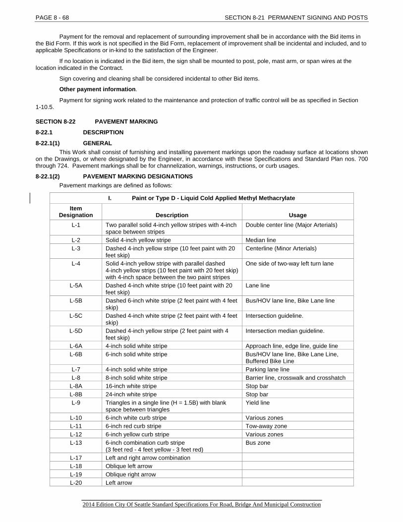
PAGE 8 - 68 SECTION 8-21 PERMANENT SIGNING AND POSTS
Payment for the removal and replacement of surrounding improvement shall be in accordance with the Bid items in the Bid Form. If this work is not specified in the Bid Form, replacement of improvement shall be incidental and included, and to applicable Specifications or in-kind to the satisfaction of the Engineer.
If no location is indicated in the Bid item, the sign shall be mounted to post, pole, mast arm, or span wires at the location indicated in the Contract.
Sign covering and cleaning shall be considered incidental to other Bid items.
Other payment information.
Payment for signing work related to the maintenance and protection of traffic control will be as specified in Section 1-10.5.
SECTION 8-22 PAVEMENT MARKING
8-22.1 DESCRIPTION
8-22.1(1) GENERAL This Work shall consist of furnishing and installing pavement markings upon the roadway surface at locations shown
on the Drawings, or where designated by the Engineer, in accordance with these Specifications and Standard Plan nos. 700 through 724. Pavement markings shall be for channelization, warnings, instructions, or curb usages.
8-22.1(2) PAVEMENT MARKING DESIGNATIONS Pavement markings are defined as follows:
I. Paint or Type D - Liquid Cold Applied Methyl Methacrylate Item
Designation Description Usage L-1 Two parallel solid 4-inch yellow stripes with 4-inch
space between stripes Double center line (Major Arterials)
L-2 Solid 4-inch yellow stripe Median line L-3 Dashed 4-inch yellow stripe (10 feet paint with 20
feet skip) Centerline (Minor Arterials)
L-4 Solid 4-inch yellow stripe with parallel dashed 4-inch yellow strips (10 feet paint with 20 feet skip) with 4-inch space between the two paint stripes
One side of two-way left turn lane
L-5A Dashed 4-inch white stripe (10 feet paint with 20 feet skip)
Lane line
L-5B Dashed 6-inch white stripe (2 feet paint with 4 feet skip)
Bus/HOV lane line, Bike Lane line
L-5C Dashed 4-inch white stripe (2 feet paint with 4 feet skip)
Intersection guideline.
L-5D Dashed 4-inch yellow stripe (2 feet paint with 4 feet skip)
Intersection median guideline.
L-6A 4-inch solid white stripe Approach line, edge line, guide line L-6B 6-inch solid white stripe Bus/HOV lane line, Bike Lane Line,
Buffered Bike Line L-7 4-inch solid white stripe Parking lane line L-8 8-inch solid white stripe Barrier line, crosswalk and crosshatch
L-8A 16-inch white stripe Stop bar L-8B 24-inch white stripe Stop bar L-9 Triangles in a single line (H = 1.5B) with blank
space between triangles Yield line
L-10 6-inch white curb stripe Various zones L-11 6-inch red curb stripe Tow-away zone L-12 6-inch yellow curb stripe Various zones L-13 6-inch combination curb stripe
(3 feet red - 4 feet yellow - 3 feet red) Bus zone
L-17 Left and right arrow combination L-18 Oblique left arrow L-19 Oblique right arrow L-20 Left arrow
_________________________________________________________________________________ 2014 Edition City Of Seattle Standard Specifications For Road, Bridge And Municipal Construction
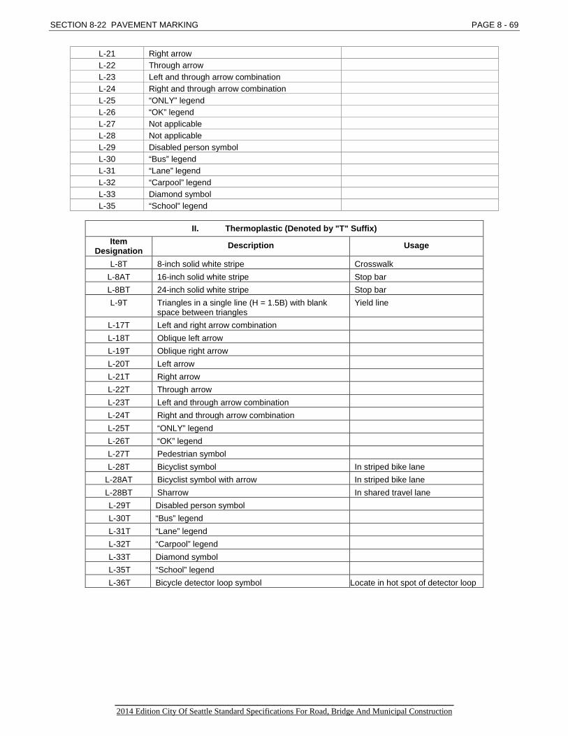
SECTION 8-22 PAVEMENT MARKING PAGE 8 - 69
L-21 Right arrow L-22 Through arrow L-23 Left and through arrow combination L-24 Right and through arrow combination L-25 “ONLY” legend L-26 “OK” legend L-27 Not applicable L-28 Not applicable L-29 Disabled person symbol L-30 “Bus” legend L-31 “Lane” legend L-32 “Carpool” legend L-33 Diamond symbol L-35 “School” legend
II. Thermoplastic (Denoted by "T" Suffix)
Item Designation Description Usage
L-8T 8-inch solid white stripe Crosswalk L-8AT 16-inch solid white stripe Stop bar L-8BT 24-inch solid white stripe Stop bar L-9T Triangles in a single line (H = 1.5B) with blank
space between triangles Yield line
L-17T Left and right arrow combination L-18T Oblique left arrow L-19T Oblique right arrow L-20T Left arrow L-21T Right arrow L-22T Through arrow L-23T Left and through arrow combination L-24T Right and through arrow combination L-25T “ONLY” legend L-26T “OK” legend L-27T Pedestrian symbol L-28T Bicyclist symbol In striped bike lane
L-28AT Bicyclist symbol with arrow In striped bike lane L-28BT Sharrow In shared travel lane L-29T Disabled person symbol L-30T “Bus” legend L-31T “Lane” legend L-32T “Carpool” legend L-33T Diamond symbol L-35T “School” legend L-36T Bicycle detector loop symbol Locate in hot spot of detector loop
_________________________________________________________________________________ 2014 Edition City Of Seattle Standard Specifications For Road, Bridge And Municipal Construction
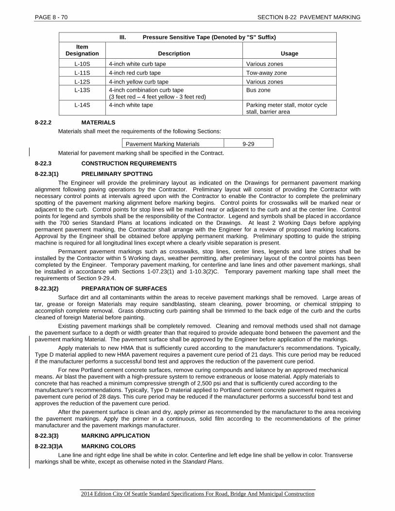
PAGE 8 - 70 SECTION 8-22 PAVEMENT MARKING
III. Pressure Sensitive Tape (Denoted by "S" Suffix) Item
Designation Description Usage
L-10S 4-inch white curb tape Various zones L-11S 4-inch red curb tape Tow-away zone L-12S 4-inch yellow curb tape Various zones L-13S 4-inch combination curb tape
(3 feet red – 4 feet yellow - 3 feet red) Bus zone
L-14S 4-inch white tape Parking meter stall, motor cycle stall, barrier area
8-22.2 MATERIALS Materials shall meet the requirements of the following Sections:
Pavement Marking Materials 9-29 Material for pavement marking shall be specified in the Contract.
8-22.3 CONSTRUCTION REQUIREMENTS
8-22.3(1) PRELIMINARY SPOTTING The Engineer will provide the preliminary layout as indicated on the Drawings for permanent pavement marking
alignment following paving operations by the Contractor. Preliminary layout will consist of providing the Contractor with necessary control points at intervals agreed upon with the Contractor to enable the Contractor to complete the preliminary spotting of the pavement marking alignment before marking begins. Control points for crosswalks will be marked near or adjacent to the curb. Control points for stop lines will be marked near or adjacent to the curb and at the center line. Control points for legend and symbols shall be the responsibility of the Contractor. Legend and symbols shall be placed in accordance with the 700 series Standard Plans at locations indicated on the Drawings. At least 2 Working Days before applying permanent pavement marking, the Contractor shall arrange with the Engineer for a review of proposed marking locations. Approval by the Engineer shall be obtained before applying permanent marking. Preliminary spotting to guide the striping machine is required for all longitudinal lines except where a clearly visible separation is present.
Permanent pavement markings such as crosswalks, stop lines, center lines, legends and lane stripes shall be installed by the Contractor within 5 Working days, weather permitting, after preliminary layout of the control points has been completed by the Engineer. Temporary pavement marking, for centerline and lane lines and other pavement markings, shall be installed in accordance with Sections 1-07.23(1) and 1-10.3(2)C. Temporary pavement marking tape shall meet the requirements of Section 9-29.4.
8-22.3(2) PREPARATION OF SURFACES Surface dirt and all contaminants within the areas to receive pavement markings shall be removed. Large areas of
tar, grease or foreign Materials may require sandblasting, steam cleaning, power brooming, or chemical stripping to accomplish complete removal. Grass obstructing curb painting shall be trimmed to the back edge of the curb and the curbs cleaned of foreign Material before painting.
Existing pavement markings shall be completely removed. Cleaning and removal methods used shall not damage the pavement surface to a depth or width greater than that required to provide adequate bond between the pavement and the pavement marking Material. The pavement surface shall be approved by the Engineer before application of the markings.
Apply materials to new HMA that is sufficiently cured according to the manufacturer’s recommendations. Typically, Type D material applied to new HMA pavement requires a pavement cure period of 21 days. This cure period may be reduced if the manufacturer performs a successful bond test and approves the reduction of the pavement cure period.
For new Portland cement concrete surfaces, remove curing compounds and laitance by an approved mechanical means. Air blast the pavement with a high-pressure system to remove extraneous or loose material. Apply materials to concrete that has reached a minimum compressive strength of 2,500 psi and that is sufficiently cured according to the manufacturer’s recommendations. Typically, Type D material applied to Portland cement concrete pavement requires a pavement cure period of 28 days. This cure period may be reduced if the manufacturer performs a successful bond test and approves the reduction of the pavement cure period.
After the pavement surface is clean and dry, apply primer as recommended by the manufacturer to the area receiving the pavement markings. Apply the primer in a continuous, solid film according to the recommendations of the primer manufacturer and the pavement markings manufacturer.
8-22.3(3) MARKING APPLICATION
8-22.3(3)A MARKING COLORS Lane line and right edge line shall be white in color. Centerline and left edge line shall be yellow in color. Transverse
markings shall be white, except as otherwise noted in the Standard Plans.
_________________________________________________________________________________ 2014 Edition City Of Seattle Standard Specifications For Road, Bridge And Municipal Construction

SECTION 8-22 PAVEMENT MARKING PAGE 8 - 71 8-22.3(3)B LINE PATTERNS
Solid Line – A continuous line without gaps. Broken Line – A line consisting of solid line segments separated by gaps. Dotted Line – A broken line with noticeably shorter line segments separated by noticeably shorter gaps.
8-22.3(3)C LINE SURFACES Flat Lines – Pavement marking lines with a flat surface. Profiled Marking – A profiled pavement marking is a marking that consists of a base line thickness and a profiled
thickness, which is a portion of the pavement marking line that is applied at a greater thickness than the base line thickness. Profiles shall be applied using the extruded method in the same application as the base line. The profiles may be slightly rounded provided the minimum profile thickness is the same throughout the length of the profile. See the Plans for the construction details.
Embossed Plastic Line – Embossed plastic lines consist of a flat line with transverse grooves. An embossed plastic line may also have profiles. See the Plans for the construction details.
8-22.3(3)D LINE APPLICATIONS Surface Line – A line constructed by applying pavement marking material directly to the pavement surface or existing
pavement marking. Grooved Line – A line constructed by grinding or saw cutting a groove into the pavement surface and spraying,
extruding, or gluing pavement marking material into the groove. Groove depth is measured vertically from the bottom of a 2 foot or longer straightedge placed on the roadway surface to the ground surface. The groove depth is dependent upon the material used, the pavement surface, and the location. See these Standard Specifications, the project Plans, and Special Provisions. Grooved line pavement marking shall not be constructed on bridge decks or on bridge approach slabs.
8-22.3(3)E INSTALLATION Apply pavement marking materials to clean, dry pavement surfaces and according to the following:
1. Place material according to the manufacture’s recommendations, 2. Place parallel double lines in one pass, 3. The top of pavement marking shall be smooth and uniform, 4. Line ends shall be square and clean, 5. Place pavement marking lines parallel and true to line, and 6. Place markings in proper alignment with existing markings.
When applying paint, Type A or Type C material, ensure that both the pavement surface and the air temperature at the time of application are not less than 50°F and rising. When applying Type B or Type D material, ensure that both the pavement surface and the air temperature at the time of application are not less than 40°F and rising.
Ensure that the Type A thermoplastic material meets the manufacturer’s temperature specifications when it contacts the pavement surface.
Two applications of paint will be required to complete all paint markings. The second application of paint shall be squarely on top of the first pass. The time period between paint applications will vary depending on the type of pavement and paint (low VOC waterborne or low VOC solvent) as follows:
Centerlines on two-lane Highways with broken line patterns, paint, or plastic shall be applied in the increasing milepost direction so they are in cycle with existing broken line patterns at the beginning of the project. Broken line patterns applied to multilane or divided Roadways shall be applied in cycle in the direction of travel.
Where paint is applied on centerline on two-way roads with bituminous surface treatment or centerline rumble strips, the second paint application shall be applied in the opposite (decreasing milepost) direction as the first application (increasing milepost) direction. This will require minor broken line pattern corrections for curves on the second application.
On painted “ladder type” crosswalks, pedestrian and bicyclist symbols (including arrows), white sharp sand shall be spread over fresh paint at a rate of approximately 1 pound per 20 square feet.
Pavement Type Paint Type Time Period
Bituminous Surface Treatment Low VOC Waterborne 4 hours min., 48 hours max.
Hot Mix Asphalt Pavement Low VOC Waterborne 4 hours min., 30 days max.
Cement Concrete Pavement Low VOC Waterborne 4 hours min., 30 days max.
Bituminous Surface Treatment Low VOC Solvent 40 min. min., 48 hrs. max.
Hot Mix Asphalt Pavement Low VOC Solvent 40 min. min., 30 days max.
Cement Concrete Pavement Low VOC Solvent 40 min. min., 30 days max.
_________________________________________________________________________________ 2014 Edition City Of Seattle Standard Specifications For Road, Bridge And Municipal Construction
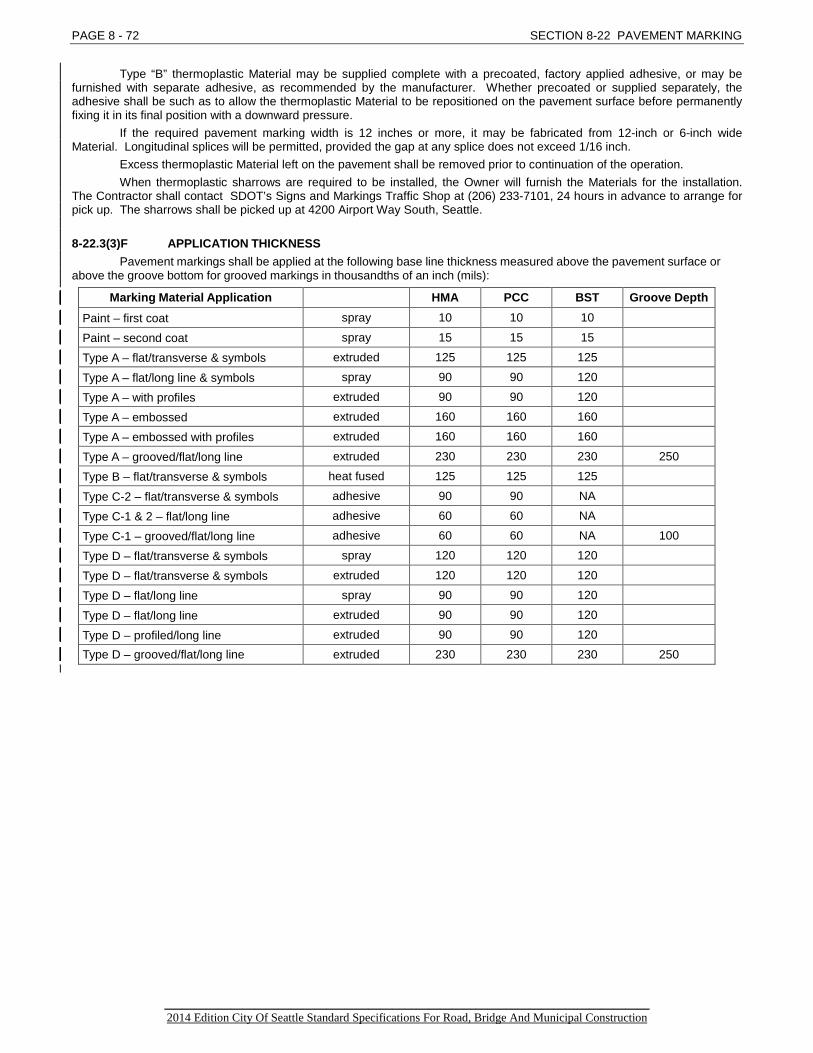
PAGE 8 - 72 SECTION 8-22 PAVEMENT MARKING
Type “B” thermoplastic Material may be supplied complete with a precoated, factory applied adhesive, or may be furnished with separate adhesive, as recommended by the manufacturer. Whether precoated or supplied separately, the adhesive shall be such as to allow the thermoplastic Material to be repositioned on the pavement surface before permanently fixing it in its final position with a downward pressure.
If the required pavement marking width is 12 inches or more, it may be fabricated from 12-inch or 6-inch wide Material. Longitudinal splices will be permitted, provided the gap at any splice does not exceed 1/16 inch.
Excess thermoplastic Material left on the pavement shall be removed prior to continuation of the operation. When thermoplastic sharrows are required to be installed, the Owner will furnish the Materials for the installation.
The Contractor shall contact SDOT’s Signs and Markings Traffic Shop at (206) 233-7101, 24 hours in advance to arrange for pick up. The sharrows shall be picked up at 4200 Airport Way South, Seattle.
8-22.3(3)F APPLICATION THICKNESS Pavement markings shall be applied at the following base line thickness measured above the pavement surface or
above the groove bottom for grooved markings in thousandths of an inch (mils):
Marking Material Application HMA PCC BST Groove Depth
Paint – first coat spray 10 10 10
Paint – second coat spray 15 15 15
Type A – flat/transverse & symbols extruded 125 125 125
Type A – flat/long line & symbols spray 90 90 120
Type A – with profiles extruded 90 90 120
Type A – embossed extruded 160 160 160
Type A – embossed with profiles extruded 160 160 160
Type A – grooved/flat/long line extruded 230 230 230 250
Type B – flat/transverse & symbols heat fused 125 125 125
Type C-2 – flat/transverse & symbols adhesive 90 90 NA
Type C-1 & 2 – flat/long line adhesive 60 60 NA
Type C-1 – grooved/flat/long line adhesive 60 60 NA 100
Type D – flat/transverse & symbols spray 120 120 120
Type D – flat/transverse & symbols extruded 120 120 120
Type D – flat/long line spray 90 90 120
Type D – flat/long line extruded 90 90 120
Type D – profiled/long line extruded 90 90 120 Type D – grooved/flat/long line extruded 230 230 230 250
_________________________________________________________________________________ 2014 Edition City Of Seattle Standard Specifications For Road, Bridge And Municipal Construction

SECTION 8-22 PAVEMENT MARKING PAGE 8 - 73
Liquid pavement marking material yield per gallon depending on thickness shall not exceed the following:
Mils thickness Feet of 4″ line/gallon Square feet/gallon 10 483 161 15 322 108 18 268 89 20 242 80 22 220 73 24 202 67 30 161 54 40 122 41 45 107 36 60 81 27 90 54 18
90 with profiles 30 10 120 40 13
120 with profiles 26 9 230 21 7
Solid pavement marking material (Type A) yield per 50-pound bag shall not exceed the following:
Mils thickness Feet of 4″ line/50# bag Square feet/50# bag 30 – flat 358 120 45 – flat 240 80 60 – flat 179 60 90 – flat 120 40
90 – flat with profiles 67 23 120 – flat 90 30
120 – flat with profiles 58 20 125 – embossed 86 29
125 – embossed with profiles 58 20 230 – flat grooved 47 15
All grooved lines shall be applied into a groove cut or ground into the pavement. For Type A or Type D material, the groove shall be cut or ground with equipment to produce a smooth square groove 4 inches wide. For Type C-1 material, the groove shall be cut with equipment to produce a smooth bottom square groove with a width in accordance with the material manufacturer’s recommendation. After grinding, clean the groove by shot-blasting or a method approved by Engineer. Immediately before placing the marking material, clean the groove with high-pressure air.
8-22.3(3)G GLASS BEADS Top dress glass beads shall be applied to all spray and extruded pavement marking material. Glass beads shall be
applied by a bead dispenser immediately following the pavement marking material application. Glass bead dispensers shall apply the glass beads in a manner such that the beads appear uniform on the entire pavement marking surface with 50 to 60 percent embedment. Hand casting of beads will not be allowed.
Glass beads shall be applied to 10 or 15 mil thick paint at a minimum application rate of 7 pounds per gallon of paint. For plastic pavement markings, glass bead type and application rate shall be as recommended by the marking material manufacturer.
When two or more spray applications are required to meet thickness requirements for Type A and Type D materials, top dressing with glass beads is only allowed on the last application. The cure period between successive applications shall be in accordance with the manufacturer’s recommendations. Any loose beads, dirt or other debris shall be swept or blown off the line prior to application of each successive application. Successive applications shall be applied squarely on top of the preceding application.
8-22.3(4) TOLERANCES FOR LINES Allowable tolerances for lines are as follows:
_________________________________________________________________________________ 2014 Edition City Of Seattle Standard Specifications For Road, Bridge And Municipal Construction

PAGE 8 - 74 SECTION 8-22 PAVEMENT MARKING
Length of Line – The longitudinal accumulative error within a 40 foot length of broken line shall not exceed plus or minus 1 inch. The broken line segment shall not be less than 10 feet.
Width of Line – The width of the line shall not be less than the specified line width or greater than the specified line width plus ¼ inch.
Lane Width – The lane width, which is defined as the lateral width from the edge of pavement to the center of the lane line or between the centers of successive lane lines, shall not vary from the widths shown in the Contract by more than plus or minus 4 inches.
Thickness – A thickness tolerance not exceeding plus 10 percent will be allowed for thickness or yield in paint and plastic material application.
Parallel Lines – The gap tolerance between parallel lines is plus or minus ½ inch.
8-22.3(5) INSTALLATION INSTRUCTIONS
8-22.3(5)A PLASTIC MARKINGS Installation instructions for plastic markings shall be provided for the Engineer. The instructions shall include
equipment requirements, approved work methods and procedures, material application temperature range, air and pavement surface temperature requirements, weather limitations, precautions, and all other requirements for successful application and material performance. Do not use materials with incomplete or missing instructions. All materials including glass beads shall be installed according to the manufacturer’s recommendations. A manufacturer’s technical representative shall be present at the initial installation of plastic material to approve the installation procedure or the material manufacturer shall certify that the Contractor will install the plastic material in accordance with their recommended procedure.
8-22.3(5)B PRESSURE SENSITIVE TAPE PAVEMENT MARKING Application procedures for pressure sensitive tape shall be as recommended by the tape manufacturer. The
Contractor shall submit these recommendations to the Engineer at least 2 Working Days in advance of usage.
8-22.3(6) REMOVAL OF PAVEMENT MARKING Removal of pavement marking shall be in accordance with Section 2-02.3(3)J. Grinding to remove painted markings is not allowed. Grinding to remove plastic marking is allowed to a depth just
above the pavement surface, then water blasting or shot blasting shall be required to remove the remaining markings.
8-22.3(7) TEMPORARY PAVEMENT MARKING See Sections 1-07.23(1) and 1-10.3(4)C.
8-22.3(8) LOCATING BICYCLE DETECTOR LOOP SYMBOL Contractor shall document the exact location of loop wire according to 1-05.3(13). Contractor shall refer to both the
Drawings and Standard Plan no. 725 for placement of the bike loop detector symbol.
8-22.4 MEASUREMENT Bid items of Work completed pursuant to the Contract will be measured as provided in Section 1-09.1 Measurement
of Quantities unless otherwise provided for by individual measurement paragraphs herein this Section. Measurement for “Pavement Marking, Paint, (Width) Stripe” will be by the linear foot of stripe, except dashed center
lines and dashed lane lines will be measured as continuous lines with no deduction for the unpainted area caused by the skip pattern specified.
Measurement for “Pavement Marking, Paint, Legend/Symbol” will be per each legend or symbol. Measurement for “Pavement Marking, Thermoplastic, 8-inch stripe” will be by the linear foot of 8-inch stripe actually
placed and will not include unmarked space. Measurement for “Pavement Marking, Thermoplastic, Legend/Symbol” will be per each legend or symbol. The legends “ONLY” and “OK” will be measured as 1 unit each. The symbol “Bicyclist” with “Arrows” will be measured as 1 unit each. Stop lines, 16 or 24 inches wide and comprised of multiple 8-inch wide stripes, will be measured by the linear foot of
8-inch width stripe. Measurement for “Pavement Marking, Pressure Sensitive Tape” will be by the linear foot of tape actually placed and
will not include unmarked space. Measurement for “Sharrow, install Owner furnished” will be per each.
8-22.5 PAYMENT Compensation for the cost necessary to complete the Work described in Section 8-22 will be made at the Bid item
prices Bid only for the Bid items listed or referenced as follows: 1. “Pavement Marking, Paint, (Width) Stripe”, per linear foot. 2. “Pavement Marking, Paint, Legend/Symbol”, per each. 3. “Pavement Marking, Thermoplastic, 8-inch Stripe”, per linear foot. 4. “Pavement Marking, Thermoplastic, Legend/Symbol”, per each. 5. “Pavement Marking, Pressure Sensitive Tape”, per linear foot.
_________________________________________________________________________________ 2014 Edition City Of Seattle Standard Specifications For Road, Bridge And Municipal Construction

SECTION 8-22 PAVEMENT MARKING PAGE 8 - 75
The Bid item prices for the above listed Bid items shall include all costs for the work required to furnish and install the specified types of pavement marking.
6. “Sharrow, install Owner furnished ”, per each. The Bid item price for “Sharrow, install Owner furnished” shall include all costs for the Work required to schedule the
sharrow pick up, pick up the sharrow and install the sharrow at the location specified in the Contract, or as directed by the Engineer.
SECTION 8-23 RESERVED
SECTION 8-24 RESERVED
SECTION 8-25 GLARE SCREEN
8-25.1 DESCRIPTION This Work shall consist of furnishing and constructing glare screen of the types specified, in accordance with the
Drawings, these Specifications, and WSDOT Standard Plan nos. L-40. Glare screen consists of diamond-woven wire mesh fence of aluminum, galvanized iron or aluminum-coated steel
wire fabricated and placed to reduce glare from headlights of opposing traffic or other adjacent light sources.
8-25.2 MATERIALS Materials shall meet the requirements of Section 9-16.6.
8-25.3 CONSTRUCTION REQUIREMENTS
8-25.3(1) GLARE SCREEN FABRIC Glare screen fabric shall be placed on the face of the posts designated by the Engineer. On curves the fabric shall
be placed on the face of the post which is on the outside of the curve. The fabric shall be stretched taut and securely fastened to the posts. Fastening to end, brace, and pull posts shall be
with stretcher bars and fabric bands spaced at 1-foot intervals. The fabric shall be cut and each span attached independently at all pull and corner posts. Fabric shall be securely fastened to line posts with tie wires, metal bands, or other approved methods at 14 inch intervals. The top and bottom of the fabric shall be fastened to the tension cable and tension wire with hog rings spaced at 24-inch intervals.
Rolls of wire fabric shall be joined by weaving a single strand into the end of the rolls to form a continuous mesh.
8-25.3(2) SLATS The slats shall be fastened into the weave by using staples, screws, or other methods as approved by the Engineer.
Allowing the tension of the mesh to hold the slats in place will not be permitted. Slats broken or split during construction shall be removed and replaced by the Contractor at no expense to the
Owner.
8-25.3(3) POSTS Posts, other than for Type 1 Design A, shall be constructed in accordance with the WSDOT Standard Plans and
applicable provisions of Section 8-12.3(2)A. Posts for Type 1 Design A shall be bolted to the beam guardrail posts as detailed in WSDOT Standard Plan no. L-5.
Drilling of the guardrail posts shall be done in such a manner to ensure that the glare screen posts are set plumb and centered over the guardrail posts.
All round posts for Type 1 Design B, and Type 2 glare screen shall be fitted with a watertight top securely fastened to the post. Line posts shall have tops designed to carry the top cable.
8-25.3(4) TENSION WIRE Tension wires shall be attached to the posts as detailed in the WSDOT Standard Plans.
8-25.3(5) TENSION CABLES The tension cable shall pass through the top of the line post. One continuous length of cable shall be used between
pull posts. Sufficient tension shall be applied to the cable to allow a maximum sag of 1/4-inch between posts after the chain link mesh has been attached to the cable. The Contractor shall provide temporary bracing on pull posts when applying tension to one length of cable at a time to prevent undue stresses on the pull post.
The cable shall be fastened to the top of the pull post with an eye bolt through the post and a turnbuckle connecting the eye bolt to the cable. Pull posts shall be braced to the bottom of the end or anchor posts with a short length of cable or tension wire as shown in the WSDOT Standard Plans. All turnbuckles shall have a minimum of 1-inch takeup clearance after tensioning.
The ends of all cables shall be seized with annealed iron wire for a distance of at least 1 inch.
_________________________________________________________________________________ 2014 Edition City Of Seattle Standard Specifications For Road, Bridge And Municipal Construction

PAGE 8 - 76 SECTION 8-25 GLARE SCREEN
8-25.3(6) FITTINGS, ATTACHMENTS, AND HARDWARE A lead washer shall be placed against the shoulder of the eye nut, eye bolt, or backup nut, and a lead washer backed
by the steel washer shall be placed between the pipe and lock washer, and the nut tightened sufficiently to seal the hole in the pipe.
A galvanized iron strap 1/4 inch in thickness by 12 inches in width, formed as shown in the WSDOT Standard Plans, shall be provided for the attachment of eye bolts to the base of the H column post in order to take the strain of the cable tension off the web of the H column.
8-25.4 MEASUREMENT Bid items of Work completed pursuant to the Contract will be measured as provided in Section 1-09.1, Measurement
of Quantities, unless otherwise provided for by individual measurement paragraphs herein this Section. Measurement of glare screen will be by the linear foot of completed glare screen for the particular type and design
specified.
8-25.5 PAYMENT Compensation for the cost necessary to complete the work described in Section 8-25 will be made at the Bid item
prices Bid only for the Bid items listed or referenced as follows: 1. “Glare Screen Type 1 Design _______”, per linear foot. 2. “Glare Screen Type 2”, per linear foot.
The Bid item price for glare screen of the type and design specified shall include all costs for the work required to furnish and assemble in place the completed installation including excavation, backfilling, tamping, concrete footings, miscellaneous hardware, smoothing the irregularities of the ground at the site, clearing the line for the glare screen, and disposing of all debris.
SECTION 8-26 RESERVED
SECTION 8-27 PROJECT IDENTIFICATION SIGN
8-27.1 DESCRIPTION Section 8-27 describes work consisting of either furnishing and installing project identification signs at the Project Site
in accordance with these Specifications and with the Contract, or installing Owner furnished project identification signs. The quality of Contractor provided signs and supports shall be such that they present a workmanlike appearance with
the paint remaining in good condition for the duration of the project. The Work also includes removing and disposing of the signs and supports after construction is completed or when
directed by the Engineer.
8-27.2 MATERIALS AND FABRICATION
8-27.2(1) GENERAL Project identification signs shall be constructed with Medium Density Overlay plywood, or shall be Owner provided.
Descriptions of Owner furnished signs will be provided in the Contract.
8-27.2(2) PLYWOOD Plywood signs shall be made of Medium Density Overlay plywood meeting the requirements of “Products Standard
PS 1-83 for Softwood Plywood, Construction and Industrial” grade, published by the Products Standards Section of the U.S. Department of Commerce. The plywood shall be free of contaminants which would adversely affect the application and life of the paint. Face veneers shall be Grade B or better.
Core and crossband veneers shall be solid. Core veneers shall be jointed. Core gaps shall not exceed 1/8 inch in width. The entire area of each contacting veneer surface shall be bonded with a waterproof adhesive that meets the requirements of the U.S. Department of Commerce for exterior type plywood.
The overlay shall be high density type. It shall have a minimum weight of 60 pounds per thousand square feet and shall be at least 0.012 inches thick before pressing. The overlay shall have a sufficient resin content to bond itself to the plywood, a content equal to 45 percent of the dry weight of the impregnated fiber.
The sign dimensions shall be as shown on the Drawings. The thickness of the single panel plywood sign shall be 1/2-inch.
8-27.2(3) SIGN BORDERS Every project identification sign shall have a border frame of 2 X 4’s as shown in the Contract.
8-27.2(4) LETTERING AND SPACING FORMULA Letters and symbols shall be of the type, size, and color specified in the Contract. Letters and symbols shall be of Material compatible with the sign surface Material recommended by the sign surface
manufacturer. The Contractor shall submit one sample of a finished project identification sign for the Engineer’s approval prior to
fabricating the remaining signs required under this Contract. _________________________________________________________________________________ 2014 Edition City Of Seattle Standard Specifications For Road, Bridge And Municipal Construction

SECTION 8-27 PROJECT IDENTIFICATION SIGN PAGE 8 - 77 8-27.2(5) SIGN SUPPORTS
Posts and wood supports shall be 4-inch x 4-inch meeting the requirements of Section 9-09.2 Preservative treatment for posts and wood supports shall be as required in Section 9-09.3. Project identification signs shall be securely mounted either to the posts, or to the wood supports and supporting framework. Posts shall be of a length capable of installing in the ground to a minimum depth of 3 feet below grade. The signs shall be mounted to be level and in a vertical plane. Backfill around the posts shall be reasonably compacted to provide adequate lateral support to prevent movement caused by moderate wind conditions. The wood supports and framework shall be sturdy and shall be installed to provide the needed stability to prevent movement caused by moderate wind conditions.
8-27.3 CONSTRUCTION REQUIREMENTS
8-27.3(1) LOCATION OF SIGNS The Contractor shall install project identification signs at locations indicated on the Drawings. Signs facing in each
direction of traffic shall be placed at all Project Sites prior to construction. Signs shall be placed so as to convey their message effectively without restricting lateral clearances or sight distance. When the Engineer requires the Contractor to relocate signs, sign support shall be as required in Section 8-27.2(5).
8-27.3(2) SIGN REMOVAL The Contractor shall remove all project identification signs, posts, and supports from the Project Site when Work is
completed at that location or when required by the Engineer. When the Engineer directs a sign to be relocated, removal of the sign, posts, and wood supports and supporting frame shall be done in such a manner as to prevent disturbance or damage to the sign, wood support and supporting frame. Should the sign, post(s), or wood support(s) be disturbed or damaged, the Contractor shall restore the sign to an acceptable condition, or provide an identical sign or post or support, as necessary, at no cost to the Owner. The Engineer will determine if new posts, or new wood supports and framework, are required to accommodate a reasonably different site terrain where signs are to be relocated.
All removed Materials become the property of the Contractor and shall be removed from the Project Site. The area(s) shall be restored to pre-existing or better condition immediately after removal.
8-27.4 MEASUREMENT Bid items of Work completed pursuant to the Contract will be measured as provided in Section 1-09.1, Measurement
of Quantities, unless otherwise provided for by individual measurement paragraphs herein this Section. Measurement for “Sign, Project Identification” and for "Sign, Project Identification, Owner Furnished" will be per each
sign actually used on the Project Site. Measurement for "Relocate Project Sign" will be per each. Measurement for posts, and for wood supports and supporting framework, will be per each sign.
8-27.5 PAYMENT Compensation for the cost necessary to complete the work described in Section 8-27 will be made at the Bid item
prices Bid only for the Bid items listed or referenced as follows: 1. “Sign, Project Identification”, per each.
The Bid item price for “Sign, Project Identification” shall include all costs for the work required to fabricate, paint, install, remove and dispose of signs, and restore all area(s) after project completion. 2. "Sign, Project Identification, Owner Furnished", per each.
The Bid item price for “Sign, Project Identification, Owner Furnished” shall include all costs for the work required to pickup and deliver, install, remove and dispose of signs, and restore the area(s) after project completion. 3. "Posts, Project Sign", per each sign. The Bid item price for "Posts, Project Sign" shall include all costs for the work required to furnish, fabricate, install, maintain, relocate, and remove the posts, or wood supports and supporting frame, for each project sign. 4. "Relocate Project Sign", per each. The Bid item price for "Relocate Project Sign" shall include all costs for the work required to relocate a project sign and posts or wood supports and support frame as specified. 5. Other payment information. No additional payment will be made for signs requiring restoration or replacement if disturbed or damaged by Contractor operations. No additional payment will be made for post(s) or wood support(s) and support frame(s) if disturbed or damaged by Contractor operations. Relocation of a project sign to a different site where a significant change in the original post(s), or wood support(s) and supporting frame, is necessary to accommodate different terrain or other conditions, will be paid as "Posts, Project Sign".
SECTION 8-28 RESERVED
_________________________________________________________________________________ 2014 Edition City Of Seattle Standard Specifications For Road, Bridge And Municipal Construction

PAGE 8 - 78 SECTION 8-29 WIRE MESH SLOPE PROTECTION SECTION 8-29 WIRE MESH SLOPE PROTECTION
8-29.1 DESCRIPTION Section 8-29 describes the work consisting of constructing wire mesh slope protection in accordance with these
Specifications and in conformity with the lines and dimensions shown on the Drawings.
8-29.2 MATERIALS Materials shall meet the requirements of the following Sections:
Wire Mesh Slope Protection 9-16.4
8-29.3 CONSTRUCTION REQUIREMENTS
8-29.3(1) ANCHORS The Contractor shall install anchors of the type shown in conformance to the layout shown on the Drawings. The
spacing and number of the anchors and cables as shown on the Drawings are approximate only, and the Engineer will arrange the spacing in such a manner as to hold the wire mesh against the slope. Backfill Material shall be thoroughly compacted.
8-29.3(2) CABLE ASSEMBLY The cable assembly shall be in place before the wire mesh is attached. The bottom cable shall not be tensioned. No
cable splicing will be allowed.
8-29.3(3) WIRE MESH The wire mesh shall be fastened to the completed cable assembly as shown in the WSDOT Standard Plan nos. D-7
and D-7a. Hog rings on the vertical lap splices shall be placed in a single row centered on the splice. Horizontal splices joining two rolls of mesh shall be made by removing a horizontal end wire and reweaving through the ends of the fabric to form a continuous mesh. All top and bottom laps shall be made by folding the mesh to the outside, away from the slope, to avoid the possibility of falling material hanging up in the folds. The bottom of the mesh shall be located so that material dislodged under the mesh can drain freely from the bottom, yet does not flow or bounce onto the roadway. The ends of all tie wires shall be secured to the mesh with a minimum of 1-1/2 turns.
The wire mesh shall not be tensioned in any direction but is to remain loose so as to increase its dampening effect on rolling rocks. The Contractor shall use care in the handling and installing of the wire mesh and cable. Any mesh or cable damaged due to the Contractor’s operations shall be replaced by the Contractor at no additional cost to the Owner.
8-29.4 MEASUREMENT Bid items of Work completed pursuant to the Contract will be measured as provided in Section 1-09.1, Measurement
of Quantities, unless otherwise provided for by individual measurement paragraphs herein this Section. Measurement of anchors will be per each for the completed anchor. Anchor types will not be differentiated. Galvanized wire mesh will be measured by the square foot of the completed area. Galvanized wire rope will be measured by the linear foot of wire rope actually used for the slope protection work.
8-29.5 PAYMENT Compensation for the cost necessary to complete the Work described in Section 8-29 will be made at the Bid item
prices Bid only for the Bid items listed or referenced as follows: 1. “Wire Mesh Slope Protection Anchor”, per each.
The Bid item price for “Wire Mesh Slope Protection Anchor” shall include all costs for the work required to furnish and install the anchors of the type required including removing obstructions, excavating, drilling, backfilling and grouting. 2. “Galvanized Wire Mesh”, per square foot. 3. “Galvanized Wire Cable”, per linear foot.
The Bid item price for “Galvanized Wire Mesh” and for “Galvanized Wire Cable” shall include all costs for the work required to furnish and install the wire mesh and the cable, including all rings, U-bolts, thimbles, wire rope, clips, hog rings, and tie wire necessary to complete the wire mesh slope protection.
SECTION 8-30 ILLUMINATION AND ELECTRICAL SYSTEMS
8-30.1 DESCRIPTION
8-30.1(1) GENERAL Section 8-30 describes the work consisting of furnishing and installing a complete and functional illumination and
electrical system as specified in the Contract and in accordance with these Standard Specifications and the Standard Plans. All existing service disconnections, temporary and final service connections and energizing of illumination and
electrical street lighting systems to overhead secondary or to secondaries in vaults or handholes will be made by Seattle City Light. The Contractor shall provide the Engineer at least 10 Working Days advance notice unless otherwise arranged with the Engineer.
Illumination and electrical street lighting systems shall not be used to serve other electrical services.
_________________________________________________________________________________ 2014 Edition City Of Seattle Standard Specifications For Road, Bridge And Municipal Construction

SECTION 8-30 ILLUMINATION AND ELECTRICAL SYSTEMS PAGE 8 - 79
Required permits for electrical Work other than street lighting and signals, and other than irrigation (see Sections 8-03.1 and 8-03.3(1)), shall be obtained in accordance with Section 1-07.6.
The Contractor shall become thoroughly familiar with the electrical environment within the Project Site and with the relevant Work.
8-30.1(2) APPLICABLE ELECTRICAL CODES AND STANDARDS In addition to the safety rules and standards specified in Section 1-07.1(2), electrical Work shall be performed in
accordance with the current applicable provisions of the following codes: 1. SCL Material Standards, SCL Construction Guideline, and Requirements for Electrical Service Connection. 2. State of Washington Electrical Workers Safety Rules, Chapter 296-45 WAC. 3. National Electrical Safety Codes. 4. National Electrical Code. 5. City of Seattle Electrical Code Supplement. 6. Edison Electric Institute (EEI).
8-30.1(3) ELECTRICAL SHOP DRAWINGS The Contractor shall submit Shop Drawings to the Engineer of the following items in accordance with Section 1-05.3: 1. Luminaires (include photometrics and socket position):
a. Housing b. Lamps c. Photoelectric Cells
2. Wiring a. Wire b. Wire Connectors c. Fuseholders d. Fuses e. Splice Kits
3. Grounding a. Ground Rods b. Ground Clamps
4. Receptacle (Festoon Outlet)
8-30.1(4) ELECTRICAL AND ELECTRONIC WORDS AND PHRASES See Section 1-01.3.
8-30.2 MATERIALS Materials shall meet the requirements of the following Sections:
Illumination and Electrical Materials, Luminaires, Ground Rods & Clamps 9-31
All welds on tubular steel shall comply with the requirements of ANSI/AWS D1.1 Section 10 Tubular Structures.
8-30.3 CONSTRUCTION REQUIREMENTS
8-30.3(1) GENERAL To maintain safe traffic conditions, existing luminaires shall remain in service until cut-over to new luminaires can be
accomplished. Roadways shall not be opened to traffic before all of the required lighting system is operating properly.
Temporary lighting plans shall be required unless provided in the Drawings. Temporary lighting shall be provided at the cost of the Contractor unless plans are provided in the Drawings. When temporary lighting plans are provided in the Drawings a bid item for Temporary Lighting shall be provided.
8-30.3(2) LUMINAIRES The luminaire glassware, reflector and lamp shall be thoroughly cleaned before installation on the tenon on the
bracket arm. For LED luminaires, the LED array shall be cleaned with a soft cloth. The luminaire shall be secured and adjusted according to the manufacturer’s recommendations. The luminaire refractor or LED array shall be level in the transverse roadway axis and parallel to the roadway grade in the longitudinal roadway axis after the pole has been plumbed with all loads added, according to SCL Construction Guidelines D12-9/NSL 30.
Date of installation shall be marked on the bottom of the photoelectric cell with an indelible ink. The luminaire shall have the installation date marked inside the metal base adjacent to the photo cell.
The photoelectric cell receptacle shall be adjusted such that the photoelectric cell faces north.
8-30.3(3) HANDHOLE, MAINTENANCE HOLE AND VAULT ACCESS REQUIREMENTS
Access to handholes, maintenance holes, and vaults shall be provided at all times. Temporary storage of any material on top of or within 2 feet of any handhole, maintenance hole and vault will not be allowed.
_________________________________________________________________________________ 2014 Edition City Of Seattle Standard Specifications For Road, Bridge And Municipal Construction
PAGE 8 - 80 SECTION 8-30 ILLUMINATION AND ELECTRICAL SYSTEMS 8-30.3(4) RELOCATING EQUIPMENT
When equipment and associated Material is to be relocated, the Contractor shall furnish and install all the equipment and material, including additional new material as necessary, required to complete the installation. All material and equipment shall meet the requirements of these Specifications.
8-30.3(5) WIRING, FUSING, AND SPLICING Luminaire fusing shall be sized appropriately per SCL Construction Standard 1730.00. Individual luminaire fuses for
roadway and pedestrian luminaires shall be located in the adjacent handhole. Festoon outlets shall be fused at 15 amps. The Contractor shall provide wiring from luminaire terminal boards to in-line fuseholders and to the source of
secondary service. The Contractor shall coil a minimum 8 feet of wire at the source of secondary service to allow for connections by
Seattle City Light. The Contractor shall coil 3 feet of excess conductor in each type handhole. Each “hot” conductor shall have an in-line fuseholder and insulating boots located as indicated on the Drawings. Multiple connectors shall also be used as required by the Drawings. Grounding and bonding for all streetlights shall
conform to requirements outlined in SCL Construction Standard 1710.50 and 1810.05. Ground wire attached to the face of a wood pole, not enclosed in conduit, shall be covered with plastic molding
meeting SCL Material Standards 5820.50. Caution shall be exercised in working near and within Seattle City Light Vaults and the electrical distribution system.
Voltages present can be 26,000 volts or higher. Vault wiring will not be de-energized while the qualified Contractor is working. The Contractor shall arrange for scheduling a Seattle City Light Electrical Safety Observer when Work is required in a Seattle City Light vault or near an electrical distribution facility in accordance with Sections 1-05.2(2).
When cables or single conductors are being installed, care shall be exercised not to exceed tension limitations recommended by the manufacturer. Conductors may be pulled directly by hand; however, conductors pulled by mechanical means require a dynamometer with drop-needle hand shall be used on every pull. On mechanical pulls, either the insulation shall be stripped off each conductor, and conductors formed into a pulling eye and firmly taped before pulling, or a cable grip shall be used. The pulling force shall be applied directly to the conductor.
Secondary insulator racks required for new construction shall be in accordance with SCL Material Standards and installed in accordance with SCL Construction Guidelines.
Where new cable is to be installed in existing conduits which are occupied, the Contractor shall protect existing wiring from damage. Cable pulling compound shall be used to minimize cable pulling tensions and adverse effects on existing wire insulation, jacket and shield. Care shall be exercised in pulling cable into poles and pedestals since sharp metal edges may be present.
Aluminum wire and connectors shall be prepared and coated with an oxide-inhibiting compound. Where triplex wire is installed overhead to feed only one street light, the two hot conductors shall be tied together
(brothered) at each pole. Wire insulation shall be removed by a method that does not “ring” or nick the wire. “Ringing” will be cause for
rejection of the splice. Wire splices shall be made mechanically and electrically secure. Each individual splice or termination of extra leads
shall be insulated and made waterproof. All cables shall be marked with a permanent stainless steel tag in handholes or access points with feed point circuit
number per SCL Construction Standard 1714.10. Racking of cables shall be required. For above ground splices, the connector shall be torqued to the manufacturer’s recommended level. The splice and
termination of extra leads shall be covered with rubber base insulating and waterproofing tape as specified in SCL Material Standards. This tape shall be worked around the wire insulation to insure a water tight assembly. The splice assembly shall be protected with two layers of electrician tape.
For below ground splices, connectors shall be tightened or crimped in accordance with the manufacturer’s specifications. Only manufacturer’s approved crimping tools shall be used to compress crimp splices. The metal splice shall be centered in the enclosure. The encapsulant shall be mixed and installed in accordance with manufacturer’s recommendation. The encapsulant shall completely fill the enclosure and be free of voids and impurities.
Where festoon outlets are installed on poles a separate circuit shall be provided.
8-30.3(6) LUMINAIRES RELAMPING Relamping shall be completed without power disconnection. The Contractor personnel servicing streetlights shall be
Washington State certified electricians licensed to work on electrical low voltage up to 600 Volts AC. Before starting work on conductive structures, the Contractor shall perform touch potential testing. Conductive
structures shall be understood as, but not limited to, any structure capable of carrying current. The Contractor shall test structures using an electric voltage detector to test touch potential voltage. Electric voltage detector shall detect voltages 5 V or greater. If a voltage above 5 V is not detected, the test is complete and Contractor shall proceed with luminaire replacement.
_________________________________________________________________________________ 2014 Edition City Of Seattle Standard Specifications For Road, Bridge And Municipal Construction
SECTION 8-30 ILLUMINATION AND ELECTRICAL SYSTEMS PAGE 8 - 81
If a voltage above 5 V is detected, the Contractor shall test structures using a voltmeter equipped with a 3000-ohm shunt. Adequate ground points shall be used to reference all measurements. All ground points shall first be checked for voltage. Fire hydrants, storm drains or other grounded structures should be sought for ground points.
If touch potential is detected, all conductive structures within a forty foot radius shall be tested for voltage. If less than 30 volts has been detected, the area shall be taped and coned off to prevent incidental contact and reported to the Engineer.
If a structure is found to be energized at 30 volts or more, the immediate area shall be secured and the Engineer shall
be notified immediately. Removal of the existing luminaire shall be done per 2-02.3(3)L. Installation of new luminaire shall be done per 8-
30.3(2). After completing work on conductive structures, Contractor shall perform touch potential testing to confirm
Contractor’s activities have not created touch potential on the structures as identified above.
8-30.3(7) GROUNDING AND BONDING Grounding and bonding for all streetlights shall conform to requirements outlined in SCL Construction Standard
1710.50. All conductive appurtenances containing electrical conductors, including cabinets, metallic conduit, metal poles,
pedestals, and junction boxes, shall be made mechanically and electrically secure to form a continuous system which shall be effectively grounded. Each streetlight or traffic management system circuit shall only have one Service Bond.
Where conduit (including steel conduit) systems are used, all metallic appurtenances shall be electrically bonded by a separate insulated ground conductor. Conduit risers shall be bonded to the grounding conductor.
Where parallel electrical circuits exist in an electrical conduit, the equipment grounding conductor shall be sized as determined by the rating of the largest overcurrent device serving any circuit contained in the conduit. The minimum size for the grounding conductor shall be #6 copper. Only one equipment grounding conductor is required in any conduit, raceway, junction box, handhole, or pole.
All conduit runs with phase conductors (with the exception of the run from the riser to the first handhole) shall have the grounding conductor installed in the conduit unless noted otherwise on the Drawings.
The grounding conductor shall connect all ground rods in each circuit. The grounding conductor shall be installed in one continuous length without a splice or joint. If necessary, splices or connections shall be made by irreversible compression-type connector listed for direct-buried use. Exothermic weld is acceptable.
Metal conduit, grounding conductor and the service neutral shall be bonded and grounded at the service entrance point as required in SCL Construction Standard 1710.50, under the NEC and the City of Seattle Electrical Code.
Only one wire shall be installed under any ground clamp. Ground rods shall be installed in firm undisturbed earth. In areas with loose or soft soil conditions, extensions shall
be coupled until the rod cannot be removed by hand. Minimum spacing between ground rods shall be 8 feet per Seattle Electrical Code.
Grounding performance shall be based on both the NESC and NEC. If installed system does not measure below 25 ohms resistance to Earth, the Engineer shall make the determination if the overcurrent protection is adequate for acceptance or if additional grounding is required.
8-30.3(8) REMOVAL AND SALVAGE OF EXISTING EQUIPMENT Refer to Section 2-02.3(3)G and 2-02.3(7)C.
8-30.3(9) FIELD TESTING Prior to completion of the Work, the Contractor shall provide the Engineer 3 Working Days advance notice. The
Engineer shall coordinate with the Contractor to determine a hold-open timeframe. Parties shall make the following tests on all electrical circuits:
1. Open-trench grounding test. During open trench, test for grounds in each circuit by physically examining the installation to ensure that all required ground jumpers, devices and appurtenances are in place, that they are mechanically and electrically firm, and that they meet Seattle City Light requirements.
2. Insulation resistance test. The insulation test shall be performed after all field connections have been made. All readings shall be recorded and made available when requested by the Engineer.
3. A functional test in which it is demonstrated that each and every part of the system functions as specified or intended herein. The functional test shall be performed after all field connections are completed. If applicable, streetlight contactor function shall be tested as part of the complete functional test as follows: a. No current on the load side of contactor when in the OFF position or in the AUTO position when the
PE cell is open. b. Correct current to the load side of the contactor when in the ON position or in the AUTO position
when the PE cell is closed. 8-30.3(10) AS-BUILT DRAWINGS
See Section 1-05.11. Prior to service connection, the Contractor shall submit to the Engineer for approval, as-built wiring drawings
indicating field wiring, conduit route and sizes, handhole location and sizes, and pole locations. _________________________________________________________________________________ 2014 Edition City Of Seattle Standard Specifications For Road, Bridge And Municipal Construction
PAGE 8 - 82 SECTION 8-30 ILLUMINATION AND ELECTRICAL SYSTEMS 8-30.3(11) FINAL INSPECTION See Section 1-07.28(8)d.
The Contractor shall coordinate with the Engineer for all inspections. The Contractor shall provide ten (10) Days notice prior to inspection.
8-30.3(12) COMMISSIONING All projects shall be subject to commissioning to ensure proper operations and installation of the system. The
Contractor shall coordinate with the Engineer to ensure completion of all commissioning requirements. a. Components in this process shall include, but not limited to, controls operation verification and
adjustments, system stress testing (operation under full load), light level verification, power quality, and consumption verification.
b. Findings in this process that do not comply with Construction, Material, and Design Standards shall be flagged and remedied during this process.
8-30.3(13) ACCEPTANCE Upon completion of punch list and remedy of flagged items, an acceptance document shall be signed by the Contractor, Engineer, and SCL, and then the system is accepted by SCL.
Upon acceptance, final connection of the lighting shall occur after a service application is made to Seattle City Light and the as-built drawings are received, confirmed, and approved.
The illuminations system will not be approved and wiring bid items not be paid until the Contractor meets all of the requirements made in Sections 8-30.3(11), 8-30.3(12), and 8-30.3(13).
8-30.4 MEASUREMENT Bid items of Work completed pursuant to the Contract will be measured as provided in Section 1-09.1, Measurement
of Quantities, unless otherwise provided for by individual measurement paragraphs herein this Section.
8-30.5 PAYMENT Compensation for the cost necessary to complete the work described in Section 8-30 will be made at the Bid item
prices Bid only for the Bid items listed or referenced as follows: 1. “Luminaire, (Light Source Type), (Description)”, per each.
The Bid item price for “Luminaire, (Light Source Type), (Wattage or Number of LEDs), (Description)” shall include all costs for the work required to furnish and install a complete luminaire including the fuse, hardware, photoelectric control and wiring to the fuseholder at the secondary source or at the base of the pole. 2. “Relocate (Item)”, per each.
The Bid item price for “Relocate (Item)” shall include all costs for the work required to remove the item and reinstall the item complete at the new location, including furnishing new hardware if necessary, and cleaning and relamping (which includes a new lamp and photoelectric cell) relocated luminaires. 3. “Wiring, Street Lighting”, per lump sum. The Bid item price for “Wiring, Street Lighting” shall include all costs for the work required to furnish and install wiring for the street light system from the service point to the luminaire fuseholder, including taps, splices, tape, fuseholder, excess wire for connections, and any other Material necessary for a complete illumination and electrical system. 4. “Relamp Luminaire, (Light Source Type), (Description)”, per each
The Bid item price for “Relamp Luminaire, (Light Source Type), (Description)” shall include all costs for the work required to completely remove and salvage the existing luminaire and furnish and install a complete luminaire including hardware and photoelectric control. 5. “Bond Existing Handhole”, per each. 6. “Bond Existing Pole”, per each.
The Bid item price for “Ground Existing Handhole” and “Ground Existing Pole” shall include all costs for the work required to bond handholes or poles to grounding electrode conductor and ground rods including furnishing and installing wire, taps, splices, tape, clamps, lugs and any other Material necessary for a complete ground system. 7. “Install Ground Rod”, per each.
The Bid item price for “Install Ground Rod” shall include all costs for the work required to furnish and install ground rods including wire, taps, splices, tape, clamps, lugs, couplers, locating underground utilities and structures, and any other Material necessary to complete a grounded system. 8. “Inspect Grounding and Bonding”, per each.
The Bid item price for “Inspect Grounding and Bonding” shall include all costs for the work required to inspect the grounding and bonding system for each existing service point location from the furthest downstream metal appurtenance to the service point. 9. “Remove (Item)”, per each.
The Bid item price for “Remove (Item) “shall include all costs for the work required to remove and salvage as required. 10. Other payment information.
_________________________________________________________________________________ 2014 Edition City Of Seattle Standard Specifications For Road, Bridge And Municipal Construction

SECTION 8-30 ILLUMINATION AND ELECTRICAL SYSTEMS PAGE 8 - 83
All existing service disconnections, temporary and final service connections of the illumination and electrical street lighting systems to overhead secondaries, or to secondaries in vaults or handholes will be made by Seattle City Light at the project’s expense.
All costs for furnishing and installing hardware not specifically called out, but required to complete the constructions in Section 8-30 shall be included in the applicable Bid item prices and no separate or additional payment will be made.
Existing materials proposed to be relocated per approved drawings and documents and found to be in need of repair or replacement during the time of construction by the Engineer shall be replaced by new material and will be addressed as extra work per Section 1-04.4.
Costs for Electrical Safety Observer shall be in accordance with Section 1-05.2(2).
SECTION 8-31 TRAFFIC SIGNAL SYSTEM
8-31.1 DESCRIPTION
8-31.1(1) GENERAL This Work shall consist of furnishing and installing a complete and functional traffic control system consisting of
controller assembly, signals, miscellaneous traffic devices, and appurtenances in accordance with the Contract. The Contractor shall become thoroughly familiar with the electrical environment within the Project Site and with the
relevant Work. All final signal system service connections to secondary overhead / underground will be made by Seattle City Light. If, for any reason, vehicular or pedestrian signal(s) fail to function properly, the Contractor shall immediately call for
an off duty Uniformed Peace Officer to control the intersection. The Contractor shall also immediately notify the Engineer and the Owner’s Signal Maintenance Office (206-386-1206) of the nature of the malfunction. The Contractor shall immediately undertake the necessary repairs. The Engineer may require the Work to be done by Owner forces.
8-31.1(2) ELECTRICAL AND ELECTRONIC WORDS AND PHRASES See Section 1-01.3.
8-31.1(3) APPLICABLE ELECTRICAL CODES See Section 8-30.1(2).
8-31.1(4) SUBMITTALS AND REFERENCE MATERIALS
8-31.1(4)A SIGNAL SHOP DRAWINGS The Contractor shall submit Shop Drawings including catalog cuts in accordance with Section 1-05.3 for the following: 1. Signal Heads and Mounting Assemblies 2. Cable and Wire
a. Wire Connections b. Fuse Kits c. Splice Kits
3. Pole Line Hardware 4. Interior Illuminated Signs and Blank Out Signs 5. ITS Equipment
a. CCTV Cameras b. Detection Cameras c. License Plate Readers d. Wireless Detectors e. Dynamic Message Signs f. Communication Devices
5. Miscellaneous a. Aerial Terminal Compartments b. Pedestrain PushButton c. Ground Rods
6. Detector Loops a. Loop Sealant b. Wire
The Contractor shall submit “redline” as-built wiring diagrams to the Engineer for each signalized intersection at least 3 working Days prior to requesting the Engineer’s approval for turn-on or cut-over.
8-31.1(4)B SAMPLES The Contractor shall submit a sample to the Engineer for approval of the type of electronic component to be used.
Approved samples will be retained for future comparison for the remaining equipment to be installed.
_________________________________________________________________________________ 2014 Edition City Of Seattle Standard Specifications For Road, Bridge And Municipal Construction

PAGE 8 - 84 SECTION 8-31- TRAFFIC SIGNAL SYSTEM 8-31.1(5) CONTROLLER ASSEMBLY TESTING REQUIREMENTS
8-31.1(5)A RESERVED
8-31.1(5)B RESERVED
8-31.1(5)C RESERVED
8-31.1(5)D FIELD TESTING The Contractor shall make the following tests on all new electrical circuits. Test equipment shall be calibrated as
recommended by the test equipment manufacturer. 1. Test for continuity of each circuit. 2. Test for grounds in each circuit which consists of the physical examination of the installation to ensure that
all required ground jumpers, devices and appurtenances do exist and are mechanically firm, meeting the requirements of Article 250 of the National Electrical Code.
3. A megger test on each circuit between the conductor and ground with all switchboards, panel boards, fuse
holders, switches, receptacles and over current devices in place and all readings recorded. The megger test shall be performed with all wiring installed but connections not made to controller, conflict monitor, load switches, or other plug connected accessories. The Contractor shall submit to the Engineer with 3 copies of the test results identifying observed readings with their respective circuits at least 3 Working Days prior to any checkout of the installation to be turned on or cut over. One copy shall be filed in the controller cabinet. The insulation resistance on all electrical circuits whose nominal voltage is between 115 volts and 600 volts, other than direct burial cable, shall not be less than 6 megohms between the conductor and ground on circuits with total single conductor lengths of more than 2,500 feet, nor less than 8 megohms for circuits with single conductor length 2,500 feet or less. For circuits below 115 volts nominal and all direct burial circuits, the insulation resistance shall not be less than 2 megohms to ground, and for loop wire not less than 10 megohms. Any change in the above stated minimum readings shall require written approval by the Engineer. Only those factors based on dielectric properties of conductor insulation, splicing insulations, terminal strips, etc., will be cause for consideration of variance.
4. A functional test (intersection check-out) in which it is demonstrated that each and every part of the system functions as specified or intended herein. The functional test will be performed after all field connections to the controller cabinet have been made. Any fault in any Material or in any part of the installation revealed by these tests shall be justification for the Material to be replaced or for the part to be repaired by the Contractor in a manner approved by the Engineer, and the same test shall be repeated until the system is approved by the Engineer.
8-31.1(6) GUARANTEE See Section 1-05.10.
8-31.2 MATERIALS Materials shall meet the requirements of Section 9-32. All welds on tubular steel shall comply with the requirements of ANSI/AWS D1.1 Section 10 Tubular Structures.
8-31.3 CONSTRUCTION REQUIREMENTS
8-31.3(1) CLEARANCE REQUIREMENTS AND INTERSECTION CHECK-OUT AND TURN-ON PROCEDURES
8-31.3(1)A TRAFFIC CONTROL The Contractor shall provide an off duty Uniformed Peace Officer at any time a signalized intersection is dark or
inoperative, such as during controller change-out, cable installation, signal turn-on or cut-over, or similar circumstances. The Contractor shall have all traffic controls (i.e., pavement markings, channelization, and signage) in place prior to requesting Engineer’s approval for turn-on or cut- over.
To maintain safe traffic conditions, existing signals shall remain in operation until a simultaneous cut-over to new signals can be accomplished.
At the time of turn-on of new signals, temporary advanced warning signs shall be installed on all approaches. These signs shall remain in place for not less than 7 Calendar Days nor more than 21 Calendar Days. All signs shall be highly visible and be placed in convenient and secure locations. Installation and removal of signs shall be the responsibility of the Contractor and incidental to sign work.
At the time of cut-over of revised signals having phasing which is different from the old signal operation (i.e., added phase, split phase, etc.) temporary “SIGNAL REVISION” signs shall be placed upstream on all approaches. These signs shall
_________________________________________________________________________________ 2014 Edition City Of Seattle Standard Specifications For Road, Bridge And Municipal Construction
SECTION 8-31 TRAFFIC SIGNAL SYSTEM PAGE 8 - 85 remain in place for not less than 7 nor more than 14 calendar Days. At a cut-over of revised signals having phasing which is the same as the old signal operation, no temporary signing is necessary. All signs shall be highly visible and placed in convenient and secure locations. See Sections 8-31.3(16), 1-07.23, and 1-10 for traffic safety and traffic control. Installation and removal of signs shall be the responsibility of the Contractor and incidental to signal work.
8-31.3(1)B TRAFFIC SIGNAL CONTROLLER CABINET AND HANDHOLE ACCESS REQUIREMENTS Access to traffic signal controller cabinets and handholes shall be provided at all times. Storage of any item on,
against, or within 3 feet of any traffic signal controller cabinet will not be allowed. Traffic signal controller cabinets shall always have at least 3 feet clear on all sides. Clear and uncluttered access between the traffic signal controller cabinet and accompanying handhole shall be provided at all times with a minimum access width of 3 feet. Temporary storage of any material on top of or within 2 feet of any handhole will not be allowed.
8-31.3(1)C TRAFFIC SIGNAL CONTROLLER ASSEMBLY REPLACEMENT At each location which requires that an existing traffic signal controller assembly be replaced by a new one using the
existing foundation, the Work shall proceed as follows:
The Contractor shall check and tag all field circuits, and shall provide the Engineer at least 5 Working Days advance notice for de-energizing.
After field circuits have been tagged, the Engineer will de-energize the traffic signal controller assembly, and disconnect and remove existing traffic signal controller and auxiliary equipment from the cabinet. The Contractor shall then remove the field wiring, remove the existing traffic signal controller cabinet, install the new traffic signal controller cabinet, and connect the field wiring.
At each location selected for modification Work that requires removal or rebuilding of the existing traffic signal controller cabinet foundation, the Engineer will de-energize the traffic signal controller cabinet and remove electronic equipment while the Contractor temporarily relocates the existing cabinet as approved by the Engineer. The cabinet shall be temporarily relocated in such a manner that the intersection operates in its present mode during foundation reconstruction or modification. The Contractor shall protect the traffic signal controller assembly within the Work area, as approved by the Engineer.
Following foundation reconstruction, the new traffic signal controller assembly shall be installed on the new or modified foundation.
8-31.3(2) TRAFFIC SIGNAL CONTROLLER ASSEMBLY
8-31.3(2)A GENERAL The Contractor shall install the traffic signal controller cabinet. The Engineer will install the traffic signal controller and
associated electronic equipment. The Contractor shall terminate all field wiring on the terminal strip in the traffic signal controller cabinet.
Auxiliary equipment added to existing traffic signal controller cabinets shall be installed as indicated on the Drawings and as specified herein.
Any field modifications shall require the Contractor to submit to the Engineer for approval a modification plan 3 weeks prior to scheduling the Work. The submittal shall include equipment layout and wiring diagrams detailing the work to be done, as well as the portion of the critical path schedule to be followed. A description of how the Work affects traffic and signal operation shall also be submitted, along with information on measures to be taken to minimize adverse impacts on traffic.
The Engineer shall be notified 2 Working Days in advance of energizing the unit. The Contractor shall coordinate with SDOT Signal Operations at the pre-construction meeting for traffic signal
controller cabinet pick up schedule. The Contractor shall pick up the traffic signal controller cabinet at the Traffic Signal Shop (at 4200 Airport Way South, 206-386-1206) for installation.
For installation of the Type 2070 traffic signal controller cabinet, the Contractor will be required to have power service at the cabinet location and to be hooked up to keep the electronics warm and dry until energizing the traffic signal.
8-31.3(2)B TEMPORARY CONTROLLER CABINET FRAMING APPARATUS Where relocation of the controller cabinet is required for locations where a new foundation is being poured in the
same location as the existing foundation, the Contractor shall furnish a temporary controller cabinet framing apparatus to support the controller cabinet over the control box handhole.
The framing apparatus shall be sized to match the base of the controller cabinet and completely cover the control box handhole. It shall also have a means to securely tie the controller cabinet to the framing apparatus.
The framing apparatus shall be constructed from wood and treated to withstand the rain while in the field. The temporary controller cabinet framing apparatus shall be installed at the same orientation as the existing traffic
signal cabinet, unless otherwise directed by the Engineer.
8-31.3(2)C AUXILIARY CABINETS The Contractor shall supply 336a cabinets installed in the location for Auxiliary Cabinets as indicated on the Drawings
and as specified herein. The cabinet shall not be supplied with a “police panel.” All hardware in the 336a cabinet will be furnished by the City of Seattle unless otherwise specified. The installation shall consist of the following:
1. Inspect cabinet prior to installation to ensure that the cabinet is free of damage.
_________________________________________________________________________________ 2014 Edition City Of Seattle Standard Specifications For Road, Bridge And Municipal Construction
PAGE 8 - 86 SECTION 8-31- TRAFFIC SIGNAL SYSTEM
2. Install cabinet on concrete foundation per the Drawings.
3. Mount cabinet to foundation per manufacturer’s instructions.
4. Seal cabinet at base and seal all conduits into cabinet with a waterproof sealant following installation.
5. Ground cabinet to meet National Electric Code (NEC) standards.
The Contractor will store each cabinet in a secured location prior to installation. This storage area may be an outdoor secure facility.
Any field modifications shall require the Contractor to submit to the Engineer for approval a modification plan 3 weeks prior to scheduling the Work. The submittal shall include equipment layout and wiring diagrams detailing the work to be done.
8-31.3(2)D TERMINAL CABINET Terminal cabinet shall be field installed on all signal poles as indicated in the Drawings. All terminal cabinets shall
have 3 – 12 position terminal strips. Terminal cabinets shall be used for all vehicular and pedestrian signal heads attached to or spanned from signal poles. Terminal cabinets shall be installed at a minimum of 12 feet from the sidewalk grade and above pedestrian signal heads. Terminal cabinet shall be locked. The Contractor shall supply construction cores with two master keys. The keys shall be delivered to the Engineer. Terminal cabinet shall be wired per the field termination diagram in the Drawings. If no field termination diagram is provided in the Drawings the Contractor shall submit a proposed termination diagram for review by the Engineer prior to installation.
8-31.3(3) SIGNAL HEADS, VEHICLE AND PEDESTRIAN
8-31.3(3)A GENERAL Signal heads shall not be installed at any intersection earlier than 10 Working Days prior to turn-on or cut-over. Mounting shall be bracket, mast arm, post top, span wire, or clamshell as indicated on the Drawings. Signals
mounted on post tops shall utilize standard 4-inch slipfitters. Bracket-mounted signal heads shall utilize the signal bracket assembly and type of mounting indicated on the Drawings. The bracket assembly shall be installed in line with the pole center line.
Attachments such as visors, backplates or adapters shall conform and readily fasten to existing mounting surfaces without affecting the weatherproofing and light integrity of the signal.
Electrical service shall be neatly formed to the supporting structure with only sufficient slack for wind effect when span wire mounted.
All new vehicular and pedestrian signals shall be temporarily, securely, and completely covered with a 6 mil minimum thickness black, or blue, polyethylene sheeting until the time of turn-on or cut-over.
Alignment of vehicular and pedestrian signal heads and the overall readiness of other traffic control devices and channelization will be approved by the Engineer prior to activating signal locations.
8-31.3(3)B VEHICLE SIGNAL HEADS The bottom of vehicle signals mounted over roadways, excluding backplates shall have a range of clearance between
17 feet to 19 feet above roadway grade at the crown of the roadway. On designated truck and overhead trolley routes, the range of clearance shall be 18 feet to 19 feet. Under no circumstances shall the bottom of the vehicle green section be more than 19 feet above roadway grade at the crown of the roadway. Vehicle signals mounted on poles or pedestals shall be 12 to 15 feet above sidewalk grade. Only steel pedestals shall have vehicular signal heads mounted to them. Pole plates used for bracket mounted installations shall be of the type that shall fit flush against the pole surface without altering the pole or pole plate.
The signal shall be mounted with standard 1-1/2 inch fittings as a single section or as a multiple section head. The signal section shall be provided with an adjustable connection that permits incremental tilting from zero to at least 10 degrees above or below the horizontal while maintaining a common vertical axis through couplers and mounting. Terminal connection shall permit external adjustment about the mounting axis in 5-degree increments. The signal shall be mountable with ordinary tools and capable of being lamped without tools.
Signal heads located over the roadway shall not be in conflict physically or visually with trolley wires, span wires, electrical wires or any other hardware existing or proposed for the location. A 3-foot edge to edge clearance shall be maintained between signal heads and trolley wires. Span wires and tether lines within 4 feet of trolley lines shall be properly insulated. If it becomes evident that a conflict exists, the Contractor shall immediately notify the Engineer and allow 5 Working Days to resolve the problem.
Balance adjusters shall not be installed when the approach grade is less than 10%. When balance adjusters are required, the vehicular heads shall be adjusted in the field such that persons standing on
the pavement, four times the speed limit in feet back from the stop bar, shall see the brightest image of the red section. Heads shall be plumbed as viewed from the direction in which they face.
Optically programmed type traffic signal heads shall be programmed before traffic signal system turn-on. Programming shall be performed in the presence of the Engineer by giving 2 Working Days advance notice.
Vehicle signal heads shall be attached to the mast arm with a signal coupling unit as detailed on Standard Plan 510A and 510B. Mounts shall include elevator straight plumbizer units between the red and yellow signal sections, or 90 degree plumbizers.
_________________________________________________________________________________ 2014 Edition City Of Seattle Standard Specifications For Road, Bridge And Municipal Construction

SECTION 8-31 TRAFFIC SIGNAL SYSTEM PAGE 8 - 87
Vehicle signal heads shall be attached to the span wire by means of a hanger clamp, balance adjuster, and suspension fittings as shown on the Standard Plans. The sag in the span wire after loading shall be within the range of 5 percent to 7 percent of the total span. Span wires shall be attached to the poles such that the signal head mounted at the lowest point on the span does not require a signal height adjuster. The top (red) section of all heads hanging on the same span shall be approximately level when viewed from the approach direction.
For optically programmed signals which are span wire mounted, a tether cable with connections and hardware as recommended by the signal head manufacturer shall be used to provide and maintain proper optical visibility of all indications. The tether cable clamps used shall be designed to release under severe wind loads and impact. The tether cable shall be insulated, bright yellow, and shall be installed a minimum 18 feet above roadway grade.
8-31.3(3)C PEDESTRIAN SIGNAL HEADS Pedestrian signal heads shall be aligned to focus on the center of the far end of the crosswalk which it is associated
with and at a point 5 feet above the opposing sidewalk. Multiple pedestrian signal heads mounted on a pedestal shall be stagger mounted so that the distance to the bottom
of the lower housing is 8 feet above the sidewalk, and the distance to the bottom of the upper housing is 9 feet 6 inches above the sidewalk.
The Contractor shall use a “Clamshell” type mounting assembly for pedestrian signals. Pedestrian signal heads mounted on the same pole (not pedestal) shall be installed so that the bottom of the housing
of each head is a minimum 8 feet to a maximum 9 feet 6inch above sidewalk grade. On poles where the signal housings interfere with each other, stagger mounting shall be required as indicated on the Standard Plans.
8-31.3(4) PEDESTRIAN PUSHBUTTON ASSEMBLY
The complete Accessible Pedestrian Signal (APS) system shall be furnished and installed by the Contractor and shall be designed as shown on the Drawings. The mounting height of the pushbutton shall be 3’-6” above the sidewalk as indicated on Standard Plans 521 and 522. The APS system shall consist of audible tones/message capabilities from the pushbutton housing, pedestrian pushbutton (with a raised tactile directional arrow and latching mode as described in Standard Specification 9-32.5), MUTCD sign, frame which provides an integral pushbutton mount and sign platform (with sign mounted above the pedestrian pushbutton), central control unit in the traffic control unit, and all associated cables and mounting hardware. The Contractor shall use the cable type and mounting assembly as recommended by the pushbutton manufacturer.
The pushbutton assembly shall be located on the side of the pole as shown on the Drawings.
8-31.3(5) VEHICLE DETECTION
8-31.3(5)A INDUCTIVE DETECTOR LOOPS Vehicle loop detectors indicated on the Drawings are located schematically and actual loop detector locations will be
verified by the Engineer prior to sawcut or installation. The Contractor shall mark out proposed detector loops on the roadway at least 3 Working Days before any sawcut or installation occurs. The location of stop bar pavement marking shall be obtained by the Contractor prior to sawcut or loop detector installation. In general, loop locations shall be located behind existing or proposed stop bar pavement marking, and shall not be located where pavement dowel or tie bars or metal supports within the pavement are located. Loops located within or beyond the stop bar pavement marking will not be allowed. The Contractor shall not begin sawcutting pavement until loop locations have been approved by the Engineer. When parallel to a pavement joint or edge, the sawcut shall be at least 1 foot away from the edge or joint. All saw cuts shall be cleaned of all debris.
Traffic loops shall be sawcut into the concrete base or HMA sublayer after planning and prior to placement of final wearing course. The Contractor shall sawcut the existing base to a depth that provides a minimum of 1 inch of cover between the top of the loop wire and the top of the existing pavement base.
One single continuous length of loop wire shall be used to form a loop with four turns. The wire shall be placed by tamping it into the saw cut with a blunt wooden stick, taking care not to damage the insulation. To reduce abrasion of the insulation, the Contractor shall sawcut all corners at least once to reduce the corner angle. This corner angle shall then be filed or smoothed acceptably free of sharp edges.
The sawcut in concrete shall be filled with a quick-drying high strength highway concrete patching material. The Contractor shall submit to the Engineer at least 3 Working Days in advance, a catalog cut describing the patch material properties including strength and time to develop strength characteristics.
In asphalt installations, the loop wire shall be sealed with an asphaltic sealant approved by the Engineer. Sealing shall not be performed when the pavement is damp.
When placing loops across joints or cracks in pavement, the portion of wires across the joint or crack shall be protected by placing it in tubing as indicated on the Standard Plans. The tubing shall be sliced open to insert the wire in the tubing and then placed across the joint or crack extending a minimum six inches each side of the joint or crack.
Loop wire, from the loop to the lead-in splice, shall be twisted a minimum of 3 turns per foot. Care shall be taken so that the twists are uniform.
A minimum of 60 inches of loop wire shall be brought into the handhole and spliced to the lead-in cable with a crimped soldered, waterproof splice.
Before Turn-on/Cut-over, the Contractor shall provide the Engineer as-built drawings diagramming the complete loop detector system. After Turn-on/Cut-over has been accepted by the Engineer, a dated as-built drawing, provided by the Contractor, of the complete loop system indicating their size, direction, lane location, inductance reading and identifying
_________________________________________________________________________________ 2014 Edition City Of Seattle Standard Specifications For Road, Bridge And Municipal Construction
PAGE 8 - 88 SECTION 8-31- TRAFFIC SIGNAL SYSTEM number assigned shall be installed in the controller cabinet. Also see Sections 1-05.3(11), 8-31.3(5)C, 8-31.3(5)E, and 8-31.3(16).
Before splicing the loop wire to the loop lead-in cable, an inductance test shall be performed by the Engineer to ensure the inductance is within the acceptable range of plus or minus 15 percent of the calculated inductance. If the inductance does not fall within the acceptable range, the Contractor shall take necessary corrective measures until the desired readings are obtained or as approved by the Engineer.Before cut-in/turn-over, the completed loop and lead-in configuration after splicing shall be checked for continuity by the Contractor, using a tester that does not exceed the voltage rating of the lead-in and loop wires.
The Contractor shall also perform a Megger test on the loop and lead-in configuration to make certain that the resistance to ground is 10 megohms or greater. If resistance to ground prior to placing the sealant is less than 10 megohms, all splices and wires should be checked for insulation damage. Corrective measures shall be taken until an acceptable resistance is obtained. After the slot has been sealed, the Contractor shall perform the resistance and continuity tests again. If the continuity and resistance tests do not meet the above-mentioned requirements, the Contractor shall take corrective measures until readings acceptable to the Engineer are obtained.
After loop wire and lead-in cable splices have been made, and the continuity test has been completed, the Engineer shall test the inductance of the loop and loop lead-in cable at the controller cabinet. The inductance shall be within the acceptable range of plus or minus 15 percent of the calculated inductance. If the inductance does not fall within the acceptable range, the Contractor shall take corrective measures until acceptable readings are obtained.
8-31.3(5)B PREFORMED DETECTOR LOOP The requirement of Section 8-31.3(5), excluding Section 8-31.3(5)A, shall apply to preformed detector loops except
as follows: Catalog cuts shall be submitted per Section 8-31.1(4)A. No greater than four different lengths of lead-in shall be
submitted. The Contractor shall mark out proposed loop detector locations for the Engineer’s approval at least 3 Working Days
prior to the concrete placement. The loop detector location coordination requirement of Section 8-31.3(5)A shall be followed. Preformed loop detectors shall be placed per plan above the concrete reinforcing steel, when present, and just above
the neutral axis of the panel. Detectors located in panels without rebar shall be secured onto poly insert tees shall as shown in details at 2’ spacing to hold the preformed loop with a minimum of 3” clearance from the top and bottom surface of the concrete. A minimum of 6’ of lead-in slack shall be placed in a neat coil in the handhole. If the loop is not to be spliced as part of this contract, the ends shall be taped and the wire marked with the loop number per the plan using permanent waterproof tags.
Preformed loop detectors shall be installed and tested prior to the pavement being placed. Before the paving operation begins, the Engineer shall conduct an inductance test per Section 8-31.3(5)C. The test shall be performed again after the pavement has been placed, and before turn-on or cut-over. The Contractor shall perform the test per section 8-31.3(5)D, in the presence of the Engineer, if the preformed detector loop is connected to the controller cabinet. The pavement shall be poured making certain not to disturb the loop cable. The lead-in cable shall be protected during construction. If the preformed loop or lead-in cable is not functional during the final test or damaged during construction the Contractor shall provide a fully functional, equivalent wireless detector system, equal to the contract plans with 1 wireless detector replacing each upstream preformed detector and 2 wireless detectors at the stop bar as approved by the Engineer and at the cost to the Contractor.
Before Turn-on/Cut-over, the Contractor shall provide the Engineer as-built drawings diagramming the complete loop detector system. After Turn-on/Cut-over has been accepted by the Engineer, a dated as-built drawing, provided by the Contractor, of the complete loop system indicating their size, direction, lane location, inductance reading and identifying number assigned shall be installed in the controller cabinet. Also see Sections 1-05.3(11), 8-31.3(5)C, 8-31.3(5)E, and 8-31.3(16).Before splicing the loop wire to the loop lead-in cable, an inductance test shall be performed by the Engineer to ensure the inductance is within the acceptable range of plus or minus 15 percent of the calculated inductance. If the inductance does not fall within the acceptable range, the Contractor shall take necessary corrective measures until the desired readings are obtained or as approved by the Engineer.Before cut-in/turn-over, the completed loop and lead-in configuration after splicing shall be checked for continuity by the Contractor, using a tester that does not exceed the voltage rating of the lead-in and loop wires.
The Contractor shall also perform a Megger test on the loop and lead-in configuration to make certain that the resistance to ground is 10 megohms or greater. If resistance to ground prior to placing the sealant is less than 10 megohms, all splices and wires should be checked for insulation damage. Corrective measures shall be taken until an acceptable resistance is obtained. After the slot has been sealed, the Contractor shall perform the resistance and continuity tests again. If the continuity and resistance tests do not meet the above-mentioned requirements, the Contractor shall take corrective measures until readings acceptable to the Engineer are obtained.
After loop wire and lead-in cable splices have been made, and the continuity test has been completed, the Engineer shall test the inductance of the loop and loop lead-in cable at the controller cabinet. The inductance shall be within the acceptable range of plus or minus 15 percent of the calculated inductance. If the inductance does not fall within the acceptable range, the Contractor shall take corrective measures until acceptable readings are obtained.
_________________________________________________________________________________ 2014 Edition City Of Seattle Standard Specifications For Road, Bridge And Municipal Construction

SECTION 8-31 TRAFFIC SIGNAL SYSTEM PAGE 8 - 89 8-31.3(5)C VIDEO DETECTION CAMERA
Video cameras shall be installed for vehicle detection in locations shown on Drawings. The Contractor shall be responsible for installation and fine-tuning the position of the cameras. The Contractor shall provide all materials necessary for a complete system including the controller interface. The Owner shall configure the detection processors installed in the controller cabinet. The Contractor shall notify the Engineer 10 working days prior to installing the cameras. The Contractor shall test all video detection equipment prior to installation. The testing shall include verifying that all components of the camera and lens are operational and that the video image processor unit can power up and receive a signal from the camera. After installation, the Contractor shall perform the same verification in the field prior to scheduling configuration. The Owner shall be responsible for configuration of the detection zones. The Contractor and the Engineer shall be present during the configuration of the detection zones. The Contractor shall keep the video detection equipment fully operational until the end of the project. Within 10 working day of the substantial completion, the Contractor shall upgrade the video detection processor software and the PC based management software to the most current version.
8-31.3(5)D WIRELESS SENSOR DETECTION Each Wireless Sensor Detection System shall contain one or more Wireless Sensors buried in the roadway for
vehicle detection, one or two SPP radios per site mounted along the roadway shoulder to receive and process information from the data collected by the sensors and Wireless Repeater(s), also mounted along the roadway shoulder for providing two-way relay between out-of-range wireless sensors.
An in-pavement Wireless Sensor shall be provided for each Wireless Sensor location called out on the Drawings. The Wireless Sensor is designed for permanent deployment in all traffic conditions, including freeways, arterials and parking lots, for detecting the presence or absence of a vehicle at the Wireless Sensor.
Access Point Contact Closure Cards in conjunction with up to two digital radios (Serial Port Protocol – SPP) shall be provided at each Wireless Sensor Detection System location for communicating to the wireless sensors in the roadway and other wireless repeaters on the roadside. The SPP are identified to be mounted on roadside poles in the Drawings. An SPP maintains two-way wireless data reception with the in-pavement sensors and/or with the repeaters in case of out-of-range sensors. It also communicates to the roadside traffic signal controller via the Contact Closure Card, and to/from the central network management centers. The Isolator is used between each SPP radio and APCC to extend the communication range between the devices and provides both electrical isolation and surge protection.
Wireless Repeaters shall be provided at the locations designated on the Drawings for two-way relay communications between out-of-range wireless sensors. At the identified locations in the design Drawings Wireless Repeaters will be pole mounted. The Wireless Repeater provides a two-way relay between the out-of-range sensors and the SPP radio.
The pole mounting brackets shall be used for mounting the SPP and repeaters. See Drawings for installation requirements.
The Contractor shall use the proper RJ45 connector crimping tool to attach connectors directly to the outdoor rated CAT5-E cable.
The Contractor shall follow the steps outlined below to complete the installation of the Wireless Sensor Detection system:
1. Mark all the sensor locations in the field prior to installation.
2. Coordinate with the Engineer for approval of all wireless sensors locations prior to installation. The Contractor shall mark five (5) intersections prior to requesting Engineer’s approval. Two days notice is required prior to the requested field review date.
3. Install the wireless sensors as outlined in Section 8-31.3(18) C1 of these Special Provisions.
4. Mount the SPP radio on the pole shown on the Drawings.
5. Coordinate with the Engineer to connect the SPP radio into the Isolator in the controller cabinet. The Contractor shall have five (5) locations ready for connection before contacting the Engineer and provide two days notice prior to the requested day for final connection.
6. Turn on the SPP radio without any of the Repeaters installed and see if all the Wireless Sensors are reliably communicating back to the SPP radio.
7. Install Repeaters at locations shown on the Drawings only for the Wireless Sensors that are not communicating with the SPP radio. All spare Repeaters shall be delivered to the City.
8. SPP radios and repeaters shall be mounted 25’ above the roadway where possible unless otherwise indicated on the Drawings. The minimum height is 20 feet.
The Contractor must install each sensor according to the Sensys installation recommendations and as shown in the
Drawings. After installation, the Contractor shall ensure successful operation of the devices using the vendor supplied software utilities.
1. Identify and locate the Wireless Sensor on site to ensure that the sensor is installed at the location as identified on the Drawings. The Engineer shall approve the final sensor locations.
2. Record distances between each Wireless Sensor in a lane.
_________________________________________________________________________________ 2014 Edition City Of Seattle Standard Specifications For Road, Bridge And Municipal Construction
PAGE 8 - 90 SECTION 8-31- TRAFFIC SIGNAL SYSTEM
3. Use a 4-inch coring bit and drill rig to make a hole not more than 3” deep at the identified wireless sensor location. Dry coring is recommended with a vacuum to remove the dust.
4. Clean the surface of each hole with a brush. Make sure the surface is completely dry before applying the epoxy.
5. A fast drying epoxy shall be used as a sealant to backfill the hole for proper installation of the sensor inside the hole.
6. Apply the epoxy in each hole. Place the sensor in the hole on top of the epoxy, with the orientation indicator on the top of the sensor pointing in the direction of the traffic flow. Apply enough pressure to the sensor so that epoxy squeezes out around the edges of the sensor and that the sensor is flush with (or slightly below) the roadway surface. Make sure that the sensor installs level in the cored hole and is not tilted.
The Contractor shall install each sensor according to Sensys recommendations and as shown on the Drawings. After installation, the Contractor shall ensure successful operation of the devices using the vendor supplied utilities.
The SPP radios and repeaters shall be pole or davit arm mounted using a clamp band at the designated location identified on the drawings using the specified mounting brackets/kits.
The Contractor shall provide a limited two-year warranty on the detection system transferred to the City of Seattle. During the warranty period, technical support shall be available from the supplier via telephone within 24 hours of the time a call is made by a user, and this support shall be available from factory-authorized personnel or factory-authorized installers. During the warranty period, standard updates to the software shall be available from the supplier without charge. On-site installation and/training support shall be provided by a factory authorized representative before the Contractor begins any installation work. All documentation shall be provided in the English language.
8-31.3(5)E DETECTOR LOOP LEAD-IN CABLE The Contractor shall sawcut pavement to a depth which provides a minimum 1 inch cover between the top of loop
wire and pavement surface. Lead in cable shall be one continuous length from the splice at the handhole to the termination point in the controller
cabinet. The cable shield and drain wire shall be grounded at the system ground only at the controller cabinet and shall be
continuous and insulated. Each loop lead-in wire shall have a permanent cloth or plastic tag with the label number shown on the loop detector
wiring chart specified on the Drawings. These tags shall be placed at handhole splice and controller cabinet terminations.
8-31.3(6) OVERHEAD ILLUMINATED SIGN Interior illuminated signs shall be temporarily covered completely with a 6 mil minimum thickness opaque
polyethylene sheeting until the sign is ready to be energized and the Engineer authorizes the Contractor to remove the sheeting.
The sign shall be mounted as indicated on the Standard Plans unless indicated otherwise in Contract. The sign shall be mountable and capable of being serviced with common tools. The clearance distance to the bottom of the sign at the lowest point on the span to the roadway shall be a minimum of 16-1/2 feet and a maximum of 19 feet. On designated truck routes, this clearance shall be a minimum 18 feet.
Signs shall be plumb.
8-31.3(7) PREEMPTION DETECTORS AND CAMERAS
8-31.3(7)A EMERGENCY VEHICLE PREEMPTION DETECTORS
Opticom emergency vehicle preemption detectors shall be installed in accordance with the manufacturer’s instructions and other requirements of this Contract. No substitution will be allowed.
The detector cable shall be brought back to the controller as shown in the wiring schedule on the Drawings. No splicing is allowed between the detector and the controller cabinet. When called for on the Drawings, the detector cable shall be attached to a #9 galvanized iron wire messenger with black nylon tie wraps at 18-inch intervals.
8-31.3(8) SIGNAL INTERCONNECT
8-31.3(8)A GENERAL The Contractor shall match the sag as closely as possible with wires already on poles to ensure minimal movement in
windstorms and adjacent wire conflict. All cable pulled through underground ducts shall be lubricated with an approved cable pulling compound. The Contractor shall use grip or “come-along” to hold on to the jacketed messenger when pulling and tensioning.
Pulling and tensioning shall be done in such manner as to not damage the jacket. When separating the messenger from the jacketed conductor assembly for dead-ending or splicing, the web shall be split in the middle. Cable with damaged jackets will be rejected and promptly replaced by the Contractor at no expense to the Owner.
At corners and run ends, the messenger strand shall be dead-ended with either automatic strand vises or preformed guy grip dead-end. When dead-ending with strand vises, the Contractor shall cut the strand and remove the jacket from the steel strand, exposing enough strand so that the ends of the strand coming through the chuck of both strand vises can be
_________________________________________________________________________________ 2014 Edition City Of Seattle Standard Specifications For Road, Bridge And Municipal Construction

SECTION 8-31 TRAFFIC SIGNAL SYSTEM PAGE 8 - 91 overlapped and bonded together to form a continuous ground. A 1-bolt guy clamp shall be used to bond the strand ends together.
Interconnect cable shall not be spliced. The cable shall be a continuous run between the terminal strip of one controller to the terminal strip of the next controller. The messenger wire shall be removed from aerial figure 8 cable in pole risers and conduit.
The shield of all cables entering an aerial terminal compartment shall be terminated on a common terminal. The shield shall be connected to the terminal strip of the controller at the start of a system and then connected only at alternate controls along the route of the system.
The installation of controllers and the connection to the energized interconnect cable shall be done starting at the master control point and going to the end of the system. When controllers are to be connected into new or existing systems, care shall be taken not to disrupt the integrity of the entire system. A plan of order for converting from an old to a new system shall be submitted for approval by the Engineer at least 10 Working Days in advance.
An extra six (6) feet of interconnect cable shall be coiled in the nearest handhole to the controller cabinet. After the cable has been pulled into the controller cabinet, the outside jacket shall be stripped back 3-feet. All exposed wiring shall have the gel removed from each wire individually. The Jacket end shall be sealed to prevent the gel from leaking out of the cable. Sealing shall be done by applying a small portion of duct seal, well pressed between the wires and jacket and then firmly taped with 4-6 wraps of friction type extending two (2) inches from each side of the jacket end to hold the seal in place. After cleaning and sealing, the exposed length of wiring shall be retwisted as a pair with the original mate. An approved shield grounding connector shall be used to ground the shielding.
Interconnect cable in conduit shall be installed in accordance with Section 8-30.3(5).
8-31.3(9) SIGNAL WIRING
8-31.3(9)A CONDUCTOR INSTALLATION The Contractor shall be responsible for making all circuits fully functional after pulling in new cables. Cable and wire which is damaged in pulling shall be promptly replaced with new cable at the sole expense of the
Contractor. When conductors and cables are being installed, care shall be exercised not to exceed tension limitations
recommended by the manufacturer. Conductors may be pulled directly by hand. However, if conductors are pulled by any mechanical means, a dynamometer with drop-needle hand shall be used on every mechanical pull.
On mechanical pulls, sufficient insulation shall be stripped off the conductor to form a pulling eye and then firmly taped before pulling; or a cable grip shall be used. The pulling force applied directly to the conductor, when pulling eyes are used or when the conductor is formed into a loop, shall be limited to 0.008 pound per circular Mil area of copper conductor but shall not exceed the recommended limits of the conductor’s manufacturer. When a cable grip is applied over nonmetallic sheathed cables, the maximum pulling force shall be limited to 1,000 pounds, provided this is not in excess of the force as calculated above.
To limit the side wall pressure at bends in duct and conduit runs, the pulling force in pounds shall not exceed 100 times the radius of the bend in feet or the manufacturer’s recommendation, whichever is less. Adequate lubrication of the proper type to reduce friction in conduit and duct pulls shall be utilized. Lubricant shall be of a non-hardening type approved by the Engineer.
In existing conduits where new cable is to be installed which contain existing traffic and street light wiring as noted on the Drawings, the Contractor shall protect existing wiring from damage due to pulling new cable. Cable pulling compound shall be used to minimize cable pulling tensions and adverse effects on existing insulation, jackets and shields.
Enough cable shall be pulled into controller cabinets to allow approximately 4 feet of cable to be stripped and coiled around the bottom of the cabinet before connections are made. Contractor shall terminate all cables on the terminal strip in the controller cabinet.
Cable routings on span wire shall be securely attached to the span wire by means of 4-6 wraps of friction tape spaced no more than 18 inches apart. Drip loops shall be left at the point of entrance to span mounted signal heads and steel pole conduit entrance fittings to allow moisture to drip from the cable rather than run down the cable into entrances. Where the drip loop from the pole outlet to the span wire exceeds 18 inches, the cable shall be secured to the pole to give a neat appearance.
All electrical cable for traffic signal facilities passing through handholes, junction boxes, conduit bodies, vaults and maintenance holes shall be properly identified.
Each cable shall be identified with the appropriate colored tape within 6 inches of a splice. Cable in handholes, junction boxes and conduit bodies shall be appropriately marked near the center of the enclosed section of cable. Cable passing through Seattle City Light handholes, maintenance holes and vaults shall be identified with a permanent waterproof marker secured to the cable. The cable marker shall indicate “SDOT SERVICE” for traffic signal service cable, “SL SERVICE” for street lighting cable, or “SDOT SIGNAL” for all other traffic signal cable usage.
Work in maintenance holes and vaults shall be done in accordance with the National Electric Safety Code and Seattle City Light Standards. Cable being installed in maintenance holes and vaults with existing power cable should be racked on the wall opposite the power cable. If cable must be racked on the same wall with power cable, it shall be mounted above the power cable, maintaining a 6-inch minimum separation. Every effort should be made to minimize any negative impact of power cable noise and transients upon the new communications cable, while adhering to all safety regulations. See Section
_________________________________________________________________________________ 2014 Edition City Of Seattle Standard Specifications For Road, Bridge And Municipal Construction

PAGE 8 - 92 SECTION 8-31- TRAFFIC SIGNAL SYSTEM 1-07.28 item 6 regarding notifications required for work in or near Seattle City Light structures. In handholes, all cables and conductors shall be orderly to provide easy recognition and quick access. Racking of cables shall be required by the Engineer.
Care shall be exercised in working near and within any Seattle City Light vaults. Voltages present are as high as 26,000 volts, and the vault wiring will not be de-energized while the Contractor is working. Seattle City Light safety and Electrical Safety Observer standards shall be adhered to while working in vaults or in the vicinity of the electrical distribution system. Also see Sections 1-05.2(2), 1-07.1(2), and 1-07.28 item 8.
8-31.3(9)B SPLICES Signal cable shall be spliced only in poles, pedestal bases, or overhead within 2 feet of the poles. Aerial splices shall
be covered by reverse wrapping of the first layer with electrician insulating tape, then a built-up rounded end of electrical tape, then a minimum of 2 layers forward with electrician tape.
At locations where existing signal cables are being utilized, the traffic signal cables shall be spliced in pole or pedestal bases and each individual conductor shall be insulated and the entire splice shall be waterproofed.
Each individual splice or termination of extra leads shall be insulated, taped and made waterproof. Loop wire shall not be spliced, except with the loop lead-in wire within the handhole. Service cable or master cable shall not be spliced except as indicated on the Drawings.
8-31.3(9)C TERMINATIONS Except at a splice, conductors shall be terminated on a terminal strip or push-on connectors at the signal equipment
which it is serving. Only terminal strips with screw-type pressure binding posts shall be used. Stranded conductors shall use compression-type pressure fittings at the terminal strip. Compression-type pressure fitting shall be applied using an irreversible crimping tool. Single solid conductors shall attach directly to the screw post; otherwise compression - type pressure fittings shall be used when more than one conductor is attached.
All electrical terminations shall be tightened to their prescribed torque value. All terminals shall be marked with field wiring termination numbers printed on back or front-mounted marking strips.
8-31.3(9)D PEDESTRIAN PUSHBUTTON CABLE Pedestrian pushbutton cable shall not be spliced and shall be one continuous length from the pedestrian pushbutton
to the termination point in the controller cabinet. The cable shield shall be grounded to the system ground only at the controller end. The cable shield between cabinet and pedestrian pushbutton shall be continuous throughout intermediate junction boxes, shall completely cover the wires, and shall be insulated to prevent grounding in any junction box or in any conduit.
8-31.3(9)E CAT5-E CABLE The Contractor shall use an outdoor, 600V rated jacketed CAT5-E cable. The Contractor shall use the proper RJ45
connector crimping tool to attach connectors directly to the outdoor rated CAT5-E cable. CAT5-E shall not be spliced. Underground installation of CAT5-E cable shall be accomplished such that there is no damage to the cable. Damaged cable shall be replaced by the Contractor at no cost to the Owner. Manufacturers recommendations for cable installation shall be followed. Shield cable shall be used per Section 9. 8-31.3(9)F ELECTRICAL SERVICE CONNECTIONS
The Contractor shall furnish and install equipment and wiring for a single 2 phase 120/240 volt, 60 Hz AC electrical services. The electrical service cable shall be installed as indicated on the Drawings.
A service cabinet shall be provided at each traffic management service point. Meter enclosures shall be required per the Drawings. Service cabinet shall be wired per the Standard Plans. Service bond shall occur in the service cabinet.
All final service connections of signal system to overhead secondaries or to secondaries in vaults or handholes will be made by Seattle City Light at the project’s expense. The Contractor shall arrange a schedule with the Engineer for service connections at the preconstruction conference. 8-31.3(9)F1 SERVICE CABINETS
Power sources shown in the drawings are approximate only; exact location will be determined in the field.
8-31.3(10) GROUNDING AND BONDING All grounding and bonding shall comply with the National Electrical Code and Seattle Electrical Code. All conductive appurtenances containing electrical or communication conductors including but not limited to cabinets,
metallic conduit, metal poles, pedestals, and junction boxes, shall be made mechanically and electrically secure to form a continuous system which shall be effectively grounded. This continuous system shall include any related traffic management system and shall only have on Service Bond.
Where conduit (including steel conduit) systems are used, all metallic appurtenances shall be electrically bonded by the equipment ground conductor. Conduit risers shall be bonded to equipment grounding conductor not SCL distribution ground. The grounding electrode conductor shall be fed through the riser and bonded at the top of the riser.
The minimum size for the grounding electrode conductor shall be #6 copper. Only one grounding electrode conductor is required in any conduit, raceway, junction box, handhole, or pole.
All conduit runs with branch circuit conductors or feeder conductors shall have the equipment grounding conductor installed in the conduit unless noted otherwise on the Drawings.
_________________________________________________________________________________ 2014 Edition City Of Seattle Standard Specifications For Road, Bridge And Municipal Construction

SECTION 8-31 TRAFFIC SIGNAL SYSTEM PAGE 8 - 93
The equipment grounding conductor shall interconnect all ground rods in each circuit. The grounding electrode conductor shall be installed in one continuous length without a splice or joint. If necessary, splices or connections shall be made by irreversible compression-type connectors listed as grounding and bonding equipment.
Metal conduit, grounding electrode conductors and the service neutral shall only be bonded and grounded at the service entrance point as required under the NEC and the City of Seattle Electrical Code.
Only one conductor shall be installed under any ground clamp. Ground rods shall be installed in firm undisturbed earth. Minimum spacing between ground rods shall be 8 feet. Grounding performance shall be based on both the NEC and NESC. If installed system does not measure below 25
ohms resistance to Earth, the Engineer shall make the determination if the overcurrent protection is adequate for acceptance or if additional grounding is required.
The equipment grounding conductor and neutral shall kept isolated from the logic ground circuits in the controller cabinet.
8-31.3(11) POLE LINE HARDWARE INSTALLATION Span wire portions that are directly above METRO trolley wires shall be insulated spanwire and covered with plastic
cable guard. The cable guard shall extend a minimum of four (4) feet beyond each side of the trolley wire track. See Section 1-07.28 item 2 regarding notifications required for coordination of Work with METRO trolley lines.
Span wire shall be secured to steel strain poles by means of pole bands, and to timber poles by means of single strand guy eye bolts. Span wire sag shall be 5 to 7 percent of the total span. Pole bands and eye bolts shall be installed as detailed on the Standard Plans.
Span wire shall be secured to eye bolts or strain clamps at poles by use of self-locking cable clamp type dead-ending devices. Span wire shall be secured to bull rings and anchors by the use of cable guy wrap and guy thimbles. Span wire shall be secured to strain insulators by the use of cable guy wraps.
Strain insulators shall only be installed when the traffic signal spans over METRO trolley, streetcar, or light rail overhead wires. Strain insulators shall be installed on all spans and down guys at a distance of 9 feet from the face of wood poles, and 3 feet from the face of steel poles.
Tether wire shall be mounted a minimum of 18 feet above the roadway. On steel poles, no lag or through bolts shall be used.
8-31.3(12) RELOCATING EQUIPMENT When existing equipment is to be relocated, the Contractor shall furnish and install all necessary new Materials and
equipment (including all hardware) required to install the salvaged equipment in the new installation. Any new hardware required to complete the installation shall be of the same quality and type as hardware required in these Specifications for all other new Work.
All traffic signals, flashing beacons, and illuminated signs to be relocated shall be cleaned and relamped.
8-31.3(13) REMOVAL AND SALVAGE OF EXISTING ELECTRICAL EQUIPMENT Refer to Section 2-02.3(3)G and 2-02.3(7)C.
8-31.3(14) OWNER FURNISHED EQUIPMENT AND MATERIALS The Contractor shall pickup equipment and Material, as specified and at pickup locations indicated in the Contract,
and install such as indicated on the Drawings.
8-31.3(15) CHECK-OUT PROCEDURE The Contractor shall arrange a schedule with the Engineer at least 2 Working Days in advance for a complete
intersection check-out after having completed the installation of the controller cabinet, all signal and illuminated sign equipment, pedestrian signal activators, vehicle detection, interconnect cable system and all the associated wiring and connections as called for on the Drawings. The Contractor shall be present and assist with the check-out by energizing each field circuit and assisting as necessary to verify completeness of the installation except for the controller unit and auxiliary units of the controller assembly. If the intersection is found to be incomplete or inadequate, the Contractor will be notified of the deficiencies to be corrected.
8-31.3(16) TURN-ON/CUT-OVER PROCEDURE See Section 8-31.3(1)A. Upon acceptable check-out of an intersection, the Contractor, after conferring with the
Engineer, shall arrange a schedule for cut-over from the old signals or a turn-on of a new installation. A request for “turn-on” of a new signalized intersection or “cut-over” modifications to existing signalized intersection shall be submitted in writing to the Engineer at least 5 Working Days prior to the proposed date of an existing signal cut-over, and 5 Working Days prior to the proposed date of a new signal turn-on. The Engineer will respond to the Contractor within 5 Working Days of receipt of request for cut-over or turn-over.
As-built drawings: The Contractor shall submit “redline” as-built wiring diagram to the Engineer at checkout. Also see Sections 1-05.3(11), 8-31.3(5)B, 8-31.3(5)C, and 8-31.3(5)E. See Section 8-31.3(17) for final as-built drawing requirements.
Turn-ons or cut-overs shall be scheduled and completed between the hours of 9:00 AM and 2:30 PM.
_________________________________________________________________________________ 2014 Edition City Of Seattle Standard Specifications For Road, Bridge And Municipal Construction
PAGE 8 - 94 SECTION 8-31- TRAFFIC SIGNAL SYSTEM
The Owner will deliver to the Project Site and plug into the controller cabinet, the controller unit and the auxiliary units. The signal timing for the controller unit will be done by the Owner. The Contractor shall not energize the signals until the Engineer is on site and has authorized the Contractor to proceed. To maintain safe traffic conditions, existing signals shall remain in operation until a simultaneous cut-over to the signal can be accomplished, unless an alternate procedure is approved in writing by the Engineer. New signals shall not obscure existing traffic controls.
The Contractor shall be present and shall be prepared at such turn-on time, with Materials and tools necessary to correct any malfunctions which may occur. Turn-on shall not take place if any subsequent Work necessitates turning off the signal system.
All new vehicular and pedestrian signals and illuminated signs shall be temporarily covered completely with a 6 mil opaque polyethylene sheeting, or approved equal until the new signals are ready to be energized. A 1 inch diameter hole shall be cut into the opaque plastic cover in front of each vehicular signal lens and a 1 inch by 3 inch slot in front of each pedestrian signal lens to allow for a visual check of indications during performance testing.
Immediately after turn-on or cut-over, all existing vehicular and pedestrian signals that have been deactivated shall be covered or removed. The old signal heads shall not obscure the new traffic controls at any time. 8-31.3(17) FINAL INSPECTION AND AS-BUILT DRAWINGS
See Section 1-05.11. As soon as practicable after completion of all signal and related Work, the Contractor shall submit to the Engineer for
approval, as-built wiring drawings indicating revised field wiring and revised controller assembly wiring. Final “redline” as-built wiring diagrams to be placed in controller cabinet(s) shall be in-place one Working Day after acceptance of Turn-on/Cut-over. See Sections 8-31.3(5)B, 8-31.3(5)C, 8-31.3(5)E, 8-31.3(16), and 1-05.3(4).
8-31.3(18) LICENSE PLATE READER (LPR) The LPR system consists of the cameras, interface boxes, mounts, and cables. The installation of the cameras shall
include all cabling connectors required to make the connections complete. The LPR Box may be mounted on poles or within a cabinet as specified on the Drawings. The installation shall also include all the cabling connectors to make the installation complete. Note that one LPR interface box can support up to two LPR cameras provided both cameras are within 100 feet of the interface box.
The Contractor shall furnish one composite PIPS CAT5-E cable as between each LPR camera and LPR interface box. The Contractor shall provide power conductors to the Interface box as specified on the Drawings.
The Contractor shall have a PIPS Technology Inc. representative on site during installation of a minimum of the first two LPR installations to assist in setting up the camera, interface box and controller to ensure proper set-up procedures are followed to maximize the number of license plates being read by the system. The representative shall provide a capture rate to validate the system performance. The Contractor shall notify the Engineer a minimum of 10 working days in advance of the time the representative will be on site. The Contractor shall follow the steps outlined below to complete the installation of the LPR System:
1. Mark the locations of all the cameras in the field prior to drilling access holes in poles. Once camera locations are approved by the Engineer, begin installation of all the cameras and the associated cabling.
2. Work with the City Signal Technician to verify the cameras are adjusted properly.
3. In the presence of the Engineer or City Signal Technician, confirm all cameras are properly detecting license plates.
The Contractor shall provide a limited two-year warranty on the LPR system transferred to the Owner. During the warranty period, technical support shall be available from the supplier via telephone within 24 hours of the time a call is made by a user, and this support shall be available from factory-authorized personnel or factory-authorized installers.
8-31.3(19) CCTV CAMERA
All CCTV cameras shall be installed at the locations shown on the Drawings. All cameras shall be securely mounted per manufacturer’s specifications. Contractor shall submit shop drawings for all attachments to existing signal strain poles and utility poles. All mounting hardware shall be adjustable. Contractor shall adjust the mounting hardware as necessary for each camera installation to ensure that the camera is mounted level. Contractor shall verify that the mounting plate supporting the camera equipment at each location is level prior to installing the camera equipment. Contractor shall use a plumb-level placed across the mounting plate in two directions (90° offset) to ensure that the mounting plate is level.
For each camera location, the camera control cable shall be installed per manufacturer specifications between the camera and the signal cabinet. The camera control cable shall be coiled in the handhole adjacent to the controller cabinet. The Contractor shall notify the Engineer 10 working days before final connection. Final termination will be conducted by the Owner.
All un-terminated/un-connected cables shall have sufficient slack coiled in each signal cabinet or handhole to allow proper connections to all communications equipment within the camera or signal cabinet.
Cameras shall be 4 feet clear of trolley lines.
The Contractor shall test the CCTV system using a Contractor-supplied NTSC-compatible video monitor and a Contractor-supplied camera control device. The control device may be laptop computer with a suitable EIA-422 converter running Contractor-supplied software. The control device and monitor shall remain the property of the Contractor. All test cables and connections shall be the responsibility of the Contractor.
_________________________________________________________________________________ 2014 Edition City Of Seattle Standard Specifications For Road, Bridge And Municipal Construction

SECTION 8-31 TRAFFIC SIGNAL SYSTEM PAGE 8 - 95
At each signal controller cabinet, the Contractor shall connect the video monitor to the coaxial video cable and connect the camera control device to the camera control cable. The Contractor shall provide the camera controller interface to be placed in the signal controller cabinet. The Contractor shall conduct Proof of Performance Testing and demonstrate to the Engineer the following features of the camera installation:
1. Display camera video on the Contractor-provided monitor.
2. Program the I.D. generator to display the location on line 1 and the cardinal direction the camera is pointing on line 2.
3. Pan and tilt the camera (For PTZ cameras).
4. Zoom and focus the camera in both fast and slow modes.
5. Turn the camera off and on.
6. Change the iris to auto and manual.
Each of these features must be demonstrated successfully for the camera installation to be accepted.
8-31.3(20) DYNAMIC MESSAGE SIGN (DMS)
The Contractor shall furnish and install the DMS as shown on the Drawings. The Contractor shall furnish and install the auxiliary equipment cabinet as shown on the Drawings, Standard Plans and in accordance with Section 8-31.
The Contractor shall install fully equipped DMS sign units and related cables as shown on the Drawings and as recommended by the manufacturer. The Contractor shall furnish and install the sign controller in the auxiliary equipment cabinet and terminate the cables.
The Contractor shall store the sign in a secured location prior to installation. This storage area may be an outdoor secure facility. Any material arriving in a cardboard box must be stored indoors. If the sign is stored for more than 3 days, it shall be stored indoors or energized so that the environmental enclosure is operable.
The equipment covered by this specification shall be tested by the Contractor, and witnessed by the Engineer.
Final system acceptance shall be defined as when all work and materials provided for in this item have been furnished and completely installed, and all parts of the work have been approved and accepted by the Engineer and the Dynamic Message Sign (DMS) System has been operated continuously and successfully for ninety (90) calendar days with no more than five (5) working days downtime due to mechanical, electrical and/or other malfunctions.
8-31.4 MEASUREMENT Bid items of Work completed pursuant to the Contract will be measured as provided in Section 1-09.1, Measurement
of Quantities, unless otherwise provided for by individual measurement paragraphs herein this Section. Measurement for “Signal Wiring, (Location)” will be by lump sum for each intersection. Measurement for “Detector Loop, (Size)” and for “Detector Loop, Encapsulated, (Size)” will be by each complete
installation. Measurement for “Boom Truck and Operator For Inspector” will be by the hour.
Measurement for “Emergency Vehicle Preemption Detector, Opticom (model number)” will be per each complete installation.
8-31.5 PAYMENT Compensation for the cost necessary to complete the Work described in Section 8-31 will be at the Bid item prices
Bid only for the Bid items listed or referenced as follows: 1. “Install Owner Furnished Traffic Signal Controller Cabinet, (Type)”, per each.
The Bid item price for “Install Owner Furnished Traffic Signal Controller Cabinet, (Type)” shall include all costs for the work required to install the Owner furnished cabinet complete on the foundation and to make all field terminal connections with the cabinet.
2. “Signal Head, (Type) (Description)”, per each.
The Bid item price for “Signal Head, (Type) (Description)” shall include all costs for the work required to furnish and install the signal head complete, including all mounting hardware for the mounting specified, installation, alignment, testing; and when specified, bimodal fiber optic arrow lens, louvers, backplates, and programming as may be required. 3. “Pedestrian Pushbutton Assembly”, per each. 4. “Accessible Pedestrian Pushbutton Assembly”, per each.
The Bid item price for “Pedestrian Pushbutton Assembly” and for “Accessible Pedestrian Pushbutton Assembly” shall include all costs for the work required to furnish and install the pedestrian pushbutton assembly complete, including the button and housing, hardware, controller interface, and signs. 5. “Detector Loop, (Size)”, per each.
_________________________________________________________________________________ 2014 Edition City Of Seattle Standard Specifications For Road, Bridge And Municipal Construction

PAGE 8 - 96 SECTION 8-31- TRAFFIC SIGNAL SYSTEM 6. “Detector Loop, Preformed, (Size)”, per each.
The Bid item price for “Detector Loop, (Size)” and “Detector Loop, Preformed, (Size)” shall include all costs for the work required to install the preformed loop cable and suspension system and conduit complete to the first handhole from the loop, including pavement fillers, splices, hardware, and restoration of pavement surface. 7. “Video Detection Camera”, per each.
The Bid item price for “Video Detection Camera” shall include all costs for the work required to furnish and install a functional video detection camera including but not limited to, video camera, mounting bracket, lens, housing, cables, processing unit, surge suppresser/lighting protection, splices, taps, and hardware,. 8. “Wireless Sensor”, per each.
The Bid item price for “Wireless Sensors” shall include the cost of all work to furnish, install, and test each sensor, sensor unit including epoxy. 9. “Wireless Sensor Access Point”, per each. The Bid item price for “Wireless Sensor Access Point” shall include the cost of all work to furnish and install the Wireless
Sensor Access Point with pole mount bracket and for the configuration, contact closure cards, expansion cards, access box, hardware, splices, and taps and testing each Access Point
10. “Wireless Sensor Repeater”, per each. “Wireless Sensor Repeater” shall include the cost of all work to furnish and install the “Wireless Sensor Repeators”
with pole mount bracket, hardware, and for the testing of each device.
11. “Sign, Illuminated, (Size)” per each. The Bid item price for “Sign, Illuminated (Size)” shall include all costs for the work required to furnish and install the
illuminated sign complete, including all mounting hardware, sign wiring and photoelectric cell.
12. “Emergency Vehicle Preemption Detector, Opticom (model number)” per each. The Bid item price for “Emergency Vehicle Preemption Detector” shall include all costs for the Work required to
furnish and install the emergency vehicle preemption detector, including all mounting hardware for the mounting specified, cabling to the controller cabinet, installation, alignment, and testing1. 13. “Signal Wiring, (Location)”, per lump sum.
The Bid item price for “Signal Wiring (Location)” shall include all costs for the work required to furnish and install complete signal wiring at the location including terminal cabinets, signal lead wiring, pushbutton wiring, sign (attached to signal) wiring, service wiring, and loop lead-in cable. 14. “Terminal Cabinet”, per each.
The Bid item price for “Terminal Cabinet” shall include all costs for the work required to furnish and install the complete cabinet including mounting hardware, terminal strips, splices, taps, and sealing. 15. “Span Wire”, per linear foot. 16. “Span Wire, Catenary”, per linear foot.
The Bid item price for “Span Wire” and for “Span Wire, Catenary”, shall include all costs for the work required to furnish and install the spanwire complete, including wire, clamps, insulators and all hardware. 17. “Relocate (Item)”, per each. 18. “Relocate (Item)”, per linear foot. 19. “Relocate (Item)”, per lump sum.
The Bid item price for “Relocate (Item)” shall include all costs for the work required to remove and reinstall the item complete, including hardware and rehabilitating signals and signs as required. 20. “Boom Truck and Operator For Inspector”, per hour.
The Bid item price for “Boom Truck and Operator for Inspector” shall include all costs for the work required to provide a boom truck and operator for the field inspector as requested by the Engineer. 21. “CCTV Camera, (Type)”, per each.
The Bid Item price for “CCTV Camera, (Type)” shall include all costs for the work required to furnish and install cameras, including but not limited to, camera, cabling, mounting hardware, controller interface, testing, equipment, labor and any other accessories required to provide an operational system. 22. “LPR System”, per each. The Bid Item price for “LPR System” shall include all costs for the work required to furnish and install the license plate reader system, including but not limited to, two cameras, interface boxes, cabling, mounting hardware, testing, equipment, and any other accessories required to provide an operational system. 23. “Dynamic Message Sign”, per each.
The Bid Item price for “Dynamic Message Sign” shall include all costs for the work required to furnish and install dynamic message signs, including but not limited to the sign, sign controller, cabling, sign mounting brackets and hardware, testing, equipment, wiring, and other accessories required to provide an operational system.
_________________________________________________________________________________ 2014 Edition City Of Seattle Standard Specifications For Road, Bridge And Municipal Construction

SECTION 8-31 TRAFFIC SIGNAL SYSTEM PAGE 8 - 97 24. “Auxiliary Cabinet”, per each.
The Bid item price for “Auxiliary Cabinet” shall include all costs for the work required to furnish and install the cabinet complete on the foundation and to make all field terminal connections with the cabinet.
25. “Service Cabinet”, per each. The Bid item price for “Service Cabinet” shall include all costs for the work required to furnish and install the cabinet,
wiring, and breakers complete on the foundation and to make all field terminal connections with the cabinet.
26. Other payment information. Existing Materials required to be relocated and found to be unacceptable by the Engineer shall be replaced by new
Material and will be addressed as extra Work per Section 1-04.4. Payment for providing an off duty Uniformed Peace Officer will be in accordance with Section 1-10.5. All final service connections of electrical signal systems to overhead secondaries or to secondary in vaults or
handholes will be made by Seattle City Light at the project’s expense. All costs for furnishing and installing hardware not specifically called out, but required to complete the Work and
approved by the Engineer shall be included in the Bid item prices for the applicable Bid items. See Section 1-05.2(2) regarding payment for Electrical Safety Observer
SECTION 8-32 POLES, PEDESTALS, AND FOUNDATIONS
8-32.1 DESCRIPTION
8-32.1(1) GENERAL This Work shall consist of furnishing and installing poles, bracket arms, pedestals, posts, mast arms, concrete
foundations and back guy assemblies in accordance with these Specifications and Standard Plans. The Contractor shall become thoroughly familiar with the electrical and civil environment within the Project Site and with the relevant Work.
8-32.1(2) APPLICABLE ELECTRICAL CODES See Section 8-30.1(2).
8-32.1(3) POLE AND PEDESTAL SHOP DRAWINGS The Contractor shall submit Shop Drawings and catalog cuts in accordance with Section 1-05.3 for the following:
Metal poles and appurtenances Anchor bolt extenders Mast Arms Anchor bolts, nuts, washers Bracket Arms Pedestals
All pole which deviate from the Drawings will be considered an alternate proposal and requires a submittal to the Engineer for review and approval at least 10 Working Days in advance of ordering the poles. The alternate pole shall meet all requirements of Section 9-33 and the requirements indicated in the Contract. The Contractor accepts all responsibility for any impact the Engineer's decision may have on the Contractor’s critical path schedule and accepts any necessary adjustment to the critical path schedule to meet Contract Time at no additional or separate cost to the Owner. This submittal shall be in accordance with Section 1-05.3.
8-32.1(4) ELECTRICAL AND ELECTRONIC WORDS AND PHRASES See Section 1-01.3.
8-32.2 MATERIALS Materials shall meet the requirements of the following Sections:
Concrete for foundations 6-02 Non-Shrink Cement Sand Grout 9-04.3(2) Poles, Mast Arms, Pedestals, Foundations, and Back Guy Assemblies
9-33
All welds on tubular steel shall comply with the requirements of ANSI/AWS D1.1 Section 10 Tubular Structures.
8-32.3 CONSTRUCTION REQUIREMENTS
8-32.3(1) POLES
8-32.3(1)A GENERAL See Section 8-32.3(2)A for foundation concrete mix design requirements. The Contractor shall lay out pole locations and grades as indicated on the Drawings. Poles shall be located to
provide a minimum of 3 feet clearance measured from the face of the curb to the face of pole unless otherwise indicated on the Drawings or Standard Plans.
Poles shall be handled during loading, unloading and erecting in such a manner that they are not damaged.
_________________________________________________________________________________ 2014 Edition City Of Seattle Standard Specifications For Road, Bridge And Municipal Construction
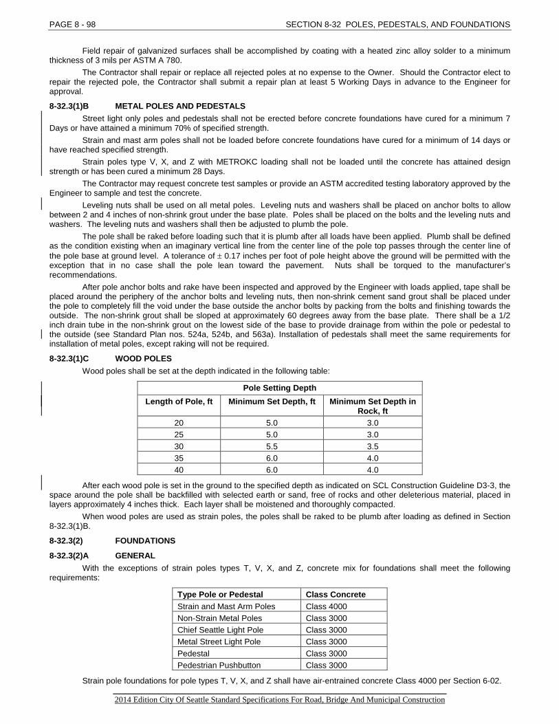
PAGE 8 - 98 SECTION 8-32 POLES, PEDESTALS, AND FOUNDATIONS
Field repair of galvanized surfaces shall be accomplished by coating with a heated zinc alloy solder to a minimum thickness of 3 mils per ASTM A 780.
The Contractor shall repair or replace all rejected poles at no expense to the Owner. Should the Contractor elect to repair the rejected pole, the Contractor shall submit a repair plan at least 5 Working Days in advance to the Engineer for approval.
8-32.3(1)B METAL POLES AND PEDESTALS Street light only poles and pedestals shall not be erected before concrete foundations have cured for a minimum 7
Days or have attained a minimum 70% of specified strength. Strain and mast arm poles shall not be loaded before concrete foundations have cured for a minimum of 14 days or
have reached specified strength. Strain poles type V, X, and Z with METROKC loading shall not be loaded until the concrete has attained design
strength or has been cured a minimum 28 Days. The Contractor may request concrete test samples or provide an ASTM accredited testing laboratory approved by the
Engineer to sample and test the concrete. Leveling nuts shall be used on all metal poles. Leveling nuts and washers shall be placed on anchor bolts to allow
between 2 and 4 inches of non-shrink grout under the base plate. Poles shall be placed on the bolts and the leveling nuts and washers. The leveling nuts and washers shall then be adjusted to plumb the pole.
The pole shall be raked before loading such that it is plumb after all loads have been applied. Plumb shall be defined as the condition existing when an imaginary vertical line from the center line of the pole top passes through the center line of the pole base at ground level. A tolerance of ± 0.17 inches per foot of pole height above the ground will be permitted with the exception that in no case shall the pole lean toward the pavement. Nuts shall be torqued to the manufacturer’s recommendations.
After pole anchor bolts and rake have been inspected and approved by the Engineer with loads applied, tape shall be placed around the periphery of the anchor bolts and leveling nuts, then non-shrink cement sand grout shall be placed under the pole to completely fill the void under the base outside the anchor bolts by packing from the bolts and finishing towards the outside. The non-shrink grout shall be sloped at approximately 60 degrees away from the base plate. There shall be a 1/2 inch drain tube in the non-shrink grout on the lowest side of the base to provide drainage from within the pole or pedestal to the outside (see Standard Plan nos. 524a, 524b, and 563a). Installation of pedestals shall meet the same requirements for installation of metal poles, except raking will not be required.
8-32.3(1)C WOOD POLES Wood poles shall be set at the depth indicated in the following table:
Pole Setting Depth Length of Pole, ft Minimum Set Depth, ft Minimum Set Depth in
Rock, ft 20 5.0 3.0 25 5.0 3.0 30 5.5 3.5 35 6.0 4.0 40 6.0 4.0
After each wood pole is set in the ground to the specified depth as indicated on SCL Construction Guideline D3-3, the space around the pole shall be backfilled with selected earth or sand, free of rocks and other deleterious material, placed in layers approximately 4 inches thick. Each layer shall be moistened and thoroughly compacted.
When wood poles are used as strain poles, the poles shall be raked to be plumb after loading as defined in Section 8-32.3(1)B.
8-32.3(2) FOUNDATIONS
8-32.3(2)A GENERAL With the exceptions of strain poles types T, V, X, and Z, concrete mix for foundations shall meet the following
requirements:
Type Pole or Pedestal Class Concrete Strain and Mast Arm Poles Class 4000 Non-Strain Metal Poles Class 3000 Chief Seattle Light Pole Class 3000 Metal Street Light Pole Class 3000 Pedestal Class 3000 Pedestrian Pushbutton Class 3000
Strain pole foundations for pole types T, V, X, and Z shall have air-entrained concrete Class 4000 per Section 6-02. _________________________________________________________________________________ 2014 Edition City Of Seattle Standard Specifications For Road, Bridge And Municipal Construction

SECTION 8-32 POLES, PEDESTALS, AND FOUNDATIONS PAGE 8 - 99
Foundations shall be augered and constructed against undisturbed soil. Concrete shall be placed against undisturbed earth within a dry hole. Should a dry hole not be maintained, the Contractor shall select a method of concrete placement which does not adversely impact the strength or durability of the concrete as approved by the Engineer. In unstable ground, the Contractor shall install sonotube or other approved form material to provide undisturbed concrete placement. Backfill between form material and undisturbed earth shall be controlled density fill. Each foundation shall be poured in one continuous pouring operation. Where new excavations are near an existing foundation, the Contractor shall provide temporary support for the existing structure as appropriate. Where foundations are installed on slopes, foundation depth shall be measured using the shortest bearing surface.
Anchor bolts shall be set securely in place and held in a vertical position with the specified bolt projection and at the specified bolt circle to match the exact hole pattern of the item to be installed. The tops of the bolts shall all be at the same elevation. A steel template shall be used at the lower end, and a wood or steel template shall be used at the upper end of the anchor bolts, to maintain the correct bolt pattern and spacing until the concrete has set. Anchor bolts shall not be altered in any way after fabrication. Bending of anchor bolts shall be cause for rejection and removal of entire foundation. The bolt circle shall be measured by the Engineer prior to pouring of the concrete.
Prior to placing concrete, all projecting anchor bolts shall be taped with a corrosion protection tape from a point 6 inches below the top of the foundation to the top of the bolt. Tape shall be in accordance with SCL Material Standard 7367.3 and shall remain permanently in place. Nuts and washers shall be installed over the tape. Immediately after concrete is placed, the location of the anchor bolts shall be checked with a template conforming to the bolt pattern of the bases of the poles. After the concrete is placed, anchor bolts and conduit shall be cleaned and kept free of concrete splatter and mortar.
Concrete shall be float-finished, edged and brushed where necessary. Adjusting anchor bolts to make them fit the hole pattern in the base plate will not be allowed after concrete has begun to set.
8-32.3(2)B TRAFFIC SIGNAL CONTROLLER FOUNDATIONS Anchors, cinch anchors, nut couplers, square washer and bolts shall be installed per Standard Plans, or by an
alternate method recommended by the manufacturer. Where the manufacturer recommends installation differing from the Standard Plans, the Contractor shall submit the manufacturer’s recommendations to the Engineer for approval at least 5 Working Days in advance of installation. The cinch anchors shall be sized as recommended by the traffic signal controller manufacturer. A bead of waterproof sealant shall be installed under the lip of the traffic signal controller cabinet prior to installing the cabinet to prevent moisture penetration.
Tops of the traffic signal controller foundations shall be level, and shall be 6 to 8 inch above adjacent finished grade. A 3/4-inch PVC conduit drain shall be installed in all concrete foundations for traffic signal controllers Type II and
Type III cabinet foundations to provide drainage from within the cabinet to the outside finished grade.
8-32.3(2)C POLE, PEDESTAL AND PEDESTRIAN PUSHBUTTON POST FOUNDATIONS Anchor bolts shall be supplied by the Contractor on foundation installations unless specified otherwise in the
Contract. Reinforcing steel shall be kept 3 inches clear from surrounding earth within the concrete pole foundation, and shall be
set securely in place. Where the foundation is in or adjacent to, a proposed sidewalk/paved area, the top of the foundation shall be at or
just below the bottom of the adjacent sidewalk or paving Material. The Contractor shall first coat the foundation top with a bond breaker, and then place sidewalk or paving Material over the top of the foundation. Install premolded joint Material in the construction joint where new pavement or sidewalk is placed over and around the foundation.
Where the foundation is in an unpaved area, the top of the foundation shall be 3” below the finished ground level. The foundation shall poured to specified depth and a 3” deep, square finished pad shall be provided above the foundation.
Conduits shall extend 1 inch above the pole base plate. Anchor bolts shall be installed, or be cut off, with sufficient projection above the foundation to allow 3 threads above the upper nut. Where inadequate projection is provided, bolt extenders may, if approved by the Engineer, be utilized, or complete removal and replacement of the foundation will be required at no expense to the Owner.
8-32.3(2)D EXISTING POLE FOUNDATIONS Where grade changes decrease the standard bolt projection, bolt couplers may be utilized as approved by the
Engineer. Existing foundation concrete shall be chipped to a depth approved by the Engineer. Existing bolts shall not be damaged by concrete chipping. Bolts shall be cut. Heavy duty couplers shall be used with straight, all thread bolts. Bolt length shall be determined according to the necessary bolt projection for the foundation type. Additional rebar may be required by the Engineer.
Where existing pole foundations require bolt pattern changes, epoxy anchors may be utilized as approved by the Engineer. The Contractor shall mark new anchor locations for approval by the Engineer before drilling holes. Anchors shall be injection epoxy type. Core drilling shall occur only with the Engineer present. Holes shall be drilled with ANSI B212.15 matched tolerance carbide tipped drill bits with drill in roto-hammer mode or with a matched tolerance diamond core drill bit of the diameter specified by the bolt manufacturer. Drilled hole specifications shall match ICC ESR 1562 or ICC ESR-1967. Anchors shall be tightened with a calibrated torque wrench. Use of an impact wrench is not permitted. Anchors shall be all-thread. Holes shall be completely cleaned with compressed air or blow out pump before epoxy is poured into the holes. The epoxy shall be set and cured per manufacturer recommendations.
_________________________________________________________________________________ 2014 Edition City Of Seattle Standard Specifications For Road, Bridge And Municipal Construction

PAGE 8 - 100 SECTION 8-32 POLES, PEDESTALS, AND FOUNDATIONS 8-32.3(3) BACK GUY ASSEMBLIES
Back guy assemblies for wood poles shall be constructed in accordance with details on the Standard Plans. All through bolts shall be properly trimmed and treated.
8-32.3(4) RELOCATING EQUIPMENT When equipment is to be relocated, the Contractor shall furnish and install all necessary materials and equipment
including all new hardware required to complete the new installation. Any new hardware required to complete the installation shall be of the same quality and type as hardware required in the Specifications for other new Work.
8-32.3(5) BRACKET ARMS Mounting point of the bracket arm on wood poles shall be located as necessary to provide the required mounting
height of the luminaire above the pavement. However, the Engineer may field determine the required mounting height to provide required wire clearances. The Engineer requires a minimum 1 Working Day advance notice.
Wood pole bracket arms shall be attached by one through bolt and two lag bolts. Through bolts on wood poles shall be cut off so no more than 4 threads nor less than 3 threads are left exposed beyond the captive nut. The exposed end shall be treated with galvanizing repair paint approved by the Engineer. This through bolt shall not be used to mount any other hardware.
8-32.4 MEASUREMENT Bid items of Work completed pursuant to the Contract will be measured as provided in Section 1-09.1, Measurement
of Quantities, unless otherwise provided for by individual measurement paragraphs herein this Section. Measurement for davit poles and the attached davit arm will be per each as a combined unit. Measurement for “Install (Item), Owner Furnished” will be per each.
8-32.5 PAYMENT Compensation for the cost necessary to complete the work described in Section 8-32 will be made at the Bid item
prices Bid only for the Bid items listed or referenced as follows: 1. “Pole, Steel Strain, (Type)”, per each. 2. “Pole, Steel Mast Arm”, per each.
The Bid item price for “Pole, Steel Strain, (Type)” and for “Pole, Steel Mast Arm” shall include all costs for the work required to furnish and install the pole complete, including pole cap, handhole, handhole cover, nut covers, bracket arm flange and bolts, base plate, all necessary hardware, raking, plumbing, and grouting. 3. “Pole Steel Strain Davit (Type) w/(Length) Arm”, per each.
The Bid item price for “Pole, Steel Strain Davit, (Type) with (Length) Arm” shall include all costs for the work required to furnish and install the complete pole, pole cap, the extension arm, including handhole, handhole cover, nut covers, steel pole extension tenon, steel pole luminaire tenon, welding, base plate, all necessary hardware, raking, plumbing, and grouting. 4. “Pole, Steel Lighting (Length)”, per each. 5. “Pole, Aluminum Lighting (Length)”, per each.
The Bid item price for “Pole, Steel Lighting (Length)” and for “Pole, Aluminum Lighting (Length)” shall include all costs for the work required to furnish and install the pole complete, including handhole, handhole cover, and all necessary hardware, raking, plumbing, and grouting. 6. “Pole, Wood, (Length), (Type), (Class)”, per each.
The Bid item price for “Pole, Wood (Length), (Type), (Class)” shall include all costs for the work required to furnish and install the wood pole complete, including excavation, backfill, and compaction. 7. “Mast Arm (Length)”, per each.
The Bid item price for “Mast Arm, (Length)” shall include all costs for the work required to furnish and install the mast arm complete with all necessary hardware, fittings and end cap. 8. “Pedestal, (Material), (Length)”, per each.
The Bid item price for “Pedestal, (Material), (Length)” shall include all costs for the work required to furnish and install the pedestal complete including pipe, cap, base, and all hardware. 9. “Pedestrian Pushbutton Post”, per each.
The Bid item price for “Pedestrian Pushbutton Post” shall include all costs for the work required to furnish and install the post complete including all drilling and tapping, plumbing, steel pipe, pipe cap “meter collar”, grout, pipe flange, and all required hardware. 10. “Foundation, Traffic Signal Controller (Type)”, per each. 11. “Foundation, (Use)”, per each.
The Bid item prices for “Foundation, Traffic Signal Controller (Type)” and for “Foundation, (Use)” shall include all costs for the work required to construct the foundation complete in place including, but not limited to, excavation, excavation support, and furnishing and placing backfill, forming, concrete, reinforcing steel, anchor bolts, ground rods and/or systems, washers, nuts, nut covers, grout, wire, conduit, ground rod, handhole and drainage hardware.
_________________________________________________________________________________ 2014 Edition City Of Seattle Standard Specifications For Road, Bridge And Municipal Construction
SECTION 8-32 POLES, PEDESTALS, AND FOUNDATIONS PAGE 8 - 101 12. “Back Guy Assembly”, per each.
The Bid item price for “Back Guy Assembly” shall include all costs for the work required to furnish and install the back guy assembly complete including installation of all guy cable, hardware, insulators, pipe, fittings, and anchor. 13. “Relocate (Item)”, per each.
The Bid item price for “Relocate (Item)” shall include all costs for the work required to remove and reinstall the item complete including all new hardware and rehabilitation as required. 14. "Remove (Item)", per each
The bid item price for “Relocate (Item)” shall include all costs for the work required to remove and salvage as required. 15. "Bracket Arm, (Length)", per each.
The Bid item price for "Bracket Arm, (Length)" shall include all costs for the work required to furnish and install the bracket arm complete including hardware. 16. “Install (Item), Owner Furnished”, per each.
The Bid item price for “Install (Item), Owner Furnished” shall include all costs for the work required to install the Owner furnished item including transportation of the item from the supply yard to the job site. 17. Other payment information.
When installation of a new pole, pedestal, or post disturbs existing surface improvement that remain, the cost of surface restoration shall be included in the Bid item price of the pole, pedestal, or post as appropriate (see Section 1-07.16).
The installation of the pole number plate furnished by Seattle City Light will be considered as incidental to the cost of installing the pole.
If the Contractor proposes an alternate pole which is approved by the Engineer, no change will be made to the Bid item price for the pole specified in the Bid item.
See Section 1-05.2(2) regarding payment for Electrical Safety Observer.
SECTION 8-33 ELECTRICAL CONDUIT AND TRENCHING
8-33.1 DESCRIPTION
8-33.1(1) GENERAL This Work shall consist of trench excavation, furnishing and installing conduit, conduit, condulets, and handholes for
illumination and signal systems as indicated in the Contract in accordance with these Specifications and Standard Plans. The Contractor shall become thoroughly familiar with the electrical environment within the Project Site and with the
relevant Work. In areas where deteriorated conduits are encountered during trenching, the Contractor shall promptly notify the
Engineer who will then determine if sleeving of conduits is required so as to keep backfill from entering the conduit. It is important to preserve conduits whenever economically practical for future use.
8-33.1(2) APPLICABLE ELECTRICAL CODES See Section 8-30.1(2).
8-33.1(3) ELECTRICAL CONDUIT SHOP DRAWINGS The Contractor shall submit Shop Drawings and catalog cuts in accordance with Section 1-05.3 for the following
items: 1. Conduit and Fittings 6. Condulets Junction Box 2. Stand-off Brackets 7. Expansion Fittings 3. Weatherhead 8. Seals and Sealing Compounds 4. Galvanizing Repair Material 9. PVC Coatings to be field installed 5. Handholes and handhole lids 10. Flexible Conduit
8-33.1(4) ELECTRICAL AND ELECTRONIC WORDS AND PHRASES See Section 1-01.3.
8-33.2 MATERIAL Materials shall meet the requirements of the following Sections:
Non-Shrink Cement Sand Grout 9-04.3(2) Paint 9-08 Conduits and Handholes 9-34
_________________________________________________________________________________ 2014 Edition City Of Seattle Standard Specifications For Road, Bridge And Municipal Construction
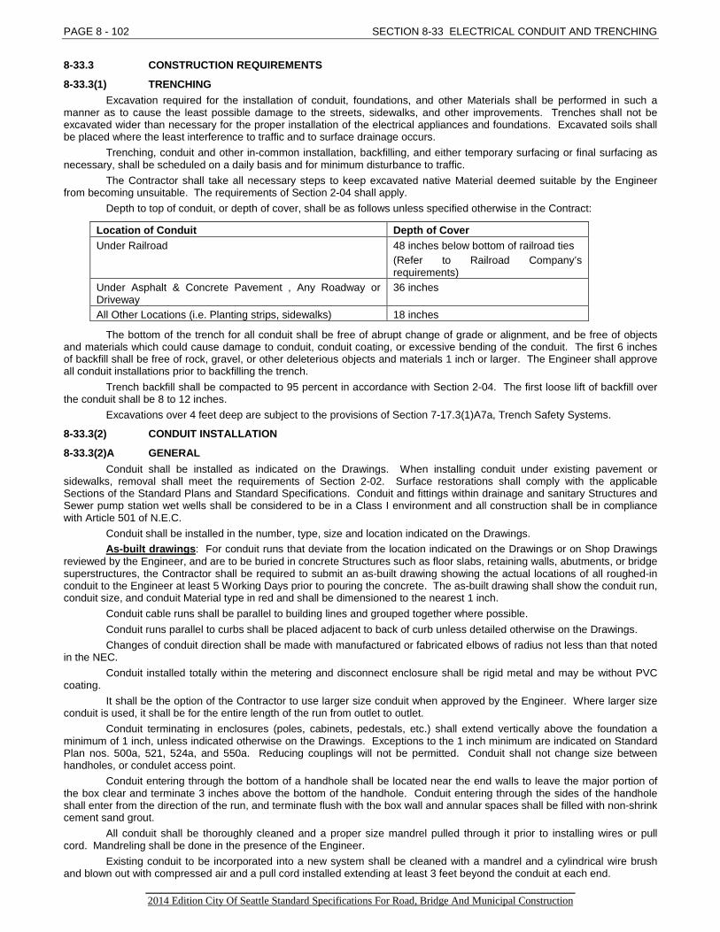
PAGE 8 - 102 SECTION 8-33 ELECTRICAL CONDUIT AND TRENCHING 8-33.3 CONSTRUCTION REQUIREMENTS
8-33.3(1) TRENCHING Excavation required for the installation of conduit, foundations, and other Materials shall be performed in such a
manner as to cause the least possible damage to the streets, sidewalks, and other improvements. Trenches shall not be excavated wider than necessary for the proper installation of the electrical appliances and foundations. Excavated soils shall be placed where the least interference to traffic and to surface drainage occurs.
Trenching, conduit and other in-common installation, backfilling, and either temporary surfacing or final surfacing as necessary, shall be scheduled on a daily basis and for minimum disturbance to traffic.
The Contractor shall take all necessary steps to keep excavated native Material deemed suitable by the Engineer from becoming unsuitable. The requirements of Section 2-04 shall apply.
Depth to top of conduit, or depth of cover, shall be as follows unless specified otherwise in the Contract:
Location of Conduit Depth of Cover Under Railroad 48 inches below bottom of railroad ties
(Refer to Railroad Company’s requirements)
Under Asphalt & Concrete Pavement , Any Roadway or Driveway
36 inches
All Other Locations (i.e. Planting strips, sidewalks) 18 inches
The bottom of the trench for all conduit shall be free of abrupt change of grade or alignment, and be free of objects and materials which could cause damage to conduit, conduit coating, or excessive bending of the conduit. The first 6 inches of backfill shall be free of rock, gravel, or other deleterious objects and materials 1 inch or larger. The Engineer shall approve all conduit installations prior to backfilling the trench.
Trench backfill shall be compacted to 95 percent in accordance with Section 2-04. The first loose lift of backfill over the conduit shall be 8 to 12 inches.
Excavations over 4 feet deep are subject to the provisions of Section 7-17.3(1)A7a, Trench Safety Systems.
8-33.3(2) CONDUIT INSTALLATION
8-33.3(2)A GENERAL Conduit shall be installed as indicated on the Drawings. When installing conduit under existing pavement or
sidewalks, removal shall meet the requirements of Section 2-02. Surface restorations shall comply with the applicable Sections of the Standard Plans and Standard Specifications. Conduit and fittings within drainage and sanitary Structures and Sewer pump station wet wells shall be considered to be in a Class I environment and all construction shall be in compliance with Article 501 of N.E.C.
Conduit shall be installed in the number, type, size and location indicated on the Drawings. As-built drawings: For conduit runs that deviate from the location indicated on the Drawings or on Shop Drawings
reviewed by the Engineer, and are to be buried in concrete Structures such as floor slabs, retaining walls, abutments, or bridge superstructures, the Contractor shall be required to submit an as-built drawing showing the actual locations of all roughed-in conduit to the Engineer at least 5 Working Days prior to pouring the concrete. The as-built drawing shall show the conduit run, conduit size, and conduit Material type in red and shall be dimensioned to the nearest 1 inch.
Conduit cable runs shall be parallel to building lines and grouped together where possible. Conduit runs parallel to curbs shall be placed adjacent to back of curb unless detailed otherwise on the Drawings. Changes of conduit direction shall be made with manufactured or fabricated elbows of radius not less than that noted
in the NEC. Conduit installed totally within the metering and disconnect enclosure shall be rigid metal and may be without PVC
coating. It shall be the option of the Contractor to use larger size conduit when approved by the Engineer. Where larger size
conduit is used, it shall be for the entire length of the run from outlet to outlet. Conduit terminating in enclosures (poles, cabinets, pedestals, etc.) shall extend vertically above the foundation a
minimum of 1 inch, unless indicated otherwise on the Drawings. Exceptions to the 1 inch minimum are indicated on Standard Plan nos. 500a, 521, 524a, and 550a. Reducing couplings will not be permitted. Conduit shall not change size between handholes, or condulet access point.
Conduit entering through the bottom of a handhole shall be located near the end walls to leave the major portion of the box clear and terminate 3 inches above the bottom of the handhole. Conduit entering through the sides of the handhole shall enter from the direction of the run, and terminate flush with the box wall and annular spaces shall be filled with non-shrink cement sand grout.
All conduit shall be thoroughly cleaned and a proper size mandrel pulled through it prior to installing wires or pull cord. Mandreling shall be done in the presence of the Engineer.
Existing conduit to be incorporated into a new system shall be cleaned with a mandrel and a cylindrical wire brush and blown out with compressed air and a pull cord installed extending at least 3 feet beyond the conduit at each end.
_________________________________________________________________________________ 2014 Edition City Of Seattle Standard Specifications For Road, Bridge And Municipal Construction
SECTION 8-33 ELECTRICAL CONDUIT AND TRENCHING PAGE 8 - 103
Conduit repairs: When small portions of damaged conduit repairs are necessary, repairs are permitted by using PVC in its place. The PVC shall be coupled to the local conduit by means of beveled edge couplings slipped into place and then sealed with PVC cement. On repairs to steel conduit using PVC, a bonding #6 AWG jumper shall be installed connecting the metal sections together with bonding clamps approved by the Engineer.
Marker stakes or tacks shall be set flush with the ground to locate the ends of stubbed out conduits which may be buried so that they may be located in the future. All stubbed out conduits shall be capped.
Conduit entrances into metal junction boxes (Except NEMA 1) shall be drilled and tapped a minimum of 3 full threads for the size conduit used. Bosses shall be provided where the wall thickness is not sufficient for the minimum number of threads.
Entry to electrical vaults or other Structures shall be made such that the physical integrity of the vault or structure is not impaired. Any hole for entry to vaults or Structures shall be core drilled of a diameter no greater than 1-1/2 times the diameter of the conduit entering the vault. See Section 1-05.2(2) for Electrical Safety Observer requirements.
Annular spaces around conduit, equipment grounding conductor, ducts, at wall penetrations of vault or other structural walls shall be filled with non-shrink cement sand grout (see Section 9-04.3(2)). Threaded inserts shall be coated with an approved rust preventative compound which is soluble in petroleum solvent.
At locations designated by the Engineer, fittings shall be installed to provide a conduit channel that permits freedom for installing the electrical control wires. When conduit fittings are indicated on the Drawings, or where their installation is required by the Engineer, the Contractor shall also furnish all necessary covers and gaskets. Expansion/deflection fittings per Standard Plans shall be installed at all structure expansion joints.
Conduits shall be attached to walls and other surfaces (except poles) using approved one hole malleable iron pipe clamps and clamp backs.
Rigid steel conduit may be jacked or bored when approved by the Engineer. New conduit that does not have wire installed (vacant) shall have a pull cord installed extending at least 3 feet
beyond the conduit at each end and fastened down. Conduit entrances into metal junction boxes shall be drilled and tapped a minimum of 5 full threads for the size
conduit used. Bosses shall be provided where the wall thickness is not sufficient for the minimum number of threads.
8-33.3(2)B RIGID STEEL CONDUIT AND PVC-COATED RIGID STEEL CONDUIT When rigid steel conduit is cut, the ends shall be made square and true with conventional pipe cutting equipment.
Conduit shall be threaded with a standard conduit cutting die. Burrs and sharp corners at the end of each conduit shall be removed with a tapered reamer. Threads shall be cleaned of all metal, lubricants, red lead, and any other Material which prevents joining with threaded counterparts. Conduit threads shall be coated with a conduit thread compound designed to ease assembly and disassembly, and to improve electrical conductivity. Conduit shall be joined by the use of rigid steel conduit couplings. Running threads will not be permitted for coupling conduit. When a standard coupling cannot be used, an approved threaded union coupling shall be used. Conduit shall be tightened securely to prevent the entrance of moisture, concrete or other foreign Material and to provide a good electrical connection throughout the entire length of the conduit run. The method of tightening shall not damage the conduit or coupling. Where the galvanizing on the conduit or the coupling has been damaged, it shall be thoroughly painted with galvanizing repair paint Federal Spec. MIL-P-21035 per the manufacturer’s recommendations. An Alternate repair method shall consist of applying a heated zinc alloy solder coating to a minimum thickness of 2 mils in accordance with ASTM A 780.
Bushings shall be of the insulated throat type. The entire conduit system shall be properly bonded and grounded in accordance with N.E.C.
Installation of the PVC-coated system shall be made in conformance with the following: 1. Coupling and Joining: All conduit connections shall be made mechanically tight with strap wrenches to
assure rigidity and maximum electrical conductivity. Over-tightening that results in gouging of the PVC coating will not be permitted. After each connection is completed, any gouges, cuts or abrasions shall be repaired. Solvent weld the sleeves to the conduit at each connection by applying touch-up compound to the PVC coating before screwing on the sleeve. Cutting off plastic sleeves shall be cause for rejection of that length of conduit.
2. Cutting: The conduit shall be tightened securely in a vise or chuck. The cut shall be made with a roll cutter or hack saw. When using either a jaw vise or a chain vise, the use of vise adapters will be required. If vise adapters are unavailable, a jaw vise shall be used and the portion of the coated conduit to be gripped in the vise shall be wrapped with emery cloth with the coarse side toward the conduit. The use of a chain vise without adapters will not be permitted.
3. Threading: When using a hand threader, a tool with an adjustable guide shall be used. If the threader to be used does not have an adjustable guide, ream the stationary guide 0.10 inch to accommodate the plastic coating. Whittling of the PVC coating will not be permitted. After threading, apply touch-up compound to indentations made by the vise. Raw field cut threads shall be protected by the methods set forth above. For machine threading, the use of a threader designed for coated conduit shall be used.
4. Bending: PVC-coated conduit may be bent with conventional bending equipment; however, the internal walls of the shoes shall be machined out approximately 0.050 inch. Bending shall be accomplished by segmented bending rather than a one-shot bend. For sharp bends, saddles, or offsets, a PVC-coated hickey shall be required. Any cuts, gouges, or abrasions shall be coated with touch-up compound. Coating
_________________________________________________________________________________ 2014 Edition City Of Seattle Standard Specifications For Road, Bridge And Municipal Construction
PAGE 8 - 104 SECTION 8-33 ELECTRICAL CONDUIT AND TRENCHING
the exterior of the conduit, prior to bending, with a slippery substance, such as wire-pulling compound, will be permitted.
5. Touch-up: During the installation of the coated conduit, the Contractor shall assure that no metal is left exposed or uncoated. Metal exposed as the result of field cuts shall be coated with touch-up compound. If an uncoated accessory must be used, it shall also be coated.
6. One hole malleable iron pipe strap, pipe spacers (clamp backs), and mounting brackets shall be PVC coated.
8-33.3(2)C PVC CONDUIT PVC conduit shall be assembled with solvent welded joints in accordance with the manufacturer’s written instructions.
Bends and fittings shall be factory-produced.
8-33.3(3) CONDUIT RISERS Conduit less than 2 inches in diameter mounted on wood poles shall be mounted by use of 2-hole malleable conduit
clamps spaced per N.E.C./N.E.S.C. A minimum of 2 clamps shall be used per length of conduit. Conduit sized 2 inches and larger, or more than 1 conduit installed on wood poles, shall be installed using stand-off
type brackets. Stand-off brackets shall be installed per N.E.C./N.E.S.C. with a 10 foot maximum spacing. Attachment shall be near the top of each 10 feet length of conduit.
All conduit risers shall be grounded with a ground clamp installed 8 feet above finished grade. Where conduit risers are connected to a ground rod, a ground rod handhole well shall be provided.
The conduit shall be wrapped with corrosion protection tape conforming to SCL Material Standard 7367.3, 8 inches above and below finished grade.
Conduit risers shall be the size indicated on the Drawings. The 90 degree bend and conduit up the pole to 10 feet above the surface shall be rigid steel. The riser above the 10-foot level shall be PVC, Schedule 80. The riser shall be equipped with a PVC weatherhead and shall be grounded as indicated on Standard Plans.
8-33.3(4) HANDHOLES Handholes shall be installed per Standard Plans 550a and 550b. The frame (ring) and lid shall be grounded with an
approved grounding clamp(s) to the ground rod per SCL Construction Standard 0233.05 at the locations shown on the Drawings. Unless dimensioned, handholes are located schematically, and shall always be located outside the pedestrian travel way. The Contractor shall provide the Engineer a minimum 1 Working Day advance notice regarding the exact handhole location.
When required by the Contract or Engineer, handhole extensions shall be provided by Contractor and installed. Unused conduit openings in handholes shall be capped to afford protection against debris from entering the conduits. Cables and conductors shall be racked. The Contractor shall select a racking method to be approved by the
Engineer. See Section 8-31.3(1)B for Traffic Signal handhole access requirements and Section 8-30.3(3) for SCL handhole,
maintenance hole, and vault access requirements. See Section 9-34.6 for additional handhole Material requirements.
8-33.3(5) JACKING OR BORING OR TUNNELING, RIGID STEEL AND OTHER CONDUIT Rigid steel conduit may be jacked or bored when approved by the Engineer. Rigid non-metallic type conduit may be
installed under existing pavement if a hole larger than the conduit is predrilled and the conduit installed by hand. When tunneling under existing pavement or other surface improvement is required for conduit installation, the
Contractor shall submit the proposed tunneling process including the Materials and methods for filling any voids created by the tunneling process at least 10 Working Days in advance for the Engineer's approval. Directional drilling shall be in accordance with Section 7-22.
8-33.3(6) RESERVED
8-33.4 MEASUREMENT Bid items of Work completed pursuant to the Contract will be measured as provided in Section 1-09.1, Measurement
of Quantities, unless otherwise provided for by individual measurement paragraphs herein this Section. Measurement for “Conduit, (Material), (Size)” will be by the linear foot measured on the ground along the conduit to
the center line of pole, to the 90 degree bend of a conduit riser, to equipment, or to the inside face of a handhole or of a vault. Measurement for “Conduit Riser, (Size)” will be by each from and including the weatherhead to and including the 90
degree rigid steel bend underground. Measurement for “Relocate (Item)” will be per each. No separate measurement will be made for jacked or augered conduit. No measurement will be made for removal or
restoration of surface improvements where the conduit is jacked or augered, but such measurement will be made at jacking pits and access holes in accordance with Section 2-02.4.
Measurement for pavement restoration will be in accordance with Sections 5-04.4 and 5-05.4 as applicable.
_________________________________________________________________________________ 2014 Edition City Of Seattle Standard Specifications For Road, Bridge And Municipal Construction
SECTION 8-33 ELECTRICAL CONDUIT AND TRENCHING PAGE 8 - 105 8-33.5 PAYMENT
Compensation for the cost necessary to complete the work described in Section 8-33 will be made at the Bid item prices Bid only for the Bid items listed or referenced as follows: 1. “Conduit, (Material), (Size)”, per linear foot.
The Bid item price for “Conduit, (Material), (Size)” shall include all costs for the work required to furnish and install the conduit complete including all bends, fittings, condulets and hardware. 2. “Trenching, Conduit”, per linear foot.
The Bid item price for “Trenching, Conduit” shall include all costs for the work required to excavate, backfill with suitable Material, and compact the trench section for both conduit and conduit riser trenching. Payment for replacement of native material determined unsuitable by the Engineer will be in accordance with Section 1-04.1(2). All costs for replacement of suitable native Material which becomes unsuitable due to Contractor operations shall be at the Contractor's sole expense. 3. “Conduit Riser, (Size)”, per each.
The Bid item price for “Conduit Riser, (Size)” shall include all costs for the work required to furnish and install the complete riser, including all conduit, fittings, clamps and hardware from and including the weatherhead to and including the 90 degree rigid steel bend underground. 4. “Handhole (Type)”, per each.
The Bid item price for “Handhole (Type)” shall include all costs for the work required to furnish and install the handhole complete including excavation, backfill and compaction, groundrod, and handhole extensions when required. 5. “Handhole (Type), Polymer”, per each.
The Bid item price for “Handhole (Type), Polymer” shall include all costs for the work required to furnish and install the handhole complete including excavation, backfill and compaction, groundrod, and handhole extensions when required. 6. “Relocate (Item)”, per each.
The Bid item price for “Relocate (Item)” shall include all costs for the work required to relocate the specified item. 7. “Remove (Item)”, per each.
The Bid item price for “Remove (Item)” shall include all costs for the work required to remove and salvage as required.
8. Other payment information. Payment for jacked or augered conduit will be made at the Bid item price for "Trenching, Conduit". All costs for ground rod wells shall be included in the Bid item prices of the applicable Bid items. See Section 1-05.2(2) regarding payment for Electrical Safety Observer.
_________________________________________________________________________________ 2014 Edition City Of Seattle Standard Specifications For Road, Bridge And Municipal Construction