08/06/18 hasta 01/06/18 desde 1 Boletín de Informaciones nro ...
Upload
khangminh22Category
view
3download
0
Air Pollution Prevention
Manual on Emission Monitoring
Texte
0608
ISSN1862-4804

TEXTE
ENVIRONMENTAL RESEARCH OF THE FEDERAL MINISTRY OF THE ENVIRONMENT, NATURE CONSERVATION AND NUCLEAR SAFETY
Research Report 360 16 004 UBA-FB 001090
TÜV Süd Industrie Service GmbH, München On behalf of the Federal Environment Agency
UMWELTBUNDESAMT
Texte
0608
ISSN
1862-4804
Air Pollution Prevention Manual on Emission Monitoring
This Publication is only available as Download under http://www.umweltbundesamt.de The contents of this publication do not necessarily reflect the official opinions. Publisher: Federal Environment Agency (Umweltbundesamt) P.O.B. 14 06 06813 Dessau-Roßlau Tel.: +49-340-2103-0 Telefax: +49-340-2103 2285 Internet: http://www.umweltbundesamt.de Edited by: Section II 4.1 Anja Ihl 2., revised edition Dessau-Roßlau, August 2008

REPORT COVER SHEET
1. Report No.
UBA-FB 00 10 90 2. 3.
4. Report Title
Air pollution Prevention Manual on Emission Monitoring 5. Author(s), Family Name(s), First Name(s)
8. Report Date
9. Publication Date
10. UFOPLAN – Ref..No.
FKZ 360 16 004
6. Performing Organisation (Name, Address)
TÜV Süd Industrie Service GmbH Westendstr. 199 80686 München
11. No. of Pages
471 12. No. of References
148 13. No. of Tables
14
7. Sponsoring Agency (Name, Address)
Umweltbundesamt, Wörlitzer Platz 1, 06844 Dessau-Roßlau
14. No. of Figures
35 15. Supplementary notes
16. Abstract
The Manual on Emission Monitoring covers the need for information about the national practice in the field of emission control at plants, requiring official approval. The legal bases for discontinuous and continuous measurements for emission control at plants, requiring official approval, are treated. Thereby also the European environmental legislation is considered. The publication procedure for testing institutes, which execute such measurements, is described. The execution of discontinuous emission measurements (course of the measurement and measurement requests) and for continuous emission measurement (suitability test, installation, maintenance, functional test and calibration of the automated measuring system) including the evaluation and documentation of the measured values is described. The procedure of remote emission monitoring is explained. The most important measuring procedures (continuous and discontinuous) are reported. The guide also includes an up-to-date list of tested and appropriate measurement devices. Such tested measuring devices are described by their manufacturers. Indications are given as to how the devices function together with their technical data (e. g. parameters from the suitability test).
17. Keywords
Emission, emission monitoring, remote emission monitoring, emission data transfer, emission measurement, emission measurement technology, suitability tests, measuring laboratory, testing institutions, automated measuring system, measuring device, maintenance, calibration, functional test, measurement methods
18. Price
19. 20.

- 1 -
Table of contents 1 GENERAL REMARKS ...........................................................................................................................................5
1.1 PURPOSE OF EMISSION MONITORING ......................................................................................................5 1.2 NATIONAL LEGAL BASES AND MEASUREMENT REGULATIONS; COMPARISON WITH EC LAWS..............5 1.3 STANDARDIZATION OF MEASUREMENT METHODS .................................................................................6 1.4 ACCREDITATION OF TEST INSTITUTES .....................................................................................................9
2 DISCONTINUOUS EMISSION MONITORING........................................................................................... 12 2.1 LEGAL BASES (REASONS FOR DISCONTINUOUS MEASUREMENTS)......................................................... 12 2.2 PLANNING OF MEASUREMENTS............................................................................................................. 13 2.3 CARRYING OUT THE MEASUREMENTS ................................................................................................... 14 2.3.1 Selection of the section of measurement and its plane................................................................... 14 2.3.2 Grid measurements............................................................................................................................. 16 2.3.3 Extractive isokinetic sampling........................................................................................................... 17 2.3.4 Extractive sampling for gas measurement....................................................................................... 18 2.3.5 Determination of waste-gas conditions............................................................................................ 19 2.4 SPECIAL REQUIREMENTS FOR INDIVIDUAL MEASUREMENTS ................................................................ 19 2.5 EVALUATION/REPORTING/DOCUMENTATION .................................................................................... 21 2.6 UNCERTAINTY OF EMISSION MEASUREMENTS ...................................................................................... 22 2.6.1 Uncertainty of individual measurements ........................................................................................ 22 2.6.2 Uncertainty of continuous emission monitoring. ........................................................................... 23
3 CONTINUOUS EMISSION MONITORING.................................................................................................. 26 3.1 LEGAL BASES.......................................................................................................................................... 26 3.1.1 Facilities requiring governmental approval .................................................................................... 26 3.1.2 Facilities not requiring governmental approval ............................................................................. 29 3.2 QUALITY ASSURANCE FOR CONTINUOUS EMISSION MONITORING....................................................... 30 3.2.1 Suitability tests..................................................................................................................................... 31 3.2.2 Installation, operation and quality control of suitability-tested measurement devices............. 34 3.3 EVALUATION AND DOCUMENTATION OF THE MEASUREMENT VALUES, SUBMISSION OF DOCUMENTS
TO AUTHORITIES/REMOTE EMISSION MONITORING............................................................................. 47
4 MEASUREMENT METHODS............................................................................................................................ 53 4.1 CONTINUOUS MEASUREMENT OF NON-ATMOSPHERIC SUBSTANCES (STATIONARY /MOBILE) ........... 53 4.1.1 Measurement of particulate emissions............................................................................................. 53 4.1.2 Measurement of gaseous substances ................................................................................................ 58 4.2 DISCONTINUOUS MEASUREMENTS........................................................................................................ 65 4.2.1 Manual measurement of dust load and determination of substances contained in dust
(semimetals and metals) ..................................................................................................................... 65 4.2.2 Determination of the mass concentration of polychlorinated dibenzodioxins and
polychlorinated dibenzofuranes (PCDD/PCDF)............................................................................ 68 4.2.3 Manual methods to measure inorganic compounds...................................................................... 69 4.2.4 Determination of individual organic components ......................................................................... 71 4.2.5 Olfactometric determination of odour emissions ........................................................................... 72 4.3 MEASUREMENT OF REFERENCE VALUES................................................................................................ 72 4.3.1 Oxygen measurement (paramagnetic effect)................................................................................... 72

- 2 -
4.3.2 Oxygen measurement (zirconium dioxide probe) ..........................................................................74 4.3.3 Oxygen measurement (electrochemical oxygen sensor) ................................................................75 4.3.4 Determination of waste gas humidity ..............................................................................................76 4.3.5 Flow velocity/waste gas volumetric flow........................................................................................76 4.3.6 Temperature measurement ................................................................................................................79 4.4 LONG-TERM SAMPLING FOR PCDD/PCDF..........................................................................................80
5 GLOSSARY.............................................................................................................................................................81
6 REFERENCES.........................................................................................................................................................85
7 ANNEX 1: LEGISLATIVE AND ADMINISTRATIVE REGULATIONS/EXCERPTS FROM QUOTED SOURCES ............................................................................................................................................94
7.1 EXCERPT OF THE FEDERAL IMMISSION CONTROL ACT.........................................................................94 7.2 EXCERPT OF THE TI AIR .........................................................................................................................98 7.3 EXCERPT OF THE LARGE FURNACES ORDER (13TH BIMSCHV) ............................................................120 7.4 EXCERPT OF THE ORDINANCE ON WASTE INCINERATION AND CO-INCINERATION (17TH BIMSCHV)
.............................................................................................................................................................126 7.5 EXCERPT OF THE ORDER ON TITANIUM DIOXIDE (25TH BIMSCHV)....................................................132 7.6 EXCERPT OF THE ORDER ON CREMATORIA (27TH BIMSCHV)..............................................................133 7.7 EXCERPT OF THE ORDINANCE RELATING TO BIOLOGICAL WASTE TREATMENT PLANTS (30TH
BIMSCHV) ...........................................................................................................................................135 7.8 EXCERPT OF THE ORDINANCE ON THE LIMITATION OF EMISSIONS OF VOLATILE ORGANIC
COMPONENTS USING ORGANIC SOLVENTS IN CERTAIN PLANTS (31ST BIMSCHV) ............................138 7.9 UNIFORM PRACTICE IN MONITORING EMISSIONS – PART 1...............................................................141 7.10 STANDARD FORM OF A TEST REPORT FOR THE DETERMINATION OF EMISSIONS IN ACCORDANCE WITH
§§ 26, 28 OF THE FEDERAL IMMISSION CONTROL ACT .......................................................................191 7.11 STANDARD REPORTS ON ANNUAL SURVEILLANCE TESTS AND CALIBRATIONS OF AUTOMATED
MEASURING SYSTEMS...........................................................................................................................211
8 ANNEX 2: LIST OF SUITABILITY TESTED AND ANNOUNCED AUTOMATED MEASURING SYSTEMS FOR EMISSION MEASUREMENTS AND ELECTRONIC EVALUATION SYSTEMS...........................................................................................................................................238
9 ANNEX 3: PRESENTATIONS OF MEASURING DEVICES BY THE MANUFACTURERS................329
Table of figures Figure 1: Flow chart for the “notification/accreditation” process ................................................................11
Figure 2.1: Example arrangement of a measurement platform on a vertical flue gas duct ..........................16
Figure 2.2: Position of the measurement points in rectangular and round duct cross sections as per VDI 2066, part 1...........................................................................................................................................17
Figure 2.3: Influence of suction errors (non-isokinetic sampling) on sampling .............................................18
Figure 3.1: Quality control of continuous emission monitoring.......................................................................30
Figure 3.2: Sequence of tasks of check of calibration and variability...............................................................40
Figure 3.3: Diagram showing the individual steps for calibration and test of variability.............................43

- 3 -
Figure 3.4: Steps in the evaluation of continuous emission monitoring ......................................................... 48
Figure 3.5: Classification structure of a system as per 17th BImSchV ............................................................. 50
Figure 3.6: Remote emissions monitoring system with connection to authorities ........................................ 52
Figure 4.1: Photometric in situ dust measurement (schematic) ....................................................................... 55
Figure 4.2: Scattered light measurement, extractive method (schematic)....................................................... 56
Figure 4.3: In situ scattered light measurement (schematic)............................................................................. 56
Figure 4.4: Dust measurement with β-ray absorption (schematic) .................................................................. 57
Figure 4.5: Simplest measuring set-up for an absorption photometer (schematic) ....................................... 59
Figure 4.6: NDIR photometer (schematic)........................................................................................................... 59
Figure 4.7: Gas filter correlation method (schematic)........................................................................................ 59
Figure 4.8: Different in situ photometer arrangements ..................................................................................... 61
Figure 4.9: FTIR spectrometer with Michelson interferometer arrangement (schematic) ............................ 62
Figure 4.10: Chemiluminescence measurement arrangement (schematic)....................................................... 63
Figure 4.11: Flame ionisation detector/FID (schematic) ..................................................................................... 64
Figure 4.12: Example of a dust sampling device with a plane filter device (in-stack) and absorption system for analysis of filter-passing dust components................................................................................ 67
Figure 4.13: PCDD/PCDF sampling using the filter/cooler method a (schematic)........................................ 68
Figure 4.14: PCDD/PCDF sampling using the dilution method b (schematic) ............................................... 68
Figure 4.15: PCDD/PCDF sampling using the cooled suction pipe method c (schematic) ........................... 68
Figure 4.16: Device for sampling (inorganic) gaseous materials by means of absorption.............................. 70
Figure 4.17: Time-integrating sampling with gas collection vessel (schematic) .............................................. 70
Figure 4.18: Oxygen measurement using ‘Siemens’ system based on paramagnetic alternating pressure (schematic) ........................................................................................................................................... 73
Figure 4.19: Oxygen measurement using Maihak’s system based on a magnetic torsion balance (schematic)............................................................................................................................................................... 74
Figure 4.20: Oxygen measurement using a zirconium probe (schematic) ........................................................ 75
Figure 4.21: Mode of operation of an oxygen measuring cell............................................................................. 75
Figure 4.22: Flow speed measurement using the Prandtl tube (schematic) ..................................................... 77
Figure 4.23: Flow balance ........................................................................................................................................ 78
Figure 4.24: Flow measurement using ultrasound............................................................................................... 78
Figure 4.25: Schematic diagram of a suction pyrometer with downstream oxygen measurement. ............. 80
- 4 -
Index of tables Table 1.1: Comparison of legal regulations .........................................................................................................6
Table 1.2: Comparison of current norms and guidelines for emission monitoring .......................................8
Table 1.2: Comparison of current norms and guidelines for emission monitoring ......................................9
Table 2.1: Time requirements for discontinuous measurements by government order..............................13
Table 3.1: Mass flow thresholds (as per TI Air) for continuous emission monitoring.................................27
Table 3.2: Steps of the functional test to carry out QAL 2 and AST ...............................................................38
Table 3.3: Calibration intervals for measurement devices for continuous emission monitoring...............41
Table 4.1: Absorption solutions for accumulating measured objects.............................................................69
Table 7.2: Measured objects for which continuous measurement is required in accordance with the 13th Federal Immissions Control Ordinance..........................................................................................120
Table 7.3: Measured objects for which continuous measurement is required in accordance with the 17th Federal Immissions Control Ordinance..........................................................................................126
Table 7.4: Measured objects for which continuous measurement is required in accordance with the 25th Federal Immissions Control Ordinance..........................................................................................132
Table 7.5: Measured objects for which continuous measurement is required in accordance with the 27th Federal Immissions Control Ordinance..........................................................................................133
Table 7.6: Measured objects for which continuous measurement is required in accordance with the 30th Federal Immissions Control Ordinance..........................................................................................135
Table 7.7: Measured objects for which continuous measurement is required in accordance with the 31th Federal Immissions Control Ordinance..........................................................................................138

- 5 -
1 General Remarks
1.1 Purpose of emission monitoring
In Germany, routine measurements are made in the environmental areas of air, noise and water. These measurements are to ensure that the quality of such media are checked as well as to evaluate any measures necessary in order to insure safety or improve quality.
The legal basis for measurements intended to monitor environmental air quality is the “Federal Immission Control Act” (Bundes-Immissionsgesetz, BImSchG [1]). It contains the requirements for the installation and operation of facilities which might potentially do damage to the environment. Legal and administrative regulations make these requirements more concrete.
In order to ensure that these regulations have been abided by, the BImSchG gives the governmental authorities the possibility to order either discontinuous emission monitoring at regular intervals or if mass flows are large by means of continuous measurements.
This manual describes those measurement methods which derive from the legal regulations for systems which require governmental approval. The requirements for plants-monitoring which derive from EC legislation is to an increasing extent having consequences for procedures in the individual member countries. This is also discussed. Requirements for plants-monitoring resulting from the UN-ECE Protocols (the UN Economic Commission for Europe) are also applicable in Germany.
The measurements themselves and the calibration of continuous measurement devices are to be carried out by named and independent measurement institutions. In the cases of audited locations (i. e. those which have submitted voluntarily to environmental management and operational testing) there is the option of diverging from this principle. Under certain conditions, the operators of such facilities may be allowed to carry out part of the monitoring themselves [2].
1.2 National legal bases and measurement regulations; comparison with EC laws
Emission monitoring is part of the catalogue of measures provided for in the Federal Immission Control Act [1]. §7 BImSchG empowers the German Federal Government to take legal measures to require that the operation and self-monitoring of facilities which require governmental approval fulfil specific standards, particularly that: “the operators of such facilities must conduct (or must cause to be conducted) measurements of both emissions and immissions which are in accordance with procedures described in greater detail in an appropriate statutory instrument.” § 23 makes the same provisions for facilities which do not require governmental approval.
The statutory instruments which regulate the facilities requiring governmental approval are:
- the first general administrative regulations of the BImSchG (TA Luft = TI Air) [3], - the 13th Federal Immission Control Ordinance (13th BImSchV)[8], - the 17th Federal Immission Control Ordinance (17th BImSchV)[9], - the 30th Federal Immission Control Ordinance (30th BImSchV)[12]
and for the facilities not requiring governmental approval they are:
- the first Federal Immission Control Ordinance (1st BImSchV)[4], - the second Federal Immission Control Ordinance (2nd BImSchV)[5], - the 25th Federal Immission Control Ordinance (25th BImSchV)[10], - the 27th Federal Immission Control Ordinance (27th BImSchV)[11].
The 31st Federal Immission Control Ordinance (31st BImSchV) [13] applies both to facilities which require governmental approval and those which do not

- 6 -
Measurement methods and regulations on the first and second BImSchV are the subject of another handbook which has been published as a UBA text [141] and will therefore not be discussed here.
On an European level, the guidelines regulating the integrated avoidance and reduction of environmental pollution (IVU-Guidelines) [15] provide the legal basis to order emission measurements. Art 9 §5 requires that any governmental approval given must contain, “appropriate requirements for the monitoring of emissions in which the measurement methods, frequency of measurements and evaluation procedures are determined.” The determination of such requirements remains primarily a national responsibility, except when, as a result of inter-European information exchanges, the necessity of taking such measures is becoming more generally apparent.
A Europe-wide requirement for emission monitoring exists at present:
- for large-scale incineration plants 2001/80/EG [16] - for the incineration of household waste 2000/76/EG [17] - for certain activities and facilities using organic solvents (VOC-Guidelines) 1999/13/EG
European guidelines are to be made a valid part of national law within set time limits. In part, national legislation already includes the EC requirements. Where this is not the case, laws will be revised or new laws initiated (e. g. the revised version of the 17th BImSchV of 14 August 2003).
Table 1.1: Comparison of legal regulations
Regulation National Law EC Law Approval procedures/ Requirement of measurements
BImSchG §§ 7, 26, 28, 29 IVU-guideline, Article 9 (previously: 84/360/EWG)
Facilities requiring approval 4th BImSchV IVU-guideline, Appendix I Measurement objects TI Air IVU-guideline, Appendix III Special Measurement Requirements: Small scale incineration plants 1st BImSchV VHC (high volatile halogen hydrocarbons) 2nd BImSchV/TI Air 1999/13/EG Large-scale incineration plants 13th BImSchV 2001/80/EG Incineration plants for household waste 17th BImSchV 2000/76/EG The titanium dioxide industry 25th BImSchV Cremation facilities 27th BImSchV Facilities for biological waste treatment 30th BImSchV Limitation of emissions from volatile organic solvents
31st BImSchV 1999/13/EG
1.3 Standardization of measurement methods
Differing measurement methods used to investigate the same object of measurement do not always produce comparable results. To be more precise: The object of measurement is only finally defined by the choice of the measurement method. Therefore it is imperative to standardize measurement and analysis methods in order to make measurement results comparable when differing methods have been used at different sites. Before their publication, the DIN and VDI regulations were first subjected to the most thorough testing. These testing procedures included determining the statistical characteristic value and the potential sites where such procedures would be used as well as any limitations they might have. Standardized measurement methods are therefore an efficient tool for determining emissions.

- 7 -
National standards
The “Commission on Air Pollution Prevention” (KRdL) of the VDI and DIN committee on technical standards brought together experts from science, industry and administration to work out voluntary VDI-guidelines and DIN-standards for environmental protection. They describe the current state of technology and scientific research in the Federal Republic of Germany and serve as a help in making decisions when it is necessary to work out and apply legal and administrative regulations. The results of this committee’s work also represent in a general way the German position within the European committee on Standards (CEN) and the international organization for standards (ISO).
The VDI-Regulations (summarized in the “VDI Air Pollution Prevention HVDI Handbuch Reinhaltung der Luft”) cover a broad spectrum of possible measurement tasks. There are also some DIN-norms for a few selected measurement methods.
European standards for air quality are being worked out in the European committee on Standards (CEN) in Technical Committee 264 and will be published in Germany as a DIN EN norm. If DIN or DIN EN norms have been published for a particular measurement task, then already published national norms with the same content are to have preference over already published VDI-Guidelines. DIN EN norms have already been published for a variety of measurement tasks, e. g. for the manual determination of PCDD/PCDF [55] or for the carrying out of quality control measures over the course of continuous emission monitoring [38]. With the expansion of EC environmental legislation (particularly with regard to emission limiting values) it is to be expected that measurement methods for emissions will become standardized throughout the European Community.
International standards are worked out at the International Organization for Standardization (ISO) in the ISO/technical committee 146. The publication of ISO norms is not legally binding in Germany. There is, however, a simplified procedure for making ISO norms part of the DIN ISO norms.
Table 1.2 gives an overview of the norms and guidelines for emission technology which have been published, either in draft or in their final form. In addition to the published versions, the table also shows whether continuous or discontinuous measurements are intended.
Meanings: E: Draft VE: First draft I.V.: In preparation WG: Working group DIS: Draft international standard FDIS: Final draft international standard

- 8 -
Table 1.2: Comparison of current norms and guidelines for emission monitoring As of: December 2006
Measurement object/Topic cont. Dis-cont.
VDI-Handbook Air Purity
DIN DIN/EN TC 264
ISO TC 146
General Topics Planning of spot sampling Emission measurements
X 2448 p. 1 [31] 15259 E [33]
Evaluation of spot sampling Emission measurements
X 2448 p. 2 [32]
Carrying out of emission measurements X 4200 [34] Emission measrements from diffuse sources 4285 p. 1 u. 2 [35][36] Calibration of automated measuring systems X 3950 [37] 14181 [38] 12039 [42] Sampling (gen.) X 10396 [43] Determination of uncertainties in emission measurements
4219 (E) [48]
Requirements for testing institutions 4220 [30] Volume flow X 2066 p. 1 [49] 10780 [44] X 14164 [45] Dust Dust (gen.) X 2066 p. 1 [49] 9096 [46] X 13284-2 [53] 10155 [47] Dust (low concentration) X 2066 p. 1 [49] 13284-1 [52] Dust (higher concentrations) X 2066 p. 1 [49] Fractionating dust measurement X 2066 p. 5 [50] Smoke number X 2066 p. 8 [51] Dust Contents Heavy metals (sampling) X 3868 p. 1 [67] 14385 [68] Heavy metals (analysis) X 2268 p. 1- 4 [69]-[72] 14385 [68] Mercury (sampling X 13211 [73] Mercury (analysis) X 1483 [75] Mercury X 14884 [74] Asbestos X 3861 p. 1, 2 [76][77] 10397 [78] Inorg. Sulphur Compounds Sulphur dioxide X 2462 p. 1, 3 u. 8
[82][83][84] 7934 [85] 14791 [86] 7934 [85]
X 11632 [87] X 7935 [88] Hydrogen sulphide X 3486 p. 1 u. 2
[112][113]
Carbon disulfide X 3487 p. 1 [89] Inorg. Nitrogen Compounds Nitrogen oxide and Nitrogen dioxide X 2456 [90] 11564 [93] X 33962 [91] 14792 [92] 10849 [94] Dinitrogen oxide X 2469 p. 1 [95] X 2469 p. 2 [96] Alkaline nitrogen compounds X 3496 p. 1 [114] Carbon Monoxide X 2459 p. 1 [97] X 2459 p. 6 [98] 15058 [99] Inorg. Chlorine Compounds Hydrogen chloride X 1911-1, -2 u. –3
[109][110][111]
X 3480 p. 2 u. 3 [100][101]
Chlorine X 3488 p. 1 u. 2 [102][103]
Inorg. Fluorine Compounds Hydrogen fluoride X 2470 p. 1 [108]

- 9 -
Table 1.2: Comparison of current norms and guidelines for emission monitoring As of: December 2006 (continuation)
Measurement object/topic Cont.
Dis-cont.
VDI-Handbook Air Purity
DIN DIN/EN TC 264
ISO TC 146
Organic Components Hydrocarbons (general) 3481 p. 6 [107] Hydrocarbons X 3481 p. 2 [104] Hydrocarbons (FID) X
X 3481 p. 3 u. 4
[105][106] 12619 [129]
13526 [130]
Hydrocarbons (IR) X 2460 p. 1, 2 u. 3 [79]-[81]
GC Determination of organic compounds X 2457 p. 1, 2 , 3, 4, 5 [117]-[121]
13649 [131]
Aliphatic aldehydes X 3862 p. 1, 2, 3, 4, 5E, 6, 7 [122]-[128]
Acrylonitrile X 3863 p. 1, 2 [132][133] 1,3 Butadiene X 3953 p. 1 [134] PCDD/PCDF X 3499 p. 1, 2, 3 [58]-
[60] 1948-1, -2 u. –3
[55]-[57]
PAH (general) X 3873 p. 1[61] 11338-1 [65] PAH (from motor vehicles) X 3872 p. 1 u. 2 [62][63] PAH X 3874 p. 1 E, [64] Vinylchloride X 3493 p.1 [66] Odours/Olfactory Measurement X 3882 p. 1 u. 2
[137][138] 13725 [135]
1.4 Accreditation of test institutes
Test institutes (also named as testing institutes, test institutions, testing laboratories or measuring laboratories) that wish to carry out investigations as ordered by appropriate governmental authority within the meaning of §§ 26, 28 of the BImSchG must be accredited by those local authorities which have jurisdiction. Such measurement institutions must previously have proven their competence in the relevant area. This means that certain demands must be made with regard to the personnel, their knowledge of measurement and test methods, the technical equipment available, practical experience, knowledge of the facilities and knowledge of the specific emission protection legislation. Such competence is also to be demonstrated through fulfilling the material requirements of DIN EN ISO/IEC 17025 in its currently valid form and the requirements of the accreditation regulations.
Activities (grouped according to the applicable certification guidelines) for which the testing institution must be certified: - Group I, Individual measurements as per BImSchG § 26, § 28,
TI Air, no. 5.3.2, 1st BImSchV § 17a, par. 4, 13th BImSchV § 17, 17th BImSchV § 13, 27th BImSchV § 9, 30th BImSchV § 11, 31st BImSchV § 5, par. 4.
Group II, Inspection of the correct installation and functioning as well as calibration of continuously operating emission measurement devices TI Air, no. 5.3.3 (4th BImSchV Annex, column 2)
1st BImSchV § 17a, par. 2, 2nd BImSchV § 12 par. 7, 30th BImSchV § 8, par. 4, 31st BImSchV § 5, par. 4,
- 10 -
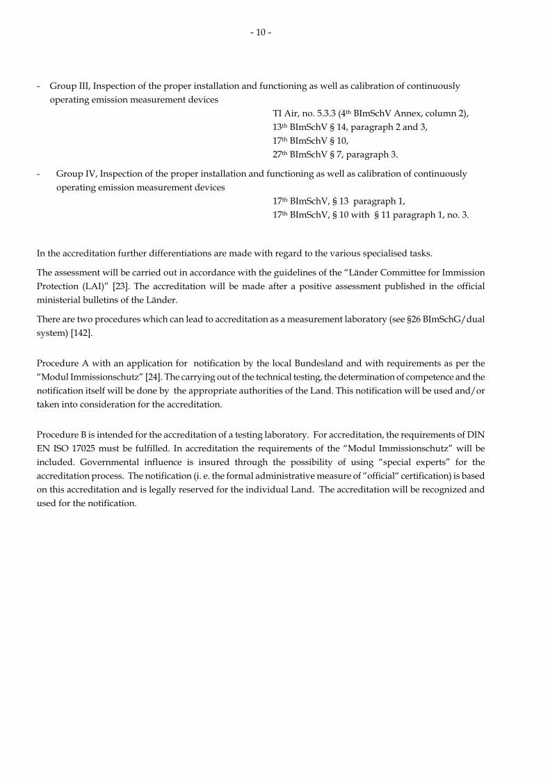
- Group III, Inspection of the proper installation and functioning as well as calibration of continuously
operating emission measurement devices TI Air, no. 5.3.3 (4th BImSchV Annex, column 2),
13th BImSchV § 14, paragraph 2 and 3, 17th BImSchV § 10, 27th BImSchV § 7, paragraph 3.
- Group IV, Inspection of the proper installation and functioning as well as calibration of continuously operating emission measurement devices 17th BImSchV, § 13 paragraph 1, 17th BImSchV, § 10 with § 11 paragraph 1, no. 3.
In the accreditation further differentiations are made with regard to the various specialised tasks.
The assessment will be carried out in accordance with the guidelines of the “Länder Committee for Immission Protection (LAI)” [23]. The accreditation will be made after a positive assessment published in the official ministerial bulletins of the Länder.
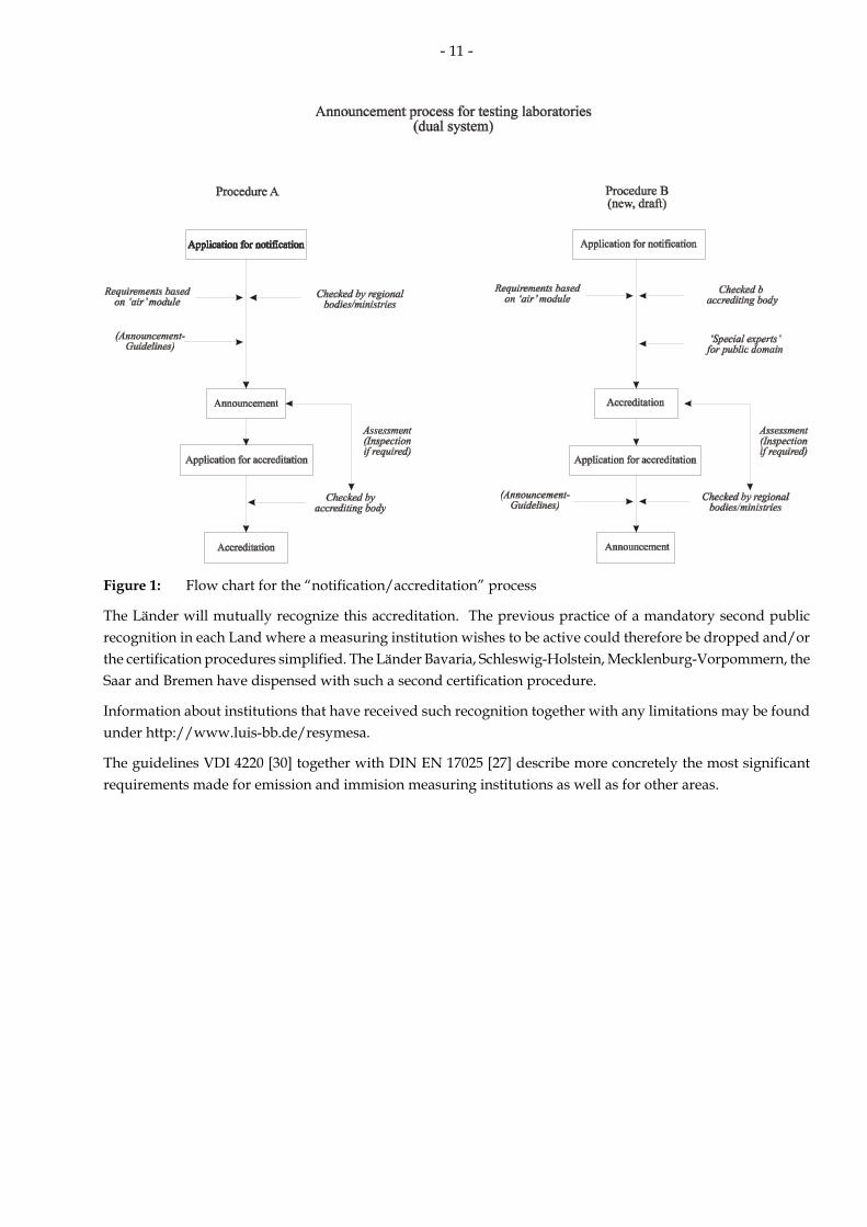
There are two procedures which can lead to accreditation as a measurement laboratory (see §26 BImSchG/dual system) [142].
Procedure A with an application for notification by the local Bundesland and with requirements as per the “Modul Immissionschutz” [24]. The carrying out of the technical testing, the determination of competence and the notification itself will be done by the appropriate authorities of the Land. This notification will be used and/or taken into consideration for the accreditation.
Procedure B is intended for the accreditation of a testing laboratory. For accreditation, the requirements of DIN EN ISO 17025 must be fulfilled. In accreditation the requirements of the “Modul Immissionschutz” will be included. Governmental influence is insured through the possibility of using “special experts” for the accreditation process. The notification (i. e. the formal administrative measure of “official“ certification) is based on this accreditation and is legally reserved for the individual Land. The accreditation will be recognized and used for the notification.
- 11 -
Figure 1: Flow chart for the “notification/accreditation” process
The Länder will mutually recognize this accreditation. The previous practice of a mandatory second public recognition in each Land where a measuring institution wishes to be active could therefore be dropped and/or the certification procedures simplified. The Länder Bavaria, Schleswig-Holstein, Mecklenburg-Vorpommern, the Saar and Bremen have dispensed with such a second certification procedure.
Information about institutions that have received such recognition together with any limitations may be found under http://www.luis-bb.de/resymesa.
The guidelines VDI 4220 [30] together with DIN EN 17025 [27] describe more concretely the most significant requirements made for emission and immision measuring institutions as well as for other areas.
- 12 -
2 Discontinuous Emission Monitoring
2.1 Legal bases (reasons for discontinuous measurements)
Discontinuous emission measurements ascertain the extent and nature of emission through taking spot samples over a limited period of time. The advantage of this method over continuous monitoring is that it requires less time and expense. There are at present some measuring objects requiring monitoring which cannot be measured by continuous methods (automatic measuring methods) either because it would be technically impossible or because the costs would be prohibitive.
In order to make sure that it is possible to draw conclusions about the continuous emission behaviour of a system, these discontinuous measurements must be carried out in a manner which will reflect such continuous emission behaviour. This means that planning the measurement procedures is of particular importance.
There are a variety of reasons for carrying out discontinuous emission measurements. In addition to those required by government authorities, there are also measurements made which serve for installation operators as self-monitoring of the installation or to improve performance.
Reasons for discontinuous emission monitoring (selected as per VDI 2448, p. 1 [31]):
a) measurements at acceptance (warranty certification), b) measurements to test compliance with emission limits, c) controlling measurements after a certain period to determine the state of the system, d) measurements in the case of complaints, e) measurements to initiate an approval application (e. g. for expansion, reconstruction, conversion), f) measurements for self-monitoring, g) measurements for an emission declaration, h) measurements in case of operational disturbances, i) measurements for safety checks, j) measurements for the calibration of continuous emission monitoring systems, k) measurements to test the function of continuous emission monitoring systems, l) measurements to analyse the causes of certain types of emission behaviour (e. g. to detect reasons for non-
compliance with warranty values/ emission limitations for waste-gas cleaning plants), m) measurements to predict the emission behaviour of a facility, e. g. after operational conversions, operational
breakdowns or an increase in capacity.
Emission monitoring ordered by government authorities is based upon §26 BImSchG [1] „measurements for special reason“ (for facilities which require governmental approval and under certain circumstances also for facilities which do not require such approval) as well as upon §28 „Initial and recurrent measurements in the case of installations subject to licensing“.
In the „Technical Instruction on Air Quality Control (TI Air) [3]“ as well as in the statutory instruments relating to BImSchG [4] - [13] one can find a more precise description of the measurement procedures required.

- 13 -
Table 2.1: Time requirements for discontinuous measurements by government order
First measurements Repeated measurements
BImSchG, § 26 In special cases
BImSchG, § 28 After putting a facility into operation or changing the facility
After three years
TI Air (TA Luft),
no. 5.3.2.1
After construction or significant change to a facility1)
After three years (if a mass-flow limitation can be demonstrated, this period can be prolonged to five years)
13th BImSchV,§ 17 After construction or significant change to a facility1)
At the latest after three years and on three consecutive days
17th BImSchV,§ 13 After construction or significant change to a facility
Every two months in the first year and on at least three days in the following years
27thBImSchV, § 9 For new facilities: three to six months after being put into operation
After three years
30th BImSchV,§ 11 After construction or significant change to a facility
Every two months in the first year and on at least three days in the following years
Facilities which do not require governmental approval: After construction or significant change to a facility1)
In every third calendar year 31st BImSchV § 5, par. 4 § 6
Those requiring governmental approval: as with “TI Air” facilities
As with „TI Air“ facilities
1) After full and successful operation has been achieved, but at the earliest after three months of operation and at the latest after six months of operation
Measurements which are government ordered will only be recognized if the measurement institution is one which has been accredited for this particular type of measurement (see 1.4).
2.2 Planning of measurements
Before measurements can be carried out, a measurement plan must first be made. Such a plan formulates the measurements’ purpose and the strategy which has been chosen to acquire the necessary information. The scope and ongoing requirements are specified in the “guideline VDI 2448, part 1 [31]: “Planning of spot sampling measurements of stationary source emissions”. In the future, the European standards DIN EN 15259 [33] (at present in the draft stage) will also be relevant for the planning and carrying out of such measurements.
The following questions should be dealt with in the measurement plan:
Where will the measurements be carried out? What is to be measured? How precise must the resulting measurements be? By what means will the results be determined? Who will carry out the measurements? When should the measurements take place?

- 14 -
Planning the measurements also brings together already known facts about the system. An assessment of the possible operational conditions at the facility is of great importance for determining the frequency and/or duration of adequate measurements.
Although there may be some exceptions, the duration of an individual measurement should not exceed one-half hour. As a rule, the measurements are to be given as half-hourly means (for the exceptions see 2.4).
The measurement plan should be agreed upon by the operator of the system together with the institution carrying out the measurement. In the case of measurements which are government-ordered, the approval of the appropriate authorities is also necessary.
The measurement plan regulates the relationship operator-measurement institution-government authority and can also serve as a description of the measurement institution’s contractual obligations because it details the tasks to be performed.
2.3 Carrying out the measurements
2.3.1 Selection of the section of measurement and its plane
In order to carry out high-quality measurements, both the sections where the measurements are made as well as their plane is of great importance. The sampling point for the measurement instruments as well as their measurement cross section must be chosen in such a way so as to ensure the kind of representative measurement which makes evaluation of emission behaviour possible [31], [33]. For this reason, an institution which is specialised in the choice of such sections and planes for continuous emission monitoring should be consulted during the planning phase [19], [41].
The distribution of waste-gas velocity and mass concentration can be inhomogeneous for the measurement cross section. In some cases an appropriate measurement plane can only be chosen after a preliminary measurement.
The requirements for the location and nature of measurement sections and planes are to be found in the guidelines listed below:
- VDI 2066, Part 1 Measurement of particulate matter – manual dust measurements in flowing gases; gravimetric determination of dust load [49]
- DIN EN 13284-1 Stationary source emissions – determination of low range mass concentration of dust – manual gravimetric method [52]
- VDI 2448, Part 1 Planning of spot sampling measurements of stationary source emissions [31]
- DIN EN 15259 Air quality - Measurement of stationary source emissions – measurement strategy, measurement planning, reporting and design of measurement sites [33]
- VDI 4200 Realization of stationary source emission measurements [34]
- DIN EN 14181 Stationary source emissions – quality assurance of automated measuring systems [38]
- VDI 3950 Stationary source emissions – quality assurance of automated measuring and electronic evaluation systems [37]
The most important requirements regard: - the position and form of the measurement section in the waste-gas duct
- the position of measurement plane in the measurement section - the number, location and nature of the measurement openings - the nature of the measurement platform (e. g. minimum
dimensions, weather protection).

- 15 -
In 5.2 of the DIN EN 13284-1 [52] the following requirements for the measurement cross section are described:
„The measurement cross section should be in a straight, preferably vertical section of the waste-gas duct with a constant form and a constant diameter. If possible, the measurement cross section should be as far downstream and upstream from any disturbance, which might change the direction of the gas-flow (such disturbances can be caused, for example, by knee-pieces, fans or partially closed dampers).
Measurements at all specified sampling points shall prove that the gas stream at the sampling plane meets the following requirements:
a) the angle between the gas-flow and the average axis of the waste-gas duct must be less than 15° b) no negative local flow may be present c) to determine the volume flow a minimum velocity in relation to the measurement technology used must be present (for Pitot tubes a differential pressure greater than 5 Pa) d) the ratio of the highest to the lowest local gas velocity in the sampling plane must be less than 3:1.
If these requirements are not fulfilled, the sampling location does not correspond to the European standard [52].
NOTE: The above requirements are generally fulfilled when using straight duct sections with an intake section of 5 hydraulic diameters1 and an outlet section of two hydraulic diameters behind the measurement cross section. (The distance to the end of the waste-gas duct must be at least five hydraulic diameters). It is therefore urgently recommended that the sampling points be chosen correspondingly.
When measuring for dust, vertical ducts are preferred to horizontal ones. When taking samples for particles in horizontal ducts, this should be done along a vertical axis because of possible sedimentation [49]
Detailed information on the design and installation of measurement points are given in the guidelines VDI 4200 [34] and in DIN EN 15259 [33].
The measurement platform must be safely reached. Its measurements must be adequate for the task to be performed (see figure 2.1). In other words:
- There must be sufficient space for equipment. When such equipment spaces are full, the personnel must still be able to operate in safety.
- If network measurements are being carried out, then sufficient traverse space must be available to move the probes. Care should be taken to make sure that protective grids or railings do not interfere with the moving of the probes.
- The operational height of the measurement platform up to the measurement axes should be 1.2 to 1.5 m. Inserting the probes into the measurement openings must be secure and without hindrance through protective grids or railings.
- The worker protection safety requirements must be observed. The measuring device must be safely and easily accessible via steps. If the measurement device is not at ground level, then lifting equipment or elevators should be available to move the measuring equipment [34].
1) The hydraulic diameter is a ratio between four times of the circular area to the circumference of the duct through which the medium flows.

- 16 -
Figure 2.1: Example arrangement of a measurement platform on a vertical flue gas duct
(with two measurement axes and four measurement ports for the realization of traverse measurements; a number of measurement methods can be carried out at the same time) [34].
2.3.2 Grid measurements
In order to carry out a network measurement, the measurement cross section is divided into several sections of equal size. Figure 2.2 shows the example of a round and a rectangular duct cross section, divided up into sections as per VDI 2066, p. 1 [49]. Rectangular cross sections are divided up into similar sections, round cross sections into circular rings. The measurement points are situated on the surface focal points of the individual sections (rectangular cross section) or, alternatively, at the intersection of the measurement axes with the pitch lines of the circular rings (round cross section). DIN EN 13284-1 and/or VDI 2066, Part 1 gives detailed instructions on the computation and determination of measurement points for network measurements

- 17 -
Rectangular cross-section with
nine measurement points
A/6A/3 A/3
A
B
B/3
B/6
B/3
Figure 2.2: Position of the measurement points in rectangular and round duct cross sections as per VDI 2066, part 1
2.3.3 Extractive isokinetic sampling
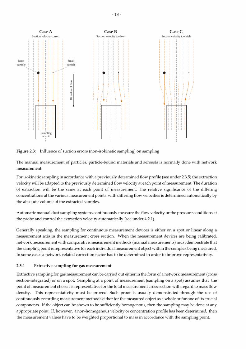
Extractive sampling for dealing with particles, particle-bound materials and aerosols must be done isokinetically in order to prevent demixing (sedimentation). Isokinetic sampling is defined as “Sampling with a volume-flow in which the velocity vn and the flow direction of the gas which enters the extraction probe is the same as the velocity va and the flow direction of the gas in the waste-gas duct at the point of measurement” [49], [52]. This requires exact knowledge of the flow situation in the measurement cross section. It is known that demixing (sedimentation) effects are stronger when the extraction velocity is too low and less so if the required extraction velocity has been exceeded. If there is any danger that the required extraction velocity cannot be regulated exactly (e. g. because of pulsating flow velocities) then one should choose an extraction velocity greater than that of the flow velocity which was determined at the point of sampling (max. 10 %). The effect of non-isokinetic extraction on the sampling of particles and aerosols is shown in figure 2.3. If the extraction velocity is not properly adapted, the gas flow outside the probe opening is effected. Larger (heavier) particles do not follow the gas flow lines because of their mass inertia. This means that with too low an extraction velocity their presence is exaggerated (Case B) and when the velocity is too great (Case C) their presence is underestimated.
Round cross section with two measurement axes and eight measurement points per axis
- 18 -
Case ASuction velocity correct
Case BSuction velocity too low
Case CSuction velocity too high
largeparticle
Smallparticle
Samplingnozzle
Dire
ctio
n of
flow
Figure 2.3: Influence of suction errors (non-isokinetic sampling) on sampling
The manual measurement of particles, particle-bound materials and aerosols is normally done with network measurement.
For isokinetic sampling in accordance with a previously determined flow profile (see under 2.3.5) the extraction velocity will be adapted to the previously determined flow velocity at each point of measurement. The duration of extraction will be the same at each point of measurement. The relative significance of the differing concentrations at the various measurement points with differing flow velocities is determined automatically by the absolute volume of the extracted samples.
Automatic manual dust sampling systems continuously measure the flow velocity or the pressure conditions at the probe and control the extraction velocity automatically (see under 4.2.1).
Generally speaking, the sampling for continuous measurement devices is either on a spot or linear along a measurement axis in the measurement cross section. When the measurement devices are being calibrated, network measurement with comparative measurement methods (manual measurements) must demonstrate that the sampling point is representative for each individual measurement object within the complex being measured. In some cases a network-related correction factor has to be determined in order to improve representativity.
2.3.4 Extractive sampling for gas measurement
Extractive sampling for gas measurement can be carried out either in the form of a network measurement (cross section-integrated) or on a spot. Sampling at a point of measurement (sampling on a spot) assumes that the point of measurement chosen is representative for the total measurement cross section with regard to mass flow density. This representativity must be proved. Such proof is usually demonstrated through the use of continuously recording measurement methods either for the measured object as a whole or for one of its crucial components. If the object can be shown to be sufficiently homogenous, then the sampling may be done at any appropriate point. If, however, a non-homogenous velocity or concentration profile has been determined, then the measurement values have to be weighted proportional to mass in accordance with the sampling point.

- 19 -
With extractive sampling it is often necessary that the material measured has to be “conditioned” prior to the actual analysis process: This means for example the removal of particles (through a filter/fine dust filter) or the removal of moisture (measurement gas coolers/driers). With such procedures care must be taken to be certain that the material to be measured is neither changed nor held back. Devices for such conditioning are to be included in the calibration and function tests of continuously operating analysis devices.
2.3.5 Determination of waste-gas conditions
In order to determine the condition of a gas flow precisely, it is essential to determine the following parameters - Waste gas density - Moisture (see under 4.3.4) - Flow velocity and static pressure (see under 4.3.5) - Temperature (see under 4.3.6) The standard density of a dry gas is computed on the basis of its composition. It results from the sum of the various standardized densities of the gas components multiplied by their volume proportion.
∑ ρ×=ρ i,ni,nn r Eq. 2.1
ρn: Norm density of the gas (dry) ρn, i: Norm density of the gas components i (dry) rn, i: Volume proportion of the gas components i (dry)
Gas components should be taken into consideration if they constitute more than 1 % of the gas volume. DI 2066, p. 1 [49] gives the numerical values for the relative molecular mass, molecular volume and norm density for the most important air components and air-polluting substances. In everyday measurement practice it is sufficient to consider the proportions of nitrogen, oxygen and carbon dioxide. There are, however, a few exceptions such as the CO-proportion of blast furnace gas. The norm density, temperature, humidity and the pressure conditions in the duct are used to compute the operational density (wet).
2.4 Special requirements for individual measurements
- special measurement requirements as per TI Air [3]
Frequency In systems in which the operational conditions remain largely unchanged, there should be at least three individual measurements under normal operational conditions and with maximum emission output and one additional measurement during regularly occurring situations in which emissions-output varies (e. g. during cleaning or regeneration work or during longer periods when facility is being put into or taken out of operation). In systems where emissions are different at different times, an adequate number of measurements have to be made; the minimum, however, is a series of at least six measurements made during periods when the highest emissions are to be expected.
Duration The duration of an individual measurement is normally half an hour. The results of the measurement are to be computed and given as an half-hourly mean. In special cases such as with intermittent high work-loads (charging operations) or low mass concentrations in the waste gas, the time(s) used to determine the average have to be correspondingly adapted. With regard to substances which occur in various states of aggregation, special measures

- 20 -
shall be taken while measuring in order to collect all respective proportions (e. g. in compliance with VDI Guideline 3868 Part 1, December 1994 version).
- special requirements for measurements as per 13th BImSchV [8]
Frequency: After being put into operation and thereafter at the latest every three years there must be at least three individual measurements on three different days. The facility must be in full operation and producing at the highest permissible level for the material in question.
Duration: The duration for individual measurements of materials as per § 3, par. 1 no. 3 a-c and § 4, par. 1 no. 3 a-c (metals, semi-metals and their compounds and benzo(a)pyrene) must be at least a half hour; it should not exceed two hours. For measurements to detect dioxins or furans, the sampling time should be at least six hours and should not exceed eight hours.
- special requirements for measurements as per 17th BImSchV [9]
Frequency: With measurements made after a plant has already been put into operation: They should be made every two months over a period of 12 months. After this, they should be made at least every 12 months with three individual measurements on three different days, in full operation and producing at the highest permissible level for the material in question.
Duration: The duration of individual measurements for materials as per §5 no. 3 (metals, semi-metals and their compounds) must be at least half an hour and should not exceed two hours. For measurements to detect dioxins or furans, the sampling time should be at least six hours and should not exceed eight hours.
- Determination of the temperature in the afterburner zone as per the unified national regulations for the monitoring of incineration conditions in household waste incineration plants [19] (reprinted in Appendix 1) and/or [22] and 17. and/or 27th BImSchV [9], [11].
Methods: The monitoring will be done using ceramically protected suction pyrometers operating on two measurement levels (beginning and ending of the afterburner zone). These measuring devices will measure the proportion of convection heat; the radiant heat will be disregarded. The measurement will be a network measurement (see under 2.3.2) carried out simultaneously on at least two measurement axes in the heating space. At the same time, the suction pyrometer can, with the help of tested measurement devices, also be used to check the minimum volume content of oxygen
Frequency Three network measurements over a total time period of at least three hours with uninterrupted operation.
Three network measurements over a total time period of at least three hours with varying operational status (e. g. partial loads if such operation has been approved).
A network measurement for the final state of the heating phase over a time period of ca. 1 hour when there is a start-up without charge.
Duration: The measurement values will be continuously recorded using electronic measurement recording system (sampling rate ≤ 10 s) and compressed to 10-minute means.

- 21 -
The retention time in the afterburner zone with a designated minimum temperature of 850 °C and/or 1200 °C is to be checked at least once using appropriate methods. This is to be carried out under the unfavourable conditions assumed for the system. In combination with this there will also be a measurement of the oxygen content of the afterburner zone to check for a homogenous blend.
- special measurement requirements as per 31st BImSchV [13]
Frequency/Duration: Facilities which do not require government approval After being put into operation and thereafter in every third calendar year. Each time three individual measurements are to be made, each to be of one hour and under normal operating conditions.
- measures in the case of unfavourable surrounding conditions
If the surrounding conditions are unfavourable, this can negatively effect the quality of the measurement results and appropriate compensatory measures must be taken.
The flow conditions can be improved through installations in the ducts (such as nozzles) and thereby promote a more homogenous blend of the gases to be measured. Only in very rare instances, however, is it possible to make such changes in systems which are already operating. In these cases the quality of the measurements must be assured through other appropriate measures. Among these measures would be a tighter grid for network measurements or an increased number of samples. Such measures are naturally more expensive and time-consuming. Their scope is at the discretion of the measuring institution.
When isokinetic samples are being taken, there should be simultaneous, continuous measurement of the flow velocity in order to able to react immediately to any changes [52], [55]. In [55] (dioxin sampling) there is the requirement for periodic recording (at least every 15 minutes) of the velocity and temperature in the waste gas duct.
2.5 Evaluation/reporting/documentation
Generally speaking, the measurement values will be evaluated on the basis of an exhaust-gas volume which is dry, and at normal pressure and temperature. The results of the measurements are in relation to a particular evaluation period. As a rule, this corresponds to the sampling/concentration period and is 30 minutes in length. Other evaluation periods are possible when differing sampling/concentration periods have been chosen as a consequence of measurement technology or operational needs. The load or mass-flow of the object being measured is computed using the mass concentrations and the waste-gas volume flows. Emission limitations are often related to the reference oxygen content laid down in the licensing/approval documents. In this case, the mass concentration of emissions measured must be recomputed in terms of the reference oxygen content. This is done with equation 2.2 [3]:
Μ
ΒΜΒ Ο21
Ο21ΕΕ−−
×= Eq. 2.2
EM: measured emission EB: emissions in relation to reference oxygen content OM: measured oxygen content OB: reference oxygen content
In the case of operations which require governmental approval (i. e. those subject to the 4th BImSchV) and which have waste-gas purification facilities, the computation above can only be for time periods in which the measured oxygen content was more than the reference oxygen content.

- 22 -
In the case of incineration processes using pure oxygen or air which has been enriched with oxygen, special measures have to be taken (for example an evaluation of the mass concentration using the carbon dioxide content).
The results of an emission measurement are communicated in the form of an emission report. In the case of measurements which were carried out on the basis of §§ 26/28 BImSchG, the scope and form of the report have been binding since 1993 and are described in the “Standard German emission measurement report” [21] and in the guideline VDI 4220 [30]. This model measurement report was worked out by the LAI and it contains not only the measurement results themselves, but also further information which is important both for the evaluation of the emission measurements as well as for the insights gained thereby.
Structure of the model measurement report:
1. Formulation of the measurement task 2. Description of the facility and the materials dealt with 3. Description of the sampling point 4. Measurement methods and analysis; equipment 5. Operational state of the facility during the measurements 6. Summary of the measurement results and discussion 7. Appendix with: Measurement plan Measurement and computational values Measurement protocol
2.6 Uncertainty of emission measurements
The various legal requirements make it necessary to take account of any possible measurement uncertainty.
In the directions for declaring measurement uncertainty (GUM) such uncertainty is defined as follows:
Measurement uncertainty: parameters of the measurement results which are characteristic for the dispersion of values which can be reasonably assumed to pertain to a measurement object.
2.6.1 Uncertainty of individual measurements
Under „5.3.2.4 Evaluation and Assessment of the Measurement Results“ of individual measurements the TI Air points out that:
In the case of the first measurements after construction, measurements made after significant changes or of recurring measurements, the requirements are then considered to have been met if the results of the individual measurement plus the measurement uncertainty factor do not exceed the emission limits given in the approval notification.
If there are subsequent official orders based on the detection of emissions and additional emission-reducing measures become necessary, then the measurement uncertainty factor will be interpreted in favour of the operators of the facility.
This means that the measurement uncertainty is to be given in the measurement report and that it is to be taken into consideration in evaluating the results. In the VDI 4219 E [139] guideline, procedures for determining the uncertainty of intermittent measurements are determined. Two approaches of equal validity are described to determine any measurement uncertainty:
• a direct approach based on double determination using the complete measurement method
• an indirect approach with separate analysis of all the individual steps of the complete procedure which might contribute to the measurement uncertainty
The VDI 4219 guidelines shows how to put into practice both the general recommendations of the guidelines for declaring measurement uncertainty (GUM) as well as the specific requirements of the DIN EN ISO 20988 [140] for determining the measurement uncertainty for emission measurements with the surrounding conditions

- 23 -
characteristic for intermittent measurement methods.
2.6.2 Uncertainty of continuous emission monitoring.
The requirements for the quality of the continuous measurement results are set down in the European guidelines for waste incineration 2000/76/EG [17] and large-scale incineration plants 2001/80/EG [16]. These requirements were then made part of the 17th [9] and 13th BImSchV [8].
Thus for example the 17th BImSchV in Appendix III, 3 requires that:
The value of the 95 % confidence interval for a single measured result shall not exceed the following percentages of the emission limit values determined as daily mean values :
Carbon monoxide 10 out of 100
Sulphur dioxide 20 out of 100
Nitrogen oxide 20 out of 100
Total dust 30 out of 100
Total organic carbon 30 out of 100
Hydrogen chloride 40 out of 100
Hydrogen fluoride 40 out of 100
Mercury 40 out of 100
The validated half-hour and daily mean values shall be determined from the measured half-hour mean values after deduction of the confidence interval determined during the calibration.
The following requirement is found in the 13th BImSchV:
This means that when calibrating measurement devices the measurement uncertainty must be determined in order to validate the half-hourly and daily means. The procedures for determining the measurement uncertainty of continuous emission monitoring is given in detail in [143] and is only described briefly here. The norm used as a basis for calibration is DIN EN 14181 [38] (see 3.2.2. for calibration) and this is also the basis for determining the measurement uncertainty of automatic emission monitoring. Since the limit values are all in reference to standard conditions, the measurement uncertainty must be treated likewise. The measurement uncertainty results from the comparing the measurements of the automated measuring system (AMS) with those of the standard reference measurements (SRM). he measurement values of the AMS and the SRM are to be given as standard conditions. According to EN 14181 the waste-gas parameters (e. g. humidity, temperature, pressure and oxygen content) which are used for standardizing the measurement values have to be determined separately. SRM measurement equipment is to be used for standardizing the SRM results. The standardizing of the AMS results is to be done with devices of the plant or, if such devices are not present, using the plant’s substitute values. Through the evaluation of the standardized measurement values, the uncertainty of the AMS values also includes the unreliabilities of the other waste-gas parameters. The quality of the measurement results of the AMS is therefore also dependent on the measurement values of the other waste-gas parameters.
For evaluation are used: The differences Di between the standardized reference values yi,s and the predicted standardized AMS-value ýi,s from the calibration function:
Di = yi,s - ýi,s Eq. 2.3

- 24 -
This type of evaluation makes possible a separate view of the systematic deviation D between yis and yis and the distribution of the Di differences around its average value D as a measure of variability/measurement uncertainty of the measurement values sD. The computation is made with the following formulae
∑=
=N
iiD
ND
1
1 Eq. 2.4
2
1)(
11 ∑
=
−−
=m
iiD DD
ms Eq. 2.5
The variability takes into consideration the random distribution of the SRM values, the random distribution of the AMS measurement signals and the random distribution of the reference quantities. Subtracting the systematic measurement deviation which results from non-calibrated measurement instruments for the waste-gas parameters does not conform to the GUM, because a measurement device must include all accidental and systematic measurement deviations.
The evaluation as per DIN EN therefore conforms to the GUM if no significant deviations are present. In order to minimize such systematic deviations, the measurement devices for waste-gas parameters are also to be calibrated.
The measurement uncertainty of an AMS is therefore ascertained through the calibration experiment and by means of a direct comparison with the SRM. It is valid for the operational conditions of the plant and for the waste-gas parameters at the calibration. The measurement uncertainty takes into consideration the accidental distribution of the values of the AMS, the SRM and the waste-gas parameters (plant measurement and SRM measurement).
In order for the variability/measurement uncertainty to be compared with a fixed value it is first necessary to determine the maximum allowable uncertainty of the measurement values and their precise definition. In the DIN EN 14181 it was assumed the EC Guidelines give the maximum allowable uncertainty of the AMS values as an expanded range of measurement uncertainty. In other words: as one-half of the 95 % confidence interval. Converting the maximum allowable uncertainty according to EC Guidelines into a standard uncertainty as per DIN EN 14181 is as follows:
96.10EP ∗
=σ Eq. 2.6
Here, P is the percentage value of the EC and/or German regulations and E is the emission limit value. With “Total Dust” for example one gets with P = 30 % and E = 10 mg/m3 for σ = 1.5 mg/m3
The AMS has passed the variability test if the following is valid:
0σ∗≤ vD ks Eq. 2.7
The factor kν takes into consideration the experimentally determined standard deviation sD. The values of kν are close to 1. The variability test as per DIN EN 14181 is to be carried out for every calibration function, i. e. for every mode of operation.

- 25 -
EU Guidelines prescribe that the comparisons of measurement values with limit values are to be on the basis of validated means. In the “Uniform practice in monitoring emissions in the Federal Republic of Germany ” [19] the determination has been made that the computation of the validated mean yval is to be done through the
subtraction of the standardized mean ýs of the AMS:
Dsval syy −= ' Eq. 2.8
Possible negatively validated means are to be set at zero. The validated daily means are derived as follows:
∑=
=n
ivalivalTag y
ny
1,,
1 Eq. 2.9

- 26 -
3 Continuous Emission Monitoring
3.1 Legal bases
Continuous emission monitoring is part of the catalogue of measures provided for in the Federal Immission Control Act [1]. Based upon § 29 of the BImSchG, the appropriate authorities can order such continuous monitoring at facilities requiring governmental approval as well as (in certain special cases) those which do not require such approval.
The concrete requirements for continuous emission monitoring are to be found in the “First general administrative regulation pertaining to the federal immission control act“ (TI Air) [3] and in the ordinances pursuant to the implementation of the BImSchG [4], [8], [9], [11], [12] and [13].
On the European level a determination of the emissions for facilities requiring governmental approval was first made in the Directive “Combating of air pollution from industrial plants” [14], Article 11. In the Directive “Integrated pollution prevention and control (IPPC directive)” [15] (IVU Guidelines) conditions for approval of both new and already existing facilities are laid down. According to article 9, para. 5 such an approval could contain, “appropriate requirements for the monitoring of the emissions in which the measuring methodology, measurement frequency and the evaluation procedures are determined as well as an obligation on the part of the appropriate authorities to provide the required data for testing compliance with the approval requirements.”
Below is a list of cases where continuous emission monitoring is appropriate and where European regulations have been made part of German law:
Regulations for National Law EC-Law Large-scale incineration plants 13th BImSchV 2001/80/EG Incineration and co-incineration of waste 17th BImSchV 2000/76/EG Limitations on the emission of volatile organic solvents
31st BImSchV 1999/13/EG
3.1.1 Facilities requiring governmental approval
Facilities which are under the jurisdiction of the 4th BImSchV [7]
According to TI Air 5.3.3.1 a monitoring of the emissions from relevant sources through continuous measuring can be ordered under certain circumstances (e. g. exceeding of the determined mass flow for the various components and/or anticipated, repeated exceeding of a determined mass concentration because of a susceptibility to misfunctioning on the part of emission reduction facilities or as the result of changing operational methods).
Continuous measurement and recording of the emissions should take place when the mass flow exceeds those given in table 3.1:

- 27 -
Table 3.1: Mass flow thresholds (as per TI Air) for continuous emission monitoring
Dust (qualitative measurement device) 1 kg/h to 3 kg/h
Dust (quantitative Measurement device) *1) > 3 kg/h
Sulphur dioxide 30 kg/h
Nitrogen monoxide and nitrogen dioxide, given as nitrogen dioxide 30 kg/h
Carbon monoxide as the main substance for assessing the burning out of incineration processes
5 kg/h
Carbon monoxide in all other cases 100 kg/h
Fluorine and gaseous inorganic fluorine compounds, given as hydrogen fluoride 0.3 kg/h
Gaseous inorganic chlorine compounds, given as hydrogen chloride 1.5 kg/h
Chlorine 0.3 kg/h
Hydrogen sulphide 0.3 kg/h
Total carbon materials no. 5.2.5, class I materials no. 5.2.5
1 kg/h
2.5 kg/h
Mercury and its compounds *2) 2.5 g/h
*1) for certain dust like materials other mass flows apply (5.3.3.2 TA air in connection with 5.2.2, 5.2.5, Class I und 5.2.7)
*2) measurement can be dispensed with if it can be reliably demonstrated that the mass concentration is being used less than 20 %. In addition to the requirement for continuous monitoring of non-air substances in the emissions, continuous monitoring of reference quantities can also be required, such as:
- waste-gas temperature - waste-gas volume flow, - humidity, - pressure, - oxygen content
may also be needed to correctly evaluate and assess continuous emission monitoring. The continuous measurement of operational parameters can be dispensed with if these parameters are shown to vary only slightly, are unimportant for the evaluation of the emissions or are apprehended with adequate reliability through other methods.
Large combustion plants subject to 13th BImSchV [8]
Continuous monitoring and recording of the emissions of
• total dust (mass concentration) when solid and liquid fuels are used and, in special cases, as with gas-fired furnaces ( without the sulphur trioxide component),
• mercury and its compounds, given as mercury, when solid fuels are used. Measuring may be dispensed with if regular controls of the fuels have reliably shown that the range of limit values has been employed to an extent less than 50 %

- 28 -
• total carbon when solid, biological fuels are used, • carbon monoxide, • nitrogen monoxide und nitrogen dioxide, given as nitrogen dioxide. The continuous measurement of nitrogen
dioxides can be dispensed with if measurements have shown that the proportion of nitrogen dioxide is less than 5 %. In this case the proportion of nitrogen dioxide will be assessed though computations,
• sulphur dioxide and sulphur trioxide when solid or liquid fuels are used (except when light heating oil or diesel fuels are used). The concentration of sulphur trioxide is determined during calibration and assessed through computation,
• smoke spot number, when light heating oil (EL-type) or comparable liquid fuels are being used.
Measurement of reference quantities: • continuous measurement of the oxygen content, • continuous measurement to assess proper operation, particular with regard to output, waste-gas temperature,
waste-gas volume flow, humidity and pressure • as a means of determining the degree of sulphur precipitation of the sulphur in the fuel.
Waste incineration plants subject to 17th BImSchV [9]
Continuous measurement, registration and evaluation of the following emissions: • carbon monoxide, • total dust, • organic materials, given as total carbon • gaseous inorganic chlorine compounds, given as hydrogen chloride, • gaseous, inorganic fluorine compounds, given as hydrogen fluoride, except when purification treatment for
gaseous inorganic chloride compounds has been used which reliably insures that the emission limit values for inorganic chloride compounds have not been exceeded,
• sulphur dioxide and sulphur trioxide, given as sulphur dioxide, • nitrogen monoxide and nitrogen dioxide, given as nitrogen dioxide. The continuous monitoring of nitrogen
dioxide can be dispensed with if, because of the material used, the nature of the construction, or because of individual measurements it can be shown that the proportion of nitrogen dioxide in the nitrogen oxide emissions is less than 10 %. In this case, the appropriate authorities should dispense with the measurement of the nitrogen dioxide proportion and permit the assessment of this proportion through computations,
• mercury and its compounds, given as mercury (except when it can reliably shown that the limit values have been employed to an extent less than 20 %
Continuous monitoring, registration and evaluation of reference quantities: • oxygen contents, • temperatures in the afterburner zone, • parameters needed to assess proper operation, especially of waste-gas temperature, waste-gas volume flow,
humidity and pressure.
Facilities for the biological treatment of waste which is subject to 30th BImSchV [12]
Continuous monitoring, registration and evaluation of the following emissions: • total dust, • organic materials as total carbon, • dinitrogen monoxide.

- 29 -
Continuous monitoring, registration and evaluation of the following reference quantities: • In order to assess proper operation, especially of waste-gas temperature, waste-gas volume flow, pressure ,
humidity as well as the mass of the materials introduced in the state in which they were supplied.
Facilities with limitations for the emission of certain organic compounds when organic solvents are used and which are subject to 31st BImSchV [13]
This ordinance encompasses both facilities which require governmental approval as well as those which do not.
With regard to the measurement and monitoring of facilities subject to the 31st BImSchV which require governmental approval the requirements of the TI Air are applicable.
3.1.2 Facilities not requiring governmental approval
Small and medium incineration plants subject to 1st BImSchV With individual incinerations and operation with heating oil and with a heating capacity of between 10 and 20 MW, the exhaust-gas turbidity is to be continuously measured and registered (e. g. via the optical transmission). The measurement equipment must show reliably that the smoke spot number one (1) has been kept to.
Facilities subject to 2nd BImSchV
Measurement methods and regulations (in addition to those mentioned above) and which are related to 1st and 2nd BImSchV are the subject of another handbook which has been published as a UBA text [141]. They will therefore not be discussed here.
Cremation facilities subject to 27th BImSchV [11] • Carbon monoxide, • Dust (smoke density). Measurement of reference quantities: • Continuous recording of the oxygen content, • Continuous recording of the temperatures in the afterburner zone. Facilities subject to 31st BImSchV and which use certain organic solvents
When measuring and monitoring emissions from plants which do not require governmental approval under 31st BImSchV
• Organic materials as total carbon if the emission mass flow exceeds 10 kg/h In addition, the operational parameters required for the evaluation and assessment of the measurement results are to be ascertained continuously.

- 30 -
3.2 Quality assurance for continuous emission monitoring
In order to make sure that the carrying out of continuous emission monitoring is done in a uniform way, a programme of quality-control measures was developed. Figure 3.1 shows the various elements of this programme.
Figure 3.1: Quality control of continuous emission monitoring
Federal Immission Control Act
§ 29
Statutory orders
Guidelines published by the Federal Ministery of Environment
or VDI or DIN EN Guidelines
Test by a competent test institute
Assessment in special discussions between Umweltbundesamt and Länder
Reccommendation for announcement to BLAI
Announcement of suitability by the Umweltbundesamt in Bundesanzeiger
Competent installation and calibration by an accredited test institute
Regular maintenance and functional tests
Evaluation of the results by the supervisory authority
Legal bases
Execution of suitability test
Use of suitability tested devices

- 31 -
3.2.1 Suitability tests
Measurement devices to determine emissions and reference quantities
The continuously registering measurement devices for the monitoring of emissions must also be suitable for such tasks, i. e. they have to satisfy certain defined quality requirements. In the TI Air as well as in the ordinances on the implementation of BImSchG the use of suitable devices for continuous emission monitoring is required. The suitability of measurement devices is determined through suitability tests. In order to make sure that the procedures for testing suitability (scope of testing, testing criteria, minimum requirements, evaluation of the results) are uniform, the German Federal Ministry for the Environment, Conservation of Nature and Reactor Safety has published a number of guidelines in the Joint Ministerial Gazette for the German Federal Ministries. These guidelines were formulated in consultation with both the highest authorities of the “Länder” and with the Federal/Local Taskforce for emission protection (BLAI) (reprinted in Appendix 1).
These guidelines pertain to:
- the suitability testing of measuring and evaluation systems for continuous emission measurements, and the continuous acquisition of reference or operational quantities and for the continuous monitoring of emissions of special substances
- the installation, calibration and maintenance of continuously operating measuring and evaluation devices
- the evaluation of continuous emission monitoring.
In the currently valid (2005) version of the “Uniform practise in monitoring emissions” all of the requirements which derive from the EC guidelines and norms, especially EN 14181 have been included.
The VDI task force has worked out testing plans for carrying out suitability tests and published them as VDI Guidelines [28], [29].
As a rule, such suitability is to be tested at the expense of the manufacturers and by appropriate testing institutions.
The testing institution must have accreditation for carrying out suitability tests as per DIN EN ISO/IEC 17025 [27]. These testing institutions must fulfil the licensing requirements given in §§ 26, 28 BImSchG and must have five years experience in the area of function tests and the calibration of measurement and evaluation devices for inorganic and organic compounds and dust. In addition, they must be able to demonstrate experience in the area of remote emission monitoring. They must also have high standards of reliability and organisation.
Tests and expertises from testing institutions in other countries of the EC or from the European Economic Zone will be considered of equal value (see the “Uniform practice in monitoring emissions in the Federal Republic of Germany” [19]). This will apply in particular when:
- the suitability test was made in accordance with the „ Uniform practice in monitoring emissions in the Federal Republic of Germany “ [19] or using technical procedures of equal quality (incl. a minimum 3 months of field testing),
- the testing institution can demonstrate a special degree of experience in the carrying out of emissions and immissions measurement, the calibration of continuously operating measurement devices as well as with instrument testing generally (as shown for example through accreditation by an EC member country),
- the testing institution has been accredited through the accrediting system of the International Laboratory Accreditation Cooperation (ILAC) and corresponding to the testing requirements of DIN EN ISO/IEC 17025 [27].

- 32 -
A suitability test can be divided into two phases:
- Laboratory testing - testing of the demands made of the control and adjustment possibilities, - testing of the influence of the surrounding temperature, humidity and variations in power supply on
the measurement signal, - testing of the linearity of the measurement signal, - testing for the influence of other components on the measurement signal (cross sensitivities) - testing of the operating manual
- Field Testing - long-term testing (at least three months), usually with two complete and identical measurement
systems. - determination of availability, - determination and checking of reproducibility through statistical comparisons of the measurement
values of both measurement systems - comparison of the readings of the measurement system with those taken at the same time with a
reference measurement system (calibration) and a statistical evaluation of the results, computation of the calibrating function and the variability in accordance with QAL 2 of the DIN EN 14181 and comparison with the determined uncertainty,
- determination of the level of the lower detection limit, - testing for long-term stability (drift behaviour at zero/reference point) - determination of maintenance intervals, - checking the effectiveness of the measuring system under real-life conditions in practice (installation-
specific test), - determination of any limitations for the use of the measurement system. - comparison of the total uncertainty as per DIN EN ISO 14956 with the determined uncertainty
requirements (from 13th/17th BImSchV) to test for compliance with QAL 1 of the DIN EN 14181 The investigations described above might possibly have to be supplemented by special testing of specific components or procedures, e. g. to determine the degree of converter effectivity with nitrogen oxides or determination of the response factors of FIDs.
The tests will be carried out under practical conditions. The goal is to prove the effectiveness of the system under real conditions. When, therefore, a system is pronounced acceptable it is considered to be acceptable for specific types of facilities. In this connection the distinction will be often made between measurement tasks as per TI Air, 13th, 17th, 27th, 30th and those as per 31st BImSchV (e. g. the different minimum measuring ranges for testing).
The institution which has been asked to make such tests will make a written report. This report will be evaluated in the context of a technical examination moderated by the Umweltbundesamt (UBA). The commission of experts will be made up of representatives of the UBA, the appropriate “Länder” authorities and the testing institutions themselves.
If these deliberations lead to a positive overall judgement a recommendation will be sent to the BLAI for publication of the results. This will be made official through subsequent publication on the part of the Umweltbundesamt in the official part of the Bundesanzeiger. This public announcement will contain information about the possible measuring range as well as any limitations, as well as about maintenance intervals, software versions and the testing report.

- 33 -
Electronic devices for the evaluation and assessment of continuous emission measurements and/or emission data remote transmission (EFÜ)
The measurement values detected must be continually recorded and automatically stored for later use.
The devices used for these tasks are expected to be part of a continuously recording measurement system. For this reason they too must be subject to a suitability test. Together with the requirements for measurement devices, the guidelines for the evaluation of continuous emission monitoring were developed and published by the BMU in the “Uniform practice in monitoring emissions in the Federal Republic of Germany“ in official ministerial publications [19].
This contains the performance characteristics and minimum requirements for the suitability test as well as information on the evaluation procedures as per TI Air, 13th BImSchV, 17th BImSchV, 27th BImSchV and 30th BImSchV.
For EFÜ systems data transfer between the monitoring system (the “B System”) and the supervising authorities (the “G System”) has been standardized via an interface definition which was developed in the LAI sub-committee “Air/Monitoring” [25].
List of the recognized measurement devices for continuous emission monitoring:
The UBA publishes an up-to-date list of all the recognized measurement devices. These lists can be found in the Internet under the address: http://www.umweltbundesamt.de/messeinrichtungen/mg-eignung.htm. The texts recognizing various measurement devices are also available there (from 1999: The lists are structured according to the objects to be measured and contain, in addition to the name of the manufacturer and distributor, the model of device and the exact place of public announcement (in the “Bundesanzeiger” since 2003). North-Rhine-Westphalia also maintains a databank of measurement devices which have been suitability tested. (http://www.lanuv.nrw.de)
Appendix 2 of this manual contains a print-out of the lists. The devices listed there: assigned to one of the following groups:
Continuously Operating Emissions Measuring Devices
1. dust concentration 2. waste-gas opacity 3. dust (qualitative) limit-value monitoring 4. sulphur dioxide 5. nitrogen oxide 6. carbon monoxide 7. inorganic gaseous chlorine compounds 8. inorganic gaseous fluorine compounds 9. hydrogen sulphide 10. phenol 11. formaldehyde 12. organic compounds with total carbon 13. ammonia 14. mercury 15. oxygen 16. humidity 17. dinitrogen monoxide (laughing gas) 18. carbon dioxide 19. waste-gas volume flow 20. minimum temperature
- 34 -
Electronic Systems for the Evaluation of Continuous Emission Measurement Devices 1. simple classifying devices 2. classifying devices with reference value computation 3. telemetric monitoring Because of the adaptation of evaluation regulations in the „minimum requirements“ of 2005 [19] the only evaluation systems which may be used in the future are those which fulfil these requirements (promulgated from October 2005).
3.2.2 Installation, operation and quality control of suitability-tested measurement devices
The presently applicable regulations for the installation, operation and quality control of suitability-tested measurement devices are:
• Circular of the Federal Environment Ministry of 13 June 2005 – IG I 2 – 45053/5 – (GMBl. 2005, p. 795-828):, Uniform practice in monitoring emissions in the Federal Republic of Germany, [19] This circular provides the basis for - the suitability testing of measuring and evaluation systems for continuous emission measurements, and the
continuous acquisition of reference or operational quantities and for the continuous monitoring of emissions of special substances
- the installation, calibration, and maintenance of continuously operating measuring and evaluation devices, - the evaluation of continuous emission measurements,
• DIN EN 14181, September 2004, Stationary source emissions – quality assurance of automated measuring systems [38] This European standard establishes procedures for setting up the quality control steps (QAL) for automatic measurement systems which have been installed in industrial plants to ascertain the waste-gas components and other characteristic quantities of the waste-gas.
This standard establishes the following procedures:
- a procedure (QAL 2) to calibrate the AMS and determine the variability of the measured values obtained by it, so as to demonstrate the suitability of the AMS for its application, following its installation;
- a procedure (QAL 3) to maintain and demonstrate the required quality of the measurement results during the normal operation of an AMS, by checking that the zero and span characteristics are consistent with those determined during QAL 1;
- a procedure for the annual surveillance tests (AST) of the AMS in order to evaluate (i) that it functions correctly and its performance remains valid and (ii) that its calibration function and variability remain as previously determined.
This standard is designed to be used after the AMS has been accepted according to the procedures specified in EN ISO 14956 (QAL 1).
This standard is restricted to quality assurance (QA) of the AMS, and does not include the QA of the data collection and recording system of the plant.
These regulations are obligatory for facilities subject to the 13th and 17th BImSchV and will also be used with all other systems which provide continuous emission monitoring, provided that there are no differing procedures or requirements deriving from VDI 3950 (see below).
• VDI 3950, December 2006, Emissions from stationary sources – Quality assurance of automatic measurement and electronic data evaluation systems [37] .

- 35 -
This guideline supplements and makes more concrete the requirements of European Standards DIN EN 14181 [38], DIN EN 13284-2 [53] and DIN EN 14884 [74] for the determination of emissions using automatic measurement and electronic data evaluation systems.
In the case of automatic dust measuring systems, DIN EN 13284-2 explains the requirements which diverge from DIN EN 14181. According to DIN EN 13284-2, these divergences may only be put into practice by the testing institution in consultation with the operator of the plant and the supervising authorities. The European Standard DIN EN 14884 contains additional information on the calibration of automatic mercury measurement systems.
Guideline VDI 3950 applies to all plants with continuous monitoring systems and with regard to the following
a) determining the suitability of the automatic measurement and electronic data evaluation systems for particular tasks
b) correct installation and a procedure for checking correct installation with regard to
− the requirements for measurement sections and sites
− the point of installation and the installation of automatic measurement and electronic evaluation systems
c) the documentation of quality-control measures.
Guideline VDI 3950 determines procedures and requirements for those facilities where the application of DIN EN 14181 would be disproportionate and therefore not completely applicable.
Plants where the full application of DIN EN 14181 would not be appropriate might for example be plants of the sort described in 1st BImSchV [4], 2nd BImSchV [5], 27th BImSchV [11] and 31st BImSchV [13] as well as plants which require governmental approval as per column 2 of the 4th BImSchV [7] and which are not under European jurisdiction.
The various steps of continuous emission monitoring are described below:
• choice of the measurement plane
• installation of the measurement devices
• maintenance of the measurement devices
• check for proper functioning and yearly functional test
• calibration and validation of the AMS
3.2.2.1 Choice of the measurement plane
The same criteria are valid for the selection of the measurement section and the measurement cross section within the measurement section as are used for discontinuous measurement methods (see Section 2.3.1). Since the parts of the AMS at the sampling points usually require regular maintenance, it is extremely important that they be easily accessible.
For technical reasons, the sampling for continuously operating measurement devices can usually not be integrated throughout the measurement plane. Extractive sampling is usually either linear or on a spot. In the case of optical measurement methods, in-situ measurements can cover linear sections of the measurement plane. It must be clearly proven through a network measurement (see 2.3.2) that the measurement point or measurement axis which was chosen is representative for the object to be measured on the measurement plane.

- 36 -
When choosing a measurement plane, planes which are downstream from the suction draft fan are to be preferred, because such planes make a more homogenous mixture of waste-gases probable. For the continuous measuring of dust, vertical ducts are to be chosen rather than horizontal ones. Even at high velocities, dust sediments can still form in an horizontal duct and create slightly irregular dust distributions.
It is more practical to carry out the manual comparative measurement method for calibrating the continuous measurement device on the same measurement plane. If the material for the comparative measurement is taken on a spot (determination of point-related analysis functions), then the sampling probe is to be installed in such a way that the sample for the comparative method and that for the continuously operating device can both be taken from sampling points which are very near each other on the measurement plane. This ensures that both the comparative and the continuous methods are being exposed to the same sampling gas. The sampling point should be such that the measuring methods to determine the reference parameters such as oxygen, carbon dioxide, temperature or moisture are also supplied with sample gas from the same measurement plane.
Any influences which the comparative and the continuous measurements might have on each other are to be avoided. The special requirements for installation or choice of the sampling point which this makes necessary can be taken from the test reports of the measurement devices themselves.
The installation point for in-situ measurements as well as the point for extractive sampling and the openings for comparative measurements must all be easily accessible from secured work platforms. These work platforms must also have adequate dimensions.
3.2.2.2 Installation of the measurement devices
The installation of the measurement devices should be carried out with the cooperation of a testing agency which is accredited by the appropriate governmental authorities of the Land [19].
A testing agency which is accredited by the appropriate governmental authorities of the Land must certify in writing that the installation has been properly done [37].
When installing emission measurement devices, the following additional reference quantities need to be taken into account:
- keeping to the temperature and pressure limits given by the manufacturer, - adequate protection from weather, - oscillation and vibration free installation, - avoidance of external influences through gas and vapour, - avoidance of disturbance through electrical or magnetic fields in the immediate vicinity of the measurement
devices or the data transfer, - operational limitations because of results of the suitability test, - suitability tested for the plant in question
Measurement devices with extractive sampling
The sampling path should be kept as short as possible to enable short response times. All gas transmission lines and components of the emission measuring device must be made from suitable material, on the one hand to prevent corrosion and on the other hand to avoid interactive reactions between these materials and the measured component. Probes, filters and sample gas tubing up to the sample gas cooler (condensate separation) must be heated to above the dew point temperature of the measured component. For instruments using filter back flushing, it must be ensured that the gas used for flushing does not cause the head of the sampling probe to be cooled down below the dew point temperature. If high levels of condensate are formed, the condensate should be discharged automatically. As a general principle, all gas lines which could contain condensate should be laid with a slight slope.

- 37 -
Optical in situ measurement methods
Where optical in situ measurement methods are used, the influence of external light needs to be taken into consideration, as do any specific requirements with respect to the prevention of warping in the device mount.
3.2.2.3 Maintenance of measurement devices
Measurement devices for continuous emission measurement must be subjected to maintenance on a regular basis. The specialist personnel responsible for looking after the measurement device must be trained how to use the measurement device. It makes sense to conclude a maintenance contract governing the regular inspection of the measurement device. This sort of maintenance contract may not be required if the operator has its own measurement and control workshop and adequately qualified personnel [19]. In order to document such maintenance, the local authorities should require that a maintenance book be kept as a record. In addition, the documentation for the on-going quality controls should be as specified in part 7 of the DIN EN 14181, QAL 3 [38].
The scope and frequency of maintenance work depends on the specific needs of the devices used and local operating conditions. The time between inspections which was determined during the suitability tests is to be found in the manufacturer’s handbook or the suitability test report and should not be exceeded.
Maintenance of in-situ measurement devices
The maintenance of in-situ measurement devices includes: - cleaning the optical surfaces, - checking the zero point and reference point signals and the sensitivity if applicable, - cleaning the filters (purging air, cooling air), - checking the measurement data recording.
Maintenance of measurement devices with extractive sampling
Maintenance covers a number of areas, including the following: - checking the sampling system heating, - replacing consumable materials (e. g. filters, reagent solutions), - replacing or cleaning sample gas filters, - checking the registration devices, - checking the condensate separation systems, - checking the gas supply lines and components for leaks, - checking the flow of the sample gas, - checking the instrument zero point and sensitivity, - checking the absorbent dosing, if applicable.
When the plant is shut down, all sample gas lines must be purged using an inert gas. Condensate collection vessels should be emptied.
3.2.2.4 Functional tests and the annual surveillance test
Continuously operating measurement devices to determine emissions as well as to determine reference quantities are to be checked annually for proper functioning. This check is to be carried out by an institution accredited by the appropriate authorities of the Land (see under 1.4 as well as [9].) The procedure is that described in DIN EN 14181 [38] in Appendix A and under Chapter 8 “”Annual Surveillance Test (AST)”. This annual test takes place in two steps:
• functional test of the AMS
• comparative measurements with a standard measurement method.

- 38 -
The functionality test must always be carried out prior to the calibration of the measurement device ( see under 3.2.2.5).
3.2.2.4.1 Functional test of the AMS in QAL 2 and AST
The table below (3.2) shows the individual steps for the AMS functional test which are required and are to be carried out before the calibration (QAL 2) and as part of the annual surveillance test (AST) for extractive and non-extractive AMS.
Table 3.2: Steps of the functional test to carry out QAL 2 and AST
QAL 2 AST Test Criterion
Extractive AMS
Non-extractive AMS
Extractive AMS
Non-extractive AMS
Alignment and cleanliness x x Sampling system x x Documentation and control book x x x x Serviceability x x x x Leak test x x Zero and span check x x x x Linearity x x Interferences x x Zero and span drift x x Response time x x x x Report x x x x
Over the course of the year the operator of the facility is obligated to record all such work in a control book as per QAL 3 (see A.4 of DIN EN 14181). This documentation is to be checked at the annual surveillance test.
Described below are individual tasks which are to be carried out as part of an functional test.
Measurement devices with extractive sampling:
- Test of the functionality of the components of the measuring instruments (e. g. heating systems). Visual check of the components for damage or dirt.
- Leak testing of the sample gas system. The test includes checking the components to extract the measured gas (probe, filter) and components for gas conditioning. The constancy of the flow section is also checked on dust measurement devices with extractive sampling. This should also be checked for systems with controls to ensure isokinetic suction.
- Checking the zero point and the reference point using zero or test gas or using appropriate measurement equipment,
- Adjusting the zero point and the reference point using appropriate testing equipment, - Checking of the linearity of the instruments characteristic using five different reference materials, including
zero concentration. In the case of gases, the various concentrations can also be made using the help of a calibrated dilution system and one single gas concentration The instrument characteristic describes the connection between the measurement signal of the continuous measurement device (usually a current signal I) and the theoretical value of the testing standard: I = f (cspangas).
- Checking cross-sensitivities to the attendant substances contained in the waste gas (for the specific application). In order to do this, the attendant substances must be introduced into the analyser, e. g. in the form of test gases, if possible in conjunction with the removal and conditioning of the measured gas. The first time the system is calibrated, a list of all relevant waste gas attendant substances whose influence will need to be checked is drawn up in accordance with the suitability test for the measurement device. Frequent attendant substances are:
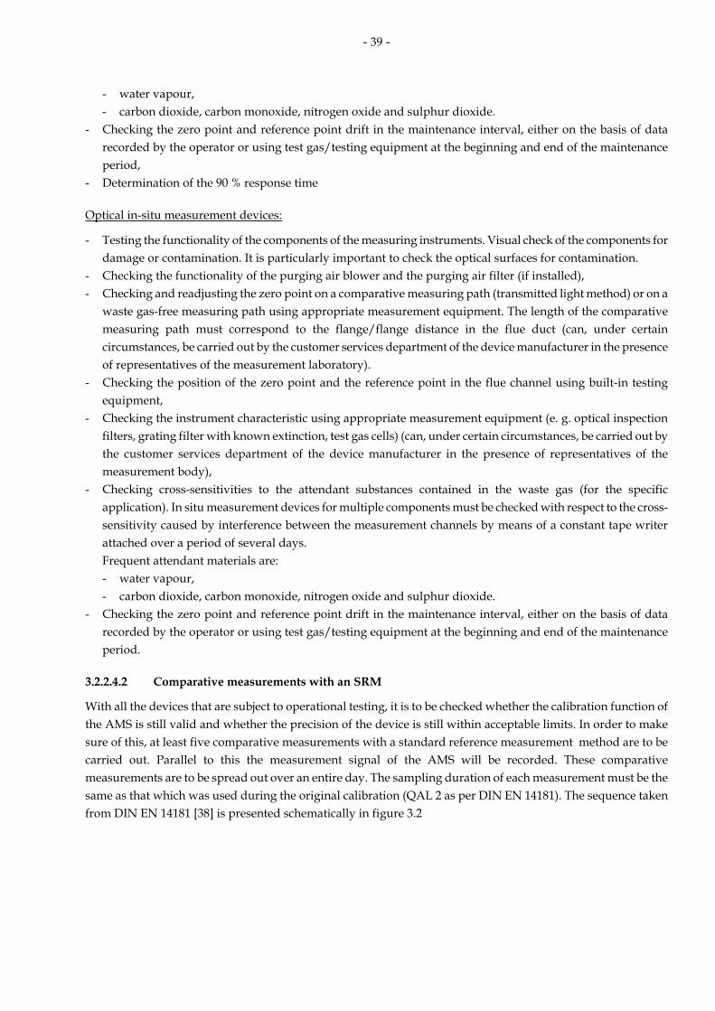
- 39 -
- water vapour, - carbon dioxide, carbon monoxide, nitrogen oxide and sulphur dioxide.
- Checking the zero point and reference point drift in the maintenance interval, either on the basis of data recorded by the operator or using test gas/testing equipment at the beginning and end of the maintenance period,
- Determination of the 90 % response time
Optical in-situ measurement devices:
- Testing the functionality of the components of the measuring instruments. Visual check of the components for damage or contamination. It is particularly important to check the optical surfaces for contamination.
- Checking the functionality of the purging air blower and the purging air filter (if installed), - Checking and readjusting the zero point on a comparative measuring path (transmitted light method) or on a
waste gas-free measuring path using appropriate measurement equipment. The length of the comparative measuring path must correspond to the flange/flange distance in the flue duct (can, under certain circumstances, be carried out by the customer services department of the device manufacturer in the presence of representatives of the measurement laboratory).
- Checking the position of the zero point and the reference point in the flue channel using built-in testing equipment,
- Checking the instrument characteristic using appropriate measurement equipment (e. g. optical inspection filters, grating filter with known extinction, test gas cells) (can, under certain circumstances, be carried out by the customer services department of the device manufacturer in the presence of representatives of the measurement body),
- Checking cross-sensitivities to the attendant substances contained in the waste gas (for the specific application). In situ measurement devices for multiple components must be checked with respect to the cross-sensitivity caused by interference between the measurement channels by means of a constant tape writer attached over a period of several days.
Frequent attendant materials are: - water vapour, - carbon dioxide, carbon monoxide, nitrogen oxide and sulphur dioxide.
- Checking the zero point and reference point drift in the maintenance interval, either on the basis of data recorded by the operator or using test gas/testing equipment at the beginning and end of the maintenance period.
3.2.2.4.2 Comparative measurements with an SRM
With all the devices that are subject to operational testing, it is to be checked whether the calibration function of the AMS is still valid and whether the precision of the device is still within acceptable limits. In order to make sure of this, at least five comparative measurements with a standard reference measurement method are to be carried out. Parallel to this the measurement signal of the AMS will be recorded. These comparative measurements are to be spread out over an entire day. The sampling duration of each measurement must be the same as that which was used during the original calibration (QAL 2 as per DIN EN 14181). The sequence taken from DIN EN 14181 [38] is presented schematically in figure 3.2

- 40 -
Figure 3.2: Sequence of tasks of check of calibration and variability
If in the course of the operational test, values occur which are outside the valid calibration range and if both the calibration function and its precision have been confirmed, then the valid calibration range may be expanded. If one of the tests is not successful, then the cause must be ascertained and dealt with.
On the results of the AST a report has to be written. Each error has to be documented. If an error has an influence on the quality of the measuring result the plant operator has to perform all measures to remove and avoid the error. The form of the report is described in VDI 3950 and presented in this manual in annex 1, 7.9, annex C.
Electronic evaluation devices:
The tasks to be performed in order to test the electronic evaluation devices derive from the minimum requirements [19] and Appendix C of the Guidelines VDI 3950 [37]. The following tests are mandatory:
- Testing of the data transmission from the measurement devices to the evaluation system. This testing will take place either through using the internal power supply of an analysis device (some emission devices offer this possibility, the signal made, however, should be checked) or through an external calibration power source. After checking the closeness to the boundary values, (TMW, HSM) the signal transmission of the lower and upper fourth of the measurement range (e. g. 6 mA, 18 mA) should also be carried out.
- Testing of the data transmission to the recording systems. With redundant electronic recording systems, this function should be checked.
- Checking of the status signals and their transmission to the evaluation systems. - Testing of the classification; this can be dispensed with (as part of the suitability test) to the extent the division
into different classes is only dependent upon one parametrical boundary value. This would not, for example, apply to mixed furnaces.
- Print out and examination of the parameters list - Testing of the EFÜ functions
The operational tests are in part independent of the operation of the plant. This means that, depending on the scope of the test, they can be carried out when the plant is not in operation.
Comparative measurements with an SRM data recording of the AMS
Data evaluation
Examination of the variability and the validity of the calibration function
Calculating of the variability
Report

- 41 -
3.2.2.5 Calibration and validation of the AMS
Devices for continuous emission monitoring must be calibrated regularly through an institution accredited by the competent authorities of the Land. Table 3.3 gives the calibration intervals for the various types of system.
Table 3.3: Calibration intervals for measurement devices for continuous emission monitoring
System Calibration Interval, every
Legal Basis
Systems requiring government approval 3 years No. 5.3.3.6 of TI Air [3], Small and medium incineration plants 3 years §17 a, par. 2 of 1st BImSchV [4], Large-scale incineration plants; gas turbines: 3 years § 14 of 13th BImSchV [8], Waste incineration plants: 3 years § 10 of 17th BImSchV [9], Crematoria: 5 years § 7 of 27th BImSchV [11], Systems for biological waste treatment 3 years § 8 of 30th BImSchV [12], Plants for solvents: - not requiring gov’t approval - requiring gov’t approval
5 years 3 years
App. VI, no. 2.1 of the 31st BImSchV [13] was well as TI Air
The calibration procedures are for systems covered by the 13th and the 17th BImSchV as given in DIN EN 14181 [38] for all others the guidelines, VDI 3950 [37] together with DIN EN 14181 are applicable.
Before a calibration is carried out, a measurement plan is to be made (see under 2.2). This plan contains the place of measurement, the measurement task, measurement dates, measurement methods and measurement personnel [31]. The goal of calibration is to determine the calibration function and the variability of the complete measurement device as well as to check the variability of the measurement values of the AMS through a comparison with the measurement uncertainties as defined in the various statutes.
The calibration function describes the relationship between the concentration c of the measured object in the waste gas and the measured signal given by the continuous measuring device (normally a current signal I).
Calibration function: c = f(I)
Before determining the calibration function a functional test of the AMS must be done.
Comparative measurements with an SRM
In order to determine the calibration function, comparative measurements are made between the AMS and a standard reference measurement method (SRM). Am SRM is a method which was described and standardized in order to determine an air quality characteristic. It is used for short testing periods together with the AMS. The exclusive use of reference materials to determine the calibration function is not sufficient.
For each calibration, at least 15 valid comparative measurements must be made under normal operating conditions. The measurements must be spread equally over at least three days and also be spread equally over the course of the working day (8-10 hours). These comparative measurements are to be completed within four weeks. The sampling time for each individual measurement must be at least 30 minutes or 4 times the length of the AMS’ response time, including the sampling system.
The results derived through the SRM must be in reference to the conditions under which the AMS measurements are carried out (i. e. with regard to pressure and temperature). In order to establish the calibration function and carry out the variability test, it is necessary (for each pair of measurements) to determine all the additional parameters and values which are necessary for computations of the measurement conditions of the AMS and the standard conditions.

- 42 -
A network measurement will be used to test whether the measurement components are distributed homogenously throughout the waste gas duct. If this is not the case, then the spatial distribution is to be taken into account. The procedure for this is described in the guidelines VDI 4200 [34] and/or in DIN EN 15259 [33]. If the comparative measurements are carried out as network measurements (as in the case of dust measurements), then no further action is required; any possible inhomogeneous distribution will have already been taken into account by the network measurement.
Care should be taken that the comparative measurements cover the entire range of measurements for which the AMS is intended. For this reason, the concentrations used during calibration for normal operating conditions should vary as widely as possible. If the plant’s normal operating conditions also include significant and distinct changes in modes of operation (e. g. a change in fuel) then additional calibrations should be carried out and the corresponding calibration functions made for each mode of operation.
DIN EN 14181 does not require functional tests and calibration of the measurement devices for the reference quantities. The standardization of the AMS and SRM measurement values is done using independently ascertained data sets of the reference quantities. Then the uncertainties of the reference quantities are attributed to the measuring system of the air pollutant in the variability test. It is therefore advisable that the measurement devices for determining the reference quantities also be subjected to tests for proper functioning and calibration in order to minimize any uncertainties deriving from the reference quantities. This is particularly important in cases where the measurement device which is to be calibrated is intended to detect pollutant concentrations in relation to the waste-gas volume in operational state and these concentrations have been standardized through an evaluation unit.
For this reason, during the calibration a statement should also be made about the functioning of the existing measurement devices for the reference quantities such as O2, CO2, temperature or humidity.
During calibration, the signals of the continuous measurement are recorded. A measurement data recording system is to be used for this. The measured values recorded must be able to be integrated for the whole duration of the sampling time for the comparative measurement method used. Alternatively, the measurement values can be recorded with a registering device which has a class accuracy of 0.5 and a writing width of at least 20 cm.
Data evaluation of the comparative measurements and the variability test
The pairs of values which were derived from comparative measurements are to be evaluated statistically. The computation of the calibration function will be done through a regression analysis. DIN EN 14181 assumes that in principle the calibration function is linear and shows a constant standard deviation. The following figure shows the various steps of calibration and variability testing [38].

- 43 -
SRM
Value yiCalculation of thecalibrationfunction
AMS
Value xi
Calculation of calibrated values
yi,S
[ys,min; ys,max]
Test of Variability
Conversion to standardconditions uing plant equipment
Definition of validcalibration range
Conversion to standardconditions using SRM equipment
Selection of cali-bration procedure
in mA resp. mg/m³
in mg/m³ [stand.cond., O2] in mg/m³ [Norm, O2]
in mg/m³ yi
yi,S
[0; 1,1 × ys,max]
AMS-conditions
Figure 3.3: Diagram showing the individual steps for calibration and test of variability
When computing the calibration function, a distinction is made if measurement values (related to the SRM) are distributed over a range which is larger or smaller than 15% of the emission limit values.
The computed calibration function is only valid for the range between 0 and the largest determined comparative value, plus 10% of the highest value. With measurements outside the valid calibration range, the calibration function has to be extrapolated so that the concentration values which exceed the valid calibration range can be determined. Alternatively, reference materials can be used in order to confirm the computation of the linear extrapolation. The validity of the valid calibration range shall be evaluated by the plant owner on a weekly basis. In the case of certain frequencies of such excess values, DIN EN 14181 mandates a complete new calibration within six months.
Data from the previous calibrations may not be used together with new calibration data.
The variability is computed using the data from the comparative measurements. This variability is the standard deviation of the differences from the comparative measurements made between the SRM and the AMS. In order to compute this variability, the waste-gas parameters are to be ascertained as follows:
a) to standardize the SRM –results with the devices of the SRM measurements
b) to standardize the AMS-results with the devices of the plant or, if these are not present, through using the substitute values of the system.
The computed variability is then compared with the maximal allowable standard deviation. If there are several calibration functions (e. g. for different operational conditions of the plant) each must be compared separately.
The measurement values of the AMS may only be used to demonstrate observance of the emission limit values once the AMS has passed the variability test.

- 44 -
When the AMS passes the variability test for compliance with legislation, then the AMS complies with the requirements for the uncertainty of the emission limit values, since it is assumed that variability will be constant throughout the range.
The institution which has made the functional tests and calibration will make a report corresponding to VDI 3950 [37] and which also fulfils the requirements of DIN EN 14181 [38]. Among other things, it will contain the following: - measurement task, - measurement date, - description of the facility and the materials used, - measurement location for continuous measurement system and the comparative measurement method, - automatic measurement systems, - reference measurement method, - operational state of the plant during the comparative measurements, - results of the functional tests and the calibration - functional test of the electronic data evaluation system.
A sample calibration report can be found in Appendix 1.
3.2.2.6 Special requirements for the functional test and calibration
In the section below you will find more detailed indications about the functional tests and calibration of continuous measuring systems. Generally, all these requirements for maintenance, functional tests, and calibration of the measurement device which were determined at the suitability test and recorded in its report must be observed.
3.2.2.6.1 Dust-content measurement devices
Measurement methods for comparative measurements at calibration:
- Low dust content: gravimetric determination of the dust load as per DIN EN 13284-1 [52]
- High dust content: gravimetric determination of the dust load as per VDI 2066, part 1 [49]
The relationship between the dust content of the waste-gas and the measurement signal of the continuous measurement device is (among other things) dependent on the grain size distribution and the material characteristics (surface, reflectivity) of the dust as well as the representative quality of its detection in the measurement cross section. This relationship can only be detected with the manual gravimetric method.
3.2.2.6.2 Smoke-density meters
Smoke-density meters can only provide qualitative information about the dust load of waste-gases. For this reason, calibration using comparative measurements with a manual measurement method is not useful.
After adjustment of the zero point signal to the brightness of the waste-gas-free measuring path, the device’s sensitivity will be further adjusted using test filters of known opacity.
3.2.2.6.3 Measurement devices for sulphur dioxide Reference measurement methods for comparative measurements at calibration:
- DIN EN 14791 [86]: reference method using ion chromatography (range 0.5 till 2000 mg/m3 SO2) or, using the thorin method (range 5 to 2000 mg/m3 SO2)
- VDI 2462, p. 8 [84], H2O2-thorine-method - VDI 2462, p. 1 [82], iodine-thiosulfate-method

- 45 -
- DIN ISO 7934 [85], hydrogen peroxide/barium perchlorate/thorine-method The choice of a comparative method depends on the sulphur dioxide concentration in the waste-gases and any cross-sensitivity of the measurement method with regard to waste-gas attendant substances.
3.2.2.6.4 Measurement devices for nitrogen oxides
Reference measurement methods for comparative measurements at calibration:
- DIN EN 14792 [92], reference method: chemiluminescence
- Guideline VDI 2456 [90], ion chromatographic method
In systems where the content of nitrogen dioxide is greater than 5 % of the total nitrogen oxide content (NO + NO2) a testing of the efficiency of the converter (if present) is necessary. This can for example be done with test gases containing known NO2 concentrations or through using gas phase titration (with ozone).
3.2.2.6.5 Measurement devices for carbon monoxide
Reference measurement methods for comparative measurements at calibration:
- DIN EN 15058 [99], reference method: NDIR-Spectroscopy - VDI 2459, p. 1 [97] measurement using FID after reduction to methane and gas chromatographic separation. The CO content of the waste gases at incineration plants is generally so low that usable measurement value pairs are impossible to obtain. VDI 3950 offers a different procedure (which can also be used for other components): The measuring range to be covered may be extended for calibrations at stationary source emission sources by application of reference materials if the plant exclusively produces low emissions (less than 20 % of the limit value for the daily average) at the time of calibration and the plant operator has no influence on the emissions by operational means. This increases the confidence in the performance of the AMS at the emission limit value. In this case the upper limit of the valid calibration range has to be specified by 20 % of the daily emission limit value.
3.2.2.6.6 Measurement devices for organic compounds
Measurement methods for comparative measurements at calibration
- DIN 12619 [129], FID-method for the range 0-20 mg/m3 - DIN EN 13526 [130], FID-method for the range 20-500 mg/m3 These two methods can be used both for continuous measurements as well as for reference methods. In the case of components of specific analyses, the following method can be used: - DIN EN 13649 [131], activated carbon adsorption and solvent desorption method In addition, the VDI guidelines offer a number of single or multiple-component methods of analysis. Where there are higher total carbon emissions, the silica gel method can be used as per VDI 3481, p. 2 [104], certain limitations must, however, be taken into account. Depending on the waste-gas composition, this method can result in other measurement results than, for example, the FID measurement method. The silica gel method is not appropriate for measuring short-chained hydrocarbons (C1 through C3) nor for humid waste-gases (e. g. incineration waste-gas). (criteria’s for selection, see VDI 3481, p. 6 [107]) Individual calibration of the FID measurement devices is required because the device is set using testing gases such as propane or butane and the organic compounds emitted from the plant could have response factors diverging from those of the test gas.
The limitations of operational safety can be found in the suitability test report. In areas where explosions are a danger, the regulations for explosion protection are to be observed. It can happen that in the interest of security certain compromises may have to be made when choosing the best point of installation.

- 46 -
3.2.2.6.7 Measurement devices for inorganic gaseous fluorine compounds
Reference method for comparative measurements at calibration:
VDI 2470, p. 1 [108], adsorption method
The analytic determination of the fluoride concentration is normally done through ion chromatographic analysis.
3.2.2.6.8 Measurement devices for gaseous inorganic chlorine compounds
Reference method for comparative measurements at calibration:
- DIN EN 1911-1-3 [109], [110], [111], adsorption method The analytic determination of the chlorine concentration is normally done through ion chromatographic
analysis.
3.2.2.6.9 Measurement devices for hydrogen sulphide
Reference methods for comparative measurements at calibration:
- VDI 3486, Part 1 [112], potentiometric titration - VDI 3486, Part 2 [113], iodometric titration
There is, however, at the moment no suitability-tested emission measurement device for hydrogen sulphide.
3.2.2.6.10 Measurement devices for ammonia
Reference method for comparative measurements at calibration:
- VDI 3496, Part 1 [114], adsorption method
3.2.2.6.11 Measurement devices for mercury
Reference methods for comparative measurements at calibration:
- DIN EN 13211 [73], sampling using potassium permanganate and subsequent analysis with AAS as per DIN 1483 [75]
It should be noted that this method determines the total mercury concentration (the sum of Hg (0) and Hg (II) while some of the suitability tested mercury analysers show only the proportion of metallic mercury. Checking the characteristics of the device during the test for proper functioning will be done through the use of test gases. These test gases must be made immediately before their use in the measuring device as, for example, through the use of a suitable test-gas generator.
3.2.2.6.12 Measurement devices for other parameters (volume flow, humidity, oxygen, temperature)
The function of measurement devices for reference quantities is to be checked through manual comparative measurements:
Humidity (water vapour)
- DIN EN 14790 [116], reference method: condensation/adsorption method
Oxygen - DIN EN 14789 [115], reference method: paramagnetism

- 47 -
Waste-gas volume flow - ISO 10780: 1994 [44], determination of the dynamic pressure over the measurement cross section;
determination of the measurement points: DIN EN 13284-1 Waste-gas temperatures In order to measure the waste-gas temperatures, appropriate thermal elements will be used, depending on the temperatures to be measured: Temperature range up to 200 °C Pt-Resistance thermometer Temperature range up to 1000 °C (gauge number > 2 mm) NiCr-Ni Type K and/or. N Temperature range up to 1300 °C (gauge number > 0,5 mm) PtRh-Pt Type R and S
3.3 Evaluation and documentation of the measurement values, submission of documents to authorities/remote emission monitoring
Registration and evaluation of measurement values
The measurement values given by the AMS must be recorded and evaluated. In order to do so they are transmitted to an electronic data evaluation system. The electronic data evaluation system must provide a complete registration, average-computation, validation, classification and evaluation and be in accordance with the minimum requirements [19]. If the recording of the data is done using a redundant data system, then additional recording systems (e. g. recorders) can be dispensed with. The electronically recorded data must be available both as monitor display as well as paper print-out and without any additional technical assistance.
All the measurement values produced during the plant’s operational time are to be recorded together with the time of their occurrence. There are to be status signals both at the beginning and at the end of the operational time of the system and the characteristic quantities of the system’s operational mode and its parameters are to be clearly defined, as well as included in the evaluation process.
The measurement values will be integrated as short-time values (with electronic detection and recording of the measurement values a mean of maximum 5 s is permissible). Using the analysis functions ascertained during calibration as a basis, they will be converted into the respective physical dimension (usually into a m ass concentration). These short-time means are then converted to half-hourly means. In the same way half-hourly means for the reference quantities will also be made. The creation of means takes place at the same time for all measurement values. The daily mean is newly computed with the beginning of each day. The integration period for the measurement of pollutants and reference quantities has to be identical for standardization according to the respective reference quantities. The half-hourly means will be used to compute the standardized half-hourly means through mathematical computations (e. g. standardization of pressure, humidity or temperature) and computations of oxygen use.
The reference period for the integration interval is normally half an hour. There should, however, be an option for freely selectable intervals between one and 120 minutes. A time-basis of 30 minutes is to be used for evaluation. In special situations where this is justified, e. g. charching operations or a longer time-basis at calibration, it is possible to deviate from this. The validated means shall be determined by deducting the standard deviation determined during calibration, according to DIN EN 14181 [38] (issue of September 2004), from the standardized means. Negatively validated means shall be set at zero.
The standardized half-hourly means will also be used to continuously check the validity of the calibration function.
The validated means will be used to compute the daily means.
The validated half-hourly means and the daily means will be classified. These classifications will be in accordance with the requirements of Appendices C-G of the “Uniform practice in monitoring emissions” [19] (see Appendix

- 48 -
1). All means will be stored together with their date and time, their status and the characteristic sign for the type of operation at the plant in question. Means will be used for assessments when at least two-thirds of the reference time is covered by usable values. The number of means which do not fulfil these pre-conditions is to be part of a separate classification. There are also a number of other special classifications, such as those for values which exceed the limit values or values which are outside the calibration range.
The classification of daily means can only take place when (normally) six hours have been covered with such values within the daily operational time.
The following figure 3.4 shows the normal sequence in the evaluation of continuous emission monitoring (HM: half-hourly mean DM: daily mean):
measured component
pollutant
1st reference value
2nd reference value
HM
HM
HM
standardized HM
validated HM
DM
consideration of measurement uncertainty
classification
classification
Figure 3.4: Steps in the evaluation of continuous emission monitoring
There is a daily and a yearly data report.
The daily data report must contain the following data:
• data relating to the daily operating time of the plant • number and classification of the daily means acquired • values in special classes with time reference of the day • frequency distribution of the means and the daily means for the current calendar year • values outside the valid calibration range and data relating to the validity of the calibration function • Last changes of the parameterization with time reference (date and time) The yearly data output must contain the following data for the whole calendar year passed: • operating time of the plant • number and classification of the acquired means • values in special classes and their time reference • number and classification of the daily means

- 49 -
• daily values in special classes with time reference (date) • changes of the parameterization with time reference (date and time) • number of values outside the valid calibration range and data relating to the validity of the calibration
function • power outages and their times • times for testing and maintenance on the evaluation systems • times when the calibration function was not valid
The half-hourly means (or the hourly means for CO as per the 27th BImSchV) are divided into 20 equal classes (M1-M20). Depending on the system to be monitored, the value for the upper classification limit will be defined differently (e. g.: with the TI Air and the 13th BImSchV the double of the limit value for the daily mean; with the 17th BImSchV, the limit value for half-hourly means). The minimum temperatures as per 17th and 27th BImSchV and the functional efficiency of the filter systems as per 27th BImSchV are classified differently.
The daily limit values are divided into 10 equal classes T1 – T10; the limit value for the daily mean is at the upper class limit of class T10.
The exact classification of the various types of facilities as well as the differentiation and definition of the special classes can be found in Appendix 1.
Figure 3.5 shows a the daily print-out of a system as per 17th BImSchV in which there was an evaluation for six components.

- 50 -
Figure 3.5: Classification structure of a system as per 17th BImSchV

- 51 -
Remote emission monitoring/emission data transmission(EFÜ) [25]
In remote emission monitoring systems, the measured data are processed by a “normal” emission computer in the usual way. Once processed, the data are saved on a remote emission monitoring computer (EFÜ computer or B system) and made available for subsequent remote data transmission (DFÜ). The emission computer and EFÜ computer can be integrated into a single unit or networked together. Depending on the number of plants monitored, the plant operator has either one B system or multiple B systems which can be networked together. Each B system analyses the figures for a plant or a section of a plant. A number of emission computers can be connected to a single B system. A G system is installed at the competent monitoring authority. This system allows access to the data stored on the B systems connected. The B system and G system communicate through the telephone system using a modem connection. The data interface has been agreed and standardized. The interface definition is published by the LAI [25]. The B systems also require a suitability test. The minimum requirements of this test can be found in the “Uniform practice in monitoring emissions” [19]. Fig. 3.6 shows a schematic representation of a remote emissions monitoring system with a connection to the authorities.
Remote emission monitoring has become reality in all of the German Länder. The advantage of this system for the authorities is that they have more information about the emission behaviour of the systems in question. If the limit values are exceeded, they are commented upon close to the time when they occur. In addition, the reliability of such systems or the malfunction of emission measurement devices can both be checked by the authorities on a daily basis.
EFÜ systems fulfil the following basic functions:
• With the frequency agreed upon (normally daily) and without having to be asked, the data (all validated means together with the appropriate status information together with any other relevant operational data) are transmitted from the B-system to the G-system.
• The B system can on request at any time provide the G system with the data of up to the last 24 months • If limit values are exceeded, the B system can provide data for the day in question. • A description of the facility (e. g. its parameters) is in the B system and gets transferred in the form of a so-
called “data model” to the G system. • Both systems are protected from data intrusion from without. In the case of wrong data connections, the
transmission of data is stopped and the connection broken off.

- 52 -
Since the B systems have high-powered computational capacity, it is possible, for example, to make a computation of trends in emission values which in turn make it possible to anticipate early on values which would be in excess of the daily limit values.
Figure 3.6 shows the principles according to which emissions remote monitoring functions.
Telephonenetwork
Telephonenetwork
Supervisory authority
B system B system B systemB system B system B system
Operator 1 Operator 2
Central B system
G system
Figure 3.6: Remote emissions monitoring system with connection to authorities
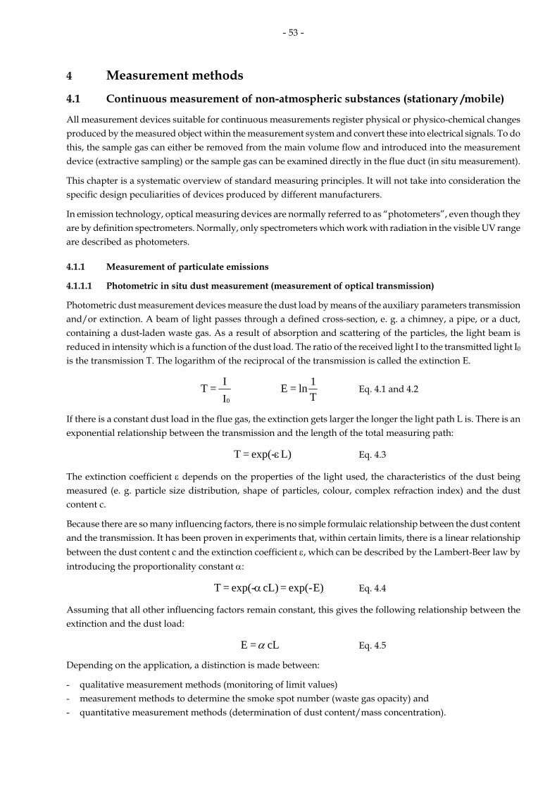
- 53 -
4 Measurement methods
4.1 Continuous measurement of non-atmospheric substances (stationary /mobile)
All measurement devices suitable for continuous measurements register physical or physico-chemical changes produced by the measured object within the measurement system and convert these into electrical signals. To do this, the sample gas can either be removed from the main volume flow and introduced into the measurement device (extractive sampling) or the sample gas can be examined directly in the flue duct (in situ measurement).
This chapter is a systematic overview of standard measuring principles. It will not take into consideration the specific design peculiarities of devices produced by different manufacturers.
In emission technology, optical measuring devices are normally referred to as “photometers”, even though they are by definition spectrometers. Normally, only spectrometers which work with radiation in the visible UV range are described as photometers.
4.1.1 Measurement of particulate emissions
4.1.1.1 Photometric in situ dust measurement (measurement of optical transmission)
Photometric dust measurement devices measure the dust load by means of the auxiliary parameters transmission and/or extinction. A beam of light passes through a defined cross-section, e. g. a chimney, a pipe, or a duct, containing a dust-laden waste gas. As a result of absorption and scattering of the particles, the light beam is reduced in intensity which is a function of the dust load. The ratio of the received light I to the transmitted light I0 is the transmission T. The logarithm of the reciprocal of the transmission is called the extinction E.
I I = T
0
T1ln = E Eq. 4.1 and 4.2
If there is a constant dust load in the flue gas, the extinction gets larger the longer the light path L is. There is an exponential relationship between the transmission and the length of the total measuring path:
L)exp(- = T ε Eq. 4.3
The extinction coefficient ε depends on the properties of the light used, the characteristics of the dust being measured (e. g. particle size distribution, shape of particles, colour, complex refraction index) and the dust content c.
Because there are so many influencing factors, there is no simple formulaic relationship between the dust content and the transmission. It has been proven in experiments that, within certain limits, there is a linear relationship between the dust content c and the extinction coefficient ε, which can be described by the Lambert-Beer law by introducing the proportionality constant α:
E)exp(- = cL)exp(- = T α Eq. 4.4
Assuming that all other influencing factors remain constant, this gives the following relationship between the extinction and the dust load:
cL = E α Eq. 4.5
Depending on the application, a distinction is made between:
- qualitative measurement methods (monitoring of limit values) - measurement methods to determine the smoke spot number (waste gas opacity) and - quantitative measurement methods (determination of dust content/mass concentration).

- 54 -
Qualitative particulate measuring devices are used for monitoring limit values. They only determine the optical transmission. At least two alarm levels need to be set on the measurement device by means of calibration using a gravimetric conventional method.
Particulate measuring devices to determine the smoke spot number (waste gas opacity) also only determine the transmission. There must be a reproducible relationship between the grey-scale value of the waste gas plume and the display on the measuring device. The measured values are given as a smoke number. (VDI 2066, part 8 [51] and DIN 51402, Part 1 [54])
Quantitative particulate measuring devices determine the dust content (dust load of the sample gas or mass concentration). To do this, the optical transmission of the extinction is derived using the Lambert-Beer law. The measuring devices normally give the measured signal as milligrams of dust per cubic metre of waste gas in operating conditions. In order to obtain reproducible measurements, it must be assumed that the dust being measured is not subject to appreciable alteration with respect to its particle size distribution and optical properties. It therefore follows that each individual device must be calibrated at the place it is used.
Fig. 4.1 is a schematic presentation of a conventional in situ dust content measuring device. The measuring head with its opto-electric receiver is installed on one side of the waste gas duct. The reflector head is on the opposite side.
The light beam emitted by the light source is separated into a measurement beam and a reference beam (dual-beam method). The measuring light beam crosses through the measurement section to the reflector and back to the measuring head, while the reference light beam passes through a dust-free reference path inside the measuring head. Both light beams reach the receiver at staggered phases, the receiver then processes the signal and supplies a direct current signal which is proportional to the extinction. The use of the dual-beam method with automatic compensation ensures that the measurement is not affected by external influences, such as fluctuations in the operating parameters of the receiver or ageing of the optical and electrical components.
In order to keep contamination on the optical surfaces between the measurement head and the waste gas duct and between the reflector head and the waste gas duct to a minimum, dust-free purging air is blown into the flange.
Standard measurement devices have automatic zero point and reference point monitoring mechanisms. For this, a second reflector in the measurement head is swung into the path of the light, so that the light beam is reflected before it reaches the waste gas duct (zero point monitoring). In order to monitor the reference point, a filter which produces a known reduction in light intensity, is also swung into the path of the beam.

- 55 -
Measuring head
Concave mirror
Reference-path
Lens
Semi-trans-parentmirror
Lightsource
Lineari-sation
DisplayOpto-elektronicreceiver
Waste gas duct
Reflector-head
Z.R.R.F.
Z.R.: Zero point reflectorR.F.: Reference point filter
Figure 4.1: Photometric in situ dust measurement (schematic)
4.1.1.2 Scattered light measurement
When passing through a dust loaded gas, a light beam experiences a reduction in intensity which is a function of the dust load as a result of absorption and scattering of the particles. In addition to the reduction in intensity (extinction photometric dust measurement), the scattering of the light can also be used to determine the dust load in gases under certain circumstances [147].
The intensity of the scattered light depends on the intensity, the wavelength and the polarisation of the incoming light, the angle at which the scattered light is measured, the size and shape of the particles and the refractive index of the particulate material. Because there are so many influencing factors, there is no simple formulaic relationship between the dust content and the intensity of the scattered light. It has been proven in experiments that, within certain limits, there is a linear relationship between the two, assuming all other influencing factors can be kept roughly constant.
This linearity range is delineated at the bottom by the influence of interference light and at the top by multiple scattering on the particles.
One of the major characteristics of the scattered light measurement principle is the optical separation of the scattered light hitting a light detector at a specific angle (observation angle) from the primary beam of light. This means the measured value zero point is independent of the intensity of the primary light and the detection sensitivity can be considerably increased relative to the extinction measurement method.
Many extractive scattered light photometers use an angle of observation of around 15° because the dust particle size is not small in comparison to the wavelength of the emitted light and therefore forward scattering (known as Mie scattering) is predominant. Fig. 4.2 is a schematic representation of a scattered light photometer. The light source emits light which covers an optical path to the oscillating flicker mirror. This deflects the incoming light in position a as a measurement beam across an optical path to the measurement chamber. Part of the scattered light generated by the measured material is received and measured by a light detector at an angle of around 15°. In position b, the oscillating flicker mirror deflects the incoming light, which is now the reference beam, through a light attenuator and onto the light detector as a reference standard.

- 56 -
The signal currents generated by the light detector in cases a and b are compared in a measurement amplifier and converted into a control signal, which passes through the light attenuator and changes the reference beam until its intensity corresponds to the intensity of the scattered light (scattered by the sample gas). In this compensated status, the position of the light attenuator corresponds to the measurement signal which is amplified and displayed.
The use of the dual-beam method with automatic compensation ensures that the measurement is not affected by external influences, such as fluctuations in the operating parameters of the receiver or ageing of the optical and electrical components.
Light source
Light-detector
Semi-transparentmirror
Measuring chamber
Reference
beam Lightattenuator
Referencestandard
Display
Scatter light(15°)
Amplifier
ba
Oscillatingmirror
Measurement beam
Figure 4.2: Scattered light measurement, extractive method (schematic)
In situ scattered light photometers work with acute observation angles. These devices can be compact in design as the sender and the receiver can be integrated in a single unit (Fig. 4.3).
Transmitter
Receiver
Analysissystem
Figure 4.3: In situ scattered light measurement (schematic)

- 57 -
4.1.1.3 Measurement with beta ray absorption
In dust measurement with β-ray absorption systems, a partial gas stream is extracted isokinetically (i. e. the velocity of the particles in the partial gas stream corresponds to the velocity in the waste gas duct) from the waste gas duct and sucked through a filter tape (Fig. 4.4). The dust quantity deposited on the filter tape is measured by the attenuation of the β-radiation after passing through the dust loaded filter [147].
Filter strip
β-radiator
Amplifier Display
Partialvolume
flow
De-tec-tor
Figure 4.4: Dust measurement with β-ray absorption (schematic)
The radiation source is artificially manufactured using radioactive material of an appropriate level (e. g. the isotope carbon 14 or krypton 85). A Geiger Müller counter is used as the detector. To compensate for the gradual reduction in radioactivity of the β-radiation source over a period of time and the variation of the radiation attenuation due to filter material, measurements of the absorption are taken before and after the dust filtration and the measured values compared with one another.
With β-dust measurement systems, the measured object accumulates on the filter material, so the measurement is not really continuous as such, but takes place in measurement cycles. The duration of a measurement cycle depends on the accumulation time. Increasing the accumulation time can increase the sensitivity of the measuring method.
4.1.1.4 Dust measurement using tribo-electric sensors
On collision, dust particles landing on a probe emit tiny electrical charges to the probe which can be detected. The electrical current can be measured. For dust concentrations between 1 and 100 mg/m³, the intensity of the current is in the region of a few pA. The level of the current signal is dependent on a number of influencing factors, such as the velocity of the gas, the properties of the particles, the effective surface area of the probe and the average particle diameter. If the framework conditions remain constant, there is a linear relationship between the current signal and the dust concentration.
Suitability tested tribo-electric measurement devices are used for qualitative dust measurement (limit value monitoring) and, with certain limitations, for quantitative dust measurement (determination of dust load).

- 58 -
4.1.2 Measurement of gaseous substances
For the continuous measurement of gaseous materials, physical, physico-chemical and chemical effects produced by the measured objects within the measurement system if handled accordingly (e. g. on stimulation) are generally used:
- Interaction with electromagnetic radiation in the optical spectral range (4.1.2.1 to 4.1.2.4), - Thermal ionisation (4.1.2.5), - Change of colour when introduced into a reagent solution (4.1.2.6), - Change of conductivity when introduced into a reagent solution (4.1.2.6), - Heat generation by means of catalytic oxidation (4.1.2.6), - Ionisation concentration change when introduced into a buffer solution (4.1.2.6), - Interaction with electromagnetic fields (4.3.1), - Change of conductivity of solids (4.3.2).
4.1.2.1 Photometry with extractive sampling
The interaction of electromagnetic radiation in the optical spectral range with the molecules of a gas is very specifically dependent on the molecular structure. When they are exposed to electromagnetic rays, the molecules are stimulated by absorbing energy. This results in the formation of characteristic absorption bands. All heteroatomic molecules, such as carbon dioxide (CO2), carbon monoxide (CO), sulphur dioxide (SO2) and nitrogen monoxide (NO) have a characteristic absorption spectrum in the infrared spectral range. SO2 and NO also have one in the ultraviolet spectral range.
Fig. 4.5 shows the simplest conceivable measuring set-up for an extractive absorption photometer. An optical filter is used to generate light in a specific wavelength range, which is passed through a measuring cell through which the sample gas is flowing. A proportion of the light is absorbed by the molecules of the air pollutant. The resulting attenuation of the light intensity is therefore a measure of the air pollutant concentration. Once it has passed through the measurement cell, the light hits a radiation detector which is connected to an electronic signal processing system.
In this simple set-up, the smallest alteration in the light emission and the receiver sensitivity leads to unacceptably high zero point errors. Measuring set-ups which avoid this fault employ either a periodic zero point correction system or a comparison standard in the form of a second comparison filter (bi-frequency method) or a reference gas (gas filter correlation method, Fig. 4.7). This comparison standard can be either time displaced – i. e. with inverted phase – when brought into the light path or arranged in a parallel reference light path (dual beam photometer).
A distinction is made between different photometers on the basis of the following criteria:
a) the type of radiation source: IR or UV photometer b) the length of the cell used: short-path or long-path cells, c) the type of zero point correction: gas filter correlation method or bi-frequency method, d) the beam path: single or dual beam photometer.

- 59 -
Measuring chamber
Samplegas
Amplifierr DisplayLightsource
Opticalfilter
Gas detektor
Figure 4.5: Simplest measuring set-up for an absorption photometer (schematic)
Measuring chamber
Samplegas
Amplifier Display
Light source Chopperwheel
Reference chamber
Gas detektor
Figure 4.6: NDIR photometer (schematic)
Amplifier DisplayLightsource Measuring chamber
Samplegas
De-tec-tor
Interferenz-filter
Filterwheel
Filter chamberwith N2
Filter chamberwith Measurment
component
Figure 4.7: Gas filter correlation method (schematic)
Simple cells through which a linear beam passes once are known as short-path cells. The light absorption (i. e. the sensitivity of a photometer) increases with the number of absorbing molecules in the path of the beam. This effect is utilised by using long-path cells. As there is generally not sufficient space for a cell to be extended at will, the light beam is reflected by a mirror at the end of the cell, which means that it passes through the cell a number of times. If it passes through the cell enough times, the resulting physical path lengths can be as long as 20 m or more.
Photometric gas analysis devices must address the components to be measured selectively in order to minimise the influence of other components in the measured product (cross-sensitivity). This selectivity can be achieved by dispersive or non-dispersive methods.

- 60 -
Dispersive methods split the light from a broad radiation source into its spectral elements before the actual measurement is made. Only the elements relevant to the specific measured object are used for the measurement.
In bi-frequency methods, for example, a filter is swung into the path of the beam in order to generate the measurement signal (I), this filter filters out anything but the characteristic wavelengths in the range of the components to be measured. Prism filters, refractive gratings or interference filters are used. A second filter is used to generate the zero point signal (I0) which enables an appropriate wavelength range outside the characteristic spectrum to pass through. The measurement signal is derived by applying the Lambert-Beer law to the two measured variables (see Section 4.1.1.1).
In order to measure mercury, the resonance absorption of mercury atoms at a wavelength of 253.7 nm is used. Mercury is the only metal which has enough vapour pressure for this method at room temperature and whose vapour is single-atom. The narrow-band UV radiation is generated using a mercury vapour lamp. Only the content of elemental mercury is measured in the analyser. As some of the mercury in the waste gas of technical plants (e. g. waste incineration plants) can be in the form of water-soluble mercury ions (Hg2+), some analysis devices use a reactor which converts Hg2+ into Hg0.
The non-dispersive methods dispense with the spectral refraction and use other wavelength-selective systems to obtain the desired selectivity.
The non-dispersive infrared (NDIR) method uses a selective detector which detects light from a beam modulated by a chopper wheel (Fig. 4.6). Multi-component measuring devices can be designed on the basis of the NDIR method. To do this, a number of gas detectors (normally two) are connected to one another, one for each of the components. It should be noted that the absorption spectrums of the components to be measured separately must not overlap.
The gas filter correlation method uses a gas-filled filter chamber attached to a filter wheel. This filter chamber is alternately and periodically brought into the light path with an opening in the filter wheel or with a filter chamber filled with nitrogen. Multi-component measuring devices can be designed on the basis of the gas filter correlation method. In this case, the filter wheel is fitted with gas filters for multiple components.
Both methods use detectors filled with the component to be measured (gas detectors). The modulated radiation generates fluctuations in pressure in the receiver chamber by means of absorption in the characteristic wavelength range. The pressure differences between two halves of the receiver chamber are either measured directly using a membrane condenser or by detecting a resulting pressure compensation flow and converted into electrical signals.
Recently, electrochemical detectors based on semiconductors have also been used. The very nature of the system means that these detectors have poor long-term stability, which can be compensated for by structural measures, such as self-calibration, preliminary attenuation or the use of detector arrays. The life expectancy of these detectors is limited and can also be drastically reduced by the influence of attendant materials (“poisoning”).
The non-dispersive ultraviolet (NDUV) method achieves selectivity by using gas-filled discharge lamps which emit characteristic spectral lines.

- 61 -
4.1.2.2 In situ photometry
In situ photometers, the absorption measuring path is in the waste gas duct itself. This means that the sample gas is not fed into the measuring cell through a sampling system. The photometer, which consists of a radiation source, a detector, a selectivity device and evaluation electronics, is installed outside the waste gas duct. In the UV range, spectral-refractive gratings are used to achieve selectivity. In the IR range, interference filters or gas-filled filter chambers are used, as with the GFC method. Generally, in situ photometers are fitted with filter combinations for a number of gaseous measured objects and for photometric dust measurement.
Fig. 4.8 shows two possible measuring arrangements. In both cases, the actual photometer is located on one side of the waste gas duct. Either the radiation source (example 1) or a retro-reflector (example 2) is installed on the other side. In the second case, the light beam crosses the measuring path twice. In both cases, the optical interface between the photometer/radiation source or the reflector and the waste gas duct are protected from contamination by means of a screen of purging air, as for photometric dust measurement (see Section 4.1.1.1).
Lightsource
Reflector
Waste gas duct
Photo-meter
Photo-meter Waste gas duct
Case 1
Case 2
Figure 4.8: Different in situ photometer arrangements

- 62 -
4.1.2.3 FTIR spectroscopy
Infrared-active gases, such as CO2, CO, SO2, NO, NO2, HCl, H2O, can be measured simultaneously using Fourier transform IR spectroscopy (FTIR spectroscopy) [79]. Unlike in traditional spectroscopy, the absorption spectrum is not recorded by means of dispersive elements such as lattices or prisms, but using an interferometer arrangement.
Most FTIR spectrometers are based on the Michelson interferometer which has the function of a monochromator. The radiation hits a beam splitter which reflects 50 % of the radiation and transmits the remaining 50 %. The reflected and transmitted beams hit two mirrors which are perpendicular to one another and are reflected back to the beam splitter. The beam splitter recombines the two reflected beams into one. The recombined beam is passed through a cell full of the product to be measured and then focused on an IR detector.
Continuously shifting one of the mirrors opposite the beam splitter produces differences in the optical path length which the two beams have to cover on the way back to the beam splitter. This difference (path difference of the interferometer) produces interference in the recombined beam which results in the fundamental coding. The shifting makes the interference signal (local intensity distribution) variable (interferogram). This means the interferogram contains all the information about the spectrum in encrypted form. The absorption of the modulated IR radiation in the measurement cell means that the interferogram contains all the spectral information at the same time.
A mathematical Fourier transformation into the IR range (demodulation) is then applied to the interferogram recorded. By comparing the IR spectrum recorded to a reference spectrum, the FTIR spectrometer can quantitatively detect a number of IR-active measured objects, depending on the software version used.
Light-source
Beam splitter withcompensator
Fixed mirror
Collimatormirror
Detec-tor
Focusingmirror
Measurment chamber
Samplegas
Movablemirror
Figure 4.9: FTIR spectrometer with Michelson interferometer arrangement (schematic)

- 63 -
4.1.2.4 Chemiluminescence methods
Some chemical reactions produce a characteristic radiation known as chemiluminescence. The intensity of this chemiluminescence is proportional to the mass flow rate of the sample gas under constant reaction conditions if the auxiliary gas necessary to produce the reaction is present in excess.
The chemiluminescence emitted during the oxidation of nitrogen oxide molecules with ozone can be used to determine the NO concentration: NO + O3 → NO2 + O2 + hν. The intensity peak of the chemiluminescence is at a wavelength of 1.2 µm.
Chemiluminescence measurements take place in a reaction chamber (Fig. 4.10). Air which has first passed through an ozone generator flows into the chamber. The oxygen in the air is partially converted into ozone by means of electrical discharges (arcing) or by UV irradiation. A constant flow of sample gas enters the reaction chamber via another entrance nozzle and is mixed in. An ozone filter is fitted in the outlet of the reaction chamber to prevent environmental pollution. The chemiluminescence is optically filtered before being measured using a photo-multiplier. A temperature-controlled reaction chamber at a constant internal pressure is required if a stable measuring effect is to be achieved.
In order to determine the concentrations of nitrogen dioxide, the sample gas is first passed through a thermo-catalytic converter which reduces NO2 to NO prior to the analysis:
- Operation without converter: ⇒ NO measurement - Operation with converter: ⇒ NOX measurement - Difference between NOX and NO measurement ⇒ NO2 concentration
Amplifier
Display
Pump
Ozonprotec-tion filter
Reactionchamber
Radiationfilter
Window
Ozoniser
N O/NOconverter
2
Photomultiplier
Sample gas
Air
Figure 4.10: Chemiluminescence measurement arrangement (schematic)

- 64 -
4.1.2.5 Flame ionisation measurement
Organic carbon compounds are, in comparison to inorganic compounds, relatively easily ionisable in a hydrogen flame. The resulting cloud of ions is extracted in an ionisation chamber by applying an electric field using electrodes and generates an electric current. This current is approximately proportional across several orders of magnitude to the mass flow rate of organic bound carbon atoms. There is, however, a slight dependence on the structural bond of the C atoms in the particular molecule [105].
Pure hydrogen flows through a nozzle into the combustion chamber of the flame ionisation detector (FID). The hydrogen can be taken from a pressurised gas cylinder or produced in an electrolytic hydrogen generator unit. Combustion air from the atmosphere is admitted via an annular slit around the nozzle. After electrical ignition, a steady hydrogen flame produces a very small ion density (zero value) in the absence of organic carbon compounds in the sample gas. The electrodes needed to extract the ion cloud are arranged near the flame. The combustion nozzle itself can be used as one of the electrodes, as shown in Figure 4.11. If the electrical potential difference is high enough, all the charge carriers will find their way onto the electrodes, i. e. the saturation current is flowing. This is raised to the desired signal amplitude by a sensitive direct current amplifier. At the same time, the zero value is compensated. The absolute measuring sensitivity depends on the material of the combustion nozzle and the design of the detector. For continuous measurements, the temperature and the pressure of the sample gas must be kept constant.
FID measurement provides a non-selective total measurement signal for organically bound carbon. At the first approximation, the measurement signal is proportional to the number of carbon atoms detected (e. g. hydrocarbons). The detector sensitivity can be different if the system primarily detects hetero-atomic hydrocarbons. If the composition of the sample gas is known (e. g. for solvent vapours), this different level of sensitivity can be reconciled by means of a response factor for the object to be measured.
Combustion chamber
Amplifier Display
Sample gas
H2Air
Combustionnozzle
Collectorelectrode
Figure 4.11: Flame ionisation detector/FID (schematic)

- 65 -
4.1.2.6 Less common measurement methods
Conductometry, colorimetry, heat change and potentiometry are all measurement methods which are now only seldom used for continuous emission monitoring.
In the conductometric measurement method, the sample gas is introduced into a suitable liquid reagent and the change in conductivity is measured after the reaction between the liquid and the gas is complete.
In the colorimetric measurement principle, the sample gas is also brought into contact with a suitable reagent and the change in colour is then measured on a photometric basis.
In the heat change system, the heat (temperature increase) given off during exothermic catalytic oxidation of combustible gas components is measured. Oxidation takes place on the surface of a catalyst heated up to an appropriate temperature.
In potentiometric measurement methods, the sample gas is introduced into a buffered electrolyte solution and the ion concentration, which is changed by the measurement components, is measured using an ion-sensitive electrode chain.
4.2 Discontinuous measurements
For all discontinuous (manual) measuring methods, part of the flow volume is removed from the flow of waste gas (extractive sampling). For most measuring methods, the measured objects contained in the partial flow volume (sample gas) are accumulated on or in suitable collection phases. The detection limits for the measurement methods used can be influenced by varying the sampling time (accumulation period) and the partial volume flow.
The sampling devices are assembled and mounted prior to sampling. This means that the particular requirements of the measurement method used and the sampling point can be addressed by varying individual components. The sampling device must be checked for leaks both before and after the sampling.
The generation of at least one blank value is an integral part of the measuring procedure. To do this, one has to run through all the stages required for a genuine sampling. But unlike a genuine sampling, the sample pump is not switched on, or is only switched on for a very short period. One way of generating a blank value is to suck purified air through the sampling device. The blank value is forwarded for analysis with the other samples.
4.2.1 Manual measurement of dust load and determination of substances contained in dust (semimetals and metals)
There are two methods for the manual measurement of dust load in stationary sources:
- measurement of low dust concentrations using plane filter devices according to DIN EN 12384, Part 1 [52] - measurement of high dust concentrations using tubular filter devices according to VDI 2066, part 1 [49]
Both measuring methods are based on isokinetic (same-speed) removal of the sample gas from the flow of waste gas and the depositing of the particles on a filter element. Sampling needs to be isokinetic to avoid sedimentation phenomena during sampling (which can occur, for example, because of different densities of gas and solids) (see Section 2.3.3).
The sample gas is sucked through a removal probe set up in the flue duct against the direction of the waste gas. The condensation of water from the sample gas, which is normally damp, before the filter element must be avoided. There are two ways of doing this:
In-stack sampling: All parts of the sampling equipment which carry sample gas, including the separation device for particles, are in the waste gas duct and are heated by the waste gas (see Fig. 4.12). This is conditional on the waste gas temperature being sufficiently high above the dew point temperature for the waste gas (a temperature difference

- 66 -
of 20 °C is normally adequate). The dimension of the waste gas duct must be adequately large, such that the filter casing in the duct does not adversely affect the flow behaviour. The separation device should be arranged directly after the suction probe in order to minimise dust settling in parts of the sampling equipment before the separation device.
Out-stack sampling: There is a 90° elbow after the suction probe. The sample gas is fed through a suction pipe, which can be heated, to the separation device for particles. The separation device is placed outside the waste gas duct and can also be heated. The temperature of the parts of the sampling equipment carrying the sample gas as far as the separation device must be selected so as to ensure that condensation is avoided. In practice, a temperature level of around 150 °C is adequate for most measured objectives. If higher temperatures are required, the temperature is normally selected at around 20 °C above the temperature of the waste gas. The heating is either electrical or by means of hot-air blowers. Occasionally, it may also be necessary to cool the suction pipe.
The suction probes must comply with defined geometrical framework conditions. It is possible partially to automate the sampling process. By controlling the partial flow volume extracted by means of monitoring the flow characteristics at all times, the suction speed can be adapted to the flow rate at the point of measurement.
Sampling devices with zero pressure probes compare the static pressure inside the probe against the static pressure in the waste gas duct and control the extraction speed automatically until the two pressures are identical [148].
For measuring low dust contents, a plane filter is used as separation device for the particles in accordance with DIN EN 13284-1. The filter diameters used for in-stack sampling are around 50 mm, while the filter diameters for out-stack sampling are between 50 and 150 mm.
A tubular filter device is used for measuring higher dust contents. The separation device used in this case is a filter tube filled with quartz wool. The detection limit of the process (around 2 mg absolute) can be lowered by connecting a plane filter downstream.
The flow rates of the sample gas are normally between 2 and 4 m³/h. Larger dust sampling devices can cope with up to 12 m³/h.
In order to separate off dust content materials which pass through the filter, part of the gas can be separated from the sample gas after the separation device (out-stack sampling) or after a heated suction pipe (in-stack sampling) and passed through an absorption system (e. g. fritted wash-bottles). The maximum volume flow is around 0.2 m³/h.
The suction is carried out by means of vacuum pumps or lateral duct blowers. The gas volumes extracted are either dried (e. g. using a blue gel receiver) and measured using a gas volume measuring device – dry design – or not dried and measured using a gas volume measuring device – wet design. The temperature and pressure at the gas volume meter are also logged so the extracted gas volume can later be standardized. A flow meter is useful for setting the volume flow required for the isokinetic extraction (e. g. a flow meter or an orifice plate).
All parts of the sampling equipment must be made of corrosion-resistant material which does not interact with the sample gas (e. g. titanium, laboratory glass, etc.) and must be cleaned in accordance with the instructions in the relevant measurement guidelines prior to sampling.
Before and after sampling, the separation elements used (plane filter and / or tubular filter) must be heated and equilibrated in a desiccator or a conditioned balance room. The separation elements are then weighed. The elements are heated for two hours before each use – the temperature is selected at around 20°C above the temperature of the waste gas. Around 150°C has proved adequate for most applications. It can be necessary to limit the temperature to which the full filter is heated because of the thermal instability of the dust sediment, especially if the composition of the dust is to be examined.
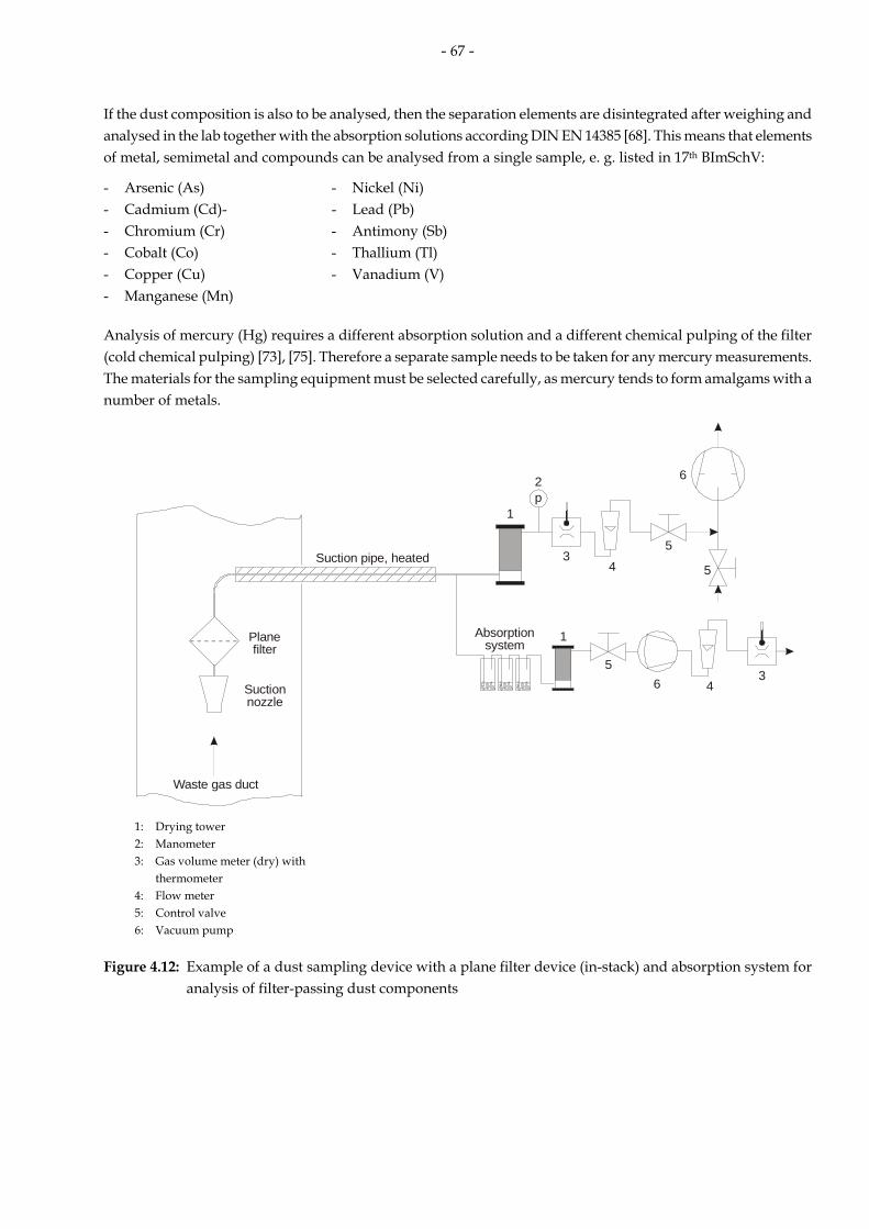
- 67 -
If the dust composition is also to be analysed, then the separation elements are disintegrated after weighing and analysed in the lab together with the absorption solutions according DIN EN 14385 [68]. This means that elements of metal, semimetal and compounds can be analysed from a single sample, e. g. listed in 17th BImSchV:
- Arsenic (As) - Nickel (Ni) - Cadmium (Cd)- - Lead (Pb) - Chromium (Cr) - Antimony (Sb) - Cobalt (Co) - Thallium (Tl) - Copper (Cu) - Vanadium (V) - Manganese (Mn)
Analysis of mercury (Hg) requires a different absorption solution and a different chemical pulping of the filter (cold chemical pulping) [73], [75]. Therefore a separate sample needs to be taken for any mercury measurements. The materials for the sampling equipment must be selected carefully, as mercury tends to form amalgams with a number of metals.
1
2
35
5
6
4
p
1
35
46
Suction pipe, heated
Planefilter
Suctionnozzle
Absorptionsystem
Waste gas duct
1: Drying tower 2: Manometer 3: Gas volume meter (dry) with thermometer 4: Flow meter 5: Control valve 6: Vacuum pump
Figure 4.12: Example of a dust sampling device with a plane filter device (in-stack) and absorption system for analysis of filter-passing dust components

- 68 -
4.2.2 Determination of the mass concentration of polychlorinated dibenzodioxins and polychlorinated dibenzofuranes (PCDD/PCDF)
Essentially, there are three different sampling methods (Fig. 4.13 to 4.15) for taking samples to determine PCDD/PCDF in accordance with DIN EN 1948-1 “Emissions from stationary sources – determination of mass concentration of PCDD/PCDF – Part 1: Sampling” [55].
a) filter/cooler method b) dilution method c) cooled suction pipe method
Samples are taken in the same way as for dust (see Section 4.2.1), by means of isokinetic extraction of the sample gas from the flow of waste gas. The PCDD/PCDF adsorbed on the particles or in gaseous form are collected and accumulated in the sampling device. The collection unit can be a combination of a filter, a condensate bulb and a solid or liquid adsorber, depending on the sampling system selected. The sampling equipment must be made of materials which do not interact with the sample gas (e. g. titanium, quartz, glass).
The main collection units are spiked with C13-marked PCDD/PCDF prior to the sampling in order to determine the sample recovery rate for the congeners. The sample gas must be cooled before entering the main collection unit (methods a and c: t < 20°C; method b: t < 40°C) in order to stabilise the measured object.
In order to isolate the separated PCDD/PCDF from the sampling device, it is extracted using a suitable solvent (e. g. toluene). The filter, adsorbers and, if required, parts of the sampling equipment, are normally isolated by means of Soxhlet extraction, while the condensate is isolated by means of liquid extraction. The extracts are normally cleaned using multi-column chromatography techniques.
The PCDD/PCDF is separated by means of gas chromatography (GC) or liquid chromatography (HPLC). High resolution mass spectrometry (HRMS) is used in conjunction with the isotope attenuation method for identification and quantification purposes.
Figure 4.13: PCDD/PCDF sampling using the filter/cooler method a (schematic)
Figure 4.14: PCDD/PCDF sampling using the dilution method b (schematic)
Figure 4.15: PCDD/PCDF sampling using the cooled suction pipe method c (schematic)

- 69 -
4.2.3 Manual methods to measure inorganic compounds
Accumulative sampling (absorption)
Inorganic gaseous chlorine and fluorine compounds, sulphur oxides (SO2 and SO3) and basic nitrogen compounds can be collected by means of accumulation in liquid phases (absorption).
Table 4.1: Absorption solutions for accumulating measured objects
Measured object Suitable absorption solution Guideline
inorganic gaseous chlorine compounds H2O or Na2CO3/NaHCO3 solution
DIN EN 1911-1 [109]
inorganic gaseous fluorine compounds H2O or NaOH solution or Na2CO3/NaHCO3 solution
VDI 2470, p. 1 [108]
sulphur oxides hydrogen peroxide solution iodine solution
VDI 2462, p. 8 [84] DIN EN 14791 [86] VDI 2462, p. 1 [82]
hydrogen sulphide sulphuric acid H2O2 solution cadmium acetate solution
VDI 3486, p. 1 [112] VDI 3486, p. 2 [113]
basic nitrogen compounds (e. g. NH3) 0.05 M sulphuric acid VDI 3496, p. 1 [114] The sample gas is extracted from the waste gas using a suction pipe. The suction pipe must be made of a material which does not interact with the sample gas (e. g. laboratory glass or quartz). Before the sample gas is passed through the absorption system, particulate components are extracted by means of a filter. Condensation effects before the absorption system are avoided by heating the filter and the path of the sample gas. For HCI sampling, it has been agreed that the temperature should be at least 150°C and should be around 20°C above the waste gas temperature.
The absorption system consists of at least two gas wash-bottles arranged in series. Muencke, fritted or impinger wash inserts can be used. Normally, a further (unfilled) wash-bottle is arranged behind the gas wash bottles to separate off the condensate. Fig. 4.16 shows an example sampling device. If there is a risk that the measured objects could occur in the flow of waste gas in aerosol form, then the sampling has to be isokinetic (see Section 2.3.3).
After sampling, the absorption solutions are analysed in the laboratory. If the degree of absorption of the measuring procedure is not known, then the absorption solutions from the wash-bottles that are arranged in series can be analysed separately. The absorption of the first wash-bottle should be at least 80 % of the total.
Depending on the measuring object, the following analysis methods can be used: - titration - potentiometric titration - photometric determination - analysis with ion-sensitive electrodes - ion chromatography

- 70 -
Fine particulatefilter, heated
Suction pipe, heated
Waste gas duct
1
35
46
Absorptionsystem
1: Drying tower3: Gas volume meter with thermometer4: Flow meter5: Control valve6: Vacuum pump
Probe
Figure 4.16: Device for sampling (inorganic) gaseous materials by means of absorption
Non-accumulative sampling (gas collection vessels)
Gas collection vessels are used for sampling for the manual measurement of nitrogen oxides [90]. The best vessels have proven to be glass gas collection containers with a volume of between 0.5 and 1.5 l and with PTFE taps and a screw connection to which a septum can be connected.
Sampling is performed according VDI 2456 over 30 minutes (Fig. 4.17) The gas collection vessel is evacuated and filled with sample gas via a capillary or a critical nozzle for the duration of the sampling time. The throughput through the capillary depends on the internal pressure in the gas collection vessel and can be considered almost linear up to a reduced pressure of nearly 500 hPa. Sampling times of up to 10 minutes can be achieved. The sample volume is calculated by means of the pressure and the temperature in the gas collection vessel at the beginning and end of the sampling time.
In both versions the sample gas is cleaned of particles by being passed through a fine particulate filter before being introduced into the sampling equipment.
Suction pipe, heatable
Gas collectionvessel
Fine particulatefilter
Stop valve
Bypasspump Vacuum
pump
Septum
Capillarytube
Waste gas duct
Heatablecasing
2-way-valve
Figure 4.17: Time-integrating sampling with gas collection vessel (schematic)

- 71 -
After sampling, the oxidation agent is introduced into the gas collection vessel. Once oxidation has taken place, the nitrogen dioxide is dissolved by shaking, and can then be analysed.
The analysis is photometric or ion-chromatographic.
4.2.4 Determination of individual organic components
Sampling for measurements of individual organic components is generally achieved by means of accumulation on appropriate collection phases. Appropriate collection phases are selected according to the following criteria:
- Retaining power for the measured object in question, - Desorption capacity/extractability of the measured object with solid collection phases, - Tendency towards chemical reactions with the measured object, - Influence of attendant materials (e. g. water vapour on solid collection phases) on the retaining power, - Chromatographic separability of the measured object, the solvent and any impurities, - Evaporation rate of the solvent at the sampling conditions.
Accumulation can have an effect on the detection limits for the measurement method. The following are examples of the materials used:
Liquid collection phases (absorbencies) in accordance with VDI 2457, part 1 [117] - Water or aqueous solutions, - Organic solvents, such as benzyl alcohol Decahydronaphtalin (Decalin), N,N-Dimethylformamide (DMF), Methyl diglycol, cooled to around 200 K, Methyl tertiary butyl ether (MTBE), 2-propanol, Toluene.
Solid collection phases (adsorbencies) - Activated carbon, - Silica gel, - Molecular sieves, - XAD.
Analysis generally takes the form of gas or ion chromatographic separation with appropriate detectors:
- Flame ionisation detector (FID), - Mass spectrometer (MS), - Electron capture detector (ECD), - Heat conductivity detector (WLD), - Conductivity detector (LFD).
If no suitable collection phases are available, the sampling method in gas collection vessels described in Chapter 4.2.3 can be used [121], (Fig. 4.17).
Sampling method 1 (flushing the gas collection vessel) should only be applied if it is impossible that the sample gas could accumulate on the glass wall by means of sorption.
The detection limits for measurements with non-accumulative samples are considerably higher than those using accumulative sampling because of the reduced sample volume.
Generally, analysis takes place directly out of the gas phase (analysis of components with a low boiling point) or after absorption of the measured objects in the gas collection vessel into a suitable solvent (components with a higher boiling point) after gas-chromatographic separation.

- 72 -
4.2.5 Olfactometric determination of odour emissions
For the purposes of emission measuring, odours are determined using an olfactometer [135]. Sample gas is extracted from the flow of waste gas using a sampling device and introduced into a sample bag (e. g. an aluminium-coated plastic bag or a disposable PE bag). During the measurement, the odour threshold is determined for the sample gas. The human sense of smell is used as an analyser. The tester (sniffer) receives a highly diluted form of the sample through the odour mask of the olfactometer. The dilution is reduced (normally by a factor of 2 or 1.4) until the tester perceives an odour. The mean value between the last dilution stage at which the tester perceived no odour and the dilution stage at which the tester was sure of recognizing an odour is agreed as the odour threshold.
The individual sense of smell of a tester is subjective and depends on a number of influencing factors. The measurement of a odour sample must therefore be undertaken by a number of testers (at least 4) and the tests must be repeated. The group of testers must fulfil specific requirements with respect to their individual odour thresholds. The individual odour thresholds of the testers are determined by measuring the odour of test gases (H2S and n-butanol). However, the personal odour threshold of any tester must be within a specific range (known as the odour window). Testers whose sense of smell is either too acute or too poor are not suitable.
As well as determining the odour threshold, odour measurements also involve determining the intensity of the odour [137] and the hedonic effect of the odour [138]. In order to determine the hedonic effect of the odour, the odour is marked on a scale between “extremely pleasant” and “extremely unpleasant”.
4.3 Measurement of reference values
4.3.1 Oxygen measurement (paramagnetic effect)
The paramagnetic properties of oxygen can be used to measure oxygen levels. Oxygen is characterised by high magnetic susceptibility (magnetisability). In uneven magnetic fields, oxygen atoms are drawn towards areas with higher field strength. Oxygen measuring devices use this effect in two ways.
Paramagnetic alternating pressure The sample gas is passed through a measuring chamber. A reference gas (e. g. N2) passes through two channels into the measurement chamber. An uneven magnetic field is generated near one of the inlet openings, which has the effect that the partial pressure in this area increases as a function of the oxygen content in the sample gas. The flow resistance for the reference gas in the measuring chamber also increases. The detection is based either directly on the resulting difference in pressure between the two reference gas channels (membrane condenser) or on the resulting compensating flow in a connecting channel between the channels of reference gas (micro-flow detector).

- 73 -
Figure 4.18: Oxygen measurement using ‘Siemens’ system based on paramagnetic alternating pressure (schematic)
Magnetic torsion balance A nitrogen-filled glass dumb-bell is suspended in a measuring chamber with an uneven magnetic field such that it can rotate (Fig. 4.19). The glass dumb-bell is diamagnetic, i. e. the ends extend out from the inside of the magnetic field. The resulting torque is compensated by a current flow through a coil on the dumb-bell until the dumb-bell reaches its zero position. If the percentage of oxygen by volume in the measuring chamber changes, the oxygen’s paramagnetic properties mean that it is drawn to the area with the greatest magnetic field strength between the magnetic poles, which displaces the dumb-bell and causes it to rotate. An optical system compensates the dumb-bell’s position by adjusting the flow of current through the dumb-bell coil until it reverts to its zero position. The electrical current required is proportional to the percentage oxygen by volume and can be measured accordingly.

- 74 -
Amplifier
Display
Samplegas
1: Measuring cell 4: Reflector mirror 2: Glass body (dumb-bell) 5: Light source 3: Electric coil 6: Detector
Figure 4.19: Oxygen measurement using Maihak’s system based on a magnetic torsion balance (schematic)
4.3.2 Oxygen measurement (zirconium dioxide probe)
A property of zirconium dioxide can be used for the measurement of oxygen. At a high temperature, this material becomes an electrical conductor because of the increasing mobility of the oxygen ions in the molecular lattice. If two sides of a zirconium dioxide probe (Fig. 4.20) are impinged with different oxygen concentrations, the cell voltage at constant temperature can be calculated using the following equation:
C+ppln*
F*4TR*=EMK
1
2 Eq. 4.7
EMK: cell voltage p1: partial oxygen pressure on one side of the cell (e. g. smoke gas side) p2: partial oxygen pressure on the other side of the cell (reference gas, e. g. ambient air) R: gas constant F: Faraday’s constant T: absolute temperature in K C cell constant
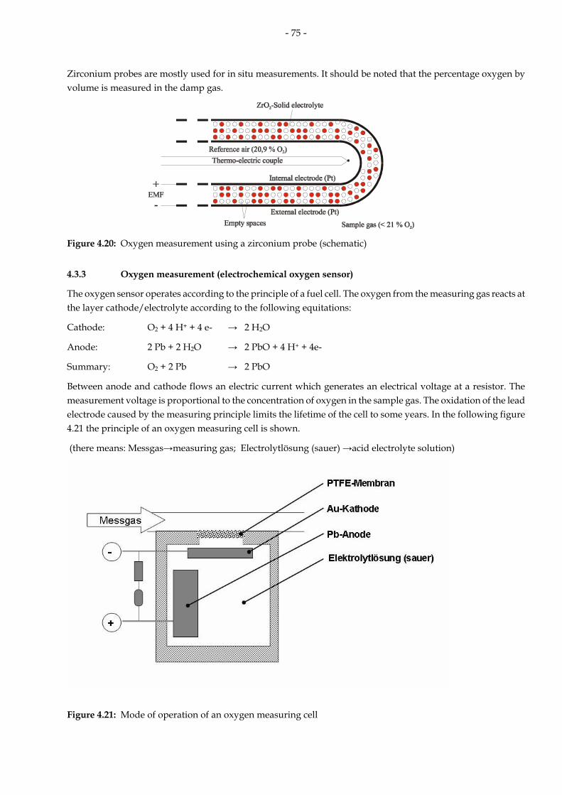
- 75 -
Zirconium probes are mostly used for in situ measurements. It should be noted that the percentage oxygen by volume is measured in the damp gas.
Figure 4.20: Oxygen measurement using a zirconium probe (schematic)
4.3.3 Oxygen measurement (electrochemical oxygen sensor)
The oxygen sensor operates according to the principle of a fuel cell. The oxygen from the measuring gas reacts at the layer cathode/electrolyte according to the following equitations:
Cathode: O2 + 4 H+ + 4 e- → 2 H2O
Anode: 2 Pb + 2 H2O → 2 PbO + 4 H+ + 4e-
Summary: O2 + 2 Pb → 2 PbO
Between anode and cathode flows an electric current which generates an electrical voltage at a resistor. The measurement voltage is proportional to the concentration of oxygen in the sample gas. The oxidation of the lead electrode caused by the measuring principle limits the lifetime of the cell to some years. In the following figure 4.21 the principle of an oxygen measuring cell is shown.
(there means: Messgas→measuring gas; Electrolytlösung (sauer) →acid electrolyte solution)
Figure 4.21: Mode of operation of an oxygen measuring cell

- 76 -
4.3.4 Determination of waste gas humidity
For calculations in association with emission measurements, the humidity content fn is normally used. This expresses the mass of the water vapour relative to the volume of the dry gas under standard conditions. There are several different methods of determining the humidity content:
Psychrometric humidity determination (two-thermometer method)
The waste gas temperature is measured once directly (dry thermometer) and once with a thermometer surrounded in fabric soaked in water (e. g. cotton, wet thermometer). If the water around the wet thermometer is evaporated as far as the saturation point, the temperature is below that of the dry thermometer. Sprung’s formula can then be used to calculate the humidity content fn on the basis of these two temperatures and other waste gas parameters [145]:
)t-t( *K - (p - p)t-t(K - p
* ρ = fftrf0
ftrtrOHn 2
Eq. 4.8
with
r* ρc * p
=K OH
p0
2
Eq. 4.9
fn: humidity content [g/m³] ρH2O: standard density of water vapour [g/m³] ttr: temperature of dry thermometer [°C] tf: temperature of wet thermometer [°C] p0: absolute pressure in psychrometer [hPa] ptr: saturation vapour pressure at ttr [hPa] pf: saturation vapour pressure at tf [hPa] K: Sprung’s constant cP: specific heat capacity of the gas [kJ/(kg*K)] r: evaporation enthalpy of water [kJ/kg]
In conventional psychrometers, both thermometers are housed in a single casing. The waste gas is introduced into the device via hoses and extracted using a pump. For psychrometric humidity determination, it must be guaranteed that no condensation can be formed either before or on the dry thermometer. This is generally the case if the waste gas temperature is sufficiently above the water dew-point in the waste gas.
Sorption in blue gel or magnesium perchlorate followed by gravimetry
A defined volume of gas is drawn through a cartridge filled with a dried sorption agent. The sorption agent used is blue gel or magnesium perchlorate (Mg(ClO4)2). The cartridge is weighed before and after impinging. The humidity content fn is calculated on the basis of the standardized gas volume and the differential mass of the cartridge.
Other options for determining humidity are as follows: - Using electrical sensors: - Calculating humidity on the basis of oxygen measurements in the dried and non-dried waste gas - Dew-point measurement (heated mirror)
4.3.5 Flow velocity/waste gas volumetric flow
For continuous emission monitoring, normally only the mass concentration of the relevant pollutants is measured. However, the overall emission level has to be determined for many installations.
The appropriate scale for continuous monitoring is mass flow of pollutants, which can be calculated as the

- 77 -
product of pollutant mass concentration and waste gas volume flow [146]. The waste gas volume flow can often be calculated precisely enough on the basis of known plant parameters, such as fuel consumption or steam generating capacity. If the plant’s operating parameters fluctuate, the waste gas volume flow needs to be determined directly. A direct manual flow speed measurement is an integral part of any discontinuous emission measurement.
If the cross-section and flow profile of the waste gas flow are known, the volume flow can be determined on the basis of the flow speed. The methods of determining volume flow used in emission measurements are based on flow speed measurements taken in the flow cross-section of a waste gas duct.
Pressure tubes [146]
Pressure tubes are often used for manual flow speed measurements. The most common type of pressure tube is the Prandtl tube (also known as an L-Pitót tube, see Fig. 4.22). The hook-shaped probe is set up against the direction of flow in the waste gas flow. The overall pressure in the flow is recorded through a hole in the middle of the semicircular or elliptical probe tip. The static pressure is recorded at an annular slot (or alternatively, at radial holes) behind the probe tip. The pressures are measured using differential pressure manometers. (e. g. U-tube manometer, inclined tube manometer for improved resolution or electronic micro-manometer).
Waste gas duct
Figure 4.22: Flow speed measurement using the Prandtl tube (schematic)

- 78 -
The dynamic pressure pdyn is a measure for the flow speed at the measuring point and is given by the difference between the total pressure pges and the static pressure pstat.
p - p = p - p = p statgesstatgesdyn ∆∆ Eq. 4.10
The flow speed (up to 100 m/s) is then given by:
ρp * 2
*k = w dyn Eq. 4.11
where w: gas velocity [m/s] k: factor taking into consideration the geometry of the pressure tube (Prandtl tube: k = 1) pdyn: dynamic pressure at Prandtl tube [Pa] ρ: gas density in operating condition [kg/m³]
The pressure tube measurement is direction-dependent. Deviations between the axis of the pressure tube and the direction of flow of less than 10 % have virtually no impact on the measurement results. Continuous measurements can be affected by contamination of the probe holes.
Adaptations of the Prandtl tube, such as multiple hole probes or pressure screens, are used for continuous measurements. These devices have a number of openings distributed across the cross-section of the channel which are pointed against the direction of flow. This enables a measurement of the total pressure across the whole measurement axis.
Flow balance
Fig. 4.23 shows the working principle of a flow balance. The force exerted on a flow body by the flow of waste gas is diverted and measured using a wire strain gauge, for example.
Ultrasound flow measurement
The ultrasound flow measurement is based on a Doppler measurement with ultrasound. Short ultrasound impulses are emitted from both ends of a measurement axis at 45° to the direction of flow and received by the other end in each case. The impulses transmitted in the direction of flow have a shorter time delay than the impulses transmitted against the direction of flow. The differential lifespan is a measure for the flow rate (see fig. 4.24)
Figure 4.23: Flow balance Figure 4.24: Flow measurement using ultrasound

- 79 -
Anemometer
Propeller anemometers are used for manual flow speed measurement. The measurement probe is held in the flow of waste gas. The flow of waste gas drives an impeller wheel, the speed of which is recorded on a no-contact basis (e. g. inductively). At a constant density of waste gas, the waste gas speed is proportional to the speed of the wheel. Propeller anemometers are sensitive to pollution and humidity (condensation). Their use is also limited by a maximum operating temperature, which is specific to the design of the individual device.
4.3.6 Temperature measurement
The measurement of temperature involves observing the properties of solid, liquid or gaseous materials which change predictably as a function of temperature. The changes can relate to, for example, the volume, length, electrical properties (resistance) or optical characteristics of the materials observed.
Expansion thermometer
These devices are based on the thermal expansion of liquids or solids. In liquid expansion thermometers, the liquid (e. g. mercury, alcohol) is held within a capillary tube on which a scale is marked. Bimetal thermometers utilise the different temperature expansion coefficients of two different materials joined together.
Platinum resistance thermometer (DIN EN 60751)
The resistance in a platinum conductor is measured in order to determine temperature. The resistance increases with temperature. The change in resistance is not proportional to the change in temperature. The display instruments used therefore have an integrated linearization system. By using thermo-sensors with 3 or 4 wires the resistance in the connection cables can be compensated.
Pt 100 resistance thermometers are often used. These devices have resistance of 100 Ω at t = 0°C and can be used for temperatures ranging from –200 °C to 850 °C. The sensor is normally encased in a ceramic body within a stainless steel pipe for extra protection.
Thermo-electric couples (DIN IEC 584):
Temperature measurement using thermo-electric couples is based on the thermo-electric effect (Seebeck effect). In a conductive circuit with two different metals, there is a potential difference between the two contact points for the two metals if they have different temperatures.
The following are the most common pairs of metals used: - NiCr/NiAl: K type thermo-electric couple -270 to +1,372 °C, - NiCrSi/NiSi: N type thermo-electric couple -270 to +1,300 °C, - Fe/Constantan J type thermo-electric couple -210 to +1,200 °C, - Cu/Constantan T type thermo-electric couple -270 to +400 °C, - PtRh 13/Pt R type thermo-electric couple -50 to +1,768 °C.
The thermo-electric voltage is in the region of 10 to 50 µV/K temperature difference between the reference and the actual measuring point. The voltages are amplified and linearised by means of measuring transducers. As the measurement result is dependent on the temperature of the reference measuring point, this is either thermostat-controlled or the measurement discrepancy is compensated electrically. The sensor is normally encased in a ceramic body within a stainless steel pipe for extra protection.
As thermo-electric voltages can also be generated by extending the thermo-element connection cables, the connections cables may need to be extended by means of compensation cables specially adapted for the thermo-electric couple used.

- 80 -
Radiation thermometer (radiation pyrometer)
Materials above absolute zero emit electromagnetic radiation, the intensity and wavelength distribution of which is primarily dependent on temperature. Hot gases emit in characteristic emission bands.
Radiation pyrometers are a no-contact method of measuring the intensity of these bands in a limited spectral range. Therefore, they are particularly useful for the continuous measurement of very high temperatures (e. g. process monitoring, monitoring combustion chamber temperature, etc.).
The spectral range measured using a radiation pyrometer must be tailored to the measurement task with respect to emission coefficient, gas composition and temperature range.
Suction pyrometer
For spot sampling of temperature in the reheating zone (as after initial operation or significant alteration required for plants in accordance with the 17th BImSchV, for example), only the convective part of the heat is of interest, while the radiation heat must not be taken into consideration. Suction pyrometers are used for this sort of measurement.
The thermo-electric couple is positioned towards the front of the suction probe and is protected from the IR radiation from the combustion chamber by a ceramic body. Hot waste gas is extracted with sufficiently high suction speed through the ceramic body and the thermo-electric couple and its temperature is measured by the thermo-electric couple. The suction probes are normally dual-walled and able to be cooled. The extracted, cooled gas can be used to measure the percentage oxygen by volume in the reheating zone (see fig. 4.25).
Omeasurement
2 t H O2
H O2
Coolable probe
Ceramicbody
Thermo-electriccouple
Figure 4.25: Schematic diagram of a suction pyrometer with downstream oxygen measurement.
4.4 Long-term sampling for PCDD/PCDF
Systems for long-term sampling have been developed to automate the sampling of emissions for polychlorinated dibenzodioxins and polychlorinated dibenzofuranes, which can be very time and resource-intensive. The aim is that automated sampling should enable quasi-continuous, uninterrupted monitoring of the emissions of these waste gas components. It is not as sometimes is assumed a continuous emission monitoring system for dioxins and furans.
Sampling is based on the standard DIN EN 1948-1 “Emissions from stationary sources – determination of mass concentration of PCDD/PCDF - Part 1: Sampling” [55]. Sampling must be isokinetic. The speed of the waste gas is continuously recorded and the resulting partial volume flow to be extracted is calculated and set. The gas volume extracted is dried and measured. There is a number of different collection and accumulation devices available (see Section 4.2.2). The collection and accumulation media can be automated to be changed at adjustable time intervals. The accumulation times can be programmed anywhere between a few hours and several weeks. After sampling, the collection and accumulation media are stored in the sampling system until they are transferred to the analysis laboratory. The samples are then analysed in the laboratory in the same way as samples extracted manually.

- 81 -
5 Glossary
Term Source
Definition
accreditation: formal recognition of the competence of a body (e. g. a testing laboratory) to carry out certain functions (e. g. tests) [DIN EN ISO/IEC 17025]; accreditation is awarded by a recognised accreditation body once certain requirements have been fulfilled
AMS, automatic measuring system DIN EN 14181 [38]
measuring system permanently installed on site for continuous monitoring of emissions
Note: An AMS is an method which is traceable to a reference method.
peripheral AMS or SRM DIN EN 14181 [38]
measuring system or SRM used to gather the data required to convert the measured values to standard reference conditions, i. e. AMS or SRM for moisture, temperature, pressure and oxygen
reference quantity DIN EN 15259 [33]
specified physical or chemical quantity which is needed for conversion of the measurand to standard conditions Note: Reference quantities are e. g. temperature (Tref = 273,15 K), pressure (pref = 101,325 kPa), water vapour volume fraction (href = 0 %) and oxygen volume fraction Oref.
declaration of suitability VDI 4203-1 [28]
administrative act for confirming the suitability of the measuring system for monitoring tasks in the area controlled by law
Note: The declaration is made by publication in the German „Bundesanzeiger“.
performance testing VDI 4203-1 [28]
experimental demonstration that the measurement and analytical equipment used for monitoring emission and air pollution complies with the minimum requirements established in regulations for the intended application, taking into account the appropriate test design
electronic data evaluation system VDI 3950 [37]
system which serves for electronic recording, storage and further processing of dates
emission limit value according DIN EN 14181 [38]
limit value related to the uncertainty requirement
Note: For EU Directives for incineration of waste and large combustion plants it is the daily emission limit value that relates to the uncertainty requirement.
emission limit values e. g. according 17th BImSchV [9]
are the mass concentrations of air pollutants present in the flue gas defined as fixed emission limits which must not be exceeded in the respective assessment period

- 82 -
Term Source
Definition
extractive AMS DIN EN 14181 [38]
AMS having the detection unit physically separated from the gas stream by means of a sampling system (the definition can be used in the same sense for an extractive manual sampling)
functional check
VDI 4203-2 [29]
establishment, at regularly recurring intervals performed by test laboratories prescribed for this purpose, of the correct working order of measurement and evaluation systems used for monitoring emissions
calibration function DIN EN 14181 [38]
linear relationship between the values of the SRM and the AMS with the assumption of a constant residual standard deviation
calibration VDI 4203-2 [29]
determination of an analytical function with (time) limited validity applicable to a measuring system at a specific measurement site; the analytical function is defined as a statistical relationship between the output quantity (measured signal) of the measuring system and the associated measurement result (measured value) simultaneously determined at the same point of measurement using a standard reference method
measurement line DIN EN 15259 [33]
line in the sampling plane along which the sampling points are located, bounded by the inner duct wall Note: Measurement line is also known as sampling line.
measurement objective DIN EN 15259 [33]
scope of the measurement programme agreed with a customer
measuring system VDI 4203-1 [28]
totality of all measuring instruments and additional devices for achieving a result of measurement
Note: The measuring system includes, apart from the actual measuring instrument (analyser), sampling devices (for example probe, sample gas lines, flow metering and control, feed pump), sample preparation (for example dust filters, preliminary separators for interfering components, coolers, converters) and data output. Furthermore, test and adjustment equipment which are required for the functional test and, if appropriate, for start-up (see VDI 3950), as well as the test report on suitability test in case of suitability-tested measuring systems are also included.
result of measurement VDI 4203-1 [28]
estimated value, produced from measurements, for the true value of a measurand
measurand DIN EN 15259 [33]
particular quantity subject to measurement Note: The measurand is a quantifiable property of the waste gas under test, for example concentration of a measured component, temperature, velocity, mass flow, oxygen content and humidity.
measured item RdSchr. BMU 2005 [19]
carrier of measured quantity (DIN 1319-1) (also designated as measured object)

- 83 -
Term Source
Definition
measurement port DIN EN 15259 [33]
opening in the waste gas channel along the measurement line, through which access to the waste gas can be gained
Note: Measurement port is also known as sampling port or access port.
planning DIN EN 15259 [33]
systematic rational action in order to develop a structured procedure to fulfil a defined objective best
measurement site DIN EN 15259 [33]
place on the waste gas channel in the area of the measurement plane consisting of structures and technical equipment, for example working platforms, measurement ports, energy supply
measurement point DIN EN 15259 [33]
position in the measurement plane at which the sample stream is taken off or the measurement data are obtained directly Note: Measurement point is also known as sampling point.
measurement plane DIN EN 15259 [33]
plane normal to the centreline of the duct at the sampling position Note: Measurement plane is also known as sampling plane.
testing laboratory DIN EN 15259 [33]
general: laboratory that performs tests
(in Germany e. g. notified by a competent authority of the Länder for carrying out measurements according to § 26 and § 28 BImSchG)
measurement section DIN EN 15259 [33]
region of the waste gas channel which includes the measurement plane and the inlet and outlet sections
measurement DIN EN 15259 [33]
set of operations having the object of determining a value of a quantity
uncertainty DIN EN 14181 [38]
parameter associated with the result of a measurement that characterises the dispersion of the values that could reasonably be attributed to the measurand
measured value DIN EN 14181 [38]
estimated value of the air quality characteristic derived from an output signal; this usually involves calculations related to the calibration process and conversion to required quantities
minimum requirements VDI 4203-1[28]
technical characteristic data and formal requirements specified in regulations for measuring and evaluation systems used for monitoring emissions
non extractive AMS: (In-situ) DIN EN 14181 [38]
AMS having the detection unit in the gas stream or in a part of it
standard conditions DIN EN 14181 [38]
conditions as given in the EU-directives to which measured values have to be standardized to verify compliance with the emission limit values
notification formal act of announcement by a government body (cf. § 26 of BImSchG)

- 84 -
Term Source
Definition
recording system VDI 3950 [37]
system which serves for collection and recording of raw measured signals
standard deviation DIN EN 14181 [38]
positive square root of: the mean squared deviation from the arithmetic mean divided by the number of degrees of freedom
standard reference method SRM DIN EN 14181 [38]
method described and standardized to define an air quality characteristic, temporarily installed on site for verification processes
validated mean (status, mean, class) RdSchr. BMU 2005 [19]
value calculated from the standardized mean by deducting the standard deviation of the standardized values determined during calibration (standard uncertainty) according to DIN EN 14181 (issue of September 2004).
A status characteristic of the operating state of the plant and the operating state of the measuring instrument and the classification status, time reference and the parameter of the operating mode forms part of each validated mean.
variability DIN EN 14181 [38]
standard deviation of the differences of parallel measurements between SRM and AMS
period of unattended operation DIN EN 14181 [38]
maximum admissible interval of time for which the performance characteristics will remain within a predefined range without external servicing, e. g. refill, calibration, adjustment

- 85 -
6 References
Statutory regulations /EU directives /LAI publications
[1] Law on the Prevention of Harmful Effects on the Environment Caused by Air Pollution, Noise, Vibration and Similar Phenomena (Bundes-Immissionsschutzgesetz [Federal Immissions Control Act] - BImSchG) of 26 September 2002, last amended on 01 November 2005 (BGBl. I, p. 1865)
[2] Ordinance on pollution control and waste legislation related relief in monitoring for sites and organisations registered according to Directive (EC) No. 761/2001, BGBl. I 2002, p. 2247 (EMAS privilege ordinance – EMASPrivilegV); Part of the ordinances for the release and modification of pollution control and waste legislation related ordinances of 24 June 2002, BGBl. I (2002) p. 2247; as last amended on 21 June 2005, BGBl. I (2005) p. 1686
[3] First general administrative regulation pertaining to the federal immission control act – TI Air of 24 July 2002 (GMBl. p. 511) (Technische Anleitung zur Reinhaltung der Luft/TA Luft)
[4] First ordinance for the enforcement of the federal immission control act (ordinance on small and medium furnaces – 1st BImSchV) of 14 March 1997 (BGBl. I p. 490) last amended on 14 August 2003 (BGBl. I p. 1614, 1631)
[5] Second ordinance for the enforcement of the federal immission control act (ordinance on limiting emissions of highly volatile halogen hydrocarbons – 2nd BImSchV) of 10 December 1990 (BGBl. I p. 2694), amended on 23 December 2004 (BGBl. I, p. 3758)
[6] Third ordinance for the enforcement of the federal immission control act (ordinance on the sulphur content of light fuel oil and diesel fuel – 3rd BImSchV) of 24 June 2002 (BGBl. I p. 2243)
[7] Fourth ordinance for the enforcement of the federal immission control act (ordinance on installations subject to licensing – 4th BImSchV) of 14 March 1997 (BGBl. I p. 504), last amended on 15 July 2006 (BGBl. I, p. 1619)
[8] Thirteenth ordinance for the enforcement of the federal immission control act (ordinance on large furnaces and gas turbines– 13th BImSchV) of 20 July 2004 (BGBl. I p. 1717)
[9] Seventeenth ordinance for the enforcement of the federal immission control act (ordinance on incineration and co-incineration of waste – 17th BImSchV) as published on 14 August 2003 (BGBl. I p. 1633)
[10] Twenty-fifth ordinance for the enforcement of the federal immission control act (ordinance on limiting emissions from the titanium dioxide industry – 25th BImSchV) of 8 November 1996 (BGBl. I p. 1722)
[11] Twenty-seventh ordinance for the enforcement of the federal immission control act (ordinance on crematoria – 27th BImSchV) of 19 March 1990 (BGBl. I, p. 545), amended on 3 May 2000 (BGBl. I, p. 632)
[12] Thirtieth ordinance on the implementation of the Federal Immission Control Act (ordinance on biological waste conditioning installations – 30th BImSchV) of 20 February 2001 (BGBl. I p. 317)
[13] Thirty first ordinance on the implementation of the Federal Immission Control Act (ordinance on limitation of volatile organic compound emissions caused by the use of organic solvents in specific installations – 31st BImSchV) of 21 August 2001 (BGBl. I p. 2180)
[14] Council of the European Community: Council directive of 28 June 1984 on the combating of air pollution from industrial plants (84/360/EEC)
[15] Council of the European Community: Council directive 96/61 EC of 24 September 1996 concerning integrated pollution prevention and control

- 86 -
(IPPC directive)
[16] Directive 2001/80/EC of the European Parliament and of the council of 23 October 2001 on the limitation of emissions of certain pollutants into the air from large combustion plants
[17] Directive 2000/76/EC of the European Parliament and of the council of 4 December 2000 on the incineration of waste
[18] Council of the European Community: Council directive of 11 March 1999 on the limitation of emissions of volatile organic compounds due to the use of organic solvents in certain activities and installations (1999/13/EC)
[19] Circular of the Federal Environment Ministry of 13 June 2005 – IG I 2 – 45053/5 – (GMBl. 2005, p. 795-828): [Bundeseinheitliche Praxis bei der Überwachung der Emissionen], Uniform practice in monitoring emissions in the Federal Republic of Germany, guidelines on: - suitability testing of measuring and evaluation systems for continuous emission measurements, and
the continuous acquisition of reference or operational values and for continuous monitoring of special substances
- installation, calibration and maintenance of continuous measuring and evaluation systems - evaluation of continuous emission measurements,
[20] Circular of the Federal Environment Ministry of 01/09/94 – IG I 3 – 51 134/3 – (GMBl. 1994, p. 1231): Uniform practice on the monitoring of combustion conditions in waste incineration installations in accordance with the seventeenth ordinance for the enforcement of the federal immission control act in the Federal Republic of Germany
[21] Annex to the administrative regulation from the environment ministry on the determination of emissions and immissions of air pollutants, noise and vibration and the inspection of technical equipment and devices] of 15/03/1993 – Az: 43-8820.50 gen./199- (GABl. 28 June 1993, p. 734 ff.) „Standard German emissions measurement report“ last amended on 05 March 2007 (published from different federal states on their internet pages)
[22] Specialist notes on: Uniform practice in monitoring combustion conditions for waste incineration plants in accordance with the 17th BImSchV in the Federal Republic of Germany, part of a series published by the LAI, Volume 7, Erich Schmidt Verlag, Berlin 1994
[23] Guidelines on the announcement and accreditation of specialist laboratories in the field of immission control], arising from the LAI decision of 02 October 2003, published by the federal states of Germany, e. g. published from Nordrhein-Westfalen by the „Ministerium für Umwelt und Naturschutz, Landwirtschaft und Verbraucherschutz „–V-3 – 8817.4.2/8843.2 (V no. 5/ 2003) on 21 October 2003; MBL NRW p. 1611
[24] „Manual on Immission protection: proof of knowledge for investigations in the field of immission control in the version of the decision of the 106th LAI-meeting from 30 September till 02 October 2003; published by the federal states of Germany
[25] Series published by the LAI, Volume 15: Remote emission monitoring/definition of interfaces, Erich-Schmidt-Verlag, Berlin, 1997
[26] Odour immissions directive (GIRL), in the version of 21 September 2004 published by several federal states of Germany
Standards and guidelines
[27] DIN EN ISO/IEC 17025 General requirements for the competence of testing and calibration August 2005 laboratories

- 87 -
[28] Guideline VDI 4203: Testing of automated measuring systems – General concepts Part 1, Oct. 2001
[29] Guideline VDI 4203 : Testing of automated measuring systems – Test procedures for measuring Part 2, March 2003 systems of gaseous and particulate emissions
[30] Guideline VDI 4220: Quality assurance – Requirements for emission and immission testing September 1999 laboratories for the determination of air pollutants
[31] Guideline VDI 2448: Planning of spot sampling measurements of stationary source emissions Part 1, April 1992
[32] Guideline VDI 2448: Statistical evaluation of random-sample measurements of stationary source Part 2, July 1997 emissions: Determination of the upper confidence limit
[33] pr EN 15259 Air quality - Measurement of stationary source emissions - Measurement August 2005 strategy, measurement planning, reporting and design of measurement sites
[34] Guideline VDI 4200: Realization of stationary source emission measurements December 2000
[35] Guideline VDI 4285: Determination of diffusive emissions by measurement - Basic concepts Part 1, June 2005
[36] Guideline VDI 4285: Determination of diffusive emissions by measurements - Part 2, Sept. 2006 Industrial halls and livestock farming
[37] Guideline VDI 3950 Stationary source emissions –Quality assurance of automated measuring and December 2006 electronic evaluation systems
[38] DIN EN 14181 Stationary source emissions – Quality assurance of automated measuring September 2004 systems
[39] Guideline VDI 3950: Calibration of automatic emission measuring instruments Part 1 [July 1994] withdrawn
[40] Guideline VDI 3950: Calibration of automatic emission measuring instruments – reporting Part 2 April 2002 withdrawn
[41] Guideline VDI 3950 Calibration of automatic emission measuring instruments- Correct installation Part 3, June 2003 withdrawn
[42] ISO 12039 Stationary source emissions -- Determination of carbon monoxide, carbon 2001 dioxide and oxygen - Performance characteristics and calibration of automated measuring systems
[43] ISO 10396 Stationary source emissions -- Sampling for the automated determination of 1993 gas concentrations
[44] ISO 10780 Stationary source emissions -- Measurement of velocity and volume flow rate 1994 of gas streams in ducts
[45] ISO 14164 Stationary source emissions -- Determination of the volume flow rate of gas 1999 streams in ducts -- Automated method
[46] ISO 9096 Stationary source emissions -- Manual determination of mass concentration of 2003 particulate matter
[47] ISO 10155 Stationary source emissions -- Automated monitoring of mass concentrations 1995, cor. 2002 of particles -- Performance characteristics, test methods and specifications

- 88 -
[48] Guideline VDI 4219 Determination of uncertainty of emission measurements by discontinuous Draft Oct. 2005 methods of measurement
[49] Guideline VDI 2066: Measurement of particulate matter – Manual dust measurements in flowing Part 1 November 2005 gases; Gravimetric determination of dust load
[50] Guideline VDI 2066: Measurement of particulate matter – Dust measurement in flowing gases; Part 5, November 1994 particle size selective measurement by impaction method – Cascade impactor
[51] Guideline VDI 2066: Measurement of particulate matter – Dust measurement in flowing gases – September 1995 Measurement of smoke number in furnaces designed for EL type fuel oil
[52] DIN EN 13284-1: Stationary source emissions – Determination of low range mass April 2002 concentration of dust – Part 1: manual gravimetric method
[53] DIN EN 13284-2: Stationary source emissions – Determination of low concentration of dust – December 2004 Part 2: automatic measuring systems
[54] DIN 51402 part 1: Analysis of waste gas from oil furnaces - Visual and photometric inspection (draft) [October 1986] of waste gases from oil furnaces - Determination of smoke number]
[55] DIN EN 1948-1: Stationary source emissions – Determination of the mass concentration of June 2006 PCDDs/PCDFs and dioxin-like PCBs– Part 1: sampling
[56] DIN EN 1948-2 Stationary source emissions – determination of the mass concentration of June 2006 PCDDs/PCDFs and dioxin-like PCBs– Part 2: extraction and clean-up
[57] DIN EN 1948-3 Stationary source emissions – Determination of the mass concentration of June 2006 PCDDs/PCDFs and dioxin-like PCBs– Part 3: identification and quantification
[58] Guideline VDI 3499 Emission measurement - Determination of polychlorinated dibenzo-p-dioxins Part 1, July 2003 (PCDDs) and dibenzofurans (PCDFs) - Dilution method; Example of application of DIN EN 1948 for the concentration range 0,1 ng I-TEQ/m3
[59] Guideline VDI 3499 Emission measurement - Determination of polychlorinated dibenzo-p-dioxins Part 2, July 2003 (PCDDs) and dibenzofurans (PCDFs) - Filter/condenser method; Example of application of DIN EN 1948 for the concentration range 0,1 ng I-TEQ/m3
[60] Guideline VDI 3499 Emission measurement - Determination of polychlorinated dibenzo-p-dioxins Part 3, July 2003 (PCDDs) and dibenzofurans (PCDFs) - Cooled probe method; Example of application of DIN EN 1948 for the concentration range 0,1 ng I-TEQ/m3
[61] Guideline VDI 3873 Emission measurement – Determination of polycyclic aromatic hydrocarbons Part 1, Nov. 1992 (PAH) at stationary industrial plants – Dilution method (RWTÜV-method) gaschromatographic method
[62] Guideline VDI 3872 Emission measurement; Measurement of polycyclic aromatic hydrocarbons Part 1, May 1989 (PAH); measurement of PAH in the exhaust gas from gasoline and diesel; engines of passenger cars; Gas chromatographic determination
[63] Guideline VDI 3872 Emission measurement - Measurement of polycyclic aromatic hydrocarbons Part 2, December 1995 (PAHs) - Measurement of PAHs in the diluted exhaust gas from gasoline and diesel engines of passenger cars gas chromatographic determination - Dilution tunnel method
[64] Guideline 3874 Emission measurement – determination of polycyclic aromatic hydrocarbons Draft, August 2005 (PAH) –GC/MS method

- 89 -
[65] ISO 11338-1 Stationary source emissions -- Determination of gas and particle-phase 2003 polycyclic aromatic hydrocarbons -- Part 1: Sampling
[66] Guideline VDI 3493 Gaseous emission measurement – Determination of vinylchloride; Part 1, November 1992 Gaschromatographic method – sampling with gas collection vessels
[67] Guideline VDI 3868: Determination of total emission of metals, semimetals and their compounds Part 1 [December 1994] – Manual measurement in flowing gases – Sampling system for particulate and filter-passing matter
[68] DIN EN 14385 Stationary source emissions – Determination of the total emission of As, May 2004 Cd, Cr, Co, Cu, Mn, Ni, Pb, Sb, Tl and V
[69] Guideline VDI 2268 Chemical analysis of particulate matter – Determination of Ba, Be, Cd, Co, Cr, Part 1, April 1987 Cu, Ni, Pb, Sr, V, Zn in particulate emissions by atomic spectrometric methods
[70] Guideline VDI 2268 Chemical analysis of particulate matter – Determination of arsenic, Part 2, Feb. 1990 antimony and selenium in particulate emissions by atomic absorption spectrometry after seperation of their volatile hydrides
[71] Guideline VDI 2268 Chemical analysis of particulate matter – Determination of thallium in Part 3, Dec. 1988 particulate emissions by atomic absorption spectrometry
[72] Guideline VDI 2268 Chemical analysis of particulate matter – Determination of arsenic, Part 4, May 1990 antimony and selenium in particulate emissions by graphite furnace atomic absorption spectrometry
[73] DIN EN 13211: Manual method of determination of the concentration of total mercury (with June 2001 an additional amendment in June 2006)
[74] DIN EN 14884 Air quality - Stationary source emissions – Determination of the March 2006 concentration of total mercury – Automatic measuring systems
[75] DIN EN 1483 Water quality– Determination of mercury August 1997
[76] Guideline VDI 3861 Emission measurement – Manual determination of asbestos particles Part 1, Dec. 1998 particles in flowing clean exhaust gas – IR-spectrographic determination of asbestos mass concentration
[77] Guideline VDI 3861 Emission measurement – Determination of inorganic fibrous particles in Part 2D, June 2006 flowing clean exhaust gas – Scanning electron microscopy method
[78] ISO 10397 Stationary source emissions -- Determination of asbestos plant emissions -- 1993 Method by fibre count measurement
[79] Guideline VDI 2460: Measurement of gaseous emissions – Infrared spectrometric determination of Part 1 [July 1996] organic compounds – General principles
[80] Guideline VDI 2460 Gaseous emission measurement – Determination of dimethylformamide by Part 2, July 1974 means of infrared spectrometry
[81] Guideline VDI 2460 Gaseous emission measurement – Determination of cresol by means of Part 3, June 1981 infrared spectrometry
[82] Guideline VDI 2462: Gaseous emission measurement – Determination of sulphur dioxide Part 1 [February 1974] concentration – Iodometric thiosulphate method
[83] Guideline VDI 2462: Gaseous emission measurement – Determination of sulphur dioxide Part 3, Feb. 1974 concentration – Gravimetric method
- 90 -
[84] Guideline VDI 2462: Gaseous emission measurement – Determination of sulphur dioxide Part 8 [March 1985] concentration – H2O2-thorin method
[85] DIN ISO 7934: Stationary source emissions – Determination of the mass concentration of July 2000 sulphur dioxide – H2O2 /barium perchlorate/thorin method
[86] DIN EN 14791 Stationary source emissions – Determination of the mass concentration of April 2006 sulphur dioxide – Reference method
[87] DIN ISO 11632 Stationary source emissions – Determination of the mass concentration of May 2005 sulphur dioxide – Ionchromatographic method]
[88] ISO 7935 Stationary source emissions -- Determination of the mass concentration of 1992 sulphur dioxide -- Performance characteristics of automated measuring methods
[89] Guideline VDI 3487 Gaseous emission measurement – Determination of carbon disulfide Part 1, November 1978 concentration – Iodometric titration method
[90] Guideline VDI 2456: Gaseous emission measurement – Reference method for the determination of November 2004 the sum of nitrogen monoxide and nitrogen dioxide – Ion chromatographic method
[91] DIN 33962: Measurement of gaseous emissions – Automatic measurement systems for March 1997 single measurements of nitrogen monoxide and nitrogen dioxide
[92] DIN EN 14792 Stationary source emissions -- Determination of the mass concentration of April 2006 nitrogen oxides (NOx) – Reference method: chemiluminescence
[93] ISO 11564 Stationary source emissions -- Determination of the mass concentration of April 1998 nitrogen oxides – Photometric method with naphthyethylendiamine]
[94] ISO 10849 Stationary source emissions -- Determination of the mass concentration of 1996 nitrogen oxides -- Performance characteristics of automated measuring systems
[95] Guideline 2469 Measurement of gaseous emissions – Determination of dinitrogen monoxide Part 1, February 2005 – Manual gaschromatographic method
[96] Guideline 2469 Measurement of gaseous emissions – Determination of dinitrogen monoxide Part 2, February 2005 – Automatic infrared spectroscopic method
[97] Guideline VDI 2459: Gaseous emission measurement – Determination of carbon monoxide Part 1, December 2000 concentration using flame ionisation detection after reduction to methane
[98] Guideline VDI 2459: Gaseous emission measurement – Determination of carbon monoxide Part 6, November 1980 concentration – non dispersive infrared adsorption method
[99] DIN EN 15058 Stationary source emissions -- Determination of the mass concentration of September 2006 carbon monoxide (CO) – Reference method: non dispersive infrared spectrometry
[100] Guideline VDI 3480 Gaseous emission measurement – Determination of hydrogen chloride Part 2, January 1992 concentration – Continuous selective determination with SPECTRAN 677IR
[101] Guideline VDI 3480 Gaseous emission measurement – Determination of hydrogen chloride Part 3, January 1992 concentration – Continuous determination of gaseous inorganic chlorine- compounds with ECOMETER
[102] Guideline 3488 Gaseous emission measurement – Determination of chlorine concentration –

- 91 -
Part 1, Dec. 1979 Methyl orange method
Guideline 3488 Gaseous emission measurement – Determination of chlorine concentration – Part 2, Nov. 1980 Bromide-iodide method
[104] Guideline VDI 3481: Gaseous emission measurement – Determination of gaseous organic carbon in Part 2 [September 1998] waste gases – Adsorption on silica gel
[105] Guideline VDI 3481: Gaseous emission measurement – Determination of volatile organic Part 3, October 1995 compounds, especially solvents, flame ionization detector (FID)
[106] Guideline VDI 3481 Gaseous emission measurement – Determination of total carbon concentration Part 4, February 2004 and methane-C with the flame ionization detector (FID)
[107] Guideline VDI 3481 Gaseous emission measurement – Choice and application of methods Part 6, Dec. 1994 measuring total gaseous organic carbon
[108] Guideline VDI 2470: Gaseous emission measurement - Measurement of gaseous fluorine Part 1, October 1975 compounds; Absorption method
[109] DIN EN 1911-1: Stationary source emissions – Manual method of determination of HCl; July 1998 Part 1: sampling of gases
[110] DIN EN 1911-2: Stationary source emissions – Manual method of determination of HCl; July 1998 Part 2: gaseous compounds absorption
[111] DIN EN 1911-3: Stationary source emissions – Manual method of determination of HCl; July 1998 Part 3: absorption solution analysis and calculation
[112] Guideline VDI 3486: Gaseous emission measurement – Measurement of hydrogen sulphide Part 1, April 1979 concentration – Potentiometric titration method
[113] Guideline VDI 3486: Gaseous emission measurement – Measurement of hydrogen sulphide Part 2, April 1979 concentration – Iodometric titration method
[114] Guideline VDI 3496: Gaseous emission measurement – Determination of basic nitrogen compounds Part 1, April 1982 sizeable by absorption in sulphuric acid
[115] DIN EN 14789 Stationary source emissions – Determination of the volume concentration of April 2006 oxygen (O2) – Reference method – paramagnetism
[116] DIN EN 14790 Stationary source emissions – Determination of water vapour in ducts April 2006
[117] Guideline VDI 2457: Gaseous emission measurement – Chromatographic determination of organic Part 1, November 1997 compounds – Fundamentals
[118] Guideline VDI 2457: Gaseous emission measurement – Gas chromatographic determination of Part 2, December 1996 organic compounds – sampling by absorption in a solvent (2-(2-methoxyethoxy)ethanol, methyl diglycol) at low temperatures
[119] Guideline VDI 2457: Gaseous emission measurement – Gas chromatographic determination of Part 3, December 1996 organic compounds – Determination of substituted anilines - Sampling by solid-phase adsorption
[120] Guideline VDI 2457: Gaseous emission measurement – Chromatographic determination of organic Part 4, December 2000 compounds – Determination of acid components in alkaline aqueous solutions – Analysis by ionchromatography
[121] Guideline VDI 2457: Gaseous emission measurement – Gas chromatographic determination of

- 92 -
Part 5 (draft), Dec, 1997 organic compounds – Sampling using gas collection containers – Gas chromatographic analysis
[122] Guideline VDI 3862: Gaseous emission measurement – Measurement of aliphatic aldehydes Part 1, December 1990 (C1 to C3) – MBTH method]
[123] Guideline VDI 3862: Gaseous emission measurement – Measurement of aliphatic and aromatic Part 2, December 2000 aldehydes and ketones – DNPH method – impinger method
[124] Guideline VDI 3862 Gaseous emission measurement – Measurement of aliphatic and aromatic Part 3, Dec. 2000 aldehydes and ketones – DNPH method – cartridges method
[125] Guideline VDI 3862 Gaseous emission measurement – Measurement of formaldehyde by the Part 4, May 2001 AMTH-method
[126] Guideline VDI 3862 Gaseous emission measurement – Measurement of lower aldehydes Part 5D, July 2004 especially acrolein by the 2-HMP-method – GC-method
[127] Guideline VDI 3862 Gaseous emission measurement – Measurement of formaldehyde by the Part 6, Feb. 2002 acetyl-acetone method
[128] Guideline VDI 3862 Gaseous emission measurement – Measurement of aliphatic and aromatic Part 7, Feb. 2002 aldehydes and ketones – DNPH method – impinger/ tetrachlorocarbon method
[129] DIN EN 12619: Stationary source emissions – Determination of the mass concentration of September 1999 total gaseous organic carbon at low concentrations in flue gases – Continuous flame ionisation detector method
[130] DIN EN 13526: Stationary source emissions – Determination of the mass concentration of total May 2005 gaseous organic carbon at high concentrations in flue gases – Continuous flame ionisation detector method
[131] DIN EN 13649 Stationary source emissions - Determination of the mass concentration of May 2005 individual gaseous organic compounds - Activated carbon adsorption and solvent desorption method
[132] Guideline VDI 3863 Gaseous emission measurement; Determination of acrylonitrile; Part 1, April 1987 Gaschromatographic method; Grab sampling
[133] Guideline VDI 3863 Gaseous emission measurement; Determination of acrylonitrile; Part 2, February 1991 Gaschromatographic method; Sampling by absorption in low temperature solvents
[134] Guideline VDI 3953 Gaseous emission measurement; Determination of 1,3-butadiene; gas Part 1D, April 1991 chromatographic method; Sampling by adsorption at activated carbon; Head space analysis
[135] DIN EN 13725: Air quality – Determination of odour material concentration using dynamic July 2003 olfactometry
[136] Guideline VDI 3477: Biological waste gas cleaning - Biofilter November 2004
[137] Guideline VDI 3882: Olfactometry Determination of odour intensity Part 1 October 1992
[138] Guideline VDI 3882: Determination of hedonic odour tone intensity Part 2, September 1994
- 93 -
[139] Guideline VDI 4219: Determination of uncertainty of emission measurements by Draft, October 2005 discontinuous methods of measurement
[140] DIN EN ISO 20988 Air quality – Guide to estimating measurement uncertainty Draft February 2005
Texts
[141] Umweltbundesamt Berlin [Federal Environmental Agency in Berlin]: Leitfaden zur bundeseinheitlichen Praxis der Emissionsüberwachung nicht genehmigungsbedürftiger Anlagen im Sinne der 1. und 2. BImSchV [Guidelines on standard German practice for the emission monitoring of installations not subject to licensing in accordance with the 1st and 2nd BImSchV], UBA Texts 1/98 ISSN 0722-186X
[142] Hans-Joachim Hummel, Neue Entwicklungen im Bereich des Bekanntgabewesens von Messstellen i.S.d. § 26 BImSchG [New developments in the accreditation process for measurement laboratories in accordance with § 26 BImschG], 34. Messtechnisches Kolloquium [34th conference on measurement and technology], 10 May 1999
[143] Bracht. G., Betrachtungen über Fortschritte auf dem Gebiet der Orsatanalyse unter besonderer Berücksichtigung von Koksofengas [Considerations on advance in the field of gas analysis, with special emphasis on coke oven gas], Brennstoff Chemie 42 [chemistry and fuels 42] (1961), p. 37
[144] V. Karfik: Fourier-Transform-Infrared-Spektrometrie für die Emissionsmessung [Fourier transform infrared spectrometry for emission measurement], VDI reports, no. 1059, 1993
[145] Ströhlein & Co.: Feuchtigkeitsmesser für Gase [Humidity meters for gases], test no. 3400-N-E-F
[146] Willi Bohl, Technische Strömungslehre [Technical flow engineering], Vogel Buchverlag. Würzburg 1989, ISBN 3-8023-0036-X
[147] Borho K., Staubmessverfahren, Messen, Steuern und Regeln in der chemischen Technik [Dust measurement methods, measurements, controls and rules in chemical engineering] Volume II. p. 216/223. Pub.: J. Hengstenberg, B. Sturm, O. Winkler. Springer-Verlag Berlin, Heidelberg, New York 1980
[148] Ermittlung von Verfahrenskenngrößen eines Messverfahrens zur Messung partikelförmiger Schadstoffe in Abgasen mit Hilfe modifizierter Nulldrucksonden [Determination of process variables for a measurement method for the measurement of particulate pollutants in waste gases using modified zero pressure probes]. Umweltplanung, Arbeits- und Umweltschutz [Environmental planning, industrial safety and environmental protection] Issue 197/1995. Schriftenreihe der hessischen Landesanstalt für Umwelt [series of papers published by the Hessen regional environment office], HLfU 1995, ISSN 0933-2391, ISBN 3-89026-208-2

- 94 –
7 Annex 1: Legislative and administrative regulations/Excerpts from quoted sources
7.1 Excerpt of the Federal Immission Control Act
Act On the Prevention of Harmful Effects on the Environment
Caused by Air Pollution, Noise, Vibration and Similar Phenomena (Federal Immission Control Act - BImSchG)
in the version promulgated on 26 September 2002 (BGBl. I p. 3830), last amended on 3 November 2005 (BGBl. I S. 1865)
Section III
Determination of Emissions and Immissions Safety Checks
Installations Safety Commission
§ 26 Measurements Taken for Special Reasons
The competent authority may order that the operator of an installation subject to licensing or, insofar as Article 22 is applicable, of an installation not subject to licensing, shall have the nature and type of the emissions released from such installation and the immissions occurring within the sphere of influence of such installation determined by one of the agencies designated by the authority responsible pursuant to Land law if there is reason to fear that any harmful effects on the environment may be caused by such installation. The competent authority is authorised to specify details regarding the type and extent of the measurements to be made and regarding the presentation of the results thereof.
§ 27 Emission Declaration
(1) The operator of an installation subject to licensing shall, within a period to be fixed by the authority or on the date fixed in the ordinance issued pursuant to paragraph (4) below, be liable to provide the competent authority with information on the type and volume and the spatial and temporal distribution of air pollutants emitted from the installation within a specified period, including the conditions governing such emission (emission declaration); he shall update the emission declaration in accordance with the ordinance referred to in paragraph (4) below. Article 52 (5) shall apply mutatis mutandis. The first sentence above shall not be applicable to operators of installations emitting only minor quantities of air pollutants.
(2) Articles 93, 97, 105 (1), Article 111 (5), in conjunction with Article 105 (1) and Article 116 (1) of the Fiscal Code (Abgabenordnung), shall not be applicable to the information and documents obtained pursuant to paragraph (1) above. This shall not apply where the tax authorities need such information for the institution of proceedings on grounds of a fiscal offence and tax assessment proceedings ensuing therefrom for the prosecution of which there exists a compelling public interest, or where deliberately false information has been given by the person liable to furnish such information or by any other person acting on his behalf.

- 95 –
(3) The content of the emission declaration shall be disclosed to third parties upon request. No details of the emission declaration shall be published or disclosed to third parties if these could be used to draw conclusions concerning industrial secrets. When submitting the emission declaration, the operator shall contact the competent authority and specify which of the details contained in the emission declaration would allow such conclusions to be drawn.
(4) The Federal Government is authorised to establish by ordinance, with the consent of the Bundesrat, the content, scope, form and time of the emission declaration, the procedure to be observed when determining emissions and the deadline for completing the update of the emission declaration. Provision shall also be made in such ordinance as to which of the operators of installations subject to licensing are to be exempted from the obligation to submit an emission declaration pursuant to paragraph (1) third sentence above. In addition, to ensure compliance with any obligations arising from binding decisions of the European Communities, the ordinance may require the competent authorities to provide the Federal Ministry for the Environment, Nature Conservation and Nuclear Safety with emission data from the emission declarations, to be forwarded via the authorities responsible under Land law at a previously determined time.
§ 28 Initial and Recurrent Measurements in the Case of Installations Subject to Licensing
In the case of installations subject to licensing, the competent authority may,
1. after the commissioning or any alteration within the meaning of Article 15 or Article 16 , and then,
2. at the end of a period of any three-year period,
issue orders pursuant to Article 26 even in the absence of the requirements specified therein. If, in view of the type, volume and hazardousness of the emissions released from the installation, the authority deems it necessary to carry out any measurements even during the period specified in No. 2 above, it shall provide, upon application by the operator, for such measurements to be carried out by the immission control officer, provided that he has the requisite technical qualification, reliability and technical equipment for such purpose.
§ 29 Continuous measurements
(1) In the case of installations subject to licensing, the competent authority may order specific emissions or immissions to be determined continuously by means of measurement loggers in lieu of individual measurements pursuant to Article 26 or Article 28 or in addition to such measurements. In the case of installations with substantial mass flows of air pollutants, orders pursuant to the first sentence above shall be issued, taking into account the type and hazardousness of these substances, if, owing to the nature of the installation, the possibility of exceeding any emission limits specified in any legal provisions adopted, conditions imposed or orders issued cannot be ruled out.
(2) In the case of installations not subject to licensing, the competent authority may, where Article 22 is applicable, order specific emissions or immissions to be determined continuously by means of measurement loggers in lieu of individual measurements pursuant to Article 26 or in addition to such measurements, if this is deemed necessary to establish whether or not the installation causes any harmful effects on the environment.

- 96 –
§ 29 a Orders Regarding Safety Checks
(1) The competent authority may order the operator of an installation subject to licensing to entrust one of the experts designated by the authority responsible under Land law with the performance of certain safety checks as well as of audits of safety-related documents. The order may provide for such checks and audits to be carried out by either the hazardous incidents officer (Article 58 a), a licensed supervisory body pursuant to Article 14 (1) of the Safety of Equipment Act or an expert appointed pursuant to any ordinance issued for installations pursuant to Article 2 (2a) of the Safety of Equipment Act, provided that these have the requisite technical qualification, reliability and technical equipment for such purpose; the same shall apply to any expert appointed pursuant to Article 36 (1) of the Industrial Code who can furnish proof of his specific professional qualification in the field of safety checks. The competent authority is authorised to prescribe details regarding the type and scope of such safety checks and the presentation of the result thereof.
(2) Orders for the performance of such checks may be issued
1. for a specific date during the construction of the installation or else before commissioning at the installation;
2. for a specific date after such commissioning;
3. at regular intervals;
4. in the event of a cessation of operation or
5. if there is any evidence to suggest that certain safety-related requirements are not met.
The first sentence above shall apply mutatis mutandis in the case of an alteration within the meaning of Article 15 or Article 16.
(3) The operator shall submit the results of the safety checks to the competent authority no later than one month after completion of the checks; he shall present the results without undue delay if this is deemed necessary for averting imminent dangers.
§ 30 Costs of Measurements and Safety Checks
The costs for the determination of emissions and immissions as well as for the safety checks shall be borne by the operator of the installation. In the case of installations not subject to licensing, the operator shall bear the costs for measurements carried out pursuant to Article 26 or Article 29 (2) only if it becomes evident from the measurements that
1. certain conditions imposed or orders issued in accordance with the provisions of this Act or of any ordinance issued hereunder have not been complied with or that
2. such orders issued or conditions imposed in accordance with the provisions of this Act or of any ordinance issued hereunder are deemed necessary.
§ 31 Information regarding Emissions and Immissions Measured
The operator of an installation shall, if so requested, inform the competent authority of the result of any measurements taken by virtue of an order given pursuant to Article 26, 28 or 29 and shall keep the recordings of the measuring equipment pursuant to Article 29 in safe custody for five years. The competent authority may prescribe the mode of transmission of such results. The results of the monitoring of emissions submitted to the

- 97 –
authority shall be made accessible to the general public in accordance with the provisions of the Environmental Information Act of 8 July 1994 (BGBl. I p. 1490), with the exception of Article 10 of that Act, as last amended by Article 21 of the Act on the Implementation of the EIA Amendment Directive, the IPPC Directive and other EC Directives for the Protection of the Environment of 27 July 2001 (BGBl. I p. 1950).

- 98 –
7.2 Excerpt of the TI Air
The TI Air includes requirements for the continuous measurement of specific emissions (see Section 3.2.3). Table 7.1: Measured objects for which continuous measurement is required in accordance with TI Air Measured object Criterion for requirement for continuous measurement
mass flow waste gas opacity particulate materials 1 kg/h to 3 kg/h dust concentration particulate materials in excess of 3 kg/h or if emissions
exceed five times the mass flows specified in Section 5.2.2 or 5.2.5, class I or 5.2.7
sulphur dioxide over 30 kg/h nitrogen monoxide and nitrogen dioxide over 30 kg/h nitrogen dioxide if the individual measurements reveal that the proportion
of NO2 in the nitrogen emissions is not less than 10 %. carbon monoxide1) over 5 kg/h carbon monoxide2) over 100 kg/h fluorine and gaseous inorganic fluorine compounds, given as hydrogen fluoride
over 0.3 kg/h
gaseous inorganic chlorine compounds, given as hydrogen chloride
over 1.5 kg/h
chlorine over 0.3 kg/h hydrogen sulphide over 0.3 kg/h total carbon content over 1 kg/h for substances in Section 5.2.5, Class I
over 2.5 kg/h for substances in Section 5.2.5 Mercury and ist compounds over 2,5 g/h indicated as Hg
Continuous measuring of mercury can be waived if it has been reliably proven that the mass concentrations are less than 20 per cent of those specified in 5.2.2 Class I.
reference parameters such as: - waste gas temperature - waste gas volume flow - humidity - pressure - oxygen content
Continuous measurements are not required if experience shows that the parameters only fluctuate within a small range, are not significant to the analysis of emissions or can be determined with sufficient accuracy using another method.
1) as the main substance for assessing the burnout of combustion processes 2) in all other cases

- 99 –
First General Administrativ Regulation
Pertaining to the Federal Imission Control Act
(Technical Instruction on Air Quality Control – TI Air)
dated 24th July 2002;
Pursuant to § 48 of the Federal Immission Control Act as promulgated on 14 May 1990
(BGBl. [Bundesgesetzblatt - Federal Law Gazette] I p. 880), as amended by Article 2 of the
Act of 27 July 2001 (BGBl. I p. 1950), the Federal Government decrees the following General
Administrative Regulation after having heard the parties concerned:
2 Definitions of Terms and Units of Measurement
2.1 Immissions
For the purposes of this Administrative Regulation, immissions shall be air pollutants affecting humans, animals, plants, soil, water, atmosphere or cultural and any other property. Immissions shall be indicated as follows:
a) mass concentration, as mass of air pollutants in relation to the volume of air polluted; with gaseous substances, the mass concentration shall refer to 293.15 K and 101.3 kPa.
b)deposition, as a time-related area cover caused by the mass of air pollutants.
2.2 Immission Indicators, Evaluation Parcels, Model Parcels
Immission indicators shall indicate the existing load, the additional load or the total load caused by the respective air pollutant. The existing load shall be indicated by an indicator which describes the existing load caused by a pollutant. The additional load shall be indicated by an indicator which describes the proportion of immissions which can be expected to be caused in the course of the project applied for (as regards facilities to be built) or which is actually caused (as regards existing facilities). As regards facilities to be built, the indicator for the total load shall be calculated on the basis of the existing load and the additional load indicators; as regards existing facilities, this indicator equals the existing load.
Evaluation parcels include those points in the vicinity of a facility for which immission indicators which indicate the total load are determined. Model parcels include those points in the vicinity of a facility for which the additional load is calculated (immissions projection).
2.3 Immission Values
The annual immission value shall be the concentration or deposition value of a substance averaged over one year.
The daily immission value shall be the concentration value of a substance averaged over one calendar day, taking into account the respective frequency limit for excess values (number of days) over one year.
The hourly immission value shall be the concentration value of a substance, averaged over
a whole hour (e. g., from 8 a.m. to 9 a.m.), taking into account the respective frequency limit for excess values (number of hours) over one year.

- 100 –
2.4 Waste Gas Volume and Waste Gas Volume Flow
For the purposes of this Administrative Regulation, waste gases shall be carrier gases together with solid, liquid or gaseous emissions.
For the purposes of this Administrative Regulation, any data regarding the waste gas volume and the waste gas volume flow shall refer to standard conditions (273.15 K and 101.3 kPa) after subtraction of the humidity content of steam unless explicitly to be indicated otherwise.
2.5 Emissions
For the purposes of this Administrative Regulation, emissions shall be air pollutants originating from a facility.
Emissions shall be indicated as follows:
a) mass of substances or groups of substances emitted as related to volume (mass concentration)
aa) of waste gas under standard conditions (273.15 K and 101.3 kPa) after subtraction of the humidity content of steam,
bb) of waste gas (f) under standard conditions (273.15 K and 101.3 kPa) after subtraction of the humidity content of steam,
b) mass of substances or groups of substances emitted, related to time as a mass flow (emitted mass flow); the mass flow is the total emission level occurring in one our of due operation of a facility under operating conditions which are most unfavourable to the maintenance of air quality;
c) quantity of fibres emitted (fibre dust concentration), in relationship to the volume of waste gas under standard conditions (273.15 K and 101.3 kPa) after subtraction of the humidity content of steam;
d) ratio of the mass of substances or groups of substances emitted to the mass of products generated or processed or to stocking density (emission factor); the mass ratio shall take into account the total emissions from the facility
occurring over one day of due operation of such facility under operating conditions most unfavourable to the maintenance of air quality;
e) amount of Odour Units of the odorous substances emitted, as related to the volume (odorous substances concentration) of waste gas at 293.15 K and 101.3 kPa before subtraction of the humidity content of steam; the odorous substances concentration is the olfactometrically measured ratio of volume flows when diluting a waste gas sample with neutral air down to the odour threshold, data shall be provided as a multiple to the odour threshold.
2.6 Emission Ratio and Emission Reduction Ratio
The emission ratio shall be the ratio of the mass of an air pollutant emitted in waste gas to the mass supplied together with fuels or charge substances; data shall be provided as a percentage.
The emission reduction ratio shall be the ratio of the mass of an air pollutant emitted in waste gas to the mass supplied together with crude gas; data shall be provided as a percentage. The odour reduction ratio is an emission reduction ratio.

- 101 –
2.7 Emission Standards and Emission Limits
Emission standards shall provide the basis for emission limits.
The emission limits shall be established in the licensing notice or in a subsequent order as
a) permissible fibre dust, odorous substances or mass concentrations of air pollutants in waste gas provided that
aa) any daily mean values do not exceed the established concentration level and
bb) any half-hourly mean values do not exceed twice the established concentration level,
b) permissible mass flows, as related to one hour of operation,
c) permissible mass ratios, as related to one day (daily mean values),
d) permissible emission ratios, as related to one day (daily mean values),
e) permissible emission reduction ratios, as related to one day (daily mean
values), or
f) any other requirements to provide precautions against harmful effects of air
pollutants on the environment.
2.8 Units and Abbreviations
µm mikrometer: 1 µm = 0,001 mm
mm millimetre: 1 mm = 0,001 m
m metre: 1 m = 0,001 km
km kilometre
m² square metre
ha hektare: 1 ha = 10 000 m2
1 litre: 1 l = 0,001 m3
m³ cubic meter
ng nanogram: 1 ng = 0,001 µg
µg mikrogram: 1 µg = 0,001 mg
mg milligram: 1 mg = 0,001 g
g gram: 1 g = 0,001 kg
kg kilogram: 1 kg = 0,001 Mg (t)
Mg megagram (same as t: tonne)
s second
h hour
d day (calendar day)
a year
°C degree Celsius

- 102 –
K Kelvin
Pa pascal: 1 Pa = 0,01 mbar (millibar)
kPa kilopascal: 1 kPa = 1 000 Pa
MPa megapascal: 1 MPa = 1 000 000 Pa
kJ kilojoule
kWh kilowatt hour: 1 kWh = 3 600 kJ
MW megawatt
GE Odour Unit
GE/m3 odorous substance concentration
GV livestock unit (1 livestock unit equals an animal live weight of 500 kg)
2.9 Adjustment
Insofar as numerical values are to be checked in order to evaluate immissions or emissions (e. g. immission values, additional load values, irrelevance values, emission standards), the respective measurement variables and operands shall comprise one digit more than the numerical value used for evaluation. The last digit of the final result shall be adjusted in compliance with No. 4.5.1 of DIN 1333 (February 1992 version) and it shall be supplied in the same unit of measurement and with the same number of digits as the numerical value.
5 Requirements to Provide Precautions against Harmful Effects on the Environment
5.1 General
5.1.1 Contents and Meaning
The following provisions contain
— emission standards which can be avoided by applying the best available techniques,
— requirements to emission reduction in compliance with the best available techniques,
— other requirements to provide precautions against harmful effects of air pollutants on the environment,
— methods to determine emissions and
— requirements to the disposal of waste gases.
The provisions of 5.2 in connection with 5.3 shall apply to all facilities. Insofar as divergent provisions are stipulated in 5.4, these provisions shall rank before the respective provisions of 5.2, 5.3 or 6.2. Insofar as soot levels, mass ratios, emission ratios, emission reduction ratios or turnover ratios are established for specific substances or groups of substances, the requirements to mass concentrations of these substances or substance groups under 5.2 shall not apply. In any other respects, the requirements under 5.2, 5.3 or 6.2 shall remain unaffected. Supplementary to this, the emission minimization principle pursuant to 5.2.7 shall be taken into account.
The provisions take into account possible shifts of adverse effects from one protected resource to another; they are intended to ensure a high level of environmental protection altogether.
Insofar as Reference Documents about Best Available Techniques (BAT Reference Documents) of the European Commission which are version the framework of information exchange pursuant to Art. 16 para. 2 of the Council Directive of 24 September 1996 concerning integrated pollution prevention and control (IPPC Directive,
- 103 –
96/61/EC, OJ L 257 of 10 October 1996, p. 26) were available when this Administrative Regulation was issued, the information contained therein has been taken into account while drawing up the requirements under 5.2, 5.3, 5.4 and 6.2.
Insofar as new or revised BAT Reference Documents are published by the European Commission after issuance of this Administrative Regulation, the requirements stipulated in this Administrative Regulation are not annulled by this. An advisory committee established by the Federal Ministry for the Environment, Nature Conservation and Nuclear Safety which consists of expert representatives of the parties concerned pursuant to § 51 of the Federal Immissions Control Act shall examine to which extent the information contained in the BAT Reference Documents points to requirements to emission reduction which reach beyond or supplement the requirements stipulated in this Administrative Regulation. This committee shall comment upon the extent of the progress made concerning the best available techniques in respect to the provisions established in this Administrative Regulation or upon the extent by which the provisions established in this Administrative Regulation require to be supplemented. Insofar as the Federal Ministry for the Environment, Nature Conservation and Nuclear Safety has given notice about the progress achieved in respect of the best available techniques or about a necessary supplement pursuant to the procedure stipulated by § 31a para. (4) of the Federal Immissions Control Act, the authorities in charge of licensing and supervision shall no longer be obliged to publish the requirements of this Administrative Regulation conflicting with such publication. In these cases, the competent authorities shall take into account the progress achieved in respect of the best available techniques when taking decisions.
As to facilities which exist only at one German site, no respective provisions are stipulated under 5.4; in such a case, the competent authority shall have sole responsibility to evaluate the special technical features of such facility.
If requirements to take precautions against harmful effects of air pollution on the environment have already been issued for a facility subject to licensing on a case-tocase basis which exceed the requirements under 5.1 to 5.4, such requirements shall remain binding in respect of § 5 para. (1) no. 2 of the Federal Immissions Control Act.
Insofar as 5.2 or 5.4 do not contain any or only incomplete provisions regarding emission reduction, BAT Reference Documents or Guidelines or standards of the VDI/DIN Air Pollution Prevention Manual shall be used as a source of information when determining the best available techniques on a case-to-case basis.
5.1.2 Taking into Account the Requirements during the Licensing Procedure
The requirements in compliance with the provisions of 5 shall be established for each emission source and for each air pollutant substance or substance group in the licensing notice insofar as a relevant proportion of such substances or substance groups is contained in crude gas. If the waste gases from several parts of the facility are gathered (collector line or collector stack), the requirements to reduce emissions shall be established in a way to ensure that the emissions generated do not exceed an emission level of the respective gases where they are disposed of individually. A substance is contained in the crude gas of a facility to a relevant extent if it cannot be excluded that a requirement under 5 is exceeded due to the composition of the crude gas.
f the observation of a specific mass flow or of a specific mass concentration is stipulated in 5, either the mass flow or – with an exceeded permissible mass flow – the mass concentration shall be limited in the licensing notice unless 5.2 or 5.4 contain explicit provisions stipulating that both the mass flow and the mass concentration shall be limited.
Emission limits in compliance with the permissible mass concentrations or mass flows contained in 5.2 or 5.4 can be waived if permissible mass ratios (e. g. g/Mg of the product generated, g/kWh of fuel energy used) are established instead and if it is proved by comparative observations involving the best available process and waste gas purification cleaning techniques that higher emission mass flows do not occur.
Special arrangements shall be drawn up for start-up or shut-off processes during which values exceeding twice

- 104 –
the established emission limit cannot be avoided. In particular, such processes include processes during which
— a waste-gas purification facility has to be avoided for safety reasons (danger ofdeflagration, clogging-up or corrosion),
— a waste-gas purification facility is not fully effective because of insufficient waste-gas throughput or
— waste gas collection and purification is not feasible or only insufficiently feasible as receptacles are charged or emptied during intermittent manufacturing processes.
Insofar as averaging periods other than those stipulated in 2.7 are required for emission limits for operational or metrological reasons (e. g. batch operation, relatively long calibration periods), these shall be established accordingly.
If waste gas from a facility is used as combustion air or as a charge material for another facility, special arrangements shall be drawn up.
The amounts of air fed to a component of the facility for waste-gas cooling or thinning shall not be considered in determining the mass concentration. Insofar as emission standards refer to the oxygen content of waste gas, the mass concentrations measured in the waste gas shall be converted in line with the following equation:
The following definitions apply:
EM mass concentration measured,
EB mass concentration, as related to reference oxygen content,
OM oxygen content measured,
OB reference oxygen content.
If waste-gas purification facilities are used to reduce emissions downstream, conversion may occur with regard to the substances for which the waste-gas purification facility is operated only for those periods during which the oxygen content measured exceeds the reference oxygen content. With combustion processes involving pure oxygen or oxygen-enriched air, special arrangements shall be drawn up.
5.1.3 Basic Requirements for Integrated Pollution Prevention and Control
In order to ensure integrated emission prevention or minimization, techniques and measures shall be applied through which emission levels to air, water and soil are prevented or limited and through which a high level of environmental protection is achieved altogether; facilities safety, the impact of waste disposal on the environment and the economical and efficient use of energy shall be taken intoaccount.
Unavoidable waste gases shall be collected at their place of origin insofar as the efforts necessary to achieve this are proportional. Any measures taken in order to limit emissions must be in compliance with the best available techniques. The requirements of this Administrative Regulation may not be met by applying measures by means of which environmental pollution is shifted to other media such as water or soil, despite better techniques available. These measures shall be targeted at both reducing the mass concentrations and the mass flows or mass ratios of the air pollutants originating from a facility. They shall be applied accordingly while the facility is in operation.
When establishing the requirements, special attention shall be paid to the following:
- 105 –
— selecting integrated process technologies with maximum product yields and minimum emission levels to the environment altogether,
— process optimisation, e. g. by optimising the use of charge materials and through coupled production,
— substituting carcinogenic, mutagenic or reproduction toxic charge materials,
— reducing the waste gas volume, e. g. by applying air circulation systems, while taking into account the requirements of health and safety legislation,
— saving energy and reducing emissions of gases with an impact on climate, e. g. by applying energetics optimisation methods in planning, building and operating facilities, through facility-internal energy recovery systems, by applying heat-insulation measures,
— preventing or reducing emissions of ozone-depleting substances, supplementary to the measures stipulated by the Regulation (EC) No 2037/2000 of the European Parliament and of the Council of 29 June 2000 (OJ L 244/1 of 29 September 2000), e. g. by substituting these substances, casing the facilities, encapsulating parts of facilities, generating a depression in encapsulated spaces and preventing facilities leakage, recording the substances in waste processing, applying optimised waste gas purification technologies and due disposal of recovered substances and of waste,
— optimising start-up and shut-off processes and any other special conditions of operation,
— the requirements of animal protection and of the physiological conditions of animals.
If substances pursuant to 5.2.2 class I or II, 5.2.4 class I or II, 5.2.5 class I or 5.2.7 may be emitted, the charge materials (raw and auxiliary materials) shall be selected, if possible, in a way as to ensure that emissions are kept at a low level.
Process cycles which may lead to increased emissions of substances pursuant to 5.2.2 class I or II or pursuant to 5.2.7 due to accumulation shall, if possible, be avoided by applying technical or administrative measures. Insofar as these process cycles are necessary for operation, e. g. when reclaiming production residues in order to recover metals, measures shall be taken in order to avoid increased emission levels, e. g. by means of targeted outward transfer of substances or by installing highly effective waste gas purification facilities.
Operational processes which involve cut-offs or the omission of waste gas purification facilities shall be designed and operated with a view to low emissio levels and be specially monitored by recording suitable process indicators. Measures shall be provided for possible breakdowns of emission-reducing devices so as to reduce emissions immediately as much as possible while taking into consideration the principle of proportionality.
5.2 General Requirements to Emission Limits
5.2.1 Total Dust, including Micro Dust
The dust emissions contained in waste gas may not exceed a
mass flow of 0,20 kg/h
or a
massconcentration of 20 mg/m³
Even with a mass flow smaller than or equal to 0.20 kg/h, a mass concentration of 0.15 g/m³ in the waste gas may not be exceeded.
Notwithstanding this, 5.2.5 para. 3 shall apply.

- 106 –
5.2.2 Inorganic Particle Matter
With regard to the inorganic particle matter listed hereunder, the following total mass concentrations or mass flows contained in waste gas may not be exceeded; notwithstanding this, the requirements for class I substances shall refer to individual substances:
Class I
— mercury and its compounds, to be indicated as Hg
— thallium and its compounds, to be indicated as Tl
massflow, per substance 0,25 g/h
or
mass concentratrion, per substance 0,05 mg/m³;
Class II
— lead and its compounds, to be indicated as Pb
— cobalt and its compounds, to be indicated as Co
— nickel and its compounds, to be indicated as Ni
— selenium and its compounds, to be indicated as Se
— tellurium and its compounds, to be indicated as Te
massflow, per substance 2,5 g/h
or
mass concentratrion, per substance 0,5 mg/m³;
Class III
— antimony and its compounds, to be indicated as Sb
— chromium and its compounds, to be indicated as Cr
— easily soluble cyanides (e. g. NaCN), to be indicated as CN
— easily soluble fluorides (e. g. NaF), to be indicated as F
— copper and its compounds, to be indicated as Cu
— manganese and its compounds, to be indicated as Mn
— vanadium and its compounds, to be indicated as V
— tin and its compounds, to be indicated as Sn
massflow, per substance 5 g/h
or
mass concentratrion, per substance 1 mg/m³;
As to an occurrence of substances belonging to different classes, irrespective of para. 1, the total emission standards of class II may not be exceeded if substances of classes I and II occur simultaneously in waste gas and the emission standards of class III may not be exceeded if substances of classes I and III, of classes II and III or of classes I to III occur simultaneously in waste gas.

- 107 –
The inorganic particle matter not listed under names (substances of categories K3, M3, RE3 or RF3, risk phrases R 40, R 62 or R 63) for which there is good cause to believe it holds a potential of being carcinogenic, mutagenic or reproduction toxic shall be allocated to class III. In this context,
— the Index of Substances which can Cause Cancer, Genetic Changes or Limit Reproductive Capability (Technical Rules for Hazardous Substances 905) and
— Annex I of the Council Directive 67/548/EEC which corresponds to the list of hazardous substances pursuant to § 4a para. (1) of the Ordinance on Hazardous Substances (Gefahrstoffverordnung, GefStoffV)
shall be taken into account. In the event of classification differences among categories K, M or R, the stricter classification stipulated by the Technical Rules for Hazardous Substances or in the Ordinance on Hazardous Substances shall be binding.
As long as the Technical Rules for Hazardous Substances or the Ordinance on Hazardous Substances do not contain any classification or evaluation, assessments by recognized scientific panels may be drawn upon, e. g. the classification of the Senate Commission for the Investigation of Health Hazards of Chemical Substances in the Work Area of the Deutsche Forschungsgemeinschaft. Moreover, the classifications of § 4a para. (3) of the Ordinance on Hazardous Substances shall apply.
Insofar as preparations are subject to classification pursuant to § 4b of the Ordinance on Hazardous Substances, their components and the respective proportions thereof shall be determined and taken into account when establishing the requirements to limit the emission level.
If waste gas disposal ensues under physical conditions (pressure, temperature) under which substances may be liquid or gaseous, the mass concentrations or mass flows pursuant to para. 1 shall be observed with regard to the total amount of solid, liquid and gaseous emissions.
5.2.3.6 Special Components
If solid substances contain substances pursuant to 5.2.2 class I or II, pursuant to 5.2.5 class I or pursuant to 5.2.7 or if such substances have been absorbed by solid substances, the most efficient measures in compliance with 5.2.3.2 to 5.2.3.5 shall be applied; storage shall occur pursuant to 5.2.3.5.1. The first sentence does not apply if the amount of special components contained in a rerun which can be separated from the materials and is obtained through sifting with a 5-millimetre mesh does not exceed the following values, all of which refer to dry mass:
— substances pursuant to 5.2.2 class I, 5.2.7.1.1 class I or 5.2.7.1.2 50 mg/kg,
— substances pursuant to 5.2.2 class II, 5.2.7.1.1 class II or 5.2.7.1.3 0.50 g/kg,
— substances pursuant to 5.2.7.1.1 class III 5.0 g/kg.
5.2.4 Inorganic Gaseous Substances
The mass concentrations or mass flows of the inorganic gaseous substances listed hereunder shall not be exceeded, in terms of waste gas content:
Class I
— arsine
— cyanogen chloride
— phosgene
— phosphine

- 108 –
mass flow per substance 2.5 g/h
or
mass concentration per substance 0.5 mg/m³;
Class II
— bromine and its gaseous compounds, to be indicated as hydrogen bromide
— chlorine
— hydrocyanic acid
— fluorine and its gaseous compounds, to be indicated as hydrogen fluoride
— hydrogen sulphide
mass flow per substance 15 g/h
or
mass concentration per substance 3 mg/m³;
Class III
— ammonia
— gaseous inorganic compounds of chlorine, unless included in class I or class II, to be indicated as hydrogen chloride
mass flow per substance 0.15 kg/h
or
mass concentration per substance 30 mg/m³;
Class IV
— sulphur oxides (sulphur dioxide and sulphur trioxide), to be indicated as sulphur dioxide
— nitrogen oxides (nitrogen monoxide and nitrogen dioxide), to be indicated as nitrogen dioxide
mass flow per substance 1.8 kg/h
or
mass concentration per substance 0.35 g/m³.
In waste gases generated by thermal or catalytic post-combustion facilities, nitrogen monoxide and nitrogen dioxide emissions, to be indicated as nitrogen dioxide, may not exceed a mass concentration of 0.20 g/m³; simultaneously, carbon monoxide emissions may not exceed a mass concentration of 0.10 g/m³. Insofar as the gases fed to the post-combustion system contain concentrations of nitrogen oxides or other nitrogen compounds which are not low, case-to-case requirements shall be established; in this context, nitrogen monoxide and nitrogen dioxide emissions, to be indicated as nitrogen dioxide, may not exceed a mass flow of 1.8 kg/h or a mass concentration of 0.35 g/m³.
5.2.5 Organic Substances
With regard to organic substances contained in waste gas, except organic particle matter,
a total mass flow of 0.50 kg/h
or

- 109 –
a total mass concentration of 50 mg/m³,
each of which to be indicated as total carbon, may not be exceeded.
With regard to existing facilities with an annual mass flow of organic substances amounting to as much as 1.5 Mg/a, to be indicated as total carbon, the emissions of organic substances contained in waste gas may not exceed a mass flow of 1.5 kg/h, to be indicated as total carbon, notwithstanding para. 1. The amount of hours of operation during which mass flows ranging above 0.5 kg/h up to 1.5 kg/h shall not exceed 8 hours of operation per day.
With regard to organic particle matter, except for substances of class I, the requirements under 5.2.1 shall apply.
Within the mass flow or the mass concentration for total carbon, the organic substances allocated to classes I (substances pursuant to Annex 4) or II, even if several substances of identical class occur simultaneously, may not exceed the following mass concentrations or mass flows contained in waste gas, each of which to be indicated as mass of organic substances:
Class I
mass flow 0.10 kg/h
or
mass concentration 20 mg/m³;
Class II
— 1-bromo-3-chloropropane
— 1,1-dichloroethane
— 1,2-dichloroethylene, cis and trans
— ethanoic acid
— methyl formiate
— nitroethane
— nitromethane
— octamethylcyclotetrasiloxane
— 1,1,1-trichloroethane
— 1,3,5-trioxane
mass flow 0.50 kg/h
or
mass concentration 0.10 g/m³.
Supplementary to the requirements pursuant to the first sentence of para. 4, as to an occurrence of substances belonging to different classes, the total emission values of class II may not be exceeded if substances of classes I and II occur simultaneously in waste gas.
The organic substances or their secondary products not listed under their names in Annex 4 which comply with one of the following categories or meet one of the following criteria:
— there is good cause to believe they are carcinogenic or mutagenic (categories K3 or M3, risk phrase R 40),
— there is good cause to believe they are reproduction toxic (categories RE3 or RF3, risk phrases R 62 or R 63) while taking into account their effective strength,

- 110 –
— limit value for air at the workplace below 25 mg/m³ applicable,
— they are toxic or very toxic,
— may cause irreversible harm or damage,
— may cause sensitization when inhaled,
— they are highly odour-intensive,
— slowly degradable and accumulative,
shall, on principle, be allocated to class I. In this context,
— the Index of Limit Values relating to the Air at the Workplace (Technical Rules for Hazardous Substances 900), the Index of Substances which can Cause Cancer, Genetic Changes or Limit Reproductive Capability (Technical Rules for Hazardous Substances 905) and
— Annex I of the Council Directive 67/548/EEC which corresponds to the list of hazardous substances pursuant to § 4a para. (1) of the Ordinance on Hazardous Substances
shall be taken into account. In the event of classification differences among categories K, M or R, the stricter classification stipulated by the Technical Rules for Hazardous Substances or in the Ordinance on Hazardous Substances shall be binding. Insofar as the emission standards of class I cannot be observed with proportional efforts as regards organic substances which are allocated to class I on the grounds of the criteria mentioned above, emission limits shall be established on a case-to-case basis.
As long as the Technical Rules for Hazardous Substances or the Ordinance on Hazardous Substances do not contain any classification or evaluation, assessments by recognized scientific panels may be drawn upon, e. g. the classification of the Senate Commission for the Investigation of Health Hazards of Chemical Substances in the Work Area of the Deutsche Forschungsgemeinschaft. Moreover, the classifications of § 4a para. (3) of the Ordinance on Hazardous Substances shall apply.
Insofar as preparations are subject to classification pursuant to § 4b of the Ordinance on Hazardous Substances, the components of such preparations and the respective proportions of such components shall be determined and taken into account when establishing emission-limiting requirements.
5.2.7 Carcinogenic, Mutagenic or Reproduction Toxic Substances and Slowly Degradable, Accumulative and Highly Toxic Organic Substances
The emissions of carcinogenic, mutagenic or reproduction toxic substances or emissions of slowly degradable, accumulative and highly toxic organic substances which are contained in waste gas shall be limited as much as possible while taking into account the principle of proportionality (emissions minimization principle).
5.2.7.1 Carcinogenic, Mutagenic or Reproduction Toxic Substances
Substances shall be deemed carcinogenic, mutagenic or reproduction toxic if,
— in the Index of Substances which can Cause Cancer, Genetic Changes or Limit Reproductive Capability (Technical Rules for Hazardous Substances 905) or
— in Annex I of the Council Directive 67/548/EEC which corresponds to the list of hazardous substances pursuant to § 4a para. (1) of the Ordinance on Hazardous Substances,
they are allocated to one of the following categories: K1, K2, M1, M2, RE1, RE2, RF1 or RF2 (risk phrases R 45, R 46, R 49, R 60 or R 61). In the event of classification differences among categories K, M or R, the stricter classification stipulated by the Technical Rules for Hazardous Substances or in the Ordinance on Hazardous

- 111 –
Substances shall be binding.
As long as the Technical Rules for Hazardous Substances or the Ordinance on Hazardous Substances do not contain any classification or evaluation, assessments by recognized scientific panels may be drawn upon, e. g. the classification of the Senate Commission for the Investigation of Health Hazards of Chemical Substances in the Work Area of the Deutsche Forschungsgemeinschaft.
Moreover, the classifications of § 4a para. (3) of the Ordinance on Hazardous Substances shall apply. Insofar as preparations are subject to classification pursuant to § 4b of the Ordinance on Hazardous Substances, the components of such preparations and the respective proportions of such components shall be determined and taken into account when establishing emission-limiting requirements.
5.2.7.1.1 Carcinogenic Substances
With regard to the substances listed hereunder, the following total mass concentrations or mass flows contained in waste gas may not be exceeded as a minimum requirement, even where several substances of one class occur simultaneously:
Class I
— arsenic and its compounds (except for arsine), to be indicated as As
— benzo(a)pyrene
— cadmium and its compounds, to be indicated as Cd
— water-soluble compounds of cobalt, to be indicated as Co
— chromium(VI) compounds (except for barium chromate and lead chromate), to be indicated as Cr
mass flow 0.15 g/h
or
mass concentration 0.05 mg/m³
Class II
— acrylamide
— acrylonitrile
— dinitrotoluenes
— ethylene oxide
— nickel and its compounds (except for nickel metal, nickel alloys, nickel carbonate, nickel hydroxide, nickel tetracarbonyl), to be indicated as Ni
— 4-vinyl-1,2-cyclohexene-diepoxy
mass flow 1.5 g/h
or
mass concentration 0.5 mg/m³;
Class III
— benzene
— bromoethane
— 1,3-butadiene

- 112 –
— 1,2-dichloroethane
— 1,2-propylene oxide (1,2-epoxy propane)
— styrene oxide
— o-toluidine
— trichloroethene
— vinyl chloride
mass flow 2.5 g/h
or
mass concentration 1 mg/m³.
As to an occurrence of substances belonging to different classes, notwithstanding para. 1, the total emission standards of class II may not be exceeded if substances of classes I and II occur simultaneously in waste gas and the emission standards of class III may not be exceeded as a total if substances of classes I and III, of classes II and III or of classes I to III occur simultaneously in waste gas.
The carcinogenic substances not listed under their names shall be allocated to the classes of substances to which they are best comparable with regard to effective strength; in this context, an evaluation of effective strength shall be carried out on the grounds of a risk calculation, e. g. by applying the unit-risk approach. Insofar as emission standards pertaining to the class determined for carcinogenic substances which have been classified on the basis of the allocation system described above cannot be observed with proportional efforts, emission limits shall be determined on a case-to-case basis while taking into account the emissions minimization principle.
Fibres
The following fibre dust concentrations may not be exceeded with regard to emissions of the carcinogenic fibrous substances listed hereunder where they are contained in waste gas:
—asbestos fibres 1 · 104 fibres/m³
(e. g. chrysotile, crocidolite, amosite),
—biopersistent ceramic fibres 1,5 · 104 fibres/m³
(e. g. consisting of aluminium silicate, aluminium oxide, silicon carbide, potassium titanate), insofar as they are included in No. 2.3 of the Technical Rules for Hazardous Substances 905 as “man-made crystalline ceramic fibres” or comprised in Annex I of the Council Directive 67/548/EEC (which corresponds to the list of hazardous substances pursuant to § 4a para. (1) of the Ordinance on Hazardous Substance) under the entry “ceramic mineral fibres”
—biopersistent mineral fibres 5 · 104 fibres/m³,
insofar as they meet the criteria established for “inorganic fibre dusts (except for asbestos)” under No. 2.3 of the Technical Rules for Hazardous Substances 905 or for “biopersistent fibres” pursuant to Annex IV No. 22 of the Ordinance on Hazardous Substances.
In the event that criteria of the Technical Rules for Hazardous Substances and of the Ordinance on Hazardous Substances diverge from each other, the respective stricter criteria shall be binding.
In individual cases, the emissions of carcinogenic fibrous substances may be limited by determining a total dust emissions value while taking into account the emissions minimization principle.

- 113 –
5.2.7.1.2 Mutagenic Substances
Insofar as mutagenic substances or preparations are not covered by the requirements made to carcinogenic substances, a mass flow below 0.15 g/h or a mass concentration below 0.05 mg/m³ shall be achieved with regard to emissions of mutagenic substances contained in waste gas. Insofar as these emission standards cannot be observed with proportional efforts, emissions of such substances contained in waste gas shall be limited while taking into account the emissions minimization principle.
5.2.7.1.3 Reproduction Toxic Substances
Insofar as reproduction toxic substances or preparations are not covered by the requirements made to carcinogenic or mutagenic substances, emissions of reproduction toxic substances contained in waste gas are to be limited while taking into account the emissions minimization principle and while taking into consideration the effective strength of the substance.
5.2.7.2 Slowly Degradable, Accumulative and Highly Toxic Organic Substances
The dioxins and furans listed in Annex 5, to be indicated as totals pursuant to the procedure established therein, may not exceed
a mass flow in waste gas of 0.25 µg/h
or
a mass concentration in waste gas of 0.1 ng/m³,
as a minimum requirement. The sampling period shall be at least 6 hours; it shall not exceed 8 hours.
As to further organic substances which are slowly degradable and accumulative and highly toxic at the same time or which, due to other highly harmful effects on the environment, may not be allocated to class I of 5.2.5 (e. g. polybrominated dibenzodioxins, polybrominated dibenzofurans or polyhalogenated biphenyles), emissions shall be limited while taking into account the emissions minimization principle.
5.2.8 Odour-Intensive Substances
Requirements shall be made to reduce emissions at facilities which may emit odourintensive substances during normal operation or due to operational fault liability, including, for example, the casing of facilities, encapsulating parts of facilities, generating a depression in encapsulated spaces, appropriate storage of charge substances, products and wastes, process control.
As a rule, odour-intensive waste gases shall be fed to waste gas purification facilities or measures of similar effect shall be taken. Waste gases shall be disposed of as stipulated in 5.5.
When determining the extent of the requirements on a case-to-case basis, spezial attention shall be paid to the waste gas volume flow, the mass flow of odourintensive substances, local dispersion conditions, the duration of emission and the distance between the facility and the next area of protected use (e. g. residential area) existing or such area established in a development plan. Insofar as the surroundings of the facility can be expected to be affected by odour, any options to further reduce emissions by applying best available techniques shall be used.
Insofar as it is not possible or not sufficient to limit emissions of individual substances or substance groups, e. g. with regard to amines, or of total carbon, the emission-reducing requirement shall be determined for facilities with waste gas purification facilities as an odour-reduction value to be determined olfactometrically or as an odorous substance concentration value.

- 114 –
5.2.9 Soil-Contaminating Substances
If the precautionary values for soil pursuant to Annex 2 of the Federal Soil Protection and Contaminated Sites Ordinance (Bundes-Bodenschutz- und Altlastenverordnung), the mass flows pursuant to Annex 2 and the additional load values pursuant to 4.5.2 letter a) aa) are exceeded, precautionary measures shall be identified by which to determine the obligations to take precautions in detail in compliance with the second sentence of § 3 para. (3) of the Federal Soil Protection and Contaminated Sites Ordinance, such measures reaching beyond the measures stipulated in 5 of this Administrative Regulation if the annual loads established in 5 of Annex 2 of the Federal Soil Protection and Contaminated Sites Ordinance are exceeded during the operation of the facility.
5.3 Measuring and Monitoring Emissions
5.3.1 Measurement Sites
If a license is issued for a facility, measurement sites or sampling points shall be demanded to be provided for and they shall be determined in detail. Measurement sites shall be sufficiently large, easily passable, designed and selected in a way by which to facilitate that emission measuring will be representative of the emissions from the facility and that such measuring will be accurate from a metrological point of view. The recommendations of VDI Guideline 4200 (December 2000 version) shall be taken into account.
5.3.2 Individual Measurements
5.3.2.1 Initial and Recurrent Measurements
It shall be demanded that after construction, significant alteration and subsequently, the emissions levels of all air pollutants for which emissions limits are to be determined in compliance with the licensing notice pursuant to 5.1.2 shall be determined repeatedly through measurements carried out by an agency designated to do so pursuant to § 26 of the Federal Immissions Control Act.
Initial measurements to take place after construction or significant alteration shall be carried out when fault-free operation is reached, no earlier, however, than after three months of operation and no later than six months after commissioning.
Initial or recurrent measurements shall not be demanded if emissions are determined pursuant to 5.3.3 or 5.3.4. Individual measurements pursuant to para. 1 need not be carried out if other tests, e. g. with regard to furnishing proof about the effectiveness of emission-reducing facilities, the composition of fuels or charge materials or process conditions, provide sufficiently reliable results to establish that emission limits are not exceeded.
Recurrent measurements shall be demanded after expiry of three-year periods. As to facilities whose emissions are limited as a mass flow, such periods may be extended to five years.
5.3.2.2 Measuring Plans
Measurements by which to assess emissions shall be carried out in a way by which to ensure that the results will be representative of the emissions from the facility and that they will be comparable to each other in the event of comparable facilities and operating conditions. Measuring plans shall be in compliance with VDI Guideline 4200 (December 2000 version) and VDI Guideline 2448 Part 1 (April 1992 version). The competent authority may demand measuring plans to be previously agreed with it.
With regard to facilities where operating conditions remain unchanged to a great extent in terms of time, a minimum of 3 individual measurements shall be carried out during fault-free operation with a maximum emission level and a minimum of one measurement each shall be carried out for states of operation occurring

- 115 –
regularly with a floating emission behaviour, e. g. for cleaning or regenerating work or during relatively long start-up or shut-off processes. With regard to facilities where operating conditions are subject to change in terms of time, a sufficient number of measurements shall be carried out, as a minimum, however, six measurements shall be carried out during states of operation which can cause maximum emission levels by experience.
As a rule, individual measurements shall be carried out over half an hour; the result of such individual measurement shall be determined and to be indicated as a halfhourly mean value. In special cases, e. g. with batch operation or low mass concentrations contained in waste gas, averaging periods shall be adapted accordingly.
With regard to substances which occur in various states of aggregation, spezial measures shall be taken while measuring in order to collect all respective proportions (e. g. in compliance with VDI Guideline 3868 Part 1, December 1994 version).
5.3.2.3 Measuring Methods Selection
Measurements by which to assess emissions shall be carried out while applying measuring methods and measuring instruments representing the best techniques available in metrology. The detection limit for the measuring method should amount to less than one tenth of the emission limit to be monitored. Emission measurements shall occur while taking into consideration the guidelines and standards for measuring methods listed in the VDI/DIN Air Pollution Prevention Manual referred to in Annex 6. Sampling shall comply with VDI Guideline 4200 (December 2000 version). Moreover, measuring methods of guidelines on emission reduction contained in the VDI/DIN Air Pollution Prevention Manual shall be taken into account.
Total carbon shall be determined by means of suitable continuous measuring instruments (e. g. based upon the measuring principle of a flame ionisation detector). The measuring instruments used shall be calibrated while defined substances or substance mixtures containing such substances or other substance mixtures are emitted or calibration shall be carried out mathematically on the grounds of response factors to be defined on the basis of propane calibration. In the event of complex substance mixtures, a representative response factor shall be drawn upon. In cases justified as exceptions, total carbon may also be determined by determining the amount of carbon which can be retrieved through silica gel absorption.
5.3.2.4 Analysing and Evaluating the Measuring Results
A measurement report regarding the result of the measurements shall be demanded to be compiled and immediately submitted. The measurement report shall contain details about measuring plans, the result of each individual measurement, the measuring method applied and the operational conditions which are relevant to evaluate the individual values and the measuring results. It shall also include details about fuels and charge materials and about the state of operation of the facility and of the emission-reducing facilities; it shall comply with Annex B of VDI Guideline 4220 (September 1999 version).
In the event of initial measurements after construction, of measurements taken after significant alteration or of recurrent measurements the requirements shall in any event only be deemed observed if the result of each individual measurement, including measurement uncertainty, does not exceed the emissions limit established in the licensing notice.
If subsequent orders which are based upon the determination of emissions demand additional measures to reduce emissions, measurement uncertainty shall be taken into account to the operator’s benefit.
An examination as to whether the measuring method complies with the best available techniques in metrology, especially with regard to its measuring uncertainty, shall be required in cases in which the measurement result, including measurement uncertainty, exceeds the established emission limit. In case of excess values, further examination (e. g. examining facility-specific reasons) shall be required.

- 116 –
5.3.2.5 Measuring Odour-Intensive Substances
If the emissions of odour-intensive substances are limited by determining an odour reduction value for a waste gas purification facility or as an odorous substances concentration when a facility is licensed, such limits shall be checked by carrying out olfactometric measurements.
5.3.3 Continuous Measuring
5.3.3.1 Measurement Programme
Emissions from relevant sources shall be monitored through continuous measuring, taking into consideration para. 4, if mass flows established in 5.3.3.2 are exceeded and respective emission limits are established. A source shall, as a rule, be considered relevant if its emissions constitute over 20 per cent of the entire mass flow of the facility. When mass flows are determined, the stipulations in the licensing notice shall prevail.
If it is to be expected that a facility will repeatedly exceed the emission standards established in the licensing notice, e. g. when changing its mode of operation, or due to the fault-liability of an emission reduction facility, continuous emission measuring may also be requested for lower mass flows than those established under 5.3.3.2. For facilities with emission reduction facilities which have to be repeatedly shut down during undisturbed operation for safety reasons, or the efficiency of which has to be reduced considerably, mass flows resulting from the remaining precipitation capacities shall be applied.
The requirement of continuous monitoring of a source shall be waived if it emits for less than 500 hours in any one year or is less than 10 % of the annual emission of the facility.
Insofar as air-polluting substances in waste gas are in constant relation to each other, continuous measuring may be restricted to a lead component. Continuous emission measuring may again be waived if attainment of emission standards may be adequately proven by applying other tests, e. g. continuous efficiency demonstrating the effectiveness of emission reduction facilities (e. g. by measuring the combustion chamber temperature in a thermal post-combustion facility instead of measuring the mass concentration of organic substances, or by determining the differential pressure in fabric filters instead of measuring the mass concentration of the particles in waste gas), composition of fuels or raw materials, or processing conditions.
5.3.3.2 Mass flow thresholds for continuous monitoring
Facilities with particles mass flows of 1 to 3 kg/h shall be equipped with measuring instruments at their relevant sources which are capable of continuously monitoring the functioning of the waste gas purification facility and the established emission limits (qualitative measuring instruments).
Facilities with particles mass flows of over 3 kg/h shall be equipped with measuring instruments at their relevant sources which continuously determine dust emission mass concentrations.
Facilities with dust emissions of substances under 5.2.2 or 5.2.5 Class I or 5.2.7 shall be equipped with measuring instruments at their relevant sources which continuously determine the total particles concentrations if the emission mass flow is more than five times greater than one of the relevant mass flows.
At facilities emitting gaseous substances in excess of the following mass flows, relevant sources shall be equipped with measuring instruments which continuously determine the mass concentrations of the respective substances
— sulphur dioxide 30 kg/h,
— nitrogen monoxide and nitrogen dioxide, to be indicated as nitrogen dioxide 30 kg/h,
— carbon monoxide as lead substance for evaluating the efficiency of combustion processes 5 kg/h,

- 117 –
— carbon monoxide, all other cases 100 kg/h,
— fluorine and gaseous inorganic fluorine compounds, to be indicated as hydrogen fluoride 0.3 kg/h,
— gaseous inorganic chlorine compounds, to be indicated as hydrogen chloride 1.5 kg/h,
— chlorine 0.3 kg/h,
— hydrogen sulphide 0.3 kg/h.
If sulphur dioxide mass concentrations are measured continuously, sulphur trioxide mass concentrations shall be determined during calibration and included in the calculation. If individual measurements show that nitrogen dioxide proportions in the nitrogen oxide emissions account for less than 10 per cent, continuous measuring of
nitrogen dioxide shall be waived and its proportion be calculated.
Facilities with mass flows of organic substances, to be indicated as total carbon, exceeding for
— substances under 5.2.5 Class I 1 kg/h,
— substances under 5.2.5 2.5 kg/h
shall be equipped with measuring instruments at their relevant sources which continuously determine the total carbon.
Facilities with mass flows of mercury and its compounds of over 2.5 g/h, to be indicated as Hg, shall be equipped with measuring instruments at their relevant sources which continuously determine mercury mass concentrations, unless it has been reliably proven that the mass concentrations are less than 20 per cent of those specified in 5.2.2 Class I.
The competent authority shall require facilities emitting substances listed under 5.2.2 Classes I and II or substances listed under 5.2.7 to be equipped with continuous measuring instruments to determine the mass concentrations if the mass flow exceeds one of the respective mass flows over five times and if suitable measuring instruments are available.
5.3.3.3 Reference Values
Facilities with emission mass concentrations requiring permanent monitoring shall be equipped with measuring and evaluation instruments to continuously determine and record operational parameters, e. g. waste gas temperature, waste gas volume flow, humidity content, pressure, oxygen content, each including relevant status signals, which allow the evaluation and assessment of continuous measuring.
The continuous measuring of operational parameters may be waived if these, from experience, show only slight deviations which are minor for emission evaluation, or may be determined by other methods with sufficient certainty.
5.3.3.4 Selecting Instruments to Determine Emission Levels
Continuous measuring shall be carried out by suitable measuring and evaluation instruments which allow permanent value determination and recording of the factors to be monitored according to 5.3.3.2, 5.3.3.3 or 5.3.4 as well as the assessment according to 5.3.3.5.
A requirement shall be that an agency which has been determined by the authority responsible under Land law certifies the correct installation of the continuous measuring instrument.
The Federal Ministry for the Environment, Nature Conservation and Nuclear Safety shall publish in the GMBl.

- 118 –
[Gemeinsames Ministerialblatt – Joint Ministerial Gazette], after consultation with the competent Land authorities, guidelines for the qualification test, installation, calibration and maintenance of measuring instruments. The measuring instruments recognized as suitable by the Länder shall be published in the Bundesanzeiger (Federal Gazette) by the Federal Ministry for the Environment, Nature Conservation and Nuclear Safety.
5.3.3.5 Evaluating and Assessing Measurement Results
Measured values shall generally be used to derive half-hourly mean values for each successive half hour. If necessary, the half hourly mean values shall be converted to the respective reference values and kept on file with the relevant status signals. The evaluation shall be made using suitable emissions calculators whose installation and parameterisation has been inspected by a designated agency. The data shall be transmitted to the authority by telemetry upon request.
For each calendar day, a daily mean value, related to the daily operating time, shall be derived from the half-hourly mean values and kept on file.
The facility complies with requirements if the emission limits established in the licensing notice or in a subsequent order are not exceeded; if limits are exceeded, this shall be reported separately and the competent authority informed immediately.
The operator shall be required to draw up evaluations of the continuous measurement results in a calendar year which shall be submitted to the competent authority within three months after the end of each calendar year. Measurement results shall be kept on file by the operator for at least 5 years. The requirement to submit the evaluation shall not apply if the data are submitted to the competent authority by telemetry.
5.3.3.6 Calibration and Functional Testing of Instruments for Continuously Determining Emissions
It is a requirement for instruments for continuously determining emissions to be calibrated and tested with regard to their functioning by an agency determined by the competent Land authority for calibrations. The calibration shall be carried out pursuant to VDI Guideline 3950 Part 1 (December 1994 version). In special cases, e. g. during batch operation, for calibration periods exceeding half an hour, or for other averaging periods, the averaging period shall be adapted accordingly.
Calibrations of measuring instruments shall be repeated subsequent to a significant alteration, otherwise every 3 years. Reports on the outcome of the calibration and the functional tests shall be submitted to the competent authority within 8 weeks.
Functional testing of instruments for continuously determining emissions shall be repeated annually.
The operator shall be required to ensure regular maintenance and functional tests of the measuring instruments.
5.3.4 Continuous Determination of Special Substances
A requirement for facilities emitting substances according to 5.2.2, 5.2.5 Class I or 5.2.7 is daily determination of the mass concentration of these substances in waste gas, as a daily mean value in relation to the daily operating time if over ten times the mass flows established therein is exceeded.
If daily mean values vary only slightly, determining the daily mean value of the mass concentration of these substances in waste gas may also be carried out after longer periods of time, e. g. on a weekly, monthly or annual basis. Determining spezial substance emissions may be waived if other tests, e. g. continuous functional control of the waste gas purification facility, show with sufficient certainty that emission limits are not exceeded.

- 119 –
The observation of the requirements according to 5.2.7.2 shall be proven by permanently recording or determining suitable operational values or waste gas parameters if continuous emission monitoring cannot be requested due to missing measuring instruments.
The operator shall be required to draw up evaluations of the permanent monitoring of special substances emissions which shall be submitted to the competent authority within three months after the end of each calendar year. Measurement results shall be kept on file by the operator for at least 5 years.
5.3.5 Equivalency to VDI Guidelines
In addition to the procedures described in the VDI Guidelines referred to in 5.3, other procedures established as equivalent may also be applied.

- 120 –
7.3 Excerpt of the Large Furnaces Order (13th BImSchV)
The 13th Federal Immissions Control Ordinance (13th BImSchV) contains requirements for the continuous measurement of certain emissions (see § 15).
Table 7.2: Measured objects for which continuous measurement is required in accordance with the 13th Federal Immissions Control Ordinance.
Measured object Criterion for requirement for continuous measurement dust concentration Combustion plants for solid, liquid and in special cases for
gaseous fuels (not in case of natural gas) carbon monoxide all installations nitrogen monoxide and nitrogen dioxide all installations;
the competent authority shall waive the continuous measuring of nitrogen dioxide and admit the determination of the proportion by calculation, if the proportion of nitrogen dioxide to the nitrogen oxide emissions accounts for less than 5 per cent.
sulphur dioxide Combustion plants for solid, liquid and for gaseous fuels with the exception of installations using exclusively light fuel oil, diesel fuel or natural gas. For operation with other liquid or gaseous fuels measurements for the determination of emissions of sulphur oxides are not needed, if the emission limit values are met by using adequate fuels.
sulphur trioxide the mass concentration of sulphur trioxide can be determined during calibration and taken into account by calculation if the mass concentration of sulphur dioxide is measured continuously.
suitable operating variables to prove that the set sulphur emission levels are not exceeded
detection method specified by the competent authority
mercury and its compounds combustion plants for solid fuels except if it has been reliably proven by regular control that the emission limit values for mercury and ist compounds are only utilized for less than 50 per cent.
total carbon combustion plants for solid fuels using biomass fuels, except black liquor from the sulphite process of the pulp industry
soot level installations using light fuel oil or diesel fuel . oxygen content by volume all installations reference parameters such as: - capacity - waste gas temperature - waste gas volume flow - humidity - pressure
continuous measurement of humidity is under special circumstances not required.

- 121 –
Thirteenth Order Implementing the Federal Immission Control Act
(Ordinance on Large Combustion Plants and Gas Turbine Plants – 13th BImSchV) dated 20th July 2004 (BGBl. I 2004 p. 1717),
amended on 15th November 2004 (BGBl. I p. 2847)1).
Part III
Measuring and monitoring
§ 13
Measurement sites
Measurement sites must be installed for measurements according to specific determination of the competent authority; they shall be sufficiently large, easily passable, designed and selected in a way to ensure representative and accurate measurements.
§ 14
Measuring methods and measuring equipment
(1) For measurements to determine emissions as well as to ascertain reference parameters or process operation parameters measuring methods and suitable measuring equipments representing the best techniques available in metrology must be used and applied according to specific provision of the competent authority. Sampling and analysis of all pollutants as well as reference measurement methods to calibrate automated measurement systems must be carried out in accordance with CEN standards. If CEN standards are not available ISO standards, national standards or other international standards shall apply which will ensure that data of an equivalent scientific quality are determined.
(2) The operator has to verify to the competent authority the correct installation of the measuring instruments for continuous monitoring before commissioning by a certification of an agency which has been announced by the competent authority for calibration.
(3) The operator shall provide for measuring instruments, used for continuous determination of emissions and process operation parameters, to be calibrated and tested once a year with regard for the functional capability (parallel measurements using the reference method) by an agency which has been announced by the competent authority for calibration. The calibration after construction or substantial change must be carried out when fault-free operation is reached, however at the earliest after three months of operation and not later than six months after commissioning and subsequently at least every three years. The reports on the outcome of the calibra ion and the testing of the functional capability must be submitted to the competent authority within twelve weeks after calibration and testing.
1) This ordinance serves as transposition of Directive 2001/80/EC of the European Parliament and of the Council of 23 October 2001 on the limitation of emissions of certain pollutants into the air from large combustion plants (OJ EC L 309 p. 1).

- 122 –
§ 15
Continuous measurements
(1) The operator has
1. the mass concentration of emissions of total dust, mercury, total carbon, carbon monoxide, nitrogen monoxide, nitrogen dioxide, sulphur dioxide, sulphur trioxide and soot level, as far as emission limit values or a limitation of soot level are determined,
2. the volume content of oxygen in the waste gas and
3. the relevant process operation parameters needed for the assessment of normal operation, particularly capacity, waste gas temperature, waste gas volume flow, humidity content and pressure
continuously to determine, record, evaluate according to Article 16 paragraph 1 and submit in case of Article 16 paragraph 2 sentence 3. For this reason the operator has to equip the plants with suitable measuring and evaluating equipments before commissioning. The emission of total dust shall be determined without the contribution of sulphur trioxide to the value measured.
(2) Measuring equipments for the humidity content are not necessary as far as the waste gas is dried before the determination of the mass concentration of emissions. The competent authority shall waive the continuous measuring of humidity content and admit the use of the value determined with individual measurements, if due to the layout and the operating method of wet waste gas desulphurisation equipment as a result of saturation vapour pressure of the waste gas and the constant waste gas temperature the humidity content in the waste gas has a constant value at the measuring point. In this case the operator has to maintain evidences of the existence of the mentioned conditions during calibration and to submit to the competent authority on demand. The evidences must be kept on file by the operator for five years after calibration.
(3) The competent authority shall waive the continuous measuring of nitrogen dioxide and admit the determination of the proportion by calculation, if due to raw materials, layout, operating method or individual measurements the proportion of nitrogen dioxide to the nitrogen oxide emissions accounts for less than 5 per cent. In this case the operator has to maintain evidences of the proportion of nitrogen dioxide during calibration and to submit to the competent authority on demand. The evidences must be kept on file by the operator for five years after calibration.
(4) The mass concentration of sulphur trioxide can be determined during calibration and taken into account by calculation if the mass concentration of sulphur dioxide is measured continuously.
(5) Notwithstanding paragraph 1 measurements for the determination of emissions of total dust are not needed for combustion plants using exclusively natural gas. For operation with other gaseous fuels measurements are not needed, if the emission limit values are met by using adequate fuels. In this case the operator has to maintain evidences of the dust content of the used fuels for each calendar year and to submit to the competent authority on demand. The evidences must be kept on file by the operator for five years after the end of the evidence period according to sentence 3.
(6) Notwithstanding paragraph 1 measurements for the determination of emissions of sulphur oxides are not needed for combustion plants and gas turbine plants using exclusively light fuel oil, diesel fuel or natural gas. For operation with other liquid or gaseous fuels measurements for the determination of emissions of sulphur oxides are not needed, if the emission limit values are met by using adequate fuels. In this case the operator has to maintain evidences of the sulphur content and the net calorific value of the used fuels for each calendar year and to submit to the competent authority on demand. The evidences must be kept on file by the operator for five years after the end of the evidence period according to sentence 3.

- 123 –
(7) Notwithstanding paragraph 1 measurements for the determination of emissions of sulphur oxides are not needed for combustion plants using exclusively biomass fuels if the emission limit values are met by using adequate fuels. In this case the operator has to maintain evidences of the sulphur content and the net calorific value of the used fuels for each calendar year and to submit to the competent authority on demand. The evidences must be kept on file by the operator for five years after the end of the evidence period according to sentence 2.
(8) Notwithstanding paragraph 1 measurements for the determination of emissions of carbon monoxide, nitrogen monoxide and nitrogen dioxide are not needed for gas turbine plants with a rated thermal input of less than 100 MW using natural gas if it is ensured by applying other tests, particularly processing conditions, that the emission limit values are met. In this case the operator has to maintain evidences of the correlation between tests and emission limit values every three years and to submit to the competent authority on demand. The evidences must be kept on file by the operator for five years after the end of the evidence period according to sentence 2.
(9) The competent authority shall on demand waive the continuous measuring of mercury and ist compounds, to be indicated as mercury, if it has been reliably proven by regular control that the emission limit values according to Article 3 for mercury and ist compounds are only utilized for less than 50 per cent.
(10) For the determination of the rate of desulphurisation the operator has to determine regularly the sulphur content in the used fuel additionally to the measurement of the emissions of sulphur dioxide and sulphur trioxide in the waste gas. The kind of evidence of the attainment of the rate of desulphurisation as daily mean value is determined by the competent authority more closely.
(11) The evidences according to paragraphs 2, 3 and 5 to 8 are to provide by procedures correspondingly appropriate CEN standards or if CEN standards are not available by proved adequate procedures. The procedure must be notified to the competent authority and approved by it. The approval is regarded as given if the competent authority does not contradict within a period of four weeks.
§ 16
Evaluation and assessment of continuous measurements
(1) During operation of the plant measured values for each successive half hour are used to derive halfhourly mean values and to convert to the reference oxygen content. The daily mean value, related to the daily operating time, is to derive from the half-hourly mean values for each day. Special arrangements must be drawn up for start-up and shut-down processes during which it cannot be avoided that values exceed twice the established emission limitations.
(2) The operator has to draw up a measurement report of the continuous measurement results for each calendar year and to submit to the competent authority until 31 March of the following year. The operator has to keep on file the report according to sentence 1as well as the appertaining records of the measuring instruments for 5 years after the end of the reporting period according to sentence 1. As far as measurement results are submitted by suitable telemetric transmission to the competent authority the obligation to submit the measurement report to the competent authority according to sentence 1 does not apply.
(3) The emission limit values are met if no result of a daily mean value or a half-hour daily mean value validated according to Annex II exceeds the respectively relevant emission limit value according to Articles 3 to 6 and 8 and no result is lower than the rate of desulphurisation according to Article 3 or Article 4.

- 124 –
§ 17
Individual measurements
(1) After construction or substantial change of a plant the operator has to provide for measurements carried out by an agency designated to do so according to Article 26 of the Federal Immission Control Act for determination whether the requirements according to Article 3 paragraph 1 no.3 and Article 4 paragraph 1 no.3 are fulfilled. Measurements must be carried out when fault-free operation is reached, however at the earliest after three months of operation and no later than six months after commissioning, and subsequently every three years at least at three days (recurrent measurements). The measurements shall be carried out while the plants are operating at the highest capacity which they are licensed for with the raw materials used during the measurements in permanent operation.
(2) Notwithstanding paragraph 1 sentence 1 measurements are not needed in the case of a substantial change if the operator verifies to the competent authority that the performed measures have no or obviously small effects on the combustion conditions and on the emissions.
(3) The sampling period for measurements to determine substances according to Article 3 paragraph 1 no. 3 letter a to c and Article 4 paragraph 1 no. 3 letter a to c is at least half an hour; it should not exceed two hours. The ampling period for measurements to determine substances according to Article 3 paragraph 1 no. 3 letter d and Article 4 paragraph 1 no. 3 letter d is at least six hours; it should not exceed eight hours.
(4) Notwithstanding paragraph 1 sentence 2 recurrent measurements for determination of emissions of substances according to Article 3 paragraph 1 no. 3 and Article 4 paragraph 1 no. 3 are not needed for combustion plants with solid and liquid fuels, if it has been reliably proven by regular control of the fuels, particularly if new fuels are used, and the operating method that the emissions are less than 50 per cent of the emission limit values. In this case the operator has to maintain corresponding evidences for each calendar year and to submit to the competent authority on demand. The evidences shall be kept on file by the operator for five years after the end of the evidence period according to sentence 2.
§ 18
Reports and evaluation of individual measurements
(1) The operator has to compile a measurement report according to Article 17, regarding the results of the measurements according to sentence 2, and immediately to submit to the competent authority. The measurement report must contain details about measuring plans, the result of each individual measurement, the measuring method applied and the operational conditions which are relevant to evaluate the measuring results.
(2) The emission limit values are regarded as met if no result of an individual measurement exceeds a mean value according to paragraph 3 or paragraph 4.
§ 19
Annual reports on emissions
(1) The operator of a plant has to submit to the competent authority starting in 2004 and for each subsequent year respectively until 31 March of the following year for each individual plant an inventory of the annual emissions of sulphur oxides, nitrogen oxides and total dust as well as the total annual amount of energy input. This one must be related to the net calorific value and broken down in terms of the fuel-categories biomass fuels, other solid fuels, liquid fuels, natural gas and other gaseous fuels.

- 125 –
(2) The operator has to submit additionally a summary of the results of these inventories for a reporting period of three years starting in 2004 to 2006 respectively until 31 March of the following year to the competent authority.
(3) The report according to paragraph 1 and an inventory of the summaries according to paragraph 2, showing the emissions of refineries separately, has to be submitted to the Federal Ministry for the Environment, Nature Conservation and Nuclear Safety for transmission to the Commission of the European Communities.

- 126 –
7.4 Excerpt of the Ordinance on Waste Incineration and Co-Incineration (17th BImSchV)
The 17th Federal Immissions Control Ordinance (17th BImSchV) contains requirements for the continuous measurement of certain emissions (see § 11).
Table 7.3: Measured objects for which continuous measurement is required in accordance with the 17th Federal Immissions Control Ordinance.
Measured object Criterion for requirement for continuous measurement dust concentration total carbon gaseous inorganic chlorine compounds, given as hydrogen chloride gaseous inorganic fluorine compounds, given as hydrogen fluoride sulphur dioxide and sulphur trioxide nitrogen monoxide and nitrogen dioxide mercury and its compounds, given as mercury Carbon monoxide
all installation except when emissions of individual substances can be ruled out or are only expected in small concentrations only and if exemptions to this effect have been granted by the competent authority
mercury and its compounds, given as mercury
the competent authority shall waive the continuous monitoring of mercury and its compounds, expressed as mercury, if reliable assurance can be provided that the actual emission concentrations account for less than 20 per cent of the given emission limit values
gaseous inorganic fluorine compounds, given as hydrogen fluoride
except where purification stages are used for gaseous inorganic chlorine compounds which guarantee that the emissions limits for HCl are not exceeded.
HCl, HF, SO2, SO3 the competent authorities may authorise individual measurements for HCl, HF, SO3 and SO2, if the operator can provide reasonable assurance that the emissions of these pollutants do not exceed the associated prescribed emission limit values
nitrogen dioxide if the nature of the materials used, the design, the method of operation or individual measurements reveal that the proportion of NO2 in the nitrogen oxide emissions is not less than 10 %.
oxygen content by volume all installations temperatures in the reheating zone all installations the operating variables required to assess normal operation, especially: - waste gas temperature - waste gas volume flow - humidity - pressure
all installations measurement devices for humidity are not required if the waste gas is dried prior to the measurement of mass concentrations of the emissions

- 127 –
Seventeenth Ordinance On the Implementation of the Federal Immission Control Act
(Ordinance on Waste Incineration and Co-Incineration – 17th BImSchV)1) of 23 November 1990 (Federal Law Gazette I p. 2545, 2832) corrected on 14 August 2003 (Federal Law Gazette I p.1633)
Part III
Measurement and Monitoring
§ 9
Sampling locations
Sampling locations shall be provided for emission measurements in accordance with the specifications of the competent authority; they shall be adequately dimensioned, readily accessible and equipped and selected such as to ensure representative and accurate measurements.
§ 10
Measurement Methods and Measuring Equipment
(1) Measurements for determining the emission concentrations or the combustion conditions as well as for determining the reference variables or process operating parameters shall be carried out using or applying state-of-the-art measurement methods and suitable measuring equipment in accordance with Annex III nos. 1 and 2 as specified in detail by the competent authority.
(2) Prior to commissioning the incineration or coincineration plant, the operator shall submit a certificate confirming the proper installation of the measuring equipment used for continuous emission monitoring, to be issued by a calibration agency designated by the responsible Supreme Land Authority or the authority responsible under the law of the Land.
(3) The operator shall have measuring equipment used for continuous emission monitoring calibrated and checked for proper function once per year by an agency designated by the responsible Supreme Land Authority; calibration shall be repeated after each substantial change to the plant or otherwise at three-year intervals. The calibration and function test reports shall be submitted to the competent authority within twelve weeks after calibration and function testing.
§ 11
Continuous Monitoring
(1) Taking into account the requirements of Annex III, the operator shall continuously measure, record and evaluate
1. the mass concentrations of the emissions set out in Art. 5 para (1) nos. 1 and 2 as well as in Annex II, nos. II.1.1, II.1.2, II.1.3, II.2.1 to II.2.6 and II.3.1 and II.3.2,
1) The ordinance transposes Directive 2000/76/EC of the European Parliament and the Council of 4 December 2000 on the incineration of

- 128 –
2. the oxygen content by volume of the flue gas,
3. the temperatures pursuant to Art. 4 para. (2) or (3) as well as para. (6) or (7) and
4. the operating parameters required to assess proper operation, in particular, the flue gas temperature, volume, moisture content and pressure.
For this purpose, incineration or co-incineration plants shall be equipped with suitable measuring equipment and computer-based evaluation units prior to commissioning. Sentence 1 no. 1 in conjunction with sentence 2 shall not apply if it can be demonstrated that emissions of individual substances set out in Art. 5 para. (1) no. 1 or Annex II, nos. II.1.1, II1.3, II.2.1 to II.2.5 and II.3.1 are ruled out or are to be expected in small concentrations only and if exemptions to this effect have been granted by the competent authority. Equipment for determining the moisture content shall not be required if the flue gas is dried before measuring the mass concentrations of the emissions.
(2) If it is established on the basis of the incinerated waste or substances pursuant to Art. 1 para. (1), the type of construction of the plant, the operating conditions or individual measurements that nitrogen dioxide accounts for less than 10 per cent of the nitrogen oxides emissions, the competent authority shall waive continuous monitoring of nitrogen dioxide and authorise the determination of the nitrogen dioxide share by calculation. Satisfaction of the afore-mentioned criterion shall in each case be demonstrated during calibration. If, due to the type of construction and operating conditions of the wet flue gas desulphurisation system, the moisture content of the flue gas at the sampling location is constant as a result of the saturation state of the flue gas and the constant flue gas temperature, the competent authority shall waive continuous monitoring of the moisture content and authorise the use of the value determined by individual measurements. Satisfaction of the aforementioned criterion shall be demonstrated by the operator within the scope of the calibrations to be performed pursuant to Art. 10 para. (3). At the operator’s request, the competent authority shall waive the continuous monitoring of mercury and its compounds, expressed as mercury, if reliable assurance can be provided that the actual emission concentrations account for less than 20 per cent of the emission limit values set out in Art. 5 para. (1) no. 1 letter g) and no. 2 letter g) or in Annex II, nos. II.1.1, II.1.2, II.2.5, II.2.6, II.3.1 and II.3.2.
(3) Para. (1) sentence 1 no. 1 shall not apply to gaseous inorganic fluorine compounds if the plant is equipped with gas cleaning stages for gaseous inorganic chlorine compounds to ensure that the emission limit values set out in Art. 5 para. (1) no. 1 letter c) and no. 2 letter c) or in Annex II, nos. II.1.1, II.1.2, II.2.5, II.2.6, II.3.1 and II.3.2 are not exceeded.
(4) Incineration or co-incineration plants shall be equipped with recording instruments to record the activation of any interlocks or tripping functions described under Art. 4 para. (5).
(5) At the competent authority’s request, the operator shall continuously monitor the mass concentrations of the emissions set out in Art. 5 para. (1) nos. 3 and 4 whenever suitable measuring equipment is available.
(6) In derogation of para. (1) sentence 1 no. 1, the competent authorities may, at the operator’s request, authorise individual measurements for HCl, HF, SO3 and SO2, if the operator can provide reasonable assurance that the emissions of these pollutants do not exceed the associated prescribed emission limit values.
§ 12
Evaluation and Assessment of Continuous Measurements
(1) During operation of incineration or coincineration plants, the half-hour mean value shall be computed from the measured data of each successive half-hour period and standardised to the reference oxygen content. For substances whose emissions are reduced and limited by flue gas cleaning systems, standardisation of the measured data shall only be allowed for such periods during which the measured oxygen content exceeds the
waste (OJ. EC No. L 332 p. 91) into German Law.

- 129 –
reference oxygen content. Based on the half-hour mean values, the daily mean value related to the daily operating time including startup and shutdown operations shall be determined for each day.
(2) The operator shall document the evaluated continuous monitoring data in a measurement report to be submitted to the competent authority within three months following the end of each calendar year. The operator shall retain the records of the measuring equipment for a period of five years. Sentence 1 shall not apply if the competent authority has prescribed the telemetric transfer of the measured data or the operator has arranged for telemetric data transfer on his own initiative.
(3) The emission limit values shall be deemed to be met if no daily mean value set out in Art. 5 para. (1) no. 1 or Annex II, nos. II.1.1, II.1.3, II.2.1 to II.2.5 as well as II.3.1 and no half-hour mean value set out in Art. 5 para. (1) no. 2 or in Annex II, nos. II.1.2, II.1.3, II.2.4, II.2.6 as well as II.3.2 is exceeded.
(4) The frequency and duration of non-compliance with the requirements of Art. 4 para. (2) in conjunction with para. (3) or of Art. 4 para. (6) in conjunction with para. (7) shall be documented by the operator in the measurement report to be submitted pursuant to para. (2).
§ 13
Individual Measurements
(1) On commissioning an incineration or coincineration plant following new construction or asubstantial change to an existing plant, the operator shall have measurements performed byan agency designated in accordance with Art. 26 of the Federal Immission Control Act to verify compliance with the combustion conditions set out in Art. 4 para. (2) or (3) or Art. 4 para. (6) or (7).
(2) Following the construction of or a substantial change to incineration or co-incineration plants, the operator shall have measurements performedby an agency designated in accordance with Art. 26 of the Federal Immission Control Act to verify compliance with the requirements set out in Art. 5 para. (1) nos. 3 and 4 or – if Art. 11 para. (2) or (6) applies - the requirements set out in Art. 5 para. (1) nos. 1 and 2 or Annex II, nos. II.1.1, II.1.2, II.2.1 to II.2.6 as well as II.3.1 and II.3.2. The measurements shall be performed every two months over a minimum period of one day during the first twelve months after commissioning and afterwards, recurrently at intervals of not less than twelve months over a minimum period of three days. The measurements shall be performed during continuous operation of the plant at the peak loads authorised for the waste or substances pursuant to Art. 1 para. (1) being incinerated during the measurement period.
(2a) In the case of a substantial change to the plant, measurements pursuant to paras (1) and (2) shall not be required, if the operator of an existing incineration or co-incineration plant can demonstrate to the competent authority that the measures implemented have no or only a minor impact on the combustion conditions and the emissions.
(3) For the determination of the emissions set out in Art. 5 para. (1)
1. no. 3, except for benzo(a)pyrene, the sampling period shall not be less than 30 minutes and shall not exceed two hours;
2. no. 4, including benzo(a)pyrene, the sampling period shall not be less than 6 hours and shall not exceed 8 hours.
The detection limit of the analysis method used to determine the emissions set out in Annex I shall not exceed 0.005 nanograms per cubic meter of flue gas.

- 130 –
§ 14
Reporting and Evaluation of Individual Measurements
(1) The operator shall document the results of the measurements performed pursuant to Art. 13 in a measurement report to be submitted to the competent authority not later than eight weeks after completion of the measurements. The measurement report shall include information on measurement planning, the result of each individual measurement, the measurement method employed and the operating parameters of relevance to the evaluation of the measurement results.
(2) The emission limit values shall be deemed to be met if no individual measurement result exceeds any of the mean values set out in Art. 5 para (1) or in Annex II.
§ 15
Special Monitoring Requirements for HeavyMetals Emissions
(1) If, because of the composition of the waste or substances pursuant to Art. 1 para. (1) or other knowledge gained, in particular from the assessment of the individual measurements, emission concentrations in excess of 60 per cent of the emission limit values are to be expected for the substances set out in Art. 5 para. (1) no. 3 letters a) and b), the operator shall determine and document the mass concentrations of such substances once per week. Art. 13 para. (3) shall apply accordingly.
(2) A determination of the emissions may be omitted if the operator can give reasonable assurance by other tests such as a function test of the flue gas cleaning systems, for instance, that the emission limits will not be exceeded.
§ 16
Abnormal Operating Conditions
(1) If the measurements show that the requirements for the operation of the incineration or co-incineration plants or for the limitation of emissions are not met, the operator shall promptly notify the competent authorities thereof. The operator shall promptly take all remedial actions necessary to restore proper operation without prejudice to the provisions of Art. 4 para. (5) nos. 2 and 3. The competent authority shall initiate adequate surveillance measures to ensure that the operator complies with the legal requirements for proper plant operation or shuts down the plant.
(2) In the case of incineration or co-incineration plants consisting of one or several incineration lines served by a common flue gas cleaning train, the competent authority shall define the maximum allowable period of any technically unavoidable outages of the flue gas cleaning systems during which the emission limit values set out in Art. 5 - except Art. 5 para. (1) no. 1 letters b) and h) and no. 2 letters b) and h) - or the emission limit values for carbon monoxide and organic compounds, expressed as total organic carbon, as laid down in Annex II may be exceeded under certain conditions. The maximum allowable period for operations to continue under such circumstances shall not exceed four successive hours, and the total allowable period in a calendar year shall not exceed 60 hours. The emission limit value for total dust shall not exceed a mass concentration of 150 milligrams per cubic meter of flue gas, determined as half-hour mean value. Art. 4 para. (5), Art. 5 para. (2), Art. 5a para. (6) and Art. 11 para. (4) shall apply accordingly.

- 131 –
Annex III
Measurement methods
1. Measurements for the determination of concentrations of air and water pollutants shall be representative.
2. Sampling and analysis of all pollutants including dioxins and furans as well as the reference measurements for the calibration of automated measuring systems shall be carried out in accordance with the CEN standards. If CEN standards are not available, ISO standards, national or other international standards which can provide data of equivalent scientific quality shall be used.
3. The value of the 95 % confidence interval for a single measured result shall not exceed the following percentages of the emission limit values determined as daily mean values:
Carbon monoxide: 10 per cent
Sulphur dioxide: 20 per cent
Nitrogen oxide: 20 per cent.
Total dust: 30 per cent
Total organic carbon: 30 per cent
Hydrogen chloride: 40 per cent
Hydrogen fluoride: 40 per cent
Mercury: 40 per cent
The validated half-hour and daily mean values shall be determined from the measured half-hour mean values after deduction of the confidence interval determined during the calibration.
Annex IV
If emission limit values are related to reference oxygen contents in the flue gas, the mass concentrations measured in the flue gas shall be converted in accordance with the following equation:
MM
BB E
OO
E ⋅−−
=2121
EB = mass concentration related to the reference oxygen content
EM = measured mass concentration
OB = reference oxygen content
OM = measured oxygen content

- 132 –
7.5 Excerpt of the Order on Titanium Dioxide (25th BImSchV)
The 25th Federal Immission Control Ordinance (25th BImSchV) includes requirements for the continuous measurement of specific emissions in accordance with TI Air (see Section 3.2.3).
Table 7.4: Measured objects for which continuous measurement is required in accordance with the 25th Federal Immissions Control Ordinance.
Measured object Criterion for requirement for continuous measurement mass flow
waste gas opacity particulate materials 2 kg/h to 5 kg/h dust concentration particulate materials in excess of 5 kg/h or if emissions
exceed five times the mass flows specified in Section 2.3, 3.1.4 or 3.1.7 of TI Air
sulphur dioxide over 50 kg/h gaseous inorganic chlorine compounds, given as hydrogen chloride
over 3 kg/h
chlorine over 1 kg/h
Twenty-Fifth Order Implementing the Federal Immission Control Act
(Order to Restrict Emissions from the Titanium Dioxide Industry – 25th BImSchV)1)
of 8 November, 1996 (BGBl. I p. 1722),
§ 5 Measurement and monitoring methods
The appropriate requirements in the First General Administrative Regulation to the Federal Immission Control Act (Technical Instructions on Air Pollution Control) of 27 February 1986 (GMBl. p. 95, 202) are applicable to the measurement and monitoring of emissions of dust, sulphur dioxide, sulphur trioxide and chlorine. At the same time, the appendix to Council Directive 92/112/EEC of 15 December 1992 on procedures for harmonising the programmes for the reduction and eventual elimination of pollution caused by waste from the titanium dioxide industry (ABl. EU no. L 409, p.11) is also applicable.
1) This order serves to implement Article 9 of Council Directive 92/112/EEC of 15 December 1992 on procedures for harmonising the programmes for the reduction and eventual elimination of pollution caused by waste from the titanium dioxide industry (ABl. EU no. L 409, p.11).

- 133 –
7.6 Excerpt of the Order on Crematoria (27th BImSchV)
The 27th Federal Immissions Control Ordinance (27th BImSchV) contains requirements for the continuous measurement of certain emissions (see § 7).
Table 7.5: Measured objects for which continuous measurement is required in accordance with the 27th Federal Immissions Control Ordinance.
Measured object Criterion for requirement for continuous measurement flue gas density all installations oxygen content by volume all installations carbon monoxide concentration all installations temperature in the reheating zone all installations
Twenty-Seventh Order Implementing the Federal Immission Control Act
(Crematoria Order – 27th BImSchV)
of 19 March, 1997 (BGBl. I, p. 545) amended on 3 May, 2000 (BGBl. I p. 632).*
§ 7 Continuous Measurements
(1) The installations shall be fitted with measurement devices which continuously measure and register the following:
1. the content of oxygen by volume in the waste gas, 2. the mass concentration of carbon monoxide in the waste gas and 3. the minimum temperature in accordance with § 3, paragraph 2.
The plants shall be equipped with fully functional measuring equipment which is suitable for the purpose.
(2) The systems shall be fitted with measuring devices which continuously measure the flue gas dust-density in order to monitor the functionality of the dust separation mechanisms. The installations shall only be operated with suitable, functional flue gas dust-density meters which enable conclusions to be drawn about the ongoing compliance with the emission limits for total dust in accordance with § 4, no. 2, letter a.
(3) The operator shall allow a calibration agency authorised by the supreme competent Federal State authority or under Federal State law to certify the proper installation of the measuring equipment for continuous monitoring of carbon monoxide, oxygen, flue gas dust-density and temperature, to calibrate the measuring equipment before it is first used and to test its functionality every year thereafter. The operator shall ensure that the equipment is calibrated no later than five years after it was last calibrated. The operator shall submit the certification of proper installation, the reports about the results of the calibration and the functional tests to the competent authority within a period of three months after implementation in each case.
* Promulgated as Article 1 of the Crematoria Order and as in amendment of the Order on Installations Subject to Licensing. Official footnote: The obligation contained in Council Directive 83/189 EEC of March 28, 1983 relating to an information method in the field of standards and procedural rules (EC gazette no. L 109 p. 8), amended last by European Parliament and Council Directive 94/10/EC of March 23, 1994 (EC gazette no. L 100 p. 30) was considered.

- 134 –
§ 8 Reporting and evaluating continuous measurements
(1) During operation of the installation, the mean carbon monoxide value shall be generated for each consecutive hour.
(2) The operator shall compile a report concerning the evaluation of the continuous measurements, or charge a third party with its compilation, and submit it to the competent authority within 3 months after the end of each calendar year. The operator shall keep the records on file for 5 years.
(3) The limit for carbon monoxide shall be deemed to have been met if no hourly mean in accordance with § 7, paragraph 1, no. 2 in conjunction with paragraph 1 exceeds the limit value defined in § 4, no. 1.
§ 9 Individual Measurements
The operator of an installation built subsequent to the enactment of this order must charge an agency designated in accordance with Article 26, paragraph 1 of the Federal Immission Control Act to inspect it with respect to its compliance with the requirements for total dust, total carbon and dioxins and furans in accordance with § 4, no earlier than 3 months and no later than six months after it commences operation. The operator shall ensure that inspection in accordance with sentence 1 is repeated at three-yearly intervals.
§ 10 Evaluation and reporting of individual measurements
(1) A report shall be compiled on the measurements carried out under § 9 and sent to the competent authority within three months after the execution of the measurement. The measurement report shall contain information on the measurement planning, the result, the measurement methods used and the operating conditions which are important for the assessment of the measurement results. The operator shall keep the reports on file for 5 years.
(2) The emission limit values shall be regarded as having been met if no single result of an individual measurement for the hourly mean exceeds the relevant emission limit in accordance with § 4, no. 2 or the mean across the sampling time in accordance with § 4, no.3.

- 135 –
7.7 Excerpt of the Ordinance relating to Biological Waste Treatment Plants (30th BImSchV)
The 30th Federal Immissions Control Ordinance (30th BImSchV) contains requirements for the continuous measurement of certain emissions (see § 9).
Table 7.6: Measured objects for which continuous measurement is required in accordance with the 30th Federal Immissions Control Ordinance.
Measured object Criterion for requirement for continuous measurement dust concentration all installations total carbon all installations dinitrogen monoxide all installations the operating variables required to assess normal operation, especially: - waste gas temperature - waste gas volume flow - pressure - humidity - mass of starting material in the state
of supply
all installations measurement devices for humidity are not required if the waste gas is dried prior to the measurement of mass concentrations of the emissions
Thirtieth Ordinance Implementing the Federal Immission Control Act
(Ordinance relating to Biological Waste Treatment Plants – 30th BImSchV)
of 20th February 2001 (BGBl. I, p. 3171).
Part III Measurement and Monitoring
§ 8 Measurement Procedures and Facilities
(1) After more precise determinations by the appropriate authorities, measurement sites must be installed which are sufficiently large, easily accessible and of such a nature and so chosen that representative and reliable measurements are assured.
(2) For measurements to determine emissions and to determine reference or process operation parameters, methods and suitable measurement devices must be used which are technically up-to-date and subject to more precise determinations by local authorities.
(3) A certification of a measuring institute approved by the responsible authority must be presented showing that continuous measurement devices have been correctly installed.
(4) Before measurement devices for continuous monitoring of emissions can be put into operation, a measuring institute approved by the responsible authority must calibrate the devices and test them for proper functioning annually. This calibration is to be repeated if significant changes are made to the plant and, otherwise, every three years. The report on calibration and functionally test is to be sent to the appropriate authorities within eight

- 136 –
weeks.
§ 9 Continuous Measurements
The operator of a plant must continuously determine, record and (as per § 10 paragraph 1 and 2) evaluate
1. the mass concentrations of the emissions as per § 6 no. 1 and 2,
2. the mass concentrations of dinitrogen monoxide and
3. the parameters necessary for the evaluation and judgement of proper operations, in particular waste-gas temperature, waste-gas volume flow, pressure, water vapour content as well as the mass of materials introduced in their original state
Measurement facilities to determine the moisture content of water vapour are not necessary, if the waste-gas is dried before determining the mass concentration of the emissions.
§ 10 Evaluation and Assessment of Continuous Measurements
(1)During the operation of a biological waste treatment plant, the measurement values of each succeeding 30 minute period as per §9 sentence 1 are to be used to calculate a half-hour average value and to be calculated in terms of the conditions as per § 2 no. 8 a. These half-hour values are to be used to compute a daily average value in relation to the daily operational time, including starting-up and shut-down times.
(2)The daily average values for the mass concentration of organic compounds described above, given as total carbon, as well as for dinitrogen monoxide and the daily waste-gas volume as per § 4 paragraph 1 sentence 2 and paragraph 2 sentence 2 and § 5 paragraph 1 sentence 2 and paragraph 2 are to be used to calculate the daily mass flow of these air pollutants. These figures for the daily mass are to be used to calculate the monthly mass. The monthly quantity of materials used is to be calculated from the amount of material delivered in its original state. The monthly mass of emissions according sentence 2 and the monthly amount of materials according to sentence 3 used will be used to calculate the mass relation as per § 2 no. 8 b.
(3)The plant operator is to compile a measurement report about the continuous measurements and the determination of quantities. This report is to be presented to the appropriate authorities within three months after the completion of the calendar year. The operator must store the recordings of the measurement devices for five years. Sentence 1 does not apply if the appropriate authority has provided for telemetric transmission of the measurement results.
(4) The emission limit values are kept if no daily average (as per § 6 no. 1), no half-hour average (as per § 6 no. 2) and no monthly average value (as per § 6 no. 3) has exceeded the respective limit values.
§ 11 Individual Measurements
(1) After the installation of a biological waste treatment plant or after significant changes being made to it, the

- 137 –
operator must have measurements made by a measuring institution which fulfills the requirements of § 26 of the Federal Immission Control Act in order to determine whether the plant fulfills the requirements of § 6, no. 4 and 5. The measurements must be made every two months and on at least one day during the 12 months after the plant was put into operation. Thereafter, tests are to be made every 12 months and on at least three days. These tests should be made when the plant is in full operation and using those materials which have been approved for the plant.
(2) Each measurement will consist of at least three samples per emissions source. The olfactometric analysis must be done immediately after the sampling.
(3) After the installation of a biological waste treatment plant or after significant changes being made to it, the responsible authorities can require that measurements should be made by a measuring institution which fulfills the requirements of § 26 of the Federal Immission Control Act. These measurements must serve to determine whether the plant’s operation results in serious olfactory annoyance as defined in § 3 paragraph 1 of the Federal Immission Control Act for the neighbouring areas. In order to determine such immissions, inspections are to be made and the olfactory situation noted. The measurements are to be made having reached full operational capacity, but, at the latest, 12 months after the beginning of operations. These tests should be made when the plant is in full operation and using those materials which have been approved for the plant.
§ 12
Reports and Evaluation of Individual Measurements
(1) The operator of the plant is required to make a measurement report as per § 11 and present it to the responsible authorities without delay. This report must contain information about the planning of the measurements, the results of each individual measurement, the measurement procedures used and the operational conditions which are relevant for evaluating the measurements.
(2) The emissions limit values are considered to have been kept to if none of the individual measurements exceeds the emissions limit values.

- 138 –
7.8 Excerpt of the ordinance on the Limitation of Emissions of Volatile
Organic Components using organic Solvents in certain Plants (31st BImSchV)
The 31th Federal Immissions Control Ordinance (31th BImSchV) contains requirements for the continuous measurement of certain emissions (see § 5 and 6).
Table 7.7: Measured objects for which continuous measurement is required in accordance with the 31th Federal Immissions Control Ordinance.
Measured object Criterion for requirement for continuous measurement total carbon and operating variables required for evaluation
for plants which are not subject to licensing mass flow > 10 kg TOC/h
total carbon plants which are subject to licensing the criterions for TI Air are valid
Thirty first Ordinance Implementing the Federal Immission Control Act
(ordinance on the Limitation of Emissions of Volatile Organic Components using organic Solvents in certain Plants - 31st BImSchV)
of 21th August 2001, BGBl I 2001, p. 21801)
Part Three
Measurement and Monitoring
§ 5 Plants Not Requiring Licensing by Authorities
(1) The requirements as per paragraph 4 through 9 are valid so long as other regulations have not been made in Appendix III.
(2) The operator of a plant which does not require licensing is required to inform the responsible authorities before starting operation if the limit values for the use of solvents (see Appendix I) are. Already existing plants which do not require licensing must register with the appropriate authorities at the latest by 25 August 2003. Plants not requiring governmental approval and which at the time this ordinance goes into effect do not exceed the limit values of Appendix I must register within six months of the first time when such values are exceeded. In addition, the operator is obligated to inform the responsible authorities in advance of any significant changes to the plant. Such a registration must also include the essential data relevant for the plant.
(3) If control measurements as per §§3 and 4 are necessary, the operator of the plant must provide appropriate measurement openings and measurement sites.
1) This ordinance serves as transposition of Directive 1999/13/EC of the Council of 11 March 1999 on the limitation of organic volatile compounds due to the use of organic solvents in certain activities and installations.

- 139 –
(4) The operator of a plant not requiring governmental approval and which is subject to the requirements in § 3 paragraph 2 sentence 2 or paragraph 3 or in § 4 sentence 1 no. 1a must have measurements made by a measuring agency institution which itself fulfils the requirements of § 26 of the Federal Immission Control Act.
1. first measurements
a) In the case of plants which already exist, the first measurement must take place latest by the end of the calendar year succeeding the year in which the requirements first had to be fulfilled.
b) In the case of new or significantly changed plants, this first test must done at the earliest three months and at the latest six months after the plant has been put into operation.
2. subsequent measurements
Thereafter, tests will be made in every third calendar year.
This does not apply if there is a continuously recording measurement device as per paragraph 5 sentence 1. Air quantities which are introduced into a system in order to dilute or cool the ascertained waste gases will not be taken into consideration in calculating the mass concentration of the ascertained waste gases. Measurements according sentence 1 or 2 to determine fulfilling to emissions limit values can be dropped if the current technical state is such that waste-gas purification facilities are not required.
(5) Plants not requiring licensing and in which the mass flow of volatile organic compounds exceeds 10 kilograms of total carbon per hour in the waste gas must be equipped with appropriate measurement facilities. Before putting the plant into operation or at the latest before the expiration of the period given in § 13 paragraph1 the operator of the plant must provide measurement facilities which (as described in Appendix VI no. 2) continuously for total organic carbon content and any other parameters required for the evaluation and assessment of the measurement results. This continuous measurement is not necessary if other forms of continuous monitoring assure that the limit values for emissions are kept.
The operator of a plant not requiring licensing is responsible for compliance with the applicable requirements as per:
1. § 4 sentence 1 no. 1b,
2. § 4 sentence 1 no. 1c or
3. § 4 sentence 2
This means that in each calendar year a solvent survey must be made according to the procedure described in Appendix V. In order to determine the quantities of volatile organic compounds entering or leaving the plant, the operator may draw on the binding information given by the manufacturers about the content of solvents in the materials used. Or he may draw on information sources of similar reliability. In deviation to sentence 1 in the case of plants as described in Appendix I Nr. 9.1 the determination of fulfilling to the requirements is to be done every three years.
(7) If the operator of a plant opts for a reduction plan as given in §4 sentence 2, then he must present such a plan to the responsible authorities in ample time before putting the plant into operation. The reduction plan for already existing plants should be made available to the authorities at the latest by 31 October 2004. This binding declaration must be approved by the responsible authorities. As long as the reduction plan is in operation, the operator of the plant must keep a copy of it at the plant.
(8)The operator of a plant must promptly make a report (or have it made) which describes the results of the measurements as per paragraph 4 and 5 as well as the solvent survey for the requirements as per paragraph 6

- 140 –
sentence 1. The operator must retain this report and keep it available at the place of operation for a period of five years beginning after it was compiled. It is to be presented to the responsible authorities upon demand.
(9) If at a plant not requiring licensing it becomes apparent that the requirements as per § 3 or § 4 sentence 1 are not being fulfilled, then the operator of the plant must report this immediately to the responsible authorities. The operator must also immediately take any measures required in order to ensure the proper operation of the plant.
§ 6 Plants Requiring Licensing by Authorities
The requirements of the TI Air are applicable for the measurement and monitoring of emissions from plants requiring licensing. Thereby the requirements of §5 paragraph 3 to 5 are valid at least. § 5 paragraph 6 to 9 will be valid adequate.
Appendix VI (on § 5 and 6)
Requirements for carrying out monitoring
1. Individual Measurements
1.1 For each monitoring procedure three individual measurements with a length of one hour each are to be made under normal operational conditions. The requirements will be considered to have been fulfilled if the average values of each individual measurement does not exceed the emissions limit values.
1.2 The report giving the results of these measurements must in particular contain information about the planning of the measurements, the measurement procedures used, and any operational conditions which would be significant for the evaluation of the results.
2. Continuous Monitoring
2.1 Before starting up operation, the operator must have the suitable installation of the measurement instruments and its calibration assessed by a measuring institute approved by the responsible authorities. At the latest after one year, the operator must have the measurement instruments tested for correct functioning. The calibration must be done at the latest five years after the last calibration, or after significant changes in the plant. The documents relating to the suitable installation, the calibration and the functional tests are to be kept at the plant for three years and presented to the appropriate authorities upon demand.
2.2 The emissions limit values are considered to have been kept if:
a) there is no daily average value (calculated from the hourly average values) which exceeds the limit values,
b) none of the hourly average values exceeds the limit values by more than 1.5.
- 141 –
7.9 Uniform Practice in Monitoring Emissions – Part 1
Circular from the Federal Environment Ministry of June 13, 2005 – IG I 2-45053/5
Uniform Practice in monitoring emissions1)
Guidelines relating to
- suitability testing of measuring and evaluation systems for continuous emission measurements, and the continuous acquisition of reference or operational values and for the continuous monitoring of emissions of special substances
- installation, calibration and maintenance of continuous measuring and evaluation systems
- evaluation of continuous emission measurements.
In the meeting of the Federal States Committee for immission Control the Federal Ministry for the Environment, Nature Conservation and Nuclear Safety and the supreme authorities of the Federal States responsible for immission control have reached agreement on the guidelines presented hereinafter.
Distribution list:
Supreme authorities of the Federal States responsible for immission control
1) The obligations resulting from Directive 98/34/EC of the European Parliament and the Council of June 22, 1998 laying down a procedure fort he provision of information in the field of technical standards and regulations and of rules on Information Society services (Official Journal of the EC no. L 104, p. 37) amended by Directive 98/48/EC of the the European Parliament and the Council of July 20, 1998 (Official Journal of the EC no. L 217, p. 18) were considered.

- 142 –
1. INTRODUCTION 5
1.1 Legal basis 5
1.2 Field of application 7
1.3 Revoking of guidelines 7
2. MINIMUM REQUIREMENTS TO BE MET IN SUITABILITY TEST 8
2.1 Joint requirements for measuring and evaluating systems for the determination of dust-like and gaseous emissions 8
2.2 Additional requirements for measuring systems for the determination of dust particle emissions 12
2.3 Additional requirements for measuring systems for the determination of gaseous emissions 13
2.4 Additional requirements for measuring systems for the determination of reference values 14
2.5 Additional requirements for electronic evaluation systems 16
2.6 Additional measuring systems for long-term sampling 21
3. TESTING INSTITUTES/PROCEDURE FOR THE SUITABILITY NOTIFICATION 24
3.1 Testing institutes 24
3.2 Procedure for the notification of suitability 24
4. USAGE OF CONTINUOUSLY MEASURING AND EVALUATION SYSTEMS 25
4.1 Selection and installation 25
4.2 Use, calibration, functional testing and maintenance 25
4.3 Use of measuring systems for the determination of the smoke spot number 26
4.4 Usage of electronic evaluation systems 27
4.5 Usage of measuring systems for long-term sampling 28

- 143 –
Annex
A DEFINITIONS, ABBREVIATIONS, STATUS SIGNALS 29
A 1 Definitions 29
A 2 Abbreviations 32
A 3 Status characteristics for the means 32
B REGISTRATION, CLASSIFICATION, DATA OUTPUT 36
B 1 Registration of the measured values, averaging, standardization and validation 36
B 2 Classification and storing of validated means 37
B 3 Calculation and classification of daily means 38
B 4 Data output 38
C REQUIREMENTS FOR MEASURING AND EVALUATION SYSTEMS FOR PLANTS, ACCORDING TO THE TI AIR 40
C 1 Calculation of the means to be classified 40
C 2 Classification of the half-hourly means (HM) 41
C 3 Special classes 41
C 4 Classification of the daily means (DM) 41
D REQUIREMENTS FOR MEASURING AND EVALUATION SYSTEMS FOR PLANTS, ACCORDING TO THE FEDERAL IMMISSION CONTROL ORDINANCE 44
D 1 General aspects 44
D 2 Mixed and multicomponent furnaces 45
D 3 Calsulation and classification of means 46
E REQUIREMENTS FOR MEASURING AND EVALUATION SYSTEMS FOR PLANTS, ACCORDING TO THE 17TH FEDERAL IMMISSION CONTROL ORDINANCE, CHECKING OF INCINERATION CONDITIONS 49
E 1 Requirements for measuring systems for plants, according to the 17th Federal Immission Control Ordinance 49
E 2 Continuous determination of the minimum temperature (§ 11, subpara. 1, no. 3 in conjunction with § 4, subparas. 2 and 3) 49
E 3 Requirements for evaluation system for plants, according to the 17th Federal Immision Control Ordinance 49
E 4 Checking of incineration conditions, according to § 13 subpara. 1 in conjunction with § 4 subparas. 2 and 3 or 6 and 7 of the 17th Federal Immission Control Ordinance 55
- 144 –
E 5 Functional testing and calibration of measuring instruments for the continuous monitoring of the minimum temperature according to § 10, subpara. 3 in conjunction with § 11, subpara. 1, no. 3 of the 17th Federal Immission Control Ordinance 59
F REQUIREMENTS FOR MEASURING AND EVALUATION SYSTEMS FOR PLANTS, ACCORDING TO THE 27TH FEDERAL IMMISSION CONTROL ORDINANCE 67
F 1 Carbon monoxide 67
F 2 Monitoring of the minimum temperature and of the filtering installation 67
G REQUIREMENTS FOR MEASURING AND EVALUATION SYSTEMS FOR PLANTS, ACCORDING TO THE 30TH FEDERAL IMMISSION CONTROL ORDINANCE 69
G 1 Classification of the half-hourly means for the components dust, Ctotal, N2O and of the volume flow 69
G 2 Special classes for half-hourly means 69
G 3 Classification of the daily means 69
G 4 Daily printout 70
G 5 Monthly printout 70
G 6 Annual printout 70

- 145 –
1. Introduction
The guidelines presented hereinafter refer to the continuous monitoring of emissions and parameters important for emission monitoring. They involve the evaluation of continuous emission measurements and the remote transmission of emission-relevant data.
1.1 Legal basis
The thirteenth ordinance for the implementation of the Federal Immission Control Act (Ordinance on Large Furnaces - 13th Federal Immission Control Ordinance) of July 20, 2004 (Federal Law Gazette I 2004, p. 1717) as last amended on November 15, 2004 by the amendment to the 13th Federal Immission Control Ordinance for the implementation of the Federal Immission Control Act (Federal Law Gazette I no. 59 of November 17, 2004, p. 2847) prescribes that the plants mentioned there shall be equipped with measuring systems to continuously determine emissions and the measuring results shall be continuously registered, automatically evaluated and, if necessary, telemetrically transmitted.
The seventeenth ordinance for the implementation of the Federal Immission Control Act (Ordinance on incinerators for wastes and similar combustible substances – 17th Federal Immission Control Ordinance) of August 14, 2003 (Federal Law Gazette 2003, p. 1633) prescribes that plants shall be equipped with facilities for the continuous determination, evaluation and assessment of emissions and with facilities for assessing the operational values required for ensuring a proper operation. In addition, it is prescribed that the measuring results shall be continuously registered, automatically evaluated and, if necessary, telemetrically transmitted.
For plants subject to licensing which are not subject to the regulations of the 13th Federal Immission Control Ordinance or the 17th Federal Immission Control Ordinance conditions have been specified under which significant emissions of dust and gaseous air pollution shall be continuously monitored The measuring results shall be continuously registered, automatically evaluated and, if necessary, telemetrically transmitted to implement § 29 in conjunction with § 48 no. 3 of the Act on the prevention of harmful effects on the environment caused by air pollution, noise, vibration and similar phenomena (Federal Immission Control Act as amended on September 26, 2002 (Federal Law Gazette I no. 71 of October 4, 2002, p. 3830, last amended on December 22, 2004 by Art. 2 of the Act relating to the revision of the Environmental Information Act and to change the legal basis of emissions trading, Federal Law Gazette no. 73 of December 28, 2004, p. 3704) in the First General Administrative
Regulation pertaining to the Federal Immission Control Act (General Instruction on Air Pollution Control – Technical Instruction on Air Quality Control “TI Air“) of July 24, 2002 (Joint Ministerial Gazette of the federal ministries nos. 25 – 29 of July 30, 2002, p. 511).
According to no. 5.3.4 of the TI Air for industrial plants with substance emissions in conformity with nos. 5.2.2, 5.2.5, class I or no. 5.2.7 the determination of the daily mean of the mass concentration of these substances in the flue gas related to the daily operating time is required, if it exceeds the tenfold of the mass flows prescribed there. The 17th Federal Immission Control Ordinance prescribes in § 15 (special monitoring of heavy metal emissions) comparable requirements for the TI Air regarding measuring methods for the determination of substances pursuant to § 5, subpara. 1 no. 3 (emission limits), but with other criteria for sampling time and frequency of individual measurements (long-term sampling).
The first ordinance for the implementation of the Federal Immission Control Act (Ordinance on small and medium-capacity furnaces – 1st Federal Immission Control Ordinance) in the version of March 14, 1997 (Federal Law Gazette I no. 17 of March 20, 1997, p. 490), last amended on August 14, 2003 (Federal Law Gazette I no. 41 of August 19, 2003, p. 1614), prescribes that oil-fired furnaces with a thermal output of 10 to 20 MW shall be equipped with measuring systems which continuously determine, register and evaluate flue gas opacity.

- 146 –
The twenty-seventh ordinance relating to the implementation of the Federal Immission Control Act (Ordinance on plants used for cremation – 27th Federal Immission Control Ordinance) as announced on March 19, 1997 (Federal law gazette I no. 18 of March 21, 1997, p. 545), as amended on May 3, 2000 (Federal law gazette I, p. 632), prescribes that cremation plants shall be equipped with facilities which continuously register and automatically evaluate the mass concentration of carbon monoxide in flue gas, the reference values required for the evaluation and assessment of the emissions measured, the operational values required for ensuring a proper operation and the operational efficiency of the dust collector.
The thirtieth ordinance for the implementation of the Federal Immission Control Act (Ordinance relating to biological waste treatment plants – 30th Federal Immission Control Ordinance) of February 20, 2001 (Joint Ministerial Gazette I 2001, p. 305) demands the use of appropriate equipment for determining, registering and evaluating emissions and the required operational values.
For all tasks mentioned above the use of appropriate measuring and evaluation systems is required. Appropriate measuring and evaluation systems are published in the Federal Gazette.
1.2 Field of application
The guidelines given hereinafter deal with
– the minimum requirements for measuring systems for determining emissions and reference values, for electronic evaluation systems and remote emission data transmission systems during the suitability test
– special requirements for long-term sampling systems
– testing institutes which come into consideration for carrying out suitability tests
– practice of publishing the suitable measuring systems
– information relating to the installation, calibration, operation and maintenance of measuring systems for continuous emission measurement, electronic evaluation systems, remote emission data transmission systems and checking of the incineration conditions
1.3 Revoking of guidelines
The guidelines presented hereinafter replace the following regulations:
- Circular of the Federal Environment Ministry of June 8, 1998 – IG I 3 – 51 134/3 – Federal Law Gazette 1998, no. 28, p. 543 – Guideline relating to the uniform practice in monitoring emissions in the Federal Republic of Germany relating to
- suitability tests, installation, calibration, maintenance of systems for continuous emission measurements and the continuous acquisition of reference or operational values for continuously monitoring of special substance emissions
- the evaluation of continuous emission measurements
- the evaluation of smoke spot number measurements in furnaces operated with extra light heating fuel
- circular letter of the Federal Environment Ministry of 01/09/1994 – IG I 3 –51 134/3 - Joint Ministerial Gazette of the federal ministries 1994, no. 44, p. 1231 ff. – Guidelines relating to the uniform practice in monitoring the incineration conditions of waste incinerators, pursuant to the seventeenth ordinance for the implementation of the Federal Immission Control Act.

- 147 –
2. Minimum requirements to be met in suitability tests
2.1 Joint requirements for measuring and evaluating systems for the determination of dust-like and gaseous emissions
2.1.1 General requirements
2.1.1.1 Suitability tests shall be carried out with regard to VDI guideline series 4203.
2.1.1.2 Suitability tests shall involve the complete measuring and evaluation system including sampling, preparation of samples and data output. The operating instructions of the manufacturer, to be made available in German language, shall be considered in the suitability test.
2.1.1.3 Meeting of the minimum requirements shall be proved in the suitability test by at least two complete measuring or evaluation systems of the same construction during a laboratory test and a field test of at least three months’ duration. The field test shall be carried out, if possible, in one test location over a continuous period.
2.1.1.4 During the suitability test the relationship between the instrument reading and the value of the test object measured, e. g. as mass concentration, volume concentration or volume flow in flue gas, according to a standard reference method, shall be determined by means of regression calculation (analytical function). For this purpose the manufacturer shall supply instrument’s characteristics for each measuring instrument. The instrument’s characteristics shall be checked according to DIN EN 14181 (issue of September 2004).
2.1.1.5 According to 2.1.1.4 the deviation of the actual values from the desired values of the instrument’s characteristic shall not exceed 2 % of the respective upper limit of the measuring range.
2.1.1.6 It shall be possible to secure the measuring and evaluation systems during operation from unauthorized or unintended deregulation.
2.1.1.7 The living zero point of the instrument reading shall lie at about 10 or 20 %, the reference point position at about 70 % of the upper limit of the measuring range.
2.1.1.8 The change of the living zero point during the maintenance interval shall not exceed 3 % of the upper limit of the measuring range.
2.1.1.9 The change of the reference point during the maintenance interval shall not exceed 3 % of the upper limit of the measuring range
2.1.1.10 The measuring systems shall be designed so that the indicating range can be adapted to the respective measurement task. The indicating range shall, as a rule, be equal to 1.5 times the effective emission limit for the half-hourly mean. Please note special measuring ranges (§ 16, subpara. 1 of the 13th Federal Immission Control Ordinance; § 16, subpara. 2 of the 17th Federal Immission Control Ordinance; § 13, subpara. 2 of the 30th Federal Immission Control Ordinance and Chapter 4.1 of the VDI guideline 3891 in plants according to the 27th Federal Immission Control Ordinance).
2.1.1.11 The measuring systems shall have appropriate data outputs where additional indicators and recorders may be connected. For an analogue data output, it shall have a 20-mA loop with a living zero point at 4 mA. For digital interfaces, 2.1.1.25 clause 3 is applicable.
2.1.1.12 The measuring systems shall be able to transmit their respective operating states (readiness for working, maintenance, failure) via status signals to a connected evaluation system
2.1.1.13 The availability of the measuring systems shall reach 95 % during the suitability test. It is to be stated whether the availability of the measuring and evaluation system for application in plants under the 13th Federal Immission Control Ordinance is ensured pursuant to Annex II of the 13th Federal Immission Control Ordinance and whether this availability is ensured pursuant to Art. 11 of the

- 148 –
2000/76/EC directives of the European Parlament and the Council on the incineration of wastes (Official Journal of the EC no. L 332, p. 91 of 28/12/2000, amended by Official Journal of the EC no. L 145, p. 52 of 31/05/2001).
2.1.1.14 The maintenance interval of the measuring system shall be determined and indicated. The maintenance interval shall be at least 8 days.
2.1.1.15 The reproducibility RD shall be determined on the basis of repeated measurements and shall be calculated according to the following equation:
95.0;DSrange measuring theoflimit upper
fD t
R•
=
sD: standard deviation from parallel measurements,
tf; 0.95: student factor; statistical confidence level 95 %.
The repeated measurements shall be carried out simultaneously by means of two identical, complete measuring systems at the same measuring point. Reproducibility shall be determined for the smallest measuring range.
2.1.1.16 The minimum requirements shall comply with the given conditions of nominal use according to DIN EN 60359 (issue of September 2002) nominal range of use II mentioned hereinafter:
a) supply voltage
b) relative atmospheric humidity
c) liquid water content of air
d) vibration
The tolerance limits for the plant shall be stated by the manufacturer.
2.1.1.17 These functions shall be considered in the suitability test of measuring systems where the performance test and re-adjustment are automatic. The maximum permissible range of correction where a re-adjustment is allowed shall be determined. If this is exceeded a status signal shall be given.
2.1.1.18 The usage of the measuring and evaluation systems shall be possible in areas mentioned hereinafter at ambient temperature:
- for structural components installed in open air (unprotected ambient conditions): –20 °C to 50 °C,
- for structural components installed in temperature-controlled places: 5 °C to 40 °C.
2.1.1.19 For extraction measuring systems the effects of changes of the sample gas flow on the measuring signal shall be indicated and the change of the measuring signal shall not exceed 1 % of the upper limit of the measuring range. If the permissible value is exceeded a status signal shall be given.
2.1.1.20 If the principle of measurement is based on optical methods (in situ application) then the deviation of the working beam shall be shown. It shall not exceed 2 % of the upper limit of the measuring range where the angle is 0.3° C.
2.1.1.21 If the principle of measurement is based on optical methods (in situ application) the measuring system shall be fitted with a facility for controlling the accumulation of dirt during operation. If necessary, optical interfaces shall be protected against dirt accumulation by taking appropriate measures.

- 149 –
2.1.1.22 The measuring systems shall have a facility allowing an automatic recording of the zero and reference points at regular intervals. For the case of optical measuring systems applying an irradiation technique with an automatic correction of the zero point, the correction value shall be recorded as a measure of dirt.
2.1.1.23 The response time (90-%-time) of the measuring systems including a sampling system shall not exceed 200 s.
2.1.1.24 Multicomponent measuring systems shall meet the requirements for each individual component, even for the event when measuring channels are simultaneously operating.
2.1.1.25 The measured value obtained externally according to 2.1.1.11, the status signals according to 2.1.1.12, 2.1.1.17 and 2.1.1.19 and information such as equipment type, measuring range, component and unit may also be transmitted through a suitable digital interface from the measuring instrument to the evaluation system. The single analogue terminals may then be unnecessary. The digital interface shall be completely described according to the relevant standards and guidelines.
2.1.1.26 The basic suitability of the measuring system for carrying out the task of measurement has to be proved by comparing the extended uncertainty of measurement detected pursuant to DIN EN ISO 14956 (issue of January 2003) with the requirements prescribed for the task of measurement.
2.2 Additional requirements for measuring systems for the determination of dust particle emissions
2.2.1 Determination of dust concentration (quantitative measuring method)
2.2.1.1 According to 2.1.1.15, the reproducibility RD shall have a minimum value of 30.
2.2.1.2 For extraction measuring systems, the volume flow of the test gas shall not exceed the given value for the apparatus by more than 5 %.
2.2.1.3 The detection limit of the measuring system shall not exceed 5 % of the daily mean limit of the smallest measuring range.
2.2.2 Determination of the dust content (qualitative measuring method)
2.2.2.1 If the measuring system monitors the functioning of a flue gas purification system the measuring system shall have an adjustable alarm threshold for the whole indicating range.
2.2.2.2 The measuring system shall allow for a control of the zero and the reference points. Zero and reference points shall be checked and recorded at least once in the maintenance interval.
2.2.2.3 According to 2.1.1.15, the reproducibility RD shall have a minimum value of 30.
2.2.2.4 For extraction measuring systems, the given value for the sample gas volume flow of the respective instrument shall not deviate from the desired value by more than 5 %.
2.2.3 Determination of the smoke spot number (flue gas opacity)
2.2.3.1 A continuous measurement of the smoke spot number requires that the means shall be evaluated every minute; it is not necessary to convert them to the oxygen reference value.
2.2.3.2 The measuring results shall be given as a smoke spot number.
2.2.3.3 The indicating range shall include the scale up to smoke spot number 5.
2.2.3.4 The reproducibility RD, according to 2.1.1.15, shall have a minimum value of 15.

- 150 –
2.2.3.5 For extraction measuring systems, the given value for the sample gas volume flow of the respective instrument shall not deviate from the desired value by more than 5 %.
2.3 Additional requirements for measuring systems for the determination of gaseous emissions
2.3.1 General requirements
2.3.1.1 For the smallest measuring range the detection limit shall not exceed 5 % of the daily mean limit.
2.3.1.2 The changes in the zero and reference point readings shall be determined for the temperature range mentioned in 2.1.1.18; these changes shall not exceed 5 % of the upper limit of the measuring range for the whole temperature range, starting from 20 °C. Effects on the zero or reference points due to changes of the test material temperature shall be compensated by taking appropriate measures.
2.3.1.3 The interfering effects due to cross sensitivity of accompanying gases in the sample gas, shall, altogether, not be greater than 4 % of the upper limit of the measuring range. If it will not be possible to meet this requirement the effects of the respective interfering component on the measuring signal shall be considered by taking appropriate measures.
2.3.1.4 Sampling and preparation of samples shall be organized as regards material and heating in a way as to achieve a perfect filtration of solids and avoid conversions and carryover effects by adsorption and desorption.
2.3.1.5 According to 2.1.1.15, the reproducibility RD shall have a minimum value of 30.
2.3.2 Additional requirements for measuring systems for the determination of organic compounds (total carbon content)
2.3.2.1 The requirements contained in DIN EN 12619 (issue of September 1999) and DIN EN 13526 (issue of May 2002) are applicable. These requirements apply to the complete measuring system.
2.3.2.2 According to 2.1.1.4 the instrument’s characteristics refer, as a rule, to the test gas propane.
2.4 Additional requirements for measuring systems for the determination of reference values
2.4.1 Measuring system for the determination of the oxygen content
2.4.1.1 The availability of the measuring system shall reach 98 % for the suitability test.
2.4.1.2 The detection limit of the measuring system shall not exceed 0.2 % by volume.
2.4.1.3 According to 2.1.1.15, the reproducibility RD shall have a minimum value of 70.
2.4.1.4 The changes in the zero and reference point readings shall be determined in the temperature range mentioned in 2.1.1.18. These changes shall not exceed 0.5 % by volume over the whole temperature range, proceeding from 20 °C. Effects on the zero or reference points with changes in the temperature of the test material shall be compensated by taking appropriate measures.
2.4.1.5 The interference due to cross sensitivity from other substances usually contained in the flue gases in mass concentrations shall altogether not exceed 0.2 % by volume. If it will not be possible to meet this requirement, the effects of the respective interfering component on the measuring signal shall be considered by taking appropriate measures.
2.4.1.6 Sampling and preparation of samples shall be organized as regards material and heating in a way as to achieve a perfect filtration of solids and to avoid conversions and carryover effects by adsorption and desorption.

- 151 –
2.4.1.7 The temporal changes of the zero and reference point readings shall not exceed 0.2 % by volume over the maintenance interval.
2.4.1.8 The deviation of the actual values from the desired values of the instrument’s characteristics shall not exceed 0.3 % by volume, according to 2.1.1.4.
2.4.2 Measuring systems for the determination of the flue gas flow
2.4.2.1 The indicating range shall be chosen in a way to reach 80 % of the upper limit of the measuring range for the highest volume flow to be expected at the respective place of installation.
2.4.2.2 The detection limit of the measuring system shall not exceed 20 % of the upper limit of the measuring range.
2.4.2.3 According to 2.1.1.15, the reproducibility RD shall have a minimum value of 30.
2.4.2.4 The change of the zero and reference point readings shall be determined in the temperature range mentioned in 2.1.1.18. These changes shall not exceed 5 % over the whole temperature range, proceeding from 20 °C. Effects on the zero and the reference points by changing the temperature of the test material shall be compensated by taking appropriate measures.
2.4.2.5 The deviation of the actual values from the desired values of the instrument’s characteristic may not exceed 5 % by volume, according to 2.1.1.4.
2.4.3 Measuring system for the determination of the moisture content
2.4.3.1 The indicating range shall be chosen in a way to ensure that the values measured during normal operation will be in the upper third of the upper limit of the measuring range.
2.4.3.2 The maximum measuring range of the measuring system shall be determined as mass concentration. The detection limit of the measuring system shall not exceed 5 % of the upper limit of the measuring range.
2.4.3.3 According to 2.1.1.15, the reproducibility RD shall have a minimum value of 30.
2.4.3.4 The change of the zero and reference point readings shall be determined for the temperature range mentioned in 2.1.1.18. These changes shall not exceed 5 % over the whole temperature range, proceeding from 20 °C. Effects on the zero or reference points, by changing the temperature of the test material, shall be compensated by taking appropriate measures
2.4.3.5 The interference due to cross sensitivity from other substances in the material to be measured in mass concentrations occurring usually in flue gases shall altogether not exceed 4 % of the upper limit of the measuring range. If it will not be possible to meet this requirement the effects of the respective interfering component on the measuring signal shall be considered by taking appropriate measures.
2.4.3.6 The measuring system shall be calibrated by means of a gravimetric method.
2.5 Additional requirements for electronic evaluation systems
2.5.1 General requirements for electronic evaluation systems
2.5.1.1 The evaluation system shall completely carry out the registration, averaging, validation, classification and evaluation of data according to the Annexes, in particular Annex B. If the data are recorded according to Annex B.1.1 by a redundant data system, additional recording equipment (e. g. printer) may be waived. The output of the electronically recorded data, according to B 1.1, shall be possible on a display and as a paper print without additional aids.

- 152 –
2.5.1.2 The technical data of the evaluation system and the software used shall be documented by the manufacturer and made known to the testing institution and, in the case of change, they shall be updated. While in operation the evaluation system shall show the identity of the software. Any change of the software shall result in a change of the identity of the software (e. g. by a suitable check sum method). Here, the requirements of the guideline series VDI 4203 shall be taken into consideration.
2.5.1.3 The availability of the evaluation system shall be at least 99 %. The availability is indicated as ratio between measuring time and deployment time. The deployment time, as a rule, is the sum of all hours per year (during the suitability test the number of hours via a field test). The measuring time is the period in the course of which the evaluation system will supply results utilizable for accomplishing the task of measurement.
2.5.1.4 Programming, parameterizing and the stored data shall be secured against unauthorized interventions. With the aid of appropriate data securing methods, regular securing of all measured data and the data model and programme files shall be possible.
2.5.1.5 Calling up and printing of the stored constants, conversion factors and variable inputs shall be possible at any time. The printout shall contain the date and time of the last parameter input and the actual valid software version. The input and output of the parameters required for evaluation shall be arranged for reading directly and thus comprehensible, and be printable as a text file.
2.5.1.6 According to Annexes B 4.1 and B 4.2 the date and time for each change of a parameter input shall be recorded in a memory and contained in the data output.
2.5.1.7 The evaluation system shall be designed in a way that the competent authority can call up the data according to Annex B 4 and the annual printout of the preceding year without engaging operating staff.
2.5.1.8 The evaluation system shall have suitable data inputs. The analogue data inputs for the measuring system shall cover the current range between O mA and 20 mA. The input resistance per measuring channel shall be about 50 Ω and not exceed 100 Ω. If multiple processing of a measured value is required a series connection of various measuring channels or a readout via a multiplexer shall be possible.
2.5.1.9 The measuring inputs shall allow for the connection of a transmitter. This connection, if the system is in continuous use, shall be secured against unauthorized use.
2.5.1.10 The evaluation system shall have an interface for connecting an external printer.
2.5.1.11 The evaluation system shall be able to recognize status signals from the emission measurement instruments for the operating states “maintenance” and “interference” and exclude the respective measured values from data processing.
2.5.1.12 The evaluation system shall be equipped with a DCF-77 clock. The system clock shall be adjusted to the radio clock at least once a day.
2.5.1.13 The evaluation system shall allow for the fixing of the operating mode of the installation according to Annex B 1.1, e. g. by varying the pre-set of a specific oxygen content in the flue gas, and inputting status signals.
2.5.1.14 The evaluation system shall be adjustable for various integration times for an interval between 1 min. and 120 min. An integration time of 30 min. is envisaged as the standard case. The integration time error shall have a maximum of 0.005 % of the adjusted time value.

- 153 –
2.5.1.15 The option for conversion to a reference oxygen content according to Annex B 1.6 shall be given separately for each measuring channel. It shall be possible to include a conti8nuous measurement of moisture.
2.5.1.16 In the calculations for the determination of the emission mass concentration, the uncertainty factor for the limited range, including the reference values shall not exceed 1 % of the determined value. This requirement does not refer to classified data.
2.5.1.17 If the mains power supply fails all information stored shall be saved.
2.5.1.18 The measuring inputs according to 2.5.1.8 and the status signal inputs according to 2.5.1.11 and 2.5.1.13 and the receiving of information such as instrument type, measuring range, components and unit may be pooled at an appropriate digital interface between the measuring and the evaluation systems. According to 2.5.1.9 the data inputs shall be designed in a way that an appropriate digital test equipment for simulating measured values may be connected. The digital interface shall be completely described in the relevant standards and guidelines.
2.5.1.19 It shall be ensured that during testing and maintenance of the evaluation system all calculating functions will be preserved. The time of testing and maintenance shall be recorded and stored.
2.5.1.20 The evaluation system shall give a prewarning signal if an intermediate assessment gives rise to expect that the current mean will exceed the limit.
2.5.1.21 The evaluation system shall give a prewarning signal if the intermediate balance drawn up during the day gives rise to the assumption that the daily mean will exceed the limit.
2.5.1.22 When preparing the emission statement, according to the 11th Ordinance for the implementation of the Federal Immission Control Act (Emission Statement Ordinance – 11th Federal Immission Control Ordinance in the valid version), it should be possible to record the daily mean values for the appropriate daily operating time related to the emission causing process (operating mode). The determination of the total annual emission including a waste volume flow measurement should be possible.
2.5.1.23 It shall be possible with the evaluation system to calculate if separate measuring channels or instruments with various measuring ranges are used in determining the measured values.
2.5.2 Additional requirements for remote emission data transmission systems
2.5.2.1 According to § 31, clause 2 of the Federal Immission Control Act and the TI Air no. 5.3.3.5, the competent authority may prescribe the way for transmitting results for the emission determinations. One possibility is the installation of a remote emission data transmission system. Remote emission data transmission systems consist of a system installed as a part of the electronic evaluation system at the operator and a system installed at the appropriate monitoring authority. The requirements presented hereinafter refer to the system installed by the plant operator.
2.5.2.2 The functions mentioned hereinafter are to be fulfilled by a remote emission data transmission system:
• transmission of all validated means of emission values and operational values (e. g. in a half-hour grid) according to the requirements of the approval certificate or the monitoring authority
• transmission of status characteristics for each mean
• transmission of the appropriate limits and standard deviations for each measured value (see Annex B1.9)

- 154 –
• complying with the definition for interfaces for remote emission data transmission systems, according to the valid version
• regular (daily) data transmission to the monitoring authority
• calling up of data by the monitoring authority at any time including present time
• spontaneous data supply from the operating system if the limits have been exceeded
• calling up of data from the last 24 months by the monitoring authority
• transmission of short explanatory texts on events by the operator
• transmission of comments with the transmission of the results
• possibility of transmitting process pictures from the monitored plant
• self-logging from the operator’s system to the computer of the monitoring authority and transmission of data models with explanation with a protocol transcript
• transmission of changes in the data model within 24 h.
2.5.2.3 It shall be ensured that no unauthorized intrusion, from outside into the system, via the data transmission time is possible. The data transmission and the connection shall be interrupted if there is a wrong connection. The number of unsuccessful connections shall be limited.
2.5.3 Suitability tests for electronic evaluation systems
2.5.3.1 It should be determined for which evaluation tasks, in accordance with the valid legislation, the tested device is most suitable.
2.5.3.2 To determine the reproducibility, the difference of the sums of the individual classes during parallel measurements shall be determined. The maximum deviation shall not be more than 1 % of the total sum.
2.5.3.3 If the evaluation system allows a remote emission data transmission control then this shall be made with a system of the same type as is used by the monitoring authority taking the operations of the remote emission data transmission into consideration. Here, the definition of the interfaces for emission data transmission for the operating system in its appropriate version shall be used as the basis. The software versions of the two systems shall be stated.
2.6 Additional measuring systems for long-term sampling
2.6.1 General aspects
2.6.1.1 Suitability testing includes the sampling system (including preparation of samples), analysis and data output.
2.6.1.2 Requirements according to 2.1.1.1, 2.1.1.3, 2.1.1.14, 2.1.1.16, 2.1.1.19 are applicable.
2.6.1.3 The measuring method shall be checked as a complete measuring method (sampling, preparation of samples and analysis) by carrying out comparison measurements according to a standard reference measuring method. The comparison measurements shall be distributed over the practical test period.
2.6.1.4 It shall be possible to secure the measuring system during operation from unauthorized or unintended deregulation. It shall be possible to document changes of the instrument parameters.

- 155 –
2.6.1.5 The measuring system shall be designed in a way that it may be adapted to the respective measurement task. As a rule, the measuring system shall be able to record double the valid emission limit.
2.6.1.6 In the event of long-term sampling sampling may be also carried out in cycles, i. e. in regular alternating sampling and pause intervals. In each case at least 30 % of the total time of use shall be documented by measurements. In connection with this, various operating states of the plant shall be considered.
2.6.1.7 The response time (90-%-time) shall be determined. It shall not exceed 10 % of the minimum cycle time.
2.6.1.8 The measuring system shall be able to process status information about the operation of the plant.
2.6.1.9 The measuring system shall be in a position to transmit its operating state (e. g. readiness for operation, maintenance, interference, sampling or pause intervals) by means of a status signal to either its own or an extra evaluation system.
2.6.1.10 During continuous use the availability of the measuring system shall be at least 80 % and 90 % during the suitability test. (The availability describes the share of individual sampling, e. g. daily means when satisfactory results are obtained for assessing the emission behaviour of an installation).
2.6.1.11 The reproducibility RD according to 2.1.1.15, in justified individual cases, may also be determined by means of a measuring system using a standard reference measuring method.
2.6.1.12 In measuring systems with an automatic post-adjustment unit, the facilities envisaged for that shall be included in the suitability test. In the case of an automatic correction being made, the regulation range shall be determined. If the control range to be determined is exceeded, then a status signal shall be given.
2.6.2 Measurement of emissions
2.6.2.1 The requirements according to 2.1.1.18 are applicable to the permissible ambient temperature range.
2.6.2.2 The extracted partial flue gas volume flow shall be determined to an accuracy of 5 %. The possibility of controlling the flow or its parameters shall be provided.
2.6.2.3 The loss of the substances to be determined in the sampling gas line (e. g. due to deposition, sorption, diffusion) shall not exceed 10 % of the limit (compared with the volume of sampling gas). If necessary, there shall be the possibility of cleaning the sampling line.
2.6.2.4 For the whole suitability test period, at least 15 values per component shall be determined according to the standard reference measuring method.
2.6.2.5 The measuring filters, cartridges etc. used shall be clearly labelled. Information required is:
- marking of the measuring point/designation of the plant,
- date,
- sampling period,
- volume of extracted sample gas.
2.6.2.6 The storage life of the measuring filters, cartridges etc. shall be tested during the suitability test and shall be assessed according to the measurement task.
2.6.2.7 The blank value for the filter and sorption materials shall not exceed 5 % of the limit to be checked relative to the respective sample volume.
- 156 –
2.6.2.8 Starting time, duration of sampling and pauses shall be adjustable and adaptable to the operating conditions of the plant.
2.6.2.9 As prescribed in the VDI guideline or DIN standards, sampling shall be isokinetically carried out within an accuracy of 10 %.
2.6.2.10 The reproducibility RD, according to 2.1.1.15 in connection with 2.6.1.11, shall have a minimum value of 10 – related to double the limit – for total dust as key parameter if it comes into consideration. The measuring uncertainty of other substances contained in the flue gas under consideration shall be compared with the value of the respective VDI guideline or DIN standard and assessed.
2.6.2.11 Essential characteristic data shall be automatically documented in a printer log (e. g. the data according to 2.6.2.5, the effective sampling period and total period of use). Electronic data carriers may be also used.
3. Testing institutes/Procedure for the suitability notification
3.1 Testing institutes
The suitability test shall be carried out by testing institutes which fulfil the requirements in Annex A of VDI 4203 guideline, page 1 (issue of March 2003).
Tests and expert opinions presented by testing institutes of other EU member states or of the European Economic Area will be recognized as adequate, in particular, if
– suitability tests were conducted according to the requirements contained in this guideline or according to equivalent procedures involving, in particular, a field test of the measuring system for at least three months and
– the testing institutes proved to have special experience in carrying out emission and immission measurements, calibrating continuous measuring systems and testing instruments, e. g. by nomination of the competent authorities of a member state as well as
– the testing institutes shall have been accredited and evaluated by a member of the ILAC (International Laboratory Accreditation Co-operation) for fulfilling respective test tasks according to the standard series DIN EN ISO/IEC 17025 (issue of April 2000).
3.2 Procedure for the notification of suitability
3.2.1 Upon completion of a suitability test, the testing institute shall present a test report of the results to the Federal States Committee for Immission Control, Sub-committee Air/Monitoring for assessment.
3.2.2 If the co-ordination between the competent Federal States authorities will result in a general positive assessment the qualification of the tested equipment shall be published in the Federal Gazette. The Federal Ministry for the Environment, Nature Conservation and Nuclear Safety will arrange for such a publication in the Federal Gazette.
3.2.3 The testing institute shall make the test documentation and results accessible to the competent Federal States authorities and retain them for at least ten years.
- 157 –
4. Usage of continuously operating measuring and evaluation systems
4.1 Selection and installation
4.1.1 If measuring and evaluation systems are used outside the given framework, the monitoring authority may require the opinion of the testing institute which carried out the suitability test (general clause).
4.1.2 The competent authority shall demand that the installation of the measuring and evaluation systems will be carried out according to VDI guideline 3950, sheet 3 (issue of June 2003) and confirmed by a certified authority.
4.1.3 In systems for measuring the flue gas volume flow the indicating range shall be chosen in a way that 80 % of the upper limit of the measuring range will be assigned to the expected maximum volume flow at the respective place of installation.
4.1.4 In systems for measuring the moisture content, the indicating range shall be chosen in a way that during normal operation the measuring signals will be in the upper third of the indicating range.
4.2 Use, calibration, functional testing and maintenance
4.2.1 The availability of the measuring systems shall be at least 95 %. Measuring systems to be used in plants shall be according to the 13th and 17th Federal Immission Control Ordinances have, in addition, an availability as indicated in 2.1.1.13. Measuring systems for the determination of the reference oxygen content shall have an availability of 98 %. The availability of evaluation systems, according to no. 2.5.1.3, shall be at least 99 %.
4.2.2 The competent authority shall demand that the calibration and functional testing of the measuring systems shall be carried out at the prescribed intervals according to DIN EN 14181 (issue of September 2004). This shall be reported according to the VDI guideline 3950, sheet 2 (issue of April 2002). Regarding nos. 6.5 and 6.6 of DIN EN 14181, the values given in Annex III, no. 3 of the 17th Federal Immission Control Ordinance are applicable to inspecting all plants in the sense of the present circular. If necessary, further standards such as e. g. DIN EN 13526 (issue of May 2002) and DIN EN 12619 (issue of September 1999) relating to measuring systems using flame ionization detectors shall be considered.
4.2.3 The competent authority shall make sure that the equipment in accordance with these regulations may only be operated by trained staff instructed in its operation, taking the operating instructions of the manufacturer into account.
4.2.4 He competent authority shall recommend that the operator of the measuring and evaluation systems shall take out a maintenance contract for the regular inspection of the systems according to these regulations. The maintenance contract can be waived if the operator has qualified staff and the necessary equipment for maintenance.
4.2.5 Ero and reference points are to be checked and recorded at least once per maintenance interval. The competent authority shall require that the operator shall implement and document these quality assurance measures according to Section 7 of DIN EN 14181 (QAL 3). The maintenance interval for the measuring system shall be documented in the respective suitability test report.
4.2.6 He competent authority shall insist that the operator of an installation keeps a control book covering all work on equipment in the sense of this ordinance which shall be presented to it. In addition current quality assurance shall be documented on control cards according to section. 7, DIN EN 14181 (QAL 3).

- 158 –
4.3 Use of measuring systems for the determination of the smoke spot number
4.3.1 The calibration of the measuring systems shall be carried out according to VDI guideline 2066, sheet 8 (issue of August 1995).
4.3.2 The values for the smoke spot number, according to number 2.9 of TI Air, are to be rounded. This rounding regulation takes into account the uncertainties of the measuring procedure, the calibration according to VDI 2066, sheet 8 (issue of August 1995) and tracing back to the smoke spot number defined according to DIN 51402, part 1 (issue of October 1986).
4.3.3 The operating time of the burner and the exceedance periods shall be measured by means of operating time meters. The smoke spot number shall be continuously recorded.
4.3.4 At standstill of the burner measurement shall be automatically interrupted. To mark the standstill a preset constant shall be indicated. Measurement shall be taken up 10 seconds after ignition of the burner.
4.3.5 The smoke spot numbers shall not be converted to a reference oxygen value.
4.4 Usage of electronic evaluation systems
4.4.1 Basically electronic evaluation systems shall be used according to the regulation 2.5. The stored data including the respective parameters (data model) shall be kept for five years.
4.4.2 Evaluation systems are to be used exclusively for the purpose of emission monitoring and remote emission data transmission.
4.4.3 The competent authority shall specify the start and the end of the classification according to Annex B. At the same time, the characteristics of the running-in periods shall be considered. Attention shall be paid to the fact that running-in periods which are of importance to the emission behaviour of an installation owing to their frequency or duration will be considered when assessing the emission. In furnaces, the oxygen contained in the flue gas shall be considered. For furnaces, as a rule, the classification begins when the oxygen concentration is less than 16 % per volume. The classification stops if the oxygen concentration is more than 16 % per volume.
4.4.4 For evaluation 30 minutes shall be envisaged as a time basis. In justified cases, e. g. in batch processes or in the event of a longer calibration time, it is possible to deviate from it. When using plants where important short-term emissions may occur additional arrangements shall be made.
4.4.5 The parameters required for evaluation according to Annex B shall be determined when calibrating the measuring system according to DIN EN 14181 (issue of September 2004).
4.5 Usage of measuring systems for long-term sampling
4.5.1 If not already demanded from the operator by legal obligations – the competent authority shall prescribe that an agency to be nominated in accordance with the legislation of the Federal State shall carry through checking of the operatability of the long-term sampling system at least once a year. Thereby, the principles of DIN EN 14181 (issue of September 2004) shall be taken into account.
4.5.2 In the instruction or direction relating to the installation of measuring systems for the continuous monitoring of the emission of special substances the operator of the plant shall be obliged to have checked the measuring system after installation by an agency entrusted with it in accordance with the legislation of the Federal State. For this, at least three comparison measurements shall be

- 159 –
conducted according to a standard reference measuring method taking the relevant VDI guidelines and DIN standards into account. A repeated checking will be required if the operation of the plant or measuring system have essentially changed, at the latest, however, after one year. If necessary, the sampling time may be shortened for this purpose; the respective suitability test provides information relating to it.

- 160 –
Annex A
A Definitions, abbreviations, status signals
A 1 Definitions
The following terms and definitions are applicable
A 1.1 Indicating range
Output range for indicating measuring instruments (VDI 4203 sheet 2)
Note: Difference between indicating range and measuring range s. Note relating to A.1.10
A 1.2 Output range
Range of all values provided as output by the measuring instrument (VDI 4203 sheet 2)
A 1.3 Failure of the gas purification system
Unforeseeable failure of the flue gas purification system. The maximum duration is limited if the operation of the plant shall be maintained.
A 1.4 Operating mode of the plant
Operating state marked by clear signals or parameters and to which specific emission limits are assigned (e. g. in the case of mixed furnaces: 1st operating mode: oil-fired operation; 2nd operating mode: gas-fired operation; 3rd operating mode: starting; 4th operating mode: stand-by)
A 1.5 Readiness of the measuring system for operation
State of the measuring system producing measured values.
A 1.6 Operating time of the plant
Period when the plant is operated.
A 1.7 Response time
Period between the time of a sudden change of the input value of a measuring instrument and the time when the output value is reliably above 90 % of the correct output value. (VDI 4203, sheet 2)
A 1.8 Substitute value
If a measuring system for the determination of reference values (e. g. oxygen, temperature) fails substitute values are used for reference calculation which are preset corresponding to a mean of the measured value.
A 1.9 Field test
Continuous test lasting for at least three months in an industrial plant appropriate to the field of use of the measuring system (VDI 4203 sheet 2)
A 1.10 Measuring range
Range of measured values where the deviations of a measuring instrument are within fixed limits
Note: The measuring range for an individual measuring system is fixed by calibration. Thus, as a rule, it differs insignificantly from the indicating range.
A 1.11 Smallest measuring range
Smallest measuring range required for fulfilling the task of monitoring (VDI 4203, sheet 2)
A 1.12 Upper limit of the measuring range

- 161 –
Note: Above the upper limit of the measuring range information on a deviation of a measuring instrument may not be given.
A 1.13 Measuring system
All measuring instruments and additional equipment to achieve a measuring result (DIN 1319-1).
Note: In addition to the proper measuring instrument (analyzer) sampling facilities (e. g. probe, sampling gas line, flow meter and regulator, feed pump), equipment for the preparation of samples (e. g. dust filter, prefractionator for interfering components, cooler, converter) and data output form part of the measuring system.
In addition, testing and adjustment facilities required for functional tests and, if necessary, for commissioning form part of it and, in the case of measuring systems tested for their suitability also the suitability test report. (VDI 4203, sheet 1)
A 1.14 Measured quantity
Physical quantity to be measured (DIN 1319-1)
A 1.15 Measured item = measured object
Carrier of measured quantity (DIN 1319-1)
A 1.16 Measuring signal
Quantity in a measuring instrument or a measuring system assigned to the measured quantity (DIN 1319-1)
A 1.17 Measured value
Value referring to the measured quantity which is clearly assigned to the output of a measuring instrument or a measuring system
A 1.18 Mean
Arithmetic mean of the measured values calculated over the integration period.
A 1.19 Validated mean (status, value, class)
Value calculated from the standardized mean by deducting the standard deviation of the standardized values determined during calibration (standard uncertainty) according to DIN EN 14181 (issue of September 2004).
A status characteristic of the operating state of the plant and the operating state of the measuring instrument and the classification status, time reference and the parameter of the operating mode forms part of each validated mean.
A 1.20 Redundant recording system
Second independent and spatially separated recording system for data according to Annex B1.1
A 1.21 Standard reference measuring method
Agreed set of theoretical and practical procedure steps for determining one or a few air quality characteristics (autonomous measuring method) for the determination of which reference materials practically may not be produced; as agreed, the measuring result will be the value of the air quality characteristic (comp. VDI 4203 sheet 2). The method has to be described and standardized, it will be used in the plant for a short time for checking.
A 1.22 Failure of the measuring system
Unforeseeable failure of the measuring system for an indefinite period

- 162 –
A 1.23 Availability
Period during which utilizable measuring results are obtained in the reference period for assessing the conditions to be monitored by the measuring system (e. g. emission behaviour of a plant) (VDI 4203 sheet 2)
A 2 Abbreviations
ARE flue gas purification unit
FWL thermal output of furnace
L limit
HM half-hourly mean
MR mass ratio
SM hourly mean
TL daily limit
TM daily mean
TABZ temperature in the afterburning zone
A 3 Status characteristics for the means
A plant status (sign of plant status) and a measured value status (sign of measured value status 1; sign of measured value status 2) shall be assigned to each mean and stored.
A plant and measured value status covering at least 2/3 of the integration time shall be chosen. If this condition will not be fulfilled plant and measured value statuses with the highest priority shall be chosen.

- 163 –
Table 1:
Installation status
Priority Sign
1 G Plant in operation (subject to monitoring; valid values)
2 X Plant out of operation (not subject to monitoring)
3 W Plant under maintenance
4 U Unclear operating mode (not automatically identifiable)
..... .....
Table 2:
Measured value status
Priority Status 1 Result / instrument related status
1 I Integration period error (measuring period < 2/3 of the integration period)
2 K Valid validated means to be classified outside the calibration range according to B 1.10
3 E Valid classified validated measured values were standardized or calculated with substitute values
4 G Valid value
5 S Measured value was disturbed; failure of the measuring instrument
6 W Measuring instrument under maintenance
7 U Unclear error state (not automatically identifiable)
8 N Measured value shall not be classified
9 X No measured values
..... .....
Priority Status 2 Status depending on the operating mode
1 B Normal operation
2 A Starting operating mode for this validated mean (only SO2 > 2 x L, 13th Federal Immission Control Ordinance)
3 N Validated mean need not be classified for this operating mode (e. g. dust in the case of gas-fired multicomponent furnaces)
4 R Indicator of ARE failure
5 X No measuring results
..... .....
For meters (e. g. failure period of the flue gas purification system)

- 164 –
Table 3:
Meter status
Priority Status
1 G Valid value
2 X Meter value invalid
..... .....
The meter shall be always added a sign relating to the meter status.

- 165 –
Examples of applying status characteristics for validated means
1st example
Operating state: plant in operation, measurement of CO normal in operation, no unusual occurrences in the plant, 1st operating mode (here defined as oil-fired)
The status information for the plant in operation, valid measured value, normal operation, 1st operating mode for the validated mean 273 mg/m³ CO is stored: 273.0 G; G; B; 1 or 273.0 GGB 1
2nd example
Operating state: plant in operation, measurement of CO normal in operation, oxygen reference measurement failed, no unusual occurrences in the plant, 2nd operating mode (here defined as gas-fired)
The status information for the plant in operation for the validated mean 324 mg/m³, the valid measured value was standardized with the substitute value (for oxygen), normal operation, 2nd operating mode, is stored: 324.0 G; E; B; 2 or 324.0 GEB 2
3rd example
Operating state: plant acc. to 13th Federal Immission Control Ordinance in operation, measuring instrument for SO2 signalizes failure, 3rd operating mode (here defined as starting)
The status information for the plant in operation, failure of the measuring instrument, normal operation, for the validated mean 0.05 mg/m³ SO2 is stored: 0,05 G; S; B; 3 (as SO2 < 2 limit no starting operation)
4th example
Operating state: plant out of operation, measuring instrument for dust normal in operation
The status information for the plant out of operation, measured value need not be classified in this operating mode - for the validated mean 0.01 mg/m³ dust is stored: 0.01 X; N; N or 0,01 XNN

- 166 –
Annex B
B Registration, classification, data output
B 1 Registration of the measured values, averaging, standardization and validation
B 1.1 All measured values obtained during the operating time of the plant shall be acquired with reference to time and recorded. Status signals giving the beginning and the end of the operating time of the plant and the parameter of the operating mode of the plant prescribed by clear parameters shall be picked up by the evaluation system.
When acquiring and recording the measured values electronically averaging over maximally 5 s is permissible. The resolution of the values shall – related to the whole indicating range of the connected measuring system including the living zero point – be a minimum of 12 bit. Using of methods for reducing storage location is permissible if a data loss will not occur.
B 1.2 The measured values of continuously operating measuring systems shall be averaged for the integration period (as a rule, half-hourly means or hourly means) and converted to the respective physical quantity (as a rule, mass concentration) based on the calibration function determined during calibration. Averaging is effected for all measured values synchronously at the actual time. Daily averaging is made with the turn of the day.
B 1.3 For integration periods not completely covered by measured values averaging is conducted with regard to the period when utilizable measured values were obtained.
B 1.4 The comparison with the respective valid emission limits requires, in general, a standardization of the emission values according to specific reference values. Means are accordingly calculated on the basis of continuous measurements which are required for evaluating the necessary reference values. Standardization shall be carried out according to the respective regulations.
B 1.5 The integration period for the measurement of pollutants and reference values has to be identical for standardization according to the respective reference values.
B 1.6 If the limitation of emissions is related to a specific oxygen content the conversion regulations of the respective instruction shall be taken into account.
B 1.7 If a failure or maintenance of the measuring systems for the determination of reference values is shown the evaluation with substitute values for the reference values to be fixed during calibration in agreement with the competent authority shall be continued. The number of means calculated with the aid of substitute values shall be additionally recorded in a special class.
B 1.8 As far as the measurement of pollutant and oxygen concentrations is conducted in moist flue gas, yet the respective limitation of emissions is related to dry flue gas and a continuous measurement of the moisture content of water vapour is not required, the maximum moisture content shall be deducted by means of a correction value to be determined during calibration.
B 1.9 The validated means shall be determined by deducting the standard deviation determined during calibration, according to DIN EN 14181 (issue of September 2004), from the standardized means. Negative validated means shall be zeroed out.
B 1.10 The validated means outside the valid calibration range shall be stored with the respective time and status.
B 1.11 An evaluation with regard to no. 6.5 of DIN EN 14181 shall be continuously carried out (validity of the calibration function). If the invalidity of the calibration function will be detected it shall be permanently indicated for the period of invalidity (up to a new calibration) and shall be stored with

- 167 –
the respective time reference/time. The valid calibration range, according to DIN EN 14181, is calculated with the substitute values fixed for the reference parameters for the respective component.
B 2 Classification and storing of validated means
B 2.1 The validated means shall be classified. The classification shall be chosen according to the requirements contained in the Annexes for the various plants. All means shall be stored with the respective time (date, time) and status and the parameter for the operating mode of the plant (see status list in Annex A 3).
B 2.2 Means are used for evaluation if at least two thirds of the reference period are covered with utilizable measured values. The number of means which do not fulfil this condition shall be recorded in a separate class (S2). The classification according to B 2.3 to B 2.5 is not affected.
B 2.3 Means not complying with B2.2 due to the plant, e. g. starting or stopping during the reference period, shall be recorded in a special class (S 7).
B 2.4 Means not complying with B 2.2 owing to a failure of the measuring system shall be recorded in a special class (S 4).
B 2.5 Means not complying with B2.2 owing to maintenance of the measuring system shall be recorded in a special class (S 5).
B 3 Calculation and classification of daily means
B 3.1 The daily means of the measurement components shall be calculated as arithmetic means from the validated means used for classification, according to B 2.1.
B 3.2 The daily mean covers the interval between the last mean the integration time of which starts before or at zero hours and the mean the integration time of which ends before or at 12.00 p.m.
B 3.3 The daily mean is only classified if during the daily operating time of the plant a minimum number of classifiable means was obtained. As a rule, at least 6 hours shall be available with means according to B 2.1 for calculating a daily mean. Daily means not fulfilling this prerequisite shall be recorded with the respective date in a separate class (TS 2).
B 3.4 The classification shall be chosen according to the requirements contained in the Annexes for the various plants.
B 4 Data output
B 4.1 The daily data output shall comprise the following data:
- data relating to the daily operating time of the plant
- number and classification of the daily means acquired
- values in special classes with time reference of the day
- frequency distribution of means and daily means for the current calendar year
- values outside the valid calibration range and data relating to the validity of the calibration function, according to B 1.10
- last changes of the parameterization with time reference (date and time)
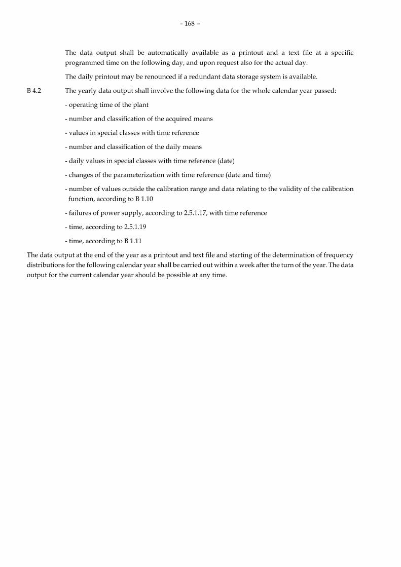
- 168 –
The data output shall be automatically available as a printout and a text file at a specific programmed time on the following day, and upon request also for the actual day.
The daily printout may be renounced if a redundant data storage system is available.
B 4.2 The yearly data output shall involve the following data for the whole calendar year passed:
- operating time of the plant
- number and classification of the acquired means
- values in special classes with time reference
- number and classification of the daily means
- daily values in special classes with time reference (date)
- changes of the parameterization with time reference (date and time)
- number of values outside the calibration range and data relating to the validity of the calibration function, according to B 1.10
- failures of power supply, according to 2.5.1.17, with time reference
- time, according to 2.5.1.19
- time, according to B 1.11
The data output at the end of the year as a printout and text file and starting of the determination of frequency distributions for the following calendar year shall be carried out within a week after the turn of the year. The data output for the current calendar year should be possible at any time.

- 169 –
Annex C
C Requirements for measuring and evaluation systems for plants, according to the TI Air
C 1 Calculation of the means to be classified
The calculation of the means to be classified is schematically represented in Fig. C1
Fig. C 1: Calculation of the means to be classified
measured component
pollutant
1st reference value
2nd reference value
HM
HM
HM
standardized HM
validated HM
DM
consideration of measurement uncertainty
classification
classification
- 170 –
C 2 Classification of the half-hourly means (HM)
Half-hourly means are classified as follows (see Fig. C2):
- Classes M 1 to M 20 of the same width for values up to double the limit for the daily mean, this value is in the upper class limit of class M 20.
- In class S 1 exceedances shall be classified.
Note: Annex F2.2 applies logically to the evaluation of qualitative dust measurements, according to TI Air no. 5.3.3.2 para. 1.
C 3 Special classes
The following special classes shall be envisaged (see Fig. C 2):
S 1 exceedance of limits
S 2 2/3 criterion not fulfilled (comp. Annex B 2.2)
S 3 substitute values (considered in the calculation of means)
S 4 failure of measuring systems (comp. Annex B 2.4)
S 5 maintenance of the measuring system (comp. Annex B 2.5)
S 6 operating time meter for the plant in the time grid of means (as a rule, number of half-hourly means, according to Annex B 1.1)
S 7 means, according to Annex B 2.3
S 8 unplausible means not falling into classes S 2 to S 7
S 9 short-time memory for values outside the calibration range, according to DIN EN 14181, no. 6.5
S 10 long-time memory for values outside the calibration range, according to DIN EN 14181, no. 6.5
S 11 failure of the flue gas purification system (number of half-hourly means in the current year)
C 4 Classification of the daily means (DM)
The daily means are classified as follows (see Fig. C 2):
- Classes T 1 to T 10 of the same width up to the limit for the daily mean, this is in the upper class limit of class T 10.
- Limit exceedances shall be classified in class TS 1.
- Days when a calculation of a daily mean will not be possible shall be classified in class TS 2.

- 171 –
Fig. C 2: Classification of half-hourly and daily means
M 1
M 2
.................... M 20
S 1
Limit exceedance
L
S 2
Measuring time
2/3 criteria
S 3
Substitute values
S 4
Failure of
measuring system
S 5
Maintenance
of measuring
system
S 6
Operating time meter
S 7
Means according
to B 2.3
S 8
Unplausible
values
S 9
Calibration range -
short-time memory
S 10
Calibration range -
long-time
memory
S 11
Failure of flue gas
purification
T 1 T 2 .................... T 10 TS 1
Exceedance of
DL
TS 2
no
DM

- 172 –
Annex D
D Requirements for measuring and evaluation systems for plants, according to the 13th Federal Immission Control Ordinance
D 1 General aspects
D 1.1 The way of continuously monitoring emissions from furnaces with desulphurization units shall be prescribed by the competent authority in the individual case, depending on the operation and system of the desulphurization units. In all furnaces with SO2 limits sums of sulphur dioxide and sulphur trioxide are concerned. Hereinafter only the term sulphur dioxide will be applied for them.
D 1.2 For furnaces equipped with a flue gas treatment system the sulphur separation efficiency may be determined by measuring the sulphur dioxide concentration and the respective reference values in unpurified and purified flue gas. If the sulphur separation level will be observed exclusively by using the flue gas purification system this clean gas – raw gas ratio will form the basis for the calculation of limits. If the natural uptake of sulphur by solid incineration residues or the sulphur uptake increased by adding sorbents are to be taken into account the natural sulphur uptake or the connection between the dosing ratio of additive to fuel and the sulphur uptake by solid incineration residues shall be repeatedly determined by an agency announced by the authority competent for calibration, according to the 13th Federal Immission Control Ordinance, in conformity with the legislation of the Federal State.
The sulphur uptake by solid incineration residues shall be taken into account when calculating the sulphur separation efficiency of the flue gas purification system. This corresponds to the practice adopted so far for the determination of the sulphur emission level.
D 1.3 If only a partial flue gas flow is treated in the flue gas purification system this fact shall be taken into account accordingly in the determination.
D 1.4 In special cases the sulphur separation efficiency may be determined by analysing the fuel sulphur and measuring the sulphur dioxide concentration in the purified flue gas.
D 1.5 The sulphur separation efficiency may be determined as a daily mean and classified. In cases according to D 1.4 the intervals of analyzing sulphur in the fuel shall be prescribed by the authority.
D 1.6 In determining the sulphur separation efficiency a confidence range according to Annex II of the 13th Federal Immission Control Ordinance shall be taken into account in the continuous measurement of sulphur dioxide concentrations and of the respective reference values.
D 1.7 Starting and shutdown times when double the emission limit will be exceeded for technical reasons shall be communicated via a status signal to the evaluation unit. Half-hourly means for the respective measured components obtained in this period shall be classified in a specific class (S 14) and recorded with reference to time in a special memory. These half-hourly means are not considered in the daily averaging, but the masses are to be taken into account in annual emissions.
D 1.8 Downtimes of the desulphurization unit shall be communicated via status signals to the evaluation unit and recorded in separate classes for consecutive half-hours (apart from the daily sum recorded in special class S 11 also in special class S 12 as the downtime continues possibly over the turn of the day and even the turn of the year) and shall be recorded as a sum flexibly over a twelve-months period (special class S 13). The criteria for the status signal shall be prescribed by the competent authority. The class for consecutive downtime hours (S 12) shall be automatically cancelled with the beginning of the next downtime.
D 1.9 When monitoring the smoke spot number evaluation shall be made accordingly.

- 173 –
D 2 Mixed and multicomponent furnaces
D 2.1 In mixed and multicomponent furnaces the way of continuous monitoring of emissions shall be prescribed by the competent authority in the individual case, depending on the operation and the ratio between the fuel quantities used.
D 2.2 To reduce the expenses an evaluation may be made applying a limit flexibly adapted to the fuel mixing ratio. To this end, classes shall be set up which pick up these values for each component in per cent of the respective half-hourly mixing limit and the daily mixing limit. In addition to the stored half-hourly means the respective flexible limit with oxygen reference shall be stored.
D 2.3 In the case of mixed furnaces according to § 8 of the 13th Federal Immission Control Ordinance or no. 5.4.1.2.4 of TI Air, a fuel mixture to which the highest emission limit is applicable shall be used for calibration.
D 2.4 Multi-substance furnaces provide the possibility of accepting a few calibration curves assigned to common fuels and of designing the evaluation unit in a way that when changing the fuel the evaluation will be converted to the assigned calibration curve. It should be possible to separately classify and store the means obtained when using various fuels. In daily recording data relating to classes and memories the content of which has not changed during the preceding day may be dropped.
D 3 Calculation and classification of means
D 3.1 Means to be classified shall be calculated according to Annex C, C1.
D 3.2 Half-hourly means shall be classified analogously to Annex C, C2 (s. Fig. C2). In addition to the special classes, according to Annex C, C3, the following special classes are adopted:
S 12: actual failure of the flue gas purification system for more than 1 day (comp. D 1.8)
S 13: flexible sum of all failures of the flue gas purification system (comp. D 1.8)
S 14: starting and shutdown phases (comp. D1.7)
D 3.3 The daily means shall be classified analogously to Annex C, C4 (s. Fig. D). In addition to the classes TS 1 and TS 2 the following classes are introduced
TS 3: daily means when, due to maintenance or failure, the measuring system was not in operation for more than six half-hourly means.

- 174 –
Fig. D: Classification of half-hourly and daily means
M 1
M 2
.................... M 20
S 1
Exceedance
of L
S 2
Measuring time
2/3 criteria
S 3
Substitute
values
S 4
Failure of
measuring system
S 5
Maintenance
of measuring
system
S 6
Operating
time meter
S 7
Means according
to
B 2.3
S 8
Unplausible
values
S 9
Calibration range -
short-time
memory
S 10
Calibration range -
long-time memory
S 11
Failure of flue gas
purification system
S 12
Failure of flue gas
purification system
> 1 day
S 13
Sum of
failures
S 14
Starting and shutdown
phases
T 1
T 2
.................... T 10
TS 1
Exceedance
of DL
TS 2
no
DM
TS 3
Failure/
main-
tenance
of
measuring
sytem
TS 4
SAG
< L
TS 5
SAG
> L

- 175 –
Annex E
E Requirements for measuring and evaluation systems for plants, according to the 17th Federal Immission Control Ordinance, checking of incineration conditions
E 1 Requirements for measuring systems for plants, according to the 17th Federal Immission Control Ordinance
E 1.1 The minimum requirements shall be proved in the range of 1.5 times the limit for daily means.
E 1.2 The instrument range up to 1.5 times the limit for half-hourly means shall be covered.
E 2 Continuous determination of the minimum temperature (§ 11, subpara. 1, no. 3 in conjunction with § 4, subparas. 2 and 3)
E 2.1 According to guideline series VDI/VDE 3511, two measuring systems shall be installed in a suitable place in the afterburner room (e. g. at the top of the boiler); the mean shall be registered and evaluated according to § 11, subpara. 1.
E 2.2 The competent authority shall make sure that in the event of a measuring system failing it will be replaced without delay by an emergency measuring system of the same construction to be held in stock.
E 3 Requirements for evaluation systems for plants, according to the 17th Federal Immission Control Ordinance
E 3.1 Calculation, standarization, validation and classification
E 3.1.1 Pollutants (according to § 5, subpara. 1, nos. 1 and 2 and, if necessary, according to § 11, subpara. 5 of the 17th Federal Immission Control Ordinance)
E 3.1.1.1 The means to be classified shall be calculated according to Annex C, C1.
E 3.1.1.2 Basically half-hourly means are classified in 20 classes of a uniform width. The classification shall be chosen in a way that the emission limit for half-hourly means falls to the upper limit of the 20th class (classes M1 – M20, see Fig. E1)
E 3.1.1.3 In addition to the special classes according to Annex C, C3 the following special classes are adopted:
S 12 actual failure of the flue gas purification system (comp. E 3.1.2.3)
S 15 dust ≤ 150 mg/m3 in the event of the flue gas purification system failing (comp. E 3.1.2.3)
S 16 dust > 150 mg/m3 in the event of the flue gas purification system failing (comp. E 3.1.2.3)
The special classes S 13 and S 14 are not occupied.
E 3.1.1.4 A classification according to E 3.1.1.2 and E 3.1.1.3 is also applicable if measuring instruments with electronically reversible measuring ranges are used.
E 3.1.1.5 The daily means are classified analogously to Annex C, C4 (s. Fig. E1).
In addition to classes TS 1 and TS 2 class TS 3 is adopted:
TS 3 daily means calculated when the measuring system was out of operation for more than 5 half-hourly means owing to maintenance or failure (Art. 11, para. 11 of the EU-RL 2000/76/EC)
E 3.1.2 Operational values/reference values

- 176 –
E 3.1.2.1 Afterburning temperature (§ 4 subparas. 2, 3 and subparas. 6, 7 in conjunction with § 10 subpara. 1 and § 13 subpara. 1 of the 17th Federal Immission Control Ordinance )
Ten-minute means shall be calculated from the afterburning temperature values measured.
These ten-minute means shall be classified in 20 classes of a uniform width. The classification shall be chosen in a way that a temperature range of altogether 400 K will be covered and the fixed minimum temperature will fall to the limit between the 10th and 11th classes. (TABZ 1 – TABZ 20), comp. Fig. E 1. Here, the upper limit (lowest temperature) is put on class TABZ 20 and the lower limit (highest temperature) on class TABZ 1.
Failures and maintenance of the measuring system shall be classified in one class TABZ 21.
E 3.1.2.2 Monitoring of charging (§ 4 subpara. 5 in conjunction with § 11 subparas. 1 and 4 of the 17th Federal Immission Control Ordinance)
Periods when charging of the plants was blocked or interrupted shall be registered for each calendar day and stored.
E 3.1.2.3 Failures of flue gas purification systems (§ 16 subpara. 2 of the 17th Federal Immission Control Ordinance )
Downtime periods of the flue gas purification system shall be communicated via status signals to the evaluation system and recorded in two separate memories for subsequent half-hours and for the current calendar year. The criteria for the status signals shall be prescribed by the competent authority.
The memory for subsequent man-hours lost shall be automatically deleted upon the beginning of the next downtime period.
The half-hourly means for the overall dust calculated during the downtime periods shall be recorded in two classes the joint limit of which is formed by the emission limit for half-hourly means (150 mg/m3) applicable to downtime periods.
E 3.1.2.4 Other operational and reference values (§ 11, subpara. 1, no. 4 of the 17th Federal Immission Control Ordinance )
If further operational or reference values (e. g. flue gas volume flow or moisture content) are continuously measured the way of evaluation shall be prescribed.by the competent authority in the individual case, following E 3.1.1.1
E 3.1.3 Data output
E 3.1.3.1 In addition to Annex B 4.1 the daily recording shall comprise the following data:
- minimum temperature
- locking time according to E 3.1.2.2
- dust > 150 mg/m3
E 3.1.3.2 In addition to Annex B 4.2 the data output at the end of the year shall comprise the following data:
- frequency distribution, according to E 3.1.2.1 and E 3.1.2.2
- results in the memories and classes, according to E 3.1.2.3

- 177 –
Fig. E 1: Classification of half-hourly and daily means and of the minimum temperature
M 1
M 2
.................... M 20
S 1
Exceedance of
L
S 2
Measuring time
2/3 criteria
S 3
Substitute values
S 4
Failure of the
measuring system
S 5
Maintenance of the
measuring system
S 6
Operating time
meter
S 7
Means according to
B 2.3
S 8
Unplausible
values
S 9
Calibration range -
short-time
memory
S 10
Calibration range -
long-term
memory
S 11
Failure of the flue gas
purification
system
S 12
Actual
state
Failure of the flue gas
purification
system
S 13
Not occupied
S 14
Not occupied
S 15
Dust
≤ 150 mg/m3
S 16
Dust
>150 mg/m3
T 1 T 2 .................... T 10 TS 1
Exceedance
of
DL
TS 2
No
DM
TS 3
Failure/
mainte-
nance of
the measuring system

- 178 –
E 4 Checking of incineration conditions, according to § 13 subpara. 1 in conjunction with § 4 subparas. 2 and 3 or 6 and 7 of the 17th Federal Immission Control Ordinance
E 4.1 Checking of the minimum temperature
E 4.1.1 Fixing of measuring planes
A measuring plane (1st measuring plane) shall be fixed at the end of the afterburning zone (above the supporting burners) for the respective approved operating states. The design data of the manufacturer or supplier are the basis for that. A further measuring plane (2nd measuring plane) shall be fixed where the beginning of the afterburning zone was defined.
This measuring plane shall be fixed after the last supply of incineration air on the basis of the design data of the manufacturer or supplier.
The plane, where, first of all, we may proceed from a uniform mixing of the incineration gases with incineration air is defined as the beginning of the afterburning zone.
Owing to the existing local conditions insignificant deviations of the position of the 2nd measuring plane from the actual beginning of the afterburning zone are possible. This will be compensated by respective conversions (comp. Fig. E 2).
E 4.1.2 Measuring equipment
According to the present state of the art, exclusively water-cooled suction pyrometers with a ceramic screen shall be used for checking the minimum temperature. A sufficiently high suction speed shall be set. At least one measuring instrument shall be used at the same time for each measuring axis fixed. The thermocouples used in the suction pyrometers shall correspond to the PTB requirements 14.2 of December 2003.
E 4.1.3 Fixing of the measuring points for grid measurement
Temperature measurement is carried out as grid measurement at least on two measuring axes in the incineration chamber. The measurement section shall be subdivided into two equal areas with the measuring points being in their centres of gravity. The number of measuring points is 1 per approx. 2 m2. A uniform distribution of the points over the measurement section is to be ensured.
E 4.1.4 Processing of measured values
Electronic recording of measured values shall be carried out with a sampling frequency of at least 0.1 Hz (corresponding maximally to 10 s between two subsequent measured values). The measured values shall be compressed to 10-minute means.
E 4.1.5 Acceptance measurement
To prove that the minimum temperature required (850 or 1100 °C) is kept the following number of network measurements according to E 4.1.3, is required in the case of a boiler being dirty as a result of its operation:
- undisturbed continuous operation (rated load): 3 grid measurements over a total period of at least 3 hours
- deviating operating states (e. g. partial load in the event of the operating state being approved): 3 grid measurements over a total period of at least 3 hours
- starting without charging with starting materials (acc. to § 4, subpara. 5, no. 1): 1 grid measurement for the final state of the heating phase over a period of approx. 1 hour (with regard to E 5.3.1).

- 179 –
For each measuring point fixed according to E 4.1.3 the individual 10-minute means are converted to a fictitious measuring plane which corresponds to a retention time of 2 seconds (minimum retention time) through the temperature gradients determined according to E 4.2.2.
The evaluation criterion is the minimum temperature in each measuring point fixed according to E 4.1.3 as a 10-minute mean for each individual measurement.
E 4.2 Checking of the retention time of the flue gases
E 4.2.1 Measuring planes
To determine the retention time during which the minimum temperature has to be maintained two measuring planes (1st and 2nd measuring planes) are used (comp. E 5.1)
E 4.2.2 Determination of the temperature gradient
Network temperature measurements (always 3 network measurements) shall be carried out at the same time in the 1st and 2nd measuring planes with the operating state of the installation being the same.
The basic conditions of the measuring equipment are given analogously to E 4.1. (The measuring results obtained on the 1st measuring plane may be used for checking the minimum temperature according to E 4.1). From the measured values the average temperature difference ∆T1,2 between the 1st and the 2nd planes is calculated for the respective operating state (s. a. E 4.1.5).
( )∑=
−=n
ni1i2i1,2 TT
n1∆T
T1i mean of network temperature measurement in the 1st measuring plane
T2i mean of network temperature measurement in the 2nd measuring plane
n number of network temperature measurements in the 1st or 2nd planes.
Assuming a linear march of temperature between the 1st and 2nd temperature planes or beyond that the mean temperature in the incineration chamber is determined for each plane, on the other hand, the plane in the incineration chamber where the minimum temperature of the flue gases is just kept may be calculated (comp. Fig. E 2).
∆ l T =
( )2,1
2,11 T
TT M ∆∆
×−l
=1T
∑=
n
1ii,1T
n1
The mean temperature gradient is calculated from ∆T1,2/∆l1,2.
T1 mean of the network temperature measurements in the 1st plane
TM minimum temperature of the flue gases
∆l1,2 distance between the 1st and the 2nd measuring planes
∆lT distance between the plane in the incineration chamber where the flue gases just keep the minimum temperature on average and on the 1st measuring plane.

- 180 –
E 4.2.3 Determination of the retention time
To determine the retention time of the flue gases in the area above the minimum temperature the flue gas volume flow (e. g. at the boiler end) shall be measured and converted to the flue gas conditions in the afterburning zone.
The volume flow is measured with regard to DIN EN ISO 10780 (issue of 1994) simultaneously with the network measurements being carried out to check the minimum temperature. When calculating the retention time the behaviour of an ideal plug flow is assumed.
The temperature on which the volume flow shall be based is the mean from the temperature at the beginning of the afterburning zone TBABZ and the minimum temperature. Taking the geometric conditions and the volume flow into account the retention time in the afterburning zone is calculated.
( )IR
TRT V
At&
ll ∆+∆×=
IRV⋅
mean of the volume flow of the flue gases in the incineration chamber (in operation, moist)
at 2MBABZ TT +
∆l distance between the beginning of the afterburning zone and the 1st measuring plane
A cross-sectional area of the incineration chamber (for A = const.)
tRT retention time of the flue gases above the minimum temperature.
The evaluation criterion is a minimum retention time of 2 hours.
E 4.3 Uniform mixing
E 4.3.1 Determination of a uniform mixing
We may proceed from a uniform mixing of the incineration gases with incineration air if the temperature in each measuring point in the two measuring planes and thus over the whole afterburning zone is maintained and the individual values for the volumetric oxygen content do not deviate more than 50 of hundred from the volumetric oxygen content for the respective network.
E 4.3.2 Measurement of the oxygen content
Usually the oxygen measurement is carried out simultaneously with the temperature measurement according to E 4.1 via suction pyrometers so that measuring plane and measuring points will be identical.
E 5 Functional testing and calibration of measuring instruments for the continuous monitoring of the minimum temperature according to § 10, subpara. 3 in conjunction with § 11, subpara. 1, no. 3 of the 17th Federal Immission Control Ordinance
E 5.1 Functional testing
Functional testing of instruments for measuring the minimum temperature shall be carried out every year as described hereinafter:

- 181 –
- plausibility testing of the readout of measuring instruments according to the checkpoint method (ice point in ice-water mixture according to VDI/VDE 3511, sheet 2) or alternatively: checking by means of a comparison element either alternately in the places of installation of the measuring instruments or in other appropriate measurement apertures (basis: 1-hour mean)
- checking of the transmission of measured values with a constant supply point
- checking to recognize an element failure caused by the electronic evaluation system. For this purpose each measuring instrument shall be disconnected.
- checking of the measuring instruments as to their construction and fitting position as compared with the time of the last calibration.
E 5.2 Calibration
The calibration shall be conducted at least every three years.
E 5.2.1 Determination of the end of the afterburning zone
The incineration chamber temperatures are determined according to E 4.2.2 (averaging) always at full load and in further approved operating states. For the operating state “starting” attention is additionally drawn to 5.3.1.
For this purpose, at least six network measurements (at full and partial loads) shall be carried out simultaneously in the 1st and 2nd planes. For the periods of these network measurements the mean values measured by operational measuring instruments shall be determined in a way that at least 6 data sets of network measurements – operational measurements - will be available.
Assuming a linear temperature march between the 1st and the 2nd planes or beyond them thus the end of the afterburning zone (defined as a plane in the incineration chamber where the minimum retention time of 2 s is exactly maintained) may be determined (comp. Fig. E 2).
∆ l ABZ = l&
∆−×
AVt IRRZ min
tRTmin minimum retention time
∆lABZ distance between the end of the afterburning zone plane and the 1st measuring plane
∆T1,2 mean temperature difference between the 1st and the 2nd measuring planes
( )ii
6
1=iTT
61T 122,1 −=∆ Σ
T2i mean of the network temperature measurement in the 2nd measuring plane
T1i mean of the network temperature measurement in the 1st measuring plane
∆l1,2 distance between the 1st and the 2nd measuring planes
The mean temperature gradient is calculated from ∆T1,2/∆l1,2.
E 5.2.2 Calibration procedure

- 182 –
The mean temperature difference and its lower confidence limit for the converted temperature values measured by network measurements in the 1st measuring plane is calculated with the aid of the measured operating temperature values:
TABZi mean of the network temperature measurement i in the 1st measuring plane converted to the plane at the end of the afterburning zone (2 s retention time)
TBi mean of the operating temperature measurement i for the period of network measurement
ABZ1,2
1,21iABZi ∆
∆∆T
TT ll
−=
Determination of the confidence limit: nSt
V 2nB
×= −
The connection TABZi = f (TBi) shall be determined by linear regression.
tn-2 threshold value of t distribution (for N = n´)
S spread around the straight regression line
n = 6 (total number of measurements)
∑=
=n
iABZiABZ T
nT
1
1
∑=
=n
iBiB T
nT
1
1
( )∑=
−=n
iBBiTT TTS
BB1
2
( )∑=
−=n
iABZABZiTT TTS
ABZABZ1
2
×−×
−=
ABZABZBB
ABZBABZABZ
TTTT
TTTT
SSS
nS
S2
2 12
For calibration of the measured operational values the following procedure shall be adopted:
BABZBCalB VTTT −∆+= 10
( )BiABZi
6
1=iABZ TT
61T −=∆ Σ
ABZT∆ mean temperature difference between the end of the afterburning zone and the measured operational values
TCal B calibrated measured operational values (input to the emission value computer)
10BT 10-minute mean of the operating temperature measurement
The calibration shall be carried out completely for each approved operating state.

- 183 –
E 5.2.3 Parameterization of the electronic evaluation system
*ABZT∆ = BABZ VT −∆
∆TABZ* is determined for each approved operating state and depending on the capacity (e. g. steam generating capacity PD) calculated flexibly by the evaluation computer; this refers also to the operating state “shutdown”.
The function TABZ* = f (PD) is parameterized.
As regards the operating state „starting“ compare E 5.3.1
E 5.3 Special criteria
E 5.3.1 Complying with the incineration conditions „starting“.
The operating state “starting” is marked only by the operation of an additional burner without charging with starting material.
By convention, the beginning of the afterburning zone in the operating state “starting” is
- the plane of the additional burner if secondary air is supplied upstream
- the plane of the last air supply if secondary air is supplied downstream.
The incineration conditions (minimum temperature, minimum retention time) are the basis for determining the end of the afterburning zone when “starting”. During the operating state „starting“ the volume flow shall be calculated or measured to determine the retention time via the fuel consumption and the oxygen volume content of the flue gases.
By temperature measurement in a measuring plane which is at least 2 m downstream (above the burner plane) the gradient to the operating temperature measurement shall be determined analogously to E 4.2.2 and used as a criterion for releasing (unblocking) the supply of waste. The period after unblocking the supply of waste up to reaching stationary operating states shall be agreed upon with the competent authority; it shall not exceed 2 hours.
In this period a special solution has to be found for evaluating the components subject to monitoring, depending only on the furnace. This refers, in particular, to the minimum temperature, CO, Ctotal and NOx when taking primary reduction measures.
E 5.3.2 Switching criteria of additional burners
The following switching criteria are recommended for additional burners:
- Switching on: when reaching the desired temperature class TABZ 10 (10-minute value between 850 °C and 870 °C or 1100 °C and 1120 °C).
- Switching off: may be carried out when reaching class TABZ 9 and lower classes (> 870°C or 1120 °C).
Controlling and regulation of the additional burners via the control system of the plant may contribute to reducing primary energy consumption.
E 5.3.3 Criteria of waste charge
The following criteria apply to blocking and unblocking of the supply of waste:
- blocking: when reaching a temperature in class TABZ 11 or a higher class (< 850 °C or 1100 °C)
- unblocking: when reaching a temperature in class TABZ 10 or a lower class (≥ 850 °C or 1100 °C).

- 184 –
Safety requirements shall be taken into account during blocking.
Fig. E 2 Representation of the parameters by the example of an incineration plant for municipal waste

- 185 –
Legend: T1 Mean of temperature measurements
1st measuring plane ∆T1,2 Mean temperature difference
between 1st and 2nd measuring planes
T2 Mean of temperature measurements 2nd measuring plane
ℓBABZ Altitude up to the beginning of the afterburning zone
TM Minimum temperature of flue gases ∆ℓT Distance between the furnace plane and the 1st measuring plane
TB Measured operating temperature value ∆ℓABZ Distance between the end of the afterburning zone plane and the 1st measuring plane
TABZ Temperature at the end of the afterburning zone
∆ℓ Distance between the beginning of the afterburning zone and the 1st measuring plane
TBABZ Temperature at the beginning of the afterburning zone
∆ℓ1,2 Distance between the 1st and 2nd measuring planes
∆T Temperature difference between the 1st measuring plane and the measured operational value
∆ℓBABZ Distance between the beginning of the afterburning zone plane and the 2nd measuring plane
∆TABZ Temperature difference between the end of the afterburning zone and the measured operational value
TRT,min Minimum retention time = 2 s

- 186 –
Annex F
F Requirements for measuring and evaluation systems for plants, according to the 27th Federal Immission Control Ordinance
The evaluation is outlined in Figure F.
F 1 Carbon monoxide
F 1.1 The hourly means for CO are classified as follows:
Classes 1 – 20 of the same width for values up to the limit. This value falls onto the upper limit of the 20th class
Exceedances of the limit shall be classified in class S1
The validation shall be carried out according to Annex C, C1.
F 1.2 The following special classes shall be envisaged:
S 2 Measuring time shorter than 2/3 regulation, i. e. shorter than 40 minutes
S 3 - S 11 see Annex C, C 3
F 2 Monitoring of the minimum temperature and of the filtering installation
F 2.1 For monitoring of the minimum temperature:
TABZ 1 minimum temperature kept
TABZ 2 minimum temperature fallen below
TABZ 3 failure of the measuring system
F 2.2 The following classes are set up for monitoring the operatability of the dust filtering installation:
F 1 limit kept
FS 1 limit exceeded
FS 2 - FS 11, according to Annex C, C 3
F2.3 The following special classes for monitoring the minimum temperature and the operatability of the filtering installation shall be envisaged:
FSE sum of exceedance events
TABZ U sum of periods of falling below the limits

- 187 –
Evaluation 27th Federal Immission Control Ordinance
Dust qualitativ
TABC CO O2 Reference values
Events:Time reference
dust classified
10min mean TABC
classified
SMW CO
standard- ized
SM O2
SM CO
validated
SM CO
classified

- 188 –
Annex G
G Requirements for measuring and evaluation systems for plants, according to the 30th Federal Immission Control Ordinance
The evaluation is outlined in Figure G.
The validation and classification is carried out according to Annex C, C1.
G 1 Classification of the half-hourly means for the components dust, Ctotal, N2O and of the volume flow
The classification is carried out in the classes M1 – M20 of the same width for values up to the limit for the half-hourly mean or the upper limit of the measuring range for dinitrogen oxide and the volume flow. The respective values fall onto the upper limit of class M 20.
G 2 Special classes for half-hourly means
The following special classes shall be set up:
S 1 – S 11 acc. to Annex C, C 3
S 12 failure of the flue gas purification system continuously for > 8 h
S 15 dust values < limit - failure of the flue gas purification system
S 16 dust values > limit - failure of the flue gas purification system
Classes S 13 and S 14 are not occupied.
G 3 Classification of the daily means
The daily means for dust and Ctotal are classified according to Annex C4: classes T 1 – T 10 of the same width up to the limit for the daily mean. It falls onto the upper limit of class T 10.
Option:
A classification of the daily means for N2O in the classes T 1 – T 10 should be possible. The values for class T10 are fixed by the upper limit of the measuring range of the measuring system.
Days when the calculation of a mean will not be possible shall be classified in class TS 2. Class TS 1 will not be applicable.
G 4 Daily printout
In addition to the details given in Annex B 4.1 the following values shall be taken up:
- daily masses N2O and Ctotal
- actual (flexible) monthly value of the masses of N2O and Ctotal
Option:
After recording (continuously) the mass of the starting materials by means of the emission computer the mass ratio between the emitted substances and the mass of the starting materials (in the state of supply) shall be calculated and printed out daily as actual (flexible) monthly value.
G 5 Monthly printout
The mass ratios between total C and dinitrogen oxide are to be put out related to the quantity of the starting materials. It shall be also possible to put out the values for the preceding months of the current year.

- 189 –
G 6 Annual printout
In addition to the data indicated in Annex B 4.2 the following values shall be taken up:
- monthly values of the mass ratio between the pollutant mass N2O or Ctotal and the mass of the starting materials

- 190 –
Figure G - Evaluation 30th Federal Immission Control Ordinance
MR = mass ratio
T dust Ctotal V N2O pressure moisture starting materials
HM dust HM Ctotal
DM dust
HM N2O
daily mass Ctotal
daily mass N2O
monthly value mass Ctotal
daily mass
starting materials
monthly mass
starting materials
MR Ctotal MR N2O
DM N2O
monthly value mass N2O
DM Ctotal
sum V
HM V

- 191 –
7.10 Standard form of a test report for the determination of
emissions in accordance with §§ 26, 28 of the Federal Immission control Act
Cover sheet:
Headline: Name of laboratory Report-No. :00000 page 1 of 00000
Name of the laboratory accredited in accordance with § 26 BImSchG
Ref.No./Report-No.: 00000 Date: Date of report
Report on emission measurements
Version of 5 March 2007
Operator:
Location:
Date of measurement:
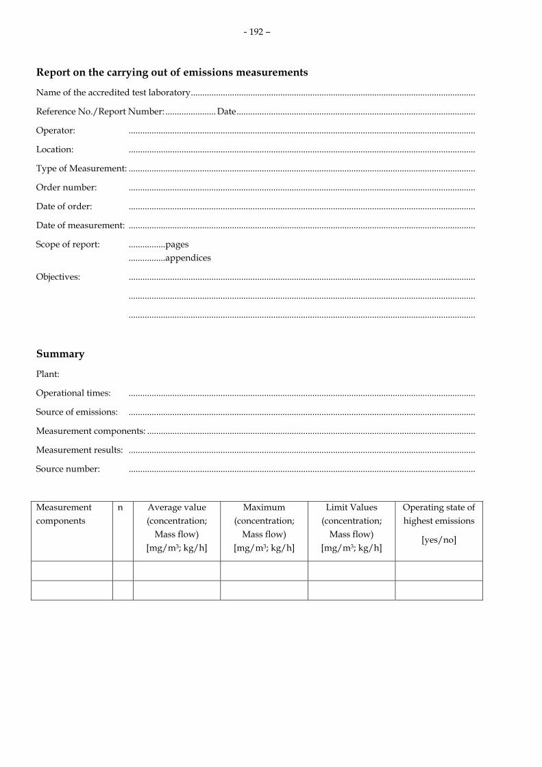
- 192 –
Report on the carrying out of emissions measurements
Name of the accredited test laboratory............................................................................................................................
Reference No./Report Number: ...................... Date........................................................................................................
Operator: .......................................................................................................................................................
Location: .......................................................................................................................................................
Type of Measurement: .......................................................................................................................................................
Order number: .......................................................................................................................................................
Date of order: .......................................................................................................................................................
Date of measurement: .......................................................................................................................................................
Scope of report: ................pages ................appendices
Objectives: .......................................................................................................................................................
.......................................................................................................................................................
.......................................................................................................................................................
Summary
Plant:
Operational times: .......................................................................................................................................................
Source of emissions: .......................................................................................................................................................
Measurement components: ...............................................................................................................................................
Measurement results: .......................................................................................................................................................
Source number: .......................................................................................................................................................
Measurement components
n Average value (concentration;
Mass flow) [mg/m3; kg/h]
Maximum (concentration;
Mass flow) [mg/m3; kg/h]
Limit Values (concentration;
Mass flow) [mg/m3; kg/h]
Operating state of highest emissions
[yes/no]

- 193 –
Table of contents Page
1. Formulation of the measurement task ...............................................................................................
1.1 Client:........................................................................................................................................................................
1.2 Plant operator: .........................................................................................................................................................
1.3 Location: ...................................................................................................................................................................
1.4 Plant: .........................................................................................................................................................................
1.5 Date of measurement:.............................................................................................................................................
1.6 Reason for Measurement: ......................................................................................................................................
1.7 Objectives: ................................................................................................................................................................
1.8 Compounds to be measured: ................................................................................................................................
1.9 Local inspection before measurement:.................................................................................................................
1.10 Coordination of the measurement plan: ..............................................................................................................
1.11 Persons participating in the sampling:.................................................................................................................
1.12 Participation of other institutions: ........................................................................................................................
1.13 Technical supervisor:..............................................................................................................................................
2. Description of the plant and the materials handled........................................................................
2.1 Type of plant:...........................................................................................................................................................
2.2 Description of the plant:.........................................................................................................................................
2.3 Description of the emission sources .....................................................................................................................
2.4 Statement of raw materials according to the permit ..........................................................................................
2.5 Operating times.......................................................................................................................................................
2.6 Facility for collecting and reducing emissions....................................................................................................
3. Description of the sampling point......................................................................................................
3.1 Position of the measuring cross section ...............................................................................................................
3.2 Dimensions of the measurement cross section: ..................................................................................................
3.3 Number of measurement axes and position of the measurement points in the cross section ....................
3.4 Number and size of the measurement openings: ...............................................................................................
4. Measurement and analysis methods, instruments ..........................................................................
4.1 Waste-gas conditions..............................................................................................................................................
4.2 Continuous measurement methods .....................................................................................................................
4.3 Discontinouos measurement methods.................................................................................................................
5. Operating conditions of the plant during measurements..............................................................
5.1 Production facilities ................................................................................................................................................
5.2 Waste-gas purification facilities ............................................................................................................................
6. Summary of the measurement results and discussion ...................................................................
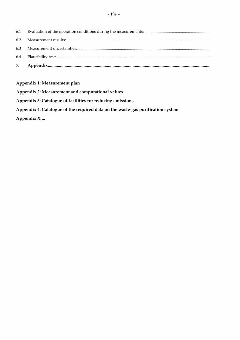
- 194 –
6.1 Evaluation of the operation conditions during the measurements: .................................................................
6.2 Measurement results:..............................................................................................................................................
6.3 Measurement uncertainties:...................................................................................................................................
6.4 Plausibility test:........................................................................................................................................................
7. Appendix..................................................................................................................................................
Appendix 1: Measurement plan
Appendix 2: Measurement and computational values
Appendix 3: Catalogue of facilities for reducing emissions
Appendix 4: Catalogue of the required data on the waste-gas purification system
Appendix X: ...

- 195 –
Table of Contents with page numbers
1 Formulation of the measurement task 1.1 Client 1.2 Plant operator
(Name, address, contact, tel. no., operator/workplace no.: depending on federal state)
1.3 Location The location given must also clearly indicate,
within a larger plant, the position of the emission source (e. g. plant C, Bldg. 5)
1.4 Plant Indications with reference to 4th BImSchV,
Plant No. (depending on federal state) 1.5 Date of the measurement: - Date of the last measurement - Date of the next measurement 1.6 Reason for the measurement A summary of the measurement tasks can be
found in No. 2.1 of VDI 2448 part 1 1.7 Objectives This paragraph should give a detailed
description of the measurement task. In the case of measurements for the purposes of a permit or orders, the relevant numbers of the notice/order and the specified limit values and other relevant regulations are to be given (possibly including the BImSchV or TA Luft)
Indications of special aspects of the measurement planning (see no. 5.3.2.2. TA Luft: e. g. batch process, load changes) and the plant history (e. g. earlier procedures, adjustments which had to be made, possibly through information from the operator.
1.8 Compound to be measured Air pollution, waste-gas conditions
1.9 Local inspection before measurement Local inspection carried out on Measurement conditions as per DIN EN
15259 were found to be present were found not to be present determined and realized (short description of the measures) not determined and not realized
(Description of the measures taken and a
detailed discussion of defects is required) no local inspection made because of previous participation in
measurements at this site. Measurement conditions as per DIN EN
15259 were present were not present
1.10 Coordination of measurement plan Indications whether and with whom the
measurement plan was coordinated 1.11 Persons participating in the sampling Names of all persons participating , plus
assistants; underline name of project manager
1.12 Participation of other institutions Give the tasks and scope of their participation
1.13 Technical supervisor - Name - Tel.-No.: - e-Mail-address:
2 Description of the plant and the materials handled
2.1 Type of plant If necessary using designation deviating
from the 4th BImSchV for greater precision 2.2 Description of the plant
A short description of the plant and the operational processes, emphasizing those aspects which are especially relevant for the emission of air pollutants. Important data such as type, boiler number, year of construction, factory number, absolute and specific load or throughput should be given. The usual sizes are to be used. The operational mode is to be described precisely (e. g. continuous operation, batch process, load behaviour, times with heavier emissions. This information must be assigned to a particular operational unit or emissions source so that (in connection with 2.4) conclusions can be drawn about the emissions behaviour of the system (e. g. fuel relationships with mixed incineration).

- 196 –
In very complex cases, a flow diagram of the system is to be enclosed. The requirements for a system description can be found in Nr. 7 of VDI 2066, page 1.
2.3 Description of the emissions sources Emissions source - Height above ground - Cross-sectional area of outlet - Horizontal/vertical value - Type of construction 2.4 Statement of raw materials possible
according to the permit To ensure that the requirement for an
operating state with maximum emissions to be measured, see Nr. 5.3.2.2 TA Luft, in respect of emission-relevant raw materials during the measurements, appropriate information has to be given here
2.5 Operating times Indications of the daily and weekly total
operating times as well as the times for the emission of any pollutants are necessary for determining the total emissions over a long period of time
2.5.1 Total operating time 2.5.2 Emissions time as given by operator 2.6 Facility for collecting and reducing
emissions A description of these facilities should make
an assessment possible and be an indication of any considerable diffuse emissions of air-pollutants.
2.6.1 Facilities to collect emissions 2.6.1.1 System for collecting emissions 2.6.1.2 Collecting element 2.6.1.3 Fan data 2.6.1.4 Suction area 2.6.2 Facilities to reduce emissions (description
corresponding to Appendix 1 2.6.3 Facility for cooling the waste -gas
(e. g. bypass, improvement of flow conditions)
3 Description of the sampling point
3.1 Position of the measurement cross section The exact position of the measurement cross section in the waste-gas system is to be given. The description of the cross section is to be such that it is completely clear whether it corresponds to the requirements of VDI
Richtlinie 4200 (or DIN EN 13284-1 in the case of dust measurements). This is a pre-condition for a representative determination of the measurement components and this allow to apply the measurement uncertainties determined in the verification procedure. If the sampling point does not correspond to the official guidelines, this should be justified. In addition, those measures should be described which were taken to ensure that acceptable measurement data is produced (see also No. 3.3).
- if necessary, a drawing may be included. For dust measurements the following is to be documented (see DIN EN 13284-1 additionally) : - Position of the measurement cross
section ≥ 5 Dh straight duct upstream and ≥ 2 Dh straight duct downstream (≥ 5 Dh from top of the duct)
- Angle of gas flow to the middle axis of the waste-gas duct < 15°
- no local negative flow - Ratio highest/lowest local gas velocity in
the cross section < 3:1 3.2 Dimensions of the measurement cross
section 3.3 Number of measurement axes and position
of the measurement points in the cross section With chimney cross sections above 0.1m² (with gaseous components above 0.2 m²) a net measurement is necessary for the emissions sampling (see VDI guideline 4200, Nr. 6.2.2). According to the draft version of DIN EN 15259 a net measurement is necessary for all components above 0.1 m² The number of measurement axes and the number of measurement points are specific to be given for the components (including the velocity measurement). A network measurement is also indispensable in order to determine the presence of a possible representative measurement point and to justify it. If such a representative measurement point is found and used for sampling, its representativeness is to be credibly demonstrated. If 3.1 shows that the measurement plain does not correspond to guidelines with regard to the entrance and exit routes, then the measurement report must show what measures were taken to ensure that reliable

- 197 –
measurement data were nevertheless produced. This should include such information as the distribution of: - Waste- gas velocity - Concentrations of continuously
measured waste-gas components over the measurement cross section on the measurement axes and points as determined in No. 3.3. This data is to be documented in the report - if necessary, enclose drawing
3.4 Number and size of the measurement openings
4 Measurement and analysis methods, instruments
The measurement instruments (with manufacturer and type) and the measurement methods are to be given and described. If instruments and methods other than those described here are used, then the description should be analogous. If necessary a drawing of complete equipment may be enclosed.
4.1 Waste-gas conditions
4.1.1 Flow velocity
Pitot tube with
- Micro-manometer, - electronic micromanometer,
other highly sensitive difference pressure measurement devices
windmill anemometer,
thermal anemometer determination by calculation (e. g. from fuel quantity, air conditions, displacement volume) made on the basis of operating data (data from the plant is required) It is to be stated whether the data was determined throughout the total sampling time by continuous measurement at a representative net point at the cross section and that, in addition it was - recorded by a registration device - detected by a measurement data detection system - calculated to half-hour average values
. 4.1.2 Static pressure in the waste-gas duct
U-tube manometer Manometer as per 4.1.1 taking into
consideration the corresponding connections negligably small (< 0,005 hPa) 4.1.3 Air pressure at the height of the sampling
location Barometer Last check/calibration 4.1.4 Waste-gas temperature Resistance thermometer Ni-CrNi-electric couple Hg-thermometer Other temperature measurement devices It should be indicated whether the
temperature was continuously measured throughout the sampling and at a representative measuring point. And that it was also
recorded by registration device detected by a measurement data
detection system calculated to half-hour average
values 4.1.5 Water vapour content in waste-gas (waste-
gas humidity) Adsorption on:
Silica gel, calcium chloride, molecular sieve or other sorption device and a following gravimetric determination
Psychrometer (manufacturer/type) Moisture measurement for gases
(manufacturer/type) Water vapour sampling tubes (z. B. Dräger-
Water vapour l/a: 0,1) 4.1.6 Waste-gas density Calculated taking into account the
proportion of Oxygen (O2) carbon dioxide (CO2) nitrogen (with 0,933 % Ar) carbon monoxide (CO) other waste-gas components such as ..... humidity in the waste gas as well as waste-gas temperature and
pressure conditions in the duct 4.1.7 Waste-gas dilution (e. g. for cooling purposes as per Nr. 5.1.2.
TA Luft). Give determination

- 198 –
4.2 Continuous measurement method
- to be given for each component –
4.2.1. Measurement object
4.2.1.1 Measurement method
Name, short description, EN norm, VDI guideline or other basis
4.2.1.2 Analyser (name, type, manufacturer)
4.2.1.3 Measurement range 4.2.1.4 Type-tested If type tested are available, they must also be
used. If the device has not been type-tested, the
following method characteristics are to be given:
- influence of accompanying substances (cross sensitivities)
- response time (90-%-time) - detection limit - zero-point drift - if necessary, standard deviation - linearity
The way these data were produced must also be shown
4.2.1.5 Measurement device design
Sampling probe: heated: °C unheated
Dust filter: heated: °C unheated:
Sampling gas line Before gas conditioning: heated: °C
unheated: Length: m Sampling gas line after gas conditioning: Length: m Materials of gas-bearing parts: Measurement gas conditioning Measurement gas cooler Manufacturer/type Temperature regulated to: °C
Dry materials (z.B. silica gel)
4.2.1.6 Testing the instrument characteristics using the following test gases:
A determination using appropriate
continuous measurement devices requires the calibration of the measurement devices used. When determining total C, one should for example use a representative response factor for complex gas mixtures (cf. DIN EN 12619 and DIN EN 13526)
Zero gas: Test gas: ..... ppm/mg/m3 Manufacturer: Date of manufacture: Stability guarantee: ..... Months Retroactive certification: yes/no Certificate checked by ..... on
Test gas throughout the entire sampling system (including probe): yes/no
Description
4.2.1.7 Response time of the overall measurement apparatus
It should also be described how this value was determined
4.2.1.8 Recording and registration of the measurement Values
- Continuous by a pen recorder Writing range: cm Quality class - With measurement value detection
system (model, manufacturer, type
Detection programme (software)
4.2.1.9 Measures for quality control
It is to be described which measures were taken to ensure quality, e. g. leak tests of the sampling equipment.
4.3 Discontinuous measurement methods - to be given for each component – 4.3.1 Gaseous emissions
4.3.1.1 Measurement object
4.3.1.2 Measurement method
Name, short description, EN norm, VDI guideline or other legal bases
4.3.1.3 Measurement device design
if necessary, a drawing of the structure of the sampling facilities

- 199 –
- Sampling probe: material heated unheated cooled to °C
- Particle filter: type material heated unheated °C
- Ab-/adsorptions devices
e. g. Standard-impinger, fritting wash bottles, ab-/adsorption tubes or activated carbon filled tubes
- Sorption materials
- quantity of sorption materials
- distance between the intake orifice of the sampling probe and the sorption materials or the collection element
- sampling transfer (e. g. time between sampling and analysis)
- participation of other laboratories (name, reason, further details)
4.3.1.4 Analytical determination
- Analytical method (description, if not already done so under Nr. 4.3.1.2)
- sample preparation, fusion process, devices
- Analytical devices
- specific characteristics/data (e. g. GC columns, temperature-time
programme, incineration temperature and duration (with incineration temperatures as per VDI guideline 3481, part 2 for detecting organic carbon)
- standards - participation of other laboratories (name,
reason, further details)
4.3.1.5 Performance characteristics of the Method
In the case of deviations from the already mentioned EN norms or VDI guidelines, the characteristics of the other methods which were used should be described here
- influence of accompanying materials (cross sensitivities)/selectivity
- detection limits - upper limit of detection - recovery rate
The method in which the recovery rate was detected should be described and it should be made clear which procedural steps were used
- repeatability - measurement uncertainty
Pointing to the obligatory presentation under 6.3 is allowed.
4.3.1.6 Quality control measures The quality control measures should be described:
- leak test of the sampling equipment - blind value (< 10 % of the determined
daily half hour limit value) - if necessary isokinetic conditions
(droplets) - measurement uncertainty of the gas
volume (< 2 Vol-%)
- Measurement uncertainty of pressure and temperature (< 1 %)
4.3.2 Particulated emissions (including filter passing components) 4.3.2.1 Measurement object
Total dust; Dust components and dust adsorbed chemical compounds (metals, semi-metals and their compounds) Including filter passing components
4.3.2.2 Measurement method name, short description, EN norm, VDI
guideline or other legal bases 4.3.2.3 Measurement device design
Measuring system for particle-like materials Filter head device
Flat filter Combination flat filter/stuffed filter
cartigde device Filter head device with quartz fiber
cartridge Impactor Other adsorption devices
Position (internal in the duct, external of the duct)
Heated to/unheated °C design/material Sampling probe/extraction pipe:

- 200 –
Active diameter heated/unheated °C material Separation medium: - Filter manufacturer/type - Filter diameter - Pore diameter/degree of separation
Absorption system for filter passing components (indications as per Nr. 4.3.1.3; drawing of the complete system of the sampling device)
4.3.2.4 Treatment of the filters and the sediments Drying temperature and drying time of the
filter (deviations are to explain, see paragraph 9 of the DIN EN 13284-1)
- before measurement: °C 180°C, at least 1 h
- after measurement: °C 160°C, at least 1 h Note:: Filters with biological or organic materials
or using other easily destroyed material may not be glowed out or torched. Instead, they are to be carefully dried. In such cases the above temperature is not to be observed and this fact noted.
Dust accumulation in front of the filter (at least once a day and at least after every series of measurements in the same measurement cross section),
Treatment of the rinsing solutions (evaporation, drying)
Determination of total blind values (the dust volume of the dust accumulation in front of the filter and the total blind values with the relevant data are to be given in paragraph 6.2).
Weighing - air-conditioned weighing room (yes/no) - scale (manufacturer, type)
Detection limits/precision) 4.3.2.5 Preparation and analysis of the
measurement filters and the absorption materials
Measurement filters - Analytical method (description if not
already provided under Nr. 4.3.2.2 ) - preparation of the sampled materials
(digestion process, devices) - Analysis devices
- specific characteristics/data Absorption solutions (indications as per Nr.
4.3.1.4)
Calibration procedure - Addition procedure - Standard calibration procedure - Standards used
4.3.2.6 Procedural characteristics
In the case of deviation from the EN norms or VDI guidelines, then the procedural characteristics chosen should be described here, together with the method of determination Influence of accompanying materials (cross sensitivities)/selectivity
Detection limits: Upper detection limits
Recovery rate (The manner of determining the recovery rate should be presented and it should be made clear which procedures were used)
Repeatability Measurement uncertainty (it is allowed to
refer to the obligatory description under Nr. 6.3 )
4.3.2.7 Quality control Measures The quality control measures which were taken are to be described, e. g.: - Treatment of the sampling device before
use (see appendix C of the DIN EN 14385) - See Nr. 4.3.1.6
4.3.3 Special, highly toxic waste-gas components (PCDD/PCDF or similar compounds)
4.3.3.1 Measurement object (PCDD/F, PCB or similar compounds) 4.3.3.2 Measurement method
Name, short description, EN norm, VDI guideline or other legal bases
4.3.3.3 Measurement device design The construction of the sampling device is to be described clearly (if possible with a drawing). Important sampling steps (water at a receiver, proper sealing, post-treatment of the sample) are to be described as well. The following are the minimum data required: Filter/cooler-Method - Sampling probe (effective diameter, it is to
describe when a glass insert curved at the front is used instead of a sampling probe )
- Sampling probe’s material - Extraction pipe (unheated/heated to: °C)

- 201 –
- Insert’s material - Filter housing (unheated/heated to °C) - Material of the filter housing/holder - Filter (type, dimensions) - Temperature after the cooler °C - solid sorbents/liquid sorbents (quantity,
filled to which height, if necessary dimensions)
Cooled extraction pipe method - Sampling probe (effective diameter, it is to
describe when a glass insert curved at the front is used instead of a sampling probe)
- Sampling probe’s material - Material of the insert (extraction pipe) - Coolant - Filter (type, dimensions) - Gas temperature after cooling °C - Solid sorbents/liquid sorbents (quantity,
filled to which height, if necessary dimensions)
other data - Description of the extraction system
(drying tower, pump, possibly gas meter and rotameter),
- Materials of all the parts which come into contact with the probe
- Short description of the cleaning procedures for the sampling bottles
- Doping standards, - Doping position, - Protection from light during sampling,
- The distance between intake orifice of the sampling probe and the sorbent or collection element
4.3.3.4 Sampling and post-sampling treatment Description of the leak test, Max. sampling volume flow (m3/h i.N.), Description of post-sampling treatment of the sampling facilities and the individual sampling components (Sampling equipment which will be re-used is to be indicated. In such cases, the cleaning is to be described in detail. With glass inserts, it should be stated whether they will be splitted in small parts after sampling or re-used.) It is to be indicated whether a doped component was replaced during sampling Storage of samples (temperature, light) Sampling transfer (e. g. time between sampling and analysis)
4.3.3.5 Analytical determination - Participation of another laboratory
(name and other details) - Processing of the sampled material
(a credible and clear description of extraction and processing of the individual sample components: rinsing solutions, condensation, adsorbents, rinsing of the sample bottles),
Processing (cleaning) of the sample extracts - Analysis procedures (clear description if
not already done under Nr. 4.3.3.2 ) - Analysis equipment - specific characteristics/data (e. g. GC
columns, length of columns, temperature-time programmes, evaluation methods)
- Standards used 4.3.3.6 Procedural characteristics
If the EN or VDI norms are not adhered to, then the procedural characteristics chosen for the measurements, including the type of determination, should be described - influence of accompanying materials
(cross sensitivities)/Selectivity - detection limits - upper detection limit
- Recovery rate (The method used to determine the recovery rate should be described and it should be made clear which procedural steps were taken.)
- Repeatability - Measurement uncertainty (Referring to the
obligatory description under Nr. 6.3 is allowed)
4.3.3.7 Quality control measures The quality control measures taken are to be described, see Nr. 4.3.1.6
4.3.4 Olfactory emissions
4.3.4.1 Basics Name, short description, EN norm, VDI
guideline or other legal bases 4.3.4.2 Sampling Sample-taking procedure (static sampling
according to the lung principle or by direct pumping)
Measurement device design - Sampling device
(exact description, manufacturer, model, type of construction, dimension of the extraction hood)
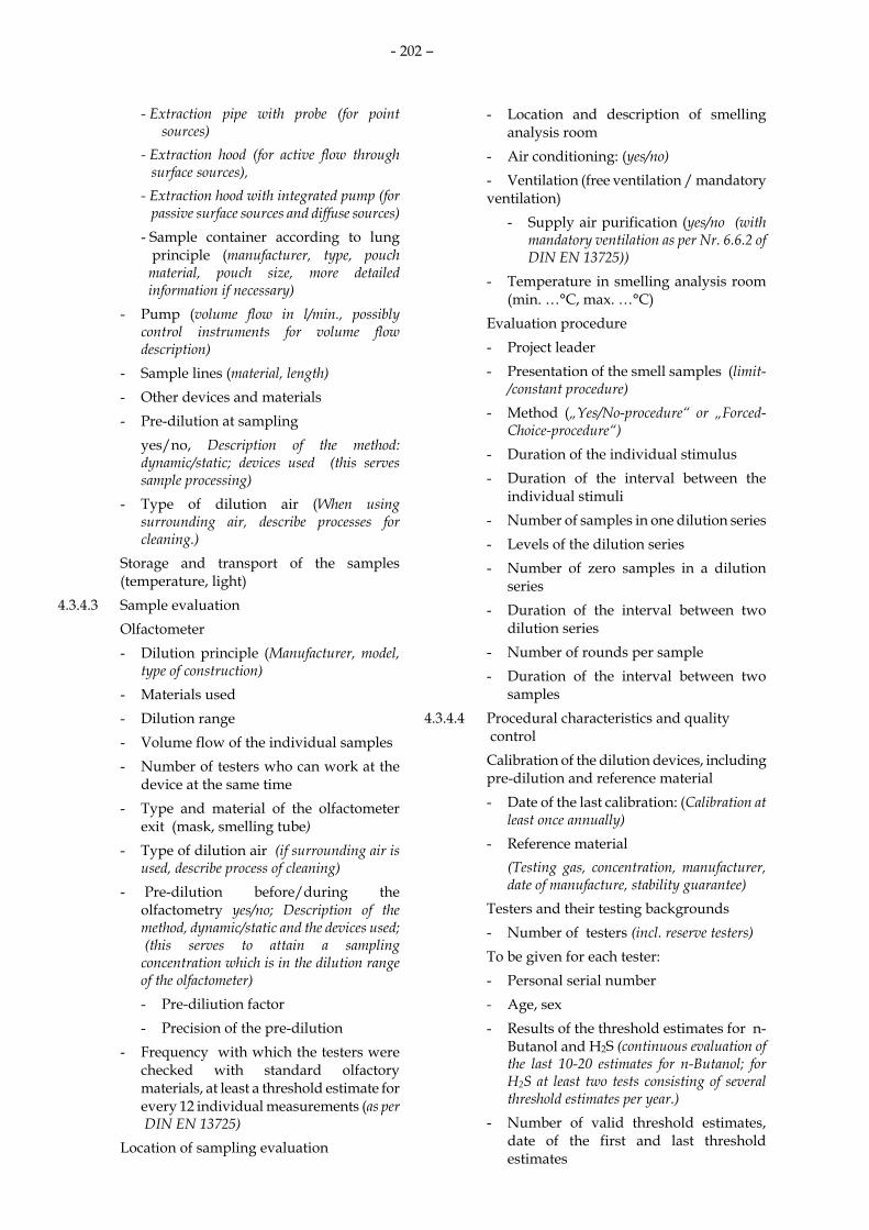
- 202 –
- Extraction pipe with probe (for point sources)
- Extraction hood (for active flow through surface sources),
- Extraction hood with integrated pump (for passive surface sources and diffuse sources)
- Sample container according to lung principle (manufacturer, type, pouch material, pouch size, more detailed information if necessary) - Pump (volume flow in l/min., possibly
control instruments for volume flow description)
- Sample lines (material, length) - Other devices and materials - Pre-dilution at sampling yes/no, Description of the method:
dynamic/static; devices used (this serves sample processing)
- Type of dilution air (When using surrounding air, describe processes for cleaning.)
Storage and transport of the samples (temperature, light)
4.3.4.3 Sample evaluation Olfactometer - Dilution principle (Manufacturer, model,
type of construction) - Materials used - Dilution range - Volume flow of the individual samples - Number of testers who can work at the
device at the same time - Type and material of the olfactometer
exit (mask, smelling tube) - Type of dilution air (if surrounding air is
used, describe process of cleaning) - Pre-dilution before/during the
olfactometry yes/no; Description of the method, dynamic/static and the devices used; (this serves to attain a sampling concentration which is in the dilution range of the olfactometer)
- Pre-diliution factor - Precision of the pre-dilution - Frequency with which the testers were
checked with standard olfactory materials, at least a threshold estimate for every 12 individual measurements (as per DIN EN 13725)
Location of sampling evaluation
- Location and description of smelling analysis room
- Air conditioning: (yes/no) - Ventilation (free ventilation / mandatory
ventilation) - Supply air purification (yes/no (with
mandatory ventilation as per Nr. 6.6.2 of DIN EN 13725))
- Temperature in smelling analysis room (min. …°C, max. …°C)
Evaluation procedure - Project leader - Presentation of the smell samples (limit-
/constant procedure) - Method („Yes/No-procedure“ or „Forced-
Choice-procedure“) - Duration of the individual stimulus - Duration of the interval between the
individual stimuli - Number of samples in one dilution series - Levels of the dilution series - Number of zero samples in a dilution
series - Duration of the interval between two
dilution series - Number of rounds per sample - Duration of the interval between two
samples 4.3.4.4 Procedural characteristics and quality
control Calibration of the dilution devices, including
pre-dilution and reference material - Date of the last calibration: (Calibration at
least once annually) - Reference material (Testing gas, concentration, manufacturer,
date of manufacture, stability guarantee) Testers and their testing backgrounds - Number of testers (incl. reserve testers) To be given for each tester: - Personal serial number - Age, sex - Results of the threshold estimates for n-
Butanol and H2S (continuous evaluation of the last 10-20 estimates for n-Butanol; for H2S at least two tests consisting of several threshold estimates per year.)
- Number of valid threshold estimates, date of the first and last threshold estimates

- 203 –
- Numerus of the standard deviation 10sITE (for n-Butanol und H2S)
- Numerus of the average value 10 y ITE of all valid threshold estimates (only for n-Butanol)
Total sensorial quality of the laboratory To be proven yearly (Evaluation of at least 10 testresults in the past 12 months)
- Repeatability r (for n-Butanol and H2S)
- Precision Aod (only for n-Butanol)
- Detection limit for olfactory measurements (as per DIN EN 13725)
Standard olfactory materials Data on the standard materials used n-Butanol and H2S (concentration, manufacturer, date of manufacture, stability guarantee).
5 Operating conditions of the plant during
measurements The test laboratory must ensure that the
entire plant operation conditions are detected during measurements. If the operator of the plant makes data available, there must be random tests to determine its accuracy. It should also be indicated in what way data were produced, i. e. from operator or by the institute’s equipment or personnel
5.1 Production facilities - Operating state (e. g. normal operation,
batch process, running up, representative operating state, special situations relevant for emissions)
- Throughput/output (process data, steam etc. percentage of
max. capacity) - Materials used/fuels - Products - Characteristic operating data (e. g. pressures, temperatures) - Deviations from approved or customary
operations (e. g. output, use of other raw materials, reasons for this)
- Special circumstances (especially those which would have an effect on the emissions of the plant)
5.2 Waste-gas purification facilities (see Appendix 2) - Operating data
(e. g. power input, pressure ph-values), temperature of the TNV, operating time of the catalyst)
- Operating temperatures (TNV, scrubber, catalyst, ..) - Parameters which influence emissions (e.
g. cleaning cycles, ph-values, temperature of the TNV, operating time of the catalyst)
- Specific characteristics of the waste-gas purification
(in-house construction, additional water injection)
- Deviation from normal operation conditions (e. g. low volume flow/temperature (cf. point 2.6), reasons for this)
- Special circumstances (especially those which influence emissions).
6 Summary of the measurement results and
discussion 6.1 Evaluation of the operating conditions
during the measurements. Evaluation of the operating conditions with regard to the approved and/or normal operations of the plant in question (manner of operation, output, materials used).
Comment on any deviation from the planned or normal operations as well as any consequences this may have for emissions.
The expert must make a clear evaluation as to whether at the time of measurement the requirement of No. 5.3.2.2 TA Luft (highest emission) was complied with (representativity of the measurements).
6.2 Measurement results All the individual results (e. g. half-hour
average values) of the components measured as well as the required auxiliary data and the original data (analysis values, raw data from automatic measurement devices) are to be presented in tabular form together with the time of the measurement. This time data is of particular importance with non-uniform processes or where there were significant changes in operations. The temporal correlation of the measurements

- 204 –
and the operating state should be presented clearly .
The pollutant emissions are to be presented as concentration in standardized form, usually in relation to dry waste-gas and, if necessary, to a given oxygen content and as mass flows. All of the numerical values are to be meaningful rounded and the end results are to be rounded as per No. 2.9 TA Luft. Dilutions of the air are to be given as per No. 5.1.2 TA Luft. In addition, the maximum and average values of the measurements are to be given. To give a better overview of continuous monitoring, it should be presented in graphic form. In such a graphic presentation, including values which had not been included elsewhere as well as the recorded raw data is advisable. The recorded data should also make the test-gas results recognizable. The legal bases for these measurements which derive from EN standards and the VDI guidelines are to be taken into account.
If the standards require separate analytic of the first and second phases of sampling, both values are to be given at the report. When converting the analysis results into concentration values [mg/m³], separate indications of the load of the individual phases is no longer necessary
When converting the measured mass concentration of nitrogen oxide to a reference value for organically bound nitrogen and to the reference conditions 10 g/kg air humidity and 20 ° C incineration air temperature as per TA Luft (No. 5.4.1.2.2), the measurement values are to be given for nitrogen oxide concentration (in mg/m³); for the oxygen content in vol.-%, for temperature and humidity of the incineration air; additionally the nitrogen oxide concentration (in mg/m³, related to the reference oxygen content) as corrected according to DIN EN 267 and the content of organically bound nitrogen in the heating oil is to be given.
If technically required, the determination of
field blind values (or from device-generated blind values or total blind values), then the following data are required:
- Time of taking the field blind value
sampling - Components of the field blind value rinsing
(solution, sorption level, filter….)
- The field blind value’s mass/ sample - The field blind value concentration in
mass/m3 - Indications of the volume used to calculate
the blind value concentration - Results of the test for adherence to the
technical requirements for the maximum height of the field blind values
- Indication of the blind value concentrations in relation to the measurement values.
When measuring highly toxic waste-gas components, the following are also required:
- Data on the retrieval rate of the sampling standards
When evaluating the olfactometrical measurements, the following data are required
- Date and time (beginning and end) of the sampling
- Pre-dilution of the sample, if yes, indication of the dilution factor
- Storage time of each sample in minutes - Pre-dilution before/during the
olfactometrical evaluation. If yes, indication of the pre-dilution factor.
- Date and beginning of the olfactometrical evaluation of each sample
- Complete data matrix together with zero samples
- Number of zero sample or invalid evaluations per tester
- Results of the subsequent selection - Results of all tests with standard olfactory
material (n-Butanol) during the measurements and corresponding to DIN EN 13725
Provisional results, computations and protocols are to be included as appendices. All measurement protocols are to be stored for five years by the measuring institution. 6.3 Measurement uncertainties The guideline VDI 4219 directs that in order to determine the measurement uncertainty of discontinuous emission measurements parallel measurements are to be used (direct method) as well as indirect approaches using the analysis of the partial steps in the complete measurement process. For all these measurement values, it must be indicated according to which procedures and for which
- 205 –
procedural steps the measurement uncertainty was determined. The measurement unreliabilities are to be given as an extended measurement uncertainty (Up = k * uc) For the extended uncertainty the confidence interval p as per DIN EN 13005 is to be given. As a rule, p = 0.95, corresponding to a statistical certainty of 95 %, or an error probability of 5 % (k = 2.086 at N = 20 double determinations). The measurement uncertainty for the entire procedure is to be given. This means that the measurement uncertainty both the sampling procedure as well as the characteristics of the sampling point (position of the measurement cross section at the duct or distributions over the measurement cross section) must be taken into account. The measurement cross section offers adequate data for the representative determination of measurement components (presentation of measurement strategies with standardized and non-standardized measurement sections) as well as for the comparability of other associated factors and procedural verification. (see following table) 6.4 Plausibility test There is to make a plausibility test of the
measurement results with regard to the plant load during the measurement period.
In this connection the manner in which the plausibility test was carried out is to be described aswell as those factors which were taken into account. Such factors might be:
- Previous knowledge of the plant - Previous knowledge of comparable
plants - Comparison of various measurement
values - Correlation of signal patterns with
varying operating states Signature of author Signature of (Project Manager) technical supervisor

- 206 –
.
Measure-ment componenty
Maximum measurement values ymax
Extended measurement uncertainty (Up)
ymax - Up ymax + Up Determination method
.... .... .... with p=....
.... .... [...] direct method (parallel measurements) [...] indirect approach

- 207 –
7 Appendix - Overview
Appendix 1: Measurement plan
Appendix 2: Measured and calculated values
Appendix 3.:Catalogue of facilities for reducing emissions
Appendix 4: Catalogue of data to be given for waste-gas purification systems
Appendix ….
Appendix 1
Measurement plan
Appendix 2
Measured and calculated values
Appendix 2 shows all the measured, calculated and analysis values. In addition, there is a table of results which assigns each individual result to a corresponding measurement uncertainty (see below).
No. Date/ Sampling time
from ….till
free choicable text
measured value [dimension]
measurement uncertainty (mu)
[dimension]
measured value + mu
[dimension]
1 06.11.06/10:08-10:38 15,3 2,3 17,6

- 208 –
Appendix 3
Catalogue of devices for reducing emissions
These are the minimum requirements; expanded specifications as per VDI 2448, page 1 are to be recommended (Other purification systems are to be discussed at analogical. Normally only one of the alternative waste-gas purification systems is to be given for each plant. It is possible, however, to describe combined systems. The specifications in Nr. 2.6 are required (among other regulations) by TA Luft Nr. 5.3.2.4)
1. Electrostatic precipitator Manufacturer, model Year manufactured Number of filter zones Effective precipitate surface Dwell time in the electrical field De-dusting: wet/mechanical Upstream cooling yes/no Water injection upstream of filter: yes/no Flow through filter Nominal rate of the suction fan Maintenance intervals Last maintenance
2. Thermal incineration units with/without heat exchanger Manufacturer, model Year manufactured Type of burner Type of additional fuel Fuel throughput Temperature of the reaction chamber Dwell time in the reaction chamber Nominal rate of the suction fan Maintenance intervals Last maintenance
3. Catalytic incineration systems Manufacturer, model Year of manufacture Type of burner Type of additional fuel Fuel charge Type of catalyst Operating time of the catalyst Temperature of the reaction chamber Dwell time in the reaction chamber Possible catalyst poisons Nominal rate of the suction fan
Maintenance intervals Last maintenance 4. Activated carbon filter with/without recovery Manufacturer, model Year of manufacture Activated carbon content Supplier/granulation/type of A-carbon Thickness of the A-carbon layer in the adsorber Cross section of A-carbon in the adsorber Type of desorption Frequency of desorption Nominal rate of the suction fan Pressure difference crude gas/purified gas Maintenance intervals Last maintenance
5. Cyclone unit Manufacturer, model Year of manufacture Number of individual cyclones Arrangement parallel/in series Cyclone diameter Nominal rate of the suction fan Type of dust discharge Pressure difference crude gas/purified gas Gas volume flow Maintenance intervals Last maintenance
6. wet precipitator
Manufacturer, model Year of manufacture Type of washing liquid Working principle of the wet precipitator, e. g. Scrubbing tower, Venturi scrubber Vortex scrubber Rotary scrubber Pressure change precipitator
- with a scrubbing tower Scrubbing fluid flow: co-current, couter-current, crosscurrent Construction: without internals, with plates, filling body Number of plates: Type of plates: sieve plates, bubble cup plates, etc. etc.

- 209 –
Height of packed column Type of packing: raschig rings, saddle bodies, discs Type of scrubbing fluid
- with vortex scrubber - Water level Sludge discharge
- with pressure change precipitators - Number of precipitation elements Scrubbing fluid Additives Amount of scrubbing fluid
- for all wet precipitators-
Amount of fresh scrubbing liquid added Pattern of scrubbing liquid replacement pH-valuet Level 1 Level 2 Temperature of the scrubbing fluid in the reservoir Last replacement of the scrubbing fluid in the settling tank: Type of downstream droplet precipitator Nominal rate of the suction fan Maintenance intervals Last maintenance:
7. Woven fabric filter Manufacturer, model Year of manufacture Number of filter zones Number of filter tubes/bags Filter area Throughput per unit area of filter gross/ net Filter material Type of cleaning mechanical/ pneumatic dedusting Last filter cloth change Pressure difference between raw gas and pure gas side Nominal rate of the suction fan Type of dust discharge Maintenance intervals Last maintenance
8. Nitrogen oxide reduction measures
Primary measures - Flue gas recirculation
- Progressive incineration etc. Secondary measures - SNCR - SCR - Reducing agent
9. Biofilter Manufacturer, model Year of manufacture Bed depht Throughput per unit area Material (e. g. compost, heather, peat, tree bark) Raw gas temperature Humidity of the raw gas Pressure difference between raw gas/pure gas Intervals between services Last service Maintenance intervals Last maintenance
10. Condensation and sedimentation precipitation
Manufacturer, model Year of manufacture Type of construction Flow (direct-current, co-current, cross-current) Coolant Condensate removal Baffles Position switch Ribbed tubes Injection condensers Pressure drop Maintenance intervals Last maintenance
Appendix 4
Catalogue of the operating data which is to be given for waste-gas purification systems
- Filtering precipitators Cleaning cycle Pressure drop Last filter change
- Electrical precipitators Current consumption of the fields/generators Knocking cycle Last maintenance
- Mechanical precipitators

- 210 –
Last cleaning Last maintenance
- Thermal afterburning Fuel use Afterburner temperature Last maintenance
- Catalytic afterburning Energy input Operating temperature Catalyst operating time Last maintenance
- Adsorber Adsorbent Operating time Operating temperature Last maintenance
- Absorber (chemic absorption)
Absorbent Model/type Circulating quantity Freshly added quantity Pressure drop Last maintenance Last absorbent change
- Liquid separators
Absorbent Additives pH-value Pressure drop Operating temperature Washing fluid circulation/intake Last replacement of the absorbent
- Biofilters Last change of the filter bed Thickness of layer Pressure drop Crude gas moisture content Crude gas temperature

- 211 –
7.11 Standard reports on annual surveillance tests and calibrations of automated measuring systems Source: VDI 3950, [December 2006] „Stationary source Emissions – Quality assurance of automated measuring and electronic data evaluation systems“
Annex A Standard report on checking the correct installation of automated measuring and electronic data evaluation system Name of the test institute notified according to § 26 of BImSchG Reference number: Date: Report on checking the correct installation of automated measuring and electronic data evaluation systems Plant operator: ................................................................................................................................ Location: ................................................................................................................................ Order number: ................................................................................................................................ Order date: ................................................................................................................................ Date of test: ................................................................................................................................ Report contents : ......................... Pages ........................... Appendices
All numbers of this standard report shall always be completed. Numbers which are not applicable shall be marked as „not applicable“. Numbers 3 and 4 shall be completed separately for each measured object continuously monitored. In the nomenclature, the measured object shall be inserted within square brackets in the first and second levels, for example 3 [NOx] and 4 [NOx]. For improved clarity within numbers 3 and 4, as to which measured object is being dealt with, it is advisable, in addition to listing the respective measured object monitored in the main headings, to list this also in footers and headers. All hints and examples are printed in italics. This information shall be deleted in the final report.
Table of contents 1 Objectives ....................................................................................................................................................<##> 2 Description of the plant and the materials handled .......................................................................................<##> Module [<Measured object 1>] 3 [<Measured object 1>] Description of the AMS and the electronic data evaluation system .....................<##> 4 [<Measured object 1>] Test of the correct installation of the AMS ...............................................................<##> : : Module [<Measured object n>] 3 [<Measured object n>] Description of the AMS and the electronic data evaluation system .....................<##> 4 [<Measured object n>] Test of the correct installation of the AMS ...............................................................<##> 5 Test of the correct installation of the electronic data evaluation system .....................................................<##> 6 Summary ...................................................................................................................................................<##> Appendices ....................................................................................................................................................<##>

- 212 –
1 Objectives 1.1 Client: 1.2 Plant operator:
name, address contact person, telephone number
Work place number: depending on the Federal State
1.3 Location: The information as to the location shall clearly indicate the position of the emission source in case of a larger site (for example site C ..., Building 5).
1.4 Plant: information with reference to 4th BImSchV
Plant number: depending on the Federal State
1.5 Date of test: 1.6 Reason: not applicable 1.7 Objectives:
In this section the objectives of the measurement task shall be described in detail. In case of measurements according to the licence, orders or ordinances on the implementation of the Federal Immission Control Act (BImSchG), the corresponding sections and the limit values shall be given. Any existing information on the plant (e. g. preliminary tests, adjustments of the plant, information provided by the plant operator) shall be given.
1.8 Measured objects: specification of the waste gas constituents or waste gas parameters to be continuously measured
1.9 Agreement of the measurement plan: not applicable 1.10 Personnel involved in the test:
names of the personnel including temporary workers 1.11 Participation of further institutes: not applicable 1.12 Technical supervisor:
name, telephone number, e-mail address 2 Description of the plant and the materials handled 2.1 Type of plant:
if necessary, any designation deviating from the 4th BImSchV for more precise description 2.2 Description of the plant:
Brief description of the plant and the process with particular emphasis on the plant components which are of particular importance in connection with the emission of air pollutants. Important characteristics such as model, year of manufacture, boiler and factory number are to be indicated. The plant description also include the absolute and the specific nominal power. Reference quantities can be, for example, raw materials and/or products. Parameters customary for the branch of industry shall be used. The figures shall be able to be assigned, as appropriate, to the operating unit or the respective emission source. Thus, fuels or heating media used for specific plant components or operating units are to be indicated, since in connection with No. 2.4 it can here be possible to draw conclusions as to the emission characteristics of the plant, e. g. fuel ratios in the case of mixed firing. In complex cases, a simplified flow diagram of the plant is to be attached.
2.3 Description of the emission sources Emission source:
– height above ground:
– cross-sectional area of outlet:
– easting/northing value:

- 213 –
– building design: 2.4 Statement of raw materials possible according to the permit:
complete summary of all emission relevant raw materials, for instance fuel ratios in the case of mixed firing
2.5 Operating times: not applicable 2.6 Device for collecting and reducing the emissions:
A description of these devices should make possible an assessment of the waste gas purification equipment and give an indication of the emissions to be expected.
2.6.1 Device collecting the emissions: apparatus for emission collection, collection element, fan data, suction area
2.6.2 Device reducing the emissions: description according to the standard report on emission measurements, Appendices 3 and 4, published in VDI 4220, Annex B
3 [<Measured object>] Description of the AMS and the electronic data evaluation system 3.1 [<Measured object>] Sampling location 3.1.1 Location of the measurement cross-section:
The exact position of the measurement cross-section in the waste gas duct is to be indicated for each measured object continuously monitored. The position of the measurement cross-section shall be indicated in such a way that it can be unambiguously seen from the description whether the installation of the sampling site has been carried out in accordance with VDI 4200. If the sampling site does not correspond to VDI 4200 in exceptional cases, a corresponding assessment shall be carried out and measures to be taken shall be described to achieve representative measured values.
3.1.2 Dimensions of the measurement cross-section: 3.1.3 Description of sampling: 3.1.3.1 Type of sampling: extractive/in-situ 3.1.3.2 Sampling method:
In the case of extractive sampling, the method of taking samples (point, line, grid measurement) shall be described. Each constituent shall be sampled in accordance with VDI 4200. The number of measurement axes and the position of the measurement points in the measurement cross-section, which ensure representative sampling, shall be specified.
3.2 [<Measured object>] Sample gas conditioning: not applicable to in-situ measurements Devices for extracting the waste gas sample and its conditioning shall be described.
Sampling probe/dust filter: – manufacturer: – type: – unheated/heated to: ............ °C – material: Sample gas line before gas treatment: – manufacturer: – type: – unheated/heated to: ............ °C – length: ............. m – internal diameter: ............. mm – material of gas-bearing parts: Sample gas conditioning, sample gas cooler: – manufacturer: – type: – temperature, controlled to: ............... °C Sample gas line downstream the sample gas conditioning: – length: ............. m – material of gas-bearing parts:

- 214 –
3.3 [<Measured object>] Measuring system: The measuring system for determining the measured object shall be described. The available aids (test rods, calibration gases) shall be listed. All instrument specifications (for example measuring ranges and zero point setting) shall be specified.
3.3.1 Measurement method: 3.3.2 Analyser:
– manufacturer: – type: – year of manufacture: – instrument no.: – version number of the software used: – installation location: – ambient temperature: ...............°C – maintenance interval: – type of span point check: automatic/manual
3.3.3 Measuring ranges set: 3.3.4 Declaration of suitability:
It shall be specified whether the measuring system used has been suitability-tested for the measurement task and whether the report on the suitability test was present. A reference to the publication of the declaration of suitability shall be given. Instrument specific hints and recommendations for practical application as well as for the functional tests or calibrations shall be quoted from the suitability test report. At least the following performance characteristics shall be specified if the measuring system is not suitability-tested:
– influence of interfering components (cross-sensitivity) – response time (90-% time) – detection limit – zero point drift and span point drift – standard deviation, if appropriate – linearity
The way in which these data were determined shall also be specified. 3.3.5 Recording system:
Chart recorder or redundant electronic recording system (see No. 3.4) – manufacturer: – type: – quality class: not applicable in case of redundant electronic recording system – chart width: – chart speed: – display range: – measured objects monitored:
3.3.6 Logbook (records) kept: yes/no 3.4 [<Measured object>] Electronic data evaluation system
– manufacturer: – type: – year of manufacture: – version number of the software used: – declaration of suitability:
It shall be specified whether the electronic data evaluation system used has been suitability-tested for the measurement task and whether the report on the suitability test was present. A reference to the publication of the declaration of suitability shall be given. Instrument specific hints and recommendations for practical application shall be quoted from the suitability test report.
– parameter setting: Listing of operating modes; operating states, special classification, mixed firing; start-up and shut-down operation, definition of a fault in waste gas cleaning system. Statements shall be made for plants with

- 215 –
bolting conditions (e. g. 17th und 27th BImSchV) whether these connections are available. In case of plants according to 30th BImSchV it has to be described how weighing data obtained at the waste delivery are securely transmitted to the electronic data evaluation system.
– installation location: – ambient temperature: ...............°C – protection against unauthorised parameter changes:
key-switch, password, date of last parameter change – printer or redundant electronic recording system: – telephone line: ISDN/analogue: Remote emission control: yes/no – actual software version: – declaration of suitability:
Reference to the publication
4 [<Measured object>] Test of correct installation of the AMS The test shall be based on the requirements of guidelines VDI 4200 and VDI 3950 as well as on the performance criteria for suitability testing of measuring systems. It shall be checked that hints and limitations included in the declaration as suitability-tested measuring system have been taken into account.
4.1 [<Measured object>] Test of the installation location 4.1.1 Ambient temperature and ambient humidity:
Based on the local conditions the environmental conditions shall be specified. Possible influences on the measuring system shall be specified. Particularly influences caused by neighbouring plants, non-insulated waste gas carrying ducts, radiating surfaces and weather shall be described and assessed.
4.1.2 Oscillations and vibrations: It shall be specified whether vibrations or oscillations are present at the mounting position of the automated measuring system. It may be necessary for this assessment that the plant to be monitored is in operation.
4.1.3 Weather protection: Measures taken to protect the measuring system against weather shall be described. It shall be assessed whether these measures are sufficient.
4.1.4 Limitation of operation based on suitability test results: It shall be specified whether the operational conditions determined are in conflict with specified limitations or hints given in the declaration of suitability. Method related limitations of operation of the measuring system shall be tested.
4.1.5 External influences e. g. by gases, vapours, electric or magnetic fields: It shall be tested for each measuring system whether influences are to be expected at the location of the measuring system, the sample gas preparation and peripheral devices. Corrosion and electromagnetic influences on the electronic hardware shall be checked.
4.1.6 Accessibility, space and safety conditions at the mounting location: The accessibility and space conditions shall be checked with respect to regular maintenance and repeated calibrations. It shall be guaranteed that sufficient space is available for test gases, tools and test devices used for maintenance as well as for the personnel required. The available space shall allow for setting up all test devices and measurement methods needed for calibration. It shall be specified whether the handling of measuring systems is possible, e. g. opening of housings or instrument cabinets and moving the sampling probe. The main dimensions of the working platform shall be specified. The measurement sites shall fulfil all safety requirements.
4.1.7 Influences caused by other measuring systems: This information shall allow an assessment of possible influences caused by other measuring systems.
4.1.8 Waste gas conditions: The expected velocity, humidity, pressure and temperature of the waste gas at the measurement cross-section shall be specified, if such data is known.
4.2 [<Measured object>] Test of the installation of the AMS 4.2.1 Installation of sampling lines:
- 216 –
The installation of sampling lines shall be described with respect to their laying and length. The specification, sampling line material and heating shall be specified. The installation shall be checked with respect to unheated sections, e. g. at connections and transitions.
4.2.2 Installation of sample gas preparation: The location of the sample gas preparation in the gas flow shall be described. A visual inspection of the sample gas cooler shall be carried out with respect to condensation and discharge of condensate.
4.2.3 Installation of measuring systems: The installation of measuring systems e. g. at the waste gas duct or in the measurement container shall be described. All sample gas carrying parts of the gas flow after the sample gas preparation shall be described and assessed with respect to correct laying and heating. The installation shall be documented by means of a gas flow plan. The agreement with this gas flow plan shall be checked.
4.2.4 Check of the installation of devices for preparation of external standards (test gases): The installation of devices for manual feeding of test gases or automatic check of the zero and span point shall be described and compared with the suitability-tested specifications. The test gas concentrations shall be specified.
4.3 [<Measured object>] Check of the measurement site for parallel measurements 4.3.1 Location of the measurement cross-section:
The exact location of the measurement cross-section for parallel measurements in the waste gas duct shall be specified. This includes specification of the lengths of the inlet and outlet sections. The location of the measurement cross-section shall be described with respect to the sampling location or measurement section of the continuous measurement. The specification of the location of the measurement cross-section shall provide an unambiguous description whether the sampling location meets the requirements of guideline VDI 4200 or DIN EN 13284-1. Reasons shall be given if the sampling location does not meet the requirements. In this case, measures to be taken shall be described to achieve measured results of sufficient quality.
4.3.2 Measurement ports for parallel measurements: 4.3.3 Accessibility, space and safety conditions at the measurement site for parallel measurements:
The accessibility and space conditions shall be checked with respect to regular maintenance and repeated calibrations. It shall be guaranteed that sufficient space is available for test gases, tools and test devices used for maintenance as well as for the personnel required. The available space shall allow for setting up all test devices and measurement methods required for calibration. It shall be specified whether the handling of measuring systems is possible, e. g. opening of housings or instrument cabinets and inserting, positioning and removing of sampling probes. The main dimensions of the working platform shall be specified. The measurement sites shall meet all safety requirements.
4.4 [<Measured object>] Functional test If a complete functional test is carried out as part of the initial calibration in close temporal connection with the check of correct installation (within 4 weeks), then the proof of the functional test can also be given and documented as part of the initial calibration.
4.4.1 Functional test for extractive sampling 4.4.1.1 Description of instrument status:
The results of the visual inspection and the check of serviceability and prevention of unauthorised maladjustment shall be presented. The description of the instrument status shall include the gas sampling and conditioning devices. Special observations recorded in the logbook (records) shall be declared in the report.
4.4.1.2 Testing for leaks: Testing for leaks shall include gas sampling and conditioning devices. An indication shall be given as to how leak tests were carried out.
4.4.1.3 Check of the linearity of the instrument characteristic: The way in which the determination was carried out and the test means used shall be specified, for example test gases, test grating filters, test rods. The individual readings at each test standard applied shall be presented in a table in temporal sequence. The linear regression between all AMS measured signals and all values of the test standards applied shall be presented as an equation in accordance with Annex B of DIN EN 14181 and as a graph. The residuals

- 217 –
between the average concentrations and the regression line shall be calculated and checked for each concentration in accordance with Annex B of DIN EN 14181. The results of this check shall be documented.
4.4.1.4 Check of the zero point and span point: The reference materials applied in this check shall be described. The results shall be documented and assessed by comparison with the performance criteria for zero and span point drift in the maintenance interval used in the suitability test.
4.4.1.5 Determination of the response time: The value of the response time (90-%-time) as well as the procedure for its determination shall be described.
4.4.1.6 Check of the cross-sensitivities: The extend of the cross-sensitivity test depends on the specific composition of the waste gas and on the measurement method (see report of the suitability test of the AMS). The presentation of the results shall include the maximum permissible cross-sensitivity and also the actual cross-sensitivities found.
4.4.1.7 Description of the test gases of the plant operator: – zero gas: – span gas: – nominal concentration: – uncertainty: – cylinder number: – manufacturer: – production date: – guarantee of stability: ................. months – test method in case of internal reference materials: – test result:
The test gases of the plant operator shall be described. If the AMS is adjusted with internal reference materials (e. g. automatic adjustment with sway cuvettes), these have to be checked.
4.4.1.8 Check of the records and the logbook: The check of the AMS records and of the logbook shall be documented. It has to be checked especially that a plan of the AMS, the suitability-test report, the operating instructions and the logbook are available. Test procedures and protocols and the maintenance time schedule as well as records on training courses for the plant personnel shall be checked. Furthermore, it shall be checked that a documentation on the check of drift and precision (QAL 3) by control charts exists.
4.4.2 Functional test for in situ measurements 4.4.2.1 Description of instrument status:
The results of the visual inspection and the check of serviceability and prevention of unauthorised maladjustment shall be presented. Particular attention shall be paid to determining the state of the optical interfaces (cleanliness). The purge air supply and the alignment of the measuring system shall be checked. Special observations which are indicated in the records (logbook) shall be specified in the report.
4.4.2.2 Check of the linearity of the instrument characteristic: The way in which the determination was carried out and the test means used shall be specified, for example test gases, test grating filters, test rods. The individual readings at each test standard applied shall be presented in a table in temporal sequence. The linear regression between all AMS measured signals and all values of the test standards applied shall be presented as an equation in accordance with Annex B of DIN EN 14181 and as a graph. The residuals between the average concentrations and the regression line shall be calculated and checked for each concentration in accordance with Annex B of DIN EN 14181. The results of this check shall be documented.
4.4.2.3 Check of the zero point and the span point in a section free from waste gas: The check of the zero point and span point shall be described. The results of the check shall be assessed by comparison with the performance criteria on the zero point and span point drift in the maintenance interval used in the suitability test, for example in the following form:

- 218 –
– before adjustment – after adjustment – after installation The state of the test standards of the plant operator shall be described. If these standards have been checked, the test procedure shall be described and the results be documented.
4.4.2.4 Determination of the response time: The value of the response time (90-%-time) as well as the procedure for its determination shall be described.
4.4.2.5 Check of the cross-sensitivities: The extend of the cross-sensitivity test depends on the specific composition of the waste gas and on the measurement method (see report of the suitability test of the AMS). The presentation of the results shall include the maximum permissible cross-sensitivity and also the actual cross-sensitivities found.
4.4.2.6 Check of the records and the logbook: The check of the AMS records and of the logbook shall be documented. It has to be checked especially that a plan of the AMS, the suitability-test report, the operating instructions and the logbook are available. Test procedures and protocols and the maintenance time schedule as well as records on training courses for the plant personnel shall be checked. Furthermore, it shall be checked that a documentation on the check of drift and precision (QAL 3) by control charts exists.
5 Test of the correct installation of the electronic data evaluation system 5.1 Check of the installation location: 5.2 Check of the installation: 5.3 Functional test of the electronic data evaluation system 5.3.1 Adjustment aids:
– manufacturer: – type: – quality class: – last check/calibration:
The adjustment aids used (for example precision current supply) shall be listed. 5.3.2 Check of the parameter list:
The parameter list shall be printed out and checked. When parameters have been changed, this shall be documented. In this case the list of parameters shall be attached as an appendix to the report.
5.3.3 Check of the data transmission from the measuring system to the electronic data evaluation system and test of the computations
The signal generation procedure and the check of the data transmission, the calculations (including validation) and the classification shall be described. In addition to tests near the limit value (TMW, HMW), signal transmission should be carried out in the lower and upper quartile of the measuring range (for example 6 mA, 18 mA). The rated values shall be compared with the actual values, the deviations specified and commented on. Checking the classification of, for example, half-hourly means, can be dispensed with (part of the suitability test of electronic data evaluation systems), if classification is dependent solely on a parameterised emission limit value, i. e. not in the case of mixed firing, for example.
5.3.4 Check of the data transmission from the measuring system to the recording devices: There is no explicit requirement for this check. For practical reasons, ± 2 % of the upper limit of the measuring range should be kept as a tolerance. The method for checking the data transmission and recording shall be described. In addition to testing near the limit value, the signal transmission shall be tested in the lower and upper quartile of the measuring range in the same way as in No. 5.3.3. The rated values shall be compared with the actual values, and the maximum deviation specified and, where appropriate, commented on. In case of redundant electronic recording devices, the correct functioning shall be checked.
5.3.5 Check of the status signals:

- 219 –
The signal generation procedure (for example simulating a fault in the AMS, actuating the service switch, shunting individual status contacts) as well as the check of the signal transmission, the calculations and the classification shall be described. If, for practical reasons, simulating operating contacts (for example fault in waste gas cleaning system) cannot be carried out, the location (terminal block, control cabinet) at which the respective status contact was bridged shall be specified.
5.3.6 Testing of printer functioning: 5.4 Testing of the remote emission control (EFÜ): 6 Summary The correct installation is certified/not certified. Signature of the person carrying out the work Signature of the responsible person or deputy Appendices:
Appendices can be attached to the report in digital form, e. g. as PDF file: – sketch of the location of the AMS measurement planes and of the measurement sites for parallel
measurements. – sketch of sampling, sample conditioning, measurement and data evaluation (if applicable) – signal flow diagrams (if applicable) – printout of the parameter list at the end of the testing day

- 220 –
Annex B Example of mounting location of measuring systems
Figure B1. Example of the mounting location of automated measuring system at a wastegas duct (outline) a) Top view, b) front view A Measurement axis, measurement plane S Socket R Reference (socket for reference measurements) S1 R S6 HCl, total carbon, humiditye S2 R S7 R S3 Dust (optical head) S8 Volume flow (transmitter) S3a Dust (reflector) S8a Volume flow (reciever) S4 SO2, NO, O2 S9 Temperature S5 R S9a Pressure

- 221 –
Annex C Standard report on annual surveillance tests and calibrations of automated measuring and electronic data evaluation systems
Name of the test institute notified according to § 26 of BImSchG Reference number: .......... Date: .....................
Report on annual surveillance tests and calibrations of automated measuring and electronic data evaluation systems
Plant operator: ................................................................................................................................ Location: ................................................................................................................................ Order number: ................................................................................................................................ Order date: ................................................................................................................................ Date and duration of the test: ........................................................................................................ Report contents : ......................... Seiten ........................... Appendices
All numbers of this standard report shall always be completed. Numbers which are not applicable shall be marked as „not applicable“. Numbers 3 to 7 shall be completed separately for each measured object continuously monitored. In the nomenclature, the measured object shall be inserted within square brackets in the first and second levels, for example 3 [NOx]. For improved clarity within numbers 3 to 7, as to which measured object is being dealt with, it is advisable, in addition to listing the respective measured object monitored in the main headings, to list this also in footers and headers. All hints and examples are printed in italics. This information shall be deleted in the final report.
Table of contents 1 Objectives ...................................................................................................................................................<##> 2 Description of the plant and the materials handled .......................................................................................<##> Module [<Measured object 1>] 3 [<Measured object 1>] Description of the AMS and the electronic data evaluation system .....................<##> 4 [<Measured object 1>] Sampling location for parallel measurements ..........................................................<##> 5 [<Measured object 1>] Measurement methods for parallel measurements .................................................<##> 6 [<Measured object 1>] Annual surveillance test of the AMS .........................................................................<##> 7 [<Measured object 1>] Determination of the calibration function and validation of the AMS .................<##> : : Module [<Measured object n>] 3 [<Measured object n>] Description of the AMS and the electronic data evaluation system .....................<##> 4 [<Measured object n>] Sampling location for parallel measurements .........................................................<##> 5 [<Measured object n>] Measurement methods for parallel measurements ................................................<##> 6 [<Measured object n>] Annual surveillance test of the AMS ........................................................................<##> 7 [<Measured object n>] Determination of the calibration function and validation of the AMS .................<##> 8 Operating state of the plant during the parallel measurements ...................................................................<##> 9 Annual surveillance test of the electronic data evaluation system ...............................................................<##> 10 Summary of the results .....................................................................................................................................<##> Appendices ....................................................................................................................................................<##>

- 222 –
1 Objectives 1.1 Client: 1.2 Plant operator:
Name, address, contact person, telephone number Work place number:
Depending on the Federal State 1.3 Location:
The information as to the location shall clearly indicate the position of the emission source in case of a larger site (for example site C ..., Building 5).
1.4 Plant: Information with reference to 4th BImSchV
Plant number: Depending on the Federal State
1.5 Date/Duration of the test: Functional test of the AMS: Performance of parallel measurements: Functional test of the electronic data evaluation system Previous functional test: Next functional test: Previous calibration: Next calibration: Presence of certificate of proper installation: yes/no
1.6 Reason and objectives: Description of the reason, type and objectives of the tests, for example – annual surveillance test with parallel measurements – initial calibration, repeated calibration. – all measured objects (continuously monitored waste gas components and waste gas parameters,
electronic data evaluation system) – emission limits (reference to specific sections of the plant licence or the order, limit values, relevant
specifications) 1.6.1 Deviations from DIN EN 14181:
deviations according to Section 6.3 and Section 6.6 of VDI 3950 and proof that the conditions are met (for example provision of annual printouts according to the „Federal Practice in Emission Monitoring”)
1.7 Measurement plan coordination: indication of with whom the measurement plan has been agreed, for example authority, plant operator
1.8 Personnel involved in the test: names of the personnel including auxiliary workers; project leader to be underlined
1.9 Participation of further institutes: All sub-contractors with their particular tasks or contributions shall be specified.
1.10 Technical supervisor: name, telephone number, e-Mail address
2 Description of the plant and the materials handled 2.1 Type of plant:
if necessary, any designation deviating from the 4th BImSchV for more precise description 2.2 Description of the plant:
Brief description of the plant and the process with particular emphasis on the plant components which are of particular importance in connection with the emission of air pollutants. Important characteristics such as model, year of manufacture, boiler and factory number are to be indicated. The plant description also include the absolute and the specific nominal power. Reference quantities can be, for example, raw materials and/or products. Parameters customary for the branch of industry shall be used. The figures shall be able to be assigned, as appropriate, to the operating unit or the respective
- 223 –
emission source. Thus, fuels or heating media used for specific plant components or operating units are to be indicated, since in connection with No. 2.4 it can here be possible to draw conclusions as to the emission characteristics of the plant, e. g. fuel ratios in the case of mixed firing. In complex cases, a simplified flow diagram of the plant is to be attached.
2.3 Description of the emission sources Emission source:
– height above ground: – cross-sectional area of outlet: – easting/northing value: – building design:
2.4 Statement of raw materials possible according to the permit: complete summary of all emission relevant raw materials, for instance fuel ratios in the case of mixed firing
2.5 Operating times: not applicable 2.6 Device for collecting and reducing the emissions:
A description of these devices should make possible an assessment of the waste gas purification equipment and give an indication of the emissions to be expected.
2.6.1 Device collecting the emissions: apparatus for emission collection, collection element, fan data, suction area
2.6.2 Device reducing the emissions: description according to the standard report on emission measurements, Appendices 3 and 4, published in VDI 4220, Annex B
3 [<Measured object>] Description of the AMS and the electronic data evaluation system 3.1 [<Measured object>] Sampling location 3.1.1 Location of the measurement cross-section:
The exact position of the measurement cross-section in the waste gas duct is to be indicated for the particular measured object continuously monitored. The position of the measurement cross-section shall be indicated in such a way that it can be unambiguously seen from the description whether the installation of the sampling location has been carried out correctly.
3.1.2 Dimensions of the measurement cross-section: 3.1.3 Description of sampling: 3.1.3.1 Type of sampling: extractive/in-situ 3.1.3.2 Sampling method:
In the case of extractive sampling, the method of taking samples (point, line, grid measurement) shall be described. Each constituent shall be sampled in accordance with VDI 4200. The number of measurement axes and the position of the measurement points in the measurement cross-section, which ensure representative sampling, shall be specified.
3.2 [<Measured object>] Sample gas conditioning: not applicable to in-situ measurements Devices for extracting the waste gas sample and its conditioning shall be described.
Sampling probe/dust filter: − manufacturer: − type: − unheated/heated to: ............ °C − material: Sample gas line before gas treatment: − manufacturer: − type: − unheated/heated to: ............ °C − length: ............. m − internal diameter: ............. mm − material of gas-bearing parts: Sample gas conditioning, sample gas cooler:

- 224 –
− manufacturer: − type: − temperature, controlled to: ............... °C Sample gas line downstream the sample gas conditioning: − length: ............. m − material of gas-bearing parts:
3.3 [<Measured object>] Measuring system: The available test standards (test rods, calibration gases) shall be listed. All instrument specifications (for example measuring ranges and zero point setting) shall be specified.
3.3.1 Measurement method: 3.3.2 Analyser:
– manufacturer: – type: – year of manufacture: – instrument no.: – version number of the software used: – installation location: – ambient temperature: ...............°C – maintenance interval: – type of span point check: automatic/manual
3.3.3 Measuring ranges set: 3.3.4 Declaration of suitability:
It shall be specified whether the measuring system used has been suitability-tested for the measurement task and whether the report on the suitability test was present. A reference to the publication of the declaration of suitability shall be given. At least the following performance characteristics shall be specified if the measuring system is not suitability-tested: – influence of interfering components (cross-sensitivity) – response time (90-%-time) – detection limit – zero point drift and span point drift – standard deviation, if appropriate – linearity The way in which these data were determined shall also be specified.
3.3.5 Certificate on the correct installation The date of the certificate and the name of the issuing test institute shall be specified.
3.3.5 Recording system: chart recorder or redundant electronic recording system (see No. 3.4)
– manufacturer: – type: – quality class: not applicable in case of redundant electronic recording system – chart width: – chart speed: – display range: – measured objects monitored:
3.3.6 Logbook (records) kept: yes/no 3.4 [<Measured object>] Electronic data evaluation system
– manufacturer: – type: – year of manufacture: – version number of the software used: – declaration of suitability:
reference to the publication – installation location:

- 225 –
– ambient temperature: ...............°C – protection against unauthorised parameter changes:
key-switch, password, date of last parameter change Remote emission control (EFÜ): yes/no – actual software version: – declaration of suitability:
reference to the publication
4 [<Measured object>] Sampling location for parallel measurements 4.1 [<Measured object>] Position of the measurement cross section:
The precise position of the measurement cross-section in the waste gas duct shall be specified. This also includes specifying the lengths of the inlet and outlet sections. The description shall include how the sampling location for reference measurements relates to the sampling position(s) of the AMS. The position of the measurement cross-section shall be specified in such a manner that the description clearly indicates whether the sampling location was correctly installed in accordance with Guideline VDI 4200 or DIN EN 13284-1 in case of dust measurements. If the sampling location does not correspond to the requirements, this shall be appropriately justified and the measures taken to obtain representative results shall be described.
4.2 [<Measured object>] Dimensions of the measurement cross section: 4.3 [<Measured object>] Number of measurement axes and position of the measurement points in the
measurement cross-section: As part of the calibration measurements, the representative sampling of the AMS shall be demonstrated. This requires that sampling for the parallel measurements takes place as grid measurements. During sampling at only one measurement point or on only one axis in the measurement cross-section considered, its representativeness shall be verified reproducibly.
5 [<Measured object>] Measurement methods for parallel measurements
For parallel measurements discontinuous standard reference methods of measurement are generally prescribed. The measuring systems and measurement methods used shall be specified and described. If instruments and methods are used which are different from those listed here as examples, the performance characteristics shall be determined and reported. In the event of deviation from the standard reference method of measurement, the measures taken to comply with the performance characteristics shall be specified and error considerations performed, for example: – performance characteristics and method of determination – quality assurance measures – influence of interfering components – detection limit – uncertainty range
5.1 [<Measured object>] Standard reference methods and measurement methods for waste gas conditions 5.1.1 Flow velocity
Measuring system: for example: – Prandtlʹs Pitot tube in conjunction with (electronic) micro-manometer – other very fine differential pressure gauge – vane anemometers – thermal anemometer – calculated results (for example from amount of fuel, air ratio, displacement volumes) – calculated from operating data (specification of operating data necessary)
− manufacturer: − type: − measuring range: − detection limit: − last check/calibration:
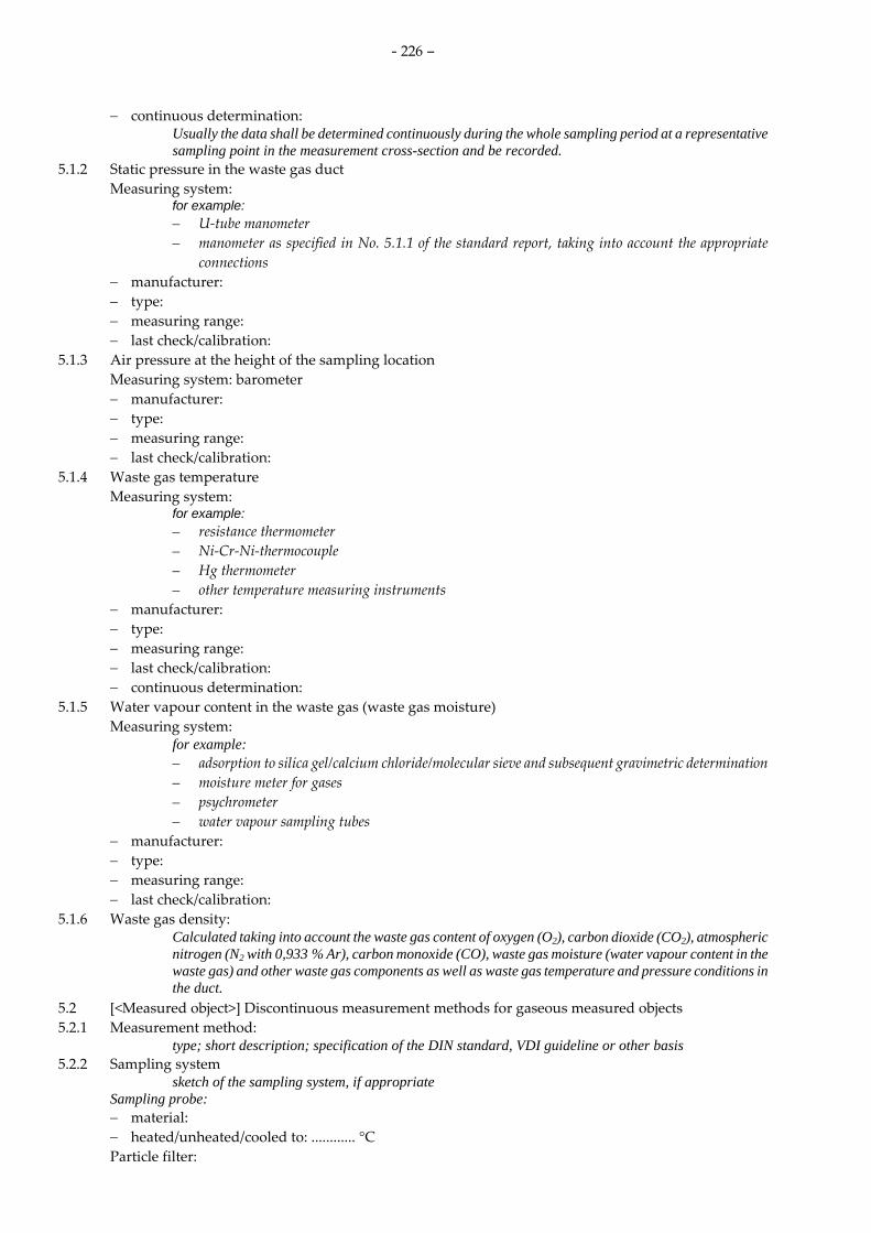
- 226 –
− continuous determination: Usually the data shall be determined continuously during the whole sampling period at a representative sampling point in the measurement cross-section and be recorded.
5.1.2 Static pressure in the waste gas duct Measuring system:
for example: – U-tube manometer – manometer as specified in No. 5.1.1 of the standard report, taking into account the appropriate
connections − manufacturer: − type: − measuring range: − last check/calibration:
5.1.3 Air pressure at the height of the sampling location Measuring system: barometer − manufacturer: − type: − measuring range: − last check/calibration:
5.1.4 Waste gas temperature Measuring system:
for example: – resistance thermometer – Ni-Cr-Ni-thermocouple – Hg thermometer – other temperature measuring instruments
− manufacturer: − type: − measuring range: − last check/calibration: − continuous determination:
5.1.5 Water vapour content in the waste gas (waste gas moisture) Measuring system:
for example: – adsorption to silica gel/calcium chloride/molecular sieve and subsequent gravimetric determination – moisture meter for gases – psychrometer – water vapour sampling tubes
− manufacturer: − type: − measuring range: − last check/calibration:
5.1.6 Waste gas density: Calculated taking into account the waste gas content of oxygen (O2), carbon dioxide (CO2), atmospheric nitrogen (N2 with 0,933 % Ar), carbon monoxide (CO), waste gas moisture (water vapour content in the waste gas) and other waste gas components as well as waste gas temperature and pressure conditions in the duct.
5.2 [<Measured object>] Discontinuous measurement methods for gaseous measured objects 5.2.1 Measurement method:
type; short description; specification of the DIN standard, VDI guideline or other basis 5.2.2 Sampling system
sketch of the sampling system, if appropriate Sampling probe: − material: − heated/unheated/cooled to: ............ °C Particle filter:

- 227 –
− type: − material: − unheated/heated to : ............ °C Absorption/adsorption systems:
for example standard impinger, frit wash bottles, silica gel tubes, activated carbon tubes − sorbent: − amount of sorbent: − distance between nozzle of the sampling probe and sorbent or separation element: Sample transfer
for example time between sampling and analysis 5.2.3 Analytical determination
Analytical method: comprehensive description if not already part of No. 5.2.1
Sample preparation: digestion method and devices
Analytical instruments: − manufacturer: − type: − specific characteristics:
GC columns, heating gradient, incineration temperature and period Standards:
5.2.4 Performance characteristics: In case of deviations from DIN standards and VDI guidelines the performance characteristics of the method of measurement determined by the measuring institute and the method of determination shall be specified: – influence of interfering components (cross-sensitivity) – detection limit – uncertainty range
5.2.5 Measures for quality assurance: All quality assurance measures taken shall be described, e. g.: – leak check of the sampling train – blank value (< 10 % of the specified TMW) – meeting the isokinetic conditions – uncertainty of the gas volume sampled (< 2 %) – uncertainty of pressure and temperature (< 1 %)
5.3 [<Measured object>] Automated measurement methods for gaseous measured objects 5.3.1 Measuring system:
type; short description; specification of the DIN standard, VDI guideline or other basis 5.3.2 Analyser:
− manufacturer: − type: − year of manufacture: − instrument no.: − version number of the software used: − maintenance interval:
5.3.3 Measuring range set: 5.3.4 Declaration of suitability:
If available, measuring systems, which are suitability-tested for the particular measurement objective, shall be used. At least the following performance characteristics shall be specified if the measuring system is not suitability-tested: – influence of interfering components (cross-sensitivity) – response time (90 % time) – detection limit – zero point drift and span point drift – standard deviation, if appropriate

- 228 –
– linearity The way in which these data were determined shall also be specified.
5.3.5 Sampling system: Sampling probe: − unheated/heated to : ............ °C Particle filter: − unheated/heated to : ............ °C Sample gas line before gas treatment: − unheated/heated to : ............ °C − length: ............. m Sample gas line downstream the sample gas conditioning: − length: ............. m Material of gas-bearing parts: Sample gas conditioning, sample gas cooler: − manufacturer: − type: − temperature, controlled to: ............... °C − desiccant:
5.3.6 Check of the instrument characteristic with test gases Zero gas: Span gas: constituents, concentration, tolerances Cylinder number: Manufacturer: Production date: Guarantee of stability: ................. months Certified: yes/no Check of the certificate by: Check of the certificate on: Application of test gases via the complete sampling system including nozzle: yes/no
5.3.7 Response time of the entire measuring system: A description shall also be given as to how this value was determined.
5.3.8 Recording of measured values: Recording system: Software:
5.4 [<Measured object>] Discontinuous measurement method for particulate substances 5.4.1 Measurement method:
type; short description; specification of the DIN standard, VDI guideline or other basis 5.4.2 Sampling system
sketch of the sampling system, if appropriate Filtration device:
plane filter/filter head device with quartz wool cartridge, combination plane filter/filter head device Positioning:
in-stack/out-stack Entry nozzle/suction tube: − unheated/heated to : ............ °C − material: Filtration medium: − manufacturer: − type: − material: − filter diameter: − pore diameter/filtration efficiency: Adsorption systems for filter passing materials:
specifications in accordance with No. 5.2.2 Suction device:

- 229 –
5.4.3 Conditioning of the filtration media Transport and storage of the filters: Drying temperature of the filtration medium before and after sampling: Drying period of the filtration medium before and after sampling: Recovery of deposits upstream the filter: Treatment of rinsing solutions:
5.4.4 Processing and evaluation of the measuring filters and the absorption solutions 5.4.4.1 Weighing
Balance: − manufacturer: − type: − detection limit: − accuracy of reading: Air-conditioned weighing room: yes/no
5.4.4.2 Preparation and analysis Preparation/digestion method: Digestion devices: Analytical methods:
comprehensive description if not specified under No. 5.4.1 Absorption solutions:
specifications in accordance with No. 5.2.3 Specific characteristics/specifications: Calibration procedure: − addition method: − standard calibration procedure: − standards used:
5.4.5 Performance characteristics In case of deviations from DIN standards and VDI guidelines the performance characteristics of the method of measurement determined by the measuring institute and the method of determination shall be specified: – influence of interfering components (cross-sensitivity) – detection limit – uncertainty range
5.4.6 Measures for quality assurance: All quality assurance measures taken shall be described, e. g.: – pre-treatment of sampling systems (see Annex C of DIN EN 14385) – determination of deposits and blank samples – see No. 5.2.5
6 [<Measured object >] Annual surveillance test of the AMS 6.1 [<Measured object>] Functional test for extractive sampling 6.1.1 Description of instrument status:
The results of the visual inspection and the check of serviceability and prevention of unauthorised maladjustment shall be presented. The description of the instrument status shall include the gas sampling and conditioning devices. Special observations recorded in the logbook (records) shall be declared in the report.
6.1.2 Testing for leaks: Testing for leaks shall include gas sampling and conditioning devices. An indication shall be given as to how leak tests were carried out.
6.1.3 Check of the linearity of the instrument characteristic: The way in which the determination was carried out and the test means used shall be specified, for example test gases, test grating filters, test rods. The individual readings at each test standard applied shall be presented in a table in temporal sequence. The linear regression between all AMS measured signals and all values of the test standards applied shall be presented as an equation in accordance with Annex B of DIN EN 14181 and as a graph. The residuals between the average concentrations and the regression line shall be calculated and checked for each

- 230 –
concentration in accordance with Annex B of DIN EN 14181. The results of this check shall be documented.
6.1.4 Check of the zero point and span point: The reference materials applied in this check shall be described. The results shall be documented and assessed by comparison with the performance criteria for zero and span point drift in the maintenance interval used in the suitability test.
6.1.5 Determination of the response time: The value of the response time (90-%-time) as well as the procedure for its determination shall be described.
6.1.6 Check of the cross-sensitivities: The extend of the cross-sensitivity test depends on the specific composition of the waste gas and the measurement method (see report of the suitability test of the AMS). The presentation of the results shall include the maximum permissible cross-sensitivity and also the actual cross-sensitivities found.
6.1.7 Description of the test gases of the plant operator: – zero gas: – span gas: – nominal concentration: – uncertainty: – cylinder number: – manufacturer: – production date: – guarantee of stability: ................. months – test method in case of internal reference materials: – test result:
The test gases of the plant operator shall be described. If the AMS is adjusted with internal reference materials (e. g. automatic adjustment with sway cuvettes), these have to best checked.
6.1.8 Check of the records and the logbook: The check of the AMS records and of the logbook shall be documented. It has to be checked especially that a plan of the AMS, the suitability-test report, the operating instructions and the logbook are available. Test procedures and protocols, maintenance reports and a maintenance time schedule as well as records on training courses for the plant personnel shall be checked. The documentation on the check of drift and precision (QAL 3) by control charts shall be checked especially with respect to whether measures dealing with measured values outside the valid calibration range have been specified and taken.
6.1.8 Check of the zero point and span point drift: The zero point and span point drift in each maintenance interval shall be determined on the basis of the values documented by QAL 3 since the last functional test. It has to be checked that the performance criteria specified for the suitability test were met.
6.2 [<Measured object>] Functional test for in situ measurements 6.2.1 Description of instrument status:
The results of the visual inspection and the check of serviceability and prevention of unauthorised maladjustment shall be presented. Particular attention shall be paid to determining the state of the optical interfaces (cleanliness). The purge air supply and the alignment of the measuring system shall be checked. Special observations which are indicated in the records (logbook) shall be specified in the report.
6.2.2 Check of the linearity of the instrument characteristic: The way in which the determination was carried out and the test means used shall be specified, for example test gases, test grating filters, test rods. The individual readings at each test standard applied shall be presented in a table in temporal sequence. The linear regression between all AMS measured signals and all values of the test standards applied shall be presented as an equation in accordance with Annex B of DIN EN 14181 and as a graph. The residuals between the average concentrations and the regression line shall be calculated and checked for each concentration in accordance with Annex B of DIN EN 14181. The results of this check shall be documented.
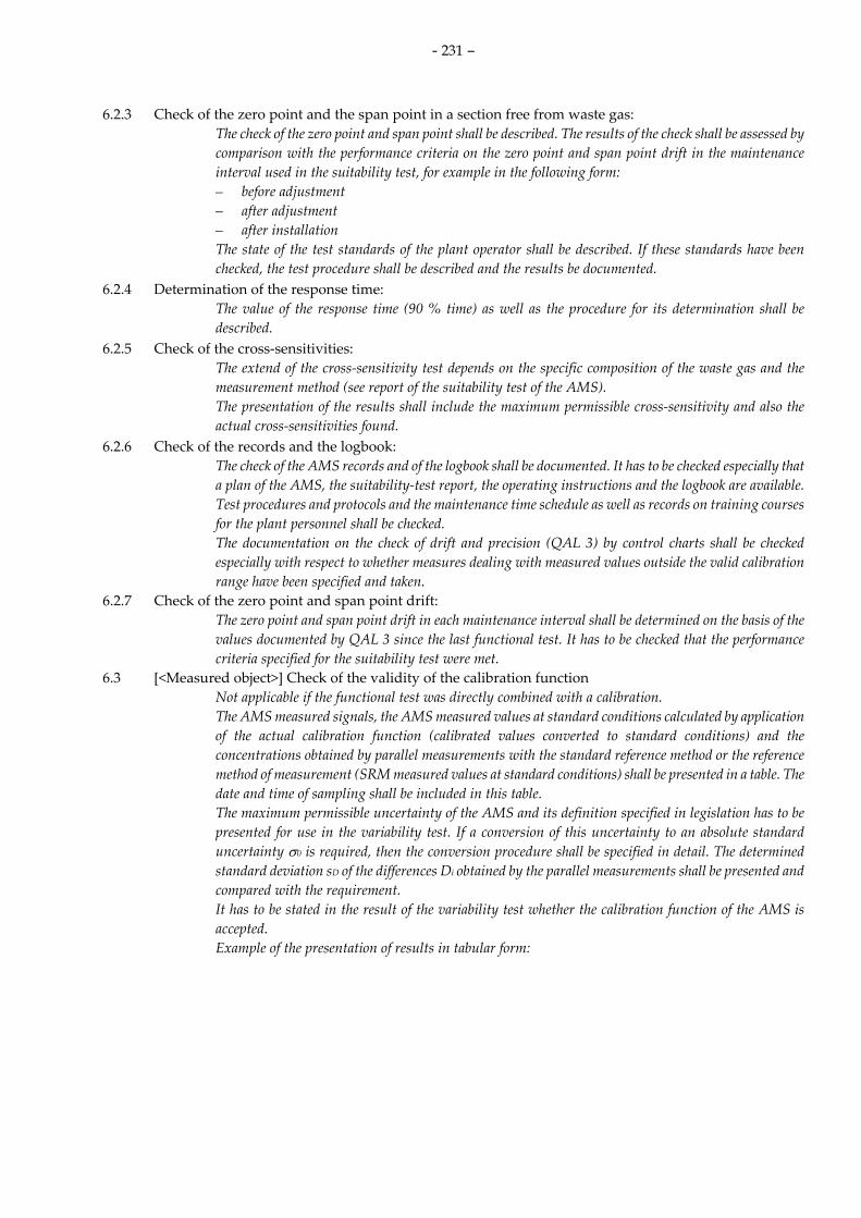
- 231 –
6.2.3 Check of the zero point and the span point in a section free from waste gas: The check of the zero point and span point shall be described. The results of the check shall be assessed by comparison with the performance criteria on the zero point and span point drift in the maintenance interval used in the suitability test, for example in the following form: – before adjustment – after adjustment – after installation The state of the test standards of the plant operator shall be described. If these standards have been checked, the test procedure shall be described and the results be documented.
6.2.4 Determination of the response time: The value of the response time (90 % time) as well as the procedure for its determination shall be described.
6.2.5 Check of the cross-sensitivities: The extend of the cross-sensitivity test depends on the specific composition of the waste gas and the measurement method (see report of the suitability test of the AMS). The presentation of the results shall include the maximum permissible cross-sensitivity and also the actual cross-sensitivities found.
6.2.6 Check of the records and the logbook: The check of the AMS records and of the logbook shall be documented. It has to be checked especially that a plan of the AMS, the suitability-test report, the operating instructions and the logbook are available. Test procedures and protocols and the maintenance time schedule as well as records on training courses for the plant personnel shall be checked. The documentation on the check of drift and precision (QAL 3) by control charts shall be checked especially with respect to whether measures dealing with measured values outside the valid calibration range have been specified and taken.
6.2.7 Check of the zero point and span point drift: The zero point and span point drift in each maintenance interval shall be determined on the basis of the values documented by QAL 3 since the last functional test. It has to be checked that the performance criteria specified for the suitability test were met.
6.3 [<Measured object>] Check of the validity of the calibration function Not applicable if the functional test was directly combined with a calibration. The AMS measured signals, the AMS measured values at standard conditions calculated by application of the actual calibration function (calibrated values converted to standard conditions) and the concentrations obtained by parallel measurements with the standard reference method or the reference method of measurement (SRM measured values at standard conditions) shall be presented in a table. The date and time of sampling shall be included in this table. The maximum permissible uncertainty of the AMS and its definition specified in legislation has to be presented for use in the variability test. If a conversion of this uncertainty to an absolute standard uncertainty σ0 is required, then the conversion procedure shall be specified in detail. The determined standard deviation sD of the differences Di obtained by the parallel measurements shall be presented and compared with the requirement. It has to be stated in the result of the variability test whether the calibration function of the AMS is accepted. Example of the presentation of results in tabular form:

- 232 –
Table 6.3.1. Measured results of AST
Number Date Time AMS measured signal
AMS measured value
(standard conditions)
SRM measured value
(standard conditions)
i x ŷs ys
in mA in mg/m3 in mg/m3
1 2005-02-01 08:00–08:30 6,14 7,57 10,54
2 2005-02-01 09:30–10:00 9,75 18,21 19,41
3 2005-02-01 11:00–11:30 4,35 1,94 5,11
4 2005-02-01 13:00–13:30 7,31 11,24 9,47
5 2005-02-01 15:00–15:30 7,07 10,28 11,85
Table 6.3.2. Results of the variability test
sD 1,98 mg/m3 Variability (standard deviation determined)
σ0 1,53 mg/m3 Requirement on measurement uncertainty (as standard deviation)
kv 0,916 kv value
1,5 kv σ0 2,10 mg/m3
sD ≤ 1,5 kv σ0 yes The AMS meets the variability test
Table 6.3.3. Results of the check of the calibration function
Dave 1,43 mg/m3 Absolute average value of the residuals
tN–1 2,132 t factor
Dmax 3,42 mg/m3 tN–1 sD N–1/2 + σ0
Dave ≤ Dmax yes The calibration function is valid
7 [<Measured object >] Determination of the calibration function and validation of the AMS Not applicable if an annual surveillance test was performed. All measured results and the calculations based on these results shall be presented in detail.
7.1 [<Measured object>] Measured results for the determination of the calibration function: The measured values obtained with the AMS to be calibrated and the measured values obtained in parallel with the standard reference method or reference method of measurement shall be presented in a table. The date and time of the measurements shall be included in this table. It has to specified whether the complete measuring range required for monitoring the emissions (e. g. range up to twice the valid limit value specified in the plant licence) could be covered. If this was not possible the chosen procedure shall be described and substantiated. Example of the presentation of measured results in tabular form:
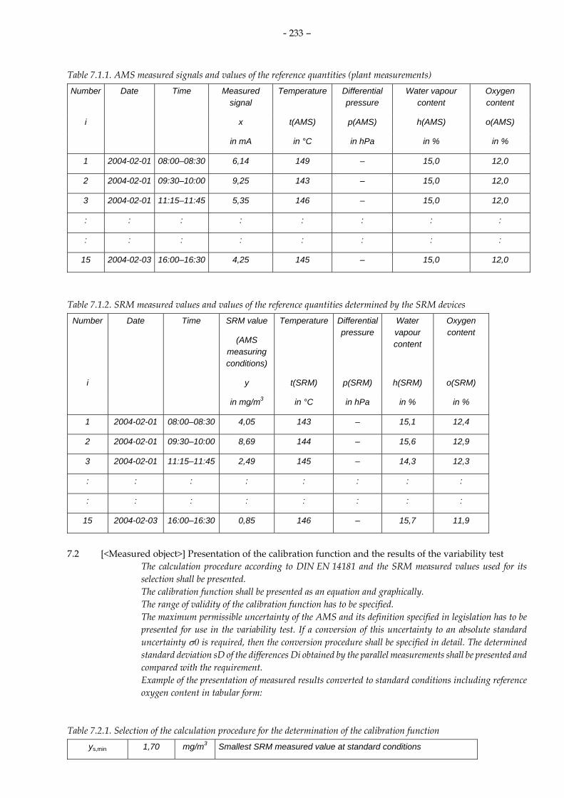
- 233 –
Table 7.1.1. AMS measured signals and values of the reference quantities (plant measurements)
Number Date Time Measured signal
Temperature Differential pressure
Water vapour content
Oxygen content
i x t(AMS) p(AMS) h(AMS) o(AMS)
in mA in °C in hPa in % in %
1 2004-02-01 08:00–08:30 6,14 149 – 15,0 12,0
2 2004-02-01 09:30–10:00 9,25 143 – 15,0 12,0
3 2004-02-01 11:15–11:45 5,35 146 – 15,0 12,0
: : : : : : : :
: : : : : : : :
15 2004-02-03 16:00–16:30 4,25 145 – 15,0 12,0
Table 7.1.2. SRM measured values and values of the reference quantities determined by the SRM devices
Number Date Time SRM value
(AMS measuring conditions)
Temperature Differential pressure
Water vapour content
Oxygen content
i y t(SRM) p(SRM) h(SRM) o(SRM)
in mg/m3 in °C in hPa in % in %
1 2004-02-01 08:00–08:30 4,05 143 – 15,1 12,4
2 2004-02-01 09:30–10:00 8,69 144 – 15,6 12,9
3 2004-02-01 11:15–11:45 2,49 145 – 14,3 12,3
: : : : : : : :
: : : : : : : :
15 2004-02-03 16:00–16:30 0,85 146 – 15,7 11,9
7.2 [<Measured object>] Presentation of the calibration function and the results of the variability test
The calculation procedure according to DIN EN 14181 and the SRM measured values used for its selection shall be presented. The calibration function shall be presented as an equation and graphically. The range of validity of the calibration function has to be specified. The maximum permissible uncertainty of the AMS and its definition specified in legislation has to be presented for use in the variability test. If a conversion of this uncertainty to an absolute standard uncertainty σ0 is required, then the conversion procedure shall be specified in detail. The determined standard deviation sD of the differences Di obtained by the parallel measurements shall be presented and compared with the requirement. Example of the presentation of measured results converted to standard conditions including reference oxygen content in tabular form:
Table 7.2.1. Selection of the calculation procedure for the determination of the calibration function
ys,min 1,70 mg/m3 Smallest SRM measured value at standard conditions

- 234 –
ys,max 19,41 mg/m3 Greatest SRM measured value at standard conditions
ys,max – ys,min 17,71 mg/m3 Difference is greater or equal to 15 % of the emission limit value
Calculation procedure a) Straight line through all points
Table 7.2.2. Parameters of the calibration function
a –5,68 mg/m3 Intercept of the calibration function
b 1,53 (mg/m3)/mA Slope of the calibration function
Table 7.2.3. Valid calibration range at standard conditions
ŷs,UG 0,00 mg/m3 Lower limit of the valid calibration range
ŷs,OG 18,53 mg/m3 Upper limit of the valid calibration range
Table 7.2.4. Results of the variability test
sD 1,03 mg/m3 Variability (determined standard deviation)
σ0 1,53 mg/m3 Requirement on measurement uncertainty (as a standard deviation)
kv 0,976 kv-Wert
kv σ0 1,49 mg/m3
sD ≤ kv σ0 yes The AMS has met the variability test
8 Operating state of the plant during the parallel measurements The individual data shall be supplemented with the following: in what manner the information was obtained; for example operator’s data, or own studies. The operating data of the production plant and the waste gas purification unit(s) shall be described over time. Reproducible information shall be given, as to which measures were taken to achieve sufficient waste gas concentrations of each measured object for the parallel measurements in the entire measuring range.
8.1 Production plant: Raw materials/fuels: Operating state:
for example normal operation, charging, start-up, representative operating state, special operating state for parallel measurements
Throughput/output: for example process data, steam
Products: Other characteristic operating parameters:
for example pressures, temperatures 8.2 Waste gas purification units:
A description of the waste gas purification units shall be added to the report as an appendix in accordance with the standard report on emission measurements published in VDI 4220, Annex B.
Operating data: for example power consumption, pH value, cleaning cycle
Operating temperatures:

- 235 –
Parameters influencing emissions: for example purification cycles, pH value, afterburner temperature, catalyst operating time
Peculiarities of the waste gas purification unit: for example in-house construction, additional water injection
9 Annual surveillance test of the electronic data evaluation system 9.1 Assignment of analogue and digital signals 9.1.1 Analogue signals:
The analogue inputs can be assigned to the individual measured objects by reference to No. 9.2 and No. 9.3; analogue signals not listed there (for example analogue outputs) shall be listed here.
9.1.2 Digital signals: 9.1.2.1 Digital inputs:
The assignment of digital input numbers to the signal-generating elements and the displays shall be specified.
9.1.2.2 Digital outputs: The assignments of the digital output numbers to the displays shall be specified.
9.2 Parameterisation of the electronic data evaluation system: 9.2.1 Measured components:
The input parameters to the data evaluation system shall be reported here for each measured component. In detail, analogue input number, regression parameters, limits of the valid calibration range, variability, measuring ranges, limit values, plausibility limits, integration time, oxygen value, and where necessary, temperature, moisture and pressure and surrogate values shall be listed.
9.2.2 Reference and other measured values: The input parameters to the data evaluation system shall be reported here for each reference value and other measured values. In detail, analogue input number, regression parameters, measuring ranges, plausibility limits, integration time, reference values for oxygen, and where necessary, temperature, moisture and pressure, shall be listed.
9.2.3 Supplementary details on parameterisation: At this point, explanatory notes on parameterisation shall be given, in particular the source of regression parameters, plant-specific calculation operations, constants and sliding calculation of emission limit values in the case of mixed firing.
9.2.4 Operating states taken into account by the electronic data evaluation system: A description shall be given of which operating states of the plant are distinguished (e. g. start-up operation and/or shut-down operation, breakdown of waste gas purification unit). In addition, the generation and reset criteria of the corresponding status signals and the resulting classification of the individual components shall be listed. If more complex relationships are involved in the composition of the generation and reset criteria, signal flow plans shall be given in the appendix.
9.3 Functional test of the electronic data evaluation system 9.3.1 Adjustment aids:
manufacturer: type: quality class: last check/calibration:
The adjustment aids used (for example precision current supply) shall be listed. 9.3.2 Check of the parameter list:
The parameter list shall be printed out and checked. When parameters have been changed, this shall be documented. In this case the list of parameters shall be attached as an appendix to the report.
9.3.3 Check of the data transmission from the measuring system to the electronic data evaluation system and test of the computations
The signal generation procedure and the check of the data transmission, the calculations (including validation) and the classification shall be described. In addition to tests near the limit value (TMW, HMW), signal transmission shall be carried out in the lower and upper quartile of the measuring range (for example 6 mA, 18 mA). The rated values should be compared with the actual values, the deviations specified and commented on. Checking the classification of, for example, half-hourly means, can be

- 236 –
dispensed with (part of the suitability test of electronic data analysis systems), if classification is dependent solely on a parameterised emission limit value, i. e. not in the case of mixed firing, for example.
9.3.4 Check of the data transmission from the measuring system to the recording devices: There is no explicit requirement for this check. For practical reasons, ±2 % of the upper limit of the measuring range should be kept as a tolerance. The method for checking the data transmission and recording shall be described. in addition to testing near the limit value, the signal transmission shall be tested in the lower and upper quartile of the measuring range in the same way as in No. 9.3.3. The rated values shall be compared with the actual values, and the maximum deviation specified and, where appropriate, commented on. In case of redundant electronic recording devices, the correct functioning shall be checked.
9.3.5 Check of the status signals: The signal generation procedure (for example simulating a fault in the AMS, actuating the service switch, shunting individual status contacts) as well as the check of the signal transmission, the calculations and the classification shall be described. If, for practical reasons, simulating operating contacts (for example fault in waste gas cleaning system) cannot be carried out, the location (terminal block, control cabinet) at which the respective status contact was shunted shall be specified.
9.3.6 Testing of printer functioning: 9.4 Testing of the remote emission control (EFÜ):
10 Summary of the results 10.1 Annual surveillance test of the AMS 10.1.1 Functional test: 10.1.2 Check of the validity of the calibration function:
Not applicable if the functional test was performed in close combination with a calibration. 10.1.3 Check of the variability:
Not applicable if the functional test was performed in close combination with a calibration. 10.2 Results of the calibration and validation and of the plausibility checks:
Not applicable if an annual surveillance test was performed only. In particular, the overall results shall be compared with the results of the preceding calibrations. Example of the tabular form for presenting results:
Table 10.2. Parameterisation of the electronic data evaluation system
Measured object
Parameter old
Measuring range
old
Parameter new
Measuring rang new
sD Upper limit of the valid calibration
range
(standard conditions)
Dust a
b
–5,82
1,58
0 to 30 mg/m³
a
b
GW
–5,68
1,53
10/30
0 to 30 mg/m³
1,0 mg/m³
18,5 mg/m³
Total carbon
a
b
–7,5
1,75
0 to 30 mg/m³
a
b
GW
–7,5
1,875
10/20
0 to 30 mg/m³
0,9 mg/m³
12,0 mg/m³
HCl a
b
–22,5
5,62
0 to 90 mg/m³
a
b
GW
–22,5
5,62
10/60
0 to 90 mg/m³
1,2 mg/m³
28,4 mg/m³

- 237 –
If the electronic data evaluation system is parameterised in the course of another monitoring report, or at a different time, at the end of the report the parameterisation requirements resulting from the calibration carried out shall be described.
10.3 Results of the check of the electronic data evaluation system:
Signature of the person carrying out the work Signature of the responsible person or deputy
Appendices Appendices can be added to the report in digital form, e. g. as PDF file: – Measured values and calculated values (all individual results of the measured objects and the
auxiliary parameters required for determination shall be tabulated) – Sketches according to No. 5.2.2 and No. 5.4.2 (if applicable) – Parameter lists (if parameters have been changed) – Computer printout of the electronic data evaluation system for the actual year before and after
parameters have been changed – Signal flow diagrams (in the event of relatively complex relationships of the formation and reset
criteria of the individual operating states)

- 238 –
8 Annex 2: List of suitability tested and announced automated measuring systems for emission measurements and electronic evaluation systems
The following tables correspond to the tables presented by the German Umweltbundesamt in the Internet (http://www.umweltbundesamt.de/messeinrichtungen/kontemi.htm), state 01 July 2008.

- 239 –
Air Pollution Prevention
Suitability-tested continuous working measuring devices for emission measurements
Measured object: Waste gas opacity – Last update: 2008-03-07
Suitable measurement devices/ Type
Manufacturer/ Distribution
Announcement in Date No. Page Details
RM 61 Sick GMBl. 1985 22 447 The device is not any longer in the delivery program of the manufacturer.
D-R 216-40 or 41 DURAG GMBl. 1990 12 231
RM 61-03 Sick GMBl. 1990 12 231 The device is not any longer in the delivery program of the manufacturer.
D-R 216-45 bis 48 DURAG GMBl. 1990 12 232 KTNR-M-RZ 1 Sigrist Photometer GMBl. 1990 34 860
RM 100 Sick GMBl. 1990 34 860 The device is not any longer in the delivery program of the manufacturer.
D-R 300 DURAG GMBl. 1991 37 1045 OF 1200 VEREWA GMBl. 1993 26 468 FW 56-I Sick GMBl. 1996 8 188 OMD 41-02/OMD 41-03 Sick GMBl. 1996 8 188 FW 56-I, Probe version Sick GMBl. 1996 28 591 RM 210-S Sick GMBl. 1996 28 591 CT NR-RZ 1 Sigrist Process Photometer GMBl. 1998 20 418
GMBl. 1998 45 946
Compact filter controller PFM 92C Födisch BAnz. 07.03.2008 38 903
IV., 5. Communication: - the measurement device is also sold
identical in construction under the designation FB-SBW 12 by the company FB Filterbau GmbH, Rodenberg

- 240 –
Air Pollution Prevention
Suitability-tested continuous working measuring devices for emission measurements
Measured object: Waste gas volumetric flow – Last update: 2008-03-07
Suitable measurement devices/ Type
Manufacturer/ Distribution
Announcement in Date No. Page Details
Annubar ANR 75/ANF 86 Dr. Rotert/Bestobell Mobrey GMBl. 1990 12 240 VMA 2 Sick GMBl. 1990 12 240
ITABAR IBF 100 Intra-Automation GMBl. 1990 12 240
Annubar DCR/DFF Dr. Rotert/Bestobell Mobrey GMBl. 1990 12 240 UNIBAR UBF 100 Unimess GMBl. 1992 32 795 Vortex VA Höntzsch Instruments GMBl. 1992 32 795 FCI-MT 86 KWW-DEPA-VIA GMBl. 1993 26 470 LPS-E for dust concentration and waste gas flow Becker-Verfahrenstechnik GMBl. 1993 26 469
SDF; SDF-22/SDF-50 with smar LD 301/ Siemens SITRANS/P S.K.I. Schlegel & Kremer GMBl. 1993 43 864
SENSYFLOW VT 2 SENSYCON Hartmann & Braun GMBl. 1995 33 702
FLOWSIC 101/102 Sick GMBl. 1996 28 593 VELOS 500 Sick GMBl. 1996 28 593
Deltaflow DF 25 and DF 50 Systec Controls Mess- u. Regeltechnik GMBl. 1996 28 593
D-FL 100 with SITRANS P 7M74430/Contrans P ASA 800 DURAG GMBl. 1996 42 883
Itabar IBF 100 INTRA-AUTOMATION GMBl. 1998 1 10

- 241 –
Measured object: Waste gas volumetric flow – (continued)
Suitable measurement devices/ Type
Manufacturer/ Distribution
Announcement in Date No. Page Details
PFM 97 for dust and waste gas flow Födisch GMBl. 1998 45 947 PFM 97 W for dust and waste gas flow Födisch GMBl. 2000 22 444
FLOWSIC 106 SICK Engineering GMBl. 2000 60 1193 FLOWSIC 107 SICK Engineering GMBl. 2000 60 1194 D-FL 200 DURAG GMBl. 2000 60 1194
GMBl. 2001 19 386 D-RX 250 for dust and waste gas flow DURAG
BAnz. 08.04.2006 70 2653 V., 1. Communication: - new software version
FLOWSIC 100-PMD/PHD/PMA SICK Engineering GMBl. 2001 19 387 FLOWSIC 100-UMD/UHD SICK Engineering GMBl. 2001 19 387 FLOWSIC 100-USD SICK Engineering GMBl. 2001 19 387 FMD 02 Födisch BAnz. 11.11.2003 210 23998 FMD 99 Födisch BAnz. 27.04.2004 79 9220
FLOWSIC 100 Sick Engineering GmbH, Ottendorf-Okrilla BAnz. 07.03.08 38 902

- 242 –
Air Pollution Prevention
Suitability-tested continuous working measuring devices for emission measurements
Measured object: Ammonia – Last update: 2008-03-07
Suitable measurement devices/ Type
Manufacturer/ Distribution
Announcement in Date No. Page Details
GMBl. 1992 32 795 GMBl. 1994 28 869 OPSIS AR 602 Z OPSIS GMBl. 1996 42 882 GMBl. 1993 26 469
MIPAN Siemens GMBl. 1993 43 863
Bodenseewerk Perkin-Elmer GMBl. 1995 7 131 MCS 100 HW for NH3, CO2 Sick Maihak GmbH
Meersburg BAnz. 06.11.2007 206 7925 III., 1. Communication: - actual name of the manufacturer
GM 30-5 Sick GMBl. 1995 33 702 GM 30-5 P Sick GMBl. 1995 33 702
GMBl. 1995 33 702 CEMAS FTIR for NO, CO, HCl, CO2, H2O, NH3
Hartmann & Braun AG GMBl. 1996 8 188
LIDIA Carl Zeiss GMBl. 1998 1 8 CEDOR for SO2, NO, CO, NH3, HCl, H2O Maihak GMBl. 1999 22 446
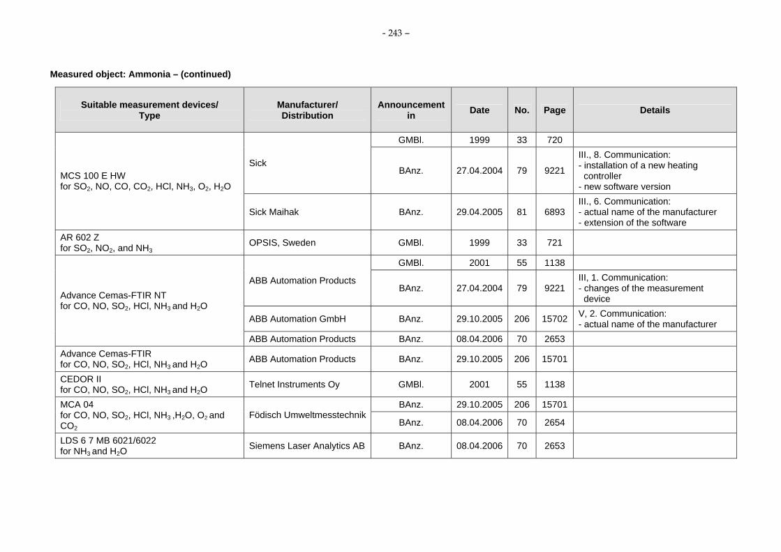
- 243 –
Measured object: Ammonia – (continued)
Suitable measurement devices/ Type
Manufacturer/ Distribution
Announcement in Date No. Page Details
GMBl. 1999 33 720
Sick BAnz. 27.04.2004 79 9221
III., 8. Communication: - installation of a new heating
controller - new software version
MCS 100 E HW for SO2, NO, CO, CO2, HCl, NH3, O2, H2O
Sick Maihak BAnz. 29.04.2005 81 6893 III., 6. Communication: - actual name of the manufacturer - extension of the software
AR 602 Z for SO2, NO2, and NH3
OPSIS, Sweden GMBl. 1999 33 721
GMBl. 2001 55 1138
ABB Automation Products BAnz. 27.04.2004 79 9221
III, 1. Communication: - changes of the measurement
device
ABB Automation GmbH BAnz. 29.10.2005 206 15702 V, 2. Communication: - actual name of the manufacturer
Advance Cemas-FTIR NT for CO, NO, SO2, HCl, NH3 and H2O
ABB Automation Products BAnz. 08.04.2006 70 2653 Advance Cemas-FTIR for CO, NO, SO2, HCl, NH3 and H2O ABB Automation Products BAnz. 29.10.2005 206 15701
CEDOR II for CO, NO, SO2, HCl, NH3 and H2O Telnet Instruments Oy GMBl. 2001 55 1138
BAnz. 29.10.2005 206 15701 MCA 04 for CO, NO, SO2, HCl, NH3 ,H2O, O2 and CO2
Födisch UmweltmesstechnikBAnz. 08.04.2006 70 2654
LDS 6 7 MB 6021/6022 for NH3 and H2O Siemens Laser Analytics AB BAnz. 08.04.2006 70 2653

- 244 –
Measured object: Ammonia – (continued)
Suitable measurement devices/ Type
Manufacturer/ Distribution
Announcement in Date No. Page Details
BAnz. 14.10.2006 194 6715 GASMET CEMS for CO, NO, NO2, N2O, SO2, HCl, NH3, CO2, H2O
Gasmet Technologies Oy, Helsinki, Finland BAnz. 20.04.2007 75 4140 IV., 8. Communication
GASMET CEMS with OXITEC 500E SME 5for O2, CO, NO, NO2, N2O, SO2, NH3, HCl, CO2 and H2O
Gasmet Technologies Oy, Helsinki, Finland BAnz. 07.03.2008 38 901
- supplementary test to the announcement of the Federal Environment Agency from 12 September 2006 (BAnz. S. 6715).
GIGAS 10M for CO, NO, NO2, NH3, HCl, CO2 and H2O BAnz. 06.11.2007 206 7925
GIGAS 10M for CO, NO, NO2, SO2, NH3, HCl, CO2 and H2O
General Impianti, Moie di Maiolati, Italy
BAnz. 07.03.2008 38 901
- supplementary test to the announcement of the Federal Environment Agency from 23 September 2007(BAnz. S. 7925).
LaserGas II for H2O and NH3
NEO Monitors AS, Lorenskog, Norway BAnz. 07.03.2008 38 901

- 245 –
Air Pollution Prevention
Suitability-tested continuous working measuring devices for emission measurements Measured object: Inorganic gaseous chlorine compounds– Last update: 2008-03-07
Suitable measurement devices/ Type
Manufacturer/ Distribution
Announcement in Date No. Page Details
Sensimeter G Bran + Luebbe GMBl. 1990 12 237 The device is not any longer in the delivery program of the manufacturer.
Bodenseewerk Perkin-Elmer GMBl. 1990 12 237 Spektran 677 IR Sick Maihak GmbH,
Meersburg BAnz. 06.11.2007 206 7925 III., 1. Communication: - actual name of the manufacturer
ECOMETER HCl (0-2000 mg/m³) Bran + Luebbe GMBl. 1990 12 238 ECOMETER HCl (0-200 mg/m³) Bran + Luebbe GMBl. 1990 12 238 Mikrogas HCl Wösthoff Messtechnik GMBl. 1990 12 238 ECOMETER HCl with microcomputer AC 85 Bran + Luebbe GMBl. 1991 37 1045
GMBl. 1991 37 1047 Perkin Elmer
GMBl. 1994 28 870 MCS 100 HW Sick Maihak GmbH, Meersburg BAnz. 06.11.2007 206 7925 III, 1. Communication:
- actual name of the manufacturer GMBl. 1992 45 1142
Mikrogas HCl/SO2 Typ MSE Wösthoff Messtechnik GMBl. 1993 43 864
Monitor 90 Ecometer (HCl) Bran + Luebbe GMBl. 1995 7 131 GMBl. 1995 33 702
CEMAS FTIR Hartmann & Braun GMBl. 1996 8 188

- 246 –
Measured object: Inorganic gaseous chlorine compounds – (continued)
Suitable measurement devices/ Type
Manufacturer/ Distribution
Announcement in Date No. Page Details
GMBl. 1996 28 592 OPSIS AR 650 OPSIS AB
GMBl. 1996 42 882 1015 (15C/EGC100) Ysselbach GMBl. 1996 42 881 CEDOR for SO2, NO, CO, NH3, HCl, H2O Maihak GMBl. 1999 22 446
Laser Gas Monitor HCl Norsk Elektro Optik AIS, Norway GMBl. 1999 33 719
GMBl. 1999 33 720 MCS 100 E HW for SO2, NO, CO, CO2, HCl, NH3, O2 and H2O
Sick BAnz. 27.04.2004 79 9221
III., 8. Communication: - installation of a new heating
controller - extension of the software
MCS 100 E PD for SO2, NO, NO2, CO, CO2, HCl, O2
Sick GMBl. 1999 33 721
AR 650 for HCl, CO and H2O OPSIS, Sweden GMBl. 1999 33 721
Laser Gas Monitor HCl Norsk Elektro Optik/Bernt GMBl. 2000 22 444 GMBl. 2001 55 1138
ABB Automation Products BAnz. 27.04.2004 79 9221
III., 1. Communication: - changes of the measurement
device
ABB Automation GmbH BAnz. 29.10.2005 206 15702 V., 2. Communication: - actual name of the manufacturer
Advance Cemas-FTIR NT for CO, NO, SO2, HCl, NH3 and H2O
ABB Automation Products BAnz. 08.04.2006 70 2653 Advance Cemas-FTIR for CO, NO, SO2, HCl, NH3 and H2O ABB Automation Products BAnz. 29.10.2005 206 15701

- 247 –
Measured object: Inorganic gaseous chlorine compounds – (continued)
Suitable measurement devices/ Type
Manufacturer/ Distribution
Announcement in Date No. Page Details
CEDOR II for CO, NO, SO2, HCl, NH3 and H2O Telnet Instruments Oy GMBl. 2001 55 1138
BAnz. 29.10.2005 206 15701 MCA 04 for CO, NO, SO2, HCl, NH3 ,H2O, O2 and CO2
Födisch UmweltmesstechnikBAnz. 08.04.2006 70 2654
BAnz. 14.10.2006 194 6715 GASMET CEMS for CO, NO, NO2, N2O, SO2, HCl, NH3, CO2, H2O
Gasmet Technologies Oy, Helsinki, Finland BAnz. 20.04.2007 75 4140 IV., 8. Communication
GASMET CEMS with OXITEC 500E SME 5for O2, CO, NO, NO2, N2O, SO2, NH3, HCl, CO2 and H2O
Gasmet Technologies Oy, Helsinki, Finland BAnz. 07.03.2008 38 901
- supplementary test to the announcement of the Federal Environment Agency from 12 September 2006 (BAnz. S. 6715).
GIGAS 10M for CO, NO, NO2, NH3, HCl, CO2 and H2O BAnz. 06.11.2007 206 7925
GIGAS 10M for CO, NO, NO2, SO2, NH3, HCl, CO2 and H2O
General Impianti, Moie di Maiolati, Italy
BAnz. 07.03.2008 38 901
- supplementary test to the announcement of the Federal Environment Agency from 23 September 2007 (BAnz. S. 7925).
BAnz. 06.11.2007 206 7925
LDS 6 7MB6121 for HCl and H2O
Siemens Laser Analytics AB, Mölndal, Sweden/Siemens AG Process Instrumentation and Analytics, Karlsruhe
BAnz. 07.03.2008 38 903 IV., 1. Communication: - new software version

- 248 –
Air Pollution Prevention
Suitability-tested continuous working measuring devices for emission measurements
Measured object: Inorganic gaseous fluorine compounds – Last update: 2005-01-15
Suitable measurement devices/ Type
Manufacturer/ Distribution
Announcement in Date No. Page Details
Sensimeter G Bran + Luebbe GMBl. 1990 12 237 The device is not any longer in the delivery program of the manufacturer.
COMPUR Ionotox HF Bayer Diagnostic GMBl. 1990 20 399 Monitor 90 Ecometer Bran + Luebbe GMBl. 1996 8 188 Unisearch LasIR HF - Analyzer
Unisearch Associates GMBl. 2002 19 401
OPSIS AR 650 for HF OPSIS AB, Sweden BAnz. 30.10.2004 207 22513
Air Pollution Prevention
Suitability-tested continuous working measuring devices for emission measurements
Measured object: Dinitrogen monoxide – Last update: 2008-03-07
Suitable measurement devices/ Type
Manufacturer/ Distribution
Announcement in Date No. Page Details
VA 3000 for CO, NOx, N2O, CO2 and O2
Horiba Europe GmbH BAnz. 08.04.2006 70 2653

- 249 –
Measured object: Dinitrogen monoxide – (continued)
Suitable measurement devices/ Type
Manufacturer/ Distribution
Announcement in Date No. Page Details
BAnz. 14.10.2006 194 6715 V., 2. Communication BAnz. 14.10.2006 194 6715
BAnz. 20.04.2007 75 4139 IV., 4. Communication: - new software version Advance Optima AO2000 series
for CO, NO, SO2, CO2, N2O and O2 ABB Automation GmbH, Frankfurt/Main
BAnz. 07.03.2008 38 903 IV., 2. Communication: - new software version
BAnz. 14.10.2006 194 6715
BAnz. 20.04.2007 75 4139 IV., 3. Communication: - new software version Easy Line EL3000 series
for CO, NO, SO2, N2O, CO2, O2 ABB Automation GmbH, Frankfurt/Main
BAnz. 07.03.2008 38 903 IV., 3. Communication: - new software version
BAnz. 14.10.2006 194 6715 GASMET CEMS for CO, NO, NO2, N2O, SO2, HCl, NH3, CO2, H2O
Gasmet Technologies Oy, Helsinki, Finland BAnz. 20.04.2007 75 4140 IV., 8. Communication:
GASMET CEMS with OXITEC 500E SME 5for O2, CO, NO, NO2, N2O, SO2, NH3, HCl, CO2 and H2O
Gasmet Technologies Oy, Helsinki, Finland BAnz. 07.03.2008 38 901
- supplementary test to the announcement of the Federal Environment Agency from 12 September 2006 (BAnz. S. 6715).
BAnz. 20.04.2007 75 4139
ULTRAMAT 237MB2338 for CO, CO2 and N2O Siemens AG, Karlsruhe
BAnz. 07.03.2008 38 902
- supplementary test to the announcement of the Federal Environment Agency from 14 April 2007 (BAnz. S. 4139).

- 250 –
Air Pollution Prevention
Suitability-tested continuous working measuring devices for emission measurements
Measured object: Humidity – Last update: 2008-03-07
Suitable measurement devices/ Type
Manufacturer/ Distribution
Announcement in Date No. Page Details
Hygrophil-h 4220 PO25 Ultrakust electronic GMBl. 1991 20 526 GMBl. 1991 37 1047
Perkin-Elmer GMBl. 1994 28 870 MCS 100 HW
Sick Maihak GmbH, Meersburg BAnz. 06.11.2007 206 7925 III., 1. Communication:
- actual name of the manufacturer GMBl. 1993 26 470
OPSIS AR 602 Z OPSIS AB GMBl. 1996 42 882
ZA 8 F Yokogawa GMBl. 1994 28 870 GMBl. 1995 33 702
CEMAS FTIR Hartmann & Braun GMBl. 1996 8 188 GMBl. 1996 28 592
OPSIS AR 650 OPSIS AB GMBl. 1996 42 882
CEDOR for SO2, NO, CO, NH3, HCl, H2O Maihak GMBl. 1999 22 446
GMBl. 1999 33 720 MCS 100 E HW for SO2, NO, CO, CO2, HCl, NH3, O2 and H2O
Sick BAnz. 27.04.2004 79 9221
III., 8. Communication: - installation of a new heating
controller - extension of the software
OPSIS AR 650 for HCl, CO and H2O OPSIS AB, Sweden GMBl. 1999 33 721

- 251 –
Measured object: Humidity – (continued)
Suitable measurement devices/ Type
Manufacturer/ Distribution
Announcement in Date No. Page Details
GMBl. 2001 55 1138
ABB Automation Products BAnz. 27.04.2004 79 9221
III., 1. Communication: - changes of the measurement
device
ABB Automation GmbH BAnz. 29.10.2005 206 15702 V., 2. Communication: - actual name of the manufacturer
Advance Cemas-FTIR NT for CO, NO, SO2, HCl, NH3 and H2O
ABB Automation Products BAnz. 08.04.2006 70 2653 CEDOR II for CO, NO, SO2, HCl, NH3 and H2O Telnet Instruments Oy GMBl. 2001 55 1138
GMBl. 2002 19 402 S 700-15, Multor for NO, SO2 and H2O Maihak
BAnz. 2003 210 23998 GMBl. 2002 19 402 S 700-26, Multor (1+2) Unor (3)
for NO, SO2, CO and H2O Maihak BAnz. 2003 210 23998 GMBl. 2002 19 402 S 700-27, Multor (1...3)
for NO, SO2, CO and H2O Maihak BAnz. 2003 210 23998 GMBl. 2002 19 402 S 700-30, Multor (1+2) Oxor P (3)
for NO, SO2, O2 and H2O Maihak BAnz. 2003 210 23998 GMBl. 2002 19 402 S 700-33, Multor (1+2) Oxor E (3)
for NO, SO2, O2 and H2O Maihak BAnz. 2003 210 23998 GMBl. 2002 19 402 S 700-34, Multor (1..3) Oxor P (3)
for CO, NO, SO2, O2 and H2O Maihak BAnz. 2003 210 23998 GMBl. 2002 19 402 S 700-35, Multor (1..3) Oxor E (3)
for CO, NO, SO2, O2 and H2O Maihak BAnz. 2003 210 23998 GMBl. 2002 19 402 S 700-38, Multor (1+2) Unor (3) Oxor P (4)
for NO, SO2, CO, O2 and H2O Maihak
BAnz. 2003 210 23998

- 252 –
Measured object: Humidity – (continued)
Suitable measurement devices/ Type
Manufacturer/ Distribution
Announcement in Date No. Page Details
GMBl. 2002 19 402 S 700-41, Multor (1+2) Unor (3) Oxor E (4) for NO, SO2, CO, O2 and H2O Maihak
BAnz. 2003 210 23998 GMBl. 2002 19 402 S 700-26, Multor (1+2) Unor (3)
for NO, SO2, CO and H2O Maihak
BAnz. 2003 210 23998 GMBl. 2002 19 402 S 700-27, Multor (1...3)
for NO, SO2, CO and H2O Maihak BAnz. 2003 210 23998 GMBl. 2002 19 402 S 700-30, Multor (1+2) Oxor P (3)
for NO, SO2, O2 and H2O Maihak BAnz. 2003 210 23998 GMBl. 2002 19 402 S 700-33, Multor (1+2) Oxor E (3)
for NO, SO2, O2 and H2O Maihak BAnz. 2003 210 23998 GMBl. 2002 19 402 S 700-34, Multor (1..3) Oxor P (3) for CO,
NO, SO2, O2 and H2O Maihak BAnz. 2003 210 23998 GMBl. 2002 19 402 S 700-35, Multor (1..3) Oxor E (3)
for CO, NO, SO2, O2 and H2O Maihak BAnz. 2003 210 23998 GMBl. 2002 19 402 S 700-38, Multor (1+2) Unor (3) Oxor P (4)
for NO, SO2, CO, O2 and H2O Maihak BAnz. 2003 210 23998 GMBl. 2002 19 402 S 700-41, Multor (1+2) Unor (3) Oxor E (4)
for NO, SO2, CO, O2 and H2O Maihak BAnz. 2003 210 23998
Hygrophil H 4230-10 Bartec BAnz. 30.04.2004 207 22513 BAnz. 29.10.2005 206 15701 MCA 04
for CO, NO, SO2, HCl, NH3 ,H2O, O2 and CO2
Födisch UmweltmesstechnikBAnz. 08.04.2006 70 2654
Advance Cemas-FTIR for CO, NO, SO2, HCl, NH3 and H2O ABB Automation Products BAnz. 29.10.2005 206 15701

- 253 –
Measured object: Humidity – (continued)
Suitable measurement devices/ Type
Manufacturer/ Distribution
Announcement in Date No. Page Details
LDS 6 7 MB 6021/6022 for NH3 and H2O Siemens Laser Analytics AB BAnz. 08.04.2006 70 2653
GM 35 In-situ-Gas Analyzer, Cross-Duct version for CO, CO2, H2O
SICK MAIHAK GmbH BAnz. 14.10.2006 194 6715
GM 35 In-situ Gas Analyzer, Probe version GMP for CO, CO2, H2O
SICK MAIHAK GmbH BAnz. 14.10.2006 194 6715
BAnz. 14.10.2006 194 6715 GASMET CEMS for CO, NO, NO2, N2O, SO2, HCl, NH3, CO2, H2O
Gasmet Technologies Oy, Helsinki, Finland BAnz. 20.04.2007 75 4140 IV., 8. Communication:
GASMET CEMS with OXITEC 500E SME 5for O2, CO, NO, NO2, N2O, SO2, NH3, HCl, CO2 and H2O
Gasmet Technologies Oy, Helsinki, Finland BAnz. 07.03.2008 38 901
- supplementary test to the announcement of the Federal Environment Agency from 12 September 2006 (BAnz. S. 6715).
GIGAS 10M for CO, NO, NO2, NH3, HCl, CO2 and H2O BAnz. 06.11.2007 206 7925
GIGAS 10M for CO, NO, NO2, SO2, NH3, HCl, CO2 and H2O
General Impianti, Moie di Maiolati, Italy
BAnz. 07.03.2008 38 901
- supplementary test to the announcement of the Federal Environment Agency from 23. September 2007 (BAnz. S. 7925).
BAnz. 06.11.2007 206 7925
LDS 6 7MB6121 for HCl and H2O
Siemens Laser Analytics AB, Mölndal, Sweden/Siemens AG Process Instrumentation and Analytics, Karlsruhe
BAnz. 07.03.2008 38 903 IV., 1. Communication: - new software version
LaserGas II for H2O and NH3
NEO Monitors AS, Lorenskog, Norway BAnz. 07.03.2008 38 901

- 254 –
Air Pollution Prevention
Suitability-tested continuous working measuring devices for emission measurements
Measured object: Formaldehyde – Last update: 2006-02-20
Suitable measurement devices/ Type
Manufacturer/ Distribution
Announcement in Date No. Page Details
GMBl. 1994 28 869 OPSIS AR 602 Z OPSIS AB
GMBl. 1998 1 8
Air Pollution Prevention
Suitability-tested continuous working measuring devices for emission measurements
Measured object: Carbon dioxide – Last update: 2008-03-07
Suitable measurement devices/ Type
Manufacturer/ Distribution
Announcement in Date No. Page Details
GMBl. 1991 37 1047 Perkin-Elmer
GMBl. 1996 42 882 MCS 100 CD Sick Maihak GmbH, Meersburg BAnz. 06.11.2007 206 7925 III., 1. Communication:
- actual name of the manufacturer GMBl. 1995 33 702 CEMAS FTIR
for H2O, CO2, CO, NO, HCl, NH3 Hartmann & Braun
GMBl. 1996 8 188

- 255 –
Measured object: Carbon dioxide – (continued)
Suitable measurement devices/ Type
Manufacturer/ Distribution
Announcement in Date No. Page Details
GMBl. 1999 33 721
MCS 100 E HW for SO2, NO, CO, CO2, HCl, NH3, O2, H2O Sick
BAnz. 27.04.2004 79 9221
III., 8. Communication: - installation of a new heating
controller - extension of the software
MCS 100 E PD for SO2, NO, NO2, CO, CO2, HCl, O2
Sick GMBl. 1999 33 721
PG 250 for NO, NO2, SO2, CO, CO2, O2
Horiba GMBl. 2001 19 387
FGA II for SO2, NO, NO2, CO, O2, CO2
LAND Instrument BAnz. 15.05.2003 90 10742
BAnz. 29.10.2005 206 15701 MCA 04 for CO, NO, SO2, HCl, NH3 ,H2O, CO2, O2, CO2
Födisch UmweltmesstechnikBAnz. 08.04.2006 70 2654
BAnz. 08.04.2006 70 2653 VA 3000 for CO, NOx, N2O, CO2, O2
Horiba Europe GmbH BAnz. 14.10.2006 194 6715 V., 2. Communication BAnz. 14.10.2006 194 6715
BAnz. 20.04.2007 75 4139 IV., 4. Communication: - new software version Advance Optima AO2000 series
for CO, NO, SO2, CO2, N2O and O2 ABB Automation GmbH, Frankfurt/Main
BAnz. 07.03.2008 38 903 IV., 2. Communication: - new software version
BAnz. 14.10.2006 194 6715
BAnz. 20.04.2007 75 4139 IV., 3. Communication: - new software version Easy Line EL3000 series
for CO, NO, SO2, N2O, CO2, O2 ABB Automation GmbH, Frankfurt/Main
BAnz. 07.03.2008 38 903 IV., 3. Communication: - new software version

- 256 –
Measured object: Carbon dioxide – (continued)
Suitable measurement devices/ Type
Manufacturer/ Distribution
Announcement in Date No. Page Details
GM 35 In-situ Gas Analyzer, Cross-Duct version for CO, CO2, H2O
SICK MAIHAK GmbH BAnz. 14.10.2006 194 6715
GM 35 In-situ Gas Analyzer, Probe version GMP
SICK MAIHAK GmbH BAnz. 14.10.2006 194 6715
BAnz. 14.10.2006 194 6715 GASMET CEMS for CO, NO, NO2, N2O, SO2, HCl, NH3, CO2, H2O
Gasmet Technologies Oy, Helsinki, Finland BAnz. 20.04.2007 75 4140 IV., 8. Communication:
GASMET CEMS with OXITEC 500E SME 5for O2, CO, NO, NO2, N2O, SO2, NH3, HCl, CO2 and H2O
Gasmet Technologies Oy, Helsinki, Finland BAnz. 07.03.2008 38 901
- supplementary test to the announcement of the Federal Environment Agency from 12 September 2006 (BAnz. S. 6715).
BAnz. 20.04.2007 75 4139
ULTRAMAT 237MB2338 for CO, CO2 and N2O Siemens AG, Karlsruhe
BAnz. 07.03.2008 38 902
- supplementary test to the announcement of the Federal Environment Agency from12 April 2007 (BAnz. S. 4139).
GIGAS 10M for CO, NO, NO2, NH3, HCl, CO2 and H2O BAnz. 06.11.2007 206 7925
GIGAS 10M for CO, NO, NO2, SO2, NH3, HCl, CO2 and H2O
General Impianti, Moie di Maiolati, Italy
BAnz. 07.03.2008 38 901
- supplementary test to the announcement of the Federal Environment Agency from 23 September 2007 (BAnz. S. 7925).

- 257 –
Air Pollution Prevention
Suitability-tested continuous working measuring devices for emission measurements
Measured object: Carbon monoxide – Last update: 2008-03-07
Suitable measurement devices/ Type
Manufacturer/ Distribution
Announcement in Date No. Page Details
UNOR 5 N-CO Maihak GMBl. 1985 22 450 The device is not any longer in the delivery program of the manufacturer.
URAS 3 G Hartmann & Braun GMBl. 1990 12 235
URAS 3 E Hartmann & Braun GMBl. 1990 12 235 The device is not any longer in the delivery program of the manufacturer.
Ultramat 1 Siemens GMBl. 1985 22 451 The device is not any longer in the delivery program of the manufacturer.
Ultramat 2 Siemens GMBl. 1985 22 451 The device is not any longer in the delivery program of the manufacturer.
Ultramat 32 Siemens GMBl. 1985 22 451 The device is not any longer in the delivery program of the manufacturer.
UNOR 6 N-CO Maihak GMBl. 1990 12 236 UNOR 6 N-F Maihak GMBl. 1990 12 236
Leybold/Rosemount GMBl. 1990 12 236 CO-IR Binos Emmerson Process
Management BAnz. 30.10.2004 207 22513 III., Communication: - actual name of the manufacturer
CO-IR Berlina Leybold/Auergesellschaft GMBl. 1990 12 236
URAS 3 K/Magnos 3 K Hartmann & Braun GMBl. 1990 12 236 The device is not any longer in the delivery program of the manufacturer.
Ultramat 21 P/22 P Siemens GMBl. 1990 12 236 IR Mod. 864 Beckmann/Rosemount GMBl. 1990 12 236
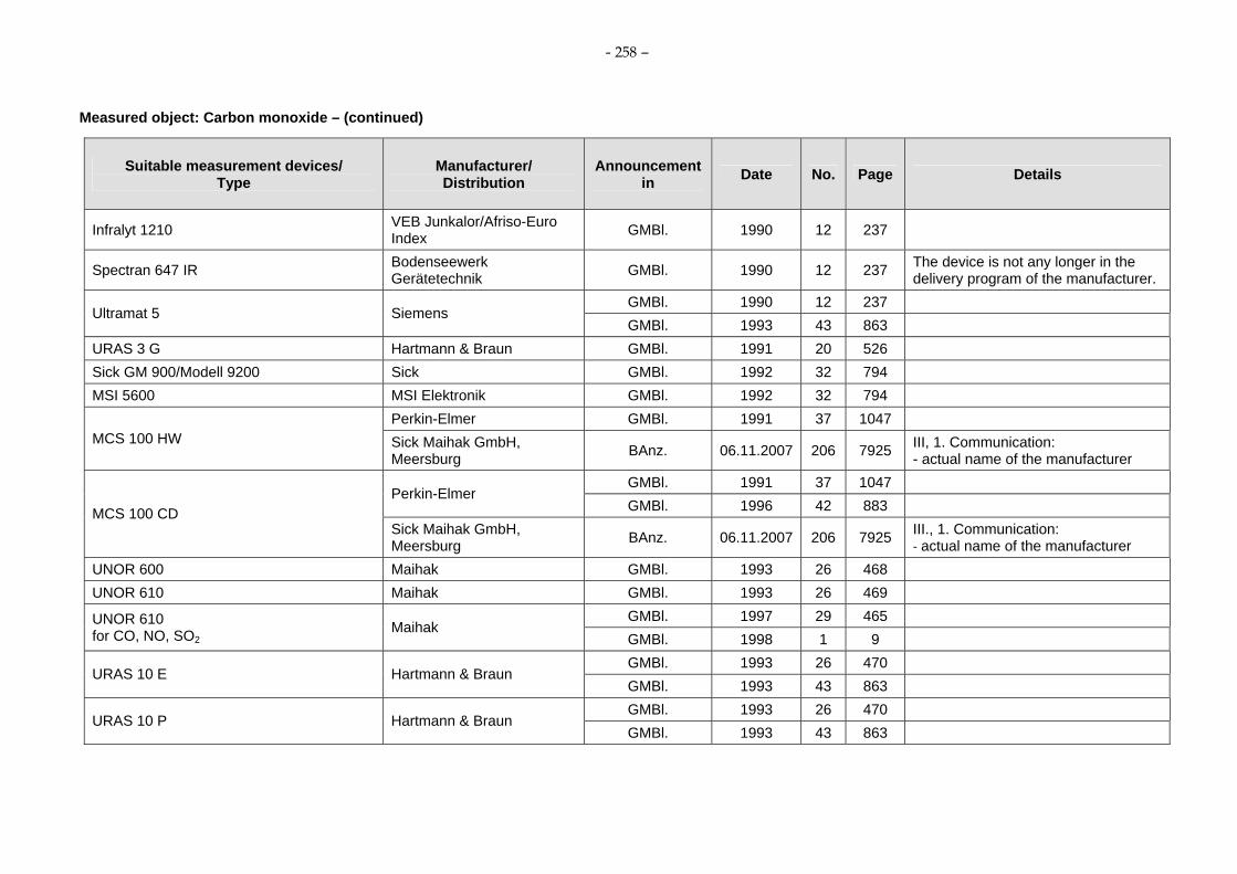
- 258 –
Measured object: Carbon monoxide – (continued)
Suitable measurement devices/ Type
Manufacturer/ Distribution
Announcement in Date No. Page Details
Infralyt 1210 VEB Junkalor/Afriso-Euro Index GMBl. 1990 12 237
Spectran 647 IR Bodenseewerk Gerätetechnik GMBl. 1990 12 237 The device is not any longer in the
delivery program of the manufacturer. GMBl. 1990 12 237
Ultramat 5 Siemens GMBl. 1993 43 863
URAS 3 G Hartmann & Braun GMBl. 1991 20 526 Sick GM 900/Modell 9200 Sick GMBl. 1992 32 794 MSI 5600 MSI Elektronik GMBl. 1992 32 794
Perkin-Elmer GMBl. 1991 37 1047 MCS 100 HW Sick Maihak GmbH,
Meersburg BAnz. 06.11.2007 206 7925 III, 1. Communication: - actual name of the manufacturer
GMBl. 1991 37 1047 Perkin-Elmer
GMBl. 1996 42 883 MCS 100 CD Sick Maihak GmbH, Meersburg BAnz. 06.11.2007 206 7925 III., 1. Communication:
- actual name of the manufacturer UNOR 600 Maihak GMBl. 1993 26 468 UNOR 610 Maihak GMBl. 1993 26 469
GMBl. 1997 29 465 UNOR 610 for CO, NO, SO2
Maihak GMBl. 1998 1 9 GMBl. 1993 26 470
URAS 10 E Hartmann & Braun GMBl. 1993 43 863 GMBl. 1993 26 470
URAS 10 P Hartmann & Braun GMBl. 1993 43 863

- 259 –
Measured object: Carbon monoxide – (continued)
Suitable measurement devices/ Type
Manufacturer/ Distribution
Announcement in Date No. Page Details
URAS 4 Hartmann & Braun GMBl. 1993 43 863 GMBl. 1993 43 864
ENDA 1000 HORIBA GMBl. 1994 28 869
Infralyt 1210/1211 Junkalor GMBl. 1995 33 701 GMBl. 1995 33 702
CEMAS NDIR Hartmann & Braun GMBl. 1996 8 189 GMBl. 1995 33 702
CEMAS FTIR Hartmann & Braun GMBl. 1996 8 188
OPSIS AR 650 OPSIS AB GMBl. 1996 28 592 GMBl. 1996 28 593
MULTOR 610 Maihak GMBl. 1996 42 883 GMBl. 1997 29 465 MULTOR 610
for CO, NO, SO2 Maihak
GMBl. 1998 1 9 XENTRA 4900 Servomex GMBl. 1996 28 593 GM 910 Sick GMBl. 1996 42 883
Fisher-Rosemount GMBl. 1996 42 883 BINOS 100 M for CO, O2 Emmerson Process
Management BAnz. 30.10.2004 207 22513 III., Communication: - actual name of the manufacturer
UNOR 611 for CO, O2
Maihak GMBl. 1996 42 883
OPSIS AR 650 OPSIS GMBl. 1996 42 882 ENDA 600 for NO, SO2,CO, O2
Horiba GMBl. 1996 42 883
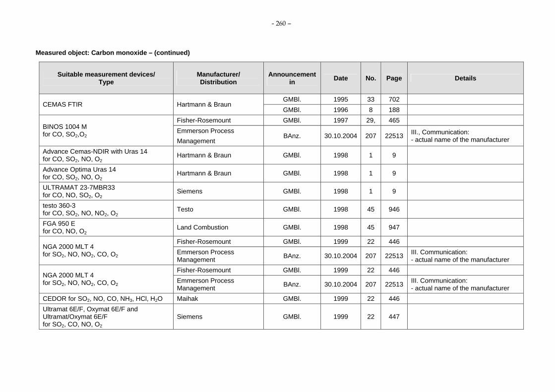
- 260 –
Measured object: Carbon monoxide – (continued)
Suitable measurement devices/ Type
Manufacturer/ Distribution
Announcement in Date No. Page Details
GMBl. 1995 33 702 CEMAS FTIR Hartmann & Braun
GMBl. 1996 8 188 Fisher-Rosemount GMBl. 1997 29, 465
BINOS 1004 M for CO, SO2,O2
Emmerson Process Management
BAnz. 30.10.2004 207 22513 III., Communication: - actual name of the manufacturer
Advance Cemas-NDIR with Uras 14 for CO, SO2, NO, O2
Hartmann & Braun GMBl. 1998 1 9
Advance Optima Uras 14 for CO, SO2, NO, O2
Hartmann & Braun GMBl. 1998 1 9
ULTRAMAT 23-7MBR33 for CO, NO, SO2, O2
Siemens GMBl. 1998 1 9
testo 360-3 for CO, SO2, NO, NO2, O2
Testo GMBl. 1998 45 946
FGA 950 E for CO, NO, O2
Land Combustion GMBl. 1998 45 947
Fisher-Rosemount GMBl. 1999 22 446 NGA 2000 MLT 4 for SO2, NO, NO2, CO, O2 Emmerson Process
Management BAnz. 30.10.2004 207 22513 III. Communication: - actual name of the manufacturer
Fisher-Rosemount GMBl. 1999 22 446 NGA 2000 MLT 4 for SO2, NO, NO2, CO, O2 Emmerson Process
Management BAnz. 30.10.2004 207 22513 III. Communication: - actual name of the manufacturer
CEDOR for SO2, NO, CO, NH3, HCl, H2O Maihak GMBl. 1999 22 446 Ultramat 6E/F, Oxymat 6E/F and Ultramat/Oxymat 6E/F for SO2, CO, NO, O2
Siemens GMBl. 1999 22 447

- 261 –
Measured object: Carbon monoxide – (continued)
Suitable measurement devices/ Type
Manufacturer/ Distribution
Announcement in Date No. Page Details
GMBl. 1999 33 720 Sick
BAnz. 27.04.2004 79 9221 MCS 100 E HW for SO2, CO, NO, O2, HCl, NH3, CO2
Sick Maihak BAnz. 29.04.2005 81 6893 III., 6, Communication: - actual name of the manufacturer
MCS 100 E PD for SO2, CO, NO, NO2, O2, HCl, CO2
Sick GMBl. 1999 33 721
AR 650 for HCl, CO, H2O OPSIS, Sweden GMBl. 1999 33 721
GMBl. 2001 19 387
BAnz. 14.10.2006 194 6715 V., 3. Communication: - new software version
Modularsystem S 700, Multor/Oxor 710/715/720 for CO, NO, SO2 and O2
Maihak
BAnz. 07.03.2008 38 903 IV., 6. Communication: - new software version
Modularsystem S 700, Unor/Oxor 710/715/720 for CO, NO, SO2 and O2
Maihak GMBl. 2001 19 387
PG 250 for NO, NO2, SO2, CO, CO2 and O2
Horiba GMBl. 2001 19 387
CEDOR II for CO, NO, SO2, HCl, NH3 and H2O Telnet Instruments Oy GMBl. 2001 55 1138
GMBl. 2001 55 1138
ABB Automation Products BAnz. 2004 79 9220
III., 1.Communication: - changes of the measurement
device Advance Cemas-FTIR NT for CO, NO, SO2, HCl, NH3 and H2O
ABB Automation GmbH BAnz. 29.10.2005 206 15702 V., 2. Communication: - actual name of the manufacturer

- 262 –
Measured object: Carbon monoxide – (continued)
Suitable measurement devices/ Type
Manufacturer/ Distribution
Announcement in Date No. Page Details
ABB Automation Products BAnz. 08.04.2006 70 2653 Advance Cemas-FTIR for CO, NO, SO2, HCl, NH3 and H2O ABB Automation Products BAnz. 29.10.2005 206 15701
BA 5000 for CO, NO, SO2 and O2
Bühler/Siemens GMBl. 1999 22 447
I., Pkt. 4.6, 2. Communication: - the measurement device is also sold
identical in construction under the designation Ultramat 23-7MB 233 by the company Siemens AG/Karlsruhe and under the designation GME 64 by the company Sick
CGA 4000 for CO, NO and O2
Land Combustion/Goyen Controls Co./UK GMBl. 2002 19 404
IV., Communication: - the measurement device is sold
identical in construction under the designation FGA 950 E by the company Land Combustion/UK
S 700 module series: Multor S 700 for CO, NO, SO2, Unor S 700 for CO, NO, SO2 and Oxor for O2
Maihak BAnz. 29.4.2005 81 6892. III., 5. Communication: - new software version
S 700 module series: (Multor S 700 for CO, NO, SO2)
Maihak BAnz. 29.10.2005 206 15702 V., 3. Communication: - correction
GMBl. 2002 19 402 S 700-1, Unor for CO Maihak
BAnz. 2003 210 23998 GMBl. 2002 19 402 S 700-6, Unor Unor
for CO and NO Maihak BAnz. 2003 210 23998 GMBl. 2002 19 402 S 700-7, Unor Unor
for CO and SO2 Maihak
BAnz. 2003 210 23998 GMBl. 2002 19 402 S 700-9 Unor Oxor P
for CO and O2 Maihak
BAnz. 2003 210 23998

- 263 –
Measured object: Carbon monoxide – (continued)
Suitable measurement devices/ Type
Manufacturer/ Distribution
Announcement in Date No. Page Details
GMBl. 2002 19 402 S 700-12, Unor Oxor E for CO and O2
Maihak BAnz. 2003 210 23998 GMBl. 2002 19 402 BAnz. 2003 210 23998 S 700-16, Multor
for CO and SO2 Maihak
BAnz. 29.10.2005 206 15702 V., 3. Communication - correction
GMBl. 2002 19 402 BAnz. 2003 210 23998 S 700-17, Multor
for CO and NO Maihak BAnz. 29.10.2005 206 15702 V., 3. Communication:
- correction Maihak GMBl. 2002 19 402 S 700-18, Unor Unor Oxor P
for CO, NO and O2 BAnz. 2003 210 23998 GMBl. 2002 19 402 S 700-19, Unor Unor Oxor P
for CO, SO2 and O2 Maihak
BAnz. 2003 210 23998 GMBl. 2002 19 402 S 700-21, Unor Unor Oxor E
for CO, NO and O2 Maihak
BAnz. 2003 210 23998 GMBl. 2002 19 402 S 700-22, Unor Unor Oxor E
for NO, SO2 and O2 Maihak
BAnz. 2003 210 23998 GMBl. 2002 19 402 S 700-24, Multor (1+2) Unor (3)
for CO, NO, SO2 Maihak
BAnz. 2003 210 23998 GMBl. 2002 19 402 S 700-25, Multor (1+2) Unor (3)
for CO, SO2, NO Maihak BAnz. 2003 210 23998 GMBl. 2002 19 402 S 700-26, Multor (1+2) Unor (3)
for NO, SO2, CO and H2O Maihak BAnz. 2003 210 23998

- 264 –
Measured object: Carbon monoxide – (continued)
Suitable measurement devices/ Type
Manufacturer/ Distribution
Announcement in Date No. Page Details
GMBl. 2002 19 402 S 700-27, Multor (1...3) for NO, SO2, CO and H2O Maihak
BAnz. 2003 210 23998 GMBl. 2002 19 402 S 700-28, Multor (1 +2) Oxor P (3)
for CO, NO and O2 Maihak
BAnz. 2003 210 23998 GMBl. 2002 19 402 S 700-29, Multor (1+2) Oxor P (3)
for CO, NO and O2 Maihak
BAnz. 2003 210 23998 GMBl. 2002 19 402 S 700-31, Multor (1+2) Oxor E (3)
for CO, NO and O2 Maihak
BAnz. 2003 210 23998 GMBl. 2002 19 402 S 700-32, Multor (1+2) Oxor E (3)
for CO, SO2 and O2 Maihak
BAnz. 2003 210 23998 GMBl. 2002 19 402 S 700-34, Multor (1..3) Oxor P (3)
for CO, NO, SO2, O2 and H2O Maihak BAnz. 2003 210 23998 GMBl. 2002 19 402 S 700-35, Multor (1..3) Oxor E (3)
for CO, NO, SO2, O2 and H2O Maihak BAnz. 2003 210 23998 GMBl. 2002 19 402 S 700-36, Multor (1+2) Unor (3) Oxor P (4)
for CO, SO2, NO and O2 Maihak
BAnz. 2003 210 23998 GMBl. 2002 19 402 S 700-37, Multor (1+2) Unor (3) Oxor P (4)
for CO, SO2, NO and O2 Maihak
BAnz. 2003 210 23998 GMBl. 2002 19 402 S 700-38, Multor (1+2) Unor (3) Oxor P (4)
for NO, SO2, CO, O2 and H2O Maihak BAnz. 2003 210 23998 GMBl. 2002 19 402 S 700-39, Multor (1+2) Unor (3) Oxor E (4)
for CO, NO, SO2 and O2 Maihak
BAnz. 2003 210 23998 GMBl. 2002 19 402 S 700-40, Multor (1+2) Unor (3) Oxor E (4)
for CO, NO, SO2 and O2 Maihak
BAnz. 2003 210 23998

- 265 –
Measured object: Carbon monoxide – (continued)
Suitable measurement devices/ Type
Manufacturer/ Distribution
Announcement in Date No. Page Details
GMBl. 2002 19 402 S 700-41, Multor (1+2) Unor (3) Oxor E (4) for NO, SO2, CO, O2 and H2O Maihak
BAnz. 2003 210 23998
GME 64 for CO, NO, SO2 and O2
Sick/Siemens GMBl. 1999 22 447
I., 4.6: - the measurement device is also
sold identical in construction under the designation Ultramat 23-7MB 233 by the company Siemens AG/Karlsruhe and under the designation BA 5000 by the company Bühler
Multi Gas Analyzer Födisch/Siemens GMBl. 2003 7 139
IV., Communication: - the measurement device is also
sold identical in construction under the designation Ultramat 23-7MB233 by the company Siemens AG/Karlsruhe
BAnz. 15.5.2003 90 10742 FGA II for SO2, NO, NO2, CO, O2, and CO2
LAND Instrument BAnz. 2003 210 23998 BAnz. 15.05.2003 90 10742
ABB Automation Products BAnz. 2004 79 9220
BAnz. 29.4.2005 81 6893 III., 1. Communication: - actual name of the manufacturer
AO2020-Uras14 for CO, NO, SO2 and O2
ABB Automation GmbH BAnz. 06.11.2007 206 7925 III., 5. Communication:
- new software version BAnz. 15.05.2003 90 10742 AO2040-Uras14
for CO, NO, SO2 and O2 ABB Automation Products
BAnz. 2004 79 9220

- 266 –
Measured object: Carbon monoxide – (continued)
Suitable measurement devices/ Type
Manufacturer/ Distribution
Announcement in Date No. Page Details
BAnz. 29.04.2005 81 6893 III., 1. Communication: - actual name of the manufacturer
ABB Automation GmbH BAnz. 06.11.2007 206 7925 III., 5. Communication:
- new software version BAnz. 29.04.2005 81 6892
Ultramat 23 7 MB 2337 for CO, NO and O2
Siemens BAnz. 20.04.2007 75 4139 IV., 2. Communication:
- new software version
Ultramat 23-7MB2337, Ultramat 23-7MB2335 for NO, CO and O2
Siemens AG, Karlsruhe BAnz. 07.03.2008 38 902
- supplementary test to the announcement of the Federal Environment Agency from 31 March 2005 (BAnz. S. 6892).
BAnz. 29.10.2005 206 15700 GM 35 In-situ Gas Analyzer, Cross-Duct version SICK MAIHAK
BAnz. 08.04.2006 70 2655 V., 4. Communication: - correction of the measuring path
length GM 35 In-situ Gas Analyzer, Probe version GMP SICK MAIHAK BAnz. 29.10.2005 206 15700
Advance Cemas-FTIR for CO, NO, SO2, HCl, NH3 and H2O ABB Automation Products BAnz. 29.10.2005 206 15701
BAnz. 29.10.2005 206 15701 MCA 04 for CO, NO, SO2, HCl, NH3 ,H2O, O2 and CO2
Födisch UmweltmesstechnikBAnz. 08.04.2006 70 2654
BAnz. 08.04.2006 70 2653 VA 3000 for CO, NOX, N2O, CO2 and O2
Horiba Europe GmbH BAnz. 14.10.2006 194 6715 V., 2. Communication

- 267 –
Measured object: Carbon monoxide – (continued)
Suitable measurement devices/ Type
Manufacturer/ Distribution
Announcement in Date No. Page Details
BAnz. 08.04.2006 70 2654 BAnz. 14.10.2006 194 6715 V., 6. Communication
ZRJ/ZFK7 for CO and O2
Fuji Electric Systems Co., Ltd.
BAnz. 06.11.2007 206 7925
III., 3. Communication: - the measurement device is also
sold under the designation Yokogawa Model IR200ZX8D by the company Yogogawa Electric Corporation/Japan
BAnz. 08.04.2006 70 2654 BAnz. 14.10.2006 194 6715 V., 5. Communication
ZKJ/ZFK7 for CO, NOX, SO2 and O2
Fuji Electric Systems Co., Ltd.
BAnz. 06.11.2007 206 7925
III, 4. Communication: - the measurement device is also
sold under the designation Yokogawa Model IR400 by the company Yogogawa Electric Corporation/Japan
BAnz. 14.10.2006 194 6715
BAnz. 20.04.2007 75 4139 IV., 4. Communication: - new software version Advance Optima AO2000 series
for CO, NO, SO2, CO2, N2O and O2 ABB Automation GmbH, Frankfurt/Main
BAnz. 07.03.2008 38 903 IV., 2. Communication: - new software version

- 268 –
Measured object: Carbon monoxide – (continued)
Suitable measurement devices/ Type
Manufacturer/ Distribution
Announcement in Date No. Page Details
BAnz. 14.10.2006 194 6715
BAnz. 20.04.2007 75 4139 IV., 3. Communication: - new software version Easy Line EL3000 series
for CO, NO, SO2, N2O, CO2, O2 ABB Automation GmbH, Frankfurt/Main
BAnz. 07.03.2008 38 903 IV., 3. Communication: - new software version
GM 35 In-situ Gas Analyzer, Cross-Duct version for CO, CO2, H2O
SICK MAIHAK GmbH BAnz. 14.10.2006 194 6715
GM 35 In-situ Gas Analyzer, Probe version GMP SICK MAIHAK GmbH BAnz. 14.10.2006 194 6715
BAnz. 14.10.2006 194 6715 GASMET CEMS for CO, NO, NO2, N2O, SO2, HCl, NH3, CO2, H2O
Gasmet Technologies Oy, Helsinki, Finland BAnz. 20.04.2007 75 4140 IV., 8. Communication
GASMET CEMS with OXITEC 500E SME 5for O2, CO, NO, NO2, N2O, SO2, HCl, NH3, CO2, H2O
Gasmet Technologies Oy, Helsinki, Finland BAnz. 07.03.2008 38 901
- supplementary test to the announcement of the Federal Environment Agency from 12 September 2006 (BAnz. S. 6715).
BAnz. 14.10.2006 194 6715 SIDOR for CO, NO, SO2, O2
MAIHAK AG, Hamburg BAnz. 07.03.2008 38 903 IV., 4. Communication:
- new software version BAnz. 20.04.2007 75 4139
ULTRAMAT 237MB2338 for CO, CO2 and N2O Siemens AG, Karlsruhe
BAnz. 07.03.2008 38 902
- supplementary test to the announcement of the Federal Environment Agency from 12 April 2007 (BAnz. S. 4139).
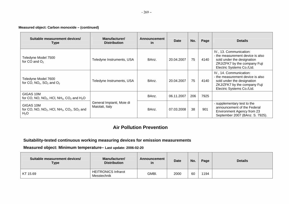
- 269 –
Measured object: Carbon monoxide – (continued)
Suitable measurement devices/ Type
Manufacturer/ Distribution
Announcement in Date No. Page Details
Teledyne Model 7500 for CO and O2
Teledyne Instruments, USA BAnz. 20.04.2007 75 4140
IV., 13. Communication: - the measurement device is also
sold under the designation ZRJ/ZFK7 by the company Fuji Electric Systems Co./Ltd.
Teledyne Model 7600 for CO, NOx, SO2 and O2
Teledyne Instruments, USA BAnz. 20.04.2007 75 4140
IV., 14. Communication: - the measurement device is also
sold under the designation ZKJ/ZFK7 by the company Fuji Electric Systems Co./Ltd.
GIGAS 10M for CO, NO, NO2, HCl, NH3, CO2 and H2O BAnz. 06.11.2007 206 7925
GIGAS 10M for CO, NO, NO2, HCl, NH3, CO2, SO2 and H2O
General Impianti, Moie di Maiolati, Italy
BAnz. 07.03.2008 38 901
- supplementary test to the announcement of the Federal Environment Agency from 23 September 2007 (BAnz. S. 7925).
Air Pollution Prevention
Suitability-tested continuous working measuring devices for emission measurements
Measured object: Minimum temperature– Last update: 2006-02-20
Suitable measurement devices/ Type
Manufacturer/ Distribution
Announcement in Date No. Page Details
KT 15.69 HEITRONICS Infrarot Messtechnik GMBl. 2000 60 1194

- 270 –
Measured object: Minimum temperature – (continued)
Suitable measurement devices/ Type
Manufacturer/ Distribution
Announcement in Date No. Page Details
KT 19.69 HEITRONICS Infrarot Messtechnik GMBl. 2000 60 1194
Air Pollution Prevention
Suitability-tested continuous working measuring devices for emission measurements
Measured object: Organic compounds as total carbon – Last update: 2006-10-20
Suitable measurement devices/ Type
Manufacturer/ Distribution
Announcement in Date No. Page Details
KM 2-CnHm-Em-ADOS ADOS GMBl. 1990 12 238
FIDAMAT I Siemens GMBl. 1990 12 238 FIDAMAT K Siemens GMBl. 1990 12 238
FIDAS 2 T Hartmann & Braun GMBl. 1990 12 239 The device is not any longer in the delivery program of the manufacturer.
BA 3004 Bernath Atomic GMBl. 1990 12 239
BA 3001 Bernath Atomic GMBl. 1990 12 239
FIDAS 2 T (0-50 mg/m3) Hartmann & Braun GMBl. 1990 12 239 The device is not any longer in the delivery program of the manufacturer.
Compur FID Bayer Diagnostic/Hartmann & Braun GMBl. 1990 12 239
GMBl. 1990 12 239 FIDAS 3 E Hartmann & Braun
GMBl. 1992 45 1141

- 271 –
Measured object: Organic compounds as total carbon – (continued)
Suitable measurement devices/ Type
Manufacturer/ Distribution
Announcement in Date No. Page Details
GMBl. 1990 20 400 GMBl. 1991 37 1046 BA 3002 RC Bernath Atomic GMBl. 1993 26 459
BA 3006 Bernath Atomic GMBl. 1996 8 188 GMBl. 1990 34 860
FID VE 7 J.U.M. Engineering GMBl. 1993 26 469
FIDAMAT K-M 52044-A10 Siemens GMBl. 1990 34 861 The device is not any longer in the delivery program of the manufacturer.
TESTA FID 123 TESTA GMBl. 1992 45 1141
Compur Multi-FID 100 E 17 Bayer Diagnostic/Hartmann & Braun GMBl. 1992 45 1141
Compur Multi-FID 100 FE 17 (without extraction line)
Bayer Diagnostic/Hartmann & Braun GMBl. 1992 45 1141
Compur MICRO-FID 100 Hartmann & Braun GMBl. 1993 43 863 RS 55 T Ratfisch Analysensysteme GMBl. 1994 28 868 FIDAMAT 5 E Siemens GMBl. 1995 33 702 FID 123, 123 I, 3001 W TESTA GMBl. 1996 28 591 FID 3-200, FID 3-300 A J.U.M. GMBl. 1996 28 591 Thermo FID Mess- u. Analysentechnik GMBl. 1997 29 464 Advance Optima Multi FID-14 Hartmann & Braun GMBl. 1998 20 418 NGA 2000 TFID Fisher-Rosemount GMBl. 1999 33 720 FID 2010 T, FID 1230 Modul TESTA GMBl. 2000 60 1193 Thermo-FID Mess- u. Analysentechnik GMBl. 2003 7 138

- 272 –
Measured object: Organic compounds as total carbon – (continued)
Suitable measurement devices/ Type
Manufacturer/ Distribution
Announcement in Date No. Page Details
BAnz. 15.5.2003 90 10743 AO2020-MultiFID14 ABB Automation Products
BAnz. 27.4.2004 79 9221 III., 5. Communication: - new software versions
BAnz. 15.5.2003 90 10743 AO2040-MultiFID14 ABB Automation Products
BAnz. 27.4.2004 79 9221 III., 5. Communication: - new software versions
Land THA 300 Land Instruments/TESTA BAnz. 11.11.2003 210 23997
IV., Communication: - the measurement device is also
sold under the designation FID 3001 W by the company Testa GmbH/München
EuroFID INLINE Analysenmesstechnik Bernath Atomic GmbH & Co.KG, Wennigsen
BAnz. 27.4.2004 79 9220
I., 2.2: - the measurement device is sold by
the company Sick Maihak GmbH/Reute
EUROFID Analysenmesstech-nik Bernath Atomic BAnz. 27.4.2004 79 9220
I., 2.3: - the measurement device is sold by
the company Sick Maihak GmbH/Reute
Termo-FID (Modell KA) Mess- u. Analysentechnik GmbH BAnz. 27.4.2004 79 9220
ADOS KM 2000-CnHm (Em) ADOS GmbH BAnz. 27.4.2004 79 9220 FIDAMAT 6 7 MB 2421 Siemens AG BAnz. 08.04.2006 70 2653

- 273 –
Air Pollution Prevention
Suitability-tested continuous working measuring devices for emission measurements
Measured object: Phenol – Last update: 2006-02-20
Suitable measurement devices/ Type
Manufacturer/ Distribution
Announcement in Date No. Page Details
OPSIS AR 602 Z OPSIS AB GMBl. 1994 28 869
Air Pollution Prevention
Suitability-tested continuous working measuring devices for emission measurements
Measured object: Mercury– Last update: 2007-11-06
Suitable measurement devices/ Type
Manufacturer/ Distribution
Announcement in Date No. Page Details
GMBl. 1994 289 869 OPSIS AR 602 Z OPSIS AB
GMBl. 1996 42 882
HG MAT II Seefelder Messtechnik GMBl. 1995 7 101 The device is not any longer in the delivery program of the manufacturer.
HGMAT 2.1 Seefelder Messtechnik GMBl. 1998 20 418 The device is not any longer in the delivery program of the manufacturer.
HM 1400 VEREWA GMBl. 1996 28 592 HG 2000 SEMTECH AB GMBl. 1996 28 592

- 274 –
Measured object: Mercury – (continued)
Suitable measurement devices/ Type
Manufacturer/ Distribution
Announcement in Date No. Page Details
Bodenseewerk Perkin-Elmer GMBl. 1996 28 592 MERCEM SICK MAIHAK GmbH,
Meersburg BAnz. 06.11.2007 206 7925 III., 1. Communication: - actual name of the manufacturer.
SM 3 Mercury Instrument und IMT Innovative Messtechnik GMBl. 1999 33 720
HG 2010 SEMTECH AB GMBl. 2000 60 1193 HG-CEM Seefelder Messtechnik GMBl. 2000 60 1193
SICK UPA GMBl. 2001 19 386 MERCEM SICK MAIHAK GmbH,
Meersburg BAnz. 06.11.2007 206 7925 III., 1. Communication: - actual name of the manufacturer.
HM 1400 TR VEREWA Umwelt- u. Prozesstechnik GMBl. 2001 19 386

- 275 –
Air Pollution Prevention
Suitability-tested continuous working measuring devices for emission measurements
Measured object: Oxygen – Last update: 2008-03-07
Suitable measurement devices/ Type
Manufacturer/ Distribution
Announcement in Date No. Page Details
Servomex OA 540/540 E Bühler Mess- und Regeltechnik GMBl. 1990 12 239
Servomex 700 B Bühler Mess- und Regeltechnik GMBl. 1990 12 239
Magnos 3/3 K Hartmann & Braun GMBl. 1990 12 240 The device is not any longer in the delivery program of the manufacturer.
Oxymat 5 Siemens GMBl. 1990 12 240 DIRAS 218 Westinghouse/Rosemount GMBl. 1990 20 400 Magnos 6 G Hartmann & Braun GMBl. 1990 34 861 LS1/LU2 Asea Brown Boveri GMBl. 1990 20 526 MSI 5600 MSI Elektronik GMBl. 1992 32 794 OXITEC SME-11 ENOTEC GMBl. 1992 32 795 Oxor 6 N/600 Maihak GMBl. 1992 32 795 Oxor 610 Maihak GMBl. 1996 8 189 Helox 3 MBE Elektronic GMBl. 1992 32 795 Oxygor 6 N Maihak GMBl. 1992 32 795 OXYNOS 100 Rosemount GMBl. 1992 32 795 LS1/LU2 (in situ) Asea Brown Boveri GMBl. 1991 37 1046
PMA 30 M & C Products Analysentechnik GMBl. 1992 45 1142
PMA 10/20 M & C Products Analysentechnik GMBl. 1992 45 1142

- 276 –
Measured object: Oxygen – (continued)
Suitable measurement devices/ Type
Manufacturer/ Distribution
Announcement in Date No. Page Details
DIRAS 500/2250/2251 Westinghouse Controlmatic GMBl. 1992 45 1142 GMBl. 1993 26 470
URAS 10 E Hartmann & Braun GMBl. 1993 43 863 GMBl. 1993 43 864
ENDA 1000 HORIBA GMBl. 1994 28 869
EXA OXY Modell ZA 8 Yokogawa Germany GMBl. 1993 43 864 Rosemount GMBl. 1993 43 864
O2-Analyzer Modell 3000 Emmerson Process Management BAnz. 30.10.2004 207 22513 III. Communication:
- actual name of the manufacturer ZFG 2/ZMT ABB Kent-Taylor GMBl. 1994 28 870 OXITEC SME 3 (in situ) and OXITEC 500 SME 3 ENOTEC GMBl. 1994 28 870
GMBl. 1995 33 702 CEMAS NDIR Hartmann & Braun
GMBl. 1996 8 189
ZIROX-K 10 ZIROX Sensoren & Elektronik GMBl. 1995 33 702
GMBl. 1996 28 593 Multor 610 Maihak
GMBl. 1996 42 882 XENTRA 4900 Servomex GMBl. 1996 28 593 BINOS 1004 M for CO, SO2,O2
Fisher-Rosemount GMBl. 1997 29 465
Thermox WDG-IV AMETEK GMBl. 1997 29 465 Thermox WDG-HP/II AMETEK GMBl. 1997 29 465 Advance Optima Magnos 16 Hartmann & Braun GMBl. 1997 29 465

- 277 –
Measured object: Oxygen – (continued)
Suitable measurement devices/ Type
Manufacturer/ Distribution
Announcement in Date No. Page Details
Advance Cemas-NDI with Uras 14 for CO, SO2, NO, O2
Hartmann & Braun GMBl. 1998 1 9
Advance Optima Uras 14 for CO, SO2, NO, O2
Hartmann & Braun GMBl. 1998 1 9
GMBl. 1998 1 9 ULTRAMAT 23-7MBR33 for CO, NO, SO2, O2
Siemens GMBl. 1999 22 447
LS1/LT1 LAMTEC GMBl. 1998 20 419 FGA 950 E for CO, NO, O2
Land Combustion GMBl. 1998 45 947
Oxy Sys 2200 Marathon Monitors GMBl. 1998 45 947 testo 360-3 for CO, SO2, NO, NO2, O2
Testo GMBl. 1998 45 946
Fisher-Rosemount GMBl. 1999 22 465 NGA 2000 MLT 1 for SO2, NO and O2 Emmerson Process
Management BAnz. 30.10.2004 207 22513 III. Communication: - actual name of the manufacturer
Fisher-Rosemount GMBl. 1999 33 720 NGA 2000 MLT 1 for SO2, NO and O2 Emmerson Process
Management BAnz. 30.10.2004 207 22513 III. Communication: - actual name of the manufacturer
Fisher-Rosemount GMBl. 1999 22 466 NGA 2000 MLT 4 for SO2, NO, NO2, CO and O2 Emmerson Process
Management BAnz. 30.10.2004 207 22513 III. Communication: - actual name of the manufacturer
Fisher-Rosemount GMBl. 1999 33 720 NGA 2000 MLT 4 for SO2, NO, NO2, CO and O2 Emmerson Process
Management BAnz. 30.10.2004 207 22513 III. Communication: - actual name of the manufacturer

- 278 –
Measured object: Oxygen – (continued)
Suitable measurement devices/ Type
Manufacturer/ Distribution
Announcement in Date No. Page Details
Ultramat 6E/F, Oxymat 6 E/F and Ultramat/Oxymat 6 E/F for SO2, NO, CO, O2
Siemens GMBl. 1999 22 467
OXYGEN MONITOR O2000, Probe Modell 502 OPSIS, Sweden GMBl. 1999 22 447
Konverter ZRM; Detector ZFK Fuji Electric, Japan GMBl. 1999 22 447 Konverter ZRY;Detector ZFK Fuji Electric, Japan GMBl. 1999 33 722
GMBl. 1999 33 720
Sick BAnz. 27.04.2004 79 9221
III., 8. Communication: - installation of a new heating
controller - extension of the software
MCS 100 E HW for SO2, NO, CO, CO2, HCl, NH3, O2 and H2O
Sick Maihak BAnz. 29.04.2005 81 6893 III., 6. Communication: - extension of the software - actual name of the manufacturer
MCS 100 E PD for SO2, NO, NO2, CO, CO2, HCl, O2
Sick GMBl. 1999 33 721
XENDOS 2700 Servomex GMBl. 1999 33 722 Analyzer 570 A Servomex GMBl. 1999 33 722 Analyzer ZDT; probe ZFG 2 ABB Instrumentation, UK GMBl. 1999 33 722 Oxitec 5000/SME 5 Enotec GMBl. 2000 22 444 Advance Optima Limas 11-UV for NO, SO2, and O2
ABB Automation GMBl. 2000 60 1193
AMS 3220 AMS GMBl. 2000 60 1194
g1200 Land Combustion, UK/Land Combustion, D GMBl. 2000 60 1194

- 279 –
Measured object: Oxygen – (continued)
Suitable measurement devices/ Type
Manufacturer/ Distribution
Announcement in Date No. Page Details
GMBl. 2001 19 387
BAnz. 14.10.2006 194 6715 V., 3. Communication: - new software version S 700, Multor/Oxor 710/715/720
for CO, NO, SO2 and O2 Maihak
BAnz. 07.03.2008 38 903 IV., 6. Communication: - new software version
GMBl. 2001 19 387 S 7 00, Unor/Oxor 710/715/720 for CO, NO, SO2 and O2
Maihak BAnz. 14.10.2006 194 6517 V., III. Communication:
- new software version PG 250 for NO, NO2, SO2, CO, CO2 and O2
Horiba GMBl. 2001 19 387
Advance Optima Limas 11-UV for NO, SO2 and O2
ABB Automation Products GMBl. 2001 55 1138
BA 5000 for CO, NO, SO2 and O2
Siemens/Bühler GMBl. 1999 22 447
I., 4.6: - the measurement device is also sold
identical in construction under the designation Ultramat 23-7MB 233 by the company Siemens AG/Karlsruhe and under the designation GME 64 by the company Sick
GMBl. 2002 19 403 Advance Optima Magnos 106 ABB Automation Products
BAnz. 27.04.2004 79 9221 III., 6. Communication: - new software version
RGM 11 ABB Automation Products GMBl. 2002 19 403
CGA 4000 for CO, NO and O2
Land Combustion/Goyen Controls GMBl. 2002 19 404
IV. Communication: - the measurement device is also sold
identical in construction under the designation FGA 950 E by the company Land Combustion/UK

- 280 –
Measured object: Oxygen – (continued)
Suitable measurement devices/ Type
Manufacturer/ Distribution
Announcement in Date No. Page Details
COA 2000 Goyen Controls/Land Combustion GMBl. 2002 19 404
IV. Communication: - the measurement device is also
sold identical in construction under the designation g 1200 by the company Land Combustion/UK
GME 64 for CO, NO, SO2 and O2
Sick/Siemens GMBl. 1999 22 447
I., 4.6: - the measurement device is also
sold identical in construction under the designation Ultramat 23-7MB 233 by the company Siemens AG/Karlsruhe and under the designation BA 5000 by the company Bühler
S 700 module series: Multor S 700 for CO, NO, SO2, Unor S 700 for CO, NO, SO2 and Oxor for O2
Maihak BAnz. 29.04.2005 81 6893 III., 5. Communication: - new software version
GMBl. 2002 19 402 S 700-4, Oxor P for O2
Maihak BAnz. 2003 210 23998 GMBl. 2002 19 402 S 700-5, Oxor E
for O2 Maihak
BAnz. 2003 210 23998 GMBl. 2002 19 402 S 700-9, Unor Oxor P
for CO and O2 Maihak
BAnz. 2003 210 23998 GMBl. 2002 19 402 S 700-10, Unor Oxor P
for NO and O2 Maihak
BAnz. 2003 210 23998 GMBl. 2002 19 402 S 700-11, Unor Oxor P
for SO2 and O2 Maihak
BAnz. 2003 210 23998 GMBl. 2002 19 402 S 700-12, Unor Oxor E
for CO2 and O2 Maihak
BAnz. 2003 210 23998

- 281 –
Measured object: Oxygen – (continued)
Suitable measurement devices/ Type
Manufacturer/ Distribution
Announcement in Date No. Page Details
GMBl. 2002 19 402 S 700-13, Unor Oxor E for NO and O2
Maihak BAnz. 2003 210 23998 GMBl. 2002 19 402 S 700-14, Unor Oxor E
for SO2 and O2 Maihak
BAnz. 2003 210 23998 GMBl. 2002 19 402 S 700- 18, Unor Unor Oxor P
for CO, NO and O2 Maihak
BAnz. 2003 210 23998 GMBl. 2002 19 402 S 700- 19, Unor Unor Oxor P
for CO, SO2 and O2 Maihak
BAnz. 2003 210 23998 GMBl. 2002 19 402 S 700- 20, Unor Unor Oxor P
for NO, SO2 and O2 Maihak
BAnz. 2003 210 23998 GMBl. 2002 19 402 S 700-21, Unor Unor Oxor E
for CO, NO and O2 Maihak
BAnz. 2003 210 23998 GMBl. 2002 19 402 S 700-22, Unor Unor Oxor E
for CO, SO2, O2 Maihak
BAnz. 2003 210 23998 GMBl. 2002 19 402 S 700-23, Unor Unor Oxor E
for NO, SO2, O2 Maihak
BAnz. 2003 210 23998 GMBl. 2002 19 402 S 700-28, Multor (1 +2) Oxor P (3)
for CO, NO and O2 Maihak
BAnz. 2003 210 23998 GMBl. 2002 19 402 S 700-29, Multor (1 +2) Oxor P (3)
for CO, SO2 and O2 Maihak
BAnz. 2003 210 23998 GMBl. 2002 19 402 S 700-30, Multor (1+2) Oxor P (3)
for NO, SO2, O2 and H2O Maihak BAnz. 2003 210 23998 GMBl. 2002 19 402 S 700-31, Multor (1+2) Oxor E (3)
for CO, NO and O2 Maihak
BAnz. 2003 210 23998
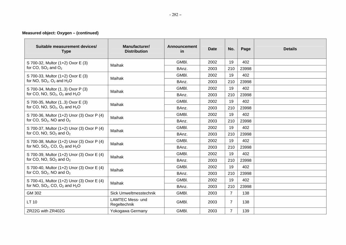
- 282 –
Measured object: Oxygen – (continued)
Suitable measurement devices/ Type
Manufacturer/ Distribution
Announcement in Date No. Page Details
GMBl. 2002 19 402 S 700-32, Multor (1+2) Oxor E (3) for CO, SO2 and O2
Maihak BAnz. 2003 210 23998 GMBl. 2002 19 402 S 700-33, Multor (1+2) Oxor E (3)
for NO, SO2, O2 and H2O Maihak BAnz. 2003 210 23998 GMBl. 2002 19 402 S 700-34, Multor (1..3) Oxor P (3)
for CO, NO, SO2, O2 and H2O Maihak BAnz. 2003 210 23998 GMBl. 2002 19 402 S 700-35, Multor (1..3) Oxor E (3)
for CO, NO, SO2, O2 and H2O Maihak BAnz. 2003 210 23998 GMBl. 2002 19 402 S 700-36, Multor (1+2) Unor (3) Oxor P (4)
for CO, SO2, NO and O2 Maihak
BAnz. 2003 210 23998 GMBl. 2002 19 402 S 700-37, Multor (1+2) Unor (3) Oxor P (4)
for CO, NO, SO2 and O2 Maihak
BAnz. 2003 210 23998 GMBl. 2002 19 402 S 700-38, Multor (1+2) Unor (3) Oxor P (4)
for NO, SO2, CO, O2 and H2O Maihak BAnz. 2003 210 23998 GMBl. 2002 19 402 S 700-39, Multor (1+2) Unor (3) Oxor E (4)
for CO, NO, SO2 and O2 Maihak
BAnz. 2003 210 23998 GMBl. 2002 19 402 S 700-40, Multor (1+2) Unor (3) Oxor E (4)
for CO, SO2, NO and O2 Maihak
BAnz. 2003 210 23998 GMBl. 2002 19 402 S 700-41, Multor (1+2) Unor (3) Oxor E (4)
for NO, SO2, CO, O2 and H2O Maihak BAnz. 2003 210 23998
GM 302 Sick Umweltmesstechnik GMBl. 2003 7 138
LT 10 LAMTEC Mess- und Regeltechnik GMBl. 2003 7 138
ZR22G with ZR402G Yokogawa Germany GMBl. 2003 7 139

- 283 –
Measured object: Oxygen – (continued)
Suitable measurement devices/ Type
Manufacturer/ Distribution
Announcement in Date No. Page Details
LIN 2 with probe WC 3000 or OXT4ADR ISW Gasanalytik & Elektrotechnik GMBl. 2003 7 139
Multi Gas Analyzer 23 for CO, NO, SO2 and O2
Födisch/Siemens GMBl. 2003 7 139
IV. Communication: - the measurement device is also
sold under the designation Ultramat 23-7MB233 by the company Siemens AG/Karlsruhe
BAnz. 15.05.2003 90 10742 FGA II for SO2, NO, NO2, CO, O2 and CO2
LAND Instrument BAnz. 11.11.2003 210 23997 BAnz. 15.05.2003 90 10743
ABB Automation Products BAnz. 27.04.2004 79 9221 III., 6. Communication:
- new software version Advance Optima 2020-Magnos 106
ABB Automation GmbH BAnz. 29.04.2005 81 6893 III., 4. Communication: - new software version - actual name of the manufacturer
BAnz. 15.05.2003 90 10743 ABB Automation Products
BAnz. 27.04.2004 79 9221 III., 6. Communication: - new software version AO 2040-Magnos 106
ABB Automation GmbH BAnz. 29.04.2005 81 6893 III., 4. Communication: - new software version - actual name of the manufacturer
BAnz. 15.05.2003 90 10743 AO 2020-Uras14 for CO, NO, SO2 and O2
ABB Automation Products BAnz. 27.04.2004 79 9221 III., 3. Communication:
- new software version

- 284 –
Measured object: Oxygen – (continued)
Suitable measurement devices/ Type
Manufacturer/ Distribution
Announcement in Date No. Page Details
BAnz. 29.04.2005 81 6893 III., 1. Communication: - actual name of the manufacturer - new software version ABB Automation GmbH
BAnz. 06.11.2007 206 7925 III., 5. Communication: - new software version
BAnz. 15.05.2003 90 10743 ABB Automation Products
BAnz. 27.04.2004 79 9221 III., 3. Communication: - new software version
BAnz. 29.04.2005 81 6893 III., 1. Communication: - new software version - actual name of the manufacturer
AO 2040-Uras14 for CO, NO, SO2 and O2
ABB Automation GmbH
BAnz. 06.11.2007 206 7925 III., 5. Communication: - new software version
BAnz. 15.05.2003 90 10743 ABB Automation Products
BAnz. 27.4.2004 79 9221 III., 4. Communication: - new software version AO 2020-Limas 11UV
for NO, SO2 and O2 ABB Automation GmbH BAnz. 29.04.2005 81 6893
III., 2. Communication: - new software version - actual name of the manufacturer
BAnz. 15.5.2003 90 10743 ABB Automation Products
BAnz. 27.04.2004 79 9221 III., 4. Communication: - new software version AO 2040-Limas11UV
for NO, SO2 and O2 ABB Automation GmbH BAnz. 29.04.2005 81 6893
III., 2. Communication: - new software version - actual name of the manufacturer

- 285 –
Measured object: Oxygen – (continued)
Suitable measurement devices/ Type
Manufacturer/ Distribution
Announcement in Date No. Page Details
DIRAS CME/CMS Controlmatic/ENOTEC BAnz. 27.04.2004 79 9220
III., 2. Communication: - the measurement device is also
sold under the designation OXITEC 5000/SME 5 by the manufacturer ENOTEC GmbH
ZIRKOR 5000 SICK/MAIHAK/ENOTEC BAnz. 27.04.2004 79 9220
III., 2. Communication: - the measurement device is also
sold under the designation OXITEC 5000/SME 5 by the manufacturer ENOTEC GmbH
OXITEC 5000 Frobes Marshall/ENOTEC BAnz. 27.04.2004 79 9220
III., 2. Communication: - the measurement device is also
sold under the designation OXITEC 5000/SME 5 by the manufacturer ENOTEC GmbH
OXITEC 5000 Siemens Industrial/ENOTEC BAnz. 27.04.2004 79 9220
III., 2. Communication: - the measurement device is also
sold under the designation OXITEC 5000/SME 5 by the manufacturer ENOTEC GmbH
Thermo WDG 210/Insitu AMETEK/Thermox, USA BAnz. 27.04.2004 79 9220
II., 1.1: - the measurement device is sold by
the company AMETEK GmbH/Meerbusch
BAnz. 29.04.2005 81 6892 Ultramat 23 7 MB 2337 for CO, NO and O2
Siemens BAnz. 20.04.2007 75 4139
IV., 2. Communication: - new software version
Ultramat 23-7MB2337, Ultramat 23-7MB2335 for NO, CO and O2
Siemens AG, Karlsruhe BAnz. 07.03.2008 38 902
- supplementary test to the announcement of the Federal Environment Agency from 31 March 2005 (BAnz. S. 6892).
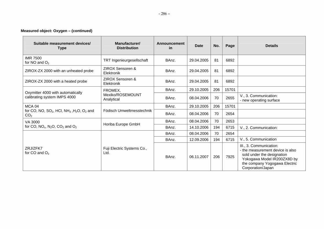
- 286 –
Measured object: Oxygen – (continued)
Suitable measurement devices/ Type
Manufacturer/ Distribution
Announcement in Date No. Page Details
IMR 7500 for NO and O2
TRT Ingenieurgesellschaft BAnz. 29.04.2005 81 6892
ZIROX-ZX 2000 with an unheated probe ZIROX Sensoren & Elektronik BAnz. 29.04.2005 81 6892
ZIROX-ZX 2000 with a heated probe ZIROX Sensoren & Elektronik BAnz. 29.04.2005 81 6892
BAnz. 29.10.2005 206 15701 Oxymitter 4000 with automatically calibrating system IMPS 4000
FROMEX, Mexiko/ROSEMOUNT Analytical BAnz. 08.04.2006 70 2655 V., 3. Communication:
- new operating surface BAnz. 29.10.2005 206 15701 MCA 04
for CO, NO, SO2, HCl, NH3 ,H2O, O2 and CO2
Födisch UmweltmesstechnikBAnz. 08.04.2006 70 2654
BAnz. 08.04.2006 70 2653 VA 3000 for CO, NOx, N2O, CO2 and O2
Horiba Europe GmbH BAnz. 14.10.2006 194 6715 V., 2. Communication: BAnz. 08.04.2006 70 2654 BAnz. 12.09.2006 194 6715 V., 5. Communication
ZRJ/ZFK7 for CO and O2
Fuji Electric Systems Co., Ltd.
BAnz. 06.11.2007 206 7925
III., 3. Communication: - the measurement device is also
sold under the designation Yokogawa Model IR200ZX8D by the company Yogogawa Electric Corporation/Japan

- 287 –
Measured object: Oxygen – (continued)
Suitable measurement devices/ Type
Manufacturer/ Distribution
Announcement in Date No. Page Details
BAnz. 08.04.2006 70 2654 V., 5. Communication:
ZKJ/ZFK7 for CO, NOx, SO2 and O2
Fuji Electric Systems Co., Ltd. BAnz. 06.11.2007 206 7925
III., 4. Communication: - the measurement device is also
sold under the designation Yokogawa Model IR400 by the company Yogogawa Electric Corporation/Japan
BAnz. 08.04.2006 70 2654
LAMDA-TRANSMITTER LT 10 P
LAMTEC Mess- und Regeltechnik für Feuerungen GmbH & Co. KG
BAnz. 12.09.2006 194 6715
VI. Appendix: - the measurement device is also
sold under the designation ZIRKOR 302 P by the company Sick Maihak GmbH
ZIRKOR 302 Fa. Sick Maihak GmbH BAnz 08.04.2006 70 2654
LAMDA-TRANSMITTER LT 10 E
LAMTEC Mess- und Regeltechnik für Feuerungen GmbH & Co. KG
BAnz. 08.04.2006 70 2654
ZIRKOR 302 E Fa. Sick Maihak GmbH BAnz. 08.04.2006 70 2654 BAnz. 14.10.2006 194 6715
BAnz 20.04.2007 75 4139 IV., 4. Communication: - new software version Advance Optima AO2000 series
for CO, NO, SO2, CO2, N2O and O2 ABB Automation GmbH, Frankfurt/Main
BAnz. 07.03.2008 38 903 IV., 2. Communication: - new software version

- 288 –
Measured object: Oxygen – (continued)
Suitable measurement devices/ Type
Manufacturer/ Distribution
Announcement in Date No. Page Details
BAnz. 14.10.2006 194 6715
BAnz. 20.04.2007 75 4139 IV., 3. Communication: - new software version Easy Line EL3000 series
for CO, NO, SO2, N2O, CO2, O2 ABB Automation GmbH, Frankfurt/Main
BAnz. 07.03.2008 38 903 IV., 3. Communication: - new software version
BAnz. 14.10.2006 194 6715 SIDOR for CO, NO, SO2, O2
MAIHAK AG, Hamburg BAnz. 07.03.2008 38 903 IV., 4. Communication:
- new software version
Genesis g1200, Genesis g1210/g1220 Lands Instrument International, Dronfield, England
BAnz. 14.10.2006 194 6715
Nova 2000 for O2 and AGV
MRU GmbH, Neckarsulm-Obereisesheim BAnz. 20.04.2007 75 4140
Teledyne Model 7500 for CO and O2
Teledyne Instruments, USA BAnz. 20.04.2007 75 4140
IV., 13. Communication: - the measurement device is also sold
identical in construction under the designation ZRJ/ZFK7 by the company Fuji Electric Systems Co./Ltd.
Teledyne Model 7600 for CO, NOx, SO2 and O2
Teledyne Instruments, USA BAnz. 20.04.2007 75 4140
IV., 14. Communication: - the measurement device is also sold
identical in construction under the designation ZKJ/ZFK7 by the company Fuji Electric Systems Co./Ltd.
GASMET CEMS with OXITEC 500E SME 5for O2, CO, NO, NO2, N2O, SO2, NH3, HCl, CO2 and H2O
Gasmet Technologies Oy, Helsinki, Finland BAnz. 07.03.2008 38 901
- supplementary test to the announcement of the Federal Environment Agency from 12 September 2006 (BAnz. S. 6715).

- 289 –
Air Pollution Prevention
Suitability-tested continuous working measuring devices for emission measurements
Measured object: Sulphur dioxide – Last update: 2008-03-07
Suitable measurement devices/ Type
Manufacturer/ Distribution
Announcement in Date No. Page Details
Mikrogas-MSK-SO2- E 1 Wösthoff Messtechnik GMBl. 1985 22 448 The device is not any longer in the delivery program of the manufacturer.
Ultramat 2 Siemens GMBl. 1985 22 448 The device is not any longer in the delivery program of the manufacturer.
UNOR 6 N-R Maihak GMBl. 1990 12 232
GM 21 Sick GMBl. 1990 12 232 The device is not any longer in the delivery program of the manufacturer.
URAS 3 G Hartmann & Braun GMBl. 1992 45 1140
URAS 3 E Hartmann & Braun GMBl. 1985 22 448 The device is not any longer in the delivery program of the manufacturer.
Modell 2225 Measurex GMBl. 1990 12 232
Ultramat 32 Siemens GMBl. 1985 22 449 The device is not any longer in the delivery program of the manufacturer.
Ultramat 3 Siemens GMBl. 1985 22 449 The device is not any longer in the delivery program of the manufacturer.
Leybold/Rosemount GMBl. 1990 12 232 SO2-UV Binos Emmerson Process
Management BAnz. 30.10.2004 207 22513 III. Communication: - actual name of the manufacturer

- 290 –
Measured object: Sulphur dioxide – (continued)
Suitable measurement devices/ Type
Manufacturer/ Distribution
Announcement in Date No. Page Details
UNOR 6 N-F Maihak GMBl. 1990 12 232
SO2-UV Berlina Leybold/Auergesellschaft GMBl. 1990 12 233
URAS 3 K/Magnos 3 K Hartmann & Braun GMBl. 1990 12 233 The device is not any longer in the delivery program of the manufacturer.
Ultramat 21 P/22 P Siemens GMBl. 1990 12 233
Mikrogas-SO2 Wösthoff GMBl. 1990 12 233
Infralyt 1210 VEB Junkalor/Afriso-Euro-Index GMBl. 1990 12 233
Spectran 647 IR Bodenseewerk Gerätetechnik GMBl. 1990 12 233
The device is not any longer in the delivery program of the manufacturer.
UNOR 6 N SO2 Maihak GMBl. 1990 12 234 The device is not any longer in the delivery program of the manufacturer.
GMBl. 1990 20 399 DEFOR 3 Maihak
GMBl. 1993 26 468
The device is not any longer in the delivery program of the manufacturer.
GM 30 Sick GMBl. 1990 20 399
GMBl. 1990 12 233 Ultramat 5 Siemens
GMBl. 1993 43 862
DEFOR 3 with MZE 2 Maihak GMBl. 1992 32 794
MCS 100 HW for HCl, SO2, NO, CO and H2O
Bodenseewerk Perkin-Elmer GmbH, Überlingen GMBl. 1991 37 1047
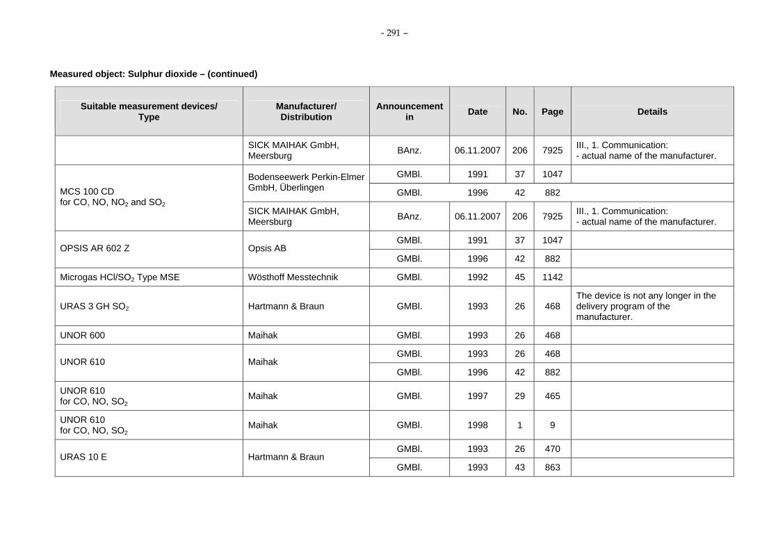
- 291 –
Measured object: Sulphur dioxide – (continued)
Suitable measurement devices/ Type
Manufacturer/ Distribution
Announcement in Date No. Page Details
SICK MAIHAK GmbH, Meersburg BAnz. 06.11.2007 206 7925 III., 1. Communication:
- actual name of the manufacturer.
GMBl. 1991 37 1047 Bodenseewerk Perkin-Elmer GmbH, Überlingen GMBl. 1996 42 882 MCS 100 CD
for CO, NO, NO2 and SO2 SICK MAIHAK GmbH, Meersburg BAnz. 06.11.2007 206 7925 III., 1. Communication:
- actual name of the manufacturer.
GMBl. 1991 37 1047 OPSIS AR 602 Z Opsis AB
GMBl. 1996 42 882
Microgas HCl/SO2 Type MSE Wösthoff Messtechnik GMBl. 1992 45 1142
URAS 3 GH SO2 Hartmann & Braun GMBl. 1993 26 468 The device is not any longer in the delivery program of the manufacturer.
UNOR 600 Maihak GMBl. 1993 26 468
GMBl. 1993 26 468 UNOR 610 Maihak
GMBl. 1996 42 882
UNOR 610 for CO, NO, SO2
Maihak GMBl. 1997 29 465
UNOR 610 for CO, NO, SO2
Maihak GMBl. 1998 1 9
GMBl. 1993 26 470 URAS 10 E Hartmann & Braun
GMBl. 1993 43 863

- 292 –
Measured object: Sulphur dioxide – (continued)
Suitable measurement devices/ Type
Manufacturer/ Distribution
Announcement in Date No. Page Details
GMBl. 1993 26 470 URAS 10 P Hartmann & Braun
GMBl. 1993 43 863
URAS 4 Hartmann & Braun GMBl. 1994 28 868
RADAS 2 for NO and SO2
Hartmann & Braun GMBl. 1994 28 869
RADAS 2 for NO and SO2; lamb EDL Hartmann & Braun GMBl. 1996 42 883
ENDA 1000 Horiba GMBl. 1994 28 869
GM 30-02 Sick GMBl. 1995 7 131
GMBl. 1995 33 702 CEMAS NDIR Hartmann & Braun
GMBl. 1996 8 188
GM 30-5 Sick GMBl. 1995 33 702
GM 30-2 Sick GMBl. 1995 33 702
GM 30-5 P Sick GMBl. 1995 33 702
GM 30-2 P Sick GMBl. 1995 33 702
URAS 4 Hartmann & Braun GMBl. 1996 28 591
Advanced CEMAS FTIR Hartmann & Braun GMBl. 1996 28 592
GMBl. 1996 28 593 MULTOR 610 Maihak
GMBl. 1996 42 882

- 293 –
Measured object: Sulphur dioxide – (continued)
Suitable measurement devices/ Type
Manufacturer/ Distribution
Announcement in Date No. Page Details
GMBl. 1997 29 465 MULTOR 610 for CO, NO, SO2
Maihak GMBl. 1998 1 9
ENDA 600 for NO, SO2, CO, O2
Horiba GMBl. 1996 42 882
GM 31-1 Sick GMBl. 1997 29 464
GM 31-2 for SO2 and NO Sick GMBl. 1997 29 464
XENTRA 4900 for SO2 and NO Servomex GMBl. 1997 29 465
Fisher-Rosemount GMBl. 1997 29 465 BINOS 1004 M for CO, SO2, O2 Emmerson Process
Management BAnz. 30.10.2004 207 22513 III. Communication: - actual name of the manufacturer
Advance Cemas-NDIR with Uras 14 for CO, SO2, NO, O2
Hartmann & Braun GMBl. 1998 1 9
Advance Optima Uras 14 for CO, SO2, NO, O2
Hartmann & Braun GMBl. 1998 1 9
ULTRAMAT 23-7 MB233 for CO, NO, SO2, O2
Siemens GMBl. 1998 1 9
testo 360-3 f for CO, SO2, NO, NO2, CO2
Testo GMBl. 1998 45 946
DEFOR 615/615 EX Maihak GMBl. 1999 22 445

- 294 –
Measured object: Sulphur dioxide – (continued)
Suitable measurement devices/ Type
Manufacturer/ Distribution
Announcement in Date No. Page Details
Fisher-Rosemount GMBl. 1999 22 445 NGA 2000 MLT 1 for SO2, NO, O2 Emmerson Process
Management BAnz. 30.10.2004 207 22513 III. Communication: - actual name of the manufacturer
Fisher-Rosemount GMBl. 1999 33 720 NGA 2000 MLT 1 for SO2, NO, O2 Emmerson
ProcessManagement BAnz. 30.10.2004 207 22513 III. Communication: - actual name of the manufacturer
Fisher-Rosemount GMBl. 1999 22 446 NGA 2000 MLT 4 for CO, SO2, NO, NO2 and O2 Emmerson Process
Management BAnz. 30.10.2004 207 22513 III. Communication: - actual name of the manufacturer
Bodenseewerk Perkin Elmer GmbH, Überlingen GMBl. 1999 22 446
MCS 100 CD for CO, SO2, NO, NO2, CO2 SICK MAIHAK GmbH,
Meersburg BAnz. 06.11.2007 206 7925 III., 1. Communication: - actual name of the manufacturer.
CEDOR for CO, SO2, NO, NH3, HCl, H2O Maihak GMBl. 1999 22 446
Ultramat 6 E/F, Oxymat 6 E/F and Ultramat/Oxymat 6 E/F for SO2, NO, CO and O2
Siemens GMBl. 1999 22 447
Ultramat 23-7MB for CO, SO2, NO, NO2, CO2
Siemens GMBl. 1999 22 447

- 295 –
Measured object: Sulphur dioxide – (continued)
Suitable measurement devices/ Type
Manufacturer/ Distribution
Announcement in Date No. Page Details
GMBl. 1999 33 721
Sick BAnz. 27.04.2004 79 9221
III., 8.Communication: - installation of a new heating
controller - update of the software
MCS 100 E HW for SO2, NO, CO, CO2, HCl, NH3, O2 and H2O
Sick Maihak BAnz. 29.04.2005 81 6893 III., 6. Communication: - extension of the software - actual name of the manufacturer
MCS 100 E PD for SO2, NO, NO2, CO, CO2, HCl, O2
Sick GMBl. 1999 33 721
AR 602 Z for SO2, NO2, and NH3
OPSIS, Sweden GMBl. 1999 33 721
AR 650 for HCl, CO and H2O OPSIS, Sweden GMBl. 1999 33 721
Advance Optima Limas 11-UV for NO, SO2, and O2
ABB Automation GMBl. 2000 60 1193
GMBl. 2001 19 387
BAnz. 14.10.2006 194 6715 V., 3. Communication: - new software version
S 700, Multor/Oxor 710/715/720 for CO, NO, SO2 and O2
Maihak
BAnz. 07.03.2008 38 903 IV., 6. Communication: - new software version
PG 250 for NO, NO2, SO2, CO, CO2 and O2
Horiba GMBl. 2001 19 387

- 296 –
Measured object: Sulphur dioxide – (continued)
Suitable measurement devices/ Type
Manufacturer/ Distribution
Announcement in Date No. Page Details
GMBl. 2001 55 1138
ABB Automation Products BAnz. 27.04.2004 79 9221
III., 1. Communication: - changes of the measurement
device
ABB Automation GmbH BAnz. 29.10.2005 206 15702 V., 2. Communication: - new software version - actual name of the manufacturer
Advance Cemas-FTIR NT for CO, NO, SO2, HCl, NH3 and H2O
ABB Automation Products BAnz. 08.04.2006 70 2653
CEDOR II for CO, NO, SO2, HCl, NH3 and H2O Telnet Instruments Oy GMBl. 2001 55 1138
Advance Optima Limas 11- UV for NO, SO2 and O2
ABB Automation Products GMBl. 2001 55 1138
BA 5000 for CO, NO, SO2 and O2
Bühler/Siemens GMBl. 1999 22 447
I., 4.6, 2: - the measurement device is also
sold identical in construction under the designation Ultramat 23-7MB 233 by the manufacturer Siemens AG/Karlsruhe and under the designation GME 64 by the company Sick
S 700 module series: Multor S 700 for CO, NO, SO2, Unor; S 700 for CO, NO, SO2 and Oxor for O2
Maihak BAnz. 29.04.2005 81 6892 III., 5. Communication: - new software version
GMBl. 2002 19 402 S 700-3, Unor for SO2
Maihak BAnz. 11.11.2003 210 23998

- 297 –
Measured object: Sulphur dioxide – (continued)
Suitable measurement devices/ Type
Manufacturer/ Distribution
Announcement in Date No. Page Details
GMBl. 2002 19 402 S 700-7, Unor Unor for CO and SO2
Maihak BAnz. 11.11.2003 210 23998
GMBl. 2002 19 402 S 700-8, Unor Unor for NO and SO2
Maihak BAnz. 11.11.2003 210 23998
GMBl. 2002 19 402 S 700-11, Unor Oxor P for SO2 and O2
Maihak BAnz. 11.11.2003 210 23998
GMBl. 2002 19 402 S 700-14, Unor Oxor E for SO2 and O2
Maihak BAnz. 11.11.2003 210 23998
GMBl. 2002 19 402
BAnz. 11.11.2003 210 23998 S 700-15, Multor for NO, SO2 and H2O Maihak
BAnz. 29.10.2005 206 15702 V., 3.Communication: - correction
GMBl. 2002 19 402
BAnz. 11.11.2003 210 23998 S 700-16, Multor for CO and SO2
Maihak
BAnz. 29.10.2005 206 15702 V., 3. Communication: - correction
GMBl. 2002 19 402 S 700-19, Unor Unor Oxor P for CO, SO2, O2
Maihak BAnz. 11.11.2003 210 23998
GMBl. 2002 19 402 S 700-20, Unor Unor Oxor P for NO, SO2, O2
Maihak BAnz. 11.11.2003 210 23998

- 298 –
Measured object: Sulphur dioxide – (continued)
Suitable measurement devices/ Type
Manufacturer/ Distribution
Announcement in Date No. Page Details
GMBl. 2002 19 402 S 700-22, Unor Unor Oxor E for CO, SO2, O2
Maihak BAnz. 11.11.2003 210 23998
GMBl. 2002 19 402 S 700-23, Unor Unor Oxor E for NO, SO2, O2
Maihak BAnz. 11.11.2003 210 23998
GMBl. 2002 19 402 S 700-24, Multor (1+2) Unor (3) for CO, NO, SO2
Maihak BAnz. 11.11.2003 210 23998
GMBl. 2002 19 402 S 700-25, Multor (1+2) Unor (3) for CO, SO2, NO Maihak
BAnz. 11.11.2003 210 23998
GMBl. 2002 19 402 S 700-26, Multor (1+2) Unor (3) for NO, SO2, CO and H2O Maihak
BAnz. 11.11.2003 210 23998
GMBl. 2002 19 402 S 700-27, Multor (1...3) for NO, SO2, CO and H2O Maihak
BAnz. 11.11.2003 210 23998
GMBl. 2002 19 402 S 700-29, Multor (1 +2) Oxor P (3) for CO, SO2 and O2
Maihak BAnz. 11.11.2003 210 23998
GMBl. 2002 19 402 S 700-30, Multor (1+2) Oxor P (3) for NO, SO2, O2 and H2O Maihak
BAnz. 11.11.2003 210 23998
GMBl. 2002 19 402 S 700-32, Multor (1+2) Oxor E (3) for CO, SO2 and O2
Maihak BAnz. 11.11.2003 210 23998

- 299 –
Measured object: Sulphur dioxide – (continued)
Suitable measurement devices/ Type
Manufacturer/ Distribution
Announcement in Date No. Page Details
GMBl. 2002 19 402 S 700-33, Multor (1+2) Oxor E (3) for NO, SO2, O2 and H2O Maihak
BAnz. 11.11.2003 210 23998
GMBl. 2002 19 402 S 700-34, Multor (1..3) Oxor P (3) for CO, NO, SO2, O2 and H2O Maihak
BAnz. 11.11.2003 210 23998
GMBl. 2002 19 402 S 700-35, Multor (1..3) Oxor E (3) for CO, NO, SO2, O2 and H2O Maihak
BAnz. 11.11.2003 210 23998
GMBl. 2002 19 402 S 700-36, Multor (1+2) Unor (3) Oxor P (4) for CO, SO2, NO and O2
Maihak BAnz. 11.11.2003 210 23998
GMBl. 2002 19 402 S 700-37, Multor (1+2) Unor (3) Oxor P (4) for CO, NO, SO2 and O2
Maihak BAnz. 11.11.2003 210 23998
GMBl. 2002 19 402 S 700-38, Multor (1+2) Unor (3) Oxor P (4) for NO, SO2, CO, O2 and H2O Maihak
BAnz. 11.11.2003 210 23998
GMBl. 2002 19 402 S 700-39, Multor (1+2) Unor (3) Oxor E (4) for CO, NO, SO2 and O2
Maihak BAnz. 11.11.2003 210 23998
GMBl. 2002 19 402 S 700-40, Multor (1+2) Unor (3) Oxor E (4) for CO, SO2, NO and O2
Maihak BAnz. 11.11.2003 210 23998
GMBl. 2002 19 402 S 700-41, Multor (1+2) Unor (3) Oxor E (4) for NO, SO2, CO, O2 and H2O Maihak
BAnz. 11.11.2003 210 23998

- 300 –
Measured object: Sulphur dioxide – (continued)
Suitable measurement devices/ Type
Manufacturer/ Distribution
Announcement in Date No. Page Details
GME 64 for CO, NO, SO2 and O2
Sick/Siemens GMBl. 1999 22 447
I., 4.6: - the measurement device is also
sold identical in construction under the designation Ultramat 23-7MB 233 by the manufacturer Siemens AG/Karlsruhe and under the designation BA 5000 by the company Bühler
Multi Gas Analyzer 23 for CO, NO, SO2 and O2
Födisch/Siemens GMBl. 2003 7 139
IV. Communication: - the measurement device is also
sold under the designation Ultramat 23-7MB233 by the manufacturer Siemens AG/Karlsruhe
GM 31 with GMA31 for NO and SO2
Sick BAnz. 15.05.2003 90 10742
FGA II for SO2, NO, NO2, CO, O2, and CO2
LAND Instrument BAnz. 15.05.2003 90 10742
BAnz. 15.05.2003 90 10742 ABB Automation Products
BAnz. 27.04.2004 79 9221 III., 3. Communication: - new software version
BAnz. 29.04.2005 81 6893 III., 1. Communication: - new software version - actual name of the manufacturer
Advance Optima (AO) 2020- Uras14 for CO, NO, SO2 and O2
ABB Automation GmbH
BAnz. 06.11.2007 206 7925 III., 5. Communication: - new software version

- 301 –
Measured object: Sulphur dioxide – (continued)
Suitable measurement devices/ Type
Manufacturer/ Distribution
Announcement in Date No. Page Details
BAnz. 15.05.2003 90 10742 ABB Automation Products
BAnz. 27.04.2004 79 9221 III., 3. Communication: - new software version
BAnz. 29.04.2005 81 6893 III., 1. Communication: - actual name of the manufacturer
AO 2040-Uras14 for CO, NO, SO2 and O2
ABB Automation GmbH
BAnz. 06.11.2007 206 7925 III., 5.Communication: - new software version
BAnz. 15.05.2003 90 10742 ABB Automation Products
BAnz. 27.04.2004 79 9221 III., 4. Communication: - new software version AO 2020-Limas11UV
for NO, SO2 and O2
ABB Automation GmbH BAnz. 29.04.2005 81 6893 III., 2. Communication: - new software version - actual name of the manufacturer
BAnz. 15.5.2003 90 10742 ABB Automation Products
BAnz. 27.04.2004 79 9221 III., 4. Communication: - new software version AO 2040-Limas11UV
for NO, SO2 and O2
ABB Automation GmbH BAnz. 29.04.2005 81 6893 III., 2. Communication: - new software version - actual name of the manufacturer
Advance Cemas-FTIR for CO, NO, SO2, HCl, NH3 and H2O ABB Automation Products BAnz. 29.10.2005 206 15701

- 302 –
Measured object: Sulphur dioxide – (continued)
Suitable measurement devices/ Type
Manufacturer/ Distribution
Announcement in Date No. Page Details
BAnz. 29.10.2005 206 15701 MCA 04 for CO, NO, SO2, HCl, NH3 ,H2O, O2 and CO2
Födisch Umweltmesstechnik BAnz. 08.04.2006 70 2654
BAnz. 08.04.2006 70 2654
ZKJ/ZFK7 for CO, NOx, SO2 and O2
Fuji Electric Systems Co., Ltd. BAnz. 06.11.2007 206 7925
III., 4. Communication: - the measurement device is also
sold under the designation Yokogawa Model IR400 by the company Yogogawa Electric Corporation/Japan
BAnz. 14.10.2006 194 6715
BAnz. 20.04.2007 75 4139 IV., 4. Communication: - new software version
Advance Optima AO2000 series for CO, NO, SO2, CO2, N2O and O2
ABB Automation GmbH, Frankfurt/Main
BAnz. 07.03.2008 38 903 IV., 2. Communication: - new software version
BAnz. 14.10.2006 194 6715
BAnz. 20.04.2007 75 4139 IV., 3. Communication: - new software version
Easy Line EL3000 series for CO, NO, SO2, N2O, CO2, O2
ABB Automation GmbH, Frankfurt/Main
BAnz. 07.03.2008 38 903 IV., 3. Communication: - new software version
GASMET CEMS for CO, NO, NO2, N2O, SO2, HCl, NH3, CO2, H2O
Gasmet Technologies Oy, Helsinki, Finland BAnz. 14.10.2006 194 6715

- 303 –
Measured object: Sulphur dioxide – (continued)
Suitable measurement devices/ Type
Manufacturer/ Distribution
Announcement in Date No. Page Details
BAnz. 20.04.2007 75 4140 IV., 8. Communication:
GASMET CEMS with OXITEC 500E SME 5for O2, CO, NO, NO2, N2O, SO2, NH3, HCl, CO2 and H2O
Gasmet Technologies Oy, Helsinki, Finland BAnz. 07.03.2008 38 901
- supplementary test to the announcement of the Federal Environment Agency from 12 September 2006 (BAnz. S. 6715).
BAnz. 14.10.2006 194 6715 SIDOR for CO, NO, SO2, O2
MAIHAK AG, Hamburg BAnz. 07.03.2008 38 903 IV., 4. Communication:
- new software version
GIGAS 10M for CO, NO, NO2, SO2, NH3, HCl, CO2 and H2O
General Impianti, Moie di Maiolati, Italy BAnz. 07.03.2008 38 901
- supplementary test to the announcement of the Federal Environment Agency from 23 September 2007 (BAnz. S. 7925).
Air Pollution Prevention
Suitability-tested continuous working measuring devices for emission measurements
Measured object: Hydrogen sulfide – Last update: 2006-02-20
Suitable measurement devices/ Type
Manufacturer/ Distribution
Announcement in Date No. Page Details
Monocolor 1001 Maihak GMBl. 1985 22 451 The device is not any longer in the delivery program of the manufacturer.

- 304 –
Air Pollution Prevention
Suitability-tested continuous working measuring devices for emission measurements
Measured object: Dust (qualitativly) emission limit control – Last update: 2004-09-15
Suitable measurement devices/ Type
Manufacturer/ Distribution
Announcement in Date No. Page Details
DT-270 and DT-770 Bühler Mess- und Regeltechnik GMBl. 1995 33 701
Filter controller PFM 92 Födisch Umweltmesstechn. GMBl. 1996 28 591 FW 56 DT Sick GMBl. 1996 8 188 FW 56 DT; Probe version Sick GMBl. 1996 28 591 Filter controller D-FW 230 and D-FW 231 DURAG GMBl. 1999 22 445
Dustalert 60 PCME, UK GMBl. 1999 22 445
I., 1.2: - the measurement device is sold by
the company Bühler Mess- und Regeltechnik GmbH, Ratingen
Goyen EMP 5 Goyen Controls Germany GMBl. 2000 22 443
Dustalert 60 A PCME, UK GMBl. 2000 22 443
I., 1.2: - the measurement device is sold by
the company Bühler Mess- und Regeltechnik GmbH, Ratingen
PFM 02 Födisch BAnz. 2003 210 23997

- 305 –
Air Pollution Prevention
Suitability-tested continuous working measuring devices for emission measurements
Measured object: Dust concentration – Last update: 2008-03-07
Suitable measurement devices/ Type
Manufacturer/ Distribution
Announcement in Date No. Page Details
RM 41 Sick GMBl. 1985 22 446 The device is not any longer in the delivery program of the manufacturer.
RM 41-03 Sick GMBl. 1990 12 230 The device is not any longer in the delivery program of the manufacturer.
F 50 and F 60 VEREWA GMBl. 1985 22 446 The device is not any longer in the delivery program of the manufacturer.
GM 21 Sick GMBl. 1990 12 230 The device is not any longer in the delivery program of the manufacturer.
KTN Sigrist Photometer GMBl. 1990 12 231
RM 46 Sick GMBl. 1985 22 446 The device is not any longer in the delivery program of the manufacturer.
D-R 280-10 DURAG GMBl. 1990 12 230 KTNR Sigrist Photometer GMBl. 1990 12 231
RM 41-07 Sick GMBl. 1987 24 417 The device is not any longer in the delivery program of the manufacturer.
INTRAS D Hartmann & Braun GMBl. 1990 12 231 The device is not any longer in the delivery program of the manufacturer.
FH 62 E-NA FAG Kugelfischer GMBl. 1990 20 399 F-904 VEREWA GMBl. 1990 20 399 GM 30 Sick GMBl. 1990 34 860
GMBl. 1992 32 794 RM 200 Sick
GMBl. 1994 28 868

- 306 –
Measured object: Dust concentration – (continued)
Suitable measurement devices/ Type
Manufacturer/ Distribution
Announcement in Date No. Page Details
GMBl. 1992 45 1140 D-R 300-40 DURAG
GMBl. 1993 43 862 KTNR Sigrist GMBl. 1992 45 1140 KTNRM Sigrist GMBl. 1993 26 467 LPS-E Becker Verfahrenstechnik GMBl. 1993 26 469 CPM 2000 Anacon GMBl. 1993 43 862 D-R 300-40 DURAG GMBl. 1995 33 701 FW 56-I Sick GMBl. 1996 8 188 RM 210 Sick GMBl. 1996 28 590 FW 56-I; Probe version Sick GMBl. 1996 28 591 RM 200 or RM 210; By-pass-System Sick GMBl. 1996 28 590 F 904 with DURAG D-MS- 285 Verewa GMBl. 1997 29 464 CTNR Sigrist GMBl. 1998 1 8 CPM 1001/CPM 5001 BHA GMBl. 1998 1 8 PFM 97 for dust concentration and waste gas flow Födisch GMBl. 1998 45 947
4500 MK II Land Combustion, UK GMBl. 1999 33 719
DT 270/770 PCME, UK GMBl. 1999 33 719
I., 1.2: - the measurement device is sold by
the company Bühler Mess- und Regeltechnik GmbH, Ratingen
EP 1000 Modell 1300 OLDHAM, France GMBl. 1999 33 719
I., 1.2: - the measurement device is sold by
the company Grimm Labortechnik GmbH & Co. KG, Ainring

- 307 –
Measured object: Dust concentration – (continued)
Suitable measurement devices/ Type
Manufacturer/ Distribution
Announcement in Date No. Page Details
PFM 97 W for dust concentration and waste gas flow Födisch GMBl. 2000 22 444
FW 101 Sick Engineering GMBl. 2000 60 1192 FW 102 Sick Engineering GMBl. 2000 60 1192 OMD 41-02/OMD 41.03 SICK AG GMBl. 2000 60 1195 SC 600 T PCME, England GMBl. 2001 19 386
GMBl. 2001 19 386 D-RX 250 for dust concentration and waste gas flow DURAG
BAnz. 08.04.2006 70 2653 V., 1. Communication: - new software version
PFM 97 ED Födisch GMBl. 2001 55 1138 FWE 200 Sick Engineering GMBl. 2001 55 1137
CPA 1000 Goyen Controls/Land Combustion GMBl. 2002 19 404
IV. Communication: - the measurement device is also
sold identical in construction under the designation 4500 MK II by the manufacturer Land Combustion/UK
BAnz. 15.5.2003 90 10742
D-R 290 DURAG BAnz. 14.10.2006 194 6715
V., 1. Communication: - details to the application of the
measurement device
DT 990 PCME (UK) BAnz. 15.5.2003 90 10742 IV. Communication: - the measurement device is also
sold under the designation DT 770 FW 101 Sick Engineering BAnz. 11.11.2003 210 23997 CPM 750 BHA Group BAnz. 2004 79 9220
4500 MK II Land Instruments International, UK BAnz. 2004 79 9220

- 308 –
Measured object: Dust concentration – (continued)
Suitable measurement devices/ Type
Manufacturer/ Distribution
Announcement in Date No. Page Details
4500 Premier Land Instruments International, UK BAnz. 2004 79 9220
4500 MK II+ Land Instruments International, UK BAnz. 27.4.2004 79 9220
III., 7. Communication: - succession version of the
measurement device 4500 MK II LM 3086 EPA 3 MIP Electromics Oy, Finland BAnz. 30.10.2004 207 22512 LM3086 SE MIP Electromics Oy, Finland BAnz. 30.10.2004 207 22513 S 305 SINTROL, Finland BAnz. 30.10.2004 207 22513 PFM 02V Födisch BAnz. 30.10.2004 207 22513
BAnz. 29.04.2005 81 6892 StackGuard Sigrist Photometer
BAnz 14.10.2006 194 6715 V., 4. Communication: - new software version
STGM 500 AFRISO EURO Index/SINTROL, Finland BAnz. 29.10.2005 206 15700
V., 1. Communication: - the measurement device is also
sold identical in construction under the designation S 305 by the manufacturer SINTROL/Finland
BAnz. 14.10.2006 194 6715 D-R 800 DURAG GmbH, Hamburg
BAnz. 20.04.2007 75 4139 - supplementary test
LMS 181 PCME Ltd., St. Ives Cambs, UK BAnz. 14.10.2006 194 6715
BAnz. 06.11.2007 206 7925
DT991 PCME Ltd., St. Ives, UK BAnz. 07.03.2008 38 901
- supplementary test to the announcement of the Federal Environment Agency from 23 September 2007 (BAnz. S. 7925).

- 309 –
Air Pollution Prevention
Suitability-tested continuous working measuring devices for emission measurements Measured object: Nitrogen oxides - Last update: 2008-03-07
Suitable measurement devices/ Type
Manufacturer/ Distribution
Announcement in Date No. Page Details
Beckmann/Rosemount GMBl. 1990 12 234 Modell 951 Emmerson Process
Management BAnz. 30.10.2004 207 22513 III. Communication: - actual name of the manufacturer
GMBl. 1990 12 234 RADAS 1 G Hartmann & Braun
GMBl. 1993 43 863
The device is not any longer in the delivery program of the manufacturer.
GMBl. 1986 34 643 RADAS 1 E Hartmann & Braun
GMBl. 1995 22 449
The device is not any longer in the delivery program of the manufacturer.
Modell 2225 Measurex GMBl. 1990 12 234
Ultramat 32 Siemens GMBl. 1985 22 450 The device is not any longer in the delivery program of the manufacturer.
UNOR 4 N-NO Maihak GMBl. 1985 22 450 The device is not any longer in the delivery program of the manufacturer.
UNOR 6 N-NO Maihak GMBl. 1990 12 235 UNOR 6 N-F Maihak GMBl. 1990 12 234
Leybold/Rosemount GMBl. 1990 12 234 NO-IR Binos Emmerson Process
Management BAnz. 30.10.2004 207 22513 III. Communication: - actual name of the manufacturer
Ultramat 21 P/22 P Siemens GMBl. 1990 12 235

- 310 –
Measured object: Nitrogen oxides - (continued)
Suitable measurement devices/ Type
Manufacturer/ Distribution
Announcement in Date No. Page Details
Leybold/Rosemount GMBl. 1990 12 235 NO2-UV-Binos Emmerson Process
Management BAnz. 30.10.2004 207 22513 III. Communication: - actual name of the manufacturer
NOx-Monitor 4000 AEG GMBl. 1990 12 235
Spectran 647 IR Bodenseewerk Gerätetechnik GMBl. 1990 12 235
The device is not any longer in the delivery program of the manufacturer.
URAS 3 G/K NO Hartmann & Braun GMBl. 1990 12 235 The device is not any longer in the delivery program of the manufacturer.
GM 30 Sick GMBl. 1990 20 399 GMBl. 1990 12 235
Ultramat 5 Siemens GMBl. 1993 43 862 GMBl. 1992 32 794
CLD 700 El ht ECO Physics AG GMBl. 1994 28 868
MSI 5600 MSI Elektronik GMBl. 1992 32 794 Perkin-Elmer GMBl. 1991 37 1047
MCS 100 HW Sick Maihak GmbH, Meersburg BAnz. 06.11.2007 206 7925 III., 1. Communication:
- actual name of the manufacturer GMBl. 1991 37 1047
Perkin-Elmer GMBl. 1996 42 883 MCS 100 CD
Sick Maihak GmbH, Meersburg BAnz. 06.11.2007 206 7925 III., 1. Communication:
- actual name of the manufacturer OPSIS AR 602-Z Opsis AB GMBl. 1991 37 1047
RADAS 1 G Hartmann & Braun GMBl. 1992 45 1141 The device is not any longer in the delivery program of the manufacturer.

- 311 –
Measured object: Nitrogen oxides - (continued)
Suitable measurement devices/ Type
Manufacturer/ Distribution
Announcement in Date No. Page Details
RADAS 1 G; lamb EDL Hartmann & Braun GMBl. 1996 42 883 UNOR 600 Maihak GMBl. 1993 26 468 UNOR 610 Maihak GMBl. 1993 26 468
GMBl. 1997 29 465 UNOR 610 for CO, NO, SO2
Maihak GMBl. 1998 1 9 GMBl. 1993 26 470
URAS 10 E Hartmann & Braun GMBl. 1993 43 863 GMBl. 1993 26 470
URAS 10 P Hartmann & Braun GMBl. 1993 43 863 GMBl. 1993 43 862
Rosemount GMBl. 1994 28 868 BINOS 1004
Emmerson Process Management BAnz. 30.10.2004 207 22513 III. Communication:
- actual name of the manufacturer GMBl. 1993 43 864
ENDA 1000 HORIBA GMBl. 1994 28 868
RADAS 2 for NO Hartmann & Braun GMBl. 1994 28 868
RADAS 2 for NO and SO2; lamb EDL Hartmann & Braun GMBl. 1996 42 883
GMBl. 1995 7 131 GM 30-02 Sick
GMBl. 1995 33 702 GM 30-5 Sick GMBl. 1995 33 702 GM 30-5 P Sick GMBl. 1995 33 702 GM 30-2 P Sick GMBl. 1995 33 702

- 312 –
Measured object: Nitrogen oxides - (continued)
Suitable measurement devices/ Type
Manufacturer/ Distribution
Announcement in Date No. Page Details
GMBl. 1995 33 702 CEMAS NDIR Hartmann & Braun
GMBl. 1996 8 189 GMBl. 1995 33 702
CEMAS FTIR Hartmann & Braun GMBl. 1996 8 188 GMBl. 1996 28 593
MULTOR 610 Maihak GMBl. 1996 42 882 GMBl. 1997 29 465 MULTOR 610
for CO, NO, SO2 Maihak
GMBl. 1998 1 9 ENDA 600 Horiba GMBl. 1996 42 882 OPSIS AR 602 Z OPSIS GMBl. 1996 42 882 OPSIS AR 650 OPSIS GMBl. 1996 42 882 GM 31-4 Sick GMBl. 1997 29 464 GM 31-2 for SO2 and NO Sick GMBl. 1997 29 464
XENTRA 4900 for SO2 and NO Servomex GMBl. 1997 29 465
Advance Cemas-NDIR with Uras 14 for CO, SO2, NO, O2
Hartmann & Braun GMBl. 1998 1 9
Advance Optima Uras 14 for CO, SO2, NO, O2
Hartmann & Braun GMBl. 1998 1 9
ULTRAMAT 23-7MBR33 for CO, NO, SO2, O2
Siemens GMBl. 1998 1 9
FGA 950 E for CO, NO, O2
Land Combustion GMBl. 1998 45 947
testo 360-3 for CO, SO2, NO, NO2, O2
Testo GMBl. 1998 45 946

- 313 –
Measured object: Nitrogen oxides - (continued)
Suitable measurement devices/ Type
Manufacturer/ Distribution
Announcement in Date No. Page Details
Fisher-Rosemount GMBl. 1999 22 445 NGA 2000 CLD Emmerson Process
Management BAnz. 30.10.2004 207 22513 III. Communication: - actual name of the manufacturer
Fisher-Rosemount GMBl. 1999 22 445 NGA 2000 MLT1 for SO2, NO, O2 Emmerson Process
Management BAnz. 30.10.2004 207 22513 III. Communication: - actual name of the manufacturer
Fisher-Rosemount GMBl. 1999 22 446 NGA MLT 4 for CO, SO2, NO, NO2, O2 Emmerson Process
Management BAnz. 30.10.2004 207 22513 III. Communication: - actual name of the manufacturer
CEDOR for CO, SO2, NO, NH3, HCl and H2O Maihak GMBl. 1999 22 446
Ultramat 6E/F, Oxymat 5E/F and Ultramat/Oxymat 6 E/F for CO, SO2, NO, O2
Siemens GMBl. 1999 22 447
GMBl. 1999 33 721
Sick BAnz. 27.04.2004 79 9221
III., 8. Communication: - installation of a new heating
controller - extension of the software
MCS 100 E HW for SO2, NO, CO, CO2, HCl, NH3, O2 and H2O
Sick Maihak BAnz. 29.04.2005 81 6893 III., 6. Communication: - extension of the software - actual name of the manufacturer
MCS 100 E PD for SO2, NO, NO2,CO, CO2, HCl, O2
Sick GMBl. 1999 33 720

- 314 –
Measured object: Nitrogen oxides - (continued)
Suitable measurement devices/ Type
Manufacturer/ Distribution
Announcement in Date No. Page Details
AR 602 Z for SO2, NO2 and NH3
OPSIS GMBl. 1999 33 721
Advance Optima Limas 11-UV for NO, SO2 and O2
ABB Automation GMBl. 2000 60 1193
GMBl. 2001 19 387
BAnz. 12.09.2006 194 6715 V., 3. Communication: - new software version
ModularSystem S 700 Multor/Oxor 710/715/720 for CO, NO, SO2 and O2
Maihak
BAnz. 07.03.2008 38 903 IV., 6. Communication: - new software version
ModularSystem S 700, Unor/Oxor 710/715/720 for CO, NO, SO2 and O2
Maihak GMBl. 2001 19 387
PG 250 for NO, NO2, SO2, CO, CO2 and O2
Horiba GMBl. 2001 19 387
GMBl. 2001 55 1138
ABB Automation Products BAnz. 27.04.2004 79 9221
III., 1. Communication: - changes of the measurement
device
ABB Automation GmbH BAnz. 29.10.2005 206 15702 V., 2. Communication: - actual name of the manufacturer
Advance Cemas-FTIR NT for CO, NO, SO2, HCl, NH3 and H2O
ABB Automation Products BAnz. 08.04.2006 70 2653 - supplementary test CEDOR II for CO, NO, SO2, HCl, NH3 and H2O Telnet Instruments Oy GMBl. 2001 55 1138
Advance Optima Limas 11-UV for NO, SO2 and O2
ABB Automation Products GMBl. 2001 55 1138
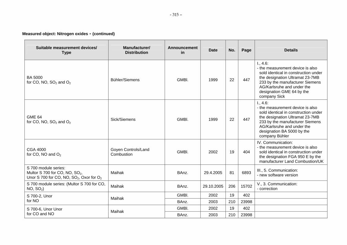
- 315 –
Measured object: Nitrogen oxides - (continued)
Suitable measurement devices/ Type
Manufacturer/ Distribution
Announcement in Date No. Page Details
BA 5000 for CO, NO, SO2 and O2
Bühler/Siemens GMBl. 1999 22 447
I., 4.6: - the measurement device is also
sold identical in construction under the designation Ultramat 23-7MB 233 by the manufacturer Siemens AG/Karlsruhe and under the designation GME 64 by the company Sick
GME 64 for CO, NO, SO2 and O2
Sick/Siemens GMBl. 1999 22 447
I., 4.6: - the measurement device is also
sold identical in construction under the designation Ultramat 23-7MB 233 by the manufacturer Siemens AG/Karlsruhe and under the designation BA 5000 by the company Bühler
CGA 4000 for CO, NO and O2
Goyen Controls/Land Combustion GMBl. 2002 19 404
IV. Communication: - the measurement device is also
sold identical in construction under the designation FGA 950 E by the manufacturer Land Combustion/UK
S 700 module series: Multor S 700 for CO, NO, SO2, Unor S 700 for CO, NO, SO2, Oxor for O2
Maihak BAnz. 29.4.2005 81 6893 III., 5. Communication: - new software version
S 700 module series: (Multor S 700 for CO, NO, SO2)
Maihak BAnz. 29.10.2005 206 15702 V., 3. Communication: - correction
GMBl. 2002 19 402 S 700-2, Unor for NO Maihak
BAnz. 2003 210 23998 GMBl. 2002 19 402 S 700-6, Unor Unor
for CO and NO Maihak BAnz. 2003 210 23998

- 316 –
Measured object: Nitrogen oxides - (continued)
Suitable measurement devices/ Type
Manufacturer/ Distribution
Announcement in Date No. Page Details
GMBl. 2002 19 402 S 700-8, Unor Unor for NO and SO2
Maihak BAnz. 2003 210 23998 GMBl. 2002 19 402 S 700-10, Unor Oxor P
for NO and O2 Maihak
BAnz. 2003 210 23998 GMBl. 2002 19 402 S 700-13, Unor Oxor E
for NO and O2 Maihak
BAnz. 2003 210 23998 GMBl. 2002 19 402 S 700-15, Multor
for NO, SO2 and H2O Maihak BAnz. 2003 210 23998 GMBl. 2002 19 402 BAnz. 2003 210 23998 S 700-17, Multor
for CO and NO Maihak BAnz. 29.10.2005 206 15702 V., 3. Communication:
- correction GMBl. 2002 19 402 S 700-18, Unor Unor Oxor P
for CO, NO, O2 Maihak
BAnz. 2003 210 23998 GMBl. 2002 19 402 S 700-20, Unor Unor Oxor P
for NO, SO2, O2 Maihak
BAnz. 2003 210 23998 GMBl. 2002 19 402 S 700-21, Unor Unor Oxor E
for CO, NO, O2 Maihak
BAnz. 2003 210 23998 GMBl. 2002 19 402 S 700-23, Unor Unor Oxor E
for NO, SO2, O2 Maihak
BAnz. 2003 210 23998 GMBl. 2002 19 402 S 700-24, Multor (1+2) Unor (3)
for CO, NO, SO2 Maihak
BAnz. 2003 210 23998 GMBl. 2002 19 402 S 700-25, Multor (1+2) Unor (3)
for CO, SO2, NO Maihak BAnz. 2003 210 23998

- 317 –
Measured object: Nitrogen oxides - (continued)
Suitable measurement devices/ Type
Manufacturer/ Distribution
Announcement in Date No. Page Details
GMBl. 2002 19 402 S 700-26, Multor (1+2) Unor (3) for NO, SO2, CO and H2O Maihak
BAnz. 2003 210 23998 GMBl. 2002 19 402 S 700-27, Multor (1...3)
for NO, SO2, CO and H2O Maihak BAnz. 2003 210 23998 GMBl. 2002 19 402 S 700-28, Multor (1 +2) Oxor P (3)
for CO, NO, and O2 Maihak
BAnz. 2003 210 23998 GMBl. 2002 19 402 S 700-30, Multor (1+2) Oxor P (3)
for NO, SO2, O2 and H2O Maihak BAnz. 2003 210 23998 GMBl. 2002 19 402 S 700-31, Multor (1+2) Oxor E (3)
for CO, NO and O2 Maihak
BAnz. 2003 210 23998 GMBl. 2002 19 402 S 700-33, Multor (1+2) Oxor E (3)
for NO, SO2, O2 and H2O Maihak BAnz. 2003 210 23998 GMBl. 2002 19 402 S 700-34, Multor (1..3) Oxor P (3)
for CO, NO, SO2, O2 and H2O Maihak BAnz. 2003 210 23998 GMBl. 2002 19 402 S 700-35, Multor (1..3) Oxor E (3)
for CO, NO, SO2, O2 and H2O Maihak BAnz. 2003 210 23998 GMBl. 2002 19 402 S 700-36, Multor (1+2) Unor (3) Oxor P (4)
for CO, SO2, NO and O2 Maihak
BAnz. 2003 210 23998 GMBl. 2002 19 402 S 700-37, Multor (1+2) Unor (3) Oxor P (4)
for CO, NO, SO2 and O2 Maihak
BAnz. 2003 210 23998 GMBl. 2002 19 402 S 700-38, Multor (1+2) Unor (3) Oxor P (4)
for NO, SO2, CO, O2 and H2O Maihak BAnz. 2003 210 23998 GMBl. 2002 19 402 S 700-39, Multor (1+2) Unor (3) Oxor E (4)
for CO, NO, SO2 and O2 Maihak
BAnz. 2003 210 23998

- 318 –
Measured object: Nitrogen oxides - (continued)
Suitable measurement devices/ Type
Manufacturer/ Distribution
Announcement in Date No. Page Details
GMBl. 2002 19 402 S 700-40, Multor (1+2) Unor (3) Oxor E (4) for CO, SO2, NO and O2
Maihak BAnz. 2003 210 23998 GMBl. 2002 19 402 S 700-41, Multor (1+2) Unor (3) Oxor E (4)
for NO, SO2, CO, O2 and H2O Maihak BAnz. 2003 210 23998
Multi Gas Analyzer 23 for CO, NO, SO2 and O2
Födisch/Siemens GMBl. 2003 7 139
IV. Communication: - the measurement device is also
sold under the designation Ultramat 23-7MB233 by the manufacturer Siemens AG/Karlsruhe
BAnz. 15.5.2003 90 10742 FGA II for SO2, NO, NO2, CO, O2 and CO2
LAND Instrument BAnz. 11.11.2003 210 23997
GM 31 with GMA31 for NO and SO2
Sick BAnz. 15.05.2003 90 10743
BAnz. 15.05.2003 90 10743 ABB Automation Products
BAnz. 27.4.2004 79 9221 III., 3. Communication: - new software version
BAnz. 29.04.2005 81 6893 III., 1. Communication: - new software version - actual name of the manufacturer
AO2020-Uras14 for CO, NO, SO2 and O2
ABB Automation GmbH
BAnz. 06.11.2007 206 7925 III., 5. Communication: - new software version
BAnz. 15.05.2003 90 10743 AO2040-Uras14 for CO, NO, SO2 and O2
ABB Automation Products BAnz. 27.04.2004 79 9221
III., 3. Communication: - new software version

- 319 –
Measured object: Nitrogen oxides - (continued)
Suitable measurement devices/ Type
Manufacturer/ Distribution
Announcement in Date No. Page Details
BAnz. 29.04.2005 81 6893 III., 1. Communication: - new software version - actual name of the manufacturer ABB Automation GmbH
BAnz. 06.11.2007 206 7925 III., 5. Communication: - new software version
BAnz. 15.05.2003 90 10743 ABB Automation Products
BAnz. 27.04.2004 79 9221 III., 4. Communication: - new software version AO2020-Limas 11UV
for NO, SO2 and O2 ABB Automation GmbH BAnz. 29.04.2005 81 6893
III., 2. Communication: - new software version - actual name of the manufacturer
BAnz. 15.05.2003 90 10743 ABB Automation Products
BAnz. 27.04.2004 79 9221 III., 4. Communication: - new software version AO2040-Limas 11UV
for NO, SO2 and O2 ABB Automation GmbH BAnz. 29.04.2005 81 6893
III., 2. Communication: - new software version - actual name of the manufacturer
Thermo NO/NOx Analysis System Thermo Electron B.V., Niederlande BAnz. 30.10.2004 207 22513
Ultramat 23 7 MB 2337 for CO, NO and O2
Siemens BAnz. 29.04.2005 81 6892
Ultramat 23-7MB2337, Ultramat 23-7MB2335 for NO, CO and O2
Siemens AG, Karlsruhe BAnz. 07.03.2008 38 902
- supplementary test to the announcement of the Federal Environment Agency from 31 March 2005 (BAnz. S. 6892).

- 320 –
Measured object: Nitrogen oxides - (continued)
Suitable measurement devices/ Type
Manufacturer/ Distribution
Announcement in Date No. Page Details
IMR 7500 for NO and O2
TRT Ingenieurgesellschaft BAnz. 29.04.2005 81 6892
Advance Cemas-FTIR for CO, NO, SO2, HCl, NH3 and H2O ABB Automation Products BAnz. 29.10.2005 206 15701
BAnz. 29.10.2005 206 15701 MCA 04 for CO, NO, SO2, HCl, NH3 ,H2O, O2 and CO2
Födisch UmweltmesstechnikBAnz. 08.04.2006 70 2654
ECO PHYSICS CLD 822 (1) ECO PHYSICS BAnz. 08.04.2006 70 2653 BAnz. 08.04.2006 70 2653 VA 3000
for CO, NOx, N2O, CO2 and O2 Horiba Europe GmbH
BAnz. 14.10.2006 194 6715 V., 2. Communication: BAnz. 08.04.2006 70 2654
ZKJ/ZFK7 for CO, NOx, SO2 and O2
Fuji Electric Systems Co., Ltd. BAnz. 06.11.2007 206 7925
III., 4. Communication: - the measurement device is also
sold under the designation Yokogawa Model IR400 by the company Yogogawa Electric Corporation/Japan
BAnz. 14.10.2006 194 6715
BAnz. 20.04.2007 75 4139 IV., 4. Communication: - new software version Advance Optima AO2000 series
for CO, NO, SO2, CO2, N2O and O2 ABB Automation GmbH, Frankfurt/Main
BAnz. 07.03.2008 38 903 IV., 2. Communication: - new software version

- 321 –
Measured object: Nitrogen oxides - (continued)
Suitable measurement devices/ Type
Manufacturer/ Distribution
Announcement in Date No. Page Details
BAnz. 14.10.2006 194 6715
BAnz. 20.04.2007 75 4139 IV. 3. Communication: - new software version Easy Line EL3000 series
for CO, NO, SO2, N2O, CO2, O2 ABB Automation GmbH, Frankfurt/Main
BAnz. 07.03.2008 38 903 IV., 3. Communication: - new software version
GASMET CEMS for CO, NO, NO2, N2O, SO2, HCl, NH3, CO2, H2O
BAnz. 14.10.2006 194 6715 Gasmet Technologies Oy, Helsinki
BAnz. 20.04.2007 75 4140 IV., 8. Communication: GASMET CEMS with OXITEC 500E SME 5for O2, CO, NO, NO2, N2O, SO2, HCl, NH3, CO2, H2O
Gasmet Technologies Oy, Helsinki BAnz. 07.03.2008 38 901
- supplementary test to the announcement of the Federal Environment Agency from 12 September 2006 (BAnz. S. 6715).
BAnz. 14.10.2006 194 6715 SIDOR for CO, NO, SO2, O2
MAIHAK AG, Hamburg BAnz. 07.03.2008 38 903 IV., 4. Communication:
- new software version
Teledyne Model 7500 for CO and O2
Teledyne Instruments, USA BAnz. 20.04.2007 75 4140
IV., 13. Communication: - the measuremnent device is also
sold identical in construction under the designation ZRJ/ZFK7 by the company Fuji Electric Systems Co./Ltd.
Teledyne Model 7600 for CO, NOx, SO2 and O2
Teledyne Instruments, USA BAnz. 20.04.2007 75 4140
IV., 14. Communication: - the measurement device is also
sold identical in construction under the designation ZKJ/ZFK7 by the company Fuji Electric Systems Co./Ltd.
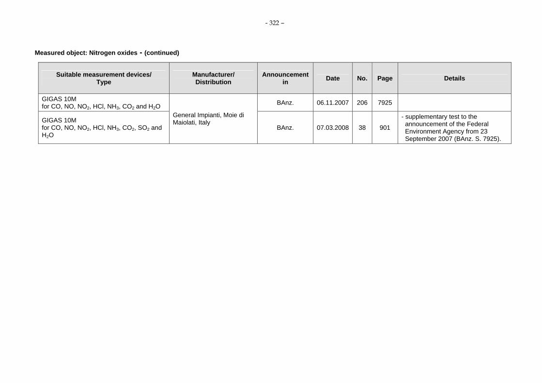
- 322 –
Measured object: Nitrogen oxides - (continued)
Suitable measurement devices/ Type
Manufacturer/ Distribution
Announcement in Date No. Page Details
GIGAS 10M for CO, NO, NO2, HCl, NH3, CO2 and H2O BAnz. 06.11.2007 206 7925
GIGAS 10M for CO, NO, NO2, HCl, NH3, CO2, SO2 and H2O
General Impianti, Moie di Maiolati, Italy
BAnz. 07.03.2008 38 901
- supplementary test to the announcement of the Federal Environment Agency from 23 September 2007 (BAnz. S. 7925).

- 323 –
Air Pollution Prevention
Suitability-tested electronic evaluation systems for evaluation of automated measuring systems In the following all evaluation systems are listed which were announced until now. Since publication of the minimum requirements which are valid at the time of making this Manual on emission monitoring’ (letter of the BMU 13 June 2005 [19]) all electronic evaluation system must correspond to these minimum requirements under regard of the legal basis of the plant in question.
Devices: Simple classificators - Last update: 2006-02-20
Suitable devices/ Type
Manufacturer/ Distribution
Announcement in Date No. Page Details
D-IG 260 DURAG GMBl. 1990 12 241 The device is not any longer in the delivery program of the manufacturer.
MI-1 Sick GMBl. 1990 12 245 The device is not any longer in the delivery program of the manufacturer.
MR 2 Sick GMBl. 1990 12 241 The device is not any longer in the delivery program of the manufacturer.
Devices: Classificators with reference value calculator - Last update: 2007-11-06
Suitable devices/ Type
Manufacturer/ Distribution
Announcement in Date No. Page Details
D-MS 385 DURAG GMBl. 1990 12 242 The device is not any longer in the delivery program of the manufacturer.
MEAC 1A Maihak GMBl. 1990 12 241 EDAS-R and EDAS-K NIS Ingenieurgesellschaft GMBl. 1990 12 241 MR 3 Sick GMBl. 1990 12 241
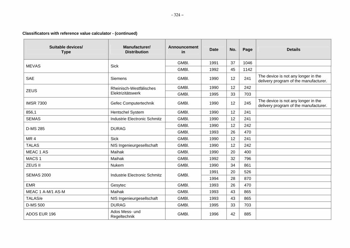
- 324 –
Classificators with reference value calculator - (continued)
Suitable devices/ Type
Manufacturer/ Distribution
Announcement in Date No. Page Details
GMBl. 1991 37 1046 MEVAS Sick
GMBl. 1992 45 1142
SAE Siemens GMBl. 1990 12 241 The device is not any longer in the delivery program of the manufacturer.
GMBl. 1990 12 242 ZEUS Rheinisch-Westfälisches
Elektrizitätswerk GMBl. 1995 33 703
IMSR 7300 Gefec Computertechnik GMBl. 1990 12 245 The device is not any longer in the delivery program of the manufacturer.
856,1 Hentschel System GMBl. 1990 12 241 SEMAS Industrie Electronic Schmitz GMBl. 1990 12 241
GMBl. 1990 12 242 D-MS 285 DURAG
GMBl. 1993 26 470 MR 4 Sick GMBl. 1990 12 241 TALAS NIS Ingenieurgesellschaft GMBl. 1990 12 242 MEAC 1 AS Maihak GMBl. 1990 20 400 MACS 1 Maihak GMBl. 1992 32 796 ZEUS II Nukem GMBl. 1990 34 861
1991 20 526 SEMAS 2000 Industrie Electronic Schmitz GMBl.
1994 28 870 EMR Gesytec GMBl. 1993 26 470 MEAC 1 A-M/1 AS-M Maihak GMBl. 1993 43 865 TALAS/e NIS Ingenieurgesellschaft GMBl. 1993 43 865 D-MS 500 DURAG GMBl. 1995 33 703
ADOS EUR 196 Ados Mess- und Regeltechnik GMBl. 1996 42 885

- 325 –
Classificators with reference value calculator - (continued)
Suitable devices/ Type
Manufacturer/ Distribution
Announcement in Date No. Page Details
MEAC 2000 MAIHAK GMBl. 1998 18 419 TALAS/e i. V. m. EmNet/s-bzw. EmNet/c-Modules NIS GMBl. 1998 20 419
ADOS EUR 196 Ados Mess- und Regeltechnik GMBl. 1998 45 947
SEMAS 2000 EFÜ-System Industrie Electronic Schmitz GMBl. 1998 45 947 D-MS 285 with D-EFÜ-Modul DURAG GMBl. 1998 45 948 D-MS 500 with D-EFÜ-Modul DURAG GMBl. 1998 45 948 MEVAS-PC UMEG GMBl. 1998 45 948 TALAS/net NIS GMBl. 2000 60 1195 RAY/2000/1 Rayen Intec GMBl. 2000 60 1195 TALAS/net incl. EmNet NIS GMBl. 2001 19 388 PRODAR ABB Utility Automation GMBl. 2001 19 388 ZEUS-CHARON, Version 5.3 RWE Power GMBl. 2001 55 1139 D-EMS 2000 – PC-Version DURAG GMBl. 2002 19 403 TALAS/e NIS Ingenieurgesellschaft GMBl. 2003 7 140 MEAC 2000 Sick/Maihak BAnz. 11.11.2003 210 23998 D-EMS 2000 – PC-version DURAG BAnz. 11.11.2003 210 23998
BAnz. 29.10.2005 206 15701 BAnz. 08.04.2006 70 2654 Talas/net with PC-System
Umweltoffice2005 RWE NUKEM GmbH/NIS Ingenieure
BAnz. 06.11.2007 206 7926 III., 6. Communication: - new software versions
EMI 3000 Version V1.11 ITBK Ingenieurgesellschaft für Umweltschutz BAnz. 29.10.2005 206 15701

- 326 –
Classificators with reference value calculator - (continued)
Suitable devices/ Type
Manufacturer/ Distribution
Announcement in Date No. Page Details
BAnz. 29.10.2005 206 15701 D-EMS 2000 (Version 4.14) DURAG
BAnz. 08.04.2006 70 2654 BAnz. 08.04.2006 70 2654
TALAS/e with Umweltoffice2005 and EFÜ-Modul
RWE NUKEM GmbH/NIS Ingenieure BAnz. 06.11.2007 206 7926 III., 8. Communication:
- new software versions BAnz. 08.04.2006 70 2654
Talas/net with DSM-05 and EFÜ-Modul RWE NUKEM GmbH/NIS Ingenieure BAnz. 06.11.2007 206 7926 III., 7. Communication:
- new software versions ARGUS Pro ABB Utilities GmbH BAnz. 08.04.2006 70 2654 MEAC 2000 Maihak AG BAnz. 08.04.2006 70 2654
BAnz. 08.04.2006 70 2655
V., 2. Communication: - the measurement device is also
sold under the designation TALAS/net with Umweltoffice 2005 and EFÜ Modul by the company RWE NUKEM GmbH/NIS Ingenieure
DAS05 withUmweltoffice 2005 and EFÜ-Modul
Dr. Födisch Umweltmesstechnik
BAnz. 06.11.2007 206 7926 III., 9. Communication: - new software versions
BAnz. 08.04.2006 70 2655
V., 2. Communication: - the measurement device is also
sold under the designation TALAS/net with DSM05 and EFÜ Modul by the company RWE NUKEM GmbH/NIS Ingenieure
DAS05 with DSM05 and EFÜ-Modul Dr. Födisch Umweltmesstechnik
BAnz. 06.11.2007 206 7926 III., 9. Communication: - new software versions
ARGUS Pro with ARGUS Pro EFÜ ABB Utilities GmbH BAnz. 14.10.2006 194 6715
EMI3000 with EFÜ ITBK Ingenieurgesellschaft für Umweltschutz BAnz. 14.10.2006 194 6715

- 327 –
Devices: Telemetric Supervision - Last update: 2007-11-06
Suitable devices/ Type
Manufacturer/ Distribution
Announcement in Date Nr. Page Details
GMBl. 1994 28 870 GMBl. 1995 33 703 GMBl. 1996 28 594 GMBl. 1998 1 10
EFÜ GTÜ
GMBl. 1998 20 10 D-EFÜ/D-EVA DURAG GMBl. 1995 33 703 MEVAS-PC UMEG GMBl. 1996 8 189 MEVAS-PC with DATA 800 UMEG GMBl. 1996 28 593 TALAS/e i. V. m. EFÜ/s bzw. EFÜ/c NIS GMBl. 1996 42 884 MEAC 2000 MAIHAK GMBl. 1998 20 419 TALAS/e i. V. m. EmNet/s bzw.EmNet/c NIS GMBl. 1998 20 419 SEMAS 2000 EFÜ-System Industrie Elektronik Schmitz GMBl. 1998 45 947
ADOS EUR 196 ADOS Mess- und Regeltechnik GMBl. 1998 45 947
D-MS 285 with D-EFÜ-Modul DURAG GMBl. 1998 45 948 D-MS 500 with D-EFÜ-Modul DURAG GMBl. 1998 45 948 MEVAS-PC UMEG GMBl. 1998 45 948
BAnz. 29.10.2005 206 15701 D-EMS 2000 with D-EFÜ DURAG
BAnz. 08.04.2006 70 2654 MEAC 2000 Maihak AG BAnz. 08.04.2006 70 2654
BAnz. 08.04.2006 70 2654 TALAS/e with Umweltoffice2005 and EFÜ-Modul
RWE NUKEM GmbH/NIS Ingenieure BAnz. 06.11.2007 206 7926 III., 8. Communication:
- new software versions

- 328 –
Telemetric Supervision - (continued)
Suitable devices/ Type
Manufacturer/ Distribution
Announcement in Date No. Page Details
BAnz. 08.04.2006 70 2654 Talas/net with DSM-05 and EFÜ-Modul RWE NUKEM GmbH/NIS
Ingenieure BAnz. 06.11.2007 206 7926 III., 7. Communication: - new software versions
BAnz. 08.04.2006 70 2655
V., 2. Communication: - the measurement device is also
sold under the designation TALAS/net with Umweltoffice 2005 and EFÜ Modul by the company RWE NUKEM GmbH/NIS Ingenieure
DAS05 with Umweltoffice 2005 and EFÜ-Modul
Dr. Födisch Umweltmesstechnik
BAnz. 06.11.2007 206 7926 III., 7. Communication: - new software versions
BAnz. 08.04.2006 70 2655
V., 2. Communication: - the measurement device is also
sold under the designation TALAS/net with DSM05 and EFÜ Modul von der Firma RWE NUKEM GmbH/NIS Ingenieure
DAS05 with DSM05 and EFÜ-Modul Dr. Födisch Umweltmesstechnik
BAnz. 06.11.2007 206 7926 III., 9. Communication: - new software versions
ARGUS Pro with ARGUS Pro EFÜ ABB Utilities GmbH BAnz. 14.10.2006 194 6715
EMI3000 with EFÜ ITBK Ingenieurgesellschaft für Umweltschutz BAnz. 14.10.2006 194 6715

- 329 –
Annex 3: Presentations of measuring devices by the manufacturers
The presentation contains data sheets from the device manufacturers. The data sheets are arranged uniformly:
1. Application 2. Setup and mode of operation 3. Technical data
Results of suitability test Further technical data
Current measuring devices without requirement on completeness, available at the market, are contained in the presentation.
For contents of the device presentations the equipment manufacturers are responsible.

ABB Automation GmbH ⋅ Analytical ⋅ Stierstaedter Strasse 5 ⋅ 60488 Frankfurt am Main ⋅ Germany Phone: +49-(0)69-7930-40 ⋅ Fax: +49-(0)69-7930-4566 ⋅ E-mail: [email protected]
Emission Measuring Device for CO, NO, SO2, HCl, NH3, H2O, HF, O2 and Ctotal Multi-Component Analysis System ACF-NT
Application Typical applications of the multi-component analysis system ACF-NT are emission monitoring tasks in power plants, municipal waste incinerators, biomedical and sludge incinerators and hazardous waste incinerators. The analysis system is qualified for use in facilities requiring authorization according to the directives 2001/80/EC (13th BImSchV) and 2000/76/EC (17th BImSchV) as well as in facilities of 27th BImSchV.
Design and Function ABB’s multi-component analyzer system, ACF-NT, combines the advantages of an infrared spectrometer using Fourier transformations with the proven technol-ogy of FID and ZrO2 analyzer modules. There is no need for frequent calibration. The high resolution FTIR spectrometer provides selective infrared measurement of the active gas molecules with great sensitivity and stability. The proven FID and ZrO2 sensors measure the unburned hydrocarbons and the oxygen content. Even for exhaust samples with high moisture levels, the accuracy of this new system has been certified by the German Technical Inspections Association (TÜV) following a six month test period. The sampling probe, sampling line and analyzer cell are heated allowing water vapor to be measured along with extremely low detection levels of pollutant such as HCl, NH3 and HF. The sample gas delivery is using an electronically controlled air injector, which creates a vacuum. This draws the sample gas into the analyzer cell without the use of a mechanical pump. Thus, no moving part is used resulting in less maintenance. As a beneficial side effect, the sample gas is diluted at the analyzer cell outlet, condensation is reduced and disposal of the exhaust gas is safer.
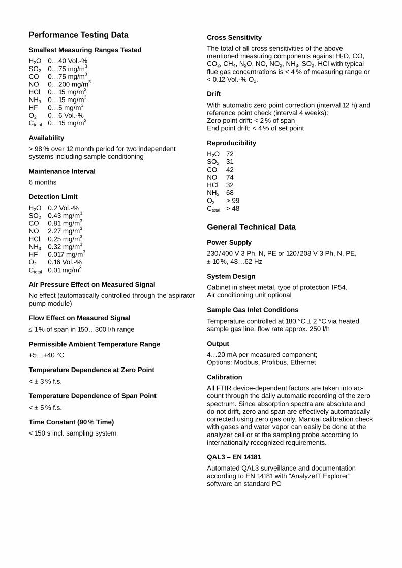
Performance Testing Data
Smallest Measuring Ranges Tested H2O 0…40 Vol.-% SO2 0…75 mg/m3 CO 0…75 mg/m3 NO 0…200 mg/m3 HCl 0…15 mg/m3 NH3 0…15 mg/m3 HF 0…5 mg/m3 O2 0…6 Vol.-% Ctotal 0…15 mg/m3
Availability > 98 % over 12 month period for two independent systems including sample conditioning
Maintenance Interval 6 months
Detection Limit H2O 0.2 Vol.-% SO2 0.43 mg/m3 CO 0.81 mg/m3 NO 2.27 mg/m3 HCl 0.25 mg/m3 NH3 0.32 mg/m3 HF 0.017 mg/m3 O2 0.16 Vol.-% Ctotal 0.01 mg/m3
Air Pressure Effect on Measured Signal No effect (automatically controlled through the aspirator pump module)
Flow Effect on Measured Signal ≤ 1 % of span in 150…300 l/h range
Permissible Ambient Temperature Range +5…+40 °C
Temperature Dependence at Zero Point < ± 3 % f.s.
Temperature Dependence of Span Point < ± 5 % f.s.
Time Constant (90 % Time) < 150 s incl. sampling system
Cross Sensitivity The total of all cross sensitivities of the above mentioned measuring components against H2O, CO, CO2, CH4, N2O, NO, NO2, NH3, SO2, HCl with typical flue gas concentrations is < 4 % of measuring range or < 0.12 Vol.-% O2.
Drift With automatic zero point correction (interval 12 h) and reference point check (interval 4 weeks): Zero point drift: < 2 % of span End point drift: < 4 % of set point
Reproducibility H2O 72 SO2 31 CO 42 NO 74 HCl 32 NH3 68 O2 > 99 Ctotal > 48
General Technical Data
Power Supply 230/400 V 3 Ph, N, PE or 120/208 V 3 Ph, N, PE, ± 10 %, 48…62 Hz
System Design Cabinet in sheet metal, type of protection IP54. Air conditioning unit optional
Sample Gas Inlet Conditions Temperature controlled at 180 °C ± 2 °C via heated sample gas line, flow rate approx. 250 l/h
Output 4…20 mA per measured component; Options: Modbus, Profibus, Ethernet
Calibration All FTIR device-dependent factors are taken into ac-count through the daily automatic recording of the zero spectrum. Since absorption spectra are absolute and do not drift, zero and span are effectively automatically corrected using zero gas only. Manual calibration check with gases and water vapor can easily be done at the analyzer cell or at the sampling probe according to internationally recognized requirements.
QAL3 – EN 14181 Automated QAL3 surveillance and documentation according to EN 14181 with “AnalyzeIT Explorer” software an standard PC

ABB Automation GmbH ⋅ Analytical ⋅ Stierstaedter Strasse 5 ⋅ 60488 Frankfurt am Main ⋅ Germany Phone: +49-(0)69-7930-40 ⋅ Fax: +49-(0)69-7930-4566 ⋅ E-mail: [email protected]
Emission Measuring Devices Advance Optima AO2000 Series
Characteristics
The Advance Optima AO2000 Series gas analyzers have a modular design that increases flexibility and saves money. Analyzer modules can be combined into tailor-made solutions and upgraded to new features at any time. Remote modules are easily attached and centrally operated. The Advance Optima AO2000 Series gas analyzers • Uras26 • Magnos206 • MultiFID14 • Limas11-UV are qualified for use in facilities requiring authorization according to the directives 2001/80/EC (13th BImSchV) and 2000/76/EC (17th BImSchV) as well as in facilities of 27th/30th BImSchV and TA-Luft (Technical Instruc-tions on Air Quality).
General Technical Data
Power Supply 100…240 V AC, 47…63 Hz, max. 175 W
Design Model AO2020: 19-inch housing, type of protection IP20 Model AO2040: Wall-mount housing, type of prot. IP54
Ethernet Interface To connect the gas analyzer to Ethernet networks; TCP/IP protocol via 10/100BASE-T interface
Integrated Gas Feed (optional) • Test gas supply with 1 or 3 solenoid valves, • Fine filtering with 1 or 2 disposable filters, • Gas feed with pump incl. coarse filter and capillary, • Flow monitoring with 1 or 2 flow sensors.
QAL3 – EN 14181 Automated QAL3 surveillance and documentation according to EN 14181 with “AnalyzeIT Explorer” software an standard PC

Emission Measuring Device for CO, NO, SO2, CO2, N2O and O2 Advance Optima AO2000 Series with Uras26
Applications Typical application of the Advance Optima AO2000 Series gas analyzer with the Uras26 analyzer module are amongst others emission monitoring, landfill gas monitoring and burner optimization.
Design and Function The continuous NDIR industrial photometer can selec-tively measure concentrations of up to four sample components. The analyzer features gas-filled opto-pneumatic detectors. Detector filling corresponds to the gas being measured. This means that the detector provides optimum sensitivity and high selectivity com-pared with the other gas components in the sample. Gas-filled calibration cells substitute expensive test gas bottles. With a magneto-mechanical oxygen analyzer module or an optional electro-chemical sensor cell, oxygen can be measured in the same AO2000 system.
Performance Testing Data
Smallest Measuring Ranges Tested AO2020 CEM1230KL: CO 0…75 mg/m3 NO 0…100 mg/m3 SO2 0…75 mg/m3 O2 0…10/25 Vol.-%
AO2020 CEM2450: CO2 0…20 Vol.-% NO 0…200 mg/m3 N2O 0…100 mg/m3 O2 0…10/25 Vol.-%
Availability > 98 % over 3 month period for two independent systems including sample conditioning
Maintenance Interval 3 weeks If the analyzers are equipped with calibration cells, the concentrations of these calibration cells must be checked with test gas at the yearly function test.
Detection Limit AO2020 CEM1230KL: CO < 5 % of TGW* NO < 5 % of TGW* SO2 < 5 % of TGW* O2 < 0.2 Vol.-%
AO2020 CEM2450: CO2 < 0.5 % f.s. NO < 5 % of TGW* N2O < 0.5 % f.s. O2 < 0.2 Vol.-%
* TGW = Daily average value
Air Pressure Effect on Measured Signal < 0.2 % f.s. per 1 % barometric pressure change
Flow Effect on Measured Signal ≤ ± 1 % f.s. in the range 20…100 l/h
Supply Voltage Effect No significant deviations
Permissible Ambient Temperature Range +5…+40 °C
Temperature Dependence of Zero/Span Point < ± 5 % f.s. in the temperature range +5…+40 °C starting from 20 °C
Time Constant (90 % Time) < 200 s incl. sampling system
Cross Sensitivity The total of all cross sensitivities of the above mentioned measuring components against O2, H2O, CO, CO2, CH4, N2O, NO, NO2, NH3, SO2, HCl, H2S with typical flue gas concentrations is < 4 % f.s. (with filter cell or internal correction if required).
Drift Zero point / reference point drift: < ± 3 % f.s.
Reproducibility AO2020 CEM1230KL: CO > 30 NO > 30 SO2 > 30 O2 > 70
AO2020 CEM2450: CO2 > 30 NO > 30 N2O > 30 O2 > 70
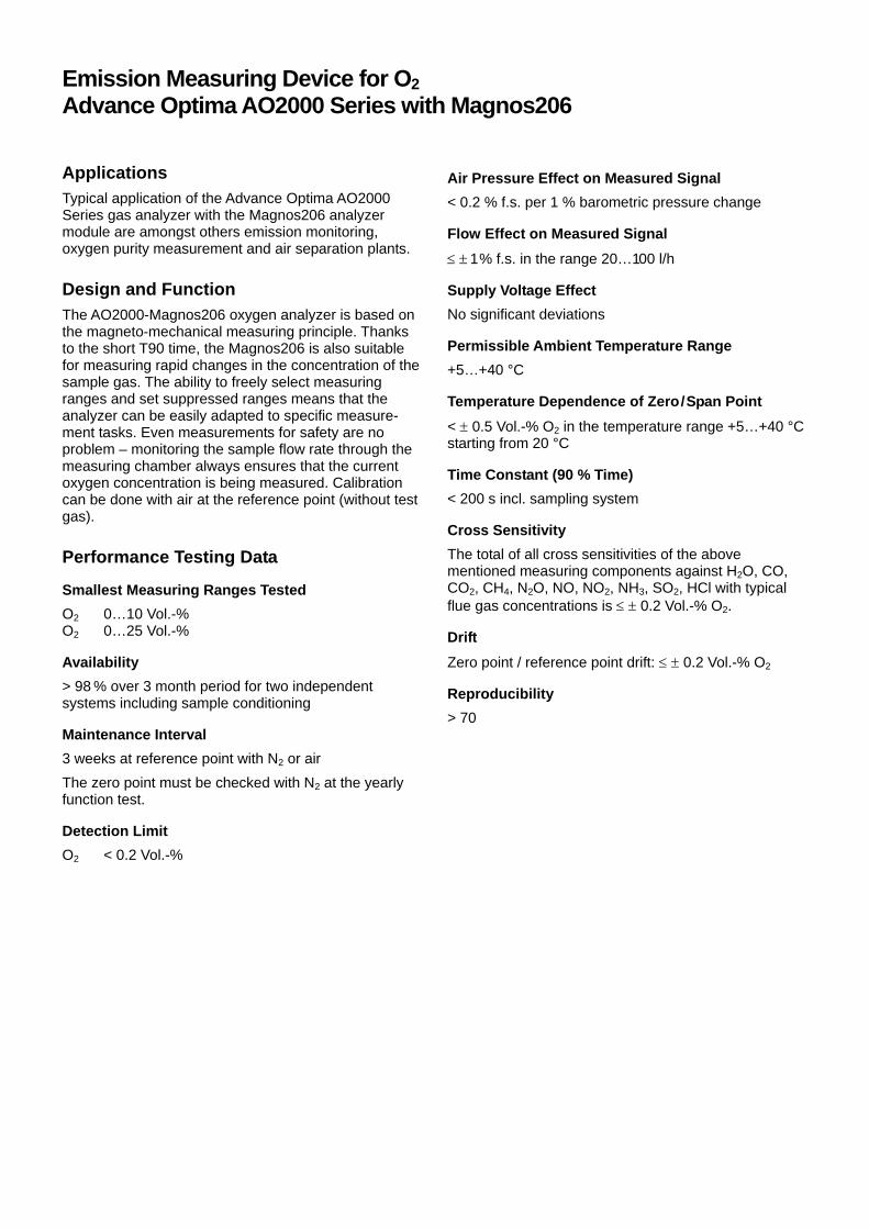
Emission Measuring Device for O2 Advance Optima AO2000 Series with Magnos206
Applications Typical application of the Advance Optima AO2000 Series gas analyzer with the Magnos206 analyzer module are amongst others emission monitoring, oxygen purity measurement and air separation plants.
Design and Function The AO2000-Magnos206 oxygen analyzer is based on the magneto-mechanical measuring principle. Thanks to the short T90 time, the Magnos206 is also suitable for measuring rapid changes in the concentration of the sample gas. The ability to freely select measuring ranges and set suppressed ranges means that the analyzer can be easily adapted to specific measure-ment tasks. Even measurements for safety are no problem – monitoring the sample flow rate through the measuring chamber always ensures that the current oxygen concentration is being measured. Calibration can be done with air at the reference point (without test gas).
Performance Testing Data
Smallest Measuring Ranges Tested O2 0…10 Vol.-% O2 0…25 Vol.-%
Availability > 98 % over 3 month period for two independent systems including sample conditioning
Maintenance Interval 3 weeks at reference point with N2 or air The zero point must be checked with N2 at the yearly function test.
Detection Limit O2 < 0.2 Vol.-%
Air Pressure Effect on Measured Signal < 0.2 % f.s. per 1 % barometric pressure change
Flow Effect on Measured Signal ≤ ± 1 % f.s. in the range 20…100 l/h
Supply Voltage Effect No significant deviations
Permissible Ambient Temperature Range +5…+40 °C
Temperature Dependence of Zero/Span Point < ± 0.5 Vol.-% O2 in the temperature range +5…+40 °C starting from 20 °C
Time Constant (90 % Time) < 200 s incl. sampling system
Cross Sensitivity The total of all cross sensitivities of the above mentioned measuring components against H2O, CO, CO2, CH4, N2O, NO, NO2, NH3, SO2, HCl with typical flue gas concentrations is ≤ ± 0.2 Vol.-% O2.
Drift Zero point / reference point drift: ≤ ± 0.2 Vol.-% O2
Reproducibility > 70

Emission Measuring Device for Ctotal Advance Optima AO2000 Series with MultiFID14
Applications Typical application of the Advance Optima AO2000 Series gas analyzer with the MultiFID14 analyzer module are amongst others emission monitoring and process monitoring.
Design and Function The AO2000-MultiFID14 is a flame ionization detector which measures the total content of organic carbon in the sample gas. For this purpose organic substances are ionized in a hydrogen flame. The current of these ions is proportional to the organic carbon content. The analyzer is heated up to 200 °C and can be directly connected to a heated sample gas line. Thus no cold spots occur at any point. The MultiFID14 features self-monitoring, fault detection, logging and messaging functions. An automatic reset is also possible after fault correction.
Performance Testing Data
Smallest Measuring Range Tested 0…15 mg C/m3
Availability > 99 % over 3 month period for two independent systems including sample conditioning
Maintenance Interval 14 days
Detection Limit ≤ 0.01 mg C/m³ for measuring range 0…15 mg C/m3
Flow Effect on Measured Signal < 1 % MR for ∆ = 35 l/h
Supply Voltage Effect No significant deviations in 185…253 range
Permissible Ambient Temperature Range +5…+40 °C
Temperature Dependence at Zero Point ≤ ± 0.2 % f.s. in +5…+40 °C range
Temperature Dependence of Span Point ≤ ± 2.1 % f.s. in +5…+40 °C range
Time Constant (90 % Time) ≤ 40 s incl. sampling system
Cross Sensitivity The total of all cross sensitivities of the measuring component against H2O, CO, CO2, NO, NO2, N2O, SO2, NH3, HCl, O2 with typical flue gas concentrations is < 4 % of measuring range.
Drift Zero point: ≤ ± 3 % f.s.
Sensitivity: ≤ ± 3 % of set point
Reproducibility ≥ 30

Emission Measuring Device for NO, SO2 and O2 Advance Optima AO2000 Series with Limas11 UV
Applications Typical application of the Advance Optima AO2000 Series gas analyzer with the Limas11 UV analyzer module are amongst others emission monitoring, control of DeNOx installations and waste gas or purity measurement.
Design and Function The Limas11 UV is a process photometer which is easily configured to meet individual process measure-ment requirements. The measuring principle is particu-larly reliable because of its high stability which is based on the four-beam signal processing principle. As a result, the Limas11 is unaffected by contamination in the cells. A high degree of selectivity is provided by using interference and gas filters as well as optimum selec-tion of measured wavelength and reference wave-length. This allows electronic cross sensitivity correc-tion. With an optional electro-chemical sensor cell, oxygen can be measured in the same AO2000 system.
Performance Testing Data
Smallest Measuring Ranges Tested NO 0…33.5 mg/m3 SO2 0…75 mg/m3 O2 0…10/25 Vol.-%
Availability > 98 % over 6 month period for two independent systems including sample conditioning
Maintenance Interval 8 days If the analyzers are equipped with calibration cells, the concentrations of these calibration cells must be checked with test gas at the yearly function test. The zero point of the O2 channel must be checked at the yearly function test.
Detection Limit NO ≤ 0.2 mg/m3 SO2 ≤ 1.8 mg/m3 O2 ≤ 0.07 Vol.-%
Air Pressure Effect on Measured Signal < 0.2 % f.s. per 1 % barometric pressure change
Flow Effect on Measured Signal ≤ ± 1 % f.s. in the range 20…100 l/h
Supply Voltage Effect No significant deviations
Permissible Ambient Temperature Range +5…+40 °C
Temperature Dependence of Zero Point ≤ 5 % f.s. or 0.5 Vol.-% in the range +5…+40 °C
Temperature Dependence of Span Point ≤ 5 % f.s. or 0.5 Vol.-% in the range +5…+40 °C
Zero-Point Drift ≤ 2 % f.s. or 0.2 Vol.-%
Sensitivity Drift ≤ 2 % f.s. or 0.2 Vol.-%
Time Constant (90 % Time) < 200 s incl. sampling system
Cross Sensitivity The total of all cross sensitivities of the above mentioned measuring components against H2O, CO, CO2, NO, NO2, N2O, SO2, NH3, O2, CH4 with typical flue gas concentrations is < 4 % f.s.
Drift With internal automatic calibration of zero point with ambient air (interval 24 h) and span point with calibration cells (interval weekly): Zero point drift: < 2 % f.s. per year End point drift: < 2 % of set point per year Automatic calibration for zero and span point must be checked yearly.
Reproducibility NO > 30 SO2 > 30 O2 > 70
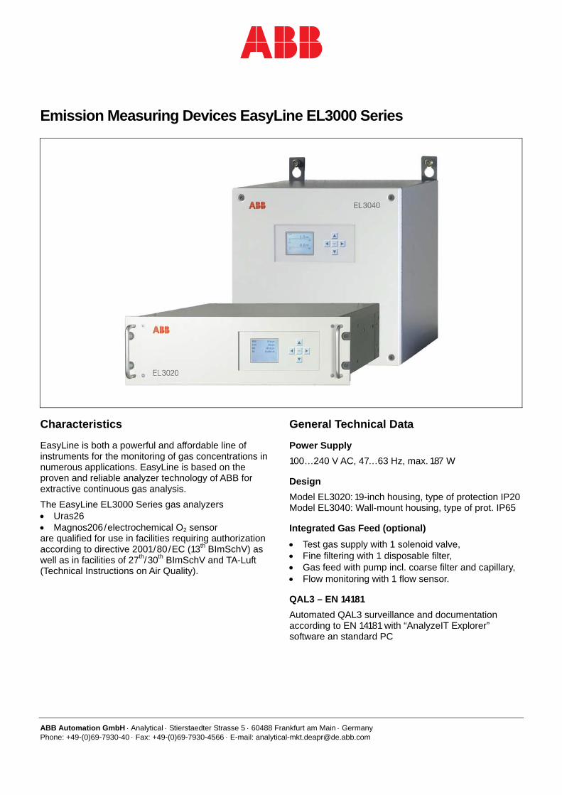
ABB Automation GmbH ⋅ Analytical ⋅ Stierstaedter Strasse 5 ⋅ 60488 Frankfurt am Main ⋅ Germany Phone: +49-(0)69-7930-40 ⋅ Fax: +49-(0)69-7930-4566 ⋅ E-mail: [email protected]
Emission Measuring Devices EasyLine EL3000 Series
Characteristics
EasyLine is both a powerful and affordable line of instruments for the monitoring of gas concentrations in numerous applications. EasyLine is based on the proven and reliable analyzer technology of ABB for extractive continuous gas analysis. The EasyLine EL3000 Series gas analyzers • Uras26 • Magnos206/electrochemical O2 sensor are qualified for use in facilities requiring authorization according to directive 2001/80/EC (13th BImSchV) as well as in facilities of 27th/30th BImSchV and TA-Luft (Technical Instructions on Air Quality).
General Technical Data
Power Supply 100…240 V AC, 47…63 Hz, max. 187 W
Design Model EL3020: 19-inch housing, type of protection IP20 Model EL3040: Wall-mount housing, type of prot. IP65
Integrated Gas Feed (optional) • Test gas supply with 1 solenoid valve, • Fine filtering with 1 disposable filter, • Gas feed with pump incl. coarse filter and capillary, • Flow monitoring with 1 flow sensor.
QAL3 – EN 14181 Automated QAL3 surveillance and documentation according to EN 14181 with “AnalyzeIT Explorer” software an standard PC

Emission Measuring Device for CO, NO, SO2, CO2, N2O and O2 EasyLine EL3000 Series with Uras26
Applications Typical application of the EasyLine EL3000 Series gas analyzer with the Uras26 analyzer module are amongst others emission monitoring, landfill gas monitoring and burner optimization.
Design and Function The continuous NDIR industrial photometer can selec-tively measure concentrations of up to four sample components. The analyzer features gas-filled opto-pneumatic detectors. Detector filling corresponds to the gas being measured. This means that the detector provides optimum sensitivity and high selectivity com-pared with the other gas components in the sample. Gas-filled calibration cells substitute expensive test gas bottles. With a magneto-mechanical oxygen analyzer module or an optional electro-chemical sensor cell, oxygen can be measured in the same device.
Performance Testing Data
Smallest Measuring Ranges Tested EL3020 CEM1230KL: CO* 0…75 mg/m3 NO 0…100 mg/m3 SO2** 0…75 mg/m3 O2 0…10/25 Vol.-%
EL3020 CEM2450: CO2 0…20 Vol.-% NO 0…200 mg/m3 N2O 0…100 mg/m3 O2 0…10/25 Vol.-%
* Lower application measuring range: 0…150 mg/m3 ** Lower application measuring range: 0…300 mg/m3
Availability > 98 % over 3 month period for two independent systems including sample conditioning
Maintenance Interval 3 weeks If the analyzers are equipped with calibration cells, the concentrations of these calibration cells must be checked with test gas at the yearly function test.
Detection Limit EL3020 CEM1230KL: CO < 5 % of TGW* NO < 5 % of TGW* SO2 < 5 % of TGW* O2 < 0.2 Vol.-%
EL3020 CEM2450: CO2 < 0.5 % f.s. NO < 5 % of TGW* N2O < 0.5 % f.s. O2 < 0.2 Vol.-%
* TGW = daily average value
Air Pressure Effect on Measured Signal < 0.2 % f.s. per 1 % barometric pressure change
Flow Effect on Measured Signal ≤ ± 1 % f.s. in the range 20…100 l/h
Supply Voltage Effect No significant deviations
Permissible Ambient Temperature Range +5…+40 °C
Temperature Dependence of Zero/Span Point < ± 5 % f.s. in the temperature range +5…+40 °C starting from 20 °C
Time Constant (90 % Time) < 200 s incl. sampling system
Cross Sensitivity The total of all cross sensitivities of the above mentioned measuring components against O2, H2O, CO, CO2, CH4, N2O, NO, NO2, NH3, SO2, HCl, H2S with typical flue gas concentrations is < 4 % f.s. (with filter cell or internal correction if required).
Drift Zero point / reference point drift: < ± 3 % f.s.
Reproducibility EL3020 CEM1230KL: CO > 30 NO > 30 SO2 > 30 O2 > 70
EL3020 CEM2450: CO2 > 30 NO > 30 N2O > 30 O2 > 70

Emission Measuring Device for O2 EasyLine EL3000 Series with Magnos206
Applications Typical application of the EasyLine EL3000 Series gas analyzer with the Magnos206 analyzer module are amongst others emission monitoring, oxygen purity measurement and air separation plants.
Design and Function The EL3000-Magnos206 oxygen analyzer is based on the magneto-mechanical measuring principle. Thanks to the short T90 time, the Magnos206 is also suitable for measuring rapid changes in the concentration of the sample gas. The ability to freely select measuring ranges and set suppressed ranges means that the analyzer can be easily adapted to specific measure-ment tasks. Even measurements for safety are no problem – monitoring the sample flow rate through the measuring chamber always ensures that the current oxygen concentration is being measured. Calibration can be done with air at the reference point (without test gas).
Performance Testing Data
Smallest Measuring Ranges Tested O2 0…10 Vol.-% O2 0…25 Vol.-%
Availability > 98 % over 3 month period for two independent systems including sample conditioning
Maintenance Interval 3 weeks at reference point with N2 or air The zero point must be checked with N2 at the yearly function test.
Detection Limit O2 < 0.2 Vol.-%
Air Pressure Effect on Measured Signal < 0.2 % f.s. per 1 % barometric pressure change
Flow Effect on Measured Signal ≤ ± 1 % f.s. in the range 20…100 l/h
Supply Voltage Effect No significant deviations
Permissible Ambient Temperature Range +5…+40 °C
Temperature Dependence of Zero/Span Point < ± 0.5 Vol.-% O2 in the temperature range +5…+40 °C starting from 20 °C
Time Constant (90 % Time) < 200 s incl. sampling system
Cross Sensitivity The total of all cross sensitivities of the above mentioned measuring components against H2O, CO, CO2, CH4, N2O, NO, NO2, NH3, SO2, HCl with typical flue gas concentrations is ≤ ± 0.2 Vol.-% O2.
Drift Zero point / reference point drift: ≤ ± 0.2 Vol.-% O2
Reproducibility > 70

ABB Automation GmbH ⋅ Analytical ⋅ Stierstaedter Strasse 5 ⋅ 60488 Frankfurt am Main ⋅ Germany Phone: +49-(0)69-7930-40 ⋅ Fax: +49-(0)69-7930-4566 ⋅ E-mail: [email protected]
Emission Measuring Device with Performance-Tested Analyzers Multi-Component Analysis System ACX
Application Typical applications of the multi-component analysis system ACX are amongst others emission monitoring tasks in power plants, municipal waste incinerators, biomedical and sludge incinerators and hazardous waste incinerators.
Design and Function The multi-component analysis system ACX is equipped with the following analyzers which are qualified for use in facilities requiring authorization according to the direc-tives 2001/80/EC (13th BImSchV) and 2000/76/EC (17th BImSchV) as well as in facilities of 27th/30th BImSchV and TA-Luft (Technical Instructions on Air Quality): • AO2000-Uras26, • AO2000-Magnos206, • AO2000-Limas11 UV. The analysis system is equipped with modules for sample gas sampling, conditioning and feeding, which have been used at the qualification test of the analyzers.
General Technical Data
Power Supply 230/400 V 3 Ph, N, PE or 115/200 V 3 Ph, N, PE, –15…+10 %, 48…62 Hz
System Design Cabinet in sheet metal or GRP, type of protection IP54. Cooling unit optional
Output Standard: Modbus; Options: 4…20 mA per measured component, Profibus, Ethernet
Calibration Automatic calibration with air and integrated calibration cells without need for test gases
QAL3 – EN 14181 Automated QAL3 surveillance and documentation according to EN 14181 with “AnalyzeIT Explorer” software an standard PC

Performance-tested Analyzer for CO, NO, SO2 and O2 Advance Optima AO2000-Uras26
Applications Typical application of the Advance Optima AO2000 Series gas analyzer with the Uras26 analyzer module are amongst others emission monitoring, landfill gas monitoring and burner optimization.
Design and Function The continuous NDIR industrial photometer can selec-tively measure concentrations of up to four sample components. The analyzer features gas-filled opto-pneumatic detectors. Detector filling corresponds to the gas being measured. This means that the detector provides optimum sensitivity and high selectivity com-pared with the other gas components in the sample. Gas-filled calibration cells substitute expensive test gas bottles. With a magneto-mechanical oxygen analyzer module or an optional electro-chemical sensor cell, oxygen can be measured in the same AO2000 system.
Performance Testing Data
Smallest Measuring Ranges Tested AO2020 CEM1230KL: CO 0…75 mg/m3 NO 0…100 mg/m3 SO2 0…75 mg/m3 O2 0…10/25 Vol.-%
AO2020 CEM2450: CO2 0…20 Vol.-% NO 0…200 mg/m3 N2O 0…100 mg/m3 O2 0…10/25 Vol.-%
Availability > 98 % over 3 month period for two independent systems including sample conditioning
Maintenance Interval 3 weeks If the analyzers are equipped with calibration cells, the concentrations of these calibration cells must be checked with test gas at the yearly function test.
Detection Limit AO2020 CEM1230KL: CO < 5 % of TGW* NO < 5 % of TGW* SO2 < 5 % of TGW* O2 < 0.2 Vol.-%
AO2020 CEM2450: CO2 < 0.5 % f.s. NO < 5 % of TGW* N2O < 0.5 % f.s. O2 < 0.2 Vol.-%
* TGW = Daily average value
Air Pressure Effect on Measured Signal < 0.2 % f.s. per 1 % barometric pressure change
Flow Effect on Measured Signal ≤ ± 1 % f.s. in the range 20…100 l/h
Supply Voltage Effect No significant deviations
Permissible Ambient Temperature Range +5…+40 °C
Temperature Dependence of Zero/Span Point < ± 5 % f.s. in the temperature range +5…+40 °C starting from 20 °C
Time Constant (90 % Time) < 200 s incl. sampling system
Cross Sensitivity The total of all cross sensitivities of the above mentioned measuring components against O2, H2O, CO, CO2, CH4, N2O, NO, NO2, NH3, SO2, HCl, H2S with typical flue gas concentrations is < 4 % f.s. (with filter cell or internal correction if required).
Drift Zero point / reference point drift: < ± 3 % f.s.
Reproducibility AO2020 CEM1230KL: CO > 30 NO > 30 SO2 > 30 O2 > 70
AO2020 CEM2450: CO2 > 30 NO > 30 N2O > 30 O2 > 70
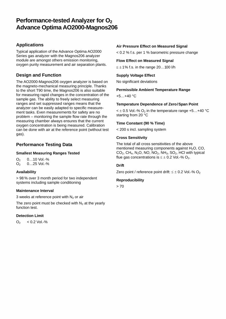
Performance-tested Analyzer for O2 Advance Optima AO2000-Magnos206
Applications Typical application of the Advance Optima AO2000 Series gas analyzer with the Magnos206 analyzer module are amongst others emission monitoring, oxygen purity measurement and air separation plants.
Design and Function The AO2000-Magnos206 oxygen analyzer is based on the magneto-mechanical measuring principle. Thanks to the short T90 time, the Magnos206 is also suitable for measuring rapid changes in the concentration of the sample gas. The ability to freely select measuring ranges and set suppressed ranges means that the analyzer can be easily adapted to specific measure-ment tasks. Even measurements for safety are no problem – monitoring the sample flow rate through the measuring chamber always ensures that the current oxygen concentration is being measured. Calibration can be done with air at the reference point (without test gas).
Performance Testing Data
Smallest Measuring Ranges Tested O2 0…10 Vol.-% O2 0…25 Vol.-%
Availability > 98 % over 3 month period for two independent systems including sample conditioning
Maintenance Interval 3 weeks at reference point with N2 or air The zero point must be checked with N2 at the yearly function test.
Detection Limit O2 < 0.2 Vol.-%
Air Pressure Effect on Measured Signal < 0.2 % f.s. per 1 % barometric pressure change
Flow Effect on Measured Signal ≤ ± 1 % f.s. in the range 20…100 l/h
Supply Voltage Effect No significant deviations
Permissible Ambient Temperature Range +5…+40 °C
Temperature Dependence of Zero/Span Point < ± 0.5 Vol.-% O2 in the temperature range +5…+40 °C starting from 20 °C
Time Constant (90 % Time) < 200 s incl. sampling system
Cross Sensitivity The total of all cross sensitivities of the above mentioned measuring components against H2O, CO, CO2, CH4, N2O, NO, NO2, NH3, SO2, HCl with typical flue gas concentrations is ≤ ± 0.2 Vol.-% O2.
Drift Zero point / reference point drift: ≤ ± 0.2 Vol.-% O2
Reproducibility > 70
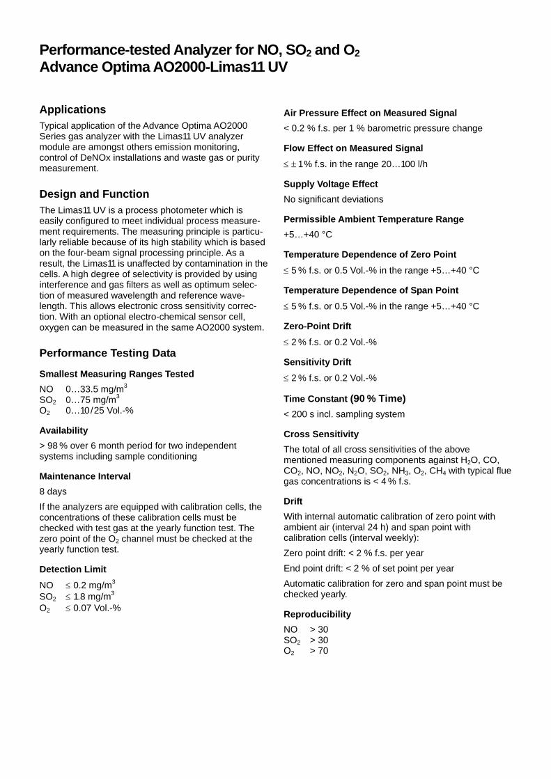
Performance-tested Analyzer for NO, SO2 and O2 Advance Optima AO2000-Limas11 UV
Applications Typical application of the Advance Optima AO2000 Series gas analyzer with the Limas11 UV analyzer module are amongst others emission monitoring, control of DeNOx installations and waste gas or purity measurement.
Design and Function The Limas11 UV is a process photometer which is easily configured to meet individual process measure-ment requirements. The measuring principle is particu-larly reliable because of its high stability which is based on the four-beam signal processing principle. As a result, the Limas11 is unaffected by contamination in the cells. A high degree of selectivity is provided by using interference and gas filters as well as optimum selec-tion of measured wavelength and reference wave-length. This allows electronic cross sensitivity correc-tion. With an optional electro-chemical sensor cell, oxygen can be measured in the same AO2000 system.
Performance Testing Data
Smallest Measuring Ranges Tested NO 0…33.5 mg/m3 SO2 0…75 mg/m3 O2 0…10/25 Vol.-%
Availability > 98 % over 6 month period for two independent systems including sample conditioning
Maintenance Interval 8 days If the analyzers are equipped with calibration cells, the concentrations of these calibration cells must be checked with test gas at the yearly function test. The zero point of the O2 channel must be checked at the yearly function test.
Detection Limit NO ≤ 0.2 mg/m3 SO2 ≤ 1.8 mg/m3 O2 ≤ 0.07 Vol.-%
Air Pressure Effect on Measured Signal < 0.2 % f.s. per 1 % barometric pressure change
Flow Effect on Measured Signal ≤ ± 1 % f.s. in the range 20…100 l/h
Supply Voltage Effect No significant deviations
Permissible Ambient Temperature Range +5…+40 °C
Temperature Dependence of Zero Point ≤ 5 % f.s. or 0.5 Vol.-% in the range +5…+40 °C
Temperature Dependence of Span Point ≤ 5 % f.s. or 0.5 Vol.-% in the range +5…+40 °C
Zero-Point Drift ≤ 2 % f.s. or 0.2 Vol.-%
Sensitivity Drift ≤ 2 % f.s. or 0.2 Vol.-%
Time Constant (90 % Time) < 200 s incl. sampling system
Cross Sensitivity The total of all cross sensitivities of the above mentioned measuring components against H2O, CO, CO2, NO, NO2, N2O, SO2, NH3, O2, CH4 with typical flue gas concentrations is < 4 % f.s.
Drift With internal automatic calibration of zero point with ambient air (interval 24 h) and span point with calibration cells (interval weekly): Zero point drift: < 2 % f.s. per year End point drift: < 2 % of set point per year Automatic calibration for zero and span point must be checked yearly.
Reproducibility NO > 30 SO2 > 30 O2 > 70

KM 2000 CnHmEM Hydrocarbon-Analyser 1. Application The modular constructed ADOS KM 2000 CnHmEM equipment incorporates a microcontrol-ler-aided measurement device for measuring sol-vents. All combustible gaseous CnHmEM copounds can be measured with the exception of chlorinated and sulphursublimed hydrocarbons. The thermocouples used for measurements, in conjunction with applying the principle of heat reaction, offer the following advantages: High degree of sensitivity Good accuracy Negligible drift of zero point Over-range signals have no effect 1.1 Fields of Application Supervision of industrial processes KM 2000 CnHm EM:
Measurement of the emission of hydrocar-bons, according to the German clean-air regulations (“TA-Luft“)
KM 2000 CnHm: Measurement of solvent saturation Measurement of the concentration of solvents
Room air (ventilation) monitoring A warning is issued at very low concentrations of poisonous gas thus preventing any danger to health.
2. Measurement Principle and Function 2.1 Gas measurement system The sampled gas is drawn in by a pump through a feed pipe (heated if required), to the reaction chamber, via a compensating filter, flow regulator and flow-through meter. The gas is warmed to a constant temperature by means of the heater coil and jacket and finally burned in a solid-matter catalytic converter. The difference in temperature before and after combustion is used as the meas-urement signal that is prepared and evaluated by the microcontroller-aided analyser. 2.2 Gas Flow Schematic
1 = Sampled gas intake 12 = Reaction chamber 2 = Test gas intake 13 = Measuring amplifier 3 = pre-filter resp. balancing filter
14 = Limit monitor 1 – 4
4 = Sampled gas pump 15 = Measured value integration
5 = Flow regulator 16 = Continuous-line recorder
6 = Flow–through meter 17 = Concentration indicator 7 = Flow monitor 18 = Heater 8 = Heating coil 19 = Temperature control 9 = Catalyst chamber 20 = Resistance-thermometer 10 = Reference measuring point
21 = Gas outlet
11 = Measuring point 22 = Inert mass 23 = Catalytic converter

2.3 Analyser The analyser functions on the principle of heat reaction. The difference in temperatures at the reference measuring point and the measuring point is a directly-dependent variable of the com-ponent part of combustible substances in the gas. The reference measuring point is subjected to the heated non-burned gas mixture, whereas the sec-ond probe of the thermocouple pile measures the temperature of the burned gas. A load-independent current of 0–(4)–20 mA is available for connecting to electrical test meters, plotters and limit value monitors. A RS 232 or RS 485 in-terface is incorporated for data communication. The inclusion of a measured value integration provides the facility of forming the average value of measured quantities, continuously or over a prescribed period of time. 2.4 Equipment Construction The hydrocarbon measuring system ADOS KM 2000 CnHmEM consists of the following 19" rack units: Reaction chamber with sensor and electronics Gas suction system with or without constant
heating for the feed pipes, with sampled gas pump, flow through meter, flow regulator, flow monitor and filter
Microcontroller-aided evaluation unit in 19"-
system with application specific standard plug-in Euro-cards
The housing 3. Technical Dates 3.1 Dates of the aptitude test
Measurement principle Measuring the heat of com-bustion in a catalytic con-verter
Measuring ranges 0-50 mg TOC/m3
Minimum detection limit
1 mg TOC/m3
Cross-sensitivity 260 g/m3 CO2 : < ±0,5 % 200 mg/m3 SO2 : < -10 % 30 mg/m3 NO2 : < -2,5 % 300 mg/m3 CO : > 100 % 300 mg/m3 NO : 7 % 180 g/m3 H2O : < -1 % 50 mg/m3 HCl : < ± 0,5 % 20 mg/m3 NH3 : < ± 0,5 % 20 mg/m3 N2O : < 1 %
Output signals Current interface 0-(4)-20 mA max. permissible load 300 Ω RS 232
Response time (t90) < 200 sec. (sampling pipe approx. 11 m dead time 10 sec.)
Accuracy < 2% of f. s. d. Zero drift < 2% of f. s. d.
3.2. Further technical dates
Permissible ambient Temperature
+5 °C to +40 °C
Temperature dependence of the zero point and the sensitivity
< 5% (between 5 °C and 40 °C)
Sampled gas flow 125 l/h ±10 l/h Preheating time approx. 120 min. Maintenance interval 4 weeks with auto-calibration,
1 week without auto-calibration
Mains supply 115V 60Hz, 600VA, other voltages on request
Dimensions (WxHxD) 600 x 478 x 500 mm Weight approx. 43 kg Test certificate TÜV approval according to
clean-air regulations (“TA-Luft”) TÜV-report: 936/21200245
3.3 Accessories CnHmEM sampling probes heated or
unheated Mounting flanges for removal of heated
extraction pipes Heated extraction pipes Test gas bottles with pressure reducer Pollution control computer according to the
clean-air regulation Continuous-line recorder Air purging system Compensation of CO cross sensitivity Automatic calibration system
ADOS GmbH Instrumentation & Control
Trierer Str. 23-25 D - 52078 Aachen Tel.+49 241 9769 0 Fax:+49 241 9769 16 www.ados.de [email protected]

1. Range of Application
The measuring unit AMS 3220, featuring the ZrO2-probe,is used for the determination of the oxygen concentrationin (wet) flue gases of incinerators at temperature until450°C.The measuring system ia approved after 13. und 17.BImSchV, TA Luft und fullfills the requirements of QAL1 after DIN EN 14181 and DIN EN ISO 14956.
Limit and threshold values can be controlled. The ZrO2-probe length varies from 150 mm to 3000 mm.
2. System Design and Operation
Using a galvanic Oxygen concevntration cell with solidelectrolyte, the Oxygen concentration in the probe gaswill be related to a reference gas with fixed Oxygenconcentration. For most applications ambient air willbe taken purposely, its Oxygen concentration taken assufficiently constant.Basically the concentration cell features two porousPlatinum electrodes and an ionic conductor. The latteris made of Zirkonia dioxide with stabilising additives.The Oxygen molecules of the reference gas will bereduced at the Platinum electrode, thus producingOxygen ions which migrate through the Zirkonia dioxideto the second Platinum electrode via pre-injected latticedisturbances.Emitting electrons the Oxygen ions convert to Oxygenmolecules again. The lower the Oxygen concentrationin the probe gas, all the more is the amount of Oxygenions migrating through the Platinum dioxide, thusincreasing the voltage at the Platinum electrodes:declining Oxygen concentration leads to a highermeasuring signal. For this particular reason themeasurent of trace Oxygen can be carried out withconvenient sensitivity.The ionic conductivity rises exponentially with thetemperature. At cell temperature well above 600°C thecorresponding measuring signal is reasonable forsensitive Oxygen measurements.Provided constant temperature of the measuring cell aswell as constant Oxygen content in the reference gas,the voltage at the Platinum electrodes measures thethe Oxygen concentration in the probe gas (Nernstequation).
Emission Control System AMS 3220 for Oxygen
Pneumatic Unit
Standard Probe
Electronic Controller

Analysen-, Mess- und Systemtechnik GmbHIndustriestrasse 9D-69234 Dielheim
Tel.+49-6222-788-770 e-mail:[email protected].+49-6222-788-7720 http://www.ams-dielheim.com
3. Technical Data
The current technical data can be obtained from our website www.ams-dielheim.com as a pdf-download.
3.1 Data from the Aptitude Test
Measuring ranges 0,1 vol-% until 6/12/25 vol-% O2 for flue gas applications0,1 ... 0,5 vol-% O2 are technically feasible
Measuring Accuracy + 0,1 vol-% O2 for the standard measuring r range
Reproducibility 437 for full scale 25 vol-% according to the aptitude testAMS-data: + 0,5 % rel. iin the 0 ... 25 vol-% range
Availability 99,8 %; interruptions through maintenance works only, not through probe failures
Maintenance intervalls Checking and calbration within 28 days intervalls. Additionally a yearlymaintenance service of the ZrO2-probe is recommended by AMS.
Detection limit For flue gas applications 0,08 vol-% and measuring range 25 vol-% Oxygen
Influence of power supply Deviations in the range 190... 250 V caused no influence on the measuringsignal
Ambient temperature range -20°C until +50°C
Temperature dependence ofthe zero point
Lower as the minimum requirement of +0,5 vol-% according to the aptitude testwithin the admissible ambient temperature range
Response time (90%-time) < 15 seconds
Cross interference Deviations lower as 0,2 vol-% by other flue gas components
Drift Significantly lower as the minimum requirement of +0,2 vol-% within themaintenance intervall (28 days)
3.2 Further Technical Data
Monitoring Sensor voltage, heating cartridge (resistance), limits
Signal outputs Galvanically isolated signal output 0/4 - 20 mAmax. load 600 Ohm freely programmable from 0,1 until 25 vol-% O2Option: additional signal outputs 0/4 - 20 mA and 0 - 1 / 2,5 V
Alarms 2 potential free relay contacts, max. 60 V 1 Afreely programmable for the entire measuring rangefor limits as well as for fast/hold
Status output 1 potentialfree relay contact, max. 1 A / 60 Ve.g. for sensor voltage, heating cartridge
Digital interface Standard: RS232
Housing/protection wall mounted cabinet made of stainless steel/IP65
Dimensions 200 x 245 x 170 mm (WxHxD)
Weight approx. 10 kg
Voltage supply 24/115/230 V AC 48 - 62 Hz
AMS GmbH 1.0 / 2006 Subject to technical modifications

CONTINUOUS EMISSIONS
MONITORING SYSTEM FOR
DEMANDING APPLICATIONS:
GASMET CEMS
1. Typical applications
The Gasmet CEMS is used for continuous
emissions monitoring in power plants and
waste incinerators according to 13., 17. and
27. BlmSchV. In addition, various process
monitoring applications are also possible.
Typically, concentrations of H2O, CO2, CO,
SO2, NO, NO2, N2O, HCl, HF, NH3, O2 and
TOC (Total Organic Carbon) are
continuously measured with the Gasmet
CEMS. The Gasmet CEMS fulfills the
requirements of QAL 1 according to EN
14181 and EN ISO 14956.
2. Overview of the system
The Gasmet CEMS is a modular
construction that typically comprises of
Gasmet Cx-4000 FTIR gas analyzer, heated
sampling unit, industrial PC, FID - detector
and ZrO2 – oxygen analyzer that are
installed in an air-conditioned cabin. All
modules are 19’’ rack mounted in pull-out
shelves for easy accessibility & service.
The Gasmet Cx-4000 FTIR multi-
component gas analyzer uses the FTIR
measuring principle, which allows the fast
measurement of Infrared spectra. The
sample spectra contain the signals of all
gases present. The GASMET Software
calculates the concentration of up to 50
gaseous compounds simultaneously. The
multi-pass sample cell is heated to 180oC
and features Gold coated mirrors, for
maximum corrosion resistance.
The hot-extractive sampling system
consists of a heated sample gas probe,
heated sample lines and heated sample
pump unit. Two-stage particle filtration is
used in order to remove particles from the
sample gas. The sample pump unit includes
gas connections for the Cx-4000 FTIR gas
analyzer, optional O2 & FID analyzers and
span & zero gas. Multipoint sampling from
two sample gas streams is supported with
the standard sampling unit.
The industrial PC is used processing &
storing the sample spectra with Calcmet -
software. The Calcmet™ software analyzes
the sample spectrum using sophisticated
analysis algorithms. Cross-interference
from other gases is automatically taken into
account in the analysis settings of each
compound. Since water content of the
sample gas is measured, the results can be
reported on either “wet” or “dry” basis.
From the industrial computer, the analysis
results can be transferred to the plant DCS
either with analog 4 – 20 mA outputs or
with digital formats (e.g. MODBUS,
PROFIBUS). Alarms can be transferred with
relay contacts. The Gasmet CEMS also
provides different alarm functions. If any of
the critical alarms is activated, instrument
air starts to flow automatically into the
system to prevent condensation.
The Gasmet CEMS is standard equipped
with remote control function. Thus the
Service department of Gasmet Technologies
is able to take a remote connection to the
system in order to check or modify key
system parameters or download sample
spectra for further analysis.
Each Gasmet FTIR analyzer is subject to an
application specific calibration which is
performed in Gasmet Technologies’
laboratory, in order to achieve greatest
possible analysis accuracy. With FTIR
measurement technology there is no need

to do any span or re-calibrations, only zero
calibration with Nitrogen every 24 hours.
Automated span gas checks are also
possible, if deemed necessary.
3. Mobile GASMET DX4000 Analyzer
In addition to the stationary GASMET CEMS
system, a portable analyzer consisting of
the GASMET DX4000 and a heated
sampling system is available.
4. Technical CEMS Data
4.1 Data from the TÜV suitability test
Tested minimum measurement ranges:
CO 0 - 75 mg/m³
NO 0 - 200 mg/m³
NO2 0 - 200 mg/m³
N2O 0 - 100 mg/m³
SO2 0 - 75 mg/m³
NH3 0 - 15 mg/m³
HCl 0 - 15 mg/m³
CO2 0 - 25 Vol.-%
H2O 0 - 30 Vol.-%
Detection limits:
< 1 % of full scale for all compounds
Availability:
98.1 % over 3 month test period
Permitted ambient temperature range:
+5oC to +40oC
Response time (T90 – time):
≤ 180 seconds
Linearity:
< 2 % for all compounds
Reproducibility:
> 30 for all compounds
4.2 Additional technical CEMS data
Power supply:
230 or 115 VAC
Dimensions:
2100 * 800 * 800 mm
Weight:
approx. 550 kg (the whole system)
Manufacturer:
Gasmet Technologies Oy
Pulttitie 8 A
00880 Helsinki
Finland
Tel: +358 9 7590 0400
Fax: +358 9 7590 0435
Email: [email protected]
www.gasmet.fi
Sales Office:
Ansyco GmbH
Ostring 4
D-76131 Karlsruhe, Germany
Tel: +49 721 626560
Fax:+49 721 621332
E-Mail: [email protected]
www.ansyco.de

BARTEC GmbH Schulstraße 30 94239 Gotteszell, Germany Phone +49 (0) 9929 301-0 Fax +49 (0) 9929 301-112 E-mail: [email protected] Internet: www.bartec.de
Moisture Analyser for Emission Measurement Hygrophil H 4230
1. Range of application Hygrophil H 4230 is a process psychrometer that covers high industrial needs considering resistance to corrosion, long-term-stability and un-affectance against dirt. With a permanent self-cleaning effect, our instrument can stand very high loads of acid, oil, dust, solvents and other aggressive components of the gas. The instrument convinces with its high accuracy. The main applications are in power plants, waste incineration- and combustion plants in more or less un-cleaned raw gas: for emission control / environmental protection to detect tube cracks to optimize the flue gas desulfurisation to optimize the E-Filters to control the cooling towers to avoid condenstation at the textile filters But these advantages also distinguish the Hygrophil H for all types of dryers and baking ovens, as well as in the chemical industry in general. The instrument is TÜV-approved and suitable for the measurement in plants that require authorisation, and in plants that require certification according to the BImSchV (13., 17., 27., 30.).
2. Design and Function The Hygrophil 4230 measures according to the psychrometric principle, which results in high accuracy, high reproducibility and high long-term-stability of the measured values. All displayed values are based on temperature measurements and can be calculated from these values. It is a so called “secondary standard method” according to DIN 50012 and does not require recalibration. Because of the patented impact-jet principle, a failure-free long-term operation is possible even at high temperatures and moisture values. An accurately defined stream of sample gas flows along the dry temperature sensor TT (gas temperature) and impacts the wet temperature sensor HT, embedded in a water cylinder / measuring cell (cooling limit temperature). With these 2 temperature values all the different moisture values can be calculated. The measuring cell is permanently feeded with tensid-added water. Due to the impact pressure of the gas and the continuous water feed-in, the contaminated water surface is permanently renewed, so that no cross effects appear (self-cleaning principle).

3. Technical data Humidity measurement
Measurement principle Psychrometric gas humidity measurement in line with the impact jet method Transducer PT 100/ 4-conductor in accordance with DIN IEC 751 Computational accuracy ≤ 0.01% Computing time Approx. 2s Settling time t90 = 90s (for sudden change in SH from 10 to 190 g/kg) Air/gas throughput Max. 17,5 Nl/min Water intake Max. 25 ml/h (tube pump) Water reserve 2l (enough for approx. 3 days) Compressed air intake 2...5 bar (max. air consumption 2000Nl/h) Measured variable inputs
Measured variable Measurement range Resolution Accuracy Type
Dry temperature TT 0...140 °C Wet temperature HT 0...140 °C Temperature T1 0...200 °C
0.1 °C
≤ 0.5% of the measurement range
Absolute pressure SP 500...1500 hPa 1 hPa ≤ 1%
Primary
Dew-point temperature DT 0...100 °C 0.1 °C Volumetric content H2O Vol.% 0...100 % 0.1 % Absolute humidity MH 10...1000 g/kg 1 g/kg Specific humidity SH 10...1000 g/kg 1 g/kg Enthalpy h 10...1000 kJ/kg 1 kJ/kg Current vapour pressure VP 10...1000 hPa 1 hPa Saturation deficit DVP 0...1000 hPa 1 hPa
Calculated
Outputs Signal output
Analogue output 2 electrically isolated output channels, can be assigned to each of the measurement ranges, spread, error behaviour programmable
Output signal 0…20 mA or 4…20 mA (programmable), linear Permissible load ≤ 500 Ω Accuracy ≤ 0.2% of the associated measured value Inputs External water detector 24 V d.c., NPN T1extern PT 100/ 4-conductor in accordance with DIN IEC 751 Data interface
Field bus interface Profibus DB Electrical data Auxiliary power Measuring unit: 90…264 V a.c., 47...63 Hz, approx. 30 VA Heating hose: 230 V or 115 V a.c.; approx. 100 VA/m Relays Warn relay Display of warnings Load: 1 A/24 V d.c., at least 10 mA ERROR-relay Display of failures Load: 1 A/24 V d.c., at least 10 mA Ambient conditions
Permitted working temperature +5...+50°C Permitted storage temperature -20...+70°C (without water) Climate category KWF in accordance with DIN 40040 Reference conditions 23°C ±2°C / 230V ± 2% Mechanical data
Enclosure Stainless steel enclosure; protection rating IP64 in accordance with DIN 40050 Dimensions 450×410×150 mm (without mount) Assembly drill holes 347x330 mm, 4×∅7x13mm (M6) Weight Approx. 12.5 kg Connections Electrical connection Screw terminals 0.5-1.5 mm2; cable feed via M 16x1.5 cable gland Compressed air connection G 1/4" Heating tube connection G 3/8" (IP54) Universal conical nipple DKR DIN3863

D-EMS 2000 Environmental and Process Data Management System
1. Fields of Application The D-EMS 2000 is an environmental and process data man-agement system which meets today's legal requirements and which in conception has been prepared for future guidelines. The system allows per one system workstation the collection, long-term archiving and visuali-sation of up to 320 environmental data relating to highly dif-ferent areas. The overall system operates under Win-dows, is capable of running in a network environment and has all the features of a state-of-the-art software product with intercommunication capability. The following are available for the various applications: • Emission data acquisition and evaluation for plants
according to the 13th, 17th, 27th, 30th and 31st Ger-man Federal Ordinances on Pollution Control (BImSchV) and the Technical Instructions for Air Quality
• Emission data acquisition and evaluation for plants according to the European guideline 2000/76/EC for waste incinerators and 2001/80/EC for large combustions following the regulations of EN 14181
• Acquisition and evaluation of data for water and sewage installations
• Weather data acquisition, evaluation and long-term archiving
• Automated preparation of emission declaration pursuant to the 11th BimSchV
The system is of modular design and enables the im-plementation of highly different customised solutions. Thus it is of interest not only for complex plants, but can also be used successfully in the smallest of plants. Suitability tested according to the Uniform Practice in monitoring emissions by the TUV Munich, test report #541935 dated 11.10.2004 and 14.12.2005. Itemized in the list of suitable instruments for continuous regis-tration of emissions. Federal Gazette # 70 of 08.04.2006.
2. Set-up and Mode of Operation The data is sent from the data communication systems or via a data bus to the D-EMS 2000 SW system work-station, the heart of the system. This central process-ing unit manages the data provision for the installed software components, the safe long-term archiving, and allows the visualisation of both current and histori-cal environmental data. Data communication with the peripheral devices (data server, online maintenance, emission data telecom-munication, Internet/Intranet) is possible via bus sys-tems, modems or permanent serial interfaces, depend-ing on requirements. The software parts available in the D-EMS 2000 have been developed as 32-bit applications for the Windows 2000 and Windows XP operating systems. Due to the system's design, one or several system workstations can communicate with an associated server or with the central server, depending on re-quirements. A higher-level, central system workstation offers both complete administration of the overall sys-tem as well as centralised inspection of the data.
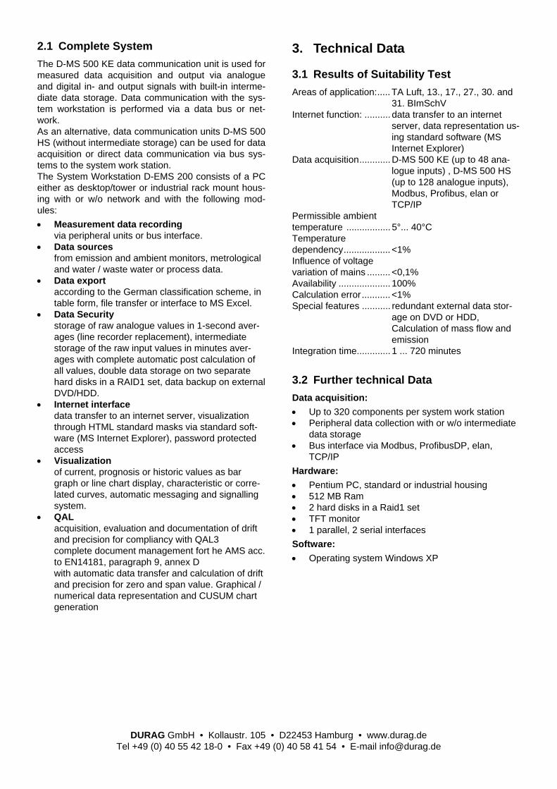
2.1 Complete System The D-MS 500 KE data communication unit is used for measured data acquisition and output via analogue and digital in- and output signals with built-in interme-diate data storage. Data communication with the sys-tem workstation is performed via a data bus or net-work. As an alternative, data communication units D-MS 500 HS (without intermediate storage) can be used for data acquisition or direct data communication via bus sys-tems to the system work station. The System Workstation D-EMS 200 consists of a PC either as desktop/tower or industrial rack mount hous-ing with or w/o network and with the following mod-ules: • Measurement data recording
via peripheral units or bus interface. • Data sources
from emission and ambient monitors, metrological and water / waste water or process data.
• Data export according to the German classification scheme, in table form, file transfer or interface to MS Excel.
• Data Security storage of raw analogue values in 1-second aver-ages (line recorder replacement), intermediate storage of the raw input values in minutes aver-ages with complete automatic post calculation of all values, double data storage on two separate hard disks in a RAID1 set, data backup on external DVD/HDD.
• Internet interface data transfer to an internet server, visualization through HTML standard masks via standard soft-ware (MS Internet Explorer), password protected access
• Visualization of current, prognosis or historic values as bar graph or line chart display, characteristic or corre-lated curves, automatic messaging and signalling system.
• QAL acquisition, evaluation and documentation of drift and precision for compliancy with QAL3 complete document management fort he AMS acc. to EN14181, paragraph 9, annex D with automatic data transfer and calculation of drift and precision for zero and span value. Graphical / numerical data representation and CUSUM chart generation
3. Technical Data
3.1 Results of Suitability Test Areas of application:..... TA Luft, 13., 17., 27., 30. and
31. BImSchV Internet function: .......... data transfer to an internet
server, data representation us-ing standard software (MS Internet Explorer)
Data acquisition............ D-MS 500 KE (up to 48 ana-logue inputs) , D-MS 500 HS (up to 128 analogue inputs), Modbus, Profibus, elan or TCP/IP
Permissible ambient temperature ................. 5°... 40°C Temperature dependency.................. <1% Influence of voltage variation of mains ......... <0,1% Availability .................... 100% Calculation error........... <1% Special features ........... redundant external data stor-
age on DVD or HDD, Calculation of mass flow and emission
Integration time............. 1 ... 720 minutes
3.2 Further technical Data Data acquisition: • Up to 320 components per system work station • Peripheral data collection with or w/o intermediate
data storage • Bus interface via Modbus, ProfibusDP, elan,
TCP/IP Hardware: • Pentium PC, standard or industrial housing • 512 MB Ram • 2 hard disks in a Raid1 set • TFT monitor • 1 parallel, 2 serial interfaces Software: • Operating system Windows XP
DURAG GmbH • Kollaustr. 105 • D22453 Hamburg • www.durag.de Tel +49 (0) 40 55 42 18-0 • Fax +49 (0) 40 58 41 54 • E-mail [email protected]

D-FL 100 Volume Flow Measuring System
1. Field of Application According to current directives pollutant emissions of industrial plants must be monitored. For mass deter-mination of the pollutants, also the exhaust gas flow must be measured with the help of a measuring devi-ce. The DURAG D-FL 100 Measuring System continuous-ly determines the flow velocity and the flow rate of the exhaust gas. Preselectable limit value surpassings are indicated inertia-free, so permitting necessary inter-ventions in the plant control system so as to comply with prescribed emission limit values. 2. Set-up and Mode of Operation The D-FL 100 Measuring System works according to the principle of mechanical effect. The probe has two separate chambers, between which a pressure diffe-rence, caused by the flow in the duct, builds up. The differential pressure resulting at the probe is proportio-nal to the square of the gas speed. Due to the probe’s special shape, a highest possible differential pressure is produced, whereby the linearity of the measuring signal is guaranteed. On this basis, and taking the other flow parameters into account, the volume flow can be converted from operational to standard conditions by the D-FL 100-10 Microprocessor Evaluation Unit. For this purpose, two additional current inputs (4-20 mA) for a temperature probe and a pressure probe have been provided for at the evaluation unit. If an emission evaluation computer is available, which can compensate the pressure and temperature-dependence of the gases and that calcu-lates the actual corrected value of the volume flow, the evaluation unit is not needed.
2.1 Complete System D-FL 100-Flow measuring without temperature and pressure compensation • 2 mounting flanges • Flow probe (material: 1.4571) • Design 1: for stack diameters 0.4-2.0 m • Design 2: for stack diameters 2.0-4.0 m • Design 3: for stack diameters > 4.0 m • Counter support • Differential pressure transducer • Cross over cock • Adaptor for transducer for flexible tube or on-probe
connection

DURAG GmbH Kollaustrasse 105 • D-22453 Hamburg • Germany
Tel. +49 (0)40 55 42 18-0 • Fax +49 (0)40 58 41 54 • Email [email protected] • www.durag.de
D-FL 100 Flow measuring with temperature and pressure compensation same as above, but additionally • D-FL 100-10 Microprocessor Evaluation Unit • Absolute pressure measuring transducer • Temperature measuring transducer
2.2 Optional accessories • Weather protection hoods when mounted in an
outside area • Automatic back flow purging for the probe
(pressurized air required)
2.3 Special Design The flow probe is also available in special materials for application with particularly aggressive exhaust gases: • Hastelloy (2.4819)
recommended for heating power plants, chemical plants and in paper manufacturing
• Inconel (2.4816) recommended for operation temperatures of up to 600°C
Single side probe mounting w/o counter support 3. Technical Data
3.1 Results of Suitability Test Certified Range............ 3-20 m/s Availability .................... 99.9% Maintenance intervals.. depending on application /
typical > 3 month Lower detectable limit .. 3 m/s Influence of barometric air pressure on measuring signal.......... compensated Permissable ambient temperature: Transmitter................... -40 .. +80°C Evaluation unit ............. -20 .. +50°C Zero temperature drift ............................... 0,1% MBE Zero drift ...................... max 0,5% MBE Reproducibilty .............. 3-10 m/s - 80
10-14.3 m/s - 124 Set up time (90% response time).... freely adjustable
1 - 180 s
3.2 Further Technical Data Technical Data of D-FL 100 Length of measuring range Probe I.......................... 400 - 2000 mm Probe II......................... 2000 - 4000 mm Probe III........................ > 4000 mm Cross section of the probe Probe I.......................... 22 x 23.9 mm Probe II......................... 50 x 53.4 mm Probe III........................ 90 x 100 mm Minimum velocity ......... 3 m/s Exhaust gas temperature min................................ greater than exhaust gas dew
point max. (Mat. 1.4571) ....... up to 400°C max. (Mat. 2.4816) ....... up to 600°C Material of the probe: ... 1.4571 (standard)
(other materials available on request, e.g.: 2.4819, 2.4816
3.3 Electrical data D-FL 100-10 Microprocessor Evaluation Unit Mains voltage ............... 115/230 V ±10% Mains frequency........... 50/60 Hz (Other voltages and
frequencies on request) Power consumption...... approx. 10 VA Limit values .................. 2 limit values L.V.1 and L.V.2
independently adjustable Output signal ................ analog current 4 - 20 mA,
max. load 500 Ohms Input signal ................... 3x analog current 4-20 mA
used for differential pressure, temperature and absolute pressure
Relay outputs ............... 2 x limit value, 1 x “measurement”-status, all contacts zero voltage
Measuring value integration time............. 1 - 180 s freely adjustable Calculation mode ......... selectable: standard or opera-
tional flow Max. permissible ambient temperature range........ -20° +50°C Differential Pressure Measuring Transducer (root extractor) Measuring range .......... adjustable 0.5 - 20 mbar Feeder voltage ............. DC 11-30 V Protection class............ IP 65

D-FL 200 Volume Flow Measuring System
1. Field of Application Acoustic methods of flow measurement use sound waves to determine velocity and flow. The pulse differ-ential method is among the best known and reliable of such methods. High resolution is achieved using fre-quencies in the ultrasonic range. This monitoring system is applicable in acquiring flue gas volumetric flow in combustion or waste incinera-tion systems. The system also allows measurements to be made that are otherwise poorly performed using traditional systems. Measurements in lower velocity ranges are also possible, in contrast to other methods. This system is especially advantageous due to its ease of installation, even on stacks that are wide in diameter. Acquisition of volumetric flow occurs along the entire profile of the flow. The essential advantage of an ultra-sonic monitoring system is that neither temperature, pressure nor density changes will influence the meas-ured result. The system is designed for velocities of 0-40 m/s. 2. Set-up and Mode of Operation The measurement of volumetric flow using ultrasonic probes offers great advantages compared to conven-tional methods, since this system operates contact-free. Purge air is used to separate the ultrasonic sen-sors from the stack gas. The monitoring system operates using two ultrasonic transducers, which can both transmit and receive acoustic signals. These transducers are installed in a stack such that the velocity of the acoustic signal is influenced by the gas flow. That is to say, the gas flow must show properties of a vectorial portion in the direc-tion of the acoustic signal. The ultrasonic sensors are installed at an angle of about 45° (range 30° - 60°) to the axis of the stack. The transit times of the acoustic impulses form the basis of the volumetric flow and velocity calculations. The transmitting oscillator re-
ceives a keyed sinusoidal signal and transforms it into an acoustic wave pack whose transit time through the gas medium is measured. Since each stack develops its own particular velocity distribution, the mean veloc-ity is determined for calculation of the volumetric flow. The acoustic impulse method enables a cross-sectional measurement to be made over the entire diameter of the stack.

DURAG GmbH Kollaustrasse 105 • D-22453 Hamburg • Germany
Tel. +49 (0)40 55 42 18-0 • Fax +49 (0)40 58 41 54 • Email [email protected] • www.durag.de
2.1 Complete System D-FL 200-Flow measuring without temperature and pressure compensation • 2 Mounting flanges • 2 Measuring heads, 30 or 41 kHz with connecting
cable • 1 Evaluation unit • Purge air blower D-FL 200 Flow measuring with temperature and pressure compensation same as above, but additionally • Absolute pressure measuring transducer • Temperature measuring transducer
2.2 Optional accessories • Weather protection hoods when mounted in an
outside area • Modbus or Profibus DP interface
2.3 Special Design • Flange and measuring head site depending in
different execution
3. Technical Data 3.1 Results of Suitability Test Certified Range............ 0-30 m/s (FS) Availability .................... > 97 % Maintenance intervals.. depending on application /
typical > 2 month Lower detectable limit .. 0.3 % FS Influence of barometric air pressure on measuring signal.......... compensated Ambient temperature ... -20 .. +50°C Zero temp. drift............. < 0.3% FS Zero drift ...................... < 0.3% FS Reference drift ............ < 0.5% FS Reproducibility ............. 10-15 m/s - 71 Set up time (90% response time).... < 10 s
3.2 Further Technical Data Technical Data of D-FL 200 Length of measuring range Measuring Head 2........ 1.2 – 8.0 m Measuring Head 3........ 2.2 – 15.0 m Mounting angle............. 30 – 60 ° Measuring range .......... 0.05 – 50 m/s Exhaust gas temp. ....... -20 to +300 °C Integration time............. 1 – 180 s, freely adjustable Calculation mode ......... selectable: standard or opera-
tional flow 3.3 Electrical data Mains voltage ............... 115/230 V ±10% Mains frequency........... 50/60 Hz (Other voltages and
frequencies on request) Power consumption...... approx. 50 VA Output signal ................ two analog current 4 - 20 mA,
Live Zero 4 mA Load ............................. 500 Ohms Input signal ................... 2x analog current 4-20 mA
used for temperature and ab-solute pressure
Relay outputs ............... Maintenance, Fault and Limit exceeding, all contacts zero voltage
Technical Data Purge Air Blower Mains voltage ............... 115 / 230 V Frequency .................... 50 / 60 Hz Capacity ....................... 0.37 / 0.45 kW or Mains voltage ............... 200…240 / 345…415 V Frequency .................... 50 / 60 Hz Capacity ....................... 0.6 kW

D-FW 230 / 231 Filter Monitor
1. Range of Application The DURAG D-FW 230 / D-FW 231 filter monitors may be used for continuous monitoring of filter installations in flue gas ducts, duct work for dust extraction, etc. The filter monitor is placed on the clean-gas side, be-hind a filter, and will report any defect. By using filter monitors at the most important emissions sources or filters, appropriate action may be taken in the event of a malfunction to prevent or limit damage, i.e., by shut-ting down the defective filter chamber. This system offers several advantages over compara-ble optical devices, including low purchase, installation and maintenance costs, as well as extremely high performance. Applicable after filtering precipitators (no ESP).
2. Functional Description The DURAG filter monitors operate according to the principle of triboelectric measuring. When dust parti-cles collide with one another, they acquire an electrical charge. If these electrically charged particles strike the measuring probe, the charge is transferred. The cur-rent flowing through the probe is thus proportional to the number of particles colliding with it. The result will accurately correspond to dust emissions, since it de-pends not only on dust concentration, but also ac-counts for the velocity of the particle flow. The complete signal processing occurs in the sensor. A measuring probe inserted into the flue gas duct al-lows the sensor to record the electrical charge of the dust particles. The measured value is calculated and then transmitted as an interference resistant 4-20 mA signal to the Control Unit or is directly to e.g. a strip chart recorder.
2.1 Complete System Two types of Filter Monitors are available: • D-FW 230 filter monitor
consisting of sensor and control unit 115/230V, 50/60 Hz, measuring probe length 400 mm (15.75 in.), mounting with 1“ thread (G1)
• D-FW 231 filter monitor with complete electronics built into probe 24 VDC, probe length 400 mm (15.75 in.) mounting with 1“ thread (G1)
•
2.2 Options • mounting with DIN flange • mounting with quick release flange • measuring probe length of 80 mm (3.15 in.) • measuring probe length of 250 mm (9.84 in.) • measuring probe length of 700 mm (27.56 in.) • flow gas temperature up to 500°C (932°F),ceramic
insulator • Special design
for use in explosive areas D-FW 240 or portable version D-FW 235
• A weather protection hood is necessary at extreme environmental conditions only.

DURAG GmbH Kollaustrasse 105 • D-22453 Hamburg • Germany
Tel. +49 (0)40 55 42 18-0 • Fax +49 (0)40 58 41 54 • Email [email protected] • www.durag.de
3. Technical Specifications D-FW 230
3.1 Results of the Performance Test Performance: ............... For the qualitative monitoring
of dust emissions. For the quantitative monitoring of dust emissions with constant ex-haust conditions (flow speed, exhaust moisture and dust composition).
Reference quantity ...... (Full Scale = FS) Availability during the performance test ......... > 99% Service frequency ........ 2 months Repeatability: 0 to 10mg/m3................ 355 0 to 20mg/m3................ 93 0 to 35mg/m3................ 34 Ambient temperature range............................ -20º - +50ºC Dependence on temperature of the zero point ........... <0.5% of FS/10 K Change in the zero point ..................... <0.3% of FS/2 months Change in sensitivity.... <0.4% of FS/2 months
3.2 General Technical Specifications D-FW 230, Full System Sensor (D-FW 231) Gas temperature .......... -20–200°C,
optional 500°C (932°F) Ambient temperature.... -20–50°C Penetration depth......... 400 mm;
optional 80, 250, 700 mm, custom lengths upon request.
Protection class ........... IP65 Probe material 1.4571 / PTFE (Ceramic) Control Unit (D-FW 230-B) Ambient temperature.... -20-50°C Measuring signal ......... 4-20 mA / 450 Ohms Limit value contact ...... Relay output, 250VAC/
100 VA resistive load, adjustable threshold
Displays........................ Digital display of the 20 mA signal, LED to signal limit va-lue exceedence
Integration time............. 2 sec. or 20 sec., selectable Supply voltage.............. 230/115VAC, 50/60 Hz,10 VA Protection class ........... IP65 Calibration check.......... Manual zero test D-FW 231, Probe Version Gas temperature .......... -20–200°C, optional 500°C Ambient temperature.... -20–50°C Penetration depth......... 400 mm; optional 80 mm,
250 mm, 700 mm, custom lengths upon request.
Probe material .............. 1.4571 / PTFE (Ceramic) Measuring signal ......... 4–20 mA / 500 Ohms Integration time............. 2 sec. or 20 sec., selectable Supply voltage.............. 24V DC, 5VA Protection class ........... IP65 Calibration check.......... Zero test

D-R 290 Dust Concentration Meter
1. Fields of Application The DURAG D-R 290 Dust Concentration and Opacity Meter is used for continuous dust measuring in flue gas chimneys and dust extraction pipings. It is suitable for dust monitoring for all plants subject to licensing incl. Co-incineration plants, crematories as well as for any other type of plant requiring quantitative measu-ring of dust concentrations. Calibrating capability in mg/m³ through gravimetric comparative measuring. Type tested to the guidelines for emission measuring equipment of the Federal Ministry of Environment (FME Circular IG I 3-51 134/3 dated 08.06.1998) by TÜV Rheinland Technical Inspection Agency, Test Report # 936/801017/A-2 of 31.01.2003. Itemized in the list of suitable instruments for continu-ous registration of emissions. Federal Gazette # 90 of 15.05.2005. 2. Set-up and Mode of Operation The instrument applies the 2-beam alternate light me-thod following the autocollimation principle, i.e., the light beam crosses the measuring section twice. The unit measures and evaluates the light beam's weake-ning caused by the dust content within the measuring section. The unavoidable drifts in light intensity that result from aging of the light source or temperature changes are automatically compensated by the monitor. The 2 kHz modulated light is split into both a measurement light beam and a comparison normal. An optical receiver alternately reads these light beams. The selection of the light paths is driven by a stepper motor. The comparison normal light beam travels across the built-in comparison normal calibration path. Every 2 minutes, the measuring beam is interrupted by the stepper motor to allow a two second measurement of the comparison normal by the photo element. This value is digitized and used as the calibration point for the next 2-minute cycle. The same amplifier is used for both light beam readings. The succeeding control and evaluation system then calculates the transmission intensity based on the light it receives and the intensity of the comparison normal beam. This data is then used in the calculation of the opacity or the extinction value. The extinction can be calibrated and is displayed in mg/m³. The result is then both displayed and given as an analog current output signal.
Hermetically sealed optics and electronics prevent dust or smoke from damaging internal system compo-nents. Two analog outputs with selectable measuring ranges on each system are available. To make sure the D-R 290 system is operating prop-erly, a control cycle runs at regular intervals, which can be set to occur every 1-99 hours. This cycle automati-cally measures and displays the zero point value, the level of window contamination on the optical surfaces, and reference point. The results of the subsequent measurements are then corrected by the extent of the measured contamination. If the window contamination exceeds a certain percentage which is adjustable, an error message will be displayed.
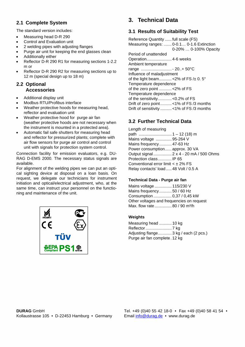
DURAG GmbH Kollaustrasse 105 • D-22453 Hamburg • Germany
Tel. +49 (0)40 55 42 18-0 • Fax +49 (0)40 58 41 54 • Email [email protected] • www.durag.de
2.1 Complete System The standard version includes: • Measuring head D-R 290 • Control and Evaluation unit • 2 welding pipes with adjusting flanges • Purge air unit for keeping the end glasses clean • Additionally either • Reflector D-R 290 R1 for measuring sections 1-2.2
m or • Reflector D-R 290 R2 for measuring sections up to
12 m (special design up to 18 m)
2.2 Optional Accessories
• Additional display unit • Modbus RTU/Profibus interface • Weather protective hoods for measuring head,
reflector and evaluation unit • Weather protective hood for purge air fan
(weather protective hoods are not necessary when the instrument is mounted in a protected area).
• Automatic fail safe shutters for measuring head and reflector for pressurized plants; complete with air flow sensors for purge air control and control unit with signals for protection system control.
Connection facility for emission evaluators, e.g. DU-RAG D-EMS 2000. The necessary status signals are available. For alignment of the welding pipes we can put an opti-cal sighting device at disposal on a loan basis. On request, we delegate our technicians for instrument initiation and optical/electrical adjustment, who, at the same time, can instruct your personnel on the functio-ning and maintenance of the unit.
3. Technical Data
3.1 Results of Suitability Test Reference Quantity ...... full scale (FS) Measuring ranges: ....... 0-0.1… 0-1.6 Extinction
0-20% … 0-100% Opacity Period of unattended Operation...................... 4-6 weeks Ambient temperature range ........................... - 20..+ 50°C Influence of maladjustment of the light beam........... <2% of FS /± 0. 5° Temperature dependence of the zero point ........... <2% of FS Temperature dependence of the sensitivity............ <0.2% of FS Drift of zero point .......... <1% of FS /3 months Drift of sensitivity .......... <1% of FS /3 months
3.2 Further Technical Data Length of measuring path ............................. 1 – 12 (18) m Mains voltage .............. 95-264 V Mains frequency........... 47-63 Hz Power consumption...... approx. 30 VA Output signal ................ 2 x 4 - 20 mA / 500 Ohms Protection class............ IP 65 Conventional error limit < ± 2% FS Relay contacts’ load ..... 48 Volt / 0.5 A Technical Data - Purge air fan Mains voltage ............... 115/230 V Mains frequency........... 50 / 60 Hz Consumption ................ 0,37 / 0,45 kW Other voltages and frequencies on request Max. flow rate ............... 80 / 90 m³/h Weights Measuring head ........... 10 kg Reflector ....................... 7 kg Adjusting flange............ 3 kg / each (2 pcs.) Purge air fan complete . 12 kg

D-R 300 / D-R 300-40 Soot / Dust Concentration Meter
1. Fields of Application Light crude-fired plants of a capacity of above 10 MW are to be equipped with a measuring system, which shall continuously detect flue gas turbidity and with adequate certainty determine the smoke spot numbers (soot). The DURAG D-R 300-40 Dust Concentration Meter is used for continuous measuring of dust emissions in dust extraction channels, flue gas chimneys, etc., and at incineration plants for waste products and similar combustible materials as per BlmSchV # 17. The DURAG D-R 300 / D-R 300-40 meters comply with these requirements. It is installed directly at the flue gas chimney and optically monitors flue gas turbi-dity on a continuous basis. The measured values are registered on a recorder and limit value exceedings are reported without any delay. This permits taking the necessary measures within the regulation system of a furnace plant so as to safeguard realization of the limit values prescribed. 2. Set-up and Mode of Operation The D-R 300 / D-R 300-40 meters work to the stray light method, which makes it extraordinary sensitive even to lowest particle concentrations. Its emission optics shape the modulated light of a long service life-halogen lamp into a cone beam, which in the exhaust gas duct lightens the smoke particles. The receiving optics detect, within a defined measuring volume, the stray light reflected by the smoke particles and map same on the optical sensor. This sensor con-verts the straylight into an intensity-proportional signal current. The stray light’s intensity is proportional to the particle concentration within the measuring volume. The digital evaluation electronics compute the particle concentration from the stray light received and the emitted light’s intensity. The value computed is then indicated in a 4-digit dis-play as a digital value and simultaneously emitted as an analog current signal. The measured result can be calibrated and indicated in smoke spot numbers (soot) (D-R 300) or in mg/m³ (D-R 300-40). The meter’s optics and electronics section is gas and dust-tight on its chimney-adjacent side. The heated optical boundary areas are kept free from soiling through a separate purge air fan. For the purpose of checking its orderly functioning, the meter performs a control cycle in periodical 4hour time lapses, whereby the zero point, the soiling of optical boundary areas as well as a reference value are mea-sured and indicated automatically. If necessary, the subsequent measuring values are corrected. If the correction surpasses a certain value, the system will generate a signal.

DURAG GmbH Kollaustrasse 105 • D-22453 Hamburg • Germany
Tel. +49 (0)40 55 42 18-0 • Fax +49 (0)40 58 41 54 • Email [email protected] • www.durag.de
2.1 Complete System Scope of Delivery: • Measuring Head • mounting flange • terminal box • 1 light trap (2 light traps for smoke spot meter) • 1 purge air fan
2.2 Optional accessories • D-R 300-40: automatic range selection for dust
concentration measurement according to 17. BImSchV
• Weather protective hood for the measuring head • Weather protective hood for the purge air fan
(Weather protective hoods are not necessary when the instrument is mounted in a protected a-rea)
• Automatic fail safe shutter as a protection for the measuring unit in case of an outage of the purge air. Complete with flow sensor for purge air control and control unit with signals for protection system control.
Connection facility for emission evaluators, e.g. DU-RAG D-EMS 2000. The necessary status signals are available. Equipment delivered comes accompanied by extensi-ve documentation on mounting and installation. For alignment of the welding pipe and the light trap we can put an optical sighting device at disposal on a loan basis. On request, we delegate our technicians for instrument initiation and optical/electrical adjustment, who, at the same time, can instruct your personnel on the functioning and maintenance of the unit.
3. Technical Data
3.1 Results of the Suitability Test Reference Quantity ...... Full scale (FS) 9 measuring ranges D-R 300 ........................ Smoke spot No 0-3…0-5 D-R 300-40................... 0-1 to 0-300 mg/m³ with
automatic range swit-ching
Period of unattended operation ...................... approx. 3 months Ambient temperature range ............................ - 20°…+50°C Availability .................... >99% Influence of voltage variation of mains ......... <0.4% of FS / 230 V±10% Temperature dependence of measured values...... <0.7 % of FS / -20…+50°C Drift of zero point .......... <0.4 % of FS / 3 months Time drift of sensitivity.. <0.4 % of FS / 3 months Reproducibility.............. 82…263
3.2 Further technical Data Integration time............. 10…900 s Mains voltage .............. 115 / 230 Volt ±10% Frequency .................... 50 / 60 Hz Power consumption...... approx. 50 VA Output signal ................ 4 - 20 mA / 500 Ohm Protection class............ IP 65 Conventional error limit ± 2% of FS Relays contacts’ load ... 250 Volt / 100 VA Technical data - Purge air fan Mains voltage ............... 115 / 230 V Frequency .................... 50 / 60 Hz Power consumption...... 0.37 / 0.43 kW Other voltages and frequencies on request Air output ...................... 80 / 90 m³/h Weights Measuring head ........... 18 kg Purge air complete ....... 12 kg

D-R 800 Low Dust Concentration Mete
1. Fields of Application The DURAG D-R 800 Dust Concentration and Opacity Meter is used for continuous low and medium dust concentration measuring in flue gas chimneys and dust extraction pipings. Due to the single-side moun-ting without any adjustment work installation is not only simplified but in some inaccessible cases even pos-sible to measure dust concentration. The D-R 800 can be calibrated per iso-kinetic gravi-metric measuring and is applicable in all authorized industrial plants as well as in crematories. Type tested to the guidelines for emission measuring equipment of the Federal Ministry of Environment by TÜV Rheinland Technical Inspection Agency, Test Report # 936/21205307/A of 07.07.2006. Itemized in the list of suitable instruments for continu-ous registration of emissions. Federal Gazette # 194 of 14.10.2006. 2. Set-up and Mode of Operation The D-R 800 measuring device operates according to the forward scattering principle. The concentrated and modulated light of a laser diode (laser protection class II) penetrates the measuring volume. The light scat-tered by dust particles (measurement light) is mainly scattered forwards, therefore the receiving lens is posi-tioned here. The measurement light is time-integrated. The integra-tion time can be set between 5 s and 1800 s. Four measuring ranges are available. All changes of parameter are realised via an incorporated display with key-board. For temperature compensation, a constant can be programmed or an external 4 - 20 mA temperature transmitter can be connected. The averaged and com-pensated measured value is the scattered light (with-out unit). The current outputs are parameterised to the desired measuring range. The measuring ranges can be switched automatically according to 17. BlmSchV.
In order to also display the dust content in milligrams on the D-R 800, a factor and an offset for converting scattered light into mg/m³ must be entered. However, this does not affect the current outputs, limit values etc.. A pollution measurement is performed every 5 min in order to record dust deposits on the optical boundary surfaces and the ageing of the optical elements.

DURAG GmbH Kollaustrasse 105 • D-22453 Hamburg • Germany
Tel. +49 (0)40 55 42 18-0 • Fax +49 (0)40 58 41 54 • Email [email protected] • www.durag.de
2.1 Complete System The standard version includes: • Measuring lance for horizontal or vertical chan-
nels, length of lance 400 or 800 mm, measured from mounting flange
• Flange with pipe • Supply unit incl. purge air fan • 3 m connecting cable • Modbus interface Analogue input for exhaust temperature for temperatu-re standardisation
2.2 Optional Accessories • 10 m connecting cable • Several pipe lengths • Linearity check filters • Wetterschutzhaube für die Messlanze
Die Wetterschutzhaube ist nicht erforderlich, wenn das Gerät in geschützten Räumen montiert wird.
• Weather protective hood for measuring lance Weather protective hood is not necessary when the instrument is mounted in a protected area.
Connection facility for emission evaluators, e.g. DU-RAG D-EMS 2000. The necessary status signals are available.
3. Technical Data
3.1 Results of Suitability Test Reference quantity: ...... full scale (FS) Measuring ranges: ....... 0-16,5 mg/m³ Period of unattended Operation:..................... 4-6 weeks Permissible ambient temperature range: ...... - 20°..+ 50°C Temperature dependence of the zero point: .......... <2,1% of FS Temperature dependence of the sensitivity:........... <1,1% of FS Drift of zero point: ......... <0,3% of FS /3 months Drift of sensitivity: ......... <1,4% of FS /3 months Reproducibility:............. 56
Further Technical Data Measuring range: ......... 0-10 … 0-200 mg/m³ Exhaust temperature:... dew point … 220°C Mains voltage: .............. 85-264 V Mains frequency:.......... 47-63 Hz Power consumption:..... approx. 50 VA Output signal : .............. 2 x 4 - 20 mA/ 500 Ohms Protection class:........... IP 65 Conventional error limit: ± 2% of FS Relay contacts’ load: .... 24 Volt/ 100 VA Dimensions and weight Measuring lance:.......... 160x160x600 (h x w x d) or
rather 1000mm Measuring lance:.......... 7 kg Connection unit: ........... 380x380x210 mm Connection unit: ........... 13 kg Purge air unit Integrated in the connection unit Exhaust gas pressure: . -50 …+10hPa

Combined probe sensor D-RX 250
1. Fields of Application The combination measuring sensing probe D-RX 250 can be deployed after filtering separators (no e-filters) for the continuous monitoring of dust concentration, volume flow, pressure and temperature in dust extrac-tion lines, flue gas channels of power generating plants and the cement industry and in incineration plants for refuse and similar combustible materials in accordance with the German 17. BlmSchV after filte-ring precipitators (no ESP). Thanks to the combination of 4 selected measuring functions in just one device, in addition to the monitor-ing of the pollutant dust, the automatic calculation of the pollutant mass flow for the drawing up of the emis-sion declaration is also possible. For measurements in accordance with TA Luft, 13 ... 17. and 27. BImSchV of the German monitoring scheme. Suitability-tested in accordance with the directives of the German Federal Minister for the Environment, Nature Conservation and Reactor Safety specific to verifying the suitability of measuring installations for continuous emission measurements. Test report no. 936 / 800006 / A of the TÜV Rhineland, Berlin - Bran-denburg dated 25 January, 2001. Itemized in the list of suitable instruments for continuous registration of e-missions. Joint Gazette # 19 of 22.06.2001. 2. Set-up and Mode of Operation Dust concentration The measuring system determines the dust load by means of the tribo-electrical measurement principle. The idea being made use of is that dusts particles in flowing gases carry an electrical charge which is passed on at the time of collision with a sensing probe. In the process, the insulated sensing probe charges and passes its charge current to the electronic hard-ware. On the basis of the measuring principle, this charge current is dependent on the flow velocity and the concen-tration of the dust in the gas. The dust con-centration is calculated from the tribo-electrical meas-urement signal and the flow velocity. The parameters required for this purpose are obtained during a calibra-tion in the typical operating velocity ranges. These
parameters then constitute the basis for the calculation of the concentration. The measurement quantities temperature and pressure, which are also made avail-able by the D-RX 250, are required for calculating the concentration in the standard state. Flow velocity The system for recording the velocity operates in ac-cordance with the differential pressure principle. The probe has 2 chambers separated from each other and between which a differential pressure builds up due to the flow dynamics. The pressure which develops, which is proportional to the square of the gas velocity, is registered by means of a differential pressure trans-mitter and the relevant signal is used for correcting the tribo-electrical value. Absolute pressure The absolute pressure of the waste gas is measured on one tube of the differential pressure transducer and evaluated by a piezo-resistive pressure sensor in the transmitter. Temperature The temperature is measured by means of a PT100 in a separate chamber in the measuring rod of the probe. Probe The sensing probe consists of the measuring rod and the electronic hardware in the measuring head for pre-processing the measured value. The 2-chamber measuring rod of the probe is a sensing profile that protrudes into the dust channel and is attached to the channel with a flange in an insulated fashion. The two chambers for measuring the pressure are connected to a differential pressure transducer. In addition, one of the two chambers is connected to the absolute-pressure transducer in the transmitter. In a third cham-
ber in the middle of the sensing profile, the gas temperature is measured by means of a measuring resis-tor. The probe housing contains the electronic mechanism for pre-processing the measured value. The tem-perature of the
measuring resistor and the tribo-electrical raw value are determined here. The two raw values of the tem-

DURAG GmbH Kollaustrasse 105 • D-22453 Hamburg • Germany
Tel. +49 (0)40 55 42 18-0 • Fax +49 (0)40 58 41 54 • Email [email protected] • www.durag.de
perature and the tribo-electrical signal are transferred digitally to the transmitter. Differential pressure transducer The differential pressure transducer converts the dif-ferential pressure, which developed in the measuring rod of the sensing probe on account of the flowing gas, to a gas velocity quantity value. Transmitter The transmitter provides the supply voltages for the sensing probe and the transducers. It also reads in the raw measurements of these units and, via the RS485 interface, transfers the measurements to the evalua-tion unit. The differential pressure measuring transformer is connected to the transmitter via a two-wire lead. The absolute pressure measuring transformer is situated in the interior of the transmitter housing. Via a tube, it receives the pressure from a chamber of the sensing probe rod. Operating and evaluation unit The operating and evaluation unit reads out the raw measurements from the transmitter. In the unit, the measurement values are offset against the normalised dust concentration or against the normalised volume current. The output of all analogue values is possible via Mod-bus or via 4 - 20 mA signals. The output of all status signals is possible via dry contacts.
2.1 Complete System The standard version includes: • 1 two-chamber circulatory-flow sensing probe (up
to 200°C) with a temperature sensor up to 1 m • 1 mounting flange • 1 differential pressure transformer 2 m connection • 1 transmitter with absolute pressure sensor • 1 operating and evaluation unit incl. mounting disc
2.2 Optional Accessories • Ceramic-mount sensing probe rod for gas tempe-
ratures of up to 350°C • Automatic rewind mechanism 230 V / 50 Hz or 115
V / 60 Hz, changeover cock FL100UH essential • Changeover cock PN 100 (FL 100UH) • Common weather-protection cap for D-RX 250 T
and D, material V2A • Weather-protection cap for the sensing
probe, material V2A • 10 m tube for tube connection, 15x3 mm 3. Technical Data
3.1 Results of Suitability Test Reference Quantity...... full scale (FS) Measuring ranges: ....... 0-15, 0-50 mg/m³
0-30 m³/h
Maintenance interval .... 2 months Temperature dependence of the zero point ........... <1% of FS Temperature dependence of the sensitivity............ <2% of FS Drift of zero point .......... <1% of FS / 3 months Drift of sensitivity .......... <1% of FS / 3 months
3.2 Further Technical Data Measuring ranges Dust concentration ....... 0...10 to 0...500 mg/Nm³ Volume range .............. 0 ... 999,999 Nm³ / h Temperature................. 0 ... 400°C Pressure ...................... 900 ... 1300 hPa Operating conditions Gas temperature .......... 0 ... 200°C, optionally 350°C Gas velocity ................. 0 ... 40 m/s Channel diameter ........ 0.3 to 5 m Gas humidity ................ < 80% rel. moisture Sensing probe D-RX 250 S Gas temperature .......... < 200°C Length of sensing profile ........................... 250, 400, 700 and 1000 mm Ambient operating temperature ................. -20 ... +50°C Material of sensing profile ........................... 1.4571 Mounting ...................... Flange, NW 65 Degree of protection .... IP65 Weight ......................... 8.5 to 9.5 kg Differential pressure measuring transformer
Measurement range .... 0..0.5 – 0..10 hPa Degree of protection .... IP 65 Transmitter D-RX 250 T Ambient operating temperature ................. -20 ...+50°C Measurement output ... RS485, Modbus RTU Voltage supply ............. 85-265 V, 47-63Hz, 10 VA Degree of protection .... IP65 Weight ......................... 4.5 kg Cabling to probe .......... 2 m Operating and evaluation unit D-RX 250 D Ambient operating temperature ................. -20 ... +50°C Integration time ............ 8 s Measurement signal .... 4 x 4 ... 20 mA / 500 ohms,
Modbus RTU Limiting value contact .. 2 relay outputs Status contacts ............ 4 relay outputs Voltage supply ............. 90-264 V, 47-63Hz, 10 VA Degree of protection .... IP65 Cable length to the transmitter ............. < 1000 m Weight ......................... 5 kg

F-904 Extractive Beta Gauge Particulate Monitor
1. Fields of Application • Coal and oil fired power plants • Waste incinerators (urban, industrial and hazar-
dous waste) • Waste water sludge incinerators • Dust monitoring after wet scrubbers • Heavy metal analysis • Small diameter stack monitoring • Particulate monitoring in process applications (bag
houses, etc.) • Transportable version for mobile applications 2. Set-up and Mode of Operation The instrument consists of five main modules: Sample Probe - Sample enters the F-904 through ei-ther a stainless steel or titanium sample probe. These probes are suitable for either direct or diluted sample extraction and are heated. Sample Collection/Measurement Assembly - Once the sample passes through the sample probe, it enters a heated sample line (stainless steel or titanium) and is directed onto a filter tape held in a heated, gas-tight holder. The C-14 sources and Geiger-Muller-Counter-Tube detectors are mounted on the holder outside of the gas stream to ensure even sample deposition on the filter tape. An optional Cover Foil is used to fix and secure the deposited particulates on the tape. Sample Gas Cooler - Once the gas passes through the filter tape, it is routed to a downstream cooler to extract water (and thus allows reporting of dust con-centration on a dry basis). Pump/Mass Flow Controller - A carbon vane rotary pump and Mass flow controller (located downstream of the sample gas cooler) pull the sample stream through the sample probe, collection assembly and cooler at a flow rate of 3 cubic meters per hour. On-Board Computer - All instrument functions are controlled by a powerful on-board plc. This plc also
calculates the particulate concentration value from the gas volume and zero/final radiation absorption diffe-rential. The F-904’s major components are housed in a sturdy cabinet and are easy accessible for periodic inspection and maintenance.

DURAG GmbH Kollaustrasse 105 • D-22453 Hamburg • Germany
Tel. +49 (0)40 55 42 18-0 • Fax +49 (0)40 58 41 54 • Email [email protected] • www.durag.de
3. Technical Data
3.1 Results of Suitability Test Certified Ranges .......... 0-5 to 0-225 mg/Nm3 MTBF ........................... >95 % availability Maintenance intervals.. weekly Lower Detectable Limit <0.3 mg/Nm3 Influence of Barometric Air Pressure on Measuring Signal .... none Sample Gas Flow ........ controlled Temperature Range..... -20°C to +50°C( -4 to 122°F)
depending on installed options Total Error .................... <±5% F.S. Zero Temperature Drift <2,5% of Measuring Range Sensitivity Temperature Drift......... <1,5% of Measuring Range Zero Drift ...................... automatic zero control Span Drift ..................... <1% F.S. / Week
3.2 Further Technical Data Ranges ......................... selectable between
0-1 and 0-2000 mg/Nm3 Power Supply ............... 230 V / 380 V - 50 Hz,
+10/-15%, 5 kVA Power Required ........... 4-7 kVA, depending on
Sample System Startup Time................. <30 min Signal Output................ 4-20 mA, Status Signals Measuring Value Display.......................... in mg/Nm3 Status Signals .............. potential free
Switching Contacts Dimensions (H x W x D) 2050 x 800 x 800 mm
(81x31x31“) Weight .......................... 350 kg (770 lbs.) Pressurized Air ............. 6 bar, Instrument Air

HM-1400 TR Total Mercury Analyzer
1. Fields of Application Stack gas as emission sources of mercury (f.e. waste incinerators) contain Mercury in various forms: Mer-cury Vapor (Hg0), Mercury Compounds (inorganic and / or organic compounds, Hg1+, Hg2+), Mercury Particu-lates (sublimated mercury compounds) and Mercury adsorbed on Particulates. The proportion of the indi-vidual forms varies over a wide range and is depend-ent on both the input to the entire plant, as well as the actual operating characteristics (incineration tempera-ture, scrubbers, etc.). That is why measuring total Mercury gives a clear picture of the Mercury emission. Typical applications are: • Waste, Hazardous Waste and Sewage Sludge
Incinerators, Crematories • Steel Plants (Scrap Metal Preparation) • Contaminated Soil Burning Plants and other Re-
cycling Plants • Mercury Mines and Refineries • Coal Fired Power Plants 2. Set-up and Mode of Operation VEREWA’s HM-1400 TR Total Mercury Analyzer uses a combination of thermal and chemical treatment of the sample gas in order to make sure all Mercury forms are transformed into elemental Mercury (Hg0). This elemental Mercury is then measured continuously in a specific photometer. The flow control is located downstream the sample gas pump in the gas stream, which has already passed a sample gas chiller at 2°C (36°F); the concentration is calculated and reported on „dry basis“ standardized on 1013 hPa and 273,15 K. The only known spectrometric interferences are UV-absorption of aromatics, SO2 and NO2. Using a Dual-
Beam UV detector and a Mercury selective gold trap VEREWA’s HM-1400 TR Total Mercury Analyser does not show any interference! Adjusting the HM 1400 TR is easy by using the calibration module. The HM-1400 TR extracts a constant flow out off the stack through a stainless steel and heated sample probe. A heated PTFE sample line connects the probe with the main cabinet. To avoid surface reactions be-tween Mercury and tubing material only PTFE, glas and stainless is used. Each component of the HM 1400 TR that comes in touch with ionic Mercury is heated up to 360°F (180°C). After passing the particle filter in the probe the sample gas enters the thermo-catalytic converter which trans-forms all incoming Mercury in elemental Mercury. This converter works at around 600°F (300°C). The sample

DURAG GmbH Kollaustrasse 105 • D-22453 Hamburg • Germany
Tel. +49 (0)40 55 42 18-0 • Fax +49 (0)40 58 41 54 • Email [email protected] • www.durag.de
gas is then physically dried and measured in a dual beam UV detector. The thermo-catalytic reactor uses carbon containing material - its surface is specially treated with a mixture of hydroxides and carbonates. The basic surface of this converter absorbs also acid stack compounds like SO2 or NOx especially at the working temperature of around 660°F. Therefore the HM 1400 TR Total-Mercury-Analyzer shows no SO2 interference up to 3,500 ppm SO2. The UV-Photometer is protected by a watchdog which shuts down all pumps immediately. The Hg-specific UV-Photometer measures Mercury vapour at 253.7 nm the main resonance wavelength of Mercury. The sample gas matrix cleaned from mercury is used as reference gas. The HM 1400 TR is controlled by an internal PLC. A display driven by the PLC shows the Mercury concen-tration and stores failure messages. Pass word protec-tion should avoid operating errors.
3. Technical Data
3.1 Results of Suitability Test Equivalent Range......... 0 - 45 μg / Nm3
MTBF ........................... >95% Rate of Maintenance (min.) ...... 4 weeks Lower Detectable Limit. <0,6 μg / Nm3 Influence of Barometric Air Pressure on Measuring Signal .... none Sample Gas Flow......... 100 NI / h Temperature Range ..... +5°C to + 30°C Zero Temperature Drift. <1% of Measuring Range Sensitivity Temperature Drift ......... <2% of Measuring Range Zero Drift ...................... <1.5% F.S. / month Span Drift ..................... <2% F.S. / month Zero Drift ...................... <1.5% F.S. / month Lag Time ...................... <180 s Reproducibility.............. 122 at 0- 5 µg/m³
114 at 5-10 µg/m³ >70 at 10-45 µg/m³
3.2 Further Technical Data Range........................... 0 - 45 to 0 - 500 μg / Nm3,
selectable (higher ranges avai-lable with dilution or option)
Power Supply ............... 230 V / 50 Hz, +10 / -15%, approx. 2.3 KVA
Startup Time................. 120 min Signal Output................ 4 - 20 mA, RS 232 Displayed concentration................ in μg / Nm3 dry basis Status Signals .............. dry contacts Dimensions (HxWxD)... 1600 x 800 x 500 mm
(55.1 x 45.3 x 23.6“) Weight .......................... 250 kg (approx. 550 lbs.) Sampling System ......... SP 2000 manufactured by
M & C Mercury Vapor Monitor. UV-Dual-Beam-Detector
(253.7 nm), CVAAS

Emission monitoring analyzer for nitrogen oxides
CLD 700 EL ht Chemiluminescence Analyzer The two-channel nitrogen oxides analyzer can measure hot, moist sample gas directly from the source and displays the precise NO, NOx and NO2 values. 1. Application range
Commercial testing and measurement services Marine engine manufacturing Generators Incinerators Research and development Metal processing industry
At a glance Approved (13. and 17. BimSchV) Heated sample inlet Pressure regulated None zero point drift Error messages in full text and codes
2. Construction and method of operation Sample gas is drawn into the analyzer and mixed with internally produced ozone. this causes the following reaction:
[1] NO + O3 → NO2* + O2 [2] NO + O3 → NO2 + O2
Only about 20% of the NO2 goes into the exited state NO2* in reaction [1]. This NO2* reverts back to the round state NO2 [3] while emitting electromagnetic radiation:
[3] NO2* → NO2 + Light The radiation emission is in the wave length between 600 – 3000 nm, with an intensity maximum at approx. 1200 nm. This chemiluminescence signal is detected photoelectrically. When O3 is present in excess the signal is proportional to the NO-concentration of the sample gas. In order to measure NO2 in the sample gas, it has first to be converted into NO. To accomplish this reduction the sample gas is passed through a converter. Modern converters usually contain metallic active material which allows better selectivity of NO2. Since sample gas normally contains both NO and NO2, it is possible to measure the sum [NO] + [NO2] = [NOx] in the converter channel. If at the same time NO is measured (without converter) by bringing the sample gas directly into the second reaction chamber the difference [NOx] - [NO] = [NO2] gives the correct NO2 concentration.
Simultaneous NO and NOx measurement is guaranteed by the two chamber construction. The sample gas is divided into two equal streams: One stream flows into the NOx reaction chamber via the converter (NOx-channel). The second gas stream flows directly into the NO reaction chamber (NO-channel). A hot subject. Thanks to the unique «hot tubing», hot gas can be fed to the CLD 700 EL ht directly from the source. Immediately downstream of the hot tubing, the sample gas pressure is reduced to below atmospheric pressure, ensuring that no condensation takes place within the instrument. As a result no damage or inaccuracies occur due to the water vapour in the sample gas. In most applications it is not necessary to use the otherwise customary sample gas cooler. The EL ht possesses two parallel reactions chambers which permit simultaneous measurement and display of NO, NOx as well as NO2. Pressure variations which occur in the sample flow are regulated by a refined, motorized bypass system. The remaining error is compensated for digitally. By virtue of its measurement performance and technical capabilities, this analyzer satisfies the highest standards whilst leaving nothing to be desired in terms of ease of maintenance. Approved by TÜV Bayern Report 155 3755, March 1992

3. Specifications 3.1 Performance test facts
Measuring ranges under test 0 - 100 ppm, 0 - 500 ppm (field test) Availability > 99,5 % Clearance of maintenance 2 weeks Minimum detectable concentration 0,32 ppm Allowed range of ambient Temperature +5 °C to +40 °C Thermal sensitivity of zero point < + 0,4 % / 10 K Thermal sensitivity of span < - 2,9 % / 10 K Quenching Zero point: < -0,7 %
Sensitivity: < - 1,5 % Response time (incl. sample conditioner) < 38 s Temporally change of zero indication < 0,5 % FS Temporally change of sensitivity < 2,0 % FS Reproducibility measuring range 100: 36, m. r. 500: 156 3.2 Other technical data Sample gas flow 1,2 l/min Dry air use for ozonator 0,55 l/min ambient air Analogue outputs selectable 1 V/10 V at 500 kOhm
selectable 0/4 - 20 mA Digital interface RS 232 Power requirement 230 Volt 50 Hz Power consumption 660 VA Weight 40 kg Dimensions (h, w, d) 3 HU (133 mm), 19" (483 mm), 588 mm
ECO PHYSICS GmbH Umwelt- und Prozess-Messtechnik Schleißheimer Straße 270 b DE-80809 München
Telefon 089 307667 0 Telefax 089 307667 29 E-Mail [email protected] Web www.ecophysics.de

Emission monitoring analyzer for nitrogen oxides
CLD 822 M h Chemiluminescence Analyzer The solution for simultaneously measured NO and NOx has got a name: CLD 822 M h. The heated inlet copes with hot and humid gas samples – no gas cooler required! 1. Application range
Commercial testing and measurement services Burners and Boilers Generators DeNOx plants Research and development Refining of fuel and lubricants
At a glance
Approved (13. and 17. BimSchV) Heated sample inlet Compact design Error messages in full text and codes Easy system integration Virtually maintenance-free operation even in
continuous operation
2. Construction and method of operation Sample gas is drawn into the analyzer and mixed with internally produced ozone. this causes the following reaction:
[1] NO + O3 → NO2* + O2 [2] NO + O3 → NO2 + O2
Only about 20% of the NO2 goes into the exited state NO2* in reaction [1]. This NO2* reverts back to the round state NO2 [3] while emitting electromagnetic radiation:
[3] NO2* → NO2 + Light The radiation emission is in the wave length between 600 – 3000 nm, with an intensity maximum at approx. 1200 nm. This chemiluminescence signal is detected photoelectrically. When O3 is present in excess the signal is proportional to the NO-concentration of the sample gas. In order to measure NO2 in the sample gas, it has first to be converted into NO. To accomplish this reduction the sample gas is passed through a converter. Modern converters usually contain metallic active material which allows better selectivity of NO2. Since sample gas normally contains both NO and NO2, it is possible to measure the sum [NO] + [NO2] = [NOx] in the converter channel. If at the same time NO is measured (without converter) by bringing the sample gas directly into the second reaction chamber the difference [NOx] - [NO] = [NO2] gives the correct NO2 concentration. Simultaneous NO and NOx measurement is guaranteed by the two chamber construction. The sample gas is divided into two equal streams: One stream flows into the
NOx reaction chamber via the converter (NOx-channel). The second gas stream flows directly into the NO reaction chamber (NO-channel). A fascinating technology. The analyzer is not only a state-of-the-art product in terms of precision and reliability. Its technological base also sets the trend for others. The integrated hot tubing (h) allows the direct measurement of hot and moist gases. The advantage of compact design: the CLD 822 M h includes everything inside the case – even the vacuum pump and the ozone scrubber. Two instead of one. The CLD 822 M h nitrogen oxide analyzer is optimized for its use in systems which require reliable NO2 measurements or the control of two sample gases in parallel. The outstanding feature is the concept of two parallel reaction chambers. They guarantee simultaneous measurement of NO and NOx in order to generate the precise value of NO2. Approved by TÜV Süd Industrie Service: Report 555 720, December 2005

3. Specifications 3.1 Performance test facts
Measuring ranges under test 0 – 100/ 200 mg/m3 or 0 – 75/ 150 ppm Availability > 98 % Clearance of maintenance 3 weeks Minimum detectable concentration < 0,25 mg/m3 Allowed range of ambient Temperature +5 °C to +40 °C Thermal sensitivity of zero point < +/- 4 % FS Thermal sensitivity of span < +/- 4 % FS Quenching Zero point: max. pos.: +0,4 %, max. neg.: -0,1 % FS
Reference point: max. pos.: +1,3 %, max. neg.: -2,7 % FS Response time (incl. sample conditioner) < 160 s Temporally change of zero indication max. 1 % FS Temporally change of sensitivity max. 3 % FS Reproducibility min. 46 3.2 Other technical data Sample gas flow 0,1 l/min Dry air use for ozonator 0,4 l/min ambient air Analogue outputs selectable 1 V/10 V at 500 kOhm
selectable 0/4 - 20 mA Digital interface RS 232 Power requirement 90 – 250 Volt/ 50 – 60 Hz Power consumption 400 VA Weight 21 kg Dimensions (h, w, d) 3 HU (133 mm), 19" (483 mm), 588 mm
ECO PHYSICS GmbH Umwelt- und Prozess-Messtechnik Schleißheimer Straße 270 b DE-80809 München
Telefon 089 307667 0 Telefax 089 307667 29 E-Mail [email protected] Web www.ecophysics.de
Emission monitoring analyzer for nitrogen oxides
CLD 82 M h Chemiluminescence Analyzer The CLD 82 M h NOx analyzer is the ideal instru-ment for series checks. It is distinguished by high precision and reliable, continuous operation. 1. Application range
Commercial testing and measurement services Burners and Boilers Generators DeNOx plants Research and development Refining of fuel and lubricants
At a glance
Approved (13. and 17. BimSchV) Heated sample inlet Compact design Error messages in full text and codes Easy system integration Virtually maintenance-free operation even in
continuous operation
2. Construction and method of operation Sample gas is drawn into the analyzer and mixed with internally produced ozone. this causes the following reaction:
[1] NO + O3 → NO2* + O2 [2] NO + O3 → NO2 + O2
Only about 20% of the NO2 goes into the exited state NO2* in reaction [1]. This NO2* reverts back to the round state NO2 [3] while emitting electromagnetic radiation:
[3] NO2* → NO2 + Light The radiation emission is in the wave length between 600 – 3000 nm, with an intensity maximum at approx. 1200 nm. This chemiluminescence signal is detected photoelectrically. When O3 is present in excess the signal is proportional to the NO-concentration of the sample gas. In order to measure NO2 in the sample gas, it has first to be converted into NO. To accomplish this reduction the sample gas is passed through a converter. Modern converters usually contain metallic active material which allows better selectivity of NO2. Since sample gas normally contains both NO and NO2, it is possible to measure the sum [NO] + [NO2] = [NOx] in the converter channel. If at the same time NO is measured (without converter) by bringing the sample gas directly into the second reaction chamber the difference [NOx] - [NO] = [NO2] gives the correct NO2 concentration. Simultaneous NO and NOx measurement is guaranteed by the two chamber construction. The sample gas is divided into two equal streams: One stream flows into the
NOx reaction chamber via the converter (NOx-channel). The second gas stream flows directly into the NO reaction chamber (NO-channel). Simply ingenious. The CLD 82 M h single channel nitrogen oxide analyzer is designed for all applications with an existing gas preconditioning unit to ensure quality control as well as keeping to threshold values. The design is remarkably compact. All components, even the vacuum pump and the thermal ozone scrubber, are contained in one single unit. In spite of its simple construction the high ECO PHYSICS standard is fully complied with. The instrument includes a temperature stabilized photo multiplier and a high performance ozone generator. Thanks to its completely modular interior the analyzer is easy to service. Approved by TÜV Süd Industrie Service: Report 555 720, December 2005

3. Specifications 3.1 Performance test facts
Measuring ranges under test 0 – 100/ 200 mg/m3 or 0 – 75/ 150 ppm Availability > 98 % Clearance of maintenance 3 weeks Minimum detectable concentration < 0,25 mg/m3 Allowed range of ambient Temperature +5 °C to +40 °C Thermal sensitivity of zero point < +/- 4 % FS Thermal sensitivity of span < +/- 4 % FS Quenching Zero point: max. pos.: +0,4 %, max. neg.: -0,1 % FS
Reference point: max. pos.: +1,3 %, max. neg.: -2,7 % FS Response time (incl. sample conditioner) < 160 s Temporally change of zero indication max. 1 % FS Temporally change of sensitivity max. 3 % FS Reproducibility min. 46 3.2 Other technical data Sample gas flow 0,1 l/min Dry air use for ozonator 0,4 l/min ambient air Analogue outputs selectable 1 V/10 V at 500 kOhm
selectable 0/4 - 20 mA Digital interface RS 232 Power requirement 90 – 250 Volt/ 50 – 60 Hz Power consumption 400 VA Weight 21 kg Dimensions (h, w, d) 3 HU (133 mm), 19" (483 mm), 588 mm
ECO PHYSICS GmbH Umwelt- und Prozess-Messtechnik Schleißheimer Straße 270 b DE-80809 München
Telefon 089 307667 0 Telefax 089 307667 29 E-Mail [email protected] Web www.ecophysics.de

Dr. Födisch Umweltmesstechnik
AG
Filter controller PFM 92
1. Fields of application 2. Construction and operation
The filter controller PFM 92 serves the qualitative monitoring of dusty emissions. In particular it is often used for the determination of the clean gas dust content behind de-dusting facilities.
Construction material industry, chemical industry as well as metallurgical industry are especially in the focus. However, food industry and wood-processing industry get an increasing importance, too. Apart from proving the observance of limit values it allows the monitoring of product losses in the exhaust gas. The Filter controller PFM 92 is approved according to TI Air.
The measuring principle is based on the use of the triboelectric effect (charge transfer at colliding or passing of particles on conducting surfaces).
ProbeProbe rod
Insulator
The filter controller consists of an isolated probe which is installed in the clean gas channel. The charge transferred by contact and triboelectric processes is derived as current, converted, amplified and provided as standard signal 4 ... 20 mA. Via a limit value detector the exceeding of the allowable emission limit value can be signalised. The equipment is operated by a separate control unit.

Dr. Födisch Umweltmesstechnik
AG
Contact: Dr. Födisch Umweltmesstechnik AG Tel.: +49(0)34205-755-0 Zwenkauer Straße 159 Fax: +49(0)34205-755-40 D-04420 Markranstädt Web: www.foedisch.de Germany Mail: [email protected]
3. Technical data
3.1 Data of suitability test
Test report No.: 936/805016 dated 29.02.1996
Suitability: for qualitative monitoring of dust emissions
Smallest measuring range: 0 ... 50 mg/m³
3.2 General technical data
Control unit: weather-proof aluminium case IP 65, Dimensions: 210 x 240 x 280 mm (H x W x D)
Probe: stainless steel probe rod with pre-amplifier in the probe head, probe length 300 mm (adjustments possible), IP 65
Measuring principle: dust: measurement with 1 triboelectric sensor
Measuring range: 0,1 ... 1.000 mg/m³ (special measuring ranges on demand)
Calibration: by gravimetric reference measurements
Display: LCD-Display (0 ... 100 %)
Media temperature: max. 280 °C
Ambient temperature: -20 ... +50 °C
Dew point difference: min. +5 K
Flow velocity: from appr. 3 m/s
Analogue signals: 1 x 4 ... 20 mA (dust)
Digital signals: 3 potential-free contacts (failure, limit value 1 and 2)
Power supply: 110 VAC, 230 VAC or 24 VAC, 24 VDC
Installation: control unit: wall assembly probe: 1"-sleeve (DIN 2986) optionally flange DN 25 PN 6
Special configurations: • for explosive areas (dust) • high temperature design (max. 500 °C exhaust gas temperature) • mobile filter controller
Suitability test: TI-Air

Dr. Födisch Umweltmesstechnik
AG
Gas analyser MCA 04
1. Fields of application 2. Construction and operation
The gas analyser MCA 04 can be used in emission measuring facilities as well as in systems of process and analysis measuring technology. It is not only suited for the use on raw and clean gas side but also as process measuring device in the same manner.
Application fields are e.g.:
• Power plants • Waste incinerations • Refineries • Cement industry • Industrial exhaust air
The gas analyser MCA 04 is approved according to TI Air, 13th, 17th and 27th BImSchV.
By means of the gas analyser MCA 04 8 gas components can be measured at the same time: maximum 7 infrared-active gases (e.g. CO, NO, NO2, SO2, HCl, NH3, H2O, CO2) and O2 with an extractive zirconium oxide cell. The following measuring principles are used: Single-Beam Dual-Wavelength Method The spectral ranges are selected by alternately inserting the interference filters for absorption (measuring filter I) and non-absorption (reference filter Io). The electronics of the MCA 04 calculates I and Io with the absorbance value A and determines the concentration value.
Meas. filter
Reference filter
IR Source Meas. cell
Gas filter correlation When the gas filter correlation method is employed, the reference signal Io, which is independent from the concentration, is generated by inserting a gas filter in the light path. This gas filter is a miniature cell filled with the measuring component under high partial pressure. Measuring signal I, which is dependent on the concentration, is obtained by inserting an empty filter wheel aperture into the beam path
Gas filter
Interferencefilter
Free aperture
IR Source Meas. cell

Dr. Födisch Umweltmesstechnik
AG
Contact: Dr. Födisch Umweltmesstechnik AG Tel.: +49(0)34205-755-0 Zwenkauer Straße 159 Fax: +49(0)34205-755-40 D-04420 Markranstädt Web: www.foedisch.de Germany Mail: [email protected]
3. Technical data
3.1 Data of suitability test
Test report No.: 936/21203173/A dated 13.07.2005
Suitability: For installations according to TI Air, 13th, 17th and 27th BImSchV
Smallest measuring ranges: CO: 0 ... 75 mg/m³ NO: 0 ... 200 mg/m³ SO2: 0 ... 75 mg/m³ HCl: 0 ... 15 mg/m³ H2O: 0 ... 40 Vol.-% NH3: 0 ... 30 mg/m³ O2: 0 ... 25 Vol.-% CO2: 0 ... 20 Vol.-%
0 ... 300 mg/m³ 0 ... 395 mg/m³ 0 ... 300 mg/m³ 0 ... 90 mg/m³
3.2 General technical data
Case: 19"-rack, 4 HU, dimensions 665 x 440 x 360 mm (B x H x T), ca. 40 kg, IP 52
Measuring principle: CO, NO, NO2, SO2, HCl, NH3, H2O, CO2: Infrared absorption (single-beam dual-wavelength method respectively gas filter correlation) O2: ZrO2-cell
Smallest measuring ranges: CO: 0 ... 75 mg/m³, NO: 0 ... 200 mg/m³, NO2: 0 … 100 mg/m³, SO2: 0 ... 75 mg/m³, HCl: 0 … 15 mg/m³, NH3: 0 … 15 mg/m³, H2O: 0 … 40 Vol%; CO2: 0 … 20 Vol%, O2: 0 ... 21 Vol%
Calibration: zero point: automatically with ambient air; sensitivity: with test gas
Display: 7.4" black/white LC-Display (640*480 Pixel)
Media temperature: max. 200 °C
Ambient temperature: +5 ... +35 °C
Interfaces: RS 232, optionally MOD-Bus
Analogue signals: max. 8 x 4 ... 20 mA
Digital signals: D/O: for failure, maintenance, maintenance request and measuring range signalisation available (230 V, 1 A)
Digital inputs: Optionally for analogue and digital signals
Power supply: 110 VAC, 230 VAC
Suitability test: TI Air, 13th, 17th and 27th BImSchV

Dr. Födisch Umweltmesstechnik
AG
Gas analyser MGA 23
1. Fields of application 2. Construction and operation
The gas analyser MGA 23 can be used in emission measuring facilities as well as in systems of process and analysis measuring technology. Application fields are e.g.:
• monitoring of exhaust gas concentration from firing systems
• operational measurements in thermal incineration plants
• optimisation of small firing systems • room air monitoring • monitoring of process control functions
For measurements of CO, NO, SO2 and O2 according to 13th respectively 27th BlmSchV and TI Air TÜV-approved versions of the MGA 23 are available.
By means of the gas analyser MGA 23 up to 4 gas components can be measured at the same time: maximum 3 infrared-active gases as e.g. CO, CO2, NO, SO2, CH4, R22 (Frigen CHCIF2) as well as O2 with an electrochemical measuring cell. The following measuring principles are used: Infrared measurement NDIR This spectroscopic method is based on the absorption of non-dispersive IR radiation. The attenuation in the radiation which depends on the wavelength is a measure of the respective concentration of the gas. Oxygen measurement
M
12
3
4
5
6
12
10
9
8
7
11
9
9
Sample gasoutlet
Sample gasinlet
123456
CapillarySecond detector layerMicroflow sensorSample cellChopper wheelChopper motor
789101112
IR sourceReflectorWindowSlideFirst detector layerThird detector layer
4
e-
U
1
2
3
6
5
Sample gas
123
Gold cathodeElectrolythe (acetic acid)Thermistor and loadresistor for temperaturecompensation
456
Signal outputLead anodeOxygen diffusionmembrane made of FEP
The oxygen sensor operates according to the principle of a fuel cell. The oxygen is converted at the boundary layer between the cathode and electrolyte; the resulting current is proportional to the concentration of oxygen. The MGA 23 with 2 IR-components without pump and optionally oxygen is also available with 2 separate gas paths. This allows the measurement of 2 measuring points or e.g. in case of NOx-measurement the state before and after converter.

Dr. Födisch Umweltmesstechnik
AG
Contact: Dr. Födisch Umweltmesstechnik AG Tel.: +49(0)34205-755-0 Zwenkauer Straße 159 Fax: +49(0)34205-755-40 D-04420 Markranstädt Web: www.foedisch.de Germany Mail: [email protected]
3. Technical data
3.1 Data of suitability test
Test report No.: 24012833 dated 18.02.1999 (basic report dated 08.08.1997)
Suitability: for installations according to TI Air, 13th BImSchV
Smallest measuring ranges: CO: 0 ... 150 mg/m³ NO: 0 ... 250 mg/m³ SO2: 0 ... 400 mg/m³ O2: 0 ... 10/25 Vol.-%
3.2 General technical data
Case: 19"-rack, 4 HU, dimensions 177 x 483 x 339 mm (W x H x D), 10 kg, IP 21
Measuring principle: CO, CO2, NO, SO2, CH4, R22 (Frigen CHCIF2): infrared absorption O2: electro-chemical measuring cell
Smallest measuring ranges: 1- and 2-components-analysers: CO: 0 ... 150 mg/m³, NO: 0 ... 250 mg/m³, SO2: 0 ... 400 mg/m³, O2: 0 ... 25 Vol%
Calibration: automatic calibration with ambient air resp. N2
Display: LCD with LED-back-light and contrast regulation, functional keys, 80 characteristics (4 lines/20 characteristics)
Media temperature: 0 ... 50 °C
Ambient temperature: +5 ... +45 °C
Interfaces: RS 485, optionally Profibus
Analogue signals: max. 4 x 4 ... 20 mA
Digital signals: 8 potential-free contacts
Digital inputs: 3 potential-free contacts
Power supply: 110 VAC, 230 VAC
Suitability test: TI Air, 13th and 27th BImSchV

Dr. Födisch Umweltmesstechnik
AG
Compact filter controllers PFM 92 C / PFM 02
PFM 92 C PFM 02
1. Fields of application 2. Construction and operation
In these days the operation of a modern filter facility can be rarely realised without permanent control of dust emissions. This is not only relevant for the responsible authorities but also for operators themselves getting profits from important advantages:
• Emission measurement and filter monitoring by means of only 1 device
• Avoidance of visible exhaust gas plumes • Simplification of maintaining filter facilities
due to early detection of beginning filter wearing, localisation of defective filter elements and membrane valves as well as possibility for systematic maintenance works
• Avoidance of product losses The compact filter controllers PFM 92 C and PFM 02 are approved according to TI Air (PFM 02 also for 27th BImSchV).
The measuring principle is based on the use of the triboelectric effect (charge transfer at colliding or passing of particles on conducting surfaces).
ProbeProbe rod
Insulator
The filter controller consists of an isolated probe which is installed in the clean gas channel. The charge transferred by contact and triboelectric processes is derived as current, converted, amplified and provided as standard signal 4 ... 20 mA. Via a limit value detector the exceeding of the allowable emission limit value can be signalised.
Compressedair
Raw gas
Pure gas
Dust measuring devicePFM 02

Dr. Födisch Umweltmesstechnik
AG
Contact: Dr. Födisch Umweltmesstechnik AG Tel.: +49(0)34205-755-0 Zwenkauer Straße 159 Fax: +49(0)34205-755-40 D-04420 Markranstädt Web: www.foedisch.de Germany Mail: [email protected]
3. Technical data
3.1 Data of suitability test
PFM 92 C (report No. 936/808005/A dated 14.08.1998)
PFM 02 (report No. 936/21200495/B dated 29.07.2003)
Suitability: for qualitative monitoring of dust emissions
Smallest measuring range: 0 … 50 mg/m³
3.2 General technical data
PFM 92 C PFM 02
Control unit: complete electronic in the probe head – no separate control unit
Probe:
round stainless-steel probe rod at the probe head, complete electronic in the probe head – no separate control unit, probe length 300 mm (adjustments possible), IP 65
stainless-steel probe rod (turnable and exchangeable) at the probe head, probe length 300 mm (adjustments possible), IP 65
Measuring principle: dust: measurement with 1 triboelectric sensor
Measuring range: 0,1 ... 1.000 mg/m³ (special measuring ranges on demand)
0 ... 100 % or 0 ... 10 (1.000) mg/m³
Calibration: by gravimetric reference measurements
Display: none Graphic display with online line diagram
Media temperature: max. 280 °C
Ambient temperature: -20 ... +50 °C
Dew point difference: min. +5 K
Flow velocity: from appr.. 3 m/s
Analogue signals: 1 x 4...20 mA (dust) 1 x 4...20 mA, galvanically isolated
Digital signals: 3 potential-free contacts (failure, limit value 1 and 2)
3 potential-free contacts (failure/maint., limit value 1 and 2/maint. request)
Power supply: 110 VAC, 230 VAC or 24 VAC, 24 VDC 110 VAC, 230 VAC or 24 VDC
Installation: probe: 1"-sleeve (DIN 2986) optionally flange DN 25 PN 6
Special configurations: for explosive areas (dust)
Suitability test: TI Air TI Air, 27th BImSchV

Dr. Födisch Umweltmesstechnik
AG
Extractive dust measuring device PFM 97 ED
1. Fields of application 2. Construction and operation
The PFM 97 ED is used for the dust concentration measurement in wet gases. Furthermore it can be applied sticky types of dust. Application fields are e.g.:
• chip board production, • urea industry, • insulating material production, • behind wet scrubber and • similar applications.
The dust measuring device PFM 97 ED is approved according to TI Air, 13th, 17th and 27th BImSchV.
The PFM 97 ED consists of a special sampling probe, a gas conditioning (dilution, temperature regulation), a triboelectric measuring cell, an injector, two side channel blowers and an electronic evaluation unit.
By means of a temperature-regulated probe the measuring gas is extracted from the process and led to the measuring chamber where the triboelectric dust sensors are located. In order to produce evaluable measuring signals and to protect the triboelectric measuring cell respectively the gas paths of the measuring device the measuring gas sucked off is continuously heated and diluted with dry and dust-free ambient air. The principle of the dust measurement applied is based on the triboelectric effect. Therefore 2 electrically isolated half-shells are arranged in a cylindric chamber (measuring cell). It’s passed by the conditioned measuring air. The arising sensor signals are converted into equivalent dust signals in the electronic of the control unit.

Dr. Födisch Umweltmesstechnik
AG
Contact: Dr. Födisch Umweltmesstechnik AG Tel.: +49(0)34205-755-0 Zwenkauer Straße 159 Fax: +49(0)34205-755-40 D-04420 Markranstädt Web: www.foedisch.de Germany Mail: [email protected]
3. Technical data
3.1 Data of suitability test
Test report No.: 936/801001/A dated 06.08.2001
Suitability: for installations according to TI Air, 13th, 17th and 27th BImSchV
Smallest measuring ranges: 0 - 15 mg/m³ 0 - 45 mg/m³
3.2 General technical data
Control unit: steel-sheet case mounted on profile frame (incl. blower)
Probe: extractive sampling with GRP weather protection case
Measuring principle: dust: redundant measurement with 2 triboelectric sensors
Measuring ranges: dust i.O.: 0 ... 15 (max. 500) mg/m³
Calibration: by gravimetric dust measurements
Display: 4-lines LCD-Display
Media temperature: max. 280 °C (higher temperatures on request)
Ambient temperature: -20 ... +50 °C
Dew point difference: min. +5 K
Flow velocity: independent
Analogue signals: 5 x 4 ... 20 mA, (including 2 x dust, temperature, flow) , galvanically isolated
Digital signals: 6 potential-free contacts (failure, maintenance, limit value 1 and 2 / maintenance request, measuring range)
Power supply: 400 VAC, 50 Hz, 3~
Installation: Control unit: wall assembly or floor mounting / frame Probe: special flange DN 80, PN 6, Di=100 mm
Suitability test: TI Air, 13th, 17th and 27th BImSchV

Dr. Födisch Umweltmesstechnik
AG
Dust measuring devices PFM 97 W / PFM 02 V
PFM 97 W PFM 02 V (in combination with FMD 02)
1. Fields of application 2. Construction and operation
Potential application fields for the dust concentration measuring devices PFM 97 W and PFM 02 V are in cement industry, power plants, combustion plants as well as in most diverse sectors of the chemical and metallurgical industry. Dust concentration under operational conditions and standard conditions as well as exhaust gas velocity and exhaust gas temperature are available as analogue 4…20mA signals. The dust measuring devices PFM 97 W and PFM 02 V are approved according to TI Air, 13th, 17th and 27th BImSchV.
The measuring principle is based on the use of the triboelectric effect (charge transfer at colliding or passing of particles on conducting surfaces).
Flow profile
Pt100Dust probes
∆p-Transmitter
Valves
Terminal case
The special probe of the PFM 97 consists of 2 tribo probes and a dynamic pressure probe: The tribo probes collect redundantly the raw signal of the dust concentration. In order to correct the velocity influence at the triboelectric measurement the gas velocity is measured by means of a dynamic pressure probe. The simultaneous determination of the gas temperature allows the calculation of the dust concentration in standard state. The device PFM 02 V is a combination of the dust measuring probe PFM 02 and an approved flow measuring device (e.g. FMD 02).
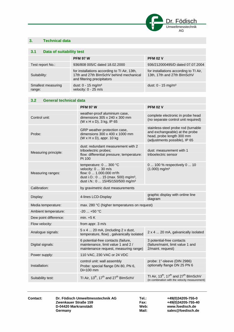
Dr. Födisch Umweltmesstechnik
AG
Contact: Dr. Födisch Umweltmesstechnik AG Tel.: +49(0)34205-755-0 Zwenkauer Straße 159 Fax: +49(0)34205-755-40 D-04420 Markranstädt Web: www.foedisch.de Germany Mail: [email protected]
3. Technical data
3.1 Data of suitability test PFM 97 W PFM 02 V
Test report No.: 936/808 005/C dated 18.02.2000 936/212000495/D dated 07.07.2004
Suitability: for installations according to TI Air, 13th, 17th and 27th BImSchV behind mechanical and filtering precipitators
for installations according to TI Air, 13th, 17th and 27th BImSchV
Smallest measuring range:
dust: 0 - 15 mg/m³ velocity: 0 - 25 m/s
dust: 0 - 15 mg/m³
3.2 General technical data PFM 97 W PFM 02 V
Control unit: weather-proof aluminium case, dimensions 305 x 240 x 300 mm (W x H x D), 3 kg, IP 65
complete electronic in probe head (no separate control unit required)
Probe: GRP weather protection case, dimensions 300 x 400 x 1000 mm (W x H x D), appr. 10 kg
stainless-steel probe rod (turnable and exchangeable) at the probe head, probe length 300 mm (adjustments possible), IP 65
Measuring principle:
dust: redundant measurement with 2 triboelectric probes; flow: differential pressure; temperature: Pt 100
dust: measurement with 1 triboelectric sensor
Measuring ranges:
temperature: 0 ... 300 °C velocity: 0 ... 30 m/s flow: 0 ... 1.000.000 m³/h dust i.O.: 0 ... 15 (max. 500) mg/m³, dust i.N.: 0 ... 15/45/150/500 mg/m³
0 ... 100 % respectively 0 ... 10 (1.000) mg/m³
Calibration: by gravimetric dust measurements
Display: 4-lines LCD-Display graphic display with online line diagram
Media temperature: max. 280 °C (higher temperatures on request)
Ambient temperature: -20 ... +50 °C
Dew point difference: min. +5 K
Flow velocity: from appr. 3 m/s
Analogue signals: 5 x 4 ... 20 mA, (including 2 x dust, temperature, flow) , galvanically isolated 2 x 4 ... 20 mA, galvanically isolated
Digital signals: 6 potential-free contacts (failure, maintenance, limit value 1 and 2 / maintenance request, measuring range)
3 potential-free contacts (failure/maint, limit value 1 and 2/maint. request)
Power supply: 110 VAC, 230 VAC or 24 VDC
Installation: control unit: wall assembly Probe: special flange DN 80, PN 6, Di=100 mm
probe: 1"-sleeve (DIN 2986) optionally flange DN 25 PN 6
Suitability test: TI Air, 13th, 17th and 27th BImSchV TI Air, 13th, 17th and 27th BImSchV (in combination with the velocity measurement)

Dr. Födisch Umweltmesstechnik
AG
Flow measuring device FMD 99 / FMD 02
FMD 99 FMD 02
1. Fields of application 2. Construction and operation
For the operation of a facility with streaming gases (e.g. exhaust air, exhaust gases etc.) the continuous registration of the exhaust gas velocity respectively the flow as well as the temperature are often of substantial importance. In case of continuous emission measurements the mass of pollutants has to be disclosed additionally (mass flow [kg/h]). The Flow measuring devices FMD 99 and FMD 02 are approved according to TI Air, 13th, 17th BImSchV (FMD 02 also for 27th BImSchV).
The measuring principle of the FMD 99 / FMD 02 is similar to the one of the Prandtl' pitot tube. A special probe is used which is adapted to the channel diameter. The differential pressure between front and back side of the measuring probe is determined by a pressure transmitter. This is a degree for the velocity of the exhaust gas. The flow of the exhaust gas can be determined in relation to the cross-section of the exhaust gas channel at the measuring point. Furthermore a Pt100 temperature sensor is integrated in the probe. The micro controller in the control unit or in the probe head produces a signal being in proportion to the velocity respectively flow. This is provided as 4 … 20 mA-signal. Both devices can display respectively provide the flow in operational or standard state. The use of the dynamic pressure and Pt100-measuring principle guarantees a device simply to install and handle as well as a timely monitoring of the measuring parameters.

Dr. Födisch Umweltmesstechnik
AG
Contact: Dr. Födisch Umweltmesstechnik AG Tel.: +49(0)34205-755-0 Zwenkauer Straße 159 Fax: +49(0)34205-755-40 D-04420 Markranstädt Web: www.foedisch.de Germany Mail: [email protected]
3. Technical data
3.1 Data of suitability test FMD 99 FMD 02
Test report No.: 936/808 005/C dated 18.02.2000 936/21 200 495/A dated 29.07.2003
Suitability: For installations according to TI Air, 13th, 17th BImSchV
For installations according to TI Air, 13th, 17th and 27th BImSchV
Smallest measuring ranges: 0 - 25 m/s 0 - 30 m/s
3.2 General technical data FMD 99 FMD 02
Control unit: Weather-proof aluminium case, dimensions 305 x 240 x 300 mm (W x H x D), 3 kg, IP 65
Electronic and display in the probe head (no separate control unit required), IP 65
Probe: GRP weather-protection case, dimensions 300 x 400 x 1000 mm (W x H x D), ca. 10 kg
1 dynamic pressure probe with integrated temperature sensor (500 mm) 160 x 130 x 550 mm (W x H x D), weight 2,1 kg
Measuring principle: Differential pressure (dynamic pressure), Pt100
Differential pressure (dynamic pressure), Pt100
Measuring ranges: Velocity: 0 ... 30 m/s, Flow: 0 ... 1.000.000 m³/h, Temperature: 0 ... 300 °C, Exhaust gas pressure: (option)
Differential pressure: 0 ... 10 mbar, velocity: 0 ... 30 m/s, Flow: 0 ... 1.000.000 m³/h, Temperature: 0 ... 300 °C
Display: 4-line LCD-Display Graphic display with online line diagram
Media temperature: max. 280 °C (higher temperatures on request)
Ambient temperature: -20 ... +50 °C
Dew point difference: min. +5 K
Flow velocity: From appr. 3 m/s
Analogue signals: 5 x 4 ... 20 mA, galvanically isolated 2 x 4 ... 20 mA
Digital signals: 6 potential-free contacts (failure, maintenance, limit value 1 and 2 / maintenance request, measuring range)
3 potential-free contacts (failure/maint, limit value 1 and 2/maint. request)
Power supply: 110 VAC, 230 VAC or 24 VDC
Installation: Control unit: wall assembly Probe: special flange DN 80 PN 6, Di=100 mm
Probe: 1"-sleeve (DIN 2986) optional flange DN 25 PN 6
Suitability test: TI Air, 13th, 17th BImSchV TI Air, 13th, 17th and 27th BImSchV

Continuous Particulate MonitorCPM 750
GE EnergyBHA Group GmbH
1. Range of application The measuring instrument is a in-situ measuring unit to determine the content of particulate.The area of application of the measuring instrument covers the determination of the dust content in exhaust gases of plants in accordance with 13. BlmSchV as well as the TA Luft. Typical applications are Cement, Steel, Foundry, Aluminum, Process Industries, Utility and Industrial Boilers as well as broken bag detector in baghouse applications.
2. Structure and functionThe monitoring device is working by the principle of dynamic transmission (Scintillation). This method is based on the principle of the optical penetration of a measuring section. The evaluation of the measuring signal is the special of this procedure. With the conventional systems the transmission and/or the extinction is used directly for the computation of the measured value. With the dynamic transmission (Scintillation) the variation in the intensity of the received light is determined, which is caused by the temporal distribution of the particles in the ray of light ("noise levels"). This variation related to the average light intensity, behaves proportionally to the dust missions. Over the calibration parameters determined in the course of a calibration by means ofreference procedures then the dust loading
can be calculated.Changes of the transmission caused by decreasing power of the optical transmitter are eliminated by the selected measuring technique and contamination of the optical boundary surfaces due to drift does not have influence on the measuring signal.By the evaluation of the transmission variation a high sensitivity of the measuring procedure is attainableThe simulation of dust values by grey glass filters, used for functional tests, is not applicable with this type of device, since these filters produce only one attenuation of the signal however no dynamics.For the examination of the linearity therefore a modulation of the ray of light is accomplished in the transmitter. For the automatic examination of the point of reference a modulation of the input signal is accomplished in the receiver.
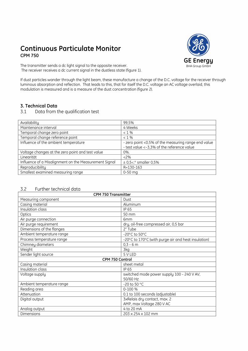
Continuous Particulate MonitorCPM 750
GE EnergyBHA Group GmbHThe transmitter sends a dc light signal to the opposite receiver.
The receiver receives a dc current signal in the dustless state (figure 1).
If dust particles wander through the light beam, these manufacture a change of the D.C. voltage for the receiver through luminous absorption and reflection. That leads to this, that for itself the D.C. voltage an AC voltage overlaid, this modulation is measured and is a measure of the dust concentration (figure 2).
3. Technical Data3.1 Data from the qualification test
Availability 99,5%Maintenance interval 4 WeeksTemporal change zero point < 1 % Temporal change reference point < 1 %Influence of the ambient temperature - zero point <0,5% of the measuring range end value
- test value <–3,3% of the reference valueVoltage changes at the zero point and test value 0%.Linearität <2%Influence of a Misalignment on the Measurement Signal 0,5. smaller 0,5%Reproducibility R=130-163Smallest examined measuring range 0-50 mg
3.2 Further technical dataCPM 750 Transmitter
Measuring component DustCasing material AluminumInsulation class IP 65Optics 50 mmAir purge connection 6mmAir purge requirement dry, oil-free compressed air, 0,5 barDimensions of the flanges 2” TubeAmbient temperature range -20C to 50CProcess temperature range -20C to 170C (with purge air and heat insulation)Chimney diameters 0,3 - 6 mWeight 3kgSender light source 5 V LED
CPM 750 ControlCasing material sheet metalInsulation class IP 65Voltage supply switched mode power supply 100 - 240 V AV,
50/60 HzAmbient temperature range -20 to 50 CReading area 0-100 %Attenuation 0.1 to 100 seconds (adjustable)Digital output 3xRelais dry contact, max. 2
AMP, max Voltage 280 V ACAnalog output 4 to 20 mADimensions 203 x 254 x 102 mm
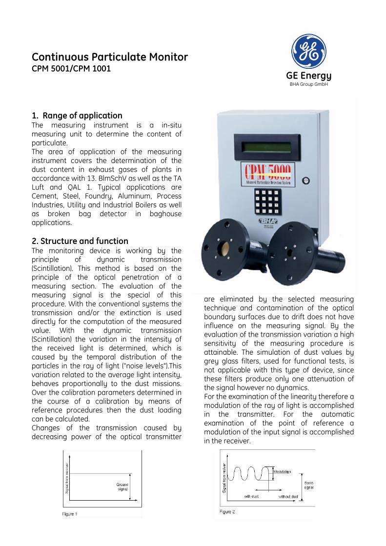
Continuous Particulate MonitorCPM 5001/CPM 1001
GE EnergyBHA Group GmbH
GE EnergyBHA Group GmbH
1. Range of application The measuring instrument is a in-situ measuring unit to determine the content of particulate.The area of application of the measuring instrument covers the determination of the dust content in exhaust gases of plants in accordance with 13. BlmSchV as well as the TA Luft and QAL 1. Typical applications are Cement, Steel, Foundry, Aluminum, Process Industries, Utility and Industrial Boilers as well as broken bag detector in baghouse applications.
2. Structure and functionThe monitoring device is working by the principle of dynamic transmission (Scintillation). This method is based on the principle of the optical penetration of a measuring section. The evaluation of the measuring signal is the special of this procedure. With the conventional systems the transmission and/or the extinction is used directly for the computation of the measured value. With the dynamic transmission (Scintillation) the variation in the intensity of the received light is determined, which is caused by the temporal distribution of the particles in the ray of light ("noise levels").This variation related to the average light intensity, behaves proportionally to the dust missions. Over the calibration parameters determined in the course of a calibration by means of reference procedures then the dust loading can be calculated.Changes of the transmission caused by decreasing power of the optical transmitter
are eliminated by the selected measuring technique and contamination of the optical boundary surfaces due to drift does not have influence on the measuring signal. By the evaluation of the transmission variation a high sensitivity of the measuring procedure is attainable. The simulation of dust values by grey glass filters, used for functional tests, is not applicable with this type of device, since these filters produce only one attenuation of the signal however no dynamics.For the examination of the linearity therefore a modulation of the ray of light is accomplished in the transmitter. For the automatic examination of the point of reference a modulation of the input signal is accomplished in the receiver.

Continuous Particulate MonitorCPM 5001/CPM 1001
GE EnergyBHA Group GmbH
GE EnergyBHA Group GmbH
The transmitter sends a dc light signal to the opposite receiver. The receiver receives a dc current signal in the dustless state (figure 1).
If dust particles wander through the light beam, these manufacture a change of the D.C. voltage for the receiver through luminous absorption and reflection. That leads to this, that for itself the D.C. voltage an AC voltage overlaid, this modulation is measured and is a measure of the dust concentration (figure 2).
3. Technical Data3.1 Data from the qualification testAvailability 100%Maintenance interval 1 monthTemporal change zero point in the maintenance interval < 2 % Temporal change reference point in the maintenance interval < 2 %Influence of the ambient temperature - to the zero point under 2% of the measuring range
end value- to the test value under 3% of the reference value
Voltage changes at the zero point and test value maximum of 0,1%.Influence of the Relative Humidity not observedInfluence of a Misalignment on the Measurement Signal no measurable deviation from the output value of 4
mA was found up to a movement of 6..Reproducibility R=78
3.2 General technical dataCPM 5001 Transmitter / Reciever
Measuring component DustCasing material AcetalInsulation class IP 65Dimensions of the flanges 180 mmAir purge connection 6mm quick-release lockAir purge requirement dry, oil-free compressed air, 0,5 barAir purge filters replaceable cartridge Ambient temperature range -20C to 50CProcess temperature range -20C to 600C (with modern heat insulation)Chimney diameters 0,1 - 15 mWeight 1,2 kgSender light source 5 V LED
CPM 5001 ControlCasing material sheet metalInsulation class IP 65Voltage supply switched mode power supply 100 - 240 V AV,
50/60 Hz protected at 5 milliamperesAmbient temperature range -20 to 50 CReading area 0.01 to 1999.9 mg/m3 (adjustable)Attenuation 0.1 to 100 seconds (adjustable)Digital exit programmable, floating relay contact, max current 2
AMP, max tension 280 V AC of AC voltageAnalog output 4 to 20 mAAnalog inputs 4 - 20 mASignalling alphanumericWeight 15 kgDimensions 405 x 405 x 175 mm


1. Typical application
The analyser unit of the ENDA-600 Series measures NOx, SO2, CO and CO2 using cross-flow modulated Non-Dispersive Infrared (NDIR) detection, a method that is inherently drift-free. Further more a magnetopneumatic bench for oxygen measurement is installed. This combination offers stability for a long period of time, reducing the required frequency of calibrations. A single analyser unit handles continuous measurements of up to five components. The ENDA-600 Series uses innovative technology from Horiba to make it possible to measure all five critical components (NOx, SO2, CO, CO2 and O2) with an single analyser unit. Measurements of up to five of these components may be made in any combination.
Major application:
• Iron and steel processing
• Refuse incinerators
• Electrical power generation plants
• Sulfuric acid plants
• Glass furnaces
• Steam boilers
2. Design and function
2.1 General
Horiba's advanced technology now makes it possible to use a single analyzer unit to measure up to five critical components in stack gas NOx, SO2, CO, CO2 and O2 The principle behind the non-dispersive infrared analyzer is the cross-flow-modulation The unique cross-flow-modulation method is intrinsically free of zero drift, and does not ever require optical adjustment or alignment. The solenoid valve that open and close continuously at a steady cycle are used to alternate introducing the sample gas and a reference gas (i.e., zero gas or fixed concentration gas) into the sample cell at a constant flow rate. Infrared rays from the infrared light source are sent through the sample cell and measured by the detector. The difference in infrared energy absorbed when the reference gas flow through the cell and when the sample gas flows through the cell results in a difference in pressure. This causes the displacement of a thin membrane within the detector; this displacement is converted to an electrical signal.
HORIBA
PG-250
HORIBA
ENDA - 600
Horiba Europe GmbH Geschäftsstelle Leichlingen Julius Kronenberg Strasse 9 D-42799 Leichlingen GERMANY +49 (0)2175-8978-0

2.2 Options
• Adapted sampling system
• HF, HCl, Cl2 treatment
• CH4 interference compensation
• NH3 scrubber
3. Technical Data
3.1 Performance testing data
GMBI: 1996, 42, 882
Smallest measuring ranges tested:
CO 0..75 mg/m3
NO 0..135 mg/m3
SO2 0..75 mg/m3
O2 0..25 Vol.-%
Availability:
> 99% (two systems in field)
Maintenance interval:
1 week
Detection limit:
CO 1,3% of F.S. NO 1,3% of F.S. SO2 2,0% of F.S. O2 0,2% Vol.
Flow effect on measured signal:
No influence
Permissible ambiant temperature range:
+5°C.. +40°C
Temperature dependence at zero point:
For CO, NO, SO2,CO2 < 2.0% F.S. / 10K For O2 < 0.2% Vol. / 10K
Temperature dependence at span point:
For CO, NO, SO2,CO2 < 3.0% F.S. / 10K For O2 < 0.1% F.S. / 10K
Time constant (90% time):
For CO, NO, O2,CO2 < 60 sec. For SO2 < 185 sec
Cross sensitivity:
Sum of all cross sensitivities above mentioned components against SO2, NO, O2, CO2, NH3, NO2, CH4, N2O, CO and H2O in typical flue gas concentrations <4% of F.S. except SO2 0..75mg/m3.
Drift:
<2% zero drift per maintenance interval <4% span drift per maintenance interval
3.2 Further technical data
Power supply:
230V AC 50Hz
Power consumption:
1500 VA
Dimensions:
800(w)*800(d)*1800(h)mm approx. 250kg

1. Typical application
The PG-250 is a single analyser capable of measuring five components with the same methods used by permanent CEMS. The number of applications for gas analysers (for example, studying global environmental problems resulting from combustion exhaust, research on energy conservation, and research on catalyst and control gas concentrations in process gas) have been steadily growing.
Major application:
• Boilers
• Gas turbines
• Refineries
• Waste incinerators
• Electric utilities
Major uses:
• CEMS backup
• Emissions testing
• Combustion efficiency
• Pollution control systems
• Relative accuracy test audits
2. Design and function
2.1 General
The Horiba PG-250 is a highly reliable and versatile gas analyser for compliance testing of NOx, SO2, CO, CO2, and O2, housed in a single lightweight and fully portable case. Unlike other portable gas analysers that rely upon electrochemical sensors, the Horiba PG-250 utilises the same measurement principles as a permanently installed CEMS. These include NDIR (pneumatic) for CO and SO2; NDIR (pyrosensor) for CO2; Chemillumine-scence (crossflow modulation) for NOx; and galvanic cell for O2 measurements. More importantly, the Horiba PG-250 meets or exceeds the regulatory requirements established by agencies such as the EPA in the U.S. for portable or backup continuous emission monitoring systems. The main benefit of the system is its compact and lightweight construction. The PG-250 is capable of intermittent or continuous measurement of five components simultaneously. The compact and lightweight case, with a built-in carrying handle, is as easy to transport as a suitcase. Thus, the PG-250 is
HORIBA
PG-250
HORIBA
PG - 250
Horiba Europe GmbH Geschäftsstelle Leichlingen Julius Kronenberg Strasse 9 D-42799 Leichlingen GERMANY +49 (0)2175-8978-0

ideal for moving between several stacks at a single plant or for carrying across the country to measure clusters of stack emissions at multiple locations.
2.2 Options
• Paramagnetic or zirconia O2 analyser
• Optional electronic cooler
• Drain separator unit
• Electronic cooler unit
• Cl2 scrubber
3. Technical Data
3.1 Performance testing data
GMBI: 2001, 19, 387
Smallest measuring ranges tested:
CO 0..125 mg/m3
NOx 0..134 mg/m3
SO2 0..572 mg/m3
CO2 0..20 Vol.-% O2 0..25 Vol.-%
Availability:
> 99% (two systems in field)
Maintenance interval:
8 days
Detection limit:
CO 0,14% F.S. NO 0,01% F.S. NO2 0,02% F.S. SO2 0,11% F.S. CO2 0,01% F.S.
Flow effect on measured signal:
+/- 50% flow w/o any influence
Permissible ambiant temperature range:
+5°C.. +40°C
Temperature dependence at zero point:
For CO, NO, NO2,CO2 < 1.0% F.S. / 10K For SO2 < 2.0% F.S. / 10K
Temperature dependence at span point:
For CO, NO, NO2,CO2 < 3.6% F.S. / 10K For SO2 < 4.1% F.S. / 10K
Time constant (90% time):
For CO, NO, NO2,CO2 < 60 sec. For SO2 < 160 sec
Cross sensitivity:
Sum of all cross sensitivities above mentioned components against SO2, NO, O2, CO2, NH3, NO2, CH4, N2O, CO and H2O in typical flue gas concentrations <4% of F.S.
Drift:
<2% zero drift per maintenance interval <3% span drift per maintenance interval
3.2 Further technical data
Power supply:
100..120V AC, 200..240V AC 50/60Hz
Power consumption:
250 VA / 400 VA
Dimensions:
260(w)*260(h)*510(d)mm 17kg

1. Typical application
From environmental monitoring to developing new energy sources and chemicals for the new era, gas analysis systems are face with needs and challenges that have changed dramatically over the time. Responding to these needs, Horiba has developed the VA-3000, the versatile gas analyser that’s ready for the future. A singe analyser is now capable of measuring a wider selection of gas components utilising many different types of sensor technology. NDIR modules are available to measure gases such as CO, CO2, NO, N2O CH4, SO2 and others. A CLA sensor module may be include to measure NO or NOx with a standard converter. Four different kind of O2 analyser are available to measure O2. VA-3000 may have installed up to 3 sensors modules in one single analyser case.
Major application:
• Environmental monitoring
• Developing new energy sources
• Developing new chemicals
• Process control
2. Design and function
2.1 General
The unique features means the VA-3000 can be used today for the broad range of applications including research and development or environmental pollution monitoring were efficiency and space-saving are crucial. The main benefit is to use up to 3 different analyser in just one single case. Even if you need one component in three different ranges. A wide variety of combinations of the analysers is possible. Please contact Horiba for detailed assistance. Different sampling systems are available to match your application properly.
2.2 Options
• Analogue outputs
• Discrete I/O options
• Different communication protocol
• Data collection software
• Different sampling system
HORIBA
PG-250
HORIBA
VA - 3000
Horiba Europe GmbH Geschäftsstelle Leichlingen Julius Kronenberg Strasse 9 D-42799 Leichlingen GERMANY +49 (0)2175-8978-0

3. Technical Data
3.1 Performance testing data
BAnz: 8.4.2006, 70, 2654
Smallest measuring ranges tested:
CO 0..75 mg/m3
NO 0..201 mg/m3
N2O 0..96 mg/m3
CO2 0..20 Vol.-% O2 0..25 Vol.-%
Availability:
98.5% (two systems in field)
Maintenance interval:
> 14 days
Detection limit:
CO 4% F.S. NO 0,1% F.S. N2O 0,37% F.S. CO2 0,09% F.S.
Flow effect on measured signal:
< 0.7%
Permissible ambiant temperature range:
+5°C.. +40°C
Temperature dependence at zero point:
For all components < 4.3% F.S.
Temperature dependence at span point:
For all components < 4.8% F.S.
Time constant (90% time):
For CO, NO, O2,CO2 < 60 sec. For N2O < 90 sec
Cross sensitivity:
Sum of all cross sensitivities above mentioned components against SO2, NO, O2, CO2, NH3, NO2, CH4, N2O, CO and H2O in typical flue gas concentrations <0.2% of O2
Drift:
<0.2Vol% zero drift per maintenance interval <0.2Vol% span drift per maintenance interval
3.2 Further technical data
Power supply:
100..120V AC, 200..240V AC 50/60Hz
Power consumption:
300 VA
Dimensions:
430(w)*132(h)*550(d)mm 20kg

______________________________________________________________________________
IMR® – a division of T & T Ingenieurgesellschaft mbH, Am Wildacker 18, D – 74172 Neckarsulm
Tel.: (+49 71 32 ) 96 06 – 0 Fax: (+49 71 32 ) 96 06 – 44 www.imr-germany.eu [email protected]
IMR® Emission Monitoring Systems
IMR 7500
Continuous emission monitoring system (CEM) TÜV approved according German and European environmental regulations. N°. 936/21200089/A from 07.01.2005 fulfils the requirements of DIN EN 14181 1. The Application The IMR 7500 is a system for continuous emission monitoring (CEM) of flue gases in industrial applications. Up to 6 gases can be measured simultaneously. Typical application for the IMR 7500 are:
• Emission monitoring • Furnace optimisation • Environmental monitoring • Combustion control
2. The performance criteria IMR is using electrochemical sensors for the gas components O2, CO, NO, NO2, SO2 and H2S . For the gases CO2 and CxHy NDIR -(non dispersive infrared absorption) sensors are used. The IMR 7500 is a modular system and consisting of the components flue gas conditioning, flue gas pump and the analyser. The components are built-in a 19“ rack, and allow easy access for maintenance and service. All components that get in
touch with the flue gas, such as pump, magnetic valve and the sensors are located after the flue gas conditioning system to avoid corrosion due to alcalic and/or basic condensate. A humidity sensor in the gas path way provides additional safety for the analyser components in case of failure of the gas conditioning system. The integrated 5,5“ display allows easy check on the analyser readings and the operating condition. Status signals allow documentation of the analyser status such as service, instrument failure and online measurement. The installation on site of a IMR 7500 is conveniently made in real time from a personal computer. Same for the regular calibration of the analyser with single standard gases. In pre-programmed intervals the analyser is performing a 0 calibration with ambient air. The IMR 7500 ensures a annual availability of > 99 %. Additionally to the analysis of flue gases, the IMR 7500 can also measure flue gas temperature, flue gas volume and flue gas velocity. Measuring data are available in digital form at the interfaces RS 232 or RS 485, or as analogue signal 4…20 mA. IMR offers also a data visualisation software TabGraph+. The calibration software is included in the IMR 7500. It can be operated on any Microsoft compatible personal computer. 2.1 The measuring principle The major advantages of electrochemical sensors are fast response, high linearity and high reproducibility. Electrochemical sensors are by definition micro fuel cells, designed to be maintenance free and stable for long periods. They have a direct response to volume concentration of gas rather than partial pressure. The simplest form of electrochemical toxic gas sensors comprises two electrodes, sensing and counter, separated by a thin layer of electrolyte. This is enclosed in a plastic housing that has a small capillary to allow gas entry to the sensing electrode and includes pins which are electrically attached to both electrodes and allow easy external interface. Gas diffusing into the sensor is either oxidised or reduced at the sensing electrode and, coupled with a corresponding (but converse) counter reaction at the

______________________________________________________________________________
IMR® – a division of T & T Ingenieurgesellschaft mbH, Am Wildacker 18, D – 74172 Neckarsulm
Tel.: (+49 71 32 ) 96 06 – 0 Fax: (+49 71 32 ) 96 06 – 44 www.imr-germany.eu [email protected]
counter electrode, a current is generated through the external circuit. This signal is digitalised as gas concentration in ppm (parts per million). The indication of the measuring results is either in ppm or in mg with oxygen reference. To eliminate the cross interference reaction of the various sensors, the IMR 7500 uses additionally a mathematic correction with matrix calculation. Another advantage of this form of calibration is, that the sensor performance over the lifetime of a sensor can be optimised. This eliminates also the possibility of incorrect measuring results due to unusual high sensor drift. The life span of electrochemical sensors is in average 2 years for oxygen sensors and 3 years for the toxic gas sensors. For the measurement of CO2 and Hydrocarbons IMR features NDIR sensors.
2.2 The flue gas conditioning The most efficient way to condition gas for flue gas analysis is the refrigeration of the flue gas humidity in a way of controlled condensation. The advantage of this technology is that condensation of target substances can be avoided. This is achieved in the gas conditioning system included in the IMR 7500. The condensed humidity of the flue gas is drained off with a peristaltic pump. To guarantee controlled condensation, the shape of the heat exchanger in the cooling block is very important. IMR has adopted a system that enforces immediate contact of the entering flue gas with the refrigerated wall of the heat exchanger. The instant temperature reduction to approx. 5°C separates the condensate from the gas. The Peltier controlled gas preparation is the most efficient way of flue gas conditioning. The gas conditioning system in the IMR 7500 is maintenance free.
Technical Data:
Component Method Smallest measuring
range Largest measuring
range Resolution Accuracy
O2 (Oxygen) 0 ... 20,95 Vol.-% 0 ... 20,95 Vol.-% 0,01 Vol.-% +/- 0,2 %
CO (Carbon monoxide) 0 ... 75 mg/m³ 0 ... 5 Vol.-%
NO (Nitric oxide) Electrochemical
0 ... 200 mg/m³ 0 ... 5.000 mg/m³ < 100 mg/m³: 0,1 mg max. +/- 3 %
NO2 (Nitric dioxide) sensor
0 ... 100 mg/m³ 0 ... 500 mg/m³ > 100 mg/m³: 1,0 mg of full scale
SO2 (Sulphur dioxide) 0 ... 75 mg/m³ 0 ... 5.000 mg/m³
H2S (Hydrogen sulphide) 0 ... 60 mg/m³ 0 ... 300 mg/m³
CxHy (Hydro carbons) 0 ... 0,2 Vol.-% 0 ... 100 Vol.-%
CO2 (Carbon dioxide) Infrared sensor 0 ... 20 Vol.-% 0 ... 100 Vol.-% 0,1 Vol.-% +/- 2 %
CO (Carbon monoxide) 0 ... 20 Vol.-% 0 ... 100 Vol.-%
°C (flue gas temperature) Thermocouple 0 ... 500 °C 0 ... 1.605 °C 1 K +/- 1 K
The analyser complies with EN 14181, TÜV approved. Further technical details: Dimension: 19“- system, 6HE - 430 mm deep Weight: 14 kg Operating temperature: + 5°C - + 35°C Power supply: 230 VAC, 50/60 Hz Power consumption: 200 W +100 W/m of heated sampling line Data signal parts: 4 … 20 mA and RS 232 Capacity of gas conditioning system: < 150 l/h Pump volume: < 3,0 l/min max. draft: +/- 0,5 bar Reproducibility: > 30 Response time / T 90: < 115 sec Annual availability: > 99 % Drift (electrochemical sensor): < 5% / year Linearity: < +/- 2,0% of range Zero- and referent point drift: < +/- 3% Detection limit of smallest range: < 1,4% Cross interference: < 4%
O2
NO2
1
1 Sampling probe 2 Heated sampling line 3 Filter 4 Solenoid valve 5 Condensate circuit breaker 6 Gas pump 7 Gas flow meter with regulator valve 8 Pump pressure control 9 Sensor chamber10 Gas conditioner11 Peristaltic pump
23
3
CO NO
SO2
GasOutput
CondensateOutput
4 5Purge airInput
GasInput
IMR 7500
67
8
9
10
11
Analyser operating software
Gas conditioner regulation Heated sampling line regulation Solenoid valve management Calculation to reference values
5,5 “ TFT - Display
Signal output
An
alog
out
put
(0)4
...20
mA
RS
232
/ R
S 4
85
Sta
tus
sign
alO
nlin
e/S
ervi
ce/E
rror
Manufactured in Germany, European Community

Emission analysis system
EMI30001. Range of application
EMI3000 is a process data collection system, whichfollows a modular concept. It is designed tocontinuously monitor emissions in accordance with:
TA Air13.-,17.-,27. , 30. and 31. BImSchV,“Bundeseinheitliche Praxis bei der Über-wachung der Emissionen“, current versionfrom the 24th of June 2005
DIN EN 14181
In addition to acquiring the emission data, operatingdata can also be collected, processed, andvisualised.
EMI3000`s certification is unrestrictive and approvedfor all types of continual emission monitoring.
The qualifying examination was carried out by TÜVNord Umweltschutz GmbH & Co KG, Hamburg, andPrüfbericht Nr. 05 UE035/8000701830 from the 15th
of July 2005.
The qualification was announced in the„Amtlicher Teil Bundesanzeiger, 29 Oktober 2005, Nummer206 Seite 15701“.
2. Design and function
EMI3000 is a modular system. The data loggerundertakes the actual measurement data collectionand releases analogue and digital signals in realtime.
The data logger acquires the following values in aone second cycle:
Analogue input signalsDigital inputAnalogue outputDigital output
The rapid data collection surpasses by far all lawrequirements.
The maximum expansion stage of every data loggercomprises 88 analogue in/outputs and 128 digitalin/outputs.
Multiple data loggers can be employed.
Optionally the data logger can be obtained with atemporary storage of either 21 or 105 days.

The data processing of the emission values takesplace on a separate computer (server). The valuesmeasured by the data logger are transferred pernetwork into the server, in a one second cycle, andare then saved permanently. This is the data basisfor all of the following data processing. The secondvalues are calculated into integration values, whichbecome the basis for the classing. The classings arein accordance with every law requirement.
The EMI3000-Server essentially fulfils the followingtasks:
Saving of second values.Calculation of derived sizes.Creation and saving of integration values,
optional automatic print-outCreation and saving of classings, optional
automatic print-outMessage generation, optional automatic print-
out, generation of digital output andanalogue output signals.
Server functionality to visualise all values.Synchronisation of the time in accordance
with DCF77.
The visualisation takes place on separate clients. Inthe simplest case this occurs locally in the EMI3000-Server.
Analogeingänge
Digitaleingänge
Analogausgänge
Digitalausgänge
Datenlogger
Emissionswertverarbeitung
(separater Rechner)
DCF77 Funkuhr
redundanteDatenspeicherung
Kommunikation per Netzwerk via TCPIP Datenlogger Emissionswertverarbeitung
Emissionsrechner
Kommunikation per Netzwerk via TCPIP Emissionsrechner Client
iMac
Drucken, Plotten Visualisierung auf unterschiedlichsten Plattformen
3. Technical data
3.1 Data from the qualificationexamination
Unrestrictive license for all types of continualemission monitoring.
Supplementary examination of a remote emissiondata transfer system (EFÜ-System) for EMI3000.
3.2 Additional technical data
Technical data of a data logger:Analogue inputs:Quantity (max)ResolutionMeasuring areaoptional with buffer amplifier
Digital Inputs:Quantity (max)Signal voltage
Analogue outputsQuantity (max)ResolutionMeasuring areaoptional with buffer amplifier
Digital outputs:Quantity (max)output as relay or 24 Volt active
Voltage supply
Robust fieldbus modules
Temporary storage of values inthe data logger based on thesecond values, optionally with21 or 105 days.
8812 Bit0,2,4 .. 20 mA
12824 Volt
8812 Bit0,2,4 .. 20 mA
128
24 Volt -
EMI3000 processes several data loggers. As aresult it is pretty much scalable in an unlimited wayin the field of emission measurement.
Technical data of the EMI3000-Server:The current server models are used respectively. AsJAVA is being used EMI3000 is platformindependent. The storage depth is for a minimum of5 years. No restrictions of the construction, or ratherthe measuring points, exist.
Additional functions:In addition to the certified breadth we also offerfurther functionalities, for example the connection ofEMI3000 to process control systems.

Sensoren und Systeme für die Feuerungstechnik
Lambda Transmitter LT1 The LT 1 Lambda transmitter is a universal, microprocessor-based O2 measuring instrument for the direct measurement of O2 concentration in exhaust gases from oil and gas combustion facilities in the super-stoichiometric domain (l>1), in conjunction with the LS 1 Lambda probe.
Lambda-Probe LS 1
Lambda-Transmitter LT 1
Combination-Probe KS 1
operationand service
LAMTEC SYSTEM BUS
Option:CANopenModbusProfibus DPEthernet
RS 232
analogeuin- andoutputs
digitale in-and outputs
CA
N,R
S4
22
recording
Lambda-Transmitter LT2 / KS1(optional)
Advantages: • Linear probe signal (direct current [mA]) with fixed
physical zero point • No special calibration gases required, automatic
calibration with ambient air (21% by vol. O2) • Measuring accuracy better than 0.2 vol.% O2 over
the entire measuring range 0…21 vol.% O2 • No gas purification necessary • No reference gas required • Settling time <15 s to 90% value (T90) with 450 mm
gas extraction device • Gas temperature does not affect measurement
accuracy
• No temperature control of the ZrO2 measuring cell is required
• Automatic adjustment of cell temperature to the cell's internal resistance (ageing compensation)
• Measured gas temperature up to 800 °C with metal extraction up to 1700 °C with ceramic extraction
• Does not constitute an ignition source in the flue gas duct. TÜV certification available.
• Intermittently operated gas pump with determination of the optimum pump running time.
• Simple operation. • Low maintenance

Sensoren und Systeme für die Feuerungstechnik
LAMTEC Meß- und Regeltechnik für Feuerungen GmbH & Co KG Impexstraße 5 D-69190 Walldorf Telefon (+49) 06227 / 6052-0 Telefax (+49) 06227 / 6052-57 Internet: http://www.lamtec.de e-mail: [email protected]
LAMTEC Leipzig GmbH & Co KG Schlesierstraße 55 D-04299 Leipzig Telefon (+49) 0341 / 863294-00 Telefax (+49) 0341 / 863294-10
Measuring principle: O2 concentration is continuously measured by the LS 1 Lambda probe (see separate publication DLT6061). A small quantity of gas (approx. 0.5 l/h) is drawn direc-tly from the measured gas through a capillary tube. A 7-wire plugged cable and a Teflon hose connect the LS 1 probe to the LT 1 Lambda transmitter. The probe's signal is analysed in the LT 1 Lambda transmitter, using the latest microprocessor technology. - A serial interface, - a monitor output 0…2.55 V DC = 0…25.5 vol. % O2,
up to 4 analogue outputs - 0/4…20 mA, 0…10 V - and up to 7 digital outputs are available Internal LEDs provide operational information and indicate any system faults identified by the diagnostic functions.
Field of application: • - in combustion exhaust gases • - in industrial waste gases • - in furnace atmospheres • - in process gases
The LT 1 Lambda transmitter is provided with the following functions: • Automatic testing and calibration of the LS 1 probe
against the ambient air. • Automatic ageing compensation of the ZrO2 cell • Compensation for the effect of gas composition on
gas flow through in highly unbalanced measured gases.
• Intermittent gas pump with automatic calculation of optimum pump running time. Optional long-life mode with limited measuring accuracy.
• Intelligent, optionally automatic cold-start delay, adjustable between 5…120 minutes.
• Integral maintenance switch. • LAMTEC SYSTEM BUS for direct coupling to the
LAMTEC linked burner control systems • alternative a RS422 interface, for coupling to the
customer's systems. • A RS 232 interface for PC-based remote control in
with the (optional) remote-display-software. • Bus-Interface for
Profibus CAN-Bus Modbus Ethernet
• Display and operating unit • Automatic calibration unit for fully automated
testing and calibration of the installed LS 1 Lambda
probe when the system operates with ambient air; alternatively via an integral pump or pneumatically.
• Portable calibration device to connect to LT 1 • Test gas actuation (1…4 test gases) for checking
the calibration (EPA standard). • Pressure compensation of the measured value;
pressure range 800…1200 mbar • Temperature compensation of the measured value • Fine draught measurement • Measurement of flue gas and intake air tem-
perature, and calculation of combustion efficiency • Calculation of CO2 concentration, fuel-referenced,
derived from the measured O2 value and the CO2-max value
• Load-dependent and fuel-specific boundary values / boundary curves
• KS 1 combined probe for the detection of combustible components (CO/H2)
• Electric heating of the gas extraction device and the sintered metal prefilter
• 1…3 additional analogue outputs, • Galvanic isolation of analogue outputs • Relay modules for digital outputs with 6 relays,
switching capability 230 V AC, 4 A • 1…4 analogue inputs via measuring cards, freely
configurable, • Remote display software for PC, Windows-based • Gas pump, 12VDC, for aggressive measured gases • Electric heating of housing for compact version IP
65, for ambient temperatures below -10°C to -25°C
Versions: • Wall-mounted housing IP 54 • Wall-mounted housing IP 65, opt. in stainless steel • mounting plate IP00 for control cabinet installation • OEM version - output possible only via LAMTEC
SYSTEM BUS, altern. via RS 422 serial interface. • 19"-version available Accuracy:
±0,2vol. % O2 after calibration to air value 21 vol.% O2 (with LS 1 Lambda probe) Setting time: <20 s to 90 % of the end value (T90) (with LS 1 Lambda probe type 650 R 0001 and 450 mm MEV)
Correction factors: Error attributable to temperature = 1% of measured value/10 K housing temperature, LS 1 Lambda probe, temperature compensation optional Error attributable to pressure =1,3 % of measured value/10 mbar pressure variation, pressure com-pensation optional

Portable Emissions Gas Analyser 570A for O2 measurement
Schematic diagram: Paramagnetic O2 cell
1. Precision dumb-bell cell (filled with N2) 2. Mirror 3. Amplifier 4. Photocell

1. Scope of Application
Portable extractive measurement of oxygen in conditioned flue gases.
This portable Oxygen Analyser has to be equipped with a sampling system (condensate trap, drier, flow control, filter and pump) in case of wet or dust-loaded flue gases.
Performance test 13. and 17. BImSchV as well as TA Luft by TÜV Rheinland Sicherheit und Umweltschutz GmbH, Report No. 936/808018/B of 30.09.1999 for the component O2.
2. Configuration and Principle of Operation The Servomex 570A consists of a multi-part plastic housing carrying the paramagnetic dumb-bell cell and the corresponding electronics.
Oxygen is attracted into a magnetic field. Most other gases are not. This paramagnetic property is used to obtain fast, accurate oxygen measurements.
A focussed magnetic field is created. Any oxygen that is present will be attracted into the strongest part of the magnetic field. Two nitrogen filled glass spheres are mounted on a rotating suspension within the magnetic field. A mirror is mounted centrally on the suspension. Light is shone onto the mirror. The reflected light is directed onto a pair of photocells. Oxygen attracted into the magnetic field will displace the nitrogen filled spheres, causing the suspension to rotate. The photocells will detect the movement and generate a signal. The signal generated by the photocells is passed to a feedback system. The feedback system will pass a current around a wire mounted on the suspension. This causes a motor effect which will keep the suspension in its original position. The current measured flowing around the wire will be directly proportional to the concentration of oxygen within the gas mixture.
3. Technical Data 3.1 Data from performance tests Measuring range: O2 0 - 100 Vol. % Detection limit << 0,2 % of final span value Repeatability min. R >> 70 Cross sensitivity << +/- 0,2 Vol. % Availability 99,5 % Maintenance interval 8 days (sight check) Response time (90% time) < 30 sec 3.2 Further technical data
Analogue output 0 - 1 V
approx. dimensions (W x D x H) 570A 150 x 305 x 190 mm Typical weight 6,5 kg (570A only) Splash-proof housing
Manufacturer Servomex GmbH Münsterstraße 5 D-59065 Hamm Telephone +49 23 81 68 82 13 Telefax +49 23 81 68 81 75 E-Mail [email protected] Internet www.servomex.com

O2 Flue Gas Analyser 2700
2700 Sensor Head Flow Schematic
1. Heated filter block 9. Breather 2. Sample aspirator (jet pump) 10. Sintered flame arrestor (inlet) 3. Flame trap (outlet) 11. Calibration/blowback inlet 4. Thickfilm COe sensor (optional) 12. Oven assembly (245 °C) 5. Auxiliary air inlet 13. Internal filter 6. Aspirator/reference air inlet 14. Sample gas inlet 7. Solenoid valve 15. Sample gas outlet 8. Zirconia O2 sensor
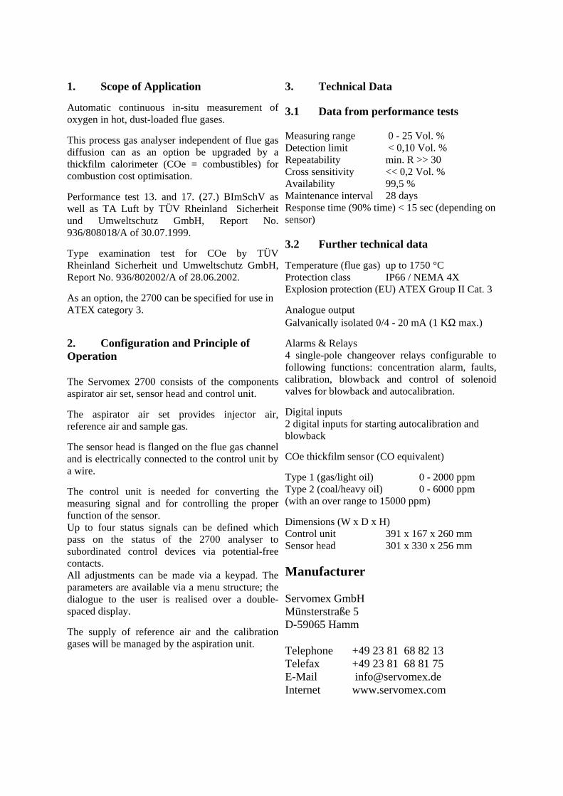
1. Scope of Application
Automatic continuous in-situ measurement of oxygen in hot, dust-loaded flue gases.
This process gas analyser independent of flue gas diffusion can as an option be upgraded by a thickfilm calorimeter (COe = combustibles) for combustion cost optimisation.
Performance test 13. and 17. (27.) BImSchV as well as TA Luft by TÜV Rheinland Sicherheit und Umweltschutz GmbH, Report No. 936/808018/A of 30.07.1999.
Type examination test for COe by TÜV Rheinland Sicherheit und Umweltschutz GmbH, Report No. 936/802002/A of 28.06.2002.
As an option, the 2700 can be specified for use in ATEX category 3.
2. Configuration and Principle of Operation The Servomex 2700 consists of the components aspirator air set, sensor head and control unit.
The aspirator air set provides injector air, reference air and sample gas.
The sensor head is flanged on the flue gas channel and is electrically connected to the control unit by a wire.
The control unit is needed for converting the measuring signal and for controlling the proper function of the sensor. Up to four status signals can be defined which pass on the status of the 2700 analyser to subordinated control devices via potential-free contacts. All adjustments can be made via a keypad. The parameters are available via a menu structure; the dialogue to the user is realised over a double-spaced display.
The supply of reference air and the calibration gases will be managed by the aspiration unit.
3. Technical Data 3.1 Data from performance tests Measuring range 0 - 25 Vol. % Detection limit < 0,10 Vol. % Repeatability min. R >> 30 Cross sensitivity << 0,2 Vol. % Availability 99,5 % Maintenance interval 28 days Response time (90% time) < 15 sec (depending on sensor) 3.2 Further technical data
Temperature (flue gas) up to 1750 °C Protection class IP66 / NEMA 4X Explosion protection (EU) ATEX Group II Cat. 3
Analogue output Galvanically isolated 0/4 - 20 mA (1 KΩ max.)
Alarms & Relays 4 single-pole changeover relays configurable to following functions: concentration alarm, faults, calibration, blowback and control of solenoid valves for blowback and autocalibration.
Digital inputs 2 digital inputs for starting autocalibration and blowback
COe thickfilm sensor (CO equivalent)
Type 1 (gas/light oil) 0 - 2000 ppm Type 2 (coal/heavy oil) 0 - 6000 ppm (with an over range to 15000 ppm)
Dimensions (W x D x H) Control unit 391 x 167 x 260 mm Sensor head 301 x 330 x 256 mm
Manufacturer Servomex GmbH Münsterstraße 5 D-59065 Hamm Telephone +49 23 81 68 82 13 Telefax +49 23 81 68 81 75 E-Mail [email protected] Internet www.servomex.com

4900 Emissions Analyser for NO, CO, SO2 and O2 measurement
Schematic diagram: IR gas filter correlation cuvette
1. Infrared source 2. Lens 3. Gas filter 4. Band pass IR filter 5. Light collector 6. Detector 7. Measurement cell (316 SS) 8. Chopper wheel (in temperated box) 9. Gas filter 10. Chopper motor
Schematic diagram: Paramagnetic O2 cell
1. Precision dumb-bell cell (filled with N2) 2. Mirror 3. Amplifier 4. Photocell

1. Scope of Application
Automatic extractive measurement of NO, CO, SO2 and O2 in flue gases.
This process gas analyser capable to measure multiple gases with max. two sample gas streams can be specified for various applications.
Performance test 13. and 17. BImSchV as well as TA Luft by TÜV Rheinland Sicherheit und Umweltschutz GmbH, Report No. 3.5.2/0784/95//674377/01 of 25.02.1997 for the components SO2 (13. BImScHV, TA Luft) and NO. Further performance test 13. and 17. BImSchV as well as TA Luft by TÜV Rheinland Sicherheit und Umweltschutz GmbH, Report No. 3.5.2/0784/95//597632/01 of 27.02.1996 for the components O2 und CO.
As an option, the 4900 can be used for the indirect analysis of NO2 by adding a so-called NOx converter.
2. Configuration and Principle of Operation The Servomex 4900 consists of a 19" chassis which carries the single component sensors and the corresponding electronics.
The Gas Filter Correlation measurement:
Used where extremely accurate low level measurements are required or where background gases have the potential to interfere with the measurement. The measure and reference filters are replaced with gas filled cuvettes. The reference cuvette is filled with a sample of the gas to be measured, the measure cuvette with (typically) nitrogen.
The Paramagnetic measurement: The strong magnetic property of oxygen is virtually unique compared to other gases. Its attraction into a magnetic field (paramagnetism) is the basis for high accuracy oxygen analysis, when fast and reliable measurements are needed. This technique is used for measuring percentage oxygen in diverse industrial applications.
3. Technical Data 3.1 Data from performance tests Measuring range (standard): O2 0 - 5 / 25 Vol. % (PM) CO 0 - 50 / 1000 ppm (IR) SO2 0 - 200 / 2500 ppm (IR) NO 0 - 200 / 1000 ppm (IR) Detection limit << 2 % of final span value Repeatability min. R >> 30 Cross sensitivity << +/- 4 % Availability 98,9 - 99,4 % Maintenance interval 8 - 14 days Response time (90% time) 20 - 30 sec (depending on sensor) 3.2 Further technical data
Analogue output (upgradeable as an option) 2 x galvanically isolated 0/4 - 20 mA (1 KΩ max.)
Status outputs (upgradeable as an option) 3 alarms freely selectable (exceeding or falling below limit). Maintenance / adjusting
Control outputs „Zero gas“, „test gas“ for addressing solenoid valves during manual or automatic adjusting
digital interface RS 232 (2400 to 19400 Baud)
approx. dimensions (W x D x H) Short chassis 483 x 478 x 133 mm Long chassis 483 x 608 x 133 mm Typical weight 25 kg
Manufacturer Servomex GmbH Münsterstraße 5 D-59065 Hamm Telephone +49 23 81 68 82 13 Telefax +49 23 81 68 81 75 E-Mail [email protected] Internet www.servomex.com

EuroFID – Total-C Analyzer Extractive Model 3010
Precise monitoring of total hydrocarbons in air as well as in corrosive and condensable gases 1. Area of application The total hydrocarbon analyzer EuroFID Extractive Model 3010 is suitable for continuous emission monitor-ing in corrosive, condensable and hot gases. Typical Applications • Emission control in power plants, incineration plants
and cement works. • Emission control behind thermal, catalytic, biological
and active-carbon waste air filter. • Monitoring flue gas in raw and treated gas in chemical
plants. • LEL measurements in process plants with solvent-
based products.
Features and advantages • No moving parts, therefore very low servicing re-
quirements • Fully heated measurement system enables meas-
urement of corrosive and reactive gases • Patented sensor block with optimized detector ge-
ometry ensures a highly reliable measurement even with smallest concentrations.
• Very low maintenance requirements – only change of easily accessible measuring gas filters is required.
• Automatic device check with zero- and test gas. • Certification for measurements in compliance with
17th BImSchV (2000/76/EC)
• Approved for measurements of total hydro carbon in accordance with European emission guidelines.
2. Design and working principle The modular concept of the EuroFID INLINE allows grea-ter flexibility in the choice of a suitable mounting place.
• Analyzer unit in wall rack housing: optimal integration in the system cabinet, directly at the entry of the bus or on mounting plates
• 19"-rack version in 3 HU • 1/2 19"-rack version in 4 HU Functionality and measuring principle
The EuroFID uses a flame ionization detector to trans-form the concentration of hydrocarbons into an electrical signal. (FID). A constant mass flow rate inside the FID is critical for a stable measuring signal. This is achieved by using an ejector with pressure sensors. It dilutes the measuring gas, making the precise measurement of corrosive and condensing gases possible. The complete measuring system is continuously heated to a tempera-ture of 200 °C to ensure reliable measurement of gases with corrosive and condensing properties. A decisive factor for stable measurement is the geometry of the detector, designed to avoid any build-up of deposits.
Principle of flame ionization

EuroFID Extractive Model3010 – Total-C Analyzer – 2 –
SICK MAIHAK GmbH | Analyzers and Process Instrumentation Nimburger Str. 11 | 79276 Reute | Germany | www.sick-maihak.com
Phone +49 7641 469-0 | Fax +49 7641 469-1149 | [email protected]
3. Technical data 3.1. Results of the performance test – fuel gas H2/He
Tested measuring range 0 ... 15 mg/m
Availability 98.8 % respectively. 99 %
Maintenance interval 1 month
Detection limit 0.16 mg/m within measuring range 0 ... 15 mg/m
Effect of power supply voltage Zero point: < 0.3 % of full scale, sensitivity: < 0.9 % (within range of 190 V ... 250 V)
Reproducibility 1 ... 10 mg/m : 83, 1 ... 3 mg/m : 88, 3 ... 6 mg/m : 91, 6 ... 10 mg/m : 72, 10 ... 15 mg/m : 45
Ambient temperature range 0 °C ... 40 °C
Temperature dependency of zero drift < 1.1 % of full scale (tested within range of 0 °C ... 40 °C)
Temperature dependency of sensitivity < 1.4 % (tested within range of 0 °C ... 40 °C)
Response time (T90-time) 48 s
Linearity Deviation from the device characteristic line: max. 1.2 % of display range
Cross sensitivity with test gas (inside measuring range: 0 ... 15 mg/m ) H2O (30 vol.%) O2 (21 vol.%) CO2 (15 vol.%) CO (737 mg/m ) NO (319 mg/m ) SO2 (200 mg/m ) HCl (54 mg/m ) NO2 (53 mg/m ) NH3 (38 mg/m ) N2O (54 mg/m )
Zero point [% of full scale] < 0.3 0.7/0.9 < 0.3 0.4 –0.6/–0.5 0.7 –0.6/–0.4 < 0.3 < 0.3 < 0.3
Reference point [% of full scale] –0.8 –0.9/–0.8 –0.4 0.5/0.6 –0.5 0.3/0.5 –0.5 –0.3/< 0.3 < 0.3 < 0.3
Influence of oxygen content (0 ... 21 vol.%) Zero point: +0.9 % of full scale, Sensitivity: –0.9 % of full scale
Zero point drift (time variant) < 1.5 % of display range per month
Drift of referential point (time variant) < 1.9 % per month
Response factors Relative standard deviation for butane, cyclohexane, n-heptane, Isopropanol, acetone, toluene, acetic acid ethyl acetate, ethyl acid isobutylester: 14.8%/15.1, for extended list: 12.8 %/ 13.0 %
Cross sensitivities with oxygen and sulfur dioxide, therefore use fuel gas mixture hydrogen and helium (40%/60%). With stable oxygen content (± 3 vol.%) and low sulfur dioxide concentrations (< 50 mg/m ) hydrogen is used.
3.2. Additional technical data
Power consumption During warm-up: approx. 330 VA, continuous operation: 280VA
Required voltage 230 V AC 48 ... 63 Hz or 115 V AC 48 ... 63 Hz
Other approvals 13th BImSchV (2001/80/EG) and TA-Air
Analog outputs 0 or 4 ... 20 mA potential free, load: max. 500
Analyzers and Process Instrumentation

EuroFID – Total-C Analyzer INLINE Model3010
Precise monitoring of total hydrocarbons
in air as well as in corrosive and condensable
gases
1. Area of application The total hydrocarbon analyzer EuroFID INLINE Model3010 is suitable for continuous emission monitoring in corrosive, condensable and hot gases. Typical Applications • Emission control in power plants, incineration plants
and cement works. • Emission control behind thermal, catalytic, biological
and active-carbon waste air filter. • Monitoring flue gas in raw and treated gas in chemical
plants. • LEL measurements in process plants with solvent-
based products.
Features and advantages • In-situ measurement technique, which means minimal
response times and no extraction lines required. • No moving parts, thereby minimizing maintenance
requirements • Measurement of corrosive and reactive gases due to
fully heated measurement system. • Patented sensor block with optimized detector ge-
ometry ensures a highly reliable measurement even with smallest concentrations.
• Very low maintenance requirements – only change of easily accessible measuring gas filters is required.
• Automatic device check with zero- and test gas. • Certification for measurements in compliance with
17th BImSchV (2000/76/EC) • Approved for measurements of total hydrocarbon in
accordance with European emission guidelines. • EU-prototype testing in accord. with 94/9/EC guide-
lines (ATEX) for LEL measurements.
2. Design and working principle The EuroFID INLINE is of modular design. The response time is extremely fast due to direct mounting at the measuring point. There is also no need for a separate sample gas extraction probe with filter or a heated meas-uring gas lead. The control unit is menu driven and there is a choice of two versions: • 19"-rack version in 3 HU • 1/2 19"-rack version in 4 HU Functionality and measuring principle
The EuroFID uses a flame ionization detector to trans-form the concentration of hydrocarbons into an electrical signal. (FID). A constant mass flow rate inside the FID is critical for a stabile measuring signal. This is achieved by using an ejector with pressure sensors. It dilutes the measuring gas, making the precise measurement of corrosive and condensing gases possible. The complete measuring system is continuously heated to a tempera-ture of 200 °C to ensure reliable measurement of gases with corrosive and condensing properties. A decisive factor for stable measurement is the geometry of the detector, designed to avoid any build-up of deposits.
Principle of flame ionization

EuroFID INLINE Model3010 – Total-C Analyzer – 2 –
SICK MAIHAK GmbH | Analyzers and Process Instrumentation Nimburger Str. 11 | 79276 Reute | Germany | www.sick-maihak.com
Phone +49 7641 469-0 | Fax +49 7641 469-1149 | [email protected]
3. Technical data – EuroFID INLINE 3.1 Results of the performance test – fuel gas H2/He
Tested measuring range 0 ... 15 mg/m
Availability 98.8 % respectively. 99 %
Maintenance interval 1 month
Detection limit 0.29 mg/m within measuring range 0 ... 15 mg/m
Effect of power supply voltage Zero point: < 0.3 % full scale, Sensitivity: < 0.9 % (within range of 190 V ... 250 V)
Reproducibility 1 ... 10 mg/m : 64, 1 ... 3 mg/m : 52, 3 ... 6 mg/m : 76, 6 ... 10 mg/m : 83, 10 ... 15 mg/m : 76
Ambient temperature range –20 °C ... 50 °C
Temperature dependency of zero drift < 2.3 % full scale (tested within range of 0 °C ... 40 °C)
Temperature dependency of sensitivity < 1.4 % (tested within range of 0 °C ... 40 °C)
Response time (T90 time) < 6 s
Linearity Deviation from the device characteristic line: max. 1.3 % of display range
Cross sensitivity with test gas (inside measuring range: 0 ... 15 mg/m ) H2O (30 Vol.%) O2 (21 Vol.%) CO2 (15 Vol.%) CO (737 mg/m ) NO (319 mg/m ) SO2 (200 mg/m ) HCl (54 mg/m ) NO2 (53 mg/m ) NH3 (38 mg/m ) N2O (54 mg/m )
Zero point [% full scale] < 0.3 0.8/0.7 < 0.3 0.4 –0.6/–0.5 0.6/0.8 –0.5/–0.6 < 0.3 < 0.3 < 0.3
Reference point [% full scale] –0.9/–0.8 –0.8/–0.7 –0.6/–0.5 0.5/0.4 –0.6/–0.4 0.3/0.4 –0.5/–0.4 –0.4/< 0.3 < 0.3/–0.3 < 0.3
Influence of oxygen content (0 ... 21 vol.%) Zero point: +0.9 % full scale, Sensitivity: –1.6 % full scale
Zero point drift (time variant) < 1.8 % of range of indication per month
Drift of referential point (time variant) < 1.9 % per month
Response factors Relative standard deviation for butane, cyclohexane, n-heptane, isopropanole, acetone, toluene, acetic acid ethyl acetate, ethyl acid isobutylester: 15.1 %/15.0, for extended list: 13.3 %/ 13.0 %
Cross sensitivities with oxygen and sulfur dioxide, therefore use fuel gas mixture hydrogen and helium (40%/60%). With stable oxygen content (± 3 vol.%) and low sulfur dioxide concentrations (< 50 mg/m ) hydrogen is used. 3.2 Additional technical data
Power consumption Warm-up time: appr. 330 VA, continuous operation: 280 VA
Required voltage 230 V AC 48 ... 63 Hz or 115 V AC 48 ... 63 Hz
Other approvals • EC-type approval certificate acc. to guidelines 94/9/EC: • BVS 05 ATEX G 005 X • Measuring function within measuring range 0 … 100 %
LEL • 13th BImSchV (2001/80/EG) and TA Air
Analog outputs 0 or 4 ... 20 mA potential-free, load: max. 500
Analyzers and Process Instrumentation

FID BA3006 Portable Total C-Analyzer
Compact device for flexible application for the measurement of Total Hydrocarbon Analyzer
1. Area of application
The portable total hydrocarbon analyzer FID BA 3006 is suitable for continuous emission monitoring in corrosive, condensable and hot gases. Typical applications: • Mobile measurement of emissions in power and incin-
eration plants as well as in the cement industry.
• Measurement of hydrocarbon emissions both in raw and treated gases in chemical plants.
• Detection of hydrocarbon leaks in air purification plants.
• Mobile measurement of emissions for detection of environmental pollution.
Features and advantages
• The compact design with integrated fuel gas and test gas supply ensures a smooth operation in the field.
• Accurate measurement due to a clever assemblage of system components (heated sample gas line, sample probe, filter).
• A data recorder, available for this measuring system allows logging of measurement concentrations for evaluation at a later time.
• Great advantage in every-day operation due to short heating-up periods, automatic shutdown function of the pump and the fuel-gas supply as well as well thought out connection technology with quick-release coupling or bayonet sockets.
• Low fuel gas consumption contributes to efficiency in operational costs and long measuring without the need to change the fuel gas bottle.
• Certified for measurements in compliance with 17th BImSchV (2000/76/EC) and 2nd BImSchV.
• Suitable for measurements of total hydrocarbon in compliance with European guidelines for emissions.
• Complies with TA Air, UL, CSA, MCERTS. • The construction is altogether rugged and has proven
over again to be the right answer for mobile measure-ment tasks in tough industrial conditions.
2. Design and working principle
The concept of the portable total hydrocarbon analyzer FID BA3006 is to offer a complete measurement system with the advantage of being mobile and easy set up. The sample gas is fed into the analyzer via an extraction probe and a heated sample gas line. Functionality and measuring principle
The FID3006 uses a flame ionization detector to trans-form the concentration of hydrocarbons into an electrical signal. (FID). A constant mass flow rate inside the FID is critical for a stable measuring signal. This is achieved by using nozzles and a precise pressure setting inside the detector cavity. The complete measuring system is continuously heated to a temperature of 200 °C to ensure reliable measure-ment of gases with corrosive and condensing properties. Another important factor for stable measurement is the geometrics of the detector, designed to avoid any build-up of deposits.
Principle of flame ionization

FID BA3006 – Portable Total-C Analyzer – 2 –
SICK MAIHAK GmbH | Analyzers and Process Instrumentation Nimburger Str. 11 | 79276 Reute | Germany | www.sick-maihak.com
Phone +49 7641 469-0 | Fax +49 7641 469-1149 | [email protected]
3. Technical data 3.1 Results of the performance test
Tested measuring range 0 ... 15 mg/m 2. BImSchV only: 0 ... 80 mg/m tetrachloride (PER)
Availability 96.8 %, 99.8 %
Maintenance interval 3 days
Detection limit 2.0 %/1.5 % of measuring range end value (full scale) 2
nd BImSchV only: 2.47 mg/m PER
Effect of power supply voltage Zero point: < 0.4 % of measuring range end value ( (full scale)
Ambient temperature range + 5 °C ... + 35 °C *
Response time (T90) 50 sec (with gas extraction probe and 3 m heated sample gas line)
Linearity < ± 0.3 % full scale 2. BImSchV only: no linearity errors in the tested range, between 0 ... 80 mg/m and 0 ... 5 g/m due to step-by-step injec-tions of tetra chlorethene test gas.
Zero point [% full scale] –0.6/0 0/–0.6 –0.6/0.6 0.6/0 0 0 0.6/–0.6 0.6 0
Reference point [% full scale] –0.6 –0.6/0 –0,6/0 0.6 –0.6 0 0.6 1.3/0.6 0
Cross sensitivity with test gas CO2 (18 vol.% in N2) CO (461 mg/m in N2) SO2 (258 mg/m in N2) NO (310 mg/m in N2) NO2 (146 mg/m in N2) NH3 (18 mg/m in N2) N2O (19 mg/m in N2) HCl (78 mg/m in N2) H2O (25 vol.% in N2)
2nd
BImSchV only: Interferences caused by cross sensitivities, as occur typically in dry cleaning detergents, dry proofing- and spotting applications, as well as water vapor have only influence on the measurement signal in positive direction.
Influence by oxygen content –3.5 ... 2.0 [% full scale
Zero point drift (time variant) ± 1.8 %/± 1.9 % of full scale per week
Drift of referential point (time variant) ± 2.7 %/± 3.8 % of span between zero point and sensitivity per week.
Reproducibility 54 (inside of range 0 ... 15 mgC/m )
2nd
BImSchV: 46 (for 0 ... 80 mg/m PER)
Response factors Relative standard deviation for butane, cyclohexane, n-heptane, isopropanole, acetone, toluene, acetic acid ethyl acetate, ethyl acid isobutylester: 14.3 %/14.5 %/14.9 % * Relative standard deviation for n-butane, n-propane, methane, ethane, benzene, toluene, dichloromethane, trichlormethane, chlo-rine benzene: 11.9 %/11.0 %
* Data from TÜV report for FID BA3002 (non-mobile version of FID BA 3006) 3.2 Additional technical information
Weight Analyzer: 13.2 kg, bottle rack: 2.6 kg
Dimensions (H x W x D) 290 x 240 x 380 mm
Measuring ranges 0…10/100/1000/10000/100000 ppm
Optional: 0-1/10/100/1000/10000 ppm
Voltage supply 115/230 V AC 50 Hz, 115/230 V AC 60 Hz
Measuring value output 0/4...20 mA output, max. load 500
Analyzers and Process Instrumentation

FLOWSIC100 Gas Velocity Measuring Device
Monitoring of velocity for emission and process control 1. Area of application All measurement devices of the series FLOWSIC100 measure contact-free and directly gas velocity, gas tem-perature and volume flow in ducts, pipes or stacks. Opti-mal solutions for a varied range of measuring tasks, from emission control up to monitoring processes for control and calibration purposes are possible due to the modular device concept. Typical applications: • Emission monitoring in power plants, waste disposal
and primary industry. • Process monitoring in the chemical industry and steel
production (e.g.. flare gas, blast furnace gas). • Flow measurement in ventilation-, heating,- and
air condition equipment for industry and agriculture. Features and advantages
• Simple installation procedure and low maintenance requirements.
• High measuring accuracy, even at velocity close to zero-point.
• No moving parts, no loss of pressure. • Probe version for one-sided installation • Certified for measurements in compliance with 13th
BImSchV (2001/80/EC), 17th BImSchV (2000/76/EC), 27th BImSchV and TA Air.
• Complies with international standards, such as MCERTS, GOST und U.S. EP
• Versions for hazardous areas, certified in accordance with guidelines 94/9/EG (ATEX).
2. Design and working principle Components
Transmitter/receiver unit (2x) or Transmitter/receiver unit „measuring probe“ (USD PR) Mounting flange (2x) Evaluation unit Purge air unit (from 220 °C upwards only) Functionality and measuring principle
Ultrasonic transducers, acting alternately as transmitter and receiver, are installed on either side of the gas duct at a defined angle to the duct axis. The transit times of the respective sound impulses vary depending on the direction and flow velocity of the gas. In the forwards direction, the transit time tv is reduced, and in the oppo-site direction, tr is extended. From the difference in transit time, gas velocity can be calculated irrespective of pres-sure and temperature conditions. The flow volume is found by multiplying the gas velocity by the effective duct cross-section. The sound velocity is dependent on temperature. Thus by determining the average transit time, the gas tempera-tures may be determined. With the temperature value, velocity and volume flow can be converted to standard conditions.
FLOWSIC100 UMD
FLOWSIC100 USD PR
FLOWSIC100 UHD
Arrangement of FLOWSIC100 components

FLOWSIC100 – Gas Velocity Measuring Device – 2 –
SICK MAIHAK GmbH | Analyzers and Process Instrumentation Nimburger Str. 11 | 79276 Reute | Germany | www.sick-maihak.com
Phone +49 7641 469-0 | Fax +49 7641 469-1149 | [email protected]
3. Technical Data 3.1 Results from the performance test
FLOWSIC 101/102 FLOWSIC 106 FLOWSIC 107 Certified measuring range 0 ... 20 m/s 0 ... 20 m/s and 0 ... 40 m/s Availability 99.6 % 99 % Maintenance interval 4 weeks 12 weeks Detection limit < 2% of indication range
of 20 m/s; 0,23m/s < 2% of indication range of 16 m/s; 0,16m/s
Reproducibility R = 81 R = 111 Deviation – actual values from set values of the device characteristic line
2.5 % of measuring range
1.5% of measuring range
0.7% of measuring range
Zero point and sensitivity drift < 2% of indication range respectively of set value Drift of the reference point indication during the mainte-nance interval
0 %
Drift of zero point indication during maintenance interval 0 % Designation until January 2001 Current designation
(refer to the TUEV statement from 2001-01-26) FLOWSIC101 FLOWSIC100 PMD FLOWSIC102 FLOWSIC100 PHD FLOWSIC103 FLOWSIC100 PMA FLOWSIC106 FLOWSIC100 UMD FLWOSIC106 FLOWSIC100 UHD FLOWSIC107 FLOWSIC100 USD PR 3.2 Additional technical data (without Ex Zone protected versions)
Measuring variables Gas velocity, volume flow (o.s./s.s*), gas temperature, speed of sound velocity Measuring range Lower limit: –40 ... 0 m/s, upper limit: 0 ... +40 m/s Accuracy emission measurement ± 0,1 m/s Reproducibility (unpurged units) ± 1 % for v > 2 m/s; ± 0,02 m/s for v < 2 m/s Response time T90 1...300 s, freely selectable PMA PMD PHD PHD-
S UMA UMD UHD USD
PR UMA PN16
UMD PN16
Active measuring path [m] 0.5...2 0.5...3 1...10 2...13 0.2...2 0.2...4 2...15 0.3 0.2...2 Gas temperature [°C] –20 ...
+300 –20 ... +450 –20 ... +220 –20 ... 200
Max. inner duct pressure [bar] ± 0,1 16 Max. dust concentration [g/m s.s.] 1 100 1 10 1 Cable length (FLSE100 –FLA) [m] 5 max. 1000 5 max. 1000 5 1000 Signals 1 x analog: 0/2/4 ... 20 mA (optional 2, additional analog modules (AO or AI)
4 x relay outputs: 48 V, 1 A 2 x digital inputs; optional puls output
Interfaces 1 x RS 232 for parameter setting optional interface module RS232/422/485; optional module Profibus DP
Ambient temperature –20 ... +55 °C
Power supply 90 ... 140 V AC; 50/60 Hz or 190 ... 260 V AC; 50/60 Hz, optional 24 V DC
Protection class IP 65
* o.s. ... operation state, s.s. ... standard state
Analyzers and Process Instrumentation

FW56-DT Filter Monitor FW56-I Dust Measuring Device
The well-established filter bag monitor
1. Area of application FW 56-D/T and FW 56-I are part of the FW 56 family, a dust monitoring system that has a proven success record for the following tasks: • Qualitative control of particles (FW 56-DT) • Quantitative determination of constantly changing dust
concentrations (FW 56-I) • Control of customized limit values Typical applications: • Monitoring of individual filter bags or caskets at filter
plants • Control of the product flow in the chemical industry,
food- and animal fodder industry • Ventilation control in metallurgy and building materials
industry (cement works, lime-sand brick and plaster production)
• Paper and glass production • Furnace gas monitoring in the steel industry • Monitoring of silos and filling plants handling dusty
materials • Coal mills and ash removal plants • Ambient air monitoring inside factory halls Features and advantages
• Continuous measurement of transmission and differ-ential transmission ensures secures reliable and fast recording of dynamic concentrations.
• Longer life-span for filters • Simple set-up and installation procedure, low in main-
tenance
• Operational-/status indication on LED or LCD (de-pending on the type of device)
• Automatic control cycle, fulfills EN14181/QAL3 • Approval for filtering separators with impulse purifica-
tion (version FW 56-I) and for qualitative emissions monitoring of smoke density (version FW 56-DT)
2. Design and working principle Standard delivery of the FW 56 contains: • Sender/receiver unit FWM56 • Reflector FWR56 • Evaluation unit FWA56-D/T or FWA56-I • Mounting flange x 2 • Purge air attachment x 2 • Purge air unit The FWM 56 and reflector FWR 56, each with a purge air attachment, are mounted onto flanges, which are in-stalled on the opposite sides in the stack wall. Evaluation unit and the receiver unit are installed in close proximity to each other. The transmitter/receiver unit contains all optical and elec-tronic components for sending and receiving of IR-light beams. An integrated visual enables exact alignment of the beam with the reflector. All electronics for registering, calculation and storage of measurement values as well as for signal in- and outputs are situated inside the evaluation unit. The purge air unit protects optical boundary surfaces from corrosive gases and deposits and prolongs thereby the maintenance interval.
Arrangement of FW56-Components

FW56 – Filter Monitor/Dust Measuring Device – 2 –
SICK MAIHAK GmbH | Analyzers and Process Instrumentation Nimburger Str. 11 | 79276 Reute | Germany | www.sick-maihak.com
Phone +49 7641 469-0 | Fax +49 7641 469-1149 | [email protected]
3. Technical Data 3.1 Results of the performance test
Availability 97.5%
Maintenance interval >4 weeks
Detection limit (range 0...1 dExt.) Dust <1 mg/m3 (full scale: 40 mg/m3)
Drift of zero point <0.2%
Drift of referential point <0.4%
Influence caused by straying light beam <2% within an angle range of ± 0.3° in T-position
Response time (T90) 0.1 ... 120 s 3.2 Additional technical data
Measured quantity Measuring range Accuracy
Transmission 0 ... 100 % freely selectable ± 2 %
Differential transmission 0 ... 100 % freely selectable ± 0.2%
Opacity 0 ... 100 % freely selectable ± 2%
Extinction 0 ... 0.3 up to 0 ... 2,0 ± 2%
Dust concentration (actual) 0 ... 20 mg/m3 up to 100 g/m3
Data memory Up to 5000 measurement values; selectable recording inter-val from 1 sec up to 2 h
Event memory Up to 500 events (Exceeding limit value, warning, failure, change of parameter) recorded with date and time
Cross section of duct 0.2 ... 3.6 m
Gas temperature Up to 250 °C, above water dew point, >140 °C, purge air required; higher temperature on request
System-Features Synchronized generation of mean value for the suppression single disturbances; system/auto testing
Signal connections Analog output 0/2/4 up to 20 mA, 3 relay outputs 250 V AC, 1 A 4 binary inputs
Interfaces RS232 for PC (laptop), electrically isolated Optional RS485/422
Ambient temperature –20 °C ... +50 °C
Power supply 90 ... 140/190-260 V AC, 50/60 Hz; opt. 24 V DC
Protection class IP65
Analyzers and Process Instrumentation

FW100 Dust measuring device
Effective control of dust concentration 1. Area of application The FW100 series is designed to conduct continuous measurements of very low (0.1 mg/m3) to medium size (>200 mg/m3) dust concentrations in gas (Temperature above dew point). The measuring device can be used for a wide range of applications, including gas ducts with extremely small or large diameters, as well as thick and thin-walled stacks. Typical applications: • Monitoring emission limit values • Monitoring bag filter installations • Dust measurement in hazardous areas
(EX zone 1, 2, and 22). Features and advantages
• High resolution and very fast measurement • Measurements are independent of speed and fluctua-
tions in the gas flow as well as humidity and load size of particles.
• Defined zero-point • Simple to mount and install electrics, no mechanical
adjustment required. • No calibration in dust-free measurement path • Parameter settings and operation easy to do • Automatic control cycle, meets EN14181/QAL3 • Automatic contamination correction (version FW101) • Low maintenance requirements
2. Design and working principle The FW100 delivery consists of: • Transmitter/receiver unit (TR unit) • Connection unit • Purge air supply (either as integral part of the connec-
tion unit or external) • Mounting flange Measurement principle
The in-situ technology of the RM210, a direct measure-ment in the gas duct, supplies measurement values free of time lags. The FW100 series is designed to conduct continuous measurements of very low (0.1 mg/m3) to medium size (200 mg/m3) dust. The probe design is particularly suitable for mounting on one side of the gas duct and does not require any mechanical adjustment or calibration with adjust-free measurement path. The measuring device can be used for a wide range of appli-cations, including gas ducts with extremely small or large diameters, as well as thick and thin-walled stacks.
Arrangement of FW100 components

FW100 – Dust Measuring Device – 2 –
SICK MAIHAK GmbH | Analyzers and Process Instrumentation Nimburger Str. 11 | 79276 Reute | Germany | www.sick-maihak.com
Phone +49 7641 469-0 | Fax +49 7641 469-1149 | [email protected]
3. Technical data 3.1 Results of the performance test
Tested measuring range 0 ... 15 mg/m
Availability 99 %
Maintenance interval 12 weeks
Drift during maintenance interval Zero and reference point <0.1%
Temperature related drift of zero and reference point <0.5%
Linearity Drift <1 %
Reproducibility R = 93 3.2 Additional technical data
Measured quantity
Scattered light intensity; dust concentration in mg/m3 after
gravimetric comparison measurement
Measuring range Smallest range: 0 ... 5 mg/m Largest range: 0 ... 200 mg/m (higher on request)
Measurement accuracy ±2 % of measuring range end value (full scale)
Response time 0.1 ... 600 s; freely selectable
Gas temperature (above dew point) –20 °C ... 220 °C (standard version FW101, FW102) –20 °C ... 400 °C (high temperature version FW101)
Inner duct pressure • Connection unit with purge air supply: –50 ... +10 mbar • Option external purge air unit: –50 ... +70 mbar • Instrumental air (supplied by customer) –50 ... +1 bar
Interfaces RS232 for laptop/PC
Signal connections Analog output 0/2/4 ... 20 mA 3 relay outputs 48 V, 1 A 1 binary input
Ambient temperature Transmitter/receiver unit: –20 ... +50 °C Connection unit with purge air supply: Suction temperature for purge air unit: –20 ... +45 °C
Power supply 100 ... 240 V AC, 50/60 Hz; opt. 24 V DC
Protection class IP 65
Analyzers and Process Instrumentation

GM31 In-Situ Gas Analyzer
For simultaneous or individual measurement of SO2, NO, NH3 or NO2 as well as temperature and pressure
1. Area of application
The multi component measuring systems of the GM31 series are measuring devices which continuously determine the mass content of SO2 and NO and NH3 or NO2 in emitted waste gas. They can be used for process control and optimization in: • Power plants and waste incineration plants • Cement- and petrochemical industry • Paper-, Pharmaceutical-, glass- and plastics industry
Features and advantages
• Compact sender/receiver unit with automatic control cycle (zero- and span point test/QAL3)
• Economically efficient, no test gases required • Rugged and reliable In situ measuring system –
low maintenance requirements • Simple installation, one-sided mounting only • Menu guided start-up and servicing works • Internal monitoring of temperature and pressure • Output of calculated values (mg/m3 in operation/
actual state, ppm) • Certified for measurements in compliance with 13th
BImSchV (2001/80/EG), 17th BImSchV 2000/76/EG) and 27th BImSchV
• Complies with TA Air and other international stan-dards, such as MCERTS, GOST und U.S. EPA
2. Design and working principle
The standard delivery design consists of: • Sender/receiver unit (SR unit) • Measuring probe with triple reflector • Mounting flange with purge air connector • Control unit EVU31 or TCU control unit with software • Purge air unit Functionality and measuring principle
The measuring beam emitted by the sender/receiver unit is reflected back at the same angle to the sender/receiver unit by the reflector, which is located at the end of the probe. The wavelength components of the light are frag-mented by an optical grid. The optical grid reproduces this spectrum on a sensitive diode cell. The GM31 determines the gas concentration based on this spectrum by applying the DOAS method. The meas-ured values are converted, together with the exhaust gas temperature, by means of an internal calibration function, into the current concentration values. Optimized evalua-tion algorithms ensure that the measured values are free of cross-sensitivities to other gas components. The GM31 has been fitted with an automatic zero-point- and control –point check, which means, cutting out the need for test gases.
Arrangement of GM31 components

GM31 – In-situ Gas Analyzer – 2 –
SICK MAIHAK GmbH | Analyzers and Process Instrumentation Nimburger Str. 11 | 79276 Reute | Germany | www.sick-maihak.com
Phone +49 7641 469-0 | Fax +49 7641 469-1149 | [email protected]
3. Technical Data 3.1 Results from the performance test
Availability > 96% Maintenance intervals > 4 weeks
Reproducibility Refuse incineration > 50; large furnace plants > 86
Detection limit SO2: 0,06 mg/m3 NO: 0.09 mg/m3
Temperature dependence on the zero point position Max. 1.6 %, related to the measuring range end value
Drift in the zero point position Not detectable
Drift in sensitivity Not detectable
Response time (90% time) < 18 s
Cross-sensitivity compared with test gas mixture: With NO With SO2
CO2 (15 Vol.%) 0% 0%
CO (300 mg/m3) 0% 0%
NO (300 mg/m3) 0%
NO2 (30 mg/m3) 0.8% 0%
HCl (50 mg/m3) 0% 0.5%
SO2 (200/1.000 mg/m3) 0%/0.6%
N2O (20 mg/m3) 0% 0%
CH4 (50 mg/m3) 0% 0%
NH3 (20 mg/m3) 0% 0%
H2O (ca. 30 Vol.%) 0.2% 1.6%
3.2 Additional technical data
Measuring gas temperature max. 500°C (550°C)
Ambient temperature range –20 ... +55 °C, other temperatures on request
Ambient humidity Max. 96% rH
Probe length 0.9 m, 1.5 m, 2.0 m, 2.5 m
Active measuring path (probe) 250 mm, 500 mm, 750 mm, 1000 mm, 1250 mm, 1750 mm
Light source Deuterium lamp (UV)
Power supply 115/230 V; 50/60 Hz
Analog outputs 3 outputs: 0 or 4 ... 20 mA; max. load 750 Ohm
Analog inputs 0 or 4 ... 20mA, 100 Ohm, ext. temperature, pressure
Relay outputs 3 outputs: status malfunction, maintenance, control functions
Digital inputs External check cycle
Interfaces on sender/receiver unit RS232 service interface for MEPA software 2 x RS422 (control unit and optional O
2 sensor)
Interfaces on evaluation unit AWE31: RS232 service interface CAN bus to the SR unit and probe and/or purge air attachments)
Interfaces on control unit TCU: RS232 service interface for PC with MEPA TCU software 2 x RS422 (SR unit and Host-PC)
Protection class IP 65
Analyzers and Process Instrumentation

GM35 In-Situ Gas Analyzer
For simultaneous or individual
measurement of CO2, CO and H2O
as well as temperature and pressure
1. Area of application The multi-component analyzers of the GM35 range mea-sure continuously, to determine CO, CO2 and H2O in waste gas. Typical applications are the monitoring and the optimizing of emissions and processes in: • Power plants • Incineration plants • Cement industry and petrochemical plants • Paper works, pharmaceutical, glass and plastics in-
dustry Features and advantages
• Compact sender/receiver unit with built-in zero-point reflector, gas cell and grid filter – thus enables a real zero and span point test (EN14181/QAL3).
• Suitable for applications with high dust contents. • With GPP measuring probe suitable for applications
with high dust content. • Only one cut-out in the duct (due to probe technology)
necessary • Certified for measurements in compliance with 13th
BImSchV (2001/80/EG), 17th BImSchV 2000/76/EG) and 27th BImSchV
• Complies with TA Air and other international stan-dards, such as MCERTS, GOST und U.S. EPA.
2. Design and working principle Two different models are available for installation at the flue gas duct or stack. One is the cross-duct version, with free light transmission inside the canal. The probe ver-sion is available with a range of different size probes, therefore adjustable to the size of the active measure-ment, which offers optimal adjustments to the conditions of an application and installation (e.g. one-sided installa-tion at a duct). The standard delivery contains: • Sender/receiver unit (SR-Unit) • Measurement probe with triple reflector or purge air
attachment and reflector inside the cross-duct shell • Mounting flange • Control unit EVU • Purge air unit(s) The sender /receiver unit beams the measurement light towards the reflector, which reflects the light back to the SR unit at the same angle as it was received. Inside the SR unit are measuring modules for CO and/or H2O/ CO2. These modules contain a detector and cell or filter wheel to determine components according to their respective principles, gas filter or filter correlation. Technical applica-tion of these measurement principles in the GM35 lead to fast and reliable measurements – a decisive advantage for the efficiency of control cycles.
Cross-duct version
Probe version
Arrangement of GM35 in cross-duct version

GM35 – In-situ Gas Analyzer – 2 –
SICK MAIHAK GmbH | Analyzers and Process Instrumentation Nimburger Str. 11 | 79276 Reute | Germany | www.sick-maihak.com
Phone +49 7641 469-0 | Fax +49 7641 469-1149 | [email protected]
3. Technical Data 3.1 Results from the performance test
Availability > 99.7%
Maintenance intervals 3 months
Reproducibility 30
Detection limit CO: <0,66 mg/m3 CO2: 0.04Vol% H2O: <1.12Vol% n
Temperature dependence on the zero point position CO: <0.91% CO2: <1.7 % H2O: 1.0%, related to the measuring range end value
Drift in the zero point position CO: <1.33% CO2: 0.00% H2O: 0.59% within maintenance interval
Drift in sensitivity <3% within maintenance interval
Response time (90% time) < 35 s
Total cross-sensitivity according to minimum requirements CO: –2.63% CO2: –2.94% H2O: –2.31%
3.2 Additional technical data
Measuring path (cross-Duct) 0,7 ... 7,5 m (flange to flange)
Measuring path (probes) 250 mm, 500 mm, 750 mm, 1000 mm, >1000 mm only for GMP probe type
Admissible ambient temperature range –20 ... +55 °C
Exhaust gas temperature Max. 430 °C
Light source IR beamer
Power supply 115/230 V; 50/60 Hz
Analog outputs 3 outputs: 0 or 4 ... 20 mA; max. load 750 Ohm
Analog inputs 0 or 4 ... 20mA, 100 Ohm, ext. temperature, pressure
Relay outputs 3 outputs: status malfunction, maintenance, control functions
Digital inputs External check cycle
Interfaces on sender/receiver unit RS232 service interface CAN bus (control unit)
Interfaces on control unit RS232 service interface CAN bus to SR unit and probe or purge air attachment
Protection class IP 65
Analyzers and Process InstrumentationAnalyzers and Process Instrumentation
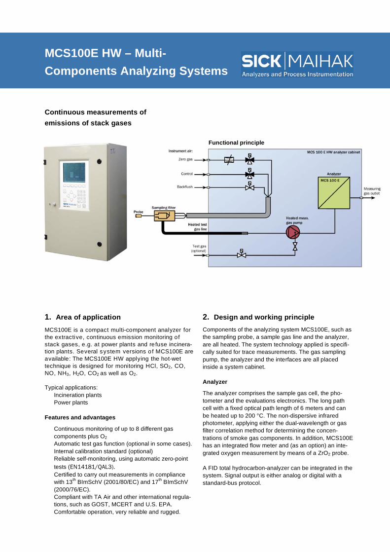
MCS100E HW – Multi- Components Analyzing Systems
Continuous measurements of emissions of stack gases
1. Area of application
MCS100E is a compact multi-component analyzer for the extractive, continuous emission monitoring of stack gases, e.g. at power plants and re fuse incinera-tion plants. Several system versions o f MCS100E are available: The MCS100E HW applying the hot-wet technique is designed for monitoring HCl, SO2, CO, NO, NH3, H2O, CO2 as well as O2. Typical applications: • Incineration plants • Power plants Features and advantages
• Continuous monitoring of up to 8 different gas components plus O2
• Automatic test gas function (optional in some cases). • Internal calibration standard (optional) • Reliable self-monitoring, using automatic zero-point
tests (EN14181/QAL3). • Certified to carry out measurements in compliance
with 13th BImSchV (2001/80/EC) and 17th BImSchV (2000/76/EC).
• Compliant with TA Air and other international regula-tions, such as GOST, MCERT and U.S. EPA.
• Comfortable operation, very reliable and rugged.
2. Design and working principle Components of the analyzing system MCS100E, such as the sampling probe, a sample gas line and the analyzer, are all heated. The system technology applied is specifi-cally suited for trace measurements. The gas sampling pump, the analyzer and the interfaces are all placed inside a system cabinet. Analyzer
The analyzer comprises the sample gas cell, the pho-tometer and the evaluations electronics. The long path cell with a fixed optical path length of 6 meters and can be heated up to 200 °C. The non-dispersive infrared photometer, applying either the dual-wavelength or gas filter correlation method for determining the concen-trations of smoke gas components. In addition, MCS100E has an integrated flow meter and (as an option) an inte-grated oxygen measurement by means of a ZrO2 probe. A FID total hydrocarbon-analyzer can be integrated in the system. Signal output is either analog or digital with a standard-bus protocol.
Functional principle

MCS100E HW – Multi Components Analyzing System – 2 –
SICK MAIHAK GmbH | Analyzers and Process Instrumentation Nimburger Str. 11 | 79276 Reute | Germany | www.sick-maihak.com
Phone +49 7641 469-0 | Fax +49 7641 469-1149 | [email protected]
3. Technical data 3.1 Results from the performance test
Measuring range HCl: 0 … 15 mg/m3 CO: 0 … 75 mg/m3 NO: 0 … 200 mg/m3 NH3: 0 … 20 mg/m3 SO2: 0 … 75 mg/ m3 CO2: 0 … 25 vol.% O2: 0 … 21 vol.% H2O: 0 … 40 vol.%
Availability in the test cycle >98 %
Maintenance interval 12 weeks
Detection limit, absolute <2% of full scale (/measuring range end value) typical
Influence on the measuring result by • Barometrical variations • Sample gas flow variations
None at barometrical correction (optional) <1 % in the monitored range
Admissible range of ambient temperature 5 ... 35 °C
Influence of the ambient temperature • at the zero point • at the reference point
< 1.2% of full scale per 10 K < 1% of full scale per 10 K
Temporal change • of the zero point • of the reference point
< 1 % of full scale per month < 1% of full scale per month
Response time (T90 time) Plant and component specific, typical <200 s
Interferences by CO2, CO, SO2, NO, NO2, NH3, N2O, HCl, CH4, H2O, C6H6
Total < 4% of full scale
Additional measuring components (with performance test)
NO2: 0 … 100 mg/m3 N2O: 0 … 100 mg/m3 CH4: 0 … 100 mg/m3
3.2 Additional technical data
Power supply 3-ph 230, +10/–15%; 50 Hz; option: 3-ph 115 V, +10/–15%; 60 Hz; special versions on request
Power consumption Cabinet: 1700 VA; heated sample gas line: 95 VA/m Sample gas filter: 450 VA; Heated sample probe: 150 VA
Dimensions (H x B x T) 2100 mm x 800 mm 600 mm (height incl. 100 mm socket)
Weight Approx. 350…500 kg (dependent on equipment)
Measuring signal output • Analog: 0 or 4 ... 20 mA • Bus protocol: Modbus, others optional
Measuring value indication Numerical and graphical
Protection class IP 43; higher protection classes on request
Automatic measuring range switching Yes
Consumption gases Instrument air
Analyzers and Process Instrumentation

MCS100E PD – Multi-Component Analyzing system
Continuous measurements of emissions of stack gases 1. Area of application MCS100E is a compact multi-component analyzer for the extractive, continuous emission monitoring of stack gases, for example HCl, SO2, CO, NO, CO2 as well as O2. By adding a permeation dryer to the MCS100E , the MCS100E PD system is able to monitor small measuring ranges. Additionally NO2 can be meas-ured specifically. Typical applications: • Incineration plants • Power plants Features and advantages
• Continuous monitoring of up to 8 different gas components plus O2
• Automatic test gas function (optional in some cases). • Internal calibration standard (optional). • Reliable self-monitoring, using automatic zero-point
tests (EN14181/QAL3). • Certified to carry out measurements in compliance
with 13th BImSchV (2001/80/EC) and 17th BImSchV (2000/76/EC).
• Compliant with TA Air and other international regula-tions, such as GOST, MCERT and U.S. EPA.
• Comfortable operation, very reliable and rugged.
2. Design and working principle Components of the analyzing system MCS100E PD, such as the sampling system with filter and the sample gas line, are all heated. The system cabinet contains a heated gas sampling pump, the permeation dryer and the transfer interfaces. Analyzer
The analyzer comprises the sample gas cell, the pho-tometer and the evaluations electronics. The cell is a long path cell with a fixed optical path length of 6 meters and can be heated up to 200 °C and optimized for the meas-urement of small volumes and fast gas flows. The pho-tometer of MCS100E is a non-dispersive infrared pho-tometer, applying either the dual-wavelength or gas filter correlation method for determining the concentrations of stack gas components. In addition, MCS100E has an integrated flow meter and (as an option) an integrated oxygen measurement by means of a ZrO2 probe. A FID total hydrocarbon-analyzer can be added to the system. Signal output is either analog or digital with a standard-bus protocol.
Functional principle

MCS100E PD – Multi Components Analyzing System – 2 –
SICK MAIHAK GmbH | Analyzers and Process Instrumentation Nimburger Str. 11 | 79276 Reute | Germany | www.sick-maihak.com
Phone +49 7641 469-0 | Fax +49 7641 469-1149 | [email protected]
3. Technical Data 3.1 Results from the performance test
Measuring range Detection limit Measuring components
HCl: 0…10 mg/m3 CO: 0…50 mg/m3 NO: 0… 50 mg/m3 NO2: 0…80 mg/m3 SO2: 0…10 mg/ m3 CO2: 0… 25 vol.% O2: 0… 21 vol.%
< 0,15 mg/m3
< 0,43 mg/m3
< 0,32 mg/m3
< 0,64 mg/m3
< 0,15 mg/m3
< 0,014 vol.%
< 0.10 vol.%
Availability < 98 %
Maintenance interval 12 weeks Maintenance work during the interval: filter check
Influence on the measuring result by • Barometrical variations • Sample gas flow variations
None at barometrical correction (optional) < 1 % at 250 ... 600 l/h
Admissible range of ambient temperature 5 ... 35 °C
Influence of the ambient temperature • at the zero point • at the reference point
< 2.1 % of full scale per 10 K < 1.9 % of full scale per 10 K
Temporal change • of the zero point • of the reference point
< ±1 % of full scale per month < ±1 % of set value per month
Response time (T90 time) Plant and component specific, typical <200 s
Interferences by CO2, CO, SO2, NO, NO2, NH3, N2O, HCl, CH4, H2O, CH3OH, CH2O, CH3COCH3, CH2Cl2
< ±2 % of full scale
Number of measuring ranges Programmable 3.2 Additional technical data
Power supply 3-ph 230, +10/–15%; 50 Hz; option: 3-ph 115 V, +10/–15%; 60 Hz; special versions on request
Power consumption Cabinet: 1700 VA; heated sample gas line: 95 VA/m Sample gas filter: 450 VA; Heated sample probe: 150 VA
Dimensions (H x B x T) 2100 mm x 800 mm 600 mm (height incl. 100 mm socket)
Weight Approx. 350…500 kg (dependent on equipment)
Measuring signal output 0 or 4 ... 20 mA
Measuring value indication Numerical and graphical
Protection class IP 43; higher protection classes on request
Automatic measuring range switching Approx. 3 h
Consumption gases Instrument air: 12000 l/h
Analyzers and Process Instrumentation

MEAC2000 – Emissions Data Acquisition System
Acquisition – Evaluation – Long-term data storage – Integrated Visualization of Emission Data – Remote Data Transfer
1. Applications The emission data acquisition system MEAC2000 fulfils the requirements for measurements according
to 13th
BImSchV (2001/80/EC), 17th
BImSchV
(2000/76/EC), 27th
and 30th
BImSchV as well as TA
Air.
Typical applications:
• Energy production, combined heat and power stations
• Waste incineration plants • Crematories • Cement works • Refineries • Plants for organic treatment of waste Features and advantages
• Evaluation of emission data recorded in plants that have to conform to 13.th (2001/80/EC) as well as 17th BImSchV (2000/76/EC).
• Implementation of German guideline „Bundesein-heitlicher Praxis bei der Überwachung von Emis-sionen von 2004“ subject to DIN EN14181.
• Visualization of emission and operational data. • Remote transfer of emission data to regulatory
authorities • Integration of emission data into existing computer
network. • Connection to process control system (PCS) via
Modbus, Profibus and OPC.
2. Design and working principle The emissions data evaluation system MEAC2000 consists of the following components: • Data acquisition unit (DAU) for collecting and
processing of measurement data as well as trans-fer to emission PC. • Possibility of using alternative field modules for
small applications • Emissions PC (EPC): PC with operating system
„Windows XP“ • Optional: possible connection of up to 16 de-
vices (DAE, field module, Modbus, OPC etc). • Take-over/transfer of data from/to a process
control system possible. • MEAC2000-Software for processing, storage and
display of all calculated values. • Control in standard operating system “Win-
dows”. Possibility of displaying data in local network.
The MEAC2000 software, with Windows XP, simplifies necessary customer specific configurations for the continuous control of emissions, makes them compre-hensible and easy to revise. It is able to monitor all data communication with connected field units and control systems.

MEAC2000 – Emissionsdaten-Auswertesystem – 2 –
SICK MAIHAK GmbH | Analyzers and Process Instrumentation Nimburger Str. 11 | 79276 Reute | Germany | www.sick-maihak.com
Phone +49 7641 469-0 | Fax +49 7641 469-1149 | [email protected]
3. Technical Data 3.1 Results from the performance test
Availability 100%
Reproducibility of the classification <1%
Admissible ambient temperature range –5 ... +50 °C
Measuring signal influence due to power supply fluctuations
< 0,5%
Computer IBM compatible PC with Windows XP
Power supply DAE 230/115V V AC switchable ; 48 ... 62 Hz
Power consumption DAE Max. 100 VA
Data interfaces RS232 RS485 Ethernet
3.2 Additional technical data
Plug-in module Channels Max. number per DAE
Analog inputs: –5 … 30 mA potential free, 100 load
16 5x
Status inputs: 24 V internal or external 32 8x
Analog outputs: 0 … 25 mA 8 4x
Relay outputs: 48 V, 500 mA 12 8x
Analyzers and Process Instrumentation

MERCEM – Mercury Analysis System
Continuous mercury emission monitoring for stack gases 1. Area of application MERCEM is used for continuous monitoring of mercury emissions (elemental mercury and mercury chloride compounds) in stack gas. By adjusting the amalgamation procedure the sensitivity of the system can be varied over a wide range to meet the individual requirements, espe-cially regarding very small measurement ranges. Typical applications are: • Waste incineration, sewage sludge incineration,
hazardous waste incineration
• Cement production • Coal-fired power plant • Ore processing, metal winning Features and advantages
• Fast Loop with approx. 1000 l/h, thereby no memory effects
• Comfortable handling, reliable and robust technology • Reliable self test by means of an auto-check of the
zero-drift-point • Low maintenance expenditure • Simple extensions with the MCS100E HW multi-
component analysis system • Certified to carry out measurements in compliance
with 17th BImSchV (2000/76/EC).
2. Design and working principle MERCEM comprises a sampling system, wet-chemical reduction of mercury chloride, an amalgamation unit, the photometer and an evaluation and control unit. A gas sampling pump extracts the stack gas via the sam-ple gas probe and sample gas line into the system cabi-net. All parts in contact with the stack gas are heated up to 180 °C and therefore protect against condensation and corrosion. The reduction of HgCl2 into elemental mercury is performed by reduction with stannous chloride (SnCl2) solution within a reactor. In a cooler the condensate is removed and the sample gas is heated and conducted to the analyzer. The measurement of mercury happens by use of cold vapor atomic absorption spectrometry (CVAAS). The single-beam photometer consists of a low pressure Hg- discharge lamp with high stability, a sample gas cell and a photodiode detector. Due to the automatic baseline correction before each measuring cycle safeguards the reliability of the measuring method. Varying the collecting time the measuring range can be set in a wide range up to 1000 g/m3 Hg max.
Functional principle

MERCEM – Mercury Analysis System – 2 –
SICK MAIHAK GmbH | Analyzers and Process Instrumentation Nimburger Str. 11 | 79276 Reute | Germany | www.sick-maihak.com
Phone +49 7641 469-0 | Fax +49 7641 469-1149 | [email protected]
3. Technical Data 3.1 Results from the performance test
Reference value Full scale (measuring range end value)
Tested measuring range 0 ... 45 μg/m3
Availability > 96 %
Maintenance interval 4 weeks
Detection limit, absolute < 1.5 μg/m3
Influence on the measuring result by • Barometrical variations none • Sample gas flow variations
None None between 200 ... 1200 l/h
Admissible range of ambient temperature 5 ... 40 °C
Influence of the ambient temperature • at the zero point • at the reference point
< 0.9 % of full scale per 10 K < 2.0 % of set value per 10 K
Temporal change • of the zero point • of the reference point
< 3 % of full scale per month < 3 % of set value per month
Response time (T90 time) < 380 s
Interferences by CO2, CO, SO2, NO, NO2, NH3, N2O, HCl, CH4, H2O, C6H6
No interferences detectable
Number of measuring ranges Programmable
Automatic measuring range switching Approx. 3 h 3.2 Additional technical data
Additional measuring ranges 0 ... 90 μg/m3
Others on request
Power supply 230 V
Power consumption Max. 4610 VA at 10 m sample gas line
Dimensions (H x B x T) 2100 mm x 800 mm 600 mm
Weight 340 kg
Measuring signal output 0 or 4 ... 20 mA
Measuring value indication Numerical and graphical
Protection class IP 43; IP 54 on request
Warm-up Approx. 1 h
Consumption gases N2 and Instrument air
Analyzers and Process Instrumentation

OMD41 Dust Measuring Device
For continuous dust measurement, qualitative as well as quantitative
1. Area of application
With its robust construction, the opacity and dust monitor OMD41 is designed for harsh industrial appli-cations. The OMD41 is suited for both measurement ranges, high range, such as occur before electrostatic filters and the small ones, as occur in treated gas after dust filters. Typical applications: • Power plants, asphalt mixing plant, • Cement, glass, steel and paper industry • Monitoring/control of electrostatic filter system • Specialized applications (thick channel walls, large
duct diameters By continuously monitoring dust concentrations, it is possible to detect deviations and transgression of limit values as required by regulations and initiate counter measures immediately. Qualitative measurement is available as transmission value given out in %. Quantita-tive dust measurement is given out by the OMD41 as extinction. These values are allocated to the actual dust concentration measurements after a calibration is carried out. Normal measuring ranges are 0 ... 200 mg/m and 0 ... 4000 mg/m . Features and Advantages
• 2 analog outputs (standard) • LC-Display for indication of quantity to be measured,
measuring range, limit value and control value • Reliable self-monitoring due to automatic control
cycle (zero and control point); EN14181/QAL3 • Integrated linearity check (4 measurement points)
• Automatic contamination correction (TR unit and reflector)
• Approved for measurements accord. to 13th
BImSchV (2001/80/EC) • Compliant with TA Air and other international regula-
tions such as GOST, MCERT and U.S. EPA. • The OMD41, with its great flexibility and rugged
construction sets the standard in its own class. 2. Design and working principle The standard delivery contains: • Transmitter/receiver unit (TR unit) • Reflector unit • Connection unit • Purge air unit with mounting flange and connection
cable (from SR unit to reflector) The OMD41 is based in-situ technology, which is instan-
taneous measurement inside the gas canal, delivering
lag-free measurement values. The optical and electronic
functional elements are contained within the sender/
receiver unit. A pulsed LED with a long lifetime serves as
the light source. An integral sighting device simplifies
alignment of the transceiver and the reflector units. In
order to protect the optical surfaces from dust and high
temperature the transceiver and reflector unit are pur-
ged with air. The connection unit contains the display
and operating elements as well as all connections.
The OMD41 can be controlled via:
• Connection unit directly • MEPA OMD41 on a PC • RCU-MS remote control unit.
Arrangement of the OMD41 components

OMD41 – Dust measuring device – 2 –
SICK MAIHAK GmbH | Analyzers and Process Instrumentation Nimburger Str. 11 | 79276 Reute | Germany | www.sick-maihak.com
Phone +49 7641 469-0 | Fax +49 7641 469-1149 | [email protected]
3. Technical data 3.1 Results of the Performance test
Availability: 99.8%. 95.7%
Maintenance rate > 4 weeks Lower detection limit (MB0-0,1Ex)
Transmission 0.51% Extinction 0.002 Dust 1.2 mg/m3 (full scale 25 mg/m3)
Drift of zero point < 1.0%
Drift of span value < 1.3%
Influence caused by straying light beam < 2% within an angle range of ±0.3°
Reproduciblity Required: R=30 Actual performance: R=40
3.2 Additional technical data
Measured quantities and measuring ranges OMD41-02 OMD41-03 Transmission (max./min.) Opacity (max./min.) Extinction (max./min.)
100 … 0 % 100…50 % 0 ... 100 % 0 ... 50 % 0 ... 2 0 ... 0.3
100 … 0 % 100 … 80 % 0 ... 100 % 0 ... 20 % 0 ... 2 0 ... 0.1
Measurement accuracy ±2 % of measuring range end value
Measuring path 0.5 ... 15 m
Response time 1 … 600 sec, selectable in 1 sec-steps
Analog output, electrically isolated 2 Analog outputs: 0, 2 or 4 ... 20 mA; Load max. 750 1: Measurement value transmission, opacity or extinction 2: Dust concentration, calibrated
Relay outputs, potential-free 4 relay inputs: max. 48 V, 1 A fault; (maintenance/cycle, limit value 1 u. 2)
Binary inputs, electrically isolated
4 binary inputs: min. 10 ... 25 V AC; 10 ... 35 V DC IN1: activate/suppress control cycle IN3: purge-air monitoring or FSS IN2, IN4: Reserve
Interfaces: RS232 service interfaces RS422 host computer interfaces
Ambient temperature –20 °C ... +55 °C
Flue gas temperature Above water dew point up to max. 600 °C
Power supply 90 ... 264 V AC; 48 ... 62 Hz
Protection class IP65
Analyzers and Process Instrumentation
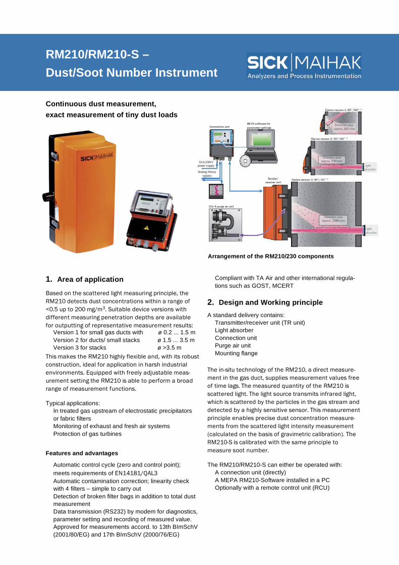
RM210/RM210-S – Dust/Soot Number Instrument
Continuous dust measurement, exact measurement of tiny dust loads
1. Area of application
Based on the scattered light measuring principle, the
RM210 detects dust concentrations within a range of
<0.5 up to 200 mg/m3. Suitable device versions with
different measuring penetration depths are available
for outputting of representative measurement results:
• Version 1 for small gas ducts with ø 0.2 ... 1.5 m • Version 2 for ducts/ small stacks ø 1.5 ... 3.5 m • Version 3 for stacks ø >3.5 m This makes the RM210 highly flexible and, with its robust
construction, ideal for application in harsh industrial
environments. Equipped with freely adjustable meas-
urement setting the RM210 is able to perform a broad
range of measurement functions. Typical applications: • In treated gas upstream of electrostatic precipitators
or fabric filters • Monitoring of exhaust and fresh air systems • Protection of gas turbines
Features and advantages
• Automatic control cycle (zero and control point); meets requirements of EN14181/QAL3
• Automatic contamination correction; linearity check with 4 filters – simple to carry out
• Detection of broken filter bags in addition to total dust measurement
• Data transmission (RS232) by modem for diagnostics, parameter setting and recording of measured value.
• Approved for measurements accord. to 13th BImSchV (2001/80/EG) and 17th BImSchV (2000/76/EG)
• Compliant with TA Air and other international regula-tions such as GOST, MCERT
2. Design and Working principle A standard delivery contains: • Transmitter/receiver unit (TR unit) • Light absorber • Connection unit • Purge air unit • Mounting flange The in-situ technology of the RM210, a direct measure-
ment in the gas duct, supplies measurement values free
of time lags. The measured quantity of the RM210 is
scattered light. The light source transmits infrared light,
which is scattered by the particles in the gas stream and
detected by a highly sensitive sensor. This measurement
principle enables precise dust concentration measure-
ments from the scattered light intensity measurement
(calculated on the basis of gravimetric calibration). The
RM210-S is calibrated with the same principle to
measure soot number.
The RM210/RM210-S can either be operated with: • A connection unit (directly) • A MEPA RM210-Software installed in a PC • Optionally with a remote control unit (RCU)
Arrangement of the RM210/230 components

RM210/RM210-S – Dust/Soot Number Instrument – 2 –
SICK MAIHAK GmbH | Analyzers and Process Instrumentation Nimburger Str. 11 | 79276 Reute | Germany | www.sick-maihak.com
Phone +49 7641 469-0 | Fax +49 7641 469-1149 | [email protected]
3. Technical data 3.1 Result of performance test
Certified measuring range • Dust concentration • Soot number SN
0 ... 5 mg/m3; 0 ... 15 mg/m3; 0 ... 150 mg/m3
0 … 4
Availability 99.8%, 95.9%
Maintenance rate > 4 weeks
Detection limit Dust: 0.02 mg/m3 (full scale: 3.5 mg/m3)
Range of ambient temperature –20 ... +55 °C
Drift of zero point < 1.2 %
Drift of span value < 1.6%
Reproduciblity R=44 3.2 Additional technical data
Measured quantity • Scattered light intensity proportional to dust concen-tration in mg/m according to calibration comparison measurement
• Soot number
Measuring range
Dust concentration Soot number
Smallest measuring range: 0 ... 0.5 mg/m3; Largest measuring range: 0 ... 200 mg/m3 *; Standard SN: 0 … 3
Measurement accuracy ±2 % of measuring range end value
Response time 1 … 255 s
Gas temperature Above water dew point, up to 500 °C (higher temperature on request)
Ambient temperature –20 °C ... +55 °C
Power supply: Transmitter/receiver unit and connection unit: 90 ... 260 V; 47 ... 63 Hz; Power consumption: 20 VA
Analog output 2 electrically isolated outputs 0.2 or 4 ... 20 mA • Dust concentration calculated with regression curve 1
or 2 in mg/m3 or soot number • Scattered light intensity (unattenuated or mean value)
Relay outputs 4 configurable outputs for the following status reports: • Malfunction; purge air failure; reference cycle active;
maintenance required; automatic measurement range changeover; exceeding limit value 1 or limit value 2; filter tear
Interface • RS232 for terminal or PC • RS422 for remote control RCU
Binary inputs 4 configurable digital input channels for the status reports such as: triggering/suppression o f control cycle; maintenance; external purge air monitoring; regression curve change over; filter tear detection; Meas. range changeover, burner on/off
Protection class Transmitter/receiver unit and connection unit: IP 65 * Intermediate ranges are freely configurable; automatic measuring range changeover
Analyzers and Process Instrumentation
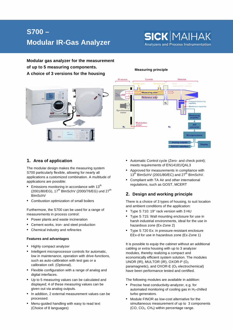
S700 – Modular IR-Gas Analyzer
Modular gas analyzer for the measurement of up to 5 measuring components. A choice of 3 versions for the housing 1. Area of application The modular design makes the measuring system S700 particularly flexible, allowing for nearly all applications a customized combination. A multitude of applications are possible: • Emissions monitoring in accordance with 13th
(2001/80/EG), 17th BlmSchV (2000/76/EG) und 27th BImSchV
• Combustion optimization of small boilers
Furthermore, the S700 can be used for a range of measurements in process control: • Power plants and waste incineration • Cement works, iron- and steel production • Chemical industry and refineries Features and advantages
• Highly compact analyzer • Intelligent microprocessor controls for automatic,
low in maintenance, operation with drive-functions, such as auto-calibration with test gas or a calibration cell. (Optional).
• Flexible configuration with a range of analog and digital interfaces.
• Up to 5 measuring values can be calculated and displayed; 4 of these measuring values can be given out via analog outputs.
• In addition, 2 external measurement values can be processed.
• Menu-guided handling with easy to read text (Choice of 8 languages)
• Automatic Control cycle (Zero- and check point); meets requirements of EN14181/QAL3
• Approved for measurements in compliance with 13th BImSchV (2001/80/EC) and 27th BImSchV.
• Compliant with TA Air and other international regulations, such as GOST, MCERT
2. Design and working principle There is a choice of 3 types of housing, to suit location and ambient conditions of the application: • Type S 710: 19" rack version with 3 HU • Type S 715: Wall mounting enclosure for use in
harsh industrial environments, ideal for the use in hazardous zone (Ex-Zone 2)
• Type S 720 Ex: in pressure-resistant enclosure EEx-d for use in hazardous zone (Ex-Zone 1)
It is possible to equip the cabinet without an additional cabling or extra housing with up to 3 analyzer modules, thereby realizing a compact and economically efficient system solution. The modules UNOR (IR), MULTOR (IR), OXOR-P (O2 paramagnetic), and OXOR-E (O2 electrochemical) have been performance tested and certified. The following modules are available in addition: • Precise heat conductivity-analyzer, e.g. for
automated monitoring of cooling gas in H2-chilled turbo generators.
• Module FINOR as low-cost alternative for the simultaneous measurement of up to 3 components (CO, CO2, CH4) within percentage range.
Measuring principle

S700 – Modular IR-Gas Analyzer – 2 –
SICK MAIHAK GmbH | Analyzers and Process Instrumentation Nimburger Str. 11 | 79276 Reute | Germany | www.sick-maihak.com
Phone +49 7641 469-0 | Fax +49 7641 469-1149 | [email protected]
3. Technical Data 3.1 Results from the performance test
Tested measuring variables CO, NO, SO2 and O2
Maintenance interval 8 days without calibration cell, otherwise 4 weeks
Availability > 99 %
Detection limits <1% of indication range/average day limit value < 0.015 vol.% O2
Linearity deviation < 1% of full scale (measuring range end value) < 0.2 vol.% O2
Zero point drift during maintenance interval < 2% of indication range < 0.2 vol.% O2
Sample gas flow Influence to measuring result < 1%
Cross-sensitivity at • zero point • reference point
Total + 2,4%
Total: – 2,4%
O2 (param.), O2 (electrochem.): < 0.2 vol.%
Ambient temperature influence in the range of +5.... 40 °C
All deviations < 1.7% full scale for CO, NO and SO2, 0,11 vol.% for O2
Response time (90% time) < 100 s
Reproducibility CO: 119 and 102 NO: 93 and 78 SO2: 71 and 55
Voltage and frequency influence 0.4% of full scale within scale the voltage and frequency range
Power supply 100, 115 or 230 V AC (+10%.... –15%), 48...63 Hz
Power consumption Max. 150 VA, typical 50 VA 3.2 Additional technical data
Measuring value indication 5-digit, quasi analog (bar graph) in physical units, measuring values and status messages always shown
Menu navigation Easy navigation within 3 levels according to NAMUR standard, help texts always available
Gas temperature 0 ... + 45 °C
Gas quality Dew point below ambient temperature, dust and aerosol free
Gas pressure against ambient pressure 700.... + 1300 hPa
Measuring gas flow Without built-in sample gas pump: 5...100 l/h with built-in sample gas pump: 30....60 l/h
Ambient temperature during operation +5...+ 45 °C
Analyzers and Process Instrumentation

SIDOR IR-Gas Analyzer
Reliable long-term measurement of 1 or 2 IR-gas components with the option of additional measurement of oxygen
1. Area of application The SIDOR is an extractive operating gas analyzer for measuring 1 or 2 gas components. With an additional electrochemical or paramagnetic measuring cell (option), oxygen can be measured as well. The SIDOR measures the gas components CO, NO, SO2, CO2, CH4 and O2
depending on the measuring tasks. Thereby it meets all requirements for: • Emission monitoring according to 13th (2001/80/EC)
and 27th BImSchV • Combustion optimization of small boilers • Exhaust measurements in power stations. Furthermore, the SIDOR has been ATEX approved for safety applications handling bio- and landfill gases and is suitable for many other industrial applications. Features and advantages
• Automatic control cycle (zero and control point); fulfils EN14181/QAL3
• Approved for measurements in compliance with 13th BImSchV (2001/80/EC) and 27th BImSchV
• Compliant with TA Air and other international regula-tions, such as GOST, MCERT
2. Design and working principle
The SIDOR analyzer consists of a basic unit in a 19"
housing, 3HU enclosure with electronics, keypad, dis-
play, software, gas connections, integrated sample gas
pressure correction and a SIDOR module for the meas-
urement of one IR component.
It can be upgraded with the following options:
• 2nd SIDOR module to measure one more IR component • O2 module: OXOR-E (electrochemical) or
OXOR-P (paramagnetic) • Sample gas pump • Humidity meter • Flow controller The intelligent signal processing and highly stable detec-
tor provide the highest degree of long- term signal stabil-
ity available to date. The stability of the detectors
means that realignments are required only 4 times a
year and then only with inert gas or ambient air that
doesn’t contain any measuring components. Influence
of noise is greatly reduced due to innovative signal
processing.
The SIDOR is based on an innovative technology that
does not only provide continuous operation with mini-
mal expense for maintenance, but one, that offers also
modern repair possibilities. All components can be ex-
changed on-site without requiring factory adjustments or
thermal alignments.
Measuring principle

SIDOR – IR-Gas Analyzer – 2 –
SICK MAIHAK GmbH | Analyzers and Process Instrumentation Nimburger Str. 11 | 79276 Reute | Germany | www.sick-maihak.com
Phone +49 7641 469-0 | Fax +49 7641 469-1149 | [email protected]
3. Technical Data 3.1 Results from the performance test
Tested measuring variables CO, NO, SO2 and O2
Maintenance interval 3 month
Availability > 98 %
Detection limits CO: 0.71 mg/m NO: 1.58 mg/m SO2: 1.65 mg/m O2 electrochemical: 0.19 vol% O2 paramagnetic: 0.16 vol%
Linearity deviation CO, NO, SO2: < ± 2% of full scale (measuring range end value) O2: < ± 0.2 vol%
Zero point drift during maintenance interval CO, NO, SO2: < ± 3% of full scale O2: < ± 0.3 vol.%
Reference point drift during maintenance interval CO, NO, SO2: < ± 3% of full scale O2: < ± 0.2 vol.%
Ambient temperature during operation +5...+ 45 °C
Influence sample gas flow < ± 1% of full scale
Cross-sensitivity: total at zero point (full scale) total at reference point (full scale)
CO: 1.5%, NO: 2.2%, SO2: 3.3% O2 (param.): 0,08 vol%, (electrochem.): 0.10 vol% CO: 1.7%, NO: 1.4%, SO2: 3.4% O2 (param.): 0.14 Vol.%, (electrochem.): 0.2 vol%
Ambient temperature influence (range) 5.... 45 °C CO, NO, SO2: < 3% of full scale O2: < ± 0.5 vol%
Measurement uncertainty Meets the requirements according to EN ISO 14956
Reproducibility
CO: 0 … 75 mg/m3: 137 NO: 0 … 125 mg/m3: 105 SO2: 0 … 100 mg/m3: 35
Voltage and frequency influence 0.1% of full scale within the voltage and frequency range 0.5% for OXOR P
Power supply 100, 115 or 230 V AC (+10%.... –15%), 48...63 Hz
Power consumption Max. 150 VA, typical 50 VA 3.2 Additional technical data
Measuring value indication 5-digit, quasi analog (bar graph) in physical units, measuring values and status messages always shown
Menu navigation Easy navigation within 3 levels, help texts always available
Gas temperature 0 ... + 45 °C
Gas quality Dew point below ambient temperature, dust and aerosol free
Gas pressure against ambient pressure –200.... + 300 hPa
Measuring gas flow 30 ... 60 l/h
Ambient temperature during operation +5...+ 45 °C
Indication delay (T90) Dependent on cell length and gas flow, typical 3 s at 60 l/h
Air pressure influence < 0.1% measuring value drift at 1% pressure drift
Analyzers and Process Instrumentation

ZIRKOR302 Oxygen Analyzer
Zirconia dioxide current principle
1. Area of application The compact ZIRKOR302 measures oxygen concentra-tions reliable, rapid and precise for: • Determining reference values for other gas compo-
nents, for example SO2, NO, NH3, NO2, • Optimizing combustion processes • Monitoring O2 excess Typical applications are: • Power stations and cement plants • Steel/iron, glass and aluminium production • Refuse incineration plants • Refineries, chemical and petrochemical industry • Pharmaceutic, paper, food, wood industry Features and advantages
• Auto. test/calibration function with ambient air (20,96 %); no specific test gases needed
• QAL3 function: internal memory for all QAL3 relevant values
• Modular design: up to 3 probes on 1 separate evalua-tion unit
• Short response time for process control demands • Applicable up to 1,400 °C ; higher on request • No reference gas necessary • All gas guiding parts are heated • No restrike into gas possible
2. Design and working principle The ZIRKOR302 Oxygen Analyzer is designed as a modular measuring system and is available in the follow-ing configurations: • ZIRKOR 302-P: analyzer with measuring gas pump
and integrated control unit • ZIRKOR 302-E: analyzer with ejector and integrated
control unit – operating with compressed air. An Evaluation Unit is available for extending the ZIRKOR302 system up to three O2 analyzers and can be used for remote control functions (e. g. in a control room) over a maximum distance of 1,200 m. The over many years proven ZrO2 technology offers exact measurements in accordance with the current sensor measuring principle. This means that a linear sensor signal is achieved over the total measuring range with a fixed physical zero point. Measurement principle
The O2 probe contains a ZrO2 solid electrolyte tube closed on one side. A constant measured gas flow passes through the heated solid electrolytic cell. A DC voltage is applied to the cell electrodes at 650 °C to determine the O2 concentration. The O2 ion current in the electrolytes is then measured. This is derived from the linear correlation between O2 conc. and gas quantity passing through the cell per time constant. A linear measuring signal, the physical zero point and the use of ambient air for calibra-tion are the results out of this.
ZIRKOR302-P: version with measuring gas
ZIRKOR302-E: version with ejector

ZIRKOR302 – Oxygen Analyzer – 2 –
SICK MAIHAK GmbH | Analyzers and Process Instrumentation Nimburger Str. 11 | 79276 Reute | Germany | www.sick-maihak.com
Phone +49 7641 469-0 | Fax +49 7641 469-1149 | [email protected]
3. Technical Data 3.1 Results of the performance test
Availability 99,84%
Maintenance interval 12 weeks
Reproducibility 290
Detection limit < 0.07 vol.% O2
Influence of the ambient temperature on the zero point Max. –0.15 vol.% O2
Influence of the ambient temperature on reference point Max. 0.26 vol. % O2
Cross-sensitivity Total <0.11 vol.% O2 at the zero point Total <0.16 vol.% O2 at the reference point
3.2 Additional technical data
Measuring principle Zirconia dioxide, current probe
Measuring range • smallest range: 0…10 vol. % • largest range: 0…25 vol. %
Accuracy Better than ± 0.2 % (along the total measuring range)
Response time (90% time) 15 s (at sample gas equipment of 1 m)
Measuring gas temperature max. • Stainless steel probe • Inconel probe • Ceramic probe
Measuring gas pressure 700…1,100 hPa (0.7…1.1 bar) for the standard version; others on request
Immersion depth 300 mm, 500 mm, 800 mm, 1000 mm, 1400 mm, 1800 mm
Ambient temperature –20…+55 °C
Protection class IP 65 or IP 67
Power supply 115/230 V AC; ±10 %; 50/60 Hz; 310 VA consumption; sample/filter heating 500 VA
Interfaces • RS 232 service interface • CAN bus or RS422 Option: PROFIBUS DP, Modbus RTU, Ethernet, Interbus S
Signals 1 analog output: 0/4…20 mA, 500 (potential-free); Options: • 4 relay outputs: 48 V AC/DC; 1 A; 60 W DC/30 W AC • 4 analog outputs: 0/4…20 mA; 500 (galv. isolated • 4 digital outputs: 24 V load (built-in or de-centralized
in a cabinet to be used) Inputs/outputs can be extended on request.
Analyzers and Process Instrumentation

www.siemens.de/processanalytics
LDS 6 In-situ Diode Laser Spectrometer
1. Overview
LDS 6 is a diode laser gas analyzer with a measuring principle based on the specific light absorption of different gas components. LDS 6 is suitable for fast and non-contact measurement of gas concentrations or temperatures in process or flue gases. One or two signals from up to three measuring points are processed simultaneously by one central analyzer unit. The in-situ cross-duct sensors at each measuring point can be separated up to 1 kilometer from the central unit by using fiber-optic cables. The sensors are designed for operation under harsh environmental conditions and contain a minimum of electrical components. By connecting a flow cell to a bypass stream, measurements can be carried out also in-situ instead of extractive. • Approved according to 13. and 17. BlmSchV and TI Air • MCERTS approved • Compliance with the requirements of EN 14956 and of
QAL 1 according to EN 14181.
2. Characteristics and Benefits
The in-situ gas analyzer LDS 6 is characterized by a high operational availability and unique analytic selectivity and by a broad scope of suitable applications. LDS 6 can be equipped with up to three measurement channels. LDS 6 enables the measurement of one or two gas components or - if desired - the gas temperature directly in the process: • With high levels of dust load • In hot, humid, corrosive, explosive, or toxic gases • In applications showing strong varying gas compositions • Under harsh environmental conditions at the measuring point • Highly selective, i.e. mostly without cross interferences. . 3. Applications • Process optimization • Continuous emission monitoring for all kinds of fuels (oil, gas, coal, and others) • Process measurements in power utilities and any kind of incinerator • Process control • Explosion protection • Measurements in corrosive and toxic gases • Quality control • Environmental protection • Plant and operator safety.

www.siemens.de/processanalytics
4. Technical Specifications of LDS 6 General
Measuring components NH3, H2O, HCL, HF, CO, CO2, O2, T
Measuring ranges Up to three per unit, adjustable
Protection class Central unit IP20. Sensors IP65
Electrical Characteristics
EMC immunity Acc. EN 61326 and standard classification acc. Namur NE21
Power supply 100...240 V AC 50-60Hz
Power consumption 50 W
Electric inputs and outputs
Analog output 2 per channel, 4...20 mA, max. load 750 Ohm
Binary output 6, with changeover contacts, configurable, AC/DC 24V/1A, floating
Binary input 6, designed for 24 V, floating, configurable
Communication interface
Ethernet 10BaseT (RJ-45)
AUTOCAL-function Permanent assurance of the calibration due to integrated reference cell.
Options Flow cell for extractive use
Conditions for the measurement gas
Gas pressure 1-5 bar, gas-dependant
Gas flow Not relevant, in-situ
Gas temperature Up to 1500°C, gas-dependant
Humidity Up to 100%, gas-dependant
Measuring response
Output signal fluctuation
2% of measurement value above the detection limit
Drift Reference: NH3 max. +0,9 % v. MBE H2O max. +2,2 % v. MBE
Detection limit Application dependent, 0,1...500 ppm
Linearity Better 1%
Influencing variables
Ambient temperature < 1%/10K
Ambient pressure < 2% / 50 Pa Data from the approval test
Smallest TÜV-approved measuring range
NH3 H2O HCl
0-20 mg/m³ res. 0-35 mg/m3 0-30 Vol.-% res. 0- 15 Vol.-% Available from 2007 on
Availability > 99%
Maintenance interval 25 weeks stable, 12 weeks interval

www.siemens.de/processanalytics
ULTRAMAT 23 Gas analyzer for IR – absorbing Gases and Oxygen
1. Overview
The ULTRAMAT 23 gas analyzer can measure up to 4 gas components at once: A maximum of three infrared sensitive gases such as CO, CO2, NO, SO2, CH4 (applying single-beam NDIR principle) plus O2 with an electrochemical oxygen measuring cell. • Approved according to 13. and 27. BlmSchV (FEPL)
and TI Air • MCERTS approved • Compliance with the requirements of EN 14956 and of
QAL 1 according to EN 14181. 2. Characteristics and Benefits
• AUTOCAL with ambient air High efficiency so no calibration gas and accessories
required
• High selectivity by multiple layer detectors • Easy to clean sample cells
Reduced maintenance cost for further use in case of
pollution
• Menu-assisted operation in plain text Operation control without manual, high operational
safety
• Service information and log book Preventive maintenance; help for service and
maintenance personnel, cost reduction
Open interface architecture (RS 485, RS 232; PROFIBUS, SIPROM GA) Simplified process integration, remote control
3. Application Areas
• Optimization of small firing systems • Monitoring of exhaust gas concentration from firing
systems with all types of fuel (oil, gas and coal) as well as operational measurements with thermal incineration plants
• Room air monitoring • Monitoring of air in fruit stores, greenhouses, fermenting
cellars and warehouses • Monitoring of process control functions • Atmosphere monitoring during heat treatment of steel • For use in non-potentially explosive atmospheres. ULTRAMAT 23 is also available as portable unit.

www.siemens.de/processanalytics
4. Technical Specifications ULTRAMAT 23 General
Measuring components max. 4, of which up to 3 infrared sensitive gases plus oxygen
Measuring ranges two per component
Degree of protection (enclosure) • Rack units • Field units
IP20 according to EN 60529
Electrical characteristics
EMC interference immunity (Electro-Magnetic Compatibility)
according to standard requirements of NAMUR NE21 (08/98) or EN 50081-1, EN 50082-2
Power supply AC 100 V, 120 V, 200 V, 230 V each +10%/-15%, 50 Hz, AC 100 V, 120 V, 230 V each +10%/-15%, 60 Hz
Power consumption approx. 60 VA
Electric inputs and outputs
Analog output per component, 0/2/4 ... 20 mA, NAMUR, floating, max. load 750 Ω
Relay outputs 8, with changeover contacts, freely selectable, e.g. for range identification, loading capacity, 24 V AC/DC /1 A, floating, non sparking
Binary inputs 3, designed for 24 V, floating for pump, AUTOCAL and synchronization
Serial interface RS 485
AUTOCAL function automatic analyzer calibration with ambient air (depending on measured component), cycle time adjustable from 0 (1) ... 24 hours
Options supplementary electronics with 8 additional binary inputs and relay outputs, e.g. for external automatic calibration and for PROFIBUS PA or PROFIBUS DP
Gas inlet conditions
Sample gas pressure • without pump • with built-in pump
• unpressurized • unpressurized suction mode
Sample gas flow 72 ... 120 l/h (1,2 ... 2 l/min)
Sample gas temperature
0 ... 50 ºC
Sample gas humidity < 90 % relative humidity, non condensing
Measuring response (Infrared channel)
Output signal fluctuation
< ±1% of smallest measuring range
Drift with AUTOCAL negligible
Repeatability ≤ 1% of smallest measuring range
Minimum detection limit
< 1% of current measuring range
Linearity error • in largest measuring range: < 1% of full-scale value
• in smallest measuring range: < 2 % of full-scale value
Influencing variables
Ambient temperature max. 2% of smallest possible measuring range (with AUTOCAL)
Atmospheric pressure Corrected by internal pressure sensor
Daten aus der Eignungsprüfung
Smallest TÜV-approved measuring ranges
CO NO SO2 O2
0 ... 150 mg/m³ 0 ... 100 mg/m³ 0 ... 400 mg/m³ 0 ... 10 / 0 ... 25 Vol.-%
Availability > 98%
Maintenance interval 1 year with an AUTOCAL cycle time of 6 h

www.siemens.de/processanalytics
FIDAMAT 6 Flammenionisationsdetektor zur gesamt Kohlenwasserstoffanalyse
1. Overview
Das Gasanalysengerät FIDAMAT 6 ist für die Bestimmung des Gesamtkohlenwasserstoffgehaltes in Luft, in Prozessgasen und hochsiedenden Gasgemischen geeignet. Die Messung erfolgt nach dem Flammenionisationsprinzip. • Approved according to 13./17. BlmSchV (FEPL) and TI
Air • MCERTS approved • Compliance with the requirements of EN 14956 and of
QAL 1 according to EN 14181. 2. Characteristics and Benefits
Das Gasanalysengerät FIDAMAT 6 zeichnet sich durch sein breites Anwendungsspektrum aus • bei Anwesenheit bis zu 100% H2O Dampf • bei Reinstgasapplikationen • bei hochsiedenden Komponenten (bis 200 °C) • bei Anwesenheit korrosiver Gase (mit Vorfilter). Der FIDAMAT 6 besitzt • sehr geringe Querempfindlichkeiten gegen Störgase • geringen Brennluftverbrauch • geringen Einfluss von Sauerstoff auf den Messwert.
Darüber hinaus ist das Gerät mit Warn- und Fehlermeldungen ausgerüstet • bei Brenngasausfall • bei Verlöschen der Flamme • Fehlfunktionen von Pumpe und Filter. 3. Application Areas
• Umweltschutz • Abwasser (in Verbindung mit einer Stripeinrichtung,
Nachweis des Kohlenwasserstoffgehalts in Flüssigkeiten)
• Messung in Rauchgasen gemäß 13. BlmSchV/17. BlmSchV und TA-Luft für Brennstoffarten Öl, Kohle, Gas und Müll
• MAK-Wert-Überwachung an Arbeitsplätzen • Qualitätsüberwachung • Prozessabgasüberwachung • Reinstgasmessung in Medien wie O2, CO2, Edelgasen
und kalten Messgasen • Messung von korrosiven und kondensierenden Gasen • Prozessoptimierung.

www.siemens.de/processanalytics
4. Technical Specifications FIDAMAT 6 General
Concentration units ppm, C1, C3, C6 or mgC/m3
Measuring ranges 4, switchable internally and externally; autoranging is also possible
Oven temperature adjustable, factory setting 200 °C
Degree of protection (enclosure)
IP20 according to EN 60529
Electrical characteristics
EMC interference immunity (Electro-Magnetic Compatibility)
in accordance with standard NAMUR NE21 requirements (08/98)
Electrical safety according to EN 61010-1, overvoltage category II
Power supply AC 100 ... 120 V, 48 ... 63 Hz AC 200 ... 240 V, 48 ... 63 Hz
Power consumption approx. 150 VA in operation, approx. 350 VA in the warm-up phase
Electric inputs and outputs
Analog output 0/2/4 ... 20 mA, floating; load ≤ 750 Ω
Relay outputs 6, with changeover contacts, freely programmable, e.g. for range identification; loading capacity: 24 V AC/DC / 1 A floating, non sparking
Binary inputs 2, designed for 0/2/4 ... 20 mA, for external pressure sensor and correction of influence of residual gas (correction of cross interference)
Serial interface 6, designed for 24 V, floating, freely programmable, e.g. for range switching
Analog output RS 485
Options Autocal function with 8 additional binary inputs and 8 relay outputs, also with PROFIBUS PA and PROFIBUS DP
Gas inlet conditions
Sample gas pressure • without pump • with built-in pump
• < 2000 hPa abs. • 600 ... 1100 hPa
Sample gas flow 18 ... 60 l/h (0,3 ... 1 l/min)
Sample gas temperature
0 ... 200 ºC
Sample gas humidity < 90 % relative humidity
Measuring response
Output signal fluctuation
< ±0,75% des kleinstmöglichen Messbereichs
Zero drift < 0,5%/Monat von der kleinstmöglichen Messspanne
Measured-value drift < 1%/Woche der jeweiligen Messspanne
Repeatability < 1% der jeweiligen Messspanne
Minimum detection limit
0,1 ppm
Linearity error < 1% der jeweiligen Messspanne
Influencing variables
Ambient temperature < 1%/10 K bezogen auf die kleinstmöglichen Messspanne
Atmospheric pressure < 1%/50 hPa
Sample gas pressurek < 2% der Messspanne/1% Druckänderung
Daten aus der Eignungsprüfung
Smallest TÜV-approved measuring ranges
Availability
Maintenance interval

www.siemens.de/processanalytics
OXYMAT 6 Paramagnetischer Sauerstoffanalysator
1. Overview
Die Funktion der Gasanalysengeräte OXYMAT 6 beruht auf dem paramagnetischen Wechseldruckverfahren und wird zur Messung von Sauerstoff in Gasen eingesetzt. Ein kombiniertes Gerät ULTRA/OXYMAT 6 zur Messung von zwei infrarot-aktiven Gasen und Sauerstoff ist ebenfalls erhältlich. • Approved according to 13./17. BlmSchV (FEPL) and TI
Air • MCERTS approved • Compliance with the requirements of EN 14956 and of
QAL 1 according to EN 14181. 2. Characteristics and Benefits
• Parametrisches Wechseldruckverfahren Kleine Messbereiche (0-0,5% oder 99,5-100% O2),
absolute Linearität
• Detektorelement hat keine Berührung mit dem Messgas Einsetzbar zur Messung korrosiver Gase, hohe
Lebensdauer • Physikalisch unterdrückter Nullpunkt durch geeignete
Vergleichsgaswahl (Luft oder O2) • Offene Schnittstellenarchitektur (RS 485, RS 232,
PROFIBUS)
• SIPROM GA Netzwerk für Wartungs- und Serviceinformationen (Option)
• Feldgerät IP 65 mit gasdichter Trennung von Elektronik und Physik; spülbar
• Beheizte Versionen (Option) 3. Application Areas
• Für die Kesselsteuerung von Verbrennungsanlagen • In sicherheitsrelevanten Bereichen • Als Bezugsgröße für die Emissionsmessung nach TA-
Luft, 13. und 17. BlmSchV • In der Automobilindustrie (Prüfstandsysteme) • Warneinrichtungen • In chemischen Anlagen • In Reinstgasen zur Qualitätsüberwachung • Umweltschutz • Qualitätsüberwachung • Inertisierungsüberwachung mit einer eignungsgeprüften
Gaswarneinrichtung • Ausführungen zur Analyse in brennbaren und
nichtbrennbaren Gasen oder Dämpfen zum Einsatz in explosionsgefährdeten Bereichen.

www.siemens.de/processanalytics
4. Technical Specifications OXYMAT 6 General
Smallest possible measuring range
0,5 Vol.%, 2 Vol.% oder 5 Vol.%O2
Largest possible measuring range
100 Vol.% O2
Measuring ranges 4, switchable internally and externally; autoranging is also possible
Degree of protection (enclosure) • Rack units • Field units
• IP20 according to EN 60529 • IP65 according to EN 60529,
restricted breathing to EN 50021
Electrical characteristics
EMC interference immunity (Electro-Magnetic Compatibility)
in accordance with standard NAMUR NE21 requirements (08/98)
Electrical safety according to EN 61010-1, overvoltage category III
Power supply AC 100 ... 120 V, 48 ... 63 Hz AC 200 ... 240 V, 48 ... 63 Hz
Power consumption approx. 35 VA
Electric inputs and outputs
Analog output 0/2/4 ... 20 mA, floating; load ≤ 750 Ω
Relay outputs 6, with changeover contacts, freely programmable, e.g. for range identification; loading capacity: 24 V AC/DC / 1 A floating, non sparking
Binary inputs 2, designed for 0/2/4 ... 20 mA, for external pressure sensor and correction of influence of residual gas (correction of cross interference)
Serial interface 6, designed for 24 V, floating, freely programmable, e.g. for range switching
Analog output RS 485
Options Autocal function with 8 additional binary inputs and 8 relay outputs, also with
PROFIBUS PA and PROFIBUS DP
Gas inlet conditions
Messgasdruck • verschlaucht
- ohne Druckschalter - mit Druckschalter
• verrohrt
500 ... 1500 hPa (absolut) 600 ... 1300 hPa (absolut) 500 ... 3000 hPa (absolut)
Sample gas flow 18 ... 60 l/h (0,3 bis 1 l/min)
Sample gas temperature
0 ... 50 ºC
Sample gas humidity < 90 % relative humidity, non condensing
Measuring response
Output signal fluctuation < ±0,75% des kleinstmöglichen Messbereichs
Zero drift < 0,5%/Monat von der kleinstmöglichen Messspanne
Measured-value drift < 0,5%/Monat der jeweiligen Messspanne
Repeatability < 1%/Monat der jeweiligen Messspanne
Minimum detection limit 1% vom aktuellen Messbereich
Linearity error < 0,1%/Monat der jeweiligen Messspanne
Influencing variables
Umgebungstemperatur < 0,5%/10 K bezogen auf die kleinstmöglichen Messspanne
Messgasdruck bei eingeschalteter Druckkompensation: < 0,2% der Messspanne/1% Druckänderung
Daten aus der Eignungsprüfung
Smallest TÜV-approved measuring ranges
0 … 5 Vol.% 0 … 25 Vol.%
Availability > 99,3 %
Maintenance interval 4 weeks

www.siemens.de/processanalytics
ULTRAMAT 6 Gasanalysengerät für IR – absorbierende Gase
1. Overview
Die Gasanalysengeräte ULTRAMAT 6, Ein- oder Zweikanal, arbeiten nach dem NDIR-Zweistrahl-Gegentaktverfahren und messen hochselektiv Gase, deren Absorptionsbanden im Infrarot-Wellenlängenbereich von 2 bis 9 µm liegen, wie z. B. CO, CO2, NO, SO2, NH3, H2O sowie CH4 und weitere Kohlenwasserstoffe. Einkanalgeräte können bis zu 2 Gaskomponenten, Zweikanalgeräte bis zu 4 Gaskomponenten gleichzeitig messen. Ein kombiniertes Gerät ULTRA/OXYMAT 6 zur Messung von zwei infrarot-aktiven Gasen und Sauerstoff ist ebenfalls erhältlich. • Approved according to 13./17. BlmSchV (FEPL) and TI
Air • MCERTS approved • Compliance with the requirements of EN 14956 and of
QAL 1 according to EN 14181. 2. Characteristics and Benefits
• Hohe Selektivität durch Zweischichtdetektor und optischen Koppler
• Niedrige Nachweisgrenzen • Korrosionsbeständige Materialien im Gasweg (Option)
Reinigbare Messkammern Kostenersparnis durch Weiterverwendung bei
Verschmutzungen • Feldgerät IP 65 mit gasdichter Trennung von Elektronik
und Physik; spülbar • Beheizte Versionen (Option)
Einsatz auch bei Anwesenheit niedrig kondensierender
Gase 3. Application Areas
• Messung zur Kesselsteuerung von Verbrennungsanlagen
• Emissionsmessungen an Verbrennungsanlagen • Warneinrichtungen • Prozessgaskonzentrationen in chemischen Anlagen • Spurenmessungen bei Reinstgasprozessen • Umweltschutz • MAK-Wert-Überwachung an Arbeitsplätzen • Qualitätsüberwachung • Ex-Ausführungen zur Analyse brennbarer und nicht
brennbarer Gase oder Dämpfe zum Einsatz in explosionsgefährdeten Bereichen.

www.siemens.de/processanalytics

www.siemens.de/processanalytics
4. Technical Specifications ULTRAMAT 6 General
Measuring components max. 3
Measuring ranges 4, switchable internally and externally; autoranging is also possible
Degree of protection (enclosure) • Rack units • Field units
• IP20 according to EN 60529 • IP65 according to EN 60529,
restricted breathing to EN 50021
Electrical characteristics
EMC interference immunity (Electro-Magnetic Compatibility)
in accordance with standard NAMUR NE21 requirements (08/98)
Electrical safety according to EN 61010-1, overvoltage category III
Power supply AC 100 ... 120 V, 48 ... 63 Hz AC 200 ... 240 V, 48 ... 63 Hz
Power consumption 1-channel unit: approx. 40 VA 2-channel unit: approx. 70 VA
Electric inputs and outputs
Analog output 0/2/4 ... 20 mA, floating; load ≤ 750 Ω
Relay outputs 6, with changeover contacts, freely programmable, e.g. for range identification; loading capacity: 24 V AC/DC / 1 A floating, non sparking
Binary inputs 2, designed for 0/2/4 ... 20 mA, for external pressure sensor and correction of influence of residual gas (correction of cross interference)
Serial interface 6, designed for 24 V, floating, freely programmable, e.g. for range switching
Analog output RS 485
Options Autocal function with 8 additional binary inputs and 8 relay outputs, also with PROFIBUS PA and PROFIBUS DP
Gas inlet conditions
Sample gas pressure • verschlaucht
- ohne Druckschalter- mit Druckschalter
• verrohrt (ohne Druckschalter)
600 ... 1500 hPa (absolut) 600 ... 1300 hPa (absolut) 600 ... 1500 hPa (absolut)
Sample gas flow 18 ... 90 l/h (0,3 ... 1,5 l/min)
Sample gas temperature
0 ... 50 ºC
Sample gas humidity < 90 % relative humidity, non condensing
Measuring response
Output signal fluctuation
± 0,1% ... ± 1% des kleinst-möglichen Messbereichs
Zero drift < 1% des Messbereiches/Woche
Measured-value drift < 1% des Messbereiches/Woche
Repeatability ≤ 1% des jeweiligen Messbereichs
Minimum detection limit
1% vom kleinsten Messbereich
Linearity error linearisiert
Output signal fluctuation
< 0,5% vom Messbereichsendwert
Influencing variables
Ambient temperature < 1% des Messbereichs/10 K (bei stabiler EK-Temperatur)
Sample gas pressure bei eingeschalteter Druckkompensation: < 0,2% der Messspanne/1% Druckänderung
Daten aus der Eignungsprüfung
Smallest TÜV-approved measuring ranges
CO NO SO2
0 ... 50 mg/m³ 0 ... 100 mg/m³ 0 ... 75 mg/m³
Availability > 99,3 %

www.siemens.de/processanalytics
Wartungsintervall CO, NO: SO2:
4 Wochen 8 Tage

Staubemissionsmessanlage StackGuard
1. Anwendungsbereich Messung der Staubkonzentration gemäss 13. und 17. BImSchV in trockenen oder feuchten, wasserdampfgesättigten und korrosiven Abgasen Überwachung von Hausmüll-, Sondermüll- und Klärschlammverbrennungsanlagen sowie Kraftwerken Staubkonzentrationsmessung in heissen Gasen in individueller Anordnung Das StackGuard ist eignungsgeprüft durch den TÜV Rheinland, Prüfbericht No. 936/21202165/A 2. Aufbau und Arbeitsweise
• Extraktive Anordnung mit Probenaufbereitung
• Automatische Null- und
Referenzpunktkontrolle
• Einfacher Abgleich mit Kontrollstäben
• Höchste Empfindlichkeit im Bereich µg/m3 Nasse Gase, die durch Gaswäscher abgekühlt und mit Wasser gesättigt sind und Anlagen die nahe am Taupunkt der Abgase betrieben werden, müssen wegen der Messwertverfälschung durch die entstehenden Tröpfchen extrahiert und über den Taupunkt aufgeheizt werden. Diese Fälle deckt die Staubmessanlage StackGuard ab.
Ein Ringleitungssystem (a) mit einem grossen Durchmesser von 40 mm transportiert das zu messende Gas mit hoher Geschwindigkeit zum Messgerät (b) und wieder zurück in den Abgaskanal (c). Damit können Ablagerungen auf ein Minimum reduziert werden. In diesem Ringleitungssystem wird das Gas mit Heizelementen (d) auf die notwendige Temperatur über den Taupunkt aufgeheizt. Die Messprobe wird nahe dem Photometer dem Ringleitungssystem entnommen und nach der Messung wieder an dieses abgegeben. Der Antrieb der Entnahme erfolgt über ein Radialgebläse (e). Absperrventile (f) trennen im Störfall die Messanlage zum Schutz vor Korrosion durch aggressive Gase vom Kamin ab. Die gesamte Bedienung, Steuerung und Überwachung der Messanlage erfolgen durch das Bedienungsgerät (g). In Rauchgas enthaltene Staubteilchen streuen das Licht eines durchgehenden Lichtstrahls. Die Messung der Streulichtintensität erlaubt daher eine Aussage über die Konzentration der Staubteilchen in der Probe. Das StackGuard misst die Streulichtintensität einer angesaugten Probe im Zweistrahlverfahren. Dabei wird das unter 20° gestreute Licht zum direkt durchgehenden Licht ins Verhältnis gesetzt. Dieses Verfahren kompensiert so auf einfache Weise Schwankungen der Lichtquelle sowie Alterungseffekte und Temperaturabhängigkeiten der Elektronik. Durch Verwendung einer Laserlichtquelle wird das Störlicht minimiert und die Empfindlichkeit des StackGuard in den Bereich von µg/m3 abgesenkt.

3. Technische Daten 3.1 Daten aus der Eignungsprüfung Staubkonzentrations- Messung Photometer StackGuard Bedienungsgerät SIGAR2
Messumfang: 0 ... 100 mg/m3 PLA Messbereiche: 0.. 0,05/0 .. 0,1/0 .. 0,3/0 .. 1/0 .. 3/0 .. 10 mg/m3 PLA Linearität: Abweichung < 0.6% Nullpunktdrift im Wartungsintervall: Nicht feststellbar Referenzpunktdrift im Wartungsintervall: 0.9% Verfügbarkeit: 99% Wartungsintervall: 3 Monate Driftkontrolle: automatische Überwachung von Null- und Referenzpunktdrift Nachweisgrenze im Feldtest: 0,006 mg/ m3 Umgebungstemperatur: -20°C … +50°C Umgebungsfeuchte: 0 .. 99% rel. Feuchte, nicht kondensierend Durchflussmenge: 25...50 l/min @ 160°C Netzanschluss: 3 x 340 .. 440 V ; 50/60 Hz Leistungsaufnahme: 5.5 kVA (Standardausführung mit 2 Heizern) Stromausgang: 2 x 0/4 ... 20 mA; Bürde max. 600 Ω Kontakte: 5 getrennt konfigurierbare Relaiskontakte 250 V AC, 4 A
3.2 Weitere Technische Daten Staubkonzentrations- Messung Photometer StackGuard Ringleitung Bedienungsgerät SIGAR2
Auflösung: ± 0,0002 PLA Messwellenlänge: 650 nm Gewicht: 8,4 kg Schutzart: IP65 Durchflussmenge: 790 .. 930 l/min @ 160°C Gewicht: ca. 240 kg (Standardausführung) Leitungslänge: max. 25 m Gesamtlänge Kaminanschlüsse: DN65 PN6 mit Flansch DIN 2641 oder kundenspezifisch Schutzart: IP40 (zusätzliche Isolation für Aufstellung im Freien erforderlich) Schnittstelle: Profibus DP (optional) Schutzart: IP 65 Gewicht: 22 kg
SIGRIST-PHOTOMETER AG · Hofurlistrasse 1 · CH-6373 Ennetbürgen Telefon +41 (0) 41/624 5454 · Telefax +41 (0) 41/624 5455 www.photometer.com · e-mail [email protected]

S.K.I. GmbH
Gerberstr. 49 41199 Mönchengladbach
Telefon: +49-2166 -62317-0 Telefax: +49-2166-611681
Flue gas - flow measuring system SDF-22 and SDF-50
1. Applications The measuring systems of the type SDF-22 and SDF-50 are, based on an expert assessment issued by the TÜV Rheinland, approved for measuring flue gas flow rates. The systems are especially designed for flow measurements of gases that are contaminated, corrosive, or charged with water or dust. 2. Setup and functional principle The measuring systems of the type SDF-22 and SDF-50 are based on the differential pressure principle. The sensor measures the pressure difference between the upstream and downstream side. Given a constant density of the medium, the differential pressure is proportional square to the
flow velocity. A differential pressure transducer is used to convert this data into an electrical signal. By integrating temperature and pressure measurement devices the influence of density fluctuations caused by changes of temperature and pressure can be considered correctly. With a gas calculator of the µFlow series or another suitable calculator already in stock, the density of the medium, the actual flow rate and the flow rate under standard conditions can be calculated. With their different profile strengths the measuring systems cover all diameter ranges from DN125 up to DN12000. To meet specific requirements regarding temperature or corrosive media the measuring systems can be manufactured in all other appropriate materials above standard 1.4571, like Hastelloy or Inconel. .

S.K.I. GmbH
Gerberstr. 49 41199 Mönchengladbach
Telefon: +49-2166 -62317-0 Telefax: +49-2166-611681
3. Technical data 3.1 Data from the expert assessment Mounting place: horizontal flue gas duct Diameter: 1050mm Sensors: 2 x SDF-22, 1 x SDF-50 Medium: heavily contaminated, wet flue gas Gas density: 1,297 kg/Nm³, wet Temperature: 25..70 °C Pressure: 995..1046 mbar abs Measuring range 0..20 m/s Output: 4.. 20 mA DC Transducer: Smar LD301, Siemens Sitrans P Availability: > 99 % Maintenance rate: Application dependent At least 3 months 3.2 Further technical data 3.2.1 SDF-Sensors Sensor types: SDF-10, SDF-22, SDF –32
and SDF-50 Diameter: DN40..DN12000 Temperature medium: -200..1200°C Pressure medium: 0,5..420 bar abs Media : Liquids, gases and steam Materials: 1.4571 (standard)
Hastelloy C22, Inconel 600 1.5415, 1.7335, 1.7380, 1.4903 others on request
Accuracy: 1% of measured value 3.2.2 Differential pressure transducer Measuring range 0..1 mbar bis 0..30 bar Output : 4..20 mA DC, HART, PROFIBUS PA Temperature medium: -40..+100°C Accuracy: up to 0,075% (dependent on type) 3.2.3 Compact computer µFLOW Functions: gas flow calculator, calculator for water, steam and heat Input : 6 x 0/4..20 mA, 2 x switchable to Pt100 direct Output : analog: max. 2 x 0/4..20 mA, electrically isolated Relais: 1 x Failcontact, 2 x configurable Pulse: open collector PNP Display two-line LCD-Display Accuracy: 0,1 %

FID-Emissionsmesseinrichtungfür GesamtkohlenstoffEignungsgeprüft nach 17.BImSchV
Mobile und stationäre Gesamt-C Messungmittels FID-Analysator
1.Anwendungsbereich
Für Anlagen der 17.BImSchV und TA Luft mitEmissionen chlorierter und nichtchlorierterorganischer Lösemittel; kleinster geprüfterMessbereich 0-15mgC/m3
2.Prüfbericht und Veröffentlichung
Prüfbericht 24095574 vom 4.8.2000 des TÜVSüddeutschlands und ist im GMBl N° 60, S.1193(Gemeinsames Ministerialblatt) veröffentlicht.
3.Aufbau und ArbeitsweiseDie Testa-Flammenionisationsdetektoren messendie Summe der Kohlenwasserstoffe inIndustrieabgasen, Raum- und Außenluft,Automobilabgasen, katalytischen und thermischenNachverbrennungsanlagen(TNV, KNV) Lösungs-mittelrückgewinnungsanlagen etc.Die Emmissionsüberwachung und die Prozess-messung ist neben den mobilen Messungen undder Überwachung von flüchtigen Kohlenwasser-stoffen in Wasser mittels Stripper, der Haupt-anwendungsbereich der FID Messtechnik.
Funktionsprinzip FID
300 V FID und AnzeigeVerstärker
H2, 5.0 Meß-Prüfgas
Brennluft
Die organischen Komponenten werden
in einer Wasserstoffflamme ionisiert.
TESTA GmbHKathi-Kobus-Str. 15D-80797 München
Fon: +49 89 129 30 06Fax: +49 89 129 88 35Webseite: www.testa-fid.deE-Mail: [email protected]
4.Technische Daten FIDaus der Eignungsprüfung
Messkomponente CxHy
Kleinster geprüfter Messbereich 0 - 15 mg C/m3
Verfügbarkeit > 99%(über Zeitraum von 3 Monaten für zwei Systeme)
Nachweisgrenze < 0,01 mg C/m3
Zulässige Umgebungstemperatur +5 - 35°C
Zeitliche Nullpunktdrift < 1,1 %
Zeitliche Änderung der Empfindlichkeit < 2% MB
Einstellzeit (90%-Zeit) 10 Sec
Querempfindlichkeit < 1,9% des MB
5. Weitere technische Daten
Analogausgänge:- Strom, galv. getrennt: 0-20 mA, 4-20 mA- Spannung: 0-10 V
Digitalausgang: USB / RS 232
Hilfsgase:- Brenngas H
2oder He/H2
- Prüfgas: C3H
8oder CH
4
- Nullgas: N2
- synth. Luft- Brennluft: über Katalysator
aus Raumluft
Brenngasverbrauch: ca. 35 ml/minNull- und Prüfgasverbrauch: 1 l/minBrennluftverbrauch: 30 l/Std.
Netzanschluß: 115V-230 V50 - 60 Hz

6. FID Messgeräte
Testa-FID Features:
• Analysenteil beheizt auf 300°C• Option Analysenteil beheizt auf 400°C• Filterüberwachung (Interner Eingangsschutz)• Katalytische Brennluftaufbereitung• Rechneranschluß USB• automatische Flammenzündung• Flammenkontrolle• Kontrollmodul für Temperatur und Druck• Temperaturregler für beheizte Leitung/Filter• Automatische Meßbereichsumschaltung• Software zur Steuerung des FID`s und
Datalogging im MS-Excel Format
Mobile MessungFID 2010T
Durch sein geringes Gewicht und seine kompaktenAbmessungen ist er besonders für den Einsatz anständig wechselnden und schwer zugänglichenMessorten ausgelegt.
19“ RackeinschubFID 1230 Modul (stationäre Messung)
Mit Luftstrahlpumpen als nahezu wartungsfreiesFID bei 24Stunden/360 Tage Prozess-überwachungen im Einsatz.
Geschütztes WandgehäuseFID 3001W (stationäre Messung)
Das Wandgehäuse entspricht der Schutzart IP65
Gaskoffer mit Versorgungsgasen
Höhe einschließlich Griff: 500 mmBreite: 500 mmTiefe: 230 mm
Bestückung:Aluminiumflaschen mit integriertem Druckminderer- Brenngasflasche B1: H
2, 5.0
- Prüfgasflasche B1: C3H
8,80ppm
- Nullgasflasche B1: N2, 5.0
oder synth. Luft
Verbindung FID Schnellkupplungen mitFlaschenhalter: PTFE-Schlauch 4/6 mm
TESTA GmbHKathi-Kobus-Str. 15D-80797 München
Fon: +49 89 129 30 06Fax: +49 89 129 88 35Webseite: www.testa-fid.deE-Mail: [email protected]


Thermo NO/NOx Analysis System
1. Typical Applications Simultaneous on-line measurement of NH3 and NOx in DeNOx installations In recent years Thermo has gained considerable experience in applying the NOx chemiluminescence technique to flue-gas applications requiring the measurement of NH3. This has resulted in the development of a specific on-line measurement system based on a chemiluminescence NOx/NH3 analyser (Thermo model 17C). A number of Thermo NOx analyser systems have to date been successfully used by the (chemical) industry and research laboratories to monitor NOx removal from flue-gases originating from gas turbines, refinery furnaces, and nitric acid and caprolactam plants, applications for which NOx is present in concentrations ranging from 10 ppm to as high as 5,000 ppm.
2. System overview and operation principle A pre-requisite for the accurate measurement of NH3 is correct conditioning of the gas sample; practical experience has shown that sample dilution with clean air is effective in preventing ammonia losses via reaction with acidic components and dissolution in condensate, during sampling and transport to the analyser. In this manner NH3 analyses can be performed with a minimum detection limit, better than 0.5 ppm and an accuracy better than ± 1 ppm NH3 (at 5 ppm NH3) in a background of approximately 100 ppm NOx. A feature of the Thermo NOx system is the ability to analyse NO, NO2 and NH3 simultaneously on-line.
Method with dilution probe and NH3 converter unit
close to sample point
Calibration gas:
• NH3
Dilution Probe
Converter Unit
NOx/NH3 analyser
model 17C
Control Panel
of Dilution Probe
Signals 4-20 mA:
• NO
• NO2
• NH3
Calibration gases:
• NO
• NO2

Thermo NO/NOx Analysis System
3. Technical Data Measuring principle : Chemiluminescence Tested measuring ranges : NO 0 – 200 mg/m
3
NO2 0 – 50 mg/m3
Detection limit : NO 0,41 mg/m
3
NO2 0,14 mg/m3
Temperature range : 0 – 30ºC (above 30ºC an optional airconditioning unit must be installed) Temperature influence on zero : NO < 0,2 % f.s. per 10 K NO2 < 0,1 % f.s. per 10 K Temperature influence on span : NO < 2,6 % f.s. per 10 K NO2 < 2,9 % f.s. per 10 K Cross interferences : < 4 % f.s. for the sum of O2, H2O, CO, CO2, CH4, N2O, NH3, SO2 and HCl (HCl must be lower than 50 mg/m
3)
Response time (T90) : NO < 120 sec NO2 < 180 sec Zero drift : < 0,19 % per 14 days Span drift : < 2,00 % per 14 days Linearity : < 2,00 % f.s. Availability : 98,7 % Outputs signals : 3x 4-20 mA (NO, NOx, NH3) General analyser failure alarm Dimensions : analyser cabinet 1140 x 700 x 900 mm (hwd) converter cabinet 600 x600 x 250 mm (hwd) Weight : analyser cabinet 100 kg converter cabinet 40 kg Power supply/consumption : 230 VAC/50 Hz ; 800 Watt Environmental Instruments Division 27 Forge Parkway Franklin, MA (508) 520-0430 tel Air Quality 02038 (508) 520-1460 fax www.thermo.com
Typical DeNOx
installations
Copyright © 2022 FDOKUMEN