
STORMWATER MANAGEMENT CRITERIA - Toronto and ...
126
STORMWATER MANAGEMENT CRITERIA AUGUST 2012 VERSION 1.0
-
Upload
khangminh22 -
Category
Documents
-
view
1 -
download
0
Transcript of STORMWATER MANAGEMENT CRITERIA - Toronto and ...

STORMWATER MANAGEMENT CRITERIA
AUGUST 2012 VERSION 1.0

this report has been formatted for double-sided printing

STORMWATER MANAGEMENT CRITERIA iii
TORONTO AND REGION CONSERVATION AUTHORITY AUGUST 2012 VERSION 1.0
Acknowledgements This document was prepared by the Toronto and Region Conservation Authority, in partnership with the Credit Valley Conservation Authority, with the direction and input of the Sustainable Technologies Evaluation Program, The Municipal Infrastructure Group Ltd., Aquafor Beech Ltd., Geomorphic Solutions, with funding generously provided by the Region of Peel, the City of Toronto, and the Region of York.
This document may be updated as a result of Watershed Studies or changes in provincial, municipal, and/or technical guidance. Please ensure you are using the latest version which can be downloaded from the TRCA and STEP websites:
www.trca.on.ca and www.sustainabletechnologies.ca
Publication Information Comments on this document should be directed to:
Sameer Dhalla, P.Eng. Senior Manager, Water Resources Toronto and Region Conservation Authority 5 Shoreham Drive Downsview, Ontario, Canada M3N 1S4 Email: [email protected]
iv STORMWATER MANAGEMENT CRITERIA
TORONTO AND REGION CONSERVATION AUTHORITY AUGUST 2012 VERSION 1.0
Preface Within the context of current legislation, policies, and science relating to stormwater management (SWM), this document provides additional guidance with respect to the Toronto and Region Conservation Authority’s (TRCA’s) specific water management strategies and programs, building on the principle that the establishment of appropriate, effective, and sustainable SWM practices requires a solid understanding of the form, function, and interrelation of the water resources and natural heritage systems.
This document provides guidance in the planning and design of stormwater management infrastructure for developers, consultants, municipalities, and landowners, and outlines the processes and infrastructure needed to address flooding, water quality, erosion, water balance, and natural heritage. While this document addresses SWM throughout TRCA’s jurisdiction, a review of site specific conditions is recommended to ensure that any necessary variations on these requirements are identified early in the planning and design process, through thorough consultation with all affected agencies and stakeholders, to maintain sound engineering and environmental practices.
This TRCA SWM Criteria document has been organized as follows:
Chapter 1: Provides an introduction and the purpose of this document, and the overall goals for SWM within TRCA watersheds.
Chapter 2: Summarizes the procedures provided in the ensuing chapters to develop an overall SWM strategy for a proposed development or related project.
Chapters 3 through 6:
Outline TRCA’s environmental design criteria with respect to stormwater quantity, quality, erosion, and water balance, and provide guidance on the studies and methodologies to be undertaken to identify specific targets as they relate to these individual components of SWM.
Chapter 7: Provides guidance with respect to the planning and design of SWM practices within TRCA watersheds.
Appendix A: Provides information relating to flood control and the unit flow relationships that exist within TRCA watersheds.
Appendix B: Provides the geomorphologic methodologies and analyses pertaining to stream erosion.
Appendix C: Provides detailed methodologies, guidance, and data associated with the analysis of water balance to maintain recharge/infiltration.
Appendix D: Provides detailed methodologies, guidance, and data associated with the analysis of water balance to protect natural features including wetlands, woodlands, and watercourses.
Appendix E: Provides information and guidance relating to the design of SWM ponds, including outlet details and planting guidelines.
STORMWATER MANAGEMENT CRITERIA v
TORONTO AND REGION CONSERVATION AUTHORITY AUGUST 2012 VERSION 1.0
Contents 1 Introduction ........................................................................................ 1
1.1 The Need for Effective Stormwater Management ............................................................... 1 1.2 Policy Framework .................................................................................................... 1 1.3 Purpose of the Document ........................................................................................... 2 1.4 Transition of the Document ......................................................................................... 3 1.5 Stormwater Design Criteria ......................................................................................... 3
2 Stormwater Management Design Process ..................................................... 5
2.1 Project Scale and the Planning Process ........................................................................... 5 2.2 Design Process ........................................................................................................ 6 2.3 Modeling Guidance ................................................................................................... 9 2.4 Practitioner Credentials ............................................................................................. 9 2.5 Summary of Stormwater Management Design Criteria ........................................................ 10
3 Stormwater Quantity (Flood) ................................................................. 12
3.1 Stormwater Quantity (Flood) Control Objective ............................................................... 12 3.2 Stormwater Quantity (Flood) Control Criteria .................................................................. 12 3.3 Regional Flood Control ............................................................................................. 16 3.4 Stormwater Quantity (Flood) Control Practices ................................................................ 17
4 Erosion ............................................................................................. 18
4.1 Erosion Control Objective .......................................................................................... 18 4.2 Erosion Control Criteria ............................................................................................ 18 4.3 Erosion Control Analysis Methodology ............................................................................ 19 4.4 Erosion Control Practices .......................................................................................... 19
5 Stormwater Quality ............................................................................. 21
5.1 Quality Control Objective .......................................................................................... 21 5.2 Quality Control Criteria ............................................................................................ 21 5.3 Quality Control Practices........................................................................................... 22
6 Water Balance .................................................................................... 23
6.1 Water Balance Objectives.......................................................................................... 23 6.1.1 Groundwater Recharge ........................................................................................ 23 6.1.2 Natural Feature Protection ................................................................................... 24
6.2 Water Balance Criteria ............................................................................................. 25 6.2.1 Recharge Criteria ............................................................................................... 25

vi STORMWATER MANAGEMENT CRITERIA
TORONTO AND REGION CONSERVATION AUTHORITY AUGUST 2012 VERSION 1.0
6.2.2 Criteria for Protection of Natural Features ................................................................ 26 6.3 Water Balance Analysis Methodology ............................................................................. 27
6.3.1 Recharge ......................................................................................................... 27 6.3.2 Protection of Natural Features ............................................................................... 28
6.4 Water Balance Practices ........................................................................................... 31
7 Stormwater Management Practices .......................................................... 32
7.1 Overview .............................................................................................................. 32 7.2 Stormwater Management Facilities ............................................................................... 32 7.3 Oil and Grit Separators ............................................................................................. 34 7.4 Low Impact Development Practices .............................................................................. 35
Appendices Appendix A: Water Quantity and Unit Flow Relationships
Appendix B: Erosion and Geomorphology
Appendix C: Water Balance and Recharge
Appendix D: Water Balance for Protection of Natural Features
Appendix E: Stormwater Management Pond Design Guidance
Appendix F: TRCA Executive Committee Communication
STORMWATER MANAGEMENT CRITERIA vii
TORONTO AND REGION CONSERVATION AUTHORITY AUGUST 2012 VERSION 1.0
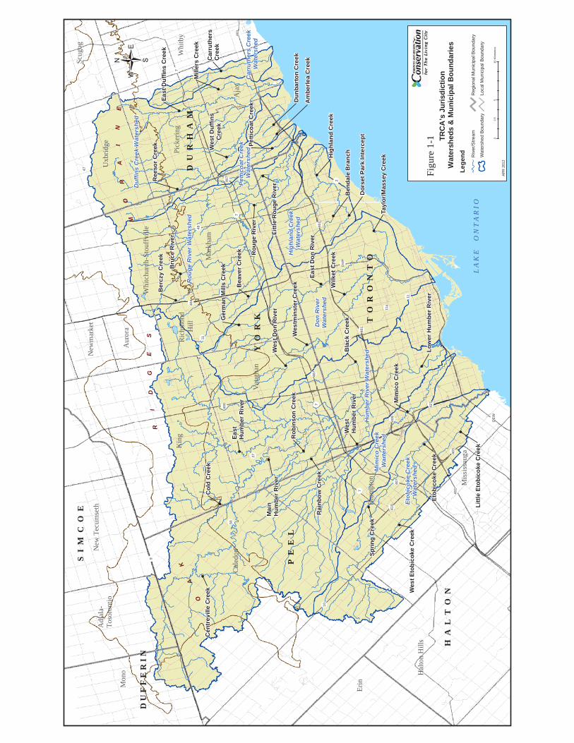
Figures Figure 1-1: TRCA’s Jurisdiction, watersheds and municipal boundaries ..................................................... 3
Figure 2-1: Scope of Analysis to Define the Stormwater Management Plan ................................................. 7 Figure 4-1: Erosion Scope of Analysis ............................................................................................ 19 Figure 6-1: Infiltration/Recharge Scope of Analysis ........................................................................... 28 Figure 6-2: Scope of Analysis for the Protection of Natural Features ....................................................... 29
Tables Table 2-1: Computer Model Recommendations .................................................................................. 9 Table 2-2: Summary of Stormwater Management Design Criteria............................................................ 10 Table 3-1: TRCA Stormwater Quantity (Flood) Control Criteria .............................................................. 12 Table 6-1: Recharge Criteria Summary .......................................................................................... 25 Table 7-1: Water Quality Storage Requirements ............................................................................... 33

viii STORMWATER MANAGEMENT CRITERIA
TORONTO AND REGION CONSERVATION AUTHORITY AUGUST 2012 VERSION 1.0
- THIS PAGE LEFT INTENTIONALLY BLANK -
STORMWATER MANAGEMENT CRITERIA 1
TORONTO AND REGION CONSERVATION AUTHORITY AUGUST 2012 VERSION 1.0
1 Introduction
1.1 The Need for Effective Stormwater Management
The practice of managing stormwater is continuing to evolve as the science of watershed management and understanding of our watersheds grow. Effective management of stormwater is critical to the continued health of our streams, rivers, lakes, fisheries and terrestrial habitats. In simple terms, precipitation that lands on the ground surface is distributed in several directions. Some of the water infiltrates the ground (infiltration), some of it runs off the surface (runoff), and much of the remainder either evaporates or is consumed by plants (evapotranspiration). This is referred to as the water budget. In natural settings, the presence of vegetation and the lack of hard surfaces define this distribution such that a relatively small part of the rainfall produces runoff. In built communities, the introduction of hard surfaces and the reduction in vegetated cover alter this proportion such that significantly more runoff is generated, and less water is taken up by evapotranspiration from natural vegetation or makes its way into the ground to naturally recharge our streams, wetlands, and groundwater resources.
During storm events, the increase in surface runoff usually generated by our communities can result in flooding and erosive damage to our streams and structures. In addition, human activity produces pollution, which in combination with the increased runoff can degrade the quality of our water resources. Together these by-products of urbanization also degrade our natural heritage systems, and can cause hydrological, water quality, and ecological impacts to natural heritage features. Past approaches to SWM have altered natural flow patterns, by redirecting rainfall away from source areas (where it falls) to concentrated points well downstream. This causes a fundamental change in the hydrology of catchments, impacting the volume, frequency, duration, timing, and distribution of flow. More recent approaches aim at managing water on a smaller scale by distributing it across the landscape instead of at a single point downstream. The resulting criteria promote these new approaches to water management, which more closely replicate pre-development hydrology.
1.2 Policy Framework
The Conservation Authorities Act was legislated by the Province of Ontario in 1946, in response to concerns expressed by agricultural, naturalist, and sportsmen’s groups who observed that much of the renewable natural resources of the province were in an ‘unhealthy state’ due to poor land, water, and forestry practices during the 1930’s and 1940’s. The combined impacts of drought and deforestation led to extensive soil loss and flooding.
Effective stormwater management is needed to manage the quantity and
quality of runoff generated by our communities
Effective stormwater management is needed to manage the quantity and
quality of runoff generated by our communities

2 STORMWATER MANAGEMENT CRITERIA
TORONTO AND REGION CONSERVATION AUTHORITY AUGUST 2012 VERSION 1.0
With decades of practical experience in protecting our environment, education, and engaging communities, Ontario’s Conservation Authorities (CAs) work with governments, businesses, and individuals to build a greener, cleaner, healthier place to live. The Conservation Authorities Act mandates CAs to prevent, eliminate, or reduce the risk to life and property from flooding and erosion, and to encourage the protection and regeneration of natural systems. Through study, management, and enforcement, Ontario’s CAs work with municipal, provincial, and private sector partners to maintain the safety, quality, and sustainability of the water resources within our communities. CAs also have Memoranda of Understanding (MOUs) with their partner municipalities to ensure that the tenets of the Provincial Policy Statement (PPS) are upheld, and that no adverse effects to significant natural features result from development applications approved through the Planning Act.
1.3 Purpose of the Document
This Stormwater Management Criteria document has been prepared to supplement the Planning and Development Procedural Manual (PDP Manual, 2007) with more detailed direction regarding the Stormwater Management (SWM) component of development approvals. Within TRCA’s jurisdiction, the PDP Manual outlines the information, fees, and other requirements needed when seeking development approvals from TRCA.
The purpose of this document is to consolidate and build upon current design guidelines and requirements relating to SWM from watershed plans and hydrology studies, and provide additional and specific detail for those areas within TRCA’s jurisdiction. Figure 1-1 shows TRCA’s jurisdiction, watersheds and municipal boundaries. Referenced documents include the Ministry of the Environment’s Stormwater Management Planning and Design Manual (SWMPD, 2003), the TRCA/CVC Low Impact Development Stormwater Management Planning and Design Guide, Version 1.0(TRCA/CVC, 2010) and TRCA’s PDP Manual, noted above.
The Stormwater Management Criteria document articulates a SWM planning framework, with associated criteria, to be applied at the various stages of the planning process, ranging from Official Plan and Secondary Plan studies through to plans of subdivision and site plans. Together the planning process and the design criteria provide a procedure for the selection of the most appropriate approaches to SWM.
The criteria described in this document may be augmented or in some cases superseded by legislative requirements or unique situations. For example, the water quantity control (flood protection) targets as defined in Section 3 are based on various independent
Hydrology Studies. These targets may be superseded or refined by the completion of subsequent and more detailed studies, such as Master Environmental Servicing Plans (MESPs) or Subwatershed Studies (SWSs), which may include regional flood assessments. Similarly, legislation or drainage policy from other agencies such as the Ministry of Transportation (MTO) and local municipalities may require additional consideration in the
This document provides guidance in the planning and design of stormwater management infrastructure for developers, consultants, municipalities, and landowners, and outlines the processes and infrastructure needed to address flooding, water quality, erosion, water balance, and natural heritage.
!400
!401
!427
!401
!401
!409
!407
!QEW
!7
!DVP
!407
!27
!403
!410
!50
!7
!10
!9
!404
!11!48
!47
!7!40
7
!11a
!2
!11
!401
!7
T O
R O
N T
O
Y O
R K
D U
R H
A M
P E
E L
D U
F F
E R
I N
S I
M C
O E
Cal
edon
Aur
ora
Bra
mpt
on
Kin
g
Whi
tchu
rch-
Stou
ffvi
lle
Ric
hmon
d H
ill
Pick
erin
g
Uxb
ridge
Mar
kham
Mis
siss
auga
Vau
ghan
Adj
ala-
Toso
ront
io
Mon
o
H A
L T
O N
Hal
ton
Hill
s
New
mar
ket
Whi
tby
OA
K
RI
DG
ES
MO
RA
IN
E
L A
K E
O
N T
A R
I O
Aja
x
Figu
re 1
-1
/
05
102.
5K
ilom
etre
s
New
Tec
umse
th
Erin
Scug
og
Lege
nd Riv
er/S
tream
Wat
ersh
ed B
ound
ary
Reg
iona
l Mun
icip
al B
ound
ary
Loca
l Mun
icip
al B
ound
ary
TRC
A’s
Jur
isdi
ctio
n W
ater
shed
s &
Mun
icip
al B
ound
arie
s
APR
201
2
Wes
t Duf
fins
Cre
ek
Am
berle
a C
reek
Dun
bart
on C
reekC
arru
ther
s C
reek
Mill
ers
Cre
ek
East
Duf
fins
Cre
ek
Petti
coat
Cre
ek
Littl
e R
ouge
Riv
er
Rou
ge R
iver
Hig
hlan
d C
reek
Bru
ce R
iver
Ree
sor C
reek
Bea
ver C
reek
East
Don
Riv
er
Tayl
or/M
asse
y C
reek
Wes
t Don
Riv
er
Ger
man
Mill
s C
reek
Wes
tmin
ster
Cre
ek Wilk
et C
reek
Ben
dale
Bra
nch
Dor
set P
ark
Inte
rcep
t
Low
er H
umbe
r Riv
er
Bla
ck C
reek
East
Hum
ber R
iver
Wes
tH
umbe
r Riv
er
Rai
nbow
Cre
ek
Rob
inso
n C
reek
Mai
nH
umbe
r Riv
er
Etob
icok
e C
reek
Mim
ico
Cre
ek
Wes
t Eto
bico
ke C
reek
Sprin
g C
reek
Littl
e Et
obic
oke
Cre
ek
Ber
czy
Cre
ek
Col
d C
reek
Cen
trev
ille
Cre
ek
Don
Riv
erW
ater
shed
Hum
ber R
iver
Wat
ersh
ed
Etob
icok
e C
reek
Wat
ersh
edMim
ico
Cre
ek
War
ters
hed
Rou
ge R
iver
Wat
ersh
ed
Duf
fins
Cre
ek W
ater
shed
Car
ruth
ers
Cre
ek
Wat
ersh
ed
Petti
coat
Cre
ek
Wat
ersh
ed
Hig
hlan
d C
reek
W
ater
shed

STORMWATER MANAGEMENT CRITERIA 3
TORONTO AND REGION CONSERVATION AUTHORITY AUGUST 2012 VERSION 1.0
definition of site targets where subject sites discharge to highway drainage or municipal storm sewer systems.
As quantity and quality control practices have a greater history of application, this document provides a comparatively broader description of the objectives, methodologies, and requirements associated with the erosion and water balance components of SWM.
1.4 Transition of the Document
It is the intent that criteria presented in this document and the associated permitting process will apply to all new Applications submitted under the Planning Act after September 7, 2012 with the exception of all new Applications subject to supporting Technical and Environmental documents which are either approved, accepted or sufficiently advanced in the review and approval process with TRCA since September 7, 2002, in which case, the policies utilized to establish the requirements for the application will be utilized.
Works completed or in progress on all development related Applications will be duly recognized and the extent of works completed will be taken into account in establishing a reasonable and mutually acceptable go forward strategy to final acceptance of the Application. The criteria presented in this document are not intended to re-set the Application review process. Background documents that are substantially advanced; Master Environmental Servicing Plans reviewed at least once by TRCA and prepared under a Terms of Reference accepted by TRCA; and other technical works that required substantial time and effort to prepare will be recognized and accredited.
1.5 Stormwater Design Criteria
Stormwater criteria are generally defined at the early stages of watershed and subwatershed studies. The design criteria are frequently refined to reflect the different scale of studies that are undertaken as development proceeds. For example, at the watershed scale, targets for flood control may consist of flow rates defined at the outlet of the subwatershed for the 2 through 100 year and Regional storms, while the focus at the site plan scale is on site release rates. Environmental design criteria are provided to:
Prevent any increases in flood risk potential;
Maintain runoff volume, frequency, and duration from frequent storm events;
Protect water quality;
Preserve groundwater and baseflow characteristics;
Prevent undesirable geomorphic changes in watercourses; and,
Maintain an appropriate diversity of terrestrial and aquatic life and opportunities for human uses.

4 STORMWATER MANAGEMENT CRITERIA
TORONTO AND REGION CONSERVATION AUTHORITY AUGUST 2012 VERSION 1.0
The design criteria include flood protection, water quality, erosion control, and water balance (for both groundwater recharge and protection of natural features), and are developed considering the interactions and cumulative effects which may be expected from urban growth. Cumulative impacts refer to the combined effect of numerous single developments. Urban development in the absence of an MESP, watershed, and/or subwatershed plan is discouraged because of the difficulty in addressing many
environmental impacts at a plan of subdivision or site plan level. In cases where development is proposed but guidance from a watershed or subwatershed plan is not available, TRCA staff should be consulted with respect to the definition of appropriate design criteria.
In some cases, the subwatershed plan has been completed but the environmental design criteria are outdated. This may be particularly true for studies that are more than five years old and where design criteria relating to erosion and water balance have not been adequately defined. In such cases, TRCA staff should be consulted with respect to the definition of appropriate design criteria.
Notwithstanding the above, the following sections of this document provide an overview of the environmental design criteria which should be used as a basis for the planning and design of SWM infrastructure. The collective intent of these criteria is to minimize the impacts of development and urbanization on the natural water cycle. To this end, mechanisms that strive to maintain water balance should be considered essential, as maintenance of the natural water cycle will inherently mitigate impacts associated with flood risk, water quality, erosion, groundwater recharge, and the related impacts to natural heritage features.
In all cases, it is recommended that
proponents consult with TRCA and municipal staff
to confirm the criteria and approaches to be
d
In general, targets are to be established through a comprehensive environmental study that defines both the existing, pre-development flows and the future anticipated post-development flows.

STORMWATER MANAGEMENT CRITERIA 5
TORONTO AND REGION CONSERVATION AUTHORITY AUGUST 2012 VERSION 1.0
2 Stormwater Management Design Process
2.1 Project Scale and the Planning Process
Development and infrastructure planning processes span a wide range of scales and scopes, and accordingly there are both common and unique aspects to these processes requiring consideration when establishing the SWM plan for a project. SWM plans must include an evaluation of the hydraulic, hydrologic, geomorphic, hydrogeologic, and ecological conditions of a subject area, and be designed to address quantity, quality, erosion, and
water balance (including both groundwater recharge and water balance for natural features), as described in the subsequent sections of this document. In areas where a comprehensive environmental study (e.g. subwatershed study) has been completed, and alternative design criteria for SWM are recommended, the specific criteria in this document may not apply. It is the applicant’s responsibility to confirm with TRCA and the appropriate municipality whether the alternative environmental design criteria for
stormwater management recommended in the comprehensive environmental study are appropriate or not.
The TRCA PDP Manual (2007) differentiates between several types of planning applications, briefly described below. While the scale and level of detail may vary between the different types of applications, this Stormwater Management Criteria document outlines principles and processes that are universally applicable, with general variations as noted below. It is normally preferred that projects at a smaller scale occur in areas where comprehensive studies, such as subwatershed studies, have been completed, in order to establish criteria within the context of the overall subwatershed area. Similarly, consideration must be given to the existing state of a subject property to establish an appropriate level of effort in establishing criteria. For example, infill and retrofit projects will likely require a different approach from greenfield developments. In all cases, consultation with municipal and TRCA staff is necessary to confirm the approaches and criteria to be used.
Urban development without watershed/subwatershed planning is discouraged because of the difficulty in addressing many environmental impacts at a plan of subdivision or site plan level. It is strongly recommended that proponents consult with TRCA early in the process to define environmental targets and criteria.
Official Plan Amendments, Secondary Plans, or “Block” Plans are normally supported by a multi-disciplinary Master Environmental Servicing Plan (MESP) or similar technical study that, with respect to water resources, includes a detailed and comprehensive evaluation of
Criteria provided in this document may not apply where a comprehensive environmental study has been completed and approved, and where the study has established refined criteria based on detailed and location specific technical analysis.
6 STORMWATER MANAGEMENT CRITERIA
TORONTO AND REGION CONSERVATION AUTHORITY AUGUST 2012 VERSION 1.0
the subject area and its catchment to define an appropriate SWM plan. The scale and comprehensive nature of the required technical evaluations may yield refinements to the targets and criteria described elsewhere within this document at later planning stages. MESPs should include extensive consultation with municipal and TRCA staff to confirm the approaches and criteria to be used.
Zoning By-law Amendments are required when a proponent wishes to use, alter, or develop a property in a way that does not conform to the existing Zoning By-law. Depending on the nature and extent of the proposed change, a SWM plan may be required, usually as part of a Functional Servicing Plan. The scale of these types of projects necessitates a greater level of detail in the evaluation of site conditions, and increased focus on the sensitivities of local features to the potential impacts of proposed works.
Plans of Subdivision are required to support the subdivision of land into three or more parcels, and are typically supported by the detailed design of proposed infrastructure, often preceded by a Functional Servicing Plan or MESP. The SWM plan for this type of application must consider the criteria presented in this document, as well as the findings of approved subwatershed studies, MESP’s, or similar studies that encompass the subject lands. The scale of these types of projects necessitates a greater level of detail in the evaluation of site conditions, and increased focus on the sensitivities of local features to the potential impacts of proposed works.
Site Plans deal with the specifics of site design for development proposals, and these are typically supported by Functional Servicing Plans and the detailed design of infrastructure. The SWM plan for this type of application must consider the criteria presented in this document, as well as the findings of approved subwatershed studies, MESP’s, or similar studies that encompass the subject lands. The scale of these types of projects necessitates a greater level of detail in the evaluation of site conditions, and increased focus on the sensitivities of local features to the potential impacts of proposed works.
Consents (Severances) and Minor Variances respectively refer to authorized separations of land parcels and minor changes to existing zoning provisions. These types of undertakings require supporting technical analyses and suitable provision for SWM requirements, with the degree of complexity dependent on the nature and extent of the works proposed by the application.
Single Lot Residential Development (<0.5 ha) For these types of undertakings, best efforts approach (i.e. implementing roof drain disconnection, rain garden, soakaway pit, permeable pavement, etc. ) should be made to achieve the SWM requirements specified in this document with the degree of complexity dependent on the nature and extent of the works proposed by the proponent.
2.2 Design Process
As described in Section 1.1, SWM is a necessary component of urban infrastructure. Effective SWM is needed to manage the quantity and quality of runoff generated by our communities in order to prevent these impacts. A SWM plan must consider two scales of precipitation events:
Management of large events is needed to prevent increased flood risk and undue inundation of natural systems; and,
STORMWATER MANAGEMENT CRITERIA 7
TORONTO AND REGION CONSERVATION AUTHORITY AUGUST 2012 VERSION 1.0
Maintenance of natural or predevelopment hydrology is needed to minimize the volume of runoff leaving a site, which will reduce the dependence of developments on downstream infrastructure, respect the sensitivities of natural receiving systems, and continue the replenishment of groundwater resources.
At both scales, the management of water quality is critical to minimize the potential for the contaminants generated by our communities to harm the surrounding environment.
Although separate approaches have been provided for flood protection, water quality, erosion control, and water balance, it should be emphasized that achieving the required design criteria for all of these categories will be dependent upon minimizing the impact that urbanization has on the water balance. Urbanization, if not dealt with appropriately, will result in significant alteration of the natural water balance. This, in turn, can cause watercourses, and other natural features, to experience less water during dry weather periods. It can also reduce the amount of rainfall available to recharge groundwater, sustain aquifers, and maintain ecological processes dependent on groundwater discharge. It can also increase surface runoff, degrade water quality, and aggravate erosion.
Designing a SWM system that manages both peak flows and the volume of runoff through encouraging water to infiltrate into the ground, evapotranspire, and/or be re-used, is critical to sustaining surface and groundwater inputs to natural features that rely on that surface and groundwater regime. Managing the water balance will therefore be paramount if appropriate design criteria are to be met for flood protection, water quality, erosion control, and water balance.
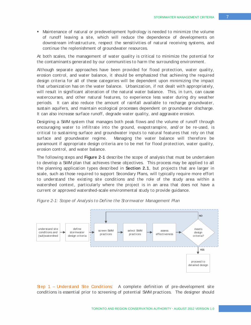
The following steps and Figure 2-1 describe the scope of analysis that must be undertaken to develop a SWM plan that achieves these objectives. This process may be applied to all the planning application types described in Section 2.1, but projects that are larger in scale, such as those required to support Secondary Plans, will typically require more effort to understand the existing site conditions and the role of the study area within a watershed context, particularly where the project is in an area that does not have a current or approved watershed-scale environmental study to provide guidance.
Figure 2-1: Scope of Analysis to Define the Stormwater Management Plan
Step 1 – Understand Site Conditions: A complete definition of pre-development site conditions is essential prior to screening of potential SWM practices. The designer should
understand site conditions and (sub)watershed
define stormwater
design criteria
screen SWM practices
select SWM practices
assess effectiveness
meets design
criteria?
proceed to detailed design
NO
YES
8 STORMWATER MANAGEMENT CRITERIA
TORONTO AND REGION CONSERVATION AUTHORITY AUGUST 2012 VERSION 1.0
prepare maps describing site conditions, to ensure that all environmental features and functions that need consideration in accordance with provincial, municipal and conservation authority development regulations/policies are identified. In addition, information regarding native soil types, infiltration capacity and depth to water table must be determined. These investigations together yield an understanding of the existing state of a proposed development area, and form the basis for the analyses that must be undertaken to prepare an appropriate SWM strategy.
Step 2 - Define SWM/Environmental Design Criteria: Once the site conditions are established, the individual SWM components described in the following sections of this document must be assessed to define the environmental design criteria relevant to the site. The design criteria from any of the following categories may apply:
Flood Protection (See Section 3);
Erosion Control (See Section 4);
Water Quality (See Section5); and,
Water Balance (See Section 6).
Step 3 - Screen Potential Stormwater Management Practices: A number of factors need to be considered when screening the suitability of a given location within a development site for application of SWM practices. A treatment train approach using source, conveyance, and end-of-pipe facilities, in combination with low impact development practices, should be considered to meet the design criteria associated with water quantity, quality, erosion, and water balance.
Step 4 - Selection of a Suite of Stormwater Management Practices: The short list of SWM practices established in Step 3 can be reviewed, assessed, and refined to establish those measures that, in combination, will achieve all the relevant environmental design criteria. The product of this step is the overall SWM strategy for the proposed development.
Step 5 - Assessing the Effectiveness of the Stormwater Management Plan: Once the SWM strategy has been defined, an assessment of the effectiveness of the strategy must be undertaken with the aid of simulation, via either computer models or simple spreadsheet analyses. Model selection will be based on the size and type of development. A wide range of simple to complex computer models is available, with modeling guidance provided in Section 2.3. If the assessment reveals that the SWM strategy will not achieve the relevant environmental design criteria, Steps 3 through 5 must be revisited iteratively until a SWM strategy is established that achieves the required objectives.
Step 6 - Detailed Design and Construction: The detailed design of SWM infrastructure for a development can proceed once an effective SWM strategy has been established. Section 7 provides design guidance in the design of SWM infrastructure specific to projects within TRCA’s jurisdiction. During construction activity, SWM is largely focused on erosion and sediment control practices. The Erosion and Sediment Control Guideline for Urban Construction (Greater Golden Horseshoe Conservation Authorities, 2006) and Designer’s Guide for Low Impact Development Construction (CVC, Draft, 2011) provides guidance on the approaches and criteria to be applied during construction. Water management during the construction phase may be required to protect natural features during interim conditions.
STORMWATER MANAGEMENT CRITERIA 9
TORONTO AND REGION CONSERVATION AUTHORITY AUGUST 2012 VERSION 1.0
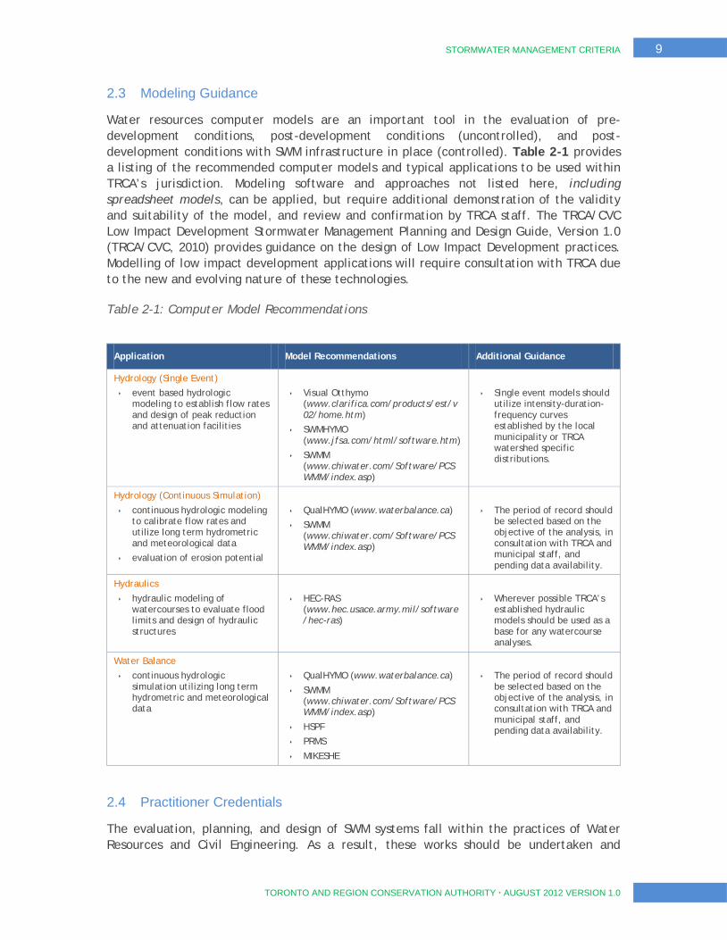
2.3 Modeling Guidance
Water resources computer models are an important tool in the evaluation of pre-development conditions, post-development conditions (uncontrolled), and post-development conditions with SWM infrastructure in place (controlled). Table 2-1 provides a listing of the recommended computer models and typical applications to be used within TRCA’s jurisdiction. Modeling software and approaches not listed here, including spreadsheet models, can be applied, but require additional demonstration of the validity and suitability of the model, and review and confirmation by TRCA staff. The TRCA/CVC Low Impact Development Stormwater Management Planning and Design Guide, Version 1.0 (TRCA/CVC, 2010) provides guidance on the design of Low Impact Development practices. Modelling of low impact development applications will require consultation with TRCA due to the new and evolving nature of these technologies.
Table 2-1: Computer Model Recommendations
Application Model Recommendations Additional Guidance
Hydrology (Single Event)
event based hydrologic modeling to establish flow rates and design of peak reduction and attenuation facilities
Visual Otthymo (www.clarifica.com/products/est/v02/home.htm)
SWMHYMO (www.jfsa.com/html/software.htm)
SWMM (www.chiwater.com/Software/PCSWMM/index.asp)
Single event models should utilize intensity-duration-frequency curves established by the local municipality or TRCA watershed specific distributions.
Hydrology (Continuous Simulation)
continuous hydrologic modeling to calibrate flow rates and utilize long term hydrometric and meteorological data
evaluation of erosion potential
QualHYMO (www.waterbalance.ca)
SWMM (www.chiwater.com/Software/PCSWMM/index.asp)
The period of record should be selected based on the objective of the analysis, in consultation with TRCA and municipal staff, and pending data availability.
Hydraulics
hydraulic modeling of watercourses to evaluate flood limits and design of hydraulic structures
HEC-RAS (www.hec.usace.army.mil/software/hec-ras)
Wherever possible TRCA’s established hydraulic models should be used as a base for any watercourse analyses.
Water Balance
continuous hydrologic simulation utilizing long term hydrometric and meteorological data
QualHYMO (www.waterbalance.ca)
SWMM (www.chiwater.com/Software/PCSWMM/index.asp)
HSPF
PRMS
MIKESHE
The period of record should be selected based on the objective of the analysis, in consultation with TRCA and municipal staff, and pending data availability.
2.4 Practitioner Credentials
The evaluation, planning, and design of SWM systems fall within the practices of Water Resources and Civil Engineering. As a result, these works should be undertaken and
10 STORMWATER MANAGEMENT CRITERIA
TORONTO AND REGION CONSERVATION AUTHORITY AUGUST 2012 VERSION 1.0
overseen by professionals with education, experience, and certification in Water Resources Engineering and/or Civil Engineering Technology.
The multi-disciplinary nature of successful SWM systems within the context of urban development requires integrated and collaborative design teams with expertise and credentials in the fields of engineering, planning/architecture, hydrogeology, geomorphology, ecology, and others.
2.5 Summary of Stormwater Management Design Criteria
A summary of SWM design criteria is provided in Table 2-2. Further information is provided in subsequent sections and their respective appendices.
Table 2-2: Summary of Stormwater Management Design Criteria
Stormwater Management Design Criteria Additional Information / Comments
STORMWATER QUANTITY (Section 3)
Control Peak Flows to the appropriate Watershed Flood Control Criteria as shown in Table 3-1.
Unit Flow Rates for predevelopment conditions are provided in Appendix A
Hydrologic study and Regional Flood assessments may be required in areas outside current planning horizons (i.e. beyond urban boundaries) or where existing models are out-dated
EROSION (Section 4)
At a minimum retain 5 mm on site where conditions do not warrant the detailed analyses described in Section 4.3.
If a site drains to a sensitive creek, or a subwatershed study or MESP is required, then the proponent must complete a geomorphologic assessment study to determine the site appropriate erosion threshold (Details provided in Appendix A)(refer to Figure 4-1).
For sites with SWM ponds, 25mm-48hr detention may also be required, depending on the results of the erosion assessment
At the subwatershed study or MESP scale, or for sites discharging to sensitive watercourse reaches, detailed erosion analyses are required to establish suitable erosion criteria
Consultation with TRCA staff is required to establish erosion methodologies and criteria, particularly where more detailed erosion analyses are required per Figure 4-1.
Appendix B provides detailed guidance on the evaluation of stormwater management criteria pertaining to erosion
STORMWATER QUALITY (Section5)
Enhanced Level of Protection (80% TSS removal) as per the latest MOE SWMPD Manual is required.
Where applicable, mitigate potential thermal and bacteriological impacts.
Refer to TRCA/Credit Valley Conservation (CVC)’s LID Guide (2010) for LID design guidance
For stormwater management facility design, planting plan and outfall design guidance are provided in Appendix E.
Refer to CVC Study Report: Thermal Impacts of Urbanization including Preventative and Mitigation Techniques (2011)
Designers should consult with MNR for development adjacent to species at risk or their habitats.
Where applicable, water quality controls should be further informed by goals and objectives arising out of applicable subwatershed studies and source water protection plans.

STORMWATER MANAGEMENT CRITERIA 11
TORONTO AND REGION CONSERVATION AUTHORITY AUGUST 2012 VERSION 1.0
Stormwater Management Design Criteria Additional Information / Comments
WATER BALANCE (Section 6)
For Significant, Ecologically Significant, and High Volume Groundwater Recharge Areas (SGRA, EGRA and HGRA), site specific water balance analyses and maintenance of recharge are required.
For Low Volume Groundwater Recharge Areas (LGRA), site specific water balance analyses are typically not required, and best efforts to maintain recharge are expected.
For natural features (woodlands, wetlands, watercourses) maintain hydrologic regimes and hydroperiods.
At the subwatershed study or MESP scale, site specific water balance analyses are required, and maintenance of recharge may be required pending the outcome of the analyses, per Figure 6-1.
Regardless of the Recharge Area Type (SGRA, etc.), presence of a sensitive ecological feature that may be impacted by development triggers the need for a site specific water balance analysis and maintenance of recharge, per Section 6.2.2.
Planning and design of infiltration facilities must consider soil conditions, depth to water table, and the presence of vulnerable areas such as Wellhead Protection Areas (WHPA’s, AppendixD). Infiltration of untreated stormwater from some sources (e.g., industrial facilities, roads, parking lots) to the groundwater may be prohibited.
Consultation with TRCA is required to establish water balance methodologies and criteria, particularly for sensitive ecological features where baseline monitoring is necessary to establish appropriate criteria, per Figure 6-2.
It is important to note that the criteria outlined in Table 2-2 represent a minimum requirement that may be superseded by the results of further studies and local constraints, proponents should consult with TRCA staff to confirm the criteria and discuss variances if necessary. In addition, some proposed SWM approaches may address multiple criteria simultaneously. For example, an erosion target of 5mm and a water balance target of 12mm are not cumulative – a site target of 12mm will address both the erosion and water balance criteria.
12 STORMWATER MANAGEMENT CRITERIA
TORONTO AND REGION CONSERVATION AUTHORITY AUGUST 2012 VERSION 1.0
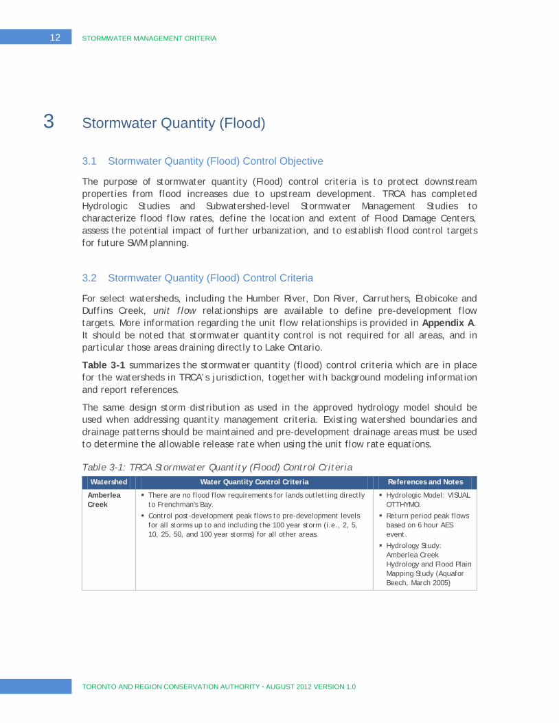
3 Stormwater Quantity (Flood)
3.1 Stormwater Quantity (Flood) Control Objective
The purpose of stormwater quantity (Flood) control criteria is to protect downstream properties from flood increases due to upstream development. TRCA has completed Hydrologic Studies and Subwatershed-level Stormwater Management Studies to characterize flood flow rates, define the location and extent of Flood Damage Centers, assess the potential impact of further urbanization, and to establish flood control targets for future SWM planning.
3.2 Stormwater Quantity (Flood) Control Criteria
For select watersheds, including the Humber River, Don River, Carruthers, Etobicoke and Duffins Creek, unit flow relationships are available to define pre-development flow targets. More information regarding the unit flow relationships is provided in Appendix A. It should be noted that stormwater quantity control is not required for all areas, and in particular those areas draining directly to Lake Ontario.
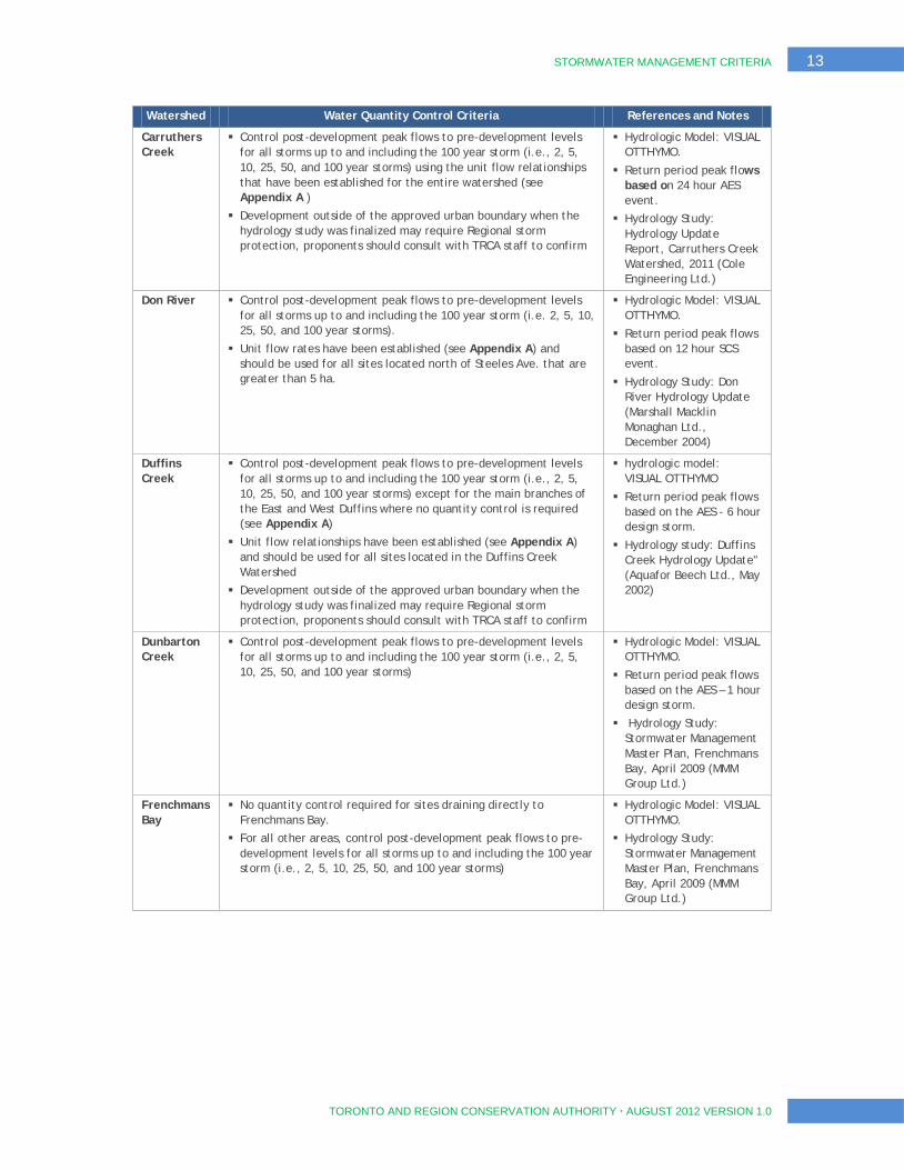
Table 3-1 summarizes the stormwater quantity (flood) control criteria which are in place for the watersheds in TRCA’s jurisdiction, together with background modeling information and report references.
The same design storm distribution as used in the approved hydrology model should be used when addressing quantity management criteria. Existing watershed boundaries and drainage patterns should be maintained and pre-development drainage areas must be used to determine the allowable release rate when using the unit flow rate equations.
Table 3-1: TRCA Stormwater Quantity (Flood) Control Criteria Watershed Water Quantity Control Criteria References and Notes
Amberlea Creek
There are no flood flow requirements for lands outletting directly to Frenchman's Bay.
Control post-development peak flows to pre-development levels for all storms up to and including the 100 year storm (i.e., 2, 5, 10, 25, 50, and 100 year storms) for all other areas.
Hydrologic Model: VISUAL OTTHYMO.
Return period peak flows based on 6 hour AES event.
Hydrology Study: Amberlea Creek Hydrology and Flood Plain Mapping Study (Aquafor Beech, March 2005)
STORMWATER MANAGEMENT CRITERIA 13
TORONTO AND REGION CONSERVATION AUTHORITY AUGUST 2012 VERSION 1.0
Watershed Water Quantity Control Criteria References and Notes
Carruthers Creek
Control post-development peak flows to pre-development levels for all storms up to and including the 100 year storm (i.e., 2, 5, 10, 25, 50, and 100 year storms) using the unit flow relationships that have been established for the entire watershed (see Appendix A )
Development outside of the approved urban boundary when the hydrology study was finalized may require Regional storm protection, proponents should consult with TRCA staff to confirm
Hydrologic Model: VISUAL OTTHYMO.
Return period peak flows based on 24 hour AES event.
Hydrology Study: Hydrology Update Report, Carruthers Creek Watershed, 2011 (Cole Engineering Ltd.)
Don River Control post-development peak flows to pre-development levels for all storms up to and including the 100 year storm (i.e. 2, 5, 10, 25, 50, and 100 year storms).
Unit flow rates have been established (see Appendix A) and should be used for all sites located north of Steeles Ave. that are greater than 5 ha.
Hydrologic Model: VISUAL OTTHYMO.
Return period peak flows based on 12 hour SCS event.
Hydrology Study: Don River Hydrology Update (Marshall Macklin Monaghan Ltd., December 2004)
Duffins Creek
Control post-development peak flows to pre-development levels for all storms up to and including the 100 year storm (i.e., 2, 5, 10, 25, 50, and 100 year storms) except for the main branches of the East and West Duffins where no quantity control is required (see Appendix A)
Unit flow relationships have been established (see Appendix A) and should be used for all sites located in the Duffins Creek Watershed
Development outside of the approved urban boundary when the hydrology study was finalized may require Regional storm protection, proponents should consult with TRCA staff to confirm
hydrologic model: VISUAL OTTHYMO
Return period peak flows based on the AES - 6 hour design storm.
Hydrology study: Duffins Creek Hydrology Update" (Aquafor Beech Ltd., May 2002)
Dunbarton Creek
Control post-development peak flows to pre-development levels for all storms up to and including the 100 year storm (i.e., 2, 5, 10, 25, 50, and 100 year storms)
Hydrologic Model: VISUAL OTTHYMO.
Return period peak flows based on the AES – 1 hour design storm.
Hydrology Study: Stormwater Management Master Plan, Frenchmans Bay, April 2009 (MMM Group Ltd.)
Frenchmans Bay
No quantity control required for sites draining directly to Frenchmans Bay.
For all other areas, control post-development peak flows to pre-development levels for all storms up to and including the 100 year storm (i.e., 2, 5, 10, 25, 50, and 100 year storms)
Hydrologic Model: VISUAL OTTHYMO.
Hydrology Study: Stormwater Management Master Plan, Frenchmans Bay, April 2009 (MMM Group Ltd.)
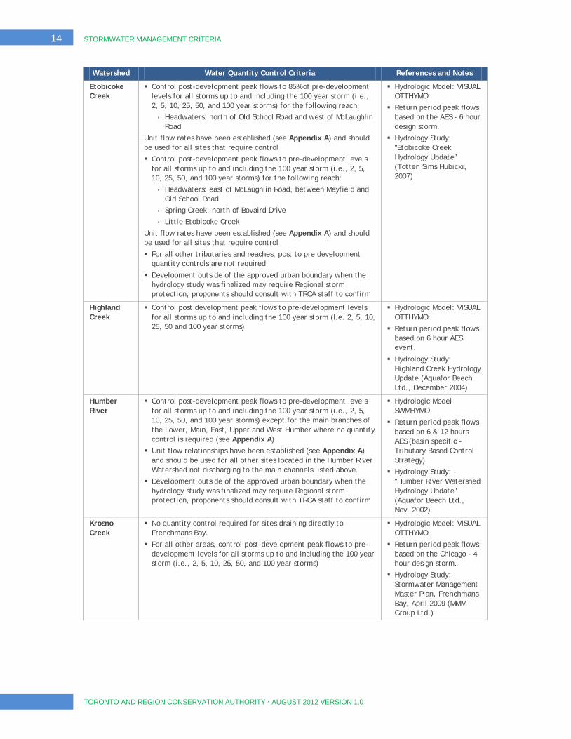
14 STORMWATER MANAGEMENT CRITERIA
TORONTO AND REGION CONSERVATION AUTHORITY AUGUST 2012 VERSION 1.0
Watershed Water Quantity Control Criteria References and Notes
Etobicoke Creek
Control post-development peak flows to 85% of pre-development levels for all storms up to and including the 100 year storm (i.e., 2, 5, 10, 25, 50, and 100 year storms) for the following reach:
Headwaters: north of Old School Road and west of McLaughlin Road
Unit flow rates have been established (see Appendix A) and should be used for all sites that require control
Control post-development peak flows to pre-development levels for all storms up to and including the 100 year storm (i.e., 2, 5, 10, 25, 50, and 100 year storms) for the following reach:
Headwaters: east of McLaughlin Road, between Mayfield and Old School Road
Spring Creek: north of Bovaird Drive
Little Etobicoke Creek
Unit flow rates have been established (see Appendix A) and should be used for all sites that require control
For all other tributaries and reaches, post to pre development quantity controls are not required
Development outside of the approved urban boundary when the hydrology study was finalized may require Regional storm protection, proponents should consult with TRCA staff to confirm
Hydrologic Model: VISUAL OTTHYMO
Return period peak flows based on the AES - 6 hour design storm.
Hydrology Study: "Etobicoke Creek Hydrology Update” (Totten Sims Hubicki, 2007)
Highland Creek
Control post development peak flows to pre-development levels for all storms up to and including the 100 year storm (I.e. 2, 5, 10, 25, 50 and 100 year storms)
Hydrologic Model: VISUAL OTTHYMO.
Return period peak flows based on 6 hour AES event.
Hydrology Study: Highland Creek Hydrology Update (Aquafor Beech Ltd., December 2004)
Humber River
Control post-development peak flows to pre-development levels for all storms up to and including the 100 year storm (i.e., 2, 5, 10, 25, 50, and 100 year storms) except for the main branches of the Lower, Main, East, Upper and West Humber where no quantity control is required (see Appendix A)
Unit flow relationships have been established (see Appendix A) and should be used for all other sites located in the Humber River Watershed not discharging to the main channels listed above.
Development outside of the approved urban boundary when the hydrology study was finalized may require Regional storm protection, proponents should consult with TRCA staff to confirm
Hydrologic Model SWMHYMO
Return period peak flows based on 6 & 12 hours AES (basin specific - Tributary Based Control Strategy)
Hydrology Study: - "Humber River Watershed Hydrology Update" (Aquafor Beech Ltd., Nov. 2002)
Krosno Creek
No quantity control required for sites draining directly to Frenchmans Bay.
For all other areas, control post-development peak flows to pre-development levels for all storms up to and including the 100 year storm (i.e., 2, 5, 10, 25, 50, and 100 year storms)
Hydrologic Model: VISUAL OTTHYMO.
Return period peak flows based on the Chicago - 4 hour design storm.
Hydrology Study: Stormwater Management Master Plan, Frenchmans Bay, April 2009 (MMM Group Ltd.)
STORMWATER MANAGEMENT CRITERIA 15
TORONTO AND REGION CONSERVATION AUTHORITY AUGUST 2012 VERSION 1.0
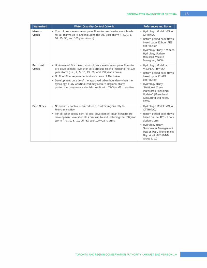
Watershed Water Quantity Control Criteria References and Notes
Mimico Creek
Control post-development peak flows to pre-development levels for all storms up to and including the 100 year storm (i.e., 2, 5, 10, 25, 50, and 100 year storms)
Hydrologic Model: VISUAL OTTHYMO
Return period peak flows based upon 12 hour AES distribution
Hydrology Study: “Mimico Hydrology Update (Marshall Macklin Monaghan, 2009)
Petticoat Creek
Upstream of Finch Ave., control post-development peak flows to pre-development levels for all storms up to and including the 100 year storm (i.e., 2, 5, 10, 25, 50, and 100 year storms)
No flood flow requirements downstream of Finch Ave.
Development outside of the approved urban boundary when the hydrology study was finalized may require Regional storm protection, proponents should consult with TRCA staff to confirm
Hydrologic Model: –VISUAL OTTHYMO
Return period peak flows based upon 12 AES distribution
Hydrology Study: "Petticoat Creek Watershed Hydrology Update” (Greenland Consulting Engineers, 2005)
Pine Creek No quantity control required for sites draining directly to Frenchmans Bay.
For all other areas, control post-development peak flows to pre-development levels for all storms up to and including the 100 year storm (i.e., 2, 5, 10, 25, 50, and 100 year storms
Hydrologic Model: VISUAL OTTHYMO.
Return period peak flows based on the AES - 1 hour design storm.
Hydrology Study: Stormwater Management Master Plan, Frenchmans Bay, April 2009 (MMM Group Ltd.)
16 STORMWATER MANAGEMENT CRITERIA
TORONTO AND REGION CONSERVATION AUTHORITY AUGUST 2012 VERSION 1.0
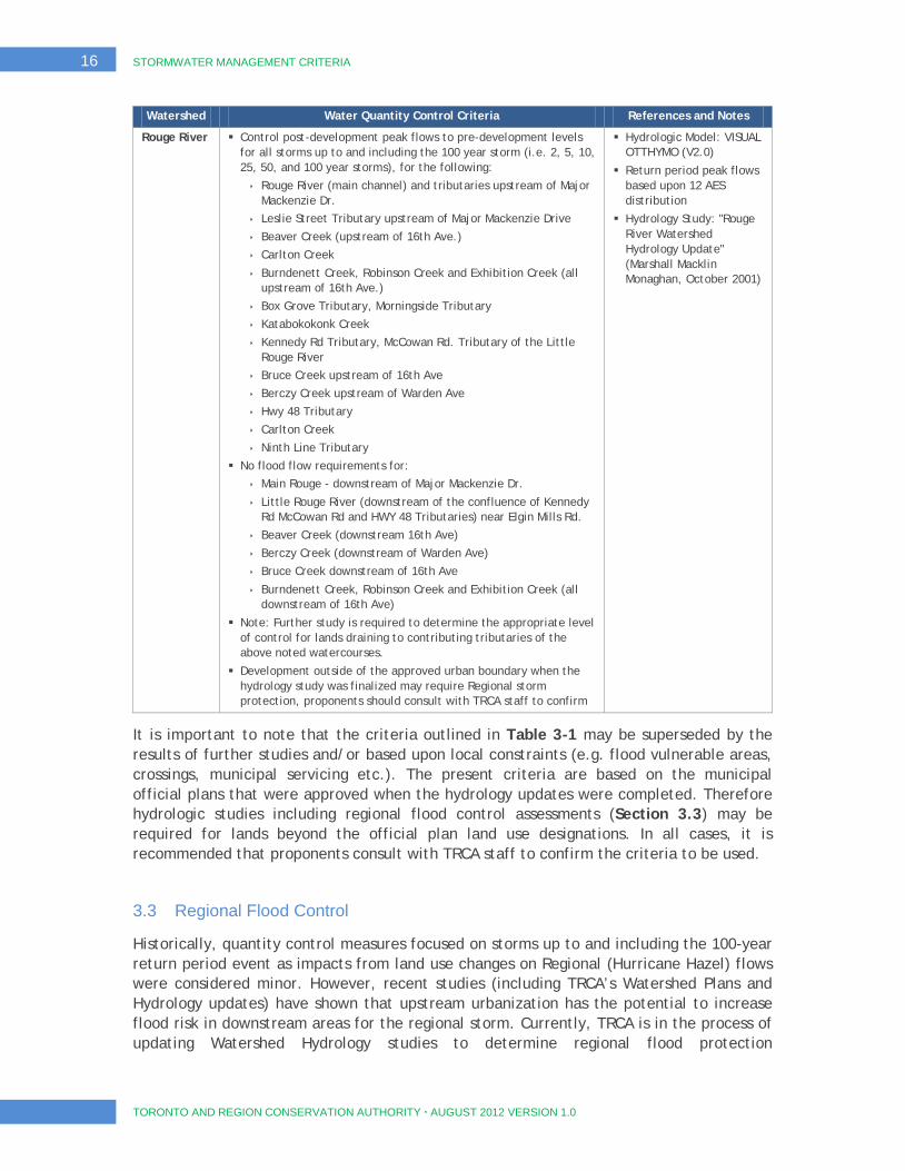
Watershed Water Quantity Control Criteria References and Notes
Rouge River Control post-development peak flows to pre-development levels for all storms up to and including the 100 year storm (i.e. 2, 5, 10, 25, 50, and 100 year storms), for the following:
Rouge River (main channel) and tributaries upstream of Major Mackenzie Dr.
Leslie Street Tributary upstream of Major Mackenzie Drive
Beaver Creek (upstream of 16th Ave.)
Carlton Creek
Burndenett Creek, Robinson Creek and Exhibition Creek (all upstream of 16th Ave.)
Box Grove Tributary, Morningside Tributary
Katabokokonk Creek
Kennedy Rd Tributary, McCowan Rd. Tributary of the Little Rouge River
Bruce Creek upstream of 16th Ave
Berczy Creek upstream of Warden Ave
Hwy 48 Tributary
Carlton Creek
Ninth Line Tributary
No flood flow requirements for:
Main Rouge - downstream of Major Mackenzie Dr.
Little Rouge River (downstream of the confluence of Kennedy Rd McCowan Rd and HWY 48 Tributaries) near Elgin Mills Rd.
Beaver Creek (downstream 16th Ave)
Berczy Creek (downstream of Warden Ave)
Bruce Creek downstream of 16th Ave
Burndenett Creek, Robinson Creek and Exhibition Creek (all downstream of 16th Ave)
Note: Further study is required to determine the appropriate level of control for lands draining to contributing tributaries of the above noted watercourses.
Development outside of the approved urban boundary when the hydrology study was finalized may require Regional storm protection, proponents should consult with TRCA staff to confirm
Hydrologic Model: VISUAL OTTHYMO (V2.0)
Return period peak flows based upon 12 AES distribution
Hydrology Study: "Rouge River Watershed Hydrology Update" (Marshall Macklin Monaghan, October 2001)
It is important to note that the criteria outlined in Table 3-1 may be superseded by the results of further studies and/or based upon local constraints (e.g. flood vulnerable areas, crossings, municipal servicing etc.). The present criteria are based on the municipal official plans that were approved when the hydrology updates were completed. Therefore hydrologic studies including regional flood control assessments (Section 3.3) may be required for lands beyond the official plan land use designations. In all cases, it is recommended that proponents consult with TRCA staff to confirm the criteria to be used.
3.3 Regional Flood Control
Historically, quantity control measures focused on storms up to and including the 100-year return period event as impacts from land use changes on Regional (Hurricane Hazel) flows were considered minor. However, recent studies (including TRCA’s Watershed Plans and Hydrology updates) have shown that upstream urbanization has the potential to increase flood risk in downstream areas for the regional storm. Currently, TRCA is in the process of updating Watershed Hydrology studies to determine regional flood protection
STORMWATER MANAGEMENT CRITERIA 17
TORONTO AND REGION CONSERVATION AUTHORITY AUGUST 2012 VERSION 1.0
requirements. Table 3-1 identifies the watersheds where regional flood protection may be required, please consult with TRCA staff to confirm the planning, hydrologic modeling and technical analysis requirements.
3.4 Stormwater Quantity (Flood) Control Practices
The MOE SWMPD Manual (2003), and to a lesser extent the CVC/TRCA LID Manual (2010), describe a number of practices that can be implemented to provide quantity control treatment of stormwater runoff as part of urban development. Examples of SWM practices that can be applied to provide stormwater quantity control include:
wet ponds;
wetlands;
dry ponds;
infiltration facilities; and,
low impact development practices.
Section 7 of this document provides specific guidance on the planning and design of SWM infrastructure within TRCA’s watersheds.
Infiltration facilities and low impact development practices (such as bioretention and rainwater harvesting) are typically designed to manage more frequent and lower magnitude rainfall events. However, should these practices be designed for year round functionality, with sufficient flood storage capacity, the volume reductions associated with these practices will only be recognized where the local municipality has endorsed the use of these practices and has considered long term operations and maintenance.
18 STORMWATER MANAGEMENT CRITERIA
TORONTO AND REGION CONSERVATION AUTHORITY AUGUST 2012 VERSION 1.0
4 Erosion
4.1 Erosion Control Objective
Natural rates of erosion are necessary for the maintenance of channel form and function. As introduced in Section 1.1, land use changes can lead to increased rates of erosion due to both an increase in the quantity of water and a decrease in the sediment supply. Adverse effects of increased erosion include channel instability, degraded water quality and aquatic habitat, and possible downstream hazards as a result of bank erosion and channel migration. By applying site-appropriate SWM measures, the hydrologic changes that lead to erosion can be largely mitigated. Cumulative impacts can also be addressed by considering multiple land use modifications within a subwatershed.
The primary tool for the mitigation of erosion problems is the reduction of the peak and duration of storm flows in addition to source controls to reduce the volume of runoff.
A target flow is usually defined for comparison between pre- and post-development conditions. This target flow is usually defined as an erosion threshold, which is the flow that theoretically can entrain bed or bank sediments within the most sensitive reach. In defined watercourses these flows are based on bed and bank materials and channel geometry. In natural systems, creeks regularly see flows that entrain and transport sediment; this is part of the natural process that maintains creek form. Issues arise when changes in the watershed’s hydrology results in an increase in the frequency or period of erosive events, or a cumulative increase in the quantity of flow that can entrain and transport sediment.
Appendix B provides a review of erosion sources and mitigation practices in southern Ontario, and summarizes the evolution of erosion mitigation practices to the present day.
4.2 Erosion Control Criteria
As a minimum, where conditions do not warrant the detailed analyses described in Section 4.3, TRCA requires on-site retention of 5mm. For sites with SWM pond, extended detention of the 25mm event for a period of 48 hours may also be required, depending on the results of the erosion assessment. If a site drains to a sensitive creek, or if a subwatershed study, MESP or similarly comprehensive study is required, then the proponent must complete a geomorphologic assessment study to determine the appropriate erosion threshold and
volume requirement. The geomorphologic assessment should be conducted in consultation with the TRCA to verify critical decisions and to confirm the scope of the analyses outlined above. It is important to note that the erosion criteria outlined above (i.e. minimum on-site retention of the first 5mm) represent a minimum requirement that may be superseded by the results of further studies and/or local
The minimum erosion control requirement for all watercourses within TRCA’s jurisdiction is retention of the first 5mm of every rainfall event.
STORMWATER MANAGEMENT CRITERIA 19
TORONTO AND REGION CONSERVATION AUTHORITY AUGUST 2012 VERSION 1.0
constraints (e.g. active valley land uses, crossings, etc.). In all cases, proponents should consult with TRCA staff to confirm the criteria to be applied. Please refer to Appendix B for more information.
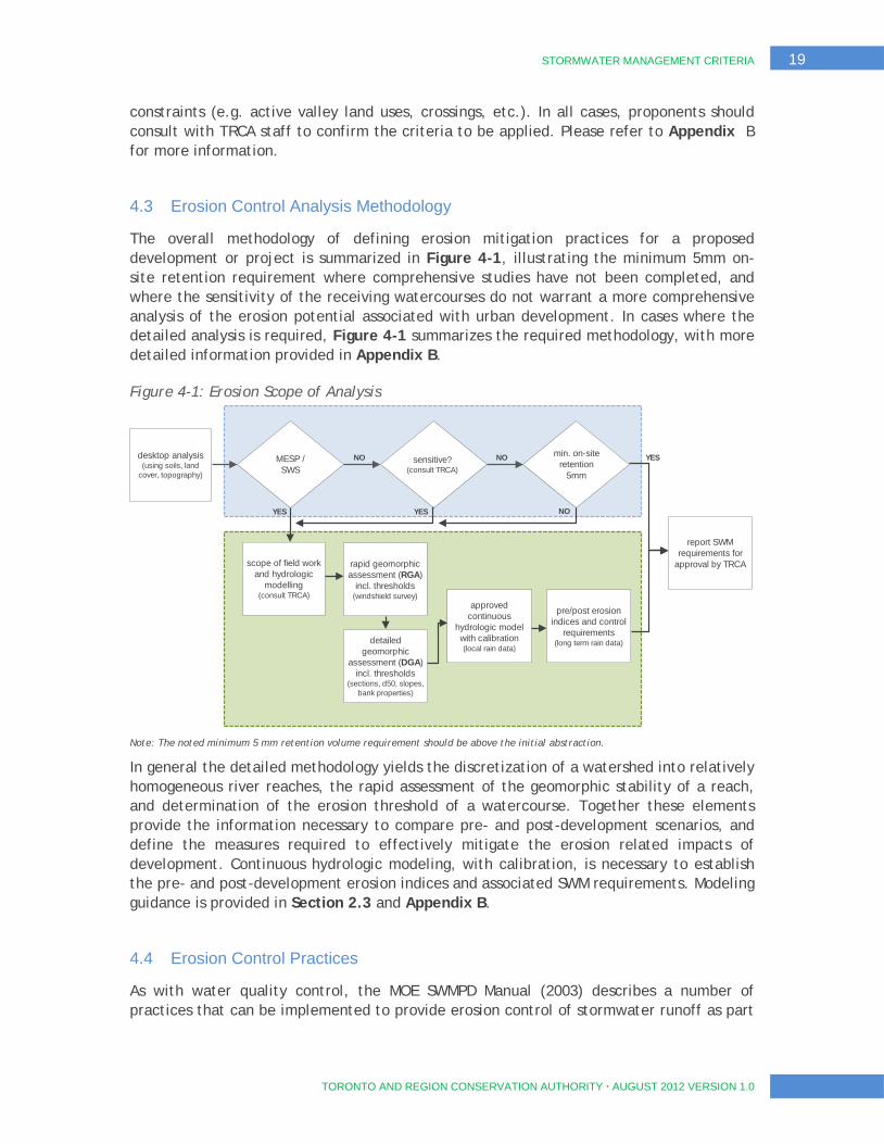
4.3 Erosion Control Analysis Methodology
The overall methodology of defining erosion mitigation practices for a proposed development or project is summarized in Figure 4-1, illustrating the minimum 5mm on-site retention requirement where comprehensive studies have not been completed, and where the sensitivity of the receiving watercourses do not warrant a more comprehensive analysis of the erosion potential associated with urban development. In cases where the detailed analysis is required, Figure 4-1 summarizes the required methodology, with more detailed information provided in Appendix B.
Figure 4-1: Erosion Scope of Analysis
Note: The noted minimum 5 mm retention volume requirement should be above the initial abstraction.
In general the detailed methodology yields the discretization of a watershed into relatively homogeneous river reaches, the rapid assessment of the geomorphic stability of a reach, and determination of the erosion threshold of a watercourse. Together these elements provide the information necessary to compare pre- and post-development scenarios, and define the measures required to effectively mitigate the erosion related impacts of development. Continuous hydrologic modeling, with calibration, is necessary to establish the pre- and post-development erosion indices and associated SWM requirements. Modeling guidance is provided in Section 2.3 and Appendix B.
4.4 Erosion Control Practices
As with water quality control, the MOE SWMPD Manual (2003) describes a number of practices that can be implemented to provide erosion control of stormwater runoff as part
desktop analysis (using soils, land
cover, topography)
MESP / SWS
sensitive? (consult TRCA)
min. on-site retention
5mm
report SWM requirements for
approval by TRCA scope of field work and hydrologic
modelling (consult TRCA)
approved continuous
hydrologic model with calibration (local rain data)
rapid geomorphic assessment (RGA)
incl. thresholds (windshield survey)
detailed geomorphic
assessment (DGA) incl. thresholds
(sections, d50, slopes, bank properties)
pre/post erosion indices and control
requirements (long term rain data)
YES YES NO
NO NO YES

20 STORMWATER MANAGEMENT CRITERIA
TORONTO AND REGION CONSERVATION AUTHORITY AUGUST 2012 VERSION 1.0
of urban development. Examples of SWM practices that can be applied to provide erosion control include:
wet ponds;
wetlands;
infiltration facilities; and,
low impact development practices.
Section 7 of this document provides some guidance on the planning and design of SWM practices within TRCA’s watersheds.

STORMWATER MANAGEMENT CRITERIA 21
TORONTO AND REGION CONSERVATION AUTHORITY AUGUST 2012 VERSION 1.0
5 Stormwater Quality
5.1 Quality Control Objective
Stormwater quality control criteria are necessary to protect receiving water bodies from the water quality degradation that may result from development and urbanization. The Ministry of Environment (MOE) administers a number of acts and regulations that are concerned with the protection and conservation of water, and the quality of drinking water supplied to the public, with associated requirements pertaining to SWM. Furthermore, the federal Fisheries Act prohibits the deposit of deleterious substances into waters that may degrade or alter the quality of water causing impact fish or fish habitat, In the context of these regulatory provisions, both suspended solids and thermal warming can be considered pollutants to the aquatic ecosystem. These principles form the basis for TRCA’s requirements with regard to stormwater quality control.
5.2 Quality Control Criteria
The MOE SWMPD Manual (2003) provides technical and procedural guidance for the planning, design, and review of SWM practices. In particular, the SWMPD Manual regulates water quality treatment levels corresponding to the removal of a percentage of total suspended solids (TSS) from runoff prior to discharge to the receiving water body.
The stormwater management criterion stipulates that all watercourses and water bodies (e.g. Lake Ontario) within TRCA’s jurisdiction are classified as requiring an Enhanced level of protection (80% TSS removal).
It is important to note that this criterion represents a minimum requirement that may be superseded by the results of additional studies and/or municipal and provincial requirements. For example, the City of Toronto’s Wet Weather Flow Management Guideline requires treatment of E.coli bacteria for discharges directly to Lake Ontario. Areas draining to Lake Wilcox within the Town of Richmond Hill must also consider phosphorus removal as part of the treatment strategy, in
accordance with Official Plan Amendment 129. Similarly, the Ministry of Natural Resources (2007) has produced draft urban guidelines for the purposes of administering the Endangered Species Act that recommends a threshold for discharge temperatures for stormwater management facilities connected to Redside Dace streams. For areas with coldwater species and other target species, it is recommended that SWM controls ensure discharge temperatures meet ambient stream temperatures or within an acceptable ecological range. Section 3 of the CVC Study Report “Thermal Impacts of Urbanization including Preventative and Mitigation Techniques” (January 2011) provides further
All watercourses and water bodies within TRCA’s jurisdiction are classified as requiring an Enhanced level of water quality protection, equivalent to 80% TSS removal.
22 STORMWATER MANAGEMENT CRITERIA
TORONTO AND REGION CONSERVATION AUTHORITY AUGUST 2012 VERSION 1.0
guidance on the planning and design of SWM infrastructure to address potential thermal impacts.
Wetlands are essential parts of ecosystems and can be sensitive to adverse water quality including chlorides from road salts. To maintain the health and ecological function, only sources of clean water (e.g. roof drainage, rain collection systems etc.) should be allowed to enter sensitive wetlands and the water balance should be managed with the intent to maintain ecological functions and characteristics and hydrological functions under post development conditions (see section 6).
In some cases, the catchments of riparian wetlands may be so large that the effect of the development on the wetland will not be detectable and not require a water balance. However, there may be instances where the sensitivity of riparian wetlands to the scale of development proposed may be of concern, and the preference for water balance mitigation in these instances will be to maximize the use of clean water. Therefore, it is recommended to consult with TRCA staff to confirm the requirements if a wetland are located within the catchment area of the proposed development.
As described in Section 2.2, construction stage SWM is largely focused on erosion and sediment control practices. The Erosion and Sediment Control Guideline for Urban Construction (Greater Golden Horseshoe Conservation Authorities, 2006), provides guidance on the suitable SWM approaches and criteria to be applied during construction, and can be downloaded from the TRCA and STEP websites.
5.3 Quality Control Practices
The MOE SWMPD Manual (2003) and the TRCA/CVC LID Manual (2010) describe a number of practices that can be implemented to provide quality treatment of stormwater runoff as part of urban development. Examples of SWM practices that can be applied to provide stormwater quality control include:
wet ponds;
wetlands;
infiltration facilities;
low impact development practices; and,
oil grit separators.
Section 7 of this document provides specific guidance on the planning and design of SWM infrastructure within TRCA’s watersheds, and outlines the volumetric requirements of different SWM practices to achieve the Enhanced level of treatment in accordance with the provisions of the MOE SWMPD (2003).

STORMWATER MANAGEMENT CRITERIA 23
TORONTO AND REGION CONSERVATION AUTHORITY AUGUST 2012 VERSION 1.0
6 Water Balance
6.1 Water Balance Objectives
Section 1.1 described the balance of infiltration, runoff, and evapotranspiration that exists in natural settings, as well as the imbalance that results through the introduction of impervious surfaces, normally associated with development. For the purposes of this document, water balance criteria have been established with the goal of protecting groundwater, baseflow and natural features such as wetlands and woodlots.
Managing the water balance may require the incorporation of infrastructure as part of development that endeavours to match the pre-development proportions of infiltration, runoff, and evapotranspiration.
In contrast with quantity control approaches that focus on major return period events (Section 3), water balance analyses are concerned with average and more frequent precipitation events that comprise the bulk of the volume of annual precipitation. By virtue of this design focus, maintenance of pre-development water balance can in part address previously described SWM objectives associated with water quality (Section 5) and erosion (Section 4).
Furthermore, measures that manage more frequent precipitation events can also in a small way reduce the extent of flood control infrastructure required to manage major events. Beyond these peripheral benefits, management of the water balance is necessary to address development related impacts to both our groundwater resources and the natural features that exist within and around our communities.
6.1.1 Groundwater Recharge
Groundwater recharge is a term that is widely used to describe the replenishment of the groundwater system from precipitation. Urbanization and land use change introduce hard surfaces to the landscape that reduce the degree to which the groundwater system can be replenished by precipitation. The groundwater system is the primary source of baseflow for many of our watercourses, and the nature of this source water yields the conditions necessary to support many sensitive ecosystems. The sensitivity of watersheds to changes in the groundwater regime has been established as part of the subwatershed studies completed throughout TRCA’s jurisdiction. In addition, groundwater continues to be a source of drinking water that is subject to the provisions of Ontario’s Clean Water Act (CWA) and the related Source Water Protection program.
It is important to note the technical distinction between recharge and infiltration. Infiltration is the process by which
Multi-faceted dependencies on the groundwater system
necessitate mitigation of the impacts that can
result from development.
24 STORMWATER MANAGEMENT CRITERIA
TORONTO AND REGION CONSERVATION AUTHORITY AUGUST 2012 VERSION 1.0
water on the ground surface enters the soil. From this point, infiltrated water can be intercepted by man-made drainage structures, consumed by vegetation or continue moving vertically to replenish groundwater resources. The water that is not captured by man-made drainage systems is termed “recharge”. However, within this document the terms recharge and infiltration are used interchangeably, with both generally referring to the entry of surface water into the soil unless otherwise noted. With respect to water balance analyses and the design of related infrastructure, emphasis is placed on promoting infiltration as a means to mimicking the natural water cycle.
6.1.2 Natural Feature Protection
Hydrology is a key factor that determines a natural feature’s ecological composition, structure and function. The physical and functional characteristics of a natural feature are based on its particular combination of key environmental variables (e.g. climate, geology, hydrology, landform, soils, and disturbances). The many combinations of these variables are what results in woodlands, wetlands and watercourses, the array of communities they contain, and the functions and ecological services they provide. Hydrology directly affects the physiochemical properties of natural features including oxygen availability, salinity, toxins, sediment movement, detritus, and soil composition.
Because hydrology is important to natural feature functions, changes in hydrology can result in adverse effects to these features. Largely due to the increase in impervious surfaces, development within a feature’s catchment can cause decreases in infiltration and evapotranspiration, and large increases in runoff volume. Developments that extract or divert groundwater from natural features will also be subject to these guidelines depending on the development form, design and construction. Some natural features may become wetter, while others may become drier following land use change or development. These changes in hydrology can cause changes in water quantity, quality, volume, duration, frequency, timing and spatial distribution of water inputs.
Measures to protect the existing water balance are necessary when there is likelihood that a proposed development will impact the hydrological functions of a feature. A water
balance analysis is required to demonstrate that the hydrological functions will not be adversely effected in the post-development scenario. The proposed development must not cause changes to the hydroperiod that negatively impact the hydrological functions of the feature. Hydroperiod is the seasonal pattern of surface and groundwater level fluctuations within a natural feature (Mitsch and Gooselink, 2007; Wright et al. 2006; Azous and Horner, 2001; Reinelt et al. 1998).
Guidelines that specifically address impacts at the feature-scale are critical to the maintenance of natural heritage features, forms, and functions in the long-term. The protection of these features through the development process may require an investment of resources for their securement and for their ongoing management.
Managing hydrologic regimes and hydroperiods means the volume, duration, frequency, timing, and spatial distribution of water does not cause negative impact to natural features, their ecological functions, and the larger natural heritage system.
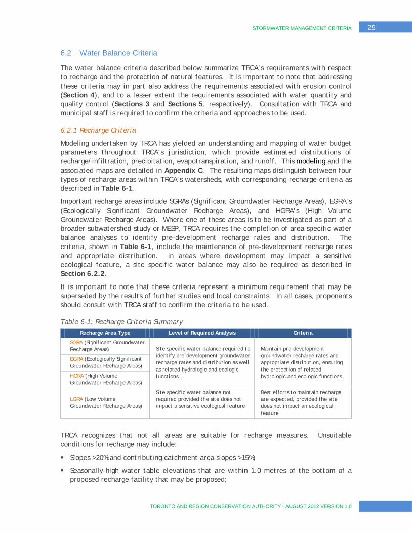
STORMWATER MANAGEMENT CRITERIA 25
TORONTO AND REGION CONSERVATION AUTHORITY AUGUST 2012 VERSION 1.0
6.2 Water Balance Criteria
The water balance criteria described below summarize TRCA’s requirements with respect to recharge and the protection of natural features. It is important to note that addressing these criteria may in part also address the requirements associated with erosion control (Section 4), and to a lesser extent the requirements associated with water quantity and quality control (Sections 3 and Sections 5, respectively). Consultation with TRCA and municipal staff is required to confirm the criteria and approaches to be used.
6.2.1 Recharge Criteria
Modeling undertaken by TRCA has yielded an understanding and mapping of water budget parameters throughout TRCA’s jurisdiction, which provide estimated distributions of recharge/infiltration, precipitation, evapotranspiration, and runoff. This modeling and the associated maps are detailed in Appendix C. The resulting maps distinguish between four types of recharge areas within TRCA’s watersheds, with corresponding recharge criteria as described in Table 6-1.
Important recharge areas include SGRAs (Significant Groundwater Recharge Areas), EGRA’s (Ecologically Significant Groundwater Recharge Areas), and HGRA’s (High Volume Groundwater Recharge Areas). Where one of these areas is to be investigated as part of a broader subwatershed study or MESP, TRCA requires the completion of area specific water balance analyses to identify pre-development recharge rates and distribution. The criteria, shown in Table 6-1, include the maintenance of pre-development recharge rates and appropriate distribution. In areas where development may impact a sensitive ecological feature, a site specific water balance may also be required as described in Section 6.2.2.
It is important to note that these criteria represent a minimum requirement that may be superseded by the results of further studies and local constraints. In all cases, proponents should consult with TRCA staff to confirm the criteria to be used.
Table 6-1: Recharge Criteria Summary Recharge Area Type Level of Required Analysis Criteria
SGRA (Significant Groundwater Recharge Areas) Site specific water balance required to
identify pre-development groundwater recharge rates and distribution as well as related hydrologic and ecologic functions.
Maintain pre-development groundwater recharge rates and appropriate distribution, ensuring the protection of related hydrologic and ecologic functions.
EGRA (Ecologically Significant Groundwater Recharge Areas)
HGRA (High Volume Groundwater Recharge Areas)
LGRA (Low Volume Groundwater Recharge Areas)
Site specific water balance not required provided the site does not impact a sensitive ecological feature
Best efforts to maintain recharge are expected, provided the site does not impact an ecological feature
TRCA recognizes that not all areas are suitable for recharge measures. Unsuitable conditions for recharge may include:
Slopes >20% and contributing catchment area slopes >15%;
Seasonally-high water table elevations that are within 1.0 metres of the bottom of a proposed recharge facility that may be proposed;
26 STORMWATER MANAGEMENT CRITERIA
TORONTO AND REGION CONSERVATION AUTHORITY AUGUST 2012 VERSION 1.0
Bedrock within 1 metre of the bottom of the proposed recharge facility;
Soils with infiltration rates less than 15mm/hour. Underdrains may be required where infiltration is proposed in areas with soil infiltration rates less than 15mm/hour;
Locations within 250 metres of the boundary of a landfill site;
Flood plains;
Wetlands and associated hydric soils;
Drinking water wells within 30 metres of the recharge facility
TRCA would not recommend any engineered recharge facilities where the above conditions are present at a site; however, the proponent should make every effort to maintain overall infiltration across the site based on the noted requirements.
The vulnerability of an aquifer to contamination from surface sources must also be considered, and consultation with TRCA is necessary to determine whether a proposed development is in proximity to areas that may impact an aquifer. Infiltration of potentially contaminated water (i.e. parking lots, roadways) would not be promoted in these areas. Considerations for infiltration in these areas include the volume and toxicity of chemicals used or stored, livestock density, and contaminant management plans.
6.2.2 Criteria for Protection of Natural Features
Natural features, including wetlands, woodlands, and watercourses, are identified through the planning and development process that require protection. These guidelines set out the requirements for managing the water balance with the intent to maintain ecological functions and characteristics and hydrological functions of features that have been recommended for protection through an Official Plan designation, Watershed Plan, Subwatershed Study, Master Environmental Servicing Plan, Environmental Implementation Report, Environmental Impact Study, or other similar study, and/or in consultation with the Conservation Authority and municipality. These guidelines outline the general requirements for a water balance for hydrologically sensitive features, which may be scoped in consultation with the Conservation Authority and municipality, depending on the sensitivity of the features, the anticipated levels of impact, and the current stage of landuse planning.
Developments that extract or divert groundwater from natural features will also be subject to these guidelines. The feature based water balance may be in addition to other stormwater criteria requirements and some of the information requirements outlined in the other sections will be common to both.
For developments proposed within proximity to these identified natural features, additional investigation is necessary to understand the water balance impacts to the feature, and to identify the measures necessary to mitigate these impacts. In areas identified as degraded, the objective may be to enhance the water balance attributes of the feature.
Appendix D outlines the procedures for assessing the water balance associated with a feature under the pre and post-development conditions. In all cases, consultation with TRCA is recommended to confirm the appropriate scope of investigation and objectives.
STORMWATER MANAGEMENT CRITERIA 27
TORONTO AND REGION CONSERVATION AUTHORITY AUGUST 2012 VERSION 1.0
For wetlands and vernal pools, the overall objective is to manage the water balance with the intent to maintain the quantity (i.e. volume, timing, and spatial distribution) of surface water and groundwater contributions that ensures the pre-development hydroperiod (seasonal pattern of water level fluctuation) of the wetland is protected. The proposed development must not cause changes to the hydroperiod that negatively impact the hydrological functions of the feature.
For vernal pools that are identified as being ecologically important, TRCA and the municipality should be consulted prior to undertaking an evaluation to determine appropriate requirements. MNR must also be contacted if species at risk are known to use the vernal pool or any other wetland feature. Wildlife Scientific Collectors Authorizations (WSCAs) and Endangered Species Act (ESA) permits are required for any surveys or studies to investigate for the presence of species at risk.
For woodlands, the overall objective is to manage the water balance with the intent to maintain the volume, timing and spatial distribution of surface water and groundwater contributions that ensures that hydrological changes do not cause a negative impact on the form and/or function of the woodland.
For watercourses and headwater drainage features, the overall objective is to manage the water balance with the intent to maintain the quantity (volume, timing, spatial distribution) of surface water and groundwater contributions to ensure the duration, frequency, magnitude, and rate of change of flow do not result in adverse effects.
Fish community, management zone mapping, and targets are defined by the Fisheries Management Plan (FMP) at the watershed scale, but may be further refined based on more recent information. In cases where an FMP does not exist, the proponent should consult with TRCA for further information and appropriate targets.
6.3 Water Balance Analysis Methodology
6.3.1 Recharge
The detailed analysis methodology associated with recharge is provided in Appendix C, and summarized in Figure 6-1.
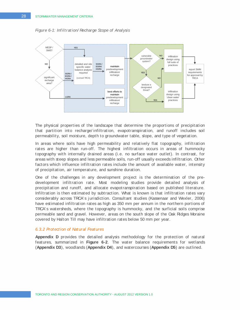
28 STORMWATER MANAGEMENT CRITERIA
TORONTO AND REGION CONSERVATION AUTHORITY AUGUST 2012 VERSION 1.0
Figure 6-1: Infiltration/Recharge Scope of Analysis
The physical properties of the landscape that determine the proportions of precipitation that partition into recharge/infiltration, evapotranspiration, and runoff includes soil permeability, soil moisture, depth to groundwater table, slope, and type of vegetation.
In areas where soils have high permeability and relatively flat topography, infiltration rates are higher than run-off. The highest infiltration occurs in areas of hummocky topography with internally drained areas (i.e. no surface water outlet). In contrast, for areas with steep slopes and less permeable soils, run-off usually exceeds infiltration. Other factors which influence infiltration rates include the amount of available water, intensity of precipitation, air temperature, and sunshine duration.
One of the challenges in any development project is the determination of the pre-development infiltration rate. Most modeling studies provide detailed analysis of precipitation and runoff, and allocate evapotranspiration based on published literature. Infiltration is then estimated by subtraction. What is known is that infiltration rates vary considerably across TRCA’s jurisdiction. Consultant studies (Kassenaar and Wexler, 2006) have estimated infiltration rates as high as 350 mm per annum in the northern portions of TRCA’s watersheds, where the topography is hummocky, and the surficial soils comprise permeable sand and gravel. However, areas on the south slope of the Oak Ridges Moraine covered by Halton Till may have infiltration rates below 50 mm per year.
6.3.2 Protection of Natural Features
Appendix D provides the detailed analysis methodology for the protection of natural features, summarized in Figure 6-2. The water balance requirements for wetlands (Appendix D3), woodlands (Appendix D4), and watercourses (Appendix D5) are outlined.
SGRA / EGRA / HGRA significant
recharge area?
LGRA
best efforts to maintain
predevelopment infiltration/ recharge
maintain predevelopment
infiltration/ recharge
vulnerable groundwater
system?
landuse a designated
threat?
infiltration design using full suite of practices
infiltration design using ‘clean water’
practices
report SWM requirements
for approval by TRCA
NO
YES
NO
YES
SGRA / EGRA/ HGRA
detailed and site specific water
balance analysis required
(consult TRCA)
MESP / SWS?
NO
YES
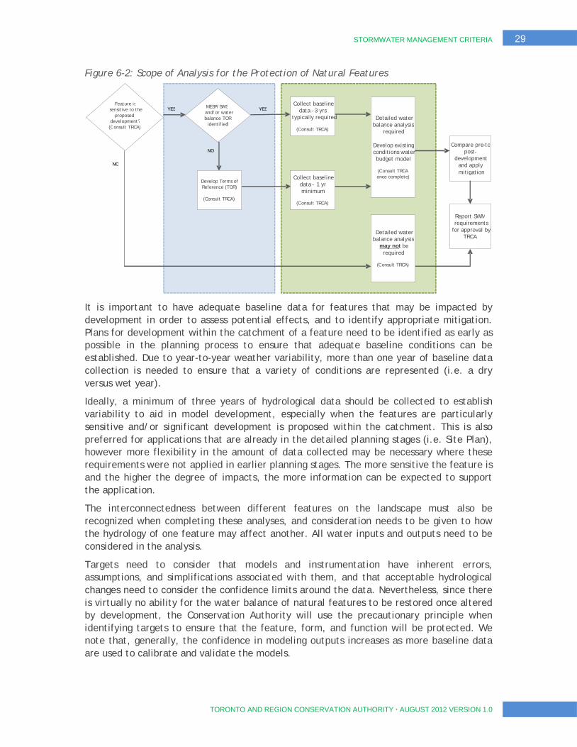
STORMWATER MANAGEMENT CRITERIA 29
TORONTO AND REGION CONSERVATION AUTHORITY AUGUST 2012 VERSION 1.0
Figure 6-2: Scope of Analysis for the Protection of Natural Features
It is important to have adequate baseline data for features that may be impacted by development in order to assess potential effects, and to identify appropriate mitigation. Plans for development within the catchment of a feature need to be identified as early as possible in the planning process to ensure that adequate baseline conditions can be established. Due to year-to-year weather variability, more than one year of baseline data collection is needed to ensure that a variety of conditions are represented (i.e. a dry versus wet year).
Ideally, a minimum of three years of hydrological data should be collected to establish variability to aid in model development, especially when the features are particularly sensitive and/or significant development is proposed within the catchment. This is also preferred for applications that are already in the detailed planning stages (i.e. Site Plan), however more flexibility in the amount of data collected may be necessary where these requirements were not applied in earlier planning stages. The more sensitive the feature is and the higher the degree of impacts, the more information can be expected to support the application.
The interconnectedness between different features on the landscape must also be recognized when completing these analyses, and consideration needs to be given to how the hydrology of one feature may affect another. All water inputs and outputs need to be considered in the analysis.
Targets need to consider that models and instrumentation have inherent errors, assumptions, and simplifications associated with them, and that acceptable hydrological changes need to consider the confidence limits around the data. Nevertheless, since there is virtually no ability for the water balance of natural features to be restored once altered by development, the Conservation Authority will use the precautionary principle when identifying targets to ensure that the feature, form, and function will be protected. We note that, generally, the confidence in modeling outputs increases as more baseline data are used to calibrate and validate the models.
Compare p re - to p ost -
development and apply mitigation
MESP/SWS and/or water balance
TOR identified ?
NO
YES YES
NO
Feature is sensitive to the
proposed development?
( C onsult TRCA)
Detailed water balance analysis
required
Develop existing conditions water budget model
( C onsult TRCA
once complete )
Collect baseline data -
3 yrs typically required
( C onsult TRCA)
Collect baseline data
– 1 yr minimum
( C onsult TRCA)
Detailed water balance analysis
may not be
required
( C onsult TRCA)
Report SWM requirements
for approval by TRCA
NO
Develop Terms of Reference (TOR)
(Consult TRCA)

30 STORMWATER MANAGEMENT CRITERIA
TORONTO AND REGION CONSERVATION AUTHORITY AUGUST 2012 VERSION 1.0
In determining the need for a water balance for a natural feature, the Conservation Authority will consider three factors:
1. The proposed changes to the feature’s surface or groundwater catchment. If there is no change to the feature’s catchment size and there is no/little development within the catchment, a water balance for the feature will not be required;
2. The form and type of development proposed within the catchment. If the majority of the development consists of permeable surfaces (e.g., parkland), a water balance may not be required;
3. The sensitivity of the feature. Water balances will be required to protect existing functions and the sensitivity of those functions to hydrological changes. At a minimum, a water balance will certainly be required for those features or functions protected by policy and/or legislation (e.g. Provincially Significant Wetlands, Jefferson salamander habitat, etc.) or are highly sensitive (e.g. brook trout streams).
If there is more than one development proceeding within the catchment of the same feature, a comprehensive water balance analysis should be conducted jointly by the proponent in consultation with and facilitated by the TRCA and municipality.
Completing a water balance requires the expertise of a multi-disciplinary team of qualified professionals, typically including a terrestrial or aquatic ecologist, water resources engineer, and hydrogeologist. The input and analysis of appropriate professionals needs to be integrated into the final water balance submission.
These guidelines focus on assessing and mitigating hydrological impacts to natural features. They do not provide specific requirements for minimizing water quality impacts on these features as these requirements are outlined in Section 5 of this document.
When development is considered within the catchments of natural features containing species at risk (SAR), proponents are responsible for meeting the requirements of the relevant federal and provincial agencies. For example, the Ministry of Natural Resources is the regulatory agency responsible for SAR under the Endangered Species Act and may have requirements that are beyond the details described within these guidelines (e.g. water quality). If SAR occur on or near the property, the appropriate agencies must be consulted; this includes monitoring activities.
The Ministry of Natural Resources is a source of available data and information on natural heritage.
When installing instrumentation for the purposes of data collection, care should be taken to minimize disturbance to natural features. Consult the conservation authority and municipality if there is a high likelihood that instrumentation will impact features as permits may be required (e.g. access that results in vegetation removal, soil compaction, etc.).
Consideration may also need to be given to providing water balance to features in the interim conditions (i.e. after grading has commenced but prior to the construction and implementation of mitigation measures).

STORMWATER MANAGEMENT CRITERIA 31
TORONTO AND REGION CONSERVATION AUTHORITY AUGUST 2012 VERSION 1.0
6.4 Water Balance Practices
Water balance can be achieved by a number of the SWM practices listed in the MOE SWMPD Manual (2003) and the CVC/TRCA LID Guide (2010). However, the principal and most effective mechanisms for achieving water balance fall under the category of low impact development. Low impact development practices are generally designed to manage rainfall and the resulting runoff at the source, which is more effective at reducing runoff volumes during frequent rainfall events than the larger and more centralized facilities.
Section 7 of this document provides specific guidance on the planning and design of SWM infrastructure within TRCA’s watersheds.
32 STORMWATER MANAGEMENT CRITERIA
TORONTO AND REGION CONSERVATION AUTHORITY AUGUST 2012 VERSION 1.0
7 Stormwater Management Practices
7.1 Overview
The preceding sections, and corresponding appendices, describe the objectives and analysis methodologies associated with SWM practices needed to manage water quantity, maintain water quality, mitigate erosion, and manage water balance.
There are numerous mechanisms and practices that can be incorporated into a proposed development or related project to achieve these objectives. Accepted practices are described extensively within both the Stormwater Management Planning and Design Manual (MOE 2003) and the Low Impact Development Stormwater Management Planning and
Design Guide (TRCA/CVC 2010). Both documents emphasize the importance of the treatment train approach, which suggests that the treatment of runoff at the source, en route, and at end-of-pipe should be incorporated into every SWM strategy. Furthermore, effective SWM strategies are best established through collaborative design approaches that endeavour to integrate the disciplines of engineering, planning, ecology, and landscape architecture at the earliest stages of the development process.
It is important to recognize, however, that every project is different, and that unique site conditions,
constraints, or objectives necessitate the development of variations on existing practices in order to achieve the overriding objective of mitigating our collective impact on our environment. Moreover, increased awareness of changing climatic conditions and the challenges of infrastructure deficits have also encouraged innovation and evolution in the development of SWM solutions, leading to the proliferation of green infrastructure and low impact development technologies. Therefore, innovation combined with sound engineering and environmental principles will continue to be encouraged and accepted by TRCA provided that the necessary technical analyses and documentation are completed, and that these proposed works also satisfy all other applicable requirements and criteria, including provision for long term operations, monitoring and maintenance.
7.2 Stormwater Management Facilities
Stormwater Management facilities are to be designed in accordance with recommendations set out in the MOE Stormwater Management Planning and Design Manual (2003). It is preferred that SWM facilities be located outside the Regional Storm Floodplain. However, if the facility location is proposed within the Regional Storm Floodplain, it must be located
Integrated design teams and the treatment train approach are essential ingredients for the implementation of successful stormwater management strategies, where the environment and our communities are soundly protected by infrastructure that is integrated within the urban fabric.

STORMWATER MANAGEMENT CRITERIA 33
TORONTO AND REGION CONSERVATION AUTHORITY AUGUST 2012 VERSION 1.0
outside the 100 year floodplain and the proponent should pre-consult with TRCA staff to determine the acceptability of the location, and any other design requirements (e.g. cut/fill balance, natural feature avoidance). Further technical guidance on SWM facilities within or near floodplains can be found in TRCA’s Floodplain Management Guidelines and TRCA’s Valley and Stream Corridor Management Program (VSCMP, October 1994).
With respect to quality control, Table 3.2 of the MOE SWMPD Manual provides direction on the volumetric requirements corresponding to desired treatment levels and selected SWM approaches. An excerpt of this table is provided in Table 7-1, focusing on the Enhanced level of treatment required throughout TRCA’s watersheds. It is required that these unit volume targets be used as a framework for establishing stormwater quality storage targets within TRCA’s watersheds.
It should be noted that maintenance of stormwater management ponds is a critical component to meet SWM water quality criteria as even a well-designed SWM pond, if not properly maintained can be a source of pollution generation [LSRCA, 2011]. As the stormwater management pond network ages and deteriorates in a watershed, level of TSS loading is expected to increase. The implementation of a comprehensive stormwater pond maintenance program is crucial to protect water quality in urbanizing watersheds [LSRCA, 2011].
It is important to note that other SWM practices that can be demonstrated to the approval agencies to meet the required long-term suspended solids removal under the prevailing site conditions can be deemed acceptable. However, the anticipated effectiveness and associated sizing of these practices must employ a sound technical and peer-reviewed methodology, and where possible must reference available performance data from other implementations. Designers and reviewers in these instances must acknowledge and account for the assumptions implicit in the design of these practices.
Table 7-1: Water Quality Storage Requirements
Protection Level SWMP Type Storage Volume (m3/ha) for Imperviousness Level 35% 55% 70% 85%
Enhanced 80% long-term S.S. removal
Infiltration 25 30 35 40
Wetlands 80 105 120 140
Hybrid Wet Pond/Wetland 110 150 175 195
Wet Pond 140 190 225 250
To supplement the information in the MOE Manual on SWM pond planning, TRCA has compiled Stormwater Management Pond Planting Guidelines, which include a list of preferred native plant species. These guidelines are provided in Appendix E.
Effectively impermeable liners may be required for SWM ponds with inverts that are below the high groundwater level condition where a liner is required to prevent groundwater discharge to the pond and to ensure the geotechnical stability of the pond.
In order to determine whether a liner should be included in the SWM pond design, it is important to collect appropriate subsurface information directly at the proposed SWM pond location. In order to identify soil conditions underlying the SWM pond location, a borehole should be drilled deeper than the proposed pond bottom with logging of appropriate soil and/or bedrock information. A monitoring well should be installed in the
34 STORMWATER MANAGEMENT CRITERIA
TORONTO AND REGION CONSERVATION AUTHORITY AUGUST 2012 VERSION 1.0
borehole to allow for measurement of groundwater levels so that the high groundwater level condition can be accurately identified to inform the pond design. Where the monitoring period and/or climate conditions are not representative of high groundwater level conditions, then a correlation to groundwater level data from nearby sites may be feasible. The soil/bedrock and high groundwater level information is to be included on SWM pond cross-section drawings, and if a liner is not recommended then a supporting rationale must be provided. Liners should typically extend from the pond bottom up to the higher of the permanent pool elevation or the high groundwater elevation. The SWM pond design report is to indicate if the liner is to be constructed of synthetic material or consolidated and compacted native low permeability material that occurs at the site. A recommendation from a geotechnical engineer or equivalent professional is required as part of the SWM pond design report, and where the high groundwater level is above the pond bottom it is to be shown that the liner will provide sufficient pressure to prevent groundwater discharge through the base of the pond. If the weight of the water in the permanent pool is included as part of the balancing force, an observation well is to be included in the design to ensure that dewatering during maintenance of the pond will not result in breach or failure of the liner.
If native materials are to be used for the liner, then the construction should be supervised by a qualified person and a letter confirming that the pond was constructed to the design specifications is to be provided to TRCA post-construction.
It is also recognized that SWM wet ponds and wetlands can result in the warming of the stored stormwater, which can have a detrimental effect on the aquatic habitat in nearby receiving streams. Therefore mitigation techniques for thermal impacts should be considered when designing SWM ponds, particularly when discharging to sensitive or near-threshold streams. Low impact development practices (Section 7.4) used to capture frequent storm events, along with enhanced facility outlets, are encouraged as preventative thermal measures. Further information on thermal impact mitigation and outfall design practices are provided in Appendix E.
Please note that any areas supporting species at risk, particularly threatened or endangered species, should be flagged as part of the process of assessing potential thermal impacts of proposed SWM facilities, and brought to the attention of MNR. The potential impact to the species or its habitat and any damage or destruction thereof requires assessment and consultation with MNR pursuant to the Endangered Species Act 2007. Any activities to restore habitat or assist species at risk also requires consultation with MNR.
7.3 Oil and Grit Separators
TRCA has adopted the City of Toronto Guidelines for OGS application. Essentially, oil and grit separators (OGS) are recommended as a pre-treatment device or may be used as part of a multi-component (treatment train) approach to achieve Enhanced quality control. According to the City of Toronto Guidelines, OGS devices, operating alone at their original design capacities, are capable of achieving a TSS removal efficiency of 50%. This removal efficiency is based on the OGS verification and certification process carried out by the New Jersey Corporation for Advanced Technology (NJCAT) and the New Jersey Department of Environmental Protection (NJDEP), which established the protocol for how units should be tested in the laboratory. Since manufacturers submitted testing data that were not fully
STORMWATER MANAGEMENT CRITERIA 35
TORONTO AND REGION CONSERVATION AUTHORITY AUGUST 2012 VERSION 1.0
consistent with the NJDEP protocol, a blanket approval of 50% removal for all OGS tested under their program was issued. Further testing is currently underway for the Toronto Guidelines for OGS application which may result in an update to the TSS removal efficiency rating indicate above; please ensure that you are using the latest version of this document which can be downloaded from www.trca.on.ca and www.sustainabletechnologies.ca.
7.4 Low Impact Development Practices
There is increasing recognition that Low Impact Development (LID) can mitigate the impacts of increased runoff volume and stormwater pollution (including temperature) by managing stormwater as close to its source as possible. Therefore LID practices can address criteria associated with water quantity (for frequent storm events), quality, erosion, and water balance. In addition to having the advantage of meeting multiple criteria goals, LID can be integrated into the urban form (bioretention in landscaping areas and parking islands, soakaways and rain gardens in back yards, and permeable pavement and subsurface infiltration in parking areas) and thereby allow for more developable space. Furthermore, the use of LID in a treatment train approach reduces the maintenance on end-of-pipe facilities. The TRCA/CVC Low Impact Development Planning and Design Guide (LID Guide, 2010) provides planning and design guidance on a wide range of LID practices.
As described in Chapter 2 of the LID Guide, the LID design process begins with a landscape-based approach to planning. The approach involves understanding regional and watershed-scale contexts, management objectives, and targets relevant to the site. Opportunities for LID practices are identified at the neighbourhood or subwatershed scales and refined at more detailed planning stages. Inventories of the natural resources and drainage features present on the site are used as the integrating framework for SWM system planning.
In order to achieve the TRCA SWM criteria with LID, the following conditions must be met:
The local municipality must endorse the use of LID SWM practices. Some practices may not be acceptable within a municipality, if LID is being proposed in lieu of conventional SWM, It is the proponent’s responsibility to ensure that the local municipality has accepted the use of these practices and has considered long term operations and maintenance.
Designs are undertaken in accordance with the recommendations of the LID Guide. As a minimum, to achieve an enhanced level of water quality control, the LID practice must be sized to provide storage for a minimum 5mm of rainfall.
For rainwater harvesting and green roof systems, calculations of runoff reduction must consider winter operation, where designs focused on warm weather functionality may yield a negligible reduction in runoff during cold weather periods.
For infiltration practices, the depth to water table, existing soil infiltration rates, and proximity to vulnerable groundwater resources must be considered as part of the planning and design processes. Infiltration facilities may be considered in areas with infiltration rates of less than 15mm per hour, provided these are designed with effective overflow/underdrain mechanisms.

36 STORMWATER MANAGEMENT CRITERIA
TORONTO AND REGION CONSERVATION AUTHORITY AUGUST 2012 VERSION 1.0
Pre-treatment for infiltration facilities (e.g. via OGS, filter strip, forebay, etc.) may also be required depending on the source of water to be infiltrated.
Overflow or underdrain mechanisms must be provided to ensure that infiltration, attenuation, and storage systems do not put properties and structures at risk due to backups and flooding. Sufficient storage must be provided to achieve the required SWM criteria before the overflow or underdrain mechanisms are triggered.

STORMWATER MANAGEMENT CRITERIA ▪ APPENDIX A. WATER QUANTITY AND UNIT FLOW RELATIONSHIPS A. 1
TORONTO AND REGION CONSERVATION AUTHORITY AUGUST 2012 VERSION 1.0
APPENDIX A WATER QUANTITY AND UNIT FLOW RELATIONSHIPS

A. 2 STORMWATER MANAGEMENT CRITERIA ▪ APPENDIX A. WATER QUANTITY AND UNIT FLOW RELATIONSHIPS
TORONTO AND REGION CONSERVATION AUTHORITY AUGUST 2012 VERSION 1.0
- THIS PAGE LEFT INTENTIONALLY BLANK -
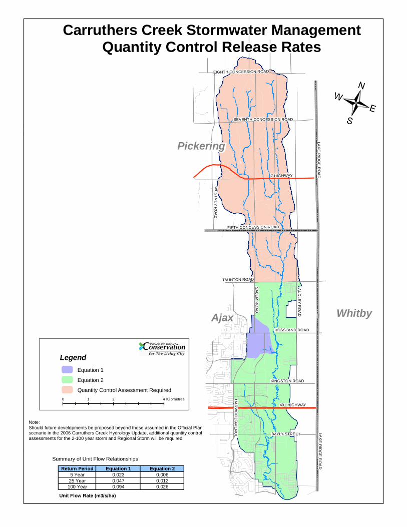
SEVENTH CONCESSION ROAD
7 HIGHWAY
FIFTH CONCESSION ROAD
TAUNTON ROAD
ROSSLAND ROAD
KINGSTON ROAD
BAYLY STREET
401 HIGHWAY
AU
DLE
Y R
OA
D
SA
LEM
RO
AD
WE
STN
EY
RO
AD
HA
RW
OO
D AV
EN
UE LA
KE
RID
GE
RO
AD
L AK
E R
IDG
E R
OA
D
EIGHTH CONCESSION ROAD
/
Carruthers Creek Stormwater ManagementQuantity Control Release Rates
Return Period Equation 1 Equation 25 Year 0.023 0.006
25 Year 0.047 0.012100 Year 0.094 0.026
Unit Flow Rate (m3/s/ha)
LegendEquation 1
Equation 2
Quantity Control Assessment Required
Note: Should future developments be proposed beyond those assumed in the Official Planscenario in the 2006 Carruthers Creek Hydrology Update, additional quantity controlassessments for the 2-100 year storm and Regional Storm will be required.
Summary of Unit Flow Relationships
0 2 41 Kilometres
Pickering
Ajax Whitby
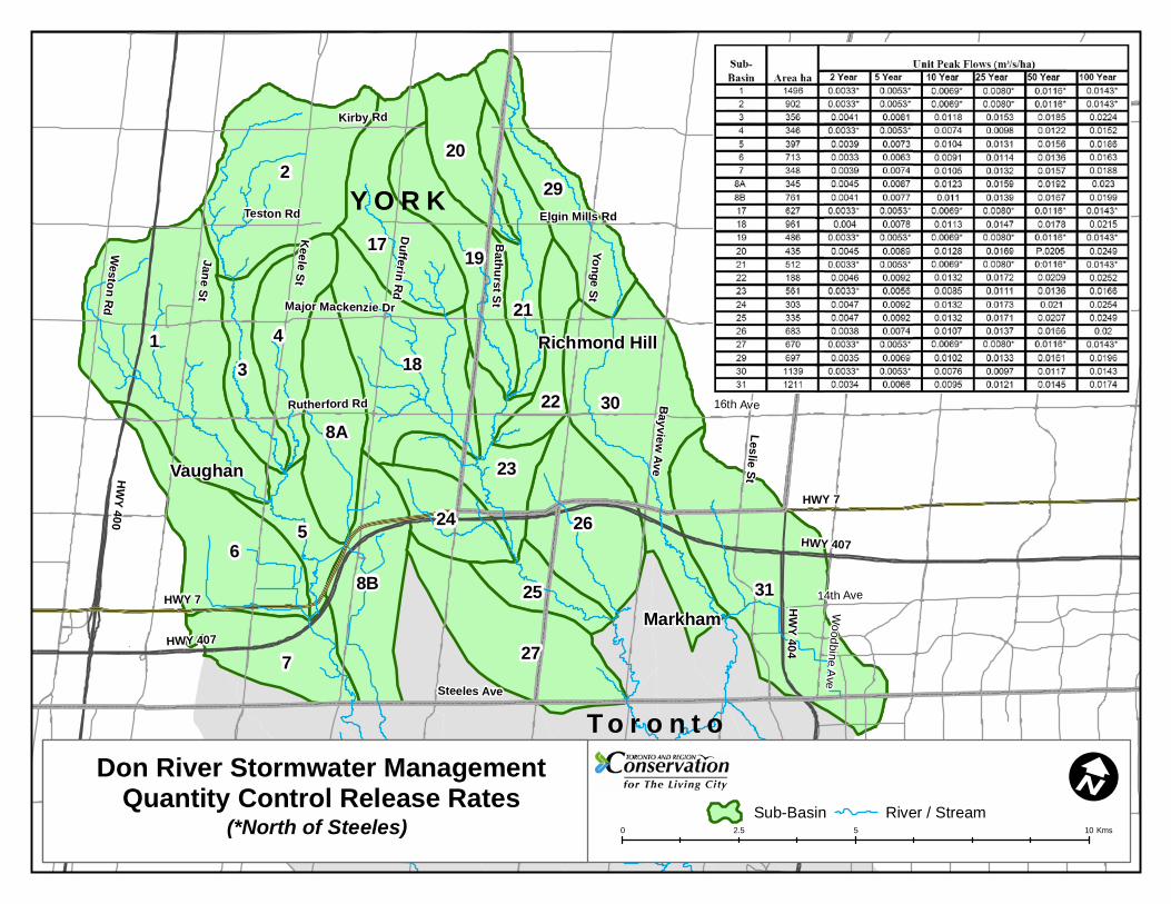
HWY 7
HWY 407
HW
Y 404
Major Mackenzie Dr
HWY 7
HWY 407
HW
Y 400
Yonge St
Dufferin R
d
Keele St
Jane St
Weston R
d
Rutherford Rd
Bathurst S
t
Bayview
Ave
Leslie St
Steeles Ave
Teston Rd
Kirby Rd
Elgin Mills Rd
14th Ave
16th Ave
Woodbine A
ve1
2
31
6
30
18
7
4
27
26
17
8B
3
29
19
8A
23
21
5
20
24
22
25Markham
Vaughan
Vaughan
Y O R K
Y O R K
T o r o n t o
0 5 102.5 Kms
I
Richmond Hill
Don River Stormwater ManagementQuantity Control Release Rates
(*North of Steeles)
T o r o n t o
Sub-Basin River / Stream
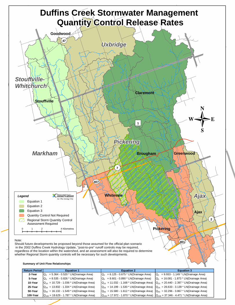
¬«47
¬«2
¬«7
UV407
UV401
")1
Summary of Unit Flow Relationships
Return Period Equation 1 Equation 2 Equation 32-Year Q2 = 5.364 - 0.520 * LN(Drainage Area) Q2 = 6.125 - 0.675 * LN(Drainage Area) Q2 = 9.933 - 1.149 * LN(Drainage Area)5-Year Q5 = 8.535 - 0.826 * LN(Drainage Area) Q5 = 8.601 - 0.890 * LN(Drainage Area) Q5 = 16.081 - 1.873 * LN(Drainage Area)
10-Year Q10 = 10.729 - 1.036 * LN(Drainage Area) Q10 = 11.032 - 1.168 * LN(Drainage Area) Q10 = 20.440 - 2.397 * LN(Drainage Area)25-Year Q25 = 13.832 - 1.334 * LN(Drainage Area) Q25 = 14.199 - 1.530 * LN(Drainage Area) Q25 = 26.633 - 3.139 * LN(Drainage Area)50-Year Q50 = 16.132 - 1.549 * LN(Drainage Area) Q50 = 15.580 - 1.612 * LN(Drainage Area) Q50 = 32.296 - 3.867 * LN(Drainage Area)100-Year Q100 = 18.629 - 1.787 * LN(Drainage Area) Q100 = 17.972 - 1.870 * LN(Drainage Area) Q100 = 37.346 - 4.471 * LN(Drainage Area)
-
Uxbridge
Ajax
Pickering
Stouffville-Whitchurch
Markham
Claremont
Stouffville
Whitevale
Brougham Greenwood
Pickering
Ajax
Goodwood
Duffins Creek Stormwater Management Quantity Control Release Rates
Note:Should future developments be proposed beyond those assumed for the official plan scenario in the 2002 Duffins Creek Hydrology Update, "post-to-pre" runoff controls may be required, regardless of the location within the watershed, and an assessment will also be required to determine whether Regional Storm quantity controls will be necessary for such developments.
0 2 41 Kilometres
LegendEquation 1Equation 2Equation 3Quantity Control Not RequiredRegional Storm Quantity Control Assessment Required
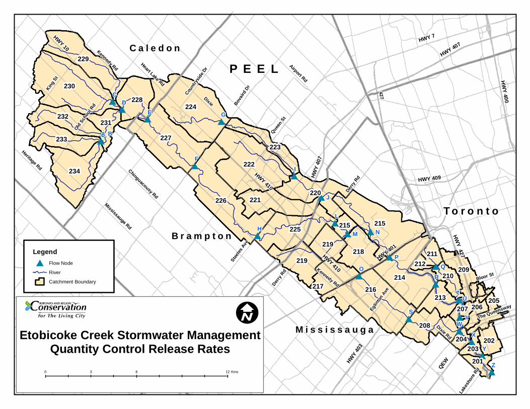
##
##
# #
#
#
#
## #
#
#
#
#
#
###
##
#
#
#
HWY 10HWY 7
HWY 407
HW
Y 400
HWY 409
427
HWY
407
HWY 427 HWY 401
Queen
St
Heart Lake Rd
HWY 410
Bova
ird D
rAirport Rd
Chinguacousy RdMississauga Rd
Stee
les A
ve
Derry
Rd Kennedy Rd
Derry
Rd
Eglin
ton A
ve
Dixie Rd
Bloor St
The Queensway
Lake
shor
e Rd
Old S
choo
l Rd
King
St
Kennedy Rd
Dixie
Count
rysid
e Dr
Heritage Rd
HWY
403
HWY 410
QEW
A B
CD
E G
F
H
I
L
M N
P
O
S
R
Q
TU
VW
X
Y
Z
J
228
229
230
234
233
232231
216217
202
206205
201
203
209
211
210
212
207
221220
223
222
224
213
214
218
225
226
227
204
208
215215
219
219
M i s s i s s a u g a
C a l e d o n
B r a m p t o n
P E E L
T o r o n t o
Legend
# Flow Node
River
Catchment Boundary
Etobicoke Creek Stormwater ManagementQuantity Control Release Rates
0 6 123 Kms
I
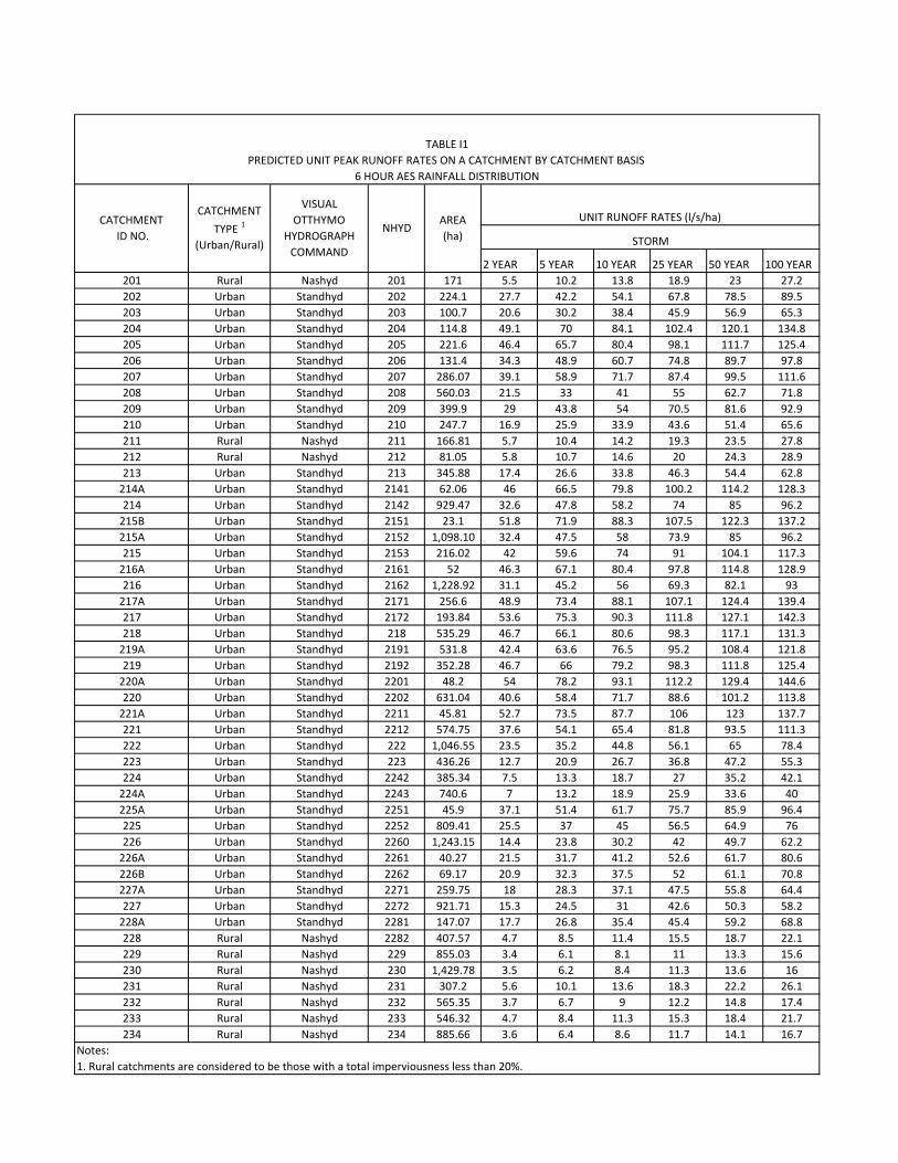
2 YEAR 5 YEAR 10 YEAR 25 YEAR 50 YEAR 100 YEAR
201 Rural Nashyd 201 171 5.5 10.2 13.8 18.9 23 27.2
202 Urban Standhyd 202 224.1 27.7 42.2 54.1 67.8 78.5 89.5
203 Urban Standhyd 203 100.7 20.6 30.2 38.4 45.9 56.9 65.3
204 Urban Standhyd 204 114.8 49.1 70 84.1 102.4 120.1 134.8
205 Urban Standhyd 205 221.6 46.4 65.7 80.4 98.1 111.7 125.4
206 Urban Standhyd 206 131.4 34.3 48.9 60.7 74.8 89.7 97.8
207 Urban Standhyd 207 286.07 39.1 58.9 71.7 87.4 99.5 111.6
208 Urban Standhyd 208 560.03 21.5 33 41 55 62.7 71.8
209 Urban Standhyd 209 399.9 29 43.8 54 70.5 81.6 92.9
210 Urban Standhyd 210 247.7 16.9 25.9 33.9 43.6 51.4 65.6
211 Rural Nashyd 211 166.81 5.7 10.4 14.2 19.3 23.5 27.8
212 Rural Nashyd 212 81.05 5.8 10.7 14.6 20 24.3 28.9
213 Urban Standhyd 213 345.88 17.4 26.6 33.8 46.3 54.4 62.8
214A Urban Standhyd 2141 62.06 46 66.5 79.8 100.2 114.2 128.3
214 Urban Standhyd 2142 929.47 32.6 47.8 58.2 74 85 96.2
215B Urban Standhyd 2151 23.1 51.8 71.9 88.3 107.5 122.3 137.2
215A Urban Standhyd 2152 1,098.10 32.4 47.5 58 73.9 85 96.2
215 Urban Standhyd 2153 216.02 42 59.6 74 91 104.1 117.3
216A Urban Standhyd 2161 52 46.3 67.1 80.4 97.8 114.8 128.9
216 Urban Standhyd 2162 1,228.92 31.1 45.2 56 69.3 82.1 93
217A Urban Standhyd 2171 256.6 48.9 73.4 88.1 107.1 124.4 139.4
217 Urban Standhyd 2172 193.84 53.6 75.3 90.3 111.8 127.1 142.3
218 Urban Standhyd 218 535.29 46.7 66.1 80.6 98.3 117.1 131.3
219A Urban Standhyd 2191 531.8 42.4 63.6 76.5 95.2 108.4 121.8
219 Urban Standhyd 2192 352.28 46.7 66 79.2 98.3 111.8 125.4
220A Urban Standhyd 2201 48.2 54 78.2 93.1 112.2 129.4 144.6
220 Urban Standhyd 2202 631.04 40.6 58.4 71.7 88.6 101.2 113.8
221A Urban Standhyd 2211 45.81 52.7 73.5 87.7 106 123 137.7
221 Urban Standhyd 2212 574.75 37.6 54.1 65.4 81.8 93.5 111.3
222 Urban Standhyd 222 1,046.55 23.5 35.2 44.8 56.1 65 78.4
223 Urban Standhyd 223 436.26 12.7 20.9 26.7 36.8 47.2 55.3
224 Urban Standhyd 2242 385.34 7.5 13.3 18.7 27 35.2 42.1
224A Urban Standhyd 2243 740.6 7 13.2 18.9 25.9 33.6 40
225A Urban Standhyd 2251 45.9 37.1 51.4 61.7 75.7 85.9 96.4
225 Urban Standhyd 2252 809.41 25.5 37 45 56.5 64.9 76
226 Urban Standhyd 2260 1,243.15 14.4 23.8 30.2 42 49.7 62.2
226A Urban Standhyd 2261 40.27 21.5 31.7 41.2 52.6 61.7 80.6
226B Urban Standhyd 2262 69.17 20.9 32.3 37.5 52 61.1 70.8
227A Urban Standhyd 2271 259.75 18 28.3 37.1 47.5 55.8 64.4
227 Urban Standhyd 2272 921.71 15.3 24.5 31 42.6 50.3 58.2
228A Urban Standhyd 2281 147.07 17.7 26.8 35.4 45.4 59.2 68.8
228 Rural Nashyd 2282 407.57 4.7 8.5 11.4 15.5 18.7 22.1
229 Rural Nashyd 229 855.03 3.4 6.1 8.1 11 13.3 15.6
230 Rural Nashyd 230 1,429.78 3.5 6.2 8.4 11.3 13.6 16
231 Rural Nashyd 231 307.2 5.6 10.1 13.6 18.3 22.2 26.1
232 Rural Nashyd 232 565.35 3.7 6.7 9 12.2 14.8 17.4
233 Rural Nashyd 233 546.32 4.7 8.4 11.3 15.3 18.4 21.7
234 Rural Nashyd 234 885.66 3.6 6.4 8.6 11.7 14.1 16.7
Notes:
1. Rural catchments are considered to be those with a total imperviousness less than 20%.
TABLE I1
PREDICTED UNIT PEAK RUNOFF RATES ON A CATCHMENT BY CATCHMENT BASIS
6 HOUR AES RAINFALL DISTRIBUTION
UNIT RUNOFF RATES (l/s/ha)
STORM
CATCHMENT
ID NO.
CATCHMENT
TYPE 1
(Urban/Rural)
VISUAL
OTTHYMO
HYDROGRAPH
COMMAND
NHYDAREA
(ha)
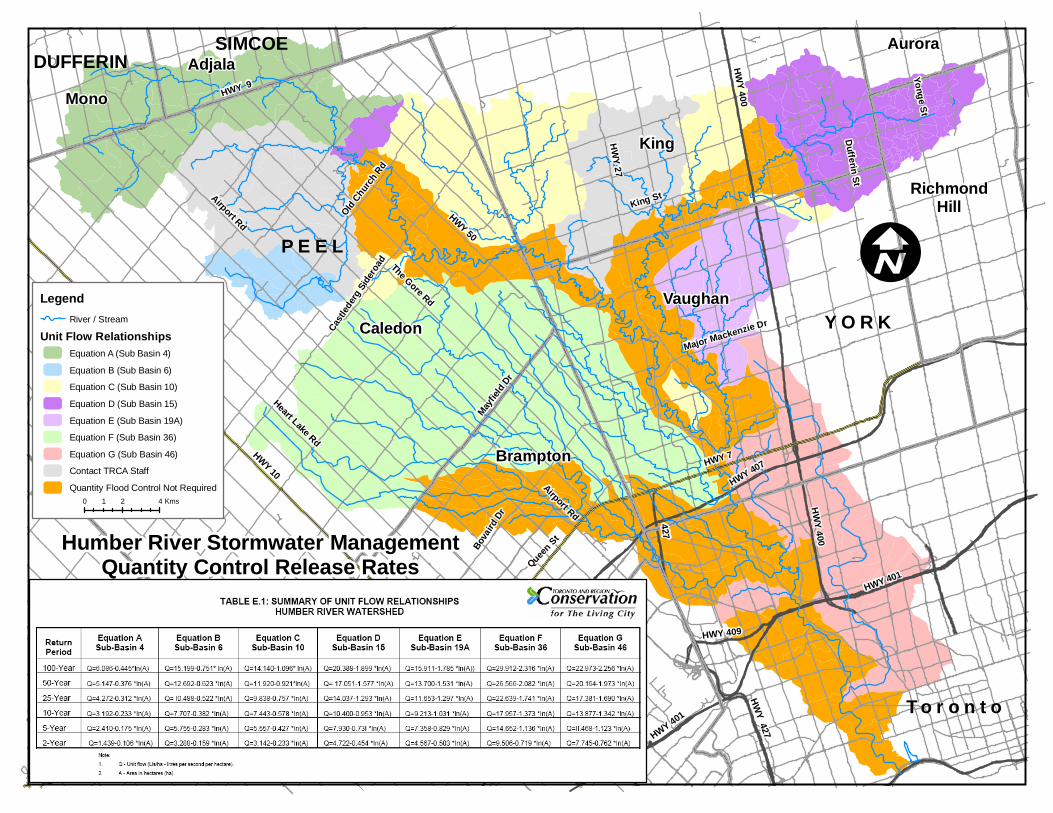
HWY 10
HWY 50
HWY 400
HWY 7
HWY 407
HW
Y 400
HWY 401
HWY 409
427
HWY
407
HWY 427 HWY 401
Queen St
Airport Rd
HWY 9
Heart Lake Rd
Major Mackenzie Dr
King St
HWY 410
Bova
ird D
r
Mayfie
ld D
r
The Gore Rd
HW
Y 27
Dufferin St
Yonge St
Cast
leder
g Si
dero
ad
Old Chu
rch R
d
Airport Rd
King
Vaughan
Caledon
Brampton
Mono
Adjala
Y O R K
P E E L
DUFFERIN
T o r o n t o
RichmondHill
AuroraSIMCOE
LegendRiver / Stream
Unit Flow RelationshipsEquation A (Sub Basin 4)
Equation B (Sub Basin 6)
Equation C (Sub Basin 10)
Equation D (Sub Basin 15)
Equation E (Sub Basin 19A)
Equation F (Sub Basin 36)
Equation G (Sub Basin 46)
Contact TRCA Staff
Quantity Flood Control Not Required
Humber River Stormwater ManagementQuantity Control Release Rates
0 2 41 Kms
I

STORMWATER MANAGEMENT CRITERIA ▪ APPENDIX B. EROSION AND GEOMORPHOLOGY B. i
TORONTO AND REGION CONSERVATION AUTHORITY AUGUST 2012 VERSION 1.0
APPENDIX B EROSION AND GEOMORPHOLOGY

B. ii STORMWATER MANAGEMENT CRITERIA ▪ APPENDIX B. EROSION AND GEOMORPHOLOGY
TORONTO AND REGION CONSERVATION AUTHORITY AUGUST 2012 VERSION 1.0
Contents B1. Erosion Analysis Methodology Summary ...................................................... 1
B2. Desktop Analysis ................................................................................... 1
2.1 Geographical Extent of Analysis ................................................................................... 1 2.2 Reach Delineation .................................................................................................... 2
B3. Rapid Geomorphic Assessment (RGA) ......................................................... 3
B4. Detailed Geomorphic Assessment (DGA) ...................................................... 4
4.1 Channel Geometry ................................................................................................... 5 4.2 Sediment Size Characterization .................................................................................... 5 4.3 Erosion Thresholds ................................................................................................... 6 4.4 Hydrologic Modelling ................................................................................................. 9 4.5 Erosion Indices ....................................................................................................... 10
B5. Plan Review Results Reporting Framework ................................................ 11
B6. References ........................................................................................ 12
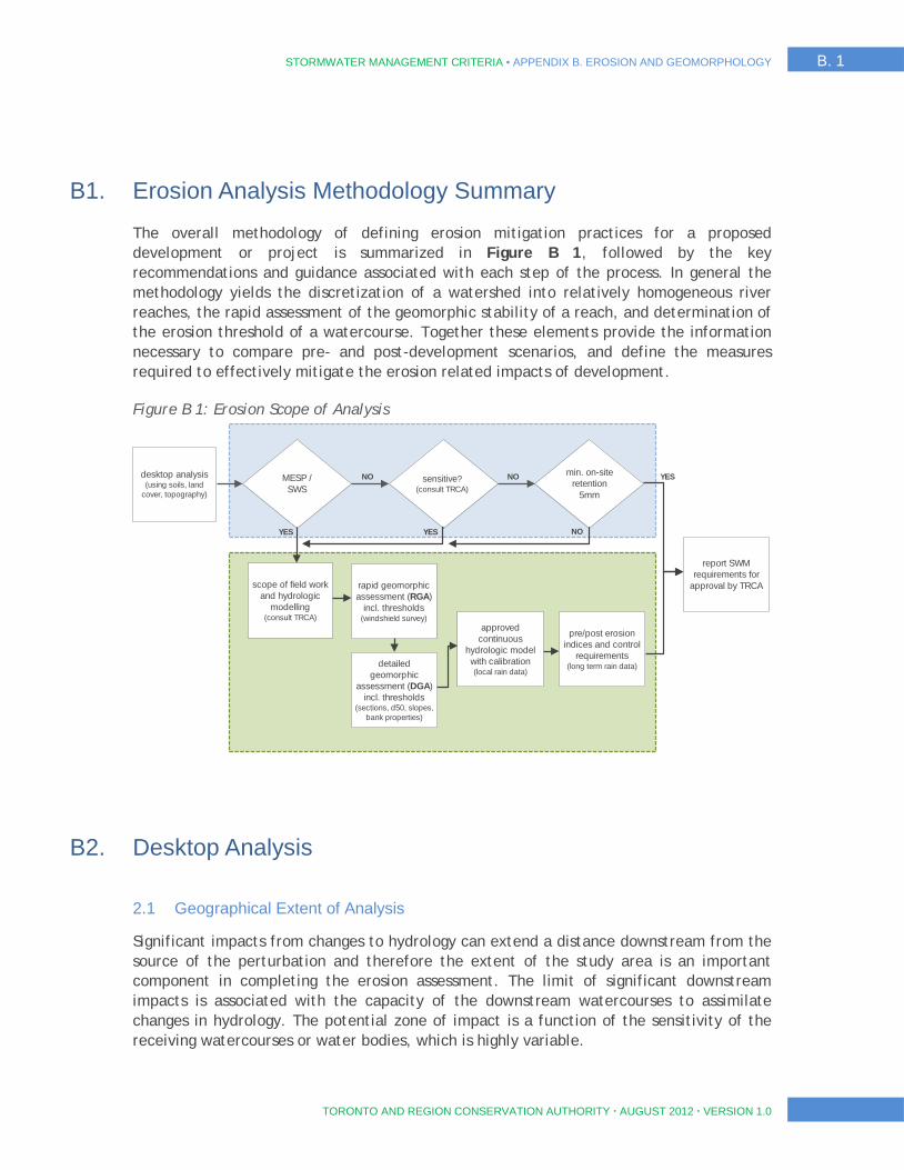
STORMWATER MANAGEMENT CRITERIA ▪ APPENDIX B. EROSION AND GEOMORPHOLOGY B. 1
TORONTO AND REGION CONSERVATION AUTHORITY AUGUST 2012 VERSION 1.0
B1. Erosion Analysis Methodology Summary
The overall methodology of defining erosion mitigation practices for a proposed development or project is summarized in Figure B 1, followed by the key recommendations and guidance associated with each step of the process. In general the methodology yields the discretization of a watershed into relatively homogeneous river reaches, the rapid assessment of the geomorphic stability of a reach, and determination of the erosion threshold of a watercourse. Together these elements provide the information necessary to compare pre- and post-development scenarios, and define the measures required to effectively mitigate the erosion related impacts of development.
Figure B 1: Erosion Scope of Analysis
B2. Desktop Analysis
2.1 Geographical Extent of Analysis
Significant impacts from changes to hydrology can extend a distance downstream from the source of the perturbation and therefore the extent of the study area is an important component in completing the erosion assessment. The limit of significant downstream impacts is associated with the capacity of the downstream watercourses to assimilate changes in hydrology. The potential zone of impact is a function of the sensitivity of the receiving watercourses or water bodies, which is highly variable.
desktop analysis (using soils, land
cover, topography)
MESP / SWS
sensitive? (consult TRCA)
min. on-site retention
5mm
report SWM requirements for
approval by TRCA scope of field work and hydrologic
modelling (consult TRCA)
approved continuous
hydrologic model with calibration (local rain data)
rapid geomorphic assessment (RGA)
incl. thresholds (windshield survey)
detailed geomorphic
assessment (DGA) incl. thresholds
(sections, d50, slopes, bank properties)
pre/post erosion indices and control
requirements (long term rain data)
YES YES NO
NO NO YES
B. 2 STORMWATER MANAGEMENT CRITERIA ▪ APPENDIX B. EROSION AND GEOMORPHOLOGY
TORONTO AND REGION CONSERVATION AUTHORITY AUGUST 2012 VERSION 1.0
The geographical extent of the assessment should be decided by identifying a zone of potential impact. This is usually defined as the length of channel downstream of the development to the next major confluence for simple single pond systems. More complicated plans involving multiple ponds, or more than one watercourse may require larger coverage and the provision of a number of thresholds from multiple reaches to properly assess the potential impact to the channel network.
The potential capacity of a watercourse or water body to assimilate changes in hydrology can be assessed in several ways. The simplest is an assessment of the relative scales of modified drainage area to the receiving watercourse’s drainage area, or comparison of two year flows.
Another method is an assessment of the scale of the receiving watercourse to downstream watercourses based on Horton stream numbering or a similar classification. With regards to receiving water bodies, comparison of two year flow to storage volume is another methodology. These or other methods should be used to provide a rationale for the study area.
If the watercourse outlets to a still water body, reservoir, or wetland, it needs to be shown that any potential change to the system is significantly mitigated by the water body. Irrespective of the method applied, the geographical extent of the analysis should be defined in consultation with TRCA staff.
2.2 Reach Delineation
Rivers are continuous channels that exhibit gradients in their slope, width, and bed material size. For the purposes of analysis, it is usually necessary to describe the channel as a series of discrete sections, called ‘reaches’ within which the physical characteristics of the river can be considered to be homogeneous. The key drivers of the river morphology are the hydrology, geology, and adjacent watershed surface conditions (Kellerhals 1976). In urban watersheds, the channel network may also be significantly fragmented due to road and stormwater networks (Chin and Gregory 2005).
Reach delineation should at a minimum be based on assessment of current aerial photographs, surficial geology and topographic mapping. Indicators used to delineate reaches include:
Drainage network – confluences will typically define points in the system where the hydrology changes. Stormwater outfalls can be considered as part of the drainage network in urbanized systems;
Surficial geology – change in soil types can produce a corresponding change in river morphology;
Land surface cover - changes in riparian vegetation, especially from forested to grassed, can have a significant impact on morphology. Surrounding land use, especially encroachment of the floodplain, will also have a significant impact and may indicate zones where the creek has been directly modified through the use of bank protection;
Breaks in slope – topographic mapping can indicate sudden changes in slope that may result from changes in hydrology and geology. Reach delineation can also be defined by grade control points such as dams, weirs and geologic outcrops; and
STORMWATER MANAGEMENT CRITERIA ▪ APPENDIX B. EROSION AND GEOMORPHOLOGY B. 3
TORONTO AND REGION CONSERVATION AUTHORITY AUGUST 2012 VERSION 1.0
Road network – bridges, utilities, and stormwater outfalls can all segment the drainage network. These urban networks are typically aligned with the road network. Urban channels may be more reliably divided into reaches using road crossings than by other means (Chin and Gregory 2005).
Desktop reach delineation can be field verified during the rapid geomorphic assessment stage.
B3. Rapid Geomorphic Assessment (RGA)
Selection of sensitive reaches is based on the identification of reaches with the least capacity to assimilate increases in flow. There are several factors that can affect the sensitivity of a creek to change including stability, past impacts on channel form, threshold of dominant bed and bank materials, physiography, and size/physical capacity of the reaches channel. Rapid assessment can be used to evaluate the geomorphic stability of reaches. The Rapid Geomorphic Assessment is a standard technique for rapid assessment that is described in the Stormwater Management Planning and Design Manual (MOE 2003). It is not the only tool available to evaluate stability of reaches (e.g. Downs 1995, Galli 1996, Johnson et al. 1999), but is recommended because it relies on indicators that can be objectively identified instead of other, more subjective techniques. Other methods should only be used after consultation with TRCA staff.
The RGA is a field assessment tool and must be done on a site visit. The method is to walk a length of the creek and record instances of physical characteristics of the river that are indicators of instability. The number of observed indicators is divided by the total number of indicators to obtain an index of instability with a value between 0 and 1. This list supplied as part of this report matches what is available in MOE (2003), but should not be considered complete. Other indicators may be added from other sources (e.g. USDA-NCRS 2007) or based on the experience of the assessor. Indicators that cannot be assessed (for instance an exposed building foundation is not possible if there are no buildings) should not be considered as part of the total number of indicators.
In the RGA, indicators are grouped into categories corresponding to different geomorphic processes including aggradation (AI), degradation (DI), widening (WI) and planimetric form adjustment (PI). Aggradation occurs when there is insufficient energy to move sediment through the reach and it collects over time, often in the middle of a creek and in pools. Degradation, widening and planimetric form adjustment are three stages of the classic model of stream adjustment (Simon 1989). In this model, degradation is initiated by the transport of more sediment out of the reach than is supplied to the reach due to an excess of energy. This process leads to incision and the entrenchment of the channel so that higher flow rates and shear stresses are contained within the channel and the floodplain is more rarely inundated. This tends to accelerate the process of incision and lead to channel widening as stream banks become more unstable and fail. Over time, widening can lead to a reduction of shear stress on the bed of the channel and deposition of a new floodplain at a lower elevation (planimetric form adjustment). Given enough time (on the order of decades), the channel should reach a new state of dynamic equilibrium.
B. 4 STORMWATER MANAGEMENT CRITERIA ▪ APPENDIX B. EROSION AND GEOMORPHOLOGY
TORONTO AND REGION CONSERVATION AUTHORITY AUGUST 2012 VERSION 1.0
The overall Stability Index (SI) is not a reliable index of stream stability; therefore the separate indices of specific geomorphic processes (AI, DI, WI, and PI) are preferred for assessing stream sensitivity. The SI value may lead to an erroneous interpretation of stability because it averages four different indices:
SI = (AI + DI + WI + PI)/4
To demonstrate the problem with this calculation, consider a severely aggrading system. Such a system may have 7 of the 9 indicators present, which would give a score of 0.77 for the Aggradation Index (AI), but is unlikely to have many examples of the indicators in the other categories. The total stability index in this case would by SI = (0.77+0+0+0)/ 4 = 0.19. The interpretation table shown in MOE (2003) would classify this system as ‘In Regime’, meaning that the ‘evidence of instability is isolated or associated with normal river meander propagation processes’. In the example given, this conclusion is demonstrably false. It is recommended that the indicators of each type of process be considered separately so that a more accurate picture of geomorphic stability can be obtained.
High index values (AI, DI, WI, or PI > 0.50) will trigger the requirement of a detailed erosion assessment in the subject reach. Minor receiving tributaries should be considered for detailed assessment even if stable because physical capacity may be limited. Where multiple reaches are similarly sensitive along a tributary, multiple detailed assessments and erosion thresholds quantification may be required. At least one reach per receiving tributary should be defined. When unstable reaches are numerous, professional judgment may be applied to group types of streams to identify a subset of reaches for the more detailed erosion assessment.
B4. Detailed Geomorphic Assessment (DGA)
Erosion thresholds determine the critical discharge in a channel that is likely to entrain and transport sediment. These thresholds are regularly exceeded in natural channels and result in normal amounts of sediment transport. The objective of the detailed geomorphic assessment is to determine whether the changes to the hydrology as a result of the development are likely to result in more or less erosion than presently occurs. A calculated index is used as a proxy for erosion. The procedure to calculate the erosion index is as follows:
Field measurement of channel geometry;
Field measurement sediment particle sizes;
Desktop analysis of erosion thresholds;
Continuous hydrologic modeling; and
Determination of erosion indices.
These steps are described in more detail below:
STORMWATER MANAGEMENT CRITERIA ▪ APPENDIX B. EROSION AND GEOMORPHOLOGY B. 5
TORONTO AND REGION CONSERVATION AUTHORITY AUGUST 2012 VERSION 1.0
4.1 Channel Geometry
Channel geometry is critical for the determination of erosion thresholds and discharge. The approach described here assumes that the reach can be described as a uniform channel with a single resistance to erosion and a single threshold of erosion. This represents a gross simplification of channels that are not lined with concrete or riprap. The approach is useful, however, for the overall estimation of erosion in a channel where a single threshold is needed. To be representative, it is necessary to select cross-section locations that are in relatively straight sections. It is assumed that the entire cross-section is active, i.e. that there are no zones of flow recirculation near the banks that would result in an artificially high estimate of the discharge at the cross-section. Riffle and run locations are most suitable for this purpose while pools are not recommended. A minimum of five cross sections should be used to get an accurate picture of the channel geometry.
The cross section can be surveyed using a total station. The cross-section should extend to at least the flood-plain elevation and should be perpendicular to the channel banks. The distance between surveyed points should be less than 5 percent of the width of the bankfull channel and should include any points where there is a break in the slope. It is also necessary to record the distance and elevation of any floodplain terraces and the width of the floodplain.
The bankfull elevation should be indicated in the cross-section measurements and the type of bankfull indicator recorded. Bankfull dimensions are primarily identified by breaks in slope in the cross section such as the first flat depositional surface, the top of the point bar or other deposits, or a distinct change in the size of substrate material (Technical Supplement 3C in USDA-NCRS 2007).
Vegetation changes can also be used to determine bankfull by looking for the lowest extent of woody vegetation or by noting the highest location of washed roots. The highest elevation of washed rock can be used as a bankfull indicator in bedrock channels. In urbanized systems it may be difficult to get a consistent estimate of bankfull depth because the reach may be unstable or in transition. Some indicators such as the floodplain elevation may reflect historical bankfull depths and may be unreliable.
To determine a representative channel slope, a distance equivalent to 20-40 times the channel width should be surveyed by locating the riffle crest at the channel centerline. Channel slopes are often quite flat (typically less than 1%), and the relative elevation of at least three successive riffle crests or runs should be made. Measurements made in pools should not be used to estimate the slope of the channel. Bankfull gradient should be measured from surveyed points of the bankfull position at each cross-section and at an adequate number of intermediate points based on standard field indicators.
For reference, there are a number of texts that detail standard protocols and field methods (Harrelson et al. 1994, Annable 1996, USDA-NCRS 2007)
4.2 Sediment Size Characterization
The location of sediment sampling will vary with the purpose of the sampling (USDA-NCRS 2007). Fine sediments will typically deposit in bars and pools during low flows and these locations should be avoided as they are likely to significantly underestimate thresholds for
B. 6 STORMWATER MANAGEMENT CRITERIA ▪ APPENDIX B. EROSION AND GEOMORPHOLOGY
TORONTO AND REGION CONSERVATION AUTHORITY AUGUST 2012 VERSION 1.0
erosion. A more representative section for erosion in the channel will be the straight runs and riffles in the channel. These are the resistant points in the channel bed and their stability will determine the overall stability of the reach.
The sediment size characterization is used to determine channel roughness and the critical shear stress of the bed and bank materials. However, the sampling and analysis will vary depending on the size of material under investigation (USDA-NCRS 2007). A hand test should be used to determine the sediment type. Following this, roughness and critical shear stress can be calculated as follows:
Clay and silt (D50 ≤ 0.062 mm): Either or both Torvane and penetrometer measurements should be collected to assess mechanical shear strength. As a note, these instruments measure mechanical failure of the bulk sediment and are not a direct measure of entrainment shear stresses. They cannot be used as a surrogate for bank material erosion thresholds. Empirical tables should be used to determine channel roughness and critical shear stress for clays and silts (Chow 1959, Fischenich 2001). No precise characterization of sediment size is required.
Sand (0.062 mm < D50 ≤ 2 mm): Bulk sampling should be used to determine a median particle size (D50) from which other calculations will follow. Following the recommendations of the U.S. Department of Agriculture, 3 to 5 samples should be taken across a representative uniform section. This material should be sieved and tabulated using standard procedures.
Gravel and cobbles: a Wolman pebble count (Wolman 1954) should be used to determine a median particle size (D50) from which other calculations will follow. The pebble count should consist of at least 100 particles at a minimum of two different locations. A method should be selected to ensure a random selection of particles across the full width of channel over a stream-wise distance equal to one channel width. Suitable approaches are to select the particle under the toe of your boot as you walk across the channel or to use a stick to randomly select a particle in front of you if the bed material is too large or angular to safely allow a step forward without guiding the steps. Sand particle diameters should not be used in the estimation of representative particle sizes. If the surface sand content is greater than 30%, bulk samples should be made of the bed material.
4.3 Erosion Thresholds
The evaluation of erosion thresholds is typically a component of the Detailed Geomorphic Assessment (DGA, Section B6). The erosion threshold calculation requires the following input:
Mean channel slope;
Median particle size;
Reference cross-section dimensions including any terraces and the floodplain width; and,
Visual assessment of roughness factors.
The calculation procedure is as follows:
STORMWATER MANAGEMENT CRITERIA ▪ APPENDIX B. EROSION AND GEOMORPHOLOGY B. 7
TORONTO AND REGION CONSERVATION AUTHORITY AUGUST 2012 VERSION 1.0
1. Determine roughness of channel;
2. Calculate shear stress on the bed and banks at various flow depths;
3. Determine the critical shear stress for bed and bank erosion; and,
4. Calculate corresponding discharges at various flow depths.
The individual analyses associated with the above procedure are described in the following subsections.
Roughness: Channel roughness (n) is a critical determinant of the depth of flow and velocity in the channel. This parameter will affect the relation between discharge and shear stress that will be used to calculate erosion indices. The estimation of n is an imprecise exercise because it is a function, not only of the bed and bank material, but also any irregularities in the channel boundary. Cowan (1956) considered the overall roughness to be the sum of different components of roughness that could be evaluated independently. The components include the bed material, the degree of channel irregularities, variations in cross section, the effect of obstructions, vegetation, and meandering as described by Chow (1959).
Manning’s equation can be used to determine channel roughness based on field measurements. However, field-derived n values should be compared against the literature for verification.
Much of the literature on roughness coefficients used field measurements to calculate the roughness coefficient and compiled the results into tables. Some of the better references include pictures of reaches so that a value for n can be selected based on a visual comparison between a reference reach and the reach of interest (Chow 1959, Hicks and Mason 1998). Most textbooks on hydraulics will have a table that gives some standard values based on a general description of the reach. Professional judgment is required in the selection of a representative value of channel roughness.
Shear Stress: Total shear stress is calculated using the standard equation derived from fluid mechanics first principles, which relates total shear stress to the specific weight of water, acceleration due to gravity, the longitudinal slope of the channel, and the hydraulic radius:
SgRhbed ρτ =
The maximum shear stress on the bed and banks can be calculated from the water depth instead of the hydraulic radius if the channels are sufficiently wide (depth less than four times the width):
gYSCbedbed ρτ =
gYSCbankbank ρτ = where Cbed and Cbank are coefficients, r is the specific weight of water, g is gravity, Y is the water depth and S is the longitudinal slope of the channel.
Critical Shear Stress: There are several commonly applied critical shear stress methods (e.g., Miller et al., 1977; Andrews, 1983; Van Rijn, 1984). There are also numerous methods for defining critical velocity (e.g., Komar, 1987) or permissible velocity (e.g.,
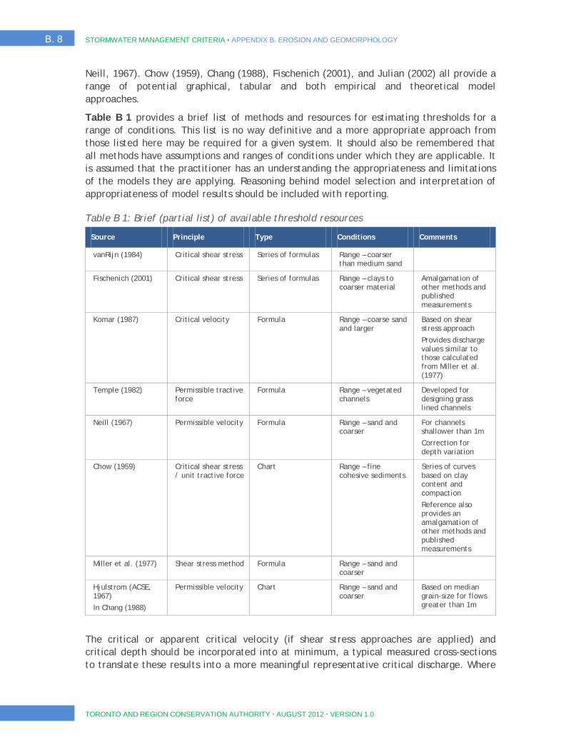
B. 8 STORMWATER MANAGEMENT CRITERIA ▪ APPENDIX B. EROSION AND GEOMORPHOLOGY
TORONTO AND REGION CONSERVATION AUTHORITY AUGUST 2012 VERSION 1.0
Neill, 1967). Chow (1959), Chang (1988), Fischenich (2001), and Julian (2002) all provide a range of potential graphical, tabular and both empirical and theoretical model approaches.
Table B 1 provides a brief list of methods and resources for estimating thresholds for a range of conditions. This list is no way definitive and a more appropriate approach from those listed here may be required for a given system. It should also be remembered that all methods have assumptions and ranges of conditions under which they are applicable. It is assumed that the practitioner has an understanding the appropriateness and limitations of the models they are applying. Reasoning behind model selection and interpretation of appropriateness of model results should be included with reporting.
Table B 1: Brief (partial list) of available threshold resources
Source Principle Type Conditions Comments
vanRijn (1984) Critical shear stress Series of formulas Range – coarser than medium sand
Fischenich (2001) Critical shear stress Series of formulas Range – clays to coarser material
Amalgamation of other methods and published measurements
Komar (1987) Critical velocity Formula Range – coarse sand and larger
Based on shear stress approach
Provides discharge values similar to those calculated from Miller et al. (1977)
Temple (1982) Permissible tractive force
Formula Range – vegetated channels
Developed for designing grass lined channels
Neill (1967) Permissible velocity Formula Range – sand and coarser
For channels shallower than 1m
Correction for depth variation
Chow (1959) Critical shear stress / unit tractive force
Chart Range – fine cohesive sediments
Series of curves based on clay content and compaction
Reference also provides an amalgamation of other methods and published measurements
Miller et al. (1977) Shear stress method Formula Range – sand and coarser
Hjulstrom (ACSE, 1967)
In Chang (1988)
Permissible velocity Chart Range – sand and coarser
Based on median grain-size for flows greater than 1m
The critical or apparent critical velocity (if shear stress approaches are applied) and critical depth should be incorporated into at minimum, a typical measured cross-sections to translate these results into a more meaningful representative critical discharge. Where

STORMWATER MANAGEMENT CRITERIA ▪ APPENDIX B. EROSION AND GEOMORPHOLOGY B. 9
TORONTO AND REGION CONSERVATION AUTHORITY AUGUST 2012 VERSION 1.0
threshold velocity methods are employed an apparent or equivalent shear stress should be provided. Typical cross-sections along with the slope and channel roughness for calculation of bankfull and threshold flows should be reported and justified. Graphical representation of the cross-section including field measured bankfull, water depth on the day and the predicted threshold water depth should be plotted for comparison. Comparisons between bankfull and threshold conditions should be provided to document reach sensitivity. Ratios of entrainment threshold depth, velocity and shear stress to bankfull depth, velocity and shear stress should be provided.
Discharge: The calculation of discharge at various depths requires the calculation of normal depth in the channel, which can be determined by averaging the measured depth at each cross-section. Alternatively, normal depth can be selected by using the measured value from a ‘representative’ section, or by amalgamating the sections into an idealized representative section. Sound engineering judgment is required in the selection of a representative cross section (USDA, 2007).
A table summarizing the results of the analyses should include discharge, in-channel velocity and excess shear stress. Where threshold velocity methods are employed an apparent or equivalent shear stress should be provided. Graphical representation of the cross-section including field measured bankfull, water depth on the day and the predicted threshold water depth should be plotted for comparison. Comparisons between bankfull and threshold conditions should be provided to document reach sensitivity.
4.4 Hydrologic Modelling
The recommended method for assessing pre- to post-development erosion potential is some form of continuous modeling. Continuous modeling accounts for the impact of pond function and antecedent conditions on instream erosion. It also allows the interaction of multiple ponds to be assessed for larger scale developments. Continuous simulation models allow examination of potential cumulative impacts from upstream and downstream development areas, or where there are multiple stormwater facilities proposed to manage multiple developments. Proponents will also be required to incorporate previous assessments from other developments in their analysis where multiple developments are proposed in the subwatershed, or to collaborate with other concurrent developments to generate a comprehensive study.
An approved continuous hydrologic model should be developed, calibrated, and verified using a long time series of meteorological data that can provide hourly time-series of the pre and post development hydrographs. To ensure accurate results, it is critical that the hydrologic model is calibrated and verified. If streamflow and precipitation data are not available in the study area the proponent will be required to collect this data for the calibration and verification of the model. The monitoring requirements for rainfall and streamflow data should be determined in consultation with TRCA staff during the development of the terms of reference for comprehensive environmental studies.
Please note that the shape of the rising and falling limb of the storm hydrograph can impact entrainment and transport of sediments. As such, an example pre-to-post hydrograph should be provided for examination. The graphical representation should be from a node within the sensitive reach for a storm event that exceeds the erosion threshold.
B. 10 STORMWATER MANAGEMENT CRITERIA ▪ APPENDIX B. EROSION AND GEOMORPHOLOGY
TORONTO AND REGION CONSERVATION AUTHORITY AUGUST 2012 VERSION 1.0
4.5 Erosion Indices
In natural systems with defined watercourses, erosion thresholds are exceeded regularly. As such, the key to maintaining natural channel function is to match the frequency of exceedance or cumulative effective work in the post-development condition. In some very sensitive systems, or where impacts have already occurred, a level of over-control may be required.
Pre- to post-development exceedance can be tested using several criteria. The simplest is the cumulative time of exceedance. Although it provides a simple comparison, it does not provide information on the work or erosive force of flows once erosion thresholds are exceeded. As such, it is only a first cut and a more stringent assessment, such as the cumulative effective work or cumulative erosion index, should be completed. The recommended criteria are the cumulative erosion index and the cumulative effective work. The calculation of erosion indices requires a continuous time series of discharge and a table relating discharge to excess shear stress. For the cumulative effective work, the mean channel velocity at various depths is also required.
The cumulative Erosion Index (Ei) is calculated as (Stormwater Management Planning and Design Manual, MOE 2003):
( )∑ ∆−= tVVE cti
Where iE is the erosion index
tV is velocity in the channel at time t
cV is critical velocity above which entrainment will occur
t∆ time step
where Ei is the erosion index, τ is the shear stress at time t, τc is the critical shear stress for either the bed or the bank, and Δt is the time interval. As a note, this index can be calculated with channel velocity where the critical velocity replaces the critical shear stress to provide a comparable index. The cumulative effective work index (Wi) is calculated as:
( )∑ ∆−= tVW ci ττ
where Wi is the cumulative effective work or stream energy expended above the critical value, and V is the mean channel velocity.
The mean channel velocity should not include floodplain velocities but should consider only the velocities and the area calculated between the stream banks for each depth. The cumulative effective work index is similar in nature to a cumulative effective stream power. It is the preferred method when assessing potential impacts because the velocity will increase as flood stage increases, which means that Wi will be more sensitive to extreme floods than Ei, which is in agreement with predictions of sediment transport in rivers (Garcia 2008).
A combination of time of exceedance and effective work approaches must be applied and the results provided for review. It is anticipated that post-development exceedance will
STORMWATER MANAGEMENT CRITERIA ▪ APPENDIX B. EROSION AND GEOMORPHOLOGY B. 11
TORONTO AND REGION CONSERVATION AUTHORITY AUGUST 2012 VERSION 1.0
match pre-development exceedance unless over-control is required. In areas where erosion thresholds cannot be matched other mitigation measured, stormwater control beyond what can be achieved using simple end-of-pipe approaches may be required. Where they are deemed necessary, these mitigation measures must be developed in consultation with the TRCA.
B5. Plan Review Results Reporting Framework
A minimum results reporting standard is necessary for TRCA to be able to adequately review proposals for development. The following checklist should be used as a minimum guideline:
Information on desktop analysis and reach delineation including: mapping of zone of influence, channel network, reach breaks, pond locations, immediate receiving reaches, and sensitive reaches; mapping of soils, current land use and the road network; identification of reach breaks.
Rapid geomorphic assessment for all reaches including: RGA form; Reach-by-reach descriptions including physical conditions, sensitivity measured by an acceptable protocol, and evaluation of systematic adjustments/dominant processes; and Photographic support of RGA analysis including general photos of reach, banks and floodplain , occurrence of indicators listed in RGA and/or stable morphologies.
Detailed field assessment of the sensitive reaches including:
Summary of cross-section geometry; Long profile (bankfull and bed gradient); Bank profile with: mechanical strength estimates, Characterization of bed and bank materials, and photographic support including downstream view, upstream view, both stream banks and the bed.
Quantification of erosion threshold(s) including: Channel roughness and critical shear stress; Table documenting discharge, velocity, depth, shear stress and excess shear stress; Bankfull flow conditions, discharge, velocity, depth and shear stress; Ratios between threshold and bankfull depth for velocity, depth, discharge and shear stress; Example cross-sections for both bankfull and critical threshold conditions; Field observations including approximate measures of water depth, velocity, and transport conditions;
Continuous hydrologic modeling including: Location of installed stream gauges; Calibration and verification of continuous hydrologic model; an example hydrograph for examination; Time of exceedance for pre-and-post conditions; and cumulative effective shear stress and effective work
B. 12 STORMWATER MANAGEMENT CRITERIA ▪ APPENDIX B. EROSION AND GEOMORPHOLOGY
TORONTO AND REGION CONSERVATION AUTHORITY AUGUST 2012 VERSION 1.0
B6. References
Booth, D.B. 1990. Stream-channel incision following drainage-basin urbanization. Water Resources Bulletin, 26(3): 407-417.
Bradford, A. and Gharabaghi, B. 2004. Evolution of Ontario’s stormwater management planning and design guidance. Water Quality Research Journal of Canada, 39 (4): 343-355.
Center for Watershed Protection. 2010. New York State Stormwater Management Design Manual. Prepared for New York State Department of Environmental Conservation.
Department of Environmental Protection. 2006. Pennsylvania Stormwater Best Management Practices Manual, Chapter 8 Stormwater Calculations and Methodology.
Graham, P., Maclean, L., Medina, D., Patwardhan, A. and Vasarhelyi, G. 2004. The role of water balance modeling in the transition to low impact development. Water Quality Research Journal of Canada, 39 (4): 331-342.
Iowa State University, Institute for Transportation. 2009. Iowa Stormwater Management Manual, 2A-4 Stormwater Management Criteria. Version 3.
Lee, K. and Ham, P.J. 1988. Effects of Surrey’s Storm Water Management Policy on Channel Erosion. International Symposium on Urban Hydrology and Municipal Eng., Town of Markham. Markham, Ontario.
Leopold, L.B., Wolman, M.G. and Miller, J.P. 1964. Fluvial Processes in Geomorphology. W.H. Freeman and Co., San Francisco.
MacRae, C.R. 1997. Experience from morphological research on Canadian Streams: Is the control of the 2-year frequency runoff event the best basis for stream channel protection? Frequency runoff control: 144-162.
MacRae, C.R. and Rowney, A.C. 1992. The Role of Moderate Flow Events and Bank Structure in the Determination of Channel Response to Urbanization. 45th Annual Conference of the Canadian Water Resources Assoc., Kingston, Ontario.
McCuen, R.H. 1979. Downstream Effects of Storm Water Management Basins. Journal of the Hydraulics Division, ASCE, 1(1): 21-42.
McCuen, R.H. and Moglen, G.E. 1988. Multicriterion Storm-Water Management Methods. Journal of Water Resources Planning & Management, 114(4): 414-431.
Ministry of the Environment (MOE). 1999. Stormwater Management Planning and Design Manual.
Mitchell, V.G., McMahon, T.A. and Mein, R.G. 2003. Components of the Total Water Balance of an Urban Catchment. Environmental Management, 32 (6): 735-746.
Montgomery, D.R. and J.M. Buffington, 1997. Channel-reach morphology in mountain drainage basins. Geological Society of America Bulletin, 109 (5): 596-611.
Richards, K.S. and Lorriman, N.R. 1987. Basal Erosion and Mass Movement in Slope Stability: Geotechnical Engineering and Geomorphology, M.G. Anderson and K.S. Richards (ed.). John Wiley, Toronto. 359-380.

STORMWATER MANAGEMENT CRITERIA ▪ APPENDIX B. EROSION AND GEOMORPHOLOGY B. 13
TORONTO AND REGION CONSERVATION AUTHORITY AUGUST 2012 VERSION 1.0
Washington State Department of Ecology. 2005. Stormwater management in Western Washington: Volume III Hydrologic Analysis and Flow Control Design/BMPs.
Villard, P.V. and R. Ness. 2006. Stormwater Management and Significant Channel Flows Below the Two-year Return. In Intelligent Modeling of Urban Water Systems. Monograph 15. Proceedings of the Stormwater and Urban Water Systems Modeling Conference February 23-24, 2006, Toronto, Ontario.
Villard, P. V. and Parish, J. D. 2003. A Geomorphic-based protocol for assessing stream sensitivity and erosion thresholds: A tool for stormwater management. In 16th Canadian Hydrotechnical Conference. Canadian Society for Civil Engineers, October 22-24, 2003, Burlington, ON, 10 p.
Wolman, M.G. 1967. A Cycle of Sedimentation and Erosion in Urban River Channels. Geography Annals, 49: 385-395.
STORMWATER MANAGEMENT CRITERIA ▪ APPENDIX C: WATER BALANCE AND RECHARGE C. i
TORONTO AND REGION CONSERVATION AUTHORITY AUGUST 2012 VERSION 1.0
APPENDIX C WATER BALANCE AND RECHARGE
C. ii STORMWATER MANAGEMENT CRITERIA ▪ APPENDIX C: WATER BALANCE AND RECHARGE
TORONTO AND REGION CONSERVATION AUTHORITY AUGUST 2012 VERSION 1.0
Contents C1. Methodology of Analysis to Assess Recharge Requirements .............................. 1
1.1 Step 1 – Assess the Vulnerability of the Groundwater System ................................................. 2 1.2 Step 2 – Estimating Infiltration and Post-development Targets ............................................... 4 1.3 Step 3 - Detailed Design Calculations of Infiltration ........................................................... 11
C2. Site Evaluation and Soil Testing Protocol for Stormwater Infiltration ........................................................................................ 12
2.1 Step 1: Background Evaluation .................................................................................... 13 2.2 Step 2: Test Pit or Soil Boring Observations ..................................................................... 14 2.3 Step 3: Infiltration Testing ......................................................................................... 15 2.4 Step 4: Design Considerations ..................................................................................... 17
C3. Design Guidance for Infiltration Measures ................................................. 18
C4. References ........................................................................................ 19

STORMWATER MANAGEMENT CRITERIA ▪ APPENDIX C: WATER BALANCE AND RECHARGE C. 1
TORONTO AND REGION CONSERVATION AUTHORITY AUGUST 2012 VERSION 1.0
C1. Methodology of Analysis to Assess Recharge Requirements
The physical properties of the landscape that determine the proportions of precipitation that partition into recharge/infiltration, evapotranspiration, and runoff include:
Soil permeability;
Soil moisture;
Depth to groundwater table;
Slope; and
Type of vegetation.
In areas where soils have high permeability and relatively flat topography, infiltration rates are higher than run-off. The highest infiltration occurs in areas of hummocky topography with internally drained areas (i.e. no surface water outlet). In contrast, for areas with steep slopes and less permeable soils, run-off usually exceeds infiltration. Other factors which influence infiltration rates include the amount of available water, intensity of precipitation, air temperature, and sunshine duration.
One of the challenges in any development project is the determination of the pre-development infiltration rate. Most modelling studies provide detailed analysis of precipitation and runoff, and allocate evapotranspiration based on published literature. Infiltration is then estimated by subtraction. What is known is that infiltration rates vary considerably across TRCA’s jurisdiction. Consultant studies (Kassenaar and Wexler, 2006; TRCA, 2010) have estimated infiltration rates as high as 350 mm per annum in the northern portions of TRCA’s watersheds, where the topography is hummocky, and the surficial soils comprise permeable sand and gravel. However, areas on the south slope of the Oak Ridges Moraine covered by Halton Till may have infiltration rates below 50 mm per year.
The recommended steps for determining existing infiltration rates and post-development targets at the site scale and selection of appropriate mitigation strategies are illustrated in Figure C 1, and described in the subsequent subsections.
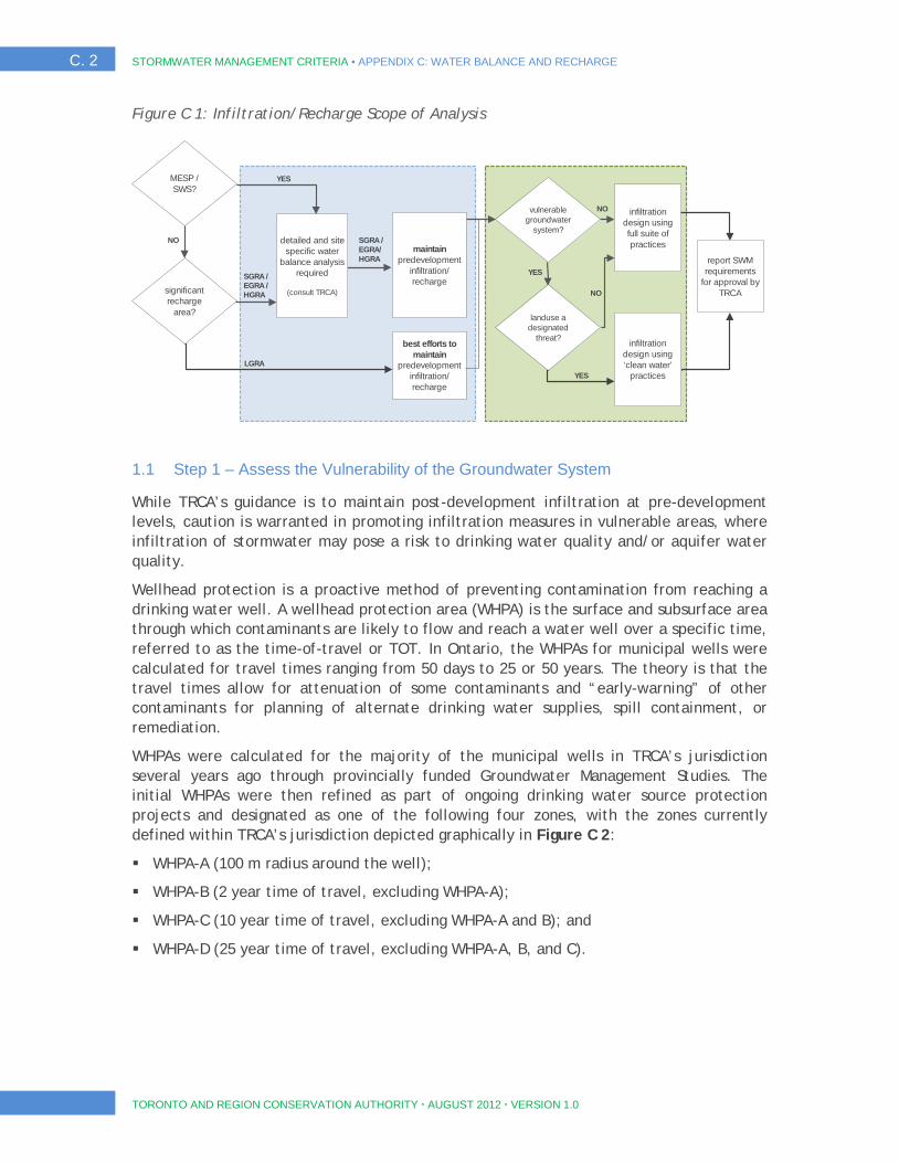
C. 2 STORMWATER MANAGEMENT CRITERIA ▪ APPENDIX C: WATER BALANCE AND RECHARGE
TORONTO AND REGION CONSERVATION AUTHORITY AUGUST 2012 VERSION 1.0
Figure C 1: Infiltration/Recharge Scope of Analysis
1.1 Step 1 – Assess the Vulnerability of the Groundwater System
While TRCA’s guidance is to maintain post-development infiltration at pre-development levels, caution is warranted in promoting infiltration measures in vulnerable areas, where infiltration of stormwater may pose a risk to drinking water quality and/or aquifer water quality.
Wellhead protection is a proactive method of preventing contamination from reaching a drinking water well. A wellhead protection area (WHPA) is the surface and subsurface area through which contaminants are likely to flow and reach a water well over a specific time, referred to as the time-of-travel or TOT. In Ontario, the WHPAs for municipal wells were calculated for travel times ranging from 50 days to 25 or 50 years. The theory is that the travel times allow for attenuation of some contaminants and “early-warning” of other contaminants for planning of alternate drinking water supplies, spill containment, or remediation.
WHPAs were calculated for the majority of the municipal wells in TRCA’s jurisdiction several years ago through provincially funded Groundwater Management Studies. The initial WHPAs were then refined as part of ongoing drinking water source protection projects and designated as one of the following four zones, with the zones currently defined within TRCA’s jurisdiction depicted graphically in Figure C 2:
WHPA-A (100 m radius around the well);
WHPA-B (2 year time of travel, excluding WHPA-A);
WHPA-C (10 year time of travel, excluding WHPA-A and B); and
WHPA-D (25 year time of travel, excluding WHPA-A, B, and C).
SGRA / EGRA / HGRA significant
recharge area?
LGRA
best efforts to maintain
predevelopment infiltration/ recharge
maintain predevelopment
infiltration/ recharge
vulnerable groundwater
system?
landuse a designated
threat?
infiltration design using full suite of practices
infiltration design using ‘clean water’
practices
report SWM requirements
for approval by TRCA
NO
YES
NO
YES
SGRA / EGRA/ HGRA
detailed and site specific water
balance analysis required
(consult TRCA)
MESP / SWS?
NO
YES

STORMWATER MANAGEMENT CRITERIA ▪ APPENDIX C: WATER BALANCE AND RECHARGE C. 3
TORONTO AND REGION CONSERVATION AUTHORITY AUGUST 2012 VERSION 1.0
Figure C 2: Wellhead Protection Areas
A list of designated threats, for both water quality and quantity, as per Ontario Regulation 287/07 is provided in Table C 1. These land uses are considered to be a potential threat to drinking water quality and/or quantity within vulnerable areas. Therefore, infiltration from all properties associated with land uses on this list (except threats 19 and 20) will generally be discouraged in WHPAs A and B due to potential impacts on the municipal drinking water quality. For example, storm water management facilities will be discouraged within these areas, since they are classified by the MOE as sewage works – a designated threat. However, infiltration from “clean” water sources such as roof runoff and/or treatment systems will be encouraged in these areas. Other forms of infiltration will be considered on a case-by-case basis.
Table C 1: Designated Threats to Drinking Water in Vulnerable Areas
No. Designated Threats (per Ontario Regulation 287/07 )
1 The establishment, operation or maintenance of a system that collects, stores, transmits, treats or disposes of sewage.
2 The application of agricultural source material to land.
3 The storage of agricultural source material.
4 The management of agricultural source material.
5 The application of non-agricultural source material to land.
6 The handling and storage of non-agricultural source material.
7 The application of commercial fertilizer to land.

C. 4 STORMWATER MANAGEMENT CRITERIA ▪ APPENDIX C: WATER BALANCE AND RECHARGE
TORONTO AND REGION CONSERVATION AUTHORITY AUGUST 2012 VERSION 1.0
No. Designated Threats (per Ontario Regulation 287/07 )
8 The handling and storage of commercial fertilizer.
9 The application of pesticide to land.
10 The handling and storage of pesticide.
11 The application of road salt.
12 The handling and storage of road salt.
13 The storage of snow.
14 The handling and storage of fuel.
15 The handling and storage of a dense non-aqueous phase liquid.
16 The handling and storage of an organic solvent.
17 The management of runoff that contains chemicals used in the de-icing of aircraft.
18 An activity that takes water from an aquifer or a surface water body without returning the water taken to the same aquifer or surface water body.
19 An activity that reduces the recharge of an aquifer.
20 The use of land as livestock grazing or pasturing land, an outdoor confinement area or a farm-animal yard.
The vulnerability of an aquifer to contamination from surface sources must also be considered, and consultation with TRCA is necessary to determine whether a proposed development is in proximity to areas that may impact an aquifer. Infiltration of potentially contaminated water (i.e. parking lots, roadways) would not be promoted in these areas. Considerations for infiltration in these areas include the volume and toxicity of chemicals used or stored, livestock density, and contaminant management plans.
1.2 Step 2 – Estimating Infiltration and Post-development Targets
Because direct measurement of water budget parameters is not practical on a site-by-site basis, numerical modelling is a common tool for estimating infiltration rates. TRCA recognizes that individual proponents may not have the resources to conduct surface water and groundwater modelling for their individual sites. It is also recognized that some areas are more sensitive to changes in infiltration resulting from land use changes.
For TRCA’s water budget developed under the Clean Water Act, 2006, a hydrologic model based on the Precipitation-Runoff Modelling System (PRMS), developed by the United States Geological Survey (USGS), was used to provide a good representation of the hydrologic processes (TRCA, 2010). The hydrologic model integrates information on land use, vegetation, surficial geology, topography, and climate (i.e. rainfall, temperature, and solar radiation) to produce daily output of the water budget components within each subwatershed. The groundwater model provides estimated groundwater potentials, groundwater budget items (such as the exchange of water between shallow and deeper aquifers) and baseflow to streams. The estimated recharge distribution across TRCA’s jurisdiction from this modelling work is provided as Figure C 3. The other water budget parameters are also mapped, including Precipitation (Figure C 4), Evapotranspiration

STORMWATER MANAGEMENT CRITERIA ▪ APPENDIX C: WATER BALANCE AND RECHARGE C. 5
TORONTO AND REGION CONSERVATION AUTHORITY AUGUST 2012 VERSION 1.0
(Figure C 5), and Runoff (Figure C 6). These model outputs can be made available to consultants as ESRI© Grid files to assist in the generation of site-level water budgets.
Figure C 3: Average Annual Recharge

C. 6 STORMWATER MANAGEMENT CRITERIA ▪ APPENDIX C: WATER BALANCE AND RECHARGE
TORONTO AND REGION CONSERVATION AUTHORITY AUGUST 2012 VERSION 1.0
Figure C 4: Average Annual Precipitation
Figure C 5: Average Annual Evapotranspiration
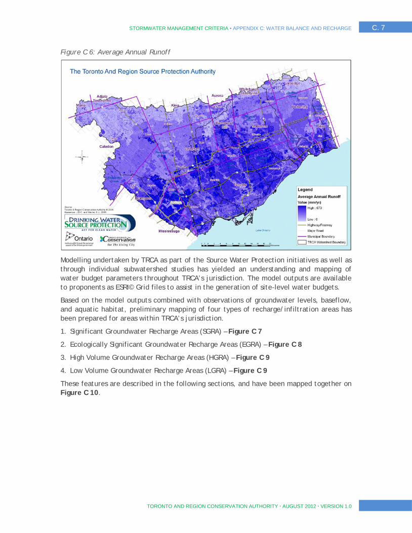
STORMWATER MANAGEMENT CRITERIA ▪ APPENDIX C: WATER BALANCE AND RECHARGE C. 7
TORONTO AND REGION CONSERVATION AUTHORITY AUGUST 2012 VERSION 1.0
Figure C 6: Average Annual Runoff
Modelling undertaken by TRCA as part of the Source Water Protection initiatives as well as through individual subwatershed studies has yielded an understanding and mapping of water budget parameters throughout TRCA’s jurisdiction. The model outputs are available to proponents as ESRI© Grid files to assist in the generation of site-level water budgets.
Based on the model outputs combined with observations of groundwater levels, baseflow, and aquatic habitat, preliminary mapping of four types of recharge/infiltration areas has been prepared for areas within TRCA’s jurisdiction.
1. Significant Groundwater Recharge Areas (SGRA) – Figure C 7
2. Ecologically Significant Groundwater Recharge Areas (EGRA) – Figure C 8
3. High Volume Groundwater Recharge Areas (HGRA) – Figure C 9
4. Low Volume Groundwater Recharge Areas (LGRA) – Figure C 9
These features are described in the following sections, and have been mapped together on Figure C 10.

C. 8 STORMWATER MANAGEMENT CRITERIA ▪ APPENDIX C: WATER BALANCE AND RECHARGE
TORONTO AND REGION CONSERVATION AUTHORITY AUGUST 2012 VERSION 1.0
Figure C 7: Significant Groundwater Recharge Areas (SGRA)
The SGRA zone is based on an average annual infiltration rate of 150 mm/year or higher in an area where there are groundwater-based drinking water systems. Ontario Regulation 287/07, under the CWA, defines an SGRA as an area in which it is desirable to regulate or monitor drinking water threats that may affect the recharge to an aquifer. O. Reg. 287/07 also lists different activities that are considered threats to drinking water in a source protection area. In addition, the CWA does not allow “grand-parenting” of non-conforming land uses, Therefore, TRCA recommends that land use changes that are currently in progress have regard for the preliminary SGRAs, and requires that proponents conduct site-specific studies within these areas to determine pre-development infiltration and provide mitigation strategies to ensure that infiltration is maintained within this zone.
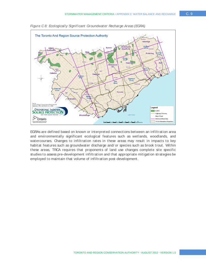
STORMWATER MANAGEMENT CRITERIA ▪ APPENDIX C: WATER BALANCE AND RECHARGE C. 9
TORONTO AND REGION CONSERVATION AUTHORITY AUGUST 2012 VERSION 1.0
Figure C 8: Ecologically Significant Groundwater Recharge Areas (EGRA)
EGRAs are defined based on known or interpreted connections between an infiltration area and environmentally significant ecological features such as wetlands, woodlands, and watercourses. Changes to infiltration rates in these areas may result in impacts to key habitat features such as groundwater discharge and/or species such as brook trout. Within these areas, TRCA requires that proponents of land use changes complete site specific studies to assess pre-development infiltration and that appropriate mitigation strategies be employed to maintain that volume of infiltration post-development.
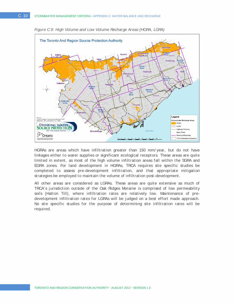
C. 10 STORMWATER MANAGEMENT CRITERIA ▪ APPENDIX C: WATER BALANCE AND RECHARGE
TORONTO AND REGION CONSERVATION AUTHORITY AUGUST 2012 VERSION 1.0
Figure C 9: High Volume and Low Volume Recharge Areas (HGRA, LGRA)
HGRAs are areas which have infiltration greater than 150 mm/year, but do not have linkages either to water supplies or significant ecological receptors. These areas are quite limited in extent, as most of the high volume infiltration areas fall within the SGRA and EGRA zones. For land development in HGRAs, TRCA requires site specific studies be completed to assess pre-development infiltration, and that appropriate mitigation strategies be employed to maintain the volume of infiltration post-development.
All other areas are considered as LGRAs. These areas are quite extensive as much of TRCA’s jurisdiction outside of the Oak Ridges Moraine is comprised of low permeability soils (Halton Till), where infiltration rates are relatively low. Maintenance of pre-development infiltration rates for LGRAs will be judged on a best effort made approach. No site specific studies for the purpose of determining site infiltration rates will be required.
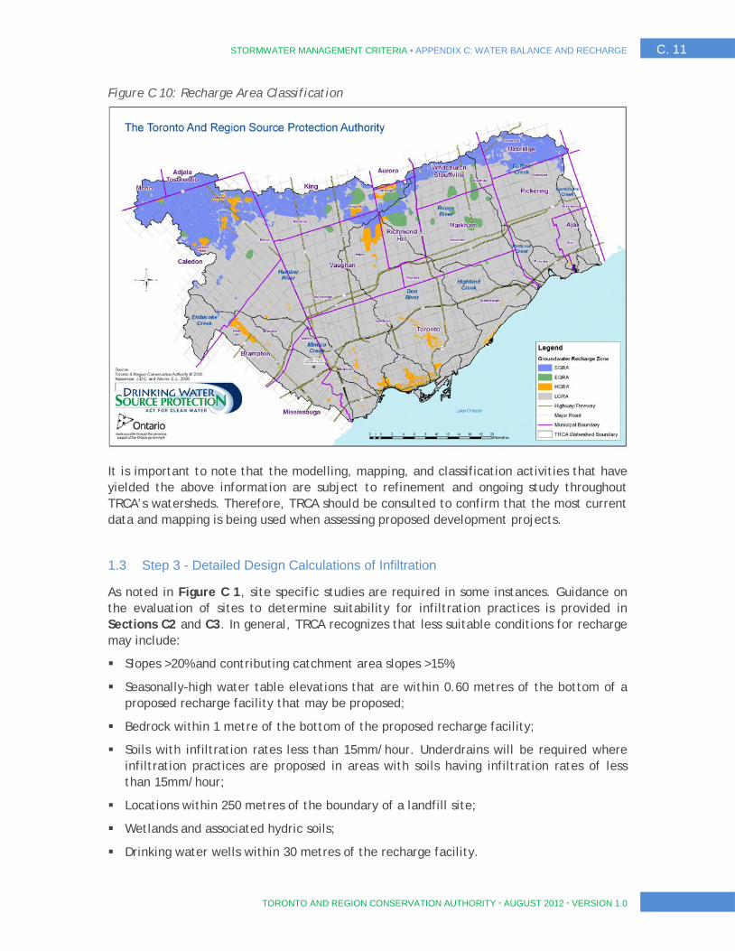
STORMWATER MANAGEMENT CRITERIA ▪ APPENDIX C: WATER BALANCE AND RECHARGE C. 11
TORONTO AND REGION CONSERVATION AUTHORITY AUGUST 2012 VERSION 1.0
Figure C 10: Recharge Area Classification
It is important to note that the modelling, mapping, and classification activities that have yielded the above information are subject to refinement and ongoing study throughout TRCA’s watersheds. Therefore, TRCA should be consulted to confirm that the most current data and mapping is being used when assessing proposed development projects.
1.3 Step 3 - Detailed Design Calculations of Infiltration
As noted in Figure C 1, site specific studies are required in some instances. Guidance on the evaluation of sites to determine suitability for infiltration practices is provided in Sections C2 and C3. In general, TRCA recognizes that less suitable conditions for recharge may include:
Slopes >20% and contributing catchment area slopes >15%;
Seasonally-high water table elevations that are within 0.60 metres of the bottom of a proposed recharge facility that may be proposed;
Bedrock within 1 metre of the bottom of the proposed recharge facility;
Soils with infiltration rates less than 15mm/hour. Underdrains will be required where infiltration practices are proposed in areas with soils having infiltration rates of less than 15mm/hour;
Locations within 250 metres of the boundary of a landfill site;
Wetlands and associated hydric soils;
Drinking water wells within 30 metres of the recharge facility.

C. 12 STORMWATER MANAGEMENT CRITERIA ▪ APPENDIX C: WATER BALANCE AND RECHARGE
TORONTO AND REGION CONSERVATION AUTHORITY AUGUST 2012 VERSION 1.0
TRCA would not recommend any enhanced recharge measures where the above conditions are present at a site; however, the proponent should make every effort to maintain overall infiltration rates across the site based on the noted requirements.
C2. Site Evaluation and Soil Testing Protocol for Stormwater Infiltration
The purpose of this protocol is to describe evaluation and field testing procedures to:
Determine if stormwater infiltration best management practices (BMPs) are well suited to a site, and at what locations; and
Obtain the required data for stormwater infiltration BMP design.
Designers are encouraged to conduct site evaluation and soil testing early in the development planning and design process so that information gained can be incorporated into the design. It is recommended that site evaluation and soil testing be conducted following the development of a preliminary plan for the proposed development. The designer should possess an understanding of potential BMP types and locations prior to soil testing. On-site tests may be carried out in advance to identify potential BMP types and locations.
Qualified professionals, who can substantiate by qualifications or experience their ability to carry out the evaluation, should conduct the soil testing. A professional, experienced in observing and evaluating soil conditions is necessary to ascertain conditions that might affect BMP performance that cannot be thoroughly assessed with testing procedures.
Soil infiltration testing is a four-step process to obtain the necessary information for stormwater management planning and design. The four steps include:
1. Background Evaluation
Based on available published and site specific data;
Includes consideration of proposed development plan;
Used to identify potential BMP types, locations and soil test locations;
Done prior to field work; and
On-site soil tests may be done to identify/screen potential BMP locations.
2. Test Pit or Soil Boring Observations
Includes multiple testing locations;
Provides an understanding of sub-surface conditions; and
Identifies limiting conditions (e.g., aquitard, bedrock or water table elevations).
3. Infiltration Testing
Must be conducted on-site;
STORMWATER MANAGEMENT CRITERIA ▪ APPENDIX C: WATER BALANCE AND RECHARGE C. 13
TORONTO AND REGION CONSERVATION AUTHORITY AUGUST 2012 VERSION 1.0
Various testing methods are available; and
Different testing methods for screening versus verification purposes.
4. Design Considerations
Determination of a suitable infiltration rate for design calculations; and
Consideration of desired BMP drawdown period.
2.1 Step 1: Background Evaluation
Prior to performing testing and developing a detailed site plan, existing site conditions should be inventoried and mapped including, but not limited to:
Surficial geology and underlying stratigraphy;
Watercourses (perennial and intermittent), water bodies, wetlands and floodplains;
Small headwater drainage features;
Topography, slope, and drainage patterns;
Existing land cover and land use;
Natural heritage conservation areas; and
Other man-made features or conditions that may impact design such as existing nearby structures (buildings, infrastructure, etc.).
A sketch plan or preliminary layout plan for the proposed development should be evaluated, including:
The preliminary grading plan and areas of cut and fill;
The location and water surface elevation of all existing, and location of proposed water supply sources and wells;
The location of all existing and proposed on-site wastewater (septic) systems;
The location of other features of note such as utility rights-of-way, water and sewer lines, etc.;
Existing data from borehole, well and geophysical testing; and
Proposed location of development features (buildings, roads, utilities, etc.).
In Step 1, the designer should determine the potential location of infiltration BMPs. The approximate location of these BMPs should be noted on the proposed development plan and should serve as the basis for the location and number of soil tests to be performed on-site.
Important: If the proposed development is located on areas that may otherwise be suitable for stormwater infiltration BMPs, or if the proposed grading plan is such that potential BMP locations are eliminated, the designer is strongly encouraged to revisit the proposed layout and grading plan and adjust the development plan as necessary. Development of areas suitable for infiltration BMPs does not preclude the use of

C. 14 STORMWATER MANAGEMENT CRITERIA ▪ APPENDIX C: WATER BALANCE AND RECHARGE
TORONTO AND REGION CONSERVATION AUTHORITY AUGUST 2012 VERSION 1.0
subsurface infiltration BMPs for runoff volume reduction and groundwater recharge benefits (e.g., soakaways, infiltration trenches and chambers, perforated pipe systems).
2.2 Step 2: Test Pit or Soil Boring Observations
Test pits or soil borings provide information regarding the soil horizons and overall soil conditions both horizontally and vertically in that portion of the site. Multiple observations can be made across a site at a relatively low cost and in a short time period. The use of test pits is preferable to soil borings as visual observation is narrowly limited in a soil boring and the soil horizons cannot be observed in-situ, but must be observed from the extracted borings.
Test pit excavations or soil borings should extend to a depth of between 2.5 to 5 metres below ground surface or until bedrock or fully saturated conditions are encountered. It is important that the tests provide information related to conditions at least 1.5 metres below the proposed bottom elevation of the infiltration BMP. Test pit trenches should be benched at 1 metre depth intervals for access and infiltration testing. A test pit should never be accessed if soil conditions are unsuitable for safe entry, or if site constraints preclude entry or exit. Where excavation of a test pit to the required depth would create an undesirable or unsafe condition, two soil borings may be conducted instead.
At each test location, the following conditions should be noted and described:
Soil horizons (upper and lower boundary);
Soil texture and colour for each horizon;
Color patterns (mottling) and observed depth;
Depth to water table (if encountered);
Depth to bedrock (if encountered);
Observations of pores or roots (size, depth);
Estimated type and percent coarse fragments;
Hardpan or other limiting layers; and
Strike and dip of soil horizons.
At the designer's discretion, soil samples may be collected at various horizons for additional analyses (e.g., grain size analysis).
The number of test pits or soil borings varies depending on site conditions and the proposed development plan. General guidelines are as follows:
For infiltration BMPs with footprint surface areas from 50 to 900 square metres, a minimum of two test pits or one test pit and two soil borings are required at, or within 10 metres of the proposed location to determine the suitability and distribution of soil types present;
For infiltration BMPs with footprint surface areas greater than 900 square metres, a minimum of one test should be conducted for each 450 square metres of footprint surface area. Tests should be conducted equidistant from each other to provide adequate characterization of the area;

STORMWATER MANAGEMENT CRITERIA ▪ APPENDIX C: WATER BALANCE AND RECHARGE C. 15
TORONTO AND REGION CONSERVATION AUTHORITY AUGUST 2012 VERSION 1.0
For linear infiltration BMPs a minimum of one test should be conducted within each soil mapping unit present along the proposed BMP location. Soil borings should be conducted every 50 metres and a test pit should be conducted every 450 metres; and
For sites with multiple infiltration BMPs, each with footprint surface areas less than 50 square metres, a minimum of one test pit is required and one soil boring per infiltration BMP location is recommended.
The recommendations above are guidelines. Additional tests should be conducted if local conditions indicate significant variability in soil type, geology, water table levels, bedrock or topography. Similarly, uniform site conditions may indicate that fewer tests are required.
2.3 Step 3: Infiltration Testing
A variety of field tests exist for estimating the infiltration rate of the native soil that include the use of permeameter or infiltrometer devices, percolation tests and empirical relationships between grain size distribution and hydraulic conductivity. At least one test should be conducted at the proposed bottom elevation of the infiltration BMP, plus additional tests at every other soil horizon encountered within 1.5 metres below the proposed bottom elevation. A minimum of two tests per test pit are recommended. More tests are warranted if results from the first two tests are substantially different. The geometric mean value should be used to determine the average infiltration rate for each soil horizon following multiple tests.
Based on field observations, infiltration testing results and the desired drawdown period (typically 48 hours), the designer may elect to modify the proposed bottom elevation of a BMP (see Step 4). Therefore, personnel conducting infiltration tests should be prepared to adjust test locations and depths depending upon observed conditions.
Infiltration testing methods discussed in this protocol include:
Guelph permeameter test;
Double-ring infiltrometer test;
Borehole permeameter test; and
Percolation test.
There are differences between these methods. Guelph permeameter and double-ring infiltrometer tests estimate the vertical movement of water through the bottom of the test area. The outer ring helps to reduce the lateral movement of water in the soil. Borehole permeameter and percolation tests allow water movement through both the bottom and sides of the test area. For this reason, the measured rate of water level drop in these types of tests must be adjusted to represent the discharge that is occurring on both the bottom and sides of the test hole.
For initial screening of a site for potential BMP types and locations, percolation tests and grain size analyses of samples from soil borings are suitable methods for estimating the infiltration rate of the native soil. Tests should not be conducted in the rain or within 24 hours of significant rainfall events (>15 millimetres depth), or when the temperature is below freezing. The preferred testing period is during April and May. This is the period

C. 16 STORMWATER MANAGEMENT CRITERIA ▪ APPENDIX C: WATER BALANCE AND RECHARGE
TORONTO AND REGION CONSERVATION AUTHORITY AUGUST 2012 VERSION 1.0
when infiltration is likely to be diminished by saturated conditions. Percolation tests conducted between June 1 and December 31 should be done following a 24 hour pre-soaking period to simulate field saturated conditions. Pre-soaking is not required for permeameter or infiltrometer test methods.
To verify native soil infiltration rates for design purposes, it is strongly recommended that infiltration tests be carried out with a permeameter or infiltrometer to determine the field saturated hydraulic conductivity (Kfs), rather than percolation tests or grain-size analyses. Alternatively, other permeability test procedures that yield a saturated hydraulic conductivity rate can be used, such as formulas developed by Elrick and Reynolds, or others for computation of hydraulic conductivity and saturated hydraulic conductivity.
Many in-situ methods have been developed for determining field saturated hydraulic conductivity within the unsaturated (vadose) zone of the soil. Detailed testing methods and standards that are available but not discussed in detail in this protocol include (but are not limited to):
Constant head well permeameter method (i.e., Guelph Permeameter method);
Constant head double-ring infiltrometer method; and,
Constant head pressure (single-ring) infiltrometer method.
A complete guide for comparing standard methods is presented in ASTM International Designation D5126-90 (2004). Further detailed discussion on standard methods can also be found in Amoozegar and Warrick (1986).
For the purpose of designing the infiltration BMP, hydraulic conductivity values (typically in centimetres per second) generated from permeameter or infiltrometer tests must be converted into infiltration rates (typically in millimetres per hour). It is critical to note that hydraulic conductivity and infiltration rate are two different concepts and that conversion from one parameter to another cannot be done through unit conversion. Particularly for fine grained soils, there is no consistent relationship due to the many factors involved. Table C 2 and Figure C 11 describe approximate relationships between hydraulic conductivity, percolation time and infiltration rate. Measured hydraulic conductivity values can be converted to infiltration rates using the approximate relationship described in Figure C 11.
Table C 2: Approximate relationships between hydraulic conductivity, percolation time and infiltration rate
Hydraulic Conductivity, Kfs (centimetres/second)
Percolation Time, T (minutes/centimetre)
Infiltration Rate, 1/T (millimetres/hour)
0.1 2 300
0.01 4 150
0.001 8 75
0.0001 12 50
0.00001 20 30
0.000001 50 12
Source: Ontario Ministry of Municipal Affairs and Housing (OMMAH). 1997. Supplementary Guidelines to the Ontario Building Code 1997. SG-6 Percolation Time and Soil Descriptions. Toronto, Ontario.

STORMWATER MANAGEMENT CRITERIA ▪ APPENDIX C: WATER BALANCE AND RECHARGE C. 17
TORONTO AND REGION CONSERVATION AUTHORITY AUGUST 2012 VERSION 1.0
Following testing, the test pits should be refilled with the original soil and the surface replaced with the original topsoil.
The results and locations of all test pits, soil borings and infiltration tests should be included in documents submitted to commenting and approval agencies in support of the development proposal.
2.4 Step 4: Design Considerations
The infiltration rate used to design an infiltration BMP must incorporate a safety correction factor that compensates for potential reductions in soil permeability due to compaction or smearing during construction, gradual accumulation of fine sediments over the lifespan of the BMP and uncertainty in measured values when less permeable soil horizons exist within 1.5 metres below the proposed bottom elevation of the BMP.
Figure C 11: Approximate relationship between infiltration rate and hydraulic conductivity
Source: Ontario Ministry of Municipal Affairs and Housing (OMMAH). 1997. Supplementary Guidelines to the Ontario Building Code 1997. SG-6 Percolation Time and Soil Descriptions. Toronto, Ontario.
The measured infiltration rate (in millimetres per hour) at the proposed bottom elevation of the BMP must be divided by a safety correction factor selected from Table C 3 to calculate the design infiltration rate. To select a safety correction factor from Table C 3, calculate the ratio of the mean (geometric) measured infiltration rate at the proposed bottom elevation of the BMP to the rate in the least permeable soil horizon within 1.5 metres below the bottom of the BMP. Based on this ratio, a safety correction factor is selected from Table C 3. For example, where the mean infiltration rate measured at the proposed bottom elevation of the BMP is 30 mm/h, and the mean infiltration rate measured in an underlying soil horizon within 1.5 metres of the bottom is 12 mm/h, the
y = 6E-11x3.7363
0.0000001
0.000001
0.00001
0.0001
0.001
0.010 5 10 15 20 25 30 35 40 45 50
Infiltration (Percolation) rate (mm/hour)
Hydr
aulic
con
duct
ivity
(Kfs
) in
cm/s
ec
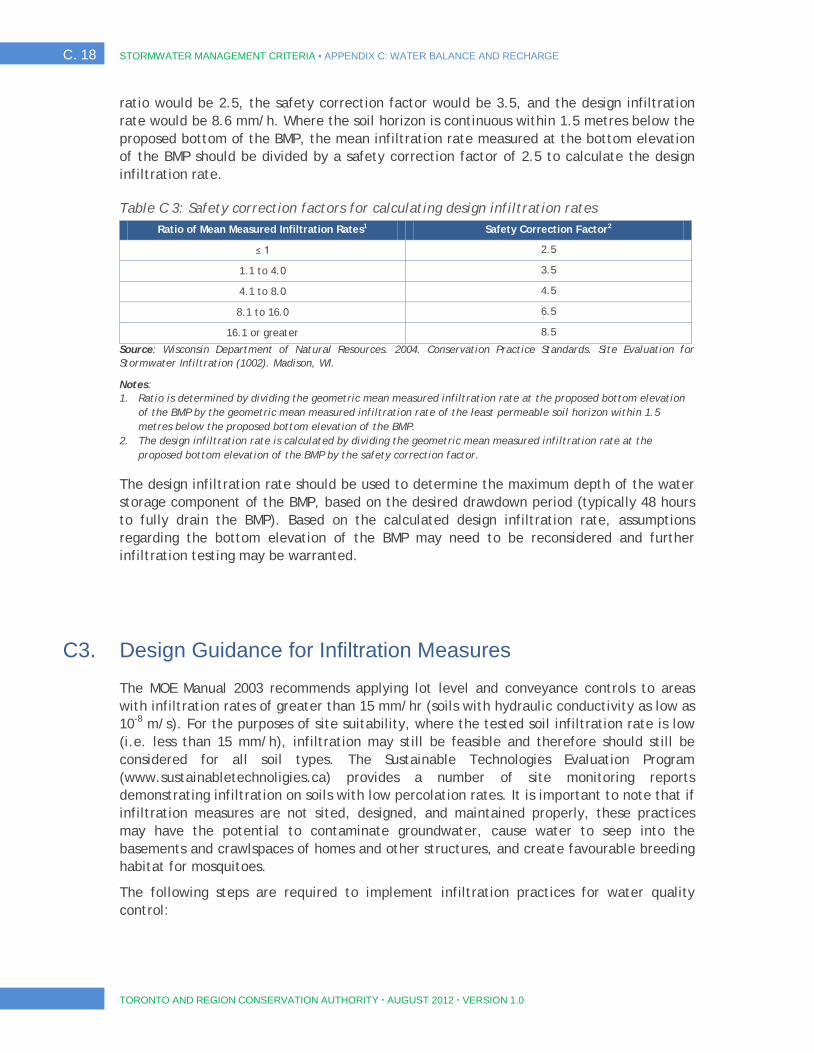
C. 18 STORMWATER MANAGEMENT CRITERIA ▪ APPENDIX C: WATER BALANCE AND RECHARGE
TORONTO AND REGION CONSERVATION AUTHORITY AUGUST 2012 VERSION 1.0
ratio would be 2.5, the safety correction factor would be 3.5, and the design infiltration rate would be 8.6 mm/h. Where the soil horizon is continuous within 1.5 metres below the proposed bottom of the BMP, the mean infiltration rate measured at the bottom elevation of the BMP should be divided by a safety correction factor of 2.5 to calculate the design infiltration rate.
Table C 3: Safety correction factors for calculating design infiltration rates Ratio of Mean Measured Infiltration Rates1 Safety Correction Factor2
≤ 1 2.5
1.1 to 4.0 3.5
4.1 to 8.0 4.5
8.1 to 16.0 6.5
16.1 or greater 8.5
Source: Wisconsin Department of Natural Resources. 2004. Conservation Practice Standards. Site Evaluation for Stormwater Infiltration (1002). Madison, WI.
Notes: 1. Ratio is determined by dividing the geometric mean measured infiltration rate at the proposed bottom elevation
of the BMP by the geometric mean measured infiltration rate of the least permeable soil horizon within 1.5 metres below the proposed bottom elevation of the BMP.
2. The design infiltration rate is calculated by dividing the geometric mean measured infiltration rate at the proposed bottom elevation of the BMP by the safety correction factor.
The design infiltration rate should be used to determine the maximum depth of the water storage component of the BMP, based on the desired drawdown period (typically 48 hours to fully drain the BMP). Based on the calculated design infiltration rate, assumptions regarding the bottom elevation of the BMP may need to be reconsidered and further infiltration testing may be warranted.
C3. Design Guidance for Infiltration Measures
The MOE Manual 2003 recommends applying lot level and conveyance controls to areas with infiltration rates of greater than 15 mm/hr (soils with hydraulic conductivity as low as 10-8 m/s). For the purposes of site suitability, where the tested soil infiltration rate is low (i.e. less than 15 mm/h), infiltration may still be feasible and therefore should still be considered for all soil types. The Sustainable Technologies Evaluation Program (www.sustainabletechnoligies.ca) provides a number of site monitoring reports demonstrating infiltration on soils with low percolation rates. It is important to note that if infiltration measures are not sited, designed, and maintained properly, these practices may have the potential to contaminate groundwater, cause water to seep into the basements and crawlspaces of homes and other structures, and create favourable breeding habitat for mosquitoes.
The following steps are required to implement infiltration practices for water quality control:
STORMWATER MANAGEMENT CRITERIA ▪ APPENDIX C: WATER BALANCE AND RECHARGE C. 19
TORONTO AND REGION CONSERVATION AUTHORITY AUGUST 2012 VERSION 1.0
Step 1 – Assess Vulnerability of the Groundwater System: While TRCA’s guidance is to encourage infiltration, caution is warranted in promoting infiltration measures in vulnerable areas, where infiltration of stormwater may pose risks to drinking water quality and/or aquifer water quality. Please refer to Section C1 of this document on the steps required to assess the vulnerability of the groundwater system and to determine if infiltration of stormwater is appropriate.
Step 2 - Define Acceptable Infiltration Type Practices and Sizing: The LID Guide describes a number of practices which can be used to offset the impacts associated with new development or redevelopment. All of these practices are of benefit to some degree for attaining targets relating to water quality, erosion, groundwater recharge, and water balance to natural features.
Pre-treatment should be provided for all infiltration practices. Several pre-treatment measures are available for infiltration practices, depending on the method of conveyance and drainage areas, including oil-grit separators, forebays, grass filter strip, gravel diaphragms etc.
Pre-treatment reduces the vulnerability of water resources to pollutants and prolongs the life of infiltration facilities by capturing coarse sediment particles before they reach the filter bed and cause premature clogging. In some cases, where the drainage areas produce little sediment, such as rooftops, infiltration practices can function effectively without pre-treatment. Further guidance for each LID practice is provided in the LID Guide.
The infiltration practices should be designed to fully drain the stormwater quality design storm runoff volume within 48-hours (inter-event period) based on the percolation rate determined in the field. It is recommended that the Guelph Permeameter test or equivalent be used to define the percolation rate, refer to Section C2 for further details on calculating percolation rate and hydraulic conductivity.
The approximate bottom area of the facility can be calculated using the following equation:
A = (1000V) / (Pn∆t),
where A is the bottom area of the facility, V is the runoff volume to be infiltrated, P is the percolation rate of the surrounding native soil, n is the porosity of the storage media, and ∆t is the desired retention time (i.e. 48 hours).
C4. References
Amoozegar, A. and Warrick, A.W. 1986. Hydraulic conductivity of saturated soils: field methods. In, A. Klute (ed.) Methods of Soil Analysis. 2nd edition. No. 9 Agronomy. American Society of Agronomy, Madison, WI.
ASTM International. 2003. Designation D 3385-03, Standard Test Method for Infiltration Rate of Soils in Field Using a Double-Ring Infiltrometer. West Conshohocken, PA.

C. 20 STORMWATER MANAGEMENT CRITERIA ▪ APPENDIX C: WATER BALANCE AND RECHARGE
TORONTO AND REGION CONSERVATION AUTHORITY AUGUST 2012 VERSION 1.0
ASTM International. 2004. Designation D5126-90 (2004), Standard Guide for Comparison of Field Methods for Determining Hydraulic Conductivity in the Vadose Zone. West Conshohocken, PA.
Elrick, D.E. and Reynolds, W.D. 1992. Infiltration from constant head well permeameters and infiltrometers. In, G.C. Topp, W.D. Reynolds and R.E. Green (Eds.). Advances in measurement of soil physical properties: Bringing theory into practice. Special Publication 30. Soil Society of America. Madison, WI.
Kassenaar, J.D.C. and Wexler, E.J., 2006: Groundwater Modelling of the Oak Ridges Moraine Area. CAMC-YPDT Technical Report #01-06.
Reynolds, W.D., Elrick, D.E. 1986. A method for simultaneous in-situ measurement in the vadose zone of field-saturated hydraulic conductivity, sorptivity and the conductivity-pressure head relationship. Ground Water Monitoring Review. No. 9. pp. 184-193.
Reynolds, W.D. 1993. Saturated Hydraulic Conductivity: Field Measurement. In, M.R. Carter (ed.). Soil Sampling and Methods of Analysis. Chapter 56. Canadian Society of Soil Science. Lewis Publishers. Ann Arbor, MA.
TRCA, 2010. SPC Accepted Tier 1 Water Budget, TRSPA Watersheds; Tier 2 for Little Rouge River and Stouffville/Reesor Creeks. Released September, 2010.
STORMWATER MANAGEMENT CRITERIA ▪ APPENDIX D: WATER BALANCE FOR PROTECTION OF NATURAL FEATURES D. i
TORONTO AND REGION CONSERVATION AUTHORITY AUGUST 2012 VERSION 1.0
APPENDIX D WATER BALANCE FOR PROTECTION OF NATURAL FEATURES
D. ii STORMWATER MANAGEMENT CRITERIA ▪ APPENDIX D: WATER BALANCE FOR PROTECTION OF NATURAL FEATURES
TORONTO AND REGION CONSERVATION AUTHORITY AUGUST 2012 VERSION 1.0
Contents D1. Introduction ........................................................................................1
1.1 Guiding Principles .................................................................................................... 1 1.2 Wetland Hydrology ................................................................................................... 2 1.3 Woodland Hydrology ................................................................................................. 2 1.4 Watercourse Hydrology.............................................................................................. 3
D2. Definitions ..........................................................................................4
2.1 Wetland ................................................................................................................ 4 2.2 Woodland .............................................................................................................. 5 2.3 Watercourse........................................................................................................... 5 2.4 Negative Impacts ..................................................................................................... 6
D3. Water Balance Requirements for Wetlands (Including Vernal Pools).................................................................................................6
D4. Water Balance Requirements for Woodlands .............................................. 10
D5. Water Balance Requirements for Watercourses (Including Headwater Drainage Features) ............................................................... 13
D6. Glossary............................................................................................ 16
D7. References ........................................................................................ 18

STORMWATER MANAGEMENT CRITERIA ▪ APPENDIX D: WATER BALANCE FOR PROTECTION OF NATURAL FEATURES D. 1
TORONTO AND REGION CONSERVATION AUTHORITY AUGUST 2012 VERSION 1.0
D1. Introduction The following guidelines set out the requirements for maintaining hydrologic function of natural features that have been recommended for protection through an Official Plan designation, Subwatershed Study, Master Environmental Servicing Plan, Environmental Impact Study, or another similar study, and/or in consultation with the conservation authority and municipality. They outline the general requirements for a water balance for natural features, which may be scoped down in consultation with the conservation authority and municipality, depending on the sensitivity of the features, degree of anticipated impacts, and the current planning stage.
1.1 Guiding Principles
The objective of protecting a natural feature’s specific water balance is to ensure that the changes anticipated post development do not exceed the feature’s capacity to respond and adapt, allowing for its long-term perpetuation and sustainability, while minimizing the resources/interventions needed to manage and maintain it. This is really an assessment of risk. The desire is to maintain the physical and biological complexity of the system and not move to a more simplified system.
The information that is collected as part of the process to determine protection will assist in scoping the work required to determine the existing hydrologic regime of the feature. This information, in concert with information on the form and type of development that is being proposed, will be used in the more detailed analysis.
It is important that the proponent’s consulting team meet with staff from the conservation authority (CA) early in the process to detail the works required as part of the water balance evaluation. Factors that will be considered when looking at field investigations, instrumentation, and modeling include but are not limited to, the following:
The extent that the feature is supported by ground water and the extent that is surface water;
The extent of the catchment (surface or ground water) that is going to be modified by the proposal;
The nature of the feature’s vegetation and habitat characteristics and their ecological amplitude or range of conditions that they are suited to;
The extent to which it has been agreed that the feature can be modified through the development process (e.g. headwater features where the functions are to be replicated through modifications).
Instrumentation and the type of modeling required will be based on the above (i.e. information may or may not be available) and discussed with the CA. The CA will assess the results to determine if the information/results are correct and will determine the degree of error/risk associated with the analysis.
D. 2 STORMWATER MANAGEMENT CRITERIA ▪ APPENDIX D: WATER BALANCE FOR PROTECTION OF NATURAL FEATURES
TORONTO AND REGION CONSERVATION AUTHORITY AUGUST 2012 VERSION 1.0
1.2 Wetland Hydrology
Wetlands can naturally control peak floods by retaining water and allowing slow release of water to receiving bodies (e.g. lakes, streams, aquifers). The hydroperiod is the seasonal pattern of water level fluctuation (Mitsch and Gooselink, 2007; Wright et al. 2006; Azous and Horner, 2001; Reinelt et al., 1998). It is the result of inflow and outflow, surface contours of the landscape, substrate and groundwater conditions. Wetlands vary in their susceptibility to changes in hydroperiod. Shallow wetlands may experience greater impacts to decreases in water depth (i.e. reduction in water volume) than deeper wetlands since even minor reductions in water depth may reduce the extent of flooding around the fringe of shallow wetlands. Swamps may experience greater changes over the long term if flood frequency and duration are altered since these features depend on a period of dry soils to replenish the oxygen supply that will sustain the community during inundation. Under natural conditions, groundwater dominated wetlands experience little fluctuation in water levels due to seasonal variation in climate. However increases in imperviousness may increase runoff and impact recharge rates thereby increasing surface water inputs and decreasing the availability of groundwater to the wetland, respectively (Wright et al. 2006).
When they qualify as wetland, due to their size and dependence on climate, vernal pools are likely the most sensitive wetland in terms of annual climatic variation. Obligate species in vernal pools are accustomed to the hydrologic regime of their specific pools. Changes to hydrology may create habitats unsuitable for inhabitants and may result in habitats more suitable for predators previously not found, thereby changing the composition and dynamics of the system.
Vegetation tolerance to fluctuations in water depth, duration and frequency varies (Baldwin et al. 2001). As water depth increases community composition transitions to more aquatic vegetation (floating or submergent species) or no vegetation at all. An increase in the duration of inundation depletes nutrients and oxygen stored in the soil and prevents recharge of these nutrients. Studies show that the frequency by which a wetland is inundated influences plant richness. Increases in inundation can translate to decreases in plant richness (Azous and Horner, 2000). Managing water balance with the intent to maintain the hydroperiod of wetlands is the first step in ensuring the long-term health and survivability of these features and those species that depend on them.
1.3 Woodland Hydrology
There is usually a decreasing gradation in soil moisture from wetlands to woodlands. However, maintaining soil moisture in woodlands is important, particularly for those with moisture regimes from moist-fresh (according to Lee, et al. 1998). Drier upland communities may be less sensitive to surface water changes than, for example, wetlands. However, water is important to these upland habitats as well. In woodlands, shallow aquifers may interact with root zones. The species composition in upland communities is in response to the hydrology of that given area. Vegetation adapts to the specific hydrology and local conditions of their community. Generally, sugar maple, white ash, and white elm are common in fresh to moist areas, whereas red oaks and red and white pines are more prevalent in areas of dry regimes. Changes in hydrology can dry out or saturate soils, changing the amount of oxygen available to roots. Moisture also plays a key role in
STORMWATER MANAGEMENT CRITERIA ▪ APPENDIX D: WATER BALANCE FOR PROTECTION OF NATURAL FEATURES D. 3
TORONTO AND REGION CONSERVATION AUTHORITY AUGUST 2012 VERSION 1.0
decomposition of organic material, which affects the composition of soils within the community.
Woodlands can be affected by development through changes to hydrology. Typically, pre-development surface drainage to woodlands may be diverted away to storm sewers, or these stormwater sewers may direct concentrated flow into woodlands where they previously did not exist. These changes can cause increases or decreases in soil moisture or water table levels that can cause detrimental community shifts over time. An example of this is Altona Forest in Pickering, which has experienced drying of forest communities following the development of surrounding lands and diversion of surface water drainage (Behera and Graham, 2004). Managing the water balance with the intent to maintain the functions of the hydrology of woodlands following development will also help to ensure that the woodland is more resilient to the many stressors it will have to endure in urban and urbanizing contexts.
1.4 Watercourse Hydrology
Variability in intensity, timing, and duration of precipitation and in the effects of terrain, soil texture, and evaporation on the hydrologic cycle collectively form the local and regional flow pattern. The timing, or predictability, of flow events is of paramount ecological importance because the life cycles of many aquatic or riparian organisms are timed to either avoid or exploit flows of variable magnitudes (Poff et al. 1997). For example, the natural timing of high or low streamflows is a trigger for the initiation of life cycle processes, such as spawning, egg hatching, rearing, movement onto floodplains for feeding or reproduction, or migration upstream or downstream.
In addition, most permanently flowing streams derive their baseflow from groundwater, interflow or wetland contributions. Groundwater discharge to streams may be more significant in some reaches than others. Areas of strong groundwater discharge often provide critical refuge or spawning habitat for some coldwater fish species. Protecting these groundwater contributions is paramount for these species, but groundwater discharge also provides thermal stability for many other species. It is important to manage the water balance with the intent to maintain/replicate these groundwater contributions through the development process via.
Urbanization can impact the natural flow regime by altering the hydrologic components. Runoff tends to increase, and evapotranspiration and infiltration tend to decrease, causing the flow regimes of streams to become more flashy (see rate of change of flow in glossary), which stresses aquatic systems. Managing the water balance after development occurs is critical to continued functionality for watercourses.
Headwater drainage features (HDFs) are zero or first-order streams, swales and wetlands, which may not flow or sustain water year-round. Because of their small size and temporary nature, HDFs provide the greatest opportunity for interaction between aquatic and terrestrial ecosystems. These features are also considered to be important sources of food, sediment, water, nutrients and organic material to downstream reaches (TRCA and CVC, 2007). Because they are temporary, HDFs have unique hydroperiods, different from perennial streams, but important in maintaining downstream aquatic integrity. Headwater drainage features also provide important habitat for amphibians (TRCA 2010) and other
D. 4 STORMWATER MANAGEMENT CRITERIA ▪ APPENDIX D: WATER BALANCE FOR PROTECTION OF NATURAL FEATURES
TORONTO AND REGION CONSERVATION AUTHORITY AUGUST 2012 VERSION 1.0
taxa that rely on temporary waters. Up to 90% of a river's flow can be derived from catchment headwaters (Saunders et al. 2002).
Alterations to the hydroperiods of HDFs can change the hydrology of downstream ecosystems and impact the supply of organic and inorganic materials that are important to aquatic communities. Naturally variable flow regimes create and maintain the dynamics of in-channel and floodplain conditions and habitats that are critical to aquatic life (Poff et al. 1997). The timing, duration, magnitude, frequency, and rate of change of flow are all critical components of flow (Poff et al. 1997; Saunders et al. 2002; Richter et al. 1997). Together these components constitute the flow regime or hydrological regime of an area. The critical components for aquatic communities, including water temperature, dissolved oxygen concentrations, suspended sediment loads, nutrient availability, and physical habitat structure, all vary with hydrological regime (Richter et al. 1997). As such, aquatic communities are vulnerable to changes in the flow regime. Poff et al. (1997) suggest that flow regime is the ‘master variable’ limiting the distribution and abundance of riverine species.
D2. Definitions
2.1 Wetland
As a result of Ontario Regulation 97/04 (Generic Regulation), “wetlands” became areas that can be regulated under Section 28(1) of the Conservation Authorities Act. A wetland is defined as land that:
a. is seasonally or permanently covered by shallow water or has a water table close to or at its surface,
b. directly contributes to the hydrologic function of a watershed through a connection with a surface watercourse,
c. has hydric soils, the formation of which has been caused by the presence of abundant water, and
d. has vegetation dominated by hydrophytic plants or water tolerant plants, the dominance of which has been favoured by the presence of abundant water, but does not include periodically soaked or wet land that is used for agricultural purposes and no longer exhibits a wetland characteristic referred to in clause (c) or (d).
Under the Provincial Policy Statement (2005), wetland refers to:
Lands that are seasonally or permanently covered by shallow water, as well as lands where the water table is close to or at the surface. In either case the presence of abundant water has caused the formation of hydric soils and has favoured the dominance of either hydrophytic plants or water tolerant plants. The four major types of wetlands are swamps, marshes, bogs and fens. Periodically soaked or wet lands being used for agricultural purposes, which no longer exhibit wetland characteristics, are not considered to be wetlands for the purposes of this definition.

STORMWATER MANAGEMENT CRITERIA ▪ APPENDIX D: WATER BALANCE FOR PROTECTION OF NATURAL FEATURES D. 5
TORONTO AND REGION CONSERVATION AUTHORITY AUGUST 2012 VERSION 1.0
Under the Oak Ridges Moraine Conservation Plan (2002) and the Greenbelt Plan (2005), wetland is defined as:
Land such as swamp, marsh, bog or fen (not including land that is being used for agricultural purposes and no longer exhibits wetland characteristics) that:
a. Is seasonally or permanently covered by shallow water or has the water table close to or at the surface;
b. Has hydric soils and vegetation dominated by hydrophytic or water-tolerant plants; and
c. Has been further identified, by the Ministry of Natural Resources or by any other person, according to evaluation procedures established by the Ministry of Natural Resources, as amended from time to time.
A feature that meets any of the above applicable definitions would qualify as a wetland for the purposes of this guideline.
2.2 Woodland
A woodland is defined by the Provincial Policy Statement (2005) as:
Treed areas that provide environmental and economic benefits to both the private landowner and the general public, such as erosion prevention, hydrological and nutrient cycling, provision of clean air and long-term storage of carbon, provision of wildlife habitat, outdoor recreational opportunities, and the sustainable harvest of a wide range of woodland products. Woodlands include treed areas, woodlots or forested areas and vary in their level of significance at the local, regional and provincial levels.
The Oak Ridges Moraine Conservation Plan (2002) defines a woodland as:
A treed area, woodlot or forested area, other than a cultivated fruit or nut orchard or a plantation established for the purpose of producing Christmas trees
The Greenbelt Plan (2005) defines a woodland as:
Treed areas that provide environmental and economic benefits to both the private landowner and the general public, such as erosion prevention, hydrological and nutrient cycling, provision of clean air and the long-term storage of carbon, provision of wildlife habitat, outdoor recreational opportunities, and the sustainable harvest of a wide range of woodland products. Woods include treed areas, woodlots or forested areas.
A feature that meets any of the above applicable definitions, or any definition used by a municipality in their Official Plan, would qualify as a woodland for the purposes of this guideline. Note that swamps are considered to be wetlands and not woodlands for the purposes of this guideline.
2.3 Watercourse
The 1998 amendments to the Conservation Authorities Act, and subsequent approval of individual Section 28(1) Regulations by the Minister of Natural Resources in May 2006, gave

D. 6 STORMWATER MANAGEMENT CRITERIA ▪ APPENDIX D: WATER BALANCE FOR PROTECTION OF NATURAL FEATURES
TORONTO AND REGION CONSERVATION AUTHORITY AUGUST 2012 VERSION 1.0
all Conservation Authorities the legal right to apply a consistent definition of watercourse, which is:
An identifiable depression in the ground in which a flow of water regularly or continuously occurs.
Headwater drainage features, which are ephemeral or intermittent streams or swales, could qualify as a watercourse under this definition and may also require a water balance to protect hydrological function.
2.4 Negative Impacts
According to the Provincial Policy Statement (2005), negative impact means:
a. degradation to the quality and quantity of water, sensitive surface water features and sensitive ground water features, and their related hydrologic functions, due to single, multiple or successive development or site alteration activities;
b. in regard to fish habitat, the harmful alteration, disruption or destruction of fish habitat, except where, in conjunction with local authorities, it has been authorized under the Fisheries Act; and
c. in regard to other natural heritage features and areas, degradation that threatens the health and integrity of the natural features or ecological functions for which an area is identified due to single, multiple or successive development or site alteration activities.
D3. Water Balance Requirements for Wetlands (Including Vernal Pools) These guidelines set out the steps for undertaking a water balance when a development is proposed that may affect a wetland that has been identified for protection through the planning or regulatory process within the CA’s jurisdiction. Vernal pools that support amphibians may also require a water balance analysis if there is a likelihood that the proposed development will impact the features and their functions.
Overall Objective: Maintain quantity of surface water and groundwater contributions that ensures the pre-development hydroperiod (seasonal pattern of water level fluctuation) of the wetland is protected. The proposed development does not cause changes to the hydroperiod that negatively impact the hydrological functions of the feature. In areas identified as degraded, the objective may be to enhance water balance of the feature.
Vernal pools may be small inclusions in larger woodland polygons, which may not be specifically targeted through a woodland water balance. Since hydrology may be an important factor that allows sensitive amphibian species to inhabit vernal pools, a wetland water balance should be undertaken where deemed necessary for these features. For vernal pools that are identified as being ecologically important, please consult the CA and municipality prior to undertaking an evaluation to determine appropriate requirements.

STORMWATER MANAGEMENT CRITERIA ▪ APPENDIX D: WATER BALANCE FOR PROTECTION OF NATURAL FEATURES D. 7
TORONTO AND REGION CONSERVATION AUTHORITY AUGUST 2012 VERSION 1.0
MNR must also be contacted if species at risk are known to use the vernal pool or any other wetland feature. Wildlife Scientific Collectors Authorizations (WSCAs) and Endangered Species Act (ESA) permits are required for any surveys or studies to investigate for the presence of species at risk.
Consult with CA and municipal staff to establish the terms of reference (TOR) and scope of work.
The following is a general outline of the process and requirements for undertaking a water balance for wetlands.
Step 1 – Determining the Need for a Water Balance
Identify existing and proposed land uses.
Delineate the area contributing (both surface and ground water catchments) to the wetland, and determine if the proposal may affect the catchment or wetland directly.
If the change in catchment size, the amount and form of the development and the sensitivity of the wetland are such that an impact is likely, a water balance will be required. Consult with Conservation Authority and municipal staff to establish the terms of reference (TOR) and scope of work. The following steps outline the general requirements.
Step 2 – Establishing Baseline Conditions
Using a digital elevation model or detailed topographical information, determine the topographical contours on the site and catchment for the feature to the finest resolution possible (e.g. 0.25 m or less).
Delineate the bathymetry of the wetland by with a series of water depth measurements referenced to a known elevation.
Collect baseline data on wetland water levels using staff gauges, data logger (continuous basis) and/or mini-piezometer(s), as necessary, for a minimum of 3 years. The number and arrangement of instrumentation and methods of equipment installation (to manage potential impacts) should be determined in consultation with the Conservation Authority.
To supplement mini-piezometer data, measure depths of organic layers and depths to mottles and gley using a soil core or auger in order to ascertain vertical water level fluctuations. High water marks may also be observed and measured.
For multiple developments within the same wetland catchment, a comprehensive, coordinated water balance analysis should be undertaken, with Conservation Authority and municipal staff to assist in facilitating discussion and development of TOR.
All monitoring should stay in place throughout the development process in order to establish multiple years of data pre and post development for the monitoring plan (see Step 6).
Step 3 – Developing the Existing Conditions Water Budget Model
Conduct a soils analysis and/or borehole drilling program within the catchment to determine the proportion of precipitation that will characterize the components of the water budget (i.e. runoff vs. infiltration).

D. 8 STORMWATER MANAGEMENT CRITERIA ▪ APPENDIX D: WATER BALANCE FOR PROTECTION OF NATURAL FEATURES
TORONTO AND REGION CONSERVATION AUTHORITY AUGUST 2012 VERSION 1.0
Determination of soil characteristics and permeability estimates should be performed using field testing methods:
visual examination and description of shallow surficial soil and changes in lithology with depth;
hydraulic testing for permeability such as percolation tests at a selection of sites within the wetland catchment area. Distinct soils would require separate tests;
the Guelph Permeameter and double ring infiltrometer are two approved methods for percolation testing.
Although grain size distribution analysis assists in identifying the soil constituents (clay, silt, sand, gravel) and soil type, it alone does not allow estimates of permeability for tills that predominately occur within the area.
Check with the Conservation Authority regarding the location of existing rain gauges to obtain precipitation data. Additional rain gauges may or may not be required.
Using the information gathered through Step 2 and the soils analysis, determine the quantity and flow paths of water to the wetland(s), and describe the proportion of flows that reach the wetland(s) via surface water and groundwater from the subject site. Ensure that each subcatchment is appropriately identified and characterized.
Include inflow and outflow information for the wetland in order to ascertain the type of wetland being assessed (i.e. palustrine, isolated, riverine or lacustrine), and how this affects the wetland’s hydrology.
Develop an Existing Conditions Water Budget using an approved continuous model, such as PRMS, HSPF, QUALHYMO, or SWMM, to be calibrated with measured data where available and technically appropriate. A groundwater model is not a requirement for the wetland water budget at this time (although the applicant is free to propose to use a groundwater model in addition to a surface water model). The understanding of groundwater/surface water interactions should inform the selection and set up of the surface water models described above.
Run long-term analysis based on nearest available climate data, e.g. precipitation, temperature, etc. as a minimum, using the period between 1991 and 2008, which is considered to be representative. Using a 30-year climate record or greater is preferred.
Using the long-term climate record, determine if the measured data represent a wet or dry year, and run the model under varying scenarios.
Daily water balance analysis should be used to generate weekly results. Consult with the Conservation Authority and municipality to determine if an alternate resolution is more appropriate.
It may be necessary to submit the Existing Conditions Water Budget Model, existing conditions/inventory data and calculations to the Conservation Authority and municipality for review and approval prior to proceeding to Step 4.
Step 4 – Comparing Pre-development and Post-development
In consultation with the Conservation Authority and appropriate agencies, establish water balance goals and targets for the wetland’s hydroperiod (including extent,
STORMWATER MANAGEMENT CRITERIA ▪ APPENDIX D: WATER BALANCE FOR PROTECTION OF NATURAL FEATURES D. 9
TORONTO AND REGION CONSERVATION AUTHORITY AUGUST 2012 VERSION 1.0
duration, depth and timing) maintaining consistency with targets and objectives determined through subwatershed plans, watershed plans, or other relevant studies
Conduct a water budget analysis to determine how the proposed changes in landuse within the wetland catchment will affect the water budget. Conduct a daily water balance analysis and generate results on a weekly basis.
A comparison of pre- development and post-development groundwater conditions can be completed in a number of ways. For example, dewatering calculations (when appropriate) or a comparison of pre-development and post-development groundwater recharge rates. The approach should be discussed with the Conservation Authority, including how the groundwater and surface water assessment results will be incorporated.
Based on the modeled analysis, quantify changes in infiltration, runoff, and evapotranspiration, as well as changes in the distribution of flow paths, and surface water and groundwater levels on a weekly basis to determine if the development will result in changes to the wetland hydroperiod.
Generate maps, tables and graphs illustrating these changes. Plot the pre-development and post-development hydroperiods on graphs, and delineate the area of flooding on a seasonal/monthly basis on maps.
Step 5 – Applying Mitigation
Please note that the Conservation Authority prefers that clean roof water be utilized to make-up the wetland water balance and that treated stormwater should be redirected to nearby creeks.
Apply mitigation measures to manage the water balance with the intent to maintain the pre-development hydroperiod of the wetland according to the Overall Objective.
If the pre-development runoff and/or infiltration cannot be achieved through the proposed mitigation measures, an analysis of the anticipated negative impacts will need to be completed in order to determine if the Overall Objective is adhered to. If negative impacts are anticipated, additional mitigation measures will be required.
Step 6 – Reporting and Monitoring
Synthesize the information gathered through the above steps into a water balance report and submit to the Conservation Authority and municipality for review. Provide a comparison table showing the differences between the pre-development conditions, post-development condition, and the post-development with mitigation condition for all components of the water budget and for each subcatchment. Appendices containing models and calculations shall be provided.
Consult with the Conservation Authority and municipality to determine if monitoring is required. If monitoring is required, the report should discuss proposed post-development monitoring of all baseline parameters to determine the effectiveness of mitigation measures and to assess the level and extent of negative impacts, if any. A Terms of Reference for the monitoring plan should be included in the water balance report. For significant features, the requirement for a monitoring plan can be anticipated.

D. 10 STORMWATER MANAGEMENT CRITERIA ▪ APPENDIX D: WATER BALANCE FOR PROTECTION OF NATURAL FEATURES
TORONTO AND REGION CONSERVATION AUTHORITY AUGUST 2012 VERSION 1.0
A 3-year post-development monitoring plan should be developed, however more may be required depending on the scope and scale of the development (i.e. timing and duration of build-out). A post-development monitoring report should be submitted to the Conservation Authority and municipality at the end of the monitoring period.
Generally, the purpose of this monitoring will be to monitor changes to the hydrology of the natural features and identify whether remediation measures to tweak the hydrology should be employed. These remediation measures need to be considered early on in the planning phases in order to ensure feasibility, and identified through discussion with the Conservation Authority and municipality. A Contingency Plan (for short-term impacts) and an Adaptive Management Plan (for the long-term) should be developed in these instances to identify steps to be taken if it is identified that there is a negative impact on the feature. Mitigation considered in previous steps should be designed to account for opportunities to refine the hydrology.
D4. Water Balance Requirements for Woodlands These guidelines set out the steps for undertaking a water balance when a development is proposed that may affect a woodland that has been identified for protection through the planning process within the Conservation Authority’s jurisdiction. These guidelines only apply to woodlands with moist-fresh moisture regimes according to Lee et al. (1998), and/or when the water table is less than 3 m below ground in spring (Schenk and Jackson, 2002, Crow 2005). They are meant to apply to more sensitive core, mature habitats and not to plantations, successional, corridors, or marginal habitats.
Overall Objective: Manage the water balance with the intent to maintain volume, timing and spatial distribution of surface water and groundwater contributions that ensures that hydrological changes do not cause a negative impact on the form and/or function of the woodland. In areas identified as degraded, the objective may be to enhance water balance of the feature.
The following is a general outline of the process and requirements for undertaking a water balance for woodlands:
Step 1 – Determining the Need for a Water Balance
Identify existing and proposed land uses.
Delineate the area contributing (both surface and ground water catchments) to the woodland, and determine if the proposal may affect the catchment or woodland directly.
If the change in catchment size, the amount and form of the development and the sensitivity of the woodland are such that an impact is likely, a water balance will be required. Consult with Conservation Authority and municipal staff to establish the terms of reference (TOR) and scope of work. The following steps outline the general requirements.
Step 2 – Developing the Existing Conditions Water Budget Model

STORMWATER MANAGEMENT CRITERIA ▪ APPENDIX D: WATER BALANCE FOR PROTECTION OF NATURAL FEATURES D. 11
TORONTO AND REGION CONSERVATION AUTHORITY AUGUST 2012 VERSION 1.0
Using a digital elevation model or detailed topographical information, determine the topographical contours on the site and for the feature using the finest resolution possible.
Conduct a soils analysis and/or borehole drilling program within the catchment to determine the proportion of precipitation that will characterize the components of the water budget (i.e. runoff vs. infiltration).
Check with the Conservation Authority regarding the location of existing gauges to obtain precipitation data. Additional rain gauges may or may not be required. For multiple developments within the same woodland catchment, a comprehensive, coordinated water balance analysis should be undertaken, with Conservation Authority and municipal staff to assist in facilitating discussion and development of TOR.
Determine the quantity and flow paths of water to the woodland(s), and describe the proportion of flows that reach the woodland(s) via surface water and groundwater from the subject site. Ensure that each subcatchment is appropriately identified and characterized.
Develop an Existing Conditions Water Budget using an approved continuous model, such as PRMS, HSPF, QUALHYMO, or SWMM. A groundwater model is not a requirement for the water budget at this time (although the applicant is free to propose to use a groundwater model in addition to a surface water model). The understanding of groundwater/surface water interactions should inform the selection and set up of the surface water models described above.
Run long-term analysis based on nearest available climate data, e.g. precipitation, temperature, etc., as a minimum, using the period between 1991 and 2008, which is considered to be representative. Using a 30-year climate record or greater is preferred.
Using the long-term climate record, determine if the measured data represent a wet or dry year, and run the model under varying scenarios.
Daily water balance analysis should be used to generate monthly results. Consult with the Conservation Authority and municipality to determine if an alternate resolution is more appropriate.
It may be necessary to submit the Existing Conditions Water Budget Model to the Conservation Authority and municipality for review and approval prior to proceeding to Step 4.
Step 3 – Comparing Pre-development and Post-development
In consultation with the Conservation Authority and appropriate agencies, establish water balance goals and targets consistent with subwatershed plans, watershed plans, and other relevant studies.
Conduct a water balance analysis to determine how the proposed changes in landuse within the woodland catchment will affect the water budget. A daily water balance analysis should be undertaken to generate monthly results.
A comparison of pre- development and post-development groundwater conditions can be completed in a number of ways. For example, dewatering calculations (when appropriate) or a comparison of pre-development and post-development groundwater

D. 12 STORMWATER MANAGEMENT CRITERIA ▪ APPENDIX D: WATER BALANCE FOR PROTECTION OF NATURAL FEATURES
TORONTO AND REGION CONSERVATION AUTHORITY AUGUST 2012 VERSION 1.0
recharge rates. The approach should be discussed with the Conservation Authority, including how the groundwater and surface water assessment results will be incorporated.
Based on the modeled analysis, quantify changes in infiltration, runoff, and evapotranspiration, as well as changes in the distribution of flow paths, and surface and groundwater levels. Provide the information on a monthly basis to determine if the development will result in changes to the woodland hydrology. Provide maps, tables and graphs as necessary.
Step 4 – Applying Mitigation
Apply mitigation measures to manage the water balance with the intent to maintain the pre-development hydrology of the woodland according to the Overall Objective.
If the pre-development runoff and/or infiltration cannot be achieved through the proposed mitigation measures, an analysis of the anticipated negative impacts will need to be completed in order to determine if the Overall Objective is adhered to. If negative impacts are anticipated, additional mitigation measures will be required.
Please note that the Conservation Authority prefers to utilize clean roof water to augment the woodland water balance and to redirect treated stormwater away to nearby creeks.
Step 5 – Reporting and Monitoring
Synthesize the information gathered through the above steps into a water balance report and submit to the Conservation Authority and municipality for review. Provide a comparison table showing the differences between the pre-development conditions, post-development condition, and the post-development with mitigation condition for all components of the water budget and for each subcatchment. Appendices containing models and calculations shall be provided.
Consult with the Conservation Authority and municipality to determine if monitoring is required. If monitoring is required, the report should discuss proposed post-development monitoring of all baseline parameters to determine the effectiveness of mitigation measures and to assess the level and extent of negative impacts, if any. A Terms of Reference for the monitoring plan should be included in the water balance report.
A minimum 3-year post-development monitoring plan should be developed, however more may be required depending on the scope and scale of the development (i.e. timing and duration of build-out). A post-development monitoring report should be submitted to the Conservation Authority and municipality at the end of the monitoring period.
Generally, the purpose of this monitoring will be to monitor changes to the hydrology of the natural features and identify whether remediation measures to tweak the hydrology should be employed. These remediation measures need to be considered early on in the planning phases in order to ensure feasibility, and identified through discussion with the Conservation Authority and municipality. A Contingency Plan (for short-term impacts) and an Adaptive Management Plan (for the long-term) should be developed in these instances to identify steps to be taken if it is identified that there

STORMWATER MANAGEMENT CRITERIA ▪ APPENDIX D: WATER BALANCE FOR PROTECTION OF NATURAL FEATURES D. 13
TORONTO AND REGION CONSERVATION AUTHORITY AUGUST 2012 VERSION 1.0
is a negative impact on the feature. Mitigation considered in previous steps should be designed to account for opportunities to refine the hydrology.
D5. Water Balance Requirements for Watercourses (Including Headwater Drainage Features)
These guidelines set out the steps for undertaking a water balance when a development is proposed that may affect a watercourse and/or headwater drainage feature that has been identified for protection through the planning or regulatory process in the Conservation Authority’s jurisdiction.
NOTE: For headwater drainage features, please refer to the Evaluation, Classification and Management of Headwater Drainage Features (HDF): Interim Guidelines March 2009, and ensure that the requirements for meeting management recommendations of the interim headwater guidelines are met, prior to proceeding with the water balance analysis, as necessary.
The requirements listed below are expected for all watercourses and HDFs, unless otherwise determined in consultation with the appropriate agencies. Please obtain further guidance from the Ministry of Natural Resources (MNR) regarding the locations of watercourses being managed for species at risk under the Endangered Species Act.
Overall Objective: Manage the water balance with the intent to maintain quantity of surface water and groundwater contributions with respect to duration, frequency, magnitude, and flow. In areas identified as degraded, the objective may be to enhance water balance of the feature.
Fish community, management zone mapping, and targets are defined by the Fisheries Management Plan (FMP) at the watershed scale, but may be further refined based on more recent information. In cases where an FMP does not exist, the proponent should consult with the Conservation Authority for further information and appropriate targets.
The following is an outline of the process for undertaking a water balance for watercourses:
Step 1 – Determining the Need for a Water Balance
Identify existing and proposed land uses.
Delineate the area contributing (both surface and ground water catchments) to the watercourse on the subject property, and determine if the proposal may affect the catchment or watercourse directly.
If the change in catchment size, the amount and form of development, and the sensitivity of the watercourse are such that an impact is likely, a water balance will be required.
Consult with Conservation Authority and municipal staff to establish the terms of reference (TOR) and scope of work. The following steps outline the general requirements.

D. 14 STORMWATER MANAGEMENT CRITERIA ▪ APPENDIX D: WATER BALANCE FOR PROTECTION OF NATURAL FEATURES
TORONTO AND REGION CONSERVATION AUTHORITY AUGUST 2012 VERSION 1.0
Step 2 – Establishing Baseline Conditions
Determine stream classification based on relevant Fisheries Management Plan including community classification, targets, and management objectives.
MNR must also be contacted if species at risk are known to occupy the watercourse. Scientific Collectors Authorizations and Endangered Species Act (ESA) permits are required for any surveys or studies to investigate for the presence of species at risk.
Identify groundwater discharge/seepage, tile drain outlets, culverts, and other relevant features that could affect drainage to the watercourse, if any, on maps for submission.
Collect continuous baseline data (data loggers) on hydraulic gradients using mini-piezometers for 3 full years to identify vertical hydraulic gradients.
Collect baseline data on stream flows on a continuous basis (data loggers), for at least one full year or check with the Conservation Authority for stream gauge data. Instrumentation should be placed in the watercourse at the upstream limit of the proposed development site, and another should be placed at the downstream limit of the site in order to assess and quantify whether the watercourse is a losing or gaining stream.
It is recommended that the proponent consult with the Conservation Authority as it may have some of the above information.
Contact the Conservation Authority for agreement on the Terms of Reference for study design, location and number of instrumentation required and to manage impacts associated with equipment installation.
All monitoring should stay in place throughout the development process in order to establish multiple years of data for the monitoring plan (see Step 6).
Step 3 – Developing the Existing Conditions Water Budget Model
Conduct a soils analysis and/or borehole drilling program to determine the proportion of precipitation that will characterize the components of the water budget (i.e. runoff vs. infiltration).
Check with the Conservation Authority regarding the location of existing gauges to obtain precipitation data. Additional rain gauges may or may not be required.
Using the information gathered through Step 2 and the soils analysis, determine the quantity and flow paths of water to the watercourse, and describe the proportion of flows that reach the watercourse via surface water and groundwater from the subject site. Ensure that each subcatchment is appropriately identified and characterized.
Develop an Existing Conditions Water Budget using an approved continuous model, such as PRMS, HSPF, QUALHYMO, or SWMM, to be calibrated with measured data where available. A groundwater model is not a requirement for the water budget at this time (although the applicant is free to propose to use a groundwater model in addition to a surface water model). The understanding of groundwater/surface water interactions should inform the selection and set up of the surface water models described above.
STORMWATER MANAGEMENT CRITERIA ▪ APPENDIX D: WATER BALANCE FOR PROTECTION OF NATURAL FEATURES D. 15
TORONTO AND REGION CONSERVATION AUTHORITY AUGUST 2012 VERSION 1.0
Run long-term analysis based on nearest available climate data, e.g. precipitation, temperature, etc., as a minimum, using the period between 1991 and 2008, which is considered to be representative. Using a 30-year climate record or greater is preferred.
Using the long-term climate record, determine if the measured data represent a wet or dry year, and run the model under varying scenarios.
Daily water balance analysis should be used to generate weekly results. Consult with the Conservation Authority and municipality to determine if an alternate resolution is more appropriate.
It may be necessary to submit the Existing Conditions Water Budget Model to the Conservation Authority and municipality for review and approval prior to proceeding to Step 4.
Step 4 – Comparing Pre-development and Post-development
In consultation with the Conservation Authority and appropriate agencies, establish water balance goals and targets consistent with subwatershed plans, watershed plans, fisheries management plans, and other relevant studies.
Conduct a water budget analysis to determine how the proposed changes in landuse within the watercourse(s) catchment will affect the water balance.
A comparison of pre- development and post-development groundwater conditions can be completed in a number of ways. For example, dewatering calculations (when appropriate) or a comparison of pre-development and post-development groundwater recharge rates. The approach should be discussed with the Conservation Authority, including how the groundwater and surface water assessment results will be incorporated.
Based on the modeled analysis, quantify changes in infiltration, runoff, and evapotranspiration, as well as changes in the distribution of flow paths, particularly groundwater discharge/upwellings cumulatively and on a weekly basis.
Generate maps, tables and graphs illustrating these changes. Plot the pre-development and post-development hydrograph.
Step 5 – Applying Mitigation
Apply mitigation measures to manage the water balance with the intent to maintain the pre-development hydrology of the watercourse or HDF according to the Overall Objective.
If the pre-development runoff and/or infiltration cannot be achieved through the proposed mitigation measures, an analysis of the anticipated negative impacts will need to be completed in order to determine if the Overall Objective is adhered to. If negative impacts are anticipated, additional mitigation measures will be required.
Step 6 – Reporting and Monitoring
Synthesize the information gathered through the above steps into a water balance report and submit to the Conservation Authority and municipality for review. Provide a comparison table showing the differences between the pre-development conditions, post-development condition, and the post-development with mitigation condition for

D. 16 STORMWATER MANAGEMENT CRITERIA ▪ APPENDIX D: WATER BALANCE FOR PROTECTION OF NATURAL FEATURES
TORONTO AND REGION CONSERVATION AUTHORITY AUGUST 2012 VERSION 1.0
all components of the water budget and for each subcatchment. Appendices containing models and calculations shall be provided.
Consult with the Conservation Authority and municipality to determine if monitoring is required. If monitoring is required, the report should discuss proposed post-development monitoring of all baseline parameters to determine the effectiveness of mitigation measures and to assess the level and extent of negative impacts, if any. A Terms of Reference for the monitoring plan should be included in the water balance report.
A minimum 3-year post-development monitoring plan should be developed, however more may be required depending on the scope and scale of the development (i.e. timing and duration of build-out). A post-development monitoring report should be submitted to the Conservation Authority and municipality at the end of the monitoring period.
Generally, the purpose of this monitoring will be to monitor changes to the hydrology of the natural features and identify whether remediation measures to tweak the hydrology should be employed. These remediation measures need to be considered early on in the planning phases in order to ensure feasibility, and identified through discussion with the Conservation Authority and municipality. A Contingency Plan (for short-term impacts) and an Adaptive Management Plan (for the long-term) should be developed in these instances to identify steps to be taken if it is identified that there is a negative impact on the feature. Mitigation considered in previous steps should be designed to account for opportunities to refine the hydrology.
D6. Glossary
Bog – a wetland ecosystem characterized by high acidity, low nutrient levels, and accumulation of peat and mosses, chiefly Sphagnum. The water table is at or near the surface in spring, and slightly below during the remainder of the year. The bog surface is often raised, or if flat or level with the surrounding wetlands, it is virtually isolated from mineral soil waters. Peat is usually formed in situ under closed drainage and oxygen saturation is very low. In Ontario, defined by a lack of vascular plant diversity.
Catchment – the groundwater and/or surface water drainage area from which a woodland, wetland or watercourse derives its water.
Duration– the period of time associated with a specific water level condition
Extent – the lateral distance inundated by water
Fen – characterized by surface layers of poorly to moderately decomposed peat, often with well-decomposed peat near the base. The waters and peats are less acid than in bogs, and often are relatively nutrient rich and minerotrophic since they receive water through groundwater discharge from adjacent uplands. May occur in rich non-peat based systems. Fens are characterized in Ontario by the presence of fen-indicator plant species.
Frequency– how often a water level above a given magnitude recurs over some specific time interval; inversely related to magnitude
STORMWATER MANAGEMENT CRITERIA ▪ APPENDIX D: WATER BALANCE FOR PROTECTION OF NATURAL FEATURES D. 17
TORONTO AND REGION CONSERVATION AUTHORITY AUGUST 2012 VERSION 1.0
Gley – A blue-grey colour in soil due to the reduction of iron. Formed in a process characterized by low oxygen conditions due to permanent water logging. The depth to gley in soils of different types is a diagnostic indication of the moisture regime.
Groundwater - Water that occurs below the earth’s surface. It originates as precipitation, runoff, and snowmelt, which infiltrates vertically downward into the ground via gravity to the water table.
Hydraulic gradient – a measure of the change in groundwater head over a given distance. Maximum flow will normally be in the direction of the maximum fall in head per unit of vertical distance.
Hydric soils – a soil that is saturated, flooded or ponded long enough during the growing season to develop anaerobic conditions.
Hydrologic cycle – The continuous movement of water from the oceans to the atmosphere (by evaporation), from the atmosphere to the land by condensation and precipitation, and from the land back to the sea (via groundwater and stream flow.
Hydrologic Function – means the functions of the hydrological cycle that include the occurrence, circulation, distribution and chemical and physical properties of water on the surface of the land, in the soil and underlying rocks, and in the atmosphere, and water’s interaction with the environment including its relation to living things.
Hydrology – A science dealing with the properties, distribution, and circulation of water on the land surface and in the soil, underlying rocks, and atmosphere.
Hydroperiod – the seasonal pattern of water level fluctuation. This approximates the hydrologic signature of each wetland type (Mitsch and Gooselink, 2007; Wright et al. 2006; Azous and Horner, 2001; Reinelt et al., 1998). Four attributes are important for this pattern, including extent, duration, depth and timing of inundation.
Interflow - The lateral movement of water in the unsaturated zone during and immediately after a precipitation event. The water moving as interflow discharges directly into a stream or lake, but is considered to be a component of the groundwater system.
Isolated wetland – wetlands that have no surface inflow or outflow, such as kettle wetlands. Inflows occur mainly as sheet flow and outflows occur mainly through infiltration.
Lacustrine wetland – wetlands that are situated on and/or are influenced by lakes.
Magnitude– the amount of water moving past a fixed location per unit time
Mottles – spots or blotches of different colours or shades of colours interspersed with the dominant colour, usually the result of alternating aerobic and anaerobic soil conditions. Caused by the oxidation of iron within the soil, it is indicative of poor drainage and seasonal water logging. The depth to mottles in soils of different types is a diagnostic indication of the moisture regime.
Marsh – marshes are wet areas periodically inundated with standing or slowly moving water, and/or inundated areas characterized by robust emergents or anchored floating plants and submergents.
D. 18 STORMWATER MANAGEMENT CRITERIA ▪ APPENDIX D: WATER BALANCE FOR PROTECTION OF NATURAL FEATURES
TORONTO AND REGION CONSERVATION AUTHORITY AUGUST 2012 VERSION 1.0
Moisture regime – The available moisture supply for plant growth estimated in relative or absolute terms; classifications for moisture regimes come from the integration of several factors, including soil texture and drainage, and depth to mottles and gley.
Palustrine wetland – wetlands with no or intermittent inflows and either intermittent or permanent outflows.
Rate of change– how quickly flow changes from one magnitude to another (i.e. flashiness).
Riverine wetland – wetlands that are situated on and are influenced by rivers. Usually defined as wetland units with permanent inflows and outflows.
Surface water - Water-related features on the earth’s surface, including headwaters, rivers, stream channels, inland lakes
Swamp – swamps are wetlands with 25% cover or more of trees or shrubs. Standing to gently flowing waters occur seasonally or persist for long periods on the surface. Many swamps are characteristically flooded in spring, with dry relict pools apparent later in the season.
Timing– the regularity with which a flow or water level of a certain magnitude occurs
Vernal pools – temporary pools of water that are usually devoid of fish, and thus allow the safe development of natal amphibian and insect species.
Water budget – the mathematical expression of the water balance.
Water balance – the accounting of inflow and outflow of water in a system according to the components of the hydrologic cycle.
Water table - The zone where the pore spaces are fully saturated.
D7. References Azous, A.L., and R.R. Horner. 2001. Wetlands and Urbanization: Implications for the Future. Washington State Department of Ecology, Olympia, WA. King County Water and Land Resources Division and the University of Washington, Seattle, WA
Baldwin, A., M. Egnotovich, E. Clarke. 2001. Hydrologic change and vegetation of tidal freshwater marshes: field, greenhouse, and seed-bank experiments. Wetlands 22: 519-531.
Bedient, P.B. and W.C. Huber. 1989. Hydrology and Floodplain Analysis. Addison-Wesley Publishing Company.
Behera, P. and E. Graham. 2004. Altona Forest Hydrologic and Water Balance Analysis, Clarifica, prepared for Toronto and Region Conservation Authority.
Crow, P. 2005. The influence of soils and species on tree root depth. Forestry Commission Information Note.
Lee, H.T., W.D. Bakowsky, J. Riley, J. Bowles, M. Puddister, P. Uhlig and S. McMurray. 1998. Ecological Land Classification for Southern Ontario: First Approximation and its Application. Ontario Ministry of Natural Resources, Southcentral Sciences Section, Science Department and Transfer Branch. SCSS Field Guide FG-02.
STORMWATER MANAGEMENT CRITERIA ▪ APPENDIX D: WATER BALANCE FOR PROTECTION OF NATURAL FEATURES D. 19
TORONTO AND REGION CONSERVATION AUTHORITY AUGUST 2012 VERSION 1.0
Mitsch, W.J. and J.G. Gosselink. 2007. Wetlands – 4th Edition. John Wiley & Sons Inc., Hoboken, New Jersey.
Nuttle, W.K. 1997. Measurement of wetland hydroperiod using harmonic analysis. Wetlands 17(1): 82-89.
Poff, N. LeRoy, J. David Allan, Mark B. Bain, James R. Karr, Karen L. Prestegaard, Brian D. Richter, Richard E. Sparks and Julie C. Stromberg, 1997. The Natural Flow Regime, American Institute of Biological Sciences
Reinelt, L., R. Horner and A. Azous, 1998. Impacts of urbanization on palustrine (depressional freshwater) wetlands—research and management in the Puget Sound Region. Urban Ecosystems, vol. 2(4): 219-236.
Richter, B.D., J.U. Bumgartner, R. Wigington, and D.P. Braun. 1997. How much water does a river need? Freshwater Biology 37: 231-249.
Saunders, D.L., J.J. Meeuwig, and C.J. Vincent. 2002. Freshwater protected areas: Strategies for Conservation. Conservation Biology: 16(1), 30-41.
Schenk, H.J., Robert B. Jackson. 2002. The global biogeography of roots. Ecological Monographs: Vol. 72, No. 3, pp. 311-328
TRCA, 2007. The Natural Functions of Headwater Drainage Features: A Literature Review.
TRCA and CVC, 2009. Evaluation, Classification and Management of Headwater Drainage Features: An Interim Guideline.
TRCA, 2010. Draft Sampling Headwater Drainage Features to Test Field Methods and to Assess Seasonal Fish Habitat.
Wright, T., J. Tomlinson, T. Schueler, K. Cappiella, A. Kitchell and D. Hirschman. 2006. Direct and indirect impacts of urbanization on wetland quality. Centre for Watershed Protection.

STORMWATER MANAGEMENT CRITERIA ▪ APPENDIX E: STORMWATER MANAGEMENT POND DESIGN GUIDANCE E. i
TORONTO AND REGION CONSERVATION AUTHORITY AUGUST 2012 VERSION 1.0
APPENDIX E STORMWATER MANAGEMENT POND DESIGN GUIDANCE
E. ii STORMWATER MANAGEMENT CRITERIA ▪ APPENDIX E: STORMWATER MANAGEMENT POND DESIGN GUIDANCE
TORONTO AND REGION CONSERVATION AUTHORITY AUGUST 2012 VERSION 1.0
Contents E1. Stormwater Management Pond Planting Guidelines ........................................ 1
1.1 Aquatic ................................................................................................................. 4 1.2 Terrestrial ............................................................................................................. 4 1.3 Calculation of Plant Material ....................................................................................... 5 1.4 SWM Pond Outfalls ................................................................................................... 6 1.5 Monitoring ............................................................................................................. 7
E2. Stormwater Outfalls............................................................................... 7
2.1 Environmental and Risk Considerations ........................................................................... 7 2.2 Existing Guideline Documents ...................................................................................... 8 2.3 Locating Outfalls and Outfall Channels ........................................................................... 8 2.4 Outfall Structure and Plunge Pool ................................................................................. 9 2.5 Flow Spreaders and Outfall Channels ............................................................................ 10 2.6 Construction Details (ESC plans, phasing, restoration) ........................................................ 11 2.7 Submission Requirements .......................................................................................... 11
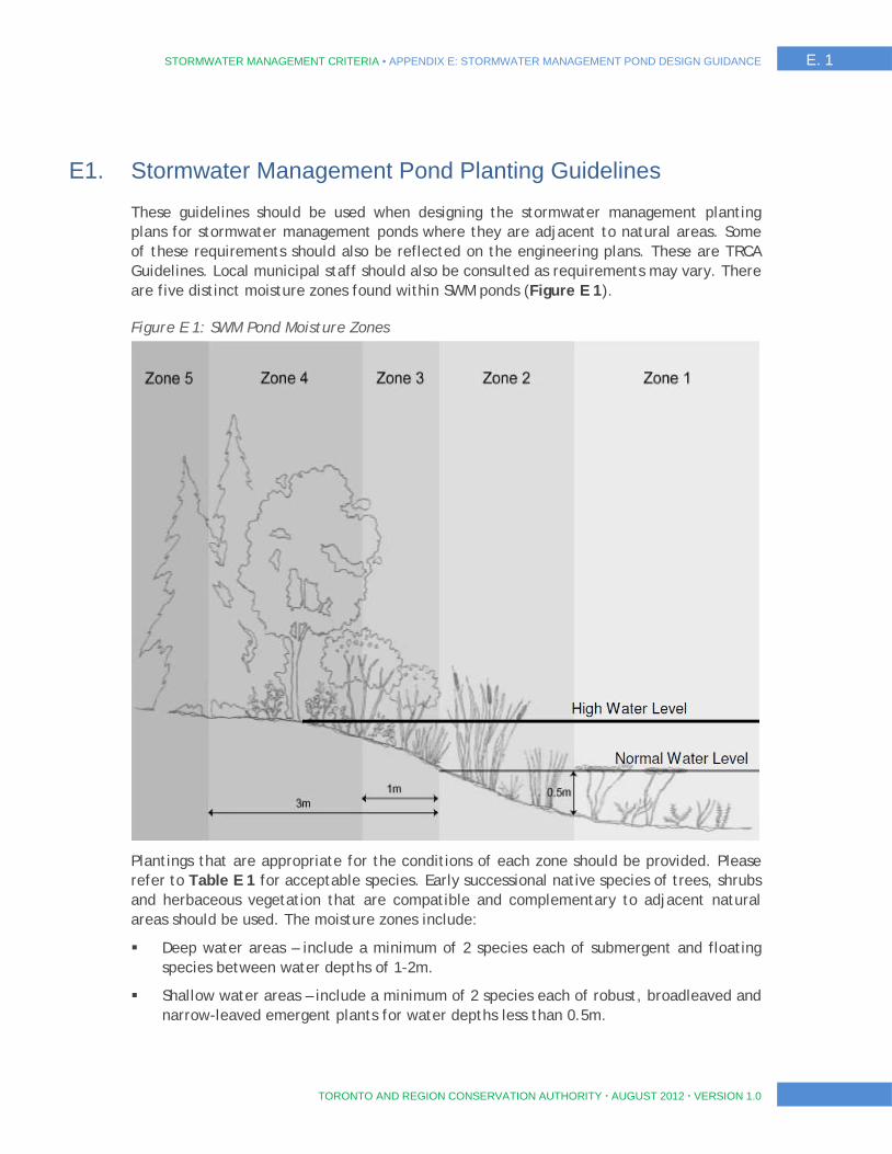
STORMWATER MANAGEMENT CRITERIA ▪ APPENDIX E: STORMWATER MANAGEMENT POND DESIGN GUIDANCE E. 1
TORONTO AND REGION CONSERVATION AUTHORITY AUGUST 2012 VERSION 1.0
E1. Stormwater Management Pond Planting Guidelines
These guidelines should be used when designing the stormwater management planting plans for stormwater management ponds where they are adjacent to natural areas. Some of these requirements should also be reflected on the engineering plans. These are TRCA Guidelines. Local municipal staff should also be consulted as requirements may vary. There are five distinct moisture zones found within SWM ponds (Figure E 1).
Figure E 1: SWM Pond Moisture Zones
Plantings that are appropriate for the conditions of each zone should be provided. Please refer to Table E 1 for acceptable species. Early successional native species of trees, shrubs and herbaceous vegetation that are compatible and complementary to adjacent natural areas should be used. The moisture zones include:
Deep water areas – include a minimum of 2 species each of submergent and floating species between water depths of 1-2m.
Shallow water areas – include a minimum of 2 species each of robust, broadleaved and narrow-leaved emergent plants for water depths less than 0.5m.
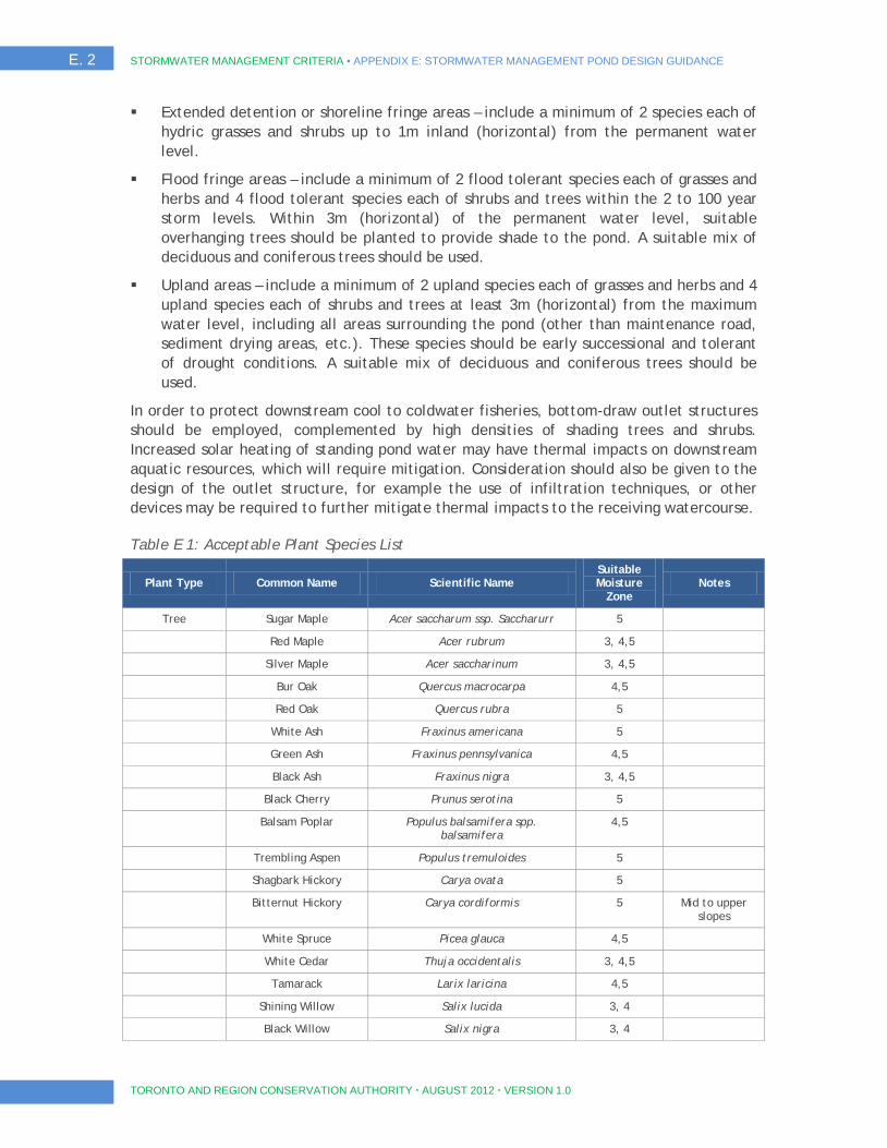
E. 2 STORMWATER MANAGEMENT CRITERIA ▪ APPENDIX E: STORMWATER MANAGEMENT POND DESIGN GUIDANCE
TORONTO AND REGION CONSERVATION AUTHORITY AUGUST 2012 VERSION 1.0
Extended detention or shoreline fringe areas – include a minimum of 2 species each of hydric grasses and shrubs up to 1m inland (horizontal) from the permanent water level.
Flood fringe areas – include a minimum of 2 flood tolerant species each of grasses and herbs and 4 flood tolerant species each of shrubs and trees within the 2 to 100 year storm levels. Within 3m (horizontal) of the permanent water level, suitable overhanging trees should be planted to provide shade to the pond. A suitable mix of deciduous and coniferous trees should be used.
Upland areas – include a minimum of 2 upland species each of grasses and herbs and 4 upland species each of shrubs and trees at least 3m (horizontal) from the maximum water level, including all areas surrounding the pond (other than maintenance road, sediment drying areas, etc.). These species should be early successional and tolerant of drought conditions. A suitable mix of deciduous and coniferous trees should be used.
In order to protect downstream cool to coldwater fisheries, bottom-draw outlet structures should be employed, complemented by high densities of shading trees and shrubs. Increased solar heating of standing pond water may have thermal impacts on downstream aquatic resources, which will require mitigation. Consideration should also be given to the design of the outlet structure, for example the use of infiltration techniques, or other devices may be required to further mitigate thermal impacts to the receiving watercourse.
Table E 1: Acceptable Plant Species List
Plant Type Common Name Scientific Name Suitable Moisture
Zone Notes
Tree Sugar Maple Acer saccharum ssp. Saccharurr 5
Red Maple Acer rubrum 3, 4,5
Silver Maple Acer saccharinum 3, 4,5
Bur Oak Quercus macrocarpa 4,5
Red Oak Quercus rubra 5
White Ash Fraxinus americana 5
Green Ash Fraxinus pennsylvanica 4,5
Black Ash Fraxinus nigra 3, 4,5
Black Cherry Prunus serotina 5
Balsam Poplar Populus balsamifera spp. balsamifera
4,5
Trembling Aspen Populus tremuloides 5
Shagbark Hickory Carya ovata 5
Bitternut Hickory Carya cordiformis 5 Mid to upper slopes
White Spruce Picea glauca 4,5
White Cedar Thuja occidentalis 3, 4,5
Tamarack Larix laricina 4,5
Shining Willow Salix lucida 3, 4
Black Willow Salix nigra 3, 4
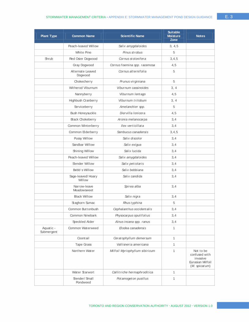
STORMWATER MANAGEMENT CRITERIA ▪ APPENDIX E: STORMWATER MANAGEMENT POND DESIGN GUIDANCE E. 3
TORONTO AND REGION CONSERVATION AUTHORITY AUGUST 2012 VERSION 1.0
Plant Type Common Name Scientific Name Suitable Moisture
Zone Notes
Peach-leaved Willow Salix amygdaloides 3, 4,5
White Pine Pinus strobus 5
Shrub Red Osier Dogwood Cornus stolonifera 3,4,5
Gray Dogwood Cornus foemina spp. racemosa 4,5
Alternate Leaved Dogwood
Cornus alternifolia 5
Chokecherry Prunus virginiana 5
Witherod Viburnum Viburnum cassinoides 3, 4
Nannyberry Viburnum lentago 4,5
Highbush Cranberry Viburnum trilobum 3, 4
Serviceberry Amelanchier spp. 5
Bush Honeysuckle Diervilla lonicera 4,5
Black Chokeberry Aronia melanocarpa 3,4
Common Winterberry Ilex verticillata 3,4
Common Elderberry Sambucus canadensis 3,4,5
Pussy Willow Salix discolor 3,4
Sandbar Willow Salix exigua 3,4
Shining Willow Salix lucida 3,4
Peach-leaved Willow Salix amygdaloides 3,4
Slender Willow Salix petiolaris 3,4
Bebb’s Willow Salix bebbiana 3,4
Sage-leaved/Hoary Willow
Salix candida 3,4
Narrow-leave Meadowsweet
Spirea alba 3,4
Black Willow Salix nigra 3,4
Staghorn Sumac Rhus typhina 5
Common Buttonbush Cephalanthus occidentalis 3,4
Common Ninebark Physocarpus opulifolius 3,4
Speckled Alder Alnus incana spp. ranus 3,4
Aquatic -Submergent
Common Waterweed Elodea canadensis 1
Coontail Ceratophyllum demersum 1
Tape Grass Vallisneria americana 1
Northern Water Milfoil Myriophyllum sibiricum 1 Not to be confused with
invasive Eurasian Milfoil (M. spicatum)
Water Starwort Callitriche hermaphroditica 1
Slender/Small Pondweed
Potamogeton pusillus 1
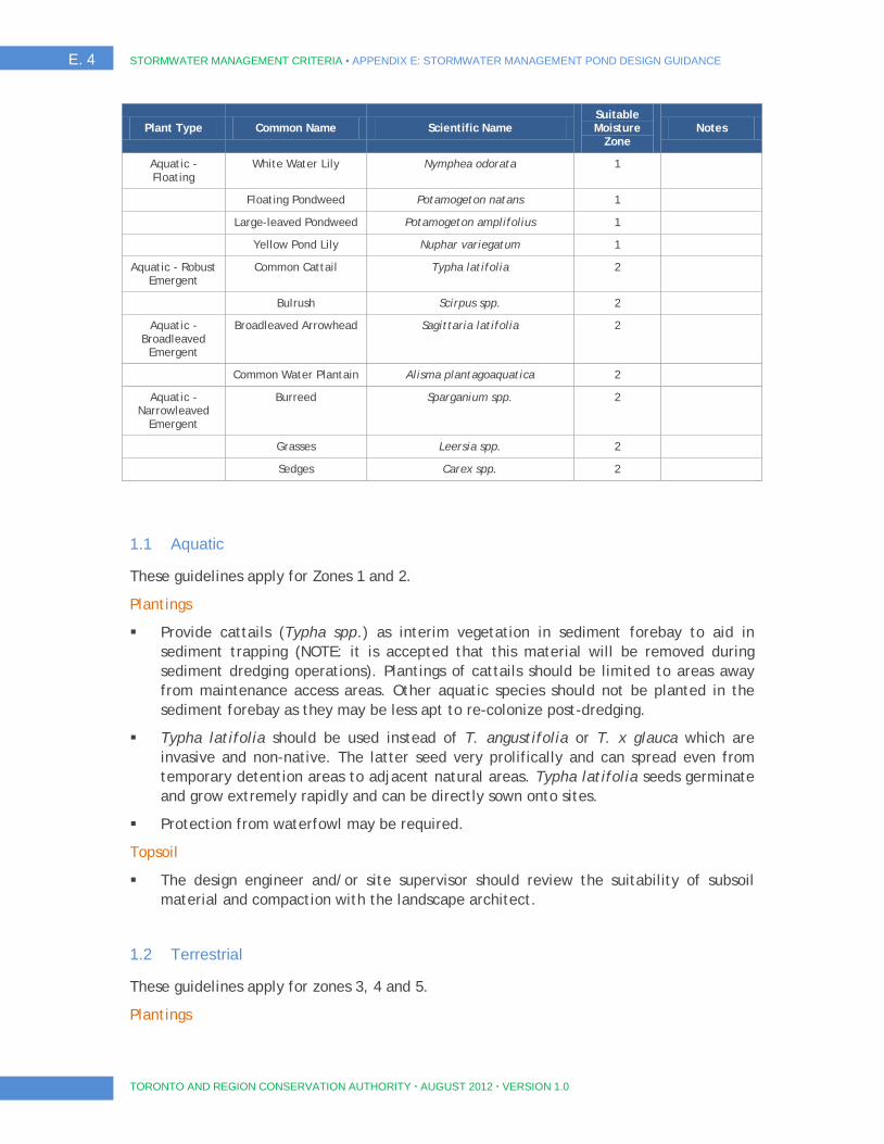
E. 4 STORMWATER MANAGEMENT CRITERIA ▪ APPENDIX E: STORMWATER MANAGEMENT POND DESIGN GUIDANCE
TORONTO AND REGION CONSERVATION AUTHORITY AUGUST 2012 VERSION 1.0
Plant Type Common Name Scientific Name Suitable Moisture
Zone Notes
Aquatic -Floating
White Water Lily Nymphea odorata 1
Floating Pondweed Potamogeton natans 1
Large-leaved Pondweed Potamogeton amplifolius 1
Yellow Pond Lily Nuphar variegatum 1
Aquatic - Robust Emergent
Common Cattail Typha latifolia 2
Bulrush Scirpus spp. 2
Aquatic -Broadleaved
Emergent
Broadleaved Arrowhead Sagittaria latifolia 2
Common Water Plantain Alisma plantagoaquatica 2
Aquatic -Narrowleaved
Emergent
Burreed Sparganium spp. 2
Grasses Leersia spp. 2
Sedges Carex spp. 2
1.1 Aquatic
These guidelines apply for Zones 1 and 2.
Plantings
Provide cattails (Typha spp.) as interim vegetation in sediment forebay to aid in sediment trapping (NOTE: it is accepted that this material will be removed during sediment dredging operations). Plantings of cattails should be limited to areas away from maintenance access areas. Other aquatic species should not be planted in the sediment forebay as they may be less apt to re-colonize post-dredging.
Typha latifolia should be used instead of T. angustifolia or T. x glauca which are invasive and non-native. The latter seed very prolifically and can spread even from temporary detention areas to adjacent natural areas. Typha latifolia seeds germinate and grow extremely rapidly and can be directly sown onto sites.
Protection from waterfowl may be required.
Topsoil
The design engineer and/or site supervisor should review the suitability of subsoil material and compaction with the landscape architect.
1.2 Terrestrial
These guidelines apply for zones 3, 4 and 5.
Plantings
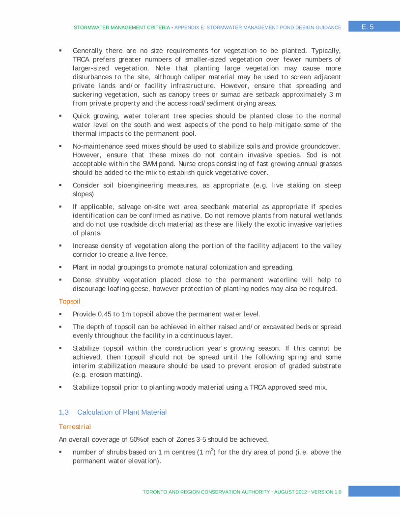
STORMWATER MANAGEMENT CRITERIA ▪ APPENDIX E: STORMWATER MANAGEMENT POND DESIGN GUIDANCE E. 5
TORONTO AND REGION CONSERVATION AUTHORITY AUGUST 2012 VERSION 1.0
Generally there are no size requirements for vegetation to be planted. Typically, TRCA prefers greater numbers of smaller-sized vegetation over fewer numbers of larger-sized vegetation. Note that planting large vegetation may cause more disturbances to the site, although caliper material may be used to screen adjacent private lands and/or facility infrastructure. However, ensure that spreading and suckering vegetation, such as canopy trees or sumac are setback approximately 3 m from private property and the access road/sediment drying areas.
Quick growing, water tolerant tree species should be planted close to the normal water level on the south and west aspects of the pond to help mitigate some of the thermal impacts to the permanent pool.
No-maintenance seed mixes should be used to stabilize soils and provide groundcover. However, ensure that these mixes do not contain invasive species. Sod is not acceptable within the SWM pond. Nurse crops consisting of fast growing annual grasses should be added to the mix to establish quick vegetative cover.
Consider soil bioengineering measures, as appropriate (e.g. live staking on steep slopes)
If applicable, salvage on-site wet area seedbank material as appropriate if species identification can be confirmed as native. Do not remove plants from natural wetlands and do not use roadside ditch material as these are likely the exotic invasive varieties of plants.
Increase density of vegetation along the portion of the facility adjacent to the valley corridor to create a live fence.
Plant in nodal groupings to promote natural colonization and spreading.
Dense shrubby vegetation placed close to the permanent waterline will help to discourage loafing geese, however protection of planting nodes may also be required.
Topsoil
Provide 0.45 to 1m topsoil above the permanent water level.
The depth of topsoil can be achieved in either raised and/or excavated beds or spread evenly throughout the facility in a continuous layer.
Stabilize topsoil within the construction year’s growing season. If this cannot be achieved, then topsoil should not be spread until the following spring and some interim stabilization measure should be used to prevent erosion of graded substrate (e.g. erosion matting).
Stabilize topsoil prior to planting woody material using a TRCA approved seed mix.
1.3 Calculation of Plant Material
Terrestrial
An overall coverage of 50% of each of Zones 3-5 should be achieved.
number of shrubs based on 1 m centres (1 m2) for the dry area of pond (i.e. above the permanent water elevation).
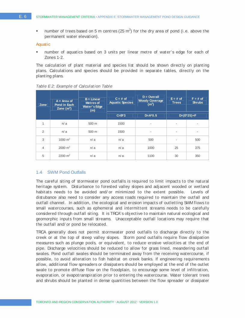
E. 6 STORMWATER MANAGEMENT CRITERIA ▪ APPENDIX E: STORMWATER MANAGEMENT POND DESIGN GUIDANCE
TORONTO AND REGION CONSERVATION AUTHORITY AUGUST 2012 VERSION 1.0
number of trees based on 5 m centres (25 m2) for the dry area of pond (i.e. above the permanent water elevation).
Aquatic
number of aquatics based on 3 units per linear metre of water’s edge for each of Zones 1-2.
The calculation of plant material and species list should be shown directly on planting plans. Calculations and species should be provided in separate tables, directly on the planting plans.
Table E 2: Example of Calculation Table
Zone A = Area of
Pond in Each Zone (m2)
B = Linear Metres of
Water’s Edge (m)
C = # of Aquatic Species
D = Overall Woody Coverage
(m2)
E = # of Trees
F = # of Shrubs
C=B*3 D=A*0.5 D=(E*25)+F
1 n/a 500 m 1500 - - -
2 n/a 500 m 1500 - - -
3 1000 m2 n/a n/a 500 - 500
4 2000 m2 n/a n/a 1000 25 375
5 2200 m2 n/a n/a 1100 30 350
1.4 SWM Pond Outfalls
The careful siting of stormwater pond outfalls is required to limit impacts to the natural heritage system. Disturbance to forested valley slopes and adjacent wooded or wetland habitats needs to be avoided and/or minimized to the extent possible. Levels of distubance also need to consider any access roads required to maintain the outfall and outfall channel. In addition, the ecological and erosion impacts of outletting SWM flows to small watercourses, such as ephemeral and intermittent streams needs to be carefully considered through outfall siting. It is TRCA’s objective to maintain natural ecological and geomorphic inputs from small streams. Unacceptable outfall locations may require that the outfall and/or pond be relocated.
TRCA generally does not permit stormwater pond outfalls to discharge directly to the creek or at the top of steep valley slopes. Storm pond outfalls require flow dissipation measures such as plunge pools, or equivalent, to reduce erosive velocities at the end of pipe. Discharge velocities should be reduced to allow for grass lined, meandering outfall swales. Pond outfall swales should be terminated away from the receiving watercourse, if possible, to avoid alteration to fish habitat on creek banks. If engineering requirements allow, additional flow spreaders or dissipaters should be employed at the end of the outlet swale to promote diffuse flow on the floodplain, to encourage some level of infiltration, evaporation, or evapotranspiration prior to entering the watercourse. Water tolerant trees and shrubs should be planted in dense quantities between the flow spreader or dissipater
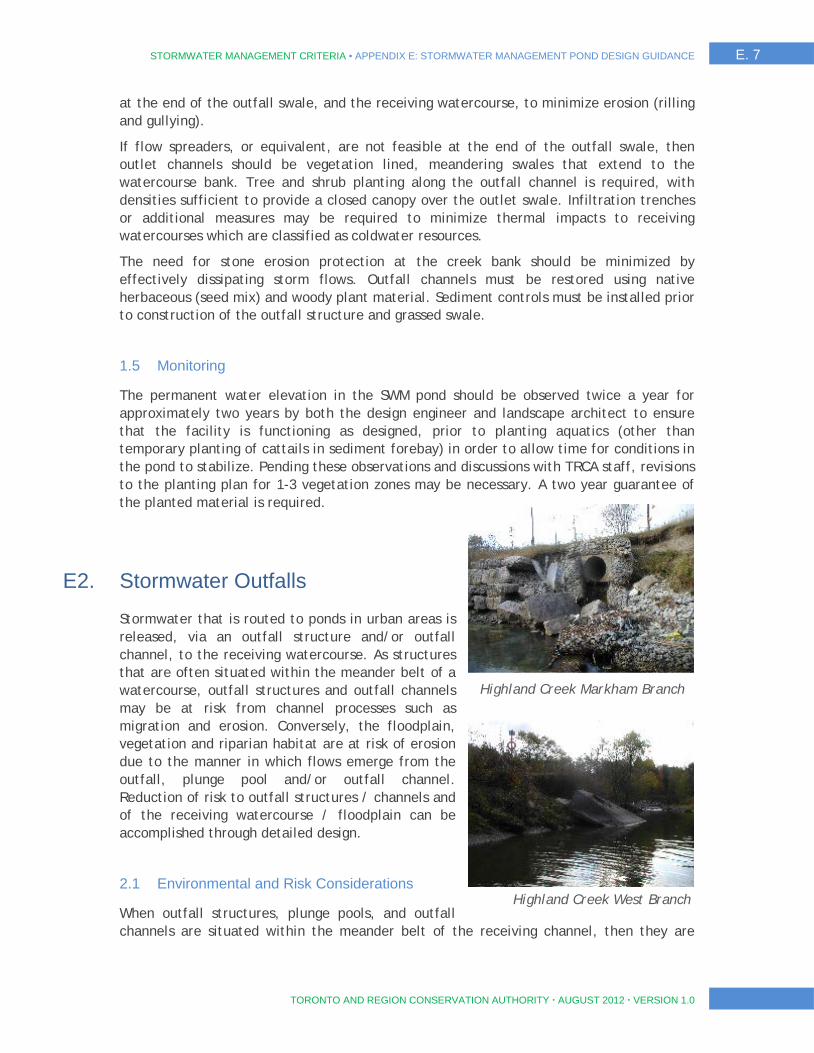
STORMWATER MANAGEMENT CRITERIA ▪ APPENDIX E: STORMWATER MANAGEMENT POND DESIGN GUIDANCE E. 7
TORONTO AND REGION CONSERVATION AUTHORITY AUGUST 2012 VERSION 1.0
at the end of the outfall swale, and the receiving watercourse, to minimize erosion (rilling and gullying).
If flow spreaders, or equivalent, are not feasible at the end of the outfall swale, then outlet channels should be vegetation lined, meandering swales that extend to the watercourse bank. Tree and shrub planting along the outfall channel is required, with densities sufficient to provide a closed canopy over the outlet swale. Infiltration trenches or additional measures may be required to minimize thermal impacts to receiving watercourses which are classified as coldwater resources.
The need for stone erosion protection at the creek bank should be minimized by effectively dissipating storm flows. Outfall channels must be restored using native herbaceous (seed mix) and woody plant material. Sediment controls must be installed prior to construction of the outfall structure and grassed swale.
1.5 Monitoring
The permanent water elevation in the SWM pond should be observed twice a year for approximately two years by both the design engineer and landscape architect to ensure that the facility is functioning as designed, prior to planting aquatics (other than temporary planting of cattails in sediment forebay) in order to allow time for conditions in the pond to stabilize. Pending these observations and discussions with TRCA staff, revisions to the planting plan for 1-3 vegetation zones may be necessary. A two year guarantee of the planted material is required.
E2. Stormwater Outfalls
Stormwater that is routed to ponds in urban areas is released, via an outfall structure and/or outfall channel, to the receiving watercourse. As structures that are often situated within the meander belt of a watercourse, outfall structures and outfall channels may be at risk from channel processes such as migration and erosion. Conversely, the floodplain, vegetation and riparian habitat are at risk of erosion due to the manner in which flows emerge from the outfall, plunge pool and/or outfall channel. Reduction of risk to outfall structures / channels and of the receiving watercourse / floodplain can be accomplished through detailed design.
2.1 Environmental and Risk Considerations
When outfall structures, plunge pools, and outfall channels are situated within the meander belt of the receiving channel, then they are
Highland Creek Markham Branch
Highland Creek West Branch

E. 8 STORMWATER MANAGEMENT CRITERIA ▪ APPENDIX E: STORMWATER MANAGEMENT POND DESIGN GUIDANCE
TORONTO AND REGION CONSERVATION AUTHORITY AUGUST 2012 VERSION 1.0
potentially at risk from meander migration and channel bed lowering (Section 2.4). The risk of becoming outflanked or undercut increases when the structure is placed flush along a channel bank, or set back within the 100 year erosion limit of the channel. Hence, TRCA requires that hard structures (i.e. headwalls or anything made of concrete) associated with outfalls be located outside of the 100-year erosion limit unless it is not technically feasible.
Outfalls that discharge directly into a watercourse occur when there is a steep floodplain slope and/or little room between outfall and channel, or if the receiving watercourse is large in proportion to the volume of discharge. These outfalls typically have minimal energy dissipation mechanisms (i.e., chute blocks). Depending on orientation of the outfall, and size of receiving watercourse, flows emerging from the outfall can cause erosion of the adjacent and/or opposite channel bank. In extreme cases, adjustments in channel pattern due to the erosion can occur.
Plunge pools, into which outfalls discharge directly, dissipate flow energy and are typically situated within the floodplain at a distance from the watercourse. Excess flow volume delivered to plunge pools via the outfall is either released directly onto the floodplain with the aid of a flow spreader or directed to the watercourse through an outfall channel. Plunge pools without channels are typically used in wide, flat floodplains where vegetation and slopes are conducive to flow dissipation.
Both methods can cause floodplain erosion. Further, the outfall channel may be susceptible to erosion at the tie-in with the main channel and from flows directed through it.
Outfall structures that are situated below design floodlines are at risk of becoming flooded if the design did not adequately account for flood levels of the receiving watercourse. This has implications for stormwater pond performance and, in some cases for the storm sewer network. That is, if outfall structures are flooded, then ponds cannot drain which would reduce the hydraulic performance of the pond, lead to pond flooding and potentially to storm sewer backups.
2.2 Existing Guideline Documents
Few guideline documents exist with respect to design of the outfall plunge pools and channels. The MTO (1997) Drainage Management Manual: Parts 1 to 4 is most commonly referenced. Other potential guideline documents are identified at the end of this appendix.
2.3 Locating Outfalls and Outfall Channels
The proposed location of outfalls and outfall channels is determined in the Stormwater Management Plan of a Block Plan for proposed development areas. At this stage,
Highland Creek Malvern Branch
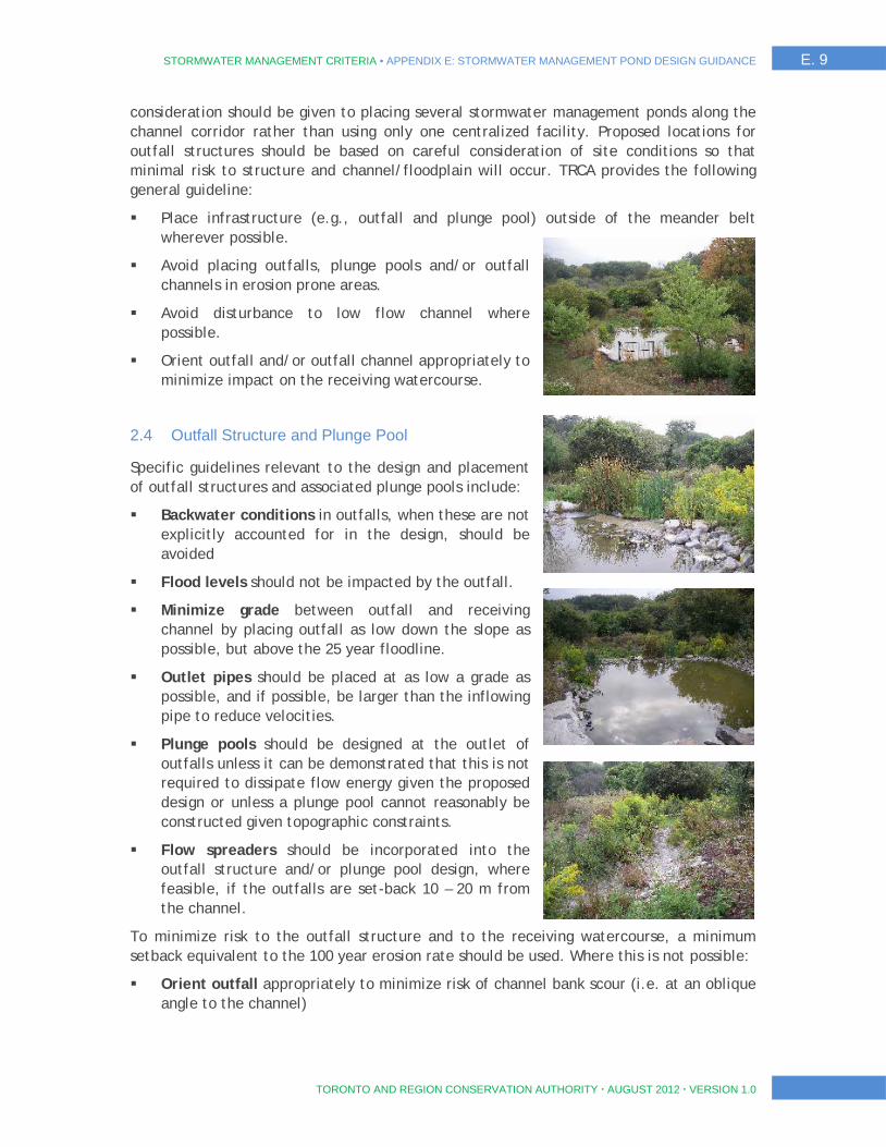
STORMWATER MANAGEMENT CRITERIA ▪ APPENDIX E: STORMWATER MANAGEMENT POND DESIGN GUIDANCE E. 9
TORONTO AND REGION CONSERVATION AUTHORITY AUGUST 2012 VERSION 1.0
consideration should be given to placing several stormwater management ponds along the channel corridor rather than using only one centralized facility. Proposed locations for outfall structures should be based on careful consideration of site conditions so that minimal risk to structure and channel/floodplain will occur. TRCA provides the following general guideline:
Place infrastructure (e.g., outfall and plunge pool) outside of the meander belt wherever possible.
Avoid placing outfalls, plunge pools and/or outfall channels in erosion prone areas.
Avoid disturbance to low flow channel where possible.
Orient outfall and/or outfall channel appropriately to minimize impact on the receiving watercourse.
2.4 Outfall Structure and Plunge Pool
Specific guidelines relevant to the design and placement of outfall structures and associated plunge pools include:
Backwater conditions in outfalls, when these are not explicitly accounted for in the design, should be avoided
Flood levels should not be impacted by the outfall.
Minimize grade between outfall and receiving channel by placing outfall as low down the slope as possible, but above the 25 year floodline.
Outlet pipes should be placed at as low a grade as possible, and if possible, be larger than the inflowing pipe to reduce velocities.
Plunge pools should be designed at the outlet of outfalls unless it can be demonstrated that this is not required to dissipate flow energy given the proposed design or unless a plunge pool cannot reasonably be constructed given topographic constraints.
Flow spreaders should be incorporated into the outfall structure and/or plunge pool design, where feasible, if the outfalls are set-back 10 – 20 m from the channel.
To minimize risk to the outfall structure and to the receiving watercourse, a minimum setback equivalent to the 100 year erosion rate should be used. Where this is not possible:
Orient outfall appropriately to minimize risk of channel bank scour (i.e. at an oblique angle to the channel)

E. 10 STORMWATER MANAGEMENT CRITERIA ▪ APPENDIX E: STORMWATER MANAGEMENT POND DESIGN GUIDANCE
TORONTO AND REGION CONSERVATION AUTHORITY AUGUST 2012 VERSION 1.0
In channel restoration designs, where this is in keeping with the overall design objective (in headwater streams), direct outfall flow into an on-line wetland features.
2.5 Flow Spreaders and Outfall Channels
Flow from outfall structures can be directed to a receiving watercourse directly by an outfall channel, or directed to a plunge pool before either spilling onto the floodplain with a flow spreader or spilling into a channel that conveys flow from the outfall to the watercourse.
Flow Spreaders: Once flow from an outfall structure is discharged into a plunge pool, release of the water onto the floodplain can occur through the use of flow spreaders that are situated at the periphery of the pool. Through careful design and construction, flow is uniformly released from the pool onto a gently sloped floodplain. Analyses would determine that the release of water would not contribute to rilling and/or gullying of the floodplain. When flow from an outfall structure or plunge pools is intended to be conveyed to the receiving watercourse through an outfall channel then there are several design options available each of which should be considered for appropriateness in the study area.
Wetland Design: Plunge pools can be designed as a wetland feature in the floodplain. This can be achieved through suitable grading that would enable a range of wetland vegetation types to be established and through including relevant aquatic and/or terrestrial features. Flow from the pool is released into the receiving watercourse through an outlet channel, or through an overland spillway (vegetated or stone reinforced).
Linear Wetland or Vegetated Channel: Where the outfall is situated a short distance from the channel, and the grade between outfall and receiving channel bed is sufficiently low, one or more vegetated channels (e.g., swale or larger feature) may effectively convey flows from plunge pool/outfall to the channel. The tie-in between outfall and receiving channel would occur at channel bed elevation. Analyses would demonstrate that vegetation within the outfall channel would be stable under outfall flow conditions. Enhancement of the vegetated channel as a linear wetland would provide additional aquatic and terrestrial benefits. Depending on grade, the vegetated channel may need to incorporate steps to dissipate energy.
Natural Channel or Rock Lined Channel: Rather than spreading flow onto the floodplain, concentration of flow into a channel is preferred when the outfall is situated a distance from the receiving channel, the floodplain is steep (i.e., and gullies or rills would form) and other design options are not feasible. Depending on length, the floodplain channel could mimic a natural channel and incorporate appropriate channel features to aid in energy dissipation and reduction of gradient. In vegetation lined channels, steps may need to be incorporated to dissipate flow energy. In shorter channel section, a rock lined channel may be more appropriate. In all cases, the outfall channel should be oriented at the tie-in to the receiving watercourse at an angle that will minimize risk of bank scour.
STORMWATER MANAGEMENT CRITERIA ▪ APPENDIX E: STORMWATER MANAGEMENT POND DESIGN GUIDANCE E. 11
TORONTO AND REGION CONSERVATION AUTHORITY AUGUST 2012 VERSION 1.0
2.6 Construction Details (ESC plans, phasing, restoration)
When valley walls are high and/or well vegetated, minimal impact to the valley and channel corridor during construction and placement of outfalls and associated subsurface piping is desirable. This can often be best accomplished with tunnelling/directional drilling rather than open cut methods construction methods. Where erosion protection may be necessary in outfall channels, filter cloth is, in general, not permitted by TRCA. Instead, a granular filter layers beneath the larger rounded stone is recommended.
An erosion and sediment control plan should be prepared and submitted as part of the design package that clearly outlines measures that will be taken to reduce and mitigate impact in the proposed construction area (e.g., see TRCA’s Erosion and Sediment Control Guidelines). Details of construction phasing and post-construction restoration should also be provided. Vegetative restoration plans (combination of native trees, shrubs and herbaceous vegetation that are compatible to existing vegetation communities) should be prepared, including species, density and planting methodology information. Site stabilization should occur during or immediately following construction to avoid erosion (e.g., hydroseeding, straw mulch, jute mats etc.)
2.7 Submission Requirements
In addition to detailed design drawings, all supporting documentation (hydraulic modeling, assessment of restoration materials, environmental assessment/studies etc.) used to determine plunge pool and outfall channel design details, if applicable, should be submitted to TRC for review. The assessments and design activities described must be conducted by a qualified practitioner and those activities that meet the definition of profession engineering or profession geoscience should be conducted, signed and stamped by a Professional Engineer or Professional Geoscientist.

STORMWATER MANAGEMENT CRITERIA ▪ APPENDIX F. TRCA EXECUTIVE COMMITTEE BOARD REPORT F. 1
TORONTO AND REGION CONSERVATION AUTHORITY AUGUST 2012 VERSION 1.0
APPENDIX F TRCA EXECUTIVE COMMITTEE BOARD REPORT

F. 2 STORMWATER MANAGEMENT CRITERIA ▪ APPENDIX F. TRCA EXECUTIVE COMMITTEE BOARD REPORT
TORONTO AND REGION CONSERVATION AUTHORITY AUGUST 2012 VERSION 1.0
- THIS PAGE LEFT INTENTIONALLY BLANK -