Malfunction Management and Analysis - Electrical and ...
53
1 RESOURCE MATERIALS Malfunction Management and Analysis U.S. Department of Transportation Federal Highway Administration Publication No. FHWA-RD-95-096 March 1995 Precursor Systems Analyses of Automated Highway Systems Raytheon Task E Page 1
-
Upload
khangminh22 -
Category
Documents
-
view
3 -
download
0
Transcript of Malfunction Management and Analysis - Electrical and ...

1
R E S O U R C E M A T E R I A L S
Malfunction Management andAnalysis
U.S. Department of TransportationFederal Highway Administration
Publication No. FHWA-RD-95-096March 1995
Precursor Systems Analyses ofAutomated Highway
Systems
Raytheon Task E Page 1

FOREWORD
This report was a product of the Federal Highway Administration’s Automated Highway System (AHS) PrecursorSystems Analyses (PSA) studies. The AHS Program is part of the larger Department of Transportation (DOT)Intelligent Transportation Systems (ITS) Program and is a multi-year, multi-phase effort to develop the next majorupgrade of our nation’s vehicle-highway system.
The PSA studies were part of an initial Analysis Phase of the AHS Program and were initiated to identify the highlevel issues and risks associated with automated highway systems. Fifteen interdisciplinary contractor teams wereselected to conduct these studies. The studies were structured around the following 16 activity areas:
(A) Urban and Rural AHS Comparison, (B) Automated Check-In, (C) Automated Check-Out, (D) Lateraland Longitudinal Control Analysis, (E) Malfunction Management and Analysis, (F) Commercial andTransit AHS Analysis, (G) Comparable Systems Analysis, (H) AHS Roadway Deployment Analysis, (I)Impact of AHS on Surrounding Non-AHS Roadways, (J) AHS Entry/Exit Implementation, (K) AHSRoadway Operational Analysis, (L) Vehicle Operational Analysis, (M) Alternative Propulsion SystemsImpact, (N) AHS Safety Issues, (O) Institutional and Societal Aspects, and (P) Preliminary Cost/BenefitFactors Analysis.
To provide diverse perspectives, each of these 16 activity areas was studied by at least three of the contractorteams. Also, two of the contractor teams studied all 16 activity areas to provide a synergistic approach to theiranalyses. The combination of the individual activity studies and additional study topics resulted in a total of 69studies. Individual reports, such as this one, have been prepared for each of these studies. In addition, each of theeight contractor teams that studied more than one activity area produced a report that summarized all theirfindings.
Lyle SaxtonDirector, Office of Safety and Traffic Operations Researchand Development
NOTICE
This document is disseminated under the sponsorship of the Department of Transportation in the interest ofinformation exchange. The United States Government assumes no liability for its contents or use thereof. Thisreport does not constitute a standard, specification, or regulation.
The United States Government does not endorse products or manufacturers. Trade and manufacturers’ namesappear in this report only because they are considered essential to the object of the document.
Raytheon Task E Page 2

1. Report No.
FHWA-RD-95-XXX2. Government Accession No. 3. Recipient's Catalog No.
4. Title and Subtitle
Precursor Systems Analyses Of Automated Highway System
Final ReportMalfunction Management and AnalysisVolume 5
5. Report Date
6. Performing Organization Code
7. Author(s) M. McGowan, T. Franks, W. Schineller, M. Shannon 8. Performing Organization Report No.
9. Performing Organization Name and Address
Raytheon CompanyMissile Systems Division50 Apple Hill DriveTewksbury, Ma 01876
10. Work Unit No. (TRAIS)
11. Contract or Grant No.
DTFH61-93-C-0019612. Sponsoring Agency Name and Address
The Federal Highway Administration400 Seventh Street, S.W.Washington, D.C. 20590
13. Type of Report and Period Covered
Final ReportSept 1993 - Feb 1995
14. Sponsoring Agency Code
15. Supplementary Notes
Contracting Officer's Technical Representative (CTOR) - J. Richard Bishop (HSR-12)
16. Abstract
This document is the draft final report of the Automated Highway System. The activities of MalfunctionManagement and Analysis are reported on in this document. This document type is resource materials.
This volume is the fifth in a series. There are nine other volumes in the series.FHWA-RD-95-XXX Volume 1 Executive SummaryFHWA-RD-95-XXX Volume 2 Automated Check InFHWA-RD-95-XXX Volume 3 Automated Check OutFHWA-RD-95-XXX Volume 4 Lateral and Longitudinal ControlFHWA-RD-95-XXX Volume 5 Malfunction Management and AnalysisFHWA-RD-95-XXX Volume 6 Commercial Vehicle and Transit AHS AnalysisFHWA-RD-95-XXX Volume 7 Entry/Exit ImplementationFHWA-RD-95-XXX Volume 8 Vehicle Operational AnalysisFHWA-RD-95-XXX Volume 9 AHS Safety IssuesFHWA-RD-95-XXX Volume 10 Knowledge Based Systems and Learning Methods17. Key Words
Automated Highway System, Check in, Check out,Lateral and Longitudinal Control, MalfunctionManagement, Entry/Exit, Safety, Commercial, TransitKnowledge Based Systems
18. Distribution Statement
No restrictions. This document is available to thepublic through the National Technical InformationService, Springfield, Virginia 22161
19. Security Classif. (of this report)
Unclassified20. Security Classif. (of this page)
Unclassified21. No. of Pages
3922. Price
Raytheon Task E Page 3

Table Of ContentsPage
1.0 EXECUTIVE SUMMARY...................................................................................................... 1
2.0 INTRODUCTION FOR ACTIVITY AREA........................................................................... 22.1 Description Of Activity Area..................................................................................................... 22.2 Purpose Of This Effort-Specific Focus ...................................................................................... 22.3 Issues Addressed ....................................................................................................................... 22.4 Overall Approach For This Activity Area .................................................................................. 22.5 Guiding Assumptions - Origins and Rationale ........................................................................... 3
3.0 EVOLUTIONARY REPRESENTATIVE SYSTEMS CONFIGURATIONS(ERSC) ................................................................................................................................. 3
4.0 TECHNICAL DISCUSSIONS OF EACH STEP.................................................................... 44.1 Develop Operational and Physical Description of Normal AHS Operations............................... 54.2 Functional Analysis Assist with Malfunction Identification Process .......................................... 74.3 Malfunction Detection and Diagnosis ........................................................................................ 84.3.1 Diagnosis of Malfunctions......................................................................................................... 94.4 Measures of Effectiveness (MOEs) to Identify Malfunctions and Classify
Their Severity............................................................................................................................ 104.4.1 Malfunction Likelihood of Occurrence ...................................................................................... 114.4.2 Malfunction Impact on Safety ................................................................................................... 124.4.3 Malfunction Impact on System Efficiency................................................................................. 124.4.4 Malfunction Impact on User Comfort ........................................................................................ 134.4.5 Secondary MOEs to Identify and Classify Malfunctions ............................................................ 144.5 Components of Complete Malfunction Management Strategy ................................................... 144.5.1 Malfunction Management Timeline........................................................................................... 144.5.2 Malfunction Prevention ............................................................................................................. 144.5.3 Malfunction Responses
Managing Risk While Restoring Normal Operations ................................................................. 164.5.4 Selection of Best Malfunction Management Response Strategies .............................................. 194.6 Application of Malfunction Management Strategy .................................................................... 224.6.1 Malfunction Analysis of Longitudinal Control........................................................................... 23
4.6.1.1 Description of Normal Operations and Operational Functions .................................. 244.6.1.2 Potential Mulfunctions ............................................................................................. 254.6.1.3 Assessment of Malfunction Response Options (Transient Effects and Response
Results) .................................................................................................................... 304.6.2 Malfunction Analysis of Lateral Control in ERSC3.................................................. 334.6.2.1 Description of Normal Operations and Operational Functions .................................. 334.6.2.2 Potential Malfunctions ............................................................................................. 344.6.2.3 Assessment of Malfunction Response Options to Lateral Control Malfunctions
in ERSC3 (Transient Effects and Response Results)................................................. 35
5.0 CONCLUSION....................................................................................................................... 38
Raytheon Task E Page 4

List Of Figures
PageFigure 1 Evolutionary Representative System Configurations ...................................................................3Figure 2 Malfunction Management and Analysis - Study Methodology.....................................................4Figure 3 Malfunction Response Dynamics ................................................................................................16Figure 4 Malfunction Response Selection Process .....................................................................................23Figure 5 Communication Paths for Longitudinal Control in ERSC1..........................................................23Figure 6 Normal Operations for Longitudinal Control (Speed and Headway Maintenance) in ERSC1......24Figure 7 Potential Malfunctions for Longitudinal Control in ERSC1.........................................................25Figure 8 Potential Malfunction Impact on Longitudinal Control in ERSC1 ...............................................26Figure 9 Potential Malfunction Responses for Longitudinal Control Malfunction V1 in ERSC1................31Figure 10 Potential Malfunction Responses for Longitudinal Control Malfunction V2 in ERSC1................32Figure 11 Normal Operations for Lateral Control (Lane Keeping) in ERSC3 ..............................................34Figure 12 Potential Malfunctions for Lateral Control in ERSC3..................................................................34Figure 13 Potential Malfunction Impact on Lateral Control in ERSC3 ........................................................35Figure 14 Potential Malfunction Responses for Lateral Control Malfunction V1 in ERSC3 ........................36
Raytheon Task E Page 5

List Of Tables
PageTable 1 Malfunction Likelihood of Occurrence...................................................................................... 11
Table 2 Malfunction Impact on Safety ................................................................................................... 12
Table 3 Malfunction Impact on System Efficiency................................................................................. 13
Table 4 Malfunction Impact on User Comfort........................................................................................ 13
Table 5 Malfunction Response Implementation Cost (to User or System) .............................................. 21
Table 6 Likelihood of Failing to Implement Malfunction Response ....................................................... 22
Raytheon Task E Page 6

LIST OF ABBREVIATIONS
AASHTO American Association of State Highway and Transportation OfficialsABS anti-lock brake systemAHSAI
Automated Highway SystemArtificial Intelligence
AICC Autonomous Intelligent Cruise ControlAICC Adaptive Intelligent Cruise ControlALK automatic lane keepingANSI American National Standards InstituteAPTS Advanced Public Transportation SystemASR anti wheel spin regulationASTM American Society for Testing and MaterialsATIS Advanced Traveler Information SystemATMS Advanced Traffic Management SystemAVCS Advanced Vehicle Control SystemsAVI automated vehicle identificationAVL automated vehicle locationBAA Broad Agency AnnouncementCICC cooperative intelligent cruise controlCLT crossing left turnCVO Commercial Vehicle OperationsCVSA Commercial Vehicle Safety AllianceDOT Department of TransportationEIA Electronics Industry AssociationEMS emergency medical servicesERSC Evolutionary Representative System ConfigurationETC electronic toll collectionEVM emergency vehicle managementFARSFFBD
Fatal Accident Reporting Systemfunctioal flow block diagram
FHWA Federal Highway AdministrationFLIRFMEA
forward looking infrared radarfailure modes and effects analysis
FTA Federal Transit AdministrationGES General Estimates SystemGPS Global Positioning Satellite navigation systemHAR Highway Advisory RadioHAZMAT hazardous materialsHDS headway detection systemHOV high occupancy vehicleHUD head-up displayICAS intersection collision avoidance systemICC intelligent cruise controlIEEE Institute of Electrical and Electronics EngineersISTEA Intermodal Surface Transportation Efficiency ActITE Institute of Transportation EngineersIVHS Intelligent Vehicle Highway SystemLCM lane change / merge collisionsLED light-emitting diode displayLORAN Land-based Radio Navigation SystemMCSAPMOE
Motor Carrier Safety Assistance Programmeasure of effectiveness
NAB National Association of BroadcastersNEC Northeast corridor
Raytheon Task E Page 7

NEMA National Electrical Manufacturer AssociationNHTSA National Highway Traffic Safety AdministrationPATH Program for Advanced Transit and Highways ( California )PCD personal communication devicePDS proximity detection systemPPT personalized public transitPRT perception reaction timePSA precursor systems analysesPSAP public safety answering pointPSS Public Safety ServicesPTS public travel securityRECA rear end collision avoidanceRECWRL
rear end collision warningreinforcement learning
RSC representative system configurationRSPA Research and Special Programs AdministrationRTTASC real-time traffic-adaptive signal controlSAE Society of Automotive EngineersSCP straight crossing pathSHMS speed headway maintanence systemSOV single occupancy vehicleSRVD single vehicle roadway departureTCS traction control systemTDM travel demand managementTIA Telecommunications Industry AssociationTMC traffic management centerTMS tire monitor systemVMS variable message signVMT vehicle miles traveledVRC vehicle-to-roadside communication
Raytheon Task E Page 8

1.0 EXECUTIVE SUMMARY
An objective of the Automated Highway System (AHS) is a system that will be accident-free inthe absence of malfunctions. The purpose of the malfunction management and analysis effortwas to identify strategies for managing AHS malfunctions, and to identify issues and risksassociated with implementing these strategies. In addition measures of effectiveness have beenidentified which could be used to evaluate and to optimize various malfunction managementstrategies.
A through understanding of the system's normal operation must be developed as the startingpoint for malfunction management and analysis. This can be accomplished by using the systemengineering approach of functional analysis to develop a framework of the systems normalsequence of operations. Functional analysis presents the interactions between the variousfunctions and can also be used for developing timelines for the occurrence of the variousfunctions.
The next step is to develop a set of operating conditions for the system which defines normaloperations. A system as complex as an AHS is not like an assembly line, a conveyor belt, oreven a railroad where objects move along a set path. Even these less complex systems arecomplicated. An example is the luggage conveyor system at the new Denver airport and thewidely reported difficulties it has encountered. In a system as complex as the AHS, normaloperations will not be described by discrete values but rather a range of values (i.e., the onesigma value of a normal distribution) in which operations can occur. The definition of thenormal operating conditions then allows the question of what is a malfunction and when does itoccur to be answered.
The end product of the functional analysis assists in answering the questions concerningmalfunction identification. It accommodates two approaches. One considers a loss infunctionality of an operational requirement and the other component failure within a particularsystem element.
Once malfunctions have been identified the next step is to evaluate the impact on the system inorder to prioritize the response. Two key attribute to consider are the likelihood of occurrenceand the severity of impact on normal operations given its occurrence. For AHS applications, amalfunctions severity might be measured according to its impact on safety, system throughput,and user comfort.
It is advantageous to assemble multiple response options to a particular malfunction.Operational flexibility in a particular system design depends on the ability of the system to adaptto the situation. Each of these responses to a particular malfunction could have a differentimplementation time for restoring normal system operation or other performance measures suchas user cost, system cost, likelihood of successful implementation, and severity of impact onsafety, system efficiency, and user comfort. The system designer must not only consider thefinal results of the malfunction management strategy but also the transient effects of a particularresponse after a malfunction outweighing the benefits to the system given the response'ssuccessful implementation.
Raytheon Task E Page 9

The following are the key findings of the malfunction analysis task. A complete set ofmalfunction management strategies will balance the desire to have the system perform withoutfailing with the need to respond to failure when it inevitably occurs, within the constraintsimposed by safety, system efficiency, user comfort, and cost.
A complete evaluation of malfunction management options includes cost/benefit tradeoffsbetween the preventative reduction in the probability of malfunction occurence and theresponsive reduction in the severity of the malfunction given its occurrence.
The time criticality and potential severity of certain malfunctions preclude dependence onsystem responses once the malfunction occurs. In these instances the malfunction managementstrategy must rely on built in redundancies either in the vehicle or roadway infrastructure.
Reliance on the driver (perceptions, capabilities, predictability, and accountability) formalfunction prevention, detection, diagnosis, and execution of management tasks is arisk/challenge.
Certain malfunctions do not lend themselves to a straight forward methodological breakdown.The complexity of the AHS assures that malfunction management will be a continuouslyevolving process.
The transient effects of a particular management response may outweigh the benefits gained byits implementation.
2.0 INTRODUCTION FOR ACTIVITY AREA
This section of the report provides a description of the activity, the purpose of this effort, alisting of the issues addressed, an overview of the overall approach, and a summary of theguiding assumptions.
2.1 Description Of Activity Area
The Malfunction Management and Analysis activity was to describe requirements and strategiesfor safely handling and managing malfunctions, to estimate the consequences of thesemalfunctions and the malfunction strategies by identifying measures of effectiveness and todefine alternative ways in which malfunctions can be detected.
2.2 Purpose Of This Effort-Specific Focus
Although perfect safety has always been, and will continue to be, a primary goal oftransportation technology, the fact is that no transportation system has yet achieved it. The AHSwill certainly strive to reach that goal. However, as in any system, things can go wrong orunanticipated events can occur. The purpose of this effort is to define a methodology foridentifying potential malfunction and then identify measures of effectiveness (MOEs) which canbe used in evaluating and selecting the optimum response. The goal of any malfunctionmanagement strategy is to prevent malfunctions from occurring and when they do occur tomitigate their effects.
Raytheon Task E Page 10

2.3 Issues Addressed
The Malfunction Management and Analysis issues addressed in this activity area were:• Functional analysis to define normal operations.• Identification and categorization of potential malfunctions.• Investigation of malfunction detection techniques.• Definition of MOEs to rate malfunction severity.• Definition of MOEs to rate malfunction responses.• Development of malfunction management strategies.
2.4 Overall Approach For This Activity Area
The overall approach was to first define a methodology which would permit the determination ofnormal operations in an AHS. This first step provides an effective framework to define,comprehend, and analyze complex system designs. Next a method for detecting malfunctions isidentified. Once identified, an assessment of the severity of the malfunction must be conductedconsidering MOEs. Finally, malfunction management strategies are discussed which not onlyconsider the final outcome but also the effects of the transient responses on the system
2.5 Guiding Assumptions - Origins and RationaleThe key guiding assumption was that the AHS is to be collision free in the absence ofmalfunctions as specified by the Broad Agency Announcement (BAA) for the PrecursorSystems Analyses (PSA) of AHS.(1) Additionally, for users of the system to be at ease, thesystem must not only be safe, it must appear safe. Conversely, the appearance of safety mustalways mean that, intrinsically, the system actually is safe.
Other assumptions were:• Operation in a freeway type of roadway was assumed.• The AHS will operate in a wide range of weather conditions.• Only instrumented vehicles will be allowed to operate on instrumented roadways
3.0 EVOLUTIONARY REPRESENTATIVE SYSTEMS CONFIGURATIONS(ERSC)
Initial analysis concluded that the PSA could best contribute to the AHS effort by focusing itsinvestigation on determining the degree to which an evolutionary approach could best meet theAHS challenge by investigating five Evolutionary Representative System Configurations(ERSC). The approach was to build upon current and planned capability using technologywhich is available in the near term to define an AHS system, to provide the earliest significantperformance, to determine how far such a system could go in meeting the growing requirements,and then to identify more advanced technologies, as required, to meet the tougher challengesdownstream. The first three ERSCs are envisioned to be single automated lanes, while ERSCsfour and five would have multiple lanes. Figure 1 provides an overview of the keycharacteristics of each ERSC. This approach is explained in detail in Volume One of this seriesof reports.
Raytheon Task E Page 11

ERSC 1: ICC (Headway And Speed Control) Low Level Communications
E RSC 2: Steering AssistRear-end Collision AvoidanceHigher Level Communications
E RSC 3: Lane Keeping Communications For Merging
E RSC 5: Roadway Based Vehicle Command
And Route Planning
E RSC 4: Lane ChangingLat / Long Collision Avoidance Vehicle Based Route Planning
Figure 1 Evolutionary Representative System Configurations4.0 TECHNICAL DISCUSSIONS OF EACH STEPWhen developing concepts for the eventual physical realization of a system that promises tohave many interrelated functions, a top level systems engineering approach can help organizeotherwise potentially unwieldy tasks into more manageable components. The AHS, withcomplex vehicle-vehicle, vehicle-roadway, and vehicle-driver interactions, is certainly a systemconcept with many interrelated functions. Therefore, it is appropriate to apply a top levelsystems engineering perspective to the malfunction management and analysis task during thePSA contract phase of the AHS program.
The complete systems engineering process leads to a well defined and optimally balanced systemdesign. It does not produce the actual system itself. Rather, it produces the set ofdocumentation necessary to fully describe the system to be developed and produced. To ensuretheir influence on the system design, the process provides for the timely and appropriateintegration of mainstream disciplines of system design engineering with engineering specialtiessuch as reliability, maintainability, human factors, safety, environmental assessment, andproducibility .
Malfunction management, like other engineering specialties, must be adaptively integrated intothe context of the overall systems engineering process. For every different system design, it isimportant to appropriately account for the issues, risks, and concerns raised as result ofmalfunction management analysis throughout the concept development process.
Figure 2 highlights the malfunction management study methodology. The first step in ourprocess then was to describe how the system engineering approach is used to determine thenormal operations for the AHS. We then describe how the functional analysis assists with themalfunction identification process. Once the normal system operation and potentialmalfunctions are known, malfunction detection techniques are identified. MOEs are then
Raytheon Task E Page 12

defined which can be applied to the malfunction to determine its severity and also to evaluate thevarious responses. Finally, malfunction management strategies are defined to mitigate the effectof the malfunction on the system. Particular attention is paid to the effects of transient responseson the system.
P e r f o r m F u n c t i o n a l A n a l y s i s o f A H S - I d e n t i f y r e q u i r e d o p e r a t i o n a l f u n c t i o n s - A l l o c a t e f u n c t i o n s t o s y s t e m e l e m e n t s
D e t e r m i n e P o t e n t i a l M a l f u n c t i o n s t o S y s t e m E l e m e n t s ( V e h i c l e , D r i v e r a n d R o a d w a y )
C l a s s i f y M a l f u n c t i o n L i k e l i h o o d a n d P o t e n t i a l S e v e r i t y ( U s i n g M e a s u r e s o f E f f e c t i v e n e s s ( M O E s ) )
E v a l u a t e P o t e n t i a l M a n a g e m e n t R e s p o n s e s t o C r i t i c a l M a l f u n c t i o n s ( u s i n g M O E ' s )
S e l e c t M o s t A p p r o p r i a t e M a l f u n c t i o n M a n a g e m e n t S t r a t e g i e s B a s e d o n M O E s , C i r c u m s t a n c e s , a n d S y s t e m D e s i g n
U n i q u e
f o r
E a c h
S y s t e m
D e s i g n
Figure 2 Malfunction Management and Analysis - Study Methodology
4.1 Develop Operational and Physical Description of Normal AHS Operations
A necessary starting point for the malfunction management and analysis of an automatedhighway system (AHS) is a thorough understanding of what can be referred to as the system's"normal operations". Before malfunctions can be considered, there must be a clearly definedframework in place to determine what the system can do and how this gets done while operatingunder benign conditions. Without a framework established to define normal system operations,questions such as "What is a malfunction?" and "When is it a malfunction?" are often difficult toconsider. These questions often depend on an answer to the broader question, "What are normaloperations?".
From a systems engineering perspective, an understanding of normal operations requiresknowledge about how each operational function is physically implemented within specificsystem elements. A process known as functional analysis helps to establish this level ofunderstanding.
As a first step in the systems engineering process, functional analysis defines a baseline set offunctions and performance requirements which must be met in order to adequately accomplishthe system's operational goals. It is useful for developing and refining requirements forequipment, software, personnel, and operational procedures that are necessary to complete thedevelopment and deployment of the system. Functional analysis is a two step process: it begins
Raytheon Task E Page 13

with the identification of top level operational functions, and it ends with the allocation of thesefunctions to lower level elements within the system.
An example of a top level function required for AHS travel under benign operating conditionsmight be "class 3 vehicles traveling at a rate of 25 meters per second on AASHTO standardroadways are required to stop within a distance of 100 meters upon receipt of signal". Thedivision of responsibility for this function might be shared between subsystem elements from thevehicle and roadway.
Functional analysis iteratively identifies and deconstructs primary system performancerequirements into increasingly detailed functions. System design flexibility is reduced as moreoperational requirements are allocated to elements in a particular design configuration. It can bethought of as adding constraints to a concept so that a boundless range of design options isreduced to a more realistic, workable system representation with which to perform a next seriesof evaluations.
The functional analysis process helps to produce a well-defined operational and physicaldescription of the system that is uniformly complete. To a given level of detail, it results in aclear mapping between operational functions of the system and the physical elements orcombinations of physical elements that are responsible for performing them. Below this givenlevel of detail, the mapping may not be unique. Since there may be several potential way fordifferent subsystem elements to satisfy the same higher level system requirement, it may bepossible to consider several lower level design options.
A follow-on, feedback step in this systems engineering process verifies that a synthesis of lowerlevel system elements is capable of meeting the allocated functional requirements. Functionalsynthesis complements the functional analysis process to yield an improved and more robustdescription of system operations and the system elements that perform those operations. Whilefunctional analysis seeks out elements to perform operational functions, functional synthesisseeks out operational functions that can be performed by system elements. Though verificationof normal operations through functional synthesis is beyond the scope of the PSA, it ismentioned here for completeness, and because it resembles the process of constructingmalfunction management responses.
For a system such as AHS, there are reasons to anticipate a wide potential variation inperformance related parameters for the driver, vehicle, and roadway elements. Variation in userdemand, and in the operational, environmental, and maintenance status of AHS will compoundthe range of normal operating conditions. Therefore, AHS will be assured to have a ratherbroad, and far from absolute definition of normal operations.
There is considerable variation in the population of drivers that utilize today's highways. Drivermotor skills, vision, reaction time, compliance, ability to reason, familiarity with surroundingenvironment, and mood can be expected to vary between drivers and even within the same driverover time. Driver performance can experience significant changes over days and years. Driversmay suffer sensory loss, develop more cautious or aggressive driving natures, be mentally ordexterously affected by medical prescription drugs, be affected by emotions, etc.
Raytheon Task E Page 14

The nation's highways have an established precedence of being very accommodating andaccepting of this driver diversity. Typically, it is up to the individual driver to assess his or herfitness to perform the necessary functions for travel on today's roadways. Most drivers bringonly a little training (that may be required to be officially licensed vehicle operator) and variousdegrees of 'on the road' experience to their driving tasks.
There is considerable variation in the fleet of passenger, commercial, transit, maintenance, andincident response vehicles that travel today's highways. For passenger vehicles and trucks, thisvariation represents a long developed free market response to diverse consumer needs (includingperceived needs generated from advertiser influence, etc.). These needs are composed ofinterrelated and often opposing factors such as availability, affordability, utility, fuel economy,performance, appearance, maintainability, safety, passenger capacity, goods capacity, andpopularity.
Vehicle performance specifications can experience significant changes between model years.For a particular model, performance status over time introduces another contributor to vehiclevariation on today's roads. Vehicles may get damaged as a result of collisions, be subject toaftermarket modifications, receive different levels of maintenance service, and experiencenormal wear during its lifetime which can all effect its operational performance. A widevariation in vehicle types implies a wide variation in operational parameters. Indeed,acceleration, braking, steering, and communications parameters on today's roads are diverse.
There is considerable variation in the network of roads that serve as today's highways. Theyvary by number of lanes, frequency of entry/access facilities, method of toll payment (if any),surface material, surface conditions, level of use, user population (e.g., urban, rural, commuters,vacationers, commercial users), geographic topography (e.g., need for steep gradients, narrowturns, elevated sections, bridges, tunnels, etc.), and environmental conditions.
Many higher level operational functions of an AHS cannot be easily categorized as exclusivelydriver, vehicle, or roadway functions. A fourth broad category, specified as interdependentfunctions, captures those functions which are performed by a combination of driver, vehicle, androadway elements. As an example, the traditional operational function "vehicle must maintaintraction with road surface" is realized through interrelated functions between roadway andvehicle. These interdependent functions could make up a significant portion of new AHSfunctions as reassigned traditional driver functions are shared between newly automated vehicleand roadway functions.
The range of variation in a system's operational conditions can be divided into three categories:• Desirable conditions exist when all system requirements are met or exceeded,• Uncertain conditions exist when system performance resides somewhere between Desirable
and Unacceptable, and• Unacceptable conditions exist when serious performance degradations result from a loss in
system functionality.
Desirable conditions never require malfunction management responses, and unacceptableconditions always require malfunction management responses. A system typically operatesbetween these extremes - in a region which can be referred to as normal operations in theabsence of a malfunction. It can be difficult to assess when deviations from desirable
Raytheon Task E Page 15

performance should be tolerated and when they should be dealt with through malfunctionmanagement strategies.
Differentiating between a malfunction and a tolerable deviation within normal operations is notalways straightforward. For instance, depending on the scope of the definition for normalsystem operations, an AHS condition such as "two inches of snow accumulation on road surface"may be considered either a malfunction to the system or just an infrequent, yet normaloccurrence.
Similarly, the system response to this event such as "reduce vehicle speeds to 40 miles per hour"may then fall into the category of a malfunction management response or just another normalsystem function. However, another event such as "degraded communications between vehicles",which may be more clearly understood as a malfunction, may utilize the identical systemresponse ("reduce vehicle speeds to 40 miles per hour") to alleviate the adverse condition. Inthis second case the response is more clearly understood to be a malfunction managementstrategy.
Typically, larger scale malfunctions don't spontaneously happen. Usually a sequence of adverseoccurrences propagates over time until some aspect of overall system performance is sufficientlydegraded below an acceptable level. Thus, another dimension to the definition of a malfunctionoccurrence is the moment in time which establishes that a change in conditions or a malfunctionhas occurred. For instance a hypothetical sequence of events on today's roads might be:
1. sharp-edged debris falls off moving truck;2. vehicle runs over debris in roadway;3. debris damages a tire and creates leak;4. under pressurized tire reduces vehicle's lateral control response;5. driver is unable to maintain vehicle's position in lane;6. lane departure occurs and vehicle veers into guardrail;
One could argue that the threshold crossing from normal operations to a malfunction occurred atany one of these steps. With proper detection resources in place, a malfunction response at anyprior stage could prevent the next, more severe occurrence from happening (e.g., at step two, thedriver could have detected and steered around debris; at step four, a controlled vehicle stop inlane or in breakdown lane could be performed).
It is not possible to quantify overall system performance for normal operations during the PSA.The ERSC descriptions do not lead to a sufficient quantitative characterization of performancerelated functions. Models to accommodate the simulation of various AHS environments andoperational conditions do not presently exist. Thus, rating a malfunction's impact on normaloperations is limited to the use of system-level MOEs with subjective / qualitative resolution.
4.2 Functional Analysis Assist with Malfunction Identification Process
The end product of a functional analysis process can assist with malfunction identification. Itaccommodates two approaches to discriminate malfunctions from normal operations:
Raytheon Task E Page 16

Approach 1. Consider a loss in functionality of an operational requirement. Trace this loss to apotential underlying failure in a particular system element that could lead to this operational loss.This failure is a malfunction.
Approach 2. Consider a component failure within a particular system element. Evaluatewhether a propagation of this failure has the potential to create or contribute to a loss infunctionality of an operational requirement. If it does, then this failure is a malfunction.
Obviously, the functional analysis process for identifying malfunctions can only be as focused asthe system requirements used in each assessment. Softer system requirements that tolerate awider range of normal operations will tend to make this identification process more subjectiveand less certain.
The first approach is preferred at this stage of the AHS program since it is more biased towardsthe information presently available. It follows the top-down system decomposition approach.Operational functions are allocated to system elements just as operational malfunctions areevaluated for potential underlying physical malfunction. Notions of AHS operational functionsand requirements are more prevalent in the AHS community than physical descriptions of acandidate system. Currently, there is neither a set of operational requirements or a physicalsystem description available that could be considered to completely describe normal operationsfor AHS.
4.3 Malfunction Detection and Diagnosis
Detection is part of the malfunction management timeline. The earlier a malfunction is detected,and the closer to the root cause, the better the chance for success of a malfunction managementstrategy.
Some malfunctions are easier to detect than others. Traditional diagnostics can be designed intothe system (at a cost) to check many individual components. These can pinpoint manymalfunctions quickly; for example, a drop in oil pressure indicating an engine failure in thisvehicle. However, it may not be technically feasible or cost-effective to monitor every sub-component, particularly in earlier ERSCs, when fewer functions are fully automated. Forexample, in ERSC1 a headway maintenance system could be implemented which is not fullyself-diagnostic. To monitor malfunctions in such subsystems, a malfunction managementstrategy should incorporate secondary "non-diagnostic" detection means. Secondarymalfunction detection could be achieved by observing unexpected, abnormal operationalbehavior and inferring a malfunction. Secondary detection also provides redundancy to normaldiagnostic tests.
In general, the element on which a given system is installed is expected to have primaryresponsibility for detecting malfunctions to that system. For example, each vehicle has primaryresponsibility for monitoring the status of all its on-board systems. Drivers are responsible forthemselves. In some cases, however, an element may not be able to best monitor itself. Forexample, vehicles traveling on the roadway are in the best position to detect missing magneticnails. Malfunction management could assign vehicles the responsibility to report this to theroadway, which would in turn initiate a response.
Raytheon Task E Page 17

The bottom line is that for every function designed into the system, malfunction managementrequires that some element be assigned primary responsibility for detecting malfunctions.
Based on their criticality, reliability, and technical feasibility issues, functions cannot and neednot have the same frequency for detecting failures. The three categories of detection frequencyof continuous monitoring, diagnostic tests and scheduled inspection are now discussed.
Wherever technically feasible and cost-effective, it is desirable to continuously monitorindividual components of each subsystem. Continuous monitoring can be accomplished throughBuilt-In Test (BIT) and should be focused on safety-critical items. Continuous monitoring canbe performed for many vehicle functions even during travel on non-AHS roads. This simplifiescheck-in procedures for ensuring the vehicle fitness before entering the AHS, and is best fordetecting malfunctions early on the malfunction management timeline before seriousdegradation occurs. Brake pads are an example of a component that can be continuouslymonitored.
Diagnostic tests can be programmed into the system to occur at particular times. Some vehicletests could be performed at ignition, while others could be performed during non-AHS travel, atcheck-in, at regular intervals during AHS travel, or at check-out. Some aspects of the roadwaymay be tested with a special probe vehicle during off peak usage hours. Diagnostic tests involveconsistency checks on outputs using known input sets. They apply not only to hardware andsoftware based systems on the vehicle and roadway, but also to the driver. The driver could beput through tests to verify his/her readiness to perform manual functions. The requiredfrequency of such tests would have to be determined during the system design process.
Regularly scheduled inspections of subsystems at each element level are valuable for detectingminor malfunctions even before they degrade into malfunctions that could cause operationaldeviations. Inspections apply to drivers in the form of license renewals, as well as to vehiclesand the roadway. The frequency at which various subsystems are inspected should bedetermined in terms of miles traveled or time as a function of how they wear, the severity ofpotential malfunctions, and cost.
Observation of operational deviations can be indicative of malfunctions that were not directlydetected by diagnostic means. Depending on the malfunction, one element, such as the driver,may be able to perform secondary detections of malfunctions in another element, such as anothervehicle. Secondary detections of malfunctions can serve as a redundant back-up to primarydetection methods. Secondary detection considerations for each element are discussed in thenext three sections.
Malfunction management strategies in earlier ERSCs can include the driver as a secondarymeans for observing many kinds of operational deviations. To the extent that the driver isinvolved, the system design must have a way of utilizing information he/she can provide.Communications would have to be designed accordingly. For example, the driver might observeanother vehicle tailgating behind him, perhaps because the following vehicle's headwaymaintenance is not operating properly (out of calibration or disengaged). This information couldbe communicated back to the following vehicle or to the roadway, which could attempt todiagnose and respond to the malfunction.
Raytheon Task E Page 18

Vehicle sensors may be designed to look for unexpected behavior by other vehicles or even bytheir own driver, and then the vehicle could communicate this to other system elements.
Particularly in later ERSCs, when it assumes more control, the roadway can play an importantrole in detecting malfunctions. Each traffic control centers could compare its own model of theroad (a prediction based on the commands it issues) with the picture of the traffic situation itreceives (from drivers and vehicles). Discrepancies between the expected and actual trafficpicture could flag possible malfunctions requiring further diagnosis and response.
4.3.1 Diagnosis of Malfunctions
The wrong response to a malfunction can have an adverse impact on system operation. To avoidcreating a worse situation, diagnosis of a malfunction should be as accurate as possible beforethe system reacts. Diagnosis can occur prior to and during a malfunction response. This sectionoutlines the steps of the diagnosis process that are necessary for selecting the appropriateresponse.
The first step of diagnosis is to verify that a malfunction actually exists. Verification of amalfunction can be attempted by repeating the test which detected it, or more preferably,performing an independent test.
The element responsible for the malfunction needs to be identified so that the response can focuson the problem and minimize impact on the rest of the system. For example, if a malfunction isdetected when a group of vehicles is observed to be slowing to a halt, those vehicles areprobably not all malfunctioning. More likely, the vehicle in front is experiencing a malfunction,or perhaps there is a problem with the roadway itself. Proper identification of the elementresponsible might mean the difference between commanding a single vehicle into the breakdownlane or bringing all vehicles to a stop.
Next the severity of the degradation must be assessed. When an element suffers a malfunction,it could result in minor or major degradation from normal operation. In the case of a minordegradation to an element, like the roadway being wet, the response need not have a majorimpact on system operation; commanded speed for all vehicles could be reduced and gapincreased somewhat. In the case of a major degradation, like a refrigerator falling off the backof a truck, more drastic measures might be taken, such as shutting down a lane and rerouting alltraffic. Additional situational information, such as traffic density, is also an important part of thediagnosis.
The diagnosis should first specify the level of the elemental degradation (i.e., what happened).For example, if a headlamp failed on a vehicle, the diagnosis should indicate this, andfurthermore whether just one or all headlamps were out. Similarly, in developing themanagement strategy for any malfunction, thought should be given to what additionalinformation about the status of the element is useful.
The diagnosis should also specify relevant information about the operational situation. By the situation,we mean the environment, traffic density, etc. To extend the failed headlamp example, the diagnosisshould indicate something about visibility. If the diagnosis was that a vehicle had two failed headlamps,
Raytheon Task E Page 19

but that it was daylight with good visibility, this would influence the selection of an appropriateresponse.
Detection discrimination between different elemental malfunctions that result in the same loss inoperational functionality may be a challenge. Two completely different malfunctions may"look" the same operationally for a period of time. Methods of diagnosis must recognize thisgray area, and strike a balance between being overcautious and undercautious.
4.4 Measures of Effectiveness (MOEs) to Identify Malfunctions and Classify TheirSeverity
In the systems engineering approach, malfunction occurrences are first identified by noting thepotential ability of a failure in a system element to sufficiently degrade normal operations. Thenthey are classified by the severity of that impact. When malfunction severity is situationallydependent, and the differentiating information is unavailable, a conservative, worst case impacton normal operations should be assumed.
Since malfunctions can degrade normal operations in many ways, it is necessary to utilize acrosscutting set of measures of effectiveness (MOEs) that reflect this broad scope. However, itis also desirable to limit the malfunction severity rating categories. This allows systemsdesigners to remain focused on how key measures of system performance are degraded in thepresence of a malfunction.
The utility of MOEs during the PSA is to help identify likely problem areas and risks in theAHS program, and to demonstrate a system engineering based approach to malfunctionmanagement. It has been subjectively determined that each MOE be defined on a scale with fiveratings (ratings A through E). A malfunction is assigned one of these ratings or it is determinedthat the malfunction has no bearing on this particular MOE (rating N/A for not applicable).Such a scale is sufficient for highlighting the more critical areas of normaloperations/malfunction management at this stage in the AHS program, and a scale with anyfurther resolution might unnecessarily imply detailed knowledge about system performance thatis unavailable at this time.
The MOE ratings are geared for use while in the presence of a malfunction to a system element.Ratings are specified for a typical vehicle or driver. For the roadway, a specific segment, ratherthan the entire system should be considered as the element. This element is assumed to havebeen contributing to normal operations in some way prior to the malfunction. Ratings on eachMOE scale have been biased towards the perceived normal operating regions of AHS, i.e., theyhave more resolution in the regions where normal AHS operations and most minor malfunctionswill occur. It may be necessary to qualify a particular malfunction rating with relevant AHSoperational circumstances at time of and in vicinity of its occurrence.
The following MOE classifies malfunction likelihood of occurrence to a system element:• malfunction likelihood of occurrence (described in Section 4.4.1).
The following MOEs classify malfunction severity:• malfunction impact on safety (described in Section 4.4.2),• malfunction impact on system efficiency (described in Section 4.4.3), and
Raytheon Task E Page 20

• malfunction impact on user comfort (described in Section 4.4.4).
4.4.1 Malfunction Likelihood of Occurrence
This MOE rates malfunction likelihood to a particular system element at a specified point intime. This scale is biased towards unlikely occurrences. Element age and wear are assumed tobe independent of this MOE. If the element is expected to be periodically inspected, serviced,and/or calibrated, then it is assumed that the rating represents an averaged value over this timeinterval.
Table 1 Malfunction Likelihood of Occurrence
Rating CriteriaA = Very Rare Element designed and built to highest achievable reliability. It can be
expected that this element will not fail. Driver task that is natural andtrivial to all drivers.
B = Improbable Failure unlikely. History of similar designs shows very few failures. Drivertask requires simple, routine interpretation and execution.
C = Remote Few failures likely to occur, but possible. Driver task requires moderate, buttypically routine interpretation and execution.
D = Occasional Some failures likely to occur. Driver task requires moderate interpretationand execution of potentially unfamiliar tasks.
E = Probable Failures typically occur several times. Driver task requires skilledinterpretation and execution of potentially unfamiliar tasks.
N/A=Not Applicable Not a malfunction likelihood of occurrence issue.
4.4.2 Malfunction Impact on Safety
This MOE rates a malfunction's potential impact on actual (not perceived) safety. This scale isbiased towards pre-accident safety conditions. There is no attempt to explicitly account for thelevel of property damage and injuries sustained from a malfunction which may result from anaccident.
Unsafe conditions include: a driver, vehicle, or roadway who is not well informed of upcomingevents, a driver who is incapable of performing routine tasks, a vehicle operating with safety-related instrumentation anomaly, a vehicle operating with unstable dynamics and control, a roadsurface with unexpected anomaly, a roadway with safety-related instrumentation anomaly,collisions resulting in property damage, and collisions resulting in personal injuries.
Raytheon Task E Page 21
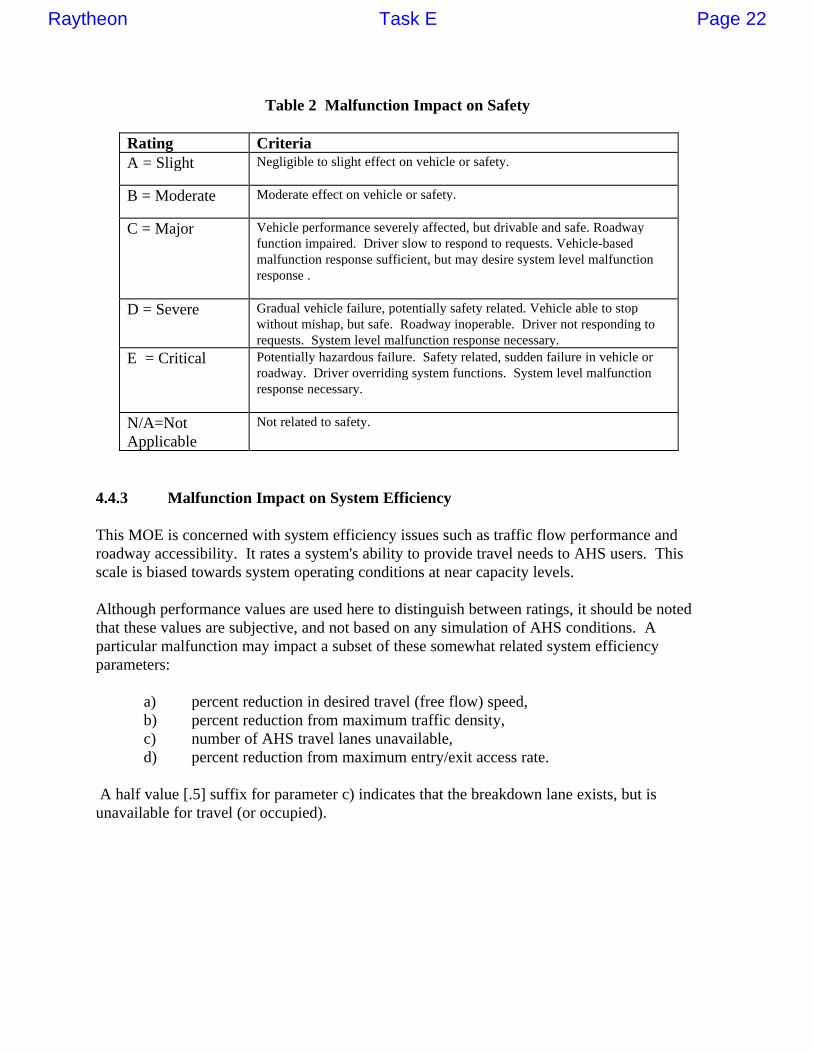
Table 2 Malfunction Impact on Safety
Rating CriteriaA = Slight Negligible to slight effect on vehicle or safety.
B = Moderate Moderate effect on vehicle or safety.
C = Major Vehicle performance severely affected, but drivable and safe. Roadwayfunction impaired. Driver slow to respond to requests. Vehicle-basedmalfunction response sufficient, but may desire system level malfunctionresponse .
D = Severe Gradual vehicle failure, potentially safety related. Vehicle able to stopwithout mishap, but safe. Roadway inoperable. Driver not responding torequests. System level malfunction response necessary.
E = Critical Potentially hazardous failure. Safety related, sudden failure in vehicle orroadway. Driver overriding system functions. System level malfunctionresponse necessary.
N/A=NotApplicable
Not related to safety.
4.4.3 Malfunction Impact on System Efficiency
This MOE is concerned with system efficiency issues such as traffic flow performance androadway accessibility. It rates a system's ability to provide travel needs to AHS users. Thisscale is biased towards system operating conditions at near capacity levels.
Although performance values are used here to distinguish between ratings, it should be notedthat these values are subjective, and not based on any simulation of AHS conditions. Aparticular malfunction may impact a subset of these somewhat related system efficiencyparameters:
a) percent reduction in desired travel (free flow) speed,b) percent reduction from maximum traffic density,c) number of AHS travel lanes unavailable,d) percent reduction from maximum entry/exit access rate.
A half value [.5] suffix for parameter c) indicates that the breakdown lane exists, but isunavailable for travel (or occupied).
Raytheon Task E Page 22
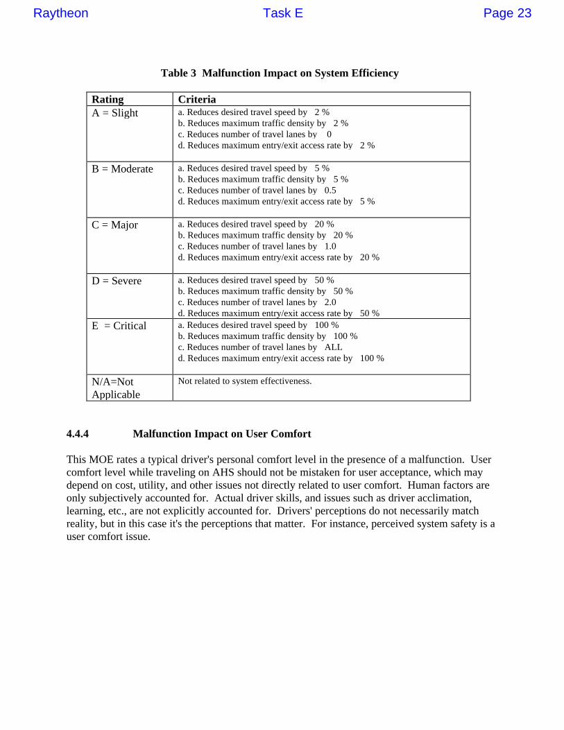
Table 3 Malfunction Impact on System Efficiency
Rating CriteriaA = Slight a. Reduces desired travel speed by 2 %
b. Reduces maximum traffic density by 2 %c. Reduces number of travel lanes by 0d. Reduces maximum entry/exit access rate by 2 %
B = Moderate a. Reduces desired travel speed by 5 %b. Reduces maximum traffic density by 5 %c. Reduces number of travel lanes by 0.5d. Reduces maximum entry/exit access rate by 5 %
C = Major a. Reduces desired travel speed by 20 %b. Reduces maximum traffic density by 20 %c. Reduces number of travel lanes by 1.0d. Reduces maximum entry/exit access rate by 20 %
D = Severe a. Reduces desired travel speed by 50 %b. Reduces maximum traffic density by 50 %c. Reduces number of travel lanes by 2.0d. Reduces maximum entry/exit access rate by 50 %
E = Critical a. Reduces desired travel speed by 100 %b. Reduces maximum traffic density by 100 %c. Reduces number of travel lanes by ALLd. Reduces maximum entry/exit access rate by 100 %
N/A=NotApplicable
Not related to system effectiveness.
4.4.4 Malfunction Impact on User Comfort
This MOE rates a typical driver's personal comfort level in the presence of a malfunction. Usercomfort level while traveling on AHS should not be mistaken for user acceptance, which maydepend on cost, utility, and other issues not directly related to user comfort. Human factors areonly subjectively accounted for. Actual driver skills, and issues such as driver acclimation,learning, etc., are not explicitly accounted for. Drivers' perceptions do not necessarily matchreality, but in this case it's the perceptions that matter. For instance, perceived system safety is auser comfort issue.
Raytheon Task E Page 23

Table 4 Malfunction Impact on User Comfort
Rating CriteriaA = Slight Tolerant. Minor system perturbations. Meets travel needs.
B = Moderate Annoyed. Uncomfortable perceptions, unexpected occurrences.
C = Major Aggravated. System unexpectedly requests user participation. System doesnot provide travel needs of user
D = Severe Hostile. User may attempt to manually override system.
E = Critical Traumatic. User in physical turmoil, becomes unglued, unlikely to usesystem again, and likely to be vigorously outspoken against its furtherdevelopment.
N/A=NotApplicable
Not related to user acceptance.
4.4.5 Secondary MOEs to Identify and Classify Malfunctions
Certain malfunctions may be more effectively classified with a more extensive list of MOEs.However, it is sufficient for this study to limit identification and classification of malfunctions toissues concerning malfunction likelihood, and impact on safety, system effectiveness, and usercomfort.
Other system-level MOEs are useful for evaluating normal operations in the AHS program, butthey play more of a secondary role in the analysis of malfunctions. MOEs in this categoryinclude cost, environmental impact, legal liability, and human factors feasibility. Malfunctionsthat have more than minimal impact on these secondary MOEs can be addressed for overall useracceptance on a case by case basis.
4.5 Components of Complete Malfunction Management Strategy
A complete malfunction management strategy includes malfunction prevention, detection, andresponse. Timeliness is also a critical factor that involves all components.
4.5.1 Malfunction Management Timeline
Incidents on the highway are seldom the result of a single, instantaneous malfunction. In manycases, severe incidents can be traced to a sequence of malfunctions which were either notnoticed, or ignored until too late. Quite often malfunctions could have been prevented, or atleast detected and responded to at an earlier stage, but cost or some other issue stood in the way.
In general, the longer the system is permitted to operate with malfunctions present, the greaterthe risk: both likelihood of occurrence and severity of the consequences tend to increase withtime. Of course, some malfunctions may be allowed to persist longer than others with little orno risk. Thus, the notion of a timeline associated with each potential malfunction is introduced.
The malfunction management timeline starts with prevention, before a loss in operationalfunctionality actually occurs. Malfunction prevention is discussed in the next section. Thetimeline extends through when the malfunction actually begins to occur. At this point, the
Raytheon Task E Page 24
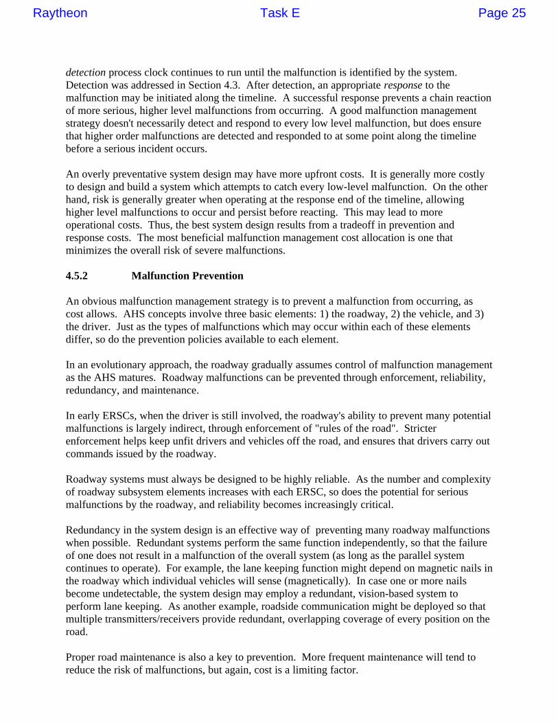
detection process clock continues to run until the malfunction is identified by the system.Detection was addressed in Section 4.3. After detection, an appropriate response to themalfunction may be initiated along the timeline. A successful response prevents a chain reactionof more serious, higher level malfunctions from occurring. A good malfunction managementstrategy doesn't necessarily detect and respond to every low level malfunction, but does ensurethat higher order malfunctions are detected and responded to at some point along the timelinebefore a serious incident occurs.
An overly preventative system design may have more upfront costs. It is generally more costlyto design and build a system which attempts to catch every low-level malfunction. On the otherhand, risk is generally greater when operating at the response end of the timeline, allowinghigher level malfunctions to occur and persist before reacting. This may lead to moreoperational costs. Thus, the best system design results from a tradeoff in prevention andresponse costs. The most beneficial malfunction management cost allocation is one thatminimizes the overall risk of severe malfunctions.
4.5.2 Malfunction Prevention
An obvious malfunction management strategy is to prevent a malfunction from occurring, ascost allows. AHS concepts involve three basic elements: 1) the roadway, 2) the vehicle, and 3)the driver. Just as the types of malfunctions which may occur within each of these elementsdiffer, so do the prevention policies available to each element.
In an evolutionary approach, the roadway gradually assumes control of malfunction managementas the AHS matures. Roadway malfunctions can be prevented through enforcement, reliability,redundancy, and maintenance.
In early ERSCs, when the driver is still involved, the roadway's ability to prevent many potentialmalfunctions is largely indirect, through enforcement of "rules of the road". Stricterenforcement helps keep unfit drivers and vehicles off the road, and ensures that drivers carry outcommands issued by the roadway.
Roadway systems must always be designed to be highly reliable. As the number and complexityof roadway subsystem elements increases with each ERSC, so does the potential for seriousmalfunctions by the roadway, and reliability becomes increasingly critical.
Redundancy in the system design is an effective way of preventing many roadway malfunctionswhen possible. Redundant systems perform the same function independently, so that the failureof one does not result in a malfunction of the overall system (as long as the parallel systemcontinues to operate). For example, the lane keeping function might depend on magnetic nails inthe roadway which individual vehicles will sense (magnetically). In case one or more nailsbecome undetectable, the system design may employ a redundant, vision-based system toperform lane keeping. As another example, roadside communication might be deployed so thatmultiple transmitters/receivers provide redundant, overlapping coverage of every position on theroad.
Proper road maintenance is also a key to prevention. More frequent maintenance will tend toreduce the risk of malfunctions, but again, cost is a limiting factor.
Raytheon Task E Page 25

Each vehicle on the highway adds more potential for malfunctions to the system. Malfunctionprevention from the vehicle side is achieved largely through building high reliability into eachvehicle, using as much redundancy in on-board systems as is feasible, and adhering to a programof regularly scheduled maintenance.
Maintenance is especially critical for each vehicle, since many components cannot be madehighly reliable, or backed up with redundant systems (e.g. steering). Even more than with theroadway, normal operation causes some vehicle parts to degrade over time. Some degradationis gradual (tire and brake wear), while in other cases, components fail with little or no warning.Another example are sensor lenses, which would have to be kept clean, just like a windshieldtoday.
Since vehicle maintenance responsibility (costs) will probably be assumed by vehicle owners,whose car care habits vary greatly, enforcement of vehicle standards by the roadway, asmentioned previously, will be very critical.
The driver retains a fair amount of control of the vehicle until later ERSCs. Even in the laterERSCs, he/she is not entirely without responsibility for the vehicle. In the early ERSCs, thedriver is depended on to perform such basic functions as lateral control, and even in the matureAHS envisioned for ERSC5, he/she is still somewhat involved in check-in (providing trip data)and check-out (re-assuming control of the vehicle when exiting onto non-AHS roads). Failure toperform driver responsibilities constitutes a malfunction. Therefore, driver education, training,and certification will be necessary for prevention in any malfunction management strategy.
4.5.3 Malfunction Responses: Managing Risk While Restoring Normal Operations
Once a malfunction has been detected and diagnosed, the system can select and implement anappropriate malfunction response.
Malfunction responses are sets of actions constructed from system element functions and theycan be separated into two categories:
• immediate responses and• supplemental responses .
In the presence of a malfunction, immediate responses are performed relatively promptly toalleviate current risk and instability to the system. Their implementation results in a system thathas transitioned from an unacceptable state to either normal operations (a desirable state) or tosome tolerable, yet still degraded state. If immediate responses do not reestablish normaloperations, then additional supplemental responses are performed. In some cases, an overallmalfunction response strategy may require immediate and supplemental responses while, forothers, immediate responses may be sufficient.
The two primary considerations for selecting an appropriate malfunction response are:• a response's ability to ultimately restore normal operations , and• a response's ability to minimize adverse transient effects during its implementation.
Raytheon Task E Page 26
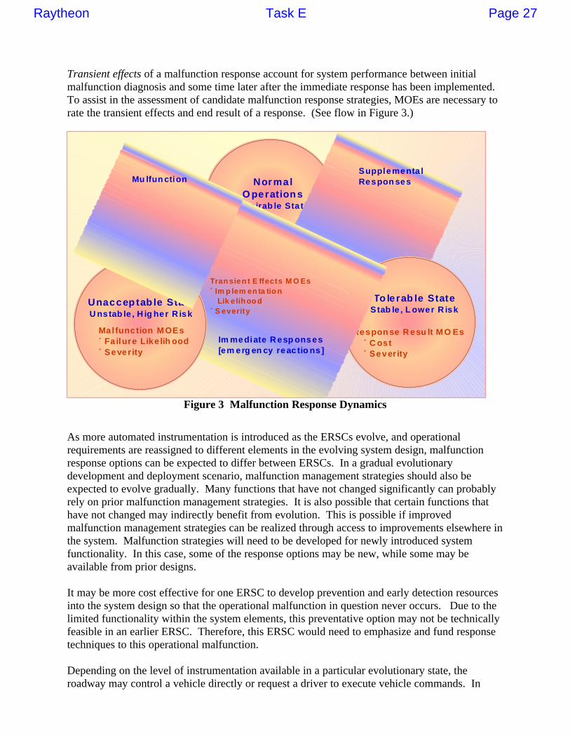
Transient effects of a malfunction response account for system performance between initialmalfunction diagnosis and some time later after the immediate response has been implemented.To assist in the assessment of candidate malfunction response strategies, MOEs are necessary torate the transient effects and end result of a response. (See flow in Figure 3.)
N o r m a l O p e r a t i o n s
D e s i r a b l e S t a t e
T o l e r a b l e S t a t e S t a b l e , L o w e r R i s k
R e s p o n s e R e s u l t M O E s ́ C o s t ́ S e v e r i t y
M a l f u n c t i o n M O E s ´ F a i l u r e L i k e l i h o o d ´ S e v e r i t y
U n a c c e p t a b l e S t a t e U n s t a b l e , H i g h e r R i s k
T r a n s i e n t E f f e c t s M O E s ´ I m p l e m e n t a t i o n L i k e l i h o o d ´ S e v e r i t y
I m m e d i a t e R e s p o n s e s [ e m e r g e n c y r e a c t i o n s ]
S u p p l e m e n t a l R e s p o n s e s M u l f u n c t i o n
Figure 3 Malfunction Response Dynamics
As more automated instrumentation is introduced as the ERSCs evolve, and operationalrequirements are reassigned to different elements in the evolving system design, malfunctionresponse options can be expected to differ between ERSCs. In a gradual evolutionarydevelopment and deployment scenario, malfunction management strategies should also beexpected to evolve gradually. Many functions that have not changed significantly can probablyrely on prior malfunction management strategies. It is also possible that certain functions thathave not changed may indirectly benefit from evolution. This is possible if improvedmalfunction management strategies can be realized through access to improvements elsewhere inthe system. Malfunction strategies will need to be developed for newly introduced systemfunctionality. In this case, some of the response options may be new, while some may beavailable from prior designs.
It may be more cost effective for one ERSC to develop prevention and early detection resourcesinto the system design so that the operational malfunction in question never occurs. Due to thelimited functionality within the system elements, this preventative option may not be technicallyfeasible in an earlier ERSC. Therefore, this ERSC would need to emphasize and fund responsetechniques to this operational malfunction.
Depending on the level of instrumentation available in a particular evolutionary state, theroadway may control a vehicle directly or request a driver to execute vehicle commands. In
Raytheon Task E Page 27

early ERSCs, various aspects of malfunction management may depend on driver participation.When appropriate or necessary, drivers may be expected to participate in prevention, detection,diagnosis, response selection, and response execution aspects of various malfunctionmanagement strategies. This introduces concerns about driver compliance to perform critical oreven routine aspects of early AHS travel.
The first step in determining malfunction responses is to construct or synthesize candidatemalfunction responses. These can be either immediate responses which minimize the transienteffects while reducing risk due to malfunction or supplemental responses to reestablish normaloperations.
Malfunction responses are sets of actions performed by system elements. Each system element(vehicle, driver, roadway) has specific functionality. At the time a malfunction is detected anddiagnosed, each element may have lost or degraded capability to perform one or more of itsnormal functions. The options available to the system when constructing a malfunction responseare thus limited by the system's remaining functionality.
It is advantageous to assemble multiple response options to a particular malfunction.Operational flexibility in a particular system design depends on the ability of system to adapt tothe situation. Thus, all feasible response options to a malfunction should be considered forevaluation.
Possible driver responses vary according to his/her physical and mental state, and according tothe allowed driver functionality in a particular ERSC. In earlier ERSCs, drivers may be requiredto play a more significant role in malfunction management. Compliance is a major concern fordriver responses.
Vehicle responses include acceleration, deceleration, maneuvers, and communication. The stateof a vehicle and its surrounding environment may restrict the vehicle functionality. Forexample, when the fuel is low, a vehicle may not be able to proceed three extra exits ahead.Vehicle response options differ from ERSC to ERSC.
The roadway will have more response options in later ERSCs when it has more informationavailable and more direct control over vehicles. In earlier ERSCs, it may only be able to issue acommand for a lower speed, whereas in later ERSCs it can slow down vehicles directly and steerthem away from incidents.
In the presence of a malfunction, immediate responses are performed relatively promptly toalleviate current risk and instability to the system. Their implementation results in a system thathas transitioned from an unacceptable state to either normal operations (a desirable state) or tosome improved, tolerable, yet still degraded state.
Each of several different immediate responses could produce equally safe outcomes, but havedifferent effects on system efficiency, user comfort, and implementation cost MOEs. While it isdesirable for an immediate response to minimize adverse transient effects, it should also avoidputting the system in a state where it is more difficult to restore normal operations. Thus,malfunction management strategy goes beyond selecting an immediate response which simplykeeps the system safe. For instance, a center median or a right shoulder breakdown lane may be
Raytheon Task E Page 28

equally suitable locations for temporarily storing a malfunctioning vehicle. Routing the vehicleto either location might be considered as equally attractive immediate responses. However, thisvehicle may be more easily serviced from the breakdown lane in a response to restore normaloperations. Therefore, routing this vehicle into the breakdown lane is the better immediateresponse.
For some malfunctions, it may be necessary for an immediate response to include emergencyreactions to prevent a serious consequence. For instance, if a vehicle experiences a sudden tireblowout, that event may automatically trigger the vehicle to execute an immediate controlledstop in order to reduce the risk of an accident. In addition, this emergency reaction may includea simultaneous notification to the driver that the vehicle is performing a controlled stop, and thatno participation is required from the driver.
Certain malfunctions might potentially severely impact the stability of vehicle dynamics andcontrol. If the decision time criticality (for detection and diagnosis) of these malfunctions mayrequire a response that is based on redundancy of this function in the vehicle.
When compared to supplemental responses, immediate responses to malfunctions can be moretime critical, shorter term solutions. They can range from requesting a driver to bring vehicle toa full stop and then immediately exit the system under manual control, to a vehicle automaticallyrouting vehicle around an in lane obstruction, to a roadway giving travel priority to anemergency medical response vehicle.
It is important to quickly, accurately, and reliably diagnose those malfunctions that may requiretime critical reactions as part of their overall malfunction response. Malfunction managementwill require that the AHS system have excellent models of itself, and computer resources capableto quickly evaluate current situations and near term consequences. In the absence of completeinformation from the diagnosis, the models should be conservative and substitute worst caseparameters.
While in the process of transitioning from an unacceptable state with a high risk of severeincident to a tolerable state with reduced risk, an immediate response may introduce factorswhich adversely impact system performance. Malfunction responses in a system as complex asAHS cannot be guaranteed to be isolated from the rest of the system. However, favorableimmediate response candidates avoid any likelihood of introducing additional risk to the system.
For example, a favorable end result may be realized from a response that removes amalfunctioning vehicle from the automated lane. However, this response may depend on thedriver to perform this exiting maneuver, especially in early evolutionary stages. Depending onthe surrounding conditions, different drivers cannot be expected to comply with this request inthe same way. Thus transient effects should reflect the system performance risks associated withthis potential noncompliance.
While an immediate response attempts to minimize the likelihood of an adverse impact onsystem operations, it is also important to factor in an immediate response's ability to reduce theseverity of a that impact should it occur anyway.
Raytheon Task E Page 29
The system needs to have a model of itself, based on the diagnosis, and quickly form aprediction of how severe the possible effects of responses under consideration could be. Couldthis response result in this vehicle being hit from behind, or does it have the potential to causean accident across several lanes? The former of these two scenarios might result in somedamage to two vehicles, with a negligible effect on the rest of the system, while the latter couldcreate serious damage and shut down several lanes for a period of time.
If immediate responses do not reestablish normal operations, then additional supplementalresponses may be required. Supplemental responses to malfunctions are typically more routine,longer term solutions compared to immediate responses. They can range from a driver travelingmanually to the next access point before entering the AHS (due to a malfunctioning entry/check-in facility), to a vehicle which is stopped in a breakdown lane automatically paging for towingservice, to a roadway disseminating information about an incident to upstream traffic beforeuninformed drivers attempt to alter their travel plans in a way that is adverse to the system.
Some supplemental responses may be more passive if the system is gradually returning tonormal operations on its own. An immediate response to an incident may residually reducesystem efficiency for a period of time under peak usage hours, but the system will be functioningnormally as soon as traffic volume reduces during off peak hours.Also, the system may temporarily alter the speed and headway parameters of vehicles inresponse to adverse weather. The system will return to normal operations as the adverse weatherconditions dissipate. The immediate response may reduce system efficiency, while thesupplemental response depends more on the weather than on system actions.
4.5.4 Selection of Best Malfunction Management Response Strategies
The systems engineering approach emphasizes the impact of malfunctions and their managementon overall normal operations. In this context, malfunction management is a high level,crosscutting discipline. Overall system performance related measures of effectiveness (MOEs)are used to assess a malfunction's impact on normal operations. Similarly, the MOEs necessaryto rate the worthiness of a particular malfunction response can be based on examining thesesame measures from a different perspective.
Unmanaged malfunction severity is measured by its impact on safety, system efficiency, anduser comfort. These same MOE categories are now used to assess a malfunction response'sability to restore normal operations. Malfunction likelihood of occurrence is not a factor inrating malfunction responses. However, two additional performance measures are introduced torate malfunction responses: the cost to implement a malfunction response and the likelihood ofa successfully implementing that response. Malfunction responses are assessed by two criteria:transient effects on the system caused by a response and the result of a response. Themalfunction response MOEs are summarized below.
The primary MOEs used to assess the results of a malfunction response are:• malfunction response impact on safety,• malfunction response impact on system efficiency,• malfunction response impact on user comfort, and .• malfunction response impact on user or system cost.
Raytheon Task E Page 30

It is desirable to categorize malfunction management responses according to how promptly andcompletely they restore normal operations, or at least some acceptable level of systemperformance. For AHS applications, a malfunction management response might be measuredaccording to system performance measures such as user cost, system cost, likelihood ofsuccessful implementation, and severity of impact on safety, system efficiency, and usercomfort.
Malfunction responses were separated into two categories: immediate responses andsupplemental responses. The ratings here focus on the immediate response portion of amalfunction response. It is meant to be independent of the transient effect of response ratings.It is a measure of how close the current state of the system is to normal operations. Immediatemalfunction responses that return the system to normal operations are desirable, and will berated highly in that category. The implementation cost of the response (either by the user or thesystem) is a relevant MOE for an immediate response. For some malfunctions, an immediateresponse is all that is necessary. However, for those responses that require, supplementalresponses, any additional costs associated with those supplemental responses is added to therating for overall implementation cost. Since supplemental responses are meant to restorenormal operations with little implementation risk, they are not rated for implementation successlikelihood or result of response effectiveness.
It is important to keep in mind that an immediate malfunction response must be rated on morethan just that response's ability to return the system to normal operations. For instance, thebenefits associated with a response that restores normal operations may be outweighed by theunacceptably high transient effect safety risks experienced during its implementation.
Severity of impact on normal operations is measured for both malfunctions and their responsesby the same MOEs with the same rating scales. They both are defined with respect to a normaloperations benchmark. The ratings of SLIGHT, MODERATE, MAJOR, SEVERE, andCRITICAL have the same meaning in both instances, however, the operating conditions thatillustrate their meaning may be different. For example, user comfort may receive aMODERATE rating when the driver is first notified of a minor vehicle malfunction unrelated tovehicle dynamics and control. The result of a malfunction response that places the vehicle in thebreakdown lane may receive the same MODERATE user comfort rating.
The MOE of malfunction response impact on system rates actual (not perceived) safety after animmediate malfunction response has been performed. The same ratings that defined malfunctionimpact on safety in Table 2 can be used here. This scale is biased towards pre-accident safetyconditions. Less than a highest rating implies that the system has not returned to normaloperations.
The MOE of malfunction response impact on system efficiency is concerned with systemefficiency issues such as traffic flow performance and roadway accessibility after the completionof a malfunction response. The same ratings that defined malfunction impact on systemefficiency in Table 3 can be used here. In addition to the four suggested categories to ratemalfunctions (i.e., impact on travel speed, traffic density, travel lanes, and entry/exit access), itmay be insightful to consider a malfunction response's impact on system efficiency via the timeduration needed to complete the malfunction response.
Raytheon Task E Page 31

The MOE of malfunction response impact on user comfort rates a typical driver's personalcomfort level after a malfunction response has been performed. The same ratings that definedmalfunction impact on user comfort in Table 4 can be used here. Additional considerations torate user comfort in a malfunction response include: a change in driver functionalresponsibility/participation required and any change to a user's travel plans.
The MOE of malfunction response implementation cost (to user or system) rates the cost of aimplementing a particular malfunction response. If the response is composed of immediate andsupplemental responses, then it represents the combined cost.
Table 5 Malfunction Response Implementation Cost (to User or System)
Effect CriteriaA = Slight Negligible cost to individual user, consistent with non-AHS costs.
No or negligible cost to system
B = Moderate User may consider AHS utility before paying additional expense$ / mile installation cost; $ / mile operational cost
C = Major Cost will limit AHS market penetration to 85 % of potential users$$ / mile installation cost; $$ / mile operational costReduces funding of other transportation programs.
D = Severe Cost will limit AHS market penetration to 50 % of potential users$$$ / mile installation cost; $$$ / mile operational costReduces funding of other taxpayer funded programs
E = Critical Affordable only to commercial, transit, fleet, and 10 % of generalpopulation. $$$$ / mile installation cost; $$$$ / mile operational costPolitical opposition to this level of funding would be strong
N/A=NotApplicable
Not related to cost
There could be other secondary MOEs to evaluate a malfunction response. A potentiallyrelevant MOE for malfunction response analysis relates to environmental issues. For instance, aresponse to a roadway malfunction that results in a system slowdown or shutdown for anextended period may result in increased vehicle emissions from heavy traffic in this vicinity.Air quality may degrade below acceptable levels. However, in this particular example, it isexpected that the system efficiency MOE provides enough correlation to air quality so thatenvironmental issues do not have to be separately rated. In other words, a response that resultsin major delays would be rejected due to system efficiency long before air quality issues becamea concern.
The primary MOEs used to assess transient effects of malfunction responses are:• likelihood of successful implementation (or rated below as the likelihood of failing to implement response),• transient effects on safety,• transient effects on system efficiency, and• transient effects on user comfort.
The risks associated with the transient effects of a malfunction response cannot be overlooked.The system is operating with less than full functionality, and until an appropriate response is
Raytheon Task E Page 32

successfully performed that puts the system in a more stable, lower risk state, the system ispotentially hazardous. Due to the anticipated short duration of an initial malfunction response,safety may play a more significant role in measuring the transient effects of impact on severitythan system efficiency or user comfort. The likelihood of being able to transition the systemfrom a high risk to lower risk state in the presence of a malfunction is also a very importantmeasure. For instance, the system may request that a malfunctioning vehicle pull over into thebreakdown lane at a time when it is already occupied (e.g., full of snow) or when no breakdownlane is available.
The MOE of transient effects of malfunction response on safety rates safety related transienteffects while an immediate malfunction response is being performed. The same ratings thatdefined malfunction impact on safety in Table 2 can be used here.
The MOE of transient effects of malfunction response on system efficiency is concerned withsystem efficiency transient effects while an immediate malfunction response is being performed.The same ratings that defined malfunction impact on system efficiency in Table 3 can be usedhere.
The MOE of transient effects of malfunction response on user comfort rates transient effects ofuser comfort while an immediate malfunction response is being performed. The same ratingsthat defined malfunction impact on user comfort in Table 4 can be used here.
For the sake of consistency in the ratings, where A is desirable and E is not, the transient effectMOE referred to as "likelihood of successfully implementing malfunction response" is rewordedas "likelihood of failing to implement malfunction response". The meaning is the same. Thelikelihood of failing to implement malfunction response rates the transient effect of the system'sability to perform a selected malfunction response. Table 6 presents the rating criteria for thisMOE. Situational factors such as traffic density or driver compliance may impact the likelihoodof failing to implement the preferred response. This scale is biased towards unlikelyoccurrences, i.e., it should be expected that most responses can be performed.
Raytheon Task E Page 33

Table 6 Likelihood of Failing to Implement Malfunction Response
Rating CriteriaA = Very Rare Under automated control within single vehicle or roadway element.
Response execution is independent of surroundings. Driver task that isnatural and trivial to all drivers.
B = Improbable Under automated control within several system elements. Responseexecution has little to do with surroundings. Driver task requires simple,routine interpretation and execution.
C = Remote Response includes an interaction with several system elements. Responseexecution is rarely sensitive to surroundings. Driver task requires moderate,but typically routine interpretation and execution.
D = Occasional Response includes moderate sequence of interactions with several systemelements. Response execution is occasionally sensitive to surroundings.Driver task requires moderate interpretation and execution of potentiallyunfamiliar tasks.
E = Probable Response includes complex interactions with multiple system elements.Response execution is highly sensitive to surroundings. Undesirable drivertask requires skilled interpretation and execution of potentially unfamiliartasks.
N/A=NotApplicable
Not a likelihood of failing to implement malfunction response issue.
4.6 Application of Malfunction Management Strategy
The ERSCs developed during the PSA can be used to illustrate malfunction management strategies forlongitudinal and lateral control.
An overview of the malfunction response selection process as applied to the ERSCs is given in figure4. A general understanding of a particular ERSC is developed from the description found in Volume 1(executive summary) of this report. A top level functional analysis of operational functions establishesdriver, vehicle, and roadway contributions to these operational functions. Malfunctions to thesecontributing elements are postulated and evaluated for potential impact on the system's normaloperations. Malfunction response options are then developed and evaluated for their ability to improvethe state of the system in the presence of a malfunction. Selection of the most appropriate response toa malfunction may depend on situational considerations. If no favorable assessments can be realizedfor a particular adverse malfunction, then a system redesign with potentially increased costs may benecessary.
Raytheon Task E Page 34

R 1 R 2 R 3 ́ ́ ́
D r i v e r C o n t r i b u t i o n t o F 1
D 1 D 2 D 3 ́ ́ ́
V e h i c l e C o n t r i b u t i o n t o F 1
V 1 V 2 V 3 ́ ́ ́
R 1 R 2 R 3 ́ ́ ́
D r i v e r C o n t r i b u t i o n t o F 1
D 1 D 2 D 3 ́ ́ ́
V e h i c l e C o n t r i b u t i o n t o F 1
V 1 V 2 V 3 ́ ́ ́
F U N C T I O N F 3
R o a d w a y C o n t r i b u t i o n t o F 1
R 1 R 2 R 3 ́ ́ ́
D r i v e r C o n t r i b u t i o n t o F 1
D 1 D 2 D 3 ́ ́ ́
V e h i c l e C o n t r i b u t i o n t o F 1
V 1 V 2 V 3 ́ ́ ́
F U N C T I O N F 2
R o a d w a y C o n t r i b u t i o n t o F 1
R 1 R 2 R 3 ́ ́ ́
D r i v e r C o n t r i b u t i o n t o F 1
D 1 D 2 D 3 ́ ́ ́
V e h i c l e C o n t r i b u t i o n t o F 1
F U N C T I O N F 1
F U N C T I O N F 4
´ ´ ´
M a l f u n c t i o n L i k e l i h o o d
L i k e l i h o o d o f S u c c e s s f u l
I m p l e m e n t a t i o n
M a l f u n c t i o n R e s p o n s e O p t i o n s f o r F 1 - V 2
0 • N o A c t i o n s T a k e n
1 • -
2 • -
3 • -
4 • -
O p e r a t i o n a l F u n c t i o n s
V 1 V 2 V 3 ́ ́ ́
M a l f u n c t i o n
S e v e r i t y & L i k e l i h o o d
M a l f u n c t i o n R e s p o n s e
C o s t t o I m p l e m e n t
M a l f u n c t i o n S e v e r i t y
T r a n s i e n t E f f e c t
P o t e n t i a l S e v e r i t y o f I m p a c t o n N o r m a l O p e r a t i o n s M O E s
S a f e t y S y s t e m • U s e r E f f i c i e n c y C o m f o r t
R e s p o n s e R e s u l t
Figure 4 Malfunction Response Selection Process
4.6.1 Malfunction Analysis of Longitudinal Control
Malfunctions associated with newly automated functions which contribute to automated longitudinalcontrol in ERSC1 are analyzed. Figure 5 pictorially presents the newly automated communicationpaths postulated for normal operations longitudinal control.
Traffic Density
Speed & Headway
ICC Radar Speed & Headway
AHS ñO.K.îAHS I.D. #
Brake Data
AHS Vehicle
Roadside Station
Traffic Management Center
AHS Lane
Traffic Incidents,Weather, etc.
(Increase Headway)
Figure 5 Communication Paths for Longitudinal Control in ERSC1
Raytheon Task E Page 35

4.6.1.1 Description of Normal Operations and Operational Functions
The system functionality available for longitudinal control of vehicles in ERSC1 is described inVolume 1 (Executive Summary) and Volume 4 (Lateral and Longitudinal Control Analysis) of thisreport. In ERSC1, longitudinal control is a semiautomated function. An intelligent cruise controldevice (ICC) in the vehicle maintains automated control of vehicle speed and headway as dictated byroadway commands. The driver is still responsible for obstacle detection and avoidance, emergencystops, and lateral control. Only a single travel lane is anticipated for this configuration. Figure 6describes individual functions residing in the roadway, vehicle, and driver elements of the system.
Under normal operations, the ICC maintains a constant time headway policy from any forwardvehicle. It receives commands from the roadway, it receives brake data from the forward vehicle,and it uses sensors to measure the forward vehicle's longitudinal motion.
´ Transmits ñAHS qualifiedî credentials to roadside stations
´ Receives speed and headway commands from roadside stations
´ Transmits brake data to following vehicle
´ Receives brake data from leading vehicle
´ Maintains constant time headway from forward vehicle (intelligent cruise control or ICC)
´ Traffic management center determines desired speed and headway characteristics for different sections of roadway
´ Traffic management center transmits speed and headway information to roadside stations
´ Roadside stations receive speed and headway information from traffic management center
´ Roadside stations transmit speed and headway information to AHS qualified vehicles
´ Roadside stations transmit traffic density characteristic to traffic management center
Vehicle Functions Vehicle Functions Roadway Functions Roadway Functions
Driver Functions Driver Functions
´ Option of increasing headway to more comfortable setting within range set by roadway
Figure 6 Normal Operations for Longitudinal Control (Speed and Headway Maintenance)in ERSC1
The traffic management center (TMC) synthesizes traffic density and entry demand information withenvironmental and incident information to arrive at speed and headway settings for the differentsections of the roadway. The TMC transmits speed and headway settings to each roadway section.
Raytheon Task E Page 36

Roadside monitor stations (RMS) along each section of road interpret the information sent from theTMC and send speed and headway inputs directly to the ICCs of passing vehicles. The distancebetween stations is a function of desired traffic flow control and may be more frequent at or near entryand exit nodes.
The vehicle's ICC receives speed and headway inputs from the roadway (the RMS). The vehicle canfine tune the headway setting if brake data is available from the forward vehicle. The ICC thenmaintains this constant time headway from the forward vehicle if it is traveling at less than or equal tothe desired speed. The headway is maintained by sensing the forward vehicle'sacceleration/deceleration and receiving brake data from the forward vehicle.
The driver may be given the option to slightly increase the headway to a more comfortable headingwithin a range sent by the roadway to the ICC. Slight variations of headway will not disrupt theefficiency of the system (this will be present anyway given the differences in vehicle capabilities andavailability of brake data). The driver will typically not be able to modify the speed setting (except foremergencies). A lower speed may be a more comfortable setting for some drivers, but since allupstream traffic in the single automated lane would be constrained by this speed, speed adjustments areassumed to not be allowed.
4.6.1.2 Potential Mulfunctions
Figure 7 highlights several possible malfunctions for each of the vehicle, roadway, and drivercomponents of the system that could impact longitudinal control.
Raytheon Task E Page 37

´ V1 ~ following vehicle not receiving brake data - or- lead vehicle not transmitting brake data
´ V2 ~ following vehicle loses use of its ICC but can still transmit brake data
´ V3 ~ leading vehicle loses use of its ICC and cannot transmit brake data -or- leading vehicle loses uses use of its ICC and following vehicle is not receiving brake data
Vehicle Malfunctions Vehicle Malfunctions
´ R1 ~ Traffic management center no longer providing correct speed and headway information to roadway stations in its section
´ R2 ~ Single roadway station no longer providing correct speed and headway information to passing vehicles
´ R3 ~ Single roadway station no longer providing traffic density information to control center
´ R4 ~ Single roadway station no longer receiving (or reading) ñAHS qualifiedî status from passing vehicles
Roadway Malfunctions Roadway Malfunctions
´ D1 ~ Driver enters lane in ñAHS unqualifiedî vehicle -or- having failed (or failed to perform) check-in test
´ D2 ~ Driver disengages (or overrides) roadway controlled ICC
´ D3 ~ Driver misadjusts roadway commanded ICC settings
Driver Malfunctions Driver Malfunctions
Compound Malfunctions Compound Malfunctions
´ C__ ~ combinations of simultaneously occurring vehicle, roadway, and driver malfunctions
Figure 7 Potential Malfunctions for Longitudinal Control in ERSC1
Figure 8 rates the malfunction likelihood and potential severity for the malfunctions described inFigure 7. They are categorized as vehicle, roadway, and driver malfunctions. An interpretation of theMOE rating scales is provided in Section 4.4.
Raytheon Task E Page 38

Vehicle Malfunctions
ERSC1 Malfunctions toLongitudinal Control
SystemEfficiency
SafetyUserComfort
V1 ~ Brake data
V2 ~ ICC failure
V3 ~ V1 + V2
R4 ~ Vehicle to station
Roadway MalfunctionsR1 ~ CC to stations
R3 ~ Station to TMC
R2 ~ Station to vehicle
Driver MalfunctionsD1 ~ No ICC ( non AHS or failed
D3 ~ Misadjusts
D2 ~ Disengages
Potential Effect On Normal
MalfunctionLikihood
A AA
A
AAAA
AB
B
CCCC
CC
CC
C
C
AAA
EE
E E
EE
Vehicle
Roadway
BCD
CBA
ABCB
ECritical
DSevere
CMajor
BModerate
ASlight
EProbable
DOccassional
CRemote
BImprobabl
AVery rare
Likelihood:
Severity or Cost:
Figure 8 Potential Malfunction Impact on Longitudinal Control in ERSC1
A brief description of potential impact on normal operations, potential severity of result if unmanaged,malfunction likelihood, detection methods, and response options for each of these malfunctions is nowdiscussed. An assessment of these response options is given in Section 4.5.3 and 4.5.4.
VEHICLE MALFUNCTIONS
V1 ~ Following vehicle not receiving brake data-or- lead vehicle not transmitting brake data
Potential impact on normal operations:• Vehicle travels with unsafe headway (spacing). ICC still operational, so no impact on system
efficiency. Driver may be unaware of malfunction, so user comfort remains high.
Potential severity of result if unmanaged:• Collision if emergency braking required while vehicle at unsafe headway
Raytheon Task E Page 39

Malfunction likelihood:• Remote. For example, high reliability in line-of-sight transmitting and receiving
communication components, but only one component needs to fail or be blocked by someobstruction ( dirt, etc.).
Detection:• Following vehicle does not receive data from forward vehicle• Forward vehicle display reports transmitter malfunction.
Responses:• Following vehicle ICC increases headway behind forward vehicle• Following vehicle continues with same speed and headway
V2 ~ Following vehicle loses use of its ICC but can still transmit brake data.Potential impact on normal operations:
• Vehicle travels with unregulated headway (spacing). Lack of ICC control, so system efficiencydegraded. Driver may be unaware of malfunction, so user comfort remains high.
Potential severity of result if unmanaged:• Collision if emergency braking required while vehicle at unsafe headway
Malfunction likelihood:• Improbable. Criticality of ICC component results in high possible reliability. May be rarely
effected by environmental interference.
Detection - for vehicle following failed vehicle:• RMS detects vehicle without "AHS qualified" capability and informs following vehicle
(transmission to ICC, warning light to driver)• Following vehicle ICC senses erratic velocity/acceleration profile of failed leading vehicle now
under manual longitudinal control (application of knowledge based systems)• Failed vehicle communicates loss of ICC to following vehicle (would not want to rely on
presence of vehicle to vehicle communication - see situation V3)Detection - for failed vehicle:
• In vehicle display reports ICC malfunction and loss of "AHS qualified" status to driver• Driver detects ICC malfunctioning (or using out of bounds speed and/or headway values) and
manually overrides. Loss of "AHS qualified" status is reported to driver.
Response - for vehicle following failed vehicle:• ICC significantly increases headway behind vehicle 2 and may enter into a "soft" following
mode to avoid fluctuations due to manual driver in forward vehicleResponse - for failed vehicle:
• Driver assumes longitudinal control responsibilities and should increase distance from forwardvehicle. Driver must exit automated lanea) as soon as safe exit can be performed in a continuous entry/exit configurationb) at the next exit ramp in a dedicated entry/exit configuration.
Raytheon Task E Page 40

V3 ~ leading vehicle loses use of its ICC and cannot transmit brake data -or-leading vehicle loses ICC and following vehicle is not receiving brake data
Potential impact on normal operations:• Vehicle travels with unregulated headway (spacing). Lack of ICC control, so system efficiency
degraded. Driver may be unaware of malfunction, so user comfort remains high.
Potential severity of result if unmanaged:• Collision if emergency braking required while vehicle at unsafe headway
Malfunction likelihood:• Very Rare. Simultaneous malfunctions must occur.
Detection - for vehicle following failed vehicle:• Same techniques as in V1 & V2 (except failed vehicle can not inform following vehicle of ICC
failure)Detection - for failed vehicle:
• Same techniques as in V1 and V2
Response - for vehicle following failed vehicle:• Same as V2Response - for failed vehicle:• Same as V2
ROADWAY MALFUNCTIONS
R1 ~ Traffic management center (TMC) no longer providing correct speed andheadway information to roadside monitor station (RMS) in its section.
Potential impact on normal operations:• No way for vehicles to get correct information in this section of road. Multiple vehicles travel
with incorrect speed and headway. Unacceptably severe safety and system efficiency concerns.If driver is unaware, user comfort remains high. Otherwise, very worrisome.
Potential severity of result if unmanaged:• Multiple collisions if emergency braking required while vehicles at unsafe headways
Malfunction likelihood:• Very Rare. TMC transmitters will likely have reliability equivalent to commercial radio
stations. System may operate so that each RMS has access to two independent TMCs forredundant coverage.
Detection:• RMS does not receive communication of speed and headway information from the TMC, or
initial check of received information shows it to be out of bounds for AHS operations. Inaddition the TMC would use other lines of communication to inform affected stations of theproblem.
Response:
Raytheon Task E Page 41

• RMS would revert to default settings. These settings could consider time of day, permit moredriver adjusting, and be station dependent (e.g., stations near entry and exit points wouldtransmit different speed and headway commands than stations in between nodes). Thesesettings would not result in as efficient of a system but would result in a safe system. Adetermination in an emergency like this has to be made as to whether the roadway can actuallyaid in system efficiency and safety and what additional responsibility if any should be given tothe driver. In the most extreme case the automated lane would return to what is essentially amanual lane with driver aids.
R2 ~ Single RMS no longer providing correct speed and headway information to passingvehicles.Potential impact on normal operations:
• RMS not transmitting up to date recommended values.
Potential severity of result if unmanaged:• Multiple collisions if emergency braking required while vehicles at unsafe headways
Malfunction likelihood:• Moderate. There are expected to be many RMSs along AHS roadways. Their close proximity
to the roadside, exposure to environment, continuous use, etc. may yield an occasional failure.
Detection - for vehicles:• Vehicles do not receive speed and headway inputs from the roadway or an initial check of
received inputs show them to be out of bounds for AHS operations.Detection - for roadway:
• Station diagnostic equipment detects transmitter malfunction.
Response - for vehicles:• If no new inputs or errant inputs then the vehicles maintain current speed and headway, and
await receipt of new instructions at next RMS.Response - for roadway:
• RMS informs TMC of its malfunctioning state. If roadway diagnostics does not reveal theproblem for some reason then a routine inspection will or a passing vehicle may call it in.
R3 ~ Single RMS no longer providing traffic density information to TMCNon critical malfunction -
• Traffic flow control only slightly degraded by less efficient use of speed and headway settingsand no safety concern. Maintenance crew dispatched to station after TMC stops receivingtransmissions
R4 ~ Single RMS no longer receiving "AHS qualified" status from passing vehicles.Non critical malfunction -
• Roadway detection and enforcement of non compliant vehicles in the automated lane requires aslightly longer time. A potential safety concern since unsafe speed and/or headway may be
Raytheon Task E Page 42

maintained for a longer time, however distance between RMSs is relatively small and detectionwill occur at RMS. Reliable manufacturing of the stations with prompt repair aftermalfunctioning should be sufficient.
DRIVER MALFUNCTIONS
D1 ~ Driver enters lane in "AHS unqualified" vehicle-or- having failed (or failed to have performed) check-in test
Detection - for vehicle:• Vehicle will not be operating with "AHS qualified" status
Detection - for driver:• If the driver is not aware that the vehicle is traveling in the automated lane without currently
being "AHS qualified" (in vehicle display will show this but driver may not be payingattention) the roadway will alert the driver after passing a station (e.g., could be something asbasic as flashing red lights).
Detection - for roadway:• Roadway station does not receive "AHS qualified" signal from the vehicle
Response - for driver:• Driver must exit the automated lane immediately or be subject to prosecutionResponse - for roadway:• Responsible for enforcing the requirement that the vehicle leave the auto lane.
D2 ~ Driver disengages (or overrides) roadway controlled ICCDetection - for vehicle:
• Vehicle's ICC has changed modes to accept driver and not roadway commandsDetection - for driver:
• In vehicle display warns driver to re-engage roadway controlled ICC mode or "AHS qualified"status will be revoked
Detection - for roadway:• Roadway station does not receive "AHS qualified" signal from the vehicle
Response - for vehicle:• "AHS qualified" status is revoked
Response - for driver:• Driver must re-engage roadway controlled ICC mode immediately or exit the automated lane
Response - for roadway:• Responsible for enforcing the requirement that the vehicle leave the auto lane if its ICC is no
longer accepting roadway commands
D3 ~ Driver misadjusts roadway commanded ICC settings.Detection - for vehicle:
• Vehicle determines that its current speed or headway is out of the legal bounds currently beingsent by the roadway
Detection - for driver:
Raytheon Task E Page 43

• In vehicle display warns driver to readjust the ICC settings or "AHS qualified" status will berevoked
Detection - for roadway:• Roadway station does not receive "AHS qualified" signal from the vehicle
Response - for vehicle:• ICC may not allow driver to change settings outside of roadway limits without the driver
disengaging from roadway controlled ICC mode (see D2) to avoid accidental misadjustmentsResponse - for driver:
• Driver must readjust ICC settings to be within the roadway commanded limits or leave the autolane
Response - for roadway:• Responsible for enforcing the requirement that the vehicle leave the auto lane if its ICC is being
misused
4.6.1.3 Assessment of Malfunction Response Options (Transient Effects andResponse Results)
Figure 9 highlights the relative effectiveness of several potential response options to a longitudinalcontrol malfunction (brake data unavailable) in the partially automated ERSC1. The same responseoptions are rated under two different operating situations. In one case, the malfunction occurs in afacility with designated entry/exit points, i.e., AHS access occurs at specific points along the roadway.The other case is a malfunction on a facility with continuous entry/exit points so that transitionsbetween AHS and non-AHS lanes can occur anywhere along the roadway.
Transient Effects Result of Response
Malfunction V1 ~ Brakedata unavailable
Safe- ty
Sys.Eff.
UserCom
Safe- ty
Sys.Eff.
UserCom
Likeli-hood
Cost
Malfunction Responses ~ Designated Entry /
3 ~
2 ~ Exit lane
1 ~ Increase headway
ø ~ No action
Malfunction Responses ~ Continuous Entry /
3 ~
2 ~ Exit lane
1 ~ Increase headway
ø ~ No action
AAB
A A AAA
AA
AA
AA
AA A AA
A A
BE
C
C A
CE
A AAA
A AAA
AAAACCCC
AAAA
ECritical
DSevere
CMajor
BModerate
EProbable
DOccassional
CRemote
BImprobable
ASlight
AVery rare
Severity or Cost:
Likelihood:
Figure 9 Potential Malfunction Responses for Longitudinal Control Malfunction V1 inERSC1
Raytheon Task E Page 44

Response option __ (no action)Transient effects and response results in a facility with designated entry/exit access points
• When braking capability of leading vehicle is unknown, it is possible that it could brake in ashorter distance than the following vehicle. If an emergency braking situation arises, theleading vehicle could stop before the following vehicle comes to a complete stop, and anaccident would result.
Transient effects and response results in a facility with continuous entry/exit access points• Same as in designated entry/exit access point case. No difference due to roadway
configuration.
Response option 1 (increase headway)Transient effects and response results in a facility with designated entry/exit access points
• When braking capability of leading vehicle is unknown, increasing headway to some defaultsafe value should be a sufficient response to this malfunction. It restores safety. Since vehicletravel speeds should be about the same, the added gap between two vehicles (not all vehicles)will have an inconsequential impact on system efficiency. Also, cost is minimal since responseis generated with existing system functionality. There are no significant transient effects fromthis response.
Transient effects and response results in a facility with continuous entry/exit access points• Same as in designated entry/exit access point case. No difference due to roadway configuration.
Response option 2 (exit lane)Transient effects and response results in a facility with designated entry/exit access points
• This response results in the restoration of safety and system efficiency, but it is inconvenient tothe user who must exit. There may be an associated system cost to monitor/enforce vehicledeparture from facility. In a designated facility, safety may be a concern if decision occurs nearan exit facility and the response time is minimal.
Transient effects and response results in a facility with continuous entry/exit access points• Same results as for designated case except that cost may be still higher due to more difficult
verification/enforcement in facility where vehicles access to system does not occur at specificcheck points. Vehicle could exit and then reenter a short while later. There are more transientresponse concerns in a continuous entry/exit facility. Vehicle/driver may attempt to exit, butcannot find a suitable gap in the manual lanes. Vehicle may try to speed up, slow down, orloiter in lane while trying to exit.
Figure 10 highlights the relative effectiveness of several potential response options to a longitudinalcontrol malfunction (ICC failure) in the partially automated ERSC1. The same response options arerated under two different operating situations. In one case, the malfunction occurs in a facility withdesignated entry/exit points, i.e., AHS access occurs at specific points along the roadway. The othercase is a malfunction on a facility with continuous entry/exit points so that transitions between AHSand non-AHS lanes can occur anywhere along the roadway.
Raytheon Task E Page 45

Transient Effects Result of Response
Malfunction V2 ~ ICC Failure
Safe- ty
Sys. Eff.
User Com
Safe- ty
Sys. Eff.
User Com
Likeli-hood
Cost
Malfunction Responses ~ Designated Entry / Exit
3 ~
2 ~ Exit lane
1 ~ Increase headway
ø ~ No action
Malfunction Responses ~ Continuous Entry / Exit
3 ~
2 ~ Exit lane
1 ~ Increase headway
ø ~ No action
E Critical
D Severe
C Major
B Moderate
A Slight
E Probable
D Occassional
C Remote
B Improbable
A Very rare
Likelihood:
Severity or Cost:
A
A
B
A
C
A
C C C
A A A A A A
A A A A A A
A A A
A A E B
A
A
A
A
C
C
C
E
A
A
C E
A
A C C C
E
A A
Figure 10 Potential Malfunction Responses for Longitudinal Control Malfunction V2 in ERSC1
Response option __ (no action)Transient effects and response results in a facility with designated entry/exit access points
• ICC operation is critical to safe efficient operation. User comfort may be satisfied if failure hasnot resulted in noticeable vehicle dynamics deviations.
Transient effects and response results in a facility with continuous entry/exit access points• Same as in designated entry/exit access point case. No difference due to roadway
configuration.
Response option 1 (increase headway)Transient effects and response results in a facility with designated entry/exit access points
• Increasing headway to some default safe value is an insufficient response to this malfunction.While safe clearance to malfunctioning vehicle improves safety, vehicle is still a hazard toitself. Also, cost is minimal since response is generated with existing system functionality.There are no significant transient effects from this response.
Transient effects and response results in a facility with continuous entry/exit access points• Same as in designated entry/exit access point case. No difference due to roadway
configuration.
Response option 2 (exit lane)Transient effects and response results in a facility with designated entry/exit access points
• This response results in the restoration of safety and system efficiency, but it is inconvenient tothe user who must exit. There may be an associated system cost to monitor/enforce vehicledeparture from facility. In a designated facility, safety may be a concern if decision occurs nearan exit facility and the response time is minimal.
Raytheon Task E Page 46

Transient effects and response results in a facility with continuous entry/exit access points• Same results as for designated case except that cost may be still higher due to more difficult
verification/enforcement in facility where vehicles access to system does not occur at specificcheck points. Vehicle could exit and then reenter a short while later. There are more transientresponse concerns in a continuous entry/exit facility. Vehicle/driver may attempt to exit, butcannot find a suitable gap in the manual lanes. Vehicle may try to speed up, slow down, orloiter in lane while trying to exit.
4.6.2 Malfunction Analysis of Lateral Control in ERSC3
Malfunctions associated with newly automated functions which contribute to automated lateral controlin ERSC3 are analyzed in the following subsections.
4.6.2.1 Description of Normal Operations and Operational Functions
The system functionality available for lateral control (lane keeping) of vehicles in ERSC3 is describedin Volume 1 (Executive Summary) and Volume 4 (Lateral and Longitudinal Control Analysis) of thisreport. In ERSC3, lateral control is an automated function. Lane keeping is a time critical function: acomplete loss in its functionality results in a highly unacceptable state due to safety concerns. For thisreason, redundancy is built into the design. Two independent systems track the vehicle in the lane: asystem which is guided by magnetic nails embedded in the road, and another completely independentsystem which optically senses lane markers. Only a single travel lane is anticipated for thisconfiguration. Figure 11 describes how individual operational functions are allocated to the roadway,vehicle, and driver elements of the system.
´ Operate optical-based lane tracking system (e.g., luminescent tape lane markers)
´ Operate electromagnetic-based lane tracking system (e.g., magnetic nail lane markers)
´ Receive lane characterization and condition information from roadway stations
´ Process data for corrective steering (and compensatory speed & headway) commands
´ Execute controlled lateral maneuvers
´ Transmit vehicle ID, lane keeping status, and lane marker map preview to following vehicle
´ Perform traditional controlled vehicle travel functions
Vehicle Functions Vehicle Functions
´ Provide unobstructed view to lane markers
´ Roadway stations transmit : - roadway segment previews
[distance to and curvature of upcoming turns] and maximum ïpostedÍ speed zones
- adjusted guidance parameters based on current roadway and environmental conditions
- driver alerts to current lane marker conditions (e.g., gaps in coverage), vehicle breakdowns, manual control requirements, roadway repair crew activity, etc.
Roadway Functions Roadway Functions
´ Selects appropriate level of ïdriver attentivenessÍ which determines AHS accessibility, vehicleÍs headway policy, and potential driver contributions to malfunction management strategies
´ Monitors lane keeping function and takes appropriate actions when necessary
Driver Functions Driver Functions
Figure 11 Normal Operations for Lateral Control (Lane Keeping) in ERSC3
4.6.2.2 Potential Malfunctions
Raytheon Task E Page 47

Figure 12 highlights several possible malfunctions for each of the vehicle, roadway, and drivercomponents of the system that could impact lateral control in ERSC3.
´ V1 ~ failed optical guidance system
´ V2 ~ failed electromagnetic guidance system
´ V3 ~ no reception of roadway station info.
´ V4 ~ unreliable lateral control commands
´ V5 ~ failed lateral guidance control actuators
´ V6 ~ no transmission of vehicle ID, lane keeping status or lane marker map preview to following vehicle
´ V7 ~ breakdown in traditional controlled vehicle travel functions
´ V8 ~ V1 occurs while V2 condition exists
Vehicle Malfunctions Vehicle Malfunctions
´ R1 ~ missing, nonfunctional, or obstructed view to luminescent tape lane markers
´ R2 ~ missing, nonfunctional, or obstructed access to magentic nail markers
´ R3 ~ Roadway station fails to transmit roadway segment previews (and turning speeds)
´ R4 ~ Roadway station fails to transmit roadway and environmental condition dependent guidance parameters
´ R5 ~ Roadway station fails to transmit current status upcoming roadway segment conditions
´
Roadway Malfunctions Roadway Malfunctions
´ D1 ~ selected level of ïdriver attentivenessÍ is too high
´ D2 ~ selected level of ïdriver attentivenessÍ is too low
´ D3 ~ does not appropriately respond when informed that lateral control function is degraded or has failed
Driver Malfunctions Driver Malfunctions
Compound Malfunctions Compound Malfunctions
´ M__ ~ combinations of simultaneously occuring vehicle, roadway, and driver malfunctions
Figure 12 Potential Malfunctions for Lateral Control in ERSC3
Figure 13 rates the malfunction likelihood and potential severity for the malfunctions described inFigure 12. They are categorized as vehicle, roadway, and driver malfunctions. An interpretation of theMOE rating scales is provided in Section 4.4.
Raytheon Task E Page 48

Potential Effect On Normal Operations
ERSC3 Malfunctions to Lateral Guidance Control
System Efficiency
SafetyUser Comfort
V1 ~ optical guidance system
V2 ~ E-mag guidance system
V3 ~ no roadway station info.
V4 ~ lateral guidance controller
R4 ~ roadway & envr. conditions
V5 ~ lateral control actuators
V6 ~ commo to following vehicle
V7 ~ mechanical functions
V8 ~ V1 while V2 exists
R5 ~ driver alerts
Roadway Malfunctions
R1 ~ optical tape lane markers
R3 ~ roadway segment preview
R2 ~ magnetic lane markers
Driver Malfunctions
D1 ~ ïattentivenessÍ too high
D2 ~ ïattentivenessÍ too low
D3 ~ no response to request
C Major
B Moderate
A Slight
E Critical
D Severe
E Probable
D Occassional
C Remote
B Improbable
A Very rare
Likelihood:
Severity or Cost:
Malfunction Likelihood
B
B
C
E
E
D E
E
B
B
B B
B
B
E
E
E
E
A
A
A
C C C C
C D
D
B A
E
A
E
B
A
D
E
C
D
A
E
E
C E
E
B
C B
A B
B C
C
D
C A
A
A A
A A
B
A
A
Vehicle Malfunctions
Figure 13 Potential Malfunction Impact on Lateral Control in ERSC3
4.6.2.3 Assessment of Malfunction Response Options to Lateral Control Malfunctionsin ERSC3 (Transient Effects and Response Results)
Figure 14 highlights the relative effectiveness of several potential response options to a lateral guidancecontrol malfunction in the partially automated ERSC3. In this case, the postulated malfunctionaddressed is to the optical guidance system in the vehicle which tracks lane reference markers and isresponsible for lane keeping in this ERSC. Lane keeping is a time critical function: a complete loss inits functionality results in a highly unacceptable state due to safety concerns. For this reason,redundancy is built into the design. It is assumed that the other postulated lane keeping system(vehicle tracking magnetic nails imbedded in road surface) is fully functional at the time of the opticalsystem failure.
Raytheon Task E Page 49

Transient Effects
Malfunction Management Strategies
Malfunction V1 ~ failed optical guidance system
6 ~
Safe- ty
Sys. Eff.
User Com
Safe- ty
Sys. Eff.
User Com
Likeli-hood
Result of Response
Cost
5 ~ Automated reduced speed
4 ~ Exit automated lane
3 ~ Manual steering (ERSC1)
2 ~ Redundant component
1 ~ Stop vehicle & tow
ø ~ No action
C Major
B Moderate
A Slight
E Critical
D Severe
E Probable
D Occassional
C Remote
B Improbable
A Very rare
Likelihood:
Severity or Cost:
B A B C
B B
E A C B
C
C
A
D D
E
B
B
C A
B
C
C
C
E E
E
A A
E
E D
A
C
C
A A
A
B
A A A
A
C C
B
B
A
Figure 14 Potential Malfunction Responses for Lateral Control Malfunction V1 inERSC3
Response option __ (no action)Response result:
• Response option _ (no action) may result in a system could otherwise operate quite benignlywith the magnetic tracking system for an indefinite period of time. However, the system isunacceptably dependent on a single lane keeping system, and there would be serious safetyconcerns if the vehicle's magnetic nail tracking system failed or if the nail markers weresomehow obstructed from the tracking system.
Transient effect:• There would be few immediate serious transient effects from this non response, except that
knowledge of the malfunction may make some drivers engage in undesirable responses.
Response option 1 (stop vehicle and tow)Response result:
• Response option 1 (stop vehicle and tow) prevents the malfunction from causing a safetyconcern and eventually removes the problem from the system. The response result restoresnormal operations to the system at the expense of inconveniencing the malfunctioning vehicle'spassengers (travel plans not satisfied) and the minor system cost of dispatching a tow truck tothe scene.
Transient effect:• While the response result may be an acceptable option, the transient effects of this response in a
heavy traffic environment may be intolerable. ERSC3 is depicted as a single laneconfiguration. A stopped vehicle in the lane for any significant time would critically impactsystem efficiency and the user comfort of many. Such a disturbance to the system couldintroduce safety concerns unrelated to the original malfunction.
Response option 2 (switch over to redundant component)Response result:
Raytheon Task E Page 50
• Response option 2 (switch over to redundant component) which restores full normal operationsis a desirable option as long as it is not overly costly to the vehicle design.
Transient effect:• There may be some transient effects concerns. Likelihood of successful implementation of this
response may be a minor concern if is possible that same failure could exist in backup part.The actual switch over to the backup component could introduce minor transients with usercomfort and safety.
Response option 3 (manual steering, like falling back to ERSC1)Response result:
• The end result of response option 3 (manual steering, like falling back to ERSC1) is a singlevehicle performing manual lane keeping in a system otherwise occupied by vehicles underautomated lane keeping control. This requires the driver to perform a function that he or shehad not planned on, but still allows them to realize their travel needs. Sufficient safety shouldbe gained with an altered speed and headway policy for this vehicle, and this could adverselyimpact system performance if the current ERSC3 travel conditions allowed for fast travel athigh traffic densities.
Transient effect:• This response has severe safety concerns in the transient response of implementing the strategy.
The transient effects of this response are a concern because the driver may not be immediatelyfit to respond to the system request to resume manual control. This issue and the uncertainty ofdriver compliance rates this a severe user comfort concern. Also, safety is a severe concernhere. Under normal check-out operations, transition to manual control happens at plannedtimes and locations known to the system and driver. In this case, the notice could be rathersudden, and after transition the vehicle stays in the lane.
Response option 4 (exit automated lane)Response result:
• Response option 4 (exit automated lane) yields similar results as response option 1. In this casethough, it is less costly to the system for the vehicle/driver to exit without further assistancefrom the roadway. User comfort is still unacceptable due to unsatisfied travel plans.
Transient effect:• The transient effects associated with executing this response may be tolerable. If the
vehicle/driver can exit relatively promptly under their own control, safety risk (which growswith time in this case) should not be too serious. This response is considered to be less timecritical than response option 3, so user comfort and system efficiency impact during thetransition are expected to be tolerable. There may be a concern with the vehicle/drivercompliance or ability to exit the system on a short notice. For instance, traffic congestion atexit may prevent or delay the response's implementation.
Response option 5 (automated reduction in vehicle speed)Response result:
• Response option 5 (automated reduction in vehicle speed) may restore safety to the system ifspeed is sufficiently reduced to make reliance on the magnetic system alone is more reliableand tolerable (e.g., if a missed track occurs, there is sufficient reaction time to bring vehicle toimmediate stop).
Transient effect:
Raytheon Task E Page 51

• However, in a single lane deployment, this results in an unacceptable impact on systemefficiency, user comfort, and the comfort of any unlucky user who managed to get stuck behindthis nuisance.
5.0 CONCLUSION
The following key findings and conclusions have been reached concerning AHS MalfunctionManagement and Analysis.
• A complete set of malfunction management strategies will balance the desire to have thesystem perform without failing with the need to respond to failure when it inevitablyoccurs, within the constraints imposed by safety, system efficiency, user comfort, andcost.
• A complete evaluation of malfunction management options includes cost/benefittradeoffs between the preventative reduction in the probability of malfunction occurenceand the responsive reduction in the severity of the malfunction given its occurrence.
• The time criticality and potential severity of certain malfunctions preclude dependenceon system responses once the malfunction occurs. In these instances the malfunctionmanagement strategy must rely on built in redundancies either in the vehicle or roadwayinfrastructure.
• Reliance on the driver (perceptions, capabilities, predictability, and accountability) formalfunction prevention, detection, diagnosis, and execution of management tasks is arisk/challenge.
• Certain malfunctions do not lend themselves to a straight forward methodologicalbreakdown. The complexity of the AHS assures that malfunction management will be acontinuously evolving process.
• The transient effects of a particular management response may outweigh the benefitsgained by its implementation.
• The systems engineering approach of functional analysis provides a complete frameworkaround which to define the normal operations of an AHS.
• The best method for identifying a malfunction is for the identification process to occur asclose to the source as possible. This is beneficial in that it increases the probability ofdetection and diagnosis while reducing the time from when the event occurs to when it isdetected.
• Based on their criticality and reliability, functions need not have the same frequency fordetecting failures (polling). Continuous monitoring can be accomplished through the useof built in test (BIT). Diagnostic tests can be programmed into the system to occur atappropriate or opportune times such as engine start up. Regular inspections of
Raytheon Task E Page 52

subsystems can also be scheduled. Additionally, observations of operational deviationscan be indicative of malfunctions that were not directly detected by diagnostic means.For instance, a vehicle's malfunctioning speed controller could be observed by the driver,another vehicle, or even the roadway.
• The appropriate MOEs to evaluate the merit of individual managing strategies are safety,efficiency of the system, user comfort, and cost. Safety should include a reduction in thelikelihood of an accident and a reduction in the severity of an accident (personal injuryand property damage). The system efficiency must include the reduction in the likelihoodof disruption to the system and a reduction in the effects on the system given adisruption. User comfort rates the desirability of the service provided from theperpective of a typical potential system user. Cost includes the additional cost requiredto implement the strategy considering both vehicle and infrastructure. This last factorcould impact other areas such as market penetration. Other secondary MOEs exist, butmany are less quantifiable and result from improvements concerning the primary MOEs(i.e., improved system efficiency also results in improved air quality and userdesirability). Further, caution must be exercised when developing the MOEs that sight ofthe key parameters effecting the system is not lost and that so many MOEs are involvedthat decision making becomes cumbersome.
• The final step is the development of strategies to mitigate malfunctions. Situationalfactors must be considered in order to select the most appropriate malfunctionmanagement response. Certain malfunctions may have several feasible response options.No single malfunction management response to a particular malfunction may be the mostappropriate under all conditions. Situational factors such as the local roadwayconfiguration, incident response vehicle availability, traffic and weather conditions,driver capability, etc., may weigh more heavily into a more optimal, adaptive responseselection decision process. Therefore, appropriate information about these factors mustbe made available at the point where the decision is made.
• In addition to considering the situation in which the malfunction occurs, the transienteffects of a particular management response may outweigh the benefits to be gained byits implementation.
Raytheon Task E Page 53