A security assessment of tiles: a new portfolio-based graphical authentication system

ARSALAN AHMED USMANI
Unit Chair: Dr Aman Than Oo Lecture Teacher: Dr Mohammad Arif

1 E-portfolio Electrical System Protection
Executive Summary
In the course of electrical system protection of the masters of engineering program, the
student are assessed based upon their learning throughout the course either through the
lecture classes, assignments, projects or lab experiments. These learning is presented by the
student in the format of e-portfolio.
E-portfolio is a collection of documents and evidences of the learning outcomes that a
student achieve in the subject of his study, it is to demonstrate that the student has
achieved appropriate knowledge and understanding for the unit he has taken.
This e-portfolio ha got two parts, the first one will have five learning outcome; the first one
will be show that the student has applied advance technical knowledge and the use of
instrument and computer applications, the second one will be to demonstrate the
application of advance systematic approaches for the use of electrical protection equipment,
third one will be to show that the student has applied problem solving and advance
research principles, the forth learning outcome will demonstrate has use innovative and
advance solution and the fifth learning outcome the student has communicated with the
engineering team and community.
The second part of the e-portfolio will contain the two projects that are conducted in our
course of electrical system protection. One of the project is to study faults in the
transmission line at different buses in the network and the other project is related to the
study of the protection applied on the 66KV to 22KV feeder and substation and to analyse
we whether the network is redundant or not.
The evidences of the learning outcome are shown in the appendices at the end of the report,
that include the evidence of the lab report, lectures, online learning and some of the pages
from the textbook.
2 E-portfolio Electrical System Protection
Table of Contents
1 Introduction .................................................................................................................................... 3
2 Learning outcomes .......................................................................................................................... 4
2.1 The learning outcome 1 is: ...................................................................................................... 4
2.2 The learning outcome 2 is: ...................................................................................................... 6
2.3 The learning outcome 3 is: ...................................................................................................... 7
2.4 The learning outcome 4 is: ...................................................................................................... 7
2.5 The learning outcome 5 is: ...................................................................................................... 8
3 PROJECT REPORT........................................................................................................................... 10
3.1 Project 1 ................................................................................................................................ 10
3.1.1 Abstract: ........................................................................................................................ 10
3.1.2 Introduction: ................................................................................................................. 10
3.1.3 Fault current: ................................................................................................................ 35
3.1.4 Conclusion: .................................................................................................................... 36
3.2 Project 2 ................................................................................................................................ 37
3.2.1 Abstract: ........................................................................................................................ 37
3.2.2 Introduction: ................................................................................................................. 37
3.2.3 Redundancy in network ................................................................................................ 38
3.2.4 Protection schemes ....................................................................................................... 43
3.2.5 Conclusion: .................................................................................................................... 57
4 Conclusion ..................................................................................................................................... 58
5 References .................................................................................................................................... 59
5.1 Books ..................................................................................................................................... 60
6 Appendix ....................................................................................................................................... 62
6.1 Appendix 1: Applying advanced technical knowledge:......................................................... 62
6.2 Appendix 2: Applying advanced systematic approaches to conduct and manage electrical
systems protection equipment ......................................................................................................... 90
6.3 Appendix 3: Apply problem-solving and advanced research principles ............................... 95
6.4 Appendix 4: Apply innovative and advanced solutions as part of electrical systems
protection ....................................................................................................................................... 108
6.5 Appendix 5: Communication with engineering teams and community to investigate and
present advanced electrical protection systems ............................................................................ 111

3 E-portfolio Electrical System Protection
1 INTRODUCTION
Electrical system protection is one of the most vital part if the electric power system. It is
necessary to have proper protection schemes designed for the electric network and its
component, so that they can function properly and in fault condition be isolated from the
rest of the network.
The objective of a protection scheme is to keep the power system stable by isolating only
the components that are under fault, whilst leaving as much of the network as possible still
in operation.
Since the current electric grid is aging, electrical engineer are finding better solutions for
controlling the electric network, therefore the advent of microprocessor based relay has
made the relay operation more precise yet it has become more complex. Electrical engineer
needs to learn know the advance technology to understand the changing electric grid.
Therefore this electric system protection course is designed for the students to get the most
advance knowledge about the protection of grid.
This postgraduate engineering course was for eleven weeks and was dived into different
topic shown in the table below
Class topics Week Lab experiment Week
Fundamental of Protection
Systems
1 Lab Induction 1
2 2
Current Transformers 3 Observe Current Transformer (CT)
characteristics
3
Overcurrent Transformer 4 Protection of a three phase Induction
Motor
4
5 5
Transformer Protection 6 Observation of Faults in a Three Phase
Power Transformer
5
6
Distance Protection 7 Protection of a Three Phase Power
Transformer
7
8 8
Motor Protection 9 Protection of Synchronous Generator
Protection
9
10
Grounding Principles 10
Feeder Protection 11

4 E-portfolio Electrical System Protection
2 LEARNING OUTCOMES
2.1 THE LEARNING OUTCOME 1 IS: This learning outcome specifies in applying advance technical knowledge and the use of
computer assisted applications to complete protection of the electrical equipment was
effectively accomplished while undertaking the course of electrical protection system.
The lab experiments that we conducted throughout the course has enable us to apply the
most latest and advance technical knowledge that we have learned in the course to
practically implemented. Electrical labs were having installed with advance trainer which
made it possible for the students to effectively and successfully implement our theoretical
knowledge.
The application of our knowledge gained in the lectures were practically applied in the labs.
One of the lab was over current protection of a three phase Induction motor, the induction
motor is the most essential element of industry or any manufacturing plant, almost 70% of
the electricity consumption in the manufacturing plant accounts to load of induction motor.
In that lab experiment we created fault and used the current transformer to detect the fault
that was initiated by the fault module in the workstation. The fault module was placed to
create phase fault and ground fault at the terminals of induction motor. The over current
was measured by current transformer and the over current relay was able to sense it by
indicating it by the tripping indicator on the relay further the relay was able to send signal to
the control relay.
The other lab experiment we did was over current protection of three phase power
transformer, transformers step up or steps down the voltages required for the transmission
of electricity they are the most reliable yet most expensive and critical part of the
transmission line, hence the proper protection of this element of the transmission line is
essential. In this experiment we initiated fault at the load side of the transformer, the fault
includes phase to phase and phase to earth fault. The fault currents are measured using the
current transformer and are detected by the overcurrent relay and AC/DC sensitive relay.
The relay then clears the fault using the control relay.
Another lab experiment was the differential protection of synchronous generator,
Synchronous generator are commonly used in the electrical power system to convert
mechanical energy into electrical energy, one such practical use of these generators are in
the wind turbines to control the full speed of the wind, they can be used as prime mover for
various other applications where electricity is generated. Protection of synchronous
generator is therefore highly required and in this experiment we have seen the use of two
sets of identical current transformers connected across the synchronous generator and the
current leaving and the current entering the synchronous generator is measured through
them, any significant difference of current can operate the relay, we created the fault using
universal fault module and the relay detected it and clears it using the control relay.

5 E-portfolio Electrical System Protection
The connection between the host computer and the EMS-workstation was developed using
the data acquisition unit in the module through the USB connection going from data
acquisition unit to the host computer. The connection allows the use of computer to
monitor and record the voltages and current value of the circuit using the software LVDAC-
EMS, the software also allows the use the data to be transferred to the excel files and the
data could also be viewed in the simulation format as well. The software was also able to
connect with the prime mover module of the synchronous generator to control the speed of
the generator using the host computer.
[Appendix 1: Shows the implementation of the experiment.]

6 E-portfolio Electrical System Protection
2.2 THE LEARNING OUTCOME 2 IS:
This learning outcome wants the student to demonstrate the systematic approach to
manage and conduct the use of electric system protection equipment.
This learning outcome was achieved by having the lab experiment arranged in the
systematic and sequentially way so as the student gets familiar with the lab equipment
before the student use them to monitor the actual protection. Every lab experiment started
off with the risk assessment of all the modules that will be used in the lab.
After connecting the circuit according to the lab guide, the power connection was not
switched ON until the connections were verified by the instructor, so as to keep both the
student and the equipment safe.
The protection relay are set to respond in the quickest time by setting the relay manually,
while conducting the lab many of the modules were used in the work station namely;
Transmission grid “A”, Universal fault module, interconnection module, data acquisition
module, power supply module, faultable Transformer (FT), current Transformers (CTs), and
resistive Load.
The relay station consisted of three phase overcurrent relay, AC/DC Sensitive overcurrent
relay and the control relays.
Appendix 2 gives the evidence of operating instrument for protection of three phase
transformer, synchronous generator and three phase induction motor against faults.

7 E-portfolio Electrical System Protection
2.3 THE LEARNING OUTCOME 3 IS:
This learning outcome specifies that the student should apply problem solving and advance
research principle as a part of design and development of electrical system protection study.
The lectures that were given in the classroom and the presentations that were presented
teach the design consideration of the protection network in the transmission, and
distribution lines. Some of the examples of the problem solving skills were gained during the
lecture were;
Selection of fuse rating on the radial distribution line having different load current and therefore the coordination of the fuse,
Calculating fault current using current transformer at a particular ratio and specification,
Calculating the fault current on the radial transmission line and indicating the relay that will detect the fault current at a particular places on the line,
Calculating the pickup current off the differential relay across the transformer,
Calculating the pickup current of the over current relay once it is placed with the transformer while taking into consideration of the overload capability of the transformer,
Calculating the impedance setting of the three zones of distance protection mho relay in the power system and determining which relay will trip under the certain current rating.
The prove of this is shown in the Appendix 3
2.4 THE LEARNING OUTCOME 4 IS:
This learning outcome specifies that the student needs to demonstrate the innovative and
advance solutions in performing the electrical system protection tasks,
During our lab experiment of over current protection of three phase induction motor, we
connected the current transformer module with the ratio 0.5:5 A which made the circuit
highly sensitive to any small rise in current. When we started the induction motor, the
inrush current of the motor was high enough for the overcurrent relay to detect that rise in
current as a fault and the tripping indicator on the relay turned ON. Our group along with
the lab instructor was able to figure out that the current transformer ratio was too less
hence we changed the CT module with the ratio of 2.5:5 A to make the circuit stable.
Another solution we find out while making our project is that when we were making our
circuit in the Matlab program Simulink, we took the transmission line as the pi module in
our program, which made the voltage and current simulation of the circuit out of phase
after some time and even the magnitude decreased and kept decreasing after that, so we
replace the module with the inductance one.
Appendix 4: provide the evidence for this particular situation.

8 E-portfolio Electrical System Protection
2.5 THE LEARNING OUTCOME 5 IS:
This learning outcome specifies that the student needs to communicate with engineering
teams and the community to investigate and present advanced electrical protection systems.
The projects that were assigned and the lab courses that were conducted both requires the
students to form a group, the students were divided into several different groups so that
they could effectively communicate and contribute to the understanding of the electrical
protection system.
Before the commencement of the lab experiment the student were required to make risk
assessment of all the modules they would be using in the experiment, the planning and
group teamwork was necessary for all the group members to complete the lab experiment
within the timeframe. The groups consult the lab supervisor for any sort of help they
required or for verifying of the connections before they switch on the main supply to
measure the required readings
The projects that were given to us as part of the course were also completed forming a
group, the group regularly consulted the unit teacher for his assistance if the group faces
any problem to find the solution to the particular problem.
Both the project and the labs enhanced the communication and teamwork skills for the
individual student and the assistance from the unit teacher helped the student in becoming
the active member of the group.
[Appendix 5: Provides the pictures of the lab experiments conducted in the team, under the
guidance of lab supervisor.]

9 E-portfolio Electrical System Protection
Project reports
Group members:
Arsalan Ahmed Usmani
Balaji
10 E-portfolio Electrical System Protection
3 PROJECT REPORT
3.1 PROJECT 1
3.1.1 Abstract:
In this project, the different types of faults are simulated in the given network by using power
system block set model. The faults are simulated at different regions of the network. In those
regions fault currents are observed with different fault resistance.
3.1.2 Introduction:
In electrical power systems consists of various complex interacting elements, there always exists the
possibility of disturbances and faults [1]. The cause of electric power system faults is insulation
breakdown. This breakdown can be due to various reasons like, Lightning ionizing air, Wires blowing
together in the wind, Animals or plants coming in contact with the wires. Different types of faults
can interrupt the healthy operation of the power system. Some of the major electrical faults are
phase faults include phase-to-phase fault (fault, when two lines come into contact), phase-to-ground
fault (fault, when one line come into contact with ground), and three phase faults (fault, when three
lines come into contact). The fault current will vary for different types of faults. The faults are
simulated using simulation tool Matlab.
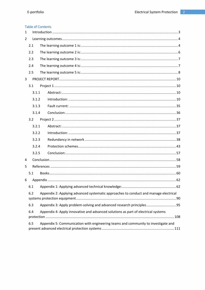
1. BUS DATA:
The faults are applied to the 66kV sub-transmission network shown in the Figure1. Bus A is
connected to Transmission substation. Bus B and C are connected to Bus A, so that all the Bus A, B,
and C are supplied with 66kV. Substation B and C are step-down to 22kV by using step-down
transformers. The Bus length, type, impedance and ratings of transmission and step-down
transformers are given below.
Figure 1. 66kV sub-transmission network

11 E-portfolio Electrical System Protection
Data 1. Bus Details
2. FAULT DETAILS:
The faults are applied to 22kV Bus at substation B and 66kV Bus at substation C.
SUBSTATION B:
Faults: Three phase fault, Phase-to-phase fault, Phase-to-earth fault
Fault currents should be given at 22kV side.
SUBSTATION C:
Faults: Three phase fault, Phase-to-earth fault for the cases of zero
fault resistance (0Ω) and a fault resistance of 10Ω.
Fault currents should be given at 66kV side.

12 E-portfolio Electrical System Protection
3. MATLAB:
Matlab is a software package which can be used to perform analysis and solve mathematical and
engineering problems [2]. The simulation is done in Simulink, which is an add-on product to Matlab.
Simulink is a block diagram environment for multi-domain simulation and model-based design [3]. It
provides an interactive, graphical environment for modelling, simulating, and analyzing of dynamic
systems [2]. In this project, faults are simulated at two different locations, substation B and
substation C. The faults are three-phase fault, phase-to-phase fault, and phase-to-earth fault.
BLOCK SET MODELS:
Block set models used for substation B and C are almost same. The block set models are three phase
source, three phase mutual inductance (Z1-Z0), three phase transformer (two winding), scope, three
phase VI measurement, power GUI, ground, and single phase series RLC block .
Three-phase source:
Figure 2. Three phase source
The Three-Phase Source block uses a balanced three-phase voltage source with an internal R-L
impedance. The three voltage sources are connected in Y with a ground connection [4]. The block
diagram of three phase source is shown in the above Figure2. Parameters of this block are
mentioned in below Table1. From the data, the source voltage is given as 66kV and their phase-to-
phase rms voltage is 66000/√2 = 46.66kV
Table 1. Parameters of Three-phase source
S. No. Parameters Value
1. Phase-to-phase rms voltage 46,669V
2. Phase angle of phase A 0°
3. Frequency 50Hz
4. Internal connection Yg
5. 3-phase short circuit level 1500MVA
6. X/R ratio 0.57

13 E-portfolio Electrical System Protection
Three-phase mutual inductance:
Figure 3. Three-phase mutual inductance
The Three-Phase Mutual Inductance Z1-Z0 block implements a three-phase balanced inductive and
resistive impedance with mutual coupling between phases [5]. The block diagram of three phase
source is shown in the above Figure3. Three blocks of three-phase mutual inductance are used for
this project. Each block represents connection between two buses like Bus A to B, Bus B to C, and
Bus A to C.
Calculated the resistance and inductance from the data. For all the line section, the impedances are
same, whereas the length of the line is different. The impedance is Z1=0.19+j0.35Ω/km and Z0 = 0.33
+ j1.68 Ω/km, which is in the format of Z=R+jX (plus (+) sign indicates the reactance is inductive
reactance). By using the formula, L= X/ (2πf), the inductance is calculated. Parameters of the Bus A
to B block are mentioned in below Table2. Parameters of the Bus B to C block are mentioned in
below Table3. Parameters of the Bus A to C block are mentioned in below Table4.
Table 2. Parameters of Three phase mutual inductance of Bus A to B
S. No. Parameters Value [R L]
1. Positive-sequence parameters [1.9 0.0111]
2. Zero-sequence parameters [3.3 0.0534]
Table 3. Parameters of Three phase mutual inductance of Bus B to C
S. No. Parameters Value [R L]
1. Positive-sequence parameters [12.35 0.0724]
2. Zero-sequence parameters [21.45 0.3475]
Table 4. Parameters of Three phase mutual inductance of Bus A to C
S. No. Parameters Value [R L]
1. Positive-sequence parameters [11.4 0.0668]
2. Zero-sequence parameters [19.8 0.3208]

14 E-portfolio Electrical System Protection
Initially, pi-transmission line block had been used instead of three-phase mutual inductance. Due to
improper sine wave, pi-transmission block had been removed. The improper sine wave is caused by
capacitance of the line, whose data is not given. So that, three phase mutual inductance block is
used in the place of pi section. The block diagram of three phase pi section line is given below in
Figure4.
Figure 4. Block Diagram of pi section line
Three-phase transformer:
Figure 5. Three phase Transformer (Two winding)
The Three-phase transformer block is changed to step-down transformer by changing the
parameters of winding1 and winding 2. This block implements a three-phase transformer using three
single phase transformers [6]. From the given data, the ratio of the transformer is given as 66000 to
22000V Dy1, which means the value of 66kV is step-down to 22kV and Dy1 means the primary
winding is in delta configuration, secondary winding in star configuration and “1” represents the
low voltage winding should lag the high voltage winding by 30°. The block diagram of three phase
transformer is shown in the above Figure4. Parameters of this block are mentioned in below Table5.
Table 5. Parameters of step down transformer
S. No. Parameters Value
1. Nominal power and frequency 30MVA and 50Hz
2. Winding 1
[Voltage Resistance Inductance]
[46.6kV 1.5 0.10]
3. Winding 2
[Voltage Resistance Inductance]
[15.5kV 1.5 0.10]
4. Magnetization Resistance 3.24MΩ
5. Magnetization Inductance 8597.9H
15 E-portfolio Electrical System Protection
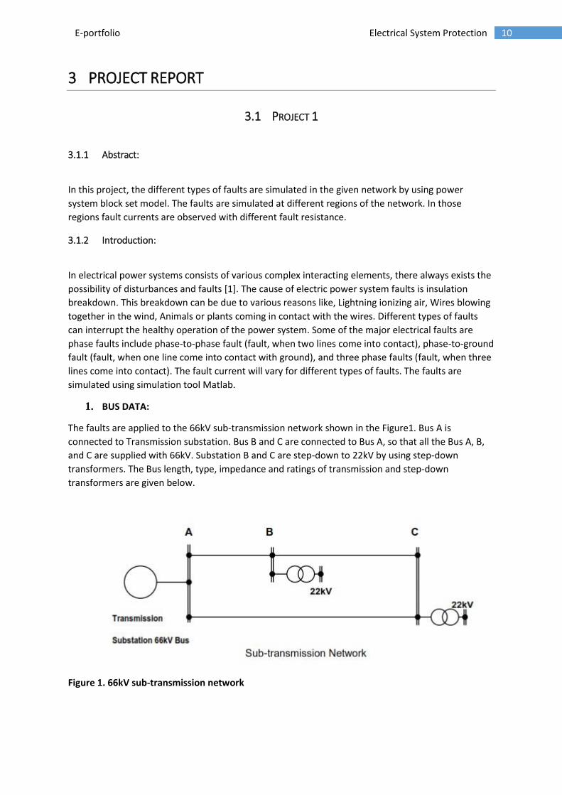
Scope:
Figure 6. Block diagram of scope
The Scope block displays inputs signals with respect to simulation time [8]. This block is
used to observe the waveform of voltage and current with respect to time. The number of
inputs to the scope can be changed by modifying the axes setting in parameters. If the
inputs are voltage and current, the waveform of both voltage and current can be observed in
the same waveform with respect to time. So that, lagging of voltage and current can be
easily observed. The block diagram of scope is shown in Figure6.
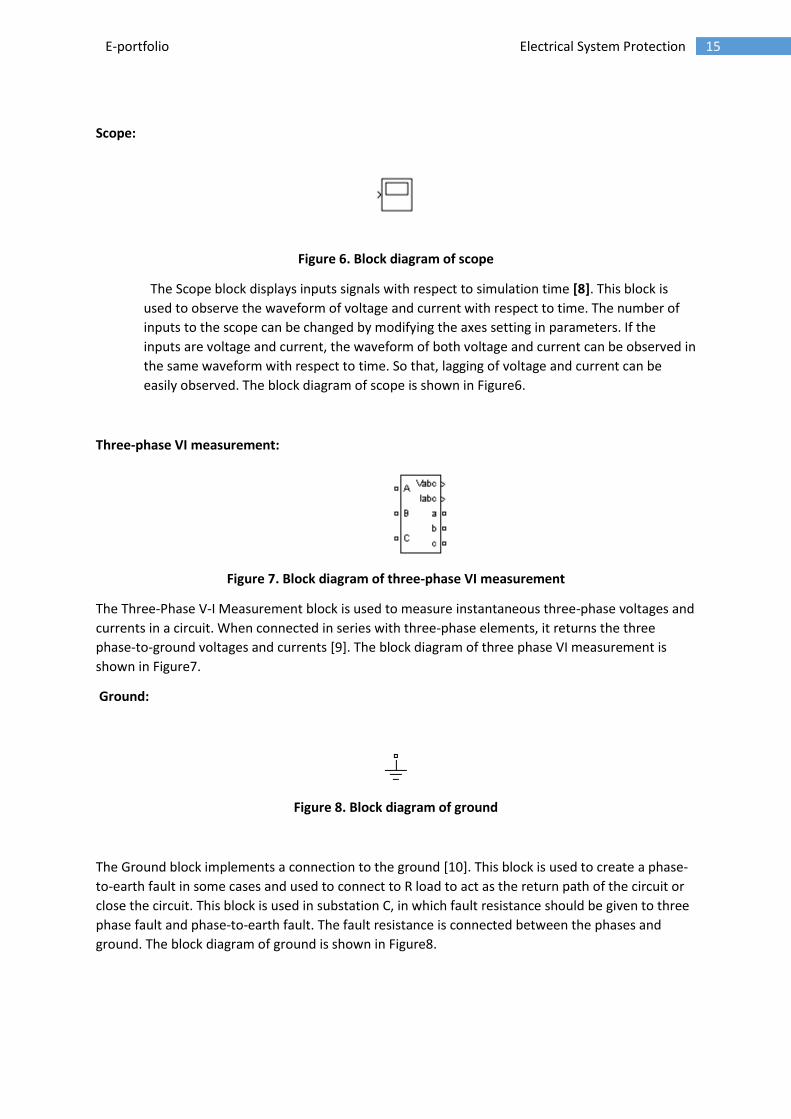
Three-phase VI measurement:
Figure 7. Block diagram of three-phase VI measurement
The Three-Phase V-I Measurement block is used to measure instantaneous three-phase voltages and
currents in a circuit. When connected in series with three-phase elements, it returns the three
phase-to-ground voltages and currents [9]. The block diagram of three phase VI measurement is
shown in Figure7.
Ground:
Figure 8. Block diagram of ground
The Ground block implements a connection to the ground [10]. This block is used to create a phase-
to-earth fault in some cases and used to connect to R load to act as the return path of the circuit or
close the circuit. This block is used in substation C, in which fault resistance should be given to three
phase fault and phase-to-earth fault. The fault resistance is connected between the phases and
ground. The block diagram of ground is shown in Figure8.

16 E-portfolio Electrical System Protection
Series RLC branch:
Figure 9.Block diagram of series RLC branch
The Series RLC Branch block implements a single resistor, inductor, or capacitor [11]. In this project,
load is taken as R load, whose values are assumed to 1kΩ. The block diagram of series RLC branch is
shown in the above Figure9. This block is used also as a fault resistance at substation C. In substation
C, different fault resistance is used and the corresponding fault currents are observed. The series RLC
branch is changed to resistor by modifying the branch parameter to R, which means resistor. As this
load value changes corresponding fault current value will change.
Initially, three phase RLC load is used as load, in which the low voltage winding and high voltage
winding of step-down transformer are in same phase, there is no 30° lag in between them which
was created in three phase transformer block. The assumption of parameters in RLC load contains
voltage, frequency, active power, inductive reactive power, and capacitive reactive power, which are
too many. So that, RLC branch is used instead of RLC load, which has less assumption and more
importantly the low voltage winding of three phase transformer get 30°lag from the high voltage
winding of three phase transformer.
Power GUI:
Figure 10. Block diagram of Power GUI
The powerGui block contains four methods to solve the circuit, which are continuous, ideal, discrete
and phasor, in which continuous method is used for simulation. The powergui block is necessary for
simulation of any Simulink model containing SimPower systems blocks. It also gives you access to
various graphical user interface (GUI) tools and functions for the steady-state analysis of SimPower
systems models and the analysis of simulation results [12]. The steady-state value of voltage and
current are observed under the steady-state analysis. So that, fault currents and phase shifts are
easily observed.

17 E-portfolio Electrical System Protection
FAULTS AT SUBSTATION B:
In this section, faults are applied to 22kV Bus at substation B, which means, the secondary of the
step-down transformer in substation B. Totally, four models are simulated in this section, which are
no fault model, three phase fault model, phase-to-phase model, and phase-to-earth model.
No fault model:
The circuit is drawn as shown in the Figure1 in simulink. This model shows the normal operation of
the circuit, which means no fault is applied to the circuit. The circuit diagram of the no fault model is
shown below in Figure11. The steady-state values of voltage and current are observed and shown in
Figure12. In the Figure12, the first and second marked values are primary and secondary values of
Bus B transformer, which have almost 30° lag. In that figure, the below marked values are the
normal current of 22kV transformer.
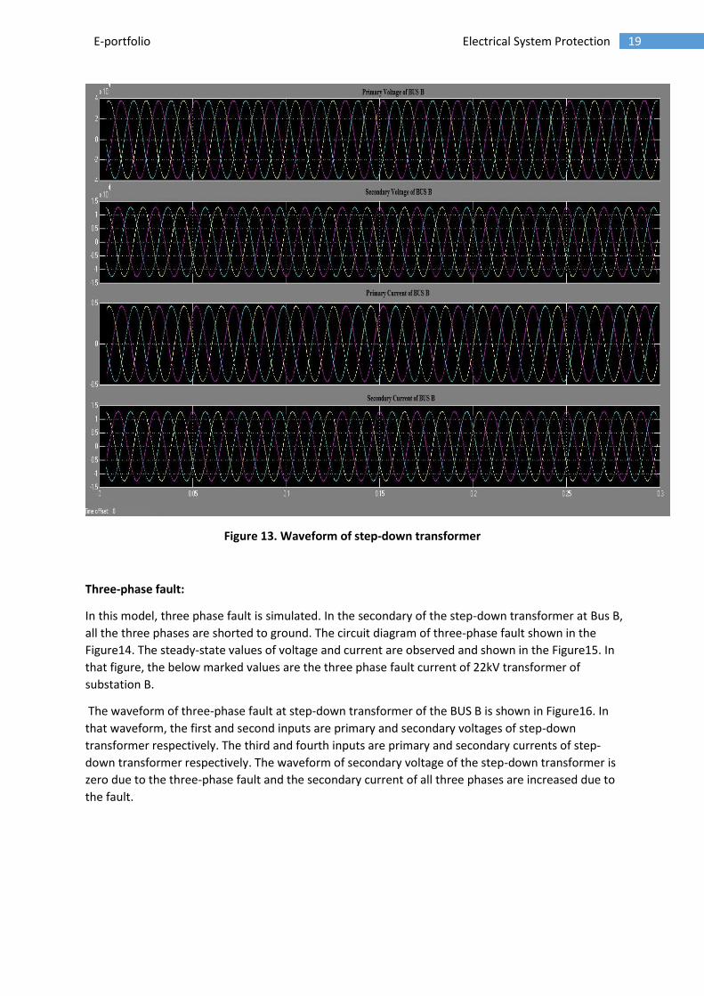
The waveform of step-down transformer of the BUS B is shown in Figure13. In that waveform, the
first and second inputs are primary and secondary voltages of step-down transformer respectively.
The third and fourth inputs are primary and secondary currents of step-down transformer
respectively. The waveforms of voltage and current are in sinusoidal. The phase shift of voltage and
current are not accurately shown in waveform.
Figure 11. Circuit diagram for No fault

18 E-portfolio Electrical System Protection
Figure 12. Steady state values
19 E-portfolio Electrical System Protection
Figure 13. Waveform of step-down transformer
Three-phase fault:
In this model, three phase fault is simulated. In the secondary of the step-down transformer at Bus B,
all the three phases are shorted to ground. The circuit diagram of three-phase fault shown in the
Figure14. The steady-state values of voltage and current are observed and shown in the Figure15. In
that figure, the below marked values are the three phase fault current of 22kV transformer of
substation B.
The waveform of three-phase fault at step-down transformer of the BUS B is shown in Figure16. In
that waveform, the first and second inputs are primary and secondary voltages of step-down
transformer respectively. The third and fourth inputs are primary and secondary currents of step-
down transformer respectively. The waveform of secondary voltage of the step-down transformer is
zero due to the three-phase fault and the secondary current of all three phases are increased due to
the fault.

20 E-portfolio Electrical System Protection
Figure 14.Circuit diagram for three phase fault
Figure 15. Steady state values of three-phase fault

21 E-portfolio Electrical System Protection
Figure 16. Waveform of three-phase fault
Phase-to-phase fault:
In this model, phase-to-phase fault is simulated. In the secondary of the step-down transformer at
Bus B, the second and third phases are shorted. The circuit diagram of phase-to-phase fault shown in
the Figure17. The steady-state values of voltage and current are observed and shown in the Figure18.
In that figure, the below marked values are the phase-to-phase fault current of 22kV transformer.
The waveform of phase-to-phase fault at step-down transformer of the BUS B is shown in Figure19.
In that waveform, the first and second inputs are primary and secondary voltages of step-down
transformer respectively. The third and fourth inputs are primary and secondary currents of step-
down transformer respectively. The waveform of the secondary voltage of step-down transformer of
two phases are reduced due to the phase-to-phase fault and the fault current of two phases are
increased due to the fault.

22 E-portfolio Electrical System Protection
Figure 17.Figure. Circuit diagram of phase-to-phase fault
Figure 18.Steady state value of phase-phase fault

23 E-portfolio Electrical System Protection
Figure 19. Waveform of phase-phase fault
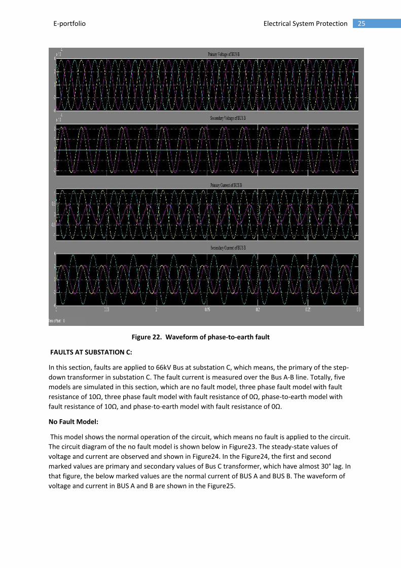
Phase-to-earth fault:
In this model, phase-to-earth fault is simulated. In the secondary of the step-down
transformer at Bus B, the third phase is shorted to ground. The circuit diagram of phase-earth fault
shown in the Figure20. The steady-state values of voltage and current are observed and shown in
the Figure21. In that figure, the below marked values are the phase-to-earth fault current of 22kV
transformer. The waveform of phase-to-phase fault at step-down transformer of the BUS B is shown
in Figure22. In that waveform, the first and second inputs are primary and secondary voltages of
step-down transformer respectively. The third and fourth inputs are primary and secondary currents
of step-down transformer respectively. The waveform of the secondary voltage of step-down
transformer of third phase is reduced to zero due to the phase-to-earth fault and the fault current of
one phase is increased compared to other two phases, which is due to the fault. But the value of the
fault current is low compared to the other faults.

24 E-portfolio Electrical System Protection
Figure20. Circuit diagram of phase-to-earth fault
Figure 21.Steady-state of phase-earth fault
25 E-portfolio Electrical System Protection
Figure 22. Waveform of phase-to-earth fault
FAULTS AT SUBSTATION C:
In this section, faults are applied to 66kV Bus at substation C, which means, the primary of the step-
down transformer in substation C. The fault current is measured over the Bus A-B line. Totally, five
models are simulated in this section, which are no fault model, three phase fault model with fault
resistance of 10Ω, three phase fault model with fault resistance of 0Ω, phase-to-earth model with
fault resistance of 10Ω, and phase-to-earth model with fault resistance of 0Ω.
No Fault Model:
This model shows the normal operation of the circuit, which means no fault is applied to the circuit.
The circuit diagram of the no fault model is shown below in Figure23. The steady-state values of
voltage and current are observed and shown in Figure24. In the Figure24, the first and second
marked values are primary and secondary values of Bus C transformer, which have almost 30° lag. In
that figure, the below marked values are the normal current of BUS A and BUS B. The waveform of
voltage and current in BUS A and B are shown in the Figure25.

26 E-portfolio Electrical System Protection
Figure 23. Circuit diagram of no fault
Figure 24. Steady state of no fault

27 E-portfolio Electrical System Protection
Figure 25. Waveform of no phase fault
Three Fault Model with 10Ω:
In this model, three phase fault is simulated. In the primary of the step-down transformer at
Bus C, all the three phases are shorted to ground with fault resistance of 10Ω. The circuit diagram of
three-phase fault with fault resistance of 10Ω shown in the Figure26. The steady-state values of
voltage and current are observed and shown in the Figure27. In that figure, the below marked values
are the fault current of third phase at Bus A, Bus B and Bus C, which clearly shows that fault current
is flowing in Bus C and Bus A but not in Bus B.
The waveform of three-phase fault with resistance of 10Ω at Bus C is shown in Figure28. In that
waveform, the first and second inputs are the voltages of Bus A and Bus B respectively. The third and
fourth inputs are the currents of Bus A and Bus B respectively. The waveform of the current at Bus A
is high due to the three phase fault, whereas the current at Bus B is normal. The fault is created at
Bus C, so that, fault current is flowing in Bus C and Bus A. The fault current at Bus A is small
compared to fault current at Bus C, which is clearly shown in the Figure27.

28 E-portfolio Electrical System Protection
Figure 26. Circuit diagram of three phase fault with fault resistance of 10Ω
Figure 27. Steady state of three phase fault with 10Ω

29 E-portfolio Electrical System Protection
Figure 28. Waveform of three phase fault with 10Ω
Three Fault Model with 0Ω:
In this model, three phase fault is simulated. In the primary of the step-down transformer at
Bus C, all the three phases are shorted and ground directly, which is considered to be the fault
resistance of 0Ω. The circuit diagram of three-phase fault with fault resistance of 0Ω shown in the
Figure29. The steady-state values of voltage and current are observed and shown in the Figure30. In
that figure, the below marked values are the fault current of third phase at Bus A, Bus B and Bus C,
which clearly shows that fault current is flowing in Bus C and Bus A but not in Bus B. The fault
current is same in both fault resistance of 0Ω and 10Ω for three phase fault.
The waveform of three-phase fault with resistance of 0Ω at Bus C is shown in Figure31. In that
waveform, the first and second inputs are the voltages of Bus A and Bus B respectively. The third and
fourth inputs are the currents of Bus A and Bus B respectively. The waveform of the current at Bus A
is high due to the three phase fault, whereas the current at Bus B is normal. The fault is created at
Bus C, so that, fault current is flowing in Bus C and Bus A. The fault current at Bus A is small
compared to fault current at Bus C, which is clearly shown in the Figure30.

30 E-portfolio Electrical System Protection
Figure 29.Circuit diagram of three phase fault with fault resistance of 0Ω
Figure 30. Steady state of three phase fault with 0Ω

31 E-portfolio Electrical System Protection
Figure 31. Waveform of three phase fault with 0Ω
Phase-earth Fault Model with 10Ω:
In this model, phase-to-earth fault is simulated. In the primary of the step-down transformer
at Bus C, third phase is shorted to ground with fault resistance of 10Ω. The circuit diagram of phase-
earth fault with fault resistance of 10Ω shown in the Figure32. The steady-state values of voltage
and current are observed and shown in the Figure33. In that figure, the below marked values are the
fault current of third phase at Bus A, Bus B and Bus C, which clearly shows that fault current is
flowing in Bus C and Bus A but not in Bus B.
The waveform of three-phase fault with resistance of 10Ω at Bus C is shown in Figure34. In that
waveform, the first and second inputs are the voltages of Bus A and Bus B respectively. The third and
fourth inputs are the currents of Bus A and Bus B respectively. The waveform of the current in Bus A,
only one phase is shorted. So that, fault current is flowing only in one phase due to that other
waveforms looks almost zero because of the normal current. The fault is created at Bus C, so that,
fault current is flowing in Bus C and Bus A.

32 E-portfolio Electrical System Protection
Figure 32.Circuit diagram of phase-earth fault with fault resistance of 10Ω
Figure 33. Steady state of phase-earth fault with 10Ω

33 E-portfolio Electrical System Protection
Figure 34. Waveform of phase-earth fault with 10Ω
Phase-earth Fault Model with 0Ω:
In this model, phase-to-earth fault is simulated. In the primary of the step-down transformer
at Bus C, third phase is shorted directly to the ground, which means the fault resistance is 0Ω. The
circuit diagram of phase-earth fault with fault resistance of 0Ω shown in the Figure35. The steady-
state values of voltage and current are observed and shown in the Figure36. In that figure, the below
marked values are the fault current of third phase at Bus A, Bus B and Bus C, which clearly shows
that fault current is flowing in Bus C and Bus A but not in Bus B and the fault current is flowing only
in third phase, which is due to phase-to-earth fault. The fault current is slightly higher in Bus C and A
compared to the fault current with 10Ω fault resistance, which is because of the fault resistance. The
fault resistance is zero in this model, so that fault current will be high in this model.
The waveform of three-phase fault with resistance of 0Ω at Bus C is shown in Figure37. In that
waveform, the first and second inputs are the voltages of Bus A and Bus B respectively. The third and
fourth inputs are the currents of Bus A and Bus B respectively. The waveform of the current at Bus A
is high due to the phase-earth fault, whereas the current at Bus B is normal. The fault is created at
Bus C, so that, fault current is flowing in Bus C and Bus A, not in Bus A to B. The voltage of Bus B in
fault phase reduced slightly.

34 E-portfolio Electrical System Protection
Figure 35.Circuit diagram of phase-earth fault with fault resistance of 0Ω
Figure 36. Steady state of phase-earth fault with 0Ω

35 E-portfolio Electrical System Protection
Figure 37. Waveform of phase-earth fault with 0Ω
3.1.3 Fault current:
Substation B:
For the load resistance of 1000Ω, the fault currents in three phases are tabulated below in Table6.
Table 6. FAULT CURRENT VALUES OF SUBSTATION B
S. No. Fault Type Phase A Phase B Phase C
1. No Fault 1.27A 1.27A 1.27A
2. Three phase Fault 374.18A 374.18A 374.18A
3. Phase-to-phase Fault 1.27A 324.68A 323.42A
4. Phase-to-earth Fault 2.19A 2.21A 3.81A

36 E-portfolio Electrical System Protection
Substation C:
For the load resistance of 1000Ω, the fault currents in three buses are tabulated below in Table7. For
the three phase fault, the fault currents in all the phases in Bus A, B and C are same. For the phase-
to-earth fault, the fault current is only in third phase.
Table 7. FAULT CURRENT VALUES OF SUBSTATION C
S. No. Fault Type BUS A BUS B BUS C
1. No Fault 0.63A 0.46A 0.46A
2. Three phase Fault_0Ω 1069.53A 0.33A 2406.17A
3. Three phase Fault_10Ω 1069.53A 0.33A 2406.17A
4. Phase-to-earth Fault_0Ω 568.87A 0.42A 1279.60A
5. Phase-to-earth Fault_10Ω 490.11 0.42A 1102.17A
3.1.4 Conclusion:
The fault currents at both substation B and C are tabulated above in Table 6 and 7
respectively. This fault is simulated for the resistive load of 1000Ω and it is taken as the balance load,
in order to apply the balance fault. It is difficult to calculate the fault current under unbalanced
condition. As the load changes, the fault currents will change. In substation B, the normal current is
1.27A (no fault condition), which means the normal operation of the circuit. For three-phase fault,
the current is increased enormously in all three phases and for phase-phase fault, the current is
increased in faulted phases (like phase B and phase C). The phase-to-earth current is very low, when
compared to other faults but it is two times higher than the normal operation of the circuit, which is
still a threat to the system. In theoretically, the phase-to-earth fault current might be higher than
three-phase fault current, which is because of the fault impedance. The formula for the three-phase
fault is
[12], in which Vll is a line-line voltage and Zsc is the total impedance of
the circuit. The formulae for phase-to-phase and phase-to-earth faults are
and , where Zo is the ground impedance. So that, for different
impedance, the fault current will change and depend on the ground impedance, the phase-to-earth
fault current might be higher than the three-phase fault current.
From the Table7, it shows that, at substation C, the fault current is flowing in Bus A and C
but not in Bus B. The fault is applied at Bus C due to that, fault current of Bus C is higher than Bus A.
The fault current is flowing through Bus A to Bus C. There is no fault current flowing through Bus A to
Bus B. The fault applied at Bus C, did not affect the current of Bus B, whereas it affected the current
of Bus A, which are due to the length of the line and source path of Bus C through Bus A is shorter
compared to Bus B. The length from Bus A to C is shorter compare to the Bus B to C. But still, there is
a slight voltage fluctuation in Bus B due to the fault. Three-phase fault currents of 10Ω and 0Ω
resistors are same. The phase-to-earth fault current of 0Ω resistor is slightly higher than the phase-
to-earth fault current of 10Ω resistor. So that, the fault current can be reduced by applying the fault
resistance. The increase in fault resistance reduces the fault current but the fault resistance should
be lower than the impedance of the load, otherwise the fault current will flow through the load.

37 E-portfolio Electrical System Protection
3.2 PROJECT 2
3.2.1 Abstract:
Electrical system protection is the essential for the equipments in the electricity grid to have
uninterrupted power supplied to the consumer. In this project our aim is to study the redundancy of
the network and the protection schemes installed at different section of the substation.
3.2.2 Introduction:
After looking at the single line diagram given in the project we are to write a report on the;
1. Redundancy in grid network shown by the SLD.
2. Protection schemes that are used installed at different section of the substation network.
First we need to research, how does the distribution network shown in the SLD is made redundant.
Consumer such as business, industries and even home users are really concerned about the
reliability of the network, to achieve the reliable network we need to have a redundant grid.
Achieving redundancy in the network is possible by having mesh topologies to form the grid network;
In case of any line failures the power supply could be rerouted so as to maintain the reliability of the
network. Therefore such topologies used for forming the network are useful in mitigating the
chances of outages for the consumer while the utility could repair the damaged and deactivated line.

38 E-portfolio Electrical System Protection
3.2.3 Redundancy in network
Below is the single line diagram of 66/11kV Berserker Sub-station in Rockhampto, we need to
analyse whether the network is redundant or not.

39 E-portfolio Electrical System Protection
66KV feeder redundancy
We can see from the picture below that there are two 66KV sources suppling to bus 1 and 2 and
they are also interconnected so as to provide back up for if one the line is disconnected due to any
fault.

40 E-portfolio Electrical System Protection
Step down transformer (66KV/11KV) Redundancy
Two sources and two buses therefore there are two 66KV/11KV step down transformer and they are
linked together by the bus section 1 and 2. If one fails then the other could supply to the load. Being
same and connected made it possible.

41 E-portfolio Electrical System Protection
11 KV bus network redundancy
The picture below shows the distribution network that has 16 of the 11KV distribution feeder that
goes to the end load of which many are spare that can be used for further load. Notice that all the
three buses are connected to each other and there is interconnecting buses 2 as well which
distributes the load.
42 E-portfolio Electrical System Protection
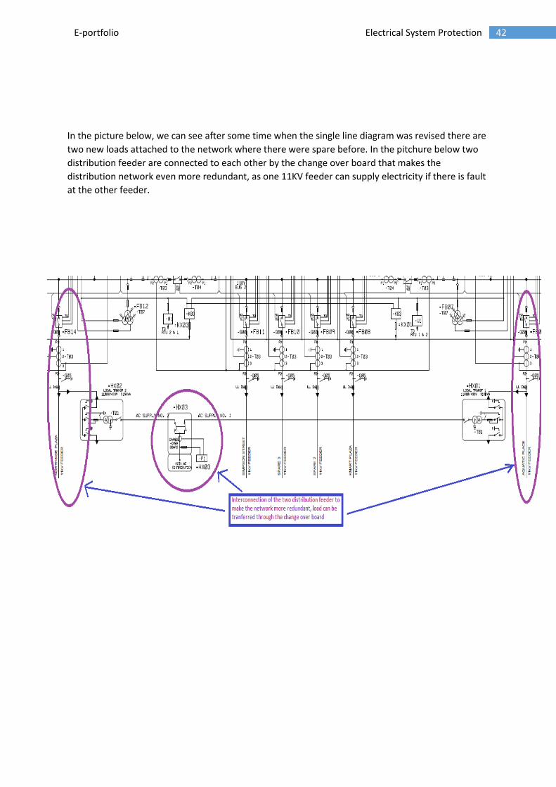
In the picture below, we can see after some time when the single line diagram was revised there are
two new loads attached to the network where there were spare before. In the pitchure below two
distribution feeder are connected to each other by the change over board that makes the
distribution network even more redundant, as one 11KV feeder can supply electricity if there is fault
at the other feeder.

43 E-portfolio Electrical System Protection
3.2.4 Protection schemes
The line diagram of Berserker Sub-station 66KV/11KV protection design

44 E-portfolio Electrical System Protection
Legends

45 E-portfolio Electrical System Protection
66 KV feeder protection
As both the feeder in the diagram are of same 66 KV rating therefore the protection of both are
similar therefore we will study only one of them.

46 E-portfolio Electrical System Protection
66 KV Feeder protection
J11- M (protection relay multifunction Main)
Relay
function
number
Description Purpose of use
ITS Protection
intertrip send
function
Once the fault is detected this function send signal to the
backup relay
ITR Protection
intertrip
receive
function
This function on the relay is essential for the coordination of
the relays and it coordinates with the back up relay
p Metering in
protection
relay
Metering is essential in relays as it calculates the current in
realtime
03 Circuit
breaker fail
function
It is a relay that operates in response to the position of a
number of other devices (or to a number of predetermined
conditions) in an equipment, to allow an operating sequence to
proceed, or to stop, or to provide a check of the position of
these devices or of these conditions for any purpose [13].
21 Distance
function
It is a relay that functions when the circuit admittance,
impedance, or reactance increases or decreases beyond
predetermined limits.
87L Line current
differential
function
It is a protective relay that functions on a percentage or phase
angle or other quantitative difference of two currents or of
some other electrical quantities.
J11- B (protection relay multifunction backup), it doesn’t have 21 but has got 79 and 67/67 N
additional
67/67 N Directional
overcurrent
and earth
fault function
Phase-to-phase short-circuit protection, with selective tripping
according to fault current direction. It comprises a phase
overcurrent function associated with direction detection, and
picks up if the phase overcurrent function in the chosen
direction (line or busbar) is activated for at least one of the 3
phases.[14]
79 Auto reclose
function
Automation device used to limit down time after tripping due
to transient or semipermanent faults on overhead lines. The
recloser orders automatic reclosing of the breaking device after
the time delay required to restore the insulation has elapsed.
Recloser operation is easy to adapt for different operating
modes by parameter setting[15].
47 E-portfolio Electrical System Protection
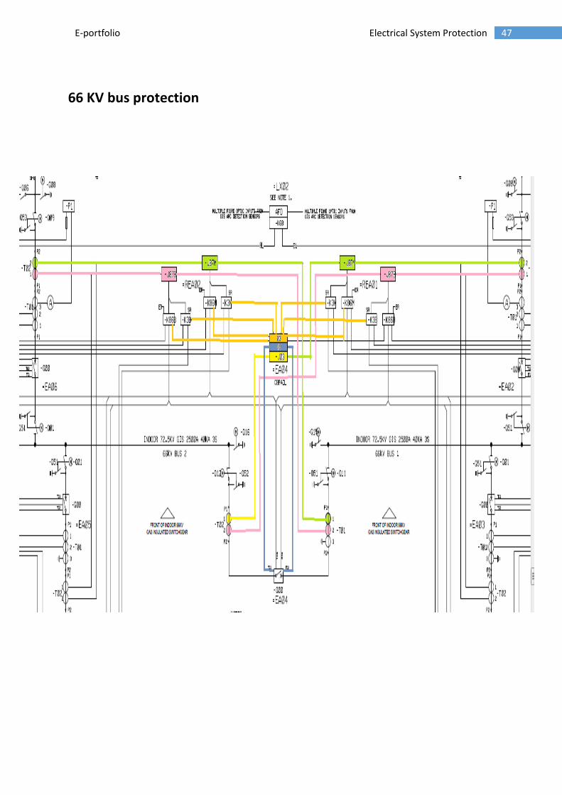
66 KV bus protection

48 E-portfolio Electrical System Protection
66 KV bus protection
-J87- M (protection relay – Bus differential Main)
Relay function
number
Description Purpose of use
J87 Bus current
differential
function
It is a protective relay that functions on a
percentage or phase angle or other quantitative
difference of two currents or of some other
electrical quantities.
-J03 (protection relay – Bus CHECKING OR INTERLOCKING RELAY)
99 Trip circuit
supervision
function
This function on the relay trips the circuit in case
of over flux at the bus
03 Circuit breaker
fail function
It is a relay that operates in response to the
position of a number of other devices (or to a
number of predetermined conditions) in an
equipment, to allow an operating sequence to
proceed, or to stop, or to provide a check of the
position of these devices or of these conditions for
any purpose[16].
-J87- B (protection relay – Bus differential Backup)
J87 Bus current
differential
function
It is a protective relay that functions on a
percentage or phase angle or other quantitative
difference of two currents or of some other
electrical quantities.

49 E-portfolio Electrical System Protection
Step down transformer (66KV/11KV) protection

50 E-portfolio Electrical System Protection
Step down transformer (66KV/11KV) protection
J11- M (protection relay multifunction Main)
Relay function
number
Description Purpose of use
87 current
differential
function
It is a protective relay that functions on a percentage or phase
angle or other quantitative difference of two currents or of some
other electrical quantities.
87G Transformer
differential relay
This relay is now also known as 87T because it is only use for
transformer whereas 87G is use for differential protection of
generator. This relay provides high speed phase and ground
protection of three phase transformer[17].
50/50N Instantaneous
over current
and earth fault
function
It is a relay that functions instantaneously on an excessive value
of current or on an excessive rate of current rise, thus indicating
a fault in the apparatus or circuit being protected
51/51N Inverse time
overcurrent and
earth fault
function
It is a relay with either a definite or inverse time characteristic
that functions when the current in an a-c circuit exceed a
predetermined value.
HV 03 Distance
function
It is a relay that operates in response to the position of a number
of other devices mainly as the name suggest it for high voltage
(or to a number of predetermined conditions) in an equipment,
to allow an operating sequence to proceed, or to stop, or to
provide a check of the position of these devices or of these
conditions for any purpose.
LV 03 Line current
differential
function
It is a relay that operates in response to the position of a number
of other devices mainly as the name suggest it for low voltage
(or to a number of predetermined conditions) in an equipment,
to allow an operating sequence to proceed, or to stop, or to
provide a check of the position of these devices or of these
conditions for any purpose.
J11- B (protection relay multifunction backup), same functions as the Main
-J51G Neutral earth
fault
It is a relay with either a definite or inverse time characteristic
that functions when the current in an a-c circuit exceed a
predetermined value and the fault current may be due to earth
fault
51 E-portfolio Electrical System Protection
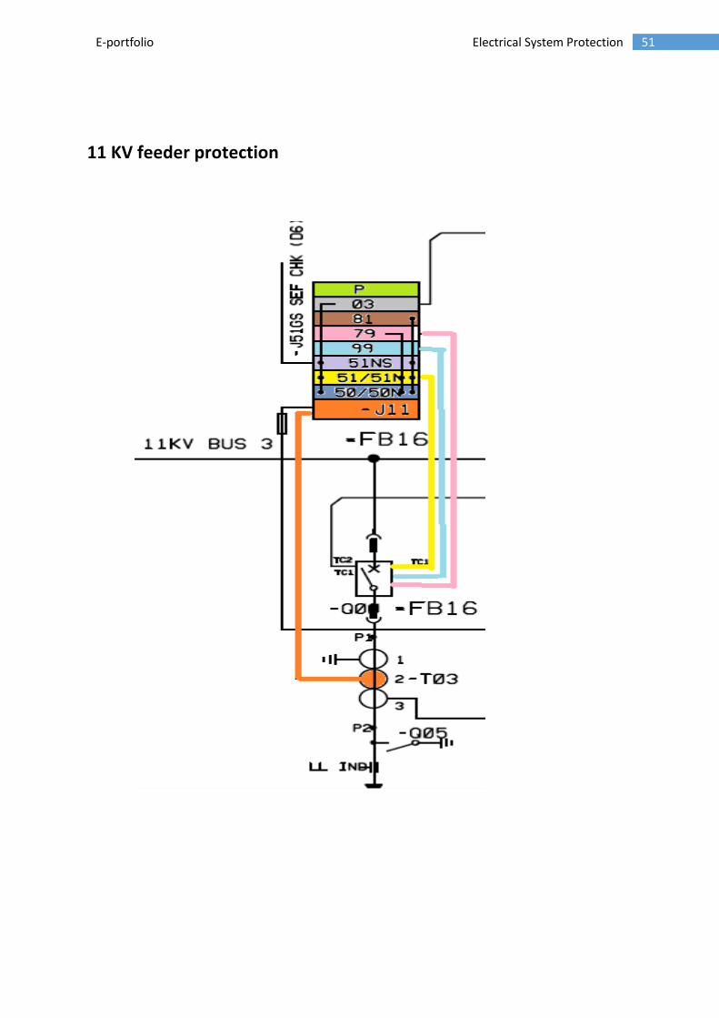
11 KV feeder protection

52 E-portfolio Electrical System Protection
11 KV feeder protection
-J11 (protection relay multifunction)
Relay function
number
Description Purpose of use
p Metering in
protection relay
Metering is essential in relays as it calculates the current in real-
time
03 Circuit breaker
fail function
It is a relay that operates in response to the position of a number of
other devices (or to a number of predetermined conditions) in an
equipment, to allow an operating sequence to proceed, or to stop,
or to provide a check of the position of these devices or of these
conditions for any purpose.
81 Under
frequency
function
It is a relay that functions on a predetermined value of frequency
(either under or over or on normal system frequency) or rate of
change of frequency.
79 Auto reclose
function
Automation device used to limit down time after tripping due to
transient or semipermanent faults on overhead lines. The recloser
orders automatic reclosing of the breaking device after the time
delay required to restore the insulation has elapsed. Recloser
operation is easy to adapt for different operating modes by
parameter setting.
99 Trip circuit
supervision
function
This function on the relay trips the circuit in case of over flux at the
bus
51NS Time sensitive
earth fault
function
This relay operates at a fixed time set in the relay and this relay
function could detect high impendence breakdown to earth[18].
50/50N Instantaneous
over current
and earth fault
function
It is a relay that functions instantaneously on an excessive value of
current or on an excessive rate of current rise, thus indicating a
fault in the apparatus or circuit being protected
51/51N Inverse time
overcurrent and
earth fault
function
It is a relay with either a definite or inverse time characteristic that
functions when the current in an a-c circuit exceed a predetermined
value.
53 E-portfolio Electrical System Protection
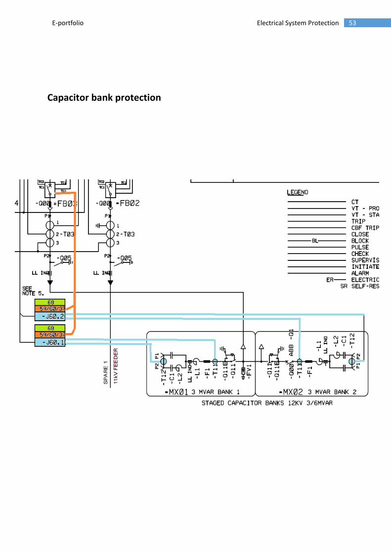
Capacitor bank protection

54 E-portfolio Electrical System Protection
Capacitor bank protection
-J60.1 (protective rlay- capacitor bank unbalance)
Relay function
number
Description Purpose of use
59 Under/
overvoltage
function
It is a relay that functions on a given value of over-voltage.
60 Voltage or
current balance
relay
It iis a relay that operates on a given difference in voltage, or
current input or output, or two circuits.
37 Under current
or under power
relay
It is a relay that functions when the current or power flow
decreases below a predetermined value.
68 Close/ reclose
inhabit function
It is a relay that initiates a pilot signal for blocking of tripping on
external faults in a transmission line or in other apparatus under
predetermined condition, or cooperates with other devices to
block tripping or to block re-closing on an out-of-step condition
or on power savings.

55 E-portfolio Electrical System Protection
11 KV Bus protection

56 E-portfolio Electrical System Protection
11 KV feeder protection
-J51- B (protection relay sum bus overcurrent)
Relay function
number
Description Purpose of use
99 Trip circuit
supervision
function
This function on the relay trips the circuit in case of over flux at
the bus
50/50N Instantaneous
over current
and earth fault
function
It is a relay that functions instantaneously on an excessive value
of current or on an excessive rate of current rise, thus indicating
a fault in the apparatus or circuit being protected
51/51N Inverse time
overcurrent and
earth fault
function
It is a relay with either a definite or inverse time characteristic
that functions when the current in an a-c circuit exceed a
predetermined value.
-J87- M (protection relay – Bus differential Main)
J87 Bus current
differential
function
It is a protective relay that functions on a percentage or phase
angle or other quantitative difference of two currents or of
some other electrical quantities.
57 E-portfolio Electrical System Protection
3.2.5 Conclusion:
In this project we investigated the network diagram of the distribution substation and its
protection schemes on the different part of the network, as we have analysed all the equipments
that are part of the network is being protected by different characteristics of relay.
Some part of the network has got two relays installed one is the main and the other is the backup
so as to improve the reliability of the network where as the dependability of the network
increases as we have redundant network.
By doing the project we come across the practical use of protection relays in the substation that
has given us good knowledge about the protection schemes installed for different components.
We have notice that their need to be mant spare connections available in the distribution network
so as to compensate the load in future that can be seen as two new load were added within small
period of time.

58 E-portfolio Electrical System Protection
4 CONCLUSION
It conclusion this e portfolio is about the electrical power protection unit that we have taken as apart
of post graduate engineering course. The e portfolio has been written to show all the topics that
were covered in the class and the lab experiments that were conducted at electrical lab.
There are also two projects that were to be completed as a part of e portfolio. The projects show the
understanding that the student have acquired about the subject during his studies. The projects
were completed with the help of unit teacher Mohammad Arif.
In this e portfolio there are five learning outcomes that were to be completed in the unit and the
justification for the learning outcome in the unit is in the appendix part of this e portfolio.
At the end I would like to thank the teaching staff especially unit teacher Mohammad Arif for his
valuable time that he has spent in teaching the subject and in helping the students understand the
subject.

59 E-portfolio Electrical System Protection
5 REFERENCES
[1]. www.science.smith.edu/~jcardell/Courses/.../MatlabSimulinkTutorial.ppt. (n.d.).
[2] myelectrical. (n.d.). Retrieved from http://myelectrical.com/notes/entryid/192/fault-calculations-
introduction
[3] subhra jana. (2013). IEEE Explore
Mathworks. (n.d.). Retrieved from
http://www.mathworks.com.au/help/physmod/sps/powersys/ref/powergui.html?searchHighlight=c
ontinuous+powergui
[5] Mathworks. (n.d.). Retrieved from
http://www.mathworks.com.au/help/physmod/sps/powersys/ref/ground.html?searchHighlight=gro
und
[6] Mathworks. (n.d.). Retrieved from
http://www.mathworks.com.au/help/physmod/sps/powersys/ref/threephasevimeasurement.html?
searchHighlight=three+phase+measurement
[7] Mathworks. (n.d.). Retrieved from
http://www.mathworks.com.au/help/simulink/slref/scope.html?searchHighlight=scope
[8] Mathworks. (n.d.). Retrieved from
http://www.mathworks.com.au/help/physmod/sps/powersys/ref/threephasetransformertwowindin
gs.html
[9] Mathworks. (n.d.). Retrieved from
http://www.mathworks.com.au/help/physmod/sps/powersys/ref/threephasesource.html
[10] Mathworks. (n.d.). Retrieved from http://www.mathworks.com.au/products/simulink/
[11] Mathwork. (n.d.). Retrieved from
http://www.mathworks.com.au/help/physmod/sps/powersys/ref/seriesrlcbranch.html
[12] Mathwork. (n.d.). Retrieved from
http://www.mathworks.com.au/help/physmod/sps/powersys/ref/threephasemutualinductancez1z0
.html
[13] http://electrical-engineering-portal.com/ansi-codes-device-designation-numbers [14] Electrical engineering portal: http://electrical-engineering-portal.com/protection-relay-ansi-standards#ANSI 67 - Directional phase overcurrent [15]Electrical engineering portal: http://electrical-engineering-portal.com/protection-relay-ansi-standards#ANSI 67 - Directional phase overcurrent [16] http://electrical-engineering-portal.com/ansi-codes-device-designation-numbers

60 E-portfolio Electrical System Protection
[17] ABB: http://www05.abb.com/global/scot/scot229.nsf/veritydisplay/744c18d45bda740bc1256ea8004bb325/$file/db41-359s%20%20%20%20%2087t.pdf [18] http://www.woodbeam.co.za/docs/2770-proddoc-20114729.pdf
5.1 BOOKS
[1] Mason, C. Russell. "The Art and Science of Protective Relaying". General Electric.
Retrieved 2009-01-26
[2] Stanley H. Horowitz and Arun G. Phadke, POWER SYSTEMRELAYING”, Third Edition,
[3] Muhammad Arif, Lecture notes , Deakin university
[4] Blackburn, J.L, A Domin, T.J, Protective Relaying: Principles and Applications, Third
Edition, 2006

61 E-portfolio Electrical System Protection
Appendices
62 E-portfolio Electrical System Protection
6 APPENDIX
6.1 APPENDIX 1: APPLYING ADVANCED TECHNICAL KNOWLEDGE:
Lab exercise 2: Over current protection of three-phase induction
motors
Objective of this experiment
To learn, to protect an induction motor from an over-current fault in the electric system
network. When I have completed this exercise, I will be familiar with over current
protection of three-phase induction motors.
Equipment used for this experiment
The list below shows the equipment required for this exercise in the EMS workstation and
Protective Relaying control station
1. Power Supply
2. Universal Fault Module (UFM)
3. Four-pole Squirrel-Cage Induction Motor
4. Prime Mover/Dynamometer
5. Transmission Grid “A”
6. Current Transformers (CTs)
7. Data Acquisition unit with Ammeter & Voltmeter
8. Three phase overcurrent relay
9. Connecting leads
Setting up Equipment:
1. Ensure that the Protective Relaying Control Station is connected to a power source.
Make sure the DC Power Supply of the Protective Relaying Control Station is turned off.
Make sure that all fault switches on the Three-Phase over Current Relay are set to the O (off)
position then install it in the Protective Relaying Control Station.

63 E-portfolio Electrical System Protection
2. Make the following settings on the Universal Fault Module:
TD1 time delay . . . . . . . . . . . . . . . . . . . . . . . . . . . . . . . . . . . ... ~1 s
SST1 time interval . . . . . . . . . . . . . . . . . . . . . . . . . . . . . . . . . ...~3 s
SST2 time interval . . . . . . . . . . . . . . . . . . . . . . . . . . . . . . . . ....~1o s
3. Install the Interconnection Module (if available), Power Supply, Universal Fault Module,
Four-Pole Squirrel-Cage Induction Motor, Prime Mover/Dynamometer, Transmission Grid
"A", Current Transformers, AC Ammeter, and AC Voltmeter in the EMS Workstation.
Mechanically couple the Four-Pole Squirrel-Cage Induction Motor to the Prime Mover/
Dynamometer using the timing belt.
Make sure the Power Supply is turned off and its voltage control knob is set to the 0 position.
Connect the Power Supply to the power outlets.
On the Current Transformers (CTs) module, make sure that all switches are set to the 1
(close) position to short-circuit the secondaries of the current transformers.
4. Connect the Prime Mover/Dynamometer module to the 240 V - AC Power Supply. On the
Power Supply, turn on the 24-V AC power source and connect to the Data acquisition unit.
5. If cables are available, connect the Interconnection Module installed in the EMS
Workstation to the Interconnection Panel of the Protective Relaying Control Station using
the supplied cables. Connect the equipment as shown in Figures 2 and 3.
6. Make the following settings:
On the Prime Mover I Dynamometer (set in brake mode)
MODE switch . . . . . . . . . . . . . . . . . . . . . . . . . . . . DYNamometer
LOAD CONTROL MODE switch . . . . . . . . . . . . . . . . . . MANual
MANUAL LOAD CONTROL knob . . . . . . . . . . . . . . . . MINimum
DISPLAY switch . . . . . . . . . . . . . . . . . . . . . . . . . . . . . TORQUE
On Transmission Grid "A" set
Switch S1 . . . . . . . . . . . . . . . . . . . . . . . . . . . . . . . . . . 0 (open)
On the Universal Fault Module set
INITIATE FAULT button . . . . . . . . . . . . . . . . . released position

64 E-portfolio Electrical System Protection
FAULT DURATION switch . . . . . . . . . . . . . . . . . . . . . . 0.05 - 5 s
65 E-portfolio Electrical System Protection
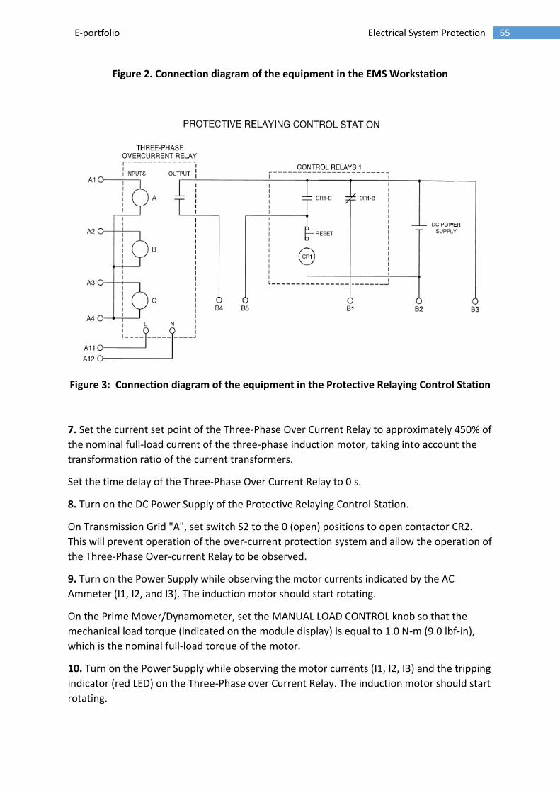
Figure 2. Connection diagram of the equipment in the EMS Workstation
Figure 3: Connection diagram of the equipment in the Protective Relaying Control Station
7. Set the current set point of the Three-Phase Over Current Relay to approximately 450% of
the nominal full-load current of the three-phase induction motor, taking into account the
transformation ratio of the current transformers.
Set the time delay of the Three-Phase Over Current Relay to 0 s.
8. Turn on the DC Power Supply of the Protective Relaying Control Station.
On Transmission Grid "A", set switch S2 to the 0 (open) positions to open contactor CR2.
This will prevent operation of the over-current protection system and allow the operation of
the Three-Phase Over-current Relay to be observed.
9. Turn on the Power Supply while observing the motor currents indicated by the AC
Ammeter (I1, I2, and I3). The induction motor should start rotating.
On the Prime Mover/Dynamometer, set the MANUAL LOAD CONTROL knob so that the
mechanical load torque (indicated on the module display) is equal to 1.0 N-m (9.0 lbf-in),
which is the nominal full-load torque of the motor.
10. Turn on the Power Supply while observing the motor currents (I1, I2, I3) and the tripping
indicator (red LED) on the Three-Phase over Current Relay. The induction motor should start
rotating.
66 E-portfolio Electrical System Protection
Turn off the Power Supply.
EXPERIMENTAL OUTPUT AND MY OBSERVATION:
11. Repeat the previous step a few times.
Is the over current protection system stable when the induction motor is starting?
Yes No
At first it wasn’t stable and the over current relay was indicating a fault because of the
inrush current at starting of the induction motor which is required to accelerate the motor
and the load to the specific speed, however after changing the current transformer module
from the ratio of 0.5: 5 A to 2.5: 5 A ratio made the relay not to operate at the starting of
the motor.
Test - bypassing Protective Relays
12. Turn on the Power Supply.
On the Universal Fault Module, depress the INITIATE FAULT button to produce a fault at the
terminals of the induction motor. While doing this, observe the circuit currents (I1, I2, I3)
and the tripping indicator on the Three-Phase Over-Current Relay.
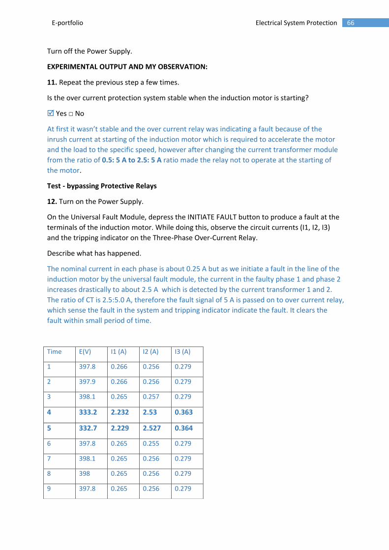
Describe what has happened.
The nominal current in each phase is about 0.25 A but as we initiate a fault in the line of the
induction motor by the universal fault module, the current in the faulty phase 1 and phase 2
increases drastically to about 2.5 A which is detected by the current transformer 1 and 2.
The ratio of CT is 2.5:5.0 A, therefore the fault signal of 5 A is passed on to over current relay,
which sense the fault in the system and tripping indicator indicate the fault. It clears the
fault within small period of time.
Time E(V) I1 (A) I2 (A) I3 (A)
1 397.8 0.266 0.256 0.279
2 397.9 0.266 0.256 0.279
3 398.1 0.265 0.257 0.279
4 333.2 2.232 2.53 0.363
5 332.7 2.229 2.527 0.364
6 397.8 0.265 0.255 0.279
7 398.1 0.265 0.256 0.279
8 398 0.265 0.256 0.279
9 397.8 0.265 0.256 0.279

67 E-portfolio Electrical System Protection
On the Universal Fault Module, place the INITIATE FAULT button in the released position.
Test - with Protective Relays
13. On Transmission Grid "A", set switch S2 to the 1 (close) position to close contractor CR2.
This will allow operation of the over current protection system.
On the Universal Fault Module, depress the INITIATE FAULT button to produce a fault at the
terminals of the induction motor. While doing this, observe the circuit currents (I1, I2, I3)
and the tripping indicator on the Three-Phase Over-Current Relay.
Describe what has happened.
As the switch S2 was open it prevented the operation of over current protection system, but
as we close the switch S2 and then initiates a fault using universal fault module the fault
current passes through the current transformer to the over current relay which then signals
the control relay to clear the fault, now the control relay CR1 starts to blink to have fault
cleared. If instead of CR1 there would have been an isolator or circuit breaker then it would
have operated and disconnected the circuit.
0
0.5
1
1.5
2
2.5
3
1 2 3 4 5 6 7 8 9 10
Current when fault is initiated
I1 (A) I2 (A) I3 (A)
10 397.6 0.265 0.256 0.279

68 E-portfolio Electrical System Protection
Time E(V) I1 (A) I2 (A) I3 (A)
1 398.8 0.262 0.255 0.281
2 398.7 0.262 0.255 0.28
3 398.9 0.263 0.255 0.28
4 399.1 0.263 0.256 0.281
5 399 0.262 0.255 0.281
6 399.3 0.263 0.256 0.28
7 396.2 2.692 2.946 0.285
8 398.7 0.263 0.255 0.28
9 399.1 0.263 0.256 0.28
10 399.2 0.263 0.256 0.28
Has the fault been cleared by the over current protection system?
Yes No
Does the over current protection system provide fast, effective protection against faults at
the induction motor terminals?
Yes No
On the Universal Fault Module, place the INITIATE FAULT button in the released position.
14. Turn off the Power Supply and turn off all modules at the EMS workstation.
Turn off the DC Power Supply of the Protective Relaying Control Station.
Remove all leads and cables.
0
0.5
1
1.5
2
2.5
3
3.5
1 2 3 4 5 6 7 8 9 10
Axi
s Ti
tle
Current during fault
I1 (A)
I2 (A)
I3 (A)

69 E-portfolio Electrical System Protection
LEARNING OUTCOMES:
In this experiment, I get to know about the protection system of the three phase induction
motor. Three phase induction motor is the critical component of many plants and
industries therefore any fault in these can result in unplanned downtime and can prove
very costly.
The main faults in induction motor can be mechanical, electrical or environmental. Our
focus in this experiment was to identify and take possible actions if any line to line or line
to earth fault occurs in the induction motor.
At first we connected the current transformers with the ratio 0.5:5 A which made the
circuit highly sensitive to any small rise in current that is why when we started the
induction motor the overcurrent relay senses the inrush current, which is 7 to 9 the
nominal current and starts to indicate the fault, so therefore we change the CTs with the
ratio of 2.5:5 A.
First we setup the EMS work station so as to make over current relay sense the fault when
the fault is generated using the universal fault module. The overcurrent relay setting is set
to 45% because the nominal current is 0.25 A and when it passes through the CTs with
ratio of 2.5:5 A, then the current becomes 0.5A and the current set point of the Three-
Phase Over Current Relay is 450% of the nominal full-load current of the three-phase
induction motor therefore it is 2.25A and which is 45% of the current setting in the over
current relay.
As we initiate the fault in step 12 the over current relay’s tripping indicator starts to
indicate the fault and when we initiate a fault in step 13 after the switch S2 is close, we
find the relay sense the fault and further sends the signal to control relay.
This experiment also shows that the three phase over current relay has got two settings in
it, one is current setting (that work on the principle that the fault current reduces as the
fault is further away from the protection scheme) and the other is time delay hence we
can calibrate both of them in such a way so as to have a backup protection in presence of
the main protection scheme.

70 E-portfolio Electrical System Protection
Lab exercise 4: Over current protection of three phase transformer
Objective of this experiment
The objective of this experiment is to observe the faults in a three phase Power Transformer
and this will show why transformer protection is important and to observe the over current
protection system. Usually the protection that is used for the transformer is differential,
restricted earth fault and over current protection. We are using over current protection
relays in this experiment only.
In the first part of the exercise, I will set up the equipment in the EMS Workstation and the
Protective Relaying Control Station.
In the second part of the exercise, I will connect the equipment as shown in Figures. In this
circuit, I will initiate fault at the load side of the transformer to observe fault current for
phase-to-phase fault and whether the relay sense the fault and cleared the fault using
control relays . Again I will initiate fault at the load side of the circuit to observe phase-to-
earth fault and whether the fault is sense by the over current relay and hence cleared by the
control relay. In this part of the experiment I will use three phase overcurrent relay, AC/DC
sensitive relay and over current relay, in the next experiment I will use these relays to clear
the faults.
When the fault will be initiated the current transformer will detect the over current and
further it’s connected to three phase over current relay, this initiate the trip mechanism of
over current relay which is further connected to control relay CR1, the trip current goes to
CR1. Therefore the contact CR1-C closes to note the fault and starts to light up. The contact
CR-1B opens to open the contractor CR1, this separates the transformer from the sources.
In this experiment we will short one of the phase of the load and will observe with happen
with the protection system. We will also initiate the fault in the primary side of the
transformer and observe what the protection system is going to do.
71 E-portfolio Electrical System Protection
EQUIPMENT USED FOR THIS EXPERIMENT
The list below shows the equipment required for this exercise in the EMS workstation and
Protective Relaying control station
1. Power Supply
2. Universal Fault Module (UFM)
3. Faultable Transformer (FT)
4. Transmission Grid A
5. Current Transformers (CTs)
6. Resistive Load (2 sets; for 533 ohm load on each phase)
7. Data Acquisition unit with Ammeter & Voltmeter
8. Interconnection module
9. Three phase overcurrent relay
10. AC/DC Sensitive overcurrent relay
11. Connecting leads

72 E-portfolio Electrical System Protection
SETTING UP EQUIPMENT:
Connect the equipment according to the diagram shown below, make sure the power
supply is off before making the connections and once they are made recheck them with the
instructor.
Using the two resistor module to implement the resistance required. Initially turning the
fault switches on transformer to 0.
Set the time delay of the Three-Phase over Current Relay to approximately 5 s.
Adjust the current set point and hysteresis of the AC/DC Current Sensitive Relay to 100 mA
and 5%, respectively.
Connection diagram of the equipment in the EMS works station is below:
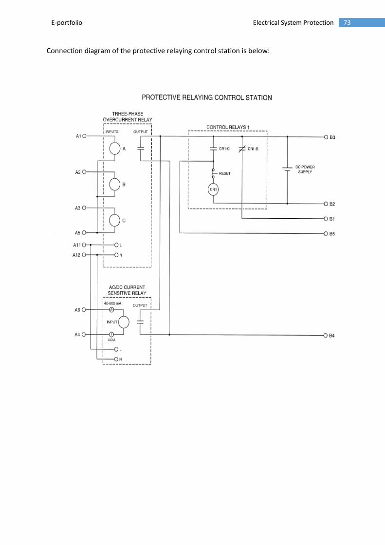
73 E-portfolio Electrical System Protection
Connection diagram of the protective relaying control station is below:

74 E-portfolio Electrical System Protection
RESULTS AND OBSERVATION
Turning on the DC power supply, to turn the protection relaying control station and setting the
transmission system switch S2 to 0, to allow only protective relay to work and not the whole control
system.
Then we turn ON the main power supply of the EMS station and turning the knob of voltage to 100%.
At no fault condition the current and line to line voltages are:
I1 = 0.409 A E1 = 389.6 V I2 = 0.392 A E2 = 356.6 V I3 = 0.008 A
Now we initiate a fault by pressing the initiate fault button this short circuits one phase of the
three phase load connected to the faultable transformer, we the observe the line current and line to
line voltage and we also observes tripping indicator that is the red light on the overcurrent relay and
AC/DC current sensitive relay.
11 = 1.088 A E1 = 382.5V 12 = 1.084A E2 = 314.3 V 13 = 0.010 A
When one phase of three phase load is short circuited, the current in the primary and the secondary winding of that phase increases almost 3 times of the nominal current, and the voltage is also dropped in secondary side of the transformer and that is indicated by the three phase over current relay and the AC/DC current sensitive relay.
Now we introduce other fault by switching the fault switch to FS1, and transformer T1 to the 1
position to insert an earth fault near the middle of the primary winding of transformer T1. While
doing this, we observe the circuit currents and voltages and also observe the tripping indicator that
is the red light on 3 phase over current and AC/DC current sensitive relay.
I1 = 0.540A E1 =389.2 V I2 = 0.412A E2 =355.6 V I3 = 0.940A
We can observe that when we introduce earth fault in the primary winding of transformer the
current in the ground going from transformer increases almost 10 times of the nominal
current, and that is shown by the ammeter at I3. Therefore the transformer primary current
also increases as there is more current drawn by the ground. These changes in current is
also sensed by the over current relay and AC/DC current sensitive relay by red light
indicating it.

75 E-portfolio Electrical System Protection
Now we set the switch S2 on the transmission grid module to close position to allow the use of
protection system.
We initiate the fault by the fault button on the EMS station to short circuit one of the phase of the
three phase load connected to the fault able transformer. We measure current and line to line
voltage and also observe the tripping indicator that is the red light on 3 phase over current and
AC/DC current sensitive relay.
I1 = 1.108A E1 =390.4 V I2 = 1.106A E2 =317.6 V I3 = 0.011A
When one phase of three phase load is short circuited, the current in the primary and the secondary winding of that phase increases almost 3 times of the nominal current, and the voltage is also dropped in secondary side of the transformer and that is indicated by the three phase over current relay and the AC/DC current sensitive relay. The relay then further removes the power supply through the control relay and hence the current becomes zero later on.
On Control Relays 1 of the Protective Relaying Control Station, press the RESET button of control
relay CR1 to reset the protection system.
Now we introduce other fault by switching the fault switch to FS1, and transformer T1 to the 1
position to insert an earth fault near the middle of the primary winding of transformer T1. While
doing this, we observe the circuit currents and voltages and also observe the tripping indicator that
is the red light on 3 phase over current and AC/DC current sensitive relay.
I1 = 0.577A E1 =391.3V I2 = 0.268A E2 =357.0 V I3 = 1.031A We can observe that when we introduce earth fault in the primary winding of transformer the current in the ground going from transformer increases almost 10 times of the nominal current, and that is shown by the ammeter at I3. Therefore the transformer primary current also increases as there is more current drawn by the ground. These changes in current is also sensed by the over current relay and AC/DC current sensitive relay by red light indicating it.The relay then further removes the power supply through the control relay and hence the current becomes zero later on. On the Faultable Transformers, set fault switch FS1 of transformer T1 to the 0 position to remove
the fault. Turn OFF the supply

76 E-portfolio Electrical System Protection
DISCUSSION AND LEARNING OUTCOMES
The graphs of the voltage E1 and current I1 of the primary side of the transformer are shown below:
0
0.2
0.4
0.6
0.8
1
1.2
1.4
1.6
1.8
2
1
9
17
25
33
41
49
57
65
73
81
89
97
10
5
11
3
12
1
12
9
13
7
14
5
15
3
16
1
16
9
17
7
18
5
19
3
20
1
M7-I1
0
50
100
150
200
250
300
350
400
450
1
9
17
25
33
41
49
57
65
73
81
89
97
10
5
11
3
12
1
12
9
13
7
14
5
15
3
16
1
16
9
17
7
18
5
19
3
20
1
M1-E1

77 E-portfolio Electrical System Protection
The graphs of the voltage E2 and current I2 of the secondary side of the transformer are shown
below:
0
0.2
0.4
0.6
0.8
1
1.2
1.4
1.6
1.8
2
1
9
17
25
33
41
49
57
65
73
81
89
97
10
5
11
3
12
1
12
9
13
7
14
5
15
3
16
1
16
9
17
7
18
5
19
3
20
1
M8-I2
0
50
100
150
200
250
300
350
400
1
9
17
25
33
41
49
57
65
73
81
89
97
10
5
11
3
12
1
12
9
13
7
14
5
15
3
16
1
16
9
17
7
18
5
19
3
20
1
M2-E2
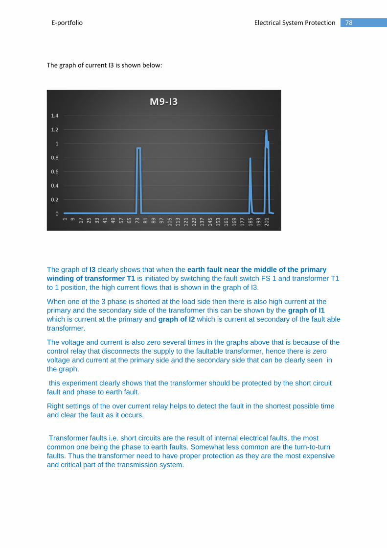
78 E-portfolio Electrical System Protection
The graph of current I3 is shown below:
The graph of I3 clearly shows that when the earth fault near the middle of the primary
winding of transformer T1 is initiated by switching the fault switch FS 1 and transformer T1
to 1 position, the high current flows that is shown in the graph of I3.
When one of the 3 phase is shorted at the load side then there is also high current at the
primary and the secondary side of the transformer this can be shown by the graph of I1
which is current at the primary and graph of I2 which is current at secondary of the fault able
transformer.
The voltage and current is also zero several times in the graphs above that is because of the
control relay that disconnects the supply to the faultable transformer, hence there is zero
voltage and current at the primary side and the secondary side that can be clearly seen in
the graph.
this experiment clearly shows that the transformer should be protected by the short circuit
fault and phase to earth fault.
Right settings of the over current relay helps to detect the fault in the shortest possible time
and clear the fault as it occurs.
Transformer faults i.e. short circuits are the result of internal electrical faults, the most
common one being the phase to earth faults. Somewhat less common are the turn-to-turn
faults. Thus the transformer need to have proper protection as they are the most expensive
and critical part of the transmission system.
0
0.2
0.4
0.6
0.8
1
1.2
1.4
1
9
17
25
33
41
49
57
65
73
81
89
97
10
5
11
3
12
1
12
9
13
7
14
5
15
3
16
1
16
9
17
7
18
5
19
3
20
1
M9-I3

79 E-portfolio Electrical System Protection
Lab exercise 5: Differential protection of three-phase induction
motors

80 E-portfolio Electrical System Protection

81 E-portfolio Electrical System Protection
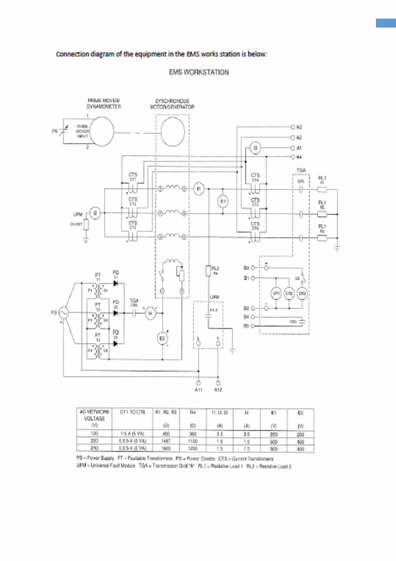
82 E-portfolio Electrical System Protection

83 E-portfolio Electrical System Protection

84 E-portfolio Electrical System Protection
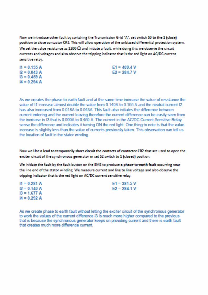
85 E-portfolio Electrical System Protection

86 E-portfolio Electrical System Protection

87 E-portfolio Electrical System Protection

88 E-portfolio Electrical System Protection
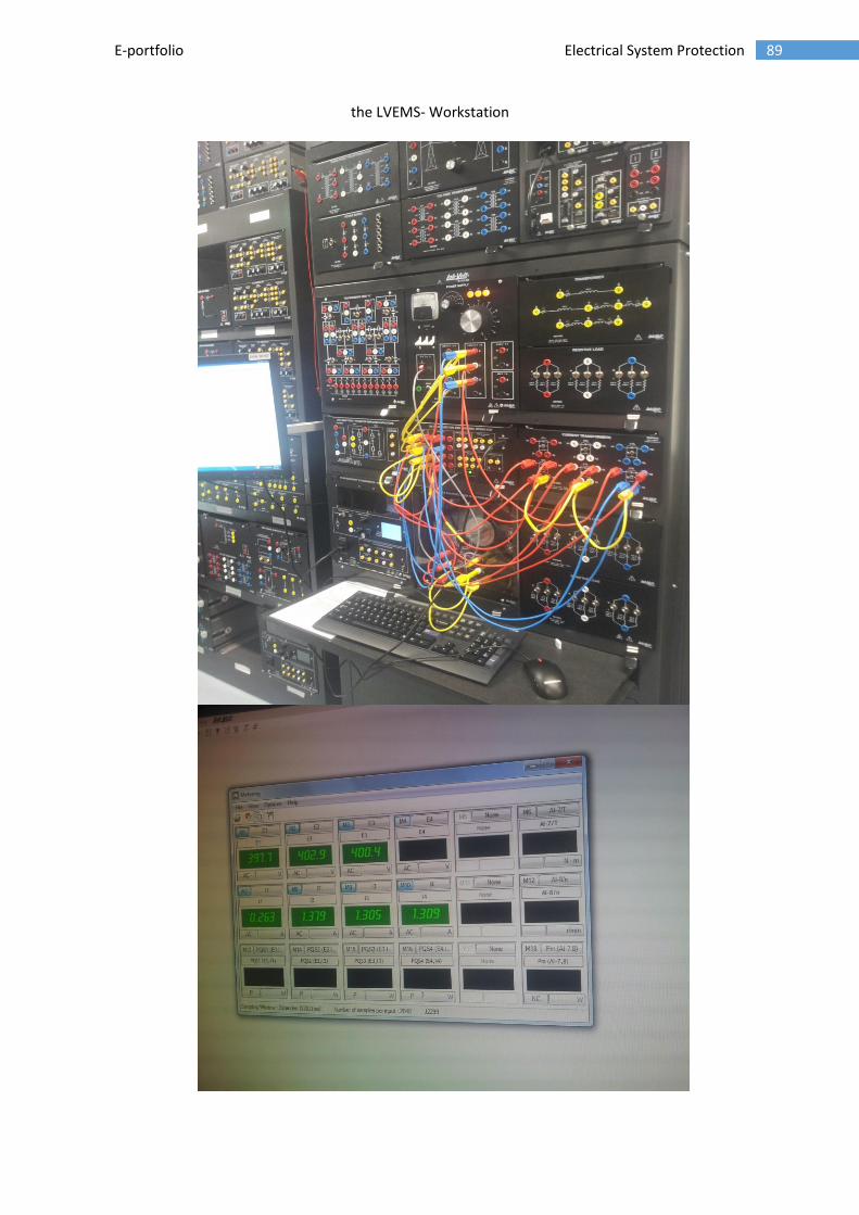
89 E-portfolio Electrical System Protection
the LVEMS- Workstation

90 E-portfolio Electrical System Protection
6.2 APPENDIX 2: APPLYING ADVANCED SYSTEMATIC APPROACHES TO CONDUCT AND MANAGE
ELECTRICAL SYSTEMS PROTECTION EQUIPMENT
Comprehensive instructions given on the EMS-workstation about the use of workstation in
the electrical lab.

91 E-portfolio Electrical System Protection
Risk assessment done before ever lab;

92 E-portfolio Electrical System Protection

93 E-portfolio Electrical System Protection

94 E-portfolio Electrical System Protection

95 E-portfolio Electrical System Protection
6.3 APPENDIX 3: APPLY PROBLEM-SOLVING AND ADVANCED RESEARCH PRINCIPLES Selection of fuse rating on the radial distribution line having different load current and
therefore the coordination of the fuse
School of Engineering, Deakin University, Waurn Ponds Campus, Geelong, VIC 3220 Australia
Tutorials
Question 4Consider the radial distribution line shown in Figure 1, where customers are served all along the length of the feeders. Fuse A is the main feeder protection, and Fuses B and C are installed on lateral feeders to limit the outage due to remote faults, for example, for faults beyond B or C.
51
The maximum and minimum
available fault currents, in
amperes, at each location are
shown in the boxes. Also shown
is the normal load current
flowing through each fuse. Check
the coordination of the fuses.
Select fuse ratings for A, B, and C
that will coordinate properly. Figure 1
School of Engineering, Deakin University, Waurn Ponds Campus, Geelong, VIC 3220 Australia
Tutorials
Question-4
Table-1: Coordination b/w EEI-NEMA Type T Fuse Links
52

96 E-portfolio Electrical System Protection
School of Engineering, Deakin University, Waurn Ponds Campus, Geelong, VIC 3220 Australia
Tutorials
Question-4
53
Table 2: Continuous Current Carrying Capacity of EEI-NEMA Fuse Links
School of Engineering, Deakin University, Waurn Ponds Campus, Geelong, VIC 3220 Australia
Tutorials
Answer Q-4
As a first trial, lets consider Fuse C be a 15T fuse.
The load current is 21 A, but the 15T is capable of 23 A, according to Table 2.
Therefore this fuse is of adequate rating, although there is little room for load growth.
From Table 1, for T links, we see that the 15T will coordinate with the 25T fuse at location B for currents up to 730 A. but the maximum fault current (at C) is 1550 A.
Therefore, we select the 30T fuse for location B.
54

97 E-portfolio Electrical System Protection
School of Engineering, Deakin University, Waurn Ponds Campus, Geelong, VIC 3220 Australia
Tutorials
Answer Q-4
The 30T can carry 45 A continuously and, from Table 1, 30T will coordinate with the 15T protecting fuse up to 1700 A. This is a good choice.
The 30T must coordinate with A for fault currents up to 1800 A.
To carry the load current at A, we must select the 80T fuse, which can carry 120 A (from Table 2).
The 80T will coordinate with the 30T for fault currents up to 5000 A, and this system has only 1800 A available.
Thus, the workable solution is 80T at A, 30T at B, and 15T at C.
If you wish to allow for a greater load growth at C, depending on the nature of the load served and its likelihood for growth. This would require a larger fuse at C, which will then require that all fuse selections be reconsidered.
55
Calculating the fault current using current transformer at a particular ratio
School of Engineering, Deakin University, Waurn Ponds Campus, Geelong, VIC 3220 Australia
TutorialsQuestion-2An overcurrent relay is set to operate at 8A is connected to a CT with a ratio of 100/5A. It is given that CT impedance Z2 = 0.082 ohms.
Find whether the relay will detect the fault current of 200A on the primary side for the following burdens and also calculate the CT errors.
Zb = 0.8 ohms
Zb = 3.0 ohms
45

98 E-portfolio Electrical System Protection
School of Engineering, Deakin University, Waurn Ponds Campus, Geelong, VIC 3220 Australia
Tutorials
Answer Q-2 (a)
(a) Zb = 0.8 ohms
Considering the equivalent circuit of Question 1
E2 = I2 (Zb + Z2) = 8(0.8 + 0.082) = 7.056V
From the CT characteristics chart, the corresponding Ie for E2 = 0.4A
Hence, the corresponding primary current I1`= I2 + Ie = 8 + 0.4 = 8.4 A
The corresponding primary current of CT I1 = I1`* CT ration = 8.4*(100/5) = 168 A
So, the relay will operate for a primary fault current of 200A.
CT error = Ie/I1`*100% = (0.4/8.4)*100 = 4.76%
This is a reasonable error.
46
School of Engineering, Deakin University, Waurn Ponds Campus, Geelong, VIC 3220 Australia
TutorialsAnswer Q-2 (b)
(b) Zb = 3.0 ohms
Considering the equivalent circuit of Question 1
E2 = I2 (Zb + Z2) = 8(3.0 + 0.082) = 24.656V
From the CT characteristics chart, the corresponding Ie for E2 = 30.0A (approximately)
Hence, the corresponding primary current I1`= I2 + Ie = 8 + 30.0 = 38.0 A
The corresponding primary current of CT I1 = I1`* CT ration = 38.0*(100/5) = 760 A
So, the relay will not operate for a primary fault current of 200A.
CT error = Ie/I1`*100% = (30.0/38.0)*100 = 78.95%
This is very high error.47

99 E-portfolio Electrical System Protection
Calculating the fault current on the radial transmission line and indicating the relay that will
detect the fault current at a particular places on the line.
School of Engineering, Deakin University, Waurn Ponds Campus, Geelong, VIC 3220 Australia
Tutorials
Question-3
Consider a simple 3 phase radial system as shown in Figure. Calculate fault currents at different fault locations and indicate which relays will operate for which faults. Consider F4 and F3 is very close to each other.
38
School of Engineering, Deakin University, Waurn Ponds Campus, Geelong, VIC 3220 Australia
Tutorials
Answer Q-3 (1/8)
Grading by current relies on the fact that the fault current along the length decreases as the distance from the source to the fault location increases.
The relays controlling various circuit breakers need to be set to operate at suitable values such that only the relay nearest to the fault will trip its breaker.
Note, we are treating all impedances as scalars. This is often done if the impedances are basically inductive. This often applies in transmission and larger distribution MV systems.
39

100 E-portfolio Electrical System Protection
School of Engineering, Deakin University, Waurn Ponds Campus, Geelong, VIC 3220 Australia
Tutorials
Answer Q-3 (2/8)
For a three phase source (as shown in figure),
the fault current level at F4 is
)( 1
/
4
LS
f
FZZ
VI
40
Where
Vf/Ø = Source phase to ground voltage
ZS = Source impedance
ZL1 = Line impedance
School of Engineering, Deakin University, Waurn Ponds Campus, Geelong, VIC 3220 Australia
Tutorials
Answer Q-3 (3/8)
ZL1 = 0.12x2 = 0.24 ohm
So,
VkV
V f 63503
11/
ohmMVA
kVZS 484.0
250
)11()( 22
kAIF 77.8)24.0484.0(
63504
41

101 E-portfolio Electrical System Protection
School of Engineering, Deakin University, Waurn Ponds Campus, Geelong, VIC 3220 Australia
Tutorials
Answer Q-3 (4/8)
The relay R3 controlling the CB if set to operate somewhat below 8.77kA to protect the whole cable from A to B. “Somewhat below” is a vague and unsatisfactory term. In practice we will consider how the source impedance (fault level) might change and the accuracy of the relays and CTs to determine how far below 8.77kA we would need to set the relay to get reliable operation.
The relay would not be able to distinguish b/w faults F4 and F3, as the distance b/w the fault locations is very small. Hence the corresponding changes from IF4 to IF3 would be negligible.
42
School of Engineering, Deakin University, Waurn Ponds Campus, Geelong, VIC 3220 Australia
Tutorials
Answer Q-3 (5/8)
For fault current at F2:
ZL1 = 0.12x2 = 0.24 ohm
ZL2 = 0.02x2 = 0.04 ohm
So kAIF 31.8
)04.024.0484.0(
63502
)( 21
/
2
LLS
f
FZZZ
VI
VkV
V f 63503
11/
ohmMVA
kVZS 484.0
250
)11()( 22
43

102 E-portfolio Electrical System Protection
School of Engineering, Deakin University, Waurn Ponds Campus, Geelong, VIC 3220 Australia
Tutorials
Answer Q-3 (6/8)
Relay R2 should operate for faults “somewhat below” 8.31kA.
It will be practically difficult to grade R3 and R2 for a fault at F2 because the currents are similar - 8.7kA and 8.3kA. Recall the accuracy of a 10P CT is 10% i.e. 0.8kA.
For the fault current at F1:
Current IF1 is)( 21
/
1
TLLS
f
FZZZZ
VI
44
School of Engineering, Deakin University, Waurn Ponds Campus, Geelong, VIC 3220 Australia
Tutorials
Answer Q-3 (7/8)
ZL1 = 0.12x2 = 0.24 ohm
ZL2 = 0.02x2 = o.04 ohm
(this is a 7% reactance on a 4MVA base)
So,
VkV
V f 63503
11/
ohmMVA
kVZS 484.0
250
)11()( 22
ohmxxMVA
kVZ T 12.207.0
4
)11(%7
)( 22
kAIF 20.2)12.204.024.0484.0(
63501
45

103 E-portfolio Electrical System Protection
School of Engineering, Deakin University, Waurn Ponds Campus, Geelong, VIC 3220 Australia
Tutorials
Answer Q-3 (8/8)
The relay R1, if set to operate reliably at 2.20kA would protect equipment downstream of the transformer for faults at F1.
R2 could be set to trip above 2.20kA (and below 8.31kA) and would protect the cable from B to C and the primary side of the transformer. It no longer provides back up to F1 for faults at F1. This is a weakness for current grading.
46
Calculating the pickup current off the differential relay across the transformer,
School of Engineering, Deakin University, Waurn Ponds Campus, Geelong, VIC 3220 Australia
Tutorials
Question-5
A single phase transformer is rated at 69/110kV, 20MVA to be protected by a differential relay.
a) What are the ideal ratios of the CTs if they have 5A secondary windings?
b) The primary CT is 300:5. The secondary CT is 200:5. For these ratios what is the differential current at full load?
c) The differential relay has a constraint winding that means the relay needs a certain difference current to pick up. Calculate what the differential current in part (b) is in per-unit terms. Round this up to the nearest 2%.This will be the constraint setting.
d) The transformer has a 1% magnetizing current. At zero transformer load what is the differential current in the relay? Set a pickup current that is rounded up to the nearest 2%. Draw the pickup region of the relay on a i1s i2s plane (in per unit terms).
56

104 E-portfolio Electrical System Protection
School of Engineering, Deakin University, Waurn Ponds Campus, Geelong, VIC 3220 Australia
Tutorials
AnswerQ-5 (a)
The current in the primary for the rated load :
=(20x1000)/69 = 289.8A
Current in the secondary for the rated load :
=(20x1000)/110 = 181.8A
The perfect ratio for CT is 289.8:5 and 181.8: 5.
57
School of Engineering, Deakin University, Waurn Ponds Campus, Geelong, VIC 3220 Australia
Tutorials
Answer Q-5 (b)
We can select CT ratio at the primary side as 300:5 and at the secondary side 200:5
For this selected CT ratios, CT at primary side of large Transformer will produce current at the secondary of the CT as:
= (289.8x5)/300 = 4.83A
Similarly, CT at the secondary side of the large Transformer will produce current at the secondary of the CT as:
= (181.8x5)/200 = 4.54A
So, the differential current is (4.83 - 4.54) = 0.29A
58

105 E-portfolio Electrical System Protection
School of Engineering, Deakin University, Waurn Ponds Campus, Geelong, VIC 3220 Australia
Tutorials
Answer Q-5 (c)
Differential current is 0.29 A, which is (0.29/4.83) = 6.004% of the primary side CT current at rated load.
We would need to set the differential current at 8% to have a margin of safety in through faults. We could reduce this by having a CT with taps on the nominal 5A winding. In an electronic relay we could set a scaling factor.
59
School of Engineering, Deakin University, Waurn Ponds Campus, Geelong, VIC 3220 Australia
Tutorials
Answer Q-5 (d)
As mentioned Transformer magnetising current is 1% i.e at the primary side magnetising current is 2.89A which results magnetising current of 0.0483A on the primary side of CT. This is 1.6% of the current so we set the pickup current at 2%. Relay will trip if the differential current is more that 8% as mentioned in part c.
A graphical representation of the trip and operate region is shown below.
60

106 E-portfolio Electrical System Protection
Calculating the impedance setting of the three zones of distance protection mho relay in the
power system and determining which relay will trip under the certain current rating.
School of Engineering, Deakin University, Waurn Ponds Campus, Geelong, VIC 3220 Australia
TutorialsQuestion-3
Three-zone mho relays are used for the protection of the power system as shown in Figure 2. Positive sequence impedances (in Ohm) are given. The rated voltage at Bus-1 is 500kV and the CT and VT ratios are 1500:5 and 4500:1 respectively. In a three zone scheme for B3, Zone-1 protects 80% of line 1-2, Zone-2 protects 120% of line 1-2 and Zone-3 protects 100% of line 1-2 and 120% of line 2-3.
(a) Determine the actual impedance settings of 3 zones.
(b) The maximum current through the line 1-2 during emergency loading condition is 1400A at 0.9p.f. Lagging. Will any of the relays trip during this condition?
19
Figure 2. Three-zone mho relays are used for the protection of the power system
School of Engineering, Deakin University, Waurn Ponds Campus, Geelong, VIC 3220 Australia
Tutorials
Answer Q-3 (a)
Impedance settings for phase ‘a’ to ground relay is given by Z = Vag/Ia
To express the same quantity for the secondary side of the Relay, as:
Hence, we can write the secondary side impedance settings as:
20
ratioVT
VV
ag
Secondaryag
)( ratioCT
II a
Secondarya
)(
ratioVT
ratioCTZx
ratioVT
ratioCTx
I
V
ratioCT
IratioVT
V
Za
ag
a
ag
.
.
.
.
151/4500
5/1500 ZZxZ

107 E-portfolio Electrical System Protection
School of Engineering, Deakin University, Waurn Ponds Campus, Geelong, VIC 3220 Australia
Tutorials
Answer Q-3 (a)
The line impedances given are:
Z12 = 6+j60
Z23 = 5+j50
So, the actual relay setting for relay at B3 as:
Zone 1 setting: 0.8 * Z12/15 = 0.8(6+j60)/15= (0.32 + j3.2) = 3.216 84.29oΩ
Zone 2 setting: 1.2 * Z12/15 =1.2(6+j60)/15 = (0.48 + j4.8) = 4.824 84.29oΩ
Zone 3 setting: (Z12 + 1.2*Z23)/15 = ((6+j60) + 1.2(5+j50))/15 = (0.80+j8.0) = 8.04
84.29oΩ
21
School of Engineering, Deakin University, Waurn Ponds Campus, Geelong, VIC 3220 Australia
Tutorials
Answer Q-3(b)
The bus voltage at Bus-1 is 500kV and the maximum current for an emergency loading condition is 1400A with 09.p.f lagging.
So, maximum current = 1400 -25.84o A
Hence, the impedance seen by the secondary of the relay as:
Since this impedance is higher than the Zone-3 impedance settings, so the impedance during the emergency loading condition is outside the trip setting of any of the 3 zones. Therefore none of the relays will trip.
22
84.25)9.0(cos 1
84.2575.1384.251400315
1000500
15 xx
xZ

108 E-portfolio Electrical System Protection
6.4 APPENDIX 4: APPLY INNOVATIVE AND ADVANCED SOLUTIONS AS PART OF ELECTRICAL SYSTEMS
PROTECTION
Both of them are current transformer module but with different ratings

109 E-portfolio Electrical System Protection
The current transformers that were changed because of the ratio

110 E-portfolio Electrical System Protection
The waveform of the pi model of the transmission line, because of the capacitance it becomes
distorted after sometime
The prime mover setting of the generator

111 E-portfolio Electrical System Protection
6.5 APPENDIX 5: COMMUNICATION WITH ENGINEERING TEAMS AND COMMUNITY TO
INVESTIGATE AND PRESENT ADVANCED ELECTRICAL PROTECTION SYSTEMS
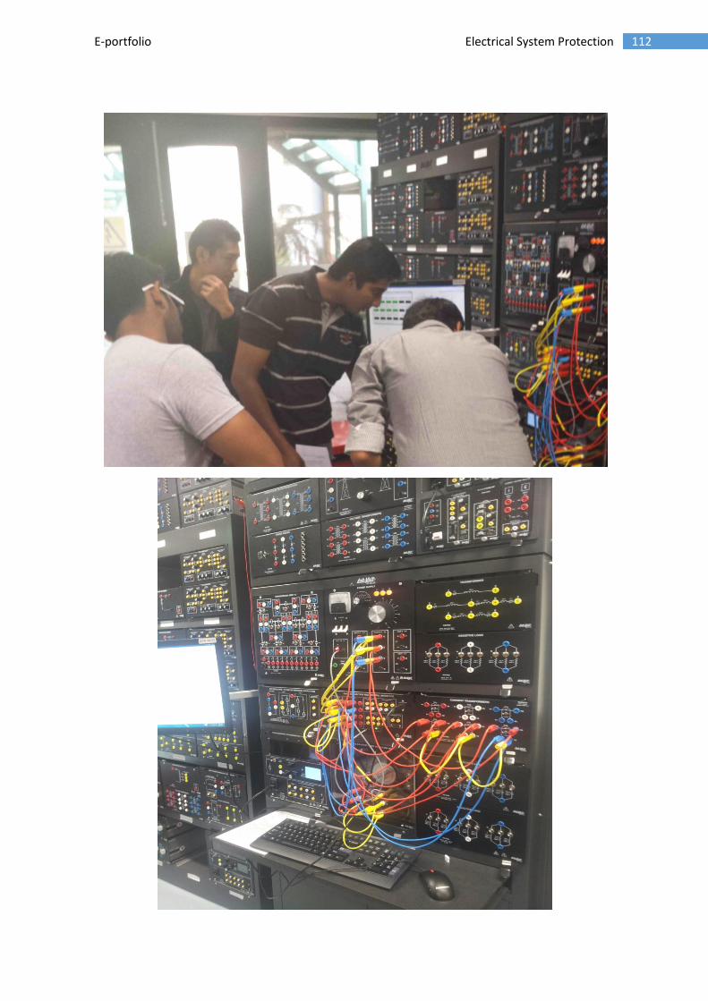
112 E-portfolio Electrical System Protection
Copyright © 2022 FDOKUMEN