Food intake, energy balance and body weight control - Nature
Upload
khangminh22Category
view
0download
0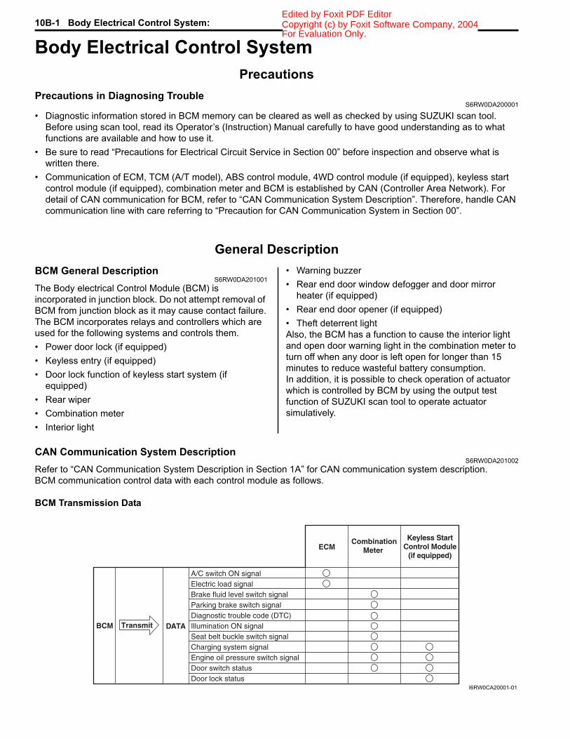
10B-1 Body Electrical Control System: Copyright (c) by Foxit Software Company, 2004Edited by Foxit PDF Editor
Control SystemsBody Electrical Control SystemPrecautions
Precautions in Diagnosing TroubleS6RW0DA200001
• Diagnostic information stored in BCM memory can be cleared as well as checked by using SUZUKI scan tool. Before using scan tool, read its Operator’s (Instruction) Manual carefully to have good understanding as to what functions are available and how to use it.
• Be sure to read “Precautions for Electrical Circuit Service in Section 00” before inspection and observe what is written there.
• Communication of ECM, TCM (A/T model), ABS control module, 4WD control module (if equipped), keyless start control module (if equipped), combination meter and BCM is established by CAN (Controller Area Network). For detail of CAN communication for BCM, refer to “CAN Communication System Description”. Therefore, handle CAN communication line with care referring to “Precaution for CAN Communication System in Section 00”.
General DescriptionBCM General Description
S6RW0DA201001The Body electrical Control Module (BCM) is incorporated in junction block. Do not attempt removal of BCM from junction block as it may cause contact failure.The BCM incorporates relays and controllers which are used for the following systems and controls them.• Power door lock (if equipped)• Keyless entry (if equipped)• Door lock function of keyless start system (if
equipped)• Rear wiper• Combination meter• Interior light
• Warning buzzer• Rear end door window defogger and door mirror
heater (if equipped)• Rear end door opener (if equipped)• Theft deterrent lightAlso, the BCM has a function to cause the interior light and open door warning light in the combination meter to turn off when any door is left open for longer than 15 minutes to reduce wasteful battery consumption.In addition, it is possible to check operation of actuator which is controlled by BCM by using the output test function of SUZUKI scan tool to operate actuator simulatively.
CAN Communication System DescriptionS6RW0DA201002
Refer to “CAN Communication System Description in Section 1A” for CAN communication system description.BCM communication control data with each control module as follows.
BCM Transmission Data
A/C switch ON signalElectric load signalBrake fluid level switch signalParking brake switch signalDiagnostic trouble code (DTC)Illumination ON signalSeat belt buckle switch signalCharging system signalEngine oil pressure switch signalDoor switch statusDoor lock status
ECMKeyless Start
Control Module(if equipped)
CombinationMeter
BCM Transmit DATA
I6RW0CA20001-01
For Evaluation Only.

Body Electrical Control System: 10B-2Copyright (c) by Foxit Software Company, 2004Edited by Foxit PDF Editor
BCM Reception Data
Theft Deterrent LightS6RW0DA201003
The information display or clock (1) of this vehicle includes a theft deterrent light (2) for the theft preventive purpose. The BCM makes the theft deterrent light flash at certain intervals after the ignition switch is turned off until it is turned on again. Also, DTCs stored in BCM can be checked by reading the flashing patterns of the theft deterrent light when diagnosing troubles.
Security Alarm Description (If Equipped)S6RW0DA201005
OperationThe security alarm system provides a warning of an abnormal condition to those who are around. Its operation is as follows. While the system is in the stand-by mode (when 20 seconds or more elapsed after the door is locked using a keyless entry transmitter or door request switch), BCM monitors door lock status, door switch status and battery power supply voltage. When it detects an abnormal condition (door is unlocked by some way other than using keyless entry transmitter or door request switch and opened or cut off BCM power supply voltage temporarily), it activates the warning buzzer (located in BCM), theft deterrent light, hazard warning relay and horn relay.The security alarm system has 2 selectable modes.• A mode: No operation• B mode: Theft deterrent light blinks, hazard warning lights blink, warning buzzer (located in BCM) sounds and horn
sounds
Engine speed signal
Vehicle speed signalEngine coolant temperature signal
Brake pedal switch signal
A/C refrigerant pressure signalFuel consumption signal
A/C compressor clutch signal
Engine type signalTransmission range sensor signal
Combination meter spec signalIgnition knob switch signalDoor lock/unlock request signalBuzzer request signalAnswer back request signal
DATABCM Receive
CombinationMeter
TCM(A/T model)
Keyless StartControl Module
(if equipped)ECM
I6RW0CA20002-01
1 2
I5RW0AA20003-01
For Evaluation Only.
10B-3 Body Electrical Control System: Copyright (c) by Foxit Software Company, 2004Edited by Foxit PDF Editor
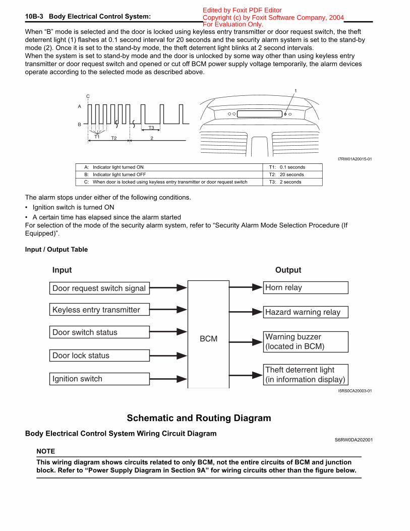
When “B” mode is selected and the door is locked using keyless entry transmitter or door request switch, the theft deterrent light (1) flashes at 0.1 second interval for 20 seconds and the security alarm system is set to the stand-by mode (2). Once it is set to the stand-by mode, the theft deterrent light blinks at 2 second intervals.When the system is set to stand-by mode and the door is unlocked by some way other than using keyless entry transmitter or door request switch and opened or cut off BCM power supply voltage temporarily, the alarm devices operate according to the selected mode as described above.
The alarm stops under either of the following conditions.• Ignition switch is turned ON• A certain time has elapsed since the alarm startedFor selection of the mode of the security alarm system, refer to “Security Alarm Mode Selection Procedure (If Equipped)”.
Input / Output Table
Schematic and Routing DiagramBody Electrical Control System Wiring Circuit Diagram
S6RW0DA202001
NOTEThis wiring diagram shows circuits related to only BCM, not the entire circuits of BCM and junction block. Refer to “Power Supply Diagram in Section 9A” for wiring circuits other than the figure below.
B
A
T3
T1 T2 2
C1
I7RW01A20015-01
A: Indicator light turned ON T1: 0.1 secondsB: Indicator light turned OFF T2: 20 secondsC: When door is locked using keyless entry transmitter or door request switch T3: 2 seconds
Input Output
Keyless entry transmitter
Door switch status
Door lock status
BCM
Horn relay
Theft deterrent light(in information display)
Warning buzzer(located in BCM)
Hazard warning relay
Door request switch signal
Ignition switchI5RS0CA20003-01
For Evaluation Only.

Body Electrical Control System: 10B-4Copyright (c) by Foxit Software Company, 2004Edited by Foxit PDF Editor
BLK/BLU
BLK/YEL
BLK/RED
12V
12V
+BB
BLU/YEL
WHT/BLU
+BB
RED/YELG272-7
YEL/REDYEL/BLK
5V
IG1
IG2 IG2
L312-4
ORNL314-9
YEL
BLUL313-3
BLUPPL/WHT
+B
+B
GRN/RED
GRN
GRN
RED/BLU
L315-9L315-10
L01-10L01-1
ON
DOOROFF
+B
+B
IG1
WHTL312-5
12V
LT GRN
BLK
5V5V
5V
PNK
+BB
GRNG273-2BLKBLK/ORN
G272-9G271-3
BLK/ORNL314-4
BLUG273-5
WHTE324-2
WHTG272-11
+B
REDWHT
REDWHT
REDWHT
+BB
130
31
6
7
8
15
16
18
19
20 20 20
21
62 63
39
40
42
41
43
43
46 46 45 44
48 49
47
50
51
56
5758
59
60
61
IG1
BRN/YEL23
25
22
RED/BLK24
RED/BLU
IG128
GRN/WHT
33
34
12V
12V
LT GRN/BLK
BRN 12V
L01-1226 GRY/WHT
GRY/RED
IG129
GRN/YEL
12V27
WHT/RED
+B32
BLU/YEL
37
35
36
G04-16
IG1
IG1
IG1
IG1
12V
17
IG2
WASH OFF INT ON
WASH, ON
WR EWONINT
BLU/BLK
YEL G272-20
GRN
12V
12V
5
4
PPL G04-1511
12
13
14
GRNE325-3
G272-3 BLU
GRY
IG19
+B
5V
L313-2YEL10
REDWHT
REDWHT
32
L01-11
G04-21
G04-22
E04-10
E04-8
G04-8GRY
E04-11
E04-4
G04-11YEL
G04-13
G04-14G04-12
L01-7
L01-15
L01-3
L01-14
E04-5
L01-6
L01-16
L01-17
L01-5
L01-4
G04-18
G04-17
G04-5
E04-9
G04-1G04-3
G04-2G04-4
E04-2E04-1
38
REDWHT
REDWHT
REDWHT
YEL
+B
L315-143
BLK/RED
BLK/RED
L314-6
G271-7
52BLK/REDL314-7
53BLK/REDL314-8
5455
46 46 45 44GRN
RED/BLU
L315-9L315-10
+B
43
[A]
[B]
I6RW0DA20001-01
[A]: Without security alarm system 21. Rear end door switch 43. Door lock actuator relay (if equipped)[B]: With security alarm system 22. Driver side seat belt switch 44. Driver side door lock actuator (if equipped)
For Evaluation Only.

10B-5 Body Electrical Control System: Copyright (c) by Foxit Software Company, 2004Edited by Foxit PDF Editor
1. BCM 23. Brake fluid level switch 45. Passenger side door lock actuator (if equipped)2. Rear end door opener actuator (if equipped) 24. Parking brake switch 46. Rear door lock actuator (if equipped)3. Rear end door opener relay (if equipped) 25. Door key cylinder switch (included in door lock
actuator) (if equipped)47. Hazard warning switch
4. Rear washer motor 26. Manual door lock switch (if equipped) 48. Turn signal and hazard warning relay5. Rear wiper and washer switch 27. Rear end door opener switch (if equipped) 49. To turn signal light6. Outside air temperature sensor (if equipped) 28. A/C switch (if equipped) 50. Interior light7. Key reminder switch 29. Rear end door window defogger switch 51. Rear end door window defogger relay8. Theft deterrent light 30. Rear wiper motor 52. Right side door mirror heater (if equipped)9. Oil pressure switch 31. Rear wiper relay 53. Left side door mirror heater (if equipped)
10. SDM 32. TCM (A/T model) 54. Rear end door window defogger11. P/S control module 33. ECM 55. Rear end door window defogger indicator light12. Navigation (if equipped) 34. ABS control module 56. Horn relay13. Audio unit (if equipped) 35. Keyless start control module (if equipped) 57. Horn switch14. Headlight leveling control module (if equipped) 36. CAN junction connector 58. Horn15. Generator 37. Combination meter 59. Lighting switch16. Information display (if equipped) 38. 4WD control module (if equipped) 60. Ignition switch17. HVAC control module (if equipped) 39. DLC 61. Battery18. Keyless entry receiver (if equipped) 40. To ABS control module and P/S control module 62. Body ground19. Driver side door switch 41. To SDM 63. Engine ground20. Other than driver side door switch 42. To HVAC control module (if equipped)
For Evaluation Only.

Body Electrical Control System: 10B-6Copyright (c) by Foxit Software Company, 2004Edited by Foxit PDF Editor
Connector Layout Diagram of BCM and Junction BlockS6RW0DA202002
BCM and Junction Block Connectors (Viewed from Harness Side)
I6RW0CA20004-01
[A]: Junction block (viewed from BCM side) 2. Junction block 5. Rear wiper relay[B]: Junction block (viewed from relay side) 3. Blower motor relay 6. Rear end door window defogger relay
1. BCM 4. Horn relay 7. Turn signal and hazard warning relay
For Evaluation Only.
10B-7 Body Electrical Control System: Copyright (c) by Foxit Software Company, 2004Edited by Foxit PDF Editor
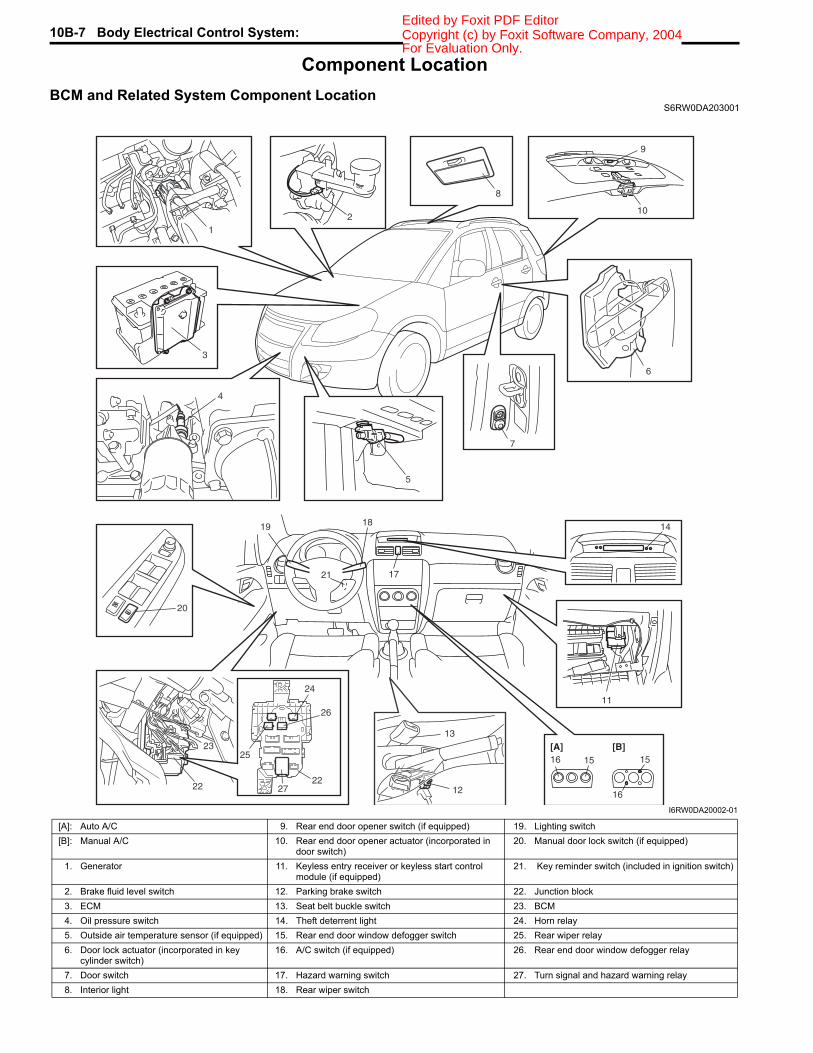
Component LocationBCM and Related System Component Location
S6RW0DA203001
13
12
17
18
21
19 14
24 25
25
26
2722
23
22
24
7
6
20
11
5
1516 15
16
[A] [B]
2
9
10
3
8
4
1
I6RW0DA20002-01
[A]: Auto A/C 9. Rear end door opener switch (if equipped) 19. Lighting switch[B]: Manual A/C 10. Rear end door opener actuator (incorporated in
door switch)20. Manual door lock switch (if equipped)
1. Generator 11. Keyless entry receiver or keyless start control module (if equipped)
21. Key reminder switch (included in ignition switch)
2. Brake fluid level switch 12. Parking brake switch 22. Junction block3. ECM 13. Seat belt buckle switch 23. BCM4. Oil pressure switch 14. Theft deterrent light 24. Horn relay5. Outside air temperature sensor (if equipped) 15. Rear end door window defogger switch 25. Rear wiper relay6. Door lock actuator (incorporated in key
cylinder switch)16. A/C switch (if equipped) 26. Rear end door window defogger relay
7. Door switch 17. Hazard warning switch 27. Turn signal and hazard warning relay8. Interior light 18. Rear wiper switch
For Evaluation Only.

Body Electrical Control System: 10B-8Copyright (c) by Foxit Software Company, 2004Edited by Foxit PDF Editor
Diagnostic Information and ProceduresBCM Self-Diagnosis Function
S6RW0DA204001
• BCM monitors conditions of the system components and its circuit with ignition switch turned to ON position. When an abnormality in the system occurs, the area where that abnormality lies is stored in the memory of EEPROM in BCM.
• DTC can be checked in either one of following ways.– DTC can be checked by SUZUKI scan tool (2) connected to DLC (1).– DTC can be read from flashing pattern of Theft deterrent light (3). Also, DTC is displayed on combination meter
(4) at the same time.
BCM Input / Output Table
3
4
2
1
I5RW0AA20007-01
Control Input Output
Power door lock system• Key cylinder switch• Manual door lock switch
• Each door lock actuator
Keyless entry system• Key reminder switch• Keyless entry receiver• Driver side door switch
• Each door lock actuator• Turn signal and hazard warning relay• Interior light
Keyless start system(Door lock function)
• Keyless start control module • Each door lock actuator• Turn signal and hazard warning relay• Interior light
Rear wiper • Rear wiper INT switch• Rear wiper LO switch
• Rear wiper relay
Combination meter
• Tail light switch• Oil pressure switch• Parking brake switch• Driver side seat belt switch• Brake fluid level switch• Generator• Each door switch
• Combination meter
Interior light• Each door switch• Key reminder switch
• Interior light
Warning buzzer
• Key reminder switch• Tail light switch• Driver side door switch• Keyless start control module (if equipped)• TCM (reverse signal) (if equipped)
• Warning buzzer (located in BCM)
For Evaluation Only.
10B-9 Body Electrical Control System: Copyright (c) by Foxit Software Company, 2004Edited by Foxit PDF Editor
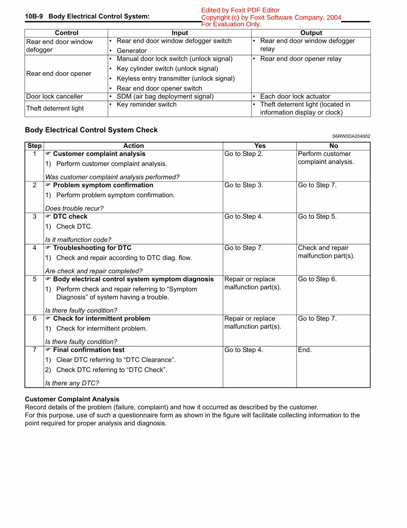
Body Electrical Control System CheckS6RW0DA204002
Customer Complaint AnalysisRecord details of the problem (failure, complaint) and how it occurred as described by the customer.For this purpose, use of such a questionnaire form as shown in the figure will facilitate collecting information to the point required for proper analysis and diagnosis.
Rear end door window defogger
• Rear end door window defogger switch• Generator
• Rear end door window defogger relay
Rear end door opener
• Manual door lock switch (unlock signal)• Key cylinder switch (unlock signal)• Keyless entry transmitter (unlock signal)• Rear end door opener switch
• Rear end door opener relay
Door lock canceller • SDM (air bag deployment signal) • Each door lock actuator
Theft deterrent light • Key reminder switch • Theft deterrent light (located in information display or clock)
Control Input Output
Step Action Yes No1 Customer complaint analysis
1) Perform customer complaint analysis.
Was customer complaint analysis performed?
Go to Step 2. Perform customer complaint analysis.
2 Problem symptom confirmation1) Perform problem symptom confirmation.
Does trouble recur?
Go to Step 3. Go to Step 7.
3 DTC check1) Check DTC.
Is it malfunction code?
Go to Step 4. Go to Step 5.
4 Troubleshooting for DTC1) Check and repair according to DTC diag. flow.
Are check and repair completed?
Go to Step 7. Check and repair malfunction part(s).
5 Body electrical control system symptom diagnosis1) Perform check and repair referring to “Symptom
Diagnosis” of system having a trouble.
Is there faulty condition?
Repair or replace malfunction part(s).
Go to Step 6.
6 Check for intermittent problem1) Check for intermittent problem.
Is there faulty condition?
Repair or replace malfunction part(s).
Go to Step 7.
7 Final confirmation test1) Clear DTC referring to “DTC Clearance”.2) Check DTC referring to “DTC Check”.
Is there any DTC?
Go to Step 4. End.
For Evaluation Only.
Body Electrical Control System: 10B-10Copyright (c) by Foxit Software Company, 2004Edited by Foxit PDF Editor
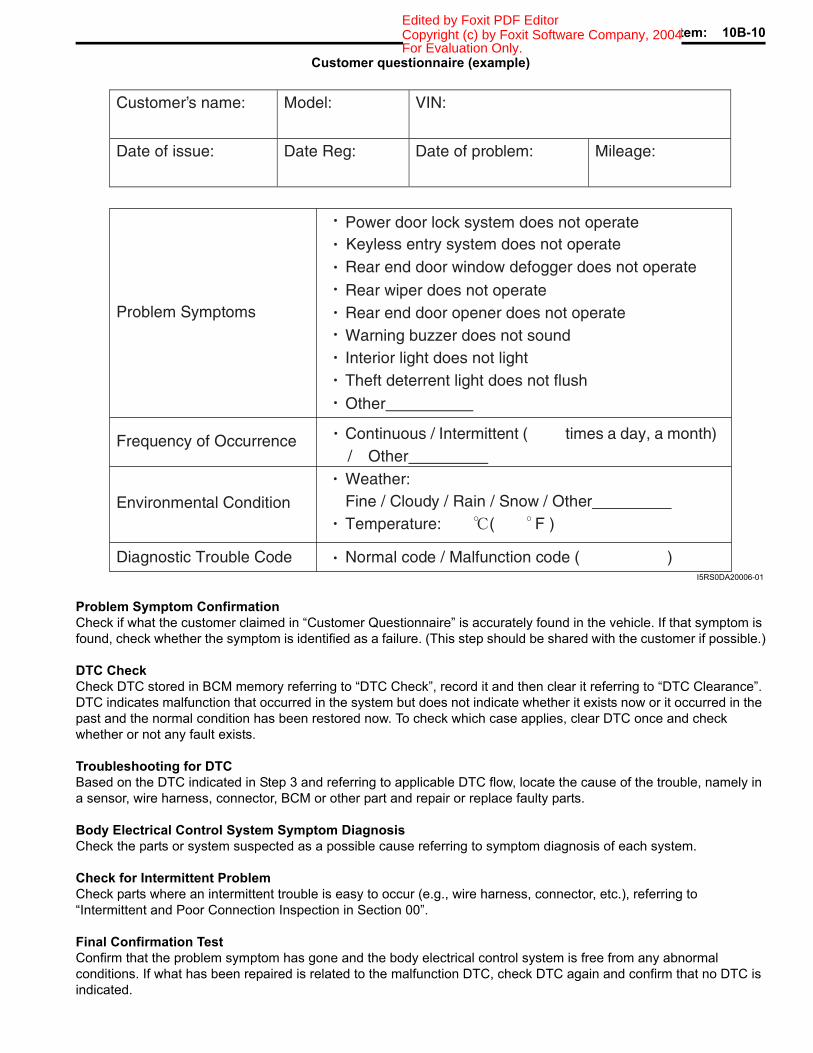
Customer questionnaire (example)
Problem Symptom ConfirmationCheck if what the customer claimed in “Customer Questionnaire” is accurately found in the vehicle. If that symptom is found, check whether the symptom is identified as a failure. (This step should be shared with the customer if possible.)
DTC CheckCheck DTC stored in BCM memory referring to “DTC Check”, record it and then clear it referring to “DTC Clearance”. DTC indicates malfunction that occurred in the system but does not indicate whether it exists now or it occurred in the past and the normal condition has been restored now. To check which case applies, clear DTC once and check whether or not any fault exists.
Troubleshooting for DTCBased on the DTC indicated in Step 3 and referring to applicable DTC flow, locate the cause of the trouble, namely in a sensor, wire harness, connector, BCM or other part and repair or replace faulty parts.
Body Electrical Control System Symptom DiagnosisCheck the parts or system suspected as a possible cause referring to symptom diagnosis of each system.
Check for Intermittent ProblemCheck parts where an intermittent trouble is easy to occur (e.g., wire harness, connector, etc.), referring to “Intermittent and Poor Connection Inspection in Section 00”.
Final Confirmation TestConfirm that the problem symptom has gone and the body electrical control system is free from any abnormal conditions. If what has been repaired is related to the malfunction DTC, check DTC again and confirm that no DTC is indicated.
Customer s name:
Model:
VIN:
Date of issue:
Date Reg:
Date of problem:
Mileage:
Problem Symptoms
Power door lock system does not operateKeyless entry system does not operate Rear end door window defogger does not operate
Rear wiper does not operateRear end door opener does not operate
Other
Frequency of Occurrence Continuous / Intermittent ( times a day, a month) / Other
Environmental Condition
Weather: Fine / Cloudy / Rain / Snow / Other Temperature: ( F )
Diagnostic Trouble Code Normal code / Malfunction code ( )
Warning buzzer does not soundInterior light does not lightTheft deterrent light does not flush
I5RS0DA20006-01
For Evaluation Only.
10B-11 Body Electrical Control System: Copyright (c) by Foxit Software Company, 2004Edited by Foxit PDF Editor
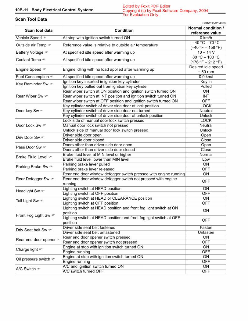
Scan Tool DataS6RW0DA204003
Scan tool data Condition Normal condition / reference value
Vehicle Speed At stop with ignition switch turned ON 0 km/h
Outside air Temp Reference value is relative to outside air temperature –40 °C – 70 °C(–40 °F – 158 °F)
Battery Voltage At specified idle speed after warming up 10 – 14 V
Coolant Temp At specified idle speed after warming up 80 °C – 100 °C(176 °F – 212 °F)
Engine Speed Engine idling with no load applied after warming up Desired idle speed± 50 rpm
Fuel Consumption At specified idle speed after warming up 0.0 km/l
Key Reminder Sw Ignition key inserted in ignition key cylinder Key inIgnition key pulled out from ignition key cylinder Pulled
Rear Wiper Sw Rear wiper switch at ON position and ignition switch turned ON ONRear wiper switch at INT position and ignition switch turned ON INTRear wiper switch at OFF position and ignition switch turned ON OFF
Door key Sw Key cylinder switch of driver side door at lock position LOCKKey cylinder switch of driver side door not turned NeutralKey cylinder switch of driver side door at unlock position Unlock
Door Lock Sw Lock side of manual door lock switch pressed LOCKManual door lock switch not pressed NeutralUnlock side of manual door lock switch pressed Unlock
Driv Door Sw Driver side door open OpenDriver side door closed Close
Pass Door Sw Doors other than driver side door open OpenDoors other than driver side door closed Close
Brake Fluid Level Brake fluid level at MIN level or higher NormalBrake fluid level lower than MIN level Low
Parking Brake Sw Parking brake lever pulled ONParking brake lever released OFF
Rear Defogger Sw Rear end door window defogger switch pressed with engine running ONRear end door window defogger switch not pressed with engine running OFF
Headlight Sw Lighting switch at HEAD position ONLighting switch at OFF position OFF
Tail Light Sw Lighting switch at HEAD or CLEARANCE position ONLighting switch at OFF position OFF
Front Fog Light Sw
Lighting switch at HEAD position and front fog light switch at ON position ON
Lighting switch at HEAD position and front fog light switch at OFF position OFF
Driv Seat belt Sw Driver side seat belt fastened FastenDriver side seat belt unfastened Unfasten
Rear end door opener Rear end door opener switch pressed ONRear end door opener switch not pressed OFF
Charge light Engine at stop with ignition switch turned ON ONEngine running OFF
Oil pressure switch Engine at stop with ignition switch turned ON ONEngine running OFF
A/C Switch A/C and ignition switch turned ON ONA/C switch turned OFF OFF
For Evaluation Only.

Body Electrical Control System: 10B-12Copyright (c) by Foxit Software Company, 2004Edited by Foxit PDF Editor
Scan Tool Data DefinitionsVehicle Speed (km/h, mph): This parameter indicates the vehicle speed computed by ECM.Outside air Temp (°C, °F): It is detected by outside air temperature sensor.Battery Voltage (V): This parameter indicates battery positive voltage inputted to BCM.Coolant Temp (Engine coolant temperature) (°C, °F): It is detected by engine coolant temperature sensor.Engine Speed (RPM): It is computed by reference pulse signals from CMP sensor.Fuel Consumption (km/l): This parameter indicates the fuel consumption computed by ECM.Key Reminder Sw (Key reminder switch) (Pulled / Key in): This parameter indicates the state of the key reminder
switch.Rear Wiper Sw (Rear wiper switch) (ON / INT / OFF): This parameter indicates the state of the rear wiper switch.Door key Sw (Door key cylinder switch) (Lock / Neutral / Unlock): This parameter indicates the state of the door
key cylinder switch.Door Lock Sw (Manual door lock switch) (Lock / Neutral / Unlock): This parameter indicates the state of the
manual door lock switch.Driv Door Sw (Driver side door switch) (Open / Close): This parameter indicates the state of the driver side door
switch.Pass Door Sw (Other than driver side door switch) (Open / Close): This parameter indicates the state of the door
switches other than driver side door switch.Brake Fluid Level (Low / Normal): Low: Brake fluid level is lower than specified level.
Normal: Brake fluid level is higher than MIN level.Parking Brake Sw (Parking brake switch) (ON / OFF): ON: Parking brake lever is pulled up.
OFF: Parking lever is released.Rear Defogger Sw (Rear end door window defogger switch) (ON / OFF): This parameter indicates the state of
the rear end door window defogger switch.Headlight Sw (Headlight switch) (ON / OFF) (Junction block without BCM type): This parameter indicates the
state of the lighting switch.Tail Light Sw (Lighting switch) (ON / OFF): This parameter indicates the state of the lighting switch.Front Fog Light Sw (Front fog light switch) (ON / OFF) (Junction block without BCM type): This parameter
indicates the state of the front fog light switch.Driv Seatbelt Sw (Driver seat belt switch) (Fasten / Unfasten): This parameter indicates the state of the driver
side seat belt buckle switch.Rear end door opener (Rear end door opener switch) (ON / OFF): This parameter indicates the state of the rear
end door opener switch.Charge light (ON / OFF): This parameter indicates the state of the charge system monitor switch.Oil pressure switch (ON / OFF): This parameter indicates the state of the oil pressure switch.A/C Switch (ON / OFF): This parameter indicates the state of the air conditioning switch.
Diagnosis Using Output Test Function of SUZUKI Scan ToolSUZUKI scan tool has the output test function which can force operation of following actuators and relays of the system controlled by BCM. When a malfunction is found in the system controlled by BCM, execute the output test which enables easy judgment whether the malfunction is on the input side or output side of BCM. For detailed information on operation of SUZUKI scan tool, refer to “SUZUKI Scan Tool Operator’s Manual”.
NOTE*1: Junction block without BCM type*2: With security alarm system
Output Teat Item Controlled PartsHazard Warning Light Turn signal and hazard warning relayInterior (Dome) Light Interior (Dome) light (when interior light switch is at DOOR position)Tail Light*1 Tail light relayFront Fog Light*1 Front fog light relay (when lighting switch is at HEAD position)Rear defogger Rear end door window defogger relayDead lock Each door lock actuatorRear end door open Rear end door opener relayDoor Each door lock actuatorWarning Buzzer Warning buzzer (in BCM)Rear wiper Rear wiper relayAlarm indicator Theft deterrent light (in information display or clock)Horn*2 Horn relay
For Evaluation Only.

10B-13 Body Electrical Control System: Copyright (c) by Foxit Software Company, 2004Edited by Foxit PDF Editor
DTC TableS6RW0DA204004
DTC (displayed on SUZUKI scan
tool)
DTC (indicated by theft
deterrent light)
DTC (displayed on odometer in
combination meter) Detected item Detecting condition
NO DTC 0000 0000 — No DTC detected B1133 1133 b1133 Battery voltage too high Battery voltage too high
B1141 1141 b1141Outside air temperature (ambient temperature) sensor circuit open
Sensor output voltage too high
B1142 1142 b1142
Outside air temperature (ambient temperature) sensor circuit short to ground
Sensor output voltage too low
B1150 1150 b1150 Air bag communication circuit malfunction
Air bag communication circuit open or short to ground
B1157 1157 b1157 Air bag deployment signal input
Air bag deployment signal inputted
B1170 1170 b1170 EEPROM access error Memory error
U0073 0073 U0073 Control module communication bus off
Transmitting and receiving error of BCM for specified time continuously
U0100 0100 U0100 Lost communication with ECM
Receiving error of BCM from ECM for specified time continuously
U0101 0101 U0101 Lost communication with TCM
Receiving error of BCM from TCM for specified time continuously
U0155 0155 U0155Lost communication with instrument panel cluster (IPC) control module
Receiving error of BCM from combination meter for specified time continuously
U1144 1144 U1144 Lost communication with keyless start control module
Receiving error of BCM from keyless start control module for specified time continuously
For Evaluation Only.

Body Electrical Control System: 10B-14Copyright (c) by Foxit Software Company, 2004Edited by Foxit PDF Editor
DTC CheckS6RW0DA204005
Using SUZUKI Scan Tool1) Prepare SUZUKI scan tool.2) With ignition switch turned OFF, connect it to data link connector (DLC) located on underside of instrument panel
of driver’s side.
Special tool(A): SUZUKI scan tool
3) Turn ignition switch ON.4) Read DTC according to instructions displayed on SUZUKI scan tool and print it or write it down.
Refer to SUZUKI scan tool operator’s manual for further details.If communication between SUZUKI scan tool and BCM is not possible, check if SUZUKI scan tool is communicable by connecting it to BCM in another vehicle. If communication is possible in this case, SUZUKI scan tool is in good condition. Then check data link connector and serial data line (circuit) in the vehicle with which communication was not possible.
5) After completing the check, turn ignition switch off and disconnect SUZUKI scan tool from data link connector.
Without Using SUZUKI Scan Tool1) Turn ignition switch to OFF position.2) Perform following Steps a) to d) within 10 seconds after ignition switch is turned ON and engine stops.
a) Turn headlight switch to “SMALL” position.b) Turn headlight switch to “OFF” position.c) Repeat Steps a) and b) 2 times.d) Press and release driver side door switch 3 times.
(A)
I5RW0AA20008-02
For Evaluation Only.
10B-15 Body Electrical Control System: Copyright (c) by Foxit Software Company, 2004Edited by Foxit PDF Editor
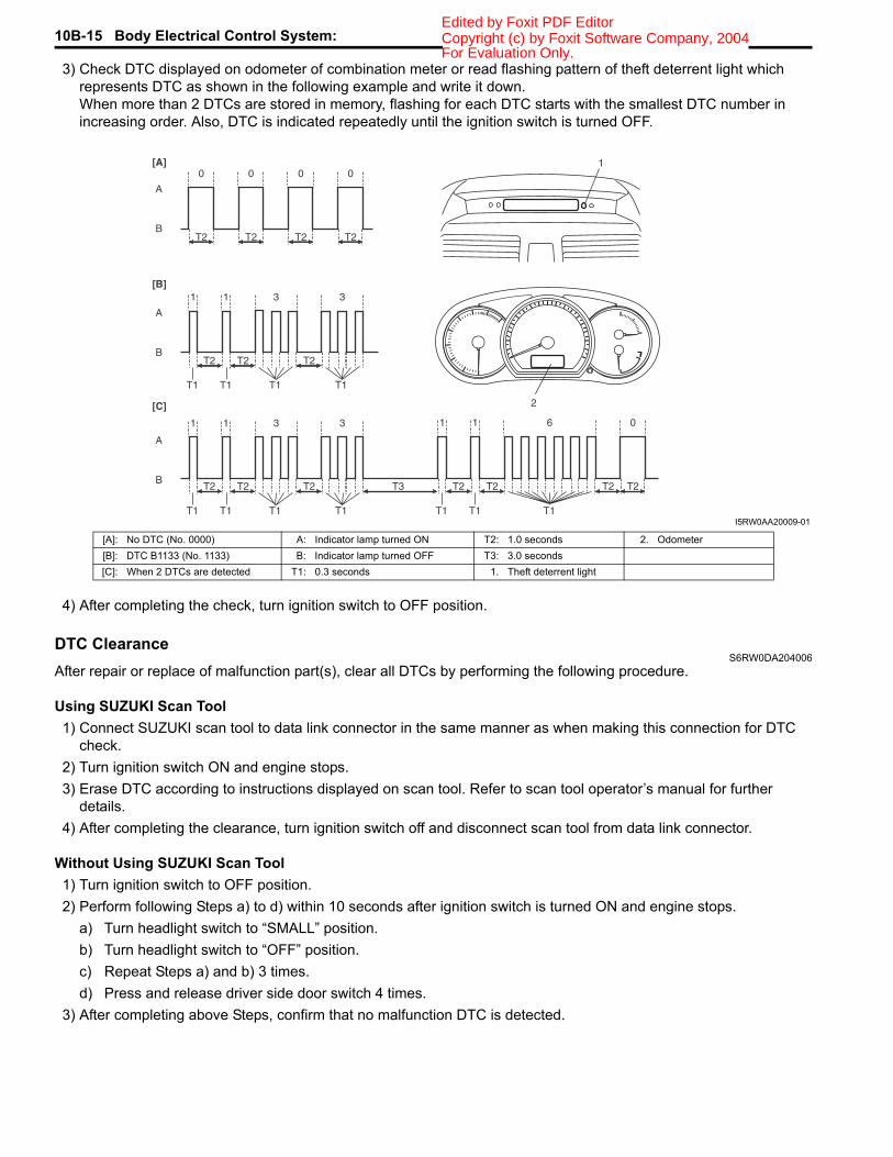
3) Check DTC displayed on odometer of combination meter or read flashing pattern of theft deterrent light which represents DTC as shown in the following example and write it down.When more than 2 DTCs are stored in memory, flashing for each DTC starts with the smallest DTC number in increasing order. Also, DTC is indicated repeatedly until the ignition switch is turned OFF.
4) After completing the check, turn ignition switch to OFF position.
DTC ClearanceS6RW0DA204006
After repair or replace of malfunction part(s), clear all DTCs by performing the following procedure.
Using SUZUKI Scan Tool1) Connect SUZUKI scan tool to data link connector in the same manner as when making this connection for DTC
check.2) Turn ignition switch ON and engine stops.3) Erase DTC according to instructions displayed on scan tool. Refer to scan tool operator’s manual for further
details.4) After completing the clearance, turn ignition switch off and disconnect scan tool from data link connector.
Without Using SUZUKI Scan Tool1) Turn ignition switch to OFF position.2) Perform following Steps a) to d) within 10 seconds after ignition switch is turned ON and engine stops.
a) Turn headlight switch to “SMALL” position.b) Turn headlight switch to “OFF” position.c) Repeat Steps a) and b) 3 times.d) Press and release driver side door switch 4 times.
3) After completing above Steps, confirm that no malfunction DTC is detected.
B
A
[B]
[A]
[C]
B
A
B
A
31 1 3
31 1 3
T2
T1 T1 T1 T1
1
2
T2 T2
T2
T1 T1 T1 T1
T2 T2
0
T2
0
T2
0
T2
0
T2
1 1 6 0
T1 T1 T1
T2T3 T2 T2 T2
I5RW0AA20009-01
[A]: No DTC (No. 0000) A: Indicator lamp turned ON T2: 1.0 seconds 2. Odometer[B]: DTC B1133 (No. 1133) B: Indicator lamp turned OFF T3: 3.0 seconds[C]: When 2 DTCs are detected T1: 0.3 seconds 1. Theft deterrent light
For Evaluation Only.

Body Electrical Control System: 10B-16Copyright (c) by Foxit Software Company, 2004Edited by Foxit PDF Editor
BCM Power Circuit and Ground Circuit CheckS6RW0DA204007
Wiring Diagram
Troubleshooting
+B
IG1
+BB
GRNG273-2BLKBLK/ORN
G272-9G271-3
BLK/ORNL314-4
BLUG273-5
WHTE324-22
3
1
E324 L314
1245 36789
101112131415161718
121245 36 1245 3678910
789101112 11121314151617181920
G272 G271
1246 5
G273[A] [A] [A]
3
[A]
I6RW0CA20006-02
[A]: Junction block connector viewed from harness side 2. Ignition switch1. Junction block 3. Battery
Step Action Yes No1 Fuse check
1) Turn ignition switch to OFF position.2) Check circuit fuses for condition.
Are circuit fuses in good condition?
Go to Step 2. Replace fuse and check for short circuit to ground.
2 Power supply circuit check1) Disconnect connectors from junction block.2) Check for proper connection to junction block connector
at terminal “E324-2”.3) If OK, then measure voltage between “E324-2” terminal
of junction block connector and vehicle body ground.
Is voltage 10 – 14 V?
Go to Step 3. Repair power supply circuit.
3 Power supply circuit check1) Check for proper connection to junction block connector
at terminals “G273-2” and “G273-5”.2) If OK, turn ignition switch to ON position.3) Measure voltage between following terminals.
• Between “G273-2” terminal of junction block connector and vehicle body ground
• Between “G273-5” terminal of junction block connector and vehicle body ground
Is each voltage 10 – 14 V?
Go to Step 4. Repair power supply circuit.
For Evaluation Only.

10B-17 Body Electrical Control System: Copyright (c) by Foxit Software Company, 2004Edited by Foxit PDF Editor
DTC B1133 (DTC No. 1133): Battery Voltage Too HighS6RW0DA204008
Wiring DiagramRefer to “BCM Power Circuit and Ground Circuit Check”.
DTC Detecting Condition and Possible Cause
Flow Test DescriptionStep 1: Check charging system
DTC Troubleshooting
4 Ground circuit check1) Turn ignition switch to OFF position.2) Check for proper connection to junction block connector
at terminals “G271-3”, “G272-9” and “L314-4”.3) If OK, then measure resistance between following
terminals.• Between “G271-3” terminal of junction block
connector and vehicle body ground• Between “G272-9” terminal of junction block
connector and vehicle body ground• Between “L314-4” terminal of junction block connector
and vehicle body ground
Is each resistance 2 Ω or less?
BCM power supply circuit and ground circuit are in good condition.
Repair ground circuit.Step Action Yes No
DTC detecting condition Possible causePower voltage supplied from battery to BCM is higher than 16V.
• Charging system malfunction• BCM malfunction
Step Action Yes No1 Charging system operation check
1) Check generator for operation referring to “Generator Test (Overcharged Battery Check) in Section 1J”.
Is it in good condition?
Substitute a known good BCM (included in junction block) and recheck.
Repair charging system.
For Evaluation Only.

Body Electrical Control System: 10B-18Copyright (c) by Foxit Software Company, 2004Edited by Foxit PDF Editor
DTC B1141 / DTC B1142 (No. 1141 / No. 1142) Outside Air Temperature (Ambient Temp.) Sensor Circuit Malfunction
S6RW0DA204009Wiring Diagram
DTC Detecting Condition and Possible Cause
Flow Test DescriptionStep 1: Check whether malfunction is in outside air temperature sensor.Step 2: Check outside air temperature sensor circuit.
DTC Troubleshooting
YEL/RED
YEL/BLK
5V
E04-10
E04-8
1
2
E04
1245 367891011121314
[A]
I6RW0CA20007-01
[A]: BCM connector viewed from harness side 2. BCM1. Outside air temperature sensor
DTC detecting condition Possible causeDTC B1141 (DTC No. 1141):Input signal from outside air temperature sensor is higher than 4.88 V.
• Open in outside air temperature sensor circuit• Outside air temperature sensor malfunction• BCM malfunction
DTC B1142 (DTC No. 1142):Input signal from outside air temperature sensor is lower than 0.1 V.
• Short in outside air temperature sensor circuit• Outside air temperature sensor malfunction• BCM malfunction
Step Action Yes No1 Outside air temperature sensor check
1) Turn ignition switch to OFF position.2) Disconnect connector from outside air temperature
sensor.3) Check outside air temperature sensor for resistance
referring to “Outside Air Temperature Sensor Inspection (If Equipped) in Section 9C”.
Is it in good condition?
Go to Step 2. Replace outside air temperature sensor.
2 Outside air temperature sensor circuit check1) Disconnect connector from BCM and check for proper
terminal connection to BCM connector.2) If connections are OK, check outside air temperature
sensor circuit for open, short and high resistance.
Is each circuit in good condition?
Substitute a known-good BCM (included in junction block) and recheck.
Repair circuit.
For Evaluation Only.
10B-19 Body Electrical Control System: Copyright (c) by Foxit Software Company, 2004Edited by Foxit PDF Editor
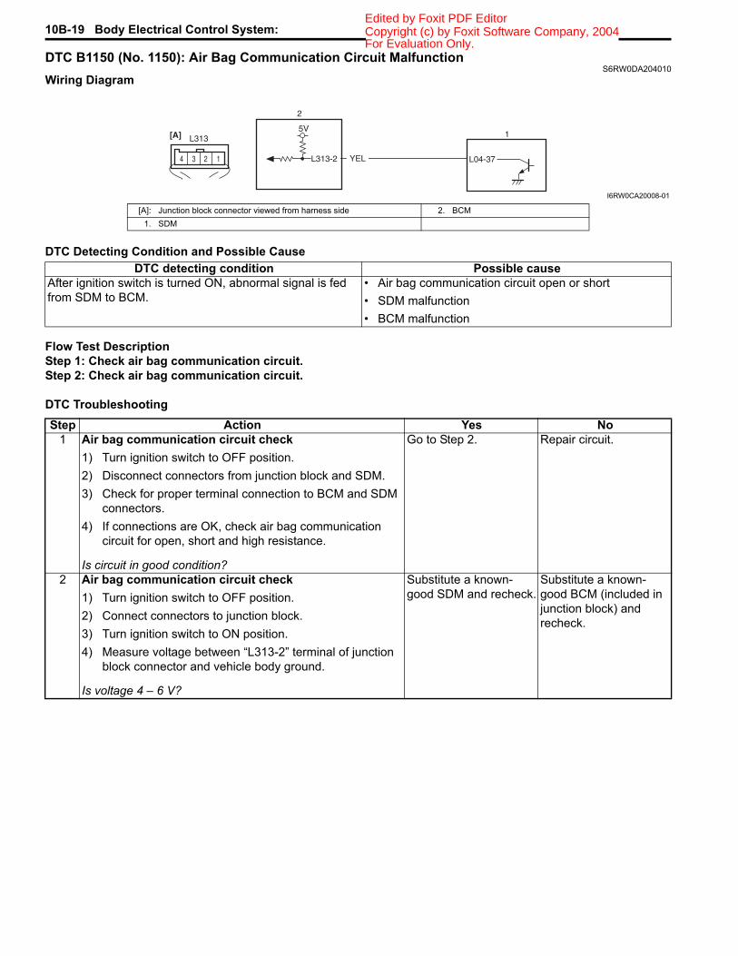
DTC B1150 (No. 1150): Air Bag Communication Circuit MalfunctionS6RW0DA204010
Wiring Diagram
DTC Detecting Condition and Possible Cause
Flow Test DescriptionStep 1: Check air bag communication circuit.Step 2: Check air bag communication circuit.
DTC Troubleshooting
YEL
5V
L313-2 L04-37
2
1L313
124 3
[A]
I6RW0CA20008-01
[A]: Junction block connector viewed from harness side 2. BCM1. SDM
DTC detecting condition Possible causeAfter ignition switch is turned ON, abnormal signal is fed from SDM to BCM.
• Air bag communication circuit open or short• SDM malfunction• BCM malfunction
Step Action Yes No1 Air bag communication circuit check
1) Turn ignition switch to OFF position.2) Disconnect connectors from junction block and SDM.3) Check for proper terminal connection to BCM and SDM
connectors.4) If connections are OK, check air bag communication
circuit for open, short and high resistance.
Is circuit in good condition?
Go to Step 2. Repair circuit.
2 Air bag communication circuit check1) Turn ignition switch to OFF position.2) Connect connectors to junction block.3) Turn ignition switch to ON position.4) Measure voltage between “L313-2” terminal of junction
block connector and vehicle body ground.
Is voltage 4 – 6 V?
Substitute a known-good SDM and recheck.
Substitute a known-good BCM (included in junction block) and recheck.
For Evaluation Only.

Body Electrical Control System: 10B-20Copyright (c) by Foxit Software Company, 2004Edited by Foxit PDF Editor
DTC B1157 (No. 1157) Air Bag Deployment Signal InputS6RW0DA204011
Wiring DiagramRefer to “DTC B1150 (No. 1150): Air Bag Communication Circuit Malfunction”.
DTC Detecting Condition and Possible Cause
Flow Test DescriptionStep 1: Check DTC for SDM.
DTC Troubleshooting
DTC B1170 (No. 1170): EEPROM Access ErrorS6RW0DA204012
DTC Detecting Condition and Possible Cause
DTC Troubleshooting
NOTEBefore performing steps below, be sure to perform “Body Electrical Control System Check”.
1) Ignition switch OFF.2) Replace BCM.3) Repeat BCM Check Flow Table.
DTC U0073 (No. 0073): Control Module Communication Bus OffS6RW0DA204013
Refer to “Troubleshooting for CAN-DTC in Section 1A”.
DTC U0100 (No. 0100): Lost Communication with ECMS6RW0DA204014
Refer to “Troubleshooting for CAN-DTC in Section 1A”.
DTC U0101 (No. 0101): Lost Communication with TCMS6RW0DA204018
Refer to “Troubleshooting for CAN-DTC in Section 1A”.
DTC U0155 (No. 0155): Lost Communication with Instrument Panel Cluster (IPC) Control ModuleS6RW0DA204015
Refer to “Troubleshooting for CAN-DTC in Section 1A”.
DTC U1144 (No. 1144): Lost Communication with Keyless Start Control ModuleS6RW0DA204016
Refer to “Troubleshooting for CAN-DTC in Section 1A”.
DTC detecting condition Possible causeAir bag deployment signal is fed from SDM to BCM. • Air bag component parts
• BCM malfunction
Step Action Yes No1 DTC check of SDM
1) Check DTC stored in SDM referring to “DTC Check in Section 8B”.
Is DTC B1021 detected?
Go to “DTC B1021: Front Air Bag Deployment Record in Section 8B”.
Substitute a known-good BCM (included in junction block) and recheck.
DTC detecting condition Possible causeData write error or check sum error. BCM malfunction
For Evaluation Only.

10B-21 Body Electrical Control System: Copyright (c) by Foxit Software Company, 2004Edited by Foxit PDF Editor
Inspection of BCM and Its CircuitsS6RW0DA204017
BCM and its circuits can be checked at BCM wiring couplers by measuring voltage and resistance.
CAUTION!
BCM cannot be checked by itself. It is strictly prohibited to connect voltmeter or ohmmeter to BCM with couplers disconnected from it.
Voltage Check1) Disconnect negative cable (–) at battery.2) Remove BCM (included in junction block) referring to “BCM (Included in Junction Block) Removal and Installation”.3) Connect connectors to BCM (1) and junction block (2).4) Check voltage at each terminal number of couplers connected.
For connector and terminal number, refer to “Connector Layout Diagram of BCM and Junction Block”.
NOTE
• As each terminal voltage is affected by the battery voltage, confirm that it is 11 V or more when ignition switch is ON.
• Voltage with asterisk (*) can not be measured by voltmeter because it is pulse signal.Check it with oscilloscope if necessary.
BCM connector “L01”
1
2
1
2
I4RS0AA20030-01
Terminal Circuit Normal voltage Condition
L01-1Passenger side door lock actuator control (Unlock) (if equipped)
10 – 14 V Unlock signal is output for passenger side door lock actuator
0 V Unlock signal is not output for passenger side door lock actuator
L01-2 — — —
L01-3 Rear end door switch 10 – 14 V Rear end door is closed0 V Rear end door is opened
L01-4 Rear end door opener switch (if equipped)
10 – 14 V Rear end door opener switch is not pushed0 V Rear end door opener switch is pushed
L01-5 Manual door lock switch(Unlock) (if equipped)
10 – 14 V Manual door lock switch is at any position other than unlock position
0 V Manual door lock switch is at unlock position
L01-6 Parking brake switch
*0 – 3 V↑↓
10 – 14 VRefer to “Reference waveform No. 1: ”
0 V Ignition switch is at ON position and parking brake lever is pulled up
L01-7 Driver side door switch 10 – 14 V Driver side door is closed0 V Driver side door is opened
L01-8 — — —L01-9 — — —
For Evaluation Only.

Body Electrical Control System: 10B-22Copyright (c) by Foxit Software Company, 2004Edited by Foxit PDF Editor
BCM connector “E04”
L01-10Driver side door lock actuator control (Unlock) (if equipped)
10 – 14 V Unlock signal is output for driver side door lock actuator
0 V Unlock signal is not output for driver side door lock actuator
L01-11 Rear end door opener actuator control (if equipped)
0 V Rear end door actuator motor is not in operation
10 – 14 V Rear end door actuator motor is in operation
L01-12 Manual door lock switch(Lock) (if equipped)
10 – 14 V Manual door lock switch is at any position other than lock position
0 V Manual door lock switch is at lock positionL01-13 — — —
L01-14 Driver side seat belt switch
*0 – 3 V↑↓
10 – 14 VRefer to “Reference waveform No. 2: ”
0 V Ignition switch is at ON position and driver side seat belt is unfastened
L01-15Door switch (other than driver side door and rear end door)
10 – 14 V Rear right and left side door and passenger side door are closed
0 V Any one of the door is opened (except driver side door and rear end door)
L01-16 Driver side door key cylinder switch (Lock) (if equipped)
10 – 14 V Driver side door key cylinder switch is at any position other than lock position
0 V Driver side door key cylinder switch is at lock position
L01-17 Driver side door key cylinder switch (Unlock) (if equipped)
10 – 14 V Driver side door key cylinder switch is at any position other than unlock position
0 V Driver side door key cylinder switch is at unlock position
L01-18 — — —
Terminal Circuit Normal voltage Condition
E04-1 CAN communication line (high) for ABS control module *2.5 – 3.6 V
Refer to “Reference waveform No. 3: ”E04-2 CAN communication line (low)
for ABS control module *1.6 – 2.5 V
E04-3 — — —
E04-4 Generator “L” terminal 10 – 14 V Engine is running0 V Ignition switch is at ON position
E04-5 Brake fluid level switch
*0 – 3 V↑↓
10 – 14 VRefer to “Reference waveform No. 1: ”
0 VIgnition switch is at ON position, parking brake lever is released and brake fluid level is lower than MIN level
E04-6 — — —E04-7 — — —
E04-8Sensor ground for outside air temperature sensor (if equipped)
0 V —
E04-9Serial communication line of data link connector for ABS control module
7 – 12 V Ignition switch is at ON position
E04-10 Outside air temperature sensor (if equipped) About 1.5 V Ignition switch is at ON position and outside
air temperature approx. 20 °C (68 °F)
E04-11 Oil pressure switch*3 – 14 V Refer to “Reference waveform No. 4: ”
0 V Ignition switch is at ON position and engine is at stop
E04-12 — — —
Terminal Circuit Normal voltage ConditionFor Evaluation Only.

10B-23 Body Electrical Control System: Copyright (c) by Foxit Software Company, 2004Edited by Foxit PDF Editor
BCM connector “G04”
E04-13 — — —E04-14 — — —
Terminal Circuit Normal voltage Condition
G04-1 CAN communication line (low) for DLC *1.6 – 2.5 V
Refer to “Reference waveform No. 3: ”G04-2 CAN communication line (low)
for each control module *1.6 – 2.5 V
G04-3 CAN communication line (high) for DLC *2.5 – 3.6 V
G04-4 CAN communication line (high) for each control module *2.5 – 3.6 V
G04-5 Serial communication line of data link connector 7 – 12 V Ignition switch is at ON position
G04-6 — — —G04-7 — — —
G04-8 Theft deterrent light 10 – 14 V Theft deterrent light is not lit up0 V Theft deterrent light is lit up
G04-9 — — —G04-10 — — —
G04-11Serial communication line for information display and HVAC control module (if equipped)
*0 – 1 V↑↓
10 – 14 VRefer to “Reference waveform No. 5: ”
G04-12 Ground for keyless entry receiver (if equipped) 0 V —
G04-13 Power supply for keyless entry receiver (if equipped) 4 – 6 V Ignition switch is at all positions
G04-14 Signal for keyless entry receiver (if equipped)
*0 – 1 V↑↓
4 – 6 VRefer to “Reference waveform No. 6: ”
G04-15 Vehicle speed signal output*0 – 1 V
↑↓4 – 6V
Refer to “Reference waveform No. 7: ”
G04-16 Key reminder switch10 – 14 V Ignition key is inserted to ignition key cylinder
0 V Ignition key is pulled out from ignition key cylinder
G04-17 Rear end door window defogger switch
*3 – 14 V Refer to “Reference waveform No. 8: ”
0 V Ignition switch is at ON position and rear end door window defogger switch is pushed
G04-18 A/C switch (if equipped)
*3 – 14 V Refer to “Reference waveform No. 8: ”
0 VIgnition switch is at ON position, blower speed selector is at any position other than OFF position and A/C switch is at ON position
G04-19 — — —G04-20 — — —
G04-21 Rear wiper INT switch
*0 – 1 V↑↓
10 – 14 VRefer to “Reference waveform No. 9: ”
0 V Ignition switch is at ON position and rear wiper switch is at INT position
G04-22 Rear wiper low switch
*0 – 1 V↑↓
10 – 14 VRefer to “Reference waveform No. 9: ”
0 V Ignition switch is at ON position and rear wiper switch is at LOW position
Terminal Circuit Normal voltage ConditionFor Evaluation Only.

Body Electrical Control System: 10B-24Copyright (c) by Foxit Software Company, 2004Edited by Foxit PDF Editor
Junction block connector “E324”
Junction block connector “E325”
Junction block connector “G271”
Junction block connector “G272”
Junction block connector “G273”
Junction block connector “L312”
Junction block connector “L313”
Terminal Circuit Normal voltage ConditionE324-2 Backup power source 10 – 14 V Ignition switch is at all positions
Terminal Circuit Normal voltage Condition
E325-3 Horn 10 – 14 V Horn switch is at ON position0 V Horn switch is at OFF position
Terminal Circuit Normal voltage ConditionG271-3 Ground for BCM 0 V Ignition switch is at all positions
G271-7 Rear end door window defogger indicator light
10 – 14 V Engine is running and rear end door window defogger indicator light is lit up
0 V Engine is running and rear end door window defogger indicator light is not lit up
Terminal Circuit Normal voltage Condition
G272-3 Horn switch 10 – 14 V Horn switch is not pushed0 V Horn switch is pushed
G272-7 Lighting switch 10 – 14 VEngine is running (with DRL model) or lighting switch is at any position other than OFF position
0 V Lighting switch is at OFF positionG272-9 Ground for BCM 0 V Ignition switch is at all positions
G272-11 Hazard warning switch
10 – 14 V Hazard warning switch is at OFF position
0 VHazard warning switch is at ON position or lock or unlock button of keyless entry transmitter (answer back control) is pushed
Terminal Circuit Normal voltage Condition
G273-2 Power source (IG)10 – 14 V Ignition switch is at ON position
0 V Ignition switch is at any position other than ON position
G273-5 Power source (ACC)10 – 14 V Ignition switch is at ACC or ON position
0 V Ignition switch is at any position other than ACC or ON position
Terminal Circuit Normal voltage Condition
L312-4 Power supply for rear wiper motor 10 – 14 V Ignition switch is at ON position
L312-5 Interior light10 – 14 V Interior light switch is at DOOR position and
interior light is not lit up
0 V Interior light switch is at DOOR position and interior light is lit up
Terminal Circuit Normal voltage Condition
L313-2 Air bag communication line*0 – 1 V
↑↓4 – 6 V
Refer to “Reference waveform No. 10: ”
L313-3 Serial communication line of data link connector for SDM 7 – 12 V Ignition switch is at ON position
For Evaluation Only.

10B-25 Body Electrical Control System: Copyright (c) by Foxit Software Company, 2004Edited by Foxit PDF Editor
Junction block connector “L314”
Junction block connector “L315”
Terminal Circuit Normal voltage ConditionL314-4 Ground for BCM 0 V Ignition switch is at all positions
L314-6 Right side door mirror heater (if equipped)
10 – 14 V Engine is running and rear end door window defogger is in operation
0 V Engine is running and rear end door window defogger is not in operation
L314-7 Left side door mirror heater (if equipped)
10 – 14 V Engine is running and rear end door window defogger is in operation
0 V Engine is running and rear end door window defogger is not in operation
L314-8 Rear end door window defogger wire
10 – 14 V Engine is running and rear end door window defogger is in operation
0 V Engine is running and rear end door window defogger is not in operation
L314-9 Rear wiper control10 – 14 V Ignition switch is at ON position and rear
wiper is not in operation
0 V Ignition switch is at ON position and rear wiper is in operation
Terminal Circuit Normal voltage Condition
L315-1 Door lock actuator control (Dead lock) (if equipped)
10 – 14 V Driver side key cylinder is turned to lock twice with in 3 seconds
0 V
Manual door lock switch is at any position other than LOCK position and driver side door key cylinder switch is at any position other than LOCK position
L315-9 Door lock actuator control (Unlock) (if equipped)
10 – 14 V Unlock signal is output for rear door lock actuator
0 V Unlock signal is not output for rear door lock actuator
L315-10 Door lock actuator control (Lock) (if equipped)
10 – 14 V Lock signal is output for all door lock actuators
0 V Lock signal is not output for all door lock actuators
For Evaluation Only.

Body Electrical Control System: 10B-26Copyright (c) by Foxit Software Company, 2004Edited by Foxit PDF Editor
Reference waveform No. 1Parking brake or brake fluid level switch signal (1)
Reference waveform No. 2Driver seat belt switch signal (1)
Reference waveform No. 3CAN communication signal
Reference waveform No. 4Oil pressure switch signal (1)
Measurement terminal Parking brake switchCH2: “L01-6” to “G271-3”Brake fluid level switchCH2: “E04-5” to “G271-3”
Oscilloscope setting CH1: 5 V / DIVTIME: 10 ms / DIV
Measurement condition
Parking brake switch:• Ignition switch is at ON
position, parking brake lever is released
Brake fluid level switch• Ignition switch is at ON
position, brake fluid level is in normal
Measurement terminal CH2: “L01-14” to “G271-3”Oscilloscope setting CH2: 5 V/DIV
TIME: 4 ms/DIVMeasurement condition
Ignition switch is at ON position and driver side seat belt is fastened
I4RS0AA20018-02
I4RS0AA20016-02
Measurement terminal CAN communication signal for ABS control moduleCH2: “E04-1” to “G271-3”CH3: “E04-2” to “G271-3”CAN communication signal for DLCCH2: “G04-3” to “G271-3”CH3: “G04-1” to “G271-3”CAN communication signal for each control moduleCH2: “G04-4” to “G271-3”CH3: “G04-2” to “G271-3”
Oscilloscope setting CH2: 1 V/DIVCH3: 1 V/DIVTIME: 40 µs/ DIV
Measurement condition
Ignition switch is at ON position
1. CAN communication line signal (High)2. CAN communication line signal (Low)
Measurement terminal CH2: “E04-11” to “G271-3”Oscilloscope setting CH2: 5 V / DIV
TIME: 10 ms / DIVMeasurement condition
Engine is running and oil pressure is in normal condition
I4RS0AA20017-02
I4RS0AA20018-02
For Evaluation Only.

10B-27 Body Electrical Control System: Copyright (c) by Foxit Software Company, 2004Edited by Foxit PDF Editor
Reference waveform No. 5Information display and HVAC control module serial communication signal (1)
Reference waveform No. 6Keyless entry receiver signal (1)
Reference waveform No. 7Vehicle speed pulse output signal (1)
Reference waveform No. 8A/C or rear end door window defogger switch signal (1)
Measurement terminal CH2: “G04-11” to “G271-3”Oscilloscope setting CH2: 5 V / DIV
TIME: 2 ms / DIVMeasurement condition
Ignition switch is at ON position
Measurement terminal CH2: “G04-14” to “G271-3”Oscilloscope setting CH2: 2 V / DIV
TIME: 200 ms / DIVMeasurementcondition
Lock or unlock button of keyless entry transmitter is pushed
I4RS0AA20021-02
I4RS0AA20022-02
Measurement terminal CH1: “G04-15” to “G271-3”Oscilloscope setting CH1: 2 V / DIV
TIME: 100 ms / DIVMeasurement condition
Vehicle speed at 10 km/h (6 mph)
Measurement terminal Rear end door window defogger switchCH2: “G04-17” to “G271-3”A/C switchCH2: “G04-18” to “G271-3”
Oscilloscope setting CH2: 5 V/DIVTIME: 10 ms/DIV
Measurementcondition
Rear end door window defogger switch:• Ignition switch is at ON
position and rear end door window defogger switch is not pushed
A/C switch:• Ignition switch is at ON
position, A/C switch or blower speed selector is at OFF position
I5RW0AA20014-01
I4RS0AA20023-02
For Evaluation Only.

Body Electrical Control System: 10B-28Copyright (c) by Foxit Software Company, 2004Edited by Foxit PDF Editor
Reference waveform No. 9Rear wiper switch signal (1)
Reference waveform No. 10SDM communication signal (1)
Repair InstructionsBCM (Included in Junction Block) Removal and Installation
S6RW0DA206001
CAUTION!
Do not attempt removal of BCM from junction block as it may cause contact failure.If there is faulty condition in BCM, replace junction block assembly.
Removal1) Disconnect negative cable from battery.2) Disable air bag system referring to “Disabling Air
Bag System in Section 8B”.3) Remove dash side trim (1) and steering column hole
cover (2).4) Remove junction block mounting nuts (3).
Measurement terminal Rear wiper INT switchCH2: “G04-21” to “G271-3”Rear wiper LOW switchCH2: “G04-22” to “G271-3”
Oscilloscope setting CH2: 5 V/DIVTIME: 10 ms/DIV
Measurementcondition
Rear wiper INT switch:• Ignition switch is at ON
position and rear wiper switch is at any position other than INT position
Rear wiper LOW switch:• Ignition switch is at ON
position and rear wiper switch is at any position other than LOW position
I4RS0AA20024-02
Measurement terminal CH2: “L314-2” to “G271-3”Oscilloscope setting CH2: 2 V / DIV
TIME: 400 ms / DIVMeasurementcondition
Ignition switch is at ON position
I4RS0AA20026-02
4. BCM 5. Junction block
21
3
3
4
5
I5RW0AA20015-01
For Evaluation Only.

10B-29 Body Electrical Control System: Copyright (c) by Foxit Software Company, 2004Edited by Foxit PDF Editor
5) Disconnect connectors from BCM and junction block.
6) Detach wiring harness clamp from junction block.
InstallationReverse removal procedure for installation, noting following points.• Connect connectors securely.• Enable air bag system referring to “Enabling Air Bag
System in Section 8B”.• With keyless entry system (other than keyless start
model), if BCM is replaced, register transmitter code into BCM, referring to “Programming Transmitter Code for Keyless Entry System (Other than Keyless Start Model) in Section 9F”.
Security Alarm Mode Selection Procedure (If Equipped)
S6RW0DA206005Security alarm mode can be selected by performing the following procedure.1) Confirm that all doors are closed, all doors are
unlocked and ignition key is inserted in ignition key cylinder.
2) Remove ignition key from ignition key cylinder.3) Perform Step a) through e) described below within
15 seconds.a) Insert ignition key (1) in ignition key cylinder (2).b) Remove ignition key from ignition key cylinder.c) Repeat Step a) and b) twice.d) Insert ignition key in ignition key cylinder.e) Push lock side (3) of driver side manual lock
switch (4) 3 times.
4) When Step 3) is completed, the mode changes to the next one automatically. The warning buzzer (located in BCM) sounds by the number of specified for each mode as follows.• Changed from A mode to B mode: Buzzer sounds
4 times• Changed from B mode to A mode: Buzzer sounds
once
Outside Air Temperature Sensor Removal and Installation
S6RW0DA206002For removal and installation, refer to “Outside Air Temperature Sensor Removal and Installation (If Equipped) in Section 9C”.
Outside Air Temperature Sensor InspectionS6RW0DA206003
For inspection, refer to “Outside Air Temperature Sensor Inspection (If Equipped) in Section 9C”.
Special Tools and EquipmentSpecial Tool
S6RW0DA208001
1
2
4
3
I7JB01A20007-01
SUZUKI scan tool—This kit includes following items. 1. Tech 2, 2. PCMCIA card, 3. DLC cable, 4. SAE 16/19 adapter, 5. Cigarette cable, 6. DLC loop back adapter, 7. Battery power cable, 8. RS232 cable, 9. RS232 adapter, 10. RS232 loop back connector, 11. Storage case, 12.
For Evaluation Only.

Immobilizer Control System: 10C-1Copyright (c) by Foxit Software Company, 2004Edited by Foxit PDF Editor
Control SystemsImmobilizer Control SystemPrecautions
Precautions in Diagnosing TroublesS6RW0DA300001
• Before confirming the diagnostic trouble code (DTC), do not disconnect connector from ECM, battery cable from battery, ground wire harness, or main fuse. Such disconnection will erase DTC stored in ECM.
• DTC stored in ECM memory can be checked as well as cleared by using SUZUKI scan tool. Before using SUZUKI scan tool, read its operator’s manual carefully to know how to use it and what functions are available.
• Be sure to read “Precautions for Electrical Circuit Service in Section 00” before inspection.
• Communication of ECM, BCM, ABS control module, TCM (if equipped), 4WD control module (if equipped), keyless start control module (if equipped), combination meter and DLC is established by CAN (Controller Area Network). Therefore, handle CAN communication lines with care referring to “Precaution for CAN Communication System in Section 00”.For CAN communication system, refer to description on “CAN Communication System Description in Section 1A”.
Precaution in Replacing ECMS6RW0DA300002
• If ECM is replaced with new or used one without Immobilizer control function, the engine will not be started. In case of the above, check if the newly installed ECM has Immobilizer control function.
• After ECM is replaced with new one or used one, the transponder code in the transponder built in the ignition key has to be registered with ECM. Or, the engine cannot be started up. For the registration procedure, refer to “Procedure after ECM Replacement”.
Precaution in Replacing Ignition KeyS6RW0DA300003
To register ignition key in case of replacing key(s) and/or making spare key(s), the transponder code in the ignition key is registered with ECM. Or the engine can not be started up. For the registration procedure, refer to “Registration of the Ignition Key”.
Precautions in Handling Immobilizer Control System
S6RW0DA300004
• Do not turn ON ignition switch with ignition key in contact with another one or quite close to another one. Or, the immobilizer control system may detect some abnormal condition and prevent the engine from starting.
• Do not turn ON ignition switch by using ignition key with any type of metal (1) wrapped its grip or in contact with it. Or, the immobilizer control system may detect some abnormal condition and prevent the engine from starting.
I3RH0AA30001-01
1
I3RH0AA30002-01
For Evaluation Only.
10C-2 Immobilizer Control System: Copyright (c) by Foxit Software Company, 2004Edited by Foxit PDF Editor
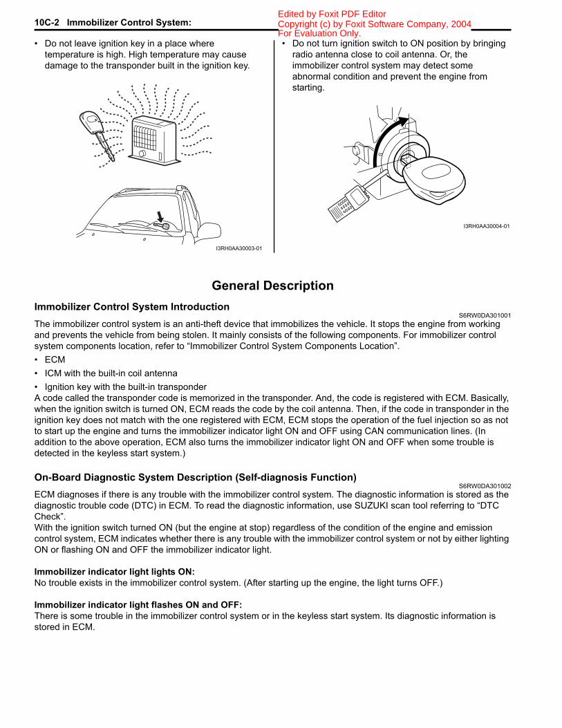
• Do not leave ignition key in a place where temperature is high. High temperature may cause damage to the transponder built in the ignition key.
• Do not turn ignition switch to ON position by bringing radio antenna close to coil antenna. Or, the immobilizer control system may detect some abnormal condition and prevent the engine from starting.
General DescriptionImmobilizer Control System Introduction
S6RW0DA301001The immobilizer control system is an anti-theft device that immobilizes the vehicle. It stops the engine from working and prevents the vehicle from being stolen. It mainly consists of the following components. For immobilizer control system components location, refer to “Immobilizer Control System Components Location”.• ECM• ICM with the built-in coil antenna• Ignition key with the built-in transponderA code called the transponder code is memorized in the transponder. And, the code is registered with ECM. Basically, when the ignition switch is turned ON, ECM reads the code by the coil antenna. Then, if the code in transponder in the ignition key does not match with the one registered with ECM, ECM stops the operation of the fuel injection so as not to start up the engine and turns the immobilizer indicator light ON and OFF using CAN communication lines. (In addition to the above operation, ECM also turns the immobilizer indicator light ON and OFF when some trouble is detected in the keyless start system.)
On-Board Diagnostic System Description (Self-diagnosis Function)S6RW0DA301002
ECM diagnoses if there is any trouble with the immobilizer control system. The diagnostic information is stored as the diagnostic trouble code (DTC) in ECM. To read the diagnostic information, use SUZUKI scan tool referring to “DTC Check”.With the ignition switch turned ON (but the engine at stop) regardless of the condition of the engine and emission control system, ECM indicates whether there is any trouble with the immobilizer control system or not by either lighting ON or flashing ON and OFF the immobilizer indicator light.
Immobilizer indicator light lights ON:No trouble exists in the immobilizer control system. (After starting up the engine, the light turns OFF.)
Immobilizer indicator light flashes ON and OFF:There is some trouble in the immobilizer control system or in the keyless start system. Its diagnostic information is stored in ECM.
I3RH0AA30003-01
I3RH0AA30004-01
For Evaluation Only.

Immobilizer Control System: 10C-3Copyright (c) by Foxit Software Company, 2004Edited by Foxit PDF Editor
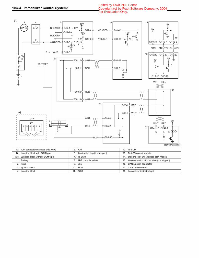
Schematic and Routing DiagramImmobilizer Control System Wiring Circuit Diagram
S6RW0DA302001NOTEFor more details about power supply circuit, ground wire circuit, and each circuit for ECM, BCM, ABS control module, keyless start control module and combination meter, refer to “System Circuit Diagram in Section 9A”.
BLK/WHT
BLK/ORN12V
G17-1
G17-2
12V
5V
12V
12VYEL/RED
YEL/BLK
G17-4
G17-3
5V
BRN
BRN/YEL
BLK/YEL
1
2 2
2
2
3 4
2
5 10 14
15
1234
G17
[A]
56
G16-20 G16-29 G16-30
G146-3 G146-7 G146-8
WHT/RED
5V
5V
9
G16-18 G16-19
E01-13
E01-28
BLU
BLU
RED
WHTE08-12
E08-1
E01-18
E01-3
RED
WHTE08-13
E08-2 E04-1
E04-2
WHT
RED
G04-1
G04-3
12V
E04-9
G04-5PPL/WHT L313-3
8
11
12
13
G17-5WHT7
6
G17-6WHT/RED
17
REDWHT
REDWHT
G241-10 G241-7
IG1
18
WHT
REDG04-4
G04-2
16
[B]
I6RW0DA30001-02
For Evaluation Only.
10C-4 Immobilizer Control System: Copyright (c) by Foxit Software Company, 2004Edited by Foxit PDF Editor
BLK/WHT
BLK/ORN12V
G17-1
G17-2
12V
5V
12V
12VYEL/RED
YEL/BLK
G17-4
G17-3
5V
BRN BRN/YEL BLK/YEL
1
2 2
2
2
3 4
2
5 10 14
15
1234
G17
[A]
56
G16-20 G16-29 G16-30
G146-3 G146-7 G146-8
WHT/RED
5V
5V
9
G16-18 G16-19
E01-13
E01-28
BLU
RED
WHTE08-12
E08-1
E01-18
E01-3
RED
WHTE08-13
E08-2
WHT
RED
G05-4
G05-2
12V
G05-35
8
11
G17-5WHT7
6
G17-6WHT/RED
17
REDWHT
REDWHT
G241-10 G241-7
IG1
18
WHT
REDG05-1
G05-3
16
[C]
I6RW0DA30002-01
[A]: ICM connector (harness side view) 5. ICM 12. To SDM[B]: Junction block with BCM type 6. Illumination ring (if equipped) 13. To ABS control module[C]: Junction block without BCM type 7. To BCM 14. Steering lock unit (keyless start model)
1. Battery 8. ABS control module 15. Keyless start control module (if equipped)2. Fuse 9. DLC 16. CAN junction connector3. Ignition switch 10. ECM 17. Combination meter4. Junction block 11. BCM 18. Immobilizer indicator light
For Evaluation Only.

Immobilizer Control System: 10C-5Copyright (c) by Foxit Software Company, 2004Edited by Foxit PDF Editor
Component LocationImmobilizer Control System Components Location
S6RW0DA303001
Diagnostic Information and ProceduresImmobilizer Control System Check
S6RW0DA304001
3
4 5 6
7
1
2
2
1
3
I6RW0BA30001-01
1. ECM 5. Ignition key (non keyless entry model)2. Immobilizer indicator light 6. Ignition key (keyless start model)3. ICM 7. Transponder4. Ignition key (keyless entry model)
Step Action Yes No1 Immobilizer indicator light check
1) Turn ignition switch to ON position using ignition key.
Does immobilizer indicator light come on?
Go to Step 2. Check if DTC P1636 and/or P1638 are detected by ECM referring to “DTC Check”. If detected, go to applicable DTC diag. flow. If not detected, go to “Immobilizer Indicator Light Does Not Come ON with Ignition Switch ON and Engine Stop”.
2 Immobilizer indicator light check
Does immobilizer indicator light flash on and off continuously in Step 1?
Check ECM for DTC referring to “DTC Check”. Then, go to applicable DTC diag. flow.
Go to Step 3.
3 Engine start check1) Start engine using ignition key.
Does engine start?
Go to Step 4. Go to “Engine and Emission Control System Check in Section 1A”.
4 Immobilizer indicator light check1) Check if immobilizer indicator light remains ON after
engine start.
Does immobilizer indicator light remains ON after engine start?
Go to “Immobilizer Indicator Light Remains ON after Engine Start”.
Immobilizer control system is in good condition. Then, go to “Keyless Start System Check in Section 10E” for keyless start model.
For Evaluation Only.

10C-6 Immobilizer Control System: Copyright (c) by Foxit Software Company, 2004Edited by Foxit PDF Editor
DTC CheckS6RW0DA304002
NOTETo know how to use SUZUKI scan tool in detail, refer to its operator’s manual.
1) Turn the ignition switch to OFF position.2) Connect SUZUKI scan tool to data link connector
(DLC) (1) located under instrument panel at driver’s seat side.
Special tool(A): SUZUKI scan tool (SUZUKI-SDT)
3) Turn the ignition switch to ON position.4) Read DTC according to instructions displayed on
SUZUKI scan tool and print them or write them down. Refer to scan tool operator’s manual for details.If communication between scan tool and ECM is not possible, go to “Troubleshooting for Communication Error with Scan Tool Using CAN in Section 1A”.
5) After completing the check, turn ignition switch to OFF position, and then disconnect SUZUKI scan tool from DLC.
DTC ClearanceS6RW0DA304003
NOTETo know how to use SUZUKI scan tool in detail, refer to its operator’s manual.
1) Turn the ignition switch to OFF position,2) Connect SUZUKI scan tool to data link connector
(DLC) (1) located under instrument panel at driver’s seat side.
Special tool(A): SUZUKI scan tool (SUZUKI-SDT)
3) Turn the ignition switch to ON position.4) Clear DTC(s) according to the instructions displayed
on SUZUKI scan tool.5) After completing the clearance, turn the ignition
switch to OFF position, and then disconnect SUZUKI scan tool from DLC.
(A)1I5RW0CA30002-01
(A)1I5RW0CA30002-01
For Evaluation Only.
Immobilizer Control System: 10C-7Copyright (c) by Foxit Software Company, 2004Edited by Foxit PDF Editor
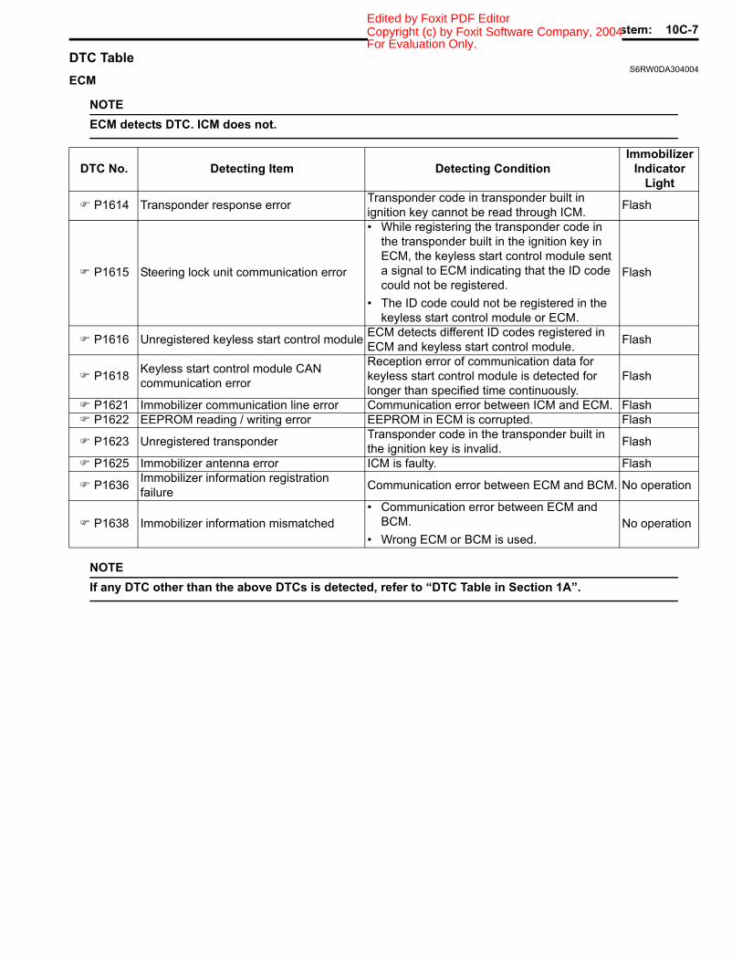
DTC TableS6RW0DA304004
ECM
NOTEECM detects DTC. ICM does not.
NOTEIf any DTC other than the above DTCs is detected, refer to “DTC Table in Section 1A”.
DTC No. Detecting Item Detecting ConditionImmobilizer
Indicator Light
P1614 Transponder response error Transponder code in transponder built in ignition key cannot be read through ICM. Flash
P1615 Steering lock unit communication error
• While registering the transponder code in the transponder built in the ignition key in ECM, the keyless start control module sent a signal to ECM indicating that the ID code could not be registered.
• The ID code could not be registered in the keyless start control module or ECM.
Flash
P1616 Unregistered keyless start control module ECM detects different ID codes registered in ECM and keyless start control module. Flash
P1618 Keyless start control module CAN communication error
Reception error of communication data for keyless start control module is detected for longer than specified time continuously.
Flash
P1621 Immobilizer communication line error Communication error between ICM and ECM. Flash P1622 EEPROM reading / writing error EEPROM in ECM is corrupted. Flash
P1623 Unregistered transponder Transponder code in the transponder built in the ignition key is invalid. Flash
P1625 Immobilizer antenna error ICM is faulty. Flash
P1636 Immobilizer information registration failure Communication error between ECM and BCM. No operation
P1638 Immobilizer information mismatched• Communication error between ECM and
BCM.• Wrong ECM or BCM is used.
No operation
For Evaluation Only.
10C-8 Immobilizer Control System: Copyright (c) by Foxit Software Company, 2004Edited by Foxit PDF Editor
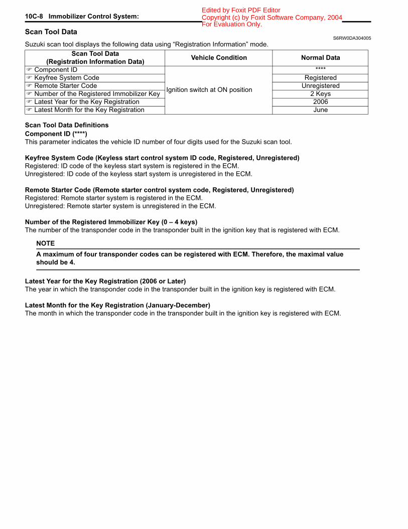
Scan Tool DataS6RW0DA304005
Suzuki scan tool displays the following data using “Registration Information” mode.
Scan Tool Data DefinitionsComponent ID (****)This parameter indicates the vehicle ID number of four digits used for the Suzuki scan tool.
Keyfree System Code (Keyless start control system ID code, Registered, Unregistered)Registered: ID code of the keyless start system is registered in the ECM.Unregistered: ID code of the keyless start system is unregistered in the ECM.
Remote Starter Code (Remote starter control system code, Registered, Unregistered)Registered: Remote starter system is registered in the ECM.Unregistered: Remote starter system is unregistered in the ECM.
Number of the Registered Immobilizer Key (0 – 4 keys)The number of the transponder code in the transponder built in the ignition key that is registered with ECM.
NOTEA maximum of four transponder codes can be registered with ECM. Therefore, the maximal value should be 4.
Latest Year for the Key Registration (2006 or Later)The year in which the transponder code in the transponder built in the ignition key is registered with ECM.
Latest Month for the Key Registration (January-December)The month in which the transponder code in the transponder built in the ignition key is registered with ECM.
Scan Tool Data(Registration Information Data) Vehicle Condition Normal Data
Component ID
Ignition switch at ON position
**** Keyfree System Code Registered Remote Starter Code Unregistered Number of the Registered Immobilizer Key 2 Keys Latest Year for the Key Registration 2006 Latest Month for the Key Registration June
For Evaluation Only.
Immobilizer Control System: 10C-9Copyright (c) by Foxit Software Company, 2004Edited by Foxit PDF Editor
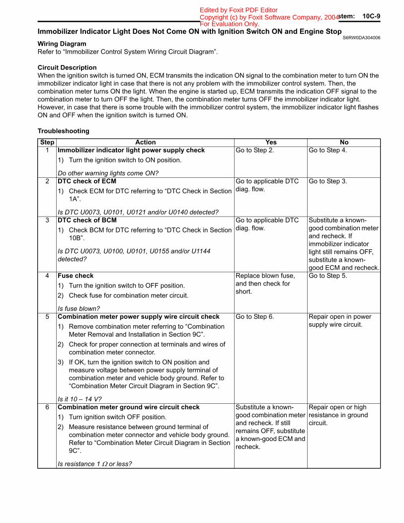
Immobilizer Indicator Light Does Not Come ON with Ignition Switch ON and Engine StopS6RW0DA304006
Wiring DiagramRefer to “Immobilizer Control System Wiring Circuit Diagram”.
Circuit DescriptionWhen the ignition switch is turned ON, ECM transmits the indication ON signal to the combination meter to turn ON the immobilizer indicator light in case that there is not any problem with the immobilizer control system. Then, the combination meter turns ON the light. When the engine is started up, ECM transmits the indication OFF signal to the combination meter to turn OFF the light. Then, the combination meter turns OFF the immobilizer indicator light. However, in case that there is some trouble with the immobilizer control system, the immobilizer indicator light flashes ON and OFF when the ignition switch is turned ON.
TroubleshootingStep Action Yes No
1 Immobilizer indicator light power supply check1) Turn the ignition switch to ON position.
Do other warning lights come ON?
Go to Step 2. Go to Step 4.
2 DTC check of ECM1) Check ECM for DTC referring to “DTC Check in Section
1A”.
Is DTC U0073, U0101, U0121 and/or U0140 detected?
Go to applicable DTC diag. flow.
Go to Step 3.
3 DTC check of BCM1) Check BCM for DTC referring to “DTC Check in Section
10B”.
Is DTC U0073, U0100, U0101, U0155 and/or U1144 detected?
Go to applicable DTC diag. flow.
Substitute a known-good combination meter and recheck. If immobilizer indicator light still remains OFF, substitute a known-good ECM and recheck.
4 Fuse check1) Turn the ignition switch to OFF position.2) Check fuse for combination meter circuit.
Is fuse blown?
Replace blown fuse, and then check for short.
Go to Step 5.
5 Combination meter power supply wire circuit check1) Remove combination meter referring to “Combination
Meter Removal and Installation in Section 9C”.2) Check for proper connection at terminals and wires of
combination meter connector.3) If OK, turn the ignition switch to ON position and
measure voltage between power supply terminal of combination meter and vehicle body ground. Refer to “Combination Meter Circuit Diagram in Section 9C”.
Is it 10 – 14 V?
Go to Step 6. Repair open in power supply wire circuit.
6 Combination meter ground wire circuit check1) Turn ignition switch OFF position.2) Measure resistance between ground terminal of
combination meter connector and vehicle body ground. Refer to “Combination Meter Circuit Diagram in Section 9C”.
Is resistance 1 Ω or less?
Substitute a known-good combination meter and recheck. If still remains OFF, substitute a known-good ECM and recheck.
Repair open or high resistance in ground circuit.
For Evaluation Only.
10C-10 Immobilizer Control System: Copyright (c) by Foxit Software Company, 2004Edited by Foxit PDF Editor
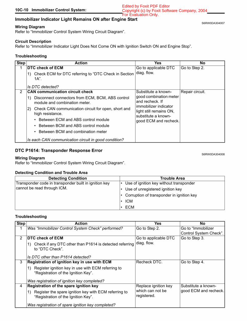
Immobilizer Indicator Light Remains ON after Engine StartS6RW0DA304007
Wiring DiagramRefer to “Immobilizer Control System Wiring Circuit Diagram”.
Circuit DescriptionRefer to “Immobilizer Indicator Light Does Not Come ON with Ignition Switch ON and Engine Stop”.
Troubleshooting
DTC P1614: Transponder Response ErrorS6RW0DA304008
Wiring DiagramRefer to “Immobilizer Control System Wiring Circuit Diagram”.
Detecting Condition and Trouble Area
Troubleshooting
Step Action Yes No1 DTC check of ECM
1) Check ECM for DTC referring to “DTC Check in Section 1A”.
Is DTC detected?
Go to applicable DTC diag. flow.
Go to Step 2.
2 CAN communication circuit check1) Disconnect connectors from ECM, BCM, ABS control
module and combination meter.2) Check CAN communication circuit for open, short and
high resistance.• Between ECM and ABS control module• Between BCM and ABS control module• Between BCM and combination meter
Is each CAN communication circuit in good condition?
Substitute a known-good combination meter and recheck. If immobilizer indicator light still remains ON, substitute a known-good ECM and recheck.
Repair circuit.
Detecting Condition Trouble AreaTransponder code in transponder built in ignition key cannot be read through ICM.
• Use of ignition key without transponder• Use of unregistered ignition key• Corruption of transponder in ignition key• ICM• ECM
Step Action Yes No1 Was “Immobilizer Control System Check” performed? Go to Step 2. Go to “Immobilizer
Control System Check”.2 DTC check of ECM
1) Check if any DTC other than P1614 is detected referring to “DTC Check”.
Is DTC other than P1614 detected?
Go to applicable DTC diag. flow.
Go to Step 3.
3 Registration of ignition key in use with ECM1) Register ignition key in use with ECM referring to
“Registration of the Ignition Key”.
Was registration of ignition key completed?
Recheck DTC. Go to Step 4.
4 Registration of the spare ignition key1) Register the spare ignition key with ECM referring to
“Registration of the Ignition Key”.
Was registration of spare ignition key completed?
Replace ignition key which can not be registered.
Substitute a known-good ECM and recheck.
For Evaluation Only.
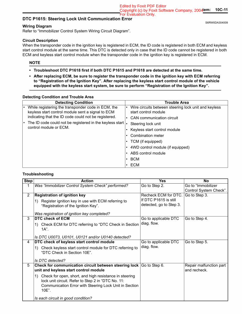
Immobilizer Control System: 10C-11Copyright (c) by Foxit Software Company, 2004Edited by Foxit PDF Editor
DTC P1615: Steering Lock Unit Communication ErrorS6RW0DA304009
Wiring DiagramRefer to “Immobilizer Control System Wiring Circuit Diagram”.
Circuit DescriptionWhen the transponder code in the ignition key is registered in ECM, the ID code is registered in both ECM and keyless start control module at the same time. This DTC is detected only in case that the ID code cannot be registered in both ECM and keyless start control module when the transponder code in the ignition key is registered in ECM.
NOTE
• Troubleshoot DTC P1618 first if both DTC P1615 and P1618 are detected at the same time.• After replacing ECM, be sure to register the transponder code in the ignition key with ECM referring
to “Registration of the Ignition Key”. After replacing the keyless start control module of the vehicle equipped with the keyless start system, be sure to perform “Registration of the Ignition Key”.
Detecting Condition and Trouble Area
Troubleshooting
Detecting Condition Trouble Area• While registering the transponder code in ECM, the
keyless start control module sent a signal to ECM indicating that the ID code could not be registered.
• The ID code could not be registered in the keyless start control module or ECM.
• Wire circuits between steering lock unit and keyless start control module
• CAN communication circuit• Steering lock unit• Keyless start control module• Combination meter• TCM (if equipped)• 4WD control module (if equipped)• ABS control module• BCM• ECM
Step Action Yes No1 Was “Immobilizer Control System Check” performed? Go to Step 2. Go to “Immobilizer
Control System Check”.2 Registration of ignition key
1) Register ignition key in use with ECM referring to “Registration of the Ignition Key”.
Was registration of ignition key completed?
Recheck ECM for DTC. If DTC P1615 is still detected, go to Step 3.
Go to Step 3.
3 DTC check of ECM1) Check ECM for DTC referring to “DTC Check in Section
1A”.
Is DTC U0073, U0101, U0121 and/or U0140 detected?
Go to applicable DTC diag. flow.
Go to Step 4.
4 DTC check of keyless start control module1) Check keyless start control module for DTC referring to
“DTC Check in Section 10E”.
Is DTC detected?
Go to applicable DTC diag. flow.
Go to Step 5.
5 Check for communication circuit between steering lock unit and keyless start control module1) Check for open, short, and high resistance in steering
lock unit circuit. Refer to Step 2 in “DTC No. 11: Communication Error with Steering Lock Unit in Section 10E”.
Is each circuit in good condition?
Go to Step 6. Repair malfunction part and recheck.
For Evaluation Only.
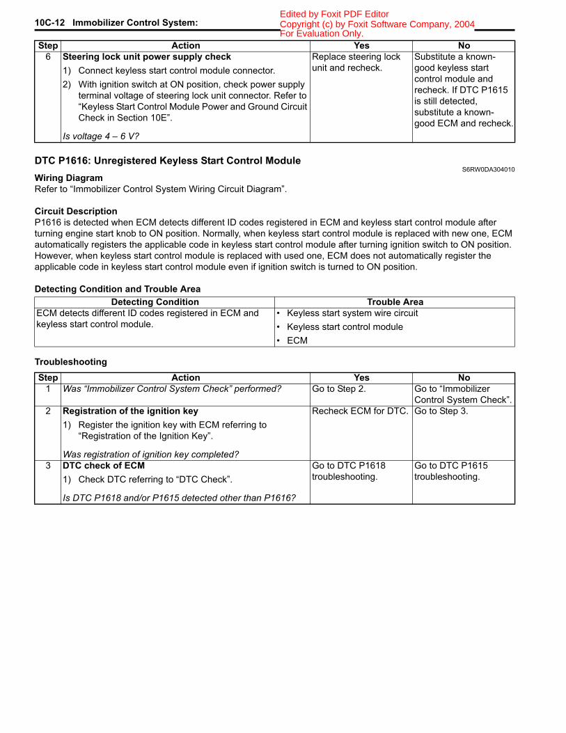
10C-12 Immobilizer Control System: Copyright (c) by Foxit Software Company, 2004Edited by Foxit PDF Editor
DTC P1616: Unregistered Keyless Start Control ModuleS6RW0DA304010
Wiring DiagramRefer to “Immobilizer Control System Wiring Circuit Diagram”.
Circuit DescriptionP1616 is detected when ECM detects different ID codes registered in ECM and keyless start control module after turning engine start knob to ON position. Normally, when keyless start control module is replaced with new one, ECM automatically registers the applicable code in keyless start control module after turning ignition switch to ON position. However, when keyless start control module is replaced with used one, ECM does not automatically register the applicable code in keyless start control module even if ignition switch is turned to ON position.
Detecting Condition and Trouble Area
Troubleshooting
6 Steering lock unit power supply check1) Connect keyless start control module connector.2) With ignition switch at ON position, check power supply
terminal voltage of steering lock unit connector. Refer to “Keyless Start Control Module Power and Ground Circuit Check in Section 10E”.
Is voltage 4 – 6 V?
Replace steering lock unit and recheck.
Substitute a known-good keyless start control module and recheck. If DTC P1615 is still detected, substitute a known-good ECM and recheck.
Step Action Yes No
Detecting Condition Trouble AreaECM detects different ID codes registered in ECM and keyless start control module.
• Keyless start system wire circuit• Keyless start control module• ECM
Step Action Yes No1 Was “Immobilizer Control System Check” performed? Go to Step 2. Go to “Immobilizer
Control System Check”.2 Registration of the ignition key
1) Register the ignition key with ECM referring to “Registration of the Ignition Key”.
Was registration of ignition key completed?
Recheck ECM for DTC. Go to Step 3.
3 DTC check of ECM1) Check DTC referring to “DTC Check”.
Is DTC P1618 and/or P1615 detected other than P1616?
Go to DTC P1618 troubleshooting.
Go to DTC P1615 troubleshooting.
For Evaluation Only.

Immobilizer Control System: 10C-13Copyright (c) by Foxit Software Company, 2004Edited by Foxit PDF Editor
DTC P1618: Keyless Start Control Module CAN Communication ErrorS6RW0DA304011
Refer to “Troubleshooting for CAN-DTC in Section 1A”.
DTC P1621: Immobilizer Communication Line ErrorS6RW0DA304012
Wiring DiagramRefer to “Immobilizer Control System Wiring Circuit Diagram”.
Detecting Condition and Trouble Area
Troubleshooting
Detecting Condition Trouble AreaCommunication error between ICM and ECM. • Related fuse(s) blown
• Poor connection at ICM connector• Poor connection at ECM connector• Power supply circuit• Ground circuit• Communication circuits between ICM and ECM• ICM• ECM
Step Action Yes No1 Was “Immobilizer Control System Check” performed? Go to Step 2. Go to “Immobilizer
Control System Check”.2 Fuse check
1) Check fuse for ICM circuit.
Is fuse in good condition?
Replace blown fuse(s) and then, check for short circuit.
Go to Step 3.
3 Voltage check at power and ground terminal1) Check power and ground terminal voltage of ICM
connector referring to “Inspection of ICM and Its Circuit”.
Is each terminal voltage in good condition?
Go to Step 4. Repair circuit.
4 ICM and ECM connector check1) With the ignition switch at OFF position, check
intermittent and poor connection of ICM connector and ECM connectors referring to “Intermittent and Poor Connection Inspection in Section 00”.
Is each connector in good condition?
Go to Step 5. Repair poor connection.
5 Communication circuit check between ICM and ECM1) Check for open, short and high resistance in serial
communication and clock circuit between ICM and ECM.
Is each communication circuit in good condition?
Substitute a known-good ICM and recheck. If DTC P1621 is still detected, substitute a known good ECM and recheck.
Repair circuit.
For Evaluation Only.

10C-14 Immobilizer Control System: Copyright (c) by Foxit Software Company, 2004Edited by Foxit PDF Editor
DTC P1622: EEPROM Reading / Writing ErrorS6RW0DA304013
Detecting Condition and Trouble Area
Troubleshooting1) Clear DTC(s) referring to “DTC Clearance”.2) Turn the ignition switch to OFF position.3) Check if DTC P1622 is still detected referring to “DTC Check”. If still detected, go to the next step. If not, the
troubleshooting is completed.4) Replace ECM with new one referring to “Engine Control Module (ECM) Removal and Installation in Section 1C”.5) Perform “Procedure after ECM Replacement”.
DTC P1623: Unregistered TransponderS6RW0DA304014
Wiring DiagramRefer to “Immobilizer Control System Wiring Circuit Diagram”.
Detecting Condition and Trouble Area
Troubleshooting
Detecting Condition Trouble AreaEEPROM in ECM is corrupted. Internal failure (EEPROM corruption) of ECM
Detecting Condition Trouble AreaTransponder code in the transponder built in the ignition key is invalid.
• Use of the unregistered ignition key• ICM• ECM
Step Action Yes No1 Was “Immobilizer Control System Check” performed? Go to Step 2. Go to “Immobilizer
Control System Check”.2 DTC check of ECM
1) Check if any DTC other than P1623 is detected referring to “DTC Check”.
Is DTC other than P1623 detected?
Go to applicable DTC diag. flow.
Go to Step 3.
3 Registration of unregistered ignition key with ECM1) Register the unregistered ignition key with ECM referring
to “Registration of the Ignition Key”.
Was registration of ignition key completed?
Recheck DTC. Go to Step 4.
4 Registration of the spare ignition key1) Register the spare ignition key referring to “Registration
of the Ignition Key”.
Was registration of spare ignition key completed?
Replace ignition key which cannot be registered.
Substitute a known-good ECM and recheck.
For Evaluation Only.
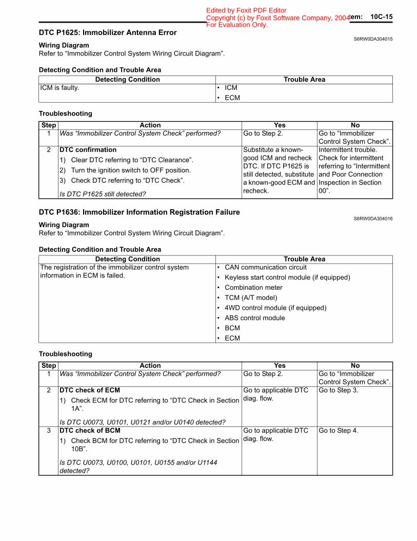
Immobilizer Control System: 10C-15Copyright (c) by Foxit Software Company, 2004Edited by Foxit PDF Editor
DTC P1625: Immobilizer Antenna ErrorS6RW0DA304015
Wiring DiagramRefer to “Immobilizer Control System Wiring Circuit Diagram”.
Detecting Condition and Trouble Area
Troubleshooting
DTC P1636: Immobilizer Information Registration FailureS6RW0DA304016
Wiring DiagramRefer to “Immobilizer Control System Wiring Circuit Diagram”.
Detecting Condition and Trouble Area
Troubleshooting
Detecting Condition Trouble AreaICM is faulty. • ICM
• ECM
Step Action Yes No1 Was “Immobilizer Control System Check” performed? Go to Step 2. Go to “Immobilizer
Control System Check”.2 DTC confirmation
1) Clear DTC referring to “DTC Clearance”.2) Turn the ignition switch to OFF position.3) Check DTC referring to “DTC Check”.
Is DTC P1625 still detected?
Substitute a known-good ICM and recheck DTC. If DTC P1625 is still detected, substitute a known-good ECM and recheck.
Intermittent trouble. Check for intermittent referring to “Intermittent and Poor Connection Inspection in Section 00”.
Detecting Condition Trouble AreaThe registration of the immobilizer control system information in ECM is failed.
• CAN communication circuit• Keyless start control module (if equipped)• Combination meter• TCM (A/T model)• 4WD control module (if equipped)• ABS control module• BCM• ECM
Step Action Yes No1 Was “Immobilizer Control System Check” performed? Go to Step 2. Go to “Immobilizer
Control System Check”.2 DTC check of ECM
1) Check ECM for DTC referring to “DTC Check in Section 1A”.
Is DTC U0073, U0101, U0121 and/or U0140 detected?
Go to applicable DTC diag. flow.
Go to Step 3.
3 DTC check of BCM1) Check BCM for DTC referring to “DTC Check in Section
10B”.
Is DTC U0073, U0100, U0101, U0155 and/or U1144 detected?
Go to applicable DTC diag. flow.
Go to Step 4.
For Evaluation Only.
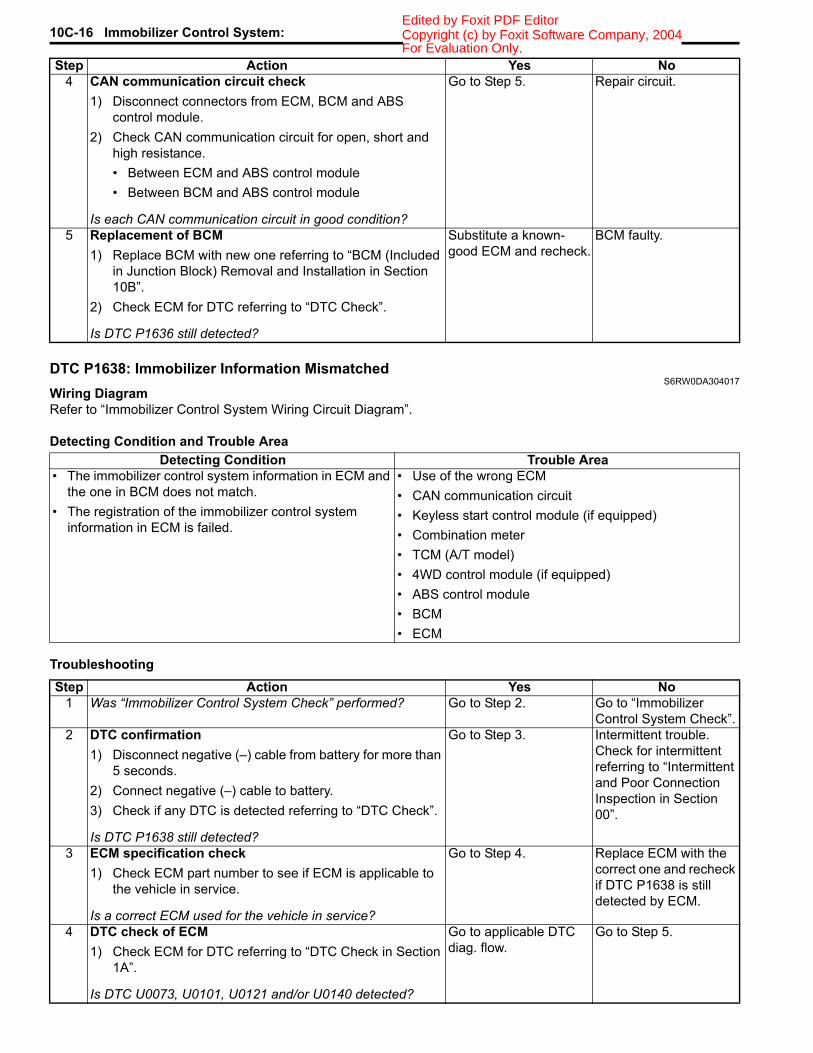
10C-16 Immobilizer Control System: Copyright (c) by Foxit Software Company, 2004Edited by Foxit PDF Editor
DTC P1638: Immobilizer Information MismatchedS6RW0DA304017
Wiring DiagramRefer to “Immobilizer Control System Wiring Circuit Diagram”.
Detecting Condition and Trouble Area
Troubleshooting
4 CAN communication circuit check1) Disconnect connectors from ECM, BCM and ABS
control module.2) Check CAN communication circuit for open, short and
high resistance.• Between ECM and ABS control module• Between BCM and ABS control module
Is each CAN communication circuit in good condition?
Go to Step 5. Repair circuit.
5 Replacement of BCM1) Replace BCM with new one referring to “BCM (Included
in Junction Block) Removal and Installation in Section 10B”.
2) Check ECM for DTC referring to “DTC Check”.
Is DTC P1636 still detected?
Substitute a known-good ECM and recheck.
BCM faulty.
Step Action Yes No
Detecting Condition Trouble Area• The immobilizer control system information in ECM and
the one in BCM does not match.• The registration of the immobilizer control system
information in ECM is failed.
• Use of the wrong ECM• CAN communication circuit• Keyless start control module (if equipped)• Combination meter• TCM (A/T model)• 4WD control module (if equipped)• ABS control module• BCM• ECM
Step Action Yes No1 Was “Immobilizer Control System Check” performed? Go to Step 2. Go to “Immobilizer
Control System Check”.2 DTC confirmation
1) Disconnect negative (–) cable from battery for more than 5 seconds.
2) Connect negative (–) cable to battery.3) Check if any DTC is detected referring to “DTC Check”.
Is DTC P1638 still detected?
Go to Step 3. Intermittent trouble. Check for intermittent referring to “Intermittent and Poor Connection Inspection in Section 00”.
3 ECM specification check1) Check ECM part number to see if ECM is applicable to
the vehicle in service.
Is a correct ECM used for the vehicle in service?
Go to Step 4. Replace ECM with the correct one and recheck if DTC P1638 is still detected by ECM.
4 DTC check of ECM1) Check ECM for DTC referring to “DTC Check in Section
1A”.
Is DTC U0073, U0101, U0121 and/or U0140 detected?
Go to applicable DTC diag. flow.
Go to Step 5.
For Evaluation Only.
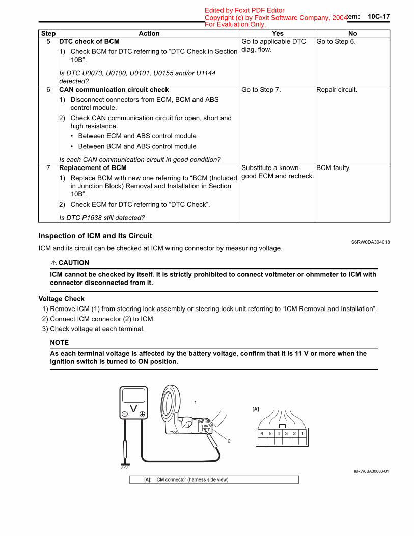
Immobilizer Control System: 10C-17Copyright (c) by Foxit Software Company, 2004Edited by Foxit PDF Editor
Inspection of ICM and Its CircuitS6RW0DA304018
ICM and its circuit can be checked at ICM wiring connector by measuring voltage.
CAUTION!
ICM cannot be checked by itself. It is strictly prohibited to connect voltmeter or ohmmeter to ICM with connector disconnected from it.
Voltage Check1) Remove ICM (1) from steering lock assembly or steering lock unit referring to “ICM Removal and Installation”.2) Connect ICM connector (2) to ICM.3) Check voltage at each terminal.
NOTEAs each terminal voltage is affected by the battery voltage, confirm that it is 11 V or more when the ignition switch is turned to ON position.
5 DTC check of BCM1) Check BCM for DTC referring to “DTC Check in Section
10B”.
Is DTC U0073, U0100, U0101, U0155 and/or U1144 detected?
Go to applicable DTC diag. flow.
Go to Step 6.
6 CAN communication circuit check1) Disconnect connectors from ECM, BCM and ABS
control module.2) Check CAN communication circuit for open, short and
high resistance.• Between ECM and ABS control module• Between BCM and ABS control module
Is each CAN communication circuit in good condition?
Go to Step 7. Repair circuit.
7 Replacement of BCM1) Replace BCM with new one referring to “BCM (Included
in Junction Block) Removal and Installation in Section 10B”.
2) Check ECM for DTC referring to “DTC Check”.
Is DTC P1638 still detected?
Substitute a known-good ECM and recheck.
BCM faulty.
Step Action Yes No
1234
1
2
56
[A]
I6RW0BA30003-01
[A]: ICM connector (harness side view)
For Evaluation Only.

10C-18 Immobilizer Control System: Copyright (c) by Foxit Software Company, 2004Edited by Foxit PDF Editor
Reference Waveform
NOTEWhen ECM cannot read the transponder code at the first try, ECM tries to read the transponder code repeatedly up to 8 times. The second waveform is the example showing that ECM read the transponder code successfully at the second try.
Terminal Circuit Normal Voltage Condition
G17-1 Power supply About 12.0 V Ignition switch at ON position0.0 V Ignition switch at OFF position
G17-2 Ground 0.0 V —
G17-3 Serial communication lineSee the reference waveform. —
0.0 V Ignition switch at OFF position
G17-4 Clock lineSee the reference waveform. —
0.0 V Ignition switch at OFF position
G17-5 Illumination ring control (if equipped)
0 V• Ignition key not inserted to the key cylinder• Door opened
0 V → 12 V
• Ignition key at OFF position• From the time door is closed to the time
interior light faded out completely(As the interior light fades out, the voltage increases.)
0 V → 12 V
• Door closed• From the ignition switch is turned ON to the
time interior light is completely faded out(As the interior light fades out, the voltage increases.)
G17-6 Illumination ring power supply(if equipped) About 12.0 V —
I6RW0CA30003-01
[A]: The transponder code read successfully at the first try. 2. Clock line[B]: The transponder code read successfully at the second try. 3. First try
1. Serial communication line 4. Second try
Measurement terminals CH1: G17-3 to G17-2CH2: G17-4 to G17-2
Oscilloscope settings CH1: 5 V/DIVCH2: 5 V/DIVTIME: 20 ms
Measurement condition Right after the ignition switch is turned ON, the waveform can be read.
For Evaluation Only.
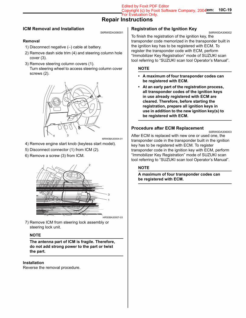
Immobilizer Control System: 10C-19Copyright (c) by Foxit Software Company, 2004Edited by Foxit PDF Editor
Repair InstructionsICM Removal and Installation
S6RW0DA306001
Removal1) Disconnect negative (–) cable at battery.2) Remove dash side trim (4) and steering column hole
cover (3).3) Remove steering column covers (1).
Turn steering wheel to access steering column cover screws (2).
4) Remove engine start knob (keyless start model).5) Disconnect connector (1) from ICM (2).6) Remove a screw (3) from ICM.
7) Remove ICM from steering lock assembly or steering lock unit.
NOTEThe antenna part of ICM is fragile. Therefore, do not add strong power to the part or twist the part.
InstallationReverse the removal procedure.
Registration of the Ignition KeyS6RW0DA306002
To finish the registration of the ignition key, the transponder code memorized in the transponder built in the ignition key has to be registered with ECM. To register the transponder code with ECM, perform “Immobilizer Key Registration” mode of SUZUKI scan tool referring to “SUZUKI scan tool Operator’s Manual”.
NOTE
• A maximum of four transponder codes can be registered with ECM.
• At an early part of the registration process, all transponder codes of the ignition keys in use already registered with ECM are cleared. Therefore, before starting the registration, prepare all ignition keys in use in addition to the new ignition key(s) to be registered with ECM.
Procedure after ECM ReplacementS6RW0DA306003
After ECM is replaced with new one or used one, the transponder code in the transponder built in the ignition key has to be registered with ECM. To register transponder code in the ignition key with ECM, perform “Immobilizer Key Registration” mode of SUZUKI scan tool referring to “SUZUKI scan tool Operator’s Manual”.
NOTEA maximum of four transponder codes can be registered with ECM.
1 2
34I6RW0BA30004-01
2
3
1
I4RS0BA30007-03
For Evaluation Only.

10C-20 Immobilizer Control System: Copyright (c) by Foxit Software Company, 2004Edited by Foxit PDF Editor
Special Tools and EquipmentSpecial Tool
S6RW0DA308001
SUZUKI scan tool (SUZUKI-SDT)—This kit includes following items. 1. SUZUKI-SDT 2. DLC3 cable 3. USB cable 4. AC/DC power supply 5. Voltage meter probe 6. Storage case /
1 2
34
5
6
For Evaluation Only.

Keyless Start System: 10E-1Copyright (c) by Foxit Software Company, 2004Edited by Foxit PDF Editor
Control SystemsKeyless Start SystemGeneral Description
Keyless Start System DescriptionS6RW0DA501001
Keyless start system consisting of the parts shown below has three functions as described below.• Keyless engine start function:
With the remote controller which has been registered in the keyless start control module carried with oneself, the engine can be started without using the ignition key.
• Door lock function:Pushing the request switch incorporated in the outside handle of the driver side door, passenger side door or rear end door while carrying the remote controller which has been registered in the keyless start control module, doors can be locked or unlocked.
• Keyless entry system function:It is possible to lock or unlock doors by pushing the lock or unlock button of remote controller.
The keyless start control module can accept registration of up to four remote controllers.
3
2
11
104
8
5
3
6
7
1
14
13
9
12
[A]12
[B]
I6RW0DA50001-01
[A]: Junction block with BCM type 5. Luggage room antenna 11. Unlock button[B]: Junction block without BCM type 6. Driver side door antenna 12. BCM
1. Keyless start control module 7. Passenger side door antenna 13. Key indicator light2. Remote controller 8. Rear end door antenna 14. ECM3. Request switch 9. Steering lock unit4. Center antenna 10. Lock button
For Evaluation Only.

10E-2 Keyless Start System: Copyright (c) by Foxit Software Company, 2004Edited by Foxit PDF Editor
Parts and FunctionsS6RW0DA501002
Parts FunctionKeyless start control module • Activates each antenna
• Verifies ID code of remote controller• Requests steering lock unit to release steering lock• Requests BCM to lock or unlock doors• Controls key indicator light in combination meter• Transmits its ID code to ECM
Remote controller • Receives request signal from each antenna• Transmits ID code and request signal to keyless start control module• Request keyless start control module to lock or unlock doors (keyless entry
system function)Request switch • Requests keyless start control module to activate each antennaCenter antenna • Transmits request signal to remote controllerLuggage room antenna • Transmits request signal to remote controllerDriver side door antenna • Transmits request signal to remote controllerPassenger side door antenna • Transmits request signal to remote controllerRear end door antenna • Transmits request signal to remote controllerSteering lock unit • Releases steering lockUnlock button • Transmits door unlock request signal (keyless entry system function)Lock button • Transmits door lock request signal (keyless entry system function)BCM • Controls each door lock actuator
• Controls warning buzzer• Lights hazard warning light and interior (DOME) light (answer back)
Key indicator light • Indicates operation state of keyless start system (indicates check result of remote controller ID code)
ECM • Checks keyless start control module ID code• Transmits its ID code to keyless start control module• Starts engine
For Evaluation Only.
Copyright © 2022 FDOKUMEN