Makes it easy to find manuals online! - Intruder Owners Club ...
454
VZ800 99500-38050-01E Downloaded from www.Manualslib.com manuals search engine
-
Upload
khangminh22 -
Category
Documents
-
view
1 -
download
0
Transcript of Makes it easy to find manuals online! - Intruder Owners Club ...
VZ800
Printed in JapanK5
VZ
80
0
No.5230 99500-38050-01E VZ800K5 Service Manual 2004. 11. 29 Cover_14 for PS printing (16 mm)
TOP
BOTTOM
K5 9 9 5 0 0 - 3 8 0 5 0 - 0 1 E
DIC75
Downloaded from www.Manualslib.com manuals search engine
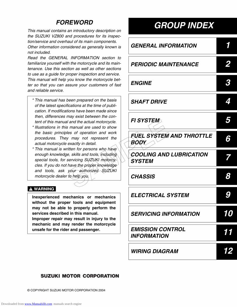
GROUP INDEX
GENERAL INFORMATION 1
PERIODIC MAINTENANCE 2
ENGINE 3
SHAFT DRIVE 4
FI SYSTEM 5
FUEL SYSTEM AND THROTTLE BODY 6
COOLING AND LUBRICATION SYSTEM 7
CHASSIS 8
ELECTRICAL SYSTEM 9
SERVICING INFORMATION 10
EMISSION CONTROL INFORMATION 11
WIRING DIAGRAM 12
© COPYRIGHT SUZUKI MOTOR CORPORATION 2004
FOREWORDThis manual contains an introductory description onthe SUZUKI VZ800 and procedures for its inspec-tion/service and overhaul of its main components.Other information considered as generally known isnot included.Read the GENERAL INFORMATION section tofamiliarize yourself with the motorcycle and its main-tenance. Use this section as well as other sectionsto use as a guide for proper inspection and service.This manual will help you know the motorcycle bet-ter so that you can assure your customers of fastand reliable service.
* This manual has been prepared on the basisof the latest specifications at the time of publi-cation. If modifications have been made sincethen, differences may exist between the con-tent of this manual and the actual motorcycle.
* Illustrations in this manual are used to showthe basic principles of operation and workprocedures. They may not represent theactual motorcycle exactly in detail.
* This manual is written for persons who haveenough knowledge, skills and tools, includingspecial tools, for servicing SUZUKI motorcy-cles. If you do not have the proper knowledgeand tools, ask your authorized SUZUKImotorcycle dealer to help you.
Inexperienced mechanics or mechanicswithout the proper tools and equipmentmay not be able to properly perform theservices described in this manual.Improper repair may result in injury to themechanic and may render the motorcycleunsafe for the rider and passenger.
SAMPLE
Downloaded from www.Manualslib.com manuals search engine
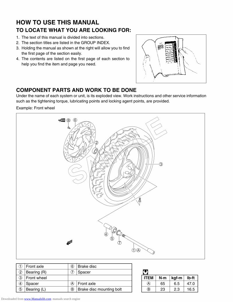
HOW TO USE THIS MANUALTO LOCATE WHAT YOU ARE LOOKING FOR:1. The text of this manual is divided into sections.2. The section titles are listed in the GROUP INDEX.3. Holding the manual as shown at the right will allow you to find
the first page of the section easily.4. The contents are listed on the first page of each section to
help you find the item and page you need.
COMPONENT PARTS AND WORK TO BE DONEUnder the name of each system or unit, is its exploded view. Work instructions and other service informationsuch as the tightening torque, lubricating points and locking agent points, are provided.
Example: Front wheel
1 Front axle 6 Brake disc2 Bearing (R) 7 Spacer 3 Front wheel ITEM N·m kgf-m lb-ft4 Spacer A Front axle A 65 6.5 47.05 Bearing (L) B Brake disc mounting bolt B 23 2.3 16.5
SAMPLE
Downloaded from www.Manualslib.com manuals search engine
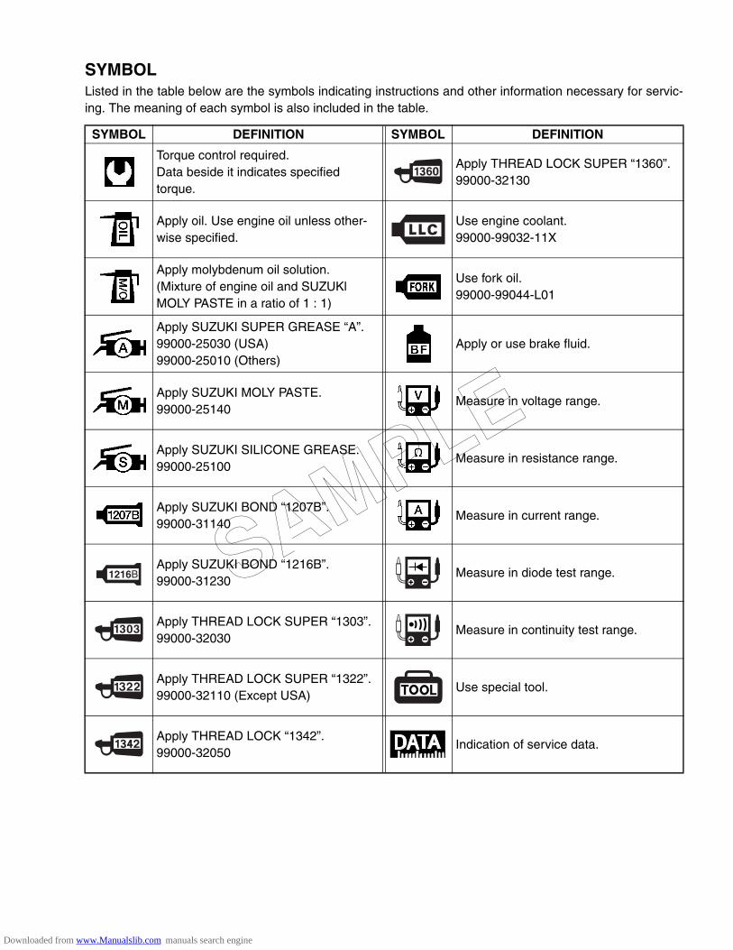
SYMBOLListed in the table below are the symbols indicating instructions and other information necessary for servic-ing. The meaning of each symbol is also included in the table.
SYMBOL DEFINITION SYMBOL DEFINITION
Torque control required.Data beside it indicates specified torque.
Apply THREAD LOCK SUPER “1360”.99000-32130
Apply oil. Use engine oil unless other-wise specified.
Use engine coolant.99000-99032-11X
Apply molybdenum oil solution.(Mixture of engine oil and SUZUKl MOLY PASTE in a ratio of 1 : 1)
Use fork oil.99000-99044-L01
Apply SUZUKI SUPER GREASE “A”.99000-25030 (USA)99000-25010 (Others)
Apply or use brake fluid.
Apply SUZUKI MOLY PASTE.99000-25140
Measure in voltage range.
Apply SUZUKI SILICONE GREASE.99000-25100
Measure in resistance range.
Apply SUZUKI BOND “1207B”.99000-31140
Measure in current range.
Apply SUZUKI BOND “1216B”.99000-31230
Measure in diode test range.
Apply THREAD LOCK SUPER “1303”.99000-32030
Measure in continuity test range.
Apply THREAD LOCK SUPER “1322”.99000-32110 (Except USA)
Use special tool.
Apply THREAD LOCK “1342”.99000-32050
Indication of service data.
1216 SAMPLE
Downloaded from www.Manualslib.com manuals search engine
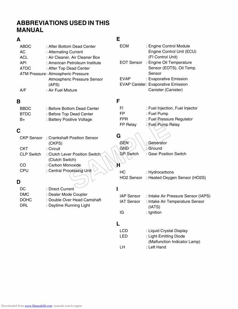
ABBREVIATIONS USED IN THIS MANUALA
ABDC : After Bottom Dead CenterAC : Alternating CurrentACL : Air Cleaner, Air Cleaner BoxAPI : American Petroleum InstituteATDC : After Top Dead CenterATM Pressure: Atmospheric Pressure
Atmospheric Pressure Sensor (APS)
A/F : Air Fuel Mixture
BBBDC : Before Bottom Dead CenterBTDC : Before Top Dead CenterB+ : Battery Positive Voltage
CCKP Sensor : Crankshaft Position Sensor
(CKPS)CKT : CircuitCLP Switch : Clutch Lever Position Switch
(Clutch Switch)CO : Carbon MonoxideCPU : Central Processing Unit
DDC : Direct CurrentDMC : Dealer Mode CouplerDOHC : Double Over Head CamshaftDRL : Daytime Running Light
EECM : Engine Control Module
Engine Control Unit (ECU)(FI Control Unit)
EOT Sensor : Engine Oil TemperatureSensor (EOTS), Oil Temp.Sensor
EVAP : Evaporative EmissionEVAP Canister : Evaporative Emission
Canister (Canister)
FFI : Fuel Injection, Fuel InjectorFP : Fuel PumpFPR : Fuel Pressure RegulatorFP Relay : Fuel Pump Relay
GGEN : GeneratorGND : GroundGP Switch : Gear Position Switch
HHC : HydrocarbonsHO2 Sensor : Heated Oxygen Sensor (HO2S)
IIAP Sensor : Intake Air Pressure Sensor (IAPS)IAT Sensor : Intake Air Temperature Sensor
(IATS)IG : Ignition
LLCD : Liquid Crystal DisplayLED : Light Emitting Diode
(Malfunction Indicator Lamp)LH : Left Hand
SAMPLE
Downloaded from www.Manualslib.com manuals search engine

MMAL-Code : Malfunction Code
(Diagnostic Code)Max : MaximumMIL : Malfunction Indicator Lamp
(LED)Min : Minimum
NNOx : Nitrogen Oxides
OOHC : Over Head CamshaftOPS : Oil Pressure Switch
PPCV : Positive Crankcase
Ventilation (Crankcase Breather)
RRH : Right HandROM : Read Only Memory
SSAE : Society of Automotive EngineersSDS : Suzuki Diagnosis SystemSTC System : Secondary Throttle Control
System (STCS)STP Sensor : Secondary Throttle Position
Sensor (STPS)ST Valve : Secondary Throttle Valve (STV)STV Actuator : Secondary Throttle Valve Actuator
(STVA)
TTO Sensor : Tip Over Sensor (TOS)TP Sensor : Throttle Position Sensor (TPS)
SAMPLE
Downloaded from www.Manualslib.com manuals search engine

WIRE COLOR
B : Black Gr : Gray R : RedBl : Blue Lbl : Light blue W : WhiteBr : Brown Lg : Light green Y : YellowDg : Dark green O : OrangeG : Green P : Pink
B/Bl : Black with Blue tracer B/Br : Black with Brown tracerB/G : Black with Green tracer B/Lg : Black with Light green tracerB/R : Black with Red tracer B/W : Black with White tracerB/Y : Black with Yellow tracer Bl/B : Blue with Black tracerBl/G : Blue with Green tracer Bl/R : Blue with Red tracerBl/W : Blue with White tracer Bl/Y : Blue with Yellow tracerBr/B : Brown with Black tracer Br/W : Brown with White tracerG/B : Green with Black tracer G/W : Green with White tracerG/Y : Green with Yellow tracer Gr/B : Gray with Black tracerGr/R : Gray with Red tracer Gr/W : Gray with White tracerLg/G : Light green with Green tracer O/B : Orange with Black tracerO/BI : Orange with Blue tracer O/G : Orange with Green tracerO/R : Orange with Red tracer O/W : Orange with White tracerO/Y : Orange with Yellow tracer P/W : Pink with White tracerR/B : Red with Black tracer R/Bl : Red with Blue tracerW/B : White with Black tracer W/Bl : White with Blue tracerW/R : White with Red tracer Y/B : Yellow with Black tracerY/Bl : Yellow with Blue tracer Y/G : Yellow with Green tracerY/R : Yellow with Red tracer Y/W : Yellow with White tracer
SAMPLE
Downloaded from www.Manualslib.com manuals search engine
1
GENERAL INFORMATION 1-1
CONTENTS
GENERAL INFORMATION
WARNING/CAUTION/NOTE .........................................................................1- 2GENERAL PRECAUTIONS ...........................................................................1- 2SUZUKI VZ800K5 (’05-MODEL) ...................................................................1- 4SERIAL NUMBER LOCATION ......................................................................1- 4FUEL, OIL AND ENGINE COOLANT RECOMMENDATION .......................1- 4
FUEL (FOR USA AND CANADA) ..........................................................1- 4FUEL (FOR OTHER COUNTRIES) ........................................................1- 4ENGINE OIL ...........................................................................................1- 5BRAKE FLUID ........................................................................................1- 5FRONT FORK OIL .................................................................................1- 5ENGINE COOLANT ...............................................................................1- 5WATER FOR MIXING ............................................................................1- 5ANTI-FREEZE/ENGINE COOLANT .......................................................1- 5LIQUID AMOUNT OF WATER/ENGINE COOLANT .............................1- 5
BREAK-lN PROCEDURES ...........................................................................1- 6CYLINDER IDENTIFICATION .......................................................................1- 6INFORMATION LABELS ...............................................................................1- 7SPECIFICATIONS .........................................................................................1- 8
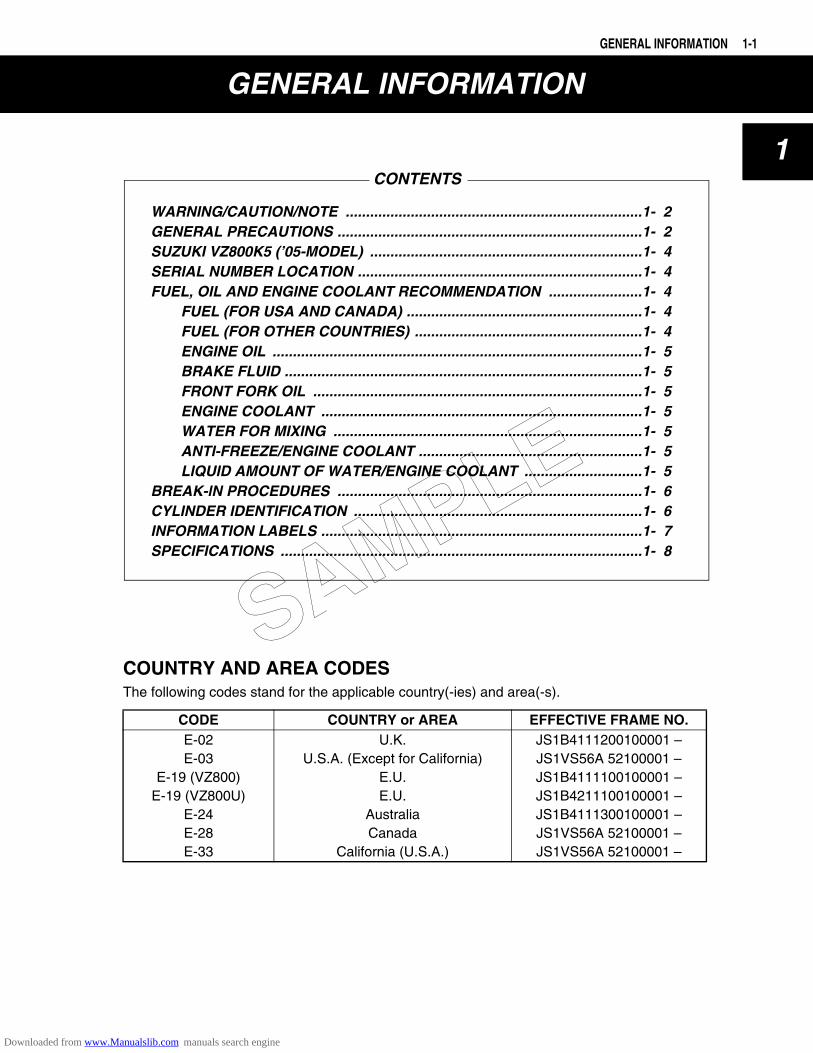
COUNTRY AND AREA CODESThe following codes stand for the applicable country(-ies) and area(-s).
CODE COUNTRY or AREA EFFECTIVE FRAME NO.E-02E-03
E-19 (VZ800)E-19 (VZ800U)
E-24E-28E-33
U.K.U.S.A. (Except for California)
E.U.E.U.
AustraliaCanada
California (U.S.A.)
JS1B4111200100001 –JS1VS56A 52100001 –JS1B4111100100001 –JS1B4211100100001 –JS1B4111300100001 –JS1VS56A 52100001 –JS1VS56A 52100001 –
SAMPLE
Downloaded from www.Manualslib.com manuals search engine
1-2 GENERAL INFORMATION
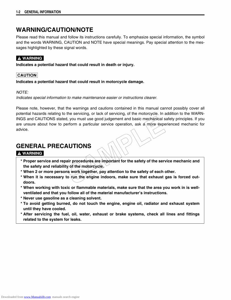
WARNING/CAUTION/NOTEPlease read this manual and follow its instructions carefully. To emphasize special information, the symboland the words WARNING, CAUTION and NOTE have special meanings. Pay special attention to the mes-sages highlighted by these signal words.
Indicates a potential hazard that could result in death or injury.
Indicates a potential hazard that could result in motorcycle damage.
NOTE:Indicates special information to make maintenance easier or instructions clearer.
Please note, however, that the warnings and cautions contained in this manual cannot possibly cover allpotential hazards relating to the servicing, or lack of servicing, of the motorcycle. In addition to the WARN-INGS and CAUTIONS stated, you must use good judgement and basic mechanical safety principles. If youare unsure about how to perform a particular service operation, ask a more experienced mechanic foradvice.
GENERAL PRECAUTIONS
* Proper service and repair procedures are important for the safety of the service mechanic andthe safety and reliability of the motorcycle.
* When 2 or more persons work together, pay attention to the safety of each other.* When it is necessary to run the engine indoors, make sure that exhaust gas is forced out-
doors.* When working with toxic or flammable materials, make sure that the area you work in is well-
ventilated and that you follow all of the material manufacturer’s instructions.* Never use gasoline as a cleaning solvent.* To avoid getting burned, do not touch the engine, engine oil, radiator and exhaust system
until they have cooled.* After servicing the fuel, oil, water, exhaust or brake systems, check all lines and fittings
related to the system for leaks.
SAMPLE
Downloaded from www.Manualslib.com manuals search engine
GENERAL INFORMATION 1-3
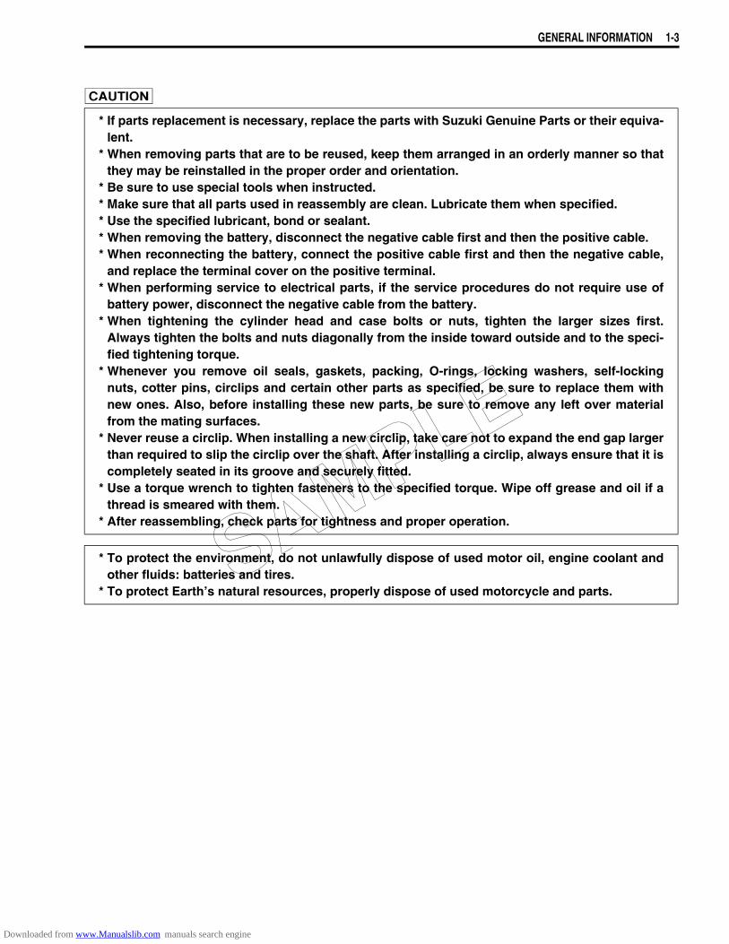
* If parts replacement is necessary, replace the parts with Suzuki Genuine Parts or their equiva-
lent.* When removing parts that are to be reused, keep them arranged in an orderly manner so that
they may be reinstalled in the proper order and orientation.* Be sure to use special tools when instructed.* Make sure that all parts used in reassembly are clean. Lubricate them when specified.* Use the specified lubricant, bond or sealant.* When removing the battery, disconnect the negative cable first and then the positive cable.* When reconnecting the battery, connect the positive cable first and then the negative cable,
and replace the terminal cover on the positive terminal.* When performing service to electrical parts, if the service procedures do not require use of
battery power, disconnect the negative cable from the battery.* When tightening the cylinder head and case bolts or nuts, tighten the larger sizes first.
Always tighten the bolts and nuts diagonally from the inside toward outside and to the speci-fied tightening torque.
* Whenever you remove oil seals, gaskets, packing, O-rings, locking washers, self-lockingnuts, cotter pins, circlips and certain other parts as specified, be sure to replace them withnew ones. Also, before installing these new parts, be sure to remove any left over materialfrom the mating surfaces.
* Never reuse a circlip. When installing a new circlip, take care not to expand the end gap largerthan required to slip the circlip over the shaft. After installing a circlip, always ensure that it iscompletely seated in its groove and securely fitted.
* Use a torque wrench to tighten fasteners to the specified torque. Wipe off grease and oil if athread is smeared with them.
* After reassembling, check parts for tightness and proper operation.
* To protect the environment, do not unlawfully dispose of used motor oil, engine coolant andother fluids: batteries and tires.
* To protect Earth’s natural resources, properly dispose of used motorcycle and parts.SAMPLE
Downloaded from www.Manualslib.com manuals search engine

1-4 GENERAL INFORMATION
SUZUKI VZ800K5 (’05-MODEL)
RIGHT SIDE LEFT SIDE* Difference between illustration and actual motorcycle may exist depending on the markets.
SERIAL NUMBER LOCATIONThe frame serial number or V.I.N. (Vehicle Identification Number) 1 is stamped on the right side of thesteering head pipe. The engine serial number 2 is located on the right side of the crankcase. These num-bers are required especially for registering the machine and ordering spare parts.
FUEL, OIL AND ENGINE COOLANT RECOMMENDATIONFUEL (FOR USA AND CANADA)Use only unleaded gasoline of at least 87 pump octane (R/2 + M/2) or 91 octane or higher rated by theresearch method.Gasoline containing MTBE (Methyl Tertiary Butyl Ether), less than 10% ethanol, or less than 5% methanolwith appropriate cosolvents and corrosion inhibitor is permissible.
FUEL (FOR OTHER COUNTRIES)Gasoline used should be graded 91 octane (Research Method) or higher. Unleaded gasoline is recom-mended.
SAMPLE
Downloaded from www.Manualslib.com manuals search engine
GENERAL INFORMATION 1-5
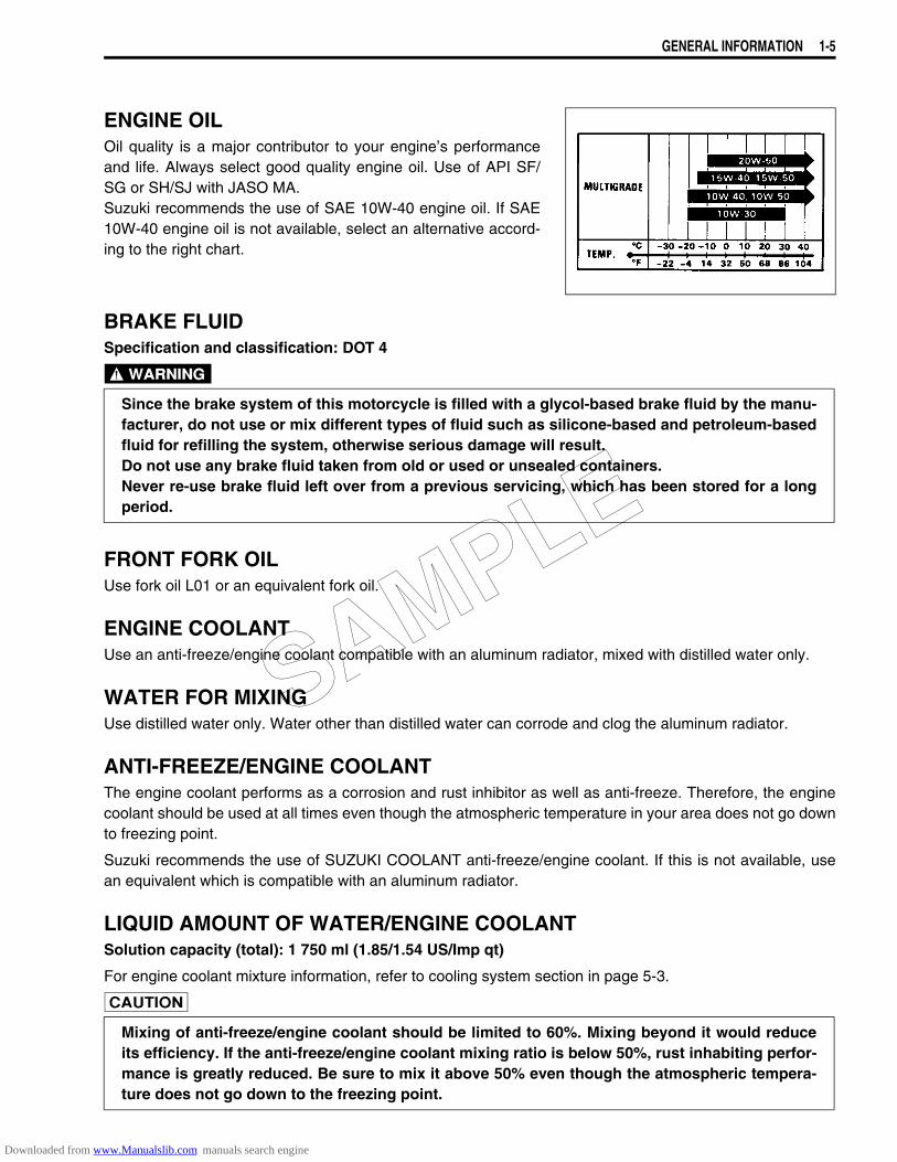
ENGINE OILOil quality is a major contributor to your engine’s performanceand life. Always select good quality engine oil. Use of API SF/SG or SH/SJ with JASO MA.Suzuki recommends the use of SAE 10W-40 engine oil. If SAE10W-40 engine oil is not available, select an alternative accord-ing to the right chart.
BRAKE FLUIDSpecification and classification: DOT 4
FRONT FORK OILUse fork oil L01 or an equivalent fork oil.
ENGINE COOLANTUse an anti-freeze/engine coolant compatible with an aluminum radiator, mixed with distilled water only.
WATER FOR MIXINGUse distilled water only. Water other than distilled water can corrode and clog the aluminum radiator.
ANTI-FREEZE/ENGINE COOLANTThe engine coolant performs as a corrosion and rust inhibitor as well as anti-freeze. Therefore, the enginecoolant should be used at all times even though the atmospheric temperature in your area does not go downto freezing point.
Suzuki recommends the use of SUZUKI COOLANT anti-freeze/engine coolant. If this is not available, usean equivalent which is compatible with an aluminum radiator.
LIQUID AMOUNT OF WATER/ENGINE COOLANTSolution capacity (total): 1 750 ml (1.85/1.54 US/Imp qt)
For engine coolant mixture information, refer to cooling system section in page 5-3.
Since the brake system of this motorcycle is filled with a glycol-based brake fluid by the manu-facturer, do not use or mix different types of fluid such as silicone-based and petroleum-basedfluid for refilling the system, otherwise serious damage will result.Do not use any brake fluid taken from old or used or unsealed containers.Never re-use brake fluid left over from a previous servicing, which has been stored for a longperiod.
Mixing of anti-freeze/engine coolant should be limited to 60%. Mixing beyond it would reduceits efficiency. If the anti-freeze/engine coolant mixing ratio is below 50%, rust inhabiting perfor-mance is greatly reduced. Be sure to mix it above 50% even though the atmospheric tempera-ture does not go down to the freezing point.
SAMPLE
Downloaded from www.Manualslib.com manuals search engine
1-6 GENERAL INFORMATION
BREAK-IN PROCEDURESDuring manufacturing only the best possible materials are used and all machined parts are finished to a veryhigh standard. It is still necessary to allow the moving parts to “BREAK-IN” before subjecting the engine tomaximum stresses. The future performance and reliability of the engine depends on the care and restraintexercised during its early life. Refer to the following break-in engine speed recommendations.
• Keep to these break-in throttle positions during the break-in period.
Break-in throttle operationInitial 800 km ( 500 miles): Less than 1/2 throttleUp to 1 600 km (1 000 miles): Less than 3/4 throttle
• Upon reaching an odometer reading of 1 600 km (1 000 miles) you can subject the motorcycle to full throt-tle operation.
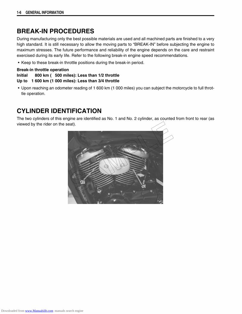
CYLINDER IDENTIFICATIONThe two cylinders of this engine are identified as No. 1 and No. 2 cylinder, as counted from front to rear (asviewed by the rider on the seat).
#1#2SAMPLE
Downloaded from www.Manualslib.com manuals search engine
GENERAL INFORMATION 1-7
INFORMATION LABELS
A: Attached
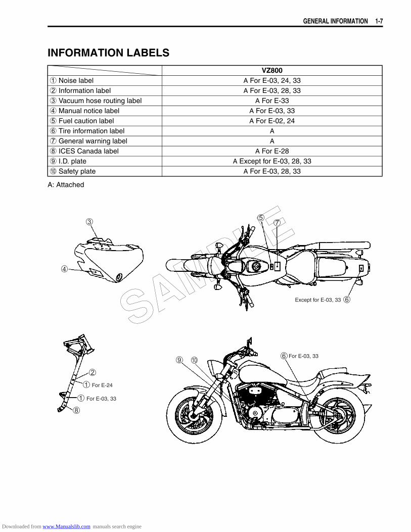
VZ8001 Noise label A For E-03, 24, 332 Information label A For E-03, 28, 333 Vacuum hose routing label A For E-334 Manual notice label A For E-03, 335 Fuel caution label A For E-02, 246 Tire information label A
7 General warning label A
8 ICES Canada label A For E-289 I.D. plate A Except for E-03, 28, 330 Safety plate A For E-03, 28, 33
For E-24
For E-03, 33
Except for E-03, 33
For E-03, 33
SAMPLE
Downloaded from www.Manualslib.com manuals search engine
1-8 GENERAL INFORMATION
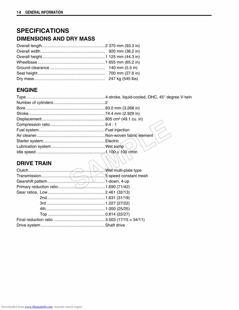
SPECIFICATIONSDIMENSIONS AND DRY MASSOverall length.......................................................2 370 mm (93.3 in)Overall width ........................................................ 920 mm (36.2 in)Overall height.......................................................1 125 mm (44.3 in)Wheelbase...........................................................1 655 mm (65.2 in)Ground clearance ................................................ 140 mm (5.5 in)Seat height........................................................... 700 mm (27.6 in)Dry mass.............................................................. 247 kg (545 lbs)
ENGINEType.....................................................................4-stroke, liquid-cooled, OHC, 45° degree V-twinNumber of cylinders .............................................2Bore .....................................................................83.0 mm (3.268 in)Stroke...................................................................74.4 mm (2.929 in)Displacement .......................................................805 cm³ (49.1 cu. in)Compression ratio................................................9.4 : 1Fuel system..........................................................Fuel injectionAir cleaner............................................................Non-woven fabric elementStarter system......................................................ElectricLubrication system...............................................Wet sumpIdle speed ............................................................1 100 ± 100 r/min
DRIVE TRAINClutch...................................................................Wet multi-plate typeTransmission........................................................5-speed constant meshGearshift pattern ..................................................1-down, 4-upPrimary reduction ratio.........................................1.690 (71/42)Gear ratios, Low..................................................2.461 (32/13)
2nd...................................................1.631 (31/19)3rd ...................................................1.227 (27/22)4th....................................................1.000 (25/25)Top ..................................................0.814 (22/27)
Final reduction ratio .............................................3.503 (17/15 × 34/11)Drive system ........................................................Shaft drive
SAMPLE
Downloaded from www.Manualslib.com manuals search engine

GENERAL INFORMATION 1-9
CHASSISFront suspension................................................. Inverted telescopic, coil spring, oil dampedRear suspension ................................................. Swingarm type, coil spring, oil dampedFront suspension stroke...................................... 140 mm (5.5 in)Rear wheel travel ................................................ 105 mm (4.1 in)Caster.................................................................. 33° 15’Trail ..................................................................... 141 mm (5.6 in)Steering angle ..................................................... 38° (right & left)Turning radius ..................................................... 3.0 m (9.8 ft)Front brake.......................................................... Disc brake, twinRear brake .......................................................... Drum brakeFront tire size ...................................................... 130/90-16M/C (67H), tubelessRear tire size ....................................................... 170/80-15M/C (77H), tubeless
ELECTRICALlgnition type ......................................................... Electronic ignition (Transistorized)lgnition timing ...................................................... 5° B.T.D.C at 1 100 r/minSpark plug ........................................................... NGK: DPR7EA-9 or DENSO: X22EPR-U9Battery................................................................. 12 V 36.0 kC (10 Ah)/10 HRGenerator ............................................................ Three-phase A.C. GeneratorMain fuse............................................................. 30 AFuse .................................................................... 10/10/10/10/10/15 AHeadlight ............................................................. 12 V 60/55 W (H4)Parking or city light.............................................. 12 V 5 W......................................For E-02, 19Front turn signal light........................................... 12 V 21/5 W.................................For E-03, 28, 33
12 V 21 W....................................For the othersRear turn signal light ........................................... 12 V 21 WBrake light/Taillight.............................................. LEDSpeedometer light ............................................... LEDFuel level indicator light....................................... LEDTurn signal indicator light .................................... LEDNeutral indicator light .......................................... LEDHigh beam indicator light..................................... LEDOil pressure/Coolant temperature/Fuel injection warning light ........................................................ LED
CAPACITIES Fuel tank, including reserve................................ 15.0 L (4.0/3.3 US/Imp gal) .......For E-33
15.5 L (4.1/3.4 US/Imp gal) .......For the othersreserve............................................... 3.0 L (0.8/0.7 US/Imp gal)
Engine oil, oil change ........................................ 3 000 ml (3.2/2.6 US/Imp qt)with filter change.............................. 3 400 ml (3.6/3.0 US/Imp qt)overhaul ........................................... 3 700 ml (3.9/3.3 US/Imp qt)
Front fork oil (each leg) ....................................... 493 ml (16.7/17.4 US/Imp oz)Coolant................................................................ 1.5 L (1.59/1.32 US/Imp qt)
These specifications are subject to change without notice.
SAMPLE
Downloaded from www.Manualslib.com manuals search engine

2
6
6
PERIODIC MAINTENANCE 2-1
CONTENTS
PERIODIC MAINTENANCE
PERIODIC MAINTENANCE SCHEDULE .......................................................2- 2PERIODIC MAINTENANCE CHART .....................................................2- 2LUBRICATION POINTS .........................................................................2- 3
MAINTENANCE AND TUNE-UP PROCEDURES ..........................................2- 4AIR CLEANER .......................................................................................2- 4SPARK PLUG ........................................................................................2- 5VALVE CLEARANCE ............................................................................2- 7FUEL HOSE ...........................................................................................2-10ENGINE OIL AND OIL FILTER ..............................................................2-11ENGINE IDLE SPEED ............................................................................2-13THROTTLE CABLE PLAY .....................................................................2-14THROTTLE VALVE SYNCHRONIZATION ............................................2-15EVAPORATIVE EMISSON CONTROL SYSTEM (FOR E-33 ONLY) ...2-15PAIR (AIR SUPPLY) SYSTEM ...............................................................2-15CLUTCH .................................................................................................2-16COOLING SYSTEM ...............................................................................2-17FINAL GEAR OIL ...................................................................................2-19BRAKE ...................................................................................................2-19TIRE ........................................................................................................2-23STEERING ..............................................................................................2-23FRONT FORK ........................................................................................2-24REAR SUSPENSION .............................................................................2-24EXHAUST PIPE BOLT ...........................................................................2-24CHASSIS BOLT AND NUT ....................................................................2-25
COMPRESSION PRESSURE CHECK ............................................................2-27COMPRESSION TEST PROCEDURE ...................................................2-27
OIL PRESSURE CHECK .................................................................................2-28OIL PRESSURE TEST PROCEDURE ...................................................2-28
SDS CHECK ....................................................................................................2-29SAMPLE: ................................................................................................2-29Data sampled from cold starting through warm-up ..........................2-29Data at 3 000 r/min under no load .......................................................2-30Data at the time of racing .....................................................................2-30
SAMPLE
Downloaded from www.Manualslib.com manuals search engine
2-2 PERIODIC MAINTENANCE
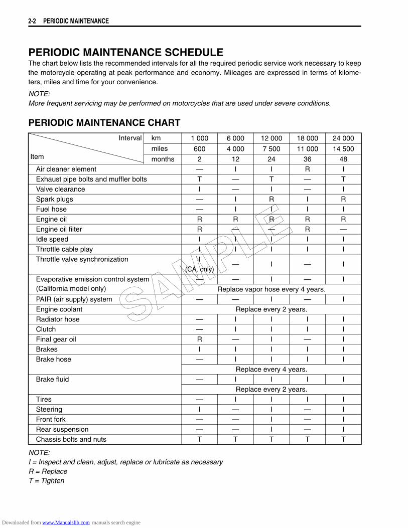
PERIODIC MAINTENANCE SCHEDULEThe chart below lists the recommended intervals for all the required periodic service work necessary to keepthe motorcycle operating at peak performance and economy. Mileages are expressed in terms of kilome-ters, miles and time for your convenience.
NOTE:More frequent servicing may be performed on motorcycles that are used under severe conditions.
PERIODIC MAINTENANCE CHART
NOTE:I = Inspect and clean, adjust, replace or lubricate as necessaryR = ReplaceT = Tighten
Interval
Item
km 1 000 6 000 12 000 18 000 24 000
miles 600 4 000 7 500 11 000 14 500
months 2 12 24 36 48Air cleaner element — I I R IExhaust pipe bolts and muffler bolts T — T — TValve clearance I — I — ISpark plugs — I R I RFuel hose — I I I IEngine oil R R R R REngine oil filter R — — R —Idle speed I I I I IThrottle cable play I I I I IThrottle valve synchronization I
— I — I(CA. only)
Evaporative emission control system(California model only)
— — I — IReplace vapor hose every 4 years.
PAIR (air supply) system — — I — IEngine coolant Replace every 2 years.Radiator hose — I I I IClutch — I I I IFinal gear oil R — I — IBrakes I I I I IBrake hose — I I I I
Replace every 4 years.Brake fluid — I I I I
Replace every 2 years.Tires — I I I ISteering I — I — IFront fork — — I — IRear suspension — — I — IChassis bolts and nuts T T T T T
SAMPLE
Downloaded from www.Manualslib.com manuals search engine
PERIODIC MAINTENANCE 2-3
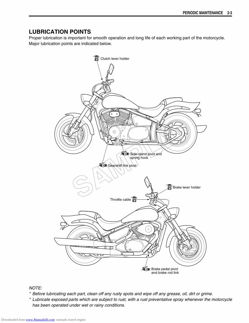
LUBRICATION POINTSProper lubrication is important for smooth operation and long life of each working part of the motorcycle.Major lubrication points are indicated below.
NOTE:* Before lubricating each part, clean off any rusty spots and wipe off any grease, oil, dirt or grime.* Lubricate exposed parts which are subject to rust, with a rust preventative spray whenever the motorcycle
has been operated under wet or rainy conditions.
Clutch lever holder
Gearshift link pivot
Side-stand pivot andspring hook
Brake lever holder
Throttle cable
Brake pedal pivotand brake rod link
SAMPLE
Downloaded from www.Manualslib.com manuals search engine
2-4 PERIODIC MAINTENANCE
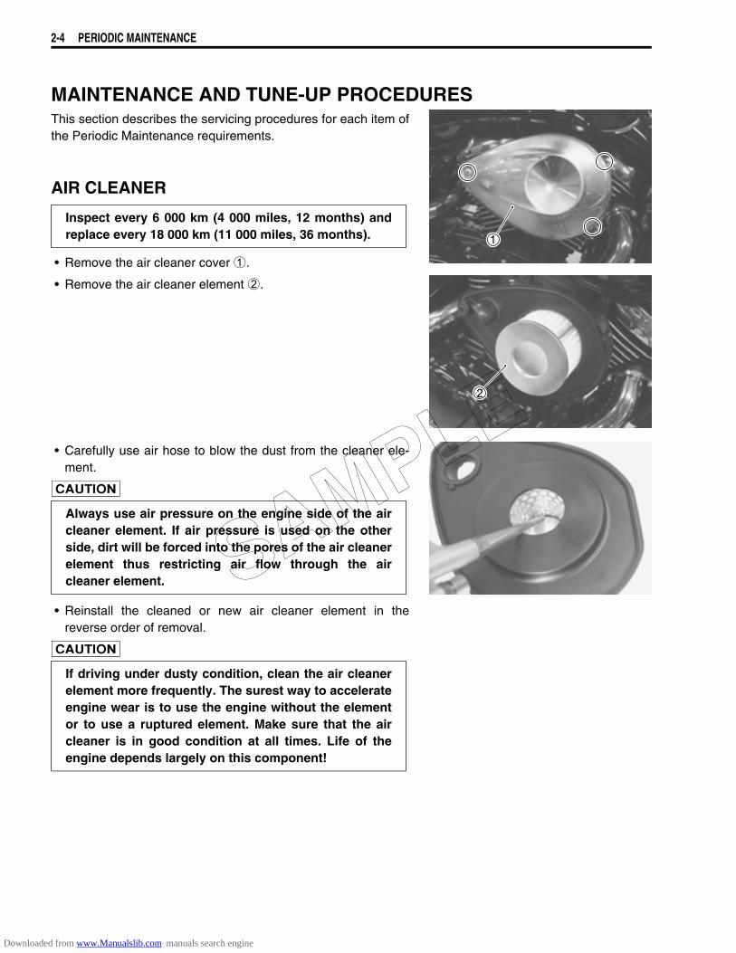
MAINTENANCE AND TUNE-UP PROCEDURESThis section describes the servicing procedures for each item ofthe Periodic Maintenance requirements.
AIR CLEANER
• Remove the air cleaner cover 1.
• Remove the air cleaner element 2.
• Carefully use air hose to blow the dust from the cleaner ele-ment.
• Reinstall the cleaned or new air cleaner element in thereverse order of removal.
Inspect every 6 000 km (4 000 miles, 12 months) andreplace every 18 000 km (11 000 miles, 36 months).
Always use air pressure on the engine side of the aircleaner element. If air pressure is used on the otherside, dirt will be forced into the pores of the air cleanerelement thus restricting air flow through the aircleaner element.
If driving under dusty condition, clean the air cleanerelement more frequently. The surest way to accelerateengine wear is to use the engine without the elementor to use a ruptured element. Make sure that the aircleaner is in good condition at all times. Life of theengine depends largely on this component!
SAMPLE
Downloaded from www.Manualslib.com manuals search engine
PERIODIC MAINTENANCE 2-5
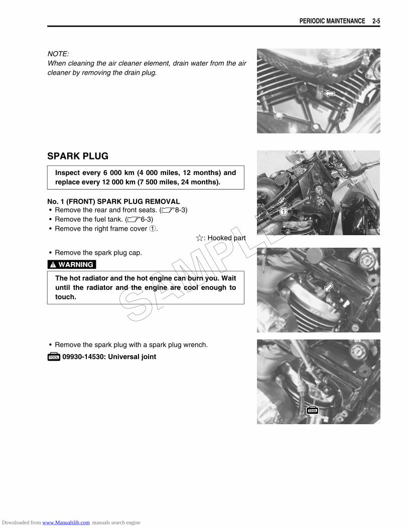
NOTE:When cleaning the air cleaner element, drain water from the aircleaner by removing the drain plug.
SPARK PLUG
No. 1 (FRONT) SPARK PLUG REMOVAL• Remove the rear and front seats. (8-3)• Remove the fuel tank. (6-3)• Remove the right frame cover 1.
: Hooked part
• Remove the spark plug cap.
• Remove the spark plug with a spark plug wrench.
09930-14530: Universal joint
Inspect every 6 000 km (4 000 miles, 12 months) andreplace every 12 000 km (7 500 miles, 24 months).
The hot radiator and the hot engine can burn you. Waituntil the radiator and the engine are cool enough totouch. SAMPLE
Downloaded from www.Manualslib.com manuals search engine
2-6 PERIODIC MAINTENANCE
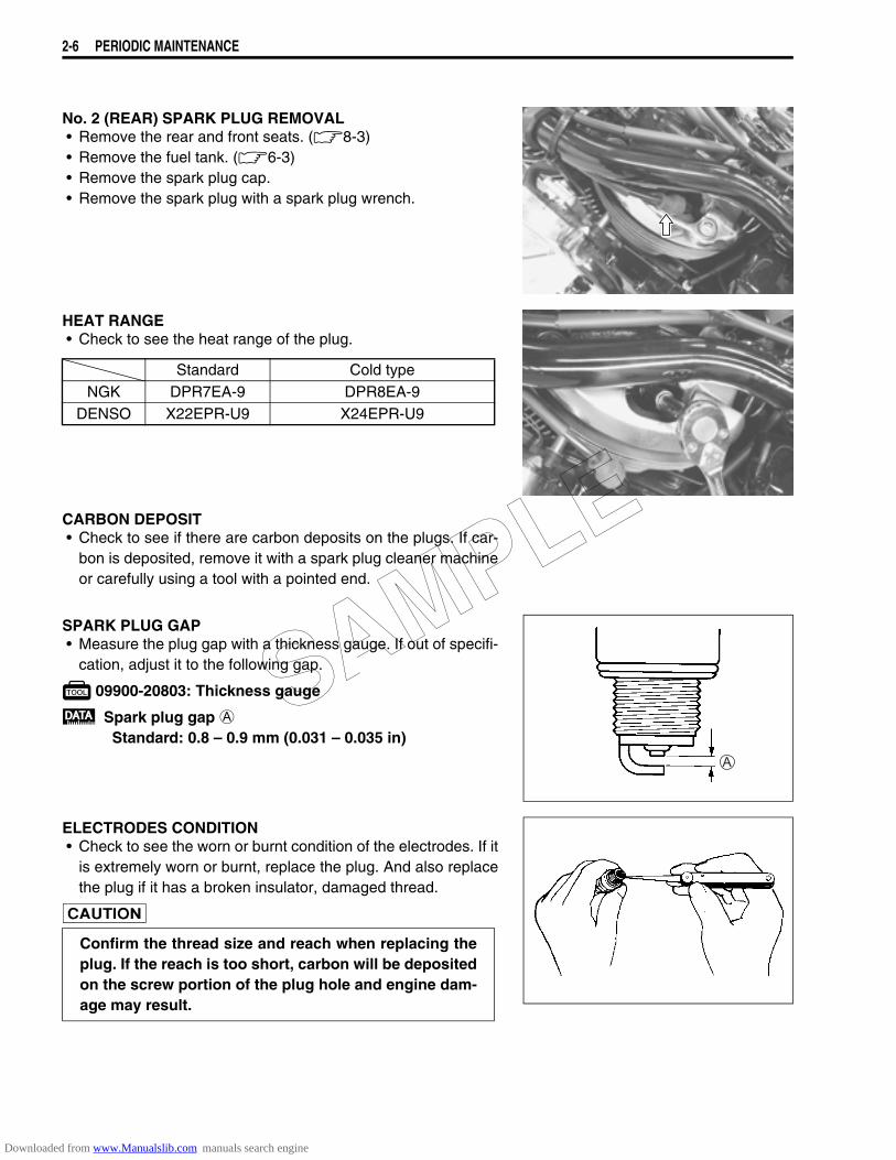
No. 2 (REAR) SPARK PLUG REMOVAL• Remove the rear and front seats. (8-3)• Remove the fuel tank. (6-3)• Remove the spark plug cap.• Remove the spark plug with a spark plug wrench.
HEAT RANGE• Check to see the heat range of the plug.
CARBON DEPOSIT• Check to see if there are carbon deposits on the plugs. If car-
bon is deposited, remove it with a spark plug cleaner machineor carefully using a tool with a pointed end.
SPARK PLUG GAP• Measure the plug gap with a thickness gauge. If out of specifi-
cation, adjust it to the following gap.
09900-20803: Thickness gauge
Spark plug gap AStandard: 0.8 – 0.9 mm (0.031 – 0.035 in)
ELECTRODES CONDITION• Check to see the worn or burnt condition of the electrodes. If it
is extremely worn or burnt, replace the plug. And also replacethe plug if it has a broken insulator, damaged thread.
Standard Cold typeNGK DPR7EA-9 DPR8EA-9
DENSO X22EPR-U9 X24EPR-U9
Confirm the thread size and reach when replacing theplug. If the reach is too short, carbon will be depositedon the screw portion of the plug hole and engine dam-age may result.
SAMPLE
Downloaded from www.Manualslib.com manuals search engine
PERIODIC MAINTENANCE 2-7
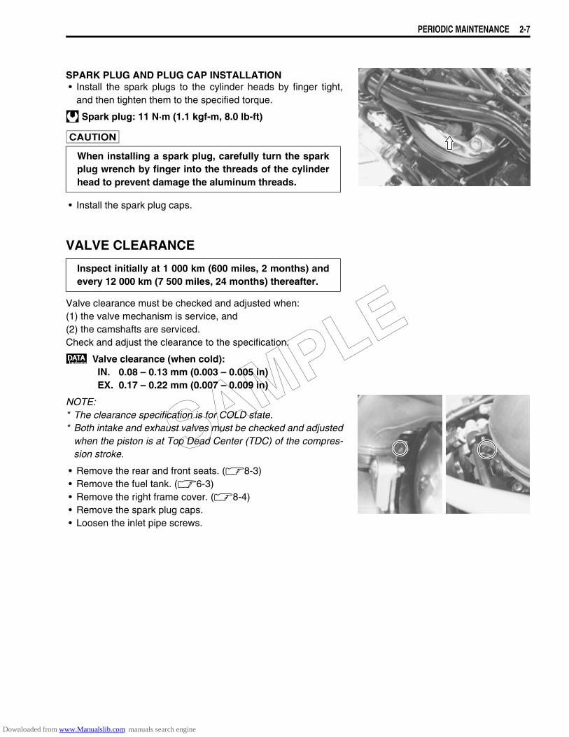
SPARK PLUG AND PLUG CAP INSTALLATION• Install the spark plugs to the cylinder heads by finger tight,
and then tighten them to the specified torque.
Spark plug: 11 N·m (1.1 kgf-m, 8.0 lb-ft)
• Install the spark plug caps.
VALVE CLEARANCE
Valve clearance must be checked and adjusted when:(1) the valve mechanism is service, and(2) the camshafts are serviced.Check and adjust the clearance to the specification.
Valve clearance (when cold):IN. 0.08 – 0.13 mm (0.003 – 0.005 in)EX. 0.17 – 0.22 mm (0.007 – 0.009 in)
NOTE:* The clearance specification is for COLD state.* Both intake and exhaust valves must be checked and adjusted
when the piston is at Top Dead Center (TDC) of the compres-sion stroke.
• Remove the rear and front seats. (8-3)• Remove the fuel tank. (6-3)• Remove the right frame cover. (8-4)• Remove the spark plug caps.• Loosen the inlet pipe screws.
When installing a spark plug, carefully turn the sparkplug wrench by finger into the threads of the cylinderhead to prevent damage the aluminum threads.
Inspect initially at 1 000 km (600 miles, 2 months) andevery 12 000 km (7 500 miles, 24 months) thereafter.
SAMPLE
Downloaded from www.Manualslib.com manuals search engine
2-8 PERIODIC MAINTENANCE
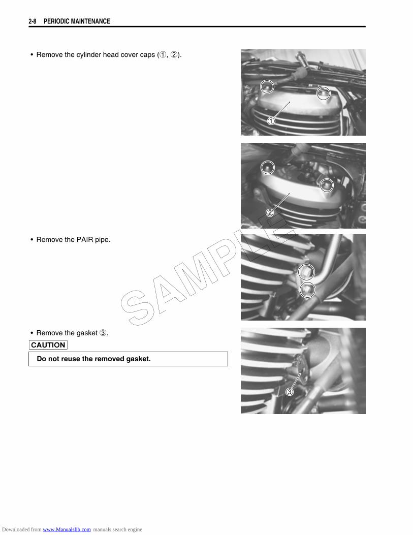
• Remove the cylinder head cover caps (1, 2).
• Remove the PAIR pipe.
• Remove the gasket 3.
Do not reuse the removed gasket.
SAMPLE
Downloaded from www.Manualslib.com manuals search engine
PERIODIC MAINTENANCE 2-9
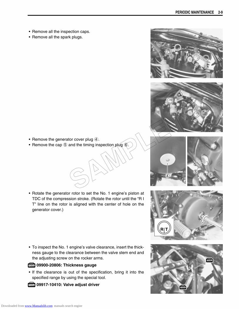
• Remove all the inspection caps.• Remove all the spark plugs.
• Remove the generator cover plug 4.• Remove the cap 5 and the timing inspection plug 6.
• Rotate the generator rotor to set the No. 1 engine’s piston atTDC of the compression stroke. (Rotate the rotor until the “R IT” line on the rotor is aligned with the center of hole on thegenerator cover.)
• To inspect the No. 1 engine’s valve clearance, insert the thick-ness gauge to the clearance between the valve stem end andthe adjusting screw on the rocker arms.
09900-20806: Thickness gauge
• If the clearance is out of the specification, bring it into thespecified range by using the special tool.
09917-10410: Valve adjust driver
R T
SAMPLE
Downloaded from www.Manualslib.com manuals search engine
2-10 PERIODIC MAINTENANCE
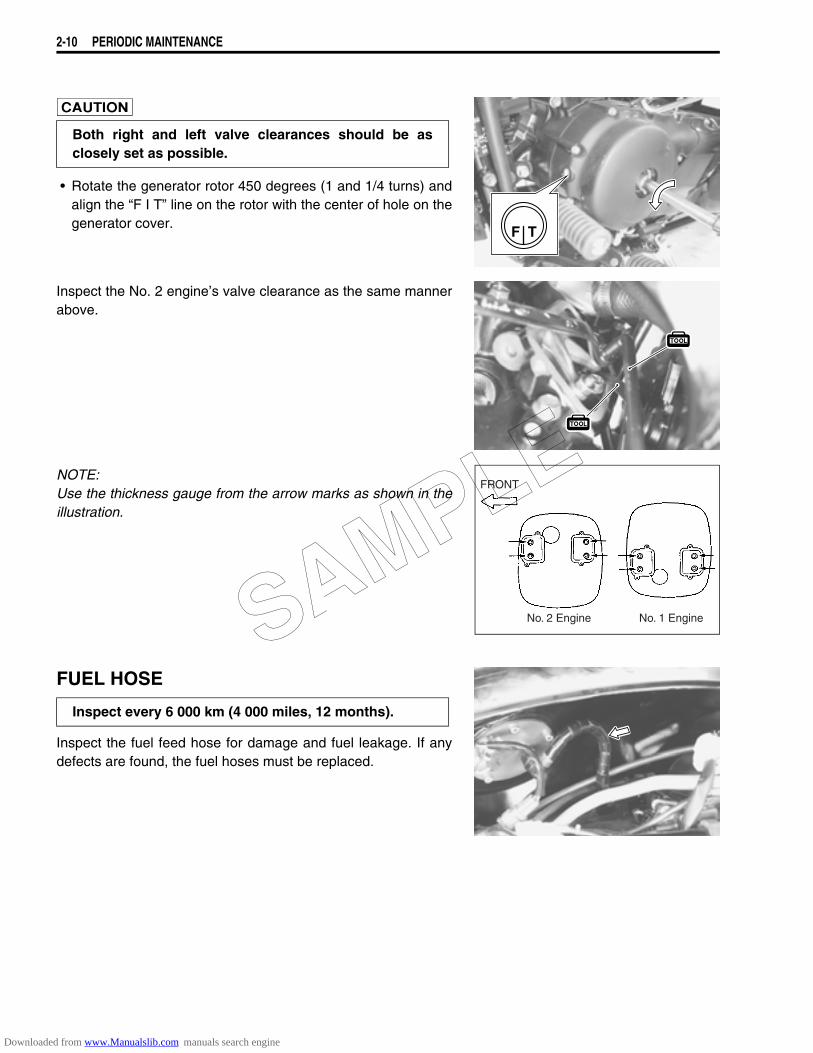
• Rotate the generator rotor 450 degrees (1 and 1/4 turns) andalign the “F I T” line on the rotor with the center of hole on thegenerator cover.
Inspect the No. 2 engine’s valve clearance as the same mannerabove.
NOTE:Use the thickness gauge from the arrow marks as shown in theillustration.
FUEL HOSE
Inspect the fuel feed hose for damage and fuel leakage. If anydefects are found, the fuel hoses must be replaced.
Both right and left valve clearances should be asclosely set as possible.
F T
FRONT
No. 2 Engine No. 1 Engine
Inspect every 6 000 km (4 000 miles, 12 months).
SAMPLE
Downloaded from www.Manualslib.com manuals search engine
PERIODIC MAINTENANCE 2-11
ENGINE OIL AND OIL FILTER
Oil should be changed while the engine is warm. Oil filterreplacement at the above intervals, should be done togetherwith the engine oil change.
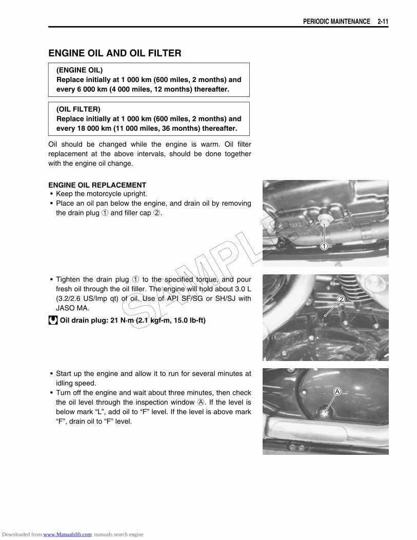
ENGINE OIL REPLACEMENT• Keep the motorcycle upright.• Place an oil pan below the engine, and drain oil by removing
the drain plug 1 and filler cap 2.
• Tighten the drain plug 1 to the specified torque, and pourfresh oil through the oil filler. The engine will hold about 3.0 L(3.2/2.6 US/Imp qt) of oil. Use of API SF/SG or SH/SJ withJASO MA.
Oil drain plug: 21 N·m (2.1 kgf-m, 15.0 lb-ft)
• Start up the engine and allow it to run for several minutes atidling speed.
• Turn off the engine and wait about three minutes, then checkthe oil level through the inspection window A. If the level isbelow mark “L”, add oil to “F” level. If the level is above mark“F”, drain oil to “F” level.
(ENGINE OIL)Replace initially at 1 000 km (600 miles, 2 months) andevery 6 000 km (4 000 miles, 12 months) thereafter.
(OIL FILTER)Replace initially at 1 000 km (600 miles, 2 months) andevery 18 000 km (11 000 miles, 36 months) thereafter.
SAMPLE
Downloaded from www.Manualslib.com manuals search engine
2-12 PERIODIC MAINTENANCE
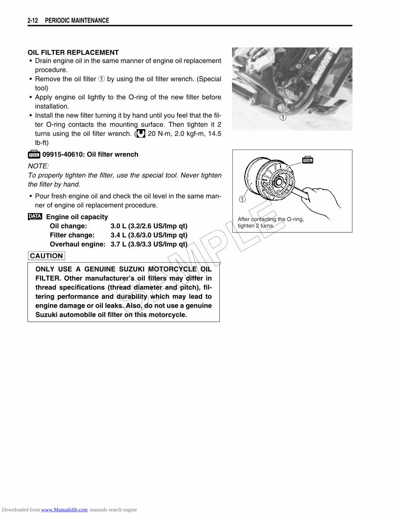
OIL FILTER REPLACEMENT• Drain engine oil in the same manner of engine oil replacement
procedure.• Remove the oil filter 1 by using the oil filter wrench. (Special
tool)• Apply engine oil lightly to the O-ring of the new filter before
installation.• Install the new filter turning it by hand until you feel that the fil-
ter O-ring contacts the mounting surface. Then tighten it 2turns using the oil filter wrench. ( 20 N·m, 2.0 kgf-m, 14.5lb-ft)
09915-40610: Oil filter wrench
NOTE:To properly tighten the filter, use the special tool. Never tightenthe filter by hand.
• Pour fresh engine oil and check the oil level in the same man-ner of engine oil replacement procedure.
Engine oil capacity Oil change: 3.0 L (3.2/2.6 US/Imp qt)Filter change: 3.4 L (3.6/3.0 US/Imp qt)Overhaul engine: 3.7 L (3.9/3.3 US/Imp qt)
ONLY USE A GENUINE SUZUKI MOTORCYCLE OILFILTER. Other manufacturer’s oil filters may differ inthread specifications (thread diameter and pitch), fil-tering performance and durability which may lead toengine damage or oil leaks. Also, do not use a genuineSuzuki automobile oil filter on this motorcycle.
After contacting the O-ring,tighten 2 turns.
SAMPLE
Downloaded from www.Manualslib.com manuals search engine

PERIODIC MAINTENANCE 2-13
ENGINE IDLE SPEED
NOTE:Warm up the engine before adjusting the engine idle speed.
• Connect the multi-circuit tester to the high-tension cord.
• Start up the engine and set its idle speed to the specifiedrange by turning the throttle stop screw 1.
Engine idle speed: 1 100 ± 100 r/min
09900-25008: Multi-circuit tester set
Inspect initially at 1 000 km (600 miles, 2 months) andevery 6 000 km (4 000 miles, 12 months) thereafter.
SAMPLE
Downloaded from www.Manualslib.com manuals search engine
2-14 PERIODIC MAINTENANCE
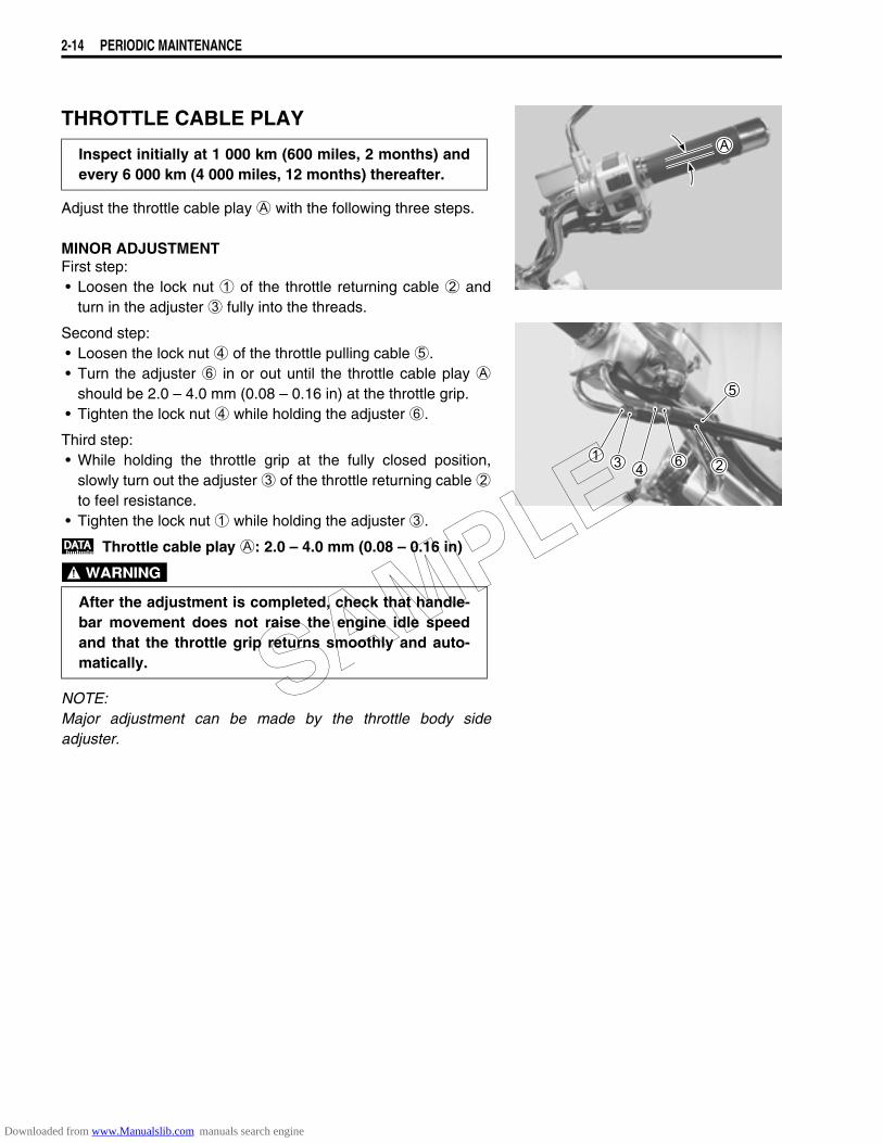
THROTTLE CABLE PLAY
Adjust the throttle cable play A with the following three steps.
MINOR ADJUSTMENTFirst step:• Loosen the lock nut 1 of the throttle returning cable 2 and
turn in the adjuster 3 fully into the threads.
Second step:• Loosen the lock nut 4 of the throttle pulling cable 5.• Turn the adjuster 6 in or out until the throttle cable play A
should be 2.0 – 4.0 mm (0.08 – 0.16 in) at the throttle grip.• Tighten the lock nut 4 while holding the adjuster 6.
Third step:• While holding the throttle grip at the fully closed position,
slowly turn out the adjuster 3 of the throttle returning cable 2to feel resistance.
• Tighten the lock nut 1 while holding the adjuster 3.
Throttle cable play A: 2.0 – 4.0 mm (0.08 – 0.16 in)
NOTE:Major adjustment can be made by the throttle body sideadjuster.
Inspect initially at 1 000 km (600 miles, 2 months) andevery 6 000 km (4 000 miles, 12 months) thereafter.
After the adjustment is completed, check that handle-bar movement does not raise the engine idle speedand that the throttle grip returns smoothly and auto-matically. SAMPLE
Downloaded from www.Manualslib.com manuals search engine
PERIODIC MAINTENANCE 2-15
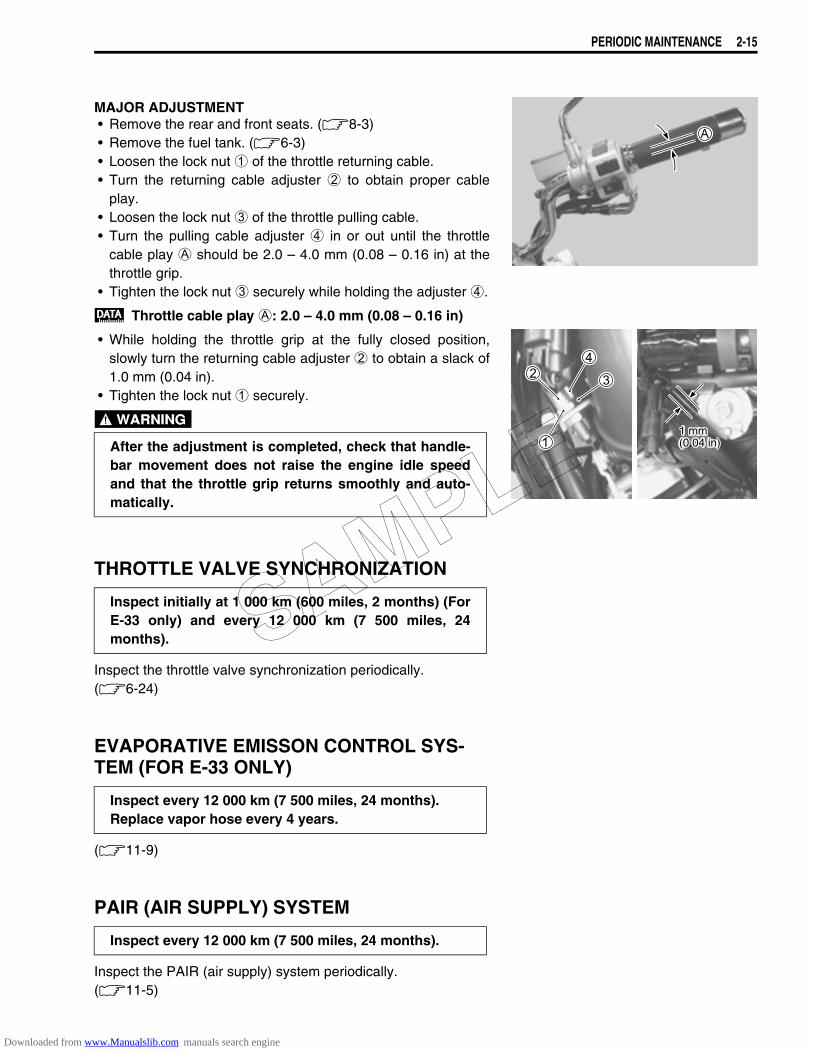
MAJOR ADJUSTMENT• Remove the rear and front seats. (8-3)• Remove the fuel tank. (6-3)• Loosen the lock nut 1 of the throttle returning cable.• Turn the returning cable adjuster 2 to obtain proper cable
play.• Loosen the lock nut 3 of the throttle pulling cable.• Turn the pulling cable adjuster 4 in or out until the throttle
cable play A should be 2.0 – 4.0 mm (0.08 – 0.16 in) at thethrottle grip.
• Tighten the lock nut 3 securely while holding the adjuster 4.
Throttle cable play A: 2.0 – 4.0 mm (0.08 – 0.16 in)
• While holding the throttle grip at the fully closed position,slowly turn the returning cable adjuster 2 to obtain a slack of1.0 mm (0.04 in).
• Tighten the lock nut 1 securely.
THROTTLE VALVE SYNCHRONIZATION
Inspect the throttle valve synchronization periodically.(6-24)
EVAPORATIVE EMISSON CONTROL SYS-TEM (FOR E-33 ONLY)
(11-9)
PAIR (AIR SUPPLY) SYSTEM
Inspect the PAIR (air supply) system periodically. (11-5)
After the adjustment is completed, check that handle-bar movement does not raise the engine idle speedand that the throttle grip returns smoothly and auto-matically.
Inspect initially at 1 000 km (600 miles, 2 months) (ForE-33 only) and every 12 000 km (7 500 miles, 24months).
Inspect every 12 000 km (7 500 miles, 24 months).Replace vapor hose every 4 years.
Inspect every 12 000 km (7 500 miles, 24 months).
1 mm(0.04 in)
SAMPLE
Downloaded from www.Manualslib.com manuals search engine
2-16 PERIODIC MAINTENANCE
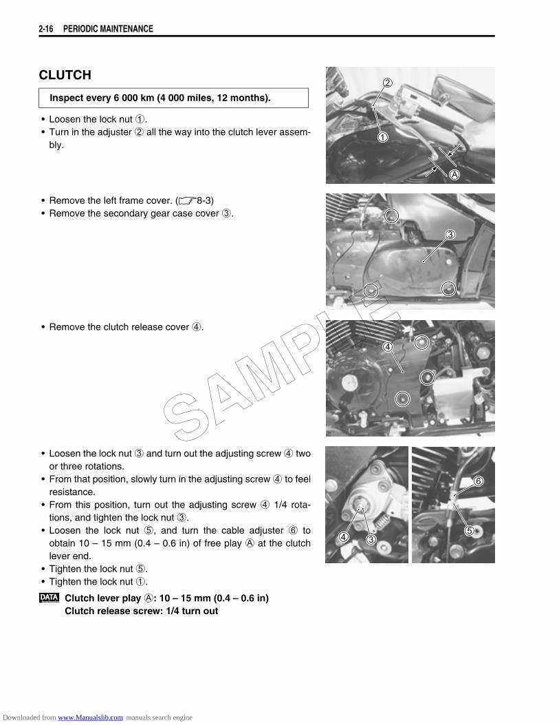
CLUTCH
• Loosen the lock nut 1.• Turn in the adjuster 2 all the way into the clutch lever assem-
bly.
• Remove the left frame cover. (8-3)• Remove the secondary gear case cover 3.
• Remove the clutch release cover 4.
• Loosen the lock nut 3 and turn out the adjusting screw 4 twoor three rotations.
• From that position, slowly turn in the adjusting screw 4 to feelresistance.
• From this position, turn out the adjusting screw 4 1/4 rota-tions, and tighten the lock nut 3.
• Loosen the lock nut 5, and turn the cable adjuster 6 toobtain 10 – 15 mm (0.4 – 0.6 in) of free play A at the clutchlever end.
• Tighten the lock nut 5.• Tighten the lock nut 1.
Clutch lever play A: 10 – 15 mm (0.4 – 0.6 in)Clutch release screw: 1/4 turn out
Inspect every 6 000 km (4 000 miles, 12 months).
SAMPLE
Downloaded from www.Manualslib.com manuals search engine
PERIODIC MAINTENANCE 2-17
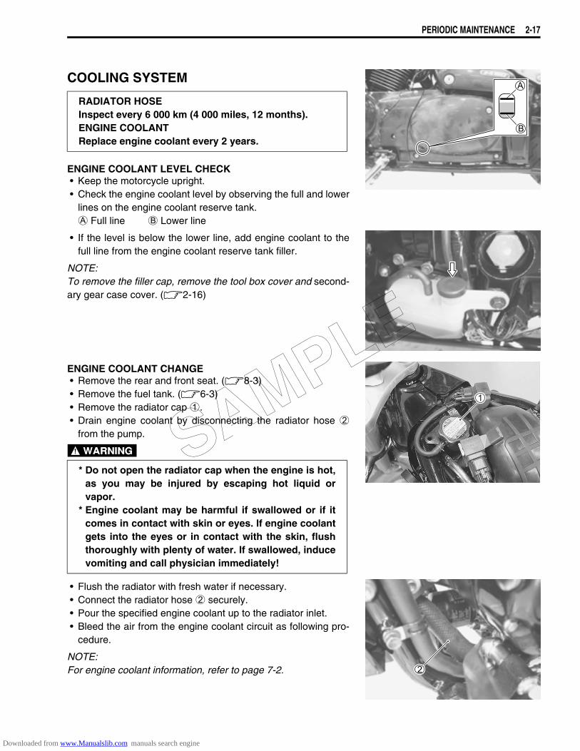
COOLING SYSTEM
ENGINE COOLANT LEVEL CHECK• Keep the motorcycle upright.• Check the engine coolant level by observing the full and lower
lines on the engine coolant reserve tank. A Full line B Lower line
• If the level is below the lower line, add engine coolant to thefull line from the engine coolant reserve tank filler.
NOTE:To remove the filler cap, remove the tool box cover and second-ary gear case cover. (2-16)
ENGINE COOLANT CHANGE• Remove the rear and front seat. (8-3)• Remove the fuel tank. (6-3)• Remove the radiator cap 1.• Drain engine coolant by disconnecting the radiator hose 2
from the pump.
• Flush the radiator with fresh water if necessary.• Connect the radiator hose 2 securely.• Pour the specified engine coolant up to the radiator inlet.• Bleed the air from the engine coolant circuit as following pro-
cedure.
NOTE:For engine coolant information, refer to page 7-2.
RADIATOR HOSEInspect every 6 000 km (4 000 miles, 12 months).ENGINE COOLANTReplace engine coolant every 2 years.
* Do not open the radiator cap when the engine is hot,as you may be injured by escaping hot liquid orvapor.
* Engine coolant may be harmful if swallowed or if itcomes in contact with skin or eyes. If engine coolantgets into the eyes or in contact with the skin, flushthoroughly with plenty of water. If swallowed, inducevomiting and call physician immediately!
SAMPLE
Downloaded from www.Manualslib.com manuals search engine
2-18 PERIODIC MAINTENANCE
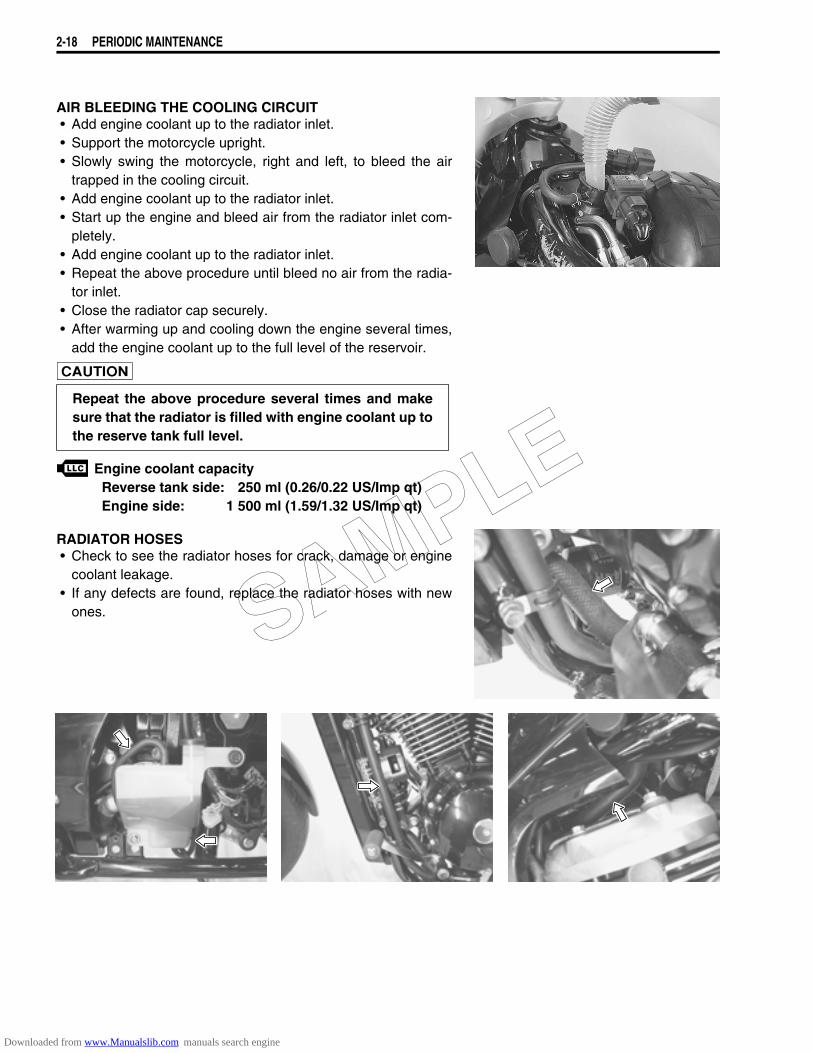
AIR BLEEDING THE COOLING CIRCUIT• Add engine coolant up to the radiator inlet.• Support the motorcycle upright.• Slowly swing the motorcycle, right and left, to bleed the air
trapped in the cooling circuit.• Add engine coolant up to the radiator inlet.• Start up the engine and bleed air from the radiator inlet com-
pletely.• Add engine coolant up to the radiator inlet.• Repeat the above procedure until bleed no air from the radia-
tor inlet.• Close the radiator cap securely.• After warming up and cooling down the engine several times,
add the engine coolant up to the full level of the reservoir.
Engine coolant capacityReverse tank side: 250 ml (0.26/0.22 US/Imp qt)Engine side: 1 500 ml (1.59/1.32 US/Imp qt)
RADIATOR HOSES• Check to see the radiator hoses for crack, damage or engine
coolant leakage.• If any defects are found, replace the radiator hoses with new
ones.
Repeat the above procedure several times and makesure that the radiator is filled with engine coolant up tothe reserve tank full level.
SAMPLE
Downloaded from www.Manualslib.com manuals search engine
PERIODIC MAINTENANCE 2-19
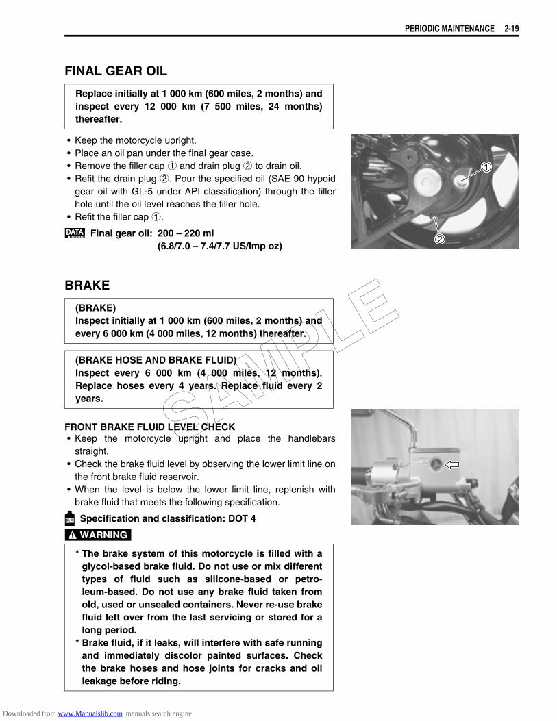
FINAL GEAR OIL
• Keep the motorcycle upright.• Place an oil pan under the final gear case.• Remove the filler cap 1 and drain plug 2 to drain oil.• Refit the drain plug 2. Pour the specified oil (SAE 90 hypoid
gear oil with GL-5 under API classification) through the fillerhole until the oil level reaches the filler hole.
• Refit the filler cap 1.
Final gear oil: 200 – 220 ml(6.8/7.0 – 7.4/7.7 US/Imp oz)
BRAKE
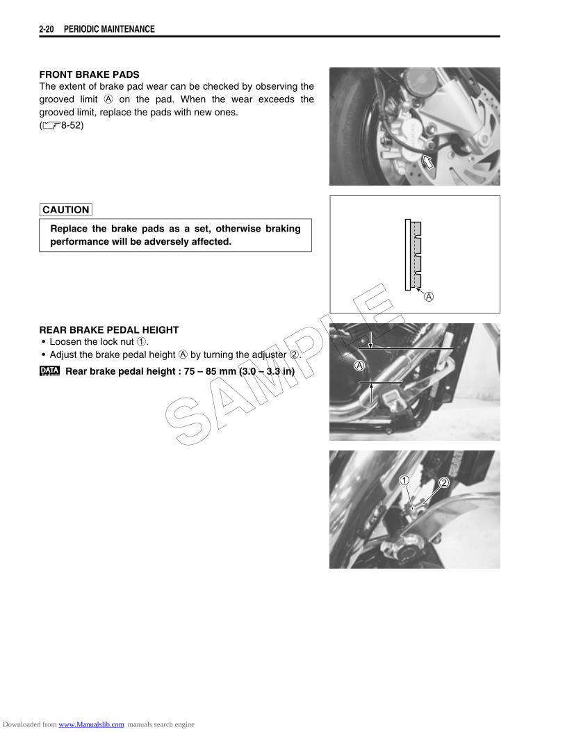
FRONT BRAKE FLUID LEVEL CHECK• Keep the motorcycle upright and place the handlebars
straight.• Check the brake fluid level by observing the lower limit line on
the front brake fluid reservoir.• When the level is below the lower limit line, replenish with
brake fluid that meets the following specification.
Specification and classification: DOT 4
Replace initially at 1 000 km (600 miles, 2 months) andinspect every 12 000 km (7 500 miles, 24 months)thereafter.
(BRAKE)Inspect initially at 1 000 km (600 miles, 2 months) andevery 6 000 km (4 000 miles, 12 months) thereafter.
(BRAKE HOSE AND BRAKE FLUID)Inspect every 6 000 km (4 000 miles, 12 months).Replace hoses every 4 years. Replace fluid every 2years.
* The brake system of this motorcycle is filled with aglycol-based brake fluid. Do not use or mix differenttypes of fluid such as silicone-based or petro-leum-based. Do not use any brake fluid taken fromold, used or unsealed containers. Never re-use brakefluid left over from the last servicing or stored for along period.
* Brake fluid, if it leaks, will interfere with safe runningand immediately discolor painted surfaces. Checkthe brake hoses and hose joints for cracks and oilleakage before riding.
SAMPLE
Downloaded from www.Manualslib.com manuals search engine
2-20 PERIODIC MAINTENANCE
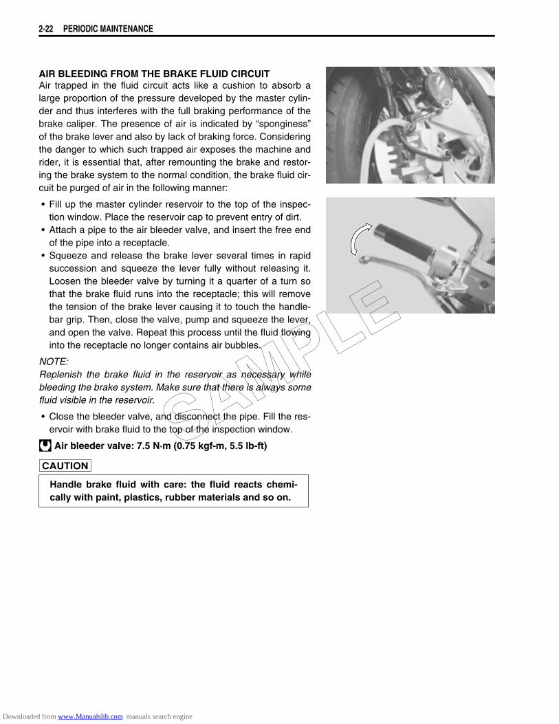
FRONT BRAKE PADSThe extent of brake pad wear can be checked by observing thegrooved limit A on the pad. When the wear exceeds thegrooved limit, replace the pads with new ones.(8-52)
REAR BRAKE PEDAL HEIGHT• Loosen the lock nut 1.• Adjust the brake pedal height A by turning the adjuster 2.
Rear brake pedal height : 75 – 85 mm (3.0 – 3.3 in)
Replace the brake pads as a set, otherwise brakingperformance will be adversely affected.
SAMPLE
Downloaded from www.Manualslib.com manuals search engine

PERIODIC MAINTENANCE 2-21
REAR BRAKE ADJUSTING• Adjust the free travel A to 20 – 30 mm by turning the adjust-
ing nut 1.
Rear brake pedal free travel A: 20 – 30 mm (0.8 – 1.2 in)
REAR BRAKE SHOE WEARThis motorcycle is equipped with brake lining wear limit indicatoron the rear brake.To check brake lining wear, perform the following steps.• Make sure that the rear brake is properly adjusted.• Depress the rear brake pedal. Make sure that the index mark1 is within the range 2 embossed on the brake panel.
• If the index mark goes beyond the range, the brake shoeassembly should be replaced with a new set of shoes.(8-62)
BRAKE LIGHT SWITCHAdjust the rear brake light switch so that the brake light willcome on just before pressure is felt when the brake pedal isdepressed.
SAMPLE
Downloaded from www.Manualslib.com manuals search engine
2-22 PERIODIC MAINTENANCE
AIR BLEEDING FROM THE BRAKE FLUID CIRCUITAir trapped in the fluid circuit acts like a cushion to absorb alarge proportion of the pressure developed by the master cylin-der and thus interferes with the full braking performance of thebrake caliper. The presence of air is indicated by “sponginess”of the brake lever and also by lack of braking force. Consideringthe danger to which such trapped air exposes the machine andrider, it is essential that, after remounting the brake and restor-ing the brake system to the normal condition, the brake fluid cir-cuit be purged of air in the following manner:
• Fill up the master cylinder reservoir to the top of the inspec-tion window. Place the reservoir cap to prevent entry of dirt.
• Attach a pipe to the air bleeder valve, and insert the free endof the pipe into a receptacle.
• Squeeze and release the brake lever several times in rapidsuccession and squeeze the lever fully without releasing it.Loosen the bleeder valve by turning it a quarter of a turn sothat the brake fluid runs into the receptacle; this will removethe tension of the brake lever causing it to touch the handle-bar grip. Then, close the valve, pump and squeeze the lever,and open the valve. Repeat this process until the fluid flowinginto the receptacle no longer contains air bubbles.
NOTE:Replenish the brake fluid in the reservoir as necessary whilebleeding the brake system. Make sure that there is always somefluid visible in the reservoir.
• Close the bleeder valve, and disconnect the pipe. Fill the res-ervoir with brake fluid to the top of the inspection window.
Air bleeder valve: 7.5 N·m (0.75 kgf-m, 5.5 lb-ft)
Handle brake fluid with care: the fluid reacts chemi-cally with paint, plastics, rubber materials and so on.
SAMPLE
Downloaded from www.Manualslib.com manuals search engine
PERIODIC MAINTENANCE 2-23
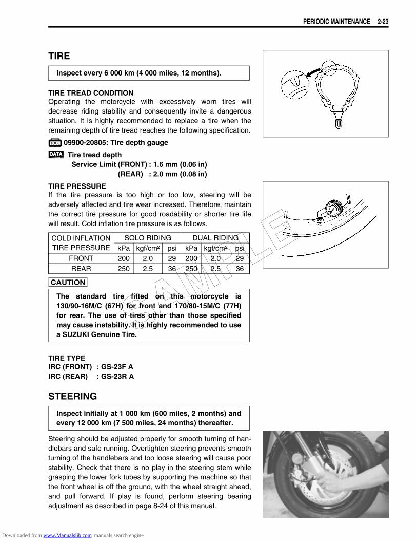
TIRE
TIRE TREAD CONDITIONOperating the motorcycle with excessively worn tires willdecrease riding stability and consequently invite a dangeroussituation. It is highly recommended to replace a tire when theremaining depth of tire tread reaches the following specification.
09900-20805: Tire depth gauge
Tire tread depthService Limit (FRONT) : 1.6 mm (0.06 in)
(REAR) : 2.0 mm (0.08 in)
TIRE PRESSUREIf the tire pressure is too high or too low, steering will beadversely affected and tire wear increased. Therefore, maintainthe correct tire pressure for good roadability or shorter tire lifewill result. Cold inflation tire pressure is as follows.
TIRE TYPEIRC (FRONT) : GS-23F AIRC (REAR) : GS-23R A
STEERING
Steering should be adjusted properly for smooth turning of han-dlebars and safe running. Overtighten steering prevents smoothturning of the handlebars and too loose steering will cause poorstability. Check that there is no play in the steering stem whilegrasping the lower fork tubes by supporting the machine so thatthe front wheel is off the ground, with the wheel straight ahead,and pull forward. If play is found, perform steering bearingadjustment as described in page 8-24 of this manual.
Inspect every 6 000 km (4 000 miles, 12 months).
COLD INFLATION TIRE PRESSURE
SOLO RIDING DUAL RIDINGkPa kgf/cm² psi kPa kgf/cm² psi
FRONT 200 2.0 29 200 2.0 29REAR 250 2.5 36 250 2.5 36
The standard tire fitted on this motorcycle is130/90-16M/C (67H) for front and 170/80-15M/C (77H)for rear. The use of tires other than those specifiedmay cause instability. It is highly recommended to usea SUZUKI Genuine Tire.
Inspect initially at 1 000 km (600 miles, 2 months) andevery 12 000 km (7 500 miles, 24 months) thereafter.
SAMPLE
Downloaded from www.Manualslib.com manuals search engine
2-24 PERIODIC MAINTENANCE
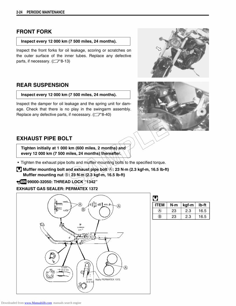
FRONT FORK
Inspect the front forks for oil leakage, scoring or scratches onthe outer surface of the inner tubes. Replace any defectiveparts, if necessary. (8-13)
REAR SUSPENSION
Inspect the damper for oil leakage and the spring unit for dam-age. Check that there is no play in the swingarm assembly.Replace any defective parts, if necessary. (8-40)
EXHAUST PIPE BOLT
• Tighten the exhaust pipe bolts and muffler mounting bolts to the specified torque.
Muffler mounting bolt and exhaust pipe bolt A: 23 N·m (2.3 kgf-m, 16.5 lb-ft)Muffler mounting nut B: 23 N·m (2.3 kgf-m, 16.5 lb-ft)
99000-32050: THREAD LOCK ‘‘1342’’
EXHAUST GAS SEALER: PERMATEX 1372
Inspect every 12 000 km (7 500 miles, 24 months).
Inspect every 12 000 km (7 500 miles, 24 months).
Tighten initially at 1 000 km (600 miles, 2 months) andevery 12 000 km (7 500 miles, 24 months) thereafter.
ITEM N·m kgf-m lb-ftA 23 2.3 16.5B 23 2.3 16.5
Apply PERMATEX 1372.5 mm (0.2 in)
5 mm (0.2 in)
SAMPLE
Downloaded from www.Manualslib.com manuals search engine
PERIODIC MAINTENANCE 2-25
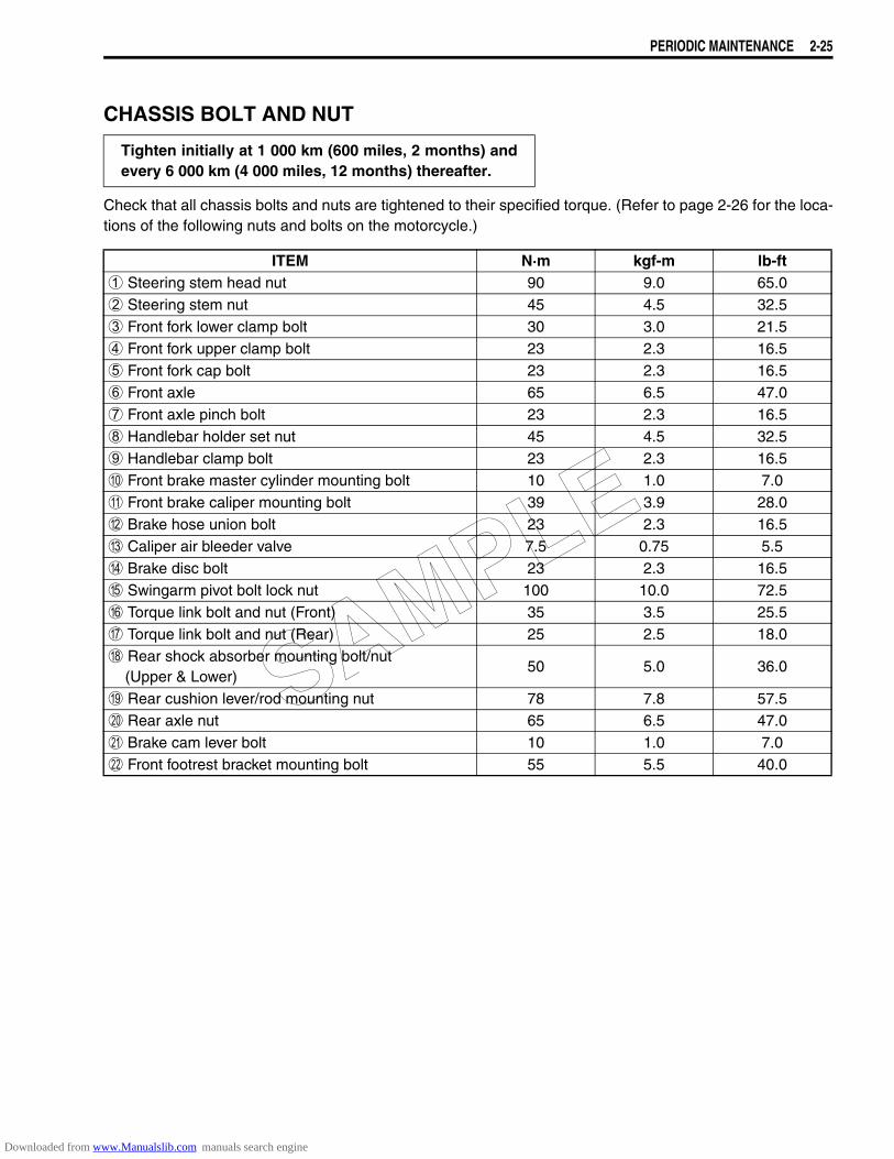
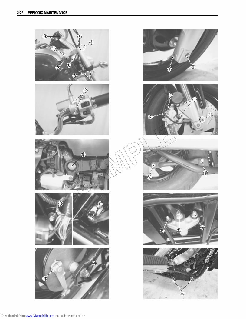
CHASSIS BOLT AND NUT
Check that all chassis bolts and nuts are tightened to their specified torque. (Refer to page 2-26 for the loca-tions of the following nuts and bolts on the motorcycle.)
Tighten initially at 1 000 km (600 miles, 2 months) andevery 6 000 km (4 000 miles, 12 months) thereafter.
ITEM N·m kgf-m lb-ft1 Steering stem head nut 90 9.0 65.02 Steering stem nut 45 4.5 32.53 Front fork lower clamp bolt 30 3.0 21.54 Front fork upper clamp bolt 23 2.3 16.55 Front fork cap bolt 23 2.3 16.56 Front axle 65 6.5 47.07 Front axle pinch bolt 23 2.3 16.58 Handlebar holder set nut 45 4.5 32.59 Handlebar clamp bolt 23 2.3 16.50 Front brake master cylinder mounting bolt 10 1.0 7.0A Front brake caliper mounting bolt 39 3.9 28.0B Brake hose union bolt 23 2.3 16.5C Caliper air bleeder valve 7.5 0.75 5.5D Brake disc bolt 23 2.3 16.5E Swingarm pivot bolt lock nut 100 10.0 72.5F Torque link bolt and nut (Front) 35 3.5 25.5G Torque link bolt and nut (Rear) 25 2.5 18.0H Rear shock absorber mounting bolt/nut (Upper & Lower)
50 5.0 36.0
I Rear cushion lever/rod mounting nut 78 7.8 57.5J Rear axle nut 65 6.5 47.0K Brake cam lever bolt 10 1.0 7.0L Front footrest bracket mounting bolt 55 5.5 40.0
SAMPLE
Downloaded from www.Manualslib.com manuals search engine
2-26 PERIODIC MAINTENANCE
SAMPLE
Downloaded from www.Manualslib.com manuals search engine
PERIODIC MAINTENANCE 2-27
COMPRESSION PRESSURE CHECKThe compression of a cylinder is a good indicator of its internal condition.The decision to overhaul the cylinder is often based on the results of a compression test. Periodic mainte-nance records kept at your dealership should include compression readings for each maintenance service.
COMPRESSION PRESSURE SPECIFICATION (Automatic de-comp. actuated)
Low compression pressure can indicate any of the following conditions:* Worn-down piston or piston rings* Piston rings stuck in grooves* Poor seating of valves* Ruptured or otherwise defective cylinder head gasket
Overhaul the engine in the following cases:* Compression pressure in one of the cylinders is less than 1 100 kPa (11 kgf/cm2, 156 psi).* Difference in compression pressure between two cylinders is more than 200 kPa (2 kgf/cm2, 28 psi).* All compression pressure are below 1 100 kPa (11 kgf/cm2, 156 psi) even when they measure more than
1 300 kPa (13 kgf/cm2, 185 psi).
COMPRESSION TEST PROCEDURENOTE:* Before testing the engine for compression pressure, make
sure that the cylinder head bolts are tightened to the specifiedtorque values and valves are properly adjusted.
* Have the engine warmed up by idling before testing.* Be sure that the battery used is in fully-charged condition.
Remove the parts concerned and test the compression pressurein the following manner.
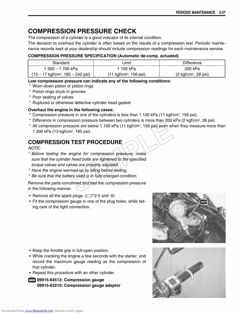
• Remove all the spark plugs. (2-5 and -6)• Fit the compression gauge in one of the plug holes, while tak-
ing care of the tight connection.
• Keep the throttle grip in full-open position.• While cranking the engine a few seconds with the starter, and
record the maximum gauge reading as the compression ofthat cylinder.
• Repeat this procedure with an other cylinder.
09915-64512: Compression gauge09915-63210: Compression gauge adaptor
Standard Limit Difference1 300 – 1 700 kPa
(13 – 17 kgf/cm2, 185 – 242 psi)1 100 kPa
(11 kgf/cm2, 156 psi)200 kPa
(2 kgf/cm2, 28 psi)
SAMPLE
Downloaded from www.Manualslib.com manuals search engine
2-28 PERIODIC MAINTENANCE
OIL PRESSURE CHECKCheck periodically the oil pressure in the engine to judge roughly the condition of the moving parts.
OIL PRESSURE SPECIFICATION
If the oil pressure is lower or higher than the specification, the following causes may be considered.
LOW OIL PRESSURE* Clogged oil filter* Oil leakage from the oil passage way* Damaged O-ring* Defective oil pump* Combination of the above items
HIGH OIL PRESSURE* Used of high viscosity engine oil* Clogged oil passage way* Combination of the above items
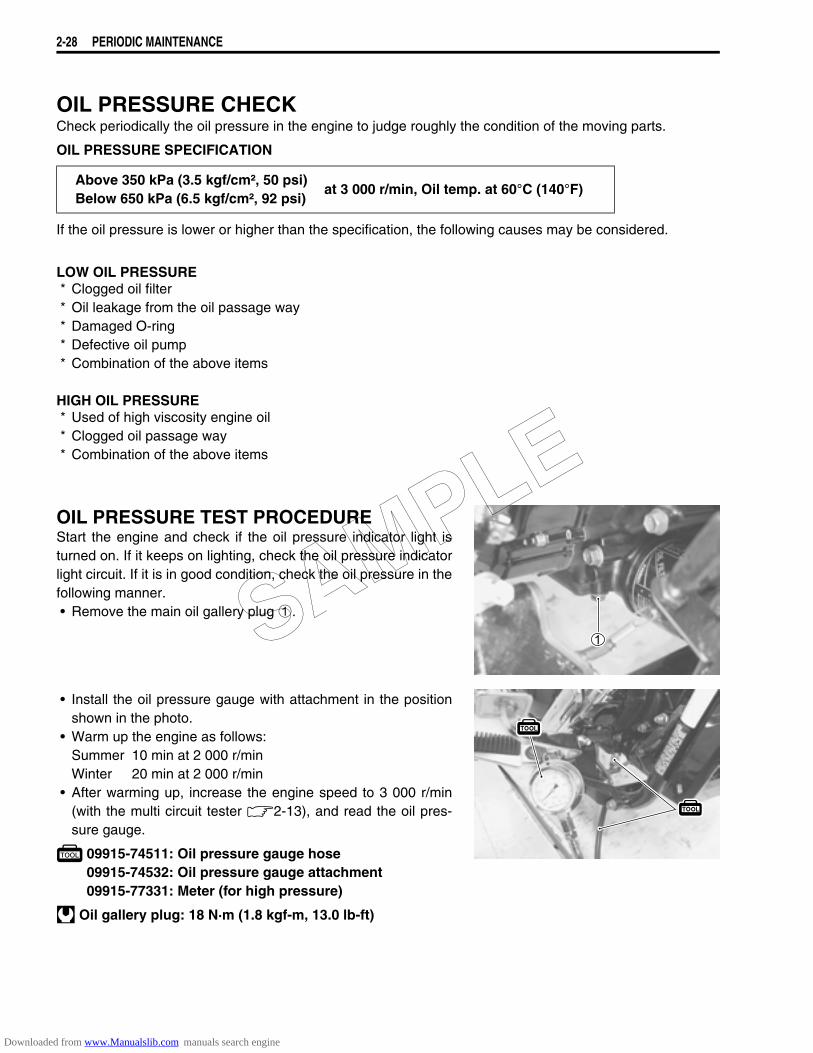
OIL PRESSURE TEST PROCEDUREStart the engine and check if the oil pressure indicator light isturned on. If it keeps on lighting, check the oil pressure indicatorlight circuit. If it is in good condition, check the oil pressure in thefollowing manner.• Remove the main oil gallery plug 1.
• Install the oil pressure gauge with attachment in the positionshown in the photo.
• Warm up the engine as follows:Summer 10 min at 2 000 r/minWinter 20 min at 2 000 r/min
• After warming up, increase the engine speed to 3 000 r/min(with the multi circuit tester 2-13), and read the oil pres-sure gauge.
09915-74511: Oil pressure gauge hose09915-74532: Oil pressure gauge attachment09915-77331: Meter (for high pressure)
Oil gallery plug: 18 N·m (1.8 kgf-m, 13.0 lb-ft)
Above 350 kPa (3.5 kgf/cm², 50 psi)Below 650 kPa (6.5 kgf/cm², 92 psi)
at 3 000 r/min, Oil temp. at 60°C (140°F)
SAMPLE
Downloaded from www.Manualslib.com manuals search engine
PERIODIC MAINTENANCE 2-29
SDS CHECKUsing SDS, take the sample of data from the new motorcycle and at the time of periodic maintenance atyour dealership.Save the data in the computer or by printing and filing the hard copies. The saved or filed data are useful fortroubleshooting as they can be compared periodically with changes over time or failure conditions of themotorcycle.For example, when a motorcycle is brought in for service but the troubleshooting is difficult, comparison withthe normal data that have been saved or filed can allow the specific engine failure to be determined.
• Remove the right frame cover. (8-3)• Set up the SDS tool. (5-24)
09904-41010: SDS set tool99565-01010: CD-ROM Ver. 5
A number of different data under a fixed condition as shown below should be saved or filed as sample.
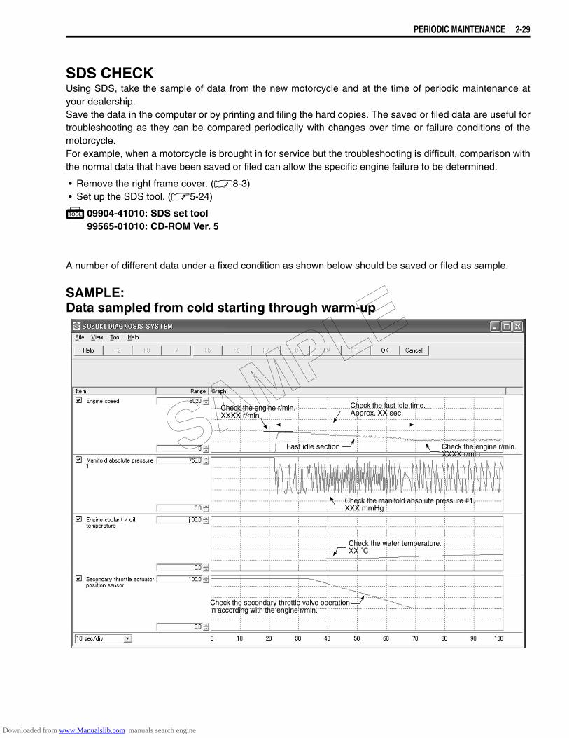
SAMPLE:Data sampled from cold starting through warm-up
Fast idle sectionFast idle section
Check the fast idle time.Approx. XX sec.Check the fast idle time.Approx. XX sec.
Check the engine r/min.XXXX r/minCheck the engine r/min.XXXX r/min
Check the engine r/min.XXXX r/minCheck the engine r/min.XXXX r/min
Check the manifold absolute pressure #1.XXX mmHgCheck the manifold absolute pressure #1.XXX mmHg
Check the water temperature.XX ˚CCheck the water temperature.XX ˚C
Check the secondary throttle valve operationin according with the engine r/min.Check the secondary throttle valve operationin according with the engine r/min.
SAMPLE
Downloaded from www.Manualslib.com manuals search engine
2-30 PERIODIC MAINTENANCE
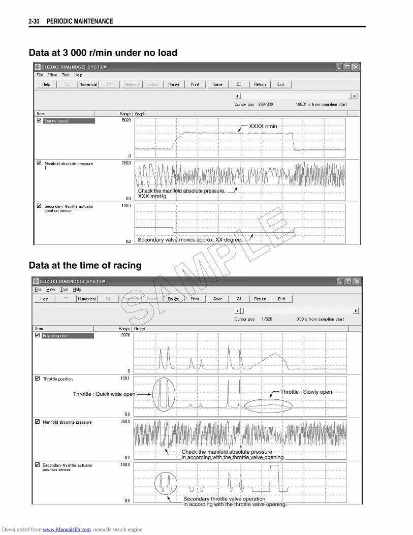
Data at 3 000 r/min under no load
Data at the time of racing
Check the manifold absolute pressure.XXX mmHgCheck the manifold absolute pressure.XXX mmHg
Secondary valve moves approx. XX degree.Secondary valve moves approx. XX degree.
XXXX r/minXXXX r/min
Throttle :Throttle : Slo Slowly openwly openThrottle : Slowly openThrottle :Throttle : Quic Quick wide openk wide openThrottle : Quick wide open
ChecCheck the manifk the manifold absolute pressure old absolute pressure in according with the throttle vin according with the throttle valvalve opening.e opening. Check the manifold absolute pressure in according with the throttle valve opening.
SecondarSecondary throttle vy throttle valvalve opere operation ation in according with the throttle vin according with the throttle valvalve opening.e opening. Secondary throttle valve operation in according with the throttle valve opening.
SAMPLE
Downloaded from www.Manualslib.com manuals search engine
3
6
6
ENGINE 3-1
CONTENTS
ENGINE
ENGINE COMPONENTS REMOVABLE WITH ENGINE IN PLACE ..............3- 2ENGINE REMOVAL AND INSTALLATION ....................................................3- 3
ENGINE REMOVAL ...............................................................................3- 3ENGINE INSTALLATION .......................................................................3- 8ENGINE DISASSEMBLY .......................................................................3-11
ENGINE COMPONENTS INSPECTION AND SERVICING ............................3-27CYLINDER HEAD COVER .....................................................................3-27CAMSHAFT ............................................................................................3-28CAM CHAIN TENSIONER AND GUIDE ................................................3-30CYLINDER HEAD ..................................................................................3-30CYLINDER ..............................................................................................3-40PISTON ...................................................................................................3-41CONROD/CRANKSHAFT ......................................................................3-44CLUTCH .................................................................................................3-53GENERATOR/SIGNAL GENERATOR/ STARTER CLUTCH ................3-54OIL PUMP ...............................................................................................3-56TRANSMISSION ....................................................................................3-57GEARSHIFT FORK ................................................................................3-60OIL JET ..................................................................................................3-60CRANKCASE .........................................................................................3-61
ENGINE REASSEMBLY .................................................................................3-65SAMPLE
Downloaded from www.Manualslib.com manuals search engine
3-2 ENGINE
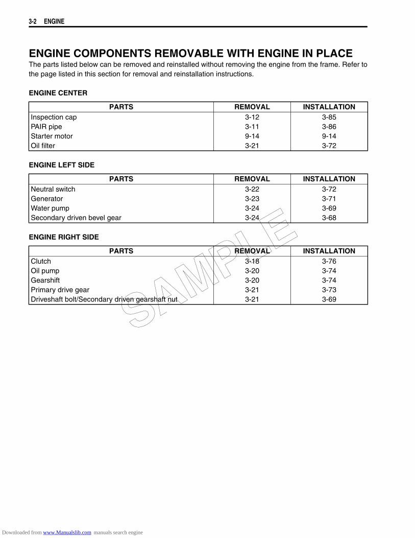
ENGINE COMPONENTS REMOVABLE WITH ENGINE IN PLACEThe parts listed below can be removed and reinstalled without removing the engine from the frame. Refer tothe page listed in this section for removal and reinstallation instructions.
ENGINE CENTER
ENGINE LEFT SIDE
ENGINE RIGHT SIDE
PARTS REMOVAL INSTALLATIONInspection capPAIR pipe Starter motorOil filter
3-123-119-143-21
3-853-869-143-72
PARTS REMOVAL INSTALLATIONNeutral switchGeneratorWater pumpSecondary driven bevel gear
3-223-233-243-24
3-723-713-693-68
PARTS REMOVAL INSTALLATIONClutchOil pumpGearshiftPrimary drive gearDriveshaft bolt/Secondary driven gearshaft nut
3-183-203-203-213-21
3-763-743-743-733-69
SAMPLE
Downloaded from www.Manualslib.com manuals search engine
ENGINE 3-3
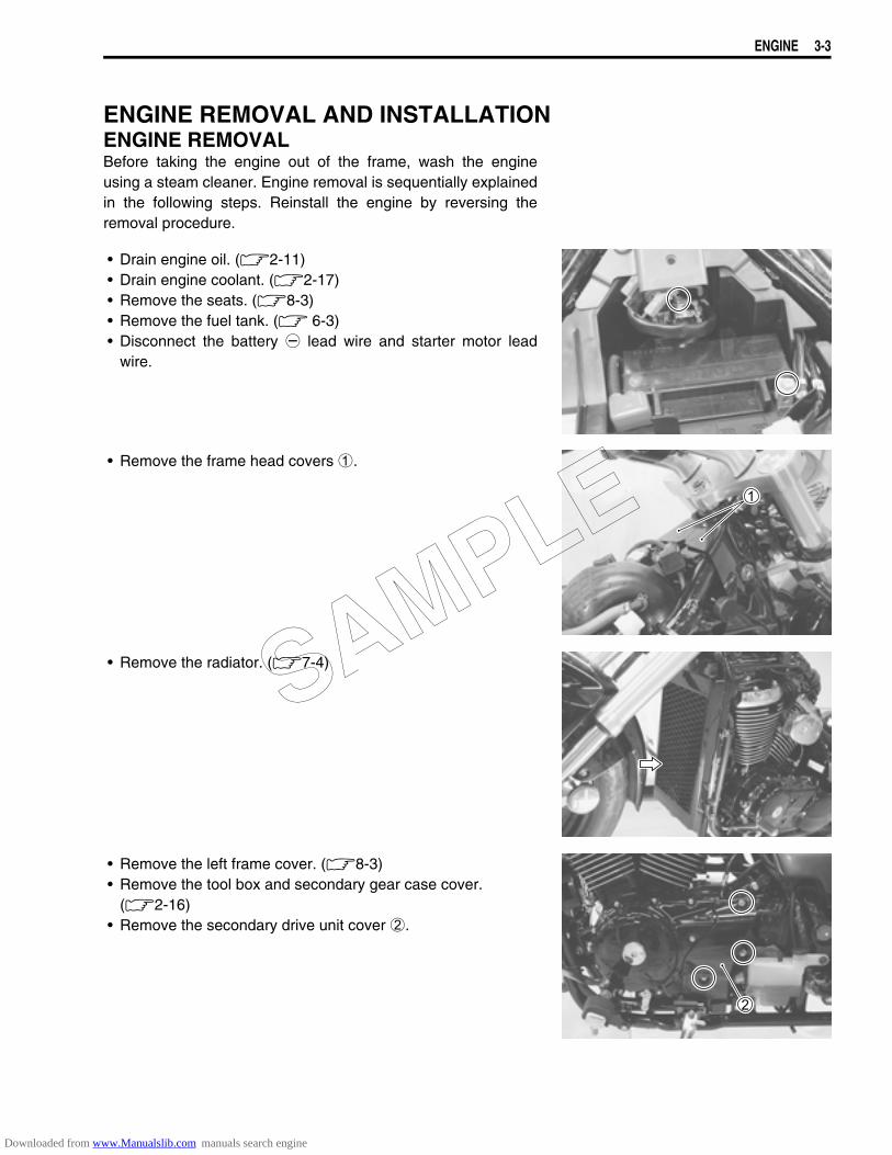
ENGINE REMOVAL AND INSTALLATIONENGINE REMOVALBefore taking the engine out of the frame, wash the engineusing a steam cleaner. Engine removal is sequentially explainedin the following steps. Reinstall the engine by reversing theremoval procedure.
• Drain engine oil. (2-11)• Drain engine coolant. (2-17)• Remove the seats. (8-3)• Remove the fuel tank. ( 6-3)• Disconnect the battery - lead wire and starter motor lead
wire.
• Remove the frame head covers 1.
• Remove the radiator. (7-4)
• Remove the left frame cover. (8-3)• Remove the tool box and secondary gear case cover.
(2-16)• Remove the secondary drive unit cover 2.
SAMPLE
Downloaded from www.Manualslib.com manuals search engine
3-4 ENGINE
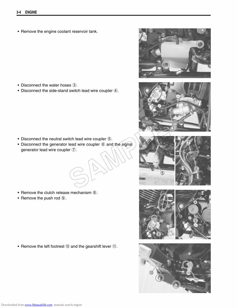
• Remove the engine coolant reservoir tank.
• Disconnect the water hoses 3.• Disconnect the side-stand switch lead wire coupler 4.
• Disconnect the neutral switch lead wire coupler 5.• Disconnect the generator lead wire coupler 6 and the signal
generator lead wire coupler 7.
• Remove the clutch release mechanism 8.• Remove the push rod 9.
• Remove the left footrest 0 and the gearshift lever A.
SAMPLE
Downloaded from www.Manualslib.com manuals search engine
ENGINE 3-5
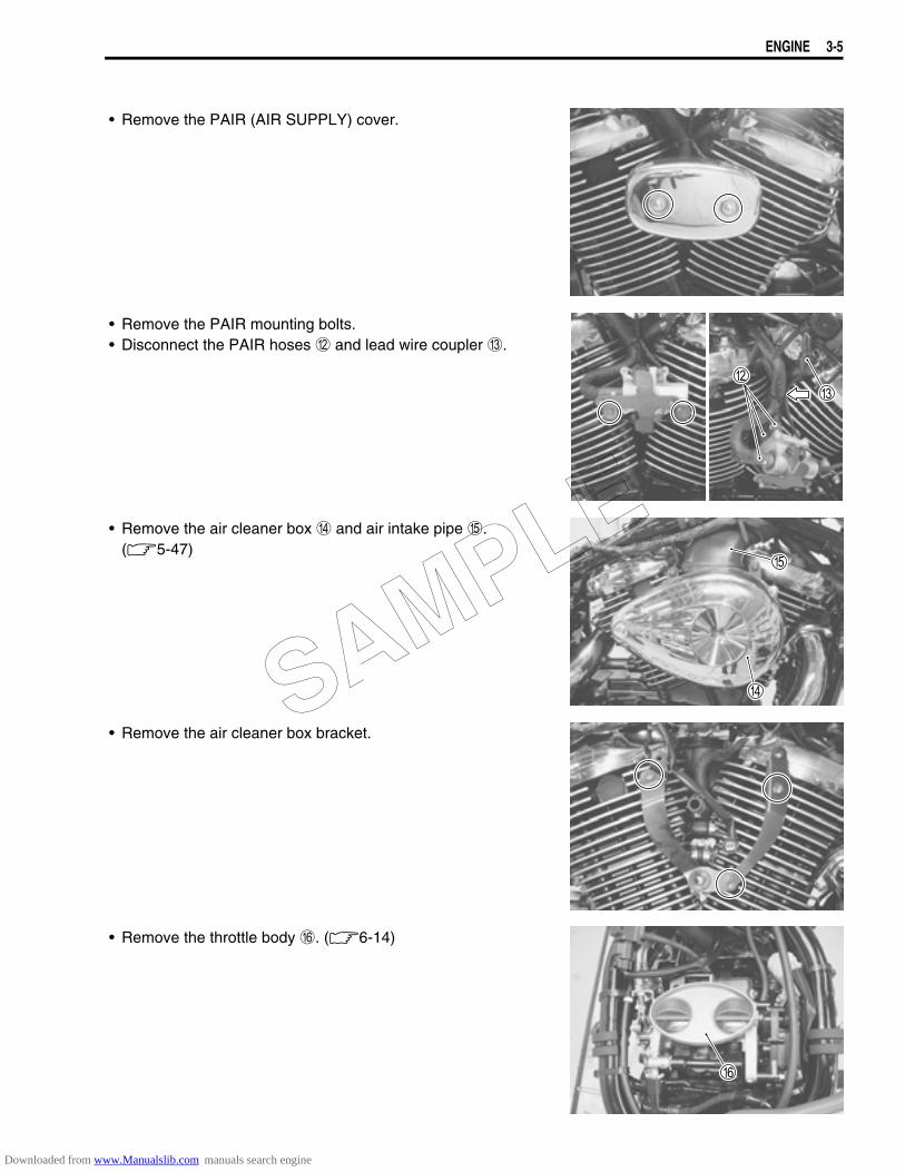
• Remove the PAIR (AIR SUPPLY) cover.
• Remove the PAIR mounting bolts.• Disconnect the PAIR hoses B and lead wire coupler C.
• Remove the air cleaner box D and air intake pipe E. (5-47)
• Remove the air cleaner box bracket.
• Remove the throttle body F. (6-14)
SAMPLE
Downloaded from www.Manualslib.com manuals search engine
3-6 ENGINE
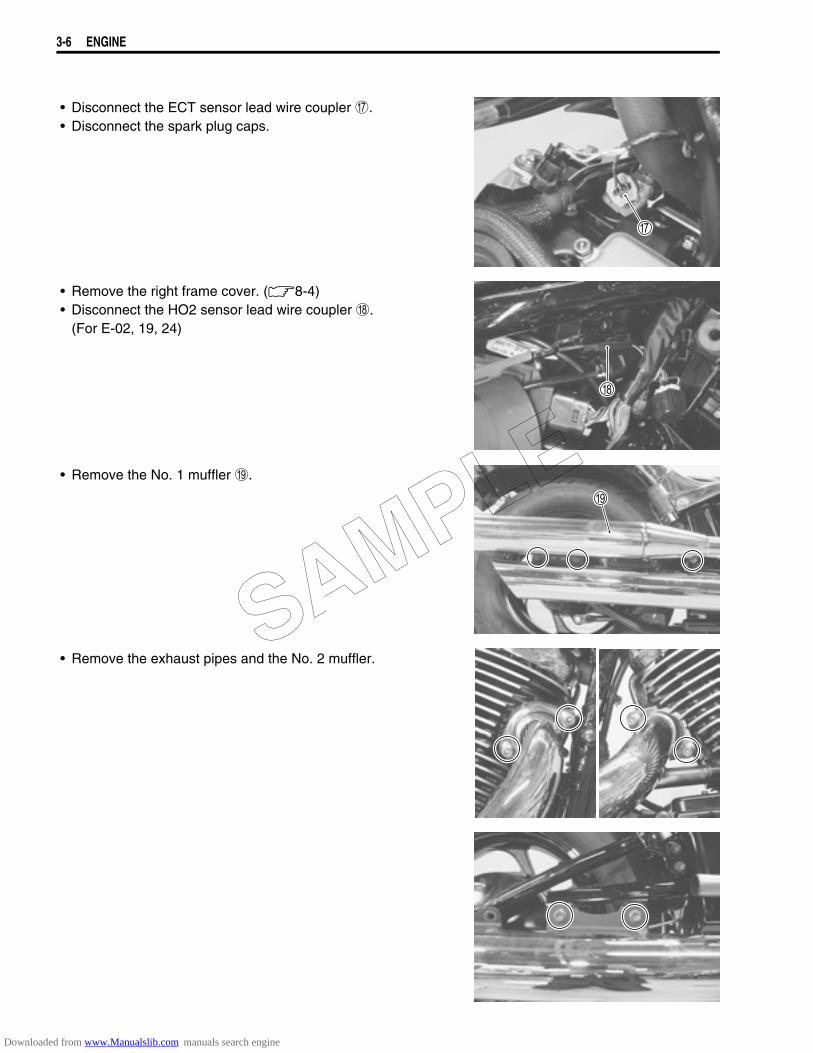
• Disconnect the ECT sensor lead wire coupler G.• Disconnect the spark plug caps.
• Remove the right frame cover. (8-4)• Disconnect the HO2 sensor lead wire coupler H.
(For E-02, 19, 24)
• Remove the No. 1 muffler I.
• Remove the exhaust pipes and the No. 2 muffler.SAMPLE
Downloaded from www.Manualslib.com manuals search engine
ENGINE 3-7
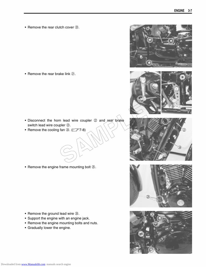
• Remove the rear clutch cover J.
• Remove the rear brake link K.
• Disconnect the horn lead wire coupler L and rear brakeswitch lead wire coupler M.
• Remove the cooling fan N. (7-8)
• Remove the engine frame mounting bolt O.
• Remove the ground lead wire P.• Support the engine with an engine jack.• Remove the engine mounting bolts and nuts.• Gradually lower the engine.
SAMPLE
Downloaded from www.Manualslib.com manuals search engine
3-8 ENGINE
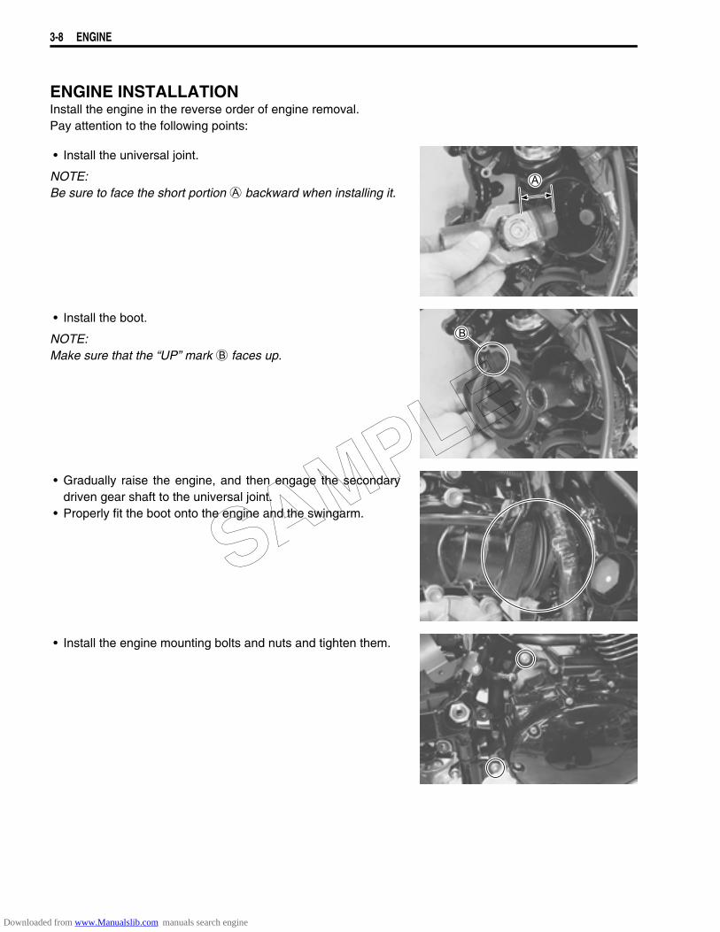
ENGINE INSTALLATIONInstall the engine in the reverse order of engine removal.Pay attention to the following points:
• Install the universal joint.
NOTE:Be sure to face the short portion A backward when installing it.
• Install the boot.
NOTE:Make sure that the “UP” mark B faces up.
• Gradually raise the engine, and then engage the secondarydriven gear shaft to the universal joint.
• Properly fit the boot onto the engine and the swingarm.
• Install the engine mounting bolts and nuts and tighten them.
SAMPLE
Downloaded from www.Manualslib.com manuals search engine
ENGINE 3-9
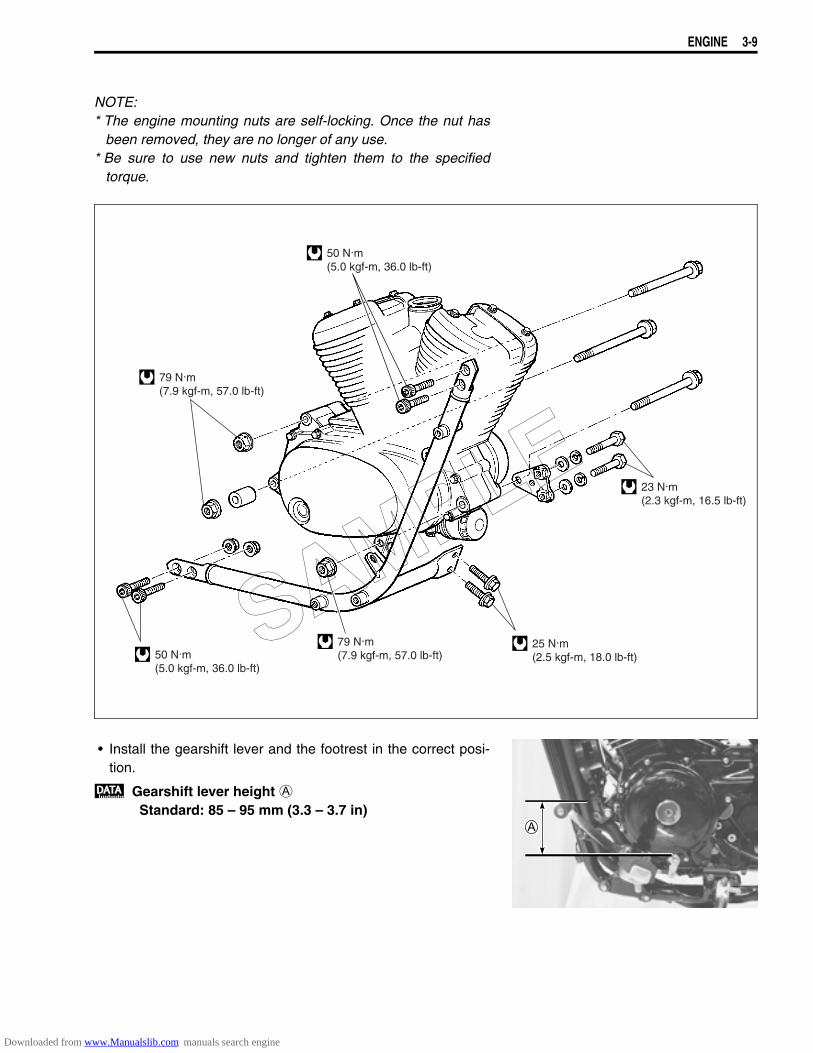
NOTE:* The engine mounting nuts are self-locking. Once the nut has
been removed, they are no longer of any use.* Be sure to use new nuts and tighten them to the specified
torque.
• Install the gearshift lever and the footrest in the correct posi-tion.
Gearshift lever height AStandard: 85 – 95 mm (3.3 – 3.7 in)
79 N.m(7.9 kgf-m, 57.0 lb-ft)
79 N.m(7.9 kgf-m, 57.0 lb-ft)50 N.m
(5.0 kgf-m, 36.0 lb-ft)
50 N.m(5.0 kgf-m, 36.0 lb-ft)
23 N.m(2.3 kgf-m, 16.5 lb-ft)
25 N.m(2.5 kgf-m, 18.0 lb-ft)
SAMPLE
Downloaded from www.Manualslib.com manuals search engine

3-10 ENGINE
• Apply grease to the push rod and install it.
99000-25030: SUZUKI SUPER GREASE “A” (USA)99000-25010: SUZUKI SUPER GREASE “A” (Others)
• Apply grease to the clutch release mechanism and install it.
99000-25030: SUZUKI SUPER GREASE “A” (USA)99000-25010: SUZUKI SUPER GREASE “A” (Others)
Clutch release screwStandard: 1/4 turn back
CLUTCH CABLE ADJUSTMENT2-16
• Install the new gaskets.• Install the exhaust pipes and mufflers.
• Apply gas sealer to the exhaust pipe connectors.
EXHAUST GAS SEALER: PERMATEX 1372
• Adjust the following items.* Engine oil 2-11* Engine coolant 2-17 and -18* Idling adjustment 2-13* Throttle cable play 2-14 and -15* Rear brake adjusting 2-21
SAMPLE
Downloaded from www.Manualslib.com manuals search engine
ENGINE 3-11
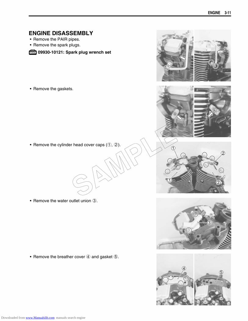
ENGINE DISASSEMBLY• Remove the PAIR pipes.• Remove the spark plugs.
09930-10121: Spark plug wrench set
• Remove the gaskets.
• Remove the cylinder head cover caps (1, 2).
• Remove the water outlet union 3.
• Remove the breather cover 4 and gasket 5.
SAMPLE
Downloaded from www.Manualslib.com manuals search engine
3-12 ENGINE
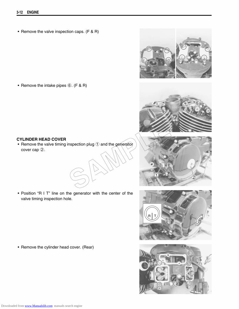
• Remove the valve inspection caps. (F & R)
• Remove the intake pipes 6. (F & R)
CYLINDER HEAD COVER• Remove the valve timing inspection plug 1 and the generator
cover cap 2.
• Position “R I T” line on the generator with the center of thevalve timing inspection hole.
• Remove the cylinder head cover. (Rear)
R T
SAMPLE
Downloaded from www.Manualslib.com manuals search engine

ENGINE 3-13
• Remove the dowel pins and camshaft end cap 3.
• Rotate the generator rotor 450 degrees (1 and 1/4 turns) andalign the “F I T” line on the generator with the center of thevalve timing inspection hole.
• Remove the cylinder head cover. (Front)
• Remove the dowel pins and camshaft end cap 4.
CAMSHAFT• Flatten the lock washer.• Remove the cam sprocket and camshaft. (Front and rear cyl-
inders)
F T
SAMPLE
Downloaded from www.Manualslib.com manuals search engine
3-14 ENGINE
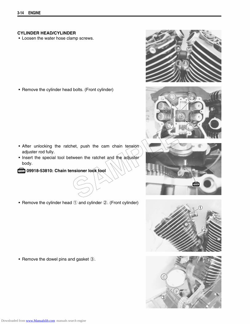
CYLINDER HEAD/CYLINDER• Loosen the water hose clamp screws.
• Remove the cylinder head bolts. (Front cylinder)
• After unlocking the ratchet, push the cam chain tensionadjuster rod fully.
• Insert the special tool between the ratchet and the adjusterbody.
09918-53810: Chain tensioner lock tool
• Remove the cylinder head 1 and cylinder 2. (Front cylinder)
• Remove the dowel pins and gasket 3.
SAMPLE
Downloaded from www.Manualslib.com manuals search engine
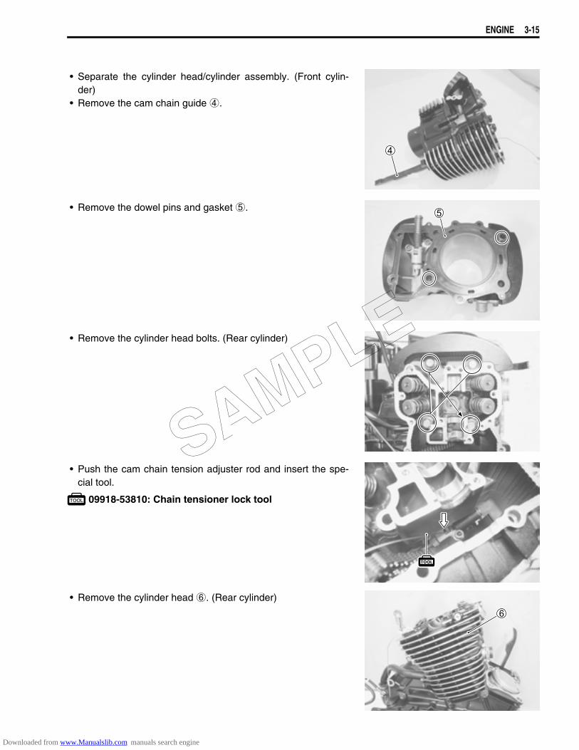
ENGINE 3-15
• Separate the cylinder head/cylinder assembly. (Front cylin-der)
• Remove the cam chain guide 4.
• Remove the dowel pins and gasket 5.
• Remove the cylinder head bolts. (Rear cylinder)
• Push the cam chain tension adjuster rod and insert the spe-cial tool.
09918-53810: Chain tensioner lock tool
• Remove the cylinder head 6. (Rear cylinder)
SAMPLE
Downloaded from www.Manualslib.com manuals search engine
3-16 ENGINE
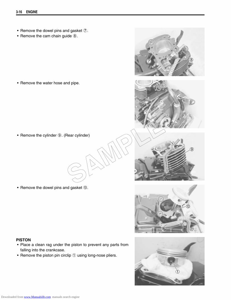
• Remove the dowel pins and gasket 7.• Remove the cam chain guide 8.
• Remove the water hose and pipe.
• Remove the cylinder 9. (Rear cylinder)
• Remove the dowel pins and gasket 0.
PISTON• Place a clean rag under the piston to prevent any parts from
falling into the crankcase.• Remove the piston pin circlip 1 using long-nose pliers.
SAMPLE
Downloaded from www.Manualslib.com manuals search engine
ENGINE 3-17
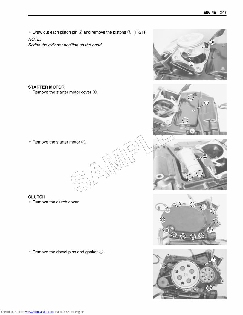
• Draw out each piston pin 2 and remove the pistons 3. (F & R)
NOTE:Scribe the cylinder position on the head.
STARTER MOTOR• Remove the starter motor cover 1.
• Remove the starter motor 2.
CLUTCH• Remove the clutch cover.
• Remove the dowel pins and gasket 1.
SAMPLE
Downloaded from www.Manualslib.com manuals search engine

3-18 ENGINE
• Remove the clutch spring mounting bolts and springs diago-nally.
• Remove the pressure plate 2.
• Remove the thrust washer 3, bearing 4, push piece 5 andpush rod 6.
• Remove the clutch drive and driven plates 7.
• Remove the spring washer 8 and spring washer seat 9.
SAMPLE
Downloaded from www.Manualslib.com manuals search engine
ENGINE 3-19
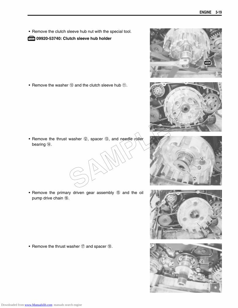
• Remove the clutch sleeve hub nut with the special tool.
09920-53740: Clutch sleeve hub holder
• Remove the washer 0 and the clutch sleeve hub A.
• Remove the thrust washer B, spacer C, and needle rollerbearing D.
• Remove the primary driven gear assembly E and the oilpump drive chain F.
• Remove the thrust washer G and spacer H.
SAMPLE
Downloaded from www.Manualslib.com manuals search engine
3-20 ENGINE
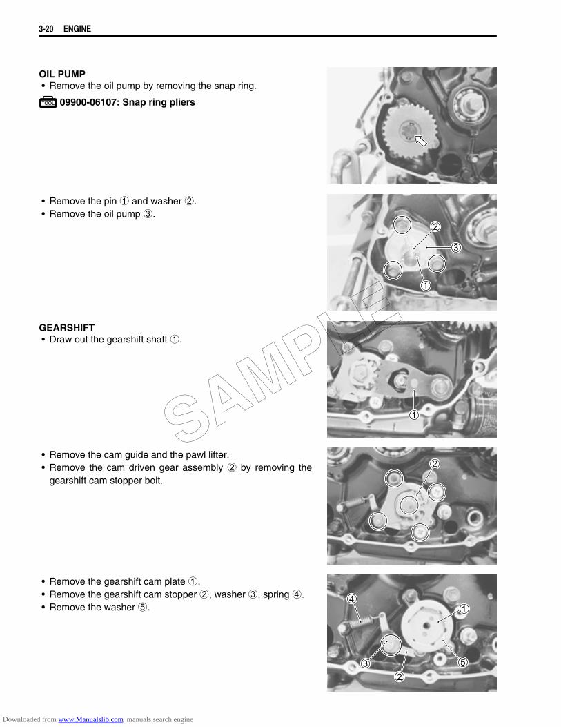
OIL PUMP• Remove the oil pump by removing the snap ring.
09900-06107: Snap ring pliers
• Remove the pin 1 and washer 2.• Remove the oil pump 3.
GEARSHIFT• Draw out the gearshift shaft 1.
• Remove the cam guide and the pawl lifter.• Remove the cam driven gear assembly 2 by removing the
gearshift cam stopper bolt.
• Remove the gearshift cam plate 1.• Remove the gearshift cam stopper 2, washer 3, spring 4.• Remove the washer 5.
SAMPLE
Downloaded from www.Manualslib.com manuals search engine
ENGINE 3-21
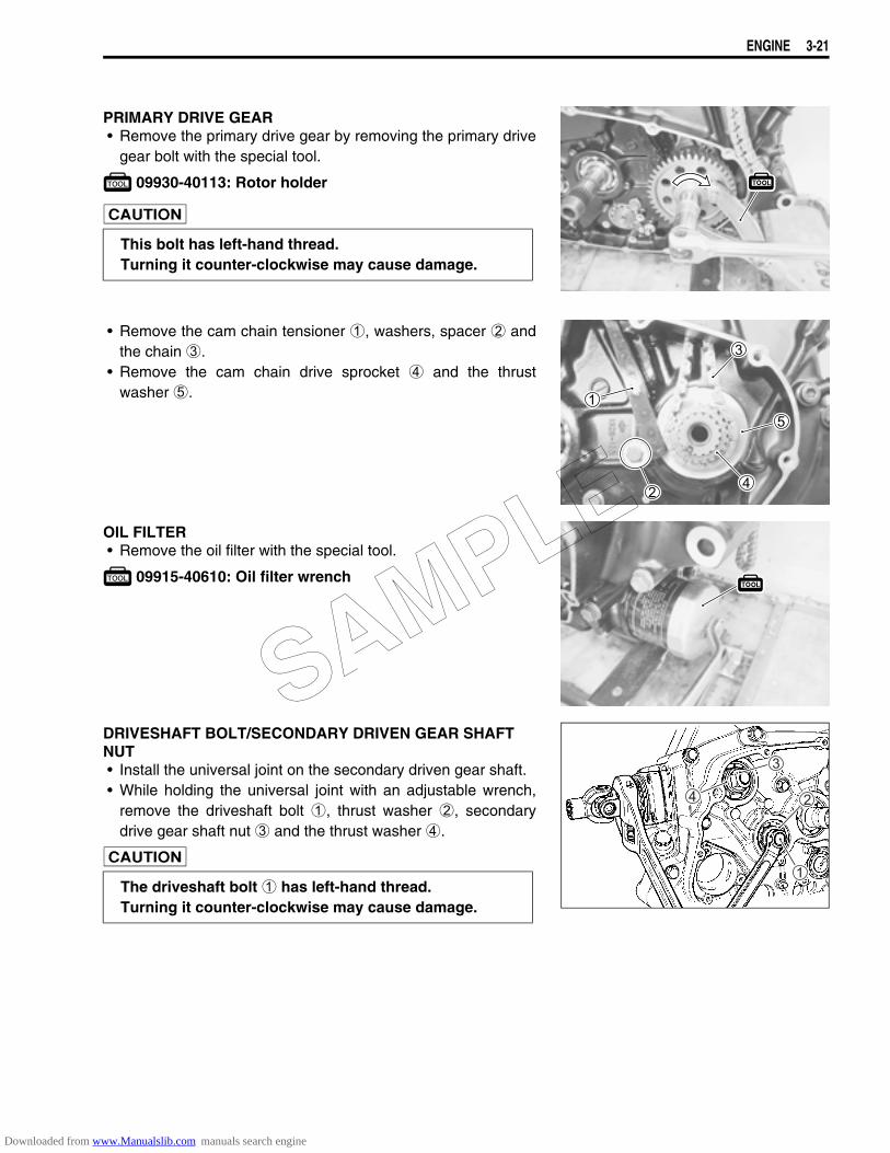
PRIMARY DRIVE GEAR• Remove the primary drive gear by removing the primary drive
gear bolt with the special tool.
09930-40113: Rotor holder
• Remove the cam chain tensioner 1, washers, spacer 2 andthe chain 3.
• Remove the cam chain drive sprocket 4 and the thrustwasher 5.
OIL FILTER• Remove the oil filter with the special tool.
09915-40610: Oil filter wrench
DRIVESHAFT BOLT/SECONDARY DRIVEN GEAR SHAFT NUT• Install the universal joint on the secondary driven gear shaft.• While holding the universal joint with an adjustable wrench,
remove the driveshaft bolt 1, thrust washer 2, secondarydrive gear shaft nut 3 and the thrust washer 4.
This bolt has left-hand thread.Turning it counter-clockwise may cause damage.
The driveshaft bolt 1 has left-hand thread.Turning it counter-clockwise may cause damage.
SAMPLE
Downloaded from www.Manualslib.com manuals search engine
3-22 ENGINE
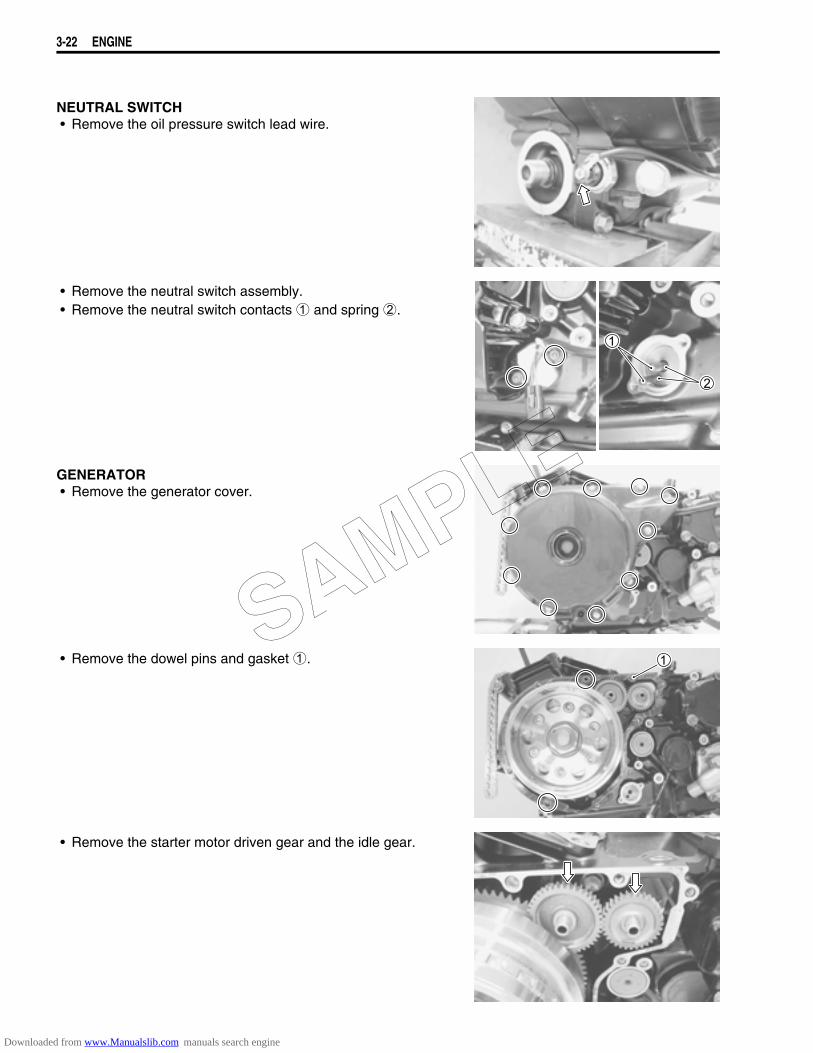
NEUTRAL SWITCH• Remove the oil pressure switch lead wire.
• Remove the neutral switch assembly.• Remove the neutral switch contacts 1 and spring 2.
GENERATOR• Remove the generator cover.
• Remove the dowel pins and gasket 1.
• Remove the starter motor driven gear and the idle gear.
SAMPLE
Downloaded from www.Manualslib.com manuals search engine
ENGINE 3-23
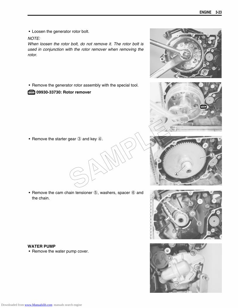
• Loosen the generator rotor bolt.
NOTE:When loosen the rotor bolt, do not remove it. The rotor bolt isused in conjunction with the rotor remover when removing therotor.
• Remove the generator rotor assembly with the special tool.
09930-33730: Rotor remover
• Remove the starter gear 3 and key 4.
• Remove the cam chain tensioner 5, washers, spacer 6 andthe chain.
WATER PUMP• Remove the water pump cover.
SAMPLE
Downloaded from www.Manualslib.com manuals search engine
3-24 ENGINE
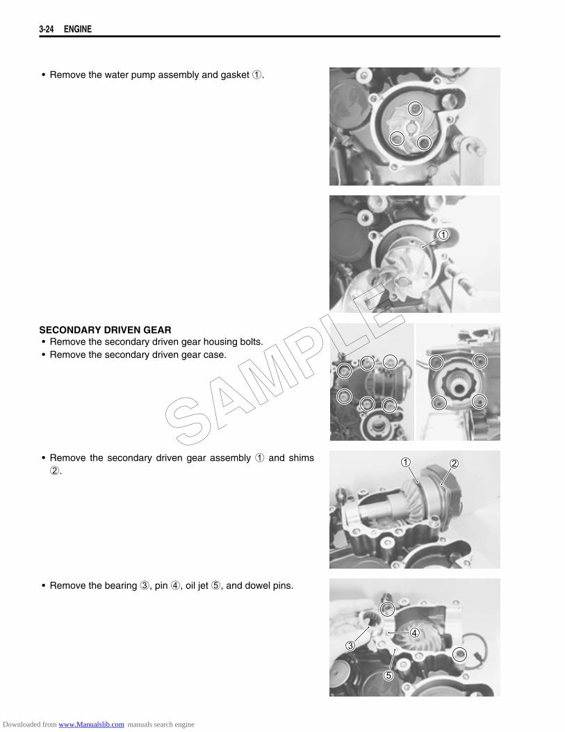
• Remove the water pump assembly and gasket 1.
SECONDARY DRIVEN GEAR• Remove the secondary driven gear housing bolts.• Remove the secondary driven gear case.
• Remove the secondary driven gear assembly 1 and shims2.
• Remove the bearing 3, pin 4, oil jet 5, and dowel pins.
SAMPLE
Downloaded from www.Manualslib.com manuals search engine
ENGINE 3-25
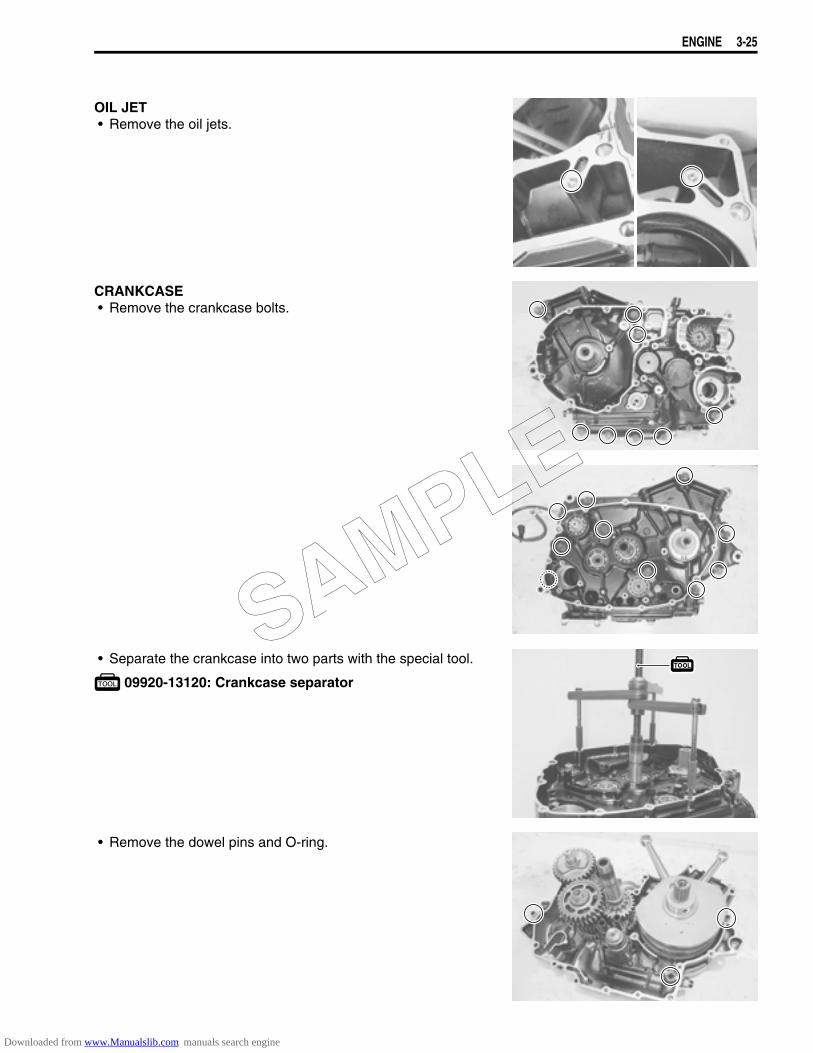
OIL JET• Remove the oil jets.
CRANKCASE• Remove the crankcase bolts.
• Separate the crankcase into two parts with the special tool.
09920-13120: Crankcase separator
• Remove the dowel pins and O-ring.
SAMPLE
Downloaded from www.Manualslib.com manuals search engine
3-26 ENGINE
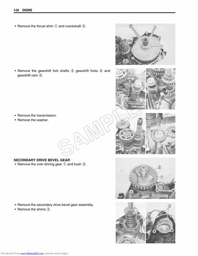
• Remove the thrust shim 1 and crankshaft 2.
• Remove the gearshift fork shafts 3 gearshift forks 4 andgearshift cam 5.
• Remove the transmission.• Remove the washer.
SECONDARY DRIVE BEVEL GEAR• Remove the over driving gear 1 and bush 2.
• Remove the secondary drive bevel gear assembly.• Remove the shims 3.
SAMPLE
Downloaded from www.Manualslib.com manuals search engine
ENGINE 3-27
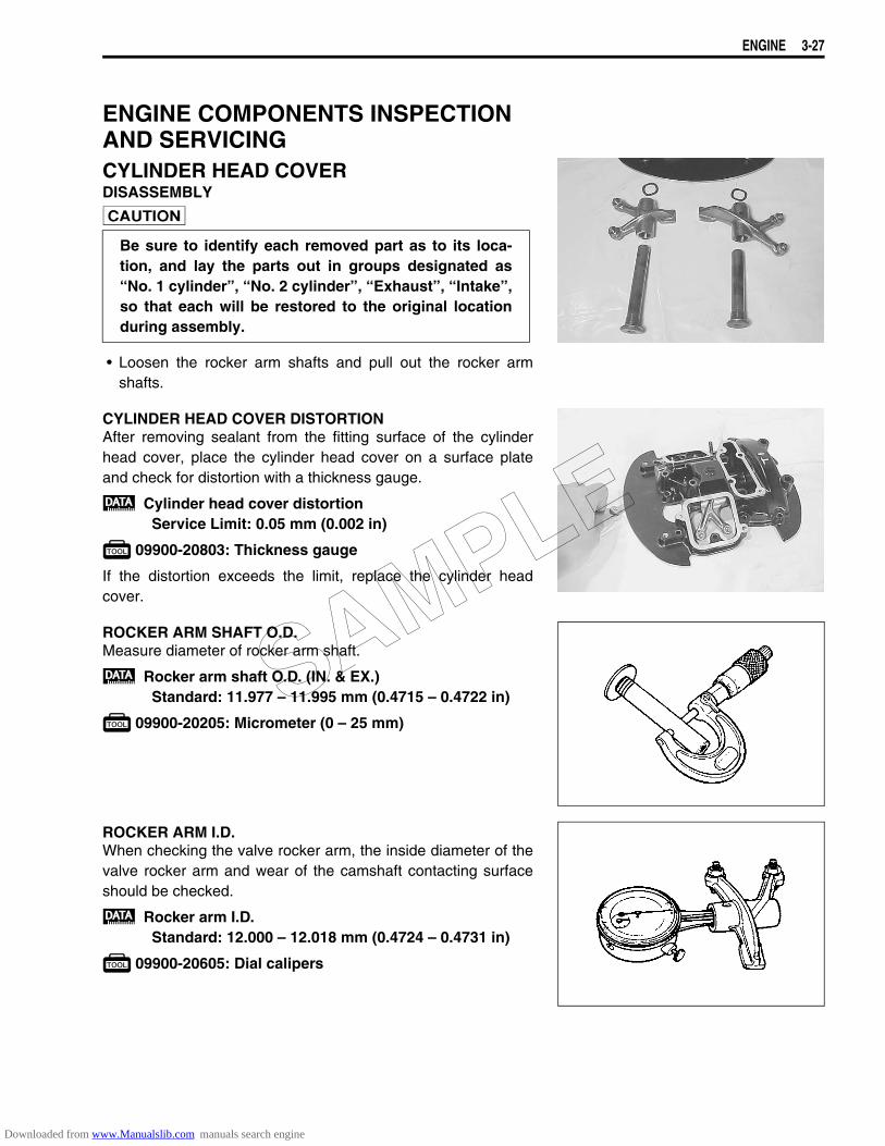
ENGINE COMPONENTS INSPECTION AND SERVICINGCYLINDER HEAD COVERDISASSEMBLY
• Loosen the rocker arm shafts and pull out the rocker armshafts.
CYLINDER HEAD COVER DISTORTIONAfter removing sealant from the fitting surface of the cylinderhead cover, place the cylinder head cover on a surface plateand check for distortion with a thickness gauge.
Cylinder head cover distortionService Limit: 0.05 mm (0.002 in)
09900-20803: Thickness gauge
If the distortion exceeds the limit, replace the cylinder headcover.
ROCKER ARM SHAFT O.D.Measure diameter of rocker arm shaft.
Rocker arm shaft O.D. (IN. & EX.)Standard: 11.977 – 11.995 mm (0.4715 – 0.4722 in)
09900-20205: Micrometer (0 – 25 mm)
ROCKER ARM I.D.When checking the valve rocker arm, the inside diameter of thevalve rocker arm and wear of the camshaft contacting surfaceshould be checked.
Rocker arm I.D.Standard: 12.000 – 12.018 mm (0.4724 – 0.4731 in)
09900-20605: Dial calipers
Be sure to identify each removed part as to its loca-tion, and lay the parts out in groups designated as“No. 1 cylinder”, “No. 2 cylinder”, “Exhaust”, “Intake”,so that each will be restored to the original locationduring assembly.
SAMPLE
Downloaded from www.Manualslib.com manuals search engine
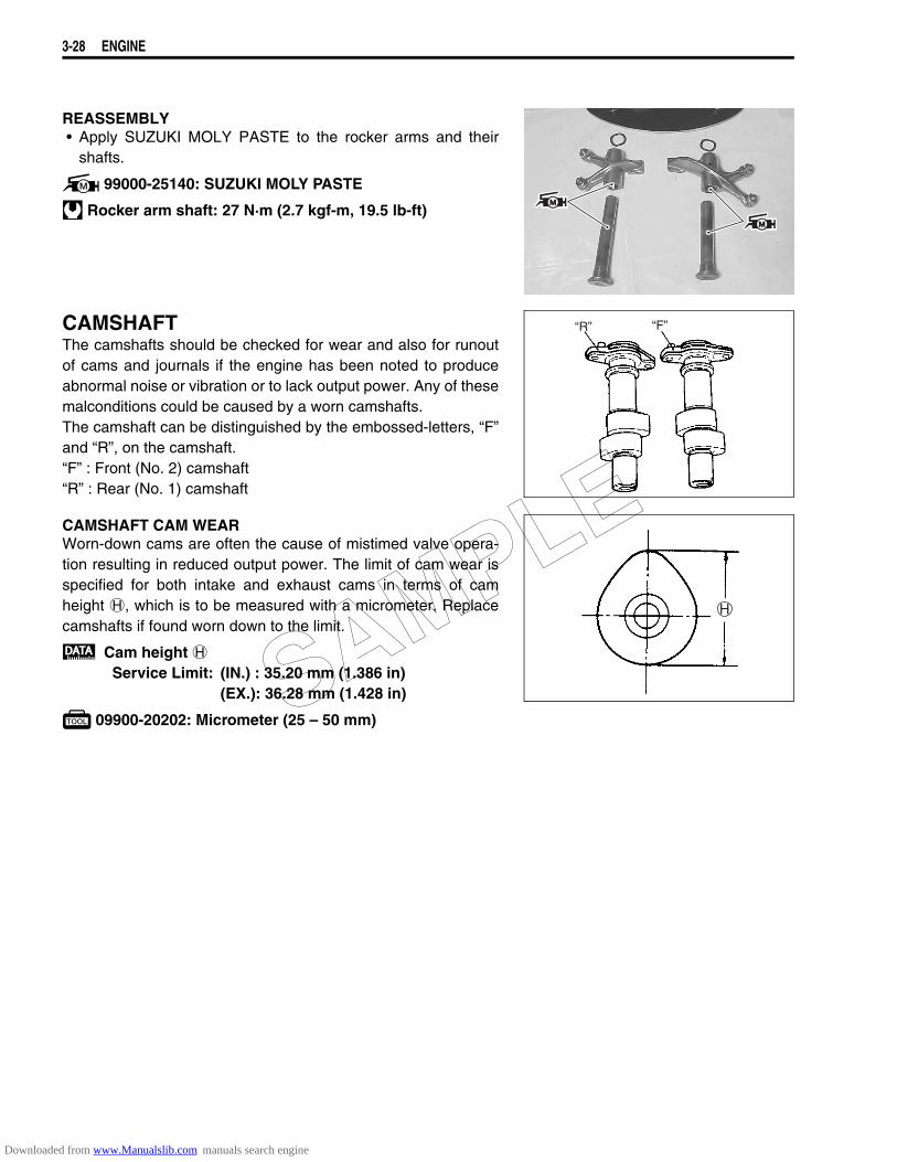
3-28 ENGINE
REASSEMBLY• Apply SUZUKI MOLY PASTE to the rocker arms and their
shafts.
99000-25140: SUZUKI MOLY PASTE
Rocker arm shaft: 27 N·m (2.7 kgf-m, 19.5 lb-ft)
CAMSHAFTThe camshafts should be checked for wear and also for runoutof cams and journals if the engine has been noted to produceabnormal noise or vibration or to lack output power. Any of thesemalconditions could be caused by a worn camshafts.The camshaft can be distinguished by the embossed-letters, “F”and “R”, on the camshaft.“F” : Front (No. 2) camshaft“R” : Rear (No. 1) camshaft
CAMSHAFT CAM WEARWorn-down cams are often the cause of mistimed valve opera-tion resulting in reduced output power. The limit of cam wear isspecified for both intake and exhaust cams in terms of camheight H, which is to be measured with a micrometer. Replacecamshafts if found worn down to the limit.
Cam height HService Limit: (IN.) : 35.20 mm (1.386 in)
(EX.): 36.28 mm (1.428 in)
09900-20202: Micrometer (25 – 50 mm)
“R” “F”
SAMPLE
Downloaded from www.Manualslib.com manuals search engine
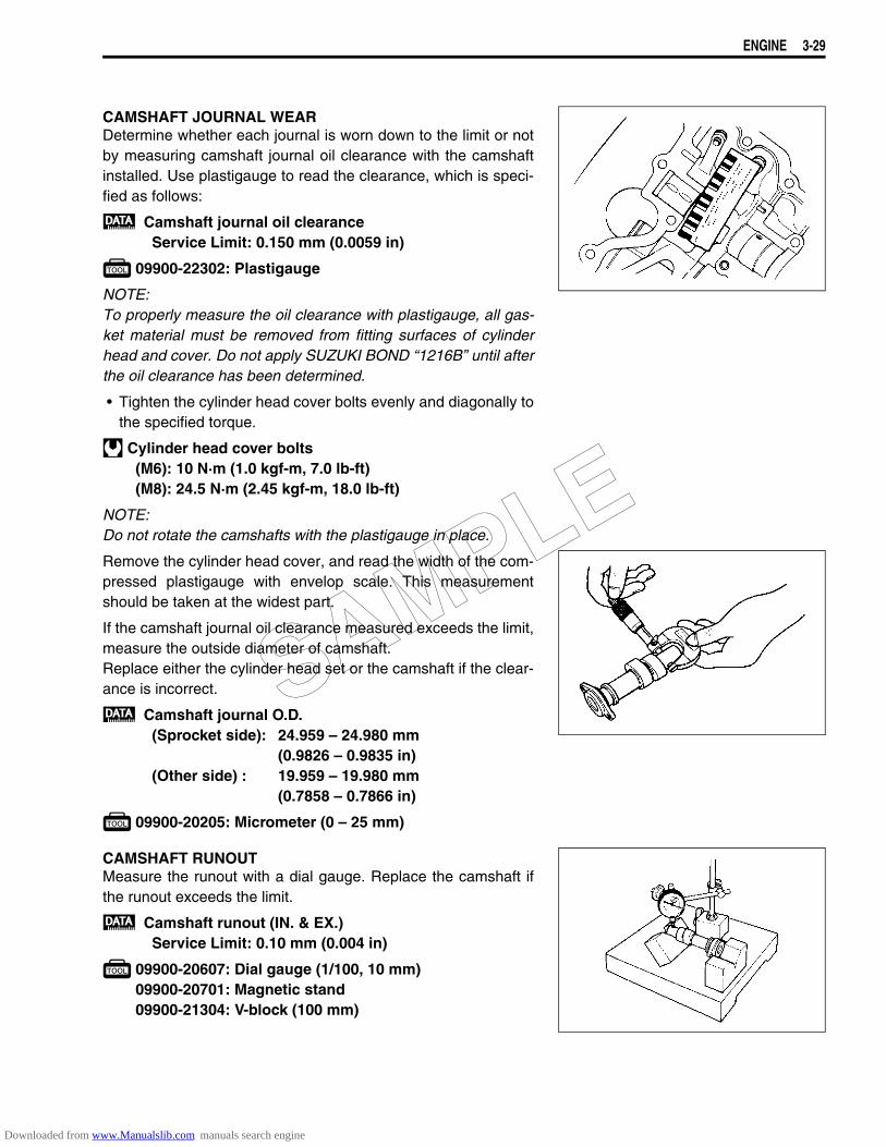
ENGINE 3-29
CAMSHAFT JOURNAL WEARDetermine whether each journal is worn down to the limit or notby measuring camshaft journal oil clearance with the camshaftinstalled. Use plastigauge to read the clearance, which is speci-fied as follows:
Camshaft journal oil clearanceService Limit: 0.150 mm (0.0059 in)
09900-22302: Plastigauge
NOTE:To properly measure the oil clearance with plastigauge, all gas-ket material must be removed from fitting surfaces of cylinderhead and cover. Do not apply SUZUKI BOND “1216B” until afterthe oil clearance has been determined.
• Tighten the cylinder head cover bolts evenly and diagonally tothe specified torque.
Cylinder head cover bolts(M6): 10 N·m (1.0 kgf-m, 7.0 lb-ft)(M8): 24.5 N·m (2.45 kgf-m, 18.0 lb-ft)
NOTE:Do not rotate the camshafts with the plastigauge in place.
Remove the cylinder head cover, and read the width of the com-pressed plastigauge with envelop scale. This measurementshould be taken at the widest part.
If the camshaft journal oil clearance measured exceeds the limit,measure the outside diameter of camshaft.Replace either the cylinder head set or the camshaft if the clear-ance is incorrect.
Camshaft journal O.D.(Sprocket side): 24.959 – 24.980 mm
(0.9826 – 0.9835 in)(Other side) : 19.959 – 19.980 mm
(0.7858 – 0.7866 in)
09900-20205: Micrometer (0 – 25 mm)
CAMSHAFT RUNOUTMeasure the runout with a dial gauge. Replace the camshaft ifthe runout exceeds the limit.
Camshaft runout (IN. & EX.)Service Limit: 0.10 mm (0.004 in)
09900-20607: Dial gauge (1/100, 10 mm)09900-20701: Magnetic stand09900-21304: V-block (100 mm)
SAMPLE
Downloaded from www.Manualslib.com manuals search engine
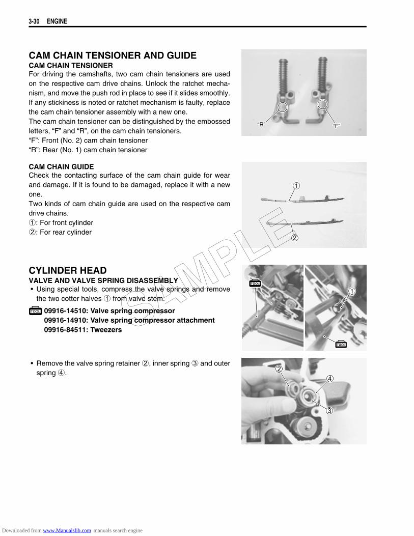
3-30 ENGINE
CAM CHAIN TENSIONER AND GUIDECAM CHAIN TENSIONERFor driving the camshafts, two cam chain tensioners are usedon the respective cam drive chains. Unlock the ratchet mecha-nism, and move the push rod in place to see if it slides smoothly.If any stickiness is noted or ratchet mechanism is faulty, replacethe cam chain tensioner assembly with a new one.The cam chain tensioner can be distinguished by the embossedletters, “F” and “R”, on the cam chain tensioners.“F”: Front (No. 2) cam chain tensioner“R”: Rear (No. 1) cam chain tensioner
CAM CHAIN GUIDECheck the contacting surface of the cam chain guide for wearand damage. If it is found to be damaged, replace it with a newone.Two kinds of cam chain guide are used on the respective camdrive chains.1: For front cylinder2: For rear cylinder
CYLINDER HEADVALVE AND VALVE SPRING DISASSEMBLY• Using special tools, compress the valve springs and remove
the two cotter halves 1 from valve stem.
09916-14510: Valve spring compressor09916-14910: Valve spring compressor attachment09916-84511: Tweezers
• Remove the valve spring retainer 2, inner spring 3 and outerspring 4.
“R” “F”
SAMPLE
Downloaded from www.Manualslib.com manuals search engine
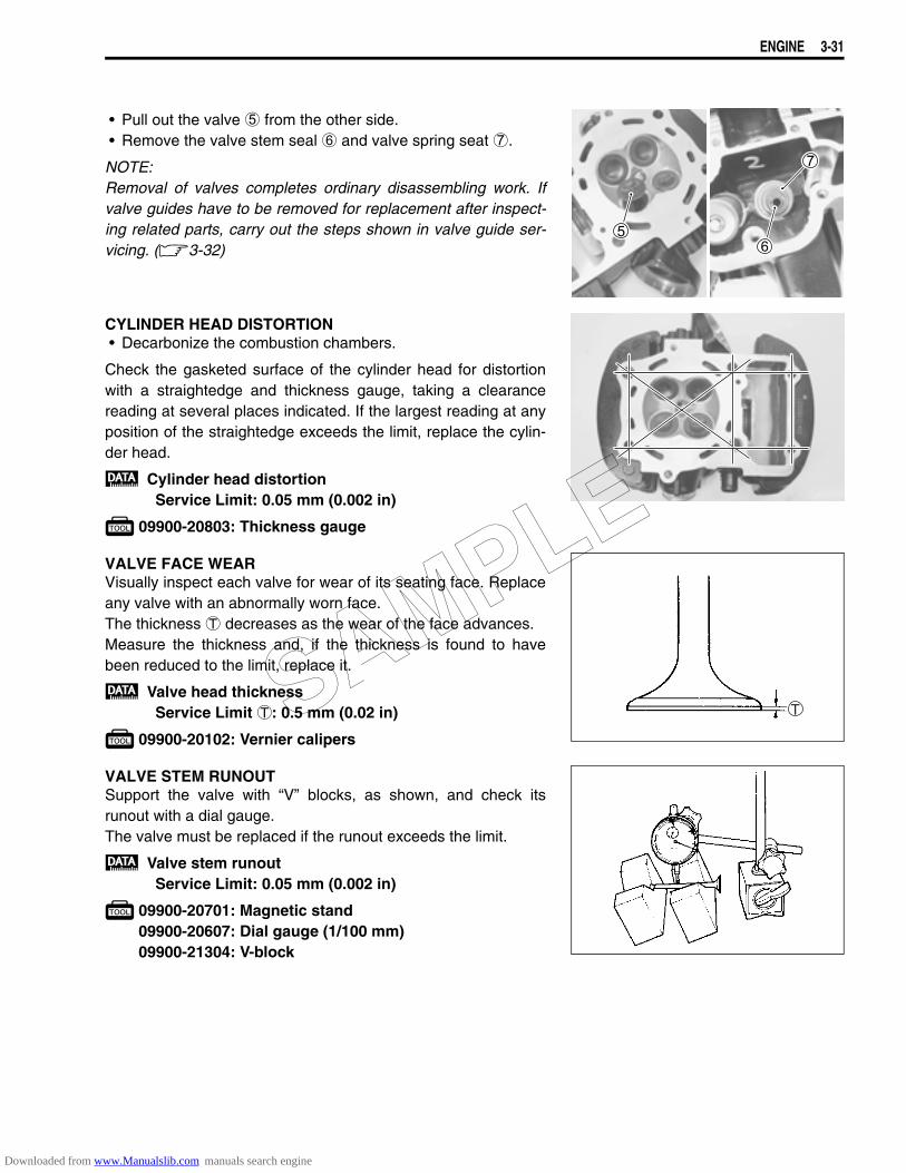
ENGINE 3-31
• Pull out the valve 5 from the other side.• Remove the valve stem seal 6 and valve spring seat 7.
NOTE:Removal of valves completes ordinary disassembling work. Ifvalve guides have to be removed for replacement after inspect-ing related parts, carry out the steps shown in valve guide ser-vicing. (3-32)
CYLINDER HEAD DISTORTION• Decarbonize the combustion chambers.
Check the gasketed surface of the cylinder head for distortionwith a straightedge and thickness gauge, taking a clearancereading at several places indicated. If the largest reading at anyposition of the straightedge exceeds the limit, replace the cylin-der head.
Cylinder head distortionService Limit: 0.05 mm (0.002 in)
09900-20803: Thickness gauge
VALVE FACE WEARVisually inspect each valve for wear of its seating face. Replaceany valve with an abnormally worn face.The thickness T decreases as the wear of the face advances.Measure the thickness and, if the thickness is found to havebeen reduced to the limit, replace it.
Valve head thicknessService Limit T: 0.5 mm (0.02 in)
09900-20102: Vernier calipers
VALVE STEM RUNOUTSupport the valve with “V” blocks, as shown, and check itsrunout with a dial gauge.The valve must be replaced if the runout exceeds the limit.
Valve stem runoutService Limit: 0.05 mm (0.002 in)
09900-20701: Magnetic stand09900-20607: Dial gauge (1/100 mm)09900-21304: V-block
SAMPLE
Downloaded from www.Manualslib.com manuals search engine
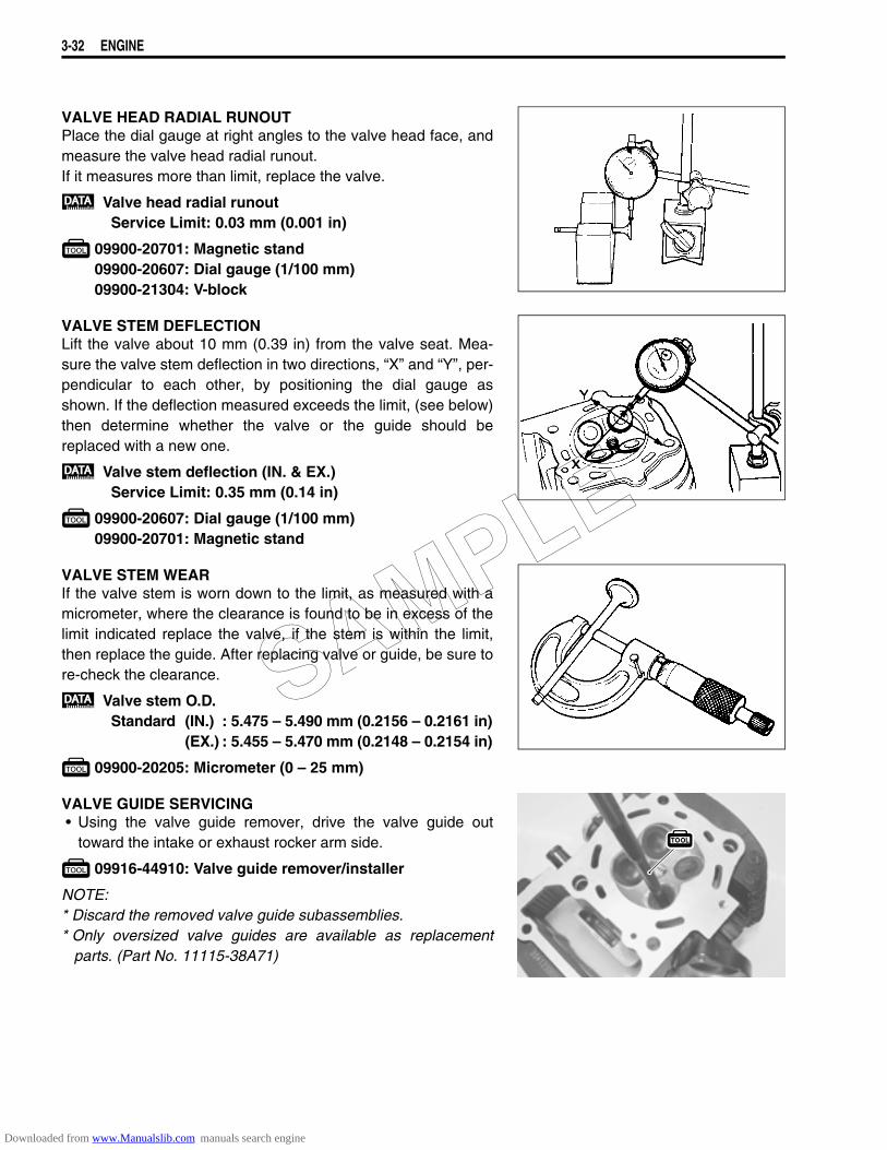
3-32 ENGINE
VALVE HEAD RADIAL RUNOUTPlace the dial gauge at right angles to the valve head face, andmeasure the valve head radial runout.If it measures more than limit, replace the valve.
Valve head radial runoutService Limit: 0.03 mm (0.001 in)
09900-20701: Magnetic stand09900-20607: Dial gauge (1/100 mm)09900-21304: V-block
VALVE STEM DEFLECTIONLift the valve about 10 mm (0.39 in) from the valve seat. Mea-sure the valve stem deflection in two directions, “X” and “Y”, per-pendicular to each other, by positioning the dial gauge asshown. If the deflection measured exceeds the limit, (see below)then determine whether the valve or the guide should bereplaced with a new one.
Valve stem deflection (IN. & EX.)Service Limit: 0.35 mm (0.14 in)
09900-20607: Dial gauge (1/100 mm)09900-20701: Magnetic stand
VALVE STEM WEARIf the valve stem is worn down to the limit, as measured with amicrometer, where the clearance is found to be in excess of thelimit indicated replace the valve, if the stem is within the limit,then replace the guide. After replacing valve or guide, be sure tore-check the clearance.
Valve stem O.D.Standard (IN.) : 5.475 – 5.490 mm (0.2156 – 0.2161 in)
(EX.) : 5.455 – 5.470 mm (0.2148 – 0.2154 in)
09900-20205: Micrometer (0 – 25 mm)
VALVE GUIDE SERVICING• Using the valve guide remover, drive the valve guide out
toward the intake or exhaust rocker arm side.
09916-44910: Valve guide remover/installer
NOTE:* Discard the removed valve guide subassemblies.* Only oversized valve guides are available as replacement
parts. (Part No. 11115-38A71)
SAMPLE
Downloaded from www.Manualslib.com manuals search engine
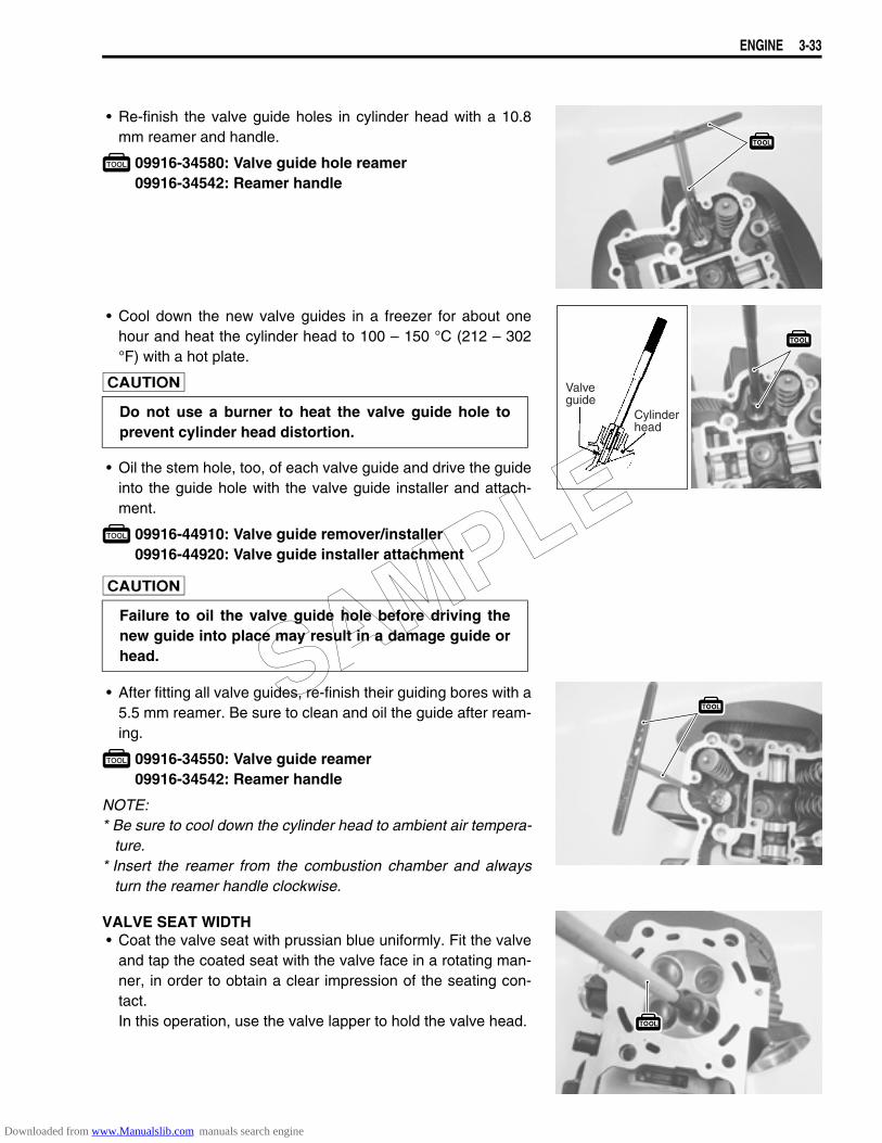
ENGINE 3-33
• Re-finish the valve guide holes in cylinder head with a 10.8mm reamer and handle.
09916-34580: Valve guide hole reamer09916-34542: Reamer handle
• Cool down the new valve guides in a freezer for about onehour and heat the cylinder head to 100 – 150 °C (212 – 302°F) with a hot plate.
• Oil the stem hole, too, of each valve guide and drive the guideinto the guide hole with the valve guide installer and attach-ment.
09916-44910: Valve guide remover/installer09916-44920: Valve guide installer attachment
• After fitting all valve guides, re-finish their guiding bores with a5.5 mm reamer. Be sure to clean and oil the guide after ream-ing.
09916-34550: Valve guide reamer09916-34542: Reamer handle
NOTE:* Be sure to cool down the cylinder head to ambient air tempera-
ture.* Insert the reamer from the combustion chamber and always
turn the reamer handle clockwise.
VALVE SEAT WIDTH• Coat the valve seat with prussian blue uniformly. Fit the valve
and tap the coated seat with the valve face in a rotating man-ner, in order to obtain a clear impression of the seating con-tact.In this operation, use the valve lapper to hold the valve head.
Do not use a burner to heat the valve guide hole toprevent cylinder head distortion.
Failure to oil the valve guide hole before driving thenew guide into place may result in a damage guide orhead.
Valveguide
Cylinderhead
SAMPLE
Downloaded from www.Manualslib.com manuals search engine
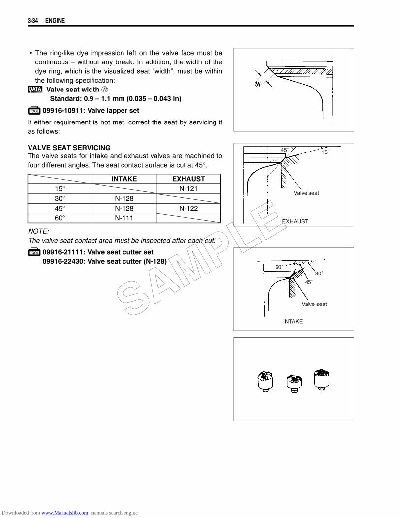
3-34 ENGINE
• The ring-like dye impression left on the valve face must becontinuous – without any break. In addition, the width of thedye ring, which is the visualized seat “width”, must be withinthe following specification:
Valve seat width WStandard: 0.9 – 1.1 mm (0.035 – 0.043 in)
09916-10911: Valve lapper set
If either requirement is not met, correct the seat by servicing itas follows:
VALVE SEAT SERVICINGThe valve seats for intake and exhaust valves are machined tofour different angles. The seat contact surface is cut at 45°.
NOTE:The valve seat contact area must be inspected after each cut.
09916-21111: Valve seat cutter set09916-22430: Valve seat cutter (N-128)
INTAKE EXHAUST15° N-12130° N-12845° N-128 N-12260° N-111
45˚ 15˚
Valve seat
EXHAUST
60˚
45˚
Valve seat
INTAKE
30˚
SAMPLE
Downloaded from www.Manualslib.com manuals search engine
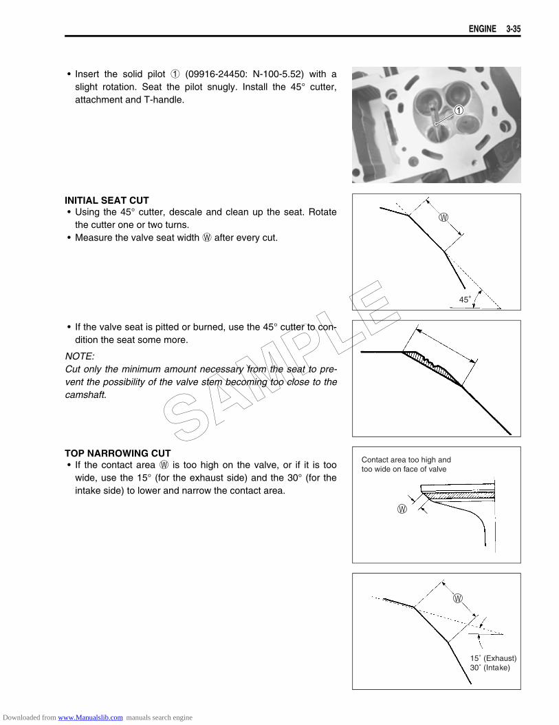
ENGINE 3-35
• Insert the solid pilot 1 (09916-24450: N-100-5.52) with aslight rotation. Seat the pilot snugly. Install the 45° cutter,attachment and T-handle.
INITIAL SEAT CUT• Using the 45° cutter, descale and clean up the seat. Rotate
the cutter one or two turns.• Measure the valve seat width W after every cut.
• If the valve seat is pitted or burned, use the 45° cutter to con-dition the seat some more.
NOTE:Cut only the minimum amount necessary from the seat to pre-vent the possibility of the valve stem becoming too close to thecamshaft.
TOP NARROWING CUT• If the contact area W is too high on the valve, or if it is too
wide, use the 15° (for the exhaust side) and the 30° (for theintake side) to lower and narrow the contact area.
Contact area too high and too wide on face of valve
15˚ (Exhaust)30˚ (Intake)
SAMPLE
Downloaded from www.Manualslib.com manuals search engine
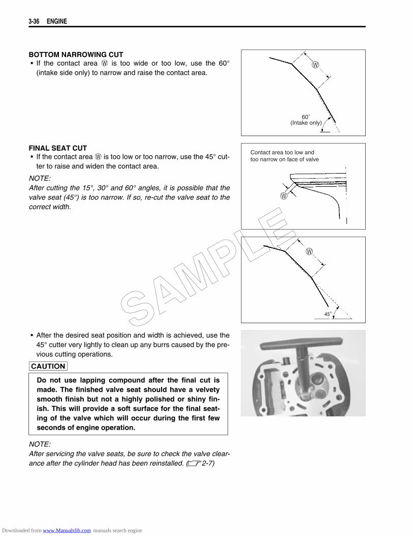
3-36 ENGINE
BOTTOM NARROWING CUT• If the contact area W is too wide or too low, use the 60°
(intake side only) to narrow and raise the contact area.
FINAL SEAT CUT• If the contact area W is too low or too narrow, use the 45° cut-
ter to raise and widen the contact area.
NOTE:After cutting the 15°, 30° and 60° angles, it is possible that thevalve seat (45°) is too narrow. If so, re-cut the valve seat to thecorrect width.
• After the desired seat position and width is achieved, use the45° cutter very lightly to clean up any burrs caused by the pre-vious cutting operations.
NOTE:After servicing the valve seats, be sure to check the valve clear-ance after the cylinder head has been reinstalled. (2-7)
60˚(Intake only)
Contact area too low andtoo narrow on face of valve
Do not use lapping compound after the final cut ismade. The finished valve seat should have a velvetysmooth finish but not a highly polished or shiny fin-ish. This will provide a soft surface for the final seat-ing of the valve which will occur during the first fewseconds of engine operation.
SAMPLE
Downloaded from www.Manualslib.com manuals search engine
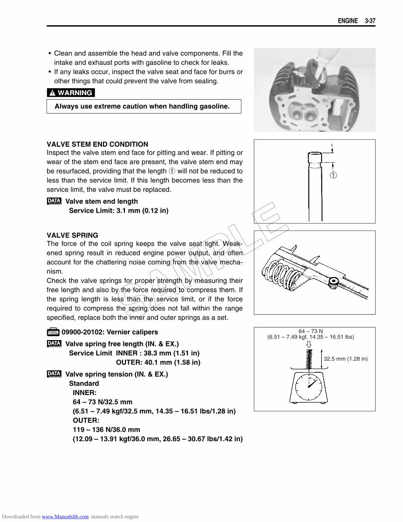
ENGINE 3-37
• Clean and assemble the head and valve components. Fill theintake and exhaust ports with gasoline to check for leaks.
• If any leaks occur, inspect the valve seat and face for burrs orother things that could prevent the valve from sealing.
VALVE STEM END CONDITIONInspect the valve stem end face for pitting and wear. If pitting orwear of the stem end face are present, the valve stem end maybe resurfaced, providing that the length 1 will not be reduced toless than the service limit. If this length becomes less than theservice limit, the valve must be replaced.
Valve stem end lengthService Limit: 3.1 mm (0.12 in)
VALVE SPRINGThe force of the coil spring keeps the valve seat tight. Weak-ened spring result in reduced engine power output, and oftenaccount for the chattering noise coming from the valve mecha-nism.Check the valve springs for proper strength by measuring theirfree length and also by the force required to compress them. Ifthe spring length is less than the service limit, or if the forcerequired to compress the spring does not fall within the rangespecified, replace both the inner and outer springs as a set.
09900-20102: Vernier calipers.
Valve spring free length (IN. & EX.)Service Limit INNER : 38.3 mm (1.51 in)
OUTER: 40.1 mm (1.58 in)
Valve spring tension (IN. & EX.)StandardINNER:64 – 73 N/32.5 mm (6.51 – 7.49 kgf/32.5 mm, 14.35 – 16.51 lbs/1.28 in)OUTER:119 – 136 N/36.0 mm(12.09 – 13.91 kgf/36.0 mm, 26.65 – 30.67 lbs/1.42 in)
Always use extreme caution when handling gasoline.
32.5 mm (1.28 in)
64 – 73 N(6.51 – 7.49 kgf, 14.35 – 16.51 lbs)
SAMPLE
Downloaded from www.Manualslib.com manuals search engine
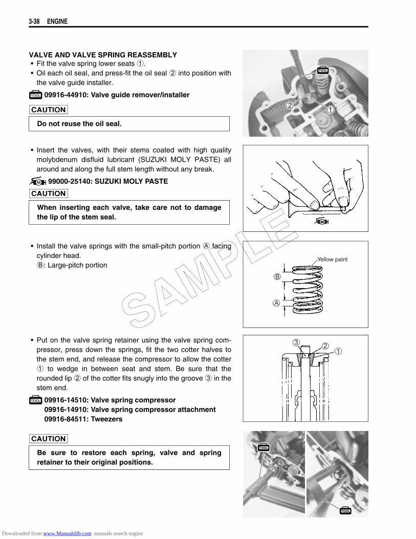
3-38 ENGINE
VALVE AND VALVE SPRING REASSEMBLY• Fit the valve spring lower seats 1.• Oil each oil seal, and press-fit the oil seal 2 into position with
the valve guide installer.
09916-44910: Valve guide remover/installer
• Insert the valves, with their stems coated with high qualitymolybdenum disfluid lubricant (SUZUKI MOLY PASTE) allaround and along the full stem length without any break.
99000-25140: SUZUKI MOLY PASTE
• Install the valve springs with the small-pitch portion A facingcylinder head.B: Large-pitch portion
• Put on the valve spring retainer using the valve spring com-pressor, press down the springs, fit the two cotter halves tothe stem end, and release the compressor to allow the cotter1 to wedge in between seat and stem. Be sure that therounded lip 2 of the cotter fits snugly into the groove 3 in thestem end.
09916-14510: Valve spring compressor09916-14910: Valve spring compressor attachment09916-84511: Tweezers
Do not reuse the oil seal.
When inserting each valve, take care not to damagethe lip of the stem seal.
Yellow paint
Be sure to restore each spring, valve and springretainer to their original positions.
SAMPLE
Downloaded from www.Manualslib.com manuals search engine

ENGINE 3-39
NOTE:When installing the water union to the cylinder head, applygrease to the new O-rings.
99000-25030: SUZUKI SUPER GREASE “A” (USA)99000-25010: SUZUKI SUPER GREASE “A” (Others)
SAMPLE
Downloaded from www.Manualslib.com manuals search engine
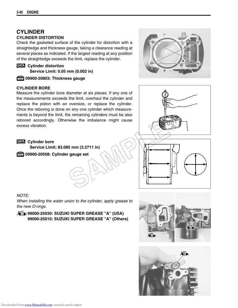
3-40 ENGINE
CYLINDERCYLINDER DISTORTIONCheck the gasketed surface of the cylinder for distortion with astraightedge and thickness gauge, taking a clearance reading atseveral places as indicated. If the largest reading at any positionof the straightedge exceeds the limit, replace the cylinder.
Cylinder distortionService Limit: 0.05 mm (0.002 in)
09900-20803: Thickness gauge
CYLINDER BOREMeasure the cylinder bore diameter at six places. If any one ofthe measurements exceeds the limit, overhaul the cylinder andreplace the piston with an oversize, or replace the cylinder.Once the reboring is done on any one cylinder which measure-ments is beyond the limit, the remaining cylinders must be alsorebored accordingly. Otherwise the imbalance might causeexcess vibration.
Cylinder boreService Limit: 83.085 mm (3.2711 in)
09900-20508: Cylinder gauge set
NOTE:When installing the water union to the cylinder, apply grease tothe new O-rings.
99000-25030: SUZUKI SUPER GREASE “A” (USA)99000-25010: SUZUKI SUPER GREASE “A” (Others)
SAMPLE
Downloaded from www.Manualslib.com manuals search engine
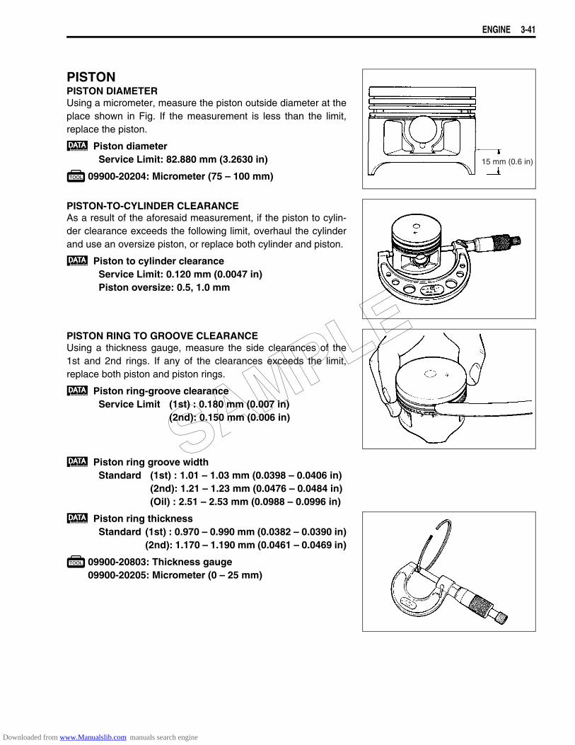
ENGINE 3-41
PISTONPISTON DIAMETERUsing a micrometer, measure the piston outside diameter at theplace shown in Fig. If the measurement is less than the limit,replace the piston.
Piston diameterService Limit: 82.880 mm (3.2630 in)
09900-20204: Micrometer (75 – 100 mm)
PISTON-TO-CYLINDER CLEARANCEAs a result of the aforesaid measurement, if the piston to cylin-der clearance exceeds the following limit, overhaul the cylinderand use an oversize piston, or replace both cylinder and piston.
Piston to cylinder clearanceService Limit: 0.120 mm (0.0047 in)Piston oversize: 0.5, 1.0 mm
PISTON RING TO GROOVE CLEARANCEUsing a thickness gauge, measure the side clearances of the1st and 2nd rings. If any of the clearances exceeds the limit,replace both piston and piston rings.
Piston ring-groove clearanceService Limit (1st) : 0.180 mm (0.007 in)
(2nd): 0.150 mm (0.006 in)
Piston ring groove widthStandard (1st) : 1.01 – 1.03 mm (0.0398 – 0.0406 in)
(2nd): 1.21 – 1.23 mm (0.0476 – 0.0484 in)(Oil) : 2.51 – 2.53 mm (0.0988 – 0.0996 in)
Piston ring thicknessStandard (1st) : 0.970 – 0.990 mm (0.0382 – 0.0390 in)
(2nd): 1.170 – 1.190 mm (0.0461 – 0.0469 in)
09900-20803: Thickness gauge09900-20205: Micrometer (0 – 25 mm)
15 mm (0.6 in)
SAMPLE
Downloaded from www.Manualslib.com manuals search engine

3-42 ENGINE
PISTON RING FREE END GAP AND END GAPBefore installing piston rings, measure the free end gap of eachring using vernier calipers. Next, fit the ring in the cylinder, andmeasure each ring end gap using a thickness gauge.If any ring has an excess end gap, replace the ring.
Piston ring free end gapService Limit (1st) : 7.7 mm (0.30 in)
(2nd): 9.4 mm (0.37 in)
Piston ring end gapService Limit (1st) : 0.70 mm (0.028 in)
(2nd): 0.70 mm (0.028 in)
09900-20102: Vernier calipers09900-20803: Thickness gauge
Oversize piston ringThe following two types of oversize piston rings are used. Theybear the following identification numbers.
Oversize oil ringThe following two types of oversize oil rings are available asoptional parts. They bear the following identification marks.
Oversize side railJust measure outside diameter to identify the side rail as there isno mark or numbers on it.
SIZE 1st 2nd0.5 mm O.S. 50 501.0 mm O.S. 100 100
SIZE COLORSTD NIL
0.5 mm O.S. Painted Red1.0 mm O.S. Painted Yellow
0.5 mm O.S.
1.0 mm O.S.
Paint
Oil ring spacer
SAMPLE
Downloaded from www.Manualslib.com manuals search engine

ENGINE 3-43
PISTON PIN AND PIN BOREUsing a small bore gauge, measure the piston pin bore insidediameter, and using a micrometer, measure the piston pin out-side diameter. If the reading exceeds following limit, replaceboth piston and piston pin.
Piston pin bore I.D.Service Limit: 20.030 mm (0.7886 in)
09900-20602: Dial gauge (1/1 000 mm, 1 mm)09900-22403: Small bore gauge (18 – 35 mm)
Using a micrometer, measure the piston pin outside diameter atthree positions.
Piston pin O.D.Service Limit: 19.980 mm (0.7866 in)
09900-20205: Micrometer (0 – 25 mm)
PISTON RING REASSEMBLY• Install the piston rings in the order of oil ring, 2nd ring and 1st
ring.• The first member to go into the oil ring groove is a spacer 1.
After placing the spacer, fit the two side rails 2.
NOTE:Side designations, top and bottom, are not applied to the spacerand side rails: you can position each either way.
• Install the 2nd ring 3 and the 1st ring 4.
NOTE:1st ring and 2nd ring differ in shape.
When installing the spacer, be careful not to allow itstwo ends to overlap in the groove.
SAMPLE
Downloaded from www.Manualslib.com manuals search engine
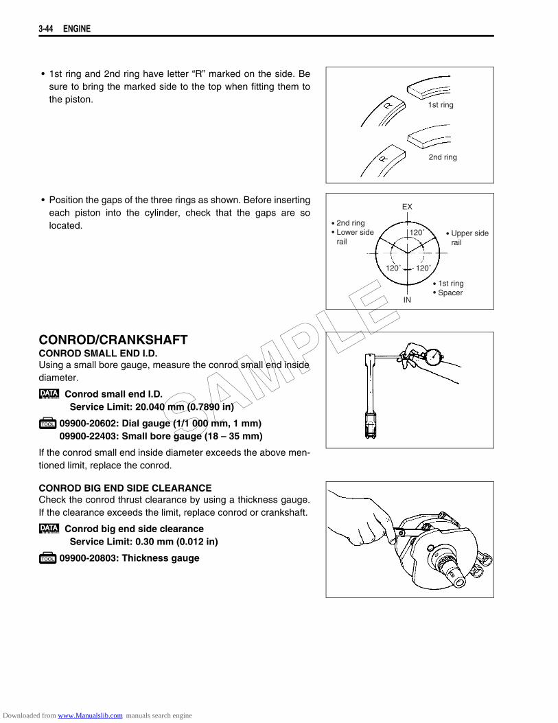
3-44 ENGINE
• 1st ring and 2nd ring have letter “R” marked on the side. Besure to bring the marked side to the top when fitting them tothe piston.
• Position the gaps of the three rings as shown. Before insertingeach piston into the cylinder, check that the gaps are solocated.
CONROD/CRANKSHAFTCONROD SMALL END I.D.Using a small bore gauge, measure the conrod small end insidediameter.
Conrod small end I.D.Service Limit: 20.040 mm (0.7890 in)
09900-20602: Dial gauge (1/1 000 mm, 1 mm)09900-22403: Small bore gauge (18 – 35 mm)
If the conrod small end inside diameter exceeds the above men-tioned limit, replace the conrod.
CONROD BIG END SIDE CLEARANCECheck the conrod thrust clearance by using a thickness gauge.If the clearance exceeds the limit, replace conrod or crankshaft.
Conrod big end side clearanceService Limit: 0.30 mm (0.012 in)
09900-20803: Thickness gauge
2nd ring
1st ring
Upper siderail
EX
IN
120˚
120˚ 120˚
2nd ringLower siderail
1st ringSpacer
SAMPLE
Downloaded from www.Manualslib.com manuals search engine
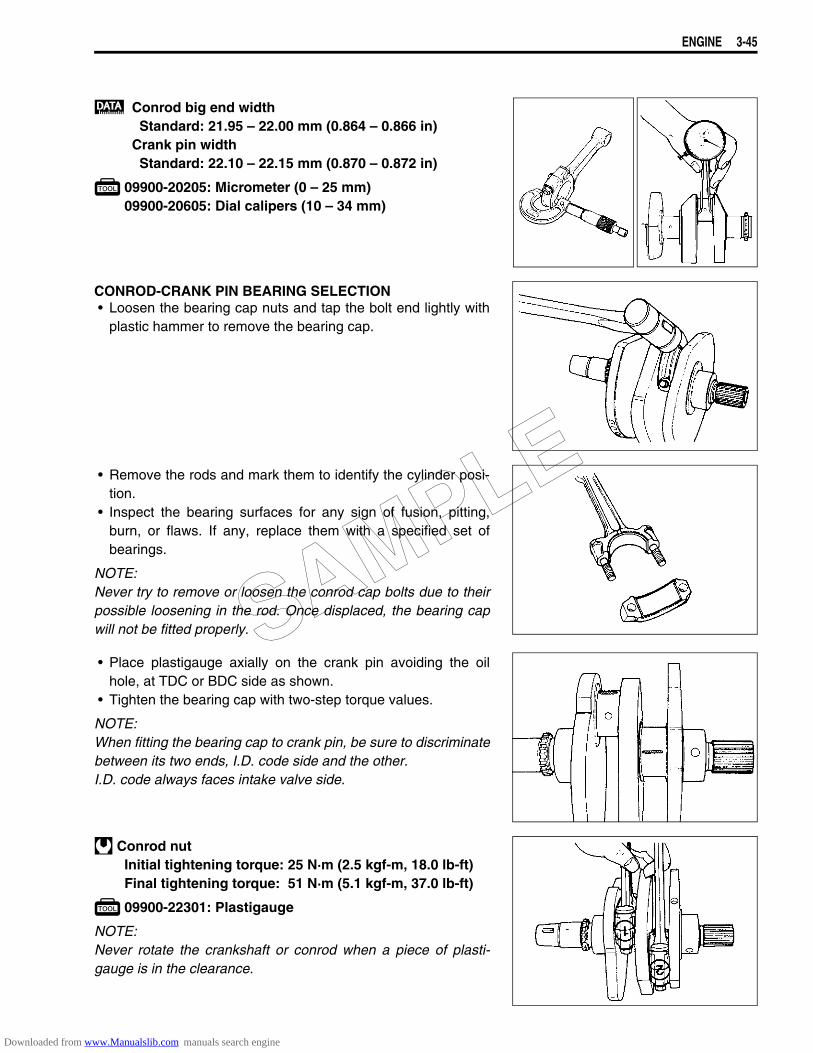
ENGINE 3-45
Conrod big end widthStandard: 21.95 – 22.00 mm (0.864 – 0.866 in)
Crank pin widthStandard: 22.10 – 22.15 mm (0.870 – 0.872 in)
09900-20205: Micrometer (0 – 25 mm)09900-20605: Dial calipers (10 – 34 mm)
CONROD-CRANK PIN BEARING SELECTION• Loosen the bearing cap nuts and tap the bolt end lightly with
plastic hammer to remove the bearing cap.
• Remove the rods and mark them to identify the cylinder posi-tion.
• Inspect the bearing surfaces for any sign of fusion, pitting,burn, or flaws. If any, replace them with a specified set ofbearings.
NOTE:Never try to remove or loosen the conrod cap bolts due to theirpossible loosening in the rod. Once displaced, the bearing capwill not be fitted properly.
• Place plastigauge axially on the crank pin avoiding the oilhole, at TDC or BDC side as shown.
• Tighten the bearing cap with two-step torque values.
NOTE:When fitting the bearing cap to crank pin, be sure to discriminatebetween its two ends, I.D. code side and the other.I.D. code always faces intake valve side.
Conrod nutInitial tightening torque: 25 N·m (2.5 kgf-m, 18.0 lb-ft)Final tightening torque: 51 N·m (5.1 kgf-m, 37.0 lb-ft)
09900-22301: Plastigauge
NOTE:Never rotate the crankshaft or conrod when a piece of plasti-gauge is in the clearance.
SAMPLE
Downloaded from www.Manualslib.com manuals search engine
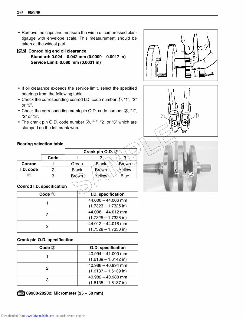
3-46 ENGINE
• Remove the caps and measure the width of compressed plas-tigauge with envelope scale. This measurement should betaken at the widest part.
Conrod big end oil clearanceStandard: 0.024 – 0.042 mm (0.0009 – 0.0017 in)Service Limit: 0.080 mm (0.0031 in)
• If oil clearance exceeds the service limit, select the specifiedbearings from the following table.
• Check the corresponding conrod I.D. code number 1, “1”, “2”or “3”.
• Check the corresponding crank pin O.D. code number 2, “1”,“2” or “3”.
• The crank pin O.D. code number 2, “1”, “2” or “3” which arestamped on the left crank web.
Bearing selection table
Conrod I.D. specification
Crank pin O.D. specification
09900-20202: Micrometer (25 – 50 mm)
Crank pin O.D. 2Code 1 2 3
Conrod I.D. code
2
1 Green Black Brown2 Black Brown Yellow3 Brown Yellow Blue
Code 1 I.D. specification
144.000 – 44.006 mm(1.7323 – 1.7325 in)
244.006 – 44.012 mm(1.7325 – 1.7328 in)
344.012 – 44.018 mm(1.7328 – 1.7330 in)
Code 2 O.D. specification
140.994 – 41.000 mm(1.6139 – 1.6142 in)
240.988 – 40.994 mm(1.6137 – 1.6139 in)
340.982 – 40.988 mm(1.6135 – 1.6137 in)
SAMPLE
Downloaded from www.Manualslib.com manuals search engine
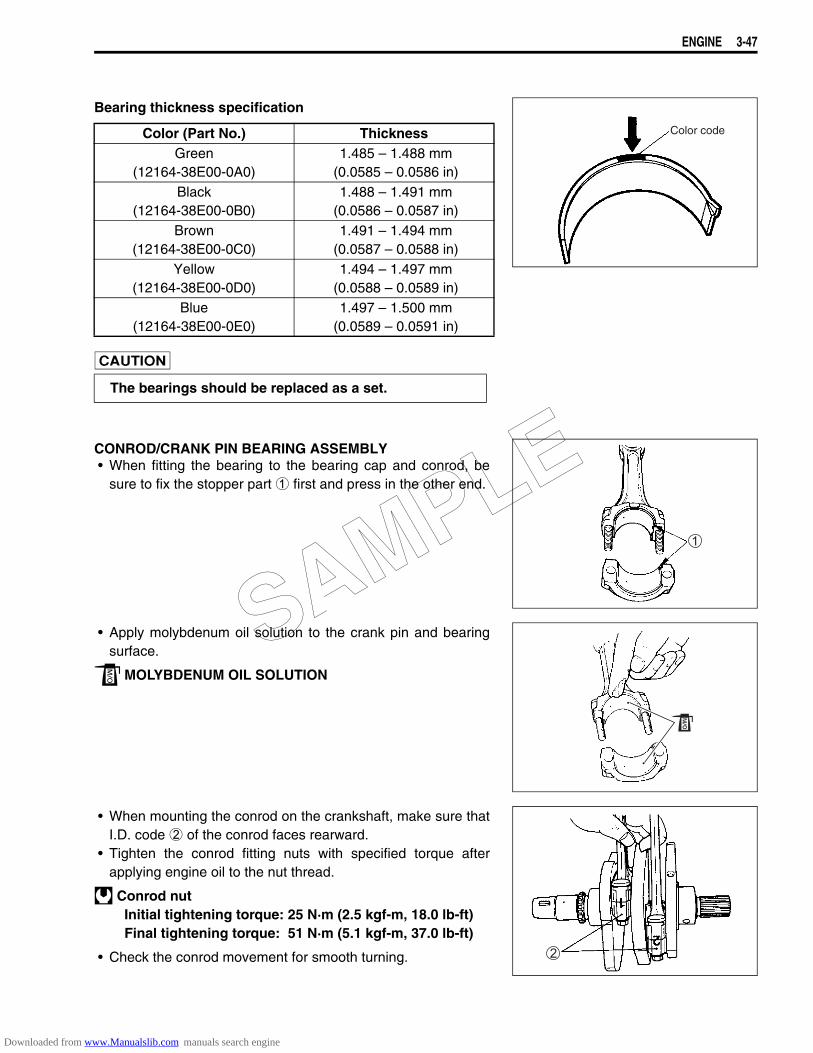
ENGINE 3-47
Bearing thickness specification
CONROD/CRANK PIN BEARING ASSEMBLY• When fitting the bearing to the bearing cap and conrod, be
sure to fix the stopper part 1 first and press in the other end.
• Apply molybdenum oil solution to the crank pin and bearingsurface.
MOLYBDENUM OIL SOLUTION
• When mounting the conrod on the crankshaft, make sure thatI.D. code 2 of the conrod faces rearward.
• Tighten the conrod fitting nuts with specified torque afterapplying engine oil to the nut thread.
Conrod nutInitial tightening torque: 25 N·m (2.5 kgf-m, 18.0 lb-ft)Final tightening torque: 51 N·m (5.1 kgf-m, 37.0 lb-ft)
• Check the conrod movement for smooth turning.
Color (Part No.) ThicknessGreen
(12164-38E00-0A0) 1.485 – 1.488 mm
(0.0585 – 0.0586 in)Black
(12164-38E00-0B0) 1.488 – 1.491 mm
(0.0586 – 0.0587 in)Brown
(12164-38E00-0C0) 1.491 – 1.494 mm
(0.0587 – 0.0588 in)Yellow
(12164-38E00-0D0) 1.494 – 1.497 mm
(0.0588 – 0.0589 in)Blue
(12164-38E00-0E0) 1.497 – 1.500 mm
(0.0589 – 0.0591 in)
The bearings should be replaced as a set.
Color code
SAMPLE
Downloaded from www.Manualslib.com manuals search engine

3-48 ENGINE
CRANKCASE/CRANKSHAFT BEARING INSPECTION• Inspect the crankshaft and crankshaft journal bearings for any
damage. If any, replace them with a specified set of bearings.
• Measure the crankshaft journal O.D. 1 by using the specialtool.
Crankshaft journal O.D. 1Standard: 47.965 – 47.980 mm (1.8884 – 1.8890 in)
09900-20202: Micrometer (25 – 50 mm)
• Measure the crankshaft journal bearing I.D. 2 by using thespecial tool.
Crankshaft journal bearing I.D. 2Standard: 48.000 – 48.015 mm (1.8898 – 1.8904 in)
09900-20508: Cylinder gauge set
• If each crankshaft journal bearing I.D. is not within the stan-dard range, replace them with new ones.
CRANKCASE-CRANKSHAFT BEARING SELECTIONSelect the specified bearings from the crankcase bore I.D. code.The crankcase bore I.D. code A “A”, “B” or “C”, is stamped onthe inside of each crankcase half.
Bearing selection table
I.D. code A I.D. specification Bearing
A52.000 – 52.006 mm(2.0472 – 2.0475 in)
Green
B52.006 – 52.012 mm(2.0475 – 2.0477 in)
Black
C52.012 – 52.018 mm(2.0477 – 2.0479 in)
Brown
SAMPLE
Downloaded from www.Manualslib.com manuals search engine
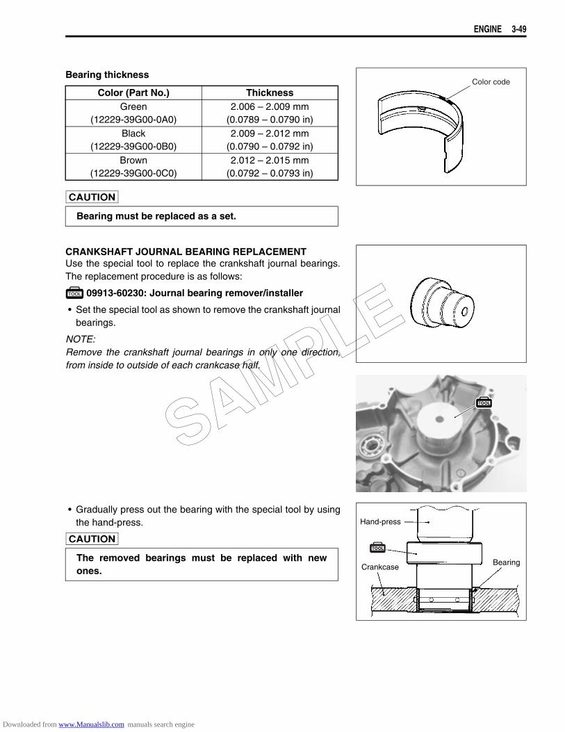
ENGINE 3-49
Bearing thickness
CRANKSHAFT JOURNAL BEARING REPLACEMENTUse the special tool to replace the crankshaft journal bearings.The replacement procedure is as follows:
09913-60230: Journal bearing remover/installer
• Set the special tool as shown to remove the crankshaft journalbearings.
NOTE:Remove the crankshaft journal bearings in only one direction,from inside to outside of each crankcase half.
• Gradually press out the bearing with the special tool by usingthe hand-press.
Color (Part No.) ThicknessGreen
(12229-39G00-0A0)2.006 – 2.009 mm
(0.0789 – 0.0790 in)Black
(12229-39G00-0B0)2.009 – 2.012 mm
(0.0790 – 0.0792 in)Brown
(12229-39G00-0C0)2.012 – 2.015 mm
(0.0792 – 0.0793 in)
Bearing must be replaced as a set.
Color code
The removed bearings must be replaced with newones.
Hand-press
CrankcaseBearing
SAMPLE
Downloaded from www.Manualslib.com manuals search engine
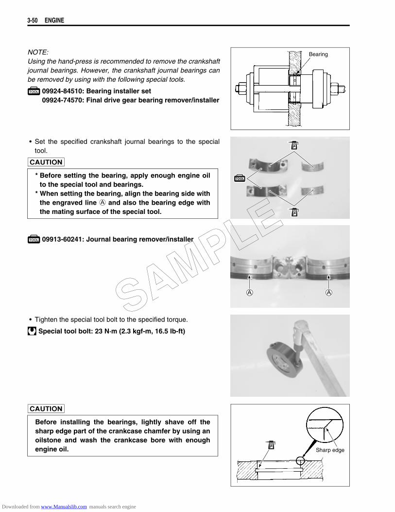
3-50 ENGINE
NOTE:Using the hand-press is recommended to remove the crankshaftjournal bearings. However, the crankshaft journal bearings canbe removed by using with the following special tools.
09924-84510: Bearing installer set09924-74570: Final drive gear bearing remover/installer
• Set the specified crankshaft journal bearings to the specialtool.
09913-60241: Journal bearing remover/installer
• Tighten the special tool bolt to the specified torque.
Special tool bolt: 23 N·m (2.3 kgf-m, 16.5 lb-ft)
Bearing
* Before setting the bearing, apply enough engine oilto the special tool and bearings.
* When setting the bearing, align the bearing side withthe engraved line A and also the bearing edge withthe mating surface of the special tool.
Before installing the bearings, lightly shave off thesharp edge part of the crankcase chamfer by using anoilstone and wash the crankcase bore with enoughengine oil. Sharp edge
SAMPLE
Downloaded from www.Manualslib.com manuals search engine

ENGINE 3-51
• Set the bearings installed in the special tool to the crankcasehalf as shown.
NOTE:The upper and lower bearings are same.
• Insert the thickness gauge 1 between the crankcase andspecial tool 3 for 1 mm (0.04 in) clearance.
• Apply enough engine oil to the special tool and the bearingsand then set the special tool carefully.
• Gradually press in the bearing into the main journal bore byusing the hand-press until the special tool 2 stops the specialtool 3.
09913-60230: Journal bearing remover/installer09900-20803: Thickness gauge
• Measure the clearance from case surface to bearing.
* Be sure the bearing protruded side B faces thecrankcase bore.
* Align the special tool mating surface with the linemark C on the crankcase.
Hand-press
Bearing
Clearance1 mm (0.04 in)
Clearance1 mm (0.04 in)
Bearing
Clearance1 mm (0.04 in)
SAMPLE
Downloaded from www.Manualslib.com manuals search engine
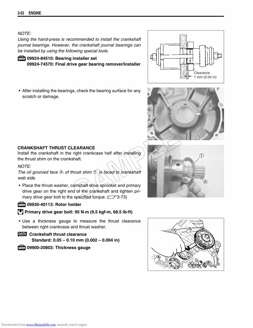
3-52 ENGINE
NOTE:Using the hand-press is recommended to install the crankshaftjournal bearings. However, the crankshaft journal bearings canbe installed by using the following special tools.
09924-84510: Bearing installer set09924-74570: Final drive gear bearing remover/installer
• After installing the bearings, check the bearing surface for anyscratch or damage.
CRANKSHAFT THRUST CLEARANCEInstall the crankshaft in the right crankcase half after installingthe thrust shim on the crankshaft.
NOTE:The oil grooved face A of thrust shim 1 is faced to crankshaftweb side.
• Place the thrust washer, camshaft drive sprocket and primarydrive gear on the right end of the crankshaft and tighten pri-mary drive gear bolt to the specified torque. (3-73)
09930-40113: Rotor holder
Primary drive gear bolt: 95 N·m (9.5 kgf-m, 68.5 lb-ft)
• Use a thickness gauge to measure the thrust clearancebetween right crankcase and thrust washer.
Crankshaft thrust clearanceStandard: 0.05 – 0.10 mm (0.002 – 0.004 in)
09900-20803: Thickness gauge
Clearance1 mm (0.04 in)
SAMPLE
Downloaded from www.Manualslib.com manuals search engine
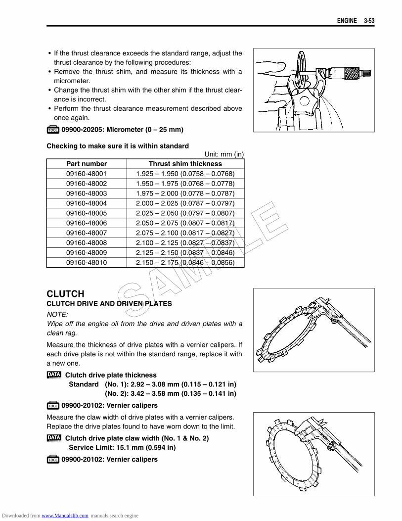
ENGINE 3-53
• If the thrust clearance exceeds the standard range, adjust thethrust clearance by the following procedures:
• Remove the thrust shim, and measure its thickness with amicrometer.
• Change the thrust shim with the other shim if the thrust clear-ance is incorrect.
• Perform the thrust clearance measurement described aboveonce again.
09900-20205: Micrometer (0 – 25 mm)
Checking to make sure it is within standardUnit: mm (in)
CLUTCHCLUTCH DRIVE AND DRIVEN PLATES
NOTE:Wipe off the engine oil from the drive and driven plates with aclean rag.
Measure the thickness of drive plates with a vernier calipers. Ifeach drive plate is not within the standard range, replace it witha new one.
Clutch drive plate thicknessStandard (No. 1): 2.92 – 3.08 mm (0.115 – 0.121 in)
(No. 2): 3.42 – 3.58 mm (0.135 – 0.141 in)
09900-20102: Vernier calipers
Measure the claw width of drive plates with a vernier calipers.Replace the drive plates found to have worn down to the limit.
Clutch drive plate claw width (No. 1 & No. 2)Service Limit: 15.1 mm (0.594 in)
09900-20102: Vernier calipers
Part number Thrust shim thickness09160-48001 1.925 – 1.950 (0.0758 – 0.0768)09160-48002 1.950 – 1.975 (0.0768 – 0.0778)09160-48003 1.975 – 2.000 (0.0778 – 0.0787)09160-48004 2.000 – 2.025 (0.0787 – 0.0797)09160-48005 2.025 – 2.050 (0.0797 – 0.0807)09160-48006 2.050 – 2.075 (0.0807 – 0.0817)09160-48007 2.075 – 2.100 (0.0817 – 0.0827)09160-48008 2.100 – 2.125 (0.0827 – 0.0837)09160-48009 2.125 – 2.150 (0.0837 – 0.0846)09160-48010 2.150 – 2.175 (0.0846 – 0.0856)
SAMPLE
Downloaded from www.Manualslib.com manuals search engine
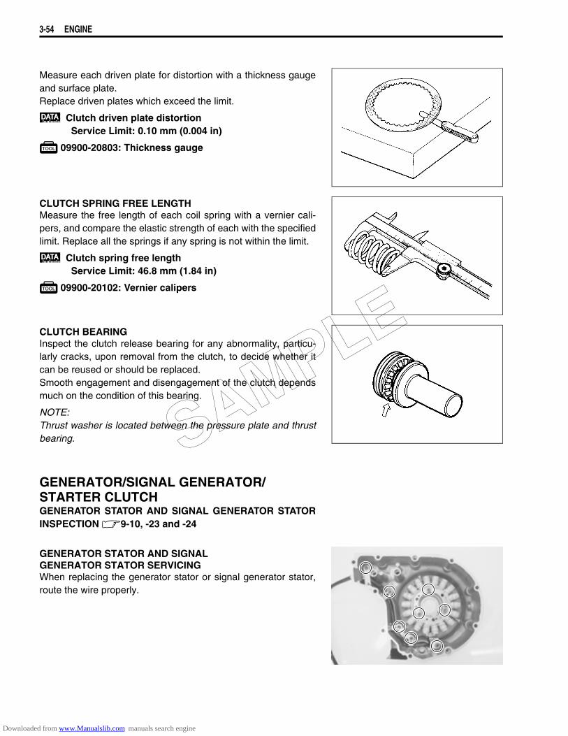
3-54 ENGINE
Measure each driven plate for distortion with a thickness gaugeand surface plate.Replace driven plates which exceed the limit.
Clutch driven plate distortionService Limit: 0.10 mm (0.004 in)
09900-20803: Thickness gauge
CLUTCH SPRING FREE LENGTHMeasure the free length of each coil spring with a vernier cali-pers, and compare the elastic strength of each with the specifiedlimit. Replace all the springs if any spring is not within the limit.
Clutch spring free lengthService Limit: 46.8 mm (1.84 in)
09900-20102: Vernier calipers
CLUTCH BEARINGInspect the clutch release bearing for any abnormality, particu-larly cracks, upon removal from the clutch, to decide whether itcan be reused or should be replaced.Smooth engagement and disengagement of the clutch dependsmuch on the condition of this bearing.
NOTE:Thrust washer is located between the pressure plate and thrustbearing.
GENERATOR/SIGNAL GENERATOR/ STARTER CLUTCHGENERATOR STATOR AND SIGNAL GENERATOR STATORINSPECTION 9-10, -23 and -24
GENERATOR STATOR AND SIGNALGENERATOR STATOR SERVICINGWhen replacing the generator stator or signal generator stator,route the wire properly.
SAMPLE
Downloaded from www.Manualslib.com manuals search engine
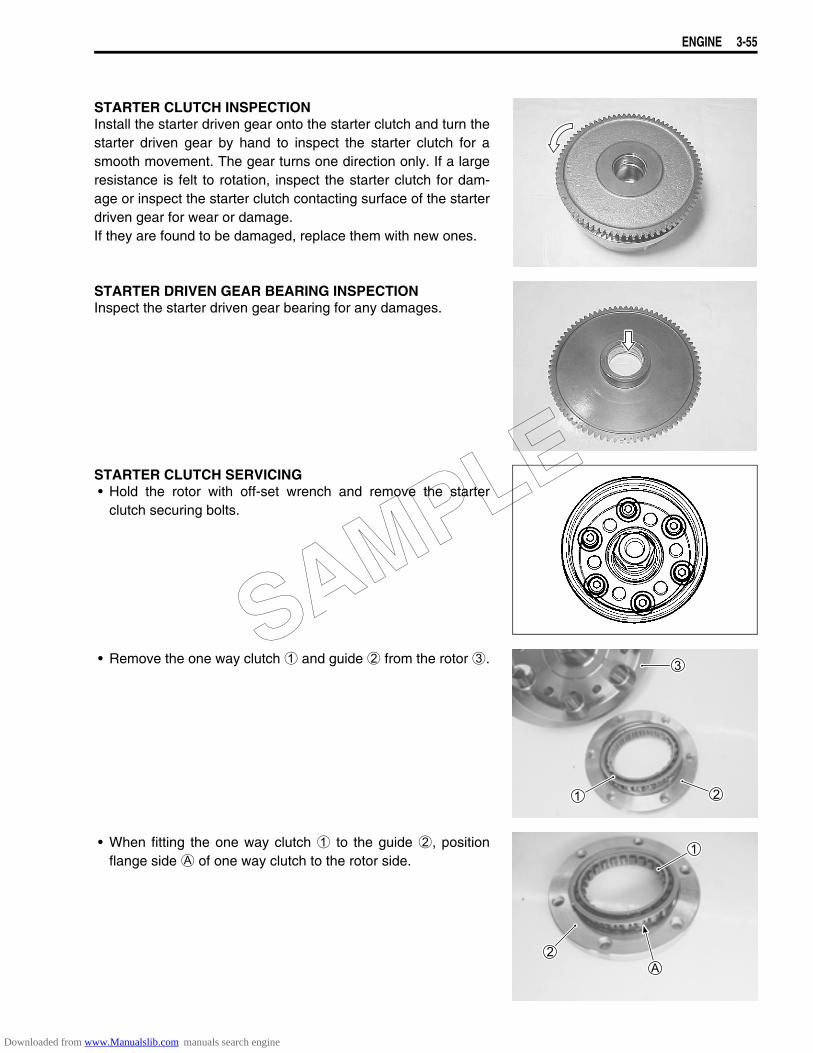
ENGINE 3-55
STARTER CLUTCH INSPECTIONInstall the starter driven gear onto the starter clutch and turn thestarter driven gear by hand to inspect the starter clutch for asmooth movement. The gear turns one direction only. If a largeresistance is felt to rotation, inspect the starter clutch for dam-age or inspect the starter clutch contacting surface of the starterdriven gear for wear or damage.If they are found to be damaged, replace them with new ones.
STARTER DRIVEN GEAR BEARING INSPECTIONInspect the starter driven gear bearing for any damages.
STARTER CLUTCH SERVICING• Hold the rotor with off-set wrench and remove the starter
clutch securing bolts.
• Remove the one way clutch 1 and guide 2 from the rotor 3.
• When fitting the one way clutch 1 to the guide 2, positionflange side A of one way clutch to the rotor side.
SAMPLE
Downloaded from www.Manualslib.com manuals search engine

3-56 ENGINE
• When installing the starter clutch guide 2, make sure that theflange B side faces out.
• Apply THREAD LOCK SUPER “1303” to the securing boltsand tighten them to the specified torque while holding therotor with off-set wrench.
99000-32030: THREAD LOCK SUPER “1303”
Starter clutch securing bolt: 26 N·m (2.6 kgf-m, 19.0 lb-ft)
OIL PUMP• Rotate the oil pump by hand and check that it moves
smoothly.• If it does not move smoothly, replace the oil pump assembly.
Do not attempt to disassemble the oil pump assembly.The oil pump is available only as an assembly.SAMPLE
Downloaded from www.Manualslib.com manuals search engine
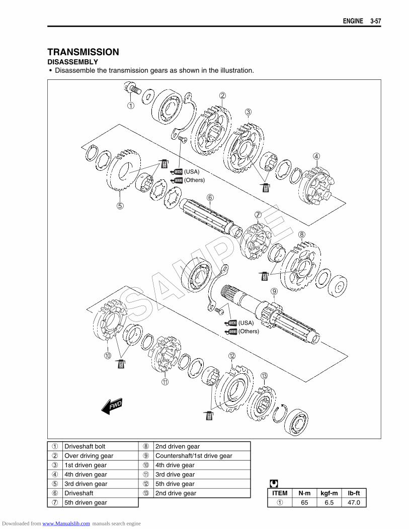
ENGINE 3-57
TRANSMISSIONDISASSEMBLY• Disassemble the transmission gears as shown in the illustration.
1 Driveshaft bolt 8 2nd driven gear
2 Over driving gear 9 Countershaft/1st drive gear
3 1st driven gear 0 4th drive gear
4 4th driven gear A 3rd drive gear
5 3rd driven gear B 5th drive gear 6 Driveshaft C 2nd drive gear ITEM N·m kgf-m lb-ft7 5th driven gear 1 65 6.5 47.0
FWDFWD
(USA)
(Others)
(USA)
(Others)SAMPLE
Downloaded from www.Manualslib.com manuals search engine
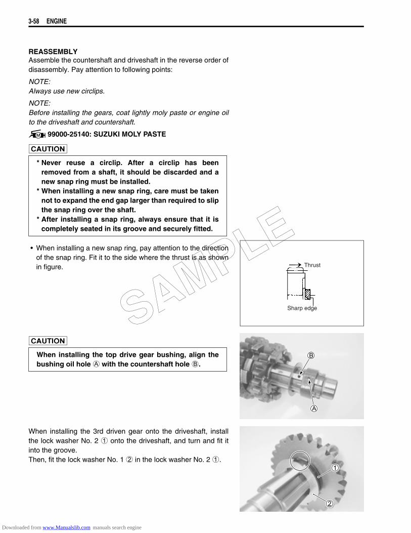
3-58 ENGINE
REASSEMBLYAssemble the countershaft and driveshaft in the reverse order ofdisassembly. Pay attention to following points:
NOTE:Always use new circlips.
NOTE:Before installing the gears, coat lightly moly paste or engine oilto the driveshaft and countershaft.
99000-25140: SUZUKI MOLY PASTE
• When installing a new snap ring, pay attention to the directionof the snap ring. Fit it to the side where the thrust is as shownin figure.
When installing the 3rd driven gear onto the driveshaft, installthe lock washer No. 2 1 onto the driveshaft, and turn and fit itinto the groove.Then, fit the lock washer No. 1 2 in the lock washer No. 2 1.
* Never reuse a circlip. After a circlip has beenremoved from a shaft, it should be discarded and anew snap ring must be installed.
* When installing a new snap ring, care must be takennot to expand the end gap larger than required to slipthe snap ring over the shaft.
* After installing a snap ring, always ensure that it iscompletely seated in its groove and securely fitted.
Thrust
Sharp edge
When installing the top drive gear bushing, align thebushing oil hole A with the countershaft hole B.
SAMPLE
Downloaded from www.Manualslib.com manuals search engine
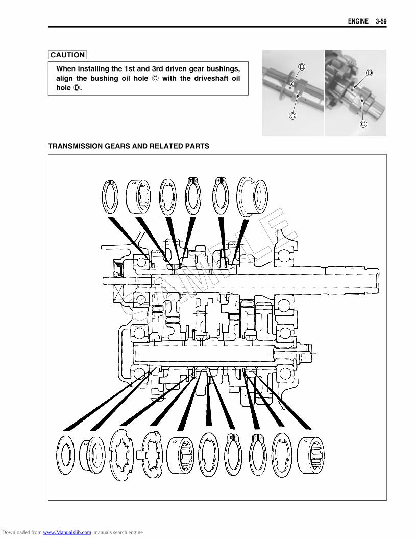
ENGINE 3-59
TRANSMISSION GEARS AND RELATED PARTS
When installing the 1st and 3rd driven gear bushings,align the bushing oil hole C with the driveshaft oilhole D.
SAMPLE
Downloaded from www.Manualslib.com manuals search engine
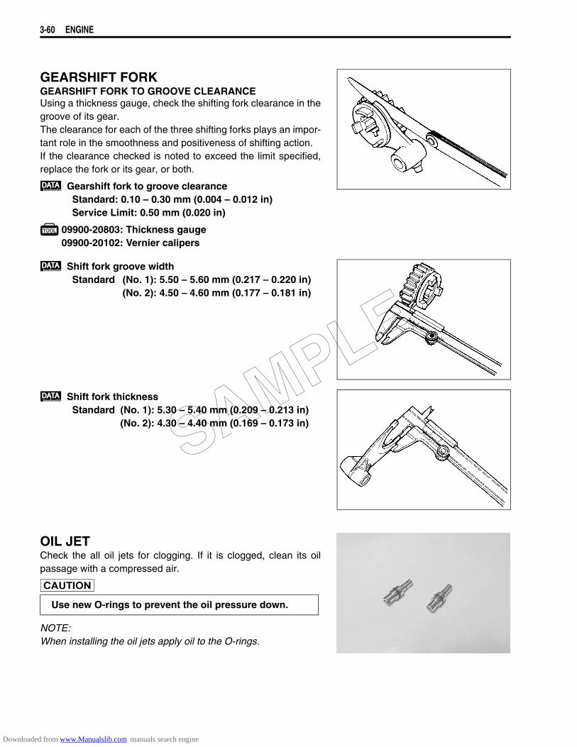
3-60 ENGINE
GEARSHIFT FORKGEARSHIFT FORK TO GROOVE CLEARANCEUsing a thickness gauge, check the shifting fork clearance in thegroove of its gear.The clearance for each of the three shifting forks plays an impor-tant role in the smoothness and positiveness of shifting action.If the clearance checked is noted to exceed the limit specified,replace the fork or its gear, or both.
Gearshift fork to groove clearanceStandard: 0.10 – 0.30 mm (0.004 – 0.012 in)Service Limit: 0.50 mm (0.020 in)
09900-20803: Thickness gauge09900-20102: Vernier calipers
Shift fork groove widthStandard (No. 1): 5.50 – 5.60 mm (0.217 – 0.220 in)
(No. 2): 4.50 – 4.60 mm (0.177 – 0.181 in)
Shift fork thicknessStandard (No. 1): 5.30 – 5.40 mm (0.209 – 0.213 in)
(No. 2): 4.30 – 4.40 mm (0.169 – 0.173 in)
OIL JETCheck the all oil jets for clogging. If it is clogged, clean its oilpassage with a compressed air.
NOTE:When installing the oil jets apply oil to the O-rings.
Use new O-rings to prevent the oil pressure down.
SAMPLE
Downloaded from www.Manualslib.com manuals search engine
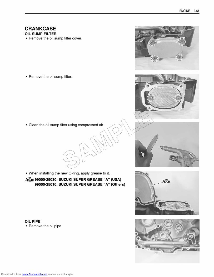
ENGINE 3-61
CRANKCASEOIL SUMP FILTER• Remove the oil sump filter cover.
• Remove the oil sump filter.
• Clean the oil sump filter using compressed air.
• When installing the new O-ring, apply grease to it.
99000-25030: SUZUKI SUPER GREASE “A” (USA)99000-25010: SUZUKI SUPER GREASE “A” (Others)
OIL PIPE• Remove the oil pipe.
SAMPLE
Downloaded from www.Manualslib.com manuals search engine

3-62 ENGINE
• When installing the oil pipe, use the new O-rings.• Apply grease to the O-rings.
99000-25030: SUZUKI SUPER GREASE “A” (USA)99000-25010: SUZUKI SUPER GREASE “A” (Others)
• Apply a small quantity of the THREAD LOCK “1342” to the oilpipe retainer bolts and tighten them securely.
99000-32050: THREAD LOCK “1342”
OIL PRESSURE REGULATOR• Remove the oil pressure regulator.
Check the operation of the oil pressure regulator by pushing onthe piston with an appropriately shaped tool. If the piston doesnot operate, replace the oil pressure regulator with a new one.
• When installing the oil pressure regulator, install the newwasher 1.
BEARING INSPECTIONRotate the bearing inner race by finger to inspect for abnormalplay, noise and smooth rotation while the bearings are in thecrankcase.Replace the bearing in the following procedure if there is any-thing unusual.
SAMPLE
Downloaded from www.Manualslib.com manuals search engine
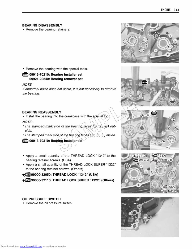
ENGINE 3-63
BEARING DISASSEMBLY• Remove the bearing retainers.
• Remove the bearing with the special tools.
09913-70210: Bearing installer set09921-20240: Bearing remover set
NOTE:If abnormal noise does not occur, it is not necessary to removethe bearing.
BEARING REASSEMBLY• Install the bearing into the crankcase with the special tool.
NOTE:* The stamped mark side of the bearing faces (1, 2, 4) out-
side.* The stamped mark side of the bearing faces (3, 5, 6) inside.
09913-70210: Bearing installer set
• Apply a small quantity of the THREAD LOCK “1342” to thebearing retainer screws. (USA)
• Apply a small quantity of the THREAD LOCK SUPER “1322”to the bearing retainer screws. (Others)
99000-32050: THREAD LOCK “1342” (USA)
99000-32110: THREAD LOCK SUPER “1322” (Others)
OIL PRESSURE SWITCH• Remove the oil pressure switch.
(Others)
(USA)
(Others)
(USA)
(Others)
(USA)SAMPLE
Downloaded from www.Manualslib.com manuals search engine
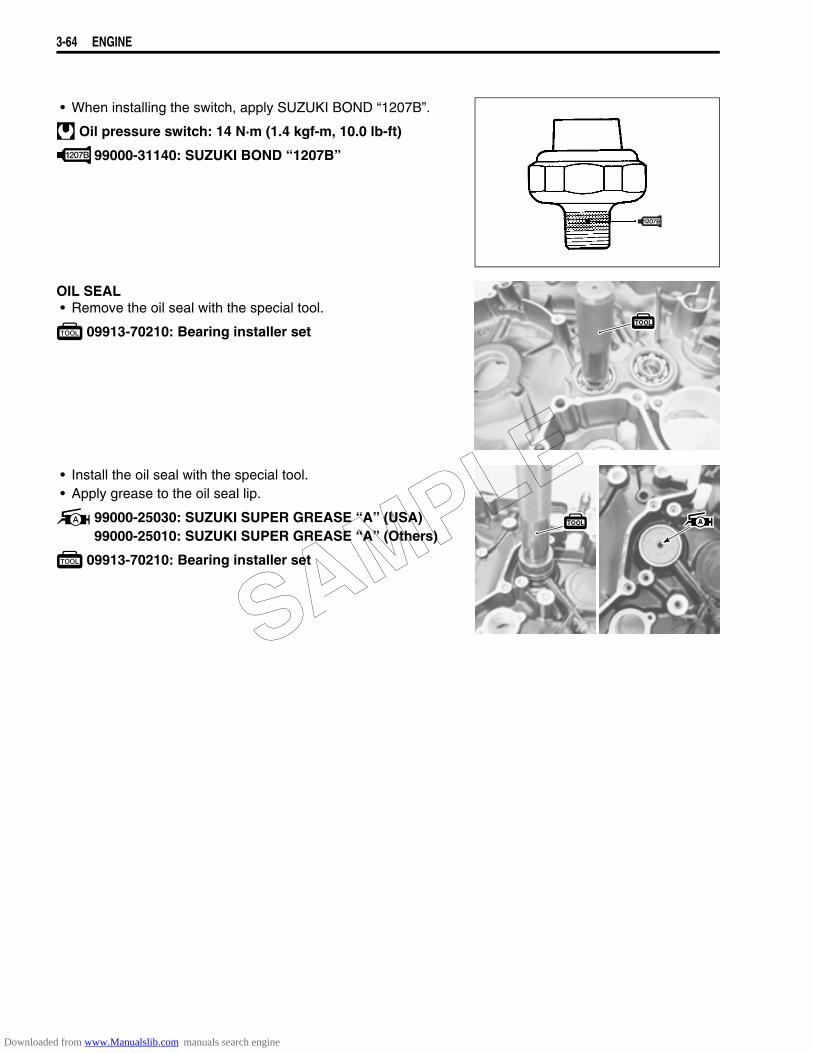
3-64 ENGINE
• When installing the switch, apply SUZUKI BOND “1207B”.
Oil pressure switch: 14 N·m (1.4 kgf-m, 10.0 lb-ft)
99000-31140: SUZUKI BOND ‘‘1207B”
OIL SEAL• Remove the oil seal with the special tool.
09913-70210: Bearing installer set
• Install the oil seal with the special tool.• Apply grease to the oil seal lip.
99000-25030: SUZUKI SUPER GREASE “A” (USA)99000-25010: SUZUKI SUPER GREASE “A” (Others)
09913-70210: Bearing installer set
SAMPLE
Downloaded from www.Manualslib.com manuals search engine
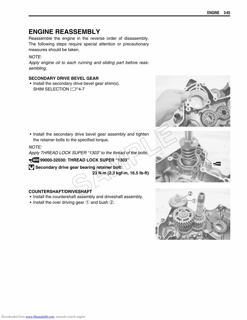
ENGINE 3-65
ENGINE REASSEMBLYReassemble the engine in the reverse order of disassembly.The following steps require special attention or precautionarymeasures should be taken.
NOTE:Apply engine oil to each running and sliding part before reas-sembling.
SECONDARY DRIVE BEVEL GEAR• Install the secondary drive bevel gear shim(s).
SHIM SELECTION 4-7
• Install the secondary drive bevel gear assembly and tightenthe retainer bolts to the specified torque.
NOTE:Apply THREAD LOCK SUPER “1303” to the thread of the bolts.
99000-32030: THREAD LOCK SUPER “1303”
Secondary drive gear bearing retainer bolt:23 N·m (2.3 kgf-m, 16.5 lb-ft)
COUNTERSHAFT/DRIVESHAFT• Install the countershaft assembly and driveshaft assembly.• Install the over driving gear 1 and bush 2.
SAMPLE
Downloaded from www.Manualslib.com manuals search engine
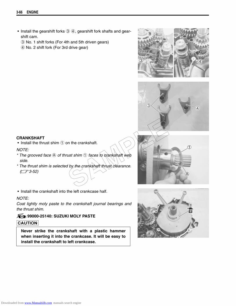
3-66 ENGINE
• Install the gearshift forks 3 4, gearshift fork shafts and gear-shift cam. 3 No. 1 shift forks (For 4th and 5th driven gears) 4 No. 2 shift fork (For 3rd drive gear)
CRANKSHAFT• Install the thrust shim 1 on the crankshaft.
NOTE:* The grooved face A of thrust shim 1 faces to crankshaft web
side.* The thrust shim is selected by the crankshaft thrust clearance.
(3-52)
• Install the crankshaft into the left crankcase half.
NOTE:Coat lightly moly paste to the crankshaft journal bearings andthe thrust shim.
99000-25140: SUZUKI MOLY PASTE
Never strike the crankshaft with a plastic hammerwhen inserting it into the crankcase. It will be easy toinstall the crankshaft to left crankcase.
SAMPLE
Downloaded from www.Manualslib.com manuals search engine

ENGINE 3-67
• Install the dowel pins and O-ring on the left crankcase half.
NOTE:Apply grease to the O-ring.
99000-25030: SUZUKI SUPER GREASE “A” (USA)99000-25010: SUZUKI SUPER GREASE “A” (Others)
• Clean the mating surfaces of the left and right crankcasehalves.
• Apply SUZUKI BOND “1207B” to the mating surface of theright crankcase.
99000-31140: SUZUKI BOND ‘‘1207B”
NOTE:Use of SUZUKI BOND “1207B” is as follows:* Make surfaces free from moisture, oil, dust and other foreign
materials.* Spread on surfaces thinly to form an even layer, and assemble
the crankcases within few minutes.* Take extreme care not to apply any BOND “1207B” to the oil
hole, oil groove and bearing.* Apply to distorted surfaces as it forms a comparatively thick
film.
• Fit the gaskets to the bolts A.• Fit the lead wire to the bolt B.• When securing the right and left crankcase halves, tighten
each bolt a little at a time to equalize the pressure. Tighten allthe securing bolts to the specified torque values.
Crankcase 8 mm bolt:Initial: 15 N·m (1.5 kgf-m, 11.0 lb-ft)Final : 22 N·m (2.2 kgf-m, 16.0 lb-ft)
Crankcase 6 mm bolt: 11 N·m (1.1 kgf-m, 8.0 lb-ft)
NOTE:After the crankcase bolts have been tightened, check if thecrankshaft, secondary drive bevel gear shaft, countershaft andthe driveshaft rotate smoothly.
Use the new O-ring to prevent oil leakage.
Do not drop the O-ring into the crankcase whenassembling the right and left crankcase halves.
SAMPLE
Downloaded from www.Manualslib.com manuals search engine
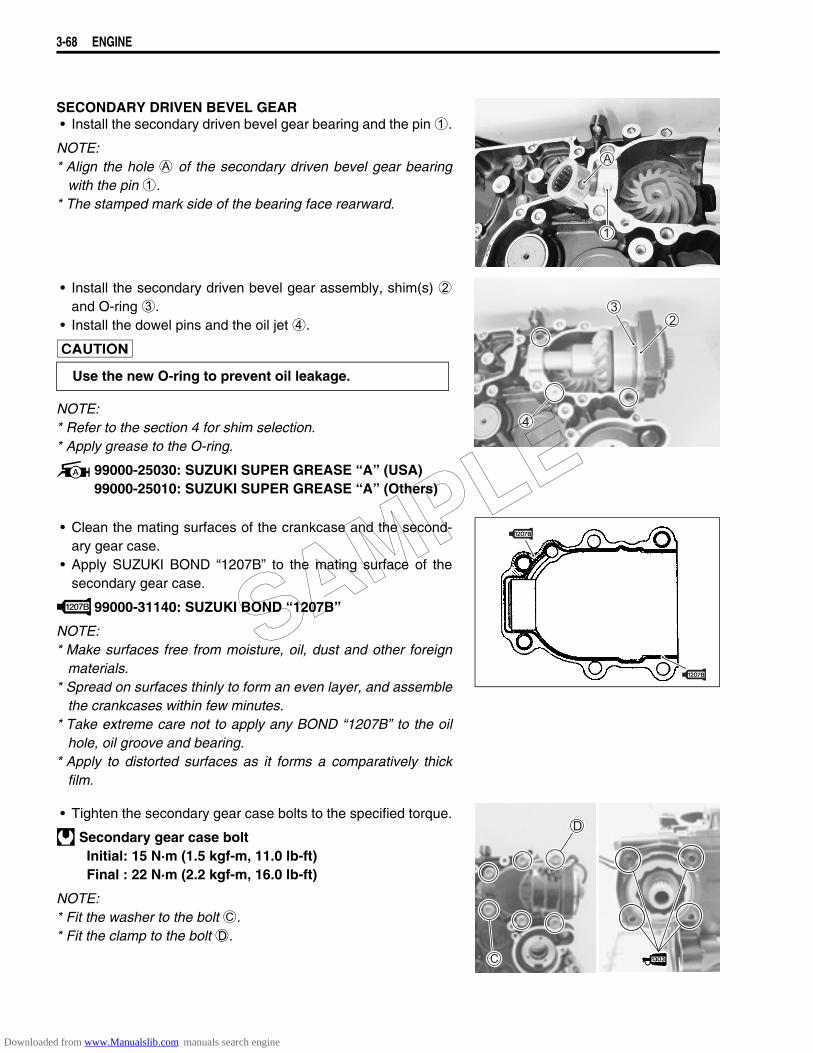
3-68 ENGINE
SECONDARY DRIVEN BEVEL GEAR• Install the secondary driven bevel gear bearing and the pin 1.
NOTE:* Align the hole A of the secondary driven bevel gear bearing
with the pin 1.* The stamped mark side of the bearing face rearward.
• Install the secondary driven bevel gear assembly, shim(s) 2and O-ring 3.
• Install the dowel pins and the oil jet 4.
NOTE:* Refer to the section 4 for shim selection.* Apply grease to the O-ring.
99000-25030: SUZUKI SUPER GREASE “A” (USA)99000-25010: SUZUKI SUPER GREASE “A” (Others)
• Clean the mating surfaces of the crankcase and the second-ary gear case.
• Apply SUZUKI BOND “1207B” to the mating surface of thesecondary gear case.
99000-31140: SUZUKI BOND ‘‘1207B”
NOTE:* Make surfaces free from moisture, oil, dust and other foreign
materials.* Spread on surfaces thinly to form an even layer, and assemble
the crankcases within few minutes.* Take extreme care not to apply any BOND “1207B” to the oil
hole, oil groove and bearing.* Apply to distorted surfaces as it forms a comparatively thick
film.
• Tighten the secondary gear case bolts to the specified torque.
Secondary gear case boltInitial: 15 N·m (1.5 kgf-m, 11.0 lb-ft)Final : 22 N·m (2.2 kgf-m, 16.0 lb-ft)
NOTE:* Fit the washer to the bolt C.* Fit the clamp to the bolt D.
Use the new O-ring to prevent oil leakage.
SAMPLE
Downloaded from www.Manualslib.com manuals search engine
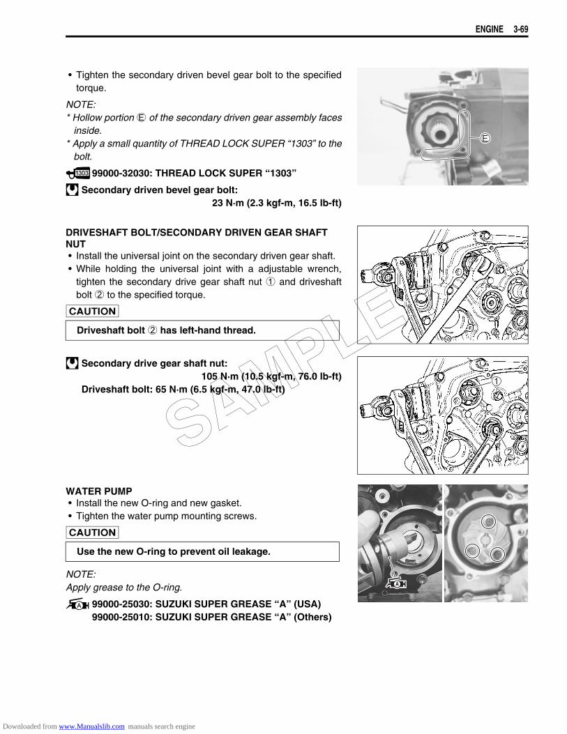
ENGINE 3-69
• Tighten the secondary driven bevel gear bolt to the specifiedtorque.
NOTE:* Hollow portion E of the secondary driven gear assembly faces
inside.* Apply a small quantity of THREAD LOCK SUPER “1303” to the
bolt.
99000-32030: THREAD LOCK SUPER “1303”
Secondary driven bevel gear bolt:23 N·m (2.3 kgf-m, 16.5 lb-ft)
DRIVESHAFT BOLT/SECONDARY DRIVEN GEAR SHAFT NUT• Install the universal joint on the secondary driven gear shaft.• While holding the universal joint with a adjustable wrench,
tighten the secondary drive gear shaft nut 1 and driveshaftbolt 2 to the specified torque.
Secondary drive gear shaft nut:105 N·m (10.5 kgf-m, 76.0 lb-ft)
Driveshaft bolt: 65 N·m (6.5 kgf-m, 47.0 lb-ft)
WATER PUMP• Install the new O-ring and new gasket.• Tighten the water pump mounting screws.
NOTE:Apply grease to the O-ring.
99000-25030: SUZUKI SUPER GREASE “A” (USA)99000-25010: SUZUKI SUPER GREASE “A” (Others)
Driveshaft bolt 2 has left-hand thread.
Use the new O-ring to prevent oil leakage.
SAMPLE
Downloaded from www.Manualslib.com manuals search engine
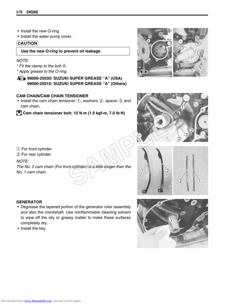
3-70 ENGINE
• Install the new O-ring.• Install the water pump cover.
NOTE:* Fit the clamp to the bolt A.* Apply grease to the O-ring.
99000-25030: SUZUKI SUPER GREASE “A” (USA)99000-25010: SUZUKI SUPER GREASE “A” (Others)
CAM CHAIN/CAM CHAIN TENSIONER• Install the cam chain tensioner 1, washers 2, spacer 3 and
cam chain.
Cam chain tensioner bolt: 10 N·m (1.0 kgf-m, 7.0 lb-ft)
1 For front cylinder2 For rear cylinder
NOTE:The No. 2 cam chain (For front cylinder) is a little longer than theNo. 1 cam chain.
GENERATOR• Degrease the tapered portion of the generator rotor assembly
and also the crankshaft. Use nonflammable cleaning solventto wipe off the oily or greasy matter to make these surfacescompletely dry.
• Install the key.
Use the new O-ring to prevent oil leakage.
SAMPLE
Downloaded from www.Manualslib.com manuals search engine
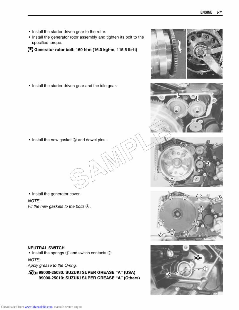
ENGINE 3-71
• Install the starter driven gear to the rotor.• Install the generator rotor assembly and tighten its bolt to the
specified torque.
Generator rotor bolt: 160 N·m (16.0 kgf-m, 115.5 lb-ft)
• Install the starter driven gear and the idle gear.
• Install the new gasket 3 and dowel pins.
• Install the generator cover.
NOTE:Fit the new gaskets to the bolts A.
NEUTRAL SWITCH• Install the springs 1 and switch contacts 2.
NOTE:Apply grease to the O-ring.
99000-25030: SUZUKI SUPER GREASE “A” (USA)99000-25010: SUZUKI SUPER GREASE “A” (Others)
SAMPLE
Downloaded from www.Manualslib.com manuals search engine

3-72 ENGINE
• Install the neutral switch.• Install the oil pressure switch lead wire.
OIL FILTER• Apply engine oil lightly to the gasket of the oil filter before
installation.• Install the oil filter turning it by hand until feeling that the filter
gasket contacts the mounting surface. Then tighten it 2 turnsusing the oil filter wrench. ( 20 N·m, 2.0 kgf-m, 14.5 lb-ft)
09915-40610: Oil filter wrench
PRIMARY DRIVE GEAR• Install the thrust washer 1 onto the crankshaft.
NOTE:The chamfer side A of thrust washer 1 face crankcase side.
• Align the punch mark B on the crankshaft with the punchmark C on the camshaft drive sprocket.
• Install the cam chain, cam chain tensioner 2, washers 3 andspacer 4.
• Tighten the cam chain tensioner bolt to the specified torque.
Cam chain tensioner bolt: 10 N·m (1.0 kgf-m, 7.0 lb-ft)
SAMPLE
Downloaded from www.Manualslib.com manuals search engine
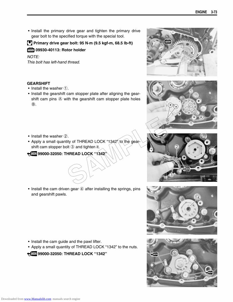
ENGINE 3-73
• Install the primary drive gear and tighten the primary drivegear bolt to the specified torque with the special tool.
Primary drive gear bolt: 95 N·m (9.5 kgf-m, 68.5 lb-ft)
09930-40113: Rotor holder
NOTE:This bolt has left-hand thread.
GEARSHIFT• Install the washer 1.• Install the gearshift cam stopper plate after aligning the gear-
shift cam pins A with the gearshift cam stopper plate holesB.
• Install the washer 2.• Apply a small quantity of THREAD LOCK “1342” to the gear-
shift cam stopper bolt 3 and tighten it.
99000-32050: THREAD LOCK “1342”
• Install the cam driven gear 4 after installing the springs, pinsand gearshift pawls.
• Install the cam guide and the pawl lifter.• Apply a small quantity of THREAD LOCK “1342” to the nuts.
99000-32050: THREAD LOCK “1342”
SAMPLE
Downloaded from www.Manualslib.com manuals search engine
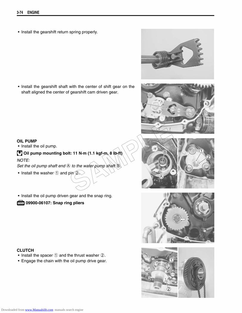
3-74 ENGINE
• Install the gearshift return spring properly.
• Install the gearshift shaft with the center of shift gear on theshaft aligned the center of gearshift cam driven gear.
OIL PUMP• Install the oil pump.
Oil pump mounting bolt: 11 N·m (1.1 kgf-m, 8 lb-ft)
NOTE:Set the oil pump shaft end A to the water pump shaft B.
• Install the washer 1 and pin 2.
• Install the oil pump driven gear and the snap ring.
09900-06107: Snap ring pliers
CLUTCH• Install the spacer 1 and the thrust washer 2.• Engage the chain with the oil pump drive gear.
SAMPLE
Downloaded from www.Manualslib.com manuals search engine
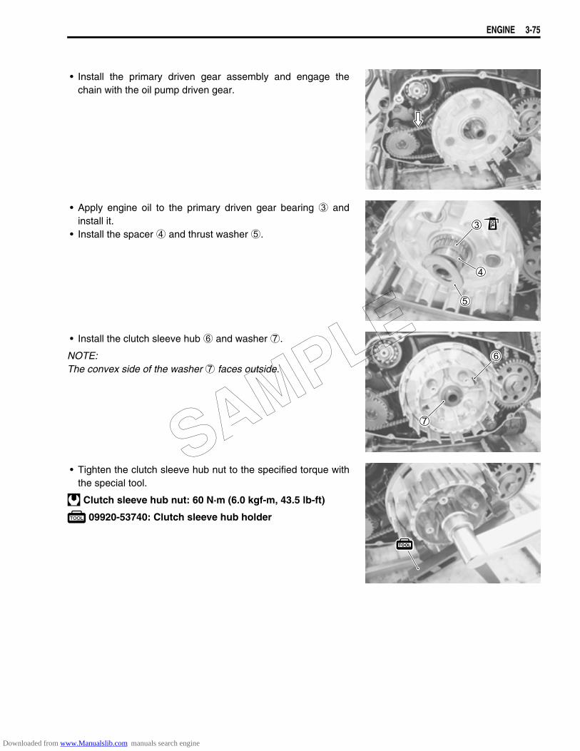
ENGINE 3-75
• Install the primary driven gear assembly and engage thechain with the oil pump driven gear.
• Apply engine oil to the primary driven gear bearing 3 andinstall it.
• Install the spacer 4 and thrust washer 5.
• Install the clutch sleeve hub 6 and washer 7.
NOTE:The convex side of the washer 7 faces outside.
• Tighten the clutch sleeve hub nut to the specified torque withthe special tool.
Clutch sleeve hub nut: 60 N·m (6.0 kgf-m, 43.5 lb-ft)
09920-53740: Clutch sleeve hub holder
SAMPLE
Downloaded from www.Manualslib.com manuals search engine
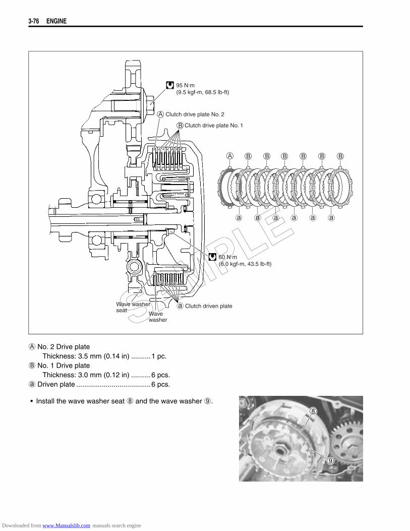
3-76 ENGINE
A No. 2 Drive plateThickness: 3.5 mm (0.14 in) ..........1 pc.
B No. 1 Drive plateThickness: 3.0 mm (0.12 in) ..........6 pcs.
a Driven plate ......................................6 pcs.
• Install the wave washer seat 8 and the wave washer 9.
95 N.m(9.5 kgf-m, 68.5 lb-ft)
60 N.m(6.0 kgf-m, 43.5 lb-ft)
Clutch drive plate No. 2
Clutch drive plate No. 1
Clutch driven plateWavewasher
Wave washerseat SAMPLE
Downloaded from www.Manualslib.com manuals search engine
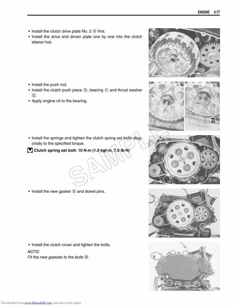
ENGINE 3-77
• Install the clutch drive plate No. 2 A first.• Install the drive and driven plate one by one into the clutch
sleeve hub.
• Install the push rod.• Install the clutch push piece 0, bearing A and thrust washerB.
• Apply engine oil to the bearing.
• Install the springs and tighten the clutch spring set bolts diag-onally to the specified torque.
Clutch spring set bolt: 10 N·m (1.0 kgf-m, 7.0 lb-ft)
• Install the new gasket C and dowel pins.
• Install the clutch cover and tighten the bolts.
NOTE:Fit the new gaskets to the bolts B.
SAMPLE
Downloaded from www.Manualslib.com manuals search engine
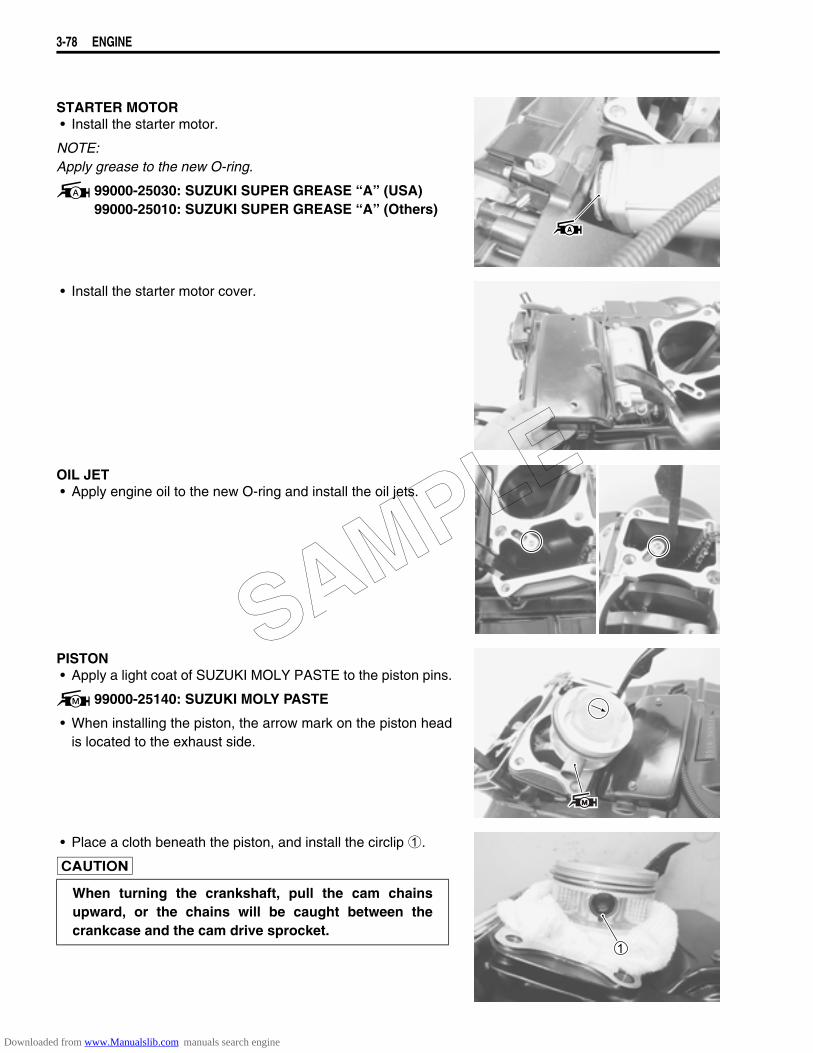
3-78 ENGINE
STARTER MOTOR• Install the starter motor.
NOTE:Apply grease to the new O-ring.
99000-25030: SUZUKI SUPER GREASE “A” (USA)99000-25010: SUZUKI SUPER GREASE “A” (Others)
• Install the starter motor cover.
OIL JET• Apply engine oil to the new O-ring and install the oil jets.
PISTON• Apply a light coat of SUZUKI MOLY PASTE to the piston pins.
99000-25140: SUZUKI MOLY PASTE
• When installing the piston, the arrow mark on the piston headis located to the exhaust side.
• Place a cloth beneath the piston, and install the circlip 1.
When turning the crankshaft, pull the cam chainsupward, or the chains will be caught between thecrankcase and the cam drive sprocket.
SAMPLE
Downloaded from www.Manualslib.com manuals search engine
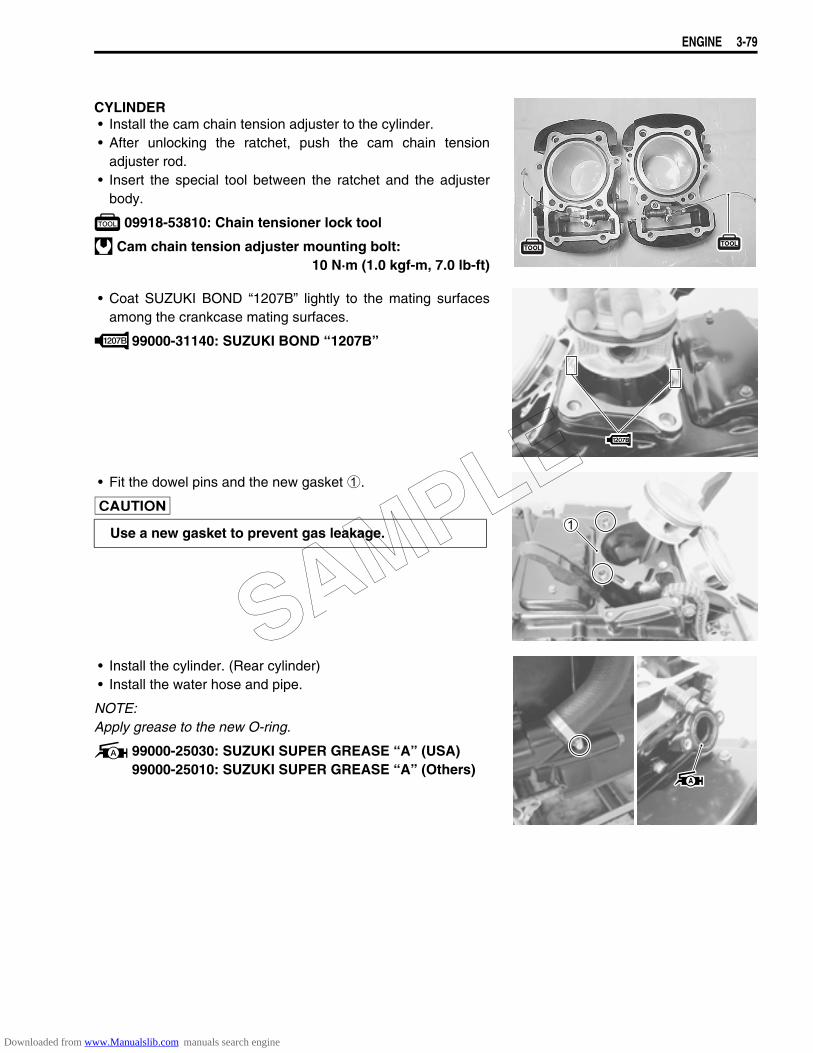
ENGINE 3-79
CYLINDER• Install the cam chain tension adjuster to the cylinder.• After unlocking the ratchet, push the cam chain tension
adjuster rod.• Insert the special tool between the ratchet and the adjuster
body.
09918-53810: Chain tensioner lock tool
Cam chain tension adjuster mounting bolt:10 N·m (1.0 kgf-m, 7.0 lb-ft)
• Coat SUZUKI BOND “1207B” lightly to the mating surfacesamong the crankcase mating surfaces.
99000-31140: SUZUKI BOND ‘‘1207B”
• Fit the dowel pins and the new gasket 1.
• Install the cylinder. (Rear cylinder)• Install the water hose and pipe.
NOTE:Apply grease to the new O-ring.
99000-25030: SUZUKI SUPER GREASE “A” (USA)99000-25010: SUZUKI SUPER GREASE “A” (Others)
Use a new gasket to prevent gas leakage.
SAMPLE
Downloaded from www.Manualslib.com manuals search engine
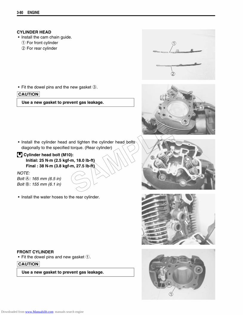
3-80 ENGINE
CYLINDER HEAD• Install the cam chain guide. 1 For front cylinder 2 For rear cylinder
• Fit the dowel pins and the new gasket 3.
• Install the cylinder head and tighten the cylinder head boltsdiagonally to the specified torque. (Rear cylinder)
Cylinder head bolt (M10):Initial: 25 N·m (2.5 kgf-m, 18.0 lb-ft)Final : 38 N·m (3.8 kgf-m, 27.5 lb-ft)
NOTE:Bolt A: 165 mm (6.5 in)Bolt B: 155 mm (6.1 in)
• Install the water hoses to the rear cylinder.
FRONT CYLINDER• Fit the dowel pins and new gasket 1.
Use a new gasket to prevent gas leakage.
Use a new gasket to prevent gas leakage.
SAMPLE
Downloaded from www.Manualslib.com manuals search engine
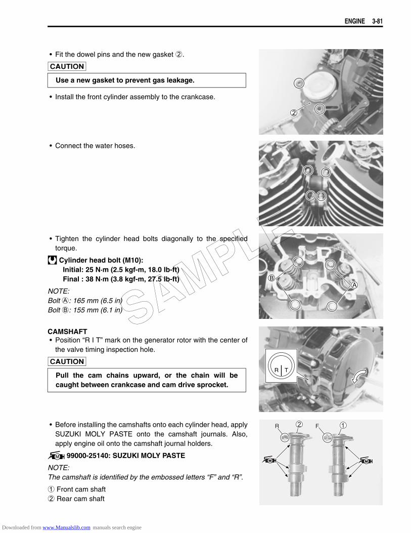
ENGINE 3-81
• Fit the dowel pins and the new gasket 2.
• Install the front cylinder assembly to the crankcase.
• Connect the water hoses.
• Tighten the cylinder head bolts diagonally to the specifiedtorque.
Cylinder head bolt (M10):Initial: 25 N·m (2.5 kgf-m, 18.0 lb-ft)Final : 38 N·m (3.8 kgf-m, 27.5 lb-ft)
NOTE:Bolt A: 165 mm (6.5 in)Bolt B: 155 mm (6.1 in)
CAMSHAFT• Position “R I T” mark on the generator rotor with the center of
the valve timing inspection hole.
• Before installing the camshafts onto each cylinder head, applySUZUKI MOLY PASTE onto the camshaft journals. Also,apply engine oil onto the camshaft journal holders.
99000-25140: SUZUKI MOLY PASTE
NOTE:The camshaft is identified by the embossed letters “F” and “R”.
1 Front cam shaft2 Rear cam shaft
Use a new gasket to prevent gas leakage.
Pull the cam chains upward, or the chain will becaught between crankcase and cam drive sprocket.
R T
RR FF
SAMPLE
Downloaded from www.Manualslib.com manuals search engine
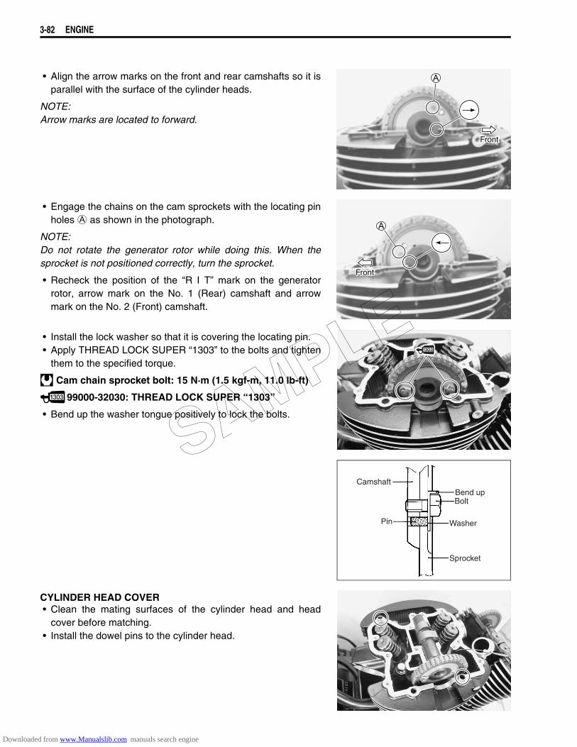
3-82 ENGINE
• Align the arrow marks on the front and rear camshafts so it isparallel with the surface of the cylinder heads.
NOTE:Arrow marks are located to forward.
• Engage the chains on the cam sprockets with the locating pinholes A as shown in the photograph.
NOTE:Do not rotate the generator rotor while doing this. When thesprocket is not positioned correctly, turn the sprocket.
• Recheck the position of the “R I T” mark on the generatorrotor, arrow mark on the No. 1 (Rear) camshaft and arrowmark on the No. 2 (Front) camshaft.
• Install the lock washer so that it is covering the locating pin.• Apply THREAD LOCK SUPER “1303” to the bolts and tighten
them to the specified torque.
Cam chain sprocket bolt: 15 N·m (1.5 kgf-m, 11.0 lb-ft)
99000-32030: THREAD LOCK SUPER “1303”
• Bend up the washer tongue positively to lock the bolts.
CYLINDER HEAD COVER• Clean the mating surfaces of the cylinder head and head
cover before matching.• Install the dowel pins to the cylinder head.
Front
Front
Camshaft
Pin
Bend upBolt
Washer
Sprocket
SAMPLE
Downloaded from www.Manualslib.com manuals search engine
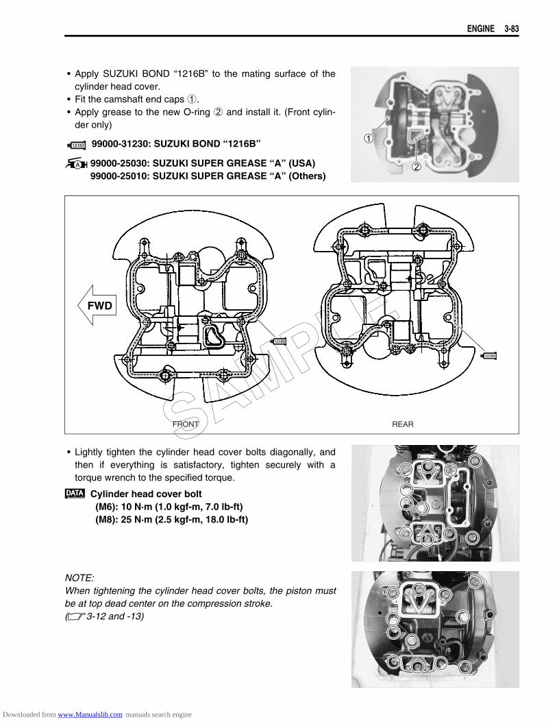
ENGINE 3-83
• Apply SUZUKI BOND “1216B” to the mating surface of thecylinder head cover.
• Fit the camshaft end caps 1.• Apply grease to the new O-ring 2 and install it. (Front cylin-
der only)
99000-31230: SUZUKI BOND “1216B”
99000-25030: SUZUKI SUPER GREASE “A” (USA)99000-25010: SUZUKI SUPER GREASE “A” (Others)
• Lightly tighten the cylinder head cover bolts diagonally, andthen if everything is satisfactory, tighten securely with atorque wrench to the specified torque.
Cylinder head cover bolt(M6): 10 N·m (1.0 kgf-m, 7.0 lb-ft)(M8): 25 N·m (2.5 kgf-m, 18.0 lb-ft)
NOTE:When tightening the cylinder head cover bolts, the piston mustbe at top dead center on the compression stroke. (3-12 and -13)
1216
1216
1216
FWD
FRONT REARSAMPLE
Downloaded from www.Manualslib.com manuals search engine

3-84 ENGINE
LOCATION OF CYLINDER HEAD COVER BOLT
NOTE:* Before installing the bolt 1, apply SUZUKI BOND “1207B” to the thread of the bolt.* Allen bolt: 2* Fit the gasket to the bolt 3.
• Remove the tensioner lock tools.
NOTE:Click sound is heard when the cam chain tension adjuster isreleased.
FRONT REAR
FWD
L: 40
L: 25
L: 20
L: 30
L: 20
L: 30
L: 250
L: 80
L: 250
L: Length Unit: mm
L: 30
L: 55
L: 30
L: 25
L: 20 L: 55
L: 30
L: 55
L: 55
L: 30
L: 25
L: 250 L: 250 L: 20
L: 30
L: 55
L: 30
L: 20
L: 25
L: 40
L: 20
L: 50 L: 30 L: 55L: 20
L: 30
L: 30 L: 50
L: 20
L: 30
SAMPLE
Downloaded from www.Manualslib.com manuals search engine
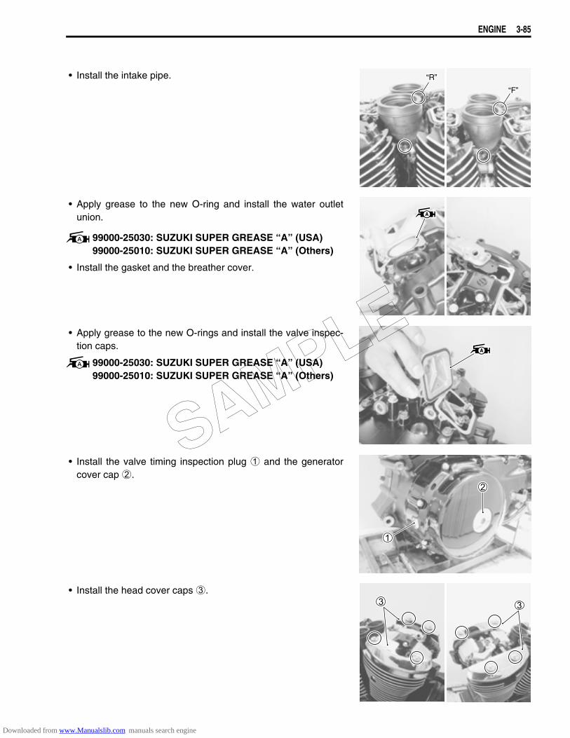
ENGINE 3-85
• Install the intake pipe.
• Apply grease to the new O-ring and install the water outletunion.
99000-25030: SUZUKI SUPER GREASE “A” (USA)99000-25010: SUZUKI SUPER GREASE “A” (Others)
• Install the gasket and the breather cover.
• Apply grease to the new O-rings and install the valve inspec-tion caps.
99000-25030: SUZUKI SUPER GREASE “A” (USA)99000-25010: SUZUKI SUPER GREASE “A” (Others)
• Install the valve timing inspection plug 1 and the generatorcover cap 2.
• Install the head cover caps 3.
“F”
“R”
SAMPLE
Downloaded from www.Manualslib.com manuals search engine
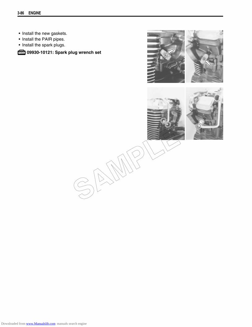
3-86 ENGINE
• Install the new gaskets.• Install the PAIR pipes.• Install the spark plugs.
09930-10121: Spark plug wrench set
SAMPLE
Downloaded from www.Manualslib.com manuals search engine

4
6
6
SHAFT DRIVE 4-1
CONTENTS
SHAFT DRIVE
SECONDARY BEVEL GEARS .......................................................................4- 2CONSTRUCTION ...................................................................................4- 2REMOVAL ..............................................................................................4- 4DISASSEMBLY ......................................................................................4- 4INSPECTION ..........................................................................................4- 5SECONDARY GEAR SHIMS ADJUSTMENT ........................................4- 6REASSEMBLY .......................................................................................4-10INSTALLATION ......................................................................................4-10
FINAL BEVEL GEARS ....................................................................................4-11CONSTRUCTION ...................................................................................4-11FINAL GEAR CASE REMOVAL ............................................................4-13FINAL GEAR CASE DISASSEMBLY ....................................................4-13FINAL GEAR SHIMS ADJUSTMENT ....................................................4-17FINAL GEAR CASE REASSEMBLY .....................................................4-21FINAL GEAR CASE INSTALLATION ....................................................4-25
SAMPLE
Downloaded from www.Manualslib.com manuals search engine
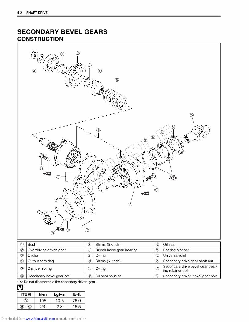
4-2 SHAFT DRIVE
SECONDARY BEVEL GEARSCONSTRUCTION
* A: Do not disassemble the secondary driven gear.
1 Bush 7 Shims (5 kinds) C Oil seal
2 Overdriving driven gear 8 Driven bevel gear bearing D Bearing stopper
3 Circlip 9 O-ring E Universal joint
4 Output cam dog 0 Shims (5 kinds) A Secondary drive gear shaft nut
5 Damper spring A O-ring BSecondary drive bevel gear bear-ing retainer bolt
6 Secondary bevel gear set B Oil seal housing C Secondary driven bevel gear bolt
ITEM N·m kgf-m lb-ftA 105 10.5 76.0
B, C 23 2.3 16.5
*A
SAMPLE
Downloaded from www.Manualslib.com manuals search engine

SHAFT DRIVE 4-3
Standard clearance A: 1.00 mm (0.039 in)B: 1.00 mm (0.039 in)
Adjust backlash by selecting shims. (Use two pieces of shims.)Shim 1 size table
The shims 1 are available as a set (24945-05810).
Shim 2 size table
The shims 2 are available as a set (24935-38810).
Part number Thickness24945-05A-0A0 0.30 mm (0.012 in)24945-05A-0B0 0.35 mm (0.014 in)24945-05A-0C0 0.40 mm (0.016 in)24945-05A-0D0 0.50 mm (0.020 in)24945-05A-0E0 0.60 mm (0.024 in)
Part number Thickness24935-38A01-030 0.30 mm (0.012 in)24935-38A01-035 0.35 mm (0.014 in)24935-38A01-040 0.40 mm (0.016 in)24935-38A01-050 0.50 mm (0.020 in)24935-38A01-060 0.60 mm (0.024 in)
Backlash 0.05 – 0.32 mm(0.002 – 0.013 in)
SAMPLE
Downloaded from www.Manualslib.com manuals search engine
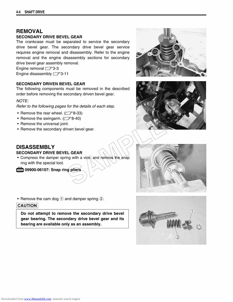
4-4 SHAFT DRIVE
REMOVALSECONDARY DRIVE BEVEL GEARThe crankcase must be separated to service the secondarydrive bevel gear. The secondary drive bevel gear servicerequires engine removal and disassembly. Refer to the engineremoval and the engine disassembly sections for secondarydrive bevel gear assembly removal.Engine removal 3-3Engine disassembly 3-11
SECONDARY DRIVEN BEVEL GEARThe following components must be removed in the describedorder before removing the secondary driven bevel gear.
NOTE:Refer to the following pages for the details of each step.
• Remove the rear wheel. (8-33)• Remove the swingarm. (8-40)• Remove the universal joint.• Remove the secondary driven bevel gear.
DISASSEMBLYSECONDARY DRIVE BEVEL GEAR• Compress the damper spring with a vice, and remove the snap
ring with the special tool.
09900-06107: Snap ring pliers
• Remove the cam dog 1 and damper spring 2.
Do not attempt to remove the secondary drive bevelgear bearing. The secondary drive bevel gear and itsbearing are available only as an assembly.
SAMPLE
Downloaded from www.Manualslib.com manuals search engine
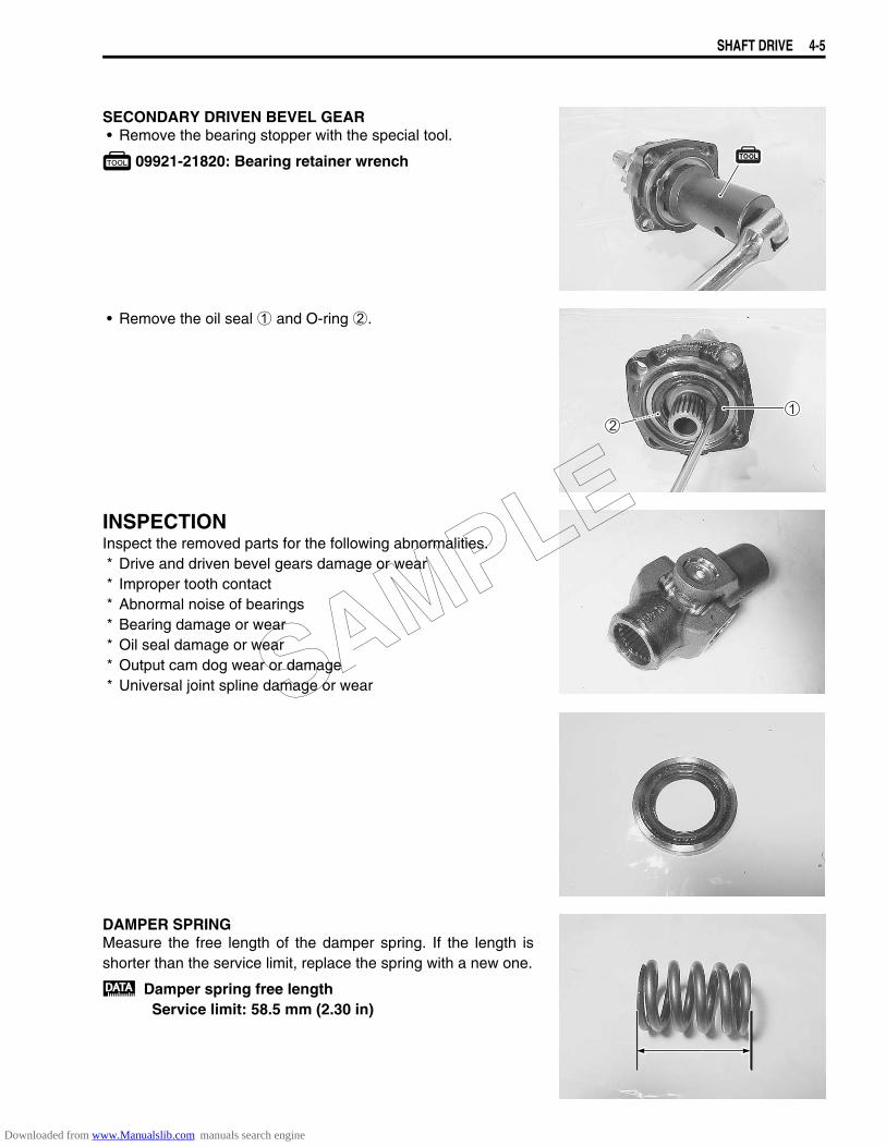
SHAFT DRIVE 4-5
SECONDARY DRIVEN BEVEL GEAR• Remove the bearing stopper with the special tool.
09921-21820: Bearing retainer wrench
• Remove the oil seal 1 and O-ring 2.
INSPECTIONInspect the removed parts for the following abnormalities.* Drive and driven bevel gears damage or wear* Improper tooth contact* Abnormal noise of bearings* Bearing damage or wear* Oil seal damage or wear* Output cam dog wear or damage* Universal joint spline damage or wear
DAMPER SPRINGMeasure the free length of the damper spring. If the length isshorter than the service limit, replace the spring with a new one.
Damper spring free lengthService limit: 58.5 mm (2.30 in)
SAMPLE
Downloaded from www.Manualslib.com manuals search engine

4-6 SHAFT DRIVE
SECONDARY GEAR SHIMS ADJUSTMENTBACKLASH• Install the secondary drive bevel gear assembly with the
removed shims and tighten the bolts to the specified torque.
Secondary drive bevel gear bearing retainer bolt:23 N·m (2.3 kgf-m, 16.5 lb-ft)
NOTE:When replacing the secondary drive and driven bevel gears,install the removed shims to the secondary drive bevel gearassembly and tighten the bolts to the specified torque.
• Install the secondary driven bevel gear assembly withremoved shims, the driven bevel gear bearing and secondarygear case.
NOTE:Do not install the O-ring on the driven gear housing at this stage.O-ring is installed after backlash and tooth contact are correct.
• Tighten the secondary bevel gear case bolts and secondarydriven bevel gear bolts to the specified torque.
Secondary bevel gear case bolt:22 N·m (2.2 kgf-m, 16.0 lb-ft)
Secondary driven bevel gear bolt:23 N·m (2.3 kgf-m, 16.5 lb-ft)
NOTE:* Hollow portion A of the secondary driven bevel gear assembly
faces inside.* It is not necessary to apply SUZUKI BOND “1207B” to the
matching surface at this stage.
SAMPLE
Downloaded from www.Manualslib.com manuals search engine
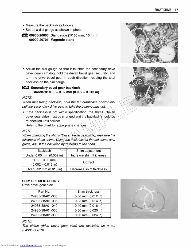
SHAFT DRIVE 4-7
• Measure the backlash as follows.• Set-up a dial gauge as shown in photo.
09900-20606: Dial gauge (1/100 mm, 10 mm)09900-20701: Magnetic stand
• Adjust the dial gauge so that it touches the secondary drivebevel gear cam dog; hold the driven bevel gear securely, andturn the drive bevel gear in each direction, reading the totalbacklash on the dial gauge.
Secondary bevel gear backlashStandard: 0.05 – 0.32 mm (0.002 – 0.013 in)
NOTE:When measuring backlash, hold the left crankcase horizontallypull the secondary drive gear to take the bearing play out.
• If the backlash is not within specification, the shims (Drivenbevel gear side) must be changed and the backlash should bere-checked until correct. Refer to the chart for appropriate changes.
NOTE:When changing the shims (Driven bevel gear side), measure thethickness of old shims. Using the thickness of the old shims as aguide, adjust the backlash by referring to the chart.
SHIM SPECIFICATIONSDrive bevel gear side
NOTE:The shims (drive bevel gear side) are available as a set(24935-38810).
Backlash Shim adjustmentUnder 0.05 mm (0.002 in) Increase shim thickness
0.05 – 0.32 mm(0.002 – 0.013 in)
Correct
Over 0.32 mm (0.013 in) Decrease shim thickness
Part No. Shim thickness24935-38A01-030 0.30 mm (0.012 in)24935-38A01-035 0.35 mm (0.014 in)24935-38A01-040 0.40 mm (0.016 in)24935-38A01-050 0.50 mm (0.020 in)24935-38A01-060 0.60 mm (0.024 in)
SAMPLE
Downloaded from www.Manualslib.com manuals search engine
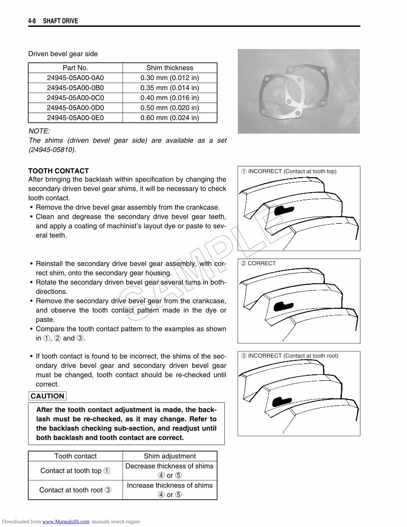
4-8 SHAFT DRIVE
Driven bevel gear side
NOTE:The shims (driven bevel gear side) are available as a set(24945-05810).
TOOTH CONTACTAfter bringing the backlash within specification by changing thesecondary driven bevel gear shims, it will be necessary to checktooth contact.• Remove the drive bevel gear assembly from the crankcase.• Clean and degrease the secondary drive bevel gear teeth,
and apply a coating of machinist’s layout dye or paste to sev-eral teeth.
• Reinstall the secondary drive bevel gear assembly, with cor-rect shim, onto the secondary gear housing.
• Rotate the secondary driven bevel gear several turns in both-directions.
• Remove the secondary drive bevel gear from the crankcase,and observe the tooth contact pattern made in the dye orpaste.
• Compare the tooth contact pattern to the examples as shownin 1, 2 and 3.
• If tooth contact is found to be incorrect, the shims of the sec-ondary drive bevel gear and secondary driven bevel gearmust be changed, tooth contact should be re-checked untilcorrect.
Part No. Shim thickness24945-05A00-0A0 0.30 mm (0.012 in)24945-05A00-0B0 0.35 mm (0.014 in)24945-05A00-0C0 0.40 mm (0.016 in)24945-05A00-0D0 0.50 mm (0.020 in)24945-05A00-0E0 0.60 mm (0.024 in)
1 INCORRECT (Contact at tooth top)
2 CORRECT
After the tooth contact adjustment is made, the back-lash must be re-checked, as it may change. Refer tothe backlash checking sub-section, and readjust untilboth backlash and tooth contact are correct.
Tooth contact Shim adjustment
Contact at tooth top 1Decrease thickness of shims
4 or 5
Contact at tooth root 3Increase thickness of shims
4 or 5
3 INCORRECT (Contact at tooth root)
SAMPLE
Downloaded from www.Manualslib.com manuals search engine
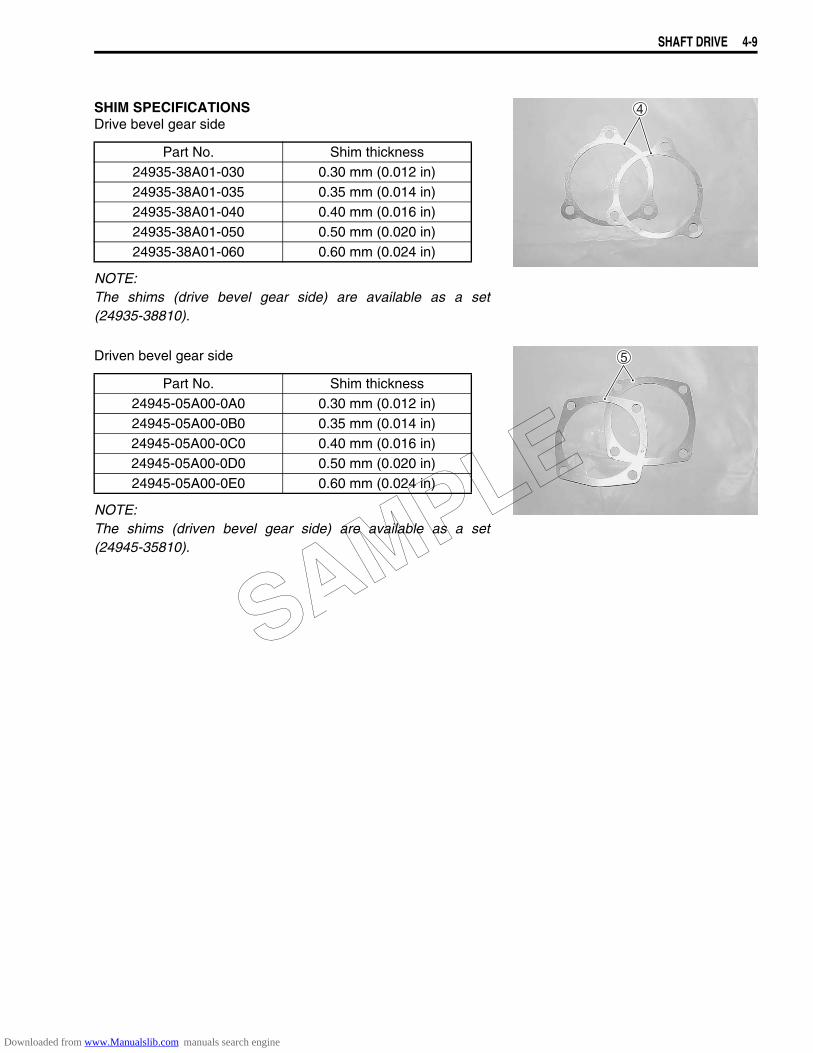
SHAFT DRIVE 4-9
SHIM SPECIFICATIONSDrive bevel gear side
NOTE:The shims (drive bevel gear side) are available as a set(24935-38810).
Driven bevel gear side
NOTE:The shims (driven bevel gear side) are available as a set(24945-35810).
Part No. Shim thickness24935-38A01-030 0.30 mm (0.012 in)24935-38A01-035 0.35 mm (0.014 in)24935-38A01-040 0.40 mm (0.016 in)24935-38A01-050 0.50 mm (0.020 in)24935-38A01-060 0.60 mm (0.024 in)
Part No. Shim thickness24945-05A00-0A0 0.30 mm (0.012 in)24945-05A00-0B0 0.35 mm (0.014 in)24945-05A00-0C0 0.40 mm (0.016 in)24945-05A00-0D0 0.50 mm (0.020 in)24945-05A00-0E0 0.60 mm (0.024 in)
SAMPLE
Downloaded from www.Manualslib.com manuals search engine
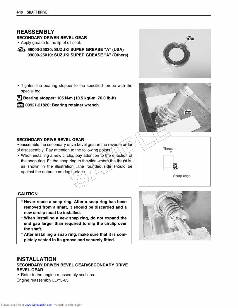
4-10 SHAFT DRIVE
REASSEMBLYSECONDARY DRIVEN BEVEL GEAR• Apply grease to the lip of oil seal.
99000-25030: SUZUKI SUPER GREASE “A” (USA)99000-25010: SUZUKI SUPER GREASE “A” (Others)
• Tighten the bearing stopper to the specified torque with thespecial tool.
Bearing stopper: 105 N·m (10.5 kgf-m, 76.0 lb-ft)
09921-21820: Bearing retainer wrench
SECONDARY DRIVE BEVEL GEARReassemble the secondary drive bevel gear in the reverse orderof disassembly. Pay attention to the following points.• When installing a new circlip, pay attention to the direction of
the snap ring. Fit the snap ring to the side where the thrust is,as shown in the illustration. The rounded side should beagainst the output cam dog surface.
INSTALLATIONSECONDARY DRIVEN BEVEL GEAR/SECONDARY DRIVE BEVEL GEAR• Refer to the engine reassembly sections.Engine reassembly 3-65
Thrust
Sharp edge
* Never reuse a snap ring. After a snap ring has beenremoved from a shaft, it should be discarded and anew circlip must be installed.
* When installing a new snap ring, do not expand theend gap larger than required to slip the circlip overthe shaft.
* After installing a snap ring, make sure that it is com-pletely seated in its groove and securely fitted.
SAMPLE
Downloaded from www.Manualslib.com manuals search engine
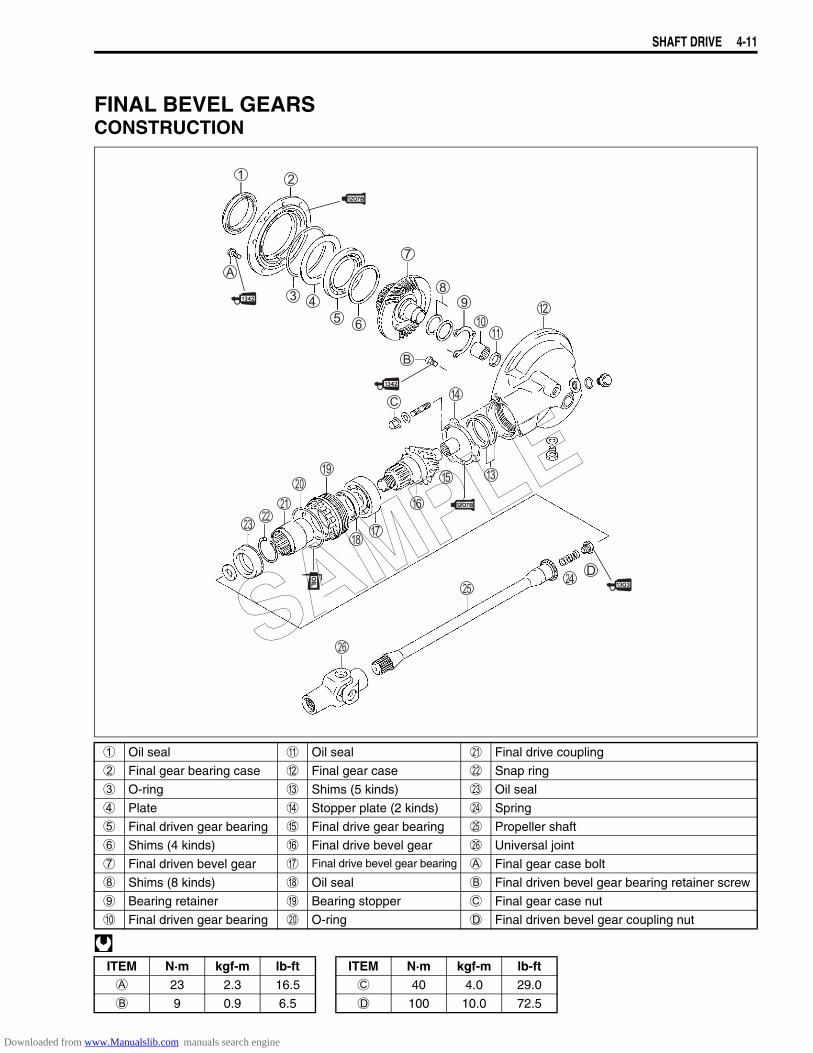
SHAFT DRIVE 4-11
FINAL BEVEL GEARSCONSTRUCTION
1 Oil seal A Oil seal K Final drive coupling
2 Final gear bearing case B Final gear case L Snap ring
3 O-ring C Shims (5 kinds) M Oil seal
4 Plate D Stopper plate (2 kinds) N Spring
5 Final driven gear bearing E Final drive gear bearing O Propeller shaft
6 Shims (4 kinds) F Final drive bevel gear P Universal joint
7 Final driven bevel gear G Final drive bevel gear bearing A Final gear case bolt
8 Shims (8 kinds) H Oil seal B Final driven bevel gear bearing retainer screw
9 Bearing retainer I Bearing stopper C Final gear case nut
0 Final driven gear bearing J O-ring D Final driven bevel gear coupling nut
ITEM N·m kgf-m lb-ft ITEM N·m kgf-m lb-ftA 23 2.3 16.5 C 40 4.0 29.0
B 9 0.9 6.5 D 100 10.0 72.5
SAMPLE
Downloaded from www.Manualslib.com manuals search engine
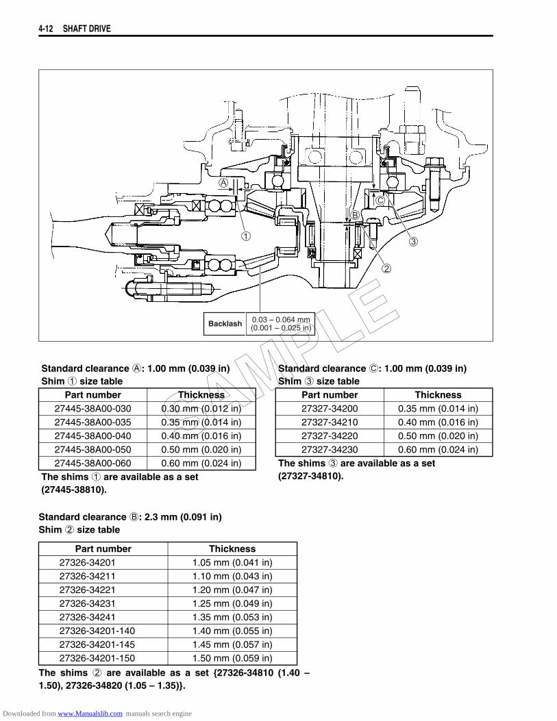
4-12 SHAFT DRIVE
Standard clearance B: 2.3 mm (0.091 in)Shim 2 size table
The shims 2 are available as a set 27326-34810 (1.40 –1.50), 27326-34820 (1.05 – 1.35).
Standard clearance A: 1.00 mm (0.039 in)Shim 1 size table
Standard clearance C: 1.00 mm (0.039 in)Shim 3 size table
Part number Thickness Part number Thickness27445-38A00-030 0.30 mm (0.012 in) 27327-34200 0.35 mm (0.014 in)27445-38A00-035 0.35 mm (0.014 in) 27327-34210 0.40 mm (0.016 in)27445-38A00-040 0.40 mm (0.016 in) 27327-34220 0.50 mm (0.020 in)27445-38A00-050 0.50 mm (0.020 in) 27327-34230 0.60 mm (0.024 in)27445-38A00-060 0.60 mm (0.024 in) The shims 3 are available as a set
(27327-34810).The shims 1 are available as a set (27445-38810).
Part number Thickness27326-34201 1.05 mm (0.041 in)27326-34211 1.10 mm (0.043 in)27326-34221 1.20 mm (0.047 in)27326-34231 1.25 mm (0.049 in)27326-34241 1.35 mm (0.053 in)27326-34201-140 1.40 mm (0.055 in)27326-34201-145 1.45 mm (0.057 in)27326-34201-150 1.50 mm (0.059 in)
Backlash 0.03 – 0.064 mm(0.001 – 0.025 in)
SAMPLE
Downloaded from www.Manualslib.com manuals search engine
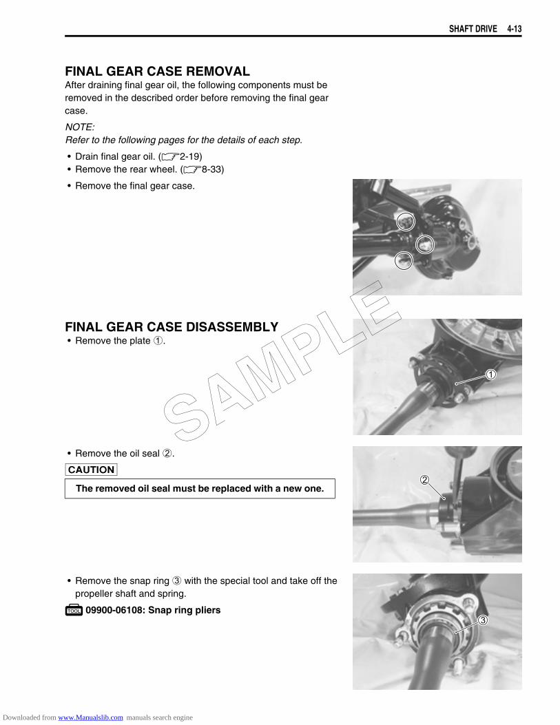
SHAFT DRIVE 4-13
FINAL GEAR CASE REMOVALAfter draining final gear oil, the following components must beremoved in the described order before removing the final gearcase.
NOTE:Refer to the following pages for the details of each step.
• Drain final gear oil. (2-19)• Remove the rear wheel. (8-33)
• Remove the final gear case.
FINAL GEAR CASE DISASSEMBLY• Remove the plate 1.
• Remove the oil seal 2.
• Remove the snap ring 3 with the special tool and take off thepropeller shaft and spring.
09900-06108: Snap ring pliers
The removed oil seal must be replaced with a new one.
SAMPLE
Downloaded from www.Manualslib.com manuals search engine
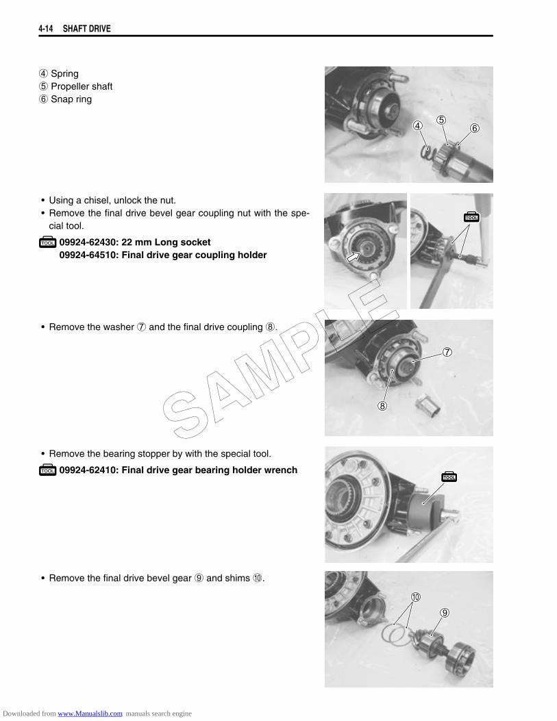
4-14 SHAFT DRIVE
4 Spring5 Propeller shaft6 Snap ring
• Using a chisel, unlock the nut.• Remove the final drive bevel gear coupling nut with the spe-
cial tool.
09924-62430: 22 mm Long socket09924-64510: Final drive gear coupling holder
• Remove the washer 7 and the final drive coupling 8.
• Remove the bearing stopper by with the special tool.
09924-62410: Final drive gear bearing holder wrench
• Remove the final drive bevel gear 9 and shims 0.
SAMPLE
Downloaded from www.Manualslib.com manuals search engine

SHAFT DRIVE 4-15
• Remove the bearing from the final drive bevel gear with thespecial tool.
09913-50121: Bearing puller
NOTE:If no abnormal noise, the bearing removal is not necessary.
• Remove the final gear bearing case bolts.
• Remove the final gear bearing case from the final gear case,by using two 5 mm screws.
• Remove the final driven bevel gear A and shims B.
• Remove the oil seal with the special tool.
09913-50121: Oil seal remover
NOTE:If no oil leakage, the oil seal removal is not necessary.
The removed bearing must be replaced with a new one.
SAMPLE
Downloaded from www.Manualslib.com manuals search engine
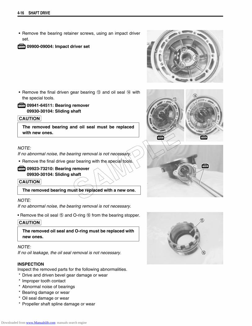
4-16 SHAFT DRIVE
• Remove the bearing retainer screws, using an impact driverset.
09900-09004: Impact driver set
• Remove the final driven gear bearing C and oil seal D withthe special tools.
09941-64511: Bearing remover09930-30104: Sliding shaft
NOTE:If no abnormal noise, the bearing removal is not necessary.
• Remove the final drive gear bearing with the special tools.
09923-73210: Bearing remover09930-30104: Sliding shaft
NOTE:If no abnormal noise, the bearing removal is not necessary.
• Remove the oil seal E and O-ring F from the bearing stopper.
NOTE:If no oil leakage, the oil seal removal is not necessary.
INSPECTIONInspect the removed parts for the following abnormalities.* Drive and driven bevel gear damage or wear* Improper tooth contact* Abnormal noise of bearings* Bearing damage or wear* Oil seal damage or wear* Propeller shaft spline damage or wear
The removed bearing and oil seal must be replacedwith new ones.
The removed bearing must be replaced with a new one.
The removed oil seal and O-ring must be replaced withnew ones.
SAMPLE
Downloaded from www.Manualslib.com manuals search engine
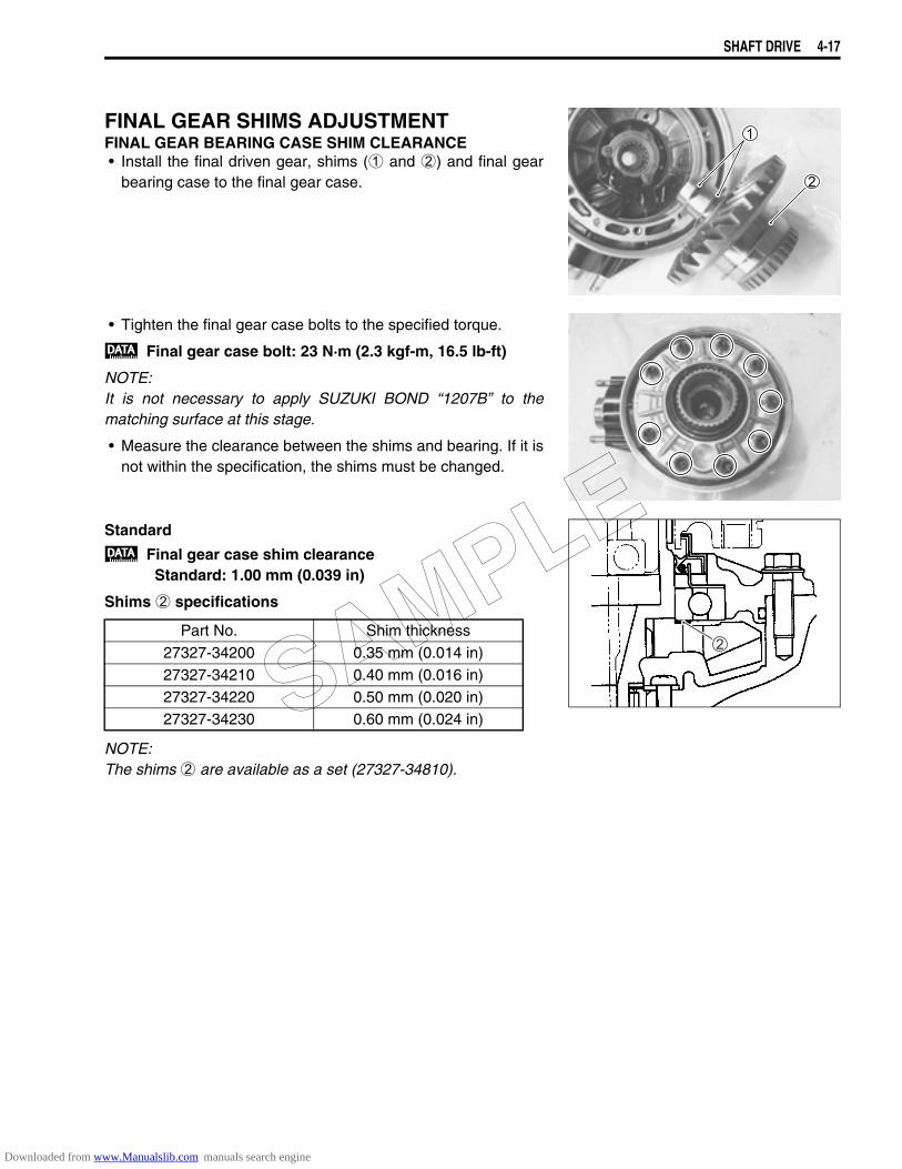
SHAFT DRIVE 4-17
FINAL GEAR SHIMS ADJUSTMENTFINAL GEAR BEARING CASE SHIM CLEARANCE• Install the final driven gear, shims (1 and 2) and final gear
bearing case to the final gear case.
• Tighten the final gear case bolts to the specified torque.
Final gear case bolt: 23 N·m (2.3 kgf-m, 16.5 lb-ft)
NOTE:It is not necessary to apply SUZUKI BOND “1207B” to thematching surface at this stage.
• Measure the clearance between the shims and bearing. If it isnot within the specification, the shims must be changed.
Standard
Final gear case shim clearanceStandard: 1.00 mm (0.039 in)
Shims 2 specifications
NOTE:The shims 2 are available as a set (27327-34810).
Part No. Shim thickness27327-34200 0.35 mm (0.014 in)27327-34210 0.40 mm (0.016 in)27327-34220 0.50 mm (0.020 in)27327-34230 0.60 mm (0.024 in)SAMPLE
Downloaded from www.Manualslib.com manuals search engine
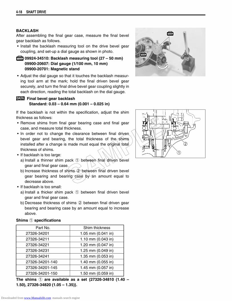
4-18 SHAFT DRIVE
BACKLASHAfter assembling the final gear case, measure the final bevelgear backlash as follows.• Install the backlash measuring tool on the drive bevel gear
coupling, and set-up a dial gauge as shown in photo.
09924-34510: Backlash measuring tool (27 – 50 mm)09900-20607: Dial gauge (1/100 mm, 10 mm)09900-20701: Magnetic stand
• Adjust the dial gauge so that it touches the backlash measur-ing tool arm at the mark; hold the final driven bevel gearsecurely, and turn the final drive bevel gear coupling slightly ineach direction, reading the total backlash on the dial gauge.
Final bevel gear backlashStandard: 0.03 – 0.64 mm (0.001 – 0.025 in)
If the backlash is not within the specification, adjust the shimthickness as follows:• Remove shims from final gear bearing case and final gear
case, and measure total thickness.• In order not to change the clearance between final driven
bevel gear and bearing, the total thickness of the shimsinstalled after a change is made must equal the original totalthickness of shims.
• If backlash is too large:a) Install a thinner shim pack 1 between final driven bevel
gear and final gear case.b) Increase thickness of shims 2 between final driven bevel
gear bearing and bearing case by an amount equal todecrease above.
• If backlash is too small:a) Install a thicker shim pack 1 between final driven bevel
gear and final gear case.b) Decrease thickness of shims 2 between final driven gear
bearing and bearing case by an amount equal to increaseabove.
Shims 1 specifications
The shims 1 are available as a set 27326-34810 (1.40 –1.50), 27326-34820 (1.05 – 1.35).
Part No. Shim thickness27326-34201 1.05 mm (0.041 in)27326-34211 1.10 mm (0.043 in)27326-34221 1.20 mm (0.047 in)27326-34231 1.25 mm (0.049 in)27326-34241 1.35 mm (0.053 in)27326-34201-140 1.40 mm (0.055 in)27326-34201-145 1.45 mm (0.057 in)27326-34201-150 1.50 mm (0.059 in)
SAMPLE
Downloaded from www.Manualslib.com manuals search engine
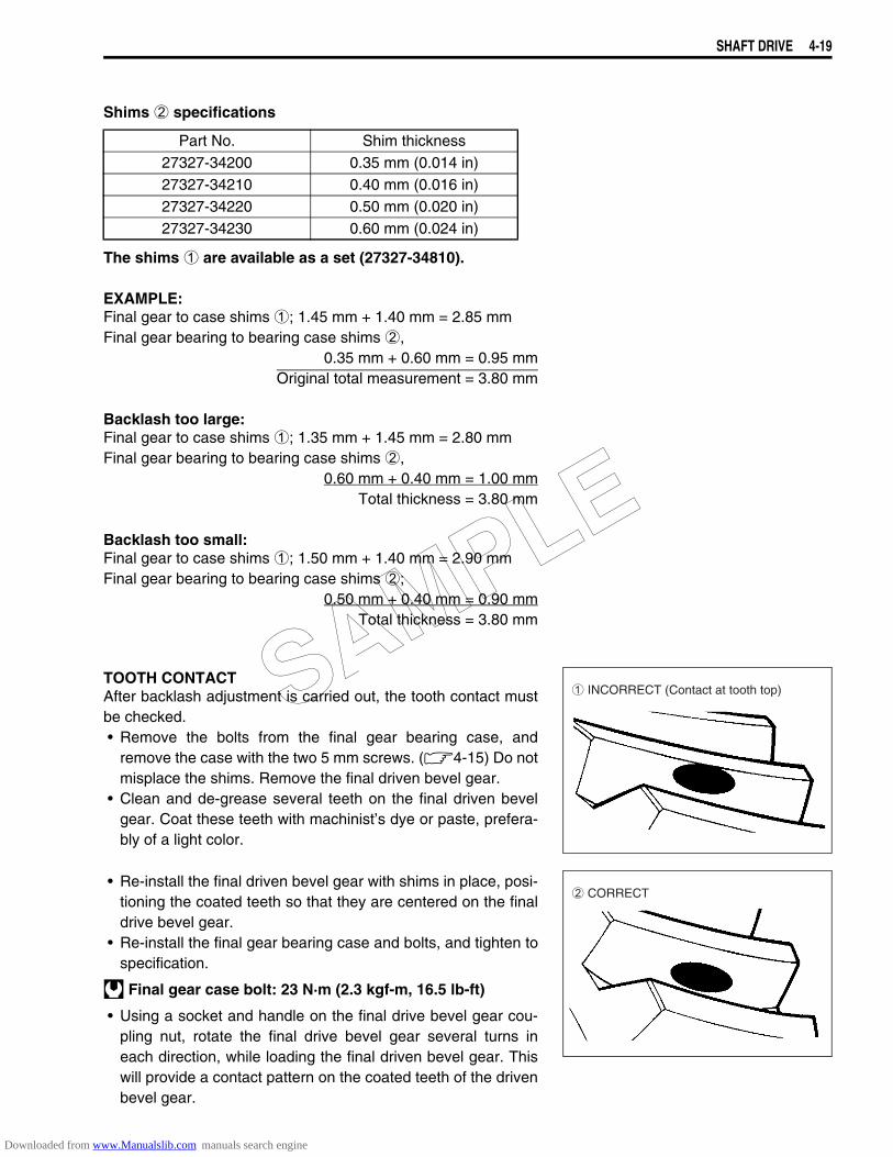
SHAFT DRIVE 4-19
Shims 2 specifications
The shims 1 are available as a set (27327-34810).
EXAMPLE:Final gear to case shims 1; 1.45 mm + 1.40 mm = 2.85 mmFinal gear bearing to bearing case shims 2,
0.35 mm + 0.60 mm = 0.95 mmOriginal total measurement = 3.80 mm
Backlash too large:Final gear to case shims 1; 1.35 mm + 1.45 mm = 2.80 mmFinal gear bearing to bearing case shims 2,
0.60 mm + 0.40 mm = 1.00 mmTotal thickness = 3.80 mm
Backlash too small:Final gear to case shims 1; 1.50 mm + 1.40 mm = 2.90 mmFinal gear bearing to bearing case shims 2;
0.50 mm + 0.40 mm = 0.90 mmTotal thickness = 3.80 mm
TOOTH CONTACTAfter backlash adjustment is carried out, the tooth contact mustbe checked.• Remove the bolts from the final gear bearing case, and
remove the case with the two 5 mm screws. (4-15) Do notmisplace the shims. Remove the final driven bevel gear.
• Clean and de-grease several teeth on the final driven bevelgear. Coat these teeth with machinist’s dye or paste, prefera-bly of a light color.
• Re-install the final driven bevel gear with shims in place, posi-tioning the coated teeth so that they are centered on the finaldrive bevel gear.
• Re-install the final gear bearing case and bolts, and tighten tospecification.
Final gear case bolt: 23 N·m (2.3 kgf-m, 16.5 lb-ft)
• Using a socket and handle on the final drive bevel gear cou-pling nut, rotate the final drive bevel gear several turns ineach direction, while loading the final driven bevel gear. Thiswill provide a contact pattern on the coated teeth of the drivenbevel gear.
Part No. Shim thickness27327-34200 0.35 mm (0.014 in)27327-34210 0.40 mm (0.016 in)27327-34220 0.50 mm (0.020 in)27327-34230 0.60 mm (0.024 in)
1 INCORRECT (Contact at tooth top)
2 CORRECT
SAMPLE
Downloaded from www.Manualslib.com manuals search engine
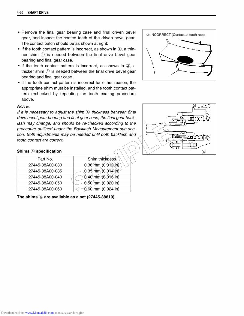
4-20 SHAFT DRIVE
• Remove the final gear bearing case and final driven bevelgear, and inspect the coated teeth of the driven bevel gear.The contact patch should be as shown at right:
• If the tooth contact pattern is incorrect, as shown in 1, a thin-ner shim 4 is needed between the final drive bevel gearbearing and final gear case.
• If the tooth contact pattern is incorrect, as shown in 3, athicker shim 4 is needed between the final drive bevel gearbearing and final gear case.
• If the tooth contact pattern is incorrect for either reason, theappropriate shim must be installed, and the tooth contact pat-tern rechecked by repeating the tooth coating procedureabove.
NOTE:If it is necessary to adjust the shim 4 thickness between finaldrive bevel gear bearing and final gear case, the final gear back-lash may change, and should be re-checked according to theprocedure outlined under the Backlash Measurement sub-sec-tion. Both adjustments may be needed until both backlash andtooth contact are correct.
Shims 4 specification
The shims 4 are available as a set (27445-38810).
Part No. Shim thickness27445-38A00-030 0.30 mm (0.012 in)27445-38A00-035 0.35 mm (0.014 in)27445-38A00-040 0.40 mm (0.016 in)27445-38A00-050 0.50 mm (0.020 in)27445-38A00-060 0.60 mm (0.024 in)
3 INCORRECT (Contact at tooth root)
SAMPLE
Downloaded from www.Manualslib.com manuals search engine
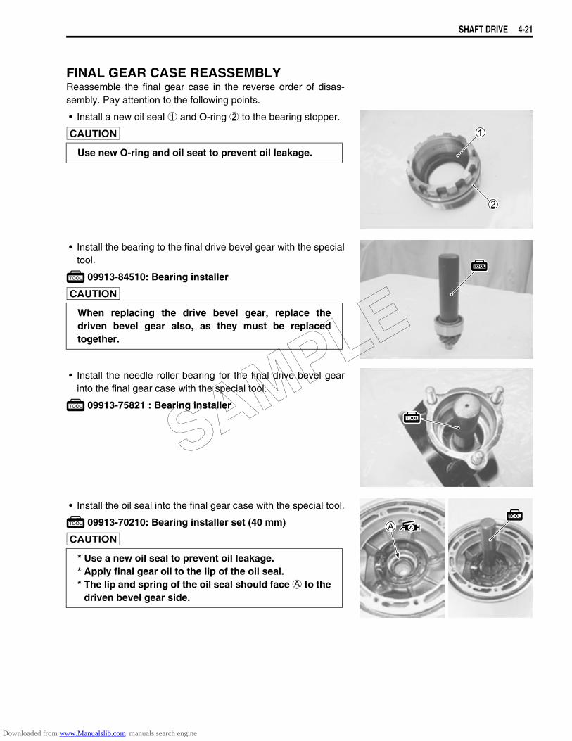
SHAFT DRIVE 4-21
FINAL GEAR CASE REASSEMBLYReassemble the final gear case in the reverse order of disas-sembly. Pay attention to the following points.
• Install a new oil seal 1 and O-ring 2 to the bearing stopper.
• Install the bearing to the final drive bevel gear with the specialtool.
09913-84510: Bearing installer
• Install the needle roller bearing for the final drive bevel gearinto the final gear case with the special tool.
09913-75821 : Bearing installer
• Install the oil seal into the final gear case with the special tool.
09913-70210: Bearing installer set (40 mm)
Use new O-ring and oil seat to prevent oil leakage.
When replacing the drive bevel gear, replace thedriven bevel gear also, as they must be replacedtogether.
* Use a new oil seal to prevent oil leakage.* Apply final gear oil to the lip of the oil seal.* The lip and spring of the oil seal should face A to the
driven bevel gear side.
SAMPLE
Downloaded from www.Manualslib.com manuals search engine
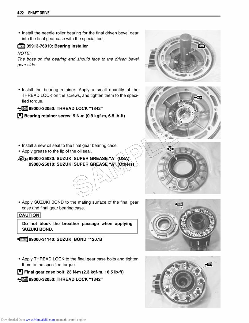
4-22 SHAFT DRIVE
• Install the needle roller bearing for the final driven bevel gearinto the final gear case with the special tool.
09913-76010: Bearing installer
NOTE:The boss on the bearing end should face to the driven bevelgear side.
• Install the bearing retainer. Apply a small quantity of theTHREAD LOCK on the screws, and tighten them to the speci-fied torque.
99000-32050: THREAD LOCK “1342”
Bearing retainer screw: 9 N·m (0.9 kgf-m, 6.5 lb-ft)
• Install a new oil seal to the final gear bearing case.• Apply grease to the lip of the oil seal.
99000-25030: SUZUKI SUPER GREASE “A” (USA)99000-25010: SUZUKI SUPER GREASE “A” (Others)
• Apply SUZUKI BOND to the mating surface of the final gearcase and final gear bearing case.
99000-31140: SUZUKI BOND “1207B”
• Apply THREAD LOCK to the final gear case bolts and tightenthem to the specified torque.
Final gear case bolt: 23 N·m (2.3 kgf-m, 16.5 lb-ft)
99000-32050: THREAD LOCK “1342”
Do not block the breather passage when applyingSUZUKI BOND.
SAMPLE
Downloaded from www.Manualslib.com manuals search engine
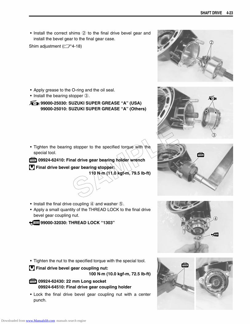
SHAFT DRIVE 4-23
• Install the correct shims 2 to the final drive bevel gear andinstall the bevel gear to the final gear case.
Shim adjustment (4-18)
• Apply grease to the O-ring and the oil seal.• Install the bearing stopper 3.
99000-25030: SUZUKI SUPER GREASE “A” (USA)99000-25010: SUZUKI SUPER GREASE “A” (Others)
• Tighten the bearing stopper to the specified torque with thespecial tool.
09924-62410: Final drive gear bearing holder wrench
Final drive bevel gear bearing stopper: 110 N·m (11.0 kgf-m, 79.5 lb-ft)
• Install the final drive coupling 4 and washer 5.• Apply a small quantity of the THREAD LOCK to the final drive
bevel gear coupling nut.
99000-32030: THREAD LOCK “1303”
• Tighten the nut to the specified torque with the special tool.
Final drive bevel gear coupling nut:100 N·m (10.0 kgf-m, 72.5 lb-ft)
09924-62430: 22 mm Long socket09924-64510: Final drive gear coupling holder
• Lock the final drive bevel gear coupling nut with a centerpunch.
SAMPLE
Downloaded from www.Manualslib.com manuals search engine
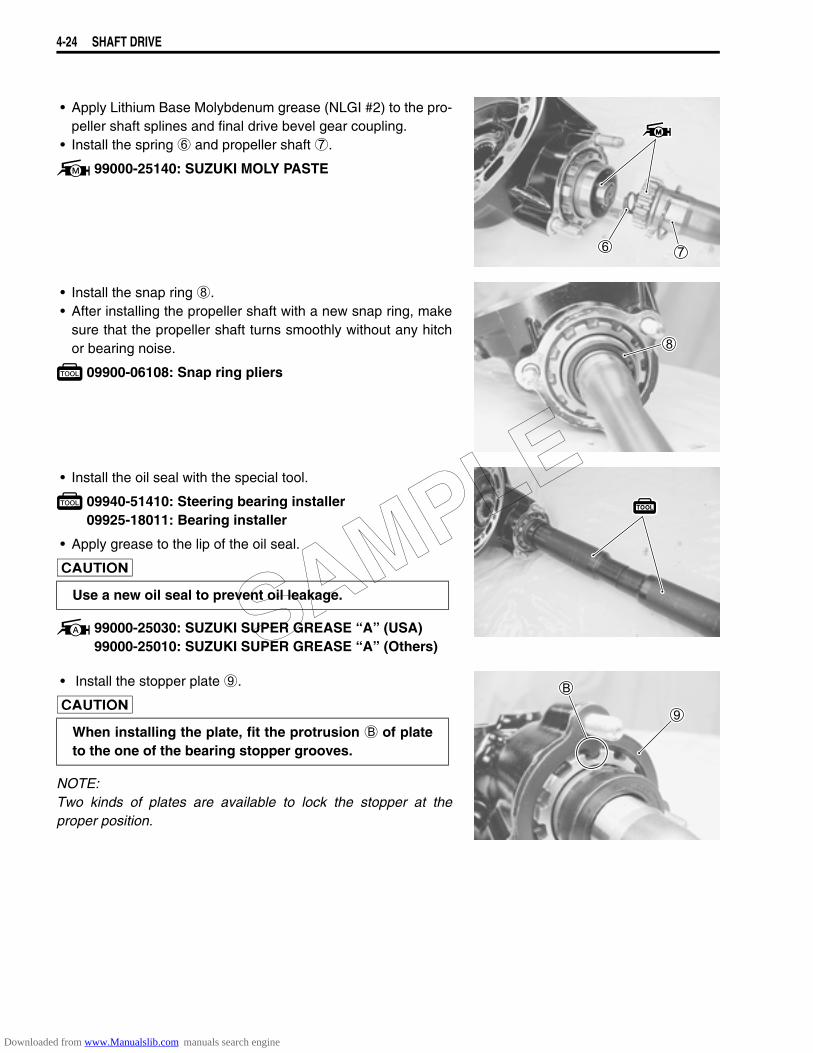
4-24 SHAFT DRIVE
• Apply Lithium Base Molybdenum grease (NLGI #2) to the pro-peller shaft splines and final drive bevel gear coupling.
• Install the spring 6 and propeller shaft 7.
99000-25140: SUZUKI MOLY PASTE
• Install the snap ring 8.• After installing the propeller shaft with a new snap ring, make
sure that the propeller shaft turns smoothly without any hitchor bearing noise.
09900-06108: Snap ring pliers
• Install the oil seal with the special tool.
09940-51410: Steering bearing installer09925-18011: Bearing installer
• Apply grease to the lip of the oil seal.
99000-25030: SUZUKI SUPER GREASE “A” (USA)99000-25010: SUZUKI SUPER GREASE “A” (Others)
• Install the stopper plate 9.
NOTE:Two kinds of plates are available to lock the stopper at theproper position.
Use a new oil seal to prevent oil leakage.
When installing the plate, fit the protrusion B of plateto the one of the bearing stopper grooves.
SAMPLE
Downloaded from www.Manualslib.com manuals search engine
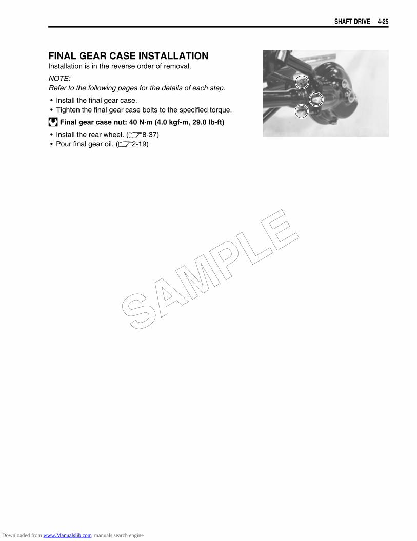
SHAFT DRIVE 4-25
FINAL GEAR CASE INSTALLATIONInstallation is in the reverse order of removal.
NOTE:Refer to the following pages for the details of each step.
• Install the final gear case.• Tighten the final gear case bolts to the specified torque.
Final gear case nut: 40 N·m (4.0 kgf-m, 29.0 lb-ft)
• Install the rear wheel. (8-37)• Pour final gear oil. (2-19)
SAMPLE
Downloaded from www.Manualslib.com manuals search engine
FI SYSTEM 5-1
5
FI SYSTEM
CONTENTS
PRECAUTIONS IN SERVICING....................................................................5- 3CONNECTOR/COUPLER .......................................................................5- 3FUSE .......................................................................................................5- 4ECM/VARIOUS SENSORS.....................................................................5- 4ELECTRICAL CIRCUIT INSPECTION PROCEDURE............................5- 6USING THE MULTI-CIRCUIT TESTER ..................................................5- 9
FI SYSTEM TECHNICAL FEATURES ..........................................................5-10INJECTION TIME (INJECTION VOLUME) .............................................5-10COMPENSATION OF INJECTION TIME (VOLUME) .............................5-11INJECTION STOP CONTROL ................................................................5-11
FI SYSTEM PARTS LOCATION ...................................................................5-12FI SYSTEM WIRING DIAGRAM .............................................................5-14
ECM TERMINAL............................................................................................5-15SELF-DIAGNOSIS FUNCTION .....................................................................5-16
USER MODE ...........................................................................................5-16DEALER MODE ......................................................................................5-17TPS ADJUSTMENT ................................................................................5-19
FAIL-SAFE FUNCTION .................................................................................5-20FI SYSTEM TROUBLESHOOTING...............................................................5-21
CUSTOMER COMPLAINT ANALYSIS...................................................5-21VISUAL INSPECTION.............................................................................5-22SELF-DIAGNOSTIC PROCEDURES......................................................5-23SELF-DIAGNOSIS RESET PROCEDURE .............................................5-23USE OF SDS DIAGNOSTIC PROCEDURES .........................................5-24USE OF SDS DIAGNOSIS RESET PROCEDURE .................................5-25SHOW DATA WHEN TROUBLE (DISPLAING DATA AT THE TIME OF DTC) ..........................................5-26MALFUNCTION CODE AND DEFECTIVE CONDITION ........................5-27“C12” (P0335) CKP SENSOR CIRCUIT MALFUNCTION .....................5-30“C13” (P1750) or “C17” (P0105) IAP SENSOR CIRCUIT MALFUNCTION.......................................................................................5-33“C14” (P0120-H/L) TP SENSOR CIRCUIT MALFUNCTION .................5-37“C15” (P0115-H/L) ECT SENSOR CIRCUIT MALFUNCTION...............5-42ECT SENSOR INSPECTION...................................................................5-46“C21” (P0110-H/L) IAT SENSOR CIRCUIT MALFUNCTION ................5-47“C23” (P1651-H/L) TO SENSOR CIRCUIT MALFUNCTION.................5-52“C24” (P0351) or “C25” (P0352) IGNITION SYSTEM MALFUNCTION.......................................................................................5-55“C28” (P1655) STV ACTUATOR CIRCUIT MALFUNCTION.................5-56“C29” (P1654-H/L) STP SENSOR CIRCUIT MALFUNCTION...............5-59“C31” (P0705) GP SWITCH CIRCUIT MALFUNCTION.........................5-64
SAMPLE
Downloaded from www.Manualslib.com manuals search engine
FI SYSTEM
CONTENTS
5-2 FI SYSTEM
“C32” (P0201) or “C33” (P0202) FUEL INJECTOR CIRCUIT MALFUNCTION ......................................................................................5-66“C41” (P0230) FP RELAY CIRCUIT MALFUNCTION...........................5-68“C42” (P01650) IG SWITCH CIRCUIT MALFUNCTION........................5-68“C44” (P0130/P0135) HO2 SENSOR (HO2S) CIRCUIT MALFUNCTION (FOR E-02, 19, 24).......................................................5-69“C49” (P1656) PAIR CONTROL SOLENOID VALVE CIRCUIT MALFUNCTION ......................................................................................5-73
SENSORS .....................................................................................................5-75IAP SENSOR INSPECTION ...................................................................5-75IAP SENSOR REMOVAL/INSTALLATION ............................................5-75TP SENSOR INSPECTION.....................................................................5-75TP SENSOR REMOVAL/INSTALLATION .............................................5-75STP SENSOR INSPECTION ..................................................................5-76STP SENSOR REMOVAL/INSTALLATION ...........................................5-76CKP SENSOR INSPECTION..................................................................5-76CKP SENSOR REMOVAL/INSTALLATION ..........................................5-76IAT SENSOR INSPECTION....................................................................5-77IAT SENSOR REMOVAL/INSTALLATION ............................................5-77ECT SENSOR INSPECTION ..................................................................5-77ECT SENSOR REMOVAL/INSTALLATION...........................................5-77TO SENSOR INSPECTION ....................................................................5-77TO SENSOR REMOVAL/INSTALLATION .............................................5-77HO2 SENSOR INSPECTION (FOR E-02, 19, 24) ..................................5-78HO2 SENSOR REMOVAL/INSTALLATION...........................................5-78
SAMPLE
Downloaded from www.Manualslib.com manuals search engine
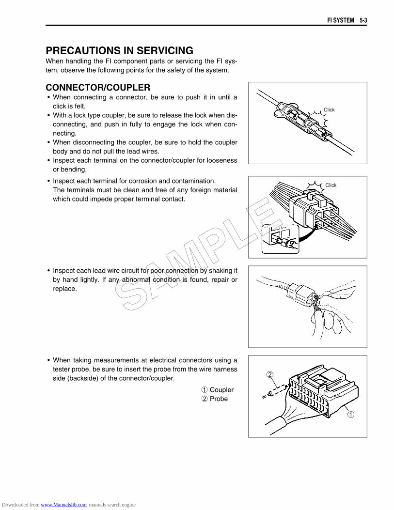
FI SYSTEM 5-3
PRECAUTIONS IN SERVICINGWhen handling the FI component parts or servicing the FI sys-tem, observe the following points for the safety of the system.
CONNECTOR/COUPLER• When connecting a connector, be sure to push it in until a
click is felt.• With a lock type coupler, be sure to release the lock when dis-
connecting, and push in fully to engage the lock when con-necting.
• When disconnecting the coupler, be sure to hold the couplerbody and do not pull the lead wires.
• Inspect each terminal on the connector/coupler for loosenessor bending.
• Inspect each terminal for corrosion and contamination.The terminals must be clean and free of any foreign materialwhich could impede proper terminal contact.
• Inspect each lead wire circuit for poor connection by shaking itby hand lightly. If any abnormal condition is found, repair orreplace.
• When taking measurements at electrical connectors using atester probe, be sure to insert the probe from the wire harnessside (backside) of the connector/coupler.
1 Coupler2 Probe
Click
Click
SAMPLE
Downloaded from www.Manualslib.com manuals search engine
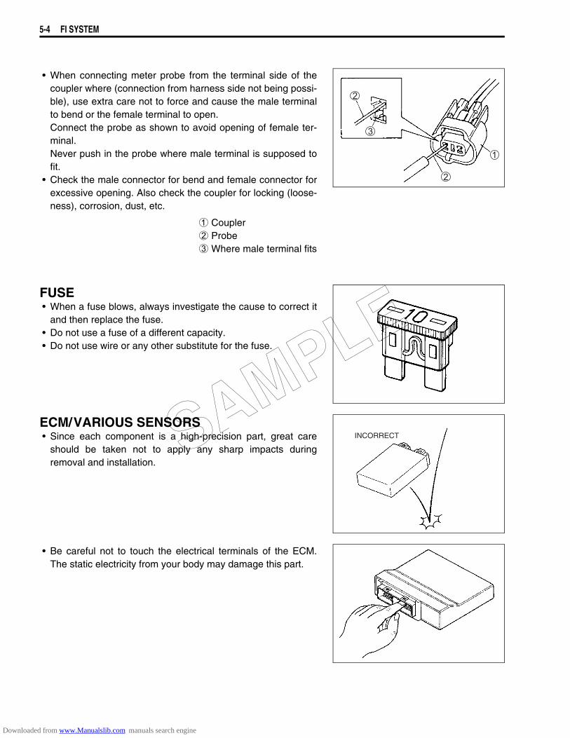
5-4 FI SYSTEM
• When connecting meter probe from the terminal side of thecoupler where (connection from harness side not being possi-ble), use extra care not to force and cause the male terminalto bend or the female terminal to open.Connect the probe as shown to avoid opening of female ter-minal.Never push in the probe where male terminal is supposed tofit.
• Check the male connector for bend and female connector forexcessive opening. Also check the coupler for locking (loose-ness), corrosion, dust, etc.
1 Coupler2 Probe3 Where male terminal fits
FUSE• When a fuse blows, always investigate the cause to correct it
and then replace the fuse.• Do not use a fuse of a different capacity.• Do not use wire or any other substitute for the fuse.
ECM/VARIOUS SENSORS• Since each component is a high-precision part, great care
should be taken not to apply any sharp impacts duringremoval and installation.
• Be careful not to touch the electrical terminals of the ECM.The static electricity from your body may damage this part.
INCORRECTSAMPLE
Downloaded from www.Manualslib.com manuals search engine
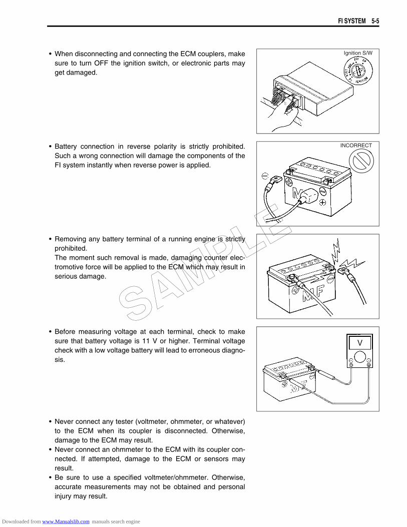
FI SYSTEM 5-5
• When disconnecting and connecting the ECM couplers, makesure to turn OFF the ignition switch, or electronic parts mayget damaged.
• Battery connection in reverse polarity is strictly prohibited.Such a wrong connection will damage the components of theFI system instantly when reverse power is applied.
• Removing any battery terminal of a running engine is strictlyprohibited.The moment such removal is made, damaging counter elec-tromotive force will be applied to the ECM which may result inserious damage.
• Before measuring voltage at each terminal, check to makesure that battery voltage is 11 V or higher. Terminal voltagecheck with a low voltage battery will lead to erroneous diagno-sis.
• Never connect any tester (voltmeter, ohmmeter, or whatever)to the ECM when its coupler is disconnected. Otherwise,damage to the ECM may result.
• Never connect an ohmmeter to the ECM with its coupler con-nected. If attempted, damage to the ECM or sensors mayresult.
• Be sure to use a specified voltmeter/ohmmeter. Otherwise,accurate measurements may not be obtained and personalinjury may result.
Ignition S/W
INCORRECT
V
SAMPLE
Downloaded from www.Manualslib.com manuals search engine
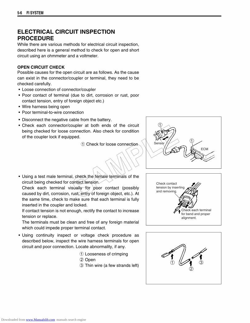
5-6 FI SYSTEM
ELECTRICAL CIRCUIT INSPECTION PROCEDUREWhile there are various methods for electrical circuit inspection,described here is a general method to check for open and shortcircuit using an ohmmeter and a voltmeter.
OPEN CIRCUIT CHECKPossible causes for the open circuit are as follows. As the causecan exist in the connector/coupler or terminal, they need to bechecked carefully.• Loose connection of connector/coupler• Poor contact of terminal (due to dirt, corrosion or rust, poor
contact tension, entry of foreign object etc.)• Wire harness being open• Poor terminal-to-wire connection
• Disconnect the negative cable from the battery.• Check each connector/coupler at both ends of the circuit
being checked for loose connection. Also check for conditionof the coupler lock if equipped.
1 Check for loose connection
• Using a test male terminal, check the female terminals of thecircuit being checked for contact tension.Check each terminal visually for poor contact (possiblycaused by dirt, corrosion, rust, entry of foreign object, etc.). Atthe same time, check to make sure that each terminal is fullyinserted in the coupler and locked.If contact tension is not enough, rectify the contact to increasetension or replace.The terminals must be clean and free of any foreign materialwhich could impede proper terminal contact.
• Using continuity inspect or voltage check procedure asdescribed below, inspect the wire harness terminals for opencircuit and poor connection. Locate abnormality, if any.
1 Looseness of crimping2 Open3 Thin wire (a few strands left)
Sensor
ECM
Check contact tension by inserting and removing.
Check each terminalfor bend and properalignment.
SAMPLE
Downloaded from www.Manualslib.com manuals search engine
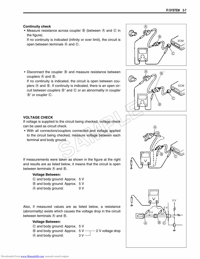
FI SYSTEM 5-7
Continuity check• Measure resistance across coupler B (between A and C in
the figure).If no continuity is indicated (infinity or over limit), the circuit isopen between terminals A and C.
• Disconnect the coupler B and measure resistance betweencouplers A and B.If no continuity is indicated, the circuit is open between cou-plers A and B. If continuity is indicated, there is an open cir-cuit between couplers B’ and C or an abnormality in couplerB’ or coupler C.
VOLTAGE CHECKIf voltage is supplied to the circuit being checked, voltage checkcan be used as circuit check.• With all connectors/couplers connected and voltage applied
to the circuit being checked, measure voltage between eachterminal and body ground.
If measurements were taken as shown in the figure at the rightand results are as listed below, it means that the circuit is openbetween terminals A and B.
Voltage Between:C and body ground: Approx. 5 VB and body ground: Approx. 5 VA and body ground: 0 V
Also, if measured values are as listed below, a resistance(abnormality) exists which causes the voltage drop in the circuitbetween terminals A and B.
Voltage Between:C and body ground: Approx. 5 VB and body ground: Approx. 5 V 2 V voltage dropA and body ground: 3 V
ECM
ECM
0 V 5 V
5 V
5 V
SAMPLE
Downloaded from www.Manualslib.com manuals search engine
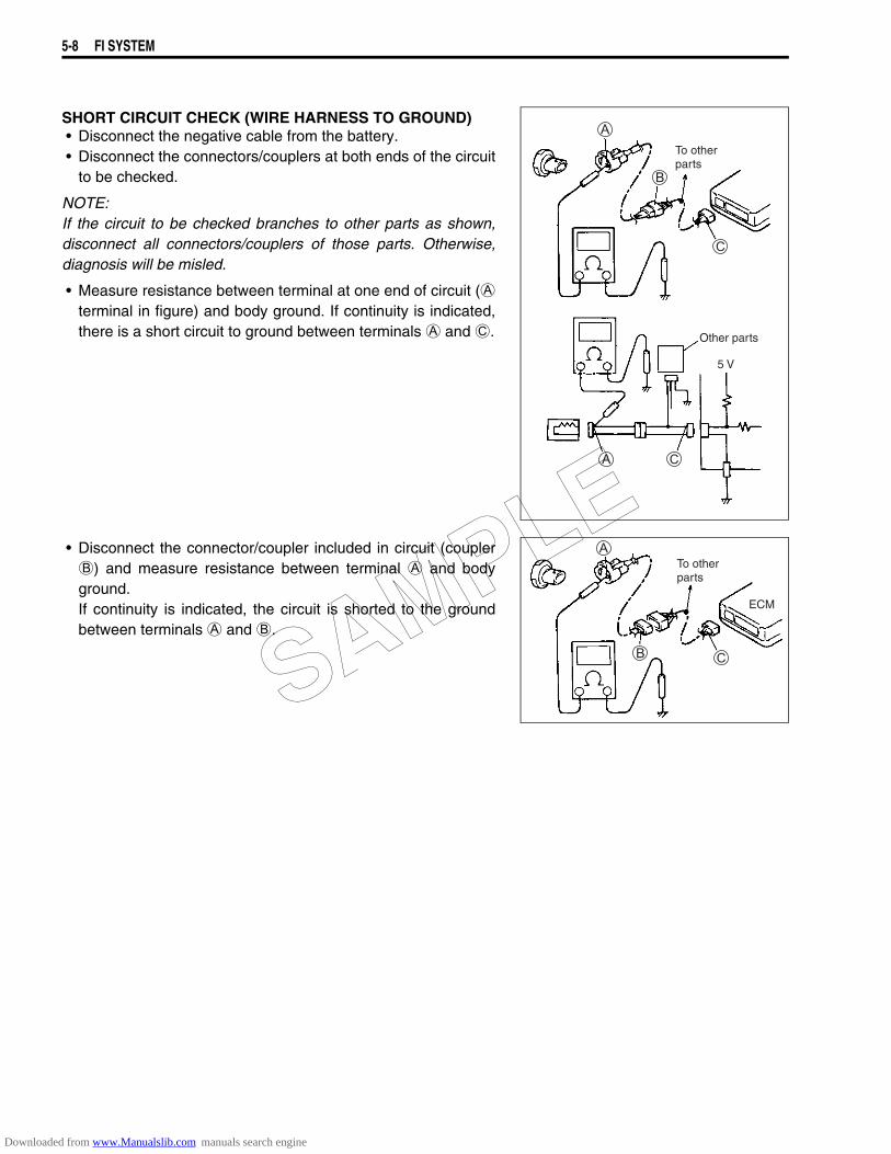
5-8 FI SYSTEM
SHORT CIRCUIT CHECK (WIRE HARNESS TO GROUND)• Disconnect the negative cable from the battery.• Disconnect the connectors/couplers at both ends of the circuit
to be checked.
NOTE:If the circuit to be checked branches to other parts as shown,disconnect all connectors/couplers of those parts. Otherwise,diagnosis will be misled.
• Measure resistance between terminal at one end of circuit (Aterminal in figure) and body ground. If continuity is indicated,there is a short circuit to ground between terminals A and C.
• Disconnect the connector/coupler included in circuit (couplerB) and measure resistance between terminal A and bodyground.If continuity is indicated, the circuit is shorted to the groundbetween terminals A and B.
To otherparts
Other parts
5 V
To otherparts
ECM
SAMPLE
Downloaded from www.Manualslib.com manuals search engine
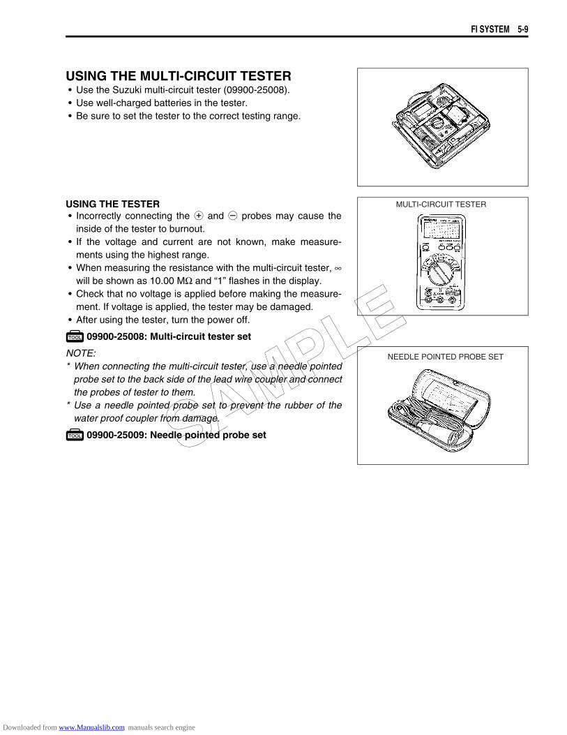
FI SYSTEM 5-9
USING THE MULTI-CIRCUIT TESTER• Use the Suzuki multi-circuit tester (09900-25008).• Use well-charged batteries in the tester.• Be sure to set the tester to the correct testing range.
USING THE TESTER• Incorrectly connecting the + and - probes may cause the
inside of the tester to burnout.• If the voltage and current are not known, make measure-
ments using the highest range.• When measuring the resistance with the multi-circuit tester, ∞
will be shown as 10.00 MΩ and “1” flashes in the display.• Check that no voltage is applied before making the measure-
ment. If voltage is applied, the tester may be damaged.• After using the tester, turn the power off.
09900-25008: Multi-circuit tester set
NOTE:* When connecting the multi-circuit tester, use a needle pointed
probe set to the back side of the lead wire coupler and connectthe probes of tester to them.
* Use a needle pointed probe set to prevent the rubber of thewater proof coupler from damage.
09900-25009: Needle pointed probe set
MULTI-CIRCUIT TESTER
NEEDLE POINTED PROBE SET
SAMPLE
Downloaded from www.Manualslib.com manuals search engine
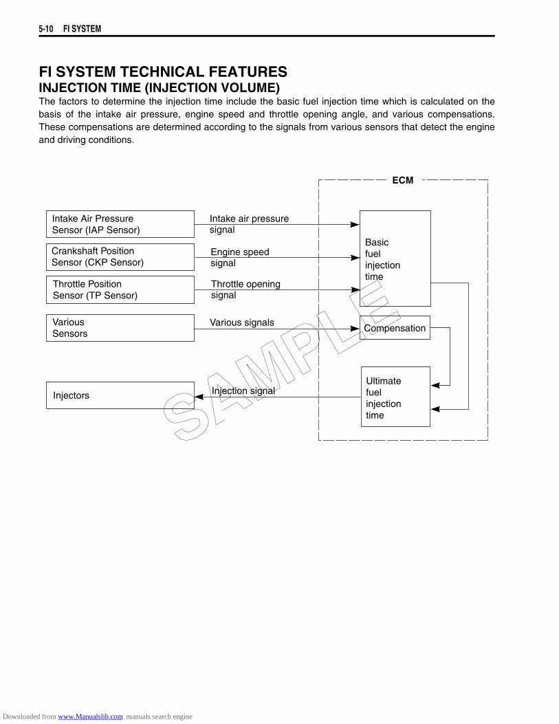
5-10 FI SYSTEM
FI SYSTEM TECHNICAL FEATURESINJECTION TIME (INJECTION VOLUME)The factors to determine the injection time include the basic fuel injection time which is calculated on thebasis of the intake air pressure, engine speed and throttle opening angle, and various compensations.These compensations are determined according to the signals from various sensors that detect the engineand driving conditions.
Intake Air PressureSensor (IAP Sensor)
Crankshaft Position Sensor (CKP Sensor)
Throttle PositionSensor (TP Sensor)
VariousSensors
Injectors
Intake air pressuresignal
Engine speedsignal
Various signals
Injection signal
Basicfuelinjectiontime
Compensation
Ultimatefuelinjectiontime
Throttle openingsignal
ECM
SAMPLE
Downloaded from www.Manualslib.com manuals search engine
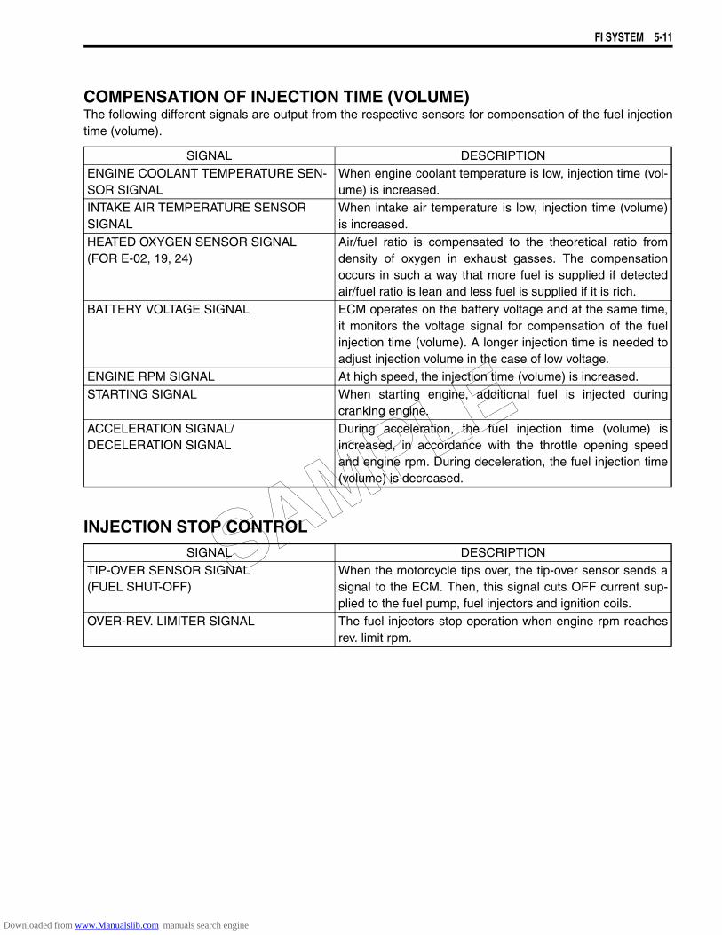
FI SYSTEM 5-11
COMPENSATION OF INJECTION TIME (VOLUME)The following different signals are output from the respective sensors for compensation of the fuel injectiontime (volume).
INJECTION STOP CONTROL
SIGNAL DESCRIPTIONENGINE COOLANT TEMPERATURE SEN-SOR SIGNAL
When engine coolant temperature is low, injection time (vol-ume) is increased.
INTAKE AIR TEMPERATURE SENSOR SIGNAL
When intake air temperature is low, injection time (volume)is increased.
HEATED OXYGEN SENSOR SIGNAL(FOR E-02, 19, 24)
Air/fuel ratio is compensated to the theoretical ratio fromdensity of oxygen in exhaust gasses. The compensationoccurs in such a way that more fuel is supplied if detectedair/fuel ratio is lean and less fuel is supplied if it is rich.
BATTERY VOLTAGE SIGNAL ECM operates on the battery voltage and at the same time,it monitors the voltage signal for compensation of the fuelinjection time (volume). A longer injection time is needed toadjust injection volume in the case of low voltage.
ENGINE RPM SIGNAL At high speed, the injection time (volume) is increased.STARTING SIGNAL When starting engine, additional fuel is injected during
cranking engine.ACCELERATION SIGNAL/DECELERATION SIGNAL
During acceleration, the fuel injection time (volume) isincreased, in accordance with the throttle opening speedand engine rpm. During deceleration, the fuel injection time(volume) is decreased.
SIGNAL DESCRIPTIONTIP-OVER SENSOR SIGNAL (FUEL SHUT-OFF)
When the motorcycle tips over, the tip-over sensor sends asignal to the ECM. Then, this signal cuts OFF current sup-plied to the fuel pump, fuel injectors and ignition coils.
OVER-REV. LIMITER SIGNAL The fuel injectors stop operation when engine rpm reachesrev. limit rpm.
SAMPLE
Downloaded from www.Manualslib.com manuals search engine
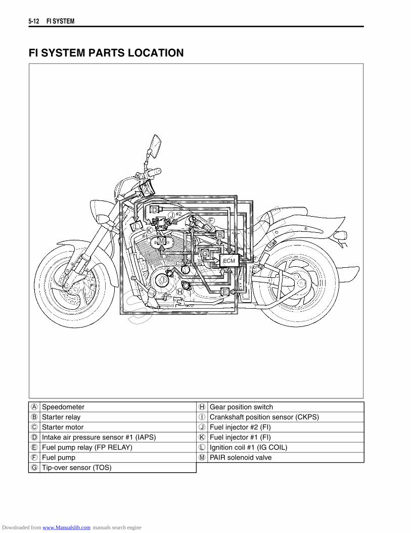
5-12 FI SYSTEM
FI SYSTEM PARTS LOCATION
ECM
#2
#1#1
A Speedometer H Gear position switchB Starter relay I Crankshaft position sensor (CKPS)C Starter motor J Fuel injector #2 (FI)D Intake air pressure sensor #1 (IAPS) K Fuel injector #1 (FI)E Fuel pump relay (FP RELAY) L Ignition coil #1 (IG COIL)F Fuel pump M PAIR solenoid valveG Tip-over sensor (TOS)
SAMPLE
Downloaded from www.Manualslib.com manuals search engine
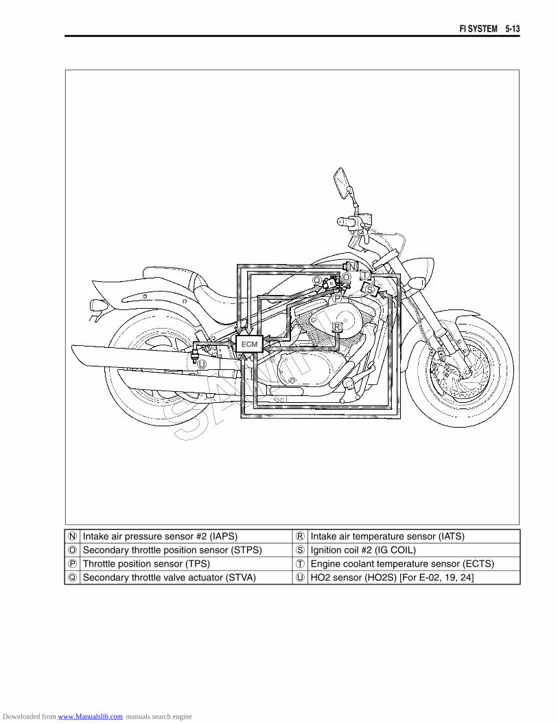
FI SYSTEM 5-13
ECM
N Intake air pressure sensor #2 (IAPS) R Intake air temperature sensor (IATS)O Secondary throttle position sensor (STPS) S Ignition coil #2 (IG COIL)P Throttle position sensor (TPS) T Engine coolant temperature sensor (ECTS)Q Secondary throttle valve actuator (STVA) U HO2 sensor (HO2S) [For E-02, 19, 24]
SAMPLE
Downloaded from www.Manualslib.com manuals search engine
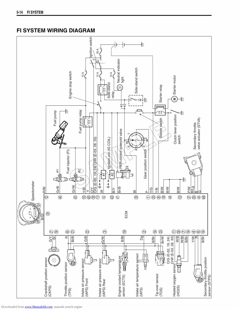
5-14 FI SYSTEM
FI SYSTEM WIRING DIAGRAM
Inta
ke a
ir pr
essu
re s
enso
r(I
AP
S)
Fron
t
Inta
ke a
ir pr
essu
re s
enso
r(I
AP
S)
Rea
r
Eng
ine
cool
ant t
empe
ratu
re
sens
or (
EC
TS
)
Inta
ke a
ir te
mpe
ratu
re s
enso
r(I
ATS
)
Tip
-ove
r se
nsor
(TO
S)
EC
M
Hea
ted
oxyg
en s
enso
r(H
O2S
)
Fue
l pum
p
Fue
l inj
ecto
r (F
I)
#1 #2
Igni
tion
coil
(IG
CO
IL)
PAIR
con
trol
sol
enoi
d va
lve
Sec
onda
ry th
rottl
e po
sitio
nse
nsor
(S
TP
S)
Clu
tch
leve
r po
sitio
nsw
itch
Sta
rter
mot
or
Sta
rter
rel
ay
10 A
10 A
30 A
15 A
Sid
e-st
and
switc
h
Sid
e-st
and
rela
y
Eng
ine
stop
sw
itch
Sta
rter
sw
itch
Fue
l pum
p re
lay
Igni
tion
switc
h
Neu
tral
indi
cato
rlig
ht
Gea
r po
sitio
n sw
itch
N5
1
4
32
Cra
nksh
aft p
ositi
on s
enso
r (C
KP
S)
Thr
ottle
pos
ition
sen
sor
(TP
S)
Sec
onda
ry th
rottl
eva
lve
actu
ator
(S
TV
A)
#1 #2
Spe
edom
eter
R/B
l
Gr/
B
Gr/
W
Y/B Y O/Y
O/G
(E
-02,
19,
24)
O/W
(E
-03,
28,
33)
W B/Y
Br/
B
Bl
P Y/G
Y/B
B/W
B/W
B/W
P/W
B/L
gB G
B/G
G/Y B
r R
Bl/B G/B
G/W B/B
l
Dg
B/B
r
Br/
W
O/G
(E
-02,
19,
24)
O
/W (
E-0
3, 2
8, 3
3)
W/B
W/B
lB
/Br
Y/W R
B/B
r
SAMPLE
Downloaded from www.Manualslib.com manuals search engine
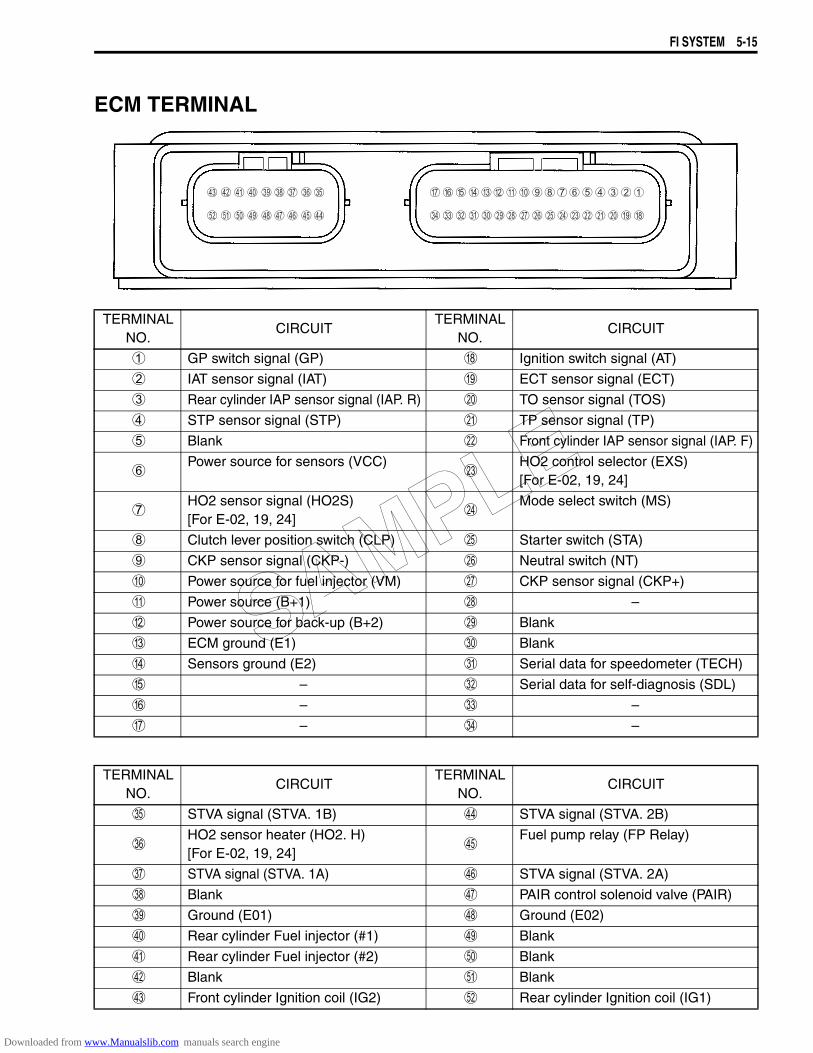
FI SYSTEM 5-15
ECM TERMINAL
TERMINAL NO.
CIRCUITTERMINAL
NO.CIRCUIT
1 GP switch signal (GP) H Ignition switch signal (AT)
2 IAT sensor signal (IAT) I ECT sensor signal (ECT)
3 Rear cylinder IAP sensor signal (IAP. R) J TO sensor signal (TOS)
4 STP sensor signal (STP) K TP sensor signal (TP)
5 Blank L Front cylinder IAP sensor signal (IAP. F)
6Power source for sensors (VCC)
MHO2 control selector (EXS)[For E-02, 19, 24]
7HO2 sensor signal (HO2S)[For E-02, 19, 24]
NMode select switch (MS)
8 Clutch lever position switch (CLP) O Starter switch (STA)
9 CKP sensor signal (CKP-) P Neutral switch (NT)
0 Power source for fuel injector (VM) Q CKP sensor signal (CKP+)
A Power source (B+1) R –
B Power source for back-up (B+2) S Blank
C ECM ground (E1) T Blank
D Sensors ground (E2) U Serial data for speedometer (TECH)
E – V Serial data for self-diagnosis (SDL)
F – W –
G – X –
TERMINAL NO.
CIRCUITTERMINAL
NO.CIRCUIT
Y STVA signal (STVA. 1B) d STVA signal (STVA. 2B)
ZHO2 sensor heater (HO2. H)[For E-02, 19, 24]
eFuel pump relay (FP Relay)
[ STVA signal (STVA. 1A) f STVA signal (STVA. 2A)
\ Blank g PAIR control solenoid valve (PAIR)
] Ground (E01) h Ground (E02)
^ Rear cylinder Fuel injector (#1) i Blank
a Rear cylinder Fuel injector (#2) j Blank
b Blank k Blank
c Front cylinder Ignition coil (IG2) l Rear cylinder Ignition coil (IG1)
SAMPLE
Downloaded from www.Manualslib.com manuals search engine
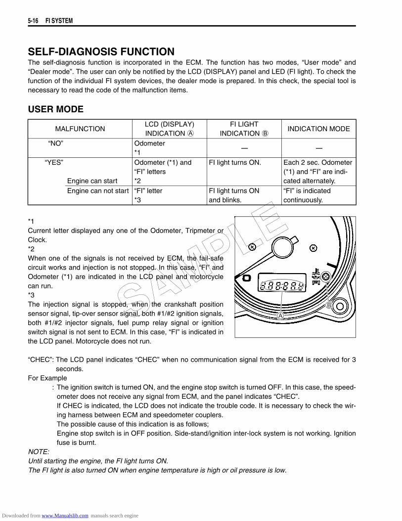
5-16 FI SYSTEM
SELF-DIAGNOSIS FUNCTIONThe self-diagnosis function is incorporated in the ECM. The function has two modes, “User mode” and“Dealer mode”. The user can only be notified by the LCD (DISPLAY) panel and LED (FI light). To check thefunction of the individual FI system devices, the dealer mode is prepared. In this check, the special tool isnecessary to read the code of the malfunction items.
USER MODE
*1Current letter displayed any one of the Odometer, Tripmeter orClock.*2When one of the signals is not received by ECM, the fail-safecircuit works and injection is not stopped. In this case, “FI” andOdometer (*1) are indicated in the LCD panel and motorcyclecan run.*3The injection signal is stopped, when the crankshaft positionsensor signal, tip-over sensor signal, both #1/#2 ignition signals,both #1/#2 injector signals, fuel pump relay signal or ignitionswitch signal is not sent to ECM. In this case, “FI” is indicated inthe LCD panel. Motorcycle does not run.
“CHEC”: The LCD panel indicates “CHEC” when no communication signal from the ECM is received for 3seconds.
For Example: The ignition switch is turned ON, and the engine stop switch is turned OFF. In this case, the speed-
ometer does not receive any signal from ECM, and the panel indicates “CHEC”.If CHEC is indicated, the LCD does not indicate the trouble code. It is necessary to check the wir-ing harness between ECM and speedometer couplers.The possible cause of this indication is as follows;Engine stop switch is in OFF position. Side-stand/ignition inter-lock system is not working. Ignitionfuse is burnt.
NOTE:Until starting the engine, the FI light turns ON.The FI light is also turned ON when engine temperature is high or oil pressure is low.
MALFUNCTIONLCD (DISPLAY) INDICATION A
FI LIGHT INDICATION B
INDICATION MODE
“NO” Odometer*1
---- ----
“YES”
Engine can start
Odometer (*1) and “FI” letters*2
FI light turns ON. Each 2 sec. Odometer (*1) and “FI” are indi-cated alternately.
Engine can not start “FI” letter*3
FI light turns ON and blinks.
“FI” is indicated continuously.
SAMPLE
Downloaded from www.Manualslib.com manuals search engine
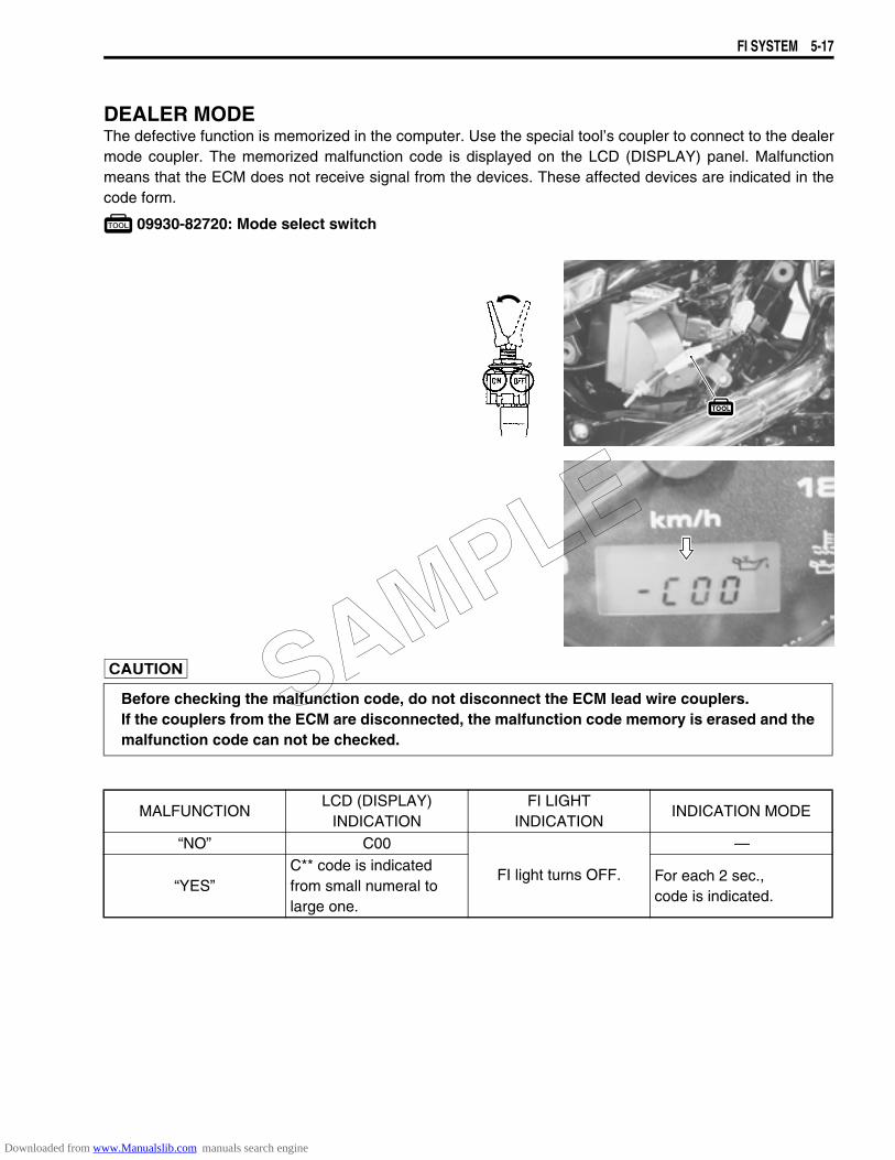
FI SYSTEM 5-17
DEALER MODEThe defective function is memorized in the computer. Use the special tool’s coupler to connect to the dealermode coupler. The memorized malfunction code is displayed on the LCD (DISPLAY) panel. Malfunctionmeans that the ECM does not receive signal from the devices. These affected devices are indicated in thecode form.
09930-82720: Mode select switch
Before checking the malfunction code, do not disconnect the ECM lead wire couplers.If the couplers from the ECM are disconnected, the malfunction code memory is erased and themalfunction code can not be checked.
MALFUNCTIONLCD (DISPLAY)
INDICATIONFI LIGHT
INDICATION INDICATION MODE
“NO” C00
FI light turns OFF.
—
“YES”C** code is indicated from small numeral to large one.
For each 2 sec., code is indicated.
SAMPLE
Downloaded from www.Manualslib.com manuals search engine
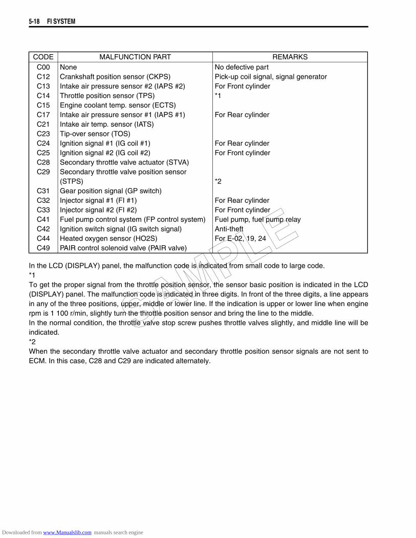
5-18 FI SYSTEM
In the LCD (DISPLAY) panel, the malfunction code is indicated from small code to large code.*1To get the proper signal from the throttle position sensor, the sensor basic position is indicated in the LCD(DISPLAY) panel. The malfunction code is indicated in three digits. In front of the three digits, a line appearsin any of the three positions, upper, middle or lower line. If the indication is upper or lower line when enginerpm is 1 100 r/min, slightly turn the throttle position sensor and bring the line to the middle.In the normal condition, the throttle valve stop screw pushes throttle valves slightly, and middle line will beindicated.*2When the secondary throttle valve actuator and secondary throttle position sensor signals are not sent toECM. In this case, C28 and C29 are indicated alternately.
CODE MALFUNCTION PART REMARKSC00C12C13C14C15C17C21C23C24C25C28C29
C31C32C33C41C42C44C49
NoneCrankshaft position sensor (CKPS)Intake air pressure sensor #2 (IAPS #2)Throttle position sensor (TPS)Engine coolant temp. sensor (ECTS)Intake air pressure sensor #1 (IAPS #1)Intake air temp. sensor (IATS)Tip-over sensor (TOS)Ignition signal #1 (IG coil #1)Ignition signal #2 (IG coil #2)Secondary throttle valve actuator (STVA)Secondary throttle valve position sensor (STPS)Gear position signal (GP switch)Injector signal #1 (FI #1)Injector signal #2 (FI #2)Fuel pump control system (FP control system)Ignition switch signal (IG switch signal)Heated oxygen sensor (HO2S)PAIR control solenoid valve (PAIR valve)
No defective partPick-up coil signal, signal generatorFor Front cylinder*1
For Rear cylinder
For Rear cylinderFor Front cylinder
*2
For Rear cylinderFor Front cylinderFuel pump, fuel pump relayAnti-theftFor E-02, 19, 24
SAMPLE
Downloaded from www.Manualslib.com manuals search engine

FI SYSTEM 5-19
TPS ADJUSTMENT1. Warm up the engine and adjust the engine idle speed to 1 100
± 100 r/min. (2-13)2. Connect the special tool (Mode select switch) and select the
dealer mode.
3. Remove the fuel tank. (6-3)4. Loosen the inlet pipe screws. (5-47)5. Move the inlet pipe 1.
6. Loosen the screw with a torx wrench (T25) and turn the throt-tle position sensor 2 and bring the line to the middle.
7. Then, tighten the screw to fix the throttle position sensor.
09930-82720: Mode select switch
The LCD displays the line for 0.4 sec. at a time, and when sucha display repeats two times, it indicates the current positionwhere the sensor is fixed.
A IncorrectB Correct position
SAMPLE
Downloaded from www.Manualslib.com manuals search engine
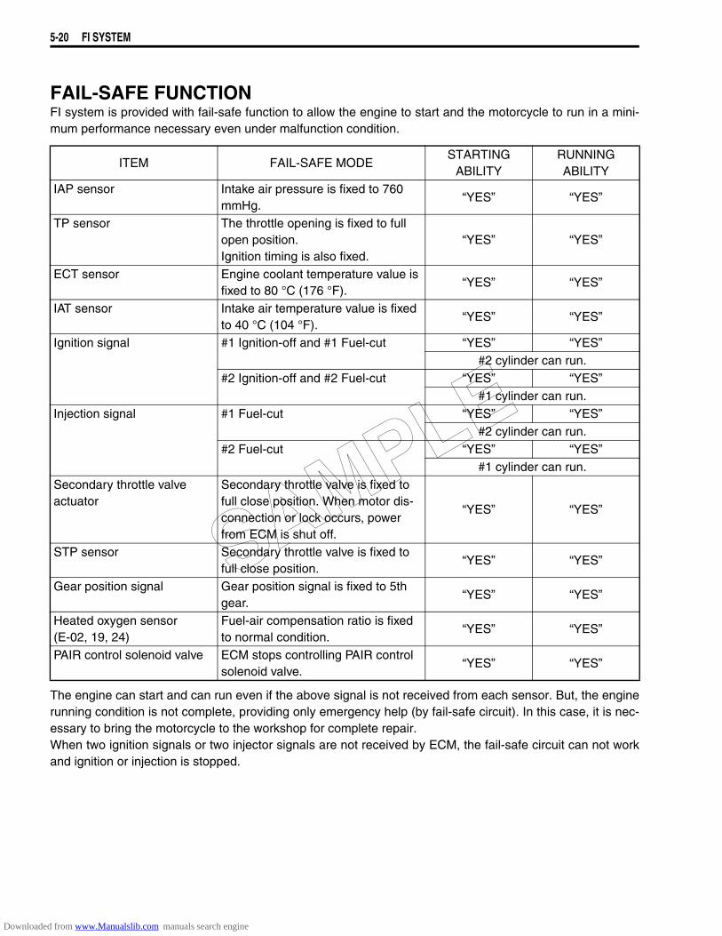
5-20 FI SYSTEM
FAIL-SAFE FUNCTIONFI system is provided with fail-safe function to allow the engine to start and the motorcycle to run in a mini-mum performance necessary even under malfunction condition.
The engine can start and can run even if the above signal is not received from each sensor. But, the enginerunning condition is not complete, providing only emergency help (by fail-safe circuit). In this case, it is nec-essary to bring the motorcycle to the workshop for complete repair.When two ignition signals or two injector signals are not received by ECM, the fail-safe circuit can not workand ignition or injection is stopped.
ITEM FAIL-SAFE MODESTARTING
ABILITYRUNNING ABILITY
IAP sensor Intake air pressure is fixed to 760 mmHg.
“YES” “YES”
TP sensor The throttle opening is fixed to full open position.Ignition timing is also fixed.
“YES” “YES”
ECT sensor Engine coolant temperature value is fixed to 80 °C (176 °F).
“YES” “YES”
IAT sensor Intake air temperature value is fixed to 40 °C (104 °F).
“YES” “YES”
Ignition signal #1 Ignition-off and #1 Fuel-cut “YES” “YES”#2 cylinder can run.
#2 Ignition-off and #2 Fuel-cut “YES” “YES”#1 cylinder can run.
Injection signal #1 Fuel-cut “YES” “YES”#2 cylinder can run.
#2 Fuel-cut “YES” “YES”#1 cylinder can run.
Secondary throttle valve actuator
Secondary throttle valve is fixed to full close position. When motor dis-connection or lock occurs, power from ECM is shut off.
“YES” “YES”
STP sensor Secondary throttle valve is fixed to full close position.
“YES” “YES”
Gear position signal Gear position signal is fixed to 5th gear.
“YES” “YES”
Heated oxygen sensor (E-02, 19, 24)
Fuel-air compensation ratio is fixed to normal condition.
“YES” “YES”
PAIR control solenoid valve ECM stops controlling PAIR control solenoid valve.
“YES” “YES”
SAMPLE
Downloaded from www.Manualslib.com manuals search engine
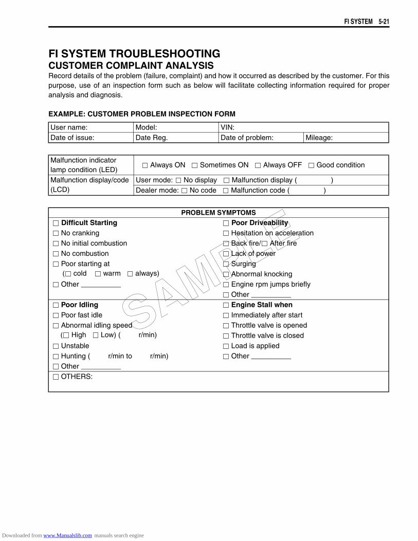
FI SYSTEM 5-21
FI SYSTEM TROUBLESHOOTINGCUSTOMER COMPLAINT ANALYSISRecord details of the problem (failure, complaint) and how it occurred as described by the customer. For thispurpose, use of an inspection form such as below will facilitate collecting information required for properanalysis and diagnosis.
EXAMPLE: CUSTOMER PROBLEM INSPECTION FORM
User name: Model: VIN:Date of issue: Date Reg. Date of problem: Mileage:
Malfunction indicator lamp condition (LED)
Always ON Sometimes ON Always OFF Good condition
Malfunction display/code (LCD)
User mode: No display Malfunction display ( )Dealer mode: No code Malfunction code ( )
PROBLEM SYMPTOMS Difficult Starting Poor Driveability No cranking Hesitation on acceleration No initial combustion Back fire/ After fire No combustion Lack of power Poor starting at ( cold warm always)
Surging Abnormal knocking
Other Engine rpm jumps briefly Other
Poor Idling Engine Stall when Poor fast idle Immediately after start Abnormal idling speed ( High Low) ( r/min)
Throttle valve is opened Throttle valve is closed
Unstable Load is applied Hunting ( r/min to r/min) Other Other OTHERS:
SAMPLE
Downloaded from www.Manualslib.com manuals search engine

5-22 FI SYSTEM
NOTE:The above form is a standard sample. The form should be modified according to conditions and characteris-tics of each market.
VISUAL INSPECTION• Prior to diagnosis using the mode select switch or SDS, perform the following visual inspections. The rea-
son for visual inspection is that mechanical failures (such as oil leakage) cannot be displayed on thescreen with the use of mode select switch or SDS.
* Engine oil level and leakage (2-11)* Fuel level and leakage (2-10)* Clogged air cleaner element (2-4)* Battery condition (9-37)* Throttle cable play (2-14)* Vacuum hoses looseness, bend and disconnection* Broken fuse* FI light operation (5-16 and 9-29)* Each warning light operation (9-29)* Speedometer operation (9-31)* Exhaust gas leakage and noise (2-24)* Each coupler disconnection* Clogged radiator core (7-5)* Engine coolant level and leakage. (7-6)
MOTORCYCLE/ENVIRONMENTAL CONDITION WHEN PROBLEM OCCURSEnvironmental condition
Weather Fair Cloudy Rain Snow Always Other Temperature Hot Warm Cool Cold ( °C/ °F) Always
Frequency Always Sometimes ( times/ day, month) Only once
Under certain condition
Road Urban Suburb Highway Mountainous ( Uphill Downhill)
Tarmacadam Gravel Other Motorcycle condition
Engine condition Cold Warming up phase Warmed up Always Other at starting
Immediately after start Racing without load Engine speed ( r/min)
Motorcycle con-dition
During driving: Constant speed Accelerating Decelerating
Right hand corner Left hand corner
At stop Motorcycle speed when problem occurs ( km/h, mile/h)
Other
SAMPLE
Downloaded from www.Manualslib.com manuals search engine
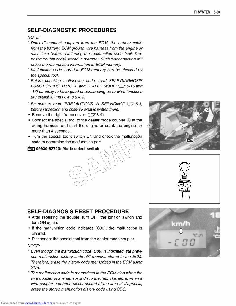
FI SYSTEM 5-23
SELF-DIAGNOSTIC PROCEDURESNOTE:* Don’t disconnect couplers from the ECM, the battery cable
from the battery, ECM ground wire harness from the engine ormain fuse before confirming the malfunction code (self-diag-nostic trouble code) stored in memory. Such disconnection willerase the memorized information in ECM memory.
* Malfunction code stored in ECM memory can be checked bythe special tool.
* Before checking malfunction code, read SELF-DIAGNOSISFUNCTION “USER MODE and DEALER MODE” (5-16 and-17) carefully to have good understanding as to what functionsare available and how to use it.
* Be sure to read “PRECAUTIONS IN SERVICING” (5-3)before inspection and observe what is written there.
• Remove the right frame cover. (8-4)• Connect the special tool to the dealer mode coupler A at the
wiring harness, and start the engine or crank the engine formore than 4 seconds.
• Turn the special tool’s switch ON and check the malfunctioncode to determine the malfunction part.
09930-82720: Mode select switch
SELF-DIAGNOSIS RESET PROCEDURE• After repairing the trouble, turn OFF the ignition switch and
turn ON again.• If the malfunction code indicates (C00), the malfunction is
cleared.• Disconnect the special tool from the dealer mode coupler.
NOTE:* Even though the malfunction code (C00) is indicated, the previ-
ous malfunction history code still remains stored in the ECM.Therefore, erase the history code memorized in the ECM usingSDS.
* The malfunction code is memorized in the ECM also when thewire coupler of any sensor is disconnected. Therefore, when awire coupler has been disconnected at the time of diagnosis,erase the stored malfunction history code using SDS.
SAMPLE
Downloaded from www.Manualslib.com manuals search engine
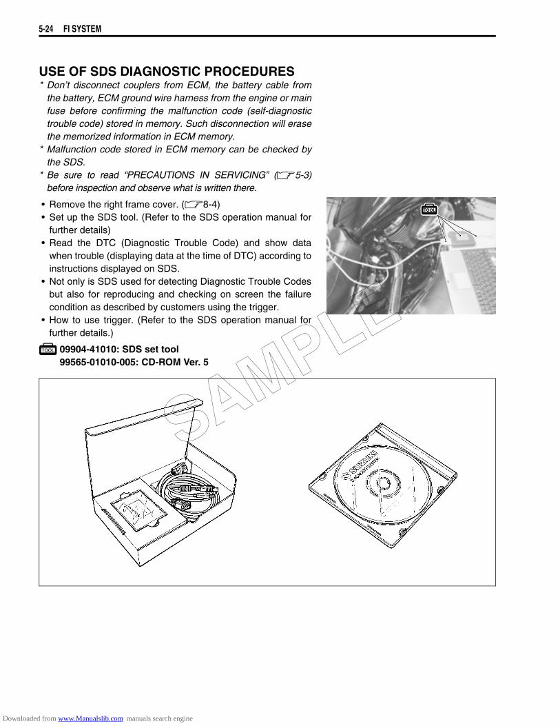
5-24 FI SYSTEM
USE OF SDS DIAGNOSTIC PROCEDURES* Don’t disconnect couplers from ECM, the battery cable from
the battery, ECM ground wire harness from the engine or mainfuse before confirming the malfunction code (self-diagnostictrouble code) stored in memory. Such disconnection will erasethe memorized information in ECM memory.
* Malfunction code stored in ECM memory can be checked bythe SDS.
* Be sure to read “PRECAUTIONS IN SERVICING” (5-3)before inspection and observe what is written there.
• Remove the right frame cover. (8-4)• Set up the SDS tool. (Refer to the SDS operation manual for
further details)• Read the DTC (Diagnostic Trouble Code) and show data
when trouble (displaying data at the time of DTC) according toinstructions displayed on SDS.
• Not only is SDS used for detecting Diagnostic Trouble Codesbut also for reproducing and checking on screen the failurecondition as described by customers using the trigger.
• How to use trigger. (Refer to the SDS operation manual forfurther details.)
09904-41010: SDS set tool99565-01010-005: CD-ROM Ver. 5
SAMPLE
Downloaded from www.Manualslib.com manuals search engine
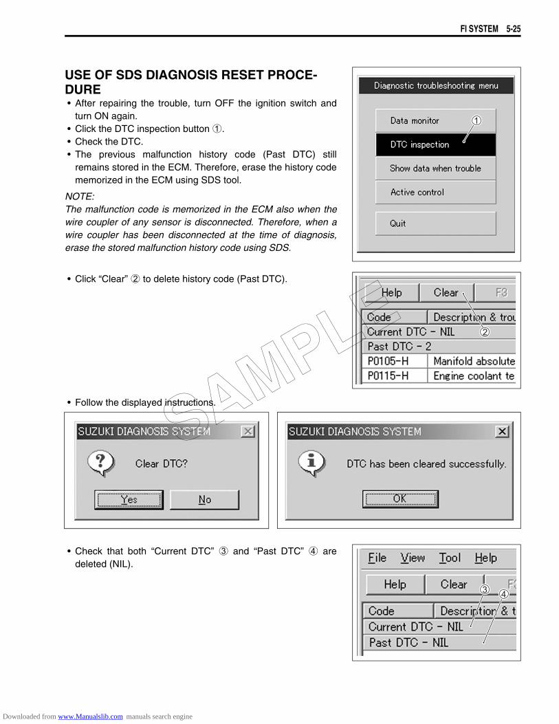
FI SYSTEM 5-25
USE OF SDS DIAGNOSIS RESET PROCE-DURE• After repairing the trouble, turn OFF the ignition switch and
turn ON again.• Click the DTC inspection button 1.• Check the DTC.• The previous malfunction history code (Past DTC) still
remains stored in the ECM. Therefore, erase the history codememorized in the ECM using SDS tool.
NOTE:The malfunction code is memorized in the ECM also when thewire coupler of any sensor is disconnected. Therefore, when awire coupler has been disconnected at the time of diagnosis,erase the stored malfunction history code using SDS.
• Click “Clear” 2 to delete history code (Past DTC).
• Follow the displayed instructions.
• Check that both “Current DTC” 3 and “Past DTC” 4 aredeleted (NIL).
SAMPLE
Downloaded from www.Manualslib.com manuals search engine
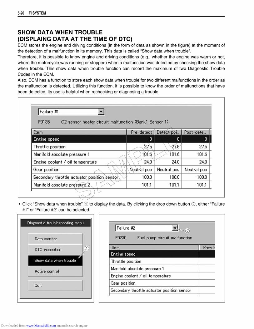
5-26 FI SYSTEM
SHOW DATA WHEN TROUBLE (DISPLAING DATA AT THE TIME OF DTC)ECM stores the engine and driving conditions (in the form of data as shown in the figure) at the moment ofthe detection of a malfunction in its memory. This data is called “Show data when trouble”.Therefore, it is possible to know engine and driving conditions (e.g., whether the engine was warm or not,where the motorcycle was running or stopped) when a malfunction was detected by checking the show datawhen trouble. This show data when trouble function can record the maximum of two Diagnostic TroubleCodes in the ECM.Also, ECM has a function to store each show data when trouble for two different malfunctions in the order asthe malfunction is detected. Utilizing this function, it is possible to know the order of malfunctions that havebeen detected. lts use is helpful when rechecking or diagnosing a trouble.
• Click “Show data when trouble” 1 to display the data. By clicking the drop down button 2, either “Failure#1” or “Failure #2” can be selected.
SAMPLE
Downloaded from www.Manualslib.com manuals search engine
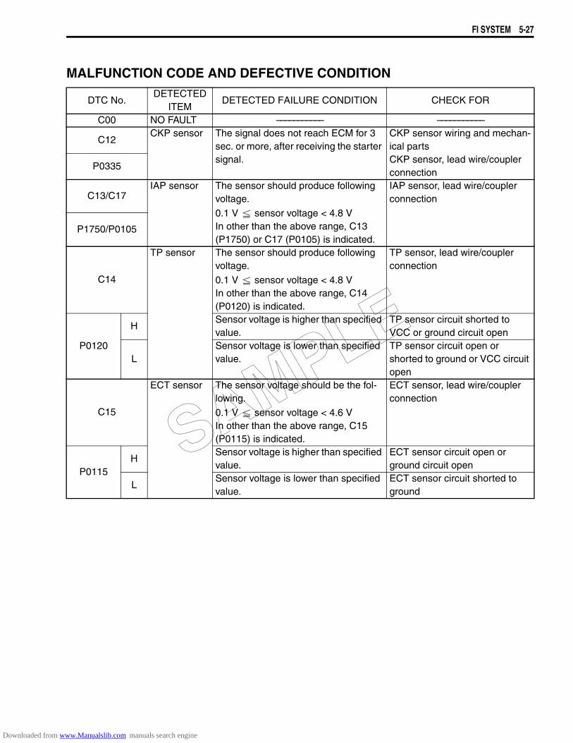
FI SYSTEM 5-27
MALFUNCTION CODE AND DEFECTIVE CONDITION
DTC No.DETECTED
ITEMDETECTED FAILURE CONDITION CHECK FOR
C00 NO FAULT ––––––––––– –––––––––––
C12CKP sensor The signal does not reach ECM for 3
sec. or more, after receiving the starter signal.
CKP sensor wiring and mechan-ical partsCKP sensor, lead wire/coupler connection
P0335
C13/C17IAP sensor The sensor should produce following
voltage.
0.1 V sensor voltage < 4.8 VIn other than the above range, C13 (P1750) or C17 (P0105) is indicated.
IAP sensor, lead wire/coupler connection
P1750/P0105
C14
TP sensor The sensor should produce following voltage.
0.1 V sensor voltage < 4.8 VIn other than the above range, C14 (P0120) is indicated.
TP sensor, lead wire/coupler connection
P0120
HSensor voltage is higher than specified value.
TP sensor circuit shorted to VCC or ground circuit open
LSensor voltage is lower than specified value.
TP sensor circuit open or shorted to ground or VCC circuit open
C15
ECT sensor The sensor voltage should be the fol-lowing.
0.1 V sensor voltage < 4.6 VIn other than the above range, C15 (P0115) is indicated.
ECT sensor, lead wire/coupler connection
P0115H
Sensor voltage is higher than specified value.
ECT sensor circuit open or ground circuit open
LSensor voltage is lower than specified value.
ECT sensor circuit shorted to ground
SAMPLE
Downloaded from www.Manualslib.com manuals search engine
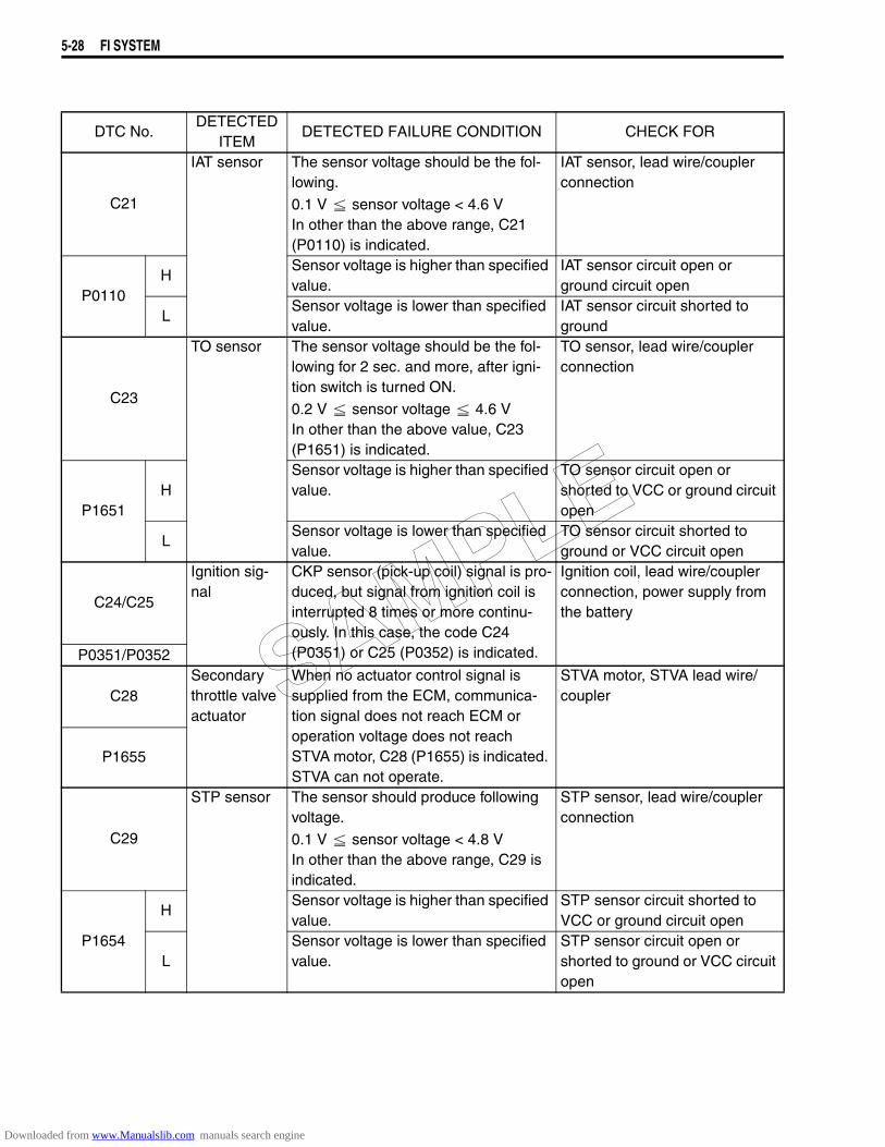
5-28 FI SYSTEM
DTC No.DETECTED
ITEMDETECTED FAILURE CONDITION CHECK FOR
C21
IAT sensor The sensor voltage should be the fol-lowing.
0.1 V sensor voltage < 4.6 VIn other than the above range, C21 (P0110) is indicated.
IAT sensor, lead wire/coupler connection
P0110H
Sensor voltage is higher than specified value.
IAT sensor circuit open or ground circuit open
LSensor voltage is lower than specified value.
IAT sensor circuit shorted to ground
C23
TO sensor The sensor voltage should be the fol-lowing for 2 sec. and more, after igni-tion switch is turned ON.
0.2 V sensor voltage 4.6 VIn other than the above value, C23 (P1651) is indicated.
TO sensor, lead wire/coupler connection
P1651H
Sensor voltage is higher than specified value.
TO sensor circuit open or shorted to VCC or ground circuit open
LSensor voltage is lower than specified value.
TO sensor circuit shorted to ground or VCC circuit open
C24/C25
Ignition sig-nal
CKP sensor (pick-up coil) signal is pro-duced, but signal from ignition coil is interrupted 8 times or more continu-ously. In this case, the code C24 (P0351) or C25 (P0352) is indicated.
Ignition coil, lead wire/coupler connection, power supply from the battery
P0351/P0352
C28Secondary throttle valve actuator
When no actuator control signal is supplied from the ECM, communica-tion signal does not reach ECM or operation voltage does not reach STVA motor, C28 (P1655) is indicated. STVA can not operate.
STVA motor, STVA lead wire/coupler
P1655
C29
STP sensor The sensor should produce following voltage.
0.1 V sensor voltage < 4.8 VIn other than the above range, C29 is indicated.
STP sensor, lead wire/coupler connection
P1654
HSensor voltage is higher than specified value.
STP sensor circuit shorted to VCC or ground circuit open
LSensor voltage is lower than specified value.
STP sensor circuit open or shorted to ground or VCC circuit open
SAMPLE
Downloaded from www.Manualslib.com manuals search engine
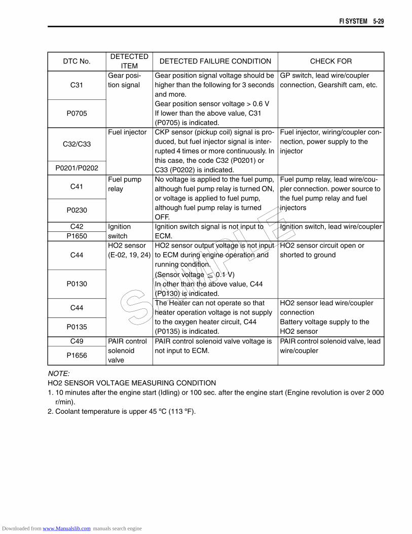
FI SYSTEM 5-29
NOTE:HO2 SENSOR VOLTAGE MEASURING CONDITION1. 10 minutes after the engine start (Idling) or 100 sec. after the engine start (Engine revolution is over 2 000
r/min).2. Coolant temperature is upper 45 ºC (113 ºF).
DTC No.DETECTED
ITEMDETECTED FAILURE CONDITION CHECK FOR
C31Gear posi-tion signal
Gear position signal voltage should be higher than the following for 3 seconds and more.Gear position sensor voltage > 0.6 VIf lower than the above value, C31 (P0705) is indicated.
GP switch, lead wire/coupler connection, Gearshift cam, etc.
P0705
C32/C33
Fuel injector CKP sensor (pickup coil) signal is pro-duced, but fuel injector signal is inter-rupted 4 times or more continuously. In this case, the code C32 (P0201) or C33 (P0202) is indicated.
Fuel injector, wiring/coupler con-nection, power supply to the injector
P0201/P0202
C41Fuel pump relay
No voltage is applied to the fuel pump, although fuel pump relay is turned ON, or voltage is applied to fuel pump, although fuel pump relay is turned OFF.
Fuel pump relay, lead wire/cou-pler connection. power source to the fuel pump relay and fuel injectorsP0230
C42 Ignition switch
Ignition switch signal is not input to ECM.
Ignition switch, lead wire/couplerP1650
C44HO2 sensor (E-02, 19, 24)
HO2 sensor output voltage is not input to ECM during engine operation and running condition.
(Sensor voltage 0.1 V)In other than the above value, C44 (P0130) is indicated.
HO2 sensor circuit open or shorted to ground
P0130
C44The Heater can not operate so that heater operation voltage is not supply to the oxygen heater circuit, C44 (P0135) is indicated.
HO2 sensor lead wire/coupler connectionBattery voltage supply to the HO2 sensor
P0135
C49 PAIR control solenoid valve
PAIR control solenoid valve voltage is not input to ECM.
PAIR control solenoid valve, lead wire/coupler
P1656
SAMPLE
Downloaded from www.Manualslib.com manuals search engine

5-30 FI SYSTEM
“C12” (P0335) CKP SENSOR CIRCUIT MALFUNCTION
INSPECTIONStep 11) Remove the left frame cover (8-3)2) Remove the left frame lower cover 1.
: Hooked part
3) Remove the tool box cover 2.
DETECTED CONDITION POSSIBLE CAUSEThe signal does not reach ECM for 3 sec. or more,after receiving the starter signal.
• Metal particles or foreign material being stuck on the CKP sensor and rotor tip
• CKP sensor circuit open or short• CKP sensor malfunction• ECM malfunction
ECM
GEN.
CKP sensorCKP
CKP
G/Y
Br
G
BI
To regulator/rectifier
1
1
SAMPLE
Downloaded from www.Manualslib.com manuals search engine
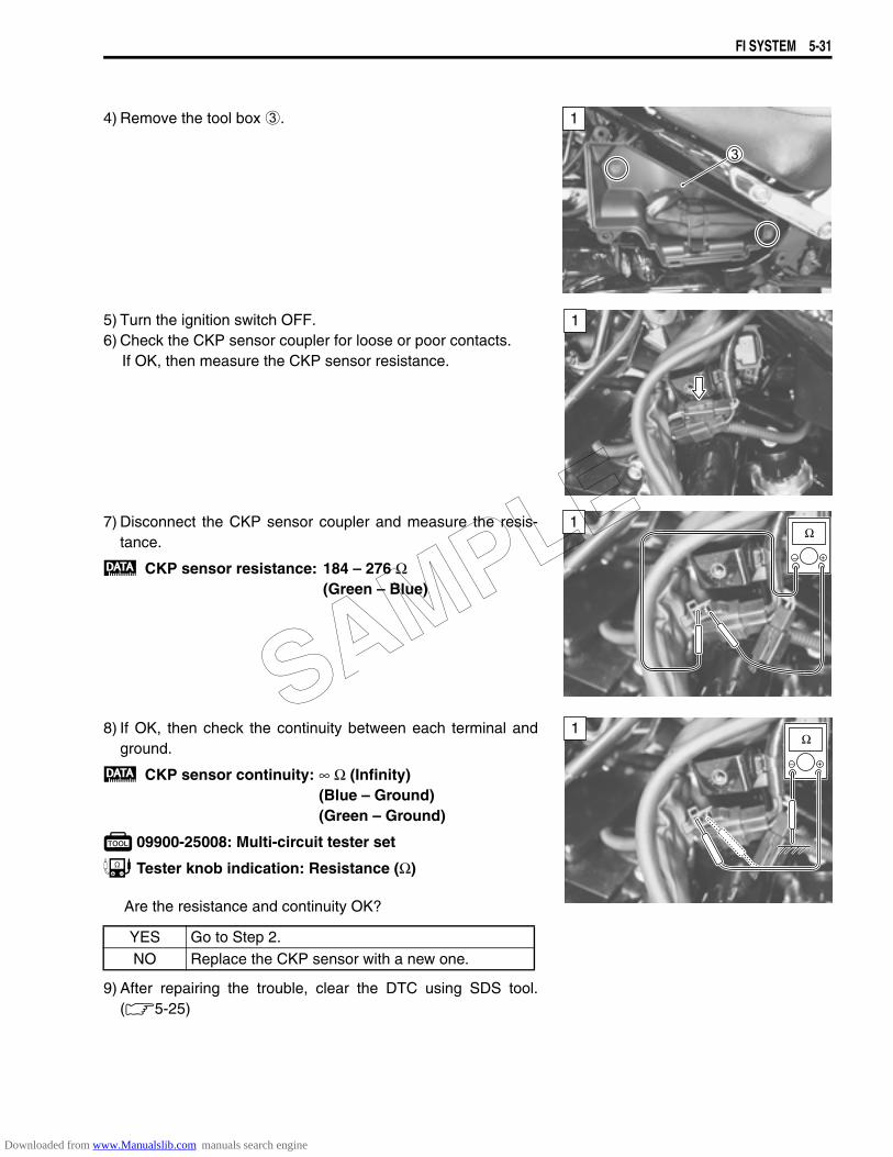
FI SYSTEM 5-31
4) Remove the tool box 3.
5) Turn the ignition switch OFF.6) Check the CKP sensor coupler for loose or poor contacts.
If OK, then measure the CKP sensor resistance.
7) Disconnect the CKP sensor coupler and measure the resis-tance.
CKP sensor resistance: 184 – 276 Ω(Green – Blue)
8) If OK, then check the continuity between each terminal andground.
CKP sensor continuity: ∞ Ω (Infinity)(Blue – Ground)(Green – Ground)
09900-25008: Multi-circuit tester set
Tester knob indication: Resistance (Ω)
Are the resistance and continuity OK?
9) After repairing the trouble, clear the DTC using SDS tool.(5-25)
1
1
1
YES Go to Step 2.NO Replace the CKP sensor with a new one.
1SAMPLE
Downloaded from www.Manualslib.com manuals search engine
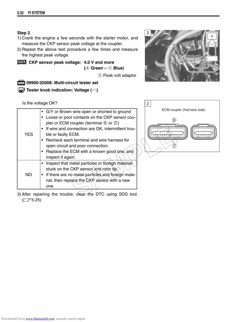
5-32 FI SYSTEM
Step 21) Crank the engine a few seconds with the starter motor, and
measure the CKP sensor peak voltage at the coupler.2) Repeat the above test procedure a few times and measure
the highest peak voltage.
CKP sensor peak voltage: 4.0 V and more (+ Green – - Blue)
1 Peak volt adaptor
09900-25008: Multi-circuit tester set
Tester knob indication: Voltage ()
.
Is the voltage OK?
3) After repairing the trouble, clear the DTC using SDS tool.(5-25)
YES
• G/Y or Brown wire open or shorted to ground• Loose or poor contacts on the CKP sensor cou-
pler or ECM coupler (terminal 9 or Q)• If wire and connection are OK, intermittent trou-
ble or faulty ECM.• Recheck each terminal and wire harness for
open circuit and poor connection.• Replace the ECM with a known good one, and
inspect it again.
NO
• Inspect that metal particles or foreign material stuck on the CKP sensor and rotor tip.
• If there are no metal particles and foreign mate-rial, then replace the CKP sensor with a new one.
2
Bl G
ECM coupler (Harness side)
2
SAMPLE
Downloaded from www.Manualslib.com manuals search engine

FI SYSTEM 5-33
“C13” (P1750) or “C17” (P0105) IAP SENSOR CIRCUIT MALFUNCTION
INSPECTIONStep 1(When indicating C13/P1750 for IAP sensor #2)1) For the other inspection procedures are the same as C17/
P0105.(When indicating C17/P0105 for IAP sensor #1)1) Remove the fuel tank. (6-3)2) Turn the ignition switch OFF.3) Check the IAP sensor coupler (Front cylinder side 1 or Rear
cylinder side 2) for loose or poor contacts. If OK, then measure the IAP sensor input voltage.
4) Disconnect the IAP sensor coupler.5) Turn the ignition switch ON.6) Measure the voltage at the Red wire 3 and ground.7) Also, measure the voltage at the Red wire 3 and B/Br wire 4.
IAP sensor input voltage: 4.5 – 5.5 V(+ Red – - Ground)(+ Red – - B/Br)
09900-25008: Multi-circuit tester set
Tester knob indication: Voltage ()
DETECTED CONDITION POSSIBLE CAUSEIAP sensor voltage low or high
(0.1 V Sensor voltage < 4.8 V)NOTE:Note that atmospheric pressure varies depending onweather conditions as well as altitude.Take that into consideration when inspecting volt-age.
• Clogged vacuum passage between throttle body and IAP sensor
• Air being drawn from vacuum passage between throttle body and IAP sensor
• IAP sensor circuit open or shorted to ground• IAP sensor malfunction• ECM malfunction
ECM
R
G/B
B/Br
VCC
IAP. F
E2
IAP sensor #2 (Front cylinder)
IAP sensor #1 (Rear cylinder)
R
G/W
B/Br
IAP. R
1
1
V
SAMPLE
Downloaded from www.Manualslib.com manuals search engine
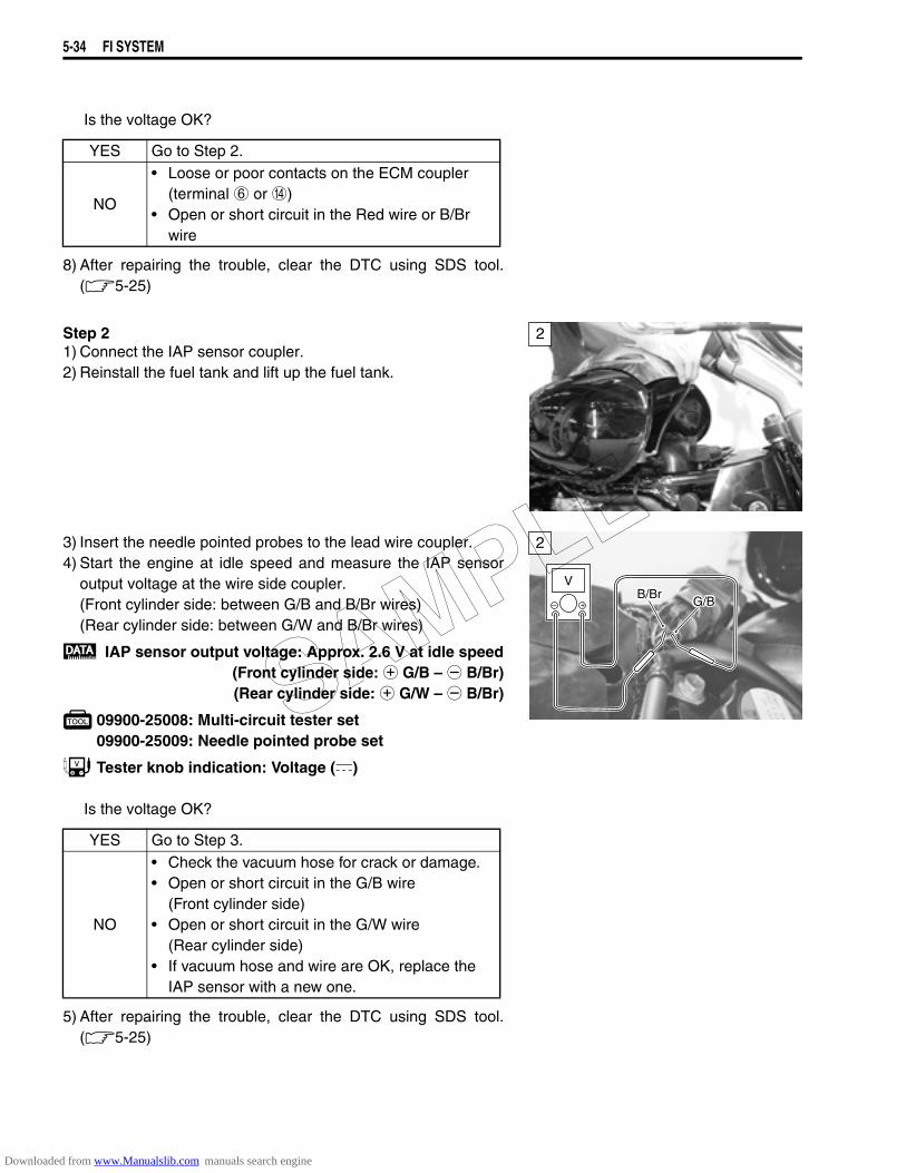
5-34 FI SYSTEM
Is the voltage OK?
8) After repairing the trouble, clear the DTC using SDS tool.(5-25)
Step 21) Connect the IAP sensor coupler.2) Reinstall the fuel tank and lift up the fuel tank.
3) Insert the needle pointed probes to the lead wire coupler.4) Start the engine at idle speed and measure the IAP sensor
output voltage at the wire side coupler.(Front cylinder side: between G/B and B/Br wires)(Rear cylinder side: between G/W and B/Br wires)
IAP sensor output voltage: Approx. 2.6 V at idle speed(Front cylinder side: + G/B – - B/Br)(Rear cylinder side: + G/W – - B/Br)
09900-25008: Multi-circuit tester set09900-25009: Needle pointed probe set
Tester knob indication: Voltage ()
Is the voltage OK?
5) After repairing the trouble, clear the DTC using SDS tool.(5-25)
YES Go to Step 2.
NO
• Loose or poor contacts on the ECM coupler (terminal 6 or D)
• Open or short circuit in the Red wire or B/Br wire
2
YES Go to Step 3.
NO
• Check the vacuum hose for crack or damage.• Open or short circuit in the G/B wire
(Front cylinder side)• Open or short circuit in the G/W wire
(Rear cylinder side)• If vacuum hose and wire are OK, replace the
IAP sensor with a new one.
2
VB/Br
G/B
SAMPLE
Downloaded from www.Manualslib.com manuals search engine
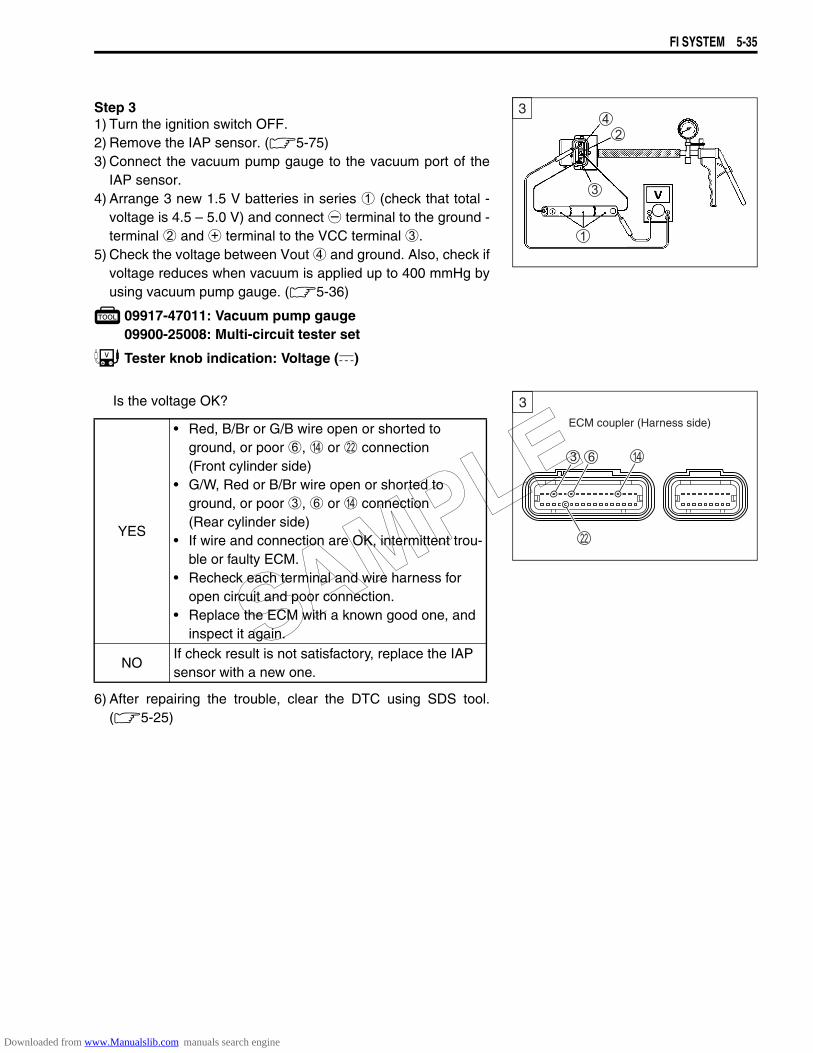
FI SYSTEM 5-35
Step 31) Turn the ignition switch OFF.2) Remove the IAP sensor. (5-75)3) Connect the vacuum pump gauge to the vacuum port of the
IAP sensor.4) Arrange 3 new 1.5 V batteries in series 1 (check that total -
voltage is 4.5 – 5.0 V) and connect - terminal to the ground -terminal 2 and + terminal to the VCC terminal 3.
5) Check the voltage between Vout 4 and ground. Also, check ifvoltage reduces when vacuum is applied up to 400 mmHg byusing vacuum pump gauge. (5-36)
09917-47011: Vacuum pump gauge09900-25008: Multi-circuit tester set
Tester knob indication: Voltage ()
Is the voltage OK?
6) After repairing the trouble, clear the DTC using SDS tool.(5-25)
YES
• Red, B/Br or G/B wire open or shorted to ground, or poor 6, D or L connection (Front cylinder side)
• G/W, Red or B/Br wire open or shorted to ground, or poor 3, 6 or D connection (Rear cylinder side)
• If wire and connection are OK, intermittent trou-ble or faulty ECM.
• Recheck each terminal and wire harness for open circuit and poor connection.
• Replace the ECM with a known good one, and inspect it again.
NOIf check result is not satisfactory, replace the IAP sensor with a new one.
3
ECM coupler (Harness side)
3
SAMPLE
Downloaded from www.Manualslib.com manuals search engine
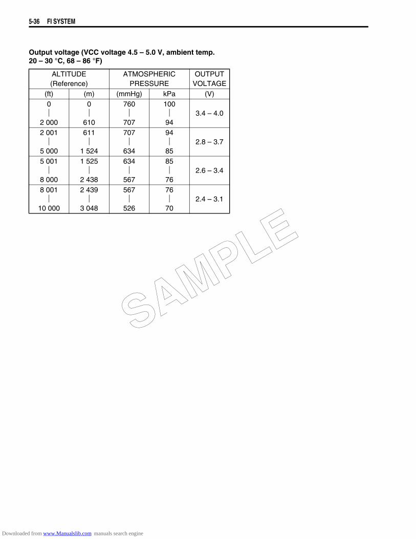
5-36 FI SYSTEM
Output voltage (VCC voltage 4.5 – 5.0 V, ambient temp. 20 – 30 °C, 68 – 86 °F)
ALTITUDE(Reference)
ATMOSPHERICPRESSURE
OUTPUTVOLTAGE
(ft) (m) (mmHg) kPa (V)0
2 000
0
610
760
707
10094
3.4 – 4.0
2 001
5 000
611
1 524
707
634
9485
2.8 – 3.7
5 001
8 000
1 525
2 438
634
567
8576
2.6 – 3.4
8 001
10 000
2 439
3 048
567
526
7670
2.4 – 3.1
SAMPLE
Downloaded from www.Manualslib.com manuals search engine
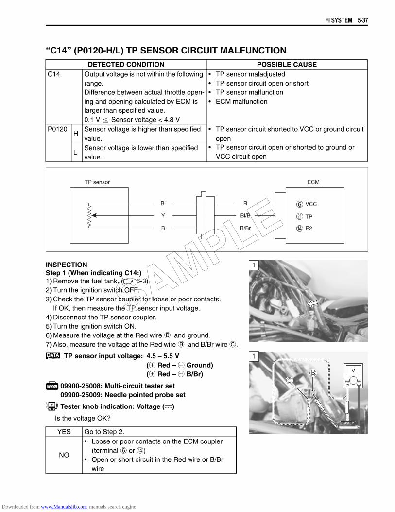
FI SYSTEM 5-37
“C14” (P0120-H/L) TP SENSOR CIRCUIT MALFUNCTION
INSPECTIONStep 1 (When indicating C14:)1) Remove the fuel tank. (6-3)2) Turn the ignition switch OFF.3) Check the TP sensor coupler for loose or poor contacts.
If OK, then measure the TP sensor input voltage.4) Disconnect the TP sensor coupler.5) Turn the ignition switch ON.6) Measure the voltage at the Red wire B and ground.7) Also, measure the voltage at the Red wire B and B/Br wire C.
TP sensor input voltage: 4.5 – 5.5 V(+ Red – - Ground)(+ Red – - B/Br)
09900-25008: Multi-circuit tester set09900-25009: Needle pointed probe set
Tester knob indication: Voltage ()
Is the voltage OK?
DETECTED CONDITION POSSIBLE CAUSEC14 Output voltage is not within the following
range.Difference between actual throttle open-ing and opening calculated by ECM is larger than specified value.0.1 V Sensor voltage < 4.8 V
• TP sensor maladjusted• TP sensor circuit open or short• TP sensor malfunction• ECM malfunction
P0120H
Sensor voltage is higher than specified value.
• TP sensor circuit shorted to VCC or ground circuit open
• TP sensor circuit open or shorted to ground or VCC circuit openL
Sensor voltage is lower than specified value.
YES Go to Step 2.
NO
• Loose or poor contacts on the ECM coupler(terminal 6 or D)
• Open or short circuit in the Red wire or B/Br wire
TP sensor ECM
E2
VCC
TP
R
Bl/B
B/Br
Bl
Y
B
1
1
V
SAMPLE
Downloaded from www.Manualslib.com manuals search engine
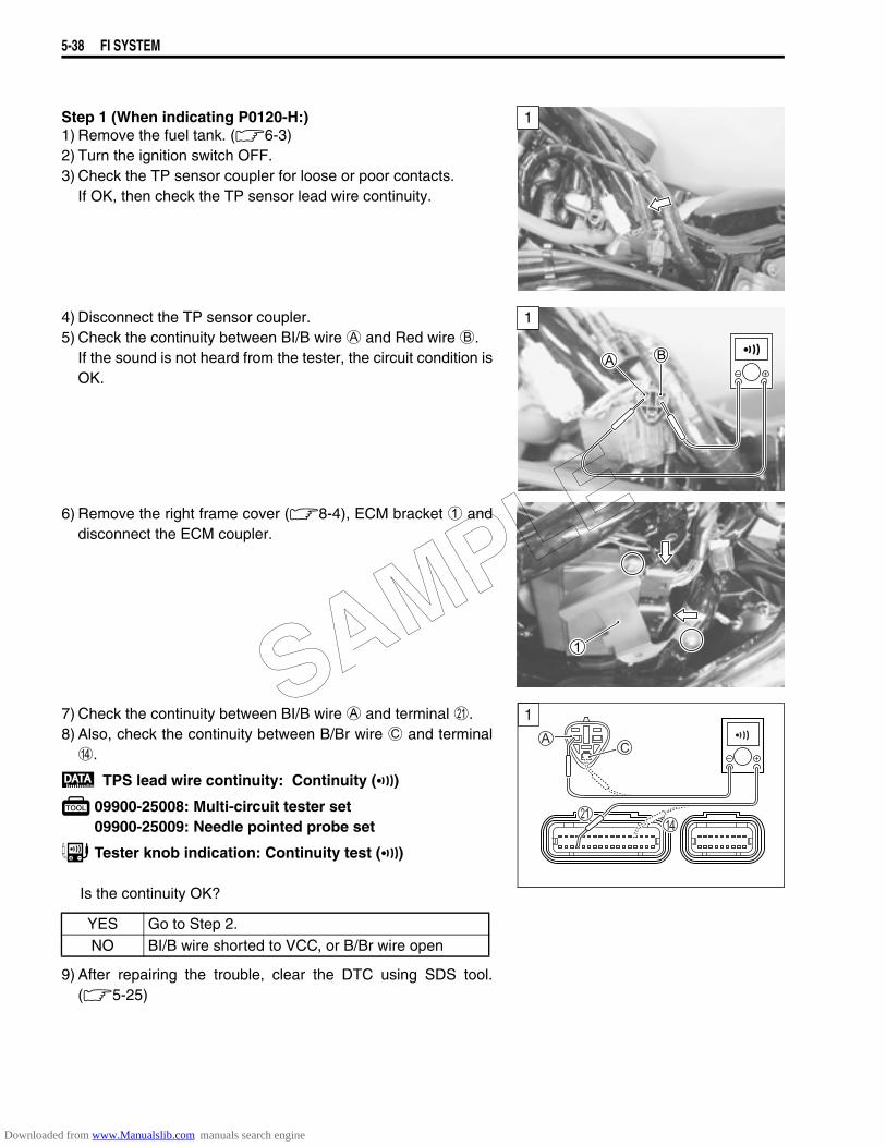
5-38 FI SYSTEM
Step 1 (When indicating P0120-H:)1) Remove the fuel tank. (6-3)2) Turn the ignition switch OFF.3) Check the TP sensor coupler for loose or poor contacts.
If OK, then check the TP sensor lead wire continuity.
4) Disconnect the TP sensor coupler.5) Check the continuity between BI/B wire A and Red wire B.
If the sound is not heard from the tester, the circuit condition isOK.
6) Remove the right frame cover (8-4), ECM bracket 1 anddisconnect the ECM coupler.
7) Check the continuity between BI/B wire A and terminal K.8) Also, check the continuity between B/Br wire C and terminal
D.
TPS lead wire continuity: Continuity ()
09900-25008: Multi-circuit tester set09900-25009: Needle pointed probe set
Tester knob indication: Continuity test ()
Is the continuity OK?
9) After repairing the trouble, clear the DTC using SDS tool.(5-25)
1
1
YES Go to Step 2.NO BI/B wire shorted to VCC, or B/Br wire open
1
SAMPLE
Downloaded from www.Manualslib.com manuals search engine
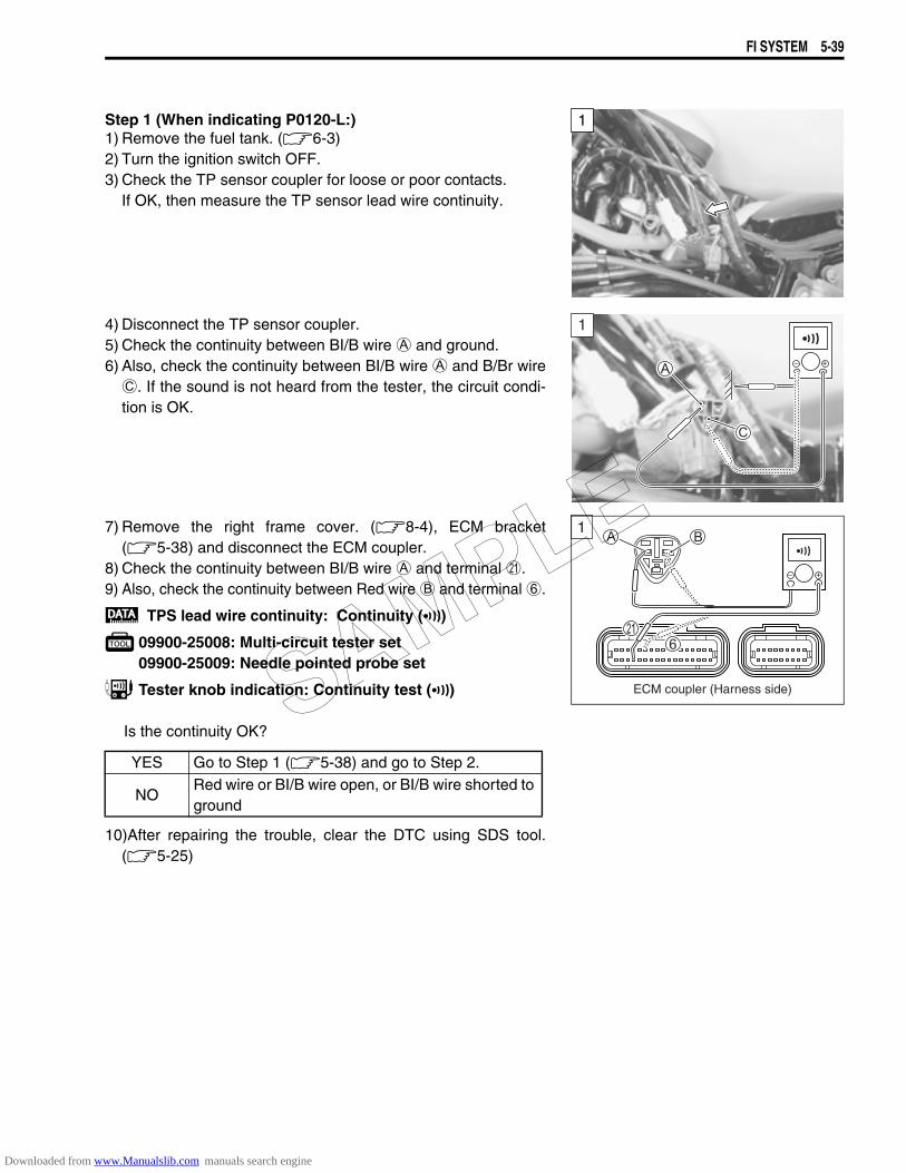
FI SYSTEM 5-39
Step 1 (When indicating P0120-L:)1) Remove the fuel tank. (6-3)2) Turn the ignition switch OFF.3) Check the TP sensor coupler for loose or poor contacts.
If OK, then measure the TP sensor lead wire continuity.
4) Disconnect the TP sensor coupler.5) Check the continuity between BI/B wire A and ground.6) Also, check the continuity between BI/B wire A and B/Br wire
C. If the sound is not heard from the tester, the circuit condi-tion is OK.
7) Remove the right frame cover. (8-4), ECM bracket(5-38) and disconnect the ECM coupler.
8) Check the continuity between BI/B wire A and terminal K.9) Also, check the continuity between Red wire B and terminal 6.
TPS lead wire continuity: Continuity ()
09900-25008: Multi-circuit tester set09900-25009: Needle pointed probe set
Tester knob indication: Continuity test ()
Is the continuity OK?
10)After repairing the trouble, clear the DTC using SDS tool.(5-25)
1
1
YES Go to Step 1 (5-38) and go to Step 2.
NORed wire or BI/B wire open, or BI/B wire shorted to ground
1
ECM coupler (Harness side)SAMPLE
Downloaded from www.Manualslib.com manuals search engine
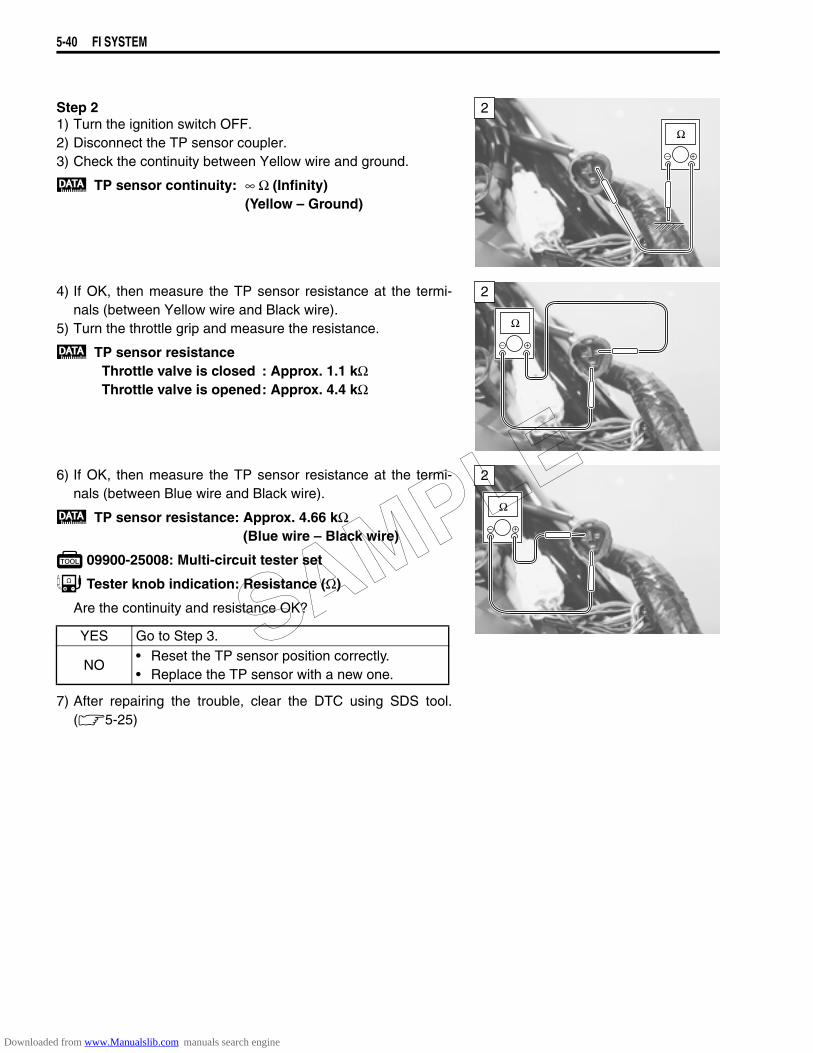
5-40 FI SYSTEM
Step 21) Turn the ignition switch OFF.2) Disconnect the TP sensor coupler.3) Check the continuity between Yellow wire and ground.
TP sensor continuity: ∞ Ω (Infinity) (Yellow – Ground)
4) If OK, then measure the TP sensor resistance at the termi-nals (between Yellow wire and Black wire).
5) Turn the throttle grip and measure the resistance.
TP sensor resistanceThrottle valve is closed : Approx. 1.1 kΩThrottle valve is opened: Approx. 4.4 kΩ
6) If OK, then measure the TP sensor resistance at the termi-nals (between Blue wire and Black wire).
TP sensor resistance: Approx. 4.66 kΩ (Blue wire – Black wire)
09900-25008: Multi-circuit tester set
Tester knob indication: Resistance (Ω)
Are the continuity and resistance OK?
7) After repairing the trouble, clear the DTC using SDS tool.(5-25)
2
2
YES Go to Step 3.
NO• Reset the TP sensor position correctly.• Replace the TP sensor with a new one.
2
SAMPLE
Downloaded from www.Manualslib.com manuals search engine
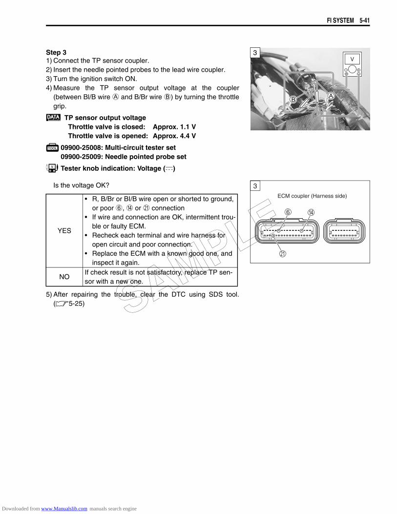
FI SYSTEM 5-41
Step 31) Connect the TP sensor coupler.2) Insert the needle pointed probes to the lead wire coupler.3) Turn the ignition switch ON.4) Measure the TP sensor output voltage at the coupler
(between Bl/B wire A and B/Br wire B) by turning the throttlegrip.
TP sensor output voltageThrottle valve is closed: Approx. 1.1 VThrottle valve is opened: Approx. 4.4 V
09900-25008: Multi-circuit tester set09900-25009: Needle pointed probe set
Tester knob indication: Voltage ()
Is the voltage OK?
5) After repairing the trouble, clear the DTC using SDS tool.(5-25)
V3
YES
• R, B/Br or BI/B wire open or shorted to ground, or poor 6, D or K connection
• If wire and connection are OK, intermittent trou-ble or faulty ECM.
• Recheck each terminal and wire harness for open circuit and poor connection.
• Replace the ECM with a known good one, and inspect it again.
NOIf check result is not satisfactory, replace TP sen-sor with a new one.
ECM coupler (Harness side)
3
SAMPLE
Downloaded from www.Manualslib.com manuals search engine
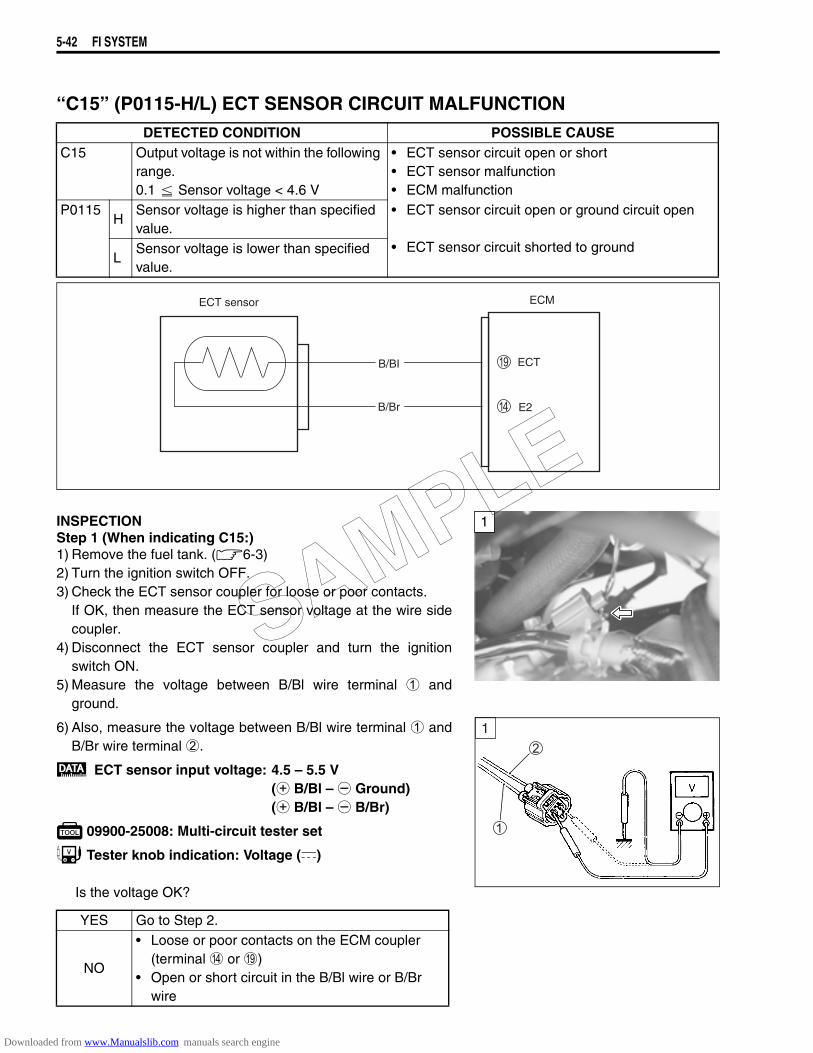
5-42 FI SYSTEM
“C15” (P0115-H/L) ECT SENSOR CIRCUIT MALFUNCTION
INSPECTIONStep 1 (When indicating C15:)1) Remove the fuel tank. (6-3)2) Turn the ignition switch OFF.3) Check the ECT sensor coupler for loose or poor contacts.
If OK, then measure the ECT sensor voltage at the wire sidecoupler.
4) Disconnect the ECT sensor coupler and turn the ignitionswitch ON.
5) Measure the voltage between B/Bl wire terminal 1 andground.
6) Also, measure the voltage between B/Bl wire terminal 1 andB/Br wire terminal 2.
ECT sensor input voltage: 4.5 – 5.5 V(+ B/Bl – - Ground)(+ B/Bl – - B/Br)
09900-25008: Multi-circuit tester set
Tester knob indication: Voltage ()
Is the voltage OK?
DETECTED CONDITION POSSIBLE CAUSEC15 Output voltage is not within the following
range.0.1 Sensor voltage < 4.6 V
• ECT sensor circuit open or short• ECT sensor malfunction• ECM malfunction
P0115H
Sensor voltage is higher than specified value.
• ECT sensor circuit open or ground circuit open
• ECT sensor circuit shorted to groundL
Sensor voltage is lower than specified value.
ECM
E2
ECT
ECT sensor
B/BI
B/Br
YES Go to Step 2.
NO
• Loose or poor contacts on the ECM coupler (terminal D or I)
• Open or short circuit in the B/Bl wire or B/Br wire
1
1
SAMPLE
Downloaded from www.Manualslib.com manuals search engine
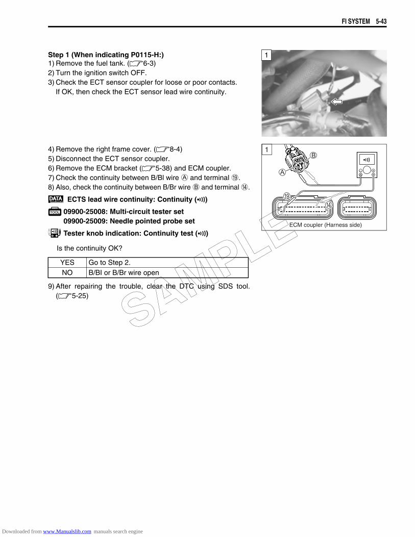
FI SYSTEM 5-43
Step 1 (When indicating P0115-H:)1) Remove the fuel tank. (6-3)2) Turn the ignition switch OFF.3) Check the ECT sensor coupler for loose or poor contacts.
If OK, then check the ECT sensor lead wire continuity.
4) Remove the right frame cover. (8-4)5) Disconnect the ECT sensor coupler.6) Remove the ECM bracket (5-38) and ECM coupler. 7) Check the continuity between B/Bl wire A and terminal I.8) Also, check the continuity between B/Br wire B and terminal D.
ECTS lead wire continuity: Continuity ()
09900-25008: Multi-circuit tester set09900-25009: Needle pointed probe set
Tester knob indication: Continuity test ()
Is the continuity OK?
9) After repairing the trouble, clear the DTC using SDS tool.(5-25)
1
1
ECM coupler (Harness side)
YES Go to Step 2.NO B/BI or B/Br wire open
SAMPLE
Downloaded from www.Manualslib.com manuals search engine
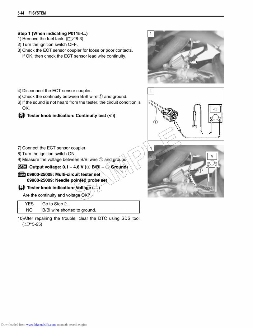
5-44 FI SYSTEM
Step 1 (When indicating P0115-L:)1) Remove the fuel tank. (6-3)2) Turn the ignition switch OFF.3) Check the ECT sensor coupler for loose or poor contacts.
If OK, then check the ECT sensor lead wire continuity.
4) Disconnect the ECT sensor coupler.5) Check the continuity between B/Bl wire 1 and ground. 6) If the sound is not heard from the tester, the circuit condition is
OK.
Tester knob indication: Continuity test ()
7) Connect the ECT sensor coupler.8) Turn the ignition switch ON.9) Measure the voltage between B/Bl wire 1 and ground.
Output voltage: 0.1 – 4.6 V (+ B/Bl – - Ground)
09900-25008: Multi-circuit tester set09900-25009: Needle pointed probe set
Tester knob indication: Voltage ()
Are the continuity and voltage OK?
10)After repairing the trouble, clear the DTC using SDS tool.(5-25)
1
1
YES Go to Step 2.NO B/Bl wire shorted to ground.
1
V
SAMPLE
Downloaded from www.Manualslib.com manuals search engine
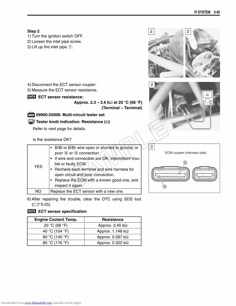
FI SYSTEM 5-45
Step 21) Turn the ignition switch OFF.2) Loosen the inlet pipe screw.3) Lift up the inlet pipe 1.
4) Disconnect the ECT sensor coupler.5) Measure the ECT sensor resistance.
ECT sensor resistance:Approx. 2.3 – 2.6 kΩ at 20 °C (68 °F)
(Terminal – Terminal)
09900-25008: Multi-circuit tester set
Tester knob indication: Resistance (Ω)
Refer to next page for details.
Is the resistance OK?
6) After repairing the trouble, clear the DTC using SDS tool.(5-25)
ECT sensor specification
22
YES
• B/Bl or B/Br wire open or shorted to ground, or poor D or I connection
• If wire and connection are OK, intermittent trou-ble or faulty ECM.
• Recheck each terminal and wire harness for open circuit and poor connection.
• Replace the ECM with a known good one, and inspect it again.
NO Replace the ECT sensor with a new one.
Engine Coolant Temp. Resistance20 °C (68 °F) Approx. 2.45 kΩ
40 °C (104 °F) Approx. 1.148 kΩ60 °C (140 °F) Approx. 0.587 kΩ80 °C (176 °F) Approx. 0.322 kΩ
2
ECM coupler (Harness side)
2
SAMPLE
Downloaded from www.Manualslib.com manuals search engine
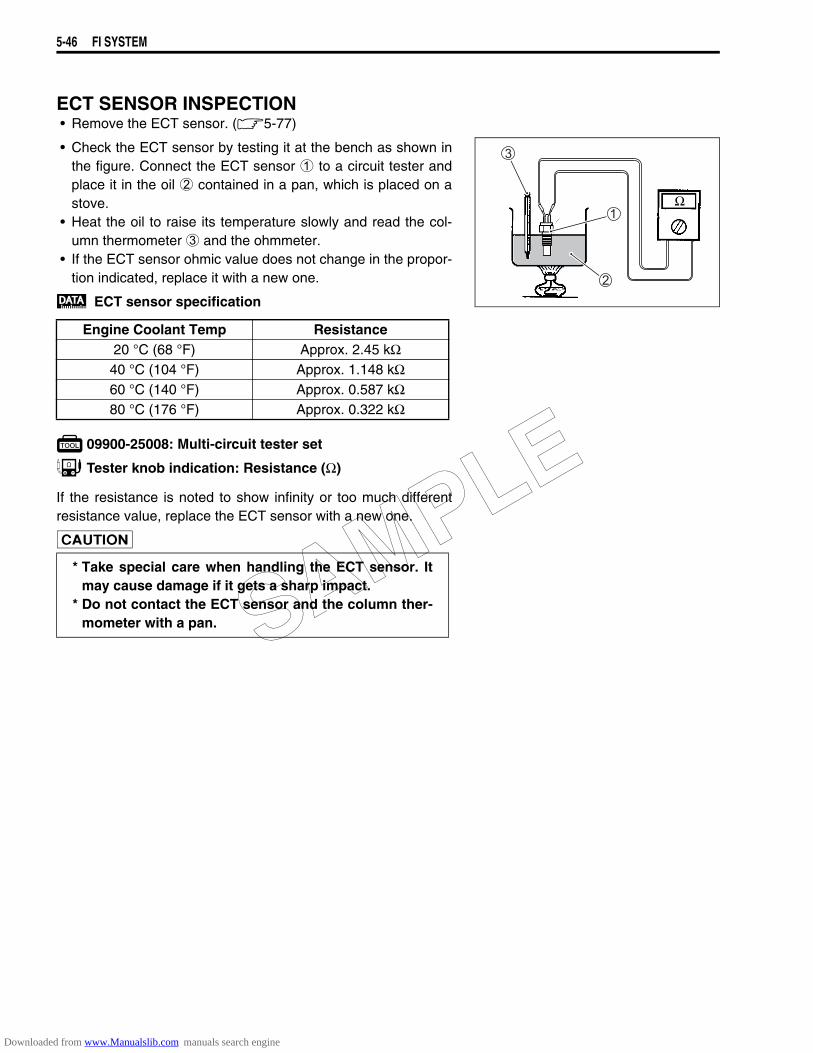
5-46 FI SYSTEM
ECT SENSOR INSPECTION• Remove the ECT sensor. (5-77)
• Check the ECT sensor by testing it at the bench as shown inthe figure. Connect the ECT sensor 1 to a circuit tester andplace it in the oil 2 contained in a pan, which is placed on astove.
• Heat the oil to raise its temperature slowly and read the col-umn thermometer 3 and the ohmmeter.
• If the ECT sensor ohmic value does not change in the propor-tion indicated, replace it with a new one.
ECT sensor specification
09900-25008: Multi-circuit tester set
Tester knob indication: Resistance (Ω)
If the resistance is noted to show infinity or too much differentresistance value, replace the ECT sensor with a new one.
Engine Coolant Temp Resistance20 °C (68 °F) Approx. 2.45 kΩ
40 °C (104 °F) Approx. 1.148 kΩ60 °C (140 °F) Approx. 0.587 kΩ80 °C (176 °F) Approx. 0.322 kΩ
* Take special care when handling the ECT sensor. Itmay cause damage if it gets a sharp impact.
* Do not contact the ECT sensor and the column ther-mometer with a pan. SAMPLE
Downloaded from www.Manualslib.com manuals search engine
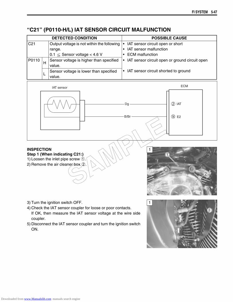
FI SYSTEM 5-47
“C21” (P0110-H/L) IAT SENSOR CIRCUIT MALFUNCTION
INSPECTIONStep 1 (When indicating C21:)1) Loosen the inlet pipe screw 1.2) Remove the air cleaner box 2.
3) Turn the ignition switch OFF.4) Check the IAT sensor coupler for loose or poor contacts.
If OK, then measure the IAT sensor voltage at the wire sidecoupler.
5) Disconnect the IAT sensor coupler and turn the ignition switchON.
DETECTED CONDITION POSSIBLE CAUSEC21 Output voltage is not within the following
range.0.1 Sensor voltage < 4.6 V
• IAT sensor circuit open or short• IAT sensor malfunction• ECM malfunction
P0110H
Sensor voltage is higher than specified value.
• IAT sensor circuit open or ground circuit open
• IAT sensor circuit shorted to groundL
Sensor voltage is lower than specified value.
ECM
B/Br E2
IATDg
IAT sensor
1
1
SAMPLE
Downloaded from www.Manualslib.com manuals search engine

5-48 FI SYSTEM
6) Measure the voltage between Dg wire terminal 3 andground.
7) Also, measure the voltage between Dg wire terminal 3 andB/Br wire terminal 4.
IAT sensor input voltage: 4.5 – 5.5 V(+ Dg – - Ground)(+ Dg – - B/Br)
09900-25008: Multi-circuit tester set
Tester knob indication: Voltage ()
Is the voltage OK?
1
V
YES Go to Step 2.
NO• Loose or poor contacts on the ECM coupler
(terminal 2 or D)• Open or short circuit in the Dg wire or B/Br wire
SAMPLE
Downloaded from www.Manualslib.com manuals search engine
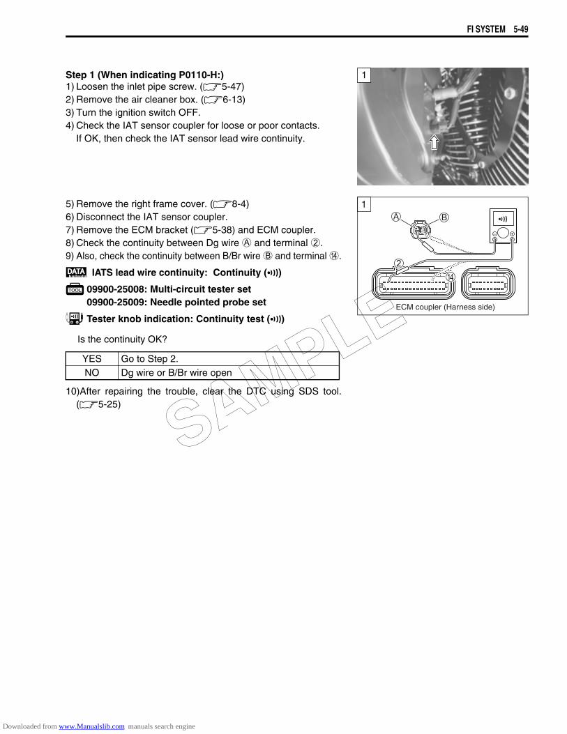
FI SYSTEM 5-49
Step 1 (When indicating P0110-H:)1) Loosen the inlet pipe screw. (5-47)2) Remove the air cleaner box. (6-13)3) Turn the ignition switch OFF.4) Check the IAT sensor coupler for loose or poor contacts.
If OK, then check the IAT sensor lead wire continuity.
5) Remove the right frame cover. (8-4)6) Disconnect the IAT sensor coupler.7) Remove the ECM bracket (5-38) and ECM coupler.8) Check the continuity between Dg wire A and terminal 2.9) Also, check the continuity between B/Br wire B and terminal D.
IATS lead wire continuity: Continuity ()
09900-25008: Multi-circuit tester set09900-25009: Needle pointed probe set
Tester knob indication: Continuity test ()
Is the continuity OK?
10)After repairing the trouble, clear the DTC using SDS tool.(5-25)
1
1
ECM coupler (Harness side)
YES Go to Step 2.NO Dg wire or B/Br wire open
SAMPLE
Downloaded from www.Manualslib.com manuals search engine
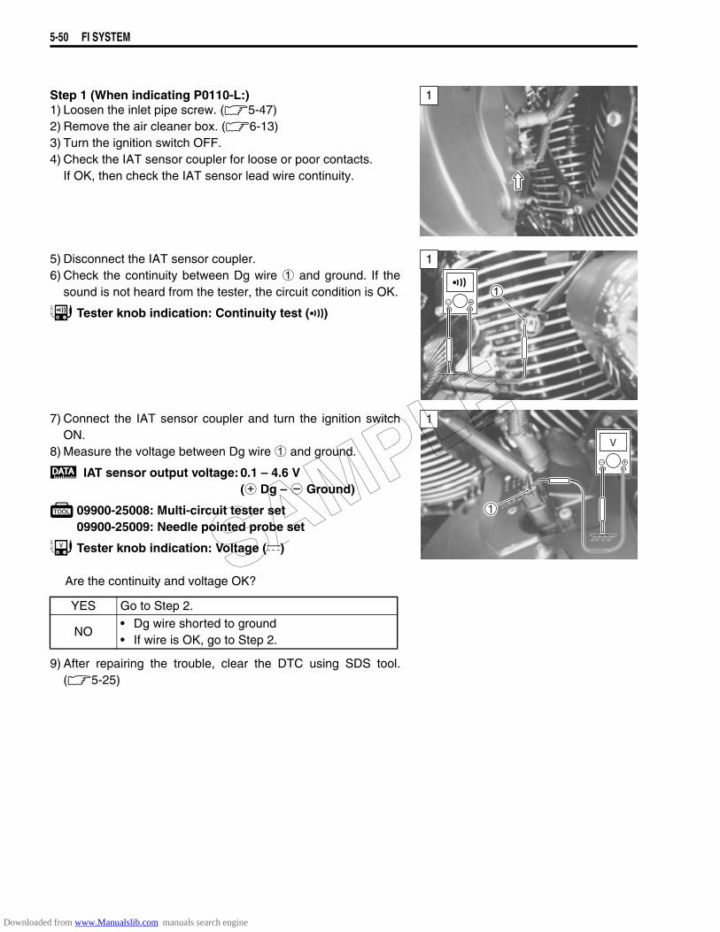
5-50 FI SYSTEM
Step 1 (When indicating P0110-L:)1) Loosen the inlet pipe screw. (5-47)2) Remove the air cleaner box. (6-13)3) Turn the ignition switch OFF.4) Check the IAT sensor coupler for loose or poor contacts.
If OK, then check the IAT sensor lead wire continuity.
5) Disconnect the IAT sensor coupler.6) Check the continuity between Dg wire 1 and ground. If the
sound is not heard from the tester, the circuit condition is OK.
Tester knob indication: Continuity test ()
7) Connect the IAT sensor coupler and turn the ignition switchON.
8) Measure the voltage between Dg wire 1 and ground.
IAT sensor output voltage: 0.1 – 4.6 V(+ Dg – - Ground)
09900-25008: Multi-circuit tester set09900-25009: Needle pointed probe set
Tester knob indication: Voltage ()
Are the continuity and voltage OK?
9) After repairing the trouble, clear the DTC using SDS tool.(5-25)
1
1
YES Go to Step 2.
NO• Dg wire shorted to ground• If wire is OK, go to Step 2.
1
V
SAMPLE
Downloaded from www.Manualslib.com manuals search engine
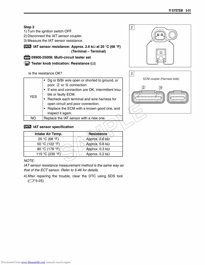
FI SYSTEM 5-51
Step 21) Turn the ignition switch OFF.2) Disconnect the IAT sensor coupler.3) Measure the IAT sensor resistance.
IAT sensor resistance: Approx. 2.6 kΩ at 20 °C (68 °F)(Terminal – Terminal)
09900-25008: Multi-circuit tester set
Tester knob indication: Resistance (Ω)
Is the resistance OK?
IAT sensor specification
NOTE:IAT sensor resistance measurement method is the same way asthat of the ECT sensor. Refer to 5-46 for details.
4) After repairing the trouble, clear the DTC using SDS tool.(5-25)
2
YES
• Dg or B/Br wire open or shorted to ground, or poor 2 or D connection
• If wire and connection are OK, intermittent trou-ble or faulty ECM.
• Recheck each terminal and wire harness for open circuit and poor connection.
• Replace the ECM with a known good one, and inspect it again.
NO Replace the IAT sensor with a new one.
Intake Air Temp. Resistance20 °C (68 °F) Approx. 2.6 kΩ
50 °C (122 °F) Approx. 0.8 kΩ80 °C (176 °F) Approx. 0.3 kΩ
110 °C (230 °F) Approx. 0.2 kΩ
ECM coupler (Harness side)
2
SAMPLE
Downloaded from www.Manualslib.com manuals search engine
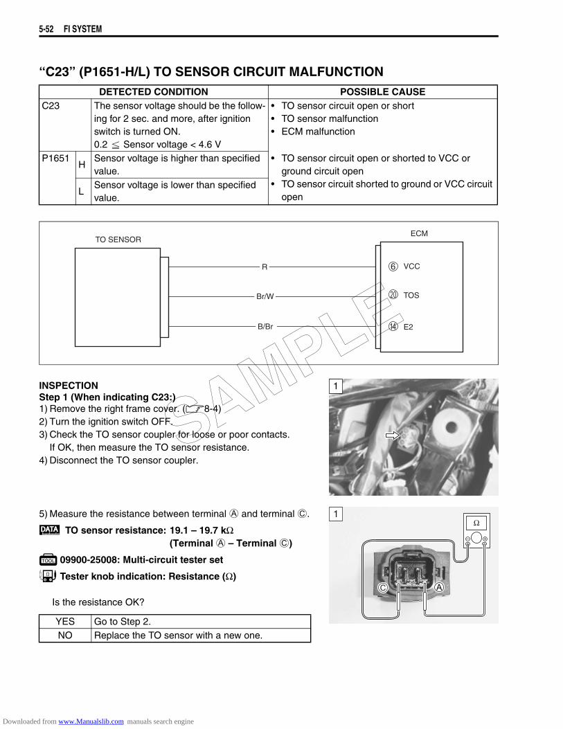
5-52 FI SYSTEM
“C23” (P1651-H/L) TO SENSOR CIRCUIT MALFUNCTION
INSPECTIONStep 1 (When indicating C23:)1) Remove the right frame cover. (8-4)2) Turn the ignition switch OFF.3) Check the TO sensor coupler for loose or poor contacts.
If OK, then measure the TO sensor resistance.4) Disconnect the TO sensor coupler.
5) Measure the resistance between terminal A and terminal C.
TO sensor resistance: 19.1 – 19.7 kΩ(Terminal A – Terminal C)
09900-25008: Multi-circuit tester set
Tester knob indication: Resistance (Ω)
Is the resistance OK?
DETECTED CONDITION POSSIBLE CAUSEC23 The sensor voltage should be the follow-
ing for 2 sec. and more, after ignition switch is turned ON.0.2 Sensor voltage < 4.6 V
• TO sensor circuit open or short• TO sensor malfunction• ECM malfunction
P1651H
Sensor voltage is higher than specified value.
• TO sensor circuit open or shorted to VCC or ground circuit open
• TO sensor circuit shorted to ground or VCC circuit openL
Sensor voltage is lower than specified value.
ECM
Br/W
E2
TOS
R
B/Br
VCC
TO SENSOR
1
YES Go to Step 2.NO Replace the TO sensor with a new one.
1
SAMPLE
Downloaded from www.Manualslib.com manuals search engine
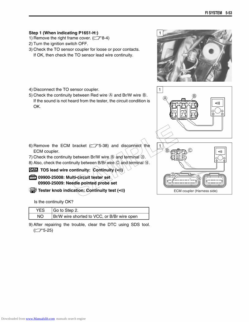
FI SYSTEM 5-53
Step 1 (When indicating P1651-H:)1) Remove the right frame cover. (8-4)2) Turn the ignition switch OFF.3) Check the TO sensor coupler for loose or poor contacts.
If OK, then check the TO sensor lead wire continuity.
4) Disconnect the TO sensor coupler.5) Check the continuity between Red wire A and Br/W wire B.
If the sound is not heard from the tester, the circuit condition isOK.
6) Remove the ECM bracket (5-38) and disconnect theECM coupler.
7) Check the continuity between Br/W wire B and terminal J.8) Also, check the continuity between B/Br wire C and terminal D.
TOS lead wire continuity: Continuity ()
09900-25008: Multi-circuit tester set09900-25009: Needle pointed probe set
Tester knob indication: Continuity test ()
Is the continuity OK?
9) After repairing the trouble, clear the DTC using SDS tool.(5-25)
1
1
!
YES Go to Step 2.NO Br/W wire shorted to VCC, or B/Br wire open
1
ECM coupler (Harness side)SAMPLE
Downloaded from www.Manualslib.com manuals search engine
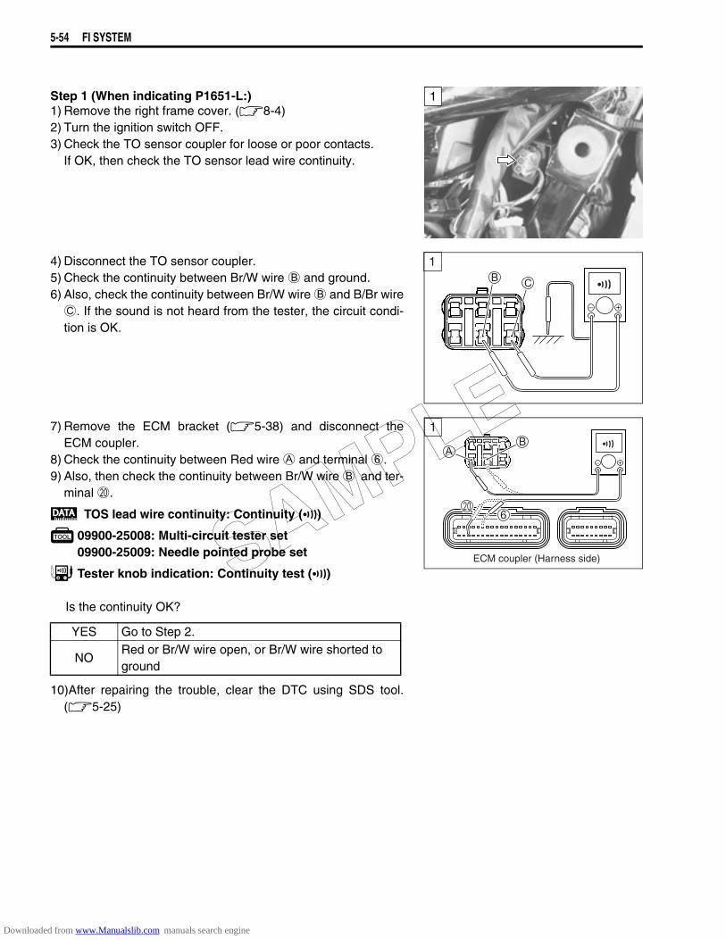
5-54 FI SYSTEM
Step 1 (When indicating P1651-L:)1) Remove the right frame cover. (8-4)2) Turn the ignition switch OFF.3) Check the TO sensor coupler for loose or poor contacts.
If OK, then check the TO sensor lead wire continuity.
4) Disconnect the TO sensor coupler.5) Check the continuity between Br/W wire B and ground.6) Also, check the continuity between Br/W wire B and B/Br wire
C. If the sound is not heard from the tester, the circuit condi-tion is OK.
7) Remove the ECM bracket (5-38) and disconnect theECM coupler.
8) Check the continuity between Red wire A and terminal 6.9) Also, then check the continuity between Br/W wire B and ter-
minal J.
TOS lead wire continuity: Continuity ()
09900-25008: Multi-circuit tester set09900-25009: Needle pointed probe set
Tester knob indication: Continuity test ()
Is the continuity OK?
10)After repairing the trouble, clear the DTC using SDS tool.(5-25)
1
1
!
YES Go to Step 2.
NORed or Br/W wire open, or Br/W wire shorted to ground
1
ECM coupler (Harness side)SAMPLE
Downloaded from www.Manualslib.com manuals search engine
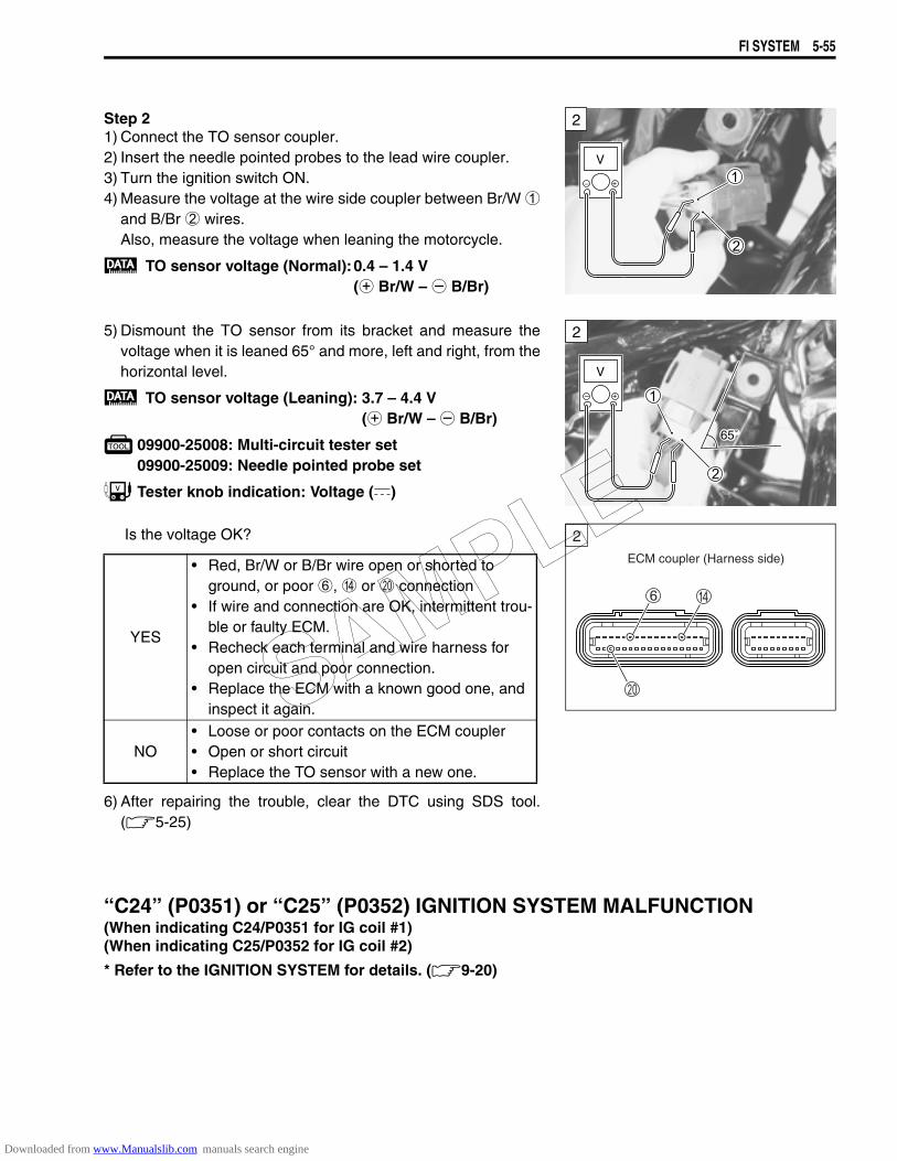
FI SYSTEM 5-55
Step 21) Connect the TO sensor coupler.2) Insert the needle pointed probes to the lead wire coupler.3) Turn the ignition switch ON.4) Measure the voltage at the wire side coupler between Br/W 1
and B/Br 2 wires. Also, measure the voltage when leaning the motorcycle.
TO sensor voltage (Normal):0.4 – 1.4 V (+ Br/W – - B/Br)
5) Dismount the TO sensor from its bracket and measure thevoltage when it is leaned 65° and more, left and right, from thehorizontal level.
TO sensor voltage (Leaning): 3.7 – 4.4 V (+ Br/W – - B/Br)
09900-25008: Multi-circuit tester set09900-25009: Needle pointed probe set
Tester knob indication: Voltage ()
Is the voltage OK?
6) After repairing the trouble, clear the DTC using SDS tool.(5-25)
“C24” (P0351) or “C25” (P0352) IGNITION SYSTEM MALFUNCTION(When indicating C24/P0351 for IG coil #1)(When indicating C25/P0352 for IG coil #2)
* Refer to the IGNITION SYSTEM for details. (9-20)
2
V
2
V
65˚
YES
• Red, Br/W or B/Br wire open or shorted to ground, or poor 6, D or J connection
• If wire and connection are OK, intermittent trou-ble or faulty ECM.
• Recheck each terminal and wire harness for open circuit and poor connection.
• Replace the ECM with a known good one, and inspect it again.
NO• Loose or poor contacts on the ECM coupler• Open or short circuit• Replace the TO sensor with a new one.
ECM coupler (Harness side)
2
SAMPLE
Downloaded from www.Manualslib.com manuals search engine
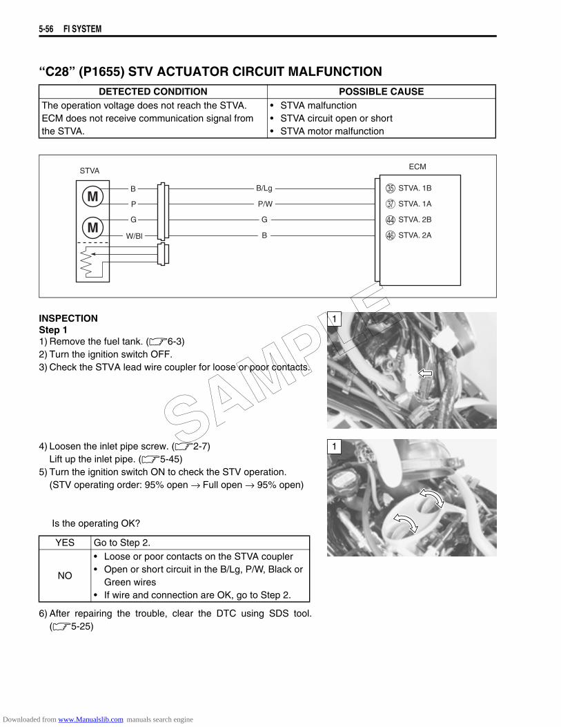
5-56 FI SYSTEM
“C28” (P1655) STV ACTUATOR CIRCUIT MALFUNCTION
INSPECTIONStep 11) Remove the fuel tank. (6-3)2) Turn the ignition switch OFF.3) Check the STVA lead wire coupler for loose or poor contacts.
4) Loosen the inlet pipe screw. (2-7)Lift up the inlet pipe. (5-45)
5) Turn the ignition switch ON to check the STV operation.(STV operating order: 95% open → Full open → 95% open)
Is the operating OK?
6) After repairing the trouble, clear the DTC using SDS tool.(5-25)
DETECTED CONDITION POSSIBLE CAUSEThe operation voltage does not reach the STVA.ECM does not receive communication signal from the STVA.
• STVA malfunction• STVA circuit open or short• STVA motor malfunction
ECM
STVA. 2B
STVA. 1A
STVA. 1B
STVA
B/Lg
P/W
B
P
G
W/Bl
G
B STVA. 2A
1
YES Go to Step 2.
NO
• Loose or poor contacts on the STVA coupler• Open or short circuit in the B/Lg, P/W, Black or
Green wires• If wire and connection are OK, go to Step 2.
1SAMPLE
Downloaded from www.Manualslib.com manuals search engine
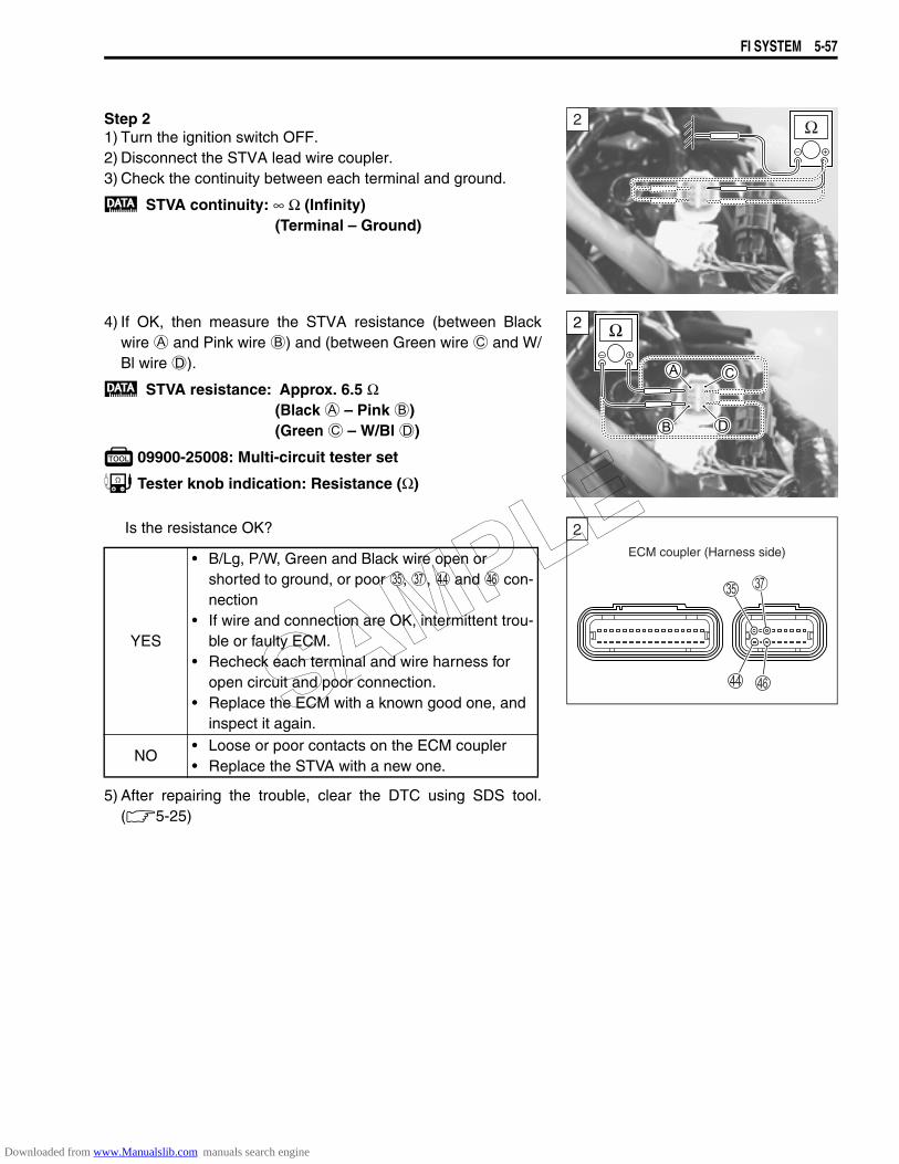
FI SYSTEM 5-57
Step 21) Turn the ignition switch OFF.2) Disconnect the STVA lead wire coupler.3) Check the continuity between each terminal and ground.
STVA continuity: ∞ Ω (Infinity)(Terminal – Ground)
4) If OK, then measure the STVA resistance (between Blackwire A and Pink wire B) and (between Green wire C and W/Bl wire D).
STVA resistance: Approx. 6.5 Ω (Black A – Pink B)(Green C – W/Bl D)
09900-25008: Multi-circuit tester set
Tester knob indication: Resistance (Ω)
Is the resistance OK?
5) After repairing the trouble, clear the DTC using SDS tool.(5-25)
2
2
YES
• B/Lg, P/W, Green and Black wire open or shorted to ground, or poor Y, [, d and f con-nection
• If wire and connection are OK, intermittent trou-ble or faulty ECM.
• Recheck each terminal and wire harness for open circuit and poor connection.
• Replace the ECM with a known good one, and inspect it again.
NO• Loose or poor contacts on the ECM coupler• Replace the STVA with a new one.
ECM coupler (Harness side)
2
SAMPLE
Downloaded from www.Manualslib.com manuals search engine
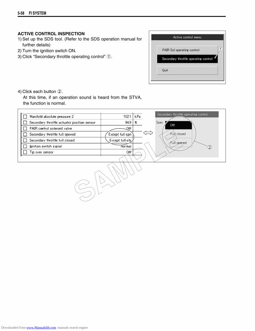
5-58 FI SYSTEM
ACTIVE CONTROL INSPECTION1) Set up the SDS tool. (Refer to the SDS operation manual for
further details)2) Turn the ignition switch ON.3) Click “Secondary throttle operating control” 1.
4) Click each button 2.At this time, if an operation sound is heard from the STVA,the function is normal.
SAMPLE
Downloaded from www.Manualslib.com manuals search engine
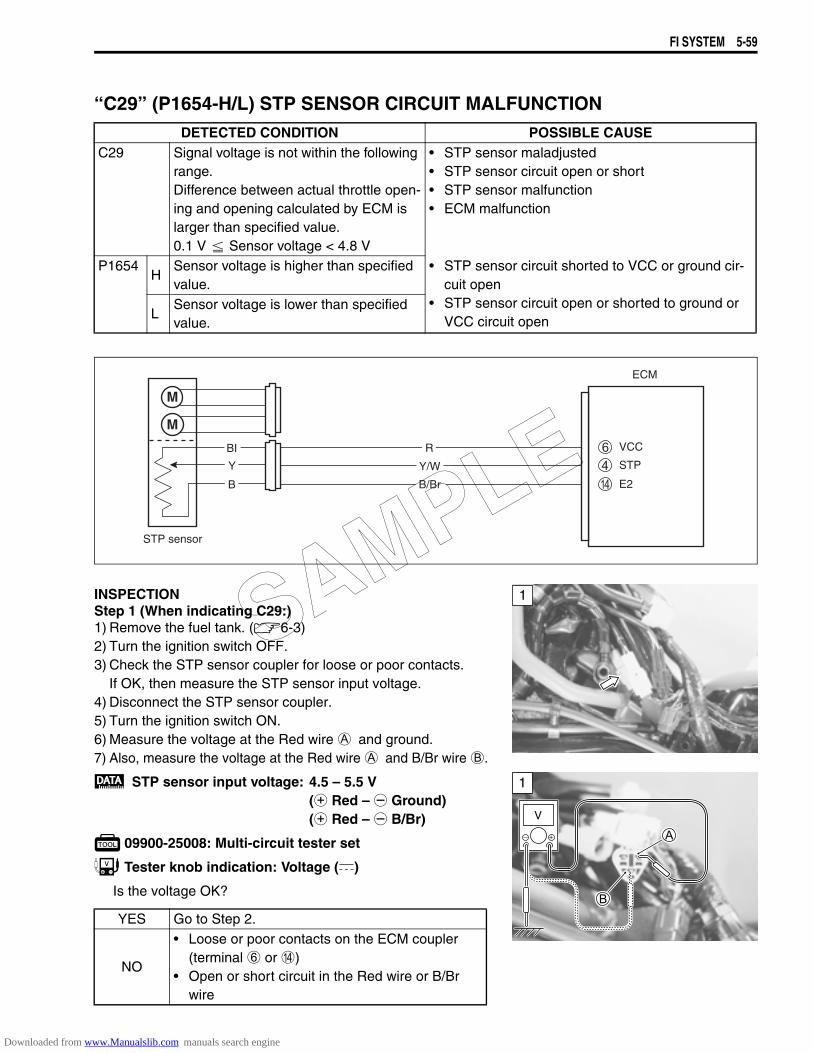
FI SYSTEM 5-59
“C29” (P1654-H/L) STP SENSOR CIRCUIT MALFUNCTION
INSPECTIONStep 1 (When indicating C29:)1) Remove the fuel tank. (6-3)2) Turn the ignition switch OFF.3) Check the STP sensor coupler for loose or poor contacts.
If OK, then measure the STP sensor input voltage.4) Disconnect the STP sensor coupler.5) Turn the ignition switch ON.6) Measure the voltage at the Red wire A and ground.7) Also, measure the voltage at the Red wire A and B/Br wire B.
STP sensor input voltage: 4.5 – 5.5 V(+ Red – - Ground)(+ Red – - B/Br)
09900-25008: Multi-circuit tester set
Tester knob indication: Voltage ()
Is the voltage OK?
DETECTED CONDITION POSSIBLE CAUSEC29 Signal voltage is not within the following
range.Difference between actual throttle open-ing and opening calculated by ECM is larger than specified value.0.1 V Sensor voltage < 4.8 V
• STP sensor maladjusted• STP sensor circuit open or short• STP sensor malfunction• ECM malfunction
P1654H
Sensor voltage is higher than specified value.
• STP sensor circuit shorted to VCC or ground cir-cuit open
• STP sensor circuit open or shorted to ground or VCC circuit openL
Sensor voltage is lower than specified value.
YES Go to Step 2.
NO
• Loose or poor contacts on the ECM coupler (terminal 6 or D)
• Open or short circuit in the Red wire or B/Br wire
ECM
E2
VCC
Y/W
R
STP
STP sensor
B/Br
Y
B
BI
1
1
V
SAMPLE
Downloaded from www.Manualslib.com manuals search engine
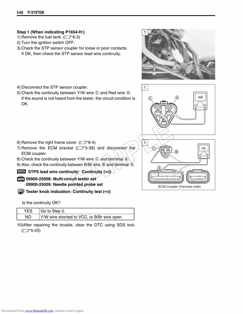
5-60 FI SYSTEM
Step 1 (When indicating P1654-H:)1) Remove the fuel tank. (6-3)2) Turn the ignition switch OFF.3) Check the STP sensor coupler for loose or poor contacts.
If OK, then check the STP sensor lead wire continuity.
4) Disconnect the STP sensor coupler.5) Check the continuity between Y/W wire C and Red wire A.
If the sound is not heard from the tester, the circuit condition isOK.
6) Remove the right frame cover. (8-4) 7) Remove the ECM bracket (5-38) and disconnect the
ECM coupler.8) Check the continuity between Y/W wire C and terminal 4.9) Also, check the continuity between B/Br wire B and terminal D.
STPS lead wire continuity: Continuity ()
09900-25008: Multi-circuit tester set09900-25009: Needle pointed probe set
Tester knob indication: Continuity test ()
Is the continuity OK?
10)After repairing the trouble, clear the DTC using SDS tool.(5-25)
1
1
!
YES Go to Step 2.NO Y/W wire shorted to VCC, or B/Br wire open
1
ECM coupler (Harness side)SAMPLE
Downloaded from www.Manualslib.com manuals search engine
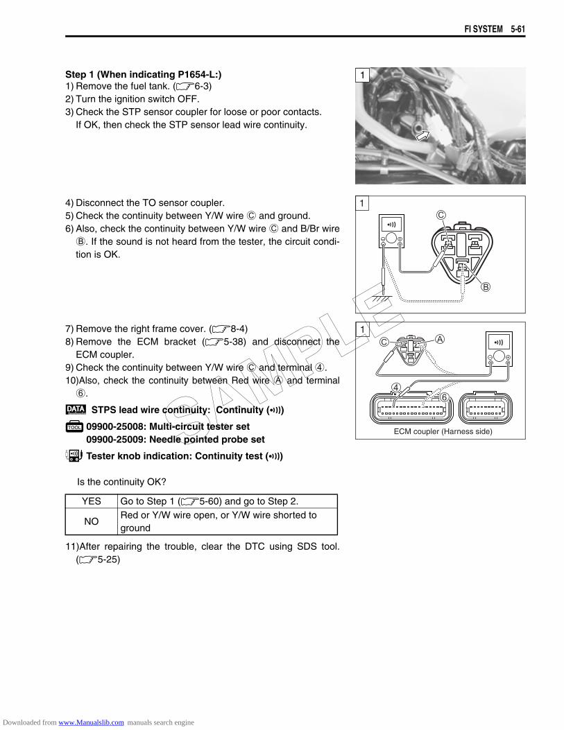
FI SYSTEM 5-61
Step 1 (When indicating P1654-L:)1) Remove the fuel tank. (6-3)2) Turn the ignition switch OFF.3) Check the STP sensor coupler for loose or poor contacts.
If OK, then check the STP sensor lead wire continuity.
4) Disconnect the TO sensor coupler.5) Check the continuity between Y/W wire C and ground.6) Also, check the continuity between Y/W wire C and B/Br wire
B. If the sound is not heard from the tester, the circuit condi-tion is OK.
7) Remove the right frame cover. (8-4) 8) Remove the ECM bracket (5-38) and disconnect the
ECM coupler.9) Check the continuity between Y/W wire C and terminal 4.10)Also, check the continuity between Red wire A and terminal
6.
STPS lead wire continuity: Continuity ()
09900-25008: Multi-circuit tester set09900-25009: Needle pointed probe set
Tester knob indication: Continuity test ()
Is the continuity OK?
11)After repairing the trouble, clear the DTC using SDS tool.(5-25)
1
1
YES Go to Step 1 (5-60) and go to Step 2.
NORed or Y/W wire open, or Y/W wire shorted to ground
1
ECM coupler (Harness side)SAMPLE
Downloaded from www.Manualslib.com manuals search engine
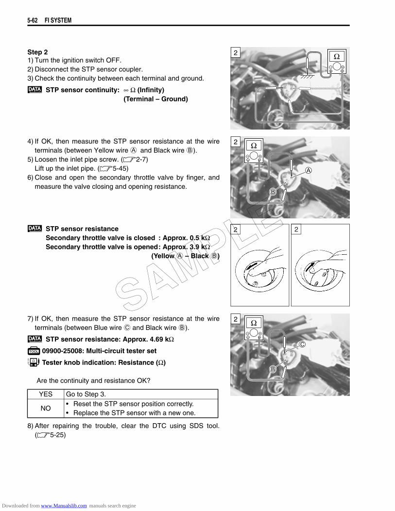
5-62 FI SYSTEM
Step 21) Turn the ignition switch OFF.2) Disconnect the STP sensor coupler.3) Check the continuity between each terminal and ground.
STP sensor continuity: ∞ Ω (Infinity) (Terminal – Ground)
4) If OK, then measure the STP sensor resistance at the wireterminals (between Yellow wire A and Black wire B).
5) Loosen the inlet pipe screw. (2-7)Lift up the inlet pipe. (5-45)
6) Close and open the secondary throttle valve by finger, andmeasure the valve closing and opening resistance.
STP sensor resistanceSecondary throttle valve is closed : Approx. 0.5 kΩSecondary throttle valve is opened: Approx. 3.9 kΩ
(Yellow A – Black B)
7) If OK, then measure the STP sensor resistance at the wireterminals (between Blue wire C and Black wire B).
STP sensor resistance: Approx. 4.69 kΩ
09900-25008: Multi-circuit tester set
Tester knob indication: Resistance (Ω)
Are the continuity and resistance OK?
8) After repairing the trouble, clear the DTC using SDS tool.(5-25)
2
2
22
YES Go to Step 3.
NO• Reset the STP sensor position correctly.• Replace the STP sensor with a new one.
2SAMPLE
Downloaded from www.Manualslib.com manuals search engine
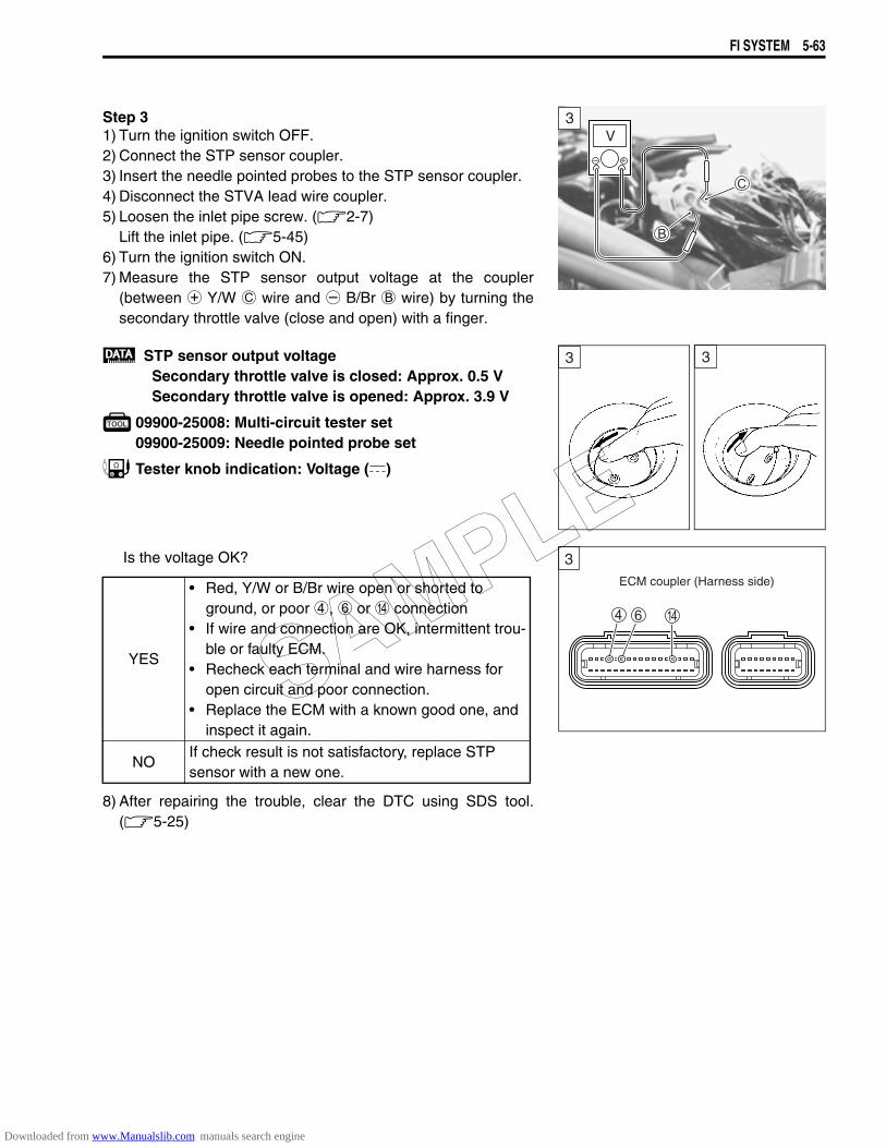
FI SYSTEM 5-63
Step 31) Turn the ignition switch OFF.2) Connect the STP sensor coupler.3) Insert the needle pointed probes to the STP sensor coupler.4) Disconnect the STVA lead wire coupler.5) Loosen the inlet pipe screw. (2-7)
Lift the inlet pipe. (5-45)6) Turn the ignition switch ON.7) Measure the STP sensor output voltage at the coupler
(between + Y/W C wire and - B/Br B wire) by turning thesecondary throttle valve (close and open) with a finger.
STP sensor output voltageSecondary throttle valve is closed: Approx. 0.5 VSecondary throttle valve is opened: Approx. 3.9 V
09900-25008: Multi-circuit tester set09900-25009: Needle pointed probe set
Tester knob indication: Voltage ()
Is the voltage OK?
8) After repairing the trouble, clear the DTC using SDS tool.(5-25)
3V
33
YES
• Red, Y/W or B/Br wire open or shorted to ground, or poor 4, 6 or D connection
• If wire and connection are OK, intermittent trou-ble or faulty ECM.
• Recheck each terminal and wire harness for open circuit and poor connection.
• Replace the ECM with a known good one, and inspect it again.
NOIf check result is not satisfactory, replace STP sensor with a new one.
ECM coupler (Harness side)
3
SAMPLE
Downloaded from www.Manualslib.com manuals search engine

5-64 FI SYSTEM
“C31” (P0705) GP SWITCH CIRCUIT MALFUNCTION
INSPECTIONStep 11) Remove the secondary gear case cover.
(2-16)2) Turn the ignition switch OFF.3) Check the GP switch coupler for loose or poor contacts.
If OK, then measure the GP switch voltage.
4) Support the motorcycle with a jack.5) Fold the side-stand to up position.6) Make sure the engine stop switch is in the “RUN” position.7) Insert the needle pointed probe to the lead wire coupler.8) Turn the ignition switch ON.9) Measure the voltage at the wire side coupler between Pink
wire A and B/W wire B, when shifting the gearshift lever from1st to Top.
GP switch voltage: 0.6 V and more(+ P A – - B/W B)
09900-25008: Multi-circuit tester set09900-25009: Needle pointed probe set
Tester knob indication: Voltage ()
DETECTED CONDITION POSSIBLE CAUSENo Gear Position switch voltage.Switch voltage is not within the following range.Switch voltage > 0.6 V
• Gear Position switch circuit open or short• Gear Position switch malfunction• ECM malfunction
Side-stand switch
Neutral indicatorlight
N15
4
23
ECM
GP switch
Side-stand relay
Ignition switch
BIBI
PP
B/W B/W
GP
To engine stop switch
1
1V
SAMPLE
Downloaded from www.Manualslib.com manuals search engine
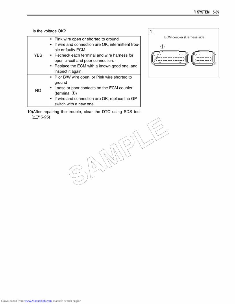
FI SYSTEM 5-65
Is the voltage OK?
10)After repairing the trouble, clear the DTC using SDS tool.(5-25)
YES
• Pink wire open or shorted to ground• If wire and connection are OK, intermittent trou-
ble or faulty ECM.• Recheck each terminal and wire harness for
open circuit and poor connection.• Replace the ECM with a known good one, and
inspect it again.
NO
• P or B/W wire open, or Pink wire shorted to ground
• Loose or poor contacts on the ECM coupler (terminal 1)
• If wire and connection are OK, replace the GP switch with a new one.
ECM coupler (Harness side)
1
SAMPLE
Downloaded from www.Manualslib.com manuals search engine
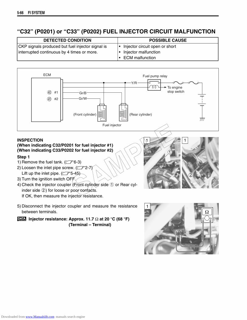
5-66 FI SYSTEM
“C32” (P0201) or “C33” (P0202) FUEL INJECTOR CIRCUIT MALFUNCTION
INSPECTION(When indicating C32/P0201 for fuel injector #1)(When indicating C33/P0202 for fuel injector #2)
Step 11) Remove the fuel tank. (6-3)2) Loosen the inlet pipe screw. (2-7)
Lift up the inlet pipe. (5-45)3) Turn the ignition switch OFF.4) Check the injector coupler (Front cylinder side 1 or Rear cyl-
inder side 2) for loose or poor contacts.If OK, then measure the injector resistance.
5) Disconnect the injector coupler and measure the resistancebetween terminals.
Injector resistance: Approx. 11.7 Ω at 20 °C (68 °F)(Terminal – Terminal)
DETECTED CONDITION POSSIBLE CAUSECKP signals produced but fuel injector signal is interrupted continuous by 4 times or more.
• Injector circuit open or short• Injector malfunction• ECM malfunction
ECM Fuel pump relay
Fuel injector
(Front cylinder) (Rear cylinder)
Y/R
Gr/W
Gr/B
#2
#1To engine stop switch
11
1
SAMPLE
Downloaded from www.Manualslib.com manuals search engine
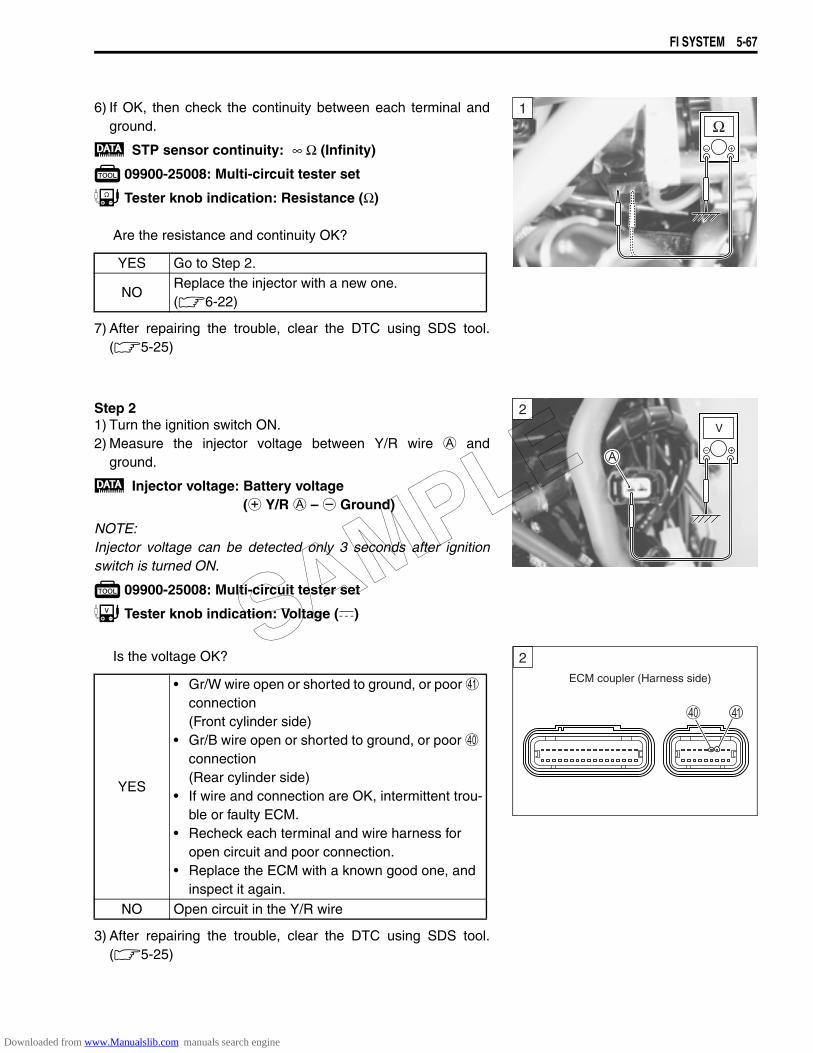
FI SYSTEM 5-67
6) If OK, then check the continuity between each terminal andground.
STP sensor continuity: ∞ Ω (Infinity)
09900-25008: Multi-circuit tester set
Tester knob indication: Resistance (Ω)
Are the resistance and continuity OK?
7) After repairing the trouble, clear the DTC using SDS tool.(5-25)
Step 21) Turn the ignition switch ON.2) Measure the injector voltage between Y/R wire A and
ground.
Injector voltage: Battery voltage(+ Y/R A – - Ground)
NOTE:Injector voltage can be detected only 3 seconds after ignitionswitch is turned ON.
09900-25008: Multi-circuit tester set
Tester knob indication: Voltage ()
Is the voltage OK?
3) After repairing the trouble, clear the DTC using SDS tool.(5-25)
YES Go to Step 2.
NOReplace the injector with a new one.(6-22)
YES
• Gr/W wire open or shorted to ground, or poor a connection (Front cylinder side)
• Gr/B wire open or shorted to ground, or poor ^ connection (Rear cylinder side)
• If wire and connection are OK, intermittent trou-ble or faulty ECM.
• Recheck each terminal and wire harness for open circuit and poor connection.
• Replace the ECM with a known good one, and inspect it again.
NO Open circuit in the Y/R wire
1
2V
ECM coupler (Harness side)
2SAMPLE
Downloaded from www.Manualslib.com manuals search engine
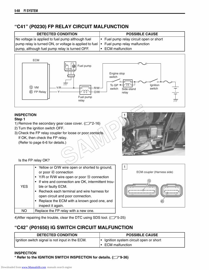
5-68 FI SYSTEM
“C41” (P0230) FP RELAY CIRCUIT MALFUNCTION
INSPECTIONStep 11) Remove the secondary gear case cover. (2-16)2) Turn the ignition switch OFF.3) Check the FP relay coupler for loose or poor contacts.
If OK, then check the FP relay. (Refer to page 6-6 for details.)
Is the FP relay OK?
4)After repairing the trouble, clear the DTC using SDS tool. (5-25)
“C42” (P01650) IG SWITCH CIRCUIT MALFUNCTION
INSPECTION* Refer to the IGNITION SWITCH INSPECTION for details. (9-36)
DETECTED CONDITION POSSIBLE CAUSENo voltage is applied to fuel pump although fuel pump relay is turned ON, or voltage is applied to fuel pump, although fuel pump relay is turned OFF.
• Fuel pump relay circuit open or short• Fuel pump relay malfunction• ECM malfunction
ECM
Side-standrelay
Engine stopswitch
Fuel pump relay
Fuel pump
Ignition switch
M
YY/RVM
FP Relay
To GP switch R/W
O/W
1
YES
• Yellow or O/W wire open or shorted to ground, or poor e connection
• Y/R or R/W wire open or poor 0 connection• If wire and connection are OK, intermittent trou-
ble or faulty ECM.• Recheck each terminal and wire harness for
open circuit and poor connection.• Replace the ECM with a known good one, and
inspect it again.NO Replace the FP relay with a new one.
DETECTED CONDITION POSSIBLE CAUSEIgnition switch signal is not input in the ECM. • Ignition system circuit open or short
• ECM malfunction
ECM coupler (Harness side)
1SAMPLE
Downloaded from www.Manualslib.com manuals search engine

FI SYSTEM 5-69
“C44” (P0130/P0135) HO2 SENSOR (HO2S) CIRCUIT MALFUNCTION (FOR E-02, 19, 24)
INSPECTIONStep 1 (When indicating C44/P0130:)1) Remove the right frame cover. (8-4)2) Turn the ignition switch OFF.3) Check the HO2 sensor for loose or poor contacts.
If OK, then check the HO2 sensor lead wire continuity.
4) Disconnect the HO2 sensor coupler 5) Check the continuity between W/Bl wire A and ground.6) Also, check the continuity between W/Bl wire A and B/Br wire
B. If the sound is not heard from the tester, the circuit condi-tion is OK.
09900-25008: Multi-circuit tester set
Tester knob indication: Continuity test ()
DETECTED CONDITION POSSIBLE CAUSEC44(P0130)
HO2 sensor output voltage is not input to ECM during engine operation and running condition.(Sensor voltage 0.1 V)
• HO2 sensor circuit open or shorted to ground• Fuel system malfunction• ECM malfunction
C44(P0135)
The heater can not operate so that heater operation voltage is not supply to the oxygen heater circuit.
• Battery voltage supply to the HO2 sensor
ECM
Side-stand relay
Ignition switch
Engine stop switch
O/WWG
rBW
B/Br
W/Bl
W/B
HO2 sensor
HO2S
HO2. H
E2
To GP switch
1
1
SAMPLE
Downloaded from www.Manualslib.com manuals search engine

5-70 FI SYSTEM
7) Remove the right frame cover. (8-4) 8) Remove the ECM bracket (5-38) and disconnect the
ECM coupler.9) Check the continuity between W/Bl wire A and terminal 7.10)Also, check the continuity between B/Br wire B and terminal
D.
HO2S lead wire continuity: Continuity ()
09900-25008: Multi-circuit tester set09900-25009: Needle pointed probe set
Tester knob indication: Continuity test ()
Is the continuity OK?
11)After repairing the trouble, clear the DTC using SDS tool.(5-25)
Step 2 (When indicating C44/P0130:)1) Connect the ECM coupler and HO2 sensor coupler.2) Warm up the engine enough.3) Insert the needle pointed probes to the HO2 sensor coupler.4) Measure the HO2 sensor output voltage between W/Bl wire
A and B/Br wire B, when idling condition.
HO2 sensor output voltage at idle speed:0.2 V and less (+ W/Bl A – - B/Br B)
5) If OK, then pinch the PAIR hose1 with a proper hose clamp.6) Measure the HO2 sensor output voltage while holding the
engine speed at 5 000 r/min.
HO2 sensor output voltage at 5 000 r/min:0.7 V and more (+ W/Bl – - B/Br)
09900-25008: Multi-circuit tester set09900-25009: Needle pointed probe set
Tester knob indication: Voltage ()
NOTE:HO2 SENSOR VOLTAGE MEASURING CONDITION1. 10 minutes after the engine start (Idling) or 100 sec. after the engine start (Engine revolution is over 2 000
r/min).2. Coolant temperature is upper 45 ºC (113 ºF).
YES Go to Step 2. (When indicating C44/P0130:)
NOW/Bl wire shorted to ground, or W/Bl or B/Br wire open
1!
ECM coupler (Harness side)
2 V
2
SAMPLE
Downloaded from www.Manualslib.com manuals search engine
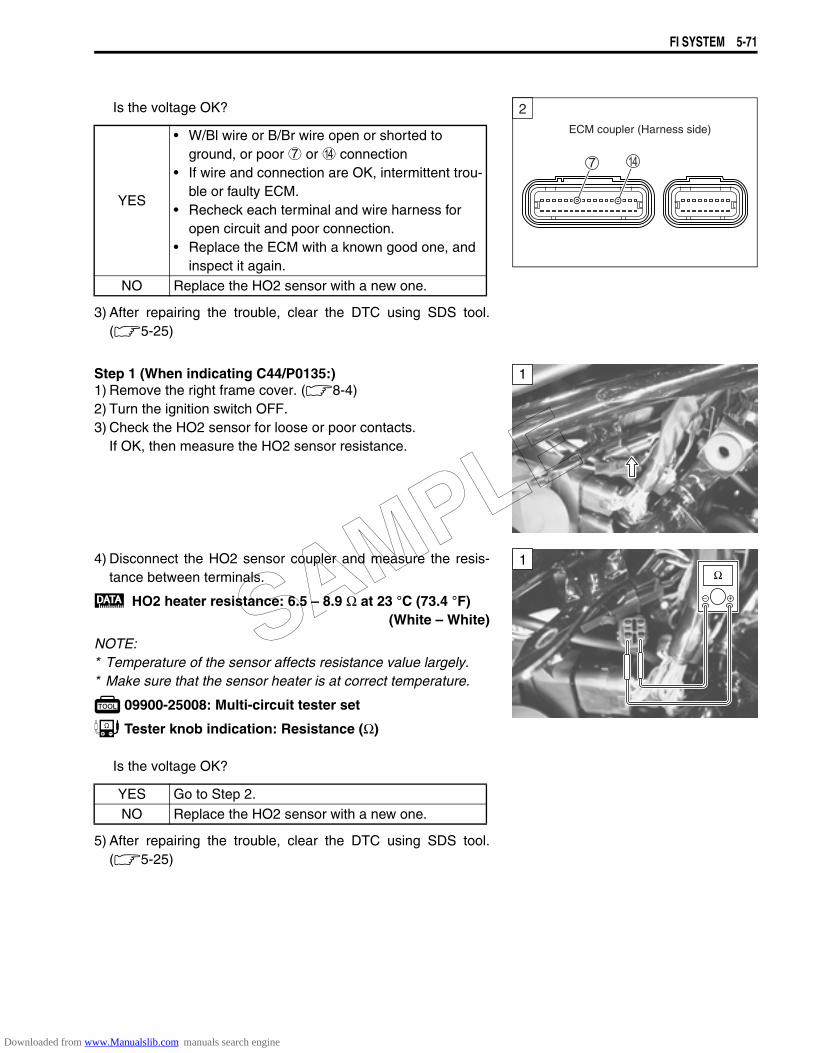
FI SYSTEM 5-71
Is the voltage OK?
3) After repairing the trouble, clear the DTC using SDS tool.(5-25)
Step 1 (When indicating C44/P0135:)1) Remove the right frame cover. (8-4)2) Turn the ignition switch OFF.3) Check the HO2 sensor for loose or poor contacts.
If OK, then measure the HO2 sensor resistance.
4) Disconnect the HO2 sensor coupler and measure the resis-tance between terminals.
HO2 heater resistance: 6.5 – 8.9 Ω at 23 °C (73.4 °F)(White – White)
NOTE:* Temperature of the sensor affects resistance value largely.* Make sure that the sensor heater is at correct temperature.
09900-25008: Multi-circuit tester set
Tester knob indication: Resistance (Ω)
Is the voltage OK?
5) After repairing the trouble, clear the DTC using SDS tool.(5-25)
YES
• W/Bl wire or B/Br wire open or shorted to ground, or poor 7 or D connection
• If wire and connection are OK, intermittent trou-ble or faulty ECM.
• Recheck each terminal and wire harness for open circuit and poor connection.
• Replace the ECM with a known good one, and inspect it again.
NO Replace the HO2 sensor with a new one.
ECM coupler (Harness side)
2
1
YES Go to Step 2.NO Replace the HO2 sensor with a new one.
1
SAMPLE
Downloaded from www.Manualslib.com manuals search engine
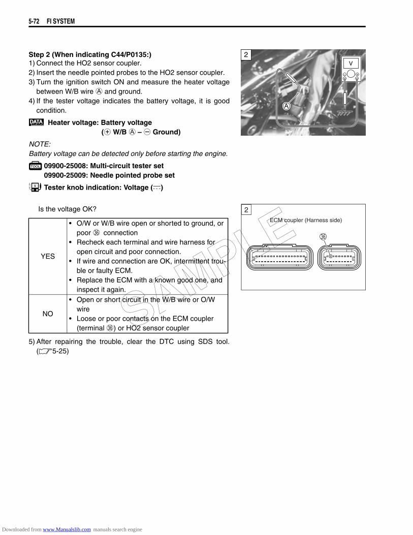
5-72 FI SYSTEM
Step 2 (When indicating C44/P0135:)1) Connect the HO2 sensor coupler.2) Insert the needle pointed probes to the HO2 sensor coupler.3) Turn the ignition switch ON and measure the heater voltage
between W/B wire A and ground.4) If the tester voltage indicates the battery voltage, it is good
condition.
Heater voltage: Battery voltage(+ W/B A – - Ground)
NOTE:Battery voltage can be detected only before starting the engine.
09900-25008: Multi-circuit tester set09900-25009: Needle pointed probe set
Tester knob indication: Voltage ()
Is the voltage OK?
5) After repairing the trouble, clear the DTC using SDS tool.(5-25)
YES
• O/W or W/B wire open or shorted to ground, or poor Z connection
• Recheck each terminal and wire harness for open circuit and poor connection.
• If wire and connection are OK, intermittent trou-ble or faulty ECM.
• Replace the ECM with a known good one, and inspect it again.
NO
• Open or short circuit in the W/B wire or O/W wire
• Loose or poor contacts on the ECM coupler (terminal Z) or HO2 sensor coupler
2V
ECM coupler (Harness side)
2
SAMPLE
Downloaded from www.Manualslib.com manuals search engine

FI SYSTEM 5-73
“C49” (P1656) PAIR CONTROL SOLENOID VALVE CIRCUIT MALFUNCTION
INSPECTIONStep 11) Turn the ignition switch OFF.2) Check the PAIR control solenoid valve coupler for loose or
poor contacts.If OK, then measure the PAIR control solenoid valve resis-tance.
3) Disconnect the PAIR control solenoid valve coupler.4) Measure the resistance between Black and Black wire termi-
nals.
PAIR valve resistance:20 – 24 Ω at 20 – 30 °C (68 – 86 °F)
(Black – Black)
09900-25008: Multi-circuit tester set
Tester knob indication: Resistance (Ω)
5) If OK, then check the continuity between each terminal andground.
PAIR valve resistance: ∞ Ω (Infinity)(Terminal – Ground)
Tester knob indication: Resistance (Ω)
Is the resistance OK?
6) After repairing the trouble, clear the DTC using SDS tool.(5-25)
DETECTED CONDITION POSSIBLE CAUSEPAIR control solenoid valve voltage is not input to ECM.
• PAIR valve circuit open or short• PAIR valve malfunction• ECM malfunction
ECMSide-stand relay
Ignition switch
Engine stop switch
O/W
PAIR control solenoid valve
Br/B
B B
SOLTo GP switch
1
YES Go to Step 2.NO Replace the PAIR valve with a new one.
1
1
SAMPLE
Downloaded from www.Manualslib.com manuals search engine
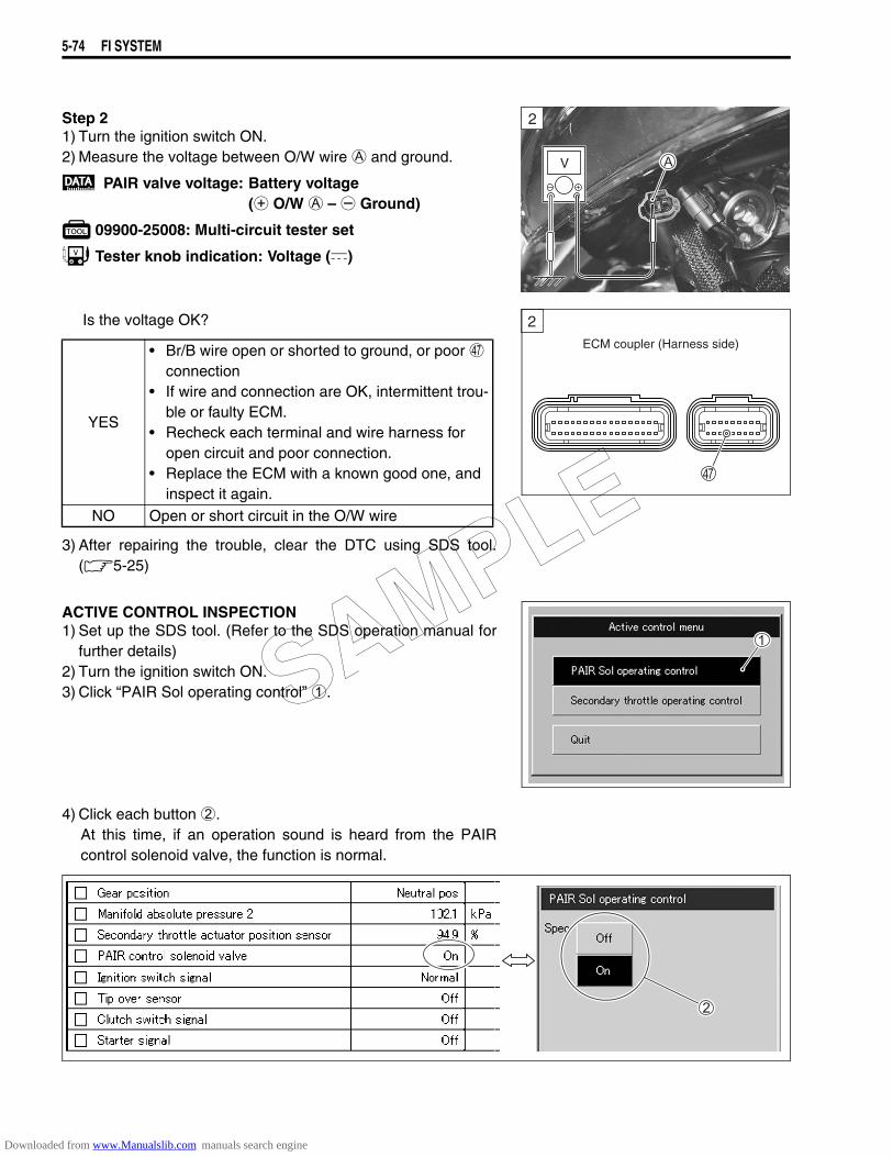
5-74 FI SYSTEM
Step 21) Turn the ignition switch ON.2) Measure the voltage between O/W wire A and ground.
PAIR valve voltage: Battery voltage(+ O/W A – - Ground)
09900-25008: Multi-circuit tester set
Tester knob indication: Voltage ()
Is the voltage OK?
3) After repairing the trouble, clear the DTC using SDS tool.(5-25)
ACTIVE CONTROL INSPECTION1) Set up the SDS tool. (Refer to the SDS operation manual for
further details)2) Turn the ignition switch ON.3) Click “PAIR Sol operating control” 1.
4) Click each button 2.At this time, if an operation sound is heard from the PAIRcontrol solenoid valve, the function is normal.
2
V
YES
• Br/B wire open or shorted to ground, or poor g connection
• If wire and connection are OK, intermittent trou-ble or faulty ECM.
• Recheck each terminal and wire harness for open circuit and poor connection.
• Replace the ECM with a known good one, and inspect it again.
NO Open or short circuit in the O/W wire
ECM coupler (Harness side)
2
SAMPLE
Downloaded from www.Manualslib.com manuals search engine
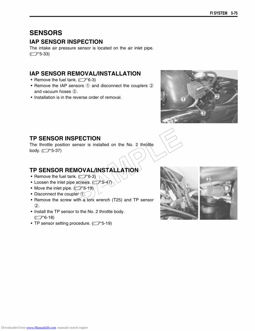
FI SYSTEM 5-75
SENSORSIAP SENSOR INSPECTIONThe intake air pressure sensor is located on the air inlet pipe.(5-33)
IAP SENSOR REMOVAL/INSTALLATION• Remove the fuel tank. (6-3)• Remove the IAP sensors 1 and disconnect the couplers 2
and vacuum hoses 3.• Installation is in the reverse order of removal.
TP SENSOR INSPECTIONThe throttle position sensor is installed on the No. 2 throttlebody. (5-37)
TP SENSOR REMOVAL/INSTALLATION• Remove the fuel tank. (6-3)• Loosen the inlet pipe screws. (5-47)• Move the inlet pipe. (5-19)• Disconnect the coupler 1.• Remove the screw with a torx wrench (T25) and TP sensor2.
• Install the TP sensor to the No. 2 throttle body.(6-18)
• TP sensor setting procedure. (5-19)
SAMPLE
Downloaded from www.Manualslib.com manuals search engine
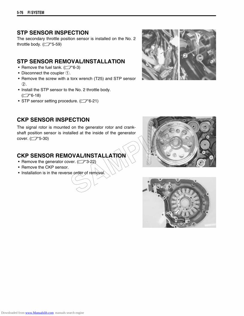
5-76 FI SYSTEM
STP SENSOR INSPECTIONThe secondary throttle position sensor is installed on the No. 2throttle body. (5-59)
STP SENSOR REMOVAL/INSTALLATION• Remove the fuel tank. (6-3)• Disconnect the coupler 1.• Remove the screw with a torx wrench (T25) and STP sensor2.
• Install the STP sensor to the No. 2 throttle body.(6-18)
• STP sensor setting procedure. (6-21)
CKP SENSOR INSPECTIONThe signal rotor is mounted on the generator rotor and crank-shaft position sensor is installed at the inside of the generatorcover. (5-30)
CKP SENSOR REMOVAL/INSTALLATION• Remove the generator cover. (3-22)• Remove the CKP sensor.• Installation is in the reverse order of removal.
SAMPLE
Downloaded from www.Manualslib.com manuals search engine
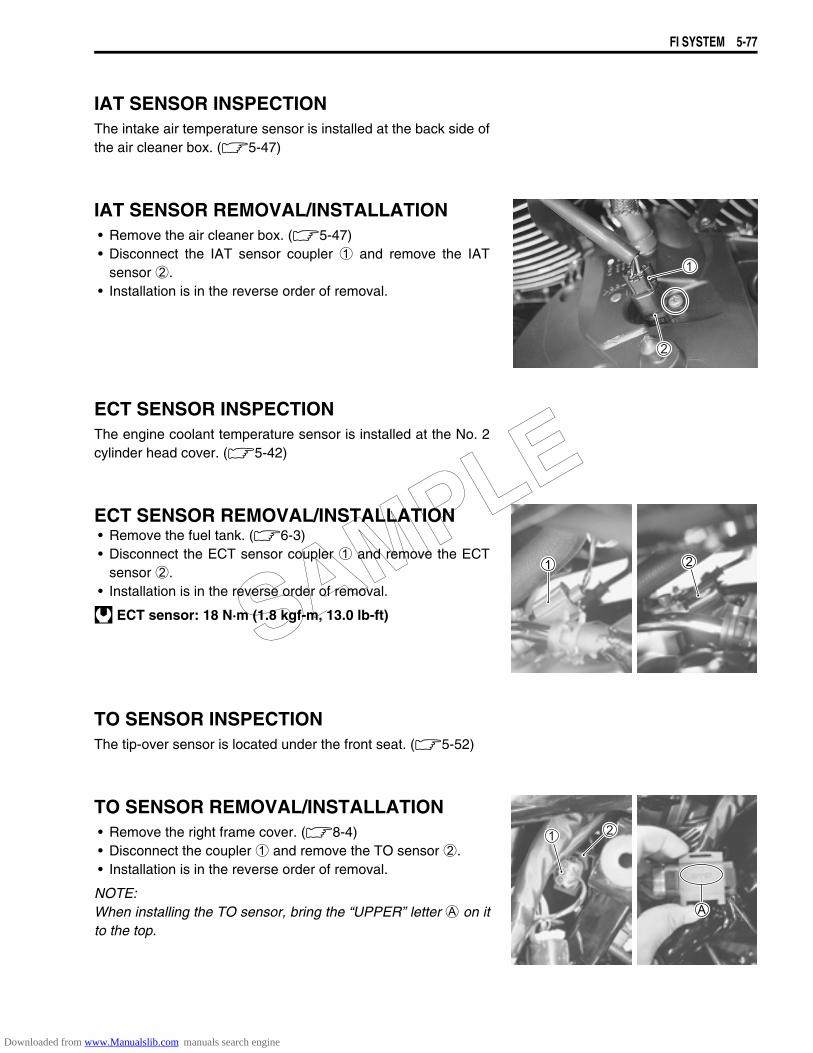
FI SYSTEM 5-77
IAT SENSOR INSPECTIONThe intake air temperature sensor is installed at the back side ofthe air cleaner box. (5-47)
IAT SENSOR REMOVAL/INSTALLATION• Remove the air cleaner box. (5-47)• Disconnect the IAT sensor coupler 1 and remove the IAT
sensor 2.• Installation is in the reverse order of removal.
ECT SENSOR INSPECTIONThe engine coolant temperature sensor is installed at the No. 2cylinder head cover. (5-42)
ECT SENSOR REMOVAL/INSTALLATION• Remove the fuel tank. (6-3)• Disconnect the ECT sensor coupler 1 and remove the ECT
sensor 2.• Installation is in the reverse order of removal.
ECT sensor: 18 N·m (1.8 kgf-m, 13.0 lb-ft)
TO SENSOR INSPECTIONThe tip-over sensor is located under the front seat. (5-52)
TO SENSOR REMOVAL/INSTALLATION• Remove the right frame cover. (8-4)• Disconnect the coupler 1 and remove the TO sensor 2.• Installation is in the reverse order of removal.
NOTE:When installing the TO sensor, bring the “UPPER” letter A on itto the top.
SAMPLE
Downloaded from www.Manualslib.com manuals search engine
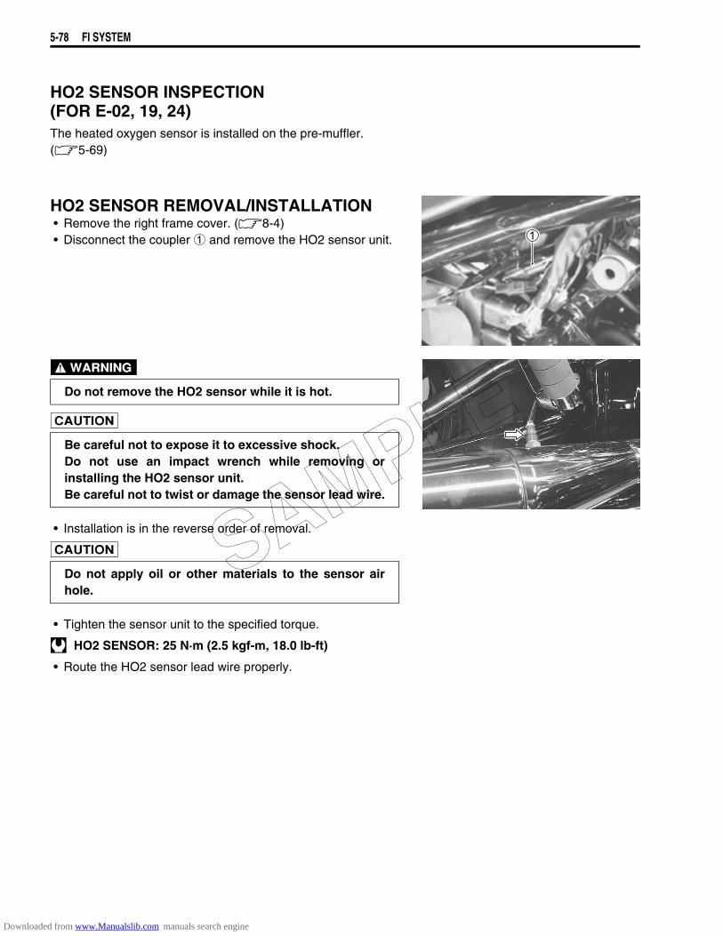
5-78 FI SYSTEM
HO2 SENSOR INSPECTION (FOR E-02, 19, 24)The heated oxygen sensor is installed on the pre-muffler.(5-69)
HO2 SENSOR REMOVAL/INSTALLATION • Remove the right frame cover. (8-4)• Disconnect the coupler 1 and remove the HO2 sensor unit.
• Installation is in the reverse order of removal.
• Tighten the sensor unit to the specified torque.
HO2 SENSOR: 25 N·m (2.5 kgf-m, 18.0 lb-ft)
• Route the HO2 sensor lead wire properly.
Do not remove the HO2 sensor while it is hot.
Be careful not to expose it to excessive shock.Do not use an impact wrench while removing orinstalling the HO2 sensor unit.Be careful not to twist or damage the sensor lead wire.
Do not apply oil or other materials to the sensor airhole.
SAMPLE
Downloaded from www.Manualslib.com manuals search engine
FUEL SYSTEM AND THROTTLE BODY 6-1
6
FUEL SYSTEM AND THROTLE BODY
CONTENTS
FUEL DELIVERY SYSTEM ...........................................................................6- 2FUEL SYSTEM ..............................................................................................6- 3
FUEL TANK REMOVAL..........................................................................6- 3FUEL TANK INSTALLATION .................................................................6- 3FUEL PRESSURE INSPECTION............................................................6- 4FUEL PUMP INSPECTION .....................................................................6- 5FUEL DISCHARGE AMOUNT INSPECTION .........................................6- 5FUEL PUMP RELAY INSPECTION........................................................6- 6FUEL PUMP REMOVAL AND DISASSEMBLY .....................................6- 7FUEL MESH FILTER INSPECTION AND CLEANING ...........................6-11FUEL PUMP REASSEMBLY AND INSTALLATION ..............................6-11
THROTTLE BODY.........................................................................................6-12CONSTRUCTION....................................................................................6-12AIR CLEANER BOX REMOVAL.............................................................6-13AIR CLEANER BOX INSTALLATION ....................................................6-13THROTTLE BODY REMOVAL ...............................................................6-13THROTTLE BODY DISASSEMBLY .......................................................6-14THROTTLE BODY CLEANING...............................................................6-17INSPECTION...........................................................................................6-17THROTTLE BODY REASSEMBLY ........................................................6-17THROTTLE BODY INSTALLATION.......................................................6-20STP SENSOR ADJUSTMENT ................................................................6-21FUEL INJECTOR REMOVAL .................................................................6-21FUEL INJECTOR INSPECTION .............................................................6-21FUEL INJECTOR INSTALLATION.........................................................6-22FAST IDLE ..............................................................................................6-22FAST IDLE ADJUSTMENT.....................................................................6-22THROTTLE VALVE SYNCHRONIZATION.............................................6-24THROTTLE POSITION SENSOR (TPS) SETTING ................................6-25
Gasoline must be handled carefully in an area well ventilated and away from fire orsparks.
SAMPLE
Downloaded from www.Manualslib.com manuals search engine

6-2 FUEL SYSTEM AND THROTTLE BODY
FUEL DELIVERY SYSTEMThe fuel delivery system consists of the fuel tank, fuel pump, fuel filters, fuel feed hose, fuel delivery pipe(including fuel injectors) and fuel pressure regulator. There is no fuel return hose. The fuel in the fuel tank ispumped up by the fuel pump and pressurized fuel flows into the injector installed in the fuel delivery pipe.Fuel pressure is regulated by the fuel pressure regulator. As the fuel pressure applied to the fuel injector (thefuel pressure in the fuel delivery pipe) is always kept at absolute fuel pressure of 3.0 kgf/cm² (300 kPa, 43psi), the fuel is injected into the throttle body in conic dispersion when the injector opens according to theinjection signal from the ECM.The fuel relieved by the fuel pressure regulator flows back to the fuel tank.
1 Fuel tank 7 Fuel mesh filter (For low pressure)2 Fuel filter (For high pressure) 8 Fuel pump3 Fuel pressure regulator A Before-pressurized fuel4 Fuel delivery pipe B Pressurized fuel5 Fuel injector C Relieved fuel6 Fuel feed hose
SAMPLE
Downloaded from www.Manualslib.com manuals search engine
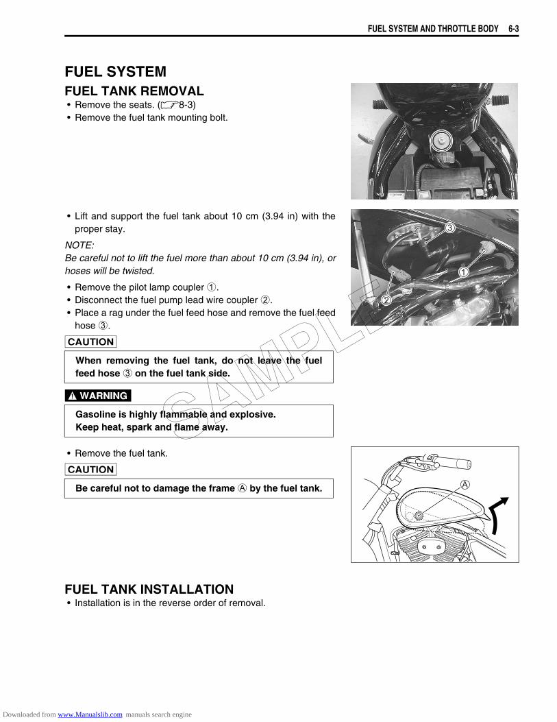
FUEL SYSTEM AND THROTTLE BODY 6-3
FUEL SYSTEMFUEL TANK REMOVAL• Remove the seats. (8-3)• Remove the fuel tank mounting bolt.
• Lift and support the fuel tank about 10 cm (3.94 in) with theproper stay.
NOTE:Be careful not to lift the fuel more than about 10 cm (3.94 in), orhoses will be twisted.
• Remove the pilot lamp coupler 1. • Disconnect the fuel pump lead wire coupler 2.• Place a rag under the fuel feed hose and remove the fuel feed
hose 3.
• Remove the fuel tank.
FUEL TANK INSTALLATION• Installation is in the reverse order of removal.
When removing the fuel tank, do not leave the fuelfeed hose 3 on the fuel tank side.
Gasoline is highly flammable and explosive.Keep heat, spark and flame away.
Be careful not to damage the frame A by the fuel tank.
SAMPLE
Downloaded from www.Manualslib.com manuals search engine
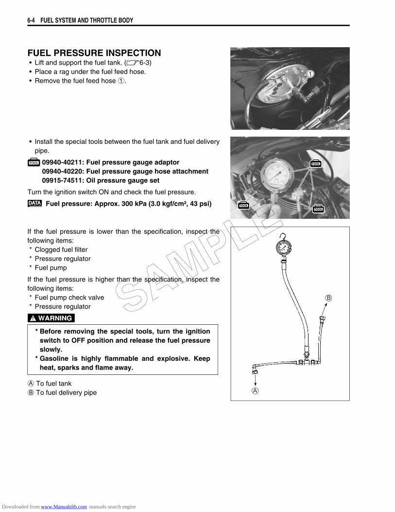
6-4 FUEL SYSTEM AND THROTTLE BODY
FUEL PRESSURE INSPECTION• Lift and support the fuel tank. (6-3)• Place a rag under the fuel feed hose.• Remove the fuel feed hose 1.
• Install the special tools between the fuel tank and fuel deliverypipe.
09940-40211: Fuel pressure gauge adaptor09940-40220: Fuel pressure gauge hose attachment09915-74511: Oil pressure gauge set
Turn the ignition switch ON and check the fuel pressure.
Fuel pressure: Approx. 300 kPa (3.0 kgf/cm², 43 psi)
If the fuel pressure is lower than the specification, inspect thefollowing items:* Clogged fuel filter* Pressure regulator* Fuel pump
If the fuel pressure is higher than the specification, inspect thefollowing items:* Fuel pump check valve* Pressure regulator
A To fuel tankB To fuel delivery pipe
* Before removing the special tools, turn the ignitionswitch to OFF position and release the fuel pressureslowly.
* Gasoline is highly flammable and explosive. Keepheat, sparks and flame away.
SAMPLE
Downloaded from www.Manualslib.com manuals search engine
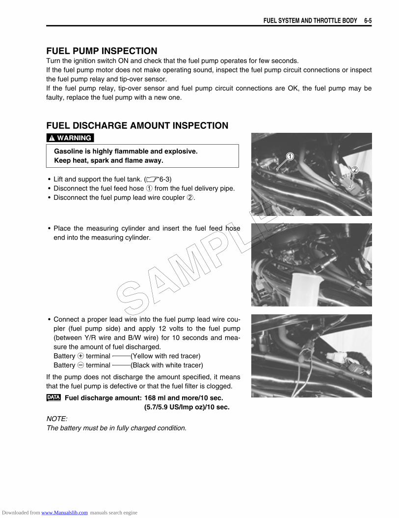
FUEL SYSTEM AND THROTTLE BODY 6-5
FUEL PUMP INSPECTIONTurn the ignition switch ON and check that the fuel pump operates for few seconds.If the fuel pump motor does not make operating sound, inspect the fuel pump circuit connections or inspectthe fuel pump relay and tip-over sensor.If the fuel pump relay, tip-over sensor and fuel pump circuit connections are OK, the fuel pump may befaulty, replace the fuel pump with a new one.
FUEL DISCHARGE AMOUNT INSPECTION
• Lift and support the fuel tank. (6-3)• Disconnect the fuel feed hose 1 from the fuel delivery pipe.• Disconnect the fuel pump lead wire coupler 2.
• Place the measuring cylinder and insert the fuel feed hoseend into the measuring cylinder.
• Connect a proper lead wire into the fuel pump lead wire cou-pler (fuel pump side) and apply 12 volts to the fuel pump(between Y/R wire and B/W wire) for 10 seconds and mea-sure the amount of fuel discharged.Battery + terminal (Yellow with red tracer)Battery - terminal (Black with white tracer)
If the pump does not discharge the amount specified, it meansthat the fuel pump is defective or that the fuel filter is clogged.
Fuel discharge amount: 168 ml and more/10 sec.(5.7/5.9 US/Imp oz)/10 sec.
NOTE:The battery must be in fully charged condition.
Gasoline is highly flammable and explosive. Keep heat, spark and flame away.
SAMPLE
Downloaded from www.Manualslib.com manuals search engine
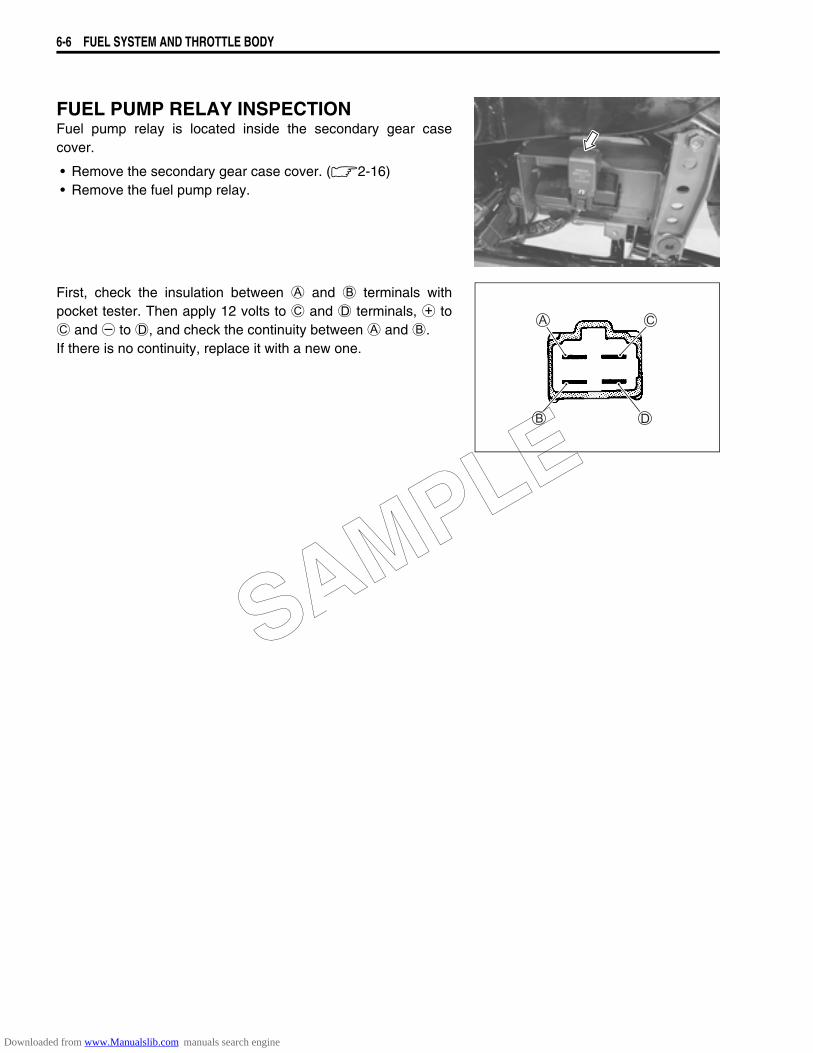
6-6 FUEL SYSTEM AND THROTTLE BODY
FUEL PUMP RELAY INSPECTIONFuel pump relay is located inside the secondary gear casecover.
• Remove the secondary gear case cover. (2-16)• Remove the fuel pump relay.
First, check the insulation between A and B terminals withpocket tester. Then apply 12 volts to C and D terminals, + toC and - to D, and check the continuity between A and B.If there is no continuity, replace it with a new one.
SAMPLE
Downloaded from www.Manualslib.com manuals search engine

FUEL SYSTEM AND THROTTLE BODY 6-7
FUEL PUMP REMOVAL AND DISASSEMBLYCONSTRUCTION
1 Thermistor 6 O-ring2 Fuel pump 7 Cover 3 Vessel 8 Fuel mesh filter ITEM N·m kgf-m lb-ft4 Rubber cushion A Fuel pump mounting bolt A 10 1.0 7.05 Fuel pump holder
SAMPLE
Downloaded from www.Manualslib.com manuals search engine
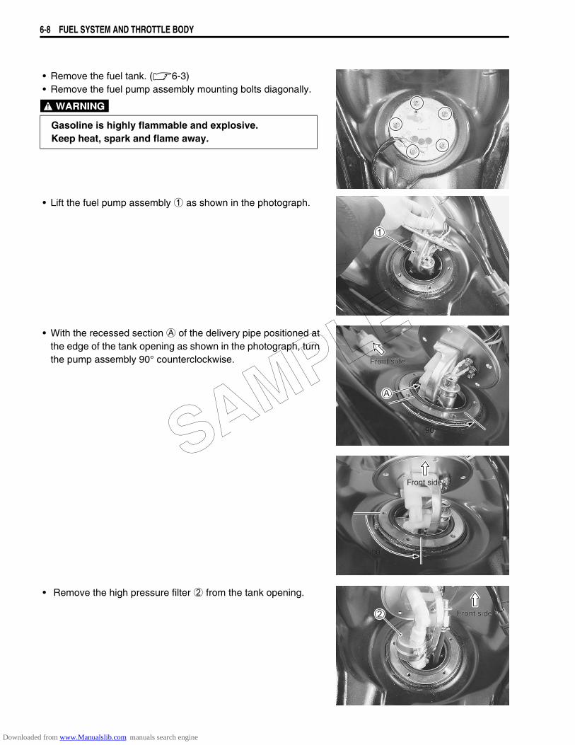
6-8 FUEL SYSTEM AND THROTTLE BODY
• Remove the fuel tank. (6-3)• Remove the fuel pump assembly mounting bolts diagonally.
• Lift the fuel pump assembly 1 as shown in the photograph.
• With the recessed section A of the delivery pipe positioned atthe edge of the tank opening as shown in the photograph, turnthe pump assembly 90° counterclockwise.
• Remove the high pressure filter 2 from the tank opening.
Gasoline is highly flammable and explosive.Keep heat, spark and flame away.
90˚90˚
Front sideFront side
90˚90˚
Front sideFront side
Front sideFront side
SAMPLE
Downloaded from www.Manualslib.com manuals search engine
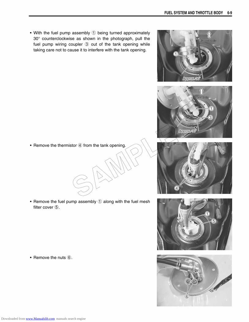
FUEL SYSTEM AND THROTTLE BODY 6-9
• With the fuel pump assembly 1 being turned approximately30° counterclockwise as shown in the photograph, pull thefuel pump wiring coupler 3 out of the tank opening whiletaking care not to cause it to interfere with the tank opening.
• Remove the thermistor 4 from the tank opening.
• Remove the fuel pump assembly 1 along with the fuel meshfilter cover 5.
• Remove the nuts 6.
Approx. 30˚Approx. 30˚
Front sideFront side
Approx. 30˚Approx. 30˚
Front sideFront side
SAMPLE
Downloaded from www.Manualslib.com manuals search engine
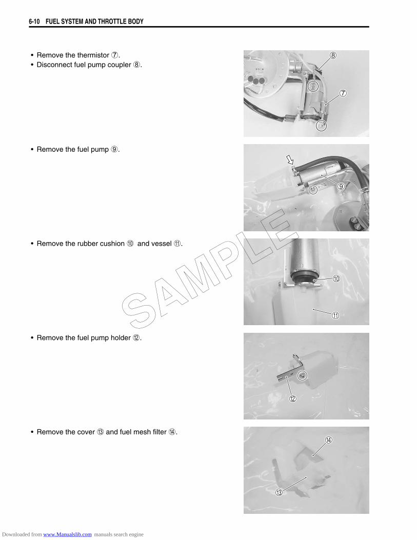
6-10 FUEL SYSTEM AND THROTTLE BODY
• Remove the thermistor 7.• Disconnect fuel pump coupler 8.
• Remove the fuel pump 9.
• Remove the rubber cushion 0 and vessel A.
• Remove the fuel pump holder B.
• Remove the cover C and fuel mesh filter D.
SAMPLE
Downloaded from www.Manualslib.com manuals search engine
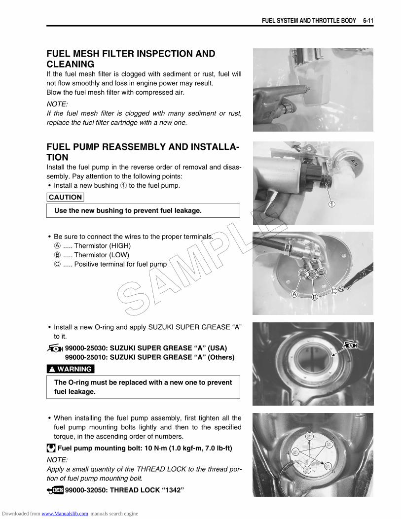
FUEL SYSTEM AND THROTTLE BODY 6-11
FUEL MESH FILTER INSPECTION AND CLEANINGIf the fuel mesh filter is clogged with sediment or rust, fuel willnot flow smoothly and loss in engine power may result.Blow the fuel mesh filter with compressed air.
NOTE:If the fuel mesh filter is clogged with many sediment or rust,replace the fuel filter cartridge with a new one.
FUEL PUMP REASSEMBLY AND INSTALLA-TIONInstall the fuel pump in the reverse order of removal and disas-sembly. Pay attention to the following points:• Install a new bushing 1 to the fuel pump.
• Be sure to connect the wires to the proper terminals.A ..... Thermistor (HIGH)B ..... Thermistor (LOW)C ..... Positive terminal for fuel pump
• Install a new O-ring and apply SUZUKI SUPER GREASE “A”to it.
99000-25030: SUZUKI SUPER GREASE “A” (USA)99000-25010: SUZUKI SUPER GREASE “A” (Others)
• When installing the fuel pump assembly, first tighten all thefuel pump mounting bolts lightly and then to the specifiedtorque, in the ascending order of numbers.
Fuel pump mounting bolt: 10 N·m (1.0 kgf-m, 7.0 lb-ft)
NOTE:Apply a small quantity of the THREAD LOCK to the thread por-tion of fuel pump mounting bolt.
99000-32050: THREAD LOCK “1342”
Use the new bushing to prevent fuel leakage.
The O-ring must be replaced with a new one to preventfuel leakage.
11
22
33
44
55
SAMPLE
Downloaded from www.Manualslib.com manuals search engine

6-12 FUEL SYSTEM AND THROTTLE BODY
THROTTLE BODYCONSTRUCTION
1 STP sensor 9 Three way joint (For E-33)2 TP sensor 0 Hose (For E-33)3 IAP sensor A Vacuum hoses4 STVA B Throttle stop screw5 Fuel delivery pipe C Idle adjusting screw 6 O-ring A STP sensor mounting screw ITEM N·m kgf-m lb-ft7 Fuel injector B TP sensor mounting screw A 3.5 0.35 2.458 Fuel feed hose B 3.5 0.35 2.45
SAMPLE
Downloaded from www.Manualslib.com manuals search engine
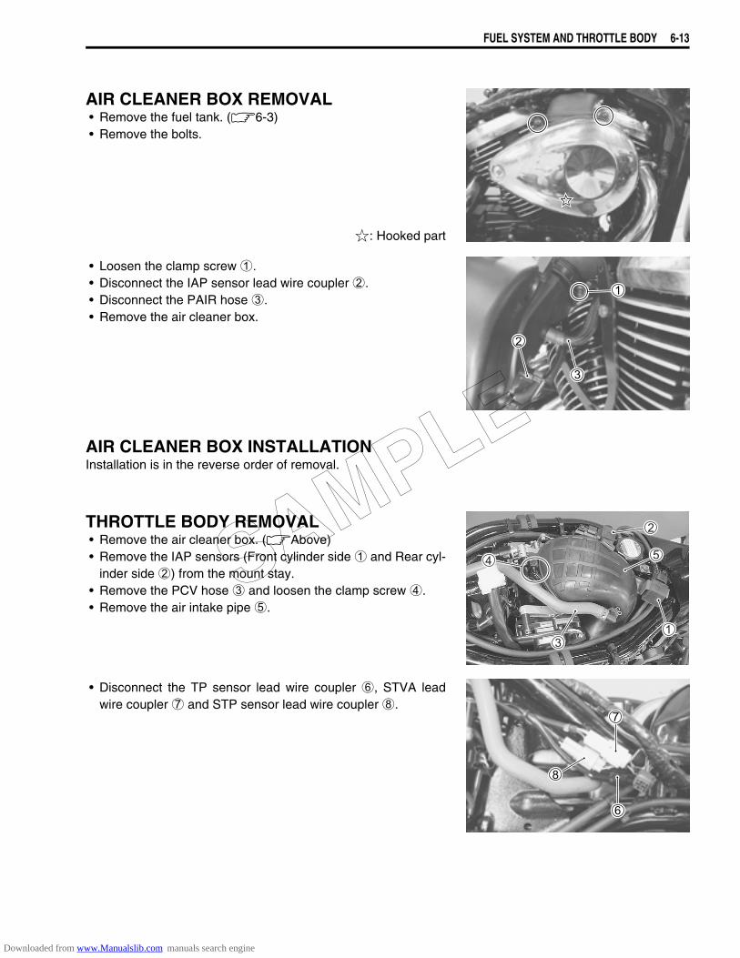
FUEL SYSTEM AND THROTTLE BODY 6-13
AIR CLEANER BOX REMOVAL• Remove the fuel tank. (6-3)• Remove the bolts.
: Hooked part
• Loosen the clamp screw 1.• Disconnect the IAP sensor lead wire coupler 2.• Disconnect the PAIR hose 3.• Remove the air cleaner box.
AIR CLEANER BOX INSTALLATIONInstallation is in the reverse order of removal.
THROTTLE BODY REMOVAL• Remove the air cleaner box. (Above)• Remove the IAP sensors (Front cylinder side 1 and Rear cyl-
inder side 2) from the mount stay.• Remove the PCV hose 3 and loosen the clamp screw 4.• Remove the air intake pipe 5.
• Disconnect the TP sensor lead wire coupler 6, STVA leadwire coupler 7 and STP sensor lead wire coupler 8.
SAMPLE
Downloaded from www.Manualslib.com manuals search engine
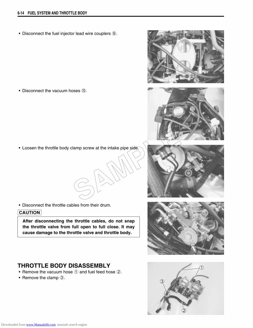
6-14 FUEL SYSTEM AND THROTTLE BODY
• Disconnect the fuel injector lead wire couplers 9.
• Disconnect the vacuum hoses 0.
• Loosen the throttle body clamp screw at the intake pipe side.
• Disconnect the throttle cables from their drum.
THROTTLE BODY DISASSEMBLY• Remove the vacuum hose 1 and fuel feed hose 2.• Remove the clamp 3.
After disconnecting the throttle cables, do not snapthe throttle valve from full open to full close. It maycause damage to the throttle valve and throttle body.
SAMPLE
Downloaded from www.Manualslib.com manuals search engine
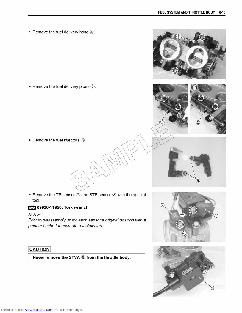
FUEL SYSTEM AND THROTTLE BODY 6-15
• Remove the fuel delivery hose 4.
• Remove the fuel delivery pipes 5.
• Remove the fuel injectors 6.
• Remove the TP sensor 7 and STP sensor 8 with the specialtool.
09930-11950: Torx wrench
NOTE:Prior to disassembly, mark each sensor’s original position with apaint or scribe for accurate reinstallation.
Never remove the STVA 9 from the throttle body.
SAMPLE
Downloaded from www.Manualslib.com manuals search engine
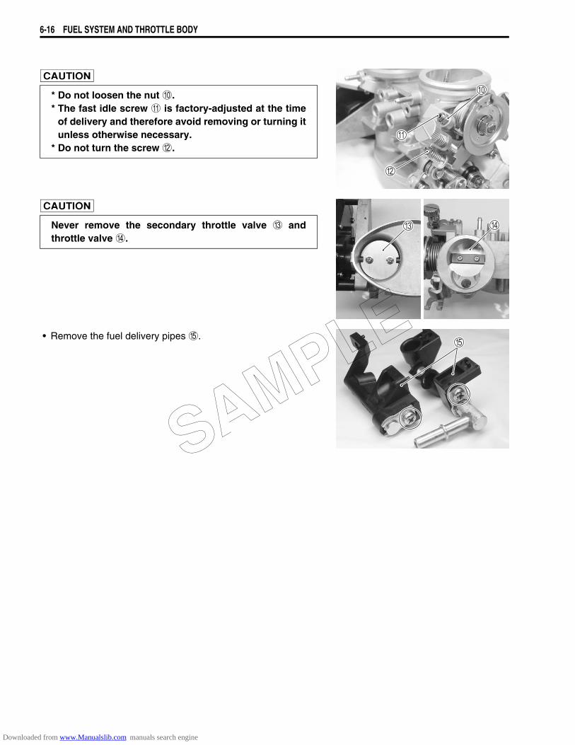
6-16 FUEL SYSTEM AND THROTTLE BODY
• Remove the fuel delivery pipes E.
* Do not loosen the nut 0.* The fast idle screw A is factory-adjusted at the time
of delivery and therefore avoid removing or turning itunless otherwise necessary.
* Do not turn the screw B.
Never remove the secondary throttle valve C andthrottle valve D.
SAMPLE
Downloaded from www.Manualslib.com manuals search engine
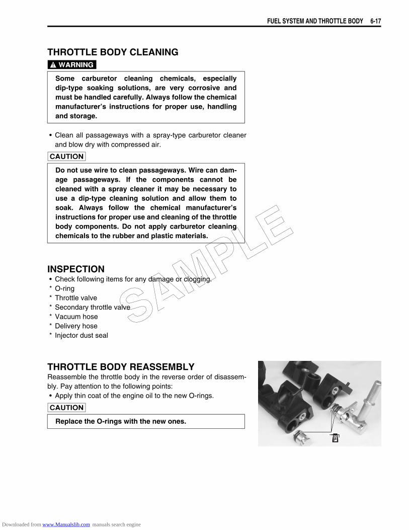
FUEL SYSTEM AND THROTTLE BODY 6-17
THROTTLE BODY CLEANING
• Clean all passageways with a spray-type carburetor cleanerand blow dry with compressed air.
INSPECTION• Check following items for any damage or clogging.* O-ring* Throttle valve* Secondary throttle valve* Vacuum hose* Delivery hose* Injector dust seal
THROTTLE BODY REASSEMBLYReassemble the throttle body in the reverse order of disassem-bly. Pay attention to the following points:• Apply thin coat of the engine oil to the new O-rings.
Some carburetor cleaning chemicals, especiallydip-type soaking solutions, are very corrosive andmust be handled carefully. Always follow the chemicalmanufacturer’s instructions for proper use, handlingand storage.
Do not use wire to clean passageways. Wire can dam-age passageways. If the components cannot becleaned with a spray cleaner it may be necessary touse a dip-type cleaning solution and allow them tosoak. Always follow the chemical manufacturer’sinstructions for proper use and cleaning of the throttlebody components. Do not apply carburetor cleaningchemicals to the rubber and plastic materials.
Replace the O-rings with the new ones.
SAMPLE
Downloaded from www.Manualslib.com manuals search engine
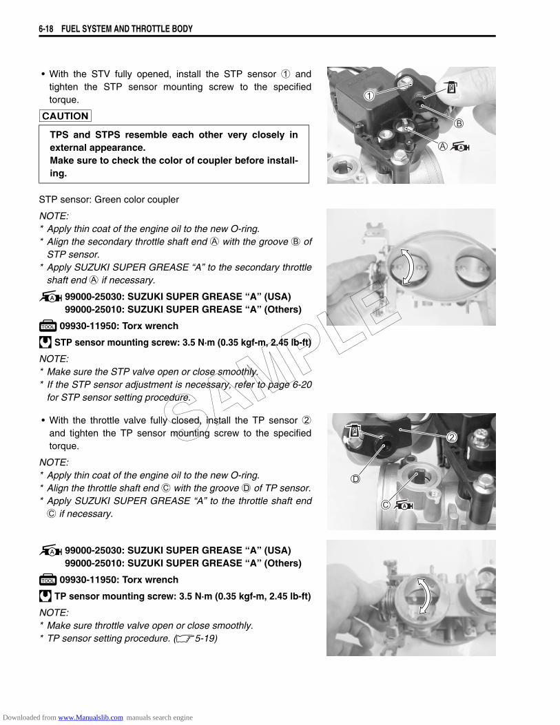
6-18 FUEL SYSTEM AND THROTTLE BODY
• With the STV fully opened, install the STP sensor 1 andtighten the STP sensor mounting screw to the specifiedtorque.
STP sensor: Green color coupler
NOTE:* Apply thin coat of the engine oil to the new O-ring.* Align the secondary throttle shaft end A with the groove B of
STP sensor.* Apply SUZUKI SUPER GREASE “A” to the secondary throttle
shaft end A if necessary.
99000-25030: SUZUKI SUPER GREASE “A” (USA)99000-25010: SUZUKI SUPER GREASE “A” (Others)
09930-11950: Torx wrench
STP sensor mounting screw: 3.5 N·m (0.35 kgf-m, 2.45 lb-ft)
NOTE:* Make sure the STP valve open or close smoothly.* If the STP sensor adjustment is necessary, refer to page 6-20
for STP sensor setting procedure.
• With the throttle valve fully closed, install the TP sensor 2and tighten the TP sensor mounting screw to the specifiedtorque.
NOTE:* Apply thin coat of the engine oil to the new O-ring.* Align the throttle shaft end C with the groove D of TP sensor.* Apply SUZUKI SUPER GREASE “A” to the throttle shaft endC if necessary.
99000-25030: SUZUKI SUPER GREASE “A” (USA)99000-25010: SUZUKI SUPER GREASE “A” (Others)
09930-11950: Torx wrench
TP sensor mounting screw: 3.5 N·m (0.35 kgf-m, 2.45 lb-ft)
NOTE:* Make sure throttle valve open or close smoothly.* TP sensor setting procedure. (5-19)
TPS and STPS resemble each other very closely inexternal appearance.Make sure to check the color of coupler before install-ing.
SAMPLE
Downloaded from www.Manualslib.com manuals search engine
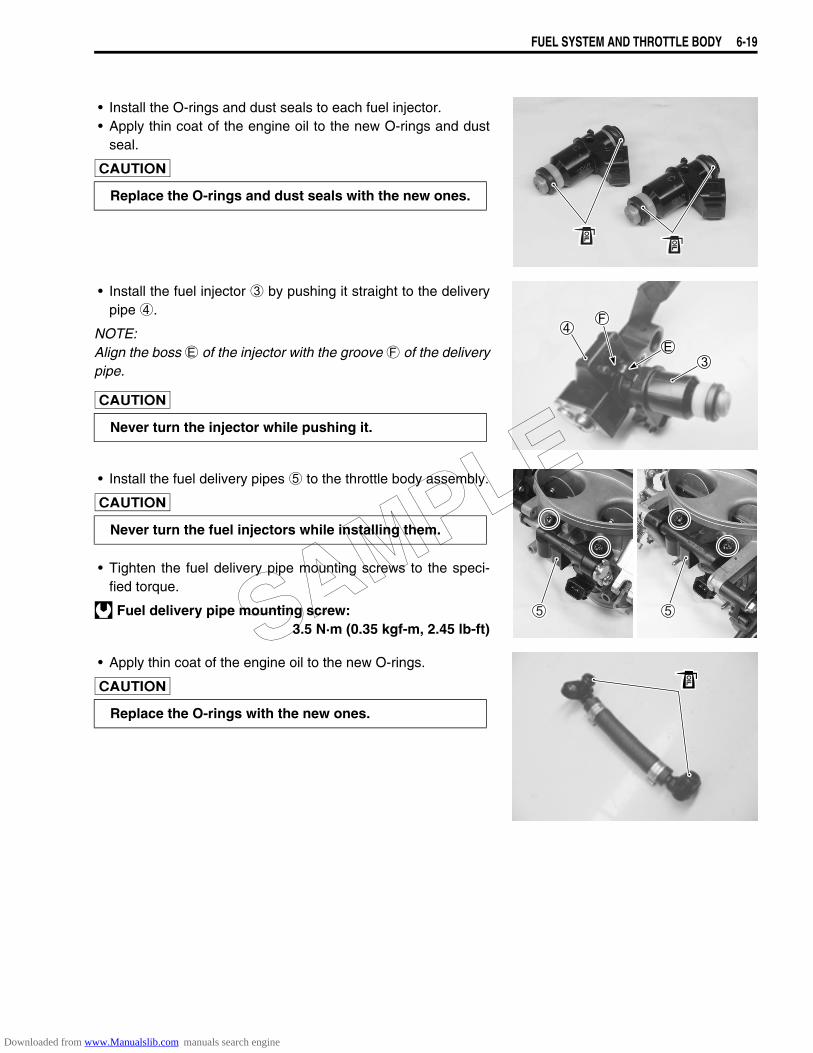
FUEL SYSTEM AND THROTTLE BODY 6-19
• Install the O-rings and dust seals to each fuel injector.• Apply thin coat of the engine oil to the new O-rings and dust
seal.
• Install the fuel injector 3 by pushing it straight to the deliverypipe 4.
NOTE:Align the boss E of the injector with the groove F of the deliverypipe.
• Install the fuel delivery pipes 5 to the throttle body assembly.
• Tighten the fuel delivery pipe mounting screws to the speci-fied torque.
Fuel delivery pipe mounting screw: 3.5 N·m (0.35 kgf-m, 2.45 lb-ft)
• Apply thin coat of the engine oil to the new O-rings.
Replace the O-rings and dust seals with the new ones.
Never turn the injector while pushing it.
Never turn the fuel injectors while installing them.
Replace the O-rings with the new ones.
SAMPLE
Downloaded from www.Manualslib.com manuals search engine
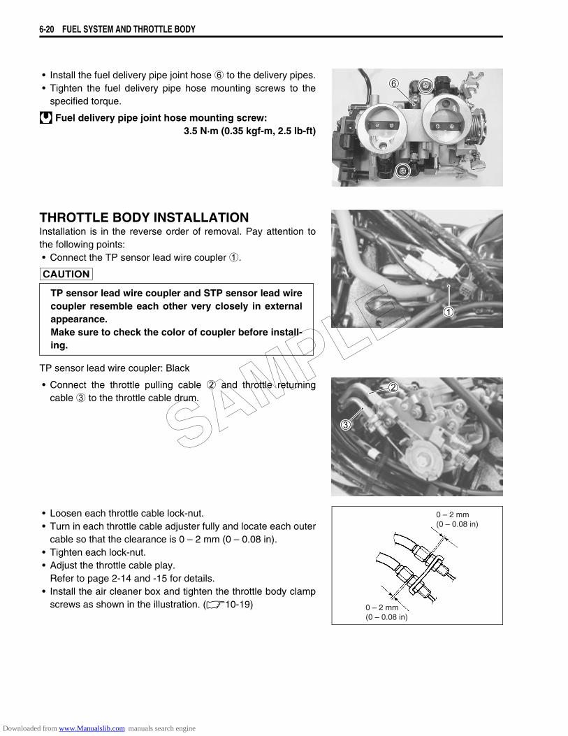
6-20 FUEL SYSTEM AND THROTTLE BODY
• Install the fuel delivery pipe joint hose 6 to the delivery pipes.• Tighten the fuel delivery pipe hose mounting screws to the
specified torque.
Fuel delivery pipe joint hose mounting screw: 3.5 N·m (0.35 kgf-m, 2.5 lb-ft)
THROTTLE BODY INSTALLATIONInstallation is in the reverse order of removal. Pay attention tothe following points:• Connect the TP sensor lead wire coupler 1.
TP sensor lead wire coupler: Black
• Connect the throttle pulling cable 2 and throttle returningcable 3 to the throttle cable drum.
• Loosen each throttle cable lock-nut.• Turn in each throttle cable adjuster fully and locate each outer
cable so that the clearance is 0 – 2 mm (0 – 0.08 in).• Tighten each lock-nut.• Adjust the throttle cable play.
Refer to page 2-14 and -15 for details.• Install the air cleaner box and tighten the throttle body clamp
screws as shown in the illustration. (10-19)
TP sensor lead wire coupler and STP sensor lead wirecoupler resemble each other very closely in externalappearance.Make sure to check the color of coupler before install-ing.
0 – 2 mm(0 – 0.08 in)
0 – 2 mm(0 – 0.08 in)
SAMPLE
Downloaded from www.Manualslib.com manuals search engine
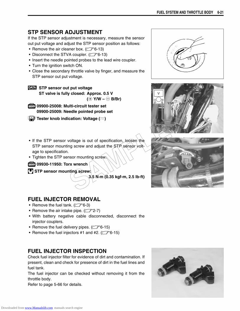
FUEL SYSTEM AND THROTTLE BODY 6-21
STP SENSOR ADJUSTMENTIf the STP sensor adjustment is necessary, measure the sensorout put voltage and adjust the STP sensor position as follows:• Remove the air cleaner box. (6-13)• Disconnect the STVA coupler. (6-13)• Insert the needle pointed probes to the lead wire coupler.• Turn the ignition switch ON.• Close the secondary throttle valve by finger, and measure the
STP sensor out put voltage.
STP sensor out put voltageST valve is fully closed: Approx. 0.5 V
(+ Y/W – - B/Br)
09900-25008: Multi-circuit tester set09900-25009: Needle pointed probe set
Tester knob indication: Voltage ()
• If the STP sensor voltage is out of specification, loosen theSTP sensor mounting screw and adjust the STP sensor volt-age to specification.
• Tighten the STP sensor mounting screw.
09930-11950: Torx wrench
STP sensor mounting screw:3.5 N·m (0.35 kgf-m, 2.5 lb-ft)
FUEL INJECTOR REMOVAL• Remove the fuel tank. (6-3)• Remove the air intake pipe. (2-7)• With battery negative cable disconnected, disconnect the
injector couplers.• Remove the fuel delivery pipes. (6-15)• Remove the fuel injectors #1 and #2. (6-15)
FUEL INJECTOR INSPECTIONCheck fuel injector filter for evidence of dirt and contamination. Ifpresent, clean and check for presence of dirt in the fuel lines andfuel tank.The fuel injector can be checked without removing it from thethrottle body.Refer to page 5-66 for details.
V
B/BrB/BrY/WY/W
SAMPLE
Downloaded from www.Manualslib.com manuals search engine
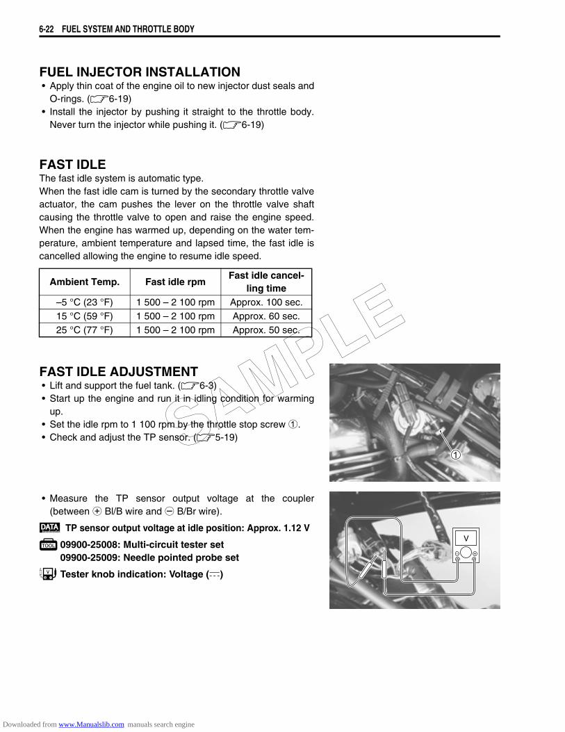
6-22 FUEL SYSTEM AND THROTTLE BODY
FUEL INJECTOR INSTALLATION• Apply thin coat of the engine oil to new injector dust seals and
O-rings. (6-19)• Install the injector by pushing it straight to the throttle body.
Never turn the injector while pushing it. (6-19)
FAST IDLEThe fast idle system is automatic type.When the fast idle cam is turned by the secondary throttle valveactuator, the cam pushes the lever on the throttle valve shaftcausing the throttle valve to open and raise the engine speed.When the engine has warmed up, depending on the water tem-perature, ambient temperature and lapsed time, the fast idle iscancelled allowing the engine to resume idle speed.
FAST IDLE ADJUSTMENT• Lift and support the fuel tank. (6-3)• Start up the engine and run it in idling condition for warming
up.• Set the idle rpm to 1 100 rpm by the throttle stop screw 1.• Check and adjust the TP sensor. (5-19)
• Measure the TP sensor output voltage at the coupler(between + Bl/B wire and - B/Br wire).
TP sensor output voltage at idle position: Approx. 1.12 V
09900-25008: Multi-circuit tester set09900-25009: Needle pointed probe set
Tester knob indication: Voltage ()
Ambient Temp. Fast idle rpmFast idle cancel-
ling time–5 °C (23 °F) 1 500 – 2 100 rpm Approx. 100 sec.15 °C (59 °F) 1 500 – 2 100 rpm Approx. 60 sec.25 °C (77 °F) 1 500 – 2 100 rpm Approx. 50 sec.
V
SAMPLE
Downloaded from www.Manualslib.com manuals search engine
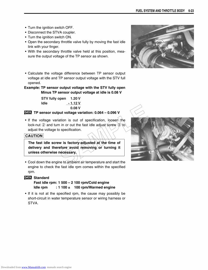
FUEL SYSTEM AND THROTTLE BODY 6-23
• Turn the ignition switch OFF.• Disconnect the STVA coupler.• Turn the ignition switch ON.• Open the secondary throttle valve fully by moving the fast idle
link with your finger.• With the secondary throttle valve held at this position, mea-
sure the output voltage of the TP sensor as shown.
• Calculate the voltage difference between TP sensor outputvoltage at idle and TP sensor output voltage with the STV fullopened.
Example: TP sensor output voltage with the STV fully openMinus TP sensor output voltage at idle is 0.08 V
TP sensor output voltage variation: 0.064 – 0.096 V
• If the voltage variation is out of specification, loosen thelock-nut 2 and turn in or out the fast idle adjust screw 3 toadjust the voltage to specification.
• Cool down the engine to ambient air temperature and start theengine to check the fast idle rpm comes within the specifiedrpm.
StandardFast idle rpm: 1 500 – 2 100 rpm/Cold engineIdle rpm : 1 100 ± 100 rpm/Warmed engine
• If it is not at the specified rpm, the cause may possibly beshort-circuit in water temperature sensor or wiring harness orSTVA.
The fast idle screw is factory-adjusted at the time ofdelivery and therefore avoid removing or turning itunless otherwise necessary.
STV fully openIdle
1.20 V- 1.12 V
0.08 V
SAMPLE
Downloaded from www.Manualslib.com manuals search engine
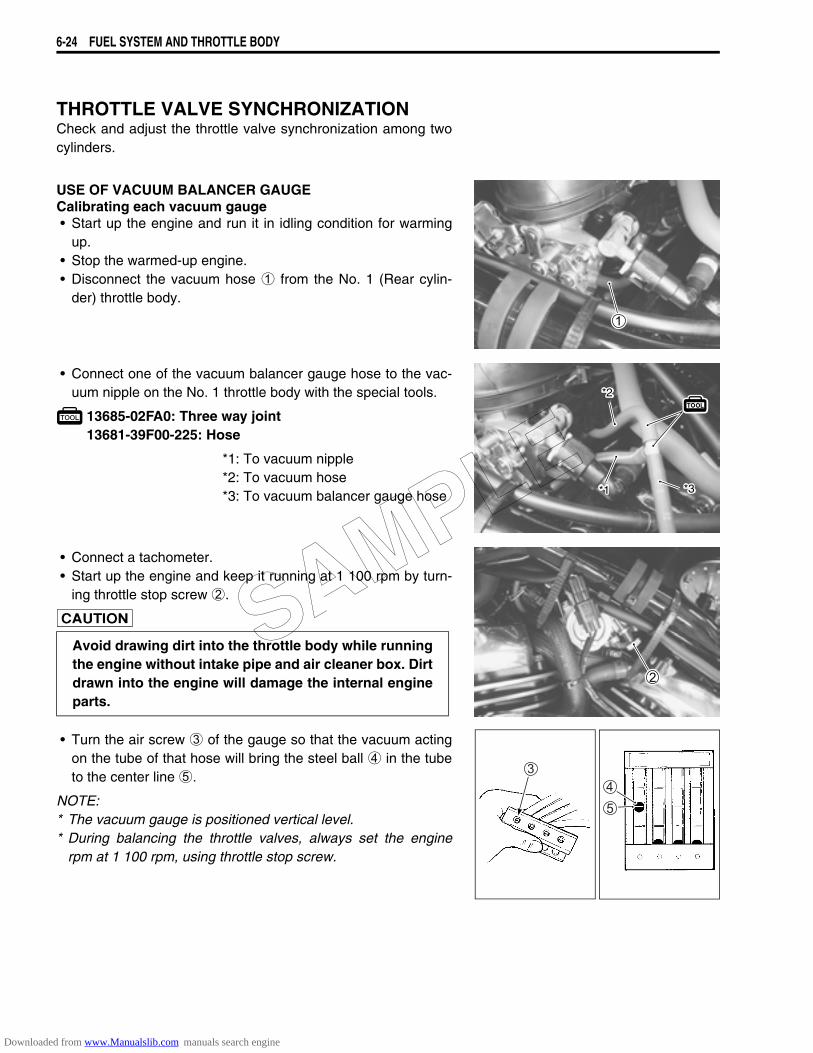
6-24 FUEL SYSTEM AND THROTTLE BODY
THROTTLE VALVE SYNCHRONIZATIONCheck and adjust the throttle valve synchronization among twocylinders.
USE OF VACUUM BALANCER GAUGECalibrating each vacuum gauge• Start up the engine and run it in idling condition for warming
up.• Stop the warmed-up engine.• Disconnect the vacuum hose 1 from the No. 1 (Rear cylin-
der) throttle body.
• Connect one of the vacuum balancer gauge hose to the vac-uum nipple on the No. 1 throttle body with the special tools.
13685-02FA0: Three way joint13681-39F00-225: Hose
*1: To vacuum nipple*2: To vacuum hose*3: To vacuum balancer gauge hose
• Connect a tachometer.• Start up the engine and keep it running at 1 100 rpm by turn-
ing throttle stop screw 2.
• Turn the air screw 3 of the gauge so that the vacuum actingon the tube of that hose will bring the steel ball 4 in the tubeto the center line 5.
NOTE:* The vacuum gauge is positioned vertical level.* During balancing the throttle valves, always set the engine
rpm at 1 100 rpm, using throttle stop screw.
*1
*2
*3
Avoid drawing dirt into the throttle body while runningthe engine without intake pipe and air cleaner box. Dirtdrawn into the engine will damage the internal engineparts.
SAMPLE
Downloaded from www.Manualslib.com manuals search engine
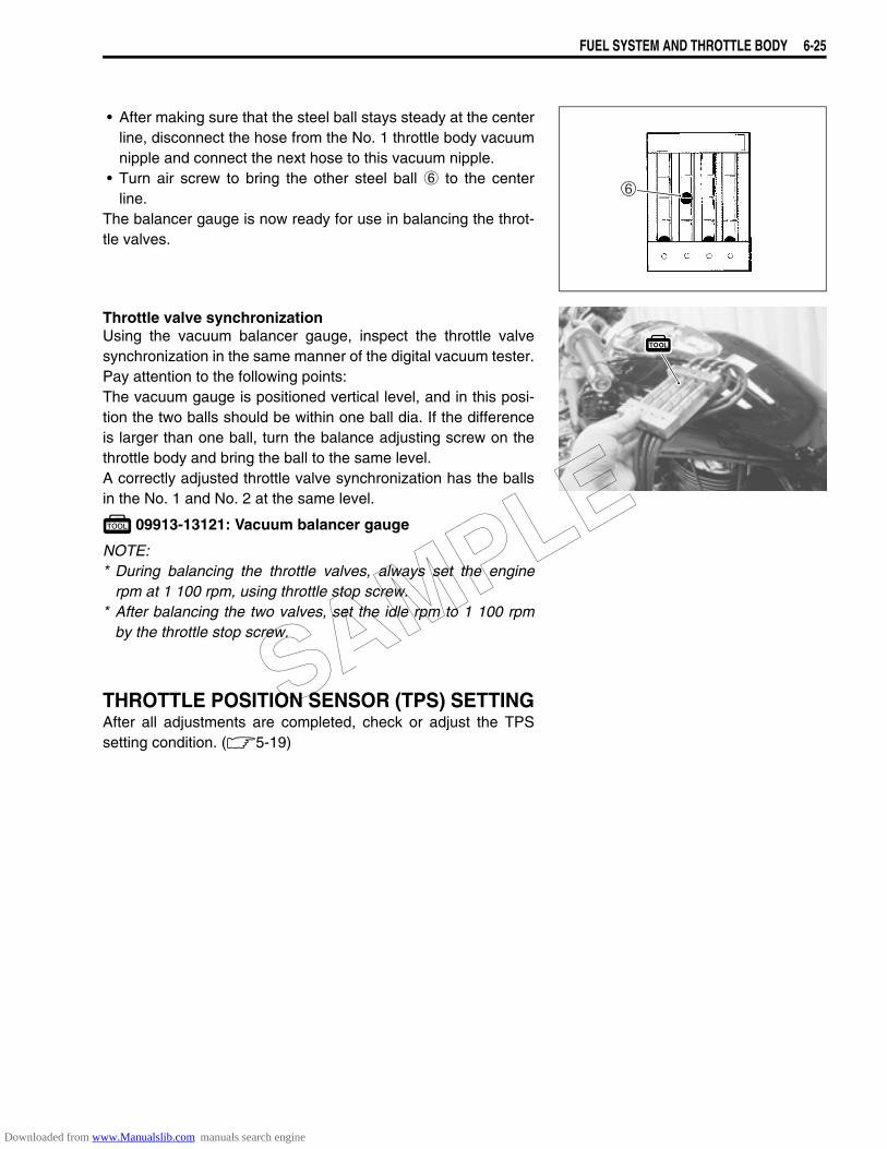
FUEL SYSTEM AND THROTTLE BODY 6-25
• After making sure that the steel ball stays steady at the centerline, disconnect the hose from the No. 1 throttle body vacuumnipple and connect the next hose to this vacuum nipple.
• Turn air screw to bring the other steel ball 6 to the centerline.
The balancer gauge is now ready for use in balancing the throt-tle valves.
Throttle valve synchronizationUsing the vacuum balancer gauge, inspect the throttle valvesynchronization in the same manner of the digital vacuum tester.Pay attention to the following points:The vacuum gauge is positioned vertical level, and in this posi-tion the two balls should be within one ball dia. If the differenceis larger than one ball, turn the balance adjusting screw on thethrottle body and bring the ball to the same level.A correctly adjusted throttle valve synchronization has the ballsin the No. 1 and No. 2 at the same level.
09913-13121: Vacuum balancer gauge
NOTE:* During balancing the throttle valves, always set the engine
rpm at 1 100 rpm, using throttle stop screw.* After balancing the two valves, set the idle rpm to 1 100 rpm
by the throttle stop screw.
THROTTLE POSITION SENSOR (TPS) SETTINGAfter all adjustments are completed, check or adjust the TPSsetting condition. (5-19)
SAMPLE
Downloaded from www.Manualslib.com manuals search engine
COOLING AND LUBRICATION SYSTEM 7-1
7
COOLING AND LUBRICATION SYSTEM
CONTENTS
ENGINE COOLANT.......................................................................................7- 2COOLING CIRCUIT .......................................................................................7- 3
COOLING CIRCUIT INSPECTION..........................................................7- 3RADIATOR AND WATER HOSES................................................................7- 4
RADIATOR REMOVAL...........................................................................7- 4RADIATOR CAP INSPECTION ..............................................................7- 5RADIATOR INSPECTION AND CLEANING ..........................................7- 5RADIATOR REMOUNTING ....................................................................7- 5WATER HOSE AND RESERVOIR TANK INSPECTION........................7- 6
COOLING FAN ..............................................................................................7- 7INSPECTION...........................................................................................7- 7REMOVAL...............................................................................................7- 7INSTALLATION.......................................................................................7- 8
COOLING FAN THERMO-SWITCH ..............................................................7- 9REMOVAL...............................................................................................7- 9INSPECTION...........................................................................................7- 9INSTALLATION.......................................................................................7- 9
ENGINE COOLANT TEMPERATURE SENSOR ..........................................7-10REMOVAL...............................................................................................7-10INSPECTION...........................................................................................7-10INSTALLATION.......................................................................................7-11
THERMOSTAT ..............................................................................................7-12REMOVAL...............................................................................................7-12INSPECTION...........................................................................................7-12INSTALLATION.......................................................................................7-13
WATER PUMP...............................................................................................7-14REMOVAL AND DISASSEMBLY ...........................................................7-14INSPECTION...........................................................................................7-15REASSEMBLY AND INSTALLATION....................................................7-16
LUBRICATION SYSTEM...............................................................................7-19OIL PRESSURE ......................................................................................7-19OIL FILTER .............................................................................................7-19OIL PRESSURE REGULATOR ..............................................................7-19OIL STRAINER........................................................................................7-19OIL JET ...................................................................................................7-19OIL PUMP................................................................................................7-19OIL PRESSURE SWITCH.......................................................................7-19ENGINE LUBRICATION SYSTEM CHART ............................................7-20
SAMPLE
Downloaded from www.Manualslib.com manuals search engine
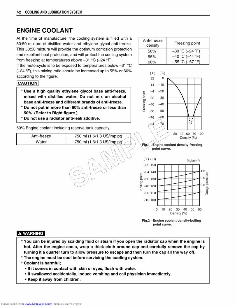
7-2 COOLING AND LUBRICATION SYSTEM
ENGINE COOLANTAt the time of manufacture, the cooling system is filled with a50:50 mixture of distilled water and ethylene glycol anti-freeze.This 50:50 mixture will provide the optimum corrosion protectionand excellent heat protection, and will protect the cooling systemfrom freezing at temperatures above –31 °C (–24 °F).If the motorcycle is to be exposed to temperatures below –31 °C(–24 °F), this mixing ratio should be increased up to 55% or 60%according to the figure.
50% Engine coolant including reserve tank capacity
* Use a high quality ethylene glycol base anti-freeze,mixed with distilled water. Do not mix an alcoholbase anti-freeze and different brands of anti-freeze.
* Do not put in more than 60% anti-freeze or less than50%. (Refer to Right figure.)
* Do not use a radiator anti-leak additive.
Anti-freeze 750 ml (1.6/1.3 US/lmp.pt)Water 750 ml (1.6/1.3 US/lmp.pt)
Anti-freezedensity Freezing point
50%55%60%
–30 ˚C (–24 ˚F)–40 ˚C (–44 ˚F)–55 ˚C (–67 ˚F)
20 40 60 80 100Density (%)
0
–10
–20
–30
–40
–50
–60
–70
32
14
–4
–22
–40
–58
–76
–94
Free
zing
poi
ntFig.1 Engine coolant density-freezing point curve.
(˚C)(˚F)
0 10 20 30 40 50 60Density (%)
150
140
130
120
110
100
Boi
ling
poin
t
(˚C)(˚F)
302
284
266
248
230
212
Engine coolant density-boilingpoint curve.
Fig.2
(kgf/cm²)
1.5
0.9
0.5
0
Gau
ge p
ress
ure
* You can be injured by scalding fluid or steam if you open the radiator cap when the engine ishot. After the engine cools, wrap a thick cloth around cap and carefully remove the cap byturning it a quarter turn to allow pressure to escape and then turn the cap all the way off.
* The engine must be cool before servicing the cooling system.* Coolant is harmful;
• If it comes in contact with skin or eyes, flush with water.• If swallowed accidentally, induce vomiting and call physician immediately.• Keep it away from children.
SAMPLE
Downloaded from www.Manualslib.com manuals search engine
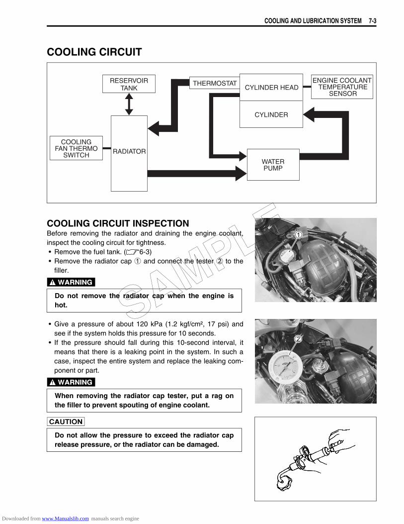
COOLING AND LUBRICATION SYSTEM 7-3
COOLING CIRCUIT
COOLING CIRCUIT INSPECTIONBefore removing the radiator and draining the engine coolant,inspect the cooling circuit for tightness.• Remove the fuel tank. (6-3)• Remove the radiator cap 1 and connect the tester 2 to the
filler.
• Give a pressure of about 120 kPa (1.2 kgf/cm², 17 psi) andsee if the system holds this pressure for 10 seconds.
• If the pressure should fall during this 10-second interval, itmeans that there is a leaking point in the system. In such acase, inspect the entire system and replace the leaking com-ponent or part.
WATERPUMP
RADIATORCOOLING
FAN THERMOSWITCH
ENGINE COOLANT TEMPERATURE
SENSOR
THERMOSTATCYLINDER HEAD
CYLINDER
RESERVOIRTANK
Do not remove the radiator cap when the engine ishot.
When removing the radiator cap tester, put a rag onthe filler to prevent spouting of engine coolant.
Do not allow the pressure to exceed the radiator caprelease pressure, or the radiator can be damaged.
SAMPLE
Downloaded from www.Manualslib.com manuals search engine
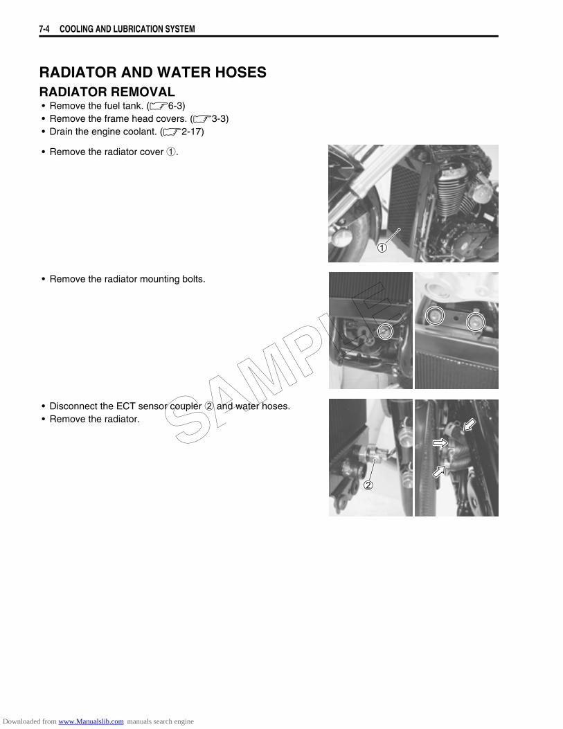
7-4 COOLING AND LUBRICATION SYSTEM
RADIATOR AND WATER HOSESRADIATOR REMOVAL• Remove the fuel tank. (6-3)• Remove the frame head covers. (3-3)• Drain the engine coolant. (2-17)
• Remove the radiator cover 1.
• Remove the radiator mounting bolts.
• Disconnect the ECT sensor coupler 2 and water hoses.• Remove the radiator. SAMPLE
Downloaded from www.Manualslib.com manuals search engine
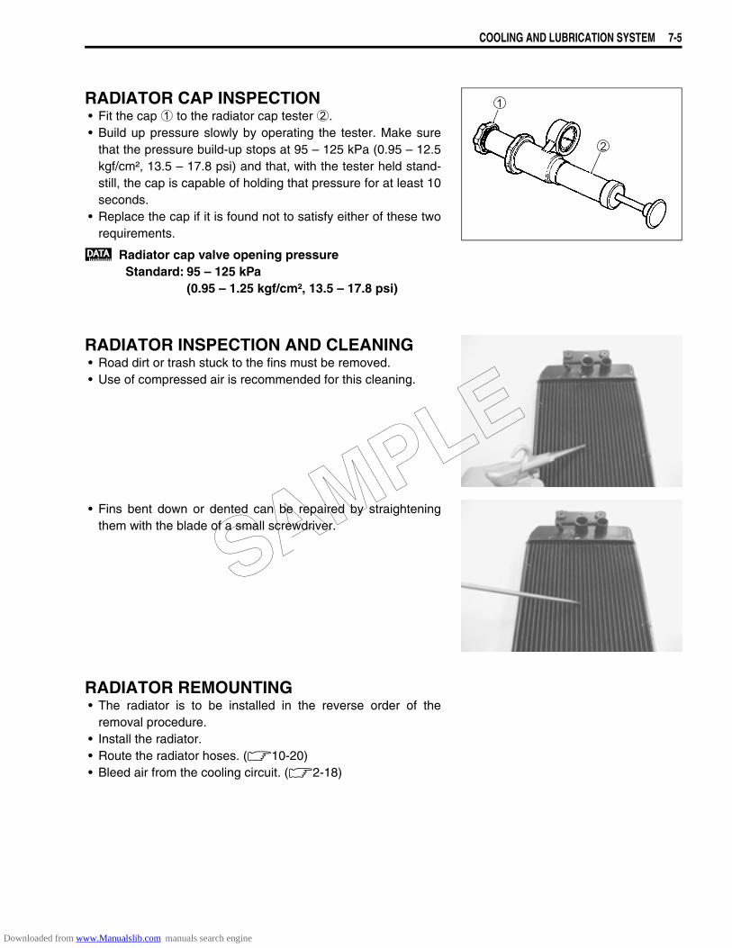
COOLING AND LUBRICATION SYSTEM 7-5
RADIATOR CAP INSPECTION• Fit the cap 1 to the radiator cap tester 2.• Build up pressure slowly by operating the tester. Make sure
that the pressure build-up stops at 95 – 125 kPa (0.95 – 12.5kgf/cm², 13.5 – 17.8 psi) and that, with the tester held stand-still, the cap is capable of holding that pressure for at least 10seconds.
• Replace the cap if it is found not to satisfy either of these tworequirements.
Radiator cap valve opening pressureStandard: 95 – 125 kPa
(0.95 – 1.25 kgf/cm², 13.5 – 17.8 psi)
RADIATOR INSPECTION AND CLEANING• Road dirt or trash stuck to the fins must be removed.• Use of compressed air is recommended for this cleaning.
• Fins bent down or dented can be repaired by straighteningthem with the blade of a small screwdriver.
RADIATOR REMOUNTING• The radiator is to be installed in the reverse order of the
removal procedure.• Install the radiator.• Route the radiator hoses. (10-20)• Bleed air from the cooling circuit. (2-18)
SAMPLE
Downloaded from www.Manualslib.com manuals search engine
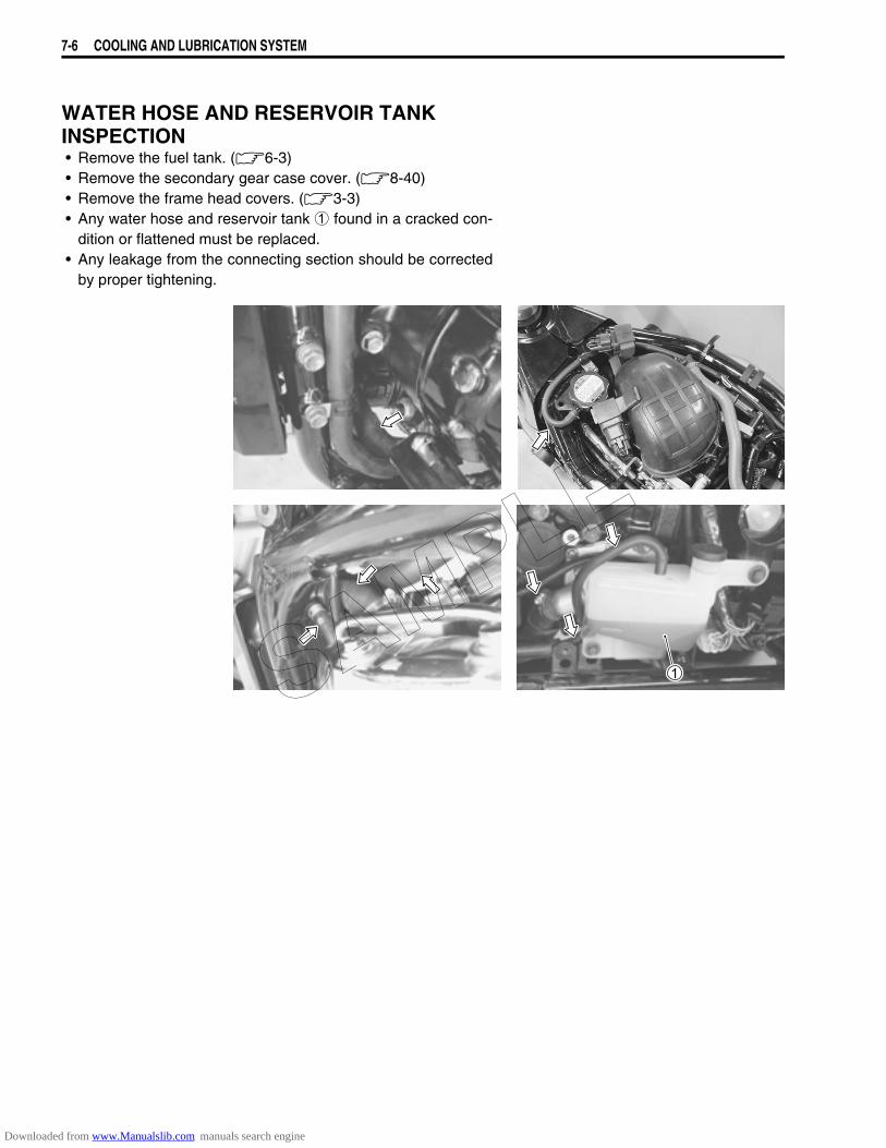
7-6 COOLING AND LUBRICATION SYSTEM
WATER HOSE AND RESERVOIR TANK INSPECTION• Remove the fuel tank. (6-3)• Remove the secondary gear case cover. (8-40)• Remove the frame head covers. (3-3)• Any water hose and reservoir tank 1 found in a cracked con-
dition or flattened must be replaced.• Any leakage from the connecting section should be corrected
by proper tightening.
SAMPLE
Downloaded from www.Manualslib.com manuals search engine
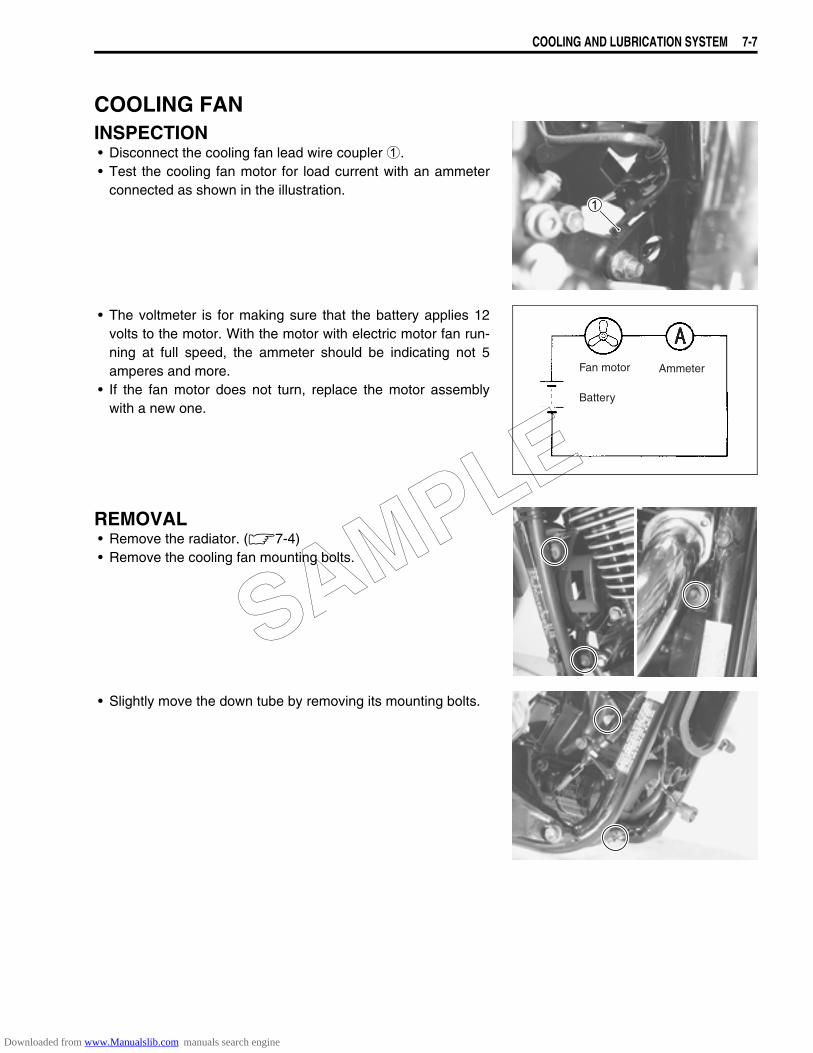
COOLING AND LUBRICATION SYSTEM 7-7
COOLING FANINSPECTION• Disconnect the cooling fan lead wire coupler 1.• Test the cooling fan motor for load current with an ammeter
connected as shown in the illustration.
• The voltmeter is for making sure that the battery applies 12volts to the motor. With the motor with electric motor fan run-ning at full speed, the ammeter should be indicating not 5amperes and more.
• If the fan motor does not turn, replace the motor assemblywith a new one.
REMOVAL• Remove the radiator. (7-4)• Remove the cooling fan mounting bolts.
• Slightly move the down tube by removing its mounting bolts.
Fan motor
Battery
Ammeter
SAMPLE
Downloaded from www.Manualslib.com manuals search engine
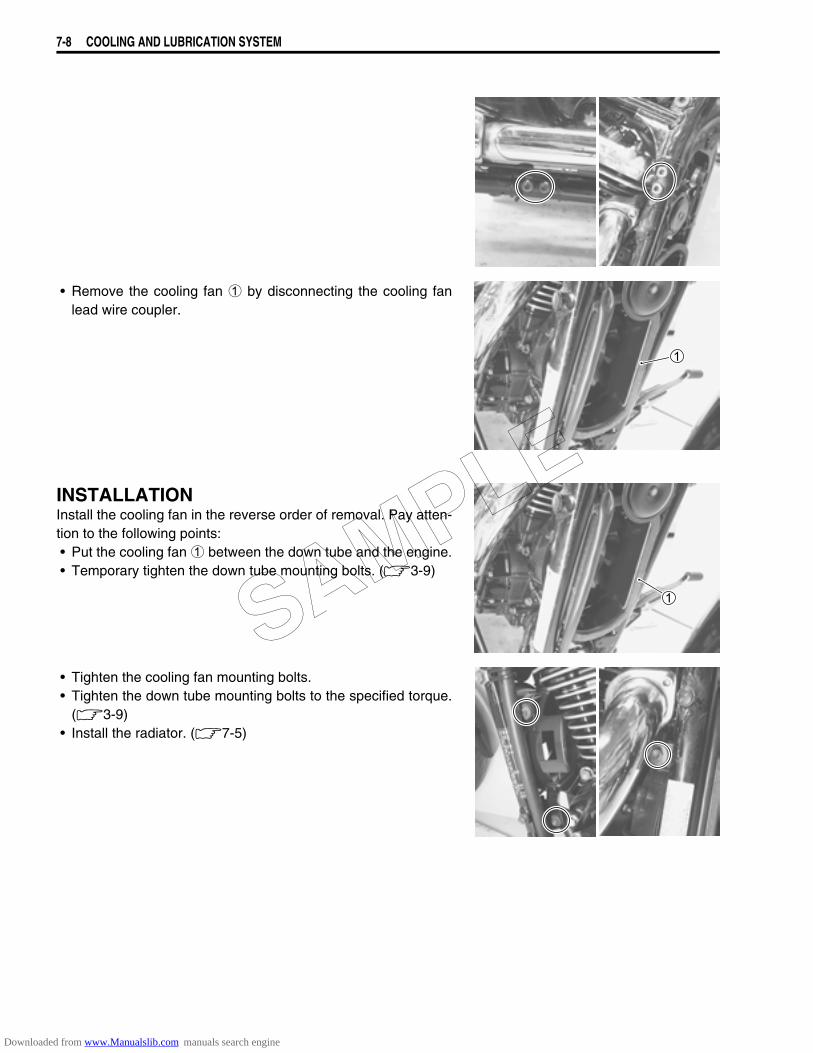
7-8 COOLING AND LUBRICATION SYSTEM
• Remove the cooling fan 1 by disconnecting the cooling fanlead wire coupler.
INSTALLATIONInstall the cooling fan in the reverse order of removal. Pay atten-tion to the following points:• Put the cooling fan 1 between the down tube and the engine.• Temporary tighten the down tube mounting bolts. (3-9)
• Tighten the cooling fan mounting bolts.• Tighten the down tube mounting bolts to the specified torque.
(3-9)• Install the radiator. (7-5)
SAMPLE
Downloaded from www.Manualslib.com manuals search engine
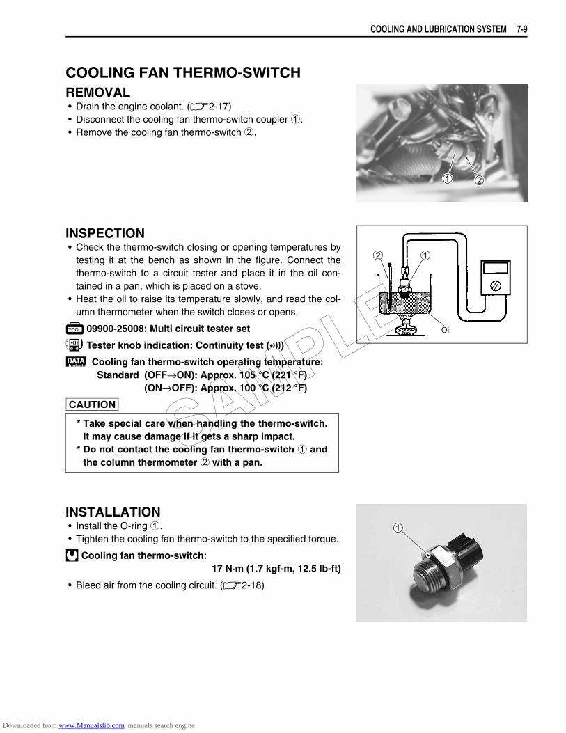
COOLING AND LUBRICATION SYSTEM 7-9
COOLING FAN THERMO-SWITCHREMOVAL• Drain the engine coolant. (2-17)• Disconnect the cooling fan thermo-switch coupler 1.• Remove the cooling fan thermo-switch 2.
INSPECTION• Check the thermo-switch closing or opening temperatures by
testing it at the bench as shown in the figure. Connect thethermo-switch to a circuit tester and place it in the oil con-tained in a pan, which is placed on a stove.
• Heat the oil to raise its temperature slowly, and read the col-umn thermometer when the switch closes or opens.
09900-25008: Multi circuit tester set
Tester knob indication: Continuity test ()
Cooling fan thermo-switch operating temperature:Standard (OFF→ON): Approx. 105 °C (221 °F)
(ON→OFF): Approx. 100 °C (212 °F)
INSTALLATION• Install the O-ring 1.• Tighten the cooling fan thermo-switch to the specified torque.
Cooling fan thermo-switch:17 N·m (1.7 kgf-m, 12.5 lb-ft)
• Bleed air from the cooling circuit. (2-18)
* Take special care when handling the thermo-switch.It may cause damage if it gets a sharp impact.
* Do not contact the cooling fan thermo-switch 1 andthe column thermometer 2 with a pan.
Oil
SAMPLE
Downloaded from www.Manualslib.com manuals search engine
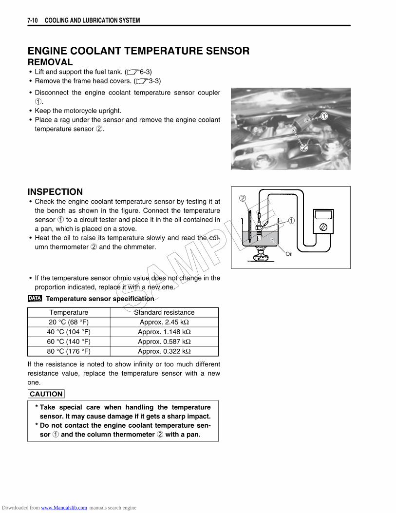
7-10 COOLING AND LUBRICATION SYSTEM
ENGINE COOLANT TEMPERATURE SENSORREMOVAL• Lift and support the fuel tank. (6-3)• Remove the frame head covers. (3-3)
• Disconnect the engine coolant temperature sensor coupler1.
• Keep the motorcycle upright.• Place a rag under the sensor and remove the engine coolant
temperature sensor 2.
INSPECTION• Check the engine coolant temperature sensor by testing it at
the bench as shown in the figure. Connect the temperaturesensor 1 to a circuit tester and place it in the oil contained ina pan, which is placed on a stove.
• Heat the oil to raise its temperature slowly and read the col-umn thermometer 2 and the ohmmeter.
• If the temperature sensor ohmic value does not change in theproportion indicated, replace it with a new one.
Temperature sensor specification
If the resistance is noted to show infinity or too much differentresistance value, replace the temperature sensor with a newone.
Oil
Temperature Standard resistance20 °C (68 °F) Approx. 2.45 kΩ
40 °C (104 °F) Approx. 1.148 kΩ60 °C (140 °F) Approx. 0.587 kΩ80 °C (176 °F) Approx. 0.322 kΩ
* Take special care when handling the temperaturesensor. It may cause damage if it gets a sharp impact.
* Do not contact the engine coolant temperature sen-sor 1 and the column thermometer 2 with a pan.
SAMPLE
Downloaded from www.Manualslib.com manuals search engine
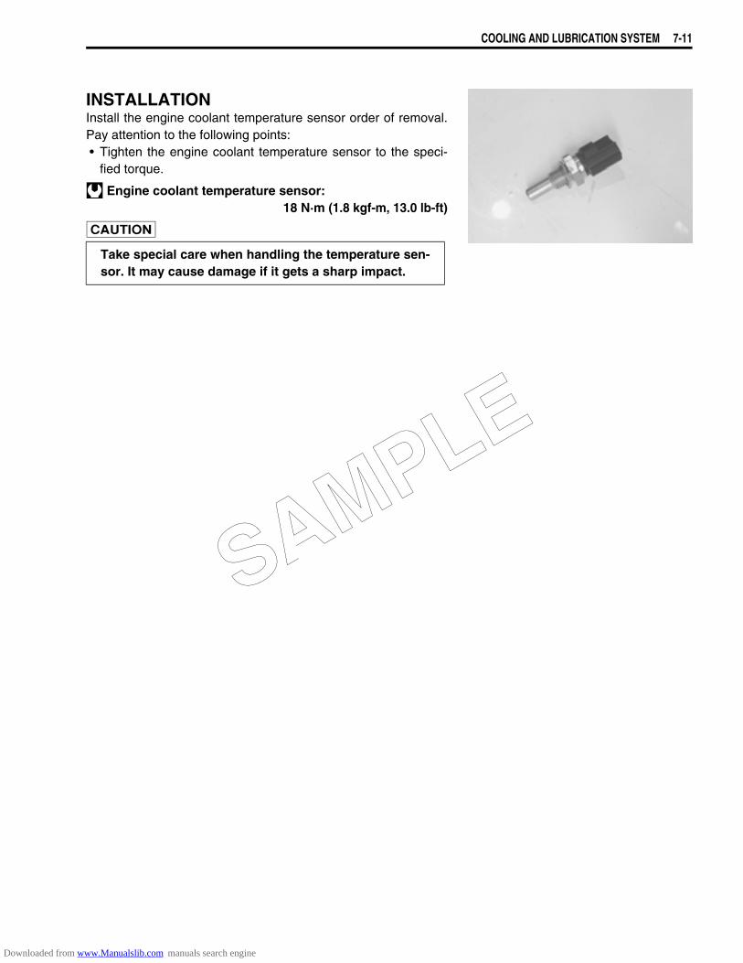
COOLING AND LUBRICATION SYSTEM 7-11
INSTALLATIONInstall the engine coolant temperature sensor order of removal.Pay attention to the following points:• Tighten the engine coolant temperature sensor to the speci-
fied torque.
Engine coolant temperature sensor:18 N·m (1.8 kgf-m, 13.0 lb-ft)
Take special care when handling the temperature sen-sor. It may cause damage if it gets a sharp impact.
SAMPLE
Downloaded from www.Manualslib.com manuals search engine
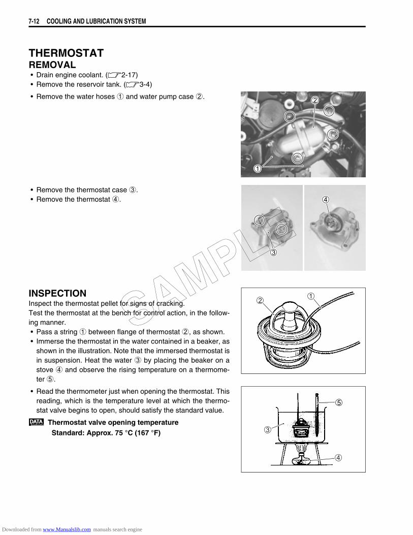
7-12 COOLING AND LUBRICATION SYSTEM
THERMOSTATREMOVAL• Drain engine coolant. (2-17)• Remove the reservoir tank. (3-4)
• Remove the water hoses 1 and water pump case 2.
• Remove the thermostat case 3.• Remove the thermostat 4.
INSPECTIONInspect the thermostat pellet for signs of cracking.Test the thermostat at the bench for control action, in the follow-ing manner.• Pass a string 1 between flange of thermostat 2, as shown.• Immerse the thermostat in the water contained in a beaker, as
shown in the illustration. Note that the immersed thermostat isin suspension. Heat the water 3 by placing the beaker on astove 4 and observe the rising temperature on a thermome-ter 5.
• Read the thermometer just when opening the thermostat. Thisreading, which is the temperature level at which the thermo-stat valve begins to open, should satisfy the standard value.
Thermostat valve opening temperatureStandard: Approx. 75 °C (167 °F)
SAMPLE
Downloaded from www.Manualslib.com manuals search engine

COOLING AND LUBRICATION SYSTEM 7-13
• Keep on heating the water to raise its temperature.• Just when the water temperature reaches specified value, the
thermostat valve should have lifted by at least 6.0 mm (0.24in).
Thermostat valve lift AStandard: 6.0 mm and over at 90 °C
(0.24 in and over at 194 °F)
• A thermostat failing to satisfy either of the two requirements(start-to-open temperature and valve lift) must be replaced.
INSTALLATIONInstall the thermostat in the revers order of removal. Pay atten-tion to the following points:• Apply engine coolant to the O-ring and install the water pump
cover.
• Tighten the water pump cover bolts.
NOTE:Fit the clamp to the bolt A.
• Bleed air from the cooling circuit. (2-18)
SAMPLE
Downloaded from www.Manualslib.com manuals search engine
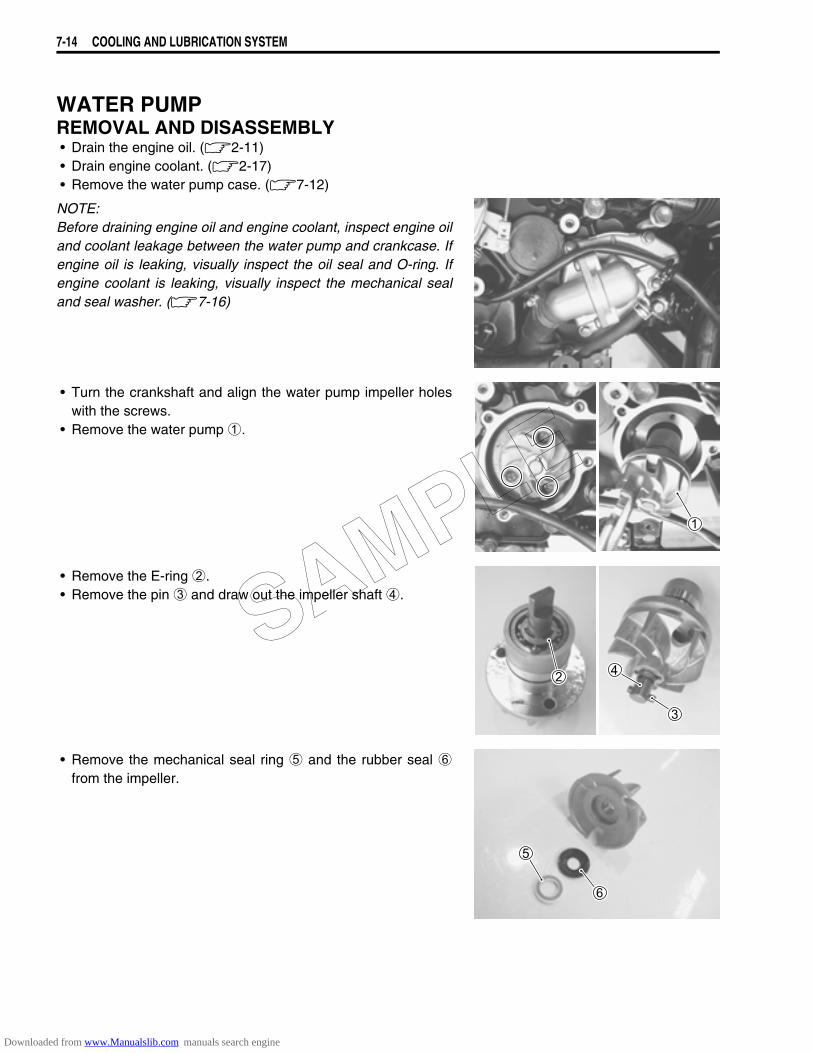
7-14 COOLING AND LUBRICATION SYSTEM
WATER PUMPREMOVAL AND DISASSEMBLY• Drain the engine oil. (2-11)• Drain engine coolant. (2-17)• Remove the water pump case. (7-12)
NOTE:Before draining engine oil and engine coolant, inspect engine oiland coolant leakage between the water pump and crankcase. Ifengine oil is leaking, visually inspect the oil seal and O-ring. Ifengine coolant is leaking, visually inspect the mechanical sealand seal washer. (7-16)
• Turn the crankshaft and align the water pump impeller holeswith the screws.
• Remove the water pump 1.
• Remove the E-ring 2.• Remove the pin 3 and draw out the impeller shaft 4.
• Remove the mechanical seal ring 5 and the rubber seal 6from the impeller.
SAMPLE
Downloaded from www.Manualslib.com manuals search engine

COOLING AND LUBRICATION SYSTEM 7-15
• Remove the bearings with the special tool.
09921-20240: Bearing remover set
NOTE:If there is no abnormal noise condition, bearing removal is notnecessary.
• Remove the mechanical seal with the special tool.
09921-20240: Bearing remover set
NOTE:If there is no abnormal condition, the mechanical seal removal isnot necessary.
• Remove the oil seal using a suitable bar.
NOTE:If no abnormal, the oil seal removal is not necessary.
INSPECTIONBEARING• Inspect the play of the bearing by hand while it is in the water
pump case.• Rotate the inner race by hand to inspect for abnormal noise
and smooth rotation.• Replace the bearing if there is anything unusual.
MECHANICAL SEAL• Visually inspect the mechanical seal for damage, with particu-
lar attention given to the sealing face.• Replace the mechanical seal that shows indications of leak-
age. Also replace the seal ring if necessary.
The removed bearing must be replaced with a newone.
The removed mechanical seal must be replaced with anew one.
The removed oil seal must be replaced with a new one.
SAMPLE
Downloaded from www.Manualslib.com manuals search engine
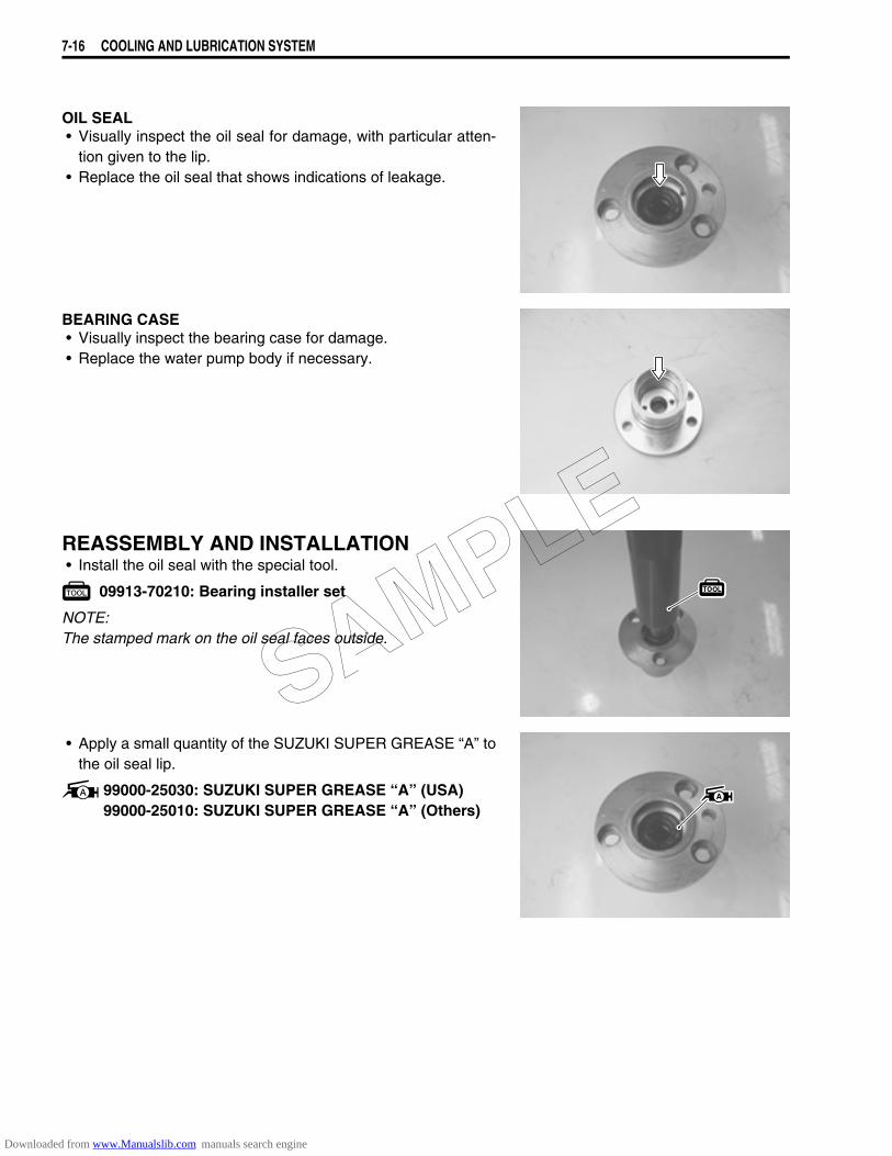
7-16 COOLING AND LUBRICATION SYSTEM
OIL SEAL• Visually inspect the oil seal for damage, with particular atten-
tion given to the lip.• Replace the oil seal that shows indications of leakage.
BEARING CASE• Visually inspect the bearing case for damage.• Replace the water pump body if necessary.
REASSEMBLY AND INSTALLATION• Install the oil seal with the special tool.
09913-70210: Bearing installer set
NOTE:The stamped mark on the oil seal faces outside.
• Apply a small quantity of the SUZUKI SUPER GREASE “A” tothe oil seal lip.
99000-25030: SUZUKI SUPER GREASE “A” (USA)99000-25010: SUZUKI SUPER GREASE “A” (Others)
SAMPLE
Downloaded from www.Manualslib.com manuals search engine
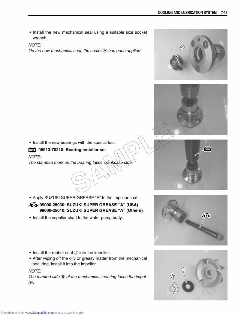
COOLING AND LUBRICATION SYSTEM 7-17
• Install the new mechanical seal using a suitable size socketwrench.
NOTE:On the new mechanical seal, the sealer A has been applied.
• Install the new bearings with the special tool.
09913-70210: Bearing installer set
NOTE:The stamped mark on the bearing faces crankcase side.
• Apply SUZUKI SUPER GREASE “A” to the impeller shaft.
99000-25030: SUZUKI SUPER GREASE “A” (USA)99000-25010: SUZUKI SUPER GREASE “A” (Others)
• Install the impeller shaft to the water pump body.
• Install the rubber seal 1 into the impeller.• After wiping off the oily or greasy matter from the mechanical
seal ring, install it into the impeller.
NOTE:The marked side B of the mechanical seal ring faces the impel-ler.
SAMPLE
Downloaded from www.Manualslib.com manuals search engine

7-18 COOLING AND LUBRICATION SYSTEM
• Apply grease to the new O-ring.• Install the impeller 2 and impeller shaft 3 to the water pump
body.• Install the pin 4 and E-ring 5.
99000-25030: SUZUKI SUPER GREASE “A” (USA)99000-25010: SUZUKI SUPER GREASE “A” (Others)
• Install the new gasket 6.• Apply grease to the O-ring.• Set the water pump shaft end C to the oil pump shaft D.
99000-25030: SUZUKI SUPER GREASE “A” (USA)99000-25010: SUZUKI SUPER GREASE “A” (Others)
• Install the water pump.• Tighten the screws.• Install the water pump cover. (7-13)
• Connect the water hose.• Install the reserve tank.• Install the secondary gear case cover.• Pour engine oil. (2-11)• Bleed air from the cooling circuit. (2-18)
SAMPLE
Downloaded from www.Manualslib.com manuals search engine

COOLING AND LUBRICATION SYSTEM 7-19
LUBRICATION SYSTEMOIL PRESSURE2-28
OIL FILTER2-12
OIL PRESSURE REGULATOR3-62
OIL STRAINER3-61
OIL JET3-60
OIL PUMP3-56
OIL PRESSURE SWITCH3-63
SAMPLE
Downloaded from www.Manualslib.com manuals search engine
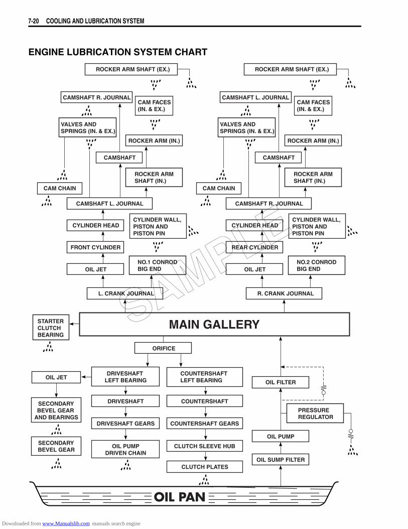
7-20 COOLING AND LUBRICATION SYSTEM
ENGINE LUBRICATION SYSTEM CHART
PRESSURE REGULATOR
OIL PAN
OIL PUMPDRIVEN CHAIN
DRIVESHAFT GEARS
DRIVESHAFT
DRIVESHAFT LEFT BEARING
CLUTCH PLATES
CLUTCH SLEEVE HUB
COUNTERSHAFT GEARS
COUNTERSHAFT
COUNTERSHAFT LEFT BEARINGOIL JET
SECONDARYBEVEL GEAR
AND BEARINGS
SECONDARYBEVEL GEAR
OIL SUMP FILTER
OIL PUMP
OIL FILTER
ORIFICE
MAIN GALLERYSTARTERCLUTCH BEARING
R. CRANK JOURNAL
OIL JET
REAR CYLINDER
CYLINDER HEAD
CAMSHAFT R. JOURNAL
CYLINDER WALL, PISTON AND PISTON PIN
NO.2 CONROD BIG END
CAM CHAIN
CAMSHAFT
ROCKER ARM (IN.)
VALVES AND SPRINGS (IN. & EX.)
CAMSHAFT L. JOURNALCAM FACES (IN. & EX.)
ROCKER ARM SHAFT (EX.)
ROCKER ARM SHAFT (IN.)
L. CRANK JOURNAL
OIL JET
FRONT CYLINDER
CYLINDER HEAD
CAMSHAFT L. JOURNAL
CYLINDER WALL, PISTON AND PISTON PIN
NO.1 CONROD BIG END
CAM CHAIN
CAMSHAFT
ROCKER ARM (IN.)
VALVES AND SPRINGS (IN. & EX.)
CAMSHAFT R. JOURNALCAM FACES (IN. & EX.)
ROCKER ARM SHAFT (EX.)
ROCKER ARM SHAFT (IN.)
SAMPLE
Downloaded from www.Manualslib.com manuals search engine
CHASSIS 8-1
8
CHASSIS
CONTENTS
EXTERIOR PARTS........................................................................................8- 3REMOVAL...............................................................................................8- 3REMOUNTING ........................................................................................8- 4
FRONT WHEEL .............................................................................................8- 5CONSTRUCTION....................................................................................8- 5REMOVAL AND DISASSEMBLY ...........................................................8- 7INSPECTION...........................................................................................8- 8REASSEMBLY AND REMOUNTING......................................................8- 9
FRONT FORK................................................................................................8-12CONSTRUCTION....................................................................................8-12REMOVAL AND DISASSEMBLY ...........................................................8-13INSPECTION...........................................................................................8-16REASSEMBLY AND REMOUNTING......................................................8-17
HANDLEBAR.................................................................................................8-21CONSTRUCTION....................................................................................8-21REMOVAL AND DISASSEMBLY ...........................................................8-22REASSEMBLY AND REMOUNTING......................................................8-22
STEERING .....................................................................................................8-24CONSTRUCTION....................................................................................8-24REMOVAL AND DISASSEMBLY ...........................................................8-25INSPECTION AND DISASSEMBLY .......................................................8-27REASSEMBLY AND REMOUNTING......................................................8-27STEERING TENSION ADJUSTMENT....................................................8-30
REAR WHEEL ...............................................................................................8-31CONSTRUCTION....................................................................................8-31REMOVAL...............................................................................................8-33DISASSEMBLY.......................................................................................8-34INSPECTION AND DISASSEMBLY .......................................................8-35REASSEMBLY AND REMOUNTING......................................................8-36
REAR SUSPENSION.....................................................................................8-38CONSTRUCTION....................................................................................8-38REMOVAL...............................................................................................8-40INSPECTION AND DISASSEMBLY .......................................................8-43REASSEMBLY........................................................................................8-45REMOUNTING ........................................................................................8-46REAR SHOCK ABSORBER DISPOSAL................................................8-49SUSPENSION SETTING.........................................................................8-49
FRONT BRAKE .............................................................................................8-50CONSTRUCTION....................................................................................8-50
SAMPLE
Downloaded from www.Manualslib.com manuals search engine
CHASSIS
CONTENTS
8-2 CHASSIS
BRAKE PAD REPLACEMENT...............................................................8-52BRAKE FLUID REPLACEMENT............................................................8-53BRAKE CALIPER REMOVAL AND DISASSEMBLY.......................................................................................8-53BRAKE CALIPER INSPECTION ............................................................8-54BRAKE CALIPER REASSEMBLY AND REMOUNTING.......................8-55BRAKE DISC INSPECTION ...................................................................8-56MASTER CYLINDER REMOVAL AND DISASSEMBLY .......................8-57MASTER CYLINDER INSPECTION .......................................................8-58MASTER CYLINDER REASSEMBLY AND REMOUNTING..................8-59
REAR BRAKE ...............................................................................................8-61CONSTRUCTION....................................................................................8-61REMOVAL AND DISASSEMBLY...........................................................8-62INSPECTION...........................................................................................8-62REASSEMBLY AND REMOUNTING .....................................................8-63REAR BRAKE ROD................................................................................8-64REASSEMBLY REMOUNTING ..............................................................8-65
TIRE AND WHEEL ........................................................................................8-66TIRE REMOVAL .....................................................................................8-66INSPECTION...........................................................................................8-66VALVE INSPECTION..............................................................................8-67TIRE INSTALLATION .............................................................................8-68BALANCER WEIGHT INSTALLATION..................................................8-69SAMPLE
Downloaded from www.Manualslib.com manuals search engine
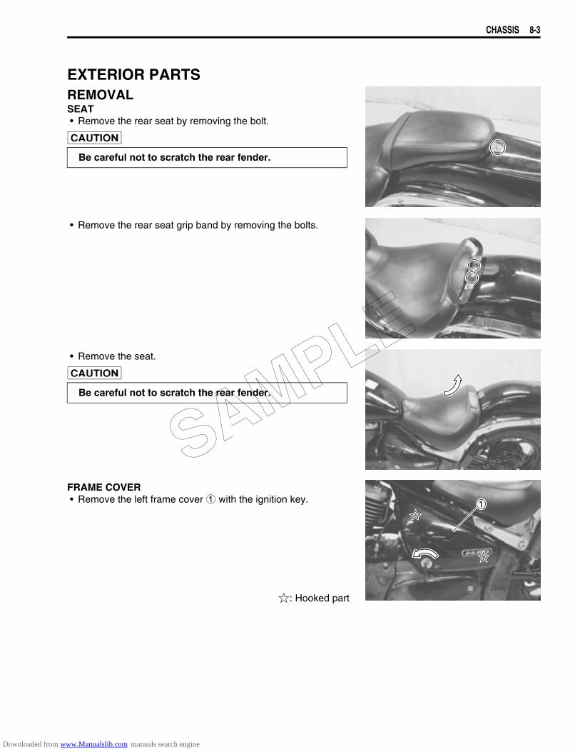
CHASSIS 8-3
EXTERIOR PARTSREMOVALSEAT• Remove the rear seat by removing the bolt.
• Remove the rear seat grip band by removing the bolts.
• Remove the seat.
FRAME COVER• Remove the left frame cover 1 with the ignition key.
: Hooked part
Be careful not to scratch the rear fender.
Be careful not to scratch the rear fender.
SAMPLE
Downloaded from www.Manualslib.com manuals search engine
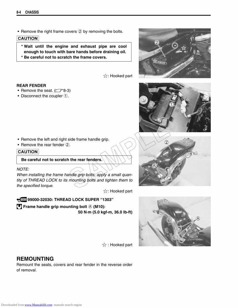
8-4 CHASSIS
• Remove the right frame covers 2 by removing the bolts.
: Hooked part
REAR FENDER• Remove the seat. (8-3)• Disconnect the coupler 1.
• Remove the left and right side frame handle grip.• Remove the rear fender 2.
NOTE:When installing the frame handle grip bolts, apply a small quan-tity of THREAD LOCK to its mounting bolts and tighten them tothe specified torque.
: Hooked part
99000-32030: THREAD LOCK SUPER “1303”
Frame handle grip mounting bolt A (M10):50 N·m (5.0 kgf-m, 36.0 lb-ft)
: Hooked part
REMOUNTINGRemount the seats, covers and rear fender in the reverse orderof removal.
* Wait until the engine and exhaust pipe are coolenough to touch with bare hands before draining oil.
* Be careful not to scratch the frame covers.
Be careful not to scratch the rear fenders.
SAMPLE
Downloaded from www.Manualslib.com manuals search engine
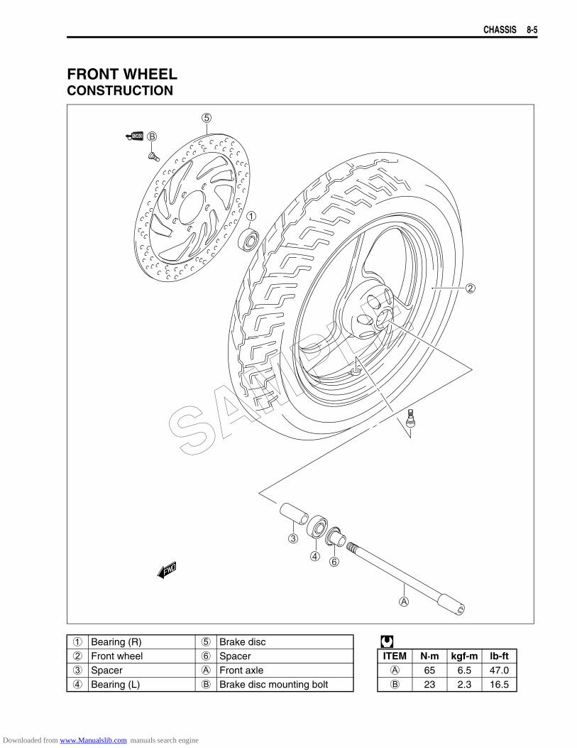
CHASSIS 8-5
FRONT WHEELCONSTRUCTION
1 Bearing (R) 5 Brake disc 2 Front wheel 6 Spacer ITEM N·m kgf-m lb-ft3 Spacer A Front axle A 65 6.5 47.04 Bearing (L) B Brake disc mounting bolt B 23 2.3 16.5
SAMPLE
Downloaded from www.Manualslib.com manuals search engine
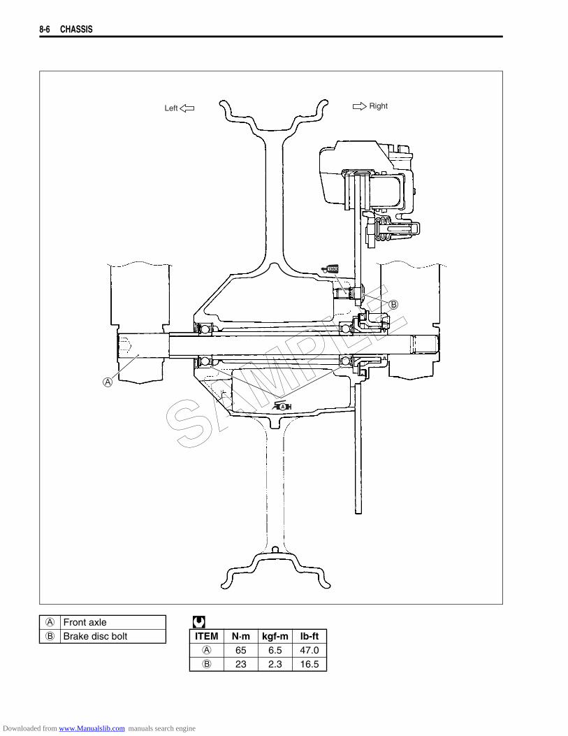
8-6 CHASSIS
A Front axle B Brake disc bolt ITEM N·m kgf-m lb-ft
A 65 6.5 47.0B 23 2.3 16.5
Left Right
SAMPLE
Downloaded from www.Manualslib.com manuals search engine
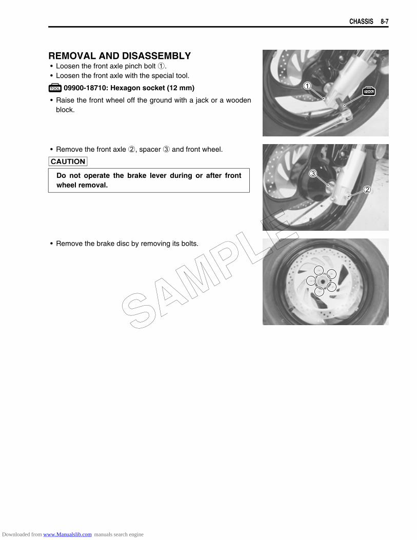
CHASSIS 8-7
REMOVAL AND DISASSEMBLY• Loosen the front axle pinch bolt 1.• Loosen the front axle with the special tool.
09900-18710: Hexagon socket (12 mm)
• Raise the front wheel off the ground with a jack or a woodenblock.
• Remove the front axle 2, spacer 3 and front wheel.
• Remove the brake disc by removing its bolts.
Do not operate the brake lever during or after frontwheel removal.
SAMPLE
Downloaded from www.Manualslib.com manuals search engine
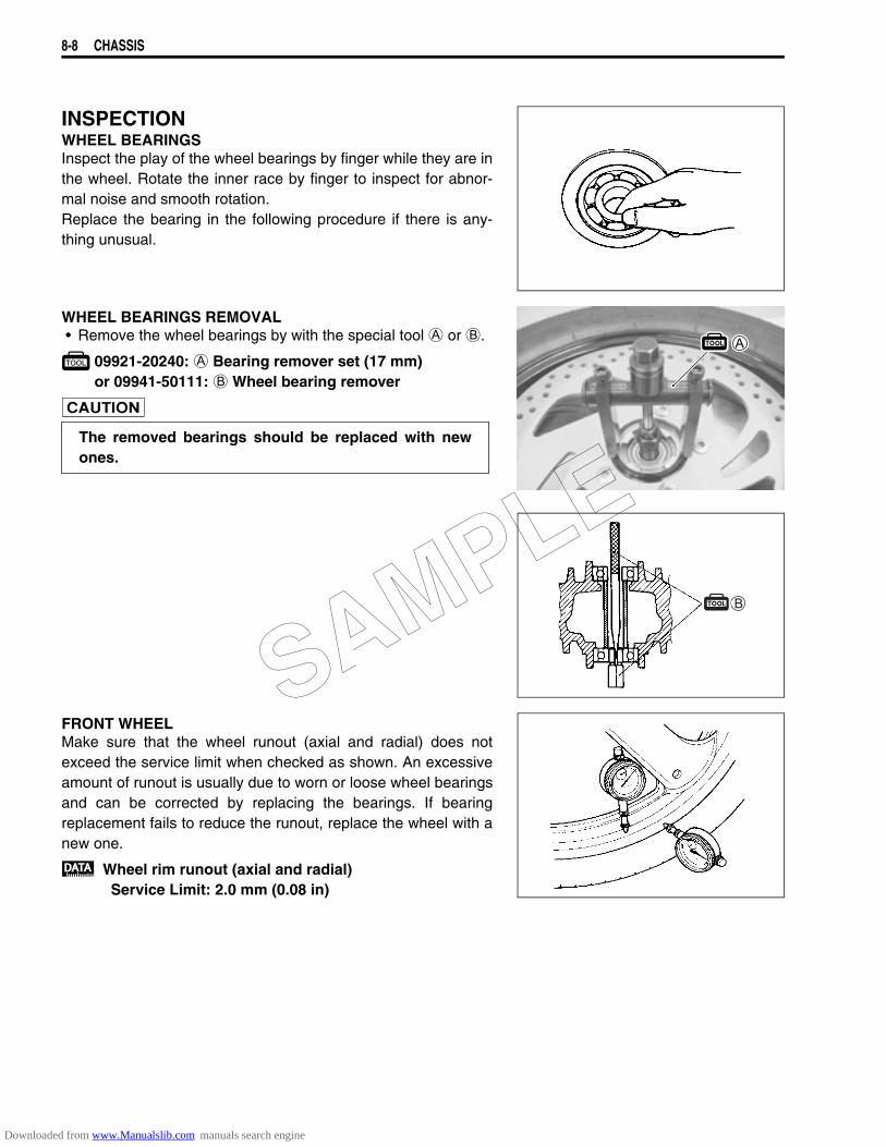
8-8 CHASSIS
INSPECTIONWHEEL BEARINGSInspect the play of the wheel bearings by finger while they are inthe wheel. Rotate the inner race by finger to inspect for abnor-mal noise and smooth rotation.Replace the bearing in the following procedure if there is any-thing unusual.
WHEEL BEARINGS REMOVAL• Remove the wheel bearings by with the special tool A or B.
09921-20240: A Bearing remover set (17 mm)or 09941-50111: B Wheel bearing remover
FRONT WHEELMake sure that the wheel runout (axial and radial) does notexceed the service limit when checked as shown. An excessiveamount of runout is usually due to worn or loose wheel bearingsand can be corrected by replacing the bearings. If bearingreplacement fails to reduce the runout, replace the wheel with anew one.
Wheel rim runout (axial and radial)Service Limit: 2.0 mm (0.08 in)
The removed bearings should be replaced with newones.
SAMPLE
Downloaded from www.Manualslib.com manuals search engine
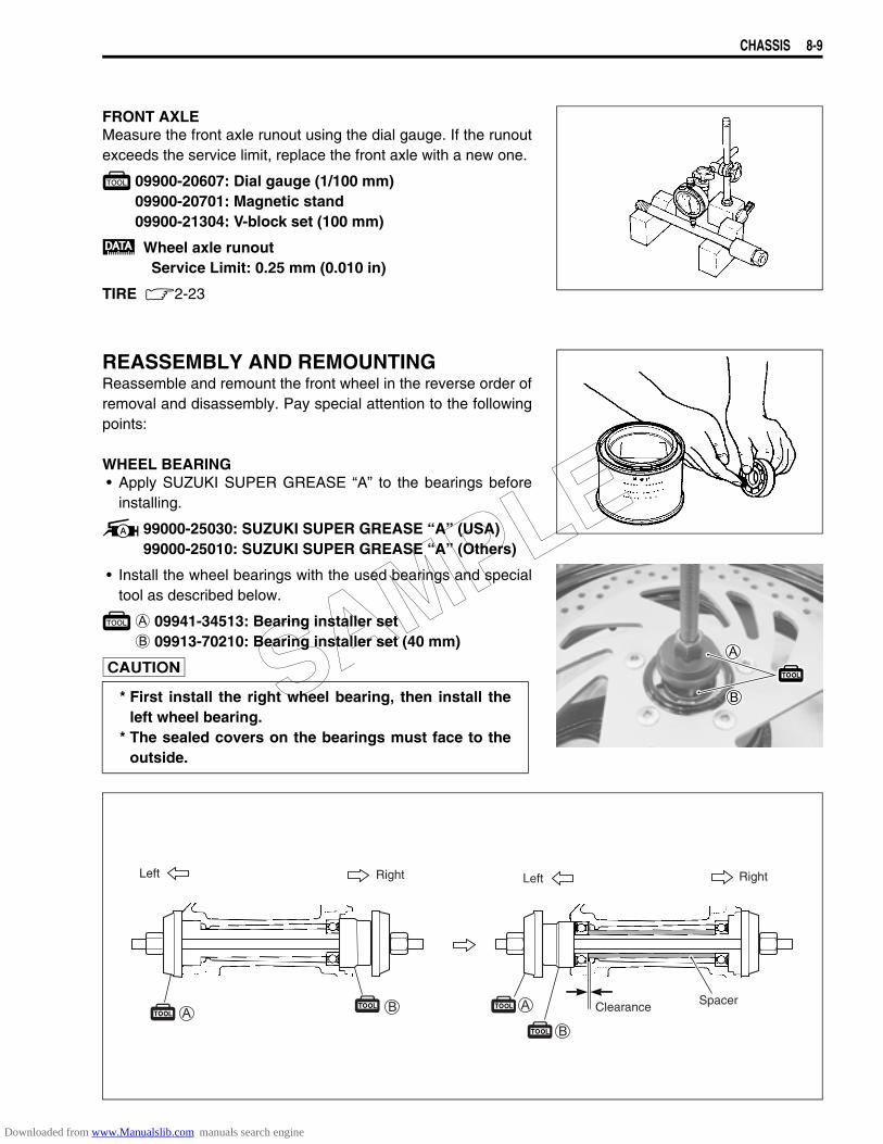
CHASSIS 8-9
FRONT AXLEMeasure the front axle runout using the dial gauge. If the runoutexceeds the service limit, replace the front axle with a new one.
09900-20607: Dial gauge (1/100 mm)09900-20701: Magnetic stand09900-21304: V-block set (100 mm)
Wheel axle runoutService Limit: 0.25 mm (0.010 in)
TIRE 2-23
REASSEMBLY AND REMOUNTINGReassemble and remount the front wheel in the reverse order ofremoval and disassembly. Pay special attention to the followingpoints:
WHEEL BEARING• Apply SUZUKI SUPER GREASE “A” to the bearings before
installing.
99000-25030: SUZUKI SUPER GREASE “A” (USA)99000-25010: SUZUKI SUPER GREASE “A” (Others)
• Install the wheel bearings with the used bearings and specialtool as described below.
A 09941-34513: Bearing installer setB 09913-70210: Bearing installer set (40 mm)
* First install the right wheel bearing, then install the
left wheel bearing.* The sealed covers on the bearings must face to the
outside.
Left Right
Clearance
Left Right
Spacer
SAMPLE
Downloaded from www.Manualslib.com manuals search engine
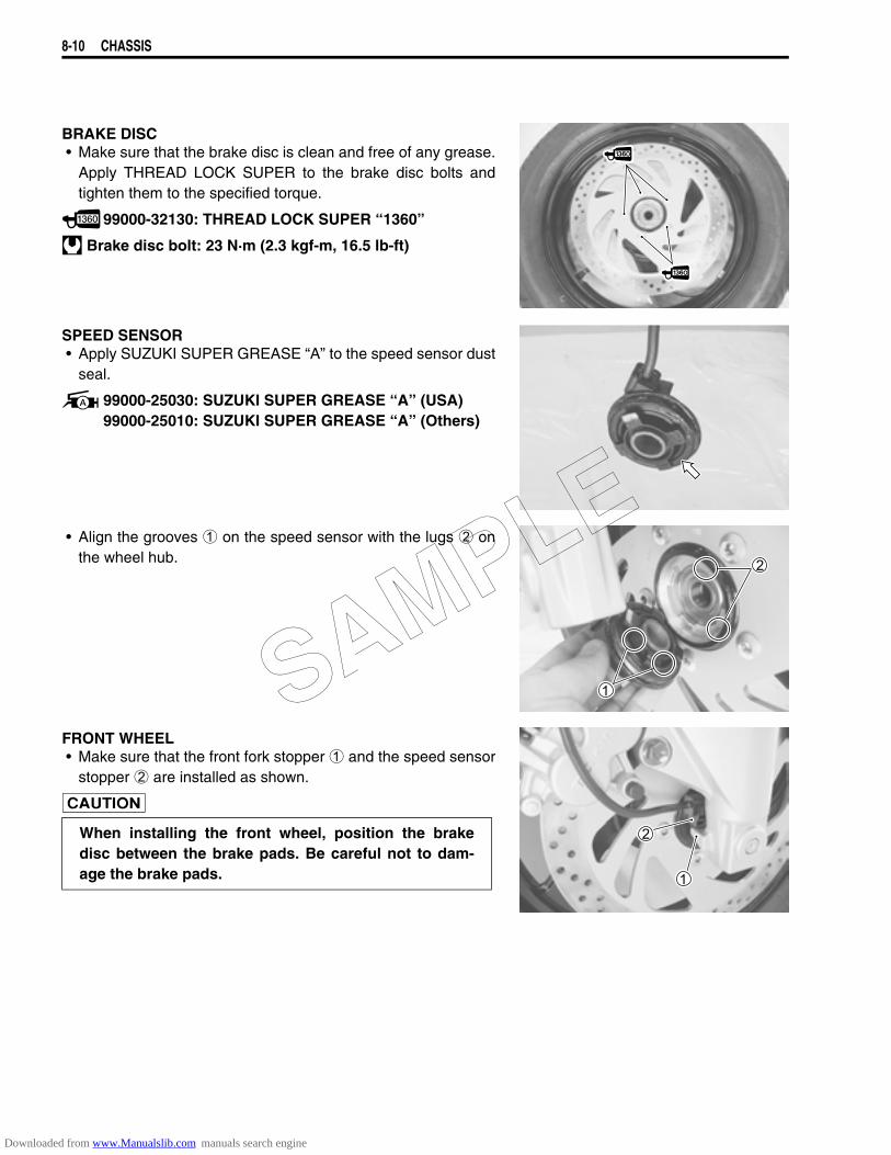
8-10 CHASSIS
BRAKE DISC• Make sure that the brake disc is clean and free of any grease.
Apply THREAD LOCK SUPER to the brake disc bolts andtighten them to the specified torque.
99000-32130: THREAD LOCK SUPER “1360”
Brake disc bolt: 23 N·m (2.3 kgf-m, 16.5 lb-ft)
SPEED SENSOR• Apply SUZUKI SUPER GREASE “A” to the speed sensor dust
seal.
99000-25030: SUZUKI SUPER GREASE “A” (USA)99000-25010: SUZUKI SUPER GREASE “A” (Others)
• Align the grooves 1 on the speed sensor with the lugs 2 onthe wheel hub.
FRONT WHEEL• Make sure that the front fork stopper 1 and the speed sensor
stopper 2 are installed as shown.
When installing the front wheel, position the brakedisc between the brake pads. Be careful not to dam-age the brake pads.
SAMPLE
Downloaded from www.Manualslib.com manuals search engine
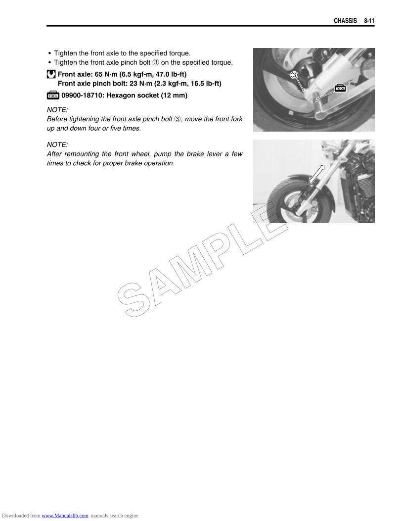
CHASSIS 8-11
• Tighten the front axle to the specified torque.• Tighten the front axle pinch bolt 3 on the specified torque.
Front axle: 65 N·m (6.5 kgf-m, 47.0 lb-ft)Front axle pinch bolt: 23 N·m (2.3 kgf-m, 16.5 lb-ft)
09900-18710: Hexagon socket (12 mm)
NOTE:Before tightening the front axle pinch bolt 3, move the front forkup and down four or five times.
NOTE:After remounting the front wheel, pump the brake lever a fewtimes to check for proper brake operation.
SAMPLE
Downloaded from www.Manualslib.com manuals search engine
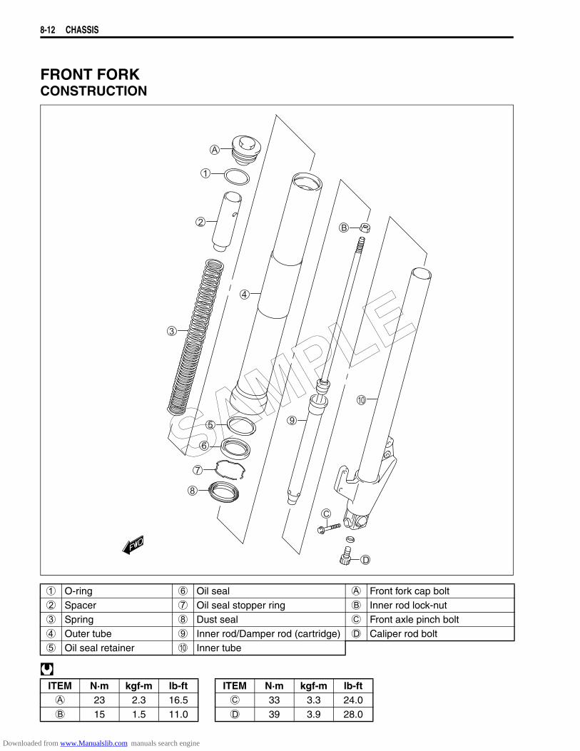
8-12 CHASSIS
FRONT FORKCONSTRUCTION
1 O-ring 6 Oil seal A Front fork cap bolt2 Spacer 7 Oil seal stopper ring B Inner rod lock-nut3 Spring 8 Dust seal C Front axle pinch bolt4 Outer tube 9 Inner rod/Damper rod (cartridge) D Caliper rod bolt5 Oil seal retainer 0 Inner tube
ITEM N·m kgf-m lb-ft ITEM N·m kgf-m lb-ftA 23 2.3 16.5 C 33 3.3 24.0B 15 1.5 11.0 D 39 3.9 28.0
SAMPLE
Downloaded from www.Manualslib.com manuals search engine
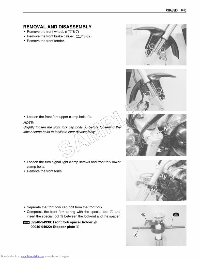
CHASSIS 8-13
REMOVAL AND DISASSEMBLY• Remove the front wheel. (8-7)• Remove the front brake caliper. (8-52)• Remove the front fender.
• Loosen the front fork upper clamp bolts 1.
NOTE:Slightly loosen the front fork cap bolts 2 before loosening thelower clamp bolts to facilitate later disassembly.
• Loosen the turn signal light clamp screws and front fork lowerclamp bolts.
• Remove the front forks.
• Separate the front fork cap bolt from the front fork.• Compress the front fork spring with the special tool A and
insert the special tool B between the lock-nut and the spacer.
09940-94930: Front fork spacer holder A09940-94922: Stopper plate B
SAMPLE
Downloaded from www.Manualslib.com manuals search engine
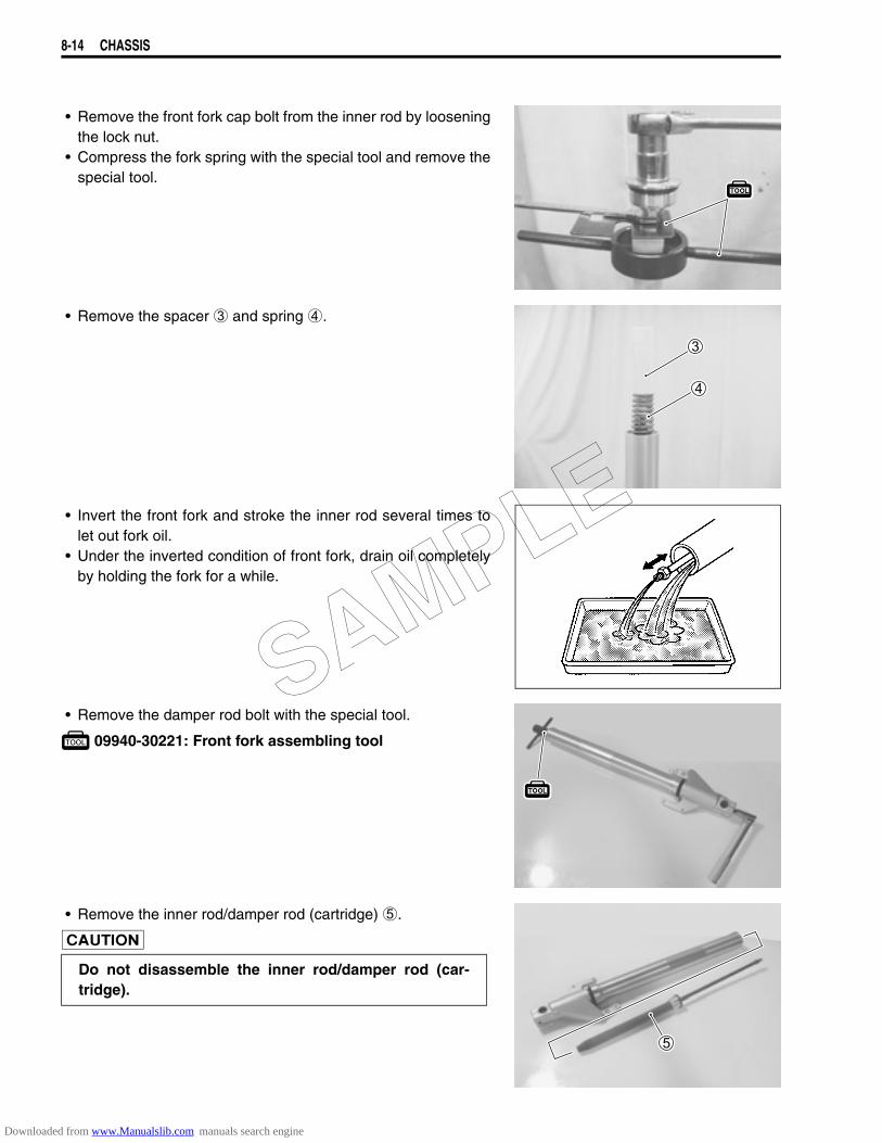
8-14 CHASSIS
• Remove the front fork cap bolt from the inner rod by looseningthe lock nut.
• Compress the fork spring with the special tool and remove thespecial tool.
• Remove the spacer 3 and spring 4.
• Invert the front fork and stroke the inner rod several times tolet out fork oil.
• Under the inverted condition of front fork, drain oil completelyby holding the fork for a while.
• Remove the damper rod bolt with the special tool.
09940-30221: Front fork assembling tool
• Remove the inner rod/damper rod (cartridge) 5.
Do not disassemble the inner rod/damper rod (car-tridge).
SAMPLE
Downloaded from www.Manualslib.com manuals search engine
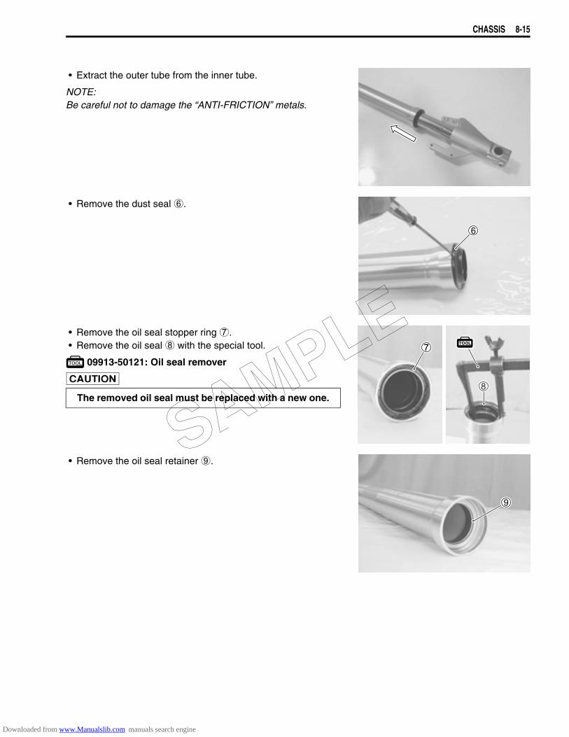
CHASSIS 8-15
• Extract the outer tube from the inner tube.
NOTE:Be careful not to damage the “ANTI-FRICTION” metals.
• Remove the dust seal 6.
• Remove the oil seal stopper ring 7.• Remove the oil seal 8 with the special tool.
09913-50121: Oil seal remover
• Remove the oil seal retainer 9.
The removed oil seal must be replaced with a new one.
SAMPLE
Downloaded from www.Manualslib.com manuals search engine
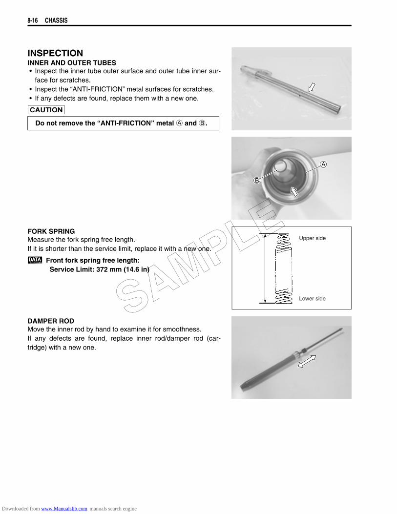
8-16 CHASSIS
INSPECTIONINNER AND OUTER TUBES• Inspect the inner tube outer surface and outer tube inner sur-
face for scratches.• Inspect the “ANTI-FRICTION” metal surfaces for scratches.• If any defects are found, replace them with a new one.
FORK SPRINGMeasure the fork spring free length.If it is shorter than the service limit, replace it with a new one.
Front fork spring free length:Service Limit: 372 mm (14.6 in)
DAMPER RODMove the inner rod by hand to examine it for smoothness.If any defects are found, replace inner rod/damper rod (car-tridge) with a new one.
Do not remove the “ANTI-FRICTION” metal A and B.
Upper side
Lower sideSAMPLE
Downloaded from www.Manualslib.com manuals search engine
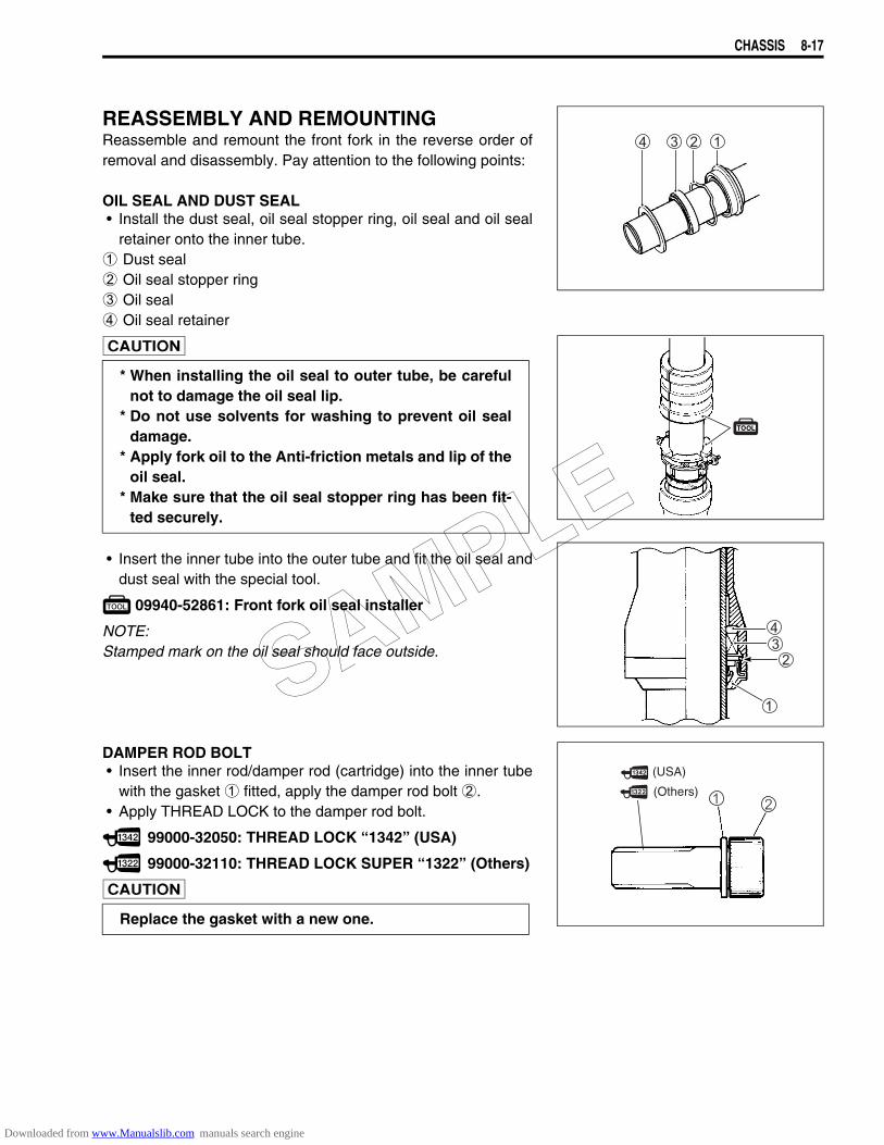
CHASSIS 8-17
REASSEMBLY AND REMOUNTINGReassemble and remount the front fork in the reverse order ofremoval and disassembly. Pay attention to the following points:
OIL SEAL AND DUST SEAL• Install the dust seal, oil seal stopper ring, oil seal and oil seal
retainer onto the inner tube.1 Dust seal2 Oil seal stopper ring3 Oil seal4 Oil seal retainer
• Insert the inner tube into the outer tube and fit the oil seal anddust seal with the special tool.
09940-52861: Front fork oil seal installer
NOTE:Stamped mark on the oil seal should face outside.
DAMPER ROD BOLT• Insert the inner rod/damper rod (cartridge) into the inner tube
with the gasket 1 fitted, apply the damper rod bolt 2.• Apply THREAD LOCK to the damper rod bolt.
99000-32050: THREAD LOCK “1342” (USA)
99000-32110: THREAD LOCK SUPER “1322” (Others)
* When installing the oil seal to outer tube, be carefulnot to damage the oil seal lip.
* Do not use solvents for washing to prevent oil sealdamage.
* Apply fork oil to the Anti-friction metals and lip of theoil seal.
* Make sure that the oil seal stopper ring has been fit-ted securely.
Replace the gasket with a new one.
(Others)
(USA)
SAMPLE
Downloaded from www.Manualslib.com manuals search engine
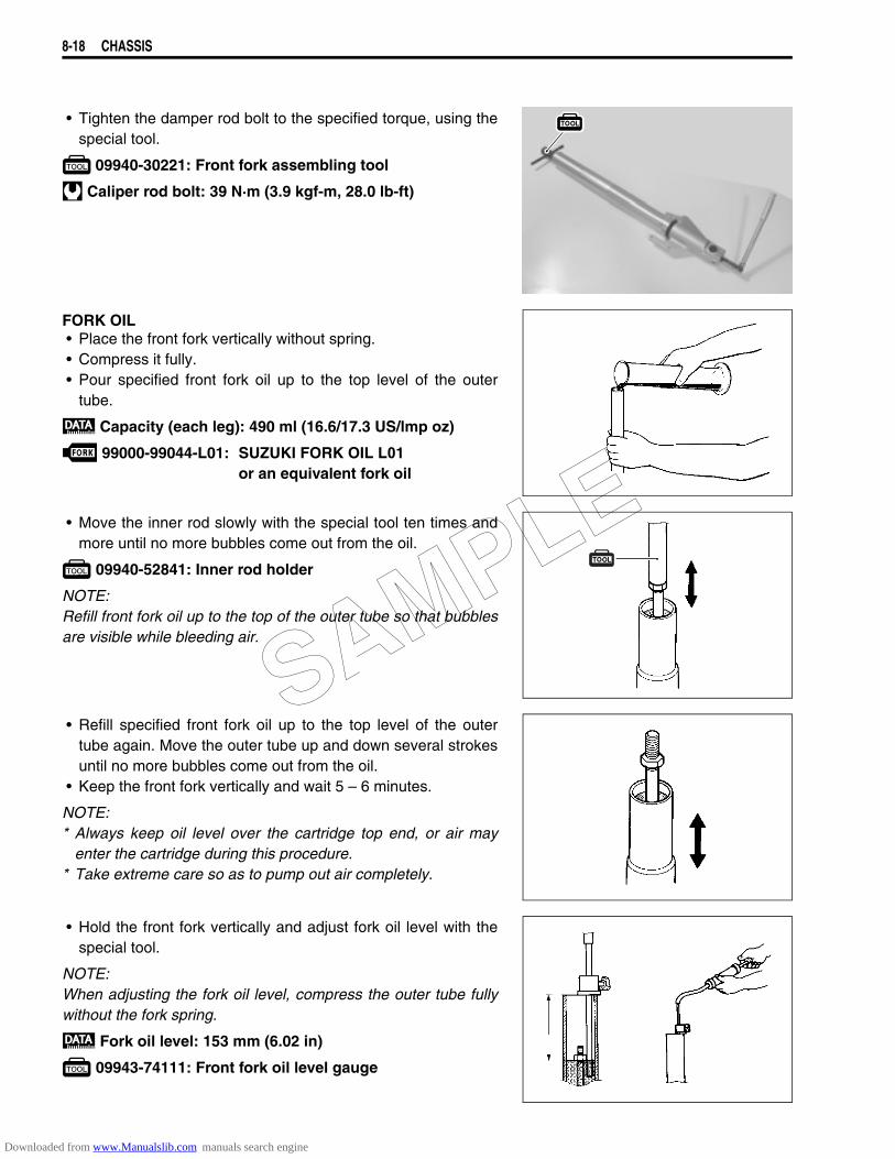
8-18 CHASSIS
• Tighten the damper rod bolt to the specified torque, using thespecial tool.
09940-30221: Front fork assembling tool
Caliper rod bolt: 39 N·m (3.9 kgf-m, 28.0 lb-ft)
FORK OIL• Place the front fork vertically without spring.• Compress it fully.• Pour specified front fork oil up to the top level of the outer
tube.
Capacity (each leg): 490 ml (16.6/17.3 US/lmp oz)
99000-99044-L01: SUZUKI FORK OIL L01or an equivalent fork oil
• Move the inner rod slowly with the special tool ten times andmore until no more bubbles come out from the oil.
09940-52841: Inner rod holder
NOTE:Refill front fork oil up to the top of the outer tube so that bubblesare visible while bleeding air.
• Refill specified front fork oil up to the top level of the outertube again. Move the outer tube up and down several strokesuntil no more bubbles come out from the oil.
• Keep the front fork vertically and wait 5 – 6 minutes.
NOTE:* Always keep oil level over the cartridge top end, or air may
enter the cartridge during this procedure. * Take extreme care so as to pump out air completely.
• Hold the front fork vertically and adjust fork oil level with thespecial tool.
NOTE:When adjusting the fork oil level, compress the outer tube fullywithout the fork spring.
Fork oil level: 153 mm (6.02 in)
09943-74111: Front fork oil level gauge
SAMPLE
Downloaded from www.Manualslib.com manuals search engine
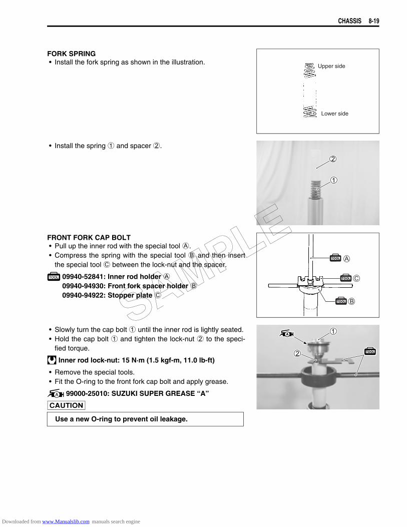
CHASSIS 8-19
FORK SPRING• Install the fork spring as shown in the illustration.
• Install the spring 1 and spacer 2.
FRONT FORK CAP BOLT• Pull up the inner rod with the special tool A.• Compress the spring with the special tool B and then insert
the special tool C between the lock-nut and the spacer.
09940-52841: Inner rod holder A09940-94930: Front fork spacer holder B09940-94922: Stopper plate C
• Slowly turn the cap bolt 1 until the inner rod is lightly seated.• Hold the cap bolt 1 and tighten the lock-nut 2 to the speci-
fied torque.
Inner rod lock-nut: 15 N·m (1.5 kgf-m, 11.0 lb-ft)
• Remove the special tools.• Fit the O-ring to the front fork cap bolt and apply grease.
99000-25010: SUZUKI SUPER GREASE “A”
Upper side
Lower side
Use a new O-ring to prevent oil leakage.
SAMPLE
Downloaded from www.Manualslib.com manuals search engine
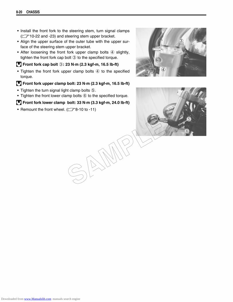
8-20 CHASSIS
• Install the front fork to the steering stem, turn signal clamps(10-22 and -23) and steering stem upper bracket.
• Align the upper surface of the outer tube with the upper sur-face of the steering stem upper bracket.
• After loosening the front fork upper clamp bolts 4 slightly,tighten the front fork cap bolt 3 to the specified torque.
Front fork cap bolt 3: 23 N·m (2.3 kgf-m, 16.5 lb-ft)
• Tighten the front fork upper clamp bolts 4 to the specifiedtorque.
Front fork upper clamp bolt: 23 N·m (2.3 kgf-m, 16.5 lb-ft)
• Tighten the turn signal light clamp bolts 5.• Tighten the front lower clamp bolts 6 to the specified torque.
Front fork lower clamp bolt: 33 N·m (3.3 kgf-m, 24.0 lb-ft)
• Remount the front wheel. (8-10 to -11)
SAMPLE
Downloaded from www.Manualslib.com manuals search engine
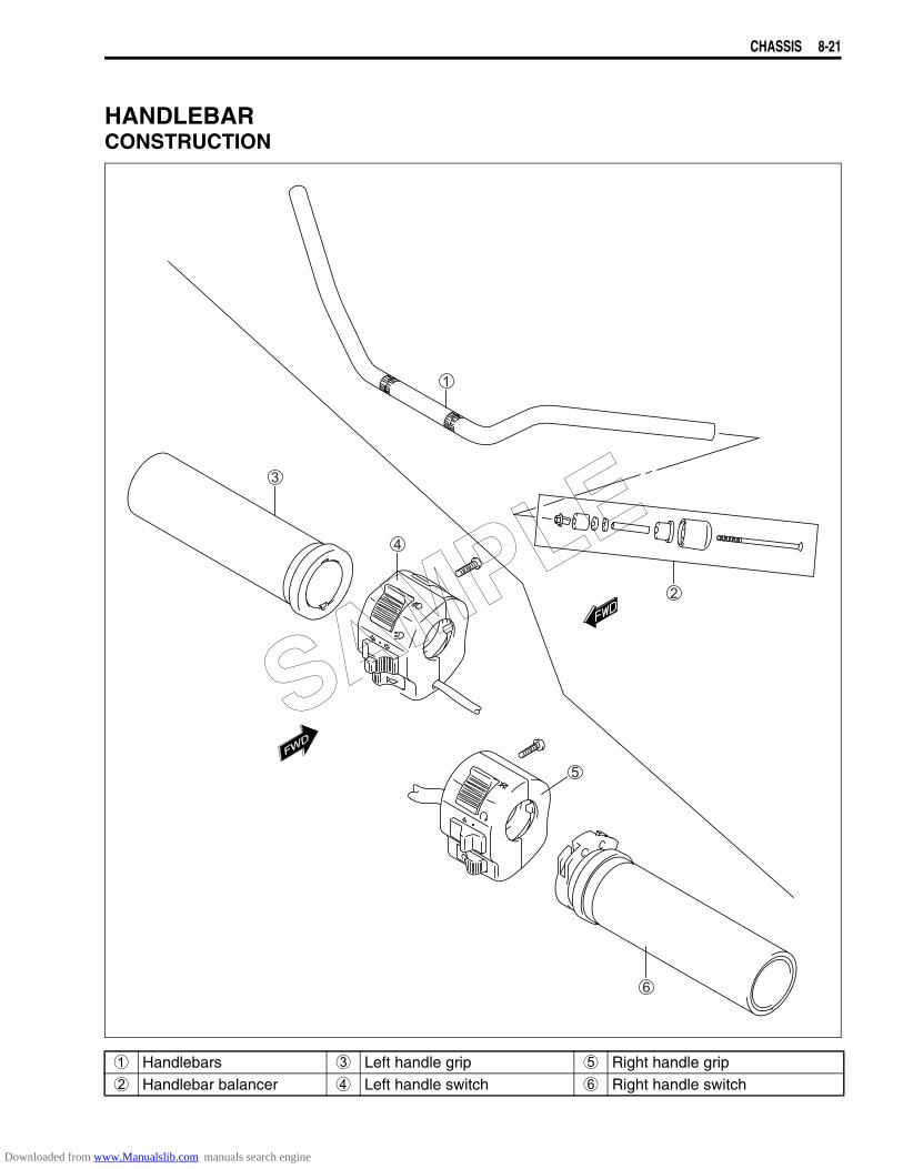
CHASSIS 8-21
HANDLEBARCONSTRUCTION
FWD
FWD
1 Handlebars 3 Left handle grip 5 Right handle grip2 Handlebar balancer 4 Left handle switch 6 Right handle switch
SAMPLE
Downloaded from www.Manualslib.com manuals search engine
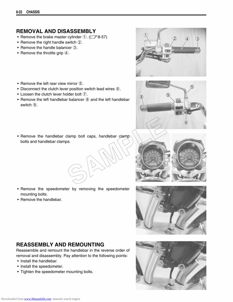
8-22 CHASSIS
REMOVAL AND DISASSEMBLY• Remove the brake master cylinder 1. (8-57)• Remove the right handle switch 2.• Remove the handle balancer 3.• Remove the throttle grip 4.
• Remove the left rear view mirror 5.• Disconnect the clutch lever position switch lead wires 6.• Loosen the clutch lever holder bolt 7.• Remove the left handlebar balancer 8 and the left handlebar
switch 9.
• Remove the handlebar clamp bolt caps, handlebar clampbolts and handlebar clamps.
• Remove the speedometer by removing the speedometermounting bolts.
• Remove the handlebar.
REASSEMBLY AND REMOUNTINGReassemble and remount the handlebar in the reverse order ofremoval and disassembly. Pay attention to the following points:• Install the handlebar.• Install the speedometer.• Tighten the speedometer mounting bolts.
SAMPLE
Downloaded from www.Manualslib.com manuals search engine
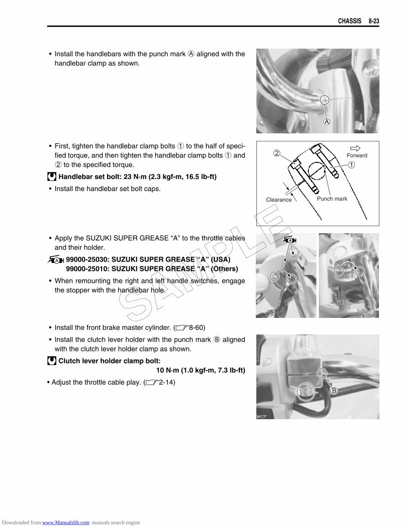
CHASSIS 8-23
• Install the handlebars with the punch mark A aligned with thehandlebar clamp as shown.
• First, tighten the handlebar clamp bolts 1 to the half of speci-fied torque, and then tighten the handlebar clamp bolts 1 and2 to the specified torque.
Handlebar set bolt: 23 N·m (2.3 kgf-m, 16.5 lb-ft)
• Install the handlebar set bolt caps.
• Apply the SUZUKI SUPER GREASE “A” to the throttle cablesand their holder.
99000-25030: SUZUKI SUPER GREASE “A” (USA)99000-25010: SUZUKI SUPER GREASE “A” (Others)
• When remounting the right and left handle switches, engagethe stopper with the handlebar hole.
• Install the front brake master cylinder. (8-60)
• Install the clutch lever holder with the punch mark B alignedwith the clutch lever holder clamp as shown.
Clutch lever holder clamp bolt:10 N·m (1.0 kgf-m, 7.3 lb-ft)
• Adjust the throttle cable play. (2-14)
Forward
Punch markClearance
SAMPLE
Downloaded from www.Manualslib.com manuals search engine
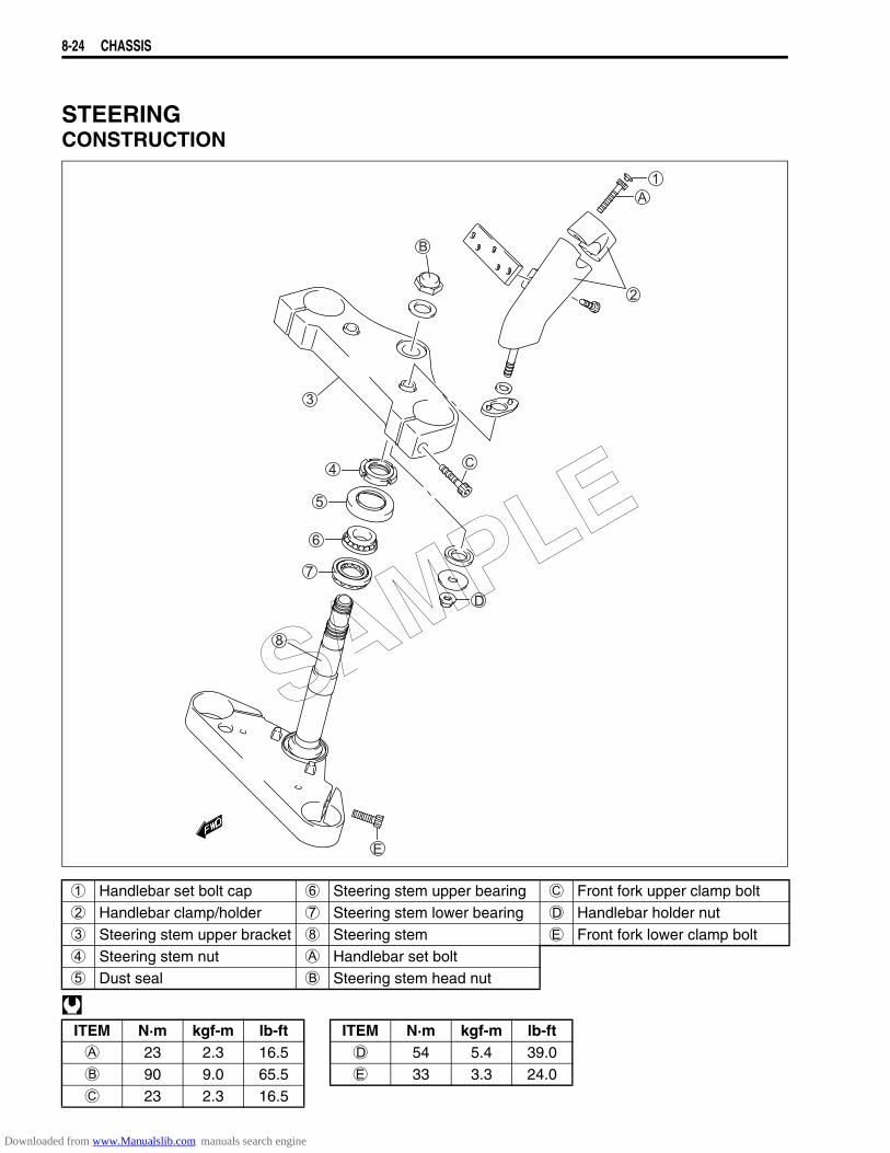
8-24 CHASSIS
STEERINGCONSTRUCTION
1 Handlebar set bolt cap 6 Steering stem upper bearing C Front fork upper clamp bolt2 Handlebar clamp/holder 7 Steering stem lower bearing D Handlebar holder nut3 Steering stem upper bracket 8 Steering stem E Front fork lower clamp bolt4 Steering stem nut A Handlebar set bolt5 Dust seal B Steering stem head nut
ITEM N·m kgf-m lb-ft ITEM N·m kgf-m lb-ftA 23 2.3 16.5 D 54 5.4 39.0B 90 9.0 65.5 E 33 3.3 24.0C 23 2.3 16.5
SAMPLE
Downloaded from www.Manualslib.com manuals search engine
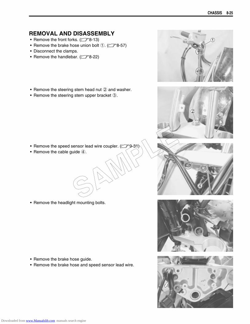
CHASSIS 8-25
REMOVAL AND DISASSEMBLY• Remove the front forks. (8-13)• Remove the brake hose union bolt 1. (8-57)• Disconnect the clamps.• Remove the handlebar. (8-22)
• Remove the steering stem head nut 2 and washer.• Remove the steering stem upper bracket 3.
• Remove the speed sensor lead wire coupler. (9-31)• Remove the cable guide 4.
• Remove the headlight mounting bolts.
• Remove the brake hose guide.• Remove the brake hose and speed sensor lead wire.
SAMPLE
Downloaded from www.Manualslib.com manuals search engine
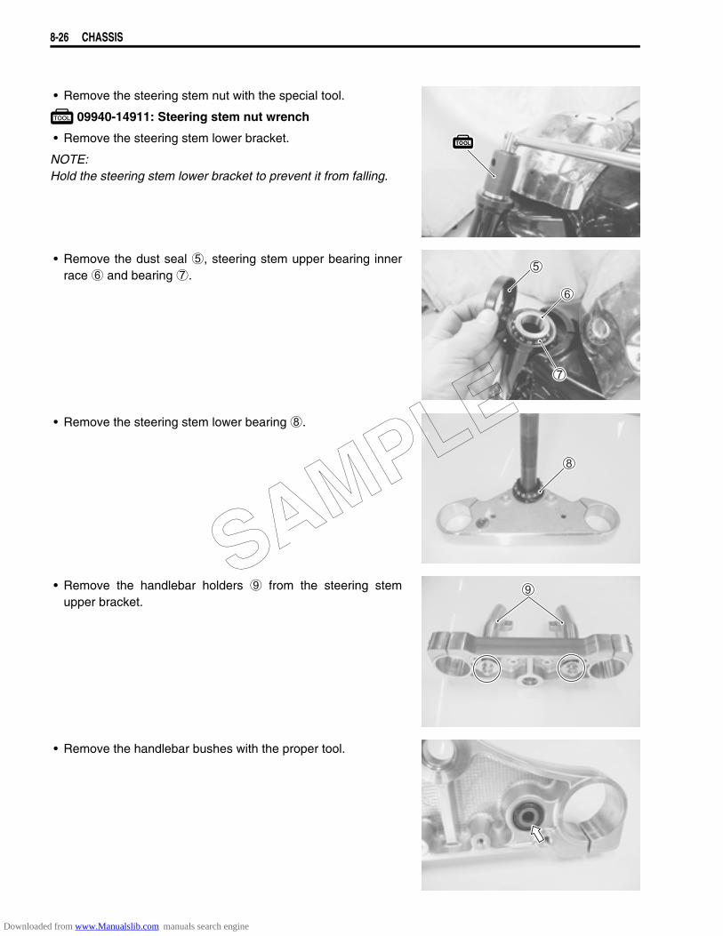
8-26 CHASSIS
• Remove the steering stem nut with the special tool.
09940-14911: Steering stem nut wrench
• Remove the steering stem lower bracket.
NOTE:Hold the steering stem lower bracket to prevent it from falling.
• Remove the dust seal 5, steering stem upper bearing innerrace 6 and bearing 7.
• Remove the steering stem lower bearing 8.
• Remove the handlebar holders 9 from the steering stemupper bracket.
• Remove the handlebar bushes with the proper tool.
SAMPLE
Downloaded from www.Manualslib.com manuals search engine
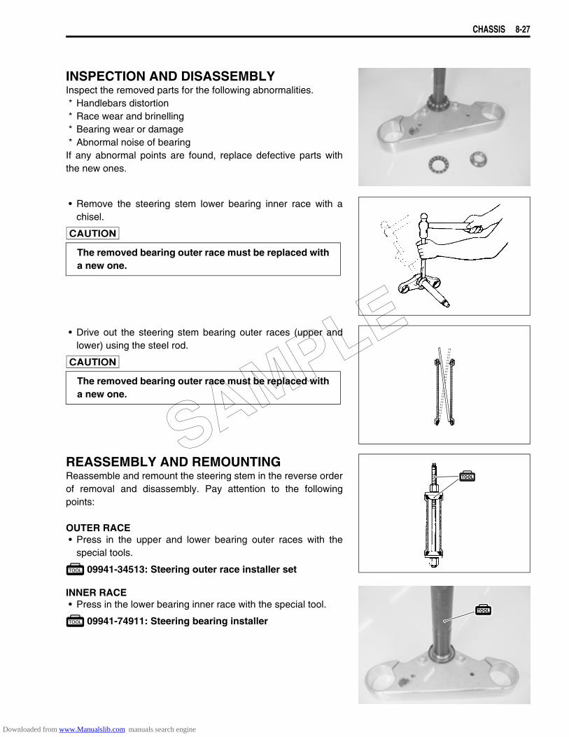
CHASSIS 8-27
INSPECTION AND DISASSEMBLYInspect the removed parts for the following abnormalities.* Handlebars distortion* Race wear and brinelling* Bearing wear or damage* Abnormal noise of bearingIf any abnormal points are found, replace defective parts withthe new ones.
• Remove the steering stem lower bearing inner race with achisel.
• Drive out the steering stem bearing outer races (upper andlower) using the steel rod.
REASSEMBLY AND REMOUNTINGReassemble and remount the steering stem in the reverse orderof removal and disassembly. Pay attention to the followingpoints:
OUTER RACE• Press in the upper and lower bearing outer races with the
special tools.
09941-34513: Steering outer race installer set
INNER RACE• Press in the lower bearing inner race with the special tool.
09941-74911: Steering bearing installer
The removed bearing outer race must be replaced witha new one.
The removed bearing outer race must be replaced witha new one.
SAMPLE
Downloaded from www.Manualslib.com manuals search engine
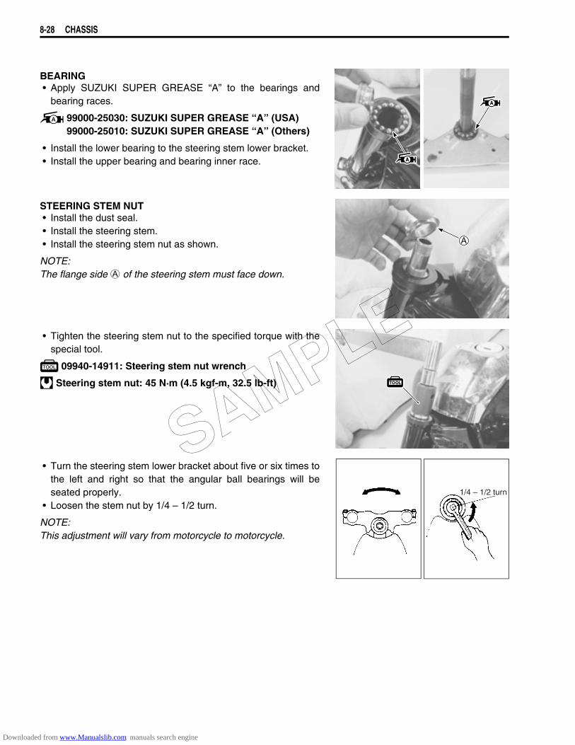
8-28 CHASSIS
BEARING• Apply SUZUKI SUPER GREASE “A” to the bearings and
bearing races.
99000-25030: SUZUKI SUPER GREASE “A” (USA)99000-25010: SUZUKI SUPER GREASE “A” (Others)
• Install the lower bearing to the steering stem lower bracket.• Install the upper bearing and bearing inner race.
STEERING STEM NUT• Install the dust seal.• Install the steering stem.• Install the steering stem nut as shown.
NOTE:The flange side A of the steering stem must face down.
• Tighten the steering stem nut to the specified torque with thespecial tool.
09940-14911: Steering stem nut wrench
Steering stem nut: 45 N·m (4.5 kgf-m, 32.5 lb-ft)
• Turn the steering stem lower bracket about five or six times tothe left and right so that the angular ball bearings will beseated properly.
• Loosen the stem nut by 1/4 – 1/2 turn.
NOTE:This adjustment will vary from motorcycle to motorcycle.
1/4 – 1/2 turn
SAMPLE
Downloaded from www.Manualslib.com manuals search engine
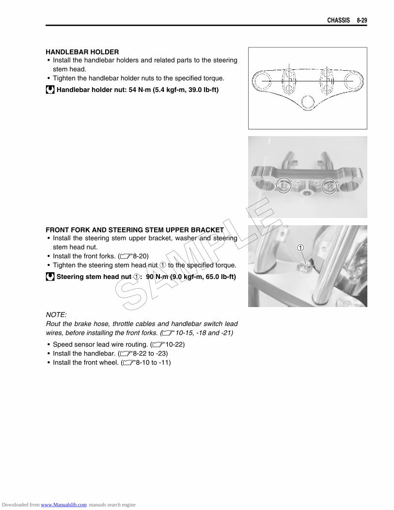
CHASSIS 8-29
HANDLEBAR HOLDER• Install the handlebar holders and related parts to the steering
stem head.• Tighten the handlebar holder nuts to the specified torque.
Handlebar holder nut: 54 N·m (5.4 kgf-m, 39.0 lb-ft)
FRONT FORK AND STEERING STEM UPPER BRACKET• Install the steering stem upper bracket, washer and steering
stem head nut.• Install the front forks. (8-20)• Tighten the steering stem head nut 1 to the specified torque.
Steering stem head nut 1: 90 N·m (9.0 kgf-m, 65.0 lb-ft)
NOTE:Rout the brake hose, throttle cables and handlebar switch leadwires, before installing the front forks. (10-15, -18 and -21)
• Speed sensor lead wire routing. (10-22)• Install the handlebar. (8-22 to -23)• Install the front wheel. (8-10 to -11)
SAMPLE
Downloaded from www.Manualslib.com manuals search engine
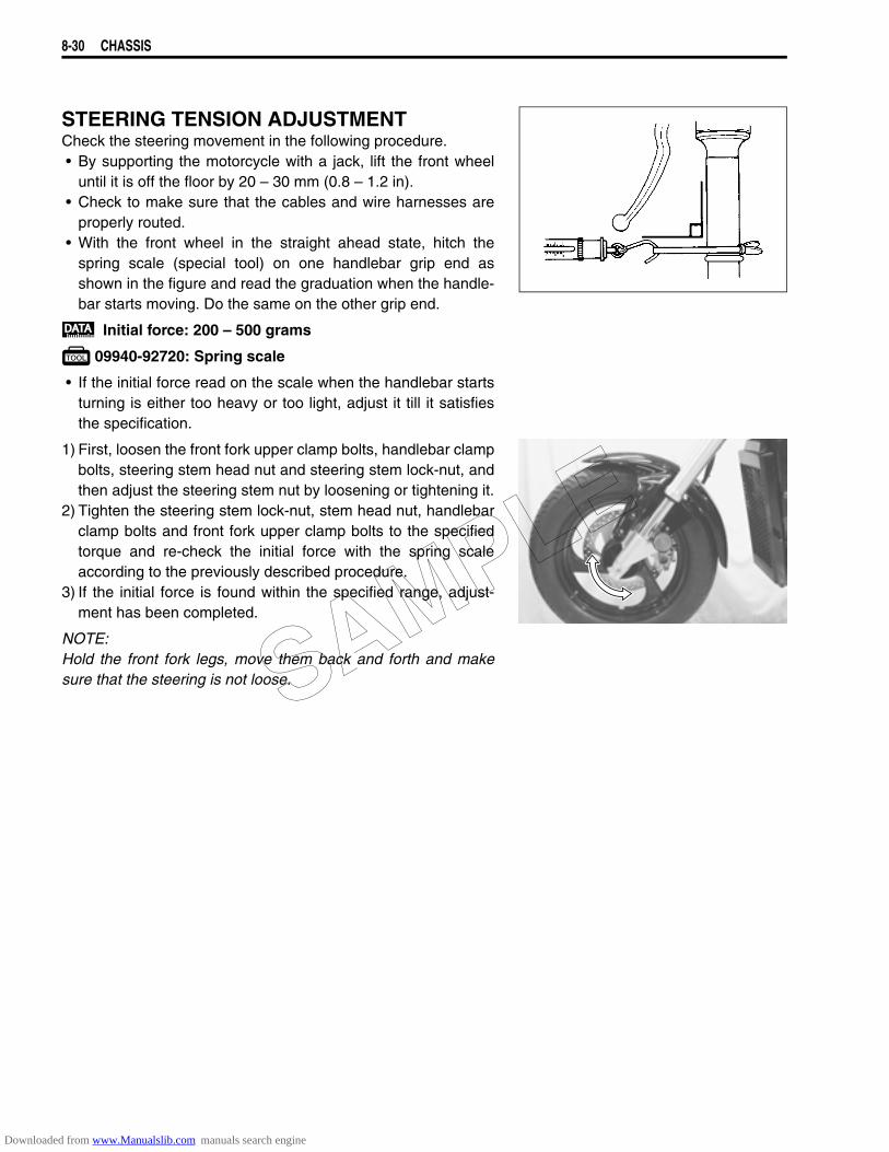
8-30 CHASSIS
STEERING TENSION ADJUSTMENTCheck the steering movement in the following procedure.• By supporting the motorcycle with a jack, lift the front wheel
until it is off the floor by 20 – 30 mm (0.8 – 1.2 in).• Check to make sure that the cables and wire harnesses are
properly routed.• With the front wheel in the straight ahead state, hitch the
spring scale (special tool) on one handlebar grip end asshown in the figure and read the graduation when the handle-bar starts moving. Do the same on the other grip end.
Initial force: 200 – 500 grams
09940-92720: Spring scale
• If the initial force read on the scale when the handlebar startsturning is either too heavy or too light, adjust it till it satisfiesthe specification.
1) First, loosen the front fork upper clamp bolts, handlebar clampbolts, steering stem head nut and steering stem lock-nut, andthen adjust the steering stem nut by loosening or tightening it.
2) Tighten the steering stem lock-nut, stem head nut, handlebarclamp bolts and front fork upper clamp bolts to the specifiedtorque and re-check the initial force with the spring scaleaccording to the previously described procedure.
3) If the initial force is found within the specified range, adjust-ment has been completed.
NOTE:Hold the front fork legs, move them back and forth and makesure that the steering is not loose.SAMPLE
Downloaded from www.Manualslib.com manuals search engine
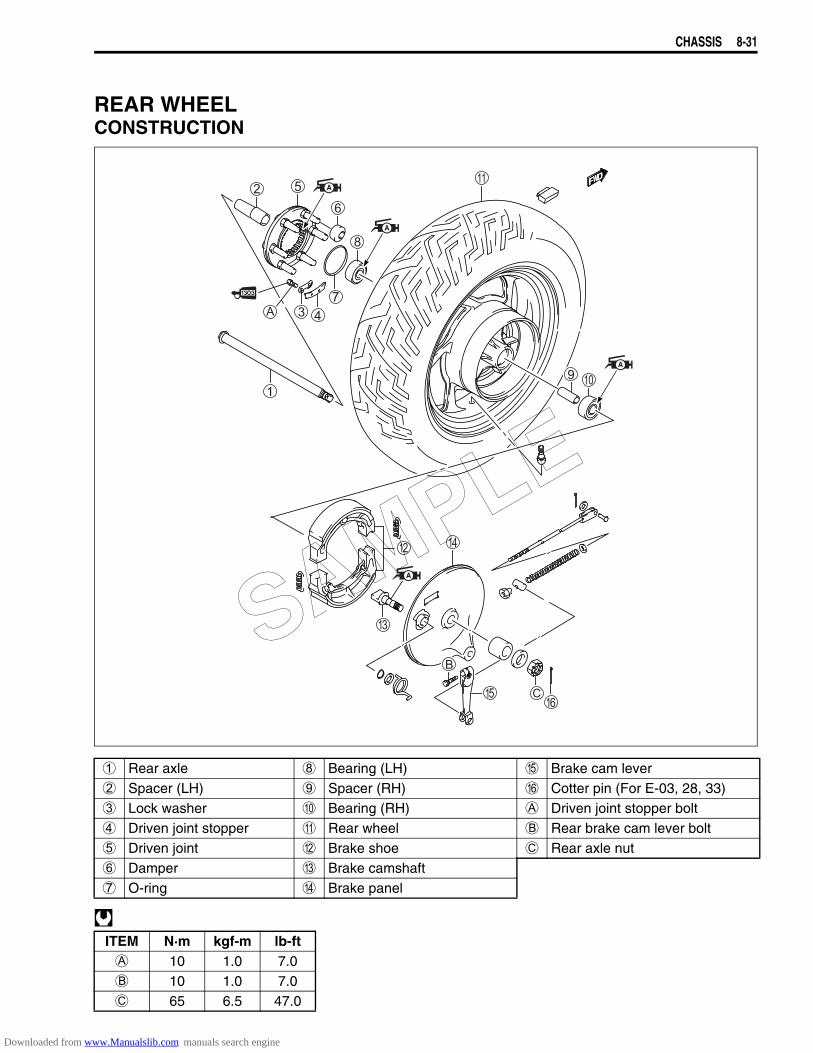
CHASSIS 8-31
REAR WHEELCONSTRUCTION
1 Rear axle 8 Bearing (LH) E Brake cam lever2 Spacer (LH) 9 Spacer (RH) F Cotter pin (For E-03, 28, 33)3 Lock washer 0 Bearing (RH) A Driven joint stopper bolt4 Driven joint stopper A Rear wheel B Rear brake cam lever bolt5 Driven joint B Brake shoe C Rear axle nut6 Damper C Brake camshaft7 O-ring D Brake panel
ITEM N·m kgf-m lb-ftA 10 1.0 7.0B 10 1.0 7.0C 65 6.5 47.0
SAMPLE
Downloaded from www.Manualslib.com manuals search engine
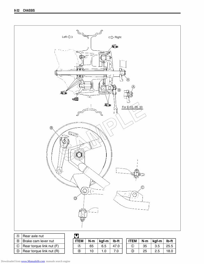
8-32 CHASSIS
A Rear axle nut B Brake cam lever nut ITEM N·m kgf-m lb-ft ITEM N·m kgf-m lb-ftC Rear torque link nut (F) A 65 6.5 47.0 C 35 3.5 25.5D Rear torque link nut (R) B 10 1.0 7.0 D 25 2.5 18.0
RightLeft
For E-03, 28, 33
SAMPLE
Downloaded from www.Manualslib.com manuals search engine

CHASSIS 8-33
REMOVAL• Raise the rear wheel off the ground and support the motorcy-
cle with a jack or wooden block.• Remove the rear brake rod 1.• Remove the torque link rod 2.
• Remove the left frame cover. (8-3)• Remove the left frame lower cover 3.
: Hooked part
• Remove the rear swingarm left cover mounting bolts.
• Remove the rear swingarm left cover.SAMPLE
Downloaded from www.Manualslib.com manuals search engine
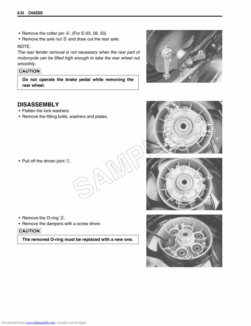
8-34 CHASSIS
• Remove the cotter pin 4. (For E-03, 28, 33)• Remove the axle nut 5 and draw out the rear axle.
NOTE:The rear fender removal is not necessary when the rear part ofmotorcycle can be lifted high enough to take the rear wheel outsmoothly.
DISASSEMBLY• Flatten the lock washers.• Remove the fitting bolts, washers and plates.
• Pull off the driven joint 1.
• Remove the O-ring 2.• Remove the dampers with a screw driver.
Do not operate the brake pedal while removing therear wheel.
The removed O-ring must be replaced with a new one.
SAMPLE
Downloaded from www.Manualslib.com manuals search engine
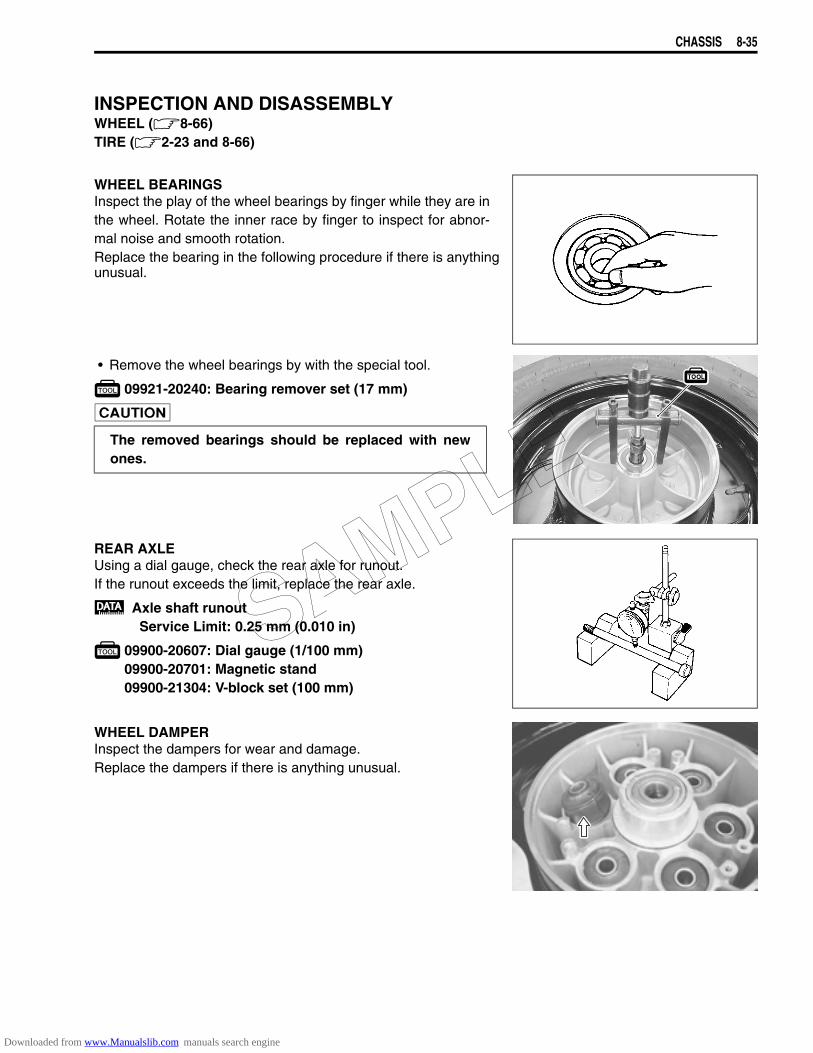
CHASSIS 8-35
INSPECTION AND DISASSEMBLYWHEEL (8-66)TIRE (2-23 and 8-66)
WHEEL BEARINGSInspect the play of the wheel bearings by finger while they are inthe wheel. Rotate the inner race by finger to inspect for abnor-mal noise and smooth rotation.Replace the bearing in the following procedure if there is anything unusual.
• Remove the wheel bearings by with the special tool.
09921-20240: Bearing remover set (17 mm)
REAR AXLEUsing a dial gauge, check the rear axle for runout.If the runout exceeds the limit, replace the rear axle.
Axle shaft runoutService Limit: 0.25 mm (0.010 in)
09900-20607: Dial gauge (1/100 mm)09900-20701: Magnetic stand09900-21304: V-block set (100 mm)
WHEEL DAMPERInspect the dampers for wear and damage.Replace the dampers if there is anything unusual.
The removed bearings should be replaced with newones.
SAMPLE
Downloaded from www.Manualslib.com manuals search engine
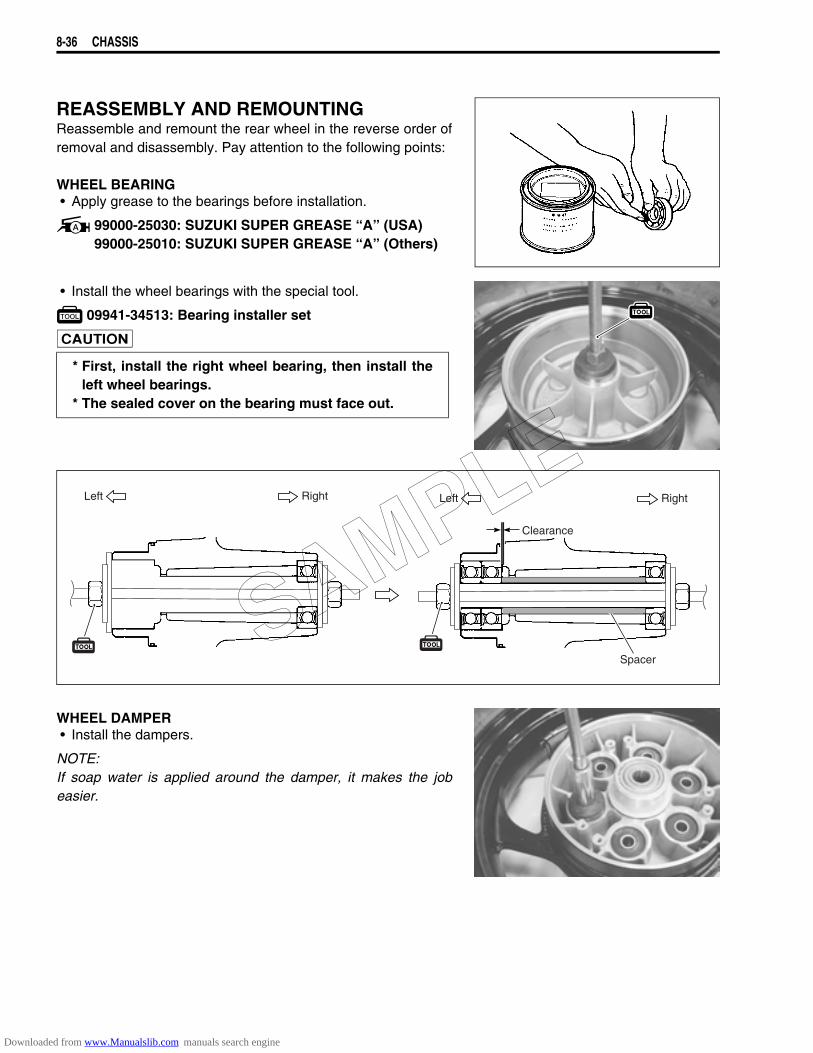
8-36 CHASSIS
REASSEMBLY AND REMOUNTINGReassemble and remount the rear wheel in the reverse order ofremoval and disassembly. Pay attention to the following points:
WHEEL BEARING• Apply grease to the bearings before installation.
99000-25030: SUZUKI SUPER GREASE “A” (USA)99000-25010: SUZUKI SUPER GREASE “A” (Others)
• Install the wheel bearings with the special tool.
09941-34513: Bearing installer set
WHEEL DAMPER• Install the dampers.
NOTE:If soap water is applied around the damper, it makes the jobeasier.
* First, install the right wheel bearing, then install theleft wheel bearings.
* The sealed cover on the bearing must face out.
Left Right
Spacer
Left Right
Clearance
SAMPLE
Downloaded from www.Manualslib.com manuals search engine
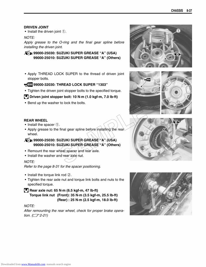
CHASSIS 8-37
DRIVEN JOINT• Install the driven joint 1.
NOTE:Apply grease to the O-ring and the final gear spline beforeinstalling the driven joint.
99000-25030: SUZUKI SUPER GREASE “A” (USA)99000-25010: SUZUKI SUPER GREASE “A” (Others)
• Apply THREAD LOCK SUPER to the thread of driven jointstopper bolts.
99000-32030: THREAD LOCK SUPER “1303”
• Tighten the driven joint stopper bolts to the specified torque.
Driven joint stopper bolt: 10 N·m (1.0 kgf-m, 7.0 lb-ft)
• Bend up the washer to lock the bolts.
REAR WHEEL• Install the spacer 1.• Apply grease to the final gear spline before installing the rear
wheel.
99000-25030: SUZUKI SUPER GREASE “A” (USA)99000-25010: SUZUKI SUPER GREASE “A” (Others)
• Remount the rear wheel spacer and rear axle.• Install the washer and rear axle nut.
NOTE:Refer to the page 8-31 for the spacer positioning.
• Install the torque link rod 2.• Tighten the rear axle nut and torque link bolts and nuts to the
specified torque.
Rear axle nut: 65 N·m (6.5 kgf-m, 47 lb-ft)Torque link nut (Front): 35 N·m (3.5 kgf-m, 25.5 lb-ft)
(Rear) : 25 N·m (2.5 kgf-m, 18.0 lb-ft)
NOTE:After remounting the rear wheel, check for proper brake opera-tion. (2-21)
SAMPLE
Downloaded from www.Manualslib.com manuals search engine
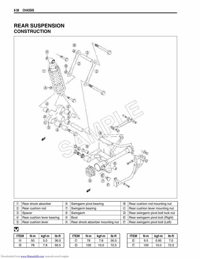
8-38 CHASSIS
REAR SUSPENSIONCONSTRUCTION
1 Rear shock absorber 6 Swingarm pivot bearing B Rear cushion rod mounting nut
2 Rear cushion rod 7 Swingarm bearing C Rear cushion lever mounting nut
3 Spacer 8 Swingarm D Rear swingarm pivot bolt lock nut
4 Rear cushion lever bearing 9 Boot E Rear swingarm pivot bolt (Right)
5 Rear cushion lever A Rear shock absorber mounting nut F Rear swingarm pivot bolt (Left)
ITEM N·m kgf-m lb-ft ITEM N·m kgf-m lb-ft ITEM N·m kgf-m lb-ftA 50 5.0 36.0 C 78 7.8 56.5 E 9.5 0.95 7.0
B 78 7.8 56.5 D 100 10.0 72.5 F 100 10.0 72.5
SAMPLE
Downloaded from www.Manualslib.com manuals search engine
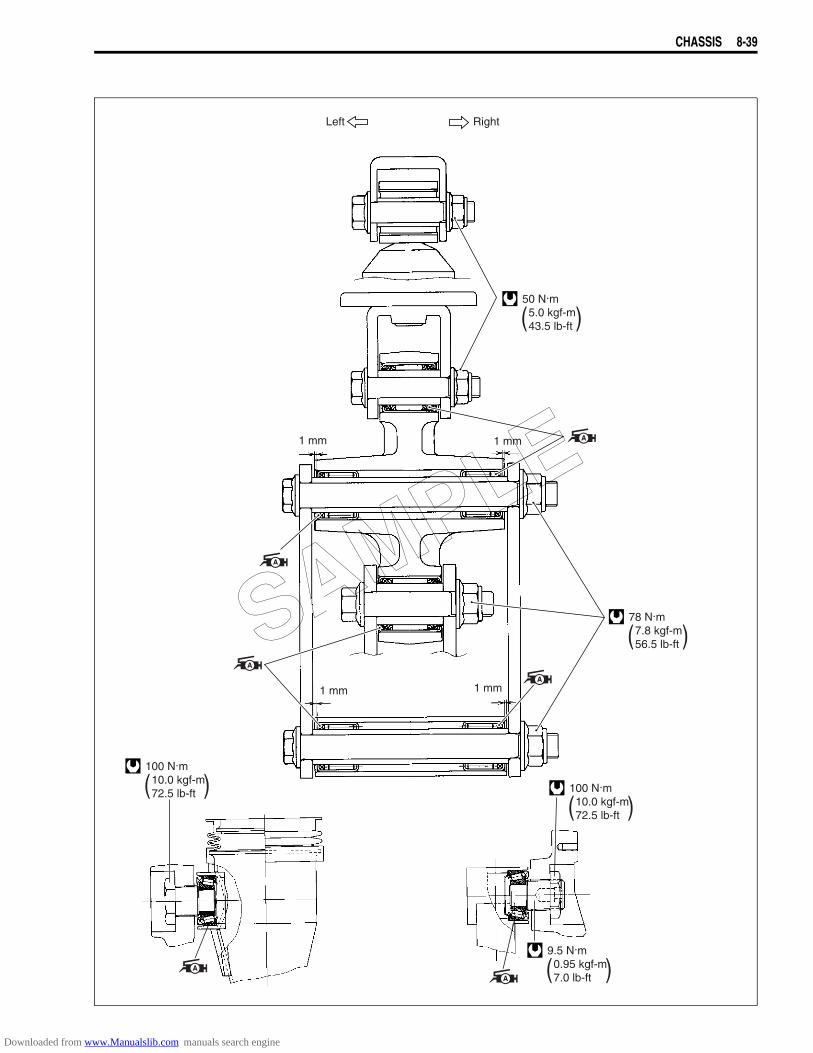
CHASSIS 8-39
Left Right
( )50 N.m 5.0 kgf-m 43.5 lb-ft
( )78 N.m 7.8 kgf-m 56.5 lb-ft
( )100 N.m 10.0 kgf-m 72.5 lb-ft
( )100 N.m 10.0 kgf-m 72.5 lb-ft
1 mm 1 mm
1 mm 1 mm
( )9.5 N.m 0.95 kgf-m 7.0 lb-ft
SAMPLE
Downloaded from www.Manualslib.com manuals search engine
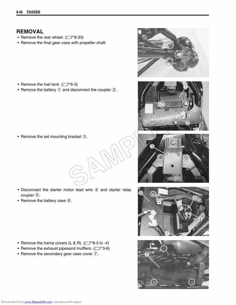
8-40 CHASSIS
REMOVAL• Remove the rear wheel. (8-33)• Remove the final gear case with propeller shaft.
• Remove the fuel tank. (6-3)• Remove the battery 1 and disconnect the coupler 2.
• Remove the set mounting bracket 3.
• Disconnect the starter motor lead wire 4 and starter relaycoupler 5.
• Remove the battery case 6.
• Remove the frame covers (L & R). (8-3 to -4)• Remove the exhaust pipesand mufflers. (3-6)• Remove the secondary gear case cover 7.
SAMPLE
Downloaded from www.Manualslib.com manuals search engine
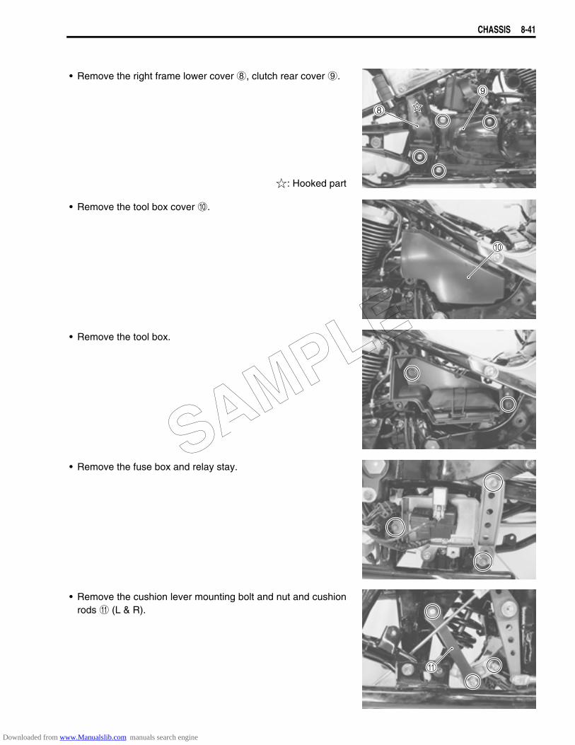
CHASSIS 8-41
• Remove the right frame lower cover 8, clutch rear cover 9.
: Hooked part
• Remove the tool box cover 0.
• Remove the tool box.
• Remove the fuse box and relay stay.
• Remove the cushion lever mounting bolt and nut and cushionrods A (L & R).
SAMPLE
Downloaded from www.Manualslib.com manuals search engine
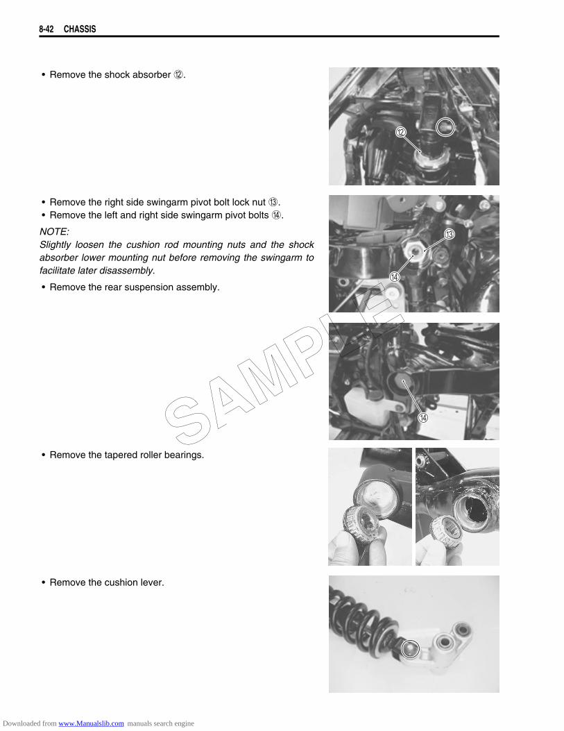
8-42 CHASSIS
• Remove the shock absorber B.
• Remove the right side swingarm pivot bolt lock nut C.• Remove the left and right side swingarm pivot bolts D.
NOTE:Slightly loosen the cushion rod mounting nuts and the shockabsorber lower mounting nut before removing the swingarm tofacilitate later disassembly.
• Remove the rear suspension assembly.
• Remove the tapered roller bearings.
• Remove the cushion lever.
SAMPLE
Downloaded from www.Manualslib.com manuals search engine
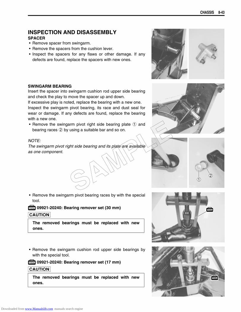
CHASSIS 8-43
INSPECTION AND DISASSEMBLYSPACER• Remove spacer from swingarm.• Remove the spacers from the cushion lever.• Inspect the spacers for any flaws or other damage. If any
defects are found, replace the spacers with new ones.
SWINGARM BEARINGInsert the spacer into swingarm cushion rod upper side bearingand check the play to move the spacer up and down.If excessive play is noted, replace the bearing with a new one.Inspect the swingarm pivot bearing, its race and dust seal forwear or damage. If any defects are found, replace the bearingwith a new one.• Remove the swingarm pivot right side bearing plate 1 and
bearing races 2 by using a suitable bar and so on.
NOTE:The swingarm pivot right side bearing and its plate are availableas one component.
• Remove the swingarm pivot bearing races by with the specialtool.
09921-20240: Bearing remover set (30 mm)
• Remove the swingarm cushion rod upper side bearings bywith the special tool.
09921-20240: Bearing remover set (17 mm)
The removed bearings must be replaced with newones.
The removed bearings must be replaced with newones.
SAMPLE
Downloaded from www.Manualslib.com manuals search engine
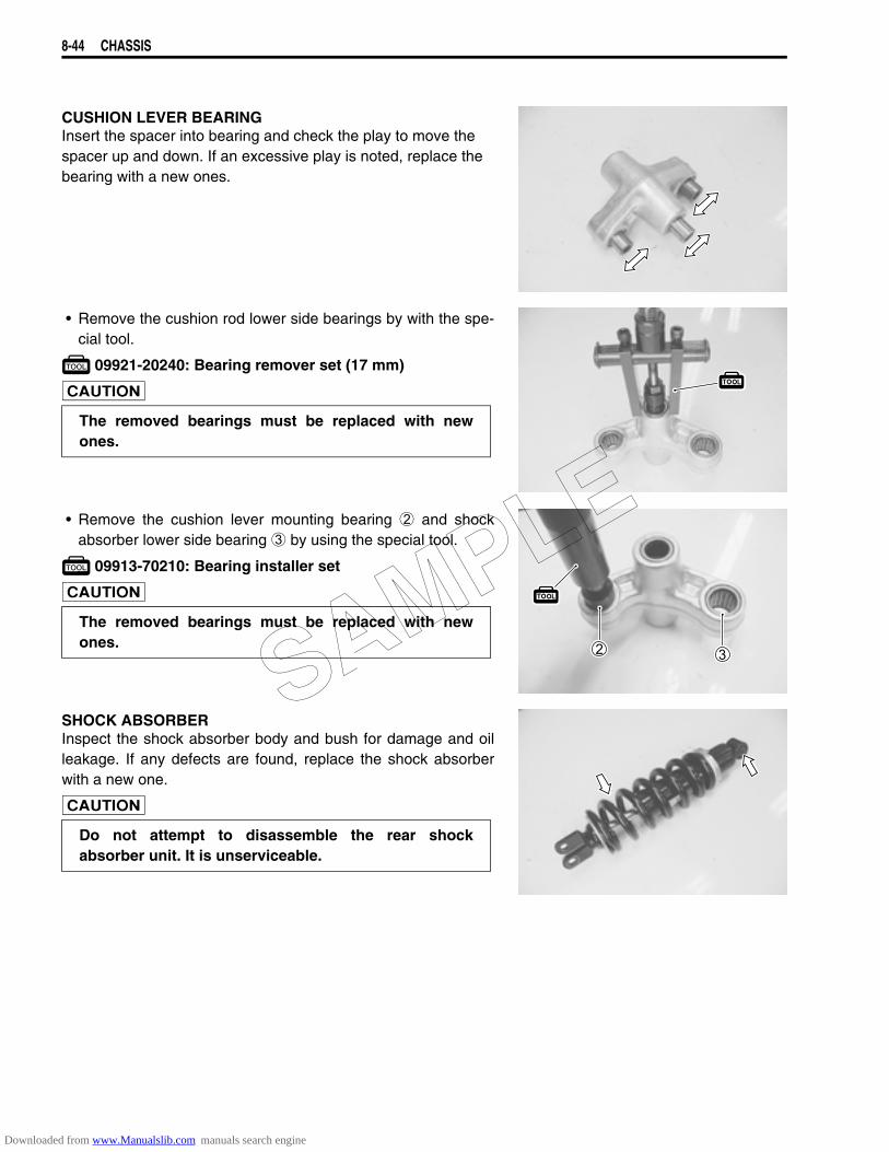
8-44 CHASSIS
CUSHION LEVER BEARINGInsert the spacer into bearing and check the play to move thespacer up and down. If an excessive play is noted, replace thebearing with a new ones.
• Remove the cushion rod lower side bearings by with the spe-cial tool.
09921-20240: Bearing remover set (17 mm)
• Remove the cushion lever mounting bearing 2 and shockabsorber lower side bearing 3 by using the special tool.
09913-70210: Bearing installer set
SHOCK ABSORBERInspect the shock absorber body and bush for damage and oilleakage. If any defects are found, replace the shock absorberwith a new one.
The removed bearings must be replaced with newones.
The removed bearings must be replaced with newones.
Do not attempt to disassemble the rear shockabsorber unit. It is unserviceable.
SAMPLE
Downloaded from www.Manualslib.com manuals search engine
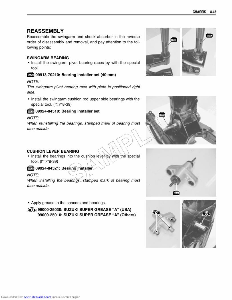
CHASSIS 8-45
REASSEMBLYReassemble the swingarm and shock absorber in the reverseorder of disassembly and removal, and pay attention to the fol-lowing points:
SWINGARM BEARING• Install the swingarm pivot bearing races by with the special
tool.
09913-70210: Bearing installer set (40 mm)
NOTE:The swingarm pivot bearing race with plate is positioned rightside.
• Install the swingarm cushion rod upper side bearings with thespecial tool. (8-39)
09924-84510: Bearing installer set
NOTE:When reinstalling the bearings, stamped mark of bearing mustface outside.
CUSHION LEVER BEARING• Install the bearings into the cushion lever by with the special
tool. (8-39)
09924-84521: Bearing installer
NOTE:When installing the bearings, stamped mark of bearing mustface outside.
• Apply grease to the spacers and bearings.
99000-25030: SUZUKI SUPER GREASE “A” (USA)99000-25010: SUZUKI SUPER GREASE “A” (Others)
SAMPLE
Downloaded from www.Manualslib.com manuals search engine
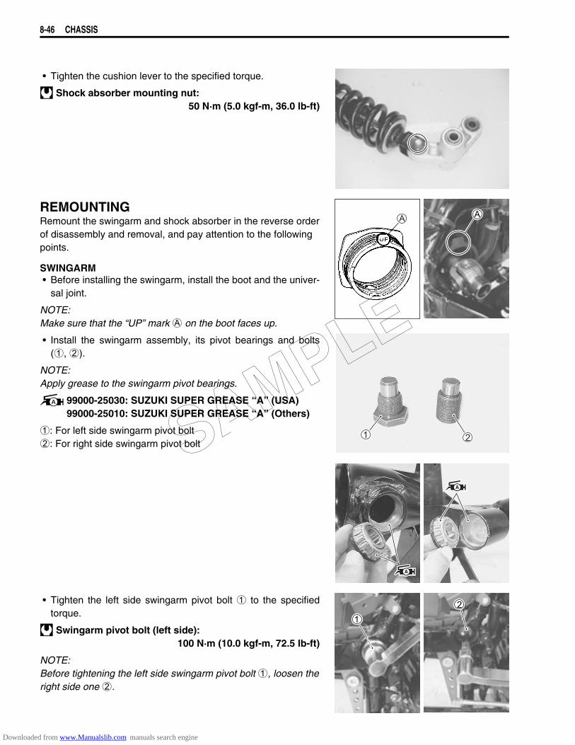
8-46 CHASSIS
• Tighten the cushion lever to the specified torque.
Shock absorber mounting nut:50 N·m (5.0 kgf-m, 36.0 lb-ft)
REMOUNTINGRemount the swingarm and shock absorber in the reverse orderof disassembly and removal, and pay attention to the followingpoints.
SWINGARM• Before installing the swingarm, install the boot and the univer-
sal joint.
NOTE:Make sure that the “UP” mark A on the boot faces up.
• Install the swingarm assembly, its pivot bearings and bolts(1, 2).
NOTE:Apply grease to the swingarm pivot bearings.
99000-25030: SUZUKI SUPER GREASE “A” (USA)99000-25010: SUZUKI SUPER GREASE “A” (Others)
1: For left side swingarm pivot bolt2: For right side swingarm pivot bolt
• Tighten the left side swingarm pivot bolt 1 to the specifiedtorque.
Swingarm pivot bolt (left side):100 N·m (10.0 kgf-m, 72.5 lb-ft)
NOTE:Before tightening the left side swingarm pivot bolt 1, loosen theright side one 2.
SAMPLE
Downloaded from www.Manualslib.com manuals search engine
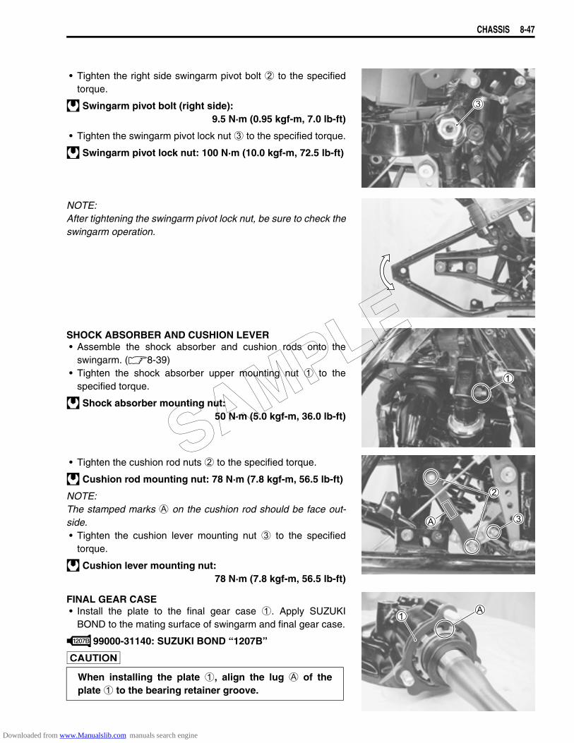
CHASSIS 8-47
• Tighten the right side swingarm pivot bolt 2 to the specifiedtorque.
Swingarm pivot bolt (right side):9.5 N·m (0.95 kgf-m, 7.0 lb-ft)
• Tighten the swingarm pivot lock nut 3 to the specified torque.
Swingarm pivot lock nut: 100 N·m (10.0 kgf-m, 72.5 lb-ft)
NOTE:After tightening the swingarm pivot lock nut, be sure to check theswingarm operation.
SHOCK ABSORBER AND CUSHION LEVER• Assemble the shock absorber and cushion rods onto the
swingarm. (8-39)• Tighten the shock absorber upper mounting nut 1 to the
specified torque.
Shock absorber mounting nut: 50 N·m (5.0 kgf-m, 36.0 lb-ft)
• Tighten the cushion rod nuts 2 to the specified torque.
Cushion rod mounting nut: 78 N·m (7.8 kgf-m, 56.5 lb-ft)
NOTE:The stamped marks A on the cushion rod should be face out-side.• Tighten the cushion lever mounting nut 3 to the specified
torque.
Cushion lever mounting nut:78 N·m (7.8 kgf-m, 56.5 lb-ft)
FINAL GEAR CASE• Install the plate to the final gear case 1. Apply SUZUKI
BOND to the mating surface of swingarm and final gear case.
99000-31140: SUZUKI BOND ‘‘1207B”
When installing the plate 1, align the lug A of theplate 1 to the bearing retainer groove.
SAMPLE
Downloaded from www.Manualslib.com manuals search engine
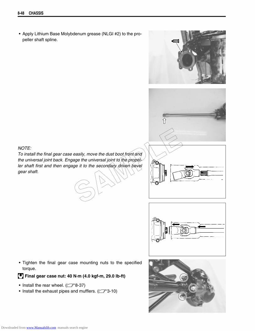
8-48 CHASSIS
• Apply Lithium Base Molybdenum grease (NLGI #2) to the pro-peller shaft spline.
NOTE:To install the final gear case easily, move the dust boot front andthe universal joint back. Engage the universal joint to the propel-ler shaft first and then engage it to the secondary driven bevelgear shaft.
• Tighten the final gear case mounting nuts to the specifiedtorque.
Final gear case nut: 40 N·m (4.0 kgf-m, 29.0 lb-ft)
• Install the rear wheel. (8-37)• Install the exhaust pipes and mufflers. (3-10)
SAMPLE
Downloaded from www.Manualslib.com manuals search engine
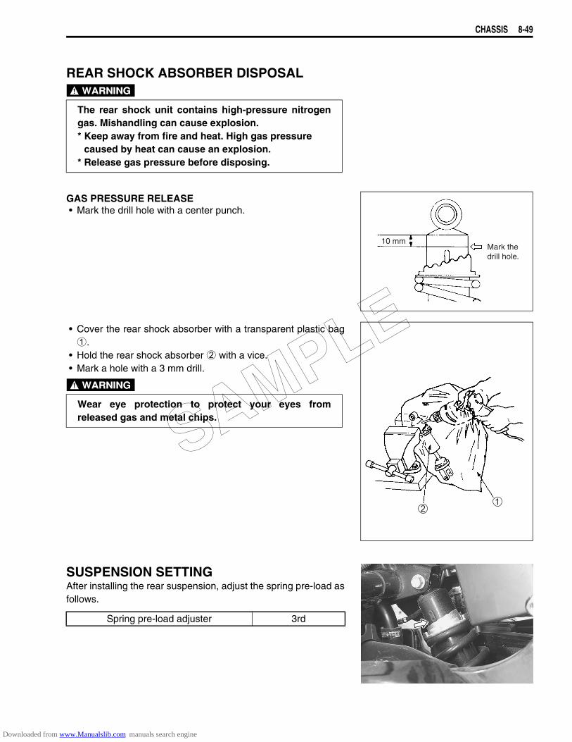
CHASSIS 8-49
REAR SHOCK ABSORBER DISPOSAL
GAS PRESSURE RELEASE• Mark the drill hole with a center punch.
• Cover the rear shock absorber with a transparent plastic bag1.
• Hold the rear shock absorber 2 with a vice.• Mark a hole with a 3 mm drill.
SUSPENSION SETTINGAfter installing the rear suspension, adjust the spring pre-load asfollows.
The rear shock unit contains high-pressure nitrogengas. Mishandling can cause explosion.* Keep away from fire and heat. High gas pressure
caused by heat can cause an explosion.* Release gas pressure before disposing.
10 mmMark thedrill hole.
Wear eye protection to protect your eyes fromreleased gas and metal chips.
Spring pre-load adjuster 3rd
SAMPLE
Downloaded from www.Manualslib.com manuals search engine
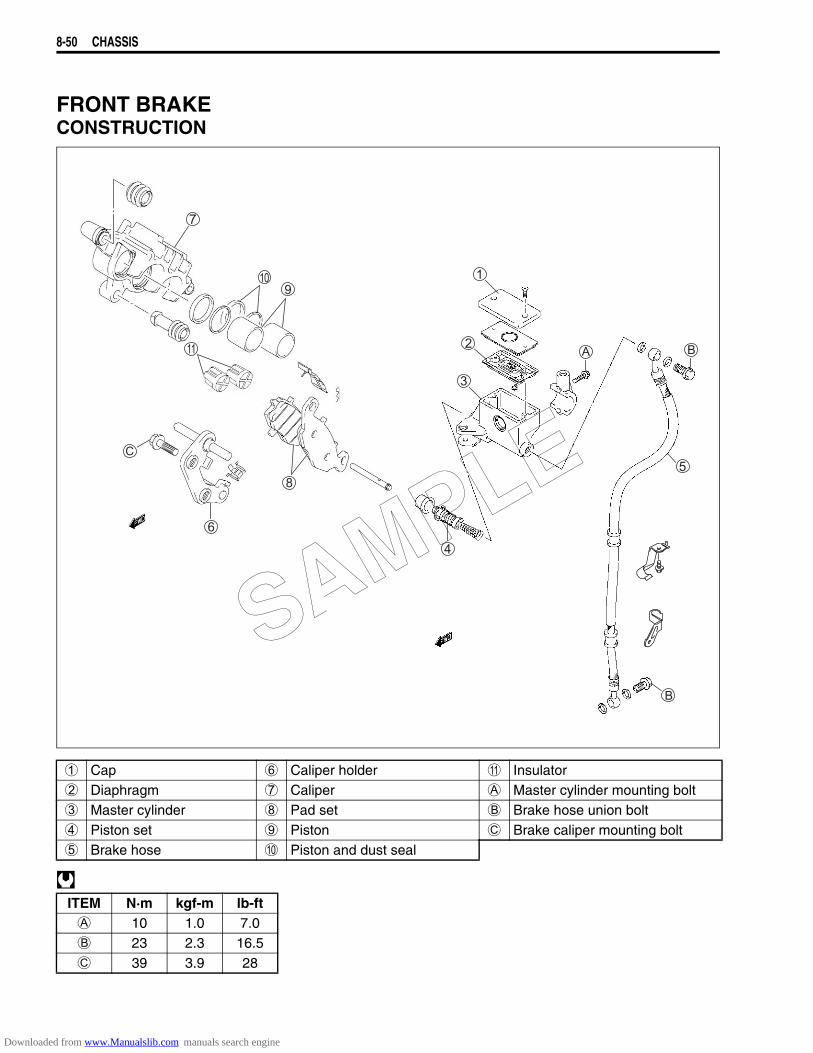
8-50 CHASSIS
FRONT BRAKECONSTRUCTION
1 Cap 6 Caliper holder A Insulator2 Diaphragm 7 Caliper A Master cylinder mounting bolt3 Master cylinder 8 Pad set B Brake hose union bolt4 Piston set 9 Piston C Brake caliper mounting bolt5 Brake hose 0 Piston and dust seal
ITEM N·m kgf-m lb-ftA 10 1.0 7.0B 23 2.3 16.5C 39 3.9 28
SAMPLE
Downloaded from www.Manualslib.com manuals search engine
CHASSIS 8-51
* The brake system is filled with an glycol-based brake fluid, which is classified DOT 4. Do notuse or mix other types of brake fluid, such as silicone-based and petroleum-based brake flu-ids when refilling the brake system, otherwise serious damage to the brake system will result.
* Do not use any brake fluid taken from old, used, or unsealed containers.* Do not reuse brake fluid left over from the last servicing or which has been stored for a long
period of time.* When storing brake fluid, be sure to seal the container completely and keep it out of the reach
of children.* When replenishing brake fluid, be sure not to get any dust or other foreign materials in the
fluid.* When washing brake components, always use new brake fluid. Do not use cleaning solvent.* A contaminated brake disc or brake pad reduces braking performance. Discard contaminated
pads and clean the brake disc with high-quality brake cleaner or a neutral detergent.
Handle brake fluid with care: the fluid reacts chemically with paint, plastics, rubber material,etc.
SAMPLE
Downloaded from www.Manualslib.com manuals search engine
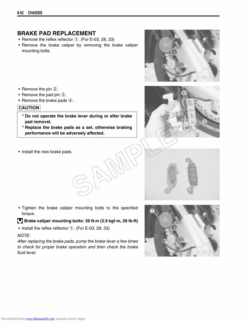
8-52 CHASSIS
BRAKE PAD REPLACEMENT• Remove the reflex reflector 1. (For E-03, 28, 33)• Remove the brake caliper by removing the brake caliper
mounting bolts.
• Remove the pin 2.• Remove the pad pin 3.• Remove the brake pads 4.
• Install the new brake pads.
• Tighten the brake caliper mounting bolts to the specifiedtorque.
Brake caliper mounting bolts: 39 N·m (3.9 kgf-m, 28 lb-ft)
• Install the reflex reflector 1. (For E-03, 28, 33)
NOTE:After replacing the brake pads, pump the brake lever a few timesto check for proper brake operation and then check the brakefluid level.
* Do not operate the brake lever during or after brakepad removal.
* Replace the brake pads as a set, otherwise brakingperformance will be adversely affected.
SAMPLE
Downloaded from www.Manualslib.com manuals search engine
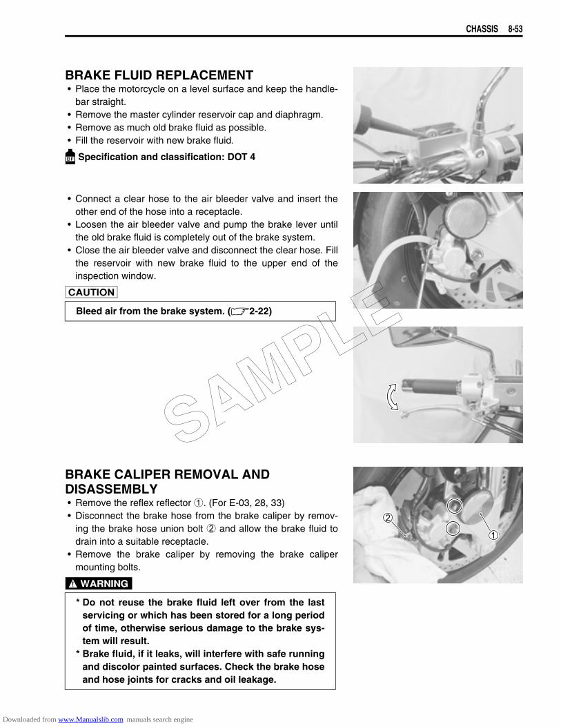
CHASSIS 8-53
BRAKE FLUID REPLACEMENT• Place the motorcycle on a level surface and keep the handle-
bar straight.• Remove the master cylinder reservoir cap and diaphragm.• Remove as much old brake fluid as possible.• Fill the reservoir with new brake fluid.
Specification and classification: DOT 4
• Connect a clear hose to the air bleeder valve and insert theother end of the hose into a receptacle.
• Loosen the air bleeder valve and pump the brake lever untilthe old brake fluid is completely out of the brake system.
• Close the air bleeder valve and disconnect the clear hose. Fillthe reservoir with new brake fluid to the upper end of theinspection window.
BRAKE CALIPER REMOVAL AND DISASSEMBLY• Remove the reflex reflector 1. (For E-03, 28, 33)• Disconnect the brake hose from the brake caliper by remov-
ing the brake hose union bolt 2 and allow the brake fluid todrain into a suitable receptacle.
• Remove the brake caliper by removing the brake calipermounting bolts.
Bleed air from the brake system. (2-22)
* Do not reuse the brake fluid left over from the lastservicing or which has been stored for a long periodof time, otherwise serious damage to the brake sys-tem will result.
* Brake fluid, if it leaks, will interfere with safe runningand discolor painted surfaces. Check the brake hoseand hose joints for cracks and oil leakage.
SAMPLE
Downloaded from www.Manualslib.com manuals search engine
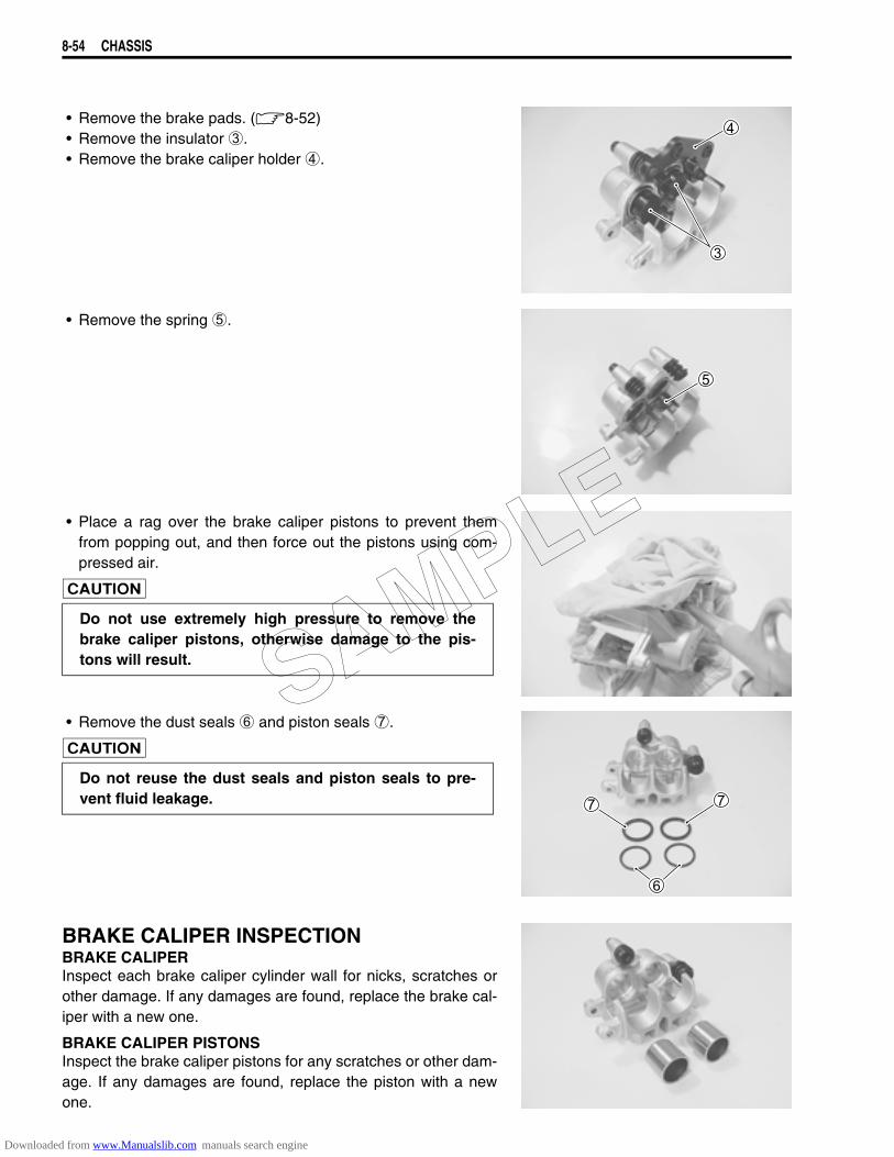
8-54 CHASSIS
• Remove the brake pads. (8-52)• Remove the insulator 3.• Remove the brake caliper holder 4.
• Remove the spring 5.
• Place a rag over the brake caliper pistons to prevent themfrom popping out, and then force out the pistons using com-pressed air.
• Remove the dust seals 6 and piston seals 7.
BRAKE CALIPER INSPECTIONBRAKE CALIPERInspect each brake caliper cylinder wall for nicks, scratches orother damage. If any damages are found, replace the brake cal-iper with a new one.
BRAKE CALIPER PISTONSInspect the brake caliper pistons for any scratches or other dam-age. If any damages are found, replace the piston with a newone.
Do not use extremely high pressure to remove thebrake caliper pistons, otherwise damage to the pis-tons will result.
Do not reuse the dust seals and piston seals to pre-vent fluid leakage.
SAMPLE
Downloaded from www.Manualslib.com manuals search engine
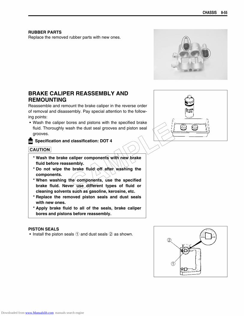
CHASSIS 8-55
RUBBER PARTSReplace the removed rubber parts with new ones.
BRAKE CALIPER REASSEMBLY AND REMOUNTINGReassemble and remount the brake caliper in the reverse orderof removal and disassembly. Pay special attention to the follow-ing points:• Wash the caliper bores and pistons with the specified brake
fluid. Thoroughly wash the dust seal grooves and piston sealgrooves.
Specification and classification: DOT 4
PISTON SEALS• Install the piston seals 1 and dust seals 2 as shown.
* Wash the brake caliper components with new brakefluid before reassembly.
* Do not wipe the brake fluid off after washing thecomponents.
* When washing the components, use the specifiedbrake fluid. Never use different types of fluid orcleaning solvents such as gasoline, kerosine, etc.
* Replace the removed piston seals and dust sealswith new ones.
* Apply brake fluid to all of the seals, brake caliperbores and pistons before reassembly.
SAMPLE
Downloaded from www.Manualslib.com manuals search engine
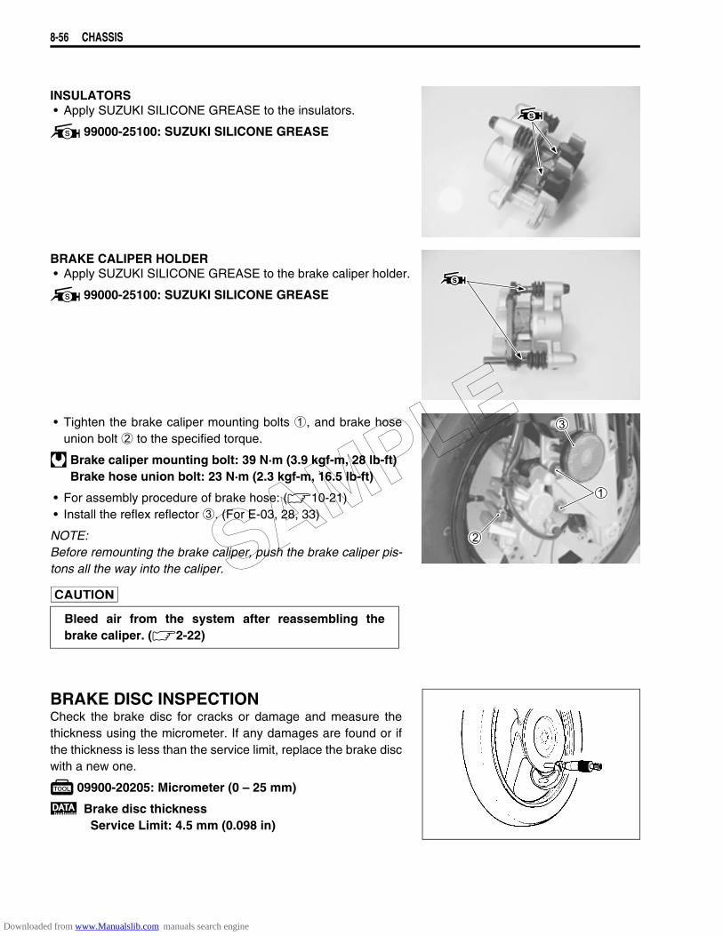
8-56 CHASSIS
INSULATORS• Apply SUZUKI SILICONE GREASE to the insulators.
99000-25100: SUZUKI SILICONE GREASE
BRAKE CALIPER HOLDER• Apply SUZUKI SILICONE GREASE to the brake caliper holder.
99000-25100: SUZUKI SILICONE GREASE
• Tighten the brake caliper mounting bolts 1, and brake hoseunion bolt 2 to the specified torque.
Brake caliper mounting bolt: 39 N·m (3.9 kgf-m, 28 lb-ft)Brake hose union bolt: 23 N·m (2.3 kgf-m, 16.5 lb-ft)
• For assembly procedure of brake hose: (10-21)• Install the reflex reflector 3. (For E-03, 28, 33)
NOTE:Before remounting the brake caliper, push the brake caliper pis-tons all the way into the caliper.
BRAKE DISC INSPECTIONCheck the brake disc for cracks or damage and measure thethickness using the micrometer. If any damages are found or ifthe thickness is less than the service limit, replace the brake discwith a new one.
09900-20205: Micrometer (0 – 25 mm)
Brake disc thicknessService Limit: 4.5 mm (0.098 in)
Bleed air from the system after reassembling thebrake caliper. (2-22)
SAMPLE
Downloaded from www.Manualslib.com manuals search engine

CHASSIS 8-57
Measure the runout using the dial gauge. If the runout exceedsthe service limit, replace the brake disc with a new one.
09900-20607: Dial gauge (1/100 mm)09900-20701: Magnetic stand
Brake disc runoutService Limit: 0.3 mm (0.012 in)
• If either measurement exceeds the service limit, replace thebrake disc with a new one. (8-7 and -10)
MASTER CYLINDER REMOVAL AND DISAS-SEMBLY• Place a rag underneath the brake hose union bolt on the mas-
ter cylinder to catch any spilt brake fluid. Remove the brakehose union bolt and disconnect the brake hose.
• Disconnect the front brake light switch lead wire 1.• Remove the right rear view mirror 2 and master cylinder
assembly 3.
• Remove the brake lever 4 and front brake light switch 5.
Immediately wipe off any brake fluid contacting anypart of the motorcycle. The brake fluid reacts chemi-cally with paint, plastics, rubber materials, etc., andwill damage them severely.
SAMPLE
Downloaded from www.Manualslib.com manuals search engine
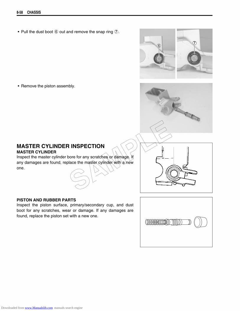
8-58 CHASSIS
• Pull the dust boot 6 out and remove the snap ring 7.
• Remove the piston assembly.
MASTER CYLINDER INSPECTIONMASTER CYLINDERInspect the master cylinder bore for any scratches or damage. Ifany damages are found, replace the master cylinder with a newone.
PISTON AND RUBBER PARTSInspect the piston surface, primary/secondary cup, and dustboot for any scratches, wear or damage. If any damages arefound, replace the piston set with a new one.
SAMPLE
Downloaded from www.Manualslib.com manuals search engine
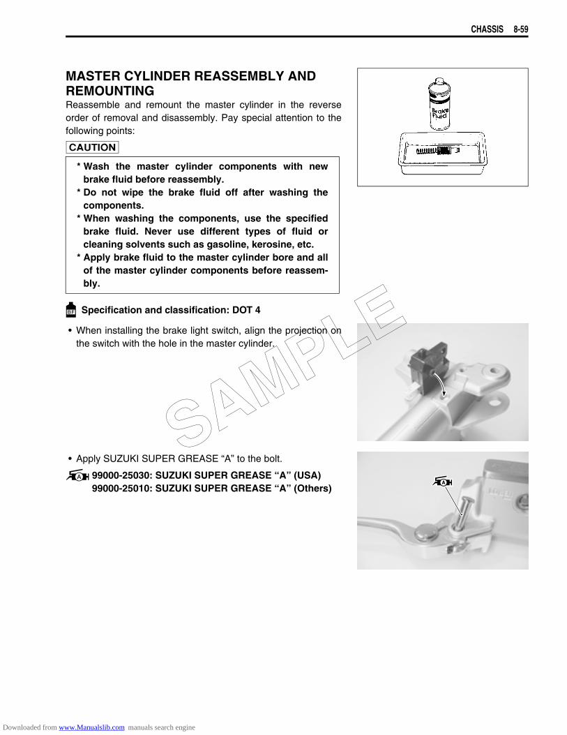
CHASSIS 8-59
MASTER CYLINDER REASSEMBLY AND REMOUNTINGReassemble and remount the master cylinder in the reverseorder of removal and disassembly. Pay special attention to thefollowing points:
Specification and classification: DOT 4
• When installing the brake light switch, align the projection onthe switch with the hole in the master cylinder.
• Apply SUZUKI SUPER GREASE “A” to the bolt.
99000-25030: SUZUKI SUPER GREASE “A” (USA)99000-25010: SUZUKI SUPER GREASE “A” (Others)
* Wash the master cylinder components with newbrake fluid before reassembly.
* Do not wipe the brake fluid off after washing thecomponents.
* When washing the components, use the specifiedbrake fluid. Never use different types of fluid orcleaning solvents such as gasoline, kerosine, etc.
* Apply brake fluid to the master cylinder bore and allof the master cylinder components before reassem-bly.
SAMPLE
Downloaded from www.Manualslib.com manuals search engine
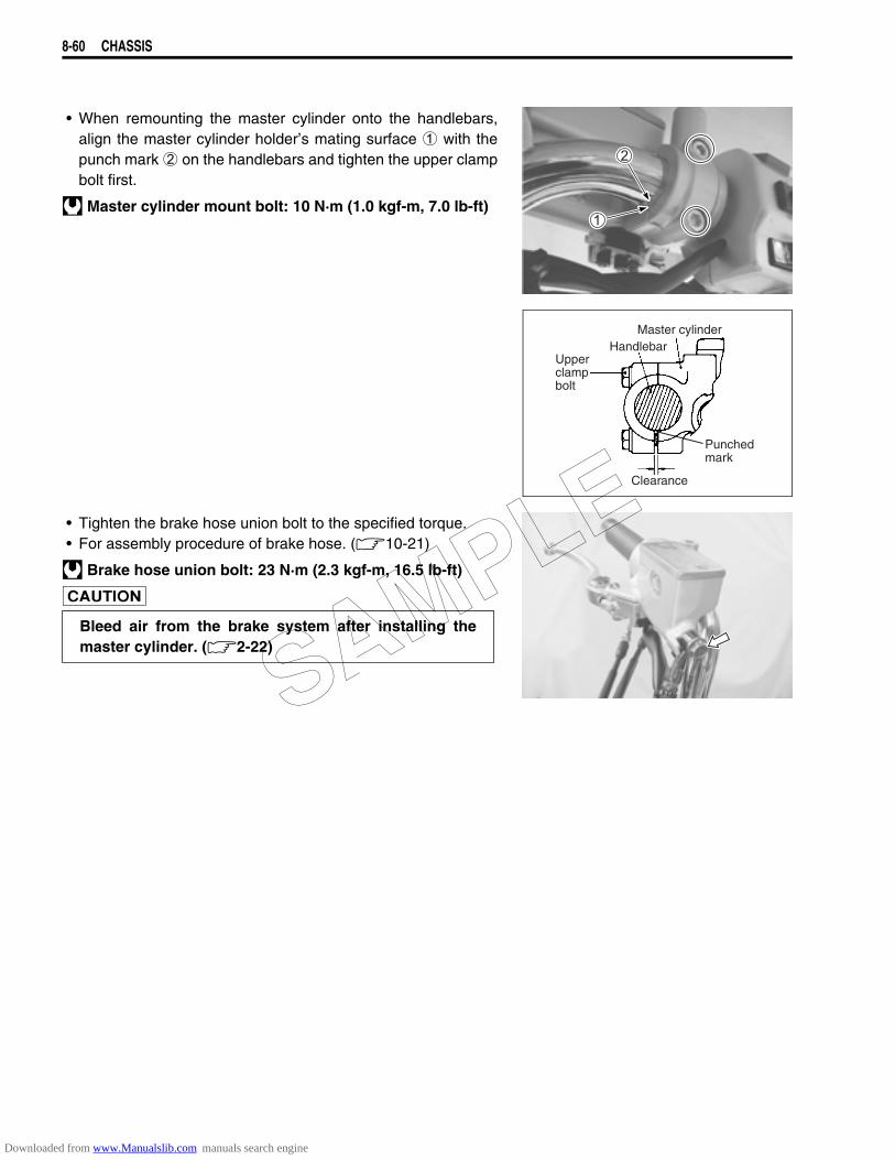
8-60 CHASSIS
• When remounting the master cylinder onto the handlebars,align the master cylinder holder’s mating surface 1 with thepunch mark 2 on the handlebars and tighten the upper clampbolt first.
Master cylinder mount bolt: 10 N·m (1.0 kgf-m, 7.0 lb-ft)
• Tighten the brake hose union bolt to the specified torque.• For assembly procedure of brake hose. (10-21)
Brake hose union bolt: 23 N·m (2.3 kgf-m, 16.5 lb-ft)
Upperclampbolt
Master cylinderHandlebar
Clearance
Punchedmark
Bleed air from the brake system after installing themaster cylinder. (2-22)
SAMPLE
Downloaded from www.Manualslib.com manuals search engine
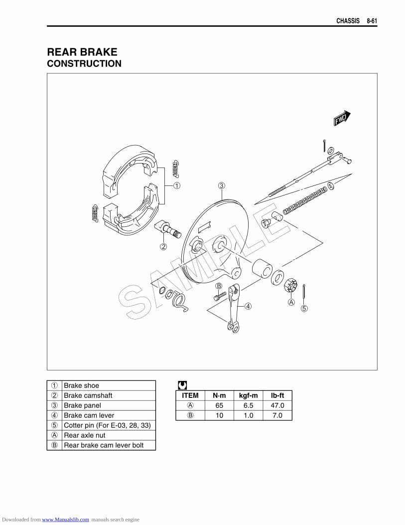
CHASSIS 8-61
REAR BRAKECONSTRUCTION
1 Brake shoe 2 Brake camshaft ITEM N·m kgf-m lb-ft3 Brake panel A 65 6.5 47.04 Brake cam lever B 10 1.0 7.05 Cotter pin (For E-03, 28, 33)A Rear axle nutB Rear brake cam lever bolt
SAMPLE
Downloaded from www.Manualslib.com manuals search engine
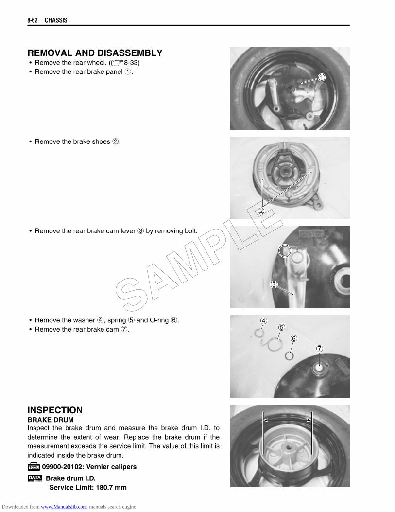
8-62 CHASSIS
REMOVAL AND DISASSEMBLY• Remove the rear wheel. (8-33)• Remove the rear brake panel 1.
• Remove the brake shoes 2.
• Remove the rear brake cam lever 3 by removing bolt.
• Remove the washer 4, spring 5 and O-ring 6.• Remove the rear brake cam 7.
INSPECTIONBRAKE DRUMInspect the brake drum and measure the brake drum I.D. todetermine the extent of wear. Replace the brake drum if themeasurement exceeds the service limit. The value of this limit isindicated inside the brake drum.
09900-20102: Vernier calipers
Brake drum I.D.Service Limit: 180.7 mm
SAMPLE
Downloaded from www.Manualslib.com manuals search engine
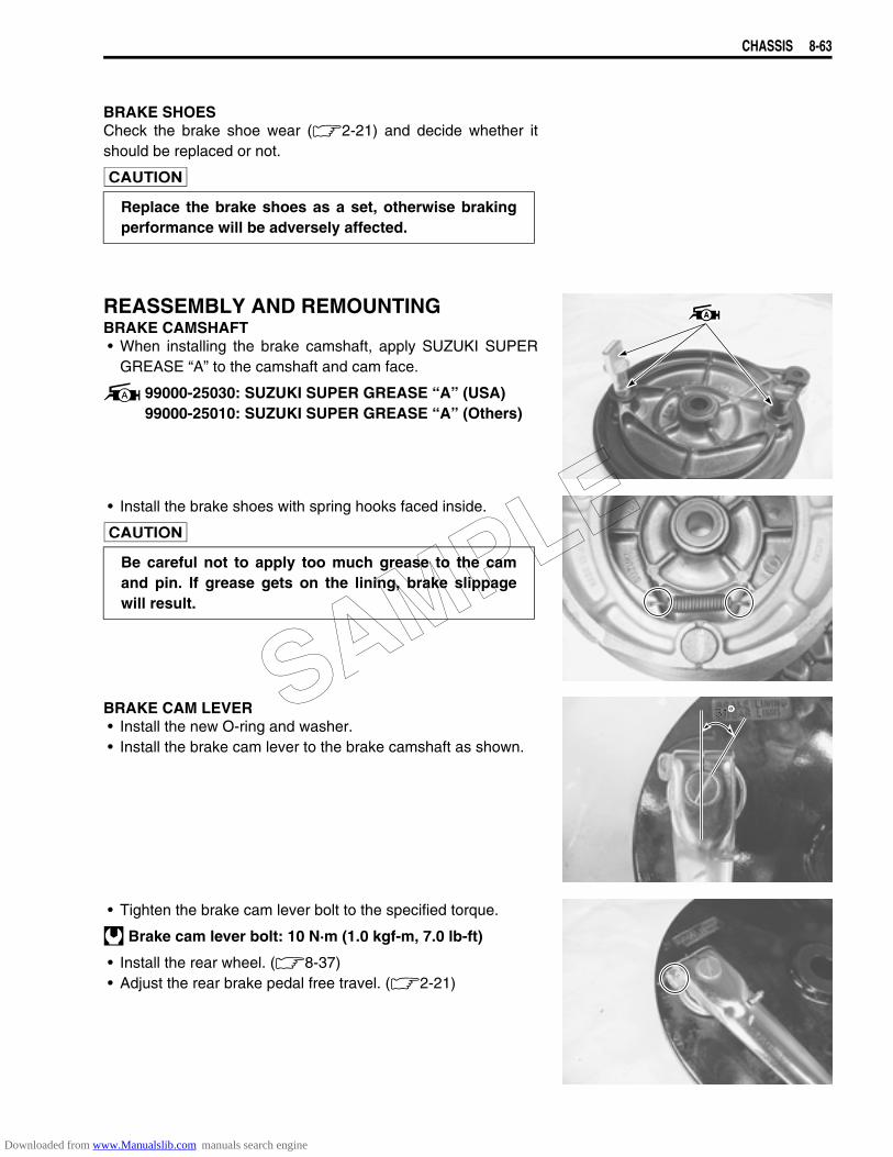
CHASSIS 8-63
BRAKE SHOESCheck the brake shoe wear (2-21) and decide whether itshould be replaced or not.
REASSEMBLY AND REMOUNTINGBRAKE CAMSHAFT• When installing the brake camshaft, apply SUZUKI SUPER
GREASE “A” to the camshaft and cam face.
99000-25030: SUZUKI SUPER GREASE “A” (USA)99000-25010: SUZUKI SUPER GREASE “A” (Others)
• Install the brake shoes with spring hooks faced inside.
BRAKE CAM LEVER• Install the new O-ring and washer.• Install the brake cam lever to the brake camshaft as shown.
• Tighten the brake cam lever bolt to the specified torque.
Brake cam lever bolt: 10 N·m (1.0 kgf-m, 7.0 lb-ft)
• Install the rear wheel. (8-37)• Adjust the rear brake pedal free travel. (2-21)
Replace the brake shoes as a set, otherwise brakingperformance will be adversely affected.
Be careful not to apply too much grease to the camand pin. If grease gets on the lining, brake slippagewill result.
3131SAMPLE
Downloaded from www.Manualslib.com manuals search engine
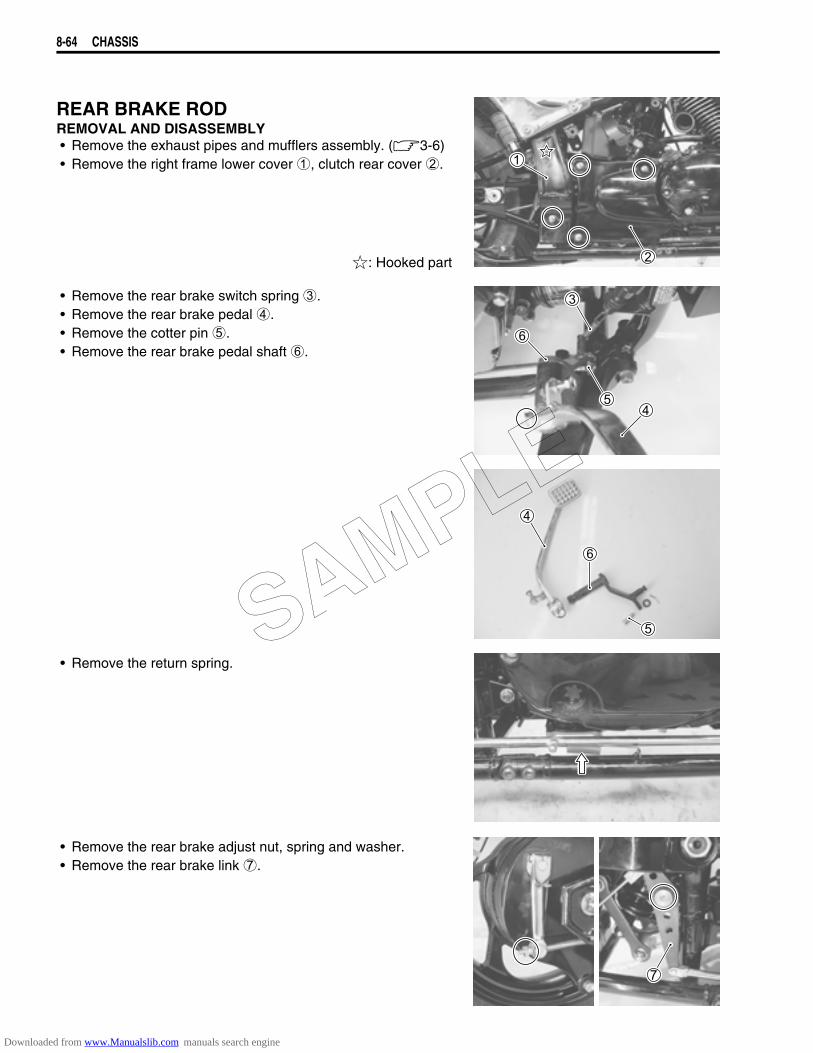
8-64 CHASSIS
REAR BRAKE RODREMOVAL AND DISASSEMBLY• Remove the exhaust pipes and mufflers assembly. (3-6)• Remove the right frame lower cover 1, clutch rear cover 2.
: Hooked part
• Remove the rear brake switch spring 3.• Remove the rear brake pedal 4.• Remove the cotter pin 5.• Remove the rear brake pedal shaft 6.
• Remove the return spring.
• Remove the rear brake adjust nut, spring and washer.• Remove the rear brake link 7.
SAMPLE
Downloaded from www.Manualslib.com manuals search engine
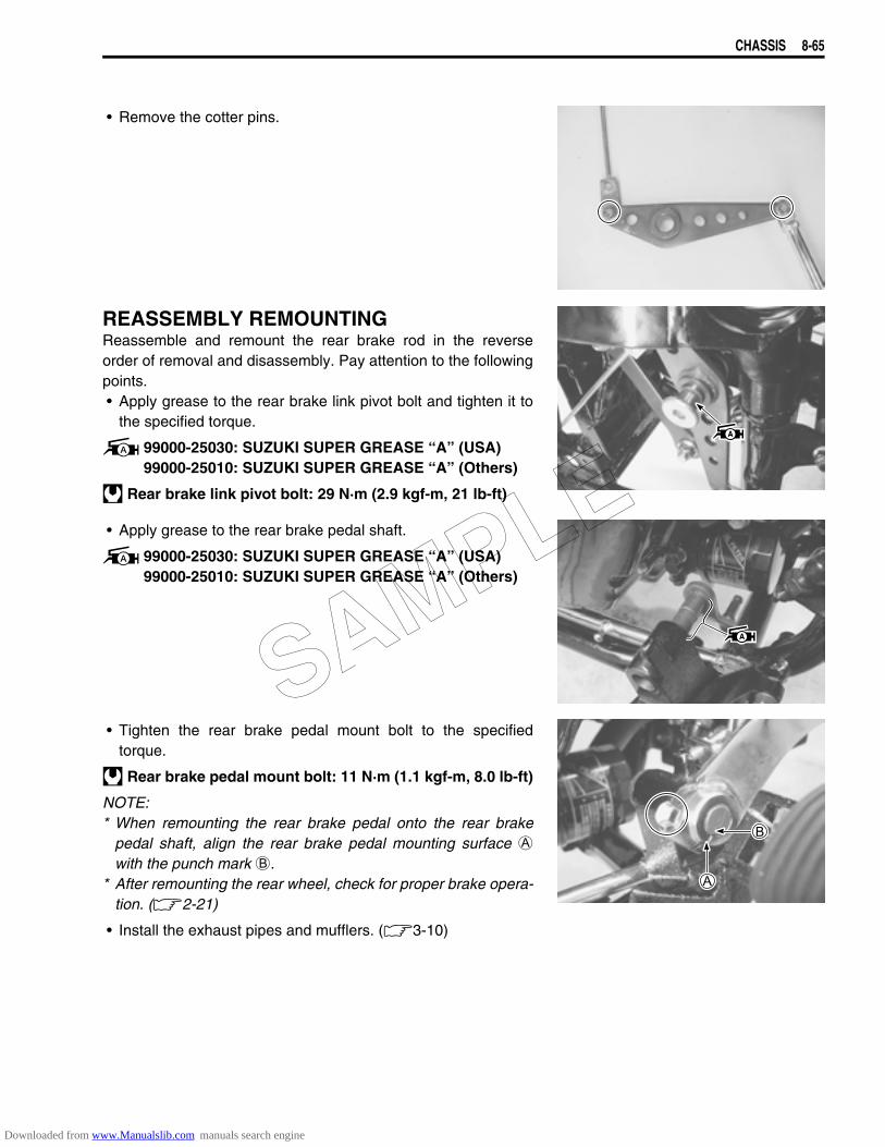
CHASSIS 8-65
• Remove the cotter pins.
REASSEMBLY REMOUNTINGReassemble and remount the rear brake rod in the reverseorder of removal and disassembly. Pay attention to the followingpoints.• Apply grease to the rear brake link pivot bolt and tighten it to
the specified torque.
99000-25030: SUZUKI SUPER GREASE “A” (USA)99000-25010: SUZUKI SUPER GREASE “A” (Others)
Rear brake link pivot bolt: 29 N·m (2.9 kgf-m, 21 lb-ft)
• Apply grease to the rear brake pedal shaft.
99000-25030: SUZUKI SUPER GREASE “A” (USA)99000-25010: SUZUKI SUPER GREASE “A” (Others)
• Tighten the rear brake pedal mount bolt to the specifiedtorque.
Rear brake pedal mount bolt: 11 N·m (1.1 kgf-m, 8.0 lb-ft)
NOTE:* When remounting the rear brake pedal onto the rear brake
pedal shaft, align the rear brake pedal mounting surface Awith the punch mark B.
* After remounting the rear wheel, check for proper brake opera-tion. (2-21)
• Install the exhaust pipes and mufflers. (3-10)
SAMPLE
Downloaded from www.Manualslib.com manuals search engine
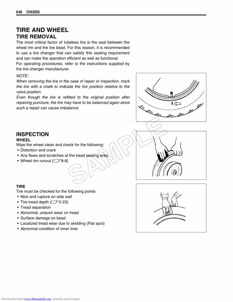
8-66 CHASSIS
TIRE AND WHEELTIRE REMOVALThe most critical factor of tubeless tire is the seal between thewheel rim and the tire bead. For this reason, it is recommendedto use a tire changer that can satisfy this sealing requirementand can make the operation efficient as well as functional.For operating procedures, refer to the instructions supplied bythe tire changer manufacturer.
NOTE:When removing the tire in the case of repair or inspection, markthe tire with a chalk to indicate the tire position relative to thevalve position.Even though the tire is refitted to the original position afterrepairing puncture, the tire may have to be balanced again sincesuch a repair can cause imbalance.
INSPECTIONWHEELWipe the wheel clean and check for the following:• Distortion and crack• Any flaws and scratches at the bead seating area.• Wheel rim runout (8-8)
TIRETire must be checked for the following points:• Nick and rupture on side wall• Tire tread depth (2-23)• Tread separation• Abnormal, uneven wear on tread• Surface damage on bead• Localized tread wear due to skidding (Flat spot)• Abnormal condition of inner liner
SAMPLE
Downloaded from www.Manualslib.com manuals search engine
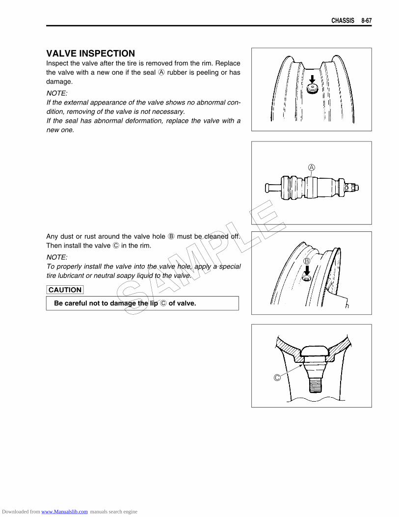
CHASSIS 8-67
VALVE INSPECTIONInspect the valve after the tire is removed from the rim. Replacethe valve with a new one if the seal A rubber is peeling or hasdamage.
NOTE:If the external appearance of the valve shows no abnormal con-dition, removing of the valve is not necessary.If the seal has abnormal deformation, replace the valve with anew one.
Any dust or rust around the valve hole B must be cleaned off.Then install the valve C in the rim.
NOTE:To properly install the valve into the valve hole, apply a specialtire lubricant or neutral soapy liquid to the valve.
Be careful not to damage the lip C of valve.SAMPLE
Downloaded from www.Manualslib.com manuals search engine
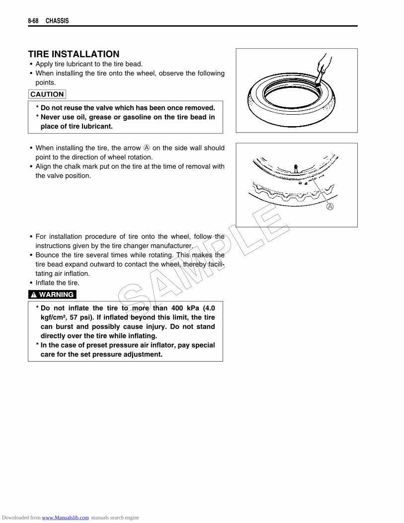
8-68 CHASSIS
TIRE INSTALLATION• Apply tire lubricant to the tire bead.• When installing the tire onto the wheel, observe the following
points.
• When installing the tire, the arrow A on the side wall shouldpoint to the direction of wheel rotation.
• Align the chalk mark put on the tire at the time of removal withthe valve position.
• For installation procedure of tire onto the wheel, follow theinstructions given by the tire changer manufacturer.
• Bounce the tire several times while rotating. This makes thetire bead expand outward to contact the wheel, thereby facili-tating air inflation.
• Inflate the tire.
* Do not reuse the valve which has been once removed.* Never use oil, grease or gasoline on the tire bead in
place of tire lubricant.
* Do not inflate the tire to more than 400 kPa (4.0kgf/cm², 57 psi). If inflated beyond this limit, the tirecan burst and possibly cause injury. Do not standdirectly over the tire while inflating.
* In the case of preset pressure air inflator, pay specialcare for the set pressure adjustment.
SAMPLE
Downloaded from www.Manualslib.com manuals search engine
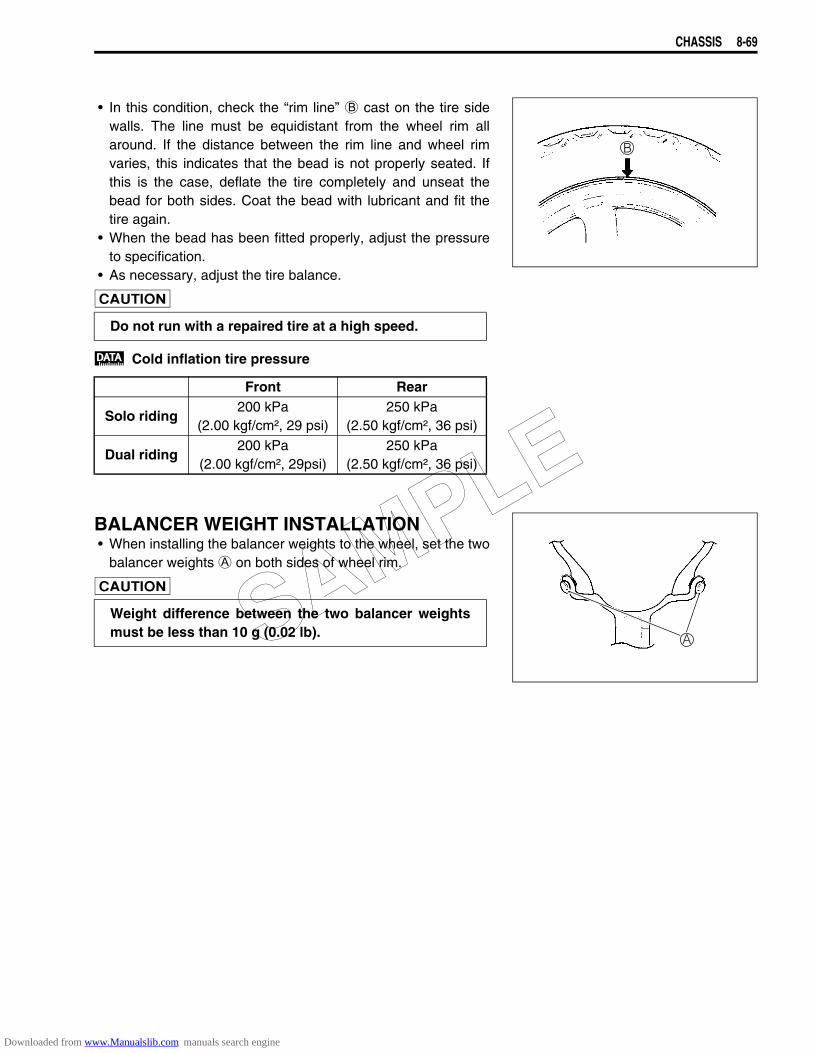
CHASSIS 8-69
• In this condition, check the “rim line” B cast on the tire sidewalls. The line must be equidistant from the wheel rim allaround. If the distance between the rim line and wheel rimvaries, this indicates that the bead is not properly seated. Ifthis is the case, deflate the tire completely and unseat thebead for both sides. Coat the bead with lubricant and fit thetire again.
• When the bead has been fitted properly, adjust the pressureto specification.
• As necessary, adjust the tire balance.
Cold inflation tire pressure
BALANCER WEIGHT INSTALLATION• When installing the balancer weights to the wheel, set the two
balancer weights A on both sides of wheel rim.
Do not run with a repaired tire at a high speed.
Front Rear
Solo riding200 kPa
(2.00 kgf/cm², 29 psi)250 kPa
(2.50 kgf/cm², 36 psi)
Dual riding200 kPa
(2.00 kgf/cm², 29psi)250 kPa
(2.50 kgf/cm², 36 psi)
Weight difference between the two balancer weightsmust be less than 10 g (0.02 lb).SAMPLE
Downloaded from www.Manualslib.com manuals search engine
ELECTRICAL SYSTEM 9-1
9
CONTENTS
ELECTRICAL SYSTEM
CAUTIONS IN SERVICING ..........................................................................9- 3CONNECTOR..........................................................................................9- 3COUPLER ...............................................................................................9- 3CLAMP ....................................................................................................9- 3FUSE .......................................................................................................9- 3SEMI-CONDUCTOR EQUIPPED PART .................................................9- 4BATTERY................................................................................................9- 4CONNECTING THE BATTERY...............................................................9- 4WIRING PROCEDURE............................................................................9- 4USING THE MULTI-CIRCUIT TESTER ..................................................9- 5
LOCATION OF ELECTRICAL COMPONENTS ...........................................9- 6CHARGING SYSTEM ...................................................................................9- 8
TROUBLESHOOTING ............................................................................9- 8INSPECTION...........................................................................................9- 9
STARTER SYSTEM AND SIDE-STAND/IGNITION INTERLOCK SYSTEM ........................................................................................................9-12
TROUBLESHOOTING ............................................................................9-12STARTER MOTOR REMOVAL AND DISASSEMBLY...........................9-14STARTER MOTOR INSPECTION...........................................................9-15STARTER MOTOR REASSEMBLY........................................................9-15STARTER RELAY INSPECTION............................................................9-16SIDE STAND/IGNITION INTERLOCK SYSTEM PARTS INSPECTION...........................................................................................9-17
IGNITION SYSTEM .......................................................................................9-20TROUBLESHOOTING ............................................................................9-20INSPECTION...........................................................................................9-22
SPEEDOMETER AND PILOT LAMP BOX ..................................................9-25DESCRIPTION ........................................................................................9-25SPEEDOMETER REMOVAL AND DISASSEMBLY...............................9-26PILOT LAMP BOX REMOVAL AND DISASSEMBLY............................9-28INSPECTION...........................................................................................9-29
LAMPS ..........................................................................................................9-33HEADLIGHT, BRAKE LIGHT/TAILLIGHT, LICENSE PLATE LIGHT AND TURN SIGNAL LIGHT....................................................................9-33
RELAYS ........................................................................................................9-35TURN SIGNAL/SIDE-STAND RELAY ....................................................9-35STARTER RELAY...................................................................................9-35FUEL PUMP RELAY...............................................................................9-35
SAMPLE
Downloaded from www.Manualslib.com manuals search engine
ELECTRICAL SYSTEM
CONTENTS
9-2 ELECTRICAL SYSTEM
SWITCHES ...................................................................................................9-35BATTERY .....................................................................................................9-37
SPECIFICATIONS ..................................................................................9-37INITIAL CHARGING ...............................................................................9-37SERVICING.............................................................................................9-39RECHARGING OPERATION..................................................................9-39
SAMPLE
Downloaded from www.Manualslib.com manuals search engine
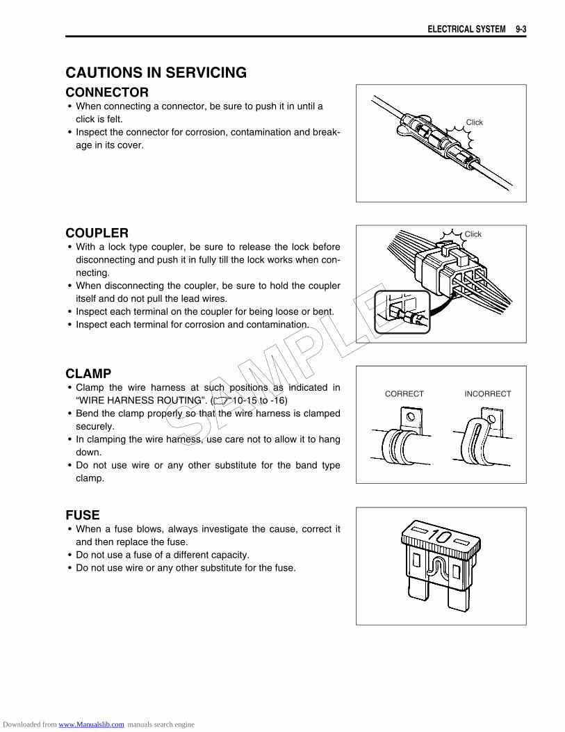
ELECTRICAL SYSTEM 9-3
CAUTIONS IN SERVICINGCONNECTOR• When connecting a connector, be sure to push it in until a
click is felt.• Inspect the connector for corrosion, contamination and break-
age in its cover.
COUPLER• With a lock type coupler, be sure to release the lock before
disconnecting and push it in fully till the lock works when con-necting.
• When disconnecting the coupler, be sure to hold the coupleritself and do not pull the lead wires.
• Inspect each terminal on the coupler for being loose or bent.• Inspect each terminal for corrosion and contamination.
CLAMP• Clamp the wire harness at such positions as indicated in
“WIRE HARNESS ROUTING”. (10-15 to -16)• Bend the clamp properly so that the wire harness is clamped
securely.• In clamping the wire harness, use care not to allow it to hang
down.• Do not use wire or any other substitute for the band type
clamp.
FUSE• When a fuse blows, always investigate the cause, correct it
and then replace the fuse.• Do not use a fuse of a different capacity.• Do not use wire or any other substitute for the fuse.
Click
Click
CORRECT INCORRECT
SAMPLE
Downloaded from www.Manualslib.com manuals search engine
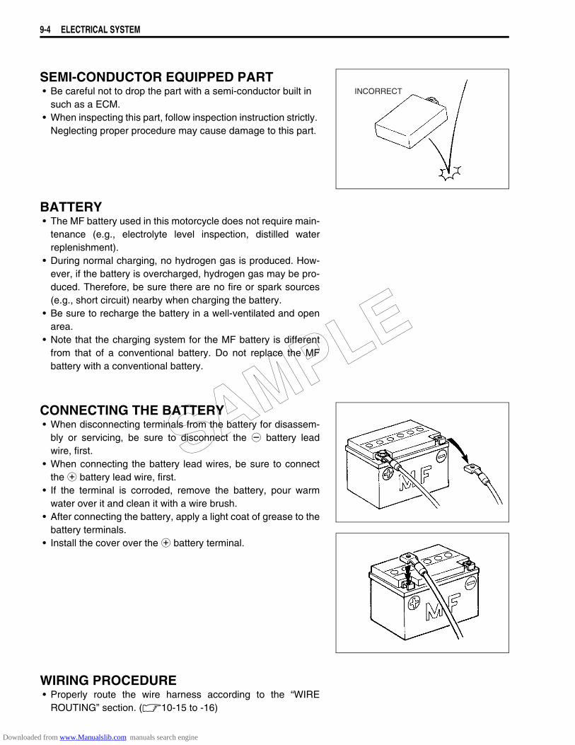
9-4 ELECTRICAL SYSTEM
SEMI-CONDUCTOR EQUIPPED PART• Be careful not to drop the part with a semi-conductor built in
such as a ECM.• When inspecting this part, follow inspection instruction strictly.
Neglecting proper procedure may cause damage to this part.
BATTERY• The MF battery used in this motorcycle does not require main-
tenance (e.g., electrolyte level inspection, distilled waterreplenishment).
• During normal charging, no hydrogen gas is produced. How-ever, if the battery is overcharged, hydrogen gas may be pro-duced. Therefore, be sure there are no fire or spark sources(e.g., short circuit) nearby when charging the battery.
• Be sure to recharge the battery in a well-ventilated and openarea.
• Note that the charging system for the MF battery is differentfrom that of a conventional battery. Do not replace the MFbattery with a conventional battery.
CONNECTING THE BATTERY• When disconnecting terminals from the battery for disassem-
bly or servicing, be sure to disconnect the - battery leadwire, first.
• When connecting the battery lead wires, be sure to connectthe + battery lead wire, first.
• If the terminal is corroded, remove the battery, pour warmwater over it and clean it with a wire brush.
• After connecting the battery, apply a light coat of grease to thebattery terminals.
• Install the cover over the + battery terminal.
WIRING PROCEDURE• Properly route the wire harness according to the “WIRE
ROUTING” section. (10-15 to -16)
INCORRECT
SAMPLE
Downloaded from www.Manualslib.com manuals search engine
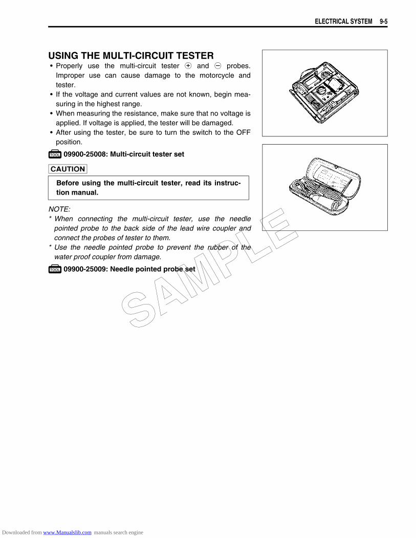
ELECTRICAL SYSTEM 9-5
USING THE MULTI-CIRCUIT TESTER• Properly use the multi-circuit tester + and - probes.
Improper use can cause damage to the motorcycle andtester.
• If the voltage and current values are not known, begin mea-suring in the highest range.
• When measuring the resistance, make sure that no voltage isapplied. If voltage is applied, the tester will be damaged.
• After using the tester, be sure to turn the switch to the OFFposition.
09900-25008: Multi-circuit tester set
NOTE:* When connecting the multi-circuit tester, use the needle
pointed probe to the back side of the lead wire coupler andconnect the probes of tester to them.
* Use the needle pointed probe to prevent the rubber of thewater proof coupler from damage.
09900-25009: Needle pointed probe set
Before using the multi-circuit tester, read its instruc-tion manual.
SAMPLE
Downloaded from www.Manualslib.com manuals search engine
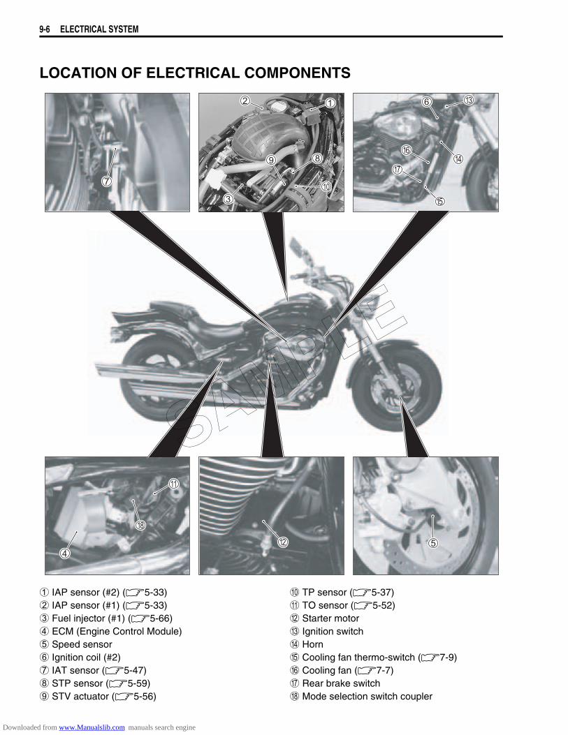
9-6 ELECTRICAL SYSTEM
LOCATION OF ELECTRICAL COMPONENTS
1 IAP sensor (#2) (5-33) 0 TP sensor (5-37)2 IAP sensor (#1) (5-33) A TO sensor (5-52)3 Fuel injector (#1) (5-66) B Starter motor4 ECM (Engine Control Module) C Ignition switch5 Speed sensor D Horn6 Ignition coil (#2) E Cooling fan thermo-switch (7-9)7 IAT sensor (5-47) F Cooling fan (7-7)8 STP sensor (5-59) G Rear brake switch9 STV actuator (5-56) H Mode selection switch coupler
SAMPLE
Downloaded from www.Manualslib.com manuals search engine

ELECTRICAL SYSTEM 9-7
1 Fuel level switch 9 Starter relay/Main fuse2 Fuel pump (6-5) 0 Turn signal/Side-stand relay3 Battery A Regulator/Rectifier4 ECT sensor (5-42) B Oil pressure switch5 Fuse box C Generator6 Ignition coil (#1) D CKP sensor (5-30)7 Fuel pump relay (6-6) E GP switch (5-64)8 Fuel injector (#2) (5-66) F Side-stand switch
SAMPLE
Downloaded from www.Manualslib.com manuals search engine
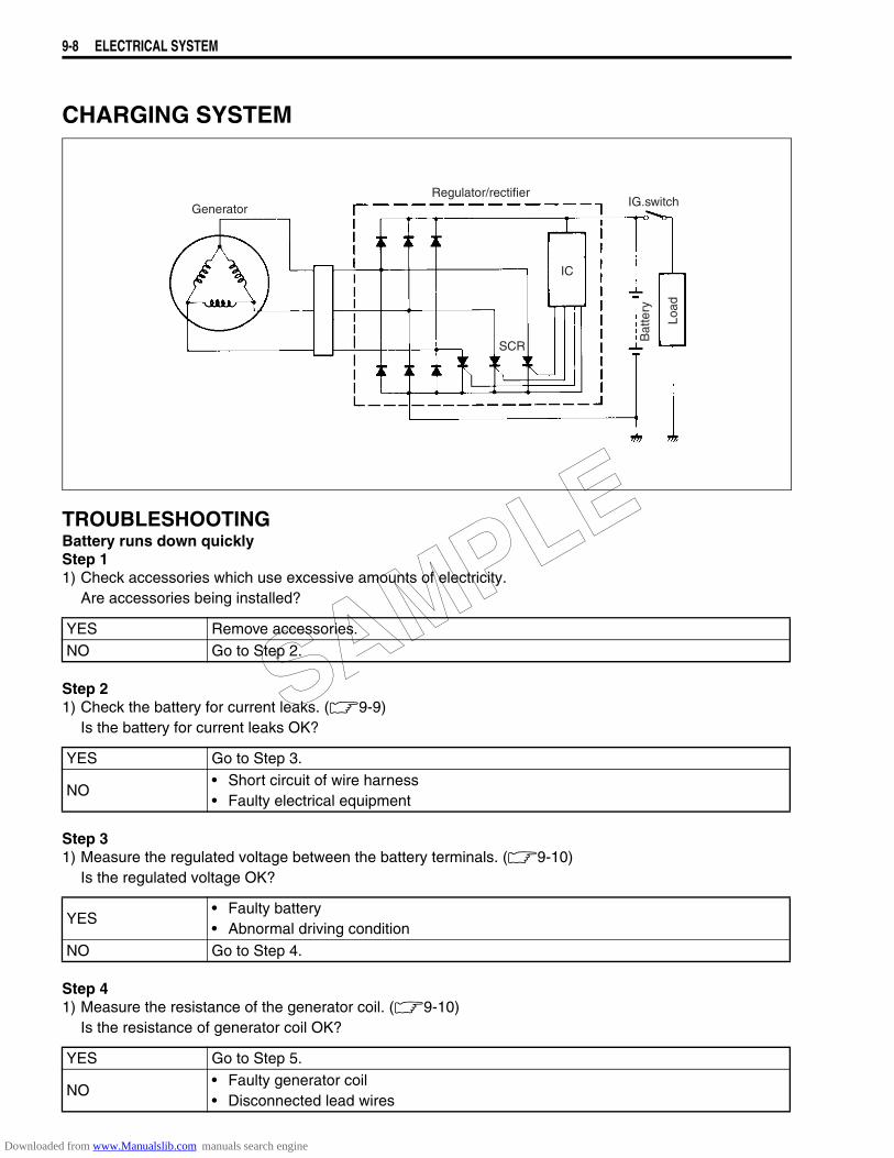
9-8 ELECTRICAL SYSTEM
CHARGING SYSTEM
TROUBLESHOOTINGBattery runs down quicklyStep 11) Check accessories which use excessive amounts of electricity.
Are accessories being installed?
Step 21) Check the battery for current leaks. (9-9)
Is the battery for current leaks OK?
Step 31) Measure the regulated voltage between the battery terminals. (9-10)
Is the regulated voltage OK?
Step 41) Measure the resistance of the generator coil. (9-10)
Is the resistance of generator coil OK?
YES Remove accessories.NO Go to Step 2.
YES Go to Step 3.
NO• Short circuit of wire harness• Faulty electrical equipment
YES• Faulty battery• Abnormal driving condition
NO Go to Step 4.
YES Go to Step 5.
NO• Faulty generator coil• Disconnected lead wires
GeneratorRegulator/rectifier
SCR
IC
IG.switch
Load
Bat
tery
SAMPLE
Downloaded from www.Manualslib.com manuals search engine
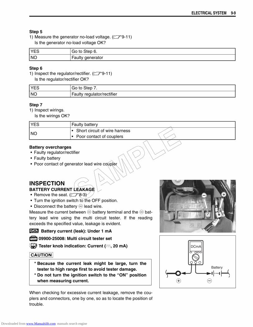
ELECTRICAL SYSTEM 9-9
Step 51) Measure the generator no-load voltage. (9-11)
Is the generator no-load voltage OK?
Step 61) Inspect the regulator/rectifier. (9-11)
Is the regulator/rectifier OK?
Step 71) Inspect wirings.
Is the wirings OK?
Battery overcharges• Faulty regulator/rectifier• Faulty battery• Poor contact of generator lead wire coupler
INSPECTIONBATTERY CURRENT LEAKAGE• Remove the seat. (8-3)• Turn the ignition switch to the OFF position.• Disconnect the battery - lead wire.Measure the current between - battery terminal and the - bat-tery lead wire using the multi circuit tester. If the readingexceeds the specified value, leakage is evident.
Battery current (leak): Under 1 mA
09900-25008: Multi circuit tester set
Tester knob indication: Current (, 20 mA)
When checking for excessive current leakage, remove the cou-plers and connectors, one by one, so as to locate the position oftrouble.
YES Go to Step 6.NO Faulty generator
YES Go to Step 7.NO Faulty regulator/rectifier
YES Faulty battery
NO• Short circuit of wire harness• Poor contact of couplers
* Because the current leak might be large, turn thetester to high range first to avoid tester damage.
* Do not turn the ignition switch to the “ON” positionwhen measuring current.
DCmA
Battery
SAMPLE
Downloaded from www.Manualslib.com manuals search engine
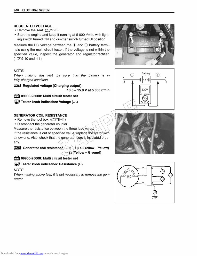
9-10 ELECTRICAL SYSTEM
REGULATED VOLTAGE• Remove the seat. (8-3)• Start the engine and keep it running at 5 000 r/min. with light-
ing switch turned ON and dimmer switch turned HI position.
Measure the DC voltage between the + and - battery termi-nals using the multi circuit tester. If the voltage is not within thespecified value, inspect the generator and regulator/rectifier.(9-10 and -11)
NOTE:When making this test, be sure that the battery is infully-charged condition.
Regulated voltage (Charging output):13.5 – 15.0 V at 5 000 r/min
09900-25008: Multi circuit tester set
Tester knob indication: Voltage ()
GENERATOR COIL RESISTANCE• Remove the tool box. (8-41)• Disconnect the generator coupler.Measure the resistance between the three lead wires.If the resistance is out of specified value, replace the stator witha new one. Also, check that the generator core is insulated prop-erly.
Generator coil resistance: 0.2 – 1.5 Ω (Yellow – Yellow)∞ Ω (Yellow – Ground)
09900-25008: Multi circuit tester set
Tester knob indication: Resistance (Ω)
NOTE:When making above test, it is not necessary to remove the gen-erator.
Battery
DCV
Y
Y
Y
SAMPLE
Downloaded from www.Manualslib.com manuals search engine
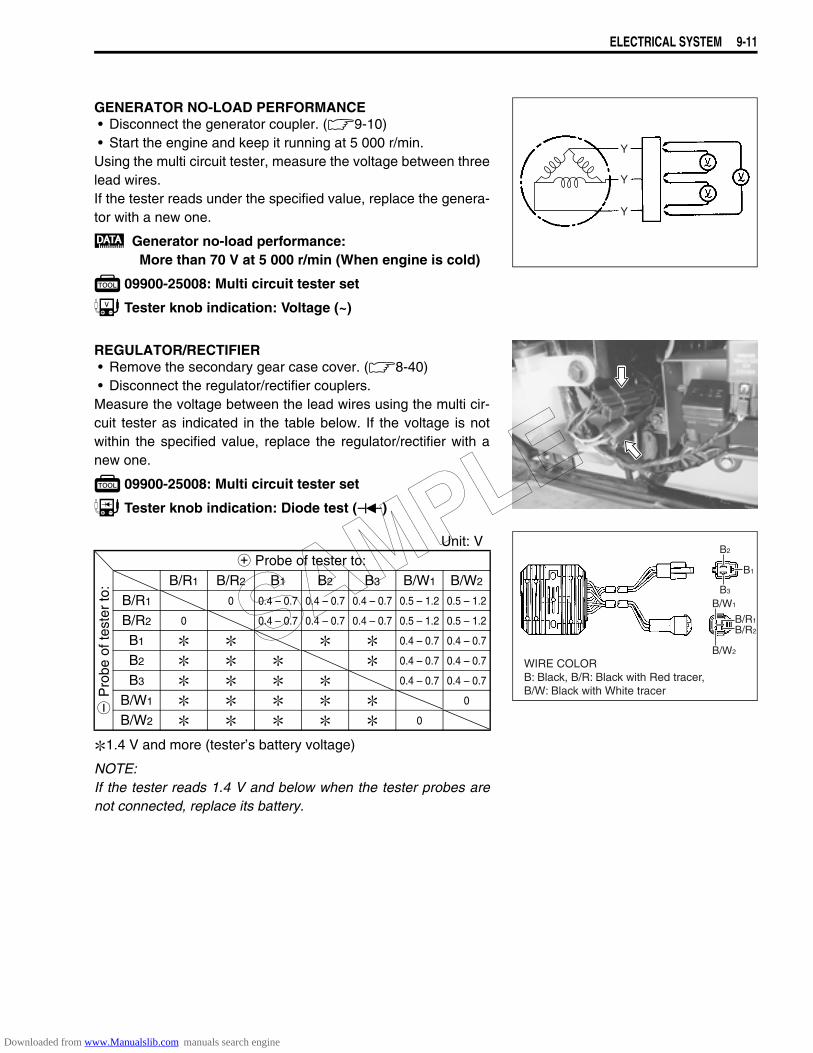
ELECTRICAL SYSTEM 9-11
GENERATOR NO-LOAD PERFORMANCE• Disconnect the generator coupler. (9-10)• Start the engine and keep it running at 5 000 r/min.Using the multi circuit tester, measure the voltage between threelead wires.If the tester reads under the specified value, replace the genera-tor with a new one.
Generator no-load performance:More than 70 V at 5 000 r/min (When engine is cold)
09900-25008: Multi circuit tester set
Tester knob indication: Voltage (~)
REGULATOR/RECTIFIER• Remove the secondary gear case cover. (8-40)• Disconnect the regulator/rectifier couplers.Measure the voltage between the lead wires using the multi cir-cuit tester as indicated in the table below. If the voltage is notwithin the specified value, replace the regulator/rectifier with anew one.
09900-25008: Multi circuit tester set
Tester knob indication: Diode test ()
Unit: V
1.4 V and more (tester’s battery voltage)
NOTE:If the tester reads 1.4 V and below when the tester probes arenot connected, replace its battery.
Y
Y
Y
+ Probe of tester to:
- P
robe
of t
este
r to
: B/R1 B/R2 B1 B2 B3 B/W1 B/W2
B/R1 0 0.4 – 0.7 0.4 – 0.7 0.4 – 0.7 0.5 – 1.2 0.5 – 1.2
B/R2 0 0.4 – 0.7 0.4 – 0.7 0.4 – 0.7 0.5 – 1.2 0.5 – 1.2
B1 0.4 – 0.7 0.4 – 0.7
B2 0.4 – 0.7 0.4 – 0.7
B3 0.4 – 0.7 0.4 – 0.7
B/W1 0
B/W2 0
B1
B2
B3
B/R2
B/R1
B/W1
B/W2
WIRE COLORB: Black, B/R: Black with Red tracer,B/W: Black with White tracer
SAMPLE
Downloaded from www.Manualslib.com manuals search engine
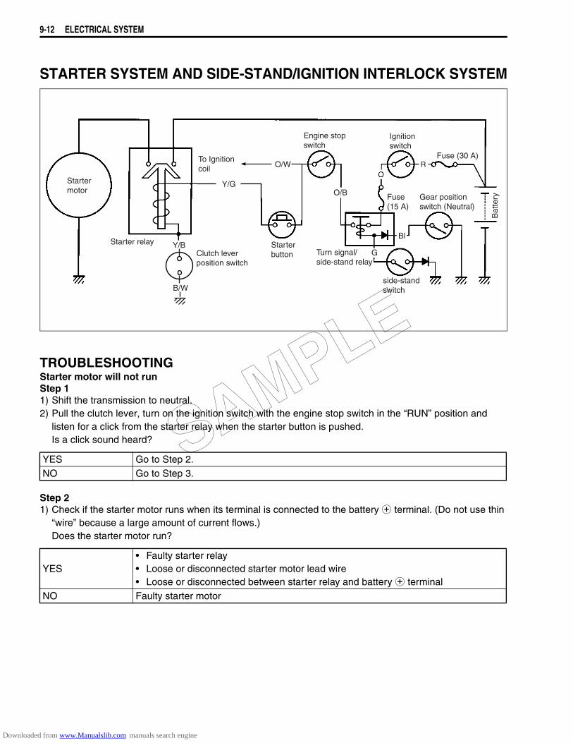
9-12 ELECTRICAL SYSTEM
STARTER SYSTEM AND SIDE-STAND/IGNITION INTERLOCK SYSTEM
TROUBLESHOOTINGStarter motor will not runStep 11) Shift the transmission to neutral.2) Pull the clutch lever, turn on the ignition switch with the engine stop switch in the “RUN” position and
listen for a click from the starter relay when the starter button is pushed.Is a click sound heard?
Step 21) Check if the starter motor runs when its terminal is connected to the battery + terminal. (Do not use thin
“wire” because a large amount of current flows.)Does the starter motor run?
YES Go to Step 2.NO Go to Step 3.
YES• Faulty starter relay• Loose or disconnected starter motor lead wire• Loose or disconnected between starter relay and battery + terminal
NO Faulty starter motor
Startermotor
Starter relay Y/B
To Ignition coil O/W
Y/G
Clutch leverposition switch
B/W
Starterbutton
Engine stopswitch
O/B
Turn signal/side-stand relay
G
Ignitionswitch
RFuse (30 A)
Gear positionswitch (Neutral)
Fuse(15 A)
Bat
tery
Bl
side-standswitch
SAMPLE
Downloaded from www.Manualslib.com manuals search engine
ELECTRICAL SYSTEM 9-13
Step 31) Measure the starter relay voltage at the starter relay connectors (between Y/G + and Y/B -) when the
starter button is pushed.Is a voltage OK?
Step 41) Check the starter relay. (9-16 to -17)
Is the starter relay OK?
Starter motor runs but does not crank the engineStep 11) The starter motor runs when the transmission is in neutral, but does not run when the transmission is in
any position other than neutral, with the side-stand up.2) Check the side-stand switch. (9-17)
Is the side-stand switch OK?
Step 21) Check the starter clutch.
Is the starter clutch OK?
YES Go to Step 4.
NO
• Faulty engine stop switch• Faulty clutch lever position switch• Faulty gear position switch• Faulty turn signal/side-stand relay• Faulty starter button• Faulty ignition switch• Faulty side-stand switch• Poor contact of connector• Open circuit in wire harness
YES Poor contact of the starter relayNO Faulty starter relay
YES Go to Step 2.NO Faulty side-stand switch
YES Faulty starter clutch
NO• Open circuit in wire harness• Poor contact of connector
SAMPLE
Downloaded from www.Manualslib.com manuals search engine
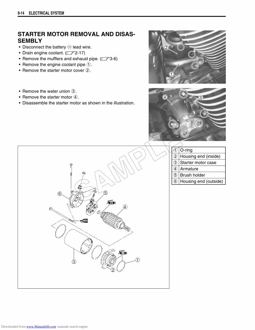
9-14 ELECTRICAL SYSTEM
STARTER MOTOR REMOVAL AND DISAS-SEMBLY• Disconnect the battery - lead wire.• Drain engine coolant. (2-17)• Remove the mufflers and exhaust pipe. (3-6)• Remove the engine coolant pipe 1.• Remove the starter motor cover 2.
• Remove the water union 3.• Remove the starter motor 4.• Disassemble the starter motor as shown in the illustration.
1 O-ring2 Housing end (inside)3 Starter motor case4 Armature5 Brush holder6 Housing end (outside)
SAMPLE
Downloaded from www.Manualslib.com manuals search engine
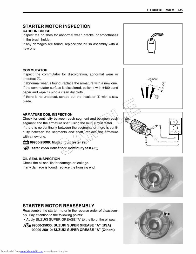
ELECTRICAL SYSTEM 9-15
STARTER MOTOR INSPECTIONCARBON BRUSHInspect the brushes for abnormal wear, cracks, or smoothnessin the brush holder.If any damages are found, replace the brush assembly with anew one.
COMMUTATORInspect the commutator for discoloration, abnormal wear orundercut A.If abnormal wear is found, replace the armature with a new one.If the commutator surface is discolored, polish it with #400 sandpaper and wipe it using a clean dry cloth.If there is no undercut, scrape out the insulator 1 with a sawblade.
ARMATURE COIL INSPECTIONCheck for continuity between each segment and between eachsegment and the armature shaft using the multi circuit tester.If there is no continuity between the segments or there is conti-nuity between the segments and shaft, replace the armaturewith a new one.
09900-25008: Multi circuit tester set
Tester knob indication: Continuity test ()
OIL SEAL INSPECTIONCheck the oil seal lip for damage or leakage.If any damage is found, replace the housing end.
STARTER MOTOR REASSEMBLYReassemble the starter motor in the reverse order of disassem-bly. Pay attention to the following points:• Apply SUZUKI SUPER GREASE “A” to the lip of the oil seal.
99000-25030: SUZUKI SUPER GREASE “A” (USA)99000-25010: SUZUKI SUPER GREASE “A” (Others)
Segment
SAMPLE
Downloaded from www.Manualslib.com manuals search engine
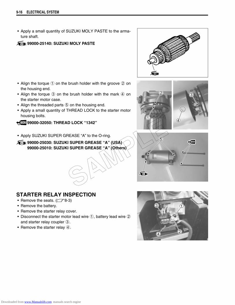
9-16 ELECTRICAL SYSTEM
• Apply a small quantity of SUZUKI MOLY PASTE to the arma-ture shaft.
99000-25140: SUZUKI MOLY PASTE
• Align the torque 1 on the brush holder with the groove 2 onthe housing end.
• Align the torque 3 on the brush holder with the mark 4 onthe starter motor case.
• Align the threaded parts 5 on the housing end.• Apply a small quantity of THREAD LOCK to the starter motor
housing bolts.
99000-32050: THREAD LOCK “1342”
• Apply SUZUKI SUPER GREASE “A” to the O-ring.
99000-25030: SUZUKI SUPER GREASE “A” (USA)99000-25010: SUZUKI SUPER GREASE “A” (Others)
STARTER RELAY INSPECTION• Remove the seats. (8-3)• Remove the battery.• Remove the starter relay cover.• Disconnect the starter motor lead wire 1, battery lead wire 2
and starter relay coupler 3.• Remove the starter relay 4.
SAMPLE
Downloaded from www.Manualslib.com manuals search engine
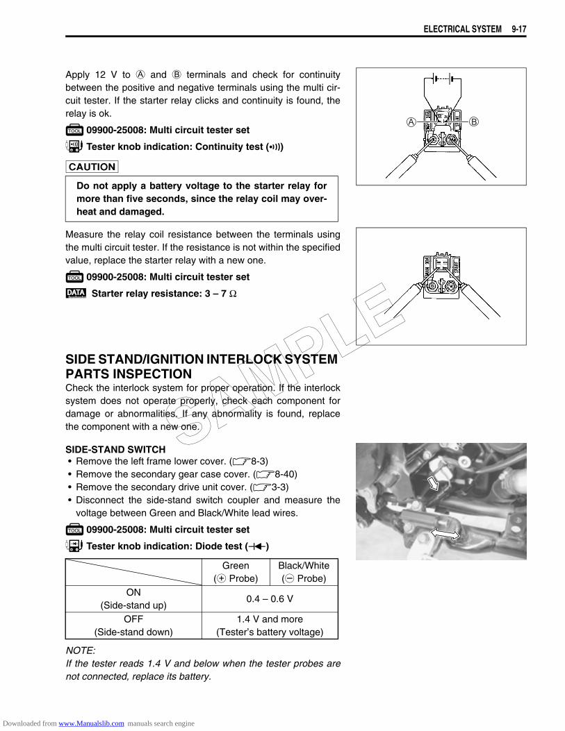
ELECTRICAL SYSTEM 9-17
Apply 12 V to A and B terminals and check for continuitybetween the positive and negative terminals using the multi cir-cuit tester. If the starter relay clicks and continuity is found, therelay is ok.
09900-25008: Multi circuit tester set
Tester knob indication: Continuity test ()
Measure the relay coil resistance between the terminals usingthe multi circuit tester. If the resistance is not within the specifiedvalue, replace the starter relay with a new one.
09900-25008: Multi circuit tester set
Starter relay resistance: 3 – 7 Ω
SIDE STAND/IGNITION INTERLOCK SYSTEM PARTS INSPECTIONCheck the interlock system for proper operation. If the interlocksystem does not operate properly, check each component fordamage or abnormalities. If any abnormality is found, replacethe component with a new one.
SIDE-STAND SWITCH• Remove the left frame lower cover. (8-3)• Remove the secondary gear case cover. (8-40)• Remove the secondary drive unit cover. (3-3)• Disconnect the side-stand switch coupler and measure the
voltage between Green and Black/White lead wires.
09900-25008: Multi circuit tester set
Tester knob indication: Diode test ()
NOTE:If the tester reads 1.4 V and below when the tester probes arenot connected, replace its battery.
Do not apply a battery voltage to the starter relay formore than five seconds, since the relay coil may over-heat and damaged.
Green(+ Probe)
Black/White(- Probe)
ON(Side-stand up)
0.4 – 0.6 V
OFF(Side-stand down)
1.4 V and more(Tester’s battery voltage)
SAMPLE
Downloaded from www.Manualslib.com manuals search engine
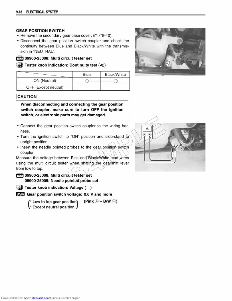
9-18 ELECTRICAL SYSTEM
GEAR POSITION SWITCH• Remove the secondary gear case cover. (8-40)• Disconnect the gear position switch coupler and check the
continuity between Blue and Black/White with the transmis-sion in “NEUTRAL”.
09900-25008: Multi circuit tester set
Tester knob indication: Continuity test ()
• Connect the gear position switch coupler to the wiring har-ness.
• Turn the ignition switch to “ON” position and side-stand toupright position.
• Insert the needle pointed probes to the gear position switchcoupler.
Measure the voltage between Pink and Black/White lead wiresusing the multi circuit tester when shifting the gearshift leverfrom low to top.
09900-25008: Multi circuit tester set09900-25009: Needle pointed probe set
Tester knob indication: Voltage ()
Gear position switch voltage: 0.6 V and more
(Pink + – B/W -)
When disconnecting and connecting the gear positionswitch coupler, make sure to turn OFF the ignitionswitch, or electronic parts may get damaged.
ON (Neutral)
Blue Black/White
OFF (Except neutral)
V
( )* Low to top gear position* Except neutral position
SAMPLE
Downloaded from www.Manualslib.com manuals search engine

ELECTRICAL SYSTEM 9-19
TURN SIGNAL/SIDE-STAND RELAYThe turn signal/side-stand relay is composed of the turn signalrelay, side-stand relay and diode.• Remove the secondary gear case cover. (8-40)• Remove the turn signal/side-stand relay.
SIDE-STAND RELAY INSPECTIONFirst check the insulation between D and E terminals with thetester. Then apply 12 V to terminals D and C (+ to D and - toC) and check the continuity between D and E. If there is nocontinuity, replace the turn signal/side-stand relay with a newone.
09900-25008: Multi circuit tester set
Tester knob indication: Continuity test ()
DIODE INSPECTIONMeasure the voltage between the terminals using the multi cir-cuit tester. Refer to the following table.
09900-25008: Multi circuit tester set
Tester knob indication: Diode test ()
NOTE:If the multi circuit tester reads 1.4 V and below when the testerprobes are not connected, replace its battery.
DIODE
SIDE-STAND RELAY
TURNSIGNALRELAY
+ Probe of tester to:
- P
robe
of
test
er to
:
C, B A
C, B1.4 V and more
(Tester’s battery voltage)
A 0.4 – 0.6 V
SAMPLE
Downloaded from www.Manualslib.com manuals search engine
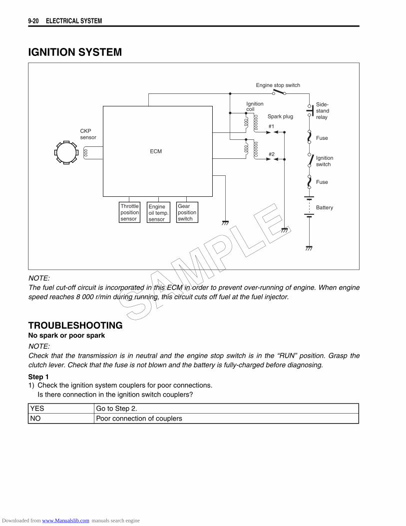
9-20 ELECTRICAL SYSTEM
IGNITION SYSTEM
NOTE:The fuel cut-off circuit is incorporated in this ECM in order to prevent over-running of engine. When enginespeed reaches 8 000 r/min during running, this circuit cuts off fuel at the fuel injector.
TROUBLESHOOTINGNo spark or poor spark
NOTE:Check that the transmission is in neutral and the engine stop switch is in the “RUN” position. Grasp theclutch lever. Check that the fuse is not blown and the battery is fully-charged before diagnosing.
Step 11) Check the ignition system couplers for poor connections.
Is there connection in the ignition switch couplers?
YES Go to Step 2.NO Poor connection of couplers
ECM
Throttlepositionsensor
Engineoil temp.sensor
Gearpositionswitch
Engine stop switch
Side-standrelay
Fuse
Fuse
Ignitionswitch
Ignitioncoil
Spark plug
Battery
CKPsensor
#1
#2
SAMPLE
Downloaded from www.Manualslib.com manuals search engine
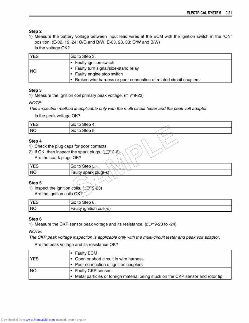
ELECTRICAL SYSTEM 9-21
Step 21) Measure the battery voltage between input lead wires at the ECM with the ignition switch in the “ON”
position. (E-02, 19, 24: O/G and B/W, E-03, 28, 33: O/W and B/W)Is the voltage OK?
Step 31) Measure the ignition coil primary peak voltage. (9-22)
NOTE:This inspection method is applicable only with the multi circuit tester and the peak volt adaptor.
Is the peak voltage OK?
Step 41) Check the plug caps for poor contacts.2) If OK, then inspect the spark plugs. (2-6)
Are the spark plugs OK?
Step 51) Inspect the ignition coils. (9-23)
Are the ignition coils OK?
Step 61) Measure the CKP sensor peak voltage and its resistance. (9-23 to -24)
NOTE:The CKP peak voltage inspection is applicable only with the multi-circuit tester and peak volt adaptor.
Are the peak voltage and its resistance OK?
YES Go to Step 3.
NO
• Faulty ignition switch• Faulty turn signal/side-stand relay• Faulty engine stop switch• Broken wire harness or poor connection of related circuit couplers
YES Go to Step 4.NO Go to Step 5.
YES Go to Step 5.NO Faulty spark plug(-s)
YES Go to Step 6.NO Faulty ignition coil(-s)
YES• Faulty ECM• Open or short circuit in wire harness• Poor connection of ignition couplers
NO • Faulty CKP sensor• Metal particles or foreign material being stuck on the CKP sensor and rotor tip
SAMPLE
Downloaded from www.Manualslib.com manuals search engine
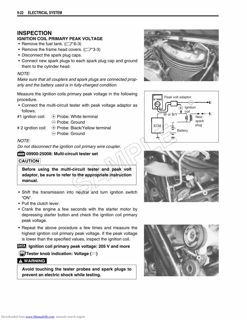
9-22 ELECTRICAL SYSTEM
INSPECTIONIGNITION COIL PRIMARY PEAK VOLTAGE• Remove the fuel tank. (6-3)• Remove the frame head covers. (3-3)• Disconnect the spark plug caps.• Connect new spark plugs to each spark plug cap and ground
them to the cylinder head.
NOTE:Make sure that all couplers and spark plugs are connected prop-erly and the battery used is in fully-charged condition.
Measure the ignition coils primary peak voltage in the followingprocedure.• Connect the multi-circuit tester with peak voltage adaptor as
follows.#1 ignition coil: + Probe: White terminal
- Probe: Ground# 2 ignition coil: + Probe: Black/Yellow terminal
- Probe: Ground
NOTE:Do not disconnect the ignition coil primary wire coupler.
09900-25008: Multi-circuit tester set
• Shift the transmission into neutral and turn ignition switch“ON”.
• Pull the clutch lever.• Crank the engine a few seconds with the starter motor by
depressing starter button and check the ignition coil primarypeak voltage.
• Repeat the above procedure a few times and measure thehighest ignition coil primary peak voltage. If the peak voltageis lower than the specified values, inspect the ignition coil.
Ignition coil primary peak voltage: 205 V and more
Tester knob indication: Voltage ()
Before using the multi-circuit tester and peak voltadaptor, be sure to refer to the appropriate instructionmanual.
Avoid touching the tester probes and spark plugs toprevent an electric shock while testing.
ECM
Peak volt adaptor
W or B/Y
Ignitioncoil
Newsparkplug
Battery
SAMPLE
Downloaded from www.Manualslib.com manuals search engine
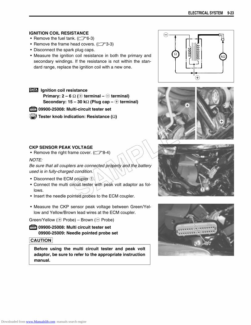
ELECTRICAL SYSTEM 9-23
IGNITION COIL RESISTANCE• Remove the fuel tank. (6-3)• Remove the frame head covers. (3-3)• Disconnect the spark plug caps.• Measure the ignition coil resistance in both the primary and
secondary windings. If the resistance is not within the stan-dard range, replace the ignition coil with a new one.
Ignition coil resistancePrimary: 2 – 6 Ω (+ terminal – - terminal)Secondary: 15 – 30 kΩ (Plug cap – + terminal)
09900-25008: Multi-circuit tester set
Tester knob indication: Resistance (Ω)
CKP SENSOR PEAK VOLTAGE• Remove the right frame cover. (8-4)
NOTE:Be sure that all couplers are connected properly and the batteryused is in fully-charged condition.
• Disconnect the ECM coupler 1.• Connect the multi circuit tester with peak volt adaptor as fol-
lows.• Insert the needle pointed probes to the ECM coupler.
• Measure the CKP sensor peak voltage between Green/Yel-low and Yellow/Brown lead wires at the ECM coupler.
Green/Yellow (+ Probe) – Brown (- Probe)
09900-25008: Multi circuit tester set09900-25009: Needle pointed probe set
kΩΩ
Before using the multi circuit tester and peak voltadaptor, be sure to refer to the appropriate instructionmanual.
Br
G/Y
SAMPLE
Downloaded from www.Manualslib.com manuals search engine
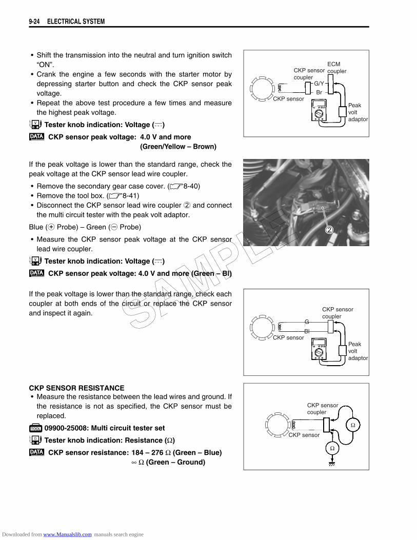
9-24 ELECTRICAL SYSTEM
• Shift the transmission into the neutral and turn ignition switch“ON”.
• Crank the engine a few seconds with the starter motor bydepressing starter button and check the CKP sensor peakvoltage.
• Repeat the above test procedure a few times and measurethe highest peak voltage.
Tester knob indication: Voltage ()
CKP sensor peak voltage: 4.0 V and more (Green/Yellow – Brown)
If the peak voltage is lower than the standard range, check thepeak voltage at the CKP sensor lead wire coupler.
• Remove the secondary gear case cover. (8-40)• Remove the tool box. (8-41)• Disconnect the CKP sensor lead wire coupler 2 and connect
the multi circuit tester with the peak volt adaptor.
Blue (+ Probe) – Green (- Probe)
• Measure the CKP sensor peak voltage at the CKP sensorlead wire coupler.
Tester knob indication: Voltage ()
CKP sensor peak voltage: 4.0 V and more (Green – Bl)
If the peak voltage is lower than the standard range, check eachcoupler at both ends of the circuit or replace the CKP sensorand inspect it again.
CKP SENSOR RESISTANCE• Measure the resistance between the lead wires and ground. If
the resistance is not as specified, the CKP sensor must bereplaced.
09900-25008: Multi circuit tester set
Tester knob indication: Resistance (Ω)
CKP sensor resistance: 184 – 276 Ω (Green – Blue)∞ Ω (Green – Ground)
CKP sensor
CKP sensorcoupler
G/W
W
ECMcoupler
Peakvoltadaptor
G/Y
Br
CKP sensorPeakvoltadaptor
CKP sensorcoupler
G
Bl
G
Bl
CKP sensor
CKP sensorcoupler
SAMPLE
Downloaded from www.Manualslib.com manuals search engine
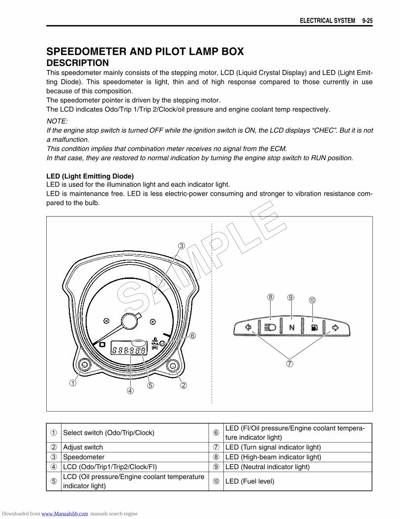
ELECTRICAL SYSTEM 9-25
SPEEDOMETER AND PILOT LAMP BOXDESCRIPTIONThis speedometer mainly consists of the stepping motor, LCD (Liquid Crystal Display) and LED (Light Emit-ting Diode). This speedometer is light, thin and of high response compared to those currently in usebecause of this composition.The speedometer pointer is driven by the stepping motor.The LCD indicates Odo/Trip 1/Trip 2/Clock/oil pressure and engine coolant temp respectively.
NOTE:If the engine stop switch is turned OFF while the ignition switch is ON, the LCD displays “CHEC”. But it is nota malfunction.This condition implies that combination meter receives no signal from the ECM.In that case, they are restored to normal indication by turning the engine stop switch to RUN position.
LED (Light Emitting Diode)LED is used for the illumination light and each indicator light.LED is maintenance free. LED is less electric-power consuming and stronger to vibration resistance com-pared to the bulb.
1 Select switch (Odo/Trip/Clock) 6LED (FI/Oil pressure/Engine coolant tempera-ture indicator light)
2 Adjust switch 7 LED (Turn signal indicator light)3 Speedometer 8 LED (High-beam indicator light)4 LCD (Odo/Trip1/Trip2/Clock/FI) 9 LED (Neutral indicator light)
5LCD (Oil pressure/Engine coolant temperature indicator light)
0 LED (Fuel level)
SAMPLE
Downloaded from www.Manualslib.com manuals search engine
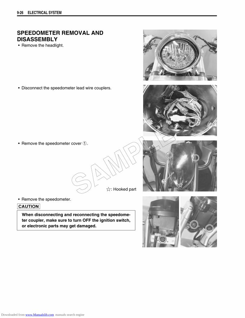
9-26 ELECTRICAL SYSTEM
SPEEDOMETER REMOVAL ANDDISASSEMBLY• Remove the headlight.
• Disconnect the speedometer lead wire couplers.
• Remove the speedometer cover 1.
: Hooked part
• Remove the speedometer.
When disconnecting and reconnecting the speedome-ter coupler, make sure to turn OFF the ignition switch,or electronic parts may get damaged.
SAMPLE
Downloaded from www.Manualslib.com manuals search engine
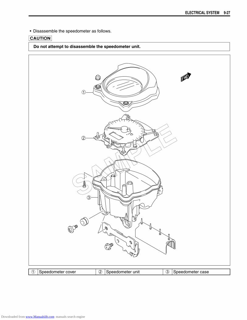
ELECTRICAL SYSTEM 9-27
• Disassemble the speedometer as follows.
Do not attempt to disassemble the speedometer unit.
1 Speedometer cover 2 Speedometer unit 3 Speedometer case
SAMPLE
Downloaded from www.Manualslib.com manuals search engine
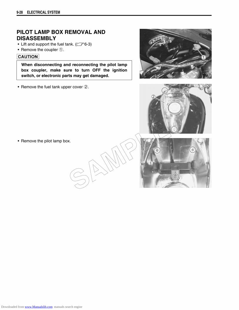
9-28 ELECTRICAL SYSTEM
PILOT LAMP BOX REMOVAL ANDDISASSEMBLY• Lift and support the fuel tank. (6-3)• Remove the coupler 1.
• Remove the fuel tank upper cover 2.
• Remove the pilot lamp box.
When disconnecting and reconnecting the pilot lampbox coupler, make sure to turn OFF the ignitionswitch, or electronic parts may get damaged.
SAMPLE
Downloaded from www.Manualslib.com manuals search engine
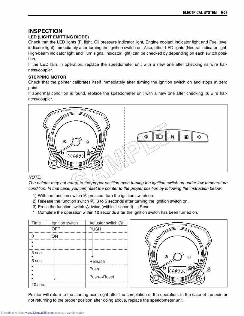
ELECTRICAL SYSTEM 9-29
INSPECTIONLED (LIGHT EMITTING DIODE)Check that the LED lights (FI light, Oil pressure indicator light, Engine coolant indicator light and Fuel levelindicator light) immediately after turning the ignition switch on. Also, other LED lights (Neutral indicator light,High-beam indicator light and Turn signal indicator light) can be checked by depending on each switch posi-tion.If the LED fails in operation, replace the speedometer unit with a new one after checking its wire har-ness/coupler.
STEPPING MOTORCheck that the pointer calibrates itself immediately after turning the ignition switch on and stops at zeropoint.If abnormal condition is found, replace the speedometer unit with a new one after checking its wire har-ness/coupler.
NOTE:The pointer may not return to the proper position even turning the ignition switch on under low temperaturecondition. In that case, you can reset the pointer to the proper position by following the instruction below:
1) With the function switch A pressed, turn the ignition switch on.2) Release the function switch A, 3 to 5 seconds after turning the ignition switch on.3) Press the function switch A twice (within 1 second). →Reset* Complete the operation within 10 seconds after the ignition switch has been turned on.
Pointer will return to the starting point right after the completion of the operation. In the case of the pointernot returning to the proper position after doing above, replace the speedometer unit.
Time Ignition switch Adjuster switch
PUSH
Release
Push
Push→Reset
OFF
ON0
••
••••
3 sec.•5 sec.
10 sec.
SAMPLE
Downloaded from www.Manualslib.com manuals search engine
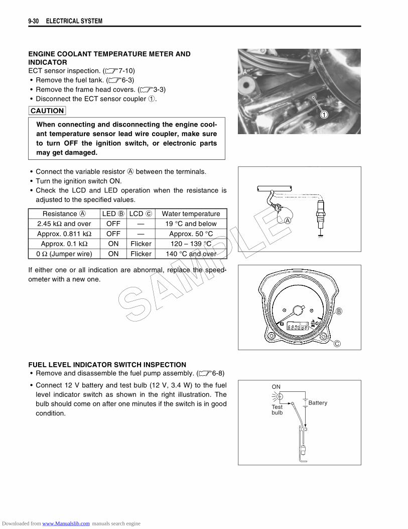
9-30 ELECTRICAL SYSTEM
ENGINE COOLANT TEMPERATURE METER ANDINDICATORECT sensor inspection. (!7-10)• Remove the fuel tank. (!6-3)• Remove the frame head covers. (!3-3)• Disconnect the ECT sensor coupler
1.
"
• Connect the variable resistor
A between the terminals.• Turn the ignition switch ON.• Check the LCD and LED operation when the resistance is
adjusted to the specified values.
If either one or all indication are abnormal, replace the speed-ometer with a new one.
FUEL LEVEL INDICATOR SWITCH INSPECTION• Remove and disassemble the fuel pump assembly. (!6-8)
• Connect 12 V battery and test bulb (12 V, 3.4 W) to the fuellevel indicator switch as shown in the right illustration. Thebulb should come on after one minutes if the switch is in goodcondition.
When connecting and disconnecting the engine cool-ant temperature sensor lead wire coupler, make sureto turn OFF the ignition switch, or electronic partsmay get damaged.
Resistance
A LED
B LCD
c Water temperature2.45 kΩ and over OFF — 19 °C and below
Approx. 0.811 kΩ OFF — Approx. 50 °CApprox. 0.1 kΩ ON Flicker 120 – 139 °C
0 Ω (Jumper wire) ON Flicker 140 °C and over
ON
Testbulb
Battery
SAMPLE
Downloaded from www.Manualslib.com manuals search engine
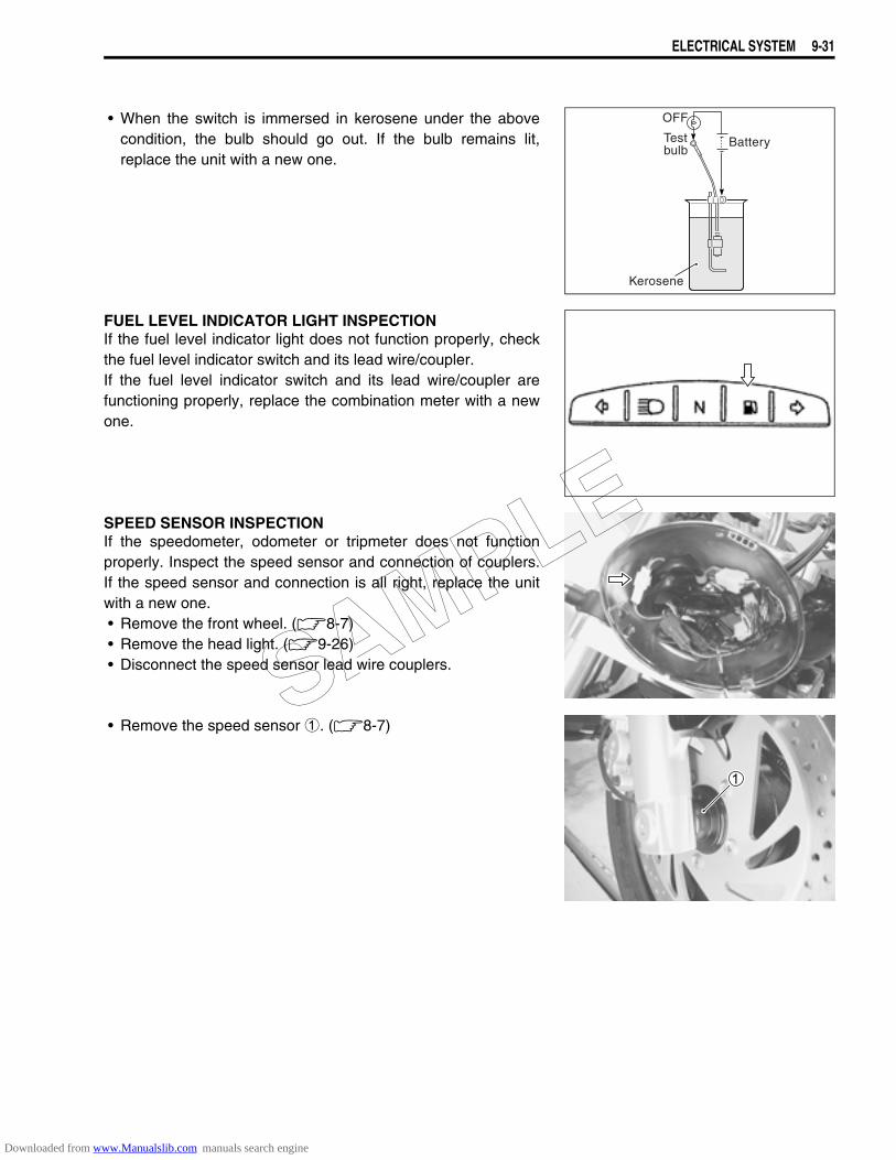
ELECTRICAL SYSTEM 9-31
• When the switch is immersed in kerosene under the abovecondition, the bulb should go out. If the bulb remains lit,replace the unit with a new one.
FUEL LEVEL INDICATOR LIGHT INSPECTIONIf the fuel level indicator light does not function properly, checkthe fuel level indicator switch and its lead wire/coupler.If the fuel level indicator switch and its lead wire/coupler arefunctioning properly, replace the combination meter with a newone.
SPEED SENSOR INSPECTIONIf the speedometer, odometer or tripmeter does not functionproperly. Inspect the speed sensor and connection of couplers.If the speed sensor and connection is all right, replace the unitwith a new one.• Remove the front wheel. (8-7)• Remove the head light. (9-26)• Disconnect the speed sensor lead wire couplers.
• Remove the speed sensor 1. (8-7)
OFF
Testbulb
Kerosene
Battery
SAMPLE
Downloaded from www.Manualslib.com manuals search engine
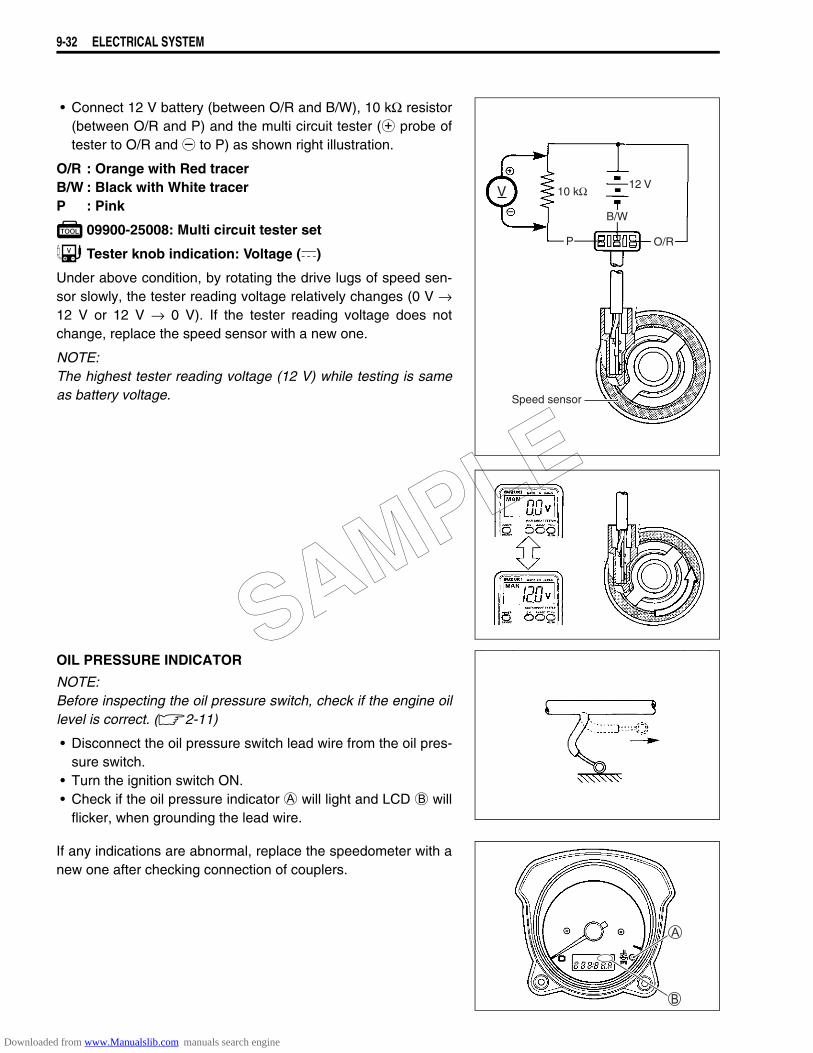
9-32 ELECTRICAL SYSTEM
• Connect 12 V battery (between O/R and B/W), 10 kΩ resistor(between O/R and P) and the multi circuit tester (+ probe oftester to O/R and - to P) as shown right illustration.
O/R : Orange with Red tracerB/W : Black with White tracerP : Pink
09900-25008: Multi circuit tester set
Tester knob indication: Voltage ()
Under above condition, by rotating the drive lugs of speed sen-sor slowly, the tester reading voltage relatively changes (0 V →12 V or 12 V → 0 V). If the tester reading voltage does notchange, replace the speed sensor with a new one.
NOTE:The highest tester reading voltage (12 V) while testing is sameas battery voltage.
OIL PRESSURE INDICATOR
NOTE:Before inspecting the oil pressure switch, check if the engine oillevel is correct. (2-11)
• Disconnect the oil pressure switch lead wire from the oil pres-sure switch.
• Turn the ignition switch ON.• Check if the oil pressure indicator A will light and LCD B will
flicker, when grounding the lead wire.
If any indications are abnormal, replace the speedometer with anew one after checking connection of couplers.
V 10 kΩ 12 V
B/W
P O/R
Speed sensor
SAMPLE
Downloaded from www.Manualslib.com manuals search engine
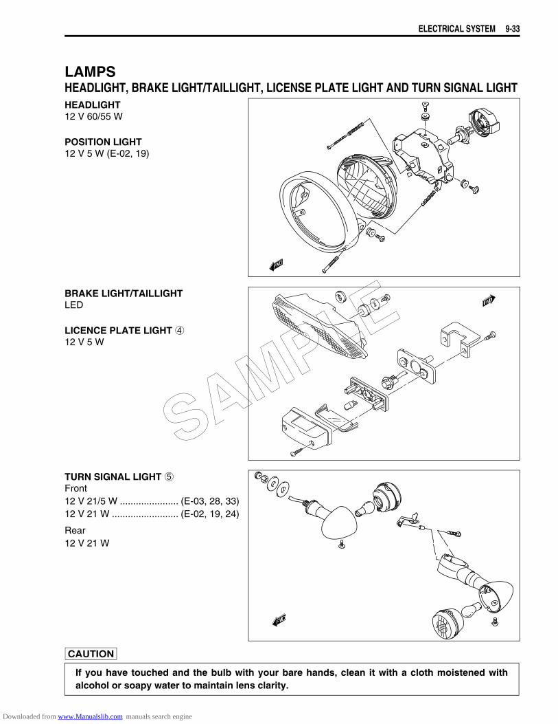
ELECTRICAL SYSTEM 9-33
LAMPSHEADLIGHT, BRAKE LIGHT/TAILLIGHT, LICENSE PLATE LIGHT AND TURN SIGNAL LIGHTHEADLIGHT12 V 60/55 W
POSITION LIGHT12 V 5 W (E-02, 19)
BRAKE LIGHT/TAILLIGHTLED
LICENCE PLATE LIGHT 412 V 5 W
TURN SIGNAL LIGHT 5Front12 V 21/5 W ...................... (E-03, 28, 33)12 V 21 W ......................... (E-02, 19, 24)
Rear12 V 21 W
If you have touched and the bulb with your bare hands, clean it with a cloth moistened withalcohol or soapy water to maintain lens clarity.
SAMPLE
Downloaded from www.Manualslib.com manuals search engine
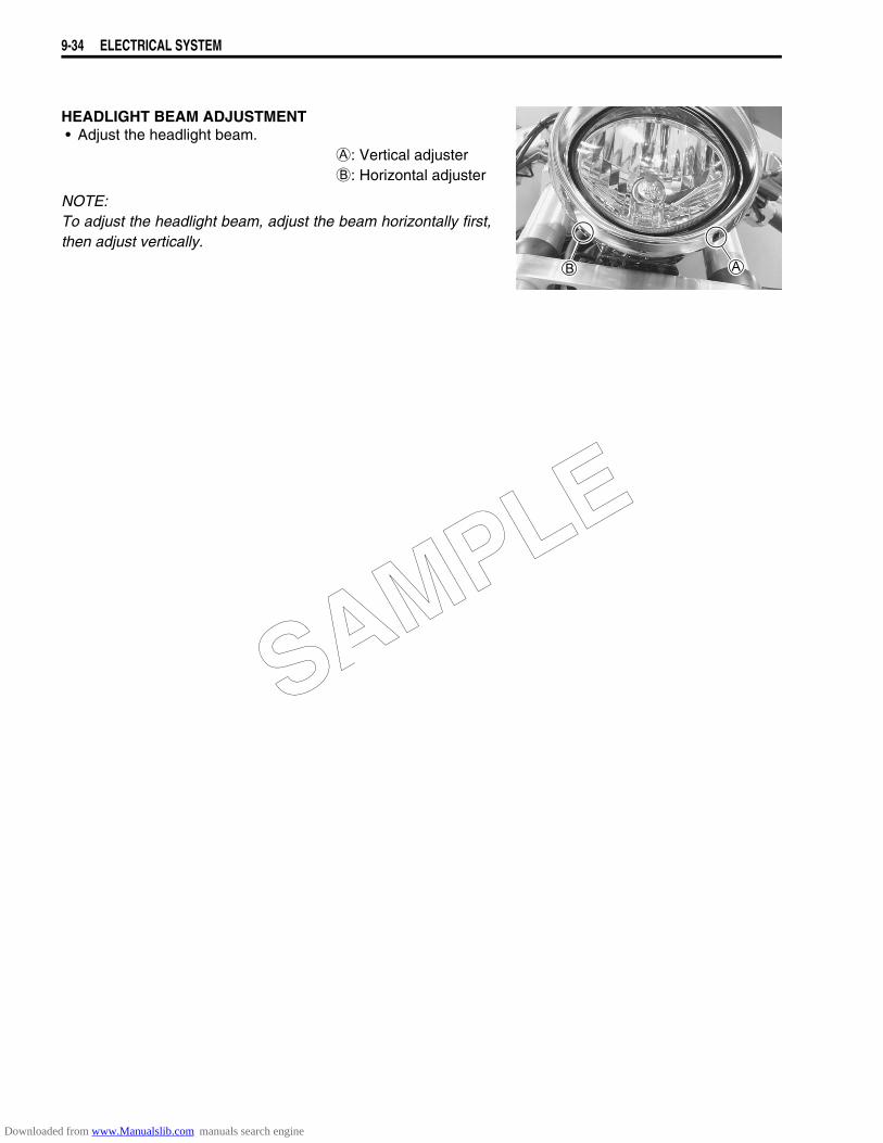
9-34 ELECTRICAL SYSTEM
HEADLIGHT BEAM ADJUSTMENT• Adjust the headlight beam.
A: Vertical adjusterB: Horizontal adjuster
NOTE:To adjust the headlight beam, adjust the beam horizontally first,then adjust vertically.
SAMPLE
Downloaded from www.Manualslib.com manuals search engine
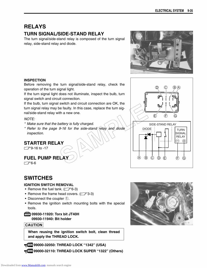
ELECTRICAL SYSTEM 9-35
RELAYSTURN SIGNAL/SIDE-STAND RELAYThe turn signal/side-stand relay is composed of the turn signalrelay, side-stand relay and diode.
INSPECTIONBefore removing the turn signal/side-stand relay, check theoperation of the turn signal light.If the turn signal light does not illuminate, inspect the bulb, turnsignal switch and circuit connection.If the bulb, turn signal switch and circuit connection are OK, theturn signal relay may be faulty. In this case, replace the turn sig-nal/side-stand relay with a new one.
NOTE:* Make sure that the battery is fully charged.* Refer to the page 9-16 for the side-stand relay and diode
inspection.
STARTER RELAY9-16 to -17
FUEL PUMP RELAY6-6
SWITCHESIGNITION SWITCH REMOVAL• Remove the fuel tank. (6-3)• Remove the frame head covers. (3-3)• Disconnect the coupler 1.• Remove the ignition switch mounting bolts with the special
tools.
09930-11920: Torx bit JT40H09930-11940: Bit holder
99000-32050: THREAD LOCK “1342” (USA)
99000-32110: THREAD LOCK SUPER “1322” (Others)
DIODE
SIDE-STAND RELAY
TURNSIGNALRELAY
When reusing the ignition switch bolt, clean threadand apply the THREAD LOCK.
SAMPLE
Downloaded from www.Manualslib.com manuals search engine
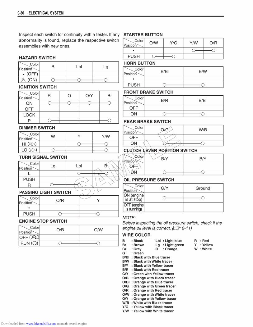
9-36 ELECTRICAL SYSTEM
ColorPosition
IGNITION SWITCH
HAZARD SWITCH
Inspect each switch for continuity with a tester. If anyabnormality is found, replace the respective switchassemblies with new ones.
NOTE:Before inspecting the oil pressure switch, check if theengine oil level is correct. (2-11)
R O O/Y Br
ONOFF
LOCKP
DIMMER SWITCH
ColorPosition
PASSING LIGHT SWITCH
W Y Y/W
HI ()
LO ()
B Lbl Lg
(OFF)
(ON)
HORN BUTTON
STARTER BUTTON
TURN SIGNAL SWITCH
ColorPosition
Lg Lbl B
LPUSH
R
ENGINE STOP SWITCH
ColorPosition
O/R Y
PUSH
ColorPosition
O/B O/W
OFF ()
RUN ()
ColorPosition
O/W Y/G Y/W O/R
PUSH
FRONT BRAKE SWITCH
REAR BRAKE SWITCH
CLUTCH LEVER POSITION SWITCH
OIL PRESSURE SWITCH
WIRE COLORB : Black Lbl : Light blue R : RedBr : Brown Lg : Light green Y : YellowGr : Gray O : Orange W : WhiteG : GreenB/BI : Black with Blue tracerB/W : Black with White tracerB/Y : Black with Yellow tracerB/R : Black with Red tracerG/Y : Green with Yellow tracerO/B : Orange with Black tracerO/BI : Orange with Blue tracerO/G : Orange with Green tracerO/R : Orange with Red tracerO/W : Orange with White tracerO/Y : Orange with Yellow tracerW/B : White with Black tracerY/G : Yellow with Black tracerY/W : Yellow with White tracer
ColorPosition
G/Y Ground
ON (engineis at stop)
OFF (engineis running)
ColorPosition
B/Y B/Y
OFFON
ColorPosition
O/G W/B
OFFON
ColorPosition
B/R B/Bl
OFFON
ColorPosition
B/Bl B/W
PUSH
ColorPosition
SAMPLE
Downloaded from www.Manualslib.com manuals search engine
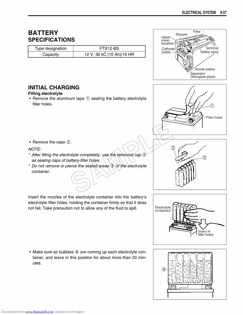
ELECTRICAL SYSTEM 9-37
BATTERYSPECIFICATIONS
INITIAL CHARGINGFilling electrolyte• Remove the aluminum tape 1 sealing the battery electrolyte
filler holes.
• Remove the caps 2.
NOTE:* After filling the electrolyte completely, use the removed cap 2
as sealing caps of battery-filler holes.* Do not remove or pierce the sealed areas 3 of the electrolyte
container.
Insert the nozzles of the electrolyte container into the battery’selectrolyte filler holes, holding the container firmly so that it doesnot fall. Take precaution not to allow any of the fluid to spill.
• Make sure air bubbles 6 are coming up each electrolyte con-tainer, and leave in this position for about more than 20 min-utes.
Type designation FTX12-BSCapacity 12 V, 36 kC (10 Ah)/10 HR
Uppercoverbreather
Cathodeplates
StopperFilter
TerminalSafety valve
Anode platesSeparator(fiberglass plate)
Filler holes
Electrolytecontainers
Insert infiller holes
SAMPLE
Downloaded from www.Manualslib.com manuals search engine
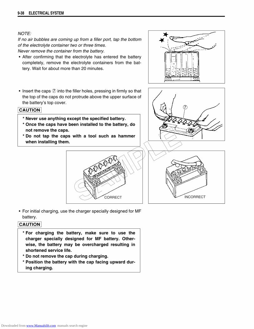
9-38 ELECTRICAL SYSTEM
NOTE:If no air bubbles are coming up from a filler port, tap the bottomof the electrolyte container two or three times.Never remove the container from the battery.• After confirming that the electrolyte has entered the battery
completely, remove the electrolyte containers from the bat-tery. Wait for about more than 20 minutes.
• Insert the caps 7 into the filler holes, pressing in firmly so thatthe top of the caps do not protrude above the upper surface ofthe battery’s top cover.
• For initial charging, use the charger specially designed for MFbattery.
* Never use anything except the specified battery.* Once the caps have been installed to the battery, do
not remove the caps.* Do not tap the caps with a tool such as hammer
when installing them.
INCORRECTCORRECT
* For charging the battery, make sure to use thecharger specially designed for MF battery. Other-wise, the battery may be overcharged resulting inshortened service life.
* Do not remove the cap during charging.* Position the battery with the cap facing upward dur-
ing charging.
SAMPLE
Downloaded from www.Manualslib.com manuals search engine
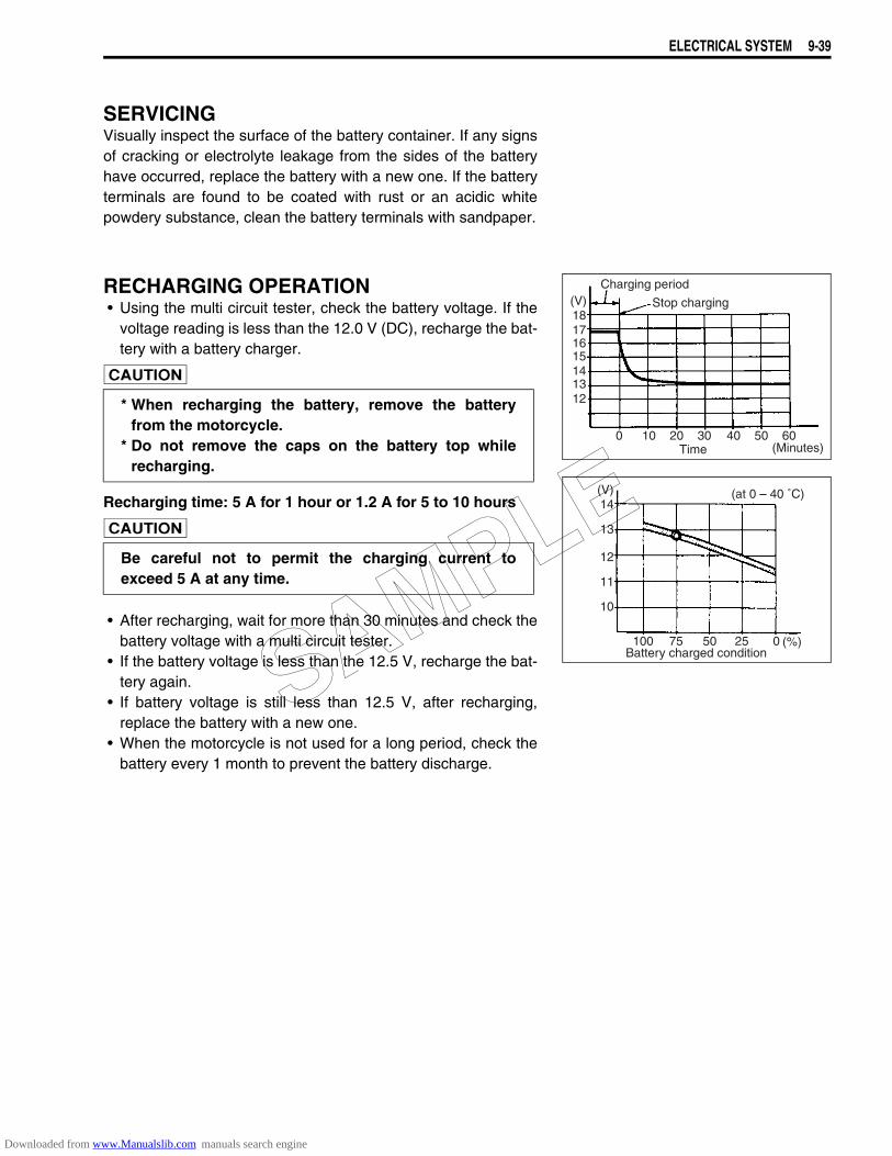
ELECTRICAL SYSTEM 9-39
SERVICINGVisually inspect the surface of the battery container. If any signsof cracking or electrolyte leakage from the sides of the batteryhave occurred, replace the battery with a new one. If the batteryterminals are found to be coated with rust or an acidic whitepowdery substance, clean the battery terminals with sandpaper.
RECHARGING OPERATION• Using the multi circuit tester, check the battery voltage. If the
voltage reading is less than the 12.0 V (DC), recharge the bat-tery with a battery charger.
Recharging time: 5 A for 1 hour or 1.2 A for 5 to 10 hours
• After recharging, wait for more than 30 minutes and check thebattery voltage with a multi circuit tester.
• If the battery voltage is less than the 12.5 V, recharge the bat-tery again.
• If battery voltage is still less than 12.5 V, after recharging,replace the battery with a new one.
• When the motorcycle is not used for a long period, check thebattery every 1 month to prevent the battery discharge.
* When recharging the battery, remove the batteryfrom the motorcycle.
* Do not remove the caps on the battery top whilerecharging.
Be careful not to permit the charging current toexceed 5 A at any time.
Time (Minutes)0 10 20 30 40 50 60
Charging period
Stop charging(V)18171615141312
Battery charged condition100 75 50 25 0 (%)
10
11
12
13
14(V) (at 0 – 40 ˚C)
SAMPLE
Downloaded from www.Manualslib.com manuals search engine
SERVICING INFORMATION 10-1
10
SERVICING INFORMATION
CONTENTS
TROUBLESHOOTING.................................................................................10- 2FI SYSTEM MALFUNCTION CODE AND DEFECTIVE CONDITION ..10- 2ENGINE .................................................................................................10- 5RADIATOR (COOLING SYSTEM) ........................................................10-10CHASSIS ...............................................................................................10-11SHAFT DRIVE.......................................................................................10-12BRAKES................................................................................................10-12ELECTRICAL ........................................................................................10-13BATTERY..............................................................................................10-14
WIRING HARNESS, CABLE AND HOSE ROUTING..................................10-15WIRING HARNESS ROUTING .............................................................10-15CABLE ROUTING.................................................................................10-18THROTTLE BODY INSTALLATION.....................................................10-19COOLING SYSTEM HOSE ROUTING..................................................10-20FRONT BRAKE ROUTING ...................................................................10-21SPEED SENSOR HARNESS ROUTING ..............................................10-22FRONT TURN SIGNAL INSTALLATION..............................................10-22FRONT TURN SIGNAL LEAD WIRE ROUTING ..................................10-23MUFFLER & EXHAUST PIPE INSTALLATION ...................................10-23HANDLEBAR BALANCER...................................................................10-24BATTERY PROTECTOR ......................................................................10-24LUBRICATION POINTS........................................................................10-25FUEL TANK INSTALLATION ...............................................................10-26REAR COMBINATION LAMP INSTALLATION ...................................10-27FRAME HEAD COVER CUSHION INSTALLATION ............................10-28LEFT SIDE COVER CUSHION INSTALLATION..................................10-28REAR FENDER CUSHION INSTALLATION ........................................10-29LEFT SIDE COVER INSTALLATION ...................................................10-30LID CUSHION INSTSALLATION..........................................................10-31TAIL LAMP INSTALLATION ................................................................10-32
PAIR (AIR SUPPLY) SYSTEM DIAGRAM..................................................10-33PAIR (AIR SUPPLY) SYSTEM HOSE ROUTING .......................................10-34SPECIAL TOOLS ........................................................................................10-35TIGHTENING TORQUE...............................................................................10-39
ENGINE .................................................................................................10-39SECONDARY AND FINAL....................................................................10-40FI SYSTEM AND INTAKE AIR SYSTEM..............................................10-40COOLING SYSTEM ..............................................................................10-40CHASSIS ...............................................................................................10-41TIGHTENING TORQUE CHART...........................................................10-42
SERVICE DATA...........................................................................................10-43
SAMPLE
Downloaded from www.Manualslib.com manuals search engine
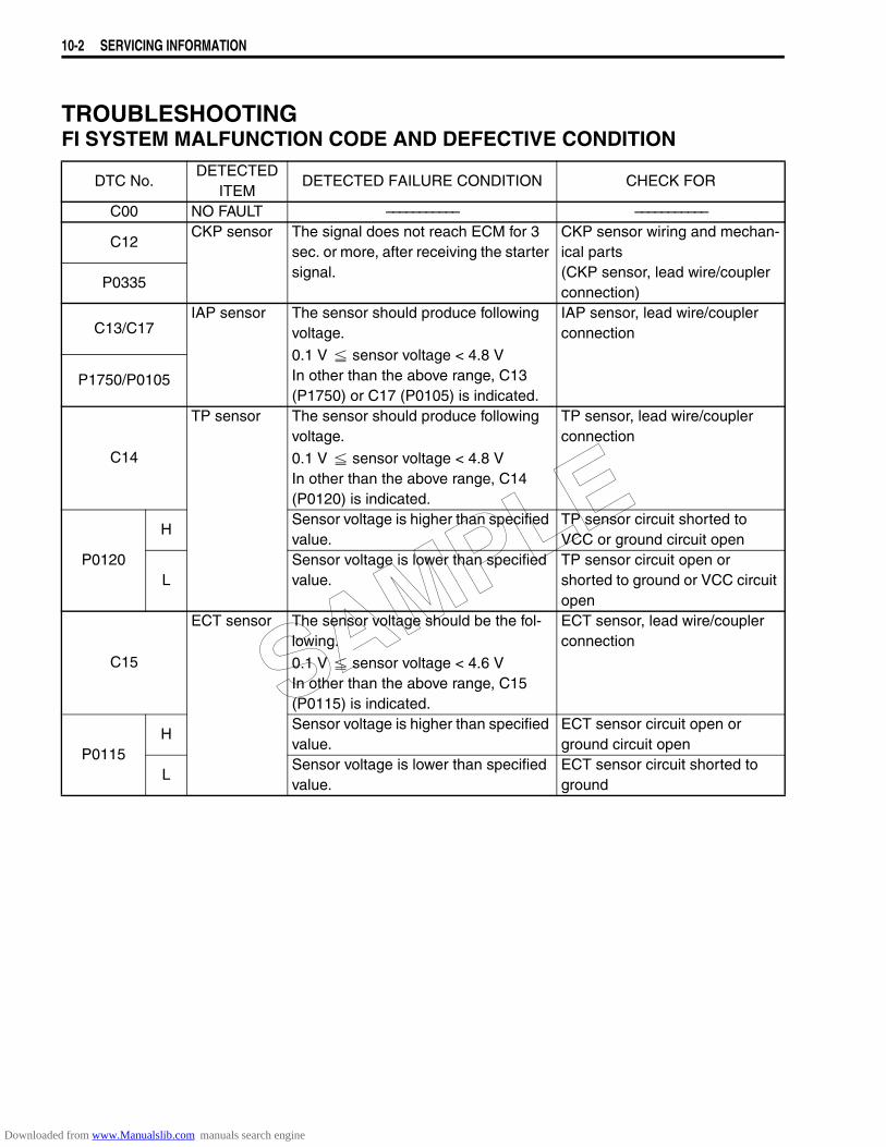
10-2 SERVICING INFORMATION
TROUBLESHOOTINGFI SYSTEM MALFUNCTION CODE AND DEFECTIVE CONDITION
DTC No.DETECTED
ITEMDETECTED FAILURE CONDITION CHECK FOR
C00 NO FAULT ––––––––––– –––––––––––
C12CKP sensor The signal does not reach ECM for 3
sec. or more, after receiving the starter signal.
CKP sensor wiring and mechan-ical parts(CKP sensor, lead wire/coupler connection)
P0335
C13/C17IAP sensor The sensor should produce following
voltage.
0.1 V sensor voltage < 4.8 VIn other than the above range, C13 (P1750) or C17 (P0105) is indicated.
IAP sensor, lead wire/coupler connection
P1750/P0105
C14
TP sensor The sensor should produce following voltage.
0.1 V sensor voltage < 4.8 VIn other than the above range, C14 (P0120) is indicated.
TP sensor, lead wire/coupler connection
P0120
HSensor voltage is higher than specified value.
TP sensor circuit shorted to VCC or ground circuit open
LSensor voltage is lower than specified value.
TP sensor circuit open or shorted to ground or VCC circuit open
C15
ECT sensor The sensor voltage should be the fol-lowing.
0.1 V sensor voltage < 4.6 VIn other than the above range, C15 (P0115) is indicated.
ECT sensor, lead wire/coupler connection
P0115H
Sensor voltage is higher than specified value.
ECT sensor circuit open or ground circuit open
LSensor voltage is lower than specified value.
ECT sensor circuit shorted to ground
SAMPLE
Downloaded from www.Manualslib.com manuals search engine
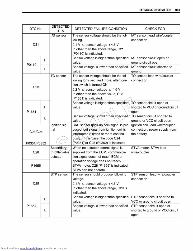
SERVICING INFORMATION 10-3
DTC No.DETECTED
ITEMDETECTED FAILURE CONDITION CHECK FOR
C21
IAT sensor The sensor voltage should be the fol-lowing.
0.1 V sensor voltage < 4.6 VIn other than the above range, C21 (P0110) is indicated.
IAT sensor, lead wire/coupler connection
P0110H
Sensor voltage is higher than specified value.
IAT sensor circuit open or ground circuit open
LSensor voltage is lower than specified value.
IAT sensor circuit shorted to ground
C23
TO sensor The sensor voltage should be the fol-lowing for 2 sec. and more, after igni-tion switch is turned ON.
0.2 V sensor voltage 4.6 VIn other than the above value, C23 (P1651) is indicated.
TO sensor, lead wire/coupler connection
P1651H
Sensor voltage is higher than specified value.
TO sensor circuit open or shorted to VCC or ground circuit open
LSensor voltage is lower than specified value.
TO sensor circuit shorted to ground or VCC circuit open
C24/C25
Ignition sig-nal
CKP sensor (pick-up coil) signal is pro-duced, but signal from ignition coil is interrupted 8 times or more continu-ously. In this case, the code C24 (P0351) or C25 (P0352) is indicated.
Ignition coil, lead wire/coupler connection, power supply from the battery
P0351/P0352
C28Secondary throttle valve actuator
When no actuator control signal is supplied from the ECM, communica-tion signal does not reach ECM or operation voltage does not reach STVA motor, C28 (P1655) is indicated. STVA can not operate.
STVA motor, STVA lead wire/coupler
P1655
C29
STP sensor The sensor should produce following voltage.
0.1 V sensor voltage < 4.8 VIn other than the above range, C29 is indicated.
STP sensor, lead wire/coupler connection
P1654
HSensor voltage is higher than specified value.
STP sensor circuit shorted to VCC or ground circuit open
LSensor voltage is lower than specified value.
STP sensor circuit open or shorted to ground or VCC circuit open
SAMPLE
Downloaded from www.Manualslib.com manuals search engine
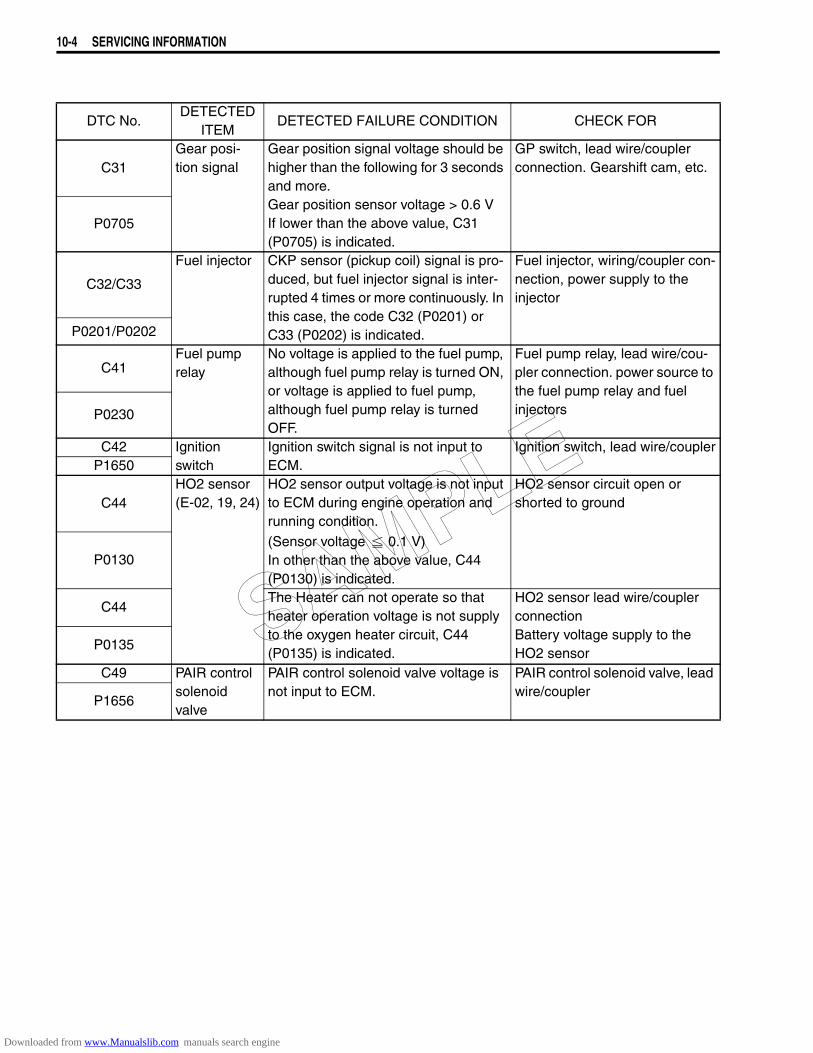
10-4 SERVICING INFORMATION
DTC No.DETECTED
ITEMDETECTED FAILURE CONDITION CHECK FOR
C31Gear posi-tion signal
Gear position signal voltage should be higher than the following for 3 seconds and more.Gear position sensor voltage > 0.6 VIf lower than the above value, C31 (P0705) is indicated.
GP switch, lead wire/coupler connection. Gearshift cam, etc.
P0705
C32/C33
Fuel injector CKP sensor (pickup coil) signal is pro-duced, but fuel injector signal is inter-rupted 4 times or more continuously. In this case, the code C32 (P0201) or C33 (P0202) is indicated.
Fuel injector, wiring/coupler con-nection, power supply to the injector
P0201/P0202
C41Fuel pump relay
No voltage is applied to the fuel pump, although fuel pump relay is turned ON, or voltage is applied to fuel pump, although fuel pump relay is turned OFF.
Fuel pump relay, lead wire/cou-pler connection. power source to the fuel pump relay and fuel injectorsP0230
C42 Ignition switch
Ignition switch signal is not input to ECM.
Ignition switch, lead wire/couplerP1650
C44HO2 sensor (E-02, 19, 24)
HO2 sensor output voltage is not input to ECM during engine operation and running condition.
(Sensor voltage 0.1 V)In other than the above value, C44 (P0130) is indicated.
HO2 sensor circuit open or shorted to ground
P0130
C44The Heater can not operate so that heater operation voltage is not supply to the oxygen heater circuit, C44 (P0135) is indicated.
HO2 sensor lead wire/coupler connectionBattery voltage supply to the HO2 sensor
P0135
C49 PAIR control solenoid valve
PAIR control solenoid valve voltage is not input to ECM.
PAIR control solenoid valve, lead wire/coupler
P1656
SAMPLE
Downloaded from www.Manualslib.com manuals search engine
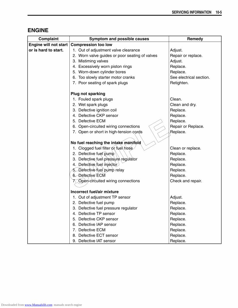
SERVICING INFORMATION 10-5
ENGINEComplaint Symptom and possible causes Remedy
Engine will not startor is hard to start.
Compression too low1. Out of adjustment valve clearance2. Worn valve guides or poor seating of valves3. Mistiming valves4. Excessively worn piston rings5. Worn-down cylinder bores6. Too slowly starter motor cranks7. Poor seating of spark plugs
Plug not sparking1. Fouled spark plugs2. Wet spark plugs3. Defective ignition coil4. Defective CKP sensor5. Defective ECM6. Open-circuited wiring connections7. Open or short in high-tension cords
No fuel reaching the intake manifold1. Clogged fuel filter or fuel hose2. Defective fuel pump3. Defective fuel pressure regulator4. Defective fuel injector5. Defective fuel pump relay6. Defective ECM7. Open-circuited wiring connections
Incorrect fuel/air mixture1. Out of adjustment TP sensor2. Defective fuel pump3. Defective fuel pressure regulator4. Defective TP sensor5. Defective CKP sensor6. Defective IAP sensor7. Defective ECM8. Defective ECT sensor9. Defective IAT sensor
Adjust.Repair or replace.Adjust.Replace.Replace.See electrical section.Retighten.
Clean.Clean and dry.Replace.Replace.Replace.Repair or Replace.Replace.
Clean or replace.Replace.Replace.Replace.Replace.Replace.Check and repair.
Adjust.Replace.Replace.Replace.Replace.Replace.Replace.Replace.Replace.
SAMPLE
Downloaded from www.Manualslib.com manuals search engine
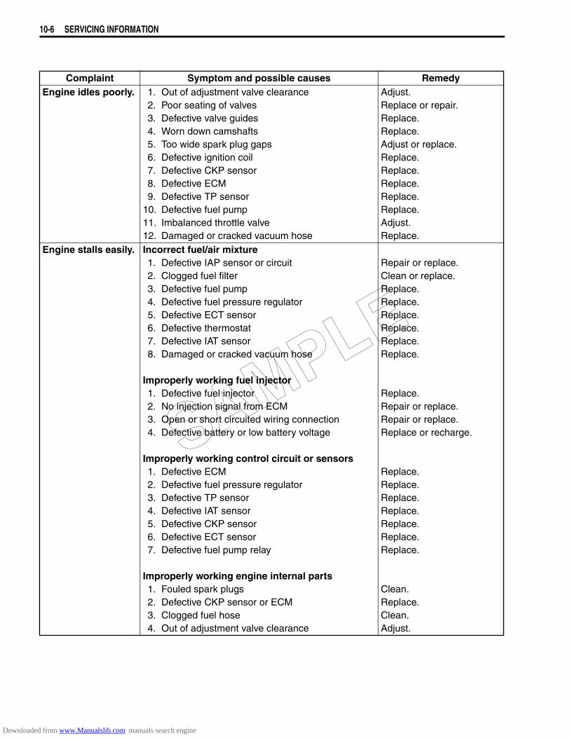
10-6 SERVICING INFORMATION
Complaint Symptom and possible causes RemedyEngine idles poorly. 1. Out of adjustment valve clearance
2. Poor seating of valves3. Defective valve guides4. Worn down camshafts5. Too wide spark plug gaps6. Defective ignition coil7. Defective CKP sensor8. Defective ECM9. Defective TP sensor
10. Defective fuel pump11. Imbalanced throttle valve12. Damaged or cracked vacuum hose
Adjust.Replace or repair.Replace.Replace.Adjust or replace.Replace.Replace.Replace.Replace.Replace.Adjust.Replace.
Engine stalls easily. Incorrect fuel/air mixture1. Defective IAP sensor or circuit2. Clogged fuel filter3. Defective fuel pump4. Defective fuel pressure regulator5. Defective ECT sensor6. Defective thermostat7. Defective IAT sensor8. Damaged or cracked vacuum hose
Improperly working fuel injector1. Defective fuel injector2. No injection signal from ECM3. Open or short circuited wiring connection4. Defective battery or low battery voltage
Improperly working control circuit or sensors1. Defective ECM2. Defective fuel pressure regulator3. Defective TP sensor4. Defective IAT sensor5. Defective CKP sensor6. Defective ECT sensor7. Defective fuel pump relay
Improperly working engine internal parts1. Fouled spark plugs2. Defective CKP sensor or ECM3. Clogged fuel hose4. Out of adjustment valve clearance
Repair or replace.Clean or replace.Replace.Replace.Replace.Replace.Replace.Replace.
Replace.Repair or replace.Repair or replace.Replace or recharge.
Replace.Replace.Replace.Replace.Replace.Replace.Replace.
Clean.Replace.Clean.Adjust.
SAMPLE
Downloaded from www.Manualslib.com manuals search engine
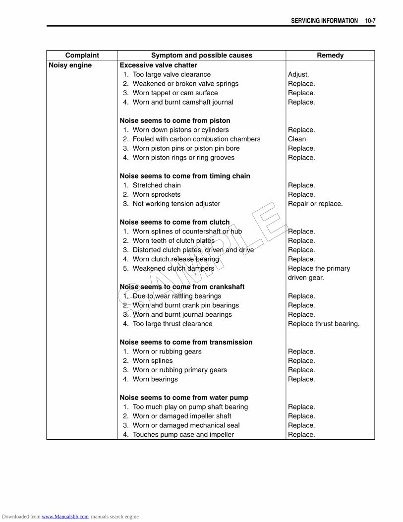
SERVICING INFORMATION 10-7
Complaint Symptom and possible causes RemedyNoisy engine Excessive valve chatter
1. Too large valve clearance2. Weakened or broken valve springs3. Worn tappet or cam surface4. Worn and burnt camshaft journal
Noise seems to come from piston1. Worn down pistons or cylinders2. Fouled with carbon combustion chambers3. Worn piston pins or piston pin bore4. Worn piston rings or ring grooves
Noise seems to come from timing chain1. Stretched chain2. Worn sprockets3. Not working tension adjuster
Noise seems to come from clutch1. Worn splines of countershaft or hub2. Worn teeth of clutch plates3. Distorted clutch plates, driven and drive4. Worn clutch release bearing5. Weakened clutch dampers
Noise seems to come from crankshaft1. Due to wear rattling bearings2. Worn and burnt crank pin bearings3. Worn and burnt journal bearings4. Too large thrust clearance
Noise seems to come from transmission1. Worn or rubbing gears2. Worn splines3. Worn or rubbing primary gears4. Worn bearings
Noise seems to come from water pump1. Too much play on pump shaft bearing2. Worn or damaged impeller shaft3. Worn or damaged mechanical seal4. Touches pump case and impeller
Adjust.Replace.Replace.Replace.
Replace.Clean.Replace.Replace.
Replace.Replace.Repair or replace.
Replace.Replace.Replace.Replace.Replace the primarydriven gear.
Replace.Replace.Replace.Replace thrust bearing.
Replace.Replace.Replace.Replace.
Replace.Replace.Replace.Replace.
SAMPLE
Downloaded from www.Manualslib.com manuals search engine
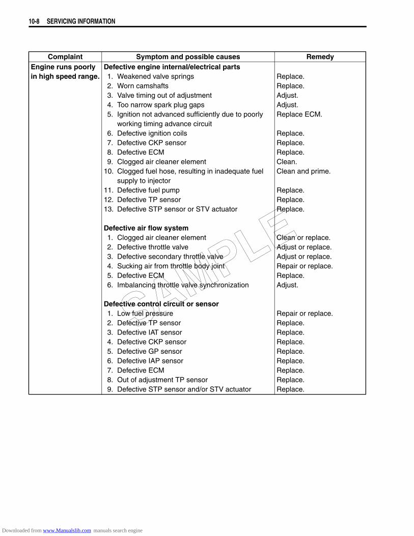
10-8 SERVICING INFORMATION
Complaint Symptom and possible causes RemedyEngine runs poorly in high speed range.
Defective engine internal/electrical parts1. Weakened valve springs2. Worn camshafts3. Valve timing out of adjustment4. Too narrow spark plug gaps5. Ignition not advanced sufficiently due to poorly
working timing advance circuit6. Defective ignition coils7. Defective CKP sensor8. Defective ECM9. Clogged air cleaner element
10. Clogged fuel hose, resulting in inadequate fuelsupply to injector
11. Defective fuel pump12. Defective TP sensor13. Defective STP sensor or STV actuator
Defective air flow system1. Clogged air cleaner element2. Defective throttle valve3. Defective secondary throttle valve4. Sucking air from throttle body joint5. Defective ECM6. Imbalancing throttle valve synchronization
Defective control circuit or sensor1. Low fuel pressure2. Defective TP sensor3. Defective IAT sensor4. Defective CKP sensor5. Defective GP sensor6. Defective IAP sensor7. Defective ECM8. Out of adjustment TP sensor9. Defective STP sensor and/or STV actuator
Replace.Replace.Adjust.Adjust.Replace ECM.
Replace.Replace.Replace.Clean.Clean and prime.
Replace.Replace.Replace.
Clean or replace.Adjust or replace.Adjust or replace.Repair or replace.Replace.Adjust.
Repair or replace.Replace.Replace.Replace.Replace.Replace.Replace.Replace.Replace.
SAMPLE
Downloaded from www.Manualslib.com manuals search engine
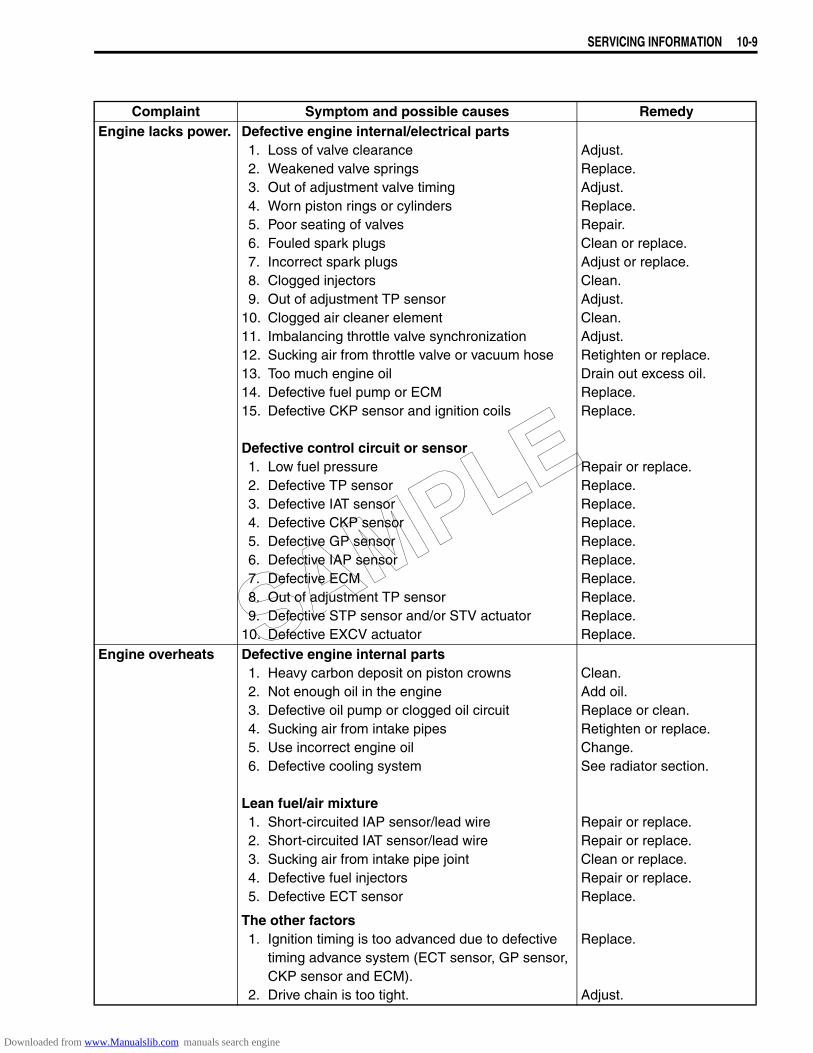
SERVICING INFORMATION 10-9
Complaint Symptom and possible causes RemedyEngine lacks power. Defective engine internal/electrical parts
1. Loss of valve clearance2. Weakened valve springs3. Out of adjustment valve timing4. Worn piston rings or cylinders5. Poor seating of valves6. Fouled spark plugs7. Incorrect spark plugs8. Clogged injectors9. Out of adjustment TP sensor
10. Clogged air cleaner element11. Imbalancing throttle valve synchronization12. Sucking air from throttle valve or vacuum hose13. Too much engine oil14. Defective fuel pump or ECM15. Defective CKP sensor and ignition coils
Defective control circuit or sensor1. Low fuel pressure2. Defective TP sensor3. Defective IAT sensor4. Defective CKP sensor5. Defective GP sensor6. Defective IAP sensor7. Defective ECM8. Out of adjustment TP sensor9. Defective STP sensor and/or STV actuator
10. Defective EXCV actuator
Adjust.Replace.Adjust.Replace.Repair.Clean or replace.Adjust or replace.Clean.Adjust.Clean.Adjust.Retighten or replace.Drain out excess oil.Replace.Replace.
Repair or replace.Replace.Replace.Replace.Replace.Replace.Replace.Replace.Replace.Replace.
Engine overheats Defective engine internal parts1. Heavy carbon deposit on piston crowns2. Not enough oil in the engine3. Defective oil pump or clogged oil circuit4. Sucking air from intake pipes5. Use incorrect engine oil6. Defective cooling system
Lean fuel/air mixture1. Short-circuited IAP sensor/lead wire2. Short-circuited IAT sensor/lead wire3. Sucking air from intake pipe joint4. Defective fuel injectors5. Defective ECT sensor
The other factors1. Ignition timing is too advanced due to defective
timing advance system (ECT sensor, GP sensor, CKP sensor and ECM).
2. Drive chain is too tight.
Clean.Add oil.Replace or clean.Retighten or replace.Change.See radiator section.
Repair or replace.Repair or replace.Clean or replace.Repair or replace.Replace.
Replace.
Adjust.
SAMPLE
Downloaded from www.Manualslib.com manuals search engine
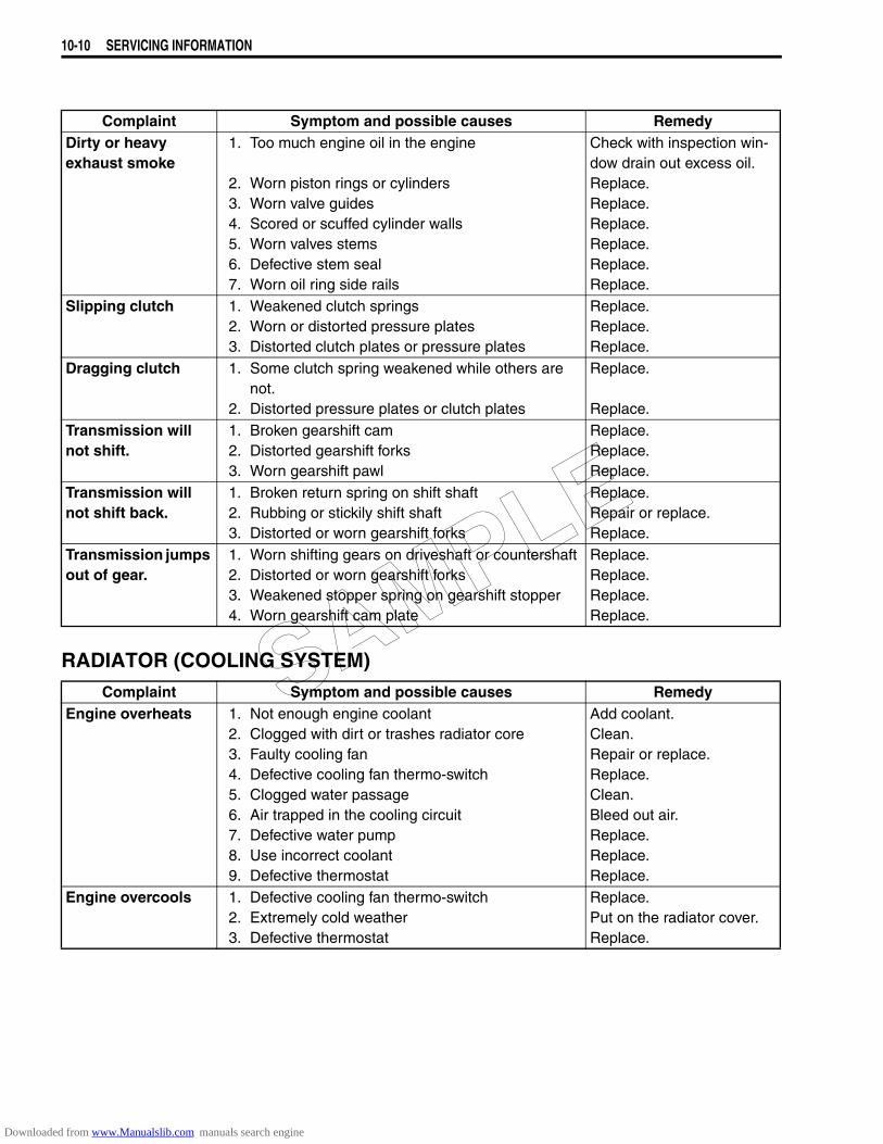
10-10 SERVICING INFORMATION
RADIATOR (COOLING SYSTEM)
Complaint Symptom and possible causes RemedyDirty or heavy exhaust smoke
1. Too much engine oil in the engine
2. Worn piston rings or cylinders3. Worn valve guides4. Scored or scuffed cylinder walls5. Worn valves stems6. Defective stem seal7. Worn oil ring side rails
Check with inspection win-dow drain out excess oil.Replace.Replace.Replace.Replace.Replace.Replace.
Slipping clutch 1. Weakened clutch springs2. Worn or distorted pressure plates3. Distorted clutch plates or pressure plates
Replace.Replace.Replace.
Dragging clutch 1. Some clutch spring weakened while others are not.
2. Distorted pressure plates or clutch plates
Replace.
Replace.Transmission willnot shift.
1. Broken gearshift cam2. Distorted gearshift forks3. Worn gearshift pawl
Replace.Replace.Replace.
Transmission willnot shift back.
1. Broken return spring on shift shaft2. Rubbing or stickily shift shaft3. Distorted or worn gearshift forks
Replace.Repair or replace.Replace.
Transmission jumps out of gear.
1. Worn shifting gears on driveshaft or countershaft2. Distorted or worn gearshift forks3. Weakened stopper spring on gearshift stopper4. Worn gearshift cam plate
Replace.Replace.Replace.Replace.
Complaint Symptom and possible causes RemedyEngine overheats 1. Not enough engine coolant
2. Clogged with dirt or trashes radiator core3. Faulty cooling fan4. Defective cooling fan thermo-switch5. Clogged water passage6. Air trapped in the cooling circuit7. Defective water pump8. Use incorrect coolant9. Defective thermostat
Add coolant.Clean.Repair or replace.Replace.Clean.Bleed out air.Replace.Replace.Replace.
Engine overcools 1. Defective cooling fan thermo-switch2. Extremely cold weather3. Defective thermostat
Replace.Put on the radiator cover.Replace.
SAMPLE
Downloaded from www.Manualslib.com manuals search engine
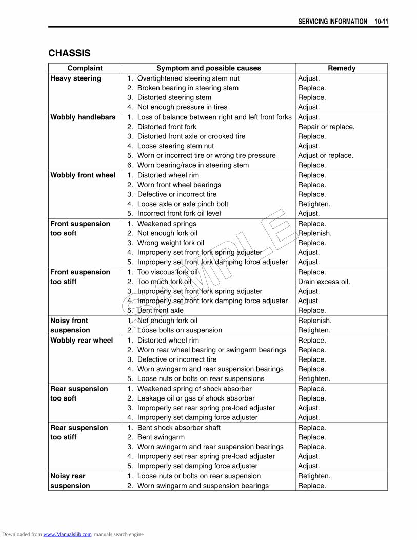
SERVICING INFORMATION 10-11
CHASSISComplaint Symptom and possible causes Remedy
Heavy steering 1. Overtightened steering stem nut2. Broken bearing in steering stem3. Distorted steering stem4. Not enough pressure in tires
Adjust.Replace.Replace.Adjust.
Wobbly handlebars 1. Loss of balance between right and left front forks2. Distorted front fork3. Distorted front axle or crooked tire4. Loose steering stem nut5. Worn or incorrect tire or wrong tire pressure6. Worn bearing/race in steering stem
Adjust.Repair or replace.Replace.Adjust.Adjust or replace.Replace.
Wobbly front wheel 1. Distorted wheel rim2. Worn front wheel bearings3. Defective or incorrect tire4. Loose axle or axle pinch bolt5. Incorrect front fork oil level
Replace.Replace.Replace.Retighten.Adjust.
Front suspension too soft
1. Weakened springs2. Not enough fork oil3. Wrong weight fork oil4. Improperly set front fork spring adjuster5. Improperly set front fork damping force adjuster
Replace.Replenish.Replace.Adjust.Adjust.
Front suspension too stiff
1. Too viscous fork oil2. Too much fork oil3. Improperly set front fork spring adjuster4. Improperly set front fork damping force adjuster5. Bent front axle
Replace.Drain excess oil.Adjust.Adjust.Replace.
Noisy front suspension
1. Not enough fork oil2. Loose bolts on suspension
Replenish.Retighten.
Wobbly rear wheel 1. Distorted wheel rim2. Worn rear wheel bearing or swingarm bearings3. Defective or incorrect tire4. Worn swingarm and rear suspension bearings5. Loose nuts or bolts on rear suspensions
Replace.Replace.Replace.Replace.Retighten.
Rear suspension too soft
1. Weakened spring of shock absorber2. Leakage oil or gas of shock absorber3. Improperly set rear spring pre-load adjuster4. Improperly set damping force adjuster
Replace.Replace.Adjust.Adjust.
Rear suspension too stiff
1. Bent shock absorber shaft2. Bent swingarm3. Worn swingarm and rear suspension bearings4. Improperly set rear spring pre-load adjuster5. Improperly set damping force adjuster
Replace.Replace.Replace.Adjust.Adjust.
Noisy rear suspension
1. Loose nuts or bolts on rear suspension2. Worn swingarm and suspension bearings
Retighten.Replace.
SAMPLE
Downloaded from www.Manualslib.com manuals search engine

10-12 SERVICING INFORMATION
SHAFT DRIVE
BRAKES
Complaint Symptom and possible causes RemedyNoisy shaft drive Noise seems to come from secondary bevel gear
and final bevel gear assemblies.1. Oil level too low
2. Drive and driven bevel gears damaged or worn3. Excessive backlash4. Improper tooth contact5. Damage to bearings
Refill.(Check oil jet./Replace oil seal.)Replace.Adjust.Adjust.Replace.
Noise seems to come from propeller shaft area.1. Propeller shaft universal joint damaged2. Propeller shaft splines damaged or worn3. Insufficient lubricant4. Cam dog contacting surface damaged or worn
Replace.Replace.Refill. (Replace oil seal.)Replace.
Complaint Symptom and possible causes RemedyInsufficient brake power
1. Leakage of brake fluid from hydraulic system2. Worn pads3. Oil adhesion of engaging surface of pads/shoe4. Worn disc5. Air in hydraulic system6. Not enough brake fluid in the reservoir
Repair or replace.Replace.Clean disc and pads.Replace.Bleed air.Replenish.
Brake squeaking 1. Carbon adhesion on pad surface
2. Tilted pad
3. Damaged wheel bearing4. Loosen front-wheel axle or rear-wheel axle
5. Worn pads6. Foreign material in brake fluid7. Clogged return port of master cylinder
Repair surface withsandpaper.Modify pad fitting or replace.Replace.Tighten to specifiedtorque.Replace.Replace brake fluid.Disassemble andclean master cylinder.
Excessive brake lever stroke
1. Air in hydraulic system2. Insufficient brake fluid
3. Improper quality of brake fluid
Bleed air.Replenish fluid to specified level; bleed air.Replace with correct fluid.
Leakage of brake fluid
1. Insufficient tightening of connection joints2. Cracked hose3. Worn piston and/or cup
Tighten to specified torque.Replace.Replace piston and/or cup.
Brake drags 1. Rusty part2. Insufficient brake lever or brake pedal pivot lubri-
cation
Clean and lubricate.Lubricate.
SAMPLE
Downloaded from www.Manualslib.com manuals search engine

SERVICING INFORMATION 10-13
ELECTRICALComplaint Symptom and possible causes Remedy
No sparking or poor sparking
1. Defective ignition coils or CKP sensor2. Defective spark plugs3. Defective ECM4. Defective tip over sensor5. Open-circuited wiring connections
Replace.Replace.Replace.Replace.Check and repair.
Spark plug soon become fouled with carbon.
1. Mixture too rich2. Idling speed set too high
3. Incorrect gasoline4. Dirty element in air cleaner5. Too cold spark plugs
Inspect FI system.Adjust fast idle or throttle stop screw.Change.Clean or replace.Replace with hot type plug.
Spark plug become fouled too soon.
1. Worn piston rings2. Worn piston or cylinders3. Excessive clearance of valve stems in valve
guides4. Worn stem oil seal
Replace.Replace.Replace.
Replace.Spark plug elec-trodes overheat or burn.
1. Too hot spark plugs
2. Overheated engine3. Loose spark plugs4. Too lean mixture
Replace with cold type plugs.Tune-up.Retighten.Inspect FI system.
Generator does not charge.
1. Open or short lead wires, or loose lead connec-tions.
2. Shorted, grounded or open generator coils3. Shorted or punctured regulator/rectifier
Repair or replace or retighten.Replace.Replace.
Generator does charge, but charg-ing rate is below the specification.
1. Lead wires tend to get shorted or open-circuited or loosely connected at terminals
2. Grounded or open-circuited generator coils or generator
3. Defective regulator/rectifier4. Defective cell plates in the battery
Repair or retighten.
Replace.
Replace.Replace the battery.
Generator overcharges
1. Internal short-circuit in the battery2. Damaged or defective regulator/rectifier3. Poorly grounded regulator/rectifier
Replace the battery.Replace.Repair, replace, orconnect properly.
Unstable charging 1. Lead wire insulation frayed due to vibration, resulting in intermittent shorting
2. Internally shorted generator3. Defective regulator/rectifier
Repair or replace.
Replace.Replace.
Starter button is not effective.
1. Run down battery2. Defective switch contacts3. Not seating properly brushes on commutator in
starter motor4. Defective starter relay/starter interlock switch5. Defective main fuse
Repair or replace.Replace.Repair or replace.
Replace.Replace.
SAMPLE
Downloaded from www.Manualslib.com manuals search engine
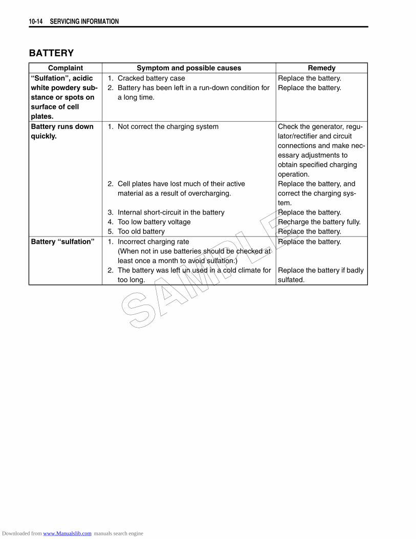
10-14 SERVICING INFORMATION
BATTERYComplaint Symptom and possible causes Remedy
“Sulfation”, acidic white powdery sub-stance or spots on surface of cell plates.
1. Cracked battery case2. Battery has been left in a run-down condition for
a long time.
Replace the battery.Replace the battery.
Battery runs down quickly.
1. Not correct the charging system
2. Cell plates have lost much of their activematerial as a result of overcharging.
3. Internal short-circuit in the battery4. Too low battery voltage5. Too old battery
Check the generator, regu-lator/rectifier and circuit connections and make nec-essary adjustments to obtain specified charging operation.Replace the battery, and correct the charging sys-tem.Replace the battery.Recharge the battery fully.Replace the battery.
Battery “sulfation” 1. Incorrect charging rate(When not in use batteries should be checked atleast once a month to avoid sulfation.)
2. The battery was left un used in a cold climate fortoo long.
Replace the battery.
Replace the battery if badly sulfated.
SAMPLE
Downloaded from www.Manualslib.com manuals search engine
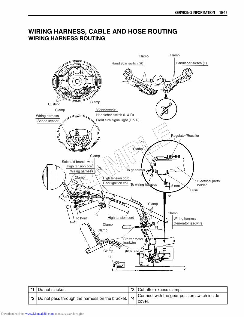
SERVICING INFORMATION 10-15
WIRING HARNESS, CABLE AND HOSE ROUTINGWIRING HARNESS ROUTING
Regulator/Rectifier
Electrical partsholder
Fuse
Wiring harnessGenerator leadwire
Clamp
Clamp
Clamp
Wiring harnessFront turn signal light (L & R)
Handlebar switch (L & R)
Speed sensor
Starter motorleadwire
*3
Clamp
Speedometer
5 mm
Clamp
Handlebar switch (R)
Clamp
Handlebar switch (L)
Clamp
Cushion
Clamp
To generatorTogenerator
To wiring harnessTo wiring harness
To horn
Wiring harness
Solenoid branch wireHigh tension cord
Clamp
Clamp
Rear ignition coilHigh tension cord
High tension cord
Clamp
Clamp
Clamp
*2
*1
*4
To generator
*1 Do not slacker. *3 Cut after excess clamp.
*2 Do not pass through the harness on the bracket. *4Connect with the gear position switch inside cover.
SAMPLE
Downloaded from www.Manualslib.com manuals search engine
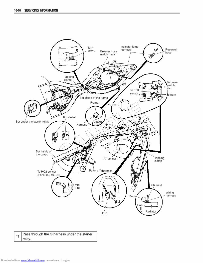
10-16 SERVICING INFORMATION
To brakeswitch,etc.
To HornTo horn
Resorvoirhose
Indicator lampharness
Breaser hosematch mark
Set inside of the frame.
Tappingclamp
Frame
Harness Tappingclamp
IAT sensor
Battery harness
Horn
FrameWiringharness
Radiator
FWD
Shuroud
Tappingclamp
Turndown.
Set under the starter relay.
*1
TO sensor
Set inside ofthe cover.
To HO2 sensor(For E-02, 19, 24)
To ECT sensor
Cleaner
No use.
28 mm(1.1 in)
*1Pass through the ⊕ harness under the starter relay.
SAMPLE
Downloaded from www.Manualslib.com manuals search engine
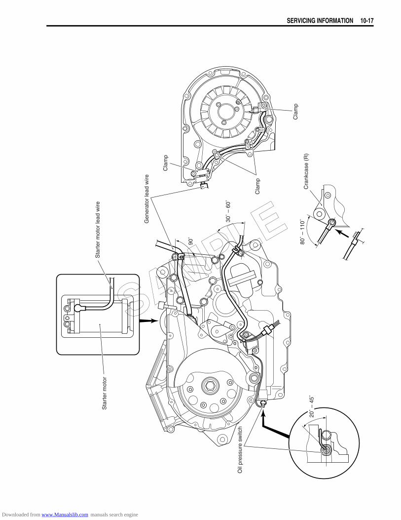
SERVICING INFORMATION 10-17
Sta
rter
mot
or
Oil
pres
sure
sw
itch
Sta
rter
mot
or le
ad w
ire
80˚
– 11
0˚30˚
– 60
˚
90˚
Cra
nkca
se (
R)
Cla
mp
Cla
mp
Cla
mp
Gen
erat
or le
ad w
ire
20˚
– 45
˚SAMPLE
Downloaded from www.Manualslib.com manuals search engine

10-18 SERVICING INFORMATION
CABLE ROUTING
*1Set the clutch cable dented part and clamp the clutch cable at white tape of cable.
*4 Clamp the back side of cushion.
*2 Clamp with this direction. *5 Do not hang the clamp on the bar.*3 Clamp the clutch cable attach to the cushion. *6 Clamp inside the bar.
Clutchcable*3
Guide
Throttle cable No. 1
Throttle cable No. 2
Clip
Whitetape
Clutch cable
Clutch cable
0 – 2 mm
0 – 2 mm
Solenoid harness
High-tension cord
Clutch cable
*4
*2
*2
*5
*2
*6
*1
High-tensioncord
High-tension cord
Throttlecable No. 1
HarnessGuide
Throttle cable No. 2
Fuel tank cushion bar
150 mm
Clutch cableUP
Outside
UP
Outside
UP
Outside
Frame
Frame
Clamp
Clamp Cushion
SAMPLE
Downloaded from www.Manualslib.com manuals search engine
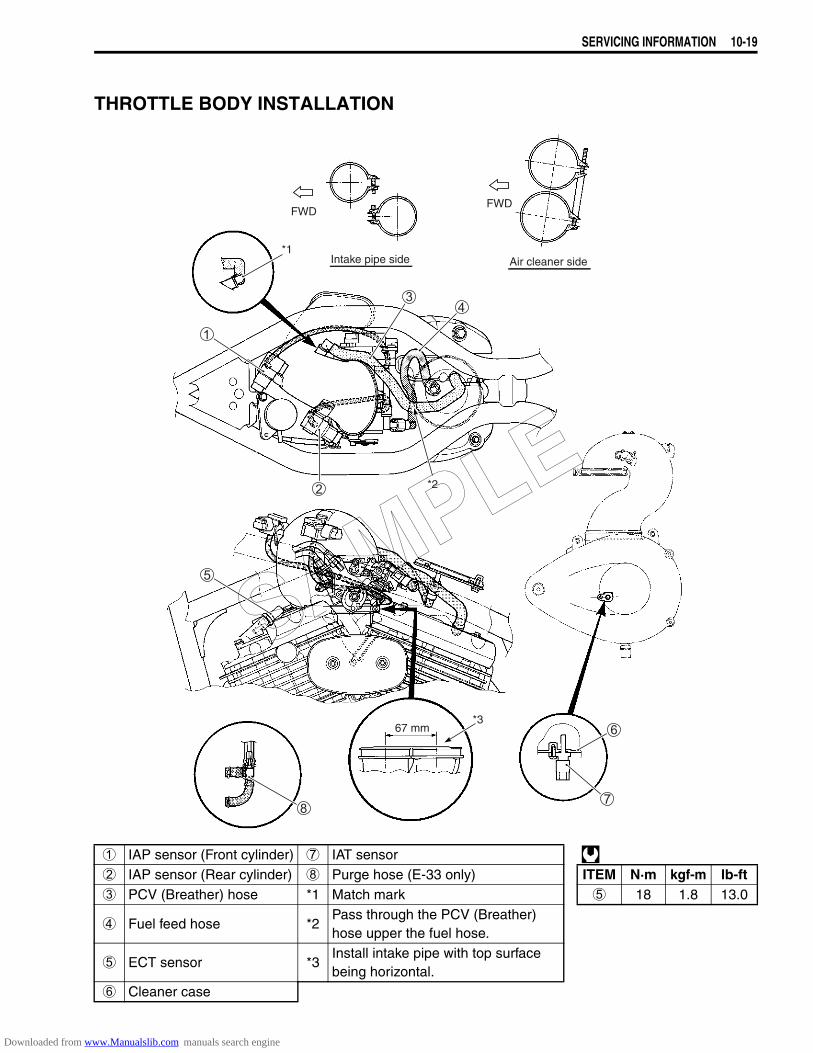
SERVICING INFORMATION 10-19
THROTTLE BODY INSTALLATION
1 IAP sensor (Front cylinder) 7 IAT sensor 2 IAP sensor (Rear cylinder) 8 Purge hose (E-33 only) ITEM N·m kgf-m lb-ft3 PCV (Breather) hose *1 Match mark 5 18 1.8 13.0
4 Fuel feed hose *2Pass through the PCV (Breather) hose upper the fuel hose.
5 ECT sensor *3Install intake pipe with top surface being horizontal.
6 Cleaner case
*1Intake pipe side Air cleaner side
FWDFWD
*2
*367 mm
SAMPLE
Downloaded from www.Manualslib.com manuals search engine
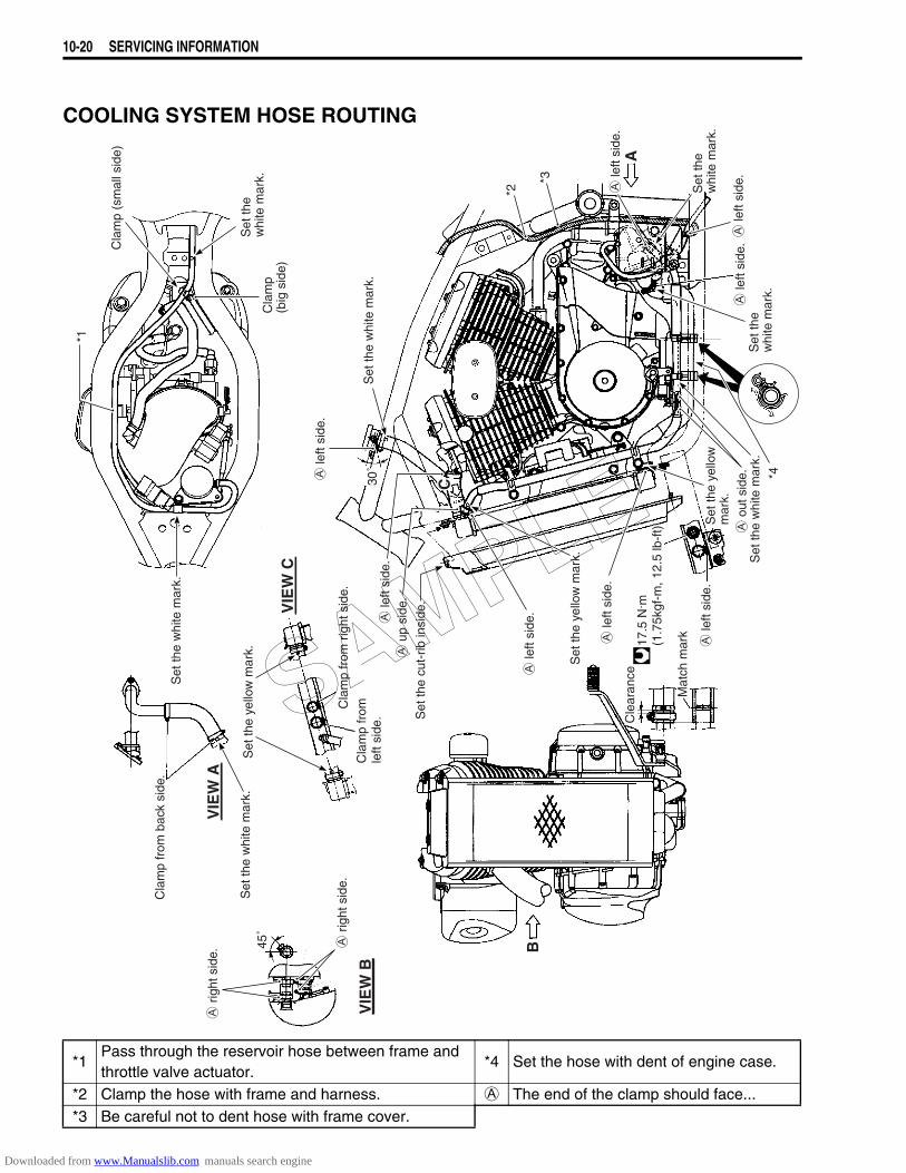
10-20 SERVICING INFORMATION
COOLING SYSTEM HOSE ROUTING
*1Pass through the reservoir hose between frame and throttle valve actuator.
*4 Set the hose with dent of engine case.
*2 Clamp the hose with frame and harness. A The end of the clamp should face...*3 Be careful not to dent hose with frame cover.
Set
the
whi
te m
ark.
le
ft si
de.
le
ft si
de.
le
ft si
de.
Set
the
whi
te m
ark.
Set
the
whi
te m
ark.
le
ft si
de.
o
ut s
ide.
Set
the
whi
te m
ark.
le
ft si
de.
Set
the
yello
wm
ark.
Cle
aran
ce
Mat
ch m
ark
Set
the
yello
w m
ark.
Cla
mp
from
left
side
.
Set
the
whi
te m
ark.
Cla
mp
from
bac
k si
de.
Cla
mp
from
rig
ht s
ide.
45˚
r
ight
sid
e.
r
ight
sid
e.
Set
the
whi
te m
ark.
VIE
W B
B
A
VIE
W A
CC
VIE
W C
Cla
mp
(sm
all s
ide)
Cla
mp
(big
sid
e)
Set
the
whi
te m
ark.
Set
the
cut-
rib in
side
.
17.5
N. m
(1
.75k
gf-m
, 12.
5 lb
-ft)
Set
the
yello
w m
ark.
le
ft si
de.
u
p si
de.
le
ft si
de.
*1
*2
*3
*4
le
ft si
de.
30˚
SAMPLE
Downloaded from www.Manualslib.com manuals search engine
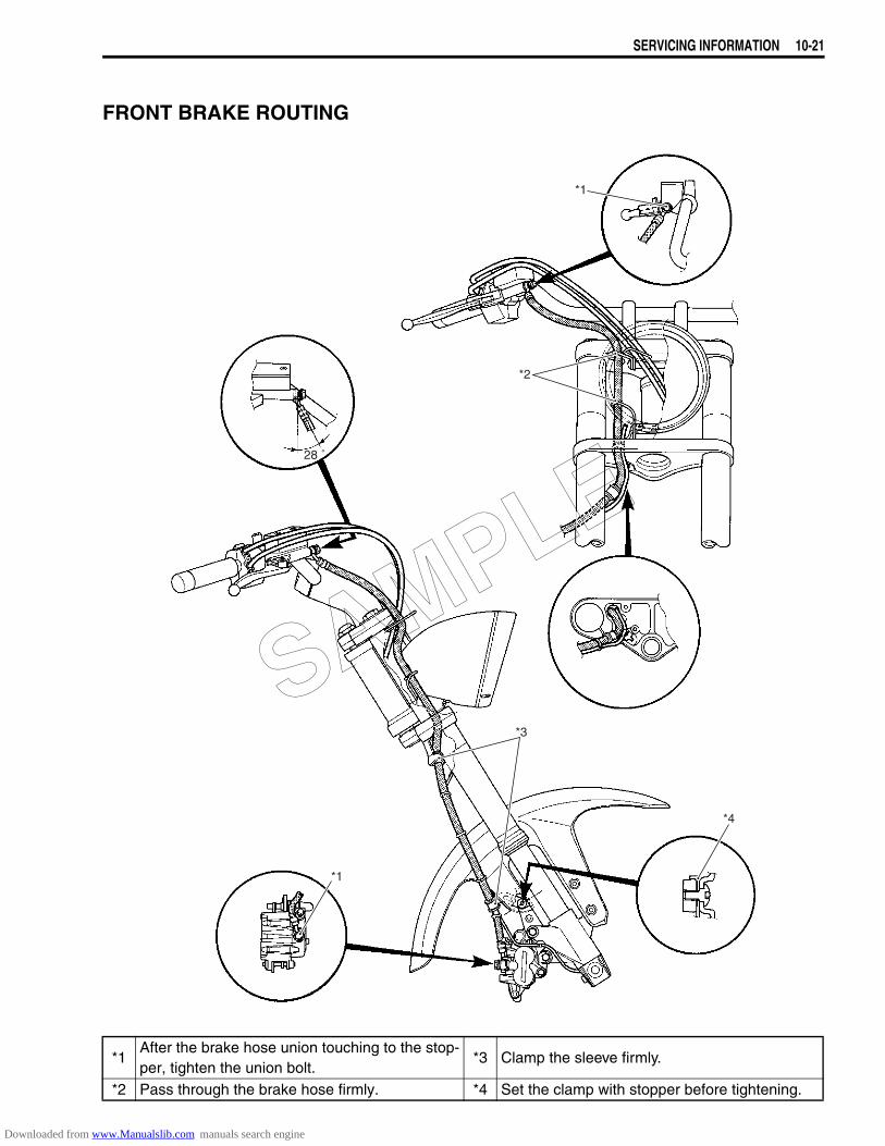
SERVICING INFORMATION 10-21
FRONT BRAKE ROUTING
*1After the brake hose union touching to the stop-per, tighten the union bolt.
*3 Clamp the sleeve firmly.
*2 Pass through the brake hose firmly. *4 Set the clamp with stopper before tightening.
28 ˚
*3
*1
*2
*1
*4
SAMPLE
Downloaded from www.Manualslib.com manuals search engine
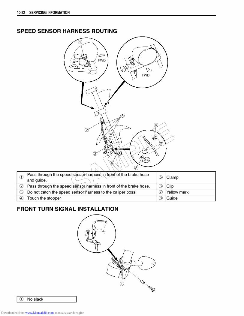
10-22 SERVICING INFORMATION
SPEED SENSOR HARNESS ROUTING
FRONT TURN SIGNAL INSTALLATION
1Pass through the speed sensor harness in front of the brake hose and guide.
5 Clamp
2 Pass through the speed sensor harness in front of the brake hose. 6 Clip3 Do not catch the speed sensor harness to the caliper boss. 7 Yellow mark4 Touch the stopper 8 Guide
1 No slack
FWD
FWD
SAMPLE
Downloaded from www.Manualslib.com manuals search engine
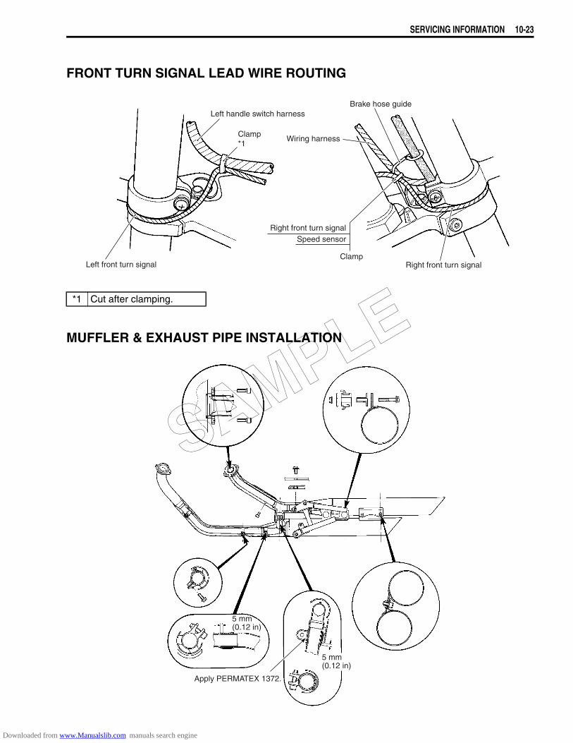
SERVICING INFORMATION 10-23
FRONT TURN SIGNAL LEAD WIRE ROUTING
MUFFLER & EXHAUST PIPE INSTALLATION
*1 Cut after clamping.
Clamp*1
Left handle switch harnessBrake hose guide
Right front turn signalClamp
Right front turn signalSpeed sensor
Wiring harness
Left front turn signal
Apply PERMATEX 1372.
5 mm(0.12 in)
5 mm(0.12 in)
SAMPLE
Downloaded from www.Manualslib.com manuals search engine
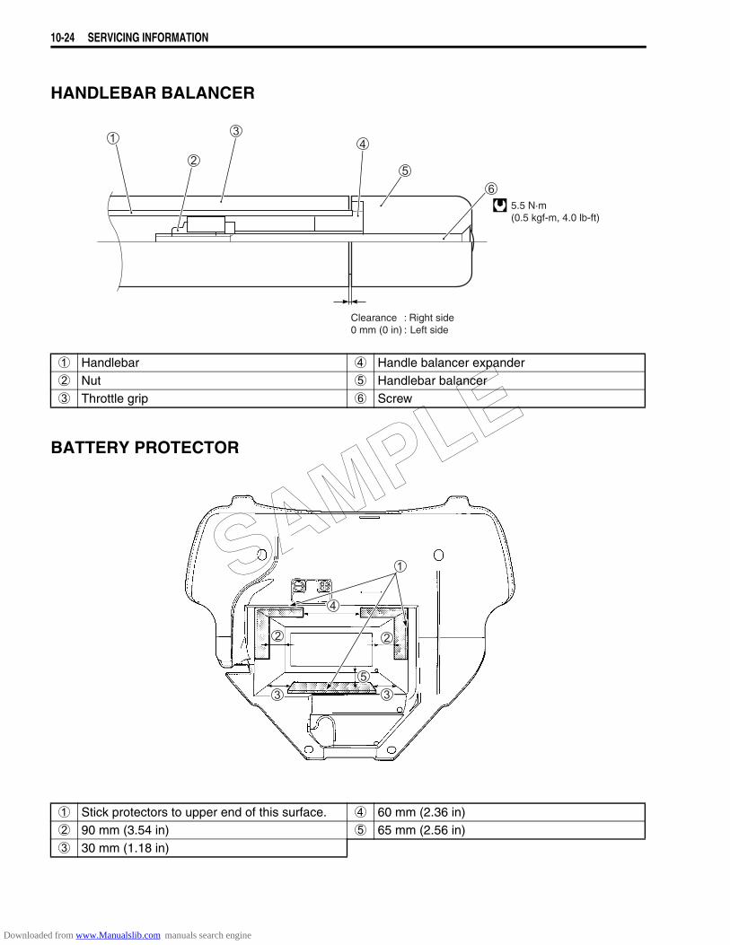
10-24 SERVICING INFORMATION
HANDLEBAR BALANCER
BATTERY PROTECTOR
1 Handlebar 4 Handle balancer expander2 Nut 5 Handlebar balancer3 Throttle grip 6 Screw
1 Stick protectors to upper end of this surface. 4 60 mm (2.36 in)2 90 mm (3.54 in) 5 65 mm (2.56 in)3 30 mm (1.18 in)
5.5 N·m(0.5 kgf-m, 4.0 lb-ft)
Clearance : Right side0 mm (0 in) : Left side
SAMPLE
Downloaded from www.Manualslib.com manuals search engine
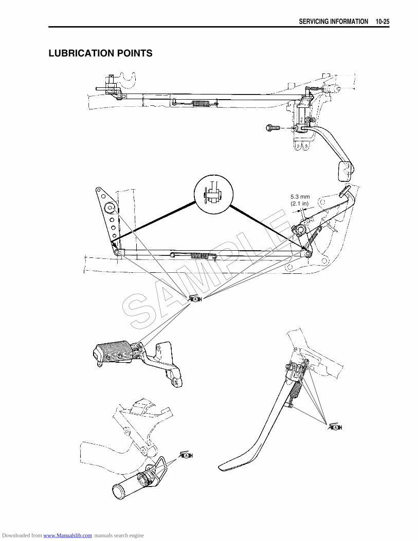
SERVICING INFORMATION 10-25
LUBRICATION POINTS
5.3 mm(2.1 in)
SAMPLE
Downloaded from www.Manualslib.com manuals search engine
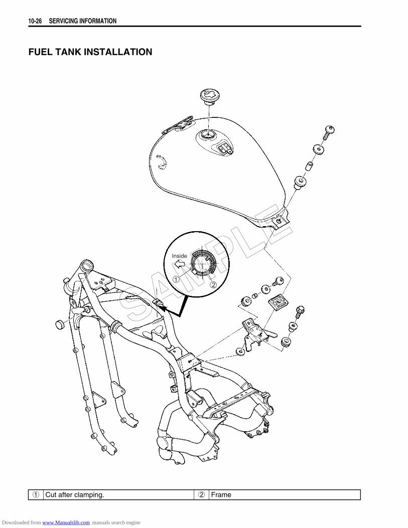
10-26 SERVICING INFORMATION
FUEL TANK INSTALLATION
1 Cut after clamping. 2 Frame
Inside
SAMPLE
Downloaded from www.Manualslib.com manuals search engine
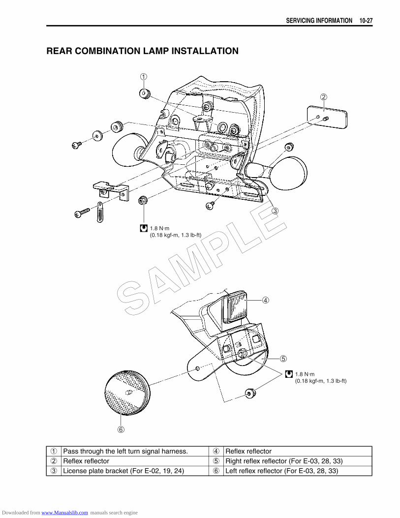
SERVICING INFORMATION 10-27
REAR COMBINATION LAMP INSTALLATION
1 Pass through the left turn signal harness. 4 Reflex reflector2 Reflex reflector 5 Right reflex reflector (For E-03, 28, 33)3 License plate bracket (For E-02, 19, 24) 6 Left reflex reflector (For E-03, 28, 33)
1.8 N.m(0.18 kgf-m, 1.3 lb-ft)
1.8 N.m(0.18 kgf-m, 1.3 lb-ft)
SAMPLE
Downloaded from www.Manualslib.com manuals search engine
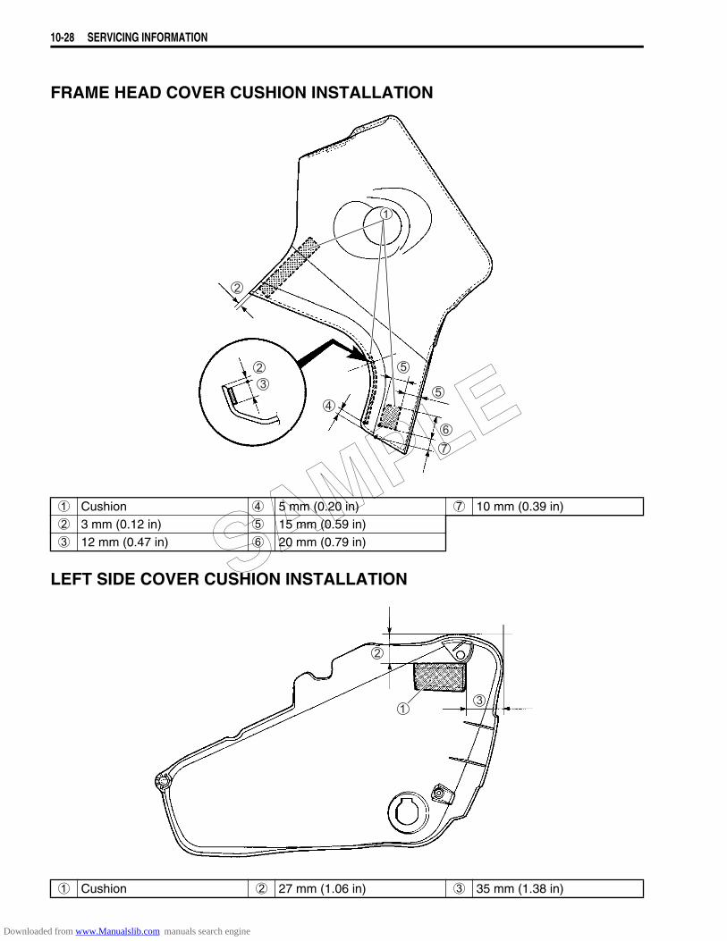
10-28 SERVICING INFORMATION
FRAME HEAD COVER CUSHION INSTALLATION
LEFT SIDE COVER CUSHION INSTALLATION
1 Cushion 4 5 mm (0.20 in) 7 10 mm (0.39 in)2 3 mm (0.12 in) 5 15 mm (0.59 in)3 12 mm (0.47 in) 6 20 mm (0.79 in)
1 Cushion 2 27 mm (1.06 in) 3 35 mm (1.38 in)
SAMPLE
Downloaded from www.Manualslib.com manuals search engine
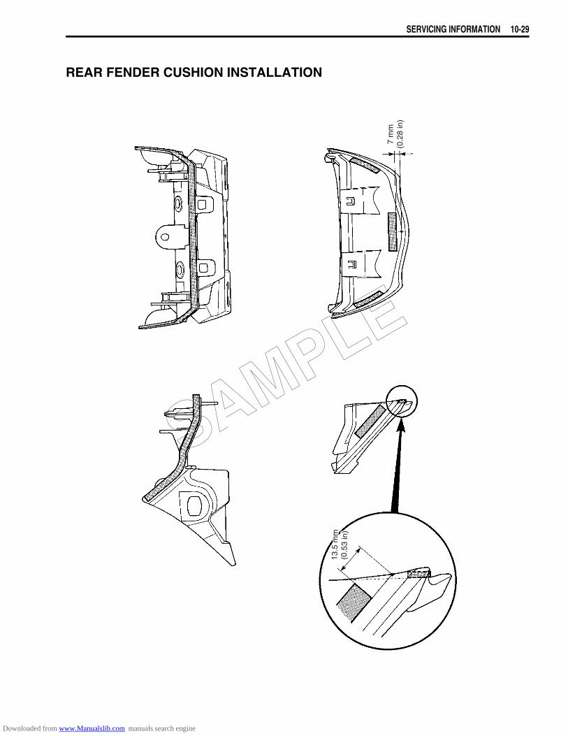
SERVICING INFORMATION 10-29
REAR FENDER CUSHION INSTALLATION
7 m
m(0
.28
in)
13.5
mm
(0.5
3 in
)
SAMPLE
Downloaded from www.Manualslib.com manuals search engine

10-30 SERVICING INFORMATION
LEFT SIDE COVER INSTALLATION
SAMPLE
Downloaded from www.Manualslib.com manuals search engine
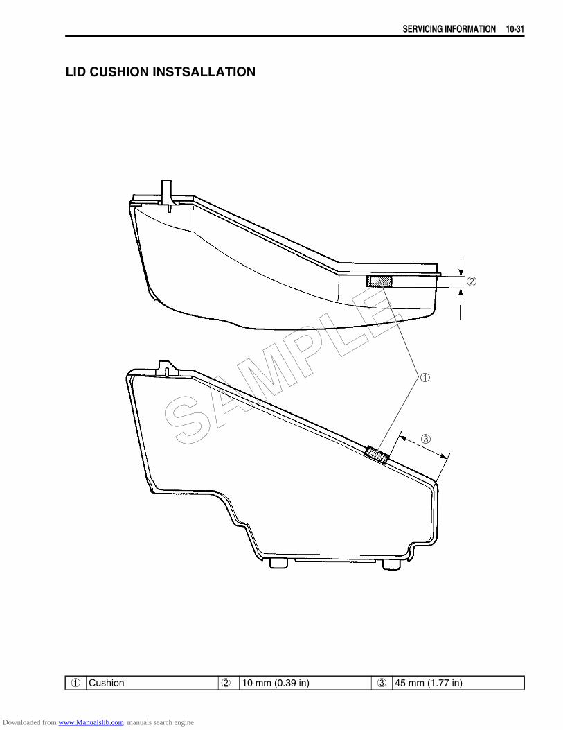
SERVICING INFORMATION 10-31
LID CUSHION INSTSALLATION
1 Cushion 2 10 mm (0.39 in) 3 45 mm (1.77 in)
SAMPLE
Downloaded from www.Manualslib.com manuals search engine
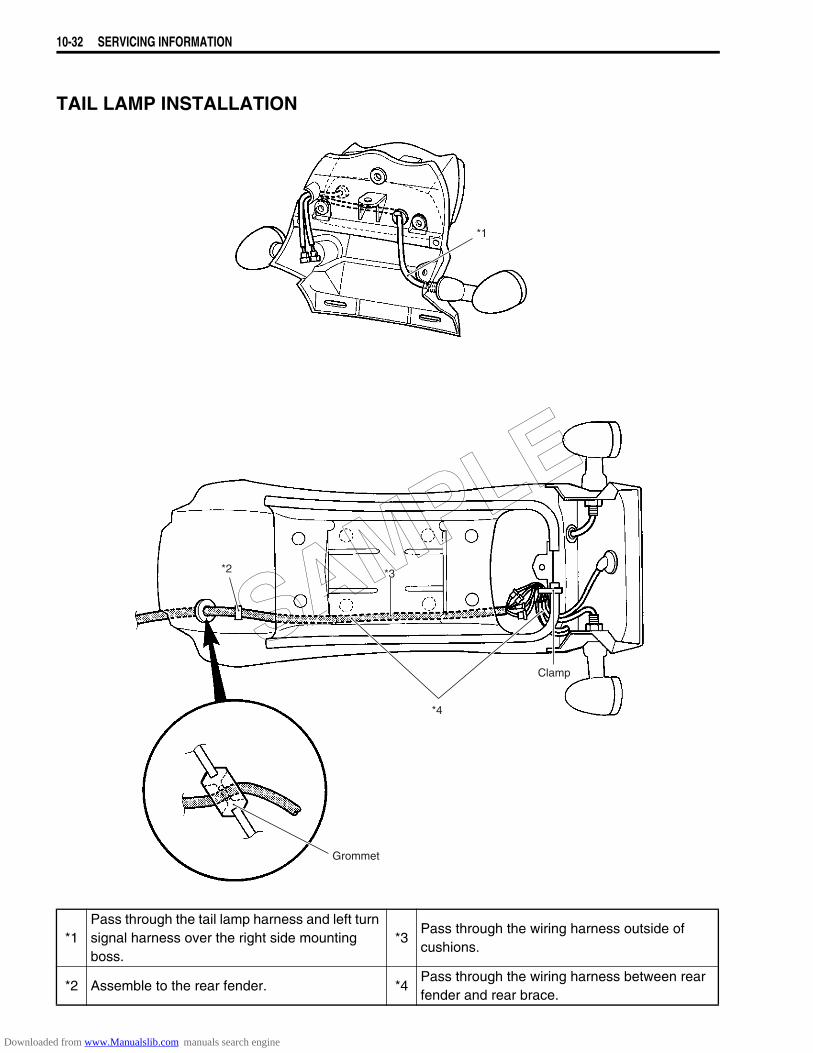
10-32 SERVICING INFORMATION
TAIL LAMP INSTALLATION
*1
*2 *3
*4
Grommet
Clamp
*1Pass through the tail lamp harness and left turn signal harness over the right side mounting boss.
*3Pass through the wiring harness outside of cushions.
*2 Assemble to the rear fender. *4Pass through the wiring harness between rear fender and rear brace.
SAMPLE
Downloaded from www.Manualslib.com manuals search engine
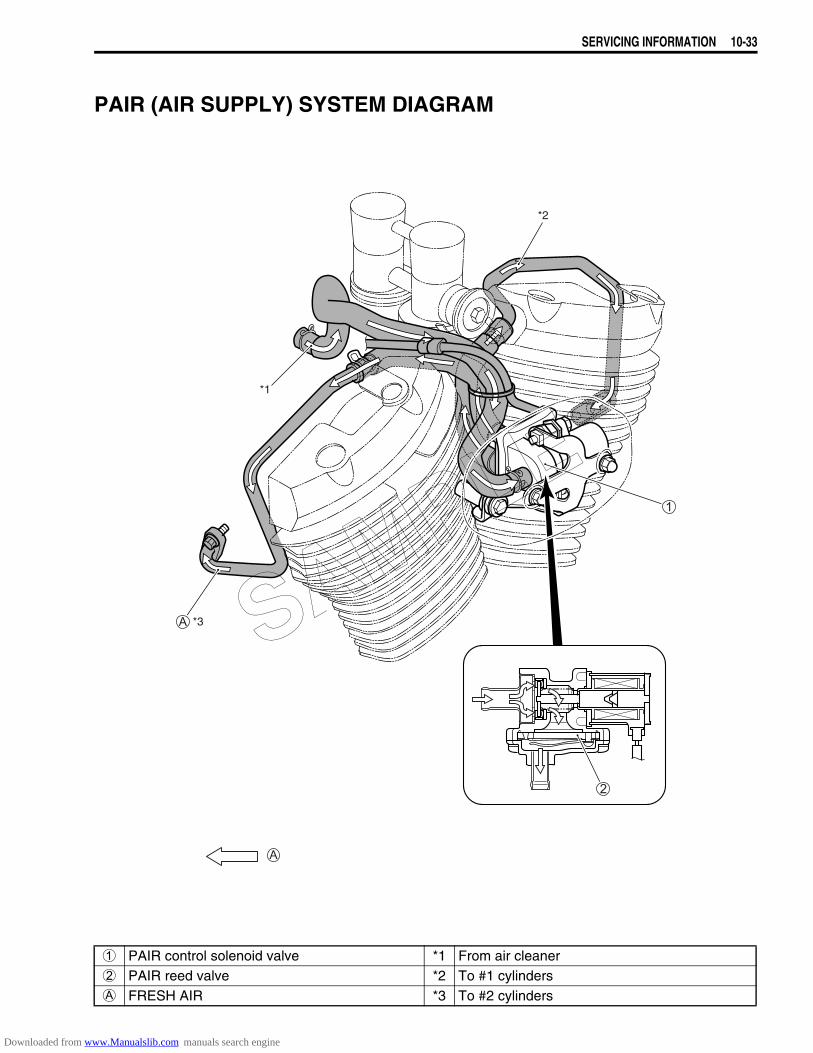
SERVICING INFORMATION 10-33
PAIR (AIR SUPPLY) SYSTEM DIAGRAM
*3
*1
*2
1 PAIR control solenoid valve *1 From air cleaner2 PAIR reed valve *2 To #1 cylindersA FRESH AIR *3 To #2 cylinders
SAMPLE
Downloaded from www.Manualslib.com manuals search engine
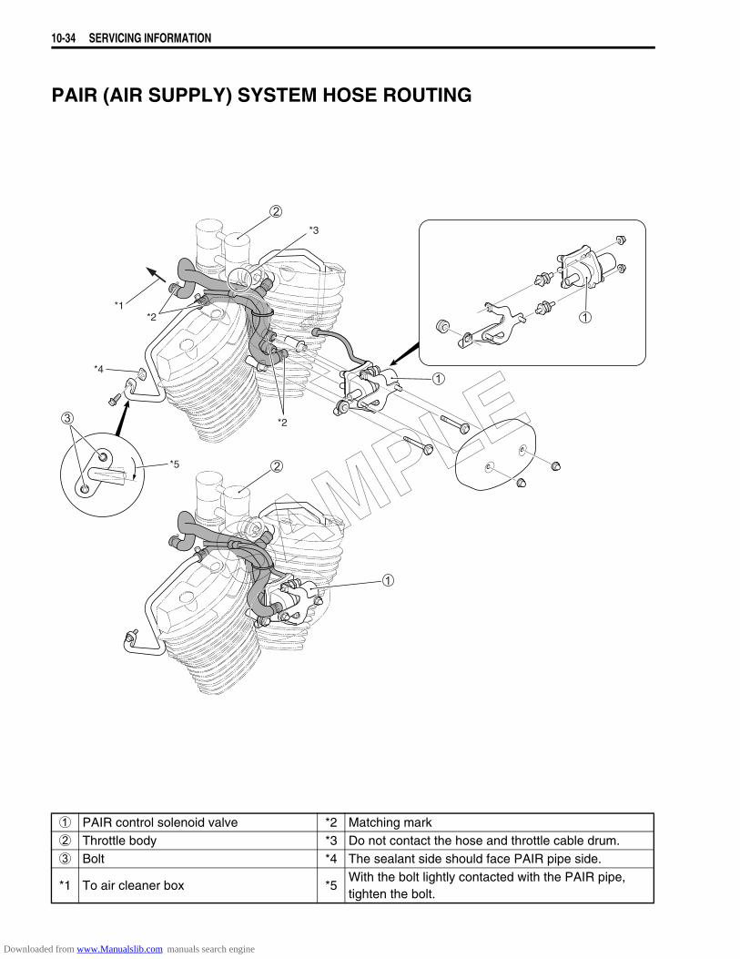
10-34 SERVICING INFORMATION
PAIR (AIR SUPPLY) SYSTEM HOSE ROUTING
*2
*2*1
*3
*5
*4
1 PAIR control solenoid valve *2 Matching mark2 Throttle body *3 Do not contact the hose and throttle cable drum.3 Bolt *4 The sealant side should face PAIR pipe side.
*1 To air cleaner box *5With the bolt lightly contacted with the PAIR pipe, tighten the bolt.
SAMPLE
Downloaded from www.Manualslib.com manuals search engine
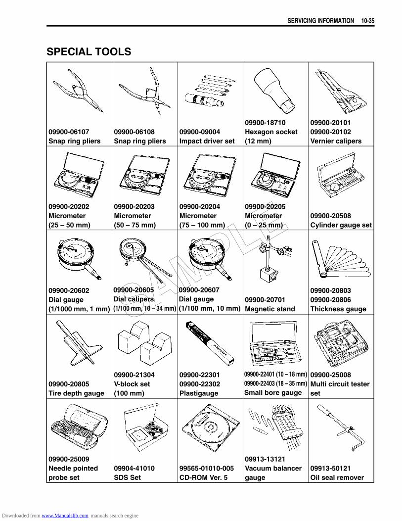
SERVICING INFORMATION 10-35
SPECIAL TOOLS
09900-06107Snap ring pliers
09900-06108Snap ring pliers
09900-09004Impact driver set
09900-18710Hexagon socket(12 mm)
09900-2010109900-20102Vernier calipers
09900-20202Micrometer(25 – 50 mm)
09900-20203Micrometer(50 – 75 mm)
09900-20204Micrometer(75 – 100 mm)
09900-20205Micrometer(0 – 25 mm)
09900-20508Cylinder gauge set
09900-20602Dial gauge(1/1000 mm, 1 mm)
09900-20605Dial calipers(1/100 mm, 10 – 34 mm)
09900-20607Dial gauge(1/100 mm, 10 mm)
09900-20701Magnetic stand
09900-2080309900-20806Thickness gauge
09900-20805Tire depth gauge
09900-21304V-block set(100 mm)
09900-2230109900-22302Plastigauge
09900-22401 (10 – 18 mm)09900-22403 (18 – 35 mm)Small bore gauge
09900-25008Multi circuit tester set
09900-25009Needle pointed probe set
09904-41010SDS Set
99565-01010-005CD-ROM Ver. 5
09913-13121Vacuum balancer gauge
09913-50121Oil seal remover
SAMPLE
Downloaded from www.Manualslib.com manuals search engine
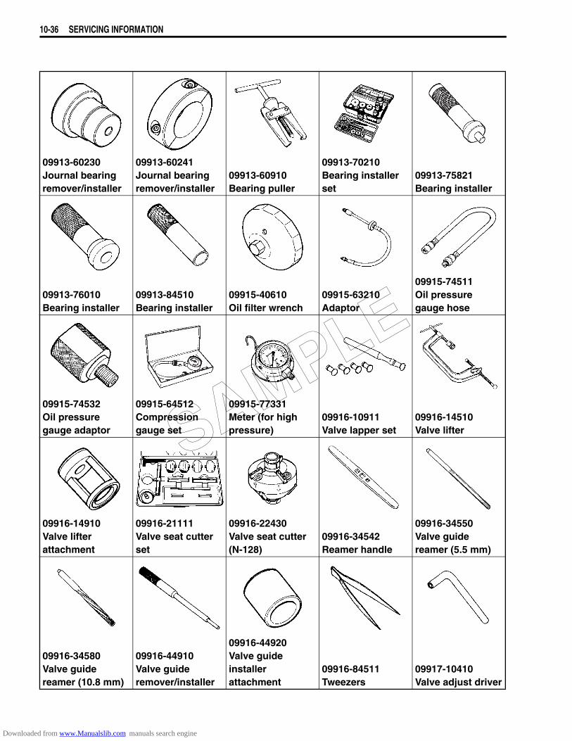
10-36 SERVICING INFORMATION
09913-60230Journal bearing remover/installer
09913-60241Journal bearing remover/installer
09913-60910Bearing puller
09913-70210Bearing installer set
09913-75821Bearing installer
09913-76010Bearing installer
09913-84510Bearing installer
09915-40610Oil filter wrench
09915-63210Adaptor
09915-74511Oil pressure gauge hose
09915-74532Oil pressure gauge adaptor
09915-64512Compression gauge set
09915-77331Meter (for high pressure)
09916-10911Valve lapper set
09916-14510Valve lifter
09916-14910Valve lifter attachment
09916-21111Valve seat cutter set
09916-22430Valve seat cutter(N-128)
09916-34542Reamer handle
09916-34550Valve guide reamer (5.5 mm)
09916-34580Valve guide reamer (10.8 mm)
09916-44910Valve guide remover/installer
09916-44920Valve guide installer attachment
09916-84511Tweezers
09917-10410Valve adjust driver
SAMPLE
Downloaded from www.Manualslib.com manuals search engine
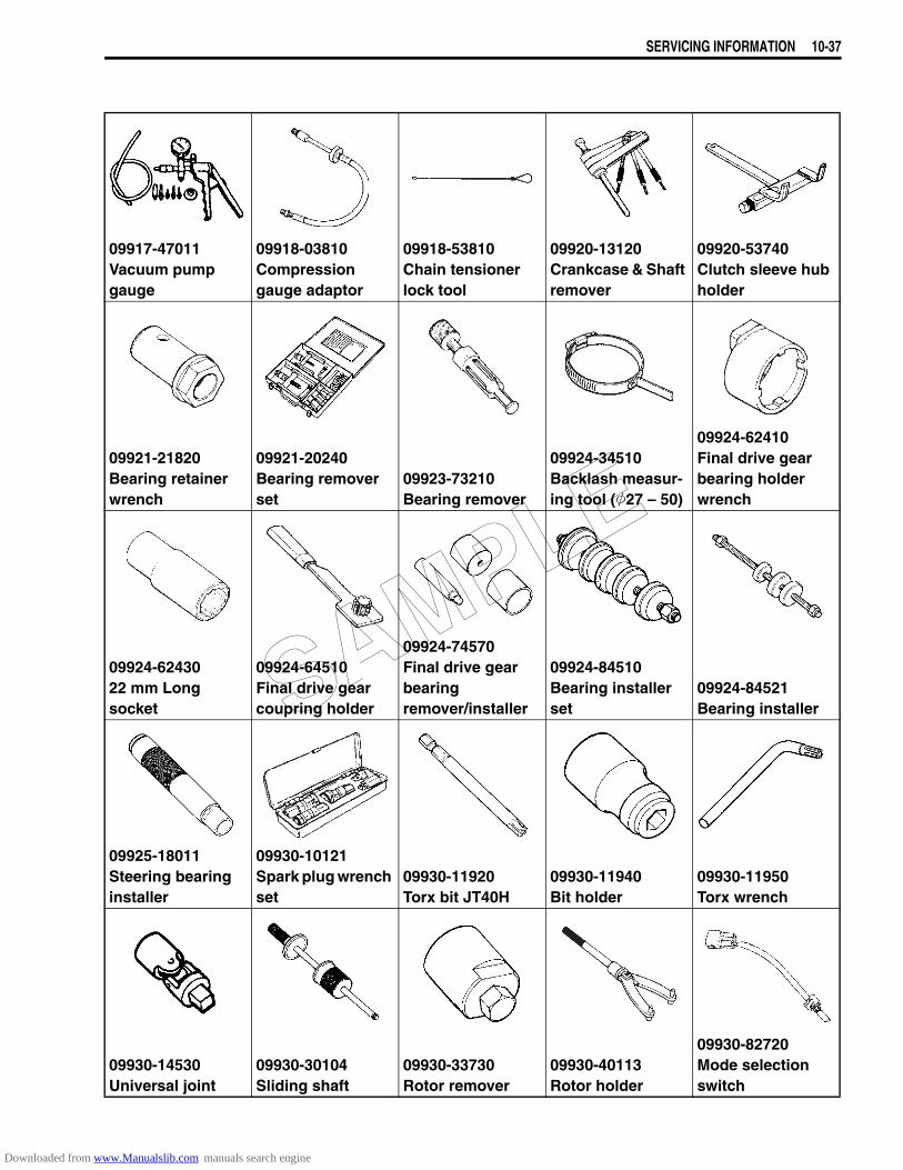
SERVICING INFORMATION 10-37
09917-47011Vacuum pump gauge
09918-03810Compression gauge adaptor
09918-53810Chain tensioner lock tool
09920-13120Crankcase & Shaft remover
09920-53740Clutch sleeve hub holder
09921-21820Bearing retainer wrench
09921-20240Bearing remover set
09923-73210Bearing remover
09924-34510Backlash measur-ing tool (27 – 50)
09924-62410Final drive gear bearing holder wrench
09924-6243022 mm Long socket
09924-64510Final drive gear coupring holder
09924-74570Final drive gear bearing remover/installer
09924-84510Bearing installer set
09924-84521Bearing installer
09925-18011Steering bearing installer
09930-10121Spark plug wrench set
09930-11920Torx bit JT40H
09930-11940Bit holder
09930-11950Torx wrench
09930-14530Universal joint
09930-30104Sliding shaft
09930-33730Rotor remover
09930-40113Rotor holder
09930-82720Mode selection switch
SAMPLE
Downloaded from www.Manualslib.com manuals search engine

10-38 SERVICING INFORMATION
NOTE:When order the special tool, please confirm whether it is available or not.
09940-14911Steering stem nut wrench
09940-30221Front fork assem-bling tool
09940-40211Fuel pressure gauge adaptor
09940-40220Fuel pressure gauge hose attachment
09940-50120Front fork inner rod holder
09940-51410Bearing installer
09940-52841Inner rod holder
09940-52861Front fork oil seal installer
09940-92720Spring scale
09940-94922Front fork spring stopper plate
09940-94930Front fork spacer holder
09941-34513Steering race installer
09941-50111Bearing remover set
09941-64511Bearing remover
09941-74911Steering bearing installer
09943-74111Fork oil level gauge
SAMPLE
Downloaded from www.Manualslib.com manuals search engine
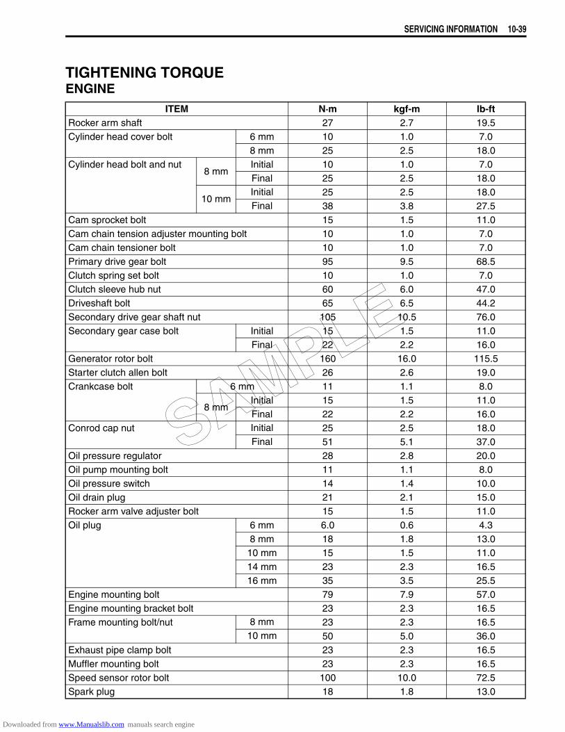
SERVICING INFORMATION 10-39
TIGHTENING TORQUEENGINE
ITEM N·m kgf-m lb-ftRocker arm shaft 27 2.7 19.5Cylinder head cover bolt 6 mm 10 1.0 7.0
8 mm 25 2.5 18.0Cylinder head bolt and nut
8 mmInitial 10 1.0 7.0Final 25 2.5 18.0
10 mmInitial 25 2.5 18.0Final 38 3.8 27.5
Cam sprocket bolt 15 1.5 11.0Cam chain tension adjuster mounting bolt 10 1.0 7.0Cam chain tensioner bolt 10 1.0 7.0Primary drive gear bolt 95 9.5 68.5Clutch spring set bolt 10 1.0 7.0Clutch sleeve hub nut 60 6.0 47.0Driveshaft bolt 65 6.5 44.2Secondary drive gear shaft nut 105 10.5 76.0Secondary gear case bolt Initial 15 1.5 11.0
Final 22 2.2 16.0Generator rotor bolt 160 16.0 115.5Starter clutch allen bolt 26 2.6 19.0Crankcase bolt 6 mm 11 1.1 8.0
8 mmInitial 15 1.5 11.0Final 22 2.2 16.0
Conrod cap nut Initial 25 2.5 18.0Final 51 5.1 37.0
Oil pressure regulator 28 2.8 20.0Oil pump mounting bolt 11 1.1 8.0Oil pressure switch 14 1.4 10.0Oil drain plug 21 2.1 15.0Rocker arm valve adjuster bolt 15 1.5 11.0Oil plug 6 mm 6.0 0.6 4.3
8 mm 18 1.8 13.010 mm 15 1.5 11.014 mm 23 2.3 16.516 mm 35 3.5 25.5
Engine mounting bolt 79 7.9 57.0Engine mounting bracket bolt 23 2.3 16.5Frame mounting bolt/nut 8 mm 23 2.3 16.5
10 mm 50 5.0 36.0Exhaust pipe clamp bolt 23 2.3 16.5Muffler mounting bolt 23 2.3 16.5Speed sensor rotor bolt 100 10.0 72.5Spark plug 18 1.8 13.0
SAMPLE
Downloaded from www.Manualslib.com manuals search engine
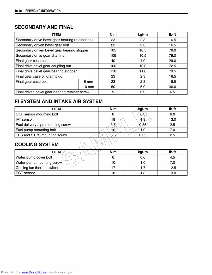
10-40 SERVICING INFORMATION
SECONDARY AND FINAL
FI SYSTEM AND INTAKE AIR SYSTEM
COOLING SYSTEM
ITEM N·m kgf-m lb-ftSecondary drive bevel gear bearing retainer bolt 23 2.3 16.5Secondary driven bevel gear bolt 23 2.3 16.5Secondary driven bevel gear bearing stopper 105 10.5 76.0Secondary drive gear shaft nut 105 10.5 76.0Final gear case nut 40 4.0 29.0Final drive bevel gear coupling nut 100 10.0 72.5Final drive bevel gear bearing stopper 110 11.0 79.5Final gear case oil drain plug 23 2.3 16.5Final gear case bolt 8 mm 23 2.3 16.5
10 mm 50 5.0 36.0Final driven bevel gear bearing retainer screw 9 0.9 6.5
ITEM N·m kgf-m lb-ftCKP sensor mounting bolt 8 0.8 6.0IAT sensor 18 1.8 13.0Fuel delivery pipe mounting screw 3.5 0.35 2.5Fuel pump mounting bolt 10 1.0 7.0TPS and STPS mounting screw 3.5 0.35 2.5
ITEM N·m kgf-m lb-ftWater pump cover bolt 6 0.6 4.5Water pump mounting screw 10 1.0 7.0Cooling fan thermo-switch 17 1.7 12.5ECT sensor 18 1.8 13.0
SAMPLE
Downloaded from www.Manualslib.com manuals search engine
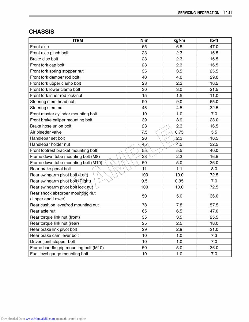
SERVICING INFORMATION 10-41
CHASSISITEM N·m kgf-m lb-ft
Front axle 65 6.5 47.0Front axle pinch bolt 23 2.3 16.5Brake disc bolt 23 2.3 16.5Front fork cap bolt 23 2.3 16.5Front fork spring stopper nut 35 3.5 25.5Front fork damper rod bolt 40 4.0 29.0Front fork upper clamp bolt 23 2.3 16.5Front fork lower clamp bolt 30 3.0 21.5Front fork inner rod lock-nut 15 1.5 11.0Steering stem head nut 90 9.0 65.0Steering stem nut 45 4.5 32.5Front master cylinder mounting bolt 10 1.0 7.0Front brake caliper mounting bolt 39 3.9 28.0Brake hose union bolt 23 2.3 16.5Air bleeder valve 7.5 0.75 5.5Handlebar set bolt 23 2.3 16.5Handlebar holder nut 45 4.5 32.5Front footrest bracket mounting bolt 55 5.5 40.0Frame down tube mounting bolt (M8) 23 2.3 16.5Frame down tube mounting bolt (M10) 50 5.0 36.0Rear brake pedal bolt 11 1.1 8.0Rear swingarm pivot bolt (Left) 100 10.0 72.5Rear swingarm pivot bolt (Right) 9.5 0.95 7.0Rear swingarm pivot bolt lock nut 100 10.0 72.5Rear shock absorber mounting nut(Upper and Lower)
50 5.0 36.0
Rear cushion lever/rod mounting nut 78 7.8 57.5Rear axle nut 65 6.5 47.0Rear torque link nut (front) 35 3.5 25.5Rear torque link nut (rear) 25 2.5 18.0Rear brake link pivot bolt 29 2.9 21.0Rear brake cam lever bolt 10 1.0 7.3Driven joint stopper bolt 10 1.0 7.0Frame handle grip mounting bolt (M10) 50 5.0 36.0Fuel level gauge mounting bolt 10 1.0 7.0
SAMPLE
Downloaded from www.Manualslib.com manuals search engine
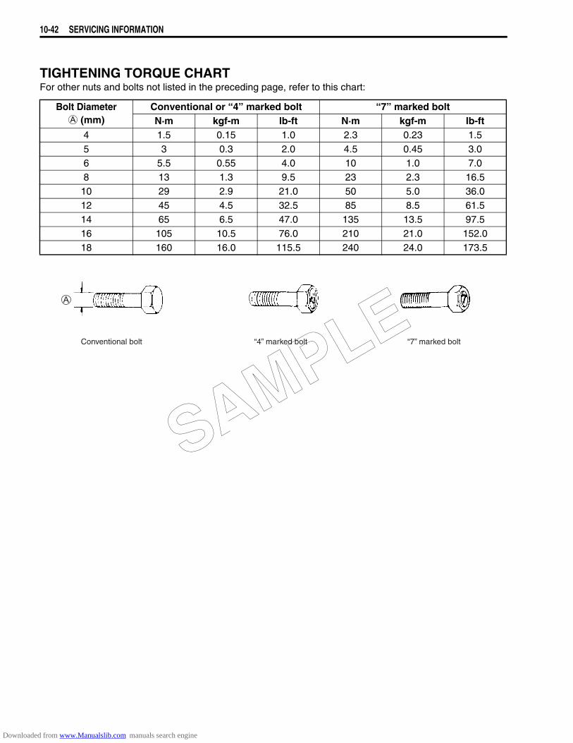
10-42 SERVICING INFORMATION
TIGHTENING TORQUE CHARTFor other nuts and bolts not listed in the preceding page, refer to this chart:
Bolt Diameter A (mm)
Conventional or “4” marked bolt “7” marked boltN·m kgf-m lb-ft N·m kgf-m lb-ft
4 1.5 0.15 1.0 2.3 0.23 1.55 3 0.3 2.0 4.5 0.45 3.06 5.5 0.55 4.0 10 1.0 7.08 13 1.3 9.5 23 2.3 16.5
10 29 2.9 21.0 50 5.0 36.012 45 4.5 32.5 85 8.5 61.514 65 6.5 47.0 135 13.5 97.516 105 10.5 76.0 210 21.0 152.018 160 16.0 115.5 240 24.0 173.5
Conventional bolt “4” marked bolt “7” marked bolt
SAMPLE
Downloaded from www.Manualslib.com manuals search engine
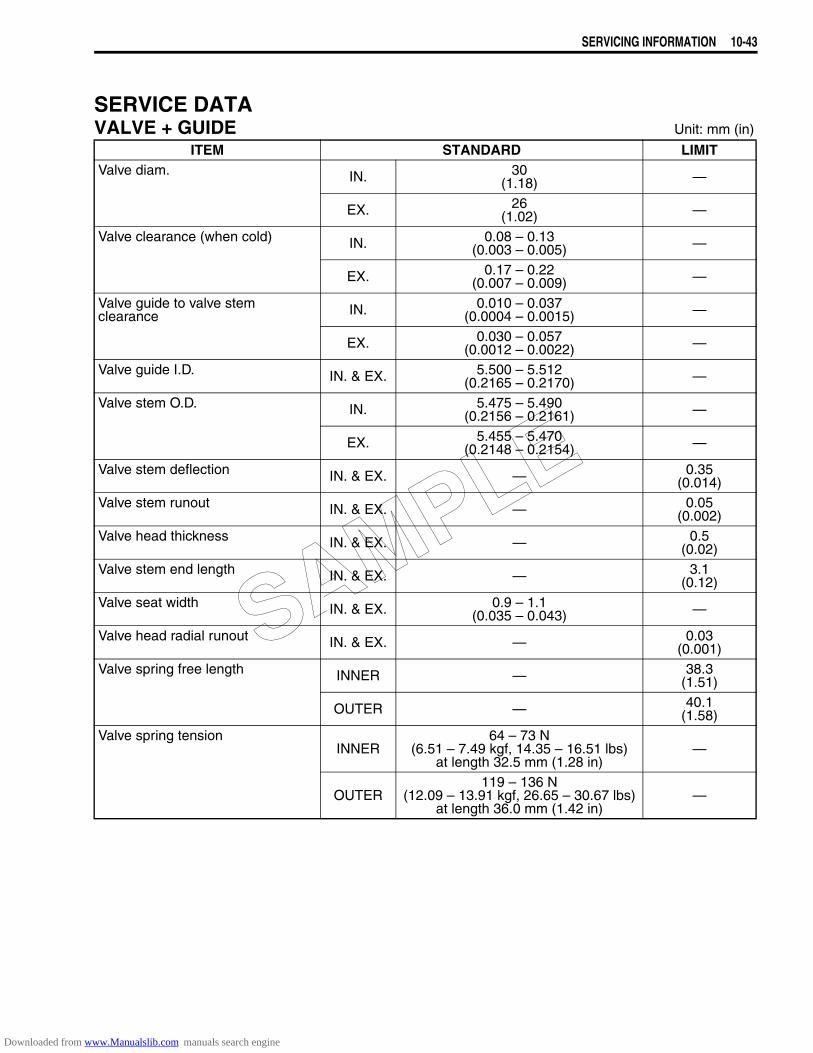
SERVICING INFORMATION 10-43
SERVICE DATAVALVE + GUIDE Unit: mm (in)
ITEM STANDARD LIMITValve diam. IN. 30
(1.18) —
EX. 26(1.02) —
Valve clearance (when cold) IN. 0.08 – 0.13(0.003 – 0.005) —
EX. 0.17 – 0.22(0.007 – 0.009) —
Valve guide to valve stem clearance IN. 0.010 – 0.037
(0.0004 – 0.0015) —
EX. 0.030 – 0.057(0.0012 – 0.0022) —
Valve guide I.D. IN. & EX. 5.500 – 5.512(0.2165 – 0.2170) —
Valve stem O.D. IN. 5.475 – 5.490(0.2156 – 0.2161) —
EX. 5.455 – 5.470(0.2148 – 0.2154) —
Valve stem deflection IN. & EX. — 0.35(0.014)
Valve stem runout IN. & EX. — 0.05(0.002)
Valve head thickness IN. & EX. — 0.5(0.02)
Valve stem end length IN. & EX. — 3.1(0.12)
Valve seat width IN. & EX. 0.9 – 1.1(0.035 – 0.043) —
Valve head radial runout IN. & EX. — 0.03(0.001)
Valve spring free length INNER — 38.3(1.51)
OUTER — 40.1(1.58)
Valve spring tension INNER
64 – 73 N(6.51 – 7.49 kgf, 14.35 – 16.51 lbs)
at length 32.5 mm (1.28 in)—
OUTER119 – 136 N
(12.09 – 13.91 kgf, 26.65 – 30.67 lbs)at length 36.0 mm (1.42 in)
—
SAMPLE
Downloaded from www.Manualslib.com manuals search engine

10-44 SERVICING INFORMATION
CAMSHAFT + CYLINDER HEAD Unit: mm (in)
CYLINDER + PISTON + PISTON RING Unit: mm (in)
ITEM STANDARD LIMITCam height IN. 35.50 – 35.54
(1.398 – 1.399)35.20
(1.386)
EX. 36.58 – 36.62(1.440 – 1.442)
36.28(1.428)
Camshaft journal oil clearance 0.032 – 0.066(0.0013 – 0.0026)
0.150(0.0059)
Camshaft journal holder I.D. Rear left sideFront right side
20.012 – 20.025(0.7879 – 0.7884) —
Rear right sideFront left side
25.012 – 25.025(0.9847 – 0.9852) —
Camshaft journal O.D. Rear left sideFront right side
19.959 – 19.980(0.7858 – 0.7866) —
Rear right sideFront left side
24.959 – 24.980(0.9826 – 0.9835) —
Camshaft runout — 0.10(0.004)
Rocker arm I. D. IN. & EX. 12.000 – 12.018(0.4724 – 0.4731) —
Rocker arm shaft O. D. IN. & EX. 11.977 – 11.995(0.4715 – 0.4722) —
Cylinder head distortion — 0.05(0.002)
Cylinder head cover distortion — 0.05(0.002)
ITEM STANDARD LIMITCompression pressure 1 300 – 1 700 kPa
(13 – 17 kgf/cm², 185 – 242 psi)1 100 kPa
(11 kgf/cm² 156 psi)
Compression pressure difference — 200 kPa
(2 kgf/cm² 28 psi)
Piston to cylinder clearance 0.045 – 0.055(0.0018 – 0.0022)
0.120(0.0047)
Cylinder bore 83.000 – 83.015 (3.2677 – 3.2683)
83.085(3.2711)
Piston diam. 82.950 – 82.965 (3.2657 – 3.2663)
Measure at 15 mm (0.6 in) from the skirt end.82.880
(3.2630)
Cylinder distortion — 0.05(0.002)
Piston ring free end gap 1st Approx. 9.6 (0.38) 7.7(0.30)
2nd R Approx. 11.8 (0.46) 9.4(0.37)
Piston ring end gap 1st 0.20 – 0.35(0.008 – 0.014)
0.70(0.028)
2nd 0.20 – 0.35(0.008 – 0.014)
0.70(0.028)
Piston ring to groove clearance 1st — 0.180(0.007)
2nd — 0.150(0.006)
SAMPLE
Downloaded from www.Manualslib.com manuals search engine

SERVICING INFORMATION 10-45
CONROD + CRANKSHAFT Unit: mm (in)
OIL PUMP
Piston ring groove width 1st 1.01 – 1.03(0.0398 – 0.0406) —
2nd 1.21 – 1.23(0.0476 – 0.0484) —
Oil 2.51 – 2.53(0.0988 – 0.0996) —
Piston ring thickness 1st 0.970 – 0.990(0.0382 – 0.0390) —
2nd 1.170 – 1.190(0.0461 – 0.0469) —
Piston pin bore 20.002 – 20.008(0.7875 – 0.7877)
20.030(0.7886)
Piston pin O.D. 19.992 – 20.000(0.7871 – 0.7874)
19.980(0.7866)
ITEM STANDARD LIMIT
ITEM STANDARD LIMITConrod small end I.D. 20.010 – 20.018
(0.7878 – 0.7881)20.040
(0.7890)Conrod big end side clearance 0.10 – 0.20
(0.004 – 0.008)0.30
(0.012)Conrod big end width 21.95 – 22.00
(0.864 – 0.866) —
Crank pin width 22.10 – 22.15(0.870 – 0.872) —
Conrod big end oil clearance 0.024 – 0.042(0.0009 – 0.0017)
0.080(0.0031)
Crank pin O.D. 40.982 – 41.000(1.6135 – 1.6142) —
Crankshaft journal oil clearance 0.002 – 0.029(0.00008 – 0.0011)
0.080(0.0031)
Crankshaft journal O.D. 47.965 – 47.980(1.8884 – 1.8890) —
Crankshaft thrust bearing thickness
1.925 – 2.175(0.0758 – 0.0856) —
Crankshaft thrust clearance 0.05 – 0.10(0.002 – 0.004) —
Crankshaft runout — 0.05(0.002)
ITEM STANDARD LIMITOil pressure (at 60 °C, 140 °F) 350 – 650 kPa
(3.5 – 6.5 kgf/cm², 50 – 92 psi)at 3 000 r/min
—
SAMPLE
Downloaded from www.Manualslib.com manuals search engine
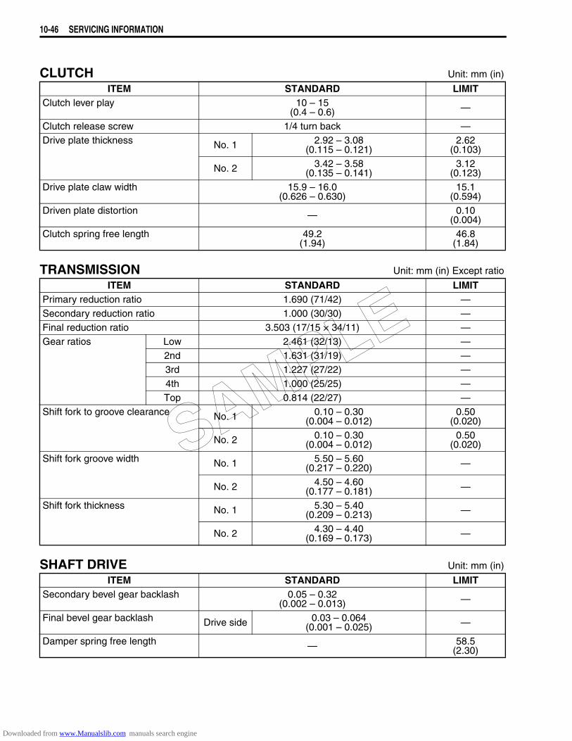
10-46 SERVICING INFORMATION
CLUTCH Unit: mm (in)
TRANSMISSION Unit: mm (in) Except ratio
SHAFT DRIVE Unit: mm (in)
ITEM STANDARD LIMITClutch lever play 10 – 15
(0.4 – 0.6) —
Clutch release screw 1/4 turn back —Drive plate thickness No. 1 2.92 – 3.08
(0.115 – 0.121)2.62
(0.103)
No. 2 3.42 – 3.58(0.135 – 0.141)
3.12(0.123)
Drive plate claw width 15.9 – 16.0(0.626 – 0.630)
15.1(0.594)
Driven plate distortion — 0.10(0.004)
Clutch spring free length 49.2(1.94)
46.8(1.84)
ITEM STANDARD LIMITPrimary reduction ratio 1.690 (71/42) —Secondary reduction ratio 1.000 (30/30) —Final reduction ratio 3.503 (17/15 × 34/11) —Gear ratios Low 2.461 (32/13) —
2nd 1.631 (31/19) —3rd 1.227 (27/22) —4th 1.000 (25/25) —Top 0.814 (22/27) —
Shift fork to groove clearance No. 1 0.10 – 0.30(0.004 – 0.012)
0.50(0.020)
No. 2 0.10 – 0.30(0.004 – 0.012)
0.50(0.020)
Shift fork groove width No. 1 5.50 – 5.60(0.217 – 0.220) —
No. 2 4.50 – 4.60(0.177 – 0.181) —
Shift fork thickness No. 1 5.30 – 5.40(0.209 – 0.213) —
No. 2 4.30 – 4.40(0.169 – 0.173) —
ITEM STANDARD LIMITSecondary bevel gear backlash 0.05 – 0.32
(0.002 – 0.013) —
Final bevel gear backlash Drive side 0.03 – 0.064(0.001 – 0.025) —
Damper spring free length — 58.5(2.30)
SAMPLE
Downloaded from www.Manualslib.com manuals search engine
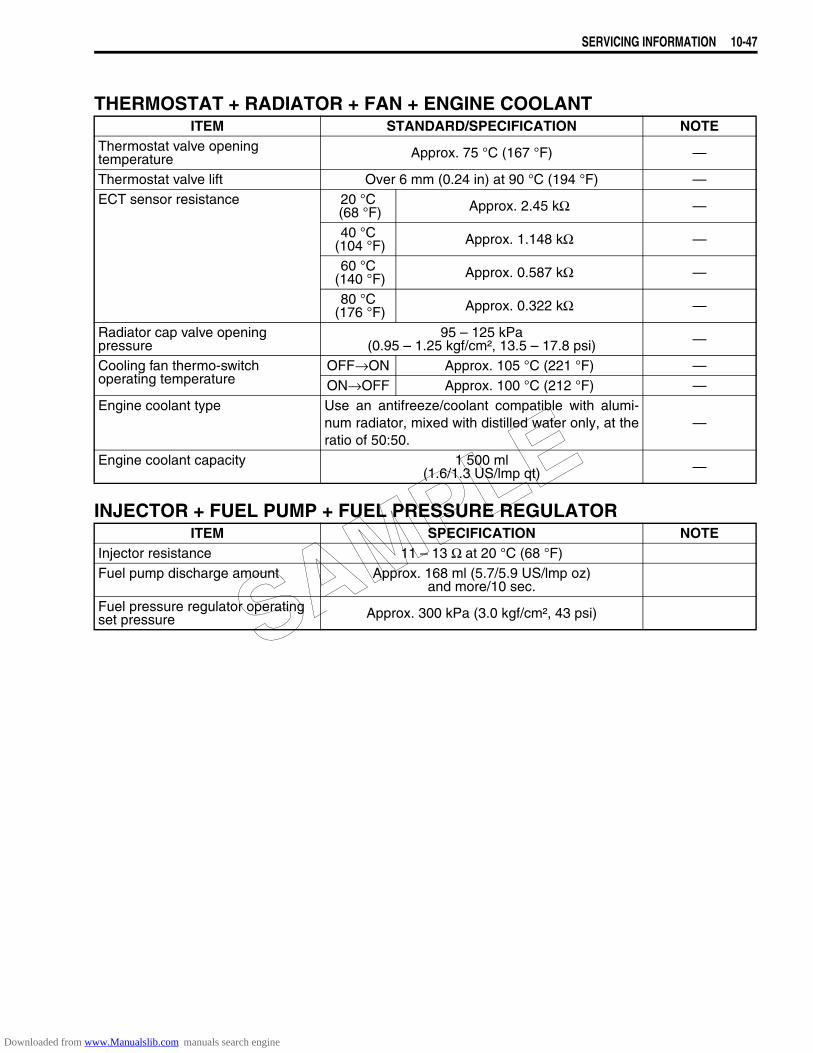
SERVICING INFORMATION 10-47
THERMOSTAT + RADIATOR + FAN + ENGINE COOLANT
INJECTOR + FUEL PUMP + FUEL PRESSURE REGULATOR
ITEM STANDARD/SPECIFICATION NOTEThermostat valve openingtemperature Approx. 75 °C (167 °F) —
Thermostat valve lift Over 6 mm (0.24 in) at 90 °C (194 °F) —ECT sensor resistance 20 °C
(68 °F) Approx. 2.45 kΩ —
40 °C (104 °F) Approx. 1.148 kΩ —
60 °C (140 °F) Approx. 0.587 kΩ —
80 °C (176 °F) Approx. 0.322 kΩ —
Radiator cap valve opening pressure
95 – 125 kPa(0.95 – 1.25 kgf/cm², 13.5 – 17.8 psi) —
Cooling fan thermo-switch operating temperature
OFF→ON Approx. 105 °C (221 °F) —ON→OFF Approx. 100 °C (212 °F) —
Engine coolant type Use an antifreeze/coolant compatible with alumi-num radiator, mixed with distilled water only, at theratio of 50:50.
—
Engine coolant capacity 1 500 ml(1.6/1.3 US/lmp qt) —
ITEM SPECIFICATION NOTEInjector resistance 11 – 13 Ω at 20 °C (68 °F)Fuel pump discharge amount Approx. 168 ml (5.7/5.9 US/lmp oz)
and more/10 sec.Fuel pressure regulator operating set pressure Approx. 300 kPa (3.0 kgf/cm², 43 psi)SAMPLE
Downloaded from www.Manualslib.com manuals search engine
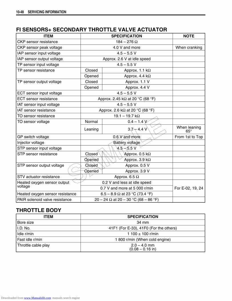
10-48 SERVICING INFORMATION
FI SENSORS+ SECONDARY THROTTLE VALVE ACTUATOR
THROTTLE BODY
ITEM SPECIFICATION NOTECKP sensor resistance 184 – 276 ΩCKP sensor peak voltage 4.0 V and more When crankingIAP sensor input voltage 4.5 – 5.5 VIAP sensor output voltage Approx. 2.6 V at idle speedTP sensor input voltage 4.5 – 5.5 VTP sensor resistance Closed Approx. 1.1 kΩ
Opened Approx. 4.4 kΩTP sensor output voltage Closed Approx. 1.1 V
Opened Approx. 4.4 VECT sensor input voltage 4.5 – 5.5 VECT sensor resistance Approx. 2.45 kΩ at 20 °C (68 °F)IAT sensor input voltage 4.5 – 5.5 VIAT sensor resistance Approx. 2.6 kΩ at 20 °C (68 °F)TO sensor resistance 19.1 – 19.7 kΩTO sensor voltage Normal 0.4 – 1.4 V
Leaning 3.7 – 4.4 V When leaning 65°
GP switch voltage 0.6 V and more From 1st to TopInjector voltage Battery voltageSTP sensor input voltage 4.5 – 5.5 VSTP sensor resistance Closed Approx. 0.5 kΩ
Opened Approx. 3.9 kΩSTP sensor output voltage Closed Approx. 0.5 V
Opened Approx. 3.9 VSTV actuator resistance Approx. 6.5 ΩHeated oxygen sensor outputvoltage
0.2 V and less at idle speedFor E-02, 19, 240.7 V and more at 5 000 r/min
Heated oxygen sensor resistance 6.5 – 8.9 Ω at 23 °C (73.4 °F)PAIR solenoid valve resistance 20 – 24 Ω at 20 – 30 °C (68 – 86 °F)
ITEM SPECIFICATIONBore size 34 mmI.D. No. 41F1 (For E-33), 41F0 (For the others)Idle r/min 1 100 ± 100 r/minFast idle r/min 1 800 r/min (When cold engine)Throttle cable play 2.0 – 4.0 mm
(0.08 – 0.16 in)
SAMPLE
Downloaded from www.Manualslib.com manuals search engine
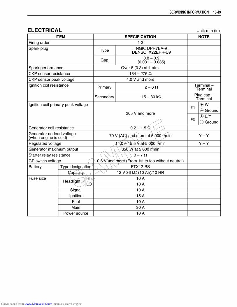
SERVICING INFORMATION 10-49
ELECTRICAL Unit: mm (in)
ITEM SPECIFICATION NOTEFiring order 1·2Spark plug Type NGK: DPR7EA-9
DENSO: X22EPR-U9
Gap 0.8 – 0.9(0.031 – 0.035)
Spark performance Over 8 (0.3) at 1 atm.CKP sensor resistance 184 – 276 ΩCKP sensor peak voltage 4.0 V and moreIgnition coil resistance Primary 2 – 6 Ω Terminal –
Terminal
Secondary 15 – 30 kΩ Plug cap – Terminal
Ignition coil primary peak voltage
205 V and more#1
+ W- Ground
#2+ B/Y- Ground
Generator coil resistance 0.2 – 1.5 ΩGenerator no-load voltage (when engine is cold) 70 V (AC) and more at 5 000 r/min Y – Y
Regulated voltage 14.0 – 15.5 V at 5 000 r/min Y – YGenerator maximum output 350 W at 5 000 r/minStarter relay resistance 3 – 7 ΩGP switch voltage 0.6 V and more (From 1st to top without neutral)Battery Type designation FTX12-BS
Capacity 12 V 36 kC (10 Ah)/10 HRFuse size
HeadlightHI 10 ALO 10 A
Signal 10 AIgnition 15 A
Fuel 10 AMain 30 A
Power source 10 A
SAMPLE
Downloaded from www.Manualslib.com manuals search engine
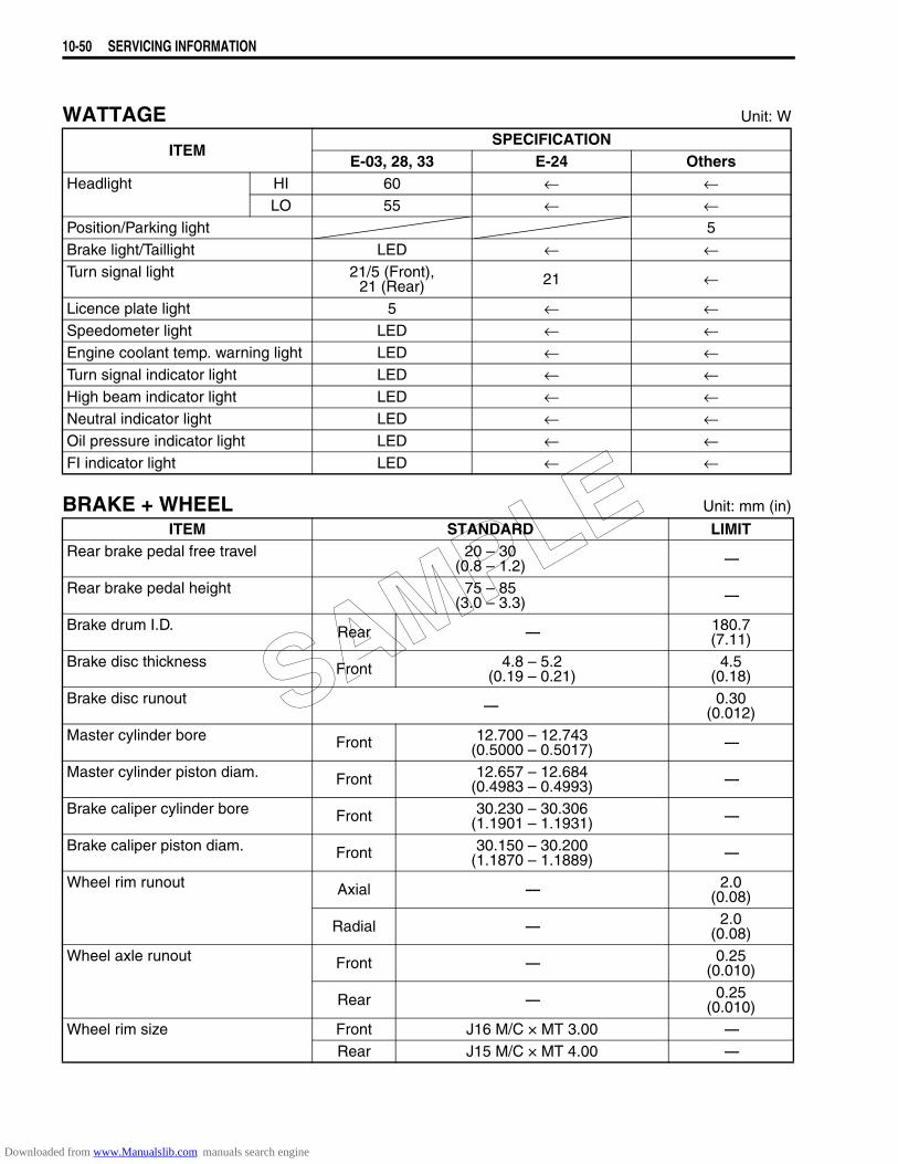
10-50 SERVICING INFORMATION
WATTAGE Unit: W
BRAKE + WHEEL Unit: mm (in)
ITEMSPECIFICATION
E-03, 28, 33 E-24 OthersHeadlight HI 60 ← ←
LO 55 ← ←Position/Parking light 5Brake light/Taillight LED ← ←Turn signal light 21/5 (Front),
21 (Rear) 21 ←
Licence plate light 5 ← ←Speedometer light LED ← ←Engine coolant temp. warning light LED ← ←Turn signal indicator light LED ← ←High beam indicator light LED ← ←Neutral indicator light LED ← ←Oil pressure indicator light LED ← ←FI indicator light LED ← ←
ITEM STANDARD LIMITRear brake pedal free travel 20 – 30
(0.8 – 1.2) ----
Rear brake pedal height 75 – 85(3.0 – 3.3) ----
Brake drum I.D. Rear ---- 180.7(7.11)
Brake disc thickness Front 4.8 – 5.2(0.19 – 0.21)
4.5(0.18)
Brake disc runout ---- 0.30(0.012)
Master cylinder bore Front 12.700 – 12.743(0.5000 – 0.5017) ----
Master cylinder piston diam. Front 12.657 – 12.684(0.4983 – 0.4993) ----
Brake caliper cylinder bore Front 30.230 – 30.306(1.1901 – 1.1931) ----
Brake caliper piston diam. Front 30.150 – 30.200(1.1870 – 1.1889) ----
Wheel rim runout Axial ---- 2.0(0.08)
Radial ---- 2.0(0.08)
Wheel axle runout Front ---- 0.25(0.010)
Rear ---- 0.25(0.010)
Wheel rim size Front J16 M/C × MT 3.00 ----Rear J15 M/C × MT 4.00 ----
SAMPLE
Downloaded from www.Manualslib.com manuals search engine
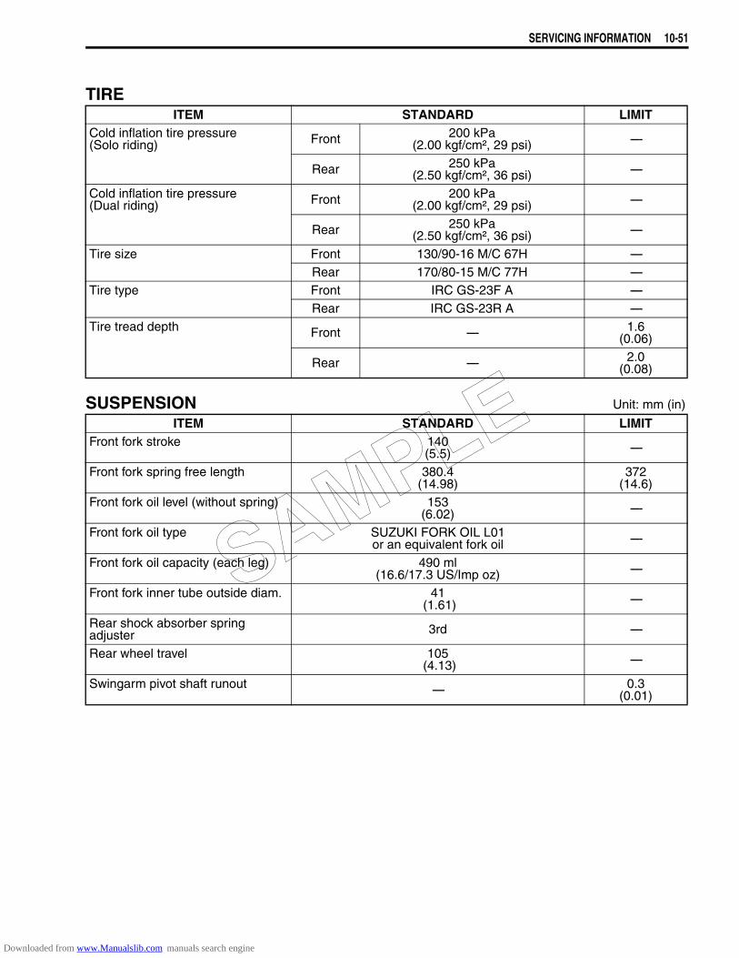
SERVICING INFORMATION 10-51
TIRE
SUSPENSION Unit: mm (in)
ITEM STANDARD LIMITCold inflation tire pressure (Solo riding) Front 200 kPa
(2.00 kgf/cm², 29 psi) ----
Rear 250 kPa(2.50 kgf/cm², 36 psi) ----
Cold inflation tire pressure (Dual riding) Front 200 kPa
(2.00 kgf/cm², 29 psi) ----
Rear 250 kPa(2.50 kgf/cm², 36 psi) ----
Tire size Front 130/90-16 M/C 67H ----Rear 170/80-15 M/C 77H ----
Tire type Front IRC GS-23F A ----Rear IRC GS-23R A ----
Tire tread depth Front ---- 1.6(0.06)
Rear ---- 2.0(0.08)
ITEM STANDARD LIMITFront fork stroke 140
(5.5) ----
Front fork spring free length 380.4(14.98)
372(14.6)
Front fork oil level (without spring) 153(6.02) ----
Front fork oil type SUZUKI FORK OIL L01 or an equivalent fork oil ----
Front fork oil capacity (each leg) 490 ml(16.6/17.3 US/Imp oz) ----
Front fork inner tube outside diam. 41 (1.61) ----
Rear shock absorber spring adjuster 3rd ----
Rear wheel travel 105 (4.13) ----
Swingarm pivot shaft runout ---- 0.3(0.01)
SAMPLE
Downloaded from www.Manualslib.com manuals search engine
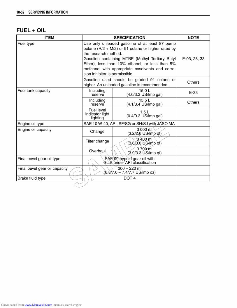
10-52 SERVICING INFORMATION
FUEL + OILITEM SPECIFICATION NOTE
Fuel type Use only unleaded gasoline of at least 87 pumpoctane (R/2 + M/2) or 91 octane or higher rated bythe research method.Gasoline containing MTBE (Methyl Tertiary ButylEther), less than 10% ethanol, or less than 5%methanol with appropriate cosolvents and corro-sion inhibitor is permissible.
E-03, 28, 33
Gasoline used should be graded 91 octane orhigher. An unleaded gasoline is recommended.
Others
Fuel tank capacity Including reserve
15.0 L(4.0/3.3 US/lmp gal) E-33
Including reserve
15.5 L(4.1/3.4 US/lmp gal) Others
Fuel level indicator light
lighting1.5 L
(0.4/0.3 US/lmp gal)
Engine oil type SAE 10 W-40, API, SF/SG or SH/SJ with JASO MA Engine oil capacity Change 3 000 ml
(3.2/2.6 US/lmp qt)
Filter change 3 400 ml(3.6/3.0 US/lmp qt)
Overhaul 3 700 ml(3.9/3.3 US/lmp qt)
Final bevel gear oil type SAE 90 hypoid gear oil with GL-5 under API classification
Final bevel gear oil capacity 200 – 220 ml(6.8/7.0 – 7.4/7.7 US/lmp oz)
Brake fluid type DOT 4SAMPLE
Downloaded from www.Manualslib.com manuals search engine
EMISSION CONTROL INFORMATION 11-1
11
EMISSION CONTROL INFORMATION
CONTENTS
EMISSION CONTROL SYSTEMS...............................................................11- 2FUEL INJECTION SYSTEM..................................................................11- 2EXHAUST EMISSION CONTROL SYSTEM (PAIR SYSTEM).............11- 3NOISE EMISSION CONTROL SYSTEM...............................................11- 4EVAPORATIVE EMISSION CONTROL SYSTEM (Only for E-33) ......11- 4
PAIR (AIR SUPPLY) SYSTEM INSPECTION .............................................11- 5HOSES ..................................................................................................11- 5PAIR REED VALVE ..............................................................................11- 5PAIR CONTROL SOLENOID VALVE...................................................11- 6
PAIR (AIR SUPPLY) SYSTEM HOSE ROUTING .......................................11- 7HEATED OXGEN SENSOR (HO2S) INSPECTION (FOR E-02, 19, 24).....11- 8EVAPORATIVE EMISSION CONTROL SYSTEM INSPECTION (Only for E-33).............................................................................................11- 9
HOSES (EVAP hose)............................................................................11- 9EVAP CANISTER..................................................................................11- 9
EVAP CANISTER HOSE ROUTING (Only for E-33)..................................11-10
SAMPLE
Downloaded from www.Manualslib.com manuals search engine
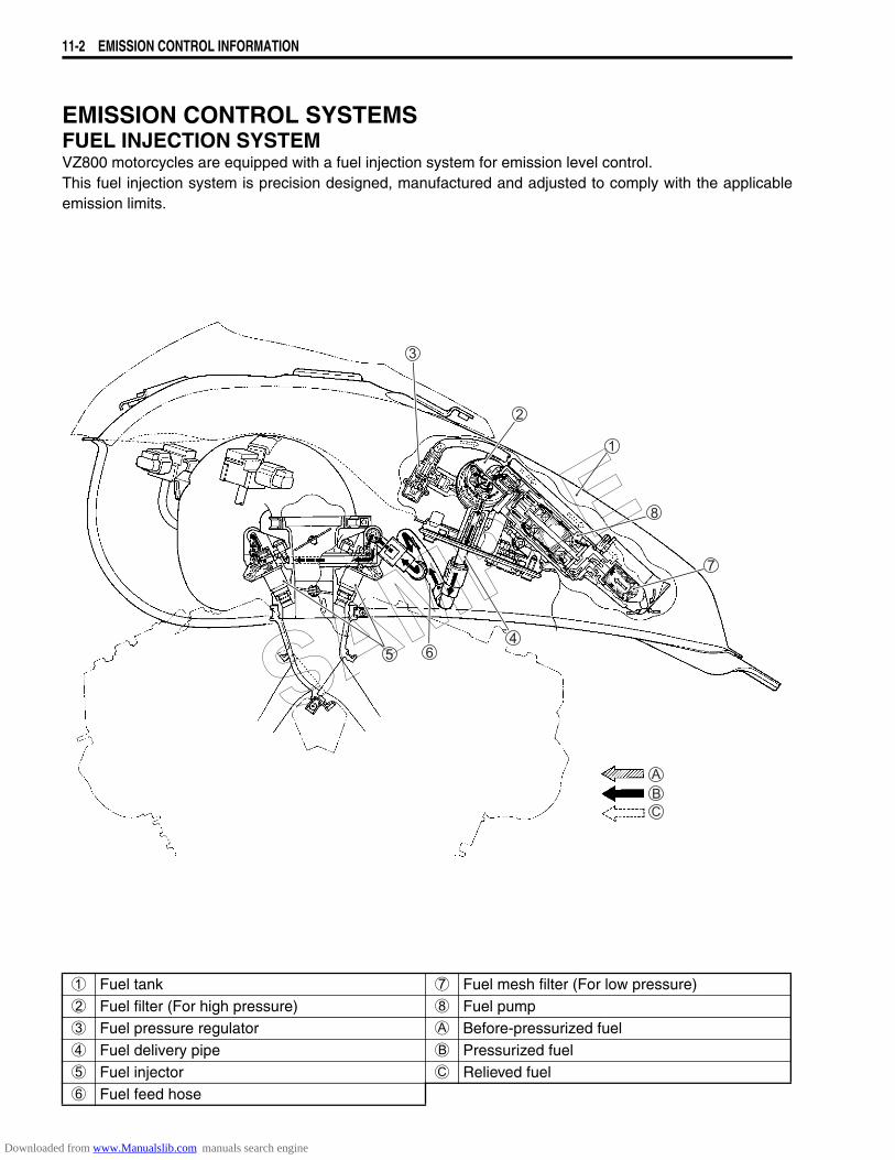
11-2 EMISSION CONTROL INFORMATION
EMISSION CONTROL SYSTEMSFUEL INJECTION SYSTEMVZ800 motorcycles are equipped with a fuel injection system for emission level control.This fuel injection system is precision designed, manufactured and adjusted to comply with the applicableemission limits.
1 Fuel tank 7 Fuel mesh filter (For low pressure)2 Fuel filter (For high pressure) 8 Fuel pump3 Fuel pressure regulator A Before-pressurized fuel4 Fuel delivery pipe B Pressurized fuel5 Fuel injector C Relieved fuel6 Fuel feed hose
SAMPLE
Downloaded from www.Manualslib.com manuals search engine
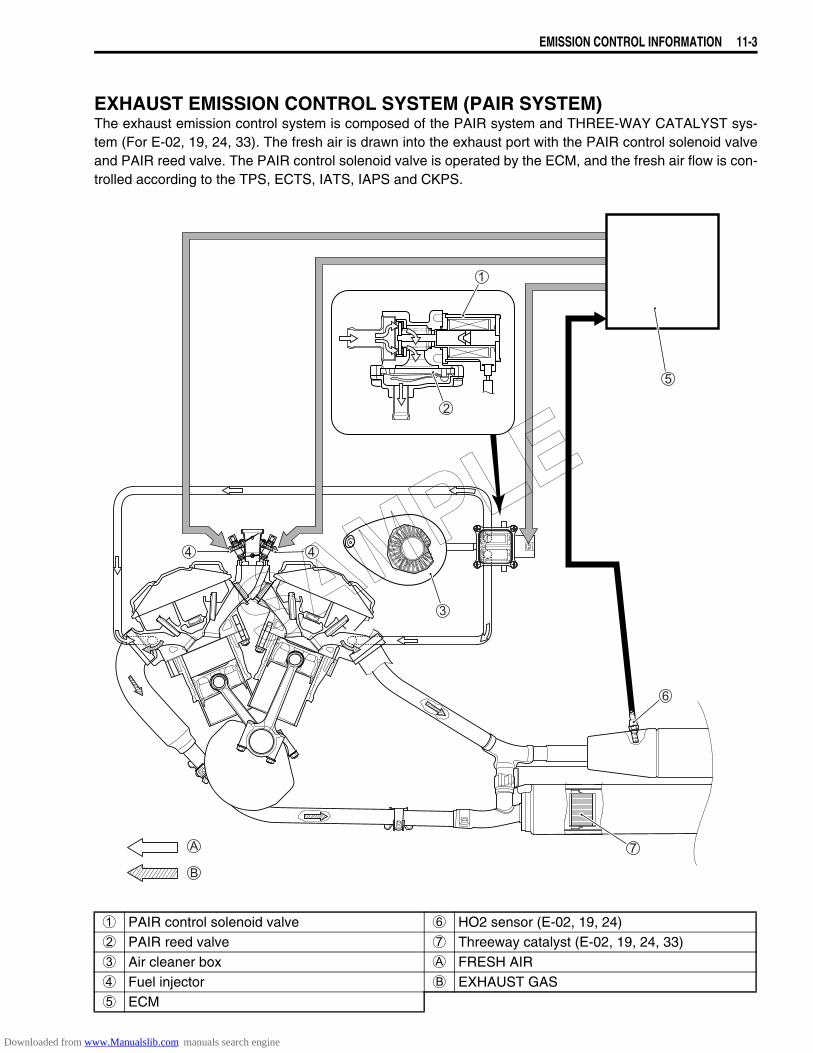
EMISSION CONTROL INFORMATION 11-3
EXHAUST EMISSION CONTROL SYSTEM (PAIR SYSTEM)The exhaust emission control system is composed of the PAIR system and THREE-WAY CATALYST sys-tem (For E-02, 19, 24, 33). The fresh air is drawn into the exhaust port with the PAIR control solenoid valveand PAIR reed valve. The PAIR control solenoid valve is operated by the ECM, and the fresh air flow is con-trolled according to the TPS, ECTS, IATS, IAPS and CKPS.
1 PAIR control solenoid valve 6 HO2 sensor (E-02, 19, 24)2 PAIR reed valve 7 Threeway catalyst (E-02, 19, 24, 33)3 Air cleaner box A FRESH AIR4 Fuel injector B EXHAUST GAS5 ECM
SAMPLE
Downloaded from www.Manualslib.com manuals search engine
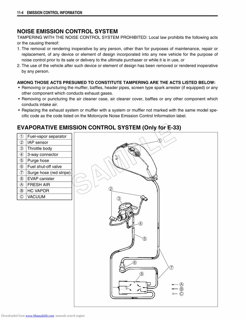
11-4 EMISSION CONTROL INFORMATION
NOISE EMISSION CONTROL SYSTEMTAMPERING WITH THE NOISE CONTROL SYSTEM PROHIBITED: Local law prohibits the following actsor the causing thereof:1. The removal or rendering inoperative by any person, other than for purposes of maintenance, repair or
replacement, of any device or element of design incorporated into any new vehicle for the purpose ofnoise control prior to its sale or delivery to the ultimate purchaser or while it is in use, or
2. The use of the vehicle after such device or element of design has been removed or rendered inoperativeby any person.
AMONG THOSE ACTS PRESUMED TO CONSTITUTE TAMPERING ARE THE ACTS LISTED BELOW:• Removing or puncturing the muffler, baffles, header pipes, screen type spark arrester (if equipped) or any
other component which conducts exhaust gases.• Removing or puncturing the air cleaner case, air cleaner cover, baffles or any other component which
conducts intake air.• Replacing the exhaust system or muffler with a system or muffler not marked with the same model spe-
cific code as the code listed on the Motorcycle Noise Emission Control Information label.
EVAPORATIVE EMISSION CONTROL SYSTEM (Only for E-33)1 Fuel-vapor separator2 IAP sensor3 Throttle body4 3-way connector5 Purge hose6 Fuel shut-off valve7 Surge hose (red stripe)8 EVAP canisterA FRESH AIRB HC VAPORC VACUUM SAMPLE
Downloaded from www.Manualslib.com manuals search engine
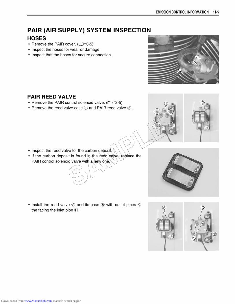
EMISSION CONTROL INFORMATION 11-5
PAIR (AIR SUPPLY) SYSTEM INSPECTIONHOSES• Remove the PAIR cover. (3-5) • Inspect the hoses for wear or damage.• Inspect that the hoses for secure connection.
PAIR REED VALVE• Remove the PAIR control solenoid valve. (3-5)• Remove the reed valve case 1 and PAIR reed valve 2.
• Inspect the reed valve for the carbon deposit.• If the carbon deposit is found in the reed valve, replace the
PAIR control solenoid valve with a new one.
• Install the reed valve A and its case B with outlet pipes Cthe facing the inlet pipe D.
SAMPLE
Downloaded from www.Manualslib.com manuals search engine

11-6 EMISSION CONTROL INFORMATION
PAIR CONTROL SOLENOID VALVE• Remove the PAIR control solenoid valve. (3-5)• Check that air flows through the air inlet port to the air outlet
port.• If air does not flow out, replace the PAIR control solenoid
valve with a new one.
A Air flow
• Connect the 12 V battery to the PAIR control solenoid valveterminals and check the air flow.
• If air does not flow out, the solenoid valve is in normal condi-tion.
• Check the resistance between the terminals of the PAIR con-trol solenoid valve.
Resistance: 20 – 24 Ω at 20 – 30 °C (68 – 86 °F)
09900-25008: Multi-circuit tester set
Tester knob indication: Resistance (Ω)
If the resistance is not within the standard range, replace thePAIR control solenoid valve with a new one. Installation is in the reverse order of removal.• Connect the PAIR control solenoid valve lead wire coupler
and PAIR hoses securely.• PAIR system hose routing. (11-7)
12V
SAMPLE
Downloaded from www.Manualslib.com manuals search engine
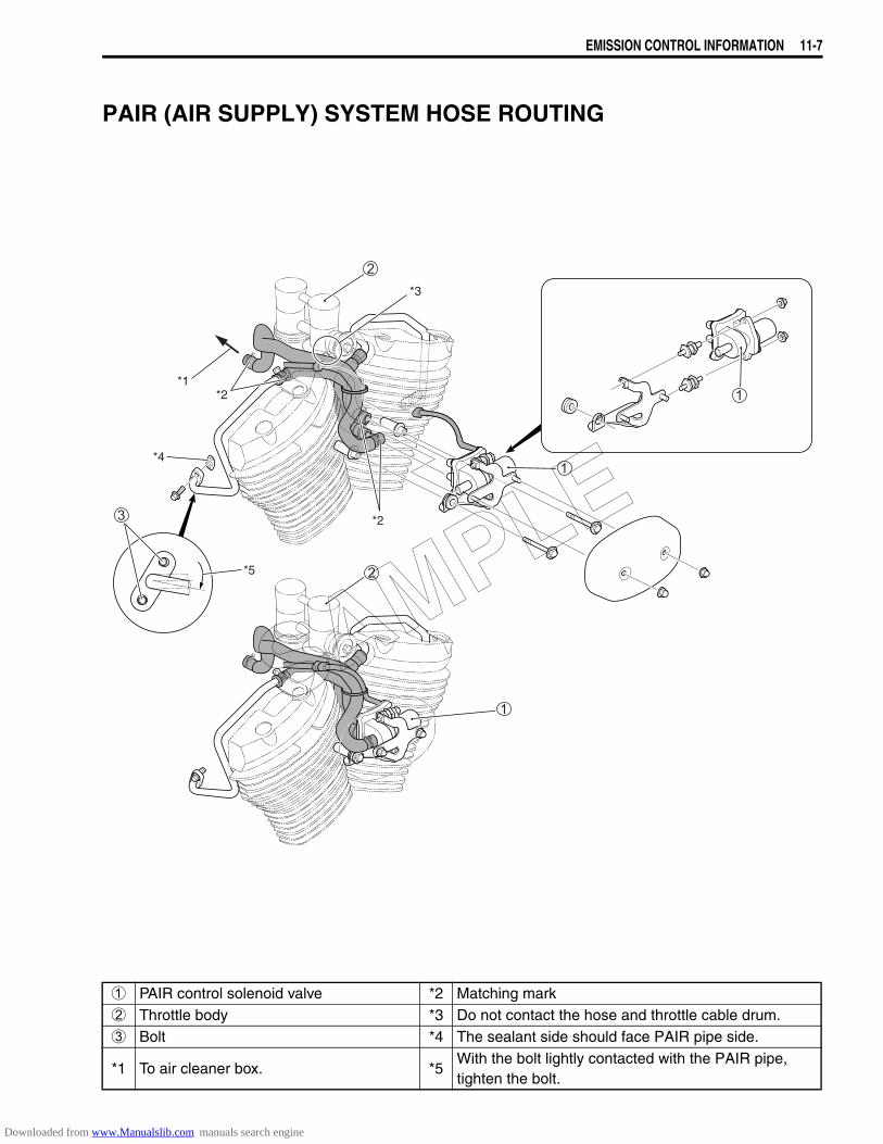
EMISSION CONTROL INFORMATION 11-7
PAIR (AIR SUPPLY) SYSTEM HOSE ROUTING
*2
*2*1
*3
*5
*4
1 PAIR control solenoid valve *2 Matching mark2 Throttle body *3 Do not contact the hose and throttle cable drum.3 Bolt *4 The sealant side should face PAIR pipe side.
*1 To air cleaner box. *5With the bolt lightly contacted with the PAIR pipe, tighten the bolt.
SAMPLE
Downloaded from www.Manualslib.com manuals search engine
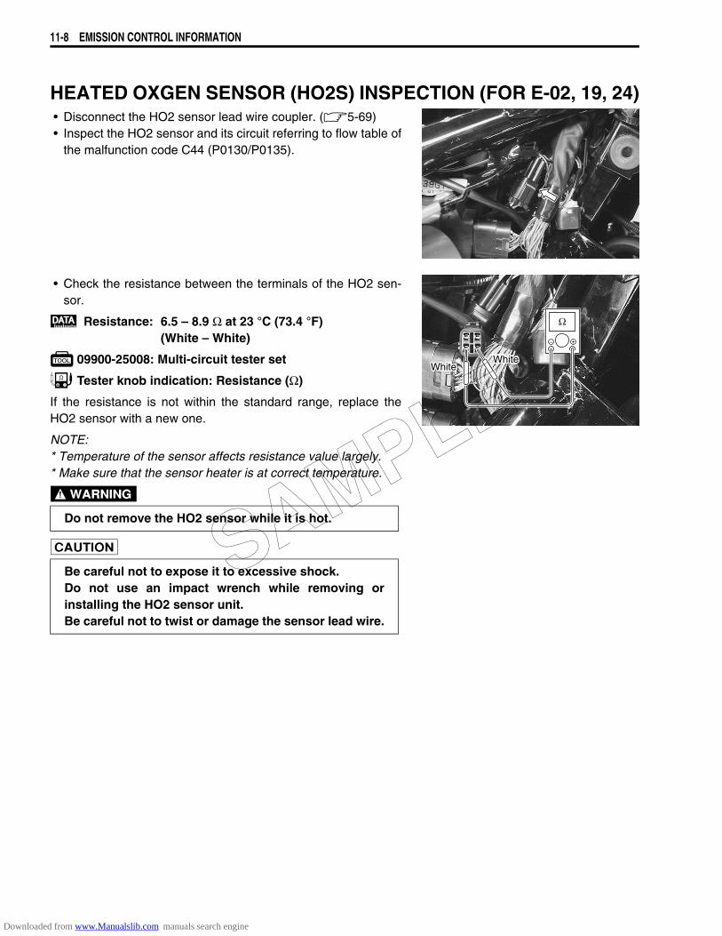
11-8 EMISSION CONTROL INFORMATION
HEATED OXGEN SENSOR (HO2S) INSPECTION (FOR E-02, 19, 24)• Disconnect the HO2 sensor lead wire coupler. (5-69)• Inspect the HO2 sensor and its circuit referring to flow table of
the malfunction code C44 (P0130/P0135).
• Check the resistance between the terminals of the HO2 sen-sor.
Resistance: 6.5 – 8.9 Ω at 23 °C (73.4 °F)(White – White)
09900-25008: Multi-circuit tester set
Tester knob indication: Resistance (Ω)
If the resistance is not within the standard range, replace theHO2 sensor with a new one.
NOTE:* Temperature of the sensor affects resistance value largely.* Make sure that the sensor heater is at correct temperature.
Do not remove the HO2 sensor while it is hot.
Be careful not to expose it to excessive shock.Do not use an impact wrench while removing orinstalling the HO2 sensor unit.Be careful not to twist or damage the sensor lead wire.
WhiteWhite
SAMPLE
Downloaded from www.Manualslib.com manuals search engine
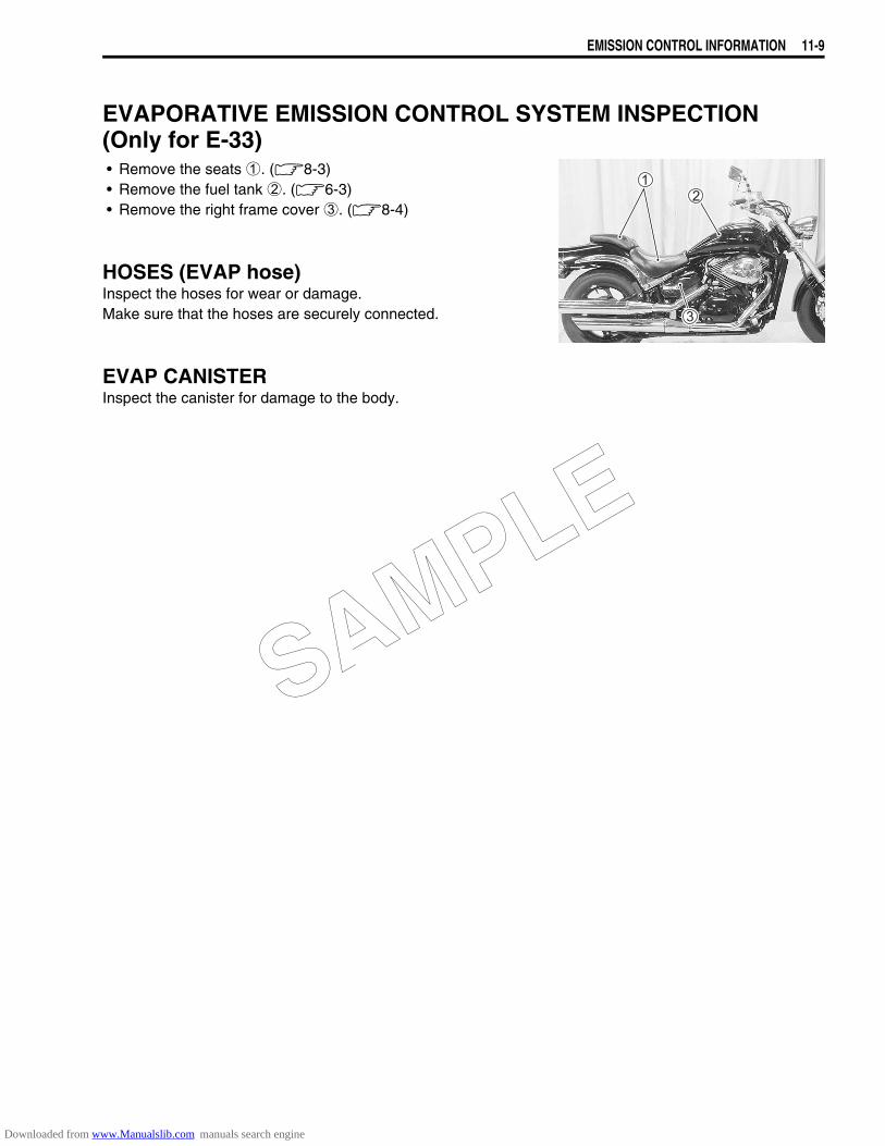
EMISSION CONTROL INFORMATION 11-9
EVAPORATIVE EMISSION CONTROL SYSTEM INSPECTION (Only for E-33)• Remove the seats 1. (8-3)• Remove the fuel tank 2. (6-3)• Remove the right frame cover 3. (8-4)
HOSES (EVAP hose)Inspect the hoses for wear or damage.Make sure that the hoses are securely connected.
EVAP CANISTERInspect the canister for damage to the body.
SAMPLE
Downloaded from www.Manualslib.com manuals search engine
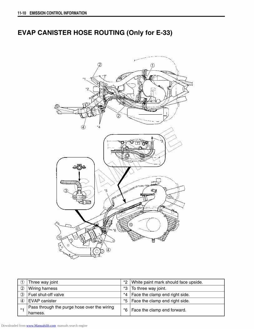
11-10 EMISSION CONTROL INFORMATION
EVAP CANISTER HOSE ROUTING (Only for E-33)
*3
*1
*2
*4
*6
*5
1 Three way joint *2 White paint mark should face upside.2 Wiring harness *3 To three way joint.3 Fuel shut-off valve *4 Face the clamp end right side.4 EVAP canister *5 Face the clamp end right side.
*1Pass through the purge hose over the wiring harness.
*6 Face the clamp end forward.
SAMPLE
Downloaded from www.Manualslib.com manuals search engine
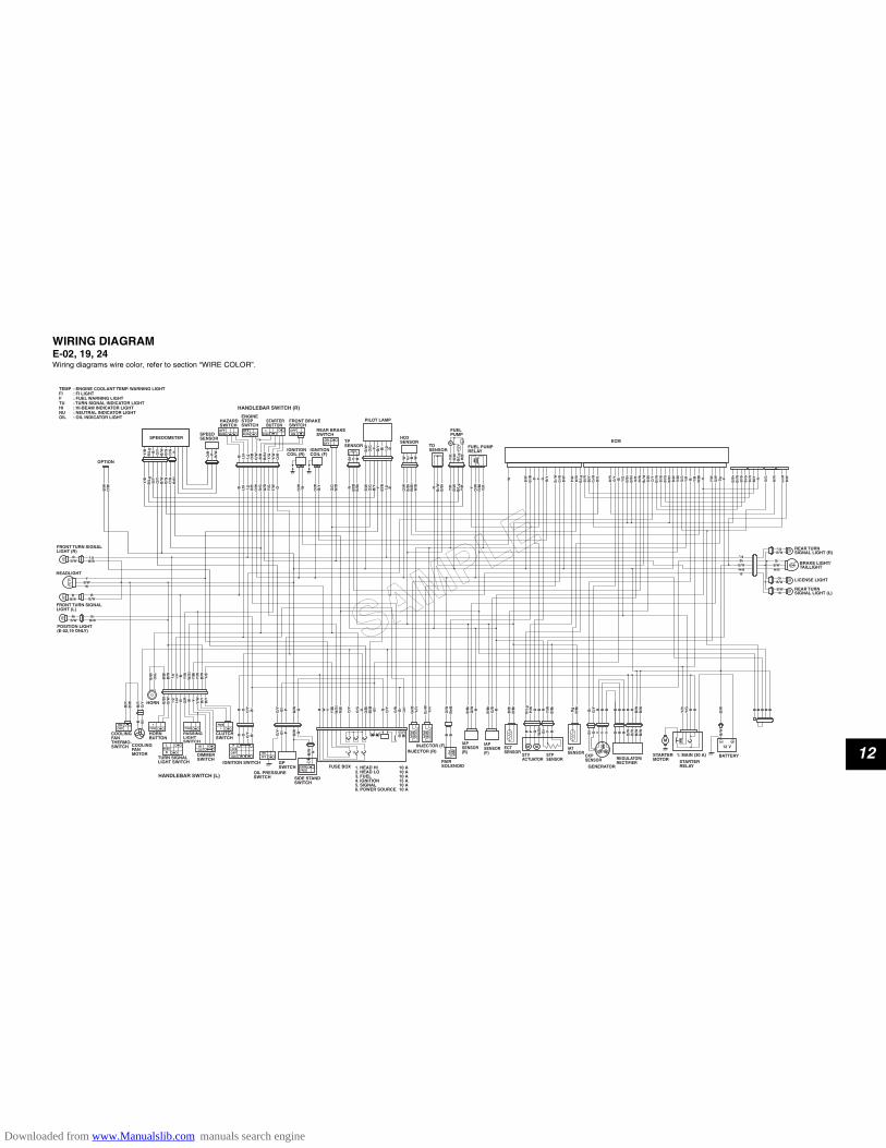
12
WIRING DIAGRAME-02, 19, 24Wiring diagrams wire color, refer to section “WIRE COLOR”.
O/R
O/R P
B/W
B/W
O/R P
B/W
W B/W
B/W
Br/
BB
r/B
B Y G B/Y
B/Y
Gr/
WG
r/W
Gr/
BG
r/B
B/W
B/W
P/W
P/W
W/B
W/B
B/L
gB
/Lg
Bl/R
Bl/R
Bl/Y
Bl/Y
Gr/
RG
r/R
B/G
B/G
W/R
W/R
G/Y
G/Y Bl
Bl
Y/G
Y/G
B/B
rB
/Br
B/B
rB
/Br
G/B
G/B
Bl/B
Bl/B
Br/
WB
r/W
B/B
lB
/Bl
O/Y
O/Y
Bl/W
Bl/W
Bl/B
Bl/B
Bl/G
Bl/G
B/B
rB
/Br
B/W
B/W
R/B
lR
/Bl
O/G
O/G
Y/R
Y/R Br
Br
Y/B
Y/B
W/B
lW
/Bl
R Y/W
Y/W
G/W
G/W Dg
Dg PW B
/WB
r/B
B Y G B/Y
Gr/
WG
r/B
B/W
P/W
W/B
B/L
gB
l/RB
l/YG
r/R
B/G
W/R
G/Y Bl
Y/G
B/B
rB
/Br
G/B
Bl/B
Br/
WB
/Bl
O/Y
Bl/W
Bl/B
Bl/G
B/B
rB
/WR
/Bl
O/G
Y/R Br
Y/B
W/B
lR Y/W
G/W Dg P
B/B
rB
/Br
Bl/W
Bl/W
Bl/B
Bl/B
Bl/G
Bl/G
Bl/R
Bl/R
Bl/Y
Bl/Y R
B/B
rB
l/WB
l/BB
l/GB
l/RB
l/Y R O/G
O/G
W/R
W/R
Gr/
RG
r/R
B/W
B/W
O/G
W/R
Gr/
RB
/W
Y/B
Y/B
Y/G
Y/G R RY/B
Y/G R RBr
Br
G/Y
G/Y B B BBr
G/Y B B B
B/L
gB
/Lg
P/W
P/W G B R Y/W
Y/W
B/B
rB
/Br
B/L
gP
/W G B R Y/W
B/B
r
Dg
Dg
B/B
rB
/Br
Dg
B/B
r
B/B
lB
/Bl
B/B
rB
/Br
B/B
lB
/Br
O/W
O/W
Br/
BB
r/B
O/W
Br/
BB BB B
Gr/
BG
r/B
Y/R
Y/R
Gr/
BY
/RR W YY
/Bl
Y/B
lW
/Bl
W/B
lR
/Bl
R/B
l
O/Y
O/Y
O/G
O/G O
O/B
lO
/Bl
Bl/B
Bl/B Bl
Bl
G O/Y
O/Y
O/B
O/B Br
Br
Lb
lL
bl
R W YY
/Bl
W/B
lR
/Bl
O/Y
O/G O
O/B
lB
l/B Bl
G O/Y
O/B Br
Lb
l
Gr/
WG
r/W
Y/R
Y/R
Gr/
WY
/R
B/B
rB
/Br
G/B
G/B R
B/B
rG
/B R
B/B
rB
/Br
G/W
G/W R
B/B
rG
/W RG/Y
G/Y Bl
Bl P
B/W
B/W GG/Y Bl P
B/W G
G/Y
G/Y Bl
Bl P
B/W
B/W GG/Y Bl P
B/W G
R O O/Y
O/Y Br
BrR O O/Y Br
B/B
lB
/Bl
O/G
O/G
B/B
lO
/G
B/R
B/R
B/W
B/W
B/R
B/W
B/R
B/R
O/Y
O/Y
B/R
O/Y
B Bl
BlB Bl
R O O/Y
O/Y Br
BrR O O/Y Br
B/B
lB
/Bl
B/W
B/W Lg
Lg
Lb
lL
bl
B Y/W
Y/W
W/B
lW
/Bl
Y/B
lY
/Bl
Y/W
Y/W
B/W
B/W Y/B
Y/B
B/B
lB
/W Lg
Lb
lB Y/W
W/B
lY
/Bl
Y/W
B/W Y/B
B/B
lB
/Bl
B/W
B/W Lg
Lg
Lb
lL
bl
B O/R
O/R W Y
Y/W
Y/W B/Y
B/Y
B/Y
B/Y
B/B
lB
/W Lg
Lb
lB O/R W Y
Y/W B/Y
B/Y
B B B R RB
/WB
/WB
/WB
/WB B B R RB
/WB
/W
B/W
B/W
B/W
B/W
B/W
B/W B B B B BB B B B B
LgLgBrBr
B/WB/WW/BW/B
B
LgBr
B/WW/B
B
LgLgB/WB/WLg
B/W
B/WB/WB
B/WB
GrGrB/WB/WGr
B/W
BrBrB/WB/WBr
B/WBrBr
B/WB/WBr
B/W
YB/WB/WW
YB/WW
BB/WB/W
BB/W
BB/WB/W
BB/W
LgLgB/WB/WLg
B/W
BB/WB/W
BB/W
Y/B
Y/B
B/L
gB
/Lg
B/Y
B/Y
G/Y
G/Y
B/W
B/W
B/G
B/G
O/G
O/G
R/B
lR
/Bl
Y/B
B/L
gB
/YG
/YB
/WB
/GO
/GR
/Bl
Y/B
Y/B
B/L
gB
/Lg
B G/Y
G/Y
B/W
B/W
B/G
B/G
O/G
O/G RY/B
B/L
gB G/Y
B/W
B/G
O/G R
B Lb
lL
bl
Lg
Lg
O/B
O/B
O/W
O/W
O/G
O/G
W/B
W/B
Y/G
Y/G
Y/W
Y/W OB Lb
lL
gO
/BO
/WO
/GW
/BY
/GY
/W O
B Lb
lL
bl
Lg
Lg
O/B
O/B
O/W
O/W
B/R
B/R
B/B
lB
/Bl
Y/G
Y/G
Y/W
Y/W
O/R
O/RB Lb
lL
gO
/BO
/WB
/RB
/Bl
Y/G
Y/W
O/R
B/W
B/W
O/B
lO
/Bl
B/W
O/B
l
O/W
O/W WO/W W O/W
O/W
B/Y
B/Y
O/W
B/Y
O/G
O/G
W/B
W/B
O/G
W/B
B/W
B/W
O/G
O/G
B/Y
B/Y Y
Bl/B
Bl/B Lg
Lg B
B/W
O/G
B/Y Y
Bl/B Lg B
B/W
B/W
O/G
O/G Y B/Y
B/Y Bl
Bl
Lg
Lg BB/W
O/G Y B/Y Bl
Lg B
RB
l/BB
l/BB
/Br
B/B
r
RB
l/BB
/Br
O/W
O/W
B/B
rB
/Br
W/B
lW
/Bl
W/B
W/B
O/W
B/B
rW
/Bl
W/B Y
O/W
O/W
R/B
lR
/Bl
Y/R
Y/RY
O/W
R/B
lY
/RRB
r/W
Br/
WB
/Br
B/B
r
RB
r/W
B/B
r
Y/R
Y/R
B/W
B/W
B/L
gB
/Lg
Y/B
Y/B
Y/R
B/W
B/L
gY
/B
B Bl
B B B B/R
B/R
B/R
B/R
B/W
B/W
B/W
B/WB B B B/R
B/R
B/W
B/WBl
Bl
G Y Y YBl
G Y Y Y
Bl
Bl Y BBl Y B W Gr
Gr B WW Gr B W Y/R
Y/R
B/W
B/W
B/L
gB
/Lg
R/B
R/B
Y/R
B/W
B/L
gR
/B
B/W
B/W GB/W G
GrGrB/WB/WW/BW/B
GrB/WW/B
PLOCKOFFON
OFFON
ONOFF M
PUSHFREE
ONOFF
ONOFF PUSH
FREE
LPUSH
R
HILO
PUSH
HANDLEBAR SWITCH (R)
REAR BRAKESWITCH
IGNITIONCOIL (F)
IGNITIONCOIL (R)
IGNITION SWITCH
ENGINE STOPSWITCH
HAZARD SWITCH
FRONT BRAKESWITCH
STARTERBUTTON
HO2SENSOR ECM
FUELPUMP
TPSENSOR
PILOT LAMP
TOSENSOR
FUEL PUMPRELAY
BRAKE LIGHT/TAILLIGHT
REAR TURN SIGNAL LIGHT (R)
REAR TURN SIGNAL LIGHT (L)
LICENSE LIGHT
BATTERY1: MAIN (30 A) STARTER MOTOR STARTER
RELAY
1
FUSE BOX 1. HEAD HI2. HEAD LO3. FUEL4. IGNITION5. SIGNAL6. POWER SOURCE
10 A10 A10 A15 A10 A10 A
REGULATOR/RECTIFIER
SIDE STANDSWITCH
OIL PRESSURE SWITCH
GP SWITCH
IATSENSOR
CKPSENSOR
ECTSENSOR1 2 3
4 5 6
IAPSENSOR(F)
IAPSENSOR(R)INJECTOR (R)
INJECTOR (F)COOLINGFANMOTOR
COOLINGFAN THERMO-SWITCH
PAIRSOLENOID
CLUTCHSWITCH
DIMMERSWITCHTURN SIGNAL
LIGHT SWITCH
PASSINGLIGHTSWITCH
HORNBUTTON
HANDLEBAR SWITCH (L)
HORN
OPTION
HEADLIGHT
FRONT TURN SIGNALLIGHT (R)
FRONT TURN SIGNALLIGHT (L)
POSITION LIGHT(E-02,19 ONLY)
: ENGINE COOLANT TEMP. WARNING LIGHT: FI LIGHT: FUEL WARNING LIGHT : TURN SIGNAL INDICATOR LIGHT: HI-BEAM INDICATOR LIGHT: NEUTRAL INDICATOR LIGHT: OIL INDICATOR LIGHT
TEMPFIFTUHINUOIL
SPEEDSENSOR
STV ACTUATOR
STP SENSOR
GENERATOR
OFFRUN PUSH
OFFRUN
B P G W/B
W/B Bl
Bl Y BB P G
W/B
lB
l Y B
SPEEDOMETER
SAMPLE
Downloaded from www.Manualslib.com manuals search engine
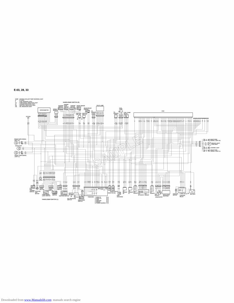
E-03, 28, 33
O/R
O/R P
B/W
B/W
O/R P
B/W
W B/W
B/W
Br/
BB
r/B
B Y G B/Y
B/Y
Gr/
WG
r/W
Gr/
BG
r/B
B/W
B/W
P/W
P/W
B/L
gB
/Lg
Bl/R
Bl/R
Bl/Y
Bl/Y
Gr/
RG
r/R
B/G
B/G
W/R
W/R
G/Y
G/Y Bl
Bl
Y/G
Y/G
B/B
rB
/Br
G/B
G/B
Bl/B
Bl/B
Br/
WB
r/W
B/B
lB
/Bl
O/Y
O/Y
Bl/W
Bl/W
Bl/B
Bl/B
Bl/G
Bl/G
B/B
rB
/Br
B/W
B/W
R/B
lR
/Bl
O/W
O/W
Y/R
Y/R Br
Br
Y/B
Y/B R Y/W
Y/W
G/W
G/W Dg
Dg PW B
/WB
r/B
B Y G B/Y
Gr/
WG
r/B
B/W
P/W
B/L
gB
l/RB
l/YG
r/R
B/G
W/R
G/Y Bl
Y/G
B/B
r
G/B
Bl/B
Br/
WB
/Bl
O/Y
Bl/W
Bl/B
Bl/G
B/B
rB
/WR
/Bl
O/W
Y/R Br
Y/B R Y/W
G/W Dg P
B/B
rB
/Br
Bl/W
Bl/W
Bl/B
Bl/B
Bl/G
Bl/G
Bl/R
Bl/R
Bl/Y
Bl/Y R
B/B
rB
l/WB
l/BB
l/GB
l/RB
l/Y R
O/W
O/W
W/R
W/R
Gr/
RG
r/R
B/W
B/W
O/W
W/R
Gr/
RB
/W
Y/B
Y/B
Y/G
Y/G R RY/B
Y/G R RBr
Br
G/Y
G/Y B B BBr
G/Y B B B
B/L
gB
/Lg
P/W
P/W G B R Y/W
Y/W
B/B
rB
/Br
B/L
gP
/W G B R Y/W
B/B
r
Dg
Dg
B/B
rB
/Br
Dg
B/B
r
B/B
lB
/Bl
B/B
rB
/Br
B/B
lB
/Br
O/W
O/W
Br/
BB
r/B
O/W
Br/
BB BB B
Gr/
BG
r/B
Y/R
Y/R
Gr/
BY
/RR W YY
/Bl
Y/B
lW
/Bl
W/B
lR
/Bl
R/B
l
O/Y
O/Y
O/G
O/G O
O/B
lO
/Bl
Bl/B
Bl/B Bl
Bl
G O/Y
O/Y
O/B
O/B Br
Br
Lb
lL
bl
R W YY
/Bl
W/B
lR
/Bl
O/Y
O/G O
O/B
lB
l/B Bl
G O/Y
O/B Br
Lb
l
Gr/
WG
r/W
Y/R
Y/R
Gr/
WY
/R
B/B
rB
/Br
G/B
G/B R
B/B
rG
/B R
B/B
rB
/Br
G/W
G/W R
B/B
rG
/W RG/Y
G/Y Bl
Bl P
B/W
B/W GG/Y Bl P
B/W G
G/Y
G/Y Bl
Bl P
B/W
B/W GG/Y Bl P
B/W G
R O O/Y
O/Y Br
BrR O O/Y Br
B/B
lB
/Bl
O/G
O/G
B/B
lO
/G
B/R
B/R
B/W
B/W
B/R
B/W
B/R
B/R
O/Y
O/Y
B/R
O/Y
B Bl
BlB Bl
R O O/Y
O/Y Br
BrR O O/Y Br
B/B
lB
/Bl
B/W
B/W Lg
Lg
Lb
lL
bl
B Y/W
Y/W
W/B
lW
/Bl
Y/B
lY
/Bl
Y/W
Y/W
B/W
B/W Y/B
Y/B
B/B
lB
/W Lg
Lb
lB Y/W
W/B
lY
/Bl
Y/W
B/W Y/B
B/B
lB
/Bl
B/W
B/W Lg
Lg
Lb
lL
bl
B O/R
O/R W Y
Y/W
Y/W B/Y
B/Y
B/Y
B/Y
B/B
lB
/W Lg
Lb
lB O/R W Y
Y/W B/Y
B/Y
B B B R RB
/WB
/WB
/WB
/WB B B R RB
/WB
/W
B/W
B/W
B/W
B/W
B/W
B/W
LgLgBrBr
B/WB/WW/BW/B
B
LgBr
B/WW/B
B
GrGrB/WB/WW/BW/B
LgLgB/WB/WLg
B/W
B/WB/WB
B/WB
GrGrB/WB/WGr
B/WY
B/WB/WW
YB/WW
BB/WB/WGrGr
BB/WGr
BB/WB/WGrGr
BB/WGr
LgLgB/WB/WO/GO/G
LgB/WO/G
BB/WB/WO/GO/G
BB/WO/G
Y/B
Y/B
B/L
gB
/Lg
B/Y
B/Y
G/Y
G/Y
B/W
B/W
B/G
B/G
O/G
O/G
R/B
lR
/Bl
Y/B
B/L
gB
/YG
/YB
/WB
/GO
/GR
/Bl
Y/B
Y/B
B/L
gB
/Lg
B G/Y
G/Y
B/W
B/W
B/G
B/G
O/G
O/G RY/B
B/L
gB G/Y
B/W
B/G
O/G R
B Lb
lL
bl
Lg
Lg
O/B
O/B
O/W
O/W
O/G
O/G
W/B
W/B
Y/G
Y/G
Y/W
Y/W OB Lb
lL
gO
/BO
/WO
/GW
/BY
/GY
/W O
B Lb
lL
bl
Lg
Lg
O/B
O/B
O/W
O/W
B/R
B/R
B/B
lB
/Bl
Y/G
Y/G
Y/W
Y/W
O/R
O/RB Lb
lL
gO
/BO
/WB
/RB
/Bl
Y/G
Y/W
O/R
B/W
B/W
O/B
lO
/Bl
B/W
O/B
l
O/W
O/W WO/W W O/W
O/W
B/Y
B/Y
O/W
B/Y
O/G
O/G
W/B
W/B
O/G
W/B
B/W
B/W
O/G
O/G
B/Y
B/Y Y
Bl/B
Bl/B Lg
Lg B
B/W
O/G
B/Y Y
Bl/B Lg B
B/W
B/W
O/G
O/G Y B/Y
B/Y Bl
Bl
Lg
Lg BB/W
O/G Y B/Y Bl
Lg B
RB
l/BB
l/BB
/Br
B/B
r
RB
l/BB
/Br
YO
/WO
/WR
/Bl
R/B
lY
/RY
/RYO
/WR
/Bl
Y/RR
Br/
WB
r/W
B/B
rB
/Br
RB
r/W
B/B
r
Y/R
Y/R
B/W
B/W
B/L
gB
/Lg
Y/B
Y/B
Y/R
B/W
B/L
gY
/B
B Bl
B B B B/R
B/R
B/R
B/R
B/W
B/W
B/W
B/WB B B B/R
B/R
B/W
B/WBl
Bl
G Y Y YBl
G Y Y Y
Bl
Bl Y BBl Y B Y/R
Y/R
B/W
B/W
B/L
gB
/Lg
R/B
R/B
Y/R
B/W
B/L
gR
/B
B/W
B/W GB/W G
GrB/WW/B
PLOCKOFFON
OFFON
ONOFF M
PUSHFREE
ONOFF
ONOFF PUSH
FREE
LPUSH
R
HILO
PUSH
HANDLEBAR SWITCH (R)
REAR BRAKESWITCH
IGNITIONCOIL (F)
IGNITIONCOIL (R)
IGNITION SWITCH
ENGINE STOPSWITCH
HAZARD SWITCH
FRONT BRAKESWITCH
STARTERBUTTON
ECM
FUELPUMP
TPSENSOR
PILOT LAMP
TOSENSOR
FUEL PUMPRELAY
BRAKE LIGHT/TAILLIGHT
REAR TURN SIGNAL LIGHT (R)
REAR TURN SIGNAL LIGHT (L)
LICENSE LIGHT
BATTERY1: MAIN (30 A) STARTER MOTOR STARTER
RELAY
1
FUSE BOX 1. HEAD HI2. HEAD LO3. FUEL4. IGNITION5. SIGNAL6. POWER SOURCE
10 A10 A10 A15 A10 A10 A
REGULATOR/RECTIFIER
SIDE STANDSWITCH
OIL PRESSURE SWITCH
GP SWITCH
IATSENSOR
CKPSENSOR
ECTSENSOR1 2 3
4 5 6
IAPSENSOR(F)
IAPSENSOR(R)INJECTOR (R)
INJECTOR (F)COOLINGFANMOTOR
COOLINGFAN THERMO-SWITCH
PAIRSOLENOID
CLUTCHSWITCH
DIMMERSWITCHTURN SIGNAL
LIGHT SWITCH
PASSINGLIGHTSWITCH
HORNBUTTON
HANDLEBAR SWITCH (L)
HORN
OPTION
HEADLIGHT
FRONT TURN SIGNALLIGHT (R)
FRONT TURN SIGNALLIGHT (L)
: ENGINE COOLANT TEMP. WARNING LIGHT: FI LIGHT: FUEL WARNING LIGHT : TURN SIGNAL INDICATOR LIGHT: HI-BEAM INDICATOR LIGHT: NEUTRAL INDICATOR LIGHT: OIL INDICATOR LIGHT
TEMPFIFTUHINUOIL
SPEEDSENSOR
STV ACTUATOR
STP SENSOR
GENERATOR
OFFRUN PUSH
OFFRUN
B P G W/B
W/B Bl
Bl Y BB P G
W/B
lB
l Y B
SPEEDOMETER
SAMPLE
Downloaded from www.Manualslib.com manuals search engine
Prepared by
December, 2004
Part No. 99500-38050-01E
Printed in Japan
456SAMPLE
Downloaded from www.Manualslib.com manuals search engine

VZ800
Printed in JapanK5
VZ
80
0
No.5230 99500-38050-01E VZ800K5 Service Manual 2004. 11. 29 Cover_14 for PS printing (16 mm)
TOP
BOTTOM
K5 9 9 5 0 0 - 3 8 0 5 0 - 0 1 E
DIC75
Downloaded from www.Manualslib.com manuals search engine