
ManualsLib - Makes it easy to find manuals online! - Mini Bike Passion
332
KLX110 KLX110L Motorcycle Service Manual Downloaded from www.Manualslib.com manuals search engine
-
Upload
khangminh22 -
Category
Documents
-
view
1 -
download
0
Transcript of ManualsLib - Makes it easy to find manuals online! - Mini Bike Passion

KLX110KLX110L
MotorcycleService Manual
Downloaded from www.Manualslib.com manuals search engine

This quick reference guide will assistyou in locating a desired topic or pro-cedure.•Bend the pages back to match theblack tab of the desired chapter num-ber with the black tab on the edge ateach table of contents page.•Refer to the sectional table of contentsfor the exact pages to locate the spe-cific topic required.
Quick Reference Guide
General Information 1 jPeriodic Maintenance 2 jFuel System 3 jEngine Top End 4 jClutch 5 jEngine Lubrication System 6 jEngine Removal/Installation 7 jCrankshaft/Transmission 8 jWheels/Tires 9 jFinal Drive 10 jBrakes 11 jSuspension 12 jSteering 13 jFrame 14 jElectrical System 15 jAppendix 16 j
Downloaded from www.Manualslib.com manuals search engine

KLX110KLX110L
MotorcycleService Manual
All rights reserved. No parts of this publication may be reproduced, stored in a retrieval system ortransmitted in any form or by any means, electronic mechanical photocopying, recording or otherwise,without the prior written permission of Quality Assurance Division/Motorcycle & Engine Company/KawasakiHeavy Industries, Ltd., Japan.No liability can be accepted for any inaccuracies or omissions in this publication, although every possible
care has been taken to make it as complete and accurate as possible.The right is reserved to make changes at any time without prior notice and without incurring an obligation
to make such changes to products manufactured previously. See your Motorcycle dealer for the latestinformation on product improvements incorporated after this publication.All information contained in this publication is based on the latest product information available at the time
of publication. Illustrations and photographs in this publication are intended for reference use only and maynot depict actual model component parts.
© 2009 Kawasaki Heavy Industries, Ltd. 5th Edition (0) : Apr. 19, 2013
Downloaded from www.Manualslib.com manuals search engine

LIST OF ABBREVIATIONSA ampere(s) lb pound(s)ABDC after bottom dead center m meter(s)AC alternating current min minute(s)ATDC after top dead center N newton(s)BBDC before bottom dead center Pa pascal(s)BDC bottom dead center PS horsepower
BTDC before top dead center psi pound(s) per squareinch
°C degree(s) Celsius r revolutionDC direct current rpm revolution(s) per minuteF farad(s) TDC top dead center°F degree(s) Fahrenheit TIR total indicator readingft foot, feet V volt(s)g gram(s) W watt(s)h hour(s) Ω ohm(s)L liter(s)
COUNTRY AND AREA CODESAU Australia TH ThailandCA Canada US United StatesEUR Europe
This motorcycle is designed for a rider weighting less than 154 pounds (70 kg). Exceeding thislimit could damage the motorcycle.
Downloaded from www.Manualslib.com manuals search engine

Foreword
This manual is designed primarily for use bytrained mechanics in a properly equipped shop.However, it contains enough detail and basic in-formation to make it useful to the owner who de-sires to perform his own basic maintenance andrepair work. A basic knowledge of mechanics,the proper use of tools, and workshop proce-dures must be understood in order to carry outmaintenance and repair satisfactorily. When-ever the owner has insufficient experience ordoubts his ability to do the work, all adjust-ments, maintenance, and repair should be car-ried out only by qualified mechanics.In order to perform the work efficiently and
to avoid costly mistakes, read the text, thor-oughly familiarize yourself with the proceduresbefore starting work, and then do the work care-fully in a clean area. Whenever special tools orequipment are specified, do not use makeshifttools or equipment. Precision measurementscan only be made if the proper instruments areused, and the use of substitute tools may ad-versely affect safe operation.To get the longest life out of your vehicle:• Follow the Periodic Maintenance Chart in theService Manual.• Be alert for problems and non-scheduledmaintenance.• Use proper tools and genuine Kawasaki Mo-torcycle parts. Special tools, gauges, andtesters that are necessary when servicingKawasaki motorcycles are introduced by theService Manual. Genuine parts provided asspare parts are listed in the Parts Catalog.• Follow the procedures in this manual care-fully. Don’t take shortcuts.• Remember to keep complete records of main-tenance and repair with dates and any newparts installed.
How to Use This ManualIn this manual, the product is divided into
its major systems and these systems make upthe manual’s chapters. The Quick ReferenceGuide shows you all of the product’s systemand assists in locating their chapters. Eachchapter in turn has its own comprehensive Ta-ble of Contents.
For example, if you want stick coil information,use the Quick Reference Guide to locate theElectrical System chapter. Then, use the Tableof Contents on the first page of the chapter tofind the Ignition Coil section.Whenever you see symbols, heed their in-
structions! Always follow safe operating andmaintenance practices.
DANGERDANGER indicates a hazardous situa-tion which, if not avoided, will result indeath or serious injury.
WARNINGWARNING indicates a hazardous situa-tion which, if not avoided, could resultin death or serious injury.
NOTICENOTICE is used to address practices notrelated to personal injury.
This manual contains four more symbolswhich will help you distinguish different typesof information.
NOTENOTE indicates information that may helpor guide you in the operation or service ofthe vehicle.
• Indicates a procedural step or work to bedone.Indicates a procedural sub-step or how to dothe work of the procedural step it follows. Italso precedes the text of a NOTE.Indicates a conditional step or what action totake based on the results of the test or inspec-tion in the procedural step or sub-step it fol-lows.
In most chapters an exploded view illustrationof the system components follows the Table ofContents. In these illustrations you will find theinstructions indicating which parts require spec-ified tightening torque, oil, grease or a lockingagent during assembly.
Downloaded from www.Manualslib.com manuals search engine

GENERAL INFORMATION 1-1
1
General InformationTable of Contents
Before Servicing ..................................................................................................................... 1-2Model Identification................................................................................................................. 1-7General Specifications............................................................................................................ 1-9Unit Conversion Table ............................................................................................................ 1-12
Downloaded from www.Manualslib.com manuals search engine

1-2 GENERAL INFORMATIONBefore Servicing
Before starting to perform an inspection service or carry out a disassembly and reassembly opera-tion on a motorcycle, read the precautions given below. To facilitate actual operations, notes, illustra-tions, photographs, cautions, and detailed descriptions have been included in each chapter wherevernecessary. This section explains the items that require particular attention during the removal andreinstallation or disassembly and reassembly of general parts.Especially note the following:
Battery GroundBefore completing any service on the motorcycle, discon-
nect the battery cables from the battery to prevent the en-gine from accidentally turning over. Disconnect the groundcable (–) first and then the positive (+). When completedwith the service, first connect the positive (+) cable to thepositive (+) terminal of the battery then the negative (–) ca-ble to the negative terminal.
Edges of PartsLift large or heavy parts wearing gloves to prevent injury
from possible sharp edges on the parts.
SolventUse a high flash-point solvent when cleaning parts. High
flash-point solvent should be used according to directionsof the solvent manufacturer.
Cleaning vehicle before disassemblyClean the vehicle thoroughly before disassembly. Dirt or
other foreign materials entering into sealed areas during ve-hicle disassembly can cause excessive wear and decreaseperformance of the vehicle.
Downloaded from www.Manualslib.com manuals search engine

GENERAL INFORMATION 1-3Before Servicing
Arrangement and Cleaning of Removed PartsDisassembled parts are easy to confuse. Arrange the
parts according to the order the parts were disassembledand clean the parts in order prior to assembly.
Storage of Removed PartsAfter all the parts including subassembly parts have been
cleaned, store the parts in a clean area. Put a clean clothor plastic sheet over the parts to protect from any foreignmaterials that may collect before re-assembly.
InspectionReuse of worn or damaged parts may lead to serious ac-
cident. Visually inspect removed parts for corrosion, discol-oration, or other damage. Refer to the appropriate sectionsof this manual for service limits on individual parts. Replacethe parts if any damage has been found or if the part is be-yond its service limit.
Replacement PartsReplacement Parts must be KAWASAKI genuine or
recommended by KAWASAKI. Gaskets, O-rings, Oil seals,Grease seals, circlips, cotter pins or self-locking nuts mustbe replaced with new ones whenever disassembled.
Assembly OrderIn most cases assembly order is the reverse of disassem-
bly, however, if assembly order is provided in this ServiceManual, follow the procedures given.
Downloaded from www.Manualslib.com manuals search engine
1-4 GENERAL INFORMATIONBefore Servicing
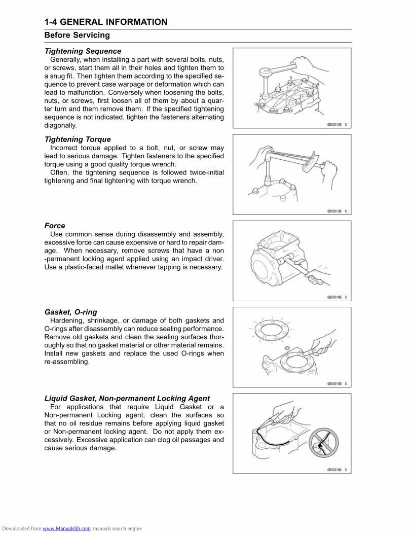
Tightening SequenceGenerally, when installing a part with several bolts, nuts,
or screws, start them all in their holes and tighten them toa snug fit. Then tighten them according to the specified se-quence to prevent case warpage or deformation which canlead to malfunction. Conversely when loosening the bolts,nuts, or screws, first loosen all of them by about a quar-ter turn and them remove them. If the specified tighteningsequence is not indicated, tighten the fasteners alternatingdiagonally.
Tightening TorqueIncorrect torque applied to a bolt, nut, or screw may
lead to serious damage. Tighten fasteners to the specifiedtorque using a good quality torque wrench.Often, the tightening sequence is followed twice-initial
tightening and final tightening with torque wrench.
ForceUse common sense during disassembly and assembly,
excessive force can cause expensive or hard to repair dam-age. When necessary, remove screws that have a non-permanent locking agent applied using an impact driver.Use a plastic-faced mallet whenever tapping is necessary.
Gasket, O-ringHardening, shrinkage, or damage of both gaskets and
O-rings after disassembly can reduce sealing performance.Remove old gaskets and clean the sealing surfaces thor-oughly so that no gasket material or other material remains.Install new gaskets and replace the used O-rings whenre-assembling.
Liquid Gasket, Non-permanent Locking AgentFor applications that require Liquid Gasket or a
Non-permanent Locking agent, clean the surfaces sothat no oil residue remains before applying liquid gasketor Non-permanent locking agent. Do not apply them ex-cessively. Excessive application can clog oil passages andcause serious damage.
Downloaded from www.Manualslib.com manuals search engine

GENERAL INFORMATION 1-5Before Servicing
PressFor items such as bearings or oil seals that must be
pressed into place, apply small amount of oil to the con-tact area. Be sure to maintain proper alignment and usesmooth movements when installing.
Ball Bearing and Needle BearingDo not remove pressed ball or needle unless removal is
absolutely necessary. Replace with new ones wheneverremoved. Press bearings with the manufacturer and sizemarks facing out. Press the bearing into place by puttingpressure on the correct bearing race as shown.Pressing the incorrect race can cause pressure between
the inner and outer race and result in bearing damage.
Oil Seal, Grease SealDo not remove pressed oil or grease seals unless removal
is necessary. Replace with new ones whenever removed.Press new oil seals with manufacture and size marks facingout. Make sure the seal is aligned properly when installing.
Apply specified grease to the lip of seal before installingthe seal.
Circlips, Cotter PinsReplace circlips or cotter pins that were removed with new
ones. Take care not to open the clip excessively when in-stalling to prevent deformation.
Downloaded from www.Manualslib.com manuals search engine

1-6 GENERAL INFORMATIONBefore Servicing
LubricationIt is important to lubricate rotating or sliding parts during
assembly to minimize wear during initial operation. Lubri-cation points are called out throughout this manual, applythe specific oil or grease as specified.
Direction of Engine RotationWhen rotating the crankshaft by hand, the free play
amount of rotating direction will affect the adjustment. Ro-tate the crankshaft to positive direction (clockwise viewedfrom output side).
Electrical LeadsA two-color lead is identified first by the primary color and
then the stripe color. Unless instructed otherwise, electricalleads must be connected to those of the same color.
InstrumentUse a meter that has enough accuracy for an accurate
measurement. Read the manufacture’s instructions thor-oughly before using the meter. Incorrect values may leadto improper adjustments.
Downloaded from www.Manualslib.com manuals search engine

GENERAL INFORMATION 1-7Model Identification
KLX110CA Left Side View
KLX110CA Right Side View
Frame Number Engine Number
Downloaded from www.Manualslib.com manuals search engine

1-8 GENERAL INFORMATIONModel Identification
KLX110DA Left Side View
KLX110DA Right Side View
Downloaded from www.Manualslib.com manuals search engine

GENERAL INFORMATION 1-9General Specifications
Items KLX110CA ∼ CE, KLX110DA ∼ DEDimensionsOverall Length 1 560 mm (61.42 in.)Overall Width 650 mm (25.59 in.)Overall Height:KLX110C 955 mm (37.60 in.)KLX110D 990 mm (38.98 in.)
Wheelbase 1 075 mm (42.32 in.)Road Clearance:KLX110C 215 mm (8.46 in.)KLX110D 265 mm (10.4 in.)
Seat Height:KLX110C 680 mm (26.8 in.)KLX110D 730 mm (28.7 in.)
Curb Mass: 76 kg (168 lb)Front:KLX110C 35 kg (77 lb)KLX110D 34 kg (75 lb)
Rear:KLX110C 41 kg (90 lb)KLX110D 42 kg (93 lb)
Fuel Tank Capacity:KLX110CA ∼ CC, KLX110DA ∼ DC 3.8 L (1.0 US gal)KLX110CD ∼ /DD ∼ 3.6 L (0.95 US gal)
PerformanceMinimum Turning Radius –
EngineType 4-stroke, single cylinder, SOHCCooling System Air-cooledBore and Stroke 53.0 × 50.6 mm (2.09 × 1.99 in.)Displacement 112 cm³ (6.83 cu in.)Compression Ratio 9.5 : 1Carburetion System Carburetor, KEIHIN PB18Fuel Type:Minimum Octane Rating:Research Octane Number (RON) (AU, EUR, TH) 91Antiknock Index (RON + MON)/2 (US, CA) 87
Starting System Kick starter and electric starterIgnition System Digital DC-CDITiming Advance Electronically advancedIgnition Timing 10° BTDC @1 300 r/min (rpm) ∼ 31° BTDC @4 000 r/min
(rpm)Spark Plug NGK CR6HSA
Downloaded from www.Manualslib.com manuals search engine

1-10 GENERAL INFORMATIONGeneral Specifications
Items KLX110CA ∼ CE, KLX110DA ∼ DEValve Timing:Inlet:Open 25° BTDCClose 55° ABDCDuration 260°
Exhaust:Open 60° BBDCClose 20° ATDCDuration 260°
Lubrication System Forced lubrication (wet sump)Engine Oil:Type API SG, SH, SJ, SL or SM with JASO MA, MA1 or MA2Viscosity SAE 10W-40Capacity 1.1 L (1.2 US qt)
Drive TrainPrimary Reduction System:Type:KLX110C Gear, centrifugalKLX110D Gear
Reduction Ratio 3.409 (75/22)Clutch Type:KLX110C Centrifugal & wet, multi discKLX110D Wet, multi disc
Transmission:Type 4-speed, constant mesh, return shiftGear Ratios:1st 3.000 (36/12)2nd 1.938 (31/16)3rd 1.350 (27/20)4th 1.087 (25/23)
Final Drive System:Type Chain driveReduction Ratio 2.923 (38/13)Overall Drive Ratio 10.832 @Top gear
FrameType BackboneSteering Angle 45° to either sideCaster (rake angle):KLX110C 24.8°KLX110D 24.2°
Trail:KLX110C 50 mm (2.0 in.)KLX110D 47 mm (1.9 in.)
Downloaded from www.Manualslib.com manuals search engine

GENERAL INFORMATION 1-11General Specifications
Items KLX110CA ∼ CE, KLX110DA ∼ DEFront Tire:Size 2.50-14 4P.R.Make/Type IRC, GS-45F, Tube
Rear Tire:Size 3.00-12 4P.R.Make/Type IRC, GS-45F, Tube
Rim Size:Front 14 × 1.40Rear 12 × 1.60
Front Suspension:Type Telescopic fork
Wheel Travel:
KLX110C 110 mm (4.3 in.)KLX110D 140 mm (5.5 in.)
Rear Suspension:Type SwingarmWheel travel:KLX110C 110 mm (4.3 in.)KLX110D 132 mm (5.2 in.)
Brake Type:Front and Rear Drum
Electrical EquipmentBattery 12 V 3 AhAlternator:Rated Output 6.4 A/14.0 V @10 000 r/min (rpm)
Specifications are subject to change without notice, and may not apply to every country.
Downloaded from www.Manualslib.com manuals search engine

1-12 GENERAL INFORMATIONUnit Conversion Table
Prefixes for Units:
Prefix Symbol Powermega M × 1 000 000kilo k × 1 000centi c × 0.01milli m × 0.001micro µ × 0.000001
Units of Mass:kg × 2.205 = lbg × 0.03527 = oz
Units of Volume:L × 0.2642 = gal (US)L × 0.2200 = gal (IMP)L × 1.057 = qt (US)L × 0.8799 = qt (IMP)L × 2.113 = pint (US)L × 1.816 = pint (IMP)mL × 0.03381 = oz (US)mL × 0.02816 = oz (IMP)mL × 0.06102 = cu in.
Units of Force:N × 0.1020 = kgN × 0.2248 = lbkg × 9.807 = Nkg × 2.205 = lb
Units of Length:km × 0.6214 = milem × 3.281 = ftmm × 0.03937 = in.
Units of Torque:N·m × 0.1020 = kgf·mN·m × 0.7376 = ft·lbN·m × 8.851 = in·lbkgf·m × 9.807 = N·mkgf·m × 7.233 = ft·lbkgf·m × 86.80 = in·lb
Units of Pressure:kPa × 0.01020 = kgf/cm²kPa × 0.1450 = psikPa × 0.7501 = cmHgkgf/cm² × 98.07 = kPakgf/cm² × 14.22 = psicmHg × 1.333 = kPa
Units of Speed:km/h × 0.6214 = mph
Units of Power:kW × 1.360 = PSkW × 1.341 = HPPS × 0.7355 = kWPS × 0.9863 = HP
Units of Temperature:
Downloaded from www.Manualslib.com manuals search engine

PERIODIC MAINTENANCE 2-1
2
Periodic MaintenanceTable of Contents
Periodic Maintenance Chart .............. 2-2Torque and Locking Agent................. 2-4Specifications .................................... 2-8Special Tools ..................................... 2-10Periodic Maintenance Procedures..... 2-11Fuel System.................................... 2-11Fuel Hose and ConnectionInspection.................................. 2-11
Throttle Cable Inspection ............. 2-11Throttle Cable Adjustment ........... 2-11Idle Speed Inspection .................. 2-12Idle Speed Adjustment................. 2-13Air Cleaner Element Cleaning ..... 2-13Fuel Hose Replacement .............. 2-14Fuel Tap Cleaning........................ 2-15
Engine Top End .............................. 2-16Valve Clearance Inspection ......... 2-16Valve Clearance Adjustment........ 2-16Spark Arrester Cleaning............... 2-17
Clutch.............................................. 2-17Clutch Release Adjustment(KLX110C)................................. 2-18
Clutch Lever Free Play Inspection(KLX110D)................................. 2-18
Clutch Lever Free PlayAdjustment (KLX110D).............. 2-18
Friction and Steel PlatesInspection.................................. 2-19
Engine Lubrication System............. 2-19Engine Oil Change....................... 2-19Oil Filter Replacement ................. 2-20
Wheel/Tires..................................... 2-21Tire Air Pressure Inspection......... 2-21Tires Inspection............................ 2-22Spoke Tightness Inspection......... 2-22Rim Runout Inspection................. 2-23Wheel Bearing Inspection ............ 2-23
Final Drive....................................... 2-24Drive Chain Slack Inspection ....... 2-24Drive Chain Slack Adjustment ..... 2-24Drive Chain Wear Inspection ....... 2-25Drive Chain Lubrication................ 2-26
Sprocket Wear Inspection............ 2-27Rear Sprocket Warp Inspection ... 2-27Drive Chain Guide and SlipperWear Inspection ........................ 2-27
Brakes............................................. 2-27Brake Lever Free Play Inspection 2-27Brake Lever Free PlayAdjustment ................................ 2-28
Brake Pedal Free Play Inspection 2-28Brake Pedal Free PlayAdjustment ................................ 2-29
Brake Lining Wear Inspection ...... 2-29Brake Shoe Lining WearInspection.................................. 2-29
Cam Lever Angle Inspection........ 2-30Cam Lever Angle Adjustment ...... 2-30Brake Panel Lubrication............... 2-32
Suspension..................................... 2-32Front Fork Inspection ................... 2-32Front Fork Oil Change ................ 2-32Rear Shock Absorber OperationInspection.................................. 2-33
Swingarm Pivot Inspection........... 2-34Steering .......................................... 2-34Steering Inspection ...................... 2-34Steering Adjustment .................... 2-34Stem Bearing Lubrication............. 2-35
Frame ............................................. 2-36Frame Inspection ......................... 2-36Sidestand Inspection.................... 2-36
Electrical System ............................ 2-36Spark Plug Cleaning andInspection.................................. 2-36
Battery Charging ConditionInspection.................................. 2-37
Battery Terminals Inspection........ 2-37Cable Inspection ............................. 2-38General Lubrication...................... 2-38
Nut, Bolt, and Fastener TightnessInspection..................................... 2-39Tightness Inspection .................... 2-39
Downloaded from www.Manualslib.com manuals search engine

2-2 PERIODIC MAINTENANCEPeriodic Maintenance Chart
The maintenance must be done in accordance with this chart to keep the motorcycle in good runningcondition.
Periodic InspectionFREQUENCY Initial Every
hours(month (s)) 5 50 100OPERATION (1) (6) (12)
SeePage
Spark plug - clean and inspect † • • 2-36Clutch plates - inspect † • • • 2-19Clutch - inspect • • • 2-17Valve clearance - inspect † • • 2-16Air cleaner element - clean † • • • 2-13Idle speed - inspect † Every ride 2-12Throttle cable - inspect and adjust • • • 2-11Fuel tap - clean • • 2-15Spark arrester - clean • 2-17
ENGINE
Engine sprocket - inspect † • • 2-27Fuel hose, connections - inspect † • • 2-11Brake - adjust † Every ride 2-27Brake lining wear - inspect † Every ride 2-29Brake camshaft - lubricate • • 2-32Spoke tightness and rim runout - inspect † • • • 2-22Drive chain - inspect and adjust Every ride 2-24Drive chain - lubricate Every ride 2-26Drive chain wear - inspect † • • • 2-25Drive chain guide and slipper - inspect † • • 2-27Front fork - clean and inspect • • 2-32Front fork oil - inspect † Every year 2-32Nuts, bolts, fasteners - inspect † • • • 2-39Steering play - inspect † • • • 2-34Steering stem bearing - lubricate • 2-35Rear sprocket - inspect † • • 2-27Battery - inspect † • • 2-37Battery terminal - inspect † • • 2-37General lubrication - perform • • • 2-38Sidestand - inspect † • • 2-36Wheel bearing - inspect † • • 2-23Swingarm pivots - inspect † • • • 2-34Rear shock absorber - inspect † • • 2-33Frame - inspect • • • 2-36
CHASSIS
Wheels/tires - inspect • • • 2-21Cable - inspect Every year 2-38†: Replace, add, adjust, clean or torque if necessary.
Downloaded from www.Manualslib.com manuals search engine

PERIODIC MAINTENANCE 2-3Periodic Maintenance Chart
Periodic Replacement PartsFREQUENCY Initial Every
hours (month (s)) 5 50 100OPERATION (1) (6) (12)
SeePage
Engine oil - change • • • 2-19Oil filter - replace • • 2-20Fuel hose - replace Every 5 years 2-14Front fork oil - change • • 2-32
Downloaded from www.Manualslib.com manuals search engine

2-4 PERIODIC MAINTENANCETorque and Locking Agent
Tighten all bolts and nuts to the proper torque using an accurate torque wrench. If insufficientlytightened, a bolt or nut may become damaged, strip an internal thread, or break and then fall out. Thefollowing table lists the tightening toque for the major bolts and nuts, and the parts requiring use of anon-permanent locking agent or liquid gasket.When checking the tightening toque of the bolts and nuts, first loosen the bolt or nut by half a turn
and then tighten to specified torque.Letters used in the "Remarks" column mean:AL: Tighten the two clamp bolts alternately two times to ensure even tightening torque.L: Apply a non-permanent locking agent to the threads.Lh: Left-hand ThreadsMO: Apply molybdenum disulfide oil.S: Tighten the fasteners following the specified sequence.Si: Apply Silicone grease.R: Replacement PartsT: First, tighten the stem nut with 39 N·m (4.0 kgf·m, 29 ft·lb) of torque, then loosen it and retightenit with 4.9 N·m (0.50 kgf·m, 43 in·lb) of torque.
TorqueFastener
N·m kgf·m ft·lbRemarks
Fuel SystemFuel Tap Mounting Bolts 4.4 0.45 39 in·lbIntake Pipe Bolts 5.2 0.53 46 in·lbCarburetor Holder Bolts 5.2 0.53 46 in·lbAir Cleaner Housing Bolts 3.5 0.36 31 in·lbAir Cleaner Cover Screws 1.5 0.15 13 in·lbAir Duct Clamp Screw 2.0 0.20 18 in·lbThrottle Cable Housing Cap Screws 0.6 0.06 5.3 in·lbScrew (for Seat Hook) 5.0 0.51 44 in·lbScrew (for Rubber Band Hook) 5.0 0.51 44 in·lb
Engine Top EndValve Adjusting Cap Bolts 5.2 0.53 46 in·lbValve Adjusting Screw Locknuts 8.8 0.90 78 in·lbCamshaft Chain Guide Bolt 5.2 0.53 46 in·lbCamshaft Chain Plate Screw 5.2 0.53 46 in·lbCamshaft Sprocket Bolts 12 1.2 106 in·lb LCamshaft Sprocket Cover Bolts 5.2 0.53 46 in·lbCamshaft Chain Tensioner Cap Bolt 5.2 0.53 46 in·lbCamshaft Chain Tensioner Mounting Bolts 5.2 0.53 46 in·lb LCylinder Head Nuts 22 2.2 16 SCylinder Head Bolts 12 1.2 106 in·lb S, LRocker Shaft Holder Plate Bolts (KLX110CA/DAEarly Models) 5.2 0.53 46 in·lb
Rocker Shaft Holder Plate Bolts (KLX110CA/DALate Models ∼ ) 5.2 0.53 46 in·lb L
Exhaust Pipe Holder Nuts 16 1.6 12Muffler Mounting Nut 30 3.1 22 RMuffler Mounting Bolt 9.8 1.0 87 in·lbMuffler Cover Screws 3.0 0.31 27 in·lbSpark Arrester Mounting Bolts 8.8 0.90 78 in·lb
Downloaded from www.Manualslib.com manuals search engine

PERIODIC MAINTENANCE 2-5Torque and Locking Agent
TorqueFastener
N·m kgf·m ft·lbRemarks
ClutchPrimary Clutch Hub Nut (KLX110C) 72 7.3 53Secondary Clutch Hub Nut (KLX110C) 72 7.3 53Clutch Hub Nut (KLX110D) 72 7.3 53Primary Gear Nut (KLX110D) 72 7.3 53Clutch Spring Bolts 5.0 0.51 44 in·lbOil Seal Retaining Plate Screws 2.9 0.30 26 in·lb LClutch Adjusting Screw Locknut (KLX110C) 19 1.9 14
Engine Lubrication SystemEngine Oil Drain Plug 29 3.0 21Clutch Cover Bolts 8.8 0.90 78 in·lbOil Filter Cap Bolts 5.2 0.53 46 in·lbOil Pump Mounting Screws (L = 25) 5.2 0.53 46 in·lbOil Pump Mounting Screw (L = 30) 5.2 0.53 46 in·lbOil Pipe Banjo Bolts 15 1.5 11Oil Pipe Clamp Screw 5.2 0.53 46 in·lb
Engine Removal/InstallationEngine Mounting Nuts 54 5.5 40 R, S
Crankshaft/TransmissionPrimary Gear Nut 72 7.3 53Crankcase Bolts (L=75) 9.8 1.0 87 in·lb S, L (1)Crankcase Bolts (L=50) 9.8 1.0 87 in·lb SShift Drum Bearing Retaining Screws 2.5 0.25 22 in·lb LDrive Shaft Bearing Retaining Screw 5.2 0.53 46 in·lb LShift Drum Cam Bolt 5.2 0.53 46 in·lb LShift Return Spring Pin (Bolt) 22 2.2 16 LShift Drum Position Plate Screw 5.2 0.53 46 in·lbShift Drum Position Lever Pivot Bolt 5.2 0.53 46 in·lbKick Pedal Bolt 8.8 0.90 78 in·lbShift Pedal Bolt 5.2 0.53 46 in·lb
Wheels/TiresFront Axle Nut 44 4.5 32 RRear Axle Nut 64 6.5 47Spoke Nipples 4.0 0.41 35 in·lbTorque Link Nuts 25 2.5 18
Final DriveRear Sprocket Nuts 44 4.5 32 REngine Sprocket Cover Bolts 5.2 0.53 46 in·lbRear Axle Nut 64 6.5 47Chain Guide Roller Mounting Bolt (KLX110D) 23 2.3 17
BrakesBrake Cam Lever Bolt 7.0 0.71 62 in·lbTorque Link Nuts 25 2.5 18
Downloaded from www.Manualslib.com manuals search engine

2-6 PERIODIC MAINTENANCETorque and Locking Agent
TorqueFastener
N·m kgf·m ft·lbRemarks
Brake Pedal Bolt 8.8 0.90 78 in·lbSuspensionFront Fork Clamp Bolts (Upper) 20 2.0 15Front Fork Clamp Bolts (Lower) 30 3.1 22Steering Stem Nut 4.9 0.50 43 in·lbSteering Stem Head Nut 44 4.5 32Swingarm Pivot Nut 78 8.0 58 RTorque Link Nuts 25 2.5 18Fork Bottom Bolt 20 2.0 15Rear Shock Absorber Mounting Bolt (Upper) 39 4.0 29Rear Shock Absorber Mounting Nut (Upper) 39 4.0 29 RRear Shock Absorber Mounting Nut (Lower) 39 4.0 29 R
SteeringHandlebar Holder Bolts 25 2.5 18Steering Stem Head Nut 44 4.5 32Steering Stem Nut 4.9 0.50 43 in·lb TFront Fork Clamp Bolts (Upper) 20 2.0 15Front Fork Clamp Bolts (Lower) 30 3.1 22
FrameFootpeg Bracket Bolts 25 2.5 18Sidestand Nut 29 3.0 21 RSidestand Bolt 9.8 1.0 87 in·lbRear Reflector Bracket Screws (CA Model) 7.4 0.75 65 in·lbScrew (for Seat Hook) 5.0 0.51 44 in·lbScrew (for Rubber Band Hook) 5.0 0.51 44 in·lb
Electrical SystemIgnition Coil Mounting Bolt 2.9 0.30 26 in·lbRegulator Mounting Screw 5.2 0.53 46 in·lbSpark Plug 13 1.3 115 in·lbEnd Cover Screws 4.4 0.45 39 in·lbStarter Motor Terminal Screw 2.0 0.20 18 in·lbStarter Motor Mounting Screws 5.2 0.53 46 in·lbBrush Holder Plate Screws 0.9 0.09 8.0 in·lbTerminal Cover Plate Screws 2.0 0.20 18 in·lbStarter Motor Clutch Bolts 11.8 1.20 104 in·lb LAlternator Rotor Nut 53.9 5.50 39.8Stator Mounting Screws 5.2 0.53 46 in·lbAlternator Cover Bolts (L=45) 8.8 0.90 78 in·lbAlternator Cover Bolts (L=25) 8.8 0.90 78 in·lbAlternator Lead Clamp Screws 5.2 0.53 46 in·lbCrankshaft Sensor Mounting Screws 2.9 0.30 26 in·lbGear Position Switch Screws 2.9 0.30 26 in·lb
Downloaded from www.Manualslib.com manuals search engine

PERIODIC MAINTENANCE 2-7Torque and Locking Agent
Basic Torque for General FastenersThreads dia. Torque
(mm) N·m kgf·m ft·lb5 3.4 ∼ 4.9 0.35 ∼ 0.50 30 ∼ 43 in·lb6 5.9 ∼ 7.8 0.60 ∼ 0.80 52 ∼ 69 in·lb8 14 ∼ 19 1.4 ∼ 1.9 10.0 ∼ 13.510 25 ∼ 34 2.6 ∼ 3.5 19.0 ∼ 2512 44 ∼ 61 4.5 ∼ 6.2 33 ∼ 4514 73 ∼ 98 7.4 ∼ 10.0 54 ∼ 7216 115 ∼ 155 11.5 ∼ 16.0 83 ∼ 11518 165 ∼ 225 17.0 ∼ 23.0 125 ∼ 16520 225 ∼ 325 23 ∼ 33 165 ∼ 240
Downloaded from www.Manualslib.com manuals search engine

2-8 PERIODIC MAINTENANCESpecifications
Item Standard Service LimitFuel SystemThrottle Grip Free Play 2 ∼ 3 mm (0.08 ∼ 0.12 in.) – – –Idle Speed 1 600 ∼ 1 700 r/min (rpm) – – –Air Cleaner Element Oil High quality foam air filter oil – – –
Engine Top EndValve Clearance:Exhaust 0.08 ∼ 0.12 mm (0.003 ∼ 0.005 in.) – – –Inlet 0.04 ∼ 0.08 mm (0.002 ∼ 0.003 in.) – – –
Clutch (KLX110C)Friction Plate Thickness 3.1 ∼ 3.3 mm (0.12 ∼ 0.13 in.) 3.0 mm (0.12 in.)Friction Plate Warp 0.2 mm (0.008 in.) or less 0.3 mm (0.01 in.)Steel Plate Warp 0.15 mm (0.0059 in.) or less 0.3 mm (0.01 in.)
Clutch (KLX110D)Clutch Lever Free Play 2 ∼ 3 mm (0.08 ∼ 0.12 in.) – – –Friction Plate Thickness 3.12 ∼ 3.28 mm (0.123 ∼ 0129 in.) 3.0 mm (0.12 in.)Friction Plate Warp 0.15 mm (0.0059 in.) or less 0.3 mm (0.01 in.)Steel Plate Warp 0.15 mm (0.0059 in.) or less 0.3 mm (0.01 in.)
Engine Lubrication SystemEngine oil:Type API SG, SH, SJ, SL or SM with JASO
MA, MA1 or MA2 – – –
Viscosity SAE 10W-40 – – –
Capacity 0.9 L (1.0 US qt) (when filter is notremoved)
– – –
1.0 L (1.1 US qt) (when filter is removed) – – –1.1 L (1.2 US qt) (when engine iscompletely dry)
Wheels/TiresRim Runout:Axial TIR 0.8 mm (0.031 in.) or less TIR 2.0 mm (0.08 in.)Radial TIR 1.2 mm (0.047 in.) or less TIR 2.0 mm (0.08 in.)
Front and Rear Tires AirPressure
100 kPa (1.0 kgf/cm², 14 psi) – – –
Standard Tire:Front:Size 2.50-14 4P.R. – – –Make IRC – – –Type GS-45F, Tube – – –Rear:Size 3.00-12 4P.R. – – –Make IRC – – –Type GS-45F, Tube – – –
Downloaded from www.Manualslib.com manuals search engine

PERIODIC MAINTENANCE 2-9Specifications
Item Standard Service LimitFinal DriveDrive Chain SlackKLX110C Models 11 ∼ 16 mm (0.4 ∼ 0.6 in.) – – –KLX110D Models 8 ∼ 13 mm (0.3 ∼ 0.5 in.) – – –
Drive Chain 20-Link Length 254.0 ∼ 254.6 mm (10.00 ∼ 10.02 in.) 259 mm (10.2 in.)Standard Chain:Make DAIDO – – –Type DID 420DX – – –Link 90 Links – – –
Rear Sprocket Warp TIR 0.4 mm (0.016 in.) or less TIR 0.5 mm (0.020 in.)BrakesBrake Lever Free Play 4 ∼ 5 mm (0.16 ∼ 0.20 in.) – – –Brake Pedal Free Play 20 ∼ 30 mm (0.79 ∼ 1.18 in.) – – –Brake Shoe Lining Thickness:Front 2.10 ∼ 3.00 mm (0.08 ∼ 0.12 in.) 1.2 mm (0.05 in.)Rear 3.85 ∼ 4.15 mm (0.152 ∼ 0.163 in.) 2.0 mm (0.08 in.)
Brake Cam Lever Angle:Front 80° ∼ 90° – – –Rear 80° ∼ 90° – – –
SuspensionFront ForkSuspension Oil Kawasaki SS-8 or equivalent – – –Amount:KLX110C 165 ±2.5 mL (5.58 ±0.085 US oz)KLX110D 182 ±2.5 mL (5.71 ±0.085 US oz) – – –
Electrical SystemSpark Plug Gap 0.6 ∼ 0.7 mm (0.024 ∼ 0.028 in.) – – –TIR: Total Indicator Readings
Downloaded from www.Manualslib.com manuals search engine

2-10 PERIODIC MAINTENANCESpecial Tools
Steering Stem Nut Wrench:57001-1100
Valve Adjusting Screw Holder:57001-1217
Jack:57001-1238
Spark Plug Wrench, Hex 16:57001-1262
Fork Oil Level Gauge:57001-1290
Filler Cap Driver:57001-1454
Downloaded from www.Manualslib.com manuals search engine

PERIODIC MAINTENANCE 2-11Periodic Maintenance Procedures
Fuel SystemFuel Hose and Connection InspectionThe fuel hoses are designed to be used throughout themotorcycle’s life without any maintenance, however, if themotorcycle is not properly handled, the inside the fuel linecan cause fuel to leak [A] or the hose to burst.• Check the fuel hose.Replace the fuel hose if any fraying, cracks [B], bulges [C]or ozonic cracks [D] are noticed.
•Check that the hose [A] is securely connected and clamps[B] are tightened correctly.•When installing the fuel hose, avoid sharp bending, kink-ing, flattening or twisting, and route the fuel hose with aminimum of bending so that the fuel flow will not be ob-structed.Replace the hose if it has been sharply bent or kinked.
Throttle Cable Inspection•Check throttle grip free play [A] by lightly turning the throt-tle grip [B] back and forth.If the free play is improper, adjust the throttle cable.
Throttle Grip Free PlayStandard: 2 ∼ 3 mm (0.08 ∼ 0.12 in.)
•Check that the throttle grip moves smoothly from full opento close, and the throttle closes quickly and completely inall steering positions by the return spring.If the throttle grip does not return properly, check the throt-tle cable routing, grip free play and cable damage. Thenlubricate the throttle cable.•Run the engine at the idle speed, and turn the handlebarall the way to the right and left to ensure that the idle speeddoes not change.If the idle speed increase, check the throttle cable freeplay and the cable routing.
Throttle Cable Adjustment• Loosen the locknut [A] at the upper end of the throttlecable.• Screw throttle cable adjuster [B] until 2 ∼ 3 mm (0.08 ∼0.12 in.) of throttle grip free play is obtained.• Tighten the locknut.
Downloaded from www.Manualslib.com manuals search engine

2-12 PERIODIC MAINTENANCEPeriodic Maintenance Procedures
If the throttle grip free play cannot be adjusted with theadjuster at the upper end of the throttle cable, use thelower cable adjuster at the carburetor.• Remove the shroud (see Shroud Removal in the Framechapter).• Pull off the boot [A] of the carburetor top.• Loosen the locknut [B], and make the necessary free playadjustment at the lower cable adjuster [C].• Tighten the locknut, and install the boot.• Check if the throttle grip moves smoothly from full open toclose, and the throttle closes quickly and completely in allsteering positions by the return spring. If not, check thethrottle cable routing, grip free play, and cable damage.Then lubricate the throttle cable.•With the engine idling, turn the handlebar both ways andcheck if handlebar movement changes the idling speed.If so, the throttle cable may be improperly adjusted orincorrectly routed, or damaged. Be sure to correct anyof these conditions before riding.
WARNINGOperation with improperly adjusted, incorrectlyrouted or damaged cables could result in an unsaferiding condition. Follow the service manual to bemake sure to correct any of these conditions.
Idle Speed Inspection•Start the engine and warm it up thoroughly.•With the engine idling, turn the handlebar to both sides[A].If handlebar movement changes the idle speed, the throt-tle cablemay be improperly adjusted or incorrectly routed,or it may be damaged. Be sure to correct any of theseconditions before riding (see Cable, Wire, and Hose Rout-ing section in the Appendix chapter).
WARNINGOperation with improperly adjusted, incorrectlyrouted or damaged cables could result in an unsaferiding condition. Follow the service manual to bemake sure to correct any of these conditions.
•Check the idle speed, using the engine revolution testerfor high accuracy.If the idle speed is out of specified range, adjust it.
Idle Speed:Standard: 1 600 ∼ 1 700 r/min (rpm)
Downloaded from www.Manualslib.com manuals search engine

PERIODIC MAINTENANCE 2-13Periodic Maintenance Procedures
Idle Speed AdjustmentNOTICE
The pilot screw [A] is set at the factory and shouldnot be adjusted. But if necessary, set the pilotscrew as follows:
NOTEFor US and CA models, the pilot screw cannot be ad-justed.
•Remove the shroud (see Shroud Removal in the Framechapter).• Turn in the pilot screw and count the number of turns untilit seats fully but not tightly.• Back out the same number of turns counted when turnedin. This is to set the screw to its original position.
NOTEA carburetor has different “turns out” of the pilot screwfor each individual unit. When setting the pilot screw,use the “turns out” determined during disassembly. Usethe specifications in this manual only if the original num-ber is unknown.
•Start the engine and warm it up thoroughly.• Turn the idle adjusting screw [B] until idle speed is correct.Open and close the throttle a few times to make sure thatthe idle speed is within the specified range. Readjust ifnecessary.• Install the shroud (see Shroud Installation in the Framechapter).
Air Cleaner Element CleaningNOTE
In dusty areas, the element should be cleaned morefrequently than recommended interval.After riding through rain or onmuddy roads, the elementshould be cleaned immediately.Since repeated cleaning opens the pores of the ele-ment, replace it with a new one in accordance with thePeriodic Maintenance Chart. Also, if there is a break inthe element material or any other damage to the ele-ment, replace the element with a new one.
Downloaded from www.Manualslib.com manuals search engine

2-14 PERIODIC MAINTENANCEPeriodic Maintenance Procedures
WARNINGGasoline and low flash-point solvents can beflammable and/or explosive and cause severeburns. Clean the element in a well-ventilated area,and take care that there is no spark or flame any-where near the working areas. Do not use gasolineor low flash-point solvents to clean the element.
•Remove:Air Cleaner Element [A] (see Air Cleaner Element Re-moval in the Fuel System chapter)• Stuff a clean, lint-free towel into the carburetor so no dirtis allowed to enter the carburetor.•Wipe out the inside of the air cleaner housing with a cleandamp towel.
NOTICEGasoline and low flash-point solvents can beflammable and/or explosive and cause severeburns. Clean the element in a well-ventilated area,and take care that there is no spark or flame any-where near the working areas. Do not use gasolineor low flash-point solvents to clean the element.
•Clean the element in a bath of high flash-point solventusing a soft bristle brush.• Squeeze it dry in a clean towel. Do not wring the elementor blow it dry; the element can be damaged.•Check all the parts of the element for visible damage.If any of the parts of the element are damaged, replacethem.•After cleaning, saturate the element with high-qualityfoam-air-filter oil, squeeze out the excess, then wrap it ina clean towel and squeeze it as dry as possible.Be careful not to tear the sponge filter.• Remove the towel from the carburetor.
• Install the air cleaner element (see Air Cleaner ElementInstallation in the Fuel System chapter).
Fuel Hose ReplacementWARNING
Gasoline is extremely flammable and can be ex-plosive under certain conditions. Always stop theengine and do not smoke. Make sure the area iswell-ventilated and free from any source of flameor sparks; this includes any appliance with a pilotlight.
Downloaded from www.Manualslib.com manuals search engine

PERIODIC MAINTENANCE 2-15Periodic Maintenance Procedures
•Remove:Fuel Tank (see Fuel Tank Removal in the Fuel Systemchapter)Fuel Hose [A]
•Replace the fuel hose with a new one.• Fix the both ends of the fuel hose with the clamps [A]securely.• Start the engine and check the fuel hose for leaks.
Fuel Tap CleaningWARNING
Gasoline and low flash-point solvents can beflammable and/or explosive and cause severeburns. Clean the tank in a well-ventilated area, andtake care that there are no sparks or flame any-where near the working area. Do not use gasolineor low flash-point solvents to clean the tank.
•Remove the fuel tank and drain the fuel (see Fuel TankRemoval in the Fuel System chapter).• Pour some high flash-point solvent into the fuel tank andshake the tank to remove dirt and fuel deposits.• Pour the solvent out of the tank.•Remove the fuel tap (see Fuel Tap Removal in the FuelSystem chapter).• Clean the fuel tap and the fuel filter screens [A] in highflash-point solvent. After cleaning, install the fuel tap.•Dry the tank, filter and tap with compressed air.• Install the fuel tank (see Fuel Tank Installation in the FuelSystem chapter).
Downloaded from www.Manualslib.com manuals search engine

2-16 PERIODIC MAINTENANCEPeriodic Maintenance Procedures
Engine Top EndValve Clearance Inspection
NOTEValve clearance must be checked and adjusted whenthe engine is cold (at room temperature).
•Remove:Valve Adjusting Covers [A] (see Camshaft Sprocket Re-moval in the Engine Top End chapter)Camshaft Sprocket Cover [B] (see Rocker Arm Removalin the Engine Top End chapter)
•Remove the alternator rotor nut cap.Special Tool - Filler Cap Driver: 57001-1454
•Turn the crankshaft counterclockwise until the line mark[A] on the KACR unit aligns with the sprocket cover matingsurface projection [B].
• Using a thickness gauge [A], measure the valve clearancebetween the adjusting screw [B] and valve stem. Measurethe clearance for both valves at a time.
Valve Clearance (when cold)Standard:Inlet 0.04 ∼ 0.08 mm (0.002 ∼ 0.003 in.)Exhaust 0.08 ∼ 0.12 mm (0.003 ∼ 0.005 in.)
Valve Clearance AdjustmentIf a valve clearance is incorrect, adjust it.Use the valve adjusting screw holder [A] to holding thevalve adjusting screw [B], loosen the adjusting screw lock-nut [C] and insert the thickness gauge [D] between thevalve and adjusting screw, and turn the screw until theadjusting screw stops.Special Tool - Valve Adjusting Screw Holder: 57001-1217
•Tighten:Torque - Valve Adjusting Screw Locknut: 8.8 N·m (0.90
kgf·m, 78 in·lb)
• Install the removed parts (see appropriate chapters).
Downloaded from www.Manualslib.com manuals search engine

PERIODIC MAINTENANCE 2-17Periodic Maintenance Procedures
Spark Arrester CleaningThis vehicle is equipped with a spark arrester. It must be
properly maintained to ensure its efficiency.
NOTICEThe spark arrester must be installed correctly andfunctioning properly to provide adequate fire pro-tection.
WARNINGHot exhaust system parts can cause serious burns.The exhaust system becomes very hot soon afterthe engine is started. To avoid burns, be sure theexhaust system is cold before cleaning the sparkarrester.
•Remove;Right Side Cover (see Side Cover Removal in the Framechapter)Muffler Cover Screws [A]Muffler Cover [B]
•Remove:Spark Arrester Mounting Bolts [A]Spark Arrester [B]
•With a wire brush, remove the carbon off the inside of thespark arrester [A] and muffler.• Inspect the spark arrester.If the spark arrester is damaged, replace it with a newone.• Install the spark arrester into the rear end of the muffler.Torque - Spark Arrester Mounting Bolts: 8.8 N·m (0.90
kgf·m, 78 in·lb)
• Install the muffler cover.Torque - Muffler Cover Screws: 3.0 N·m (0.31 kgf·m, 27
in·lb)
ClutchWARNING
The engine and exhaust system get extremely hotduring normal operation and can cause seriousburns. Never touch the engine or exhaust pipeduring clutch adjustment.
Downloaded from www.Manualslib.com manuals search engine

2-18 PERIODIC MAINTENANCEPeriodic Maintenance Procedures
Clutch Release Adjustment (KLX110C)• Loosen the adjusting screw locknut [A].• Turn the adjusting screw [B] counterclockwise until it be-comes hard to turn.• Loosen the adjusting screw until the specified value.
Clutch Release: 1/4 turn out
•Tighten the locknut without changing the adjusting screwposition.Torque - Clutch Adjusting Screw Locknut: 19 N·m (1.9
kgf·m, 14 ft·lb)
•Start the engine and inspect the conditions of engine shift-ing the pedal a few times.
Clutch Lever Free Play Inspection (KLX110D)•Slide the dust cover [A] out of place.•Check that the clutch cable upper end is fully seated inthe adjuster [B].• Pull the clutch lever [C] lightly, and check the clutch leverfree play.
Clutch Lever Free PlayStandard: 2 ∼ 3 mm (0.08 ∼ 0.12 in.)
If it does not, adjust the lever play.
Clutch Lever Free Play Adjustment (KLX110D)•Slide the dust cover [A] out of place.• Loosen the locknut [B] and turn the adjuster [C] so thatthe clutch lever will have 2 ∼ 3 mm (0.08 ∼ 0.12 in.) ofplay.
NOTEBe sure that the outer cable end at the clutch lever isfully seated in the adjuster at the clutch lever, or it couldslip into the place later, creating enough cable play toprevent clutch disengagement.
• If it cannot be done, loosen the rear locknut [A] at thelower of the clutch cable, and turn the front locknut [B] sothat clutch lever has 2 ∼ 3 mm (0.08 ∼ 0.12 in.) of play.• After the adjustment is made, tighten the locknut, andstart the engine and check that the clutch does not slipand that it release properly.
Downloaded from www.Manualslib.com manuals search engine

PERIODIC MAINTENANCE 2-19Periodic Maintenance Procedures
Friction and Steel Plates Inspection•Remove the clutch plates (see Secondary ClutchDisassembly (KLX110C) or Clutch Hub Disassembly(KLX110D) in the Clutch chapter).• Visually inspect the friction and steel plates to see if theyshow any signs of seizure, or uneven wear.If any plates show signs of damage, replace the frictionplates and steel plates as a set.•Measure the thickness of the friction plates [A] with verniercalipers.[B] KLX110C[C] KLX110DIf they have worn past the service limit, replace them withnew ones.
Friction Plate ThicknessStandard:KLX110C 3.1 ∼ 3.3 mm
(0.12 ∼ 0.13 in.)KLX110D 3.12 ∼ 3.28 mm
(0.123 ∼ 0.129 in.)Service Limit: 3.0 mm (0.12 in.)
•Place each friction plate or steel plate on a surface plate,and measure the gap between the surface plate [A] andeach friction plate or steel plate [B] with a thickness gauge[C]. The gap is the amount of friction or steel plate warp.If any plate is warped over the service limit, replace it witha new one.
Friction Plate WarpStandard:KLX110C 0.2 mm (0.008 in.) or lessKLX110D 0.15 mm (0.0059 in.) or less
Service Limit: 0.3 mm (0.01 in.)
Steel Plate WarpStandard: 0.15 mm (0.0059 in.) or lessService Limit: 0.3 mm (0.01 in.)
Engine Lubrication SystemEngine Oil Change•Warm up the engine thoroughly so that the oil will pick upany sediment and drain easily. Then stop the engine.
Downloaded from www.Manualslib.com manuals search engine

2-20 PERIODIC MAINTENANCEPeriodic Maintenance Procedures
WARNINGThe engine and exhaust system get extremely hotduring normal operation and can cause seriousburns. Never touch the engine or exhaust pipeduring oil change.
•Place an oil pan beneath the engine.•Remove the engine oil drain plug [A], and let the oil draincompletely.• Replace the oil drain gasket with a new one if it is dam-aged.• After draining, install the drain plug.Torque - Engine Oil Drain Plug: 29 N·m (3.0 kgf·m, 21 ft·lb)
•Fill the engine with a good quality motor oil specified be-low.
Recommended Engine
Type: API SG, SH, SJ, SL or SM with JASO MA,MA1 or MA2
Viscosity: SAE 10W-40Capacity: 0.9 L (1.0 US qt) (when filter is not removed)
1.0 L (1.1 US qt) (when filter is removed)1.1 L (1.2 US qt) (when engine is completelydry)
NOTEDo not add any chemical additive to the oil. Oils fulfillingthe above requirements are fully formulated and provideadequate lubrication for both the engine and the clutch.Although 10W-40 engine oil is the recommended oilfor most conditions, the oil viscosity may need to bechanged to accommodate atmospheric conditions inyour riding area.
•Tighten:Torque - Oil Filler Cap: Hand-tighten
•Check the oil level (see Oil Level Inspection in the EngineLubrication System chapter).
Oil Filter Replacement•Drain the engine oil (see Engine Oil Change).•Remove the engine guard (see Engine Guard Re-moval/Installation in the Frame chapter).• Remove:Oil Filter Cap Bolts [A]Oil Filter Cap [B]
Downloaded from www.Manualslib.com manuals search engine

PERIODIC MAINTENANCE 2-21Periodic Maintenance Procedures
•Replace the oil filter [A] with a new one.• Apply engine oil to the grommet [B].• Be sure to install the filter with the grommet facing inside.NOTICE
Inside out installation stops oil flow, causing engineseizure.
•Replace the O-ring [A] with a new one.• Apply grease to the O-ring.• Install the spring [B] securely.• Install the oil filter cap.Torque - Oil Filter Cap Bolt: 5.2 N·m (0.53 kgf·m, 46 in·lb)
• Install the engine guard (see Engine Guard Removal/In-stallation in the Frame chapter).• Pour in the specified type and amount of oil (see EngineOil Change).
Wheel/TiresTire Air Pressure Inspection•Remove the air valve cap.•Measure the tire air pressure with an air pressure gauge[A] when the tires are cold (that is, when the motorcyclehas not been ridden more than a mile during the past 3hours).• Install the air valve cap.Adjust the tire air pressure according to the specificationsif necessary.
Air Pressure (when Cold)Front 100 kPa (1.0 kgf/cm², 14 psi)Rear 100 kPa (1.0 kgf/cm², 14 psi)
Downloaded from www.Manualslib.com manuals search engine

2-22 PERIODIC MAINTENANCEPeriodic Maintenance Procedures
Tires InspectionAs the tire tread wears down, the tire becomes more sus-
ceptible the puncture and failure.•Remove any imbedded stones or other foreign particlesfrom the tread.• Visually inspect the tire for cracks and cuts, replacing thetire in case of bad damage. Swelling or high spots indi-cate internal damage, requiring tire replacement.
WARNINGSome replacement tires may adversely affect han-dling and cause an accident resulting in serious in-jury or death. To ensure proper handling and sta-bility, use only the recommended standard tires forreplacement, inflated to the standard pressure.
NOTECheck and balance the wheel when a tire is replacedwith a new one.
Standard TireFront:Size: 2.50-14 4P.R.Make: IRCType: GS-45F
Rear:Size: 3.00-12 4P.R.Make: IRCType: GS-45F
Spoke Tightness Inspection•Check that all the spokes are tightened evenly.If spoke tightness is uneven or loose, tighten the spokenipples evenly.Torque - Spoke Nipples: 4.0 N·m (0.41 kgf·m, 35 in·lb)
•Check the rim runout (see Rim Runout Inspection).WARNING
A missing spoke places an additional load onthe other spokes, which will eventually causeother spokes to break, creating the potential foran accident resulting in serious injury or death.Immediately replace any broken spoke(s).
Downloaded from www.Manualslib.com manuals search engine

PERIODIC MAINTENANCE 2-23Periodic Maintenance Procedures
Rim Runout Inspection•Place the jack under the frame so that the front/rear wheeloff the ground.Special Tool - Jack: 57001-1238
• Inspect the rim for small cracks, dents, bending, or warp-ing.If there is any damage to the rim, it must be replaced.• Set a dial gauge against the side of the rim, and rotatethe rim to measure the axial runout [A]. The difference be-tween the highest and lowest dial readings is the amountof runout.• Set a dial gauge against the outer circumference of therim, and rotate the rim to measure radial runout [B]. Thedifference between the highest and lowest dial readingsis the amount of runout.If rim runout exceeds the service limit, check the wheelbearings first. Replace them if they are damaged. If theproblem is not due to the bearings, correct the rim warp(runout). A certain amount of rim warp can be correctedby recentering the rim. Loosen some spokes and tightenothers within the standard torque to change the position ofdifferent parts of the rim. If the rim is badly bent, however,it must be replaced.
Rim Runout (with tire installed)Standard:Axial TIR 0.8 mm (0.031 in.) or lessRadial TIR 1.2 mm (0.047 in.) or less
Service Limit:Axial TIR 2.0 mm (0.08 in.)Radial TIR 2.0 mm (0.08 in.)
Wheel Bearing Inspection•Raise the front/rear wheel off the ground.Special Tool - Jack: 57001-1238
•Spin the wheel lightly, and check for roughness, bindingor noise.If roughness, binding, abnormal noise is found, replacethe hub bearing.
• Turn the handlebar until the handlebar doesn’t move toeither side.• The wheel edge is moved to one direction gripping theedge of the wheel by both hands and the play of the wheelbearing is checked.If the play is found, replace the bearing.
Downloaded from www.Manualslib.com manuals search engine

2-24 PERIODIC MAINTENANCEPeriodic Maintenance Procedures
Final DriveDrive Chain Slack Inspection•Raise the rear wheel off the ground, rotate the rear wheelto find the place where the chain is tightest (because itwears unevenly).• Check the wheel alignment (seeWheel Alignment Inspec-tion in the Final Drive chapter), and adjust it if necessary(see Drive Chain Slack Adjustment).
NOTEClean the drive chain if it is dirty, and lubricate it if itappears dry.
•Push up the chain midway between the engine sprocketand rear sprocket.•Measure the space (chain slack) [A] between the chainand the swingarm as shown.If the drive chain slack exceeds the standard, adjust it.
Drive Chain SlackStandard:KLX110C Models 11 ∼ 16 mm (0.4 ∼ 0.6 in.)KLX110D Models 8 ∼ 13 mm (0.3 ∼ 0.5 in.)
Drive Chain Slack Adjustment•Remove:Cotter Pin [A]• Loosen:Rear Torque Link Nut [B]Axle Nut [C]Brake Adjusting Nut [D]Right and Left Chain Adjuster Locknuts [E]
NOTICEIf you don’t loosen the torque link nut, it may leadto the brake parts damage when the adjusters areset.
• If the chain is too tight, back out the left and right chainadjusting nuts [A] evenly, and push the wheel forward untilthe chain is too loose.• Turn both chain adjusting nuts evenly until the drive chainhas the correct amount of slack. To keep the chain andwheel properly aligned, the notch [B] on the right chainadjuster [C] should align with the same swingarm mark[D] that the left chain adjuster notch aligns with.
Check the wheel alignment.
WARNINGMisalignment of the wheel will result in abnormalwear and may result in an unsafe riding condition.Be sure the wheel is properly aligned.
Downloaded from www.Manualslib.com manuals search engine

PERIODIC MAINTENANCE 2-25Periodic Maintenance Procedures
•Tighten both chain adjuster locknuts securely.• Tighten the axle nut.Torque - Rear Axle Nut: 64 N·m (6.5 kgf·m, 47 ft·lb)
•Rotate the wheel, measure the chain slack again at thetightest position, and readjust if necessary.• Tighten the rear torque link nut.Torque - Rear Torque Link Nut: 25 N·m (2.5 kgf·m, 18 ft·lb)
• Insert a new cotter pin [A] into the axle.NOTE
When inserting the cotter pin, if the slots in the nut donot align with the cotter pin hole in the axle, tighten thenut clockwise [B] up to next alignment.It should be within 30 degrees.Loosen once and tighten again when the slot goes pastthe nearest hole.
•Bend the cotter pin [A] over the nut [B].• Check the rear brake effectiveness.
WARNINGA loose axle nut can lead to an accident resulting inserious injury or death. Tighten the axle nut to theproper torque and install a new cotter pin.
Drive Chain Wear Inspection•Remove the bolts [A] and take off the chain cover [B].• Rotate the rear wheel to inspect the drive chain for dam-aged rollers, and loose pins and links.If there is any irregularity, replace the drive chain (seeDrive Chain Removal and Installation in the Final Drivechapter).Lubricate the drive chain if it appears dry (see Drive ChainLubrication).
Downloaded from www.Manualslib.com manuals search engine

2-26 PERIODIC MAINTENANCEPeriodic Maintenance Procedures
•Stretch the chain taut by hanging a 10 kg (20 lb) weight[A] on the chain.•Measure the length of 20 links [B] on the straight part [C] ofthe chain from the pin center of the 1st pin to the pin centerof the 21st pin. Since the chain may wear unevenly, takemeasurements at several places.
Drive Chain 20-link LengthStandard: 254.0 ∼ 254.6 mm (10.00 ∼ 10.02 in.)Service Limit: 259 mm (10.2 in.)
If any measurements exceed the service limit, replace thechain. Also, replace the front and rear sprockets when thedrive chain is replaced.
WARNINGA chain that breaks or jumps off the sprocketscould snag on the engine sprocket or lock therear wheel, severely damaging the motorcycle andcausing it to go out of control. Inspect the chain fordamage and proper adjustment before each ride.If chain wear exceeds the service limit, replace itwith the standard chain.
Standard ChainMake: DAIDOType: DID 420DXLink: 90 Links
Drive Chain LubricationThe chain should be lubricated with a lubricant which willboth prevent the exterior from rusting and also absorbshock and reduce friction in the interior of the chain.If the chain is especially dirty, it should bewashed in dieseloil or kerosene, and afterward soaked in heavy oil. Shakethe chain while it is in the oil so that oil will penetrate tothe inside of each roller.• An effective, good quality lubricant specially formulatedfor chains is best for regular chain lubrication.
• If a special lubricant is not available, a heavy oil such asSAE90 is preferred to a lighter oil because it will stay onthe chain longer and provide better lubrication.• Apply oil to the sides of the rollers so that oil will penetrateto the rollers and bushings.•Wipe off any excess oil.Oil applied area [A]
Downloaded from www.Manualslib.com manuals search engine

PERIODIC MAINTENANCE 2-27Periodic Maintenance Procedures
Sprocket Wear Inspection•Visually inspect the front and rear sprocket teeth for wearand damage.If they are worn as illustrated or damaged, replace thesprocket.[A] Worn Tooth (Engine Sprocket)[B] Worn Tooth (Rear Sprocket)[C] Direction of Rotation
NOTEIf a sprocket requires replacement, the chain is proba-bly worn also. When replacing a sprocket, inspect thechain.
Rear Sprocket Warp Inspection•Using the jack, raise the rear wheel off the ground.Special Tool - Jack: 57001-1238
•Set a dial gauge [A] against the rear sprocket [B] near theteeth as shown.•Rotate [C] the rear wheel to measure the sprocket runout(warp).The difference between the highest and lowest dial gaugereadings is the amount of runout (warp).If the runout exceeds the service limit, replace the rearsprocket.
Rear Sprocket WarpStandard: TIR 0.4 mm (0.016 in.) or lessService Limit: TIR 0.5 mm (0.020 in.)
Drive Chain Guide and Slipper Wear Inspection•Visually inspect the following parts.Chain Slipper [A]Chain Guide Roller [B] (KLX110D Models)Chain Guide [C]If the chain guides, chain slipper and chain guide rollershow any signs of abnormal wear or damage, replacethem.
BrakesBrake Lever Free Play Inspection•Slide the brake lever dust cover [A] out of place.•Check the front brake lever free play [B] when the brakeis lightly applied.
Brake Lever Free PlayStandard: 4 ∼ 5 mm (0.16 ∼ 0.20 in.)
If the lever has improper play, adjust it.•Operate the lever a few times to see that it returns to itsrest position immediately upon release.•Check for brake drag.•Check braking effectiveness.• Slide the brake lever dust cover back into place.
Downloaded from www.Manualslib.com manuals search engine

2-28 PERIODIC MAINTENANCEPeriodic Maintenance Procedures
Brake Lever Free Play Adjustment•Slide the brake lever dust cover [A] out of place.• Loosen the locknut [B] and turn the adjuster [C] so thatthe brake lever will have 4 ∼ 5 mm (0.16 ∼ 0.20 in.) ofplay.
• If it cannot be done, use the adjuster at the end of thebrake cable.• Loosen the locknuts [A] at the lower end of the brake ca-ble.• Turn the adjuster [B] so that the brake lever has the cor-rect amount of play, and tighten the locknuts.• If sufficient adjustment can not be made with the adjusterat the lower end of the brake cable, complete the adjust-ment with the adjuster at the brake lever, and then tightenthe locknut.• Check for brake drag.•Check braking effectiveness.• Slide the brake lever dust cover back into place.
NOTEForminor corrections, use the adjuster at the front brakelever.If the brake lever adjustment cannot be made with theadjuster, move the front brake cam lever to a new posi-tion on the brake camshaft.
Brake Pedal Free Play Inspection•Check the brake pedal free play [A] when the pedal ispushed down lightly by hand.
Brake Pedal Free PlayStandard: 20 ∼ 30 mm (0.76 ∼ 1.18 in.)
If the pedal has improper play, adjust it.•Operate the pedal a few times to see that it returns to itsrest position immediately upon release.•Rotate the rear wheel to check for brake drag.•Check braking effectiveness.If there is any doubt as to the conditions of the brake,check the brake parts for wear or damage.
Downloaded from www.Manualslib.com manuals search engine

PERIODIC MAINTENANCE 2-29Periodic Maintenance Procedures
Brake Pedal Free Play Adjustment•Turn the adjusting nut [A] at the brake cam lever so thatthe pedal has proper play.•Operate the pedal a few times to see that it returns to itsrest position immediately upon release.•Rotate the rear wheel to check for brake drag.•Check braking effectiveness.If there is any doubt as to the conditions of the brake,check the brake parts for wear or damage.
Brake Lining Wear Inspection•Check the brake lining wear indicator [A] (only rear brake)points within the USABLE RANGE [B] when the brake isfully applied.If it does not, the brake shoes must be immediately re-placed and the other brake parts examined.
Brake Shoe Lining Wear Inspection•Check whether the brake lining wear indicator [A] pointswithin the USABLERANGE [B] when the brakes are firmlyapplied, or remove the brake shoes and inspect the liningthickness at few locations.If the lining thickness is out of the range, or beyond theservice limit, replace the brake shoes as a set and inspectother brake parts.If the lining thickness is greater than the service limit, dothe following before installing the shoes.File or sand down any high spots on the surface of thelining.Use a wire brush to remove any foreign particles from thelining.
Downloaded from www.Manualslib.com manuals search engine

2-30 PERIODIC MAINTENANCEPeriodic Maintenance Procedures
Brake Shoe Lining Thickness [A]Standard:Front 2.10 ∼ 3.00 mm
(0.08 ∼ 0.12 in.)Rear 3.85 ∼ 4.15 mm
(0.152 ∼ 0.163 in.)(When the wear indicator iswithin the USABLE RANGE.)
Service limit:Front 1.2 mm (0.05 in.)Rear 2.0 mm (0.08 in.)
(When the wear indicator is outof the USABLE RANGE.)
•Wash off any oil or grease with oilless cleaning fluid suchas trichloroethylene or acetone.
WARNINGThese cleaning fluids are usually highly flammableand harmful if breathed for prolonged periods. Besure to heed the fluid manufacturer’s warnings.
• Install the brake panel (see Brake Panel Installation in theBrakes chapter).
Cam Lever Angle Inspection•Check that the brake cam lever comes to an 80° ∼ 90° an-gle [A] with the brake rod when the brake is fully applied.If it does not, adjust the brake cam lever angle.
Brake Cam Lever AngleStandard: 80 ∼ 90°
After adjusting the cam lever angle, make sure to adjustthe brake pedal free play (see Brake Pedal Free Play Ad-justment).
WARNINGSince a cam lever angle greater than 90° reducesbraking effectiveness, periodically check and ad-just the cam lever angle.
Cam Lever Angle AdjustmentFront Brake Cam Lever Angle:•Remove:Front Wheel (see Front Wheel Removal in theWheels/Tires chapter)Brake Panel (see Brake Panel Removal in the Brakeschapter)
Downloaded from www.Manualslib.com manuals search engine

PERIODIC MAINTENANCE 2-31Periodic Maintenance Procedures
•Before removing the cam lever [A], mark the position [B]of the cam lever.• Remove the brake cam lever bolt [C] and nut [D], and thenpull out the brake cam lever from the brake camshaft.•Mount the cam lever at a new position so that the camlever has a proper angle when the brake is fully applied.
Brake Cam Lever AngleStandard: 80 ∼ 90°
•Tighten the brake cam lever bolt and nut.• Install the removed parts (see appropriate chapters).• Adjust the brake lever free play (see Brake Lever FreePlay Adjustment).
Rear Brake Cam Lever Angle:NOTICE
Do not depress the brake pedal deeply in order toseparate the brake rod from the brake cam leverjoint, this may extend the brake spring beyond itsallowable spring extension.Rotate the rear brake panel clockwise as far as itwill go with the brake rod inserted into the brakecam lever joint, then depress the brake pedal lightly,the brake rod will be separated from the brake camlever joint.
•Remove the brake rod end [A] from the brake cam lever[B] (see Rear Wheel Removal in the Wheels/Tires chap-ter).• Before removing the cam lever, mark the position [C] ofthe cam lever.• Remove the brake cam lever bolt [D] and nut [E], and thenpull out the brake cam lever from the brake camshaft.•Mount the cam lever at a new position so that the camlever has a proper angle when the brake is fully applied.
Brake Cam Lever AngleStandard: 80 ∼ 90°
•Tighten the brake cam lever bolt and nut.Torque - Brake Cam Lever Bolt: 7.0 N·m (0.71 kgf·m, 62
in·lb)
WARNINGWhen remounting the cam lever, be sure that theposition of the wear indicator on the serrated shaftis not altered. A change in cam lever angle iscaused by wear of internal brake parts. Wheneverthe cam lever angle is adjusted, also check fordrag and proper operation, taking particular noteof the brake lining wear indicator position. In caseof doubt as to braking effectiveness, disassembleand inspect all internal brake parts. Worn parts canresult in the brake locking or failing.
• Install the removed parts (see appropriate chapters).• Adjust the brake pedal free play (see Brake Pedal FreePlay Adjustment).
Downloaded from www.Manualslib.com manuals search engine

2-32 PERIODIC MAINTENANCEPeriodic Maintenance Procedures
Brake Panel Lubrication•Disassemble the brake panel (see Brake Panel Disas-sembly in the Brakes chapter).• Clean all old grease out of the brake parts with a cloth.• Apply high-temperature grease to the following.Brake Shoe Anchor Pin [A]Spring Ends [B]Cam Surfaces [C]Cam Shaft Groove [D]
SuspensionFront Fork Inspection•Visually inspect the front fork for oil leakage, scoring orscratches on the outer surface of the inner tubes [A].• Holding the brake lever, pump the front fork down and upmanually to check for smooth operation.If the fork shown damages or oil leak, replace the dam-aged parts.If the fork rattles, inspect the oil level or tightening torque.
NOTICEIf the inner tube is badly bent or creased, replaceit. Excessive bending, followed by subsequentstraightening, can weaken the inner tube.
Front Fork Oil Change•Remove the cap.• Loosen the front fork upper clamp bolt [A].• Remove the snap ring [B] while pressing the top plug [C],and then remove the top plug with O-ring.
•Remove the front fork (see Front Fork Removal in theSuspension chapter).
• Thoroughly clean the fork before disassembly.NOTICE
Be careful not scratch the inner tube and not todamage the dust seal.Avoid scratching or damaging the inner tube or thedust seal. Use a mild detergent and sponge out dirtwith plenty of water.
•Remove:Fork SpringDust Seal
Downloaded from www.Manualslib.com manuals search engine

PERIODIC MAINTENANCE 2-33Periodic Maintenance Procedures
•Drain the fork oil [A] with the fork upside down.NOTE
Pump the fork tube several times to discharge the oil.•Pour in the specified type and amount of oil.Suspension Oil - SS-8 (1 L): 44091-0007
Fork Oil Amount:KLX110C Models 165 ±2.5 mL (5.58 ±0.085 US oz)KLX110D Models 182 ±2.5 mL (5.71 ±0.085 US oz)
•Hold the outer tube vertically in a vise and compress thefork completely.•Wait until the oil level stabilizes.•Use the fork oil level gauge [A] to measure the distancebetween the top of the inner tube to the oil level.Special Tool - Fork Oil Level Gauge: 57001-1290Set the oil level gauge stopper [B] so that the distance [C]from the bottom of the stopper to the lower end of the pipeis the standard oil level distance.A correct measurement can not be obtained unless thelevel gauge pipe is placed in the center of the inner tube.
Oil Level (fully compressed, without spring)Standard:KLX110C Models 85 ±2 mm (3.35 ±0.08 in.)KLX110D Models 118 ±2 mm (4.65 ±0.08 in.)
Place the stopper of the level gauge at the top [D] of theinner tube [E] and pull the handle slowly to draw out theexcess oil from fork into the gauge, thus attaining the stan-dard level.If no oil is drawn out, there is not enough oil in the fork.Pour in some more oil and measure again.•Change the oil in the another fork leg in the samemanner.• Install the removed parts (see appropriate chapters).Rear Shock Absorber Operation Inspection•Bounce [A] the rear of the motorcycle up and down andcheck for smooth suspension stroke.•Remove the side cover (see Side Cover Removal in theFrame chapter).• Check for a broken or collapsed spring.•Check the shock for a bent shaft or oil leaks.If the shock does not smoothly or damaged, replace orrepair defective parts.
Downloaded from www.Manualslib.com manuals search engine

2-34 PERIODIC MAINTENANCEPeriodic Maintenance Procedures
Swingarm Pivot Inspection•Raise the rear wheel off the ground with the jack.Special Tool - Jack: 57001-1238
•Move the swingarm [A] side to side to check for worn,damaged or loose suspension pivot components.If any play is detected, check for looseness of swingarmpivot shaft nut or for damage to the swingarm rubberbushings.
SteeringSteering Inspection•Raise the front wheel off the ground with the jack.Special Tool - Jack: 57001-1238
•With the front wheel pointing straight ahead, alternatelynudge each end of the handlebar. The front wheel shouldswing fully left and right from the force of gravity until thefork hits the stop.If the steering binds or catches before the stop, check therouting of the cables, hoses and harnesses.If the steering feels tight, adjust or lubricate the steering.
• Feel for steering looseness by pushing and pulling theforks.If you feel looseness, adjust the steering.
Steering Adjustment•Raise the front wheel off the ground with the jack.Special Tool - Jack: 57001-1238
•Remove:Number Plate (see Number Plate Removal in the Framechapter)Handlebar Holder Bolts [A]Handlebar Holders [B]Handlebar [C] (from holder)
Downloaded from www.Manualslib.com manuals search engine

PERIODIC MAINTENANCE 2-35Periodic Maintenance Procedures
• Loosen the front fork upper clamp bolts [A], and removethe steering stem head nut [B] and steering stem head[C].
• Turn the steering stem nut [A] with the steering stem nutwrench [B] to obtain the proper adjustment.If the steering is too tight, loosen the stem nut a fraction ofa turn; if the steering is too loose, tighten the nut a fractionof a turn.Special Tool - Steering Stem Nut Wrench: 57001-1100
NOTETurn the stem nut 1/8 turn at a time maximum.
• Install the steering stem head.• Tighten the following:Torque - Steering Stem Head Nut: 44 N·m (4.5 kgf·m, 32
ft·lb)Front Fork Clamp Bolts (Upper): 20 N·m (2.0kgf·m, 15 ft·lb)
•Check the steering again.If the steering is too tight or too loose, repeat the adjust-ment as mentioned above.• Install the removed parts (see appropriate chapters).Stem Bearing Lubrication•Remove the steering stem (see Steering Stem, StemBearing Removal in the Steering chapter).• Using a high flash-point solvent, wash the upper ball bear-ing and lower tapered rollers in the cages, and wipe theupper and lower outer races, which are press-fitted intothe frame head pipe, clean off grease and dirt.• Visually check the outer races and the rollers.Replace the bearing part if they show wear or damage.• Apply grease liberally to the upper races, and stick theball bearing in place with grease. There are 23 steel balls[A] installed in the upper outer race.• Pack the lower tapered roller bearings [B] in the cageswith grease, and apply a light coat of grease to the lowerouter race.• Install the steering stem, and adjust the steering (seeSteering Adjustment).
Downloaded from www.Manualslib.com manuals search engine

2-36 PERIODIC MAINTENANCEPeriodic Maintenance Procedures
FrameFrame Inspection•Clean the frame with steam cleaner.• Visually inspect the frame [A] for cracks, dents, bending,or warp.If there is any damage to the frame, replace it.
WARNINGA repaired frame may fail in use, possibly causingan accident resulting in injury or death. If the frameis bent, dented, cracked, or warped, replace it.
Sidestand Inspection•See if the sidestand [A] moves smoothly and retracts fully.If not, clean and grease the pivot [B] and sliding portion[C].• Check the sidestand spring [D] for damage.If necessary, replace the spring.
Electrical SystemSpark Plug Cleaning and Inspection•Remove the spark plug cap [A].• Remove the spark plug [B], using the spark plug wrench[C].Special Tool - Spark Plug Wrench: 57001-1262
Owner’s Tool - Spark Plug Wrench, 16 mm: 92110-1206
•The plug may also be cleaned using high flash-point sol-vent and a nonmetal brush (nylon etc.).If the spark plug electrodes are corroded or damaged orif the insulator is cracked, replace the plug. Use the stan-dard spark plug.
Downloaded from www.Manualslib.com manuals search engine

PERIODIC MAINTENANCE 2-37Periodic Maintenance Procedures
•Measure the gap [A] with a wire-type thickness gauge.If the gap is incorrect, carefully bend the side electrode[B] with a suitable tool to obtain the correct gap.
Spark Plug GapStandard: 0.6 ∼ 0.7 mm (0.024 ∼ 0.028 in.)
• Install the spark plug.Torque - Spark Plug: 13 N·m (1.3 kgf·m, 115 in·lb)
• Insert the plug cap, and confirm for the spark plug not tocome off.
Battery Charging Condition InspectionBattery charging condition can be checked by measuringbattery terminal voltage with a digital voltmeter [A].• Remove:Left Side Cover (see Side Cover Removal in the Framechapter)Seat (see Seat Removal in the Frame chapter)•Open the battery cover (see Battery Removal in the Elec-trical System chapter).• Disconnect the battery terminals.
NOTICEBe sure to disconnect the negative (–) cable first.
•Measure the battery terminal voltage.NOTE
Measure with a digital voltmeter which can be read onedecimal place voltage.
If the reading is 12.6 V or more, no refresh charge is re-quired, however, if the read is below the specified, refreshcharge is required.
Battery Terminal VoltageStandard: 12.6 V or more
Terminal Voltage (V) [A]Battery Charge Rate (%) [B]Refresh charge is required [C]Good [D]
Battery Terminals Inspection•Check the battery terminal screws [A] for tightness andmake sure the terminal cover is in place.
WARNINGLoose battery cables can create sparks which cancause a fire or explosion resulting in injury or death.Make sure the battery terminal screws are tightenedsecurely and the covers are installed over the termi-nals.
Downloaded from www.Manualslib.com manuals search engine

2-38 PERIODIC MAINTENANCEPeriodic Maintenance Procedures
•Check that the battery terminals are not corroded.If necessary, remove the battery (see Battery Removalin the Electrical System chapter) and clean the terminalsand cable ends using a solution of baking soda and water.• After attaching both cables, coat the terminals and cableends with grease to prevent corrosion.• Install the battery (see Battery Installation in the ElectricalSystem chapter).
Cable InspectionGeneral Lubrication•Before lubricating each part, clean off any rusty spots withrust remover and wipe off any grease, oil, dirt, or grime.• Lubricate the points listed below with indicated lubricant.
NOTEWhenever the vehicle has been operated underwet or rainy conditions, or especially after using ahigh-pressure water spray, perform the general lubri-cation.
Points: Lubricate with Grease.Clutch Inner Cable Upper and Lower Ends [A] (KLX110D)Choke Inner Cable Upper EndThrottle Inner Cable Upper End
Cables: Lubricate with Rust Inhibitor.Throttle CablesClutch Cable (KLX110D)Choke Cable
Downloaded from www.Manualslib.com manuals search engine

PERIODIC MAINTENANCE 2-39Periodic Maintenance Procedures
•With the cable disconnected at the both ends, the cableshould move freely [A] within the cable housing.If cable movement is not free after lubricating, if the cableis frayed [B], or if the cable housing is kinked [C], replacethe cable.
Nut, Bolt, and Fastener Tightness InspectionTightness Inspection•Check the tightness of the bolts and nuts listed here inaccordance with the Periodic Maintenance Chart. Also,check to see that each cotter pin is in place and in goodcondition.
NOTEFor the engine fasteners, check the tightness of themwhen the engine is cold (at room temperature).
If there are loose fasteners, retorque them to the specifiedtorque following the specified tightening sequence. Referto the Torque and Locking Agent section in this chapterfor torque specifications. For each fastener, first loosen itby 1/2 turn, then tighten it.If cotter pins are damaged, replace them with new ones.
Nut, Bolt and Fastener to be checkedWheels:Spoke NipplesFront Axle NutFront Axle Nut Cotter PinRear Axle NutRear Axle Nut Cotter Pin
Final Drive:Chain Adjuster LocknutsRear Sprocket Nuts
Downloaded from www.Manualslib.com manuals search engine

2-40 PERIODIC MAINTENANCEPeriodic Maintenance Procedures
Brakes:Rear Brake Adjust NutBrake Lever Pivot BoltBrake Pedal BoltTorque Link NutsTorque Link Nut Cotter Pins
Suspension:Front Fork Clamp BoltsRear Shock Absorber Mounting Bolts, NutsSwingarm Pivot Nut
Steering:Steering Stem Head NutHandlebar Holder Bolts
Engine:Throttle Cable Adjuster LocknutsEngine Mounting NutsShift Pedal BoltMuffler Mounting NutExhaust Pipe Holder NutsClutch Cable Adjuster Locknut (KLX110D)Clutch Lever Pivot Nut (KLX110D)
Others:Footpeg Cotter PinsFootpeg Bracket BoltsSidestand Nut
Downloaded from www.Manualslib.com manuals search engine

FUEL SYSTEM 3-1
3
Fuel SystemTable of Contents
Exploded View........................................................................................................................ 3-2Specifications ......................................................................................................................... 3-6Special Tool ............................................................................................................................ 3-7Throttle Grip and Cable .......................................................................................................... 3-8
Free Play Inspection ......................................................................................................... 3-8Free Play Adjustment........................................................................................................ 3-8Throttle Cable Replacement ............................................................................................. 3-8Throttle Cable Lubrication................................................................................................. 3-9Throttle Cable Inspection .................................................................................................. 3-9Choke Cable Removal ...................................................................................................... 3-9Choke Cable Installation ................................................................................................... 3-10Choke Cable Lubrication................................................................................................... 3-10Choke Cable Inspection.................................................................................................... 3-10
Carburetor .............................................................................................................................. 3-11Idle Speed Inspection ....................................................................................................... 3-11Idle Speed Adjustment...................................................................................................... 3-11Service Fuel Level Inspection ........................................................................................... 3-11Float Height Inspection ..................................................................................................... 3-12Carburetor Removal.......................................................................................................... 3-13Carburetor Installation....................................................................................................... 3-14Carburetor Disassembly ................................................................................................... 3-14Carburetor Cleaning.......................................................................................................... 3-15Carburetor Inspection ....................................................................................................... 3-16Carburetor Assembly ........................................................................................................ 3-18
Air Cleaner.............................................................................................................................. 3-19Air Cleaner Housing Removal........................................................................................... 3-19Air Cleaner Housing Installation........................................................................................ 3-19Air Cleaner Element Removal........................................................................................... 3-19Air Cleaner Element Installation........................................................................................ 3-20Air Cleaner Element Cleaning and Inspection .................................................................. 3-20Air Cleaner Oil Draining .................................................................................................... 3-20
Fuel Tank................................................................................................................................ 3-21Fuel Tank Removal ........................................................................................................... 3-21Fuel Tank Installation ........................................................................................................ 3-21Fuel Tap Removal ............................................................................................................. 3-22Fuel Tap Installation .......................................................................................................... 3-22Fuel Tap Cleaning............................................................................................................. 3-22Fuel Tap and Filter Inspection........................................................................................... 3-22Fuel Inspection.................................................................................................................. 3-22
Downloaded from www.Manualslib.com manuals search engine

3-2 FUEL SYSTEMExploded View
Downloaded from www.Manualslib.com manuals search engine

FUEL SYSTEM 3-3Exploded View
TorqueNo. Fastener
N·m kgf·m ft·lbRemarks
1 Carburetor Holder Bolts 5.2 0.53 46 in·lb2 Throttle Cable Housing Cap Screws 0.6 0.06 5.3 in·lb3. Throttle Cable4. Choke Cable5. Throttle Grip6. Carburetor Cap7. Retainer8. Circlip9. Jet Needle10. Throttle Valve11. Idle Adjusting Screw12. Needle Jet13. Needle Jet Holder14. Pilot Jet15. Float Valve Needle16. Main Jet17. Float18. Carburetor Drain Plug19. Fuel HoseCL: Apply cable lubricant.G: Apply grease.R: Replacement Parts
Downloaded from www.Manualslib.com manuals search engine

3-4 FUEL SYSTEMExploded View
Downloaded from www.Manualslib.com manuals search engine

FUEL SYSTEM 3-5Exploded View
TorqueNo. Fastener
N·m kgf·m ft·lbRemarks
1 Air Cleaner Cover Screws 1.5 0.15 13 in·lb2 Air Cleaner Housing Bolts 3.5 0.36 31 in·lb3 Air Duct Clamp Screw 2.0 0.20 18 in·lb4 Fuel Tap Mounting Bolts 4.4 0.45 39 in·lb5 Screw (for Seat Hook) 5.0 0.51 44 in·lb6 Screw (for Rubber Band Hook) 5.0 0.51 44 in·lbG: Apply grease.O: High-quality foam air filter oil.R: Replacement Parts
Downloaded from www.Manualslib.com manuals search engine

3-6 FUEL SYSTEMSpecifications
Item StandardThrottle Grip and CableThrottle Grip Free Play 2 ∼ 3 mm (0.08 ∼ 0.12 in.)
CarburetorMake/Type KEIHIN PB18Idle Speed 1 600 ∼ 1 700 r/min (rpm)Main Jet #78Main Air Jet #180Jet Needle NCFAThrottle Valve Cutaway 3.0Slow Jet #40/40Pilot Screw (turns out) 1 3/8Service Fuel Level 3.0 ±1 mm (0.12 ±0.04 in.)(below the bottom edge of the carburetor body)
Float Height 10.7 ±2 mm (0.421 ±0.08 in.)Air CleanerAir Cleaner Element Oil High quality form air filter oil
Downloaded from www.Manualslib.com manuals search engine

FUEL SYSTEM 3-7Special Tool
Fuel Level Gauge:57001-1017
Downloaded from www.Manualslib.com manuals search engine

3-8 FUEL SYSTEMThrottle Grip and Cable
If the throttle grip has excessive free play due to cablestretch or misadjustment, there will be a delay in throttle re-sponse. Also, the throttle valve may not open fully at fullthrottle. On the other hand, if the throttle grip has no play,the throttle will be hard to control, and the idle speed willbe erratic. Check the throttle grip play periodically in accor-dance with the Periodic Maintenance Chart, and adjust theplay if necessary.The throttle cable routing is shown in Cable, Wire and
Hose Routing Section in the Appendix chapter.
Free Play Inspection•Refer to the Throttle Grip Free Play Inspection in the Pe-riodic Maintenance chapter.
Free Play Adjustment•Refer to the Throttle Grip Free Play Adjustment in thePeriodic Maintenance chapter.
Throttle Cable Replacement•Tuck up the dust cover [A].• Remove the throttle cable housing cap screws [B], andtake off the cap [C].
• Loosen the locknut [A], and screw in the adjuster [B].• Remove the throttle cable [C] from the cable housing.
•Remove the fuel tank (see Fuel Tank Removal).• Loosen the cap [A], and remove the throttle valve (seeCarburetor Disassembly).
Downloaded from www.Manualslib.com manuals search engine
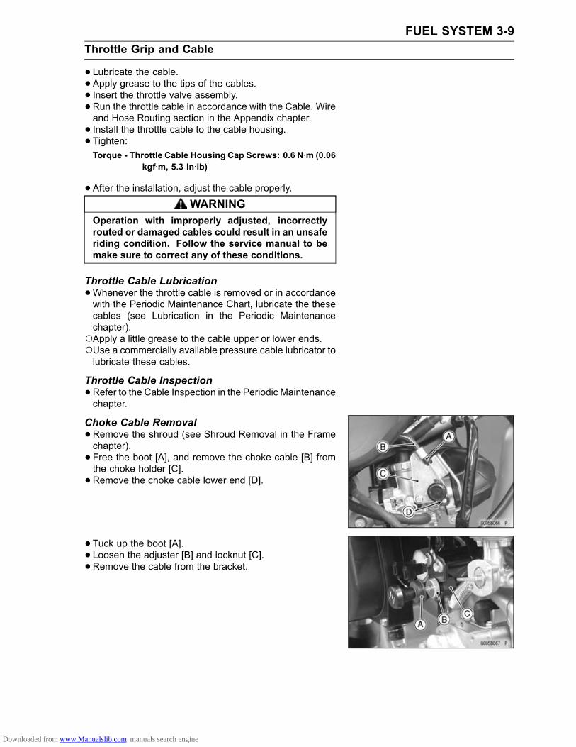
FUEL SYSTEM 3-9Throttle Grip and Cable
• Lubricate the cable.• Apply grease to the tips of the cables.• Insert the throttle valve assembly.•Run the throttle cable in accordance with the Cable, Wireand Hose Routing section in the Appendix chapter.• Install the throttle cable to the cable housing.• Tighten:Torque - Throttle Cable Housing Cap Screws: 0.6 N·m (0.06
kgf·m, 5.3 in·lb)
•After the installation, adjust the cable properly.WARNING
Operation with improperly adjusted, incorrectlyrouted or damaged cables could result in an unsaferiding condition. Follow the service manual to bemake sure to correct any of these conditions.
Throttle Cable Lubrication•Whenever the throttle cable is removed or in accordancewith the Periodic Maintenance Chart, lubricate the thesecables (see Lubrication in the Periodic Maintenancechapter).Apply a little grease to the cable upper or lower ends.Use a commercially available pressure cable lubricator tolubricate these cables.
Throttle Cable Inspection•Refer to the Cable Inspection in the Periodic Maintenancechapter.
Choke Cable Removal•Remove the shroud (see Shroud Removal in the Framechapter).• Free the boot [A], and remove the choke cable [B] fromthe choke holder [C].• Remove the choke cable lower end [D].
• Tuck up the boot [A].• Loosen the adjuster [B] and locknut [C].• Remove the cable from the bracket.
Downloaded from www.Manualslib.com manuals search engine
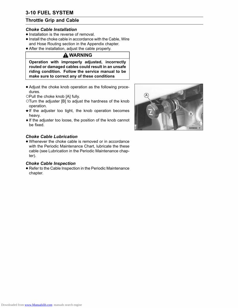
3-10 FUEL SYSTEMThrottle Grip and Cable
Choke Cable Installation• Installation is the reverse of removal.• Install the choke cable in accordance with the Cable, Wireand Hose Routing section in the Appendix chapter.• After the installation, adjust the cable properly.
WARNINGOperation with improperly adjusted, incorrectlyrouted or damaged cables could result in an unsaferiding condition. Follow the service manual to bemake sure to correct any of these conditions
•Adjust the choke knob operation as the following proce-dures.Pull the choke knob [A] fully.Turn the adjuster [B] to adjust the hardness of the knoboperation.If the adjuster too tight, the knob operation becomesheavy.If the adjuster too loose, the position of the knob cannotbe fixed.
Choke Cable Lubrication•Whenever the choke cable is removed or in accordancewith the Periodic Maintenance Chart, lubricate the thesecable (see Lubrication in the Periodic Maintenance chap-ter).
Choke Cable Inspection•Refer to the Cable Inspection in the Periodic Maintenancechapter.
Downloaded from www.Manualslib.com manuals search engine

FUEL SYSTEM 3-11Carburetor
Since the carburetor regulates and mixes the fuel and airgoing to the engine, there are two general types of carbure-tor trouble: too rich a mixture (too much fuel), and too leana mixture (too little fuel). Such trouble can be caused bydirt, wear, maladjustment or improper fuel level in the floatchamber. A dirty or damaged air cleaner can also alter thefuel to air ratio.
Idle Speed Inspection•Refer to the Idle Speed Inspection in the Periodic Main-tenance chapter.
Idle Speed Adjustment•Refer to the Idle Speed Adjustment in the Periodic Main-tenance chapter.
Service Fuel Level InspectionWARNING
Gasoline is extremely flammable and can be ex-plosive under certain conditions. Always stop theengine and do not smoke. Make sure the area iswell-ventilated and free from any source of flameor sparks; this includes any appliance with a pilotlight.
•Remove:Fuel Tank (see Fuel Tank Removal)Carburetor (see Carburetor Removal)•Hold the carburetor in true vertical position on a stand.• Put the fuel tank on a bench, and connect the fuel tap tothe carburetor with a fuel hose.•Connect the fuel gauge [A] to the carburetor drain [B] us-ing a suitable hose [C].Special Tool - Fuel Level Gauge: 57001-1017
•Hold the gauge vertically against the side of the carburetorbody so that the "middle" line [D] is several millimetershigher than the bottom edge [E] of the carburetor body.• Turn the fuel tap to the ON position to feed fuel to thecarburetor, then turn out the drain plug [F] a few turns.•Wait until the fuel level in the gauge settles.• Keeping the gauge vertical, slowly lower the gauge untilthe "middle" line is even with the bottom edge of the car-buretor body.
NOTEDo not lower the "middle" line below the bottom edge ofthe carburetor body. If the gauge is lowered and thenraised again, the fuel level measure shows somewhathigher than the actual fuel level. If the gauge is loweredtoo far, dump the fuel out of it into a suitable containerand start the procedure over again.
Downloaded from www.Manualslib.com manuals search engine
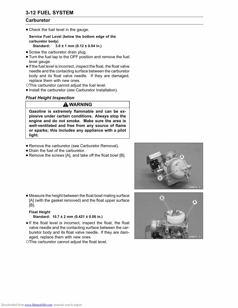
3-12 FUEL SYSTEMCarburetor
•Check the fuel level in the gauge.Service Fuel Level (below the bottom edge of thecarburetor body)Standard: 3.0 ± 1 mm (0.12 ± 0.04 in.)
•Screw the carburetor drain plug.• Turn the fuel tap to the OFF position and remove the fuellevel gauge.If the fuel level is incorrect, inspect the float, the float valveneedle and the contacting surface between the carburetorbody and its float valve needle. If they are damaged,replace them with new ones.This carburetor cannot adjust the fuel level.• Install the carburetor (see Carburetor Installation).Float Height Inspection
WARNINGGasoline is extremely flammable and can be ex-plosive under certain conditions. Always stop theengine and do not smoke. Make sure the area iswell-ventilated and free from any source of flameor sparks; this includes any appliance with a pilotlight.
•Remove the carburetor (see Carburetor Removal).• Drain the fuel of the carburetor.• Remove the screws [A], and take off the float bowl [B].
•Measure the height between the float bowl mating surface[A] (with the gasket removed) and the float upper surface[B].
Float HeightStandard: 10.7 ± 2 mm (0.421 ± 0.08 in.)
If the float level is incorrect, inspect the float, the floatvalve needle and the contacting surface between the car-buretor body and its float valve needle. If they are dam-aged, replace them with new ones.This carburetor cannot adjust the float level.
Downloaded from www.Manualslib.com manuals search engine

FUEL SYSTEM 3-13Carburetor
Float Bowl Mating Surface [A]Float Valve Needle Rod (contacted but unloaded) [B]Float [C]Float Height [D]
NOTEMeasure the height with the carburetor upside down.Do not push the needle rod in during the float heightmeasurement.
• Install:Float BowlCarburetor (see Carburetor Installation)
Carburetor RemovalWARNING
Gasoline is extremely flammable and can be ex-plosive under certain conditions. Always stop theengine and do not smoke. Make sure the area iswell-ventilated and free from any source of flameor sparks; this includes any appliance with a pilotlight.
•Turn the fuel tap to the OFF position.•Remove the shroud (see Shroud Removal in the Framechapter).• Loosen the clamp screw [A] and pull out the air duct [B]from the carburetor.• Remove:Carburetor Holder Bolts [C]Insulator [D]
• Free the boot [A] and remove the choke cable [B] fromthe holder [C].• Remove the choke cable lower end [D].• Unscrew the cap [E] and pull out the throttle cable lowerend with the throttle valve, spring and jet needle as a set.
WARNINGIf dirt or dust is allowed to pass through into thecarburetor, the throttle may become stuck, possiblycausing accident. Replace the air cleaner elementaccording to the maintenance chart.
NOTICEIf dirt gets through into the engine, excessive en-gine wear and possibly engine damage will occur.If the throttle valve is not removed from the cable,wrap clean cloths around the throttle valve to avoiddamaging to it.
Downloaded from www.Manualslib.com manuals search engine

3-14 FUEL SYSTEMCarburetor
Carburetor Installation• Installation is the reverse of removal.• Fit the slit [A] and the projection [B], and insert the throttlevalve assembly [C] into the carburetor body.
•Replace the O-ring with a new one.• Install the insulator [A] between intake pipe [B] and car-buretor [C] so that the O-ring faces to the intake pipe.• Tighten:Torque - Carburetor Holder Bolts: 5.2 N·m (0.53 kgf·m, 46
in·lb)
•After installing the carburetor, perform the following.Check fuel leakage from the carburetor.
WARNINGFuel spilled from the carburetor is hazardous.
Adjust the following:Idle Speed (see Idle Speed Adjustment in the PeriodicMaintenance chapter)Throttle Grip Free Play (see Throttle Cable Adjustmentin the Periodic Maintenance chapter)
Carburetor Disassembly•Remove the carburetor (see Carburetor Removal).• Pull the whole of spring [A] to the cap [B] side, and hold it.• Free the cable lower end [C] from the throttle valve [D].
• Remove the retainer place [A] and the jet needle [B] withthe clip [C].
Downloaded from www.Manualslib.com manuals search engine

FUEL SYSTEM 3-15Carburetor
•Remove the following parts from the carburetor body.Idle Adjusting Screw [A]O-ring [B]Spring [C]Pilot Screw [D]Washer [E]Spring [F]O-ring [G]O-ring [H]
Pilot Jet [A]Needle Jet [B]Needle Jet Holder [C]Main Jet [D]Float Valve Needle [E]Float [F]Pin [G]O-ring [H]Float Bowl [I]
Carburetor CleaningWARNING
Gasoline and low flash-point solvents can beflammable and/or explosive and cause severeburns. Clean the carburetor in a well-ventilatedarea, and take care that there are no sparks orflame anywhere near the working area; this in-cludes any appliance with a pilot light. Do not usegasoline or a low flash-point solvent to clean thecarburetor.
•Make sure the fuel tap is in the OFF position.•Remove the carburetor (see Carburetor Removal).• Drain the fuel in the carburetor.• Disassemble the carburetor (see Carburetor Disassem-bly).
NOTICEDo not use compressed air on an assembled carbu-retor, the float may be deformed by the pressure.Remove as many rubber or plastic parts from thecarburetor as possible before cleaning the car-buretor with cleaning solution. This will preventdamage or deterioration of the parts. Do not usestrong carburetor cleaning solution which couldattack the plastic parts; instead, use mild highflash-point cleaning solution safe for plastic parts.Do not use wire or any other hard instrument toclean carburetor parts, especially jets, as they maybe damaged.
Downloaded from www.Manualslib.com manuals search engine

3-16 FUEL SYSTEMCarburetor
• Immerse all the metal parts in carburetor cleaning solu-tion.•Rinse the parts in water.• After the parts are cleaned, dry them with compressed air.• Blow through the air and fuel passages with compressedair.• Assemble the carburetor, and install it on the motorcycle.Carburetor Inspection
WARNINGGasoline is extremely flammable and can be ex-plosive under certain conditions. Always stop theengine and do not smoke. Make sure the area iswell-ventilated and free from any source of flameor sparks; this includes any appliance with a pilotlight.
•Remove the carburetor (see Carburetor Removal).• Before disassembling the carburetor, check the fuel level.If the fuel level is incorrect, inspect the rest of the carbu-retor before correcting it.
• Check that the throttle valve [A] moves smoothly and re-turn back with the spring tension. The surface of the valvemust not be excessively worn.If the throttle valve does not move smoothly, or if it is veryloose in the carburetor body. Replace the carburetor.If the spring tension is weak, replace it.
• Turn the choke cable bracket to check that the choke but-terfly valve [A] move smoothly and return with spring ten-sion.If the choke butterfly valve do not move smoothly, replacethe carburetor.
NOTEDo not remove the pilot screw from the carburetor orchange the pilot screw setting, or you will lose the bestsetting.
•Disassemble the carburetor (see Carburetor Disassem-bly).• Clean the carburetor (see Carburetor Cleaning).• Check that the O-rings on the float bowl, drain plug andthe intake pipe are in good condition.If any of the O-rings are not in good condition, replacethem.
Downloaded from www.Manualslib.com manuals search engine

FUEL SYSTEM 3-17Carburetor
•Remove the float valve needle.•Check the float valve needle [A].If the needle is worn [B] as shown in the figure, replacethe valve needle.• Push the rod [C] in the valve needle, and then release it[D].If the rod does not spring out, replace the valve needle.
•Check the main jet [A], needle jet holder [B] and pilot jet[C] for any damage.If they are damaged, replace them with new ones.
• Inspect the outside of the throttle valve [A] for scratchesand abnormal wear.If the valve is badly scratched or worn, replace it.• Inspect the inside of the carburetor body for these samefaults.If it is badly scratched or worn, replace the entire carbu-retor.[B] Sliding Surface
•Check the jet needle [A] and needle jet [B] for wear.A worn needle jet holder or jet needle should be replaced.
•Disassemble the carburetor, and clean the fuel, air pas-sages with high flash-point solvent and compressed air.• Stuff the lint-free, clean cloths into the air cleaner housingto keep dirt or other foreign material from entering.
WARNINGIf dirt or dust is allowed to pass through into the car-buretor, the throttle valve may become stuck, pos-sibly causing accident. Replace the air cleaner ele-ment according to the maintenance chart.
Downloaded from www.Manualslib.com manuals search engine

3-18 FUEL SYSTEMCarburetor
Carburetor Assembly•Clean the disassembly parts before assembling.•Clean the fuel and air passages with high flash-point sol-vent and compressed air.• Install the needle jet [A] into the carburetor so that thesmaller diameter end [B] of the jet goes in first.
• Carefully screw in the needle jet holder. It will seat againstthe needle jet, pushing the end of the jet into the carbu-retor bore.
NOTICEDo not force the needle jet holder [A] and main jet[B] or overtighten them. The needle jet or the car-buretor body could be damaged requiring replace-ment.
Downloaded from www.Manualslib.com manuals search engine

FUEL SYSTEM 3-19Air Cleaner
Air Cleaner Housing Removal•Remove the shroud (see Shroud Removal in the Framechapter).• Loosen the clamp screw [A] and pull out the air cleanerduct [B] from the carburetor.
• Remove the air cleaner housing mounting bolts [A].• Remove the air cleaner housing [B].
Air Cleaner Housing Installation• Installation is the reverse of removal.• Install the intake portion [A] of the air cleaner housing intothe frame hole [B].
Air Cleaner Element Removal•Remove:Shroud (see Shroud Removal in the Frame chapter)Screws [A]Air Cleaner Cover [B]
• Pull out the element [A].• Stuff a clean, lint-free cloth into the air cleaner housing sono dirt is allowed to enter the carburetor.•Wipe out the inside of the air cleaner housing with a cleandamp towel.
NOTICECheck inside of the inlet tract and carburetor fordirt. If dirt is present, clean the inlet tract and car-buretor thoroughly. You may also need to replacethe element and seal the housing and inlet tract.
Downloaded from www.Manualslib.com manuals search engine

3-20 FUEL SYSTEMAir Cleaner
Air Cleaner Element Installation• Installation is the reverse of removal.•When installing the element, coat the lip of the elementwith a thick layer of all purpose grease [A] to assure acomplete seal against the air cleaner element base. Also,coat the base where the lip of the element fits.• Take out the cloth from the carburetor securely.
Air Cleaner Element Cleaning and Inspection•Refer to the Air Cleaner Element Cleaning and Inspectionin the Periodic Maintenance chapter.
Air Cleaner Oil Draining• Inspect the transparent plug [A] under the air cleanerhousing [B] to see if the water or oil accumulates.If any water or oil accumulates in the cap, remove the plugand drain it.
Downloaded from www.Manualslib.com manuals search engine

FUEL SYSTEM 3-21Fuel Tank
Fuel Tank RemovalWARNING
Gasoline is extremely flammable and can be ex-plosive under certain conditions. Always stop theengine and do not smoke. Make sure the area iswell-ventilated and free from any source of flameor sparks; this includes any appliance with a pilotlight.
•Remove the shroud (see Shroud Removal in the Framechapter).Install the fuel tank cap.• Turn the fuel tap lever [A] to the OFF position.•Disconnect the fuel hose [B] from the fuel tap.
•Remove the fuel tank mounting bolt [A] and washer.• Take off the fuel tank, and remove the rubber band [B].
Fuel Tank Installation• Inspect the rubber damper [A] on the frame.If the damper is damaged or deteriorated, replace it witha new one.• Set the fuel tank on the frame.•Connect the fuel hose to the fuel tap securely.
• Install the rubber band, fuel tank bolt and other removedparts.• Insert the fuel tank breather hose outlet end into the num-ber plate hole.
Downloaded from www.Manualslib.com manuals search engine

3-22 FUEL SYSTEMFuel Tank
Fuel Tap Removal•Remove the fuel tank (see Fuel Tank Removal).• Drain the fuel.• Remove the mounting bolts [A] and take off the fuel tap[B].
Fuel Tap Installation•Replace the O-ring [A] with a new one.• Insert the filter part into the tank, and tighten the bolts.Torque - Fuel Tap Mounting Bolts: 4.4 N·m (0.45 kgf·m, 39
in·lb)
Fuel Tap Cleaning•Refer to the Fuel Tap Cleaning in the Periodic Mainte-nance chapter.
Fuel Tap and Filter Inspection•Remove the fuel tap from the fuel tank.•Check the fuel filters [A] for any breaks or deterioration.If the fuel filters have any breaks or are deteriorated, itmay allow dirt to reach the carburetor, causing poor run-ning. Replace the fuel tap.•Check the fuel tap for fuel leaks.• If the fuel tap leaks, or allows fuel to flow when it is at OFFposition, replace the O-ring in the fuel tap lever with a newone.
Fuel InspectionWARNING
Gasoline is extremely flammable and can be ex-plosive under certain conditions. Always stop theengine and do not smoke. Make sure the area iswell-ventilated and free from any source of flameor sparks; this includes any appliance with a pilotlight.
Downloaded from www.Manualslib.com manuals search engine

FUEL SYSTEM 3-23Fuel Tank
•Turn the fuel tap to the OFF position.• Place a suitable container beneath the carburetor drainhose [A].• Loosen the drain plug [B] from the bottom of the float bowland check for water or dirt in the fuel.If any water or dirt comes out, clean the carburetor, fuelfilter, fuel tap and fuel tank.• Tighten the drain plug securely.
Downloaded from www.Manualslib.com manuals search engine

ENGINE TOP END 4-1
4
Engine Top EndTable of Contents
Exploded View................................... 4-2Specifications .................................... 4-6Special Tools ..................................... 4-8Camshaft Chain Tensioner ................ 4-10
Camshaft Chain TensionerRemoval .................................... 4-10
Camshaft Chain TensionerInstallation ................................. 4-11
Camshaft ........................................... 4-12Camshaft Removal ...................... 4-12Camshaft Installation ................... 4-12Camshaft Inspection .................... 4-12KACR Removal............................ 4-12KACR Installation......................... 4-13KACR Inspection.......................... 4-13Camshaft Bearing Inspection....... 4-13Camshaft Sprocket Removal ....... 4-14Camshaft Sprocket Installation .... 4-15Camshaft Chain Removal ............ 4-16Camshaft Chain Installation ......... 4-17Camshaft Chain Guide WearInspection.................................. 4-17
Rocker Arm, Rocker Arm Shaft ......... 4-18Rocker Arm Removal................... 4-18Rocker Arm Installation................ 4-18Rocker Arm & Arm Shaft WearInspection.................................. 4-19
Cylinder Head.................................... 4-20Compression Measurement......... 4-20Cylinder Head Removal ............... 4-21Cylinder Head Installation ............ 4-21Cylinder Head Cleaning ............... 4-22Cylinder Head Warp Inspection ... 4-22
Valves ................................................ 4-23Valve Clearance Inspection ......... 4-23Valve Clearance Adjustment........ 4-23
Valve Removal ............................. 4-23Valve Installation .......................... 4-23Valve Guide Removal .................. 4-24Valve Guide Installation ............... 4-24Valve Seat Inspection .................. 4-25Valve Seat Repair ........................ 4-26Valve Head Thickness Inspection 4-29Valve Stem Bend Inspection ........ 4-29Valve Stem Diameter Inspection.. 4-30Valve Guide Inside DiameterInspection.................................. 4-30
Valve to Guide ClearanceMeasurement ............................ 4-30
Cylinder, Piston.................................. 4-33Cylinder Removal......................... 4-33Cylinder Installation...................... 4-33Piston Removal............................ 4-34Piston Installation......................... 4-34Cylinder Inside DiameterMeasurement ............................ 4-35
Piston Wear Inspection ................ 4-35Piston/Cylinder ClearanceInspection.................................. 4-36
Boring, Honing Performance ....... 4-36Piston Ring End Gap Inspection .. 4-37Piston Ring, Piston Ring GrooveInspection.................................. 4-37
Piston, Piston Pin, ConnectingRod Wear Inspection................. 4-38
Piston, Piston Pin, ConnectingRod Inspection .......................... 4-39
Muffler................................................ 4-40Muffler Removal........................... 4-40Muffler Installation........................ 4-41Spark Arrester Cleaning............... 4-41
Downloaded from www.Manualslib.com manuals search engine

4-2 ENGINE TOP ENDExploded View
Downloaded from www.Manualslib.com manuals search engine

ENGINE TOP END 4-3Exploded View
TorqueNo. Fastener
N·m kgf·m ft·lbRemarks
1 Valve Adjusting Cap Bolts 5.2 0.53 46 in·lb2 Cylinder Head Bolts 12 1.2 106 in·lb S, L3 Cylinder Head Nuts 22 2.2 16 S
Rocker Shaft Holder Plate Bolts(KLX110CA/DA Early Models) 5.2 0.53 46 in·lb
4Rocker Shaft Holder Plate Bolts(KLX110CA/DA Late Models ∼ ) 5.2 0.53 46 in·lb L
5 Camshaft Sprocket Cover Bolts 5.2 0.53 46 in·lb6 Intake Pipe Bolts 5.2 0.53 46 in·lb7 Carburetor Holder Bolts 5.2 0.53 46 in·lb8 Valve Adjusting Screw Locknuts 8.8 0.90 78 in·lb9 Camshaft Sprocket Bolts 12 1.2 106 in·lb L10 Camshaft Chain Guide Bolt 5.2 0.53 46 in·lb11 Camshaft Chain Plate Screw 5.2 0.53 46 in·lb12. KLX110CA/DA Early ModelsEO: Apply engine oil.G: Apply grease.L: Apply a non-permanent locking agent.M: Apply molybdenum disulfide grease.R: Replacement PartsS: Follow the specific tightening sequence.
Downloaded from www.Manualslib.com manuals search engine

4-4 ENGINE TOP ENDExploded View
Downloaded from www.Manualslib.com manuals search engine

ENGINE TOP END 4-5Exploded View
TorqueNo. Fastener
N·m kgf·m ft·lbRemarks
1 Camshaft Chain Tensioner Cap Bolt 5.2 0.53 46 in·lb2 Camshaft Chain Tensioner Mounting Bolts 5.2 0.53 46 in·lb L3 Muffler Cover Screws 3.0 0.31 27 in·lb4 Exhaust Pipe Holder Nuts 16 1.6 125 Muffler Mounting Bolt 9.8 1.0 87 in·lb6 Muffler Mounting Nut 30 3.1 22 R7 Spark Arrester Mounting Bolts 8.8 0.90 78 in·lbEO: Apply engine oil.L: Apply a non-permanent locking agent.R: Replacement Parts
Downloaded from www.Manualslib.com manuals search engine

4-6 ENGINE TOP ENDSpecifications
Item Standard Service LimitRocker Arm, Rocker Arm ShaftRocker Arm Inside Diameter 10.000 ∼ 10.015 mm (0.3937 ∼ 0.3943 in.) 10.05 mm (0.396 in.)Rocker Arm Shaft Diameter 9.980 ∼ 9.995 mm (0.3929 ∼ 0.3935 in.) 9.95 mm (0.392 in.)
CamshaftCam Height:Exhaust 29.054 ∼ 29.168 mm (1.1439 ∼ 1.1483 in.) 28.95 mm (1.140 in.)Inlet 29.017 ∼ 29.131 mm (1.1424 ∼ 1.1469 in.) 28.92 mm (1.139 in.)
Cylinder HeadCylinder Compression (UsableRange):Kick 700 ∼ 1098 kPa (7.14 ∼ 11.2 kgf/cm², 102
∼ 159 psi) @5 times– – –
Electric Starter 280 ∼ 498 kPa (2.86 ∼ 5.08 kgf/cm², 41 ∼72 psi) @350 r/min (rpm)
– – –
Cylinder Head Warp – – – 0.03 mm (0.001 in.)ValveValve Clearance:Exhaust 0.08 ∼ 0.12 mm (0.003 ∼ 0.005 in.) – – –Inlet 0.04 ∼ 0.08 mm (0.002 ∼ 0.003 in.) – – –
Valve Head Thickness:Exhaust 0.8 mm (0.031 in.) 0.5 mm (0.020 in.)Inlet 0.5 mm (0.020 in.) 0.25 mm (0.010 in.)
Valve Stem Bend TIR 0.01 mm (0.0004 in.) or less TIR 0.05 mm(0.002 in.)
Valve Stem Diameter:Exhaust 4.462 ∼ 4.472 mm (0.1757 ∼ 0.1761 in.) 4.44 mm (0.1748 in.)Inlet 4.475 ∼ 4.490 mm (0.1762 ∼ 0.1768 in.) 4.46 mm (0.1756 in.)
Valve Guide Inside Diameter:Exhaust 4.500 ∼ 4.512 mm (0.1772 ∼ 0.1776 in.) 4.58 mm (0.1803 in.)Inlet 4.500 ∼ 4.512 mm (0.1772 ∼ 0.1776 in.) 4.58 mm (0.1803 in.)
Valve Guide Clearance (WobbleMethod):Exhaust 0.05 ~ 0.08 mm (0.002 ~ 0.003 in.) 0.19 mm (0.0075 in.)Inlet 0.02 ~0.06 mm (0.0008 ~ 0.002 in.) 0.17 mm (0.0067 in.)
Valve Seat Cutting Angle 32°, 45°, 60°, 67.5° – – –Valve Seat Surface:Outside Diameter:Exhaust 19.9 ∼ 20.1 mm (0.783 ∼ 0.791 in.) – – –Inlet 22.9 ∼ 23.1 mm (0.902 ∼ 0.909 in.) – – –
Width:Exhaust 0.80 ∼ 1.15 mm (0.031 ∼ 0.045 in.) – – –Inlet 0.80 ∼ 1.15 mm (0.031 ∼ 0.045 in.) – – –
Valve Spring Free Length 36.6 mm (1.441 in.) 35.8 mm (1.409 in.)
Downloaded from www.Manualslib.com manuals search engine

ENGINE TOP END 4-7Specifications
Item Standard Service LimitCylinder, PistonCylinder Inside Diameter 52.997 ∼ 53.009 mm (2.0865 ∼ 2.0870 in.) 53.10 mm (2.0905
in.)Piston Diameter 52.969 ∼ 52.981 mm (2.0854 ∼ 2.0859 in.) 52.82 mm (2.080 in.)Piston/Cylinder Clearance 0.010 ∼ 0.022 mm (0.00039 ∼ 0.00086 in.) – – –Over Size Piston and Rings +0.50 (0.0197 in.)
+1.0 (0.0394 in.)Piston Ring/Groove Clearance:Top 0.020 ∼ 0.060 mm (0.0008 ∼ 0.0024 in.) 0.16 mm (0.0063 in.)Second 0.010 ∼ 0.050 mm (0.0004 ∼ 0.0020 in.) 0.15 mm (0.0059 in.)
Piston Ring Groove Width:Top 0.81 ∼ 0.83 mm (0.0319 ∼ 0.0327 in.) 0.91 mm (0.0358 in.)Second 0.80 ∼ 0.82 mm (0.0315 ∼ 0.0323 in.) 0.90 mm (0.0354 in.)
Piston Ring Thickness:Top 0.77 ∼ 0.79 mm (0.0303 ∼ 0.0311 in.) 0.70 mm (0.0276 in.)Second 0.77 ∼ 0.79 mm (0.0303 ∼ 0.0311 in.) 0.70 mm (0.0276 in.)
Piston Ring End Gap:Top 0.10 ∼ 0.20 mm (0.0039 ∼ 0.0079 in.) 0.6 mm (0.024 in.)Second 0.30 ∼ 0.45 mm (0.0118 ∼ 0.0177 in.) 0.8 mm (0.031 in.)Oil 0.10 ∼ 0.60 mm (0.0039 ∼ 0.0236 in.) 0.9 mm (0.035 in.)
Piton Pin Diameter 12.995 ∼ 13.000 mm (0.5116 ∼ 0.5118 in.) 12.96 mm (0.510 in.)Piston Pin Hole Diameter 13.001 ∼ 13.007 mm (0.5118 ∼ 0.5121 in.) 13.08 mm (0.515 in.)Connecting Rod Small EndInside Diameter
13.003 ∼ 13.014 mm (0.5119 ∼ 0.5124 in.) 13.05 mm (0.514 in.)
Downloaded from www.Manualslib.com manuals search engine

4-8 ENGINE TOP ENDSpecial Tools
Compression Gauge, 20 kgf/cm²:57001-221
Valve Spring Compressor Assembly:57001-241
Piston Pin Puller Assembly:57001-910
Valve Seat Cutter, 45° - 27.5:57001-1114
Valve Seat Cutter, 32° - 25:57001-1118
Valve Seat Cutter, 60° - 30:57001-1123
Valve Seat Cutter Holder Bar:57001-1128
Valve Spring Compressor Adapter, 20:57001-1154
Valve Seat Cutter, 45° - 22:57001-1205
Valve Seat Cutter, 32° - 22:57001-1206
Downloaded from www.Manualslib.com manuals search engine

ENGINE TOP END 4-9Special Tools
Valve Seat Cutter, 67.5° - 22:57001-1207
Compression Gauge Adapter, M10 × 1.0:57001-1317
Valve Seat Cutter Holder, 4.5:57001-1330
Valve Guide Arbor, 4.5:57001-1331
Valve Guide Reamer, 4.5:57001-1333
Filler Cap Driver:57001-1454
Downloaded from www.Manualslib.com manuals search engine

4-10 ENGINE TOP ENDCamshaft Chain Tensioner
Camshaft Chain Tensioner RemovalNOTICE
This is a non-return type cam chain tensioner. Thepush rod does not return to its original positiononce it moves out to take up cam chain slack. Ob-serve all the rules listed below:When removing the tensioner, do not take out themounting bolts only halfway. Retightening themounting bolts from this position could damagethe tensioner and the camshaft chain. Once thebolts are loosened, the tensioner must be removedand reset as described in “Chain Tensioner Instal-lation”. Do not turn over the crankshaft while thetensioner is removed. This could upset the camchain timing, and damage the valves.
•Remove the fuel tank (see Fuel Tank Removal in the FuelSystem chapter).• Remove the choke knob holder for extra clearance.• Loosen the cap bolt [A] before tensioner removal for laterdisassembly convenience.•Unscrew the mounting bolts [B] and remove the camshaftchain tensioner [C].
NOTICEDo not turn over the crankshaft while the tensioneris removed. This could upset the cam chain timing,and damaging the valves.
Remove the camshaft chain tensioner [A] while turningthe push rod [B] clockwise [C] and compressing [D] it witha standard tip screwdriver [E].
Downloaded from www.Manualslib.com manuals search engine

ENGINE TOP END 4-11Camshaft Chain Tensioner
Camshaft Chain Tensioner Installation•Remove the tensioner cap bolt and O-ring.•While compressing the push rod [A], turn it clockwise [B]with a standard tip screwdriver until the rod protrusioncomes to about 10 mm (0.4 in.) from the tensioner body.
NOTICEDo not turn the rod counterclockwise at installation.This could detach the rod and the tensioner cannotbe reinstalled.
•While holding the rod in position with a suitable push rodholder plate [A], install the tensioner on the cylinder.4 mm (0.16 in.) [B]6 mm (0.24 in.) [C]15 mm (0.60 in.) [D]9.5 mm (0.37 in.) [E]
NOTETo make the procedure easy, use a holder plate to keepthe rod from pushing out. A replacement chain ten-sioner (spare parts) has a holder plate. The holder platecan be made less than 1 mm (0.0394 in.) thick steelplate as shown.
•Apply a non-permanent locking agent to the threads oftensioner mounting bolts [A] and tighten them to the spec-ified torque.Torque - Camshaft Chain Tensioner Mounting Bolts: 5.2
N·m (0.53 kgf·m, 46 in·lb)
•Take out the holder plate [B].
• Be sure that the new O-ring [A] is properly in place andtighten the cap bolt [B].Torque - Camshaft Chain Tensioner Cap Bolt: 5.2 N·m (0.53
kgf·m, 46 in·lb)
• Install the fuel tank (see Fuel Tank Installation in the FuelSystem chapter).
Downloaded from www.Manualslib.com manuals search engine

4-12 ENGINE TOP ENDCamshaft
Camshaft Removal•Remove the rocker arms (see Rocker Arm Removal).• Pull out the camshaft [A].
Camshaft Installation•Clean the camshaft with high flash-point solvent.• Apply clean engine oil to all cam parts.• Install the camshaft in the cylinder head.• Install the rocker arm.• Install the other removed parts.Check and adjust the valve clearance.Camshaft Inspection•Visually inspect the cam for wear or damage.If there is any damage or wear, replace the camshaft.•Measure the height [A] of each cam.Cam HeightStandard:Exhaust 29.054 ∼ 29.168 mm (1.1439 ∼ 1.1483 in.)Inlet 29.017 ∼ 29.131 mm (1.1424 ∼ 1.1469 in.)
Service Limit:Exhaust 28.95 mm (1.140 in.)Inlet 28.92 mm (1.139 in.)
If any cam is worn down past service limit, replace thecamshaft.
KACR Removal•Remove:Camshaft Sprocket CoverCamshaft Sprocket Bolts [A]Retaining Plate [B]Shaft [C]Weight [D]
Remove the camshaft sprocket bolts while holding the al-ternator rotor nut with a wrench.
Downloaded from www.Manualslib.com manuals search engine

ENGINE TOP END 4-13Camshaft
KACR Installation• Install:Weight [A]• Insert the shaft [B] as shown.Retaining PlateCamshaft Sprocket BoltsCamshaft Sprocket Cover
KACR InspectionThe Kawasaki Automatic Compression Release (KACR)
momentarily opens the valve on the compression stroke atvery low speed. This allows some of the compression pres-sure to escape, making it easy to turn over the engine duringstarting.Due to the simplicity of the mechanism, no periodic main-
tenance is needed. There are only two symptoms of prob-lems with the KACR mechanism [A]: compression is not re-leased during starting, and compression is released duringrunning.
(1) If compression is not released during starting, the weightis not returning to their rest position.•Remove the KACR unit.• Visually inspect the spring [A].If damaged, deformed, or missing, replace the weight.• Check that the weight arm [B] move back and forth.If the weight do not move smoothly, replace the KACRunit. Also inspect the inlet rocker arm for any damage,and replace the rocker arm if necessary.[C] Rest Position (compression is released)
(2) If compression is released while the engine is running,the weights are not swinging out.• Check that the weight arm [A] move back and forth.If the weight do not move easily from the retracted posi-tion, replace the KACR unit. Also inspect the inlet rockerarm for any damage, and replace the rocker arm if nec-essary.[B] Running Position (compression is not released)
Camshaft Bearing Inspection•Visually inspect each camshaft bearing [A].If there is any damage replace the camshaft.• Turn the bearing back and forth while checking for rough-ness or binding.If roughness or binding is found, replace the camshaft.If it is noisy, does not spin smoothly, or has any roughspots, replace the camshaft.
Downloaded from www.Manualslib.com manuals search engine
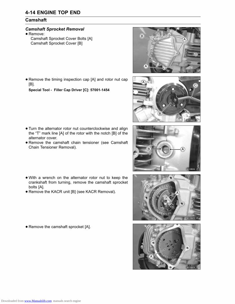
4-14 ENGINE TOP ENDCamshaft
Camshaft Sprocket Removal•Remove:Camshaft Sprocket Cover Bolts [A]Camshaft Sprocket Cover [B]
•Remove the timing inspection cap [A] and rotor nut cap[B].Special Tool - Filler Cap Driver [C]: 57001-1454
•Turn the alternator rotor nut counterclockwise and alignthe “T” mark line [A] of the rotor with the notch [B] of thealternator cover.• Remove the camshaft chain tensioner (see CamshaftChain Tensioner Removal).
•With a wrench on the alternator rotor nut to keep thecrankshaft from turning, remove the camshaft sprocketbolts [A].• Remove the KACR unit [B] (see KACR Removal).
• Remove the camshaft sprocket [A].
Downloaded from www.Manualslib.com manuals search engine

ENGINE TOP END 4-15Camshaft
•Use a suitable tool [A] or wire to keep the chain [B] fromfalling down into the cylinder block.
NOTICEAlways pull the camshaft chain taut while turningthe crankshaft when the camshaft chain is loose.This avoids kinking the chain on the lower (crank-shaft) sprocket. A kinked chain could damage boththe chain and the sprocket.
Camshaft Sprocket Installation•Position the piston at TDC.Turn the crankshaft counterclockwise and align the “T”mark line [A] of the rotor with the notch [B] of the alternatorcover.• Remember to pull the camshaft chain taut before rotatingthe crankshaft.
• Pull the lower side of the chain taut and fit it onto thesprocket so that the line [A] on the sprocket aligns withthe mark on the sprocket cover mating surface projection[B].
• Fit the sprocket up into place.Turn the camshaft so that the cam lobes point downward,while holding the sprocket steady to align the bolt holes[A].• Install the sprocket [B].• Install the KACR unit (see KACR Installation).• Keep the crankshaft from turning by holding a wrench onthe alternator rotor nut.• Apply a non-permanent locking agent to the threads ofcamshaft sprocket bolts.• Tighten:Torque - Camshaft Sprocket Bolts: 12 N·m (1.2 kgf·m, 104
in·lb)
• Install the camshaft chain tensioner (see Camshaft ChainTensioner Installation).• Check the camshaft chain timing.Turn the crankshaft two turns in the counterclockwise, thecrankshaft is at TDC, and re-check the camshaft chaintiming.If the timing mark is aligned, the camshaft chain timing iscorrect.
Downloaded from www.Manualslib.com manuals search engine

4-16 ENGINE TOP ENDCamshaft
•Apply grease to the new O-ring [A] and install thecamshaft sprocket cover [B].• Tighten:Torque - Camshaft Sprocket Cover Bolts [C]: 5.2 N·m (0.53
kgf·m, 46 in·lb)
NOTICERotation of the crankshaft with improper camshafttiming could cause the valve to contact each otheror the piston, and bend.If any resistance is felt when turning the crankshaft,stop immediately, and check the camshaft chaintiming.
• Install the other removed parts.• Tighten:Torque - Timing Inspection Cap [A]: 2.4 N·m (0.24 kgf·m, 21
in·lb)Alternator Rotor Nut Cap [B]: 2.4 N·m (0.24 kgf·m,21 in·lb)
Special Tools - Filler Cap Driver [C]: 57001-1454
Camshaft Chain Removal•Drain the engine oil (see Engine Oil Change in the Peri-odic Maintenance chapter).• RemoveCamshaft Sprocket (see Camshaft Sprocket Removal)Cylinder Head (see Cylinder Head Removal)Alternator Rotor [A] (see Alternator Rotor Removal in theElectrical System chapter)Woodruff KeyTorque Limiter [B]Starter Motor Clutch Gear [C]
•Remove:Screws [A]Camshaft Chain Holder [B]Camshaft Chain [C]
Downloaded from www.Manualslib.com manuals search engine

ENGINE TOP END 4-17Camshaft
Camshaft Chain Installation• Install the camshaft chain to the crankshaft, and pull up itthrough camshaft chain hole of the cylinder.• Keep the chain.• Install the camshaft chain holder.• Tighten:Torque - Camshaft Chain Plate Screws [A]: 5.2 N·m (0.53
kgf·m, 46 in·lb)
• Install the other removed parts (see appropriate chap-ters).
Camshaft Chain Guide Wear Inspection•Visually inspect the guides.If the rubber is damaged, replace the guide.
Downloaded from www.Manualslib.com manuals search engine

4-18 ENGINE TOP ENDRocker Arm, Rocker Arm Shaft
Rocker Arm Removal•Remove:Camshaft Sprocket (see Camshaft Sprocket Removal)Valve Adjusting Cover Bolts [A]Valve Adjusting Covers [B]
•Remove:Rocker Shaft Holder Plate Bolts [A]Rocker Shaft Holder Plate Stopper [B]
•While holding the rocker arm [A] with hand, pull out therocker arm shaft [B] and take off the rocker arm.Mark and record the rocker arm locations so that therocker arm can be reinstalled in their original positions.When it is difficult to pull out the shaft, loosen the cylinderhead nut [C].
Rocker Arm Installation•Clean the rocker arms and rocker arm shafts with highflash-point solvent.• Apply a clean engine oil to the rocker arm shaft outsideand rocker arm cam parts.• Turn the camshaft so that the cam lobes point downward.• Install the each rocker arm shaft, running it through eachrocker arm.• Install the rocker shaft holder plate [A] so that the rockerarm shaft protrusion [B] face each other.• Apply a non-permanent locking agent to the rocker shaftholder plate bolts [C] (KLX110CA/DA Late Models ∼ ).• Tighten:Torque - Rocker Shaft Holder Plate Bolts: 5.2 N·m (0.53
kgf·m, 46 in·lb)
• Install the camshaft sprocket.Check and adjust the valve clearance (see Valve Clear-ance Inspection in the Periodic Maintenance chapter).
NOTICEWhen install the valve adjusting covers, be carefulnot to drop the O-rings from the cover grooves. Ifthe O-ring is installed improperly, oil will leak.
Downloaded from www.Manualslib.com manuals search engine

ENGINE TOP END 4-19Rocker Arm, Rocker Arm Shaft
Rocker Arm & Arm Shaft Wear Inspection•Visually inspect the area on the rocker armwhere the camrubs.If there is any damage or uneven wear, replace the rockerarm.•Measure the inside diameter [A] of each rocker arm witha cylinder gauge.
Rocker Arm Inside DiameterStandard: 10.000 ∼ 10.015 mm (0.3937 ∼ 0.3943 in.)Service Limit: 10.05 mm (0.396 in.)
If it exceeds the service limit, replace the rocker arm.•Measure the diameter [B] of each rocker arm shaft wherethe rocker arm fits.
Rocker Arm Shaft DiameterStandard: 9.980 ∼ 9.995 mm (0.3929 ∼ 0.3935 in.)Service Limit: 9.95 mm (0.392 in.)
If the diameter is less than the service limit, replace therocker arm shaft.
Downloaded from www.Manualslib.com manuals search engine

4-20 ENGINE TOP ENDCylinder Head
Compression Measurement•Warm up the engine thoroughly.• Stop the engine.•Remove the spark plug (see Spark Plug Cleaning andInspection in the Periodic Maintenance chapter).• Attach compression gauge and adapter firmly into thespark plug hole.Special Tools - Compression Gauge, 20 kgf/cm²: 57001-221
[A]Compression Gauge Adapter, M10 × 1.0:57001-1317 [B]
•With the throttle fully open, turn the engine over sharplywith the kick starter several times until the compressiongauge stops rising; the compression is the highest read-ing obtainable.
Cylinder CompressionUsable Range: 700 ∼ 1098 kPa (7.14 ∼ 11.2 kgf/cm²,
102 ∼ 159 psi) @5 times
•Using the starter motor, turn the engine over with the throt-tle fully open until the compression gauge stops rising; thecompression is the highest reading obtainable.
Cylinder CompressionUsable Range: 280 ∼ 498 kPa (2.86 ∼ 5.08 kgf/cm², 41 ∼
72 psi) @350 r/min (rpm)
The following table should be consulted if the obtainable compression reading is not within the us-able range.
Problem Diagnosis Remedy (Action)Carbon accumulation on piston and incombustion chamber possibly due todamaged valve stem oil seal and/ordamaged piston oil rings (This may beindicated by white exhaust smoke).
Remove the carbon depositsand replace damaged parts ifnecessary.
Incorrect cylinder head gasket, cylinderbase gasket thickness.
Replace to gasket with astandard part.
Damaged KACR spring. Replace the spring.
Cylinder compressionis higher than usablerange
KACR weight do not move smoothly. Replace the KACR unit.Gas leakage around cylinder head. Replace damaged gasket and
check cylinder head warp.Bad condition of valve seating. Repair if necessary.Incorrect valve clearance. Adjust the valve clearance.Incorrect piston/cylinder clearance. Replace the piston and/or
cylinderPiston seizure. Inspect the cylinder (and liner)
and replace/repair the cylinderand/or piston as necessary.
Bad condition of piston ring and/or pistonring grooves.
Replace the piston and/or thepiston rings.
Cylinder compressionis lower than usablerange
KACR weight do not move smoothly. Replace the KACR unit.
• Remove the compression gauge and adapter, and installthe spark plug.Torque - Spark Plug: 13 N·m (1.3 kgf·m, 115 in·lb)
Downloaded from www.Manualslib.com manuals search engine

ENGINE TOP END 4-21Cylinder Head
Cylinder Head Removal•Remove:Muffler (see Muffler Removal)Oil Pipe (see Oil Pipe Removal in the Engine LubricationSystem chapter)Spark Plug Cap [A]Intake Pipe Bolts [B]Insulator
•Remove:Camshaft Sprocket (see Camshaft Sprocket Removal)Clamp [A] (KLX110D Models)•Remove the cylinder head bolts [B] first, then remove thenuts [C], and take off the cylinder head [D].
Cylinder Head Installation•Check to see that the two dowel pins [A] are in place onthe cylinder.• Install a new cylinder head gasket [B].
• Fit the cylinder head onto the cylinder block using ascrewdriver or wire to keep the chain from falling downinto the cylinder block.• Apply a non-permanent locking agent to the cylinder headbolts.• Tighten the cylinder head nuts and bolts following thetightening sequence as shown.The cylinder head nut [A] has gasket.First Torque -
Cylinder Head Bolts: 5.9 N·m (0.60 kgf·m, 52in·lb)
Cylinder Head Nuts: 13 N·m (1.3 kgf·m, 113 in·lb)
Final Torque -Cylinder Head Bolts: 12 N·m (1.2 kgf·m, 104 in·lb)Cylinder Head Nuts: 22 N·m (2.2 kgf·m, 16 ft·lb)
• Install the camshaft sprocket (see Camshaft Sprocket In-stallation).• Install the other removed parts (see appropriate chap-ters).
Downloaded from www.Manualslib.com manuals search engine

4-22 ENGINE TOP ENDCylinder Head
Cylinder Head Cleaning•Scrape out any carbon, and wash the head with high flash-point solvent.
Cylinder Head Warp Inspection• Lay a straightedge across the lower surface of the cylinderhead at several positions.•Use a thickness gauge [A] to measure the space betweenthe straightedge [B] and the cylinder head.
Cylinder Head WarpStandard: – – –Service Limit: 0.03 mm (0.001 in.)
If the cylinder head is warped more than the service limit,replace it.If the cylinder head is warped less than the service limit,repair the head by rubbing the lower surface on emerypaper secured to a surface plate (first No. 200, then No.400).
Downloaded from www.Manualslib.com manuals search engine

ENGINE TOP END 4-23Valves
Valve Clearance Inspection•Refer to Valve Clearance Inspection in the Periodic Main-tenance chapter.
Valve Clearance Adjustment•Refer to Valve Clearance Adjustment in the PeriodicMaintenance chapter.
Valve Removal•Remove:Cylinder Head (see Cylinder Head Removal)Camshaft (see Camshaft Removal)•Using the valve spring compressor assembly to pressdown the valve spring retainer, remove the split keeper.Special Tools - Valve Spring Compressor Assembly: 57001
-241 [A]Valve Spring Compressor Adapter, 20:57001-1154 [B]
•Remove the tool and then remove the spring retainer,spring, and spring seat.• Push out the valve.• Pull off the valve stem oil seal.
Valve Installation•Replace the valve stem oil seal [A].• Push a new valve stem oil seal into place.If a new valve is to be used, check the valve to guideclearance.If there is too much clearance, install a new valve guide.•Check the spring seat [B].• Apply a thin coat of molybdenum disulfide grease to thevalve stem [C].• Install spring [D] so that the closed coil end [E] facesdownwards, white paint faces upward.• Install the spring retainer [F] press it down with the valvespring compressor assembly, and put on the split keepers[G].• After making sure that the split keepers and valve stemare all properly fitted, remove the tool.• Install:Camshaft (see Camshaft Installation)Rocker Arm & Rocker Arm Shaft (see Rocker Arm In-stallation)Cylinder Head (see Cylinder Head Installation)
Check the valve clearance, and adjust if necessary.
Downloaded from www.Manualslib.com manuals search engine
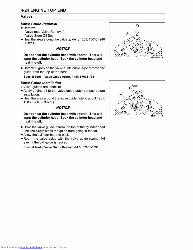
4-24 ENGINE TOP ENDValves
Valve Guide Removal•Remove:Valve (see Valve Removal)Valve Stem Oil Seal•Heat the area around the valve guide to 120 ∼ 150°C (248
∼ 302°F).
NOTICEDo not heat the cylinder head with a torch. This willwarp the cylinder head. Soak the cylinder head andheat the oil.
•Hammer lightly on the valve guide arbor [A] to remove theguide from the top of the head.Special Tool - Valve Guide Arbor, 4.5: 57001-1331
Valve Guide InstallationValve guides are identical.• Apply engine oil to the valve guide outer surface beforeinstallation.•Heat the area around the valve guide hole to about 120 ∼150°C (248 ∼ 302°F).
NOTICEDo not heat the cylinder head with a torch. This willwarp the cylinder head. Soak the cylinder head andheat the oil.
•Drive the valve guide in from the top of the cylinder headuntil the circlip stops the guide from going in too far.• Allow the cylinder head to cool.• Ream the valve guide with the valve guide reamer [A]even if the old guide is reused.Special Tool - Valve Guide Reamer, 4.5: 57001-1333
Downloaded from www.Manualslib.com manuals search engine

ENGINE TOP END 4-25Valves
Valve Seat Inspection•Remove the valve (see Valve Removal).• Check the valve seat surface [A] between the valve [B]and valve seat [C].Measure the outside diameter [D] of the seating patternon the valve seat.If the outside diameter is too large or too small, repair theseat (see Valve Seat Repair).
Valve Seat Surface Outside DiameterStandard:Exhaust 19.9 ∼ 20.1 mm (0.783 ∼ 0.791 in.)Inlet 22.9 ∼ 23.1 mm (0.902 ∼ 0.909 in.)
NOTEThe valve stem and guide must be in good condition orthis check will not be valid.
If the valve seating pattern is not correct, repair the seat.• Check the seating surface width of the valve seat.Measure the seat width [E] of the portion where there isno build-up carbon (white portion) of the valve seat with avernier caliper.Good [F]If the width is too wide [G], too narrow [H] or uneven [J],repair the seat (see Valve Seat Repair).
Valve Seat WidthStandard:Exhaust 0.80 ∼ 1.15 mm (0.031 ∼ 0.045 in.)Inlet 0.80 ∼ 1.15 mm (0.031 ∼ 0.045 in.)
Downloaded from www.Manualslib.com manuals search engine

4-26 ENGINE TOP ENDValves
Valve Seat Repair•Repair the valve seat with the valve seat cutters.Special Tools - Valve Seat Cutter Holder, 4.5: 57001-1330
Valve Seat Cutter Holder Bar: 57001-1128InletSpecial Tools - Valve Seat Cutter, 45° - 27.5: 57001-1114
Valve Seat Cutter, 32° - 25: 57001-1118Valve Seat Cutter, 60° - 30: 57001-1123
ExhaustSpecial Tools - Valve Seat Cutter, 32° - 22: 57001-1206
Valve Seat Cutter, 45° - 22: 57001-1205Valve Seat Cutter, 67.5° - 22: 57001-1207
If the manufacturer’s instructions are not available, usethe following procedure.
Seat Cutter Operating Care1. This valve seat cutter is developed to grind the valve forrepair. Therefore the cutter must not be used for otherpurpose than seat repair.
2. Do not drop or shock the valve seat cutter, or the dia-mond particles may fall off.
3. Do not fail to apply engine oil to the valve seat cutterbefore grinding the seat surface. Also wash off groundparticles sticking to the cutter with washing oil.
NOTEDo not use a wire brush to remove the metal particlesfrom the cutter. It will take off the diamond particles.
4. Setting the valve seat cutter holder in position, operatethe cutter in one hand. Do not apply too much force tothe diamond position.
NOTEPrior to grinding, apply engine oil to the cutter and dur-ing the operation, wash off any ground particles stickingto the cutter with washing oil.
5. After use, wash the cutter with washing oil and apply athin layer of engine oil before storing.
Marks Stamped on the cutterThemarks stamped on the back of the cutter [A] represent
the following.60° ........................... Cutter angle [B]30 .......................... Outer diameter of cutter [C]
Downloaded from www.Manualslib.com manuals search engine

ENGINE TOP END 4-27Valves
Operating Procedures•Clean the seat area carefully.• Coat the seat with machinist’s dye.• Fit a 45° cutter [A] to the holder [B] and slide it into thevalve guide.• Press down lightly on the handle [C] and turn it right orleft. Grind the seating surface only until it is smooth.
NOTICEDo not grind the seat too much. Overgrinding willreduce valve clearance by sinking the valve into thehead. If the valve sinks too far into the head, it willbe impossible to adjust the clearance, and the cylin-der head must be replaced.
Valve seat area form is as follows:Widened Width [A] of engagement by machining with45° cutterGround Volume [B] by 32° cutter32° [C]Correct Width [D]Ground Volume [E] by 60° cutter60° [F]
•Measure the outside diameter of the seating surface witha vernier caliper.If the outside diameter of the seating surface is too small,repeat the 45° grind [A] until the diameter is within thespecified range.Original Seating Surface [B]
NOTERemove all pittings of flaws from 45° ground surface.After grinding with 45° cutter, apply thin coat of machin-ist’s dye to seating surface. This makes seating surfacedistinct and 32° and 60° grinding operation easier.When the valve guide is replaced, be sure to grind with45° cutter for centering and good contact.
Downloaded from www.Manualslib.com manuals search engine

4-28 ENGINE TOP ENDValves
If the outside diameter of the seating surface is too large,make the 32° grind described below.If the outside diameter [A] of the seating surface is withinthe specified range, measure the seat width as describedbelow.•Grind the seat at a 32° angle [B] until the seat outsidediameter is within the specified range.To make the 32° grind, fit a 32° cutter into the holder, andslide it into the valve guide.Turn the holder one turn at a time while pressing downvery lightly. Check the seat after each turn.
NOTICEThe 32° cutter removes material very quickly.Check the seat outside diameter frequently to pre-vent overgrinding.
After making the 32° grind, return to the seat outside di-ameter measurement step above.• To measure the seat width, use a vernier caliper to mea-sure the width of the 45° angle portion of the seat at sev-eral places around the seat.If the seat width is too narrow, repeat the 45° grind untilthe seat is slightly too wide, and then return to the seatoutside diameter measurement step above.
If the seat width is too wide, make the 60° [A] grind de-scribed below.If the seat width is within the specified range, lap the valveto the seat as described below.•Grind the seat at a 60° angle until the seat width is withinthe specified range.To make the 60° grind, fit 60° cutter into the holder, andslide it into the valve guide.Turn the holder, while pressing down lightly.After making the 60° grind, return to the seat width mea-surement step above.Correct Width [B]
Downloaded from www.Manualslib.com manuals search engine

ENGINE TOP END 4-29Valves
• Lap the valve to the seat using a lapper, once the seatwidth and outside diameter are within the ranges specifiedabove.Put a little coarse grinding compound on the face of thevalve in a number of places around the valve head.Spin the valve against the seat until the grinding com-pound produces a smooth, matched surface on both theseat and the valve.Repeat the process with fine grinding compound.[A] Lapper[B] Valve Seat[C] Valve• The seating area should be marked about in the middleof the valve face.If the seat area is incorrect place on the valve, be sureto check the valve is the correct part. If it is, it may havebeen refaced too much replace the valve.• Be sure to remove all grinding compound before assem-bly.•When the engine is assembled, be sure to adjust the valveclearance (see Valve Clearance Adjustment in the Peri-odic Maintenance chapter).
Valve Head Thickness Inspection•Measure the thickness of valve head.Valve Head Thickness [A]Standard:Exhaust valve 0.8 mm (0.031 in.)Inlet valve 0.5 mm (0.020 in.)
Service Limit:Exhaust valve 0.5 mm (0.020 in.)Inlet valve 0.25 mm (0.010 in.)
If it is under the service limit, replace the valve.
Valve Stem Bend Inspection•Support the valve at both ends of the straight stem por-tion, and set a dial gauge against the center of the stem.• Turn the valve and read the variation in the dial gauge [A].Valve Stem BendStandard: TIR 0.01 mm (0.0004 in.) or lessService Limit: TIR 0.05 mm (0.002 in.)
If it is bent over the service limit, replace the valve.
Downloaded from www.Manualslib.com manuals search engine
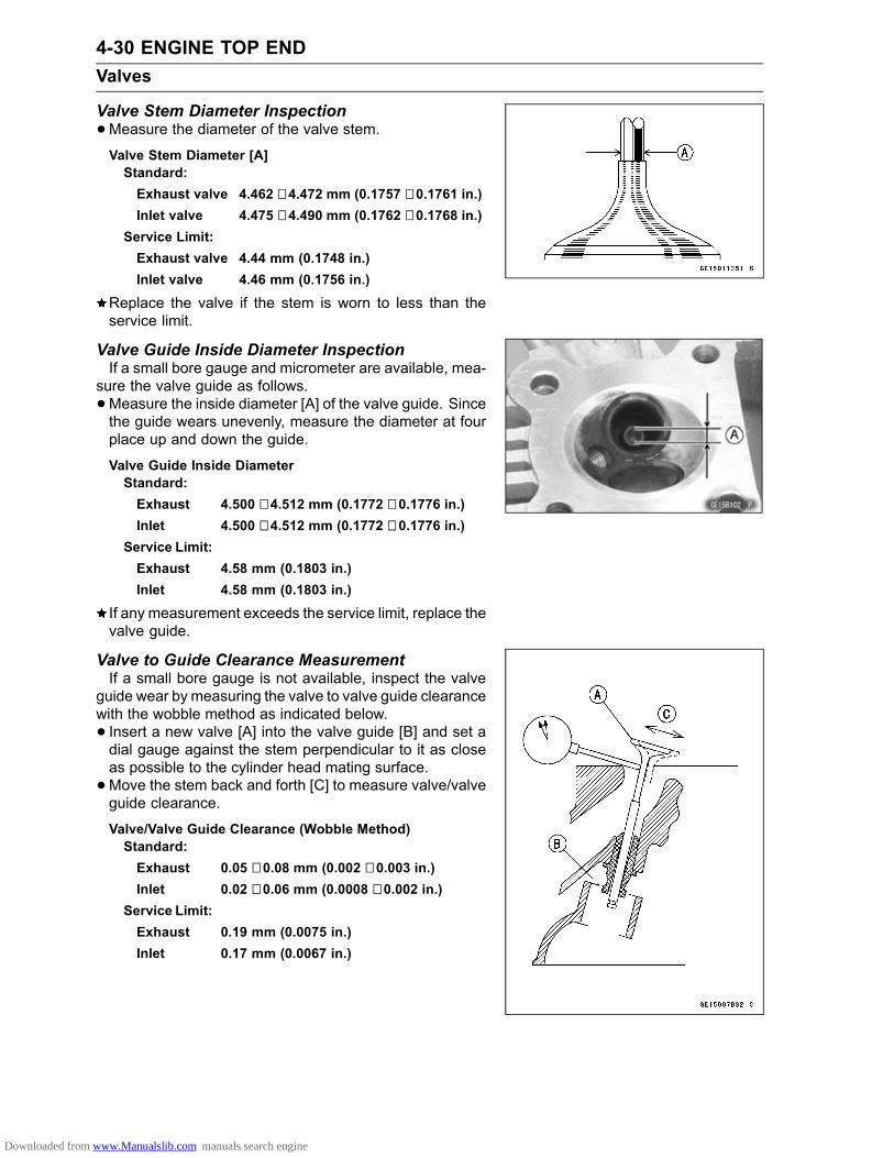
4-30 ENGINE TOP ENDValves
Valve Stem Diameter Inspection•Measure the diameter of the valve stem.Valve Stem Diameter [A]Standard:Exhaust valve 4.462 ∼ 4.472 mm (0.1757 ∼ 0.1761 in.)Inlet valve 4.475 ∼ 4.490 mm (0.1762 ∼ 0.1768 in.)
Service Limit:Exhaust valve 4.44 mm (0.1748 in.)Inlet valve 4.46 mm (0.1756 in.)
Replace the valve if the stem is worn to less than theservice limit.
Valve Guide Inside Diameter InspectionIf a small bore gauge and micrometer are available, mea-
sure the valve guide as follows.•Measure the inside diameter [A] of the valve guide. Sincethe guide wears unevenly, measure the diameter at fourplace up and down the guide.
Valve Guide Inside DiameterStandard:Exhaust 4.500 ∼ 4.512 mm (0.1772 ∼ 0.1776 in.)Inlet 4.500 ∼ 4.512 mm (0.1772 ∼ 0.1776 in.)
Service Limit:Exhaust 4.58 mm (0.1803 in.)Inlet 4.58 mm (0.1803 in.)
If any measurement exceeds the service limit, replace thevalve guide.
Valve to Guide Clearance MeasurementIf a small bore gauge is not available, inspect the valve
guide wear by measuring the valve to valve guide clearancewith the wobble method as indicated below.• Insert a new valve [A] into the valve guide [B] and set adial gauge against the stem perpendicular to it as closeas possible to the cylinder head mating surface.•Move the stem back and forth [C] to measure valve/valveguide clearance.
Valve/Valve Guide Clearance (Wobble Method)Standard:Exhaust 0.05 ∼ 0.08 mm (0.002 ∼ 0.003 in.)Inlet 0.02 ∼ 0.06 mm (0.0008 ∼ 0.002 in.)
Service Limit:Exhaust 0.19 mm (0.0075 in.)Inlet 0.17 mm (0.0067 in.)
Downloaded from www.Manualslib.com manuals search engine

ENGINE TOP END 4-31Valves
•Repeat the measurement in a direction at a right angle tothe first.If the reading exceeds the service limit, replace the guide.
NOTEThe reading is not actual valve/valve guide clearancebecause the measuring point is above the guide.
Downloaded from www.Manualslib.com manuals search engine

4-32 ENGINE TOP ENDValves
Downloaded from www.Manualslib.com manuals search engine

ENGINE TOP END 4-33Cylinder, Piston
Cylinder Removal•Remove:Cylinder Head (see Cylinder Head Removal)Lower Camshaft Chain Guide [A]• Tap the cylinder [B] lightly with a plastic mallet to separatefrom the crankcase.•Remove the cylinder base gasket.
Cylinder InstallationNOTE
If the cylinder block is replaced with a new one, piston tocylinder clearance must be checked against the speci-fied value.
• Install a new cylinder base gasket [A] and be sure thattwo dowel pins [B] are properly fitted in the crankcase.
• Pull the camshaft chain taut top avoid kinking it and usea wrench on the crankshaft to set the piston at BDC.•Position the piston ring opening as follows.Top Ring [A]Second Ring [B]Upper Oil Ring Steel Rail [C]Oil Ring Expander [D]Lower Oil Ring Steel Rail [E]30 ∼ 90° [F]
• Apply engine oil to the piston rings and the cylinder insidesurface.• Pull the camshaft chain up through the cylinder and inserta screwdriver to keep the chain from falling back into theengine.• Place the upper camshaft chain guide inside the cylinderblocks.• Fit the bottom of the cylinder over the piston rings, press-ing in on opposite sides of the rings as necessary. Takecare that the rings do not slip out of their proper positions.• Insert the lower camshaft chain guide [A] all the waydown.• Install the cylinder head (see Cylinder Head Installation).
Downloaded from www.Manualslib.com manuals search engine

4-34 ENGINE TOP ENDCylinder, Piston
Piston Removal•Remove the cylinder (see Cylinder Removal).•Wrap a clean cloth around the base of the piston.•Use the plier [A] and remove the snap ring [B].
• Remove the piston by pushing the piston pin and pullingit out. Use the piston pin puller assembly [A] if the pin istight.Special Tool - Piston Pin Puller Assembly: 57001-910
•Remove the piston rings [A]. Carefully spread the ringopening with your thumbs and then push up on the op-posite side of the ring to remove it.
Piston InstallationNOTE
The oil ring rails have no “top” or “bottom”.• Install the oil ring expander [A] in the bottom piston ringgroove so that the ends [B] but together, never overlap.• Install the oil ring steel rails, one above the expander andone below it.Spread the rail with your thumbs, but only enough to fitthe rail over the piston.Release the rail into the bottom piston ring groove.•Do not mix up the top ring and second ring.• Install the top ring [A] so that the “O” mark [B] faces up.• Install the second ring [C] so that the “N” mark [D] facesup.
Downloaded from www.Manualslib.com manuals search engine

ENGINE TOP END 4-35Cylinder, Piston
NOTEIf a new piston is used, check piston to cylinder clear-ance (see Piston/Cylinder Clearance Inspection), anduse new piston rings.
• Install the piston so that the “EX” mark [A] on the pistontoward exhaust side.
• Fit a new piston snap ring into the side of the piston sothat the ring opening [A] does not coincide with the slit [B]of the piston pin hole.When installing a piston pin snap ring, compress it onlyenough to install it no more.
NOTICEDo not reuse snap rings, as removal weakens anddeforms them. They could fall out and score thecylinder wall.
Cylinder Inside Diameter Measurement•Since there is a difference in cylinder wear in different di-rections, take a side to side and a front to back measure-ment at each of the three locations (total of six measure-ments) shown in the figure.If any of the cylinder inside diameter measurements ex-ceeds the service limit, the cylinder will have to bored tooversize and then honed.
Cylinder Inside DiameterStandard: 52.997 ∼ 53.009 mm (2.0865 ∼ 2.0870
in.) and less than 0.01 mm (0.0004in.) difference between any twomeasurements
Service Limit: 53.10 mm (2.0905 in.) or 0.05 mm(0.002 in.) difference between any twomeasurements
10 mm (0.39 in.) [A]60 mm (2.4 in.) [B]20 mm (0.79 in.) [C]
Piston Wear Inspection•Measure the outside diameter [A] of the piston 3.8 mm[B] up from the bottom of the piston at a right angle to thedirection of the piston pin.
Piston DiameterStandard: 52.969 ∼ 52.981 mm (2.0854 ∼ 2.0859 in.)Service Limit: 52.82 mm (2.080 in.)
NOTEAbnormal wear such as a marked diagonal patternacross the piston skirt may mean a bent connectingrod or crankshaft.
Downloaded from www.Manualslib.com manuals search engine

4-36 ENGINE TOP ENDCylinder, Piston
Piston/Cylinder Clearance InspectionThe most accurate way to find the piston clearance is
by making separate piston and cylinder diameter measure-ments and then computing the difference between the twovalues. Measure the piston diameter as just described, andmeasure the cylinder diameter at the very bottom of thecylinder.
Piston/Cylinder ClearanceStandard: 0.010 ∼ 0.022 mm (0.00039 ∼ 0.00086 in.)
NOTEWhenever the piston or cylinder has been replaced witha new one, the motorcycle must be broken in the sameas with a new machine.
Boring, Honing PerformanceWhen boring and honing a cylinder, note the following:There are two sizes of oversize pistons available. Over-size pistons require oversize rings.
Oversize Pistons and Rings0.50 mm (0.0197 in.) Oversize1.0 mm (0.0394 in.) Oversize
Before boring a cylinder [A], first measure the exact di-ameter of the oversize piston, and then, according to thestandard clearance in the specifications section, deter-mine the rebore diameter. However, if the amount of bor-ing necessary would make the inside diameter greaterthan 1.0mm (0.0394 in.) oversize, the cylinder blockmustbe replaced.Cylinder inside diameter must not vary more than 0.01mm (0.0004 in.) at any point.Be wary of measurements taken immediately after boringsince the heat affects cylinder diameter.In the case of a rebored cylinder and oversize piston, theservice limit for the cylinder is the diameter that the cylin-der was bored to plus 0.1 mm (0.004 in.) and the servicelimit for the piston is the oversize piston original diameterminus 0.20 mm (0.0079 in.). If the exact figure for the re-bored diameter is unknown, it can be roughly determinedby measuring the diameter at the base of the cylinder.
Downloaded from www.Manualslib.com manuals search engine

ENGINE TOP END 4-37Cylinder, Piston
Piston Ring End Gap Inspection•Place the piston ring [A] inside the cylinder, using the pis-ton to locate the ring squarely in place. Set it close to thebottom of the cylinder, where cylinder wear is low.•Measure the gap [B] between the ends of the ring with athickness gauge.
Piston Ring End GapStandard:Top 0.10 ∼ 0.20 mm (0.0039 ∼ 0.0079 in.)Second 0.30 ∼ 0.45 mm (0.0118 ∼ 0.0177 in.)Oil 0.10 ∼ 0.60 mm (0.0039 ∼ 0.0236 in.)
Service Limit:Top 0.6 mm (0.024 in.)Second 0.8 mm (0.031 in.)Oil 0.9 mm (0.035 in.)
Piston Ring, Piston Ring Groove Inspection•Visually inspects the piston rings and the piston ringgrooves.If the rings are worn unevenly or damaged, they must bereplaced.If the piston ring grooves are worn unevenly or damaged,the piston must be replaced and fitted with new rings.•Check for uneven groovewear by inspecting the ring seat-ing.The rings should fit perfectly parallel to the groove sur-faces. If not, the piston must be replaced.•With the piston rings in their grooves, make several mea-surements with a thickness gauge [A] to determine pistonring groove clearance.
Downloaded from www.Manualslib.com manuals search engine

4-38 ENGINE TOP ENDCylinder, Piston
Piston Ring/Groove ClearanceStandard:Top 0.020 ∼ 0.060 mm (0.0008 ∼ 0.0024 in.)Second 0.010 ∼ 0.050 mm (0.0004 ∼ 0.0020 in.)
Service Limit:Top 0.16 mm (0.0063 in.)Second 0.15 mm (0.0059 in.)
Piston Ring ThicknessStandard:Top 0.77 ∼ 0.79 mm (0.0303 ∼ 0.0311 in.)Second 0.77 ∼ 0.79 mm (0.0303 ∼ 0.0311 in.)
Service Limit:Top 0.70 mm (0.0276 in.)Second 0.70 mm (0.0276 in.)
Piston Ring Groove WidthStandard:Top 0.81 ∼ 0.83 mm (0.0319 ∼ 0.0327 in.)Second 0.80 ∼ 0.82 mm (0.0315 ∼ 0.0323 in.)
Service Limit:Top 0.91 mm (0.0358 in.)Second 0.90 mm (0.0354 in.)
If the clearance exceeds the service limit, remove the pis-ton rings, and measure the thickness of the piston ringsand the width of the ring grooves. If the ring has worndown to less than the service limit, replace the ring, if thegroove width exceeds the service limit replace the piston.
NOTEThese tables apply to oversize pistons and rings as wellas standard pistons and rings.
Piston, Piston Pin, Connecting Rod WearInspection•Visually inspect the snap rings [A] are fitted in place.If the ring shows weakness or deformation, replace thering. Also if the pin hole groove shows excessive wear,replace the piston.• Visually inspect the piston pin hole and connecting rodsmall end hole.If the piston pin hole shows uneven wear, replace the pis-ton.If the rod small end hole shows uneven wear, replace therod, or crankshaft assembly.• Visually inspect the outer surface of the piston pin [B].If the pin shows color change or stepped wear, replacethe pin.
Downloaded from www.Manualslib.com manuals search engine

ENGINE TOP END 4-39Cylinder, Piston
Piston, Piston Pin, Connecting Rod Inspection•Measure the inside diameter of both piston pin holes inthe piston.
Piston Pin Hole Inside Diameter [A]Standard: 13.001 ∼ 13.007 mm (0.5118 ∼ 05121 in.)Service Limit: 13.08 mm (0.515 in.)
If either piston pin hole diameter exceeds the service limit,replace the piston.•Measure the diameter of the piston pin.Piston Pin Diameter [B]Standard: 12.995 ∼ 13.000 mm (0.5116 ∼ 0.5118 in.)Service Limit: 12.96 mm (0.0510 in.)
If the piston pin diameter is less than the service limit atany point, replace the piston pin.
Measure the inside diameter [A] of the connecting rodsmall end.
Connecting Rod Small End Inside DiameterStandard: 13.003 ∼ 13.014 mm (0.5119 ∼ 0.5124 in.)Service limit: 13.05 mm (0.514 in.)
If the diameter exceeds the service limit, replace the con-necting rod.
Downloaded from www.Manualslib.com manuals search engine

4-40 ENGINE TOP ENDMuffler
Muffler Removal•Remove:Right Side Cover (see Side Cover Removal in the Framechapter)Screws [A]Exhaust Pipe Covers [B]
•Remove the exhaust pipe holder nuts [A].
• Remove the muffler mounting nut [A] and bolt [B].
• Remove the muffler assembly [A] rearward.
Downloaded from www.Manualslib.com manuals search engine

ENGINE TOP END 4-41Muffler
Muffler Installation• Installation is the reverse of removal; note the following.•Replace the gasket with a new one.• Tighten:Torque - Exhaust Pipe Holder Nuts: 16 N·m (1.6 kgf·m, 12
ft·lb)
•Replace the muffler mounting nut [B] with a new one.Tighten the muffler mounting bolt [A] and nut in the follow-ing procedure.• Install the muffler mounting bolt to the frame [C] andtighten it to the specified torque.Torque - Muffler Mounting Bolt: 9.8 N·m (1.0 kgf·m, 87 in·lb)
• Install the muffler [D] and tighten the nut to the specifiedtorque.Torque - Muffler Mounting Nut: 30 N·m (3.1 kgf·m, 22 ft·lb)
• Loosen the nut, and tighten the nut again to the specifiedtorque.• Thoroughly warm up the engine, wait until the enginecools down, and then retighten the bolt and nuts.
Spark Arrester Cleaning•Refer to the Spark Arrester Cleaning in the Periodic Main-tenance chapter.
Downloaded from www.Manualslib.com manuals search engine

CLUTCH 5-1
5
ClutchTable of Contents
Exploded View........................................................................................................................ 5-2Specifications ......................................................................................................................... 5-6Special Tools .......................................................................................................................... 5-7Clutch Lever and Cable (KLX110D) ....................................................................................... 5-8
Clutch Lever Free Play Inspection .................................................................................... 5-8Clutch Lever Free Play Adjustment .................................................................................. 5-8Clutch Cable Removal ...................................................................................................... 5-8Clutch Cable Installation ................................................................................................... 5-8Clutch Cable Lubrication and Inspection .......................................................................... 5-8
Clutch Cover (KLX110C) ........................................................................................................ 5-9Clutch Cover Removal ...................................................................................................... 5-9Clutch Cover Installation ................................................................................................... 5-9Clutch Cover Disassembly................................................................................................ 5-9Clutch Cover Assembly..................................................................................................... 5-10
Clutch Cover (KLX110D) ........................................................................................................ 5-11Clutch Cover Removal ...................................................................................................... 5-11Clutch Cover Installation ................................................................................................... 5-11Release Shaft Removal .................................................................................................... 5-11Release Shaft Installation ................................................................................................. 5-12
Clutch ..................................................................................................................................... 5-13Clutch Removal (KLX110C) .............................................................................................. 5-13Secondary Clutch Disassembly (KLX110C)...................................................................... 5-14Secondary Clutch Assembly (KLX110C) .......................................................................... 5-14Clutch Installation (KLX110C) ........................................................................................... 5-15Clutch Removal (KLX110D) .............................................................................................. 5-16Clutch Hub Disassembly (KLX110D) ................................................................................ 5-18Clutch Hub Assembly (KLX110D) ..................................................................................... 5-18Clutch Installation (KLX110D) ........................................................................................... 5-18Primary Clutch Housing Wear Inspection (KLX110C)....................................................... 5-19Primary Clutch Shoe Lining Wear Inspection (KLX110C)................................................. 5-19One-Way Clutch Inspection (KLX110C)............................................................................ 5-20Friction and Steel Plate Damage, Wear Inspection .......................................................... 5-20Friction and Steel Plate Warp Inspection.......................................................................... 5-20Clutch Spring Free Length Measurement ......................................................................... 5-20Clutch Housing Finger Damage Inspection ...................................................................... 5-21Clutch Hub Spline Damage Inspection ............................................................................. 5-21Clutch Adjustment (KLX110C) .......................................................................................... 5-21
Downloaded from www.Manualslib.com manuals search engine

5-2 CLUTCHExploded View
KLX110C Models
Downloaded from www.Manualslib.com manuals search engine

CLUTCH 5-3Exploded View
TorqueNo. Fastener
N·m kgf·m ft·lbRemarks
1 Clutch Cover Bolts 8.8 0.9 78 in·lb2 Oil Seal Retaining Plate Screws 2.9 0.3 26 in·lb L3 Primary Clutch Hub Nut 72 7.3 534 Clutch Spring Bolts 5.0 0.51 44 in·lb5 Secondary Clutch Hub Nut 72 7.3 536 Clutch Adjusting Screw Locknut 19 1.9 14EO: Apply engine oil.G: Apply grease.L: Apply a non-permanent locking agent.R: Replacement Parts
Downloaded from www.Manualslib.com manuals search engine

5-4 CLUTCHExploded View
KLX110D Models
Downloaded from www.Manualslib.com manuals search engine

CLUTCH 5-5Exploded View
TorqueNo. Fastener
N·m kgf·m ft·lbRemarks
1 Clutch Cover Bolts 8.8 0.9 78 in·lb2 Clutch Hub Nut 72 7.3 533 Primary Gear Nut 72 7.3 53CL: Apply cable lubricant.EO: Apply engine oil.G: Apply grease.R: Replacement Parts
Downloaded from www.Manualslib.com manuals search engine

5-6 CLUTCHSpecifications
Item Standard Service LimitClutch (KLX110C)Primary Clutch:Primary Clutch HousingInside Diameter
104.0 ∼ 104.2 mm (4.094 ∼ 4.102 in.) 104.5 mm (4.114 in.)
Primary Clutch Shoe GrooveDepth
1.0 mm (0.04 in.) 0.5 mm (0.02 in.)
Secondary Clutch:Friction Plate Thickness 3.1 ∼ 3.3 mm (0.12 ∼ 0.13 in.) 3.0 mm (0.12 in.)Friction and Steel Plate Warp 0.2 mm (0.008 in.) or less 0.3 mm (0.01 in.)Clutch Spring Free Length 19.1 mm (0.752 in.) 18.0 mm (0.709 in.)
Clutch (KLX110D)Clutch Lever Free Play 2 ∼ 3 mm (0.08 ∼ 0.12 in.) – – –Friction Plate Thickness 3.12 ∼ 3.28 mm (0.123 ∼ 0.129 in.) 3.0 mm (0.12 in.)Friction and Steel Plate Warp 0.15 mm (0.0059 in.) or less 0.3 mm (0.01 in.)Clutch Spring Free Length 22.04 mm (0.868 in.) 20.4 mm (0.803 in.)
Downloaded from www.Manualslib.com manuals search engine

CLUTCH 5-7Special Tools
Bearing Driver Set:57001-1129
Clutch Holder 1:57001-1507
Clutch Holder 2:57001-1508
Gear Holder:57001-1602
Downloaded from www.Manualslib.com manuals search engine
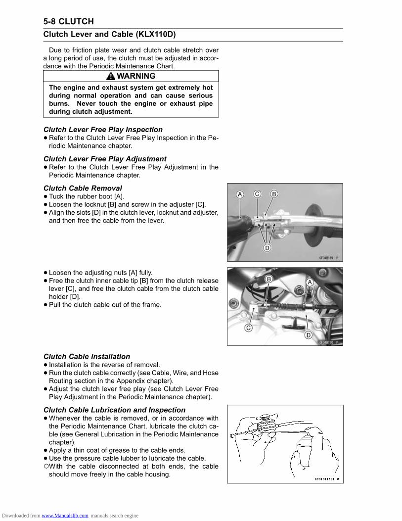
5-8 CLUTCHClutch Lever and Cable (KLX110D)
Due to friction plate wear and clutch cable stretch overa long period of use, the clutch must be adjusted in accor-dance with the Periodic Maintenance Chart.
WARNINGThe engine and exhaust system get extremely hotduring normal operation and can cause seriousburns. Never touch the engine or exhaust pipeduring clutch adjustment.
Clutch Lever Free Play Inspection•Refer to the Clutch Lever Free Play Inspection in the Pe-riodic Maintenance chapter.
Clutch Lever Free Play Adjustment•Refer to the Clutch Lever Free Play Adjustment in thePeriodic Maintenance chapter.
Clutch Cable Removal•Tuck the rubber boot [A].• Loosen the locknut [B] and screw in the adjuster [C].• Align the slots [D] in the clutch lever, locknut and adjuster,and then free the cable from the lever.
• Loosen the adjusting nuts [A] fully.• Free the clutch inner cable tip [B] from the clutch releaselever [C], and free the clutch cable from the clutch cableholder [D].• Pull the clutch cable out of the frame.
Clutch Cable Installation• Installation is the reverse of removal.• Run the clutch cable correctly (see Cable, Wire, and HoseRouting section in the Appendix chapter).• Adjust the clutch lever free play (see Clutch Lever FreePlay Adjustment in the Periodic Maintenance chapter).
Clutch Cable Lubrication and Inspection•Whenever the cable is removed, or in accordance withthe Periodic Maintenance Chart, lubricate the clutch ca-ble (see General Lubrication in the Periodic Maintenancechapter).• Apply a thin coat of grease to the cable ends.•Use the pressure cable lubber to lubricate the cable.With the cable disconnected at both ends, the cableshould move freely in the cable housing.
Downloaded from www.Manualslib.com manuals search engine

CLUTCH 5-9Clutch Cover (KLX110C)
Clutch Cover Removal•Drain the engine oil (see Engine Oil Change in the Peri-odic Maintenance chapter).• Remove the kick pedal (see Kick Pedal Removal in theCrankshaft/Transmission chapter).When the clutch cove is to be disassembled, loosen theclutch adjuster locknut [A] before clutch cover removal.• Loosen the footpeg bracket bolts for extra clearance.•Remove:Brake Pedal Return Spring [B] (Upper End)Clutch Cover Bolts [C]Clutch Cover [D]
Clutch Cover Installation•Blow on compressed air to the oil passage [A] in the clutchcover.
• Install the dowel pins [A].• Install a new gasket.• Apply grease to the kick shaft oil seal lip.• Install the clutch cover, be sure that the release cam [B]and release ball assembly [C] are not falling down.Torque - Clutch Cover Bolts: 8.8 N·m (0.90 kgf·m, 78 in·lb)
• Install other removed parts.• Tighten:Torque - Footpeg Bracket Bolts: 25 N·m (2.5 kgf·m, 18 ft·lb)
•Pour in the specified engine oil (see Engine Oil Changein the Periodic Maintenance chapter).• Adjust the clutch lever free play (see Clutch Lever FreePlay Adjustment in the Periodic Maintenance chapter).
Clutch Cover Disassembly•Remove the clutch cover (see Clutch Cover Removal).• Unscrew the clutch adjuster locknut [A].• Remove the release plate [B] and the release shaft [C].
Downloaded from www.Manualslib.com manuals search engine

5-10 CLUTCHClutch Cover (KLX110C)
•Remove the screws [A] and plate [B].• Take the oil seal [C] out of the cover with a hook.
Clutch Cover Assembly•Replace the O-ring and the oil seal with new ones.• Apply high-temperature grease to the oil seal lips [A].Press in the new oil seal so that the seal surface is flushwith the cover.Special Tool - Bearing Driver Set: 57001-1129
•Apply a non-permanent locking agent to the oil seal re-taining plate screws.• Install the plate, and tighten the plate screws.Torque - Oil Seal Retaining Plate Screws: 2.9 N·m (0.30
kgf·m, 26 in·lb)
•Apply high-temperature grease to the O-ring, and installit.• Turn in the release plate [A] into the release shaft [B] fullybut no tightly and then back it out the three turns, andinsert it into the holes [C] of clutch cover securely.• Tighten the locknut into the release shaft from the oppo-site side.Torque - Clutch Adjusting Screw Locknut: 19 N·m (1.9
kgf·m, 14 ft·lb)
Downloaded from www.Manualslib.com manuals search engine

CLUTCH 5-11Clutch Cover (KLX110D)
Clutch Cover Removal•Drain the engine oil (see Engine Oil Change in the Peri-odic Maintenance chapter).• Remove the kick pedal (see Kick Pedal Removal in theCrankshaft/Transmission chapter).
• Remove the clutch cover bolts [A].• Free the clutch cable lower end [B] from the clutch releaselever [C].
• Remove:Brake Pedal Return Spring [A] (Upper End)Clutch Cover Bolts [B]Clutch Cover [C]
NOTEDo not remove the clutch release lever and shaft as-sembly unless it is absolutely necessary. If removed,the oil seal replacement may be required. Apply greaseto the oil seal lips.
Clutch Cover Installation• Install the dowel pins [A].• Install a new gasket.• Apply high-temperature grease to the oil seal lip of thecrankshaft of the clutch cover.• Apply grease to the kick shaft oil seal lip.• Install the clutch cover and clutch cable.Torque - Clutch Cover Bolts: 8.8 N·m (0.90 kgf·m, 78 in·lb)
• Install other removed parts.• Pour in the specified engine oil (see Engine Oil Changein the Periodic Maintenance chapter).• Adjust the clutch lever free play (see Clutch Lever FreePlay Adjustment in the Periodic Maintenance chapter).
Release Shaft RemovalNOTICE
Do not remove the clutch release shaft unless it isabsolutely necessary. If removed, release shaft oilseal must be replaced with a new one.
•Remove the clutch cover (see Clutch Cover Removal).• Pull the lever and shaft assembly [A] straight out of theclutch cover.
Downloaded from www.Manualslib.com manuals search engine

5-12 CLUTCHClutch Cover (KLX110D)
Release Shaft Installation• Installation is the reverse of removal.• Apply grease to the new oil seal lips.• Press in the oil seal [A] until it bottoms out.
Downloaded from www.Manualslib.com manuals search engine

CLUTCH 5-13Clutch
Clutch Removal (KLX110C)•Remove the clutch cover (see Clutch Cover Removal).• Pull out the clutch release lever [A].• Remove:Release Ball Assembly [B]Release Cam [C]Ball Bearing [D]Ball Bearing Holder [E]
• Loosen the primary clutch hub nut while holding the pri-mary clutch steady with the gear holder.Special Tool - Gear Holder: 57001-1602
NOTEIf the primary clutch hub nut is difficult to loosen us-ing a gear holder (57001-1602), use the clutch holder1 (57001-1507).
• Loosen the primary clutch hub nut [A], while holding theprimary clutch steady with the clutch holder [B].Special Tool - Clutch Holder 1: 57001-1507
•Remove the secondary clutch hub nut, while holding thesecondary clutch steady with the gear holder [A].Special Tool - Gear Holder: 57001-1602
•Remove:Primary Clutch Hub NutPrimary Clutch Hub Nut Assembly
•Remove the primary clutch housing [A] and secondaryclutch [B] together.
Downloaded from www.Manualslib.com manuals search engine

5-14 CLUTCHClutch
•Remove:Collar [A]Spacer [B]
Secondary Clutch Disassembly (KLX110C)•Remove the secondary clutch (see Clutch Removal).• Unscrew the clutch spring bolts [A] and take off the springplate [B] and springs [C].
• Remove the clutch hub [A] and clutch wheel [B].• Remove the secondary clutch plates [C].
Secondary Clutch Assembly (KLX110C)• Install the friction plates [A] and steel plates [B] on thesecondary clutch hub [C], starting with a friction plate andalternating them.The grooves [D] on the friction plate surfaces are cut tan-gentially and radially. Install the friction plates so that thegrooves run toward the center in the direction of the clutchhousing rotation (counterclockwise viewed from the en-gine right side).
NOTICEIf new dry steel plates and friction plates are in-stalled, apply engine oil to the surfaces of eachplate to avoid clutch plate seizure.
Downloaded from www.Manualslib.com manuals search engine

CLUTCH 5-15Clutch
• Install the clutch wheel on the clutch hub.• Install the clutch spring plate [A] with the springs andspring bolts temporarily and fit the clutch hub and plateassembly into the clutch housing [B].
• Install the last friction plate [A] fitting the tangs in thegrooves on the housing as shown.• Tighten:Torque - Secondary Clutch Spring Bolts: 5.0 N·m (0.51
kgf·m, 44 in·lb)
Clutch Installation (KLX110C)If the primary clutch housing disassembled, assemble itas follows.Install the gear [B] to the primary clutch housing [A].Fit the tooth form of the gears, and press the holder to theclutch housing.• Install the clutch housing.
• Apply engine oil to the collar.• Install:Spacer [A]Collar [B]• Insert the primary [C] and secondary clutch [D] together.Hard to install the secondary clutch, turn the drive shaftwhile pushing the clutch.
• Tighten the secondary clutch nut [A], while holding thegear holder [B].Torque - Secondary Clutch Hub Nut: 72 N·m (7.3 kgf·m, 53
ft·lb)
Special Tool - Gear Holder: 57001-1602
Downloaded from www.Manualslib.com manuals search engine

5-16 CLUTCHClutch
If the one-way clutch and race dropped from the primaryclutch housing, install it as follows.Put the one-way clutch [A] in the clutch housing halfwaywith the rotation mark [B] facing out.Fit the race [C] into the one-way clutch with the machin-ing unevenness side facing outside. Push the race in theclutch housing white turning the clutch housing counter-clockwise [D].
• Install the clutch hub.• Tighten the primary clutch hub nut, while holding the pri-mary clutch steady with the clutch holder.Special Tool - Clutch Holder 1: 57001-1507
Torque - Primary Clutch Hub Nut: 72 N·m (7.3 kgf·m, 53ft·lb)
• Install the ball bearing holder [A] and ball bearing [B].
• Apply high-temperature grease to the release ball assem-bly.• Install the release cam [A] and release ball assembly [B].• Install the release lever [C] to the shift shaft, with shiftshaft line [D] aligning to release lever line [E].• Install the clutch cover (see Clutch Cover Installation).• Adjust the clutch (see Clutch Release Adjustment in thePeriodic Maintenance chapter).
Clutch Removal (KLX110D)•Remove the clutch cover (see Clutch Cover Removal).• Remove:Clutch Pusher [A]Ball Bearing [B]Ball Bearing Holder [C]
Downloaded from www.Manualslib.com manuals search engine

CLUTCH 5-17Clutch
• Loosen the clutch hub nut while holding the clutch steadywith the gear holder.Special Tool - Gear Holder: 57001-1602
NOTEIf the clutch hub nut is difficult to loosen using a gearholder (57001-1602), use the clutch holder 2 (57001-1508).
• Loosen the clutch hub nut [A], while holding the clutchsteady with the clutch holder [B].Search the positions of three notches of clutch holder,which can be aligned.Remove two clutch spring bolts [C] inserted into the twoholes of clutch holder when searching.Set a clutch holder.Special Tool - Clutch Holder 2: 57001-1508
•Using the gear holder [A] to prevent the clutch from rotat-ing.Special Tool - Gear Holder: 57001-1602
•Remove:Primary Gear Nut [B]Clutch Hub Nut [C]
•Remove the clutch hub [A] and primary gear [B] together.
• Remove:Collar [A]Spacer [B]
Downloaded from www.Manualslib.com manuals search engine

5-18 CLUTCHClutch
Clutch Hub Disassembly (KLX110D)•Separate the clutch hub assembly from the clutch hous-ing.•Remove:Clutch Spring Bolts [A]Clutch Spring Plate [B]Clutch Springs [C]Clutch Holder [D]Friction Plates [E]Steel Plates [F]Friction Plates [G]
Clutch Hub Assembly (KLX110D)•Clutch hub assembly is the reverse of disassembly.The friction plates [A] are different from the other plates[B]. These plates are installed to both end of the all plates.
• Install the clutch spring plate and then tighten the clutchspring bolts to specified torque.Torque - Clutch Spring Bolts: 5.0 N·m (0.51 kgf·m, 44 in·lb)
NOTICEIf new dry friction plates and steel plates are in-stalled, apply engine oil to the surfaces of eachplate to avoid clutch plate seizure.
Clutch Installation (KLX110D)•Apply molybdenum disulfide oil to the drive shaft and col-lar.• Install:Spacer [A]Collar [B]• Install the clutch hub [C] and primary gear [D] together.Hard to install the clutch hub, turn the drive shaft whilepushing the clutch.
Downloaded from www.Manualslib.com manuals search engine

CLUTCH 5-19Clutch
•Tighten the clutch hub nut while holding the clutch steadywith the gear holder.Special Tool - Gear Holder: 57001-1602
NOTEIf the clutch hub nut is difficult to tighten using a gearholder (57001-1602), use the clutch holder 2 (57001-1508).
•Tighten the clutch hub nut, while holding the clutch steadywith the clutch holder.Special Tool - Clutch Holder 2: 57001-1508
Torque - Clutch Hub Nut: 72 N·m (7.3 kgf·m, 53 ft·lb)
•Tighten two clutch spring bolts holding the clutch housingwith hand.Torque - Clutch Spring Bolts: 5.0 N·m (0.51 kgf·m, 44 in·lb)
•Use the gear holder [A] to prevent the clutch from rotating.Special Tool - Gear Holder: 57001-1602
•Tighten the primary gear nut [B].Torque - Primary Gear Nut: 72 N·m (7.3 kgf·m, 53 ft·lb)
• Install other removed parts.
Primary Clutch Housing Wear Inspection(KLX110C)•Measure the inside diameter [A] of the clutch housing slid-ing surface.Use a vernier caliper and measure at several points asshown.If any measurement is greater than the service limit, re-place the primary clutch housing.
Primary Clutch Housing Inside DiameterStandard: 104.0 ∼ 104.2 mm (4.094 ∼ 4.102 in.)Service Limit: 104.5 mm (4.114 in.)
Primary Clutch Shoe Lining Wear Inspection(KLX110C)•Remove the primary clutch hub (see Clutch Removal).• Visually inspect the primary clutch shoe linings [A] for un-even wear, discoloration, missing friction material, cracksor other damage.If any of the linings are damaged, replace the primaryclutch hub.
Downloaded from www.Manualslib.com manuals search engine

5-20 CLUTCHClutch
•Measure the groove depth [A].Use a depth gauge, and measure at several points asshown.If any measurement is less than the service limit, replacethe primary clutch hub.
Primary Clutch Shoe Groove DepthStandard: 1.0 mm (0.04 in.)Service Limit: 0.5 mm (0.02 in.)
One-Way Clutch Inspection (KLX110C)•Remove the clutch cover.• Turn the primary clutch housing by hand. When view fromthe right side of the engine, the primary clutch housingshould turn counterclockwise freely [A] but should not turnclockwise.
If the one-way clutch does not operate as it should or if itmakes noise, go to the next steps.Remove the primary clutch.Check that the one-way clutch is installed so that the ro-tation mark faces out.Visually inspect the one-way clutch [A] and the race [B] inthe primary clutch housing.If there is any worn or damaged part, replace it.Check that the rollers [C] in the one-way clutch is installedwhen viewed from the right side of the engine.
Friction and Steel Plate Damage, Wear Inspection•Refer to Friction and Steel Plates Inspection in the Peri-odic Maintenance chapter.
Friction and Steel Plate Warp Inspection•Refer to Friction and Steel Plates Inspection in the Peri-odic Maintenance chapter.
Clutch Spring Free Length Measurement•Measure the free length of the clutch springs [A].If any spring is shorter than the service limit, it must bereplaced.
Clutch Spring Free LengthStandard:KLX110C Models 19.10 mm (0.752 in.)KLX110D Models 22.04 mm (0.868 in.)
Service Limit:KLX110C Models 18.0 mm (0.709 in.)KLX110D Models 20.4 mm (0.803 in.)
Downloaded from www.Manualslib.com manuals search engine

CLUTCH 5-21Clutch
Clutch Housing Finger Damage Inspection•Visually inspect the clutch housing fingers [A] where thefriction plate tangs [B] hit them.If they are badly worn or if there are groove cuts where thetangs hit, replace the housing. Also, replace the frictionplates if their tangs are damaged.
Clutch Hub Spline Damage Inspection•Visually inspect where the teeth on the steel plates wearagainst the clutch hub splines.If there are notches worn into the clutch hub splines [A],replace the clutch hub. Also, replace the steel plates iftheir teeth are damaged.
Clutch Adjustment (KLX110C)•Refer to the Clutch Release Adjustment in the PeriodicMaintenance chapter.
Downloaded from www.Manualslib.com manuals search engine

ENGINE LUBRICATION SYSTEM 6-1
6
Engine Lubrication SystemTable of Contents
Exploded View........................................................................................................................ 6-2Engine Oil Flow Chart............................................................................................................. 6-4Specifications ......................................................................................................................... 6-5Special Tools .......................................................................................................................... 6-6Engine Oil and Oil Filter.......................................................................................................... 6-7
Oil Level Inspection........................................................................................................... 6-7Engine Oil Change............................................................................................................ 6-7Oil Filter Change............................................................................................................... 6-7Oil Screen Cleaning .......................................................................................................... 6-8
Oil Pump................................................................................................................................. 6-9Oil Pump Removal ............................................................................................................ 6-9Oil Pump Installation ......................................................................................................... 6-9Oil Pump Inspection.......................................................................................................... 6-9
Oil Pipe................................................................................................................................... 6-10Oil Pipe Removal .............................................................................................................. 6-10Oil Pipe Installation ........................................................................................................... 6-10
Oil Pressure............................................................................................................................ 6-11Oil Pressure Measurement ............................................................................................... 6-11
Downloaded from www.Manualslib.com manuals search engine

6-2 ENGINE LUBRICATION SYSTEMExploded View
Downloaded from www.Manualslib.com manuals search engine

ENGINE LUBRICATION SYSTEM 6-3Exploded View
TorqueNo. Fastener
N·m kgf·m ft·lbRemarks
1 Oil Pipe Banjo Bolts 15 1.5 112 Oil Pipe Clamp Screw 5.2 0.53 46 in·lb3 Oil Pump Mounting Screws (L = 25) 5.2 0.53 46 in·lb4 Oil Pump Mounting Screw (L = 30) 5.2 0.53 46 in·lb5 Oil Filter Cap Bolts 5.2 0.53 46 in·lb6 Engine Oil Drain Plug 29 3.0 21G: Apply grease.R: Replacement Parts
Downloaded from www.Manualslib.com manuals search engine

6-4 ENGINE LUBRICATION SYSTEMEngine Oil Flow Chart
1. Crankshaft2. Oil Screen3. Oil Filter4. Camshaft5. Oil Pump6. Oil Pipe
Downloaded from www.Manualslib.com manuals search engine

ENGINE LUBRICATION SYSTEM 6-5Specifications
Item StandardEngine OilType API SG, SH, SJ, SL or SM with JASO MA, MA1 or MA2Viscosity SAE 10W-40Capacity 0.9 L (1.0 US qt) (when filter is not removed)
1.0 L (1.1 US qt) (when filter is removed)1.1 L (1.2 US qt) (when engine is completely dry)
Level Between upper and lower level linesOil Pressure MeasurementOil pressure 88 ∼ 147 kPa (0.9 ∼ 1.5 kgf/cm², 13 ∼ 21 psi) at 4 000 r/min
(rpm), Oil Temperature 50°C (122°F)
Downloaded from www.Manualslib.com manuals search engine

6-6 ENGINE LUBRICATION SYSTEMSpecial Tools
Oil Pressure Gauge, 5 kgf/cm²:57001-125
Oil Pressure Gauge Adapter, M10 × 1.25:57001-1182
Oil Pressure Cap:57001-1651
Downloaded from www.Manualslib.com manuals search engine

ENGINE LUBRICATION SYSTEM 6-7Engine Oil and Oil Filter
WARNINGVehicle operation with insufficient, deteriorated,or contaminated engine oil will cause acceleratedwear and may result in engine seizure, accident,and injury. Check the oil level before each use andchange the oil and filter according to the periodicmaintenance chart.
Oil Level Inspection•Check that the engine oil level is between the upper [A]and lower [B] levels in the oil level inspection window.
NOTESituate the motorcycle so that it is perpendicular to theground.If the motorcycle has just been used, wait several min-utes for all the oil to drain down.If the oil has just been changed, start the engine andrun it for several minutes at idle speed. This fills the oilfilter with oil. Stop the engine, then wait several minutesuntil the oil settles.
NOTICERacing the engine before the oil reaches every partcan cause engine seizure.
If the oil level is too high, remove the excess oil, using asyringe or other suitable device.If the oil level is too low, add the correct amount of oil.Use the same type and make of oil that is already in theengine.
NOTEIf the engine oil type and make are unknown, use anybrand of the specified oil to top off the level rather thanrunning the engine with the oil level low. Then at yourearliest convenience, change the oil completely.
Engine Oil Change•Refer to the Engine Oil Change in the Periodic Mainte-nance chapter.
Oil Filter Change•Refer to the Oil Filter Replacement in the Periodic Main-tenance chapter.
Downloaded from www.Manualslib.com manuals search engine

6-8 ENGINE LUBRICATION SYSTEMEngine Oil and Oil Filter
Oil Screen Cleaning•Drain the engine oil (see Engine Oil Change in the Peri-odic Maintenance chapter).• Remove:Clutch Cover (see Clutch Cover Removal in the Clutchchapter)Oil Screen [A]
•Clean the oil screen [A] with high flash-point solvent andremove any particles stuck to it.Clean thoroughly whenever the oil screen is removed.
WARNINGGasoline and low flash-point solvents can beflammable and/or explosive and cause severeburns. Clean the screen in a well-ventilated area,and take care that there are no sparks or flameanywhere near the working area; this includes anyappliance with a pilot light. Do not use gasoline ora low flash-point solvent to clean the screen.
NOTEWhile cleaning the screen, check for any metal particlesthat might indicate internal engine damage.
• Inspect the screen carefully for net tearing or other dam-ages.If the screen is damaged, replace it with a new one.• Install:Oil ScreenClutch Cover (see Clutch Cover Installation in the Clutchchapter)
Downloaded from www.Manualslib.com manuals search engine

ENGINE LUBRICATION SYSTEM 6-9Oil Pump
Oil Pump Removal•Drain the engine oil (see Engine Oil Change in the Peri-odic Maintenance chapter).• Remove the clutch cover (see Clutch Cover Removal inthe Clutch chapter).
KLX110C Models•Remove the clutch (see Clutch Removal (KLX110C) in theClutch chapter).
• Remove the mounting screws [A] and remove the oilpump assembly [B].Turn the pump gear so that the pump mounting screwscan be removed through the pump gear holes.
Oil Pump Installation•Replace the O-rings [A] with new ones.• Apply grease to the O-rings.• Install the dowel pin [B].
• Install the oil pump assembly [A] and screws.The lower screw [B] is longer than the other ones.Torque - Oil Pump Mounting Screws: 5.2 N·m (0.53 kgf·m,
46 in·lb)
• Install the clutch cover (see Clutch Cover Installation inthe Clutch chapter).
Oil Pump Inspection•Visually inspect the oil pump body [A] and the gear [B].If there is any damage or uneven wear, replace the oilpump assembly.• Turn the gear by hand to inspect the condition of the oilpump.If the rotation of the pump is noisy, dose not turn smoothlyor has any rough spots, replace the oil pump assembly.
NOTICEDo not disassemble the oil pump, because the indi-vidual parts of pump are not supplied.
Downloaded from www.Manualslib.com manuals search engine

6-10 ENGINE LUBRICATION SYSTEMOil Pipe
Oil Pipe Removal•Drain the engine oil (see Engine Oil Change in the Peri-odic Maintenance chapter).• Remove:Banjo Bolts [A]Oil Pipe Clamp Screw [B]Oil Pipe [C]
Oil Pipe Installation•Before installation, flush out the pipe with a high flash-point solvent.• Discard the used copper washers and install newwashers[A] on each side of the pipe fittings.• Lightly tighten the banjo bolts and oil pipe clamp screw toa snug fit, and tighten them to the specified torque.Torque - Oil Pipe Banjo Bolts [B]: 15 N·m (1.5 kgf·m, 11 ft·lb)
Oil Pipe Clamp Screw [C]: 5.2 N·m (0.53 kgf·m, 46in·lb)
Downloaded from www.Manualslib.com manuals search engine

ENGINE LUBRICATION SYSTEM 6-11Oil Pressure
Oil Pressure Measurement•Remove the engine guard (see Engine Guard Re-moval/Installation in the Frame chapter).• Remove the bolts [A] and oil filter cap [B].•Move the spring and the O-ring of the oil filter cap to theoil pressure cap.Special Tool - Oil Pressure Cap: 57001-1651
•Attach the oil pressure cap [A], the oil pressure gaugeadapter [B] and the oil pressure gauge [C].Special Tools - Oil Pressure Gauge, 5 kgf/cm²: 57001-125
Oil Pressure Gauge Adapter, M10 × 1.25:57001-1182
Oil Pressure Cap: 57001-1651
•Start the engine and warm up the engine thoroughly.•Run the engine at the specified speed, and read the oilpressure value.If the oil pressure is much lower than the standard, checkthe oil pump, and crankshaft oil seal of the clutch cover.If the value is much higher than the standard, check theoil pump screen and the oil filter first, and oil passages fordirt or clogging.
Oil PressureStandard: 88 ∼ 147 kPa (0.9 ∼ 1.5 kgf/cm², 13 ∼ 21
psi) at 4 000 r/min (rpm), Oil Temperature50°C (122°F)
•Stop the engine, and remove the oil pressure cap, gaugeand adapter.
WARNINGHot oil can cause severe burns. Beware of hot en-gine oil that will drain through the oil passage whenthe gauge adapter is removed.
• Install the oil filter cap (see Oil Filter Replacement in thePeriodic Maintenance chapter).
Downloaded from www.Manualslib.com manuals search engine

ENGINE REMOVAL/INSTALLATION 7-1
7
Engine Removal/InstallationTable of Contents
Exploded View........................................................................................................................ 7-2Special Tool ............................................................................................................................ 7-4Engine Removal/Installation ................................................................................................... 7-5
Engine Removal................................................................................................................ 7-5Engine Installation............................................................................................................. 7-6
Downloaded from www.Manualslib.com manuals search engine

7-2 ENGINE REMOVAL/INSTALLATIONExploded View
Downloaded from www.Manualslib.com manuals search engine

ENGINE REMOVAL/INSTALLATION 7-3Exploded View
TorqueNo. Fastener
N·m kgf·m ft·lbRemarks
1 Upper Engine Mounting Nut 54 5.5 40 R2 Middle Engine Mounting Nut 54 5.5 40 R3 Lower Engine Mounting Nut 54 5.5 40 R4. Upper Engine Mounting Bolt (L = 105)5. Middle Engine Mounting Bolt (L = 125)6. Lower Engine Mounting Bolt (L = 125)R: Replacement Parts
Downloaded from www.Manualslib.com manuals search engine

7-4 ENGINE REMOVAL/INSTALLATIONSpecial Tool
Jack:57001-1238
Downloaded from www.Manualslib.com manuals search engine

ENGINE REMOVAL/INSTALLATION 7-5Engine Removal/Installation
Engine Removal•Squeeze the brake lever slowly and hold it with a band[A].
WARNINGMotorcycle may fall over unexpectedly resulting inan accident or injury. Be sure to hold the front brakewhen removing the engine.
NOTICEBe sure to hold the front brake when removing theengine, or the motorcycle may fall over. The engineor the motorcycle could be damaged.
•Drain the engine oil (see Engine Oil Change in the Peri-odic Maintenance chapter).
• Remove:Side Covers (see Side Cover Removal in the Framechapter)Engine Guard (see Engine Guard Removal/Installationin the Frame chapter)Muffler (see Muffler Removal in the Engine Top Endchapter)Shift Pedal (see Shift Pedal Removal in the Crank-shaft/Transmission chapter)Kick Pedal (see Kick Pedal Removal in the Crank-shaft/Transmission chapter)Battery Negative (–) Cable (see Battery Removal in theElectrical System chapter)
•Remove:Intake Pipe Bolts [A]InsulatorSpark Plug Cap [B]
KLX110D Models•Remove:Clamp [C]Clutch Cable Holder [D]Clutch Cable Lower End [E]
•Remove:Engine Ground Lead Terminal [A]Starter Motor Cable [B]
Downloaded from www.Manualslib.com manuals search engine

7-6 ENGINE REMOVAL/INSTALLATIONEngine Removal/Installation
•Remove the breather tube [A].• Free the leads from the clamp [B].• Disconnect:Gear Position Switch Lead Connector [C]Alternator Lead Connector [D]•Remove the engine sprocket (see Engine Sprocket Re-moval in the Final Drive chapter).
• Support the rear part of the frame on the jack.Special Tool - Jack [A]: 57001-1238
•Remove the footpeg bracket (see Footpeg Bracket Re-moval in the Frame chapter).• Remove the brake pedal (see Brake Pedal and Rod Re-moval in the Brakes chapter).
• Support the engine with a suitable stand [A].• Remove the engine mounting nuts [B] and bolts, and dis-mount the engine.
Engine Installation•Support the engine with a suitable stand and set it at thecorrect position.• Install the lower [A], middle [B] and upper [C] enginemounting bolts from left side of the engine.•Replace the engine mounting nuts with new ones.• Tighten the engine mounting nuts following the tighteningsequence.Torque - Lower Engine Mounting Nut: 54 N·m (5.5 kgf·m,
40 ft·lb)Middle Engine Mounting Nut: 54 N·m (5.5 kgf·m,40 ft·lb)
Upper Engine Mounting Nut: 54 N·m (5.5 kgf·m, 40ft·lb)
• Install the removed parts (see appropriate chapters).• Run the cables, hoses and leads according to the Cable,Wire and Hose Routing section in the Appendix chapter.• Fill the engine oil (see Engine Oil Change in the PeriodicMaintenance chapter).• Adjust the drive chain (see Drive Chain Slack Adjustmentin the Periodic Maintenance chapter).
Downloaded from www.Manualslib.com manuals search engine

CRANKSHAFT/TRANSMISSION 8-1
8
Crankshaft/TransmissionTable of Contents
Exploded View........................................................................................................................ 8-2Specifications ......................................................................................................................... 8-6Special Tools & Sealant.......................................................................................................... 8-7Crankcase .............................................................................................................................. 8-8
Crankcase Splitting ........................................................................................................... 8-8Crankcase Assembly ........................................................................................................ 8-9
Crankshaft, Connecting Rod .................................................................................................. 8-12Crankshaft Disassembly .................................................................................................. 8-12Crankshaft Assembly ........................................................................................................ 8-12Connecting Rod Big End Seizure Inspection .................................................................... 8-13Connecting Rod Big End Radial Clearance Inspection..................................................... 8-13Connecting Rod Big End Side Clearance Inspection........................................................ 8-13Crankshaft Runout Inspection........................................................................................... 8-13Crankshaft Alignment........................................................................................................ 8-14Crankshaft Main Bearing Wear Inspection ....................................................................... 8-14
External Shift Mechanism....................................................................................................... 8-15Shift Pedal Removal ......................................................................................................... 8-15Shift Pedal Installation ...................................................................................................... 8-15External Shift Mechanism Removal .................................................................................. 8-15External Shift Mechanism Installation ............................................................................... 8-15External Shift Mechanism Inspection................................................................................ 8-16
Transmission .......................................................................................................................... 8-17Shift Drum Removal.......................................................................................................... 8-17Shift Drum Installation....................................................................................................... 8-17Transmission Removal ..................................................................................................... 8-17Transmission Installation .................................................................................................. 8-17Transmission Shaft Disassembly...................................................................................... 8-18Transmission Shaft Assembly........................................................................................... 8-18Shift Fork Bending Inspection ........................................................................................... 8-19Shift Fork Ear/Gear Shift Fork Groove Wear Inspection................................................... 8-20Shift Fork Guide Pin/Shift Drum Groove Wear Inspection ................................................ 8-20Gear Dog/Gear Dog Hole Damage Inspection ................................................................. 8-20
Ball Bearing, Needle Bearing, and Oil Seal............................................................................ 8-21Ball and Needle Bearing Wear Inspection ........................................................................ 8-21Oil Seal Inspection ............................................................................................................ 8-21
Kickstarter............................................................................................................................... 8-22Kick Pedal Removal.......................................................................................................... 8-22Kick Pedal Installation....................................................................................................... 8-22Kick Shaft Removal........................................................................................................... 8-22Kick Shaft Installation........................................................................................................ 8-22Kick Shaft Disassembly/Assembly.................................................................................... 8-22Kick Shaft Inspection ........................................................................................................ 8-23
Downloaded from www.Manualslib.com manuals search engine

8-2 CRANKSHAFT/TRANSMISSIONExploded View
Downloaded from www.Manualslib.com manuals search engine

CRANKSHAFT/TRANSMISSION 8-3Exploded View
TorqueNo. Fastener
N·m kgf·m ft·lbRemarks
1 Shift Return Spring Pin (Bolt) 22 2.2 16 L2 Shift Drum Bearing Retaining Screws 2.5 0.25 22 in·lb L3 Drive Shaft Bearing Retaining Screw 5.2 0.53 46 in·lb L4 Crankcase Bolts (L = 50) 9.8 1.0 87 in·lb S5 Crankcase Bolts (L = 75) 9.8 1.0 87 in·lb S, L (1)6. KLX110CA ∼ CC, KLX110DA ∼ DC
EO: Apply engine oil.G: Apply grease.L: Apply a non-permanent locking agent.
LG: Apply liquid gasket (Liquid Gasket, TB1215: 92104-1065).MO: Apply molybdenum disulfide oil (mixture of the engine oil and molybdenum disulfide grease in
a weight rasio 10:1).R: Replacement PartsS: Follow the specific tightening sequence.
Downloaded from www.Manualslib.com manuals search engine

8-4 CRANKSHAFT/TRANSMISSIONExploded View
Downloaded from www.Manualslib.com manuals search engine

CRANKSHAFT/TRANSMISSION 8-5Exploded View
TorqueNo. Fastener
N·m kgf·m ft·lbRemarks
1 Kick Pedal Bolt 8.8 0.90 78 in·lb2 Shift Drum Position Lever Pivot Bolt 5.2 0.53 46 in·lb L3 Shift Drum Position Plate Screw 5.2 0.53 46 in·lb4 Shift Drum Cam Bolt 5.2 0.53 46 in·lb L5 Shift Pedal Bolt 5.2 0.53 46 in·lb6. KLX110C Models7. KLX110D Models
EO: Apply engine oil.L: Apply a non-permanent locking agent.M: Apply molybdenum disulfide grease.R: Replacement Parts
Downloaded from www.Manualslib.com manuals search engine
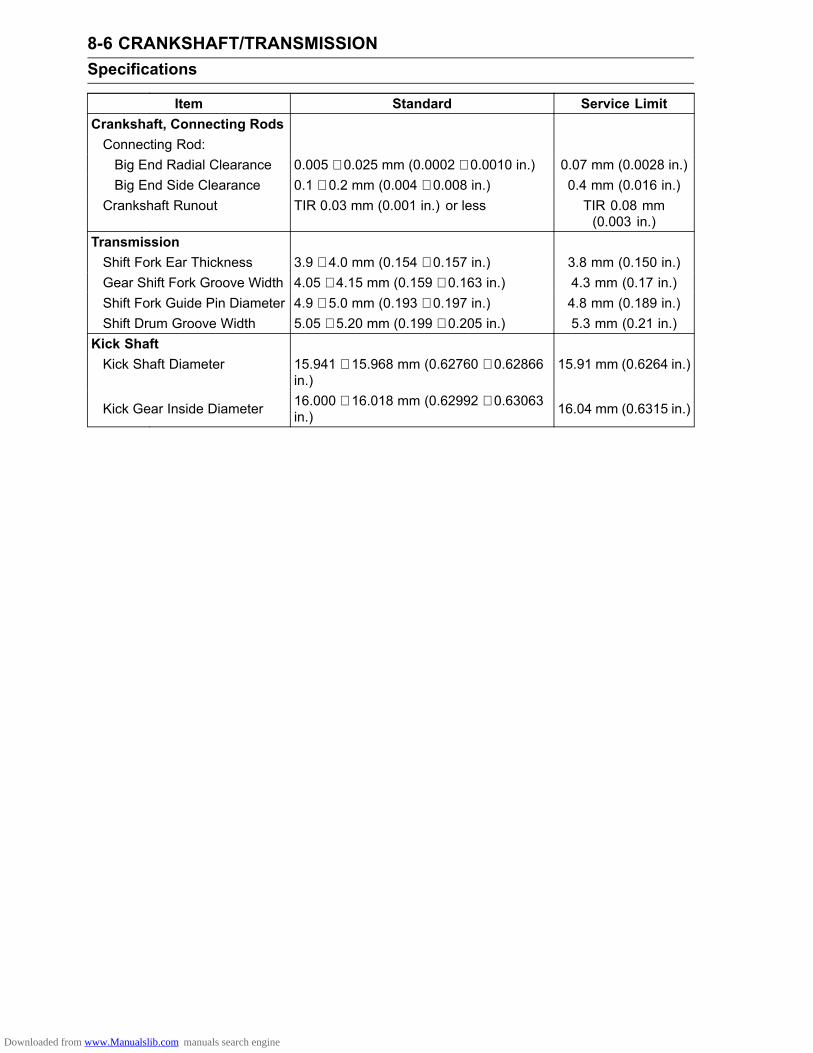
8-6 CRANKSHAFT/TRANSMISSIONSpecifications
Item Standard Service LimitCrankshaft, Connecting RodsConnecting Rod:Big End Radial Clearance 0.005 ∼ 0.025 mm (0.0002 ∼ 0.0010 in.) 0.07 mm (0.0028 in.)Big End Side Clearance 0.1 ∼ 0.2 mm (0.004 ∼ 0.008 in.) 0.4 mm (0.016 in.)
Crankshaft Runout TIR 0.03 mm (0.001 in.) or less TIR 0.08 mm(0.003 in.)
TransmissionShift Fork Ear Thickness 3.9 ∼ 4.0 mm (0.154 ∼ 0.157 in.) 3.8 mm (0.150 in.)Gear Shift Fork Groove Width 4.05 ∼ 4.15 mm (0.159 ∼ 0.163 in.) 4.3 mm (0.17 in.)Shift Fork Guide Pin Diameter 4.9 ∼ 5.0 mm (0.193 ∼ 0.197 in.) 4.8 mm (0.189 in.)Shift Drum Groove Width 5.05 ∼ 5.20 mm (0.199 ∼ 0.205 in.) 5.3 mm (0.21 in.)
Kick ShaftKick Shaft Diameter 15.941 ∼ 15.968 mm (0.62760 ∼ 0.62866
in.)15.91 mm (0.6264 in.)
Kick Gear Inside Diameter 16.000 ∼ 16.018 mm (0.62992 ∼ 0.63063in.) 16.04 mm (0.6315 in.)
Downloaded from www.Manualslib.com manuals search engine
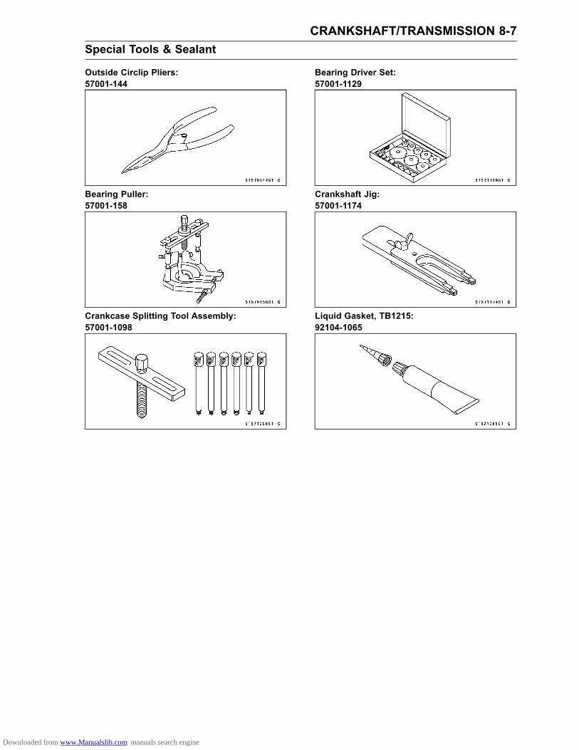
CRANKSHAFT/TRANSMISSION 8-7Special Tools & Sealant
Outside Circlip Pliers:57001-144
Bearing Puller:57001-158
Crankcase Splitting Tool Assembly:57001-1098
Bearing Driver Set:57001-1129
Crankshaft Jig:57001-1174
Liquid Gasket, TB1215:92104-1065
Downloaded from www.Manualslib.com manuals search engine

8-8 CRANKSHAFT/TRANSMISSIONCrankcase
Crankcase Splitting•Remove the engine (see Engine Removal in the EngineRemoval/Installation chapter).• Set the engine on a clean surface and hold the enginesteady while parts are being removed.•Remove:Cylinder Head (see Cylinder Head Removal in the En-gine Top End chapter)Cylinder (see Cylinder Removal in the Engine Top Endchapter)Piston (see Piston Removal in the Engine Top End chap-ter)
Clutch Cover (see Clutch Cover Removal in the Clutchchapter)Clutch (see Clutch Removal (KLX110C/D) in the Clutchchapter)Kick Shaft (see Kick Shaft Removal)Oil Filter and Oil Pump (see Oil Filter Replacement in thePeriodic Maintenance chapter and Oil Pump Removal inthe Engine Lubrication System chapter)External Shift Mechanism (see External Shift Mecha-nism Removal)Alternator Rotor (see Alternator Rotor Removal in theElectrical System chapter)Starter Motor (see Starter Motor Removal in the Electri-cal System chapter)Gear Position Switch (see Gear Position Switch Re-moval in the Electrical System chapter)Crankcase Bolts [A]
• Screw the crankcase splitting tool [A] into the left side ofthe crankcase [B]. Be certain to screw the adapters in allthe way.Special Tool - Crankcase Splitting Tool Assembly: 57001
-1098
•Tighten the center bolt of the crankcase splitting tool tosplit the crankcase.•Once the crankcase is split, remove the crankcase split-ting tool and separate the crankcase halves.
•Remove the crankshaft [A] from the right crankcase halfusing a press [B].
NOTICEDo not remove the ball, needle bearings and the oilseals unless it is necessary. Removal may damagethem.
•Press the bearing out of the crankcase half if the bearingremains on the crankcase half.
Downloaded from www.Manualslib.com manuals search engine
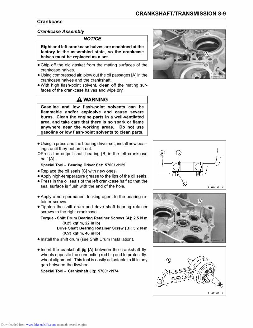
CRANKSHAFT/TRANSMISSION 8-9Crankcase
Crankcase AssemblyNOTICE
Right and left crankcase halves are machined at thefactory in the assembled state, so the crankcasehalves must be replaced as a set.
•Chip off the old gasket from the mating surfaces of thecrankcase halves.•Using compressed air, blow out the oil passages [A] in thecrankcase halves and the crankshaft.•With high flash-point solvent, clean off the mating sur-faces of the crankcase halves and wipe dry.
WARNINGGasoline and low flash-point solvents can beflammable and/or explosive and cause severeburns. Clean the engine parts in a well-ventilatedarea, and take care that there is no spark or flameanywhere near the working areas. Do not usegasoline or low flash-point solvents to clean parts.
•Using a press and the bearing driver set, install new bear-ings until they bottoms out.Press the output shaft bearing [B] in the left crankcasehalf [A].Special Tool - Bearing Driver Set: 57001-1129
•Replace the oil seals [C] with new ones.• Apply high-temperature grease to the lips of the oil seals.• Press in the oil seals of the left crankcase half so that theseal surface is flush with the end of the hole.
• Apply a non-permanent locking agent to the bearing re-tainer screws.• Tighten the shift drum and drive shaft bearing retainerscrews to the right crankcase.Torque - Shift Drum Bearing Retainer Screws [A]: 2.5 N·m
(0.25 kgf·m, 22 in·lb)Drive Shaft Bearing Retainer Screw [B]: 5.2 N·m(0.53 kgf·m, 46 in·lb)
• Install the shift drum (see Shift Drum Installation).• Insert the crankshaft jig [A] between the crankshaft fly-wheels opposite the connecting rod big end to protect fly-wheel alignment. This tool is easily adjustable to fit in anygap between the flywheel.Special Tool - Crankshaft Jig: 57001-1174
Downloaded from www.Manualslib.com manuals search engine

8-10 CRANKSHAFT/TRANSMISSIONCrankcase
•Fit the crankshaft into the right crankcase half using apress [A].
• Install:Transmission Shaft Assemblies [A]Shift Forks [B]•Check that the shift drum is in neutral position.
•Make sure that the mating surfaces of the crankcasehalves are completely free of oil or contamination.• Apply liquid gasket to the mating surface of the leftcrankcase half as shown.Sealant - Liquid Gasket, TB1215: 92104-1065
NOTEDo not apply liquid gasket to this area [A].
•Check that two dowel pins [A], O-rings [B] and drive shaftspacer [C] are in place.
•Using a suitable tool [A] on the left crankcase to pressaround the hole for the crankshaft, fit the crankcasehalves together with a press [B] on the tool.• Remove the crankshaft jig [C].
Downloaded from www.Manualslib.com manuals search engine

CRANKSHAFT/TRANSMISSION 8-11Crankcase
• Install the crankcase bolts in the left and right crankcasehalf and tighten them, starting with the nearest ones tothe crankshaft, then farther ones.Longer Bolts [A]Shorter Bolts [B]L: Apply a non-permanent locking agent.Torque - Crankcase Bolts: 9.8 N·m (1.0 kgf·m, 87 in·lb)
•Check to see that the crankshaft, and out put shaft all turnfreely.If the crankshaft will not turn, it is probably not centered.Tap themount portion of the crankcase with a plastic ham-mer [A] to reposition it. If it does not free up, split thecrankcase again and find the cause.Spinning the output shaft, shift the transmission throughall the gears to make certain there is not binding and thatall the gears shift properly.• Clean the cylinder and oil filter cap of the mating surfaceand wipe off the liquid gasket forced out.• Install the removed parts.
Downloaded from www.Manualslib.com manuals search engine

8-12 CRANKSHAFT/TRANSMISSIONCrankshaft, Connecting Rod
Crankshaft DisassemblyNOTICE
Since assembly of the crankshaft demands exact-ing tolerance, the disassembly and reassemblyof the crankshaft should only be performed byexperienced mechanics with the necessary toolsand equipment. The crankpin, connecting rod, andright crankshaft are available separately as spareparts, however it is recommended that the crank-shaft assembly be replaced rather than attemptingto replace the components.
• If it should be necessary to disassemble the crankshaft,follow the following procedures.•Remove the oil pump drive gear and bearing, using thebearing puller.Special Tool - Bearing Puller: 57001-158
•Use a press to remove the crankpin.•Removal of the crankpin separates the flywheels, con-necting rod, big end needle bearing, and crankpin.
Crankshaft Assembly•Carefully align the oil passage hole in the right flywheel[A] with the one in the crankpin [B] at rebuilding of thecrankshaft as shown.
• Apply engine oil to the big end bearing.• Press the crank halves onto the crankpin, noting thecrankpin direction until connecting rod side clearance iswithin specification as shown.Side Clearance [A]: 0.1 ∼ 0.2 mm (0.004 ∼ 0.008 in.)Crankpin Depth [B]: 0.8 ∼ 1.2 mm (0.0315 ∼ 0.0472 in.)
• Press the bearing [A] and oil pump drive gear [B] until theybottom out.
Downloaded from www.Manualslib.com manuals search engine

CRANKSHAFT/TRANSMISSION 8-13Crankshaft, Connecting Rod
•Check the following items are within specifications afterthe crankshaft assembly.Connecting Rod Radial Clearance (see Connecting RodBig End Radial Clearance Inspection)Connecting Rod Side Clearance (see Connecting RodBig End Side Clearance Inspection)Crankshaft Runout (see Crankshaft Runout Inspection)
Connecting Rod Big End Seizure InspectionIn the case of serious seizure with damaged flywheels,the crankshaft must be replaced.In the case of less serious damage, disassemble thecrankshaft and replace the crankpin, needle bearing,side washers, and connecting rod.
Connecting Rod Big End Radial ClearanceInspection•Set the crankshaft in flywheel alignment jig or on a Vblock, and place a dial gauge [A] against the big end ofthe connecting rod.• Push [B] the connecting rod first towards the gauge andthen in the opposite direction. The difference between thetwo gauge readings is the radial clearance.If the radial clearance exceeds the service limit, the crank-shaft should be either replaced or disassembled and thecrankpin, needle bearing, and connecting rod big end ex-amined for wear.
Connecting Rod Big End Radial ClearanceStandard: 0.005 ∼ 0.025 mm (0.0002 ∼ 0.0010 in.)Service Limit: 0.07 mm (0.0028 in.)
Connecting Rod Big End Side ClearanceInspection•Measure the side clearance [A] of the connecting rod witha thickness gauge.If the clearance exceeds the service limit, replace thecrankshaft.
Connecting Rod Big End Side ClearanceStandard: 0.1 ∼ 0.2 mm (0.004 ∼ 0.008 in.)Service Limit: 0.4 mm (0.016 in.)
Crankshaft Runout Inspection•Set the crankshaft in a flywheel alignment jig or on Vblocks, and place a dial gauge [A] against the points indi-cated.Measurement Point [B]: 8 mm (0.315 in.)• Turn the crankshaft slowly. The maximum difference ingauge readings is the crankshaft runout.
Crankshaft RunoutStandard: TIR 0.03 mm (0.001 in.) or lessService Limit: TIR 0.08 mm (0.003 in.)
Downloaded from www.Manualslib.com manuals search engine

8-14 CRANKSHAFT/TRANSMISSIONCrankshaft, Connecting Rod
Crankshaft AlignmentIf the runout at either point exceeds the service limit, alignthe flywheels so that the runout falls within the servicelimit.• In the case of horizontal misalignment, which is the mostcommon, strike the projecting rim of the flywheel with aplastic, soft lead, or brass hammer as indicated in thefigure.•Recheck the runout with a dial gauge, repeating theprocess until the runout falls within the service limit.Vertical misalignment is corrected either by driving awedge in between the flywheels, or by squeezing theflywheel rims in a vise, depending on the nature of themisalignment.
• In the case of both horizontal and vertical misalignment,correct the horizontal misalignment first.• Recheck big end side clearance after aligning crankshaft(see Connecting Rod Big End Side Clearance Inspec-tion).
NOTEIf crankshaft alignment cannot be corrected by theabove method, replace the crankpin or crank halves asrequired. Recheck the runout and repeat the processuntil the runout is within service limit.
NOTICEDon’t hammer the flywheel at the point [A].
Crankshaft Main Bearing Wear Inspection•Wash the bearings in high flash-point solvent, blow themdry (DO NOT SPIN THEM), and lubricate them with en-gine oil.• Turn [A] each bearing over by hand and see that it makesno noise, turns smoothly and has no rough spots.If any of the bearings are defective, replace them.
Downloaded from www.Manualslib.com manuals search engine
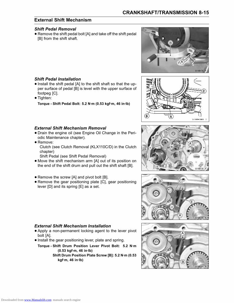
CRANKSHAFT/TRANSMISSION 8-15External Shift Mechanism
Shift Pedal Removal•Remove the shift pedal bolt [A] and take off the shift pedal[B] from the shift shaft.
Shift Pedal Installation• Install the shift pedal [A] to the shift shaft so that the up-per surface of pedal [B] is level with the upper surface offootpeg [C].• Tighten:Torque - Shift Pedal Bolt: 5.2 N·m (0.53 kgf·m, 46 in·lb)
External Shift Mechanism Removal•Drain the engine oil (see Engine Oil Change in the Peri-odic Maintenance chapter).• Remove:Clutch (see Clutch Removal (KLX110C/D) in the Clutchchapter)Shift Pedal (see Shift Pedal Removal)•Move the shift mechanism arm [A] out of its position onthe end of the shift drum and pull out the shift shaft [B].
• Remove the screw [A] and pivot bolt [B].• Remove the gear positioning plate [C], gear positioninglever [D] and its spring [E] as a set.
External Shift Mechanism Installation•Apply a non-permanent locking agent to the lever pivotbolt [A].• Install the gear positioning lever, plate and spring.Torque - Shift Drum Position Lever Pivot Bolt: 5.2 N·m
(0.53 kgf·m, 46 in·lb)Shift Drum Position Plate Screw [B]: 5.2 N·m (0.53kgf·m, 46 in·lb)
Downloaded from www.Manualslib.com manuals search engine
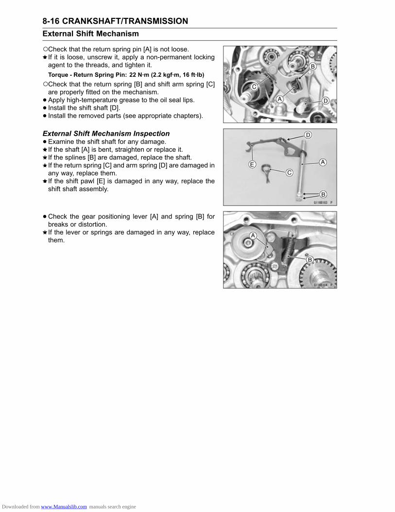
8-16 CRANKSHAFT/TRANSMISSIONExternal Shift Mechanism
Check that the return spring pin [A] is not loose.If it is loose, unscrew it, apply a non-permanent lockingagent to the threads, and tighten it.Torque - Return Spring Pin: 22 N·m (2.2 kgf·m, 16 ft·lb)Check that the return spring [B] and shift arm spring [C]are properly fitted on the mechanism.• Apply high-temperature grease to the oil seal lips.• Install the shift shaft [D].• Install the removed parts (see appropriate chapters).External Shift Mechanism Inspection•Examine the shift shaft for any damage.If the shaft [A] is bent, straighten or replace it.If the splines [B] are damaged, replace the shaft.If the return spring [C] and arm spring [D] are damaged inany way, replace them.If the shift pawl [E] is damaged in any way, replace theshift shaft assembly.
•Check the gear positioning lever [A] and spring [B] forbreaks or distortion.If the lever or springs are damaged in any way, replacethem.
Downloaded from www.Manualslib.com manuals search engine

CRANKSHAFT/TRANSMISSION 8-17Transmission
Shift Drum Removal•Remove:Clutch (see Clutch Removal (KLX110C/D) in the Clutchchapter)External Shift Mechanism (see External Shift Mecha-nism Removal)Shift Drum Allen Bolt [A]Cam Holder [B]Shift Drum CamDowel Pin•Split the crankcase (see Crankcase Splitting).• Remove the shift drum.Shift Drum Installation•Fit the shift drum to the right crankcase half.• Install the shift drum cam [A] aligning its hole [B] with thedowel pin [C].• Install the cam holder.• Apply a non-permanent locking agent to the threads ofcam bolt, and tighten it.Torque - Shift Drum Cam Bolt: 5.2 N·m (0.53 kgf·m, 46 in·lb)
Transmission Removal•Split the crankcase (see Crankcase Splitting).• Remove:Shift Rods [A]Shift Forks [B]Transmission Shafts [C]
Transmission Installation•Apply a clean engine oil to the transmission gears, bear-ings, and shaft journal, and fit the output [A] and driveshaft [B] assemblies as a set into the right crankcase half.• Set the shift drum in neutral position.
Downloaded from www.Manualslib.com manuals search engine
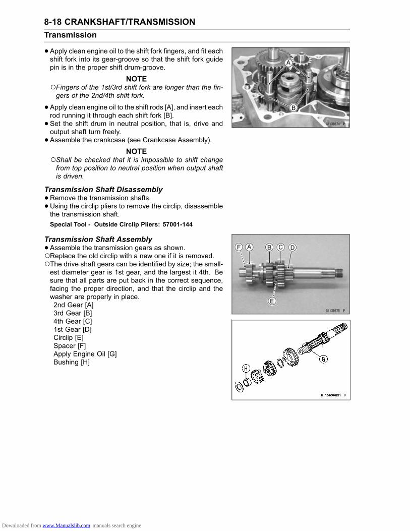
8-18 CRANKSHAFT/TRANSMISSIONTransmission
•Apply clean engine oil to the shift fork fingers, and fit eachshift fork into its gear-groove so that the shift fork guidepin is in the proper shift drum-groove.
NOTEFingers of the 1st/3rd shift fork are longer than the fin-gers of the 2nd/4th shift fork.
•Apply clean engine oil to the shift rods [A], and insert eachrod running it through each shift fork [B].• Set the shift drum in neutral position, that is, drive andoutput shaft turn freely.• Assemble the crankcase (see Crankcase Assembly).
NOTEShall be checked that it is impossible to shift changefrom top position to neutral position when output shaftis driven.
Transmission Shaft Disassembly•Remove the transmission shafts.• Using the circlip pliers to remove the circlip, disassemblethe transmission shaft.Special Tool - Outside Circlip Pliers: 57001-144
Transmission Shaft Assembly•Assemble the transmission gears as shown.Replace the old circlip with a new one if it is removed.The drive shaft gears can be identified by size; the small-est diameter gear is 1st gear, and the largest it 4th. Besure that all parts are put back in the correct sequence,facing the proper direction, and that the circlip and thewasher are properly in place.2nd Gear [A]3rd Gear [B]4th Gear [C]1st Gear [D]Circlip [E]Spacer [F]Apply Engine Oil [G]Bushing [H]
Downloaded from www.Manualslib.com manuals search engine

CRANKSHAFT/TRANSMISSION 8-19Transmission
The output shaft gears can be identified by size; thelargest diameter gear is 1st gear, and the smallest is4th. Be sure that all parts are put back in the correctsequence and facing the proper direction, and that thecirclip is properly in place.2nd Gear [A]3rd Gear [B]4th Gear [C]1st Gear [D]
Circlip [E]Spacer [F]Apply Engine Oil [G]Circlip [H]KLX110CA ∼ CC, KLX110DA ∼ DC Models [I]KLX110CD, KLX110DD Models ∼ [J]
Always install circlips so that the opening is aligned witha spline groove. To install a circlip without damage, firstfit the circlip onto the shaft expanding it just enough toinstall it, and then use a suitable gear to push the circlipinto place.[A] Opening of Circlip[B] Groove of Shaft Spline
Shift Fork Bending Inspection•Visually inspect the shift forks, and replace any fork that isbent. A bent fork could cause difficulty in shifting, or allowthe transmission to jump out of gear when under power.90° [A]
Downloaded from www.Manualslib.com manuals search engine

8-20 CRANKSHAFT/TRANSMISSIONTransmission
Shift Fork Ear/Gear Shift Fork Groove WearInspection•Measure the thickness [A] of the shift fork ears.If the thickness of a shift fork ear is less than the servicelimit, the shift fork must be replaced.
Shift Fork Ear ThicknessStandard: 3.9 ∼ 4.0 mm (0.154 ∼ 0.157 in.)Service Limit: 3.8 mm (0.150 in.)
•Measure the width [A] of the gear shift fork grooves in thetransmission gears.If a gear shift fork groove is worn over the service limit,the gear must be replaced.
Gear Shift Fork Groove WidthStandard: 4.05 ∼ 4.15 mm (0.159 ∼ 0.163 in.)Service Limit: 4.3 mm (0.17 in.)
Shift Fork Guide Pin/Shift Drum Groove WearInspection•Measure the diameter [A] of each shift fork guide pin, andmeasure the width of each shift drum groove.If the guide pin on any shift fork is less than the servicelimit, the fork must be replaced.
Shift Fork Guide Pin DiameterStandard: 4.9 ∼ 5.0 mm (0.193 ∼ 0.197 in.)Service Limit: 4.8 mm (0.189 in.)
If any shift drum groove [A] is worn over the service limit,the drum must be replaced.
Shift Drum Groove WidthStandard: 5.05 ∼ 5.20 mm (0.199 ∼ 0.205 in.)Service Limit: 5.3 mm (0.21 in.)
Gear Dog/Gear Dog Hole Damage Inspection•Visually inspect the gear dogs [A] and gear dog holes [B].Replace any damaged gears or gears with excessivelyworn dogs or dog holes.
Downloaded from www.Manualslib.com manuals search engine

CRANKSHAFT/TRANSMISSION 8-21Ball Bearing, Needle Bearing, and Oil Seal
Ball and Needle Bearing Wear InspectionNOTICE
Do not remove the ball bearings for inspection. Re-moval may damage them.
•Check the ball bearings.Since the ball bearings are made to extremely close toler-ances, the wear must be judged by feel rather than mea-surement. Clean each bearing in high flash-point solvent,dry it (do not spin the bearing while it is dry), and oil it withengine oil.Spin [A] the bearing by hand to check its condition.If the bearing is noisy, does not spin smoothly, or has anyrough spots, replace it.
• Check the needle bearings.The rollers in a needle bearing normally wear very little,and wear is difficult to measure. Instead of measuring,inspect the bearing for abrasion, color change, or otherdamage.If there is any doubt as to the condition of a needle bear-ing, replace it.
Oil Seal Inspection• Inspect the oil seal.Replace it if the lips are misshapen, discolored (indicatingthat the rubber has deteriorated), hardened or otherwisedamaged.
Downloaded from www.Manualslib.com manuals search engine

8-22 CRANKSHAFT/TRANSMISSIONKickstarter
Kick Pedal Removal•Remove:Bolt [A]Kick Pedal [B]
Kick Pedal Installation• Installation is the reverse of removal.Install the kick pedal as shown in the figure.[A] About 16°
Tighten:Torque - Kick Pedal Bolt [B]: 8.8 N·m (0.90 kgf·m, 78 in·lb)
Kick Shaft Removal•Remove the clutch (see Clutch Removal (KLX110C/D) inthe Clutch chapter).• Remove the return spring [A] with pliers.•Remove the kick shaft assembly [B], twisting it counter-clockwise.• There is a thrust washer between the kick shaft end andthe crankcase.
Kick Shaft Installation•Apply molybdenum disulfide grease to the thrust washer.• Fit the return spring end [A] into the kick shaft and installthe plastic spring guide [B].• Put the thrust washer on the kick shaft end, and fit thekick shaft assembly in the crankcase.• Insert the other spring end [C] into the crankcase.
Kick Shaft Disassembly/Assembly•The kick shaft assembly consists of the following parts.
[A] Kick Gear[B] Circlips[C] Washer ( 20 × 13.2)[D] Spring[E] Ratchet Gear[F] Kick Shaft[G] Return Spring[H] Spring Guide[I] Washer ( 22 × 16.8)
Downloaded from www.Manualslib.com manuals search engine

CRANKSHAFT/TRANSMISSION 8-23Kickstarter
•Apply molybdenum disulfide grease to the inside of thekick gear [A] and kick shaft [B].• Replace the removed circlips with new ones.
When assembling the ratchet gear onto the kick shaft,align the punch mark [A] on the ratchet gear with thepunch mark [B] on the kick shaft.
Kick Shaft Inspection•Visually inspect the parts and portion listed below.Kick shaft return spring [A]Ratchet gear spring [B]Ratchet portion [C] of the kick gear [D] and ratchet gear[E]If there is any kind of damage, replace the damaged part.
•Measure the kick shaft diameter [A] where the kick gearfits.If it is under the service limit, replace the shaft.•Measure the inside diameter [B] of the kick gear.If it exceeds the service limit, replace the gear.
Kick Shaft, Kick Gear Inside DiameterStandard:Kick Shaft 15.941 ∼ 15.968 mm
(0.62760 ∼ 0.62866 in.)Kick Gear 16.000 ∼ 16.018 mm
(0.62992 ∼ 0.63063 in.)Service Limit:Kick Shaft 15.91 mm (0.6264 in.)Kick Gear 16.04 mm (0.6315 in.)
Downloaded from www.Manualslib.com manuals search engine

WHEELS/TIRES 9-1
9
Wheels/TiresTable of Contents
Exploded View........................................................................................................................ 9-2Specifications ......................................................................................................................... 9-4Special Tools .......................................................................................................................... 9-5Wheels (Rims) ........................................................................................................................ 9-6
Front Wheel Removal ....................................................................................................... 9-6Front Wheel Installation .................................................................................................... 9-6Rear Wheel Removal........................................................................................................ 9-7Rear Wheel Installation..................................................................................................... 9-8Wheels Inspection............................................................................................................. 9-9Spoke Tightness Inspection.............................................................................................. 9-9Rim Runout Inspection...................................................................................................... 9-9Rim Installation Position.................................................................................................... 9-9Axle Inspection.................................................................................................................. 9-10
Tires........................................................................................................................................ 9-11Tire Removal..................................................................................................................... 9-11Tire Installation.................................................................................................................. 9-11Air Pressure Inspection/Adjustment.................................................................................. 9-12
Hub Bearings.......................................................................................................................... 9-13Hub Bearing Removal....................................................................................................... 9-13Hub Bearing Installation.................................................................................................... 9-13Bearing Inspection ............................................................................................................ 9-13Bearing Lubrication ........................................................................................................... 9-14
Downloaded from www.Manualslib.com manuals search engine

9-2 WHEELS/TIRESExploded View
Downloaded from www.Manualslib.com manuals search engine

WHEELS/TIRES 9-3Exploded View
TorqueNo. Fastener
N·m kgf·m ft·lbRemarks
1 Spoke Nipples 4.0 0.41 35 in·lb2 Front Axle Nut 44 4.5 32 R3 Torque Link Nuts 25 2.5 184 Rear Axle Nut 64 6.5 47G: Apply grease.R: Replacement Parts
WL: Apply soap and water solution, or rubber lubricant.
Downloaded from www.Manualslib.com manuals search engine

9-4 WHEELS/TIRESSpecifications
Item Standard Service LimitWheels (Rims)Rim Size:Front 14 × 1.40 – – –Rear 12 × 1.60 – – –
Rim Runout:Axial TIR 0.8 mm (0.031 in.) or less TIR 2.0 mm (0.08 in.)Radial TIR 1.2 mm (0.047 in.) or less TIR 2.0 mm (0.08 in.)
Front Axle Runout/100 mm (3.94 in.) TIR 0.1 mm (0.004 in.) or less TIR 0.2 mm (0.008 in.)Rear Axle Runout/110 mm (4.33 in.) TIR 0.1 mm (0.004 in.) or less TIR 0.2 mm (0.008 in.)
TiresAir Pressure (when cold):Front and Rear 100 kPa (1.0 kgf/cm², 14 psi) – – –
Standard Tire:Front:Size 2.50-14 4P.R. – – –Make IRC – – –Type GS-45F – – –
Rear:Size 3.00-12 4P.R. – – –Make IRC – – –Type GS-45F – – –
Downloaded from www.Manualslib.com manuals search engine

WHEELS/TIRES 9-5Special Tools
Rim Protector:57001-1063
Bearing Driver Set:57001-1129
Jack:57001-1238
Bearing Remover Shaft, 9:57001-1265
Bearing Remover Head, 10 × 12:57001-1266
Downloaded from www.Manualslib.com manuals search engine

9-6 WHEELS/TIRESWheels (Rims)
Front Wheel Removal•Stabilize the motorcycle with the jack.Special Tool - Jack: 57001-1238
•Apply the rear brake so that the rear wheel does not turn.•Remove:Cotter Pin [A]Front Axle Nut [B]•Raise the front wheel off the ground with the jack.•Remove:Front Brake Cable [C] (see Brake Cable Removal in theBrakes chapter)Front Axle [D]Front WheelFront Brake Panel [E]
•Remove the collar [A] on the right side of the hub.
Front Wheel Installation•Apply high-temperature grease to the oil seal [A].• Install the collar [B] on the right side of the hub.• Install the front brake panel.
• Fit the tongue [A] on the fork leg into the groove [B] on thefront brake panel.
Downloaded from www.Manualslib.com manuals search engine

WHEELS/TIRES 9-7Wheels (Rims)
•Replace the axle nut [B] with a new one.• Insert the axle [A] from right side, and tighten the axle nut.Torque - Front Axle Nut: 44 N·m (4.5 kgf·m, 32 ft·lb)
• Insert a new cotter pin [C] to the front axle, and bend it toboth sides.
• Install the front brake cable and adjust the brake leverfree play (see Brake Lever Free Play Adjustment in thePeriodic Maintenance chapter).• Remove the jack.Rear Wheel Removal•Raise the rear wheel off the ground with the jack.Special Tool - Jack: 57001-1238
•Remove:Adjusting Nut [A]Cotter Pin [B]Rear Torque Link Nut [C], Washer and BoltCotter Pin [D]Rear Axle Nut [E]
• To remove the brake rod end from the brake cam lever,first turn the brake panel clockwise [A] as far as it will go,then depress the brake pedal lightly, the brake rod [B] willbe separated from the brake cam lever joint [C].• Remove the rear axle [D].• Disengage the drive chain from the rear sprocket.Hang the chain on the swingarm.•Remove:Rear WheelRear Brake Panel [E]
•Remove the collar [A] on the left side of the hub.
Downloaded from www.Manualslib.com manuals search engine

9-8 WHEELS/TIRESWheels (Rims)
Rear Wheel Installation•Apply high-temperature grease to the oil seal [A].• Install the collar [B] on the left side of the hub.• Install the rear brake panel.• Engage the drive chain with the rear sprocket, and set therear wheel to the motorcycle.• Insert the axle from the left side.• Turn the brake panel clockwise until the brake cam leverjoint goes beyond the brake rod end then insert the brakerod end into the joint hole.
NOTICEDo not insert the brake rod into the cam lever jointby depressing the brake pedal deeply, this will ex-tend the brake spring beyond its allowable springextension.
•Tighten:Torque - Rear Axle Nut: 64 N·m (6.5 kgf·m, 47 ft·lb)
Torque Link Nut: 25 N·m (2.5 kgf·m, 18 ft·lb)
• Insert a new cotter pin [A].NOTE
When inserting the cotter pin, if the slots in the nut donot align with the cotter pin hole in the axel, tighten thenut clockwise [B] up to next alignment.It should be within 30 degrees.Loosen once and tighten again when the slot goes pastthe nearest hole.
•Bend the cotter pin [A] over the nut [B].WARNING
A loose axle nut can lead to an accident resulting inserious injury or death. Tighten the axle nut to theproper torque and install a new cotter pin.
• Insert the cotter pin [A] into the torque link bolt hole andspread its ends.• Adjust:Drive Chain Slack (see Drive Chain Slack Adjustment inthe Periodic Maintenance chapter)Brake Pedal Free Play (see Brake Pedal Free Play Ad-justment in the Periodic Maintenance chapter)•Remove the jack.
Downloaded from www.Manualslib.com manuals search engine

WHEELS/TIRES 9-9Wheels (Rims)
Wheels Inspection•Raise the front/rear wheel off the ground with the jack.Special Tool - Jack: 57001-1238
•Spin the wheel lightly, and check for roughness or binding.If the roughness or binding is found, replace the hub bear-ings.• Visually inspect the front and rear axles for damage.If the axle is damaged or bent, replace it.
Spoke Tightness Inspection•Refer to the Spoke Tightness Inspection in the PeriodicMaintenance chapter.
Rim Runout Inspection•Refer to the Rim Runout Inspection in the Periodic Main-tenance chapter.
Rim Installation Position•When installing the rim, set the rim following position.The distance [A] from the left end [B] of the front hub [C]to left end of the front rim [D] should be as follows.View from Front [E]Distance: 9.0 ±0.5 mm (0.35 ±0.020 in.)
The distance [A] from the right end [B] of the rear hub [C]to right end of the rear rim [D] should be as follows.View from Rear [E]Distance: 4.0 ±0.5 mm (0.16 ±0.020 in.)
• Check the rim runout (see Rim Runout Inspection in thePeriodic Maintenance chapter).
Downloaded from www.Manualslib.com manuals search engine

9-10 WHEELS/TIRESWheels (Rims)
Axle Inspection•Visually inspect the front and rear axle for damages.If the axle is damaged or bent, replace it.• Place the front axle in V blocks that are 100 mm (3.94in.) (Rear Axle: 110 mm (4.33 in.)) [A] apart, and seta dial gauge [B] on the axle at a point halfway betweenthe blocks. Turn [C] the axle to measure the runout. Thedifference between the highest and lowest dial readingsis the amount of runout.If the runout exceeds the service limit, replace the axle.
Front Axle Runout: 100 mm (3.94 in.)Standard: 0.1 mm (0.004 in.) or lessService Limit: 0.2 mm (0.008 in.)
Rear Axle Runout: 110 mm (3.94 in.)Standard: 0.1 mm (0.004 in.) or lessService Limit: 0.2 mm (0.008 in.)
Downloaded from www.Manualslib.com manuals search engine

WHEELS/TIRES 9-11Tires
Tire Removal•Remove the wheel (see Front/Rear Wheel Removal).• To maintain wheel balance, mark [A] the valve stem posi-tion on the tire with chalk so that the tire can be reinstalledin the same position.• Take out the valve core [B] to let out the air.• Remove the valve stem nut [C].When handling the rim, be careful not to damage the rimflanges.
• Lubricate the tire beads and rim flanges on both sides witha soap and water solution or rubber lubricant. This helpsthe tire beads slip off the rim flanges.
NOTICENever lubricate with engine oil or petroleum distil-lates because they will deteriorate the tire.
•Break the beads away from both sides of the rim with asuitable bead breaker.
• Step on the side of the tire opposite air valve, and pry thetire off the rim with the tire iron [A] protecting the rim withrim protectors [B].Special Tool - Rim Protector: 57001-1063
NOTICETake care not to insert the tire irons so deeply thatthe tube gets damaged.
•Remove the tube when one side of the tire is pried off.• Pry the tire off the rim.•Remove the rim protector.
Tire Installation• Inspect the rim and the tire before installing the tire, andreplace them if necessary.• Apply a soap and water solution or rubber lubricant to boththe tire bead and the rim flange.
Downloaded from www.Manualslib.com manuals search engine

9-12 WHEELS/TIRESTires
Position the tire on the rim so that the air valve [A] is atthe tire balance mark [B] (the chalk mark made duringremoval, or the paint mark on a new tire).• Insert the valve stem into the rim, and screw the nut onloosely.• Fit the rim protectors and use suitable tire irons to installthe tire bead.
NOTETo prevent rim damage, be sure to place the rim protec-tors at any place the tire irons are applied.
•Replace the tire back on the rim from the opposite side ofthe valve.Insert the tire irons so deeply that the tube is not dam-aged.• Similarly, slip the tire bead back over the rim on the otherside.•Check that the tube is not pinched between the tire andrim.
• Tighten the valve stem nut [A], and put on the valve cap[B].• Check and adjust the air pressure after installing.
Air Pressure Inspection/Adjustment•Refer to the Air Pressure Inspection in the Periodic Main-tenance chapter.
Downloaded from www.Manualslib.com manuals search engine

WHEELS/TIRES 9-13Hub Bearings
Hub Bearing Removal•Remove the wheel (see Front/Rear Wheel Removal).• To remove the grease seals, pry out the grease seal usinga screwdriver.• Using the bearing remover shaft and bearing removerhead, remove the hub bearings [A].Special Tools - Bearing Remover Shaft, 9: 57001-1265 [B]
Bearing Remover Head, 10 × 12: 57001-1266 [C]
Hub Bearing Installation•Before installing the hub bearings, blow any dirt or foreignparticles out the hub with compressed air to prevent con-tamination of the bearings.•Replace the bearings with new ones.• Install the bearings [A] using the bearing driver set [B] sothat the marked or shield sides face out.Press in the bearings until they bottom out.Special Tool - Bearing Driver Set: 57001-1129
NOTEFor correct tire alignment, the right bearing must be in-stalled first rather than left bearing in both front and rearhubs.
•Replace the grease seal [A] with new ones.• Apply high-temperature grease to the grease seal lips.• Press in the grease seal so that the seal surface is flush[B] with the end of the hole using the bearing driver set[C].Special Tool - Bearing Driver Set: 57001-1129
Bearing InspectionSince the hub bearings are made to extremely close tol-
erances, the clearance cannot normally be measured.
NOTICEDo not remove any bearings for inspection. If anybearings are removed, they will need to be replacedwith new ones.
•Turn each bearing in the hub back and forth [A] whilechecking for plays, roughness, or binding. If bearing play,roughness, or binding is found, replace the bearing.• Examine the bearing seal [B] for damage or leakage.If the seal is damaged or is leaking, replace the bearing.
Downloaded from www.Manualslib.com manuals search engine

9-14 WHEELS/TIRESHub Bearings
Bearing Lubrication•Remove the hub bearings on the front and rear wheelhubs.•Wash the bearings with a high flash-point solvent, drythem (do not spin them while they are dry), and oil them.•Spin each bearings by hand to check its condition.If it is noisy, does not spin smoothly, or has any roughspots, it must be replaced.• If the same bearing is to be used again, re-wash it with ahigh flash-point solvent, and dry it.• Pack each bearings with good quality bearing grease [A]before installation. Turn each bearing around by handa few times to make sure the grease is distributed uni-formly inside the bearing, and wipe the old grease out ofthe bearing housings on the wheel hub before bearing in-stallation.• Install the bearings.
Downloaded from www.Manualslib.com manuals search engine
FINAL DRIVE 10-1
10
Final DriveTable of Contents
Exploded View........................................................................................................................ 10-2Specifications ......................................................................................................................... 10-4Special Tools .......................................................................................................................... 10-5Drive Chain............................................................................................................................. 10-6
Drive Chain Slack Inspection ............................................................................................ 10-6Drive Chain Slack Adjustment .......................................................................................... 10-6Wheel Alignment Inspection ............................................................................................. 10-6Wheel Alignment Adjustment............................................................................................ 10-6Drive Chain Wear Inspection ............................................................................................ 10-6Drive Chain Lubrication..................................................................................................... 10-6Drive Chain Removal ........................................................................................................ 10-6Drive Chain Installation ..................................................................................................... 10-7
Sprockets................................................................................................................................ 10-9Engine Sprocket Removal ................................................................................................ 10-9Engine Sprocket Installation ............................................................................................ 10-9Rear Sprocket Removal.................................................................................................... 10-9Rear Sprocket Installation................................................................................................. 10-9Sprocket Wear Inspection................................................................................................. 10-9Rear Sprocket Warp Inspection ........................................................................................ 10-10Coupling Bearing Removal ............................................................................................... 10-10Coupling Bearing Installation ............................................................................................ 10-10Coupling Bearing Inspection and Lubrication ................................................................... 10-10Coupling Damper Inspection............................................................................................. 10-10
Downloaded from www.Manualslib.com manuals search engine

10-2 FINAL DRIVEExploded View
Downloaded from www.Manualslib.com manuals search engine

FINAL DRIVE 10-3Exploded View
TorqueNo Fastener
N·m kgf·m ft·lbRemarks
1 Engine Sprocket Cover Bolts 5.2 0.53 46 in·lb2 Chain Guide Roller Mounting Bolt 23 2.3 173 Rear Sprocket Nuts 44 4.5 32 R4 Rear Axle Nut 64 6.5 475. KLX110D ModelsG: Apply grease.HO: Apply heavy oil.R: Replacement Parts
Downloaded from www.Manualslib.com manuals search engine

10-4 FINAL DRIVESpecifications
Item Standard Service LimitDrive ChainDrive Chain Slack:KLX110C Models 11 ∼ 16 mm (0.4 ∼ 0.6 in.) – – –KLX110D Models 8 ∼ 13 mm (0.3 ∼ 0.5 in.) – – –
Drive Chain 20-link Length 254.0 ∼ 254.6 mm (10.00 ∼ 10.02 in.) 259 mm (10.2 in.)Standard Chain:Make DAIDO – – –Type DID420DX – – –Length 90 Links – – –
SprocketRear Sprocket Warp TIR 0.4 mm (0.016 in.) or less TIR 0.5 mm (0.020 in.)
Downloaded from www.Manualslib.com manuals search engine
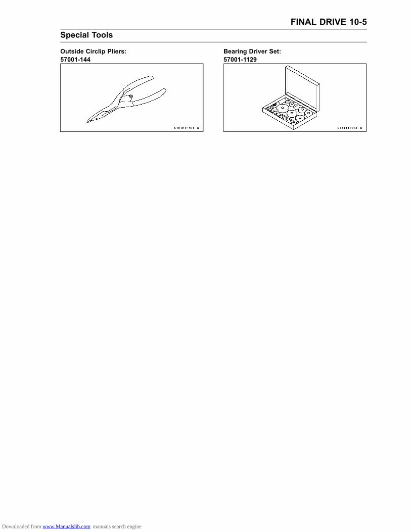
FINAL DRIVE 10-5Special Tools
Outside Circlip Pliers:57001-144
Bearing Driver Set:57001-1129
Downloaded from www.Manualslib.com manuals search engine

10-6 FINAL DRIVEDrive Chain
Drive Chain Slack Inspection•Refer to the Drive Chain Slack Inspection in the PeriodicMaintenance chapter.
Drive Chain Slack Adjustment•Refer to the Drive Chain Slack Adjustment in the PeriodicMaintenance chapter.
Wheel Alignment Inspection•Check that the notch [A] of the chain adjuster aligns withthe same swing arm mark [B] as the other side adjuster.If they do not, adjust the chain slack and align the wheelalignment (see Drive Chain Slack Adjustment in the Peri-odic Maintenance chapter).
NOTEWheel alignment can be also checked using thestraightedge or string method.
WARNINGMisalignment of the wheel will result in abnormalwear and may result in an unsafe riding condition.Be sure the wheel is properly aligned.
Wheel Alignment Adjustment•This procedure is the same as Drive Chain Slack Adjust-ment (see Drive Chain Slack Adjustment in the PeriodicMaintenance chapter).
Drive Chain Wear Inspection•Refer to the Drive Chain Wear Inspection in the PeriodicMaintenance chapter.
Drive Chain Lubrication•Refer to the Drive Chain Lubrication in the Periodic Main-tenance chapter.
Drive Chain Removal•Remove the bolts [A] and the engine sprocket cover [B]with the chain tension guide.
Downloaded from www.Manualslib.com manuals search engine

FINAL DRIVE 10-7Drive Chain
•Remove the clip [A] from the master link using pliers, andremove the chain from the rear sprocket.• Take the chain off the motorcycle, being careful that thechain does not get dirty from contact with the ground.
Drive Chain InstallationWARNING
For safety, use only the standard chain.
•Fit the drive chain back onto the sprockets with the endsat the rear sprocket.• Install the master link from the frame side.• Install the clip [A] so that the closed end of the "U" pointsin the direction of chain rotation [B]. (The open end of the"U" points in the reverse direction of chain rotation).
WARNINGIncorrect installation of the master link clip can al-low it to catch on an adjacent part. If the clip dis-lodges, the chain could come a part, and this couldresult in rear wheel lockup and loss of control. Besure the master link clip is installed correctly.
•Adjust the drive chain slack (see Drive Chain Slack Ad-justment in the Periodic Maintenance chapter).• Check the brake for good braking power, and no brakedrag.
WARNINGA rear brake that cannot be fully operated with thepedal can cause a crash resulting in serious injuryor death. If a full brake pedal is not obtained, disas-semble and inspect the brake parts for wear. Wornbrake parts diminish brake performance, can dam-age brake components and lead to brake failure orcause the brake to lock, resulting in a crash thatmay cause serious injury or death.
•Put the chain tension guide [A] on the engine sprocketcover [B], and install the sprocket cover.
Downloaded from www.Manualslib.com manuals search engine

10-8 FINAL DRIVEDrive Chain
The upper bolt is longer than the other ones.• Tighten:Torque - Engine Sprocket Cover Bolts [A]: 5.2 N·m (0.53
kgf·m, 46 in·lb)
Downloaded from www.Manualslib.com manuals search engine

FINAL DRIVE 10-9Sprockets
Engine Sprocket Removal•Remove the engine sprocket cover (see Drive Chain Re-moval).• Remove the circlip [A] and the engine sprocket [B] withthe drive chain [C].Special Tool - Outside Circlip Pliers: 57001-144
•Take off the sprocket from the chain.
Engine Sprocket Installation•Replace the O-ring [A] on the output shaft with a new one.• Apply grease to the O-ring.• Install the O-ring on the output shaft while expanding theO-ring by the hand.• Install the collar [B] to the output shaft.The chamfered side [C] of the collar must be faced in.
• Install the engine sprocket [A] and drive chain together.Install the engine sprocket so that tooth number markingon it faces outward.•Replace the circlip [B] with a new one.• Fit the circlip so that the round side [C] faces in as shown.• Adjust the drive chain slack if necessary (see Drive ChainSlack Adjustment in the Periodic Maintenance chapter).• Install the engine sprocket cover (see Drive Chain Instal-lation).
Rear Sprocket Removal•Remove the rear wheel (see Rear Wheel Removal in theWheels/Tires chapter).• Unscrew the rear sprocket nuts [A], and remove the rearsprocket [B].
Rear Sprocket Installation• Install the rear sprocket so that the marked [A] side facesoutward.•Replace the rear sprocket nuts with new ones.Torque - Rear Sprocket Nuts: 44 N·m (4.5 kgf·m, 32 ft·lb)
• Install the rear wheel (see Rear Wheel Installation in theWheels/Tires chapter).
Sprocket Wear Inspection•Refer to the Sprocket Wear Inspection in the PeriodicMaintenance chapter.
Downloaded from www.Manualslib.com manuals search engine

10-10 FINAL DRIVESprockets
Rear Sprocket Warp Inspection•Refer to the Rear Sprocket Warp Inspection in PeriodicMaintenance chapter.
Coupling Bearing Removal•Pull out the coupling collar from the left.• Remove the oil seal.• Using the bearing driver set [A] or some other suitabletool, remove the bearing [B] by tapping from the drumside.Special Tool - Bearing Driver Set: 57001-1129
Coupling Bearing Installation•Press in the bearing so that the marked side faces outuntil it is bottomed.•Replace the oil seal with a new one.• Press in the oil seal so that the seal surface is flush withthe end of the hole.Special Tool - Bearing Driver Set: 57001-1129Apply high-temperature grease to the oil seal lips.Coupling Bearing Inspection and LubricationSince the coupling bearing is made to extremely close
tolerances, the clearance cannot normally be measured.•Wash the bearing with a high flash-point solvent, dry it(do not spin it while it is dry), and oil it. Spin it by hand tocheck its condition.If it is noisy, doesn’t spin smoothly, or has any roughsports, it must be replaced.
• If the bearing is to be used again, rewash it with a highflash-point solvent, dry it, and pack it with good qualitybearing grease. Turn the bearing around by hand a fewtimes to make sure the grease [A] is distributed uniformlyinside the bearing, and wipe the old grease out of thecoupling before bearing installation.
Coupling Damper Inspection•Remove the rear wheel coupling, and inspect the rubberdampers [A].Replace the dampers if they appear damaged or deterio-rated.
Downloaded from www.Manualslib.com manuals search engine

BRAKES 11-1
11
BrakesTable of Contents
Exploded View........................................................................................................................ 11-2Specifications ......................................................................................................................... 11-6Special Tools .......................................................................................................................... 11-7Brake Lever and Cable........................................................................................................... 11-8
Brake Lever Free Play Inspection..................................................................................... 11-8Brake Lever Free Play Adjustment ................................................................................... 11-8Brake Cable Removal ....................................................................................................... 11-8Brake Cable Installation .................................................................................................... 11-8Brake Cable Lubrication.................................................................................................... 11-8
Brake Pedal and Rod ............................................................................................................. 11-9Brake Pedal Free Play Inspection..................................................................................... 11-9Brake Pedal Free Play Adjustment ................................................................................... 11-9Brake Pedal and Rod Removal......................................................................................... 11-9Brake Pedal and Rod Installation...................................................................................... 11-9
Brake Panel and Drum .......................................................................................................... 11-10Brake Lining Wear Inspection ........................................................................................... 11-10Cam Lever Angle Inspection............................................................................................. 11-10Cam Lever Angle Adjustment ........................................................................................... 11-10Brake Panel Removal ....................................................................................................... 11-10Brake Panel Installation .................................................................................................... 11-10Brake Panel Disassembly ................................................................................................. 11-10Brake Panel Assembly...................................................................................................... 11-11Brake Drum Wear Inspection............................................................................................ 11-12Brake Shoe Lining Wear Inspection.................................................................................. 11-12Camshaft Wear Inspection................................................................................................ 11-13Brake Shoe Springs Inspection......................................................................................... 11-13Brake Panel Lubrication.................................................................................................... 11-13
Downloaded from www.Manualslib.com manuals search engine

11-2 BRAKESExploded View
Downloaded from www.Manualslib.com manuals search engine

BRAKES 11-3Exploded View
CL: Apply cable lubricant.G: Apply grease.R: Replacement PartsSi: Apply silicone grease.
Downloaded from www.Manualslib.com manuals search engine

11-4 BRAKESExploded View
Downloaded from www.Manualslib.com manuals search engine

BRAKES 11-5Exploded View
TorqueNo. Fastener
N·m kgf·m ft·lbRemarks
1 Brake Pedal Bolt 8.8 0.90 78 in·lb2 Torque Link Nuts 25 2.5 183 Brake Cam Lever Bolt 7.0 0.71 62 in·lbG: Apply grease.R: Replacement Parts
Downloaded from www.Manualslib.com manuals search engine

11-6 BRAKESSpecifications
Item Standard Service LimitBrake Lever and PedalBrake Lever Free Play 4 ∼ 5 mm (0.16 ∼ 0.20 in.) – – –Brake Pedal Free Play 20 ∼ 30 mm (0.79 ∼ 1.18 in.) – – –
Brake Drum, Brake ShoesShoe Lining Thickness:Front 2.10 ∼ 3.00 mm (0.08 ∼ 0.12 in.) 1.2 mm (0.05 in.)Rear 3.85 ∼ 4.15 mm (0.152 ∼ 0.163 in.) 2.0 mm (0.08 in.)
Shoe Spring Free Length:Front 30.8 ∼ 31.2 mm (1.21 ∼ 1.23 in.) 32.6 mm (1.28 in.)Rear 32.5 mm (1.28 in.) 34.1 mm (1.34 in.)
Drum Inside Diameter:Front 90.000 ∼ 90.087 mm (3.543 ∼ 3.547 in.) 90.75 mm (3.57 in.)Rear 110.000 ∼ 110.087 mm (4.331 ∼ 4.334 in.) 110.75 mm (4.36 in.)
Camshaft Diameter:Front 11.957 ∼ 11.984 mm (0.471 ∼ 0.472 in.) 11.88 mm (0.47 in.)Rear 14.957 ∼ 14.984 mm (0.589 ∼ 0.590 in.) 14.88 mm (0.59 in.)
Camshaft Hole Inside Diameter:Front 12.000 ∼ 12.027 mm (0.472 ∼ 0.474 in.) 12.15 mm (0.478 in.)Rear 15.000 ∼ 15.027 mm (0.591 ∼ 0.592 in.) 15.15 mm (0.596 in.)
Cam Lever Angle 80° ∼ 90° – – –
Downloaded from www.Manualslib.com manuals search engine

BRAKES 11-7Special Tools
Inside Circlip Pliers:57001-143
Jack:57001-1238
Downloaded from www.Manualslib.com manuals search engine

11-8 BRAKESBrake Lever and Cable
Brake Lever Free Play Inspection•Refer to the Brake Lever Free Play Inspection in the Pe-riodic Maintenance chapter.
Brake Lever Free Play Adjustment•Refer to the Brake Lever Free Play Adjustment in the Pe-riodic Maintenance chapter.
Brake Cable Removal•Free the brake cable from the lever.• Loosen:Front Brake Adjusting Nuts [A]•Remove:Brake Cable Lower End [B]Bolt [C]• Pull the brake cable out of the frame.
Brake Cable Installation• Installation is the reverse of the removal.• Run the brake cable according to the Cable, Wire, andHose Routing section in the Appendix chapter.• Adjust the brake lever free play (see Brake Lever FreePlay Adjustment in the Periodic Maintenance chapter).
Brake Cable Lubrication•Whenever the brake cable is removed or in accordancewith the Periodic Maintenance Chart, lubricate the ca-ble. Refer to the Lubrication in the Periodic Maintenancechapter.
Downloaded from www.Manualslib.com manuals search engine

BRAKES 11-9Brake Pedal and Rod
Brake Pedal Free Play Inspection•Refer to Brake Pedal Free Play Inspection in the PeriodicMaintenance chapter.
Brake Pedal Free Play Adjustment•Refer to Brake Pedal Free Play Adjustment in the PeriodicMaintenance chapter.
Brake Pedal and Rod Removal•Remove the brake rod [A] end from the brake cam lever[B] (see Rear Wheel Removal in the Wheels/Tires chap-ter).
• Remove:Brake Pedal Return Spring [A]Brake Pedal Mounting Bolt [B]Brake Pedal [C] with Rod [D]
•Remove:Cotter Pin [A]WasherPin [B]Brake Rod [C]O-rings [D]
Brake Pedal and Rod Installation• Installation is the reverse of removal.• Replace the cotter pin and O-rings with new ones.• Apply multi purpose grease to the pedal pivot andO-rings.• Before installing the brake pedal, set in the return springeach end to the brake pedal.Install the return spring [A] so that its long hook portion[B] faces downward.• Tighten:Torque - Brake Pedal Mounting Bolt: 8.8 N·m (0.90 kgf·m,
78 in·lb)
•Adjust the brake pedal free play (see Brake Pedal FreePlay Adjustment in the Periodic Maintenance chapter).
Downloaded from www.Manualslib.com manuals search engine

11-10 BRAKESBrake Panel and Drum
Brake Lining Wear Inspection•Refer to Brake Lining Wear Inspection in the PeriodicMaintenance chapter.
Cam Lever Angle Inspection•Refer to Cam Lever Angle Inspection in the PeriodicMain-tenance chapter.
Cam Lever Angle Adjustment•Refer to Cam Lever Angle Adjustment in the PeriodicMaintenance chapter.
Brake Panel Removal•Remove the front or rear wheel (see Front/Rear WheelRemoval in the Wheels/Tires chapter).• Separate the brake panel [A] from the wheel.
Brake Panel Installation•Place the brake panel in the drum and install the frontor rear wheel (see Front/Rear Wheel Installation in theWheels/Tires chapter).• Adjust the brake lever and pedal free play (see BrakeLever/Pedal Free Play Adjustment in the Periodic Main-tenance chapter).
Brake Panel DisassemblyFront Brake Panel:•Remove:Front Wheel (see Front Wheel Removal in theWheels/Tires chapter)Brake Panel (see Brake Panel Removal)
•Using a clean cloth around the linings to prevent greaseor oil from getting on them, remove and install the brakeshoes [A] by pulling up on the center of the linings.
Downloaded from www.Manualslib.com manuals search engine

BRAKES 11-11Brake Panel and Drum
•Mark the position [A] of the cam lever before removal sothat it can be installed later in the same position.•Remove the brake cam lever bolt [B] and nut [C], and thenpull out the brake cam lever [D] from the brake camshaft.• Pull out the brake camshaft from the brake panel inside.
Rear Brake Panel:NOTICE
Do not depress the brake pedal deeply in order to separate the brake rod from the brakecam lever joint, this may extend the brake spring beyond its allowable spring extension.Rotate the rear brake panel clockwise as far as it will go with the brake rod inserted into thebrake cam lever joint, then depress the brake pedal lightly, the brake rod will be separatedfrom the brake cam lever joint.
•Remove the brake rod [A] end from the brake cam lever[B] (see Rear Wheel Removal in the Wheels/Tires chap-ter).•Mark the position [C] of the cam lever before removal sothat it can be installed later in the same position.•Remove the brake cam lever bolt [D] and nut [E], and thenpull out the brake cam lever from the brake camshaft.• Remove the indicator [F].• Remove:Rear Wheel (see Rear Wheel Removal in theWheels/Tires chapter)Brake Panel (see Brake Panel Removal)•Remove and install the brake shoes by referring to thefront brake panel disassembly.• Pull out the brake camshaft from the brake panel inside.Brake Panel Assembly•Wipe off any oil grease from the various areas of the brakepanel.• Apply thin coat of grease:Anchor Pin [A]Shoe Spring (both ends) [B]Camshaft cam face [C]Camshaft shaft portion [D]
Do not allow grease to come in contact with the lining ofthe brake shoes.Wipe off any excess grease.
Downloaded from www.Manualslib.com manuals search engine

11-12 BRAKESBrake Panel and Drum
•Face the triangle mark [A] on the cam surface towards thecenter of the panel and install the camshaft in the panel.
WARNINGIneffective brakes can cause a serious accidentresulting in serious injury death. Improper instal-lation will cause ineffective braking. Be sure thebrake components are properly installed.
• Install the shoe springs [A] as shown.• Install the brake shoes, making sure that grease does notcome in contact with the lining [B].
• Instal the O-ring and fit the indicator [A] on the serration sothat it points to the extreme right of the USABLE RANGE[B] (rear brake panel only).• Install the cam lever is its original position by aligning itwith the mark.• Tighten:Torque - Brake Cam Lever Bolt: 7.0 N·m (0.71 kgf·m, 62
in·lb) (rear brake panel only)
• Install the removed parts (see appropriate chapters).Brake Drum Wear InspectionIf the drum is worn unevenly or if it is scored, turn the drumdown on a brake drum lathe or replace the hub with a newone (Do not turn it down to the service limit, and do notturn it down if any diameter measurement exceeds theservice limit).•Measure the inside diameter [A] of the brake drum. Sinceuneven drum wear will decrease braking effectiveness,take measurement at a minimum of two places.If any diameter measurement exceeds the service limit,replace the hub with a new one.
Brake Drum Inside DiameterStandard:Front 90.000 ∼ 90.087 mm (3.543 ∼ 3.547 in.)Rear 110.000 ∼ 110.087 mm (4.331 ∼ 4.334 in.)
Service Limit:Front 90.75 mm (3.57 in.)Rear 110.75 mm (4.36 in.)
Brake Shoe Lining Wear Inspection•Refer to the Brake Shoe Lining Wear Inspection in thePeriodic Maintenance Chart.
Downloaded from www.Manualslib.com manuals search engine

BRAKES 11-13Brake Panel and Drum
Camshaft Wear Inspection•Measure the shaft diameter [A].If it is worn down to less than the service limit, replace theshaft.•Measure the inside diameter [B] of the camshaft hole.If it is worn past the service limit, replace the brake panel.
Camshaft DiameterStandard:Front 11.957 ∼ 11.984 mm (0.471 ∼ 0.472 in.)Rear 14.957 ∼ 14.984 mm (0.589 ∼ 0.590 in.)
Service Limit:Front 11.88 mm (0.47 in.)Rear 14.88 mm (0.59 in.)
Camshaft Hole Inside DiameterStandard:Front 12.000 ∼ 12.027 mm (0.472 ∼ 0.474 in.)Rear 15.000 ∼ 15.027 mm (0.591 ∼ 0.592 in.)
Service Limit:Front 12.15 mm (0.478 in.)Rear 15.15 mm (0.596 in.)
Brake Shoe Springs Inspection•Visually inspect the brake shoe springs for breaks or dis-tortion.If the springs are damaged in any way, replace them.•Measure the free length [A] of the brake shoe springs.If either is stretched beyond the service limit, replace bothsprings.
Brake Shoe Springs InspectionStandard:Front 30.8 ∼ 31.2 mm (1.21 ∼ 1.23 in.)Rear 32.5 mm (1.28 in.)
Service Limit:Front 32.6 mm (1.28 in.)Rear 34.1 mm (1.34 in.)
Brake Panel Lubrication•Refer to Brake Panel Lubrication in the Periodic Mainte-nance chapter.
Downloaded from www.Manualslib.com manuals search engine

SUSPENSION 12-1
12
SuspensionTable of Contents
Exploded View........................................................................................................................ 12-2Specifications ......................................................................................................................... 12-6Special Tools .......................................................................................................................... 12-7Front Fork ............................................................................................................................... 12-8
Front Fork Oil Change ...................................................................................................... 12-8Front Fork Removal .......................................................................................................... 12-8Front Fork Installation ....................................................................................................... 12-8Front Fork Disassembly (each fork leg) ............................................................................ 12-9Front Fork Assembly......................................................................................................... 12-10Inner Tube Inspection ....................................................................................................... 12-12Oil Seal Inspection ............................................................................................................ 12-12Spring Tension Inspection................................................................................................. 12-12
Rear Shock Absorber ............................................................................................................. 12-13Rear Shock Absorber Removal ........................................................................................ 12-13Rear Shock Absorber Installation ..................................................................................... 12-13Rear Shock Absorber Inspection ...................................................................................... 12-14Rear Shock Absorber Scrapping ...................................................................................... 12-14
Swingarm................................................................................................................................ 12-15Swingarm Removal........................................................................................................... 12-15Swingarm Installation........................................................................................................ 12-15
Downloaded from www.Manualslib.com manuals search engine

12-2 SUSPENSIONExploded View
Downloaded from www.Manualslib.com manuals search engine
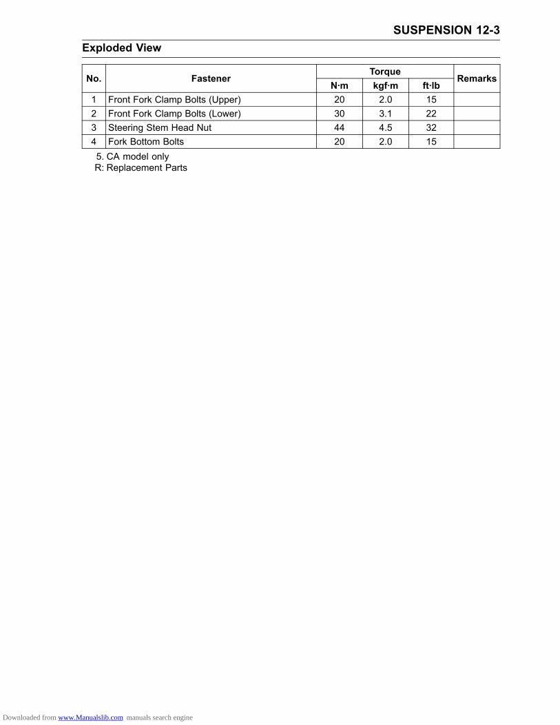
SUSPENSION 12-3Exploded View
TorqueNo. Fastener
N·m kgf·m ft·lbRemarks
1 Front Fork Clamp Bolts (Upper) 20 2.0 152 Front Fork Clamp Bolts (Lower) 30 3.1 223 Steering Stem Head Nut 44 4.5 324 Fork Bottom Bolts 20 2.0 155. CA model onlyR: Replacement Parts
Downloaded from www.Manualslib.com manuals search engine

12-4 SUSPENSIONExploded View
Downloaded from www.Manualslib.com manuals search engine

SUSPENSION 12-5Exploded View
TorqueNo. Fastener
N·m kgf·m ft·lbRemarks
1 Rear Shock Absorber Mounting Bolt (Upper) 39 4.0 292 Rear Shock Absorber Mounting Nut (Upper) 39 4.0 29 R3 Rear Shock Absorber Mounting Nut (Lower) 39 4.0 29 R4 Swingarm Pivot Nut 78 8.0 58 R5 Torque Link Nuts 25 2.5 18G: Apply grease.R: Replacement Parts
Downloaded from www.Manualslib.com manuals search engine

12-6 SUSPENSIONSpecifications
Item Standard Service LimitFront ForkAir Pressure Atmospheric pressure – – –Rebound Damping Adjustment Non-Adjustable – – –Compression Damping Adjustment Non-Adjustable – – –Suspension Oil Kawasaki SS-8 or equivalent – – –Amount (KLX110C) 165 ±2.5 mL (5.58 ±0.085
US oz)– – –
(KLX110D) 182 ±2.5 mL (6.15 ±0.085US oz)
– – –
Level (KLX110C) 85 ±2 mm (3.35 ±0.08 in.) – – –(fully compressed, without spring) (KLX110D) 118 ±2 mm (4.65 ±0.08 in.) – – –Fork Spring Free Length (KLX110C) 442.7 mm (17.43 in.) 433.8 mm (17.08 in.)
(KLX110D) 498.9 mm (19.64 in.) 488.9 mm (19.25 in.)Rear Shock AbsorberGas Pressure 980 kPa (10 kgf/cm², 142 psi) – – –
Downloaded from www.Manualslib.com manuals search engine

SUSPENSION 12-7Special Tools
Fork Cylinder Holder Handle:57001-183
Fork Cylinder Holder Adapter:57001-1011
Front Fork Oil Seal Driver:57001-1219
Jack:57001-1238
Downloaded from www.Manualslib.com manuals search engine

12-8 SUSPENSIONFront Fork
Front Fork Oil Change•Refer to the Front Fork Oil Change in the Periodic Main-tenance chapter.
Front Fork Removal•Remove:Number Plate (see Number Plate Removal in the Framechapter)Front Wheel (see Front Wheel Removal in theWheels/Tires chapter)
• Loosen the upper [A] and lower [B] fork clamp bolts.
• Pull out to downward the fork leg [A] with a twisting motion[B].
Front Fork Installation• Install the fork, aligning the top end [A] of the inner tubewith the upper surface [B] of the steering stem head.•Route the cables and hose according to the Cable, Har-ness and Hose Routing section in the Appendix chapter.• Install the front wheel (see Front Wheel Installation in theWheels/Tires chapter).• Tighten the fork clamp bolts.Torque - Front Fork Clamp Bolt (Upper): 20 N·m (2.0 kgf·m,
15 ft·lb)Front Fork Clamp Bolt (Lower): 30 N·m (3.1 kgf·m,22 ft·lb)
• Install the other removed parts (see appropriate chap-ters).• Check the front brake operation after installation.
Downloaded from www.Manualslib.com manuals search engine

SUSPENSION 12-9Front Fork
Front Fork Disassembly (each fork leg)•Remove the cap.• Loosen the front fork upper clamp bolt [A].• Remove the snap ring [B] while pressing the top plug [C],and then remove the top plug with O-ring.•Remove the front fork (see Front Fork Removal).• Thoroughly clean the fork before disassembly.
NOTICEBe careful not scratch the inner tube and not todamage the dust seal.Avoid scratching or damaging the inner tube or thedust seal. Use a mild detergent and sponge out dirtwith plenty of water.
•Remove:Fork SpringDust Seal•Drain the fork oil [A] with the fork upside down.
NOTEPump the fork tube several times to discharge the oil.
•Hold the outer tube horizontally in a vice.• Stop the cylinder [A] from turning by using the fork cylinderholder handle [B] and adapter [C].Special Tools - Fork Cylinder Holder Handle: 57001-183
Fork Cylinder Holder Adapter: 57001-1011
•Unscrew the Allen bolt [D], then take out the bolt and gas-ket from the bottom of the outer tube.
•Remove the cylinder unit [A] and spring [B] from the fork.
Downloaded from www.Manualslib.com manuals search engine

12-10 SUSPENSIONFront Fork
•Separate the inner tube [A] from the outer tube [B] bypulling them out.
• Take the cylinder base [A] out of the outer tube [B].
• Remove the retaining ring [A] from the outer tube.•Remove the oil seal [B], using a standard tip screwdriverif necessary.
Front Fork Assembly•When the fork tubes are not disassembled, hold the forkinverted position for more than 20 minutes to allow thefork oil to fully drain.
• Assembly is the reverse of disassembly.•Replace the following parts removed with a new one.Retaining RingOil SealBottom Allen Bolt Washer• Inspect the following and replace them with new ones ifdamaged.Inner Tube (see Inner Tube Inspection)Top Plug O-ring• Insert the cylinder unit and spring in the inner tube.
Downloaded from www.Manualslib.com manuals search engine

SUSPENSION 12-11Front Fork
• Insert the cylinder base [A] in the cylinder unit [B].The cylinder base must be installed with the tapered side[C] facing upward.• Insert the inner tube and cylinder unit as a set into theouter tube.
• Apply a non-permanent locking agent to the bottom Allenbolt and tighten it to the specified torque, using the frontfork cylinder holder.Torque - Fork Bottom Bolt: 20 N·m (2.0 kgf·m, 15 ft·lb)
Special Tools - Fork Cylinder Holder Handle: 57001-183Fork Cylinder Holder Adapter: 57001-1011
• Install the oil seal [A] by tapping with the fork oil seal driver[B] until it stops.Special Tool - Fork Oil Seal Driver: 57001-1219
• Install the following.RetainerDust Seal
•Measure the both diameters of the fork spring ends andinsert the fork spring with the small diameter end [A] fac-ing down.
• Fill the fork oil (see Front Fork Oil Change in the PeriodicMaintenance chapter).• Install the fork legs (see Front Fork Installation).
Downloaded from www.Manualslib.com manuals search engine

12-12 SUSPENSIONFront Fork
Inner Tube Inspection•Visually inspect the inner tube [A].If there is any damage, replace the inner tube. Sincedamage to the inner tube damages the oil seal and dustseal, replace the oil seal and dust seal whenever the innertube is replaced.
NOTICEIf the inner tube is badly bent or creased, replaceit. Excessive bending, followed by subsequentstraightening, can weaken the inner tube.
•Temporarily assemble the inner and outer [B] tubes, andpump them back and forth manually to check for smoothoperation.If you feel binding or catching, the inner and outer tubesmust be replaced.
WARNINGA straightened inner or outer fork tube may fall inuse, possibly causing an accident resulting in seri-ous injury or death. Replace a badly bent or dam-aged inner or outer tube and inspect the other tubecarefully before reusing it.
Oil Seal Inspection•Replace the oil seal [A] with a new one whenever it hasbeen removed.
Spring Tension Inspection•Since a spring becomes shorter as it weakens, check itsfree length [A] to determine its condition.If the spring of either fork leg is shorter than the servicelimit, it must be replaced. If the length of a replacementspring and that of the remaining spring vary greatly, theremaining spring should also be replaced in order to keepthe fork legs balanced from motorcycle stability.
Spring Free LengthStandard:KLX110C Models 442.7 mm (17.43 in.)KLX110D Models 498.9 mm (19.64 in.)
Service Limit:KLX110C Models 433.8 mm (17.08 in.)KLX110D Models 488.9 mm (19.25 in.)
Downloaded from www.Manualslib.com manuals search engine

SUSPENSION 12-13Rear Shock Absorber
Rear Shock Absorber Removal•Remove:Seat (see Seat Removal in the Frame chapter)Fuel Tank (see Fuel Tank Removal in the Fuel Systemchapter)•Raise the rear wheel off the ground with the jack.Special Tool - Jack: 57001-1238
NOTICEWhen pulling out the mounting bolts, lift the rearwheel slightly. Forcing or tapping on a bolt coulddamage the bolt, sleeve and bearing.
•Remove:Rear Shock Absorber Mounting Nut [A] and Bolt (Lower)Rear Shock Absorber Mounting Nut [B] and Bolt (Upper)
•Remove the rear shock absorber [A] backward.
Rear Shock Absorber Installation• Installation is the reverse of removal; note the following.•Replace the rear shock absorber mounting nuts [B] withnew ones.• Tighten:Torque - Rear Shock Absorber Mounting Bolt (Upper) [A]:
39 N·m (4.0 kgf·m, 29 ft·lb)Rear Shock Absorber Mounting Nuts: 39 N·m (4.0kgf·m, 29 ft·lb)
Downloaded from www.Manualslib.com manuals search engine

12-14 SUSPENSIONRear Shock Absorber
Rear Shock Absorber Inspection•Remove the rear shock absorber (see Rear Shock Ab-sorber Removal).• Visually inspect the following items.Oil LeakageCrack or DentIf there is any damage to the rear shock absorber, replaceit.• Visually inspect the rubber bushings [A].If it show any signs of damage, replace it.
Rear Shock Absorber ScrappingWARNING
Since the rear shock absorber contains nitrogengas, do not incinerate the rear shock absorber with-out first releasing the gas or it may explode.Before a rear shock absorber is scrapped, drill ahole at the point [A] shown to release the nitrogengas completely. Wear safety glasses when drillingthe hole, as the gas may blow out bits of drilledmetal when the hole opens.
Downloaded from www.Manualslib.com manuals search engine

SUSPENSION 12-15Swingarm
Swingarm Removal•Raise the rear wheel off the ground with the jack.Special Tool - Jack: 57001-1238
•Remove:Drive Chain (see Drive Chain Removal in the Final Drivechapter)Rear Wheel (see Rear Wheel Removal in theWheels/Tires chapter)
•Remove:Drive Chain Cover Bolts [A]Drive Chain Cover [B]Drive Chain Guide Bolts [C]Drive Chain Guide [D]
•Remove:Rear Shock Absorber Lower End [A] (see Rear ShockAbsorber Removal)Swingarm Pivot Shaft Nut [B]• Pull out the Swingarm pivot shaft [C] and remove theswingarm [D] backward.•Remove the chain slipper [E] from the swingarm.
Swingarm Installation• Installation is the reverse of removal.• Replace the rear shock absorber mounting nut [A] andswingarm pivot shaft nut [B] with new ones.Tighten the pivot shaft nut after installing the rear shockabsorber.Torque - Rear Shock Absorber Mounting Nut: 39 N·m (4.0
kgf·m, 29 ft·lb)Swingarm Pivot Shaft Nut: 78 N·m (8.0 kgf·m, 58ft·lb)
Downloaded from www.Manualslib.com manuals search engine

STEERING 13-1
13
SteeringTable of Contents
Exploded View........................................................................................................................ 13-2Special Tools .......................................................................................................................... 13-4Steering .................................................................................................................................. 13-5
Steering Inspection ........................................................................................................... 13-5Steering Adjustment.......................................................................................................... 13-5
Steering Stem......................................................................................................................... 13-6Steering Stem, Stem Bearing Removal ............................................................................ 13-6Steering Stem, Stem Bearing Installation ......................................................................... 13-7Stem Bearing Lubrication.................................................................................................. 13-9Stem Bearing Inspection................................................................................................... 13-9Stem Warp Inspection....................................................................................................... 13-9
Handlebar ............................................................................................................................... 13-10Handlebar Removal .......................................................................................................... 13-10Handlebar Installation ....................................................................................................... 13-11
Downloaded from www.Manualslib.com manuals search engine

13-2 STEERINGExploded View
Downloaded from www.Manualslib.com manuals search engine

STEERING 13-3Exploded View
TorqueNo. Fastener
N·m kgf·m ft·lbRemarks
1 Handlebar Holder Bolts 25 2.5 182 Steering Stem Head Nut 44 4.5 323 Steering Stem Nut 4.9 0.50 43 in·lb T4 Front Fork Clamp Bolts (Upper) 20 2.0 155 Front Fork Clamp Bolts (Lower) 30 3.1 22AD: Apply adhesive cement.G: Apply grease.T: First, tighten the stem nut with 39 N·m (4.0 kgf·m, 29 ft·lb) of torque, then loosen it and retightenit with 4.9 N·m (0.50 kgf·m, 43 in·lb) of torque.
Downloaded from www.Manualslib.com manuals search engine

13-4 STEERINGSpecial Tools
Bearing Puller Adapter:57001-136
Steering Stem Bearing Driver:57001-137
Steering Stem Bearing Driver Adapter, 32:57001-292
Head Pipe Outer Race Press Shaft:57001-1075
Head Pipe Outer Race Driver, 51.5:57001-1076
Steering Stem Nut Wrench:57001-1100
Head Pipe Outer Race Driver, 46.5:57001-1106
Bearing Puller:57001-1675
Downloaded from www.Manualslib.com manuals search engine

STEERING 13-5Steering
Steering Inspection•Refer to the Steering Inspection in the Periodic Mainte-nance chapter.
Steering Adjustment•Refer to the Steering Adjustment in the Periodic Mainte-nance chapter.
Downloaded from www.Manualslib.com manuals search engine

13-6 STEERINGSteering Stem
Steering Stem, Stem Bearing Removal•Remove:Front Wheel (see Front Wheel Removal in theWheels/Tires chapter)Front Fender (see Front Fender Removal in the Framechapter)
•Remove:Number Plate (see Number Plate Removal in the Framechapter)Handlebar Holder Bolts [A]Handlebar Holders [B]Handlebar [C]
• Loosen the steering stem head nut [A].• Remove the front fork (see Front Fork Removal in theSuspension chapter).• Remove the head nut and the steering stem head [B].
• Pushing up on the stem base [A], and remove the steeringstem nut [B] with the steering stem nut wrench [C], thenremove the steering stem [D] and stem base.Special Tool - Steering Stem Nut Wrench: 57001-1100
•Remove:Steering Stem Cap [A]Upper Inner Race [B]Steel Balls [C]
There are 23 steel balls installed in the upper outer race.
Downloaded from www.Manualslib.com manuals search engine

STEERING 13-7Steering Stem
•To remove the outer races [A] pressed into the head pipe[B], insert a bar [C] into the head pipe, and hammer evenlyaround the circumference of the opposite race to drive itout.
NOTEIf either steering stem bearing is damaged, it is recom-mended that both the upper and lower bearing (includ-ing outer races) should be replaced with new ones.
•Remove the lower stem bearing inner race (tapered rollerbearing) [A] with its grease seal from the stem using bear-ing puller.Special Tools - Bearing Puller: 57001-1675
Bearing Puller Adapter: 57001-136
Steering Stem, Stem Bearing Installation•Replace the bearing outer race with new ones.Apply grease to the outer races, and drive them into thehead pipe at the same time using the head pipe outer racepress shaft [A] and the head pipe outer race drivers.Special Tools - Head Pipe Outer Race Press Shaft: 57001
-1075Head Pipe Outer Race Driver, 51.5: 57001-1076 [B]
Head Pipe Outer Race Driver, 46.5: 57001-1106 [C]
•Replace the lower inner races with new ones.Apply grease to the lower tapered roller bearing [A], anddrive it onto the stem using the steering stem bearingdriver [B] and adapter [C].Special Tools - Steering Stem Bearing Driver: 57001-137
Steering Stem Bearing Driver Adapter, 32:57001-292
Downloaded from www.Manualslib.com manuals search engine

13-8 STEERINGSteering Stem
•Apply grease liberally to the upper outer race in the headpipe so that the steel balls will stick in place during steminsertion, and install upper steel balls.• Insert the steering stem [A] carefully through the headpipe so that the steel balls on the steering stem does notfall.• Install the stem cap [B] and steering stem nut [C], andtighten it by hand.
• Install the stem head [A].• Tighten the stem head nut [B] lightly.
• Settle the bearing in place as follows;Tighten the stem nut to 39 N·m (4.0 kgf·m, 29 ft·lb) oftorque. (To tighten the steering stem nut to the specifiedtorque, hook the wrench [A] on the stem nut, and pull thewrench at the hole by 22.2 kg force [B] in the directionshown.)Special Tool - Steering Stem Nut Wrench: 57001-1100Check that there is no play and the steering stem turnssmoothly without rattles. If not, the steering stem bearingsmay be damaged.Again back out the stem nut a fraction of a turn until itturns lightly.Turn the stem nut lightly clockwise until it just becomeshard to turn. Do not overtighten, or the steering will betoo tight.Torque - Steering Stem Nut: 4.9 N·m (0.50 kgf·m, 43 in·lb)
• Install the front fork (see Front Fork Installation in the Sus-pension chapter).
NOTETighten the fork upper clamp bolts first, next the stemhead nut, last the fork lower clamp bolt.
Downloaded from www.Manualslib.com manuals search engine

STEERING 13-9Steering Stem
•Tighten:Torque - Steering Stem Head Nut [A]: 44 N·m (4.5 kgf·m, 32
ft·lb)Front Fork Clamp Bolts (Upper) [B]: 20 N·m (2.0kgf·m, 15 ft·lb)
Front Fork Clamp Bolts (Lower) [C]: 30 N·m (3.1kgf·m, 22 ft·lb)
• Install the other removed parts (see appropriate chap-ters).
WARNINGIf the handlebar does not turn to the steering stop itmay cause an accident resulting in injury or death.Be sure the cables, harnesses and hoses are routedproperly and do not interfere with handlebar move-ment (see Cable, Wire, and Hose Routing section inthe Appendix chapter).
•Check and Adjust:SteeringFront BrakeClutch Cable (KLX110D Models)Throttle Cable
Stem Bearing Lubrication•Refer to the Stem Bearing Lubrication in the PeriodicMaintenance chapter.
Stem Bearing Inspection•Using high flash-point solvent, wipe the bearings clean ofgrease and dirt.•Wipe the upper and lower outer races, which are press-fitted into the frame head pipe, clean off grease and dirt.• Check the upper races and steel balls.If the balls or races are worn, or if either race is dented,replace both races and all the balls for that bearing as aset.• Visually check the lower outer race and tapered roller.Replace the bearing assembly if it show damage.
Stem Warp Inspection•Whenever the steering stem is removed, or if the steeringcannot be adjusted for smooth action, check the steeringstem for straightness.If the steering stem shaft [A] is bent, replace the steeringstem.
Downloaded from www.Manualslib.com manuals search engine

13-10 STEERINGHandlebar
Handlebar Removal•Remove:Number Plate (see Number Plate Removal in the Framechapter)Screws [A]Brake Lever Holder [B]Brake Lever Assembly [C]
• Slide out the dust cover [A].• Loosen the screws [B] and remove the throttle cable hous-ing [C] together with the throttle grip [D] from the handle-bar.
• Free the starter lockout switch lead [A] (KLX110D modelsonly) and left switch housing lead [B] from the clamps [C].
KLX110D Models•Remove:Bolts [A]Clutch Lever Holder [B]Clutch Lever Assembly [C]
•Remove:Screws [A]Left Switch Housing [B]Left Handlebar Grip [C]
Downloaded from www.Manualslib.com manuals search engine

STEERING 13-11Handlebar
•Remove:Handlebar Holder Bolts [A]Handlebar Holders [B]Handlebar [C]
Handlebar Installation•Apply adhesive to the inside of the left handlebar grip.• Install the left handlebar grip so that the projection of gripaligns with the punch mark of the handlebar.
•Mount the handlebar holders [B] so that the arrows [C] onthe holder point at the front [A].Align the punch mark [D] on the handlebar to the matingsurface of each holders of handlebar.• Tighten the holder bolts, front first and then the rear. If thehandlebar holder is correctly installed, there will be no gapat the front and a gap [E] at the rear after tightening.• Tighten the handlebar holder bolts to the specified torque.Torque - Handlebar Holder Bolts: 25 N·m (2.5 kgf·m, 18
ft·lb)
• Install the left switch housing [A].KLX110D Models• Install the clutch lever [B].Position the clutch lever so that the mating surface [C]aligns with the punch mark [D] of the handlebar.
• Install the throttle grip assembly so that the grip is in asfar as it will go.• Position the throttle grip assembly so that the mating sur-face of the throttle cases [A] aligns with the punch mark[B] of the handlebar, and tighten the screws [C].• Slip the dust cover [D] back onto place.
Downloaded from www.Manualslib.com manuals search engine

13-12 STEERINGHandlebar
• Install the brake lever [A].Position the brake lever so that the mating surface [B]aligns with the punch mark [C] of the handlebar.
• Install the number plate (see Number Plate Installation inthe Frame chapter).• Route the cables and leads correctly (see Cable, Wire,and Hose Routing section in the Appendix chapter).
Downloaded from www.Manualslib.com manuals search engine

FRAME 14-1
14
FrameTable of Contents
Exploded View........................................................................................................................ 14-2Special Tool ............................................................................................................................ 14-6Frame ..................................................................................................................................... 14-7
Frame Inspection .............................................................................................................. 14-7Engine Guard Removal/Installation .................................................................................. 14-7
Shroud.................................................................................................................................... 14-8Shroud Removal ............................................................................................................... 14-8Shroud Installation ............................................................................................................ 14-8
Seat ........................................................................................................................................ 14-9Seat Removal ................................................................................................................... 14-9Seat Installation ................................................................................................................ 14-9
Side Covers ............................................................................................................................ 14-10Side Cover Removal ......................................................................................................... 14-10Side Cover Installation ...................................................................................................... 14-10
Number Plate.......................................................................................................................... 14-11Number Plate Removal..................................................................................................... 14-11Number Plate Installation.................................................................................................. 14-11
Fenders .................................................................................................................................. 14-12Front Fender Removal ...................................................................................................... 14-12Front Fender Installation ................................................................................................... 14-12Rear Fender Removal/Installation .................................................................................... 14-12Rear Flap Removal/Installation......................................................................................... 14-13
Footpegs and Bracket ............................................................................................................ 14-14Footpeg Removal/Installation ........................................................................................... 14-14Footpeg Bracket Removal ................................................................................................ 14-14Footpeg Bracket Installation ............................................................................................. 14-14
Sidestand................................................................................................................................ 14-15Sidestand Removal........................................................................................................... 14-15Sidestand Installation........................................................................................................ 14-15
Downloaded from www.Manualslib.com manuals search engine

14-2 FRAMEExploded View
Downloaded from www.Manualslib.com manuals search engine

FRAME 14-3Exploded View
TorqueNo. Fastener
N·m kgf·m ft·lbRemarks
1 Footpeg Bracket Bolts 25 2.5 182 Sidestand Bolt 9.8 1.0 87 in·lb3 Sidestand Nut 29 3.0 21 RG: Apply grease.R: Replacement Parts
Downloaded from www.Manualslib.com manuals search engine

14-4 FRAMEExploded View
Downloaded from www.Manualslib.com manuals search engine

FRAME 14-5Exploded View
TorqueNo. Fastener
N·m kgf·m ft·lbRemarks
1 Rear Reflector Bracket Screws 7.4 0.75 65 in·lb2 Screw (for Seat Hook) 5.0 0.51 44 in·lb3 Screw (for Rubber Band Hook) 5.0 0.51 44 in·lb4. CA model only
Downloaded from www.Manualslib.com manuals search engine

14-6 FRAMESpecial Tool
Jack:57001-1238
Downloaded from www.Manualslib.com manuals search engine

FRAME 14-7Frame
Frame Inspection•Refer to the Frame Inspection in the Periodic Mainte-nance chapter.
Engine Guard Removal/Installation•Remove:Bolts [A]Footpeg Bracket Bolts [B]Engine Guard [C]
• Installation is the reverse of removal; note the following.• Tighten:Torque - Footpeg Bracket Bolts [A]: 25 N·m (2.5 kgf·m, 18
ft·lb)
Downloaded from www.Manualslib.com manuals search engine

14-8 FRAMEShroud
Shroud Removal•Remove:Side Covers (see Side Cover Removal)Seat (see Seat Removal)Bolts [A] (Both Sides)Screw [B]Fuel Tank Cap [C]Shroud [D]
Shroud Installation• Installation is the reverse of removal.
Downloaded from www.Manualslib.com manuals search engine

FRAME 14-9Seat
Seat Removal•Remove the seat mounting bolts [A] on both sides.• Take off the seat [B] backward.
Seat Installation• Installation is the reverse of removal.Insert the hooks [A] under the washer [B] and the bracket[C].
Downloaded from www.Manualslib.com manuals search engine

14-10 FRAMESide Covers
Side Cover Removal•Remove the bolts [A].• Pull the side cover [B] outward to clear the stopper.
Side Cover Installation• Installation is the reverse of removal.Install the collars to the side cover.Insert the tab [A] into the slot [B].Insert the projection [C] into the grommet [D].
Rear bolt [A] is longer than the front bolt [B].
Downloaded from www.Manualslib.com manuals search engine

FRAME 14-11Number Plate
Number Plate Removal•Remove the band [A] from the handlebar.•Remove the bolt [B] and take off the number plate [C]upward.
Number Plate Installation• Install the collar [A] to the number plate.
• Fit the holes [A] at the bottom of number plate onto thebolt threads [B] in the front fork lower bracket.
• Tighten the bolt [A].• Install the band [B] to the handlebar.•Run the cables and leads correctly (see Cable, Wire, andHose Routing section in the Appendix chapter).
Downloaded from www.Manualslib.com manuals search engine

14-12 FRAMEFenders
Front Fender Removal•Remove the bolts [A] and take off the front fender [B].
Front Fender Installation• Installation is the reverse of removal; note the following.Install the collars [A] to the front fender [B].
Install the longer bolts to the front [A] and the shorter boltsto the rear [B].
Install the front fender so that the front bolt threads [A] areinserted into the holes at the bottom of the number plate.
Rear Fender Removal/Installation•Remove:Seat (see Seat Removal)Side Covers (see Side Cover Removal)Battery [A] (see Battery Removal in the Electrical Systemchapter)Igniter [B]Starter Relay [C]Fuse [D]
Downloaded from www.Manualslib.com manuals search engine

FRAME 14-13Fenders
•Remove the bolts [A].
• Remove the bolts [A] and take off the rear fender [B].
• Installation is the reverse of removal.Run the cables and leads correctly (see Cable, Wire, andHose Routing section in the Appendix chapter).
Rear Flap Removal/Installation•Remove:Right Side Cover (see Side Cover Removal)Bolts [A] and CollarsRear Flap [B]
• Installation is the reverse of removal.
Downloaded from www.Manualslib.com manuals search engine

14-14 FRAMEFootpegs and Bracket
Footpeg Removal/Installation•Remove:Cotter pin [A]Pivot Pin [B]Spring [C]Footpeg [D]
• Installation is reverse of removal; note the following.•Replace the cotter pin with a new one.• Apply grease to the sliding area of the footpeg.• Bend the longer side of the cotter pin.Footpeg Bracket Removal•Remove the engine guard (see Engine Guard Re-moval/Installation).• Place the jack under the frame to support the motorcycle.Special Tool - Jack: 57001-1238
•Remove the bolts [A] with spring washers.•Remove the footpeg bracket [B] together with the foot-pegs and the sidestand.
Footpeg Bracket Installation• Installation is the reverse of removal.Tighten:Torque - Footpeg Bracket Bolts [A]: 25 N·m (2.5 kgf·m, 18
ft·lb)
Downloaded from www.Manualslib.com manuals search engine

FRAME 14-15Sidestand
Sidestand Removal•Raise the rear wheel off the ground with the jack.Special Tool - Jack: 57001-1238
•Remove:Spring [A]Sidestand Bolt [B]Sidestand Nut [C]Sidestand [D]
Sidestand Installation•Apply grease to the sliding area [A] of the sidestand [B].• Replace the sidestand nut [D] with a new one.• Tighten the sidestand bolt [C] and nut.Torque - Sidestand Bolt: 9.8 N·m (1.0 kgf·m, 87 in·lb)
Sidestand Nut: 29 N·m (3.0 kgf·m, 21 ft·lb)
•Hook the spring [E] so that the longer spring end facesupward.
Downloaded from www.Manualslib.com manuals search engine

ELECTRICAL SYSTEM 15-1
15
Electrical SystemTable of Contents
Exploded View................................... 15-2Specifications .................................... 15-6Special Tools and Sealant ................. 15-7Wiring Diagram.................................. 15-8Precautions........................................ 15-12Electrical Wiring................................. 15-13
Wiring Inspection ......................... 15-13Battery ............................................... 15-14
Battery Removal .......................... 15-14Battery Installation ....................... 15-14Battery Activation ......................... 15-14Precautions .................................. 15-17Interchange.................................. 15-18Charging Condition Inspection..... 15-18Refreshing Charge....................... 15-18
Charging System............................... 15-20Alternator Cover Removal............ 15-20Alternator Cover Installation......... 15-20Alternator Rotor Removal ............ 15-21Alternator Rotor Installation ......... 15-21Stator Removal ............................ 15-22Stator Installation ......................... 15-22Alternator Inspection .................... 15-22Charging Voltage Inspection ........ 15-24Regulator/Rectifier Inspection...... 15-24
Starter Motor Clutch .......................... 15-28Starter Motor Clutch/Starter MotorClutch Gear Removal................ 15-28
Starter Motor Clutch/Starter MotorClutch Gear Installation............. 15-28
Starter Motor Clutch Inspection ... 15-29Starter Torque Limiter Inspection . 15-29
Ignition System.................................. 15-30Crankshaft Sensor Removal ........ 15-30Crankshaft Sensor Installation ..... 15-30Ignition Coil Removal/Installation. 15-30Ignition Coil Inspection................. 15-30Spark Plug Cleaning andInspection.................................. 15-31
Spark Plug Gap Inspection .......... 15-31Igniter Removal............................ 15-31Igniter Inspection.......................... 15-31Crankshaft Sensor Inspection...... 15-33
Electrical Starter System ................... 15-37Starter Motor Removal................. 15-37Starter Motor Installation.............. 15-37Starter Motor Disassembly........... 15-37Starter Motor Assembly ............... 15-39Starter Motor Brush Inspection .... 15-40Commutator Cleaning/Inspection. 15-40Armature Inspection..................... 15-41Starter Relay Inspection............... 15-41
Switches and Sensors ....................... 15-45Switch Inspection ......................... 15-45Gear Position Switch Removal .... 15-45Gear Position Switch Installation . 15-45
Fuses................................................. 15-46Main Fuse 10 A Removal............. 15-46Main Fuse 10 A Inspection .......... 15-46
Downloaded from www.Manualslib.com manuals search engine

15-2 ELECTRICAL SYSTEMExploded View
Downloaded from www.Manualslib.com manuals search engine

ELECTRICAL SYSTEM 15-3Exploded View
TorqueNo. Fastener
N·m kgf·m ft·lbRemarks
1 Regulator Mounting Screw 5.2 0.53 46 in·lb2 Ignition Coil Mounting Bolt 2.9 0.30 26 in·lb3 Gear Position Switch Screws 2.9 0.30 26 in·lb4 Spark Plug 13 1.3 115 in·lb5. Battery6. Starter Relay7. IC Igniter8. Main Fuse 10 A9. KLX110D Models10. KLX110CA/DA ModelsG: Apply Grease.R: Replacement Parts
Downloaded from www.Manualslib.com manuals search engine

15-4 ELECTRICAL SYSTEMExploded View
Downloaded from www.Manualslib.com manuals search engine

ELECTRICAL SYSTEM 15-5Exploded View
TorqueNo. Fastener
N·m kgf·m ft·lbRemarks
1 Starter Motor Terminal Screw 2.0 0.20 18 in·lb2 Terminal Cover Plate Screws 2.0 0.20 18 in·lb3 Brush Holder Plate Screws 0.9 0.09 8.0 in·lb4 End Cover Screws 4.4 0.45 39 in·lb5 Starter Motor Mounting Screws 5.2 0.53 46 in·lb6 Alternator Cover Bolts (L=25) 8.8 0.90 78 in·lb7 Alternator Cover Bolts (L=45) 8.8 0.90 78 in·lb8 Timing Inspection Cap 2.4 0.24 21 in·lb9 Alternator Rotor Nut Cap 2.4 0.24 21 in·lb10 Starter Motor Clutch Bolts 11.8 1.20 104 in·lb L11 Alternator Rotor Nut 53.9 5.50 39.812 Alternator Lead Clamp Screws 5.2 0.53 46 in·lb13 Stator Mounting Screws 5.2 0.53 46 in·lb14 Crankshaft Sensor Mounting Screws 2.9 0.30 26 in·lb15. Starter Motor ClutchG: Apply grease.L: Apply a non-permanent locking agent.
MO: Apply molybdenum disulfide oil.R: Replacement PartsLG: Apply liquid gasket.
Downloaded from www.Manualslib.com manuals search engine

15-6 ELECTRICAL SYSTEMSpecifications
Item Standard Service LimitBatteryType Sealed Battery (wet) – – –Model Name FTH4L-BS – – –Capacity 12 V 3 Ah – – –Voltage 12.6 V or more – – –Gross Weight 1.4 kg (3.1 lb) – – –Electrolyte Volume 0.18 L (10.98 cu in.) – – –
Charging SystemCrankshaft Sensor Resistance 50 ∼ 200 Ω at 20°C (68°F) – – –Alternator Output Voltage in the text – – –Stator Coil Resistance in the text – – –Charging Voltage 13.9 ∼ 14.9 V – – –
Ignition SystemIgnition Timing BTDC 10° @1 650 r/min (rpm) – – –Ignition Coil:3 Needle Arcing Distance 7 mm (0.26 in.) or more – – –Primary Winding Resistance 0.19 ∼ 0.23 Ω at 20°C (68°F) – – –Secondary WindingResistance 2.5 ∼ 3.7 kΩ at 20°C (68°F) – – –
Primary Peak Voltage 100 V or more – – –Crankshaft Sensor PeakVoltage 2 V or more – – –
Spark Plug:Type NGK CR6HSA – – –Gap 0.6 ∼ 0.7 mm (0.024 ∼ 0.028 in.) – – –
Electric Starter SystemStarter Motor:Brush Length 7.0 mm (0.28 in.) 3.5 mm (0.14 in.)Commutator Diameter 22.0 mm (0.87 in.) 21.5 mm (0.85 in.)
Downloaded from www.Manualslib.com manuals search engine

ELECTRICAL SYSTEM 15-7Special Tools and Sealant
Rotor Puller M18 × 1.5, M16 × 1.5:57001-1099
Rotor Puller, M16/M18/M20/M22 × 1.5:57001-1216
Flywheel Holder:57001-1313
Hand Tester:57001-1394
Peak Voltage Adapter:57001-1415
Needle Adapter Set:57001-1457
Flywheel Puller, M28 × 1.0:57001-1471
Liquid Gasket, TB1211F:92104-0004
Downloaded from www.Manualslib.com manuals search engine
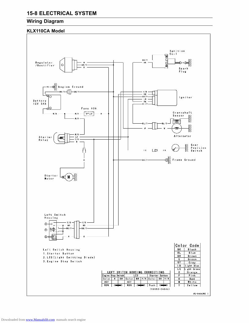
15-8 ELECTRICAL SYSTEMWiring Diagram
KLX110CA Model
Downloaded from www.Manualslib.com manuals search engine

ELECTRICAL SYSTEM 15-9Wiring Diagram
KLX110DA Model
Downloaded from www.Manualslib.com manuals search engine

15-10 ELECTRICAL SYSTEMWiring Diagram
KLX110CB Models ∼
Downloaded from www.Manualslib.com manuals search engine

ELECTRICAL SYSTEM 15-11Wiring Diagram
KLX110DB Models ∼
Downloaded from www.Manualslib.com manuals search engine

15-12 ELECTRICAL SYSTEMPrecautions
There are numbers of important precautions that aremusts when servicing electrical systems. Learn and ob-serve all the rules below.The electrical parts should never be struck sharply, aswith a hammer, or allowed to fall on a hard surface. Sucha shock to the parts can damage them.Troubles may involve one or in some cases all items.Never replace a defective part without determining whatCAUSED the failure. If the failure was caused by someother item(s), they too must be repaired or replaced, orthe new replacement will soon fail again.Make sure all connectors in the circuit are clean and tight,and examine wires for signs of burning, fraying, etc. Poorwires and bad connections will affect electrical system op-eration.Measure coil and winding resistance when the part is cold(at room temperature).Electrical ConnectorsConnectors [A]
Connectors [B]
Safety Instructions:
WARNINGThe ignition system produces extremely high volt-age. Do not touch the spark plug, ignition coil or ig-nition coil lead while the engine is running, or youcould receive a severe electrical shock.
Downloaded from www.Manualslib.com manuals search engine

ELECTRICAL SYSTEM 15-13Electrical Wiring
Wiring Inspection•Visually inspect the wiring for signs of burning, fraying,etc.If any wiring is poor, replace the damaged wiring.• Pull each connector [A] apart and inspect it for corrosion,dirt, and damage.If the connector is corroded or dirty, clean it carefully. If itis damaged, replace it.• Check the wiring for continuity.Use the wiring diagram to find the ends of the lead whichis suspected of being a problem.Connect a digital meter between the ends of the leads.If the digital meter does not read about 0 Ω, the lead isdefective. Replace the lead or the wiring harness [A] ifnecessary.
Downloaded from www.Manualslib.com manuals search engine

15-14 ELECTRICAL SYSTEMBattery
Battery Removal•Remove:Seat (see Seat Removal in the Frame chapter)Left Side Cover (see Side Cover Removal in the Framechapter)Battery Holder Bolts [A]• Slide the battery, and disconnect the negative (–) cable[B] and then positive (+) cable [C].
NOTICEBe sure to disconnect the negative (–) cable first.
•Remove:Battery Holder [D]Battery [E]
Battery Installation•Visually inspect the surface of the battery container.If any signs of cracking or electrolyte leakage from thesides of the battery, replace it.• Put the battery and battery holder into the battery case.•Connect the positive cable [A] to the (+) terminal first, andthen the negative cable [B] to the (–) terminal.• Tighten the battery holder bolts.• Apply a little grease on the terminals to prevent corrosion.•Cover the (+) terminal with the cap.• Install the removed parts (see appropriate chapter).
NOTETo avoid the battery discharging, check that the enginestop switch is in the stop position [A] and the indicatorlight (LED) [B] goes off when the motorcycle is not used.
Battery ActivationElectrolyte Filling•Make sure that the model name [A] of the electrolyte con-tainer matches the model name [B] of the battery. Thesenames must be the same.Battery Model NameKLX110C/D: FTH4L-BS
NOTICEEach battery comes with its own specific elec-trolyte container; using the wrong container mayoverfill the battery with incorrect electrolyte, whichcan shorten battery life and deteriorate battery per-formance. Be sure to use the electrolyte containerwith the same model name as the battery since theelectrolyte volume and specific gravity vary withthe battery type.
Downloaded from www.Manualslib.com manuals search engine

ELECTRICAL SYSTEM 15-15Battery
NOTICEDo not remove the aluminum sealing sheet [A] fromthe filler ports [B] until just prior to use. Be sure touse the dedicated electrolyte container for correctelectrolyte volume.
DANGERSulfuric acid in battery electrolyte can cause severeburns. To prevent burns, wear protective clothingand safety glasses when handling electrolyte. Ifthe electrolyte comes in contact with your skin oreyes, wash the area with liberal amounts of waterand seek medical attention for more severe burns.
•Place the battery on a level surface.•Check to see that the sealing sheet has no peeling, tears,or holes in it.• Remove the sealing sheet.
NOTEThe battery is vacuum sealed. If the sealing sheet hasleaked air into the battery, it may require a longer initialcharge.
•Remove the electrolyte container from the vinyl bag.•Detach the strip of caps [A] from the container and setaside, these will be used later to seal the battery.
NOTEDo not pierce or otherwise open the sealed cells [B] ofthe electrolyte container. Do not attempt to separateindividual cells.
•Place the electrolyte container upside down with the sixsealed cells into the filler ports of the battery. Hold thecontainer level, push down to break the seals of all sixcells. You will see air bubbles rising into each cell as theports fill.
NOTEDo not tilt the electrolyte container.
Downloaded from www.Manualslib.com manuals search engine

15-16 ELECTRICAL SYSTEMBattery
•Check the electrolyte flow.If no air bubbles [A] are coming up from the filler ports, orif the container cells have not emptied completely, tap thecontainer [B] a few times.
NOTEBe careful not to have the battery fall down.•Keep the container in place. Don’t remove the containerfrom the battery, the battery requires all the electrolytefrom the container for proper operation.
NOTICERemoval of the container before it is completelyempty can shorten the service life of the battery.Do not remove the container until it is completelyempty.
•After filling, let the battery sit for 20 ∼ 60 minutes with theelectrolyte container kept in place, which is required forthe electrolyte to fully permeate into the plates.•Make sure that the container cells have emptied com-pletely, and remove the container from the battery.
• Place the strip of caps [A] loosely over the filler ports,press down firmly with both hands to seat the strip of capsinto the battery (don’t pound or hammer). When properlyinstalled, the strip of caps will be level with the top of thebattery.
NOTICEOnce the strip of caps is installed onto the battery,never remove the caps, nor add water or electrolyteto the battery.
NOTECharging the battery immediately after filling canshorten service life.
Downloaded from www.Manualslib.com manuals search engine

ELECTRICAL SYSTEM 15-17Battery
Initial Charge•Newly activated sealed batteries require an initial charge.
Standard Charge: 0.9 A × 5 ∼ 10 hours
If using a recommended battery charger, follow thecharger’s instructions for newly activated sealed battery.
Kawasaki-recommended chargers:Battery Mate 150-9OptiMate PRO 4-S/PRO S/PRO2Yuasa MB-2040/2060Christie C10122S
If the above chargers are not available, use equivalentone.• Let battery sit 30 minutes after initial charge, then checkvoltage using a voltmeter. (Voltage immediately aftercharging becomes temporarily high. For accurate mea-suring, let the battery sit for given time.)
NOTECharging rates will vary depending on how long thebattery has been stored, temperature, and the type ofcharger used. If voltage is not at least 12.6 V, repeatcharging cycle.To ensure maximum battery life and customer satisfac-tion, it is recommended the battery be load tested atthree times its amp-hour rating for 15 seconds.Re-check voltage and if less than 12.6 V repeat thecharging cycle and load test. If still below 12.6 V thebattery is defective.
Precautions1) No need of topping-up.No topping-up is necessary in this battery until it ends its life under normal use. Forcibly prying off theseal cap to add water is very dangerous. Never do that.2) Refreshing charge.
Give a refresh charge for 5 to 10 hours with charging current shown in the specification (seeRefreshing Charge).When a fast charge is inevitably required, do it following precisely the maximum charge current
and time conditions indicated on the battery.
NOTICEThis battery is designed to sustain no unusual deterioration if refresh-charged accordingto the method specified above. However, the battery’s performance may be reduced no-ticeably if charged under conditions other than given above. Never remove the seal capduring refresh charge.If by chance an excessive amount of gas is generated due to overcharging, the relief valvereleases the gas to keep the battery normal.
3) When you do not use the motorcycle for months.Give a refresh charge before you store the motorcycle. And then store it with the negative cable
removed. However, check the battery’s state of charge at every month to be sure it meets theminimum 12.4 V specification and charge it to 100 % state of charge.
4) Battery life.If the battery will not start the engine even after several refresh charges, the battery has ex-
ceeded its useful life. Replace it (Provided, however, the vehicle’s starting system has no prob-lem).
Downloaded from www.Manualslib.com manuals search engine

15-18 ELECTRICAL SYSTEMBattery
DANGERBatteries produce an explosive gas mixture of hydrogen and oxygen that can cause seri-ous injury and burns if ignited. Keep the battery away from sparks and open flames duringcharging. When using a battery charger, connect the battery to the charger before turningon the charger. This procedure prevents sparks at the battery terminals which could igniteany battery gases. The electrolyte contains sulfuric acid. Be careful not to have it touchyour skin or eyes. If touched, wash it off with liberal amount of water and seek medial at-tention for more severe burns.
InterchangeA sealed battery can fully display its performance only when combined with a proper vehicle electric
system. Therefore, replace a sealed battery only on a motorcycle which was originally equipped witha sealed battery.Be careful, if a sealed battery is installed on a motorcycle which had an ordinary battery as original
equipment, the sealed battery’s life will be shortened.
Charging Condition Inspection•Refer to Battery Charging Condition Inspection in the Pe-riodic Maintenance chapter.
Refreshing Charge•Remove the battery (see Battery Removal).• Do refresh charge by following method according to thebattery terminal voltage.
WARNINGThis battery is sealed type. Charge with current andtime as stated below.
Terminal Voltage: 11.5 ∼ less than 12.6 VStandard Charge 0.4 A × 5 ∼ 10 h (see following chart)Quick Charge 4 A × 0.5 h
NOTICEIf possible, do not quick charge. If quick charge isdone unavoidably, do standard charge later on.
Terminal Voltage: less than 11.5 VCharging Method: 0.4 A × 20 h
NOTEIncrease the charging voltage to a maximum voltage of25 V if the battery will not accept current initially. Chargefor nomore than 5minutes at the increased voltage thencheck if the battery is drawing current. If the batterywill accept current decrease the voltage and charge bythe standard charging method described on the batterycase. If the battery will not accept current after 5 min-utes, replace the battery.
Battery [A]Battery Charger [B]Standard Value [C]Current starts to flow [D].
Downloaded from www.Manualslib.com manuals search engine

ELECTRICAL SYSTEM 15-19Battery
•Determine the battery condition after refresh charge.Determine the condition of the battery left for 30 minutesafter completion of the charge by measuring the terminalvoltage according to the table below.
Criteria Judgement12.6 V or higher Good
12.0 ∼ lower than 12.6 V Charge insufficient→ Rechargelower than 12.0 V Unserviceable → Replace
Downloaded from www.Manualslib.com manuals search engine

15-20 ELECTRICAL SYSTEMCharging System
Alternator Cover Removal•Drain the engine oil (see Engine Oil Change in the Peri-odic Maintenance chapter).• Remove:Left Side Cover (see Side Cover Removal in the Framechapter)Seat (see Seat Removal in the Frame chapter)Engine Sprocket Cover (see Engine Sprocket Removalin the Final Drive chapter)
Clear the lead from the clamp [A].• Disconnect the alternator lead connector [B].• Remove:Alternator Cover Bolts [A]Alternator Cover [B]
Alternator Cover Installation•Be sure to install the dowel pins [A].• Install a new gasket.
• Using a high flash-point solvent, clean off any oil or dirtthat may be on the silicone sealant coating area. Drythem with a clean cloth.• Apply liquid gasket to the area [A] to the alternator leadgrommet.Sealant - Liquid Gasket, TB1211F: 92104-0004
NOTEWipe off excess silicone sealant after installing the al-ternator cover.
• Install the alternator cover.Torque - Alternator Cover Bolts: 8.8 N·m (0.90 kgf·m, 78
in·lb)
• Install the removed parts (see appropriate chapters).
Downloaded from www.Manualslib.com manuals search engine

ELECTRICAL SYSTEM 15-21Charging System
Alternator Rotor Removal•Remove:Alternator Cover (see Alternator Cover Removal)Starter Idle Gear and Washers•Wipe oil off the outer circumference of the rotor.• Hold the alternator rotor steady with the flywheel holder[A], and remove the alternator rotor nut [B].Special Tool - Flywheel Holder: 57001-1313
•Remove the flywheel holder.• Using the flywheel puller [A] and rotor puller [B], removethe alternator rotor from the crankshaft.Special Tools - Flywheel Puller, M28 × 1.0: 57001-1471
Rotor Puller, M16/M18/M20/M22 × 1.5: 57001-1216 or
Rotor Puller M18 × 1.5, M16 × 1.5: 57001-1099
Hold the flywheel puller using a wrench, screw in the rotorpuller and remove the alternator rotor.
NOTEIf the rotor is difficult to remove using a rotor puller(57001-1216), tap the cap head on the rotor puller witha hammer, while holding the rotor puller in the directionof the turning.
NOTICEDo not attempt to strike the grab bar or the alter-nator rotor itself. Striking the bar or the rotor cancause the bar to bend or the magnets to lose theirmagnetism.
Alternator Rotor Installation•Apply molybdenum disulfide oil to the crankshaft [A].• Using high flash-point solvent, clean off any oil or dirt onthe crankshaft tapered portion [B] and rotor tapered por-tion [C]. Dry them with a clean cloth.• Fit the woodruff key [D] securely in the slot on the crank-shaft.
• Install the rotor [A] while turning the starter motor clutchgear [B] clockwise.
NOTERemove the starter idle gear and turn the torque limitergear [C] conterclockwise.
Downloaded from www.Manualslib.com manuals search engine

15-22 ELECTRICAL SYSTEMCharging System
•Hold the rotor steady with the flywheel holder [A], tightenthe rotor nut [B].Torque - Alternator Rotor Nut: 53.9 N·m (5.50 kgf·m, 39.8
ft·lb)
Special Tool - Flywheel Holder: 57001-1313
• Install the alternator cover (see Alternator Cover Installa-tion).
Stator Removal•Remove:Alternator Cover (see Alternator Cover Removal)Stator Screws [A]Crankshaft Sensor Screws [B]Alternator Lead Clamp Screws [C]Lead Clamps [D]Wiring Grommet [E]• Take off the stator and the crankshaft sensor as a set.Stator Installation• Install:Stator [A]Crankshaft Sensor [B]Clamps [C]•Run the alternator lead [D] as shown.• Tighten:Torque - Stator Screws: 5.2 N·m (0.53 kgf·m, 46 in·lb)
Crankshaft Sensor Screws: 2.9 N·m (0.30 kgf·m,26 in·lb)
Alternator Lead Clamp Screws: 5.2 N·m (0.53kgf·m, 46 in·lb)
•Using a high flash-point solvent, clean off any oil or dirtthat may be on the silicone sealant coating area. Drythem with a clean cloth.• Apply liquid gasket around the circumference of the wiringgrommet [E].Sealant - Liquid Gasket, TB1211F: 92104-0004
•Set the stator wiring grommet securely in the notch of thealternator cover.• Install the alternator cover (see Alternator Cover Installa-tion).
Alternator Inspection•There are three types of alternator problems: short, open(wire burned out), or loss in rotor magnetism.A short or open in one of the coil wires will result in eithera low output, or no output at all.A loss in rotor magnetism, which may be caused by drop-ping or hitting the rotor by leaving it near an electromag-netic field, or just by aging, will result in low output.
Downloaded from www.Manualslib.com manuals search engine

ELECTRICAL SYSTEM 15-23Charging System
•Check the alternator output voltage, do the following pro-cedures.Remove:Left Side Cover (see Side Cover Removal in the Framechapter)Seat (see Seat Removal in the Frame chapter)
Clear the leads from the clamp [A].Connect a tester to the connector [B] as shown in the table1, using the needle adapter set.Start the engine.Run it at the rpm given in the table 1.Note the voltage readings.Special Tool - Needle Adapter Set: 57001-1457
Table 1, Alternator Output VoltageConnections
Tester (+) to Tester (–) toReading
@4 000 rpm
White lead Ground AC 48 V or more
If the output voltage shows the value in the table, the al-ternator operates properly.If the output voltage shows amuch lower reading than thatgiven in the table indicates that the alternator is defective.
•Check the stator coil resistance as follows.Stop the engine.Disconnect the alternator lead connector.Connect the tester [A] to the connector [B] as shown inthe table 2.Note the readings.Table 2, Stator Coil Resistance
ConnectionsTester (+) to Tester (–) to
Reading
White lead Ground 0.2 ∼ 1.0 Ω
If there is more resistance than shown in the table, or notester reading (∞) the stator has an open lead and mustbe replaced. Much less than this resistance means thestator is shorted, and must be replaced.•Using the tester, measure the resistance between eachleads and chassis ground.Any tester reading less than infinity (∞) indicates a short,necessitating stator replacement.If the stator coils have normal resistance, but the voltagecheck showed the alternator to be defective; then the rotorhave probably weakened, and the rotor must be replaced.
Downloaded from www.Manualslib.com manuals search engine

15-24 ELECTRICAL SYSTEMCharging System
Charging Voltage Inspection•Remove:Seat (see Seat Removal in the Frame chapter)Left Side Cover (see Side Cover Removal in the Framechapter)•Check the battery condition (see Charging Condition In-spection).•Warm up the engine to obtain actual alternator operatingconditions.•Connect a digital meter [A] as shown in the table.Charging Voltage
ConnectionsMeter (+) to Meter (−) to
Reading
Battery (+)Terminal
Battery (−)Terminal DC 13.9 ∼ 14.9 V
•Start the engine, and note the voltage readings at variousengine speeds. The readings should show nearly batteryvoltage when the engine speeds is low, and, as the enginespeed rises, the readings should also rise. But they mustbe kept under the specified voltage.• Stop the engine and disconnect the digital meter.If the charging voltage is kept between the values given inthe table, the charging system is considered to be workingnormally.If the charging voltage is much higher than the valuesspecified in the table, the regulator/rectifier is defectiveor the regulator/rectifier leads are loose or open.If the charging voltage does not rise as the engine speedincreases, the regulator/rectifier is defective or the alter-nator output is insufficient for the loads. Check the al-ternator and regulator/rectifier to determine which part isdefective.
Regulator/Rectifier Inspection•Remove the shroud (see Shroud Removal in the Framechapter).• Remove the screw [A], and disconnect the connector [B].
Downloaded from www.Manualslib.com manuals search engine

ELECTRICAL SYSTEM 15-25Charging System
•With the Kawasaki hand tester, measure the internal re-sistance in both directions between the terminals.Special Tool - Hand Tester: 57001-1394If the reading is not the specified value, replace the reg-ulator/rectifier.
Internal Resistance @20°C (68°F) Unit: kΩTester (+) Lead
Terminal A B C(–)* A – 6.9 ∼ 70 ∞
B ∞ – ∞C ∞ ∞ –
(–)*: Tester (–) Lead
NOTICEUse only Hand Tester 57001-1394 for this test. Anohmmeter other than the Hand Tester may showdifferent readings. If a megger or a meter with alarge-capacity battery is used, the regulator will bedamaged.
•Connect the regulator/rectifier lead connector and installthe rubber cover [A] over the connector.• Tighten:Torque - Regulator Mounting Screw [B]: 5.2 N·m (0.53
kgf·m, 46 in·lb)
Downloaded from www.Manualslib.com manuals search engine

15-26 ELECTRICAL SYSTEMCharging System
Charging System Troubleshooting•Recharge the battery if it is discharged.
Downloaded from www.Manualslib.com manuals search engine

ELECTRICAL SYSTEM 15-27Charging System
Charging System Circuit (KLX110CA/DA Models)
1. Load2. Main Fuse 10 A3. Battery 12 V 3 Ah4. Regulator/Rectifier5. Alternator
Charging System Circuit (KLX110CB/DB Models ∼ )
1. Load2. Main Fuse 10 A3. Battery 12 V 3 Ah4. Regulator/Rectifier5. Alternator
Downloaded from www.Manualslib.com manuals search engine

15-28 ELECTRICAL SYSTEMStarter Motor Clutch
Starter Motor Clutch/Starter Motor Clutch GearRemoval•Remove:Alternator Rotor (see Alternator Rotor Removal)•Remove the bolts [A] and take off the starter motor clutch[B] from the rotor.Special Tool - Flywheel Holder [C]: 57001-1313
•Pull the starter motor idle gear [A] and shaft out of thecrankcase.•Remove the torque limiter [B].• Remove the woodruff key [C] and starter motor clutchgear [D].
Starter Motor Clutch/Starter Motor Clutch GearInstallation•Apply a non-permanent locking agent to the starter motorclutch bolts.• Install the starter motor clutch [A] to the alternator rotor.• Tighten:Torque - Starter Motor Clutch Bolts [B]: 11.8 N·m (1.20
kgf·m, 104 in·lb)
Special Tool - Flywheel Holder: 57001-1313
•Apply molybdenum disulfide oil solution to the following:Crankshaft [A]Starter Motor Idle Gear Shaft [B]Torque Limiter Shaft [C]• Install:Starter Motor Clutch Gear [D]Starter Motor Idle GearTorque LimiterWoodruff Key [E]Alternator Rotor (see Alternator Rotor Installation)
Downloaded from www.Manualslib.com manuals search engine

ELECTRICAL SYSTEM 15-29Starter Motor Clutch
Starter Motor Clutch Inspection•Drain the engine oil (see Engine Oil Change in the Peri-odic Maintenance chapter).• Remove:Alternator Cover (see Alternator Cover Removal)Starter Motor Idle Gear [A]
• Turn the torque limiter [A] by hand. The starter motorclutch gear [B] should turn clockwise freely [C] but shouldnot turn counterclockwise.If the starter motor clutch does not operate as it should orif it makes noise, go to the next step.•Disassemble the starter motor clutch, and visually inspectthe clutch parts.If there is any worn or damaged part, replace it.
• Remove the alternator rotor (see Alternator Rotor Re-moval).• Inspect the starter motor clutch gear [A].If the sliding surfaces [B] are worn or damaged, replacethe starter motor clutch gear.
Starter Torque Limiter Inspection•Drain the engine oil (see Engine Oil Change in the Peri-odic Maintenance chapter).• Remove:Alternator Rotor (see Alternator Rotor Removal)Torque Limiter [A]• Visually inspect the torque limiter.If the limiter has wear, discoloration or other damage, re-place it as a unit.
Downloaded from www.Manualslib.com manuals search engine

15-30 ELECTRICAL SYSTEMIgnition System
WARNINGThe ignition system produces extremely high volt-age. Do not touch the spark plug, ignition coil or ig-nition coil lead while the engine is running, or youcould receive a severe electrical shock.
Crankshaft Sensor Removal•Refer to the Stator Removal.Crankshaft Sensor Installation•Refer to the Stator Installation.Ignition Coil Removal/Installation•Remove:Shroud (see Shroud Removal in the Frame chapter)Spark Plug Cap•Disconnect the ignition coil leads [A].• Remove the mounting bolt [B] and remove the ignition coil[C].
• Installation is the reverse of removal; note the following.• Tighten:Torque - Ignition Coil Mounting Bolt: 2.9 N·m (0.30 kgf·m,
26 in·lb)
Ignition Coil InspectionMeasuring Arcing DistanceThe most accurate test for determining the condition of
the ignition coil is made by measuring arcing distance usingthe coil tester for the 3-needle method.•Remove the ignition coil (see Ignition Coil Removal/Instal-lation).• Connect the ignition coil (with the spark plug cap installedon the spark plug lead) [A] to the tester [B], and measurethe arcing distance.
WARNINGTo avoid extremely high voltage shocks, do nottouch the coil body or leads.
If the distance reading is less than the specified value, theignition coil or spark plug cap is defective.
3 Needle Arcing DistanceStandard: 7 mm (0.26 in.) or more
•To determine which part is defective, measure the arcingdistance again with the spark plug cap removed from theignition coil lead. Remove the cap by turning it counter-clockwise.If the arcing distance is subnormal as before, the troubleis with the ignition coil itself. If the arcing distance is nownormal, the trouble is with the spark plug cap.
Downloaded from www.Manualslib.com manuals search engine

ELECTRICAL SYSTEM 15-31Ignition System
Measuring Coil ResistanceIf the arcing tester is not available, the coil can be
checked for a broken or badly shorted winding with anohmmeter. However, an ohmmeter cannot detect layershorts and shorts resulting from insulation breakdownunder high voltage.•Remove the ignition coil (see Ignition Coil Removal/Instal-lation).•Measure the primary winding resistance [A].Connect an ohmmeter between the coil terminals.Set the meter to the × 1 Ω range, and read the meter.•Measure the secondary winding resistance [B].Remove the spark plug cap by turning it counterclock-wise.Connect an ohmmeter between the spark plug lead andthe green terminal (earth).Set the meter to the × 1 kΩ range, and read the meter.Ignition Coil Winding ResistancePrimary windings: 0.19 ∼ 0.23 Ω at 20°C (68°F)Secondary windings: 2.5 ∼ 3.7 kΩ at 20°C (68°F)
If the meter does not read as specified, replace the coil.If the meter reads as specified, the ignition coil windingsare probably good. However, if the ignition system stilldoes not perform as it should after all other componentshave been checked, test replace the coil with one knownto be good.•Check the spark plug lead for visible damage.If the spark plug lead is damaged, replace the coil.
Spark Plug Cleaning and Inspection•Refer to the Spark Plug Cleaning and Inspection in thePeriodic Maintenance chapter.
Spark Plug Gap Inspection•Refer to the Spark Plug Cleaning and Inspection in thePeriodic Maintenance chapter.
Igniter Removal•Remove:Seat (see Seat Removal in the Frame chapter)Left Side Cover (see Side Cover Removal in the Framechapter)Starter Relay•Remove the igniter [A], and disconnect the igniter con-nectors [B].
Igniter InspectionNOTICE
When inspecting the IC Igniter observe the follow-ing to avoid damage to the IC Igniter.Do not disconnect the IC Igniter while the engine isrunning.This may damage the IC Igniter.
Downloaded from www.Manualslib.com manuals search engine

15-32 ELECTRICAL SYSTEMIgnition System
Ignition Coil Primary Peak Voltage Check•Disconnect the spark plug cap from the spark plug, but donot remove the spark plug.•Connect the good spark plug [A] to the spark plug cap,then touch the engine with it.
NOTEMeasure the voltage with each lead connected cor-rectly. The correct value may not be obtained ifdisconnected.Maintain the correct value of compression pressure forthe cylinder (Be sure to measure the voltage with thespark plug install to the cylinder head).
•Connect the peak voltage adapter [B] between the termi-nal of primary lead (black) and ground connection of theunit with the lead of the ignition coil [C] connected.Special Tools - Peak Voltage Adapter: 57001-1415
Type: KEK-54-9-BNeedle Adapter Set: 57001-1457
Connection: Adapter Digital MeterGround [D] ← Red Lead → (+)Black Lead [E] ← Black Lead → (–)
IC Igniter [F]Needle Adapter [G]
• Shift the gear to the neutral position.•Crank the engine by pushing the starter button severaltimes to measure the peak voltage of the primary ignitioncoil.
Ignition Coil Primary Peak VoltageStandard: 100 V or more
WARNINGElectrical equipment can cause serious electricalshock. To avoid being shocked, do not touch themetal portion of the probe whenmeasuring voltage.
If the voltage is less than the specified value, check theignition coil (see Ignition Coil Inspection).If the ignition coil is good, check the other parts (see theflow chart in this section).If the all parts are good, replace the igniter.
Downloaded from www.Manualslib.com manuals search engine

ELECTRICAL SYSTEM 15-33Ignition System
Crankshaft Sensor Peak Voltage Check•To check the peak voltage, do the following procedures.Disconnect the alternator lead connector from the mainharness (see Alternator Cover Removal).
NOTEMeasure the voltage with each lead connected cor-rectly. The correct value may not be obtained ifdisconnected.Maintain the correct value of compression pressure forthe cylinder (Be sure to measure the voltage with thespark plug installed to the cylinder head).
Connect the peak voltage adapter [A] to the digital meterand the terminals of the alternator lead connector [B].Special Tool - Peak Voltage Adapter: 57001-1415
Type: KEK-54-9-B
Connection: Adapter Digital MeterBlue/YellowLead [C]
← Red Lead → (+)
Ground ← Black Lead → (–)
Crank the engine by pushing the starter button severaltimes with the transmission gear in neutral to measurethe peak voltage of the crankshaft sensor.
Crankshaft Sensor Peak VoltageStandard: DC 2 V or more
WARNINGElectrical equipment can cause serious electricalshock. To avoid being shocked, do not touch themetal portion of the probe whenmeasuring voltage.
If the voltage is less than the specified, check the crank-shaft sensor (see Crankshaft Sensor Inspection).If the crankshaft sensor is good, check the other parts(see the flow chart in this section).If the all parts are good, replace the igniter.
Crankshaft Sensor Inspection•Remove:Alternator Lead Connector (see Alternator Cover Re-moval).• Using a digital meter [A] and connect it to the Blue/Yellowlead [B] in the connector and the ground.If there is more resistance than the specified value, thecoil has an open lead and must be replaced. Muchless than this resistance means the crankshaft sensor isshorted, and must be replaced.
Crankshaft Sensor ResistanceStandard: 50 ∼ 200 Ω at 20°C (68°F)
Downloaded from www.Manualslib.com manuals search engine

15-34 ELECTRICAL SYSTEMIgnition System
Downloaded from www.Manualslib.com manuals search engine

ELECTRICAL SYSTEM 15-35Ignition System
Ignition System Circuit (KLX110CA/DA Models)
1. Engine Stop Switch2. Engine Starter Button3. Main Fuse 10 A4. Battery 12 V 3 Ah5. Crankshaft Sensor6. IC Igniter7. Ignition Coil8. Spark Plug
Downloaded from www.Manualslib.com manuals search engine

15-36 ELECTRICAL SYSTEMIgnition System
Ignition System Circuit (KLX110CB/DB Models ∼ )
1. Engine Stop Switch2. Engine Starter Button3. Main Fuse 10 A4. Battery 12 V 3 Ah5. Crankshaft Sensor6. IC Igniter7. Ignition Coil8. Spark Plug
Downloaded from www.Manualslib.com manuals search engine

ELECTRICAL SYSTEM 15-37Electrical Starter System
Starter Motor RemovalNOTICE
Do not tap the starter motor shaft or body. Tappingthe shaft or body could damage the motor.
•Remove:Exhaust Pipe Cover (see Muffler Removal in the EngineTop End chapter)• Slide out the rubber cap [A].• Remove:Starter Motor Terminal Screw [B]Starter Motor Mounting Screws [C]• Pull out the starter motor [D].Starter Motor Installation
NOTICEDo not tap the starter motor shaft or body. Tappingthe shaft or body could damage the motor.
•Replace the O-ring [A] with a new one.• Apply grease to the O-ring.• Install the starter motor and other removed parts.Torque - Starter Motor Mounting Screws: 5.2 N·m (0.53
kgf·m, 46 in·lb)Starter Motor Terminal Screw: 2.0 N·m (0.20 kgf·m,18 in·lb)
Starter Motor Disassembly•Remove the starter motor (see Starter Motor Removal).• Remove the end cover screws [A] with lockwashers.•Hold the pinion gear portion [B] and pull out the yoke [C].
• Remove the armature [A] and gasket [B] from the endcover [C].
NOTEWrap the pinion gear portion [D] by the vinyl tape beforeremoval of the armature.
Downloaded from www.Manualslib.com manuals search engine

15-38 ELECTRICAL SYSTEMElectrical Starter System
NOTEHold the carbon brush leads [A], using the suitable tool[B] as shown.
•Pull out the carbon brush spring [A].• Remove the brush holder screws [B] with lockwashersand flat washers.•Remove the (–) carbon brush [C].
• Remove the terminal cover plate screws [A] and terminalcover plate [B].• Push the terminal [C] into the end cover.Remove the terminal with (+) carbon brush.
•Remove the brush holder plate [A] and insulator plates[B].• Using a suitable tool (or oil seal remover), remove the oilseal [C] from the end cover.
•Using a suitable tool [A] (or bearing puller), remove thebearing [B] from the armature shaft.
Downloaded from www.Manualslib.com manuals search engine

ELECTRICAL SYSTEM 15-39Electrical Starter System
Starter Motor Assembly•Smooth the commutator surface if necessary with fineemery paper (more than #600).• Blow or wipe the parts of the starter motor to clean thedust or any carbon particles.•Replace the oil seal with a new one.• Apply engine oil to the oil seal outer circumference.• Press in the oil seal [A].Install the oil seal so that the marked side faces yoke side.• Install the insulator plates [B] and the brush holder plate[C].• Install the terminal [D] trough the grommet [E] from insideto outside.• Tighten the brush holder plate screws [F] (one screwshould be tightened with the carbon brush lead).Torque - Brush Holder Plate Screws: 0.9 N·m (0.09 kgf·m,
8 in·lb)
•Apply adhesive cement [A] to the terminal [B] as shown.• Install the terminal cover plate so that the flat side facesoutside.• Tighten:Torque - Terminal Cover Plate Screws: 2.0 N·m (0.20 kgf·m,
18 in·lb)
•Replace the bearing with a new one.• Press in the bearing [A] with a suitable tool.NOTE
Install the bearing with the marked side toward the pin-ion gear.Spin the bearing by hand to check its condition. If it isnoisy or does not spin smoothly, replace it.
• Insert the (–) carbon brush spring into the brush holder[A].• Insert the (–) carbon brush [B] into the brush holder untilit is bottomed.
Downloaded from www.Manualslib.com manuals search engine

15-40 ELECTRICAL SYSTEMElectrical Starter System
•Hold the (–) carbon brush in the brush holder so that asuitable tool [A] could hold the (–) carbon brush lead [B]as shown.• Install the (+) carbon brush spring.
•Hold the (+) carbon brush lead with a suitable tool.• Apply high-temperature grease to the oil seal lip.• Before inserting the armature [A], wrap the pinion gearportion [B] by the vinyl tape.•Remove the suitable tool.
• Check that movement of the carbon brushes is smoothand they touch the commutator properly.• Raise the lead.• Apply high-temperature grease to the shaft end of the ar-mature.• Install the gasket and yoke to the end cover.• Tighten:Torque - End Cover Screws: 4.4 N·m (0.45 kgf·m, 39 in·lb)
• Install the starter motor.Starter Motor Brush Inspection•Measure the overall length [A] of each brush.Starter Motor Brush LengthStandard: 7.0 mm (0.28 in.)Service Limit: 3.5 mm (0.14 in.)
If any is worn down to the service limit, replace the carbonbrush.
Commutator Cleaning/Inspection•Smooth the commutator surface [A] if necessary with fineemery cloth [B], and clean out the grooves.
Downloaded from www.Manualslib.com manuals search engine
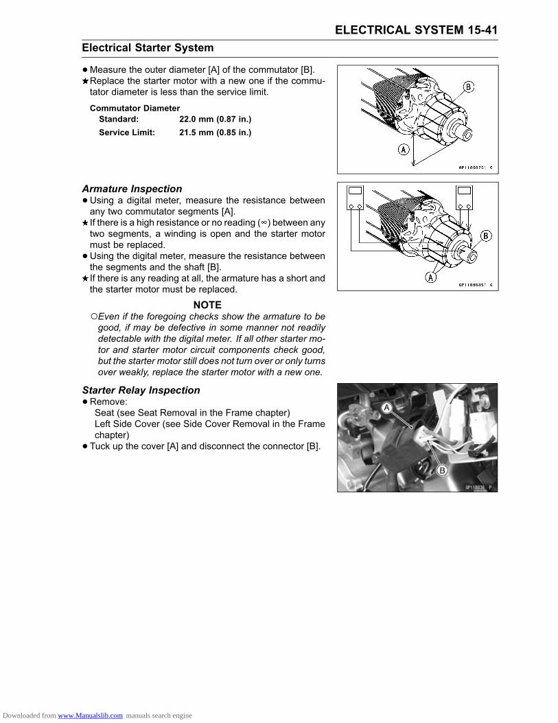
ELECTRICAL SYSTEM 15-41Electrical Starter System
•Measure the outer diameter [A] of the commutator [B].Replace the starter motor with a new one if the commu-tator diameter is less than the service limit.
Commutator DiameterStandard: 22.0 mm (0.87 in.)Service Limit: 21.5 mm (0.85 in.)
Armature Inspection•Using a digital meter, measure the resistance betweenany two commutator segments [A].If there is a high resistance or no reading (∞) between anytwo segments, a winding is open and the starter motormust be replaced.•Using the digital meter, measure the resistance betweenthe segments and the shaft [B].If there is any reading at all, the armature has a short andthe starter motor must be replaced.
NOTEEven if the foregoing checks show the armature to begood, if may be defective in some manner not readilydetectable with the digital meter. If all other starter mo-tor and starter motor circuit components check good,but the starter motor still does not turn over or only turnsover weakly, replace the starter motor with a new one.
Starter Relay Inspection•Remove:Seat (see Seat Removal in the Frame chapter)Left Side Cover (see Side Cover Removal in the Framechapter)• Tuck up the cover [A] and disconnect the connector [B].
Downloaded from www.Manualslib.com manuals search engine

15-42 ELECTRICAL SYSTEMElectrical Starter System
•Connect a digital meter [A] and 12 V battery [B] to thestarter relay [C] as shown in the figure.If the relay does not work as specified, the relay is defec-tive. Replace the relay.KLX110CA/DA Models [D]KLX110CB/DB Models ∼ [E]
Starter Relay InspectionStandard: When battery is connected→ 0 Ω
When battery is disconnected→ ∞ Ω
• Install the cables and other removed parts.Torque - Starter Relay Terminal Screws: 2.9 N·m (0.30
kgf·m, 26 in·lb)
Downloaded from www.Manualslib.com manuals search engine

ELECTRICAL SYSTEM 15-43Electrical Starter System
Electrical Starter System Circuit (KLX110CA/DA Models)
1. Engine Stop Switch2. Engine Starter Button3. Starter Motor4. Starter Relay5. Main Fuse 10 A6. Battery 12 V 3 Ah7. Starter Lockout Switch (KLX110D Models)8. Gear Position Switch
Downloaded from www.Manualslib.com manuals search engine

15-44 ELECTRICAL SYSTEMElectrical Starter System
Electrical Starter System Circuit (KLX110CB/DB Models ∼ )
1. Engine Stop Switch2. Engine Starter Button3. Starter Motor4. Starter Relay5. Main Fuse 10 A6. Battery 12 V 3 Ah7. Starter Lockout Switch (KLX110D Models)8. Gear Position Switch
Downloaded from www.Manualslib.com manuals search engine

ELECTRICAL SYSTEM 15-45Switches and Sensors
Switch Inspection•Using a digital meter, check to see that only the con-nections shown in the table have continuity (about zeroohms).If the switch has an open or short, repair it or replace itwith a new one.
Gear Position Switch Removal•Disconnect the gear position switch lead connector [A].• Remove:Engine Sprocket Cover (see Drive Chain Removal in theFinal Drive chapter)Screws [B]Gear Position Switch [C]
•Remove:O-ring [A]Gear Position Switch Finger [B]Spring [C]
Gear Position Switch Installation• Insert the spring into the hole in the shift drum.• Insert the switch finger [A] so that the small diameter [B]is toward hole side.•Replace the O-ring with a new one.• Apply high-temperature grease to the O-ring.•Clean the contact points on the position switch.• Tighten the gear position switch screw.Torque - Gear Position Switch Screws: 2.9 N·m (0.30 kgf·m,
26 in·lb)
• Install the other removed parts.
Downloaded from www.Manualslib.com manuals search engine

15-46 ELECTRICAL SYSTEMFuses
Main Fuse 10 A Removal•Remove:Seat (see Seat Removal in the Frame chapter)Left Side Cover (see Side Cover Removal in the Framechapter)•Remove the main fuse [A].
Main Fuse 10 A Inspection•Remove the fuse (see Main Fuse 10 A Removal) and in-spect the fuse element.If the fuse element is blown, replace the fuse.Housing [A]Fuse Element [B]Terminal [C]Blown Element [D]
NOTICEWhen replacing a fuse, be sure the new fusematches the specified fuse rating for that circuit.Installation of a fuse with a higher rating may causedamage to wiring and components.
Downloaded from www.Manualslib.com manuals search engine

APPENDIX 16-1
16
AppendixTable of Contents
Cable, Wire, and Hose Routing .............................................................................................. 16-2Troubleshooting Guide ........................................................................................................... 16-10
Downloaded from www.Manualslib.com manuals search engine

16-2 APPENDIXCable, Wire, and Hose Routing
Downloaded from www.Manualslib.com manuals search engine

APPENDIX 16-3Cable, Wire, and Hose Routing
1. Brake Cable2. Throttle Cable3. Battery Positive (+) Cable4. Route the starter motor cable through the inside of engine mount.5. Igniter
Downloaded from www.Manualslib.com manuals search engine
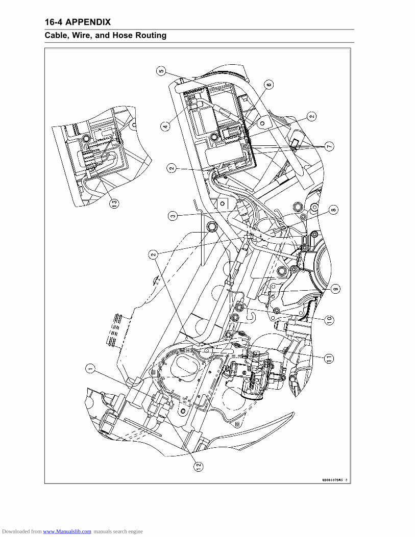
16-4 APPENDIXCable, Wire, and Hose Routing
Downloaded from www.Manualslib.com manuals search engine
APPENDIX 16-5Cable, Wire, and Hose Routing
1. Left Switch Housing Lead Connector2. Clamps3. Alternator Lead Connector4. Battery Negative (–) Cable5. Damper6. Fuse7. Starter Relay Leads8. Gear Position Switch Lead Connector9. Starter Motor Cable10. Frame Ground Lead Terminal11. Ignition Coil12. Starter Lockout Switch Lead Connector (KLX110D Models)13. Igniter
Downloaded from www.Manualslib.com manuals search engine

16-6 APPENDIXCable, Wire, and Hose Routing
Downloaded from www.Manualslib.com manuals search engine

APPENDIX 16-7Cable, Wire, and Hose Routing
1. Throttle Cable2. Clutch Cable (KLX110D Models)3. Route the clutch cable in front of the band of number plate.4. Starter Lockout Switch Lead (KLX110D Models)5. Left Switch Housing Lead6. Clamps7. Route the brake cable in front of the number plate.8. Route the throttle cable and clutch cable inside of the number plate.
Downloaded from www.Manualslib.com manuals search engine
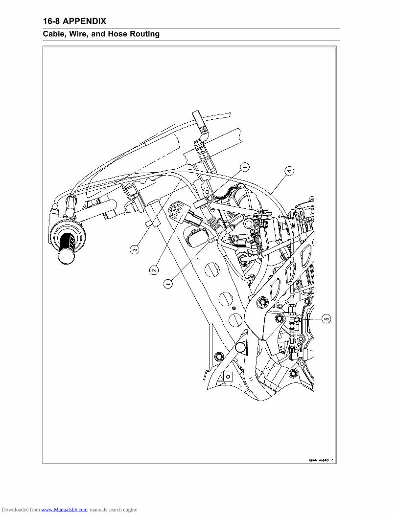
16-8 APPENDIXCable, Wire, and Hose Routing
Downloaded from www.Manualslib.com manuals search engine

APPENDIX 16-9Cable, Wire, and Hose Routing
1. Clamps2. Regulator/Rectifier3. Throttle Cable4. Clutch Cable (KLX110D Models)5. Engine Ground Lead Terminal
Downloaded from www.Manualslib.com manuals search engine

16-10 APPENDIXTroubleshooting Guide
This is not an exhaustive list, giving everypossible cause for each problem listed. it ismeant simply as a rough guide to assist thetroubleshooting for some of the more commondifficulties.
Engine Doesn’t Start, StartingDifficulty:Starter motor not rotating:Engine stop switch not ONStarter lockout switch trouble (KLX110D)Gear position switch troubleStarter motor troubleBattery voltage lowStarter relay not contacting or operatingStarter button not contactingWiring open or shortedEngine stop switch troubleFuse blown
Starter motor rotating but engine doesn’tturn over:Starter clutch troubleStarter idle gear trouble
Engine won’t turn over:Valve seizureCylinder, piston seizureCrankshaft seizureConnecting rod small end, big end seizureTransmission gear or bearing seizureCamshaft seizureStarter idle gear seizureKick shaft return spring brokenKick ratchet gear not engaging
No fuel flow:No fuel in tankFuel tank cap air vent obstructedFuel tap cloggedFuel tap turned offFuel line cloggedCarburetor float valve clogged
Engine flooded:Fuel level in carburetor float bowl too highFloat valve worn or jammed with foreignmatter
Starting technique faulty (When flooded,crank the engine with the throttle fullyopened to allow more air to reach theengine.)
Fuel/air mixture incorrect:Pilot screw and/or idle adjusting screw mal-adjusted
Pilot jet or air passage cloggedAir cleaner clogged, poorly sealed or miss-ing
Starter jet cloggedNo spark; spark weak:Engine stop switch turned OFF
Spark plug dirty, broken or gap maladjustedSpark plug cap or ignition coil lead troubleSpark plug cap shorted or not in good con-tact
Spark plug incorrectIgniter troubleCrankshaft sensor troubleIgnition coil troubleEngine stop switch shortedGear position switch troubleWiring shorted or openRotor damaged
Compression Low:Spark plug looseCylinder head not sufficiently tighteneddown
No valve clearanceCylinder, piston wornPiston ring bad (worn, weak, broken orsticking)
Piston ring/groove clearance excessiveCylinder head gasket damagedCylinder head warpedCylinder gasket damagedValve spring broken or weakValve not seating properly (valve bent, de-formed, worn or carbon accumulation onthe seating surface)
Poor Running at Low Speed:Spark weak:Battery voltage lowSpark plug dirty, broken or gap maladjustedSpark plug cap or ignition coil lead troubleSpark plug cap shorted or not in good con-tact
Spark plug incorrectIgniter troubleCrankshaft sensor troubleRotor damagedIgnition coil troubleWiring connector not in good contact
Fuel/air mixture incorrect:Pilot screw and/or idle adjusting screw mal-adjusted
Pilot jet or air passage cloggedNeedle Jet or air passage cloggedAir cleaner clogged, poorly sealed or miss-ing
Choke valve closedFuel level in carburetor float bowl too highor too low
Fuel tank cap air vent obstructedFuel tap cloggedCarburetor holder looseAir cleaner duct loose
Downloaded from www.Manualslib.com manuals search engine

APPENDIX 16-11Troubleshooting Guide
Compression low:Spark plug looseCylinder head not sufficiently tighteneddown
No valve clearanceCylinder, piston wornPiston ring bad (worn, weak, broken orsticking)
Piston ring/groove clearance excessiveCylinder head gasket damagedCylinder head warpedCylinder gasket damagedValve spring broken or weakValve not seating properly (valve bent, de-formed, worn or carbon accumulation onthe seating surface)
Decompression troubleOther:Igniter troubleEngine oil level too highEngine oil viscosity too highBrake draggingDrive train troubleEngine overheatingClutch slipping
Poor Running or No Power at HighSpeed:Firing incorrect:Spark plug dirty, broken or gap maladjustedSpark plug cap or ignition coil lead troubleSpark plug cap shorted or not in good con-tact
Spark plug incorrectIgniter troubleCrankshaft sensor troubleRotor damagedIgnition coil troubleWiring connector not in good contact
Fuel/air mixture incorrect:Choke valve closedMain jet clogged or wrong sizeJet needle or needle jet wornAir jet cloggedFuel level in carburetor float bowl too highor too low
Needle Jet or air passage cloggedAir cleaner clogged, poorly sealed or miss-ing
Air cleaner duct looseWater or foreign matter in fuelCarburetor holder looseFuel tank cap air vent obstructedFuel tap cloggedFuel line clogged
Compression low:Spark plug loose
Cylinder head not sufficiently tighteneddown
No valve clearanceCylinder, piston wornPiston ring bad (worn, weak, broken orsticking)
Piston ring/groove clearance excessiveCylinder head gasket damagedCylinder head warpedCylinder gasket damagedValve spring broken or weakValve not seating properly (valve bent, de-formed, worn or carbon accumulation onthe seating surface.)
Decompression troubleKnocking:Carbon built up in combustion chamberFuel poor quality or incorrectSpark plug incorrectIgniter trouble
Other:Throttle valve won’t fully openBrake draggingAir cleaner cloggedWater or foreign matter in fuelClutch slippingOverheatingEngine oil level too highEngine oil viscosity too highDrive chain troubleCrankshaft bearing worn or damaged
Engine Overheating:Firing incorrect:Spark plug dirty, broken or maladjustedSpark plug incorrectIgniter trouble
Fuel/air mixture incorrect:Main jet clogged or wrong sizeFuel level in carburetor float bowl too lowCarburetor holder looseAir cleaner clogged, poorly sealed or miss-ing
Air cleaner duct looseChoke valve closed
Compression high:Carbon built up in combustion chamber
Engine load faulty:Clutch slippingEngine oil level too highEngine oil viscosity too highBrake draggingDrive chain trouble
Lubrication inadequate:Engine oil level too lowEngine oil poor quality or incorrect
Downloaded from www.Manualslib.com manuals search engine

16-12 APPENDIXTroubleshooting Guide
Clutch Operation Faulty:Clutch slipping:No clutch release play (KLX110C)No clutch lever play (KLX110D)Clutch cable maladjusted (KLX110D)Clutch inner cable sticking (KLX110D)Friction plate worn or warpedSteel plate worn or warpedClutch spring broken or weakClutch release maladjusted (KLX110C)Clutch release function troubleClutch hub or housing unevenly worn
Clutch not disengaging properly:Clutch release play excessive (KLX110C)Clutch lever play excessive (KLX110D)Clutch spring compression unevenEngine oil deterioratedEngine oil viscosity too highEngine oil level too highClutch housing seizedClutch release function troubleClutch hub nut looseClutch plate warped or roughClutch hub spline damaged
Gear Shifting Faulty:Doesn’t go into gear; shift pedal doesn’treturn:Clutch not disengagingShift fork bent, worn, or seizedShift return spring pin looseShift return spring weak or brokenShift shaft lever brokenPawl guide plate brokenShift pawl brokenShift pawl spring tension looseGear seizedGear set lever operation troubleShift drum broken
Jumps out of gear:Shift fork ear worn, bentGear groove wornGear dogs and/or dog holes wornShift drum groove wornGear set lever spring weak or brokenShift fork guide pin wornDrive shaft, output shaft and/or gear splinesworn
Overshifts:Gear set lever spring weak or brokenPawl guide plate worn
Abnormal Engine Noise:Knocking:Igniter troubleCarbon built up in combustion chamberFuel poor quality or incorrect
Spark plug incorrectOverheating
Piston slap:Cylinder/piston clearance excessiveCylinder, piston wornConnecting rod bentPiston pin, piston pin hole worn
Valve noise:Valve clearance incorrectValve spring broken or weakCamshaft bearing or cam face wornValve lifter worn
Other noise:Connecting rod big end and/or small endclearance excessive
Piston ring worn, broken or stuckPiston seizure, damagedCylinder head gasket leakingExhaust pipe leaking at cylinder head con-nection
Crankshaft runout excessiveEngine mounts looseCrankshaft bearing wornCamshaft chain tensioner troubleCamshaft chain, sprocket, chain guide wornPrimary gear worn or damagedAlternator rotor loose
Abnormal Drive Train Noise:Clutch noise:Clutch housing finger and friction plate tangworn
Clutch housing gear wornMetal chips jammed in clutch housing gearteeth
Transmission noise:Bearings wornTransmission gears worn or chippedMetal chips jammed in gear teethEngine oil insufficient, low viscosityKick ratchet gear not properly disengagingfrom kick gear
Kick shaft idle gear worn or chippedDrive chain noise:Drive chain maladjustedDrive chain wornRear and/or engine sprocket wornDrive chain lubrication insufficientRear wheel misaligned
Abnormal Frame Noise:Front fork noise:Oil insufficient or too thinSpring weak or broken
Rear shock absorber noise:Shock absorber damaged
Downloaded from www.Manualslib.com manuals search engine

APPENDIX 16-13Troubleshooting Guide
Brake noise:Brake linings over worn or worn unevenlyDrum worn unevenly or scoredBrake spring(s) weak or brokenForeign matter in hubBrake not properly adjusted
Other noise:Bracket, nut, bolt, etc., not properlymounted or tightened
Abnormal Exhaust Color:White smoke:Piston oil ring wornCylinder wornValve oil seal damagedValve guide wornEngine oil level too high
Black smoke:Air cleaner element cloggedMain jet too large or fallen offChoke valve closedFuel level in carburetor float bowl too high
Brown smoke:Main jet too smallFuel level in carburetor float bowl too lowAir cleaner duct looseAir cleaner poorly sealed or missing
Handling and/or StabilityUnsatisfactory:Handlebar hard to turn:Cable, hose, wire routing incorrectSteering stem nut too tightSteering stem bearing damagedSteering stem bearing lubrication inade-quate
Steering stem bentTire air pressure too low
Handlebar shakes or excessively vibrates:Tire wornSwingarm pivot bearings wornRim warped or not balancedSpokes looseWheel bearing wornHandlebar holder bolt loose
Steering stem head nut looseFront, rear axle runout excessive
Handlebar pulls to one side:Frame bentRear wheel misalignmentSwingarm bent or twistedSwingarm pivot shaft runout excessiveSteering maladjustedSteering stem bentFront fork bentRight and left front fork oil level uneven
Suspension operation trouble:(Too hard)Tire air pressure too highFront fork oil excessiveFront fork oil viscosity too highFront fork bent
(Too soft)Front fork oil insufficient or leakingFront fork oil viscosity too lowFront fork, rear shock absorber spring weakRear shock absorber oil or gas leakingTire air pressure too low
Brake Doesn’t Hold:Brake not properly adjustedBrake linings over worn or worn unevenlyDrum worn unevenly or scoredCam, camshaft, shaft hole wornOil, grease on lining and drumDirt, water between lining and drumOverheated
Battery Trouble:Battery discharged:Charge insufficientBattery faulty (too low terminal voltage)Battery lead making poor contactAlternator troubleWiring faultyRegulator/rectifier trouble
Battery overcharged:Alternator troubleRegulator/rectifier troubleBattery faulty
Downloaded from www.Manualslib.com manuals search engine

MODEL APPLICATIONYear Model Beginning Frame No.
2010 KLX110CA JKALXSC1ADA71826JKALX110CCDA71829
2010 KLX110DA JKALXSD1ADA718302011 KLX110CB JKALXSC1BDA76725
JKALX110CCDA772752011 KLX110DB JKALXSD1BDA767352012 KLX110CC JKALXSC1CDA81071
JKALX110CCDA818412012 KLX110DC JKALXSD1CDA810722013 KLX110CD JKALXSC1DDA85234
JKALX110CCDA852342013 KLX110DD JKALXSD1DDA854342014 KLX110CE JKALXSC1EDA89018
JKALX110CCDA890182014 KLX110DE JKALXSD1EDA88968
:This digit in the frame number changes from one machine to another.
Part No.99924-1429-05 Printed in Japan
Downloaded from www.Manualslib.com manuals search engine