YFM80RX - bike-parts-yam.de
116
This A MANUAL DEL PROPIETARIO 5TH-28199-66 YFM80RX MANUEL DU PROPRIÉTAIRE OWNER’S MANUAL
-
Upload
khangminh22 -
Category
Documents
-
view
0 -
download
0
Transcript of YFM80RX - bike-parts-yam.de

This A
MANUAL DEL PROPIETARIO
5TH-28199-66
YFM80RX
MANUEL DU PROPRIÉTAIREOWNER’S MANUAL

PRINTED IN JAPAN2007.05-0.3x1 !
(E,F,S)
YAMAHA MOTOR CO., LTD.

This A
5TH-28199-66-E0
YFM80RX
OWNER’S MANUAL


EBU17170
INTRODUCTION
EBU17260
Congratulations on your purchase of the Yamaha YFM80RX. This ATV represents the result of many yearsof Yamaha experience in the production of fine sporting, touring, and pacesetting racing machines. With thepurchase of this Yamaha, you can now appreciate the high degree of craftsmanship and reliability that havemade Yamaha a leader in these fields.This manual will provide you with a good basic understanding of the features and operation of this ATV.
This manual includes important safety information. It provides information about special tech-niques and skills necessary to ride the ATV.
It also includes basic maintenance and inspection proce-dures. If you have any questions regarding the operation or maintenance of your ATV, please consult aYamaha dealer.
AN IMPORTANT SAFETY MESSAGE:
�
READ THIS MANUAL COMPLETELY BEFORE OPERATING YOUR ATV. MAKE SURE YOU UNDER-STAND ALL INSTRUCTIONS.
�
PAY CLOSE ATTENTION TO THE WARNING AND CAUTION LABELS ON THE ATV.
�
THIS ATV, AND ANY OTHER ATV OVER 70 cc, SHOULD NOT BE OPERATED BY A CHILD UNDER12 YEARS OF AGE.
AN IMPORTANT NOTE TO PARENTS:
This ATV is not a toy. Before you let your child ride this ATV, you should understand the instructions andwarnings in this Owner’s Manual. Then be sure your child understands and will follow them. Children differin skills, physical abilities and judgment. Some children may not be able to operate an ATV safely. Parentsshould supervise their child’s use of the ATV at all times. Parents should permit continued use only if theydetermine that the child has the ability to operate the ATV safely.

Your ATV was delivered with an adjustable speed limiter and also with an air intake restrictor plate. Yamaharecommends that all beginners start off with the speed limiter screw turned in and the air intake restrictorplate installed to limit the amount of speed available while they learn. The limiter screw may be graduallyturned out to increase maximum speed as the beginner becomes more familiar with operating the ATV. Par-ents should decide when to adjust the ATV for more power as their youngster’s riding skills improve. Oncethe ATV rider can operate with skill at the top speed permitted by adjusting the speed limiter alone, the airintake restrictor plate can be removed. Since removal of this plate will result in a significant increase in pow-er, turn the speed limiter completely back in again; adjust it out in stages as you did before.If your child is a beginner or is inexperienced, he or she should take a training course.

EBU17330
IMPORTANT MANUAL INFORMATION
EBU17341
FAILURE TO FOLLOW THE WARNINGS CONTAINED IN THIS MANUAL CAN RESULT IN SERIOUS IN-JURY OR DEATH.Particularly important information is distinguished in this manual by the following notations:
* Product and specifications are subject to change without notice.
The Safety Alert Symbol means ATTENTION! BECOME ALERT! YOURSAFETY IS INVOLVED!
Failure to follow WARNING instructions could result in severe injuryor death to the ATV operator, a bystander, or a person inspecting orrepairing the ATV.
A CAUTION indicates special precautions that must be taken to avoiddamage to the ATV.
A NOTE provides key information to make procedures easier or clearer.
WARNING
CAUTION:
NOTE:

EBU17350
IMPORTANT NOTICE
EBU17370
Welcome to the Yamaha world of motor sports!This ATV is designed and manufactured for use on UNPAVED surfaces only. It is unsafe to operate thisATV on any paved surface, paved street, paved road or motorway.Please check your local riding laws and regulations before operating this ATV.
EBU17390
YFM80RXOWNER’S MANUAL
©2007 by Yamaha Motor Co., Ltd.1st edition, May 2007All rights reserved.
Any reprinting or unauthorized use without the written permission of
Yamaha Motor Co., Ltd. is expressly prohibited.
Printed in Japan.

EBU17420
TABLE OF CONTENTS
SAFETY INFORMATION .............................. 1-1
LOCATION OF THE WARNING AND SPECIFICATION LABELS ............................ 2-1
DESCRIPTION .............................................. 3-1Left view ..................................................... 3-1Right view................................................... 3-1Controls and instruments ........................... 3-2
INSTRUMENT AND CONTROL FUNCTIONS .................................................. 4-1
Main switch ............................................... 4-1Indicator light ............................................. 4-1Handlebar switches ................................... 4-2Throttle lever ............................................. 4-2Speed limiter and air intake restrictor
plate ........................................................ 4-3Front brake lever ....................................... 4-4Brake pedal and rear brake lever .............. 4-5Parking brake ............................................ 4-6Shift pedal ................................................. 4-6Fuel tank cap ............................................. 4-7Fuel ........................................................... 4-7Fuel cock ................................................... 4-8
Choke ...................................................... 4-10Seat ......................................................... 4-10
PRE-OPERATION CHECKS ..........................5-1Pre-operation check list ............................. 5-1Fuel ............................................................ 5-3Engine oil ................................................... 5-3Final gear oil .............................................. 5-3Front and rear brakes ................................ 5-3Throttle lever .............................................. 5-4Tires ........................................................... 5-4Measuring the tire pressure ....................... 5-5Tire wear limit ............................................ 5-6Chassis fasteners ...................................... 5-6Instruments, lights and switches ................ 5-6Battery ....................................................... 5-6
OPERATION...................................................6-1Starting a cold engine ................................ 6-1Starting a warm engine .............................. 6-3Shifting ....................................................... 6-3Engine break-in .......................................... 6-5Parking ....................................................... 6-5Parking on a slope ..................................... 6-6Accessories and loading ............................ 6-7

RIDING YOUR ATV ...................................... 7-1GETTING TO KNOW YOUR ATV.............. 7-2RIDE WITH CARE AND GOOD
JUDGEMENT ...........................................7-2BE CAREFUL WHERE YOU RIDE............ 7-9TURNING YOUR ATV ............................. 7-13CLIMBING UPHILL .................................. 7-14RIDING DOWNHILL................................. 7-17CROSSING A SLOPE.............................. 7-18CROSSING THROUGH SHALLOW
WATER ..................................................7-19RIDING OVER ROUGH TERRAIN .......... 7-20SLIDING AND SKIDDING........................ 7-21WHAT TO DO IF... ................................... 7-22WHAT TO DO... ....................................... 7-22
PERIODIC MAINTENANCE AND MINOR REPAIR.......................................................... 8-1
Owner’s manual and tool kit ...................... 8-1Periodic maintenance chart for the
emission control system .......................... 8-3General maintenance and lubrication
chart ........................................................ 8-5Checking the spark plug ............................ 8-8Engine oil .................................................. 8-9Final gear oil ............................................ 8-12Cleaning the air filter element ................. 8-13Removing the air intake restrictor plate ... 8-17Cleaning the spark arrester ..................... 8-17
Adjusting the carburetor ........................... 8-18Adjusting the engine idling speed ............ 8-18Checking the throttle cable free play ....... 8-19Timing chain ............................................ 8-20Valve clearance ....................................... 8-20Checking the front and rear brake
shoes .....................................................8-20Adjusting the front brake lever free
play ........................................................8-21Adjusting the rear brake lever and brake
pedal free play .......................................8-23Adjusting the clutch free play ................... 8-26Checking and lubricating the cables ........ 8-26Checking and lubricating the front and
rear brake levers ....................................8-27Checking and lubricating the brake and
shift pedals .............................................8-28Checking the wheel hub bearings ............ 8-28Lubricating the front knuckle pivots ......... 8-28Lubricating the steering shaft ................... 8-28Battery ..................................................... 8-29Replacing the fuse ................................... 8-31Removing a wheel ................................... 8-32Installing a wheel ..................................... 8-33Troubleshooting ....................................... 8-33Troubleshooting chart .............................. 8-35
CLEANING AND STORAGE ..........................9-1Cleaning ..................................................... 9-1

Storage ...................................................... 9-2
SPECIFICATIONS ...................................... 10-1
CONSUMER INFORMATION ...................... 11-1Identification numbers ............................. 11-1

1-1
1
2
3
4
5
6
7
8
9
10
11
EBU17430
SAFETY INFORMATION
SAFETY INFORMATION
EBU17622
AN ATV IS NOT A TOY AND CAN BE HAZARD-OUS TO OPERATE.
An ATV handles differently from other vehicles, in-cluding motorcycles and cars. A collision or roll-over can occur quickly, even during routinemaneuvers such as turning and riding on hills orover obstacles, if you fail to take proper precau-tions.SEVERE INJURY OR DEATH can result if you donot follow these instructions:
�
Read this manual and all labels carefully and fol-low the operating procedures described.
�
Never operate an ATV without proper training orinstruction.
�
Always follow the age recommendation:– A child under 12 years old should never oper-ate an ATV with engine size greater than 70 cc.– A child under 16 years old should never oper-ate an ATV with engine size greater than 90 cc.
�
Never allow a child under age 16 to operate anATV without adult supervision, and never allowcontinued use of an ATV by a child if he or shedoes not have the abilities to operate it safely.
�
Never carry a passenger on an ATV.
�
Always avoid operating an ATV on any pavedsurfaces, including sidewalks, driveways, park-ing lots and paved streets.
�
Never operate an ATV on any paved street,paved road or motorway.
�
Watch carefully for other vehicles when operat-ing on unpaved public streets or roads. Makesure you know your country’s laws and regula-tions before you ride on unpaved public streetsor roads.
�
Never operate an ATV without wearing an ap-proved motorcycle helmet that fits properly. Youshould also wear eye protection (goggles or faceshield), gloves, boots, a long-sleeved shirt or ajacket, and long pants.
�
Never consume alcohol or drugs before or while

1-2
1
2
3
4
5
6
7
8
9
10
11
operating this ATV.
�
Never operate at speeds too fast for your skillsor the riding conditions. Always go at a speedthat is proper for the terrain, visibility, operatingconditions, and your experience.
�
Never attempt wheelies, jumps, or other stunts.
�
Always inspect your ATV each time you use it tomake sure it is in safe operating condition. Al-ways follow the inspection and maintenanceprocedures and schedules described in thismanual.
�
Always keep both hands on the handlebars andboth feet on the footrests of the ATV during op-eration.
�
Always go slowly and be extra careful when op-erating on unfamiliar terrain. Always be alert tochanging terrain conditions when operating theATV.
�
Never operate on excessively rough, slippery orloose terrain until you have learned and prac-ticed the skills necessary to control the ATV onsuch terrain. Always be especially cautious onthese kinds of terrain.
�
Always follow proper procedures for turning asdescribed in this manual. Practice turning at lowspeeds before attempting to turn at faster
speeds and never turn at excessive speeds.
�
Never operate the ATV on hills too steep for theATV or for your abilities. Practice on smaller hillsbefore attempting larger hills.
�
Always follow proper procedures for climbinghills as described in this manual. Check the ter-rain carefully before you start up any hill. Neverclimb hills with excessively slippery or loose sur-faces. Shift your weight forward. Never open thethrottle suddenly or make sudden gear changes.Never go over the top of a hill at high speed.
�
Always follow proper procedures for going downhills and for braking on hills as described in thismanual. Check the terrain carefully before youstart down any hill. Shift your weight backward.Never go down a hill at high speed. Avoid goingdown a hill at an angle that would cause the ve-hicle to lean sharply to one side. Go straightdown the hill where possible.
�
Always follow proper procedures for crossingthe side of a hill as described in this manual.Avoid hills with excessively slippery or loose sur-faces. Shift your weight to the uphill side of theATV. Never attempt to turn the ATV around onany hill until you have mastered the turning tech-nique described in this manual on level ground.

1-3
1
2
3
4
5
6
7
8
9
10
11
Avoid crossing the side of a steep hill if possible.
�
Always use proper procedures if you stall or rollbackwards when climbing a hill. To avoid stall-ing, use the proper gear and maintain a steadyspeed when climbing a hill. If you stall or rollbackwards, follow the special procedure forbraking described in this manual. Dismount onthe uphill side or to a side if pointed straight up-hill. Turn the ATV around and remount, followingthe procedure described in this manual.
�
Always check for obstacles before operating in anew area.
�
Never attempt to operate over large obstacles,such as large rocks or fallen trees. Always followproper procedures when operating over obsta-cles as described in this manual.
�
Always be careful when skidding or sliding.Learn to safely control skidding or sliding bypracticing at low speeds and on level, smoothterrain. On extremely slippery surfaces, such asice, go slowly and be very cautious in order to re-duce the chance of skidding or sliding out of con-trol.
�
Never operate an ATV in fast flowing water or inwater deeper than that recommended in thismanual. Remember that wet brakes may have
reduced stopping ability. Test your brakes afterleaving water. If necessary, apply them severaltimes to let friction dry out the linings.
�
Always use the size and type of tires specified inthis manual.
�
Always maintain proper tire pressure as de-scribed in this manual.
�
Never modify an ATV through improper installa-tion or use of accessories.
�
Never exceed the stated load capacity for anATV. Cargo should be properly distributed andsecurely attached. Reduce speed and follow in-structions in this manual for carrying cargo orpulling a trailer. Allow greater distance for brak-ing.
WARNING
EWB00061
�
Always turn off the engine when refueling.
�
Do not refuel right after the engine has beenrunning and is still very hot.
�
Do not spill gasoline on the engine or ex-haust pipe/muffler when refueling. Never re-fuel while smoking, or in the vicinity ofsparks, open flames, or other sources of ig-nition such as the pilot lights of water heat-ers and clothes dryers. Gasoline can catch

1-4
1
2
3
4
5
6
7
8
9
10
11
fire and you could be burned.
�
When transporting the ATV in another vehi-cle, be sure it is kept upright and that the fuelcock is in the “OFF” position. Otherwise, fuelmay leak out of the carburetor or fuel tank.
�
Gasoline is poisonous. If you should swal-low some gasoline or inhale a lot of gasolinevapor, or get some gasoline in your eyes,seek medical help immediately. If gasolinespills on your skin, wash with soap and wa-ter. If gasoline spills on your clothing,
change your clothes.
WARNING
EWB00070
Always operate your ATV in an area with ade-quate ventilation. Never start or run the enginein a closed area. Exhaust fumes are poisonousand may cause loss of consciousness and
death within a short time.

2-1
1
2
3
4
5
6
7
8
9
10
11
EBU17660
LOCATION OF THE WARNING AND SPECIFICATION LABELS
EBU27150
Read and understand all of the labels on your ATV. These labels contain important information for safe andproper operation.Never remove any labels from your ATV. If a label becomes difficult to read or comes off, request a replace-ment label from your Yamaha dealer.
1
2
3
4
5

2-2
1
2
3
4
5
6
7
8
9
10
11
For Europe
GB
D
E
F
I
NL
P
S
Before you operate this vehicle,read the owner’s manual.
Lesen Sie die Bedienungsanleitungbevor Sie dieses Fahrzeug fahren.
Antes de conducir este vehículo,lea el Manual del Propietario.
Lire le manuel du propriétaire avantd’utiliser ce véhicule.
Prima di usare il veicolo,leggete il manuale di istruzioni.
Voor het gebruik van dit voertuigde handleiding met aandacht lezen.
Antes de utilizar este veículo,leia o manual do proprietário.
Innan du kör detta fordon,läs handboken.
5FK-21568-00
5
GB
D
E
F
I
NL
P
S
Set with tires cold.
Bei kalten Reifen.
Ajuste con losneum�ticos en fr�o.
Pneus � froid.
Impostare a pneumaticifreddi.
Wanneer de bandenkoud zijn.
Regular com pneusfrios.
St�ll in med kalla d�ck.
20 kPa
0.20 kgf/cm2
2.9 psi
20 kPa
0.20 kgf/cm2
2.9 psi
5YF-21696-M0
YAMAHA MOTOR CO., LTD.SHIZUOKA JAPAN
p 4GB-2155A-005FK-2151H-00
<125NE-21697-00
1 2 3
4

2-3
1
2
3
4
5
6
7
8
9
10
11
For Oceania
WARNINGIMPROPER TIRE PRESSURE OR OVERLOADING CANCAUSE LOSS OF CONTROL.LOSS OF CONTROL CAN RESULT IN SEVEREINJURY OR DEATH.OPERATING TIRE PRESSURE: Set with tires cold9Recommended : FRONT : 20 kPa, {0.20 kgf/cm2 } 2.9 psi
REAR : 20 kPa, {0.20 kgf/cm2 } 2.9 psi9Minimum : FRONT : 17 kPa, {0.17 kgf/cm2 } 2.5 psi
REAR : 17 kPa, {0.17 kgf/cm2 } 2.5 psi9Never set tire pressure below minimum.It could cause the tire to dislodge from the rim.
LOADING9Maximum Vehicle Load : 95 kg, (209 lbs).Includes weight of operator, cargo and accessories.
4EM-21696-11
1
Improper ATV use can result in SEVEREINJURY or DEATH.
ALWAYS USE NEVER USE NEVER CARRY NEVER USEAN APPROVED ON PUBLIC PASSENGERS WITH DRUGSHELMET AND ROADS OR ALCOHOLPROTECTIVE
GEARNEVER operate :9 without proper training or instruction.9 at speeds too fast for your skills or
the conditions.9 on public roads-a collision can occur
with another vehicle.9 with a passenger-passengers affect balance
and steering and increase riskof losing control.
ALWAYS :9 use proper riding techniques to avoid
vehicle overturns on hills and rough terrainand it turns.9 avoid paved surfaces-pavement may
seriously affect handling and control.LOCATE AND READ OWNER'S MANUAL.
FOLLOW ALL INSTRUCTIONS AND WARNINGS.
5FE-21568-11
WARNING
UNDER12
Operating this ATV if you are underthe age of 12 increases your chanceof severe injury or death.
NEVER permit children under age 12to operate this ATV.
Adult supervision required for childrenunder age 16.
WARNINGNEVER ride as a
passenger.Passengers can causea loss of control,resulting in SEVEREINJURY or DEATH.
4EM-21697-31
5FE-2151H-01
2 3
4

3-1
1
2
3
4
5
6
7
8
9
10
11
EBU17680
DESCRIPTION
EBU17690
Left view
EBU17700
Right view
1. Choke2. Fuel cock3. Rear wheel4. Footrest5. Shift pedal6. Front wheel
2
6 5 4 3
1
1. Spark arrester2. Seat3. Brake pedal4. Footrest
21
4 3

3-2
1
2
3
4
5
6
7
8
9
10
11
EBU17712
Controls and instruments
NOTE:
The ATV you have purchased may differ slightly
from the figures shown in this manual.
1. Rear brake lever2. Parking brake3. Neutral indicator light4. Front brake lever5. Throttle lever6. Main switch7. Fuel tank cap8. Handlebar switches
1 2 3 4
5678

4-1
1
2
3
4
5
6
7
8
9
10
11
EBU17731
INSTRUMENT AND CONTROL FUNCTIONS
EBU17740
Main switch
The positions of the main switch are as follows:
ON
All electrical systems are supplied with power, andthe engine can be started. The key cannot be re-moved.
OFF
All electrical systems are off. The key can be re-moved.
EBU17781
Indicator light
EBU17860
Neutral indicator light “ ”
This indicator light comes on when the transmis-sion is in the neutral position.
1. Main switch
OFF ON
1
1. Neutral indicator light “N”
1

4-2
1
2
3
4
5
6
7
8
9
10
11
EBU18061
Handlebar switches
EBU18070
Engine stop switch “ENG. STOP”
Set this switch to “RUN” before starting the engine.The engine stop switch controls the ignition andstops the engine when it is running. Use this switchto stop the engine in an emergency situation. Theengine will not start or run when this switch is setto “OFF”.
EBU18090
Start switch “START”
Push this switch to crank the engine with the start-er.
CAUTION:
ECB00050
See the starting instructions on page 6-1 prior
to starting the engine.
EBU18280
Throttle lever
Once the engine is running, movement of the throt-tle lever will increase the engine speed.Regulate the speed of the ATV by varying thethrottle position. Because the throttle is spring-loaded, the ATV will decelerate, and the engine willreturn to an idle any time the hand is removed fromthe throttle lever.
1. Engine stop switch “ENG. STOP”2. Start switch “START”
1 2

4-3
1
2
3
4
5
6
7
8
9
10
11
Before starting the engine, check the throttle to besure it is operating smoothly. Make sure it returnsto the idle position as soon as the lever is released.
WARNING
EWB00250
Malfunction of the throttle could make it diffi-cult to speed up or slow down when you needto. This could cause an accident. Check the op-eration of the throttle lever before you start theengine. If the throttle does not work smoothly,check for the cause. Correct the problem be-
fore riding the ATV or consult a Yamaha dealer.
EBU18341
Speed limiter and air intake restrictor plate
Your ATV was delivered with an adjustable speedlimiter and an air intake restrictor plate. Yamaharecommends that all beginning riders start off withthe speed limiter adjusting screw fully turned in andthe air intake restrictor plate installed to limit theamount of speed available while they learn.The speed limiter keeps the throttle from fullyopening, even when the throttle lever is pushed tothe maximum. The adjusting screw may be gradu-ally turned out as the beginner becomes more fa-miliar with operating the ATV. Parents shoulddecide when to adjust the ATV for more power astheir youngster’s riding skills improve. Once theATV rider can operate with skill at the top speedpermitted by adjusting the speed limiter alone, theair intake restrictor plate can be removed. Since re-moval of this plate will result in a significant in-crease in power, turn the adjusting screwcompletely back in again; adjust it out in stages asdone previously.1. Loosen the locknut.2. To increase the maximum engine power avail-
able and the maximum speed of the ATV, turn
1. Throttle lever
1

4-4
1
2
3
4
5
6
7
8
9
10
11
the adjusting screw in direction (a). To de-crease the maximum engine power availableand the maximum speed of the ATV, turn theadjusting screw in direction (b).
NOTE:
Adjusting for maximum throttle lever movementwithout removing the air intake restrictor plate willcause the engine to run roughly at higher speeds.
(See page 8-17.)
3. Tighten the locknut.
WARNING
EWB00230
Improper adjustment of the speed limiter andthrottle could cause throttle cable damage orimproper throttle operation. The child couldlose control, have an accident or be injured. Donot turn the adjusting screw out more than 20mm (0.8 in) or the throttle cable could be dam-
aged.
EBU18391
Front brake lever
The front brake lever is located on the right handle-bar. To apply the front brake, pull the brake levertoward the handlebar grip.
1. Locknut2. Adjusting screw3. No more than 20 mm (0.8 in)
3
1 2
(b)
(a)

4-5
1
2
3
4
5
6
7
8
9
10
11
EBU18442
Brake pedal and rear brake lever
The brake pedal is located on the right side of theATV and the rear brake lever is located on the lefthandlebar. To apply the rear brake, push down onthe brake pedal or pull the brake lever toward thehandlebar grip.
1. Front brake lever
1
1. Brake pedal
1. Rear brake lever
1
1

4-6
1
2
3
4
5
6
7
8
9
10
11
EBU18460
Parking brake
Use the parking brake before starting the engine orparking the ATV, especially on a slope. Apply therear brake lever and push down the lock plate toapply the parking brake. Squeeze the rear brakelever to release the parking brake.
WARNING
EWB00220
�
Always set the parking brake before startingthe engine. The ATV could start moving un-expectedly if the parking brake is not ap-plied. This could cause loss of control or a
collision.
�
Always be sure you have released the park-ing brake before you begin to ride. The brakecould overheat if you ride the ATV without re-leasing the parking brake. You could losebraking performance which could cause anaccident. You could also wear out the brakes
prematurely.
EBU18550
Shift pedal
This ATV is equipped with a constant-mesh 3-speed transmission. The shift pedal is located onthe left side of the engine. Neutral is at the bottomposition.
1. Parking brake lock plate
1

4-7
1
2
3
4
5
6
7
8
9
10
11
EBU18720
Fuel tank cap
Remove the fuel tank cap by turning it counter-clockwise.
EBU18752
Fuel
Make sure that there is sufficient fuel in the tank.Fill the fuel tank to the bottom of the filler tube asshown.
1. Shift pedal2. Neutral position
321
1
N
2
1. Fuel tank cap
1

4-8
1
2
3
4
5
6
7
8
9
10
11
NOTE:
If knocking or pinging occurs, use a different brand
of gasoline or higher octane grade.
CAUTION:
ECB00070
Use only unleaded gasoline. The use of leadedgasoline will cause severe damage to internalengine parts, such as the valves and piston
rings, as well as to the exhaust system.
WARNING
EWB00310
�
Do not overfill the fuel tank. Fuel expandswhen it heats up. If the fuel tank is overfilled,fuel could spill out due to heat from the en-gine or the sun.
�
Be careful not to spill fuel, especially on theengine or exhaust pipe which can cause afire and severe injury. Wipe up any spilledfuel immediately.
�
Do not refuel right after the engine has beenrunning and is still very hot.
�
Be sure the fuel tank cap is closed securely.
EBU18820
Fuel cock
The fuel cock supplies fuel from the tank to the car-buretor while also filtering it.
1. Fuel level2. Filler tube
Recommended fuel:UNLEADED GASOLINE ONLYFor Europe: Regular unleaded gasoline only with a research octane number of 91 or high-er
Fuel tank capacity:6.8 L (1.80 US gal) (1.50 Imp.gal)
Fuel reserve amount:0.9 L (0.24 US gal) (0.20 Imp.gal)

4-9
1
2
3
4
5
6
7
8
9
10
11
The fuel cock lever positions are explained as fol-lows and shown in the illustrations.
OFF
With the fuel cock lever in this position, fuel will notflow. Always turn the fuel cock lever to this positionwhen the engine is not running.
ON
With the fuel cock lever in this position, fuel flowsto the carburetor. Turn the fuel cock lever to thisposition when starting the engine and riding.
1. Arrow mark positioned over “OFF”
RES
ONFUEL
OFF
1
1. Arrow mark positioned over “ON”
ONFUEL
RES
OFF
ON
1

4-10
1
2
3
4
5
6
7
8
9
10
11
RES
This indicates reserve. With the fuel cock lever inthis position, the fuel reserve is made available.Turn the fuel cock lever to this position if you runout of fuel while riding. When this occurs, refuel assoon as possible and be sure to turn the fuel cocklever back to “ON”!
EBU18860
Choke
The choke is used to start a cold engine.Move the choke in direction (a) to turn on thechoke.
Move the choke in direction (b) to turn off thechoke.See the “Starting a cold engine” section on page6-1 for proper operation.
EBU18870
Seat
To remove the seat
Pull the seat lock lever upward and pull up the seatat the rear.
1. Arrow mark positioned over “RES”
OFF
ONFUEL
RES
RES
1
1. Fully open “ON”2. Half open (warming up position)3. Closed “OFF”4. Choke
4
1 2 3(a)
(b)

4-11
1
2
3
4
5
6
7
8
9
10
11
To install the seat
Insert the projection on the front of the seat into theseat holder and push down on the seat at the rear.
NOTE:
Make sure that the seat is securely fitted.
1. Seat lock lever
1
1. Projection2. Seat holder
1
2

5-1
1
2
3
4
5
6
7
8
9
10
11
EBU19200
PRE-OPERATION CHECKS
EBU19222
Pre-operation check list
Before operating this ATV, be sure to check the items listed in the following table.
WARNING
EWB00480
Always inspect your ATV each time you use it to make sure it is in safe operating condition. Always follow the inspection and maintenance procedures and schedules described in the Owner’s
Manual. Failure to inspect increases the possibility of an accident or equipment damage.
NOTE:
The maintenance of some items in the table has to be performed by a Yamaha dealer. Refer to the periodic
maintenance charts on page 8-3 to determine which service should be performed by a Yamaha dealer.
ITEM ROUTINE PAGE
Fuel
�
Check fuel level in fuel tank, and add recommended fuel if neces-sary.
�
Check fuel line for leakage. Correct if necessary.4-7, 5-3
Engine oil
�
Check oil level in engine, and add recommended oil to specifiedlevel if necessary.
�
Check ATV for oil leakage. Correct if necessary.5-3, 8-9
Final gear oil
�
Check ATV for oil leakage. Correct if necessary. 5-3, 8-12
Front brake
�
Check operation, and correct if necessary.
�
Lubricate cable if necessary.
�
Check lever free play, and adjust if necessary.5-3, 8-20, 8-21

5-2
1
2
3
4
5
6
7
8
9
10
11
Rear brake
�
Check operation, and correct if necessary.
�
Lubricate cable if necessary.
�
Check lever and pedal free play, and adjust if necessary.5-3, 8-20, 8-23
Throttle lever
�
Make sure that operation is smooth. Lubricate cable and lever hous-ing if necessary.
�
Check cable free play, and adjust if necessary.5-4, 8-19
Control cables
�
Make sure that operation is smooth. Lubricate if necessary. 8-26
Wheels and tires
�
Check wheel condition, and replace if damaged.
�
Check tire condition and tread depth. Replace if necessary.
�
Check air pressure. Correct if necessary.5-4, 5-5, 5-6
Brake and shift pedals
�
Make sure that operation is smooth. Lubricate pedal pivoting pointsif necessary. 8-28
Brake levers
�
Make sure that operation is smooth. Lubricate lever pivoting pointsif necessary. 8-27
Chassis fasteners
�
Make sure that all nuts, bolts and screws are properly tightened. 5-6
Instruments and switches
�
Check operation, and correct if necessary. 5-6
Battery
�
Check electrolyte level. Fill with distilled water if necessary. 5-6, 8-29
ITEM ROUTINE PAGE

5-3
1
2
3
4
5
6
7
8
9
10
11
EBU19540
Fuel
Make sure that there is sufficient fuel in the tank.(See page 4-7.)
WARNING
EWB00520
�
Do not overfill the fuel tank. Fuel expandswhen it heats up. If the fuel tank is overfilled,fuel could spill out due to heat from the en-gine or the sun.
�
Be careful not to spill fuel, especially on theengine or exhaust pipe which can cause afire and severe injury. Wipe up any spilledfuel immediately.
�
Do not refuel right after the engine has beenrunning and is still very hot.
�
Be sure the fuel tank cap is closed securely.
EBU19560
Engine oil
Make sure that the engine oil is at the specified lev-el. Add oil as necessary. (See page 8-9.)
EBU19590
Final gear oil
Make sure that the final gear oil is at the specifiedlevel. Add oil as necessary. (See page 8-12.)
EBU19670
Front and rear brakes
Brake levers and brake pedal
�
Check for correct free play in the brake leversand brake pedal. If the free play is incorrect, ad-just it. (See pages 8-21 and 8-23.)
�
Check operation of the brake levers and brakepedal. They should move smoothly and thereshould be a firm feeling when the brakes are ap-plied. If not, have the ATV checked by a Yamahadealer.
Brake operation
Test the brakes at slow speed after starting out tomake sure they are working properly. If the brakesdo not provide proper braking performance, checkthe brake linings for wear. (See page 8-20.)
WARNING
EWB00570
Always check the brakes at the start of everyride. Do not ride the ATV if you find any prob-lem with the brakes or you could lose brakingability, which could lead to an accident. If aproblem cannot be corrected by the adjust-ment procedures provided in this manual, have

5-4
1
2
3
4
5
6
7
8
9
10
11
the ATV checked by a Yamaha dealer.
EBU19761
Throttle lever
Check the operation of the throttle lever. It mustopen smoothly and spring back to the idle positionwhen released. Have a Yamaha dealer correct ifnecessary.
EBU19791
Tires
WARNING
EWB00601
Use of improper tires on this ATV, or operationof this ATV with improper or uneven tire pres-sure, may cause loss of control, increasingyour risk of accident.Pay attention to the following.
�
The tires listed below have been approvedby Yamaha Motor Co., Ltd. for this model.Other tire combinations are not recommend-ed.Front:
Manufacturer/model:DUNLOP/KT586
Size:AT18 x 7-7
Type:Tubeless
Rear:Manufacturer/model:
DUNLOP/KT587Size:
AT18 x 8-7Type:
Tubeless
�
The tires should be set to the recommendedpressure:Recommended tire pressure:
Front:20 kPa (2.9 psi) (0.20 kgf/cm
2
)Rear:
20 kPa (2.9 psi) (0.20 kgf/cm
2
)
�
Check and adjust tire pressures when thetires are cold.
�
Tire pressures must be equal on bothsides.
�
Tire pressure below the minimum speci-fied could cause the tire to dislodge fromthe rim under severe riding conditions.
Minimum tire pressure:Front:
17 kPa (2.5 psi) (0.17 kgf/cm
2
)

5-5
1
2
3
4
5
6
7
8
9
10
11
Rear:17 kPa (2.5 psi) (0.17 kgf/cm
2
)
�
Use no more than the following pressureswhen seating the tire beads.
Maximum tire seating pressure:Front:
250 kPa (36 psi) (2.5 kgf/cm
2
)Rear:
250 kPa (36 psi) (2.5 kgf/cm
2
)Higher pressures and fast inflation maycause a tire to burst. Inflate the tires very
slowly and carefully.
EBU19820
Measuring the tire pressure
Use the low-pressure tire gauge.
NOTE:
The low-pressure tire gauge is included as stan-dard equipment. Make two measurements of thetire pressure and use the second reading. Dust ordirt in the gauge could cause the first reading to be
incorrect.
Set the tire pressure when the tires are cold. Setthe tire pressures to the following specifications:
1. Low-pressure tire gauge
1

5-6
1
2
3
4
5
6
7
8
9
10
11
EBU19830
Tire wear limit
Replace the tire when the tire groove decreases to3 mm (0.12 in).
EBU19840
Chassis fasteners
Make sure that all nuts, bolts and screws are prop-erly tightened.
EBU19850
Instruments, lights and switches
Check that all instruments, lights and switches areworking properly. Correct if necessary.
EBU19860
Battery
Check the fluid level in the battery. Fill with distilledwater if necessary. (See page 8-29.)
Recommended pressure:Front
20 kPa (2.9 psi) (0.20 kgf/cm
2
)Rear
20 kPa (2.9 psi) (0.20 kgf/cm
2
)Minimum:
Front17 kPa (2.5 psi) (0.17 kgf/cm
2
)Rear
17 kPa (2.5 psi) (0.17 kgf/cm
2
)Maximum:
Front23 kPa (3.3 psi) (0.23 kgf/cm
2
)Rear
23 kPa (3.3 psi) (0.23 kgf/cm
2
)
1. Tire wear limit

6-1
1
2
3
4
5
6
7
8
9
10
11
EBU19880
OPERATION
EBU19900
Read the Owner’s Manual carefully before ridingthe ATV.
WARNING
EWB00630
Read the Owner’s Manual carefully to becomefamiliar with all controls in order to help pre-vent any loss of control, which could cause anaccident or injury. If there is a control or func-tion you do not understand, ask your Yamaha
dealer.
EBU20221
Starting a cold engine
WARNING
EWB00640
Always make sure all control cables worksmoothly before you begin riding in coldweather. If the control cables are frozen or donot work smoothly, you could be unable tocontrol the ATV, which could lead to an acci-
dent or collision.
CAUTION:
ECB00150
See the “Engine break-in” section on page 6-5
prior to operating the engine for the first time.
1. Set the parking brake.2. Turn the fuel cock to “ON”.3. Turn the main switch to “ON” and the engine
stop switch to “RUN”.4. Shift the transmission into neutral. The neutral
indicator light should come on. If the indicatorlight does not come on, have a Yamaha deal-er check the electrical circuit.
NOTE:
This model is equipped with an ignition circuit cut-off system. The engine can be started under thefollowing conditions.
�
The transmission is in neutral.
�
The rear brake lever is applied with the transmis-sion in any gear. However, it is recommended to
shift into neutral before starting the engine.
5. Use the choke in reference to the figure:

6-2
1
2
3
4
5
6
7
8
9
10
11
Position (1):
�
Cold engine start with ambient temperature be-low 30 °C (90 °F).
Position (2):
�
Warming up position.
Position (3):
�
Cold engine start with ambient temperatureabove 25 °C (80 °F).
Ambient temp./choke position
6. Completely close the throttle lever and startthe engine by pushing the start switch.
NOTE:
If the engine fails to start, release the start switch,then push it again. Pause a few seconds beforethe next attempt. Each cranking should be as shortas possible to preserve battery energy. Do not
1. Fully open “ON”2. Half open (warming up position)3. Closed “OFF”4. Choke
ON
OFF
0°
30°
10° 20° 30°
50° 70° 90° °F
°C
4
1
13
3
2
6-3
1
2
3
4
5
6
7
8
9
10
11
crank the engine more than 10 seconds on each
attempt.
7. If the engine is started with the choke in posi-tion (1), the choke should be returned to posi-tion (2) to warm up the engine. If the engine isstarted with the choke in position (2), keep thechoke in this position to warm up the engine.
CAUTION:
ECB00160
For maximum engine life, always warm the en-gine up before starting off. Never accelerate
hard when the engine is cold!
8. Continue warming up the engine until it idlessmoothly, then return the choke to position (3)before riding.
NOTE:
The engine is warm when it responds normally to
the throttle with the choke turned off.
EBU20301
Starting a warm engine
Follow the same procedure as for starting a coldengine, with the exception that the choke is not re-quired when the engine is warm. Instead, start theengine with the throttle slightly open.
EBU20550
Shifting
This ATV has a 3-speed forward transmission witha centrifugal, automatic clutch. The transmissionallows you to control the amount of power youhave available at a given speed or for starting ac-celerating, climbing, etc.To shift into neutral, return the throttle lever to theclosed position and repeatedly depress the shiftpedal until it stops.
EBU20610
To start out and accelerate
1. Release the throttle lever.
1. Shift pedal2. Neutral position
321
1
N2

6-4
1
2
3
4
5
6
7
8
9
10
11
CAUTION:
ECB00200
Always close the throttle before shifting gears,otherwise damage to the engine and drive train
may result.
2. Shift into first gear and release the shift pedal.3. Open the throttle gradually.4. Once the ATV has attained adequate speed,
release the throttle lever.5. Shift into second gear and release the shift
pedal.6. Open the throttle gradually.7. Follow the same procedure when shifting to
the next higher gear.
WARNING
EWB00740
Always open the throttle gradually. Openingthe throttle abruptly would increase the chanceof an accident. It could make the ATV wheelie
or overturn.
EBU20650
To decelerate
When slowing down or stopping, release the throt-tle and apply the brakes smoothly and evenly. Asyou slow down, shift to a lower gear. Be sure that
the engine has sufficiently slowed before engaginga lower gear. Improper use of the brakes or shiftingcan cause the tires to lose traction, reducing con-trol and increasing the possibility of an accident.
WARNING
EWB00710
Make sure the engine has sufficiently slowedbefore shifting to a lower gear. Engaging a low-er gear when the engine speed is too highcould make the wheels stop rotating and losetraction. This could cause loss of control, anaccident and injury. It could also cause engine
or drive train damage.
CAUTION:
ECB00190
Even with the transmission in the neutral posi-tion, do not coast for long periods of time withthe engine off, and do not tow the ATV for longdistances. The transmission is properly lubri-cated only when the engine is running. Inade-quate lubrication may damage the
transmission.

6-5
1
2
3
4
5
6
7
8
9
10
11
EBU20672
Engine break-in
NOTE:
�
For ATVs equipped with an odometer or an hourmeter, follow the figures given in km (mi) or thefigures given in hours.
�
For ATVs not equipped with an odometer or
hour meter, follow the figures given in hours.
There is never a more important period in the life ofyour engine than the first 320 km (200 mi) or 20hours of riding. For this reason, you should readthe following material carefully.Since the engine is brand new, do not put an ex-cessive load on it for the first 320 km (200 mi) or 20hours. The various parts in the engine wear andpolish themselves to the correct operating clear-ances. During this period, prolonged full-throttleoperation or any condition that might result in en-gine overheating must be avoided.
0–160 km (0–100 mi) or 0–10 hours
Avoid prolonged operation above 1/2 throttle. Varythe speed of the ATV regularly. Do not operate it atone set throttle position.
160–320 km (100–200 mi) or 10–20 hours
Avoid prolonged operation above 3/4 throttle. Revthe engine through the gears freely, but do not usefull throttle at any time.
320 km (200 mi) or 20 hours and beyond
The ATV can now be operated normally.
CAUTION:
ECB00220
If any engine trouble should occur during theengine break-in period, immediately have a
Yamaha dealer check the ATV.
EBU20721
Parking
When parking the ATV, stop the engine, shift intofirst gear, apply the parking brake, and then turnthe fuel cock to “OFF”.

6-6
1
2
3
4
5
6
7
8
9
10
11
EBU20840
Parking on a slope
WARNING
EWB00850
Avoid parking on hills or other inclines. Park-ing on a hill or other incline could cause theATV to roll out of control, increasing thechance of an accident. If you must park on anincline, place the ATV transversely across theincline, shift into first gear, stop the engine, ap-ply the parking brake, and then block the frontand rear wheels with rocks or other objects.Do not park the ATV at all on hills that are so
steep you could not walk up them easily.
1. Bring the ATV to a stop by applying the brakesin first gear.
2. Stop the engine.3. With the rear brake lever and brake pedal ap-
plied, apply the parking brake and slowly re-lease the brake pedal.
1. Parking brake lock plate
1. Locked position
1
1

6-7
1
2
3
4
5
6
7
8
9
10
11
EBU20910
Accessories and loading
EBU20920
Accessories
Accessories can affect the handling and control ofyour ATV. Keep the following in mind when consid-ering an accessory or operating an ATV which hasaccessories.
�
Choose only accessories designed for yourATV. Your Yamaha dealer has a variety of gen-uine Yamaha accessories. Other accessoriesmay also be available on the market. However,it is not possible for Yamaha to test all non-
Yamaha accessories, nor control over their qual-ity or suitability. Choose a genuine Yamaha ac-cessory, or one that is equivalent in design andquality.
�
Accessories should be rigidly and securelymounted. An accessory which can shift positionor come off while you are riding could affect yourability to control the ATV.
�
Do not mount an accessory where it could inter-fere with your ability to control the ATV. Exam-ples include (but are not limited to) a heavy orbulky object attached to the handlebars whichcould make steering difficult, an accessory thatlimits your ability to move around on the seat, orone that limits your view.
�
Use extra caution when riding an ATV with ac-cessories. The ATV may handle differently thanit does without accessories.
EBU20940
Loading
As originally equipped, this ATV is not designed tocarry cargo or tow a trailer. If you choose to add ac-cessories so that you can carry cargo or tow a trail-er, you must use common sense and goodjudgment as the stability and handling of an ATVcan be changed. When adding accessories, keep

6-8
1
2
3
4
5
6
7
8
9
10
11
the following points in mind:
�
Never exceed the weight limits shown. An over-loaded ATV can be unstable.
�
If you are carrying cargo and towing a trailer, in-clude the tongue weight in the maximum ATVload limit.
�
Load cargo on the carriers as close to the centerof the ATV as possible. Put cargo at the rear ofthe front carrier, at the front of the rear carrier,and center it.
�
Tie down cargo securely to the carriers. Makesure cargo in the trailer cannot move around. Ashifting load can cause an accident.
�
Make sure the load does not interfere with con-trols or your ability to see where you are going.
�
Ride more slowly than you would without a load.The more weight you carry, the slower youshould go. Although conditions vary, it is goodpractice not to exceed 2nd gear whenever youare carrying heavier loads or when towing a trail-er.
�
Allow more braking distance. A heavier ATVtakes longer to stop.
�
Avoid making sharp turns unless at very slowspeeds.
�
Avoid hills and rough terrain. Choose terraincarefully. Added weight affects the stability andhandling of the ATV.
WARNING
EWB00820
Never exceed the stated load capacity for thisATV. Overloading this ATV or carrying or tow-ing cargo improperly could cause changes inATV handling which could lead to an accident.Cargo should be properly distributed and se-curely attached. Reduce speed when carryingcargo or pulling a trailer. Allow greater dis-
tance for braking.
MAXIMUM LOADING LIMITATV loading limit (total weight of rider, cargo, accessories, and tongue):
95.0 kg (209 lb)

7-1
1
2
3
4
5
6
7
8
9
10
11
EBU21141
RIDING YOUR ATV

7-2
1
2
3
4
5
6
7
8
9
10
11
EBU21552
GETTING TO KNOW YOUR ATV
This ATV is for recreation use. This section, Ridingyour ATV, provides general ATV riding instructionsfor recreational riding. The skills and techniquesdescribed in this section, however, are appropriatefor all types of riding. Riding your ATV requiresspecial skills acquired through practice over a pe-riod of time. Take the time to learn the basic tech-niques well before attempting more difficultmaneuvers.Riding your new ATV can be a very enjoyable ac-tivity, providing you with hours of pleasure. But it isessential to familiarize yourself with the operationof the ATV to achieve the skill necessary to enjoyriding safely. Before you begin to ride, be sure youhave read this Owner’s Manual completely and un-derstand the operation of the controls. Pay partic-ular attention to the safety information on pages1-1–1-4. Please also read all caution and warninglabels on your ATV.
RIDE WITH CARE AND GOOD JUDGEMENT
Get training if you are inexperienced.
Beginners should get training from a certified in-structor.Become familiar with this ATV at slow speeds first,even if you are an experienced operator. Do not at-tempt to operate at maximum performance untilyou are totally familiar with the ATV’s handling andperformance characteristics.
WARNING
EWB01380
Never operate this ATV without proper instruc-tion. Beginning and inexperienced operatorsshould regularly practice the skills and the op-erating techniques described in this Owner’sManual. The risk of an accident is greatly in-creased if the operator does not know how tooperate the ATV properly in different situations
and on different types of terrain.
Riding your ATV requires skills acquiredthrough practice over a period of time.
Take the time to learn the basic techniques wellbefore attempting more difficult maneuvers.

7-3
1
2
3
4
5
6
7
8
9
10
11
Not recommended for children under 12 yearsof age.
WARNING
EWB01700
A child under 12 should never operate an ATVwith engine size greater than 70 cc. Use by chil-dren of ATVs that are not recommended fortheir age can lead to severe injury or death of
the child.
This ATV is designed to carry operator only –
passengers prohibited.
WARNING
EWB01400
Never carry a passenger. The long seat is to al-low the operator to shift position as neededduring operation. It is not for carrying passen-gers. Carrying a passenger on this ATV greatlyreduces your ability to balance and control thisATV. It could cause an accident, resulting in
harm to you and/or your passenger.
Apparel
Always wear an approved motorcycle helmet that

7-4
1
2
3
4
5
6
7
8
9
10
11
fits properly.You should also wear:
�
eye protection (goggles or face shield)
�
gloves
�
boots
�
long-sleeved shirt or jacket
�
long pants
WARNING
EWB01410
Never operate this ATV without wearing an ap-
proved motorcycle helmet, eye protection andprotective clothing. Operating without an ap-proved motorcycle helmet increases yourchances of a severe head injury or death in theevent of an accident. Operating without eyeprotection can result in an accident and in-creases your chances of a severe injury in theevent of an accident. Operating without protec-tive clothing increases your chances of severe
injury in the event of an accident.
Do not operate after consuming alcohol ordrugs.
The operator’s performance capability is reducedby the influence of alcohol or drugs.
1. Protective clothing2. Goggles3. Gloves4. Boots5. Helmet

7-5
1
2
3
4
5
6
7
8
9
10
11
WARNING
EWB01420
Never consume alcohol or drugs before or
while driving this ATV.
Pre-operation checks
Always perform the pre-operation checks listed onpage 5-1 before riding for proper care of the ATVand to ensure safety.
WARNING
EWB01430
Always inspect your ATV each time you use itto make sure the ATV is in safe operating con-dition. Always follow the inspection and main-tenance procedures and schedules describedin the Owner’s Manual. Failure to inspect theATV before operating or failure to properlymaintain the ATV increases the possibility of
an accident or equipment damage.
WARNING
EWB01440
Always use the size and type tires specified inthe Owner’s Manual for this ATV on page 5-4.Always maintain proper tire pressure as de-scribed in the Owner’s Manual on page 5-5.
Use of improper tires on this ATV, or operationof this ATV with improper or uneven tire pres-sure, may cause loss of control, increasing
your risk of an accident.
Do not operate at speeds too fast for yourskills or the conditions.
WARNING
EWB01450
Always go at a speed that is proper for the ter-rain, visibility and operating conditions, andyour experience. Operating this ATV at speedstoo fast for your skills or the conditions in-creases your chances of losing control of the
ATV, which can result in an accident.
Speed limiter
For riders less experienced with this model, thethrottle lever housing is equipped with a speed lim-iter. The speed limiter keeps the throttle from fullyopening, even when the throttle lever is pushed tothe maximum. Turning in the adjusting screw limitsthe maximum engine power available and de-creases the maximum speed of the ATV. Turningin the adjusting screw decreases top speed, andturning it out increases top speed. (See page 4-3.)

7-6
1
2
3
4
5
6
7
8
9
10
11
This model also has an air intake restrictor plate tolimit the amount of engine power available.Yamaha recommends that all beginning ridersstart off with the speed limiter turned in and the airintake restrictor plate installed to limit the amountof speed available while they learn. The limiter maybe gradually adjusted to increase maximum speedas the beginner becomes more familiar with oper-ating the ATV. Parents should decide when to ad-just the ATV for more power as their youngster’sriding skills improve. Once the ATV rider can oper-ate with skill at the top speed permitted by adjust-ing the speed limiter alone, the air intake restrictorplate can be removed. Since removal of this platewill result in a significant increase in power, turnthe speed limiter back in again; adjust it out in stag-es as you did before.Adjusting for maximum throttle lever movementwithout removing the air intake restrictor plate willcause the engine to run roughly at higher speeds.For air intake restrictor plate removal instructions,see page 8-17.
Loading and accessories
Use extra caution when riding the ATV with addi-tional loads, such as accessories or cargo. TheATV’s handling may be adversely affected. Re-duce your speed when adding additional loads.
1. Locknut2. Adjusting screw
MAXIMUM LOADING LIMITATV loading limit (total weight of cargo, rider, accessories, and tongue):
95.0 kg (209 lb)
1 2

7-7
1
2
3
4
5
6
7
8
9
10
11
WARNING
EWB01460
�
Never exceed the stated load capacity forthis ATV.
�
Cargo should be properly distributed and se-curely attached.
�
Reduce speed when carrying cargo or pull-ing a trailer. Allow greater distance for brak-ing.
�
Always follow the instructions in your Own-er’s Manual for carrying cargo or pulling a
trailer.
During operation
Always keep your feet on the footboards during op-eration, otherwise they may contact the rearwheels.
WARNING
EWB01470
Always keep both hands on the handlebarsand both feet on the footboards of your ATVduring operation. Removing even one hand orfoot can reduce your ability to control the ATVor could cause you to lose your balance andfall off of the ATV. If you remove a foot from afootboard, your foot or leg may come into con-tact with the rear wheels, which could injure
you or cause an accident.
Avoid wheelies and jumping. You may lose control

7-8
1
2
3
4
5
6
7
8
9
10
11
of the ATV or overturn.
WARNING
EWB01480
Never attempt stunts, such as wheelies or
jumps. Don’t try to show off.
Modifications
WARNING
EWB01490
Never modify this ATV through improper in-stallation or use of accessories. All parts andaccessories added to this ATV should be gen-uine Yamaha or equivalent components de-
signed for use on this ATV and should beinstalled and used according to instructions.Improper installation of accessories or modifi-cation of this ATV may cause changes in han-dling which in some situations could lead to anaccident. If you have questions, consult an au-
thorized ATV dealer.
Exhaust system
The exhaust system on the ATV is very hot duringand following operation. To prevent burns, avoidtouching the exhaust system. Park the ATV in aplace where pedestrians or children are not likelyto touch it. Also, avoid parking in or around drygrass, brush or other combustible materials to pre-vent causing a fire hazard.
WARNING
EWB01500
�
Do not touch the hot exhaust system.
�
Do not park the ATV during or after operationin a place where others might be likely totouch it.
�
Do not operate, idle, or park the ATV in drygrass, dry ground cover, or combustible ma-
terials.

7-9
1
2
3
4
5
6
7
8
9
10
11
BE CAREFUL WHERE YOU RIDE
This ATV is designed for use on unpaved surfacesonly. Riding on paved surfaces can cause loss ofcontrol.
WARNING
EWB01510
Always avoid paved surfaces, including side-walks, driveways, parking lots and streets.ATVs are designed for use on unpaved surfac-es only. Paved surfaces may seriously affecthandling and control of the ATV, and may
cause the ATV to go out of control.
While riding on unpaved public streets or roadsmay be legal in your area, such operation can in-crease the risk of collision with other vehicles.Watch carefully for other vehicles. Make sure youknow your country’s laws and regulations beforeyou ride on unpaved public streets or roads. Do notride on any paved public street, road or motorway.
WARNING
EWB01520
Never operate this ATV on any paved street,

7-10
1
2
3
4
5
6
7
8
9
10
11
paved road or motorway. You can collide withanother vehicle. In many areas, it is illegal tooperate ATVs on public streets, roads and
highways.
Know the terrain where you ride. Ride cautiously inunfamiliar areas. Stay alert for
holes, rocks, orroots
in the terrain, and
other hidden hazards
which may cause the ATV to upset.
WARNING
EWB01530
Go slowly and be extra careful when operatingon unfamiliar terrain. Always be alert to chang-
ing terrain conditions when operating the ATV.
WARNING
EWB01540
Do not operate on excessively rough, slipperyor loose terrain until you have learned andpracticed the skills necessary to control theATV on such terrain. Failure to use extra carewhen operating on excessively rough, slipperyor loose terrain could cause loss of traction orATV control, which could result in an accident,
including an overturn.

7-11
1
2
3
4
5
6
7
8
9
10
11
When riding in an area where you might not easilybe seen, such as desert terrain, mount a cautionflag on the ATV. DO NOT use the flag pole bracketas a trailer hitch.
WARNING
EWB01550
Always mount a caution flag on the ATV tomake you more visible when operating in areaswhere you might not be seen by other vehicles.
Watch carefully for other vehicles.
Do not ride in areas posted “no trespassing”.Do not ride on private property without getting per-mission.

7-12
1
2
3
4
5
6
7
8
9
10
11
Select a large, flat, unpaved area to become famil-iar with your ATV. Make sure that this area is freeof obstacles and other riders. You should practicecontrol of the throttle, brakes, shifting procedures,and turning techniques in this area before tryingmore difficult terrain. Always avoid riding on pavedsurfaces: the ATV is designed for use on unpavedsurfaces only, and handling maneuvers are moredifficult to perform on pavement.Set the parking brake and follow the instruction onpage 6-1 to start the engine. Once it has warmedup you are ready to begin riding your ATV. As youget on the ATV, be sure not to accidentally movethe shift pedal. Remember that the engine and ex-haust pipe will be hot when riding and afterwards;do not allow skin or clothing to come in contact with
these components.With the engine idling, lift the shift pedal to the 1stgear position and then release the parking brake.Apply the throttle slowly and smoothly. The centrif-ugal clutch will engage and you will start to accel-erate. Once the ATV has attained adequatespeed, release the throttle and lift the shift pedal tothe 2nd gear position. Release the shift pedal andapply the throttle smoothly. Use this same proce-dure as you move into the higher gears. Be sure tocoordinate the use of the throttle and shift pedalproperly. If the throttle is applied too abruptly or ifthe throttle is not released during shifting, or if theshift pedal is not released before applying thethrottle, the front wheels may lift off the ground, re-sulting in a loss of directional control. Avoid higherspeeds until you are thoroughly familiar with theoperation of your ATV.
CAUTION:
ECB00230
Do not shift gears without releasing the throt-tle. Damage to the engine or drive train may oc-
cur.
When slowing down or stopping, release the throt-tle and apply the brakes smoothly and evenly. Asyou slow down, shift to a lower gear. Be sure that

7-13
1
2
3
4
5
6
7
8
9
10
11
the engine has sufficiently slowed before engaginga lower gear. Improper use of the brakes or shiftingcan cause the tires to lose traction, reducing con-trol and increasing the possibility of an accident.
WARNING
EWB01560
Make sure the engine has sufficiently slowedbefore shifting to a lower gear. Engaging a low-er gear when the engine speed is too high
could cause the wheels to stop rotating.
TURNING YOUR ATV
To achieve maximum traction on unpaved surfac-es, the two rear wheels are mounted solidly on oneaxle and turn together at the same speed. There-fore, unless the wheel on the inside of the turn is al-lowed to slip or lose some traction, the ATV willresist turning. A special turning technique must beused to allow the ATV to make turns quickly andeasily. It is essential that this skill be learned first atlow speed.
WARNING
EWB01570
Always follow proper procedures for turningas described in this Owner’s Manual. Practiceturning at low speeds before attempting to turn
at faster speeds. Do not turn at speeds too fast
for your skills or the conditions.
As you approach a curve, slow down and begin toturn the handlebars in the desired direction. As youdo so, put your weight on the footboard to the out-side of the turn (opposite your desired direction)and lean your upper body into the turn. Use thethrottle to maintain an even speed through theturn. This maneuver will let the wheel on the insideof the turn slip slightly, allowing the ATV to makethe turn properly.

7-14
1
2
3
4
5
6
7
8
9
10
11
This procedure should be practiced at slow speedmany times in a large unpaved area with no obsta-cles. If an incorrect technique is used, your ATVmay continue to go straight. If the ATV doesn’tturn, come to a stop and then practice the proce-dure again. If the riding surface is slippery or loose,it may help to position more of your weight over thefront wheels by moving forward on the seat.Once you have learned this technique, you shouldbe able to perform it at higher speeds or in tighter
curves.Improper riding procedures such as abrupt throttlechanges, excessive braking, incorrect body move-ments, or too much speed for the sharpness of theturn may cause the ATV to tip. If the ATV begins totip over to the outside while negotiating a turn, leanmore to the inside. It may also be necessary togradually let off on the throttle and steer to the out-side of the turn to avoid tipping over.Remember: Avoid higher speeds until you arethoroughly familiar with the operation of your ATV.
CLIMBING UPHILL
Use proper riding techniques to avoid ATV over-turns on hills. Be sure that you can maneuver yourATV well on flat ground before attempting any in-cline and then practice riding first on gentle slopes.Try more difficult climbs only after you have devel-oped your skill. In all cases avoid inclines with slip-pery or loose surfaces, or obstacles that mightcause you to lose control.
WARNING
EWB01580
Never operate the ATV on hills too steep for theATV or for your abilities. The ATV can overturnmore easily on extremely steep hills than onlevel surfaces or small hills. Practice on small-
1. Lean towards inside of turn.2. Support your weight on the outer footrest.
1
2

7-15
1
2
3
4
5
6
7
8
9
10
11
er hills before attempting large hills.
It is important when climbing a hill to make surethat your weight is transferred forward on the ATV.This can be accomplished by leaning forward and,on steeper inclines, standing on the footboardsand leaning forward over the handlebars.
WARNING
EWB01590
�
Always follow proper procedures for climb-ing hills as described in this Owner’s Manu-al.
�
Always check the terrain carefully beforeyou start up any hill.
�
Never climb hills with excessively slippery orloose surfaces.
�
Shift your weight forward.
�
Never open the throttle suddenly or makesudden gear changes. The ATV could flipover backwards.
�
Never go over the top of any hill at highspeed. An obstacle, a sharp drop, or anothervehicle or person could be on the other side
of the hill.
If you are climbing a hill and you find that you havenot properly judged your ability to make it to thetop, you should turn the ATV around while you stillhave forward motion (provided you have the roomto do so) and go down the hill.
WARNING
EWB01600
Never attempt to turn the ATV around on anyhill until you have mastered the turning tech-nique as described in the Owner’s Manual onlevel ground. Be very careful when turning onany hill. Avoid crossing the side of a steep hill
OK

7-16
1
2
3
4
5
6
7
8
9
10
11
if possible.When crossing the side of a hill:
�
Always follow proper procedures as de-scribed in the Owner’s Manual.
�
Avoid hills with excessively slippery or loosesurfaces.
�
Shift your weight to the uphill side of the
ATV.
If your ATV has stalled or stopped and you believeyou can continue up the hill, restart carefully tomake sure you do not lift the front wheels whichcould cause you to lose control. If you are unable
to continue up the hill, dismount the ATV on the up-hill side. Physically turn the ATV around and thendescend the hill.If you start to roll backwards, DO NOT apply therear brake to stop or try to put the ATV in gear. TheATV could easily tip over backwards. Instead, ap-ply the front brake gradually, or dismount the ATVimmediately on the uphill side.
WARNING
EWB01711
Use the proper gear and maintain a steadyspeed when climbing a hill.If you lose all forward speed:
�
Keep weight uphill.
�
Apply the brakes.
�
Lock the parking brake after you arestopped.
If you begin rolling backwards:
�
Keep weight uphill.
�
Never apply the rear brake while rollingbackwards. Apply the front brake.
�
When fully stopped, apply the rear brake aswell, and then lock the parking brake.
Dismount on uphill side or to a side if pointedstraight uphill. Turn the ATV around and re-mount, following the procedure described in
OK

7-17
1
2
3
4
5
6
7
8
9
10
11
the Owner’s Manual.
RIDING DOWNHILL
When riding your ATV downhill, shift your weightas far to the rear and uphill side of the ATV as pos-sible. Move back on the seat and sit with your armsstraight. Choose a low gear which will allow the en-gine compression to do most of the braking foryou. Improper braking may cause a loss of trac-tion.Use caution while descending a hill with loose orslippery surfaces. Braking ability and traction maybe adversely affected by these surfaces. Improper
braking may also cause a loss of traction.Whenever possible, ride your ATV straight down-hill. Avoid sharp angles which could allow the ATVto tip or roll over. Carefully choose your path andride no faster than you will be able to react to ob-stacles which may appear.
WARNING
EWB01620
Always follow proper procedures for goingdown hills as described in this Owner’s Manu-al.Note: a special technique is required whenbraking as you go down a hill.
�
Always check the terrain carefully beforeyou start down any hill.
�
Shift your weight backward.
�
Never go down a hill at high speed.
�
Avoid going down a hill at an angle thatwould cause the ATV to lean sharply to oneside. Go straight down the hill where possi-
ble.

7-18
1
2
3
4
5
6
7
8
9
10
11
CROSSING A SLOPE
Traversing a sloping surface on your ATV requiresyou to properly position your weight to maintainproper balance. Be sure that you have learned thebasic riding skills on flat ground before attemptingto cross a sloping surface. Avoid slopes with slip-pery surfaces or rough terrain that may upset yourbalance.As you travel across a slope, lean your body in theuphill direction. It may be necessary to correct thesteering when riding on loose surfaces by pointingthe front wheels slightly uphill. When riding on
slopes, be sure not to make sharp turns either upor down hill.If your ATV does begin to tip over, gradually steerin the downhill direction if there are no obstacles inyour path. As you regain proper balance, graduallysteer again in the direction you wish to travel.
WARNING
EWB01631
Never attempt to turn the ATV around on anyhill until you have mastered the turning tech-nique as described in the Owner’s Manual onlevel ground. Be very careful when turning onany hill. Avoid crossing the side of a steep hillif possible.When crossing the side of a hill:
�
Always follow proper procedures as de-scribed in the Owner’s Manual.
�
Avoid hills with excessively slippery or loosesurfaces.
�
Shift your weight to the uphill side of the
ATV.
OK

7-19
1
2
3
4
5
6
7
8
9
10
11
CROSSING THROUGH SHALLOW WATER
The ATV can be used to cross slow moving, shal-low water of up to a maximum of 20 cm (8 in) indepth. Before entering the water, choose your pathcarefully. Enter where there is no sharp drop off,and avoid rocks or other obstacles which may beslippery or upset the ATV. Drive slowly and care-fully.
WARNING
EWB01640
Never operate this ATV in fast flowing water orin water deeper than that specified in your
Owner’s Manual. Remember that wet brakesmay have reduced stopping ability. Test yourbrakes after leaving water. If necessary, applythem several times to let friction dry out the lin-ings. If the ATV is operated through deep orfast flowing water, the tires may float, causingloss of traction and loss of control, which
could lead to an accident.
Test your brakes after leaving the water. Do notcontinue to ride your ATV without verifying that youhave regained proper braking ability.
OK

7-20
1
2
3
4
5
6
7
8
9
10
11
CAUTION:
ECB00240
After riding your ATV in water, be sure to drainthe trapped water by removing the check hoseat the bottom of the air filter case. Wash theATV in fresh water if it has been operated in
salt water or muddy conditions.
RIDING OVER ROUGH TERRAIN
Riding over rough terrain should be done with cau-tion. Look out for obstacles which could causedamage to the ATV or could lead to an upset or ac-cident. Be sure to keep your feet firmly mounted onthe footboards at all times. Avoid jumping the ATVas loss of control and damage to the ATV may re-sult.
WARNING
EWB01650
Before operating in a new area, check for ob-stacles. Never attempt to ride over large obsta-cles, such as large rocks or fallen trees. When
1. Air filter case check hose
1

7-21
1
2
3
4
5
6
7
8
9
10
11
you go over obstacles, always follow properprocedures as described in the Owner’s Manu-
al.
SLIDING AND SKIDDING
Care should be used when riding on loose or slip-pery surfaces since the ATV may slide. If unex-pected and uncorrected, sliding could lead to anaccident.To reduce the tendency for the front wheels to slidein loose or slippery conditions, positioning yourweight over the front wheels will sometimes help.
If the rear wheels of your ATV start to slide side-ways, control can usually be regained (if there isroom to do so) by steering in the direction of theslide. Applying the brakes or accelerating is notrecommended until you have corrected the slide.
With practice, over a period of time, skill at con-trolled sliding can be developed. The terrainshould be chosen carefully before attempting suchmaneuvers, since both stability and control are re-duced. Bear in mind that sliding maneuvers shouldalways be avoided on extremely slippery surfacessuch as ice, since all control may be lost.

7-22
1
2
3
4
5
6
7
8
9
10
11
WARNING
EWB01661
Learn to safely control skidding or sliding bypracticing at low speeds and on level, smoothterrain.On extremely slippery surfaces, such as ice,go slowly and be very cautious in order to re-duce the chance of skidding or sliding out of
control.
WHAT TO DO IF...
This section is designed to be a reference guideonly. Be sure to read each section on riding tech-niques completely.
WHAT TO DO...
�
If your ATV doesn’t turn when you want it to:Bring the ATV to a stop and practice the turningmaneuvers again. Be sure you are putting yourweight on the footboard to the outside of theturn. Position your weight over the front wheelsfor better control. (See page 7-13.)
�
If your ATV begins to tip while turning:Lean more into the turn to regain balance. If nec-essary, gradually let off the throttle and/or steerto the outside of the turn. (See page 7-13.)
�
If your ATV starts to slide sideways:Steer in the direction of the slide if you have theroom. Applying the brakes or accelerating is notrecommended until you have corrected theslide. (See page 7-21.)
�
If your ATV can’t make it up a hill you are tryingto climb:Turn the ATV around if you still have forwardspeed. If not, stop, dismount on the uphill side ofthe ATV and physically turn the ATV around. Ifthe ATV starts to slip backwards, DO NOT USETHE REAR BRAKE – the ATV may tip over ontop of you. Instead, apply the front brake or dis-mount the ATV on the uphill side. (Seepage 7-14.)
�
If your ATV is traversing a sloping surface:Be sure to ride with your weight positioned to-wards the uphill side of the ATV to maintainproper balance. If the ATV starts to tip, steerdown the hill (if there are no obstacles in yourway) to regain balance. If you discover that theATV is going to tip over, dismount on the uphillside. (See page 7-14.)
�
If your ATV encounters shallow water:Ride slowly and carefully through slow movingwater, watching for obstacles. Be sure to let wa-

7-23
1
2
3
4
5
6
7
8
9
10
11
ter drain from the ATV and CHECK YOURBRAKES FOR PROPER OPERATION whenyou come out of the water. Do not continue toride your ATV until you have regained adequatebraking ability. (See page 7-19.)

8-1
1
2
3
4
5
6
7
8
9
10
11
EBU28781
PERIODIC MAINTENANCE AND MINOR REPAIR
EBU21670
Safety is an obligation of the owner. Periodic in-spection, adjustment and lubrication will keep yourATV in the safest and best operating conditionpossible. The most important points of inspection,adjustment, and lubrication are explained on thefollowing pages.The intervals given in the periodic maintenanceand lubrication chart should be considered as ageneral guide under normal riding conditions.However, DEPENDING ON THE WEATHER,TERRAIN, GEOGRAPHICAL LOCATION, ANDINDIVIDUAL USE, THE MAINTENANCE INTER-VALS MAY NEED TO BE SHORTENED.
WARNING
EWB01840
Never service an engine while it is running.Moving parts can catch clothing or parts of thebody, causing injury. Electrical componentscan cause shocks or start fires. Turn off the en-gine when performing maintenance unlessotherwise specified. Have a Yamaha dealerperform the service if you are not familiar with
maintenance work.
EBU27110
Owner’s manual and tool kit
Be sure to put this owner’s manual in the plasticbag and to always carry it as well as the owner’stool kit and the low-pressure tire gauge in their re-spective compartments under the seat.
1. Owner’s manual2. Low-pressure tire gauge3. Owner’s tool kit
3
1
2

8-2
1
2
3
4
5
6
7
8
9
10
11
The service information included in this manualand the tools provided in the owner’s tool kit are in-tended to assist you in the performance of preven-tive maintenance and minor repairs. However,additional tools such as a torque wrench may benecessary to perform certain maintenance workcorrectly.
NOTE:
If you do not have the tools or experience requiredfor a particular job, have a Yamaha dealer perform
it for you.
WARNING
EWB01850
Never modify this ATV through improper in-stallation or use of accessories, as it maycause changes in handling, which in some sit-uations could lead to an accident. All parts andaccessories added to this ATV should be gen-uine Yamaha or equivalent components de-signed for use on this ATV and should beinstalled and used according to instructions. Ifyou have questions, consult an authorized
Yamaha ATV dealer.

8-3
1
2
3
4
5
6
7
8
9
10
11
EBU21742
Periodic maintenance chart for the emission control system
NOTE:
�
For ATVs not equipped with an odometer or an hour meter, follow the month maintenance intervals.
�
For ATVs equipped with an odometer or an hour meter, follow the km (mi) or hours maintenance inter-vals. However, keep in mind that if the ATV isn’t used for a long period of time, the month maintenanceintervals should be followed.
�
Items marked with an asterisk should be performed by a Yamaha dealer as they require special tools,
data and technical skills.
NO. ITEM CHECK OR MAINTENANCE JOB
INITIAL EVERY
Whichev-er comes
first
month 1 3 6 6 12
km (mi)
320 (200)
1300 (800)
2500 (1600)
2500 (1600)
5000 (3200)
hours 20 80 160 160 320
1
*
Fuel line
�
Check fuel hoses for cracks or other damage, and replace if necessary.
√ √ √
2 Spark plug
�
Check condition and clean, regap, or replace if necessary.
√ √ √ √ √
3
*
Valves
�
Check valve clearance and adjust if necessary.
√ √ √ √
4
*
Carburetor
�
Check choke operation and correct if necessary.
�
Check engine idling speed and adjust if neces-sary.
√ √ √ √
5
*
Crankcase breather system
�
Check breather hose for cracks or other damage, and replace if necessary.
√ √ √

8-4
1
2
3
4
5
6
7
8
9
10
11
6
*
Exhaust system
�
Check for leakage and replace gasket(s) if neces-sary.
�
Check for looseness and tighten all screw clamps and joints if necessary.
√ √ √
7 Spark arrester
�
Clean.
√ √ √
NO. ITEM CHECK OR MAINTENANCE JOB
INITIAL EVERY
Whichev-er comes
first
month 1 3 6 6 12
km (mi)
320 (200)
1300 (800)
2500 (1600)
2500 (1600)
5000 (3200)
hours 20 80 160 160 320

8-5
1
2
3
4
5
6
7
8
9
10
11
EBU21864
General maintenance and lubrication chart
NO. ITEM CHECK OR MAINTENANCE JOB
INITIAL EVERY
Whichev-er comes
first
month 1 3 6 6 12
km (mi)
320 (200)
1300 (800)
2500 (1600)
2500 (1600)
5000 (3200)
hours 20 80 160 160 320
1
*
Timing chain
�
Check chain tension.
�
Adjust if necessary.
√ √ √ √
2 Air filter element
�
Clean and replace if necessary. Every 20–40 hours (more often in wet or dusty areas)
3
*
Clutch
�
Check operation and adjust if necessary.
√ √ √ √
4
*
Front brake
�
Check operation and correct if necessary.
�
Check brake lever free play and adjust if neces-sary.
√ √ √ √ √
�
Replace brake shoes. Whenever worn to the limit
5
*
Rear brake
�
Check operation and correct if necessary.
�
Check brake lever and pedal free play, and adjust if necessary.
√ √ √ √ √
�
Replace brake shoes. Whenever worn to the limit
6
*
Wheels
�
Check runout and for damage, and replace if nec-essary.
√ √ √ √
7
*
Tires
�
Check tread depth and for damage, and replace if necessary.
�
Check air pressure and balance, and correct if necessary.
√ √ √ √
8
*
Wheel hub bearings
�
Check for looseness or damage, and replace if necessary.
√ √ √ √
9
*
Chassis fasteners
�
Make sure that all nuts, bolts, and screws are properly tightened.
√ √ √ √ √

8-6
1
2
3
4
5
6
7
8
9
10
11
10
*
Shock absorber assemblies
�
Check operation and correct if necessary.
�
Check for oil leakage and replace if necessary.
√ √ √
11
*
Front knuckle piv-ots
�
Lubricate with lithium-soap-based grease.
√ √ √
12
*
Steering shaft
�
Lubricate with lithium-soap-based grease.
√ √ √
13
*
Steering system
�
Check operation and repair or replace if damaged.
�
Check toe-in and adjust if necessary.
√ √ √ √ √
14 Engine oil
�
Change.
�
Check ATV for oil leakage, and correct if neces-sary.
√ √ √ √
15 Final gear oil
�
Change.
�
Check ATV for oil leakage, and correct if neces-sary.
√ √
16
*
Moving parts and cables
�
Lubricate.
√ √ √ √
17
*
Throttle lever hous-ing and cable
�
Check operation and correct if necessary.
�
Check throttle cable free play and have a Yamaha dealer adjust if necessary.
�
Lubricate throttle lever housing and cable.
√ √ √ √ √
18
*
Front and rear brake switches
�
Check operation and correct if necessary.
√ √ √ √ √
19
*
Battery
�
Check electrolyte level and specific gravity, and correct if necessary.
�
Make sure that the breather hose is properly routed.
√ √ √ √ √
NO. ITEM CHECK OR MAINTENANCE JOB
INITIAL EVERY
Whichev-er comes
first
month 1 3 6 6 12
km (mi)
320 (200)
1300 (800)
2500 (1600)
2500 (1600)
5000 (3200)
hours 20 80 160 160 320

8-7
1
2
3
4
5
6
7
8
9
10
11
EBU23060
NOTE:
The air filter needs more frequent service if you are riding in unusually wet or dusty areas.

8-8
1
2
3
4
5
6
7
8
9
10
11
EBU23211
Checking the spark plug
The spark plug is an important engine component,which is easy to check. Since heat and depositswill cause any spark plug to slowly erode, the sparkplug should be removed and checked in accor-dance with the periodic maintenance and lubrica-tion chart. In addition, the condition of the sparkplug can reveal the condition of the engine.
To remove the spark plug
1. Remove the spark plug cap.
2. Remove the spark plug as shown, with the
spark plug wrench included in the owner’s toolkit.
To check the spark plug
1. Check that the porcelain insulator around thecenter electrode of the spark plug is a medi-um-to-light tan (the ideal color when the ATVis ridden normally).
NOTE:
If the spark plug shows a distinctly different color,the engine could be operating improperly. Do notattempt to diagnose such problems yourself. In-
stead, have a Yamaha dealer check the ATV.
1. Spark plug cap
1
1. Spark plug wrench
1

8-9
1
2
3
4
5
6
7
8
9
10
11
2. Check the spark plug for electrode erosionand excessive carbon or other deposits, andreplace it if necessary.
To install the spark plug
1. Measure the spark plug gap with a wire thick-ness gauge and, if necessary, adjust the gapto specification.
2. Clean the surface of the spark plug gasketand its mating surface, and then wipe off anygrime from the spark plug threads.
3. Install the spark plug with the spark plugwrench, and then tighten it to the specifiedtorque.
NOTE:
If a torque wrench is not available when installinga spark plug, a good estimate of the correct torqueis 1/4–1/2 turn past finger tight. However, the sparkplug should be tightened to the specified torque as
soon as possible.
4. Install the spark plug cap.
EBU23253
Engine oil
The engine oil level should be checked beforeeach ride. In addition, the oil must be changed atthe intervals specified in the periodic maintenanceand lubrication chart.
Specified spark plug:NGK/CR7HSA
Spark plug gap:0.6–0.7 mm (0.024–0.028 in)
1. Spark plug gap
Tightening torque:Spark plug:
12.5 Nm (1.3 m·kgf, 9.0 ft·lbf)

8-10
1
2
3
4
5
6
7
8
9
10
11
To check the engine oil level
1. Place the ATV on a level surface.2. Check the engine oil level on a cold engine.
NOTE:
If the engine was started before checking the oillevel, be sure to warm up the engine sufficiently,and then wait at least ten minutes until the oil set-
tles for an accurate reading.
3. Remove the engine oil filler cap, and thenwipe the dipstick off with a clean rag.
4. Insert the dipstick into the filler hole (withoutscrewing it in), and then remove it again to
check the oil level.
NOTE:
The engine oil should be between the minimum
and maximum level marks.
5. If the engine oil is at or below the minimumlevel mark, add sufficient oil of the recom-mended type to raise it to the correct level.
6. Insert the dipstick into the oil filler hole, andthen tighten the engine oil filler cap.
1. Engine oil filler cap
1
1. Dipstick2. Maximum level mark3. Minimum level mark
2
1 3

8-11
1
2
3
4
5
6
7
8
9
10
11
To change the engine oil
1. Place the ATV on a level surface.2. Start the engine, warm it up for several min-
utes, and then turn it off.3. Place an oil pan under the engine to collect
the used oil.4. Remove the engine oil filler cap, and then re-
move the engine oil drain bolt to drain the oilfrom the crankcase.
5. Check the O-ring for damage and replace it ifnecessary.
6. Install the engine oil drain bolt, and then tight-en it to the specified torque.
7. Add the specified amount of the recommend-ed engine oil, and then install and tighten theengine oil filler cap.
CAUTION:
ECB00300
�
In order to prevent clutch slippage (since theengine oil also lubricates the clutch), do notmix any chemical additives. Do not use oilswith a diesel specification of “CD” or oils ofa higher quality than specified. In addition,do not use oils labeled “ENERGY CONSERV-ING II” or higher.
�
Make sure that no foreign material enters the
crankcase.
8. Start the engine, and then let it idle for several
1. Engine oil drain bolt
1
Tightening torque:Engine oil drain bolt:
20 Nm (2.0 m·kgf, 14.5 ft·lbf)
Recommended oil:See page 10-1.
Oil quantity:0.80 L (0.85 US qt) (0.70 Imp.qt)

8-12
1
2
3
4
5
6
7
8
9
10
11
minutes while checking it for oil leakage. If oilis leaking, immediately turn the engine off andcheck for the cause.
9. Turn the engine off, wait at least ten minutes,and then check the oil level and correct it ifnecessary.
EBU23403
Final gear oil
The final gear case must be checked for oil leak-age before each ride. If any leakage is found, havea Yamaha dealer check and repair the ATV. In ad-dition, the final gear oil level must be checked andthe oil changed as follows at the intervals specifiedin the periodic maintenance and lubrication chart.
To check the final gear oil level
1. Place the ATV on a level surface.
NOTE:
The final gear oil level must be checked on a cold
engine.
2. Remove the final gear oil filler cap, wipe thedipstick off with a clean rag, insert it back intothe oil filler hole (without screwing it in), andthen remove it again to check the oil level.
NOTE:
The final gear oil should be between the minimum
and maximum level marks.
3. If the oil is at or below the minimum level mark,add sufficient oil of the recommended type toraise it to the correct level.
4. Insert the dipstick into the oil filler hole, andthen tighten the oil filler cap.
1. Final gear oil filler cap2. Dipstick3. Maximum level mark4. Minimum level mark
2
3
4
1

8-13
1
2
3
4
5
6
7
8
9
10
11
To change the final gear oil
1. Place the ATV on a level surface.2. Place an oil pan under the final gear case to
collect the used oil.3. Remove the final gear oil filler cap and the fi-
nal gear oil drain bolt to drain the oil from thefinal gear case.
4. Install the drain bolt, and then tighten it to thespecified torque.
5. Add the specified amount of the recommend-ed final gear oil, and then check the oil level.
CAUTION:
ECB00420
Be sure no foreign material enters the final
gear case.
6. Install and tighten the oil filler cap.7. Check the final gear case for oil leakage. If oil
is leaking, check for the cause.
EBU23802
Cleaning the air filter element
The air filter element should be cleaned at the in-tervals specified in the periodic maintenance andlubrication chart. Clean the air filter element morefrequently if you are riding in unusually wet or dustyareas.
NOTE:
There is a check hose at the bottom of the air filtercase. If dust or water collects in this hose, empty
1. Final gear oil drain bolt
Tightening torque:Final gear oil drain bolt:
23 Nm (2.3 m·kgf, 16.6 ft·lbf)
1
Recommended final gear oil:See page 10-1.
Oil quantity:0.12 L (0.13 US qt) (0.11 Imp.qt)

8-14
1
2
3
4
5
6
7
8
9
10
11
the hose and clean the air filter element and air fil-
ter case.
1. Remove the panel shown by removing thebolts.
2. Remove the air filter case cover by unhookingthe holders.
1. Air filter case check hose
1
1. Panel2. Bolt
1
22

8-15
1
2
3
4
5
6
7
8
9
10
11
3. Unhook the holder holding the air filter ele-ment, and then pull out the sponge materialfrom the air filter element.
4. Wash the sponge material gently but thor-oughly in solvent.
WARNING
EWB01940
Always use parts cleaning solvent to clean thesponge material. Never use low-flash-pointsolvents or gasoline to clean the sponge mate-rial because the engine could catch fire or ex-
plode.
5. Squeeze the excess solvent out of the spongematerial and let it dry.
1. Air filter case cover2. Air filter case holder
2 2
1
1. Air filter element holder2. Sponge material
2
1

8-16
1
2
3
4
5
6
7
8
9
10
11
CAUTION:
ECB00440
Do not twist the sponge material when squeez-
ing it.
6. Check the sponge material and replace it ifdamaged.
7. Apply a quality foam air filter oil to the spongematerial.
NOTE:
The sponge material should be wet but not drip-
ping.
8. Install the sponge material into the air filter el-ement.
9. Place the air filter element in the original posi-tion, and then hook the holder.
10. Install the air filter case cover by hooking theholders onto the air filter case.
11. Install the panel by installing the bolts.
NOTE:
The air filter element should be cleaned every 20–40 hours. It should be cleaned and lubricated moreoften if the ATV is operated in extremely dusty ar-eas. Each time the air filter element maintenanceis performed, check the air inlet of the air filter case
for obstructions.
CAUTION:
ECB00460
�
Make sure that the air filter element is prop-erly seated in the air filter case.
�
Never operate the engine with the air filter el-ement removed. This will allow unfiltered airto enter the engine, causing rapid enginewear and possible engine damage. Addition-ally, operation without the air filter elementwill affect carburetor jetting with subsequentpoor performance and possible engine over-
heating.

8-17
1
2
3
4
5
6
7
8
9
10
11
EBU23850
Removing the air intake restrictor plate
To obtain full engine performance capability, re-moving the air intake restrictor plate is required.1. Remove the air filter element. (See
page 8-13.)2. Remove the air intake restrictor plate.
NOTE:
Store the air intake restrictor plate with the owner’smanual so that it is readily available whenever you
want to reduce the top speed.
3. Install the air filter element.
EBU27630
Cleaning the spark arrester
Be sure the exhaust pipe and muffler are cool be-fore cleaning the spark arrester.1. Remove the screws.
2. Remove the tailpipe by pulling it out of themuffler.
3. Tap the tailpipe lightly, and then use a wirebrush to remove any carbon deposits from thespark arrester portion of the tailpipe and insideof the tailpipe housing.
1. Air intake restrictor plate
1
1. Screw
1
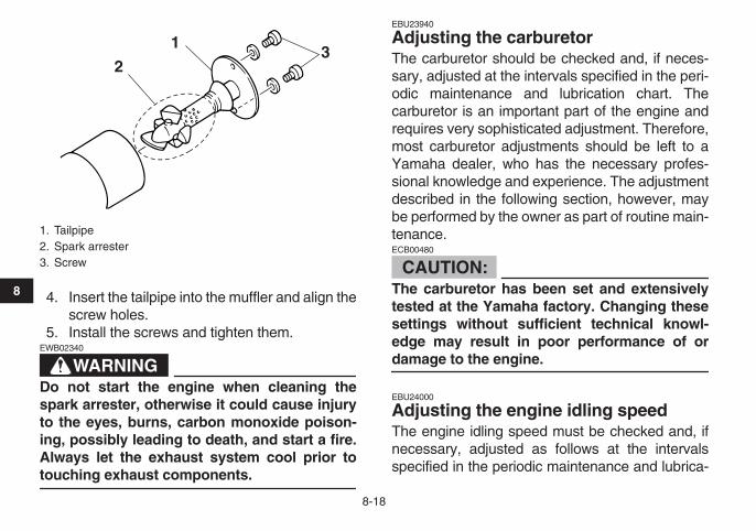
8-18
1
2
3
4
5
6
7
8
9
10
11
4. Insert the tailpipe into the muffler and align thescrew holes.
5. Install the screws and tighten them.
WARNING
EWB02340
Do not start the engine when cleaning thespark arrester, otherwise it could cause injuryto the eyes, burns, carbon monoxide poison-ing, possibly leading to death, and start a fire.Always let the exhaust system cool prior to
touching exhaust components.
EBU23940
Adjusting the carburetor
The carburetor should be checked and, if neces-sary, adjusted at the intervals specified in the peri-odic maintenance and lubrication chart. Thecarburetor is an important part of the engine andrequires very sophisticated adjustment. Therefore,most carburetor adjustments should be left to aYamaha dealer, who has the necessary profes-sional knowledge and experience. The adjustmentdescribed in the following section, however, maybe performed by the owner as part of routine main-tenance.
CAUTION:
ECB00480
The carburetor has been set and extensivelytested at the Yamaha factory. Changing thesesettings without sufficient technical knowl-edge may result in poor performance of or
damage to the engine.
EBU24000
Adjusting the engine idling speed
The engine idling speed must be checked and, ifnecessary, adjusted as follows at the intervalsspecified in the periodic maintenance and lubrica-
1. Tailpipe2. Spark arrester3. Screw
2
13

8-19
1
2
3
4
5
6
7
8
9
10
11
tion chart.
NOTE:
A diagnostic tachometer is needed to make this
adjustment.
1. Start the engine and warm it up.
NOTE:
The engine is warm when it quickly responds to the
throttle.
2. Attach the tachometer to the spark plug lead.3. Check the engine idling speed and, if neces-
sary, adjust it to specification by turning thethrottle stop screw at the carburetor. To in-crease the engine idling speed, turn the throt-tle stop screw in direction (a), and to decreaseit, turn the screw in direction (b). NOTE:
If the specified idling speed cannot be obtained asdescribed above, have a Yamaha dealer make the
adjustment.
EBU27071
Checking the throttle cable free play
The throttle cable free play should be checked atthe intervals specified in the periodic maintenanceand lubrication chart.
1. Throttle stop screw
Engine idling speed:1700–1900 r/min
1
(a)(b)

8-20
1
2
3
4
5
6
7
8
9
10
11
The throttle cable free play should measure 1.0–3.0 mm (0.04–0.12 in) at the throttle lever. Period-ically check the throttle cable free play and, if nec-essary, have a Yamaha dealer adjust it.
EBU24050
Timing chain
The timing chain stretches with use, resulting in im-proper valve timing and engine noise. To preventthis from occurring, the timing chain tensionermust be adjusted by a Yamaha dealer at the inter-vals specified in the periodic maintenance and lu-brication chart.
EBU24060
Valve clearance
The valve clearance changes with use, resulting inimproper air-fuel mixture and/or engine noise. Toprevent this from occurring, the valve clearancemust be adjusted by a Yamaha dealer at the inter-vals specified in the periodic maintenance and lu-brication chart.
EBU24090
Checking the front and rear brake shoes
The front and rear brake shoes must be checkedfor wear at the intervals specified in the periodicmaintenance and lubrication chart. Each brake isprovided with a wear indicator, which allows you tocheck the brake shoe wear without having to dis-assemble the brake. To check the brake shoewear, check the position of the wear indicator whileapplying the brake. If a brake shoe has worn to thepoint that the wear indicator reaches the wear limitline or mark, have a Yamaha dealer replace thebrake shoes as a set.
1. Throttle lever free play
1

8-21
1
2
3
4
5
6
7
8
9
10
11
Front brake Rear brake
EBU24330
Adjusting the front brake lever free play
The brake lever free play must be checked and, ifnecessary, adjusted at the intervals specified inthe periodic maintenance and lubrication chart.
NOTE:
Before adjusting the brake lever free play, check
the front brake shoes for wear.
The brake lever free play should measure 10.0–
1. Wear limit line2. Wear indicator
12
1. Wear limit mark2. Wear indicator
1
2

8-22
1
2
3
4
5
6
7
8
9
10
11
12.0 mm (0.39–0.47 in) as shown. If the free playis incorrect, adjust it as follows.
1. Loosen the upper locknut and fully turn in theupper adjusting bolt.
2. Loosen the lower locknut.3. Turn the lower adjusting bolt in direction (a) to
increase the free play, and in direction (b) todecrease it.
4. Tighten the lower locknut.5. While applying the front brake, turn out the up-
per adjusting bolt until the upper and lower ca-ble lengths are equal. The cable joint willbecome vertical.
1. Brake lever free play
1
1. Upper locknut2. Upper adjusting bolt3. Lower locknut4. Lower adjusting bolt
1 2
43
(a)
(b) (a)
(b)

8-23
1
2
3
4
5
6
7
8
9
10
11
6. Tighten the upper locknut.
WARNING
EWB02080
Operating with improperly serviced or adjust-ed brakes could cause loss of braking ability,which could lead to an accident.After servicing:
�
Make sure the brakes operate smoothly andthat the free play is correct.
�
Make sure the brakes do not drag.Replacement of brake components requiresprofessional knowledge. These procedures
should be performed by a Yamaha dealer.
EBU24473
Adjusting the rear brake lever and brake pedal free play
The brake lever and brake pedal free play must bechecked and, if necessary, adjusted at the inter-vals specified in the periodic maintenance and lu-brication chart.
NOTE:
�
Always perform this maintenance completely inthe following order whenever adjusting the rearbrake.
�
Before adjusting the brake lever and brake pedal
free play, check the rear brake shoes for wear.
Adjusting the brake lever free play
The brake lever free play should measure 5.0–8.0mm (0.20–0.31 in) as shown. If the free play is in-correct, adjust it as follows.
1. Cable joint
1

8-24
1
2
3
4
5
6
7
8
9
10
11
1. Loosen the locknut at the brake lever.2. Turn the brake lever free play adjusting bolt at
the brake lever in direction (a) to increase thefree play, and in direction (b) to decrease it.
3. Tighten the locknut at the brake lever.If the specified free play cannot be obtained,proceed with the following steps.
4. Loosen the locknut at the brake lever.5. Fully turn the adjusting bolt at the brake lever
in direction (a) to loosen the brake cable.6. To increase the brake lever free play, turn the
adjusting nut on the brake cable at the rearwheel hub in direction (a), and to decrease it,turn the nut in direction (b).
7. Tighten the locknut at the crankcase and thebrake lever.
NOTE:
If the specified free play cannot be obtained as de-scribed above or if the rear brake does not operatecorrectly, have a Yamaha dealer check the internalrear brake mechanism.When adjusting the rear brake lever free play:
�
Be sure not to step on the brake pedal.
1. Locknut2. Brake lever free play adjusting bolt3. Brake lever free play
3 1 2 (a)
(b)
1. Brake lever free play adjusting nut
1
(a) (b)

8-25
1
2
3
4
5
6
7
8
9
10
11
�
Make sure the brake pedal does not move.
Adjusting the brake pedal free play
The brake pedal free play should measure 20.0–30.0 mm (0.79–1.18 in) as shown. If the free playis incorrect, adjust it as follows.
Turn the brake pedal free play adjusting nut on thebrake rod at the rear wheel hub in direction (a) toincrease the free play, and in direction (b) to de-crease it.
WARNING
EWB02080
Operating with improperly serviced or adjust-ed brakes could cause loss of braking ability,which could lead to an accident.After servicing:
�
Make sure the brakes operate smoothly andthat the free play is correct.
�
Make sure the brakes do not drag.Replacement of brake components requiresprofessional knowledge. These procedures
should be performed by a Yamaha dealer.
1. Brake pedal free play
1
1. Brake pedal free play adjusting nut
1
(a) (b)

8-26
1
2
3
4
5
6
7
8
9
10
11
EBU24781
Adjusting the clutch free play
The clutch free play must be adjusted periodically.Adjust the free play as follows.1. Remove the rubber cap.2. Loosen the locknut.3. Slowly turn the adjusting bolt clockwise until
resistance is felt, and then turn it 1/8 counter-clockwise.
NOTE:
Turning the adjusting bolt in decreases clutch free
play and turning it out increases clutch free play.
4. Tighten the locknut to the specified torque.
NOTE:
When tightening the locknut, hold the adjustingbolt with a screwdriver so that the adjusting bolt
does not turn together with the locknut.
5. Install the rubber cap securely.
EBU24900
Checking and lubricating the cables
The operation and the condition of all control ca-bles should be checked before each ride, and thecables and cable ends should be lubricated if nec-essary. If a cable is damaged or does not movesmoothly, have a Yamaha dealer check or replaceit.
1. Rubber cap2. Locknut3. Adjusting bolt
1 2
3
Tightening torque:Locknut:
8 Nm (0.8 m·kgf, 5.8 ft·lbf)
Recommended lubricant:Engine oil

8-27
1
2
3
4
5
6
7
8
9
10
11
WARNING
EWB02130
Inspect cables frequently and replace if dam-aged. Corrosion can result when the cablesheaths become damaged, and cables canalso become frayed or kinked, which could re-strict the operation of controls and lead to an
accident or injury.
EBU28700
Checking and lubricating the front and rear brake levers
The operation of the front and rear brake leversshould be checked before each ride, and the leverpivots should be lubricated if necessary.
Front brake lever
Rear brake lever
Recommended lubricant:Lithium-soap-based grease

8-28
1
2
3
4
5
6
7
8
9
10
11
EBU28840
Checking and lubricating the brake and shift pedals
The operation of the brake and shift pedals shouldbe checked before each ride, and the pedal pivotsshould be lubricated if necessary.
EBU24962
Checking the wheel hub bearings
The front and rear wheel hub bearings must bechecked at the intervals specified in the periodicmaintenance and lubrication chart. If there is playin a wheel hub or if a wheel does not turn smoothly,have a Yamaha dealer check the wheel hub bear-ings.
EBU28820
Lubricating the front knuckle pivots
The front knuckle pivots must be lubricated at theintervals specified in the periodic maintenance andlubrication chart.Lubricate the front knuckle pivots using a greasegun.
EBU25100
Lubricating the steering shaft
The steering shaft must be lubricated at the inter-vals specified in the periodic maintenance and lu-brication chart.
Recommended lubricant:Lithium-soap-based grease (all-purpose grease)
Recommended lubricant:Lithium-soap-based grease
1. Grease nipple
1

8-29
1
2
3
4
5
6
7
8
9
10
11
EBU25121
Battery
A poorly maintained battery will corrode and dis-charge quickly. The electrolyte level, battery leadconnections and breather hose routing should bechecked before each ride and at the intervalsspecified in the periodic maintenance and lubrica-tion chart.
To check the electrolyte level
1. Place the ATV on a level surface.2. Check the electrolyte level in the battery.
NOTE:
The electrolyte should be between the minimum
and maximum level marks.
3. If the electrolyte is at or below the minimumlevel mark, add distilled water to raise it to themaximum level mark.
CAUTION:
ECB00590
Use only distilled water, as tap water contains
minerals that are harmful to the battery.
WARNING
EWB02160
Battery electrolyte is poisonous and danger-ous, as it contains sulfuric acid, which cancause severe burns. Avoid contact with skin,eyes or clothing. Always shield your eyeswhen working near batteries.
Recommended lubricant:Lithium-soap-based grease
1. Maximum level mark2. Minimum level mark
1
2

8-30
1
2
3
4
5
6
7
8
9
10
11
Antidote:EXTERNAL: Flush with water.INTERNAL: Drink large quantities of water ormilk. Follow with milk of magnesia, beaten eggor vegetable oil. Call a physician immediately.EYES: Flush with water for 15 minutes and getprompt medical attention.Batteries produce explosive gases. Keepsparks, flame, cigarettes or other sources of ig-nition away. Ventilate when charging or usingin an enclosed space.
KEEP OUT OF REACH OF CHILDREN.
4. Check and, if necessary, tighten the batterylead connections and correct the breatherhose routing.
To store the battery
If the ATV will not be used for more than onemonth, the battery will need to be removed andstored as follows.1. Disconnect the negative lead first and then the
positive lead.
2. Remove the battery, fully charge it, and thenplace it in a cool, dry place.
CAUTION:
ECB00600
Do not leave or store the battery on its side.
3. If the battery will be stored for more than twomonths, check the specific gravity of the elec-trolyte at least once a month and fully chargethe battery whenever necessary.
1. Battery2. Negative battery lead (black)3. Positive battery lead (red)
2
3
1

8-31
1
2
3
4
5
6
7
8
9
10
11
To install the battery
NOTE:
Be sure the battery is fully charged.
1. Install the battery.2. Connect the positive lead first, and then con-
nect the negative lead.3. Make sure that the breather hose is properly
routed, in good condition, and not obstructed.
CAUTION:
ECB00610
If the breather hose is positioned in such a way
that the frame is exposed to electrolyte or gasexpelled from the battery, the frame could suf-
fer structural and external damages.
EBU25242
Replacing the fuse
The fuse holder is located under the seat. (Seepage 4-10.)If the fuse is blown, replace it as follows.1. Turn the key to “OFF” and turn off all electrical
circuits.
1. Battery2. Battery breather hose
12
1. Fuse2. Spare fuse
1
2

8-32
1
2
3
4
5
6
7
8
9
10
11
CAUTION:
ECB00640
To prevent accidental short-circuiting, turn offthe main switch when checking or replacing a
fuse.
2. Remove the blown fuse, and then install anew fuse of the specified amperage.
WARNING
EWB02171
Always use a fuse of the specified rating, andnever use a substitute object in place of theproper fuse. An improper fuse or a substituteobject can cause damage to the electrical sys-
tem, which could lead to a fire.
3. Turn the key to “ON” and turn on the electricalcircuits to check if the devices operate.
4. If the fuse immediately blows again, have aYamaha dealer check the electrical system.
EBU25650
Removing a wheel
1. Loosen the wheel nuts.
Front
Specified fuse:5.0 A
1. Wheel nut
1
1

8-33
1
2
3
4
5
6
7
8
9
10
11
Rear
2. Elevate the ATV and place a suitable standunder the frame.
3. Remove the nuts from the wheel.4. Remove the wheel.
EBU25660
Installing a wheel
1. Install the wheel and the nuts.2. Lower the ATV to the ground.3. Tighten the wheel nuts to the specified
torques.
EBU25720
Troubleshooting
Although Yamaha ATVs receive a thorough in-spection before shipment from the factory, troublemay occur during operation. Any problem in the fu-el, compression, or ignition systems, for example,can cause poor starting and loss of power.The following troubleshooting chart represents aquick and easy procedure for checking these vitalsystems yourself. However, should your ATV re-quire any repair, take it to a Yamaha dealer, whoseskilled technicians have the necessary tools, expe-rience, and know-how to service the ATV properly.Use only genuine Yamaha replacement parts. Im-itation parts may look like Yamaha parts, but theyare often inferior, have a shorter service life andcan lead to expensive repair bills.
1. Wheel nut
1
Tightening torques:Front wheel nut:
28 Nm (2.8 m·kgf, 20.3 ft·lbf)Rear wheel nut:
28 Nm (2.8 m·kgf, 20.3 ft·lbf)

8-34
1
2
3
4
5
6
7
8
9
10
11
WARNING
EWB02280
Do not smoke when checking the fuel system.Fuel can ignite or explode, causing severe inju-ry or property damage. Make sure there are noopen flames or sparks in the area, including pi-
lot lights from water heaters or furnaces.

8-35
1
2
3
4
5
6
7
8
9
10
11
EBU25791
Troubleshooting chart
Check the fuel level inthe fuel tank.
1. FuelThere is enough fuel.
There is no fuel.
Check the compression.
Supply fuel. The engine does not start. Check the compression.
Operate the electric starter.
2. CompressionThere is compression.
There is no compression.
Check the ignition.
Have a Yamaha dealercheck the ATV.
Remove the spark plugand check the electrodes.
3. Ignition Wipe off with a dry cloth and correct thespark plug gap, or replace the spark plug.
Have a Yamaha dealer check the ATV.
The engine does not start.Have a Yamaha dealercheck the ATV.
The engine does not start.Check the battery.
Operate the electric starter.
4. BatteryThe engine turns over quickly.
The engine turns over slowly.
The battery is good.
Check the electrolyte level, recharge thebattery and check the lead connections.
Dry
WetOpen the throttle halfway and operatethe electric starter.

9-1
1
2
3
4
5
6
7
8
9
10
11
EBU25860
CLEANING AND STORAGE
EBU25880
Cleaning
Frequent, thorough cleaning of your ATV will notonly enhance its appearance but will improve itsgeneral performance and extend the useful life ofmany components.1. Before cleaning the ATV:
a. Block off the end of the exhaust pipe toprevent water entry. A plastic bag andstrong rubber band may be used.
b. Make sure the spark plug and all filler capsare properly installed.
2. If the engine case is excessively greasy, applydegreaser with a paint brush. Do not apply de-greaser to the wheel axles.
3. Rinse the dirt and degreaser off with a gardenhose. Use only enough pressure to do the job.
CAUTION:
ECB00710
Excessive water pressure may cause waterseepage and deterioration of wheel bearings,brakes, transmission seals and electrical de-vices. Many expensive repair bills have result-ed from improper high-pressure detergent
applications such as those available in coin-
operated car washers.
4. Once most of the dirt has been hosed off,wash all surfaces with warm water and mild,detergent-type soap. An old toothbrush or bot-tle brush is handy for hard-to-reach places.
5. Rinse the ATV off immediately with clean wa-ter and dry all surfaces with a chamois, cleantowel or soft absorbing cloth.
6. Clean the seat with a vinyl upholstery cleanerto keep the cover pliable and glossy.
7. Automotive type wax may be applied to allpainted and chrome plated surfaces. Avoidcombination cleaner-waxes. Many containabrasives which may mar the paint or protec-tive finish. When finished cleaning, start theengine and let it idle for several minutes.
WARNING
EWB02310
Wet brakes may have reduced stopping ability,increasing the chance of an accident. Test thebrakes after washing. Apply the brakes severaltimes at slow speeds to let friction dry out the

9-2
1
2
3
4
5
6
7
8
9
10
11
linings.
EBU25932
Storage
Short-term
Always store your ATV in a cool, dry place and, ifnecessary, protect it against dust with a porouscover.
CAUTION:
ECB00720
�
Storing the ATV in a poorly ventilated roomor covering it with a tarp while it is still wet,will allow water and humidity to seep in andcause rust.
�
To prevent corrosion, avoid damp cellars,stables (because of the presence of ammo-nia) and areas where strong chemicals are
stored.
Long-term
Before storing your ATV for several months:1. Follow all the instructions in the “Cleaning”
section of this chapter.2. Turn the fuel cock lever to “OFF”.3. Drain the carburetor float chamber by loosen-
ing the drain bolt; this will prevent fuel depositsfrom building up. Pour the drained fuel into thefuel tank.
4. Fill up the fuel tank and add fuel stabilizer (ifavailable) to prevent the fuel from deteriorat-ing.
5. Perform the following steps to protect the cyl-inder, piston rings, etc. from corrosion.a. Remove the spark plug cap and spark
plug.b. Pour a teaspoonful of engine oil into the
spark plug bore.c. Install the spark plug cap onto the spark
plug, and then place the spark plug on thecylinder head so that the electrodes aregrounded. (This will limit sparking duringthe next step.)
d. Turn the engine over several times withthe starter. (This will coat the cylinder wallwith oil.)
e. Remove the spark plug cap from the sparkplug, and then install the spark plug and
Specified amount:7.5 ml of stabilizer to each liter of fuel (or 1 oz of stabilizer to each gallon of fuel)

9-3
1
2
3
4
5
6
7
8
9
10
11
the spark plug cap.6. Lubricate all control cables and the pivoting
points of all levers and pedals.7. Check and, if necessary, correct the tire air
pressure, and then block up the ATV so thatall of its wheels are off the ground. Alternative-ly, turn the wheels a little every month in orderto prevent the tires from becoming degradedin one spot.
8. Cover the muffler outlet with a plastic bag toprevent moisture from entering it.
9. Remove the battery and fully charge it. Storeit in a cool, dry place and charge it once amonth. Do not store the battery in an exces-sively cold or warm place [less than 0 °C (30°F) or more than 30 °C (90 °F)]. For more in-formation on storing the battery, see page8-29.
NOTE:
Make any necessary repairs before storing the
ATV.

10-1
1
2
3
4
5
6
7
8
9
10
11
EBU25960
SPECIFICATIONS
EBU2597A
Dimensions:
Overall length: 1537 mm (60.5 in)
Overall width: 841 mm (33.1 in)
Overall height: 940 mm (37.0 in)
Seat height: 669 mm (26.3 in)
Wheelbase: 1030 mm (40.6 in)
Ground clearance: 100 mm (3.9 in)
Minimum turning radius: 2400 mm (94 in)
Weight:
With oil and fuel: 116.0 kg (256 lb)
Engine:
Engine type: Air cooled 4-stroke, SOHC
Cylinder arrangement: Forward-inclined single cylinder
Displacement: 79.0 cm
3
Bore
×
stroke: 47.0
×
45.6 mm
Compression ratio: 9.60 :1
Starting system: Electric starter
Lubrication system: Wet sump
Engine oil:
Type: SAE5W30 or SAE10W30 or SAE10W40 or SAE15W40or SAE20W40 or SAE20W50
Recommended engine oil grade: API service SG type or higher, JASO standard MA
-20˚ -10˚ 0˚ 10˚ 20˚ 30˚ 40˚ 50˚C
10W/30
15W/40
20W/40
20W/50
10W/40
5W/30

10-2
1
2
3
4
5
6
7
8
9
10
11
Engine oil quantity:Periodic oil change:
0.80 L (0.85 US qt) (0.70 Imp.qt)
Final gear oil:
Type: SAE80 API GL-4 Hypoid gear oil
Quantity: 0.12 L (0.13 US qt) (0.11 Imp.qt)
Air filter:
Air filter element: Wet element
Fuel:
Recommended fuel: Regular unleaded gasoline only (EUR)Unleaded gasoline only (AUS)(NZL)
Fuel tank capacity: 6.8 L (1.80 US gal) (1.50 Imp.gal)
Fuel reserve amount: 0.9 L (0.24 US gal) (0.20 Imp.gal)
Carburetor:
Manufacturer: MIKUNI
Type x quantity: VM16SH x 1
Spark plug (s):
Manufacturer/model: NGK/CR7HSA
Spark plug gap: 0.6–0.7 mm (0.024–0.028 in)
Clutch:
Clutch type: Wet, multiple-disc automatic
Transmission:
Primary reduction system: Spur gear
Primary reduction ratio: 65/20 (3.250)
Secondary reduction system: Shaft drive
Secondary reduction ratio: 19/18
×
34/10 (3.588)Transmission type:
Constant mesh 3-speedOperation:
Left foot operation1st:
39/11 (3.545)2nd:
35/17 (2.059)3rd:
31/22 (1.409)
Chassis:
Frame type: Steel tube frame
Caster angle: 1.0 °
Trail: 3.8 mm (0.15 in)

10-3
1
2
3
4
5
6
7
8
9
10
11
Front tire:
Type: Tubeless
Size: AT18 x 7-7
Manufacturer/model: DUNLOP/KT586
Rear tire:
Type: Tubeless
Size: AT18 x 8-7
Manufacturer/model: DUNLOP/KT587
Loading:
Maximum loading limit: 95.0 kg (209 lb)(Total weight of rider, cargo, accessories, and tongue)
Tire air pressure (measured on cold tires):
Recommended:Front:
20 kPa (2.9 psi) (0.20 kgf/cm
2
)Rear:
20 kPa (2.9 psi) (0.20 kgf/cm
2
)Minimum:
Front: 17 kPa (2.5 psi) (0.17 kgf/cm
2
)Rear:
17 kPa (2.5 psi) (0.17 kgf/cm
2
)
Maximum:Front:
23 kPa (3.3 psi) (0.23 kgf/cm
2
)Rear:
23 kPa (3.3 psi) (0.23 kgf/cm
2
)
Front wheel:
Wheel type: Panel wheel
Rim size: 7 x 5.5AT
Rear wheel:
Wheel type: Panel wheel
Rim size: 7 x 6.5AT
Front brake:
Type: Drum brake
Operation: Right hand operation
Rear brake:
Type: Drum brake
Operation: Left hand and right foot operation
Front suspension:
Type: Leading arm
Spring/shock absorber type: Coil spring/oil damper

10-4
1
2
3
4
5
6
7
8
9
10
11
Wheel travel: 57 mm (2.3 in)
Rear suspension:
Type: Swingarm
Spring/shock absorber type: Coil spring/oil damper
Wheel travel: 56 mm (2.2 in)
Electrical system:
Ignition system: CDI
Charging system: AC magneto
Battery:
Model: 12N7D-3B
Voltage, capacity: 12 V, 7.0 Ah
Bulb voltage, wattage x quantity:
Neutral indicator light: 12 V, 1.7 W
×
1
Fuses:
Main fuse: 5.0 A

11-1
1
2
3
4
5
6
7
8
9
10
11
EBU26000
CONSUMER INFORMATION
EBU26011
Identification numbers
Record the key identification number, vehicle iden-tification number and model label information inthe spaces provided below for assistance when or-dering spare parts from a Yamaha dealer or for ref-erence in case the ATV is stolen.
�
KEY IDENTIFICATION NUMBER:
�
VEHICLE IDENTIFICATION NUMBER:
�
MODEL LABEL INFORMATION:
EBU26020
Key identification number
The key identification number is stamped into thekey. Record this number in the space provided anduse it for reference when ordering a new key.
EBU26030
Vehicle identification number
The vehicle identification number is stamped intothe frame.
1. Key identification number
1

11-2
1
2
3
4
5
6
7
8
9
10
11
NOTE:
The vehicle identification number is used to identi-
fy your ATV.
EBU26050
Model label
The model label is affixed at the location in the il-lustration. Record the information on this label inthe space provided. This information will be need-ed when ordering spare parts from a Yamaha deal-er.
1. Vehicle identification number
1
1. Model label
1

INDEX
A
Accessories and loading ................................................ 6-7Air filter element, cleaning............................................ 8-13Air intake restrictor plate, removing.............................. 8-17
B
Battery.................................................................. 5-6
,
8-29Brake and shift pedals, checking and lubricating ......... 8-28Brake lever and brake pedal free play (rear),
adjusting..................................................................... 8-23Brake lever free play, adjusting the front...................... 8-21Brake lever, front............................................................ 4-4Brake levers, checking and lubricating......................... 8-27Brake pedal and rear brake lever................................... 4-5Brakes, front and rear .................................................... 5-3Brake shoes, checking the front and rear .................... 8-20
C
Cables, checking and lubricating ................................. 8-26Carburetor, adjusting.................................................... 8-18Chassis fasteners........................................................... 5-6Choke........................................................................... 4-10Cleaning ......................................................................... 9-1Clutch free play, adjusting............................................ 8-26
E
Engine break-in .............................................................. 6-5Engine, cold start ........................................................... 6-1Engine idling speed...................................................... 8-18
Engine oil ............................................................... 5-3
,
8-9Engine, starting a warm ................................................. 6-3Engine stop switch ......................................................... 4-2
F
Final gear oil......................................................... 5-3
,
8-12Front knuckle pivots, lubricating................................... 8-28Fuel ........................................................................ 4-7
,
5-3Fuel cock........................................................................ 4-8Fuel tank cap.................................................................. 4-7Fuse, replacing............................................................. 8-31
H
Handlebar switches........................................................ 4-2
I
Identification numbers .................................................. 11-1Indicator light.................................................................. 4-1Instruments, lights and switches .................................... 5-6
K
Key identification number............................................. 11-1
L
Label locations ............................................................... 2-1
M
Main switch .................................................................... 4-1Maintenance and lubrication chart ................................. 8-5Maintenance chart, emission control system ................. 8-3Model label................................................................... 11-2

N
Neutral indicator light ..................................................... 4-1
O
Owner’s manual and tool kit ........................................... 8-1
P
Parking ........................................................................... 6-5Parking brake ................................................................. 4-6Parking on a slope ......................................................... 6-6Part locations ................................................................. 3-1Pre-operation check list.................................................. 5-1
R
Riding your ATV ............................................................. 7-1
S
Safety information .......................................................... 1-1Seat.............................................................................. 4-10Shifting ........................................................................... 6-3Shift pedal ...................................................................... 4-6Spark arrester, cleaning ............................................... 8-17Spark plug, checking...................................................... 8-8Specifications ............................................................... 10-1Speed limiter and air intake restrictor plate.................... 4-3Start switch..................................................................... 4-2Steering shaft, lubricating............................................. 8-28Storage........................................................................... 9-2
T
Throttle cable free play, checking ................................ 8-19Throttle lever .......................................................... 4-2
,
5-4Timing chain................................................................. 8-20Tire pressure, measuring ............................................... 5-5Tires ............................................................................... 5-4Tire wear limit................................................................. 5-6
Troubleshooting ........................................................... 8-33Troubleshooting chart .................................................. 8-35
V
Valve clearance............................................................ 8-20Vehicle identification number ....................................... 11-1
W
Wheel hub bearings, checking ..................................... 8-28Wheel, installing ........................................................... 8-33Wheel, removing .......................................................... 8-32


PRINTED IN JAPAN2007.05-0.3x1 !
(E)
YAMAHA MOTOR CO., LTD.PRINTED ON RECYCLED PAPER