

ManualsLib - Makes it easy to find manuals online! - Mr Memory
230
Aspire MS2361 SERVICE GUIDE Downloaded from www.Manualslib.com manuals search engine
-
Upload
khangminh22 -
Category
Documents
-
view
2 -
download
0
Transcript of ManualsLib - Makes it easy to find manuals online! - Mr Memory
Aspire MS2361
SERVICEGUIDE
Downloaded from www.Manualslib.com manuals search engine
ii
Revision HistoryRefer to the table below for the updates made to this Aspire MS2361 Service Guide.
Service guide files and updates are available on the ACER/CSD website. For more information, go to http://csd.acer.com.tw.The information in this guide is subject to change without notice.
DisclaimerThe information in this guide is subject to change without notice.
There are no representations or warranties, either expressed or implied, with respect to the contents hereof and specifically disclaims any warranties of merchantability or fitness for any particular purpose. The software described in this manual is sold or licensed "as is". Should the programs prove defective following their purchase, the buyer (not the manufacturer, distributor, or its dealer) assumes the entire cost of all necessary servicing, repair, and any incidental or consequential damages resulting from any defect in the software.
Copyright© 2012 by Acer Incorporated. All rights reserved. No part of this publication may be reproduced, transmitted, transcribed, stored in a retrieval system, or translated into any language or computer language, in any form or by any means, electronic, mechanical, magnetic, optical, chemical, manual or otherwise, without the prior written permission of Acer Incorporated.
HDMI, the HDMI logo, and High Definition Multimedia Interface are trademarks or registered trademarks of HDMI Licensing, LLC in the United States and other countries.
Date Chapter Updates
Downloaded from www.Manualslib.com manuals search engine
iii
ConventionsThe following conventions are used in this manual:
WARNING:!Indicates a potential for personal injury.
CAUTION:!Indicates a potential loss of data or damage to equipment.
IMPORTANT:+Indicates information that is important to know for the proper completion of a procedure, choice of an option, or completing a task.
The following typographical conventions are used in this document:
Book titles, directory names, file names, path names, and program/process names are shown in italics.
Example:
the DRS5 User's Guide
/usr/local/bin/fd
the /TPH15spool_M program
Computer output (text that represents information displayed on a computer screen, such as menus, prompts, responses to input, and error messages) are shown in constant width.
Example:
[01] The server has been stopped
User input (text that represents information entered by a computer user, such as command names, option letters, and words) are shown in constant width bold.
Variables contained within user input are shown in angle brackets (< >).
Example:
At the prompt, type run <file name> -m
Keyboard keys are shown in bold italics.
Example:
After entering data, press Enter.
Downloaded from www.Manualslib.com manuals search engine
iv
General information 0
Before using this information and the product it supports, read the following general information.
This service guide provides you with all technical information relating to the basic configuration for Acer’s global product offering. To better fit local market requirements and enhance product competitiveness, your regional office may have decided to extend the functionality of a machine (such as add-on cards, modems, or extra memory capabilities). These localized features are not covered in this generic service guide. In such cases, contact your regional office or the responsible personnel/channel to provide you with further technical details.
When ordering FRU parts: Check the most up-to-date information available on your regional Web or channel. If, for whatever reason, a part number change is made, it may not be noted in this printed service guide.
Acer-authorized Service Providers: Your Acer office may have a different part number code than those given in the FRU list in this service guide. You must use the list provided by your regional Acer office to order FRU parts for repair and service of customer machines.
Downloaded from www.Manualslib.com manuals search engine
v
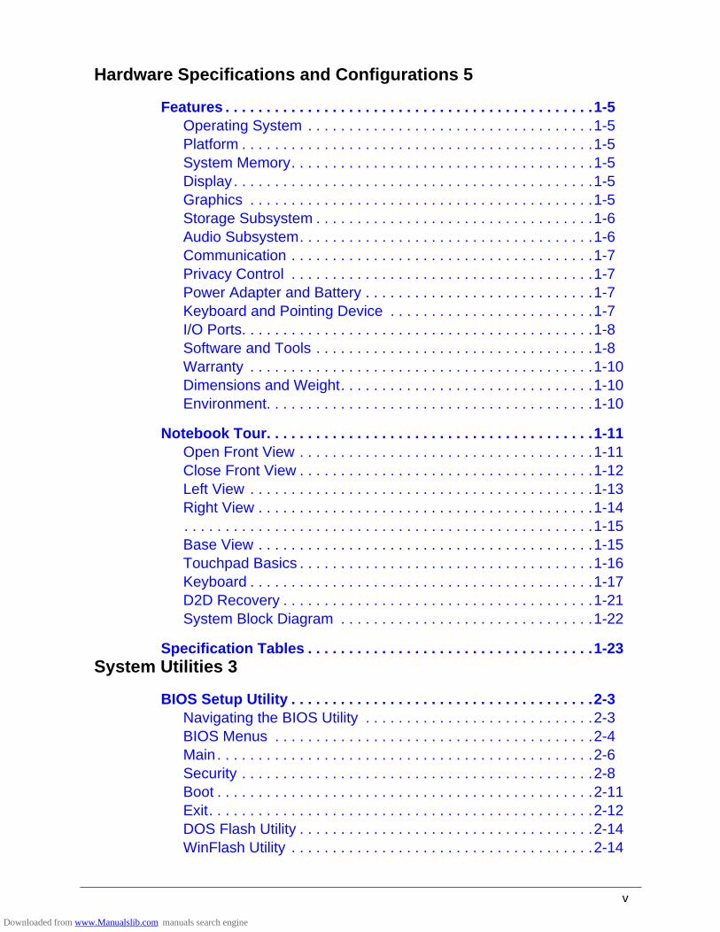
Hardware Specifications and Configurations 5
Features . . . . . . . . . . . . . . . . . . . . . . . . . . . . . . . . . . . . . . . . . . . . .1-5Operating System . . . . . . . . . . . . . . . . . . . . . . . . . . . . . . . . . . .1-5Platform . . . . . . . . . . . . . . . . . . . . . . . . . . . . . . . . . . . . . . . . . . .1-5System Memory. . . . . . . . . . . . . . . . . . . . . . . . . . . . . . . . . . . . .1-5Display . . . . . . . . . . . . . . . . . . . . . . . . . . . . . . . . . . . . . . . . . . . .1-5Graphics . . . . . . . . . . . . . . . . . . . . . . . . . . . . . . . . . . . . . . . . . .1-5Storage Subsystem . . . . . . . . . . . . . . . . . . . . . . . . . . . . . . . . . .1-6Audio Subsystem. . . . . . . . . . . . . . . . . . . . . . . . . . . . . . . . . . . .1-6Communication . . . . . . . . . . . . . . . . . . . . . . . . . . . . . . . . . . . . .1-7Privacy Control . . . . . . . . . . . . . . . . . . . . . . . . . . . . . . . . . . . . .1-7Power Adapter and Battery . . . . . . . . . . . . . . . . . . . . . . . . . . . .1-7Keyboard and Pointing Device . . . . . . . . . . . . . . . . . . . . . . . . .1-7I/O Ports. . . . . . . . . . . . . . . . . . . . . . . . . . . . . . . . . . . . . . . . . . .1-8Software and Tools . . . . . . . . . . . . . . . . . . . . . . . . . . . . . . . . . .1-8Warranty . . . . . . . . . . . . . . . . . . . . . . . . . . . . . . . . . . . . . . . . . .1-10Dimensions and Weight. . . . . . . . . . . . . . . . . . . . . . . . . . . . . . .1-10Environment. . . . . . . . . . . . . . . . . . . . . . . . . . . . . . . . . . . . . . . .1-10
Notebook Tour. . . . . . . . . . . . . . . . . . . . . . . . . . . . . . . . . . . . . . . .1-11Open Front View . . . . . . . . . . . . . . . . . . . . . . . . . . . . . . . . . . . .1-11Close Front View . . . . . . . . . . . . . . . . . . . . . . . . . . . . . . . . . . . .1-12Left View . . . . . . . . . . . . . . . . . . . . . . . . . . . . . . . . . . . . . . . . . .1-13Right View . . . . . . . . . . . . . . . . . . . . . . . . . . . . . . . . . . . . . . . . .1-14. . . . . . . . . . . . . . . . . . . . . . . . . . . . . . . . . . . . . . . . . . . . . . . . . .1-15Base View . . . . . . . . . . . . . . . . . . . . . . . . . . . . . . . . . . . . . . . . .1-15Touchpad Basics . . . . . . . . . . . . . . . . . . . . . . . . . . . . . . . . . . . .1-16Keyboard . . . . . . . . . . . . . . . . . . . . . . . . . . . . . . . . . . . . . . . . . .1-17D2D Recovery . . . . . . . . . . . . . . . . . . . . . . . . . . . . . . . . . . . . . .1-21System Block Diagram . . . . . . . . . . . . . . . . . . . . . . . . . . . . . . .1-22
Specification Tables . . . . . . . . . . . . . . . . . . . . . . . . . . . . . . . . . . .1-23System Utilities 3
BIOS Setup Utility . . . . . . . . . . . . . . . . . . . . . . . . . . . . . . . . . . . . .2-3Navigating the BIOS Utility . . . . . . . . . . . . . . . . . . . . . . . . . . . .2-3BIOS Menus . . . . . . . . . . . . . . . . . . . . . . . . . . . . . . . . . . . . . . .2-4Main. . . . . . . . . . . . . . . . . . . . . . . . . . . . . . . . . . . . . . . . . . . . . .2-6Security . . . . . . . . . . . . . . . . . . . . . . . . . . . . . . . . . . . . . . . . . . .2-8Boot . . . . . . . . . . . . . . . . . . . . . . . . . . . . . . . . . . . . . . . . . . . . . .2-11Exit. . . . . . . . . . . . . . . . . . . . . . . . . . . . . . . . . . . . . . . . . . . . . . .2-12DOS Flash Utility . . . . . . . . . . . . . . . . . . . . . . . . . . . . . . . . . . . .2-14WinFlash Utility . . . . . . . . . . . . . . . . . . . . . . . . . . . . . . . . . . . . .2-14
Downloaded from www.Manualslib.com manuals search engine
vi
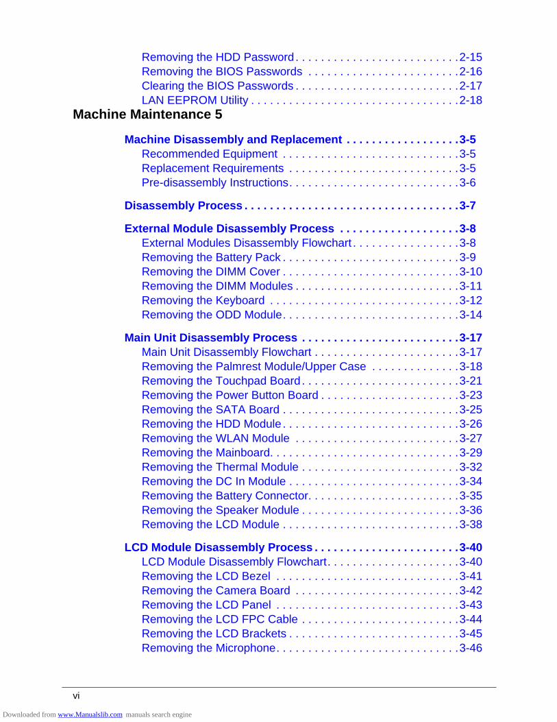
Removing the HDD Password . . . . . . . . . . . . . . . . . . . . . . . . . .2-15Removing the BIOS Passwords . . . . . . . . . . . . . . . . . . . . . . . .2-16Clearing the BIOS Passwords . . . . . . . . . . . . . . . . . . . . . . . . . .2-17LAN EEPROM Utility . . . . . . . . . . . . . . . . . . . . . . . . . . . . . . . . .2-18
Machine Maintenance 5
Machine Disassembly and Replacement . . . . . . . . . . . . . . . . . .3-5Recommended Equipment . . . . . . . . . . . . . . . . . . . . . . . . . . . .3-5Replacement Requirements . . . . . . . . . . . . . . . . . . . . . . . . . . .3-5Pre-disassembly Instructions. . . . . . . . . . . . . . . . . . . . . . . . . . .3-6
Disassembly Process . . . . . . . . . . . . . . . . . . . . . . . . . . . . . . . . . .3-7
External Module Disassembly Process . . . . . . . . . . . . . . . . . . .3-8External Modules Disassembly Flowchart . . . . . . . . . . . . . . . . .3-8Removing the Battery Pack . . . . . . . . . . . . . . . . . . . . . . . . . . . .3-9Removing the DIMM Cover . . . . . . . . . . . . . . . . . . . . . . . . . . . .3-10Removing the DIMM Modules . . . . . . . . . . . . . . . . . . . . . . . . . .3-11Removing the Keyboard . . . . . . . . . . . . . . . . . . . . . . . . . . . . . .3-12Removing the ODD Module. . . . . . . . . . . . . . . . . . . . . . . . . . . .3-14
Main Unit Disassembly Process . . . . . . . . . . . . . . . . . . . . . . . . .3-17Main Unit Disassembly Flowchart . . . . . . . . . . . . . . . . . . . . . . .3-17Removing the Palmrest Module/Upper Case . . . . . . . . . . . . . .3-18Removing the Touchpad Board . . . . . . . . . . . . . . . . . . . . . . . . .3-21Removing the Power Button Board . . . . . . . . . . . . . . . . . . . . . .3-23Removing the SATA Board . . . . . . . . . . . . . . . . . . . . . . . . . . . .3-25Removing the HDD Module . . . . . . . . . . . . . . . . . . . . . . . . . . . .3-26Removing the WLAN Module . . . . . . . . . . . . . . . . . . . . . . . . . .3-27Removing the Mainboard. . . . . . . . . . . . . . . . . . . . . . . . . . . . . .3-29Removing the Thermal Module . . . . . . . . . . . . . . . . . . . . . . . . .3-32Removing the DC In Module . . . . . . . . . . . . . . . . . . . . . . . . . . .3-34Removing the Battery Connector. . . . . . . . . . . . . . . . . . . . . . . .3-35Removing the Speaker Module . . . . . . . . . . . . . . . . . . . . . . . . .3-36Removing the LCD Module . . . . . . . . . . . . . . . . . . . . . . . . . . . .3-38
LCD Module Disassembly Process . . . . . . . . . . . . . . . . . . . . . . .3-40LCD Module Disassembly Flowchart. . . . . . . . . . . . . . . . . . . . .3-40Removing the LCD Bezel . . . . . . . . . . . . . . . . . . . . . . . . . . . . .3-41Removing the Camera Board . . . . . . . . . . . . . . . . . . . . . . . . . .3-42Removing the LCD Panel . . . . . . . . . . . . . . . . . . . . . . . . . . . . .3-43Removing the LCD FPC Cable . . . . . . . . . . . . . . . . . . . . . . . . .3-44Removing the LCD Brackets . . . . . . . . . . . . . . . . . . . . . . . . . . .3-45Removing the Microphone. . . . . . . . . . . . . . . . . . . . . . . . . . . . .3-46
Downloaded from www.Manualslib.com manuals search engine
vii
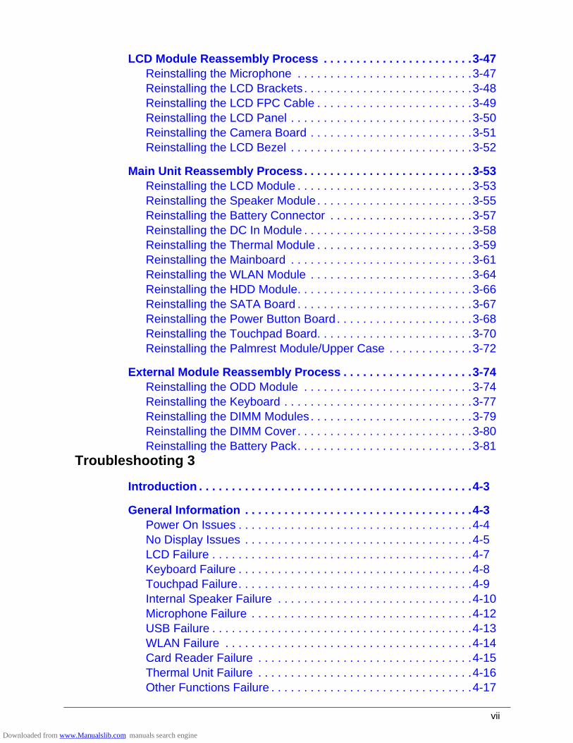
LCD Module Reassembly Process . . . . . . . . . . . . . . . . . . . . . . .3-47Reinstalling the Microphone . . . . . . . . . . . . . . . . . . . . . . . . . . .3-47Reinstalling the LCD Brackets . . . . . . . . . . . . . . . . . . . . . . . . . .3-48Reinstalling the LCD FPC Cable . . . . . . . . . . . . . . . . . . . . . . . .3-49Reinstalling the LCD Panel . . . . . . . . . . . . . . . . . . . . . . . . . . . .3-50Reinstalling the Camera Board . . . . . . . . . . . . . . . . . . . . . . . . .3-51Reinstalling the LCD Bezel . . . . . . . . . . . . . . . . . . . . . . . . . . . .3-52
Main Unit Reassembly Process. . . . . . . . . . . . . . . . . . . . . . . . . .3-53Reinstalling the LCD Module . . . . . . . . . . . . . . . . . . . . . . . . . . .3-53Reinstalling the Speaker Module . . . . . . . . . . . . . . . . . . . . . . . .3-55Reinstalling the Battery Connector . . . . . . . . . . . . . . . . . . . . . .3-57Reinstalling the DC In Module . . . . . . . . . . . . . . . . . . . . . . . . . .3-58Reinstalling the Thermal Module . . . . . . . . . . . . . . . . . . . . . . . .3-59Reinstalling the Mainboard . . . . . . . . . . . . . . . . . . . . . . . . . . . .3-61Reinstalling the WLAN Module . . . . . . . . . . . . . . . . . . . . . . . . .3-64Reinstalling the HDD Module. . . . . . . . . . . . . . . . . . . . . . . . . . .3-66Reinstalling the SATA Board . . . . . . . . . . . . . . . . . . . . . . . . . . .3-67Reinstalling the Power Button Board . . . . . . . . . . . . . . . . . . . . .3-68Reinstalling the Touchpad Board. . . . . . . . . . . . . . . . . . . . . . . .3-70Reinstalling the Palmrest Module/Upper Case . . . . . . . . . . . . .3-72
External Module Reassembly Process . . . . . . . . . . . . . . . . . . . .3-74Reinstalling the ODD Module . . . . . . . . . . . . . . . . . . . . . . . . . .3-74Reinstalling the Keyboard . . . . . . . . . . . . . . . . . . . . . . . . . . . . .3-77Reinstalling the DIMM Modules . . . . . . . . . . . . . . . . . . . . . . . . .3-79Reinstalling the DIMM Cover . . . . . . . . . . . . . . . . . . . . . . . . . . .3-80Reinstalling the Battery Pack. . . . . . . . . . . . . . . . . . . . . . . . . . .3-81
Troubleshooting 3
Introduction . . . . . . . . . . . . . . . . . . . . . . . . . . . . . . . . . . . . . . . . . .4-3
General Information . . . . . . . . . . . . . . . . . . . . . . . . . . . . . . . . . . .4-3Power On Issues . . . . . . . . . . . . . . . . . . . . . . . . . . . . . . . . . . . .4-4No Display Issues . . . . . . . . . . . . . . . . . . . . . . . . . . . . . . . . . . .4-5LCD Failure . . . . . . . . . . . . . . . . . . . . . . . . . . . . . . . . . . . . . . . .4-7Keyboard Failure . . . . . . . . . . . . . . . . . . . . . . . . . . . . . . . . . . . .4-8Touchpad Failure. . . . . . . . . . . . . . . . . . . . . . . . . . . . . . . . . . . .4-9Internal Speaker Failure . . . . . . . . . . . . . . . . . . . . . . . . . . . . . .4-10Microphone Failure . . . . . . . . . . . . . . . . . . . . . . . . . . . . . . . . . .4-12USB Failure . . . . . . . . . . . . . . . . . . . . . . . . . . . . . . . . . . . . . . . .4-13WLAN Failure . . . . . . . . . . . . . . . . . . . . . . . . . . . . . . . . . . . . . .4-14Card Reader Failure . . . . . . . . . . . . . . . . . . . . . . . . . . . . . . . . .4-15Thermal Unit Failure . . . . . . . . . . . . . . . . . . . . . . . . . . . . . . . . .4-16Other Functions Failure . . . . . . . . . . . . . . . . . . . . . . . . . . . . . . .4-17
Downloaded from www.Manualslib.com manuals search engine
viii
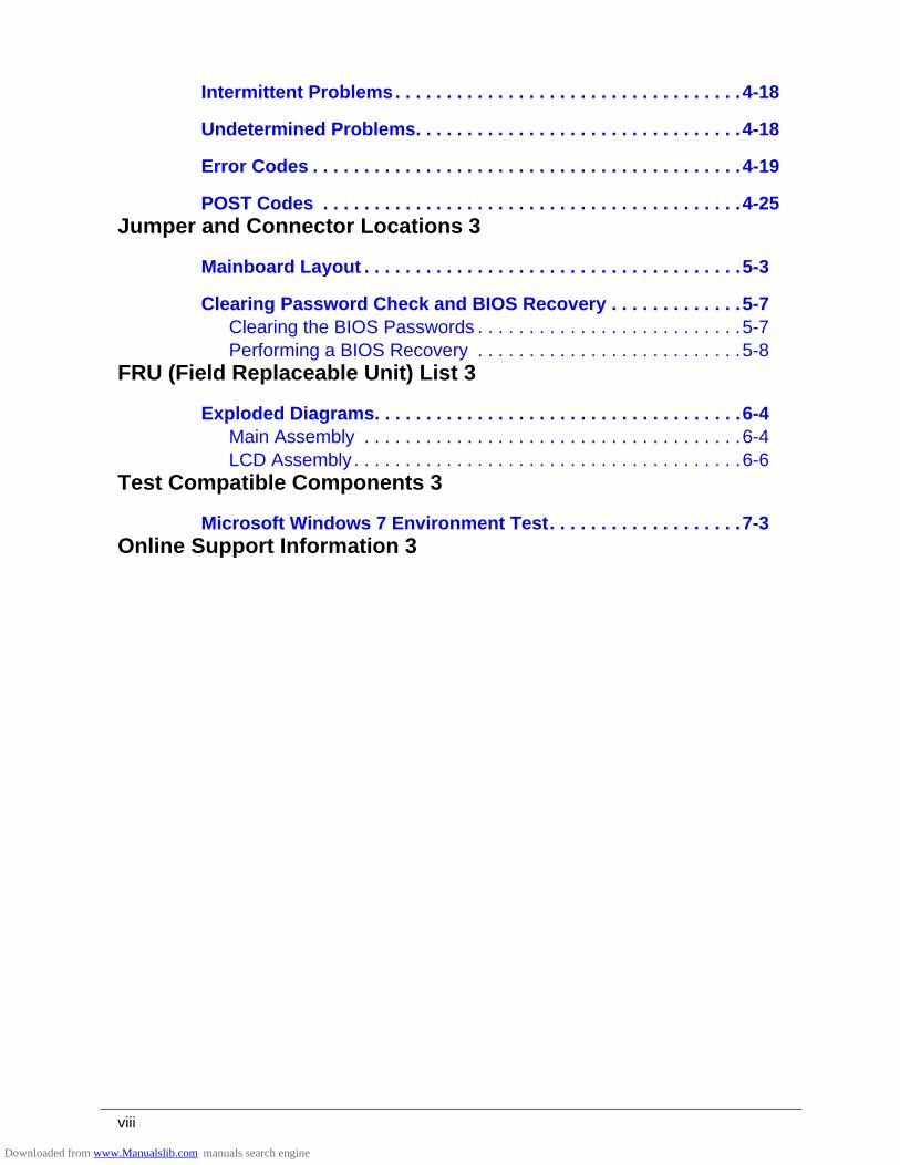
Intermittent Problems. . . . . . . . . . . . . . . . . . . . . . . . . . . . . . . . . .4-18
Undetermined Problems. . . . . . . . . . . . . . . . . . . . . . . . . . . . . . . .4-18
Error Codes . . . . . . . . . . . . . . . . . . . . . . . . . . . . . . . . . . . . . . . . . .4-19
POST Codes . . . . . . . . . . . . . . . . . . . . . . . . . . . . . . . . . . . . . . . . .4-25Jumper and Connector Locations 3
Mainboard Layout . . . . . . . . . . . . . . . . . . . . . . . . . . . . . . . . . . . . .5-3
Clearing Password Check and BIOS Recovery . . . . . . . . . . . . .5-7Clearing the BIOS Passwords . . . . . . . . . . . . . . . . . . . . . . . . . .5-7Performing a BIOS Recovery . . . . . . . . . . . . . . . . . . . . . . . . . .5-8
FRU (Field Replaceable Unit) List 3
Exploded Diagrams. . . . . . . . . . . . . . . . . . . . . . . . . . . . . . . . . . . .6-4Main Assembly . . . . . . . . . . . . . . . . . . . . . . . . . . . . . . . . . . . . .6-4LCD Assembly . . . . . . . . . . . . . . . . . . . . . . . . . . . . . . . . . . . . . .6-6
Test Compatible Components 3
Microsoft Windows 7 Environment Test. . . . . . . . . . . . . . . . . . .7-3Online Support Information 3
Downloaded from www.Manualslib.com manuals search engine

CHAPTER 1
Hardware Specifications
Downloaded from www.Manualslib.com manuals search engine
1-2
Features . . . . . . . . . . . . . . . . . . . . . . . . . . . . . . . . . . . . . . . . . . . . .1-5Operating System . . . . . . . . . . . . . . . . . . . . . . . . . . . . . . . . . . .1-5Platform . . . . . . . . . . . . . . . . . . . . . . . . . . . . . . . . . . . . . . . . . . .1-5System Memory. . . . . . . . . . . . . . . . . . . . . . . . . . . . . . . . . . . . .1-5Display . . . . . . . . . . . . . . . . . . . . . . . . . . . . . . . . . . . . . . . . . . . .1-5Graphics . . . . . . . . . . . . . . . . . . . . . . . . . . . . . . . . . . . . . . . . . .1-5Storage Subsystem . . . . . . . . . . . . . . . . . . . . . . . . . . . . . . . . . .1-6Audio Subsystem. . . . . . . . . . . . . . . . . . . . . . . . . . . . . . . . . . . .1-6Communication . . . . . . . . . . . . . . . . . . . . . . . . . . . . . . . . . . . . .1-7Privacy Control . . . . . . . . . . . . . . . . . . . . . . . . . . . . . . . . . . . . .1-7Power Adapter and Battery . . . . . . . . . . . . . . . . . . . . . . . . . . . .1-7Keyboard and Pointing Device . . . . . . . . . . . . . . . . . . . . . . . . .1-7I/O Ports. . . . . . . . . . . . . . . . . . . . . . . . . . . . . . . . . . . . . . . . . . .1-8Software and Tools . . . . . . . . . . . . . . . . . . . . . . . . . . . . . . . . . .1-8Warranty . . . . . . . . . . . . . . . . . . . . . . . . . . . . . . . . . . . . . . . . . .1-10Dimensions and Weight. . . . . . . . . . . . . . . . . . . . . . . . . . . . . . .1-10Environment. . . . . . . . . . . . . . . . . . . . . . . . . . . . . . . . . . . . . . . .1-10
Notebook Tour. . . . . . . . . . . . . . . . . . . . . . . . . . . . . . . . . . . . . . . .1-11Open Front View . . . . . . . . . . . . . . . . . . . . . . . . . . . . . . . . . . . .1-11Close Front View . . . . . . . . . . . . . . . . . . . . . . . . . . . . . . . . . . . .1-12Left View . . . . . . . . . . . . . . . . . . . . . . . . . . . . . . . . . . . . . . . . . .1-13Right View . . . . . . . . . . . . . . . . . . . . . . . . . . . . . . . . . . . . . . . . .1-14Base View . . . . . . . . . . . . . . . . . . . . . . . . . . . . . . . . . . . . . . . . .1-15Touchpad Basics . . . . . . . . . . . . . . . . . . . . . . . . . . . . . . . . . . . .1-16Keyboard . . . . . . . . . . . . . . . . . . . . . . . . . . . . . . . . . . . . . . . . . .1-17D2D Recovery . . . . . . . . . . . . . . . . . . . . . . . . . . . . . . . . . . . . . .1-21System Block Diagram . . . . . . . . . . . . . . . . . . . . . . . . . . . . . . .1-22
Specification Tables . . . . . . . . . . . . . . . . . . . . . . . . . . . . . . . . . . .1-23Computer Specifications . . . . . . . . . . . . . . . . . . . . . . . . . . . . . .1-23Processor. . . . . . . . . . . . . . . . . . . . . . . . . . . . . . . . . . . . . . . . . .1-24Processor Specifications . . . . . . . . . . . . . . . . . . . . . . . . . . . . . .1-25System Memory. . . . . . . . . . . . . . . . . . . . . . . . . . . . . . . . . . . . .1-25Graphics Controller . . . . . . . . . . . . . . . . . . . . . . . . . . . . . . . . . .1-26VRAM (Discrete models only) . . . . . . . . . . . . . . . . . . . . . . . . . .1-26System BIOS . . . . . . . . . . . . . . . . . . . . . . . . . . . . . . . . . . . . . . .1-27Keyboard . . . . . . . . . . . . . . . . . . . . . . . . . . . . . . . . . . . . . . . . . .1-27Hard Disk Drive . . . . . . . . . . . . . . . . . . . . . . . . . . . . . . . . . . . . .1-28Super-Multi Drive . . . . . . . . . . . . . . . . . . . . . . . . . . . . . . . . . . . .1-29Card Reader . . . . . . . . . . . . . . . . . . . . . . . . . . . . . . . . . . . . . . .1-29LCD Panel . . . . . . . . . . . . . . . . . . . . . . . . . . . . . . . . . . . . . . . . .1-30
Downloaded from www.Manualslib.com manuals search engine
1-3
Supported Display Resolutions . . . . . . . . . . . . . . . . . . . . . . . . .1-30Audio Codec . . . . . . . . . . . . . . . . . . . . . . . . . . . . . . . . . . . . . . .1-31Audio Interface. . . . . . . . . . . . . . . . . . . . . . . . . . . . . . . . . . . . . .1-31Webcam. . . . . . . . . . . . . . . . . . . . . . . . . . . . . . . . . . . . . . . . . . .1-31LAN . . . . . . . . . . . . . . . . . . . . . . . . . . . . . . . . . . . . . . . . . . . . . .1-32Wireless LAN. . . . . . . . . . . . . . . . . . . . . . . . . . . . . . . . . . . . . . .1-32USB Interface . . . . . . . . . . . . . . . . . . . . . . . . . . . . . . . . . . . . . .1-33HDMI Port . . . . . . . . . . . . . . . . . . . . . . . . . . . . . . . . . . . . . . . . .1-33Expansion Card . . . . . . . . . . . . . . . . . . . . . . . . . . . . . . . . . . . . .1-33System LED Indicators . . . . . . . . . . . . . . . . . . . . . . . . . . . . . . .1-33Battery Pack . . . . . . . . . . . . . . . . . . . . . . . . . . . . . . . . . . . . . . .1-34AC Adapter . . . . . . . . . . . . . . . . . . . . . . . . . . . . . . . . . . . . . . . .1-34System Power Management . . . . . . . . . . . . . . . . . . . . . . . . . . .1-35System DMA Specification . . . . . . . . . . . . . . . . . . . . . . . . . . . .1-35
Downloaded from www.Manualslib.com manuals search engine
Hardware Specifications and Configurations 1-5
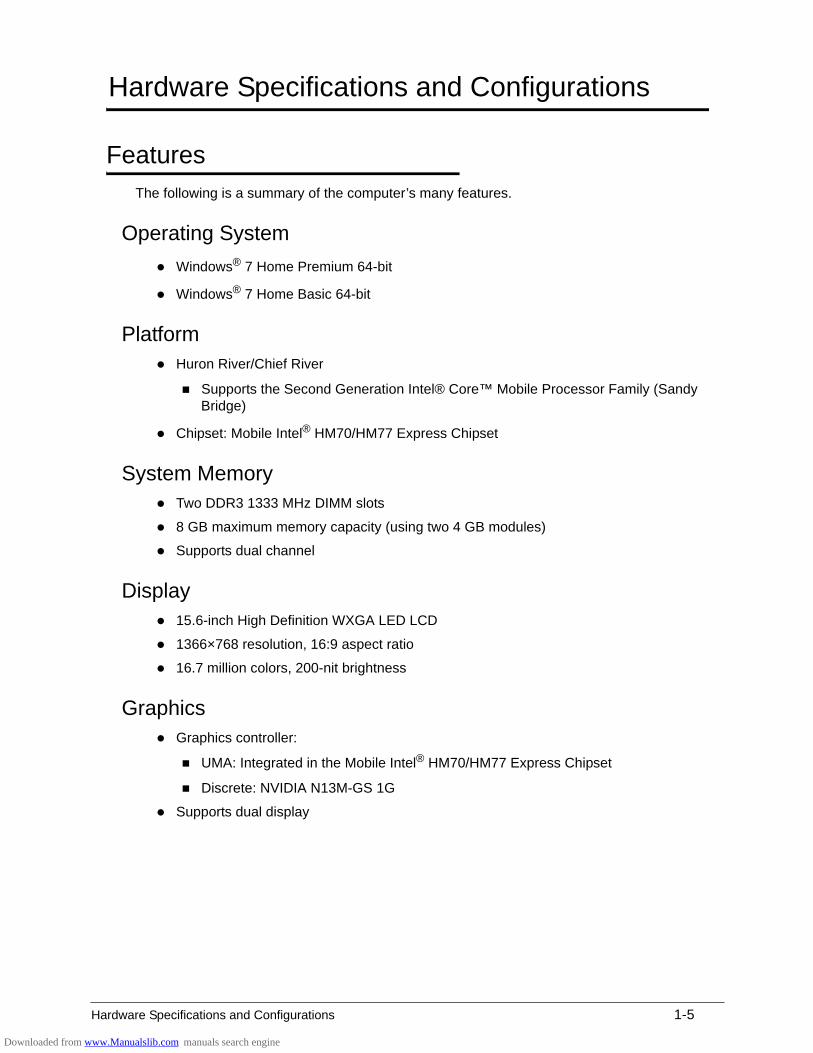
Hardware Specifications and Configurations
Features 0
The following is a summary of the computer’s many features.
Operating System 0
Windows® 7 Home Premium 64-bit
Windows® 7 Home Basic 64-bit
Platform 0
Huron River/Chief River
Supports the Second Generation Intel® Core™ Mobile Processor Family (Sandy Bridge)
Chipset: Mobile Intel® HM70/HM77 Express Chipset
System Memory 0
Two DDR3 1333 MHz DIMM slots
8 GB maximum memory capacity (using two 4 GB modules)
Supports dual channel
Display 0
15.6-inch High Definition WXGA LED LCD
1366×768 resolution, 16:9 aspect ratio
16.7 million colors, 200-nit brightness
Graphics 0
Graphics controller:
UMA: Integrated in the Mobile Intel® HM70/HM77 Express Chipset
Discrete: NVIDIA N13M-GS 1G
Supports dual display
Downloaded from www.Manualslib.com manuals search engine
1-6 Hardware Specifications and Configurations
Internal resolutions and refresh rate supported (applies to both UMA and Discrete models):
800×600, 60 Hz
1024×768, 60 Hz
1280×600, 60 Hz
1280×720, 60 Hz
1280×768, 60 Hz
1360×768, 60 Hz
1366×768, 60 Hz
Maximum Resolution HDMI: 1900x1200
Maximum Resolution D-Sub: 2560x1600
Storage Subsystem 0
Hard disk drive 0
2.5-inch, 7.0 mm, 5400 rpm SATA hard disk drive (HDD)
Optical disc drive 0
Slim-type SATA optical disc drive (ODD)
Detailed read/write specifications on page 1-29.
Card reader 0
Multi-in-1 card reader slot
Supports MultiMediaCard™ (MMC), MultiMediaCard Plus (MMCplus™) and Secure Digital™ (SD) cards
Audio Subsystem 0
Built-in microphone
Two 2W, 2 cc chamber built-in speakers
Headphone/speaker/line-out jack
Realtek 271-VB6
Downloaded from www.Manualslib.com manuals search engine
Hardware Specifications and Configurations 1-7
Communication 0
Webcam 0
1.3M DV slim camera module
Acer Video Conference software, featuring:
Acer Crystal Eye webcam with 1280×1024 resolution
Acer Video Conference Manager featuring Video Quality Enhancement (VQE) technology
Supports 640×480 resolution online video calls
Wireless and networking 0
WLAN:
IEEE 802.11b/g/n
Supports Acer SignalUp technology
LAN on Feature Port (thru bundled Y Cable):
Gigabit Ethernet, Wake-on-LAN ready
Realtek RTL8411 EN controller
Privacy Control 0
BIOS supervisor, user, and HDD passwords
Kensington lock slot
Power Adapter and Battery 0
19 V 3-pin 65 W AC adapter
4-Cell 2.8 Ah Li-ion battery pack
Battery life: 4 hours
Charging period:
1.5 to 2 hours for 0–80% capacity
3 to 3.5 hours for 0–99% capacity
3.5 to 4 hours for 0–100% (charge-in-use)
ACPI 3.0-compliant power management system
ENERGY STAR compliant
Keyboard and Pointing Device 0
Keyboard 0
AS7F Chiclet keyboard
Inverted “T” cursor keys
Downloaded from www.Manualslib.com manuals search engine
1-8 Hardware Specifications and Configurations
Hotkeys for volume and brightness level, media playback, wireless and sleep functions, and display and touchpad toggle
Windows® and Application keys
Multilanguage support
Touchpad 0
Multi-gesture touchpad pointing device
Touchpad lock hotkey
Adjustable touchpad sensitivity function
I/O Ports 0
Multi-in-1 card reader (SD/MMC)
USB ports (2 x 2.0, 1 x 3.0)
HDMI™ port with HDCP support
Headphones/speaker/line-out jack without S/PDIF support
Internal microphone
Feature port (bundled Y cable with LAN/VGA combo port)
DC-in jack for AC adapter
Kensington lock slot
Software and Tools 0
Productivity 0
Acer Backup Manager
Acer ePower Management
Acer eRecovery Management
Adobe® Flash® Player 11.x
Adobe® Reader® 10.x
AUPEO! (United States only)
Bing™ Bar
Evernote (except Japan)
Internet Explorer 9
Kobo™ (Australia, Canada, New Zealand, United Kingdom only)
Microsoft® Office Starter 2010
Microsoft® Office Personal 2010 (Japan only, subject to customer request)
newsXpresso
NOOK for PC (US only)
Norton™ Online Backup
Downloaded from www.Manualslib.com manuals search engine
Hardware Specifications and Configurations 1-9
Windows Live™ Essentials
Security 0
McAfee® Internet Security Suite (trial only)
MyWinLocker® (except China, Hong Kong)
Multimedia 0
Acer clear.fi
NTI Media Maker™
Cyberlink® MediaEspresso
Gaming 0
Acer Games powered by WildTangentÆ1 (except China, Hong Kong, Japan, Korea)
Fooz Kids (except Japan)
Communication and ISP 0
Acer Crystal Eye
Microsoft® Silverlight™
Skype™
Web links and utilities 0
Acer Accessory Store (Belgium, France, Germany, Italy, Netherlands, Spain, Sweden, UK only)
Acer Identity Card
Acer Registration
Acer Updater
eBay® shortcut (Australia, Austria, Canada, France, Germany, Italy, India, Ireland, Mexico, Netherlands, Philippines, Poland, Russia, Singapore, Spain, Switzerland, United States, United Kingdom only)
Netflix shortcut (Canada, Latin America, United States only)
Downloaded from www.Manualslib.com manuals search engine
1-10 Hardware Specifications and Configurations
Warranty 0
One-year International Travelers Warranty (ITW)
Dimensions and Weight 0
Dimensions 0
Width × Depth × Height: 381.6 x 253 x 20.6mm (15.02 × 9.96 × 0.81 in)
Weight 0
2.23 kg (4.92 lb) (including battery) for UMA models
2.28 kg (5.03 lb) (including battery) for Discrete models
Environment 0
Temperature:
Operating: 0 to 40 °C
Non-operating: -20 to 60 °C
Humidity (non-condensing):
Operating: 20% to 80%
Non-operating: 20% to 80%
Downloaded from www.Manualslib.com manuals search engine
Hardware Specifications and Configurations 1-11
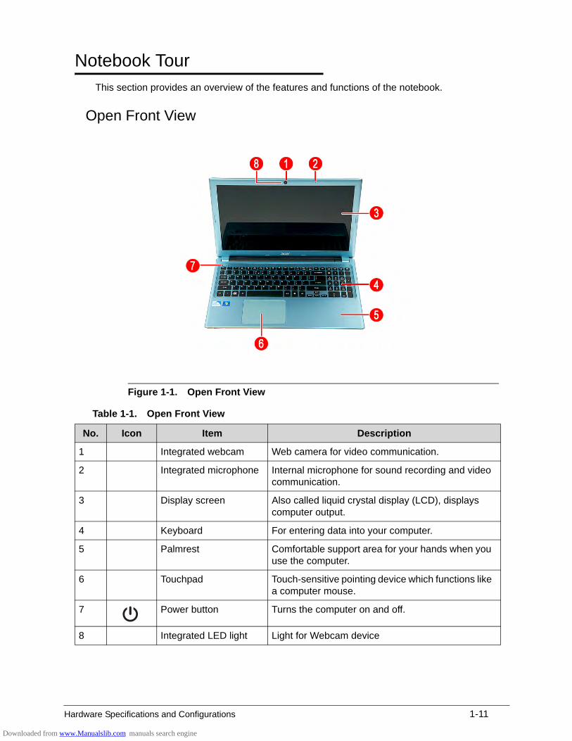
Notebook Tour 0
This section provides an overview of the features and functions of the notebook.
Open Front View 0
Figure 1-1. Open Front View
Table 1-1. Open Front View
No. Icon Item Description
1 Integrated webcam Web camera for video communication.
2 Integrated microphone Internal microphone for sound recording and video communication.
3 Display screen Also called liquid crystal display (LCD), displays computer output.
4 Keyboard For entering data into your computer.
5 Palmrest Comfortable support area for your hands when you use the computer.
6 Touchpad Touch-sensitive pointing device which functions like a computer mouse.
7 Power button Turns the computer on and off.
8 Integrated LED light Light for Webcam device
Downloaded from www.Manualslib.com manuals search engine
1-12 Hardware Specifications and Configurations
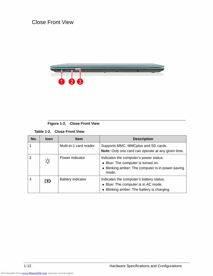
Close Front View 0
Figure 1-2. Close Front View
Table 1-2. Close Front View
No. Icon Item Description
1 Multi-in-1 card reader Supports MMC, MMCplus and SD cards.
Note: Only one card can operate at any given time.
2 Power indicator Indicates the computer’s power status.
Blue: The computer is turned on.
Blinking amber: The computer is in power-saving mode.
3 Battery indicator Indicates the computer’s battery status.
Blue: The computer is in AC mode.
Blinking amber: The battery is charging.
Downloaded from www.Manualslib.com manuals search engine
Hardware Specifications and Configurations 1-13
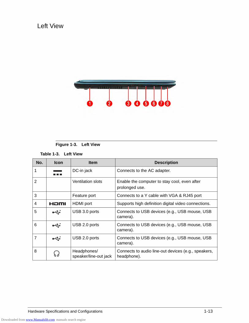
Left View 0
Figure 1-3. Left View
Table 1-3. Left View
No. Icon Item Description
1 DC-in jack Connects to the AC adapter.
2 Ventilation slots Enable the computer to stay cool, even after
prolonged use.
3 Feature port Connects to a Y cable with VGA & RJ45 port
4 HDMI port Supports high definition digital video connections.
5 USB 3.0 ports Connects to USB devices (e.g., USB mouse, USB camera).
6 USB 2.0 ports Connects to USB devices (e.g., USB mouse, USB camera).
7 USB 2.0 ports Connects to USB devices (e.g., USB mouse, USB camera).
8 Headphones/ speaker/line-out jack
Connects to audio line-out devices (e.g., speakers, headphone).
Downloaded from www.Manualslib.com manuals search engine

1-14 Hardware Specifications and Configurations
Right View 0
Figure 1-4. Right View
Table 1-4. Right View
No. Icon Item Description
1 Optical disc drive (ODD)
Internal optical disc drive; accepts CDs or DVDs.
2 ODD access indicator Lights up when the optical drive is active.
3 ODD eject button Ejects the optical disc from the drive.
4 ODD emergency eject hole
Insert a paper clip to the emergency eject hole to eject the optical drive tray when the computer is off.
5 Kensington lock slot Connects to a Kensington-compatible computer security lock.
Note: Wrap the computer security lock cable around an immovable object such as a table or the handle of a locked drawer. Insert the lock into the notch and turn the key to secure the lock. Some keyless models are also available.
Downloaded from www.Manualslib.com manuals search engine
Hardware Specifications and Configurations 1-15
0
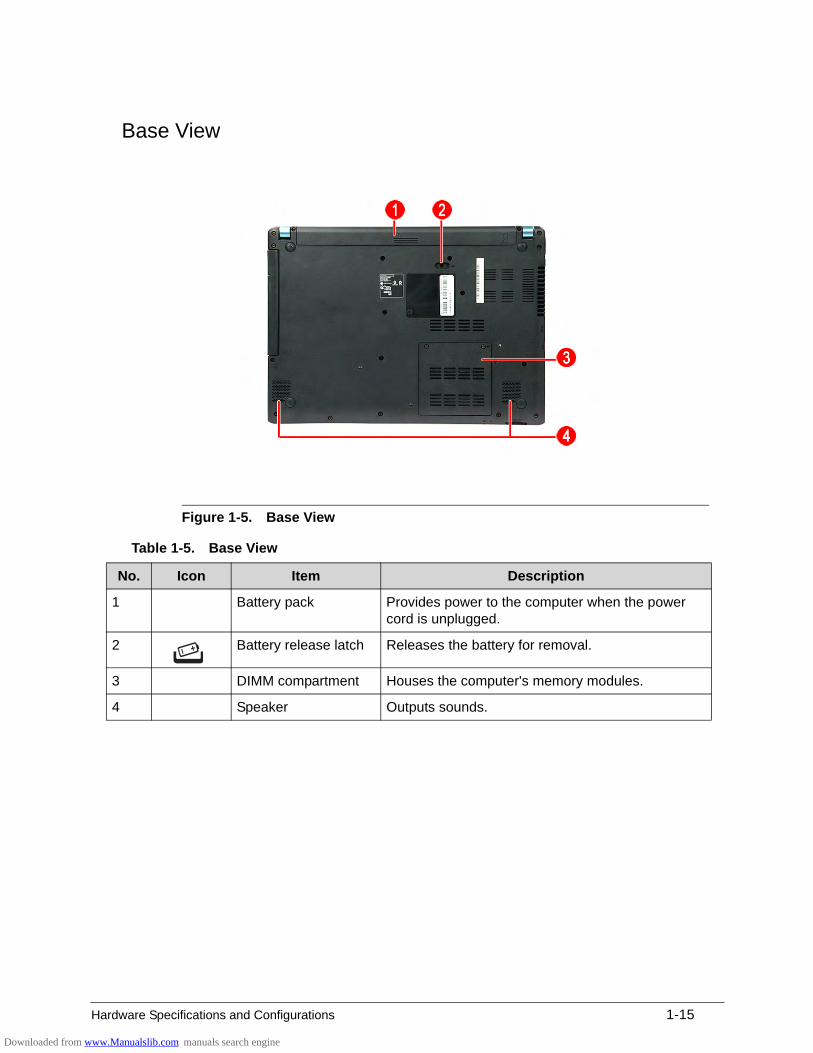
Base View 0
Figure 1-5. Base View
Table 1-5. Base View
No. Icon Item Description
1 Battery pack Provides power to the computer when the power cord is unplugged.
2 Battery release latch Releases the battery for removal.
3 DIMM compartment Houses the computer's memory modules.
4 Speaker Outputs sounds.
Downloaded from www.Manualslib.com manuals search engine
1-16 Hardware Specifications and Configurations
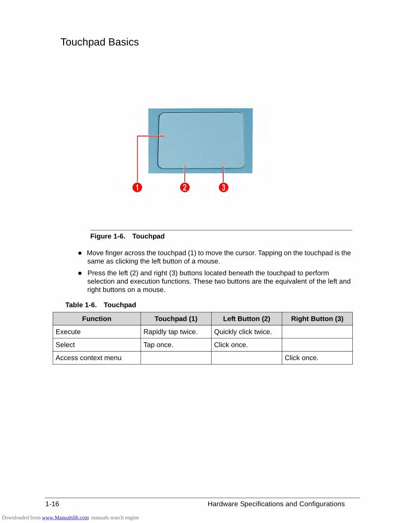
Touchpad Basics 0
Figure 1-6. Touchpad
Move finger across the touchpad (1) to move the cursor. Tapping on the touchpad is the same as clicking the left button of a mouse.
Press the left (2) and right (3) buttons located beneath the touchpad to perform selection and execution functions. These two buttons are the equivalent of the left and right buttons on a mouse.
Table 1-6. Touchpad
Function Touchpad (1) Left Button (2) Right Button (3)
Execute Rapidly tap twice. Quickly click twice.
Select Tap once. Click once.
Access context menu Click once.
Downloaded from www.Manualslib.com manuals search engine
Hardware Specifications and Configurations 1-17
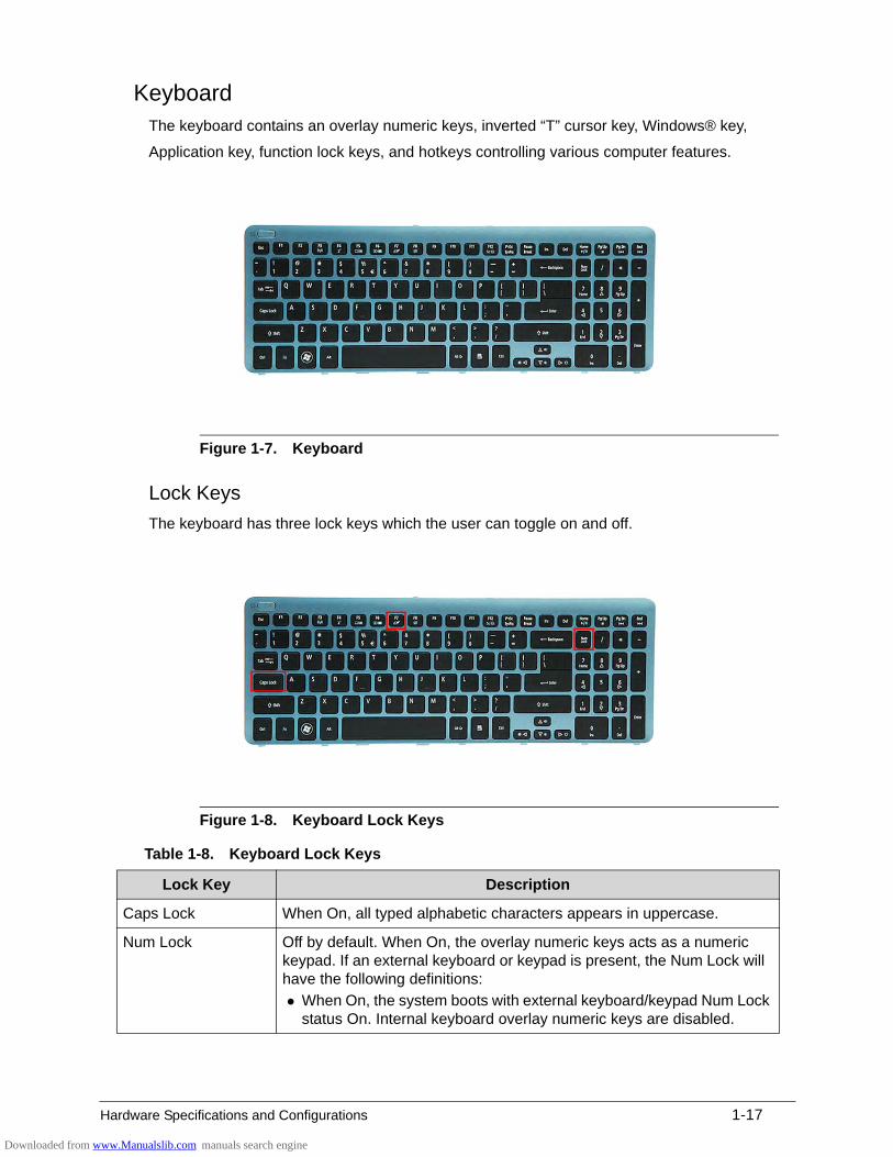
Keyboard 0
The keyboard contains an overlay numeric keys, inverted “T” cursor key, Windows® key,
Application key, function lock keys, and hotkeys controlling various computer features.
Figure 1-7. Keyboard
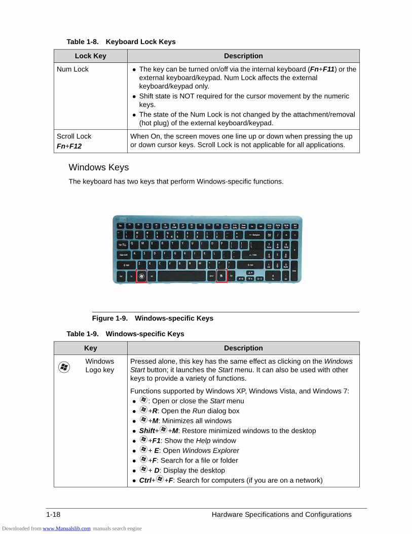
Lock Keys 0
The keyboard has three lock keys which the user can toggle on and off.
Figure 1-8. Keyboard Lock Keys
Table 1-8. Keyboard Lock Keys
Lock Key Description
Caps Lock When On, all typed alphabetic characters appears in uppercase.
Num Lock Off by default. When On, the overlay numeric keys acts as a numeric keypad. If an external keyboard or keypad is present, the Num Lock will have the following definitions:
When On, the system boots with external keyboard/keypad Num Lock status On. Internal keyboard overlay numeric keys are disabled.
Downloaded from www.Manualslib.com manuals search engine
1-18 Hardware Specifications and Configurations
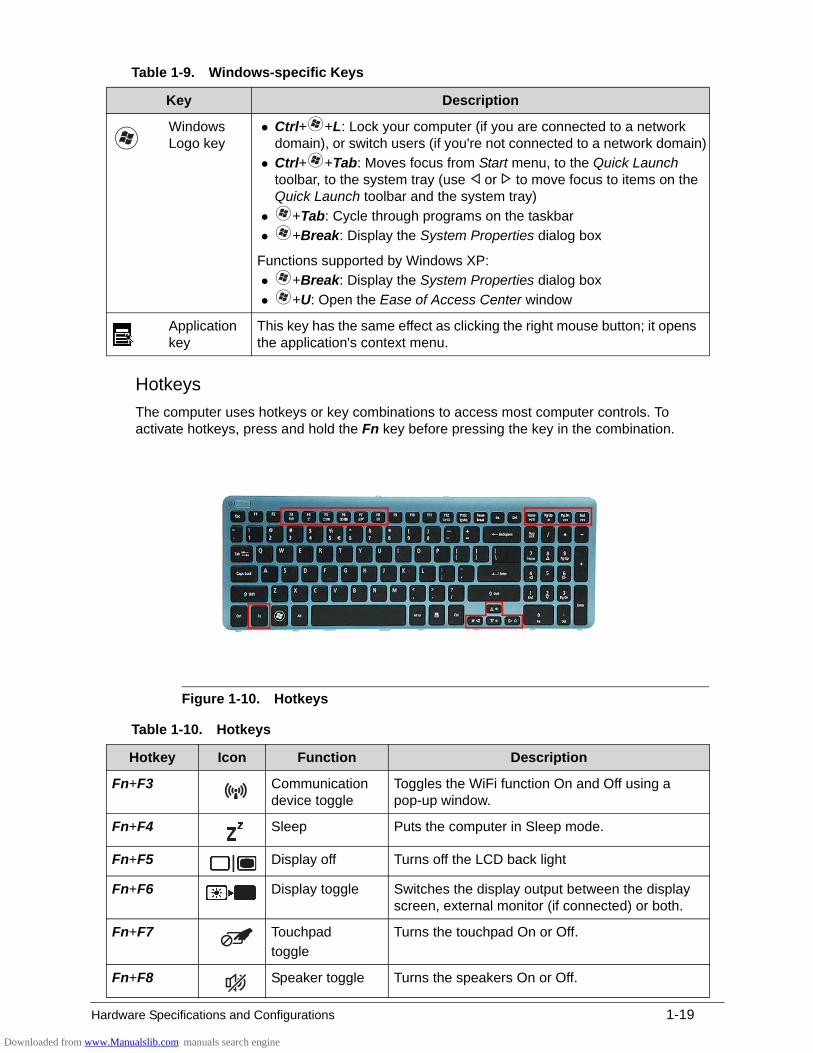
Windows Keys 0
The keyboard has two keys that perform Windows-specific functions.
Figure 1-9. Windows-specific Keys
Num Lock The key can be turned on/off via the internal keyboard (Fn+F11) or the external keyboard/keypad. Num Lock affects the external keyboard/keypad only.
Shift state is NOT required for the cursor movement by the numeric keys.
The state of the Num Lock is not changed by the attachment/removal (hot plug) of the external keyboard/keypad.
Scroll Lock
Fn+F12
When On, the screen moves one line up or down when pressing the up or down cursor keys. Scroll Lock is not applicable for all applications.
Table 1-9. Windows-specific Keys
Key Description
Windows Logo key
Pressed alone, this key has the same effect as clicking on the Windows Start button; it launches the Start menu. It can also be used with other keys to provide a variety of functions.
Functions supported by Windows XP, Windows Vista, and Windows 7:
: Open or close the Start menu
+R: Open the Run dialog box
+M: Minimizes all windows
Shift+ +M: Restore minimized windows to the desktop
+F1: Show the Help window
+ E: Open Windows Explorer
+F: Search for a file or folder
+ D: Display the desktop
Ctrl+ +F: Search for computers (if you are on a network)
Table 1-8. Keyboard Lock Keys
Lock Key Description
Downloaded from www.Manualslib.com manuals search engine
Hardware Specifications and Configurations 1-19
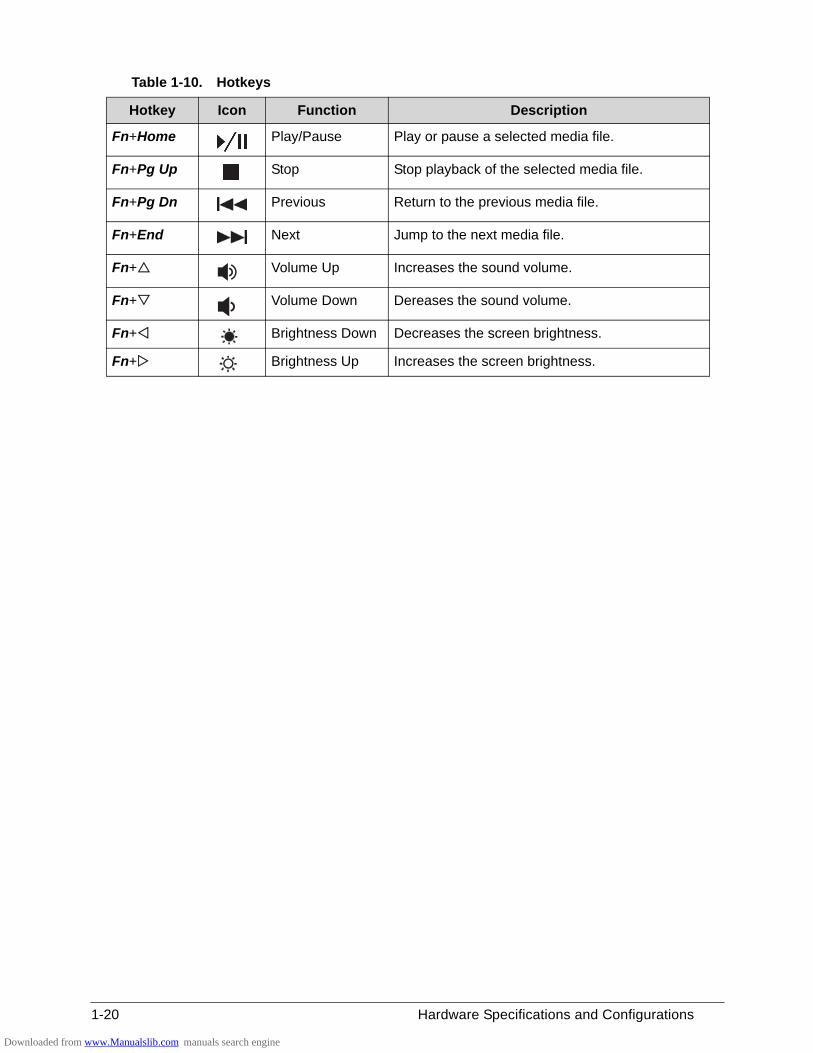
Hotkeys 0
The computer uses hotkeys or key combinations to access most computer controls. To activate hotkeys, press and hold the Fn key before pressing the key in the combination.
Figure 1-10. Hotkeys
Windows Logo key
Ctrl+ +L: Lock your computer (if you are connected to a network domain), or switch users (if you're not connected to a network domain)
Ctrl+ +Tab: Moves focus from Start menu, to the Quick Launch toolbar, to the system tray (use or to move focus to items on the Quick Launch toolbar and the system tray)
+Tab: Cycle through programs on the taskbar
+Break: Display the System Properties dialog box
Functions supported by Windows XP:
+Break: Display the System Properties dialog box
+U: Open the Ease of Access Center window
Application key
This key has the same effect as clicking the right mouse button; it opens the application's context menu.
Table 1-10. Hotkeys
Hotkey Icon Function Description
Fn+F3 Communication device toggle
Toggles the WiFi function On and Off using a pop-up window.
Fn+F4 Sleep Puts the computer in Sleep mode.
Fn+F5 Display off Turns off the LCD back light
Fn+F6 Display toggle Switches the display output between the display screen, external monitor (if connected) or both.
Fn+F7 Touchpad
toggle
Turns the touchpad On or Off.
Fn+F8 Speaker toggle Turns the speakers On or Off.
Table 1-9. Windows-specific Keys
Key Description
Downloaded from www.Manualslib.com manuals search engine
1-20 Hardware Specifications and Configurations
0
Fn+Home Play/Pause Play or pause a selected media file.
Fn+Pg Up Stop Stop playback of the selected media file.
Fn+Pg Dn Previous Return to the previous media file.
Fn+End Next Jump to the next media file.
Fn+ Volume Up Increases the sound volume.
Fn+ Volume Down Dereases the sound volume.
Fn+ Brightness Down Decreases the screen brightness.
Fn+ Brightness Up Increases the screen brightness.
Table 1-10. Hotkeys
Hotkey Icon Function Description
Downloaded from www.Manualslib.com manuals search engine
Hardware Specifications and Configurations 1-21
D2D Recovery 0
The Acer Disk to Disk (D2D) recovery function allows you to use the recovery partition to troubleshoot your computer.
1. Restart the computer.
2. During POST, press F1 to access the BIOS Setup screen.
3. Press to select the Main menu.
4. Press to select the D2D Recovery field and make sure it is set to Enabled.
5. Press F10 to save settings and close the BIOS Setup screen.
6. During POST, press Alt+F10 to enter the system recovery partition. This will display the eRecovery Management window.
7. Follow the onscreen instructions to return your computer to factory condition.
Downloaded from www.Manualslib.com manuals search engine
1-22 Hardware Specifications and Configurations
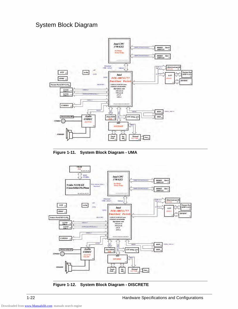
System Block Diagram 0
Figure 1-11. System Block Diagram - UMA
Figure 1-12. System Block Diagram - DISCRETE
Downloaded from www.Manualslib.com manuals search engine
Hardware Specifications and Configurations 1-23
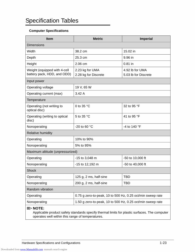
Specification Tables 0
Computer Specifications
Item Metric Imperial
Dimensions
Width 38.2 cm 15.02 in
Depth 25.3 cm 9.96 in
Height 2.06 cm 0.81 in
Weight (equipped with 4-cell battery pack, HDD, and ODD)
2.23 kg for UMA
2.28 kg for Discrete
4.92 lb for UMA
5.03 lb for Discrete
Input power
Operating voltage 19 V, 65 W
Operating current (max) 3.42 A
Temperature
Operating (not writing to optical disc)
0 to 35 °C 32 to 95 °F
Operating (writing to optical disc)
5 to 35 °C 41 to 95 °F
Nonoperating -20 to 60 °C -4 to 140 °F
Relative humidity
Operating 10% to 90%
Nonoperating 5% to 95%
Maximum altitude (unpressurized)
Operating -15 to 3,048 m -50 to 10,000 ft
Nonoperating -15 to 12,192 m -50 to 40,000 ft
Shock
Operating 125 g, 2 ms, half-sine TBD
Nonoperating 200 g, 2 ms, half-sine TBD
Random vibration
Operating 0.75 g zero-to-peak, 10 to 500 Hz, 0.25 oct/min sweep rate
Nonoperating 1.50 g zero-to-peak, 10 to 500 Hz, 0.25 oct/min sweep rate
NOTE:Applicable product safety standards specify thermal limits for plastic surfaces. The computer operates well within this range of temperatures.
Downloaded from www.Manualslib.com manuals search engine
1-24 Hardware Specifications and Configurations
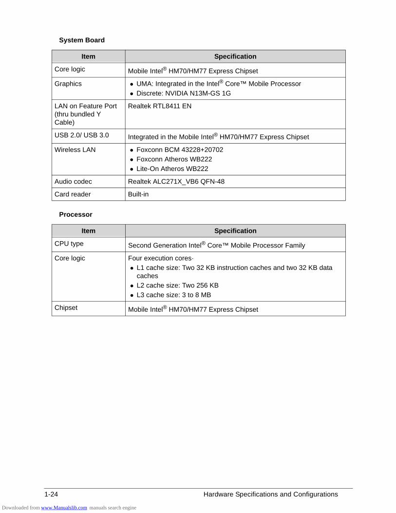
System Board
Processor
Item Specification
Core logic Mobile Intel® HM70/HM77 Express Chipset
Graphics UMA: Integrated in the Intel® Core™ Mobile Processor
Discrete: NVIDIA N13M-GS 1G
LAN on Feature Port (thru bundled Y Cable)
Realtek RTL8411 EN
USB 2.0/ USB 3.0 Integrated in the Mobile Intel® HM70/HM77 Express Chipset
Wireless LAN Foxconn BCM 43228+20702
Foxconn Atheros WB222
Lite-On Atheros WB222
Audio codec Realtek ALC271X_VB6 QFN-48
Card reader Built-in
Item Specification
CPU type Second Generation Intel® Core™ Mobile Processor Family
Core logic Four execution cores·
L1 cache size: Two 32 KB instruction caches and two 32 KB data caches
L2 cache size: Two 256 KB
L3 cache size: 3 to 8 MB
Chipset Mobile Intel® HM70/HM77 Express Chipset
Downloaded from www.Manualslib.com manuals search engine
Hardware Specifications and Configurations 1-25
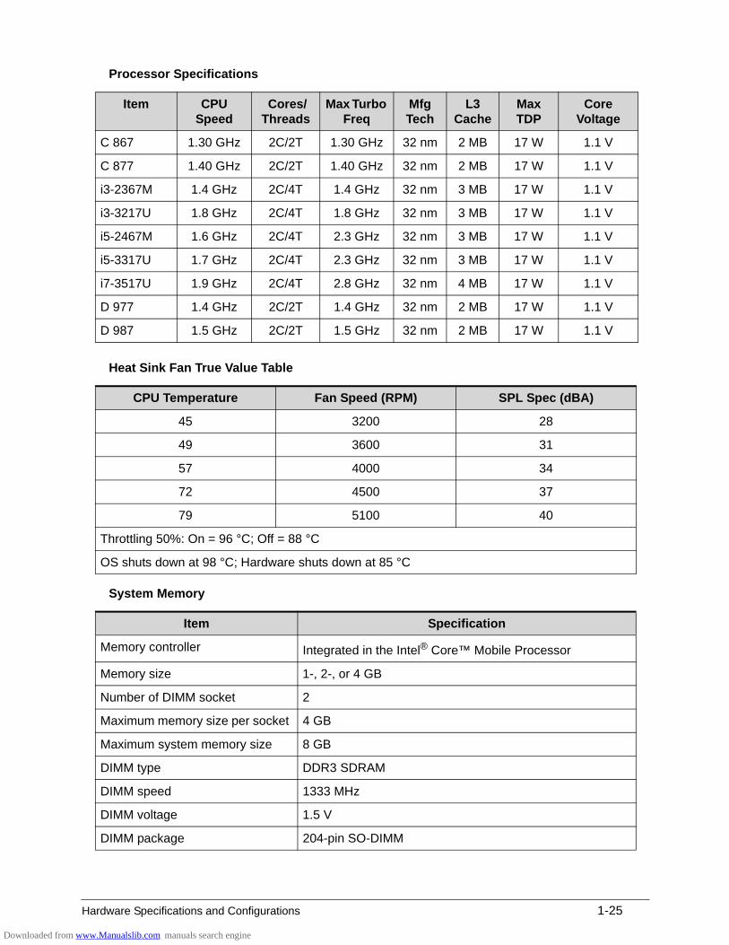
Processor Specifications
Heat Sink Fan True Value Table
System Memory
Item CPU Speed
Cores/ Threads
Max Turbo Freq
Mfg Tech
L3 Cache
Max TDP
Core Voltage
C 867 1.30 GHz 2C/2T 1.30 GHz 32 nm 2 MB 17 W 1.1 V
C 877 1.40 GHz 2C/2T 1.40 GHz 32 nm 2 MB 17 W 1.1 V
i3-2367M 1.4 GHz 2C/4T 1.4 GHz 32 nm 3 MB 17 W 1.1 V
i3-3217U 1.8 GHz 2C/4T 1.8 GHz 32 nm 3 MB 17 W 1.1 V
i5-2467M 1.6 GHz 2C/4T 2.3 GHz 32 nm 3 MB 17 W 1.1 V
i5-3317U 1.7 GHz 2C/4T 2.3 GHz 32 nm 3 MB 17 W 1.1 V
i7-3517U 1.9 GHz 2C/4T 2.8 GHz 32 nm 4 MB 17 W 1.1 V
D 977 1.4 GHz 2C/2T 1.4 GHz 32 nm 2 MB 17 W 1.1 V
D 987 1.5 GHz 2C/2T 1.5 GHz 32 nm 2 MB 17 W 1.1 V
CPU Temperature Fan Speed (RPM) SPL Spec (dBA)
45 3200 28
49 3600 31
57 4000 34
72 4500 37
79 5100 40
Throttling 50%: On = 96 °C; Off = 88 °C
OS shuts down at 98 °C; Hardware shuts down at 85 °C
Item Specification
Memory controller Integrated in the Intel® Core™ Mobile Processor
Memory size 1-, 2-, or 4 GB
Number of DIMM socket 2
Maximum memory size per socket 4 GB
Maximum system memory size 8 GB
DIMM type DDR3 SDRAM
DIMM speed 1333 MHz
DIMM voltage 1.5 V
DIMM package 204-pin SO-DIMM
Downloaded from www.Manualslib.com manuals search engine
1-26 Hardware Specifications and Configurations
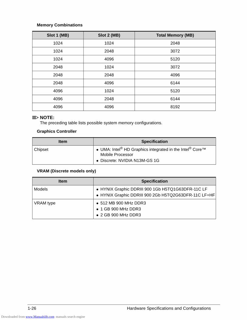
Memory Combinations
NOTE:The preceding table lists possible system memory configurations.
Graphics Controller
VRAM (Discrete models only)
Slot 1 (MB) Slot 2 (MB) Total Memory (MB)
1024 1024 2048
1024 2048 3072
1024 4096 5120
2048 1024 3072
2048 2048 4096
2048 4096 6144
4096 1024 5120
4096 2048 6144
4096 4096 8192
Item Specification
Chipset UMA: Intel® HD Graphics integrated in the Intel® Core™ Mobile Processor
Discrete: NVIDIA N13M-GS 1G
Item Specification
Models HYNIX Graphic DDRIII 900 1Gb H5TQ1G63DFR-11C LF
HYNIX Graphic DDRIII 900 2Gb H5TQ2G63DFR-11C LF+HF
VRAM type 512 MB 900 MHz DDR3
1 GB 900 MHz DDR3
2 GB 900 MHz DDR3
Downloaded from www.Manualslib.com manuals search engine
Hardware Specifications and Configurations 1-27
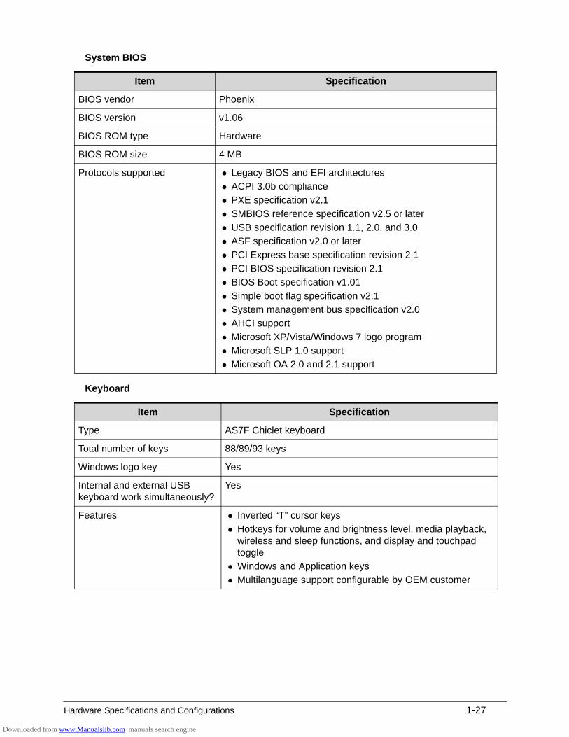
System BIOS
Keyboard
Item Specification
BIOS vendor Phoenix
BIOS version v1.06
BIOS ROM type Hardware
BIOS ROM size 4 MB
Protocols supported Legacy BIOS and EFI architectures
ACPI 3.0b compliance
PXE specification v2.1
SMBIOS reference specification v2.5 or later
USB specification revision 1.1, 2.0. and 3.0
ASF specification v2.0 or later
PCI Express base specification revision 2.1
PCI BIOS specification revision 2.1
BIOS Boot specification v1.01
Simple boot flag specification v2.1
System management bus specification v2.0
AHCI support
Microsoft XP/Vista/Windows 7 logo program
Microsoft SLP 1.0 support
Microsoft OA 2.0 and 2.1 support
Item Specification
Type AS7F Chiclet keyboard
Total number of keys 88/89/93 keys
Windows logo key Yes
Internal and external USB keyboard work simultaneously?
Yes
Features Inverted “T” cursor keys
Hotkeys for volume and brightness level, media playback, wireless and sleep functions, and display and touchpad toggle
Windows and Application keys
Multilanguage support configurable by OEM customer
Downloaded from www.Manualslib.com manuals search engine
1-28 Hardware Specifications and Configurations
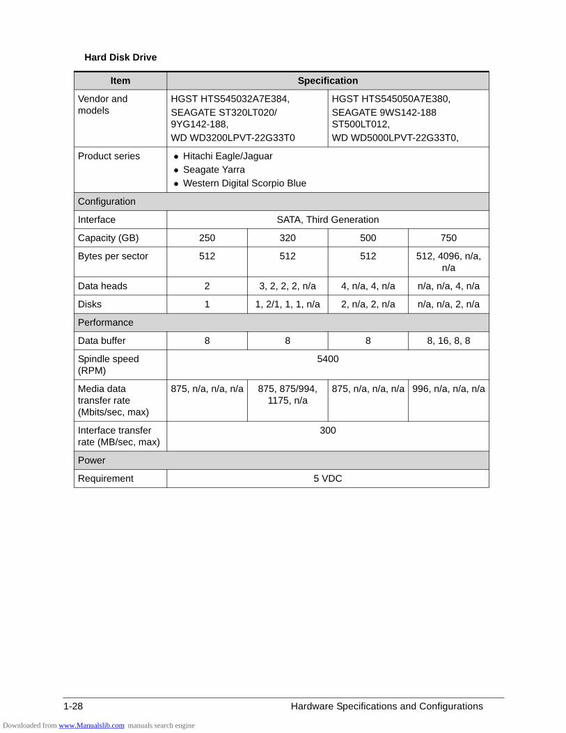
Hard Disk Drive
Item Specification
Vendor and models
HGST HTS545032A7E384,
SEAGATE ST320LT020/ 9YG142-188,
WD WD3200LPVT-22G33T0
HGST HTS545050A7E380,
SEAGATE 9WS142-188 ST500LT012,
WD WD5000LPVT-22G33T0,
Product series Hitachi Eagle/Jaguar
Seagate Yarra
Western Digital Scorpio Blue
Configuration
Interface SATA, Third Generation
Capacity (GB) 250 320 500 750
Bytes per sector 512 512 512 512, 4096, n/a, n/a
Data heads 2 3, 2, 2, 2, n/a 4, n/a, 4, n/a n/a, n/a, 4, n/a
Disks 1 1, 2/1, 1, 1, n/a 2, n/a, 2, n/a n/a, n/a, 2, n/a
Performance
Data buffer 8 8 8 8, 16, 8, 8
Spindle speed (RPM)
5400
Media data transfer rate (Mbits/sec, max)
875, n/a, n/a, n/a 875, 875/994, 1175, n/a
875, n/a, n/a, n/a 996, n/a, n/a, n/a
Interface transfer rate (MB/sec, max)
300
Power
Requirement 5 VDC
Downloaded from www.Manualslib.com manuals search engine
Hardware Specifications and Configurations 1-29
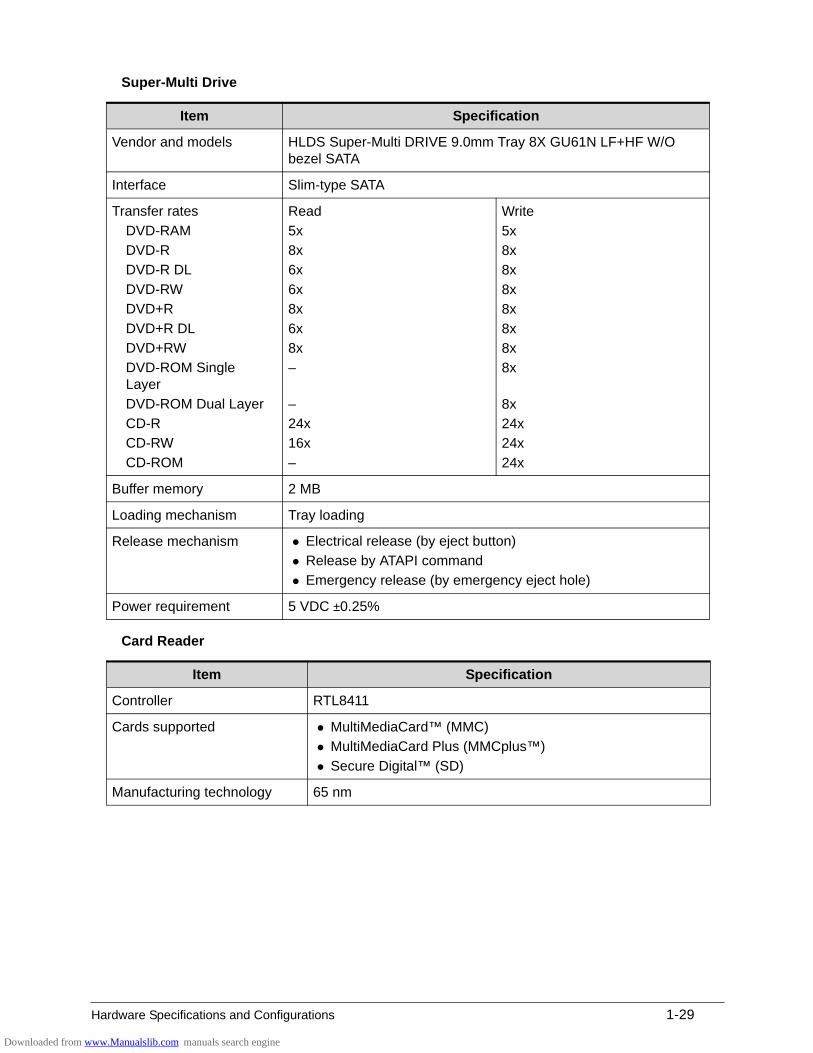
Super-Multi Drive
Card Reader
Item Specification
Vendor and models HLDS Super-Multi DRIVE 9.0mm Tray 8X GU61N LF+HF W/O bezel SATA
Interface Slim-type SATA
Transfer rates
DVD-RAM
DVD-R
DVD-R DL
DVD-RW
DVD+R
DVD+R DL
DVD+RW
DVD-ROM Single Layer
DVD-ROM Dual Layer
CD-R
CD-RW
CD-ROM
Read
5x
8x
6x
6x
8x
6x
8x
–
–
24x
16x
–
Write
5x
8x
8x
8x
8x
8x
8x
8x
8x
24x
24x
24x
Buffer memory 2 MB
Loading mechanism Tray loading
Release mechanism Electrical release (by eject button)
Release by ATAPI command
Emergency release (by emergency eject hole)
Power requirement 5 VDC ±0.25%
Item Specification
Controller RTL8411
Cards supported MultiMediaCard™ (MMC)
MultiMediaCard Plus (MMCplus™)
Secure Digital™ (SD)
Manufacturing technology 65 nm
Downloaded from www.Manualslib.com manuals search engine
1-30 Hardware Specifications and Configurations
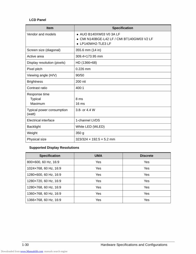
LCD Panel
Supported Display Resolutions
Item Specification
Vendor and models AUO B140XW03 V0 3A LF
CMI N140BGE-L42 LF / CMI BT140GW03 V2 LF
LP140WH2-TLE3 LF
Screen size (diagonal) 355.6 mm (14 in)
Active area 309.4×173.95 mm
Display resolution (pixels) HD (1366×68)
Pixel pitch 0.226 mm
Viewing angle (H/V) 90/50
Brightness 200 nit
Contrast ratio 400:1
Response time
Typical
Maximum
8 ms
16 ms
Typical power consumption (watt)
3.8- or 4.4 W
Electrical interface 1-channel LVDS
Backlight White LED (WLED)
Weight 350 g
Physical size 323/324 × 192.5 × 5.2 mm
Specification UMA Discrete
800×600, 60 Hz, 16:9 Yes Yes
1024×768, 60 Hz, 16:9 Yes Yes
1280×600, 60 Hz, 16:9 Yes Yes
1280×720, 60 Hz, 16:9 Yes Yes
1280×768, 60 Hz, 16:9 Yes Yes
1360×768, 60 Hz, 16:9 Yes Yes
1366×768, 60 Hz, 16:9 Yes Yes
Downloaded from www.Manualslib.com manuals search engine
Hardware Specifications and Configurations 1-31
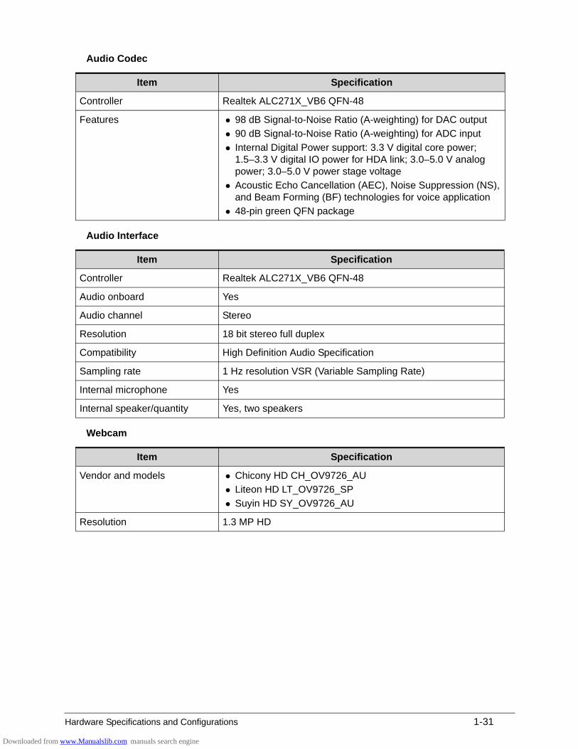
Audio Codec
Audio Interface
Webcam
Item Specification
Controller Realtek ALC271X_VB6 QFN-48
Features 98 dB Signal-to-Noise Ratio (A-weighting) for DAC output
90 dB Signal-to-Noise Ratio (A-weighting) for ADC input
Internal Digital Power support: 3.3 V digital core power; 1.5–3.3 V digital IO power for HDA link; 3.0–5.0 V analog power; 3.0–5.0 V power stage voltage
Acoustic Echo Cancellation (AEC), Noise Suppression (NS), and Beam Forming (BF) technologies for voice application
48-pin green QFN package
Item Specification
Controller Realtek ALC271X_VB6 QFN-48
Audio onboard Yes
Audio channel Stereo
Resolution 18 bit stereo full duplex
Compatibility High Definition Audio Specification
Sampling rate 1 Hz resolution VSR (Variable Sampling Rate)
Internal microphone Yes
Internal speaker/quantity Yes, two speakers
Item Specification
Vendor and models Chicony HD CH_OV9726_AU
Liteon HD LT_OV9726_SP
Suyin HD SY_OV9726_AU
Resolution 1.3 MP HD
Downloaded from www.Manualslib.com manuals search engine
1-32 Hardware Specifications and Configurations
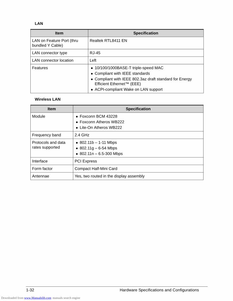
LAN
Wireless LAN
Item Specification
LAN on Feature Port (thru bundled Y Cable)
Realtek RTL8411 EN
LAN connector type RJ-45
LAN connector location Left
Features 10/100/1000BASE-T triple-speed MAC
Compliant with IEEE standards
Compliant with IEEE 802.3az draft standard for Energy Efficient Ethernet™ (EEE)
ACPI-compliant Wake on LAN support
Item Specification
Module Foxconn BCM 43228
Foxconn Atheros WB222
Lite-On Atheros WB222
Frequency band 2.4 GHz
Protocols and data rates supported
802.11b – 1-11 Mbps
802.11g – 6-54 Mbps
802.11n – 6.5-300 Mbps
Interface PCI Express
Form factor Compact Half-Mini Card
Antennae Yes, two routed in the display assembly
Downloaded from www.Manualslib.com manuals search engine
Hardware Specifications and Configurations 1-33
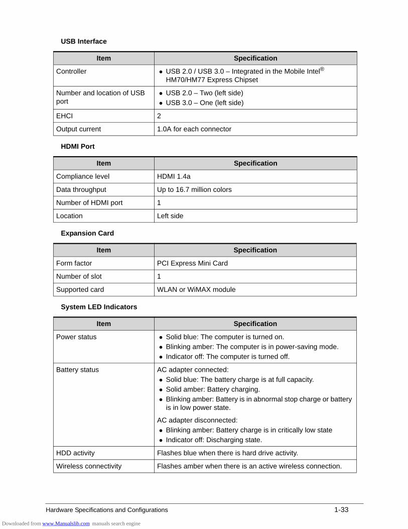
USB Interface
HDMI Port
Expansion Card
System LED Indicators
Item Specification
Controller USB 2.0 / USB 3.0 – Integrated in the Mobile Intel® HM70/HM77 Express Chipset
Number and location of USB port
USB 2.0 – Two (left side)
USB 3.0 – One (left side)
EHCI 2
Output current 1.0A for each connector
Item Specification
Compliance level HDMI 1.4a
Data throughput Up to 16.7 million colors
Number of HDMI port 1
Location Left side
Item Specification
Form factor PCI Express Mini Card
Number of slot 1
Supported card WLAN or WiMAX module
Item Specification
Power status Solid blue: The computer is turned on.
Blinking amber: The computer is in power-saving mode.
Indicator off: The computer is turned off.
Battery status AC adapter connected:
Solid blue: The battery charge is at full capacity.
Solid amber: Battery charging.
Blinking amber: Battery is in abnormal stop charge or battery is in low power state.
AC adapter disconnected:
Blinking amber: Battery charge is in critically low state
Indicator off: Discharging state.
HDD activity Flashes blue when there is hard drive activity.
Wireless connectivity Flashes amber when there is an active wireless connection.
Downloaded from www.Manualslib.com manuals search engine
1-34 Hardware Specifications and Configurations
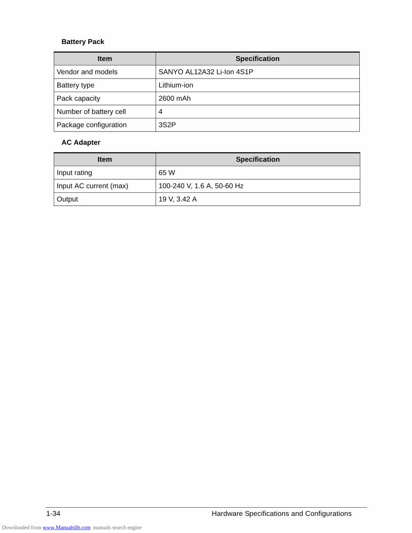
Battery Pack
AC Adapter
Item Specification
Vendor and models SANYO AL12A32 Li-Ion 4S1P
Battery type Lithium-ion
Pack capacity 2600 mAh
Number of battery cell 4
Package configuration 3S2P
Item Specification
Input rating 65 W
Input AC current (max) 100-240 V, 1.6 A, 50-60 Hz
Output 19 V, 3.42 A
Downloaded from www.Manualslib.com manuals search engine
Hardware Specifications and Configurations 1-35
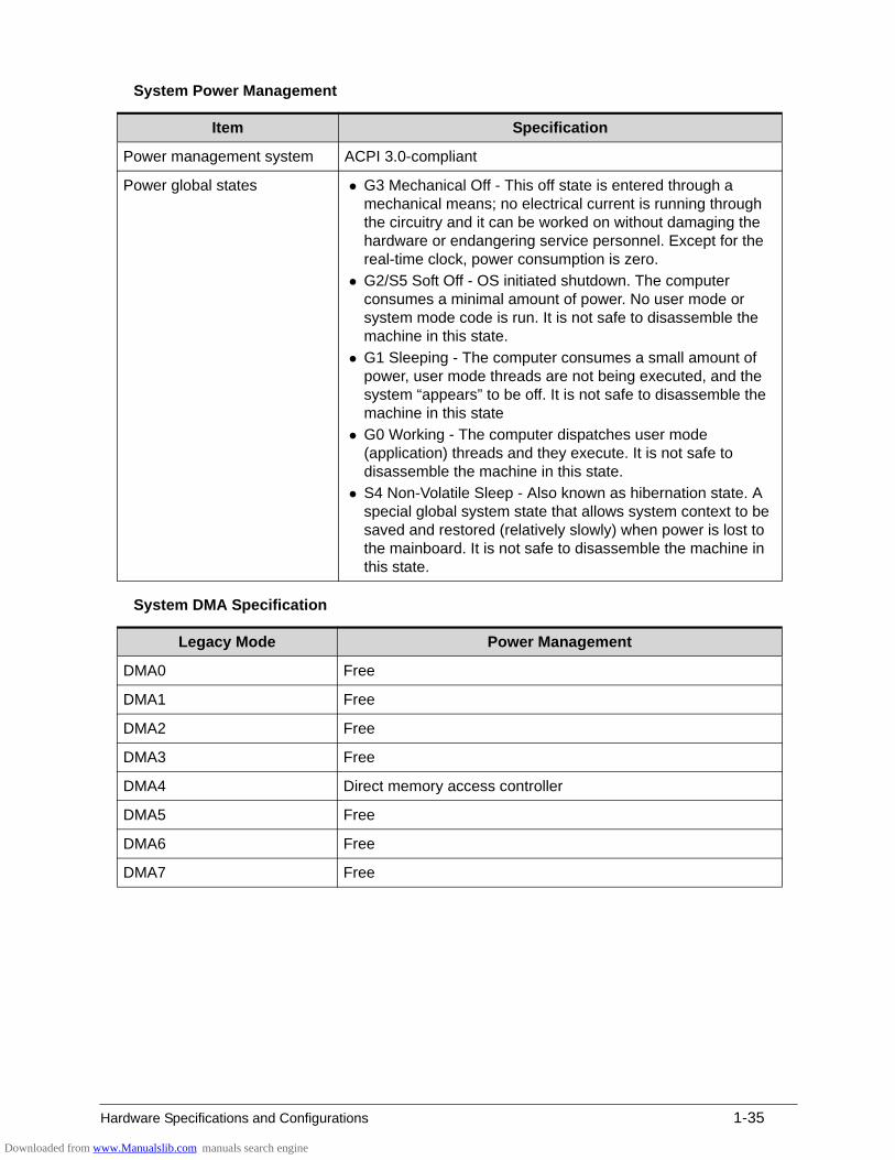
System Power Management
System DMA Specification
Item Specification
Power management system ACPI 3.0-compliant
Power global states G3 Mechanical Off - This off state is entered through a mechanical means; no electrical current is running through the circuitry and it can be worked on without damaging the hardware or endangering service personnel. Except for the real-time clock, power consumption is zero.
G2/S5 Soft Off - OS initiated shutdown. The computer consumes a minimal amount of power. No user mode or system mode code is run. It is not safe to disassemble the machine in this state.
G1 Sleeping - The computer consumes a small amount of power, user mode threads are not being executed, and the system “appears” to be off. It is not safe to disassemble the machine in this state
G0 Working - The computer dispatches user mode (application) threads and they execute. It is not safe to disassemble the machine in this state.
S4 Non-Volatile Sleep - Also known as hibernation state. A special global system state that allows system context to be saved and restored (relatively slowly) when power is lost to the mainboard. It is not safe to disassemble the machine in this state.
Legacy Mode Power Management
DMA0 Free
DMA1 Free
DMA2 Free
DMA3 Free
DMA4 Direct memory access controller
DMA5 Free
DMA6 Free
DMA7 Free
Downloaded from www.Manualslib.com manuals search engine
1-36 Hardware Specifications and Configurations
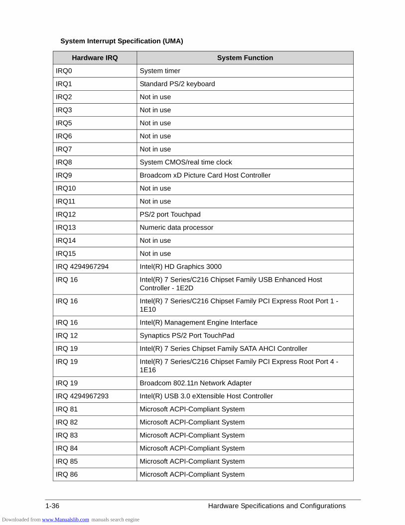
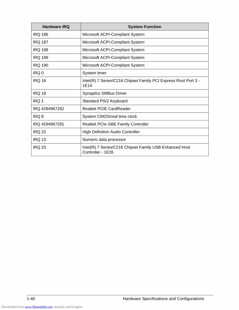
System Interrupt Specification (UMA)
Hardware IRQ System Function
IRQ0 System timer
IRQ1 Standard PS/2 keyboard
IRQ2 Not in use
IRQ3 Not in use
IRQ5 Not in use
IRQ6 Not in use
IRQ7 Not in use
IRQ8 System CMOS/real time clock
IRQ9 Broadcom xD Picture Card Host Controller
IRQ10 Not in use
IRQ11 Not in use
IRQ12 PS/2 port Touchpad
IRQ13 Numeric data processor
IRQ14 Not in use
IRQ15 Not in use
IRQ 4294967294 Intel(R) HD Graphics 3000
IRQ 16 Intel(R) 7 Series/C216 Chipset Family USB Enhanced Host Controller - 1E2D
IRQ 16 Intel(R) 7 Series/C216 Chipset Family PCI Express Root Port 1 - 1E10
IRQ 16 Intel(R) Management Engine Interface
IRQ 12 Synaptics PS/2 Port TouchPad
IRQ 19 Intel(R) 7 Series Chipset Family SATA AHCI Controller
IRQ 19 Intel(R) 7 Series/C216 Chipset Family PCI Express Root Port 4 - 1E16
IRQ 19 Broadcom 802.11n Network Adapter
IRQ 4294967293 Intel(R) USB 3.0 eXtensible Host Controller
IRQ 81 Microsoft ACPI-Compliant System
IRQ 82 Microsoft ACPI-Compliant System
IRQ 83 Microsoft ACPI-Compliant System
IRQ 84 Microsoft ACPI-Compliant System
IRQ 85 Microsoft ACPI-Compliant System
IRQ 86 Microsoft ACPI-Compliant System
Downloaded from www.Manualslib.com manuals search engine
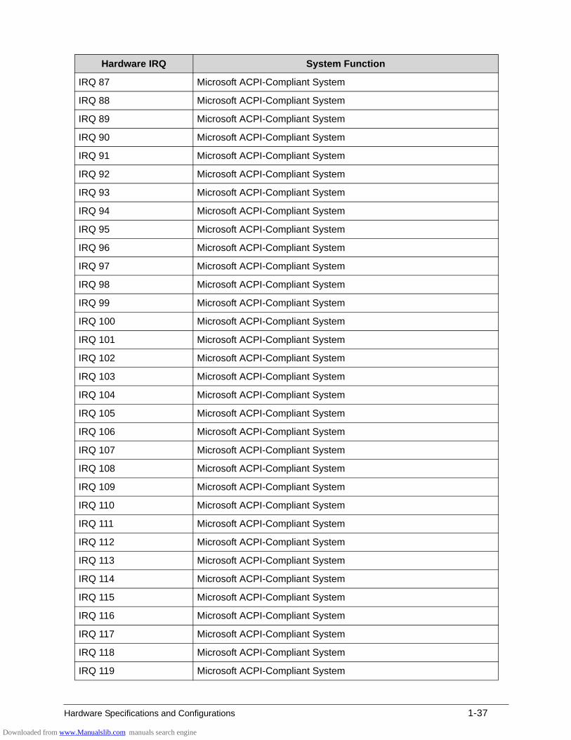
Hardware Specifications and Configurations 1-37
IRQ 87 Microsoft ACPI-Compliant System
IRQ 88 Microsoft ACPI-Compliant System
IRQ 89 Microsoft ACPI-Compliant System
IRQ 90 Microsoft ACPI-Compliant System
IRQ 91 Microsoft ACPI-Compliant System
IRQ 92 Microsoft ACPI-Compliant System
IRQ 93 Microsoft ACPI-Compliant System
IRQ 94 Microsoft ACPI-Compliant System
IRQ 95 Microsoft ACPI-Compliant System
IRQ 96 Microsoft ACPI-Compliant System
IRQ 97 Microsoft ACPI-Compliant System
IRQ 98 Microsoft ACPI-Compliant System
IRQ 99 Microsoft ACPI-Compliant System
IRQ 100 Microsoft ACPI-Compliant System
IRQ 101 Microsoft ACPI-Compliant System
IRQ 102 Microsoft ACPI-Compliant System
IRQ 103 Microsoft ACPI-Compliant System
IRQ 104 Microsoft ACPI-Compliant System
IRQ 105 Microsoft ACPI-Compliant System
IRQ 106 Microsoft ACPI-Compliant System
IRQ 107 Microsoft ACPI-Compliant System
IRQ 108 Microsoft ACPI-Compliant System
IRQ 109 Microsoft ACPI-Compliant System
IRQ 110 Microsoft ACPI-Compliant System
IRQ 111 Microsoft ACPI-Compliant System
IRQ 112 Microsoft ACPI-Compliant System
IRQ 113 Microsoft ACPI-Compliant System
IRQ 114 Microsoft ACPI-Compliant System
IRQ 115 Microsoft ACPI-Compliant System
IRQ 116 Microsoft ACPI-Compliant System
IRQ 117 Microsoft ACPI-Compliant System
IRQ 118 Microsoft ACPI-Compliant System
IRQ 119 Microsoft ACPI-Compliant System
Hardware IRQ System Function
Downloaded from www.Manualslib.com manuals search engine
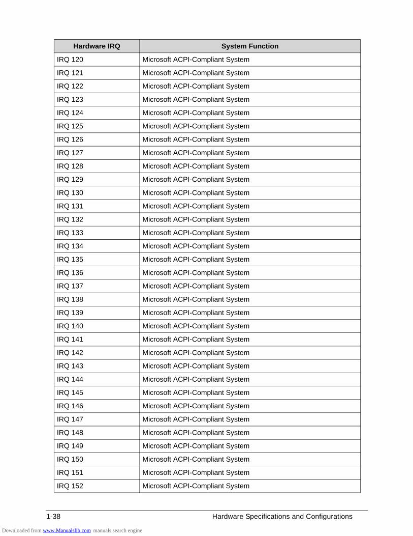
1-38 Hardware Specifications and Configurations
IRQ 120 Microsoft ACPI-Compliant System
IRQ 121 Microsoft ACPI-Compliant System
IRQ 122 Microsoft ACPI-Compliant System
IRQ 123 Microsoft ACPI-Compliant System
IRQ 124 Microsoft ACPI-Compliant System
IRQ 125 Microsoft ACPI-Compliant System
IRQ 126 Microsoft ACPI-Compliant System
IRQ 127 Microsoft ACPI-Compliant System
IRQ 128 Microsoft ACPI-Compliant System
IRQ 129 Microsoft ACPI-Compliant System
IRQ 130 Microsoft ACPI-Compliant System
IRQ 131 Microsoft ACPI-Compliant System
IRQ 132 Microsoft ACPI-Compliant System
IRQ 133 Microsoft ACPI-Compliant System
IRQ 134 Microsoft ACPI-Compliant System
IRQ 135 Microsoft ACPI-Compliant System
IRQ 136 Microsoft ACPI-Compliant System
IRQ 137 Microsoft ACPI-Compliant System
IRQ 138 Microsoft ACPI-Compliant System
IRQ 139 Microsoft ACPI-Compliant System
IRQ 140 Microsoft ACPI-Compliant System
IRQ 141 Microsoft ACPI-Compliant System
IRQ 142 Microsoft ACPI-Compliant System
IRQ 143 Microsoft ACPI-Compliant System
IRQ 144 Microsoft ACPI-Compliant System
IRQ 145 Microsoft ACPI-Compliant System
IRQ 146 Microsoft ACPI-Compliant System
IRQ 147 Microsoft ACPI-Compliant System
IRQ 148 Microsoft ACPI-Compliant System
IRQ 149 Microsoft ACPI-Compliant System
IRQ 150 Microsoft ACPI-Compliant System
IRQ 151 Microsoft ACPI-Compliant System
IRQ 152 Microsoft ACPI-Compliant System
Hardware IRQ System Function
Downloaded from www.Manualslib.com manuals search engine
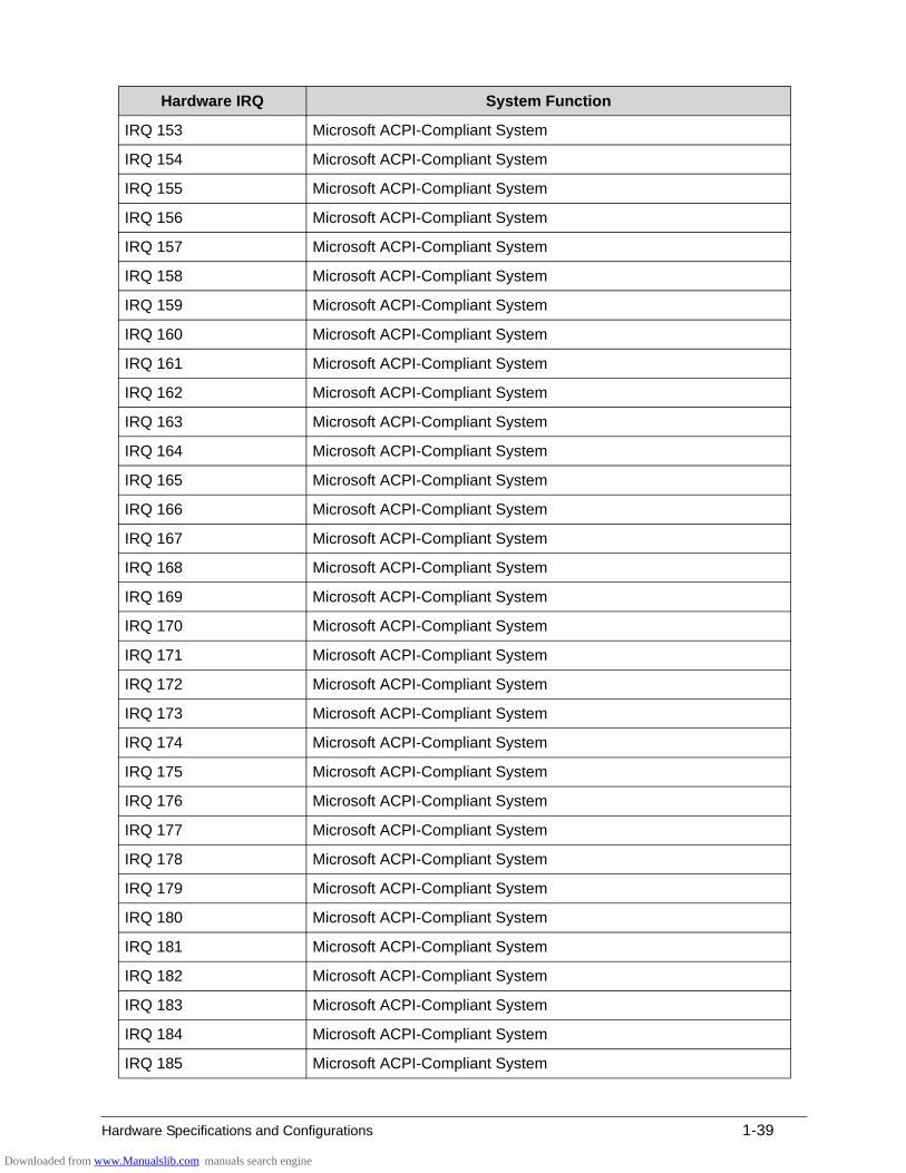
Hardware Specifications and Configurations 1-39
IRQ 153 Microsoft ACPI-Compliant System
IRQ 154 Microsoft ACPI-Compliant System
IRQ 155 Microsoft ACPI-Compliant System
IRQ 156 Microsoft ACPI-Compliant System
IRQ 157 Microsoft ACPI-Compliant System
IRQ 158 Microsoft ACPI-Compliant System
IRQ 159 Microsoft ACPI-Compliant System
IRQ 160 Microsoft ACPI-Compliant System
IRQ 161 Microsoft ACPI-Compliant System
IRQ 162 Microsoft ACPI-Compliant System
IRQ 163 Microsoft ACPI-Compliant System
IRQ 164 Microsoft ACPI-Compliant System
IRQ 165 Microsoft ACPI-Compliant System
IRQ 166 Microsoft ACPI-Compliant System
IRQ 167 Microsoft ACPI-Compliant System
IRQ 168 Microsoft ACPI-Compliant System
IRQ 169 Microsoft ACPI-Compliant System
IRQ 170 Microsoft ACPI-Compliant System
IRQ 171 Microsoft ACPI-Compliant System
IRQ 172 Microsoft ACPI-Compliant System
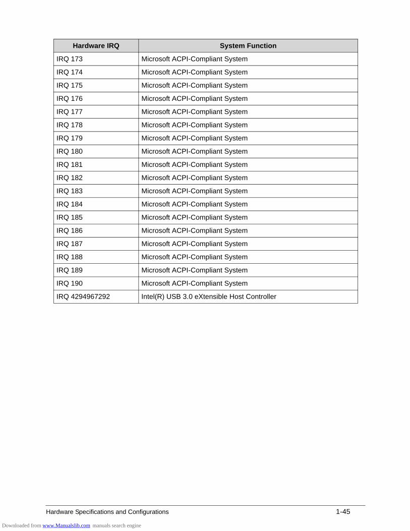
IRQ 173 Microsoft ACPI-Compliant System
IRQ 174 Microsoft ACPI-Compliant System
IRQ 175 Microsoft ACPI-Compliant System
IRQ 176 Microsoft ACPI-Compliant System
IRQ 177 Microsoft ACPI-Compliant System
IRQ 178 Microsoft ACPI-Compliant System
IRQ 179 Microsoft ACPI-Compliant System
IRQ 180 Microsoft ACPI-Compliant System
IRQ 181 Microsoft ACPI-Compliant System
IRQ 182 Microsoft ACPI-Compliant System
IRQ 183 Microsoft ACPI-Compliant System
IRQ 184 Microsoft ACPI-Compliant System
IRQ 185 Microsoft ACPI-Compliant System
Hardware IRQ System Function
Downloaded from www.Manualslib.com manuals search engine
1-40 Hardware Specifications and Configurations
IRQ 186 Microsoft ACPI-Compliant System
IRQ 187 Microsoft ACPI-Compliant System
IRQ 188 Microsoft ACPI-Compliant System
IRQ 189 Microsoft ACPI-Compliant System
IRQ 190 Microsoft ACPI-Compliant System
IRQ 0 System timer
IRQ 18 Intel(R) 7 Series/C216 Chipset Family PCI Express Root Port 3 - 1E14
IRQ 18 Synaptics SMBus Driver
IRQ 1 Standard PS/2 Keyboard
IRQ 4294967292 Realtek PCIE CardReader
IRQ 8 System CMOS/real time clock
IRQ 4294967291 Realtek PCIe GBE Family Controller
IRQ 22 High Definition Audio Controller
IRQ 13 Numeric data processor
IRQ 23 Intel(R) 7 Series/C216 Chipset Family USB Enhanced Host Controller - 1E26
Hardware IRQ System Function
Downloaded from www.Manualslib.com manuals search engine
Hardware Specifications and Configurations 1-41
System Interrupt Specification (Discrete)
Hardware IRQ System Function
IRQ0 System timer
IRQ1 Standard PS/2 keyboard
IRQ2 Not in use
IRQ3 Not in use
IRQ5 Not in use
IRQ6 Not in use
IRQ7 Not in use
IRQ8 System CMOS/real time clock
IRQ9 Broadcom xD Picture Card Host Controller
IRQ10 Not in use
IRQ11 Not in use
IRQ12 PS/2 port Touchpad
IRQ13 Numeric data processor
IRQ14 Not in use
IRQ15 Not in use
IRQ 16 NVIDIA GeForce GT 620M
IRQ 16 Intel(R) 7 Series/C216 Chipset Family PCI Express Root Port 1 - 1E10
IRQ 16 Intel(R) Management Engine Interface
IRQ 16 Xeon E3-1200/2nd Generation Intel(R) Core(TM) Processor Family PCI Express Root Port - 0101
IRQ 16 Intel(R) 7 Series/C216 Chipset Family USB Enhanced Host Controller - 1E2D
IRQ 0 System timer
IRQ 4294967291 Realtek PCIE CardReader
IRQ 18 Intel(R) 7 Series/C216 Chipset Family PCI Express Root Port 3 - 1E14
IRQ 1 Standard PS/2 Keyboard
IRQ 4294967294 Realtek PCIe GBE Family Controller
IRQ 19 Intel(R) 7 Series/C216 Chipset Family PCI Express Root Port 4 - 1E16
IRQ 19 Qualcomm Atheros AR5BWB222 Wireless Network Adapter
IRQ 19 Intel(R) 7 Series Chipset Family SATA AHCI Controller
IRQ 8 System CMOS/real time clock
Downloaded from www.Manualslib.com manuals search engine
1-42 Hardware Specifications and Configurations
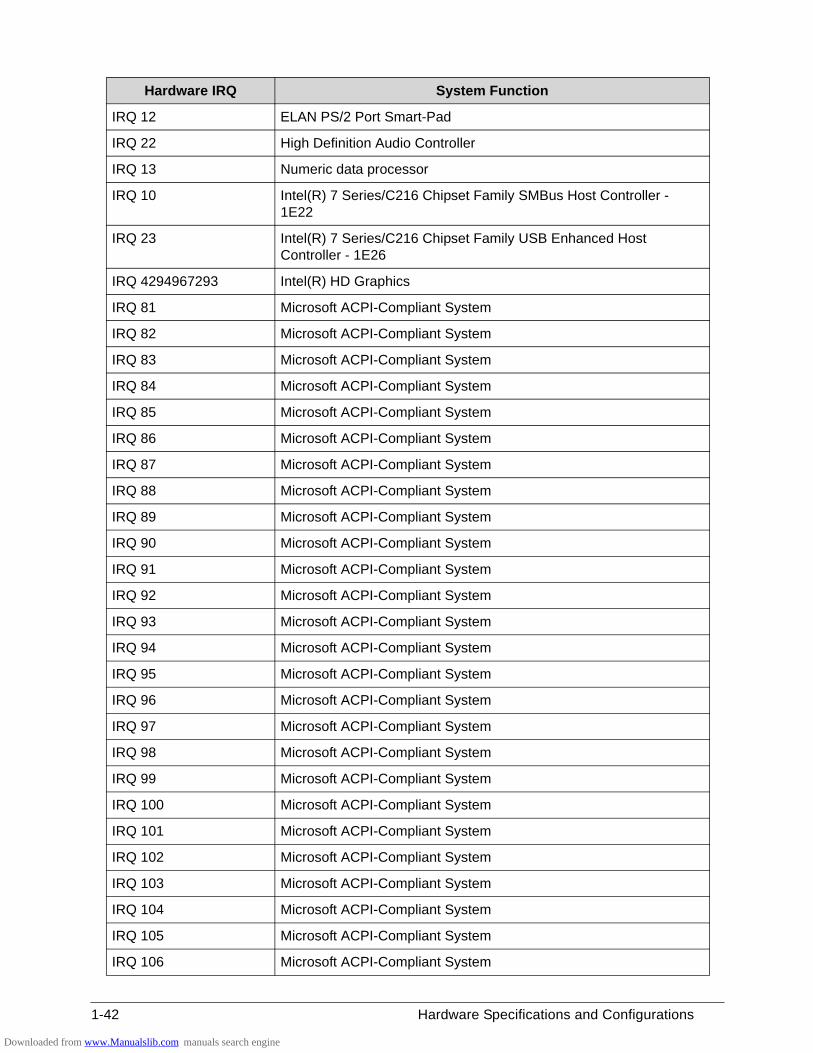
IRQ 12 ELAN PS/2 Port Smart-Pad
IRQ 22 High Definition Audio Controller
IRQ 13 Numeric data processor
IRQ 10 Intel(R) 7 Series/C216 Chipset Family SMBus Host Controller - 1E22
IRQ 23 Intel(R) 7 Series/C216 Chipset Family USB Enhanced Host Controller - 1E26
IRQ 4294967293 Intel(R) HD Graphics
IRQ 81 Microsoft ACPI-Compliant System
IRQ 82 Microsoft ACPI-Compliant System
IRQ 83 Microsoft ACPI-Compliant System
IRQ 84 Microsoft ACPI-Compliant System
IRQ 85 Microsoft ACPI-Compliant System
IRQ 86 Microsoft ACPI-Compliant System
IRQ 87 Microsoft ACPI-Compliant System
IRQ 88 Microsoft ACPI-Compliant System
IRQ 89 Microsoft ACPI-Compliant System
IRQ 90 Microsoft ACPI-Compliant System
IRQ 91 Microsoft ACPI-Compliant System
IRQ 92 Microsoft ACPI-Compliant System
IRQ 93 Microsoft ACPI-Compliant System
IRQ 94 Microsoft ACPI-Compliant System
IRQ 95 Microsoft ACPI-Compliant System
IRQ 96 Microsoft ACPI-Compliant System
IRQ 97 Microsoft ACPI-Compliant System
IRQ 98 Microsoft ACPI-Compliant System
IRQ 99 Microsoft ACPI-Compliant System
IRQ 100 Microsoft ACPI-Compliant System
IRQ 101 Microsoft ACPI-Compliant System
IRQ 102 Microsoft ACPI-Compliant System
IRQ 103 Microsoft ACPI-Compliant System
IRQ 104 Microsoft ACPI-Compliant System
IRQ 105 Microsoft ACPI-Compliant System
IRQ 106 Microsoft ACPI-Compliant System
Hardware IRQ System Function
Downloaded from www.Manualslib.com manuals search engine

Hardware Specifications and Configurations 1-43
IRQ 107 Microsoft ACPI-Compliant System
IRQ 108 Microsoft ACPI-Compliant System
IRQ 109 Microsoft ACPI-Compliant System
IRQ 110 Microsoft ACPI-Compliant System
IRQ 111 Microsoft ACPI-Compliant System
IRQ 112 Microsoft ACPI-Compliant System
IRQ 113 Microsoft ACPI-Compliant System
IRQ 114 Microsoft ACPI-Compliant System
IRQ 115 Microsoft ACPI-Compliant System
IRQ 116 Microsoft ACPI-Compliant System
IRQ 117 Microsoft ACPI-Compliant System
IRQ 118 Microsoft ACPI-Compliant System
IRQ 119 Microsoft ACPI-Compliant System
IRQ 120 Microsoft ACPI-Compliant System
IRQ 121 Microsoft ACPI-Compliant System
IRQ 122 Microsoft ACPI-Compliant System
IRQ 123 Microsoft ACPI-Compliant System
IRQ 124 Microsoft ACPI-Compliant System
IRQ 125 Microsoft ACPI-Compliant System
IRQ 126 Microsoft ACPI-Compliant System
IRQ 127 Microsoft ACPI-Compliant System
IRQ 128 Microsoft ACPI-Compliant System
IRQ 129 Microsoft ACPI-Compliant System
IRQ 130 Microsoft ACPI-Compliant System
IRQ 131 Microsoft ACPI-Compliant System
IRQ 132 Microsoft ACPI-Compliant System
IRQ 133 Microsoft ACPI-Compliant System
IRQ 134 Microsoft ACPI-Compliant System
IRQ 135 Microsoft ACPI-Compliant System
IRQ 136 Microsoft ACPI-Compliant System
IRQ 137 Microsoft ACPI-Compliant System
IRQ 138 Microsoft ACPI-Compliant System
IRQ 139 Microsoft ACPI-Compliant System
Hardware IRQ System Function
Downloaded from www.Manualslib.com manuals search engine
1-44 Hardware Specifications and Configurations
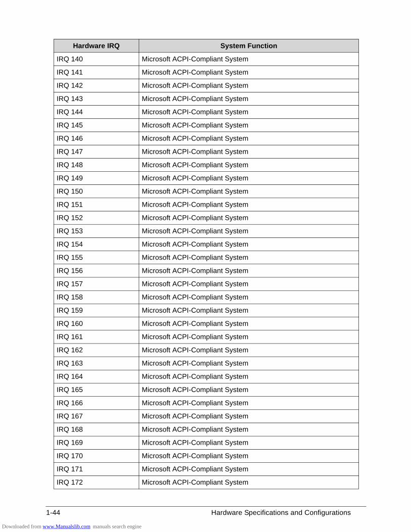
IRQ 140 Microsoft ACPI-Compliant System
IRQ 141 Microsoft ACPI-Compliant System
IRQ 142 Microsoft ACPI-Compliant System
IRQ 143 Microsoft ACPI-Compliant System
IRQ 144 Microsoft ACPI-Compliant System
IRQ 145 Microsoft ACPI-Compliant System
IRQ 146 Microsoft ACPI-Compliant System
IRQ 147 Microsoft ACPI-Compliant System
IRQ 148 Microsoft ACPI-Compliant System
IRQ 149 Microsoft ACPI-Compliant System
IRQ 150 Microsoft ACPI-Compliant System
IRQ 151 Microsoft ACPI-Compliant System
IRQ 152 Microsoft ACPI-Compliant System
IRQ 153 Microsoft ACPI-Compliant System
IRQ 154 Microsoft ACPI-Compliant System
IRQ 155 Microsoft ACPI-Compliant System
IRQ 156 Microsoft ACPI-Compliant System
IRQ 157 Microsoft ACPI-Compliant System
IRQ 158 Microsoft ACPI-Compliant System
IRQ 159 Microsoft ACPI-Compliant System
IRQ 160 Microsoft ACPI-Compliant System
IRQ 161 Microsoft ACPI-Compliant System
IRQ 162 Microsoft ACPI-Compliant System
IRQ 163 Microsoft ACPI-Compliant System
IRQ 164 Microsoft ACPI-Compliant System
IRQ 165 Microsoft ACPI-Compliant System
IRQ 166 Microsoft ACPI-Compliant System
IRQ 167 Microsoft ACPI-Compliant System
IRQ 168 Microsoft ACPI-Compliant System
IRQ 169 Microsoft ACPI-Compliant System
IRQ 170 Microsoft ACPI-Compliant System
IRQ 171 Microsoft ACPI-Compliant System
IRQ 172 Microsoft ACPI-Compliant System
Hardware IRQ System Function
Downloaded from www.Manualslib.com manuals search engine
Hardware Specifications and Configurations 1-45
IRQ 173 Microsoft ACPI-Compliant System
IRQ 174 Microsoft ACPI-Compliant System
IRQ 175 Microsoft ACPI-Compliant System
IRQ 176 Microsoft ACPI-Compliant System
IRQ 177 Microsoft ACPI-Compliant System
IRQ 178 Microsoft ACPI-Compliant System
IRQ 179 Microsoft ACPI-Compliant System
IRQ 180 Microsoft ACPI-Compliant System
IRQ 181 Microsoft ACPI-Compliant System
IRQ 182 Microsoft ACPI-Compliant System
IRQ 183 Microsoft ACPI-Compliant System
IRQ 184 Microsoft ACPI-Compliant System
IRQ 185 Microsoft ACPI-Compliant System
IRQ 186 Microsoft ACPI-Compliant System
IRQ 187 Microsoft ACPI-Compliant System
IRQ 188 Microsoft ACPI-Compliant System
IRQ 189 Microsoft ACPI-Compliant System
IRQ 190 Microsoft ACPI-Compliant System
IRQ 4294967292 Intel(R) USB 3.0 eXtensible Host Controller
Hardware IRQ System Function
Downloaded from www.Manualslib.com manuals search engine
1-46 Hardware Specifications and Configurations
System IO Address Map (UMA)
I/O address (hex) System Function (shipping configuration)
3000-303F Intel(R) HD Graphics 3000
03B0-03BB Intel(R) HD Graphics 3000
03C0-03DF Intel(R) HD Graphics 3000
3088-308F Intel(R) 7 Series Chipset Family SATA AHCI Controller
309C-309F Intel(R) 7 Series Chipset Family SATA AHCI Controller
3080-3087 Intel(R) 7 Series Chipset Family SATA AHCI Controller
3098-309B Intel(R) 7 Series Chipset Family SATA AHCI Controller
3060-307F Intel(R) 7 Series Chipset Family SATA AHCI Controller
0454-0457 Motherboard resources
0020-0021 Programmable interrupt controller
0024-0025 Programmable interrupt controller
0028-0029 Programmable interrupt controller
002C-002D Programmable interrupt controller
0030-0031 Programmable interrupt controller
0034-0035 Programmable interrupt controller
0038-0039 Programmable interrupt controller
003C-003D Programmable interrupt controller
00A0-00A1 Programmable interrupt controller
00A4-00A5 Programmable interrupt controller
00A8-00A9 Programmable interrupt controller
00AC-00AD Programmable interrupt controller
00B0-00B1 Programmable interrupt controller
00B4-00B5 Programmable interrupt controller
00B8-00B9 Programmable interrupt controller
00BC-00BD Programmable interrupt controller
04D0-04D1 Programmable interrupt controller
0040-0043 System timer
0050-0053 System timer
2000-2FFF Intel(R) 7 Series/C216 Chipset Family PCI Express Root Port 3 - 1E14
0000-001F PCI bus
0081-0091 Direct memory access controller
0093-009F Direct memory access controller
Downloaded from www.Manualslib.com manuals search engine
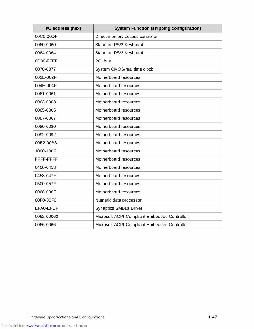
Hardware Specifications and Configurations 1-47
00C0-00DF Direct memory access controller
0060-0060 Standard PS/2 Keyboard
0064-0064 Standard PS/2 Keyboard
0D00-FFFF PCI bus
0070-0077 System CMOS/real time clock
002E-002F Motherboard resources
004E-004F Motherboard resources
0061-0061 Motherboard resources
0063-0063 Motherboard resources
0065-0065 Motherboard resources
0067-0067 Motherboard resources
0080-0080 Motherboard resources
0092-0092 Motherboard resources
00B2-00B3 Motherboard resources
1000-100F Motherboard resources
FFFF-FFFF Motherboard resources
0400-0453 Motherboard resources
0458-047F Motherboard resources
0500-057F Motherboard resources
0068-006F Motherboard resources
00F0-00F0 Numeric data processor
EFA0-EFBF Synaptics SMBus Driver
0062-00062 Microsoft ACPI-Compliant Embedded Controller
0066-0066 Microsoft ACPI-Compliant Embedded Controller
I/O address (hex) System Function (shipping configuration)
Downloaded from www.Manualslib.com manuals search engine
1-48 Hardware Specifications and Configurations
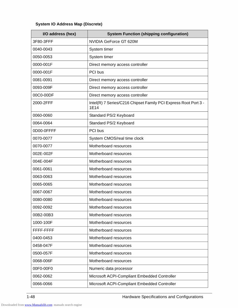
System IO Address Map (Discrete)
I/O address (hex) System Function (shipping configuration)
3F80-3FFF NVIDIA GeForce GT 620M
0040-0043 System timer
0050-0053 System timer
0000-001F Direct memory access controller
0000-001F PCI bus
0081-0091 Direct memory access controller
0093-009F Direct memory access controller
00C0-00DF Direct memory access controller
2000-2FFF Intel(R) 7 Series/C216 Chipset Family PCI Express Root Port 3 - 1E14
0060-0060 Standard PS/2 Keyboard
0064-0064 Standard PS/2 Keyboard
0D00-0FFFF PCI bus
0070-0077 System CMOS/real time clock
0070-0077 Motherboard resources
002E-002F Motherboard resources
004E-004F Motherboard resources
0061-0061 Motherboard resources
0063-0063 Motherboard resources
0065-0065 Motherboard resources
0067-0067 Motherboard resources
0080-0080 Motherboard resources
0092-0092 Motherboard resources
00B2-00B3 Motherboard resources
1000-100F Motherboard resources
FFFF-FFFF Motherboard resources
0400-0453 Motherboard resources
0458-047F Motherboard resources
0500-057F Motherboard resources
0068-006F Motherboard resources
00F0-00F0 Numeric data processor
0062-0062 Microsoft ACPI-Compliant Embedded Controller
0066-0066 Microsoft ACPI-Compliant Embedded Controller
Downloaded from www.Manualslib.com manuals search engine
Hardware Specifications and Configurations 1-49
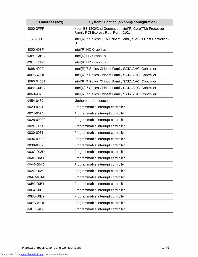
3000-3FFF Xeon E3-1200/2nd Generation Intel(R) Core(TM) Processor Family PCI Express Root Port - 0101
EFA0-EFBF Intel(R) 7 Series/C216 Chipset Family SMBus Host Controller - 1E22
4000-403F Intel(R) HD Graphics
03B0-03BB Intel(R) HD Graphics
03C0-03DF Intel(R) HD Graphics
4098-409F Intel(R) 7 Series Chipset Family SATA AHCI Controller
40BC-40BF Intel(R) 7 Series Chipset Family SATA AHCI Controller
4090-04097 Intel(R) 7 Series Chipset Family SATA AHCI Controller
40B8-40BB Intel(R) 7 Series Chipset Family SATA AHCI Controller
4060-407F Intel(R) 7 Series Chipset Family SATA AHCI Controller
0454-0457 Motherboard resources
0020-0021 Programmable interrupt controller
0024-0025 Programmable interrupt controller
0028-00029 Programmable interrupt controller
002C-002D Programmable interrupt controller
0030-0031 Programmable interrupt controller
0034-00035 Programmable interrupt controller
0038-0039 Programmable interrupt controller
003C-003D Programmable interrupt controller
00A0-00A1 Programmable interrupt controller
00A4-00A5 Programmable interrupt controller
00A8-00A9 Programmable interrupt controller
00AC-00AD Programmable interrupt controller
00B0-00B1 Programmable interrupt controller
00B4-00B5 Programmable interrupt controller
00B8-00B9 Programmable interrupt controller
00BC-00BD Programmable interrupt controller
04D0-04D1 Programmable interrupt controller
I/O address (hex) System Function (shipping configuration)
Downloaded from www.Manualslib.com manuals search engine

1-50 Hardware Specifications and Configurations
Downloaded from www.Manualslib.com manuals search engine
CHAPTER 2
System Utilities
Downloaded from www.Manualslib.com manuals search engine
2-2
BIOS Setup Utility . . . . . . . . . . . . . . . . . . . . . . . . . . . . . . . . . . . . .2-3Navigating the BIOS Utility . . . . . . . . . . . . . . . . . . . . . . . . . . . .2-3BIOS Menus . . . . . . . . . . . . . . . . . . . . . . . . . . . . . . . . . . . . . . .2-4Main. . . . . . . . . . . . . . . . . . . . . . . . . . . . . . . . . . . . . . . . . . . . . .2-6Security . . . . . . . . . . . . . . . . . . . . . . . . . . . . . . . . . . . . . . . . . . .2-8Boot . . . . . . . . . . . . . . . . . . . . . . . . . . . . . . . . . . . . . . . . . . . . . .2-11Exit. . . . . . . . . . . . . . . . . . . . . . . . . . . . . . . . . . . . . . . . . . . . . . .2-12
BIOS Flash Utilities. . . . . . . . . . . . . . . . . . . . . . . . . . . . . . . . . . . .2-13
DOS Flash Utility . . . . . . . . . . . . . . . . . . . . . . . . . . . . . . . . . . . .2-14WinFlash Utility . . . . . . . . . . . . . . . . . . . . . . . . . . . . . . . . . . . . .2-14
Remove HDD/BIOS Password Utilities . . . . . . . . . . . . . . . . . . . .2-15
Removing the HDD Password . . . . . . . . . . . . . . . . . . . . . . . . . .2-15Removing the BIOS Passwords . . . . . . . . . . . . . . . . . . . . . . . .2-16Clearing the BIOS Passwords . . . . . . . . . . . . . . . . . . . . . . . . . .2-17
Using DMI Tools . . . . . . . . . . . . . . . . . . . . . . . . . . . . . . . . . . . . . .2-18
LAN EEPROM Utility . . . . . . . . . . . . . . . . . . . . . . . . . . . . . . . . .2-18
Downloaded from www.Manualslib.com manuals search engine
System Utilities 2-3
System Utilities
BIOS Setup Utility 0
This utility is a hardware configuration program built into a computer’s BIOS (Basic Input/Output System).
The utility is pre-configured and optimized so most users do not need to run it. If configuration problems occur, the setup utility may need to be run. Refer to Chapter 4, Troubleshooting when a problem arises.
To enter this utility, during POST (power-on self-test), press F2 when the prompt appears on the bottom of screen.
The default setting of the F12 Boot Menu is Disabled. To change the boot device without entering the BIOS Setup Utility, set the parameter to Enabled. During the next POST, press F12 to enter the multi-boot menu.
Navigating the BIOS Utility 0
The BIOS Setup Utility has five menu options, namely:
Information
Main
Security
Boot
Exit
Perform the following actions to navigate through the BIOS Setup Utility:
Press to select items in the menu bar.
Press to select an item in the menu screen or in an option box.
Press F5 or F6 to change the parameter value.
Press Esc to exit from the Setup Utility.
Press F9 to load the default settings.
Press F10 to save changes and exit from the Setup Utility.
NOTE:NOTE:Parameter values enclosed in square brackets [ ] can be change. Navigation keys appear on the bottom of the screen. Read the item specific help on the right area of the screen before making changes to the parameter values.
NOTE:NOTE:System information can vary depending on the computer model.
Downloaded from www.Manualslib.com manuals search engine
2-4 System Utilities
BIOS Menus 0
This section describes the Phoenix SecureCore Tiano BIOS Setup Utility menu tabs.
NOTE:NOTE:The screenshots used in this chapter are for reference only. Actual values can vary depending on the computer model.
Information 0
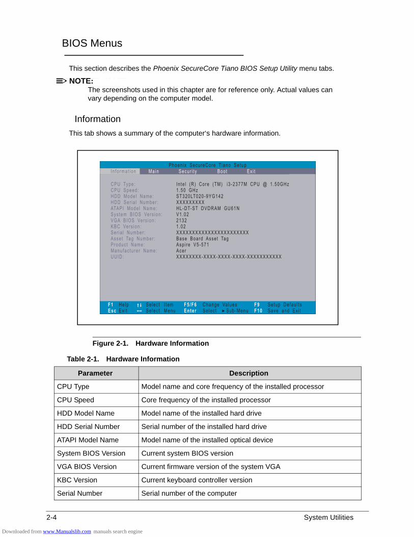
This tab shows a summary of the computer‘s hardware information.
Figure 2-1. Hardware Information
Table 2-1. Hardware Information
Parameter Description
CPU Type Model name and core frequency of the installed processor
CPU Speed Core frequency of the installed processor
HDD Model Name Model name of the installed hard drive
HDD Serial Number Serial number of the installed hard drive
ATAPI Model Name Model name of the installed optical device
System BIOS Version Current system BIOS version
VGA BIOS Version Current firmware version of the system VGA
KBC Version Current keyboard controller version
Serial Number Serial number of the computer
Downloaded from www.Manualslib.com manuals search engine
System Utilities 2-5
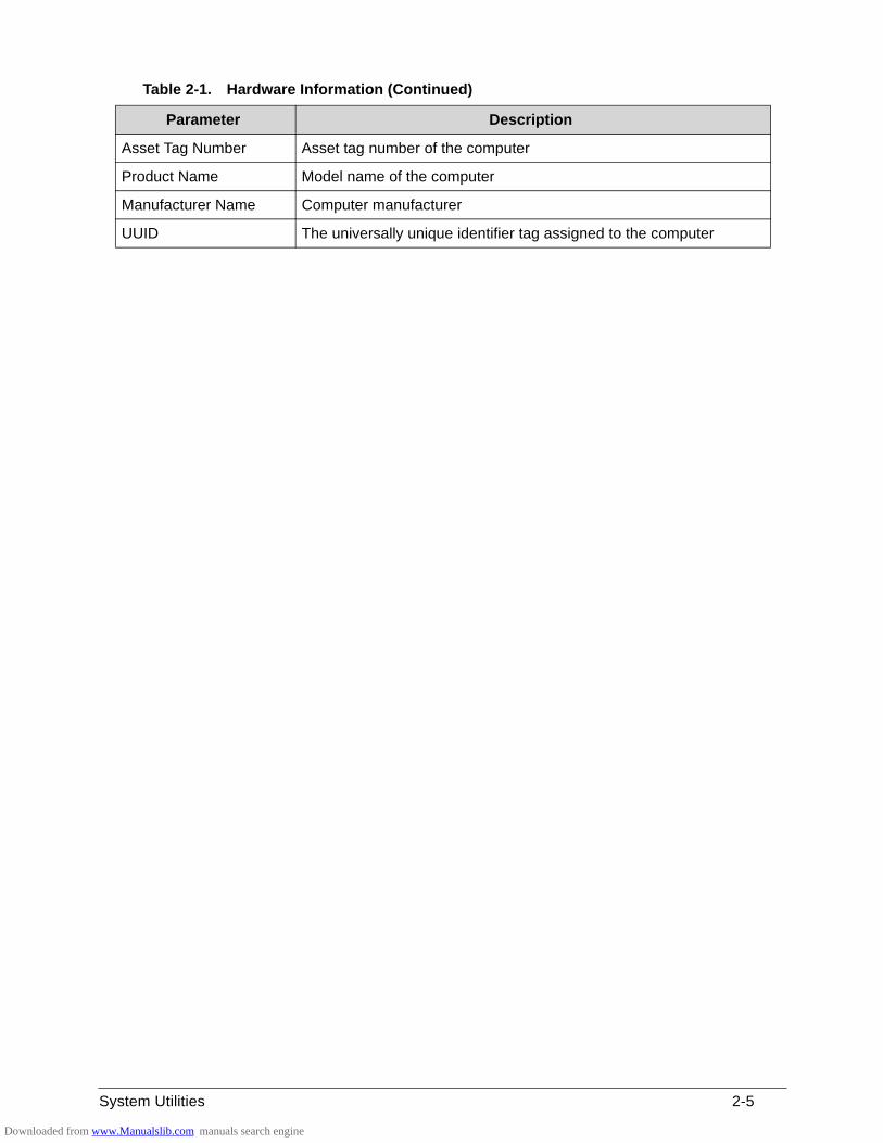
Asset Tag Number Asset tag number of the computer
Product Name Model name of the computer
Manufacturer Name Computer manufacturer
UUID The universally unique identifier tag assigned to the computer
Table 2-1. Hardware Information (Continued)
Parameter Description
Downloaded from www.Manualslib.com manuals search engine
2-6 System Utilities
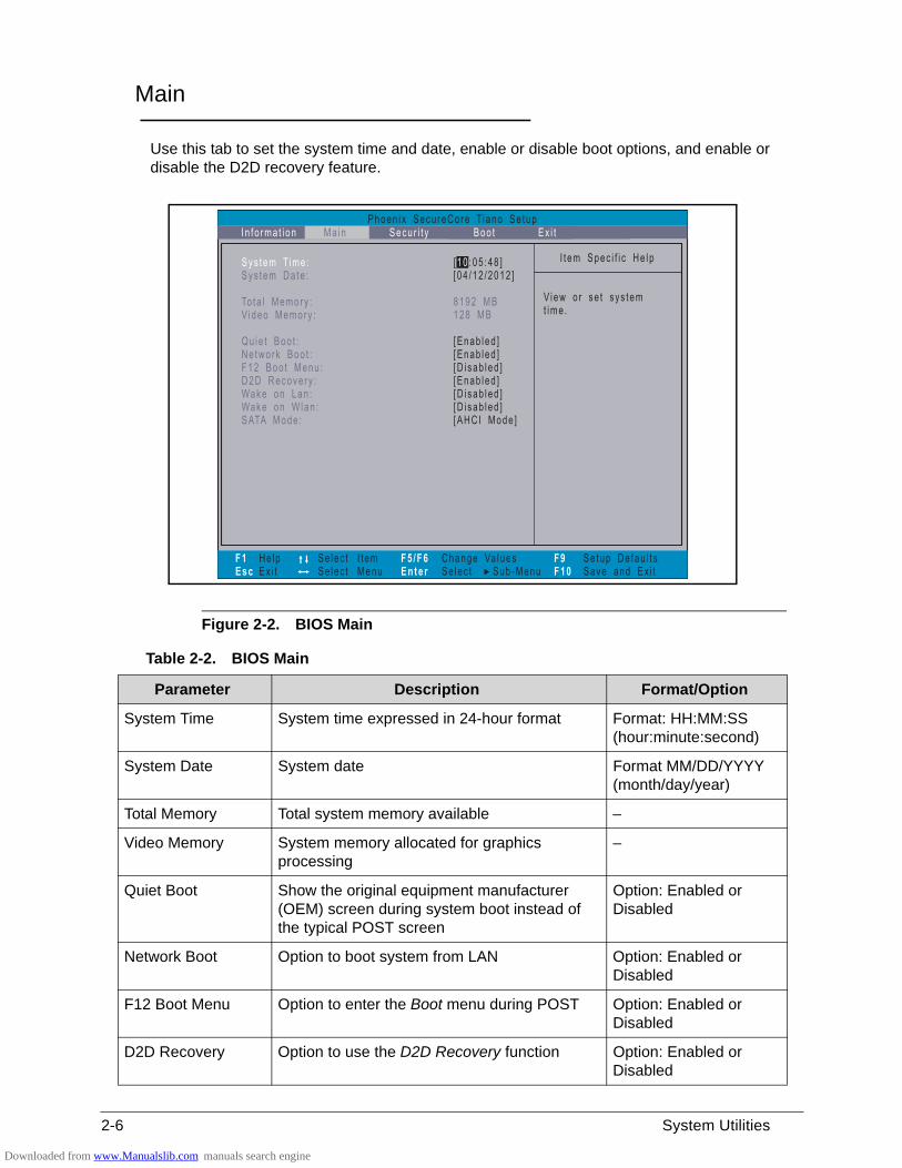
Main 0
Use this tab to set the system time and date, enable or disable boot options, and enable or disable the D2D recovery feature.
Figure 2-2. BIOS Main
Table 2-2. BIOS Main
Parameter Description Format/Option
System Time System time expressed in 24-hour format Format: HH:MM:SS (hour:minute:second)
System Date System date Format MM/DD/YYYY (month/day/year)
Total Memory Total system memory available –
Video Memory System memory allocated for graphics processing
–
Quiet Boot Show the original equipment manufacturer (OEM) screen during system boot instead of the typical POST screen
Option: Enabled or Disabled
Network Boot Option to boot system from LAN Option: Enabled or Disabled
F12 Boot Menu Option to enter the Boot menu during POST Option: Enabled or Disabled
D2D Recovery Option to use the D2D Recovery function Option: Enabled or Disabled
Downloaded from www.Manualslib.com manuals search engine
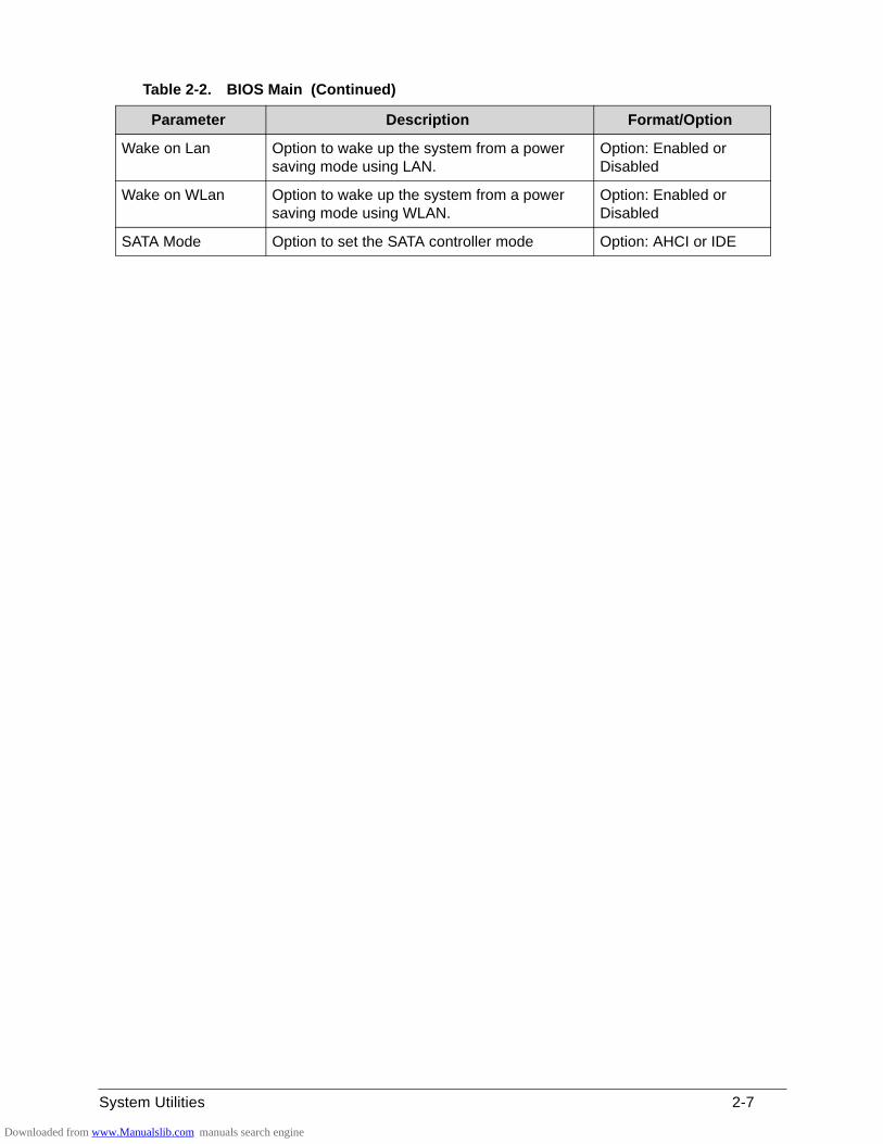
System Utilities 2-7
Wake on Lan Option to wake up the system from a power saving mode using LAN.
Option: Enabled or Disabled
Wake on WLan Option to wake up the system from a power saving mode using WLAN.
Option: Enabled or Disabled
SATA Mode Option to set the SATA controller mode Option: AHCI or IDE
Table 2-2. BIOS Main (Continued)
Parameter Description Format/Option
Downloaded from www.Manualslib.com manuals search engine
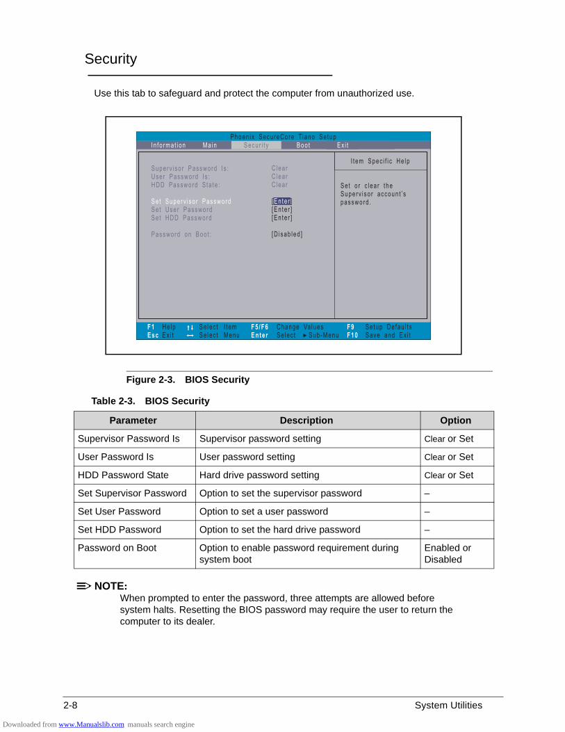
2-8 System Utilities
Security 0
Use this tab to safeguard and protect the computer from unauthorized use.
Figure 2-3. BIOS Security
NOTE:NOTE:When prompted to enter the password, three attempts are allowed before system halts. Resetting the BIOS password may require the user to return the computer to its dealer.
Table 2-3. BIOS Security
Parameter Description Option
Supervisor Password Is Supervisor password setting Clear or Set
User Password Is User password setting Clear or Set
HDD Password State Hard drive password setting Clear or Set
Set Supervisor Password Option to set the supervisor password –
Set User Password Option to set a user password –
Set HDD Password Option to set the hard drive password –
Password on Boot Option to enable password requirement during system boot
Enabled or Disabled
Downloaded from www.Manualslib.com manuals search engine
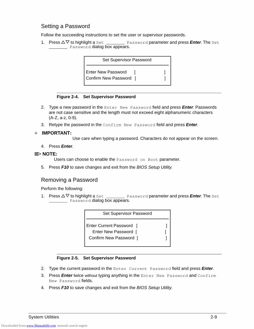
System Utilities 2-9
Setting a Password 0
Follow the succeeding instructions to set the user or supervisor passwords.
1. Press to highlight a Set _______ Password parameter and press Enter. The Set _______ Password dialog box appears.
Figure 2-4. Set Supervisor Password
2. Type a new password in the Enter New Password field and press Enter. Passwords are not case sensitive and the length must not exceed eight alphanumeric characters (A-Z, a-z, 0-9).
3. Retype the password in the Confirm New Password field and press Enter.
IMPORTANT:+Use care when typing a password. Characters do not appear on the screen.
4. Press Enter.
NOTE:NOTE:Users can choose to enable the Password on Boot parameter.
5. Press F10 to save changes and exit from the BIOS Setup Utility.
Removing a Password 0
Perform the following:
1. Press to highlight a Set _______ Password parameter and press Enter. The Set _______ Password dialog box appears.
Figure 2-5. Set Supervisor Password
2. Type the current password in the Enter Current Password field and press Enter.
3. Press Enter twice without typing anything in the Enter New Password and Confirm New Password fields.
4. Press F10 to save changes and exit from the BIOS Setup Utility.
Set Supervisor Password
Enter New Password [ ]
Confirm New Password [ ]
Set Supervisor Password
Enter Current Password [ ]
Enter New Password [ ]
Confirm New Password [ ]
Downloaded from www.Manualslib.com manuals search engine
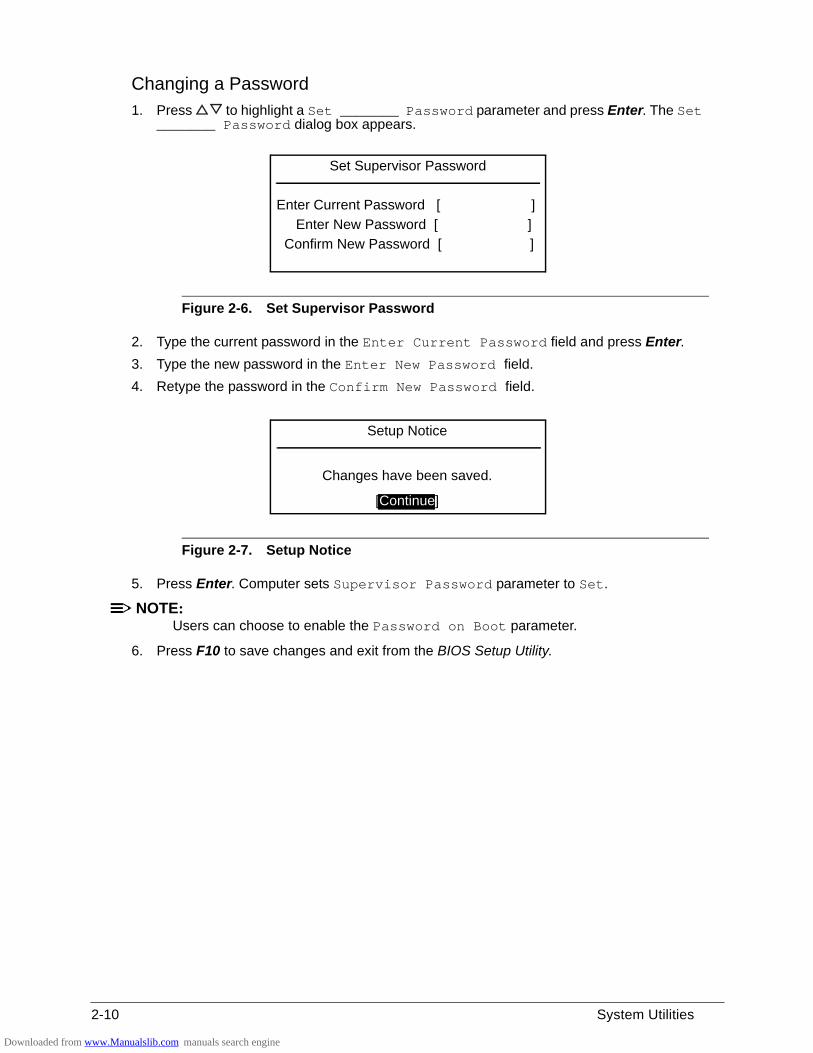
2-10 System Utilities
Changing a Password 0
1. Press to highlight a Set _______ Password parameter and press Enter. The Set _______ Password dialog box appears.
Figure 2-6. Set Supervisor Password
2. Type the current password in the Enter Current Password field and press Enter.
3. Type the new password in the Enter New Password field.
4. Retype the password in the Confirm New Password field.
Figure 2-7. Setup Notice
5. Press Enter. Computer sets Supervisor Password parameter to Set.
NOTE:NOTE:Users can choose to enable the Password on Boot parameter.
6. Press F10 to save changes and exit from the BIOS Setup Utility.
Set Supervisor Password
Enter Current Password [ ]
Enter New Password [ ]
Confirm New Password [ ]
Setup Notice
Changes have been saved.
[Continue]
Downloaded from www.Manualslib.com manuals search engine
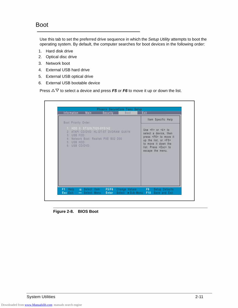
System Utilities 2-11
Boot 0
Use this tab to set the preferred drive sequence in which the Setup Utility attempts to boot the operating system. By default, the computer searches for boot devices in the following order:
1. Hard disk drive
2. Optical disc drive
3. Network boot
4. External USB hard drive
5. External USB optical drive
6. External USB bootable device
Press to select a device and press F5 or F6 to move it up or down the list.
Figure 2-8. BIOS Boot
Downloaded from www.Manualslib.com manuals search engine
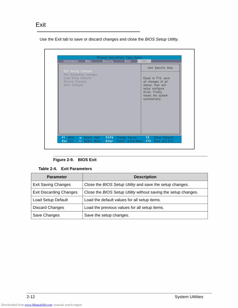
2-12 System Utilities
Exit 0
Use the Exit tab to save or discard changes and close the BIOS Setup Utility.
Figure 2-9. BIOS Exit
Table 2-4. Exit Parameters
Parameter Description
Exit Saving Changes Close the BIOS Setup Utility and save the setup changes.
Exit Discarding Changes Close the BIOS Setup Utility without saving the setup changes.
Load Setup Default Load the default values for all setup items.
Discard Changes Load the previous values for all setup items.
Save Changes Save the setup changes.
Downloaded from www.Manualslib.com manuals search engine
System Utilities 2-13
BIOS Flash Utilities 0
BIOS Flash memory updates are required for the following conditions:
New versions of system programs
New features or options
Restore a BIOS when it becomes corrupted.
Use the Flash utility to update the system BIOS Flash ROM.
NOTE:NOTE:If a Crisis Recovery Disc is not available, create one before Flash utility is used.
NOTE:NOTE:Do not install memory related drivers (XMS, EMS, DPMI) when Flash is used.
NOTE:NOTE:Use AC adaptor power supply when running Flash utility. If battery pack does not contain power to finish loading BIOS Flash, do not boot system.
Perform the following to run Flash.
1. Rename the BIOS file as “XXXXXXX.FD”.
2. Copy the “XXXXXXX.FD” file to a bootable USB device containing the Crisis Recovery disk files.
3. Turn off the computer.
4. Insert the USB device containing the renamed BIOS file and the Crisis Recovery disk files to any USB port.
5. Press and hold the Fn + Esc keys (this is the BIOS recovery hotkey), then press the power button.
6. Release the Fn + Esc keys after POST.
NOTE:NOTE:Flash utility has auto execution function.
Downloaded from www.Manualslib.com manuals search engine
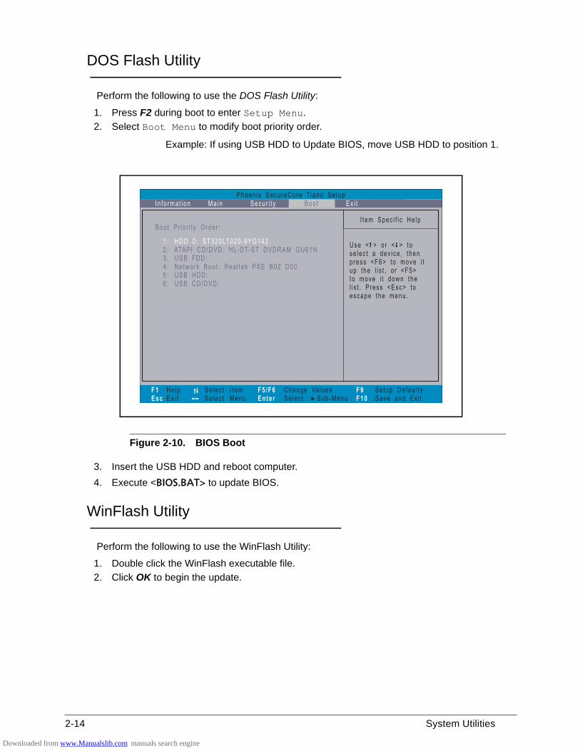
2-14 System Utilities
DOS Flash Utility 0
Perform the following to use the DOS Flash Utility:
1. Press F2 during boot to enter Setup Menu.
2. Select Boot Menu to modify boot priority order.
Example: If using USB HDD to Update BIOS, move USB HDD to position 1.
Figure 2-10. BIOS Boot
3. Insert the USB HDD and reboot computer.
4. Execute <BIOS.BAT> to update BIOS.
WinFlash Utility 0
Perform the following to use the WinFlash Utility:
1. Double click the WinFlash executable file.
2. Click OK to begin the update.
Downloaded from www.Manualslib.com manuals search engine
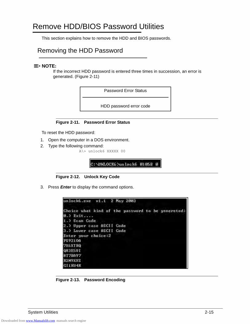
System Utilities 2-15
Remove HDD/BIOS Password Utilities 0
This section explains how to remove the HDD and BIOS passwords.
Removing the HDD Password 0
NOTE:NOTE:If the incorrect HDD password is entered three times in succession, an error is generated. (Figure 2-11)
Figure 2-11. Password Error Status
To reset the HDD password:
1. Open the computer in a DOS environment.
2. Type the following command: A\> unlock6 XXXXX 00
Figure 2-12. Unlock Key Code
3. Press Enter to display the command options.
Figure 2-13. Password Encoding
Password Error Status
HDD password error code
Downloaded from www.Manualslib.com manuals search engine
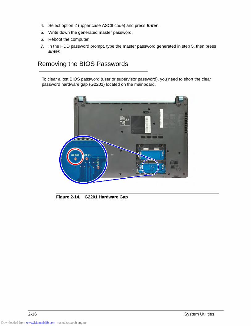
2-16 System Utilities
4. Select option 2 (upper case ASCII code) and press Enter.
5. Write down the generated master password.
6. Reboot the computer.
7. In the HDD password prompt, type the master password generated in step 5, then press Enter.
Removing the BIOS Passwords 0
To clear a lost BIOS password (user or supervisor password), you need to short the clear password hardware gap (G2201) located on the mainboard.
Figure 2-14. G2201 Hardware Gap
Downloaded from www.Manualslib.com manuals search engine
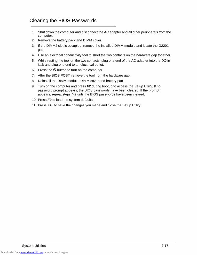
System Utilities 2-17
Clearing the BIOS Passwords 0
1. Shut down the computer and disconnect the AC adapter and all other peripherals from the computer.
2. Remove the battery pack and DIMM cover.
3. If the DIMM2 slot is occupied, remove the installed DIMM module and locate the G2201 gap.
4. Use an electrical conductivity tool to short the two contacts on the hardware gap together.
5. While resting the tool on the two contacts, plug one end of the AC adapter into the DC-in jack and plug one end to an electrical outlet.
6. Press the button to turn on the computer.
7. After the BIOS POST, remove the tool from the hardware gap.
8. Reinstall the DIMM module, DIMM cover and battery pack.
9. Turn on the computer and press F2 during bootup to access the Setup Utility. If no password prompt appears, the BIOS passwords have been cleared. If the prompt appears, repeat steps 4-9 until the BIOS passwords have been cleared.
10. Press F9 to load the system defaults.
11. Press F10 to save the changes you made and close the Setup Utility.
Downloaded from www.Manualslib.com manuals search engine
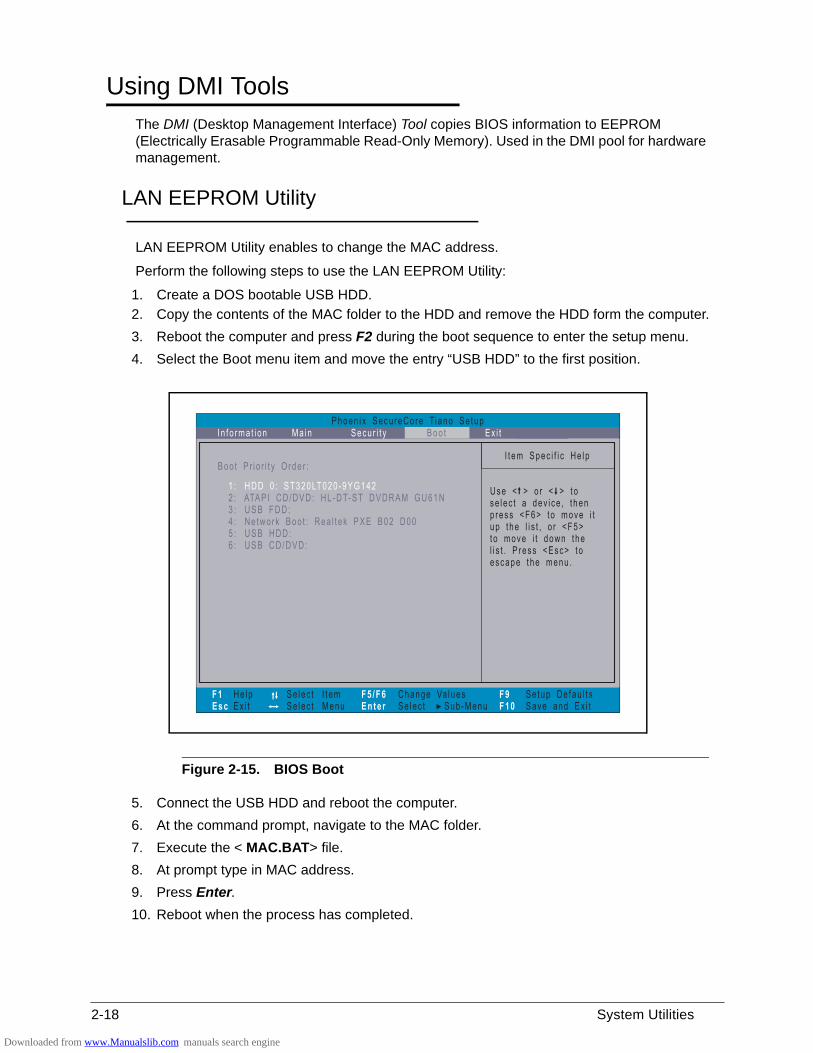
2-18 System Utilities
Using DMI Tools 0
The DMI (Desktop Management Interface) Tool copies BIOS information to EEPROM (Electrically Erasable Programmable Read-Only Memory). Used in the DMI pool for hardware management.
LAN EEPROM Utility 0
LAN EEPROM Utility enables to change the MAC address.
Perform the following steps to use the LAN EEPROM Utility:
1. Create a DOS bootable USB HDD.
2. Copy the contents of the MAC folder to the HDD and remove the HDD form the computer.
3. Reboot the computer and press F2 during the boot sequence to enter the setup menu.
4. Select the Boot menu item and move the entry “USB HDD” to the first position.
Figure 2-15. BIOS Boot
5. Connect the USB HDD and reboot the computer.
6. At the command prompt, navigate to the MAC folder.
7. Execute the < MAC.BAT> file.
8. At prompt type in MAC address.
9. Press Enter.
10. Reboot when the process has completed.
Downloaded from www.Manualslib.com manuals search engine
CHAPTER 3
Machine Maintenance
Downloaded from www.Manualslib.com manuals search engine
3-2
Machine Disassembly and Replacement . . . . . . . . . . . . . . . . . .3-5Recommended Equipment . . . . . . . . . . . . . . . . . . . . . . . . . . . .3-5Replacement Requirements . . . . . . . . . . . . . . . . . . . . . . . . . . .3-5Pre-disassembly Instructions. . . . . . . . . . . . . . . . . . . . . . . . . . .3-6
Disassembly Process . . . . . . . . . . . . . . . . . . . . . . . . . . . . . . . . . .3-7
External Module Disassembly Process . . . . . . . . . . . . . . . . . . .3-8External Modules Disassembly Flowchart . . . . . . . . . . . . . . . . .3-8Removing the Battery Pack . . . . . . . . . . . . . . . . . . . . . . . . . . . .3-9Removing the DIMM Cover . . . . . . . . . . . . . . . . . . . . . . . . . . . .3-10Removing the DIMM Modules . . . . . . . . . . . . . . . . . . . . . . . . . .3-11Removing the Keyboard . . . . . . . . . . . . . . . . . . . . . . . . . . . . . .3-12Removing the ODD Module. . . . . . . . . . . . . . . . . . . . . . . . . . . .3-14
Main Unit Disassembly Process . . . . . . . . . . . . . . . . . . . . . . . . .3-17Main Unit Disassembly Flowchart . . . . . . . . . . . . . . . . . . . . . . .3-17Removing the Palmrest Module/Upper Case . . . . . . . . . . . . . .3-18Removing the Touchpad Board . . . . . . . . . . . . . . . . . . . . . . . . .3-21Removing the Power Button Board . . . . . . . . . . . . . . . . . . . . . .3-23Removing the SATA Board . . . . . . . . . . . . . . . . . . . . . . . . . . . .3-25Removing the HDD Module . . . . . . . . . . . . . . . . . . . . . . . . . . . .3-26Removing the WLAN Module . . . . . . . . . . . . . . . . . . . . . . . . . .3-27Removing the Mainboard. . . . . . . . . . . . . . . . . . . . . . . . . . . . . .3-29Removing the Thermal Module . . . . . . . . . . . . . . . . . . . . . . . . .3-32Removing the DC In Module . . . . . . . . . . . . . . . . . . . . . . . . . . .3-34Removing the Battery Connector. . . . . . . . . . . . . . . . . . . . . . . .3-35Removing the Speaker Module . . . . . . . . . . . . . . . . . . . . . . . . .3-36Removing the LCD Module . . . . . . . . . . . . . . . . . . . . . . . . . . . .3-38
LCD Module Disassembly Process . . . . . . . . . . . . . . . . . . . . . . .3-40LCD Module Disassembly Flowchart. . . . . . . . . . . . . . . . . . . . .3-40Removing the LCD Bezel . . . . . . . . . . . . . . . . . . . . . . . . . . . . .3-41Removing the Camera Board . . . . . . . . . . . . . . . . . . . . . . . . . .3-42Removing the LCD Panel . . . . . . . . . . . . . . . . . . . . . . . . . . . . .3-43Removing the LCD FPC Cable . . . . . . . . . . . . . . . . . . . . . . . . .3-44Removing the LCD Brackets . . . . . . . . . . . . . . . . . . . . . . . . . . .3-45Removing the Microphone. . . . . . . . . . . . . . . . . . . . . . . . . . . . .3-46
LCD Module Reassembly Process . . . . . . . . . . . . . . . . . . . . . . .3-47Reinstalling the Microphone . . . . . . . . . . . . . . . . . . . . . . . . . . .3-47Reinstalling the LCD Brackets . . . . . . . . . . . . . . . . . . . . . . . . . .3-48Reinstalling the LCD FPC Cable . . . . . . . . . . . . . . . . . . . . . . . .3-49
Downloaded from www.Manualslib.com manuals search engine
3-3
Reinstalling the LCD Panel . . . . . . . . . . . . . . . . . . . . . . . . . . . .3-50Reinstalling the Camera Board . . . . . . . . . . . . . . . . . . . . . . . . .3-51Reinstalling the LCD Bezel . . . . . . . . . . . . . . . . . . . . . . . . . . . .3-52
Main Unit Reassembly Process. . . . . . . . . . . . . . . . . . . . . . . . . .3-53Reinstalling the LCD Module . . . . . . . . . . . . . . . . . . . . . . . . . . .3-53Reinstalling the Speaker Module . . . . . . . . . . . . . . . . . . . . . . . .3-55Reinstalling the Battery Connector . . . . . . . . . . . . . . . . . . . . . .3-57Reinstalling the DC In Module . . . . . . . . . . . . . . . . . . . . . . . . . .3-58Reinstalling the Thermal Module . . . . . . . . . . . . . . . . . . . . . . . .3-59Reinstalling the Mainboard . . . . . . . . . . . . . . . . . . . . . . . . . . . .3-61Reinstalling the WLAN Module . . . . . . . . . . . . . . . . . . . . . . . . .3-64Reinstalling the HDD Module. . . . . . . . . . . . . . . . . . . . . . . . . . .3-66Reinstalling the SATA Board . . . . . . . . . . . . . . . . . . . . . . . . . . .3-67Reinstalling the Power Button Board . . . . . . . . . . . . . . . . . . . . .3-68Reinstalling the Touchpad Board. . . . . . . . . . . . . . . . . . . . . . . .3-70Reinstalling the Palmrest Module/Upper Case . . . . . . . . . . . . .3-72
External Module Reassembly Process . . . . . . . . . . . . . . . . . . . .3-74Reinstalling the ODD Module . . . . . . . . . . . . . . . . . . . . . . . . . .3-74Reinstalling the Keyboard . . . . . . . . . . . . . . . . . . . . . . . . . . . . .3-77Reinstalling the DIMM Modules . . . . . . . . . . . . . . . . . . . . . . . . .3-79Reinstalling the DIMM Cover . . . . . . . . . . . . . . . . . . . . . . . . . . .3-80Reinstalling the Battery Pack. . . . . . . . . . . . . . . . . . . . . . . . . . .3-81
Downloaded from www.Manualslib.com manuals search engine
Machine Maintenance 3-5
Machine Maintenance
Machine Disassembly and Replacement 0
This chapter contains step-by-step procedures on how to disassemble the notebook computer for maintenance and troubleshooting.
Cable paths and positioning may not represent the actual model. During the removal and installation of the components, ensure all available cable channels and clips are used and that the cables are replaced in the same position.
The screws for the different components vary in size. During the disassembly process, group the screws with the corresponding components to avoid mismatch when putting back the components.
The product previews seen in the disassembly procedures may not represent the final product color or configuration.
Recommended Equipment 0
To disassemble the computer, the following tools are suggested:
Wrist grounding strap and conductive mat for preventing electrostatic discharge
Non-marring scribe
Phillips screwdriver
Flat-blade screwdriver
Plastic flat screwdriver
Plastic tweezers
Cyanoacrylate glue
Replacement Requirements 0
NOTE:NOTE:Cabling and components require adhesive to be applied during the replacement and reassembly process.
Downloaded from www.Manualslib.com manuals search engine
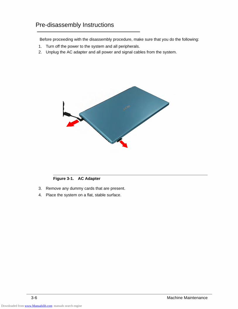
3-6 Machine Maintenance
Pre-disassembly Instructions 0
Before proceeding with the disassembly procedure, make sure that you do the following:
1. Turn off the power to the system and all peripherals.
2. Unplug the AC adapter and all power and signal cables from the system.
Figure 3-1. AC Adapter
3. Remove any dummy cards that are present.
4. Place the system on a flat, stable surface.
Downloaded from www.Manualslib.com manuals search engine
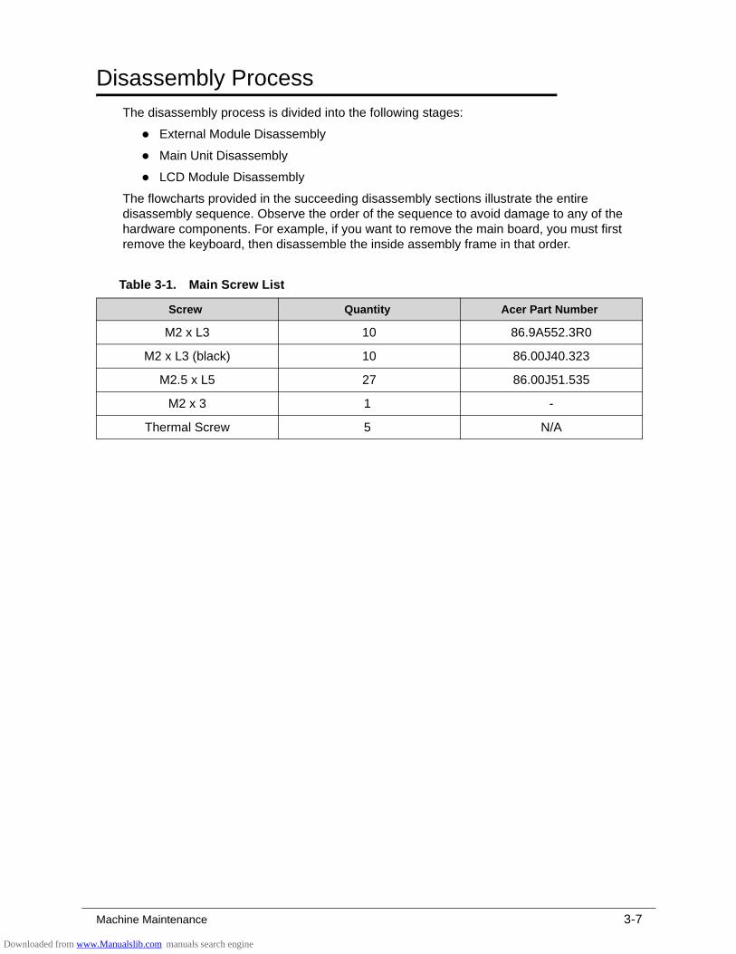
Machine Maintenance 3-7
Disassembly Process 0
The disassembly process is divided into the following stages:
External Module Disassembly
Main Unit Disassembly
LCD Module Disassembly
The flowcharts provided in the succeeding disassembly sections illustrate the entire disassembly sequence. Observe the order of the sequence to avoid damage to any of the hardware components. For example, if you want to remove the main board, you must first remove the keyboard, then disassemble the inside assembly frame in that order.
Table 3-1. Main Screw List
Screw Quantity Acer Part Number
M2 x L3 10 86.9A552.3R0
M2 x L3 (black) 10 86.00J40.323
M2.5 x L5 27 86.00J51.535
M2 x 3 1 -
Thermal Screw 5 N/A
Downloaded from www.Manualslib.com manuals search engine
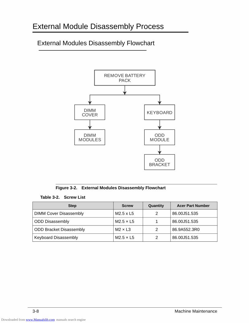
3-8 Machine Maintenance
External Module Disassembly Process 0
External Modules Disassembly Flowchart 0
Figure 3-2. External Modules Disassembly Flowchart
Table 3-2. Screw List
Step Screw Quantity Acer Part Number
DIMM Cover Disassembly M2.5 x L5 2 86.00J51.535
ODD Disassembly M2.5 × L5 1 86.00J51.535
ODD Bracket Disassembly M2 × L3 2 86.9A552.3R0
Keyboard Disassembly M2.5 × L5 2 86.00J51.535
REMOVE BATTERYPACK
DIMMMODULES
KEYBOARD
ODDMODULE
ODDBRACKET
DIMMCOVER
Downloaded from www.Manualslib.com manuals search engine
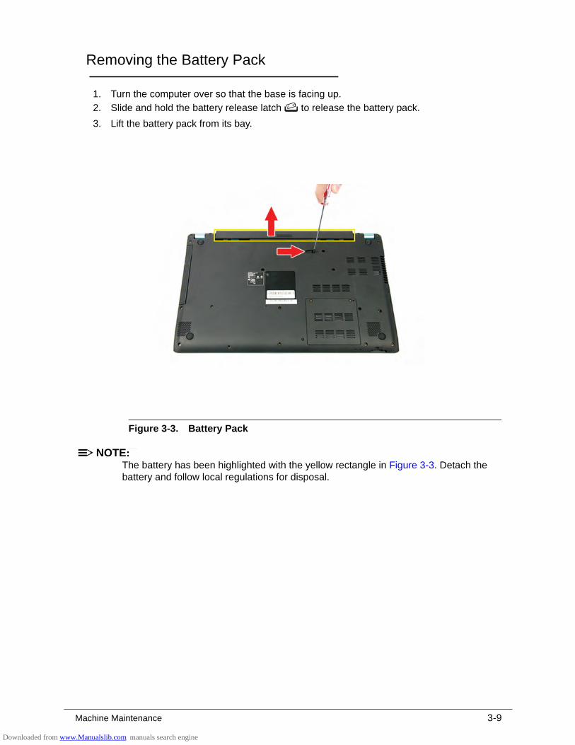
Machine Maintenance 3-9
Removing the Battery Pack 0
1. Turn the computer over so that the base is facing up.
2. Slide and hold the battery release latch to release the battery pack.
3. Lift the battery pack from its bay.
Figure 3-3. Battery Pack
NOTE:NOTE:The battery has been highlighted with the yellow rectangle in Figure 3-3. Detach the battery and follow local regulations for disposal.
Downloaded from www.Manualslib.com manuals search engine
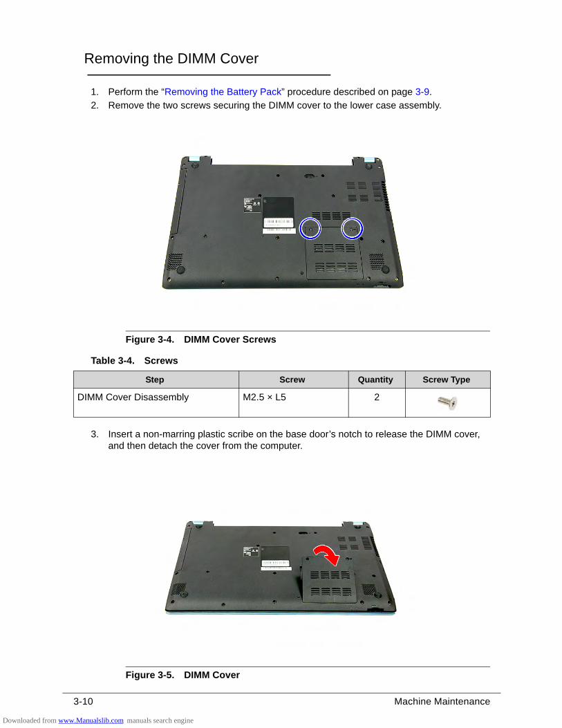
3-10 Machine Maintenance
Removing the DIMM Cover 0
1. Perform the “Removing the Battery Pack” procedure described on page 3-9.
2. Remove the two screws securing the DIMM cover to the lower case assembly.
Figure 3-4. DIMM Cover Screws
3. Insert a non-marring plastic scribe on the base door’s notch to release the DIMM cover, and then detach the cover from the computer.
Figure 3-5. DIMM Cover
Table 3-4. Screws
Step Screw Quantity Screw Type
DIMM Cover Disassembly M2.5 × L5 2
Downloaded from www.Manualslib.com manuals search engine
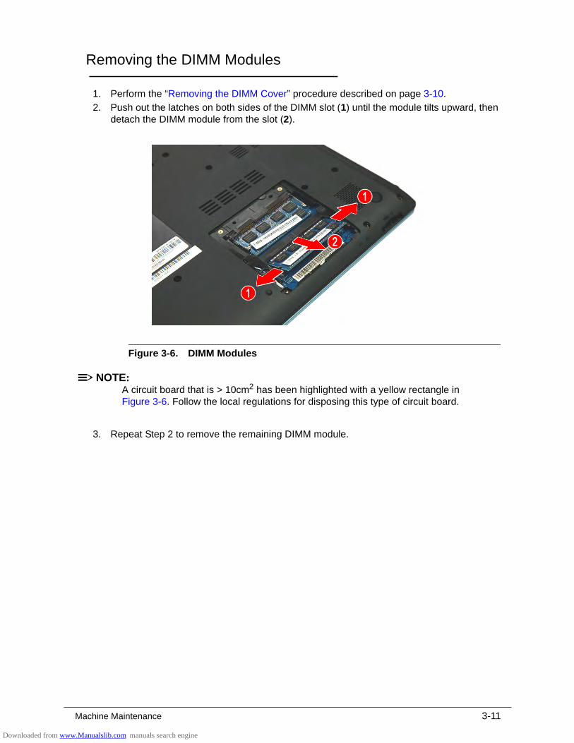
Machine Maintenance 3-11
Removing the DIMM Modules 0
1. Perform the “Removing the DIMM Cover” procedure described on page 3-10.
2. Push out the latches on both sides of the DIMM slot (1) until the module tilts upward, then detach the DIMM module from the slot (2).
Figure 3-6. DIMM Modules
NOTE:NOTE:A circuit board that is > 10cm2 has been highlighted with a yellow rectangle in Figure 3-6. Follow the local regulations for disposing this type of circuit board.
3. Repeat Step 2 to remove the remaining DIMM module.
Downloaded from www.Manualslib.com manuals search engine
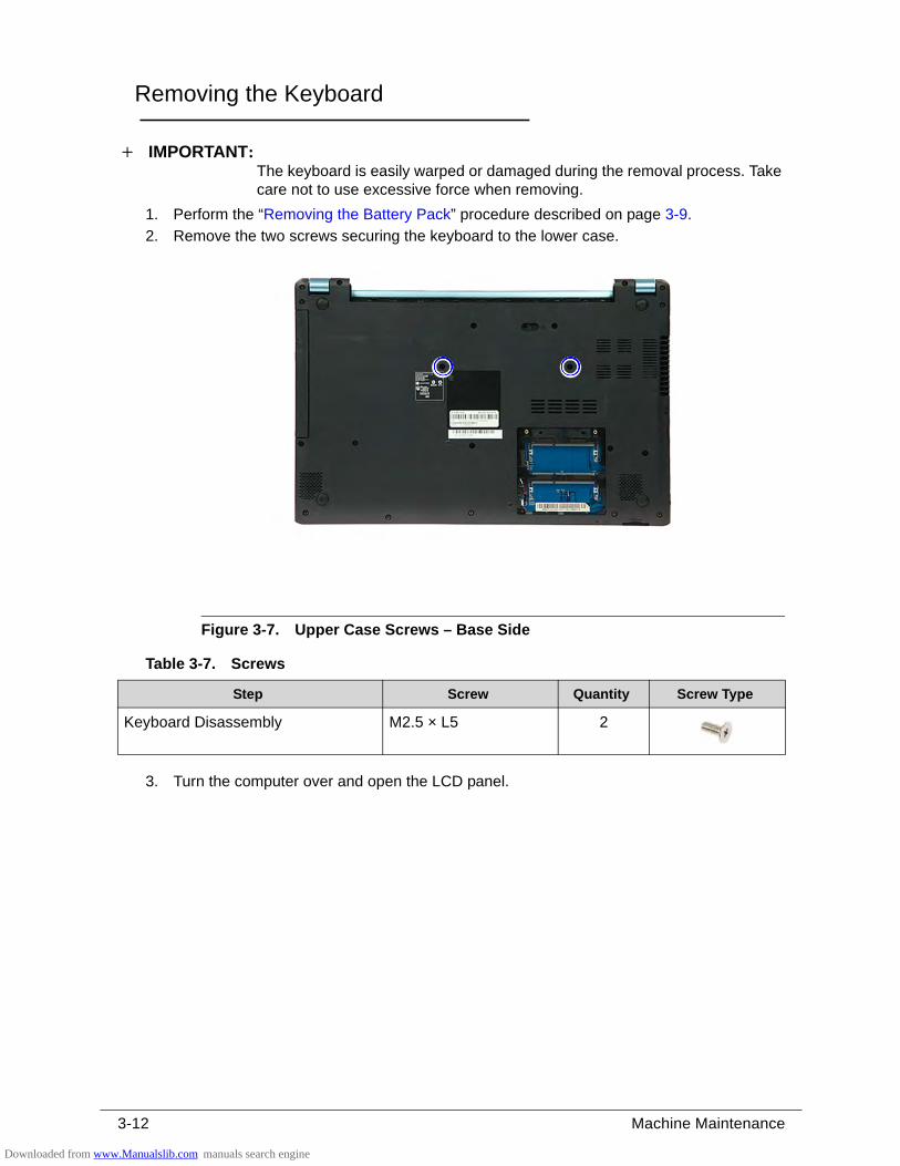
3-12 Machine Maintenance
Removing the Keyboard 0
IMPORTANT:+The keyboard is easily warped or damaged during the removal process. Take care not to use excessive force when removing.
1. Perform the “Removing the Battery Pack” procedure described on page 3-9.
2. Remove the two screws securing the keyboard to the lower case.
Figure 3-7. Upper Case Screws – Base Side
3. Turn the computer over and open the LCD panel.
Table 3-7. Screws
Step Screw Quantity Screw Type
Keyboard Disassembly M2.5 × L5 2
Downloaded from www.Manualslib.com manuals search engine
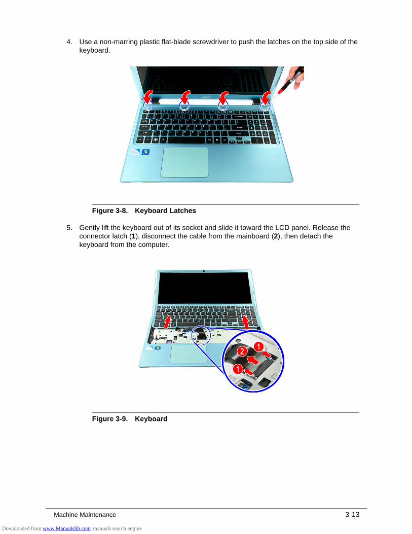
Machine Maintenance 3-13
4. Use a non-marring plastic flat-blade screwdriver to push the latches on the top side of the keyboard.
Figure 3-8. Keyboard Latches
5. Gently lift the keyboard out of its socket and slide it toward the LCD panel. Release the connector latch (1), disconnect the cable from the mainboard (2), then detach the keyboard from the computer.
Figure 3-9. Keyboard
Downloaded from www.Manualslib.com manuals search engine
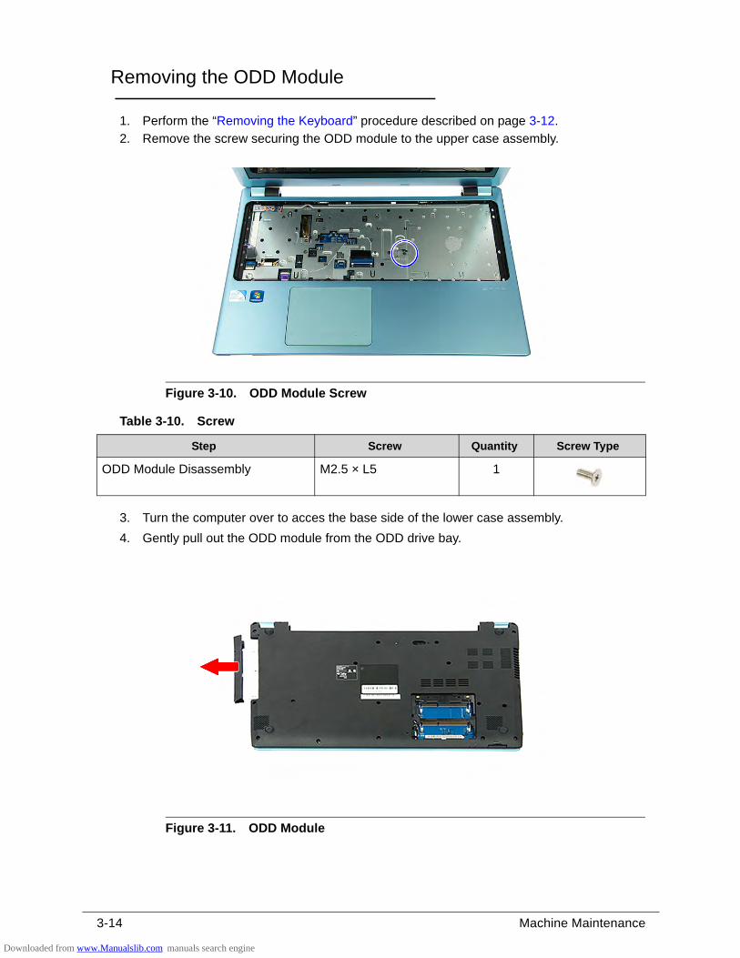
3-14 Machine Maintenance
Removing the ODD Module 0
1. Perform the “Removing the Keyboard” procedure described on page 3-12.
2. Remove the screw securing the ODD module to the upper case assembly.
Figure 3-10. ODD Module Screw
3. Turn the computer over to acces the base side of the lower case assembly.
4. Gently pull out the ODD module from the ODD drive bay.
Figure 3-11. ODD Module
Table 3-10. Screw
Step Screw Quantity Screw Type
ODD Module Disassembly M2.5 × L5 1
Downloaded from www.Manualslib.com manuals search engine
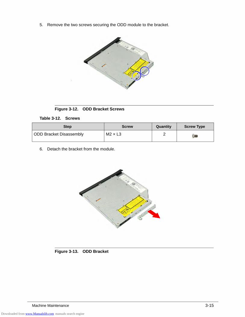
Machine Maintenance 3-15
5. Remove the two screws securing the ODD module to the bracket.
Figure 3-12. ODD Bracket Screws
6. Detach the bracket from the module.
Figure 3-13. ODD Bracket
Table 3-12. Screws
Step Screw Quantity Screw Type
ODD Bracket Disassembly M2 × L3 2
Downloaded from www.Manualslib.com manuals search engine
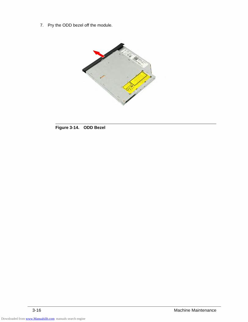
3-16 Machine Maintenance
7. Pry the ODD bezel off the module.
Figure 3-14. ODD Bezel
Downloaded from www.Manualslib.com manuals search engine
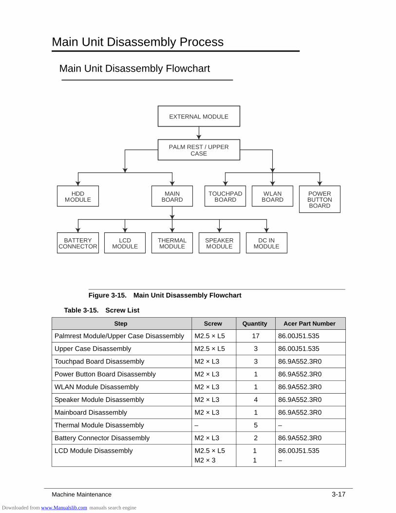
Machine Maintenance 3-17
Main Unit Disassembly Process 0
Main Unit Disassembly Flowchart 0
Figure 3-15. Main Unit Disassembly Flowchart
Table 3-15. Screw List
Step Screw Quantity Acer Part Number
Palmrest Module/Upper Case Disassembly M2.5 × L5 17 86.00J51.535
Upper Case Disassembly M2.5 × L5 3 86.00J51.535
Touchpad Board Disassembly M2 × L3 3 86.9A552.3R0
Power Button Board Disassembly M2 × L3 1 86.9A552.3R0
WLAN Module Disassembly M2 × L3 1 86.9A552.3R0
Speaker Module Disassembly M2 × L3 4 86.9A552.3R0
Mainboard Disassembly M2 × L3 1 86.9A552.3R0
Thermal Module Disassembly – 5 –
Battery Connector Disassembly M2 × L3 2 86.9A552.3R0
LCD Module Disassembly M2.5 × L5
M2 × 3
1
1
86.00J51.535
–
EXTERNAL MODULE
THERMALMODULE
BATTERYCONNECTOR
DC INMODULE
LCDMODULE
MAINBOARD
POWERBUTTONBOARD
SPEAKERMODULE
TOUCHPADBOARD
PALM REST / UPPERCASE
WLANBOARD
HDDMODULE
Downloaded from www.Manualslib.com manuals search engine
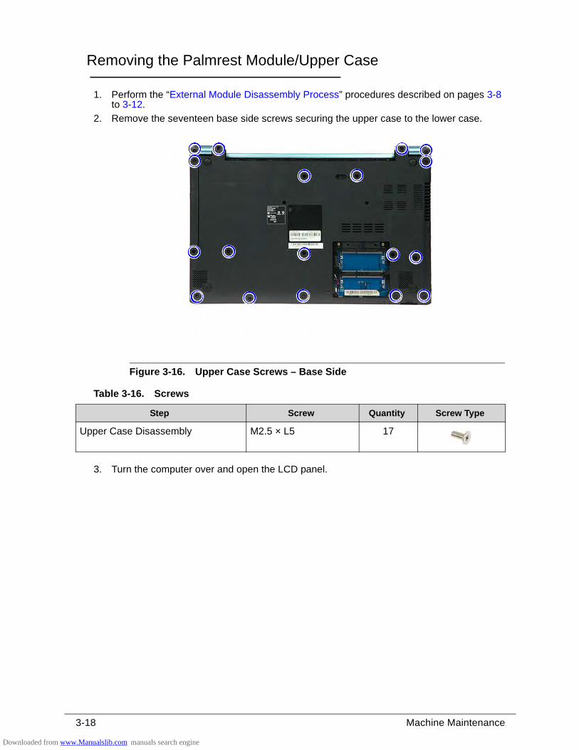
3-18 Machine Maintenance
Removing the Palmrest Module/Upper Case 0
1. Perform the “External Module Disassembly Process” procedures described on pages 3-8 to 3-12.
2. Remove the seventeen base side screws securing the upper case to the lower case.
Figure 3-16. Upper Case Screws – Base Side
3. Turn the computer over and open the LCD panel.
Table 3-16. Screws
Step Screw Quantity Screw Type
Upper Case Disassembly M2.5 × L5 17
Downloaded from www.Manualslib.com manuals search engine
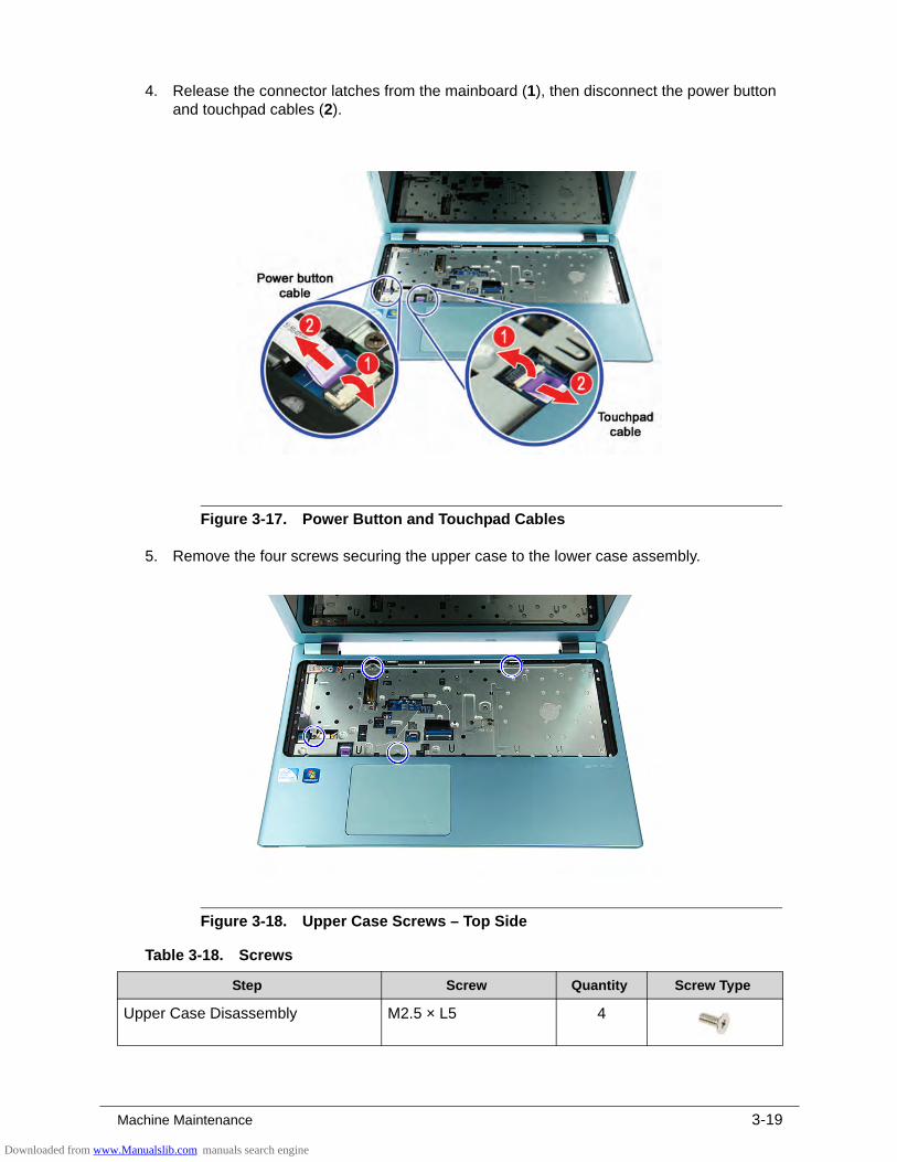
Machine Maintenance 3-19
4. Release the connector latches from the mainboard (1), then disconnect the power button and touchpad cables (2).
Figure 3-17. Power Button and Touchpad Cables
5. Remove the four screws securing the upper case to the lower case assembly.
Figure 3-18. Upper Case Screws – Top Side
Table 3-18. Screws
Step Screw Quantity Screw Type
Upper Case Disassembly M2.5 × L5 4
Downloaded from www.Manualslib.com manuals search engine
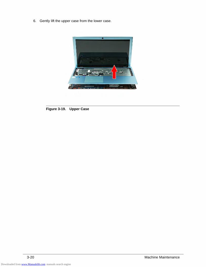
3-20 Machine Maintenance
6. Gently lift the upper case from the lower case.
Figure 3-19. Upper Case
Downloaded from www.Manualslib.com manuals search engine
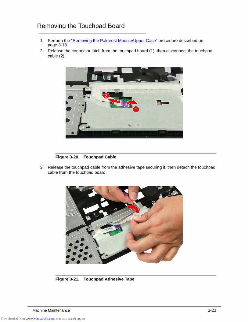
Machine Maintenance 3-21
Removing the Touchpad Board 0
1. Perform the “Removing the Palmrest Module/Upper Case” procedure described on page 3-18.
2. Release the connector latch from the touchpad board (1), then disconnect the touchpad cable (2).
Figure 3-20. Touchpad Cable
3. Release the touchpad cable from the adhesive tape securing it, then detach the touchpad cable from the touchpad board.
Figure 3-21. Touchpad Adhesive Tape
Downloaded from www.Manualslib.com manuals search engine
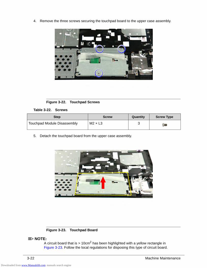
3-22 Machine Maintenance
4. Remove the three screws securing the touchpad board to the upper case assembly.
Figure 3-22. Touchpad Screws
5. Detach the touchpad board from the upper case assembly.
Figure 3-23. Touchpad Board
NOTE:NOTE:A circuit board that is > 10cm2 has been highlighted with a yellow rectangle in Figure 3-23. Follow the local regulations for disposing this type of circuit board.
Table 3-22. Screws
Step Screw Quantity Screw Type
Touchpad Module Disassembly M2 × L3 3
Downloaded from www.Manualslib.com manuals search engine
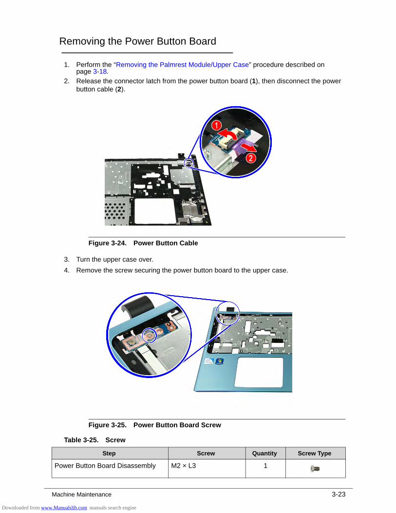
Machine Maintenance 3-23
Removing the Power Button Board 0
1. Perform the “Removing the Palmrest Module/Upper Case” procedure described on page 3-18.
2. Release the connector latch from the power button board (1), then disconnect the power button cable (2).
Figure 3-24. Power Button Cable
3. Turn the upper case over.
4. Remove the screw securing the power button board to the upper case.
Figure 3-25. Power Button Board Screw
Table 3-25. Screw
Step Screw Quantity Screw Type
Power Button Board Disassembly M2 × L3 1
Downloaded from www.Manualslib.com manuals search engine
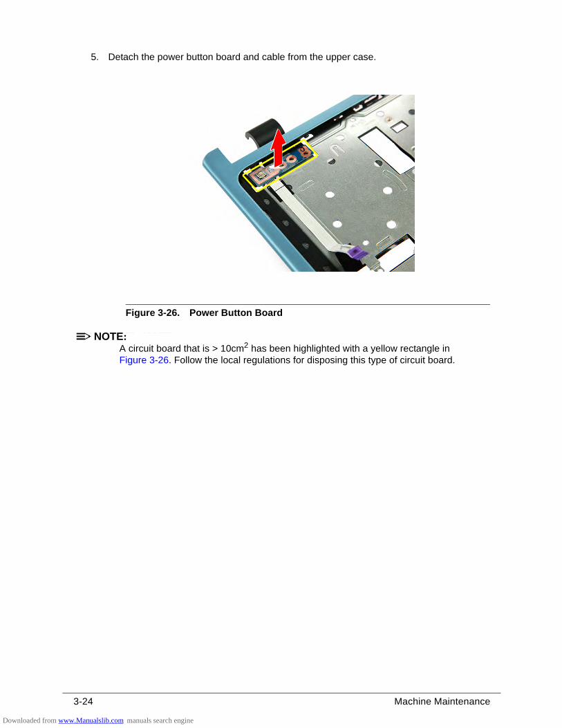
3-24 Machine Maintenance
5. Detach the power button board and cable from the upper case.
Figure 3-26. Power Button Board
NOTE:NOTE:A circuit board that is > 10cm2 has been highlighted with a yellow rectangle in Figure 3-26. Follow the local regulations for disposing this type of circuit board.
Downloaded from www.Manualslib.com manuals search engine
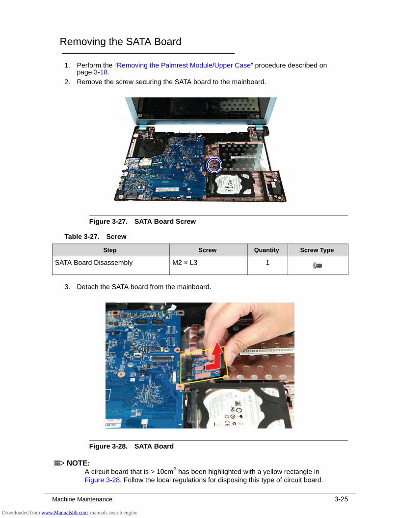
Machine Maintenance 3-25
Removing the SATA Board 0
1. Perform the “Removing the Palmrest Module/Upper Case” procedure described on page 3-18.
2. Remove the screw securing the SATA board to the mainboard.
Figure 3-27. SATA Board Screw
3. Detach the SATA board from the mainboard.
Figure 3-28. SATA Board
NOTE:NOTE:A circuit board that is > 10cm2 has been highlighted with a yellow rectangle in Figure 3-28. Follow the local regulations for disposing this type of circuit board.
Table 3-27. Screw
Step Screw Quantity Screw Type
SATA Board Disassembly M2 × L3 1
Downloaded from www.Manualslib.com manuals search engine
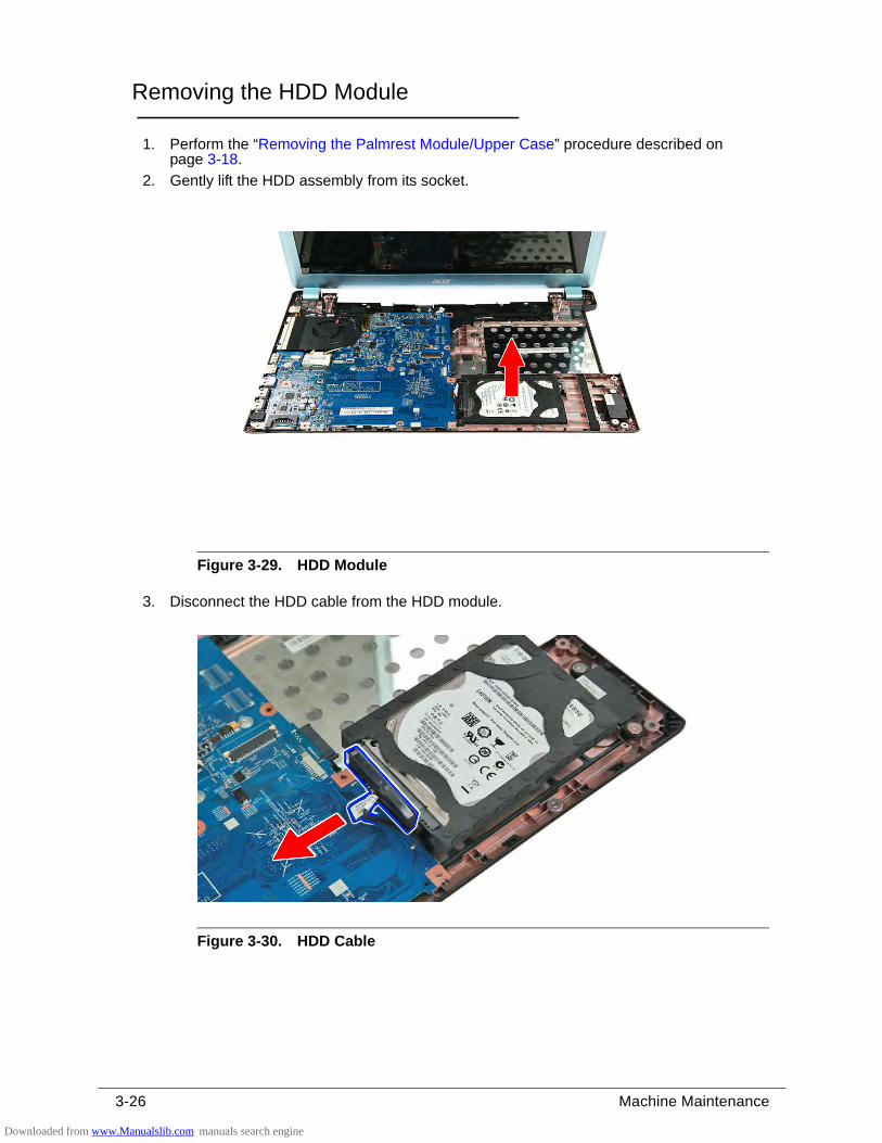
3-26 Machine Maintenance
Removing the HDD Module 0
1. Perform the “Removing the Palmrest Module/Upper Case” procedure described on page 3-18.
2. Gently lift the HDD assembly from its socket.
Figure 3-29. HDD Module
3. Disconnect the HDD cable from the HDD module.
Figure 3-30. HDD Cable
Downloaded from www.Manualslib.com manuals search engine
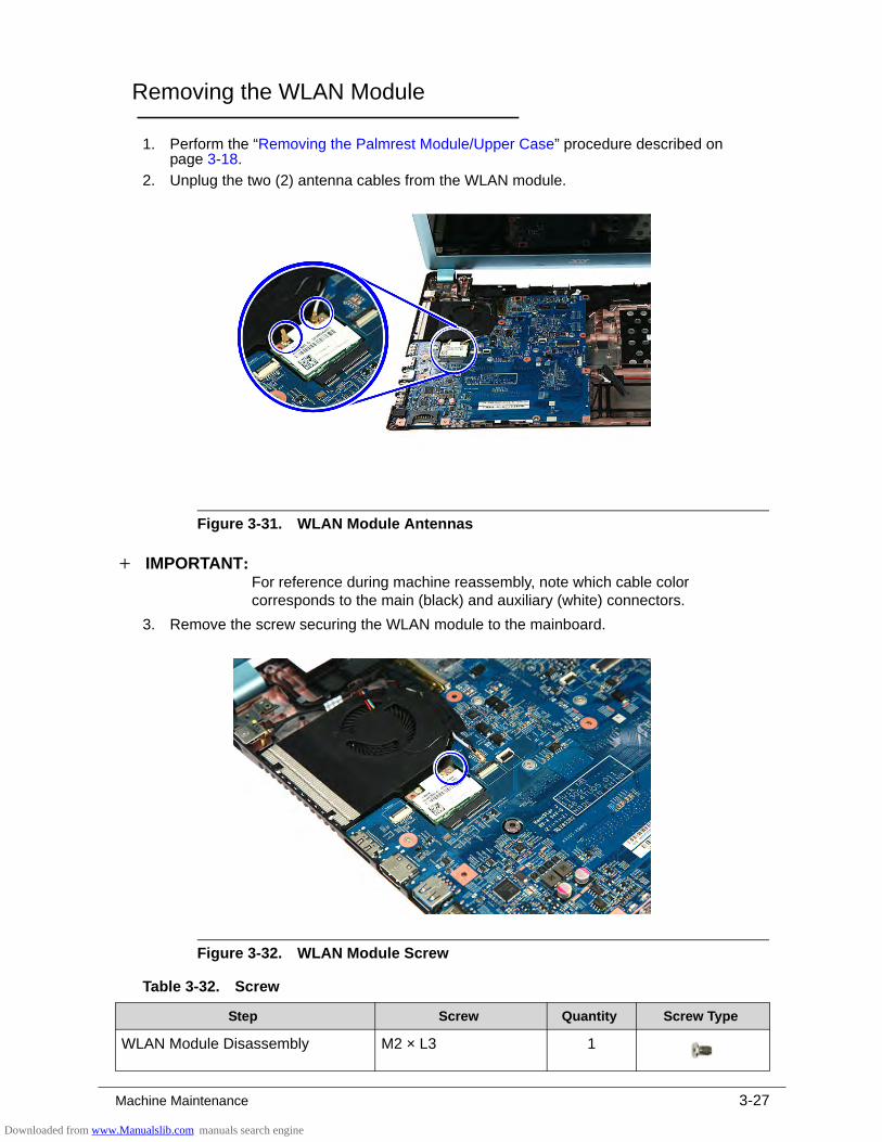
Machine Maintenance 3-27
Removing the WLAN Module 0
1. Perform the “Removing the Palmrest Module/Upper Case” procedure described on page 3-18.
2. Unplug the two (2) antenna cables from the WLAN module.
Figure 3-31. WLAN Module Antennas
IMPORTANT:+For reference during machine reassembly, note which cable color corresponds to the main (black) and auxiliary (white) connectors.
3. Remove the screw securing the WLAN module to the mainboard.
Figure 3-32. WLAN Module Screw
Table 3-32. Screw
Step Screw Quantity Screw Type
WLAN Module Disassembly M2 × L3 1
Downloaded from www.Manualslib.com manuals search engine
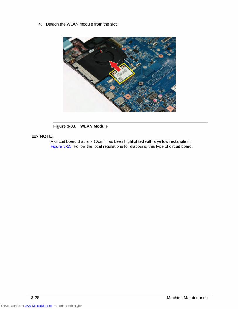
3-28 Machine Maintenance
4. Detach the WLAN module from the slot.
Figure 3-33. WLAN Module
NOTE:NOTE:A circuit board that is > 10cm2 has been highlighted with a yellow rectangle in Figure 3-33. Follow the local regulations for disposing this type of circuit board.
Downloaded from www.Manualslib.com manuals search engine
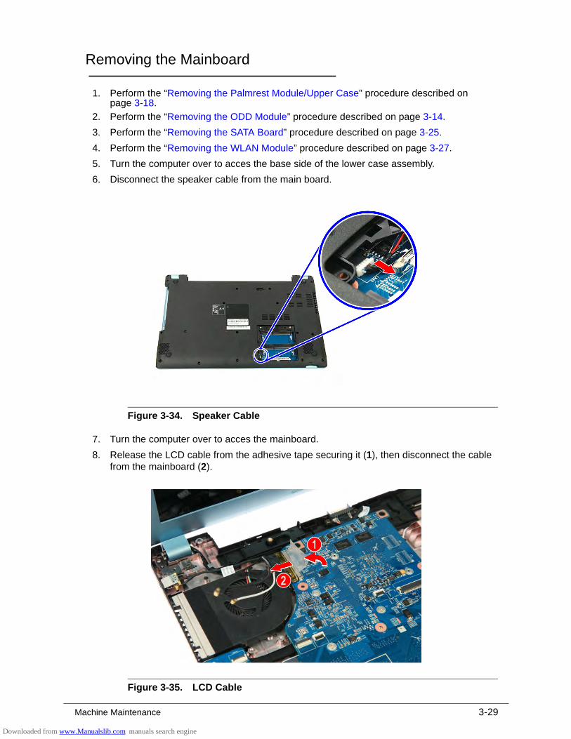
Machine Maintenance 3-29
Removing the Mainboard 0
1. Perform the “Removing the Palmrest Module/Upper Case” procedure described on page 3-18.
2. Perform the “Removing the ODD Module” procedure described on page 3-14.
3. Perform the “Removing the SATA Board” procedure described on page 3-25.
4. Perform the “Removing the WLAN Module” procedure described on page 3-27.
5. Turn the computer over to acces the base side of the lower case assembly.
6. Disconnect the speaker cable from the main board.
Figure 3-34. Speaker Cable
7. Turn the computer over to acces the mainboard.
8. Release the LCD cable from the adhesive tape securing it (1), then disconnect the cable from the mainboard (2).
Figure 3-35. LCD Cable
Downloaded from www.Manualslib.com manuals search engine
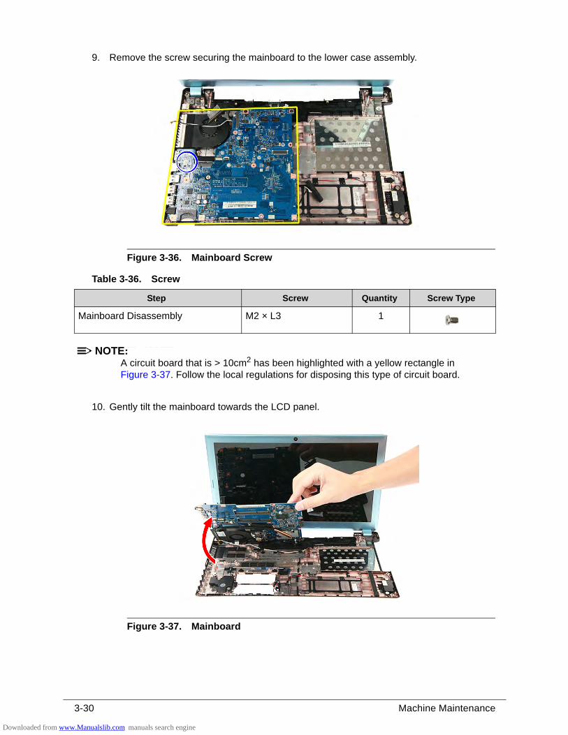
3-30 Machine Maintenance
9. Remove the screw securing the mainboard to the lower case assembly.
Figure 3-36. Mainboard Screw
NOTE:NOTE:A circuit board that is > 10cm2 has been highlighted with a yellow rectangle in Figure 3-37. Follow the local regulations for disposing this type of circuit board.
10. Gently tilt the mainboard towards the LCD panel.
Figure 3-37. Mainboard
Table 3-36. Screw
Step Screw Quantity Screw Type
Mainboard Disassembly M2 × L3 1
Downloaded from www.Manualslib.com manuals search engine
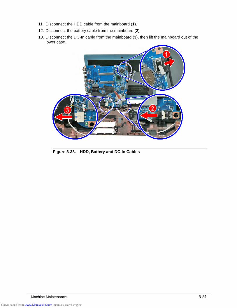
Machine Maintenance 3-31
11. Disconnect the HDD cable from the mainboard (1).
12. Disconnect the battery cable from the mainboard (2).
13. Disconnect the DC-In cable from the mainboard (3), then lift the mainboard out of the lower case.
Figure 3-38. HDD, Battery and DC-In Cables
Downloaded from www.Manualslib.com manuals search engine
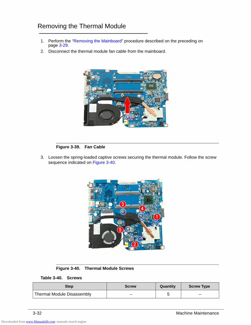
3-32 Machine Maintenance
Removing the Thermal Module 0
1. Perform the “Removing the Mainboard” procedure described on the preceding on page 3-29.
2. Disconnect the thermal module fan cable from the mainboard.
Figure 3-39. Fan Cable
3. Loosen the spring-loaded captive screws securing the thermal module. Follow the screw sequence indicated on Figure 3-40.
Figure 3-40. Thermal Module Screws
Table 3-40. Screws
Step Screw Quantity Screw Type
Thermal Module Disassembly – 5 –
Downloaded from www.Manualslib.com manuals search engine
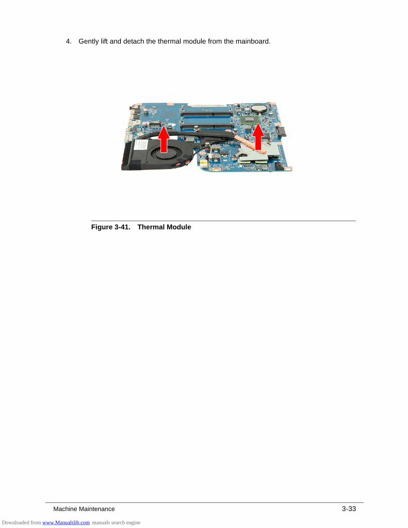
Machine Maintenance 3-33
4. Gently lift and detach the thermal module from the mainboard.
Figure 3-41. Thermal Module
Downloaded from www.Manualslib.com manuals search engine
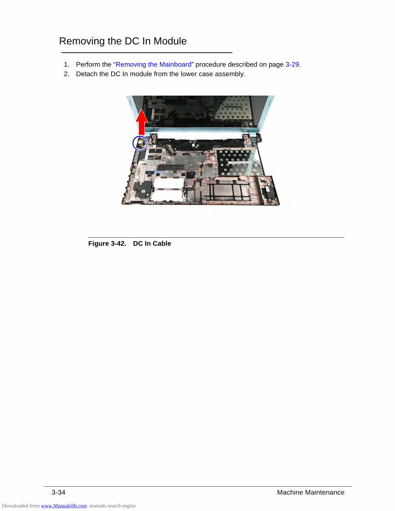
3-34 Machine Maintenance
Removing the DC In Module 0
1. Perform the “Removing the Mainboard” procedure described on page 3-29.
2. Detach the DC In module from the lower case assembly.
Figure 3-42. DC In Cable
Downloaded from www.Manualslib.com manuals search engine
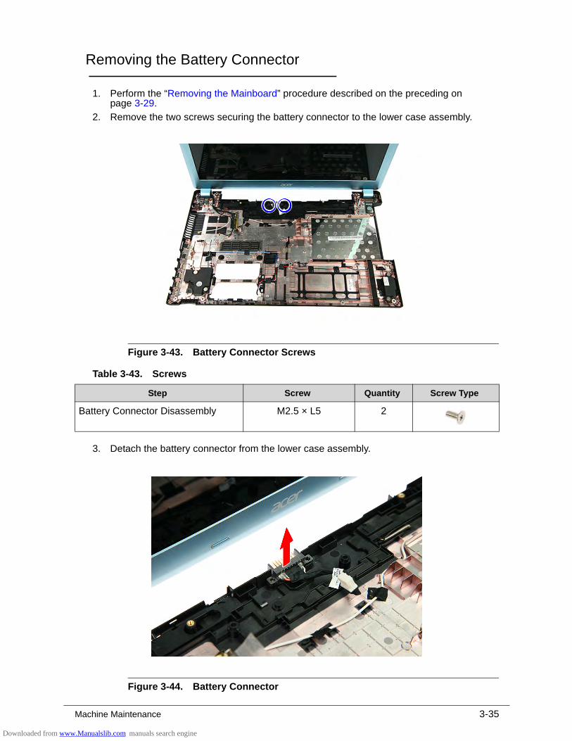
Machine Maintenance 3-35
Removing the Battery Connector 0
1. Perform the “Removing the Mainboard” procedure described on the preceding on page 3-29.
2. Remove the two screws securing the battery connector to the lower case assembly.
Figure 3-43. Battery Connector Screws
3. Detach the battery connector from the lower case assembly.
Figure 3-44. Battery Connector
Table 3-43. Screws
Step Screw Quantity Screw Type
Battery Connector Disassembly M2.5 × L5 2
Downloaded from www.Manualslib.com manuals search engine
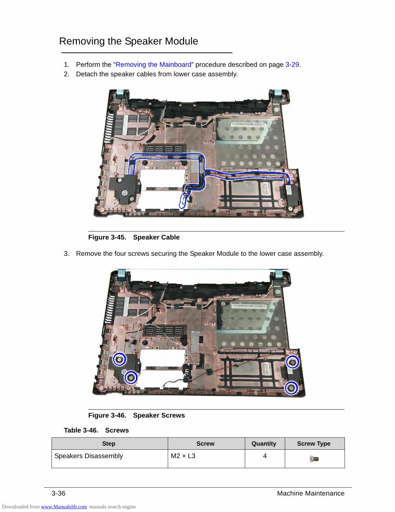
3-36 Machine Maintenance
Removing the Speaker Module 0
1. Perform the “Removing the Mainboard” procedure described on page 3-29.
2. Detach the speaker cables from lower case assembly.
Figure 3-45. Speaker Cable
3. Remove the four screws securing the Speaker Module to the lower case assembly.
Figure 3-46. Speaker Screws
Table 3-46. Screws
Step Screw Quantity Screw Type
Speakers Disassembly M2 × L3 4
Downloaded from www.Manualslib.com manuals search engine
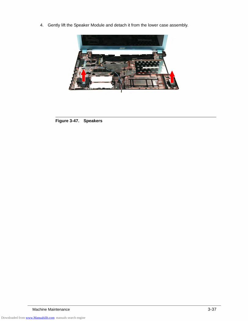
Machine Maintenance 3-37
4. Gently lift the Speaker Module and detach it from the lower case assembly.
Figure 3-47. Speakers
Downloaded from www.Manualslib.com manuals search engine
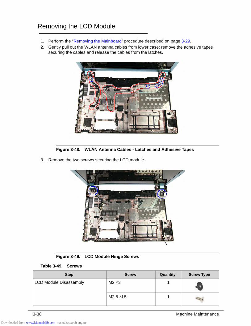
3-38 Machine Maintenance
Removing the LCD Module 0
1. Perform the “Removing the Mainboard” procedure described on page 3-29.
2. Gently pull out the WLAN antenna cables from lower case; remove the adhesive tapes securing the cables and release the cables from the latches.
Figure 3-48. WLAN Antenna Cables - Latches and Adhesive Tapes
3. Remove the two screws securing the LCD module.
Figure 3-49. LCD Module Hinge Screws
Table 3-49. Screws
Step Screw Quantity Screw Type
LCD Module Disassembly M2 ×3 1
M2.5 ×L5 1
Downloaded from www.Manualslib.com manuals search engine
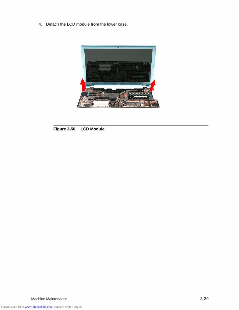
Machine Maintenance 3-39
4. Detach the LCD module from the lower case.
Figure 3-50. LCD Module
Downloaded from www.Manualslib.com manuals search engine
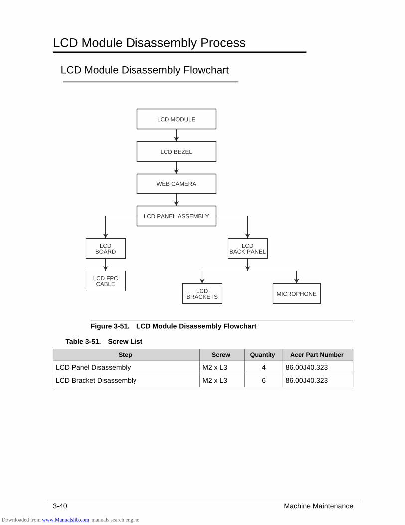
3-40 Machine Maintenance
LCD Module Disassembly Process 0
LCD Module Disassembly Flowchart 0
Figure 3-51. LCD Module Disassembly Flowchart
Table 3-51. Screw List
Step Screw Quantity Acer Part Number
LCD Panel Disassembly M2 x L3 4 86.00J40.323
LCD Bracket Disassembly M2 x L3 6 86.00J40.323
LCDBOARD
LCDBACK PANEL
LCD PANEL ASSEMBLY
LCD BEZEL
WEB CAMERA
LCD MODULE
MICROPHONE
LCD FPCCABLE
LCDBRACKETS
Downloaded from www.Manualslib.com manuals search engine
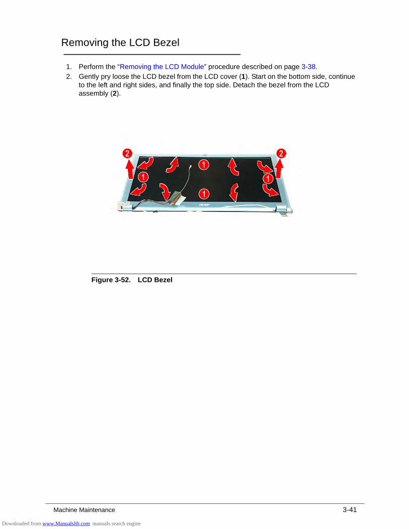
Machine Maintenance 3-41
Removing the LCD Bezel 0
1. Perform the “Removing the LCD Module” procedure described on page 3-38.
2. Gently pry loose the LCD bezel from the LCD cover (1). Start on the bottom side, continue to the left and right sides, and finally the top side. Detach the bezel from the LCD assembly (2).
Figure 3-52. LCD Bezel
Downloaded from www.Manualslib.com manuals search engine
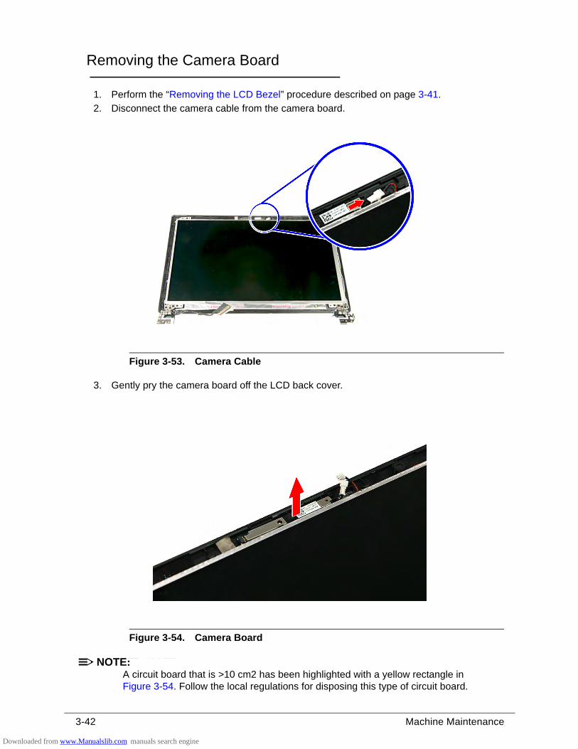
3-42 Machine Maintenance
Removing the Camera Board 0
1. Perform the “Removing the LCD Bezel” procedure described on page 3-41.
2. Disconnect the camera cable from the camera board.
Figure 3-53. Camera Cable
3. Gently pry the camera board off the LCD back cover.
Figure 3-54. Camera Board
NOTE:NOTE:A circuit board that is >10 cm2 has been highlighted with a yellow rectangle in Figure 3-54. Follow the local regulations for disposing this type of circuit board.
Downloaded from www.Manualslib.com manuals search engine
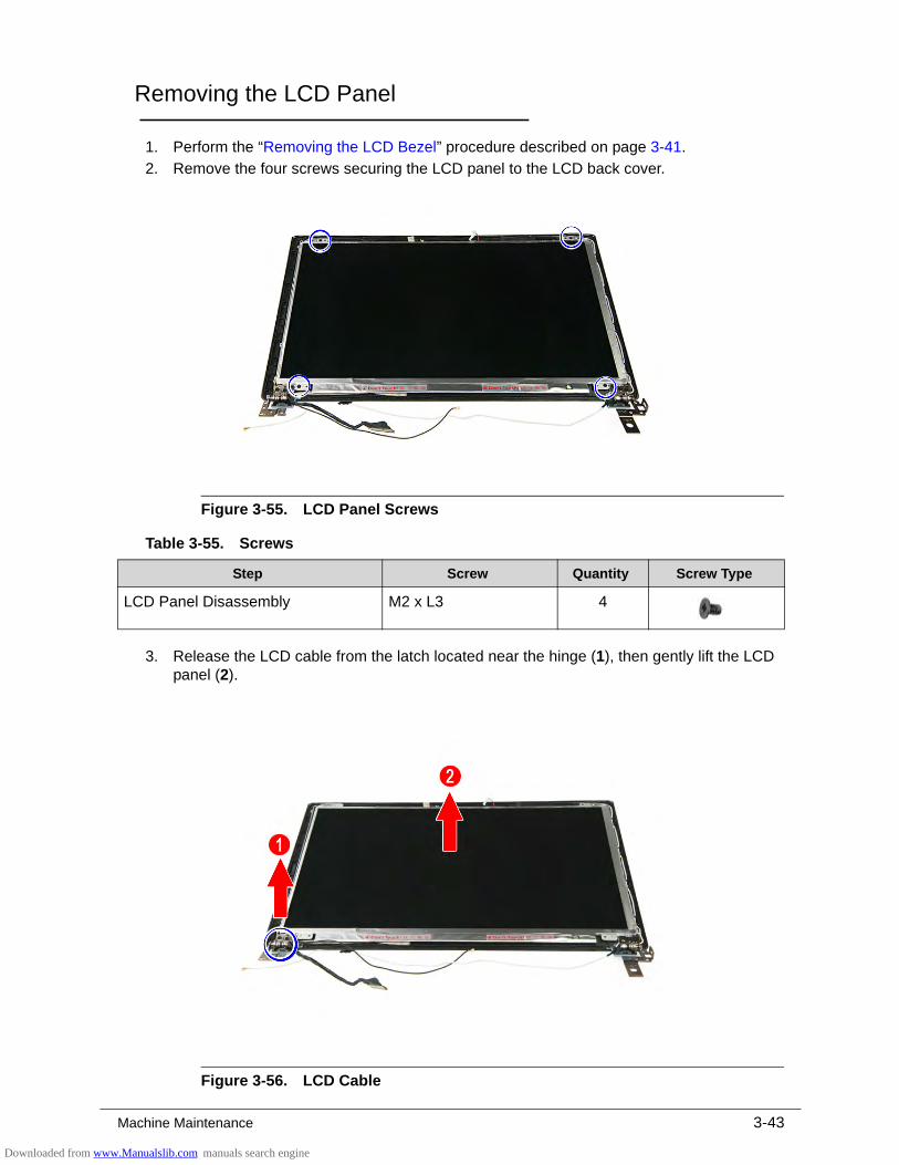
Machine Maintenance 3-43
Removing the LCD Panel 0
1. Perform the “Removing the LCD Bezel” procedure described on page 3-41.
2. Remove the four screws securing the LCD panel to the LCD back cover.
Figure 3-55. LCD Panel Screws
3. Release the LCD cable from the latch located near the hinge (1), then gently lift the LCD panel (2).
Figure 3-56. LCD Cable
Table 3-55. Screws
Step Screw Quantity Screw Type
LCD Panel Disassembly M2 x L3 4
Downloaded from www.Manualslib.com manuals search engine
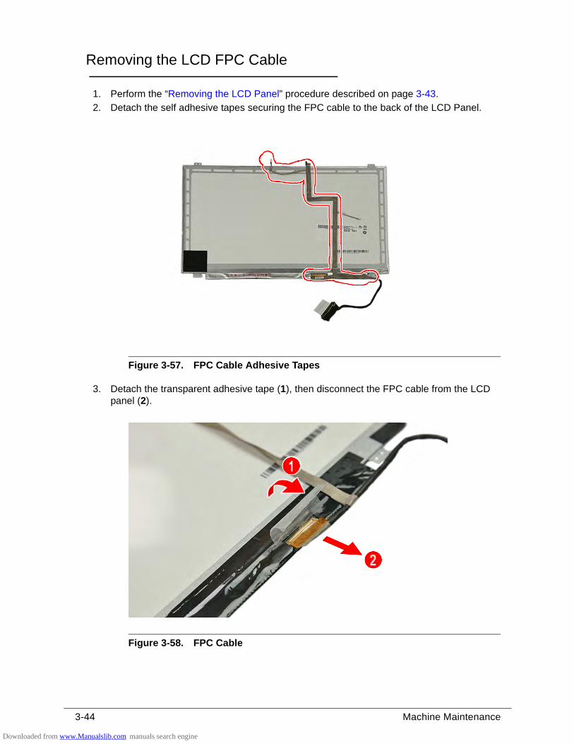
3-44 Machine Maintenance
Removing the LCD FPC Cable 0
1. Perform the “Removing the LCD Panel” procedure described on page 3-43.
2. Detach the self adhesive tapes securing the FPC cable to the back of the LCD Panel.
Figure 3-57. FPC Cable Adhesive Tapes
3. Detach the transparent adhesive tape (1), then disconnect the FPC cable from the LCD panel (2).
Figure 3-58. FPC Cable
Downloaded from www.Manualslib.com manuals search engine
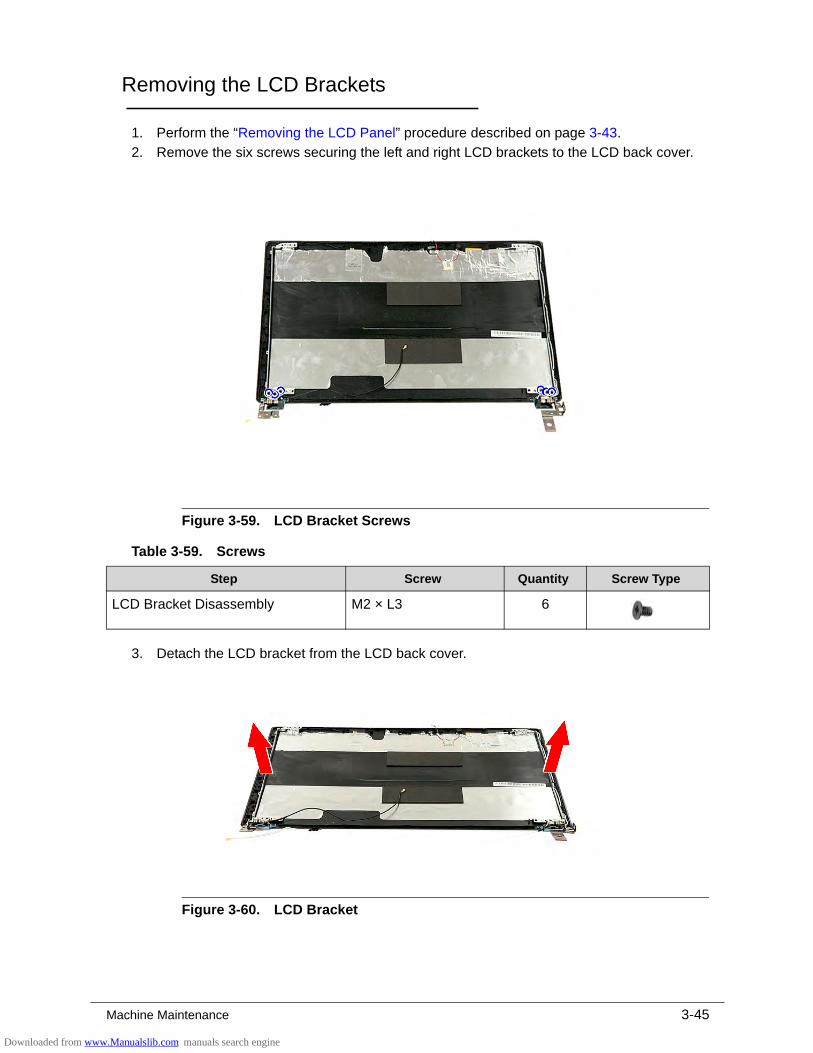
Machine Maintenance 3-45
Removing the LCD Brackets 0
1. Perform the “Removing the LCD Panel” procedure described on page 3-43.
2. Remove the six screws securing the left and right LCD brackets to the LCD back cover.
Figure 3-59. LCD Bracket Screws
3. Detach the LCD bracket from the LCD back cover.
Figure 3-60. LCD Bracket
Table 3-59. Screws
Step Screw Quantity Screw Type
LCD Bracket Disassembly M2 × L3 6
Downloaded from www.Manualslib.com manuals search engine
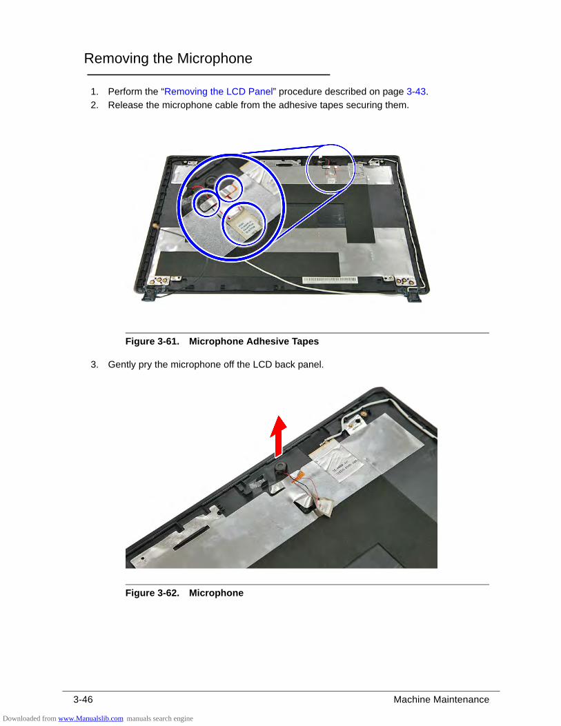
3-46 Machine Maintenance
Removing the Microphone 0
1. Perform the “Removing the LCD Panel” procedure described on page 3-43.
2. Release the microphone cable from the adhesive tapes securing them.
Figure 3-61. Microphone Adhesive Tapes
3. Gently pry the microphone off the LCD back panel.
Figure 3-62. Microphone
Downloaded from www.Manualslib.com manuals search engine
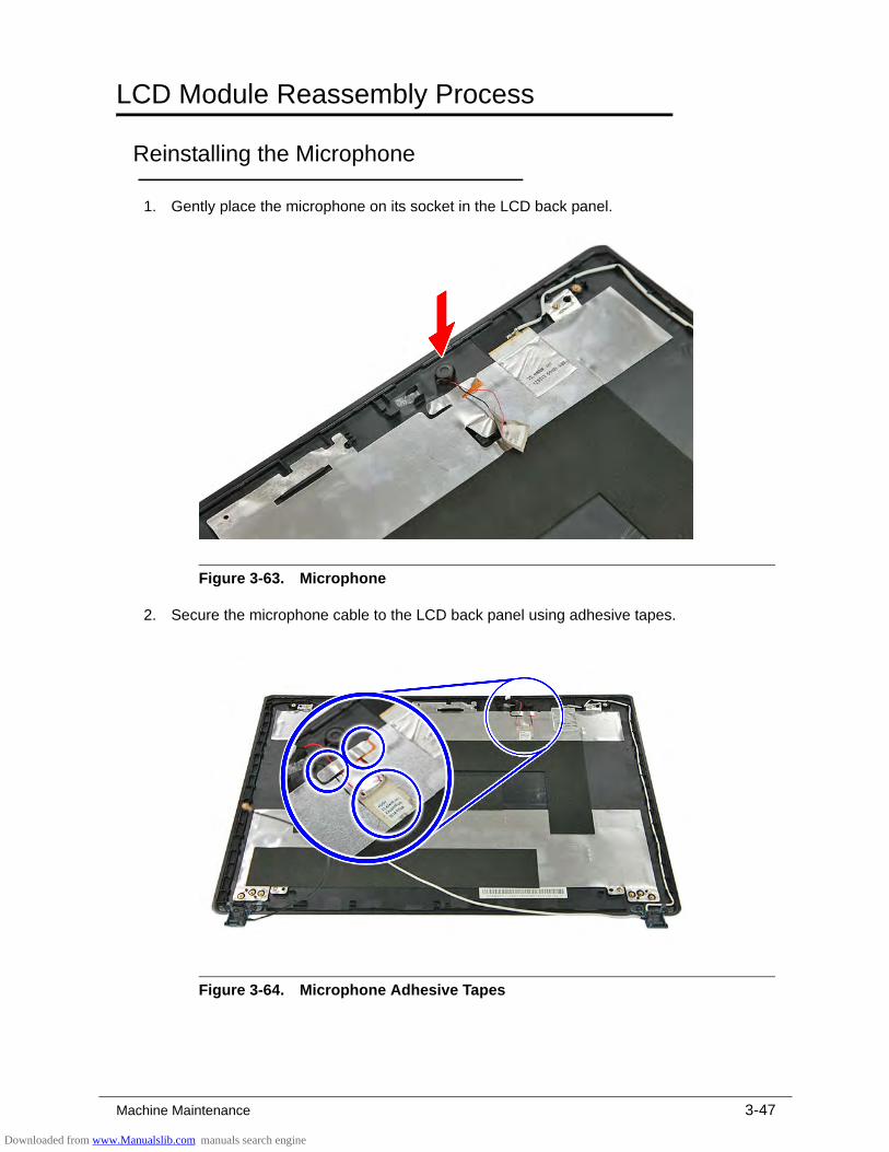
Machine Maintenance 3-47
LCD Module Reassembly Process 0
Reinstalling the Microphone 0
1. Gently place the microphone on its socket in the LCD back panel.
Figure 3-63. Microphone
2. Secure the microphone cable to the LCD back panel using adhesive tapes.
Figure 3-64. Microphone Adhesive Tapes
Downloaded from www.Manualslib.com manuals search engine
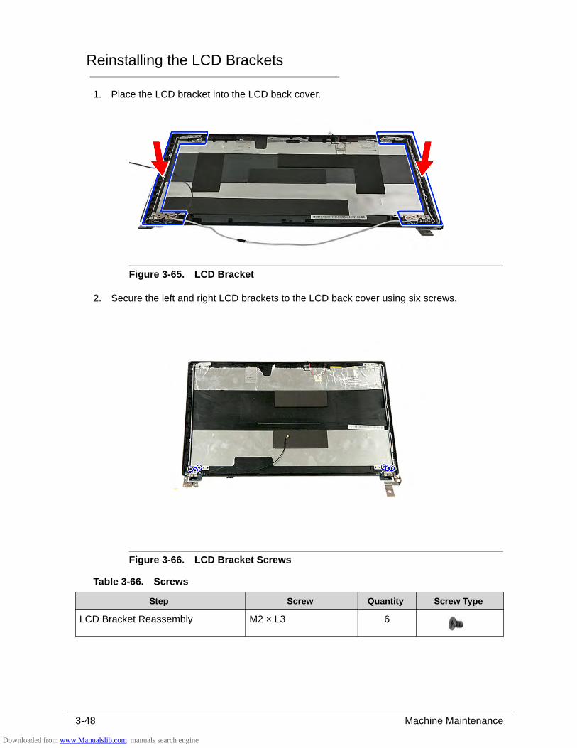
3-48 Machine Maintenance
Reinstalling the LCD Brackets 0
1. Place the LCD bracket into the LCD back cover.
Figure 3-65. LCD Bracket
2. Secure the left and right LCD brackets to the LCD back cover using six screws.
Figure 3-66. LCD Bracket Screws
Table 3-66. Screws
Step Screw Quantity Screw Type
LCD Bracket Reassembly M2 × L3 6
Downloaded from www.Manualslib.com manuals search engine
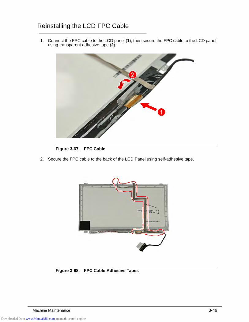
Machine Maintenance 3-49
Reinstalling the LCD FPC Cable 0
1. Connect the FPC cable to the LCD panel (1), then secure the FPC cable to the LCD panel using transparent adhesive tape (2).
Figure 3-67. FPC Cable
2. Secure the FPC cable to the back of the LCD Panel using self-adhesive tape.
Figure 3-68. FPC Cable Adhesive Tapes
Downloaded from www.Manualslib.com manuals search engine
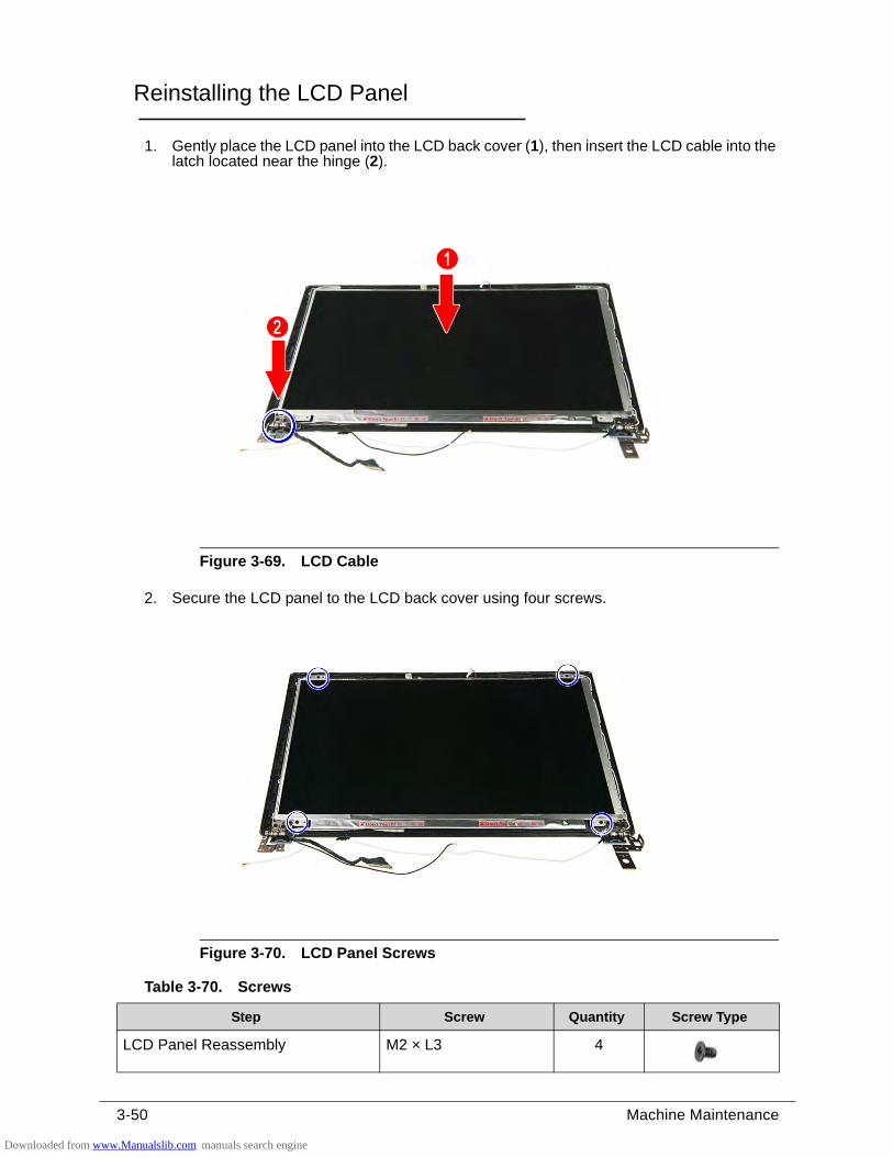
3-50 Machine Maintenance
Reinstalling the LCD Panel 0
1. Gently place the LCD panel into the LCD back cover (1), then insert the LCD cable into the latch located near the hinge (2).
Figure 3-69. LCD Cable
2. Secure the LCD panel to the LCD back cover using four screws.
Figure 3-70. LCD Panel Screws
Table 3-70. Screws
Step Screw Quantity Screw Type
LCD Panel Reassembly M2 × L3 4
Downloaded from www.Manualslib.com manuals search engine
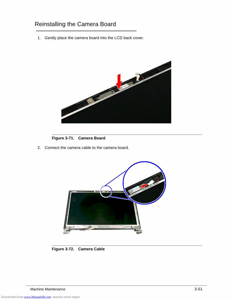
Machine Maintenance 3-51
Reinstalling the Camera Board 0
1. Gently place the camera board into the LCD back cover.
Figure 3-71. Camera Board
2. Connect the camera cable to the camera board.
Figure 3-72. Camera Cable
Downloaded from www.Manualslib.com manuals search engine
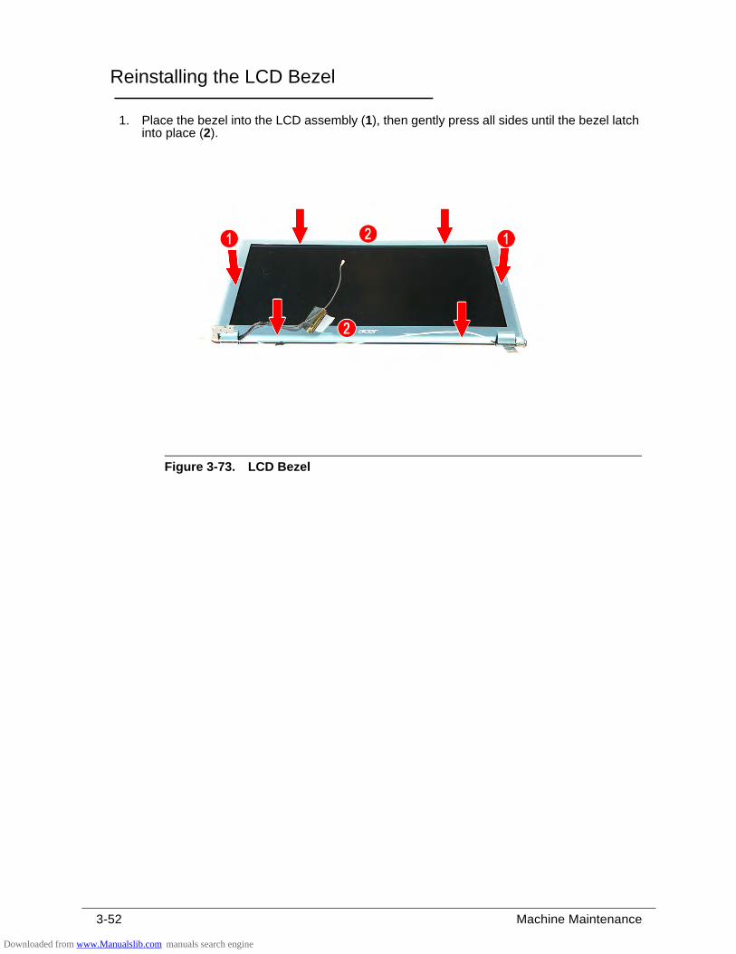
3-52 Machine Maintenance
Reinstalling the LCD Bezel 0
1. Place the bezel into the LCD assembly (1), then gently press all sides until the bezel latch into place (2).
Figure 3-73. LCD Bezel
Downloaded from www.Manualslib.com manuals search engine
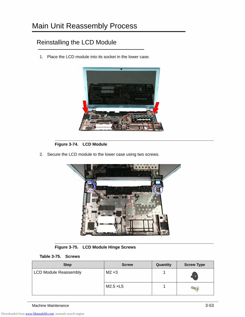
Machine Maintenance 3-53
Main Unit Reassembly Process 0
Reinstalling the LCD Module 0
1. Place the LCD module into its socket in the lower case.
Figure 3-74. LCD Module
2. Secure the LCD module to the lower case using two screws.
Figure 3-75. LCD Module Hinge Screws
Table 3-75. Screws
Step Screw Quantity Screw Type
LCD Module Reassembly M2 ×3 1
M2.5 ×L5 1
Downloaded from www.Manualslib.com manuals search engine
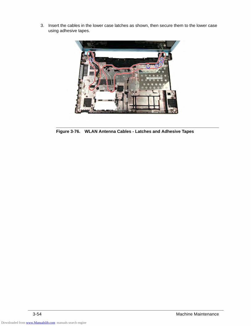
3-54 Machine Maintenance
3. Insert the cables in the lower case latches as shown, then secure them to the lower case using adhesive tapes.
Figure 3-76. WLAN Antenna Cables - Latches and Adhesive Tapes
Downloaded from www.Manualslib.com manuals search engine
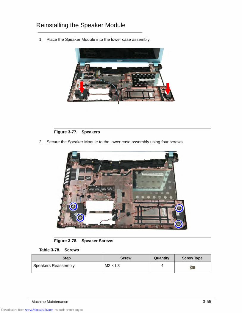
Machine Maintenance 3-55
Reinstalling the Speaker Module 0
1. Place the Speaker Module into the lower case assembly.
Figure 3-77. Speakers
2. Secure the Speaker Module to the lower case assembly using four screws.
Figure 3-78. Speaker Screws
Table 3-78. Screws
Step Screw Quantity Screw Type
Speakers Reassembly M2 × L3 4
Downloaded from www.Manualslib.com manuals search engine
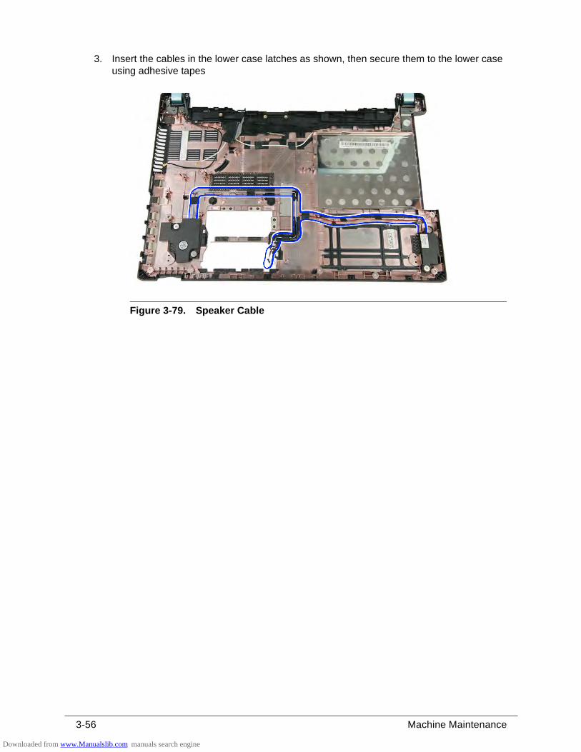
3-56 Machine Maintenance
3. Insert the cables in the lower case latches as shown, then secure them to the lower case using adhesive tapes
Figure 3-79. Speaker Cable
Downloaded from www.Manualslib.com manuals search engine
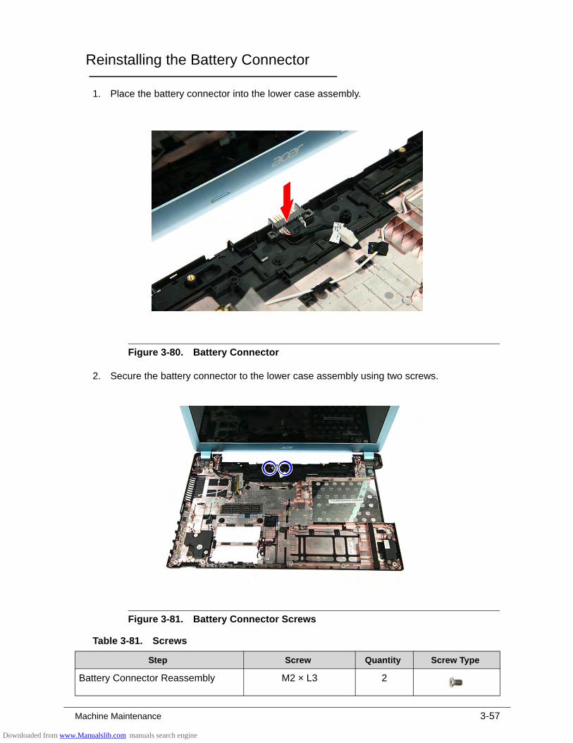
Machine Maintenance 3-57
Reinstalling the Battery Connector 0
1. Place the battery connector into the lower case assembly.
Figure 3-80. Battery Connector
2. Secure the battery connector to the lower case assembly using two screws.
Figure 3-81. Battery Connector Screws
Table 3-81. Screws
Step Screw Quantity Screw Type
Battery Connector Reassembly M2 × L3 2
Downloaded from www.Manualslib.com manuals search engine
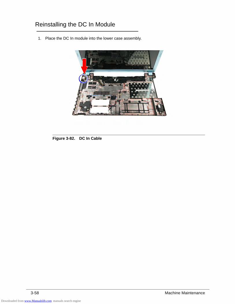
3-58 Machine Maintenance
Reinstalling the DC In Module 0
1. Place the DC In module into the lower case assembly.
Figure 3-82. DC In Cable
Downloaded from www.Manualslib.com manuals search engine
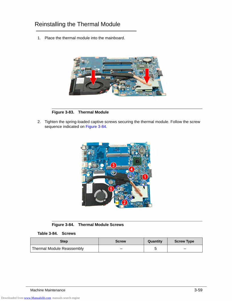
Machine Maintenance 3-59
Reinstalling the Thermal Module 0
1. Place the thermal module into the mainboard.
Figure 3-83. Thermal Module
2. Tighten the spring-loaded captive screws securing the thermal module. Follow the screw sequence indicated on Figure 3-84.
Figure 3-84. Thermal Module Screws
Table 3-84. Screws
Step Screw Quantity Screw Type
Thermal Module Reassembly – 5 –
Downloaded from www.Manualslib.com manuals search engine
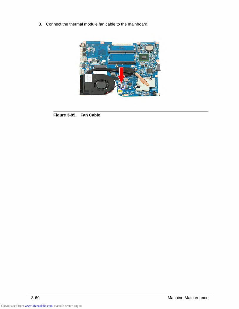
3-60 Machine Maintenance
3. Connect the thermal module fan cable to the mainboard.
Figure 3-85. Fan Cable
Downloaded from www.Manualslib.com manuals search engine
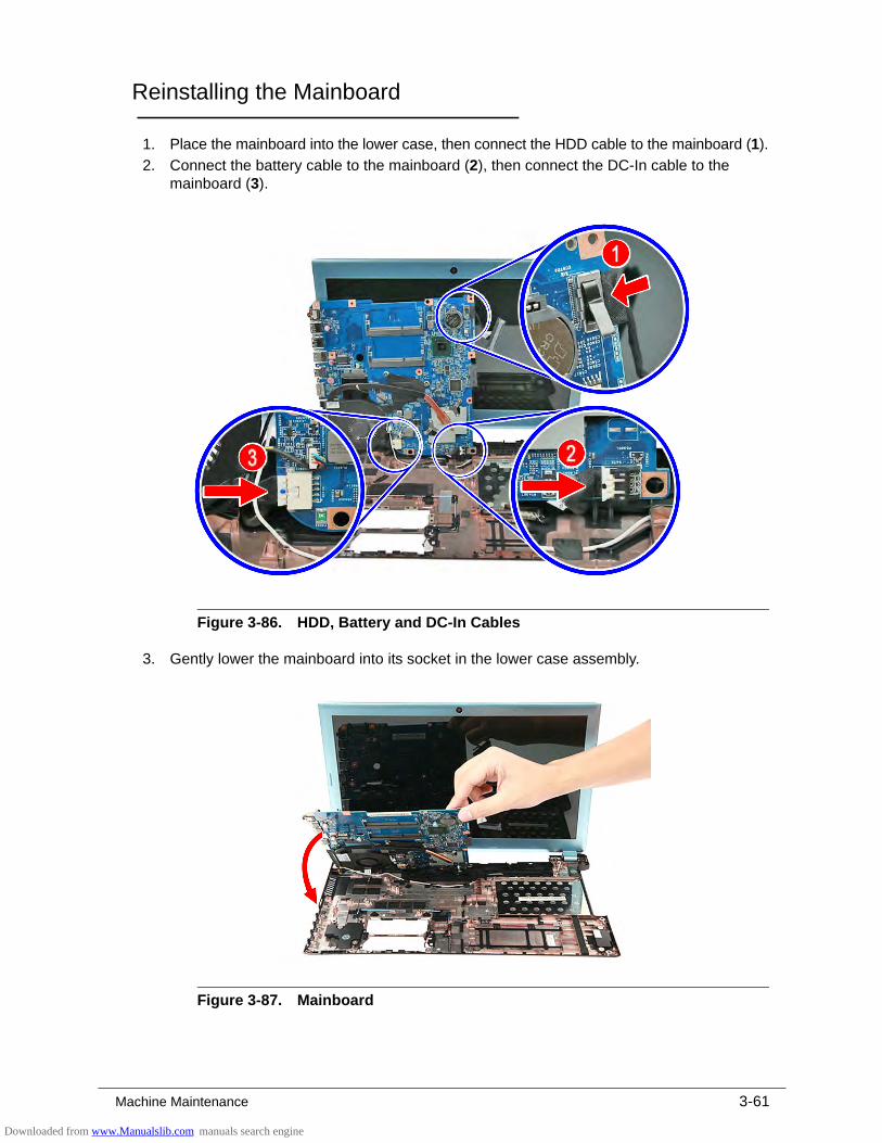
Machine Maintenance 3-61
Reinstalling the Mainboard 0
1. Place the mainboard into the lower case, then connect the HDD cable to the mainboard (1).
2. Connect the battery cable to the mainboard (2), then connect the DC-In cable to the mainboard (3).
Figure 3-86. HDD, Battery and DC-In Cables
3. Gently lower the mainboard into its socket in the lower case assembly.
Figure 3-87. Mainboard
Downloaded from www.Manualslib.com manuals search engine
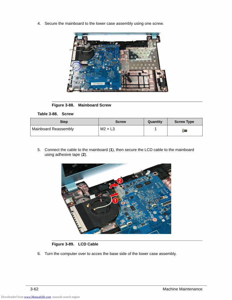
3-62 Machine Maintenance
4. Secure the mainboard to the lower case assembly using one screw.
Figure 3-88. Mainboard Screw
5. Connect the cable to the mainboard (1), then secure the LCD cable to the mainboard using adhesive tape (2).
Figure 3-89. LCD Cable
6. Turn the computer over to acces the base side of the lower case assembly.
Table 3-88. Screw
Step Screw Quantity Screw Type
Mainboard Reassembly M2 × L3 1
Downloaded from www.Manualslib.com manuals search engine
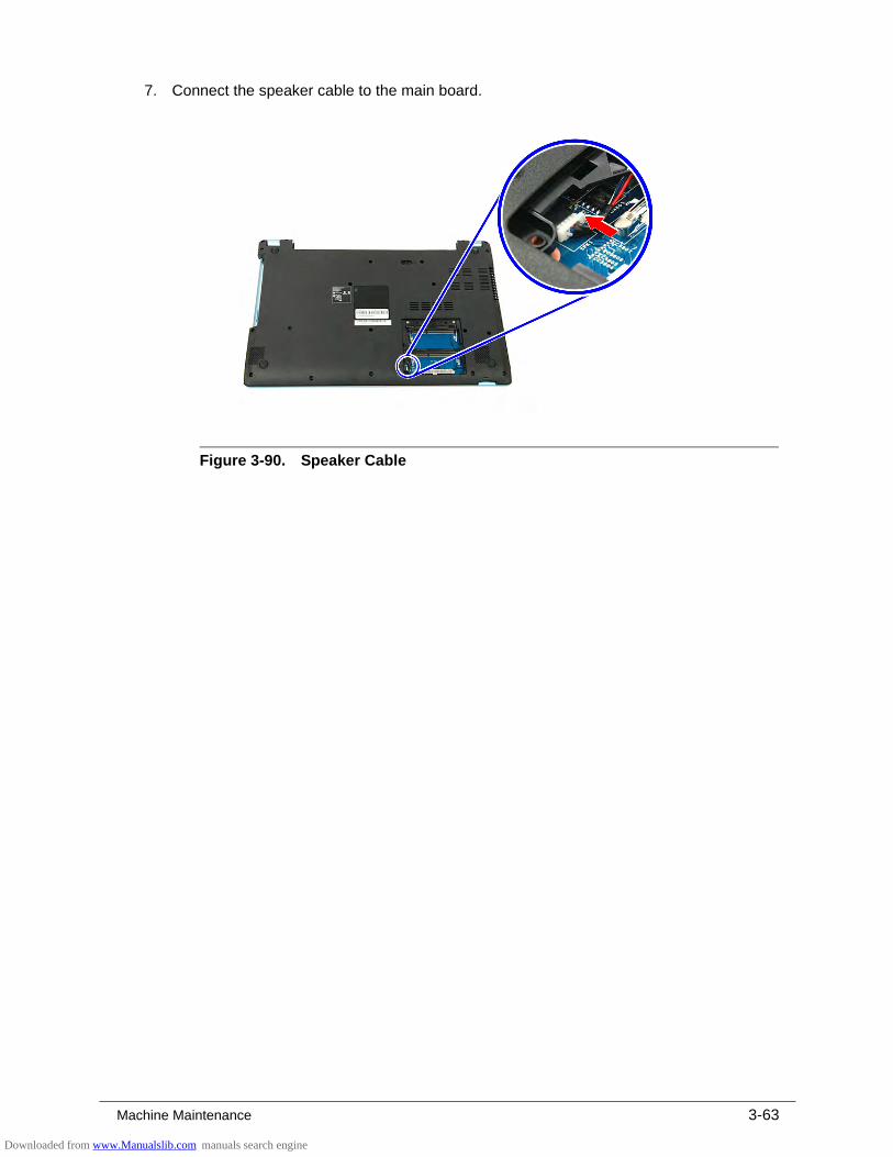
Machine Maintenance 3-63
7. Connect the speaker cable to the main board.
Figure 3-90. Speaker Cable
Downloaded from www.Manualslib.com manuals search engine
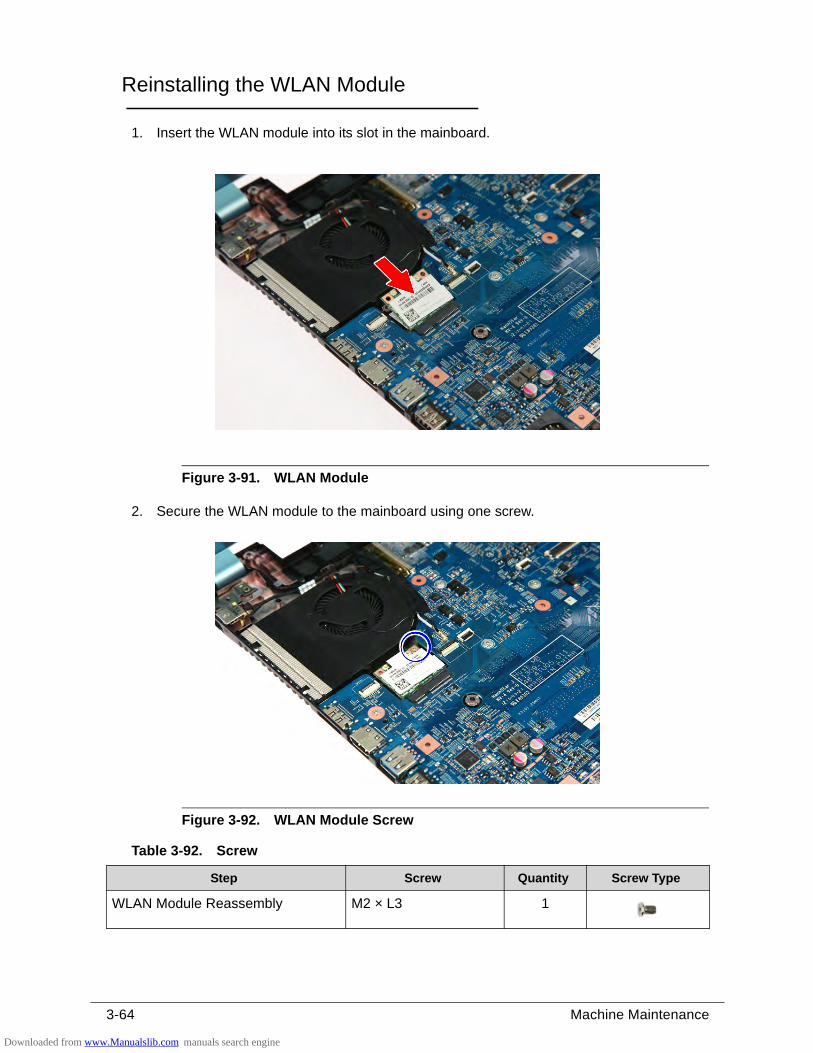
3-64 Machine Maintenance
Reinstalling the WLAN Module 0
1. Insert the WLAN module into its slot in the mainboard.
Figure 3-91. WLAN Module
2. Secure the WLAN module to the mainboard using one screw.
Figure 3-92. WLAN Module Screw
Table 3-92. Screw
Step Screw Quantity Screw Type
WLAN Module Reassembly M2 × L3 1
Downloaded from www.Manualslib.com manuals search engine
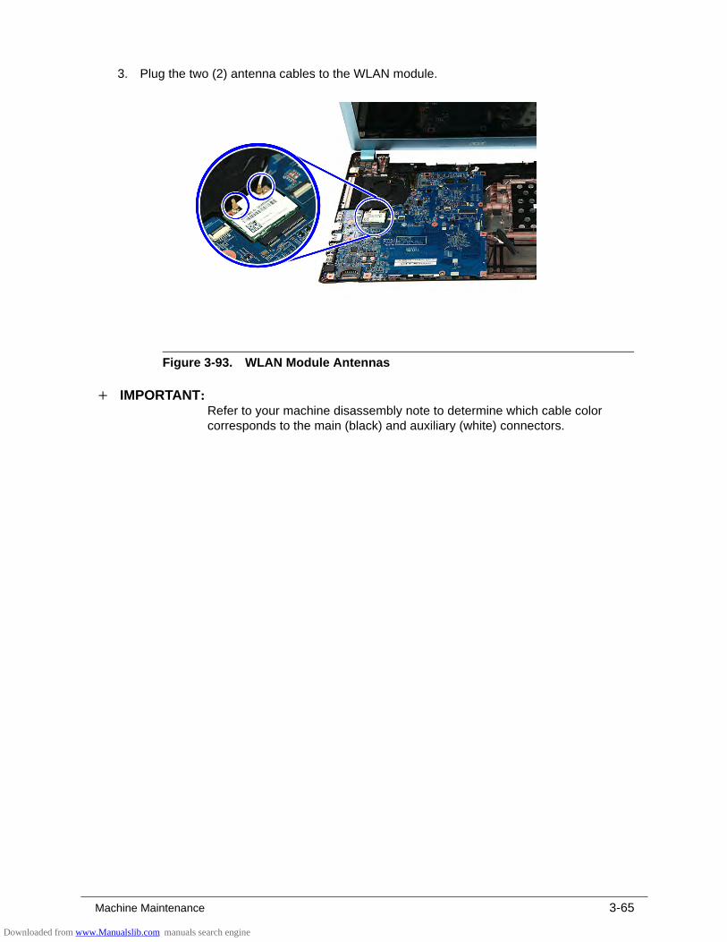
Machine Maintenance 3-65
3. Plug the two (2) antenna cables to the WLAN module.
Figure 3-93. WLAN Module Antennas
IMPORTANT:+Refer to your machine disassembly note to determine which cable color corresponds to the main (black) and auxiliary (white) connectors.
Downloaded from www.Manualslib.com manuals search engine
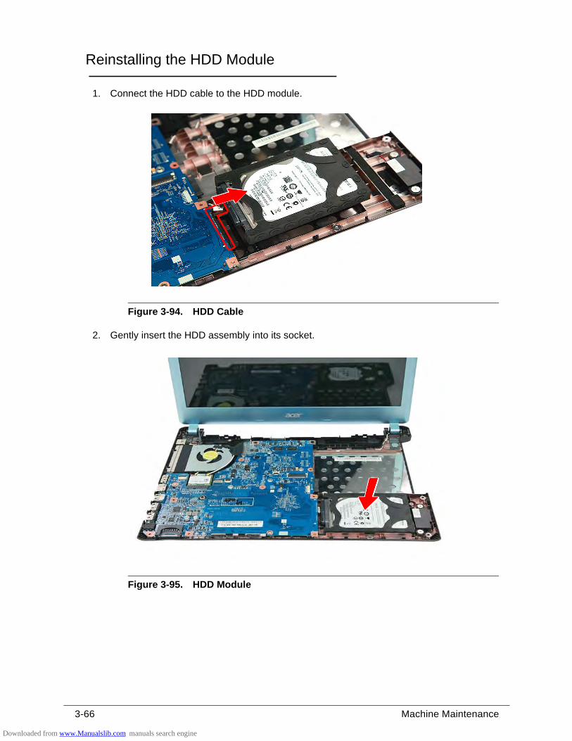
3-66 Machine Maintenance
Reinstalling the HDD Module 0
1. Connect the HDD cable to the HDD module.
Figure 3-94. HDD Cable
2. Gently insert the HDD assembly into its socket.
Figure 3-95. HDD Module
Downloaded from www.Manualslib.com manuals search engine
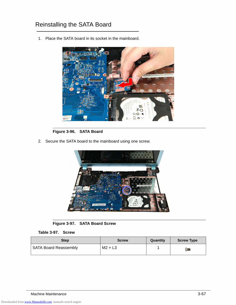
Machine Maintenance 3-67
Reinstalling the SATA Board 0
1. Place the SATA board in its socket in the mainboard.
Figure 3-96. SATA Board
2. Secure the SATA board to the mainboard using one screw.
Figure 3-97. SATA Board Screw
Table 3-97. Screw
Step Screw Quantity Screw Type
SATA Board Reassembly M2 × L3 1
Downloaded from www.Manualslib.com manuals search engine
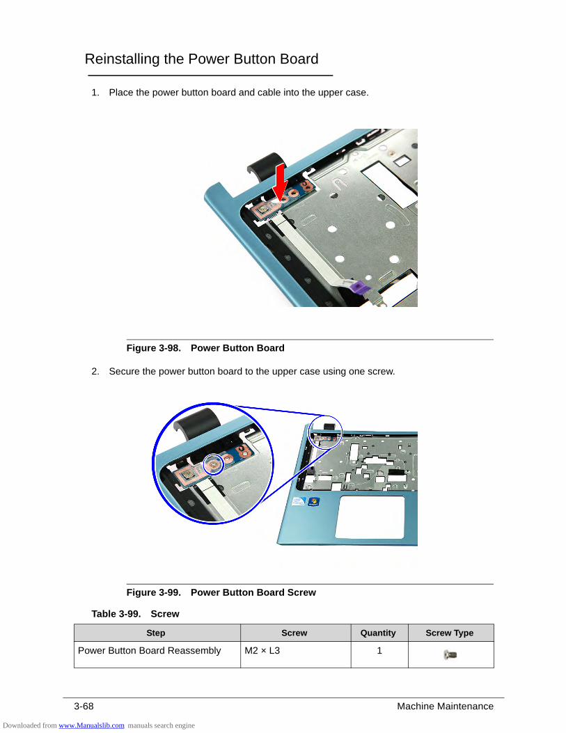
3-68 Machine Maintenance
Reinstalling the Power Button Board 0
1. Place the power button board and cable into the upper case.
Figure 3-98. Power Button Board
2. Secure the power button board to the upper case using one screw.
Figure 3-99. Power Button Board Screw
Table 3-99. Screw
Step Screw Quantity Screw Type
Power Button Board Reassembly M2 × L3 1
Downloaded from www.Manualslib.com manuals search engine
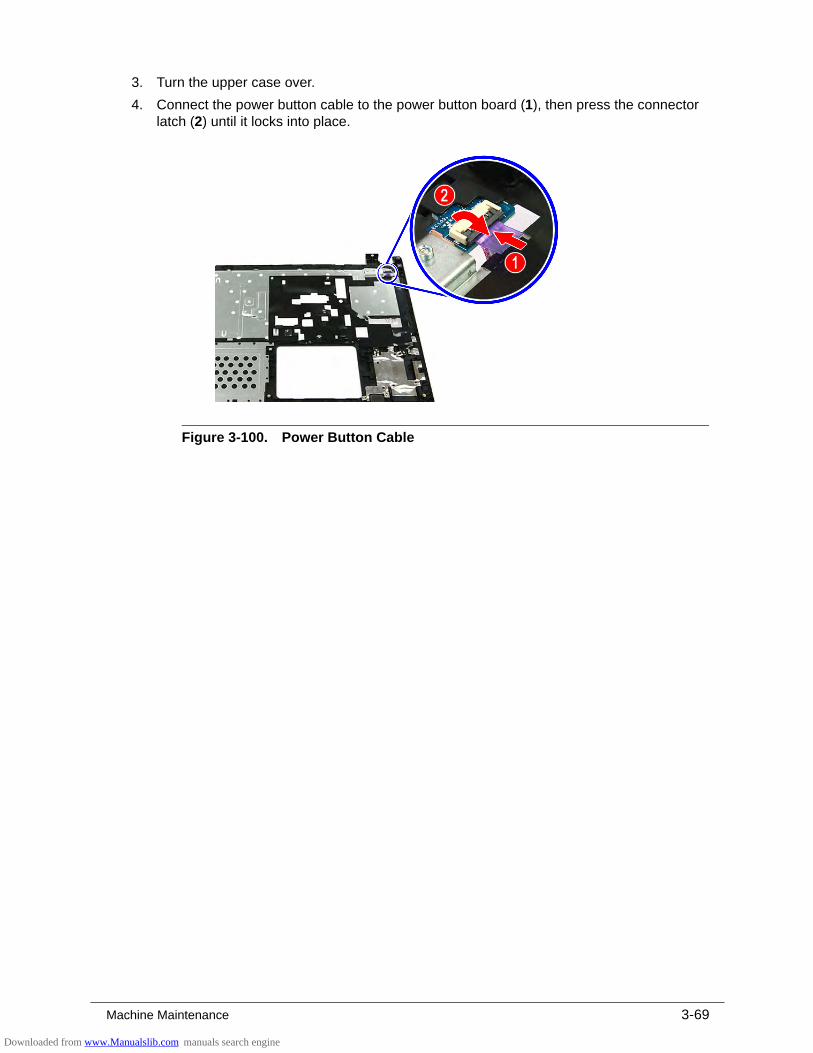
Machine Maintenance 3-69
3. Turn the upper case over.
4. Connect the power button cable to the power button board (1), then press the connector latch (2) until it locks into place.
Figure 3-100. Power Button Cable
Downloaded from www.Manualslib.com manuals search engine
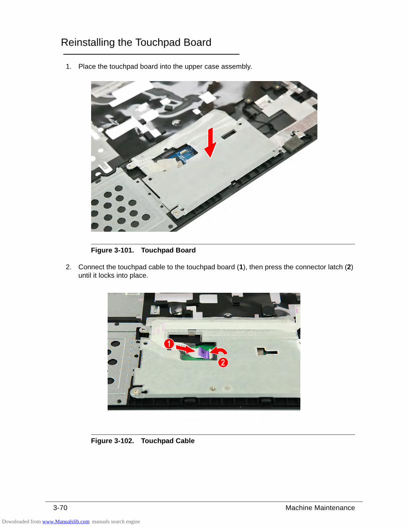
3-70 Machine Maintenance
Reinstalling the Touchpad Board 0
1. Place the touchpad board into the upper case assembly.
Figure 3-101. Touchpad Board
2. Connect the touchpad cable to the touchpad board (1), then press the connector latch (2) until it locks into place.
Figure 3-102. Touchpad Cable
Downloaded from www.Manualslib.com manuals search engine
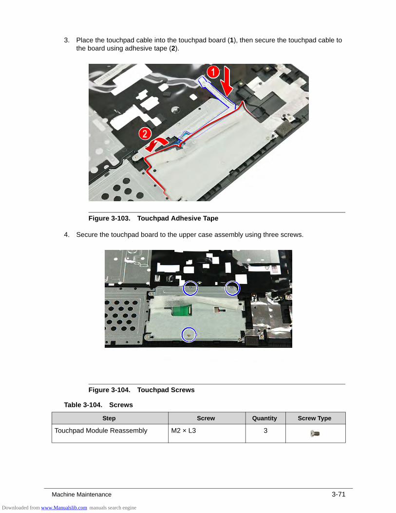
Machine Maintenance 3-71
3. Place the touchpad cable into the touchpad board (1), then secure the touchpad cable to the board using adhesive tape (2).
Figure 3-103. Touchpad Adhesive Tape
4. Secure the touchpad board to the upper case assembly using three screws.
Figure 3-104. Touchpad Screws
Table 3-104. Screws
Step Screw Quantity Screw Type
Touchpad Module Reassembly M2 × L3 3
Downloaded from www.Manualslib.com manuals search engine
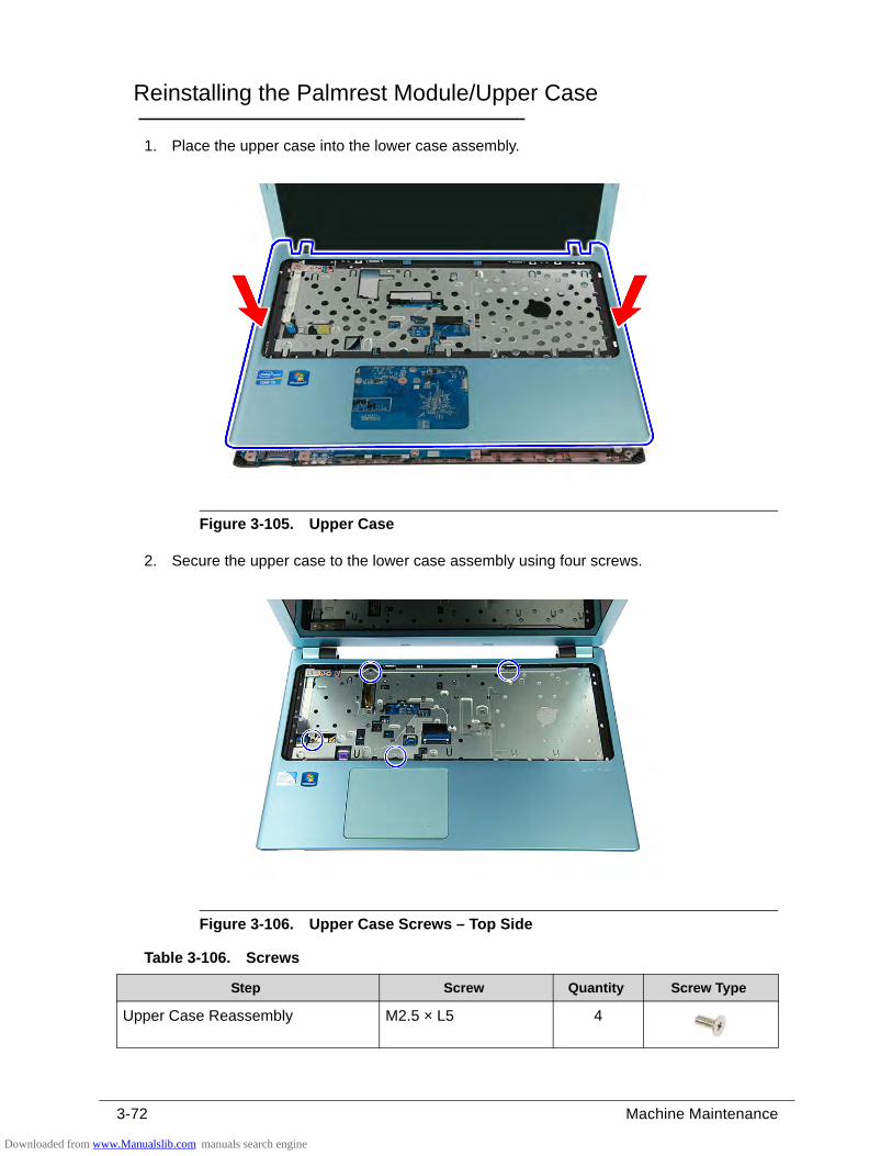
3-72 Machine Maintenance
Reinstalling the Palmrest Module/Upper Case 0
1. Place the upper case into the lower case assembly.
Figure 3-105. Upper Case
2. Secure the upper case to the lower case assembly using four screws.
Figure 3-106. Upper Case Screws – Top Side
Table 3-106. Screws
Step Screw Quantity Screw Type
Upper Case Reassembly M2.5 × L5 4
Downloaded from www.Manualslib.com manuals search engine
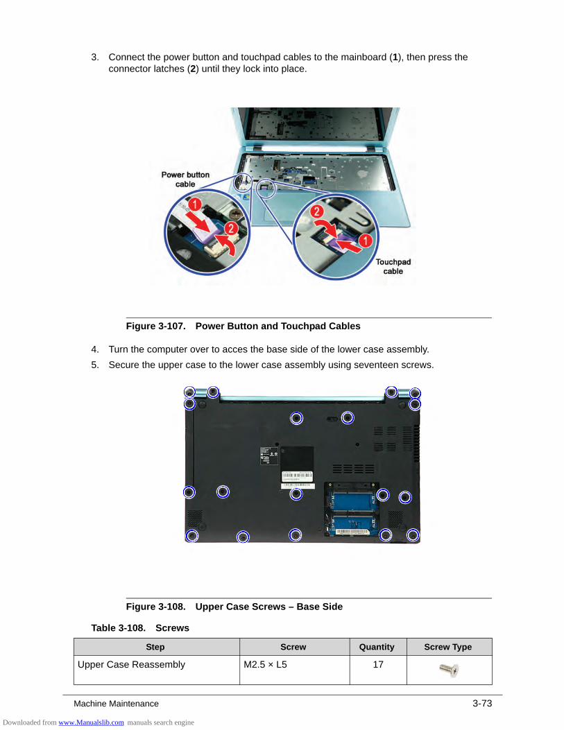
Machine Maintenance 3-73
3. Connect the power button and touchpad cables to the mainboard (1), then press the connector latches (2) until they lock into place.
Figure 3-107. Power Button and Touchpad Cables
4. Turn the computer over to acces the base side of the lower case assembly.
5. Secure the upper case to the lower case assembly using seventeen screws.
Figure 3-108. Upper Case Screws – Base Side
Table 3-108. Screws
Step Screw Quantity Screw Type
Upper Case Reassembly M2.5 × L5 17
Downloaded from www.Manualslib.com manuals search engine
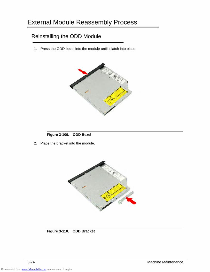
3-74 Machine Maintenance
External Module Reassembly Process 0
Reinstalling the ODD Module 0
1. Press the ODD bezel into the module until it latch into place.
Figure 3-109. ODD Bezel
2. Place the bracket into the module.
Figure 3-110. ODD Bracket
Downloaded from www.Manualslib.com manuals search engine
Machine Maintenance 3-75
3. Secure the ODD module to the bracket using two screws.
Figure 3-111. ODD Bracket Screws
4. Gently push the ODD module into the ODD drive bay until the ODD connector latch into place.
Figure 3-112. ODD Module
5. Turn the computer over and open the LCD panel.
6. Secure the ODD module to the upper case assembly using one screw.
Table 3-111. Screws
Step Screw Quantity Screw Type
ODD Bracket Reassembly M2 × L3 2
Downloaded from www.Manualslib.com manuals search engine
3-76 Machine Maintenance
Figure 3-113. ODD Module Screw
Table 3-113. Screw
Step Screw Quantity Screw Type
ODD Module Reassembly M2.5 × L5 1
Downloaded from www.Manualslib.com manuals search engine
Machine Maintenance 3-77
Reinstalling the Keyboard 0
1. Turn the computer over and open the LCD panel.
2. Connect the cable to the mainboard (1), then press the connector latch (2) until it locks into place. Place the keyboard into its socket.
Figure 3-114. Keyboard
3. Use a non-marring plastic flat-blade screwdriver to push the latches on the top side of the keyboard, then press the keyboard until it latch into place.
Figure 3-115. Keyboard Latches
Downloaded from www.Manualslib.com manuals search engine
3-78 Machine Maintenance
4. Turn the computer over to acces the base side of the lower case assembly.
5. Secure the keyboard to the lower case assembly using two screws.
Figure 3-116. Upper Case Screws – Base Side
Table 3-116. Screws
Step Screw Quantity Screw Type
Upper Case Reassembly M2.5 × L5 17
Downloaded from www.Manualslib.com manuals search engine

Machine Maintenance 3-79
Reinstalling the DIMM Modules 0
1. Insert the DIMM module into the slot (1), then push it downward until it latches into place (2).
Figure 3-117. DIMM Modules
2. Repeat Step 1 to reinstall the remaining DIMM module.
Downloaded from www.Manualslib.com manuals search engine
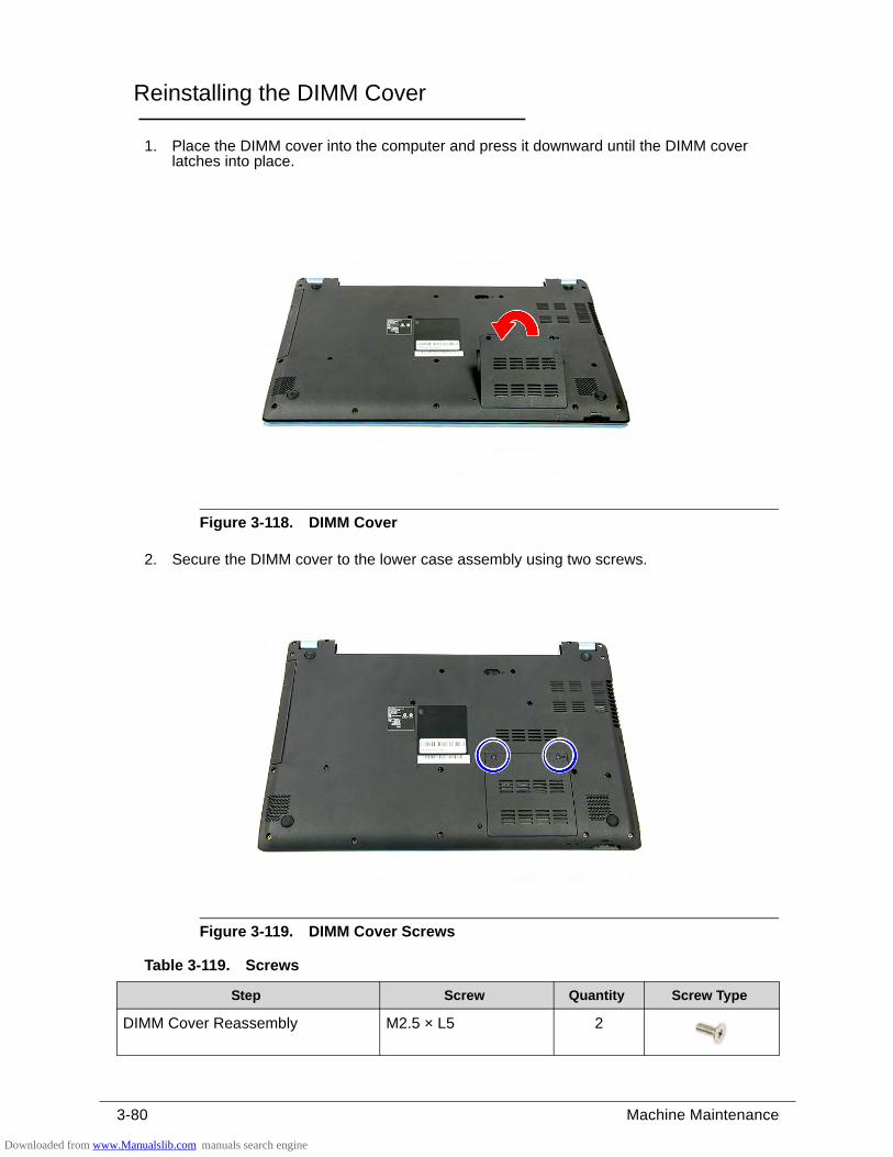
3-80 Machine Maintenance
Reinstalling the DIMM Cover 0
1. Place the DIMM cover into the computer and press it downward until the DIMM cover latches into place.
Figure 3-118. DIMM Cover
2. Secure the DIMM cover to the lower case assembly using two screws.
Figure 3-119. DIMM Cover Screws
Table 3-119. Screws
Step Screw Quantity Screw Type
DIMM Cover Reassembly M2.5 × L5 2
Downloaded from www.Manualslib.com manuals search engine
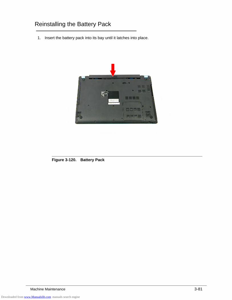
Machine Maintenance 3-81
Reinstalling the Battery Pack 0
1. Insert the battery pack into its bay until it latches into place.
Figure 3-120. Battery Pack
Downloaded from www.Manualslib.com manuals search engine

3-82 Machine Maintenance
Downloaded from www.Manualslib.com manuals search engine

CHAPTER 4
Troubleshooting
Downloaded from www.Manualslib.com manuals search engine
4-2
Introduction . . . . . . . . . . . . . . . . . . . . . . . . . . . . . . . . . . . . . . . . . .4-3
General Information . . . . . . . . . . . . . . . . . . . . . . . . . . . . . . . . . . .4-3Power On Issues . . . . . . . . . . . . . . . . . . . . . . . . . . . . . . . . . . . .4-4No Display Issues . . . . . . . . . . . . . . . . . . . . . . . . . . . . . . . . . . .4-5LCD Failure . . . . . . . . . . . . . . . . . . . . . . . . . . . . . . . . . . . . . . . .4-7Keyboard Failure . . . . . . . . . . . . . . . . . . . . . . . . . . . . . . . . . . . .4-8Touchpad Failure. . . . . . . . . . . . . . . . . . . . . . . . . . . . . . . . . . . .4-9Internal Speaker Failure . . . . . . . . . . . . . . . . . . . . . . . . . . . . . .4-10Microphone Failure . . . . . . . . . . . . . . . . . . . . . . . . . . . . . . . . . .4-12USB Failure . . . . . . . . . . . . . . . . . . . . . . . . . . . . . . . . . . . . . . . .4-13WLAN Failure . . . . . . . . . . . . . . . . . . . . . . . . . . . . . . . . . . . . . .4-14Card Reader Failure . . . . . . . . . . . . . . . . . . . . . . . . . . . . . . . . .4-15Thermal Unit Failure . . . . . . . . . . . . . . . . . . . . . . . . . . . . . . . . .4-16Other Functions Failure . . . . . . . . . . . . . . . . . . . . . . . . . . . . . . .4-17
Intermittent Problems. . . . . . . . . . . . . . . . . . . . . . . . . . . . . . . . . .4-18
Undetermined Problems. . . . . . . . . . . . . . . . . . . . . . . . . . . . . . . .4-18
Error Codes . . . . . . . . . . . . . . . . . . . . . . . . . . . . . . . . . . . . . . . . . .4-19BIOS Beep Codes . . . . . . . . . . . . . . . . . . . . . . . . . . . . . . . . . . . . .4-20
POST Codes . . . . . . . . . . . . . . . . . . . . . . . . . . . . . . . . . . . . . . . . .4-25Component Codes . . . . . . . . . . . . . . . . . . . . . . . . . . . . . . . . . . .4-25Progress Codes . . . . . . . . . . . . . . . . . . . . . . . . . . . . . . . . . . . . .4-30
Downloaded from www.Manualslib.com manuals search engine
Troubleshooting 4-3
Troubleshooting
Introduction 0
This chapter contains information about troubleshooting common problems associated with the computer.
General Information 0
The following procedures are a guide for troubleshooting computer problems. The step by step procedures are designed to be performed as described.
NOTE:NOTE:The diagnostic tests are intended for Acer products only. Non-Acer products, prototype cards, or modified options can give false errors and invalid system responses.
1. Obtain as much detailed information as possible about the problem.
2. If possible, verify the symptoms by re-creating the failure through diagnostic tests or repeating the operation that led to the problem.
3. Refer to Table 4-1 for a list of verified symptom category to determine the solution.
4. If the issue is still not resolved, refer to the Online Support Information on page 8-3
Table 4-1. Common Problems
Symptoms (Verified)
Power On Issues
No Display Issues
LCD Failure
Keyboard Failure
Touchpad Failure
Internal Speaker Failure
Microphone Failure
USB Failure
WLAN Failure
Card Reader Failure
Thermal Unit Failure
Other Functions Failure
Intermittent Problems
Undetermined Problems
Downloaded from www.Manualslib.com manuals search engine
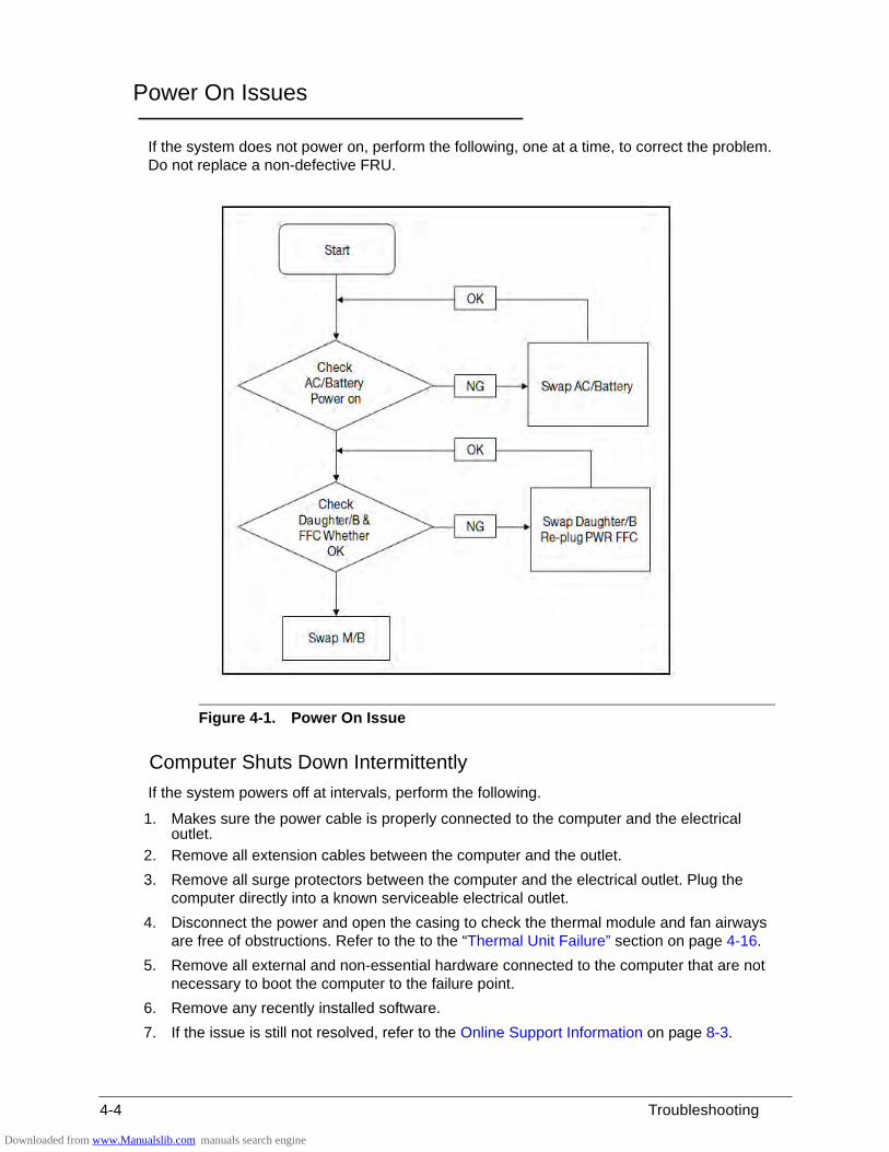
4-4 Troubleshooting
Power On Issues 0
If the system does not power on, perform the following, one at a time, to correct the problem. Do not replace a non-defective FRU.
Figure 4-1. Power On Issue
Computer Shuts Down Intermittently 0
If the system powers off at intervals, perform the following.
1. Makes sure the power cable is properly connected to the computer and the electrical outlet.
2. Remove all extension cables between the computer and the outlet.
3. Remove all surge protectors between the computer and the electrical outlet. Plug the computer directly into a known serviceable electrical outlet.
4. Disconnect the power and open the casing to check the thermal module and fan airways are free of obstructions. Refer to the to the “Thermal Unit Failure” section on page 4-16.
5. Remove all external and non-essential hardware connected to the computer that are not necessary to boot the computer to the failure point.
6. Remove any recently installed software.
7. If the issue is still not resolved, refer to the Online Support Information on page 8-3.
Downloaded from www.Manualslib.com manuals search engine
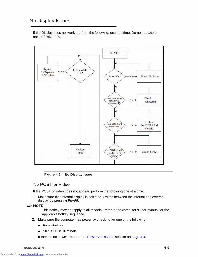
Troubleshooting 4-5
No Display Issues 0
If the Display does not work, perform the following, one at a time. Do not replace a non-defective FRU:
Figure 4-2. No Display Issue
No POST or Video 0
If the POST or video does not appear, perform the following one at a time.
1. Make sure that internal display is selected. Switch between the internal and external display by pressing Fn+F5.
NOTE:NOTE:This hotkey may not apply to all models. Refer to the computer’s user manual for the applicable hotkey sequence.
2. Make sure the computer has power by checking for one of the following:
Fans start up
Status LEDs illuminate
If there is no power, refer to the “Power On Issues” section on page 4-4.
Downloaded from www.Manualslib.com manuals search engine
4-6 Troubleshooting
3. Drain stored power by removing the power cable and the battery pack. Hold the power button for 10 seconds.
4. Connect the power cable and reboot the computer.
5. Connect an external monitor to the computer and switch between the internal display and the external display by pressing Fn+F5.
6. If the POST or video appears on the external display only, refer to the “LCD Failure” section on page 4-7.
7. Disconnect power and all external devices including port replicators or docking stations.
8. Remove any memory cards and CD/DVD discs.
9. Start the computer. If the computer boots correctly, add the devices one by one until the failure point is discovered.
10. Reinstall the memory modules.
11. Perform the “Reinstalling the HDD Module” and “Reinstalling the ODD Module” procedures described on pages 3-66 and 3-74 respectively.
12. If the issue is still not resolved, refer to the Online Support Information on page 8-3.
Abnormal Video 0
If the video appears abnormal, perform the following one at a time.
1. Boot the computer.
If permanent vertical/horizontal lines or dark spots appear in the same location, the LCD panel is faulty and should be replaced. The same goes for when there is extensive pixel damage (i.e. different colored spots in the same locations on the screen). Perform the “Removing the LCD Module” and “Removing the Camera Board” procedures described on pages 3-38 and 3-42 respectively.
NOTE:NOTE:Make sure that the computer is not running on battery alone as this may reduce display brightness.
2. Adjust the brightness to its highest level. Refer to the User Manual for instructions on adjusting the settings. If the display is too dim at the highest brightness setting, the LCD is faulty and should be replaced. Refer to Disassembly Process.
3. Check the display resolution is correctly configured:
Minimize or close all Windows.
If display size is only abnormal in an application, check the view settings and control/mouse wheel zoom feature in the application.
If desktop display resolution is not normal, right-click on the desktop and select Personalize Display Settings.
Click and drag the Resolution slider to the desired resolution.
Click Apply and check the display. Readjust if necessary.
4. Roll back the video driver to the previous version if updated.
5. Remove and reinstall the video driver.
6. Check the Device Manager to determine that:
The device is properly installed. There are no red Xs or yellow exclamation marks
There are no device conflicts
No hardware is listed under Other Devices
Downloaded from www.Manualslib.com manuals search engine
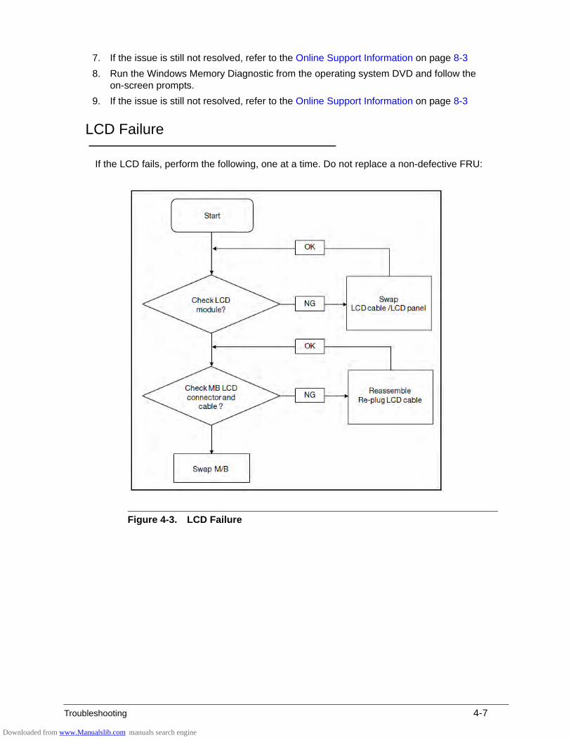
Troubleshooting 4-7
7. If the issue is still not resolved, refer to the Online Support Information on page 8-3
8. Run the Windows Memory Diagnostic from the operating system DVD and follow the on-screen prompts.
9. If the issue is still not resolved, refer to the Online Support Information on page 8-3
LCD Failure 0
If the LCD fails, perform the following, one at a time. Do not replace a non-defective FRU:
Figure 4-3. LCD Failure
Downloaded from www.Manualslib.com manuals search engine
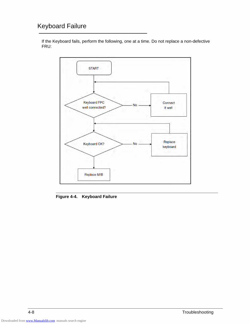
4-8 Troubleshooting
Keyboard Failure 0
If the Keyboard fails, perform the following, one at a time. Do not replace a non-defective FRU:
Figure 4-4. Keyboard Failure
Downloaded from www.Manualslib.com manuals search engine
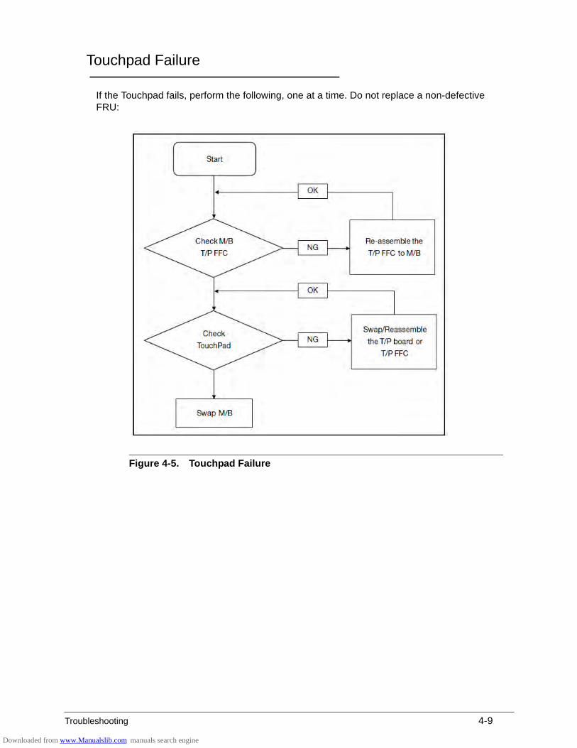
Troubleshooting 4-9
Touchpad Failure 0
If the Touchpad fails, perform the following, one at a time. Do not replace a non-defective FRU:
Figure 4-5. Touchpad Failure
Downloaded from www.Manualslib.com manuals search engine
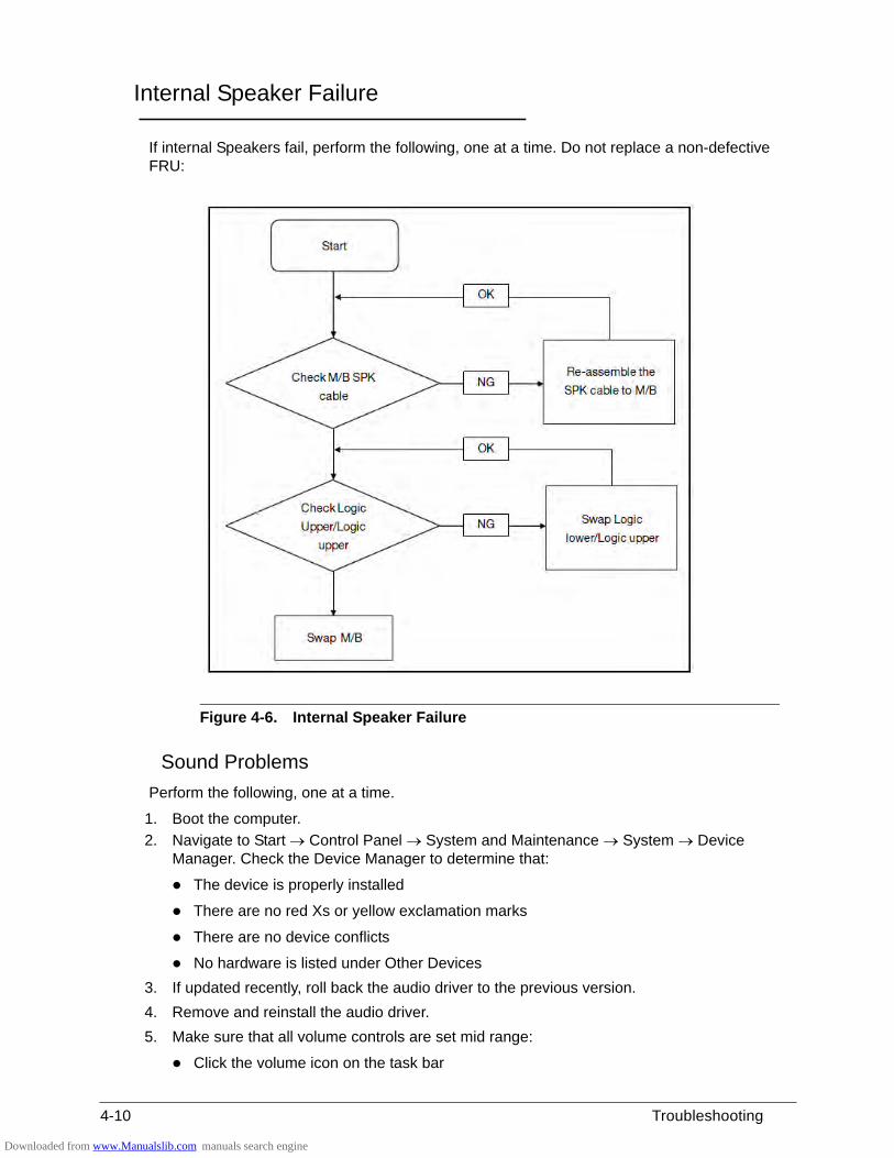
4-10 Troubleshooting
Internal Speaker Failure 0
If internal Speakers fail, perform the following, one at a time. Do not replace a non-defective FRU:
Figure 4-6. Internal Speaker Failure
Sound Problems 0
Perform the following, one at a time.
1. Boot the computer.
2. Navigate to Start Control Panel System and Maintenance System Device Manager. Check the Device Manager to determine that:
The device is properly installed
There are no red Xs or yellow exclamation marks
There are no device conflicts
No hardware is listed under Other Devices
3. If updated recently, roll back the audio driver to the previous version.
4. Remove and reinstall the audio driver.
5. Make sure that all volume controls are set mid range:
Click the volume icon on the task bar
Downloaded from www.Manualslib.com manuals search engine
Troubleshooting 4-11
Drag the slider to 50. Confirm that the volume is not muted.
Click Mixer to verify that other audio applications are set to 50 and not muted.
6. Navigate to Start Control Panel Hardware and Sound Sound. Confirm that Speakers are selected as the default audio device (green check mark).
NOTE:NOTE:If Speakers do not show, right-click on the Playback tab and select Show Disabled Devices (clear by default).
7. Select Speakers and click Configure to start Speaker Setup. Follow the on-screen prompts to configure the speakers.
8. Remove any recently installed hardware or software.
9. Restore system and file settings from a known good date using System Restore.
10. If the issue is remains, repeat step 9, selecting an earlier time and date.
11. Reinstall the Operating System.
12. If the issue is still not resolved, refer to the Online Support Information on page 8-3
Downloaded from www.Manualslib.com manuals search engine
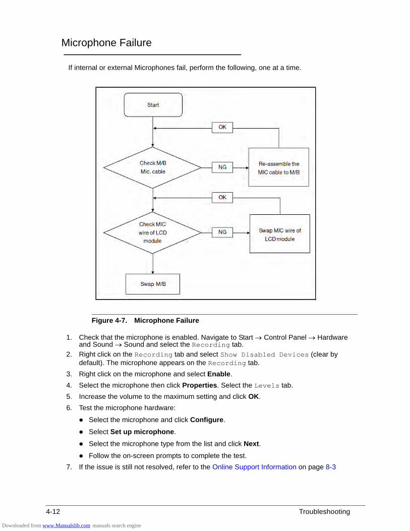
4-12 Troubleshooting
Microphone Failure 0
If internal or external Microphones fail, perform the following, one at a time.
Figure 4-7. Microphone Failure
1. Check that the microphone is enabled. Navigate to Start Control Panel Hardware and Sound Sound and select the Recording tab.
2. Right click on the Recording tab and select Show Disabled Devices (clear by default). The microphone appears on the Recording tab.
3. Right click on the microphone and select Enable.
4. Select the microphone then click Properties. Select the Levels tab.
5. Increase the volume to the maximum setting and click OK.
6. Test the microphone hardware:
Select the microphone and click Configure.
Select Set up microphone.
Select the microphone type from the list and click Next.
Follow the on-screen prompts to complete the test.
7. If the issue is still not resolved, refer to the Online Support Information on page 8-3
Downloaded from www.Manualslib.com manuals search engine
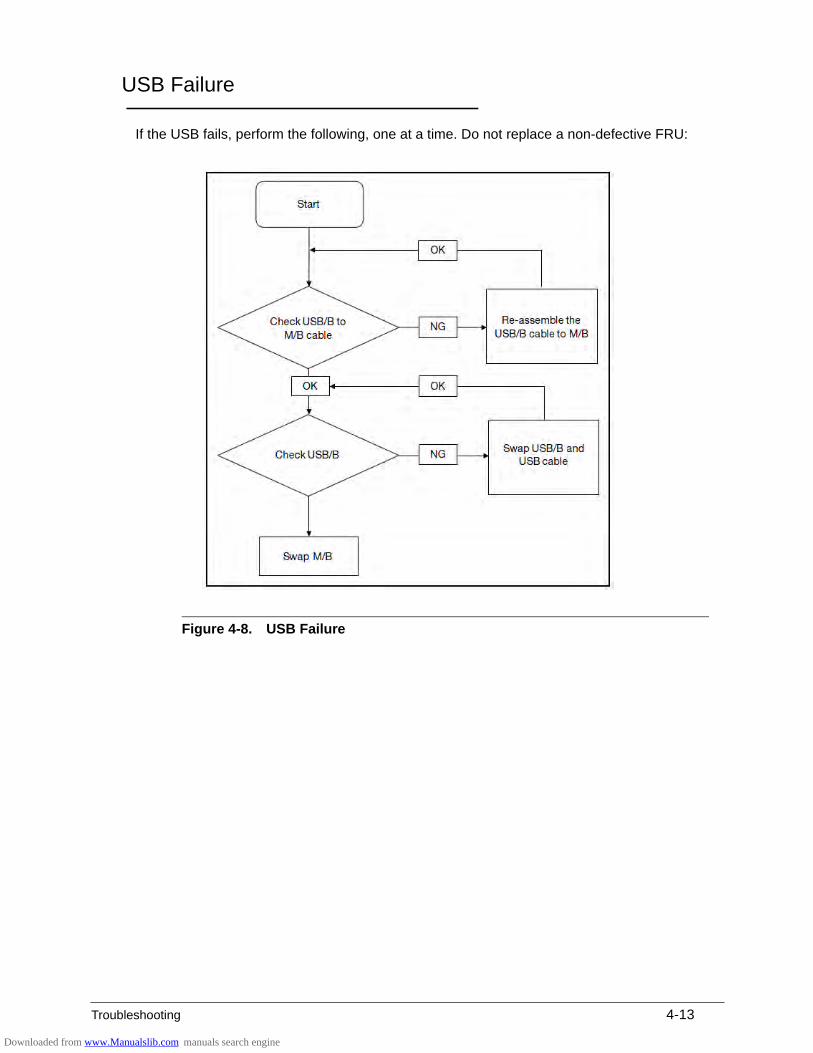
Troubleshooting 4-13
USB Failure 0
If the USB fails, perform the following, one at a time. Do not replace a non-defective FRU:
Figure 4-8. USB Failure
Downloaded from www.Manualslib.com manuals search engine
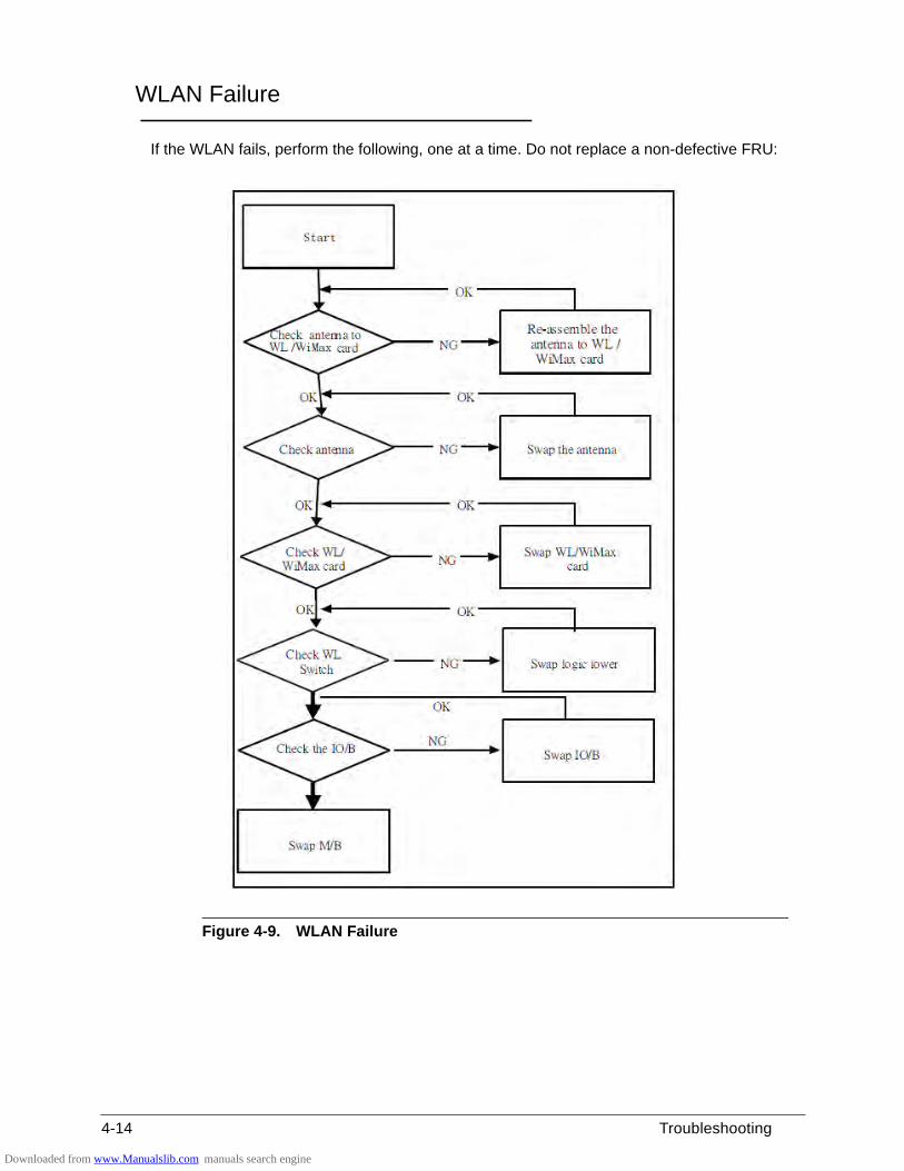
4-14 Troubleshooting
WLAN Failure 0
If the WLAN fails, perform the following, one at a time. Do not replace a non-defective FRU:
Figure 4-9. WLAN Failure
Downloaded from www.Manualslib.com manuals search engine
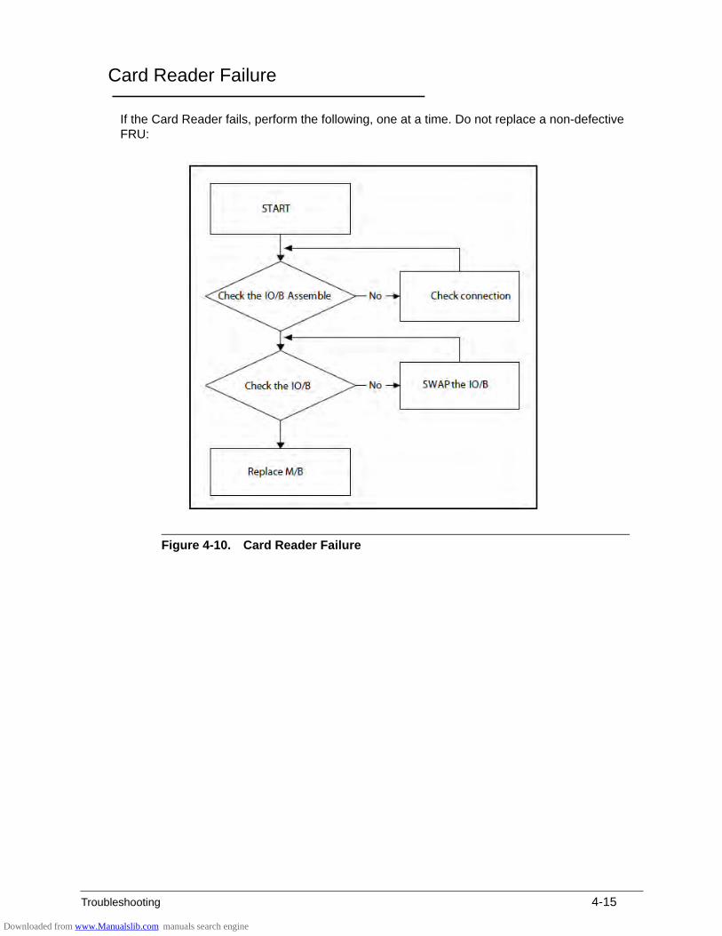
Troubleshooting 4-15
Card Reader Failure 0
If the Card Reader fails, perform the following, one at a time. Do not replace a non-defective FRU:
Figure 4-10. Card Reader Failure
Downloaded from www.Manualslib.com manuals search engine
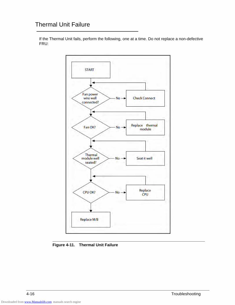
4-16 Troubleshooting
Thermal Unit Failure 0
If the Thermal Unit fails, perform the following, one at a time. Do not replace a non-defective FRU:
Figure 4-11. Thermal Unit Failure
Downloaded from www.Manualslib.com manuals search engine
Troubleshooting 4-17
Other Functions Failure 0
1. Check if drives are functioning correctly.
2. Check if external modules are functioning correctly.
3. Change mainboard to check if current one is defective.
Downloaded from www.Manualslib.com manuals search engine
4-18 Troubleshooting
Intermittent Problems 0
Intermittent system hang problems can be caused by a variety of reasons that have nothing to do with a hardware defect, such as: cosmic radiation, electrostatic discharge, or software errors. FRU replacement should be considered only when a recurring problem exists.
When analyzing an intermittent problem, perform the following:
1. Run the advanced diagnostic test for the system board in loop mode at least 10 times.
2. If no error is detected, do not replace any FRU.
3. If an error is detected, replace the FRU. Rerun the test to verify that there are no more errors.
Undetermined Problems 0
The diagnostic problems does not identify which adapter or device failed, which installed devices are incorrect, whether a short circuit is suspected, or whether the system is inoperative.
Perform the following procedures to isolate the failing FRU (do not replace non-defective FRU).
NOTE:NOTE:Verify that all attached devices are supported by the computer.
NOTE:NOTE:Verify that the power supply being used at the time of the failure is operating correctly.
1. Remove power from the computer.
2. Visually check the components for damage. If any problems are found, replace the FRU.
3. Remove or disconnect all of the following devices:
Non-Acer devices
Printer, mouse, and other external devices
Battery pack
Hard disk drive
DIMM
CD-ROM/Diskette drive Module
PC Cards
4. Apply power to the computer.
5. Determine if the problem has changed.
6. If the problem does not recur, connect the removed devices one at a time until failing FRU is found.
7. If the problem remains, replace the following FRUs one at a time. Do not replace a non-defective FRU:
Mainboard
LCD assembly
Downloaded from www.Manualslib.com manuals search engine
Troubleshooting 4-19
Error Codes 0
Table 4-2. Error Codes
Error Codes Error Messages
006 Equipment Configuration Error
Causes:
1. CPU BIOS Update Code Mismatch
2. IDE Primary Channel Master Drive Error
(The causes will be shown before “Equipment Configuration Error”)
010 Memory Error at xxxx:xxxx:xxxxh (R:xxxxh, W:xxxxh)
070 Real Time Clock Error
071 CMOS Battery Bad
072 CMOS Checksum Error
110 System is disabled. An incorrect password was entered.
<No error code> Battery critically low. In this situation BIOS will issue four (4) short beeps, then shuts the system down. No message is displayed.
<No error code> Temperature is critically high. In this situation BIOS shuts the system down. No message is displayed.
Downloaded from www.Manualslib.com manuals search engine
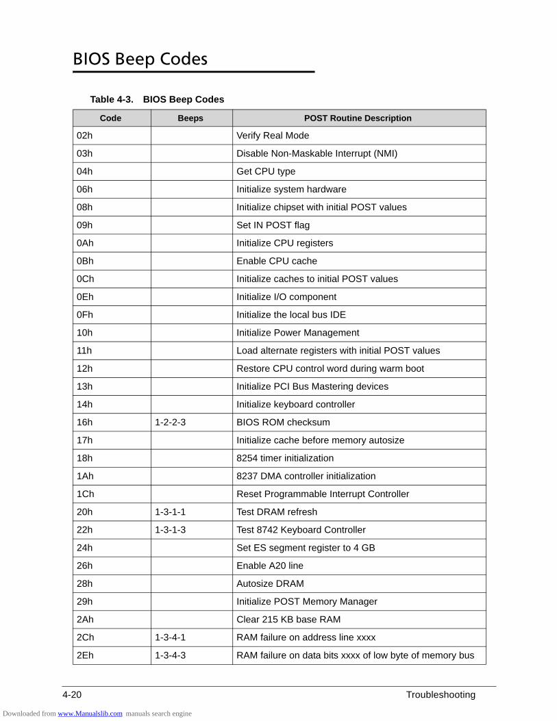
4-20 Troubleshooting
BIOS Beep Codes 0
Table 4-3. BIOS Beep Codes
Code Beeps POST Routine Description
02h Verify Real Mode
03h Disable Non-Maskable Interrupt (NMI)
04h Get CPU type
06h Initialize system hardware
08h Initialize chipset with initial POST values
09h Set IN POST flag
0Ah Initialize CPU registers
0Bh Enable CPU cache
0Ch Initialize caches to initial POST values
0Eh Initialize I/O component
0Fh Initialize the local bus IDE
10h Initialize Power Management
11h Load alternate registers with initial POST values
12h Restore CPU control word during warm boot
13h Initialize PCI Bus Mastering devices
14h Initialize keyboard controller
16h 1-2-2-3 BIOS ROM checksum
17h Initialize cache before memory autosize
18h 8254 timer initialization
1Ah 8237 DMA controller initialization
1Ch Reset Programmable Interrupt Controller
20h 1-3-1-1 Test DRAM refresh
22h 1-3-1-3 Test 8742 Keyboard Controller
24h Set ES segment register to 4 GB
26h Enable A20 line
28h Autosize DRAM
29h Initialize POST Memory Manager
2Ah Clear 215 KB base RAM
2Ch 1-3-4-1 RAM failure on address line xxxx
2Eh 1-3-4-3 RAM failure on data bits xxxx of low byte of memory bus
Downloaded from www.Manualslib.com manuals search engine
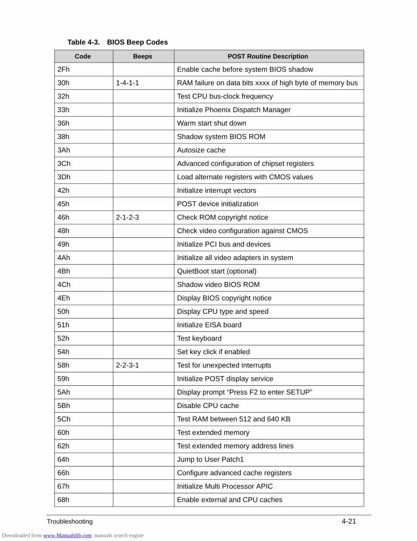
Troubleshooting 4-21
2Fh Enable cache before system BIOS shadow
30h 1-4-1-1 RAM failure on data bits xxxx of high byte of memory bus
32h Test CPU bus-clock frequency
33h Initialize Phoenix Dispatch Manager
36h Warm start shut down
38h Shadow system BIOS ROM
3Ah Autosize cache
3Ch Advanced configuration of chipset registers
3Dh Load alternate registers with CMOS values
42h Initialize interrupt vectors
45h POST device initialization
46h 2-1-2-3 Check ROM copyright notice
48h Check video configuration against CMOS
49h Initialize PCI bus and devices
4Ah Initialize all video adapters in system
4Bh QuietBoot start (optional)
4Ch Shadow video BIOS ROM
4Eh Display BIOS copyright notice
50h Display CPU type and speed
51h Initialize EISA board
52h Test keyboard
54h Set key click if enabled
58h 2-2-3-1 Test for unexpected interrupts
59h Initialize POST display service
5Ah Display prompt “Press F2 to enter SETUP”
5Bh Disable CPU cache
5Ch Test RAM between 512 and 640 KB
60h Test extended memory
62h Test extended memory address lines
64h Jump to User Patch1
66h Configure advanced cache registers
67h Initialize Multi Processor APIC
68h Enable external and CPU caches
Table 4-3. BIOS Beep Codes
Code Beeps POST Routine Description
Downloaded from www.Manualslib.com manuals search engine
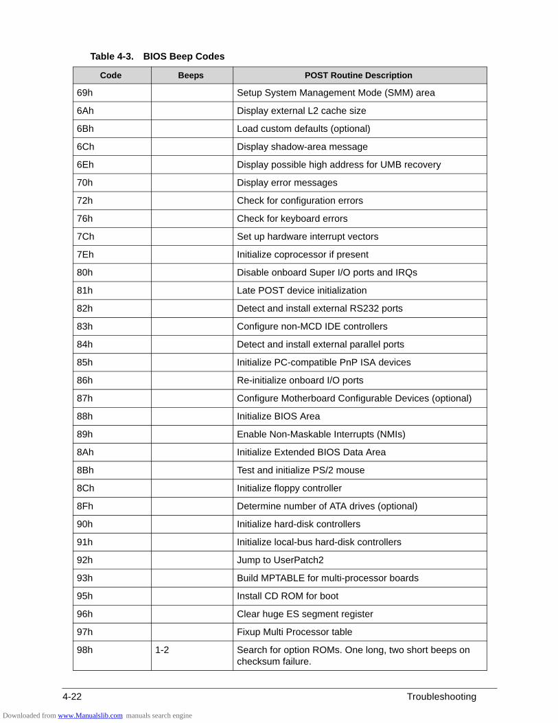
4-22 Troubleshooting
69h Setup System Management Mode (SMM) area
6Ah Display external L2 cache size
6Bh Load custom defaults (optional)
6Ch Display shadow-area message
6Eh Display possible high address for UMB recovery
70h Display error messages
72h Check for configuration errors
76h Check for keyboard errors
7Ch Set up hardware interrupt vectors
7Eh Initialize coprocessor if present
80h Disable onboard Super I/O ports and IRQs
81h Late POST device initialization
82h Detect and install external RS232 ports
83h Configure non-MCD IDE controllers
84h Detect and install external parallel ports
85h Initialize PC-compatible PnP ISA devices
86h Re-initialize onboard I/O ports
87h Configure Motherboard Configurable Devices (optional)
88h Initialize BIOS Area
89h Enable Non-Maskable Interrupts (NMIs)
8Ah Initialize Extended BIOS Data Area
8Bh Test and initialize PS/2 mouse
8Ch Initialize floppy controller
8Fh Determine number of ATA drives (optional)
90h Initialize hard-disk controllers
91h Initialize local-bus hard-disk controllers
92h Jump to UserPatch2
93h Build MPTABLE for multi-processor boards
95h Install CD ROM for boot
96h Clear huge ES segment register
97h Fixup Multi Processor table
98h 1-2 Search for option ROMs. One long, two short beeps on checksum failure.
Table 4-3. BIOS Beep Codes
Code Beeps POST Routine Description
Downloaded from www.Manualslib.com manuals search engine
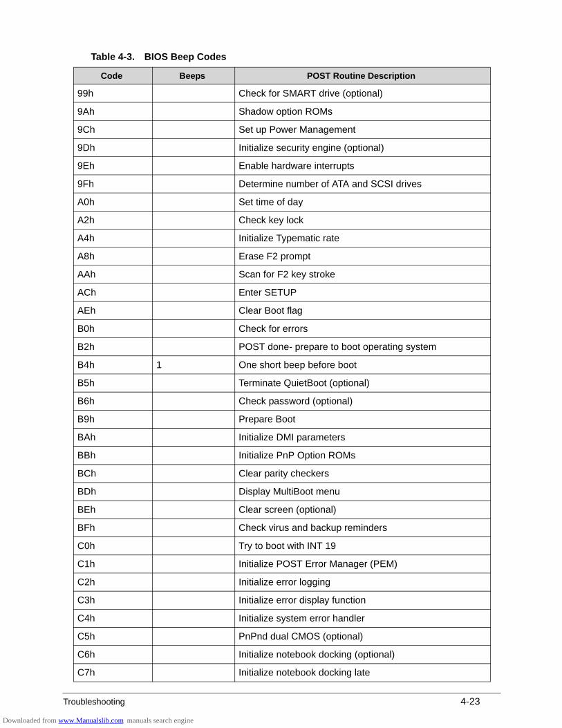
Troubleshooting 4-23
99h Check for SMART drive (optional)
9Ah Shadow option ROMs
9Ch Set up Power Management
9Dh Initialize security engine (optional)
9Eh Enable hardware interrupts
9Fh Determine number of ATA and SCSI drives
A0h Set time of day
A2h Check key lock
A4h Initialize Typematic rate
A8h Erase F2 prompt
AAh Scan for F2 key stroke
ACh Enter SETUP
AEh Clear Boot flag
B0h Check for errors
B2h POST done- prepare to boot operating system
B4h 1 One short beep before boot
B5h Terminate QuietBoot (optional)
B6h Check password (optional)
B9h Prepare Boot
BAh Initialize DMI parameters
BBh Initialize PnP Option ROMs
BCh Clear parity checkers
BDh Display MultiBoot menu
BEh Clear screen (optional)
BFh Check virus and backup reminders
C0h Try to boot with INT 19
C1h Initialize POST Error Manager (PEM)
C2h Initialize error logging
C3h Initialize error display function
C4h Initialize system error handler
C5h PnPnd dual CMOS (optional)
C6h Initialize notebook docking (optional)
C7h Initialize notebook docking late
Table 4-3. BIOS Beep Codes
Code Beeps POST Routine Description
Downloaded from www.Manualslib.com manuals search engine
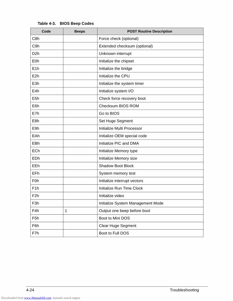
4-24 Troubleshooting
C8h Force check (optional)
C9h Extended checksum (optional)
D2h Unknown interrupt
E0h Initialize the chipset
E1h Initialize the bridge
E2h Initialize the CPU
E3h Initialize the system timer
E4h Initialize system I/O
E5h Check force recovery boot
E6h Checksum BIOS ROM
E7h Go to BIOS
E8h Set Huge Segment
E9h Initialize Multi Processor
EAh Initialize OEM special code
EBh Initialize PIC and DMA
ECh Initialize Memory type
EDh Initialize Memory size
EEh Shadow Boot Block
EFh System memory test
F0h Initialize interrupt vectors
F1h Initialize Run Time Clock
F2h Initialize video
F3h Initialize System Management Mode
F4h 1 Output one beep before boot
F5h Boot to Mini DOS
F6h Clear Huge Segment
F7h Boot to Full DOS
Table 4-3. BIOS Beep Codes
Code Beeps POST Routine Description
Downloaded from www.Manualslib.com manuals search engine
Troubleshooting 4-25
POST Codes 0
There are two types of POST codes: Progress Codes and Error Codes. Progress Codes are designed to show the execution point while booting or executing services. Error Codes are designed to halt on exceptional (fatal) error conditions.
Component Codes 0
The Component Code is an unsigned integer value that is assigned by the build process. The following tables describe the various ranges of component codes:
The Component Code is assigned to an individual component (or driver) using the POSTCODE= option in the DSC file. If the value that follows POSTCODE= is a hexadecimal or decimal number, in the range 0x00-0xdf, then that code will be used with all POST Codes associated with that driver.
Table 4-4. Component Codes
Range Description
0x00-0x1f OEM Components. These values are reserved for OEM components
Downloaded from www.Manualslib.com manuals search engine
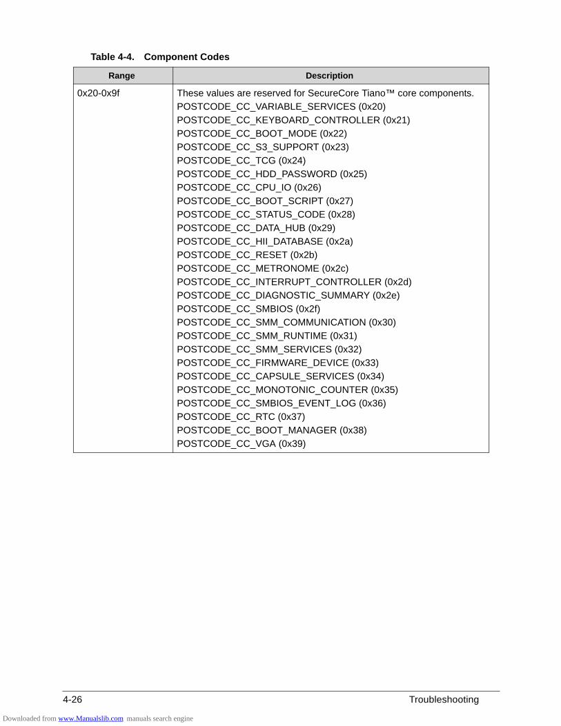
4-26 Troubleshooting
0x20-0x9f These values are reserved for SecureCore Tiano™ core components.
POSTCODE_CC_VARIABLE_SERVICES (0x20)
POSTCODE_CC_KEYBOARD_CONTROLLER (0x21)
POSTCODE_CC_BOOT_MODE (0x22)
POSTCODE_CC_S3_SUPPORT (0x23)
POSTCODE_CC_TCG (0x24)
POSTCODE_CC_HDD_PASSWORD (0x25)
POSTCODE_CC_CPU_IO (0x26)
POSTCODE_CC_BOOT_SCRIPT (0x27)
POSTCODE_CC_STATUS_CODE (0x28)
POSTCODE_CC_DATA_HUB (0x29)
POSTCODE_CC_HII_DATABASE (0x2a)
POSTCODE_CC_RESET (0x2b)
POSTCODE_CC_METRONOME (0x2c)
POSTCODE_CC_INTERRUPT_CONTROLLER (0x2d)
POSTCODE_CC_DIAGNOSTIC_SUMMARY (0x2e)
POSTCODE_CC_SMBIOS (0x2f)
POSTCODE_CC_SMM_COMMUNICATION (0x30)
POSTCODE_CC_SMM_RUNTIME (0x31)
POSTCODE_CC_SMM_SERVICES (0x32)
POSTCODE_CC_FIRMWARE_DEVICE (0x33)
POSTCODE_CC_CAPSULE_SERVICES (0x34)
POSTCODE_CC_MONOTONIC_COUNTER (0x35)
POSTCODE_CC_SMBIOS_EVENT_LOG (0x36)
POSTCODE_CC_RTC (0x37)
POSTCODE_CC_BOOT_MANAGER (0x38)
POSTCODE_CC_VGA (0x39)
Table 4-4. Component Codes
Range Description
Downloaded from www.Manualslib.com manuals search engine
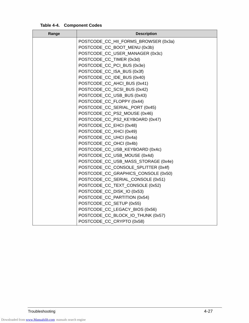
Troubleshooting 4-27
POSTCODE_CC_HII_FORMS_BROWSER (0x3a)
POSTCODE_CC_BOOT_MENU (0x3b)
POSTCODE_CC_USER_MANAGER (0x3c)
POSTCODE_CC_TIMER (0x3d)
POSTCODE_CC_PCI_BUS (0x3e)
POSTCODE_CC_ISA_BUS (0x3f)
POSTCODE_CC_IDE_BUS (0x40)
POSTCODE_CC_AHCI_BUS (0x41)
POSTCODE_CC_SCSI_BUS (0x42)
POSTCODE_CC_USB_BUS (0x43)
POSTCODE_CC_FLOPPY (0x44)
POSTCODE_CC_SERIAL_PORT (0x45)
POSTCODE_CC_PS2_MOUSE (0x46)
POSTCODE_CC_PS2_KEYBOARD (0x47)
POSTCODE_CC_EHCI (0x48)
POSTCODE_CC_XHCI (0x49)
POSTCODE_CC_UHCI (0x4a)
POSTCODE_CC_OHCI (0x4b)
POSTCODE_CC_USB_KEYBOARD (0x4c)
POSTCODE_CC_USB_MOUSE (0x4d)
POSTCODE_CC_USB_MASS_STORAGE (0x4e)
POSTCODE_CC_CONSOLE_SPLITTER (0x4f)
POSTCODE_CC_GRAPHICS_CONSOLE (0x50)
POSTCODE_CC_SERIAL_CONSOLE (0x51)
POSTCODE_CC_TEXT_CONSOLE (0x52)
POSTCODE_CC_DISK_IO (0x53)
POSTCODE_CC_PARTITION (0x54)
POSTCODE_CC_SETUP (0x55)
POSTCODE_CC_LEGACY_BIOS (0x56)
POSTCODE_CC_BLOCK_IO_THUNK (0x57)
POSTCODE_CC_CRYPTO (0x58)
Table 4-4. Component Codes
Range Description
Downloaded from www.Manualslib.com manuals search engine
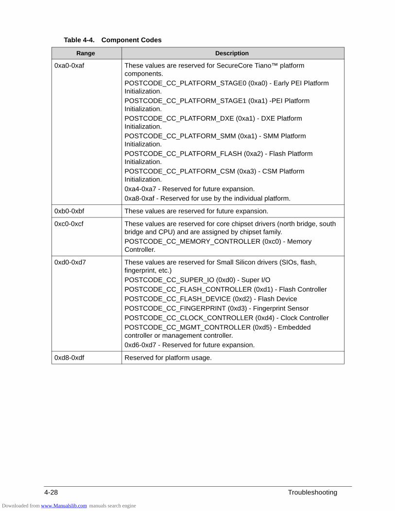
4-28 Troubleshooting
0xa0-0xaf These values are reserved for SecureCore Tiano™ platform components.
POSTCODE_CC_PLATFORM_STAGE0 (0xa0) - Early PEI Platform Initialization.
POSTCODE_CC_PLATFORM_STAGE1 (0xa1) -PEI Platform Initialization.
POSTCODE_CC_PLATFORM_DXE (0xa1) - DXE Platform Initialization.
POSTCODE_CC_PLATFORM_SMM (0xa1) - SMM Platform Initialization.
POSTCODE_CC_PLATFORM_FLASH (0xa2) - Flash Platform Initialization.
POSTCODE_CC_PLATFORM_CSM (0xa3) - CSM Platform Initialization.
0xa4-0xa7 - Reserved for future expansion.
0xa8-0xaf - Reserved for use by the individual platform.
0xb0-0xbf These values are reserved for future expansion.
0xc0-0xcf These values are reserved for core chipset drivers (north bridge, south bridge and CPU) and are assigned by chipset family.
POSTCODE_CC_MEMORY_CONTROLLER (0xc0) - Memory Controller.
0xd0-0xd7 These values are reserved for Small Silicon drivers (SIOs, flash, fingerprint, etc.)
POSTCODE_CC_SUPER_IO (0xd0) - Super I/O
POSTCODE_CC_FLASH_CONTROLLER (0xd1) - Flash Controller
POSTCODE_CC_FLASH_DEVICE (0xd2) - Flash Device
POSTCODE_CC_FINGERPRINT (0xd3) - Fingerprint Sensor
POSTCODE_CC_CLOCK_CONTROLLER (0xd4) - Clock Controller
POSTCODE_CC_MGMT_CONTROLLER (0xd5) - Embedded controller or management controller.
0xd6-0xd7 - Reserved for future expansion.
0xd8-0xdf Reserved for platform usage.
Table 4-4. Component Codes
Range Description
Downloaded from www.Manualslib.com manuals search engine
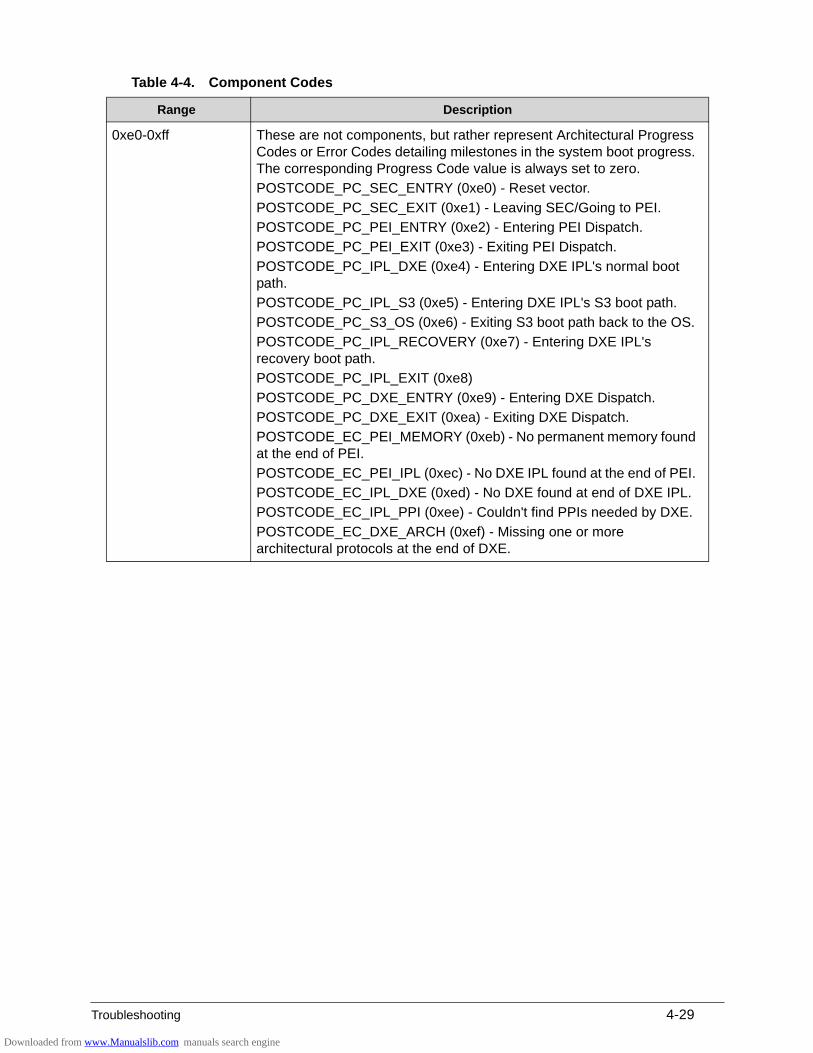
Troubleshooting 4-29
0xe0-0xff These are not components, but rather represent Architectural Progress Codes or Error Codes detailing milestones in the system boot progress. The corresponding Progress Code value is always set to zero.
POSTCODE_PC_SEC_ENTRY (0xe0) - Reset vector.
POSTCODE_PC_SEC_EXIT (0xe1) - Leaving SEC/Going to PEI.
POSTCODE_PC_PEI_ENTRY (0xe2) - Entering PEI Dispatch.
POSTCODE_PC_PEI_EXIT (0xe3) - Exiting PEI Dispatch.
POSTCODE_PC_IPL_DXE (0xe4) - Entering DXE IPL's normal boot path.
POSTCODE_PC_IPL_S3 (0xe5) - Entering DXE IPL's S3 boot path.
POSTCODE_PC_S3_OS (0xe6) - Exiting S3 boot path back to the OS.
POSTCODE_PC_IPL_RECOVERY (0xe7) - Entering DXE IPL's recovery boot path.
POSTCODE_PC_IPL_EXIT (0xe8)
POSTCODE_PC_DXE_ENTRY (0xe9) - Entering DXE Dispatch.
POSTCODE_PC_DXE_EXIT (0xea) - Exiting DXE Dispatch.
POSTCODE_EC_PEI_MEMORY (0xeb) - No permanent memory found at the end of PEI.
POSTCODE_EC_PEI_IPL (0xec) - No DXE IPL found at the end of PEI.
POSTCODE_EC_IPL_DXE (0xed) - No DXE found at end of DXE IPL.
POSTCODE_EC_IPL_PPI (0xee) - Couldn't find PPIs needed by DXE.
POSTCODE_EC_DXE_ARCH (0xef) - Missing one or more architectural protocols at the end of DXE.
Table 4-4. Component Codes
Range Description
Downloaded from www.Manualslib.com manuals search engine
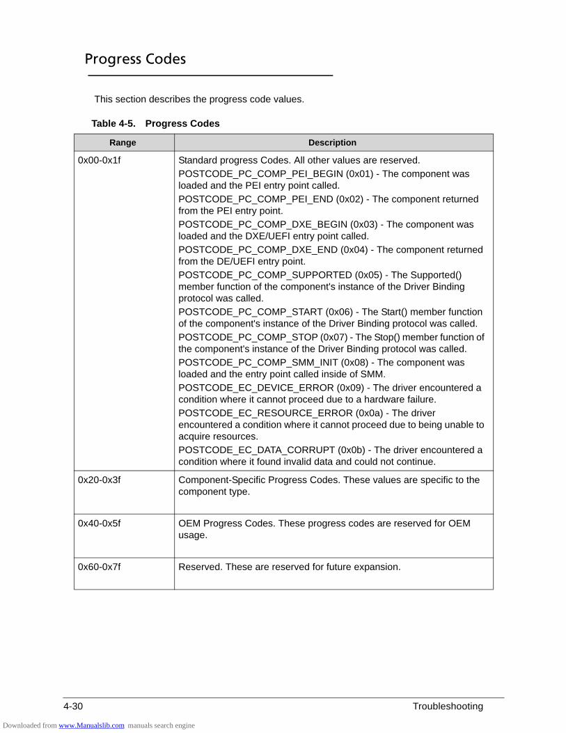
4-30 Troubleshooting
Progress Codes 0
This section describes the progress code values.
Table 4-5. Progress Codes
Range Description
0x00-0x1f Standard progress Codes. All other values are reserved.
POSTCODE_PC_COMP_PEI_BEGIN (0x01) - The component was loaded and the PEI entry point called.
POSTCODE_PC_COMP_PEI_END (0x02) - The component returned from the PEI entry point.
POSTCODE_PC_COMP_DXE_BEGIN (0x03) - The component was loaded and the DXE/UEFI entry point called.
POSTCODE_PC_COMP_DXE_END (0x04) - The component returned from the DE/UEFI entry point.
POSTCODE_PC_COMP_SUPPORTED (0x05) - The Supported() member function of the component's instance of the Driver Binding protocol was called.
POSTCODE_PC_COMP_START (0x06) - The Start() member function of the component's instance of the Driver Binding protocol was called.
POSTCODE_PC_COMP_STOP (0x07) - The Stop() member function of the component's instance of the Driver Binding protocol was called.
POSTCODE_PC_COMP_SMM_INIT (0x08) - The component was loaded and the entry point called inside of SMM.
POSTCODE_EC_DEVICE_ERROR (0x09) - The driver encountered a condition where it cannot proceed due to a hardware failure.
POSTCODE_EC_RESOURCE_ERROR (0x0a) - The driver encountered a condition where it cannot proceed due to being unable to acquire resources.
POSTCODE_EC_DATA_CORRUPT (0x0b) - The driver encountered a condition where it found invalid data and could not continue.
0x20-0x3f Component-Specific Progress Codes. These values are specific to the component type.
0x40-0x5f OEM Progress Codes. These progress codes are reserved for OEM usage.
0x60-0x7f Reserved. These are reserved for future expansion.
Downloaded from www.Manualslib.com manuals search engine

CHAPTER 5
Jumper and Connector Locations
Downloaded from www.Manualslib.com manuals search engine
5-2
Mainboard Layout . . . . . . . . . . . . . . . . . . . . . . . . . . . . . . . . . . . . . 5-3
Clearing Password Check and BIOS Recovery . . . . . . . . . . . . . 5-7Clearing the BIOS Passwords . . . . . . . . . . . . . . . . . . . . . . . . . . 5-7Performing a BIOS Recovery . . . . . . . . . . . . . . . . . . . . . . . . . . 5-8
Downloaded from www.Manualslib.com manuals search engine
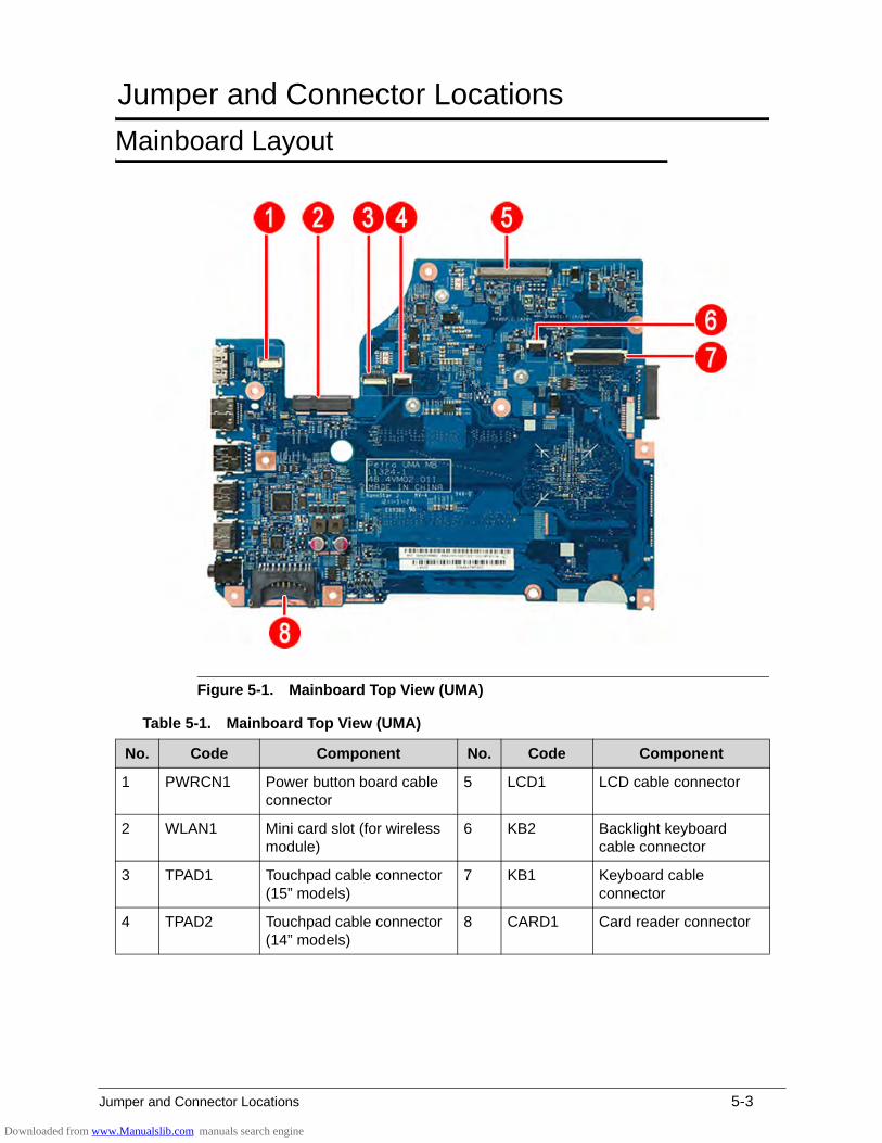
Jumper and Connector Locations 5-3
Jumper and Connector Locations
Mainboard Layout 0
Figure 5-1. Mainboard Top View (UMA)
Table 5-1. Mainboard Top View (UMA)
No. Code Component No. Code Component
1 PWRCN1 Power button board cable connector
5 LCD1 LCD cable connector
2 WLAN1 Mini card slot (for wireless module)
6 KB2 Backlight keyboard cable connector
3 TPAD1 Touchpad cable connector (15” models)
7 KB1 Keyboard cable connector
4 TPAD2 Touchpad cable connector (14” models)
8 CARD1 Card reader connector
Downloaded from www.Manualslib.com manuals search engine
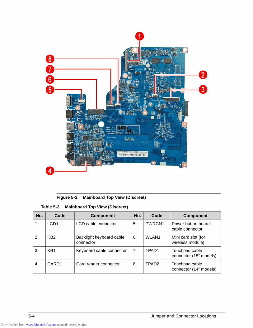
5-4 Jumper and Connector Locations
Figure 5-2. Mainboard Top View (Discreet)
Table 5-2. Mainboard Top View (Discreet)
No. Code Component No. Code Component
1 LCD1 LCD cable connector 5 PWRCN1 Power button board cable connector
2 KB2 Backlight keyboard cable connector
6 WLAN1 Mini card slot (for wireless module)
3 KB1 Keyboard cable connector 7 TPAD1 Touchpad cable connector (15” models)
4 CARD1 Card reader connector 8 TPAD2 Touchpad cable connector (14” models)
Downloaded from www.Manualslib.com manuals search engine
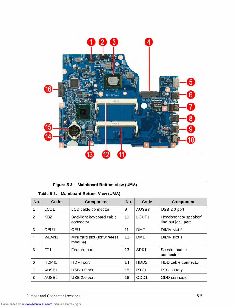
Jumper and Connector Locations 5-5
Figure 5-3. Mainboard Bottom View (UMA)
Table 5-3. Mainboard Bottom View (UMA)
No. Code Component No. Code Component
1 LCD1 LCD cable connector 9 AUSB3 USB 2.0 port
2 KB2 Backlight keyboard cable connector
10 LOUT1 Headphones/ speaker/ line-out jack port
3 CPU1 CPU 11 DM2 DIMM slot 2
4 WLAN1 Mini card slot (for wireless module)
12 DM1 DIMM slot 1
5 FT1 Feature port 13 SPK1 Speaker cable connector
6 HDMI1 HDMI port 14 HDD2 HDD cable connector
7 AUSB1 USB 3.0 port 15 RTC1 RTC battery
8 AUSB2 USB 2.0 port 16 ODD1 ODD connector
Downloaded from www.Manualslib.com manuals search engine
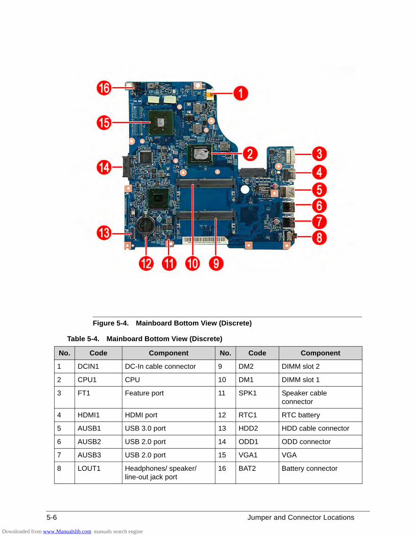
5-6 Jumper and Connector Locations
Figure 5-4. Mainboard Bottom View (Discrete)
Table 5-4. Mainboard Bottom View (Discrete)
No. Code Component No. Code Component
1 DCIN1 DC-In cable connector 9 DM2 DIMM slot 2
2 CPU1 CPU 10 DM1 DIMM slot 1
3 FT1 Feature port 11 SPK1 Speaker cable connector
4 HDMI1 HDMI port 12 RTC1 RTC battery
5 AUSB1 USB 3.0 port 13 HDD2 HDD cable connector
6 AUSB2 USB 2.0 port 14 ODD1 ODD connector
7 AUSB3 USB 2.0 port 15 VGA1 VGA
8 LOUT1 Headphones/ speaker/ line-out jack port
16 BAT2 Battery connector
Downloaded from www.Manualslib.com manuals search engine
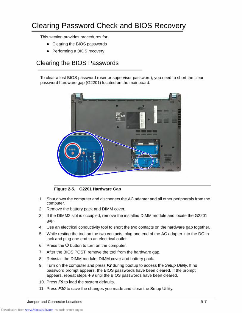
Jumper and Connector Locations 5-7
Clearing Password Check and BIOS Recovery 0
This section provides procedures for:
Clearing the BIOS passwords
Performing a BIOS recovery
Clearing the BIOS Passwords 0
To clear a lost BIOS password (user or supervisor password), you need to short the clear password hardware gap (G2201) located on the mainboard.
Figure 2-5. G2201 Hardware Gap
1. Shut down the computer and disconnect the AC adapter and all other peripherals from the computer.
2. Remove the battery pack and DIMM cover.
3. If the DIMM2 slot is occupied, remove the installed DIMM module and locate the G2201 gap.
4. Use an electrical conductivity tool to short the two contacts on the hardware gap together.
5. While resting the tool on the two contacts, plug one end of the AC adapter into the DC-in jack and plug one end to an electrical outlet.
6. Press the button to turn on the computer.
7. After the BIOS POST, remove the tool from the hardware gap.
8. Reinstall the DIMM module, DIMM cover and battery pack.
9. Turn on the computer and press F2 during bootup to access the Setup Utility. If no password prompt appears, the BIOS passwords have been cleared. If the prompt appears, repeat steps 4-9 until the BIOS passwords have been cleared.
10. Press F9 to load the system defaults.
11. Press F10 to save the changes you made and close the Setup Utility.
Downloaded from www.Manualslib.com manuals search engine
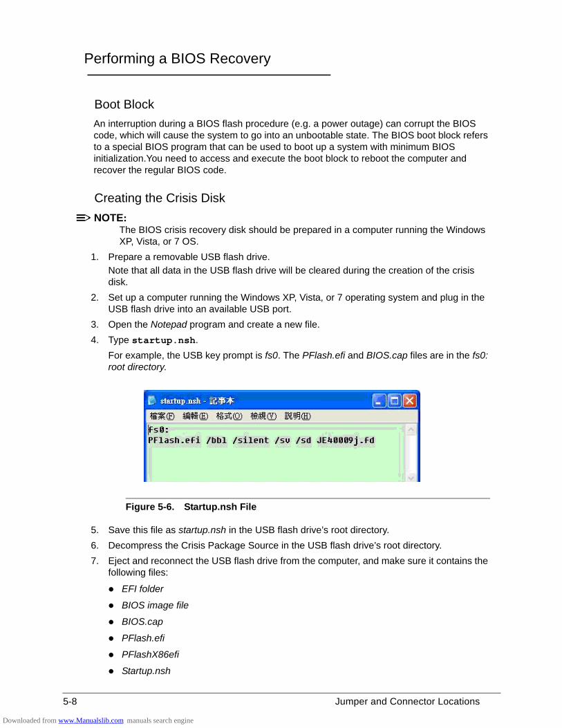
5-8 Jumper and Connector Locations
Performing a BIOS Recovery 0
Boot Block 0
An interruption during a BIOS flash procedure (e.g. a power outage) can corrupt the BIOS code, which will cause the system to go into an unbootable state. The BIOS boot block refers to a special BIOS program that can be used to boot up a system with minimum BIOS initialization.You need to access and execute the boot block to reboot the computer and recover the regular BIOS code.
Creating the Crisis Disk 0
NOTE:NOTE:The BIOS crisis recovery disk should be prepared in a computer running the Windows XP, Vista, or 7 OS.
1. Prepare a removable USB flash drive.
Note that all data in the USB flash drive will be cleared during the creation of the crisis disk.
2. Set up a computer running the Windows XP, Vista, or 7 operating system and plug in the USB flash drive into an available USB port.
3. Open the Notepad program and create a new file.
4. Type startup.nsh.
For example, the USB key prompt is fs0. The PFlash.efi and BIOS.cap files are in the fs0: root directory.
Figure 5-6. Startup.nsh File
5. Save this file as startup.nsh in the USB flash drive’s root directory.
6. Decompress the Crisis Package Source in the USB flash drive’s root directory.
7. Eject and reconnect the USB flash drive from the computer, and make sure it contains the following files:
EFI folder
BIOS image file
BIOS.cap
PFlash.efi
PFlashX86efi
Startup.nsh
Downloaded from www.Manualslib.com manuals search engine
Jumper and Connector Locations 5-9
Performing a BIOS recovery 0
NOTE:NOTE:Make sure the battery pack is installed to the system and that the computer is connected to a UPS unit during the BIOS recovery process.
The function hotkey sequence Fn+Esc is used to enable the BIOS recovery process when system is powered On during BIOS POST. If this function is enabled, the system will force the BIOS to execute the boot block program.
To perform a BIOS recovery:
1. Shut down the BIOS failed-computer.
2. Connect the USB flash drive containing the Crisis Recovery disk files to the computer.
3. Press and hold the Fn+Esc keys, then press the power button .
The BIOS recovery process begins. When the process is complete the computer will automatically reboot.
4. Disconnect the USB flash drive from the computer.
5. Perform a BIOS flash procedure to update the BIOS firmware. Refer to the “BIOS Flash Utilities” section on page 2-13 for detailed instructions.
Downloaded from www.Manualslib.com manuals search engine

5-10 Jumper and Connector Locations
Downloaded from www.Manualslib.com manuals search engine
CHAPTER 6
FRU List
Downloaded from www.Manualslib.com manuals search engine
6-2
Aspire MS2361Exploded Diagrams. . . . . . . . . . . . . . . . . . . . . . . . . . . . . . . . . . . . 6-4
Main Assembly . . . . . . . . . . . . . . . . . . . . . . . . . . . . . . . . . . . . . 6-4LCD Assembly . . . . . . . . . . . . . . . . . . . . . . . . . . . . . . . . . . . . . . 6-6
FRU List . . . . . . . . . . . . . . . . . . . . . . . . . . . . . . . . . . . . . . . . . . . . . 6-7
Downloaded from www.Manualslib.com manuals search engine
FRU (Field Replaceable Unit) List 6-3
FRU (Field Replaceable Unit) List
This chapter provides users with a FRU (Field Replaceable Unit) listing in global configurations for the Aspire MS2361. Refer to this chapter whenever ordering for parts to repair or for RMA (Return Merchandise Authorization).
NOTE:NOTE:WHEN ORDERING FRU PARTS, check the most up-to-date information available on the regional web or channel. Part number changes will not be noted on the printed Service Guide. For ACER AUTHORIZED SERVICE PROVIDERS, the Acer office may have a DIFFERENT part number code from those given in the FRU list of this printed Service Guide. Users MUST use the local FRU list provided by the regional Acer office to order FRU parts for repair and service of customer machines.
NOTE:NOTE:To scrap or to return the defective parts, users should follow the local government ordinance or regulations on how to dispose it properly, or follow the rules set by the regional Acer office on how to return it.
Downloaded from www.Manualslib.com manuals search engine
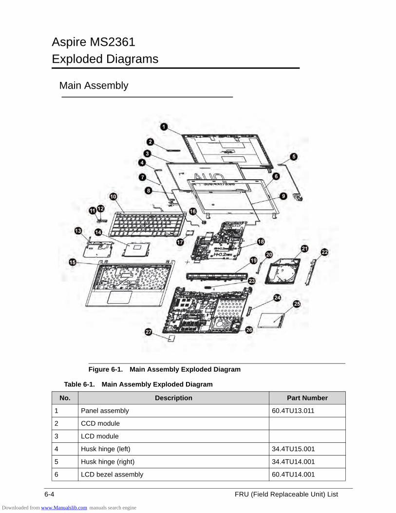
6-4 FRU (Field Replaceable Unit) List
Aspire MS2361 0
Exploded Diagrams 0
Main Assembly 0
Figure 6-1. Main Assembly Exploded Diagram
Table 6-1. Main Assembly Exploded Diagram
No. Description Part Number
1 Panel assembly 60.4TU13.011
2 CCD module
3 LCD module
4 Husk hinge (left) 34.4TU15.001
5 Husk hinge (right) 34.4TU14.001
6 LCD bezel assembly 60.4TU14.001
Downloaded from www.Manualslib.com manuals search engine
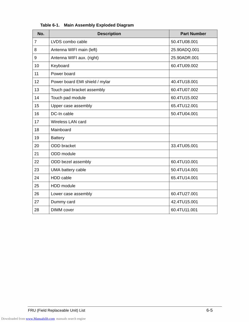
FRU (Field Replaceable Unit) List 6-5
7 LVDS combo cable 50.4TU08.001
8 Antenna WIFI main (left) 25.90ADQ.001
9 Antenna WIFI aux. (right) 25.90ADR.001
10 Keyboard 60.4TU09.002
11 Power board
12 Power board EMI shield / mylar 40.4TU18.001
13 Touch pad bracket assembly 60.4TU07.002
14 Touch pad module 60.4TU15.002
15 Upper case assembly 65.4TU12.001
16 DC-In cable 50.4TU04.001
17 Wireless LAN card
18 Mainboard
19 Battery
20 ODD bracket 33.4TU05.001
21 ODD module
22 ODD bezel assembly 60.4TU10.001
23 UMA battery cable 50.4TU14.001
24 HDD cable 65.4TU14.001
25 HDD module
26 Lower case assembly 60.4TU27.001
27 Dummy card 42.4TU15.001
28 DIMM cover 60.4TU11.001
Table 6-1. Main Assembly Exploded Diagram
No. Description Part Number
Downloaded from www.Manualslib.com manuals search engine
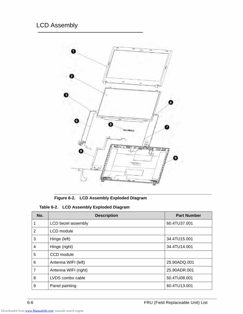
6-6 FRU (Field Replaceable Unit) List
LCD Assembly 0
Figure 6-2. LCD Assembly Exploded Diagram
Table 6-2. LCD Assembly Exploded Diagram
No. Description Part Number
1 LCD bezel assembly 60.4TU37.001
2 LCD module
3 Hinge (left) 34.4TU15.001
4 Hinge (right) 34.4TU14.001
5 CCD module
6 Antenna WIFI (left) 25.90ADQ.001
7 Antenna WIFI (right) 25.90ADR.001
8 LVDS combo cable 50.4TU08.001
9 Panel painting 60.4TU13.001
Downloaded from www.Manualslib.com manuals search engine
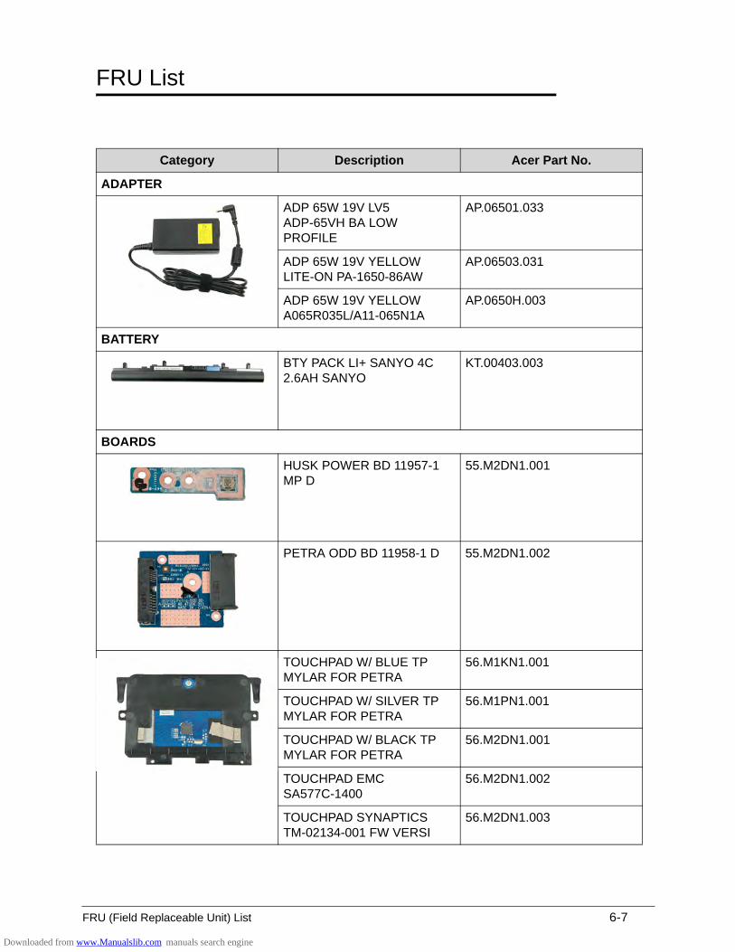
FRU (Field Replaceable Unit) List 6-7
FRU List 0
Category Description Acer Part No.
ADAPTER
ADP 65W 19V LV5 ADP-65VH BA LOW PROFILE
AP.06501.033
ADP 65W 19V YELLOW LITE-ON PA-1650-86AW
AP.06503.031
ADP 65W 19V YELLOW A065R035L/A11-065N1A
AP.0650H.003
BATTERY
BTY PACK LI+ SANYO 4C 2.6AH SANYO
KT.00403.003
BOARDS
HUSK POWER BD 11957-1 MP D
55.M2DN1.001
PETRA ODD BD 11958-1 D 55.M2DN1.002
TOUCHPAD W/ BLUE TP MYLAR FOR PETRA
56.M1KN1.001
TOUCHPAD W/ SILVER TP MYLAR FOR PETRA
56.M1PN1.001
TOUCHPAD W/ BLACK TP MYLAR FOR PETRA
56.M2DN1.001
TOUCHPAD EMC SA577C-1400
56.M2DN1.002
TOUCHPAD SYNAPTICS TM-02134-001 FW VERSI
56.M2DN1.003
Downloaded from www.Manualslib.com manuals search engine
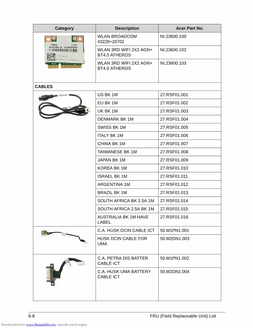
6-8 FRU (Field Replaceable Unit) List
WLAN BROADCOM 43228+20702
NI.23600.100
WLAN 3RD WIFI 2X2 AGN+ BT4.0 ATHEROS
NI.23600.102
WLAN 3RD WIFI 2X2 AGN+ BT4.0 ATHEROS
NI.23600.103
CABLES
US BK 1M 27.RSF01.001
EU BK 1M 27.RSF01.002
UK BK 1M 27.RSF01.003
DENMARK BK 1M 27.RSF01.004
SWISS BK 1M 27.RSF01.005
ITALY BK 1M 27.RSF01.006
CHINA BK 1M 27.RSF01.007
TAIWANESE BK 1M 27.RSF01.008
JAPAN BK 1M 27.RSF01.009
KOREA BK 1M 27.RSF01.010
ISRAEL BK 1M 27.RSF01.011
ARGENTINA 1M 27.RSF01.012
BRAZIL BK 1M 27.RSF01.013
SOUTH AFRICA BK 2.5A 1M 27.RSF01.014
SOUTH AFRICA 2.5A BK 1M 27.RSF01.015
AUSTRALIA BK 1M HAVE LABEL
27.RSF01.016
C.A. HUSK DCIN CABLE ICT 50.M1PN1.001
HUSK DCIN CABLE FOR UMA
50.M2DN1.003
C.A. PETRA DIS BATTER CABLE ICT
50.M1PN1.002
C.A. HUSK UMA BATTERY CABLE ICT
50.M2DN1.004
Category Description Acer Part No.
Downloaded from www.Manualslib.com manuals search engine
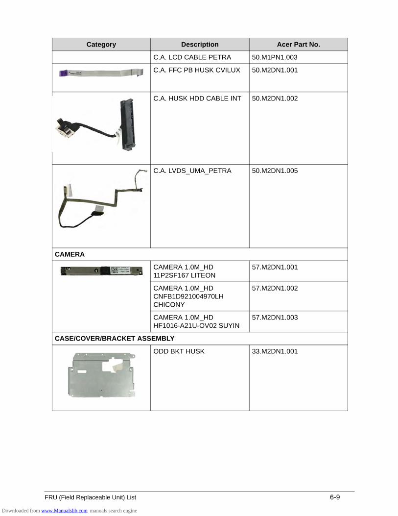
FRU (Field Replaceable Unit) List 6-9
C.A. LCD CABLE PETRA 50.M1PN1.003
C.A. FFC PB HUSK CVILUX 50.M2DN1.001
C.A. HUSK HDD CABLE INT 50.M2DN1.002
C.A. LVDS_UMA_PETRA 50.M2DN1.005
CAMERA
CAMERA 1.0M_HD 11P2SF167 LITEON
57.M2DN1.001
CAMERA 1.0M_HD CNFB1D921004970LH CHICONY
57.M2DN1.002
CAMERA 1.0M_HD HF1016-A21U-OV02 SUYIN
57.M2DN1.003
CASE/COVER/BRACKET ASSEMBLY
ODD BKT HUSK 33.M2DN1.001
Category Description Acer Part No.
Downloaded from www.Manualslib.com manuals search engine
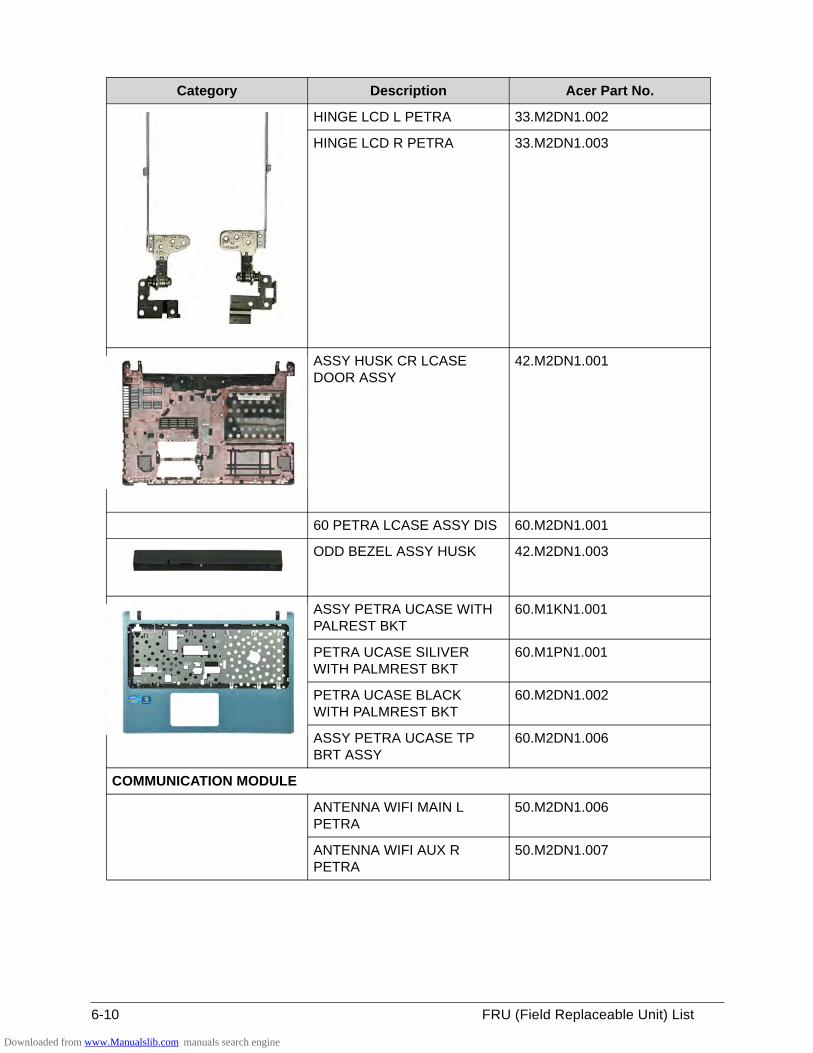
6-10 FRU (Field Replaceable Unit) List
HINGE LCD L PETRA 33.M2DN1.002
HINGE LCD R PETRA 33.M2DN1.003
ASSY HUSK CR LCASE DOOR ASSY
42.M2DN1.001
60 PETRA LCASE ASSY DIS 60.M2DN1.001
ODD BEZEL ASSY HUSK 42.M2DN1.003
ASSY PETRA UCASE WITH PALREST BKT
60.M1KN1.001
PETRA UCASE SILIVER WITH PALMREST BKT
60.M1PN1.001
PETRA UCASE BLACK WITH PALMREST BKT
60.M2DN1.002
ASSY PETRA UCASE TP BRT ASSY
60.M2DN1.006
COMMUNICATION MODULE
ANTENNA WIFI MAIN L PETRA
50.M2DN1.006
ANTENNA WIFI AUX R PETRA
50.M2DN1.007
Category Description Acer Part No.
Downloaded from www.Manualslib.com manuals search engine
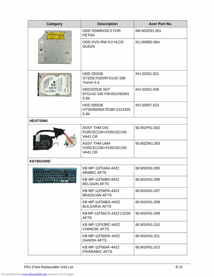
FRU (Field Replaceable Unit) List 6-11
ODD NSM8XS9.0 FOR PETRA
6M.M2DN1.001
ODD DVD-RW 9.0 HLDS GU61N
KU.0080D.064
HDD 320GB ST320LT020/9YG142-188 7mmH 5.4
KH.32001.021
HDD320GB SGT 9YG142-190 FW:0010SDM1 5.4K
KH.32001.026
HDD 500GB HTS545050A7E380 0J23335 5.4K
KH.50007.023
HEATSINK
ASSY THM DIS FORCECON+FORCECON VA41 CR
60.M1PN1.002
ASSY THM UMA FORCECON+FORCECON VA41 CR
60.M2DN1.003
KEYBOARD
KB MP-11F53A0-4422 ARABIC AF7S
60.M1KN1.005
KB MP-11F56B0-4422 BELGIUN AF7S
60.M1KN1.006
KB MP-11F56PA-4422 BRAZILIAN AF7S
60.M1KN1.007
KB MP-11F56BG-4422 BULGARIA AF7S
60.M1KN1.008
KB MP-11F56CS-4422 CZ/SK AF7S
60.M1KN1.009
KB MP-11F53RC-4422 CHINESE AF7S
60.M1KN1.010
KB MP-11F56DK-4422 DANISH AF7S
60.M1KN1.011
KB MP-11F56AF-4422 FR/ARABIC AF7S
60.M1KN1.012
Category Description Acer Part No.
Downloaded from www.Manualslib.com manuals search engine
6-12 FRU (Field Replaceable Unit) List
KEYBOARD KB MP-11F56F0-4422 FRENCH AF7S
60.M1KN1.013
KB MP-11F56D0-4422 GERMAN AF7S
60.M1KN1.014
KB MP-11F53GR-4422 GREEK AF7S
60.M1KN1.015
KB MP-11F56HU-4422 HUNGARIAN AF7S
60.M1KN1.016
KB MP-11F56I0-4422 ITALIAN AF7S
60.M1KN1.017
KB MP-11F50J0-4422 JAPANESE AF7S
60.M1KN1.018
KB MP-11F53K0-4422 KOREAN AF7S
60.M1KN1.019
KB MP-11F56DN-4422 NORDIC AF7S
60.M1KN1.020
KB MP-11F56N0-4422 NORWEGIAN AF7S
60.M1KN1.021
KB MP-11F56P0-4422 PORTUGUESE AF7S
60.M1KN1.022
KB MP-11F53SU-4422 RUSSIAN AF7S
60.M1KN1.023
KB MP-11F56SA-4422 SLO/CRO AF7S
60.M1KN1.024
KB MP-11F56E0-4422 SPANISH AF7S
60.M1KN1.025
KB MP-11F56S0-4422 SWEDEN AF7S
60.M1KN1.026
KB MP-11F56CH-4422 SWISS/G AF7S
60.M1KN1.027
KB MP-11F53T0-4422 THAILAND AF7S
60.M1KN1.028
KB MP-11F56TQ-4422 TURKISH AF7S
60.M1KN1.029
KB MP-11F56GB-4422 UK AF7S
60.M1KN1.030
KB MP-11F53U4-4422 US-INTERNATION AF7S
60.M1KN1.031
KB MP-11F53HB-4422 HEBREW AF7S
60.M1KN1.032
Category Description Acer Part No.
Downloaded from www.Manualslib.com manuals search engine
FRU (Field Replaceable Unit) List 6-13
KEYBOARD KB MP-11F56CU-4422 CANADA BILINGUAL AF7S
60.M1KN1.033
KB MP-11F53A0-4421 ARABIC AF7S
60.M1PN1.006
KB MP-11F56B0-4421 BELGIUN AF7S
60.M1PN1.007
KB MP-11F56PA-4421 BRAZILIAN AF7S
60.M1PN1.008
KB MP-11F56BG-4421 BULGARIA AF7S
60.M1PN1.009
KB MP-11F56CS-4421 CZ/SK AF7S
60.M1PN1.010
KB MP-11F53RC-4421 CHINESE AF7S
60.M1PN1.011
KB MP-11F56DK-4421 DANISH AF7S
60.M1PN1.012
KB MP-11F56AF-4421 FR/ARABIC AF7S
60.M1PN1.013
KB MP-11F56F0-4421 FRENCH AF7S
60.M1PN1.014
KB MP-11F56D0-4421 GERMAN AF7S
60.M1PN1.015
KB MP-11F53GR-4421 GREEK AF7S
60.M1PN1.016
KB MP-11F56HU-4421 HUNGARIAN AF7S
60.M1PN1.017
KB MP-11F56I0-4421 ITALIAN AF7S
60.M1PN1.018
KB MP-11F50J0-4421 JAPANESE AF7S
60.M1PN1.019
KB MP-11F53K0-4421 KOREAN AF7S
60.M1PN1.020
KB MP-11F56DN-4421 NORDIC AF7S
60.M1PN1.021
KB MP-11F56N0-4421 NORWEGIAN AF7S
60.M1PN1.022
KB MP-11F56P0-4421 PORTUGUESE AF7S
60.M1PN1.023
KB MP-11F53SU-4421 RUSSIAN AF7S
60.M1PN1.024
Category Description Acer Part No.
Downloaded from www.Manualslib.com manuals search engine
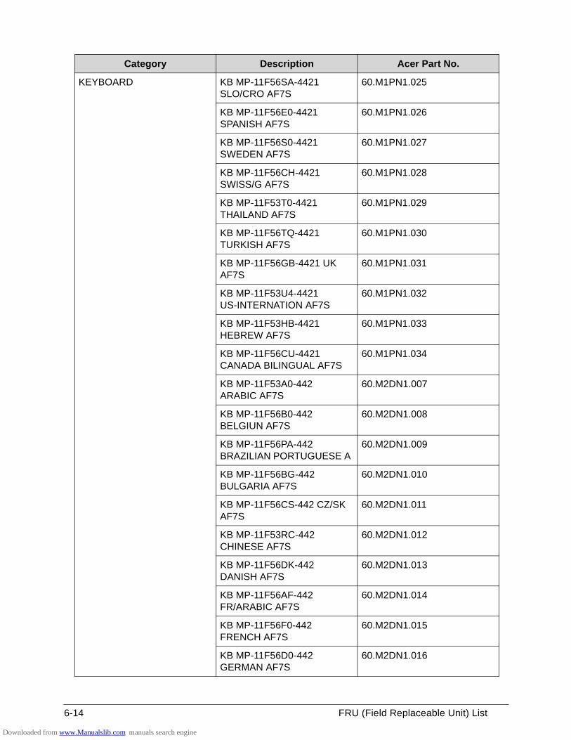
6-14 FRU (Field Replaceable Unit) List
KEYBOARD KB MP-11F56SA-4421 SLO/CRO AF7S
60.M1PN1.025
KB MP-11F56E0-4421 SPANISH AF7S
60.M1PN1.026
KB MP-11F56S0-4421 SWEDEN AF7S
60.M1PN1.027
KB MP-11F56CH-4421 SWISS/G AF7S
60.M1PN1.028
KB MP-11F53T0-4421 THAILAND AF7S
60.M1PN1.029
KB MP-11F56TQ-4421 TURKISH AF7S
60.M1PN1.030
KB MP-11F56GB-4421 UK AF7S
60.M1PN1.031
KB MP-11F53U4-4421 US-INTERNATION AF7S
60.M1PN1.032
KB MP-11F53HB-4421 HEBREW AF7S
60.M1PN1.033
KB MP-11F56CU-4421 CANADA BILINGUAL AF7S
60.M1PN1.034
KB MP-11F53A0-442 ARABIC AF7S
60.M2DN1.007
KB MP-11F56B0-442 BELGIUN AF7S
60.M2DN1.008
KB MP-11F56PA-442 BRAZILIAN PORTUGUESE A
60.M2DN1.009
KB MP-11F56BG-442 BULGARIA AF7S
60.M2DN1.010
KB MP-11F56CS-442 CZ/SK AF7S
60.M2DN1.011
KB MP-11F53RC-442 CHINESE AF7S
60.M2DN1.012
KB MP-11F56DK-442 DANISH AF7S
60.M2DN1.013
KB MP-11F56AF-442 FR/ARABIC AF7S
60.M2DN1.014
KB MP-11F56F0-442 FRENCH AF7S
60.M2DN1.015
KB MP-11F56D0-442 GERMAN AF7S
60.M2DN1.016
Category Description Acer Part No.
Downloaded from www.Manualslib.com manuals search engine
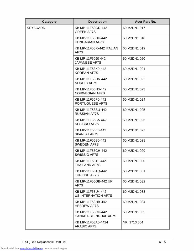
FRU (Field Replaceable Unit) List 6-15
KEYBOARD KB MP-11F53GR-442 GREEK AF7S
60.M2DN1.017
KB MP-11F56HU-442 HUNGARIAN AF7S
60.M2DN1.018
KB MP-11F56I0-442 ITALIAN AF7S
60.M2DN1.019
KB MP-11F50J0-442 JAPANESE AF7S
60.M2DN1.020
KB MP-11F53K0-442 KOREAN AF7S
60.M2DN1.021
KB MP-11F56DN-442 NORDIC AF7S
60.M2DN1.022
KB MP-11F56N0-442 NORWEGIAN AF7S
60.M2DN1.023
KB MP-11F56P0-442 PORTUGUESE AF7S
60.M2DN1.024
KB MP-11F53SU-442 RUSSIAN AF7S
60.M2DN1.025
KB MP-11F56SA-442 SLO/CRO AF7S
60.M2DN1.026
KB MP-11F56E0-442 SPANISH AF7S
60.M2DN1.027
KB MP-11F56S0-442 SWEDEN AF7S
60.M2DN1.028
KB MP-11F56CH-442 SWISS/G AF7S
60.M2DN1.029
KB MP-11F53T0-442 THAILAND AF7S
60.M2DN1.030
KB MP-11F56TQ-442 TURKISH AF7S
60.M2DN1.031
KB MP-11F56GB-442 UK AF7S
60.M2DN1.032
KB MP-11F53U4-442 US-INTERNATION AF7S
60.M2DN1.033
KB MP-11F53HB-442 HEBREW AF7S
60.M2DN1.034
KB MP-11F56CU-442 CANADA BILINGUAL AF7S
60.M2DN1.035
KB MP-11F53A0-4424 ARABIC AF7S
NK.I1713.004
Category Description Acer Part No.
Downloaded from www.Manualslib.com manuals search engine
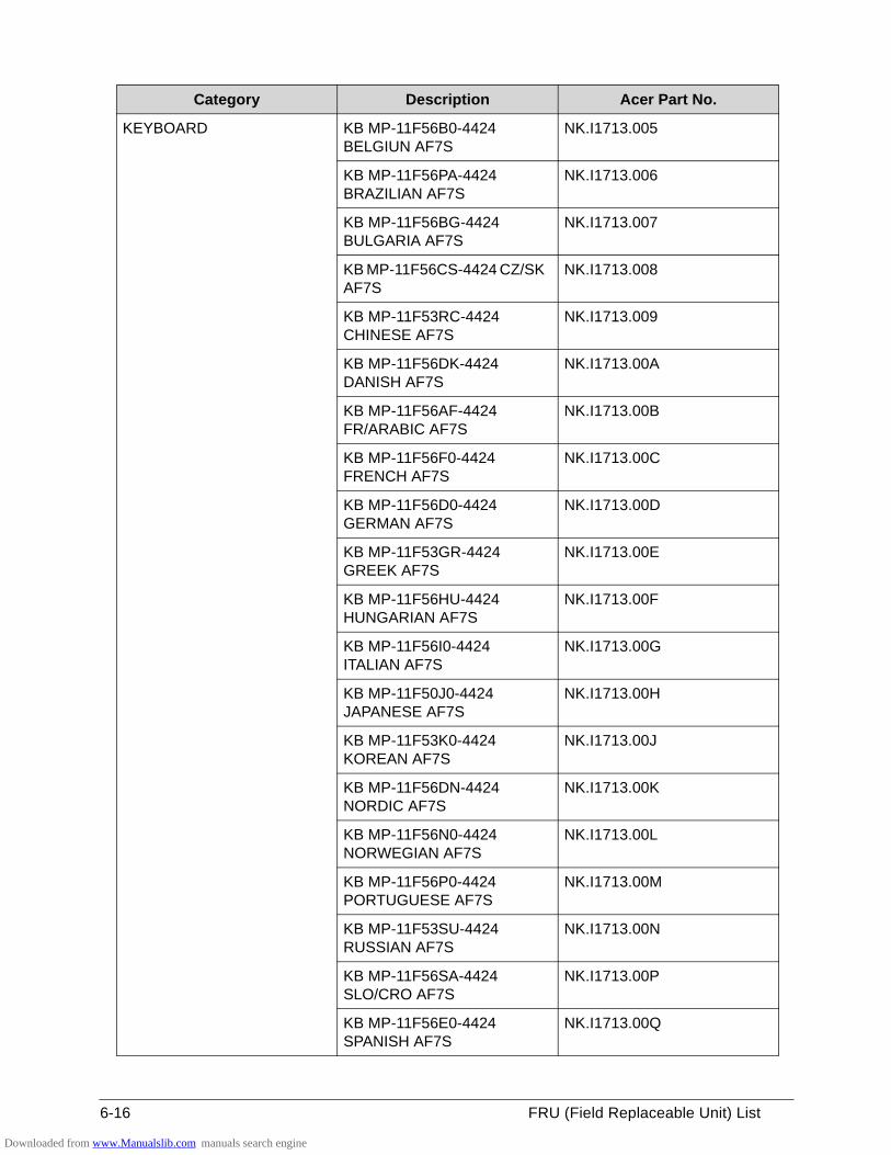
6-16 FRU (Field Replaceable Unit) List
KEYBOARD KB MP-11F56B0-4424 BELGIUN AF7S
NK.I1713.005
KB MP-11F56PA-4424 BRAZILIAN AF7S
NK.I1713.006
KB MP-11F56BG-4424 BULGARIA AF7S
NK.I1713.007
KB MP-11F56CS-4424 CZ/SK AF7S
NK.I1713.008
KB MP-11F53RC-4424 CHINESE AF7S
NK.I1713.009
KB MP-11F56DK-4424 DANISH AF7S
NK.I1713.00A
KB MP-11F56AF-4424 FR/ARABIC AF7S
NK.I1713.00B
KB MP-11F56F0-4424 FRENCH AF7S
NK.I1713.00C
KB MP-11F56D0-4424 GERMAN AF7S
NK.I1713.00D
KB MP-11F53GR-4424 GREEK AF7S
NK.I1713.00E
KB MP-11F56HU-4424 HUNGARIAN AF7S
NK.I1713.00F
KB MP-11F56I0-4424 ITALIAN AF7S
NK.I1713.00G
KB MP-11F50J0-4424 JAPANESE AF7S
NK.I1713.00H
KB MP-11F53K0-4424 KOREAN AF7S
NK.I1713.00J
KB MP-11F56DN-4424 NORDIC AF7S
NK.I1713.00K
KB MP-11F56N0-4424 NORWEGIAN AF7S
NK.I1713.00L
KB MP-11F56P0-4424 PORTUGUESE AF7S
NK.I1713.00M
KB MP-11F53SU-4424 RUSSIAN AF7S
NK.I1713.00N
KB MP-11F56SA-4424 SLO/CRO AF7S
NK.I1713.00P
KB MP-11F56E0-4424 SPANISH AF7S
NK.I1713.00Q
Category Description Acer Part No.
Downloaded from www.Manualslib.com manuals search engine
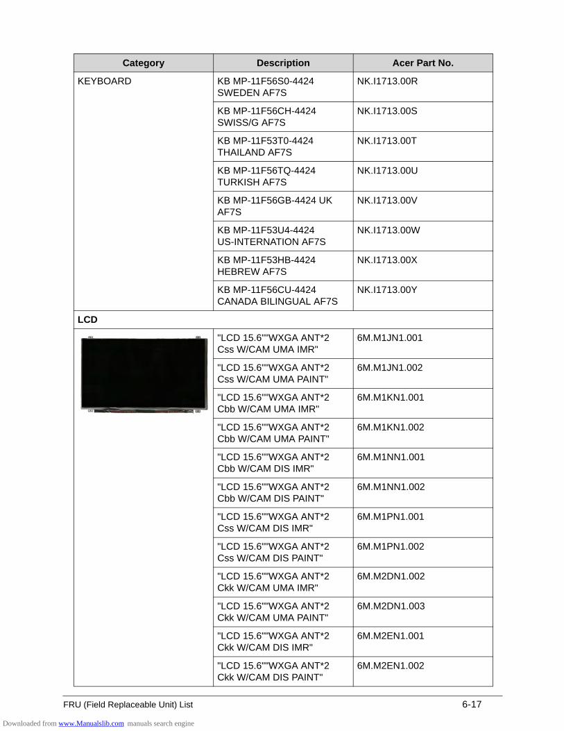
FRU (Field Replaceable Unit) List 6-17
KEYBOARD KB MP-11F56S0-4424 SWEDEN AF7S
NK.I1713.00R
KB MP-11F56CH-4424 SWISS/G AF7S
NK.I1713.00S
KB MP-11F53T0-4424 THAILAND AF7S
NK.I1713.00T
KB MP-11F56TQ-4424 TURKISH AF7S
NK.I1713.00U
KB MP-11F56GB-4424 UK AF7S
NK.I1713.00V
KB MP-11F53U4-4424 US-INTERNATION AF7S
NK.I1713.00W
KB MP-11F53HB-4424 HEBREW AF7S
NK.I1713.00X
KB MP-11F56CU-4424 CANADA BILINGUAL AF7S
NK.I1713.00Y
LCD
"LCD 15.6""WXGA ANT*2 Css W/CAM UMA IMR"
6M.M1JN1.001
"LCD 15.6""WXGA ANT*2 Css W/CAM UMA PAINT"
6M.M1JN1.002
"LCD 15.6""WXGA ANT*2 Cbb W/CAM UMA IMR"
6M.M1KN1.001
"LCD 15.6""WXGA ANT*2 Cbb W/CAM UMA PAINT"
6M.M1KN1.002
"LCD 15.6""WXGA ANT*2 Cbb W/CAM DIS IMR"
6M.M1NN1.001
"LCD 15.6""WXGA ANT*2 Cbb W/CAM DIS PAINT"
6M.M1NN1.002
"LCD 15.6""WXGA ANT*2 Css W/CAM DIS IMR"
6M.M1PN1.001
"LCD 15.6""WXGA ANT*2 Css W/CAM DIS PAINT"
6M.M1PN1.002
"LCD 15.6""WXGA ANT*2 Ckk W/CAM UMA IMR"
6M.M2DN1.002
"LCD 15.6""WXGA ANT*2 Ckk W/CAM UMA PAINT"
6M.M2DN1.003
"LCD 15.6""WXGA ANT*2 Ckk W/CAM DIS IMR"
6M.M2EN1.001
"LCD 15.6""WXGA ANT*2 Ckk W/CAM DIS PAINT"
6M.M2EN1.002
Category Description Acer Part No.
Downloaded from www.Manualslib.com manuals search engine
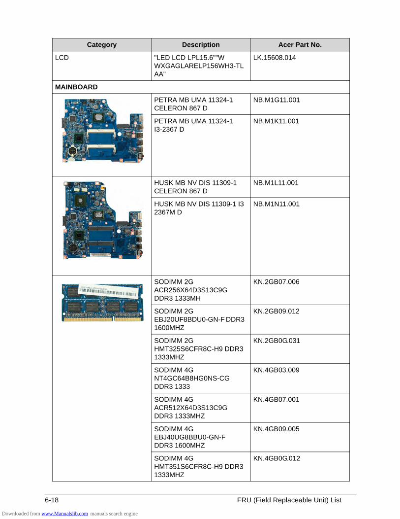
6-18 FRU (Field Replaceable Unit) List
LCD "LED LCD LPL15.6""W WXGAGLARELP156WH3-TLAA"
LK.15608.014
MAINBOARD
PETRA MB UMA 11324-1 CELERON 867 D
NB.M1G11.001
PETRA MB UMA 11324-1 I3-2367 D
NB.M1K11.001
HUSK MB NV DIS 11309-1 CELERON 867 D
NB.M1L11.001
HUSK MB NV DIS 11309-1 I3 2367M D
NB.M1N11.001
SODIMM 2G ACR256X64D3S13C9G DDR3 1333MH
KN.2GB07.006
SODIMM 2G EBJ20UF8BDU0-GN-F DDR3 1600MHZ
KN.2GB09.012
SODIMM 2G HMT325S6CFR8C-H9 DDR3 1333MHZ
KN.2GB0G.031
SODIMM 4G NT4GC64B8HG0NS-CG DDR3 1333
KN.4GB03.009
SODIMM 4G ACR512X64D3S13C9G DDR3 1333MHZ
KN.4GB07.001
SODIMM 4G EBJ40UG8BBU0-GN-F DDR3 1600MHZ
KN.4GB09.005
SODIMM 4G HMT351S6CFR8C-H9 DDR3 1333MHZ
KN.4GB0G.012
Category Description Acer Part No.
Downloaded from www.Manualslib.com manuals search engine
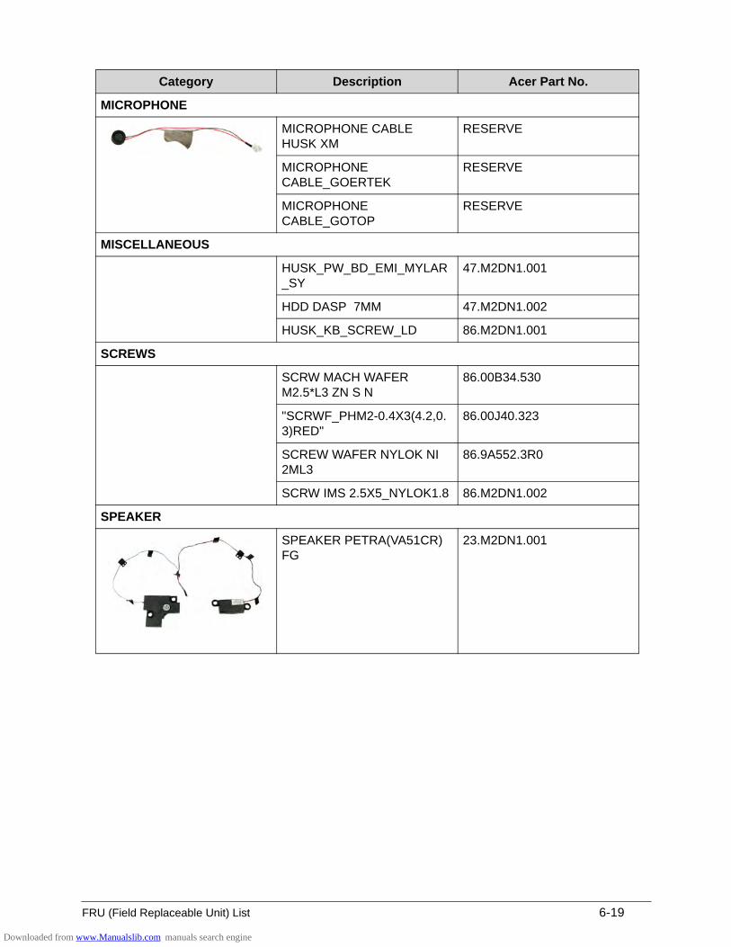
FRU (Field Replaceable Unit) List 6-19
MICROPHONE
MICROPHONE CABLE HUSK XM
RESERVE
MICROPHONE CABLE_GOERTEK
RESERVE
MICROPHONE CABLE_GOTOP
RESERVE
MISCELLANEOUS
HUSK_PW_BD_EMI_MYLAR_SY
47.M2DN1.001
HDD DASP 7MM 47.M2DN1.002
HUSK_KB_SCREW_LD 86.M2DN1.001
SCREWS
SCRW MACH WAFER M2.5*L3 ZN S N
86.00B34.530
"SCRWF_PHM2-0.4X3(4.2,0.3)RED"
86.00J40.323
SCREW WAFER NYLOK NI 2ML3
86.9A552.3R0
SCRW IMS 2.5X5_NYLOK1.8 86.M2DN1.002
SPEAKER
SPEAKER PETRA(VA51CR) FG
23.M2DN1.001
Category Description Acer Part No.
Downloaded from www.Manualslib.com manuals search engine

6-20 FRU (Field Replaceable Unit) List
Downloaded from www.Manualslib.com manuals search engine
CHAPTER 7
Test Compatible Components
Downloaded from www.Manualslib.com manuals search engine

7-2
Microsoft Windows 7 Environment Test. . . . . . . . . . . . . . . . . . . 7-3
Downloaded from www.Manualslib.com manuals search engine
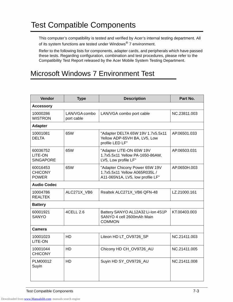
Test Compatible Components 7-3
Test Compatible Components
This computer’s compatibility is tested and verified by Acer’s internal testing department. All
of its system functions are tested under Windows® 7 environment.
Refer to the following lists for components, adapter cards, and peripherals which have passed these tests. Regarding configuration, combination and test procedures, please refer to the Compatibility Test Report released by the Acer Mobile System Testing Department.
Microsoft Windows 7 Environment Test 0
Vendor Type Description Part No.
Accessory
10000286 WISTRON
LAN/VGA combo port cable
LAN/VGA combo port cable NC.23811.003
Adapter
10001081 DELTA
65W "Adapter DELTA 65W 19V 1.7x5.5x11 Yellow ADP-65VH BA, LV5, Low profile LED LF"
AP.06501.033
60036752 LITE-ON SINGAPORE
65W "Adapter LITE-ON 65W 19V 1.7x5.5x11 Yellow PA-1650-86AW, LV5, Low profile LF"
AP.06503.031
60016453 CHICONY POWER
65W "Adapter Chicony Power 65W 19V 1.7x5.5x11 Yellow A065R035L / A11-065N1A, LV5, low profile LF"
AP.0650H.003
Audio Codec
10004786 REALTEK
ALC271X_VB6 Realtek ALC271X_VB6 QFN-48 LZ.21000.161
Battery
60001921 SANYO
4CELL 2.6 Battery SANYO AL12A32 Li-Ion 4S1P SANYO 4 cell 2600mAh Main COMMON
KT.00403.003
Camera
10001023 LITE-ON
HD Liteon HD LT_OV9726_SP NC.21411.003
10001044 CHICONY
HD Chicony HD CH_OV9726_AU NC.21411.005
PLM00012 Suyin
HD Suyin HD SY_OV9726_AU NC.21411.008
Downloaded from www.Manualslib.com manuals search engine
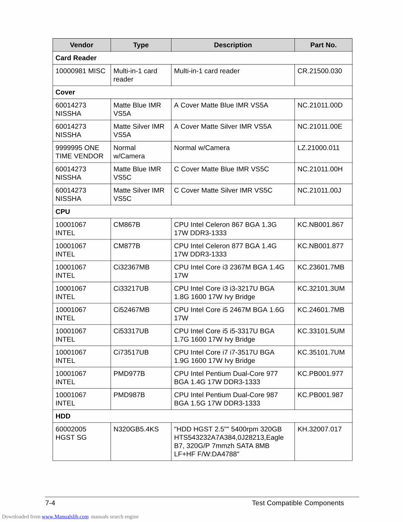
7-4 Test Compatible Components
Card Reader
10000981 MISC Multi-in-1 card reader
Multi-in-1 card reader CR.21500.030
Cover
60014273 NISSHA
Matte Blue IMR VS5A
A Cover Matte Blue IMR VS5A NC.21011.00D
60014273 NISSHA
Matte Silver IMR VS5A
A Cover Matte Silver IMR VS5A NC.21011.00E
9999995 ONE TIME VENDOR
Normal w/Camera
Normal w/Camera LZ.21000.011
60014273 NISSHA
Matte Blue IMR VS5C
C Cover Matte Blue IMR VS5C NC.21011.00H
60014273 NISSHA
Matte Silver IMR VS5C
C Cover Matte Silver IMR VS5C NC.21011.00J
CPU
10001067 INTEL
CM867B CPU Intel Celeron 867 BGA 1.3G 17W DDR3-1333
KC.NB001.867
10001067 INTEL
CM877B CPU Intel Celeron 877 BGA 1.4G 17W DDR3-1333
KC.NB001.877
10001067 INTEL
Ci32367MB CPU Intel Core i3 2367M BGA 1.4G 17W
KC.23601.7MB
10001067 INTEL
Ci33217UB CPU Intel Core i3 i3-3217U BGA 1.8G 1600 17W Ivy Bridge
KC.32101.3UM
10001067 INTEL
Ci52467MB CPU Intel Core i5 2467M BGA 1.6G 17W
KC.24601.7MB
10001067 INTEL
Ci53317UB CPU Intel Core i5 i5-3317U BGA 1.7G 1600 17W Ivy Bridge
KC.33101.5UM
10001067 INTEL
Ci73517UB CPU Intel Core i7 i7-3517U BGA 1.9G 1600 17W Ivy Bridge
KC.35101.7UM
10001067 INTEL
PMD977B CPU Intel Pentium Dual-Core 977 BGA 1.4G 17W DDR3-1333
KC.PB001.977
10001067 INTEL
PMD987B CPU Intel Pentium Dual-Core 987 BGA 1.5G 17W DDR3-1333
KC.PB001.987
HDD
60002005 HGST SG
N320GB5.4KS "HDD HGST 2.5"" 5400rpm 320GB HTS543232A7A384,0J28213,Eagle B7, 320G/P 7mmzh SATA 8MB LF+HF F/W:DA4788"
KH.32007.017
Vendor Type Description Part No.
Downloaded from www.Manualslib.com manuals search engine
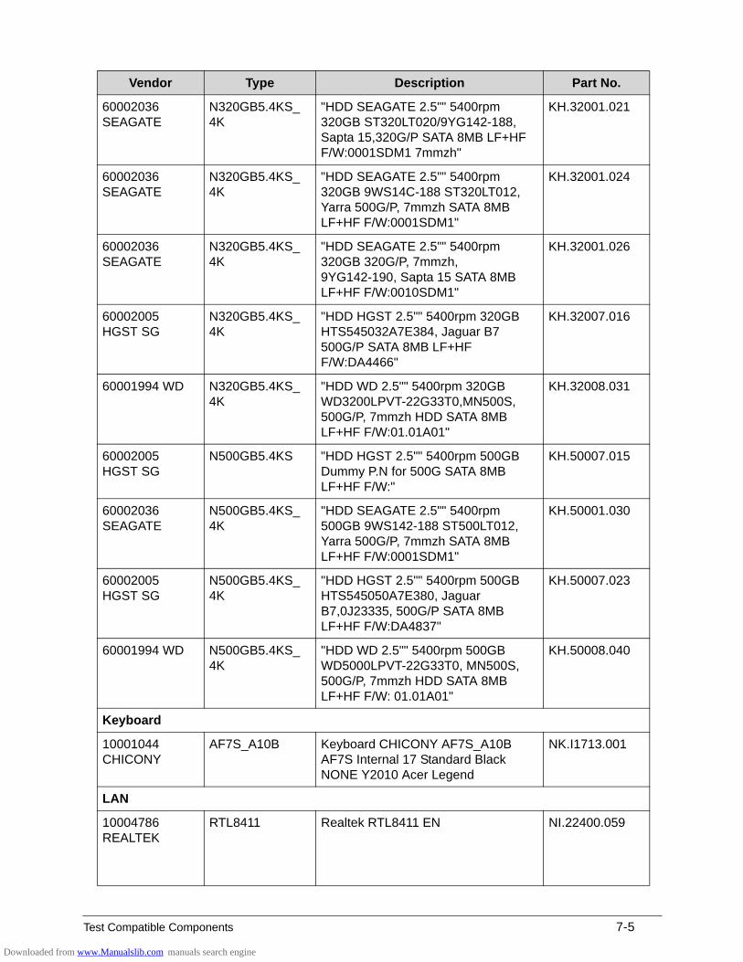
Test Compatible Components 7-5
60002036 SEAGATE
N320GB5.4KS_4K
"HDD SEAGATE 2.5"" 5400rpm 320GB ST320LT020/9YG142-188, Sapta 15,320G/P SATA 8MB LF+HF F/W:0001SDM1 7mmzh"
KH.32001.021
60002036 SEAGATE
N320GB5.4KS_4K
"HDD SEAGATE 2.5"" 5400rpm 320GB 9WS14C-188 ST320LT012, Yarra 500G/P, 7mmzh SATA 8MB LF+HF F/W:0001SDM1"
KH.32001.024
60002036 SEAGATE
N320GB5.4KS_4K
"HDD SEAGATE 2.5"" 5400rpm 320GB 320G/P, 7mmzh, 9YG142-190, Sapta 15 SATA 8MB LF+HF F/W:0010SDM1"
KH.32001.026
60002005 HGST SG
N320GB5.4KS_4K
"HDD HGST 2.5"" 5400rpm 320GB HTS545032A7E384, Jaguar B7 500G/P SATA 8MB LF+HF F/W:DA4466"
KH.32007.016
60001994 WD N320GB5.4KS_4K
"HDD WD 2.5"" 5400rpm 320GB WD3200LPVT-22G33T0,MN500S, 500G/P, 7mmzh HDD SATA 8MB LF+HF F/W:01.01A01"
KH.32008.031
60002005 HGST SG
N500GB5.4KS "HDD HGST 2.5"" 5400rpm 500GB Dummy P.N for 500G SATA 8MB LF+HF F/W:"
KH.50007.015
60002036 SEAGATE
N500GB5.4KS_4K
"HDD SEAGATE 2.5"" 5400rpm 500GB 9WS142-188 ST500LT012, Yarra 500G/P, 7mmzh SATA 8MB LF+HF F/W:0001SDM1"
KH.50001.030
60002005 HGST SG
N500GB5.4KS_4K
"HDD HGST 2.5"" 5400rpm 500GB HTS545050A7E380, Jaguar B7,0J23335, 500G/P SATA 8MB LF+HF F/W:DA4837"
KH.50007.023
60001994 WD N500GB5.4KS_4K
"HDD WD 2.5"" 5400rpm 500GB WD5000LPVT-22G33T0, MN500S, 500G/P, 7mmzh HDD SATA 8MB LF+HF F/W: 01.01A01"
KH.50008.040
Keyboard
10001044 CHICONY
AF7S_A10B Keyboard CHICONY AF7S_A10B AF7S Internal 17 Standard Black NONE Y2010 Acer Legend
NK.I1713.001
LAN
10004786 REALTEK
RTL8411 Realtek RTL8411 EN NI.22400.059
Vendor Type Description Part No.
Downloaded from www.Manualslib.com manuals search engine
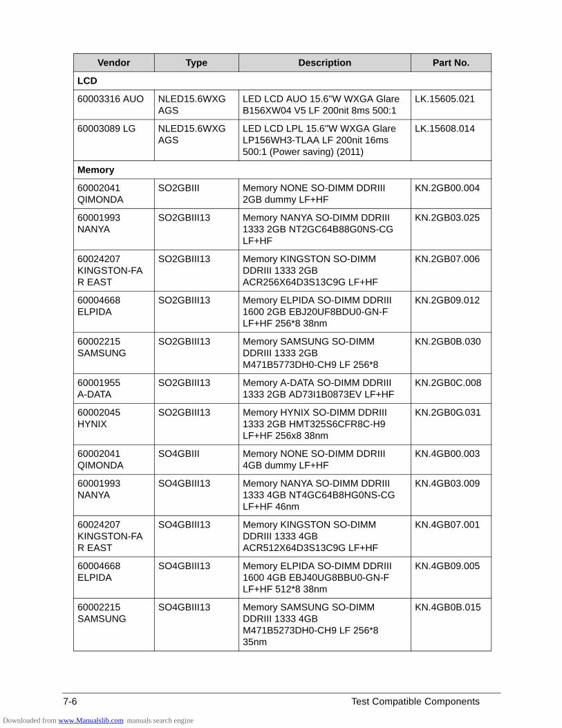
7-6 Test Compatible Components
LCD
60003316 AUO NLED15.6WXGAGS
LED LCD AUO 15.6''W WXGA Glare B156XW04 V5 LF 200nit 8ms 500:1
LK.15605.021
60003089 LG NLED15.6WXGAGS
LED LCD LPL 15.6''W WXGA Glare LP156WH3-TLAA LF 200nit 16ms 500:1 (Power saving) (2011)
LK.15608.014
Memory
60002041 QIMONDA
SO2GBIII Memory NONE SO-DIMM DDRIII 2GB dummy LF+HF
KN.2GB00.004
60001993 NANYA
SO2GBIII13 Memory NANYA SO-DIMM DDRIII 1333 2GB NT2GC64B88G0NS-CG LF+HF
KN.2GB03.025
60024207 KINGSTON-FAR EAST
SO2GBIII13 Memory KINGSTON SO-DIMM DDRIII 1333 2GB ACR256X64D3S13C9G LF+HF
KN.2GB07.006
60004668 ELPIDA
SO2GBIII13 Memory ELPIDA SO-DIMM DDRIII 1600 2GB EBJ20UF8BDU0-GN-F LF+HF 256*8 38nm
KN.2GB09.012
60002215 SAMSUNG
SO2GBIII13 Memory SAMSUNG SO-DIMM DDRIII 1333 2GB M471B5773DH0-CH9 LF 256*8
KN.2GB0B.030
60001955 A-DATA
SO2GBIII13 Memory A-DATA SO-DIMM DDRIII 1333 2GB AD73I1B0873EV LF+HF
KN.2GB0C.008
60002045 HYNIX
SO2GBIII13 Memory HYNIX SO-DIMM DDRIII 1333 2GB HMT325S6CFR8C-H9 LF+HF 256x8 38nm
KN.2GB0G.031
60002041 QIMONDA
SO4GBIII Memory NONE SO-DIMM DDRIII 4GB dummy LF+HF
KN.4GB00.003
60001993 NANYA
SO4GBIII13 Memory NANYA SO-DIMM DDRIII 1333 4GB NT4GC64B8HG0NS-CG LF+HF 46nm
KN.4GB03.009
60024207 KINGSTON-FAR EAST
SO4GBIII13 Memory KINGSTON SO-DIMM DDRIII 1333 4GB ACR512X64D3S13C9G LF+HF
KN.4GB07.001
60004668 ELPIDA
SO4GBIII13 Memory ELPIDA SO-DIMM DDRIII 1600 4GB EBJ40UG8BBU0-GN-F LF+HF 512*8 38nm
KN.4GB09.005
60002215 SAMSUNG
SO4GBIII13 Memory SAMSUNG SO-DIMM DDRIII 1333 4GB M471B5273DH0-CH9 LF 256*8 35nm
KN.4GB0B.015
Vendor Type Description Part No.
Downloaded from www.Manualslib.com manuals search engine
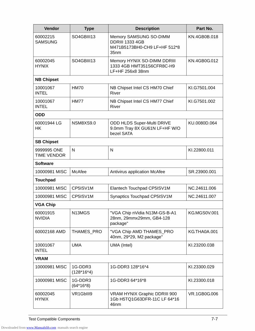
Test Compatible Components 7-7
60002215 SAMSUNG
SO4GBIII13 Memory SAMSUNG SO-DIMM DDRIII 1333 4GB M471B5173BH0-CH9 LF+HF 512*8 35nm
KN.4GB0B.018
60002045 HYNIX
SO4GBIII13 Memory HYNIX SO-DIMM DDRIII 1333 4GB HMT351S6CFR8C-H9 LF+HF 256x8 38nm
KN.4GB0G.012
NB Chipset
10001067 INTEL
HM70 NB Chipset Intel CS HM70 Chief River
KI.G7501.004
10001067 INTEL
HM77 NB Chipset Intel CS HM77 Chief River
KI.G7501.002
ODD
60001944 LG HK
NSM8XS9.0 ODD HLDS Super-Multi DRIVE 9.0mm Tray 8X GU61N LF+HF W/O bezel SATA
KU.0080D.064
SB Chipset
9999995 ONE TIME VENDOR
N N KI.22800.011
Software
10000981 MISC McAfee Antivirus application McAfee SR.23900.001
Touchpad
10000981 MISC CP5ISV1M Elantech Touchpad CP5ISV1M NC.24611.006
10000981 MISC CP5ISV1M Synaptics Touchpad CP5ISV1M NC.24611.007
VGA Chip
60001915 NVIDIA
N13MGS "VGA Chip nVidia N13M-GS-B-A1 28nm, 29mmx29mm, GB4-128 package"
KG.MGS0V.001
60002168 AMD THAMES_PRO "VGA Chip AMD THAMES_PRO 40nm, 29*29, M2 package"
KG.THA0A.001
10001067 INTEL
UMA UMA (Intel) KI.23200.038
VRAM
10000981 MISC 1G-DDR3 (128*16*4)
1G-DDR3 128*16*4 KI.23300.029
10000981 MISC 1G-DDR3 (64*16*8)
1G-DDR3 64*16*8 KI.23300.018
60002045 HYNIX
VR1GbIII9 VRAM HYNIX Graphic DDRIII 900 1Gb H5TQ1G63DFR-11C LF 64*16 46nm
VR.1GB0G.006
Vendor Type Description Part No.
Downloaded from www.Manualslib.com manuals search engine
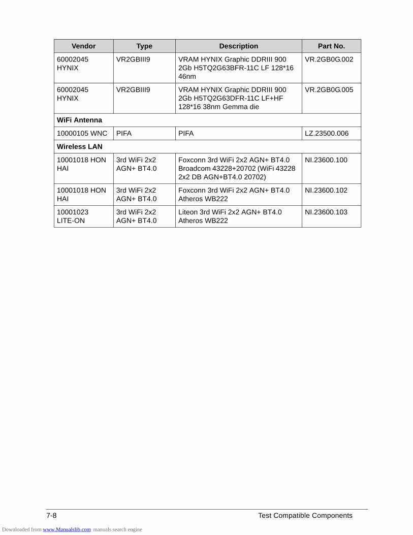
7-8 Test Compatible Components
60002045 HYNIX
VR2GBIII9 VRAM HYNIX Graphic DDRIII 900 2Gb H5TQ2G63BFR-11C LF 128*16 46nm
VR.2GB0G.002
60002045 HYNIX
VR2GBIII9 VRAM HYNIX Graphic DDRIII 900 2Gb H5TQ2G63DFR-11C LF+HF 128*16 38nm Gemma die
VR.2GB0G.005
WiFi Antenna
10000105 WNC PIFA PIFA LZ.23500.006
Wireless LAN
10001018 HON HAI
3rd WiFi 2x2 AGN+ BT4.0
Foxconn 3rd WiFi 2x2 AGN+ BT4.0 Broadcom 43228+20702 (WiFi 43228 2x2 DB AGN+BT4.0 20702)
NI.23600.100
10001018 HON HAI
3rd WiFi 2x2 AGN+ BT4.0
Foxconn 3rd WiFi 2x2 AGN+ BT4.0 Atheros WB222
NI.23600.102
10001023 LITE-ON
3rd WiFi 2x2 AGN+ BT4.0
Liteon 3rd WiFi 2x2 AGN+ BT4.0 Atheros WB222
NI.23600.103
Vendor Type Description Part No.
Downloaded from www.Manualslib.com manuals search engine
CHAPTER 8
Online Support Information
Downloaded from www.Manualslib.com manuals search engine
8-2
Online Support Information . . . . . . . . . . . . . . . . . . . . . . . . . . . . 8-3
Downloaded from www.Manualslib.com manuals search engine
Online Support Information 8-3
Online Support Information
This section describes online technical support services available to help users repair their Acer Systems.
For distributors, dealers, ASP or TPM, please refer the technical queries to a local Acer branch office. Acer Branch Offices and Regional Business Units may access our website. However some information sources will require a user i.d. and password. These can be obtained directly from Acer CSD Taiwan.
Acer's Website offers convenient and valuable support resources.
In the Technical Information section users can download information on all of Acer's Notebook, Desktop and Server models including:
Service guides for all models
Bios updates
Software utilities
Spare parts lists
TABs (Technical Announcement Bulletin)
For these purposes, we have included an Acrobat File to facilitate the problem-free downloading of our technical material.
Also contained on this website are:
Detailed information on Acer's International Traveller’s Warranty (ITW)
Returned material authorization procedures
An overview of all the support services we offer, accompanied by a list of telephone, fax and email contacts for all technical queries.
We are always looking for ways to optimize and improve our services, so do not hesitate to direct any suggestions or comments to us.
Downloaded from www.Manualslib.com manuals search engine

8-4 Online Support Information
Downloaded from www.Manualslib.com manuals search engine