Magnetic Effet of Electric Current
48
Magnetic Effet of Electric Current 15 COMPREHENSIVE REVIEW 1. Basic Concept i) The magnetic effect of electric current was discovered by Oersted in 1820. It was mathematically explained by Biot and Savart. ii) The product of current I and elementary length d of the current carrying conductor is called current element. Thus, current element is given by Id . The direction of current element is same as that of electric current. 2. Magnetic field, Magnetic induction The region or space around a magnet, current carrying conductor or a moving charge, in which magnetic effect can be experienced is called magnetic field. i) The magnetic field strength is called magnetic induction. It is denoted by B. ii) Magnetic induction is a vector quantity. iii) The magnetic induction may be geometri- cally represented by the lines of magnetic induction in the same way as the electric field is represented by the electric field lines. iv) The lines of magnetic induction are closed curves (continuous curves). However, it may be remembered that the electric field lines are discontinuous curves originating from the +VE charge and ending at the –VE charge. v) The lines of magnetic induction for uniform magnetic field are parallel and equally spaced. But that for the non-uniform magnetic field are curves or unequally spaced or both. vi) The SI unit of magnetic induction is tesla (T) or weber/metre 2 (Wb/m 2 ). vii) The cgs unit of magnetic induction is maxwell/centimetre 2 (Mx/cm 2 ) or gauss (Gs). viii) 1 T = 10 4 Gs MAGNETIC EFFECT OF ELECTRIC CURRENT ( 146 ) 3. Biot Savart Law The magnetic field due to a current element is given by the following relation. 0 2 ˆ Id r B 4 r It is called Biot Savart law. See the figure below : Fig. 3.1 Here I d the current element and P is the observation point where magnetic field due to the current element is dB. Also, here r is the position vector of the observation point from the current element. In the above expression 0 is a magnetic constant for free space. It is called permeability of free space. i) If be the angle between Id and r , then : 0 2 Id B sin 4 r ii) The unit of magnetic field B is called tesla (T). iii) 0 = 4 10 –7 T mA –1 . iv) B is perpendicular to both Id and r. v) The current element plays the same role in producing a magnetic field as the point charge does in producing electric field. vi) Biot Savart law is the analogue of the coulomb's law in electrostatics. 4. The Magnetic field due to a straight current carrying conductor DGT Group - Tuitions (Feed Concepts) XIth – XIIth | JEE | CET | NEET | Call : 9920154035 / 8169861448 DGT MH –CET 12th PHYSICS Study Material 1
-
Upload
khangminh22 -
Category
Documents
-
view
2 -
download
0
Transcript of Magnetic Effet of Electric Current

Magnetic Effet of ElectricCurrent
15
COMPREHENSIVE REVIEW
1. Basic Concept
i) The magnetic effect of electric current was
discovered by Oersted in 1820. It was
mathematically explained by Biot and
Savart.
ii) The product of current I and elementary
length d of the current carrying conductor
is called current element. Thus, current
element is given by Id . The direction of
current element is same as that of electric
current.
2. Magnetic field, Magnetic induction
The region or space around a magnet, current
carrying conductor or a moving charge, in which
magnetic effect can be experienced is called
magnetic field.
i) The magnetic field strength is called
magnetic induction. It is denoted by B.
ii) Magnetic induction is a vector quantity.
iii) The magnetic induction may be geometri-
cally represented by the lines of magnetic
induction in the same way as the electric
field is represented by the electric field lines.
iv) The lines of magnetic induction are closed
curves (continuous curves). However, it may
be remembered that the electric field lines
are discontinuous curves originating from the
+VE charge and ending at the –VE charge.
v) The lines of magnetic induction for uniform
magnetic field are parallel and equally
spaced. But that for the non-uniform
magnetic field are curves or unequally spaced
or both.
vi) The SI unit of magnetic induction is tesla
(T) or weber/metre2 (Wb/m2).
vii) The cgs unit of magnetic induction is
maxwell/centimetre2 (Mx/cm2) or gauss
(Gs).
viii) 1 T = 104 Gs
MAGNETIC EFFECT OF ELECTRIC CURRENT ( 146 )
3. Biot Savart Law
The magnetic field due to a current element
is given by the following relation.
0
2
ˆId rB
4 r
It is called Biot Savart law. See the figure
below :
Fig. 3.1
Here I d the current element and P is the
observation point where magnetic field due to the
current element is dB.
Also, here r
is the position
vector of the observation point from the current
element.
In the above expression 0 is a magnetic
constant for free space. It is called permeability
of free space.
i) If be the angle between Id and r
, then :
0
2
IdB sin
4 r
ii) The unit of magnetic field B is called tesla
(T).
iii) 0 = 4 10–7 T mA–1.
iv) B
is perpendicular to both Id and r.
v) The current element plays the same role in
producing a magnetic field as the point
charge does in producing electric field.
vi) Biot Savart law is the analogue of the
coulomb's law in electrostatics.
4. The Magnetic field due to a straight current
carrying conductor
DGT Group - Tuitions (Feed Concepts) XIth – XIIth | JEE | CET | NEET | Call : 9920154035 / 8169861448
DGT MH –CET 12th PHYSICS Study Material 1
DGT GROUP TUITIONS [MHT - CET] PHYSICS
MAGNETIC EFFECT OF ELECTRIC CURRENT ( 147 )
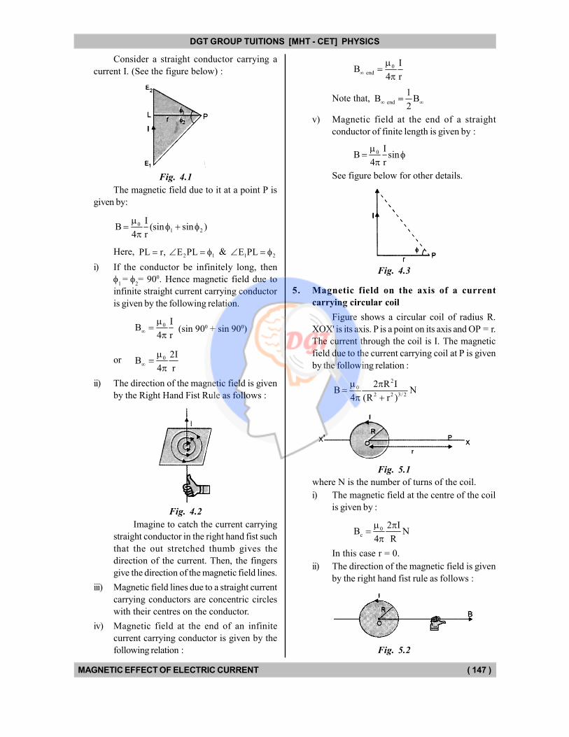
Consider a straight conductor carrying a
current I. (See the figure below) :
Fig. 4.1
The magnetic field due to it at a point P is
given by:
01 2
IB (sin sin )
4 r
Here, 2 1PL r, E PL &
1 2E PL
i) If the conductor be infinitely long, then
1=
2= 900. Hence magnetic field due to
infinite straight current carrying conductor
is given by the following relation.
0 IB
4 r
(sin 900 + sin 900)
or 0 2IB
4 r
ii) The direction of the magnetic field is given
by the Right Hand Fist Rule as follows :
Fig. 4.2
Imagine to catch the current carrying
straight conductor in the right hand fist such
that the out stretched thumb gives the
direction of the current. Then, the fingers
give the direction of the magnetic field lines.
iii) Magnetic field lines due to a straight current
carrying conductors are concentric circles
with their centres on the conductor.
iv) Magnetic field at the end of an infinite
current carrying conductor is given by the
following relation :
0 end
IB
4 r
Note that, end
1B B
2
v) Magnetic field at the end of a straight
conductor of finite length is given by :
0 IB sin
4 r
See figure below for other details.
Fig. 4.3
5. Magnetic field on the axis of a current
carrying circular coil
Figure shows a circular coil of radius R.
XOX' is its axis. P is a point on its axis and OP = r.
The current through the coil is I. The magnetic
field due to the current carrying coil at P is given
by the following relation :
2
0
2 2 3/ 2
2 R IB N
4 (R r )
Fig. 5.1
where N is the number of turns of the coil.
i) The magnetic field at the centre of the coil
is given by :
0c
2 IB N
4 R
In this case r = 0.
ii) The direction of the magnetic field is given
by the right hand fist rule as follows :
Fig. 5.2
DGT Group - Tuitions (Feed Concepts) XIth – XIIth | JEE | CET | NEET | Call : 9920154035 / 8169861448
DGT MH –CET 12th PHYSICS Study Material 2
DGT GROUP TUITIONS [MHT - CET] PHYSICS
MAGNETIC EFFECT OF ELECTRIC CURRENT ( 148 )
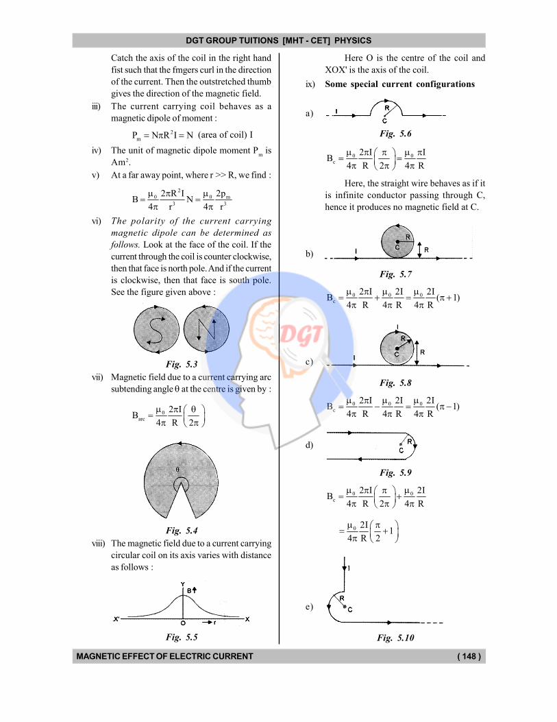
Catch the axis of the coil in the right hand
fist such that the fmgers curl in the direction
of the current. Then the outstretched thumb
gives the direction of the magnetic field.
iii) The current carrying coil behaves as a
magnetic dipole of moment :
2
mP N R I N (area of coil) I
iv) The unit of magnetic dipole moment Pm is
Am2.
v) At a far away point, where r >> R, we find :
2
0 0 m
3 3
2p2 R IB N
4 r 4 r
vi) The polarity of the current carrying
magnetic dipole can be determined as
follows. Look at the face of the coil. If the
current through the coil is counter clockwise,
then that face is north pole. And if the current
is clockwise, then that face is south pole.
See the figure given above :
Fig. 5.3
vii) Magnetic field due to a current carrying arc
subtending angle at the centre is given by :
0
arc
2 IB
4 R 2
Fig. 5.4
viii) The magnetic field due to a current carrying
circular coil on its axis varies with distance
as follows :
Fig. 5.5
Here O is the centre of the coil and
XOX' is the axis of the coil.
ix) Some special current configurations
a)
Fig. 5.6
0 0c
2 I IB
4 R 2 4 R
Here, the straight wire behaves as if it
is infinite conductor passing through C,
hence it produces no magnetic field at C.
b)
Fig. 5.7
0 0 0c
2 I 2I 2IB ( 1)
4 R 4 R 4 R
c)
Fig. 5.8
0 0 0c
2 I 2I 2IB ( 1)
4 R 4 R 4 R
d)
Fig. 5.9
0 0
c
2 I 2IB
4 R 2 4 R
0 2I
14 R 2
e)
Fig. 5.10
DGT Group - Tuitions (Feed Concepts) XIth – XIIth | JEE | CET | NEET | Call : 9920154035 / 8169861448
DGT MH –CET 12th PHYSICS Study Material 3
DGT GROUP TUITIONS [MHT - CET] PHYSICS
MAGNETIC EFFECT OF ELECTRIC CURRENT ( 149 )
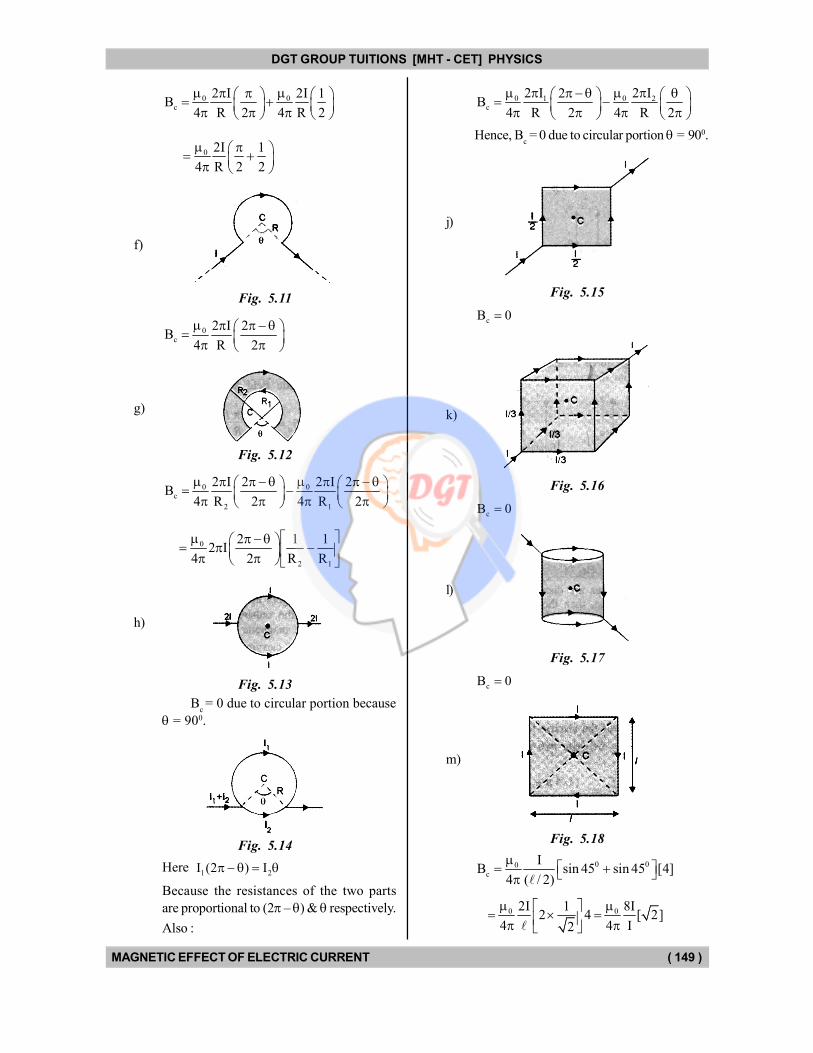
0 0c
2 I 2I 1B
4 R 2 4 R 2
0 2I 1
4 R 2 2
f)
Fig. 5.11
0
c
2 I 2B
4 R 2
g)
Fig. 5.12
0 0c
2 1
2 I 2 2 I 2B
4 R 2 4 R 2
0
2 1
2 1 12 I
4 2 R R
h)
Fig. 5.13
Bc = 0 due to circular portion because
= 900.
Fig. 5.14
Here 1 2I (2 ) I
Because the resistances of the two parts
are proportional to (2 – ) & respectively.
Also :
0 01 2c
2 I 2 I2B
4 R 2 4 R 2
Hence, Bc = 0 due to circular portion = 900.
j)
Fig. 5.15
cB 0
k)
Fig. 5.16
cB 0
l)
Fig. 5.17
cB 0
m)
Fig. 5.18
0 00c
IB sin 45 sin 45 [4]
4 ( / 2)
0 02I 1 8I
2 4 [ 2]4 4 I2
DGT Group - Tuitions (Feed Concepts) XIth – XIIth | JEE | CET | NEET | Call : 9920154035 / 8169861448
DGT MH –CET 12th PHYSICS Study Material 4
DGT GROUP TUITIONS [MHT - CET] PHYSICS
MAGNETIC EFFECT OF ELECTRIC CURRENT ( 150 )
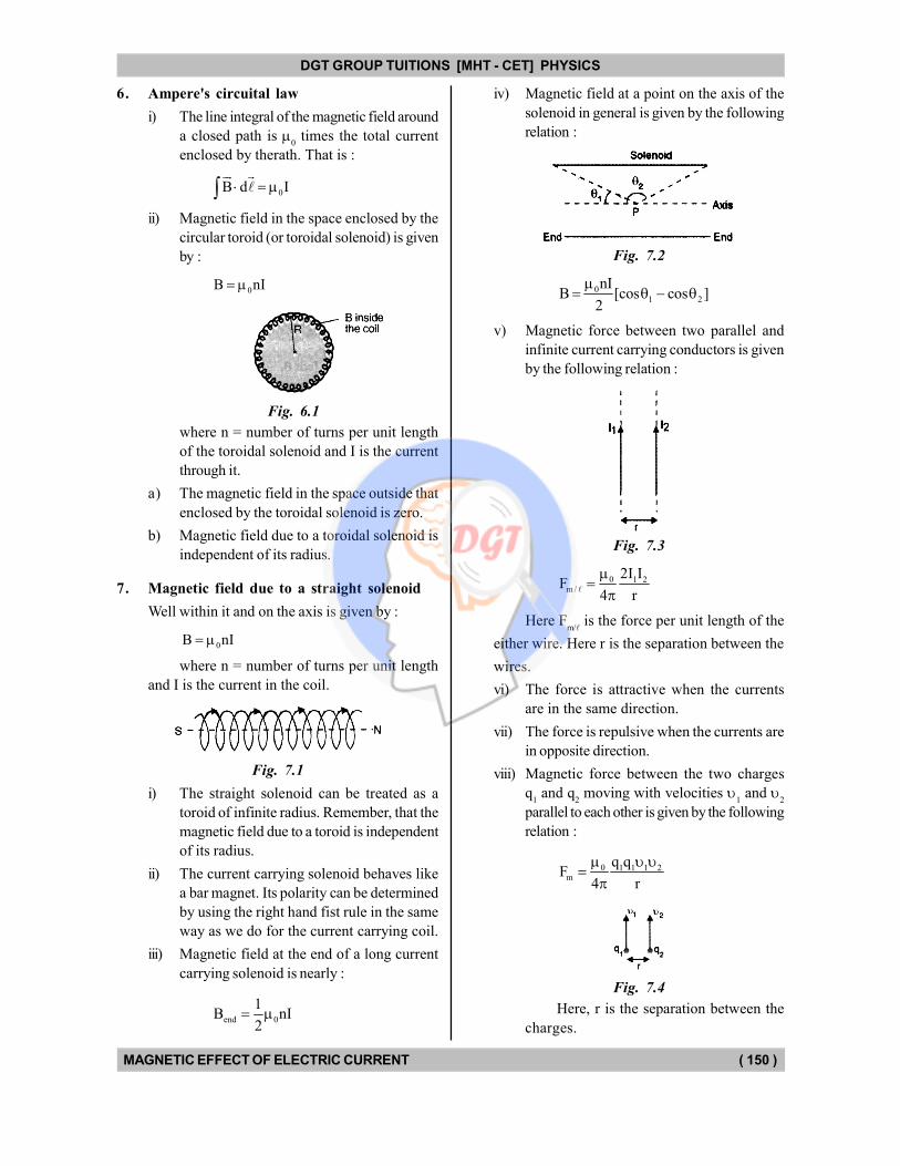
6. Ampere's circuital law
i) The line integral of the magnetic field around
a closed path is 0 times the total current
enclosed by therath. That is :
0B d I
ii) Magnetic field in the space enclosed by the
circular toroid (or toroidal solenoid) is given
by :
0B nI
Fig. 6.1
where n = number of turns per unit length
of the toroidal solenoid and I is the current
through it.
a) The magnetic field in the space outside that
enclosed by the toroidal solenoid is zero.
b) Magnetic field due to a toroidal solenoid is
independent of its radius.
7. Magnetic field due to a straight solenoid
Well within it and on the axis is given by :
0B nI
where n = number of turns per unit length
and I is the current in the coil.
Fig. 7.1
i) The straight solenoid can be treated as a
toroid of infinite radius. Remember, that the
magnetic field due to a toroid is independent
of its radius.
ii) The current carrying solenoid behaves like
a bar magnet. Its polarity can be determined
by using the right hand fist rule in the same
way as we do for the current carrying coil.
iii) Magnetic field at the end of a long current
carrying solenoid is nearly :
end 0
1B nI
2
iv) Magnetic field at a point on the axis of the
solenoid in general is given by the following
relation :
Fig. 7.2
01 2
nIB [cos cos ]
2
v) Magnetic force between two parallel and
infinite current carrying conductors is given
by the following relation :
Fig. 7.3
0 1 2m /
2I IF
4 r
Here Fm/
is the force per unit length of the
either wire. Here r is the separation between the
wires.
vi) The force is attractive when the currents
are in the same direction.
vii) The force is repulsive when the currents are
in opposite direction.
viii) Magnetic force between the two charges
q1 and q
2 moving with velocities
1 and
2
parallel to each other is given by the following
relation :
0 1 1 1 2m
q qF
4 r
Fig. 7.4
Here, r is the separation between the
charges.
DGT Group - Tuitions (Feed Concepts) XIth – XIIth | JEE | CET | NEET | Call : 9920154035 / 8169861448
DGT MH –CET 12th PHYSICS Study Material 5
DGT GROUP TUITIONS [MHT - CET] PHYSICS
MAGNETIC EFFECT OF ELECTRIC CURRENT ( 151 )
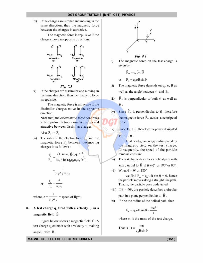
ix) If the charges are similar and moving in the
same direction, then the magnetic force
between the charges is attractive.
The magnetic force is repulsive if the
charges move in opposite directions.
Fig. 7.5
x) If the charges are dissimilar and moving in
the same direction, then the magnetic force
is repulsive.
The magnetic force is attractive if the
dissimilar charges move in the opposite
direction.
Note that, the electrostatic force continues
to be repulsive between similar charges and
attractive between dissimilar charges.
Also e mF F
xi) The ratio of the electric force Fe and the
magnetic force Fm between two moving
charges is as follows :
2
0 1 2e
2
m 0 1 2 1 2
1/ 4 q q / rF
F ( / 4 )(q q / r )
0 0 1 2
1
or
2
e
m 1 2
F c
F
where, c = 0 0
1
= speed of light.
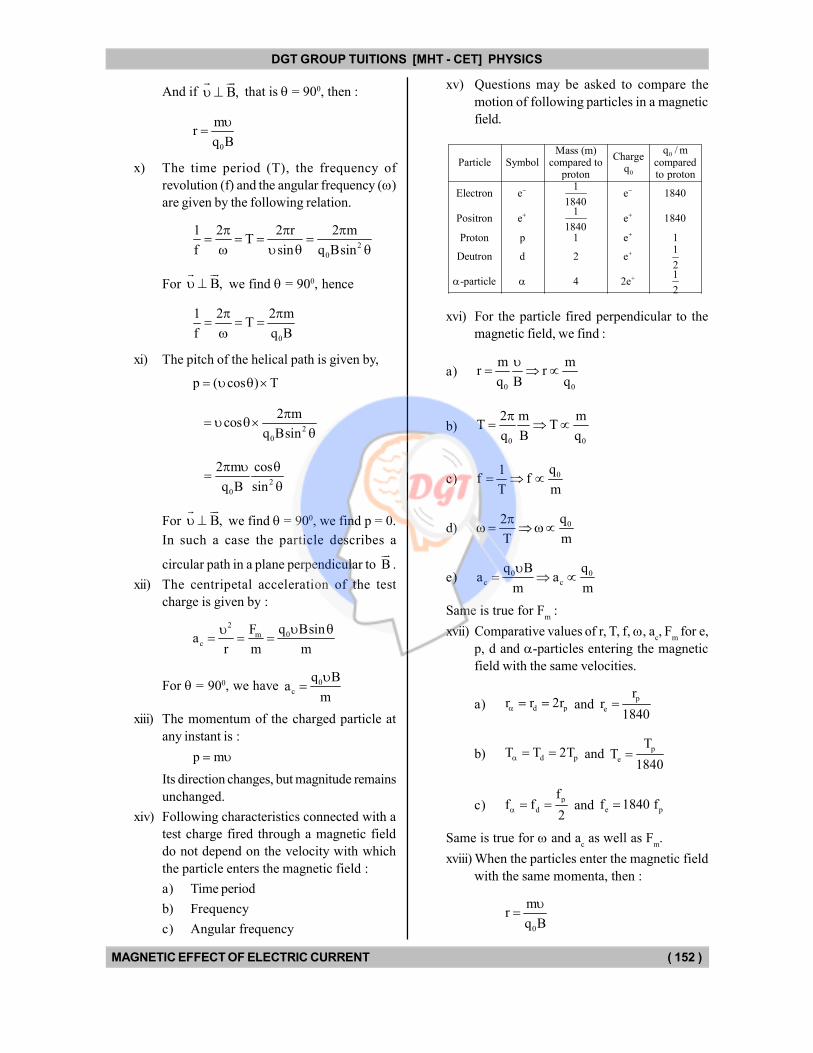
8. A test charge q0 fired with a velocity
in a
magnetic field B
Figure below shows a magnetic field B
. AA
test charge q0 enters it with a velocity
making
angle with B
.
Fig. 8.1
i) The magnetic force on the test charge is
given by :
m 0F q B
orm 0F q Bsin
ii) The magnetic force depends on q0, , B as
well as the angle between
and B
.
iii) mF
is perpendicular to both
as well as
B
.
iv) Since mF
is perpendicular to
, therefore
the magnetic force mF
acts as a centripetal
force.
v) Since mF ,
therefore the power dissipated
mF 0.
That is why, no energy is dissipated by
the magnetic field on the test charge.
Consequently, the speed of the particle
remains constant.
vi) The test charge describes a helical path with
axis parallel to B
if 00 or 1800 or 900.
vii) When = 00 or 1800,
we find Fm = q
0 B sin = 0, hence
the particle moves along a straight line path.
That is, the particle goes undeviated.
viii) If = 900, the particle describes a circular
path in a plane perpendicular to B
.
ix) If r be the radius of the helical path, then
2
m 0
mF q Bsin
r
where m is the mass of the test charge.
That is : 0
mr
q Bsin
DGT Group - Tuitions (Feed Concepts) XIth – XIIth | JEE | CET | NEET | Call : 9920154035 / 8169861448
DGT MH –CET 12th PHYSICS Study Material 6
DGT GROUP TUITIONS [MHT - CET] PHYSICS
MAGNETIC EFFECT OF ELECTRIC CURRENT ( 152 )
And if B,
that is = 900, then :
0
mr
q B
x) The time period (T), the frequency of
revolution (f) and the angular frequency ()
are given by the following relation.
2
0
1 2 2 r 2 mT
f sin q Bsin
For B,
we find = 900, hence
0
1 2 2 mT
f q B
xi) The pitch of the helical path is given by,
p ( cos ) T
2
0
2 mcos
q Bsin
2
0
2 m cos
q B sin
For B,
we find = 900, we find p = 0.
In such a case the particle describes a
circular path in a plane perpendicular to B
.
xii) The centripetal acceleration of the test
charge is given by :
2
0mc
q BsinFa
r m m
For = 900, we have 0c
q Ba
m
xiii) The momentum of the charged particle at
any instant is :
p m
Its direction changes, but magnitude remains
unchanged.
xiv) Following characteristics connected with a
test charge fired through a magnetic field
do not depend on the velocity with which
the particle enters the magnetic field :
a) Time period
b) Frequency
c) Angular frequency
xv) Questions may be asked to compare the
motion of following particles in a magnetic
field.
0
0
q / mMass (m)Charge
Particle Symbol compared to comparedq
proton to proton1
Electron e e 18401840
1Positron e e 1840
1840Proton p 1 e 1
1Deutron d 2 e
21
-particle 4 2e2
xvi) For the particle fired perpendicular to the
magnetic field, we find :
a)0 0
m mr r
q B q
b)0 0
2 m mT T
q B q
c) 0q1f f
T m
d) 0q2
T m
e) 0 0c c
q B qa a
m m
Same is true for Fm :
xvii) Comparative values of r, T, f, , ac, F
m for e,
p, d and -particles entering the magnetic
field with the same velocities.
a) d pr r 2r and p
e
rr
1840
b) d pT T 2T and p
e
TT
1840
c)p
d
ff f
2 and e pf 1840 f
Same is true for and ac as well as F
m.
xviii) When the particles enter the magnetic field
with the same momenta, then :
0
mr
q B
DGT Group - Tuitions (Feed Concepts) XIth – XIIth | JEE | CET | NEET | Call : 9920154035 / 8169861448
DGT MH –CET 12th PHYSICS Study Material 7
DGT GROUP TUITIONS [MHT - CET] PHYSICS
MAGNETIC EFFECT OF ELECTRIC CURRENT ( 153 )
That is 0
1r ,
q because
m
B
is constant.
Hence, ae p d
rr r r
2
9. Cyclotron
The cyclotron consists of two dees, placed in a
strong magnetic field. Oscillating electric field is
applied to the two dees from an oscillator. The
magnetic field is perpendicular to the electric field.
The electric field exists only across the gap
between the dees.
i) The charged particles are accelerated while
crossing the gap and move along circular
paths of radius.
0
mr
q B
This happens in accordance with the
description of motion of the charged particle
in the previous section.
ii) As the charged particle is accelerated while
crossing the gap its kinetic energy increases
and the radius of the circular path also
increases.
But the frequency of revolution remains
unchanged so long as mass remains constant.
iii) Cyclotron cannot be used to accelerate the
electrons because, the electrons move with
velocities very near the velocity of light.
Hence appreciable increase in mass occurs
according to the relation :
0
2 2
mm
1 / c
Hence, the frequency of revolution also
changes.
10. Motion of charged particle in electric field
i) When a charged particle is fired in an electric
field E,
the force acting on the test charge
q0 is given by :
e 0F q E
ii) eF
is either parallel to E
when q0 is +VE
or opposite to E
when q0 is –VE.
iii) Suppose the instantaneous velocity of the
particle is
. Then it is found that Fe is
independent of .
iv) The particle goes undeviated through E
if
the angle between
and E
is 00 or 1800.
v) The charged particle describes a parabolic
path in E
when the angle between
and
E
is other than 00 or 1800.
vi) The particle gains or loses energy as follows :
00 0
0 0
0 0
0 0
0 0
Angle betweenNature of Gain or losscharge (q ) of energy and E ( )
+VE 90 90 Gain
+VE 90 270 Loss
VE 90 90 Loss
VE 90 270 GainNeither gain
+VE or VE = 90 or 270nor loss
11. Motion of the charged particle in magnetic
and electric fields.
Case I.
When , E and B
all the three are collinear..
In this case, the charged particle is moving parallel
or antiparallel to the fields, the magnetic force on
the charged particle is zero. The electric force
on the charged particle will produce acceleration.
qEa
m
As a result of electric force there will be
change in the speed of the charged particle along
the direction of the field. There will be no change
in the direction of motion of the charged particle
but speed, velocity, momentum and kinetic energy
will change.
Case II.
When , E and B
are mutually perpendicular
to each other.
If E & B
are such that, e mF F F 0,
then acceleration of the particle, F
a 0.m
It
means particle will pass through the fields without
any change in its velocity. Here
e mF F , So qE q B or E
B
DGT Group - Tuitions (Feed Concepts) XIth – XIIth | JEE | CET | NEET | Call : 9920154035 / 8169861448
DGT MH –CET 12th PHYSICS Study Material 8
DGT GROUP TUITIONS [MHT - CET] PHYSICS
MAGNETIC EFFECT OF ELECTRIC CURRENT ( 154 )
This concept is used in velocity selector to get a
charged beam having a definite velocity.
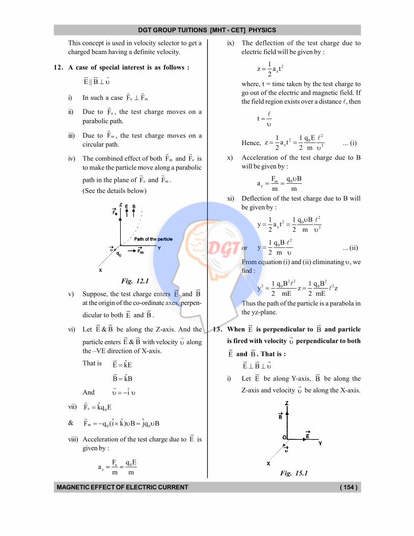
12. A case of special interest is as follows :
E || B
i) In such a case e mF F
ii) Due to eF
, the test charge moves on a
parabolic path.
iii) Due to mF
, the test charge moves on a
circular path.
iv) The combined effect of both mF
and eF
is
to make the particle move along a parabolic
path in the plane of eF
and mF
.
(See the details below)
Fig. 12.1
v) Suppose, the test charge enters E
and B
at the origin of the co-ordinate axes, perpen-
dicular to both E
and B
.
vi) Let E & B
be along the Z-axis. And the
particle enters E & B
with velocity
along
the –VE direction of X-axis.
That is ˆE kE
ˆB kB
And i
vii) e 0ˆF kq E
& m 0 0ˆ ˆ ˆF q (i k) B jq B
viii) Acceleration of the test charge due to E
is
given by :
e 0z
F q Ea
m m
ix) The deflection of the test charge due to
electric field will be given by :
2
z
1z a t
2
where, t = time taken by the test charge to
go out of the electric and magnetic field. If
the field region exists over a distance , then
t
Hence,
22 0
z 2
q E1 1z a t
2 2 m
... (i)
x) Acceleration of the test charge due to B
will be given by :
0my
q BFa
m m
xi) Deflection of the test charge due to B will
be given by :
22 0
y 2
q B1 1y a t
2 2 m
or
2
0q B1y
2 m
... (ii)
From equation (i) and (ii) eliminating , we
find :
2 2 22 20 0q B q B1 1
y z z2 mE 2 mE
Thus the path of the particle is a parabola in
the yz-plane.
13. When E
is perpendicular to B
and particle
is fired with velocity
perpendicular to both
E
and B
. That is :
E B
i) Let E
be along Y-axis, B
be along the
Z-axis and velocity
be along the X-axis.
Fig. 15.1
DGT Group - Tuitions (Feed Concepts) XIth – XIIth | JEE | CET | NEET | Call : 9920154035 / 8169861448
DGT MH –CET 12th PHYSICS Study Material 9
DGT GROUP TUITIONS [MHT - CET] PHYSICS
MAGNETIC EFFECT OF ELECTRIC CURRENT ( 155 )
ii) Then, e 0 0ˆF q E jq E
& m 0 0ˆF q B jq B
iii) e mF & F
are directed opposite to each other,,
hence they can cancel each other. In such
a case the test charge goes undeviated. For
such a case, we have
0 0q B q E
Hence, E
B
14. Galvanometers
Galvanometer is an instrument to detect
electric current. It can also be used to measure
potential difference or current strength by suitable
modification and calibration.
i) Types of galvanometers.
On the basis of principle of operation,
galvanometers are categorised as follows :
a) Moving magnet galvanometer.
Which operates on the basis of torque
acting on small permanent bar magnet due
to the magnetic field produced by the current
in a circular coil. In it magnet moves and
current carrying coil is stationary. Such a
galvanometer is also called moving iron type.
b) Moving coil galvanometer.
Which operates on the basis of torque
acting on a current carrying coil due to the
magnetic field of a permanent magnet. In it,
the current carrying coil moves and the
magnet is stationary.
Moving coil galvanometers are further
divided into two types, on the basis of
construction, as follows :
D' Arsonaval type galvanometer.
In it the coil is suspended from a
torsion head (support) with the help of a
phosphor bronze wire. The deflection is
noted with the lamp and scale arrangement.
It was designed by Kelvin and then modified
by D' Arsonaval.
Weston type galvanometer.
In it the coil is pivoted. The deflection
is noted with the help of a pointer and hence
it is also called pointer type galvanometer.
It was designed by Dr. Weston.
ii) The current through the moving coil galvano-
meter is given by :
cI
nAB ... (i)
where, c = torsional couple per unit
twist of the suspension wire, n = number of
turns, A = area of cross-section of the coil,
B = magnetic field in which the coil rotates
and = angle of deflection.
15. Current sensitivity of a moving coil galvano-
meter.
The deflection per unit current is called
current sensitivity of the galvanometer.
Suppose, a current I produces deflection in the galvanometer.
Then, current sensitivity is given by :
II
From equation (i), we find
1
nAB nAB or
I c c
Thus, current sensitivity of, the galvanometer
is directly proportional to the number of turns,
area of the coil and magnetic field in which the
coil is placed. Also, it is inversely proportional to
the torsional rigidity 'c' of the suspension wire.
In practice n and A cannot be increased
beyond a certain limit. So, to increase the current
sensitivity we make B as large as possible.
The 1 should be large for a good quality
galvanometer. In sensitive galvanometer quartz
fibre is used as a suspension wire for which c is
very small.
16. Voltage sensitivity
The deflection per unit potential difference or
voltage applied across the terminals of the
galvanometer is called voltage sensitivity.
If, be the deflection in the galvanometer
when the potential difference applied across it is
V, then voltage sensitivity is given by :
V
But V = IG where G is the resistance of the
galvanometer.
DGT Group - Tuitions (Feed Concepts) XIth – XIIth | JEE | CET | NEET | Call : 9920154035 / 8169861448
DGT MH –CET 12th PHYSICS Study Material 10

DGT GROUP TUITIONS [MHT - CET] PHYSICS
MAGNETIC EFFECT OF ELECTRIC CURRENT ( 156 )
Hence we find :
1
1 q nAB
IG G G c
Thus, voltage sensitivity
1 Current sensitivity
Resistance
Voltage sensitivity depends upon the same factors
on which current sensitivity does.
17. Ammeter
Is an instrument for measuring current. It is a
low resistance galvanometer, so that its
inclusion in the circuit does not substantially
affect the current.
It is obtained from a galvanometer by connecting
a suitable shunt across the galvanometer.
Converting a galvanometer into ammeter.
Suppose, we wish to have an ammeter to
measure a current in the range 0 to I. Let G be
the resistance of the galvanometer and Ig be the
current that produces maximum possible
deflection in the galvanometer. Let S be the
resistance of the shunt. (See figure below).
When the current through the ammeter is I,
the current through the galvanometer should be
Ig, so that the deflection is maximum. When this
happens, the potential drop across the
galvanometer = potential drop across the shunt.
That is :
Fig. 17.1
g gI G (I I )S
This gives, g
g
IS G
I I
Thus, S can be calculated and the given
galvanometer can be converted into ammeter, by
connecting a shunt S across it.
18. Voltmeter
Is an instrument for measuring potential
difference. It is a high resistance galvanometer,
so that its inclusion in the circuit does not affect
the potential difference in the circuit. It is obtained
by connecting a high resistance in series with a
galvanometer.
Converting a galvanometer into a voltmeter.
Suppose, we wish to have a voltmeter to
measure potential difference in the range of 0 to
V. Let G be the resistance of the galvanometer
and Ig be the current that produces maximum
possible deflection in the galvanometer. We
connect a resistance R in series with the
galvanometer, so that when potential difference
across the combinations is V, the current through
the galvanometer is Ig. (See fig. below) Applying
Ohm's law we find : V = Ig (R + G). That is :
Fig. 18.1
g gV I G I R
This gives, g
g g
V I G VR G
I I
Thus, R can be calculated and given galvanometer
can be converted into a voltmeter by connecting
R in series with it.
19. Increasing the range of ammeter
Suppose, the resistance of an ammeter of
range I1 is G
A. Its range can be increased to I
2
by connecting a shunt S1 across it. The value of
S1 is given by,
11 A
2 1
IS G
I I
a) This process is similar to the conversion of
a galvanometer into ammeter.
Here Ig = I
1, G = G
A and I = I
2.
b) If 2 1I nI , then A
1
GS
n 1
.
DGT Group - Tuitions (Feed Concepts) XIth – XIIth | JEE | CET | NEET | Call : 9920154035 / 8169861448
DGT MH –CET 12th PHYSICS Study Material 11
DGT GROUP TUITIONS [MHT - CET] PHYSICS
MAGNETIC EFFECT OF ELECTRIC CURRENT ( 157 )
20. Increasing the range of a voltmeter
Suppose the resistance of a voltmeter of
range V1 is G
. Its range can be increased to V
2
by connecting a resistance R1 in series with it.
The value of R1 is given by :
2 2 11
1 1
V V VR G G
(V / G ) V
a) Here Ig is equivalent to :
1V.
G
That is : 1g
VI
G
Also, the process is equivalent to the
conversion of a galvanometer into voltmeter
of range V2 and G = G
.
b) If 2 1V nV , then
1R (n 1)G .
21. Converting an ammeter into a voltmeter
Suppose, we have an ammeter of range I
and resistance GA. It can be converted into a
voltmeter of range V, by connecting a resistance
R in series with it. The value of R is given by :
A
VR G
I
22. Converting a voltmeter into ammeter
Suppose, we have a voltmeter of range V
and resistance G. To convert it into an ammeter
of range I, we need to connect a shunt S across
it. The value of shunt is given by :
VG
G VGS
I V IG V
G
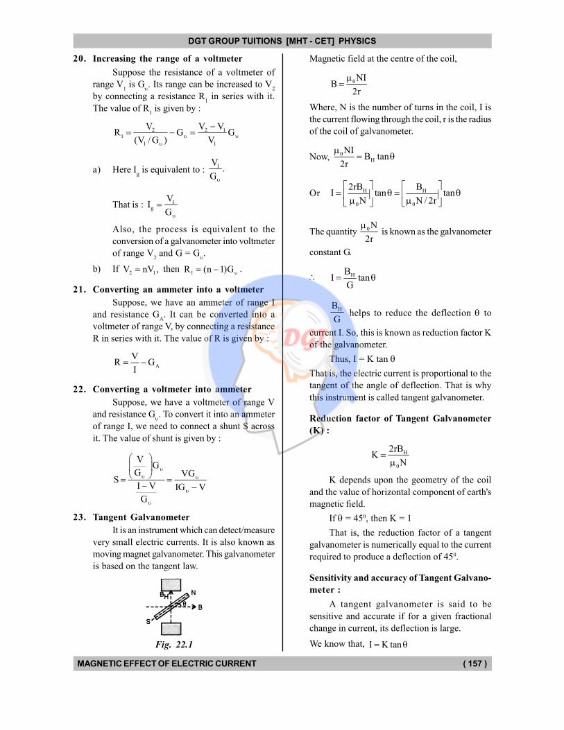
23. Tangent Galvanometer
It is an instrument which can detect/measure
very small electric currents. It is also known as
moving magnet galvanometer. This galvanometer
is based on the tangent law.
Fig. 22.1
Magnetic field at the centre of the coil,
0NIB
2r
Where, N is the number of turns in the coil, I is
the current flowing through the coil, r is the radius
of the coil of galvanometer.
Now, 0H
NIB tan
2r
Or H H
0 0
2rB BI tan tan
N N / 2r
The quantity 0N
2r
is known as the galvanometer
constant G.
HBI tan
G
HB
G helps to reduce the deflection to
current I. So, this is known as reduction factor K
of the galvanometer.
Thus, I = K tan
That is, the electric current is proportional to the
tangent of the angle of deflection. That is why
this instrument is called tangent galvanometer.
Reduction factor of Tangent Galvanometer
(K) :
H
0
2rBK
N
K depends upon the geometry of the coil
and the value of horizontal component of earth's
magnetic field.
If = 450, then K = 1
That is, the reduction factor of a tangent
galvanometer is numerically equal to the current
required to produce a deflection of 450.
Sensitivity and accuracy of Tangent Galvano-
meter :
A tangent galvanometer is said to be
sensitive and accurate if for a given fractional
change in current, its deflection is large.
We know that, I K tan
DGT Group - Tuitions (Feed Concepts) XIth – XIIth | JEE | CET | NEET | Call : 9920154035 / 8169861448
DGT MH –CET 12th PHYSICS Study Material 12
DGT GROUP TUITIONS [MHT - CET] PHYSICS
MAGNETIC EFFECT OF ELECTRIC CURRENT ( 158 )
Differentiating, we get,
2dI Ksec d
2
2
dI sec d cos d
I tan cos sin
d
sin cos
2d
sin 2
orsin 2 dI
d2 I
d will be maximum if sin 2 is maximum
i.e., 1. This is possible when 2 = 900.
or = 450
Therefore, the tangent galvanometer has
maximum sensitivity when the deflection is 450.
DGT Group - Tuitions (Feed Concepts) XIth – XIIth | JEE | CET | NEET | Call : 9920154035 / 8169861448
DGT MH –CET 12th PHYSICS Study Material 13

DGT Group - Tuitions (Feed Concepts) XIth – XIIth | JEE | CET | NEET | Call : 9920154035 / 8169861448
DGT MH –CET 12th PHYSICS Study Material 14

DGT GROUP TUITIONS [MHT - CET] PHYSICS
MAGNETIC EFFECT OF ELECTRIC CURRENT ( 159 )
Magnetic Field
1. The magnetic field at the centre of the current
carrying coil :
a) is directed normal to the plane of coil
b) is directed parallel to the plane of the coil
c) is zero
d) has none of the above characteristics
2. An electron is fired parallel to uniform electric
and uniform magnetic fields acting simultaneously
and in the same direction. The electron :
a) gains energy
b) loses energy
c) moves along circular path
d) moves along a parabolic path
3. The magnetic field due to a current element is
independent of :
a) current through it
b) distance from it
c) its length d) none of the above
4. The unit of current element is :
a) Am–1 b) Am
c) Am2 d) Am–2
5. Magnetic field B on the axis of a circular coil far
away at distance x from the centre of the coil
are related as :
a) 3B x b)
2B x
c) 1B x d) none of the above
6. Two concentric coils carry the same current in
opposite directions. The diameter of the outer coil
is twice as compared to the inner coil. If at its
centre, the smaller coil produces a magnetic field
of 2 T, then, the magnetic field at the common
centres is :
a) 4 T b) 3 T
c) 2 T d) 1 T
7. An electron enter a region of space in which there
exist an electric field E and magnetic field B. If
the electron continues to move with the same
velocity in the same direction as before, which of
the following is NOT possible ?
a) E 0, B 0 b) E 0, B 0
c) E 0, B 0 d) E 0, B 0
MULTIPLE CHOICE QUESTIONS
8. A solenoid of 2.5 metre length and 2.0 cm diameter
possesses 10 turns per cm. A current of 0.5 ampere
is flowing through it. The magnetic induction at
axis inside the solenoid is :
a) 2 10–4 tesla b) 2 10–5 tesla
c) 2 10–6 tesla d) 2 10–7 tesla
9. A long wire carries a steady current. It is bent
into a circle of one turn and the magnetic field at
the centre of the coil is B. It is then bent into a
circular loop of n turns. The magnetic field at the
centre of the coil will be :
a) n B b) n2 B
c) 2 nB d) 2 n2B
10. What will be the value of the magnetic field
induction at the centre of the coil, if 1= 2 A,
h = 10 cm in the following figure ?
Fig. 10.1
a) 51.14 10 T
b) 5
0
41.14 10 T
c) 51.14
10 T4
d) 50 2.14 10 T
4
11. An infinite long straight wire is bent into a
semicircle of radius R, as shown in the figure. A
current I is sent through the conductor. The
magnetic field at the centre of the semicircle is :
Fig. 11.1
a) infinite b) zero
c) 0 I
4 R
d)
0 I( 1)
4 R
Magnetic Force
12. The torque acting on a magnetic dipole of moment
mP
when placed in a magnetic field B is :
a) pm B b) mP B
c) mP B
d) given by none of the above
DGT Group - Tuitions (Feed Concepts) XIth – XIIth | JEE | CET | NEET | Call : 9920154035 / 8169861448
DGT MH –CET 12th PHYSICS Study Material 15

DGT GROUP TUITIONS [MHT - CET] PHYSICS
MAGNETIC EFFECT OF ELECTRIC CURRENT ( 160 )
13. A magnetic field exerts no force on :
a) stream of electrons
b) stream of proton
c) unmagnetised piece of iron
d) stationary charge
14. A current carrying coil is placed in an uniform
magnetic field, with its plane parallel to the
magnetic field. If the coil turns through angle ,
the torque and are related as :
a) sin b) cos
c) tan d) cot
15. A charge is fired through a magnetic field. The
force acting on it is maximum when the angle
between the direction of motion and magnetic
field is :
a) zero b) 4
c) 2
d)
16. The force on a current carrying conductor in a
magnetic field is maximum, when angle between
current and magnetic field is :
a) zero b) 4
c) 2
d)
3
4
17. No force is exerted by a magnetic field on a
stationary :
a) current loop
b) electric dipole
c) magnetic dipole
d) current carrying conductor
18. A straight wire 5 m long is placed parallel to an
infinitely long straight wire carrying current 5 A.
The distance between the two wires is 10 cm
and the 5 m long wire is carrying current 2 A.
The force on the shorter wire is :
a) 30 10 N
4
b) 103 N
c) 70 10 N
4
d) 10–7 N
Cyclotron
19. A cyclotron can be used to produce high energy :
a) -particle b) -particles
c) neutrons d) atoms
20. A cyclotron cannot be used to accelerate the :
a) protons b) ions
c) electrons d) -particles
21. What limits the energy that can be imparted to
charged particle in a cyclotron ?
a) Charge
b) Variation in mass with velocity
c) The gap between the dees
d) Some factor other than those mentioned above
22. A beam of a-particles having specific charge
2.5 107 C kg–1 moves with a speed of 2 105
m s–1 in a magnetic field of 0.05 T. What is
the radius of the circular path described by the
-particle ?
a) 4 cm b) 8 cm
c) 16 cm d) 32 cm
23. An -particle describes a circular path of radius
r in a magnetic field B. What will be the radius of
the circular path described by the proton of same
energy in the same magnetic field ?
a) r
2b) r
c) 2 d) 2 r
Galvanometer
24. Which one of the following is NOT the name of
a category of galvanometers ?
a) Moving coil b) Moving magnet
c) Moving field d) Moving iron
25. The ratio of earth's magnetic field and galvano-
meter constant for the tangent galvanometer is
called reduction factor because it reduces the :
a) magnetic field of earth
b) magnetic field of the coil
c) deflection of the magnet
d) tangent of deflection to current
26. To increase the range of a voltmeter we need to
connect a suitable :
a) high resistance in series
b) high resistance in parallel
DGT Group - Tuitions (Feed Concepts) XIth – XIIth | JEE | CET | NEET | Call : 9920154035 / 8169861448
DGT MH –CET 12th PHYSICS Study Material 16

DGT GROUP TUITIONS [MHT - CET] PHYSICS
MAGNETIC EFFECT OF ELECTRIC CURRENT ( 161 )
c) low resistance in series
d) low resistance in parallel
27. To measure the resistance of a device using
Ohm's law, which of the following mode of
connection is used ?
a) Ammeter in series, voltmeter in parallel
b) Voltmeter in series, ammeter in parallel
c) Both ammeter and voltmeter in series
d) Both ammeter and voltmeter in parallel
28. Which of the following is correct statement ?
a) Ammeter is a high resistance galvanometer and
voltmeter is a low resistance galvanometer
b) Ammeter is a low resistance galvanometer and
voltmeter is a high resistance galvanometer
c) Ammeter and voltmeter cannot be distinguished
on the basis of their resistance
d) None of the above
29. The magnetic field in case of the moving coil
galvanometer should be radial so that current I
through the coil and its deflection are related to
each other as :
a) I tan b) I log
c) I d) I e
30. To increase the range of an ammeter, we need to
connect a suitable :
a) low resistance in parallel
b) low resistance in series
c) high resistance in parallel
d) high resistance in series
31. Why should the plane of the coil of tangent
galvanometer be parallel to the magnetic meridian?
a) To avoid the influence of earth's magnetic field
b) To increase the magnetic field due to the
current in the coil
c) To make earth's magnetic field perpendicular
to that due to the current in the coil
d) For some other reason
32. A galvanometer may be converted into ammeter
or a voltmeter. In which of the following cases
the resistance of the device so obtained will be
the largest ?
a) Ammeter of range 1 A
b) Ammeter of range 10 A
c) Voltmeter of range 1 V
d) Voltmeter of range 10 V
33. In the above question which device will have the
least resistance ?
a) Ammeter of range 1 A
b) Ammeter of range 10 A
c) Voltmeter of range 1 V
d) Voltmeter of range 10 V
34. On which of the following effects of current, is
the moving coil galvanometer based ?
a) Heating effect
b) Chemical effect
c) Magnetic effect
d) Thermoelectric effect
35. Which of the following relations is directly
applicable to the moving coil galvanometer ?
a) m
p B
b) 0B B tan
c) m 0F q B
d) none of the above
36. What is the relation between voltage sensitivity
and the current sensitive
1 of a moving coil
galvanometer ? Given that G is the resistance of
the galvanometer.
a) 1G b)
1
G
c) 1 G d) one of the above
37. The sensitivity of a moving coil galvanometer
increases with the decrease in :
a) number of turns b) area of coil
c) magnetic field d) none of the above
38. Best method to increase the sensitivity of the
moving coil galvanometer is to increase :
a) radius of the coil
b) number of turns of the coil
c) external magnetic field
d) none of the above
39. A voltmeter of range 3 V and resistance 200 cannot be converted to an ammeter of range :
a) 10 mA b) 100 mA
c) 1 A d) 10 A
40. In an ammeter 4% of the mains current is passing
through galvanometer. If the galvanometer is
shunted with a 5 resistance. What is the
resistance of the galvanometer ?
a) 4 b) 5
c) 20 d) 120
DGT Group - Tuitions (Feed Concepts) XIth – XIIth | JEE | CET | NEET | Call : 9920154035 / 8169861448
DGT MH –CET 12th PHYSICS Study Material 17
DGT GROUP TUITIONS [MHT - CET] PHYSICS
MAGNETIC EFFECT OF ELECTRIC CURRENT ( 162 )
41. A galvanometer of resistance 100 gives full
scale deflection with 0.01 A current. How much
resistance should be connected in parallel with it
to convert it into an ammeter of range 10 A ?
Give the value up to 3 significant figures.
a) 0.100 b) 1.00
c) 10.0 d) none of the above
42. A voltmeter has resistance R0 and range V. What
resistance should be connected in series with it
to increase its range to nV ?
a) nR0
b) 0(n 1)R
c) 0(n 1)R d)
0R
n
43. To reduce the range of voltmeter, its resistance
need to be reduced. A voltmeter has resistance
R0 and range V. Which of the following resi tance
when connected in parallel will convert it into a
voltmeter of range V
?n
a) nR0
b) 0(n 1)R
c) 0(n 1)R d) none of these
44. An ammeter has resistance R0 and range I. What
resistance hould be connected in parallel with it
to increase its range to n ?
a) 0R
nb)
0R
(n 1)
c) 0R (n 1) d) none of the above
45. To decrease the range of an ammeter its resistance
need to be increased. An ammeter has resistance
R0 and range I. Which of the following resistance
can be connected In series with it to decrease its
range to I/n.
a) 0R
nb)
0R
(n 1)
c) 0R
(n 1) d) none of the above
46. When we shunt a galvanometer with a resistance
of 20 its deflection is reduced to half. What is
the resistance of the galvanometer ?
a) 80 b) 40
c) 20 d) 10
47. An ammeter is obtained by shunting a 30 galvanometer with a 30 resistance. What
additional shunt should be connected across it to
double its range ?
a) 10 b) 15
c) 30 d) none of the above
48. What resistance should be connected in series
with a 0.5. A ammeter to convert it into a 15 V
voltmeter. Given that the resistance of the ammeter
is 2 ?
a) 2 b) 5
c) 15 d) none of the above
49. A galvanometer gives full scale deflection when
the current passed through it is 1 mA. lts resistance
is 100 . Without shunting it, as such, it can be
used as an ammeter of range :
a) 1.000 A b) 0.100 A
c) 0.010 A d) 0.001 A
50. A galvanometer gives full scale deflection when
the current passed through it is 1 mA. Its resistance
is 100 . Without connecting additional resistance
in series with it, it can be used as a voltmeter of
range :
a) 1.000 V b) 0.100 V
c) 0.010 V d) 0.001 V
51. The sensitivity of a galvanometer is 60 divisions
per ampere. When a shunt is used its sensitivity
becomes 10 divisions per ampere. If the galvano-
meter is of 20 resistance, the value of the shunt
is :
a) 2 b) 4
c) 5 d) 8
52. An ammeter of range 100 mA has a resistance
of 2 ohm. What resistance should be connected
in series with it to use it as a voltmeter of range
1 volt ?
a) 8 b) 12
c) 16 d) 24
53. A galvanometer of resistance 200 ohm gives a
full scale deflection for a current of 10–3 ampere.
To convert it into an ammeter capable of measuring
upto one ampere, what resistance should be
connected in parallel with it ?
a) 2 10–6 ohm b) 2 10–3 ohm
c) 2 10–1 ohm d) 2 ohm
DGT Group - Tuitions (Feed Concepts) XIth – XIIth | JEE | CET | NEET | Call : 9920154035 / 8169861448
DGT MH –CET 12th PHYSICS Study Material 18

DGT GROUP TUITIONS [MHT - CET] PHYSICS
MAGNETIC EFFECT OF ELECTRIC CURRENT ( 163 )
54. An ammeter A, a voltmeter V and a resistance
R are connected as shown in the figure. If the
voltmeter reading is 1.6 V and the ammeter
reading is 0.4 ampere then R is :
Fig. 54.1
a) Equal to 4 ohm
b) Equal to 5 ohm
c) Less than 4 ohm
d) Between 4 ohm and 5 ohm
55. If 10% of the main current is to the passed through
the moving coil galvanometer of resistance
99 ohm, then the required shunt resistance will
be :
a) 9.9 ohm b) 10 ohm
c) 11 ohm d) 9 ohm
56. A galvanometer of resistance 200 ohm gives full
scale deflection with 15 rnilli ampere current. In
order to convert it into a 15 volt range voltmeter,
the value of resistance connected in series is :
a) 800 ohm b) 1000 ohm
c) 1500 ohm d) 2500 ohm
57. A voltmeter of range 5 V is to be converted into
an ammeter of range 10 mA. If the resistance of
voltmeter is 1 k, then what resistance should
be connected in parallel with it ?
a) 0.2 k b) 0.5 k
c) 0.8 k d) 1.0 k
58. An ammeter of range 5 A is to be converted into
a voltmeter of range 10 V. If the resistance of
ammeter be 0.1 , then what resistance should
be converted in series with it ?
a) 1.1 b) 1.9
c) 2.1 d) 4.9
Recent Questions from MH-CET Exams.
59. When a galvanometer of resistance G is converted
into an ammeter of range IA then the current
passing through the galvanometer is given by :
a) g
SI I
S G
b) g
GI I
S G
c) g
S GI I
S
d) g
S GI I
G
60. A voltmeter has a resistance of G and a range
of V volts. The value of the resistance used in
series with it to convert it into voltmeter of range
nv volts is :
a) nG b) (n – 1) G
c) G
nd)
G1
n
61. Two tangent galvanometers are connected in
series and a current is passed through them. The
deflections recorded are 450 and 600. K1 and K
2
respectively are their reduction factors K1
: K2
is :
a) 1.732 : 1 b) 1.414 : 1
c) 1 : 2 d) 1 : 3
62. A tangent galvanometer is an instrument to
measure :
a) electric voltage
b) magnetic field
c) electric current
d) tangent of any geometrical angle
63. A wire of length L is bent into a circle and a current
I is passed through it. Next, the same wire is bent
into a coil of three turns and the same current is
passed through it. The magnetic induction at the
centre now, as compared to its value in the first
case is :
a) 1
9b)
1
3
c) Thrice d) Nine times
64. A moving coil galvanometer (sensitivity = 200
div/A) is connected in series with a tangent galv-
anometer. On passing a current, the galvanometer
shows a deflection of 15 divisions while the
tangent galvanometer shows a deflection of 450.
The reduction factor of tangent galvanometer is :
a) 7.5 10–3 A b) 7.5 10–4 A
c) 75 10–3 A d) 30 10–4 A
65. If 36 is resistance of galvanometer and 12 is resistance of combination of galvanometer and
shunt, the value of shunt is :
a) 16 b) 19
c) 18 d) 20
DGT Group - Tuitions (Feed Concepts) XIth – XIIth | JEE | CET | NEET | Call : 9920154035 / 8169861448
DGT MH –CET 12th PHYSICS Study Material 19
DGT GROUP TUITIONS [MHT - CET] PHYSICS
MAGNETIC EFFECT OF ELECTRIC CURRENT ( 164 )
66. When 2 A current is passed through a tangent
galvanometer, it gives a deflection of 300. For 600
deflection, the current must be :
a) 1 A b) 2 3 A
c) 4 A d) 6 A
67. Accuracy of tangent galvanometer is maximum
for :
a) 450 b) 900
c) 00 d) 300
68. A voltmeter has a resistance of G ohm and range
V volt. The value of resistance used in series to
convert it into a voltmeter of range nV volt is :
a) nG b) G / n
c) (n 1)G d) G
n 1
69. The tangent galvanometers having coils of the
same radius are connected in series. Same current
flowing in them produces deflections of 600 and
450 respectively. The ratio of the number of tums
in the coil is :
a) 4
3b)
3 1
1
c) 3 1
3 1
d)
3
1
70. In ballistic galvanometer, the frame on which the
coil is wound is non-metallic to :
a) avoid the production of induced emf
b) avoid the production of eddy currents
c) increase the production of eddy currents
d) increase the production of induced emf
71. Which of the following is / are the units of strength
of magnetic field at a point ?
a) NA m–1 b) NAm
c) NA–1 m–1 d) NA–2 m–2
72. A wire of length L metre carrying current I ampere
is bent in the form of a circle. What is the magnitude
of magnetic dipole moment ?
a)
2IL
4b)
2 2I L
4
c)
2I L
8d)
2IL
8
73. The current sensitivity of moving coil galvanometer
is given by :
a) C
NIABb)
C
NAB
c) NAB
Cd)
NIAB
C
74. In an electron gun, electron accelerates through
a potential difference V. If the electron has charge
'e' and mass 'm then maximum velocity is :
a) 2V
mb)
m
e
V
c) 2eV
md) none of these
75. The difference in potential of 2 points lying on
the axis of a short bar magnet of moment 3 Am2
at the distance of 50 cms & 100 cms respectively
from its centre is :
a) 9 107 J/Am b) 8 10–7 J/Am
c) 9 10–7 J/Am d) 8 107 J/Am
76. The deflection in a moving coil galvanometer falls
from 50 divisions to 10 divisions, when a shunt of
12 is applied. The resistance of galvanometer
coil is :
a) 12 b) 24 c) 48 d) 50
77. Deflection of 450 produces current 173.2 mA in
a T.G., then how much current will give deflection
of 300 :
a) 10 mA b) 1 mA
c) 100 mA d) 173.2 mA
78. In a M.C.G., the sensitivity can be increased by :
a) increasing the effective area of coil
b) decreasing the magnetic field induction
c) decreasing the number of tums of coil
d) increasing the restoring torque per unit twist
79. For an ammeter, shunt resistance is given by :
a)R
Sn 1
in parallel
b)R
Sn 1
in series
c) S R(n 1) in parallel
d) S R(n 1) in series
DGT Group - Tuitions (Feed Concepts) XIth – XIIth | JEE | CET | NEET | Call : 9920154035 / 8169861448
DGT MH –CET 12th PHYSICS Study Material 20

DGT GROUP TUITIONS [MHT - CET] PHYSICS
MAGNETIC EFFECT OF ELECTRIC CURRENT ( 165 )
80. A circular coil of 100 turns and cross-sectional
1 cm2 is wound to an inductor of 1 mH. If current
through the coil is 2 A, then, Bcentre
= ?
a) 0.2 T b) 0.4 T
c) 0.8 T d) 1 T
81. Sensitivity of moving coil galvanometer is increased
by 25%, then the number of turns is to be changed
from 28 to :
a) 24 b) 28
c) 35 d) 42
82. The current sensitivity of a galvanometer is x
div/mA and voltage sensitivity is y div/V. The
resistance of galvanometer is g. Then relation
between x and y is :
a) 3xG 10
y b)
yG
x
c) x
Gy
d) 3y G 10
83. Tangent galvanometer shows a deflection of 450
for some current. When the current is reduced
to 1
3 times the original, what is the deflection?
a) increases by 150 b) decreases by 150
c) increases by 300 d) decreases by 300
84. In order to convert a moving coil galvanometer
into a voltmeter ?
a) a high resistance is connected in parallel with
the galvanometer
b) a high resistance is connected in series with
the galvanometer
c) a low resistance is connected in parallel with
the galvanometer
d) a low resistance is connected in series with
the galvanometer
85. The tangent galvanometer is set into magnetic
meridian :
a) to rninirnise error due to parallax
b) to produce strong magnetic field
c) to make magnetic field due to current carrying
coil, exactly parallel to horizontal component
of earth's magnetic field.
d) to make magnetic field due to current carrying
coil, exactly perpendicular to horizontal com-
ponent of earth's magnetic field
86. Toroid is :
a) ring shaped closed solenoid
b) rectangular shaped solenoid
c) ring shaped open solenoid
d) square shaped solenoid
87. When a resistance of 100 is connected in series
with a galvanometer of resistance R, its range is
V. To double its range, a resistance of 1000 is
connected in series. Find R :
a) 700 b) 800
c) 900 d) 100
88. A voltmeter has a range O–V with a series
resistance R. With a series resistance 2 R its
range is O–V'. The correct relation between V
and V' is :
a) V' < 2 V b) V' > 2 V
c) V' = 2 V d) V' = V
89. The magnetic field inside a solenoid is :
a) directly proportional to its length
b) inversely proportional to the total number of
turns
c) inversely proportional to the current
d) directly proportional to the current
90. The sensitivity of a galvanometer is 60 divisions/
amp. When a shunt is used, its sensitivity becomes
10 divisions/amp. If galvanometer is of resistance
20 , the value of shunt used is :
a) 4 b) 5
c) 20 d) 8
91. In cyclotron, for a given magnet, radius of the
semicircle traced by positive ion is directly
proportional to :
[v = velocity of positive ion]
a) v–2 b) v–1
c) v d) v2
92. Magnetic induction produced at the centre of a
circular loop carrying current is. 'B'. The magnetic
moment of the loop of radius 'R' is :
[0 = permeability of free space]
a)
3
0
BR
3 b)
3
0
2 BR
c)
2
0
BR
2 d)
2
0
2 BR
DGT Group - Tuitions (Feed Concepts) XIth – XIIth | JEE | CET | NEET | Call : 9920154035 / 8169861448
DGT MH –CET 12th PHYSICS Study Material 21
DGT GROUP TUITIONS [MHT - CET] PHYSICS
MAGNETIC EFFECT OF ELECTRIC CURRENT ( 166 )
93. Sensitivity of a moving coil galvanometer can be
increased by :
a) decreasing the number of turns of coil
b) increasing the number of turns of coil
c) decreasing the area of a coil
d) by using a weak magnet
94. A range of galvanometer is 'V', when 50 resis-
tance is connected in series. Its range gets doubled
when 500 resistance is connected in series.
Galvanometer resistance is :
a) 100 b) 200
c) 300 d) 400
REVISION OUESTIONS
from Competitive Exams
1. A current carrying coil is subjected to a uniform
magnetic field. The coil will orient so that its plane
becomes :
a) inclined at 450 to the magnetic field
b) inclined at any arbitrary angle to the magnetic
field
c) parallel to the magnetic field
d) perpendicular to the magnetic field
2. To convert a galvanometer into an ammeter, we
connect :
a) low resistance in series
b) low resistance in parallel
c) high resistance in series
d) high resistance in parallel
3. To convert a galvanometer of the moving coil type
into a voltmeter, we connect :
a) high resistance in series
b) high resistance in parallel
c) low resistance in series
d) low resistance in parallel
4. A current loop placed in a magnetic field behaves
like a :
a) magnetic dipole b) magnetic substance
c) magnetic pole d) all are true
5. The work done in turning a magnet of magnetic
moment 'M' by an angle of 900 from the meridian
is 'n' times the corresponding work done to turn it
through an angle of 600, where 'n' is given by :
a) 1 / 2 b) 2
c) 1 / 4 d) 1
6. A voltmeter has resistance of 2000 ohms and it
can measure upto 2 V. If we want to increase its
range to 10 V then required resistance in series
will be :
a) 2000 b) 4000
c) 6000 d) 8000
7. The resistance of a galvanometer is 2.5 and it
requires 50 mA for full deflection. The value of
the shunt resistance required to convert it into an
ammeter of 5 A is :
a) 2.5 10–2 b) 1.25 10–5
c) 0.05 d) 2.5
DGT Group - Tuitions (Feed Concepts) XIth – XIIth | JEE | CET | NEET | Call : 9920154035 / 8169861448
DGT MH –CET 12th PHYSICS Study Material 22
DGT GROUP TUITIONS [MHT - CET] PHYSICS
MAGNETIC EFFECT OF ELECTRIC CURRENT ( 167 )
8. If only 2% of the main current is to be passed
through a galvanometer of resistance G then the
resistance of shunt will be :
a) G
50b)
G
49
c) 50 G d) 49 G
9. The resistance of an ideal voltmeter is :
a) zero b) very low
c) very large d) infinite
10. A galvanometer having a resistance of 8 ohm is
shunted by a wire of resistance 2 ohm. If the
total current is 1 ampere, the part of it passing
through the shunt will be :
a) 0.25 A b) 0.8 A
c) 0.2 A d) 0.5 A
11. We have a galvanometer of resistance 25 . It is
shunted by a 2.5 wire. The part of total current
that flows through the galvanometer is given as :
a) 0
I 1
I 11
b) 0
I 1
I 10
c) 0
I 3
I 11
d) 0
I 4
I 11
12. The coil of a moving coil galvanometer wound
over a metal frame in order to :
a) reduce hysteresis
b) provide electromagnetic damping
c) increase the moment of inertia
d) increase the sensitivity
13. Shunt required in an ammeter of resistance to
decrease its deflection from 30 ampere to 10
ampere is :
a) R
4b)
R
3
c) R
2d) R
[where, R is Resistance of ammeter]
14. A moving charge will produce :
a) only a magnetic field
b) only a electric field
c) both electric and magnetic field
d) none of the fields
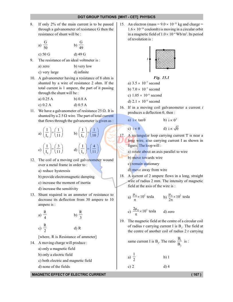
15. An electron (mass = 9.0 10–31 kg and charge =
1.6 10–19 coulomb) is moving in a circular orbit
in a magnetic field of 1.0 10–4 Wb/m2. Its period
of revolution is :
Fig. 15.1
a) 3.5 10–7 second
b) 7.0 10–7 second
c) 1.05 10–6 second
d) 2.1 10–6 second
16. If in a moving coil galvanometer a current i
produces a deflection , then :
a) i tan b) 2i
c) i d) i
17. A rectangular loop carrying current 'I' is near a
long wire, also carrying current I as shown in
figure. The loop will :
a) rotate about an axis parallel to wire
b) move towards wire
c) remain stationary
d) move away from wire
18. A current of 2 ampere flows in a long, straight
wire of radius 2 mm. The intensity of magnetic
field at the axis of the wire is :
a) 30 10 tesla
b)
30 10 tesla2
c) 302
10 tesla
d) zero
19. The magnetic field at the centre of a circular coil
of radius r carrying current I is B1. The field at
the centre of another coil of radius 2 r carrying
same current I is B2. The ratio
1
2
B
B is :
a) 1
2b) 1
c) 2 d) 4
DGT Group - Tuitions (Feed Concepts) XIth – XIIth | JEE | CET | NEET | Call : 9920154035 / 8169861448
DGT MH –CET 12th PHYSICS Study Material 23

DGT GROUP TUITIONS [MHT - CET] PHYSICS
MAGNETIC EFFECT OF ELECTRIC CURRENT ( 168 )
20. If in a circular coil A of radius R, current I is
flowing and in another coil B of radius 2 R a
current 2 I is flowing, then the ratio of the
magnetic fields, BA and B
B, produced by them
will be :
a) 1 b) 2
c) 1
2d) 4
21. If an electron and a proton having same momenta
enter perpendicular to a magnetic field, then :
a) curved path of electron and proton will be
same (ignoring the sense of revolution)
b) they will move undeflected
c) curved path of electron is more curved than
that of the proton
d) path of proton is more curved
22. If a current is passed through a spring then the
spring will :
a) expand b) compress
c) remain same d) none of these
23. When a charged particle enters in a uniform
magnetic field, its kinetic energy :
a) remains constant b) increases
c) decreases d) becomes zero
24. There are four voltmeters of the same range but
of resistances 10000 , 8000 and 4000 respectively. The best voltmeter among these is
the one whose resistance is :
a) 10000 b) 8000
c) 4000 d) all the equally good
e) none of the above
25. The magnetic field of given length of wire for
single turn coil at its centre is 'B', then its value
for two turns coil for the same wire is :
a) B
4b)
B
2
c) 4 B d) 2 B
26. A long solenoid carrying a current produces a
magnetic field B along its axis. If the current is
doubled and the number of turns per em is halved,
the new value of the magnetic field is :
a) B b) 2 B
c) 4 B d) B
2
27. A wire is wound in the form of a solenoid of length
and diameter d. When a strong current is passed
through the solenoid, there is tendency to :
a) keep both and d constant
b) decrease both and d
c) increase both and d
d) decrease but increase d
e) increase but decrease d
28. A wire of certain length carries a steady current.
It is first bent to form a circular of one turn. The
same wire is next bent to form a circular coil of
three turns. The ratio of magnetic inductions at
the centre of the coil in the two cases is :
a) 9 : 1 b) 1 : 9
c) 1 : 3 d) 3 : 1
e) 1 : 1
29. A proton and an -particle are projected normally
into a magnetic field. What will be the ratio of
the radii of the trjectories of the proton and particle ?
a) 2 : 1 b) 1 : 2
c) 4 : 1 d) 1 : 4
30. A long wire carries a steady current. It is bent
into a circle of one turn and the magnetic field at
the centre of the coil is B. It is then bent into a
circular loop of n turns. The magnetic field at the
coil will be :
a) n B b) n2 B
c) 2 n B d) 2 n2 B
31. The magnetic field due to a current carrying
circular loop of radius 3 cm at a point on the axis
at a distance of 4 cm from the centre is 54 T.
What will be its value at the centre of the loop ?
a) 250 T b) 150 T
c) 125 T d) 75 T
32. Two long conductors, separated by a distance d
carry currents I1 and I
2 in the same direction.
They exert a force F on each other. Now the
current in one of them is increased to two times
and its direction is reversed. The distance is also
increased to 3d. The net value of the force between
them is :
a) – 2 F b) F / 3
c) 2F
3 d)
F
3
DGT Group - Tuitions (Feed Concepts) XIth – XIIth | JEE | CET | NEET | Call : 9920154035 / 8169861448
DGT MH –CET 12th PHYSICS Study Material 24
DGT GROUP TUITIONS [MHT - CET] PHYSICS
MAGNETIC EFFECT OF ELECTRIC CURRENT ( 169 )
33. Two parallel beams of positrons moving in the
same direction will :
a) repel each other
b) not interact with each other
c) attract each other
d) be deflected normal to the plane containing
the two beams
34. The maximum current that can be measured by
a galvanometer of resistance 40 is 10 mA. It
is converted into a voltmeter that can read upto
50 V. The resistance to be connected in series
with the galvanometer is ...... (in ohm) :
a) 2010 b) 4050
c) 5040 d) 4960
35. A proton a deutron and an alpha particle are
accelerated through same potential difference and
then they enter a normal uniform magnetic field.
The ratio of their kinetic energies will be :
a) 2 : 1 : 3
b) 1 : 1 : 2
c) 1 : 1 : 1
d) 1 : 2 : 4
36. A uniform electric field and a uniform magnetic
field are acting along the same direction in a
certain region. If an electron is projected in the
region such that its velocity is pointed along the
direction of fields. then the electron :
a) will turn towards right of direction of motion
b) speed will decrease
c) speed will increase
d) will turn towards left of direction of motion
37. Which of the field patterns given below is valid
for electric field as well as for magnetic field ?
a) b)
c) d)
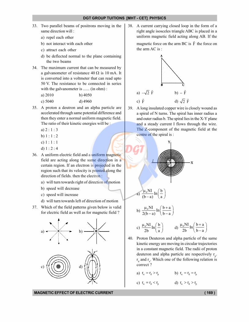
38. A current carrying closed loop in the form of a
right angle isosceles triangle ABC is placed in a
uniform magnetic field acting along AB. If the
magnetic force on the arm BC is F
the force on
the arm AC is :
a) 2 F
b) F
c) F
d) 2 F
39. A long insulated copper wire is closely wound as
a spiral of N turns. The spiral has inner radius a
and outer radius b. The spiral lies in the X-Y plane
and a steady current I flows through the wire.
The Z-component of the magnetic field at the
centre of the spiral is :
a) 0NI b
In(b a) a
b) 0NI b a
In2(b a) b a
c) 0NI bIn
2b a
d) 0NI b a
In2b b a
40. Proton Deuteron and alpha particle of the same
kinetic energy are moving in circular trajectories
in a constant magnetic field. The radii of proton
deuteron and alpha particle are respectively rp.
rd and r
a. Which one of the following relation is
correct ?
a) d pr r r b) d pr r r
c) d pr r r d) d pr r r
DGT Group - Tuitions (Feed Concepts) XIth – XIIth | JEE | CET | NEET | Call : 9920154035 / 8169861448
DGT MH –CET 12th PHYSICS Study Material 25
DGT GROUP TUITIONS [MHT - CET] PHYSICS
MAGNETIC EFFECT OF ELECTRIC CURRENT ( 170 )
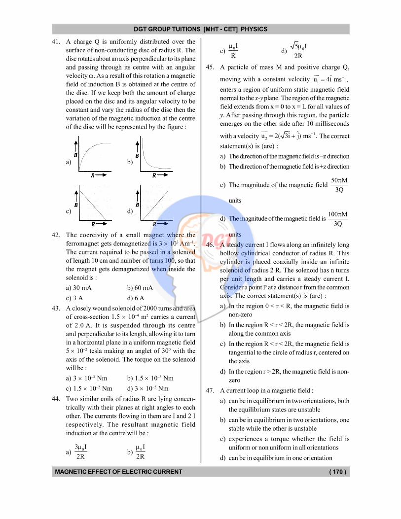
41. A charge Q is uniformly distributed over the
surface of non-conducting disc of radius R. The
disc rotates about an axis perpendicular to its plane
and passing through its centre with an angular
velocity . As a result of this rotation a magnetic
field of induction B is obtained at the centre of
the disc. If we keep both the amount of charge
placed on the disc and its angular velocity to be
constant and vary the radius of the disc then the
variation of the magnetic induction at the centre
of the disc will be represented by the figure :
a) b)
c) d)
42. The coercivity of a small magnet where the
ferromagnet gets demagnetized is 3 103 Am–1.
The current required to be passed in a solenoid
of length 10 cm and number of turns 100, so that
the magnet gets demagnetized when inside the
solenoid is :
a) 30 mA b) 60 mA
c) 3 A d) 6 A
43. A closely wound solenoid of 2000 turns and area
of cross-section 1.5 10–4 m2 carries a current
of 2.0 A. It is suspended through its centre
and perpendicular to its length, allowing it to turn
in a horizontal plane in a uniform magnetic field
5 10–2 tesla making an anglet of 300 with the
axis of the solenoid. The torque on the solenoid
will be :
a) 3 10–3 Nm b) 1.5 10–3 Nm
c) 1.5 10–2 Nm d) 3 10–2 Nm
44. Two similar coils of radius R are lying concen-
trically with their planes at right angles to each
other. The currents flowing in them are I and 2 I
respectively. The resultant magnetic field
induction at the centre will be :
a) 03 I
2R
b)
0I
2R
c) 0I
R
d) 05 I
2R
45. A particle of mass M and positive charge Q,
moving with a constant velocity 1
1ˆu 4i ms ,
enters a region of uniform static magnetic field
normal to the x-y plane. The region of the magnetic
field extends from x = 0 to x = L for all values of
y. After passing through this region, the particle
emerges on the other side after 10 milliseconds
with a velocity 1
2ˆ ˆu 2( 3i j) ms .
The correct
statement(s) is (are) :
a) The direction of the magnetic field is –z direction
b) The direction of the magnetic field is +z direction
c) The magnitude of the magnetic field 50 M
3Q
units
d) The magnitude of the magnetic field is 100 M
3Q
units
46. A steady current I flows along an infinitely long
hollow cylindrical conductor of radius R. This
cylinder is placed coaxially inside an infinite
solenoid of radius 2 R. The solenoid has n turns
per unit length and carries a steady current I.
Consider a point P at a distance r from the common
axis. The correct statement(s) is (are) :
a) In the region 0 < r < R, the magnetic field is
non-zero
b) In the region R < r < 2R, the magnetic field is
along the common axis
c) In the region R < r < 2R, the magnetic field is
tangential to the circle of radius r, centered on
the axis
d) In the region r > 2R, the magnetic field is non-
zero
47. A current loop in a magnetic field :
a) can be in equilibrium in two orientations, both
the equilibrium states are unstable
b) can be in equilibrium in two orientations, one
stable while the other is unstable
c) experiences a torque whether the field is
uniform or non uniform in all orientations
d) can be in equilibrium in one orientation
DGT Group - Tuitions (Feed Concepts) XIth – XIIth | JEE | CET | NEET | Call : 9920154035 / 8169861448
DGT MH –CET 12th PHYSICS Study Material 26
DGT GROUP TUITIONS [MHT - CET] PHYSICS
MAGNETIC EFFECT OF ELECTRIC CURRENT ( 171 )
48. Two identical long conducting wires AOB and
COD are placed at right angle to each other, with
one above other such that 'O' is their common
point for the two. The wires carry 1 and
2
currents, respectively. Point' P' is lying at distance
'd' from 'O' along a direction perpendicular to the
plane containing the wires. The magnetic field at
the point 'P' will be :
a) 2 2 1/ 20
1 2( )2 d
b)
0 1
22 d
c) 01 2
2 d
d)
2 201 2( )
2 d
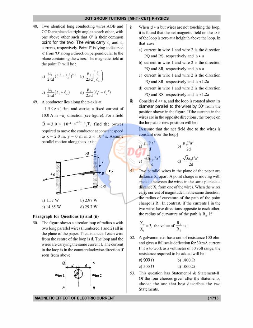
49. A conductor lies along the z-axis at
1.5 z 1.5m and carries a fixed current of
10.0 A in za direction (see figure). For a field
B
= 3.0 10–4 0.2x
yˆe a T,
find the power
required to move the conductor at constant speed
to x = 2.0 m, y = 0 m in 5 10–3 s. Assume
parallel motion along the x-axis :
a) 1.57 W b) 2.97 W
c) 14.85 W d) 29.7 W
Paragraph for Questions (i) and (ii)
50. The figure shows a circular loop of radius a with
two long parallel wires (numbered 1 and 2) all in
the plane of the paper. The distance of each wire
from the centre of the loop is d. The loop and the
wires are carrying the same current I. The current
in the loop is in the counterclockwise direction if
seen from above.
i) When d a but wires are not touching the loop,
it is found that the net magnetic field on the axis
of the loop is zero at a height h above the loop. In
that case.
a) current in wire 1 and wire 2 is the direction
PQ and RS, respectively and h a
b) current in wire 1 and wire 2 is the direction
PQ and SR, respectively and h a
c) current in wire 1 and wire 2 is the direction
PQ and SR, respectively and h 1.2a
d) current in wire 1 and wire 2 is the direction
PQ and RS, respectively and h 1.2a
ii) Consider d >> a, and the loop is rotated about its
diameter parallel to the wires by 300 from the
position shown in the figure. If the currents in the
wires are in the opposite directions, the torque on
the loop at its new position will be :
[Assume that the net field due to the wires is
constant over the loop]
a)
2 2
0I a
d
b)
2 2
0I a
2d
c)
2 2
03 I a
d
d)
2 2
03 I a
2d
51. Two parallel wires in the plane of the paper are
distance X0 apart. A point charge is moving with
speed u between the wires in the same plane at a
distance X1 from one of the wires. When the wires
carry current of magnitude I in the same direction,
the radius of curvature of the path of the point
charge is R1. In contrast, if the currents I in the
two wires have directions opposite to each other,
the radius of curvature of the path is R2. If
0
1
X3,
X the value of 1
2
R
R is :
52. A galvanometer has a coil of resistance 100 ohm
and gives a full scale deflection for 30 mA current
If it is to work as a voltmeter of 30 volt range, the
resistance required to be added will be :
a) 900 b) 1800
c) 500 d) 1000
53. This question has Statement-I & Statement-II.
Of the four choices given after the Statements,
choose the one that best describes the two
Statements.
DGT Group - Tuitions (Feed Concepts) XIth – XIIth | JEE | CET | NEET | Call : 9920154035 / 8169861448
DGT MH –CET 12th PHYSICS Study Material 27
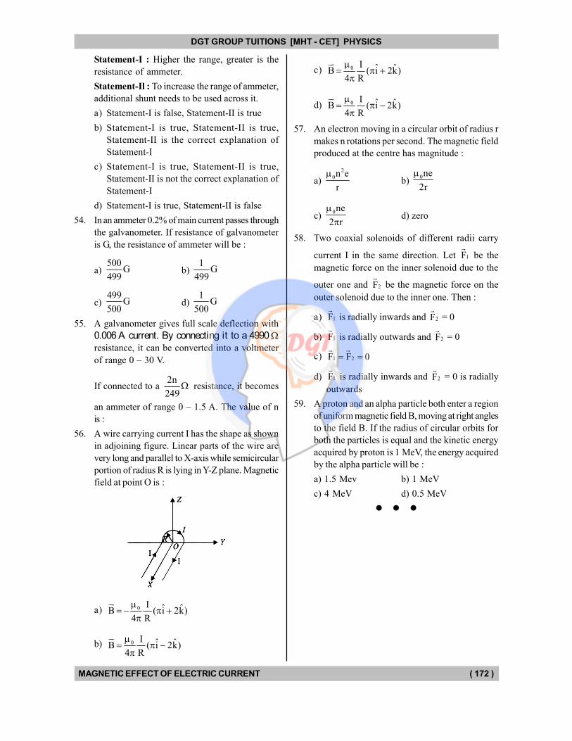
DGT GROUP TUITIONS [MHT - CET] PHYSICS
MAGNETIC EFFECT OF ELECTRIC CURRENT ( 172 )
Statement-I : Higher the range, greater is the
resistance of ammeter.
Statement-Il : To increase the range of ammeter,
additional shunt needs to be used across it.
a) Statement-I is false, Statement-II is true
b) Statement-I is true, Statement-II is true,
Statement-II is the correct explanation of
Statement-I
c) Statement-I is true, Statement-II is true,
Statement-II is not the correct explanation of
Statement-I
d) Statement-I is true, Statement-II is false
54. In an ammeter 0.2% of main current passes through
the galvanometer. If resistance of galvanometer
is G, the resistance of ammeter will be :
a) 500
G499
b) 1
G499
c) 499
G500
d) 1
G500
55. A galvanometer gives full scale deflection with
0.006 A current. By connecting it to a 4990 resistance, it can be converted into a voltmeter
of range 0 – 30 V.
If connected to a 2n
249 resistance, it becomes
an ammeter of range 0 – 1.5 A. The value of n
is :
56. A wire carrying current I has the shape as shown
in adjoining figure. Linear parts of the wire are
very long and parallel to X-axis while semicircular
portion of radius R is lying in Y-Z plane. Magnetic
field at point O is :
a) 0 I ˆ ˆB ( i 2k)4 R
b) 0 I ˆ ˆB ( i 2k)4 R
c) 0 I ˆ ˆB ( i 2k)4 R
d) 0 I ˆ ˆB ( i 2k)4 R
57. An electron moving in a circular orbit of radius r
makes n rotations per second. The magnetic field
produced at the centre has magnitude :
a)
2
0n e
r
b)
0ne
2r
c) 0ne
2 r
d) zero
58. Two coaxial solenoids of different radii carry
current I in the same direction. Let 1F
be the
magnetic force on the inner solenoid due to the
outer one and 2F
be the magnetic force on the
outer solenoid due to the inner one. Then :
a) 1F
is radially inwards and 2F
= 0
b) 1F
is radially outwards and 2F
= 0
c) 1 2F F 0
d) 1F
is radially inwards and 2F
= 0 is radially
outwards
59. A proton and an alpha particle both enter a region
of uniform magnetic field B, moving at right angles
to the field B. If the radius of circular orbits for
both the particles is equal and the kinetic energy
acquired by proton is 1 MeV, the energy acquired
by the alpha particle will be :
a) 1.5 Mev b) 1 MeV
c) 4 MeV d) 0.5 MeV
DGT Group - Tuitions (Feed Concepts) XIth – XIIth | JEE | CET | NEET | Call : 9920154035 / 8169861448
DGT MH –CET 12th PHYSICS Study Material 28
DGT GROUP TUITIONS [MHT - CET] PHYSICS
MAGNETIC EFFECT OF ELECTRIC CURRENT ( 173 )
Brain Teasers
1. Two co-axial wires one solid and one hollow, each
carry the same current I in opposite directions.
The radius of inner wire is r. The inner radius of
the hollow wire is r2 and the outer radius is r
3.
What is the magnetic induction at a distance r
from the axis, such that r2 < r < r
3 ?
a) 2 203
Ir r
2 r
b) 2 20
3 2
Ir r
2 r
c)
2 2
0 3
2 2
3 2
I r r
2 r r r
d) 0
2 2
3 2
I 1
2 r r r
2. In the above question what is the magnetic field
at a point where r < r1 ?
a) 0 1
2
Ir
2 r
b) 0
2
1
Ir
2 r
c) 0 I2
d)
2
0
2
1
Ir
2 r
3. Two circular coils 1 and 2 are made from same
wire but radius of 1st coil is twice that of 2nd coil.
What potential difference should be applied across
them so that the magnetic field at their centres is
the same ?
a) 2 b) 3
c) 4 d) 6
4. A plane spiral of N turns carries current I. The
turns are closely packed and the inner and outer
radii are a & b respectively. What is the magnetic
field at the centre of the spiral ?
a) 0 2 I
4 b a
b) 0e
2 I blog
4 b a a
c) 0e
b2 I log
4 a
d) 0 2 I
4
5. A circular coil of radius 7 m carries a current of
2 A. It is changed into a square. What is the
magnetic field at the centre of the coil in the two
cases ?
a) 0 0,
7 11
b) 0 0 4 2
, 7 11
c) 0 04 2,
11 7
d)
0 0, 11 7
6. Three long straight wires of same material are
connected to the same power supply in parallel.
The internal resistance of the power supply is
negligible. The lengths of the wires are same but
their areas of cross-section are in the ratio
3 : 4 : 5. What is the ratio of distances of 'middle
wire from the outerwires so that the net magnetic
force on it is zero ?
a) 3
5b)
5
3
c) 4
5d)
5
4
7. An electron moving with kinetic energy 6.6 10–14 J
enters a magnetic field 4 10–3 T at right angle
to it. The radius of its circular path will be nearest
to :
a) 25 cm b) 50 cm
c) 75 cm d) 1 m
8. A galvanometer of resistance 50 ohm is connected
to a battery of 3 volt alongwith a resistance of
2950 in series. A full scale deflection of 30
divisions is obtained in the galvanometer. In order
to reduce this deflection to 20 divisions, the
resistance in series should be :
a) 4450 ohm b) 5050 ohm
c) 5550 ohm d) 6050 ohm
DGT Group - Tuitions (Feed Concepts) XIth – XIIth | JEE | CET | NEET | Call : 9920154035 / 8169861448
DGT MH –CET 12th PHYSICS Study Material 29
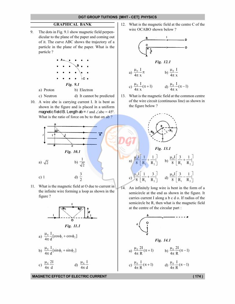
DGT GROUP TUITIONS [MHT - CET] PHYSICS
MAGNETIC EFFECT OF ELECTRIC CURRENT ( 174 )
GRAPHICAL BANK
9. The dots in Fig. 9.1 show magnetic field perpen-
dicular to the plane of the paper and coming out
of it. The curve ABC shows the trajectory of a
particle in the plane of the paper. What is the
particle ?
Fig. 9.1
a) Proton b) Electron
c) Neutron d) It cannot be predicted
10. A wire abe is carrying current I. It is bent as
shown in the figure and is placed in a uniform
magnetic field B. Length ab = and abc = 450.
What is the ratio of force on bc to that on ab ?
Fig. 10.1
a) 2 b) 1
2
c) 1 d) 3
2
11. What is the magnetic field at O due to current in
the infinite wire forming a loop as shown in the
figure ?
Fig. 11.1
a)0
1 2
I[cos cos ]
4 d
b)0
1 2
I[sin sin ]
4 d
c)0 2I
4 d
d)
0 I
4 d
12. What is the magnetic field at the centre C of the
wire OCABO shown below ?
Fig. 12.1
a) 0 I
4 x
b)
0 I
4 x
c) 0 I
( 1)4 x
d)
0 I( 1)
4 x
13. What is the magnetic field at the common centre
of the wire circuit (continuous line) as shown in
the figure below ?
Fig. 13.1
a) 0
1 2
I 1 1
8 R R
b)
0
1 2
I 3 1
8 R R
c) 0
1 2
I 1 3
8 R R
d)
0
1 2
I 3 1
8 R R
14. An infinitely long wire is bent in the form of a
semicircle at the end as shown in the figure. It
carries current I along a b c d o. If radius of the
semicircle be R, then what is the magnetic field
at the centre of the circular part :
Fig. 14.1
a) 0 2I
( 1)4 R
b)
0 2I( 1)
4 R
c) 0 I
( 1)4 R
d)
0 I( 1)
4 R
DGT Group - Tuitions (Feed Concepts) XIth – XIIth | JEE | CET | NEET | Call : 9920154035 / 8169861448
DGT MH –CET 12th PHYSICS Study Material 30
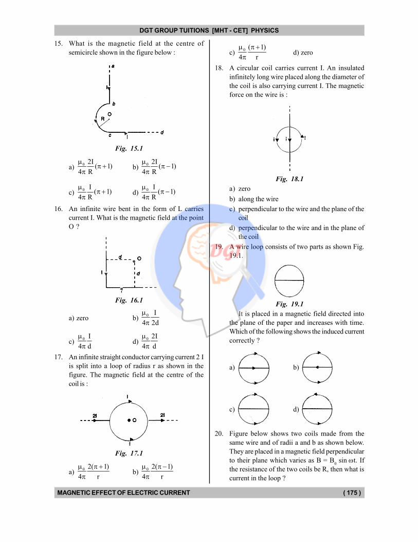
DGT GROUP TUITIONS [MHT - CET] PHYSICS
MAGNETIC EFFECT OF ELECTRIC CURRENT ( 175 )
15. What is the magnetic field at the centre of
semicircle shown in the figure below :
Fig. 15.1
a) 0 2I
( 1)4 R
b)
0 2I( 1)
4 R
c) 0 I
( 1)4 R
d)
0 I( 1)
4 R
16. An infinite wire bent in the form of L carries
current I. What is the magnetic field at the point
O ?
Fig. 16.1
a) zero b) 0 I
4 2d
c) 0 I
4 d
d)
0 2I
4 d
17. An infinite straight conductor carrying current 2 I
is split into a loop of radius r as shown in the
figure. The magnetic field at the centre of the
coil is :
Fig. 17.1
a) 0 2( 1)
4 r
b) 0 2( 1)
4 r
c) 0 ( 1)
4 r
d) zero
18. A circular coil carries current I. An insulated
infinitely long wire placed along the diameter of
the coil is also carrying current I. The magnetic
force on the wire is :
Fig. 18.1
a) zero
b) along the wire
c) perpendicular to the wire and the plane of the
coil
d) perpendicular to the wire and in the plane of
the coil
19. A wire loop consists of two parts as shown Fig.
19.1.
Fig. 19.1
It is placed in a magnetic field directed into
the plane of the paper and increases with time.
Which of the following shows the induced current
correctly ?
a) b)
c) d)
20. Figure below shows two coils made from the
same wire and of radii a and b as shown below.
They are placed in a magnetic field perpendicular
to their plane which varies as B = B0 sin t. If
the resistance of the two coils be R, then what is
current in the loop ?
DGT Group - Tuitions (Feed Concepts) XIth – XIIth | JEE | CET | NEET | Call : 9920154035 / 8169861448
DGT MH –CET 12th PHYSICS Study Material 31
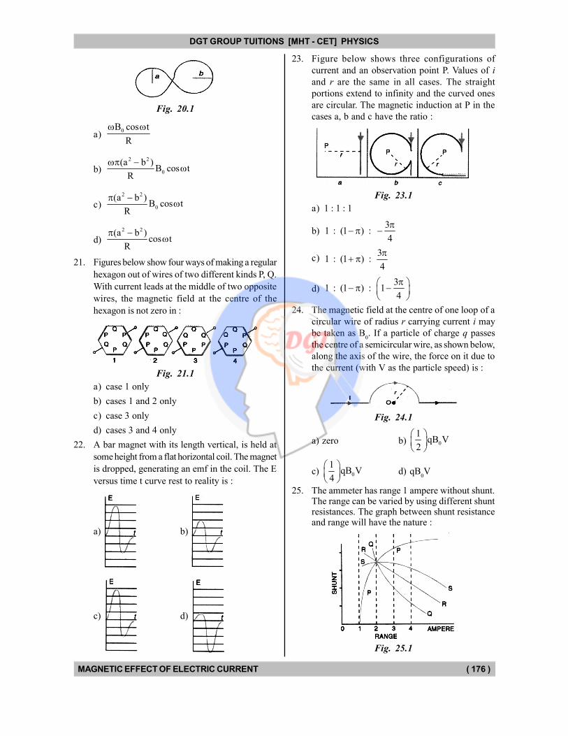
DGT GROUP TUITIONS [MHT - CET] PHYSICS
MAGNETIC EFFECT OF ELECTRIC CURRENT ( 176 )
Fig. 20.1
a)0B cos t
R
b)
2 2
0
(a b )B cos t
R
c)
2 2
0
(a b )B cos t
R
d)
2 2(a b )cos t
R
21. Figures below show four ways of making a regular
hexagon out of wires of two different kinds P, Q.
With current leads at the middle of two opposite
wires, the magnetic field at the centre of the
hexagon is not zero in :
Fig. 21.1
a) case 1 only
b) cases 1 and 2 only
c) case 3 only
d) cases 3 and 4 only
22. A bar magnet with its length vertical, is held at
some height from a flat horizontal coil. The magnet
is dropped, generating an emf in the coil. The E
versus time t curve rest to reality is :
a) b)
c) d)
23. Figure below shows three configurations of
current and an observation point P. Values of i
and r are the same in all cases. The straight
portions extend to infinity and the curved ones
are circular. The magnetic induction at P in the
cases a, b and c have the ratio :
Fig. 23.1
a) 1 : 1 : 1
b)3
1 : (1 ) : 4
c)3
1 : (1 ) : 4
d)3
1 : (1 ) : 14
24. The magnetic field at the centre of one loop of a
circular wire of radius r carrying current i may
be taken as B0. If a particle of charge q passes
the centre of a semicircular wire, as shown below,
along the axis of the wire, the force on it due to
the current (with V as the particle speed) is :
Fig. 24.1
a) zero b) 0
1qB V
2
c) 0
1qB V
4
d) qB0V
25. The ammeter has range 1 ampere without shunt.The range can be varied by using different shuntresistances. The graph between shunt resistanceand range will have the nature :
Fig. 25.1
DGT Group - Tuitions (Feed Concepts) XIth – XIIth | JEE | CET | NEET | Call : 9920154035 / 8169861448
DGT MH –CET 12th PHYSICS Study Material 32
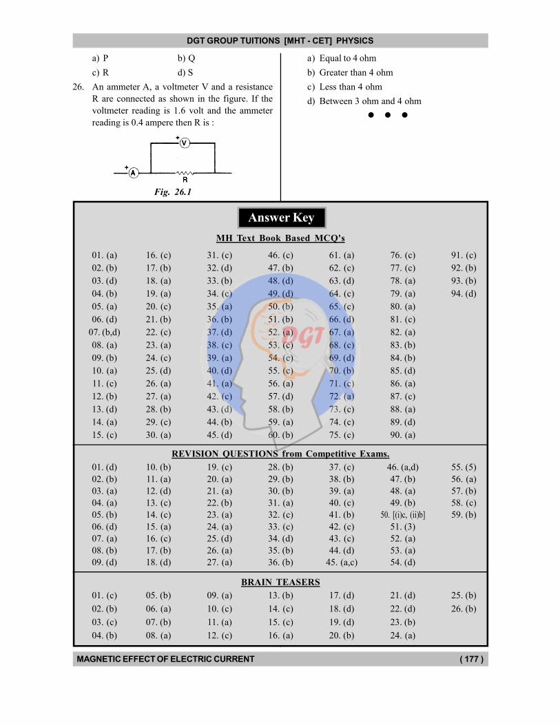
DGT GROUP TUITIONS [MHT - CET] PHYSICS
MAGNETIC EFFECT OF ELECTRIC CURRENT ( 177 )
a) P b) Q
c) R d) S
26. An ammeter A, a voltmeter V and a resistance
R are connected as shown in the figure. If the
voltmeter reading is 1.6 volt and the ammeter
reading is 0.4 ampere then R is :
Fig. 26.1
a) Equal to 4 ohm
b) Greater than 4 ohm
c) Less than 4 ohm
d) Between 3 ohm and 4 ohm
01. (c)
02. (b)
03. (c)
04. (b)
09. (a)
10. (c)
11. (a)
12. (c)
17. (d)
18. (d)
19. (d)
20. (b)
Answer Key
MH Text Book Based MCQ's
01. (a)
02. (b)
03. (d)
04. (b)
05. (a)
06. (d)
07. (b,d)
08. (a)
09. (b)
10. (a)
11. (c)
12. (b)
13. (d)
14. (a)
15. (c)
16. (c)
17. (b)
18. (a)
19. (a)
20. (c)
21. (b)
22. (c)
23. (a)
24. (c)
25. (d)
26. (a)
27. (a)
28. (b)
29. (c)
30. (a)
31. (c)
32. (d)
33. (b)
34. (c)
35. (a)
36. (b)
37. (d)
38. (c)
39. (a)
40. (d)
41. (a)
42. (c)
43. (d)
44. (b)
45. (d)
46. (c)
47. (b)
48. (d)
49. (d)
50. (b)
51. (b)
52. (a)
53. (c)
54. (c)
55. (c)
56. (a)
57. (d)
58. (b)
59. (a)
60. (b)
61. (a)
62. (c)
63. (d)
64. (c)
65. (c)
66. (d)
67. (a)
68. (c)
69. (d)
70. (b)
71. (c)
72. (a)
73. (c)
74. (c)
75. (c)
76. (c)
77. (c)
78. (a)
79. (a)
80. (a)
81. (c)
82. (a)
83. (b)
84. (b)
85. (d)
86. (a)
87. (c)
88. (a)
89. (d)
90. (a)
91. (c)
92. (b)
93. (b)
94. (d)
REVISION QUESTIONS from Competitive Exams.
01. (d)
02. (b)
03. (a)
04. (a)
05. (b)
06. (d)
07. (a)
08. (b)
09. (d)
10. (b)
11. (a)
12. (d)
13. (c)
14. (c)
15. (a)
16. (c)
17. (b)
18. (d)
19. (c)
20. (a)
21. (a)
22. (b)
23. (a)
24. (a)
25. (d)
26. (a)
27. (a)
28. (b)
29. (b)
30. (b)
31. (a)
32. (c)
33. (c)
34. (d)
35. (b)
36. (b)
37. (c)
38. (b)
39. (a)
40. (c)
41. (b)
42. (c)
43. (c)
44. (d)
45. (a,c)
46. (a,d)
47. (b)
48. (a)
49. (b)
50. [(i)c, (ii)b]
51. (3)
52. (a)
53. (a)
54. (d)
55. (5)
56. (a)
57. (b)
58. (c)
59. (b)
BRAIN TEASERS
05. (b)
06. (a)
07. (b)
08. (a)
13. (b)
14. (c)
15. (c)
16. (a)
21. (d)
22. (d)
23. (b)
24. (a)
25. (b)
26. (b)
DGT Group - Tuitions (Feed Concepts) XIth – XIIth | JEE | CET | NEET | Call : 9920154035 / 8169861448
DGT MH –CET 12th PHYSICS Study Material 33

DGT Group - Tuitions (Feed Concepts) XIth – XIIth | JEE | CET | NEET | Call : 9920154035 / 8169861448
DGT MH –CET 12th PHYSICS Study Material 34

DGT Group - Tuitions (Feed Concepts) XIth – XIIth | JEE | CET | NEET | Call : 9920154035 / 8169861448
Hints & Solutions 35
DGT Group - Tuitions (Feed Concepts) XIth – XIIth | JEE | CET | NEET | Call : 9920154035 / 8169861448
Hints & Solutions 36
DGT Group - Tuitions (Feed Concepts) XIth – XIIth | JEE | CET | NEET | Call : 9920154035 / 8169861448
Hints & Solutions 37
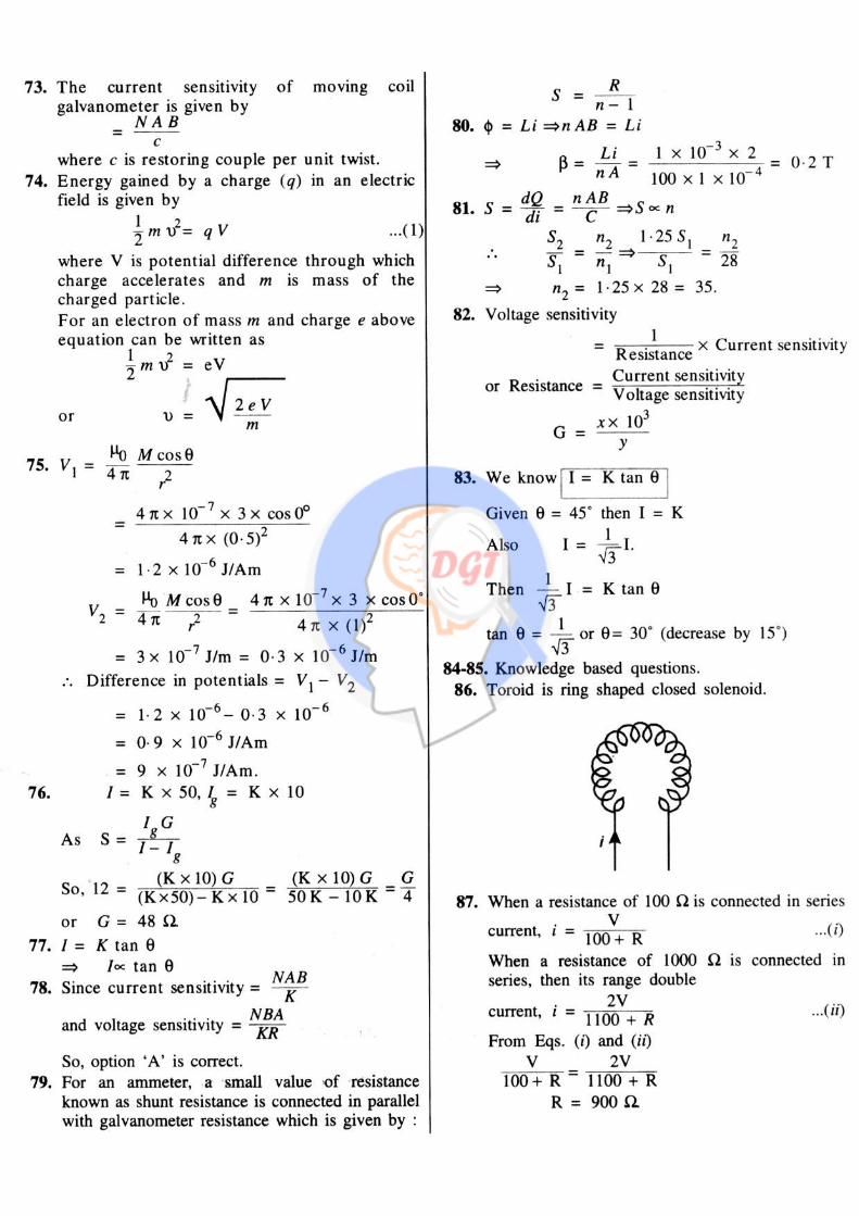
DGT Group - Tuitions (Feed Concepts) XIth – XIIth | JEE | CET | NEET | Call : 9920154035 / 8169861448
Hints & Solutions 38
DGT Group - Tuitions (Feed Concepts) XIth – XIIth | JEE | CET | NEET | Call : 9920154035 / 8169861448
Hints & Solutions 39
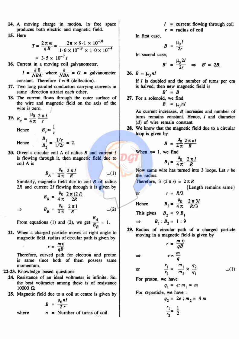
DGT Group - Tuitions (Feed Concepts) XIth – XIIth | JEE | CET | NEET | Call : 9920154035 / 8169861448
Hints & Solutions 40
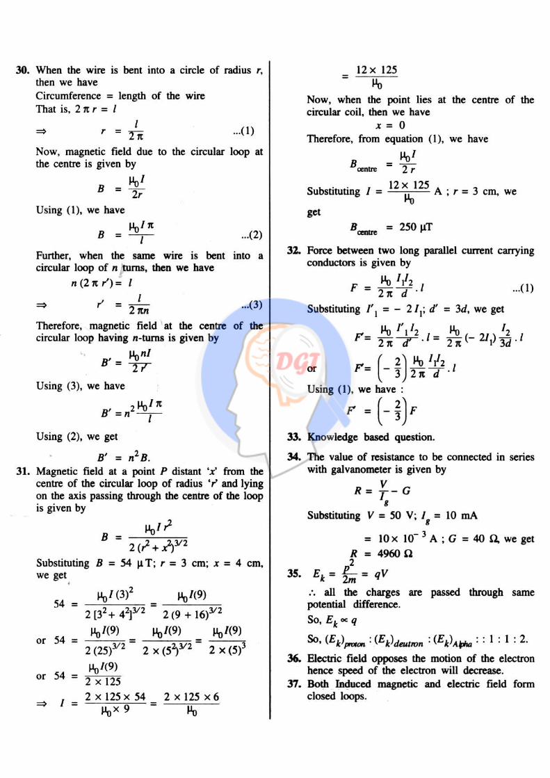
DGT Group - Tuitions (Feed Concepts) XIth – XIIth | JEE | CET | NEET | Call : 9920154035 / 8169861448
Hints & Solutions 41
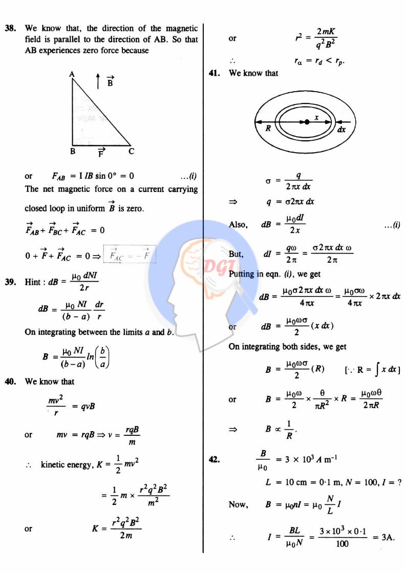
DGT Group - Tuitions (Feed Concepts) XIth – XIIth | JEE | CET | NEET | Call : 9920154035 / 8169861448
Hints & Solutions 42
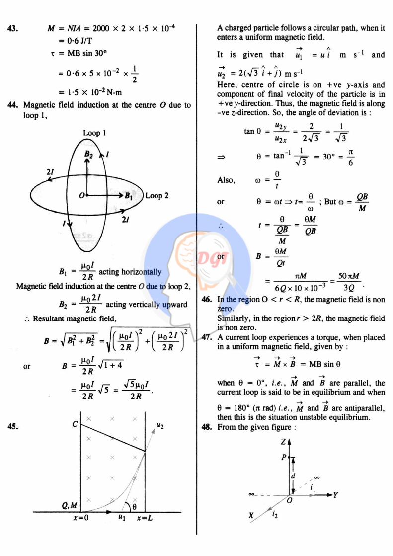
DGT Group - Tuitions (Feed Concepts) XIth – XIIth | JEE | CET | NEET | Call : 9920154035 / 8169861448
Hints & Solutions 43
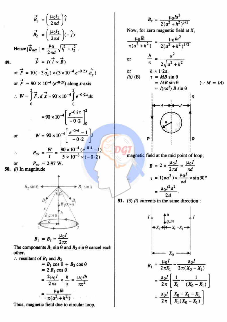
DGT Group - Tuitions (Feed Concepts) XIth – XIIth | JEE | CET | NEET | Call : 9920154035 / 8169861448
Hints & Solutions 44

DGT Group - Tuitions (Feed Concepts) XIth – XIIth | JEE | CET | NEET | Call : 9920154035 / 8169861448
Hints & Solutions 45
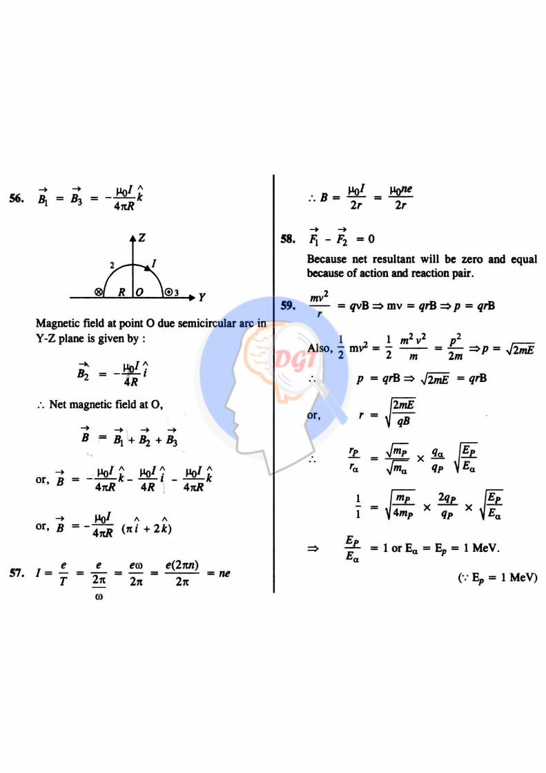
DGT Group - Tuitions (Feed Concepts) XIth – XIIth | JEE | CET | NEET | Call : 9920154035 / 8169861448
Hints & Solutions 46
DGT Group - Tuitions (Feed Concepts) XIth – XIIth | JEE | CET | NEET | Call : 9920154035 / 8169861448
Hints & Solutions 47
DGT Group - Tuitions (Feed Concepts) XIth – XIIth | JEE | CET | NEET | Call : 9920154035 / 8169861448
Hints & Solutions 48