Magnetic-Effect-of-Electric-Current-Class-10-Notes-@Net ...
7
13. Magnetic Effects of Electric Current Notes Class 10 www.netexplanations.com Crafted by Best Physics Teachers, Net Explanations Dear students, here we are going to learn the most interesting part from Physics syllabus i.e. magnetism and magnetic effect of electric current. If you remember from standard 7, you are well familiar with all these concepts. In std. X it becomes more interesting as we are learning each and every concept in detail and in practical perspective. Magnet and magnetic field: The substance which attracts small pieces of iron is known as magnet, and the property of that substance is called magnetism. The region around magnet up to which its effect can seems is called as the magnetic field. Magnets are available in different sizes viz. needle magnet, bar magnet, horse shoe magnet, ring magnet and coin magnet. Every magnet consists of two poles, where its strength is concentrated, known as North pole and South pole. If you break magnet in to two pieces, poles of magnets cannot be separated, instead it will again form the pole missing at the broken edge. Thus monopole (single pole) of magnet can never be exist. We know that a magnetic needle suspended freely using string, aligns itself towards North and South pole of earth, which indicates that magnet have directive property too! Magnetic lines of forces: Magnetic lines of force give us the strength of magnetic field. They are close and continuous curved which starts from North pole and end at South pole of magnet. Some important properties of magnetic lines of forces are, 1. Magnetic lines of force are close continuous curve, starts from North Pole and ends at South Pole.
-
Upload
khangminh22 -
Category
Documents
-
view
4 -
download
0
Transcript of Magnetic-Effect-of-Electric-Current-Class-10-Notes-@Net ...
13. Magnetic Effects of Electric Current
Notes
Class 10
www.netexplanations.com
Crafted by Best Physics Teachers, Net Explanations
Dear students, here we are going to learn the most interesting part from Physics syllabus i.e. magnetism and magnetic effect of electric current. If you remember from standard 7, you are well familiar with all these concepts. In std. X it becomes more interesting as we are learning each and every concept in detail and in practical perspective.
Magnet and magnetic field: The substance which attracts small pieces of iron is known as magnet, and the
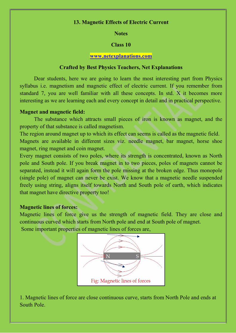
property of that substance is called magnetism. The region around magnet up to which its effect can seems is called as the magnetic field. Magnets are available in different sizes viz. needle magnet, bar magnet, horse shoe magnet, ring magnet and coin magnet. Every magnet consists of two poles, where its strength is concentrated, known as North pole and South pole. If you break magnet in to two pieces, poles of magnets cannot be separated, instead it will again form the pole missing at the broken edge. Thus monopole (single pole) of magnet can never be exist. We know that a magnetic needle suspended freely using string, aligns itself towards North and South pole of earth, which indicates that magnet have directive property too! Magnetic lines of forces: Magnetic lines of force give us the strength of magnetic field. They are close and continuous curved which starts from North pole and end at South pole of magnet. Some important properties of magnetic lines of forces are,
1. Magnetic lines of force are close continuous curve, starts from North Pole and ends at South Pole.

2. Magnetic lines of force never intersect each other 3. Tangent drawn at any point on the curve indicates the direction of magnetic field at the point (shown in fig). 4. Magnetic field is strong if lines are crowded and weak if the lines are widely spaced.
Magnetic effect of electric current: It is said that some accidents can also discoveries of the most unique and important thing. The same was happened with Sir. H. C. Oerstad in 1820, that during certain experiments with electric field he found that a needle magnet was deviated by its own. After so much confusion about the cause of deflection of needle magnet, finally he concluded that there is magnetic field around a conductor carrying current. This accidently invented phenomenon is the world’s most used one.
The phenomenon of producing magnetic field around the conductor, when current passes through the conductor is known as magnetic effect of electric current. Magnetic field due to straight conductor:
When current passes through straight conductor, magnetic field is produced this is like circular rings around conductor. The structure of magnetic field lines will resemble to structure of ripples produced in silent pond of water and stone is thrown in to it. Refer the fig below, in which you can see that magnetic compass gets deflected when current passes through the conductor, hence we can conclude that,
Fig: Magnetic field produced around conductor, deflects the magnetic compass.
Magnetic field produced around the conductor was found to be depend upon three factors which are,
1. Amount of current flowing through conductor. 2. Distance of magnetic material from conductor. 3. Direction of current in conductor.
Right hand thumb rule: The direction of magnetic field produced around the conductor due to current can be studied with the rule, known as Right hand thumb rule.

When you hold a current carrying conductor in your right hand, such that the thumb is stretched along conductor and remaining four fingers are wound around the conductor, then if outstretched thumb will direction of current flowing through the conductor, the curled fingers around the conductor will give direction of magnetic field around the conductor. (Refer the following figure)
Magnetic field due to circular loop of conductor carrying current:
Suppose that a metallic wire is allowed to pass through two holes created on card board paper and some iron filing are spread paper as shown in fig. It is observed that each point on wire produces magnetic field lines like concentric circles. Here as we can in diagram, magnetic field lines produced around circular loop of wire also forms concentric circles whose direction can be defined
using right hand thumb rule. The radii of these concentric circles goes on increases, so that the arcs of big circle almost appears as a straight lines towards the midpoint of the two holes created on paper. This indicates that the magnetic lines passing through axis of coil shows similarities with magnetic lines formed by bar magnet.
If circular loop is made with ‘n’ turns of same radius, magnetic field also can be increased by ‘n’ times. Hence magnetic field along the axis of magnet is considered as an alternative for magnetic field of bar magnet. Magnetic field produced due to solenoid:
An insulated copper wire wrapped with ‘N’ turns on cylindrical rod forms solenoid. When current is passed through the solenoid magnetic field is produced around it. The direction of magnetic field can be demonstrated using right hand thumb rule. Magnetic
lines of forces around solenoid are shown in figure below. 1. Each turn of solenoid produces magnetic field similar to concentric circles. As the radius of circles increases the arc of lines are almost straight line passes through axis. 2. The lines of forces along axis of each turn in solenoid contributes magnetic field which is

similar to magnetic field produced by bar magnet. 3. Magnetic lines of forces outside solenoid are widely spaced; hence the magnetic field due to these lines is very weak and can be neglected. 4. Hence solenoid is excellent alternative for bar magnet as, lines of forces passing through axis of solenoid are crowded, so as to produce strong magnetic field like bar magnet. 5. In industries solenoid made up of alloys like Alnico (Aluminium-Nickel-Cobalt) is preferred to produce permanent magnetic field. Force acting on conductor placed in uniform magnetic field:
When current carrying conductor is placed in uniform magnetic field, it experiences the force.
In fig. we can see that current carrying conductor is stretched between two clamps of retort stand, which is passing through U shaped magnet placed on other stand. As soon as current started, the wire gets oscillates between two clamps, just like the wires stretched on guitar. This indicates that there is force due to interaction of two magnetic fields. First one due to electric current and second one due to U shaped magnet.
The direction of the force is depends upon the direction current flow and direction of uniform magnetic field.
Fleming’s left hand rule:
To find the direction of force acting on conductor placed in uniform magnetic field, Fleming’s left hand rule is used.
According to this rule, if you stretched thumb, index finger and middle finger such that they are mutually perpendicular to each other then, 1.Index finger is used to indicate direction of magnetic field. 2. Middle finger is used to indicate direction of current. 3. Thumb will point towards direction of force acting on conductor.
Electric motor:
The device which converts an electric energy in mechanical energy is known as electric motor. It works on principle that, current carrying coil suspended in magnetic field rotates due to force acting on it.

Construction: The parts of motor are shown in figure. 1. Armature coil: Number of turns of insulated copper wire wrapped on rectangular frame ABCD of soft iron forms armature. 2. Ends of armature are connected to axle with brushes B1and B2 and split rings. 3. The whole set up is suspended in two strong poles of U-shaped magnet. 4. The source of electric energy (battery) is connected to armature through brushes.
Working: 1. When we close the key a current is flow through enters thearmature ABCD through brush B1leaves through brush B2. 2. As current is flowing along length of arms AC and BD, forces act on these arms due to two magnetic fields and it starts rotating clockwise. 3. According to Fleming’s left hand rule force on arm AC is downwards and on thatarm BD is upwards and coil rotates clockwise.These forces are of equal magnitude and opposite in direction hence constitutes the torque and makes coils rotate about its own axis. 3. After half a rotation, the position of AC and BD gets reversed by reversing key i.e. commutatorand armature completes further rotation. Electromagnetic induction:
As we know that, electric current in conductor can produce magnetic field around the conductor, this effect is known as magnetic effect of electric current. Sir Michael Faraday thought in inverse manner and tried to find that can electric field be produced by magnetic field? He successfully found the answer and discovered that, changing magnetic field around conductor can induces current in conductor and the effect is known as electromagnetic induction.
Whenever there is change in magnetic field link with coil takes place, an electric current is produced in the conductor, this is known as Electromagnetic induction. This statement is also known as Faraday’s law of electromagnetic induction. The current is called as Induced current. Changing magnetic field in 1st coil induces current in neighbouring coil; this is also known as electromagnetic induction.

Fleming’s right hand rule: To find direction of current induced in coil we need to use Fleming’s right hand rule. It is stated as if thumb, index finger and middle finger of right hand are stretched such that they are mutually perpendicular to each other then, 1.) thumb indicates direction of force 2.) index finger indicates direction of magnetic field 3.) then middle finger will indicate the direction of induced current. Electric generator: The device which converts mechanical energy in to electrical energy is called as Electric generator.
Principle of working: It works on principle of electromagnetic such that the coil rotated in uniform magnetic field, induces current in it. Construction: 1. Armature coil: Number of turns of insulated copper wire wrapped on rectangular frame ABCD of soft iron forms armature. 2. Ends of armature are connected to axle with brushes B1and B2
and split rings. 3. The whole set up is suspended in two strong poles of U-shaped magnet. 4. Sensitive galvanometer is connected to detect the direction of current. Working: 1.) Initially armature is in horizontal position, and then rotated in anticlockwise direction between two poles of horse-shoe magnet. 2.) Arm AC moves down, BD moves up this changes magnetic field on arms AC and BD of coil. 3.) Due to this current is induced in the arm AC and BD. By Fleming’s right hand rule the direction of current is from A to C and B to D through brush B1 and B2. 4.) After half rotation, arms AC and BD interchanges the position moves in opposite direction of previous and again current is induced in arms but now in opposite direction, this can be noticed in galvanometer. Domestic electric circuit:

Figure shows the structure of common domestic circuits. 1.) It consists of live wire (red colour) and neutral wire (blue colour) withseparate switches to ‘ON’/‘OFF’ the flow of current connected to electricity meter which generally maintains the potential difference of 220 V. 2.) To get equal potential difference, all switches are connected parallel to each other. 3.) Electric fuse is connected in series with live wire, which can prevent appliances from getting damaged due to short-circuiting or overloading. 4. All neutral terminals are connected together and buried to earth by process called as Earthing (shown by green wire in fig). Earthing: It is a process in which the neutral terminals from all switches are combined together and connected to copper rod of about 2 feet in length and buried deep in earth. This arrangement is very important as it saves our appliances from excess charges, fire that can caused due to short circuit and overloading. Short circuiting: When insulation over live wire and neutral wire is removed accidently and they get joined, carries large current is called as short circuiting. Overloading: When number of electric appliances of higher power ratings is connected at a time, then the wires tries to draw more current, this is known as overloading.