Machine Mounts, Levelling Mounts Anti Vibration Materials
16
CAT 1.06 Complete Solutions Machine Mounts, Levelling Mounts Anti Vibration Materials www.farrat.com Squaregrip NBR Vidam Isomat (SG) page 4 (NBR) page 4 (VM) page 5 (IM) page 5 Corner / Side Foot Anti Vibration Washers Jackmounts Jackmounts Captive (CF, SF) page 7 (AW, AWS) page 7 (JCM, JRM, JSM, JMS) page 8 (JMP) page 9 Jackmounts Captive MF Mounts Levelling Mounts Isomounts (JMS-P Stainless) page 9 (MF) page 10 (LF Stainless) page 11 (ISO) page 12 Isobloc Wedgemounts Wedgemounts Wedge Levelling Elements (ISB) page 13 (WL, WLF) page 14 (WLB, WLT) page 15 (WLE) page 16
-
Upload
khangminh22 -
Category
Documents
-
view
3 -
download
0
Transcript of Machine Mounts, Levelling Mounts Anti Vibration Materials

CAT 1.06
Complete SolutionsMachine Mounts, Levelling MountsAnti Vibration Materials
ww
w.f
arra
t.co
m
Squaregrip NBR Vidam Isomat(SG) page 4 (NBR) page 4 (VM) page 5 (IM) page 5
Corner / Side Foot Anti Vibration Washers Jackmounts Jackmounts Captive (CF, SF) page 7 (AW, AWS) page 7 (JCM, JRM, JSM, JMS) page 8 (JMP) page 9
Jackmounts Captive MF Mounts Levelling Mounts Isomounts (JMS-P Stainless) page 9 (MF) page 10 (LF Stainless) page 11 (ISO) page 12
Isobloc Wedgemounts Wedgemounts Wedge Levelling Elements (ISB) page 13 (WL, WLF) page 14 (WLB, WLT) page 15 (WLE) page 16

Complete solutionsaaaaaaaaaaaaaaaaaaaaFarrat Products
aaaaaaaaaaaaaaaaaaaaaaaaaaaaaaaaPages 4-6 Pages 4-6 Page 9Page 8
2.022.01 2.062.052.04
Bolt throughAnti-vibration pads
SQUAREGRIP,VIDAM,
NBR, ISOMAT,
Free standingAnti-vibration pads
SQUAREGRIP,VIDAM,
NBR, ISOMAT,
JACKMOUNTPendulum Screw
JMPStainless Jackmount
Pendulum ScrewJMS-P
JACKMOUNTJSM, JCM, JRMFreestanding: FS
Bolt-on: BOFlat recess: FR
Typical applicationsFree standing
installation andisolation of a wide
range of machineryand equipment.
Shock & vibrationisolation of
presses, shipboardmachinery, pumpsand compressors.
Mounts for generalmachinery, suited to
levelling screwsupport.
For machines suitedto levelling screw
support, e.g.grinders, lathes,
machining centres.
2
aaaaaaaaaaaaaaaaaaaaaaaaaaaaaaaaaaaaaaaaaaaaaaaaaaaaaaaMF MOUNTS
Zinc plated MF-P
Stainless MF-S
Page 10
For machinery andequipment in
Pharmaceutical,Food and drink,
Chemical industries
Farrat machine mounting methods Theory of vibration isolation
Farrat Machine Mounts provide a systematicmethod of machine installation.
Vibration damping mounts for:• Shock, vibration and noise reduction.• Reduced machine maintenance costs.• Protection of factory floors, machines
and people from shock and vibration.• Accurate levelling.• Excellent machine to floor contact.• Economic installation and re-location
Installation Modes:• Free standing mounts for a wide range of
machinery.• Bolt-on mounts for machines with strong
shock and inertia forces.• Bolt-through mounts for machines
needing stiffness and damping.• Rigid support systems:
Levalators, Levelling Elements WLE for long bed machinery.
Farrat experienceFarrat has over 42 years experience in the field ofmachine installation methods, shock and vibrationcontrol.
Farrat mountings are used throughout the world.Installations include:
• General machinery in electrical and mechanical engineering,
• Printing, and packaging machines.• Long bed lathes and roll grinders.• Steam and gas turbines. • Shipboard machinery• Co-ordinate measuring machines.• Plastic and rubber machinery.• Steel processing plant.
VibrationVibration can affect machine performance anddamage buildings and structures.Vibration transmitted to the air becomes noisewhich can be harmful and annoying
Vibration has several causes which include:• Out of balance in rotating parts• Electromagnetic forces• Cutting and impact forces• Hydraulic fluctuations
Vibration controlVibration can be controlled, reduced or eliminatedby adopting some of the following measures:
• Make machines to finer tolerances.• Balance rotating parts.• Introduce cushioning and damping
elements into structures.• Support machines on vibration isolation
mountings.• Increase machine mass.
• Increase mass by attaching machine to an elastically supported foundation.
• Alter machine design to avoid internal resonances.
• Use machine mounts to avoid or reduce support resonance.
Resonance occurs when the disturbing vibrationalfrequency ƒe is the same as a natural frequency ƒnin the structure being affected by the vibration.In resonant conditions large amplitudes of vibrationcan occur.
Vibration IsolationVibration Isolation reduces the level of vibrationtransmitted to or from a machine, building orstructure from another source.
The degree of isolation achieved depends on theRatio:Frequency of disturbing vibration ƒe
Natural frequency of isolator =
ƒn
2: The level of isolator damping C/CcReferring to the diagram 3.07, the degree of isolationis given as Transmissibility (i.e. amount of vibrationtransmitted at a specific frequency ƒe as a fraction ofthe disturbing vibration at the same frequency ƒe).
Transmissibility: > 1 = Increased transmitted vibration= 1 = No vibration isolation< 1 = Vibration isolation
Page 72.03
CORNERFOOT CF
SIDEFOOTSF
Moulded MachineMounting pads,
eg general purposemachinery
Farrat machine mounting methods www.farrat.com

Shock and vibration isolationaaaaaaaaaaaaaaaaaaaaaaPage 11
3.01
LFSStainless Steel
levelling mounts
For machinery andequipment in
Pharmaceutical,Food and drink,
Chemical industries
3
aaaaaaaaaaaaaaaaaaaaaaaaaaaaaaaaaaaaaaaa aaaaaaaaaaaaaaPage 16Page 14Page12 Page 15
3.02 3.053.04
LEVELLINGELEMENTS
WL-LEWLB-LEWLT-LE
SpheriseatsSPS
WEDGEMOUNTSWLB-Bolt-on
WLT-Bolt-through
WEDGEMOUNTSWL. WLF
Freestanding
ISOMOUNTSRound
Bolt-on mounts forinjection moulders,
power presses.
Bolt-through mountsfor long bed or topheavy machines.
Supporting andlevelling machinery
requiring rigidsupport.
Injection moulders,power presses,
diesel generators,packaging machines,impact machinery.
Machine tools,rubber and plastic
machinery, printingmachines, large
injection mouldingmachines.
Transmissibility T can be read from diagram 3.07or calculated as follows:If no damping present in isolators i.e. C/Cc = 0
Transmissibility T =1
1 - R2
If damping present then:
R2
Q2
Transmissibility T = R2
Q2
ƒe 1ƒn 2 C/Cc
ƒe- disturbing frequency can be determined bymeasurement. The natural frequency ƒndof amachine supported on isolators is given by:
fnd = 1 Kt x D Hz2π M
Kt = Sum of Isolator Spring Constants(K1+K2+K3...) N/m
D = Dynamic compression modulus Ecd N/mm
2
Static compression modulus EcsN/mm2
of the isolators.
M = Mass of machine kg
Natural frequency for anti-vibration pads
Natural frequency fnd for anti-vibration padsTotal area of AV pads under machine A mm2
Thickness of AV pads t mmStatic Compression modulus Ecs N/mm2
Ratio: Dynamic/Static Modulus DSpring Constant K N/m
K = Ecs x A x 1000 N/mt
Mounted Machine mass M kg
Dynamic natural frequency ofthe mounted machine ƒnd Hz
1 K x D2π M
3.07
Machine vibration when machine is rigidly supported
Machine vibration when machine is on vibrationdamping mounts
(1 - R2)2 +
1+
Q =R =
ƒnd =
Isolator DampingDamping in a vibration isolation system convertsvibrational energy into heat which is thendissipated. The damping level C/Cc equals thefraction of vibrational energy lost per vibrationcycle
Effect of damping on machine vibration andisolation efficiency:
Damping levels C/Cc for isolator types
Damping: Low Average High
C/Cc: 0 - 0.02 0.03 - 0.09 0.1 +Isolator Steel spring Synthetic High dampingtype: Natural elastomers elastomers
rubber and mounts and mounts
Isolationefficiency:
high good moderate
Machinemovement:
high moderate low
Vibration damping can actually reduce machine vibration:
Hz
3.08
Tran
smis
sibi
lity
T
Ratio fe / fnd= R
3.09
Page 133.03
ISOBLOCRectangular
Diesel generators,Forging machines,
Power pressesInjection moulding
machines.
3.06
Farrat machine mounting methods www.farrat.comaaaaaaaaaaaaaaaaa

SQUAREGRIPCompr. Maximum
Hard- Thick- Modulus Loadingness ness Ecs Pressure SSPC*Irhd mm Tread N/mm2 N/mm2 kg/cm2 N/mm/mm2
SG 90 5 T2 18 2.0 20 3.60SG 90 15 T2 37 2.0 20 2.47SG 90 5 P1 22 2.0 20 4.40SG 90 15 P1 45 2.0 20 3.00SG 90 2 P2 60 6 60 30.00SG 90 6 P2 60 6 60 10.00SG 90 10 P2 60 6 60 6.00SG 90 15 P2 60 6 60 4.00SG 90 25 P2 60 6 60 2.40Tread Key T2 Tread both sides, P1 Tread one side, P2 No tread either side
NBRCompr. Maximum
Hard- Thick- Modulus Loadingness ness Ecs Pressure SSPC*Irhd mm Tread N/mm2 N/mm2 kg/cm2 N/mm/mm2
NBR 40 8 T2 3.4 0.5 5 0.43NBR 60 8 T2 7 1 10 0.88NBR 70 8 T2 12 1.5 15 1.50NBR 70 15 T2 12 1.5 15 0.80NBR 70 25 T2 12 1.5 15 0.48NBR 80 25 T2 28 2 20 1.12NBR 70 5 P1 16 1.5 15 3.20NBR 70 15 P1 16 1.5 15 1.07
Tread Key T2 Tread both sides, P1 Tread one side, P2 No tread either side
SG
Description; High strength, stiff vibration damping materialsfor machinery needing stiff vibration damped supportwith minimum machine movement.
SG 5, SG 15, Tread both sides (T2)SG 5P1, SG 15 P1Tread one side, Plain side for adhesive bondingApplicationse.g. Machine tools, printing machinery, textile machines, structuraldamping of machinery.
SG 2P2, SG 6P2 , SG 15P2, SG 25 P2No Tread, plain both sidesApplicationsMachines requiring some damping with high support stiffness e.g.Lathes, Machining Centres, long bed machines Structural damping,High impact loads, buffers.
ConstructionMoulded from high grade nitrile rubber re-inforced with microscopiccotton and polyester fibres to increase strength and stiffness
Oil and Chemical Resistance:ExcellentFull chemical resistance table available on requestDamping C/Cc: 0.16Coefficient of Friction (dry): 0.6-0.7Ratio Dynamic to Static Modulus:5Working Temperature Range deg. C: -30 to + 120Standard Sheet Sizes:1000 x 500mm plus Strips and Pads
Cut with bandsaw, circular saw or waterjet. Holes: drill or punch
NBR
Description; An elastic vibration damping material with high shockand vibration damping
NBR 40-8, NBR 60-8, NBR 70-8, NBR 70-15, NBR 70-25, NBR 80-25Tread both sides (T2)NBR 70-5P1, NBR 70-15P1Tread one side,Plain for adhesive bondingApplicationsPassive Isolatione.g. Sensitive equipment such as scientific, measuring and testequipment.Active Isolatione.g. Pumps, compressors, power presses, forging machines, dieselgenerators, Hydraulic equipment, granulators, material handlingequipment
ConstructionMoulded from high grade nitrile (NBR) rubber in various hardnessesto suit desired natural frequency and isolation efficiency.
Oil and Chemical Resistance:Excellent Full chemical resistance, table available on request Damping C/Cc: 0.09Coefficient of Friction (dry): 0.8-0.9Ratio Dynamic to Static Modulus: 4Working temperature range deg. C: - 30 to + 120Standard Sheet Sizes;1000 x 500mm plus Strips and Pads
Cut with bandsaw or waterjet; Holes: drill or punch
4
SQUAREGRIP-SG & NBR www.farrat.com
*SSPC Specific static spring constant.*SSPC Specific static spring constant.

5
Vidam VM
Description;General purpose machine mounting anti vibration material
VM 3, 6,10,13,20,25ApplicationsLight machine tools, woodworking machines, assembly machines, Machinery and equipment in food, drink, chemical andpharmaceutical industries, heating and ventilating equipment. No tread. May need adhesive in certain situations. Use Farrat Squaregrip Adhesive
Construction A nitrile rubber/granulated cork composite material.
Oil and Chemical Resistance: ExcellentFull chemical resistance, table available on request. Damping C/Cc: 0.12Coefficient of Friction (dry): 0.6-0.7Ratio Dynamic to Static Modulus: 3.9Working temperature range; deg. C: - 30 to + 120Standard Sheet Sizes;1000x1000mm plus Strips and Pads
Cut with bandsaw, circular saw or waterjet. Holes: drill or punch
ISOMAT IM
Description;An elastic vibration isolation material with holes moulded into oneside to increase flexibility and shock absorption with the createdinternal air pockets
IM BR 40-25, IM BR 50-20, -25 , IM BR 70-25 ApplicationsPassive IsolationVibration sensitive machinery and equipment e.g. Measuringmachines, test equipment, electronic equipment, Also incorporatedinto ISOMAT machine foundation isolatorsActive IsolationShock and vibration isolation of impact and vibration generatingmachinery and equipment: e.g. Presses, forging machines,granulators
Construction Manufactured from high quality Nitrile rubber
Oil and Chemical Resistance: ExcellentFull chemical resistance, table available on request. Damping C/Cc: 0.10Coefficient of Friction (dry): 0.7-0.8Ratio Dynamic to Static Modulus: 2.4Working temperature range; deg. C: - 30 to + 120Standard Sheet Sizes;1000x500mm plus Strips and Pads
Cut with bandsaw or waterjet; Holes: drill or punch
VIDAM VMCompr. Maximum
Hard- Thick- Modulus Loadingness ness Ecs Pressure SSPC*Irhd mm Tread N/mm2 N/mm2 kg/cm2 N/mm/mm2
VM 65 3 No 7 0.5 5 2.33VM 65 6 No 7 0.5 5 1.17VM 65 10 No 7 0.5 5 0.70VM 65 13 No 7 0.5 5 0.54VM 65 20 No 7 0.5 5 0.35VM 65 25 No 7 0.5 5 0.28
ISOMAT IMCompr. Maximum
Hard- Thick- Modulus Loadingness ness Ecs Pressure SSPC*Irhd mm Tread N/mm2 N/mm2 kg/cm2 N/mm/mm2
IM BR 40 25 Top 3.00 0.4 4 0.12IM BR 40 50 Top 3.00 0.4 4 0.06IM BR 50 20 No 3.70 0.5 5 0.19IM BR 50 25 Top 3.70 0.5 5 0.15IM BR 50 50 Top 3.70 0.5 5 0.07IM BR 70 25 Top 6.00 1.2 12 0.24IM BR 70 50 Top 6.00 1.2 12 0.12
VIDAM - VM & ISOMAT-IM www.farrat.com
*SSPC Specific static spring constant. *SSPC Specific static spring constant.

Key to diagramA) Vibration damping padB) Additional vibration damping or shim
gripping padC) Levelling shims-either steel plates
(tackwelded together to prevent slippage), or SG 2 P2 or SG 6 P2 pads.
1) Free standing installation on single thickness pads. Floors must be level.
Pad A as above.Pad B for shim gripping: SG 5.Pad B for extra isolation same as Pad A.
2) Free standing installation on multiple thickness pads A, B with shims C for levelling in between pads. Shims C can be steel plates (tack weld multiple plates together) or Squaregrip SG 2 P2 or 5 P2 pads.
Pad ASG 15 Machine tools, weaving machinery.NBR 80 Heavy cutting machine tools, impact machines.NBR 15 Injection moulders, hydraulic equipment.IM 25 Power presses and other impact machines.IM 25 Sensitive measuring, electronic and testing equipment.VM General machinery and equipment.SG P2 Anvil Pads, Transfer machinery
Power presses and other impact machines. Process plant, pumps, compressors, air-conditioningplant. Shipboard machinery.
Generally for large power presses, steelprocessing machinery and other impactmachinery.
4) Bolt through pad installation with extra large anti-vibration washers D for applications wherehigh static and/or dynamic bolt loadings expected.
For top heavy or tall machines e.g. power presses.Machines needing to be bolted down for extra stiffness orstability. e.g. certain weaving machines, shipboard machinery.
3) Bolt through pad installation using single A, or multiple pad A, B configuration. AW anti-vibration washers D to isolate holding down bolts. Sleeve bolts passing through machine foot with Isolation Bush E if space permits.
6) Vibration damping pads A under steel spreader plates M installed in a drip tray. Drip tray L can be installed on Vidam 3 or 6 mm, material K to provide good seating on floor.
Machinery needing installation in oil drip trayse.g. machine tools
5) Bolt through pad installations to steelwork support.
7) Vibration damping pads A under steel spreader plates installed under adjustable mountse.g. Isomounts, Wedgemounts
Pad A - ISOMAT IM
Impact machinery e.g. power presses where very high shock and vibration isolation is required.Machines on suspended floors where very good isolation is required.
aaaaaaaaaaaaaaaaaaaa Aaaaaaaaaaaaaaaaaaaaa ABCaaaaaaaaaaaaaaaaaaaaaaaaaaaaaaaaF DE
BA
G
G
D
F
Aaaaaaaaaaaaaaaaaaaaaaa LKMaaaaaaaaaaaaaaaaaaaaaaaaaaaaaaaaaaaaaaaaaaaaaaaaaaaaaaaaaaaaaaaaaaaaaaaaAD
F
B
G
J H
6.01
6.02
6.03
6.04
6.05
6.06
6.07
Typical applications
D) Bolt isolation (anti-vibration) washers AW, AWS
E) Bolt isolation bush, if space permits F) Self-locking nut or normal nut + lock nut.G) Hold down/foundation bolts.H) Optional steel spreader plate (6-10mm thick)
same size as pads A, B used to span bolt pockets in floor/foundation prior to grouting.
J) Vidam 6 seating pad under steel plate H.
K) Vidam VM 3 or VM6 padsL) Driptray M) Steel spreader PlateN) Adjustable machine mount
e.g. Isomount, Wedgemount
6
A
A
N
M
Farrat vibration isolation materials www.farrat.com

CF/SF machine mounting pads are an ideal way of installing generalpurpose machines. The moulded edges form a location corner on theCF units and an end location on the SF units.CF/SF -EMoulded from 70 IRHD NBR nitrile rubber
Colour: Black
Advantages
• Positive location of pads under machine
• Excellent friction grip and seating
• Vibration damping
• Re-usable
• Excellent chemical and oil resistance.
LevellingIf levelling is required this is best doneusing Squaregrip shimming pads SG 2P2,6P2 or 15P2 placed between floor andunderside of CF/SF pads.
Cornerfoot CF, Sidefoot SF
Model L x B L 1 B1 H H1 Shim size
CF 75E 75 x 75 62 62 25 15 75 x 75 600
CF 90E 90 x 90 78 78 25 15 90 x 90 800
CF 125E125 x 125 112 112 25 15 125 x 125 1600
SF 90E 90 x 90 78 - 25 15 90 x 90 800
Dimensions: mm 1daN = 1kg
AWS L D2 H1 H2 T F
AWS 30 80 31 21 6 190 34
AWS 36 90 37 21 6 280 42
AWS 42 100 43 25 10 390 50
AWS 48 110 49 25 10 540 60
AWS 56 125 57 25 10 840 80
AW D1 D2 H1 H2 T F
AW 10 30 11 11 5 7 4
AW 12 30 13 11 5 13 6
AW 14 35 15 12 6 20 8
AW 16 40 17 12 6 30 10
AW 20 40 21 12 6 60 13
AW 24 50 25 14 8 90 18
AW 30 60 31 14 8 140 24
AW 36 70 37 16 10 230 33
Farrat AW - AWS anti vibration washers reduce vibration transmitted to or from holding down bolts. AW - AWS washers are placed betweenthe hold down nut and machine base or flange. AWS for high bolt load applications. Tightening torques 'T' relate to dry, unplated, metric coarse threads. If higher tightening torques (T) are required, consult Farrat for advice.AV Material - AW=SG 6P2 AWS=SG 15 P2
T = Max tightening torque Nm
F = Corresponding bolt tension kN
Dimensions: mm
Max.
Load
daN
D1
D1
L
H2H1
SF CF
H1H
B1 B
L1
L
BSF
CF
LD2
H2H1
7
7.01 7.02
7.03
SG 6P2 SG 15 P2
Anti-Vibration Washers AW, AWS www.farrat.com
Cornerfoot CF Sidefoot SF Machine mounting pads www.farrat.com
AW Anti Vibration Washers, Round AWS Anti Vibration Washers, Square

L D
B
C
8.01
8.02
8.03
8.04
8.05
8.06
8.07
B
L
JSM JCM
JRM
FS
H
SA
FS
SA
BO
FR
FR
BT
8
Anti vibration grades
AV Material Typical Applications
-50 Soft NBR-50-10 P2 Vibration sensitive equipment eg Measuring and Test, Optical, Laboratory
-70 Elastic NBR-70-10 P2 Active Shock & Vibration eg.injection moulders, packaging machines
-80 Stiff NBR-80-10 P2 High stiffness with damping eg machine tools, printing machines
-90 Very Stiff SG -10 P2 Very Stiff with damping eg lathes, transfer machines, grinders
Dimensions, Load Capacities and Characteristics
Base size Base Height FS Cone Maximum Loads / Mount UnitModel L x B H dia. C Variants -50 -70 -80 -90 Mass
JSM mm mm mm daN daN daN daN kg
5* 75x75 20 20 BO 200 400 600 700 0.610* 100x100 22 24 BO 400 800 1200 1400 1.0620* 125x125 24 30 BO 650 1300 2000 2500 1.930* 150x150 26 30 BO 1000 2000 3000 3600 2.3
JRM L x B
16* 165x85 25 24 BO 600 1200 1700 2000 1.421* 215x115 27 30 BO 1000 2000 3200 3800 2.7524* 265x165 30 32 BO 2000 4000 6000 7200 5.5
JCM D
60* 70 22 20 BO,FR,FR/BT 150 300 400 500 0.380* 90 22 22 BO,FR,FR/BT 250 500 800 1000 0.6
100* 110 24 26 BO,FR,FR/BT 400 800 1200 1400 0.9120* 130 26 26 BO,FR,FR/BT 550 1100 1700 2000 1.45130* 140 26 28 BO,FR,FR/BT 650 1300 2000 2400 1.65170* 180 28 32 BO,FR,FR/BT 1100 2200 3400 4000 3.05200* 210 32 40 BO,FR,FR/BT 1600 3200 4700 5600 5.2
JACKMOUNTS JCM. JRM, JSM www.farrat.com
Screw assemblies SA to convert plain hole in Dimensions: mmmachine base into a levelling screw.7
Size Pitch L S H D T
M10 1.5 80 8 10 30 5
M12 1.75 80, 100, 120, 150, - 2508 10 30 5
M16 2.0 80, 100, 115, 150, 180, 25011 10 40 6
M20 2.5 - 100, 115, 150, 180, 25013 10 40 6
M24 3.0 - - - 150, 180 - 18 10 50 8
S
M
D
L
HT
8.08
* Specify Vibration damping grades e.g. -50 and fixing e.g.BO M16x2 1 daN = 1kgBO (Bolt On) variants: M10 x 1.5; M12 x 1.75; M16 x 2; M20 x 2.5; M24 x 3.FR (Flat Recess) variants: FR 32; FR 38; FR44; FR 50.
Order ExamplesFree Standing FS Base only JSM 5-50 FSBolt on BO Base only JRM 21-70 BO M16x2Flat recess FR (JCM only) Base only JCM 200-80 FR 32FR with bolt-through FR+BT Base only JCM 130-90 FR 32 BT 18Bolt on with screw assemblyBO+SA Base+Screw JCM 80-50 BO M16x2+SA 16x150
For mounting, levelling and vibration damping of machines andequipment suited to levelling screw support in all industries.

JMP Jackmounts with Captive Pendulum Screw Cast Iron 250 Base, Zinc plated mild steel screw
Model Maximum Static Load/Mount
Unit JMP Dimensions mm -50 -70 -80 MassCast Iron D H daN daN daN kg
60-* 70 22 150 300 400 0.3080-* 90 22 250 500 800 0.60
100-* 110 24 400 800 1200 0.90120-* 130 26 550 1100 1700 1.45130-* 140 26 650 1300 2000 1.65170-* 180 28 1100 2200 3400 3.05
Finishes to JMP Bases Suffix
Standard Green RAL 6011 GNto order ZP Zinc Plated Yellow Passivate ZP
Model Maximum Static Load/MountUnit
JMS-P Dimensions mm -50 -70 -80 MassStainless D H daN daN daN kg
60-* 60 22 150 300 400 0.3080-* 80 22 250 500 800 0.60
100-* 100 24 400 800 1200 0.90120-* 120 26 550 1100 1700 1.45150-* 150 26 1600 1300 2000 2.20
9
JMP JMS P www.farrat.com
PSP Pendulum Screws Zinc Plated Mild SteelPSS Pendulum Screws Stainless Steel 304
Pendulum Screws Dimensions mm
Thread M M10x1.5 M12x1.75 M16x2 M20x2.5 M24x3
T1 8 10 12 19 10T2 21 23 25 32 23D 15.5 15.5 15.5 15.5 15.5
AF 17 19 24 30 19L1 44 70 70 70 -
94 90 90 90 - - 140 140 150 150- 200 200 200 200- 250 250 250 -
Order Examples PSP 16x2x140 Pendulum Screw Assembly Zinc Plated Mild SteelPSS 20x2.5x150 Pendulum Screw Assembly Stainless Steel 304JMP 100-50 GN PSP 16x2x140 Base Green, Screw Zinc Plated Mild SteelJMS-P 80-70 PSS 20x2.5x150 Stainless Steel 304 Base and Screw
M
D
L1
T1
9.05
T2
9.01 9.02
9.03
9.04
Pendulum screw tilts up to 50 in any direction. For mounting, levelling and vibration damping of machines and equipment all industries and suited to levelling screw support.
JMS P Jackmounts with Captive Pendulum ScrewStainless Steel 304 Base and screw
9.05
JMP Base + PNP Pendulum Nut e.g. JMP 100-50+PNP 16x 2
JMS-P Base + PNS Pendulum Nut e.g. JMS-P 100-50+PNS 16x 2
1 daN = 1kg
1 daN = 1kg

aaaaaaaaaaaaaaaaaaaaaaMF MOUNTS www.farrat.com
For machine and equipment with loads of up to 850 daN per mount
aaaaaaaaaaaaaaaaaaaaaa10.02 10.04 10.06
10.05
aaaaaaaaaaaaaaaaaaaaaa aaaaaaaaaaaaaaaaaaaaaaaaaaaaaaaaaaaaaaaaaaaa aaaaaaaaaaaaaaaaaaaaaaAdjusting Screws Bright Zinc Plated Mild Steel
Dimensions mm
Model A/F M R L 1 L2ASP 10 x 100 17 10 x 1.50 11 20 90ASP 12 x 100 19 12 x 1.75 11 21 90ASP 12 x 150 19 12 x 1.75 11 21 140ASP 16 x 100 24 16 x 2.00 11 24 90ASP 16 x 150 24 16 x 2.00 11 24 140ASP 20 x 100 30 20 x 2.50 11 28 90ASP 20 x 150 30 20 x 2.50 11 28 140
Adjusting screws with 2 Hex. Nuts, 2 WashersOrder example: Base with screw MFP-5E+ASP-12x1.75x100
Adjusting Screws Stainless Steel 304/15 (S)
Dimensions mm
Model A/F M R L 1 L2ASS 10 x 100 17 10 x 1.50 11 20 90ASS 12 x 100 19 12 x 1.75 11 21 90ASS 12 x 150 19 12 x 1.75 11 21 140ASS 16 x 100 24 16 x 2.00 11 24 90ASS 16 x 150 24 16 x 2.00 11 24 140ASS 20 x 100 30 20 x 2.50 11 28 90ASS 20 x 150 30 20 x 2.50 11 28 140Adjusting screws with 2 Hex. Nuts, 2 WashersOrder example: Base with screw MFS-5E+ASS-12x1.75x100
Machine’s ownself levelling screw
MF
Plain hole in machine base
Tapped hole inmachine base
Farrat MFMachine feet with oil resistant nitrile rubberpad bonded to steel cover. Excellentvibration damping and high friction grip. The swivelling adjusting screw tilts up to 5
o
in any direction.
Typical applications; Special purpose machines, Automationequipment, Conveyors, Lightweightmachine tools, Weighing machines, Food,drink and pharmaceutical machines andequipment, Chemical plant, Process &Packaging machines.
MFP Bright zinc plated mild steelMFS Stainless Steel for food drink &chemical industries10.01
10.03
MFP or S + ASP or S
MFP or S + ASP or S
MFP or S + ASP or SMF P or S
MFP or S + SNP or S
ASP or S
D1
H3 H1
10.07
MF
MF
MF
5o Tilt in any direction
MF
L2
L1A/F Spanner size
M
10
ASP or SASP or S
ASP or S
ASP or S
M5 or M8 screw
R
MF Bases Stainless Steel 304 MFSBase Max Load Dimensions mmModel daN D1 H1 H3
MFS- 5E 300 50 15 17MFS - 8E 600 80 16 21MFS -10E 850 100 18 24
MF Bases Bright Zinc Plated Mild Steel MFPBase Max Load Dimensions mmModel daN D1 H1 H3
MFP- 5E 300 50 14 17MFP- 8E 600 80 14 21MFP-10E 850 100 14 24
H2
Swivel NutSNP or S
Swivel Nuts Zinc plated mild steel SNPStainless Steel 304 SNS
Dimensions mm
Model A/F M R L 1 ThreadSNP or S 10 x 1.5 17 10 x 1.50 11 20 M5SNP or S 12 x 1.75 19 12 x 1.75 11 21 M5SNP or S 16 x 2 24 12 x 1.75 11 24 M5SNP or S 20 x 2.5 30 16 x 2.00 11 28 M5SNP or S 20 x 2.5 30 16 x 2.00 11 28 M8SNP or S 24 x 3 30 20 x 2.50 11 28 M5SNP or S 24 x 3 30 20 x 2.50 11 28 M8Order example: Base with swivel nut: e.g. MFP-5E+SNP 12 x 1.75 M5; MFS-8E+SNS 20 x 2.5 M8
1 daN = 1kg

11
With captive swivel ball nut: LFNwith levelling screw assembly: LFS
ApplicationsMachine and equipment support andlevelling in Chemical, Food and Drink,Textile, Pharmaceutical andScientific industries.
Base + Swivel Nut+Screw Assembly LFSMax
Product Dimensions Ball LoadCode D H1 H2 T AF M L Dia. daN
LFS 051010 50 11 25 9 17 10 x 1.50 100 8 600LFS 061210 60 15 38 10 19 12 x 1.75 100 16 1500LFS 081210 80 19 42 10 19 12 x 1.75 100 16 1500LFS 081215 80 19 42 10 19 12 x 1.75 150 16 1500LFS 081610 80 19 42 12 24 16 x 2.0 100 16 2000LFS 081615 80 19 42 12 24 16 x 2.0 150 16 2000LFS 101610 100 26 49 12 24 16 x 2.0 100 16 2000LFS 101615 100 26 49 12 24 16 x 2.0 150 16 2000LFS 102010 100 26 53 15 30 20 x 2.5 100 16 3000LFS 102015 100 26 53 15 30 20 x 2.5 150 16 3000LFS 102415 100 26 53 18 36 24 x 3.0 150 16 4000
aaaaaaaaaaaaaaaaaaaaaaaaaaaaaaaaaaaaaaaaaaaaSW
H2
M
T
D
M
T
L
LFN
LFS
11.02
11.01
Base + Swivel Nut LFNMax
Product Dimensions Ball LoadCode D H1 H2 T AF M L Dia. daN
LFN 0510 50 11 25 9 17 10 x 1.50 - 8 600LFN 0612 60 15 38 10 19 12 x 1.75 - 16 1500LFN 0812 80 19 42 10 24 12 x 1.75 - 16 1500LFN 0816 80 19 42 12 24 16 x 2.0 - 16 2000LFN 1016 100 26 49 12 24 16 x 2.0 - 16 2000LFN 1020 100 26 53 15 30 20 x 2.5 - 16 3000LFN 1024 100 26 53 18 36 24 x 3.0 - 16 4000
H1
Base + Swivel Nut+Screw Assembly LFS
LF Bases with Screws (other screw lengths to order) Order CodesScrew ScrewThread Length L LFS04 LFS05 LFS06 LFS08 LFS10
M10 x1.5 100 LFS041010 LFS051010 - - -M12 x1.75 100 - - LFS061210 LFS081210 LFS101210M12 x1.75 150 - - LFS061215 LFS081215 LFS101215M16 x2 100 - - LFS061610 LFS081610 LFS101610M16 x2 150 - - LFS061615 LFS081615 LFS101615M16 x2 200 - - LFS061620 LFS081620 LFS101620M20 x2.5 100 - - LFS062010 LFS082010 LFS102010M20 x2.5 150 - - LFS062015 LFS082015 LFS102015M20 x2.5 250 - - LFS062025 LFS082025 LFS102025M24 x3 100 - - LFS062410 LFS082410 LFS102410M24 x3 150 - - LFS062415 LFS082415 LFS102415M24 x3 200 - - LFS062420 LFS082420 LFS102420M24 x3 250 - - LFS062425 LFS082425 LFS102425
LF MOUNTS www.farrat.com
Solid stainless steel machine and equipment levelling mounts
aaaaaaaaaaaaaaaaaaaaaaLFS-P
11.03
n.b. Can be supplied with 3mm Rubber Pad bonded to underside of base- add suffix P when orderinge.g. LFS102010 P
n.b. Can be supplied with 3mm Rubber Pad bonded to underside of base- add suffix P when ordering e.g. LFS102010 P
1 daN = 1kg
1 daN = 1kg

Mounts for levelling, shock and vibration absorption
Adjusting Screws Size x Lengths available
H = Hexagon Head, screw zinc plated
M10 x 1.5 M12 x 1.75 M16 x 2 M20 x 1.5 M24 x 1.5 M30 x 2.0
60 H 80 H 70 H 100 H 130 H 200 H
80 H 100 H 100 H 120 H 150 H -
- - 150 H 150 H 180 H -
- - - 180 H 250 H -
- - - 250 H - -
17 A/F 19 A/F 24 A/F 30 A/F 36 A/F 46 A/F
SH = Hexagon Head stud, zinc plated
M12 x 1.25 M16 x 1.5 M20 x 1.5 M24 x 1.5 M30 x 1.5
120 SH 120 SH 170 SH 170 SH 170 SH
Spanner 9 A/F 12 A/F 15 A/F 19 A/F 24 A/F
Dimensions, Capacities and Characteristics
Isomount Unit 0-70 1-80 2-80 3-80 3 HM-80 35-80 4-80 5-80
Diameter D1 mm 50 78 120 160 160 200 228 320
Diameter D2 mm 36 60 100 135 140 170 200 300
Height, Min.. H1 mm 21 32 55 39 55 55 55 70
Height, Max H2 mm 30 44 70 55 75 75 75 100
Vertical Adjust - 9 12 15 16 20 20 20 30
Screw Thread H or SH M10x1.50 M12x1.25 M16x1.5 M20x1.50 M20x1.50 M24x1.50 M24x1.50 M30x1.5
Alternative Thread H or SH - M10x1.50 M12x1.25 M16x1.5 M16x1.5 M20x1.50 M20x1.50 M24x1.50
H - M12x1.75 M16x2 - - - - M30x2
Standard Rubber IRHD A -70 -80 -80 -80 -80 -80 -80 -80
Spring Constant Standard
Vertical kN / mm 1.2 3.3 7 9 17 21 26 55
Horizontal kN / mm 0.4 1.2 2.5 3 6 7 10 20
Damping Factor C / Cc 0.09 0.09 0.09 0.09 0.09 0.09 0.09 0.09
Maximum Load/Mount daN 150 500 1200 2500 3000 4000 5000 12000
Mass without screw kg 0.25 0.5 1.5 2.5 2.6 3.9 6.4 19.1
12
12.0312.01
H
Order examples: ISO-5-80 + M30 x 2 x 200HSteel cover normal finish: Bright zinc plated
ISOMOUNTS www.farrat.com
Isomounts provide an efficient and economic method of installation of awide range of machinery and equipment. Machines can be installed andaccurately levelled without bolting down or grouting. Machine performanceis improved through effective shock and vibration isolation and damping.
Typical applications include:
• Compressors and Pump Sets
• Diecasting machines
• Diesel Generators
• Hydraulic Power Packs
• Injection Moulding Machines
• Packaging Machinery
• Presses: Forging, Hydraulic and Mechanical
• Rubber Machinery
• Testing Machines
SH
12.02aaaaaaaaaaaaaaaaaaaaaaaaaaaaaaaaaaaaaaaaaaaaaaaaaaaaaaaaaaaaaaaaaaD 2D 2D 1D 1
H 1 H 2
12.04
1 daN = 1 kg
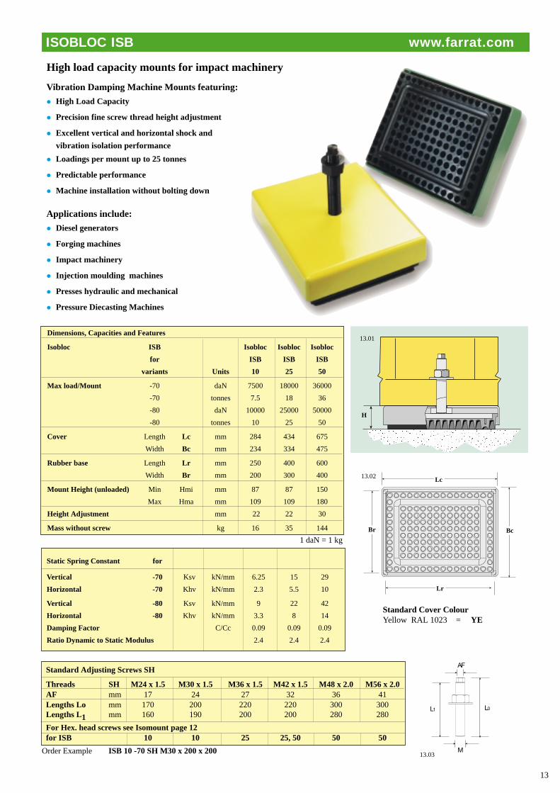
Vibration Damping Machine Mounts featuring:
• High Load Capacity
• Precision fine screw thread height adjustment
• Excellent vertical and horizontal shock and
vibration isolation performance
• Loadings per mount up to 25 tonnes
• Predictable performance
• Machine installation without bolting down
Applications include:
• Diesel generators
• Forging machines
• Impact machinery
• Injection moulding machines
• Presses hydraulic and mechanical
• Pressure Diecasting Machines
L1 L0
M
AF
13
13.01
13.03
Standard Cover ColourYellow RAL 1023 = YE
H
Dimensions, Capacities and Features
Isobloc ISB Isobloc Isobloc Isobloc
for ISB ISB ISB
variants Units 10 25 50
Max load/Mount -70 daN 7500 18000 36000
-70 tonnes 7.5 18 36
-80 daN 10000 25000 50000
-80 tonnes 10 25 50
Cover Length Lc mm 284 434 675
Width Bc mm 234 334 475
Rubber base Length Lr mm 250 400 600
Width Br mm 200 300 400
Mount Height (unloaded) Min Hmi mm 87 87 150
Max Hma mm 109 109 180
Height Adjustment mm 22 22 30
Mass without screw kg 16 35 144
Static Spring Constant for
Vertical -70 Ksv kN/mm 6.25 15 29
Horizontal -70 Khv kN/mm 2.3 5.5 10
Vertical -80 Ksv kN/mm 9 22 42
Horizontal -80 Khv kN/mm 3.3 8 14
Damping Factor C/Cc 0.09 0.09 0.09
Ratio Dynamic to Static Modulus 2.4 2.4 2.4
Standard Adjusting Screws SH
Threads SH M24 x 1.5 M30 x 1.5 M36 x 1.5 M42 x 1.5 M48 x 2.0 M56 x 2.0AF mm 17 24 27 32 36 41Lengths Lo mm 170 200 220 220 300 300Lengths L1 mm 160 190 200 200 280 280
For Hex. head screws see Isomount page 12for ISB 10 10 25 25, 50 50 50
13.02 Lc
Lr
Br Bc
High load capacity mounts for impact machinery
ISOBLOC ISB www.farrat.com
Order Example ISB 10 -70 SH M30 x 200 x 200
1 daN = 1 kg

H
14
14.01 14.02
W
L14.03
Maximum Load Capacity daN for variants
Damping Grades
Model A B C D E
WL1* 500 600 400 500 1500WLF1* 1000 1300 800 1000 3000WL2* 900 1200 700 900 3000WLF2* 1300 1600 1000 1300 4000WL3* 1900 2200 1500 1900 6000WLF3* 2300 3000 1800 2300 7000WL4* 4000 5000 3200 4000 12000WL5* 3000 4000 2300 3000 9000WL6* 5400 7000 4000 5400 14000WL7* 9000 10000 6500 9000 25000
Order Example WL 2 - A
Vibration damping grades
Type Top (T) Bottom (B) Grade Application examples
A SG5 P1 SG 15 P1 Standard General machine tools, Printing machines etc
B SG 2P2 SG 6 P2 Stiff CNC Lathes, Machining centres, Boring and Milling machines, Grinders, Transfer machines
C SG 2 P2 IM BR-70-25 Elastic Passive isolation of sensitive equipment Active isolation of Impact machinery, Presses etc.
D NBR 5P1 NBR 15P1 Flexible Shock absorbing Injection moulding and Diecasting machines
E SG 2 P2 SG2P2 Very Stiff Long bed machinery
Typical applictions: Machine tools, rubber and plastics machinery,printing and packaging machinery.
Free Standing Wedgemounts WL,WLF
Dimensions mm Heights H (mid position.) Height Unit Adj. Mass
Model L W A B C D E +/- kg
WL 1* 105 55 56 44 63 56 40 4 1.4WLF1* 115 80 60 48 67 60 44 5 2.6WL 2* 150 75 60 48 67 60 44 5 3.2WLF2* 115 115 66 54 73 66 50 6 3.5WL 3* 200 95 66 54 73 66 50 6 5.8WLF3* 150 150 66 54 73 66 50 6 6.9WL 4* 200 200 66 54 73 66 50 6 11.8WL 5* 250 115 90 78 97 90 74 9 13.5WL 6* 200 250 92 80 99 92 76 10 18.0WL 7* 250 330 90 78 97 90 74 9 33.1
*Specify grade: e.g. WL 2B
Precision, height adjustable, vibrationdamping machine mounts for accurate,efficient and economical machine installation
WEDGEMOUNTS Free standing - WL, WLF www.farrat.com
1 daN = 1 kg

Maximum Load/Mount daN
Vibration damping variantWLB WLT F G H
WLB 1 WLT 1 900 1200 3000WLB 2 WLT 2 1300 1600 4000WLB 3 WLT 3 2300 3000 7000WLB 4 WLT 4 4000 5000 12000WLB 6 WLT 6 5500 7000 14000WLB 7 WLT 7 9000 10000 25000
Order Examples: WLB 2 F, WLT 3 G
Precision, height adjustable, vibration damping machine mounts for accurate, efficient andeconomical machine installation
15
WLB
WLT
Ld
M
W
15.01
e
e
Fitted with vibration damping pads
Type Top (T) Bottom (B) Grade Application examples
F No pad SG 15 P1 Standard General Machine Tools, Printing Machines etc
G No pad SG 6P2 Stiff CNC Lathes, Machining Centres, Boring and Milling Machines,Grinders, Transfer machines
H No pad SG 2P2 Very Stiff Long Bed Machinery
WLB and WLT can also be supplied on request with vibration damping variants A,B,C, D or E (See WL, WLF)
Wedgemounts Bolt on WLB, Bolt through WLT Dimensions mm
Height Bolt on/through holes
Heights H (mid position.) Adj. WLB WLTWLB WLT L W F G H +/- d e Thread dia M
WLB 1 WLT 1 115 80 55 45 42 6 45 17 M12 14WLB 2 WLT 2 115 115 61 51 48 6 50 24 M16 18WLB 3 WLT 3 150 150 61 51 48 6 60 24 M20 22WLB 4 WLT 4 200 200 61 51 48 6 75 27 M20 22WLB 6 WLT 6 200 250 87 78 74 10 95 27 M20 22WLB 7 WLT 7 250 330 85 76 72 9 125 117 M24 26
15.02 15.03
S
M
L
H
15.04
WLB WLT
WEDGEMOUNTS Bolt-on WLB, Bolt-through WLT www.farrat.com
Bolt on screw assemblies BOS
Zinc plated mild steel Dimensions mm
Thread M M12x1.75 M16x2 M20x2.5 M24x3
S 8 11 13 18H 10 10 10 10
L 80 80 - - Zinc Plated 100 100 100 -Mild Steel 120 115 115 -
150 150 150 150Order Example - 180 180 180BOS M20x2.5x115 250 250 250 -
Order ExamplesWLB 1 F+ 1-BOS M12x1.75x100 Wedgemount WLB with one (1) Bolt on screw per mount
WLB 2 G+ 2-BOS M16x2x150 Wedgemount WLB with two (2) Bolt on screws per mount
WLB 3 H Wedgemount WLB No Bolt on screw
Typical applictions: Machine tools, Rubber machinery, Printing and Packaging Machinery, Injection Moulders
WLB WLT
1 daN = 1 kg

Spheriseats SPSOptional Spheriseats placed on the LE units can be used to take up complex angles between the LE andmachine base.
WL-LE units are vertical rise screw drivenWedgemounts with both top and bottom faces fullymachined.
Applications include:Supporting and levelling machinery duringconstruction, erection and operation. LEsprovide a rigid support for maximum stiffness.They can be installed free standing for machineswithout strong dynamic forces or in conjunctionwith holding down bolts located alongside theWL-LE units.
Wedge Levelling Elements WL-LE Dimensions: mmB T Max.Load/ M
Free standing Bolt on Bolt through Mount daN L x W H mid. H Adj.. d e B T
WL 1-LE - - 1500 105 x 55 34 ± 4 - - -
WLF 1-LE WLB 1-LE WLT1 -LE 3000 115 x 80 38 ± 6 45 15 M12 14
WL 2-LE - - 3000 150 x 75 38 ± 5 - - -
WLF 2-LE WLB 2-LE WLT 2 -LE 4000 115 x 115 44 ± 6 50 24 M16 18
WL 3-LE - - 6000 200 x 195 45 ± 6 - - -
WLF 3-LE WLB 3-LE WLT 3 -LE 7000 150 x 150 44 ± 6 60 24 M20 22
WL 5-LE - - 9000 250 x 115 68 ± 9 - - -
WL 6-LE WLB 6-LE WLT 6 -LE 14000 200 x 220 72 ± 10 95 27 M20 22
WL 7-LE WLB 7-LE WLT 7 -LE 25000 250 x 330 68 ± 9 125 117 M24 26
Spheriseats SPS Dimensions: mm
SPS 75 95 110 150
D1 75 95 110 150D2 70 90 100 140H 15 17 20 25
D3 To be specified, D4 = D3 + 5 Order example:SPS 95 - D3 = 50
H
H
D3 D1D2
16.01
16.03
16.04
Steel beam in concrete floor
W
L
WL(F)-LE
16.02
16
16.06
16.07
16.08
WLB-LE
WLT-LE
Ld
M
W
e
16.05
e
Farrat Isolevel Ltd.Balmoral Road, Altrincham, Cheshire WA15 8HJ. England GB Tel: +44(0) 8700 111899 Fax: +44(0) 8700 111809 email: [email protected] www.farrat.com
Information in this brochure is for guidance only and in the interests of product development may change
LEVELLING ELEMENTS WL(F)- LE, WLB-LE, WLT-LE www.farrat.com
D4
Precision Wedge Levelling units for rigid machine support
Order examples ; WL2 LE; WLF 3LE; WLB 2LE; WLT 1LE. 1daN = 1 kg