VIBRATION TESTING SYSTEMS - ETS Solutions Asia
52
VIBRATION TESTING SYSTEMS
-
Upload
khangminh22 -
Category
Documents
-
view
1 -
download
0
Transcript of VIBRATION TESTING SYSTEMS - ETS Solutions Asia

VIBRATION TESTING SYSTEMS

2
TABLE OF CONTENT
INDEX
4 Product Series
6 Vibration Testing Technology
7 Vibration Testing System Setup
8 VT-MS Series
12 L Series
16 M Series
20 LS Series
24 H Series
28 I Series
32 MET Series
34 MPA Series Power Amplifiers
36 IPA Series Power Amplifiers
38 Slip Table
42 Head Expander
45 Accelerometers
46 Vibration Control
48 Environmental Vibration Test Systems
50 Customized Products & Applications

3
TABLE OF CONTENT
YOUR LEADING SUPPLIER OF HIGH RELIABILITY VIBRATION TESTING SYSTEMSETS Solutions is formed by an experienced team of engineers with various professional experiences in the vibration and shock testing industry.
With more than five decades of expertise in the business, we’ve created our own line of efficient instruments and tools to alleviate the need of several industries that include aerospace, defence, automotive, consumer electronics, locomotive, construction and more.
Our talented engineering team works continuously on development of new products and improvement of the existing product range. This has enabled ETS Solutions to deliver products in a shorter time period without compromising quality or cost. We have been successful offering products that exceed the specifications of other vibration equipment manufacturers.
We are passionate about helping our customers produce reliable products by utilizing our equipment and expertise. We strive to consistently deliver quality products, responsive service, and delivering the best value in the industry.
Our superb technical team is constantly improving and innovating our products and this is what motivates us to be a leading innovator and solutions provider in the field of structural testing and measurement with comprehensive and cutting-edge technologies.

4
PRODUCT SERIES
FEATURES APPLICATIONS
VT SERIES
MS SERIES
L SERIES
M SERIES
LS SERIES
H SERIES
MET SERIES
I SERIES
Solutions to assist engineers to carry out vibration testing on small components and exciting structures for modal and structural analysis
Ideal for production testing of small components, electronic assemblies, sensor calibration and laboratory research
Ideal for screening of small electronic assemblies, automotive components, handheld units, storage devices, connectors
Ideal for testing medium to large sized electronic assemblies, automotive parts, and aviation and avionics parts
Ideal for test applications such as packaging testing and vehicle testing
High force system with high performance ideal for testing large sized assemblies with high accelerations
Screening of medium sized assemblies with extreme high acceleration test level and high frequency range
Multi-Excitation Testing real world vibration simulation and screening tests
• General mechanical mobility measurements• Experimental modal analysis on most mechanical
structures• Advanced structural dynamics investigations• Structural damage detection• Finite element model correlation• Ground vibration test• Modal survey
• Automotive and aerospace component testing• Electronic assembly testing• In-house test and calibration facilities• General mechanical mobility measurements• Experimental modal analysis on most mechanical
structures• Advanced structural dynamics investigations• Structural damage detection• Finite element model correlation• Ground vibration test• Modal survey
• Automotive and aerospace parts and modules testing• Avionics and defence equipment testing• Satellite module testing• Consumer electronics devices - quality qualification testing• Product packaging testing• Product stress screening
• Automotive and aerospace parts and modules testing• Low frequency road simulation test on product and
vehicle parts • Product packaging testing• Transportation stress screening on product
• Squeak & Rattle Test • Automotive part testing that requires high force and long
duration• High acceleration magnitude testing for aerospace,
avionics, military devices• Large size product packaging testing• Transportation stress screening on large sized equipment• Structural test on large size satellite launchers
• Real life vibration test replication• Squeak & Rattle Test• Automotive part testing with actual field data replication• Mil-STD 810G• Avionics parts testing• Transportation stress screening on medium sized devices• Structural test on medium size shipboard equipment
• Automotive and aerospace engines component test• Vehicle exhaust test• Heavy duty connector test• Avionics parts testing• Mil-STD testing

5
PRODUCT SERIES
BENEFITS• Simple system operation• Reasonable priced optimal performance system for major test standards• Ultra-compact energy efficient amplifiers output signal indication, overload protection,
connectivity error indication, constant current or constant voltage output• Used in conjunction with Sweeping signal generator• All-encompassing fuse protection designs for high current system components• Complies with USA, European and international safety and EMCregulations• Simple initial self-system setup• Easy maintenance and rapid servicing
• Complies with USA, European and international safety and EMC regulations• State-of-the-art microprocessor logic control unit• Integration with unibase or standalone slip table• Reasonably priced optimal performance system for major test standards• Compact shaker and amplifier size saving valuable floor space• All-encompassing fuse protection designed for high current system components• Interactive diagnostic ‘System Status’ displayed on LCD or touch screen• Compatible with all vibration controllers
• Complies with USA, European and international safety and EMC regulations• State-of-the-art microprocessor logic control unit• Integration with unibase or standalone slip table• Reasonably priced optimal performance system for major test standards• Modular multi-cabinet design• All-encompassing fuse protection designed for high current system components• Interactive diagnostic ‘System Status’ displayed on touch screen• Compatible with all vibration controllers
• Complies with USA, European and international safety and EMC regulations• State-of-the-art microprocessor logic control unit• Reasonably priced optimal performance system for major test standards• Modular multi-cabinet design• All-encompassing fuse protection designed for high current system components• Interactive diagnostic ‘System Status’ displayed on touch screen• Integrated design, compact structure• Compatible with any multi-axis MDOF vibration controller
• Simple system operation; State-of-the-art microprocessor logic control unit• High-energy conversion efficiency Amplifier (greater than 90%)• All-encompassing fuse protection designed for high current system components• Detailed scope of system interlock protection; Complies with USA, European and international
safety and EMC regulations• Compatible with all vibration controllers• Remote control panel available with full Amplifier features• Low-profile body design ready for chamber integration• Integration with unibase or standalone slip table; Simple initial self-system setup
6
VIBRATION TESTING TECHNOLOGY
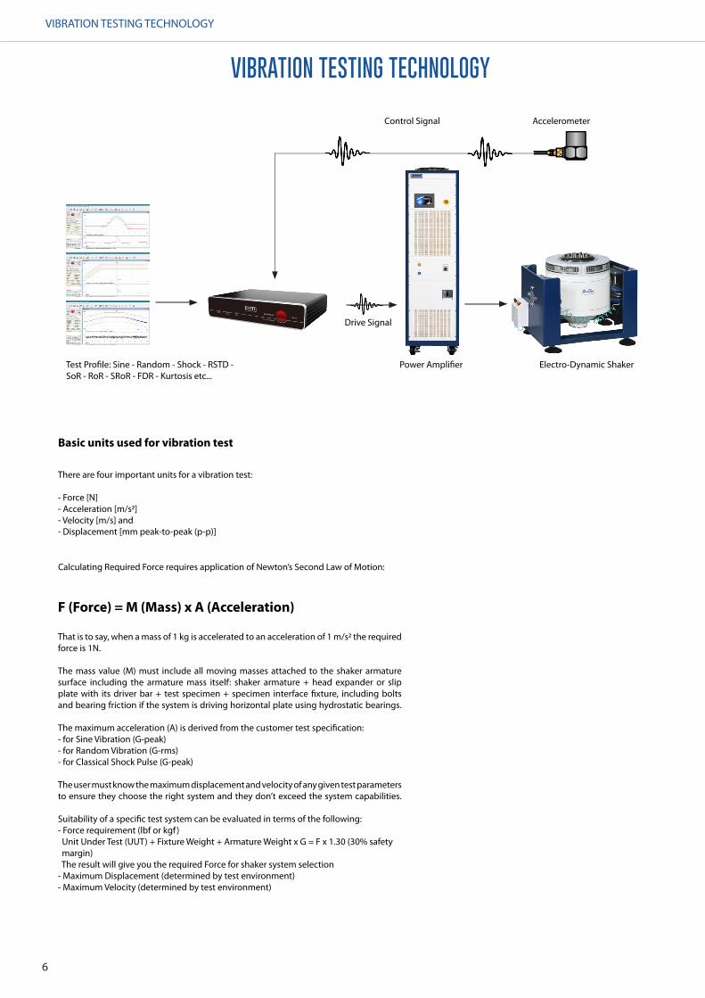
VIBRATION TESTING TECHNOLOGY
Basic units used for vibration test
There are four important units for a vibration test:
- Force [N]- Acceleration [m/s2]- Velocity [m/s] and - Displacement [mm peak-to-peak (p-p)]
Calculating Required Force requires application of Newton’s Second Law of Motion:
F (Force) = M (Mass) x A (Acceleration)
That is to say, when a mass of 1 kg is accelerated to an acceleration of 1 m/s2 the required force is 1N.
The mass value (M) must include all moving masses attached to the shaker armature surface including the armature mass itself: shaker armature + head expander or slip plate with its driver bar + test specimen + specimen interface fixture, including bolts and bearing friction if the system is driving horizontal plate using hydrostatic bearings.
The maximum acceleration (A) is derived from the customer test specification:- for Sine Vibration (G-peak)- for Random Vibration (G-rms)- for Classical Shock Pulse (G-peak)
The user must know the maximum displacement and velocity of any given test parameters to ensure they choose the right system and they don’t exceed the system capabilities.
Suitability of a specific test system can be evaluated in terms of the following:- Force requirement (lbf or kgf ) Unit Under Test (UUT) + Fixture Weight + Armature Weight x G = F x 1.30 (30% safety margin) The result will give you the required Force for shaker system selection- Maximum Displacement (determined by test environment)- Maximum Velocity (determined by test environment)
Test Profile: Sine - Random - Shock - RSTD - SoR - RoR - SRoR - FDR - Kurtosis etc...
Control Signal
Drive Signal
Power Amplifier Electro-Dynamic Shaker
Accelerometer

7
VIBRATION TESTING SYSTEM SETUP
VIBRATION TESTING SYSTEM SETUP
Power Amplifier
Electro-Dynamic Shaker
Cooling Blower
Water Cooling Unit
Accelerometer
Vibration Controller
Servo Control Console (SCC-1)
AND / OR
Head Expander
Remote Control
The use of vibration in Environmental Stress Screening (ESS) has expanded from the past from purely military applications until today commonly applied in the commercial sector. The use of ESS becomes a standard customer defined requirement in the aerospace and defence related products to ensure safe operation of critical equipment. Commercial product manufacturers today typically have full ESS programs in place with vibration test or combined with thermal cycling. The ESS programs are designed to comply with military and other international standards such as MIL, ASTM, IEC, ISO, BS etc.
The use of vibration in ESS has been proven to be a way to increase product reliability. It is also a tool to assist engineer in the product development process. Simulating the environment condition on the developing product will allow the design engineers to classify and analyse screening data to identify problem areas and recommend early corrective action.
Vibration testing as a part of ESS ensures the occurrence of failures in the product in early stage. These failures then occur before the units leave the manufacturing facility, dramatically improving field reliability. The optimal screening will maintain field failure cost savings.
PREREQUISITE SYSTEM COMPONENTS1. Vibration controller required for test profiling control. ETS shakers are compatible with all major vibration controllers.2. Signal conditioner required to provide current source for accelerometer or function as a charge amplifier.3. Accelerometer built-in amplifier type or charge-type for signal feedback to vibration controller or data acquisition.
ETS is able to provide a complete system package with a suitable controller of your choice.
SHAKER ACCESSORIES UNITS- Optional Remote Control Panel with full logic module replication function at remote site of up to 500m.- Servo Control Console for static and dynamic and armature auto-centering.- Customised head expanders and fixtures. Contact us for more information.- Different sizes of slip table available for horizontal testing. Contact us for more information.
AIR COOLED SHAKER SYSTEMS:L, M, LS Series
WATER COOLED SHAKER SYSTEMS:H Series
AIR & WATER COOLED SHAKER SYSTEMS:I Series

8
VIBRATION TESTING SYSTEMS
VT-MS SERIESIdeal for production testing of small components, electronic assemblies, sensor calibration and laboratory research.
The VT & MS Series applications include modal and structural analysis to measure vibration response of a wide-range of structures in both defence and civil engineering. VT & MS Series shakers can also be used to test fatigue life and vibration influences on small electric and mechanical components or devices. In addition, they are often used for the calibration of accelerometers and field vibration measurement systems.
Designed using permanent-magnet technology to deliver excitation, this palm-sized unit is suitable for a number of research and educational applications, including structural response testing and vibration transducer and accelerometer calibration. Has light weight, small volume and is convenient to move.This miniature exciter has a frequency range from 2 - 10 kHz and maximum peak-to-peak displacement of 10 mm. It delivers optimal performance when driven by our 200 VA power amplifier and can impart sine forces up to 50 N.
Software package include:- Random - performs real-time closed loop control of PSD profiles- Sine - performs closed swept sine vibration, to determine resonant frequencies and damping factors, overall peak G response of the structure- Classical Shock - performs closed loop control of transient waveforms. The entire transient period is sampled simultaneously and gap free. All of the classical types are supported. There are several displacement optimising methods
FEATURES- Large range of force and displacement output - Robust flexures providing best cross axial restraint- Reliable performance- Rugged, industrial design- Wide-frequency range, low distortion- Long-term stable performance- Small size and lightweight - Natural convection air cooling, with optional additional forced air cooling (MS)
PERFORMANCES - BENEFITS- Simple system operation- Reasonable priced optimal performance system for major test standards- Ultra-compact energy efficient amplifiers, output signal indication, overload protection, connectivity error indication, constant current or constant voltage output- Used in conjunction with sweeping signal generator - All-encompassing fuse protection designs for high current system components- Complies with USA, European and international safety and EMC regulations- Simple initial self-system setup- Easy maintenance and rapid servicing- Worldwide spare parts support
Modal Shaker MS Series Accessories Kit

9
VIBRATION TESTING SYSTEMS
SPECIFICATIONS - VT SERIESModel VT50 /
ST200 (T)VT100A / ST450 (T)
VT100B / ST450 (T)
VT200 / ST650 (T)
VT300 / ST750 (T)
VT500 / ST1100 (T)
VT1000 / ST1500 (T)
Rated Peak Force (N) Forced-Air Cooled (Sine/Random)
N/A 100N N/A 200N 300N 500N/350N 1000N/700N
Rated Peak Force (N) Convention (Sine/Random)
50N 50N 100N 100N 150N 250N/175N 500N/350N
Frequency Range (Hz) 5 - 10,000 5 - 10,000 5 - 7,000 5 - 6,500 5 - 6,500 5 - 5,000 5 - 4,000
Max. Displacement (mm) Peak-Peak 10 10 12 12 12 15 15
Max. Speed (m/s) 1.6 1.6 1.6 1.6 1.6 1.6 1.6
Max. Acceleration Speed (g) 20 35 35 50 65 80 80
Effective Moving Mass (kg) 0.25 0.3 0.4 0.4 0.45 0.63 1.3
Table Diameter (mm) ø 30 ø 30 ø 50 ø 50 ø 50 ø 50 ø 60
Max. Load (kg) 2 2 3 3 4 4 6
Shaker Weight (kg) 3.6 3.6 14.5 14.5 14.5 15 41
Coupling (Thread ø mm) 4 x M5 4 x M5 4 x M5 4 x M5 4 x M5 4 x M5 4 x M6
Dimensions (W x H x D) (mm) 148 x 95 x 188 148 x 95 x 188 200 x 265 x 250 200 x 265 x 250 200 x 265 x 250 200 x 265 x 250 266 x 347 x 342
Max. Operating Current 4A 8A 5A 10A 10A 10A 13A
DC Resistance (Ω) 1.1 1.1 2.8 2.8 2.8 4 3.8
Protection Over-displacementOver-current
Over-temperature
Over-displacementOver-voltageOver-current
Over-temperature
Over-displacementOver-voltageOver-current
Over-temperature
Over-displacementOver-voltageOver-current
Over-temperature
Over-displacementOver-voltageOver-current
Over-temperature
Over-displacementOver-voltageOver-current
Over-temperature
Over-displacementOver-voltageOver-current
Over-temperature
SPECIFICATIONS - MS SERIESModel MS50 /
ST200 (T)MS100A / ST450 (T)
MS100B / ST450 (T)
MS200 / ST650 (T)
MS250 / ST650 (T)
MS300 / ST750 (T)
MS500 / ST1100 (T)
MS1000 / ST1500 (T)
Rated Peak Force (N) Forced-Air Cooled (Sine/Random)
N/A 100N N/A 200N 250N 300N 500N/350N 1000N/700N
Rated Peak Force (N) Convention (Sine/Random)
50N 50N 100N 100N 130N 150N 250N/175N 500N/350N
Frequency Range (Hz) DC - 10,000 DC - 10,000 DC - 8,000 DC - 8,000 DC - 8,000 DC - 8,000 DC - 6,000 DC - 4,500
Main Resonance Frequency (Hz) 10,000 10,000 5,800 5,800 5,800 5,800 4,700 3,900
Max. Displacement (mm) Peak-Peak
16 16 18 18 18 18 20 20
Max. Acceleration Speed (g)
40 80 35 70 80 100 100 100
Effective Moving Mass (kg) 0.13 0.13 0.32 0.3 0.3 0.3 0.45 1
Shaker Weight (kg) 4 4 14.5 14.5 14.5 15 16 41
Coupling (Thread ø mm) M6 M6 M6 M6 M6 M6 M6 M6
Dimensions (W x H x D) (mm) 148 x 95 x 188 148 x 95 x 188 200 x 265 x 250 200 x 265 x 250 200 x 265 x 250 200 x 265 x 250 200 x 265 x 250 266 x 347 x 342
Max. Operating Current 4A 8A 5A 10A 10A 10A 10A 13A
DC resistance (Ω) 1.1 1.1 2.8 2.8 2.8 3 4 3.8
Protection Over-displacementOver-voltageOver-current
Over-temperature
Over-displacementOver-voltageOver-current
Over-temperature
Over-displacementOver-voltageOver-current
Over-temperature
Over-displacementOver-voltageOver-current
Over-temperature
Over-displacementOver-voltageOver-current
Over-temperature
Over-displacementOver-voltageOver-current
Over-temperature
Over-displacementOver-voltageOver-current
Over-temperature
Over-displacementOver-voltageOver-current
Over-temperature

10
VIBRATION TESTING SYSTEMS
VT-MS SERIES POWER AMPLIFIER
SPECIFICATIONS - POWER AMPLIFIERModel ST200 (T) ST450 (T) ST650 (T) ST750 (T) ST1100 (T) ST1500 (T)Linear or Digital Amplifier linear or digital linear or digital linear or digital linear or digital linear or digital linear or digital
Continous Sine Power Rating 200VA 450VA 650VA 750VA 1100VA 1500VA
Frequency Range (Hz) DC - 20 kHz DC - 20 kHz DC - 20 kHz DC - 20 kHz DC - 20 kHz DC - 20 kHz
Max. Output Voltage 30V 45V 65V 75V 110V 110V
Max. Output Current 6A 10A 10A 10A 10A 13A
Signal Input Voltage < 3Vrms < 3Vrms < 3Vrms < 3Vrms < 1Vrms < 1Vrms
Signal to Noise Ratio > 90 dB > 90 dB > 90 dB > 90 dB > 90 dB > 90 dB
Total Harmonic Distortion < 1% (1KHZ) < 1% (1KHZ) < 1% (1KHZ) < 1% (1KHZ) < 1% (1KHZ) < 1% (1KHZ)
Weight (kg) 4.5 4.5 5 6 6 6.5
Dimensions (W x H x D) (mm) 250 x 160 x 320 250 x 160 x 320 250 x 160 x 320 250 x 160 x 320 480 x 470 x 132 480 x 470 x 132
Adjustment Function
Current & voltage limits
Current & voltage limits
Current & voltage limits
Current & voltage limits
Current & voltage limits
Current & voltage limits
Max. Power Consumption at 230V
440VA 500VA 720VA 820VA 1200VA 1600VA
ProtectionOver-voltageOver-current
Over-temperature
Over-displacementOver-voltageOver-current
Over-temperature
Over-displacementOver-voltageOver-current
Over-temperature
Over-displacementOver-voltageOver-current
Over-temperature
Over-displacementOver-voltageOver-current
Over-temperature
Over-displacementOver-voltageOver-current
Over-temperature
(T) - Touch Screen
Specifications are correct at the time of publication. In keeping with our commitment to continuous product improvement, the information herewith is subject to change. ETS reserves the rights to amend specifications without prior notice.

11
VIBRATION TESTING SYSTEMS
APPLICABLE OBJECTS- Working piezoelectric acceleration transducer, velocity transducer and vibrometer while produced, maintained and employed- Various types of acceleration, velocity transducer and vibrometer, such as voltage type, charge type, IEPE type, TEDS type and so on.
STANDARDISO 16063-21:2003 Vibration and Shock Transducer Calibration Method
FEATURES- Calibrate accurately all kinds of acceleration transducer, velocity transducer and vibrometer, including voltage type, charge type, IEPE, TEDS, etc.- Frequency range is 2Hz-10kHz, support point-bypoint comparison calibration, swept sine calibration, random excitation and impact excitation methods, etc.- High precision and dynamic range, system uncertainty: <1% (160Hz, 100 m/s2)- At the end of calibration, it will automatically generate a detailed report, including sensitivity, linearity and amplitude and frequency response curve; all data will be input database, compiling refers to ISO17025- Substitution calibration option prolongs the service life of standard transducer- TEDS transducer support, and results wrote in it- Power Amplifier with digital display
CALIBRATION ITEMS- Sensitivity Calibration: frequency range default 160Hz, acceleration default 10 m/s2 - Frequency Response Swept Sine: Breakpoint tabular form defined the sweep range and reference acceleration value; User defined sweep method (logarithmic or linear), sweep speed and time. Step Sine: Tabular form defined at least 10 frequency points and its reference acceleration, max. 4096 discrete points, frequency points according to 1/3 octave or 1/1 octave. Random Calibration (FFT): Breakpoint tabular form defined random profile; User defined RMS value, analysis lines and calibration time.- Amplitude Linearity: The curve is frequency VS acceleration which reflects the frequency VS sensitivity. Tabular form defined the measurement frequency points.- Transverse Sensitivity Calibration: The transverse sensitivity is the accelerometer output sensitivity when acceleration is applied at its geometrical right angle.
CALIBRATION SYSTEM

12
VIBRATION TESTING SYSTEMS
L SERIESVibration System Force Rating from 200 kgf to 600 kgf
Ideal for screening of small electronics assemblies, automotive components, handheld units, storage devices, connectors.
Designed to meet military and international test standards including MIL, ASTM, IEC, ISO, BS, JIS etc. A large diameter armature with high cross-axial stiffness will allow using a proportioned head expander to test multiple specimens simultaneously yet achieving good vibration transmissibility ratio. Other test requirements including transportation vibration simulation, combined vibration-climatic test and seismic simulations for small size components can easily be fulfilled by the “L” Series. ETS Solutions “L” Series is the low-cost vibration product qualification and testing solution for small sized test specimens.
FEATURESTHE PERFORMANCE- Specimen payload up to 300 kg- Excellent random performance meeting ISO standard with 3 sigma peak current rating- Armature diameters range from 150 mm to 200 mm- Up to 51 mm continuous displacement- Test frequency up to 4,500 Hz
THE SHAKER- Rugged trunnion design with bearing guidance- Air bag or elastomer isolator built-in reducing dynamic floor stress- Dual layer reinforced armature for high acceleration performance- Roller-truss flexure suspension system with high cross-axial stiffness
THE AMPLIFIER- Integrated with high performance MPA series small sized amplifier- Modular designed amplifier- 12 kVA power module with two self-reliant compact 6 kVA sub- modules- High modulation switching frequency- High signal to noise ratio- Low total harmonic distortion- Individual power module operation indication light
THE ACCESSORIES- Air load support for armature centering- Dynamic and static armature centering available- Rotary worm-gear built-in for uni-base slip table- Thermal barrier for combined climatic chamber test available- Remote control capabilities available
BENEFITS- Simple system operation- State-of-the-art microprocessor logic control unit- High-energy conversion efficiency (greater than 90%)- Reasonable priced optimal performance system for major test standards- Compact shaker and amplifier size saving valuable floor space- Shaker air-cooled by rugged outdoor blower for continuous long-period operation- Air cooled amplifier for safe and reliable operation- Design to reduced reliance on mechanical switchgears with CPU logic controlled- All-encompassing fuse protection designed for high current system components- Detailed scope of system interlock protections- Complies with USA, European and international safety and EMC regulations- Compatible with all vibration controllers- Remote control panel available with full functional features- Low-profile body design ready for chamber integration- Integration with unibase or standalone slip table- Simple initial self-system setup- Interactive diagnostic “System Status” displayed on LCD- Easy maintenance and rapid servicing- Worldwide spare parts support

13
VIBRATION TESTING SYSTEMS
SPECIFICATIONS - L SERIESSYSTEM MODEL MPA101 / L215M MPA101 / L315M MPA102 / L620MSine Force 200 kgf 300 kgf 600 kgf
Random Force 200 kgf 300 kgf 600 kgf
Shock Force (½ Sine) 400 kgf 600 kgf 1,200 kgf
Usable Frequency Range DC to 4,500 Hz DC to 4,000 Hz DC to 3,500 Hz
Continuous / Shock Displacement (1) 25.4 mm / 25.4 mm 25.4 mm / 25.4 mm 51 mm / 51 mm
Max. Velocity (Sine) 2.0 m/s 2.0 m/s 2.0 m/s
Max. Acceleration (Sine) 981 m/s² 981 m/s² 981 m/s²
SHAKER UNIT L215M L315M L620MArmature Diameter 150 mm 150 mm 200 mm
Effective Moving Element Mass 2 kg 2.5 kg 6 kg
Load Attachment Points 12 stainless steel inserts 12 stainless steel inserts 16 stainless steel inserts
Inserts Size (Standard) M8 M8 M8
Grid Pattern (Diameter, Circle) 6 on Ø 60mm; 6 on Ø 120mm 6 on Ø 60mm; 6 on Ø 120mm 8 on Ø 100mm; 8 on Ø 160mm
Nominal, Bare Table (2) 3,100 Hz 2,900 Hz 3,300 Hz
Max. Static Payload 70 kg 120 kg 300 kg
Natural Frequency (Thrust Axis) < 5 Hz < 5 Hz < 5 Hz
Stray Flux Density (3) Less than 10 gauss Less than 10 gauss Less than 10 gauss
Dimensions (Uncrated) (L x W x H) 696 x 599 x 595 mm 754 x 599 x 620 mm 943 x 633 x 710 mm
Weight (Uncrated) 440 kg 490 kg 730 kg
AMPLIFIER UNIT MPA101 MPA101 MPA102Amplifier Output 2 kVA 3 kVA 6 kVA
Total Harmonic Distortion (At Rated Output) From DC (0.1Hz) to 500Hz less than 0.5%; From 500Hz to 5,000Hz less than 1.0%
Signal-Noise-Ratio More than 65 dB at 100 V rms output, 10KΩ input termination with rated resistive load
DC Stability Less than 0.05% of full output voltage with 10% change in line voltage
Input Drive 4 V rms into 10KΩ for full output (120V rms)
Amplifier Frequency Response (4) From DC (0.1Hz) to 4,500Hz: ± 3dB; From 10Hz to 3,000Hz: ± 1dB
Switching Frequency 112 kHz 112 kHz 112 kHz
Max. Output Voltage 120V rms 120V rms 120V rms
Max. Output Current Per Module(Continuous / Transient) 50 A rms / 150 A rms 50 A rms / 150 A rms 50 A rms / 150 A rms
Amplifier Efficiency > 90% > 90% > 90%
Dimensions (Uncrated) (L x W x H) 550 x 680 x 1455 mm 550 x 680 x 1455 mm 550 x 680 x 1455 mm
Weight (Uncrated) 230 kg 230 kg 280 kg
BLOWER UNIT HP-1A HP-1A HP-2APower Output 0.75 kW 0.75 kW 4 kW
Air Flow 0.095 m³ / s 0.104 m³ / s 0.192 m³ / s
Air Pressure 0.012 kgf / cm² 0.011 kgf / cm² 0.06 kgf / cm²
Dimensions (Uncrated) (L x W x H) 488 x 373 x 1055 mm 488 x 373 x 1055 mm 748 x 604 x 1450 mm
Weight (Uncrated) 40 kg 40 kg 115 kg
Specifications are correct at the time of publication. In keeping with our commitment to continuous product improvement, the information herewith is subject to change. ETS reserves the rights to amend specifications without prior notice.
REMARKS:1. Test payload should be less than 10% of shaker weight2. First resonance frequency at ± 5% tolerance3. Measured at 152mm above armature table. Contact us for lower gauss level requirement.4. Sine mode, resistive load

14
VIBRATION TESTING SYSTEMS
L SERIES
L215M L315M L620M
MPA101MPA102
HP-1A HP-2A
Servo Control Console (SCC-1 Unit)
Remote Control Panel (RCP)
SYSTEM OPTIONS MPA101 / L215M MPA101 / L315M MPA102 / L620MTable Inserts
M8 • • •
M10 - - 0
1/2” UNC - - 0
3/8” UNC 0 0 0
Internal Load Support • • •
Thermal Barrier 0 0 0
Unibase Slip Table 0 0 0
Air Caster 0 0 0
Degauss Coil - - -
Electrical Rotation Unit - - -
Air Isolation Trunnion • • •
Geared Aided Rotation (Ratchet Crank) 0 0 0
Servo Control Console (SCC-1 Unit) - - •
Auxiliary Interlock Unit (AIU) 0 0 0
Remote Control Panel (RCP) 0 0 0
• Standard 0 Optional - Not Available

15
VIBRATION TESTING SYSTEMS
OPERATING ENVIRONMENTAL DATA
MPA101 / L215M MPA101 / L315M MPA102 / L620M
Max. Heat Rejection to Air (Shaker) 0.21 kW 0.27 kW 0.54 kW
Max. Heat Rejection to Air (Amplifier) 0.3 kW 0.45 kW 0.85 kW
Max. Heat Rejection to Air (Blower) 0.64 kW 0.64 kW 3.4 kW
Working Ambient Temperature * 5 ~ 35 °C 5 ~ 35 °C 5 ~ 35 °C
Working Ambient Pressure 0.1 MPa 0.1 MPa 0.1 MPa
Relative Humidity (Non-Condensing) ≤ 80% ≤ 80% ≤ 80%
Max. Acoustic Noise 92 dB 92 dB 92 dB
Temperature Range of Air Flow at Shaker Inlet 0 ~ 35 °C 0 ~ 35 °C 0 ~ 35 °C
Air Line Supply Required (Compressed Air Supply) 6.9 bar 6.9 bar 6.9 bar
Input Voltage (Standard) 380 VAC, 50 Hz, 3 Phase
Power Requirements 6 kVA 7.5 kVA 17 kVA
*Full power to 35 °C, derate at 2% per °C to 50 °C

16
VIBRATION TESTING SYSTEMS
M SERIESVibration System Force Rating from 1,000 kgf to 7,000 kgf
Ideal for testing medium to large sized electronic assemblies, automotive parts, aviation and avionics parts.
The “M” Series is designed to meet military and international test standards including MIL, ASTM, IEC, ISO, BS, and JIS. A wide diameter armature with high cross-axial stiffness will allow using a proportioned head expander to test multiple specimens simultaneously yet achieving good vibration transmissibility ratio.
Other test requirements including transportation vibration simulation, combined vibration-climatic test and seismic simulations for small size components can easily be fulfilled by the “M” Series.
FEATURESTHE PERFORMANCE- Specimen payload up to 1,000 kg- Excellent random performance meeting ISO standard with 3 sigma peak current rating- Armature diameters range from 240 mm to 480 mm- Up to 51 mm continuous displacement- Test frequency up to 4,000 Hz
THE SHAKER- Rugged trunnion design with bearing guidance- Air bag or elastomer isolator built-in reducing dynamic floor stress- Light weight composite armature coil for high acceleration performance- Flexure suspension system with high cross axial stiffness
THE AMPLIFIER- Integrated with new Intelligent Power Amplifier - New design with High Speed IGBT technology - Compact sized power module with large output (30 kVA each)- High modulation switching frequency- High signal to noise ratio- Dynamic fault current error control protection- Complete digital control
THE ACCESSORIES- Air load support for armature centering- Dynamic and static armature centering available - Rotary worm-gear built-in for uni-base slip table- Thermal barrier for combined climatic chamber test available- Remote control capabilities available
BENEFITS- Simple system operation- Intelligent PLC control and monitoring system- High energy conversion efficiency (greater than 90%)- Reasonably priced optimal performance system for major test standards- Compact shaker and amplifier size saving valuable floor space - Compatible with any vibration controller- Remote control panel via Ethernet cable connections- Low profile body design ready for chamber integration - Integration with unibase or standalone slip table- Shaker air cooled by rugged outdoor blower for continuous long period operation- Air cooled amplifier power electronics for safe and reliable operation- Ethernet port available for data exchange - All-encompassing fuse protection design for high current system components - Detailed scope of system interlock protections- Complies with USA, European and international safety and EMC regulations- Simple initial self-system setup- Interactive diagnostic “System Status” on touch screen - Easy maintenance and rapid servicing- Worldwide spare parts support

17
VIBRATION TESTING SYSTEMS
SPECIFICATIONS - M SERIESSYSTEM MODEL MPA403 / M124M IPA30L / M232A IPA60L / M437A IPA90L / M544A IPA90L / M748ASine Force 1,000 kgf 2,000 kgf 4,000 kgf 5,000 kgf 7,000 kgf
Random Force 1,000 kgf 2,000 kgf 4,000 kgf 5,000 kgf 7,000 kgf
Shock Force (½ Sine) 2,000 kgf 4,000 kgf 8,000 kgf 10,000 kgf 14,000 kgf
Usable Frequency Range DC to 4,000 Hz DC to 3,000 Hz DC to 2,500 Hz DC to 2,700 Hz DC to 2,500 Hz
Continuous / Shock Displacement (1) 51 mm / 51 mm 51 mm / 51 mm 51 mm / 51 mm 51 mm / 51 mm 51 mm / 63.5 mm
Max. Velocity (Sine) 2.0 m/s 2.0 m/s 2.0 m/s 2.0 m/s 2.0 m/s
Max. Acceleration (Sine) 981 m/s² 981 m/s² 981 m/s² 981 m/s² 981 m/s²
SHAKER UNIT M124M M232A M437A M544A M748AArmature Diameter 240 mm 320 mm 370 mm 445 mm 480 mm
Effective Moving Element Mass 10 kg 20 kg 34 kg 50 kg 64 kg
Load Attachment Points 16 stainless steel inserts 16 stainless steel inserts 16 stainless steel inserts 16 stainless steel inserts 16 stainless steel inserts
Inserts Size (Standard) M10 M10 M10 M12 M12
Grid Pattern (Diameter, Circle)
8 on Ø 100mm; 8 on Ø 200mm
8 on Ø 120mm; 8 on Ø 250 mm
8 on Ø 150mm; 8 on Ø 300 mm
8 on Ø 200mm; 8 on Ø 400 mm
8 on Ø 200mm; 8 on Ø 400 mm
Nominal, Bare Table (2) 3,600 Hz 2,500 Hz 2,250 Hz 2,400 Hz 2,100 Hz
Max. Static Payload 140 kg 300 kg 500 kg 1,000 kg 1,000 kg
Natural Frequency (Thrust Axis) <5 Hz <5 Hz <5 Hz <5 Hz <5 Hz
Stray Flux Density (3) Less than 10 gauss Less than 10 gauss Less than 10 gauss Less than 10 gauss Less than 10 gauss
Dimensions (Uncrated) (L x W x H) 1061 x 730 x 784 mm 1189 x 780 x 1020 mm 1336 x 860 x 1118 mm 1620 x 1202 x 1313 mm 1620 x 1202 x 1390 mm
Weight (Uncrated) 960 kg 1,650 kg 2,470 kg 4,500 kg 4,500 kg
AMPLIFIER UNIT MPA403 IPA30L IPA60L IPA90L IPA90LAmplifier Output 13 kVA 30 kVA 60 kVA 90 kVA 90 kVA
Total Harmonic Distortion (At Rated Output)
From DC (0.1Hz) to 500Hz less than 0.5%; From 500Hz to 5,000Hz less than 1.0%
From 5 Hz to 2,500 Hz less than 1.2%; from 2,500 Hz to 3,500 Hz less than 1.5% with resistive load
Signal-Noise-Ratio More than 65dB at 100V rms output, 10KΩ input termination with rated
resistive load
More than 65 dB at 120 V rms output, 10 kΩ input termination with rated resistive load
DC Stability Less than 0.05% of full output voltages with 10% change in line voltage
Input Drive 4V rms into 10KΩ for full output (120V rms) 2 V rms into 10 kΩ for full output (120 V rms)
Amplifier Frequency Response (4)
From DC (0.1Hz) to 4,500Hz: ± 3dB; From 10Hz
to 3,000Hz: ± 1dBFrom 5 Hz to 10 Hz: ±6 dB; from 10 Hz to 5,000 Hz: ±3 dB
Switching Frequency 112 kHz 150 kHz 150 kHz 150 kHz 150 kHz
Max. Output Voltage 120 Vrms 120 Vrms 120 Vrms 120 Vrms 120 Vrms
Max. Output Current Per Module (Continuous / Transient)
50 Arms / 150 Arms 250 Arms / 750 Arms 250 Arms / 750 Arms 250 Arms / 750 Arms 250 Arms / 750 Arms
Amplifier Efficiency >90% >90% >90% >90% >90%
Dimensions (Uncrated) (L x W x H) 550 x 800 x 1850 mm 550 x 800 x 1850 mm 550 x 800 x 2070 mm 550 x 800 x 2070 mm 550 x 800 x 2070 mm
Weight (Uncrated) 420 kg 480 kg 515 kg 550 kg 550 kg
BLOWER UNIT HP-2A HP-3A HP-3A HP-4A HP-4APower Output 4 kW 7.5 kW 7.5 kW 22 kW 22 kW
Air Flow 0.21 m³ / s 0.467 m³ / s 0.73 m³ / s 0.91 m³ / s 1.035 m³ / s
Air Pressure 0.058 kgf / cm² 0.057 kgf / cm² 0.082 kgf / cm² 0.079 kgf / cm² 0.095 kgf / cm²
Dimensions (Uncrated) (L x W x H) 748 x 604 x 1450 mm 945 x 693 x 1466 mm 945 x 693 x 1466 mm 930 x 1143 x 2185 mm 930 x 1143 x 2185 mm
Weight (Uncrated) 115 kg 175 kg 175 kg 370 kg 370 kg

18
VIBRATION TESTING SYSTEMS
M SERIESSpecifications are correct at the time of publication. In keeping with our commitment to continuous product improvement, the information herewith is subject to change. ETS reserves the rights to amend specifications without prior notice.
REMARKS:1. Test payload should be less than 10% of shaker weight2. First resonance frequency at ± 5% tolerance3. Measured at 152mm above armature table. Contact us for lower gauss level requirement.4. Sine mode, resistive load
M124M M232A M437A
M544A M748A IPA Series Amplifier
HP-2A HP-3A HP-4A
Servo Control Console (SCC-1 Unit)
Remote Control Panel (RCP)

19
VIBRATION TESTING SYSTEMS
SYSTEM OPTIONS MPA403 / M124M IPA30L / M232A IPA60L / M437A IPA90L / M544A IPA90L / M748A
Table Inserts
M10 • • • 0 0
M12 0 0 0 • •
1/2” UNC 0 0 0 0 0
3/8” UNC 0 0 0 0 0
Internal Load Support • • • • •
Thermal Barrier 0 0 0 0 0
Unibase Slip Table 0 0 0 0 0
Air Caster 0 0 0 0 0
Degauss Coil • • • • •
Electrical Rotation Unit - 0 0 0 0
Air Isolation Trunnion • • • • •
Geared Aided Rotation (Ratchet Crank) 0 • • 0 0
Geared Aided Rotation (Chain Wheel Reducer) - 0 0 • •
Servo Control Console (SCC-1 Unit) • • • • •
Remote Control Panel (RCP) 0 0 0 0 0
• Standard 0 Optional - Not Available
OPERATING ENVIRONMENTAL DATA
MPA403 / M124M IPA30L / M232A IPA60L / M437A IPA90L / M544A IPA90L / M748A
Max. Heat Rejection to Air (Shaker) 0.8 kW 1.5 kW 2.76 kW 3.5 kW 4.6 kW
Max. Heat Rejection to Air (Amplifier) 2.03 kW 3.15 kW 5.63 kW 7.5 kW 9.9 kW
Max. Heat Rejection to Air (Blower) 3.4 kW 6.38 kW 6.38 kW 12.75 kW 12.75 kW
Working Ambient Temperature * 5 ~ 35 °C 5 ~ 35 °C 5 ~ 35 °C 5 ~ 35 °C 5 ~ 35 °C
Working Ambient Pressure 0.1 MPa 0.1 MPa 0.1 MPa 0.1 MPa 0.1 MPa
Relative Humidity (Non-Condensing) ≤ 80% ≤ 80% ≤ 80% ≤ 80% ≤ 80%
Max. Acoustic Noise 92 dB 92 dB 92 dB 92 dB 92 dB
Temperature Range of Air Flow at Shaker Inlet 0 ~ 35 °C 0 ~ 35 °C 0 ~ 35 °C 0 ~ 35 °C 0 ~ 35 °C
Air Line Supply Required (Compressed Air Supply)
6.9 bar 6.9 bar 6.9 bar 6.9 bar 6.9 bar
Input Voltage (Standard) 380 VAC, 50 Hz, 3 Phase
Power Requirements 28 kVA 40 kVA 68 kVA 97 kVA 112 kVA
*Full power to 35 °C, derate at 2% per °C to 50 °C

20
VIBRATION TESTING SYSTEMS
LS SERIESVibration System Force Rating from 2,000 kgf to 7,000 kgf
Ideal for test applications such as packaging testing and vehicle testing.
The Long-Stroke (LS) Series vibration testing systems are designed for long-stroke displacement test requirements normally performed by hydraulic shakers.Compared to a hydraulic shaker where maximum test frequency is typically around 400 Hz, the Long-Stroke Series is capable to testing up to 2,700 Hz with maximum acceleration of 100g (bare table) bounded by 2.0 m/s maximum velocity. This provides users time and cost savings for wide test requirements.
FEATURESTHE PERFORMANCE- Specimen payload up to 1,000 kg- Excellent random performance meeting ISO standard with 3 sigma peak current rating- Armature diameters range from 320 mm to 480 mm- Up to 100 mm continuous displacement- Test frequency up to 2,700 Hz
THE SHAKER- Rugged trunnion design with bearing guidance- Air bag isolator built-in reducing dynamic floor stress- Dual layer reinforced armature for high acceleration performance- Roller bearing flexure with load support bearing suspension system achieving high cross-axial stiffness
THE AMPLIFIER- Integrated with new Intelligent Power Amplifier- New design with High Speed IGBT technology- Compact sized power module with large output (60 kVA each)- High modulation switching frequency- High signal to noise ratio- Dynamic fault current error control protection- Complete digital control
THE ACCESSORIES- Air load support for armature centering- Dynamic and static armature centering available- Geared aided rotation for uni-base slip table- Thermal barrier for combined climatic chamber test available- Remote control capabilities available
BENEFITS- Simple system operation- Intelligent PLC control and monitoring system- High-energy conversion efficiency (greater than 90%)- Reasonably priced optimal performance system for major test standards- Compact shaker and amplifier size saving valuable floor space- Shaker air-cooled by rugged outdoor blower for continuous long-period operation- Air cooled amplifier for safe and reliable operation- Ethernet port available for data exchange- All-encompassing fuse protection designed for high current system components- Detailed scope of system interlock protections- Complies with USA, European and international safety and EMC regulations- Compatible with all vibration controllers- Remote control panel via Ethernet cable connections- Low-profile body design ready for chamber integration- Integration with unibase or standalone slip table- Simple initial self-system setup- Interactive diagnostic “System Status” displayed on touch screen- Easy maintenance and rapid servicing- Worldwide spare parts support

21
VIBRATION TESTING SYSTEMS
SPECIFICATIONS - LS SERIESSYSTEM MODEL IPA60H / LS232A IPA60H / LS437A IPA60H / LS544A IPA120H / LS748ASine Force 2,000 kgf 4,000 kgf 5,000 kgf 7,000 kgf
Random Force 2,000 kgf 4,000 kgf 5,000 kgf 7,000 kgf
Shock Force (½ Sine) 4,000 kgf 8,000 kgf 10,000 kgf 14,000 kgf
Usable Frequency Range DC to 2,700 Hz DC to 2,500 Hz DC to 2,700 Hz DC to 2,500 Hz
Continuous / Shock Displacement (1) 80 mm / 100 mm 80 mm / 100 mm 80 mm / 100 mm 63.5 mm / 76 mm
Max. Velocity (Sine) 2.0 m/s 2.0 m/s 2.0 m/s 2.0 m/s
Max. Acceleration (Sine) 784 m/s² 784 m/s² 784 m/s² 784 m/s²
SHAKER UNIT LS232A LS437A LS544A LS748AArmature Diameter 320 mm 370 mm 445 mm 480 mm
Effective Moving Element Mass 22 kg 37 kg 62 kg 68 kg
Load Attachment Points 16 stainless steel inserts 16 stainless steel inserts 16 stainless steel inserts 16 stainless steel inserts
Inserts Size (Standard) M10 M10 M12 M12
Grid Pattern (Diameter, Circle)
8 on Ø 120mm; 8 on Ø 250mm
8 on Ø 150mm; 8 on Ø 300mm
8 on Ø 200mm; 8 on Ø 400mm
8 on Ø 200mm; 8 on Ø 400mm
Nominal, Bare Table (2) 2,300 Hz 2,100 Hz 2,100 Hz 2,100 Hz
Max. Static Payload 300 kg 500 kg 1,000 kg 1,000 kg
Natural Frequency (Thrust Axis) < 5 Hz < 5 Hz < 5 Hz < 5 Hz
Stray Flux Density (3) Less than 10 gauss Less than 10 gauss Less than 10 gauss Less than 10 gauss
Dimensions (Uncrated) (L x W x H) 1189 x 775 x 1078 mm 1336 x 865 x 1204 mm 1621 x 1102 x 1363 mm 1620 x 1202 x 1390 mm
Weight (Uncrated) 1,700 kg 2,800 kg 4,500 kg 4,500 kg
AMPLIFIER UNIT IPA60H IPA60H IPA60H IPA120HAmplifier Output 60 kVA 60 kVA 60 kVA 120 kVA
Total Harmonic Distortion (At Rated Output) From 5Hz to 2,500Hz less than 1.2%; From 2,500Hz to 3,500Hz less than 1.5% with resistive load
Signal-Noise-Ratio More than 70 dB at 320 V rms output, 10KΩ input termination with rated resistive load
DC Stability Less than 0.05% of full output voltage with 10% changes in line voltage
Input Drive 2 V rms into 10KΩ for full output (320V rms)
Amplifier Frequency Response (4) From 5Hz to 10Hz: ± 6dB; From 10Hz to 5,000Hz: ± 3dB
Switching Frequency 150 kHz 150 kHz 150 kHz 150 kHz
Max. Output Voltage 320V rms 320V rms 320V rms 320V rms
Max. Output Current Per Module(Continuous / Transient) 190 A rms / 570 A rms 190 A rms / 570 A rms 190 A rms / 570 A rms 190 A rms / 570 A rms
Amplifier Efficiency > 90% > 90% > 90% > 90%
Dimensions (Uncrated) (L x W x H) 550 x 800 x 1850 mm 550 x 800 x 2070 mm 550 x 800 x 2070 mm 550 x 800 x 2070 mm
Weight (Uncrated) 500 kg 500 kg 500 kg 550 kg
BLOWER UNIT HP-3A HP-3A HP-4A HP-4APower Output 7.5 kW 7.5 kW 22 kW 22 kW
Air Flow 0.476 m³ / s 0.745 m³ / s 0.91 m³ / s 1.035 m³ / s
Air Pressure 0.056 kgf / cm² 0.082 kgf / cm² 0.079 kgf / cm² 0.095 kgf / cm²
Dimensions (Uncrated) (L x W x H) 945 x 693 x 1466 mm 945 x 693 x 1466 mm 930 x 1143 x 2185 mm 930 x 1143 x 2185 mm
Weight (Uncrated) 175 kg 175 kg 370 kg 370 kg
Specifications are correct at the time of publication. In keeping with our commitment to continuous product improvement, the information herewith is subject to change. ETS reserves the rights to amend specifications without prior notice.
REMARKS:1. Test payload should be less than 10% of shaker weight2. First resonance frequency at ± 5% tolerance3. Measured at 152mm above armature table. Contact us for lower gauss level requirement.4. Sine mode, resistive load

22
VIBRATION TESTING SYSTEMS
LS SERIES
HP-3A HP-4A
Servo Control Console (SCC-1 Unit)
Remote Control Panel (RCP)
IPA Series Amplifier
LS748ALS544ALS437ALS232A

23
VIBRATION TESTING SYSTEMS
SYSTEM OPTIONS IPA60H / LS232A IPA60H / LS437A IPA60H / LS544A IPA120H / LS748ATable Inserts
M10 • • 0 0
M12 0 0 • •
1/2” UNC 0 0 0 0
3/8” UNC 0 0 0 0
Internal Load Support • • • •
Thermal Barrier 0 0 0 0
Unibase Slip Table 0 0 0 0
Air Caster 0 0 0 0
Degauss Coil • • 0 0
Electrical Rotation Unit - - 0 0
Air Isolation Trunnion • • • •
Geared Aided Rotation (Ratchet Crank) • • 0 0
Geared Aided Rotation (Chain Wheel Reducer) 0 0 • •
Servo Control Console (SCC-1 Unit) • • • •
Remote Control Panel (RCP) 0 0 0 0
• Standard 0 Optional - Not Available
OPERATING ENVIRONMENTAL DATA
IPA60H / LS232A IPA60H / LS437A IPA60H / LS544A IPA120H / LS748A
Max. Heat Rejection to Air (Shaker) 1.5 kW 2.23 kW 3.5 kW 4.6 kW
Max. Heat Rejection to Air (Amplifier) 3.15 kW 4.35 kW 7.5 kW 9.9 kW
Max. Heat Rejection to Air (Blower) 6.38 kW 6.38 kW 12.75 kW 12.75 kW
Working Ambient Temperature * 5 ~ 35 °C 5 ~ 35 °C 5 ~ 35 °C 5 ~ 35 °C
Working Ambient Pressure 0.1 MPa 0.1 MPa 0.1 MPa 0.1 MPa
Relative Humidity (Non-Condensing) ≤ 80% ≤ 80% ≤ 80% ≤ 80%
Max. Acoustic Noise 92 dB 92 dB 92 dB 92 dB
Temperature Range of Air Flow at Shaker Inlet 0 ~ 35 °C 0 ~ 35 °C 0 ~ 35 °C 0 ~ 35 °C
Air Line Supply Required (Compressed Air Supply) 6.9 bar 6.9 bar 6.9 bar 6.9 bar
Input Voltage (Standard) 380 VAC, 50 Hz, 3 Phase
Power Requirements 40 kVA 68 kVA 97 kVA 112 kVA
*Full power to 35 °C, derate at 2% per °C to 50 °C

24
VIBRATION TESTING SYSTEMS
H SERIESVibration System Force Rating from 8,000 kgf to 30,000 kgf
Ideal for screening of large sized assemblies with high acceleration test requirements.
The “H” Series also meets typical vibration test requirements of other large sized electronic assemblies, automotive parts, aviation, avionics parts, satellites, aerospace and military systems. The “H” Series vibration is designed to meet military and international test standards including MIL, ASTM, IEC, ISO, BS and JIS. A wide diameter armature with high cross-axial stiffness will allow for using a proportioned head expander to test multiple specimens simultaneously yet achieving good vibration transmissibility ratio.Other test requirements including transportation vibration simulation, combined vibration-climatic test and seismic simulations for large size components can easily be fulfilled by the “H” Series. Options are available to meet the most stringent test requirements for hazardous or explosive materials.
FEATURESTHE PERFORMANCE- Specimen payload up to 5,000 kg- Excellent random performance meeting ISO standard with 3 sigma peak current rating- Armature diameters range from 445 mm to 800 mm- Up to 63.5 mm continuous displacement- Test frequency up to 2,500 Hz
THE SHAKER- Separated water inlets and outlets current leads to the armature coil- Dual bearing shaft built-in for load support- High efficient water-cooled armature coil- Special copper flexure suspension system with high cross axial stiffness- Closed loop water cooling system
THE AMPLIFIER- Integrated with new Intelligent Power Amplifier - New design with High Speed IGBT technology - Compact sized power module with large output- High modulation switching frequency- High signal to noise ratio- Dynamic fault current error control protection- Complete digital control
THE ACCESSORIES- Dynamic and static armature centering available - Geared aided rotation built-in for uni-base slip table- Thermal barrier for combined climatic chamber test available- Remote control capabilities available
BENEFITS- Simple system operation- Intelligent PLC control and monitoring system- High energy conversion efficiency (greater than 90%)- Reasonably priced optimal performance system for major test standards- Compact shaker and amplifier size saving valuable floor space - Compatible with any vibration controller- Remote control panel via Ethernet cable connections- Low profile body design ready for chamber integration - Integration with unibase or standalone slip table- Shaker water cooled by water cooling system for continuous long period operation- Air cooled amplifier power electronics for safe and reliable operation- Ethernet port available for data exchange - All-encompassing fuse protection design for high current system components - Detailed scope of system interlock protections- Complies with USA, European and international safety and EMC regulations- Simple initial self-system setup- Interactive diagnostic “System Status” on touch screen - Easy maintenance and rapid servicing- Worldwide spare parts support

25
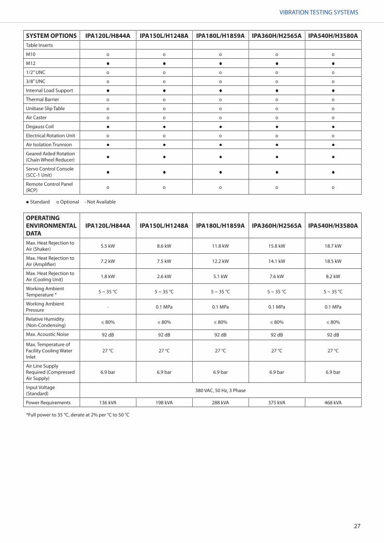
VIBRATION TESTING SYSTEMS
SPECIFICATIONS - H SERIESSYSTEM MODEL IPA120L/H844A IPA150L/H1248A IPA180L/H1859A IPA360H/H2565A IPA540H/H3580ASine Force 8,000 kgf 10,000 kgf 16,000 kgf 20,000 kgf 30,000 kgf
Random Force 8,000 kgf 10,000 kgf 16,000 kgf 20,000 kgf 27,000 kgf
Shock Force (½ Sine) 16,000 kgf 20,000 kgf 32,000 kgf 40,000 kgf 60,000 kgf
Usable Frequency Range 5 ~ 2,500 Hz 5 ~ 2,500 Hz 5 ~ 2,000 Hz 5 ~ 2,000 Hz 5 ~ 1,700 Hz
Continuous / Shock Displacement (1) 63.5 mm / 76 mm 51 mm (Opt.: 63.5 mm) /
76 mm 51 mm / 51 mm 63.5 mm / 76 mm 51 mm / 51 mm
Max. Velocity (Sine) 2.0 m/s 2.0 m/s 2.0 m/s 2.0 m/s 2.0 m/s
Max. Acceleration (Sine) 981 m/s² 981 m/s² 981 m/s² 981 m/s² 981 m/s²
SHAKER UNIT H844A H1248A H1859A H2565A H3580AArmature Diameter 445 mm 480 mm 590 mm 650 mm 800 mm
Effective Moving Element Mass 60 kg 85 kg 130 kg 200 kg 300 kg
Load Attachment Points 16 stainless steel inserts 16 stainless steel inserts 24 stainless steel inserts 32 stainless steel inserts 40 stainless steel inserts
Inserts Size (Standard) M12 M12 M12 M16 M20
Grid Pattern (Diameter, Circle) 8 on Ø 200mm; 8 on Ø 400mm
8 on Ø 254mm; 8 on Ø 406.4mm; 8 on Ø 558.8mm
16 on Ø 450mm; 16 on Ø 610 mm
8 on Ø 450mm; 16 on Ø 610 mm; 16 on Ø 760 mm
Nominal, Bare Table (2) 2,200 Hz 2,100 Hz 1,800 Hz 1,600 Hz 1,450 Hz
Max. Static Payload 800 kg 1,100 kg 1,600 kg 2,000 kg 5,000 kg
Natural Frequency (Thrust Axis) < 3 Hz < 5 Hz < 5 Hz < 5 Hz < 5 Hz
Stray Flux Density (3) Less than 10 gauss Less than 10 gauss Less than 10 gauss Less than 20 gauss Less than 20 gauss
Dimensions (Uncrated) (L x W x H) 1392 x 1316 x 1198 mm 1590 x 1346 x 1393 mm 1963 x 1413 x 1536 mm 1680 x 2410 x 1600 mm 2953 x 1920 x 1951 mm
Weight (Uncrated) 3,200 kg 4,500 kg 9,000 kg 25,000 kg 30,000 kg
AMPLIFIER UNIT IPA120L IPA150L IPA180L IPA360H IPA540HAmplifier Output 120 kVA 150 kVA 180 kVA 360 kVA 540 kVA
Total Harmonic Distortion (At Rated Output) From 5 Hz to 2,500 Hz less than 1.2%; from 2,500 Hz to 3,500 Hz less than 1.5% with resistive load
Signal-Noise-Ratio More than 65 dB at 120 V rms output, 10 kΩ input termination with rated resistive load More than 70 dB at 320 V rms output, 10 kΩ input termi-nation with rated resistive load
DC Stability Less than 0.05% of full output voltages with 10% change in line voltage
Input Drive 2 V rms into 10 kΩ for full output (120 V rms) 2 V rms into 10 kΩ for full output (320 V rms)
Amplifier Frequency Response (4) From 5 Hz to 10 Hz: ±6 dB; from 10 Hz to 5,000 Hz: ±3 dB
Switching Frequency 150 kHz 150 kHz 150 kHz 150 kHz 150 kHz
Max. Output Voltage 120 Vrms 120 Vrms 120 Vrms 320 Vrms 320 Vrms
Max. Output Current Per Module (Continuous / Transient)
250 Arms / 750 Arms 250 Arms / 750 Arms 250 Arms / 750 Arms 190 Arms / 570 Arms 190 Arms / 570 Arms
Amplifier Efficiency > 90% > 90% > 90% > 90% > 90%
Dimensions (Uncrated) (L x W x H) 1100 x 800 x 2060 mm 1650 x 800 x 2070 mm 1650 x 800 x 2070 mm 1650 x 800 x 2070 mm 2200 x 800 x 2070 mm
Weight (Uncrated) 1,350 kg 1,950 kg 2,250 kg 1,750 kg 2,650 kg
COOLING UNIT CU-O CU-1 CU-2 CU-3 CU-4Power Requirement 6 kW 8 kW 10 kW 15 kW 18 kW
Facility Cooling Water Flow 135 L/min 180 L/min 280 L/min 345 L/min 400 L/min
Facility Cooling Water Pressure Drop 0.25 ~ 0.4 MPa 0.25 ~ 0.4 MPa 0.25 ~ 0.4 MPa 0.25 ~ 0.4 MPa 0.25 ~ 0.4 MPa
Dimensions (Uncrated) (L x W x H) 1180 x 1780 x 1850 mm 1180 x 1780 x 1850 mm 1180 x 1780 x 1850 mm 1350 x 2000 x 2070 mm 1350 x 2000 x 2070 mm
Weight (Uncrated) 550 kg 630 kg 750 kg 1,000 kg 1,320 kg
Specifications are correct at the time of publication. In keeping with our commitment to continuous product improvement, the information herewith is subject to change. ETS reserves the rights to amend specifications without prior notice.
REMARKS:1. Test payload should be less than 10% of shaker weight2. First resonance frequency at ± 5% tolerance3. Measured at 152mm above armature table. Contact us for lower gauss level requirement.4. Sine mode, resistive load

26
VIBRATION TESTING SYSTEMS
H SERIES
Servo Control Console (SCC-1 Unit)
Remote Control Panel (RCP)
CU-0 CU-1 CU-2IPA Series Amplifier CU-3 CU-4
H844A H1248A
H1859A H2565A H3580A
27
VIBRATION TESTING SYSTEMS
SYSTEM OPTIONS IPA120L/H844A IPA150L/H1248A IPA180L/H1859A IPA360H/H2565A IPA540H/H3580ATable Inserts
M10 0 0 0 0 0
M12 • • • • •
1/2” UNC 0 0 0 0 0
3/8” UNC 0 0 0 0 0
Internal Load Support • • • • •
Thermal Barrier 0 0 0 0 0
Unibase Slip Table 0 0 0 0 0
Air Caster 0 0 0 0 0
Degauss Coil • • • • •
Electrical Rotation Unit 0 0 0 0 0
Air Isolation Trunnion • • • • •
Geared Aided Rotation (Chain Wheel Reducer) • • • • •
Servo Control Console (SCC-1 Unit) • • • • •
Remote Control Panel (RCP) 0 0 0 0 0
• Standard 0 Optional - Not Available
OPERATING ENVIRONMENTAL DATA
IPA120L/H844A IPA150L/H1248A IPA180L/H1859A IPA360H/H2565A IPA540H/H3580A
Max. Heat Rejection to Air (Shaker) 5.5 kW 8.6 kW 11.8 kW 15.8 kW 18.7 kW
Max. Heat Rejection to Air (Amplifier) 7.2 kW 7.5 kW 12.2 kW 14.1 kW 18.5 kW
Max. Heat Rejection to Air (Cooling Unit) 1.8 kW 2.6 kW 5.1 kW 7.6 kW 8.2 kW
Working Ambient Temperature * 5 ~ 35 °C 5 ~ 35 °C 5 ~ 35 °C 5 ~ 35 °C 5 ~ 35 °C
Working Ambient Pressure - 0.1 MPa 0.1 MPa 0.1 MPa 0.1 MPa
Relative Humidity (Non-Condensing) ≤ 80% ≤ 80% ≤ 80% ≤ 80% ≤ 80%
Max. Acoustic Noise 92 dB 92 dB 92 dB 92 dB 92 dB
Max. Temperature of Facility Cooling Water Inlet
27 °C 27 °C 27 °C 27 °C 27 °C
Air Line Supply Required (Compressed Air Supply)
6.9 bar 6.9 bar 6.9 bar 6.9 bar 6.9 bar
Input Voltage (Standard) 380 VAC, 50 Hz, 3 Phase
Power Requirements 136 kVA 198 kVA 288 kVA 375 kVA 468 kVA
*Full power to 35 °C, derate at 2% per °C to 50 °C

28
VIBRATION TESTING SYSTEMS
I SERIESVibration System Force Rating from 4,000 kgf to 16,000 kgf
Ideal for screening of medium sized assemblies with extreme high acceleration test level and high frequency range.
The “I” Series exceeds typical vibration test requirements of other medium to large sized electronic assemblies, automotive parts, aviation and avionics parts. The “I” Series is designed to meet military and international test standards including MIL, ASTM, IEC, ISO, BS and JIS. The Extreme Acceleration Shaker Y-Ring (EAS-Y Ring) armature is a revolutionary design which will allow for using a proportioned head expander to test multiple specimens simultaneously at extreme high acceleration level. Other test requirements including transportation vibration simulation combined vibration-climatic test and seismic simulations for small size components can easily be fulfilled by the ETS “I” Series.
FEATURESTHE PERFORMANCE- Specimen payload up to 1,200 kg- Excellent random performance meeting ISO standard with 3 sigma peak current rating- Armature diameters range from 370 mm to 590 mm- Up to 51 mm continuous displacement- Test frequency up to 2,800 Hz
THE SHAKER- Light weight solid armature for high acceleration performance (No Multiple Windings)- Rugged trunnion design with bearing guidance - Air load support for armature centering- Air bag isolator built-in reducing dynamic floor stress
THE AMPLIFIER- Integrated with new Intelligent Power Amplifier - New design with High Speed IGBT technology - Compact sized power module with large output- High modulation switching frequency- High signal to noise ratio- Dynamic fault current error control protection- Complete digital control
THE ACCESSORIES- Dynamic and static armature centering available - Geared aided rotation built-in for uni-base slip table- Thermal barrier for combined climatic chamber test available- Remote control capabilities available
BENEFITS- Simple system operation- Intelligent PLC control and monitoring system- High energy conversion efficiency (greater than 90%)- Reasonably priced optimal performance system for major test standards- Compact shaker and amplifier size saving valuable floor space - Compatible with any vibration controller- Remote control panel via Ethernet cable connections- Low profile body design ready for chamber integration - Integration with unibase or standalone slip table- Shaker water cooled by water cooling system for continuous long period operation- Air cooled amplifier power electronics for safe and reliable operation- Ethernet port available for data exchange - All-encompassing fuse protection design for high current system components - Detailed scope of system interlock protections- Complies with USA, European and international safety and EMC regulations- Simple initial self-system setup- Interactive diagnostic “System Status” on touch screen - Easy maintenance and rapid servicing- Worldwide spare parts support

29
VIBRATION TESTING SYSTEMS
SPECIFICATIONS - I SERIESSYSTEM MODEL IPA120H/I537M IPA180H/I537M IPA240H/I1045M IPA300H/I1045M IPA360H/I1859ASine Force 4,000 kgf 5,000 kgf 8,000 kgf 10,000 kgf 16,000 kgf
Random Force 4,000 kgf 5,000 kgf 8,000 kgf 10,000 kgf 16,000 kgf
Shock Force (½ Sine) 10,000 kgf 12,500 kgf 20,000 kgf 20,000 kgf 40,000 kgf
Usable Frequency Range DC ~ 2,500 Hz (Opt 2,800 Hz) 5 ~ 2,500 Hz DC ~ 2,000 Hz 5 ~ 2,000 Hz DC ~ 2,000 Hz
Continuous / Shock Displacement (1) 51 mm / 76 mm 51 mm / 76 mm 51 mm / 76 mm 51 mm / 76 mm 51 mm / 65 mm
Max. Velocity (Sine/Shock) 2.0 m/s / 3.5 m/s 2.0 m/s / 3.5 m/s 2.0 m/s / 3.5 m/s 2.0 m/s / 3.5 m/s 2.0 m/s / 3.5 m/s
Max. Acceleration (Sine / Random) 1,275 m/s² / 981 m/s² 1,275 m/s² / 981 m/s² 1,275 m/s² / 981 m/s² 1,275 m/s² / 981 m/s² 1,177 m/s² / 981 m/s²
SHAKER UNIT I537M I537M I1045M I1045M I1859AArmature Diameter 370 mm 370 mm 445 mm 445 mm 590 mm
Effective Moving Element Mass 30 kg 30 kg 60 kg 60 kg 145 kg
Load Attachment Points 16 stainless steel inserts 16 stainless steel inserts 28 stainless steel inserts 28 stainless steel inserts 24 stainless steel inserts
Inserts Size (Standard) M10 M10 M12 M12 M12
Grid Pattern (Diameter, Circle) 8 on Ø 150mm; 8 on Ø 300 mm 4 on Ø 100mm; 8 on Ø 200mm;
8 on Ø 300mm; 8 on Ø 400mm8 on Ø 254mm;
8 on Ø 406.4mm; 8 on Ø 558.8mm
Nominal, Bare Table (2) 2,100 Hz 2,100 Hz 2,100 Hz 2,100 Hz 1,800 Hz
Max. Static Payload 500 kg 500 kg 600 kg 600 kg 1,200 kg
Natural Frequency (Thrust Axis) < 5 Hz < 5 Hz < 5 Hz < 5 Hz < 5 Hz
Stray Flux Density (3) Less than 10 gauss Less than 10 gauss Less than 10 gauss Less than 10 gauss Less than 10 gauss
Dimensions (Uncrated)(L x W x H) 1336 x 865 x 1150 mm 1336 x 865 x 1150 mm 1590 x 1395 x 1485 mm 1590 x 1395 x 1485 mm 1605 x 1124 x 1342 mm
Weight (Uncrated) 2,400 kg 2,400 kg 4,700 kg 4,700 kg 10,000 kg
AMPLIFIER UNIT IPA120H IPA180H IPA240H IPA300H IPA360HAmplifier Output 120 kVA 180 kVA 240 kVA 300 kVA 360 kVA
Total Harmonic Distortion (At Rated Output) From 5 Hz to 2,500 Hz less than 1.2%; from 2,500 Hz to 3,500 Hz less than 1.5% with resistive load
Signal-Noise-Ratio More than 70dB at 320V rms output, 10KΩ input termina-tion with rated resistive load More than 70 dB at 320 V rms output, 10 kΩ input termination with rated resistive load
DC Stability Less than 0.05% of full output voltage with 10% change in line voltage
Input Drive 2 V rms into 10KΩ for full output (320 V rms)
Amplifier Frequency Response (4) From 5 Hz to 10 Hz: ±6 dB; from 10 Hz to 5,000 Hz: ±3 dB
Switching Frequency 150 kHz 150 kHz 150 kHz 150 kHz 150 kHz
Max. Output Voltage 320 V rms 320 V rms 320 V rms 320 V rms 320 V rms
Max. Output Current Per Module (Continuous/Transient)
190 A rms / 570 A rms 190 A rms / 570 A rms 190 A rms / 570 A rms 190 A rms / 570 A rms 190 A rms / 570 A rms
Amplifier Efficiency > 90% > 90% > 90% > 90% > 90%
Dimensions (Uncrated) (L x W x H) 800 x 550 x 2070 mm 800 x 550 x 2070 mm 800 x 1100 x 2070 mm 800 x 1650 x 2070 mm 800 x 1650 x 2070 mm
Weight (Uncrated) 550 kg 600 kg 1,400 kg 1,500 kg 1,800 kg
BLOWING UNIT HP-4B HP-4B HP-4B HP-4B HP-4BPower Output 22 kW 22 kW 22 kW 22 kW 22 kW
Air Flow 1.67 m³/s 1.67 m³/s 1.67 m³/s 1.67 m³/s 1.67 m³/s
Air Pressure 0.12 kgf / cm² 0.12 kgf / cm² 0.12 kgf / cm² 0.12 kgf / cm² 0.12 kgf / cm²
Dimension (Uncrated) (L x W x H) 962 x 1329 x 2230 mm 962 x 1329 x 2230 mm 962 x 1329 x 2230 mm 962 x 1329 x 2230 mm 962 x 1329 x 2230 mm
Weight (Uncrated) 420 kg 420 kg 420 kg 420 kg 420 kg
COOLING UNIT NA NA CU-1 CU-1 CU-2Power Requirement - - 8 kW 8 kW 10 kW
Facility Cooling Water Flow - - 180 L/min 180 L/min 280 L/min
Facility Cooling Water Pressure Drop - - 0.25 ~ 0.4 MPa 0.25 ~ 0.4 MPa 0.25 ~ 0.4 MPa
Dimension (Uncrated) (L x W x H) - - 1180 x 1780 x 1850 mm 1180 x 1780 x 1850 mm 1180 x 1780 x 1850 mm
Weight (Uncrated) - - 630 kg 630 kg 750 kg

30
VIBRATION TESTING SYSTEMS
I SERIESSpecifications are correct at the time of publication. In keeping with our commitment to continuous product improvement, the information herewith is subject to change. ETS reserves the rights to amend specifications without prior notice.
REMARKS:1. Test payload should be less than 10% of shaker weight. Shock Displacement: 63.5mm (High Field); 76mm (Low Field). Continuous Displacement: 41mm (High Field); 51mm (Low Field).2. First resonance frequency at ± 5% tolerance3. Measured at 152mm above armature table. Contact us for lower gauss level requirement.4. Sine mode, resistive load
Servo Control Console (SCC-1 Unit)
Remote Control Panel (RCP)
IPA Series Amplifier HP-4B CU-1 CU-2
I537M I1045M I1859M
31
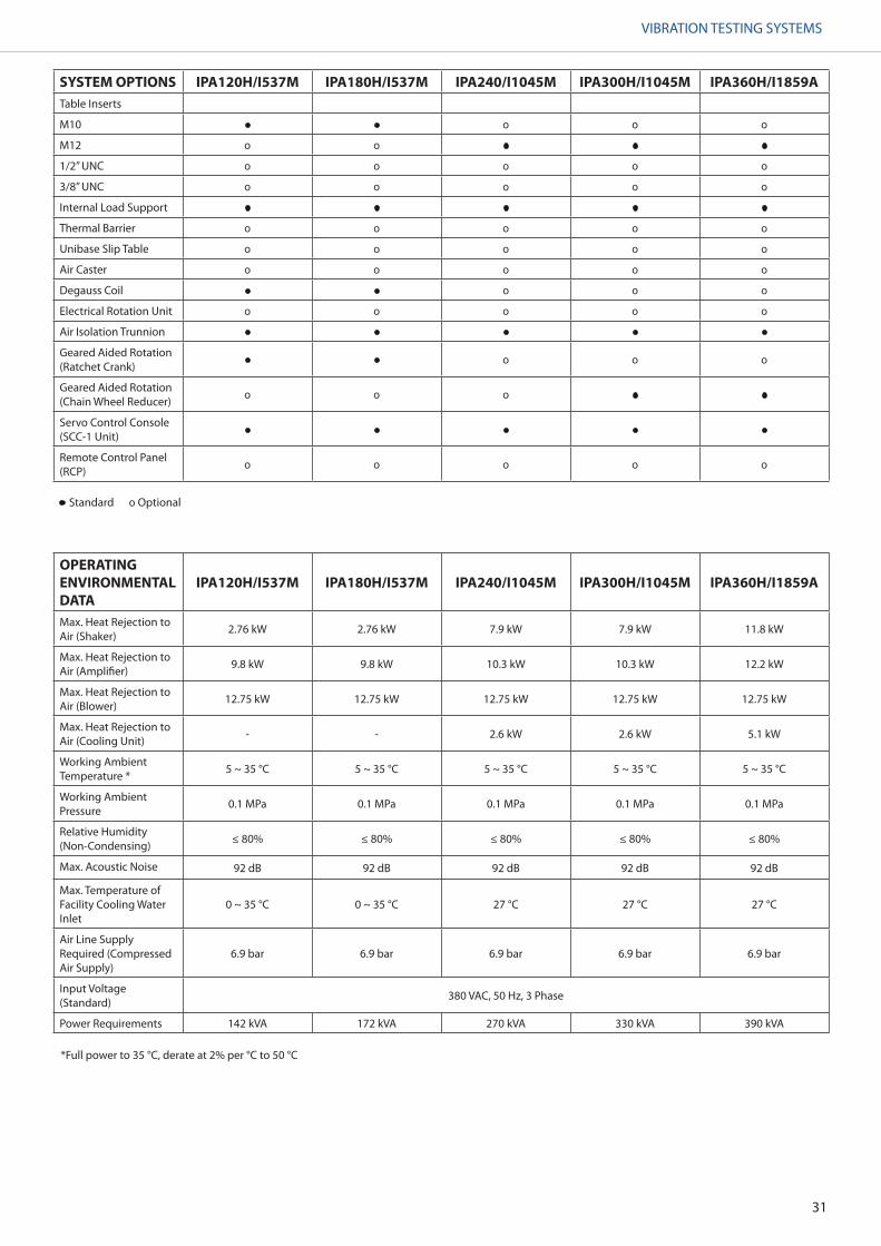
VIBRATION TESTING SYSTEMS
SYSTEM OPTIONS IPA120H/I537M IPA180H/I537M IPA240/I1045M IPA300H/I1045M IPA360H/I1859ATable Inserts
M10 • • 0 0 0
M12 0 0 • • •
1/2” UNC 0 0 0 0 0
3/8” UNC 0 0 0 0 0
Internal Load Support • • • • •
Thermal Barrier 0 0 0 0 0
Unibase Slip Table 0 0 0 0 0
Air Caster 0 0 0 0 0
Degauss Coil • • 0 0 0
Electrical Rotation Unit 0 0 0 0 0
Air Isolation Trunnion • • • • •
Geared Aided Rotation (Ratchet Crank) • • 0 0 0
Geared Aided Rotation (Chain Wheel Reducer) 0 0 0 • •
Servo Control Console (SCC-1 Unit) • • • • •
Remote Control Panel (RCP) 0 0 0 0 0
• Standard 0 Optional
OPERATING ENVIRONMENTAL DATA
IPA120H/I537M IPA180H/I537M IPA240/I1045M IPA300H/I1045M IPA360H/I1859A
Max. Heat Rejection to Air (Shaker) 2.76 kW 2.76 kW 7.9 kW 7.9 kW 11.8 kW
Max. Heat Rejection to Air (Amplifier) 9.8 kW 9.8 kW 10.3 kW 10.3 kW 12.2 kW
Max. Heat Rejection to Air (Blower) 12.75 kW 12.75 kW 12.75 kW 12.75 kW 12.75 kW
Max. Heat Rejection to Air (Cooling Unit) - - 2.6 kW 2.6 kW 5.1 kW
Working Ambient Temperature * 5 ~ 35 °C 5 ~ 35 °C 5 ~ 35 °C 5 ~ 35 °C 5 ~ 35 °C
Working Ambient Pressure 0.1 MPa 0.1 MPa 0.1 MPa 0.1 MPa 0.1 MPa
Relative Humidity (Non-Condensing) ≤ 80% ≤ 80% ≤ 80% ≤ 80% ≤ 80%
Max. Acoustic Noise 92 dB 92 dB 92 dB 92 dB 92 dB
Max. Temperature of Facility Cooling Water Inlet
0 ~ 35 °C 0 ~ 35 °C 27 °C 27 °C 27 °C
Air Line Supply Required (Compressed Air Supply)
6.9 bar 6.9 bar 6.9 bar 6.9 bar 6.9 bar
Input Voltage (Standard) 380 VAC, 50 Hz, 3 Phase
Power Requirements 142 kVA 172 kVA 270 kVA 330 kVA 390 kVA
*Full power to 35 °C, derate at 2% per °C to 50 °C

32
VIBRATION TESTING SYSTEMS
MET SERIESVibration System Force Rating from 300 kgf to 10,000 kgf
Ideal for Real World Vibration Simulation and Screening Tests.
ETS Solutions “MET” (Multi-Excitation Testing) Series vibration testing systems can achieve 3-Axis vibration tests simultaneously and is designed to meet the test requirements of wide frequency range, long stroke and high acceleration sine/random/shock test.An object (or specimen, samples) in the actual vibration environment subject to vibration excitation should be multi-directional, which means that vibration environment is actually a complex multi-degree of freedom vibration environment. As a result of limitations from vibration test equipment in the past, it has to rely on a single direction of vibration test (single-axis vibration testing) in the laboratory to simulate on-site vibration environment.The “MET” Series Multi-Axis vibration testing system consists of 3 single axis vibration test system specially engineered to function as one system. The “MET” Series system redefines how standard tests can be carried out. The “MET” Series multi-axis simultaneous vibration test system is a new generation of environmental testing equipment in the space, aviation, weapons, electronics, communications, automotive, home appliances and other industries.
FEATURES- Simultaneous dual-axial, tri-axial or multi degree of freedom vibration testing- Configurable force rating per test axis - configured the desired test axis force rating to achieve the vibration magnitude to meet different testing requirements- Combined Temperature & Humidity Test Option available- Compatible with any reputable MDOF vibration controller- Mixed Mode Vibration test can be achieved to simulate real world environmental conditions- Test frequency up to 2,000 Hz- Reduce Test Setup Time and undue Stress to Test Specimen - one time test setup for all axis test -Air Cooled Design with simple maintenance

33
VIBRATION TESTING SYSTEMS
SPECIFICATIONS - MET SERIESSYSTEM MODEL
MET-600 MET-2000 MET-4000 MET-5000 MET-7000 MET-10000
Frequency Range 5 - 2,000 Hz 5 - 800 Hz (Sine Full Force) / 5 - 2000 Hz (Random)
Sine Force 600 kgf 2,000 kgf 4,000 kgf 5,000 kgf (X, Y, Z Axis) 7,000 kgf 10,000 kgf
Random Force 420 kgf 1,400 kgf 2,800 kgf 3,500 kgf (X, Y, Z Axis) 4,900 kgf 7,000 kgf
Max. Displacement (1) 30 mm 30 mm 30 mm 30 mm 30 mm 30 mm
Max. Velocity 1 m/s 1 m/s 1 m/s 1 m/s 1 m/s 1 m/s
Working Table 300 x 300 mm 600 x 600 mm800 x 800 mm
1000 x 1000 mm400 x 400 mm800 x 800 mm
1200 x 1200 mm600 x 600 mm
500 x 500 mm1000 x 1000 mm1500 x 1500 mm
800 x 800 mm1200 x 1200 mm2000 x 2000 mm
AMPLIFIER UNIT
MPA102 IPA30L IPA60L IPA90L IPA90L IPA150L
Amplifier Output 3 x 6 kVA 3 x 30 kVA 3 x 60 kVA 3 x 90 kVA 3 x 90 kVA 3 x 150 kVA
Total Harmonic Distortion (At Rated Output)
From DC (0.1Hz) to 500Hz less than
0.5%; From 500Hz to 5,000Hz less than 1.0%
From 5 Hz to 2,500 Hz less than 1.2%; from 2,500 Hz to 3,500 Hz less than 1.5% with resistive load
Signal-Noise-Ratio More than 65dB at 100V rms output, 10KΩ input termi-nation with rated
resistive load
More than 65 dB at 120 V rms output, 10 kΩ input termination with rated resistive load
DC Stability Less than 0.05% of full output voltage with 10% changes in line voltage
Input Drive 4V rms into 10KΩ for full output (120V rms) 2 V rms into 10KΩ for full output (120V rms)
Amplifier Frequency Response (2)
From DC (0.1Hz) to 4,500Hz: ± 3dB; From
10Hz to 3,000Hz: ± 1dB
From 5 Hz to 10 Hz: ±6 dB; from 10 Hz to 5,000 Hz: ±3 dB
Switching Frequency 112 kHz 150 kHz 150 kHz 150 kHz 150 kHz 150 kHz
Max. Output Voltage 120V rms 120V rms 120V rms 120V rms 120V rms 120V rms
Max. Output Current per module (Continuous/Transient)
50A rms / 150A rms 250A rms / 750A rms
250A rms / 750A rms
250A rms / 750A rms
250A rms / 750A rms
250A rms / 750A rms
Amplifier Efficiency > 90% > 90% > 90% > 90% > 90% > 90%
Dimensions (Est.) (Uncrated) (L x W x H)
550 x 680 x 1455 mm 550 x 800 x 1850 mm 550 x 800 x 2070 mm 550 x 800 x 2070 mm 550 x 800 x 2070 mm 1650 x 800 x 2070 mm
Weight (Est.) (Uncrated) 280 kg 480 kg 515 kg 550 kg 550 kg 1,950 kg
BLOWER UNIT HP-2A HP-3A HP-3A HP-4A HP-4A NAPower Requirement 3 x 4 kW 3 x 7.5 kW 3 x 7.5 kW 3 x 22 kW 3 x 22 kW -
Air Flow 0.21 m³ / s 0.73 m³ / s 0.73 m³ / s 1.035 m³ / s 1.035 m³ / s -
Air Pressure 0.06 kgf / cm2 0.082 kgf / cm2 0.082 kgf / cm2 0.095 kgf / cm2 0.095 kgf / cm2 -
Dimensions (Est.) (Uncrated) (L x W x H)
748 x 604 x 1450 mm 945 x 693 x 1466 mm 945 x 693 x 1466 mm 1143 x 930 x 2185 mm 1143 x 930 x 2185 mm -
Weight (Est.) (Uncrated) 115 kg 175 kg 175 kg 370 kg 370 kg -
COOLING UNIT NA NA NA NA NA CU-1Power Requirement - - - - - 3 x 8 kW
Facility Cooling Water Flow - - - - - 180 L/min
Facility Cooling Water Pressure Drop - - - - - 0.25 ~ 0.4 MPa
Dimensions (Est.) (Uncrated) (L x W x H) - - - - - 1180 x 1780 x 1850
mm
Weight (Est.) (Uncrated) - - - - - 630 kg
Specifications are correct at the time of publication. In keeping with our commitment to continuous product improvement, the information herewith is subject to change. ETS reserves the rights to amend specifications without prior notice.
REMARKS:1. Test payload should be less than 10% of shaker weight. 2. Sine mode, resistive load

34
POWER AMPLIFIERS
Designed for continuous operation with any electro-dynamic shaker
The ETS Solutions MPA Series amplifier family is a wide frequency band digital switching (Class D) Power Amplifier designed with latest state-of-the-art technology. A number of built-in features in the amplifier allow vibration testing to be simple and easy. The MPA amplifier series are made for continuous operation with each configuration adaptable to any existing or new air-cooled / water cooled electro dynamic shaker. Amplifier outputs range from 1kVA to 300 kVA.
MPA SERIES
PERFORMANCE- High conversion efficiency (greater than 90%) for energy saving- High modulation switching frequency- Low total harmonic distortion (< 0.5% at typical testing frequency)- High signal to noise ratio (> 65%)- Exceeds ISO Peak current rating of 4-Sigma
USER INTERFACE- Intelligence microprocessor logic control and monitoring system- Interactive system interface- Green back lit LCD for system status and diagnostic messages- Auxiliary Interlock Unit (AIU) for additional safety interlock I/O points (Optional)- Remote control panel via RS485 communication (Optional)
LOGIC CONTROL UNITManaged by high-speed microprocessor logic unit, the intelligence logic control system assures high output power with maximum safety protection. High switching frequency delivers low distortion with full power output over a broad frequency band. Control logic modulator handles generation of pulse-width modulated driving commands to the power output modules. System digital and analogue feedbacks are optically isolated and processed by the high-speed microprocessor unit. System status and fault indications are real-time displayed on the green back lit LCD panel. Fault occurrences are relayed as interactively on the LCD panel with alarm indication. Solid state relay ensures electrical power control. Power modules operating status are on-line monitored by the control logic modulator. Any over-current, short-circuit or over-temperature situation will prompt an instantaneous system halt.An optional remote control panel can be connected to the logic module via RS485 communication port. The remote control panel allows full system control at a distance control room of up to 500m.
SAFETY AND RELIABILITY- Soft-Start and Soft-Stop circuits- Detailed scope of system interlock protections- International compliance to safety and EMC standards- Totally air cooled amplifier designed for continuous and safe thermal operation- All-encompassing fuse protection for high current system components- Designed to reduce reliance on mechanical switch gears with CPU logic controlled- Complies with USA, European and International safety and EMC regulations
SYSTEM MAINTENANCE- 12 kVA power modules configured with two self-reliant sub 6 kVA modules - Interchangeable compact size power modules- Space saving compact size designs- Easy maintenance and rapid servicing- Worldwide spare parts support
POWER MODULEModular and compact sized power output modules are designed with the latest solid state MOSFET technology to ensure optimum performance reliability and overall system efficiency (> 90%). Pulse-width modulated commands from the logic module drive the power modules conversion of DC power rectified from AC line power into variable amplitude and frequency driving power for the shaker. Switching command signals are optically isolated and routed via a ribbon cable. Ample heat sinking and cooling fans are incorporated to allow continuous safe thermal operation.Output driven at rated 120 V rms voltage and 50 A current per module with reserve capacity to provide peak currents of at least 3 times the RMS levels.Designed to reduce the loss of power during a failed component, the 12 kVA power module is made up of two self-reliant 6 kVA sub modules. Each sub module operates independently in the event when the other is out of action. Built-in operation and fault LED lights provide a quick source to identify the failed sub module.
35
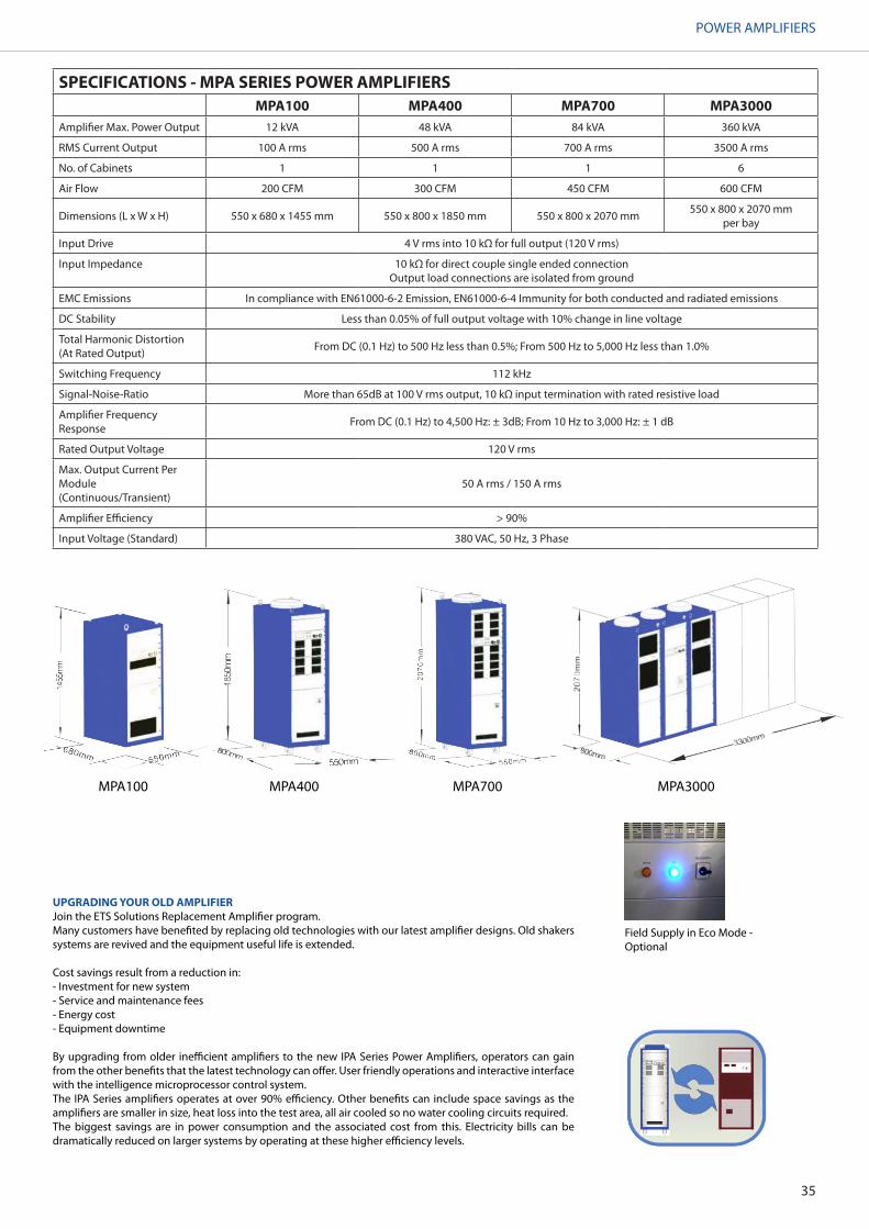
POWER AMPLIFIERS
SPECIFICATIONS - MPA SERIES POWER AMPLIFIERSMPA100 MPA400 MPA700 MPA3000
Amplifier Max. Power Output 12 kVA 48 kVA 84 kVA 360 kVA
RMS Current Output 100 A rms 500 A rms 700 A rms 3500 A rms
No. of Cabinets 1 1 1 6
Air Flow 200 CFM 300 CFM 450 CFM 600 CFM
Dimensions (L x W x H) 550 x 680 x 1455 mm 550 x 800 x 1850 mm 550 x 800 x 2070 mm 550 x 800 x 2070 mm per bay
Input Drive 4 V rms into 10 kΩ for full output (120 V rms)
Input Impedance 10 kΩ for direct couple single ended connectionOutput load connections are isolated from ground
EMC Emissions In compliance with EN61000-6-2 Emission, EN61000-6-4 Immunity for both conducted and radiated emissions
DC Stability Less than 0.05% of full output voltage with 10% change in line voltage
Total Harmonic Distortion (At Rated Output) From DC (0.1 Hz) to 500 Hz less than 0.5%; From 500 Hz to 5,000 Hz less than 1.0%
Switching Frequency 112 kHz
Signal-Noise-Ratio More than 65dB at 100 V rms output, 10 kΩ input termination with rated resistive load
Amplifier Frequency Response From DC (0.1 Hz) to 4,500 Hz: ± 3dB; From 10 Hz to 3,000 Hz: ± 1 dB
Rated Output Voltage 120 V rms
Max. Output Current Per Module (Continuous/Transient)
50 A rms / 150 A rms
Amplifier Efficiency > 90%
Input Voltage (Standard) 380 VAC, 50 Hz, 3 Phase
MPA100 MPA400 MPA700 MPA3000
Field Supply in Eco Mode - Optional
UPGRADING YOUR OLD AMPLIFIERJoin the ETS Solutions Replacement Amplifier program.Many customers have benefited by replacing old technologies with our latest amplifier designs. Old shakers systems are revived and the equipment useful life is extended.
Cost savings result from a reduction in:- Investment for new system- Service and maintenance fees- Energy cost- Equipment downtime
By upgrading from older inefficient amplifiers to the new IPA Series Power Amplifiers, operators can gain from the other benefits that the latest technology can offer. User friendly operations and interactive interface with the intelligence microprocessor control system.The IPA Series amplifiers operates at over 90% efficiency. Other benefits can include space savings as the amplifiers are smaller in size, heat loss into the test area, all air cooled so no water cooling circuits required.The biggest savings are in power consumption and the associated cost from this. Electricity bills can be dramatically reduced on larger systems by operating at these higher efficiency levels.

36
POWER AMPLIFIERS
IPA SERIESThe IPA Series is an 4th generation high performance PWM switching (Class-D) power amplifier designed for continuous operation with any shaker system in the vibration testing industry. The IPA (Intelligent Power Amplifier) series amplifier have incorporated many new features and designs. The IPA amplifier uses a large touch screen user interface and the latest FPGA with DSP technology which is designed to drive and monitor its IGBT power modules output. A complete new design concept is taken to built-in a dedicated FPGA-PWM controller into each power module. The high-speed FPGA-PWM controller handles a closed loop digital signal processed pulse width modulation driving circuit to the IGBT FETs. An error control logic in the FPGA-PWM controller handles low output distortion with fast over-current and short-circuit protection on the IGBT FETs. The FPGD-PWM controller incorporates a synchronous phase logic control to ensure all power modules operates in phase and its output current are balanced. The touchscreen control provides clear and easy interface on the amplifier control and monitoring. It is also capable of remote control and monitoring function via the internet. This makes the IPA series amplifier the most user friendly, reliable and high performance switching amplifier for shaker system in the market. The amplifier outputs range from 30 kVA to 1,200 kVA.
PERFORMANCE- New design with High Speed IGBT technology- Compact sized power module with large output (60 kVA each)- High conversion efficiency (greater than 90%) for energy saving- High modulation switching frequency (150 kHz)- High signal to noise ratio (greater than 70 dB)- Parallel power module operating output current differential current less than 2%- Dynamic fault current error control protection- Intelligent PLC control and monitoring system- Interactive diagnostic “System Status” on touch screen- Complete digital control (digital gain and monitoring)
LOGIC CONTROL UNIT- Interactive Touch Screen interface- Fully digital gain with precise sensitivity (1%)- Multiple languages to choose- Various extension functions available- Internet port available for data exchange and remote monitoring
POWER MODULE- DSP/FPGA fully digital PWM control and current protection- High current output capacity per module- Constant current output and dynamics current sharing capability- Ultra fast PWM logic control for high reliable performance- Robust design to protect the fuses and FETs even in the events of transient over-current or short circuit
SAFETY AND RELIABILITY- Soft start and soft stop circuits- Detailed scope of system interlock protections- Totally air cooled amplifier designed for continuous and safe thermal operation- All-encompassing fuse protection for high current system components- Interchangeable compact size designs- Easy maintenance and rapid servicing - Internet port available for data exchange between amplifier and other equipment- Remote control and monitoring available via internet port- Compatible with all vibration controllers- Worldwide service spare parts support

37
POWER AMPLIFIERS
SPECIFICATIONS - IPA SERIES POWER AMPLIFIERIPA***H
Amplifier Output 60 ~ 1,200 kVA
AC Output Each Power Module 60 kVA
Rated Output Voltage 320 V rms
Rated Output Current Per Module (Continuous/Transient) 190 A rms / 570 A rms
Power Module DC Supply 530 V
Switching Frequency 150 kHz
Signal-Noise-Ratio More than 70 dB at 320 V rms output, 10 kΩ input termination with rated resistive load
Power Module Current Sharing Differential ≤ 2%
Crest Factor Of Output Current ≥ 3
Input Sensitivity 2 V rms into 10 kΩ for full output (320 V rms)
DC Stability Less than 0.05% of full output voltages with 10% change in line voltage
Total Harmonic Distortion (At Rated Output) From 5 Hz to 2,500 Hz less than 1.2%; From 2,500 Hz to 3,500 Hz less than 1.5% with resistive load
Amplifier Frequency Response (Sine Mode, Resistive Load) From 5 Hz to 10 Hz: ± 6dB; From 10 Hz to 5,000 Hz: ± 3dB
Amplifier Efficiency > 90%
SPECIFICATIONS - IPA SERIES POWER AMPLIFIERIPA***L
Amplifier Output 30 ~ 480 kVA
AC Output Each Power Module 30 kVA
Rated Output Voltage 120 V rms
Rated Output Current Per Module (Continuous/Transient) 250 A rms / 750 A rms
Power Module DC Supply 180 V
Switching Frequency 150 kHz
Signal-Noise-Ratio More than 65 dB at 120 V rms output, 10 kΩ input termination with rated resistive load
Power Module Current Sharing Differential ≤ 2%
Crest Factor Of Output Current ≥ 3
Input Sensitivity 2 V rms into 10 kΩ for full output (120 V rms)
DC Stability Less than 0.05% of full output voltages with 10% change in line voltage
Total Harmonic Distortion (At Rated Output) From 5 Hz to 2,500 Hz less than 1.2%; From 2,500 Hz to 3,500 Hz less than 1.5% with resistive load
Amplifier Frequency Response (Sine Mode, Resistive Load) From 5 Hz to 10 Hz: ± 6dB; From 10 Hz to 5,000 Hz: ± 3dB
Amplifier Efficiency > 90%
Field Supply in Eco Mode - Optional

38
SLIP TABLE
ETS Solutions offers options of unibase or standalone slip table to meet different requirements for horizontal test. The unibase is built-in with the vertical shaker body by common steel base platform. The standalone slip table is customized design with an independent steel base platform to match with any new or existing shaker.
UNIBASE SLIP TABLEThe unibase design is optimized solution for horizontal vibration testing. The common base reinforces assembly allow easy and consistent alignment between shaker and the slip table. The low profile concept conveniently fit for environmental testing with chamber.
STANDALONE SLIP TABLEThe standalone design, an independent steel platform supported by the levelling feet. The customized design allows the feasibility of any vertical shaker from ETS or other manufacturers to couple with the standalone slip table assembly.
FEATURES- Light weight magnesium slip table- Economical aluminium slip table available- Low profile reaction mass with total system isolation (less than 5Hz)- Stiffened and welded steel body design with high mass to force ratios- Designed for combined environment applications- Standalone slip table available to interface to any shaker (existing or new)
ETS Solutions slip table are designed to provide the optimum test platform for horizontal testing with any shaker combination. Our unibase concept provides structural steel body to align the shaker and table on a rigid platform. All the slip tables are designed with precise grinded natural granite slab with a selection of guidance bearings to meet different application and budgets. The stiffened and welded body provides good reaction mass and damping. The isolation system reduces vibration transmission to the floor and prevents any interference between lab equipment.
Rotation of shaker body to couple the slip table can be performed quickly and easily by one person using the rotation system. Slip plate alignment with shaker is always ensured with mechanical stops installed. Slip plates can be provided in almost any size from 300mm square (for small shakers) to 2m square for large sized specimen test. Different types of restraining bearings are available to meet different application requirements and operating budgets.
SLIP TABLE

39
SLIP TABLE
GT SERIESGT Series, guided oil film table are designed with less expensive guided V-Groove bearings, combined with magnesium slip table. Oil is supplied through the granite slab port holes and is dispersed throughout the underside of the slip plate. The oil film provides a low friction slip surface and a damping medium for restrain of pitch, roll and yaw moments.- Magnesium slip plate- Low pressure hydraulic pump- Self-contained oil reservoir with oil filter- Yaw restrain by V-Groove guide bearings combining with the armature guidance system- Less expensive technique to perform horizontal testing
BT SERIESThe BT Series design provides a high over-turning moment and cross-axial restraint. This concept combines a standard slip table assembly with high pressure 3,000 psi hydrostatic bearings to provide high dynamic moment restraint while preserving the damping characteristics of the guide oil film.This system allows testing of heavy products with high center of gravity by reacting moments through the hydrostatic bearings.- Heavy products testing with high centers with restraint moments by hydrostatic bearings- High pressure 3,000 psi Hydraulic power supply- Hydrostatic journal bearings to restrain high pitch, roll and yaw moments- Pressure interlocks- Reservoir oil filter- T-film bearing (optional)
SPECIFICATIONS - GT SERIES
Slip Table Model
Working Area
(mm x mm)
Thickness (mm)
Usable Frequency
(Hz)
Slip Plate Mass (kg)
Max. Pay-load (kg)
Bearing Qty.
Mass per Bearing
(kg)
Over Turning Moment (Nm)
Pitch Roll Yaw
GT300M 300 x 300 25 2000 6 300 1 0.58 1036 1036 203
GT400M 400 x 400 25 2000 9 300 1 0.58 1295 1295 203
GT500M 500 x 500 40 2000 22 400 1 0.58 2529 2529 203
GT600M 600 x 600 40 2000 31 550 1 0.58 4370 4370 203
GT700M 700 x 700 40 2000 41 800 2 0.58 8536 8536 203
GT800M 800 x 800 40 2000 52 900 2 0.58 11642 11642 203
GT900M 900 x 900 40 2000 65 1100 2 0.58 14749 14749 203
GT1000M 1000 x 1000 50 2000 99 1200 2 0.58 20232 20232 203
GT1100M 1100 x 1100 50 2000 124 1200 2 0.58 27192 27192 203
GT1200M 1200 x 1200 50 2000 141 1200 2 0.58 34961 34961 203
SPECIFICATIONS - BT SERIES
Slip Table Model
Working Area
(mm x mm)
Thickness (mm)
Usable Frequency
(Hz)
Slip Plate Mass (kg)
Max. Pay-load (kg)
Bearing Qty.
Mass per Bearing
(kg)
Over Turning Moment (Nm)
Pitch Roll Yaw
BT700M 700 x 700 50 2000 53 6500 2 4.8 51246 36851 43184
BT800M 800 x 800 50 2000 69 7000 2 4.8 54260 39019 45725
BT900M 900 x 900 50 2000 87 7500 2 4.8 61490 51329 46741
BT1000M 1000 x 1000 50 2000 100 8000 2 4.8 73069 60876 52837
BT1100M 1100 x 1100 50 2000 124 8500 2 4.8 88446 71173 58730
BT1200M 1200 x 1200 50 2000 145 10000 3 4.8 104055 83733 69095
BT1300M 1300 x 1300 50 2000 183 11000 3 4.8 129410 103398 74784
BT1400M 1400 x 1400 50 2000 212 11500 3 4.8 137498 109860 79458
BT1500M 1500 x 1500 50 2000 243 12000 3 4.8 161763 129248 93481
BT1600M 1600 x 1600 50 2000 276 12500 3 4.8 188687 152920 94294
BT1700M 1700 X 1700 60 2000 375 13000 3 4.8 212273 172035 106081
BT1800M 1800 X 1800 60 2000 420 13500 3 4.8 235859 191150 117868
Remarks:1. Slip Table inserts standard grid pattern. Armature inserts pattern plus 100mm x 100mm grid.2. All the specifications here are for magnesium material. Please contact ETS for aluminium material specifications.

40
SLIP TABLE
DOUBLE SLIP TABLE UNIBASEDouble Slip Table Unibase allows users to have double configuration of the slip table in order to perform different tests.The shaker system can rotate 180 degree in order to be combined with both tables. In the middle position, the shaker can be combined with the Head Expander in order to perform vertical test.This configuration is suitable for GT Series and BT Series.
TABLE IN TABLE UNIBASE
Table in Table Unibase allows users to have double configuration of the slip table in order to perform different tests.The small and the big table are integrated in order to save space in the lab. In order to perform the test with the small table the user has just to detach it from the bigger table.Simple configuration and easy to use.This configuration is suitable for GT Series and BT Series.

41
SLIP TABLE
DRIVER BAR WEIGHTShaker Model L215M L315M L620M M124M M232A M437A M544A M748A LS232A LS437A LS544A LS748A
Weight 1.4 kg 1.4 kg 2.2 kg 4.6 kg 5.8 kg 8 kg 19.7 kg 19.7 kg 5.8 kg 8 kg 19.7 kg 19.7 kg
Shaker Model H844A H1248A H1859A H2565A H3580A I537M I1045M I1859A
Weight 19.7 kg 19.7 kg 50 kg 80 kg 150 kg 8 kg 19.7 kg 50 kg
DRIVER BARETS driver bars provide perfect link between shaker and slip table.- Magnesium driver bars- FEM design- Casting single pieces- Precision coupling- Excellent force transmission
STANDARD ACCESSORIESGeared Aided Rotation Rotation of the shaker body to work with the slip table is achieved by either ratchet crank rotation chain wheel gear reducer. Rotating of the shaker is perform with ease by rotation aid. Mechanical stop is installed to align the shaker with table precisely.
Safety ProtectionThe Stainless steel guard is installed in front of slip plate. The safety protection prevents any operators from putting their fingers into the oil trough. It will prevent any falling foreign particles or contaminants from falling into the oil trough during the test.
OPTIONAL ACCESSORIESAir Isolations FeetOptional air isolation feet prevent the vibration from the shaker during operation from transmitting to the floor and building. The need for an seismic base can be eliminated.
Air CasterThe air caster is the load module system which utilizes the air film to float the shaker system. The load movement is easy, exceptionally smooth and omnidirectional.
Levelling FeetThe levelling feet is combined with the outrigger support and adjustable foot. The levelling feet could provide efficient precision mounting and swift screw adjustment. This allows consistent and solid support for the heavy assembly.
Thermal BarriersGlass fibre thermal insulating sheet is available when the slip table is to be integrated with the chamber for combined vibration-temperature testing.
Electric Rotation Unit The electric rotation unit enables easier reconfiguration for switching shaker test axis.
Noise EnclosureAcoustic enclosure to reduce the noise of the cooling blower in installations where the blower cannot be located outside the working area.

42
HEAD EXPANDER
ETS Solutions offers Head Expander for applications where larger vertical test mounting surface are required. Head Expanders are manufactured from light-weight magnesium alloys, providing high strength to weight ratio. A choice of less expensive aluminium alloys is also available for smaller fixtures without much addition to the total mass.The Head Expander allows multiple items to be tested at the same time, decreasing total test. A group of experienced engineers provide a turnkey of head expander solutions by FEM design, accurately calculation, precise machining, special processing makes, flatness and parallelism working surface and insure maximum strength and penetration.Latest software for precision calculation is incorporated into the fixture designs to produce the best results for designed fixture with an overall dynamic performance.
FEATURES- Uniform surface obtained by precision machining- Magnesium composition fixture for lower total operating mass- FEM designed fixtures for predictable results- Round, square and octagon shape Head Expander are available- Useful frequency up to 2,000Hz- Designed to couple with your current shaker system- Integrated easily for use with thermal chamber and with optional thermal barrier- Cost effective to increases production testing yield- High resonant frequencies available, depending on size- Choice of insert mounting hole pattern available - Special surface processing by coating with protect layer could achieve a long time operating
SPECIAL CUSTOMIZED FIXTURES
3.5 x 3m HE with 16 Ton LoadSupport and Guidance System
Cube Fixture for ComponentsTesting
Special Dual Shaker CouplingTest Jig
Test Jig for Shaft Coupling
Cube Fixture for Semiconductors Special Test Jig for VehicleAlternator Type-2
Test Rig for Satellite Dish Test Jig for Exhaust Manifold
HEAD EXPANDER

43
HEAD EXPANDER
SQUARE HEAD EXPANDER SPECIFICATIONSTable Diameter 150 mm 200 mm 240 mm 320 mm 370 mm 445 mm 480 mm 590 mm
Model
HE300SQM6 kg 10 kg
2200 Hz 2700 Hz
HE400SQM10 kg 16 kg 20 kg 18.5 kg
2181 Hz 2500 Hz 1238 Hz 2000 Hz
HE500SQM21 kg 25 kg 21 kg 25 kg 26 kg 15 kg
1869 Hz 2100 Hz 2107 Hz 1700 Hz 1810 Hz 1550 Hz
HE600SQM30 kg 35 kg 35 kg 40 kg 40 kg 60 kg
1625 Hz 1649 Hz 1564 Hz 1639 Hz 1590 Hz 1867 Hz
HE700SQM60 kg 55 kg 52 kg
1254 Hz 1450 kg 1420 Hz
HE800SQM75 kg 90 kg 75 kg 70 kg 70 kg
1265 Hz 1300 Hz 1648 Hz 1750 Hz 1153 Hz
HE900SQM90 kg 120 kg 130 kg 100 kg
1092 Hz 1200 Hz 1650 Hz 1428 Hz
HE1000SQM90 kg 130 kg 150 kg 140 kg 160 kg
853 Hz 937 Hz 1237 Hz 1000 Hz 959 Hz
HE1200SQM250 kg 240 kg 200 kg
668 Hz 784 Hz 907 Hz
HE1300SQM55 kg
711 Hz
HE1400SQM
HE1500SQM240 kg 210 kg 300 kg 340 kg 500 kg
400 Hz 431 Hz 373 Hz 605 Hz 769 Hz
ROUND HEAD EXPANDER SPECIFICATIONSTable Diameter 150 mm 200 mm 240 mm 320 mm 370 mm 445 mm 480 mm 590 mm
Model
HE300RDM7 kg 10 kg
2760 Hz 2970 Hz
HE400RDM15 kg
2500 Hz
HE500RDM13 kg 25 kg
1644 Hz 2468 Hz
HE600RDM35 kg 30 kg 40 kg
1890 Hz 1936 Hz 1850 Hz
HE700RDM37 kg 36 kg
1865 Hz 1750 Hz
HE800RDM60 kg 70 kg
1200 Hz 1450 Hz
HE900RDM65 kg
1585 Hz
HE1000RDM130 kg 110 kg
1100 Hz 1650 Hz
HE1200RDM
The above mentioned effective mass and usable frequency are for the magnesium alloy head expander. Specification are indicative only and subject to change. For the aluminium alloy head expander specification or customizable dimensions, please contact us.
HE300SQM means it is square head expander, the effective size of the head expander is 300 x 300 mm, Magnesium.HE300RDM means it is round head expander, the diameter of the head expander is 300 mm.

44
HEAD EXPANDER
LOAD SUPPORT SYSTEMHead Expanders with load support guidance allows payloads with large foot prints to be safely mounted and tested on the shaker, reducing the risk of damage to the shaker suspension system. The Guided Head Expanders are designed for testing of large, heavy packages to handle tough transportation and other demanding test profiles while providing additional restraints and load support.
The load support system has different options to maintain different testing requirements. An ideal testing result achieved by optimized design, latest software analysis, and perfect machine.
BEARING GUIDANCEProvide good constraints for cross-axial, rotation and overturning. Utilize linear bearings and number of shear mountings, which is optimized for high center-of-gravity and off-set load.
- High frequency- Stable and safe- Easy to install and maintain- No damage to the system suspension system
LOAD ISOLATION SUPPORTPneumatic isolation support is supported by the air bags and bearings. Its low frequency applied option.
- Economical cost- Reasonable isolator array- Restraint rotation and overturning- Easy to be installed and aligned
THERMAL BARRIERG10 insulating sheet provides bolts pattern on the surface. Could be rigidly installed onto slip table for horizontal operation with chamber.
HE900RDM-480 with Thermal Barrier & Load Support for 2 Ton Payload
Guided head expander fifting post for quick axial switch over.
GUIDED LIFTING SYSTEM

45
ACCELEROMETERS
IEPE Charge Miniature Tri-Axial Shock
Features - Single Axis- Lightweight- High Sensitivity- Base Isolated- Radial Connector- Optional TEDS capabilities- IEPE
- Single Axis- Lightweight- High Sensitivity- Base Isolated- Radial Connector- Charge mode- High Temperature
- Miniature Design- Adhesive Mount- Integrale Cable- Ultra Leightweight- Base Isolated- IEPE
- Triaxial- Lightweight- 10-32 Stud Mount- Optional High Temperature- Base Isolated- IEPE
- High Natural Frequency > 100 kHz- Broad Frequency Response- Base Isolated- IEPE
Application - Routine Vibration Testing- Product Testing- Structural Testing- Vibration Control- Package Drop Testing
- Routine Vibration Testing- Product Testing- Structural Testing- Vibration Control- Package Drop Testing- Agree Chamber Testing
- Drop Testing & Package Testing- Small Components Qualification Testing- Low Amplitude Vibration Measurement- High Frequency Applications- Space Restricted Installations
- Modal Analysis- Micro Machining- Motor & Pumps- Vibration Isolation
- Drop Testing- Far-field Blast Testing- Pyrotechnic Testing- Shock Testing
Sensitivity (mV/g) 10, 50, 100, 200, 500 0.4, 2.5, 5, 10, 15 pC/g 2, 5, 10 1, 5, 10 0.05, 0.1, 0.25, 0.5, 1, 2
Full Scale Range for +/- 5V output (g’s) 500, 100, 50, 25, 10 - 500, 10000, 2500 5000, 1000, 500 70000, 50000, 20000,
10000, 5000, 2500
Frequency Range (Hz) 1 to 10,000 (+/-5%) 1 to 10,000 (+/-10%) 0.7 to 7,000 (+/-10%) 1.5 to 5,000 (+/-15%) 0.35 to 10000 (+/-10%)
Weight (grams) 10 10 0.2 4.0 6.0
Offered in various models with available sensitivities from 1 mV/g to 1000 mV/g, design features a ceramic or quartz shear sensing element packaged within a laser welded rugged titanium housing, with 10-32 radial connector and 10-32 stud mounting capabilities. Optional Transducer Electronic Data Sheet (TEDS; per IEE 1451.4) capabilities are also available for larger channel count applications. Units are base isolated to avoid EMI/ground loop interference and incorporate low-noise JFET electronics.
ACCELEROMETERS
Get connected with our vast offering of cable assemblies. Choose from “standard” 10-32 type, coaxial connectors or ultra-miniature cables with 3-56 threaded plugs. Standard offerings include 10-32 to 10-32 and 10-32 to BNC combinations with regular RG196 or low noise RG196 coaxial cable. Many industries from laboratory to industrial are covered.
ACCESSORIES
In-Line Charge Amplifiers Signal Conditioners Impulse Hammers IEPE Current Source Power Units
CABLES

46
CONTROL SYSTEM
Complete portfolio solution for noise and vibration testing can be offered with the ETS Solutions vibration testing system. We can offer entry-level vibration control system till high-end control system. The control system will combine optimal ease of use with the performance and reliability of an advanced system.
FEATURES- Configurable from 2 to 2000+ channels- Input signal conditioning: Voltage, ICP, charge, strain, tacho *- Output conditioning and signal generation- Autonomous recording on Compact Flash card *- On-the-spot validation measured data *- Wireless PDA smart control with Bluetooth communication- On-board GPS and CAN *- Parallel data streaming to internal memory & PC *- Easy-to-use recorder software for acquisition measurement set-up, instant data validation and data export *
* Available only in high end control system
APPLICATIONSAerospace engineering- Groud vibration & modal survey testing- Operational modal analysis- Dynamic testing & qualification of Jet engines
Automotive engineering- Engine noise & vibration testing- Squeak & Rattle testing- Sound power testing- Acoustic intensity testing- Sound quality- Pass-by noise testing- Acoustic material testing- Modal testing and analysis
Heavy machinery testing- Modal testing and analysis
Wind energy & power generation system testingOff-road, construction and agricultural vehiclesConsumer and business electronics acoustic and vibration testing
SOFTWARESine control- Swept Sine Control- Tracked Sine Dwell- Sine Notching- Throughput Recording- Online Sine Reduction
Random Control- Response Limiting- SoR, RoR, SoRoR- Kurtosis- Online Random & Acoustic Reduction
Transient- Shock Control- Measured Pulse- SRS, SRA- Transient Capture
Advanced- Test Sequencing- Analysis: ODS- Time Animation- Modal Analysis, Compare runs
VIBRATION CONTROL

47
CONTROL SYSTEM
FEATURES- User friendly- Drag and Drop, enables users to quickly load any test into Microsoft® Word or Excel.- Ethernet connection- PC and Windows integration- Customizable reporting, presentation-ready, sophisticated reports at the end of testing sequence- 128 available inputs, scalable from 1 to 128 channels - Rack mountable, easily mounted on an amplifier rack, which eliminates the need for long accelerometer and drive cables- Web and Email option / remote interface- Easy integration
HARDWARE FEATURES- < -100dB THD+N- Control Sine, Random, or Shock vibration to 50,000Hz- 26,000 lines of resolution- 24-bit dynamic range- > 100dB Random dynamic range- > 130dB Sine dynamic range- 1 to 128 simultaneous channels- Analog anti-aliasing filters- Digital anti-aliasing filters with < -92dB attenuation- 24-bit Digital to Analog (DAC) converter- Analog reconstruction filters
APPLICATIONS- Aerospace- Automotive - Medical - Military - Packaging - Transportation
SOFTWARESine Control- Accelerometer Calibration Verification- Sine Resonance Track and Dwell Control- High Frequency for Sine- Step Test Mode- Sine-on-Sine
Random Control- Random-on-Random- Sine-on-Random- Random Import- Sine-and-Random-on-Random- High Frequency for Random
Shock Control- Shock Transient Capture- Shock Response Spectra Control- High Frequency for Shock- Transient Waveforms Control
Fatigue Damage SpectrumKurtosionField Data ReplicationInstant Degrees of Freedom
The system offers accurate closed-loop shaker control and a maximum of built-in safety mechanisms, which minimize the risks of damaging costly test items. User guidance and secure automation capabilities deliver maximum productivity and enable testing teams to meet critical deadlines.

48
AGREE CHAMBER
- Various customized chamber sizes- For desired shaker and slip table sizes- Designed for rapid temperature change rates- Mechanical refrigeration cooling systems- High performances
ETS Solutions can supply shakers with a climatic chamber to customer specifications and needs. The system can be movable or non-movable depending on test requirements.
The AGREE chambers have been the workhorses of the environmental test chamber industry.
Originally created to meet military test standards, their flexible design has made them suitable for a wide variety of applications. Fast temperature changes of 5 to 25⁰ C/m are possible, even with significant loads. The chambers have a removable floor, allowing integration with vibration test systems. Customs designs are available, allowing configurations to meet your exact requirements.
State-of-the-art climatic chamber for combined vibration, temperature and humidity environmental testing
ENVIRONMENTAL VIBRATION TEST SYSTEM

49
AGREE CHAMBER
Cabinet- Full opening door with multi-panel heated window & interior light- Chamber floor designed to be changeable to accomodate different “floor plugs” for vibration systems. Standard floor plug provided is “solid” for non-vibration applications (other floor optional). Embedded perimeter heaters in floor plugs to avoid condensation and freeze-up, plus Teflon glides in floor slot make floor replacement very easy- One 4” cable port with flexible plug cenetered in the left hand wall (additional ports optional)
User friendly interface- 7” TFT color LCD Display, optional 5.7” and 10”- Up to 100 programs can be stored in memory with 100 steps for each program, 9999 max. circles- RAM with battery protection, equipment setting value, sample value and sample time can be saved, max. record time is 4 years (sample interval is 1 min.), graphic test data display and CSV format test data logging file, real time recording of temperature and humidity versus time- Power failure protection function, alarm indication function, help function, circuit breaker, upper and lower limit temperature protection function, timer function (automatic start and stop), self-diagnosis function, over-load protection function, over-pressure protection function

50
CUSTOMIZED PRODUCTS & APPLICATIONS
The dual H3580A 350kN system coupled with our customized-design 5m diameter head expander redefine how the industry carry out vibration test on extremely large structures. The ‘Combo System’ is designed to handle dynamic payload of up to 10ton satellite.
The world largest high performance 4 Poster vibration test system with four 350kN vibration test systems, successfully applied to carry out vibration test on mining vehicles.
A customized M Series M748A vibration system to carry out product qualification and fatigue test on vehicle alternator that is under simulated field conditions.
Aircraft landing gear suspension dampener fatigue test carry out on a customized LS Series shaker unit with adjustable clamping jig for different DUT length. The system is capable of achieving continous 90mm peak to peak displacement.
Customized 4.5m slip table combined with two 350 kN vibration test system

51
CUSTOMIZED PRODUCTS & APPLICATIONS
The H3580A 350kN system coupled with our customized design 2.5m head expander and slip table, capable to take up dynamic payload of up to 5 ton.
Product design reliability testing on an industrial handheld tablet by a M124M shaker with 500 x 500 mm slip table.
The H128A (100kN) shaker designed with a customized head expander with load support and guidance for dynamic lateral restraint to test the 2.5 ton turret payload.
High intensity vibration testing on the 250 kgf high speed train traction motor is carried out by the H Series H1859A shaker unit to validate its system performance and conformance to its criteria under abnormal field conditions.
Customized slip table with 350kN vibration testing system

ETS Solutions Asia Pte LtdNo 1 Kaki Bukit Road 1Enterprise One #03-20Singapore 415934
Tel: +65 6340 1036Fax: +65 6340 1037Email: [email protected]: www.etssolution-asia.com