M015710/06E - Operating Instructions Diesel engine
326
Operating Instructions Diesel engine 12V4000Gx3x 16V4000Gx3x M015710/06E
-
Upload
khangminh22 -
Category
Documents
-
view
1 -
download
0
Transcript of M015710/06E - Operating Instructions Diesel engine

Operating InstructionsDiesel engine12V4000Gx3x16V4000Gx3x
M015710/06E

Engine model Frequency Application group *12V4000G23 50 Hz 3B, 3D, 3E, 3F, 3G, 3H12V4000G23R 50 Hz 3B12V4000G43 60 Hz 3A, 3B, 3D, 3F, 3G, 3H12V4000G63 50 Hz 3A, 3B, 3D, 3E, 3F, 3G, 3H12V4000G83 60 Hz 3A, 3B, 3D, 3F, 3G, 3H16V4000G23 50 Hz 3B, 3D, 3E, 3F, 3G, 3H16V4000G43 60 Hz 3A, 3B, 3D, 3F, 3G, 3H16V4000G63 50 Hz 3A, 3B, 3D, 3E, 3F, 3G, 3H16V4000G83 60 Hz 3A, 3B, 3D, 3F, 3G, 3H16V4000G83L 60 Hz 3D, 3H*3A Continuous operation, unrestricted3B Continuous operation, variable load, ICXN3D Standby power, fuel stop power, IFN3E Standby power, with overload according to ICXN3F Standby operation mode, unlimited, ICXN3G Continuous operation, limited in time, ICXN3H Standby operation mode, special qualifications
Table 1: Applicability
© 2017 Copyright MTU Friedrichshafen GmbH
This publication is protected by copyright and may not be used in any way, whether in whole or in part, without the prior writ-ten consent of MTU Friedrichshafen GmbH. This particularly applies to its reproduction, distribution, editing, translation, micro-filming and storage or processing in electronic systems including databases and online services.
All information in this publication was the latest information available at the time of going to print. MTU Friedrichshafen GmbHreserves the right to change, delete or supplement the information provided as and when required.

Table of Contents1 Safety
1.1 Important provisions for all products 61.2 Correct use of all products 71.3 Personnel and organizational requirements 81.4 Safety regulations for initial start-up and
operation 91.5 Safety regulations for assembly,
maintenance, and repair work 111.6 Fire prevention and environmental
protection, fluids and lubricants, indirectmaterials 15
1.7 Standards for warning notices in the textand highlighted information 17
2 Transport
2.1 Transportation 182.2 Lifting requirements 192.3 Crankshaft transport locking device 20
3 General Information
3.1 Engine side and cylinder designations 233.2 Engine – Overview 243.3 Sensors and actuators – Overview 25
4 Technical Data
4.1 Product data 12V/16V4000Gx3, continuousoperation 3A, optimized fuel consumption 28
4.2 Product data 12V4000Gx3x, continuousoperation 3B, optimized fuel consumption 33
4.3 Product data 16V4000Gx3, continuousoperation 3B, optimized fuel consumption 37
4.4 Product data 12V/16V4000Gx3x,continuous operation 3B, optimized exhaustgas emissions (TA-Luft) 41
4.5 Product data 12V/16V4000Gx3, continuousoperation 3B, EPA Stationary EMERG T2(40CFR60) und EPA Nonroad T2 Comp(40CFR89) 45
4.6 Product data 12V/16V4000Gx3x,continuous operation 3B, NEA Singapore forORDE and China Nonroad mobileMachinery Stage III 49
4.7 Product data 12V4000Gx3, standbyoperation 3D, optimized fuel consumption 53
4.8 Product data 16V4000Gx3x, standbyoperation 3D, optimized fuel consumption 57
4.9 Product data 12V/16V4000Gx3x, standbyoperation 3D, EPA Stationary EMERG T2(40CFR60) and EPA Nonroad T2 Comp(40CFR89) 61
4.10 Product data 12V/16V4000Gx3, standbyoperation 3D, NEA Singapore for ORDE andChina Nonroad mobile Machinery Stage III 66
4.11 Product data 12V/16V4000Gx3, standbyoperation 3E, optimized fuel consumption 70
4.12 Product data 12V/16V4000Gx3, standbyoperation 3E, optimized exhaust gasemissions (TA-Luft) 74
4.13 Product data 12V/16V4000Gx3, standbyoperation 3E, NEA Singapore for ORDE andChina Nonroad mobile Machinery Stage III 78
4.14 Product data 12V4000Gx3, standby poweroperation 3F, optimized fuel consumption 82
4.15 Product data 16V4000Gx3, standby poweroperation 3F, optimized fuel consumption 86
4.16 Product data 12V/16V4000Gx3, standbypower operation 3F, optimized exhaust gasemissions (TA-Luft) 90
4.17 Product data 12V/16V4000Gx3, standbypower operation 3F, EPA Stationary EMERGT2 (40CFR60) und EPA Nonroad T2 Comp(40CFR89) 94
4.18 Product data 12V/16V4000Gx3, standbypower operation 3F, NEA Singapore forORDE and China Nonroad mobileMachinery Stage III 98
4.19 Product data 12V4000Gx3, continuousoperation 3G, optimized fuel consumption 102
4.20 Product data 16V4000Gx3, continuousoperation 3G, optimized fuel consumption 106
4.21 Product data 12V/16V4000Gx3, continuousoperation 3G, optimized exhaust gasemissions (TA-Luft) 110
4.22 Product data 12V/16V4000Gx3, continuousoperation 3G, EPA Stationary EMERG T2(40CFR60) und EPA Nonroad T2 Comp(40CFR89) 114
4.23 Product data 12V/16V4000Gx3, continuousoperation 3G, NEA Singapore for ORDE andChina Nonroad mobile Machinery Stage III 118
4.24 Product data 12V4000Gx3, standby poweroperation 3H, optimized fuel consumption 122
4.25 Product data 16V4000Gx3x, standby poweroperation 3H, optimized fuel consumption 126
M015710/06E 2017-07 | Table of Contents | 3
DCL-
ID: 0
0000
0750
0 - 0
06

4.26 Product data 12V/16V4000Gx3, standbypower operation 3H, optimized exhaust gasemissions (TA-Luft) 131
4.27 Product data 12V/16V4000Gx3x, standbypower operation 3H, EPA Stationary EMERGT2 (40CFR60) and EPA Nonroad T2 Comp(40CFR89) 135
4.28 Product data 12V/16V4000Gx3, standbypower operation 3H, NEA Singapore forORDE and China Nonroad mobileMachinery Stage III 140
4.29 Final compression pressure 1444.30 Firing order 1454.31 Main engine dimensions 146
5 Operation
5.1 Putting the engine into operation afterextended out-of-service periods (>3 months) 147
5.2 Putting into operation after scheduled out-of-service-period 148
5.3 Engine – Starting in manual mode (test run) 1495.4 Safety system – Override 1505.5 Starting the engine in emergency situations
(override mode) 1515.6 Operational checks 1525.7 Emission label – Check 1535.8 Engine – Stopping in manual mode (test
run) 1545.9 Engine – Emergency stop 155
5.10 After stopping the engine – Engine remainsready for operation 156
5.11 After stopping the engine – Putting theengine out of operation 157
5.12 Plant – Cleaning 158
6 Maintenance
6.1 Maintenance task reference table [QL1] 159
7 Troubleshooting
7.1 Troubleshooting 1617.2 Engine governor ADEC (ECU 7) for Series
4000 genset engines – Fault messages 164
8 Task Description
8.1 Engine 2138.1.1 Engine – Barring manually 2138.1.2 Engine – Turning on starting system 2158.1.3 Engine – Test run 216
8.2 Cylinder Liner 217
8.2.1 Cylinder liner – Endoscopic examination 2178.2.2 Cylinder liner – Instructions and comments on
endoscopic and visual examination 219
8.3 Crankcase Breather 2218.3.1 Crankcase breather – Oil separator element
replacement 2218.3.2 Crankcase breather – Filter element
replacement 224
8.4 Valve Drive 2268.4.1 Valve protrusion – Measurement 2268.4.2 Valve gear – Lubrication 2308.4.3 Valve clearance – Check and adjustment 2318.4.4 Cylinder head cover – Removal and
installation 235
8.5 Injection Pump / HP Pump 2368.5.1 HP fuel pump – Filling with engine oil 236
8.6 Injector 2388.6.1 Injector – Replacement 2388.6.2 Injector – Removal and installation 239
8.7 Fuel System 2458.7.1 Fuel system – Venting 245
8.8 Fuel Filter 2468.8.1 Fuel filter – Replacement 2468.8.2 Fuel prefilter – Pressure ratios 2478.8.3 Fuel prefilter (non-switchable) – Draining 2488.8.4 Fuel prefilter (switchable) – Draining 2508.8.5 Fuel prefilter (switchable) – Contamination
indicator check 2538.8.6 Fuel prefilter (non-switchable) – Filter element
replacement 2548.8.7 Fuel prefilter (switchable) – Filter element
replacement 2568.8.8 Fuel prefilter – Venting 259
8.9 Charge-Air Cooling 2618.9.1 Intercooler – Checking condensate drain for
coolant leakage and obstruction 261
8.10 Air Filter 2628.10.1 Air filter ‒ Replacement 2628.10.2 Air filter – Check 2638.10.3 Air filter – Removal and installation 264
8.11 Air Intake 2658.11.1 Service indicator – Signal ring position check 265
8.12 Starting Equipment 2668.12.1 Air starter – Manual operation 266
8.13 Lube Oil System, Lube Oil Circuit 2678.13.1 Engine oil – Change 2678.13.2 Engine oil level – Check 2698.13.3 Engine oil – Sample extraction and analysis 2708.13.4 Oil priming pump – Visual check 272
8.14 Oil Filtration / Cooling 2738.14.1 Engine oil filter – Replacement 273
4 | Table of Contents | M015710/06E 2017-07
DCL-
ID: 0
0000
0750
0 - 0
06

8.14.2 Oil indicator filter – Cleaning and check 2748.14.3 Centrifugal oil filter – Cleaning and filter-
sleeve replacement 276
8.15 Coolant Circuit, General, High-TemperatureCircuit 2788.15.1 Engine coolant – Level check 2788.15.2 Engine coolant – Change 2808.15.3 Engine coolant – Draining 2818.15.4 Engine coolant – Filling 2838.15.5 Engine coolant pump – Relief bore check 2858.15.6 Engine coolant – Sample extraction and
analysis 2868.15.7 Preheater – Overview 2888.15.8 Preheater – Overhaul 2898.15.9 Electrical operation of heating elements –
Check 2918.15.10 Preheater – Function and leak-tightness check 2928.15.11 Valve cover – Replacement 293
8.16 Low-Temperature Circuit 2948.16.1 Charge-air coolant – Level check 2948.16.2 Charge-air coolant – Change 2958.16.3 Charge-air coolant – Draining 2968.16.4 Charge-air coolant – Filling 2988.16.5 Charge-air coolant pump – Relief bore check 301
8.17 Belt Drive 3028.17.1 Drive belt – Condition check 302
8.18 Battery-Charging Generator 3038.18.1 Battery-charging generator – Drive belt
tension adjustment 3038.18.2 Battery-charging generator drive – Drive belt
replacement 304
8.19 Engine Mounting / Support 3058.19.1 Engine mounting – Check 305
8.20 Wiring (General) for Engine/Gearbox/Unit 3068.20.1 Engine cabling – Check 306
8.21 Accessories for (Electronic) EngineGovernor / Control System 3078.21.1 Engine governor and connector – Cleaning 3078.21.2 Engine governor plug connections – Check 3088.21.3 Engine governor ECU 7 – Removal and
installation 309
9 Appendix A
9.1 Abbreviations 3109.2 MTU Contact/Service Partners 313
10 Appendix B
10.1 Special Tools 31410.2 Index 322
M015710/06E 2017-07 | Table of Contents | 5
DCL-
ID: 0
0000
0750
0 - 0
06

1 Safety
1.1 Important provisions for all products
General informationThis product may pose a risk of injury or damage in the following cases:• Incorrect use• Operation, maintenance and repair by unqualified personnel• Changes or modifications which are neither made nor authorized by the manufacturer• Noncompliance with the safety instructions and warning notices
NameplatesThe product is identified by nameplate, model designation or serial number and must match with the infor-mation on the title page of this manual.
Nameplates, model designation or serial number can be found on the product.
All EU-certified engines delivered by MTU come with a second nameplate. When operating the machine in theEU: The second nameplate must be affixed in a prominent position as described in the accompanying specifi-cations.
Emission regulations and emission labels
Responsibility for compliance with emission regulationsModification or removal of any mechanical/electronic components or the installation of additional compo-nents including the execution of calibration processes that might affect the emission characteristics of theproduct are prohibited by emission regulations. Emission control units/systems may only be maintained, ex-changed or repaired if the components used for this purpose are approved by the manufacturer.
Noncompliance with these regulations will invalidate the design type approval issued by the emissions regu-lation authorities. The manufacturer does not accept any liability for violations of the emission regulations.
The product must be operated over its entire life cycle according to the conditions defined as "Intended use"(→ Page 7).
Replacing components with emission labelsOn all MTU engines fitted with emission labels, these labels must remain on the engine throughout its opera-tional life.
Exception: Engines used exclusively in land-based, military applications other than by US government agen-cies.
Please note the following when replacing components with emission labels:• The relevant emission labels must be affixed to the spare part.• Emission labels shall not be transferred from the replaced part to the spare part.• The emission labels must be removed from the replaced part and destroyed.
6 | Safety | M015710/06E 2017-07
TIM
-ID: 0
0000
4053
0 - 0
10

1.2 Correct use of all products
Correct useThe product is intended for use in accordance with its contractually-defined purpose as described in the rele-vant technical documents only.
Intended use entails operation:• Within the permissible operating parameters in accordance with the (→ Technical data)• With fluids and lubricants approved by the manufacturer in accordance with the (→ Fluids and Lubricants
Specifications of the manufacturer)• With preservation approved by the manufacturer in accordance with the (→ Preservation and Represerva-
tion Specifications of the manufacturer)• With spare parts approved by the manufacturer in accordance with the (→ Spare Parts Catalog/MTU con-
tact/Service partner)• In the original as-delivered configuration or in a configuration approved by the manufacturer in writing (al-
so applies to engine control/parameters)• In compliance with all safety regulations and in adherence with all warning notices in this manual• In compliance with the maintenance work and intervals specified in the (→ Maintenance Schedule)
throughout the useful life of the product• In compliance with the maintenance and repair instructions contained in this manual, in particular with
regard to the specified tightening torques• With the exclusive use of technical personnel trained in commissioning, operation, maintenance and re-
pair• By contracting only workshops authorized by the manufacturer to carry out repair and overhaul
The product must not be operated in explosive atmospheres, unless the engine fulfills the conditions for suchuse and approval has been granted.
Any other use, particularly misuse, is considered as being contrary to the intended purpose. Such improperuse increases the risk of injury and damage when working with the product. The manufacturer shall not beheld liable for any damage resulting from improper, non-intended use.
The specifications of the manufacturer will be amended or supplemented as necessary. Prior to operation,make sure that the latest version is used. The latest version can be found on the websites:• For drive systems: http://www.mtu-online.com• For power generation: http://www.mtuonsiteenergy.com
Modifications or conversionsUnauthorized changes to the product represent a contravention of its intended use and compromise safety.
Changes or modifications shall only be considered to comply with the intended use when expressly author-ized by the manufacturer. The manufacturer shall not be held liable for any damage resulting from unauthor-ized changes or modifications.
M015710/06E 2017-07 | Safety | 7
TIM
-ID: 0
0000
6567
1 - 0
04

1.3 Personnel and organizational requirements
Organizational measures of the user/manufacturerThis manual must be issued to all personnel involved in operation, maintenance, repair, assembly, installa-tion, or transportation.
Keep this manual handy in the vicinity of the product such that it is accessible to operating, maintenance,repair, assembly, installation, and transport personnel at all times.
Personnel must receive instruction on product handling and repair based on this manual. In particular, per-sonnel must have read and understood the safety requirements and warnings before starting work.
This is important in the case of personnel who only occasionally perform work on or around the product.These personnel must be instructed repeatedly.
Personnel requirementsAll work on the product must be carried out by trained, instructed and qualified personnel only:• Training at the Training Center of the manufacturer• Qualified personnel from the areas mechanical engineering, plant construction, and electrical engineering
The operator must define the responsibilities of the personnel involved in operation, maintenance, repair, as-sembly, installation, and transport in writing.
Personnel shall not report for duty under the influence of alcohol, drugs or strong medication.
Clothing and personal protective equipmentAlways wear appropriate personal protective equipment, e.g. safety shoes, ear protectors, protective gloves,goggles, breathing mask. Follow the instructions concerning personal protective equipment in the descrip-tions of the individual activities.
8 | Safety | M015710/06E 2017-07
TIM
-ID: 0
0000
4053
1 - 0
10

1.4 Safety regulations for initial start-up and operation
Safety regulations for initial start-upInstall the product correctly and carry out acceptance in accordance with the manufacturer's specificationsbefore putting the product into service. All necessary approvals must be granted by the relevant authoritiesand all requirements for initial startup must be fulfilled.
Whenever the product is subsequently taken into operation ensure that:• All personnel is clear of the danger zone surrounding moving parts of the machine.
Electrically-actuated linkages may be set in motion when the Engine Control Unit (governor) is switchedon.
• All maintenance and repair work has been completed.• All loose parts have been removed from rotating machine components.• All safety equipment is in place.• All components must be properly grounded. Ground separately by means of a grounding stake as neces-
sary.• No persons wearing pacemakers or any other technical body aids are present.• The service room is adequately ventilated.• In the first few hours of operation, the product emits gases as a result of smoldering e.g. lacquers or oil.
These gases may be hazardous to health. Always wear respiratory protection in the operating room duringthis period.
• The exhaust system is leak-tight and that the gases are vented to atmosphere.• The product must be free of any damage, this applies in particular to lines and cabling.• Protect battery terminals, generator terminals or cables against accidental contact.• Check that all connections have been correctly allocated e.g. +/- polarity, fuel line/urea solution line, sup-
ply/return.
Immediately after putting the product into operation, make sure that all control and display instruments aswell as the signaling and alarm systems work properly.
Smoking is prohibited in the area of the product.
Safety regulations during operationThe operator must be familiar with the control and display elements.
The operator must be familiar with the consequences of any operations performed.
During operation, the display instruments and monitoring units must be permanently observed with regard topresent operating status, violation of limit values and warning or alarm messages.
Malfunctions and emergency stopPractice emergency procedures, especially emergency stopping, at regular intervals.
The following steps must be taken if a malfunction of the system is recognized or reported by the system:• inform supervisor(s) in charge,• analyze the message,• respond by taking any necessary emergency action, e.g. emergency stop.
OperationDo not remain in the operating room when the product is running unless absolutely necessary. Keep yourstay as short as possible.
Keep a safe distance away from the product if possible. Do not touch the product unless expressly instructedto do so following a written procedure.
Do not inhale the exhaust gases of the product.
The following requirements must be fulfilled before the product is started:• Wear ear protectors.• Mop up any leaked or spilled fluids and lubricants immediately or soak up with a suitable binding agent.
M015710/06E 2017-07 | Safety | 9
TIM
-ID: 0
0000
4053
3 - 0
16

Operation of electrical equipmentWhen electrical equipment is in operation, certain components of these appliances are electrically live.
Follow the applicable operating and safety instructions when operating the devices and heed warnings at alltimes.
10 | Safety | M015710/06E 2017-07
TIM
-ID: 0
0000
4053
3 - 0
16

1.5 Safety regulations for assembly, maintenance, and repairwork
Safety regulations for work prior to assembly, maintenance, and repairHave assembly, maintenance, or repair work carried out by qualified and authorized personnel only.
Allow the product to cool down to less than 50 °C (risk of explosion for oil vapors, fluids and lubricants, riskof burning).
Relieve pressure in fluid and lubricant systems and compressed-air lines which are to be opened. Use suita-ble containers of adequate capacity to catch fluids and lubricants.
Release residual pressure before removing or replacing a component in the supply line. To depressurize pres-surized lines, shut off the lines first, then release the residual pressure.
When changing the oil or working on the fuel system, ensure that the service room is adequately ventilated.
Never carry out assembly, maintenance, or repair work with the product in operation, unless:• It is expressly permitted to do so following a written procedure.
Lock-out the product to preclude undesired starting, e.g.• Start interlock• Key switch• Close supply line for hydraulic starting.
Attach “Do not operate” sign in the operating area or to control equipment.
Disconnect the battery cables or actuate the battery isolating switch, if fitted. Lock circuit breakers.
Before starting work on CaPoS, if used:• Switch of the charging system (DC/DC converter).• Discharge the UltraCap modules using the appropriate discharger.• Short-circuit the UltraCap modules with a suitable wire jumper.
Close the main valve on the compressed-air system and vent the compressed-air line when pneumatic start-ers are fitted.
Before working on the exhaust gas treatment system close the shut-off valve on the urea solution tank. Takeinto consideration that the urea solution pumps continue to run for a certain period when the engine wasstopped.
Disconnect the control equipment from the product.
Use the recommended special tools or suitable equivalents when instructed to do so.
Safety regulations when performing assembly, maintenance, and repair work
Special tools and lifting equipmentUse only proper and calibrated tools. Observe the specified tightening torques during assembly or disassem-bly.
Setting down, lifting and climbingCarry out work only on assemblies or plants which are properly secured.
Use appropriate lifting equipment for all components. Use all specified attachment points and observe thecenter of gravity.
Never work on engines or components when they are held in place by lifting equipment.
Make sure components or assemblies are placed on stable surfaces. Adopt suitable measures to avoid thatcomponents/tools fall down.
Ensure safe stand when performing assembly work.
M015710/06E 2017-07 | Safety | 11
TIM
-ID: 0
0000
4053
5 - 0
17

Never use the product as a climbing aid.
When working high on the equipment, always use suitable ladders and work platforms. Special instructionsfor outdoor areas: There must be no risk of slipping e.g. due to icing.
Removing, installing and cleanlinessPay particular attention to cleanliness at all times.
Take special care when removing ventilation or plug screws from the product.
Ensure that O-rings are not installed in a slanted/twisted condition.
Carry out appropriate cleaning procedures to clean and inspect components requiring special cleanness(e.g. components carrying oil, fuel, or air).
Note cooling time for components which are heated for installation or removal (risk of burning).
Ensure that all retainers and dampers are installed correctly.
Remove any accumulation of condensate after assembling chilled components. Coat the components with asuitable corrosion inhibitor as necessary.
LinesKeep gaseous/liquid fuel injection lines, lines for urea solution and connections clean.
Always seal connections with caps or covers if a line is removed or opened.
Fit new seals when re-installing lines.
Never bend lines and avoid damaging lines, particularly the fuel lines.
Ensure that all fuel injection and pressurized oil lines are installed with enough clearance to prevent contactwith other components. Do not place fuel or oil lines near hot components.
MiscellaneousWear a breathing mask offering protection against soot, dust, and mineral fibers (filter class P2) when work-ing on exhaust components. Wear protective gloves and goggles for protection against acidic condensate.
Do not touch elastomeric seals (e.g. Viton sealing rings) with your bare hands if they have a carbonized orresinous appearance.
Elastomer components (e.g. engine mounts, damping elements, couplings and V-belts) must not be painted.Only install them after painting the engine or mask them prior to painting.
The following applies to starters with copper-beryllium alloy pinions:• Wear a respirator mask (filter class P3). Do not blow out the interior of the flywheel housing or the starter
with compressed air. Clean the flywheel housing inside with a class H dust extraction device.• Observe the safety data sheet.
Safety regulations after performing assembly, maintenance, and repair workBefore barring the engine, make sure that nobody is standing in the danger zone of the product.
Check that all access ports/apertures which have been opened to facilitate working are closed again.
Check that all safety equipment has been installed and that all tools and loose parts have been removed(especially the barring tool).
Ensure that no unattached parts have been left in/on the product (e.g. including rags and cable straps).
Ensure that the grounding system is properly connected.
Welding workWelding operations on the product or mounted units are not permitted. Cover the product when welding inits vicinity.
12 | Safety | M015710/06E 2017-07
TIM
-ID: 0
0000
4053
5 - 0
17

Before starting welding work:• Switch off the power supply master switch.• Disconnect the battery cables or actuate the battery isolating switch.• Separate the electrical ground of electronic equipment from the ground of the unit.
No other assembly, maintenance, or repair work must be carried out in the vicinity of the product while weld-ing is in progress. There is a risk of explosion or fire due to oil vapors or highly flammable fluids and lubri-cants.
Do not use product as ground terminal.
Never position the welding power supply cable adjacent to, or crossing wiring harnesses of the product. Thewelding current can induce interfering voltages in the wiring harnesses which may damage the electrical sys-tem.
Remove components (e.g. exhaust pipe) from the product before performing necessary welding work.
Hydraulic installation and removalCheck the function and safe operating condition of tools and fixtures to be used. Use only the specified devi-ces for hydraulic removal/installation procedures.
Observe the max. permissible push-on pressure specified for the equipment.
Do not attempt to bend or apply force to lines which are under pressure.
Before starting work, pay attention to the following:• Vent the installation/removal device, the pumps and the pipework at the relevant designated points.• For hydraulic installation, screw on the tool with the piston retracted.• For hydraulic removal, screw on the tool with the piston extended.
For a hydraulic installation/removal device with central expansion pressure supply, screw spindle into shaftend until correct sealing is established.
During hydraulic installation and removal, ensure that nobody is standing in the immediate vicinity of thecomponent to be installed/removed.
Working with batteriesObserve the safety instructions of the manufacturer when working on batteries.
Gases released from the battery are explosive. Avoid sparks and naked flames.
Do not allow battery acids to come into contact with skin or clothing.
Wear protective clothing, goggles and protective gloves.
Do not place objects on the battery.
Before connecting the cable to the battery, check the battery polarity. The battery may explode and sprayacid if the battery terminals are connected incorrectly.
Working on electrical and electronic assembliesAlways obtain the permission of the person in charge before commencing assembly, maintenance, and repairwork or switching off any part of the electronic system required to do so.
De-energize the appropriate areas prior to working on assemblies.
ESD: Work on electrostatically endangered components which could be damaged by electrostatic discharge(ESD) must always be carried out with appropriate equipment. Appropriate equipment is e.g. electrically con-ductive work surfaces or antistatic wristbands.
Do not damage wiring during removal work. When reconnecting, ensure that cabling cannot be damaged dur-ing operation by:• Contact with sharp edges• Chafing on components• Contact with hot surfaces.
M015710/06E 2017-07 | Safety | 13
TIM
-ID: 0
0000
4053
5 - 0
17

Do not secure cables on lines carrying fluids.
Do not use cable ties to secure lines.
Always use connector pliers to tighten union nuts on connectors.
Subject the device as well as the product to functional testing on completion of all repair work. The emergen-cy stop function must be tested in particular.
Store spare parts properly prior to replacement, i.e. protect them against moisture in particular. Packagefaulty electronic components or assemblies properly before dispatching for repair:• Moisture-proof• Shock-proof• Wrapped in antistatic foil (as necessary)
Working with laser equipmentWork with laser devices shall be carried out by trained and qualified personnel only. Follow the safety in-structions in the manufacturer's user manual when working with laser equipment.
Wear special laser safety glasses when working with laser equipment (danger of concentrated radiation).
Laser equipment must be fitted with the protective devices necessary for safe operation according to typeand application.
Measuring component dimensionsWorkpieces, components and measuring equipment lie in the specified tolerance range at a reference tem-perature of 20 °C.
14 | Safety | M015710/06E 2017-07
TIM
-ID: 0
0000
4053
5 - 0
17

1.6 Fire prevention and environmental protection, fluids andlubricants, indirect materials
Fire prevention and safetyFlames, naked light and smoking are prohibited.
Ensure the area is well ventilated when working with combustible fluids and lubricants (e.g. cleaning agents).The resultant steam/air mixture must be sufficiently diluted to prevent a potentially explosive atmosphere.
Rectify any fuel or oil leaks immediately. Oil or fuel on hot components can cause fires so keep the productclean at all times. Do not leave rags saturated with fluids and lubricants on the product. Do not store com-bustible materials near the product.
Clean welding points with a non-flammable fluid before welding. Do not carry out welding work on pipes andcomponents carrying oil or fuel.
When starting the engine with an external power source, connect the ground lead last and remove it first. Toavoid sparks in the vicinity of the battery, connect the ground cable from the external power source to theground cable of the engine or to the ground terminal of the starter.
Ensure that suitable extinguishing agents (fire extinguisher) are always available and that staff are familiarwith their correct handling.
Toxic substances may be present following a fire. Always wear protective gloves and other appropriate per-sonal protective equipment when handling components.
NoiseWear ear protectors in work areas with a sound pressure level in excess of 85dB (A).
Noise can lead to an increased risk of accident if acoustic signals, warning shouts or noises indicating dan-ger are drowned.
Environmental protection and disposalDispose of used fluids, lubricants and components in accordance with local regulations.
Within the EU, batteries can be returned free of charge to the manufacturer where they will be properly recy-cled.
Indirect materials, fluids and lubricantsIndirect materials, fluids and lubricants may be hazardous or contain toxic substances. Observe the informa-tion provided in the safety data sheet for the product when using indirect materials and other chemical sub-stances. The safety data sheet may be obtained from the relevant manufacturer or from MTU.
Only use fluids and lubricants which have been approved by the manufacture and are specified in the Fluidsand Lubricants Specifications. Request the latest version from the manufacturer.
Contamination of fluids and lubricants with aqueous urea solution (e.g. AdBlue®, DEF): Store fluids and lubri-cants in separate containers and use different drip trays. Even tiny amounts of aqueous urea solution cancontaminate sensors and other components leading to malfunction.
Used oilUsed oil contains harmful combustion residue.
Wear protective gloves.
Wash relevant areas after contact with used oil.
M015710/06E 2017-07 | Safety | 15
TIM
-ID: 0
0000
4053
6 - 0
13

Lead• Adopt suitable measures to avoid the formation of lead dust.• Switch on extraction system.• Avoid direct contact with lead or pastes containing lead.• Do not inhale lead vapors.• Wash affected areas after contact with lead or substances containing lead.
Compressed air• Unauthorized use of compressed air, e.g. forcing flammable liquids (hazard class AI, AII and B) out of con-
tainers, risks causing an explosion.• Wear goggles when blowing off workpieces or blowing away chips.• Blowing compressed air into thin-walled containers (e.g. containers made of sheet metal, plastic or glass)
for drying purposes or to check for leaks risks bursting them.• Pay special attention to the pressure level in the compressed air network or pressure vessel.• Assemblies or products which are to be connected must be designed to withstand this pressure. Install
pressure-reducing or safety valves set to the admissible pressure if this is not the case.• Hose couplings and connections must be securely attached.• Provide the snout of the air nozzle with a protective disk (e.g. rubber disk).• Relieve residual pressure before removing compressed-air equipment from the supply line. To depressu-
rize compressed-air lines, shut off the lines first, then release the residual pressure.• Perform leak testing in accordance with instructions.
Paints and lacquers• Observe the relevant safety data sheet for all materials.• When carrying out painting work outside the spray stands provided with fume extraction systems, ensure
that the area is well ventilated. Make sure that neighboring work areas are not impaired.• Avoid open flames in the vicinity.• No smoking.• Observe fire prevention regulations.• Always wear a mask providing protection against paint and solvent vapors.
Liquid nitrogen• Observe the relevant safety data sheet for all materials.• Work with liquid nitrogen may be carried out only by qualified personnel.• Store liquid nitrogen only in small quantities and always in regulation containers without fixed covers.• Avoid body contact (eyes, hands).• Wear protective clothing, protective gloves, closed shoes and protective goggles / safety mask.• Make sure that working area is well ventilated.• Avoid all knocks and jars to the containers, fixtures or workpieces.
Acids/alkaline solutions/urea (e.g. AdBlue®, DEF)• Observe the relevant safety data sheet for all materials.• When working with acids and alkaline solutions, wear protective goggles or face mask, gloves and protec-
tive clothing.• Do not inhale vapors.• If urea solution is swallowed, rinse out mouth and drink plenty of water.• Remove any wet clothing immediately.• Wash affected body areas with plenty of water after skin contact.• Rinse eyes immediately with eyedrops or clean tap water after eye contact. Seek medical attention as
soon as possible.Contamination of aqueous urea solution with other fluids and lubricants: Store aqueous urea solution inseparate containers and use different drip trays. Even the slightest contamination may cause the exhaustaftertreatment system to malfunction.
16 | Safety | M015710/06E 2017-07
TIM
-ID: 0
0000
4053
6 - 0
13

1.7 Standards for warning notices in the text and highlightedinformation
DANGERIn the event of immediate danger.Consequences: Death, serious or permanent injury!• Remedial action.
WARNINGIn the event of a situation involving potential danger.Consequences: Death, serious or permanent injury!• Remedial action.
CAUTIONIn the event of a situation involving potential danger.Consequences: Minor or moderate injuries!• Remedial action.
NOTICEIn the event of a situation involving potentially adverse effects on the product.Consequences: Material damage!• Remedial action.• Additional product information.
Warning notices1. This manual with all safety instructions and warning notices must be issued to all personnel involved in oper-
ation, maintenance, repair, assembly, installation, or transportation.2. The highest level warning notice is used if several hazards apply at the same time. Warnings related to per-
sonal injury shall be considered to include a warning of potential damage.
Highlighted informationImportantThis field contains product information which is important or useful for the user.This information must not refer to hazards related to personal injury or material damage.
M015710/06E 2017-07 | Safety | 17
TIM
-ID: 0
0000
4057
8 - 0
06

2 Transport
2.1 Transportation
Special tools, Material, Spare partsDesignation / Use Part No. Qty.
Crossbeam T80091826 1Crossbeam T80092360 1
DANGERSuspended load.Danger to life!• Use appropriate lifting devices and appliances.• Never stand beneath a suspended load.
Transportation1. Install the engine mounting locking devices and the engine transportation lock prior to transportation
(→ Page 20).2. Use the lifting eyes provided to transport the engine/generator (→ Page 19).3. Use suitable transport and lifting gear only.4. The engine/generator must only be transported in installation position: max. admissible diagonal pull 10°
(→ Page 19).5. Remove any loose parts on the engine/generator.6. Raise and lower the engine/generator slowly. Do not allow hoist slings or chains to contact the engine/
generator or any of their component parts. Adjust lifting gear as necessary.7. For special packaging with aluminum foil: Suspend the engine by the lifting eyes on the bearing pedestal or
transport by means of handling equipment (forklift truck) capable of bearing the load.8. Secure the engine/generator such as to preclude tipping during transport. Secure such as to preclude slip-
ping and tipping when driving up or down inclines and ramps.
Setting down after transport1. Set the system down on a firm, flat surface only.2. Make sure that the consistency and load-bearing capacity of the ground or support surface is adequate.3. Never set the engine down on its oil pan unless expressly authorized to do so by MTU.
18 | Transport | M015710/06E 2017-07
TIM
-ID: 0
0000
6584
0 - 0
02

2.2 Lifting requirementsLifting requirements
DANGERSuspended load.Danger to life!• Use appropriate lifting devices and appliances.• Never stand beneath a suspended load.
1 Max. admissible diagonalpull 10°
2 Center of gravity
Take note of the engine center of gravityRefer to the installation/arrangement drawings for details of the center of gravity of the system or the centerof gravity of the engine/generator.
M015710/06E 2017-07 | Transport | 19
TIM
-ID: 0
0000
6577
2 - 0
01

2.3 Crankshaft transport locking device
Special tools, Material, Spare partsDesignation / Use Part No. Qty.
Torque wrench, 10–60 Nm F30452769 1Torque wrench, 60–320 Nm F30452768 1Engine oil
Transport locking devices
Note: The transport locking device on both sides protects the crankshaft bearings from shocks and vibration dam-age during engine transport.
For installation and removal of the transport locking device, follow the in-structions below:
1. The transport locking device must remain installed on both engine sides as long as possible during engineinstallation in order to avoid damage.
2. Prior to every engine transport, the transport locking device must be reinstalled on both engine sides accord-ing to the instructions.
3. If the engine is to be moved together with the generator, the transport locking device for the generator mustalso be installed.
4. Always use the screws supplied with or installed in the transport locking device to secure it on the engine.5. Starting or barring the engine is allowed only with the transport locking device removed. If the generator is
already mounted on the engine, ensure that the transport locking device of the generator is also removed.
Removing guard plates and en-gine mounting brackets (if appli-cable) on driving end (KS)
1. Remove screws (4) on both sides and take offwith washers (3), guard plates (1) and enginesupports (2).
2. Store the removed parts of the transportlocking device carefully for possible reuse.
20 | Transport | M015710/06E 2017-07
TIM
-ID: 0
0000
0401
0 - 0
16

Installing the transport lockingdevice on driving end (KS)
Note: Install plate (6) on the upper part of the openings only.1. Secure the plates (6) with screws (4) and washers (5) at the lateral openings on both sides of the flywheel
housing and tighten to the specified tightening torque.
Name Size Type Lubricant Value/Standard
Screw M16 Tightening torque (Engine oil) 250 nm +25 nm
2. Screw locknut (2) onto screws (1) up to the end of the thread.3. The long side of holder (3) must point downwards. Insert holder (3) through the openings of plate (6).
Note: Holder (3) must lock only the flywheel, not the ring gear.4. Screw in screw (1) in bores of holder (3) until holder (3) is locked in position.
Note: Screw (1) must be tightened stepwise and alternately on both sides of the flywheel housing.5. Tighten screw (1) to specified tightening torque.
Name Size Type Lubricant Value/Standard
Screw M10 Tightening torque (Engine oil) 30 Nm +3 Nm
6. Install locknut (2) of screw (1) on plate (6) and tighten.
Removing the transport lockingdevice from driving end (KS)
1. Release the locknuts (2) on both sides of theflywheel housing, remove screw (1) and takeoff holder (3).
2. Remove screws (4) and take off with wash-ers (5) and plates (6).
3. Store the removed parts of the transportlocking device carefully together with thisdocumentation for possible reuse.
M015710/06E 2017-07 | Transport | 21
TIM
-ID: 0
0000
0401
0 - 0
16

Installing guard plates and en-gine mounting brackets (if appli-cable) on driving end (KS)
Note: Always use the screws supplied with the equipment or removed from the guard plates and engine supportsto secure them on the engine.
u Install engine supports (2) on both sides with guard plates (1) washers (3) and screws (4) and tighten tospecified tightening torque tightening.
Name Size Type Lubricant Value/Standard
Screw M16 Tightening torque (Engine oil) 250 Nm +25 Nm
22 | Transport | M015710/06E 2017-07
TIM
-ID: 0
0000
0401
0 - 0
16

3 General Information
3.1 Engine side and cylinder designations
1 Left engine side (A-side)2 Engine free end in accord-
ance with DIN ISO 1204(KGS = Kupplungsgegen-seite)
3 Right engine side (B-side)4 Engine driving end in ac-
cordance withDIN ISO 1204 (KS = Kup-plungsseite)
Engine sides are always designated (in accordance with DIN ISO 1204) as viewed from driving end (4).
For cylinder designation (in accordance with DIN ISO 1204), the letter "Ax" refers to the cylinders on the left-hand side of the engine (1) and letter "Bx" refers to the cylinders on the right-hand side (3). The cylinders ofeach bank are numbered consecutively, starting with x=1 at driving end (4).
The numbering of other engine components also starts with 1 at driving end (4).
M015710/06E 2017-07 | General Information | 23
TIM
-ID: 0
0000
0218
5 - 0
14

3.2 Engine – OverviewIllustration also applies to 12V4000Gx3x.
1 Exhaust gas outlet connec-tion
2 Air filter3 Exhaust turbocharger4 Charge-air cooler5 Cylinder head6 Flywheel7 Lifting eye
8 Charge-air pipe9 Starter
10 Engine mounting11 Oil pan12 Crankcase13 Engine oil filter14 Fuel filter
15 HP fuel pump16 Battery-charging generator17 Centrifugal oil filter18 Oil heat exchanger19 Crankcase breather
KGS Free end
Engine model designationKey to the engine model designation 12V/16V4000Gx3x12/16 Number of cylindersV Cylinder arrangement: V engine4000 SeriesG Application (G = Genset)x Application segment (2 = 50 Hz, 4 = 60 Hz, 6 = 50 Hz high power, 8 = 60 Hz
high power)3 Design indexx L (enhanced power / speed)
R (power / speed reduction)
24 | General Information | M015710/06E 2017-07
TIM
-ID: 0
0000
2269
7 - 0
04

3.3 Sensors and actuators – OverviewIllustrations are also valid for 12V4000Gx3 engines.
B44 Exhaust turbocharger speedB10 Charge-air pressure
B9 Charge-air temperatureY39.A1-A8 Injectors, engine side A
B34 Fuel pressure after filterF46 Leak fuel level
The injectors (Y39.1 to Y39.8, engine side A) are underneath the cylinder head covers of the cylinder. Injec-tor replacement and necessary activities (→ Page 238).
M015710/06E 2017-07 | General Information | 25
TIM
-ID: 0
0000
0095
4 - 0
07

B50 Crankcase pressureB5.3 (connector) Lube-oil pressure before fil-
ter (only for automatic oil fil-ters)
B7 Lube-oil temperatureB5.1 Lube-oil pressure after filter
B33 Fuel temperatureB48 High-pressure fuelM8 Fuel pump (suction restric-
tor valve)B1 Camshaft speed (on equip-
ment carrier)
XB54 Adaption oil replenishmentpump
B26 Charge-air coolant tempera-ture
B6 Coolant temperature
26 | General Information | M015710/06E 2017-07
TIM
-ID: 0
0000
0095
4 - 0
07

Y39.B1-B8 Injectors, engine side BB13 Crankshaft speed
XF57 Coolant level LT intercoolerXF33 Coolant level HT
The injectors (Y39.1 to Y39.8, engine side B) are underneath the cylinder head covers of the cylinder. Injec-tor replacement and necessary activities (→ Page 238)
M015710/06E 2017-07 | General Information | 27
TIM
-ID: 0
0000
0095
4 - 0
07

4 Technical Data
4.1 Product data 12V/16V4000Gx3, continuous operation 3A,optimized fuel consumptionLegend
DL Reference value: Continuous power. Continuous driving performance under standard conditionsBL Reference value: Fuel stop power. Maximum engine power. With some applications, not drivable on
continuous basis (adjustment reserve)A Design value. Value required to design an external system (plant)R Guideline value. Typical average value for information, only conditionally suitable for designL Limit value. Value which must not be undershot (lower limit value, min. value) or exceeded (upper lim-
it value, max. value), not suitable for designN Not yet defined value. Value not yet named/will not be named- Not applicable. Module does not apply to this product type
X Applicable. Module applies to this product type> Actual value must be greater than the specified value.< Actual value must be smaller than the specified value.* Insufficiently guaranteed value (tolerance +/- 10%)
** Insufficiently guaranteed value (tolerance +/- 5%)
ID Product type Application Engine speed Listed output1 12V4000G43 Power generation
3A continuous opera-tion, unlimited
1800 rpm60 Hz
1190 kW1596 bhp
Ref. 25 °C/55 °COptimized fuel con-sumption
2 12V4000G63 Power generation3A continuous opera-tion, unlimited
1500 rpm50 Hz
1310 kW1757 bhp
Ref. 25 °C/55 °C (1)Optimized fuel con-sumption
3 12V4000G83 Power generation3A continuous opera-tion, unlimited
1800 rpm60 Hz
1420 kW1904 bhp
Ref. 25 °C/55 °COptimized fuel con-sumption
4 16V4000G43 Power generation3A continuous opera-tion, unlimited
1800 rpm60 Hz
1680 kW2253 bhp
Ref. 25 °C/55 °COptimized fuel con-sumption
5 16V4000G63 Power generation3A continuous opera-tion, unlimited
1500 rpm50 Hz
1635 kW2193 bhp
Ref. 25 °C/55 °C (5)Optimized fuel con-sumption
6 16V4000G83 Power generation3A continuous opera-tion, unlimited
1800 rpm60 Hz
1950 kW2615 bhp
Ref. 25 °C/55 °C (5)Optimized fuel con-sumption
Reference conditionsID 1 2 3 4 5 6Intake air temperature °C 25 25 25 25 25 25Charge-air coolant tem-perature
°C 55 55 55 55 55 55
Barometric pressure mbar 1000 1000 1000 1000 1000 1000Site altitude above sealevel
m 100 100 100 100 100 100
28 | Technical Data | M015710/06E 2017-07
TIM
-ID: 0
0000
2271
4 - 0
03

Performance dataID 1 2 3 4 5 6Rated engine speed A rpm 1800 1500 1800 1800 1500 1800Fuel stop power ISO3046
A kW 1310 1440 1562 1848 1799 2145
General conditions (for max. power)ID 1 2 3 4 5 6Intake depression (newfilter)
A mbar 15 15 15 15 15 15
Intake depression, max. L mbar 50 50 50 30 30 30Exhaust overpressure A mbar 30 30 30 30 30 30Exhaust overpressure,max.
L mbar 85 85 85 50 50 50
Model related data (basic design)ID 1 2 3 4 5 6Number of cylinders - 12 12 12 16 16 16Cylinder arrangement: Vangle
Degrees(°)
90 90 90 90 90 90
Bore mm 170 170 170 170 170 170Stroke mm 210 210 210 210 210 210Displacement of a cylin-der
Liters 4.77 4.77 4.77 4.77 4.77 4.77
Total displacement Liters 57.2 57.2 57.2 76.3 76.3 76.3Compression ratio - 16.4 16.4 16.4 16.4 16.4 16.4Number of inlet valvesper cylinder
- 2 2 2 2 2 2
Number of exhaust valvesper cylinder
- 2 2 2 2 2 2
Combustion air / exhaust gasID 1 2 3 4 5 6Charge air pressure be-fore cylinder - DL
R bar abs 2.5 2.5 2.8 2.7 2.4 2.9
Charge-air pressure be-fore cylinder - BL
R bar abs 2.7 2.7 3.0 2.8 2.6 3.1
Coolant system (HT circuit)ID 1 2 3 4 5 6Coolant temperature (atengine connection: outletto cooling equipment)
A °C 100 100 100 100 100 100
Coolant temperature afterengine, limit 1
L °C 102 102 102 102 102 102
Coolant temperature afterengine, limit 2
L °C 104 104 104 104 104 104
M015710/06E 2017-07 | Technical Data | 29
TIM
-ID: 0
0000
2271
4 - 0
03

ID 1 2 3 4 5 6Coolant antifreeze con-tent, max.
L % 50 50 50 50 50 50
Pressure loss in off-en-gine cooling system, max.
L bar 0.7 0.7 0.7 0.7 0.7 0.7
Coolant system (LT circuit)ID 1 2 3 4 5 6Coolant temperature be-fore charge-air cooler (atengine connection: fromcooling equipment)
A °C 55 55 55 55 55 55
Coolant antifreeze con-tent, max.
L % 50 50 50 50 50 50
Pressure loss in off-en-gine cooling system, max.
L bar 0.7 0.7 0.7 0.7 0.7 0.7
Lube oil systemID 1 2 3 4 5 6Lube oil operating tem-perature upstream of en-gine, from
R °C 88 88 88 88 89 88
Lube oil operating tem-perature upstream of en-gine, to
R °C 98 98 98 96 95 96
Lube oil temperature be-fore engine, limit 1
L °C 99 99 99 97 97 97
Lube oil temperature be-fore engine, limit 2
L °C 101 101 101 99 99 99
Lube oil operating pres-sure upstream of engine,from
R bar 5.0 5.0 5.0 4.7 4.2 4.7
Lube oil operating pres-sure upstream of engine,to
R bar 7.0 7.0 7.0 6.5 5.5 6.5
Fuel systemID 1 2 3 4 5 6Fuel pressure at engineinlet connection, min.(when engine is starting)
L bar -0.1 -0.1 -0.1 -0.1 -0.1 -0.1
Fuel pressure at engineinlet connection, max.(when engine is starting)
L bar 1.5 1.5 1.5 1.5 1.5 1.5
30 | Technical Data | M015710/06E 2017-07
TIM
-ID: 0
0000
2271
4 - 0
03

General operating dataID 1 2 3 4 5 6Cold start capability: airtemperature (w/o startaid, w/o preheating) -(case A)
R °C 10 10 10 10 10 10
Coolant preheating: pre-heating temperature(min.)
L °C 32 32 32 32 32 32
CapacitiesID 1 2 3 4 5 6Engine coolant, engineside (without coolingequipment)
R Liters 160 160 160 175 175 175
Charge-air coolant, en-gine side
R Liters 40 40 40 50 50 50
Engine oil capacity, initialfilling (standard oil sys-tem) (option: max. oper-ating inclinations)
R Liters 260 260 260 300 300 300
Oil change quantity, max.(standard oil system) (op-tion: max. operating incli-nations)
R Liters 200 200 200 240 240 240
Oil pan capacity at dip-stick mark “min.” (stand-ard oil system) (option:max. operating inclina-tions)
L Liters 160 160 160 210 210 210
Oil pan capacity at dip-stick mark “max.” (stand-ard oil system) (option:max. operating inclina-tions)
L Liters 200 200 200 240 240 240
Weights / main dimensionsID 1 2 3 4 5 6Engine weight, dry (basicengine configuration acc.to scope of delivery spec-ification)
R kg 6200 * 6200 * 6200 * 7700 7700 7700
M015710/06E 2017-07 | Technical Data | 31
TIM
-ID: 0
0000
2271
4 - 0
03
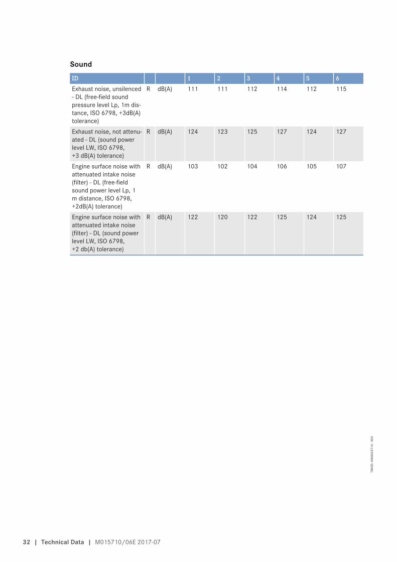
SoundID 1 2 3 4 5 6Exhaust noise, unsilenced- DL (free-field soundpressure level Lp, 1m dis-tance, ISO 6798, +3dB(A)tolerance)
R dB(A) 111 111 112 114 112 115
Exhaust noise, not attenu-ated - DL (sound powerlevel LW, ISO 6798,+3 dB(A) tolerance)
R dB(A) 124 123 125 127 124 127
Engine surface noise withattenuated intake noise(filter) - DL (free-fieldsound power level Lp, 1m distance, ISO 6798,+2dB(A) tolerance)
R dB(A) 103 102 104 106 105 107
Engine surface noise withattenuated intake noise(filter) - DL (sound powerlevel LW, ISO 6798,+2 db(A) tolerance)
R dB(A) 122 120 122 125 124 125
32 | Technical Data | M015710/06E 2017-07
TIM
-ID: 0
0000
2271
4 - 0
03
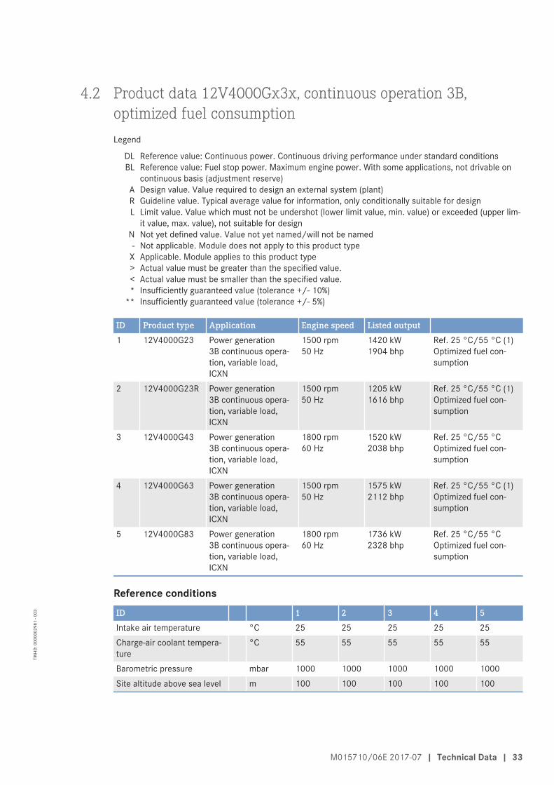
4.2 Product data 12V4000Gx3x, continuous operation 3B,optimized fuel consumptionLegend
DL Reference value: Continuous power. Continuous driving performance under standard conditionsBL Reference value: Fuel stop power. Maximum engine power. With some applications, not drivable on
continuous basis (adjustment reserve)A Design value. Value required to design an external system (plant)R Guideline value. Typical average value for information, only conditionally suitable for designL Limit value. Value which must not be undershot (lower limit value, min. value) or exceeded (upper lim-
it value, max. value), not suitable for designN Not yet defined value. Value not yet named/will not be named- Not applicable. Module does not apply to this product type
X Applicable. Module applies to this product type> Actual value must be greater than the specified value.< Actual value must be smaller than the specified value.* Insufficiently guaranteed value (tolerance +/- 10%)
** Insufficiently guaranteed value (tolerance +/- 5%)
ID Product type Application Engine speed Listed output1 12V4000G23 Power generation
3B continuous opera-tion, variable load,ICXN
1500 rpm50 Hz
1420 kW1904 bhp
Ref. 25 °C/55 °C (1)Optimized fuel con-sumption
2 12V4000G23R Power generation3B continuous opera-tion, variable load,ICXN
1500 rpm50 Hz
1205 kW1616 bhp
Ref. 25 °C/55 °C (1)Optimized fuel con-sumption
3 12V4000G43 Power generation3B continuous opera-tion, variable load,ICXN
1800 rpm60 Hz
1520 kW2038 bhp
Ref. 25 °C/55 °COptimized fuel con-sumption
4 12V4000G63 Power generation3B continuous opera-tion, variable load,ICXN
1500 rpm50 Hz
1575 kW2112 bhp
Ref. 25 °C/55 °C (1)Optimized fuel con-sumption
5 12V4000G83 Power generation3B continuous opera-tion, variable load,ICXN
1800 rpm60 Hz
1736 kW2328 bhp
Ref. 25 °C/55 °COptimized fuel con-sumption
Reference conditionsID 1 2 3 4 5Intake air temperature °C 25 25 25 25 25Charge-air coolant tempera-ture
°C 55 55 55 55 55
Barometric pressure mbar 1000 1000 1000 1000 1000Site altitude above sea level m 100 100 100 100 100
M015710/06E 2017-07 | Technical Data | 33
TIM
-ID: 0
0000
0298
1 - 0
03

Performance dataID 1 2 3 4 5Rated engine speed A rpm 1500 1500 1800 1500 1800Fuel stop power ISO 3046 A kW 1562 1325 1672 1733 1910
General conditions (for max. power)ID 1 2 3 4 5Intake depression (new filter) A mbar 15 15 15 15 15Intake depression, max. L mbar 50 50 50 50 50Exhaust overpressure A mbar 30 30 30 30 30Exhaust overpressure, max. L mbar 85 85 85 85 85
Model related data (basic design)ID 1 2 3 4 5Number of cylinders - 12 12 12 12 12Cylinder arrangement: V an-gle
Degrees(°)
90 90 90 90 90
Bore mm 170 170 170 170 170Stroke mm 210 210 210 210 210Displacement of a cylinder Liters 4.77 4.77 4.77 4.77 4.77Total displacement Liters 57.2 57.2 57.2 57.2 57.2Compression ratio - 16.4 16.4 16.4 16.4 16.4Number of inlet valves percylinder
- 2 2 2 2 2
Number of exhaust valvesper cylinder
- 2 2 2 2 2
Combustion air / exhaust gasID 1 2 3 4 5Charge-air pressure beforecylinder - BL
R bar abs 2.9 2.7 3.2 3.2 3.4
Coolant system (HT circuit)ID 1 2 3 4 5Coolant temperature (at en-gine connection: outlet tocooling equipment)
A °C 100 100 100 100 100
Coolant temperature afterengine, limit 1
L °C 102 102 102 102 102
Coolant temperature afterengine, limit 2
L °C 104 104 104 104 104
Coolant antifreeze content,max.
L % 50 50 50 50 50
Pressure loss in off-enginecooling system, max.
L bar 0.7 0.7 0.7 0.7 0.7
34 | Technical Data | M015710/06E 2017-07
TIM
-ID: 0
0000
0298
1 - 0
03

Coolant system (LT circuit)ID 1 2 3 4 5Coolant temperature beforecharge-air cooler (at engineconnection: from coolingequipment)
A °C 55 55 55 55 55
Coolant antifreeze content,max.
L % 50 50 50 50 50
Pressure loss in off-enginecooling system, max.
L bar 0.7 0.7 0.7 0.7 0.7
Lube oil systemID 1 2 3 4 5Lube oil operating tempera-ture upstream of engine,from
R °C 88 88 88 88 88
Lube oil operating tempera-ture upstream of engine, to
R °C 98 98 98 98 98
Lube oil temperature beforeengine, limit 1
L °C 99 99 99 99 99
Lube oil temperature beforeengine, limit 2
L °C 101 101 101 101 101
Lube oil operating pressureupstream of engine, from
R bar 5.0 5.0 5.0 5.0 5.0
Lube oil operating pressureupstream of engine, to
R bar 6.0 7.0 7.0 7.0 7.0
Fuel systemID 1 2 3 4 5Fuel pressure at engine inletconnection, min. (when en-gine is starting)
L bar -0.1 -0.1 -0.1 -0.1 -0.1
Fuel pressure at engine inletconnection, max. (when en-gine is starting)
L bar 1.5 1.5 1.5 1.5 1.5
General operating dataID 1 2 3 4 5Cold start capability: air tem-perature (w/o start aid, w/opreheating) - (case A)
R °C 10 10 10 10 10
Coolant preheating: preheat-ing temperature (min.)
L °C 32 32 32 32 32
Firing speed, from R rpm 80 80 80 80 80Firing speed, to R rpm 120 120 120 120 120
M015710/06E 2017-07 | Technical Data | 35
TIM
-ID: 0
0000
0298
1 - 0
03

CapacitiesID 1 2 3 4 5Engine coolant, engine side(without cooling equipment)
R Liters 160 160 160 160 160
Charge-air coolant, engineside
R Liters 40 40 40 40 40
Engine oil capacity, initial fill-ing (standard oil system) (op-tion: max. operating inclina-tions)
R Liters 260 260 260 260 260
Oil change quantity, max.(standard oil system) (op-tion: max. operating inclina-tions)
R Liters 200 200 200 200 200
Oil pan capacity at dipstickmark “min.” (standard oilsystem) (option: max. oper-ating inclinations)
L Liters 160 160 160 160 160
Oil pan capacity at dipstickmark “max.” (standard oilsystem) (option: max. oper-ating inclinations)
L Liters 200 200 200 200 200
Weights / main dimensionsID 1 2 3 4 5Engine weight, dry (basic en-gine configuration acc. toscope of delivery specifica-tion)
R kg 6200 * 6200 * 6200 * 6200 * 6200 *
SoundID 1 2 3 4 5Exhaust noise, not attenuat-ed - DL (sound power levelLW, ISO 6798, +3 dB(A) tol-erance)
R dB(A) 124 124 125 125 127
Engine surface noise with at-tenuated intake noise (filter)- DL (sound power level LW,ISO 6798, +2 db(A) toler-ance)
R dB(A) 120 120 122 121 123
36 | Technical Data | M015710/06E 2017-07
TIM
-ID: 0
0000
0298
1 - 0
03

4.3 Product data 16V4000Gx3, continuous operation 3B,optimized fuel consumptionLegend
DL Reference value: Continuous power. Continuous driving performance under standard conditionsBL Reference value: Fuel stop power. Maximum engine power. With some applications, not drivable on
continuous basis (adjustment reserve)A Design value. Value required to design an external system (plant)R Guideline value. Typical average value for information, only conditionally suitable for designL Limit value. Value which must not be undershot (lower limit value, min. value) or exceeded (upper lim-
it value, max. value), not suitable for designN Not yet defined value. Value not yet named/will not be named- Not applicable. Module does not apply to this product type
X Applicable. Module applies to this product type> Actual value must be greater than the specified value.< Actual value must be smaller than the specified value.* Insufficiently guaranteed value (tolerance +/- 10%)
** Insufficiently guaranteed value (tolerance +/- 5%)
ID Product type Application Engine speed Listed output1 16V4000G23 Power generation
3B continuous opera-tion, variable load,ICXN
1500 rpm50 Hz
1798 kW2411 bhp
Ref. 25 °C/55 °C (1)Optimized fuel con-sumption
2 16V4000G43 Power generation3B continuous opera-tion, variable load,ICXN
1800 rpm60 Hz
2020 kW2709 bhp
Ref. 25 °C/55 °COptimized fuel con-sumption
3 16V4000G63 Power generation3B continuous opera-tion, variable load,ICXN
1500 rpm50 Hz
1965 kW2635 bhp
Ref. 25 °C/55 °C (1)Optimized fuel con-sumption
4 16V4000G83 Power generation3B continuous opera-tion, variable load,ICXN
1800 rpm60 Hz
2280 kW3058 bhp
Ref. 25 °C/55 °COptimized fuel con-sumption
Reference conditionsID 1 2 3 4Intake air temperature °C 25 25 25 25Charge-air coolant temperature °C 55 55 55 55Barometric pressure mbar 1000 1000 1000 1000Site altitude above sea level m 100 100 100 100
Performance dataID 1 2 3 4Rated engine speed A rpm 1500 1800 1500 1800Fuel stop power ISO 3046 A kW 1978 2222 2162 2508
M015710/06E 2017-07 | Technical Data | 37
TIM
-ID: 0
0000
0300
3 - 0
03

General conditions (for max. power)ID 1 2 3 4Intake depression (new filter) A mbar 15 15 15 15Intake depression, max. L mbar 50 50 50 50Exhaust overpressure A mbar 30 30 30 30Exhaust overpressure, max. L mbar 85 85 85 85
Model related data (basic design)ID 1 2 3 4Number of cylinders - 16 16 16 16Cylinder arrangement: V angle Degrees
(°)90 90 90 90
Bore mm 170 170 170 170Stroke mm 210 210 210 210Displacement of a cylinder Liters 4.77 4.77 4.77 4.77Total displacement Liters 76.3 76.3 76.3 76.3Compression ratio - 16.4 16.4 16.4 16.4Number of inlet valves per cylinder - 2 2 2 2Number of exhaust valves per cylinder - 2 2 2 2
Combustion air / exhaust gasID 1 2 3 4Charge-air pressure before cylinder - BL R bar abs 2.8 3.1 3.1 3.3
Coolant system (HT circuit)ID 1 2 3 4Coolant temperature (at engine connec-tion: outlet to cooling equipment)
A °C 100 100 100 100
Coolant temperature after engine, limit 1 L °C 102 102 102 102Coolant temperature after engine, limit 2 L °C 104 104 104 104Coolant antifreeze content, max. L % 50 50 50 50Pressure loss in off-engine cooling sys-tem, max.
L bar 0.7 0.7 0.7 0.7
Coolant system (LT circuit)ID 1 2 3 4Coolant temperature (at engine connec-tion: outlet to cooling equipment)
R °C 63 66 65 70
Coolant antifreeze content, max. L % 50 50 50 50Pressure loss in off-engine cooling sys-tem, max.
L bar 0.7 0.7 0.7 0.7
38 | Technical Data | M015710/06E 2017-07
TIM
-ID: 0
0000
0300
3 - 0
03

Lube oil systemID 1 2 3 4Lube oil operating temperature upstreamof engine, from
R °C 89 90 89 88
Lube oil operating temperature upstreamof engine, to
R °C 95 96 95 95
Lube oil temperature before engine, limit1
L °C 97 97 97 97
Lube oil temperature before engine, limit2
L °C 99 99 99 99
Lube oil operating pressure upstream ofengine, from
R bar 4.2 4.7 4.2 4.7
Lube oil operating pressure upstream ofengine, to
R bar 5.5 6.5 5.5 6.5
Fuel systemID 1 2 3 4Fuel pressure at engine inlet connection,min. (when engine is starting)
L bar -0.1 -0.1 -0.1 -0.1
Fuel pressure at engine inlet connection,max. (when engine is starting)
L bar 1.5 1.5 1.5 1.5
General operating dataID 1 2 3 4Cold start capability: air temperature(w/o start aid, w/o preheating) - (case A)
R °C 10 10 10 10
Coolant preheating: preheating tempera-ture (min.)
L °C 32 32 32 32
Firing speed, from R rpm 80 80 80 80Firing speed, to R rpm 120 120 120 120
CapacitiesID 1 2 3 4Engine coolant, engine side (withoutcooling equipment)
R Liters 175 175 175 175
Charge-air coolant, engine side R Liters 50 50 50 50Engine oil capacity, initial filling (standardoil system) (option: max. operating incli-nations)
R Liters 300 300 300 300
Oil change quantity, max. (standard oilsystem) (option: max. operating inclina-tions)
R Liters 240 240 240 240
Oil pan capacity at dipstick mark “min.”(standard oil system) (option: max. oper-ating inclinations)
L Liters 210 210 210 210
Oil pan capacity at dipstick mark “max.”(standard oil system) (option: max. oper-ating inclinations)
L Liters 240 240 240 240
M015710/06E 2017-07 | Technical Data | 39
TIM
-ID: 0
0000
0300
3 - 0
03

Weights / main dimensionsID 1 2 3 4Engine weight, dry (basic engine configu-ration acc. to scope of delivery specifica-tion)
R kg 7700 7700 7700 7700
SoundID 1 2 3 4Exhaust noise, not attenuated - DL(sound power level LW, ISO 6798,+3 dB(A) tolerance)
R dB(A) 125 127 126 129
Engine surface noise with attenuated in-take noise (filter) - DL (sound power levelLW, ISO 6798, +2 db(A) tolerance)
R dB(A) 126 125 128 125
40 | Technical Data | M015710/06E 2017-07
TIM
-ID: 0
0000
0300
3 - 0
03

4.4 Product data 12V/16V4000Gx3x, continuous operation 3B,optimized exhaust gas emissions (TA-Luft)Legend
DL Reference value: Continuous power. Continuous driving performance under standard conditionsBL Reference value: Fuel stop power. Maximum engine power. With some applications, not drivable on
continuous basis (adjustment reserve)A Design value. Value required to design an external system (plant)R Guideline value. Typical average value for information, only conditionally suitable for designL Limit value. Value which must not be undershot (lower limit value, min. value) or exceeded (upper lim-
it value, max. value), not suitable for designN Not yet defined value. Value not yet named/will not be named- Not applicable. Module does not apply to this product type
X Applicable. Module applies to this product type> Actual value must be greater than the specified value.< Actual value must be smaller than the specified value.* Insufficiently guaranteed value (tolerance +/- 10%)
** Insufficiently guaranteed value (tolerance +/- 5%)
ID Product type Application Engine speed Listed output1 12V4000G23 Power generation
3B continuous opera-tion, variable load,ICXN
1500 rpm50 Hz
1420 kW1904 bhp
Ref. 25 °C/55 °C (10)TA-Luft-optimized (die-sel)
2 12V4000G23R Power generation3B continuous opera-tion, variable load,ICXN
1500 rpm50 Hz
1205 kW1616 bhp
Ref. 25 °C/55 °C (10)TA-Luft-optimized (die-sel)
3 12V4000G63 Power generation3B continuous opera-tion, variable load,ICXN
1500 rpm50 Hz
1575 kW2112 bhp
Ref. 25 °C/55 °C (10)TA-Luft-optimized (die-sel)
4 16V4000G23 Power generation3B continuous opera-tion, variable load,ICXN
1500 rpm50 Hz
1798 kW2411 bhp
Ref. 25 °C/55 °C (10)TA-Luft-optimized (die-sel)
5 16V4000G63 Power generation3B continuous opera-tion, variable load,ICXN
1500 rpm50 Hz
1965 kW2635 bhp
Ref. 25 °C/55 °C (10)TA-Luft-optimized (die-sel)
Reference conditionsID 1 2 3 4 5Intake air temperature °C 25 25 25 25 25Charge-air coolant tempera-ture
°C 55 55 55 55 55
Barometric pressure mbar 1000 1000 1000 1000 1000Site altitude above sea level m 100 100 100 100 100
M015710/06E 2017-07 | Technical Data | 41
TIM
-ID: 0
0000
0303
2 - 0
03

Performance dataID 1 2 3 4 5Rated engine speed A rpm 1500 1500 1500 1500 1500Fuel stop power ISO 3046 A kW 1562 1325 1733 1978 2162
General conditions (for max. power)ID 1 2 3 4 5Intake depression (new filter) A mbar 15 15 15 15 15Intake depression, max. L mbar 50 50 50 50 50Exhaust overpressure A mbar 30 30 30 30 30Exhaust overpressure, max. L mbar 85 85 85 85 85
Model related data (basic design)ID 1 2 3 4 5Number of cylinders - 12 12 12 16 16Cylinder arrangement: V an-gle
Degrees(°)
90 90 90 90 90
Bore mm 170 170 170 170 170Stroke mm 210 210 210 210 210Displacement of a cylinder Liters 4.77 4.77 4.77 4.77 4.77Total displacement Liters 57.2 57.2 57.2 76.3 76.3Compression ratio - 16.4 16.4 16.4 16.4 16.4Number of inlet valves percylinder
- 2 2 2 2 2
Number of exhaust valvesper cylinder
- 2 2 2 2 2
Combustion air / exhaust gasID 1 2 3 4 5Charge-air pressure beforecylinder - BL
R bar abs 3.5 3.1 3.5 3.5 3.7
Coolant system (HT circuit)ID 1 2 3 4 5Coolant temperature (at en-gine connection: outlet tocooling equipment)
A °C 100 100 100 100 100
Coolant temperature afterengine, limit 1
L °C 102 102 102 102 102
Coolant temperature afterengine, limit 2
L °C 104 104 104 104 104
Coolant antifreeze content,max.
L % 50 50 50 50 50
Pressure loss in off-enginecooling system, max.
L bar 0.7 0.7 0.7 0.7 0.7
42 | Technical Data | M015710/06E 2017-07
TIM
-ID: 0
0000
0303
2 - 0
03

Coolant system (LT circuit)ID 1 2 3 4 5Coolant temperature beforecharge-air cooler (at engineconnection: from coolingequipment)
A °C 55 55 55 55 55
Coolant antifreeze content,max.
L % 50 50 50 50 50
Pressure loss in off-enginecooling system, max.
L bar 0.7 0.7 0.7 0.7 0.7
Lube oil systemID 1 2 3 4 5Lube oil operating tempera-ture upstream of engine,from
R °C 88 88 88 89 89
Lube oil operating tempera-ture upstream of engine, to
R °C 98 98 98 95 95
Lube oil temperature beforeengine, limit 1
L °C 99 99 99 97 97
Lube oil temperature beforeengine, limit 2
L °C 101 101 101 102 102
Lube oil operating pressureupstream of engine, from
R bar 5.0 5.0 5.0 4.0 4.0
Lube oil operating pressureupstream of engine, to
R bar 7.0 7.0 7.0 5.5 5.5
Fuel systemID 1 2 3 4 5Fuel pressure at engine inletconnection, min. (when en-gine is starting)
L bar -0.1 -0.1 -0.1 -0.1 -0.1
Fuel pressure at engine inletconnection, max. (when en-gine is starting)
L bar 1.5 1.5 1.5 1.5 1.5
General operating dataID 1 2 3 4 5Cold start capability: air tem-perature (w/o start aid, w/opreheating) - (case A)
R °C 10 10 10 10 10
Coolant preheating: preheat-ing temperature (min.)
L °C 32 32 32 32 32
Firing speed, from R rpm 80 80 80 80 80Firing speed, to R rpm 120 120 120 120 120
M015710/06E 2017-07 | Technical Data | 43
TIM
-ID: 0
0000
0303
2 - 0
03

CapacitiesID 1 2 3 4 5Engine coolant, engine side(without cooling equipment)
R Liters 160 160 160 175 175
Charge-air coolant, engineside
R Liters 40 40 40 50 50
Engine oil capacity, initial fill-ing (standard oil system) (op-tion: max. operating inclina-tions)
R Liters 260 260 260 300 300
Oil change quantity, max.(standard oil system) (op-tion: max. operating inclina-tions)
R Liters 200 200 200 240 240
Oil pan capacity at dipstickmark “min.” (standard oilsystem) (option: max. oper-ating inclinations)
L Liters 160 160 160 210 210
Oil pan capacity at dipstickmark “max.” (standard oilsystem) (option: max. oper-ating inclinations)
L Liters 200 200 200 240 240
Weights / main dimensionsID 1 2 3 4 5Engine weight, dry (basic en-gine configuration acc. toscope of delivery specifica-tion)
R kg 6200 * 6200 * 6200 * 7700 7700
SoundID 1 2 3 4 5Exhaust noise, not attenuat-ed - DL (sound power levelLW, ISO 6798, +3 dB(A) tol-erance)
R dB(A) 126 126 127 126 127
Engine surface noise with at-tenuated intake noise (filter)- DL (sound power level LW,ISO 6798, +2 db(A) toler-ance)
R dB(A) 122 122 122 127 126
44 | Technical Data | M015710/06E 2017-07
TIM
-ID: 0
0000
0303
2 - 0
03

4.5 Product data 12V/16V4000Gx3, continuous operation 3B, EPAStationary EMERG T2 (40CFR60) und EPA Nonroad T2 Comp(40CFR89)Legend
DL Reference value: Continuous power. Continuous driving performance under standard conditionsBL Reference value: Fuel stop power. Maximum engine power. With some applications, not drivable on
continuous basis (adjustment reserve)A Design value. Value required to design an external system (plant)R Guideline value. Typical average value for information, only conditionally suitable for designL Limit value. Value which must not be undershot (lower limit value, min. value) or exceeded (upper lim-
it value, max. value), not suitable for designN Not yet defined value. Value not yet named/will not be named- Not applicable. Module does not apply to this product type
X Applicable. Module applies to this product type> Actual value must be greater than the specified value.< Actual value must be smaller than the specified value.* Insufficiently guaranteed value (tolerance +/- 10%)
** Insufficiently guaranteed value (tolerance +/- 5%)
ID Product type Application Engine speed Listed output1 12V4000G43 Power generation
3B continuous opera-tion, variable load,ICXN
1800 rpm60 Hz
1520 kW2038 bhp
Ref. 25 °C/45 °CEPA Stationary EMERGT2 (40CFR60)EPA Nonroad T2 Comp(40CFR89)
2 12V4000G83 Power generation3B continuous opera-tion, variable load,ICXN
1800 rpm60 Hz
1736 kW2328 bhp
Ref. 25 °C/45 °CEPA Stationary EMERGT2 (40CFR60)EPA Nonroad T2 Comp(40CFR89)
3 16V4000G43 Power generation3B continuous opera-tion, variable load,ICXN
1800 rpm60 Hz
2020 kW2709 bhp
Ref. 25 °C/45 °CEPA Stationary EMERGT2 (40CFR60)EPA Nonroad T2 Comp(40CFR89)
4 16V4000G83 Power generation3B continuous opera-tion, variable load,ICXN
1800 rpm60 Hz
2280 kW3058 bhp
Ref. 25 °C/45 °CEPA Stationary EMERGT2 (40CFR60)EPA Nonroad T2 Comp(40CFR89)
Reference conditionsID 1 2 3 4Intake air temperature °C 25 25 25 25Charge-air coolant temperature °C 45 45 45 45Barometric pressure mbar 1000 1000 1000 1000Site altitude above sea level m 100 100 100 100
M015710/06E 2017-07 | Technical Data | 45
TIM
-ID: 0
0000
0301
8 - 0
03

Performance dataID 1 2 3 4Rated engine speed A rpm 1800 1800 1800 1800Fuel stop power ISO 3046 A kW 1672 1910 2222 2508
General conditions (for max. power)ID 1 2 3 4Intake depression (new filter) A mbar 15 15 15 15Intake depression, max. L mbar 50 50 50 50Exhaust overpressure A mbar 30 30 30 30Exhaust overpressure, max. L mbar 85 85 85 85
Model related data (basic design)ID 1 2 3 4Number of cylinders - 12 12 16 16Cylinder arrangement: V angle Degrees
(°)90 90 90 90
Bore mm 170 170 170 170Stroke mm 210 210 210 210Displacement of a cylinder Liters 4.77 4.77 4.77 4.77Total displacement Liters 57.2 57.2 76.3 76.3Compression ratio - 16.4 16.4 16.4 16.4Number of inlet valves per cylinder - 2 2 2 2Number of exhaust valves per cylinder - 2 2 2 2
Combustion air / exhaust gasID 1 2 3 4Charge-air pressure before cylinder - BL R bar abs 3.1 3.3 3.2 3.3
Coolant system (HT circuit)ID 1 2 3 4Coolant temperature (at engine connec-tion: outlet to cooling equipment)
A °C 100 100 100 100
Coolant temperature after engine, limit 1 L °C 102 102 102 102Coolant temperature after engine, limit 2 L °C 104 104 104 104Coolant antifreeze content, max. L % 50 50 50 50Pressure loss in off-engine cooling sys-tem, max.
L bar 0.7 0.7 0.7 0.7
46 | Technical Data | M015710/06E 2017-07
TIM
-ID: 0
0000
0301
8 - 0
03

Coolant system (LT circuit)ID 1 2 3 4Coolant temperature before charge-aircooler (at engine connection: from cool-ing equipment)
A °C 45 45 45 45
Coolant antifreeze content, max. L % 50 50 50 50Pressure loss in off-engine cooling sys-tem, max.
L bar 0.7 0.7 0.7 0.7
Lube oil systemID 1 2 3 4Lube oil operating temperature upstreamof engine, from
R °C 88 88 90 88
Lube oil operating temperature upstreamof engine, to
R °C 98 98 96 94
Lube oil temperature before engine, lim-it 1
L °C 99 99 97 97
Lube oil temperature before engine, lim-it 2
L °C 101 101 99 99
Lube oil operating pressure upstream ofengine, from
R bar 5.0 5.0 4.7 4.7
Lube oil operating pressure upstream ofengine, to
R bar 7.0 7.0 6.5 6.5
Fuel systemID 1 2 3 4Fuel pressure at engine inlet connection,min. (when engine is starting)
L bar -0.1 -0.1 -0.1 -0.1
Fuel pressure at engine inlet connection,max. (when engine is starting)
L bar 1.5 1.5 1.5 1.5
General operating dataID 1 2 3 4Cold start capability: air temperature(w/o start aid, w/o preheating) - (case A)
R °C 10 10 10 10
Coolant preheating: preheating tempera-ture (min.)
L °C 32 32 32 32
Firing speed, from R rpm 80 80 80 80Firing speed, to R rpm 120 120 120 120
CapacitiesID 1 2 3 4Engine coolant, engine side (withoutcooling equipment)
R Liters 160 160 175 175
Charge-air coolant, engine side R Liters 40 40 50 50
M015710/06E 2017-07 | Technical Data | 47
TIM
-ID: 0
0000
0301
8 - 0
03

ID 1 2 3 4Engine oil capacity, initial filling (standardoil system) (option: max. operating incli-nations)
R Liters 260 260 300 300
Oil change quantity, max. (standard oilsystem) (option: max. operating inclina-tions)
R Liters 200 200 240 240
Oil pan capacity at dipstick mark “min.”(standard oil system) (option: max. oper-ating inclinations)
L Liters 160 160 210 210
Oil pan capacity at dipstick mark “max.”(standard oil system) (option: max. oper-ating inclinations)
L Liters 200 200 240 240
Weights / main dimensionsID 1 2 3 4Engine weight, dry (basic engine configu-ration acc. to scope of delivery specifica-tion)
R kg 6200 * 6200 * 7700 7700
SoundID 1 2 3 4Exhaust noise, not attenuated - DL(sound power level LW, ISO 6798,+3 dB(A) tolerance)
R dB(A) 125 127 127 129
Engine surface noise with attenuated in-take noise (filter) - DL (sound power levelLW, ISO 6798, +2 db(A) tolerance)
R dB(A) 122 123 125 125
48 | Technical Data | M015710/06E 2017-07
TIM
-ID: 0
0000
0301
8 - 0
03

4.6 Product data 12V/16V4000Gx3x, continuous operation 3B,NEA Singapore for ORDE and China Nonroad mobileMachinery Stage IIILegend
DL Reference value: Continuous power. Continuous driving performance under standard conditionsBL Reference value: Fuel stop power. Maximum engine power. With some applications, not drivable on
continuous basis (adjustment reserve)A Design value. Value required to design an external system (plant)R Guideline value. Typical average value for information, only conditionally suitable for designL Limit value. Value which must not be undershot (lower limit value, min. value) or exceeded (upper lim-
it value, max. value), not suitable for designN Not yet defined value. Value not yet named/will not be named- Not applicable. Module does not apply to this product type
X Applicable. Module applies to this product type> Actual value must be greater than the specified value.< Actual value must be smaller than the specified value.* Insufficiently guaranteed value (tolerance +/- 10%)
** Insufficiently guaranteed value (tolerance +/- 5%)
ID Product type Application Engine speed Listed output1 12V4000G23 Power generation
3B continuous opera-tion, variable load,ICXN
1500 rpm50 Hz
1420 kW1904 bhp
Ref. 25 °C/45 °CNEA Singapore forORDEChina Nonroad mobileMachinery Stage III
2 12V4000G23R Power generation3B continuous opera-tion, variable load,ICXN
1500 rpm50 Hz
1205 kW1616 bhp
Ref. 25 °C/45 °CNEA Singapore forORDEChina Nonroad mobileMachinery Stage III
3 12V4000G63 Power generation3B continuous opera-tion, variable load,ICXN
1500 rpm50 Hz
1575 kW2112 bhp
Ref. 25 °C/45 °CNEA Singapore forORDE
4 16V4000G23 Power generation3B continuous opera-tion, variable load,ICXN
1500 rpm50 Hz
1798 kW2411 bhp
Ref. 25 °C/45 °CNEA Singapore forORDEChina Nonroad mobileMachinery Stage III
5 16V4000G63 Power generation3B continuous opera-tion, variable load,ICXN
1500 rpm50 Hz
1965 kW2635 bhp
Ref. 25 °C/45 °CNEA Singapore forORDEChina Nonroad mobileMachinery Stage III
Reference conditionsID 1 2 3 4 5Intake air temperature °C 25 25 25 25 25Charge-air coolant tempera-ture
°C 45 45 45 45 45
M015710/06E 2017-07 | Technical Data | 49
TIM
-ID: 0
0000
6802
3 - 0
01

ID 1 2 3 4 5Barometric pressure mbar 1000 1000 1000 1000 1000Site altitude above sea level m 100 100 100 100 100
Performance dataID 1 2 3 4 5Rated engine speed A rpm 1500 1500 1500 1500 1500Fuel stop power ISO 3046 A kW 1562 1325 1732 1978 2162
General conditions (for max. power)ID 1 2 3 4 5Intake depression (new filter) A mbar 15 15 15 15 15Intake depression, max. L mbar 50 50 50 50 50
Model related data (basic design)ID 1 2 3 4 5Number of cylinders - 12 12 12 16 16Cylinder arrangement: V an-gle
Degrees(°)
90 90 90 90 90
Bore mm 170 170 170 170 170Stroke mm 210 210 210 210 210Displacement of a cylinder Liters 4.77 4.77 4.77 4.77 4.77Total displacement Liters 57.2 57.2 57.2 76.3 76.3Compression ratio - 16.4 16.4 16.4 16.4 16.4Number of inlet valves percylinder
- 2 2 2 2 2
Number of exhaust valvesper cylinder
- 2 2 2 2 2
Combustion air / exhaust gasID 1 2 3 4 5Charge air pressure beforecylinder - DL
R bar abs 2.9 2.6 3.13 2.9 3.1
Coolant system (HT circuit)ID 1 2 3 4 5Coolant temperature (at en-gine connection: outlet tocooling equipment)
A °C 100 100 100 100 100
Coolant temperature afterengine, limit 1
L °C 102 102 102 102 102
Coolant temperature afterengine, limit 2
L °C 104 104 104 104 104
50 | Technical Data | M015710/06E 2017-07
TIM
-ID: 0
0000
6802
3 - 0
01

ID 1 2 3 4 5Coolant antifreeze content,max.
L % 50 50 50 50 50
Pressure loss in off-enginecooling system, max.
L bar 0.7 0.7 0.7 0.7 0.7
Coolant system (LT circuit)ID 1 2 3 4 5Coolant temperature beforecharge-air cooler (at engineconnection: from coolingequipment)
A °C 45 45 45 45 45
Coolant antifreeze content,max.
L % 50 50 50 50 50
Pressure loss in off-enginecooling system, max.
L bar 0.7 0.7 0.7 0.7 0.7
Lube oil systemID 1 2 3 4 5Lube oil operating tempera-ture upstream of engine,from
R °C 88 88 88 89 89
Lube oil operating tempera-ture upstream of engine, to
R °C 98 98 98 95 95
Lube oil temperature beforeengine, limit 1
L °C 99 99 99 97 97
Lube oil temperature beforeengine, limit 2
L °C 101 101 101 99 99
Lube oil operating pressureupstream of engine, from
R bar 5.0 5.0 5.0 4.2 4.2
Lube oil operating pressureupstream of engine, to
R bar 7.0 7.0 7.0 5.5 5.5
Fuel systemID 1 2 3 4 5Fuel pressure at engine inletconnection, min. (when en-gine is starting)
L bar -0.1 -0.1 -0.1 -0.1 -0.1
Fuel pressure at engine inletconnection, max. (when en-gine is starting)
L bar 1.5 1.5 1.5 1.5 1.5
General operating dataID 1 2 3 4 5Cold start capability: air tem-perature (w/o start aid, w/opreheating) - (case A)
R °C 10 10 10 10 10
Coolant preheating: preheat-ing temperature (min.)
L °C 32 32 32 32 32
M015710/06E 2017-07 | Technical Data | 51
TIM
-ID: 0
0000
6802
3 - 0
01

ID 1 2 3 4 5Firing speed, from R rpm 80 80 80 80 80Firing speed, to R rpm 120 120 120 120 120
CapacitiesID 1 2 3 4 5Engine coolant, engine side(without cooling equipment)
R Liters 160 160 160 175 175
Charge-air coolant, engineside
R Liters 40 40 40 50 50
Engine oil capacity, initial fill-ing (standard oil system) (op-tion: max. operating inclina-tions)
R Liters 260 260 260 300 300
Oil change quantity, max.(standard oil system) (op-tion: max. operating inclina-tions)
R Liters 200 200 200 240 240
Oil pan capacity at dipstickmark “min.” (standard oilsystem) (option: max. oper-ating inclinations)
L Liters 160 160 160 210 210
Oil pan capacity at dipstickmark “max.” (standard oilsystem) (option: max. oper-ating inclinations)
L Liters 200 200 200 240 240
Weights / main dimensionsID 1 2 3 4 5Engine weight, dry (basic en-gine configuration acc. toscope of delivery specifica-tion)
R kg 6200 * 6200 * 6200 * 7700 7700
SoundID 1 2 3 4 5Exhaust noise, not attenuat-ed - DL (sound power levelLW, ISO 6798, +3 dB(A) tol-erance)
R dB(A) 126 126 126 125 126
Engine surface noise with at-tenuated intake noise (filter)- DL (sound power level LW,ISO 6798, +2 db(A) toler-ance)
R dB(A) 122 122 122 126 128
52 | Technical Data | M015710/06E 2017-07
TIM
-ID: 0
0000
6802
3 - 0
01

4.7 Product data 12V4000Gx3, standby operation 3D, optimizedfuel consumptionLegend
DL Reference value: Continuous power. Continuous driving performance under standard conditionsBL Reference value: Fuel stop power. Maximum engine power. With some applications, not drivable on
continuous basis (adjustment reserve)A Design value. Value required to design an external system (plant)R Guideline value. Typical average value for information, only conditionally suitable for designL Limit value. Value which must not be undershot (lower limit value, min. value) or exceeded (upper lim-
it value, max. value), not suitable for designN Not yet defined value. Value not yet named/will not be named- Not applicable. Module does not apply to this product type
X Applicable. Module applies to this product type> Actual value must be greater than the specified value.< Actual value must be smaller than the specified value.* Insufficiently guaranteed value (tolerance +/- 10%)
** Insufficiently guaranteed value (tolerance +/- 5%)
ID Product type Application Engine speed Listed output1 12V4000G23 Power generation
3D standby power,fuel stop power, IFN
1500 rpm50 Hz
1575 kW2112 bhp
Ref. 25 °C/55 °C (1)Optimized fuel con-sumption
2 12V4000G43 Power generation3D standby power,fuel stop power, IFN
1800 rpm60 Hz
1736 kW2328 bhp
Ref. 25 °C/55 °COptimized fuel con-sumption
3 12V4000G63 Power generation3D standby power,fuel stop power, IFN
1500 rpm50 Hz
1750 kW2347 bhp
Ref. 25 °C/55 °C (1)Optimized fuel con-sumption
4 12V4000G83 Power generation3D standby power,fuel stop power, IFN
1800 rpm60 Hz
1910 kW2561 bhp
Ref. 25 °C/55 °COptimized fuel con-sumption
Reference conditionsID 1 2 3 4Intake air temperature °C 25 25 25 25Charge-air coolant temperature °C 55 55 55 55Barometric pressure mbar 1000 1000 1000 1000Site altitude above sea level m 100 100 100 100
Performance dataID 1 2 3 4Rated engine speed A rpm 1500 1800 1500 1800Fuel stop power ISO 3046 A kW 1575 1736 1750 1910
General conditions (for max. power)ID 1 2 3 4Intake depression (new filter) A mbar 15 15 15 15Intake depression, max. L mbar 50 50 50 50
M015710/06E 2017-07 | Technical Data | 53
TIM
-ID: 0
0000
0287
3 - 0
03

ID 1 2 3 4Exhaust overpressure A mbar 30 30 30 30Exhaust overpressure, max. L mbar 85 85 85 85
Model related data (basic design)ID 1 2 3 4Number of cylinders - 12 12 12 12Cylinder arrangement: V angle Degrees
(°)90 90 90 90
Bore mm 170 170 170 170Stroke mm 210 210 210 210Displacement of a cylinder Liters 4.77 4.77 4.77 4.77Total displacement Liters 57.2 57.2 57.2 57.2Compression ratio - 16.4 16.4 16.4 16.4Number of inlet valves per cylinder - 2 2 2 2Number of exhaust valves per cylinder - 2 2 2 2
Combustion air / exhaust gasID 1 2 3 4Charge-air pressure before cylinder - BL R bar abs 2.9 3.2 3.2 3.4
Coolant system (HT circuit)ID 1 2 3 4Coolant temperature (at engine connec-tion: outlet to cooling equipment)
A °C 100 100 100 100
Coolant temperature after engine, limit 1 L °C 102 102 102 102Coolant temperature after engine, limit 2 L °C 104 104 104 104Coolant antifreeze content, max. L % 50 50 50 50Pressure loss in off-engine cooling sys-tem, max.
L bar 0.7 0.7 0.7 0.7
Coolant system (LT circuit)ID 1 2 3 4Coolant temperature before charge-aircooler (at engine connection: from cool-ing equipment)
A °C 55 55 55 55
Coolant antifreeze content, max. L % 50 50 50 50Pressure loss in off-engine cooling sys-tem, max.
L bar 0.7 0.7 0.7 0.7
Lube oil systemID 1 2 3 4Lube oil operating temperature upstreamof engine, from
R °C 88 88 88 88
Lube oil operating temperature upstreamof engine, to
R °C 98 98 98 98
54 | Technical Data | M015710/06E 2017-07
TIM
-ID: 0
0000
0287
3 - 0
03

ID 1 2 3 4Lube oil temperature before engine, limit1
L °C 99 99 99 99
Lube oil temperature before engine, limit2
L °C 101 101 101 101
Lube oil operating pressure upstream ofengine, from
R bar 5.0 5.0 5.0 5.0
Lube oil operating pressure upstream ofengine, to
R bar 7.0 7.0 7.0 7.0
Fuel systemID 1 2 3 4Fuel pressure at engine inlet connection,min. (when engine is starting)
L bar -0.1 -0.1 -0.1 -0.1
Fuel pressure at engine inlet connection,max. (when engine is starting)
L bar 1.5 1.5 1.5 1.5
General operating dataID 1 2 3 4Cold start capability: air temperature(w/o start aid, w/o preheating) - (case A)
R °C 10 10 10 10
Coolant preheating: preheating tempera-ture (min.)
L °C 32 32 32 32
Firing speed, from R rpm 80 80 80 80Firing speed, to R rpm 120 120 120 120
CapacitiesID 1 2 3 4Engine coolant, engine side (withoutcooling equipment)
R Liters 160 160 160 160
Charge-air coolant, engine side R Liters 40 40 40 40Engine oil capacity, initial filling (standardoil system) (option: max. operating incli-nations)
R Liters 260 260 260 260
Oil change quantity, max. (standard oilsystem) (option: max. operating inclina-tions)
R Liters 200 200 200 200
Oil pan capacity at dipstick mark “min.”(standard oil system) (option: max. oper-ating inclinations)
L Liters 160 160 160 160
Oil pan capacity at dipstick mark “max.”(standard oil system) (option: max. oper-ating inclinations)
L Liters 200 200 200 200
M015710/06E 2017-07 | Technical Data | 55
TIM
-ID: 0
0000
0287
3 - 0
03

Weights / main dimensionsID 1 2 3 4Engine weight, dry (basic engine configu-ration acc. to scope of delivery specifica-tion)
R kg 6200 * 6200 * 6200 * 6200 *
SoundID 1 2 3 4Exhaust noise, unsilenced - BL (soundpower level LW, ISO 6798, +3 dB(A) tol-erance)
R dB(A) 125 127 126 129
Engine surface noise with attenuated in-take noise (filter) - BL (sound power levelLW, ISO 6798, +2 dB(A) tolerance)
R dB(A) 121 123 122 124
56 | Technical Data | M015710/06E 2017-07
TIM
-ID: 0
0000
0287
3 - 0
03

4.8 Product data 16V4000Gx3x, standby operation 3D, optimizedfuel consumptionLegend
DL Reference value: Continuous power. Continuous driving performance under standard conditionsBL Reference value: Fuel stop power. Maximum engine power. With some applications, not drivable on
continuous basis (adjustment reserve)A Design value. Value required to design an external system (plant)R Guideline value. Typical average value for information, only conditionally suitable for designL Limit value. Value which must not be undershot (lower limit value, min. value) or exceeded (upper lim-
it value, max. value), not suitable for designN Not yet defined value. Value not yet named/will not be named- Not applicable. Module does not apply to this product type
X Applicable. Module applies to this product type> Actual value must be greater than the specified value.< Actual value must be smaller than the specified value.* Insufficiently guaranteed value (tolerance +/- 10%)
** Insufficiently guaranteed value (tolerance +/- 5%)
ID Product type Application Engine speed Listed output1 16V4000G23 Power generation
3D standby power,fuel stop power, IFN
1500 rpm50 Hz
1965 kW2635 bhp
Ref. 25 °C/55 °C (1)Optimized fuel con-sumption
2 16V4000G43 Power generation3D standby power,fuel stop power, IFN
1800 rpm60 Hz
2280 kW3058 bhp
Ref. 25 °C/55 °COptimized fuel con-sumption
3 16V4000G63 Power generation3D standby power,fuel stop power, IFN
1500 rpm50 Hz
2185 kW2930 bhp
Ref. 25 °C/55 °C (1)Optimized fuel con-sumption
4 16V4000G83 Power generation3D standby power,fuel stop power, IFN
1800 rpm60 Hz
2500 kW3353 bhp
Ref. 25 °C/55 °COptimized fuel con-sumption
5 16V4000G83L Power generation3D standby power,fuel stop power, IFN
1800 rpm60 Hz
2740 kW3674 bhp
Ref. 25 °C/45 °COptimized fuel con-sumption
Reference conditionsID 1 2 3 4 5Intake air temperature °C 25 25 25 25 25Charge-air coolant tempera-ture
°C 55 55 55 55 45
Barometric pressure mbar 1000 1000 1000 1000 1000Site altitude above sea level m 100 100 100 100 100
Performance dataID 1 2 3 4 5Rated engine speed A rpm 1500 1800 1500 1800 1800Fuel stop power ISO 3046 A kW 1965 2280 2185 2500 2740
M015710/06E 2017-07 | Technical Data | 57
TIM
-ID: 0
0000
0292
2 - 0
03

General conditions (for max. power)ID 1 2 3 4 5Intake depression (new filter) A mbar 15 15 15 15 15Intake depression, max. L mbar 50 50 50 50 30Exhaust overpressure A mbar 30 30 30 30 30Exhaust overpressure, max. L mbar 85 85 85 85 85
Model related data (basic design)ID 1 2 3 4 5Number of cylinders - 16 16 16 16 16Cylinder arrangement: V an-gle
Degrees(°)
90 90 90 90 90
Bore mm 170 170 170 170 170Stroke mm 210 210 210 210 210Displacement of a cylinder Liters 4.77 4.77 4.77 4.77 4.77Total displacement Liters 76.3 76.3 76.3 76.3 76.3Compression ratio - 16.4 16.4 16.4 16.4 16.4Number of inlet valves percylinder
- 2 2 2 2 2
Number of exhaust valvesper cylinder
- 2 2 2 2 2
Combustion air / exhaust gasID 1 2 3 4 5Charge-air pressure beforecylinder - BL
R bar abs 2.8 3.1 3.1 3.3 3.7
Coolant system (HT circuit)ID 1 2 3 4 5Coolant temperature (at en-gine connection: outlet tocooling equipment)
A °C 100 100 100 100 100
Coolant temperature afterengine, limit 1
L °C 102 102 102 102 102
Coolant temperature afterengine, limit 2
L °C 104 104 104 104 104
Coolant antifreeze content,max.
L % 50 50 50 50 50
Pressure loss in off-enginecooling system, max.
L bar 0.7 0.7 0.7 0.7 0.7
58 | Technical Data | M015710/06E 2017-07
TIM
-ID: 0
0000
0292
2 - 0
03

Coolant system (LT circuit)ID 1 2 3 4 5Coolant temperature beforecharge-air cooler (at engineconnection: from coolingequipment)
A °C 55 55 55 55 45
Coolant antifreeze content,max.
L % 50 50 50 50 50
Pressure loss in off-enginecooling system, max.
L bar 0.7 0.7 0.7 0.7 0.7
Lube oil systemID 1 2 3 4 5Lube oil operating tempera-ture upstream of engine,from
R °C 89 88 89 88 88
Lube oil operating tempera-ture upstream of engine, to
R °C 95 95 95 94 94
Lube oil temperature beforeengine, limit 1
L °C 97 97 97 97 97
Lube oil temperature beforeengine, limit 2
L °C 99 99 99 99 99
Lube oil operating pressureupstream of engine, from
R bar 4.2 4.7 4.2 4.7 4.7
Lube oil operating pressureupstream of engine, to
R bar 5.5 6.5 5.5 6.5 6.5
Fuel systemID 1 2 3 4 5Fuel pressure at engine inletconnection, min. (when en-gine is starting)
L bar -0.1 -0.1 -0.1 -0.1 -0.1
Fuel pressure at engine inletconnection, max. (when en-gine is starting)
L bar 1.5 1.5 1.5 1.5 1.5
General operating dataID 1 2 3 4 5Cold start capability: air tem-perature (w/o start aid, w/opreheating) - (case A)
R °C 10 10 10 10 10
Coolant preheating: preheat-ing temperature (min.)
L °C 32 32 32 32 32
Firing speed, from R rpm 80 80 80 80 80Firing speed, to R rpm 120 120 120 120 120
M015710/06E 2017-07 | Technical Data | 59
TIM
-ID: 0
0000
0292
2 - 0
03

CapacitiesID 1 2 3 4 5Engine coolant, engine side(without cooling equipment)
R Liters 175 175 175 175 175
Charge-air coolant, engineside
R Liters 50 50 50 50 50
Engine oil capacity, initial fill-ing (standard oil system) (op-tion: max. operating inclina-tions)
R Liters 300 300 300 300 300
Oil change quantity, max.(standard oil system) (op-tion: max. operating inclina-tions)
R Liters 240 240 240 240 240
Oil pan capacity at dipstickmark “min.” (standard oilsystem) (option: max. oper-ating inclinations)
L Liters 210 210 210 210 210
Oil pan capacity at dipstickmark “max.” (standard oilsystem) (option: max. oper-ating inclinations)
L Liters 240 240 240 240 240
Weights / main dimensionsID 1 2 3 4 5Engine weight, dry (basic en-gine configuration acc. toscope of delivery specifica-tion)
R kg 7700 7700 7700 7700 7700
SoundID 1 2 3 4 5Exhaust noise, unsilenced -BL (sound power level LW,ISO 6798, +3 dB(A) toler-ance)
R dB(A) 126 129 128 130 -
Engine surface noise with at-tenuated intake noise (filter)- BL (sound power level LW,ISO 6798, +2 dB(A) toler-ance)
R dB(A) 128 125 125 126 -
Exhaust noise, unsilenced -DL (free-field sound pressurelevel Lp, 1 m distance, ISO6798, +3 dB(A) tolerance)
R dB(A) - - - - 118
Engine surface noise with at-tenuated intake noise (filter)- DL (free-field sound powerlevel Lp, 1 m distance, ISO6798, +2 dB(A) tolerance)
R dB(A) - - - - 107
60 | Technical Data | M015710/06E 2017-07
TIM
-ID: 0
0000
0292
2 - 0
03

4.9 Product data 12V/16V4000Gx3x, standby operation 3D, EPAStationary EMERG T2 (40CFR60) and EPA Nonroad T2 Comp(40CFR89)Legend
DL Reference value: Continuous power. Continuous driving performance under standard conditionsBL Reference value: Fuel stop power. Maximum engine power. With some applications, not drivable on
continuous basis (adjustment reserve)A Design value. Value required to design an external system (plant)R Guideline value. Typical average value for information, only conditionally suitable for designL Limit value. Value which must not be undershot (lower limit value, min. value) or exceeded (upper lim-
it value, max. value), not suitable for designN Not yet defined value. Value not yet named/will not be named- Not applicable. Module does not apply to this product type
X Applicable. Module applies to this product type> Actual value must be greater than the specified value.< Actual value must be smaller than the specified value.* Insufficiently guaranteed value (tolerance +/- 10%)
** Insufficiently guaranteed value (tolerance +/- 5%)
ID Product type Application Engine speed Listed output1 12V4000G43 Power generation
3D standby power,fuel stop power, IFN
1800 rpm60 Hz
1736 kW2328 bhp
Ref. 25 °C/45 °CEPA Stationary EMERGT2 (40CFR60)EPA Nonroad T2 Comp(40CFR89)
2 12V4000G83 Power generation3D standby power,fuel stop power, IFN
1800 rpm60 Hz
1910 kW2561 bhp
Ref. 25 °C/45 °CEPA Stationary EMERGT2 (40CFR60)EPA Nonroad T2 Comp(40CFR89)
3 16V4000G43 Power generation3D standby power,fuel stop power, IFN
1800 rpm60 Hz
2280 kW3058 bhp
Ref. 25 °C/45 °CEPA Stationary EMERGT2 (40CFR60)EPA Nonroad T2 Comp(40CFR89)
4 16V4000G83 Power generation3D standby power,fuel stop power, IFN
1800 rpm60 Hz
2500 kW3353 bhp
Ref. 25 °C/45 °CEPA Stationary EMERGT2 (40CFR60)EPA Nonroad T2 Comp(40CFR89)
5 16V4000G83L Power generation3D standby power,fuel stop power, IFN
1800 rpm60 Hz
2740 kW3674 bhp
Ref. 25 °C/45 °CEPA Stationary EMERGT2 (40CFR60)EPA Nonroad T2 Comp(40CFR89)
Reference conditionsID 1 2 3 4 5Intake air temperature °C 25 25 25 25 25Charge-air coolant tempera-ture
°C 45 45 45 45 45
M015710/06E 2017-07 | Technical Data | 61
TIM
-ID: 0
0000
0295
5 - 0
03

ID 1 2 3 4 5Barometric pressure mbar 1000 1000 1000 1000 1000Site altitude above sea level m 100 100 100 100 100
Performance dataID 1 2 3 4 5Rated engine speed A rpm 1800 1800 1800 1800 1800Fuel stop power ISO 3046 A kW 1736 1910 2280 2500 2740
General conditions (for max. power)ID 1 2 3 4 5Intake depression (new filter) A mbar 15 15 15 15 15Intake depression, max. L mbar 50 50 50 50 30Exhaust overpressure A mbar 30 30 30 30 30Exhaust overpressure, max. L mbar 85 85 85 85 85
Model related data (basic design)ID 1 2 3 4 5Number of cylinders - 12 12 16 16 16Cylinder arrangement: V an-gle
Degrees(°)
90 90 90 90 90
Bore mm 170 170 170 170 170Stroke mm 210 210 210 210 210Displacement of a cylinder Liters 4.77 4.77 4.77 4.77 4.77Total displacement Liters 57.2 57.2 76.3 76.3 76.3Compression ratio - 16.4 16.4 16.4 16.4 16.4Number of inlet valves percylinder
- 2 2 2 2 2
Number of exhaust valvesper cylinder
- 2 2 2 2 2
Combustion air / exhaust gasID 1 2 3 4 5Charge-air pressure beforecylinder - BL
R bar abs 3.2 3.3 3.2 3.3 3.7
Coolant system (HT circuit)ID 1 2 3 4 5Coolant temperature (at en-gine connection: outlet tocooling equipment)
A °C 100 100 100 100 100
Coolant temperature afterengine, limit 1
L °C 102 102 102 102 102
Coolant temperature afterengine, limit 2
L °C 104 104 104 104 104
62 | Technical Data | M015710/06E 2017-07
TIM
-ID: 0
0000
0295
5 - 0
03

ID 1 2 3 4 5Coolant antifreeze content,max.
L % 50 50 50 50 50
Pressure loss in off-enginecooling system, max.
L bar 0.7 0.7 0.7 0.7 0.7
Coolant system (LT circuit)ID 1 2 3 4 5Coolant temperature beforecharge-air cooler (at engineconnection: from coolingequipment)
A °C 45 45 45 45 45
Coolant antifreeze content,max.
L % 50 50 50 50 50
Pressure loss in off-enginecooling system, max.
L bar 0.7 0.7 0.7 0.7 0.7
Lube oil systemID 1 2 3 4 5Lube oil operating tempera-ture upstream of engine,from
R °C 88 88 88 88 88
Lube oil operating tempera-ture upstream of engine, to
R °C 98 98 94 94 94
Lube oil temperature beforeengine, limit 1
L °C 99 99 97 97 97
Lube oil temperature beforeengine, limit 2
L °C 101 101 99 99 99
Lube oil operating pressureupstream of engine, from
R bar 5.0 5.0 4.7 4.7 4.7
Lube oil operating pressureupstream of engine, to
R bar 7.0 7.0 6.5 6.5 6.5
Fuel systemID 1 2 3 4 5Fuel pressure at engine inletconnection, min. (when en-gine is starting)
L bar -0.1 -0.1 -0.1 -0.1 -0.1
Fuel pressure at engine inletconnection, max. (when en-gine is starting)
L bar 1.5 1.5 1.5 1.5 1.5
General operating dataID 1 2 3 4 5Cold start capability: air tem-perature (w/o start aid, w/opreheating) - (case A)
R °C 10 10 10 10 10
Coolant preheating: preheat-ing temperature (min.)
L °C 32 32 32 32 32
M015710/06E 2017-07 | Technical Data | 63
TIM
-ID: 0
0000
0295
5 - 0
03

ID 1 2 3 4 5Firing speed, from R rpm 80 80 80 80 80Firing speed, to R rpm 120 120 120 120 120
CapacitiesID 1 2 3 4 5Engine coolant, engine side(without cooling equipment)
R Liters 160 160 175 175 175
Charge-air coolant, engineside
R Liters 40 40 50 50 50
Engine oil capacity, initial fill-ing (standard oil system) (op-tion: max. operating inclina-tions)
R Liters 260 260 300 300 300
Oil change quantity, max.(standard oil system) (op-tion: max. operating inclina-tions)
R Liters 200 200 240 240 240
Oil pan capacity at dipstickmark “min.” (standard oilsystem) (option: max. oper-ating inclinations)
L Liters 160 160 210 210 210
Oil pan capacity at dipstickmark “max.” (standard oilsystem) (option: max. oper-ating inclinations)
L Liters 200 200 240 240 240
Weights / main dimensionsID 1 2 3 4 5Engine weight, dry (basic en-gine configuration acc. toscope of delivery specifica-tion)
R kg 6200 * 6200 * 7700 7700 7700
SoundID 1 2 3 4 5Exhaust noise, unsilenced -BL (sound power level LW,ISO 6798, +3 dB(A) toler-ance)
R dB(A) 127 129 129 130 -
Engine surface noise with at-tenuated intake noise (filter)- BL (sound power level LW,ISO 6798, +2 dB(A) toler-ance)
R dB(A) 123 124 125 126 -
64 | Technical Data | M015710/06E 2017-07
TIM
-ID: 0
0000
0295
5 - 0
03
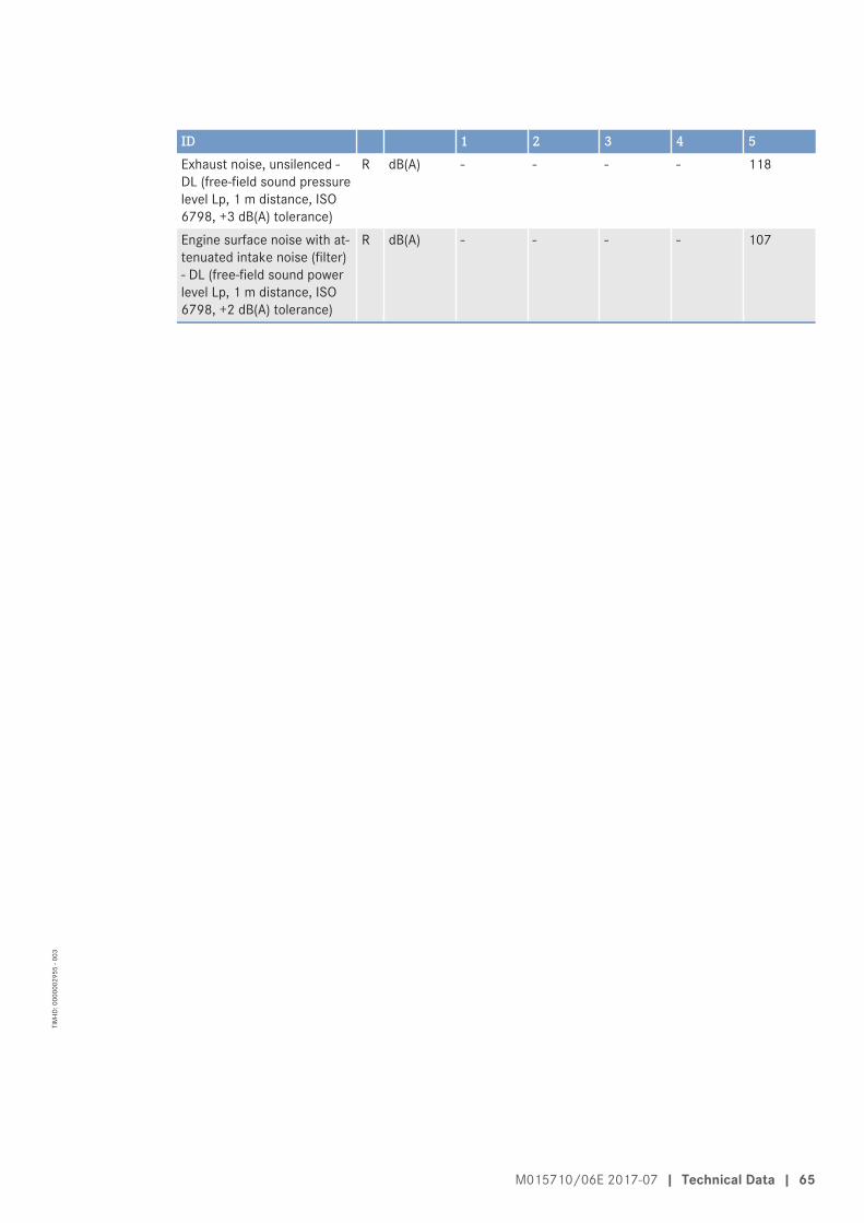
ID 1 2 3 4 5Exhaust noise, unsilenced -DL (free-field sound pressurelevel Lp, 1 m distance, ISO6798, +3 dB(A) tolerance)
R dB(A) - - - - 118
Engine surface noise with at-tenuated intake noise (filter)- DL (free-field sound powerlevel Lp, 1 m distance, ISO6798, +2 dB(A) tolerance)
R dB(A) - - - - 107
M015710/06E 2017-07 | Technical Data | 65
TIM
-ID: 0
0000
0295
5 - 0
03

4.10 Product data 12V/16V4000Gx3, standby operation 3D, NEASingapore for ORDE and China Nonroad mobile MachineryStage IIILegend
DL Reference value: Continuous power. Continuous driving performance under standard conditionsBL Reference value: Fuel stop power. Maximum engine power. With some applications, not drivable on
continuous basis (adjustment reserve)A Design value. Value required to design an external system (plant)R Guideline value. Typical average value for information, only conditionally suitable for designL Limit value. Value which must not be undershot (lower limit value, min. value) or exceeded (upper lim-
it value, max. value), not suitable for designN Not yet defined value. Value not yet named/will not be named- Not applicable. Module does not apply to this product type
X Applicable. Module applies to this product type> Actual value must be greater than the specified value.< Actual value must be smaller than the specified value.* Insufficiently guaranteed value (tolerance +/- 10%)
** Insufficiently guaranteed value (tolerance +/- 5%)
ID Product type Application Engine speed Listed output1 12V4000G23 Power generation
3D standby power,fuel stop power, IFN
1500 rpm50 Hz
1575 kW2112 bhp
Ref. 25 °C/45 °CNEA Singapore forORDEChina Nonroad mobileMachinery Stage III
2 12V4000G63 Power generation3D standby power,fuel stop power, IFN
1500 rpm50 Hz
1750 kW2347 bhp
Ref. 25 °C/45 °CNEA Singapore forORDE
3 16V4000G23 Power generation3D standby power,fuel stop power, IFN
1500 rpm50 Hz
1965 kW2635 bhp
Ref. 25 °C/45 °CNEA Singapore forORDEChina Nonroad mobileMachinery Stage III
4 16V4000G63 Power generation3D standby power,fuel stop power, IFN
1500 rpm50 Hz
2185 kW2930 bhp
Ref. 25 °C/45 °CNEA Singapore forORDEChina Nonroad mobileMachinery Stage III
Reference conditionsID 1 2 3 4Intake air temperature °C 25 25 25 25Charge-air coolant temperature °C 45 45 45 45Barometric pressure mbar 1000 1000 1000 1000Site altitude above sea level m 100 100 100 100
66 | Technical Data | M015710/06E 2017-07
TIM
-ID: 0
0000
6802
5 - 0
02

Performance dataID 1 2 3 4Rated engine speed A rpm 1500 1500 1500 1500Fuel stop power ISO 3046 A kW 1575 1750 1965 2185
General conditions (for max. power)ID 1 2 3 4Intake depression (new filter) A mbar 15 15 15 15Intake depression, max. L mbar 50 50 50 50
Model related data (basic design)ID 1 2 3 4Number of cylinders - 12 12 16 16Cylinder arrangement: V angle Degrees
(°)90 90 90 90
Bore mm 170 170 170 170Stroke mm 210 210 210 210Displacement of a cylinder Liters 4.77 4.77 4.77 4.77Total displacement Liters 57.2 57.2 76.3 76.3Compression ratio - 16.4 16.4 16.4 16.4Number of inlet valves per cylinder - 2 2 2 2Number of exhaust valves per cylinder - 2 2 2 2
Combustion air / exhaust gasID 1 2 3 4Charge-air pressure before cylinder - BL R bar abs 3.1 3.4 3.1 3.4
Coolant system (HT circuit)ID 1 2 3 4Coolant temperature (at engine connec-tion: outlet to cooling equipment)
A °C 100 100 100 100
Coolant temperature after engine, limit 1 L °C 102 102 102 102Coolant temperature after engine, limit 2 L °C 104 104 104 104Coolant antifreeze content, max. L % 50 50 50 50Pressure loss in off-engine cooling sys-tem, max.
L bar 0.7 0.7 0.7 0.7
Coolant system (LT circuit)ID 1 2 3 4Coolant temperature before charge-aircooler (at engine connection: from cool-ing equipment)
A °C 45 45 45 45
Coolant antifreeze content, max. L % 50 50 50 50Pressure loss in off-engine cooling sys-tem, max.
L bar 0.7 0.7 0.7 0.7
M015710/06E 2017-07 | Technical Data | 67
TIM
-ID: 0
0000
6802
5 - 0
02

Lube oil systemID 1 2 3 4Lube oil operating temperature upstreamof engine, from
R °C 88 88 89 89
Lube oil operating temperature upstreamof engine, to
R °C 98 98 95 95
Lube oil temperature before engine, limit1
L °C 99 99 97 97
Lube oil temperature before engine, limit2
L °C 101 101 99 99
Lube oil operating pressure upstream ofengine, from
R bar 5.0 5.0 4.2 4.2
Lube oil operating pressure upstream ofengine, to
R bar 7.0 7.0 5.5 5.5
Fuel systemID 1 2 3 4Fuel pressure at engine inlet connection,min. (when engine is starting)
L bar -0.1 -0.1 -0.1 -0.1
Fuel pressure at engine inlet connection,max. (when engine is starting)
L bar 1.5 1.5 1.5 1.5
General operating dataID 1 2 3 4Cold start capability: air temperature(w/o start aid, w/o preheating) - (case A)
R °C 10 10 10 10
Coolant preheating: preheating tempera-ture (min.)
L °C 32 32 32 32
Firing speed, from R rpm 80 80 80 80Firing speed, to R rpm 120 120 120 120
CapacitiesID 1 2 3 4Engine coolant, engine side (withoutcooling equipment)
R Liters 160 160 175 175
Charge-air coolant, engine side R Liters 40 40 50 50Engine oil capacity, initial filling (standardoil system) (option: max. operating incli-nations)
R Liters 260 260 300 300
Oil change quantity, max. (standard oilsystem) (option: max. operating inclina-tions)
R Liters 200 200 240 240
Oil pan capacity at dipstick mark “min.”(standard oil system) (option: max. oper-ating inclinations)
L Liters 160 160 210 210
Oil pan capacity at dipstick mark “max.”(standard oil system) (option: max. oper-ating inclinations)
L Liters 200 200 240 240
68 | Technical Data | M015710/06E 2017-07
TIM
-ID: 0
0000
6802
5 - 0
02

Weights / main dimensionsID 1 2 3 4Engine weight, dry (basic engine configu-ration acc. to scope of delivery specifica-tion)
R kg 6200 * 6200 * 7700 7700
SoundID 1 2 3 4Exhaust noise, unsilenced - BL (soundpower level LW, ISO 6798+3)
R dB(A) 126 126 126 128
Engine surface noise with attenuated in-take noise (filter) - BL (sound power levelLW, ISO 6798, +2dB(A) tolerance)
R dB(A) 122 122 128 125
M015710/06E 2017-07 | Technical Data | 69
TIM
-ID: 0
0000
6802
5 - 0
02

4.11 Product data 12V/16V4000Gx3, standby operation 3E,optimized fuel consumptionLegend
DL Reference value: Continuous power. Continuous driving performance under standard conditionsBL Reference value: Fuel stop power. Maximum engine power. With some applications, not drivable on
continuous basis (adjustment reserve)A Design value. Value required to design an external system (plant)R Guideline value. Typical average value for information, only conditionally suitable for designL Limit value. Value which must not be undershot (lower limit value, min. value) or exceeded (upper lim-
it value, max. value), not suitable for designN Not yet defined value. Value not yet named/will not be named- Not applicable. Module does not apply to this product type
X Applicable. Module applies to this product type> Actual value must be greater than the specified value.< Actual value must be smaller than the specified value.* Insufficiently guaranteed value (tolerance +/- 10%)
** Insufficiently guaranteed value (tolerance +/- 5%)
ID Product type Application Engine speed Listed output1 12V4000G23 Power generation
3E standby power,overload capability ac-cording to ICXN
1500 rpm50 Hz
1420 kW1904 bhp
Ref. 25 °C/55 °COptimized fuel con-sumption
2 12V4000G63 Power generation3E standby power,overload capability ac-cording to ICXN
1500 rpm50 Hz
1575 kW2112 bhp
Ref. 25 °C/55 °COptimized fuel con-sumption
3 16V4000G23 Power generation3E standby power,overload capability ac-cording to ICXN
1500 rpm50 Hz
1798 kW2411 bhp
Ref. 25 °C/55 °C (1)Optimized fuel con-sumption
4 16V4000G63 Power generation3E standby power,overload capability ac-cording to ICXN
1500 rpm50 Hz
1965 kW2635 bhp
Ref. 25 °C/55 °C (1)Optimized fuel con-sumption
Reference conditionsID 1 2 3 4Intake air temperature °C 25 25 25 25Charge-air coolant temperature °C 55 55 55 55Barometric pressure mbar 1000 1000 1000 1000Site altitude above sea level m 100 100 100 100
Performance dataID 1 2 3 4Rated engine speed A rpm 1500 1500 1500 1500Fuel stop power ISO 3046 A kW 1562 1733 1978 2162
70 | Technical Data | M015710/06E 2017-07
TIM
-ID: 0
0000
6747
0 - 0
01

General conditions (for max. power)ID 1 2 3 4Intake depression (new filter) A mbar 15 15 15 15Intake depression, max. L mbar 50 50 50 50Exhaust overpressure A mbar 30 30 30 30Exhaust overpressure, max. L mbar 85 85 85 85
Model related data (basic design)ID 1 2 3 4Number of cylinders - 12 12 16 16Cylinder arrangement: V angle Degrees
(°)90 90 90 90
Bore mm 170 170 170 170Stroke mm 210 210 210 210Displacement of a cylinder Liters 4.77 4.77 4.77 4.77Total displacement Liters 57.2 57.2 76.3 76.3Compression ratio - 16.4 16.4 16.4 16.4Number of inlet valves per cylinder - 2 2 2 2Number of exhaust valves per cylinder - 2 2 2 2
Combustion air / exhaust gasID 1 2 3 4Charge air pressure before cylinder - DL R bar abs 2.6 2.9 2.6 2.8Charge-air pressure before cylinder - BL R bar abs 2.9 3.2 2.8 3.1
Coolant system (HT circuit)ID 1 2 3 4Coolant temperature (at engine connec-tion: outlet to cooling equipment)
A °C 100 100 100 100
Coolant temperature after engine, limit 1 L °C 102 102 102 102Coolant temperature after engine, limit 2 L °C 104 104 104 104Coolant antifreeze content, max. L % 50 50 50 50Pressure loss in off-engine cooling sys-tem, max.
L bar 0.7 0.7 0.7 0.7
Coolant system (LT circuit)ID 1 2 3 4Coolant temperature before charge-aircooler (at engine connection: from cool-ing equipment)
A °C 55 55 55 55
Coolant antifreeze content, max. L % 50 50 50 50Pressure loss in off-engine cooling sys-tem, max.
L bar 0.7 0.7 0.7 0.7
M015710/06E 2017-07 | Technical Data | 71
TIM
-ID: 0
0000
6747
0 - 0
01

Lube oil systemID 1 2 3 4Lube oil operating temperature upstreamof engine, from
R °C 88 88 89 89
Lube oil operating temperature upstreamof engine, to
R °C 98 98 95 95
Lube oil temperature before engine, limit1
L °C 99 99 97 97
Lube oil temperature before engine, limit2
L °C 101 101 99 99
Lube oil operating pressure upstream ofengine, from
R bar 5.0 5.0 4.2 4.2
Lube oil operating pressure upstream ofengine, to
R bar 6.0 7.0 5.5 5.5
Fuel systemID 1 2 3 4Fuel pressure at engine inlet connection,min. (when engine is starting)
L bar -0.1 -0.1 -0.1 -0.1
Fuel pressure at engine inlet connection,max. (when engine is starting)
L bar 1.5 1.5 1.5 1.5
General operating dataID 1 2 3 4Cold start capability: air temperature(w/o start aid, w/o preheating) - (case A)
R °C 10 10 10 10
Coolant preheating: preheating tempera-ture (min.)
L °C 32 32 32 32
Firing speed, from R rpm 80 80 80 80Firing speed, to R rpm 120 120 120 120
CapacitiesID 1 2 3 4Engine coolant, engine side (withoutcooling equipment)
R Liters 160 160 175 175
Charge-air coolant, engine side R Liters 40 40 50 50Engine oil capacity, initial filling (standardoil system) (option: max. operating incli-nations)
R Liters 260 260 300 300
Oil change quantity, max. (standard oilsystem) (option: max. operating inclina-tions)
R Liters 200 200 240 240
Oil pan capacity at dipstick mark “min.”(standard oil system) (option: max. oper-ating inclinations)
L Liters 160 160 210 210
Oil pan capacity at dipstick mark “max.”(standard oil system) (option: max. oper-ating inclinations)
L Liters 200 200 240 240
72 | Technical Data | M015710/06E 2017-07
TIM
-ID: 0
0000
6747
0 - 0
01

Weights / main dimensionsID 1 2 3 4Engine weight, dry (basic engine configu-ration acc. to scope of delivery specifica-tion)
R kg 6200 * 6200 * 7700 7700
SoundID 1 2 3 4Exhaust noise, not attenuated - DL(sound power level LW, ISO 6798,+3 dB(A) tolerance)
R dB(A) 124 125 125 126
Engine surface noise with attenuated in-take noise (filter) - DL (sound power levelLW, ISO 6798, +2 db(A) tolerance)
R dB(A) 120 121 126 128
M015710/06E 2017-07 | Technical Data | 73
TIM
-ID: 0
0000
6747
0 - 0
01

4.12 Product data 12V/16V4000Gx3, standby operation 3E,optimized exhaust gas emissions (TA-Luft)Legend
DL Reference value: Continuous power. Continuous driving performance under standard conditionsBL Reference value: Fuel stop power. Maximum engine power. With some applications, not drivable on
continuous basis (adjustment reserve)A Design value. Value required to design an external system (plant)R Guideline value. Typical average value for information, only conditionally suitable for designL Limit value. Value which must not be undershot (lower limit value, min. value) or exceeded (upper lim-
it value, max. value), not suitable for designN Not yet defined value. Value not yet named/will not be named- Not applicable. Module does not apply to this product type
X Applicable. Module applies to this product type> Actual value must be greater than the specified value.< Actual value must be smaller than the specified value.* Insufficiently guaranteed value (tolerance +/- 10%)
** Insufficiently guaranteed value (tolerance +/- 5%)
ID Product type Application Engine speed Listed output1 12V4000G23 Power generation
3E standby power,overload capability ac-cording to ICXN
1500 rpm50 Hz
1420 kW1904 bhp
Ref. 25 °C/55 °C (1)TA-Luft-optimized (die-sel)
2 12V4000G63 Power generation3E standby power,overload capability ac-cording to ICXN
1500 rpm50 Hz
1575 kW2112 bhp
Ref. 25 °C/55 °C (1)TA-Luft-optimized (die-sel)
3 16V4000G23 Power generation3E standby power,overload capability ac-cording to ICXN
1500 rpm50 Hz
1798 kW2411 bhp
Ref. 25 °C/55 °CTA-Luft-optimized (die-sel)
4 16V4000G63 Power generation3E standby power,overload capability ac-cording to ICXN
1500 rpm50 Hz
1965 kW2635 bhp
Ref. 25 °C/55 °CTA-Luft-optimized (die-sel)
Reference conditionsID 1 2 3 4Intake air temperature °C 25 25 25 25Charge-air coolant temperature °C 55 55 55 55Barometric pressure mbar 1000 1000 1000 1000Site altitude above sea level m 100 100 100 100
Performance dataID 1 2 3 4Rated engine speed A rpm 1500 1500 1500 1500Fuel stop power ISO 3046 A kW 1562 1733 1978 2162
74 | Technical Data | M015710/06E 2017-07
TIM
-ID: 0
0000
6748
5 - 0
01

General conditions (for max. power)ID 1 2 3 4Intake depression (new filter) A mbar 15 15 15 15Intake depression, max. L mbar 50 50 50 50Exhaust overpressure A mbar 30 30 30 30Exhaust overpressure, max. L mbar 85 85 85 85
Model related data (basic design)ID 1 2 3 4Number of cylinders - 12 12 16 16Cylinder arrangement: V angle Degrees
(°)90 90 90 90
Bore mm 170 170 170 170Stroke mm 210 210 210 210Displacement of a cylinder Liters 4.77 4.77 4.77 4.77Total displacement Liters 57.2 57.2 76.3 76.3Compression ratio - 16.4 16.4 16.4 16.4Number of inlet valves per cylinder - 2 2 2 2Number of exhaust valves per cylinder - 2 2 2 2
Combustion air / exhaust gasID 1 2 3 4Charge air pressure before cylinder - DL R bar abs 3.2 3.5 3.3 3.5Charge-air pressure before cylinder - BL R bar abs 3.5 3.5 3.5 3.7
Coolant system (HT circuit)ID 1 2 3 4Coolant temperature (at engine connec-tion: outlet to cooling equipment)
A °C 100 100 100 100
Coolant temperature after engine, limit 1 L °C 102 102 102 102Coolant temperature after engine, limit 2 L °C 104 104 104 104Coolant antifreeze content, max. L % 50 50 50 50Pressure loss in off-engine cooling sys-tem, max.
L bar 0.7 0.7 0.7 0.7
Coolant system (LT circuit)ID 1 2 3 4Coolant temperature before charge-aircooler (at engine connection: from cool-ing equipment)
A °C 55 55 55 55
Coolant antifreeze content, max. L % 50 50 50 50Pressure loss in off-engine cooling sys-tem, max.
L bar 0.7 0.7 0.7 0.7
M015710/06E 2017-07 | Technical Data | 75
TIM
-ID: 0
0000
6748
5 - 0
01

Lube oil systemID 1 2 3 4Lube oil operating temperature upstreamof engine, from
R °C 88 88 89 89
Lube oil operating temperature upstreamof engine, to
R °C 98 98 95 95
Lube oil temperature before engine, limit1
L °C 99 99 97 97
Lube oil temperature before engine, limit2
L °C 101 101 102 102
Lube oil operating pressure upstream ofengine, from
R bar 5.0 5.0 4.0 4.0
Lube oil operating pressure upstream ofengine, to
R bar 7.0 7.0 5.5 5.5
Fuel systemID 1 2 3 4Fuel pressure at engine inlet connection,min. (when engine is starting)
L bar -0.1 -0.1 -0.1 -0.1
Fuel pressure at engine inlet connection,max. (when engine is starting)
L bar 1.5 1.5 1.5 1.5
General operating dataID 1 2 3 4Cold start capability: air temperature(w/o start aid, w/o preheating) - (case A)
R °C 10 10 10 10
Coolant preheating: preheating tempera-ture (min.)
L °C 32 32 32 32
Firing speed, from R rpm 80 80 80 80Firing speed, to R rpm 120 120 120 120
CapacitiesID 1 2 3 4Engine coolant, engine side (withoutcooling equipment)
R Liters 160 160 175 175
Charge-air coolant, engine side R Liters 40 40 50 50Engine oil capacity, initial filling (standardoil system) (option: max. operating incli-nations)
R Liters 260 260 300 300
Oil change quantity, max. (standard oilsystem) (option: max. operating inclina-tions)
R Liters 200 200 240 240
Oil pan capacity at dipstick mark “min.”(standard oil system) (option: max. oper-ating inclinations)
L Liters 160 160 210 210
Oil pan capacity at dipstick mark “max.”(standard oil system) (option: max. oper-ating inclinations)
L Liters 200 200 240 240
76 | Technical Data | M015710/06E 2017-07
TIM
-ID: 0
0000
6748
5 - 0
01

Weights / main dimensionsID 1 2 3 4Engine weight, dry (basic engine configu-ration acc. to scope of delivery specifica-tion)
R kg 6200 * 6200 * 7700 7700
SoundID 1 2 3 4Exhaust noise, not attenuated - DL(sound power level LW, ISO 6798,+3 dB(A) tolerance)
R dB(A) 126 127 126 127
Engine surface noise with attenuated in-take noise (filter) - DL (sound power levelLW, ISO 6798, +2 db(A) tolerance)
R dB(A) 122 122 127 126
M015710/06E 2017-07 | Technical Data | 77
TIM
-ID: 0
0000
6748
5 - 0
01

4.13 Product data 12V/16V4000Gx3, standby operation 3E, NEASingapore for ORDE and China Nonroad mobile MachineryStage IIILegend
DL Reference value: Continuous power. Continuous driving performance under standard conditionsBL Reference value: Fuel stop power. Maximum engine power. With some applications, not drivable on
continuous basis (adjustment reserve)A Design value. Value required to design an external system (plant)R Guideline value. Typical average value for information, only conditionally suitable for designL Limit value. Value which must not be undershot (lower limit value, min. value) or exceeded (upper lim-
it value, max. value), not suitable for designN Not yet defined value. Value not yet named/will not be named- Not applicable. Module does not apply to this product type
X Applicable. Module applies to this product type> Actual value must be greater than the specified value.< Actual value must be smaller than the specified value.* Insufficiently guaranteed value (tolerance +/- 10%)
** Insufficiently guaranteed value (tolerance +/- 5%)
ID Product type Application Engine speed Listed output1 12V4000G23 Power generation
3E standby power,overload capability ac-cording to ICXN
1500 rpm50 Hz
1420 kW1904 bhp
Ref. 25 °C/45 °CNEA Singapore forORDEChina Nonroad mobileMachinery Stage III
2 12V4000G63 Power generation3E standby power,overload capability ac-cording to ICXN
1500 rpm50 Hz
1575 kW2112 bhp
Ref. 25 °C/45 °CNEA Singapore forORDE
3 16V4000G23 Power generation3E standby power,overload capability ac-cording to ICXN
1500 rpm50 Hz
1798 kW2411 bhp
Ref. 25 °C/45 °CNEA Singapore forORDEChina Nonroad mobileMachinery Stage III
4 16V4000G63 Power generation3E standby power,overload capability ac-cording to ICXN
1500 rpm50 Hz
1965 kW2635 bhp
Ref. 25 °C/45 °CNEA Singapore forORDEChina Nonroad mobileMachinery Stage III
Reference conditionsID 1 2 3 4Intake air temperature °C 25 25 25 25Charge-air coolant temperature °C 45 45 45 45Barometric pressure mbar 1000 1000 1000 1000Site altitude above sea level m 100 100 100 100
78 | Technical Data | M015710/06E 2017-07
TIM
-ID: 0
0000
6802
6 - 0
01

Performance dataID 1 2 3 4Rated engine speed A rpm 1500 1500 1500 1500Fuel stop power ISO 3046 A kW 1562 1732 1978 2162
General conditions (for max. power)ID 1 2 3 4Intake depression (new filter) A mbar 15 15 15 15Intake depression, max. L mbar 50 50 50 50
Model related data (basic design)ID 1 2 3 4Number of cylinders - 12 12 16 16Cylinder arrangement: V angle Degrees
(°)90 90 90 90
Bore mm 170 170 170 170Stroke mm 210 210 210 210Displacement of a cylinder Liters 4.77 4.77 4.77 4.77Total displacement Liters 57.2 57.2 76.3 76.3Compression ratio - 16.4 16.4 16.4 16.4Number of inlet valves per cylinder - 2 2 2 2Number of exhaust valves per cylinder - 2 2 2 2
Combustion air / exhaust gasID 1 2 3 4Charge air pressure before cylinder - DL R bar abs 2.9 3.13 2.9 3.1Charge-air pressure before cylinder - BL R bar abs 3.1 3.37 3.1 3.3
Coolant system (HT circuit)ID 1 2 3 4Coolant temperature (at engine connec-tion: outlet to cooling equipment)
A °C 100 100 100 100
Coolant temperature after engine, limit 1 L °C 102 102 102 102Coolant temperature after engine, limit 2 L °C 104 104 104 104Coolant antifreeze content, max. L % 50 50 50 50Pressure loss in off-engine cooling sys-tem, max.
L bar 0.7 0.7 0.7 0.7
M015710/06E 2017-07 | Technical Data | 79
TIM
-ID: 0
0000
6802
6 - 0
01

Coolant system (LT circuit)ID 1 2 3 4Coolant temperature before charge-aircooler (at engine connection: from cool-ing equipment)
A °C 45 45 45 45
Coolant antifreeze content, max. L % 50 50 50 50Pressure loss in off-engine cooling sys-tem, max.
L bar 0.7 0.7 0.7 0.7
Lube oil systemID 1 2 3 4Lube oil operating temperature upstreamof engine, from
R °C 88 88 89 89
Lube oil operating temperature upstreamof engine, to
R °C 98 98 95 95
Lube oil temperature before engine, limit1
L °C 99 99 97 97
Lube oil temperature before engine, limit2
L °C 101 101 99 99
Lube oil operating pressure upstream ofengine, from
R bar 5.0 5.0 4.2 4.2
Lube oil operating pressure upstream ofengine, to
R bar 7.0 7.0 5.5 5.5
Fuel systemID 1 2 3 4Fuel pressure at engine inlet connection,min. (when engine is starting)
L bar -0.1 -0.1 -0.1 -0.1
Fuel pressure at engine inlet connection,max. (when engine is starting)
L bar 1.5 1.5 1.5 1.5
General operating dataID 1 2 3 4Cold start capability: air temperature(w/o start aid, w/o preheating) - (case A)
R °C 10 10 10 10
Coolant preheating: preheating tempera-ture (min.)
L °C 32 32 32 32
Firing speed, from R rpm 80 80 80 80Firing speed, to R rpm 120 120 120 120
CapacitiesID 1 2 3 4Engine coolant, engine side (withoutcooling equipment)
R Liters 160 160 175 175
Charge-air coolant, engine side R Liters 40 40 50 50
80 | Technical Data | M015710/06E 2017-07
TIM
-ID: 0
0000
6802
6 - 0
01

ID 1 2 3 4Engine oil capacity, initial filling (standardoil system) (option: max. operating incli-nations)
R Liters 260 260 300 300
Oil change quantity, max. (standard oilsystem) (option: max. operating inclina-tions)
R Liters 200 200 240 240
Oil pan capacity at dipstick mark “min.”(standard oil system) (option: max. oper-ating inclinations)
L Liters 160 160 210 210
Oil pan capacity at dipstick mark “max.”(standard oil system) (option: max. oper-ating inclinations)
L Liters 200 200 240 240
Weights / main dimensionsID 1 2 3 4Engine weight, dry (basic engine configu-ration acc. to scope of delivery specifica-tion)
R kg 6200 * 6200 * 7700 7700
SoundID 1 2 3 4Exhaust noise, not attenuated - DL(sound power level LW, ISO 6798,+3 dB(A) tolerance)
R dB(A) 126 126 125 126
Engine surface noise with attenuated in-take noise (filter) - DL (sound power levelLW, ISO 6798, +2db(A) tolerance)
R dB(A) 122 122 126 128
M015710/06E 2017-07 | Technical Data | 81
TIM
-ID: 0
0000
6802
6 - 0
01

4.14 Product data 12V4000Gx3, standby power operation 3F,optimized fuel consumptionLegend
DL Reference value: Continuous power. Continuous driving performance under standard conditionsBL Reference value: Fuel stop power. Maximum engine power. With some applications, not drivable on
continuous basis (adjustment reserve)A Design value. Value required to design an external system (plant)R Guideline value. Typical average value for information, only conditionally suitable for designL Limit value. Value which must not be undershot (lower limit value, min. value) or exceeded (upper lim-
it value, max. value), not suitable for designN Not yet defined value. Value not yet named/will not be named- Not applicable. Module does not apply to this product type
X Applicable. Module applies to this product type> Actual value must be greater than the specified value.< Actual value must be smaller than the specified value.* Insufficiently guaranteed value (tolerance +/- 10%)
** Insufficiently guaranteed value (tolerance +/- 5%)
ID Product type Application Engine speed Listed output1 12V4000G23 Power generation
3F standby power op-eration, unlimited,ICXN
1500 rpm50 Hz
1420 kW1904 bhp
Ref. 25 °C/55 °COptimized fuel con-sumption
2 12V4000G43 Power generation3F standby power op-eration, unlimited,ICXN
1800 rpm60 Hz
1520 kW2038 bhp
Ref. 25 °C/55 °COptimized fuel con-sumption
3 12V4000G63 Power generation3F standby power op-eration, unlimited,ICXN
1500 rpm50 Hz
1575 kW2112 bhp
Ref. 25 °C/55 °COptimized fuel con-sumption
4 12V4000G83 Power generation3F standby power op-eration, unlimited,ICXN
1800 rpm60 Hz
1736 kW2328 bhp
Ref. 25 °C/55 °COptimized fuel con-sumption
Reference conditionsID 1 2 3 4Intake air temperature °C 25 25 25 25Charge-air coolant temperature °C 55 55 55 55Barometric pressure mbar 1000 1000 1000 1000Site altitude above sea level m 100 100 100 100
Performance dataID 1 2 3 4Rated engine speed A rpm 1500 1800 1500 1800Fuel stop power ISO 3046 A kW 1562 1672 1733 1910
82 | Technical Data | M015710/06E 2017-07
TIM
-ID: 0
0000
6748
7 - 0
01

General conditions (for max. power)ID 1 2 3 4Intake depression (new filter) A mbar 15 15 15 15Intake depression, max. L mbar 50 50 50 50Exhaust overpressure A mbar 30 30 30 30Exhaust overpressure, max. L mbar 85 85 85 85
Model related data (basic design)ID 1 2 3 4Number of cylinders - 12 12 12 12Cylinder arrangement: V angle Degrees
(°)90 90 90 90
Bore mm 170 170 170 170Stroke mm 210 210 210 210Displacement of a cylinder Liters 4.77 4.77 4.77 4.77Total displacement Liters 57.2 57.2 57.2 57.2Compression ratio - 16.4 16.4 16.4 16.4Number of inlet valves per cylinder - 2 2 2 2Number of exhaust valves per cylinder - 2 2 2 2
Combustion air / exhaust gasID 1 2 3 4Charge air pressure before cylinder - DL R bar abs 2.6 2.9 2.9 3.2Charge-air pressure before cylinder - BL R bar abs 2.9 3.2 3.2 3.4
Coolant system (HT circuit)ID 1 2 3 4Coolant temperature (at engine connec-tion: outlet to cooling equipment)
A °C 100 100 100 100
Coolant temperature after engine, limit 1 L °C 102 102 102 102Coolant temperature after engine, limit 2 L °C 104 104 104 104Coolant antifreeze content, max. L % 50 50 50 50Pressure loss in off-engine cooling sys-tem, max.
L bar 0.7 0.7 0.7 0.7
Coolant system (LT circuit)ID 1 2 3 4Coolant temperature before charge-aircooler (at engine connection: from cool-ing equipment)
A °C 55 55 55 55
Coolant antifreeze content, max. L % 50 50 50 50Pressure loss in off-engine cooling sys-tem, max.
L bar 0.7 0.7 0.7 0.7
M015710/06E 2017-07 | Technical Data | 83
TIM
-ID: 0
0000
6748
7 - 0
01

Lube oil systemID 1 2 3 4Lube oil operating temperature upstreamof engine, from
R °C 88 88 88 88
Lube oil operating temperature upstreamof engine, to
R °C 98 98 98 98
Lube oil temperature before engine, lim-it 1
L °C 99 99 99 99
Lube oil temperature before engine, lim-it 2
L °C 101 101 101 101
Lube oil operating pressure upstream ofengine, from
R bar 5.0 5.0 5.0 5.0
Lube oil operating pressure upstream ofengine, to
R bar 6.0 7.0 7.0 7.0
Fuel systemID 1 2 3 4Fuel pressure at engine inlet connection,min. (when engine is starting)
L bar -0.1 -0.1 -0.1 -0.1
Fuel pressure at engine inlet connection,max. (when engine is starting)
L bar 1.5 1.5 1.5 1.5
General operating dataID 1 2 3 4Cold start capability: air temperature(w/o start aid, w/o preheating) - (case A)
R °C 10 10 10 10
Coolant preheating: preheating tempera-ture (min.)
L °C 32 32 32 32
Firing speed, from R rpm 80 80 80 80Firing speed, to R rpm 120 120 120 120
CapacitiesID 1 2 3 4Engine coolant, engine side (withoutcooling equipment)
R Liters 160 160 160 160
Charge-air coolant, engine side R Liters 40 40 40 40Engine oil capacity, initial filling (standardoil system) (option: max. operating incli-nations)
R Liters 260 260 260 260
Oil change quantity, max. (standard oilsystem) (option: max. operating inclina-tions)
R Liters 200 200 200 200
Oil pan capacity at dipstick mark “min.”(standard oil system) (option: max. oper-ating inclinations)
L Liters 160 160 160 160
Oil pan capacity at dipstick mark “max.”(standard oil system) (option: max. oper-ating inclinations)
L Liters 200 200 200 200
84 | Technical Data | M015710/06E 2017-07
TIM
-ID: 0
0000
6748
7 - 0
01

Weights / main dimensionsID 1 2 3 4Engine weight, dry (basic engine configu-ration acc. to scope of delivery specifica-tion)
R kg 6200 * 6200 * 6200 * 6200 *
SoundID 1 2 3 4Exhaust noise, not attenuated - DL(sound power level LW, ISO 6798,+3 dB(A) tolerance)
R dB(A) 124 125 125 127
Engine surface noise with attenuated in-take noise (filter) - DL (sound power levelLW, ISO 6798, +2 db(A) tolerance)
R dB(A) 120 122 121 123
M015710/06E 2017-07 | Technical Data | 85
TIM
-ID: 0
0000
6748
7 - 0
01

4.15 Product data 16V4000Gx3, standby power operation 3F,optimized fuel consumptionLegend
DL Reference value: Continuous power. Continuous driving performance under standard conditionsBL Reference value: Fuel stop power. Maximum engine power. With some applications, not drivable on
continuous basis (adjustment reserve)A Design value. Value required to design an external system (plant)R Guideline value. Typical average value for information, only conditionally suitable for designL Limit value. Value which must not be undershot (lower limit value, min. value) or exceeded (upper lim-
it value, max. value), not suitable for designN Not yet defined value. Value not yet named/will not be named- Not applicable. Module does not apply to this product type
X Applicable. Module applies to this product type> Actual value must be greater than the specified value.< Actual value must be smaller than the specified value.* Insufficiently guaranteed value (tolerance +/- 10%)
** Insufficiently guaranteed value (tolerance +/- 5%)
ID Product type Application Engine speed Listed output1 16V4000G23 Power generation
3F standby power op-eration, unlimited,ICXN
1500 rpm50 Hz
1798 kW2411 bhp
Ref. 25 °C/55 °C (1)Optimized fuel con-sumption
2 16V4000G43 Power generation3F standby power op-eration, unlimited,ICXN
1800 rpm60 Hz
2020 kW2709 bhp
Ref. 25 °C/55 °COptimized fuel con-sumption
3 16V4000G63 Power generation3F standby power op-eration, unlimited,ICXN
1500 rpm50 Hz
1965 kW2635 bhp
Ref. 25 °C/55 °C (1)Optimized fuel con-sumption
4 16V4000G83 Power generation3F standby power op-eration, unlimited,ICXN
1800 rpm60 Hz
2280 kW3057 bhp
Ref. 25 °C/55 °COptimized fuel con-sumption
Reference conditionsID 1 2 3 4Intake air temperature °C 25 25 25 25Charge-air coolant temperature °C 55 55 55 55Barometric pressure mbar 1000 1000 1000 1000Site altitude above sea level m 100 100 100 100
Performance dataID 1 2 3 4Rated engine speed A rpm 1500 1800 1500 1800Fuel stop power ISO 3046 A kW 1978 2222 2162 2508
86 | Technical Data | M015710/06E 2017-07
TIM
-ID: 0
0000
6748
8 - 0
01

Model related data (basic design)ID 1 2 3 4Number of cylinders - 16 16 16 16Cylinder arrangement: V angle Degrees
(°)90 90 90 90
Bore mm 170 170 170 170Stroke mm 210 210 210 210Displacement of a cylinder Liters 4.77 4.77 4.77 4.77Total displacement Liters 76.3 76.3 76.3 76.3Compression ratio - 16.4 16.4 16.4 16.4Number of inlet valves per cylinder - 2 2 2 2Number of exhaust valves per cylinder - 2 2 2 2
Combustion air / exhaust gasID 1 2 3 4Charge air pressure before cylinder - DL R bar abs 2.6 2.9 2.8 3.1Charge-air pressure before cylinder - BL R bar abs 2.8 3.1 3.1 3.3
Coolant system (HT circuit)ID 1 2 3 4Coolant temperature (at engine connec-tion: outlet to cooling equipment)
A °C 100 100 100 100
Coolant temperature after engine, limit 1 L °C 102 102 102 102Coolant temperature after engine, limit 2 L °C 104 104 104 104Coolant antifreeze content, max. L % 50 50 50 50Pressure loss in off-engine cooling sys-tem, max.
L bar 0.7 0.7 0.7 0.7
Coolant system (LT circuit)ID 1 2 3 4Coolant temperature before charge-aircooler (at engine connection: from cool-ing equipment)
A °C 55 55 55 55
Coolant antifreeze content, max. L % 50 50 50 50Pressure loss in off-engine cooling sys-tem, max.
L bar 0.7 0.7 0.7 0.7
Lube oil systemID 1 2 3 4Lube oil operating temperature upstreamof engine, from
R °C 89 90 89 88
Lube oil operating temperature upstreamof engine, to
R °C 95 96 95 95
Lube oil temperature before engine, limit1
L °C 97 97 97 97
M015710/06E 2017-07 | Technical Data | 87
TIM
-ID: 0
0000
6748
8 - 0
01

ID 1 2 3 4Lube oil temperature before engine, limit2
L °C 99 99 99 99
Lube oil operating pressure upstream ofengine, from
R bar 4.2 4.7 4.2 4.7
Lube oil operating pressure upstream ofengine, to
R bar 5.5 6.5 5.5 6.5
Fuel systemID 1 2 3 4Fuel pressure at engine inlet connection,min. (when engine is starting)
L bar -0.1 -0.1 -0.1 -0.1
Fuel pressure at engine inlet connection,max. (when engine is starting)
L bar 1.5 1.5 1.5 1.5
General operating dataID 1 2 3 4Cold start capability: air temperature(w/o start aid, w/o preheating) - (case A)
R °C 10 10 10 10
Coolant preheating: preheating tempera-ture (min.)
L °C 32 32 32 32
Firing speed, from R rpm 80 80 80 80Firing speed, to R rpm 120 120 120 120
CapacitiesID 1 2 3 4Engine coolant, engine side (withoutcooling equipment)
R Liters 175 175 175 175
Charge-air coolant, engine side R Liters 50 50 50 50Engine oil capacity, initial filling (standardoil system) (option: max. operating incli-nations)
R Liters 300 300 300 300
Oil change quantity, max. (standard oilsystem) (option: max. operating inclina-tions)
R Liters 240 240 240 240
Oil pan capacity at dipstick mark “min.”(standard oil system) (option: max. oper-ating inclinations)
L Liters 210 210 210 210
Oil pan capacity at dipstick mark “max.”(standard oil system) (option: max. oper-ating inclinations)
L Liters 240 240 240 240
Weights / main dimensionsID 1 2 3 4Engine weight, dry (basic engine configu-ration acc. to scope of delivery specifica-tion)
R kg 7700 7700 7700 7700
88 | Technical Data | M015710/06E 2017-07
TIM
-ID: 0
0000
6748
8 - 0
01

SoundID 1 2 3 4Exhaust noise, not attenuated - DL(sound power level LW, ISO 6798,+3 dB(A) tolerance)
R dB(A) 125 127 126 129
Engine surface noise with attenuated in-take noise (filter) - DL (sound power levelLW, ISO 6798, +2 db(A) tolerance)
R dB(A) 126 125 128 125
M015710/06E 2017-07 | Technical Data | 89
TIM
-ID: 0
0000
6748
8 - 0
01

4.16 Product data 12V/16V4000Gx3, standby power operation 3F,optimized exhaust gas emissions (TA-Luft)Legend
DL Reference value: Continuous power. Continuous driving performance under standard conditionsBL Reference value: Fuel stop power. Maximum engine power. With some applications, not drivable on
continuous basis (adjustment reserve)A Design value. Value required to design an external system (plant)R Guideline value. Typical average value for information, only conditionally suitable for designL Limit value. Value which must not be undershot (lower limit value, min. value) or exceeded (upper lim-
it value, max. value), not suitable for designN Not yet defined value. Value not yet named/will not be named- Not applicable. Module does not apply to this product type
X Applicable. Module applies to this product type> Actual value must be greater than the specified value.< Actual value must be smaller than the specified value.* Insufficiently guaranteed value (tolerance +/- 10%)
** Insufficiently guaranteed value (tolerance +/- 5%)
ID Product type Application Engine speed Listed output1 12V4000G23 Power generation
3F standby power op-eration, unlimited,ICXN
1500 rpm50 Hz
1420 kW1904 bhp
Ref. 25 °C/55 °CTA-Luft-optimized (die-sel)
2 12V4000G63 Power generation3F standby power op-eration, unlimited,ICXN
1500 rpm50 Hz
1575 kW2112 bhp
Ref. 25 °C/55 °CTA-Luft-optimized (die-sel)
3 16V4000G23 Power generation3F standby power op-eration, unlimited,ICXN
1500 rpm50 Hz
1798 kW2411 bhp
Ref. 25 °C/55 °CTA-Luft-optimized (die-sel)
4 16V4000G63 Power generation3F standby power op-eration, unlimited,ICXN
1500 rpm50 Hz
1965 kW2635 bhp
Ref. 25 °C/55 °CTA-Luft-optimized (die-sel)
Reference conditionsID 1 2 3 4Intake air temperature °C 25 25 25 25Charge-air coolant temperature °C 55 55 55 55Barometric pressure mbar 1000 1000 1000 1000Site altitude above sea level m 100 100 100 100
Performance dataID 1 2 3 4Rated engine speed A rpm 1500 1500 1500 1500Fuel stop power ISO 3046 A kW 1562 1733 1978 2162
90 | Technical Data | M015710/06E 2017-07
TIM
-ID: 0
0000
6802
9 - 0
01

General conditions (for max. power)ID 1 2 3 4Intake depression (new filter) A mbar 15 15 15 15Intake depression, max. L mbar 50 50 50 50
Model related data (basic design)ID 1 2 3 4Number of cylinders - 12 12 16 16Cylinder arrangement: V angle Degrees
(°)90 90 90 90
Bore mm 170 170 170 170Stroke mm 210 210 210 210Displacement of a cylinder Liters 4.77 4.77 4.77 4.77Total displacement Liters 57.2 57.2 76.3 76.3Compression ratio - 16.4 16.4 16.4 16.4Number of inlet valves per cylinder - 2 2 2 2Number of exhaust valves per cylinder - 2 2 2 2
Combustion air / exhaust gasID 1 2 3 4Charge air pressure before cylinder - DL R bar abs 3.2 3.5 3.3 3.5Charge-air pressure before cylinder - BL R bar abs 3.5 3.5 3.5 3.7
Coolant system (HT circuit)ID 1 2 3 4Coolant temperature (at engine connec-tion: outlet to cooling equipment)
A °C 100 100 100 100
Coolant temperature after engine, limit 1 L °C 102 102 102 102Coolant temperature after engine, limit 2 L °C 104 104 104 104Coolant antifreeze content, max. L % 50 50 50 50Pressure loss in off-engine cooling sys-tem, max.
L bar 0.7 0.7 0.7 0.7
Coolant system (LT circuit)ID 1 2 3 4Coolant temperature before charge-aircooler (at engine connection: from cool-ing equipment)
A °C 55 55 55 55
Coolant antifreeze content, max. L % 50 50 50 50Pressure loss in off-engine cooling sys-tem, max.
L bar 0.7 0.7 0.7 0.7
M015710/06E 2017-07 | Technical Data | 91
TIM
-ID: 0
0000
6802
9 - 0
01

Lube oil systemID 1 2 3 4Lube oil operating temperature upstreamof engine, from
R °C 88 88 89 89
Lube oil operating temperature upstreamof engine, to
R °C 98 98 95 95
Lube oil temperature before engine, limit1
L °C 99 99 97 97
Lube oil temperature before engine, limit2
L °C 101 101 102 102
Lube oil operating pressure upstream ofengine, from
R bar 5.0 5.0 4.0 4.0
Lube oil operating pressure upstream ofengine, to
R bar 7.0 7.0 5.5 5.5
Fuel systemID 1 2 3 4Fuel pressure at engine inlet connection,min. (when engine is starting)
L bar -0.1 -0.1 -0.1 -0.1
Fuel pressure at engine inlet connection,max. (when engine is starting)
L bar 1.5 1.5 1.5 1.5
General operating dataID 1 2 3 4Cold start capability: air temperature(w/o start aid, w/o preheating) - (case A)
R °C 10 10 10 10
Coolant preheating: preheating tempera-ture (min.)
L °C 32 32 32 32
Firing speed, from R rpm 80 80 80 80Firing speed, to R rpm 120 120 120 120
CapacitiesID 1 2 3 4Engine coolant, engine side (withoutcooling equipment)
R Liters 160 160 175 175
Charge-air coolant, engine side R Liters 40 40 50 50Engine oil capacity, initial filling (standardoil system) (option: max. operating incli-nations)
R Liters 260 260 300 300
Oil change quantity, max. (standard oilsystem) (option: max. operating inclina-tions)
R Liters 200 200 240 240
Oil pan capacity at dipstick mark “min.”(standard oil system) (option: max. oper-ating inclinations)
L Liters 160 160 210 210
Oil pan capacity at dipstick mark “max.”(standard oil system) (option: max. oper-ating inclinations)
L Liters 200 200 240 240
92 | Technical Data | M015710/06E 2017-07
TIM
-ID: 0
0000
6802
9 - 0
01

Weights / main dimensionsID 1 2 3 4Engine weight, dry (basic engine configu-ration acc. to scope of delivery specifica-tion)
R kg 6200 * 6200 * 7700 7700
SoundID 1 2 3 4Exhaust noise, not attenuated - DL(sound power level LW, ISO 6798,+3 dB(A) tolerance)
R dB(A) 126 127 126 127
Engine surface noise with attenuated in-take noise (filter) - DL (sound power levelLW, ISO 6798, +2 db(A) tolerance)
R dB(A) 122 122 127 126
M015710/06E 2017-07 | Technical Data | 93
TIM
-ID: 0
0000
6802
9 - 0
01

4.17 Product data 12V/16V4000Gx3, standby power operation 3F,EPA Stationary EMERG T2 (40CFR60) und EPA Nonroad T2Comp (40CFR89)Legend
DL Reference value: Continuous power. Continuous driving performance under standard conditionsBL Reference value: Fuel stop power. Maximum engine power. With some applications, not drivable on
continuous basis (adjustment reserve)A Design value. Value required to design an external system (plant)R Guideline value. Typical average value for information, only conditionally suitable for designL Limit value. Value which must not be undershot (lower limit value, min. value) or exceeded (upper lim-
it value, max. value), not suitable for designN Not yet defined value. Value not yet named/will not be named- Not applicable. Module does not apply to this product type
X Applicable. Module applies to this product type> Actual value must be greater than the specified value.< Actual value must be smaller than the specified value.* Insufficiently guaranteed value (tolerance +/- 10%)
** Insufficiently guaranteed value (tolerance +/- 5%)
ID Product type Application Engine speed Listed output1 12V4000G43 Power generation
3F standby power op-eration, unlimited,ICXN
1800 rpm60 Hz
1520 kW2038 bhp
Ref. 25 °C/45 °CEPA Stationary EMERGT2 (40CFR60)EPA Nonroad T2 Comp(40CFR89)
2 12V4000G83 Power generation3F standby power op-eration, unlimited,ICXN
1800 rpm60 Hz
1736 kW2328 bhp
Ref. 25 °C/45 °CEPA Stationary EMERGT2 (40CFR60)EPA Nonroad T2 Comp(40CFR89)
3 16V4000G43 Power generation3F standby power op-eration, unlimited,ICXN
1800 rpm60 Hz
2020 kW2709 bhp
Ref. 25 °C/45 °CEPA Stationary EMERGT2 (40CFR60)EPA Nonroad T2 Comp(40CFR89)
4 16V4000G83 Power generation3F standby power op-eration, unlimited,ICXN
1800 rpm60 Hz
2280 kW3057 bhp
Ref. 25 °C/45 °CEPA Stationary EMERGT2 (40CFR60)EPA Nonroad T2 Comp(40CFR89)
Reference conditionsID 1 2 3 4Intake air temperature °C 25 25 25 25Charge-air coolant temperature °C 45 45 45 45Barometric pressure mbar 1000 1000 1000 1000Site altitude above sea level m 100 100 100 100
94 | Technical Data | M015710/06E 2017-07
TIM
-ID: 0
0000
6748
6 - 0
01

Performance dataID 1 2 3 4Rated engine speed A rpm 1800 1800 1800 1800Fuel stop power ISO 3046 A kW 1672 1910 2222 2508
General conditions (for max. power)ID 1 2 3 4Intake depression (new filter) A mbar 15 15 15 15Intake depression, max. L mbar 50 50 50 50Exhaust overpressure A mbar 30 30 30 30Exhaust overpressure, max. L mbar 85 85 85 85
Model related data (basic design)ID 1 2 3 4Number of cylinders - 12 12 16 16Cylinder arrangement: V angle Degrees
(°)90 90 90 90
Bore mm 170 170 170 170Stroke mm 210 210 210 210Displacement of a cylinder Liters 4.77 4.77 4.77 4.77Total displacement Liters 57.2 57.2 76.3 76.3Compression ratio - 16.4 16.4 16.4 16.4Number of inlet valves per cylinder - 2 2 2 2Number of exhaust valves per cylinder - 2 2 2 2
Combustion air / exhaust gasID 1 2 3 4Charge-air pressure before cylinder - BL R bar abs 3.1 3.3 3.2 3.3
Coolant system (HT circuit)ID 1 2 3 4Coolant temperature (at engine connec-tion: outlet to cooling equipment)
A °C 100 100 100 100
Coolant temperature after engine, limit 1 L °C 102 102 102 102Coolant temperature after engine, limit 2 L °C 104 104 104 104Coolant antifreeze content, max. L % 50 50 50 50Pressure loss in off-engine cooling sys-tem, max.
L bar 0.7 0.7 0.7 0.7
M015710/06E 2017-07 | Technical Data | 95
TIM
-ID: 0
0000
6748
6 - 0
01

Coolant system (LT circuit)ID 1 2 3 4Coolant temperature before charge-aircooler (at engine connection: from cool-ing equipment)
A °C 45 45 45 45
Coolant antifreeze content, max. L % 50 50 50 50Pressure loss in off-engine cooling sys-tem, max.
L bar 0.7 0.7 0.7 0.7
Lube oil systemID 1 2 3 4Lube oil operating temperature upstreamof engine, from
R °C 88 88 90 88
Lube oil operating temperature upstreamof engine, to
R °C 98 98 96 94
Lube oil temperature before engine, limit1
L °C 99 99 97 97
Lube oil temperature before engine, limit2
L °C 101 101 99 99
Lube oil operating pressure upstream ofengine, from
R bar 5.0 5.0 4.7 4.7
Lube oil operating pressure upstream ofengine, to
R bar 7.0 7.0 6.5 6.5
Fuel systemID 1 2 3 4Fuel pressure at engine inlet connection,min. (when engine is starting)
L bar -0.1 -0.1 -0.1 -0.1
Fuel pressure at engine inlet connection,max. (when engine is starting)
L bar 1.5 1.5 1.5 1.5
General operating dataID 1 2 3 4Cold start capability: air temperature(w/o start aid, w/o preheating) - (case A)
R °C 10 10 10 10
Coolant preheating: preheating tempera-ture (min.)
L °C 32 32 32 32
Firing speed, from R rpm 80 80 80 80Firing speed, to R rpm 120 120 120 120
CapacitiesID 1 2 3 4Engine coolant, engine side (withoutcooling equipment)
R Liters 160 160 175 175
Charge-air coolant, engine side R Liters 40 40 50 50
96 | Technical Data | M015710/06E 2017-07
TIM
-ID: 0
0000
6748
6 - 0
01

ID 1 2 3 4Engine oil capacity, initial filling (standardoil system) (option: max. operating incli-nations)
R Liters 260 260 300 300
Oil change quantity, max. (standard oilsystem) (option: max. operating inclina-tions)
R Liters 200 200 240 240
Oil pan capacity at dipstick mark “min.”(standard oil system) (option: max. oper-ating inclinations)
L Liters 160 160 210 210
Oil pan capacity at dipstick mark “max.”(standard oil system) (option: max. oper-ating inclinations)
L Liters 200 200 240 240
Weights / main dimensionsID 1 2 3 4Engine weight, dry (basic engine configu-ration acc. to scope of delivery specifica-tion)
R kg 6200 * 6200 * 7700 7700
SoundID 1 2 3 4Exhaust noise, not attenuated - DL(sound power level LW, ISO 6798,+3 dB(A) tolerance)
R dB(A) 125 127 127 129
Engine surface noise with attenuated in-take noise (filter) - DL (sound power levelLW, ISO 6798, +2 db(A) tolerance)
R dB(A) 122 123 125 125
M015710/06E 2017-07 | Technical Data | 97
TIM
-ID: 0
0000
6748
6 - 0
01
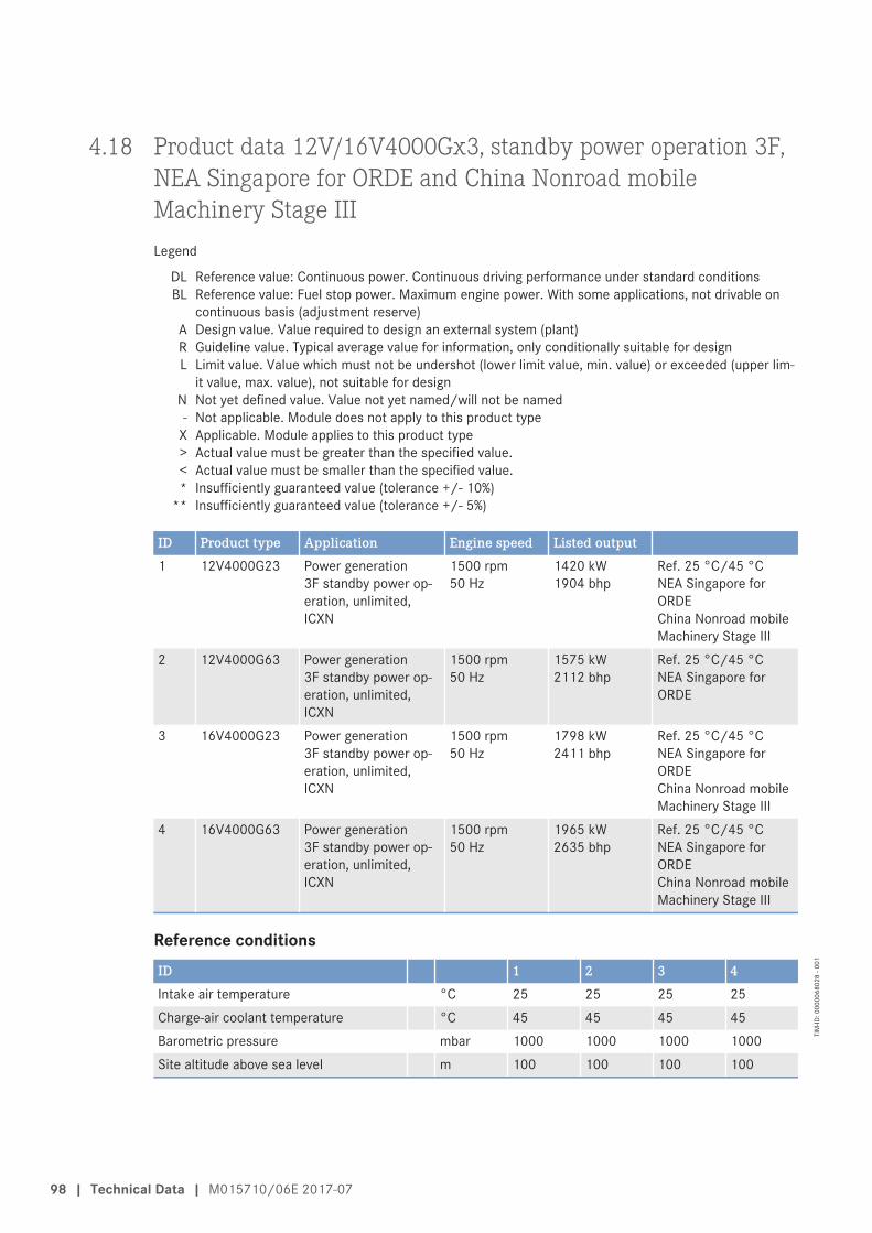
4.18 Product data 12V/16V4000Gx3, standby power operation 3F,NEA Singapore for ORDE and China Nonroad mobileMachinery Stage IIILegend
DL Reference value: Continuous power. Continuous driving performance under standard conditionsBL Reference value: Fuel stop power. Maximum engine power. With some applications, not drivable on
continuous basis (adjustment reserve)A Design value. Value required to design an external system (plant)R Guideline value. Typical average value for information, only conditionally suitable for designL Limit value. Value which must not be undershot (lower limit value, min. value) or exceeded (upper lim-
it value, max. value), not suitable for designN Not yet defined value. Value not yet named/will not be named- Not applicable. Module does not apply to this product type
X Applicable. Module applies to this product type> Actual value must be greater than the specified value.< Actual value must be smaller than the specified value.* Insufficiently guaranteed value (tolerance +/- 10%)
** Insufficiently guaranteed value (tolerance +/- 5%)
ID Product type Application Engine speed Listed output1 12V4000G23 Power generation
3F standby power op-eration, unlimited,ICXN
1500 rpm50 Hz
1420 kW1904 bhp
Ref. 25 °C/45 °CNEA Singapore forORDEChina Nonroad mobileMachinery Stage III
2 12V4000G63 Power generation3F standby power op-eration, unlimited,ICXN
1500 rpm50 Hz
1575 kW2112 bhp
Ref. 25 °C/45 °CNEA Singapore forORDE
3 16V4000G23 Power generation3F standby power op-eration, unlimited,ICXN
1500 rpm50 Hz
1798 kW2411 bhp
Ref. 25 °C/45 °CNEA Singapore forORDEChina Nonroad mobileMachinery Stage III
4 16V4000G63 Power generation3F standby power op-eration, unlimited,ICXN
1500 rpm50 Hz
1965 kW2635 bhp
Ref. 25 °C/45 °CNEA Singapore forORDEChina Nonroad mobileMachinery Stage III
Reference conditionsID 1 2 3 4Intake air temperature °C 25 25 25 25Charge-air coolant temperature °C 45 45 45 45Barometric pressure mbar 1000 1000 1000 1000Site altitude above sea level m 100 100 100 100
98 | Technical Data | M015710/06E 2017-07
TIM
-ID: 0
0000
6802
8 - 0
01

Performance dataID 1 2 3 4Rated engine speed A rpm 1500 1500 1500 1500Fuel stop power ISO 3046 A kW 1562 1732 1978 2162
General conditions (for max. power)ID 1 2 3 4Intake depression (new filter) A mbar 15 15 15 15Intake depression, max. L mbar 50 50 50 50
Model related data (basic design)ID 1 2 3 4Number of cylinders - 12 12 16 16Cylinder arrangement: V angle Degrees
(°)90 90 90 90
Bore mm 170 170 170 170Stroke mm 210 210 210 210Displacement of a cylinder Liters 4.77 4.77 4.77 4.77Total displacement Liters 57.2 57.2 76.3 76.3Compression ratio - 16.4 16.4 16.4 16.4Number of inlet valves per cylinder - 2 2 2 2Number of exhaust valves per cylinder - 2 2 2 2
Combustion air / exhaust gasID 1 2 3 4Charge air pressure before cylinder - DL R bar abs 2.9 3.13 2.9 3.1Charge-air pressure before cylinder - BL R bar abs 3.1 3.37 3.1 3.3
Coolant system (HT circuit)ID 1 2 3 4Coolant temperature (at engine connec-tion: outlet to cooling equipment)
A °C 100 100 100 100
Coolant temperature after engine, limit 1 L °C 102 102 102 102Coolant temperature after engine, limit 2 L °C 104 104 104 104Coolant antifreeze content, max. L % 50 50 50 50Pressure loss in off-engine cooling sys-tem, max.
L bar 0.7 0.7 0.7 0.7
M015710/06E 2017-07 | Technical Data | 99
TIM
-ID: 0
0000
6802
8 - 0
01

Coolant system (LT circuit)ID 1 2 3 4Coolant temperature before charge-aircooler (at engine connection: from cool-ing equipment)
A °C 45 45 45 45
Coolant antifreeze content, max. L % 50 50 50 50Pressure loss in off-engine cooling sys-tem, max.
L bar 0.7 0.7 0.7 0.7
Lube oil systemID 1 2 3 4Lube oil operating temperature upstreamof engine, from
R °C 88 88 89 89
Lube oil operating temperature upstreamof engine, to
R °C 98 98 95 95
Lube oil temperature before engine, limit1
L °C 99 99 97 97
Lube oil temperature before engine, limit2
L °C 101 101 99 99
Lube oil operating pressure upstream ofengine, from
R bar 5.0 5.0 4.2 4.2
Lube oil operating pressure upstream ofengine, to
R bar 7.0 7.0 5.5 5.5
Fuel systemID 1 2 3 4Fuel pressure at engine inlet connection,min. (when engine is starting)
L bar -0.1 -0.1 -0.1 -0.1
Fuel pressure at engine inlet connection,max. (when engine is starting)
L bar 1.5 1.5 1.5 1.5
General operating dataID 1 2 3 4Cold start capability: air temperature(w/o start aid, w/o preheating) - (case A)
R °C 10 10 10 10
Coolant preheating: preheating tempera-ture (min.)
L °C 32 32 32 32
Firing speed, from R rpm 80 80 80 80Firing speed, to R rpm 120 120 120 120
CapacitiesID 1 2 3 4Engine coolant, engine side (withoutcooling equipment)
R Liters 160 160 175 175
Charge-air coolant, engine side R Liters 40 40 50 50
100 | Technical Data | M015710/06E 2017-07
TIM
-ID: 0
0000
6802
8 - 0
01

ID 1 2 3 4Engine oil capacity, initial filling (standardoil system) (option: max. operating incli-nations)
R Liters 260 260 300 300
Oil change quantity, max. (standard oilsystem) (option: max. operating inclina-tions)
R Liters 200 200 240 240
Oil pan capacity at dipstick mark “min.”(standard oil system) (option: max. oper-ating inclinations)
L Liters 160 160 210 210
Oil pan capacity at dipstick mark “max.”(standard oil system) (option: max. oper-ating inclinations)
L Liters 200 200 240 240
Weights / main dimensionsID 1 2 3 4Engine weight, dry (basic engine configu-ration acc. to scope of delivery specifica-tion)
R kg 6200 * 6200 * 7700 7700
SoundID 1 2 3 4Exhaust noise, not attenuated - DL(sound power level LW, ISO 6798,+3 dB(A) tolerance)
R dB(A) 126 126 125 126
Engine surface noise with attenuated in-take noise (filter) - DL (sound power levelLW, ISO 6798, +2 db(A) tolerance)
R dB(A) 122 122 126 128
M015710/06E 2017-07 | Technical Data | 101
TIM
-ID: 0
0000
6802
8 - 0
01

4.19 Product data 12V4000Gx3, continuous operation 3G,optimized fuel consumptionLegend
DL Reference value: Continuous power. Continuous driving performance under standard conditionsBL Reference value: Fuel stop power. Maximum engine power. With some applications, not drivable on
continuous basis (adjustment reserve)A Design value. Value required to design an external system (plant)R Guideline value. Typical average value for information, only conditionally suitable for designL Limit value. Value which must not be undershot (lower limit value, min. value) or exceeded (upper lim-
it value, max. value), not suitable for designN Not yet defined value. Value not yet named/will not be named- Not applicable. Module does not apply to this product type
X Applicable. Module applies to this product type> Actual value must be greater than the specified value.< Actual value must be smaller than the specified value.* Insufficiently guaranteed value (tolerance +/- 10%)
** Insufficiently guaranteed value (tolerance +/- 5%)
ID Product type Application Engine speed Listed output1 12V4000G23 Power generation
3G continuous opera-tion, time-limited,ICXN
1500 rpm50 Hz
1420 kW1904 bhp
Ref. 25 °C/55 °COptimized fuel con-sumption
2 12V4000G43 Power generation3G continuous opera-tion, time-limited,ICXN
1800 rpm60 Hz
1520 kW2038 bhp
Ref. 25 °C/55 °COptimized fuel con-sumption
3 12V4000G63 Power generation3G continuous opera-tion, time-limited,ICXN
1500 rpm50 Hz
1575 kW2112 bhp
Ref. 25 °C/55 °COptimized fuel con-sumption
4 12V4000G83 Power generation3G continuous opera-tion, time-limited,ICXN
1800 rpm60 Hz
1736 kW2328 bhp
Ref. 25 °C/55 °COptimized fuel con-sumption
Reference conditionsID 1 2 3 4Intake air temperature °C 25 25 25 25Charge-air coolant temperature °C 55 55 55 55Barometric pressure mbar 1000 1000 1000 1000Site altitude above sea level m 100 100 100 100
Performance dataID 1 2 3 4Rated engine speed A rpm 1500 1800 1500 1800Fuel stop power ISO 3046 A kW 1562 1672 1733 1910
102 | Technical Data | M015710/06E 2017-07
TIM
-ID: 0
0000
6748
9 - 0
01

General conditions (for max. power)ID 1 2 3 4Intake depression (new filter) A mbar 15 15 15 15Intake depression, max. L mbar 50 50 50 50Exhaust overpressure A mbar 30 30 30 30Exhaust overpressure, max. L mbar 85 85 85 85
Model related data (basic design)ID 1 2 3 4Number of cylinders - 12 12 12 12Cylinder arrangement: V angle Degrees
(°)90 90 90 90
Bore mm 170 170 170 170Stroke mm 210 210 210 210Displacement of a cylinder Liters 4.77 4.77 4.77 4.77Total displacement Liters 57.2 57.2 57.2 57.2Compression ratio - 16.4 16.4 16.4 16.4Number of inlet valves per cylinder - 2 2 2 2Number of exhaust valves per cylinder - 2 2 2 2
Combustion air / exhaust gasID 1 2 3 4Charge air pressure before cylinder - DL R bar abs 2.6 2.9 2.9 3.2Charge-air pressure before cylinder - BL R bar abs 2.9 3.2 3.2 3.4
Coolant system (HT circuit)ID 1 2 3 4Coolant temperature (at engine connec-tion: outlet to cooling equipment)
A °C 100 100 100 100
Coolant temperature after engine, limit 1 L °C 102 102 102 102Coolant temperature after engine, limit 2 L °C 104 104 104 104Coolant antifreeze content, max. L % 50 50 50 50Pressure loss in off-engine cooling sys-tem, max.
L bar 0.7 0.7 0.7 0.7
Coolant system (LT circuit)ID 1 2 3 4Coolant temperature before charge-aircooler (at engine connection: from cool-ing equipment)
A °C 55 55 55 55
Coolant antifreeze content, max. L % 50 50 50 50Pressure loss in off-engine cooling sys-tem, max.
L bar 0.7 0.7 0.7 0.7
M015710/06E 2017-07 | Technical Data | 103
TIM
-ID: 0
0000
6748
9 - 0
01

Lube oil systemID 1 2 3 4Lube oil operating temperature upstreamof engine, from
R °C 88 88 88 88
Lube oil operating temperature upstreamof engine, to
R °C 98 98 98 98
Lube oil temperature before engine, limit1
L °C 99 99 99 99
Lube oil temperature before engine, limit2
L °C 101 101 101 101
Lube oil operating pressure upstream ofengine, from
R bar 5.0 5.0 5.0 5.0
Lube oil operating pressure upstream ofengine, to
R bar 6.0 7.0 7.0 7.0
Fuel systemID 1 2 3 4Fuel pressure at engine inlet connection,min. (when engine is starting)
L bar -0.1 -0.1 -0.1 -0.1
Fuel pressure at engine inlet connection,max. (when engine is starting)
L bar 1.5 1.5 1.5 1.5
General operating dataID 1 2 3 4Cold start capability: air temperature(w/o start aid, w/o preheating) - (case A)
R °C 10 10 10 10
Coolant preheating: preheating tempera-ture (min.)
L °C 32 32 32 32
Firing speed, from R rpm 80 80 80 80Firing speed, to R rpm 120 120 120 120
CapacitiesID 1 2 3 4Engine coolant, engine side (withoutcooling equipment)
R Liters 160 160 160 160
Charge-air coolant, engine side R Liters 40 40 40 40Engine oil capacity, initial filling (standardoil system) (option: max. operating incli-nations)
R Liters 260 260 260 260
Oil change quantity, max. (standard oilsystem) (option: max. operating inclina-tions)
R Liters 200 200 200 200
Oil pan capacity at dipstick mark “min.”(standard oil system) (option: max. oper-ating inclinations)
L Liters 160 160 160 160
Oil pan capacity at dipstick mark “max.”(standard oil system) (option: max. oper-ating inclinations)
L Liters 200 200 200 200
104 | Technical Data | M015710/06E 2017-07
TIM
-ID: 0
0000
6748
9 - 0
01

Weights / main dimensionsID 1 2 3 4Engine weight, dry (basic engine configu-ration acc. to scope of delivery specifica-tion)
R kg 6200 * 6200 * 6200 * 6200 *
SoundID 1 2 3 4Exhaust noise, not attenuated - DL(sound power level LW, ISO 6798,+3 dB(A) tolerance)
R dB(A) 124 125 125 127
Engine surface noise with attenuated in-take noise (filter) - DL (sound power levelLW, ISO 6798, +2 db(A) tolerance)
R dB(A) 120 122 121 123
M015710/06E 2017-07 | Technical Data | 105
TIM
-ID: 0
0000
6748
9 - 0
01

4.20 Product data 16V4000Gx3, continuous operation 3G,optimized fuel consumptionLegend
DL Reference value: Continuous power. Continuous driving performance under standard conditionsBL Reference value: Fuel stop power. Maximum engine power. With some applications, not drivable on
continuous basis (adjustment reserve)A Design value. Value required to design an external system (plant)R Guideline value. Typical average value for information, only conditionally suitable for designL Limit value. Value which must not be undershot (lower limit value, min. value) or exceeded (upper lim-
it value, max. value), not suitable for designN Not yet defined value. Value not yet named/will not be named- Not applicable. Module does not apply to this product type
X Applicable. Module applies to this product type> Actual value must be greater than the specified value.< Actual value must be smaller than the specified value.* Insufficiently guaranteed value (tolerance +/- 10%)
** Insufficiently guaranteed value (tolerance +/- 5%)
ID Product type Application Engine speed Listed output1 16V4000G23 Power generation
3G continuous opera-tion, time-limited,ICXN
1500 rpm50 Hz
1798 kW2411 bhp
Ref. 25 °C/55 °C (1)Optimized fuel con-sumption
2 16V4000G43 Power generation3G continuous opera-tion, time-limited,ICXN
1800 rpm60 Hz
2020 kW2709 bhp
Ref. 25 °C/55 °COptimized fuel con-sumption
3 16V4000G63 Power generation3G continuous opera-tion, time-limited,ICXN
1500 rpm50 Hz
1965 kW2635 bhp
Ref. 25 °C/55 °COptimized fuel con-sumption
4 16V4000G83 Power generation3G continuous opera-tion, time-limited,ICXN
1800 rpm60 Hz
2280 kW3057 bhp
Ref. 25 °C/55 °COptimized fuel con-sumption
Reference conditionsID 1 2 3 4Intake air temperature °C 25 25 25 25Charge-air coolant temperature °C 55 55 55 55Barometric pressure mbar 1000 1000 1000 1000Site altitude above sea level m 100 100 100 100
Performance dataID 1 2 3 4Rated engine speed A rpm 1500 1800 1500 1800Fuel stop power ISO 3046 A kW 1978 2222 2162 2508
106 | Technical Data | M015710/06E 2017-07
TIM
-ID: 0
0000
6749
0 - 0
01

General conditions (for max. power)ID 1 2 3 4Intake depression (new filter) A mbar 15 15 15 15Intake depression, max. L mbar 50 50 50 50Exhaust overpressure A mbar 30 30 30 30Exhaust overpressure, max. L mbar 85 85 85 85
Model related data (basic design)ID 1 2 3 4Number of cylinders - 16 16 16 16Cylinder arrangement: V angle Degrees
(°)90 90 90 90
Bore mm 170 170 170 170Stroke mm 210 210 210 210Displacement of a cylinder Liters 4.77 4.77 4.77 4.77Total displacement Liters 76.3 76.3 76.3 76.3Compression ratio - 16.4 16.4 16.4 16.4Number of inlet valves per cylinder - 2 2 2 2Number of exhaust valves per cylinder - 2 2 2 2
Combustion air / exhaust gasID 1 2 3 4Charge air pressure before cylinder - DL R bar abs 2.6 2.9 2.8 3.1Charge-air pressure before cylinder - BL R bar abs 2.8 3.1 3.1 3.3
Coolant system (HT circuit)ID 1 2 3 4Coolant temperature (at engine connec-tion: outlet to cooling equipment)
A °C 100 100 100 100
Coolant temperature after engine, limit 1 L °C 102 102 102 102Coolant temperature after engine, limit 2 L °C 104 104 104 104Coolant antifreeze content, max. L % 50 50 50 50Pressure loss in off-engine cooling sys-tem, max.
L bar 0.7 0.7 0.7 0.7
Coolant system (LT circuit)ID 1 2 3 4Coolant temperature (at engine connec-tion: outlet to cooling equipment)
R °C 63 66 65 70
Coolant antifreeze content, max. L % 50 50 50 50Pressure loss in off-engine cooling sys-tem, max.
L bar 0.7 0.7 0.7 0.7
M015710/06E 2017-07 | Technical Data | 107
TIM
-ID: 0
0000
6749
0 - 0
01

Lube oil systemID 1 2 3 4Lube oil operating temperature upstreamof engine, from
R °C 89 90 89 88
Lube oil operating temperature upstreamof engine, to
R °C 95 96 95 95
Lube oil temperature before engine, limit1
L °C 97 97 97 97
Lube oil temperature before engine, limit2
L °C 99 99 99 99
Lube oil operating pressure upstream ofengine, from
R bar 4.2 4.7 4.2 4.7
Lube oil operating pressure upstream ofengine, to
R bar 5.5 6.5 5.5 6.5
Fuel systemID 1 2 3 4Fuel pressure at engine inlet connection,min. (when engine is starting)
L bar -0.1 -0.1 -0.1 -0.1
Fuel pressure at engine inlet connection,max. (when engine is starting)
L bar 1.5 1.5 1.5 1.5
General operating dataID 1 2 3 4Cold start capability: air temperature(w/o start aid, w/o preheating) - (case A)
R °C 10 10 10 10
Coolant preheating: preheating tempera-ture (min.)
L °C 32 32 32 32
Firing speed, from R rpm 80 80 80 80Firing speed, to R rpm 120 120 120 120
CapacitiesID 1 2 3 4Engine coolant, engine side (withoutcooling equipment)
R Liters 175 175 175 175
Charge-air coolant, engine side R Liters 50 50 50 50Engine oil capacity, initial filling (standardoil system) (option: max. operating incli-nations)
R Liters 300 300 300 300
Oil change quantity, max. (standard oilsystem) (option: max. operating inclina-tions)
R Liters 240 240 240 240
Oil pan capacity at dipstick mark “min.”(standard oil system) (option: max. oper-ating inclinations)
L Liters 210 210 210 210
Oil pan capacity at dipstick mark “max.”(standard oil system) (option: max. oper-ating inclinations)
L Liters 240 240 240 240
108 | Technical Data | M015710/06E 2017-07
TIM
-ID: 0
0000
6749
0 - 0
01

Weights / main dimensionsID 1 2 3 4Engine weight, dry (basic engine configu-ration acc. to scope of delivery specifica-tion)
R kg 7700 7700 7700 7700
SoundID 1 2 3 4Exhaust noise, not attenuated - DL(sound power level LW, ISO 6798,+3 dB(A) tolerance)
R dB(A) 125 127 126 129
Engine surface noise with attenuated in-take noise (filter) - DL (sound power levelLW, ISO 6798, +2 db(A) tolerance)
R dB(A) 126 125 128 125
M015710/06E 2017-07 | Technical Data | 109
TIM
-ID: 0
0000
6749
0 - 0
01

4.21 Product data 12V/16V4000Gx3, continuous operation 3G,optimized exhaust gas emissions (TA-Luft)Legend
DL Reference value: Continuous power. Continuous driving performance under standard conditionsBL Reference value: Fuel stop power. Maximum engine power. With some applications, not drivable on
continuous basis (adjustment reserve)A Design value. Value required to design an external system (plant)R Guideline value. Typical average value for information, only conditionally suitable for designL Limit value. Value which must not be undershot (lower limit value, min. value) or exceeded (upper lim-
it value, max. value), not suitable for designN Not yet defined value. Value not yet named/will not be named- Not applicable. Module does not apply to this product type
X Applicable. Module applies to this product type> Actual value must be greater than the specified value.< Actual value must be smaller than the specified value.* Insufficiently guaranteed value (tolerance +/- 10%)
** Insufficiently guaranteed value (tolerance +/- 5%)
ID Product type Application Engine speed Listed output1 12V4000G23 Power generation
3G continuous opera-tion, time-limited,ICXN
1500 rpm50 Hz
1420 kW1904 bhp
Ref. 25 °C/55 °CTA-Luft-optimized (die-sel)
2 12V4000G63 Power generation3G continuous opera-tion, time-limited,ICXN
1500 rpm50 Hz
1575 kW2112 bhp
Ref. 25 °C/55 °CTA-Luft-optimized (die-sel)
3 16V4000G23 Power generation3G continuous opera-tion, time-limited,ICXN
1500 rpm50 Hz
1798 kW2411 bhp
Ref. 25 °C/55 °CTA-Luft-optimized (die-sel)
4 16V4000G63 Power generation3G continuous opera-tion, time-limited,ICXN
1500 rpm50 Hz
1965 kW2635 bhp
Ref. 25 °C/55 °CTA-Luft-optimized (die-sel)
Reference conditionsID 1 2 3 4Intake air temperature °C 25 25 25 25Charge-air coolant temperature °C 55 55 55 55Barometric pressure mbar 1000 1000 1000 1000Site altitude above sea level m 100 100 100 100
Performance dataID 1 2 3 4Rated engine speed A rpm 1500 1500 1500 1500Fuel stop power ISO 3046 A kW 1562 1733 1978 2162
110 | Technical Data | M015710/06E 2017-07
TIM
-ID: 0
0000
6803
1 - 0
01

General conditions (for max. power)ID 1 2 3 4Intake depression (new filter) A mbar 15 15 15 15Intake depression, max. L mbar 50 50 50 50
Model related data (basic design)ID 1 2 3 4Number of cylinders - 12 12 16 16Cylinder arrangement: V angle Degrees
(°)90 90 90 90
Bore mm 170 170 170 170Stroke mm 210 210 210 210Displacement of a cylinder Liters 4.77 4.77 4.77 4.77Total displacement Liters 57.2 57.2 76.3 76.3Compression ratio - 16.4 16.4 16.4 16.4Number of inlet valves per cylinder - 2 2 2 2Number of exhaust valves per cylinder - 2 2 2 2
Combustion air / exhaust gasID 1 2 3 4Charge air pressure before cylinder - DL R bar abs 3.2 3.5 3.3 3.5Charge-air pressure before cylinder - BL R bar abs 3.5 3.5 3.5 3.7
Coolant system (HT circuit)ID 1 2 3 4Coolant temperature (at engine connec-tion: outlet to cooling equipment)
A °C 100 100 100 100
Coolant temperature after engine, limit 1 L °C 102 102 102 102Coolant temperature after engine, limit 2 L °C 104 104 104 104Coolant antifreeze content, max. L % 50 50 50 50Pressure loss in off-engine cooling sys-tem, max.
L bar 0.7 0.7 0.7 0.7
Coolant system (LT circuit)ID 1 2 3 4Coolant temperature before charge-aircooler (at engine connection: from cool-ing equipment)
A °C 55 55 55 55
Coolant antifreeze content, max. L % 50 50 50 50Pressure loss in off-engine cooling sys-tem, max.
L bar 0.7 0.7 0.7 0.7
M015710/06E 2017-07 | Technical Data | 111
TIM
-ID: 0
0000
6803
1 - 0
01

Lube oil systemID 1 2 3 4Lube oil operating temperature upstreamof engine, from
R °C 88 88 89 89
Lube oil operating temperature upstreamof engine, to
R °C 98 98 95 95
Lube oil temperature before engine, limit1
L °C 99 99 97 97
Lube oil temperature before engine, limit2
L °C 101 101 102 102
Lube oil operating pressure upstream ofengine, from
R bar 5.0 5.0 4.0 4.0
Lube oil operating pressure upstream ofengine, to
R bar 7.0 7.0 5.5 5.5
Fuel systemID 1 2 3 4Fuel pressure at engine inlet connection,min. (when engine is starting)
L bar -0.1 -0.1 -0.1 -0.1
Fuel pressure at engine inlet connection,max. (when engine is starting)
L bar 1.5 1.5 1.5 1.5
General operating dataID 1 2 3 4Cold start capability: air temperature(w/o start aid, w/o preheating) - (case A)
R °C 10 10 10 10
Coolant preheating: preheating tempera-ture (min.)
L °C 32 32 32 32
Firing speed, from R rpm 80 80 80 80Firing speed, to R rpm 120 120 120 120
CapacitiesID 1 2 3 4Engine coolant, engine side (withoutcooling equipment)
R Liters 160 160 175 175
Charge-air coolant, engine side R Liters 40 40 50 50Engine oil capacity, initial filling (standardoil system) (option: max. operating incli-nations)
R Liters 260 260 300 300
Oil change quantity, max. (standard oilsystem) (option: max. operating inclina-tions)
R Liters 200 200 240 240
Oil pan capacity at dipstick mark “min.”(standard oil system) (option: max. oper-ating inclinations)
L Liters 160 160 210 210
Oil pan capacity at dipstick mark “max.”(standard oil system) (option: max. oper-ating inclinations)
L Liters 200 200 240 240
112 | Technical Data | M015710/06E 2017-07
TIM
-ID: 0
0000
6803
1 - 0
01

Weights / main dimensionsID 1 2 3 4Engine weight, dry (basic engine configu-ration acc. to scope of delivery specifica-tion)
R kg 6200 * 6200 * 7700 7700
SoundID 1 2 3 4Exhaust noise, not attenuated - DL(sound power level LW, ISO 6798,+3 dB(A) tolerance)
R dB(A) 126 127 126 127
Engine surface noise with attenuated in-take noise (filter) - DL (sound power levelLW, ISO 6798, +2 db(A) tolerance)
R dB(A) 122 122 127 126
M015710/06E 2017-07 | Technical Data | 113
TIM
-ID: 0
0000
6803
1 - 0
01

4.22 Product data 12V/16V4000Gx3, continuous operation 3G,EPA Stationary EMERG T2 (40CFR60) und EPA Nonroad T2Comp (40CFR89)Legend
DL Reference value: Continuous power. Continuous driving performance under standard conditionsBL Reference value: Fuel stop power. Maximum engine power. With some applications, not drivable on
continuous basis (adjustment reserve)A Design value. Value required to design an external system (plant)R Guideline value. Typical average value for information, only conditionally suitable for designL Limit value. Value which must not be undershot (lower limit value, min. value) or exceeded (upper lim-
it value, max. value), not suitable for designN Not yet defined value. Value not yet named/will not be named- Not applicable. Module does not apply to this product type
X Applicable. Module applies to this product type> Actual value must be greater than the specified value.< Actual value must be smaller than the specified value.* Insufficiently guaranteed value (tolerance +/- 10%)
** Insufficiently guaranteed value (tolerance +/- 5%)
ID Product type Application Engine speed Listed output1 12V4000G43 Power generation
3G continuous opera-tion, time-limited,ICXN
1800 rpm60 Hz
1520 kW2038 bhp
Ref. 25 °C/45 °CEPA Stationary EMERGT2 (40CFR60)EPA Nonroad T2 Comp(40CFR89)
2 12V4000G83 Power generation3G continuous opera-tion, time-limited,ICXN
1800 rpm60 Hz
1736 kW2328 bhp
Ref. 25 °C/45 °CEPA Stationary EMERGT2 (40CFR60)EPA Nonroad T2 Comp(40CFR89)
3 16V4000G43 Power generation3G continuous opera-tion, time-limited,ICXN
1800 rpm60 Hz
2020 kW2709 bhp
Ref. 25 °C/45 °CEPA Stationary EMERGT2 (40CFR60)EPA Nonroad T2 Comp(40CFR89)
4 16V4000G83 Power generation3G continuous opera-tion, time-limited,ICXN
1800 rpm60 Hz
2280 kW3057 bhp
Ref. 25 °C/45 °CEPA Stationary EMERGT2 (40CFR60)EPA Nonroad T2 Comp(40CFR89)
Reference conditionsID 1 2 3 4Intake air temperature °C 25 25 25 25Charge-air coolant temperature °C 45 45 45 45Barometric pressure mbar 1000 1000 1000 1000Site altitude above sea level m 100 100 100 100
114 | Technical Data | M015710/06E 2017-07
TIM
-ID: 0
0000
6749
1 - 0
01

Performance dataID 1 2 3 4Rated engine speed A rpm 1800 1800 1800 1800Fuel stop power ISO 3046 A kW 1672 1910 2222 2508
General conditions (for max. power)ID 1 2 3 4Intake depression (new filter) A mbar 15 15 15 15Intake depression, max. L mbar 50 50 50 50Exhaust overpressure A mbar 30 30 30 30Exhaust overpressure, max. L mbar 85 85 85 85
Model related data (basic design)ID 1 2 3 4Number of cylinders - 12 12 16 16Cylinder arrangement: V angle Degrees
(°)90 90 90 90
Bore mm 170 170 170 170Stroke mm 210 210 210 210Displacement of a cylinder Liters 4.77 4.77 4.77 4.77Total displacement Liters 57.2 57.2 76.3 76.3Compression ratio - 16.4 16.4 16.4 16.4Number of inlet valves per cylinder - 2 2 2 2Number of exhaust valves per cylinder - 2 2 2 2
Combustion air / exhaust gasID 1 2 3 4Charge-air pressure before cylinder - BL R bar abs 3.1 3.3 3.2 3.3
Coolant system (HT circuit)ID 1 2 3 4Coolant temperature (at engine connec-tion: outlet to cooling equipment)
A °C 100 100 100 100
Coolant temperature after engine, limit 1 L °C 102 102 102 102Coolant temperature after engine, limit 2 L °C 104 104 104 104Coolant antifreeze content, max. L % 50 50 50 50Pressure loss in off-engine cooling sys-tem, max.
L bar 0.7 0.7 0.7 0.7
M015710/06E 2017-07 | Technical Data | 115
TIM
-ID: 0
0000
6749
1 - 0
01

Coolant system (LT circuit)ID 1 2 3 4Coolant temperature before charge-aircooler (at engine connection: from cool-ing equipment)
A °C 45 45 45 45
Coolant antifreeze content, max. L % 50 50 50 50Pressure loss in off-engine cooling sys-tem, max.
L bar 0.7 0.7 0.7 0.7
Lube oil systemID 1 2 3 4Lube oil operating temperature upstreamof engine, from
R °C 88 88 90 88
Lube oil operating temperature upstreamof engine, to
R °C 98 98 96 94
Lube oil temperature before engine, limit1
L °C 99 99 97 97
Lube oil temperature before engine, limit2
L °C 101 101 99 99
Lube oil operating pressure upstream ofengine, from
R bar 5.0 5.0 4.7 4.7
Lube oil operating pressure upstream ofengine, to
R bar 7.0 7.0 6.5 6.5
Fuel systemID 1 2 3 4Fuel pressure at engine inlet connection,min. (when engine is starting)
L bar -0.1 -0.1 -0.1 -0.1
Fuel pressure at engine inlet connection,max. (when engine is starting)
L bar 1.5 1.5 1.5 1.5
General operating dataID 1 2 3 4Cold start capability: air temperature(w/o start aid, w/o preheating) - (case A)
R °C 10 10 10 10
Coolant preheating: preheating tempera-ture (min.)
L °C 32 32 32 32
Firing speed, from R rpm 80 80 80 80Firing speed, to R rpm 120 120 120 120
CapacitiesID 1 2 3 4Engine coolant, engine side (withoutcooling equipment)
R Liters 160 160 175 175
Charge-air coolant, engine side R Liters 40 40 50 50
116 | Technical Data | M015710/06E 2017-07
TIM
-ID: 0
0000
6749
1 - 0
01

ID 1 2 3 4Engine oil capacity, initial filling (standardoil system) (option: max. operating incli-nations)
R Liters 260 260 300 300
Oil change quantity, max. (standard oilsystem) (option: max. operating inclina-tions)
R Liters 200 200 240 240
Oil pan capacity at dipstick mark “min.”(standard oil system) (option: max. oper-ating inclinations)
L Liters 160 160 210 210
Oil pan capacity at dipstick mark “max.”(standard oil system) (option: max. oper-ating inclinations)
L Liters 200 200 240 240
Weights / main dimensionsID 1 2 3 4Engine weight, dry (basic engine configu-ration acc. to scope of delivery specifica-tion)
R kg 6200 * 6200 * 7700 7700
SoundID 1 2 3 4Exhaust noise, not attenuated - DL(sound power level LW, ISO 6798,+3 dB(A) tolerance)
R dB(A) 125 127 127 129
Engine surface noise with attenuated in-take noise (filter) - DL (sound power levelLW, ISO 6798, +2 db(A) tolerance)
R dB(A) 122 123 125 125
M015710/06E 2017-07 | Technical Data | 117
TIM
-ID: 0
0000
6749
1 - 0
01

4.23 Product data 12V/16V4000Gx3, continuous operation 3G,NEA Singapore for ORDE and China Nonroad mobileMachinery Stage IIILegend
DL Reference value: Continuous power. Continuous driving performance under standard conditionsBL Reference value: Fuel stop power. Maximum engine power. With some applications, not drivable on
continuous basis (adjustment reserve)A Design value. Value required to design an external system (plant)R Guideline value. Typical average value for information, only conditionally suitable for designL Limit value. Value which must not be undershot (lower limit value, min. value) or exceeded (upper lim-
it value, max. value), not suitable for designN Not yet defined value. Value not yet named/will not be named- Not applicable. Module does not apply to this product type
X Applicable. Module applies to this product type> Actual value must be greater than the specified value.< Actual value must be smaller than the specified value.* Insufficiently guaranteed value (tolerance +/- 10%)
** Insufficiently guaranteed value (tolerance +/- 5%)
ID Product type Application Engine speed Listed output1 12V4000G23 Power generation
3G continuous opera-tion, time-limited,ICXN
1500 rpm50 Hz
1420 kW1904 bhp
Ref. 25 °C/45 °CNEA Singapore forORDEChina Nonroad mobileMachinery Stage III
2 12V4000G63 Power generation3G continuous opera-tion, time-limited,ICXN
1500 rpm50 Hz
1575 kW2112 bhp
Ref. 25 °C/45 °CNEA Singapore forORDE
3 16V4000G23 Power generation3G continuous opera-tion, time-limited,ICXN
1500 rpm50 Hz
1798 kW2411 bhp
Ref. 25 °C/45 °CNEA Singapore forORDEChina Nonroad mobileMachinery Stage III
4 16V4000G63 Power generation3G continuous opera-tion, time-limited,ICXN
1500 rpm50 Hz
1965 kW2635 bhp
Ref. 25 °C/45 °CNEA Singapore forORDEChina Nonroad mobileMachinery Stage III
Reference conditionsID 1 2 3 4Intake air temperature °C 25 25 25 25Charge-air coolant temperature °C 45 45 45 45Barometric pressure mbar 1000 1000 1000 1000Site altitude above sea level m 100 100 100 100
118 | Technical Data | M015710/06E 2017-07
TIM
-ID: 0
0000
6803
0 - 0
01

Performance dataID 1 2 3 4Rated engine speed A rpm 1500 1500 1500 1500Fuel stop power ISO 3046 A kW 1562 1732 1978 2162
General conditions (for max. power)ID 1 2 3 4Intake depression (new filter) A mbar 15 15 15 15Intake depression, max. L mbar 50 50 50 50
Model related data (basic design)ID 1 2 3 4Number of cylinders - 12 12 16 16Cylinder arrangement: V angle Degrees
(°)90 90 90 90
Bore mm 170 170 170 170Stroke mm 210 210 210 210Displacement of a cylinder Liters 4.77 4.77 4.77 4.77Total displacement Liters 57.2 57.2 76.3 76.3Compression ratio - 16.4 16.4 16.4 16.4Number of inlet valves per cylinder - 2 2 2 2Number of exhaust valves per cylinder - 2 2 2 2
Combustion air / exhaust gasID 1 2 3 4Charge air pressure before cylinder - DL R bar abs 2.9 3.13 2.9 3.1Charge-air pressure before cylinder - BL R bar abs 3.1 3.37 3.1 3.3
Coolant system (HT circuit)ID 1 2 3 4Coolant temperature (at engine connec-tion: outlet to cooling equipment)
A °C 100 100 100 100
Coolant temperature after engine, limit 1 L °C 102 102 102 102Coolant temperature after engine, limit 2 L °C 104 104 104 104Coolant antifreeze content, max. L % 50 50 50 50Pressure loss in off-engine cooling sys-tem, max.
L bar 0.7 0.7 0.7 0.7
M015710/06E 2017-07 | Technical Data | 119
TIM
-ID: 0
0000
6803
0 - 0
01

Coolant system (LT circuit)ID 1 2 3 4Coolant temperature before charge-aircooler (at engine connection: from cool-ing equipment)
A °C 45 45 45 45
Coolant antifreeze content, max. L % 50 50 50 50Pressure loss in off-engine cooling sys-tem, max.
L bar 0.7 0.7 0.7 0.7
Lube oil systemID 1 2 3 4Lube oil operating temperature upstreamof engine, from
R °C 88 88 89 89
Lube oil operating temperature upstreamof engine, to
R °C 98 98 95 95
Lube oil temperature before engine, limit1
L °C 99 99 97 97
Lube oil temperature before engine, limit2
L °C 101 101 99 99
Lube oil operating pressure upstream ofengine, from
R bar 5.0 5.0 4.2 4.2
Lube oil operating pressure upstream ofengine, to
R bar 7.0 7.0 5.5 5.5
Fuel systemID 1 2 3 4Fuel pressure at engine inlet connection,min. (when engine is starting)
L bar -0.1 -0.1 -0.1 -0.1
Fuel pressure at engine inlet connection,max. (when engine is starting)
L bar 1.5 1.5 1.5 1.5
General operating dataID 1 2 3 4Cold start capability: air temperature(w/o start aid, w/o preheating) - (case A)
R °C 10 10 10 10
Coolant preheating: preheating tempera-ture (min.)
L °C 32 32 32 32
Firing speed, from R rpm 80 80 80 80Firing speed, to R rpm 120 120 120 120
CapacitiesID 1 2 3 4Engine coolant, engine side (withoutcooling equipment)
R Liters 160 160 175 175
Charge-air coolant, engine side R Liters 40 40 50 50
120 | Technical Data | M015710/06E 2017-07
TIM
-ID: 0
0000
6803
0 - 0
01

ID 1 2 3 4Engine oil capacity, initial filling (standardoil system) (option: max. operating incli-nations)
R Liters 260 260 300 300
Oil change quantity, max. (standard oilsystem) (option: max. operating inclina-tions)
R Liters 200 200 240 240
Oil pan capacity at dipstick mark “min.”(standard oil system) (option: max. oper-ating inclinations)
L Liters 160 160 210 210
Oil pan capacity at dipstick mark “max.”(standard oil system) (option: max. oper-ating inclinations)
L Liters 200 200 240 240
Weights / main dimensionsID 1 2 3 4Engine weight, dry (basic engine configu-ration acc. to scope of delivery specifica-tion)
R kg 6200 * 6200 * 7700 7700
SoundID 1 2 3 4Exhaust noise, not attenuated - DL(sound power level LW, ISO 6798,+3 dB(A) tolerance)
R dB(A) 126 126 125 126
Engine surface noise with attenuated in-take noise (filter) - DL (sound power levelLW, ISO 6798, +2 db(A) tolerance)
R dB(A) 122 122 126 128
M015710/06E 2017-07 | Technical Data | 121
TIM
-ID: 0
0000
6803
0 - 0
01

4.24 Product data 12V4000Gx3, standby power operation 3H,optimized fuel consumptionLegend
DL Reference value: Continuous power. Continuous driving performance under standard conditionsBL Reference value: Fuel stop power. Maximum engine power. With some applications, not drivable on
continuous basis (adjustment reserve)A Design value. Value required to design an external system (plant)R Guideline value. Typical average value for information, only conditionally suitable for designL Limit value. Value which must not be undershot (lower limit value, min. value) or exceeded (upper lim-
it value, max. value), not suitable for designN Not yet defined value. Value not yet named/will not be named- Not applicable. Module does not apply to this product type
X Applicable. Module applies to this product type> Actual value must be greater than the specified value.< Actual value must be smaller than the specified value.* Insufficiently guaranteed value (tolerance +/- 10%)
** Insufficiently guaranteed value (tolerance +/- 5%)
ID Product type Application Engine speed Listed output1 12V4000G23 Power generation
3H standby power op-eration, special qualifi-cations
1500 rpm50 Hz
1420 kW1904 bhp
Ref. 25 °C/55 °COptimized fuel con-sumption
2 12V4000G43 Power generation3H standby power op-eration, special qualifi-cations
1800 rpm60 Hz
1736 kW2328 bhp
Ref. 25 °C/55 °COptimized fuel con-sumption
3 12V4000G63 Power generation3H standby power op-eration, special qualifi-cations
1500 rpm50 Hz
1575 kW2112 bhp
Ref. 25 °C/55 °COptimized fuel con-sumption
4 12V4000G83 Power generation3H standby power op-eration, special qualifi-cations
1800 rpm60 Hz
1910 kW2561 bhp
Ref. 25 °C/55 °COptimized fuel con-sumption
Reference conditionsID 1 2 3 4Intake air temperature °C 25 25 25 25Charge-air coolant temperature °C 55 55 55 55Barometric pressure mbar 1000 1000 1000 1000Site altitude above sea level m 100 100 100 100
Performance dataID 1 2 3 4Rated engine speed A rpm 1500 1800 1500 1800Fuel stop power ISO 3046 A kW 1562 1736 1733 1910
122 | Technical Data | M015710/06E 2017-07
TIM
-ID: 0
0000
6749
2 - 0
01

General conditions (for max. power)ID 1 2 3 4Intake depression (new filter) A mbar 15 15 15 15Intake depression, max. L mbar 50 50 50 50Exhaust overpressure A mbar 30 30 30 30Exhaust overpressure, max. L mbar 85 85 85 85
Model related data (basic design)ID 1 2 3 4Number of cylinders - 12 12 12 12Cylinder arrangement: V angle Degrees
(°)90 90 90 90
Bore mm 170 170 170 170Stroke mm 210 210 210 210Displacement of a cylinder Liters 4.77 4.77 4.77 4.77Total displacement Liters 57.2 57.2 57.2 57.2Compression ratio - 16.4 16.4 16.4 16.4Number of inlet valves per cylinder - 2 2 2 2Number of exhaust valves per cylinder - 2 2 2 2
Combustion air / exhaust gasID 1 2 3 4Charge-air pressure before cylinder - BL R bar abs 2.9 3.2 3.2 3.4
Coolant system (HT circuit)ID 1 2 3 4Coolant temperature (at engine connec-tion: outlet to cooling equipment)
A °C 100 100 100 100
Coolant temperature after engine, limit 1 L °C 102 102 102 102Coolant temperature after engine, limit 2 L °C 104 104 104 104Coolant antifreeze content, max. L % 50 50 50 50Pressure loss in off-engine cooling sys-tem, max.
L bar 0.7 0.7 0.7 0.7
Coolant system (LT circuit)ID 1 2 3 4Coolant temperature before charge-aircooler (at engine connection: from cool-ing equipment)
A °C 55 55 55 55
Coolant antifreeze content, max. L % 50 50 50 50Pressure loss in off-engine cooling sys-tem, max.
L bar 0.7 0.7 0.7 0.7
M015710/06E 2017-07 | Technical Data | 123
TIM
-ID: 0
0000
6749
2 - 0
01

Lube oil systemID 1 2 3 4Lube oil operating temperature upstreamof engine, from
R °C 88 88 88 88
Lube oil operating temperature upstreamof engine, to
R °C 98 98 98 98
Lube oil temperature before engine, limit1
L °C 99 99 99 99
Lube oil temperature before engine, limit2
L °C 101 101 101 101
Lube oil operating pressure upstream ofengine, from
R bar 5.0 5.0 5.0 5.0
Lube oil operating pressure upstream ofengine, to
R bar 6.0 7.0 7.0 7.0
Fuel systemID 1 2 3 4Fuel pressure at engine inlet connection,min. (when engine is starting)
L bar -0.1 -0.1 -0.1 -0.1
Fuel pressure at engine inlet connection,max. (when engine is starting)
L bar 1.5 1.5 1.5 1.5
General operating dataID 1 2 3 4Cold start capability: air temperature(w/o start aid, w/o preheating) - (case A)
R °C 10 10 10 10
Coolant preheating: preheating tempera-ture (min.)
L °C 32 32 32 32
Firing speed, from R rpm 80 80 80 80Firing speed, to R rpm 120 120 120 120
CapacitiesID 1 2 3 4Engine coolant, engine side (withoutcooling equipment)
R Liters 160 160 160 160
Charge-air coolant, engine side R Liters 40 40 40 40Engine oil capacity, initial filling (standardoil system) (option: max. operating incli-nations)
R Liters 260 260 260 260
Oil change quantity, max. (standard oilsystem) (option: max. operating inclina-tions)
R Liters 200 200 200 200
Oil pan capacity at dipstick mark “min.”(standard oil system) (option: max. oper-ating inclinations)
L Liters 160 160 160 160
Oil pan capacity at dipstick mark “max.”(standard oil system) (option: max. oper-ating inclinations)
L Liters 200 200 200 200
124 | Technical Data | M015710/06E 2017-07
TIM
-ID: 0
0000
6749
2 - 0
01

Weights / main dimensionsID 1 2 3 4Engine weight, dry (basic engine configu-ration acc. to scope of delivery specifica-tion)
R kg 6200 * 6200 * 6200 * 6200 *
SoundID 1 2 3 4Exhaust noise, not attenuated - DL(sound power level LW, ISO 6798,+3 dB(A) tolerance)
R dB(A) 124 - 125 -
Engine surface noise with attenuated in-take noise (filter) - DL (sound power levelLW, ISO 6798, +2 db(A) tolerance)
R dB(A) 120 - 121 -
Exhaust noise, unsilenced - BL (soundpower level LW, ISO 6798, +3 dB(A) tol-erance)
R dB(A) - 127 - 129
Engine surface noise with attenuated in-take noise (filter) - BL (sound power levelLW, ISO 6798, +2 dB(A) tolerance)
R dB(A) - 123 - 124
M015710/06E 2017-07 | Technical Data | 125
TIM
-ID: 0
0000
6749
2 - 0
01

4.25 Product data 16V4000Gx3x, standby power operation 3H,optimized fuel consumptionLegend
DL Reference value: Continuous power. Continuous driving performance under standard conditionsBL Reference value: Fuel stop power. Maximum engine power. With some applications, not drivable on
continuous basis (adjustment reserve)A Design value. Value required to design an external system (plant)R Guideline value. Typical average value for information, only conditionally suitable for designL Limit value. Value which must not be undershot (lower limit value, min. value) or exceeded (upper lim-
it value, max. value), not suitable for designN Not yet defined value. Value not yet named/will not be named- Not applicable. Module does not apply to this product type
X Applicable. Module applies to this product type> Actual value must be greater than the specified value.< Actual value must be smaller than the specified value.* Insufficiently guaranteed value (tolerance +/- 10%)
** Insufficiently guaranteed value (tolerance +/- 5%)
ID Product type Application Engine speed Listed output1 16V4000G23 Power generation
3H standby power op-eration, special qualifi-cations
1500 rpm50 Hz
1798 kW2411 bhp
Ref. 25 °C/55 °C (1)Optimized fuel con-sumption
2 16V4000G43 Power generation3H standby power op-eration, special qualifi-cations
1800 rpm60 Hz
2280 kW3057 bhp
Ref. 25 °C/55 °COptimized fuel con-sumption
3 16V4000G63 Power generation3H standby power op-eration, special qualifi-cations
1500 rpm50 Hz
1965 kW2635 bhp
Ref. 25 °C/55 °C (1)Optimized fuel con-sumption
4 16V4000G83 Power generation3H standby power op-eration, special qualifi-cations
1800 rpm60 Hz
2500 kW3353 bhp
Ref. 25 °C/55 °COptimized fuel con-sumption
5 16V4000G83L Power generation3H standby power op-eration, special qualifi-cations
1800 rpm60 Hz
2740 kW3674 bhp
Ref. 25 °C/55 °COptimized fuel con-sumption
Reference conditionsID 1 2 3 4 5Intake air temperature °C 25 25 25 25 25Charge-air coolant tempera-ture
°C 55 55 55 55 45
Barometric pressure mbar 1000 1000 1000 1000 1000Site altitude above sea level m 100 100 100 100 100
126 | Technical Data | M015710/06E 2017-07
TIM
-ID: 0
0000
6749
3 - 0
01

Performance dataID 1 2 3 4 5Rated engine speed A rpm 1500 1800 1500 1800 1800Fuel stop power ISO 3046 A kW 1978 2280 2162 2500 2740
General conditions (for max. power)ID 1 2 3 4 5Intake depression (new filter) A mbar 15 15 15 15 15Intake depression, max. L mbar 50 50 50 50 30Exhaust overpressure A mbar 30 30 30 30 30Exhaust overpressure, max. L mbar 85 85 85 85 85
Model related data (basic design)ID 1 2 3 4 5Number of cylinders - 16 16 16 16 16Cylinder arrangement: V an-gle
Degrees(°)
90 90 90 90 90
Bore mm 170 170 170 170 170Stroke mm 210 210 210 210 210Displacement of a cylinder Liters 4.77 4.77 4.77 4.77 4.77Total displacement Liters 76.3 76.3 76.3 76.3 76.3Compression ratio - 16.4 16.4 16.4 16.4 16.4Number of inlet valves percylinder
- 2 2 2 2 2
Number of exhaust valvesper cylinder
- 2 2 2 2 2
Combustion air / exhaust gasID 1 2 3 4 5Charge-air pressure beforecylinder - BL
R bar abs 2.8 3.1 3.1 3.3 3.7
Coolant system (HT circuit)ID 1 2 3 4 5Coolant temperature (at en-gine connection: outlet tocooling equipment)
A °C 100 100 100 100 100
Coolant temperature afterengine, limit 1
L °C 102 102 102 102 102
Coolant temperature afterengine, limit 2
L °C 104 104 104 104 104
Coolant antifreeze content,max.
L % 50 50 50 50 50
Pressure loss in off-enginecooling system, max.
L bar 0.7 0.7 0.7 0.7 0.7
M015710/06E 2017-07 | Technical Data | 127
TIM
-ID: 0
0000
6749
3 - 0
01

Coolant system (LT circuit)ID 1 2 3 4 5Coolant temperature beforecharge-air cooler (at engineconnection: from coolingequipment)
A °C 55 55 55 55 45
Coolant antifreeze content,max.
L % 50 50 50 50 50
Pressure loss in off-enginecooling system, min.
L bar 0.55 0.55 0.55 0.55 0.55
Lube oil systemID 1 2 3 4 5Lube oil operating tempera-ture upstream of engine,from
R °C 89 88 89 88 88
Lube oil operating tempera-ture upstream of engine, to
R °C 95 95 95 94 94
Lube oil temperature beforeengine, limit 1
L °C 97 97 97 97 97
Lube oil temperature beforeengine, limit 2
L °C 99 99 99 99 99
Lube oil operating pressureupstream of engine, from
R bar 4.2 4.7 4.2 4.7 4.7
Lube oil operating pressureupstream of engine, to
R bar 5.5 6.5 5.5 6.5 6.5
Fuel systemID 1 2 3 4 5Fuel pressure at engine inletconnection, min. (when en-gine is starting)
L bar -0.1 -0.1 -0.1 -0.1 -0.1
Fuel pressure at engine inletconnection, max. (when en-gine is starting)
L bar 1.5 1.5 1.5 1.5 1.5
General operating dataID 1 2 3 4 5Cold start capability: air tem-perature (w/o start aid, w/opreheating) - (case A)
R °C 10 10 10 10 10
Coolant preheating: preheat-ing temperature (min.)
L °C 32 32 32 32 32
Firing speed, from R rpm 80 80 80 80 80Firing speed, to R rpm 120 120 120 120 120
128 | Technical Data | M015710/06E 2017-07
TIM
-ID: 0
0000
6749
3 - 0
01

CapacitiesID 1 2 3 4 5Engine coolant, engine side(without cooling equipment)
R Liters 175 175 175 175 175
Charge-air coolant, engineside
R Liters 50 50 50 50 50
Engine oil capacity, initial fill-ing (standard oil system) (op-tion: max. operating inclina-tions)
R Liters 300 300 300 300 300
Oil change quantity, max.(standard oil system) (op-tion: max. operating inclina-tions)
R Liters 240 240 240 240 240
Oil pan capacity at dipstickmark “min.” (standard oilsystem) (option: max. oper-ating inclinations)
L Liters 210 210 210 210 210
Oil pan capacity at dipstickmark “max.” (standard oilsystem) (option: max. oper-ating inclinations)
L Liters 240 240 240 240 240
Weights / main dimensionsID 1 2 3 4 5Engine weight, dry (basic en-gine configuration acc. toscope of delivery specifica-tion)
R kg 7700 7700 7700 7700 7700
SoundID 1 2 3 4 5Exhaust noise, not attenuat-ed - DL (sound power levelLW, ISO 6798, +3 dB(A) tol-erance)
R dB(A) 125 - 126 - -
Engine surface noise with at-tenuated intake noise (filter)- DL (sound power level LW,ISO 6798, +2 db(A) toler-ance)
R dB(A) 126 - 128 - -
Exhaust noise, unsilenced -BL (sound power level LW,ISO 6798, +3 dB(A) toler-ance)
R dB(A) - 129 - 130 -
Engine surface noise with at-tenuated intake noise (filter)- BL (sound power level LW,ISO 6798, +2 dB(A) toler-ance)
R dB(A) - 125 - 126 -
M015710/06E 2017-07 | Technical Data | 129
TIM
-ID: 0
0000
6749
3 - 0
01

ID 1 2 3 4 5Exhaust noise, unsilenced -DL (free-field sound pressurelevel Lp, 1 m distance, ISO6798, +3 dB(A) tolerance)
R dB(A) - - - - 118
Engine surface noise with at-tenuated intake noise (filter)- DL (free-field sound powerlevel Lp, 1 m distance, ISO6798, +2 dB(A) tolerance)
R dB(A) - - - - 107
130 | Technical Data | M015710/06E 2017-07
TIM
-ID: 0
0000
6749
3 - 0
01

4.26 Product data 12V/16V4000Gx3, standby power operation 3H,optimized exhaust gas emissions (TA-Luft)Legend
DL Reference value: Continuous power. Continuous driving performance under standard conditionsBL Reference value: Fuel stop power. Maximum engine power. With some applications, not drivable on
continuous basis (adjustment reserve)A Design value. Value required to design an external system (plant)R Guideline value. Typical average value for information, only conditionally suitable for designL Limit value. Value which must not be undershot (lower limit value, min. value) or exceeded (upper lim-
it value, max. value), not suitable for designN Not yet defined value. Value not yet named/will not be named- Not applicable. Module does not apply to this product type
X Applicable. Module applies to this product type> Actual value must be greater than the specified value.< Actual value must be smaller than the specified value.* Insufficiently guaranteed value (tolerance +/- 10%)
** Insufficiently guaranteed value (tolerance +/- 5%)
ID Product type Application Engine speed Listed output1 12V4000G23 Power generation
3H standby power op-eration, special qualifi-cations
1500 rpm50 Hz
1420 kW1904 bhp
Ref. 25 °C/55 °CTA-Luft-optimized (die-sel)
2 12V4000G63 Power generation3H standby power op-eration, special qualifi-cations
1500 rpm50 Hz
1575 kW2112 bhp
Ref. 25 °C/55 °CTA-Luft-optimized (die-sel)
3 16V4000G23 Power generation3H standby power op-eration, special qualifi-cations
1500 rpm50 Hz
1798 kW2411 bhp
Ref. 25 °C/55 °CTA-Luft-optimized (die-sel)
4 16V4000G63 Power generation3H standby power op-eration, special qualifi-cations
1500 rpm50 Hz
1965 kW2635 bhp
Ref. 25 °C/55 °CTA-Luft-optimized (die-sel)
Reference conditionsID 1 2 3 4Intake air temperature °C 25 25 25 25Charge-air coolant temperature °C 55 55 55 55Barometric pressure mbar 1000 1000 1000 1000Site altitude above sea level m 100 100 100 100
Performance dataID 1 2 3 4Rated engine speed A rpm 1500 1500 1500 1500Fuel stop power ISO 3046 A kW 1562 1733 1978 2162
M015710/06E 2017-07 | Technical Data | 131
TIM
-ID: 0
0000
6803
3 - 0
01

General conditions (for max. power)ID 1 2 3 4Intake depression (new filter) A mbar 15 15 15 15Intake depression, max. L mbar 50 50 50 50
Model related data (basic design)ID 1 2 3 4Number of cylinders - 12 12 16 16Cylinder arrangement: V angle Degrees
(°)90 90 90 90
Bore mm 170 170 170 170Stroke mm 210 210 210 210Displacement of a cylinder Liters 4.77 4.77 4.77 4.77Total displacement Liters 57.2 57.2 76.3 76.3Compression ratio - 16.4 16.4 16.4 16.4Number of inlet valves per cylinder - 2 2 2 2Number of exhaust valves per cylinder - 2 2 2 2
Combustion air / exhaust gasID 1 2 3 4Charge air pressure before cylinder - DL R bar abs 3.2 3.5 3.3 3.5Charge-air pressure before cylinder - BL R bar abs 3.5 3.5 3.5 3.7
Coolant system (HT circuit)ID 1 2 3 4Coolant temperature (at engine connec-tion: outlet to cooling equipment)
A °C 100 100 100 100
Coolant temperature after engine, limit 1 L °C 102 102 102 102Coolant temperature after engine, limit 2 L °C 104 104 104 104Coolant antifreeze content, max. L % 50 50 50 50Pressure loss in off-engine cooling sys-tem, max.
L bar 0.7 0.7 0.7 0.7
Coolant system (LT circuit)ID 1 2 3 4Coolant temperature before charge-aircooler (at engine connection: from cool-ing equipment)
A °C 55 55 55 55
Coolant antifreeze content, max. L % 50 50 50 50Pressure loss in off-engine cooling sys-tem, max.
L bar 0.7 0.7 0.7 0.7
132 | Technical Data | M015710/06E 2017-07
TIM
-ID: 0
0000
6803
3 - 0
01

Lube oil systemID 1 2 3 4Lube oil operating temperature upstreamof engine, from
R °C 88 88 89 89
Lube oil operating temperature upstreamof engine, to
R °C 98 98 95 95
Lube oil temperature before engine, limit1
L °C 99 99 97 97
Lube oil temperature before engine, limit2
L °C 101 101 102 102
Lube oil operating pressure upstream ofengine, from
R bar 5.0 5.0 4.0 4.0
Lube oil operating pressure upstream ofengine, to
R bar 7.0 7.0 5.5 5.5
Fuel systemID 1 2 3 4Fuel pressure at engine inlet connection,min. (when engine is starting)
L bar -0.1 -0.1 -0.1 -0.1
Fuel pressure at engine inlet connection,max. (when engine is starting)
L bar 1.5 1.5 1.5 1.5
General operating dataID 1 2 3 4Cold start capability: air temperature(w/o start aid, w/o preheating) - (case A)
R °C 10 10 10 10
Coolant preheating: preheating tempera-ture (min.)
L °C 32 32 32 32
Firing speed, from R rpm 80 80 80 80Firing speed, to R rpm 120 120 120 120
CapacitiesID 1 2 3 4Engine coolant, engine side (withoutcooling equipment)
R Liters 160 160 175 175
Charge-air coolant, engine side R Liters 40 40 50 50Engine oil capacity, initial filling (standardoil system) (option: max. operating incli-nations)
R Liters 260 260 300 300
Oil change quantity, max. (standard oilsystem) (option: max. operating inclina-tions)
R Liters 200 200 240 240
Oil pan capacity at dipstick mark “min.”(standard oil system) (option: max. oper-ating inclinations)
L Liters 160 160 210 210
Oil pan capacity at dipstick mark “max.”(standard oil system) (option: max. oper-ating inclinations)
L Liters 200 200 240 240
M015710/06E 2017-07 | Technical Data | 133
TIM
-ID: 0
0000
6803
3 - 0
01

Weights / main dimensionsID 1 2 3 4Engine weight, dry (basic engine configu-ration acc. to scope of delivery specifica-tion)
R kg 6200 * 6200 * 7700 7700
SoundID 1 2 3 4Exhaust noise, not attenuated - DL(sound power level LW, ISO 6798,+3 dB(A) tolerance)
R dB(A) 126 127 126 127
Engine surface noise with attenuated in-take noise (filter) - DL (sound power levelLW, ISO 6798, +2 db(A) tolerance)
R dB(A) 122 122 127 126
134 | Technical Data | M015710/06E 2017-07
TIM
-ID: 0
0000
6803
3 - 0
01

4.27 Product data 12V/16V4000Gx3x, standby power operation3H, EPA Stationary EMERG T2 (40CFR60) and EPA NonroadT2 Comp (40CFR89)Legend
DL Reference value: Continuous power. Continuous driving performance under standard conditionsBL Reference value: Fuel stop power. Maximum engine power. With some applications, not drivable on
continuous basis (adjustment reserve)A Design value. Value required to design an external system (plant)R Guideline value. Typical average value for information, only conditionally suitable for designL Limit value. Value which must not be undershot (lower limit value, min. value) or exceeded (upper lim-
it value, max. value), not suitable for designN Not yet defined value. Value not yet named/will not be named- Not applicable. Module does not apply to this product type
X Applicable. Module applies to this product type> Actual value must be greater than the specified value.< Actual value must be smaller than the specified value.* Insufficiently guaranteed value (tolerance +/- 10%)
** Insufficiently guaranteed value (tolerance +/- 5%)
ID Product type Application Engine speed Listed output1 12V4000G43 Power generation
3H standby power op-eration, special qualifi-cations
1800 rpm60 Hz
1736 kW2328 bhp
Ref. 25 °C/45 °CEPA Stationary EMERGT2 (40CFR60)EPA Nonroad T2 Comp(40CFR89)
2 12V4000G83 Power generation3H standby power op-eration, special qualifi-cations
1800 rpm60 Hz
1910 kW2561 bhp
Ref. 25 °C/45 °CEPA Stationary EMERGT2 (40CFR60)EPA Nonroad T2 Comp(40CFR89)
3 16V4000G43 Power generation3H standby power op-eration, special qualifi-cations
1800 rpm60 Hz
2280 kW3057 bhp
Ref. 25 °C/45 °CEPA Stationary EMERGT2 (40CFR60)EPA Nonroad T2 Comp(40CFR89)
4 16V4000G83 Power generation3H standby power op-eration, special qualifi-cations
1800 rpm60 Hz
2500 kW3353 bhp
Ref. 25 °C/45 °CEPA Stationary EMERGT2 (40CFR60)EPA Nonroad T2 Comp(40CFR89)
5 16V4000G83L Power generation3H standby power op-eration, special qualifi-cations
1800 rpm60 Hz
2740 kW3674 bhp
Ref. 25 °C/45 °CEPA Stationary EMERGT2 (40CFR60)EPA Nonroad T2 Comp(40CFR89)
Reference conditionsID 1 2 3 4 5Intake air temperature °C 25 25 25 25 25Charge-air coolant tempera-ture
°C 45 45 45 45 45
M015710/06E 2017-07 | Technical Data | 135
TIM
-ID: 0
0000
6749
4 - 0
01

ID 1 2 3 4 5Barometric pressure mbar 1000 1000 1000 1000 1000Site altitude above sea level m 100 100 100 100 100
Performance dataID 1 2 3 4 5Rated engine speed A rpm 1800 1800 1800 1800 1800Fuel stop power ISO 3046 A kW 1736 1910 2280 2500 2740
General conditions (for max. power)ID 1 2 3 4 5Intake depression (new filter) A mbar 15 15 15 15 15Intake depression, max. L mbar 50 50 50 50 30Exhaust overpressure A mbar 30 30 30 30 30Exhaust overpressure, max. L mbar 85 85 85 85 85
Model related data (basic design)ID 1 2 3 4 5Number of cylinders - 12 12 16 16 16Cylinder arrangement: V an-gle
Degrees(°)
90 90 90 90 90
Bore mm 170 170 170 170 170Stroke mm 210 210 210 210 210Displacement of a cylinder Liters 4.77 4.77 4.77 4.77 4.77Total displacement Liters 57.2 57.2 76.3 76.3 76.3Compression ratio - 16.4 16.4 16.4 16.4 16.4Number of inlet valves percylinder
- 2 2 2 2 2
Number of exhaust valvesper cylinder
- 2 2 2 2 2
Combustion air / exhaust gasID 1 2 3 4 5Charge-air pressure beforecylinder - BL
R bar abs 3.2 3.3 3.2 3.3 3.7
Coolant system (HT circuit)ID 1 2 3 4 5Coolant temperature (at en-gine connection: outlet tocooling equipment)
A °C 100 100 100 100 100
Coolant temperature afterengine, limit 1
L °C 102 102 102 102 102
Coolant temperature afterengine, limit 2
L °C 104 104 104 104 104
136 | Technical Data | M015710/06E 2017-07
TIM
-ID: 0
0000
6749
4 - 0
01

ID 1 2 3 4 5Coolant antifreeze content,max.
L % 50 50 50 50 50
Pressure loss in off-enginecooling system, max.
L bar 0.7 0.7 0.7 0.7 0.7
Coolant system (LT circuit)ID 1 2 3 4 5Coolant temperature beforecharge-air cooler (at engineconnection: from coolingequipment)
A °C 45 45 45 45 45
Coolant antifreeze content,max.
L % 50 50 50 50 50
Pressure loss in off-enginecooling system, max.
L bar 0.7 0.7 0.7 0.7 0.7
Lube oil systemID 1 2 3 4 5Lube oil operating tempera-ture upstream of engine,from
R °C 88 88 88 88 88
Lube oil operating tempera-ture upstream of engine, to
R °C 98 98 94 94 94
Lube oil temperature beforeengine, limit 1
L °C 99 99 97 97 97
Lube oil temperature beforeengine, limit 2
L °C 101 101 99 99 99
Lube oil operating pressureupstream of engine, from
R bar 5.0 5.0 4.7 4.7 4.7
Lube oil operating pressureupstream of engine, to
R bar 7.0 7.0 6.5 6.5 6.5
Fuel systemID 1 2 3 4 5Fuel pressure at engine inletconnection, min. (when en-gine is starting)
L bar -0.1 -0.1 -0.1 -0.1 -0.1
Fuel pressure at engine inletconnection, max. (when en-gine is starting)
L bar 1.5 1.5 1.5 1.5 1.5
General operating dataID 1 2 3 4 5Cold start capability: air tem-perature (w/o start aid, w/opreheating) - (case A)
R °C 10 10 10 10 10
Coolant preheating: preheat-ing temperature (min.)
L °C 32 32 32 32 32
M015710/06E 2017-07 | Technical Data | 137
TIM
-ID: 0
0000
6749
4 - 0
01

ID 1 2 3 4 5Firing speed, from R rpm 80 80 80 80 80Firing speed, to R rpm 120 120 120 120 120
CapacitiesID 1 2 3 4 5Engine coolant, engine side(without cooling equipment)
R Liters 160 160 175 175 175
Charge-air coolant, engineside
R Liters 40 40 50 50 50
Engine oil capacity, initial fill-ing (standard oil system) (op-tion: max. operating inclina-tions)
R Liters 260 260 300 300 300
Oil change quantity, max.(standard oil system) (op-tion: max. operating inclina-tions)
R Liters 200 200 240 240 240
Oil pan capacity at dipstickmark “min.” (standard oilsystem) (option: max. oper-ating inclinations)
L Liters 160 160 210 210 210
Oil pan capacity at dipstickmark “max.” (standard oilsystem) (option: max. oper-ating inclinations)
L Liters 200 200 240 240 240
Weights / main dimensionsID 1 2 3 4 5Engine weight, dry (basic en-gine configuration acc. toscope of delivery specifica-tion)
R kg 6200 * 6200 * 7700 7700 7700
SoundID 1 2 3 4 5Exhaust noise, unsilenced -BL (sound power level LW,ISO 6798, +3 dB(A) toler-ance)
R dB(A) 127 129 129 130 -
Engine surface noise with at-tenuated intake noise (filter)- BL (sound power level LW,ISO 6798, +2 dB(A) toler-ance)
R dB(A) 123 124 125 126 -
138 | Technical Data | M015710/06E 2017-07
TIM
-ID: 0
0000
6749
4 - 0
01

ID 1 2 3 4 5Exhaust noise, unsilenced -DL (free-field sound pressurelevel Lp, 1 m distance, ISO6798, +3 dB(A) tolerance)
R dB(A) - - - - 118
Engine surface noise with at-tenuated intake noise (filter)- DL (free-field sound powerlevel Lp, 1 m distance, ISO6798, +2 dB(A) tolerance)
R dB(A) - - - - 107
M015710/06E 2017-07 | Technical Data | 139
TIM
-ID: 0
0000
6749
4 - 0
01

4.28 Product data 12V/16V4000Gx3, standby power operation 3H,NEA Singapore for ORDE and China Nonroad mobileMachinery Stage IIILegend
DL Reference value: Continuous power. Continuous driving performance under standard conditionsBL Reference value: Fuel stop power. Maximum engine power. With some applications, not drivable on
continuous basis (adjustment reserve)A Design value. Value required to design an external system (plant)R Guideline value. Typical average value for information, only conditionally suitable for designL Limit value. Value which must not be undershot (lower limit value, min. value) or exceeded (upper lim-
it value, max. value), not suitable for designN Not yet defined value. Value not yet named/will not be named- Not applicable. Module does not apply to this product type
X Applicable. Module applies to this product type> Actual value must be greater than the specified value.< Actual value must be smaller than the specified value.* Insufficiently guaranteed value (tolerance +/- 10%)
** Insufficiently guaranteed value (tolerance +/- 5%)
ID Product type Application Engine speed Listed output1 12V4000G23 Power generation
3H standby power op-eration, special qualifi-cations
1500 rpm50 Hz
1420 kW1904 bhp
Ref. 25 °C/45 °CNEA Singapore forORDEChina Nonroad mobileMachinery Stage III
2 12V4000G63 Power generation3H standby power op-eration, special qualifi-cations
1500 rpm50 Hz
1575 kW2112 bhp
Ref. 25 °C/45 °CNEA Singapore forORDE
3 16V4000G23 Power generation3H standby power op-eration, special qualifi-cations
1500 rpm50 Hz
1798 kW2411 bhp
Ref. 25 °C/45 °CNEA Singapore forORDEChina Nonroad mobileMachinery Stage III
4 16V4000G63 Power generation3H standby power op-eration, special qualifi-cations
1500 rpm50 Hz
1965 kW2635 bhp
Ref. 25 °C/45 °CNEA Singapore forORDEChina Nonroad mobileMachinery Stage III
Reference conditionsID 1 2 3 4Intake air temperature °C 25 25 25 25Charge-air coolant temperature °C 45 45 45 45Barometric pressure mbar 1000 1000 1000 1000Site altitude above sea level m 100 100 100 100
140 | Technical Data | M015710/06E 2017-07
TIM
-ID: 0
0000
6803
2 - 0
01

Performance dataID 1 2 3 4Rated engine speed A rpm 1500 1500 1500 1500Fuel stop power ISO 3046 A kW 1562 1732 1978 2162
General conditions (for max. power)ID 1 2 3 4Intake depression (new filter) A mbar 15 15 15 15Intake depression, max. L mbar 50 50 50 50
Model related data (basic design)ID 1 2 3 4Number of cylinders - 12 12 16 16Cylinder arrangement: V angle Degrees
(°)90 90 90 90
Bore mm 170 170 170 170Stroke mm 210 210 210 210Displacement of a cylinder Liters 4.77 4.77 4.77 4.77Total displacement Liters 57.2 57.2 76.3 76.3Compression ratio - 16.4 16.4 16.4 16.4Number of inlet valves per cylinder - 2 2 2 2Number of exhaust valves per cylinder - 2 2 2 2
Combustion air / exhaust gasID 1 2 3 4Charge air pressure before cylinder - DL R bar abs 2.9 3.13 2.9 3.1Charge-air pressure before cylinder - BL R bar abs 3.1 3.37 3.1 3.3
Coolant system (HT circuit)ID 1 2 3 4Coolant temperature (at engine connec-tion: outlet to cooling equipment)
A °C 100 100 100 100
Coolant temperature after engine, limit 1 L °C 102 102 102 102Coolant temperature after engine, limit 2 L °C 104 104 104 104Coolant antifreeze content, max. L % 50 50 50 50Pressure loss in off-engine cooling sys-tem, max.
L bar 0.7 0.7 0.7 0.7
M015710/06E 2017-07 | Technical Data | 141
TIM
-ID: 0
0000
6803
2 - 0
01

Coolant system (LT circuit)ID 1 2 3 4Coolant temperature before charge-aircooler (at engine connection: from cool-ing equipment)
A °C 45 45 45 45
Coolant antifreeze content, max. L % 50 50 50 50Pressure loss in off-engine cooling sys-tem, max.
L bar 0.7 0.7 0.7 0.7
Lube oil systemID 1 2 3 4Lube oil operating temperature upstreamof engine, from
R °C 88 88 89 89
Lube oil operating temperature upstreamof engine, to
R °C 98 98 95 95
Lube oil temperature before engine, lim-it 1
L °C 99 99 97 97
Lube oil temperature before engine, lim-it 2
L °C 101 101 99 99
Lube oil operating pressure upstream ofengine, from
R bar 5.0 5.0 4.2 4.2
Lube oil operating pressure upstream ofengine, to
R bar 7.0 7.0 5.5 5.5
Fuel systemID 1 2 3 4Fuel pressure at engine inlet connection,min. (when engine is starting)
L bar -0.1 -0.1 -0.1 -0.1
Fuel pressure at engine inlet connection,max. (when engine is starting)
L bar 1.5 1.5 1.5 1.5
General operating dataID 1 2 3 4Cold start capability: air temperature(w/o start aid, w/o preheating) - (case A)
R °C 10 10 10 10
Coolant preheating: preheating tempera-ture (min.)
L °C 32 32 32 32
Firing speed, from R rpm 80 80 80 80Firing speed, to R rpm 120 120 120 120
CapacitiesID 1 2 3 4Engine coolant, engine side (withoutcooling equipment)
R Liters 160 160 175 175
Charge-air coolant, engine side R Liters 40 40 50 50
142 | Technical Data | M015710/06E 2017-07
TIM
-ID: 0
0000
6803
2 - 0
01

ID 1 2 3 4Engine oil capacity, initial filling (standardoil system) (option: max. operating incli-nations)
R Liters 260 260 300 300
Oil change quantity, max. (standard oilsystem) (option: max. operating inclina-tions)
R Liters 200 200 240 240
Oil pan capacity at dipstick mark “min.”(standard oil system) (option: max. oper-ating inclinations)
L Liters 160 160 210 210
Oil pan capacity at dipstick mark “max.”(standard oil system) (option: max. oper-ating inclinations)
L Liters 200 200 240 240
Weights / main dimensionsID 1 2 3 4Engine weight, dry (basic engine configu-ration acc. to scope of delivery specifica-tion)
R kg 6200 * 6200 * 7700 7700
SoundID 1 2 3 4Exhaust noise, not attenuated - DL(sound power level LW, ISO 6798,+3 dB(A) tolerance)
R dB(A) 126 126 125 126
Engine surface noise with attenuated in-take noise (filter) - DL (sound power levelLW, ISO 6798, +2 db(A) tolerance)
R dB(A) 122 122 126 128
M015710/06E 2017-07 | Technical Data | 143
TIM
-ID: 0
0000
6803
2 - 0
01

4.29 Final compression pressureFinal compression pressureAt 120 rpm 24 bar to 28 bar
144 | Technical Data | M015710/06E 2017-07
TIM
-ID: 0
0000
0282
0 - 0
02

4.30 Firing order
Firing orderNumber of cylinders Firing order8V A1-B4-A4-A2-B3-A3-B2-B112V A1-B5-A5-B3-A3-B6-A6-B2-A2-B4-A4-B116V A1-A7-B4-B6-A4-B8-A2-A8-B3-B5-A3-A5-B2-A6-B1-B720V A1-B5-A8-B7-A5-B2-A7-B10-A2-B3-A10-B6-A3-B4-A6-B9-A4-B1-A9-B8
M015710/06E 2017-07 | Technical Data | 145
TIM
-ID: 0
0000
0279
6 - 0
05

4.31 Main engine dimensions
Engine model Length (A) Width (B) Height (C)12V4000Gx3 with 2-barrel HP fuel pump 2433.5 mm 1660.5 mm 2181.5 mm12V4000Gx3 with 4-barrel HP fuel pump 2495 mm 1660.5 mm 2181.5 mm16V4000Gx3 2981.3 mm 1660.5 mm 2181.5 mm
146 | Technical Data | M015710/06E 2017-07
TIM
-ID: 0
0000
0213
3 - 0
03

5 Operation
5.1 Putting the engine into operation after extended out-of-serviceperiods (>3 months)
PreconditionsEngine is stopped and starting disabled.
MTU Preservation and Represervation Specifications (A001070/..) available.
Putting the engine into operation after extended out-of-service-periods (>3months)Item ActionEngine Depreserve (→ MTU Preservation and Represervation Specifications
A001070/..).Valve drive Lubricate valve drive every ≥ 6 months (→ Page 230).Lube oil system Check engine oil level (→ Page 269).Fuel prefilter Fill with fuel (→ Page 254), (→ Page 256).Fuel prefilter, pressuregauge
Align adjustable pointer with position of pressure indicator (→ Page 253).
Coolant circuit If engine is out of service for more than one year, change engine coolant(→ Page 280).Change charge-air coolant (→ Page 295).
Coolant circuit Check engine coolant level (→ Page 278);Check charge-air coolant level (→ Page 294).
Coolant circuit Heat engine coolant with coolant preheater.Engine governor Check plug-in connections (→ Page 308).Monitoring system Carry out lamp test (see manufacturer's documentation).Engine/generator controlsystem
Switch ON;Select operating mode, e.g. MANUAL OPERATION, AUTOMATIC OPERATION.
HP fuel pump Only for engines without oil priming pumpFill HP fuel pump with fresh engine oil (→ Page 236).
M015710/06E 2017-07 | Operation | 147
TIM
-ID: 0
0000
7430
2 - 0
01

5.2 Putting into operation after scheduled out-of-service-period
PreconditionsEngine is stopped and starting disabled.
Putting into operationItem ActionLube oil system Check engine oil level (→ Page 269);Coolant circuit Check engine coolant level (→ Page 278).
Check charge-air coolant level (→ Page 294).Coolant circuit Heat engine coolant with coolant preheater.Fuel prefilter Drain water (→ Page 248), (→ Page 250).Monitoring system Carry out lamp test (see manufacturer's documentation).Engine/generator controlsystem
Switch ON;Select operating mode, e.g.: MANUAL, AUTOMATIC OPERATION.
148 | Operation | M015710/06E 2017-07
TIM
-ID: 0
0000
7430
3 - 0
01

5.3 Engine – Starting in manual mode (test run)
PreconditionsGenerator (if fitted) is not connected to network.
External start interlock is not active.
DANGERRotating and moving engine parts.Risk of crushing, danger of parts of the body being caught or pulled in!• Before cranking the engine with starter system, make sure that there are no persons in the engine's
danger zone.
WARNINGHigh level of engine noise when the engine is running.Risk of damage to hearing!• Wear ear protectors.
PreparationItem ActionOperating mode switch (iffitted)
Change to manual mode.
Preheating pump (if fitted) Switch on.
Engine – StartingItem ActionSwitchgear cabinet, controlpanel etc. (depending onmanufacturer)
If coolant temperature is• with preheater: min. 32 °C, max. 55 °C, recommended > 40 °C, or• without preheater: > 10 °C:Press start button.• Automatic starting sequence is performed;• Engine speed display instrument indicates increasing speed;• After the starting sequence is completed, engine is running at rated
speed.
Connecting the generator (if fitted) to network, engine warm-up procedure toreach operating temperatureItem ActionSwitchgear cabinet, controlpanel etc. (depending onmanufacturer)
Close the generator circuit breaker.
Engine Do not connect to full load until the engine is at operating temperature (en-gine coolant temperature, min. 60 °C, recommended 75 °C).
M015710/06E 2017-07 | Operation | 149
TIM
-ID: 0
0000
7776
8 - 0
01

5.4 Safety system – OverrideNOTICE
Safety functions and engine shutdown alarms will be disregarded.Severe material damage!• Initiate emergency start only in emergency situations.
NOTICEInadmissible operating status.Severe damage to property!• Use override function only in hazardous situations to ensure full capability in the event of engine
faults.
Preparation
Note: This function is only available when a pushbutton is provided.
Safety system – OverrideItem ActionSwitchgear cabinet, controlpanel etc. (depending onmanufacturer)
Activate pushbutton for Override input of the ECU.• Certain shutdown criteria and/or starting prerequisites are ignored.
Switchgear cabinet, controlpanel etc. (depending onmanufacturer)
Actuate start button, for further starting sequence, refer to engine start(→ Page 149).
Control and display panels During operation, check the displayed operational data (speed, temperature,pressures).Constantly monitor plant limit values.
150 | Operation | M015710/06E 2017-07
TIM
-ID: 0
0000
0098
4 - 0
03

5.5 Starting the engine in emergency situations (override mode)NOTICE
Safety functions and engine shutdown alarms will be disregarded.Severe material damage!• Initiate emergency start only in emergency situations.
PreparationItem MeasureOperating mode switch Change to override mode (manual mode, if applicable).
Starting the engine in emergency situationsItem MeasureControl cabinet Actuate switch/button for ECU override input.Control cabinet • Automatic starting procedure is performed; any safety functions and
alarms leading to engine shutdown are disregarded;• Engine speed display instrument indicates increasing speed;• After the starting sequence is completed, engine is running at rated
speed.
Connecting the generator (if fitted) to mainsItem MeasureControl cabinet If generator is not connected to mains: Close the generator circuit breaker.Engine Operate engine at rated power.
M015710/06E 2017-07 | Operation | 151
TIM
-ID: 0
0000
1066
5 - 0
02

5.6 Operational checksDANGER
Rotating and moving engine parts.Risk of crushing, danger of parts of the body being caught or pulled in!• Only run the engine at low power. Keep away from the engine's danger zone.
WARNINGHigh level of engine noise when the engine is running.Risk of damage to hearing!• Wear ear protectors.
Operational checksItem MeasureControl and display panels Check readings of operational data (speed, temperature, pressures).Engine oil Check engine oil level (→ Page 269)Engine under loadEngine at nominal speed
Check engine/plant and piping for leaks, repair leaky pipes with the enginestopped (exhaust lines and turbocharger turbine housings may be red-hot. Ifthe maximum exhaust temperatures are not exceeded, no restrictions in en-gine operation are required)Check for abnormal running noises and vibration.
Fuel prefilter Check reading on differential pressure gauge to ensure that maximum per-missible value is not exceeded (→ Page 253).
Exhaust system Check exhaust color (→ Page 161).Intercooler Check condensate drain(s) for water discharge and obstruction
(→ Page 261).Air filter Check signal ring position of contamination indicator (→ Page 265).
Replace air filter (→ Page 262) if the signal ring is completely visible in thecontamination indicator control window.
Engine coolant pump Check relief bore (→ Page 285).Charge-air coolant pump Check relief bore (→ Page 301).Compressed-air system (ifinstalled)
Check operating pressure on pressure gauge;Always fill compressed-air tank to max. pressure;Drain condensate from compressed-air tank, pressure drop must not exceed1 bar.
152 | Operation | M015710/06E 2017-07
TIM
-ID: 0
0000
0225
8 - 0
05

5.7 Emission label – Check
Emission label – CheckNote: If there are any irregularities, notify your MTU contact person/service partner without delay.
1. Check that emission labels are present (there can be more than one).2. Check emission label for intactness.3. Check that emission label is fully legible.4. Check content of emission label:
• Does the label on the engine match the label document in the Business Portal/Equipment?• Does the engine number on the emission label match the engine identification plate?• Does the Manufacturing Date match the year of manufacture on the identification plate?
M015710/06E 2017-07 | Operation | 153
TIM
-ID: 0
0000
6375
2 - 0
02

5.8 Engine – Stopping in manual mode (test run)
PreconditionsGenerator (if fitted) is not connected to network
Engine in manual mode
NOTICEStopping the engine when it is running at full load subjects it to extreme thermal and mechanical stress-es.Overheating of and, therefore, damage to components is possible!• Before shutting down the engine, allow it to idle until the engine temperatures decrease and constant
levels are indicated.
Preparing a generator drive (only if generator circuit breaker is provided)Item ActionEngine After the generator breaker (if provided) has been opened, allow the engine
to cool down by running it idle for approx. 5 minutes.
Preparing a pump drive (diesel-mechanical/diesel-electric)Item ActionEngine Allow the engine to cool down by running it at reduced speed for approx. 5
minutes. Observe the natural frequencies (plant-specific values) of the en-gine!
Stopping the engineItem ActionSwitchgear cabinet, controlpanel etc. (depending onmanufacturer)
Press stop button.• Automatic stopping sequence is performed;• Engine at a standstill.
After stopping the engineItem ActionCoolant circulation pump Operate pump for a sufficient period of time after the engine is stopped.
154 | Operation | M015710/06E 2017-07
TIM
-ID: 0
0000
0228
5 - 0
04

5.9 Engine – Emergency stopNOTICE
An emergency stop subjects the engine system to an extremely high load.Risk of overheating, damage to components!• Trigger an emergency stop only in emergency situations.
Emergency engine stop from LOPItem ActionEmergency stop pushbutton Press pushbutton.
• Engine is stopped by disconnecting the power supply to the ECU;• Signaling (e.g. by horn, flashing lamp) is tripped.
After emergency engine stop from LOPItem ActionControl cabinet, control pan-el etc. (depending on manu-facturer)
Press pushbutton for alarm acknowledgment.• Audible and visual alarm signaling stops.
M015710/06E 2017-07 | Operation | 155
TIM
-ID: 0
0000
0230
5 - 0
04

5.10 After stopping the engine – Engine remains ready foroperation
After stopping the engineItem ActionEngine/generator/pumpcontrol
Select operating mode, e.g. MANUAL, AUTOMATIC OPERATION.
156 | Operation | M015710/06E 2017-07
TIM
-ID: 0
0000
0098
3 - 0
03

5.11 After stopping the engine – Putting the engine out ofoperation
PreconditionsMTU Preservation and Represervation Specifications (A001070/..) are available.
After stopping the engineItem ActionCoolant circuit Drain engine coolant (→ Page 281);
Drain charge-air coolant (→ Page 296) if:• freezing temperatures are to be expected and the engine is to remain out
of service for an extended period and if no antifreeze has been added tothe coolant;
• the engine room is not heated;• the coolant is not kept at a suitable temperature;• the antifreeze concentration is insufficient for the engine-room tempera-
ture;• antifreeze concentration is 50 % and engine-room temperature is below
-40 °C.Engine/generator/pumpcontrol
Switch off.
Air intake and exhaust sys-tem
If the engine is to remain out of service for more than 1 week, seal the en-gine's air and exhaust sides. If the engine is to remain out of service for morethan 1 month, carry out preservation (→ Preservation and RepreservationSpecifications A001070/..).
M015710/06E 2017-07 | Operation | 157
TIM
-ID: 0
0000
0270
6 - 0
03

5.12 Plant – Cleaning
PreconditionsEngine is stopped and starting disabled.
No operating voltage applied.
Special tools, Material, Spare partsDesignation / Use Part No. Qty.
High-pressure cleaner (→ Tools Catalog) 1Cleaner (Hakupur 50/136) X00056700 1
WARNINGCompressed air gun ejects a jet of pressurized air.Risk of injury to eyes and damage to hearing, risk of rupturing internal organs!• Never direct air jet at people.• Always wear safety goggles/face mask and ear defenders.
WARNINGWater jet from high-pressure cleaning unit.Risk of eye injury, risk of scalding!• Do not direct water jet at persons.• Wear protective clothing, protective gloves, and goggles/safety mask.
NOTICECleaning agents should not be left to take effect for too long.Damage to components is possible!• Observe manufacturer's instructions.
NOTICEBlowing down product with compressed air.Entry of dirt and damage to components is possible!• Do not aim compressed air gun directly at seals or electronic components such as connectors or
ECUs.
Cleaning the plant1. Carry out plant cleaning only in areas where an appropriate oil separator is provided (environmental protec-
tion).2. Prior to putting the cleaning unit into operation, read the operating instructions of the high-pressure cleaning
units carefully and observe the safety precautions.3. The following requirements apply for cleaning the plant outside with a high-pressure cleaning unit:
• The pressure of the high-pressure jet (cleaning jet) must not exceed 50 bar.• A minimum distance between spray nozzle and plant of 1 m must be observed.• The temperature of the cleaning medium must not exceed 80 °C.
4. For external cleaning with high-pressure jet, use a fan jet nozzle only.
Note: Never direct compressed air directly at electronic components.5. Carry out external cleaning as follows:
a) Seal all openings in a suitable way.b) Remove coarse dirt.c) Spray on cleaner sparingly and leave it for 1 to 5 minutes.d) Use high-pressure jet to remove loosened dirt.e) Dry engine with compressed air.
158 | Operation | M015710/06E 2017-07
TIM
-ID: 0
0000
1017
1 - 0
34
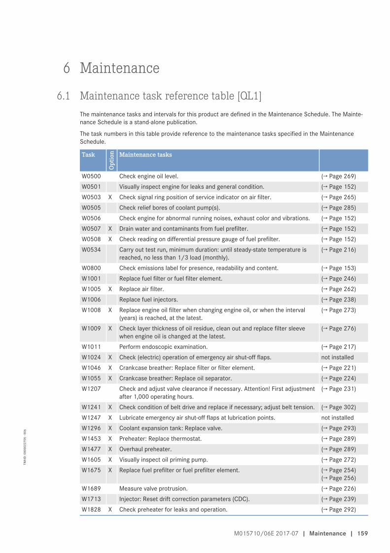
6 Maintenance
6.1 Maintenance task reference table [QL1]The maintenance tasks and intervals for this product are defined in the Maintenance Schedule. The Mainte-nance Schedule is a stand-alone publication.
The task numbers in this table provide reference to the maintenance tasks specified in the MaintenanceSchedule.
Task
Opt
ion Maintenance tasks
W0500 Check engine oil level. (→ Page 269)W0501 Visually inspect engine for leaks and general condition. (→ Page 152)W0503 X Check signal ring position of service indicator on air filter. (→ Page 265)W0505 Check relief bores of coolant pump(s). (→ Page 285)W0506 Check engine for abnormal running noises, exhaust color and vibrations. (→ Page 152)W0507 X Drain water and contaminants from fuel prefilter. (→ Page 152)W0508 X Check reading on differential pressure gauge of fuel prefilter. (→ Page 152)W0534 Carry out test run, minimum duration: until steady-state temperature is
reached, no less than 1/3 load (monthly).(→ Page 216)
W0800 Check emissions label for presence, readability and content. (→ Page 153)W1001 Replace fuel filter or fuel filter element. (→ Page 246)W1005 X Replace air filter. (→ Page 262)W1006 Replace fuel injectors. (→ Page 238)W1008 X Replace engine oil filter when changing engine oil, or when the interval
(years) is reached, at the latest.(→ Page 273)
W1009 X Check layer thickness of oil residue, clean out and replace filter sleevewhen engine oil is changed at the latest.
(→ Page 276)
W1011 Perform endoscopic examination. (→ Page 217)W1024 X Check (electric) operation of emergency air shut-off flaps. not installedW1046 X Crankcase breather: Replace filter or filter element. (→ Page 221)W1055 X Crankcase breather: Replace oil separator. (→ Page 224)W1207 Check and adjust valve clearance if necessary. Attention! First adjustment
after 1,000 operating hours.(→ Page 231)
W1241 X Check condition of belt drive and replace if necessary; adjust belt tension. (→ Page 302)W1247 X Lubricate emergency air shut-off flaps at lubrication points. not installedW1296 X Coolant expansion tank: Replace valve. (→ Page 293)W1453 X Preheater: Replace thermostat. (→ Page 289)W1477 X Overhaul preheater. (→ Page 289)W1605 X Visually inspect oil priming pump. (→ Page 272)W1675 X Replace fuel prefilter or fuel prefilter element. (→ Page 254)
(→ Page 256)W1689 Measure valve protrusion. (→ Page 226)W1713 Injector: Reset drift correction parameters (CDC). (→ Page 239)W1828 X Check preheater for leaks and operation. (→ Page 292)
M015710/06E 2017-07 | Maintenance | 159
TIM
-ID: 0
0000
2270
5 - 0
06

Task
Opt
ion Maintenance tasks
W1864 X Check and clean oil indicator filter. (→ Page 274)W4172 X Check general condition of rubber mount (visual inspection). (→ Page 305)
Table 2: Maintenance task reference table [QL1]
160 | Maintenance | M015710/06E 2017-07
TIM
-ID: 0
0000
2270
5 - 0
06

7 Troubleshooting
7.1 Troubleshooting
Engine does not turn when starter is actuatedCause Corrective action
Battery low or faulty u Charge or replace (→ manufacturer's documentation).Cable connections faulty u Check cable connections for secure seating (→ manufacturer's
documentation).Starter (electric): Engine cablingor starter faulty
u Check whether cable connections are properly secured.Contact Service.
Starter (compressed air): Cablingon starting valve or starterdefective
u Check whether cable connections are properly secured.Contact Service.
Engine wiring faulty u Check (→ Page 306).Engine / generator control:Assemblies or connectorspossibly loose
u Perform visual inspection (→ manufacturer's documentation).
Engine governor: Plug-inconnections loose
u Check plug-in connections (→ Page 308).
Running gear blocked (enginecannot be barred manually)
u Contact Service.
Engine turns on starting but does not fireCause Corrective action
Poor rotation by (electric) starter:Battery low or faulty
u Charge or replace (→ manufacturer's documentation).
Poor rotation by (air) starter:Pressure too low.
u Check compressed air system.
Engine wiring faulty u Check (→ Page 306).Air in fuel system u Vent fuel system (→ Page 245).Engine governor defective u Contact Service.
Engine fires unevenlyCause Corrective action
Injector defective u Check, replace as necessary (→ Page 238).Engine wiring faulty u Check (→ Page 306).Air in fuel system u Vent fuel system (→ Page 245).Engine governor defective u Contact Service.
M015710/06E 2017-07 | Troubleshooting | 161
TIM
-ID: 0
0000
7430
0 - 0
01

Engine does not reach nominal speedCause Corrective action
Fuel prefilter (not switchable)clogged
u Replace (→ Page 254).
Fuel prefilter (switchable) clogged. u Replace (→ Page 256).Fuel filter clogged u Replace (→ Page 246).Air filter clogged u Check signal ring position of service indicator (→ Page 265).Injector defective u Replace (→ Page 238).Engine wiring faulty u Check (→ Page 306).Engine: Overload u Contact Service.
Engine speed not steadyCause Corrective action
Injector defective u Replace (→ Page 238).Speed transmitter defective u Contact Service.Air in fuel system u Vent fuel system (→ Page 245).Engine governor defective u Contact Service.
Charge-air temperature too highCause Corrective action
Engine coolant treatmentincorrect
u Check (→ MTU test kit).
Intercooler dirty u Contact Service.Engine room: Air-intaketemperature too high
u Check fans and intake/exhaust lines.
Charge-air pressure too lowCause Corrective action
Air pipework leaking u Check air pipework for leakage.Air filter clogged u Check signal ring position of service indicator (→ Page 265).Intercooler dirty u Contact Service.Exhaust turbocharger defective u Contact Service.
Coolant discharge at intercoolerCause Corrective action
Leaking, major coolant discharge u Contact Service.
Black exhaust gasCause Corrective action
Air filter clogged u Check signal ring position of service indicator (→ Page 265).Injector defective u Replace (→ Page 238).Engine: Overload u Contact Service.
162 | Troubleshooting | M015710/06E 2017-07
TIM
-ID: 0
0000
7430
0 - 0
01

Blue exhaust gasCause Corrective action
Too much engine oil in the engine u Drain engine oil (→ Page 267).Oil separator of crankcasebreather contaminated
u Replace filter (→ Page 221).
Exhaust turbocharger, cylinderhead, piston rings or cylinder linerdefective
u Contact Service.
White exhaust gasCause Corrective action
Engine is not at operatingtemperature
u Run engine to reach operating temperature.
Water in fuel u Check fuel system on fuel prefilter;Drain water from fuel prefilter (not switchable) (→ Page 248).Drain fuel prefilter (switchable) (→ Page 250).
Intercooler leaky u Contact Service.
M015710/06E 2017-07 | Troubleshooting | 163
TIM
-ID: 0
0000
7430
0 - 0
01

7.2 Engine governor ADEC (ECU 7) for Series 4000 genset engines– Fault messages
003 – HI T-FuelZKP-Number: 2.0122.931
Limit value 1
Cause Corrective action
Fuel temperature too high u Contact Service.
004 – SS T-FuelZKP-Number: 2.0122.932
Limit value 2
Cause Corrective action
Fuel temperature too high. Enginestop
u Contact Service.
005 – HI T-Charge AirZKP-Number: 2.0121.931
Limit value 1
Cause Corrective action
Charge air temperature too high 1. Reduce power.2. Check intercooler.
006 – SS T-Charge AirZKP-Number: 2.0121.932
Limit value 2
Cause Corrective action
Charge-air temperature too high.Engine stop
1. Reduce power.2. Check intercooler.
009 – HI T-Coolant IntercoolerZKP-Number: 2.0124.931
Limit value 1
Cause Corrective action
Coolant temperature inintercooler too high
u Reduce power.
164 | Troubleshooting | M015710/06E 2017-07
TIM
-ID: 0
0000
0850
6 - 0
05

010 – SS T-Coolant IntercoolerZKP-Number: 2.0124.932
Limit value 2
Cause Corrective action
Coolant temperature inintercooler too high. Engine stop
u Reduce power.
015 – LO P-Lube OilZKP-Number: 2.0100.921
Limit value 1
Cause Corrective action
Lube oil pressure too low u Check oil level, top up as necessary (→ Page 269).
016 – SS P-Lube OilZKP-Number: 2.0100.922
Limit value 2
Cause Corrective action
Lube oil pressure too low.Automatic engine shutdown
u Engine must not be started (risk of engine failure), contact Service.
019 – HI T-Exhaust AZKP-Number: 2.0126.931
Limit value 1
Cause Corrective action
Exhaust gas temperature (A side)too high
1. Check cabling (→ Page 306).2. Contact Service.
020 – SS T-Exhaust AZKP-Number: 2.0126.932
Limit value 2
Cause Corrective action
Exhaust gas temperature (A side)too high. Engine stop
1. Check wiring (→ Page 306).2. Contact Service.
021 – HI T-Exhaust BZKP-Number: 2.0127.931
Limit value 1
Cause Corrective action
Exhaust gas temperature (B side)too high
1. Check wiring (→ Page 306).2. Contact Service.
M015710/06E 2017-07 | Troubleshooting | 165
TIM
-ID: 0
0000
0850
6 - 0
05

022 – SS T-Exhaust BZKP-Number: 2.0127.932
Limit value 2
Cause Corrective action
Exhaust gas temperature (B-side)too high. Engine stop
1. Check wiring (→ Page 306).2. Contact Service.
023 – LO Coolant LevelZKP-Number: 2.0152.921
Limit value 1
Cause Corrective action
Coolant level too low u Check coolant level in expansion tank(→ Page 278) .
025 – HI P-Diff-Lube OilZKP-Number: 2.0154.931
Limit value 1
Cause Corrective action
Oil filter differential pressure toohigh
u Replace oil filter (→ Page 273).
026 – SS P-Diff-Lube OilZKP-Number: 2.0154.932
Limit value 2
Cause Corrective action
Oil filter differential pressure toohigh
u Replace oil filter (→ Page 273).
027 – HI Level Leakage FuelZKP-Number: 2.0151.931
Limit value 1
Cause Corrective action
Leak-off fuel level too high 1. Check fuel system.2. Contact Service.
029 – HI ETC2 Idle Speed too HighZKP-Number: 1.8004.206
Cause Corrective action
ETC 2 idling speed too high u Contact Service.
166 | Troubleshooting | M015710/06E 2017-07
TIM
-ID: 0
0000
0850
6 - 0
05

030 – SS Engine OverspeedZKP-Number: 2.2510.932
Limit value 2
Cause Corrective action
Engine overspeed: automaticengine emergency stop.
1. Acknowledge alarm.2. Attempt to restart engine.
031 – HI ETC1 OverspeedZKP-Number: 2.3011.931
Limit value 1
Cause Corrective action
Speed of primary turbochargertoo high
u Contact Service.
032 – SS ETC1 OverspeedZKP-Number: 2.3012.932
Limit value 2
Cause Corrective action
Speed of primary turbochargertoo high
1. Automatic power reduction by engine control system.2. Check air filters (→ Page 263).
033 – HI P-Diff-FuelZKP-Number: 20.114.931
Limit value 1
Cause Corrective action
Fuel filter differential pressure toohigh
u Replace fuel filter (→ Page 246).
034 – SS P-Diff-FuelZKP-Number: 20.114.932
Limit value 2
Cause Corrective action
Fuel filter differential pressure toohigh
u Replace fuel filter (→ Page 246).
036 – HI ETC2 OverspeedZKP-Number: 2.3013.931
Limit value 1
Cause Corrective action
Speed of 1st secondaryturbocharger too high
1. Reduce power.2. Contact Service.
M015710/06E 2017-07 | Troubleshooting | 167
TIM
-ID: 0
0000
0850
6 - 0
05

037 – SS ETC2 OverspeedZKP-Number: 2.3013.912
Limit value 2
Cause Corrective action
Speed of 1st secondaryturbocharger too high
1. Reduce power.2. Contact Service.
038 – AL ETC Speed DeviationZKP-Number: 1.8004.205
Cause Corrective action
Synchro fault between primaryturbocharger and one of thesecondary turbochargers
1. Reduce power.2. Contact Service.
039 – AL ETC2 Cutin FailureZKP-Number: 1.8004.204
Cause Corrective action
ETC 2 failed to cut in 1. Reduce power.2. Contact Service.
044 – LO Coolant Level IntercoolerZKP-Number: 2.0153.921
Limit value 1
Cause Corrective action
Intercooler coolant level too low u Check coolant level (→ Page 294).
051 – HI T-Lube OilZKP-Number: 2.0125.931
Limit value 1
Cause Corrective action
Lube oil temperature too high u Reduce power.
052 – SS T-Lube OilZKP-Number: 2.0125.932
Limit value 2
Cause Corrective action
Lube oil temperature too high.Engine stop
1. Reduce power.2. Check engine oil level (→ Page 269).
168 | Troubleshooting | M015710/06E 2017-07
TIM
-ID: 0
0000
0850
6 - 0
05

057 – LO P-CoolantZKP-Number: 2.0101.921
Limit value 1
Cause Corrective action
Coolant pressure too low u Check coolant circuit.
058 – SS P-CoolantZKP-Number: 2.0101.922
Limit value 2
Cause Corrective action
Coolant pressure too low. Enginestop or reduced injection quantity
1. Automatic engine shutdown.2. Check coolant level (→ Page 278).
059 – SS T-Coolant L3ZKP-Number: 20.120.933
Limit value 3
Cause Corrective action
Coolant temperature too high/low 1. Allow engine to cool down.2. Check engine coolant cooler, clean if dirty.3. Contact Service.
060 – SS T-Coolant L4ZKP-Number: 20.120.934
Limit value 4
Cause Corrective action
Coolant temperature too high/low 1. Allow engine to cool down.2. Check engine coolant cooler, clean if dirty.3. Contact Service.
063 – HI P-Crank CaseZKP-Number: 2.0106.931
Limit value 1
Cause Corrective action
Crankcase pressure too high 1. Reduce power.2. Replace oil separator element (→ Page 221).
M015710/06E 2017-07 | Troubleshooting | 169
TIM
-ID: 0
0000
0850
6 - 0
05

064 – SS P-Crank CaseZKP-Number: 2.0106.932
Limit value 2
Cause Corrective action
Crankcase pressure too high.Automatic engine shutdown
u Engine must not be started (risk of engine failure), contact Service.
065 – LO P-FuelZKP-Number: 2.0102.921
Limit value 1
Cause Corrective action
Fuel inlet pressure too low 1. Check fuel lines for leakage.2. Drain fuel prefilter (→ Page 248), (→ Page 250).3. Replace filter element of fuel prefilter (→ Page 254), (→ Page 256).4. Replace fuel filter (→ Page 246).
066 – SS P-FuelZKP-Number: 2.0102.922
Limit value 2
Cause Corrective action
Fuel supply pressure too low.Engine stop
1. Check fuel lines for leakage.2. Drain fuel prefilter (→ Page 248), (→ Page 250).3. Replace filter element of fuel prefilter (→ Page 254), (→ Page 256).4. Replace fuel filter (→ Page 246).
067 – HI T-CoolantZKP-Number: 2.0120.931
Limit value 1
Cause Corrective action
Coolant temperature too high u Reduce power.
068 – SS T-CoolantZKP-Number: 2.0120.932
Limit value 2
Cause Corrective action
Coolant temperature too high.Engine stop
1. Allow engine to cool down.2. Check engine coolant cooler, clean if dirty.3. Restart engine (→ Page 149).4. Contact Service.
170 | Troubleshooting | M015710/06E 2017-07
TIM
-ID: 0
0000
0850
6 - 0
05

081 – AL Rail LeakageZKP-Number: 1.8004.046
Cause Corrective action
Pressure gradient in rail is too lowduring starting or too high duringstopping. HP system leaky, air insystem
u Contact Service.
082 – HI P-Fuel (Common Rail)ZKP-Number: 2.0104.931
Cause Corrective action
Rail pressure > set value. DBR fuellimitation, start of injectionreadjusted towards late. Suctionrestrictor of HP fuel blockjamming or HP fuel control blockwiring faulty
u Contact Service.
083 – LO P-Fuel (Common Rail)ZKP-Number: 2.0104.921
Cause Corrective action
Rail pressure < set value. Speedlimitation control DBR reduction.Suction restrictor of HP fuelcontrol block faulty or leakage inHP fuel system
u Contact Service.
085 – HI T-UmblasenZKP-Number: 2.0128.931
Limit value 1
Cause Corrective action
Recirculation temperature toohigh
u Reduce power.
086 – HIHI T-UmblasenZKP-Number: 2.0128.932
Limit value 2
Cause Corrective action
Recirculation temperature toohigh
u Reduce power.
M015710/06E 2017-07 | Troubleshooting | 171
TIM
-ID: 0
0000
0850
6 - 0
05

089 – SS Engine Speed too LowZKP-Number: 2.2500.030
Cause Corrective action
Engine speed too low u Check for additional messages.
090 – SS Idle Speed Not ReachedZKP-Number: 2.1090.925
Cause Corrective action
Idling speed not attained u Contact Service.
091 – SS Release Speed Not ReachedZKP-Number: 2.1090.924
Cause Corrective action
Runup speed was not attained u Contact Service.
092 – SS Starter Speed Not ReachedZKP-Number: 2.1090.923
Cause Corrective action
Starter speed was not attained.Termination of starting sequence.Starter rotates too slowly or doesnot rotate at all
u Contact Service.
093 – SS T-PreheatZKP-Number: 2.1090.922
Limit value 2
Cause Corrective action
Preheating temperature too low.Coolant temperature too low forengine start. Engine startinterlock active
u Check preheater.
094 – LO T-PreheatZKP-Number: 2.1090.921
Limit value 1
Cause Corrective action
Preheating temperature too low.Coolant temperature too low forengine start
u Check preheater.
172 | Troubleshooting | M015710/06E 2017-07
TIM
-ID: 0
0000
0850
6 - 0
05

095 – AL Prelubrication FaultZKP-Number: 2.1090.920
Cause Corrective action
Oil priming fault u Check oil priming system.
102 – AL Fuel Cons. Counter DefectZKP-Number: 1.8004.624
Cause Corrective action
Consumption meter faulty u Contact Service.
104 – AL Eng Hours Counter DefectZKP-Number: 1.8004.623
Cause Corrective action
Hour meter defective u Contact Service.
118 – LO ECU Power Supply VoltageZKP-Number: 2.0140.921
Limit value 1
Cause Corrective action
Supply voltage too low 1. Check supply voltage of engine governor.2. Contact Service.
119 – LOLO ECU Power Supply VoltageZKP-Number: 2.0140.922
Limit value 2
Cause Corrective action
Supply voltage too low 1. Check supply voltage of engine governor.2. Contact Service.
120 – HI ECU Power Supply VoltageZKP-Number: 2.0140.931
Limit value 1
Cause Corrective action
Supply voltage too high 1. Check supply voltage of engine governor.2. Contact Service.
M015710/06E 2017-07 | Troubleshooting | 173
TIM
-ID: 0
0000
0850
6 - 0
05

121 – HIHI ECU Power Supply VoltageZKP-Number: 2.0140.932
Limit value 2
Cause Corrective action
Supply voltage too high 1. Check supply voltage of engine governor.2. Contact Service.
122 – HI T-ECUZKP-Number: 2.0132.921
Limit value 1
Cause Corrective action
Temperature in ECS too high 1. Reduce power.2. Improve engine room ventilation.
141 – AL Power too highZKP-Number: 11.088.007
Cause Corrective action
Alarm is tripped when averagepower value has exceeded themax. value defined inPR1.1088.001 over the last24 hours
u Reduce power.
142 – AL MCR exceeded 1 hourZKP-Number: 1.1088.006
Cause Corrective action
The MCR has been exceeded formore than 1 hour within the last12 hours
u Reduce power.
176 – AL LifeData not availableZKP-Number: 2.4000.004
Cause Corrective action
No (appropriate) LifeData backupsystem available, ECU reset onexpiry of timeout period
u Contact Service.
174 | Troubleshooting | M015710/06E 2017-07
TIM
-ID: 0
0000
0850
6 - 0
05

177 – AL LifeData restore incompleteZKP-Number: 2.4000.006
Cause Corrective action
This fault message is generated ifa CRC is faulty during a dataupload to ADEC (indicated foreach individual module)
u Contact Service.
180 – AL CAN1 Node LostZKP-Number: 2.0500.680
Cause Corrective action
Connection to a node on CAN bus1 failed
u Contact Service.
181 – AL CAN2 Node LostZKP-Number: 2.0500.681
Cause Corrective action
Connection to a node on CAN bus2 failed
u Contact Service.
182 – AL CAN Wrong ParametersZKP-Number: 2.0500.682
Cause Corrective action
Incorrect parameter valuesentered in data record
u Contact Service.
183 – AL CAN No PU-DataZKP-Number: 2.0500.683
Cause Corrective action
The selected CAN mode initializescommunication by means of thePU data module. However, therequired PU data module is notavailable or not valid
u Contact Service.
184 – AL CAN PU-Data Flash ErrorZKP-Number: 2.0500.684
Cause Corrective action
A programming error occurredwhen attempting to copy areceived PU data module into theFlash module
u Contact Service.
M015710/06E 2017-07 | Troubleshooting | 175
TIM
-ID: 0
0000
0850
6 - 0
05

186 – AL CAN1 Bus OffZKP-Number: 2.0500.686
Cause Corrective action
CAN controller 1 is in “Bus-Off”status
1. Check CAN bus for short circuit, rectify short circuit as necessary.2. Check shielding, improve shielding as necessary.3. Contact Service.
187 – AL CAN1 Error PassiveZKP-Number: 2.0500.687
Cause Corrective action
CAN controller 1 has indicated awarning
1. Check CAN bus for short circuit, rectify short circuit as necessary.2. Check shielding, improve shielding as necessary.3. Contact Service.
188 – AL CAN2 Bus OffZKP-Number: 2.0500.688
Cause Corrective action
CAN controller 2 is in “Bus-Off”status. => automatic changeoverto CAN 1. Short circuit, massiveinterference or baud rateincompatibility
1. Check CAN bus for short circuit, rectify short circuit as necessary.2. Check shielding, improve shielding as necessary.3. Contact Service.
189 – AL CAN2 Error PassiveZKP-Number: 2.0500.689
Cause Corrective action
CAN controller 2 has indicated awarning
1. Check CAN bus for short circuit, rectify short circuit as necessary.2. Check shielding, improve shielding as necessary.3. Contact Service.
190 – AL EMU Parameter Not SupportedZKP-Number: 2.0500.690
Cause Corrective action
EMU parameters are notsupported.
u Contact Service.
201 – SD T-CoolantZKP-Number: 1.8004.570
Cause Corrective action
Coolant temperature sensorfaulty. Short circuit or wire break
u Check sensor and cabling (B6), replace as necessary.Error cleared after restarting the engine.
176 | Troubleshooting | M015710/06E 2017-07
TIM
-ID: 0
0000
0850
6 - 0
05

202 – SD T-FuelZKP-Number: 1.8004.572
Cause Corrective action
Fuel temperature sensor faulty.Short circuit or wire break
u Check sensor and cabling (B33), replace as necessary.Error cleared after restarting the engine.
203 – SD T-Charge AirZKP-Number: 1.8004.571
Cause Corrective action
Charge-air temperature sensorfaulty. Short circuit or wire break
u Check sensor and cabling (B9), replace as necessary.Error cleared after restarting the engine.
204 – SD Level Lube OilZKP-Number: 1.8004.602
Cause Corrective action
Lube oil level sensor defective.Short circuit or wire break
u Check sensor and cabling, replace as necessary.
205 – SD T-Coolant IntercoolerZKP-Number: 1.8004.574
Cause Corrective action
Intercooler coolant temperaturesensor faulty. Short circuit or wirebreak
u Check sensor and cabling (B26), replace as necessary.Error cleared after restarting the engine.
206 – SD T-Exhaust AZKP-Number: 1.8004.576
Cause Corrective action
Exhaust temperature sensor on Aside faulty. Short circuit or wirebreak
u Check sensor and cabling (B4.21), replace as necessary.Error cleared after restarting the engine.
207 – SD T-Exhaust BZKP-Number: 18.004.577
Cause Corrective action
Exhaust temperature sensor on B-side faulty. Short circuit or wirebreak
u Check sensor and cabling (B4.22), replace as necessary.
M015710/06E 2017-07 | Troubleshooting | 177
TIM
-ID: 0
0000
0850
6 - 0
05

208 – SD P-Charge AirZKP-Number: 1.8004.566
Cause Corrective action
Charge-air pressure sensor faulty.Short circuit or wire break
u Check sensor and cabling (B10), replace as necessary.Error cleared after restarting the engine.
211 – SD P-Lube OilZKP-Number: 1.8004.563
Cause Corrective action
Lube oil pressure sensor faulty.Short circuit or wire break
u Check sensor and cabling (B5), replace as necessary.Error cleared after restarting the engine.
212 – SD P-CoolantZKP-Number: 1.8004.564
Cause Corrective action
Coolant pressure sensor faulty.Short circuit or wire break
u Check sensor and cabling (B16), replace as necessary.Error cleared after restarting the engine.
213 – SD P-Coolant IntercoolerZKP-Number: 1.8004.569
Cause Corrective action
Intercooler coolant pressuresensor faulty. Short circuit or wirebreak
u Check sensor and cabling (B43), replace as necessary.Error cleared after restarting the engine.
214 – SD P-CrankCaseZKP-Number: 1.8004.568
Cause Corrective action
Crankcase pressure sensor faulty.Short circuit or wire break
u Check sensor and cabling (B50), replace as necessary.Error cleared after restarting the engine.
215 – SD P-HDZKP-Number: 1.8004.567
Cause Corrective action
Rail pressure sensor faulty. High-pressure regulator in emergencymode ==> Short circuit or wirebreak
u Check sensor and cabling (B48), replace as necessary.Error cleared after restarting the engine.
178 | Troubleshooting | M015710/06E 2017-07
TIM
-ID: 0
0000
0850
6 - 0
05

216 – SD T-Lube OilZKP-Number: 1.8004.575
Cause Corrective action
Lube oil temperature sensorfaulty. Short circuit or wire break
u Check sensor and cabling (B7), replace as necessary.Error cleared after restarting the engine.
219 – SD T-Intake AirZKP-Number: 1.8004.573
Cause Corrective action
Intake air temperature sensorfaulty. Short circuit or wire break
u Check sensor and cabling (B3), replace as necessary.Error cleared after restarting the engine.
220 – SD Level Coolant WaterZKP-Number: 1.8004.584
Cause Corrective action
Coolant level sensor faulty. Shortcircuit or wire break
u Check sensor and cabling (F33), replace as necessary.Error cleared after restarting the engine.
221 – SD P-Diff Lube OilZKP-Number: 1.8004.585
Cause Corrective action
Lube oil pressure differentialsensor faulty. Short circuit or wirebreak
u Check sensor and cabling (F25), replace as necessary.Error cleared after restarting the engine.
222 – SD Level Leakage FuelZKP-Number: 1.8004.582
Cause Corrective action
Leak-off fuel level sensor faulty.Short circuit or wire break
u Check sensor and cabling (F46), replace as necessary.Error cleared after restarting the engine.
223 – SD Level Coolant IntercoolerZKP-Number: 1.8004.583
Cause Corrective action
Sensor for intercooler coolantlevel faulty. Short circuit or wirebreak
u Check sensor and cabling (F57), replace as necessary.Error cleared after restarting the engine.
M015710/06E 2017-07 | Troubleshooting | 179
TIM
-ID: 0
0000
0850
6 - 0
05

227 – SD P-Lube Oil before FilterZKP-Number: 1.8004.620
Cause Corrective action
Sensor for lube oil pressurebefore filter faulty. Short circuit orwire break
u Check sensor and cabling (B5.3), replace as necessary.Error cleared after restarting the engine.
228 – SD P-Fuel before FilterZKP-Number: 18.004.595
Cause Corrective action
Fuel pressure sensor faulty. Shortcircuit or wire break
u Check sensor and cabling (B5.3), replace as necessary.
229 – AL Stop Camshaft Sensor DefectZKP-Number: 1.8004.562
Cause Corrective action
Engine stop due to camshaftsensor fault (and a previouscrankshaft sensor fault in thesame operating cycle)
u Check connector and cabling to sensor B1, replace as necessary.Error cleared after restarting the engine.
230 – SD Crankshaft SpeedZKP-Number: 1.8004.498
Cause Corrective action
Crankshaft sensor faulty. Shortcircuit or wire break
u Check sensor and cabling (B13), replace as necessary.Error cleared after restarting the engine.
231 – SD Camshaft SpeedZKP-Number: 1.8004.499
Cause Corrective action
Camshaft sensor faulty. Shortcircuit or wire break
u Check sensor and cabling (B13), replace as necessary.Error cleared after restarting the engine.
232 – SD Charger 1 SpeedZKP-Number: 1.3011.128
Cause Corrective action
Speed sensor of primaryturbocharger faulty. Short circuitor wire break
u Check sensor and cabling (B44.1), replace as necessary.Error cleared after restarting the engine.
180 | Troubleshooting | M015710/06E 2017-07
TIM
-ID: 0
0000
0850
6 - 0
05

233 – SD Charger 2 SpeedZKP-Number: 1.3011.129
Cause Corrective action
Speed sensor of secondaryturbocharger faulty. Short circuitor wire break
u Check sensor and cabling (B44.2), replace as necessary.Error cleared after restarting the engine.
239 – SD P-Diff FuelZKP-Number: 18.004.598
Cause Corrective action
Fuel differential pressure sensorfaultyThis alarm occurs only incombination with the alarm SD P-Fuel before Filter or SD P-Fuelafter Filter
u Observe additional message.
240 – SD P-FuelZKP-Number: 1.8004.565
Cause Corrective action
Fuel pressure sensor faulty. Shortcircuit or wire break
u Check sensor and cabling (B34), replace as necessary.Error cleared after restarting the engine.
241 – SD T-UmblasenZKP-Number: 1.8004.581
Cause Corrective action
Recirculation sensor faulty. Shortcircuit or wire break
u Check sensor and cabling (B49), replace as necessary.Error cleared after restarting the engine.
242 – SD T-Coolant (R)ZKP-Number: 1.8004.622
Cause Corrective action
Redundant coolant pressuresensor faulty. Short circuit or wirebreak
u Check sensor and cabling, replace as necessary.Error cleared after restarting the engine.
244 – SD P-Lube Oil (R)ZKP-Number: 1.8004.621
Cause Corrective action
Redundant lube oil pressuresensor faulty. Short circuit or wirebreak
u Check sensor and cabling, replace as necessary.Error cleared after restarting the engine.
M015710/06E 2017-07 | Troubleshooting | 181
TIM
-ID: 0
0000
0850
6 - 0
05
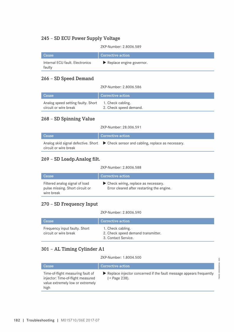
245 – SD ECU Power Supply VoltageZKP-Number: 2.8006.589
Cause Corrective action
Internal ECU fault. Electronicsfaulty
u Replace engine governor.
266 – SD Speed DemandZKP-Number: 2.8006.586
Cause Corrective action
Analog speed setting faulty. Shortcircuit or wire break
1. Check cabling.2. Check speed demand.
268 – SD Spinning ValueZKP-Number: 28.006.591
Cause Corrective action
Analog skid signal defective. Shortcircuit or wire break
u Check sensor and cabling, replace as necessary.
269 – SD Loadp.Analog filt.ZKP-Number: 2.8006.588
Cause Corrective action
Filtered analog signal of loadpulse missing. Short circuit orwire break
u Check wiring, replace as necessary.Error cleared after restarting the engine.
270 – SD Frequency InputZKP-Number: 2.8006.590
Cause Corrective action
Frequency input faulty. Shortcircuit or wire break
1. Check cabling.2. Check speed demand transmitter.3. Contact Service.
301 – AL Timing Cylinder A1ZKP-Number: 1.8004.500
Cause Corrective action
Time-of-flight measuring fault ofinjector: Time-of-flight measuredvalue extremely low or extremelyhigh
u Replace injector concerned if the fault message appears frequently(→ Page 238).
182 | Troubleshooting | M015710/06E 2017-07
TIM
-ID: 0
0000
0850
6 - 0
05

302 – AL Timing Cylinder A2ZKP-Number: 1.8004.501
Cause Corrective action
Time-of-flight measuring fault ofinjector: Time-of-flight measuredvalue extremely low or extremelyhigh
u Replace injector concerned if the fault message appears frequently(→ Page 238).
303 – AL Timing Cylinder A3ZKP-Number: 1.8004.502
Cause Corrective action
Time-of-flight measuring fault ofinjector: Time-of-flight measuredvalue extremely low or extremelyhigh
u Replace injector concerned if the fault message appears frequently(→ Page 238).
304 – AL Timing Cylinder A4ZKP-Number: 1.8004.503
Cause Corrective action
Time-of-flight measuring fault ofinjector: Time-of-flight measuredvalue extremely low or extremelyhigh
u Replace injector concerned if the fault message appears frequently(→ Page 238).
305 – AL Timing Cylinder A5ZKP-Number: 1.8004.504
Cause Corrective action
Time-of-flight measuring fault ofinjector: Time-of-flight measuredvalue extremely low or extremelyhigh
u Replace injector concerned if the fault message appears frequently(→ Page 238).
306 – AL Timing Cylinder A6ZKP-Number: 1.8004.505
Cause Corrective action
Time-of-flight measuring fault ofinjector: Time-of-flight measuredvalue extremely low or extremelyhigh
u Replace injector concerned if the fault message appears frequently(→ Page 238).
M015710/06E 2017-07 | Troubleshooting | 183
TIM
-ID: 0
0000
0850
6 - 0
05

307 – AL Timing Cylinder A7ZKP-Number: 1.8004.506
Cause Corrective action
Time-of-flight measuring fault ofinjector: Time-of-flight measuredvalue extremely low or extremelyhigh
u Replace injector concerned if the fault message appears frequently(→ Page 238).
308 – AL Timing Cylinder A8ZKP-Number: 1.8004.507
Cause Corrective action
Time-of-flight measuring fault ofinjector: Time-of-flight measuredvalue extremely low or extremelyhigh
u Replace injector concerned if the fault message appears frequently(→ Page 238).
309 – AL Timing Cylinder A9ZKP-Number: 1.8004.508
Cause Corrective action
Time-of-flight measuring fault ofinjector: Time-of-flight measuredvalue extremely low or extremelyhigh
u Replace injector concerned if the fault message appears frequently(→ Page 238).
310 – AL Timing Cylinder A10ZKP-Number: 1.8004.509
Cause Corrective action
Time-of-flight measuring fault ofinjector: Time-of-flight measuredvalue extremely low or extremelyhigh
u Replace injector concerned if the fault message appears frequently(→ Page 238).
311 – AL Timing Cylinder B1ZKP-Number: 1.8004.510
Cause Corrective action
Time-of-flight measuring fault ofinjector: Time-of-flight measuredvalue extremely low or extremelyhigh
u Replace injector concerned if the fault message appears frequently(→ Page 238).
184 | Troubleshooting | M015710/06E 2017-07
TIM
-ID: 0
0000
0850
6 - 0
05

312 – AL Timing Cylinder B2ZKP-Number: 1.8004.511
Cause Corrective action
Time-of-flight measuring fault ofinjector: Time-of-flight measuredvalue extremely low or extremelyhigh
u Replace injector concerned if the fault message appears frequently(→ Page 238).
313 – AL Timing Cylinder B3ZKP-Number: 1.8004.512
Cause Corrective action
Time-of-flight measuring fault ofinjector: Time-of-flight measuredvalue extremely low or extremelyhigh
u Replace injector concerned if the fault message appears frequently(→ Page 238).
314 – AL Timing Cylinder B4ZKP-Number: 1.8004.513
Cause Corrective action
Time-of-flight measuring fault ofinjector: Time-of-flight measuredvalue extremely low or extremelyhigh
u Replace injector concerned if the fault message appears frequently(→ Page 238).
315 – AL Timing Cylinder B5ZKP-Number: 1.8004.514
Cause Corrective action
Time-of-flight measuring fault ofinjector: Time-of-flight measuredvalue extremely low or extremelyhigh
u Replace injector concerned if the fault message appears frequently(→ Page 238).
316 – AL Timing Cylinder B6ZKP-Number: 1.8004.515
Cause Corrective action
Time-of-flight measuring fault ofinjector: Time-of-flight measuredvalue extremely low or extremelyhigh
u Replace injector concerned if the fault message appears frequently(→ Page 238).
M015710/06E 2017-07 | Troubleshooting | 185
TIM
-ID: 0
0000
0850
6 - 0
05

317 – AL Timing Cylinder B7ZKP-Number: 1.8004.516
Cause Corrective action
Time-of-flight measuring fault ofinjector: Time-of-flight measuredvalue extremely low or extremelyhigh
u Replace injector concerned if the fault message appears frequently(→ Page 238).
318 – AL Timing Cylinder B8ZKP-Number: 1.8004.517
Cause Corrective action
Time-of-flight measuring fault ofinjector: Time-of-flight measuredvalue extremely low or extremelyhigh
u Replace injector concerned if the fault message appears frequently(→ Page 238).
319 – AL Timing Cylinder B9ZKP-Number: 1.8004.518
Cause Corrective action
Time-of-flight measuring fault ofinjector: Time-of-flight measuredvalue extremely low or extremelyhigh
u Replace injector concerned if the fault message appears frequently(→ Page 238).
320 – AL Timing Cylinder B10ZKP-Number: 1.8004.519
Cause Corrective action
Time-of-flight measuring fault ofinjector: Time-of-flight measuredvalue extremely low or extremelyhigh
u Replace injector concerned if the fault message appears frequently(→ Page 238).
321 – AL Wiring Cylinder A1ZKP-Number: 1.8004.520
Cause Corrective action
Short circuit in injector cabling tocylinder. Result: Misfiring
1. Check solenoid valve.2. Contact Service.
322 – AL Wiring Cylinder A2ZKP-Number: 1.8004.521
Cause Corrective action
Short circuit in injector cabling tocylinder. Result: Misfiring
1. Check solenoid valve.2. Contact Service.
186 | Troubleshooting | M015710/06E 2017-07
TIM
-ID: 0
0000
0850
6 - 0
05

323 – AL Wiring Cylinder A3ZKP-Number: 1.8004.522
Cause Corrective action
Short circuit in injector cabling tocylinder. Result: Misfiring
1. Check solenoid valve.2. Contact Service.
324 – AL Wiring Cylinder A4ZKP-Number: 1.8004.523
Cause Corrective action
Short circuit in injector cabling tocylinder. Result: Misfiring
1. Check solenoid valve.2. Contact Service.
325 – AL Wiring Cylinder A5ZKP-Number: 1.8004.524
Cause Corrective action
Short circuit in injector cabling tocylinder. Result: Misfiring
1. Check solenoid valve.2. Contact Service.
326 – AL Wiring Cylinder A6ZKP-Number: 1.8004.525
Cause Corrective action
Short circuit in injector cabling tocylinder. Result: Misfiring
1. Check solenoid valve.2. Contact Service.
327 – AL Wiring Cylinder A7ZKP-Number: 1.8004.526
Cause Corrective action
Short circuit in injector cabling tocylinder. Result: Misfiring
1. Check solenoid valve.2. Contact Service.
328 – AL Wiring Cylinder A8ZKP-Number: 1.8004.527
Cause Corrective action
Short circuit in injector cabling tocylinder. Result: Misfiring
1. Check solenoid valve.2. Contact Service.
329 – AL Wiring Cylinder A9ZKP-Number: 1.8004.528
Cause Corrective action
Short circuit in injector cabling tocylinder. Result: Misfiring
1. Check solenoid valve.2. Contact Service.
M015710/06E 2017-07 | Troubleshooting | 187
TIM
-ID: 0
0000
0850
6 - 0
05

330 – AL Wiring Cylinder A10ZKP-Number: 1.8004.529
Cause Corrective action
Short circuit in injector cabling tocylinder. Result: Misfiring
1. Check solenoid valve.2. Contact Service.
331 – AL Wiring Cylinder B1ZKP-Number: 1.8004.530
Cause Corrective action
Short circuit in injector cabling tocylinder. Result: Misfiring
1. Check solenoid valve.2. Contact Service.
332 – AL Wiring Cylinder B2ZKP-Number: 1.8004.531
Cause Corrective action
Short circuit in injector cabling tocylinder. Result: Misfiring
1. Check solenoid valve.2. Contact Service.
333 – AL Wiring Cylinder B3ZKP-Number: 1.8004.532
Cause Corrective action
Short circuit in injector cabling tocylinder. Result: Misfiring
1. Check solenoid valve.2. Contact Service.
334 – AL Wiring Cylinder B4ZKP-Number: 1.8004.533
Cause Corrective action
Short circuit in injector cabling tocylinder. Result: Misfiring
1. Check solenoid valve.2. Contact Service.
335 – AL Wiring Cylinder B5ZKP-Number: 1.8004.534
Cause Corrective action
Short circuit in injector cabling tocylinder. Result: Misfiring
1. Check solenoid valve.2. Contact Service.
336 – AL Wiring Cylinder B6ZKP-Number: 1.8004.535
Cause Corrective action
Short circuit in injector cabling tocylinder. Result: Misfiring
1. Check solenoid valve.2. Contact Service.
188 | Troubleshooting | M015710/06E 2017-07
TIM
-ID: 0
0000
0850
6 - 0
05

337 – AL Wiring Cylinder B7ZKP-Number: 1.8004.536
Cause Corrective action
Short circuit in injector cabling tocylinder. Result: Misfiring
1. Check solenoid valve.2. Contact Service.
338 – AL Wiring Cylinder B8ZKP-Number: 1.8004.537
Cause Corrective action
Short circuit in injector cabling tocylinder. Result: Misfiring
1. Check solenoid valve.2. Contact Service.
339 – AL Wiring Cylinder B9ZKP-Number: 1.8004.538
Cause Corrective action
Short circuit in injector cabling tocylinder. Result: Misfiring
1. Check solenoid valve.2. Contact Service.
340 – AL Wiring Cylinder B10ZKP-Number: 1.8004.539
Cause Corrective action
Short circuit in injector cabling tocylinder. Result: Misfiring
1. Check solenoid valve.2. Contact Service.
341 – AL Open Load Cylinder A1ZKP-Number: 1.8004.540
Cause Corrective action
Open circuit in injector wiring tocylinder. Result: Misfiring
1. Check solenoid valve.2. Contact Service.
342 – AL Open Load Cylinder A2ZKP-Number: 1.8004.541
Cause Corrective action
Open circuit in injector wiring tocylinder. Result: Misfiring
1. Check solenoid valve.2. Contact Service.
343 – AL Open Load Cylinder A3ZKP-Number: 1.8004.542
Cause Corrective action
Open circuit in injector wiring tocylinder. Result: Misfiring
1. Check solenoid valve.2. Contact Service.
M015710/06E 2017-07 | Troubleshooting | 189
TIM
-ID: 0
0000
0850
6 - 0
05

344 – AL Open Load Cylinder A4ZKP-Number: 1.8004.543
Cause Corrective action
Open circuit in injector wiring tocylinder. Result: Misfiring
1. Check solenoid valve.2. Contact Service.
345 – AL Open Load Cylinder A5ZKP-Number: 1.8004.544
Cause Corrective action
Open circuit in injector wiring tocylinder. Result: Misfiring
1. Check solenoid valve.2. Contact Service.
346 – AL Open Load Cylinder A6ZKP-Number: 1.8004.545
Cause Corrective action
Open circuit in injector wiring tocylinder. Result: Misfiring
1. Check solenoid valve.2. Contact Service.
347 – AL Open Load Cylinder A7ZKP-Number: 1.8004.546
Cause Corrective action
Open circuit in injector wiring tocylinder. Result: Misfiring
1. Check solenoid valve.2. Contact Service.
348 – AL Open Load Cylinder A8ZKP-Number: 1.8004.547
Cause Corrective action
Open circuit in injector wiring tocylinder. Result: Misfiring
1. Check solenoid valve.2. Contact Service.
349 – AL Open Load Cylinder A9ZKP-Number: 1.8004.548
Cause Corrective action
Open circuit in injector wiring tocylinder. Result: Misfiring
1. Check solenoid valve.2. Contact Service.
350 – AL Open Load Cylinder A10ZKP-Number: 1.8004.549
Cause Corrective action
Open circuit in injector wiring tocylinder. Result: Misfiring
1. Check solenoid valve.2. Contact Service.
190 | Troubleshooting | M015710/06E 2017-07
TIM
-ID: 0
0000
0850
6 - 0
05

351 – AL Open Load Cylinder B1ZKP-Number: 1.8004.550
Cause Corrective action
Open circuit in injector wiring tocylinder. Result: Misfiring
1. Check solenoid valve.2. Contact Service.
352 – AL Open Load Cylinder B2ZKP-Number: 1.8004.551
Cause Corrective action
Open circuit in injector wiring tocylinder. Result: Misfiring
1. Check solenoid valve.2. Contact Service.
353 – AL Open Load Cylinder B3ZKP-Number: 1.8004.552
Cause Corrective action
Open circuit in injector wiring tocylinder. Result: Misfiring
1. Check solenoid valve.2. Contact Service.
354 – AL Open Load Cylinder B4ZKP-Number: 1.8004.553
Cause Corrective action
Open circuit in injector wiring tocylinder. Result: Misfiring
1. Check solenoid valve.2. Contact Service.
355 – AL Open Load Cylinder B5ZKP-Number: 1.8004.554
Cause Corrective action
Open circuit in injector wiring tocylinder. Result: Misfiring
1. Check solenoid valve.2. Contact Service.
356 – AL Open Load Cylinder B6ZKP-Number: 1.8004.555
Cause Corrective action
Open circuit in injector wiring tocylinder. Result: Misfiring
1. Check solenoid valve.2. Contact Service.
357 – AL Open Load Cylinder B7ZKP-Number: 1.8004.556
Cause Corrective action
Open circuit in injector wiring tocylinder. Result: Misfiring
1. Check solenoid valve.2. Contact Service.
M015710/06E 2017-07 | Troubleshooting | 191
TIM
-ID: 0
0000
0850
6 - 0
05

358 – AL Open Load Cylinder B8ZKP-Number: 1.8004.557
Cause Corrective action
Open circuit in injector wiring tocylinder. Result: Misfiring
1. Check solenoid valve.2. Contact Service.
359 – AL Open Load Cylinder B9ZKP-Number: 1.8004.558
Cause Corrective action
Open circuit in injector wiring tocylinder. Result: Misfiring
1. Check solenoid valve.2. Contact Service.
360 – AL Open Load Cylinder B10ZKP-Number: 1.8004.559
Cause Corrective action
Open circuit in injector wiring tocylinder. Result: Misfiring
1. Check solenoid valve.2. Contact Service.
361 – AL Power Stage LowZKP-Number: 1.8004.496
Cause Corrective action
Internal electronic fault(electronics possibly faulty: startITS) Check additional messages ifITS indicates diagnosis“Electronics OK” (e.g. cablingfaulty)
1. Check solenoid valve cabling.2. Replace engine governor.
362 – AL Power Stage HighZKP-Number: 1.8004.497
Cause Corrective action
Internal electronic fault(electronics possibly faulty: startITS) Check additional messages ifITS indicates diagnosis“Electronics OK” (e.g. cablingfaulty)
1. Check solenoid valve cabling.2. Replace engine governor.
192 | Troubleshooting | M015710/06E 2017-07
TIM
-ID: 0
0000
0850
6 - 0
05

363 – AL Stop Power StageZKP-Number: 1.8004.560
Cause Corrective action
Internal electronic fault(electronics possibly faulty: startITS)
1. Check cabling.2. Attempt to restart engine.
365 – AL Stop MV-Wiring GroundZKP-Number: 1.8004.561
Cause Corrective action
Injector cabling fault: If bit“1.1020.021” (Power StageFailure: Stop engine) is set, engineis additionally stopped in thiscase.• Short circuit of injector positive
connection to ground of one ormore injectors
• Short circuit of the negativeinjector connection or of one ormore injectors to ground
1. Check cabling.2. Attempt to restart engine.
371 – AL Wiring TO 1ZKP-Number: 1.8004.634
Cause Corrective action
Short circuit or wire break attransistor output 1 (TO 1)
1. Check charger valve/cabling, repair as necessary.2. Replace engine governor.
372 – AL Wiring TO 2ZKP-Number: 1.8004.635
Cause Corrective action
Short circuit or wire break attransistor output 2 (TO 2)
1. Check recirculation valve/cabling, repair as necessary.2. Replace engine governor.
373 – AL Wiring TO 3ZKP-Number: 1.8004.636
Cause Corrective action
Short circuit or wire break attransistor output 3 (TO 3)
u -
M015710/06E 2017-07 | Troubleshooting | 193
TIM
-ID: 0
0000
0850
6 - 0
05

374 – AL Wiring TO 4ZKP-Number: 1.8004.637
Cause Corrective action
Short circuit or wire break attransistor output 4 (TO 4)
u -
381 – AL Wiring TOP 1ZKP-Number: 2.8006.638
Cause Corrective action
Short circuit or wire break attransistor output 1, plant side(TOP 1)
u Check cabling to plant.
382 – AL Wiring TOP 2ZKP-Number: 2.8006.639
Cause Corrective action
Short circuit or wire break attransistor output 2, plant side(TOP 2)
u Check cabling to plant.
383 – AL Wiring TOP 3ZKP-Number: 2.8006.640
Cause Corrective action
Short circuit or wire break attransistor output 3, plant side(TOP 3)
u Check cabling to plant.
384 – AL Wiring TOP 4ZKP-Number: 2.8006.641
Cause Corrective action
Short circuit or wire break attransistor output 4, plant side(TOP 4)
u Check cabling to plant.
390 – AL MCR exceededZKP-Number: 1.1085.009
Cause Corrective action
DBR/MCR function: MCRexceeded
1. No action required if alarm only applied temporarily.2. Contact Service if alarm applied constantly.
194 | Troubleshooting | M015710/06E 2017-07
TIM
-ID: 0
0000
0850
6 - 0
05

392 – HI T-Coolant RedZKP-Number: 2.0129.931
Limit value 1
Cause Corrective action
Redundant coolant temperaturereading too high
1. Check cabling.2. Contact Service.
393 – SS T-Coolant RedZKP-Number: 2.0129.932
Limit value 2
Cause Corrective action
Redundant coolant temperaturereading too high. Engine stop
1. Check wiring and sensor.2. Contact Service.
394 – LO P-Lube Oil RedZKP-Number: 2.0112.921
Limit value 1
Cause Corrective action
Redundant lube oil pressurereading too low
1. Check wiring and sensor.2. Contact Service.
395 – SS P-Lube Oil RedZKP-Number: 2.0112.922
Limit value 2
Cause Corrective action
Redundant lube oil pressurereading too low
1. Check wiring and sensor.2. Contact Service.
396 – TD T-Coolant Sensor DeviationZKP-Number: 1.0480.193
Cause Corrective action
Maximum coolant temperaturedeviation
1. Check wiring and sensor.2. Contact Service.
397 – TD P-Oil Sensor DeviationZKP-Number: 1.0480.293
Cause Corrective action
Maximum lube oil pressuredeviation
1. Check wiring and sensor.2. Contact Service.
M015710/06E 2017-07 | Troubleshooting | 195
TIM
-ID: 0
0000
0850
6 - 0
05

400 – AL Open Load Digital Input 1ZKP-Number: 2.8006.625
Cause Corrective action
Line disruption on digital input 1.Cabling faulty or no resistanceover switch
1. Check cabling.2. Check target device input.3. Contact Service.
401 – AL Open Load Digital Input 2ZKP-Number: 2.8006.626
Cause Corrective action
Line disruption on digital input 2.Cabling faulty or no resistanceover switch
1. Check cabling.2. Check target device input.3. Contact Service.
402 – AL Open Load Digital Input 3ZKP-Number: 2.8006.627
Cause Corrective action
Line disruption on digital input 3.Cabling faulty or no resistanceover switch
1. Check cabling.2. Check target device input.3. Contact Service.
403 – AL Open Load Digital Input 4ZKP-Number: 2.8006.628
Cause Corrective action
Line disruption on digital input 4.Cabling faulty or no resistanceover switch
1. Check cabling.2. Check target device input.3. Contact Service.
404 – AL Open Load Digital Input 5ZKP-Number: 2.8006.629
Cause Corrective action
Line disruption on digital input 5.Cabling faulty or no resistanceover switch
1. Check cabling.2. Check target device input.3. Contact Service.
405 – AL Open Load Digital Input 6ZKP-Number: 2.8006.630
Cause Corrective action
Line disruption on digital input 6.Cabling faulty or no resistanceover switch
1. Check cabling.2. Check target device input.3. Contact Service.
196 | Troubleshooting | M015710/06E 2017-07
TIM
-ID: 0
0000
0850
6 - 0
05

406 – AL Open Load Digital Input 7ZKP-Number: 2.8006.631
Cause Corrective action
Line disruption on digital input 7.Cabling faulty or no resistanceover switch
1. Check cabling.2. Check target device input.3. Contact Service.
407 – AL Open Load Digital Input 8ZKP-Number: 2.8006.632
Cause Corrective action
Line disruption on digital input 8.Cabling faulty or no resistanceover switch
1. Check cabling.2. Check target device input.3. Contact Service.
408 – AL Open Load Emerg. Stop Input ESIZKP-Number: 2.8006.633
Cause Corrective action
Open circuit at input foremergency stop. Cabling faulty orno resistance over switch
1. Check cabling.2. Check target device input.3. Contact Service.
410 – LO U-PDUZKP-Number: 2.0141.921
Limit value 1
Cause Corrective action
Injector voltage too low 1. Check cabling.2. Check supply.3. Contact Service.
411 – LOLO U-PDUZKP-Number: 2.0141.922
Limit value 2
Cause Corrective action
Injector voltage too low 1. Check cabling.2. Check supply.3. Contact Service.
M015710/06E 2017-07 | Troubleshooting | 197
TIM
-ID: 0
0000
0850
6 - 0
05

412 – HI U-PDUZKP-Number: 2.0141.931
Limit value 1
Cause Corrective action
Injector voltage too high 1. Check cabling.2. Check supply.3. Contact Service.
413 – HIHI U-PDUZKP-Number: 2.0141.932
Limit value 2
Cause Corrective action
Injector voltage too high 1. Check cabling.2. Check supply.3. Contact Service.
414 – HI Level Water Fuel PrefilterZKP-Number: 2.0156.931
Limit value 1
Cause Corrective action
Water level in fuel prefilter toohigh
u Drain water (→ Page 248), (→ Page 250).
415 – LO P-Coolant InterCoolerZKP-Number: 2.0107.921
Limit value 1
Cause Corrective action
Coolant pressure in intercoolertoo low
u Top up coolant (→ Page 298).
416 – SS P-Coolant InterCoolerZKP-Number: 2.0107.922
Limit value 2
Cause Corrective action
Coolant pressure in intercoolertoo low. Engine stop
u Top up coolant (→ Page 298).
198 | Troubleshooting | M015710/06E 2017-07
TIM
-ID: 0
0000
0850
6 - 0
05

417 – SD Level Water Fuel PrefilterZKP-Number: 1.8004.594
Cause Corrective action
Sensor for water level in fuelprefilter faulty. Short circuit orwire break
u Check sensor and cabling, replace as necessary.Error cleared after restarting the engine.
419 – SD T-Coolant b.EngineZKP-Number: 18.004.604
Cause Corrective action
Coolant inlet temperature sensordefective. Short circuit or wirebreak
u Check sensor and cabling (B3), replace as necessary.
420 – AL L1 Aux 1ZKP-Number: 2.0160.921
Limit value 1
Cause Corrective action
Input signal of Aux 1 has violatedlimit value 1, depending onconfiguration
u Determine cause of limit value violation and rectify fault.
421 – AL L2 Aux 1ZKP-Number: 2.0160.922
Limit value 2
Cause Corrective action
Input signal of Aux 1 has violatedlimit value 2, depending onconfiguration
u Determine cause of limit value violation and rectify fault.
428 – AL L1 T-Aux 1ZKP-Number: 2.0130.921
Limit value 1
Cause Corrective action
Temperature signal of Aux 1 hasviolated limit value 1, dependingon configuration
u Determine cause of limit value violation and rectify fault.
M015710/06E 2017-07 | Troubleshooting | 199
TIM
-ID: 0
0000
0850
6 - 0
05

430 – LO P-Coolant before EngineZKP-Number: 20.168.921
Limit value 1
Cause Corrective action
Coolant pressure too low u Check coolant circuit.
431 – SS P-Coolant before EngineZKP-Number: 20.168.922
Limit value 2
Cause Corrective action
Coolant pressure too low u Check coolant circuit.
434 – HI T-Coolant before EngineZKP-Number: 20.173.931
Limit value 1
Cause Corrective action
Coolant temperature too high u Check coolant circuit.
435 – SS T-Coolant before EngineZKP-Number: 20.173.932
Limit value 2
Cause Corrective action
Coolant temperature too high u Check coolant circuit.
440 – AL L1 P-Aux 1ZKP-Number: 2.0110.921
Limit value 1
Cause Corrective action
Pressure signal of Aux 1 hasviolated limit value 1, dependingon configuration
u Determine cause of limit value violation and rectify fault.
442 – AL L2 P-Aux 1ZKP-Number: 2.0110.931
Limit value 2
Cause Corrective action
Pressure signal of Aux 1 hasviolated limit value 2, dependingon configuration
u Determine cause of limit value violation and rectify fault.
200 | Troubleshooting | M015710/06E 2017-07
TIM
-ID: 0
0000
0850
6 - 0
05

444 – SD U-PDUZKP-Number: 1.8004.578
Cause Corrective action
Injector power stage sensordefect. Internal fault in ECU
u Replace engine governor.
445 – SD P-Ambient AirZKP-Number: 1.8004.580
Cause Corrective action
Ambient air pressure sensor faulty u Replace engine governor.
448 – HI P-Charge AirZKP-Number: 2.0103.931
Limit value 1
Cause Corrective action
Charge-air pressure too high u Contact Service.
449 – SS P-Charge AirZKP-Number: 2.0103.932
Limit value 2
Cause Corrective action
Charge-air pressure too high u Contact Service.
450 – SD Idle/End-Torque Input [%]ZKP-Number: 2.8006.592
Cause Corrective action
Input signal for initial/final torquefaulty. Short circuit or wire break
u Check signal transmitter and cabling, replace as necessary.Error cleared after restarting the engine.
454 – SS Power Reduction ActiveZKP-Number: 2.7000.011
Cause Corrective action
Power reduction is active 1. Observe any other messages.2. Determine cause of power reduction and rectify fault.
M015710/06E 2017-07 | Troubleshooting | 201
TIM
-ID: 0
0000
0850
6 - 0
05

455 – AL L1 Aux1 PlantZKP-Number: 2.8006.650
Limit value 1
Cause Corrective action
Input signal of Aux 1 (plant side)has violated limit value 1,depending on configuration
u Determine cause of limit value violation and rectify fault.
456 – AL L2 Aux1 PlantZKP-Number: 2.8006.651
Limit value 2
Cause Corrective action
Input signal of Aux 1 (plant side)has violated limit value 2,depending on configuration
u Determine cause of limit value violation and rectify fault.
460 – HI T-Exhaust EMUZKP-Number: 2.8006.652
Limit value 1
Cause Corrective action
EMU exhaust gas temperaturevalue too high
1. Check cabling.2. Contact Service.
461 – LO T-Exhaust EMUZKP-Number: 2.8006.653
Limit value 1
Cause Corrective action
EMU exhaust gas temperaturevalue too low
1. Check cabling.2. Contact Service.
462 – HI T-Coolant EMUZKP-Number: 2.8006.654
Limit value 1
Cause Corrective action
EMU coolant temperature valuetoo high / low
u Check configuration with DiaSys.
202 | Troubleshooting | M015710/06E 2017-07
TIM
-ID: 0
0000
0850
6 - 0
05

464 – SD P-AUX 1ZKP-Number: 1.8004.589
Cause Corrective action
Analog input signal for Aux 1pressure faulty. Short circuit orwire break
u Check pressure transmitter and cabling, replace as necessary.Error cleared after restarting the engine.
467 – AL L2 T-Aux 1ZKP-Number: 2.0130.922
Limit value 2
Cause Corrective action
Temperature signal of Aux 1 hasviolated limit value 2, dependingon configuration
u Determine cause of limit value violation and rectify fault.
468 – SD T-AUX 1ZKP-Number: 1.8004.579
Cause Corrective action
Analog input for Aux 1temperature faulty
u Replace engine governor.
469 – SD AUX 1ZKP-Number: 1.8004.590
Cause Corrective action
Analog input signal for Aux 1faulty. Short circuit or wire break
u Check signal transmitter and cabling, replace as necessary.Error cleared after restarting the engine.
470 – SD T-ECUZKP-Number: 1.8004.587
Cause Corrective action
Temperature sensor for ECUfaulty. Short circuit or wire break
u Check sensor and cabling, replace as necessary.Error cleared after restarting the engine.
471 – SD Coil CurrentZKP-Number: 1.8004.592
Cause Corrective action
Control of HP fuel control blockfaulty. Short circuit or wire break
u Check sensor and cabling, replace as necessary.Error cleared after restarting the engine.
M015710/06E 2017-07 | Troubleshooting | 203
TIM
-ID: 0
0000
0850
6 - 0
05

472 – AL Stop SDZKP-Number: 2.8006.593
Cause Corrective action
Engine stops because “Sensorfaulty” present at channels
1. Check cabling.2. Contact Service.
473 – AL Wiring PWM_CM2ZKP-Number: 1.8004.593
Cause Corrective action
Cable break or short circuit onchannel PWM_CM2
1. Check cabling.2. Contact Service.
474 – AL Wiring FOZKP-Number: 2.8006.655
Cause Corrective action
Cable break or short circuit onchannel FO
1. Check cabling.2. Contact Service.
475 – AL CR Trigger Engine StopZKP-Number: 1.8010.009
Cause Corrective action
Activated when crash recordertriggered by an engine shutdown
u Determine and rectify cause of triggering / engine shutdown.
476 – AL Crash Rec. Init. ErrorZKP-Number: 1.8010.007
Cause Corrective action
Initialization error of crashrecorder
u Check settings with DiaSys.
478 – AL Comb. Alarm Yel (Plant)ZKP-Number: 2.8006.001
Cause Corrective action
Combined YELLOW alarm fromplant
u Check additional messages.
479 – AL Comb. Alarm Red (Plant)ZKP-Number: 2.8006.002
Cause Corrective action
Combined RED alarm from plant u Check additional messages.
204 | Troubleshooting | M015710/06E 2017-07
TIM
-ID: 0
0000
0850
6 - 0
05

480 – AL Ext. Engine ProtectionZKP-Number: 20.291.921
Cause Corrective action
External engine protectionfunction active
u Monitoring of plant signal by ECU active (plant side). Check plantsignal.
482 – SD T-Exhaust CZKP-Number: 18.004.596
Cause Corrective action
Exhaust temperature sensor on Aside faulty. Short circuit or wirebreak
u Check sensor and cabling (B4.23), replace as necessary.
483 – SD T-Exhaust DZKP-Number: 18.004.597
Cause Corrective action
Exhaust temperature sensor on Aside faulty. Short circuit or wirebreak
u Check sensor and cabling (B4.24), replace as necessary.
484 – HI T-Exhaust CZKP-Number: 20.133.931
Limit value 1
Cause Corrective action
Exhaust gas temperature (C-side)too high
1. Reduce power.2. Contact Service.
485 – SS T-Exhaust CZKP-Number: 20.133.932
Limit value 2
Cause Corrective action
Exhaust gas temperature (C-side)too high
1. Reduce power.2. Contact Service.
486 – HI T-Exhaust DZKP-Number: 20.134.931
Limit value 1
Cause Corrective action
Exhaust gas temperature (D-side)too high
1. Reduce power.2. Contact Service.
M015710/06E 2017-07 | Troubleshooting | 205
TIM
-ID: 0
0000
0850
6 - 0
05

487 – SS T-Exhaust DZKP-Number: 20.134.932
Limit value 2
Cause Corrective action
Exhaust gas temperature (D-side)too high
1. Reduce power.2. Contact Service.
488 – HI ETC3 OverspeedZKP-Number: 23.014.931
Limit value 1
Cause Corrective action
Speed of 2nd secondaryturbocharger too high
u Reduce power.
489 – SS ETC3 OverspeedZKP-Number: 23.014.932
Limit value 2
Cause Corrective action
Speed of 2nd secondaryturbocharger too high
u Reduce power.
490 – HI ETC4 OverspeedZKP-Number: 23.015.931
Limit value 1
Cause Corrective action
Speed of the third secondaryturbocharger too high
u Reduce power.
491 – SS ETC4 OverspeedZKP-Number: 23.015.932
Limit value 2
Cause Corrective action
Speed of the third secondaryturbocharger too high
u Reduce power.
492 – AL ETC4 Cutin FailureZKP-Number: 18.004.202
Cause Corrective action
ETC4 failed to cut in u Check control valve at turbocharger 4.
206 | Troubleshooting | M015710/06E 2017-07
TIM
-ID: 0
0000
0850
6 - 0
05

493 – AL ETC3 Cutin FailureZKP-Number: 18.004.203
Cause Corrective action
ETC3 failed to cut in u Check control valve at turbocharger 3.
500 – AL Wiring POM Starter 1ZKP-Number: 14.500.900
Cause Corrective action
A cabling fault in connection ofstarter 1 of CPM has beendetected. This may be due to amissing consumer, wire break or ashort circuit
u Check connection between POM and starter.
501 – AL Wiring POM Starter 2ZKP-Number: 14.500.901
Cause Corrective action
A cabling fault in connection ofstarter 2 of CPM has beendetected. This may be due to amissing consumer, wire break or ashort circuit
u Check connection between POM and starter.
502 – AL Open Load POM AlternatorZKP-Number: 14.500.902
Cause Corrective action
A line interruption was detectedat the battery-chargingconnection for the POM
u Check connection between POM and battery-charging generator.
503 – AL Battery Not ChargingZKP-Number: 14.500.903
Cause Corrective action
Battery is not charged by battery-charging generator
u Check battery-charging generator and cabling.
504 – AL CAN POM Node LostZKP-Number: 14.500.904
Cause Corrective action
POM missing on CAN bus. u Check connection and POM.
M015710/06E 2017-07 | Troubleshooting | 207
TIM
-ID: 0
0000
0850
6 - 0
05

506 – AL Low Starter VoltageZKP-Number: 14.500.906
Cause Corrective action
The battery voltage is too low forthe starting process
u Check starter battery and cabling.
507 – AL POM ErrorZKP-Number: 14.500.907
Cause Corrective action
A general POM fault occurred. u Replace POM.
508 – AL Wrong POM-IDZKP-Number: 14.500.908
Cause Corrective action
POM sends a different ID numberthan expected
u Check POM wiring harness.
510 – AL Override appliedZKP-Number: 27.002.010
Cause Corrective action
Override was activated u Deactivate Override pushbutton again.
515 – AL Starter Not EngagedZKP-Number: 21.090.926
Cause Corrective action
Starter on CPM / POM could notbe engaged. Start is canceledwhen the number of automaticstart attempts from PR2.1090.134 Number of StartAttempts has been used up.Check CPM, starter and cabling
1. Repeat starting attempt2. Check CPM, starter and cabling
519 – Oillevel Calibration ErrorZKP-Number: 10.158.921
Cause Corrective action
Error writing calibration value intoflash or SD of level sensor
1. Check sensor and cabling, replace as necessary.2. Contact Service.
208 | Troubleshooting | M015710/06E 2017-07
TIM
-ID: 0
0000
0850
6 - 0
05

521 – SS P-Lube Oil Mid ValZKP-Number: 20.480.289
Limit value 1
Cause Corrective action
Average oil pressure value fromthree sources is too low
u Check oil level, top up as necessary.
523 – SS T-Coolant Red Mid ValZKP-Number: 20.480.189
Limit value 2
Cause Corrective action
Average coolant temperaturevalue from three sources is toohigh
u Reduce power.
524 – SS Engine Overspeed Mid ValZKP-Number: 20.480.089
Limit value 2
Cause Corrective action
Average engine overspeed valuefrom three sources is too high
1. Acknowledge alarm.2. Attempt to restart engine.
525 – SD P-Lube Oil (R2)ZKP-Number: 18.004.638
Cause Corrective action
Redundant lube oil pressuresensor faulty. Short circuit or wirebreak
u Check sensor and cabling, replace as necessary.
526 – SD T-Coolant (R2)ZKP-Number: 18.004.639
Cause Corrective action
Redundant coolant pressuresensor faulty. Short circuit or wirebreak
u Check sensor and cabling, replace as necessary.
527 – TD EngineSpd. Sensor DeviationZKP-Number: 10.480.093
Cause Corrective action
Maximum deviation of speedsensors
1. Check speed sensor cabling.2. Check for additional messages.3. Contact Service.
M015710/06E 2017-07 | Troubleshooting | 209
TIM
-ID: 0
0000
0850
6 - 0
05
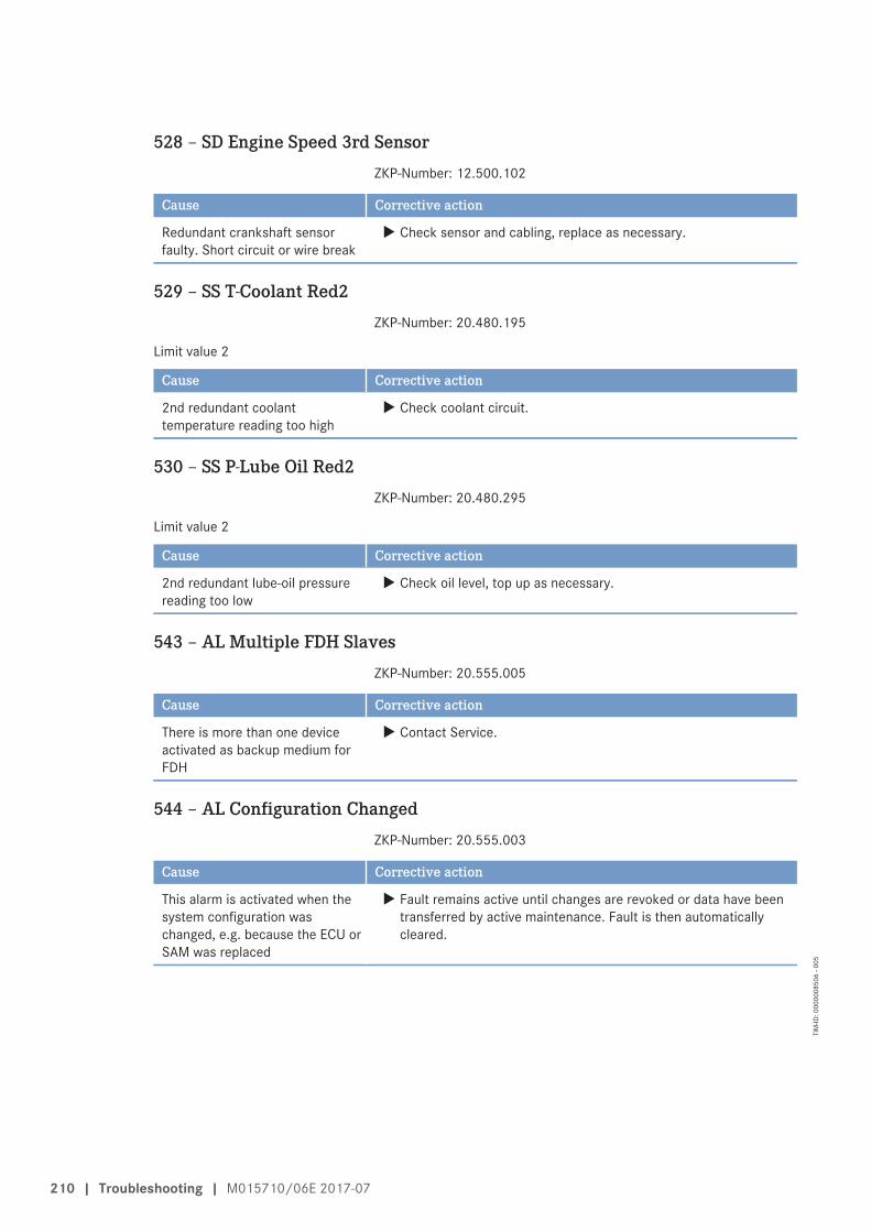
528 – SD Engine Speed 3rd SensorZKP-Number: 12.500.102
Cause Corrective action
Redundant crankshaft sensorfaulty. Short circuit or wire break
u Check sensor and cabling, replace as necessary.
529 – SS T-Coolant Red2ZKP-Number: 20.480.195
Limit value 2
Cause Corrective action
2nd redundant coolanttemperature reading too high
u Check coolant circuit.
530 – SS P-Lube Oil Red2ZKP-Number: 20.480.295
Limit value 2
Cause Corrective action
2nd redundant lube-oil pressurereading too low
u Check oil level, top up as necessary.
543 – AL Multiple FDH SlavesZKP-Number: 20.555.005
Cause Corrective action
There is more than one deviceactivated as backup medium forFDH
u Contact Service.
544 – AL Configuration ChangedZKP-Number: 20.555.003
Cause Corrective action
This alarm is activated when thesystem configuration waschanged, e.g. because the ECU orSAM was replaced
u Fault remains active until changes are revoked or data have beentransferred by active maintenance. Fault is then automaticallycleared.
210 | Troubleshooting | M015710/06E 2017-07
TIM
-ID: 0
0000
0850
6 - 0
05

549 – AL Power Cut-Off detectedZKP-Number: 27.001.952
This is an alarm from the emergency stop counter function.
Cause Corrective action
ECU operating voltage wasswitched off while the engine wasrunning. This can result inoverpressure in the high-pressuresystem, whereby the engine maybe damaged
u Instruct operators to switch off the power supply only after theengine has come to a standstill.
550 – SS Engine Overspeed Red2ZKP-Number: 20.480.095
Limit value 2
Cause Corrective action
Redundant engine overspeed 1. Acknowledge alarm.2. Attempt to restart engine.
551 – SS Engine Overspeed CamshaftZKP-Number: 22.510.933
Limit value 2
Cause Corrective action
Camshaft overspeed 1. Acknowledge alarm.2. Attempt to restart engine.
555 – AL Call MTU Field ServiceZKP-Number: 20.555.001
Cause Corrective action
This fault becomes active if amaintenance case has beenprocessed by the ECU Field DataHandling (FDH) feature thatresults in a change of engineparametersThis fault remains active evenafter switching off and back onuntil a valid enabling code isentered via the SAM display andkey controls. This enabling codecan be requested via the internetusing a special procedure
u Request enabling code via internet.
M015710/06E 2017-07 | Troubleshooting | 211
TIM
-ID: 0
0000
0850
6 - 0
05

576 – AL ESCM OverrideZKP-Number: 11.075.083
Cause Corrective action
Violation of corrected MCR orDBR/MCR curve. Engine overload!
u Reduce power.
577 – SD T-Lube Oil PanZKP-Number: 10.137.900
Cause Corrective action
Oil pan temperature sensor faulty.Short circuit or wire break
u Check sensor and cabling, replace as necessary.
578 – AL L1 T-Lube Oil PanZKP-Number: 20.137.921
Limit value 1
Cause Corrective action
L1 T-Lube oil in oil pan violatedlimit 1
u -
579 – AL MD CAN Request Idle SpeedZKP-Number: 21.063.511
Cause Corrective action
MD forced idle demand => nodefailure (node 3, 4 or 5)
u -
580 – AL MD CAN Speed LimitationZKP-Number: 21.063.513
Cause Corrective action
MD speed limitation demand =>node failure (node 3, 4 or 5)
u -
581 – AL MD CAN StopZKP-Number: 21.063.515
Cause Corrective action
MD CAN stop demand => nodefailure (node 3, 4 or 5)
u -
212 | Troubleshooting | M015710/06E 2017-07
TIM
-ID: 0
0000
0850
6 - 0
05

8 Task Description
8.1 Engine
8.1.1 Engine – Barring manually
PreconditionsEngine is stopped and starting disabled.
Special tools, Material, Spare partsDesignation / Use Part No. Qty.
Barring gear F6555766 1Ratchet with extension F30006212 1
DANGERRotating and moving engine parts.Risk of crushing, danger of parts of the body being caught or pulled in!• Before cranking the engine with starter system, make sure that there are no persons in the engine's
danger zone.
Barring engine manually1. Loosen screws (1) and remove end cover (2)
from flywheel housing.
M015710/06E 2017-07 | Task Description | 213
TIM
-ID: 0
0000
7659
3 - 0
01

2. Engage barring gear (2) in ring gear of fly-wheel and mount on flywheel housing.
3. Fit ratchet (1) on barring gear.
Note: No resistance other than compression resist-ance must be encountered.
4. Rotate crankshaft in engine direction of rota-tion.
Result: If the resistance exceeds the normal com-pression resistance, contact Service.
5. For barring gear removal follow reverse se-quence of working steps.
214 | Engine | M015710/06E 2017-07
TIM
-ID: 0
0000
7659
3 - 0
01

8.1.2 Engine – Turning on starting system
DANGERRotating and moving engine parts.Risk of crushing, danger of parts of the body being caught or pulled in!• Before barring the engine, make sure that there are no persons in the engine's danger zone.• After finishing work on the engine, make sure that all safety devices are put back in place and all
tools are removed from the engine.
Turning engine on starting system1. Release latch of connector X4.2. Remove connector from Engine Control Unit.3. Turn engine in unloaded condition: Press START button.4. Let the engine turn until oil pressure is indicated.5. Engine starting stops automatically when the max. admissible time has expired. Repeat this procedure after
approx. 20 seconds as necessary.6. Connect connector X4 to Engine Control Unit and latch in position.
M015710/06E 2017-07 | Engine | 215
TIM
-ID: 0
0000
0091
8 - 0
06

8.1.3 Engine – Test run
DANGERRotating and moving engine parts.Risk of crushing, danger of parts of the body being caught or pulled in!• Before cranking the engine with starter system, make sure that there are no persons in the engine's
danger zone.
WARNINGHigh level of engine noise when the engine is running.Risk of damage to hearing!• Wear ear protectors.
Engine – Test run1. Start engine (→ Page 149).2. Perform test run not below 1/3 load and at least until steady-state temperature is reached.3. Carry out operational checks (→ Page 152).4. Stop engine (→ Page 154).
216 | Engine | M015710/06E 2017-07
TIM
-ID: 0
0000
0087
0 - 0
08

8.2 Cylinder Liner
8.2.1 Cylinder liner – Endoscopic examination
PreconditionsEngine is stopped and starting disabled
Special tools, Material, Spare partsDesignation / Use Part No. Qty.
Barring tool F6555766 1Ratchet with extension F30006212 1Endoscope Y20097353 1
Preparatory steps1. Remove cylinder head cover (→ Page 235).2. Remove injector (→ Page 239).
Positioning crankshaft at BDC1. Using barring tool, turn crankshaft until crankshaft journal of the cylinder to be tested has reached BDC.2. Insert endoscope into cylinder liner through injector seat.
Endoscopic examination of cylinder linerFindings Measure• Thin carbon coating around carbon scraper ring• Slight localized additive deposits at top edge• Localized smooth areas at bottom edge• Carbon deposits on entire circumference between top piston ring and
bottom edge of carbon scraper ring• First signs of marks left by top piston ring• Bright mark on entire circumference• Faultless, even honing pattern• First signs of marks left by lower cooling bores• Running pattern seems darker
No actions required.
• Dark areas with even or varying degrees of discoloration• Beginning and end of the discoloration are not sharply defined and do
not cover the entire stroke area• Dark areas in the upper section of the cooling bore, remaining circum-
ference are faultless• Piston rings are faultless
Further endoscopic examina-tion required as part of mainte-nance work.
• On the entire circumference, apart from light areas of discoloration (donot impair operation) clearly darker stripes that start at the top pistonring
• Heat discoloration in the direction of stroke and honing pattern dam-age
• Heat discoloration of piston rings
Cylinder liner must be replaced,contact Service.
M015710/06E 2017-07 | Cylinder Liner | 217
TIM
-ID: 0
0000
0330
4 - 0
06

1. Compile endoscopic report using the table.2. Use technical terms to describe the liner surface (→ Page 219).3. Depending on findings:
• Do not take any action or• carry out a further endoscopic examination as part of maintenance work or• contact Service; cylinder liner must be replaced.
Final steps1. Install injector (→ Page 239).2. Install cylinder head cover (→ Page 235).
218 | Cylinder Liner | M015710/06E 2017-07
TIM
-ID: 0
0000
0330
4 - 0
06

8.2.2 Cylinder liner – Instructions and comments on endoscopic and visualexamination
Terms used for endoscopic examinationUse the terms listed below to describe the condition of the cylinder-liner surface in the endoscopic examina-tion report.
Findings Explanations/ActionMinor dirt scores Minor dirt scores can occur during the assembly of a new engine (honing products,
particles, broken-off burrs). Removed cylinders clearly show such scoring on therunning surface under endoscope magnification. Cannot be felt with the fingernail.Findings not critical
Single scores Clearly visible scores caused by hard particles. They usually start in the TDC areaand cross through the honing pattern in the direction of stroke.Findings not critical
Scored area These areas consist of scores of different length and depth next to one another. Inmost cases, they are found at the 6-o'clock and 12-o'clock positions (inlet/exhaust) along the transverse engine axis.Findings not critical
Polished area Polished areas are on the running surface but almost the whole honing pattern isstill visible. Polished areas appear brighter and more shiny than the surroundingrunning surface.Findings not critical
Bright area Bright areas are on the running surface and show local removal of the honing pat-tern. Grooves from the honing process are not visible any more.
Discoloration This is caused by oxidation (surface discoloration through oil or fuel) and tempera-ture differences around the liner. It appears rather darker within the honed struc-ture in contrast to the bright metallic running surface. The honing pattern is undis-turbed. Discolorations extend in stroke direction and may be interrupted.Findings not critical
Corrosion fields /spots
Corrosion fields / spots result from moisture (condensate) with the valves in theoverlap (open) position. They are clearly visible due to the dark color of the honinggroove bottom.This corrosion is not critical unless there is corrosion pitting.
Black lines Black lines are a preliminary stage of burn marks. They are visible as a clear discol-oration from TDC to BDC in the running surface and the start of localized damageto the honing pattern.Cylinder liners with a large number of black lines around the running surface havelimited service life and should be replaced.
Burn mark These are caused by a disturbance in the liner / ring tribo system. Usually they runover the whole ring-travel area (TDC/BDC), starting at the first TDC-ring and be-coming more visible from the second TDC-ring 2 onwards and less pronouncedfrom TDC-ring 1. The honing pattern is usually no longer visible and displays aclearly defined (straight) edge to the undisturbed surface. The damaged surface isusually discolored. The circumferential length varies.Liners with burn marks starting in TDC ring 1 have to be replaced.
Seizure marks, scuff-ing
Irregular circumference lengths and depths. Can be caused either by the pistonskirt or the piston crown. Material deposits on the liner (smear), heavy discolora-tion. Severe, visible scoring.Replace liner.
Table 3: Endoscopic examination – Terms used
M015710/06E 2017-07 | Cylinder Liner | 219
TIM
-ID: 0
0000
0001
4 - 0
16

Evaluation of findings and further measuresThe findings in the start phase of oxidation discoloration and burn marks are similar. A thorough investigationand compliance with the above evaluation criteria allow an unambiguous evaluation. To avoid unnecessarydisassembly work, it is recommended that another inspection be carried out after further operation of theengine.
220 | Cylinder Liner | M015710/06E 2017-07
TIM
-ID: 0
0000
0001
4 - 0
16

8.3 Crankcase Breather
8.3.1 Crankcase breather – Oil separator element replacement
PreconditionsEngine is stopped and starting disabled.
Special tools, Material, Spare partsDesignation / Use Part No. Qty.
Torque wrench, 4–20 Nm F30044239 1Ratchet adapter F30027340 1Engine oilFilter element (→ Spare Parts Catalog)O-ring (→ Spare Parts Catalog)
WARNINGOil is hot.Oil can contain residue/substances which are harmful to health.Risk of injury and poisoning!• Allow the product to cool to below 50 °C before beginning work.• Wear protective clothing, protective gloves and goggles/safety mask.• Avoid contact with skin.• Do not inhale oil vapor.
Replacing oil separator element– Variant A
1. Remove securing screws (2) for cover (1)with screwdriver.
2. Remove cover (1) with O-ring.
M015710/06E 2017-07 | Crankcase Breather | 221
TIM
-ID: 0
0000
0091
9 - 0
06

3. Remove filter element (1) from housing (2).4. Insert new filter element in housing.5. Install cover with new O-ring.
6. Tighten cover screws to specified torque using a torque wrench.
Name Size Type Lubricant Value/Standard
Screw Tightening torque (Engine oil) 6 Nm +2 Nm
7. Replace further oil separator filter elements in the same way.
Replacing oil separator element– Variant B
1. Remove securing screws (2) for cover (1)with screwdriver.
2. Remove cover (1) and O-ring.
222 | Crankcase Breather | M015710/06E 2017-07
TIM
-ID: 0
0000
0091
9 - 0
06

3. Remove filter element (1) from oil separatorhousing (2).
4. Insert new filter element in housing.5. Install cover with new O-ring.
6. Tighten cover screws tighten to specified torque using a torque wrench.
Name Size Type Lubricant Value/Standard
Screw Tightening torque (Engine oil) 8 Nm +1 Nm
7. Replace further oil separator filter elements in the same way.
M015710/06E 2017-07 | Crankcase Breather | 223
TIM
-ID: 0
0000
0091
9 - 0
06

8.3.2 Crankcase breather – Filter element replacement
PreconditionsEngine is stopped and starting disabled.
Special tools, Material, Spare partsDesignation / Use Part No. Qty.
Torque wrench, 4–20 Nm F30044239 1Ratchet bit F30027340 1Assembly compound (Kluthe Hakuform 30-10) X00067260 1Engine oilFilter insert (→ Spare Parts Catalog) 3O-ring (→ Spare Parts Catalog) 3
WARNINGOil is hot.Oil can contain residue/substances which are harmful to health.Risk of injury and poisoning!• Allow the product to cool to below 50 °C before beginning work.• Wear protective clothing, protective gloves and goggles/safety mask.• Avoid contact with skin.• Do not inhale oil vapor.
Filter element – Replacement1. Release clamp (2) and remove hose (3) from
cover (1).2. Undo clamp (6) and remove cover (1).3. Remove air filter (5) with filter mounts (4).4. Remove O-ring (9) from adapter (8).5. Coat new O-ring (9) with assembly compound
and insert in groove on adapter (8).6. Insert filter holder (4) in correct position in
adapter (8).7. Place new air filter (5) in correct position on
filter holder (4).
Note: Angular position of air filter cover(→ Step 13).
8. Insert filter holder (4) in correct position incover (1) and mount cover (1).
9. Coat thread and nut mating face on clamp (6)with engine oil.
10. Tighten clamp (6) to specified tightening torque.
Name Size Type Lubricant Value/Standard
Clamp Tightening torque (Engine oil) 9 Nm +1 Nm
11. Install hose (3) and tighten clamp (2) with torque wrench to the specified torque.
Name Size Type Lubricant Value/Standard
Clamp Tightening torque 5 Nm +1 Nm
12. Replace other oil separator filter elements in the same way.
224 | Crankcase Breather | M015710/06E 2017-07
TIM
-ID: 0
0000
7748
2 - 0
01
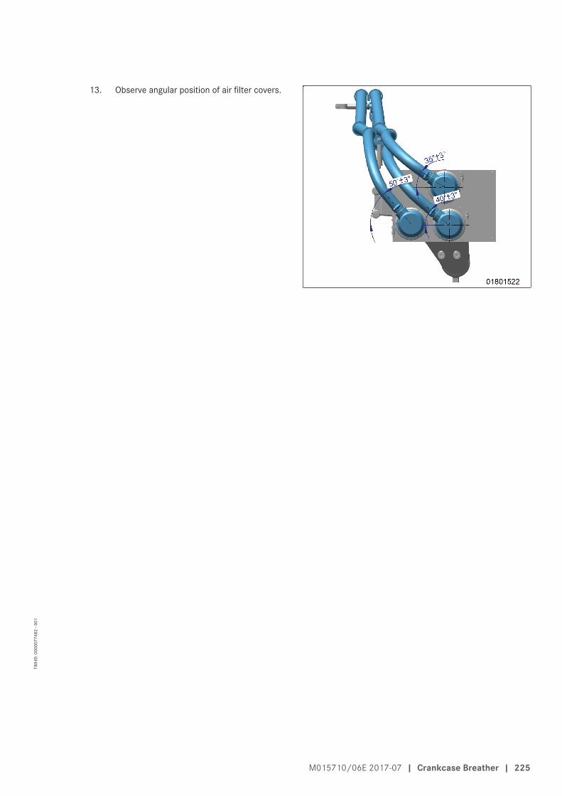
13. Observe angular position of air filter covers.
M015710/06E 2017-07 | Crankcase Breather | 225
TIM
-ID: 0
0000
7748
2 - 0
01

8.4 Valve Drive
8.4.1 Valve protrusion – Measurement
PreconditionsEngine is stopped and starting disabled.
Special tools, Material, Spare partsDesignation / Use Part No. Qty.
Measuring jig 1 Y4350009 1Depth gage, 200 mm Y20000918 1Measuring jig 2, optional Y4350010 1
Preparatory steps1. Remove cylinder head covers (→ Page 235).2. Install barring tool (→ Page 213).
3. Turn crankshaft in direction of rotation usingbarring tool until TDC mark (1) and pointer (2)are aligned.
Calibrating measuring jigs 1 and2
1. Place measuring unit (2) on calibrationplate (3).
226 | Valve Drive | M015710/06E 2017-07
TIM
-ID: 0
0000
4559
3 - 0
10

2. Turn measuring unit screws (1) into the threads and tighten to specified torque using a torque wrench.
Name Size Type Lubricant Value/Standard
Screw M10 Tightening torque 20 Nm
3. Set all dial gages to 0.4. Unscrew measuring unit (2) from calibration plate (3).
Step 1: Measure valve protrusion at the valve head with measuring jig 11. Check TDC position of piston in cylinder A1:
• If rocker arms on cylinder A1 are unloaded, the piston is in firing TDC.• If rocker arms on cylinder A1 are loaded, the piston is in overlap TDC.
2. Measure valve stem end to cylinder head top distance for each valve in two crankshaft positions (firing TDCand overlap TDC) according to the diagram. Diagram (→ Page 231).
3. Place measuring unit 1 (2) on the cylinderhead (3).
4. Turn measuring unit screws (1) into the threads provided for the cylinder head cover and tighten to specifiedtorque using a torque wrench.
Name Size Type Lubricant Value/Standard
Screw M10 Tightening torque 20 Nm
5. Determine the values with all dial gages.• The valve protrusion value must be ≤ 1.5 mm.• If the value is > 1.5 mm, measure with a depth gage or optionally with measuring jig 2.
6. Unscrew measuring unit (2) from cylinder head (3).
Step 2: Measure valve protrusion at the valve stem with a depth gage1. Check TDC position of piston in cylinder A1:
• If rocker arms on cylinder A1 are unloaded, the piston is in firing TDC.• If rocker arms on cylinder A1 are loaded, the piston is in overlap TDC.
2. Measure valve stem end to cylinder head top distance for each valve in two crankshaft positions (firing TDCand overlap TDC) according to the diagram. Diagram (→ Page 231).
M015710/06E 2017-07 | Valve Drive | 227
TIM
-ID: 0
0000
4559
3 - 0
10

3. Release adjusting screw (1) and remove valvebridge. Do not remove rocker arm (2).
4. Measure distance (A) between valve stemend and cylinder head top at the injectorbore with depth gage.• The specified value for a new cylinder
head: 93.8 mm.• Admissible wear: 2 mm.• Have the affected cylinder head replaced
by expert personnel ahead of schedule ifthe measured value is > 95.8 mm.
5. Install valve bridge.6. Adjusting valve clearance (→ Page 231)
Step 2 optional: Measure valve protrusion at the valve stem with measuringjig 2
1. Check TDC position of piston in cylinder A1:• If rocker arms on cylinder A1 are unloaded, the piston is in firing TDC.• If rocker arms on cylinder A1 are loaded, the piston is in overlap TDC.
2. Measure valve stem end to cylinder head top distance for each valve in two crankshaft positions (firing TDCand overlap TDC) according to the diagram. Diagram (→ Page 231).
228 | Valve Drive | M015710/06E 2017-07
TIM
-ID: 0
0000
4559
3 - 0
10

Note: Do not remove rocker arm (2).3. Release adjusting screw (1) and remove valve
bridge.
4. Place measuring unit 2 (2) on the cylinderhead (3).
5. Turn measuring unit screws (1) into the threads provided for the cylinder head cover and tighten to specifiedtorque using a torque wrench.
Name Size Type Lubricant Value/Standard
Screw M10 Tightening torque 20 Nm
6. Determine the values with all dial gages.• The valve protrusion value must be ≤ 2 mm.• Have the affected cylinder head replaced by expert personnel if the value is > 2 mm.
7. Unscrew measuring unit (2) from cylinder head (3).8. Install valve bridge.9. Adjusting valve clearance (→ Page 231)
Final steps1. Remove barring tool (→ Page 213).2. Install cylinder head cover (→ Page 235).
M015710/06E 2017-07 | Valve Drive | 229
TIM
-ID: 0
0000
4559
3 - 0
10
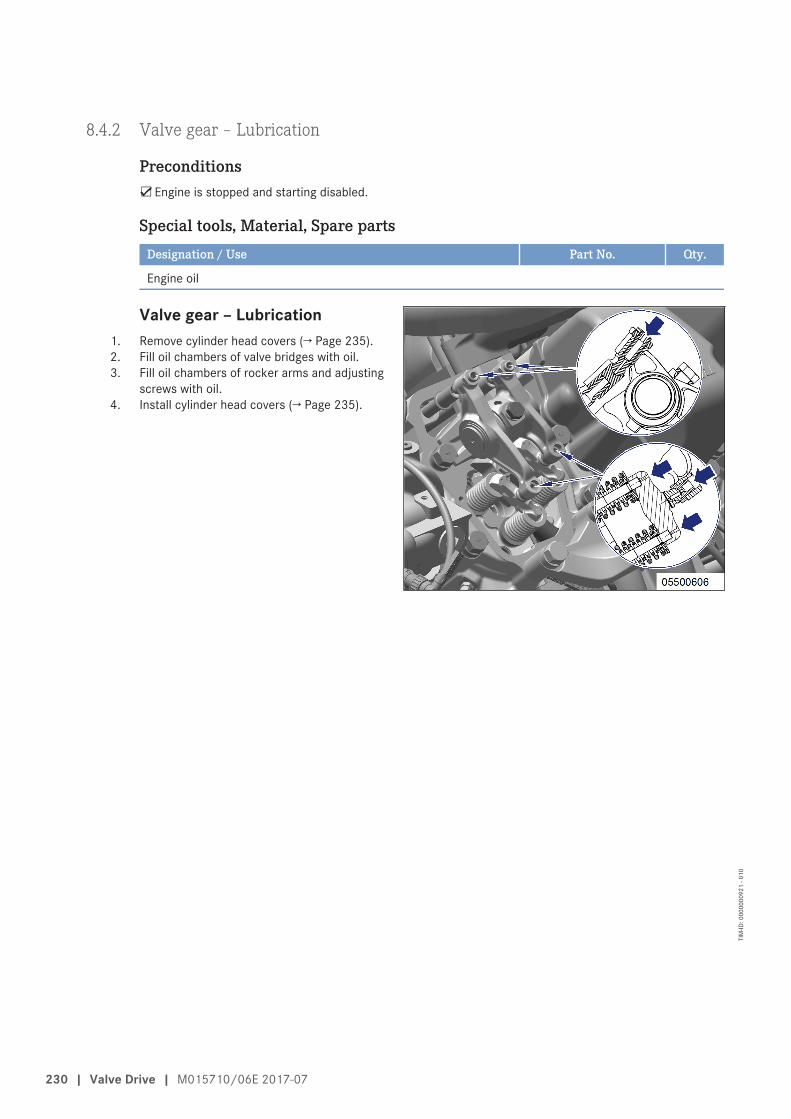
8.4.2 Valve gear – Lubrication
PreconditionsEngine is stopped and starting disabled.
Special tools, Material, Spare partsDesignation / Use Part No. Qty.
Engine oil
Valve gear – Lubrication1. Remove cylinder head covers (→ Page 235).2. Fill oil chambers of valve bridges with oil.3. Fill oil chambers of rocker arms and adjusting
screws with oil.4. Install cylinder head covers (→ Page 235).
230 | Valve Drive | M015710/06E 2017-07
TIM
-ID: 0
0000
0092
1 - 0
10

8.4.3 Valve clearance – Check and adjustment
PreconditionsEngine is stopped and starting disabled.
Engine coolant temperature is max. 40 °C.
Valves are closed.
Special tools, Material, Spare partsDesignation / Use Part No. Qty.
Feeler gage Y20098771 1Valve setting gauge Y4349603 1Angular screw driver F30002815 1Torque wrench, 60–320 Nm F30452768 1Socket wrench, 24 mm F30039526 1Engine oil
Preparatory steps1. Remove cylinder head covers (→ Page 235).2. Install barring device (→ Page 213).
Note: Pointer (1) is located in the lower opening ofthe flywheel housing (arrow).
3. Use barring device to turn crankshaft in di-rection of rotation until marking OT/A1 onthe rear side of the flywheel housing andpointer (1) are aligned.
M015710/06E 2017-07 | Valve Drive | 231
TIM
-ID: 0
0000
0092
2 - 0
15
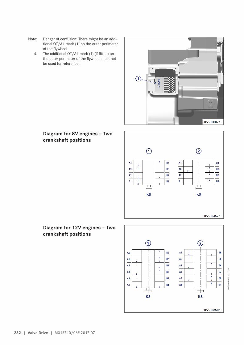
Note: Danger of confusion: There might be an addi-tional OT/A1 mark (1) on the outer perimeterof the flywheel.
4. The additional OT/A1 mark (1) (if fitted) onthe outer perimeter of the flywheel must notbe used for reference.
Diagram for 8V engines – Twocrankshaft positions
Diagram for 12V engines – Twocrankshaft positions
232 | Valve Drive | M015710/06E 2017-07
TIM
-ID: 0
0000
0092
2 - 0
15

Diagram for 16V engines – Twocrankshaft positions
Diagram for 20V engines – Twocrankshaft positions
Checking valve clearance at two crankshaft positions1. Check TDC position of piston in cylinder A1:
• If the rocker arms are unloaded on cylinder A1, the piston is in firing TDC.• If the rocker arms are under load on cylinder A1, the piston is in overlap TDC.
2. Check valve clearance adjustment with cold engine:• Inlet valves (long rocker arm) = 0.2 mm ±0.05 mm• Exhaust valves (short rocker arm) = 0.5 mm ±0.05 mm
3. Check all valve clearances in two crankshaft positions (firing TDC and overlap TDC of cylinder A1) as perdiagram:
1 Cylinder A1 is in firing TDC2 Cylinder A1 is in overlap TDCI Inlet valve
X Exhaust valve4. Use valve setting gauge or feeler gauge to determine the distance between valve bridge and rocker arm.5. If the deviation from the set value exceeds 0.1 mm, adjust valve clearance.
M015710/06E 2017-07 | Valve Drive | 233
TIM
-ID: 0
0000
0092
2 - 0
15

Adjusting valve clearance1. Release locknut (1).2. Insert valve setting gauge (3) between valve
bridge and rocker arm.
Note: Replace or rectify adjusting screws and/orlocknuts which do not move freely.
3. Using angular screw driver, set adjustingscrew (2) so that the specified valve clear-ance is provided.
Note: Valve setting gauge must just pass throughthe gap.
4. Pass valve setting gauge (3) between valvebridge and rocker arm.
5. Tighten locknut (1) with torque wrench to the specified tightening torque, holding the adjusting screw (2) toprevent it from turning.
Name Size Type Lubricant Value/Standard
Locknut M16x1.5 Tightening torque (Engine oil) 90 Nm +9 Nm
6. Check valve clearance, adjust if necessary.
Final steps1. Remove barring device (→ Page 213).2. Install cylinder head covers (→ Page 235).
234 | Valve Drive | M015710/06E 2017-07
TIM
-ID: 0
0000
0092
2 - 0
15

8.4.4 Cylinder head cover – Removal and installation
PreconditionsEngine is stopped and starting disabled.
Special tools, Material, Spare partsDesignation / Use Part No. Qty.
Assembly compound (Kluthe Hakuform 30-15) X00067260 1O-ring (→ Spare Parts Catalog)
Removing cylinder head cover1. Clean very dirty cylinder head covers (1) prior
to removal.2. Remove screws (3, 4) with washers (2, 5).3. Take off cylinder head cover with O-ring (6)
from cylinder head (7).
Installing cylinder head cover1. Clean installation surface.2. Check O-ring (6) for damage, replace as necessary.3. Coat O-ring with assembly compound.4. Insert O-ring in groove on cylinder head cover (1).5. Fit cylinder head cover on cylinder head (7).6. Install cylinder head cover with screws (3, 4) and washers (2, 5).
M015710/06E 2017-07 | Valve Drive | 235
TIM
-ID: 0
0000
1230
9 - 0
15

8.5 Injection Pump / HP Pump
8.5.1 HP fuel pump – Filling with engine oil
PreconditionsEngine is stopped and starting disabled.
Special tools, Material, Spare partsDesignation / Use Part No. Qty.
Torque wrench, 10–60 Nm F30452769 1Fuel suction device F30378207 1Engine oil
WARNINGFuels are combustible and explosive.Risk of fire and explosion!• Avoid open flames, electrical sparks and ignition sources.• Do not smoke.• Wear protective clothing, protective gloves, and safety glasses / facial protection.
WARNINGLiquid or gaseous media, e.g. fuel, are poisonous.Escaping vapors of highly volatile media, e.g. fuel or ether.Risk of fatal injury through swallowing; risk of poisoning through inhalation; irritation to eyesand skin!• Seek medical attention immediately; do not induce vomiting.• Do not inhale vapors or mist.• Wear protective clothing, protective gloves, and safety glasses.• If contact is made with skin, wash off with water and soap.
WARNINGOils/oil vapors are combustible/explosive.Risk of fire and explosion!• Avoid open flames, electric sparks and ignition sources.• Do not smoke.
NOTICEHP fuel pump not filled with engine oil.Damage to components, major material damage!• Ensure that th HP fuel pump is filled with engine oil before it is installed or put into operation.
NOTICEContaminated components.Risk of damage to component!• Check components for special cleanliness and clean if necessary.
236 | Injection Pump / HP Pump | M015710/06E 2017-07
TIM
-ID: 0
0000
0164
0 - 0
16

Preparatory stepsu Loosen nut (2) and remove oil line (1) from
HP pump.
HP pump – Filling1. Remove union (1).
Note: Excess engine oil runs into gear box.2. Use fuel suction device to fill HP pump with
2 liters of clean engine oil.
3. Screw in union (1) and use torque wrench to tighten to specified tightening torque.
Name Size Type Lubricant Value/Standard
Neck M16x1.5 Tightening torque 40 Nm
Final stepsu Install oil line.
M015710/06E 2017-07 | Injection Pump / HP Pump | 237
TIM
-ID: 0
0000
0164
0 - 0
16

8.6 Injector
8.6.1 Injector – Replacement
Special tools, Material, Spare partsDesignation / Use Part No. Qty.
Injector (→ Spare Parts Catalog)
Injector – Replacementu Remove injector and install new one (→ Page 239).
238 | Injector | M015710/06E 2017-07
TIM
-ID: 0
0000
4232
9 - 0
02

8.6.2 Injector – Removal and installation
PreconditionsEngine is stopped and starting disabled.
Special tools, Material, Spare partsDesignation / Use Part No. Qty.
Installation/removal device F6789889 1Milling cutter F30452739 1Torque screwdriver, 1–5 Nm F30452774 1Torque wrench, 10–60 Nm F30452769 1Ratchet bit F30027340 1Torque wrench, 60–320 Nm F30452768 1Ratchet bit F30027341 1Assembly compound (Molykote P 37) 50564 1Assembly compound (Kluthe Hakuform 30-15) X00067260 1Multi-purpose grease 40320 1Engine oil
WARNINGFuels are combustible and explosive.Risk of fire and explosion!• Avoid open flames, electrical sparks and ignition sources.• Do not smoke.• Wear protective clothing, protective gloves, and safety glasses / facial protection.
WARNINGLiquid or gaseous media, e.g. fuel, are poisonous.Escaping vapors of highly volatile media, e.g. fuel or ether.Risk of fatal injury through swallowing; risk of poisoning through inhalation; irritation to eyesand skin!• Seek medical attention immediately; do not induce vomiting.• Do not inhale vapors or mist.• Wear protective clothing, protective gloves, and safety glasses.• If contact is made with skin, wash off with water and soap.
WARNINGHot components/surfaces.Risk of burns!• Allow the engine to cool down to below 50 °C before beginning work.• Wear suitable protective equipment/thermal gloves.• Avoid unprotected contact with hot surfaces.
WARNINGInternal tension and residual pressure in the HP fuel system.Parts can be ejected when loosening them.Risk of injury by ejected parts!• Only use specified tools and devices.• Wear goggles/facial protection.
M015710/06E 2017-07 | Injector | 239
TIM
-ID: 0
0000
7748
4 - 0
01

NOTICEContamination of components.Damage to component!• Observe manufacturer's instructions.• Check components for special cleanliness.
Preparatory steps1. Allow HP system to cool down.2. Shut off fuel supply to engine.3. Remove cylinder head cover (→ Page 235).
Removing injector1. Disconnect cable connector at injector (ar-
row).
Note: Be aware of system pressure.2. Slowly loosen union on HP line (4).3. Remove HP fuel line (4).
Note: When the adapter is unscrewed, the storedvolume of the injector is drained.
4. Remove adapter (3).5. Remove screw (2) and take off hold-down
clamp (1).
240 | Injector | M015710/06E 2017-07
TIM
-ID: 0
0000
7748
4 - 0
01

6. Install installation/removal tool on the cylin-der head.
7. Remove injector with installation/removaltool.
8. Remove the installation/removal tool.
9. Remove sealing ring (4) from injector or use aself-made wire hook or magnet to take it outof the cylinder head.
Note: The sealing ring (4) for sealing the combus-tion chamber must only be used once.
10. Dispose of sealing ring (4) and injector.11. Clean all mating and sealing surfaces.12. Cover all connections and bores, or seal with
suitable plugs.
Installing new injectorNote: • The new sealing ring is included in the
scope of supply of the injector.• A multi-purpose grease without solids
must be used.1. Install new sealing ring (1) abutted to (Multi-
purpose grease) and ensure that the installa-tion position is correct.
M015710/06E 2017-07 | Injector | 241
TIM
-ID: 0
0000
7748
4 - 0
01

Note: Remove plugs on HP line only before installa-tion of the adapter.
2. Remove plug.3. Use milling cutter to remove oil carbon from
sealing face on cylinder head and protectivesleeve.
4. Coat damper ring (1) with (Assembly com-pound (Molykote P 37)).
5. Coat O-rings (3) and (2) with (Assembly com-pound (Kluthe Hakuform 30-15)).
Note: Make sure that the sealing ring does not fallinto the water sleeve.
6. Ensure that the sealing ring (4) is correctlyseated.
7. Insert injector into cylinder head, ensuringthat the HP line connection is correctlyaligned.
8. Press in injector with installation/removal de-vice.
9. Remove installation/removal device.
10. Coat screw mating face (2) and thread withengine oil.
11. Fit hold-down clamp (1) in correct position, fitscrew (2) and tighten by hand.
Note: Make sure parts are perfectly clean.12. Apply engine oil to thread, sealing taper and
thrust ring of adapter (3).13. Apply (Assembly compound (Kluthe Haku-
form 30-15)) to O-rings on adapter (3).14. Install adapter (3).
242 | Injector | M015710/06E 2017-07
TIM
-ID: 0
0000
7748
4 - 0
01

15. Tighten screw (2) with torque wrench to the specified tightening torque.
Name Size Type Lubricant Value/Standard
Screw M12 Tightening torque (Engine oil) 100 Nm+10 Nm
16. Tighten adapter (3) to specified torque using a torque wrench.
Name Size Type Lubricant Value/Standard
Adapter Tightening torque (Engine oil) 100 Nm+10 Nm
Installing HP lines (single-walled HP system)Note: Make sure parts are perfectly clean.
1. Coat thread, sealing cone and thrust ring of HP line (5) with engine oil.2. Coat jacket surface in area of union nut to rail (6) with engine oil.3. Thread in HP line (5), ensuring that the sealing areas are not damage.4. Tighten union nuts (4) and (6) as far as possible by hand.
5. Use torque wrench to tighten HP line (5) according following to tightening sequence to the specified torque.1 Adapter (4)2 Rail (6)
Name Size Type Lubricant Value/Standard
Union nut / thrustscrew
Preload torque (Engine oil) 4 Nm +2 Nm
Note: Holding firmly with hand is not admitted.6. Tighten HP line (5) in the same tightening sequence to specified final tightening torque.
1 Adapter (4)2 Rail (6)
Name Size Type Lubricant Value/Standard
Union nut / thrustscrew
Tightening torque (Engine oil) 30 Nm +5 Nm
Installing HP lines (double-walled HP system)Note: Make sure parts are perfectly clean.
1. Coat thread, sealing cone and thrust ring of HP line (5) with engine oil.2. Coat O-rings with (Assembly compound (Kluthe Hakuform 30-15)).3. Thread in HP line (5), ensuring that the sealing areas are not damage.
4. Use torque wrench to tighten HP line (5) according following to tightening sequence to specified tighteningtorque.
1 Adapter (4)2 Rail (6)
Name Size Type Lubricant Value/Standard
Union nut / thrustscrew
Tightening torque (Engine oil) 40 Nm +5 Nm
M015710/06E 2017-07 | Injector | 243
TIM
-ID: 0
0000
7748
4 - 0
01

Note: Holding firmly with hand is not admitted.5. Loosen union nuts (4) and (6) by approx. 45° angle of rotation and tighten immediately again to the specified
tightening torque following the same sequence.1 Adapter (4)2 Rail (6)
Name Size Type Lubricant Value/Standard
Union nut / thrustscrew
Tightening torque (Engine oil) 40 Nm +5 Nm
1. Fit cable connector on injector.
Note: Failure to reset drift compensation (CDC) willvoid the emissions certification of the engine.
2. Reset drift compensation (CDC) with Dia-Sys® (→ Dialog system DiaSys®E531920/..). If DiaSys® is not available, con-tact Service.
Final steps1. Install cylinder head cover (→ Page 235).2. Open fuel supply to engine.
244 | Injector | M015710/06E 2017-07
TIM
-ID: 0
0000
7748
4 - 0
01

8.7 Fuel System
8.7.1 Fuel system – Venting
PreconditionsEngine is stopped and starting disabled.
Special tools, Material, Spare partsDesignation / Use Part No. Qty.
Diesel fuel
WARNINGFuels are combustible and explosive.Risk of fire and explosion!• Avoid open flames, electrical sparks and ignition sources.• Do not smoke.• Wear protective clothing, protective gloves, and safety glasses / facial protection.
WARNINGLiquid or gaseous media, e.g. fuel, are poisonous.Escaping vapors of highly volatile media, e.g. fuel or ether.Risk of fatal injury through swallowing; risk of poisoning through inhalation; irritation to eyesand skin!• Seek medical attention immediately; do not induce vomiting.• Do not inhale vapors or mist.• Wear protective clothing, protective gloves, and safety glasses.• If contact is made with skin, wash off with water and soap.
Venting LP fuel system1. Open vent plug (1).2. Unlock fuel priming pump (2), screw out han-
dle by turning it counterclockwise.3. Operate the pump with the handle (2) until
bubble-free fuel emerges from the ventplug (1).
4. Close vent plug (1).5. Screw in handle by turning it clockwise.6. Verify that fuel priming pump (2) is locked:
Handle must be tightened.
M015710/06E 2017-07 | Fuel System | 245
TIM
-ID: 0
0000
0092
6 - 0
07

8.8 Fuel Filter
8.8.1 Fuel filter – Replacement
PreconditionsEngine is stopped and starting disabled.
Special tools, Material, Spare partsDesignation / Use Part No. Qty.
Filter wrench F30379104 1Engine oilEasy-change filter (→ Spare Parts Catalog)
WARNINGFuels are combustible and explosive.Risk of fire and explosion!• Avoid open flames, electrical sparks and ignition sources.• Do not smoke.• Wear protective clothing, protective gloves, and safety glasses / facial protection.
WARNINGLiquid or gaseous media, e.g. fuel, are poisonous.Escaping vapors of highly volatile media, e.g. fuel or ether.Risk of fatal injury through swallowing; risk of poisoning through inhalation; irritation to eyesand skin!• Seek medical attention immediately; do not induce vomiting.• Do not inhale vapors or mist.• Wear protective clothing, protective gloves, and safety glasses.• If contact is made with skin, wash off with water and soap.
Fuel filter – Replacement1. Remove easy-change filter using the filter
wrench.2. Clean sealing surface on filter head.3. Slightly lubricate seal on the easy-change fil-
ter (arrow).4. Screw on the easy-change filter by hand until
the seal makes contact and tighten finger-tight.
5. Replace further easy-change filters in thesame way.
6. Vent fuel system (→ Page 245).
246 | Fuel Filter | M015710/06E 2017-07
TIM
-ID: 0
0000
0092
7 - 0
10

8.8.2 Fuel prefilter – Pressure ratios
WARNINGLiquid or gaseous media, e.g. fuel, are poisonous.Escaping vapors of highly volatile media, e.g. fuel or ether.Risk of fatal injury through swallowing; risk of poisoning through inhalation; irritation to eyesand skin!• Seek medical attention immediately; do not induce vomiting.• Do not inhale vapors or mist.• Wear protective clothing, protective gloves, and safety glasses.• If contact is made with skin, wash off with water and soap.
Pressure ratiosNote: • If the fuel prefilter is above the full level of the fuel tank, during engine operation the fuel pressure in the
filter is lower than ambient pressure (vacuum).• If the fuel prefilter is below the empty level of the fuel tank, during engine operation the fuel pressure in
the filter is higher than ambient pressure (overpressure).In the case of overpressure, fuel can escape under pressure.
u The pressure ratios shown be known from commissioning. Pressure ratios can be checked with the engineshut down.
Checking pressure ratios1. Stop engine and disable engine start.
2. Carefully open threaded vent plug (1) slightly:Result: • If no fuel emerges, this is an indication of
vacuum or pressure balance.• If fuel emerges, this is a sign of overpres-
sure.3. Collect fuel as it emerges.
M015710/06E 2017-07 | Fuel Filter | 247
TIM
-ID: 0
0000
6672
6 - 0
02

8.8.3 Fuel prefilter (non-switchable) – Draining
DANGERComponents are moving or rotating.Risk of crushing, danger of parts of the body being caught or pulled in!• Operate the engine at low load only. Keep clear of the danger zone of the engine.
WARNINGFuels are combustible and explosive.Risk of fire and explosion!• Avoid open flames, electrical sparks and ignition sources.• Do not smoke.• Wear protective clothing, protective gloves, and safety glasses / facial protection.
WARNINGLiquid or gaseous media, e.g. fuel, are poisonous.Escaping vapors of highly volatile media, e.g. fuel or ether.Risk of fatal injury through swallowing; risk of poisoning through inhalation; irritation to eyesand skin!• Seek medical attention immediately; do not induce vomiting.• Do not inhale vapors or mist.• Wear protective clothing, protective gloves, and safety glasses.• If contact is made with skin, wash off with water and soap.
WARNINGHigh level of engine noise when the engine is running.Risk of damage to hearing!• Wear ear protectors.
WARNINGFuel in the prefilter can be pressurized.Risk of injury through spraying fuel!• Wear protective gloves and eye protectors/safety mask.• Open screw-coupling slowly.
Preparatory stepsu Pressure ratios in the fuel prefilter, see (→ Page 247).
• In case of low pressure, drain fuel prefilter according to version A, see (→ Page 248).• In case of high pressure, drain fuel prefilter according to version B, see (→ Page 249).
Draining fuel prefilter with low pressure, version ANote: The fuel prefilter must only be drained with the engine at a standstill!
1. Provide a suitable container to collect the water.2. Stop engine and disable engine start.3. Close fuel supply if a shutoff valve is available.
248 | Fuel Filter | M015710/06E 2017-07
TIM
-ID: 0
0000
6642
8 - 0
03

4. Open threaded vent plug (1) of filter to beserviced.
5. Open drain screw (1).6. Allow water to drain.7. Close drain screw (2) again.8. Drain second filter on module, from
(→ Step 4).9. Open fuel supply.
10. Vent fuel prefilter (→ Page 259).
Draining fuel prefilter with highpressure, version B
Note: The fuel prefilter can be drained duringengine operation or with the engine at astandstill!
1. Provide a suitable container to collect the wa-ter.
2. Take care when opening drain screw (1) be-cause fuel or water can spurt out.
3. Allow water to drain.4. Close drain screw (2) again.
M015710/06E 2017-07 | Fuel Filter | 249
TIM
-ID: 0
0000
6642
8 - 0
03

8.8.4 Fuel prefilter (switchable) – Draining
DANGERComponents are moving or rotating.Risk of crushing, danger of parts of the body being caught or pulled in!• Operate the engine at low load only. Keep clear of the danger zone of the engine.
WARNINGFuels are combustible and explosive.Risk of fire and explosion!• Avoid open flames, electrical sparks and ignition sources.• Do not smoke.• Wear protective clothing, protective gloves, and safety glasses / facial protection.
WARNINGLiquid or gaseous media, e.g. fuel, are poisonous.Escaping vapors of highly volatile media, e.g. fuel or ether.Risk of fatal injury through swallowing; risk of poisoning through inhalation; irritation to eyesand skin!• Seek medical attention immediately; do not induce vomiting.• Do not inhale vapors or mist.• Wear protective clothing, protective gloves, and safety glasses.• If contact is made with skin, wash off with water and soap.
WARNINGHigh level of engine noise when the engine is running.Risk of damage to hearing!• Wear ear protectors.
WARNINGFuel in the prefilter can be pressurized.Risk of injury through spraying fuel!• Wear protective gloves and eye protectors/safety mask.• Open screw-coupling slowly.
Preparatory stepsu Pressure ratios in the fuel prefilter, see (→ Page 247).
• In case of low pressure, drain fuel prefilter according to version A, see (→ Page 250).• In case of high pressure, drain fuel prefilter according to version B, see (→ Page 252).
Draining fuel prefilter with low pressure, version ANote: • During engine operation, only the cut-out filter module must be drained!
• At engine standstill, both filter modules can be drained!1. Provide a suitable container to collect the water.
250 | Fuel Filter | M015710/06E 2017-07
TIM
-ID: 0
0000
6639
3 - 0
03

2. During engine operation, turn the switchoverlevel as far as the stop (arrow) to cut out thefilter module to be serviced.
Result: • Filter module (1) is cut in• Filter module (2) is cut out
3. Open threaded vent plug (1) of filter to beserviced.
4. Open drain screw (1).5. Allow water to drain.6. Close drain screw (2) again.7. Drain the second filter on the module to be
serviced, from (→ Step 3).8. Vent fuel prefilter (→ Page 259).
M015710/06E 2017-07 | Fuel Filter | 251
TIM
-ID: 0
0000
6639
3 - 0
03

Draining fuel prefilter with high pressure, version BNote: The filter modules can be drained without switchover during engine operation and at engine stand-
still!1. Provide a suitable container to collect the water.
2. Take care when opening drain screw (1) be-cause fuel or water can spurt out.
3. Allow water to drain.4. Close drain screw (2) again.
252 | Fuel Filter | M015710/06E 2017-07
TIM
-ID: 0
0000
6639
3 - 0
03

8.8.5 Fuel prefilter (switchable) – Contamination indicator check
Contamination indicator onswitchable fuel prefilter
1. Check contamination indicator at low pres-sure gage (3):• Red zone (1): -1.0 bar to -0.4 bar (low
pressure)• Green zone (2): -0.4 bar to +0.5 bar (nor-
mal operation)2. Switch over the fuel prefilter or replace a fil-
ter element (→ Page 256) when the low pres-sure gage (3) indicates minimum admissiblefuel pressure during operation (1) .
M015710/06E 2017-07 | Fuel Filter | 253
TIM
-ID: 0
0000
7406
4 - 0
01

8.8.6 Fuel prefilter (non-switchable) – Filter element replacement
Special tools, Material, Spare partsDesignation / Use Part No. Qty.
Torque wrench, 6–50 Nm F30027336 1Ratchet adapter F30027340 1Diesel fuelFilter parts kit (→ Spare Parts Catalog)
WARNINGFuels are combustible and explosive.Risk of fire and explosion!• Avoid open flames, electrical sparks and ignition sources.• Do not smoke.• Wear protective clothing, protective gloves, and safety glasses / facial protection.
WARNINGLiquid or gaseous media, e.g. fuel, are poisonous.Escaping vapors of highly volatile media, e.g. fuel or ether.Risk of fatal injury through swallowing; risk of poisoning through inhalation; irritation to eyesand skin!• Seek medical attention immediately; do not induce vomiting.• Do not inhale vapors or mist.• Wear protective clothing, protective gloves, and safety glasses.• If contact is made with skin, wash off with water and soap.
WARNINGFuel in the prefilter can be pressurized.Risk of injury through spraying fuel!• Wear protective gloves and eye protectors/safety mask.• Open screw-coupling slowly.
Preparatory stepsu Pressure ratios in the fuel prefilter, see (→ Page 247).
Replacing filter elementNote: The filter element on the fuel prefilter must only be changed with the engine at a standstill!
1. Provide a suitable container in which to collect the fuel.2. Stop engine and disable engine start.3. Close fuel supply if a shutoff valve is available.
254 | Fuel Filter | M015710/06E 2017-07
TIM
-ID: 0
0000
6639
5 - 0
03

4. Open threaded vent plug and ensure that fueldoes not emerge continuously.
Result: The filter can now be changed!5. If fuel emerges continuously, check shutoff
valve in fuel supply, notify Service.
Note: • As soon as the filter housing is opened,absolute cleanness is imperative!
• Carefully extract the filter element straightup avoiding contact with the upper edge ofthe cylinder if at all possible to preventcontamination of the fuel remaining in thefilter housing.
6. Unscrew filter cover (1) and withdraw with fil-ter element (3) from filter housing (4).
7. Unclip filter element (3) from filter cover (1).8. Install new O-ring (2) on filter cover (1).9. Coat new O-rings on filter cover and filter ele-
ment with fuel.10. Clip new filter element (3) into filter cover (1).11. Screw filter cover (1) into filter housing.
Result: Filter cover (1) must lie flat on the housing(4).
12. Tighten filter cover (1) with torque wrench to the specified tightening torque.
Name Size Type Lubricant Value/Standard
Filter cover Tightening torque 40 Nm
13. Replace second filter element in the same manner.14. Open fuel supply.15. Vent fuel prefilter (→ Page 259).16. Check fuel prefilter for leaks.
M015710/06E 2017-07 | Fuel Filter | 255
TIM
-ID: 0
0000
6639
5 - 0
03

8.8.7 Fuel prefilter (switchable) – Filter element replacement
Special tools, Material, Spare partsDesignation / Use Part No. Qty.
Torque wrench, 6–50 Nm F30027336 1Ratchet adapter F30027340 1Diesel fuelFilter parts kit (→ Spare Parts Catalog)
DANGERComponents are moving or rotating.Risk of crushing, danger of parts of the body being caught or pulled in!• Operate the engine at low load only. Keep clear of the danger zone of the engine.
WARNINGFuels are combustible and explosive.Risk of fire and explosion!• Avoid open flames, electrical sparks and ignition sources.• Do not smoke.• Wear protective clothing, protective gloves, and safety glasses / facial protection.
WARNINGLiquid or gaseous media, e.g. fuel, are poisonous.Escaping vapors of highly volatile media, e.g. fuel or ether.Risk of fatal injury through swallowing; risk of poisoning through inhalation; irritation to eyesand skin!• Seek medical attention immediately; do not induce vomiting.• Do not inhale vapors or mist.• Wear protective clothing, protective gloves, and safety glasses.• If contact is made with skin, wash off with water and soap.
WARNINGHigh level of engine noise when the engine is running.Risk of damage to hearing!• Wear ear protectors.
WARNINGFuel in the prefilter can be pressurized.Risk of injury through spraying fuel!• Wear protective gloves and eye protectors/safety mask.• Open screw-coupling slowly.
Preparatory stepsu Pressure ratios in the fuel prefilter, see (→ Page 247).
• In case of low pressure, replace fuel prefilter according to version A, see (→ Page 256).• In case of high pressure, replace fuel prefilter according to version B, see (→ Page 257).
Replacing fuel prefilter with low pressure, version ANote: • During engine operation, the filter elements must only be replaced on the cut-out filter module!
• At engine standstill, the filter elements on both filter modules can be replaced!1. Provide a suitable container in which to collect the fuel.
256 | Fuel Filter | M015710/06E 2017-07
TIM
-ID: 0
0000
6643
1 - 0
03

2. During engine operation, turn the switchoverlevel as far as the stop (arrow) to cut out thefilter module to be serviced.
Result: • Filter module (1) is cut in• Filter module (2) is cut out
3. Check fuel level in filter.Result: If the fuel level is stable, the filter can be
changed!4. If the fuel level falls, the switchover point is
leaking. Screw on the filter cover again imme-diately and vent the filter (→ Page 259).Check the switchover point, contact Service.
Note: • As soon as the filter housing is opened,absolute cleanness is imperative!
• Carefully extract the filter element straightup avoiding contact with the upper edge ofthe cylinder if at all possible to preventcontamination of the fuel remaining in thefilter housing.
5. Unscrew filter cover (1) and withdraw with fil-ter element (3) from filter housing (4).
6. Unclip filter element (3) from filter cover (1).7. Install new O-ring (2) on filter cover (1).8. Coat new O-rings on filter cover and filter ele-
ment with fuel.9. Clip new filter element (3) into filter cover (1).
10. Screw filter cover (1) into filter housing.Result: Filter cover (1) must lie flat on the housing
(4).
11. Tighten filter cover (1) with torque wrench to the specified tightening torque.
Name Size Type Lubricant Value/Standard
Filter cover Tightening torque 40 Nm
12. Replace other filter elements in the same way.13. Vent fuel prefilter (→ Page 259).14. Check fuel prefilter for leaks.
Replacing fuel prefilter with high pressure, version BNote: The filter modules must only be replaced with the engine at a standstill!
1. Provide a suitable container in which to collect the fuel.2. Stop engine and disable engine start.3. Close fuel inlet.
M015710/06E 2017-07 | Fuel Filter | 257
TIM
-ID: 0
0000
6643
1 - 0
03

4. Open threaded vent plug and ensure that fueldoes not emerge continuously.
Result: The filter can now be changed!5. If fuel emerges continuously, check shutoff
valve in fuel supply, notify Service.
Note: • As soon as the filter housing is opened,absolute cleanness is imperative!
• Carefully extract the filter element straightup avoiding contact with the upper edge ofthe cylinder if at all possible to preventcontamination of the fuel remaining in thefilter housing.
6. Unscrew filter cover (1) and withdraw with fil-ter element (3) from filter housing (4).
7. Unclip filter element (3) from filter cover (1).8. Install new O-ring (2) on filter cover (1).9. Coat new O-rings on filter cover and filter ele-
ment with fuel.10. Clip new filter element (3) into filter cover (1).11. Screw filter cover (1) into filter housing.
Result: Filter cover (1) must lie flat on the housing(4).
12. Tighten filter cover (1) with torque wrench to the specified tightening torque.
Name Size Type Lubricant Value/Standard
Filter cover Tightening torque 40 Nm
13. Replace other filter elements in the same way.14. Open fuel supply.15. Vent fuel prefilter (→ Page 259).16. Check fuel prefilter for leaks.
258 | Fuel Filter | M015710/06E 2017-07
TIM
-ID: 0
0000
6643
1 - 0
03

8.8.8 Fuel prefilter – Venting
DANGERComponents are moving or rotating.Risk of crushing, danger of parts of the body being caught or pulled in!• Operate the engine at low load only. Keep clear of the danger zone of the engine.
WARNINGFuels are combustible and explosive.Risk of fire and explosion!• Avoid open flames, electrical sparks and ignition sources.• Do not smoke.• Wear protective clothing, protective gloves, and safety glasses / facial protection.
WARNINGLiquid or gaseous media, e.g. fuel, are poisonous.Escaping vapors of highly volatile media, e.g. fuel or ether.Risk of fatal injury through swallowing; risk of poisoning through inhalation; irritation to eyesand skin!• Seek medical attention immediately; do not induce vomiting.• Do not inhale vapors or mist.• Wear protective clothing, protective gloves, and safety glasses.• If contact is made with skin, wash off with water and soap.
WARNINGHigh level of engine noise when the engine is running.Risk of damage to hearing!• Wear ear protectors.
WARNINGFuel in the prefilter can be pressurized.Risk of injury through spraying fuel!• Wear protective gloves and eye protectors/safety mask.• Open screw-coupling slowly.
Preparatory steps1. Pressure ratios in the fuel prefilter, see (→ Page 247).
• In case of low pressure, drain fuel prefilter according to version A, see (→ Page 259).• In case of high pressure, drain fuel prefilter according to version B, see (→ Page 260).
2. With the non-switchable fuel prefilter, the engine must be shut down and secured against starting.3. With the switchable fuel prefilter, the cut-out filter module can be vented during engine operation.
Venting fuel prefilter with low pressure, version A1. Open fuel supply as necessary.
M015710/06E 2017-07 | Fuel Filter | 259
TIM
-ID: 0
0000
5827
9 - 0
05

2. Release threaded vent plugs (2, 3) and un-screw at least one rotation.
Note: • Only operate the fuel priming pump man-ually!
• Only hold the pump plunger vertically toavoid damaging the pump!
3. Unlock fuel priming pump, screw out han-dle (1).
Note: Catch escaping fuel with a suitable rag.4. Operate fuel priming pump handle (1) until
bubble-free fuel emerges from the threadedvent plugs (2, 3).
Note: Never actuate the handle with the threadedvent plugs closed!
5. Move handle (1) of fuel priming pump backand screw in.
6. Close threaded vent plugs (2, 3) and tightenby hand.
Venting fuel prefilter with highpressure, version B
1. Open fuel supply as necessary.2. Carefully release threaded vent plugs (1) and
unscrew at least one rotation.3. Leave threaded vent plugs (1) opened until
bubble-free fuel emerges at the vent plugs.4. Close threaded vent plugs (1) and tighten by
hand.
260 | Fuel Filter | M015710/06E 2017-07
TIM
-ID: 0
0000
5827
9 - 0
05

8.9 Charge-Air Cooling
8.9.1 Intercooler – Checking condensate drain for coolant leakage and obstruction
DANGERComponents are moving or rotating.Risk of crushing, danger of parts of the body being caught or pulled in!• Operate the engine at low load only. Keep clear of the danger zone of the engine.
WARNINGHigh level of engine noise when the engine is running.Risk of damage to hearing!• Wear ear protectors.
WARNINGCompressed air gun ejects a jet of pressurized air.Risk of injury to eyes and damage to hearing, risk of rupturing internal organs!• Never direct air jet at people.• Always wear safety goggles/face mask and ear defenders.
Intercooler – Checking conden-sate drain for coolant leakageand obstruction
1. With the engine running, check if air escapesfrom the condensate drain bore(s) on theright and left of the engine (driving end). If noair escapes:• Clean condensate drain bore(s)• Blow out with compressed air
2. If a large amount of coolant is continuouslydischarged, the intercooler is leaking. Con-tact Service.
Emergency measures prior to engine start with a leaking intercooler1. Remove injectors (→ Page 239).2. Bar engine manually (→ Page 213).3. Bar engine with starting system to blow out combustion chambers (→ Page 215).4. Install injectors (→ Page 239).
M015710/06E 2017-07 | Charge-Air Cooling | 261
TIM
-ID: 0
0000
0092
9 - 0
09

8.10 Air Filter
8.10.1 Air filter ‒ Replacement
Special tools, Material, Spare partsDesignation / Use Part No. Qty.
Air filter (→ Spare Parts Catalog)
Air filter ‒ Replacement1. Remove air filter and install new one (→ Page 264).2. Reset signal ring of service indicator (→ Page 265).
262 | Air Filter | M015710/06E 2017-07
TIM
-ID: 0
0000
0090
3 - 0
05

8.10.2 Air filter – Check
Special tools, Material, Spare partsDesignation / Use Part No. Qty.
Air filter (→ Spare Parts Catalog)
Checking air filter1. Check entire circumference of air filter for damage.2. Fit new air filter if damaged (→ Page 264).
M015710/06E 2017-07 | Air Filter | 263
TIM
-ID: 0
0000
0543
0 - 0
04

8.10.3 Air filter – Removal and installation
PreconditionsEngine is stopped and starting disabled.
Special tools, Material, Spare partsDesignation / Use Part No. Qty.
Torque screwdriver, 1–5 Nm F30452774 1
Removing and installing air fil-ter
1. Release clamp (2).2. Remove air filter (1) and clamp (2) from con-
necting flange of intake housing (3).3. Verify that there are no objects in the con-
necting flange of the intake housing (3) andclean it.
4. Place new air filter (1) with clamp (2) onto in-take housing (3).
5. Tighten screw on clamp (2) with torque wrench to the specified tightening torque.
Name Size Type Lubricant Value/Standard
Screw - Tightening torque 5 Nm
264 | Air Filter | M015710/06E 2017-07
TIM
-ID: 0
0000
0545
7 - 0
11

8.11 Air Intake
8.11.1 Service indicator – Signal ring position check
PreconditionsEngine is stopped and starting disabled.
Checking signal ring position1. If the signal ring is completely visible in the
control window (2), replace air filter(→ Page 262).
2. After installation of new filter, press resetbutton (1).
Result: Engaged piston with signal ring moves backto initial position.
M015710/06E 2017-07 | Air Intake | 265
TIM
-ID: 0
0000
0548
4 - 0
09

8.12 Starting Equipment
8.12.1 Air starter – Manual operation
DANGERRotating and moving engine parts.Risk of crushing, danger of parts of the body being caught or pulled in!• Before cranking the engine with starter system, make sure that there are no persons in the engine's
danger zone.
WARNINGHigh level of engine noise when the engine is running.Risk of damage to hearing!• Wear ear protectors.
Air starter – Manual operation1. Press pushbutton for manual start (arrow)
and hold.2. Allow compressed air to enter the starter un-
til the engine fires evenly.3. Release pushbutton.
266 | Starting Equipment | M015710/06E 2017-07
TIM
-ID: 0
0000
0607
6 - 0
06

8.13 Lube Oil System, Lube Oil Circuit
8.13.1 Engine oil – Change
PreconditionsEngine is stopped and starting disabled.
Engine is at operating temperature.
MTU Fluids and Lubricants Specifications (A001061/..) are available.
Special tools, Material, Spare partsDesignation / Use Part No. Qty.
Torque wrench, 60–320 Nm F30452768 1Ratchet adapter F30027341 1Engine oilSealing ring (→ Spare Parts Catalog)
WARNINGOil is hot.Oil can contain residue/substances which are harmful to health.Risk of injury and poisoning!• Allow the product to cool to below 50 °C before beginning work.• Wear protective clothing, protective gloves and goggles/safety mask.• Avoid contact with skin.• Do not inhale oil vapor.
Oil change without semirotary hand pump: Draining engine oil at drainplug(s) on oil pan
1. Provide a suitable container in which to collect the engine oil.2. Remove drain plug(s) and drain engine oil.3. Install drain plug(s) with new sealing ring.
Oil change with semirotary hand pump: Extracting engine oil1. Provide a suitable container in which to collect the engine oil.2. Use semirotary hand pump to extract all engine oil from oil pan.
Engine oil treatment1. Check layer thickness of oil residues in the centrifugal oil filter, clean centrifugal oil filter and replace filter
sleeve (→ Page 276).2. Replace engine oil filter (→ Page 273).
M015710/06E 2017-07 | Lube Oil System, Lube Oil Circuit | 267
TIM
-ID: 0
0000
0093
0 - 0
15

Draining residual oil from equip-ment carrier (only with un-scheduled engine oil change)
1. Provide a suitable container in which to col-lect the engine oil.
2. Remove drain plug (1) and drain engine oilfrom engine oil heat exchanger and from en-gine oil filter.
3. Remove drain plugs (2) and (3) and drain en-gine oil.
4. Install drain plug(s) with new sealing ring.
5. Use torque wrench to tighten drain plugs (2) and (3) to specified tightening torque.
Name Size Type Lubricant Value/Standard
Screw M26 x 1.5 Tightening torque (Engine oil) 100 Nm +10 Nm
Filling with new engine oil1. Open cover (1) on filler neck.2. Pour oil in at filler neck up to 'max.' mark at
oil dipstick.3. Close cover (1) on filler neck.4. Check engine oil level (→ Page 269).5. Bar engine with starting system
(→ Page 215).
268 | Lube Oil System, Lube Oil Circuit | M015710/06E 2017-07
TIM
-ID: 0
0000
0093
0 - 0
15

8.13.2 Engine oil level – Check
PreconditionsEngine is stopped and starting disabled.
WARNINGOil is hot.Oil can contain residue/substances which are harmful to health.Risk of injury and poisoning!• Allow the product to cool to below 50 °C before beginning work.• Wear protective clothing, protective gloves and goggles/safety mask.• Avoid contact with skin.• Do not inhale oil vapor.
Checking engine oil level afterextended standstill
1. Pull out dipstick from guide tube and wipe it.2. Insert oil dipstick into guide tube up to the
stop, pull it out after approx. 10 seconds andcheck oil level.
Note: After extended standstill, the oil level may beup to 2 cm above mark (1). This may becaused e.g. by oil from oil filters and heat ex-changers flowing back into the oil pan. Afterextended standstill, the oil level "2 cm abovemark (2)" is the minimum oil level.
3. Oil level must be at least 2 cm abovemark (2).
4. If necessary, top up with oil, maximum tomark (1) (→ Page 267).
5. Insert oil dipstick into guide tube up to thestop.
Checking oil level immediately after engine stop1. 5 minutes after stopping the engine, pull out oil dipstick from guide tube and wipe it.2. Insert oil dipstick into guide tube up to the stop, pull it out after approx. 10 seconds and check oil level.3. Oil level must be between marks (1) and (2).4. If necessary, top up with oil, maximum to mark (1) (→ Page 267).5. Insert oil dipstick into guide tube up to the stop.
M015710/06E 2017-07 | Lube Oil System, Lube Oil Circuit | 269
TIM
-ID: 0
0000
0093
1 - 0
16

8.13.3 Engine oil – Sample extraction and analysis
PreconditionsMTU Fluids and Lubricants Specifications (A001061/..) are available.
Special tools, Material, Spare partsDesignation / Use Part No. Qty.
MTU test kit F6798833 1Engine oil
DANGERComponents are moving or rotating.Risk of crushing, danger of parts of the body being caught or pulled in!• Operate the engine at low load only. Keep clear of the danger zone of the engine.
WARNINGOil is hot.Oil can contain residue/substances which are harmful to health.Risk of injury and poisoning!• Allow the product to cool to below 50 °C before beginning work.• Wear protective clothing, protective gloves and goggles/safety mask.• Avoid contact with skin.• Do not inhale oil vapor.
WARNINGHigh level of engine noise when the engine is running.Risk of damage to hearing!• Wear ear protectors.
Engine oil sample extractionand analysis (engine withoutcentrifugal oil filter)
Note: Only take the engine oil sample by openingan oil drain screw with the engine stationary.
1. With the engine shut down, open the screw,e.g. at the oil filter.
2. Drain approx. 1 liter engine oil into a cleancontainer.
3. Seal oil drain screw (arrow) again with a newsealing ring.
4. Use equipment and chemicals in MTU test kitto analyze engine oil for:• Dispersing capacity (spot test)• Proportion of water• Dilution by fuel
270 | Lube Oil System, Lube Oil Circuit | M015710/06E 2017-07
TIM
-ID: 0
0000
7495
1 - 0
01

Engine oil, sample extractionand analysis
1. With the engine running at operating temper-ature, open screw (1) on carrier of centrifugaloil filter support by 1 to 2 rotations.
2. Drain approx. 2 liters engine oil to flush outthe oil sludge.
3. Drain approx. 1 liter engine oil into a cleancontainer.
4. Close screw (1) and tighten to specified tightening torque.
Name Size Type Lubricant Value/Standard
Screw - Tightening torque (Engine oil) 20 Nm +2 Nm
5. Use equipment and chemicals in MTU test kit to analyze engine oil for:• Dispersing capacity (spot test)• Proportion of water• Dilution by fuel
M015710/06E 2017-07 | Lube Oil System, Lube Oil Circuit | 271
TIM
-ID: 0
0000
7495
1 - 0
01

8.13.4 Oil priming pump – Visual check
Oil priming pump, visual check1. Inspect oil priming pump and connections for
secure condition and leaks. Retighten thread-ed connections if necessary.
2. Check whether oil emerges at the leak tell-tale bore (2). If oil emerges, the gearpump (1) usually has to be changed.
272 | Lube Oil System, Lube Oil Circuit | M015710/06E 2017-07
TIM
-ID: 0
0000
6476
5 - 0
01

8.14 Oil Filtration / Cooling
8.14.1 Engine oil filter – Replacement
PreconditionsEngine is stopped and starting disabled.
Special tools, Material, Spare partsDesignation / Use Part No. Qty.
Filter wrench F30379104Engine oilOil filter (→ Spare Parts Catalog)
WARNINGOil is hot.Oil can contain residue/substances which are harmful to health.Risk of injury and poisoning!• Allow the product to cool to below 50 °C before beginning work.• Wear protective clothing, protective gloves and goggles/safety mask.• Avoid contact with skin.• Do not inhale oil vapor.
Replacing engine oil filter1. Remove engine oil filter using the filter
wrench.2. Clean the sealing surface on the connecting
piece.3. Check sealing ring of new engine oil filter and
apply a thin layer of engine oil.4. Check inscription of filter: must be "Oil Fil-
ter".5. Screw on and tighten new engine oil filter by
hand.6. Replace other engine oil filters in the same
way.7. Bar engine with starting system
(→ Page 215).8. Check engine oil level (→ Page 269).
M015710/06E 2017-07 | Oil Filtration / Cooling | 273
TIM
-ID: 0
0000
0093
3 - 0
13

8.14.2 Oil indicator filter – Cleaning and check
PreconditionsEngine is stopped and starting disabled.
Special tools, Material, Spare partsDesignation / Use Part No. Qty.
Cleaner (Snow-White 11-0) X00054118 1Cleaner (Hakupur 50/136) X00056700 1Engine oilStrainer (→ Spare Parts Catalog)Square-section ring (→ Spare Parts Catalog)O-ring (→ Spare Parts Catalog)
WARNINGEngine oil is hot.Engine oil can contain combustion residues which are harmful to health.Risk of injury and poisoning!• Allow the engine to cool to below 50 °C before beginning work.• Wear protective clothing, protective gloves, and safety glasses / facial protection.• Avoid contact with skin.• Do not inhale oil vapor.
WARNINGCompressed air gun ejects a jet of pressurized air.Risk of injury to eyes and damage to hearing, risk of rupturing internal organs!• Never direct air jet at people.• Always wear safety goggles/face mask and ear defenders.
NOTICEInappropriate cleaning tool.Risk of damage to component!• Observe manufacturer's instructions.• Use appropriate cleaning tool.
Removing strainer1. Clean oil indicator filter before disassembling
it.2. Remove screws (1).3. Take off cover (2) and O-ring (3).4. Remove strainer (5) from housing and allow
oil to drip into container.
274 | Oil Filtration / Cooling | M015710/06E 2017-07
TIM
-ID: 0
0000
3622
7 - 0
08

Cleaning strainer1. Shake coarse contamination out of strainer (5).2. Clean all metallic parts with cleaner (Snow-White 11-0), then rinse with cleaner (Hakupur 50/136).
Note: Do not damage the fabric of the strainer.3. Use a soft brush to remove stubborn deposits from strainer if required.4. Blow out strainer (5) with compressed air from outside to inside.
Checking strainerItem Findings MeasureStrainer Metallic residues • Clean
• Monitor engine operation• Check strainer daily• Contact Service.
Strainer Damaged ReplaceSquare-section ring Damaged ReplaceO-ring Damaged Replace
Installing strainer1. Coat square-section ring (4) on strainer (5) with engine oil and install strainer (5).2. Insert strainer into housing.3. Fill housing with new engine oil.4. Coat O-ring (3) with engine oil and install in filter housing.5. Install cover (2) and secure with screws (1) and washers.
M015710/06E 2017-07 | Oil Filtration / Cooling | 275
TIM
-ID: 0
0000
3622
7 - 0
08

8.14.3 Centrifugal oil filter – Cleaning and filter-sleeve replacement
PreconditionsEngine is stopped and starting disabled.
Special tools, Material, Spare partsDesignation / Use Part No. Qty.
Torque wrench, 4–20 Nm F30044239 1Torque wrench, 10–60 Nm F30452769 1Cold cleaner (Hakutex 60) X00056750 1Filter sleeve (→ Spare Parts Catalog)Sealing ring (→ Spare Parts Catalog)
WARNINGOil is hot.Oil can contain residue/substances which are harmful to health.Risk of injury and poisoning!• Allow the product to cool to below 50 °C before beginning work.• Wear protective clothing, protective gloves and goggles/safety mask.• Avoid contact with skin.• Do not inhale oil vapor.
WARNINGCompressed air gun ejects a jet of pressurized air.Risk of injury to eyes and damage to hearing, risk of rupturing internal organs!• Never direct air jet at people.• Always wear safety goggles/face mask and ear defenders.
Centrifugal oil filter – Cleaningand filter-sleeve replacement
1. Remove clamp (17).2. Release cover nut (2) and take off cover (1).3. Carefully lift rotor (14), allow oil to drain and
remove from housing.4. Holding the rotor (14) firmly, release rotor
cover nut (3).5. Take off rotor cover (3).6. Remove filter sleeve (6).7. Measure thickness of oil residues on filter
sleeve (6).Result: Shorten maintenance interval if the oil resi-
dues exceed the maximum thickness of45 mm.
8. Disassemble rotor tube (7), conical disk (8)and rotor base (13).
276 | Oil Filtration / Cooling | M015710/06E 2017-07
TIM
-ID: 0
0000
6025
1 - 0
04

1. Wash rotor cover (3), rotor tube (7), conical disk (8) and rotor base (13) with cold cleaner.2. Blow out with compressed air.3. Check sealing rings (9, 10, 12), fit new ones if necessary.4. Apply assembly compound to sealing rings (9, 10) and insert them in grooves of bearing axle (11).5. Assemble rotor tube (7), conical disk (8) and rotor base (13) with sealing ring (12).
Note: Observe marks and notices on the paper sleeve!6. Insert new filter sleeve (6) in rotor tube (7) with the smooth paper surface facing the outer wall.7. Check sealing rings (4, 5), fit new ones if necessary.8. Fit sealing ring (5) in rotor tube (7) and sealing ring (4) in rotor cover (3).
9. Install rotor cover (3) and tighten nut of rotor cover (3) to specified torque using a torque wrench.
Name Size Type Lubricant Value/Standard
Nut M12 Tightening torque 80 Nm ±12 Nm
10. Place rotor (14) in housing (15) and check for ease of movement.11. Check sealing ring (16), fit new one if necessary.12. Fit sealing ring (16) on housing (15).13. Fit cover (1).14. Tighten cover nut (2) by hand.
15. Install clamp (17) and tighten to specified torque using a torque wrench.
Name Size Type Lubricant Value/Standard
Clamp Tightening torque 20 Nm ±3 Nm
16. Tighten cover nut (2) tighten to specified torque using a torque wrench.
Name Size Type Lubricant Value/Standard
Screw Tightening torque 7 Nm ±1 Nm
M015710/06E 2017-07 | Oil Filtration / Cooling | 277
TIM
-ID: 0
0000
6025
1 - 0
04

8.15 Coolant Circuit, General, High-Temperature Circuit
8.15.1 Engine coolant – Level check
PreconditionsEngine is stopped and starting disabled.
MTU Fluids and Lubricants Specifications (A001061/..) are available.
WARNINGCoolant is hot and under pressure.Risk of injury and scalding!• Let the engine cool down.• Wear protective clothing, gloves, and goggles / safety mask.
Checking coolant level at filler neck:1. Turn cap on coolant expansion tank counterclockwise to the first stop and allow pressure to escape.2. Continue to turn cap counterclockwise and remove.3. Check engine coolant level (engine coolant must be visible at bottom edge of cast-in eye of filler neck).
Checking coolant level at exter-nal cooler:
Note: Engine coolant must be visible at markerplate.
1. Check engine coolant level.2. Top up engine coolant as necessary
(→ Page 283).3. Check and clean cap.4. Place cap on filler neck and close.
Checking coolant level with level sensor:Note: Engine coolant level is automatically monitored by the engine control system.
1. Switch on engine control system and check readings on the display.2. Top up engine coolant as necessary (→ Page 283).
278 | Coolant Circuit, General, High-Temperature Circuit | M015710/06E 2017-07
TIM
-ID: 0
0000
0093
7 - 0
15
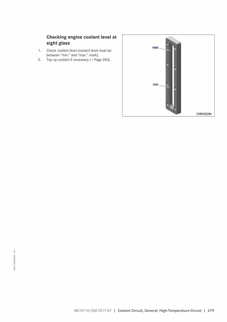
Checking engine coolant level atsight glass
1. Check coolant level (coolant level must bebetween “min.” and “max.” mark).
2. Top up coolant if necessary (→ Page 283).
M015710/06E 2017-07 | Coolant Circuit, General, High-Temperature Circuit | 279
TIM
-ID: 0
0000
0093
7 - 0
15

8.15.2 Engine coolant – Change
Special tools, Material, Spare partsDesignation / Use Part No. Qty.
Coolant
Engine coolant change1. Drain engine coolant (→ Page 281).2. Fill with engine coolant (→ Page 283).
280 | Coolant Circuit, General, High-Temperature Circuit | M015710/06E 2017-07
TIM
-ID: 0
0000
0003
6 - 0
31

8.15.3 Engine coolant – Draining
PreconditionsEngine is stopped and starting disabled.
DANGERFalling from great heights.Risk of serious injury – danger to life!• When working high on the equipment, always use suitable ladders or work platforms.• Use personal protective equipment.
WARNINGCoolant is hot and under pressure.Risk of injury and scalding!• Let the engine cool down.• Wear protective clothing, gloves, and goggles / safety mask.
WARNINGCoolant contains antifreeze and is toxic.Risk of poisoning and slipping!• Avoid contact with eyes and skin.• Do not inhale vapors or mist, wear breathing protection.• Do not eat, drink, smoke when working with antifreeze.• Wear protective clothing, protective gloves and goggles/safety mask.• Wipe up escaped/spilled coolant immediately.
Preparatory steps1. Provide a suitable container to catch the coolant.2. Switch off preheater.
Draining engine coolant1. Turn valve cover of coolant expansion tank
counterclockwise until the first stop and al-low pressure to escape.
2. Continue to turn valve cover counterclock-wise and remove.
3. Draw off separated corrosion inhibitor oil inexpansion tank through the filler neck.
4. Open drain valves and/or drain plugs anddrain coolant at the following points:• At preheater• Thermostat housing (1)• Twin elbow (2)• At elbow (4) of HT coolant pump• Crankcase (3), left and right side
Final steps1. Tighten shutoff cocks (3) and (4) with torque wrench to specified tightening torque.
Name Size Type Lubricant Value/Standard
Spindle 11 A/F Tightening torque 12 Nm
M015710/06E 2017-07 | Coolant Circuit, General, High-Temperature Circuit | 281
TIM
-ID: 0
0000
0096
0 - 0
05

2. Close all other open drain points.3. Position valve cover on filler neck and close.
282 | Coolant Circuit, General, High-Temperature Circuit | M015710/06E 2017-07
TIM
-ID: 0
0000
0096
0 - 0
05

8.15.4 Engine coolant – Filling
PreconditionsEngine is stopped and starting disabled.
MTU Fluids and Lubricants Specifications (A001061/..) are available.
Special tools, Material, Spare partsDesignation / Use Part No. Qty.
Coolant
WARNINGCoolant is hot and under pressure.Risk of injury and scalding!• Let the engine cool down.• Wear protective clothing, gloves, and goggles / safety mask.
NOTICECold coolant in hot engine can cause thermal stress.Possible formation of cracks in the engine!• Fill / top up coolant only into cold engine.
Preparatory steps1. Turn valve cover on coolant expansion tank
counterclockwise to the first stop and allowpressure to escape.
2. Continue to turn valve cover counterclock-wise and remove.
M015710/06E 2017-07 | Coolant Circuit, General, High-Temperature Circuit | 283
TIM
-ID: 0
0000
0095
9 - 0
10

Filling coolant from below withpump
1. Connect appropriate pump with hose to drainvalve of engine coolant pump (arrow).
2. Loosen vent line union at distributor piece(arrow).
3. Open drain valve and pump coolant into en-gine at 0.5 bar minimum.
4. Tighten union (arrow) if coolant leaks out atloose union.
5. Fill expansion tank until overflow edge isreached.
6. Close drain valve.7. Check serviceable condition of valve cover on
coolant expansion tank, clean sealing facesas necessary.
8. Fit valve cover and close it.9. Start engine (→ Page 149).
10. After 10 seconds of running the engine with-out load, stop engine (→ Page 154).
11. Turn valve cover on coolant expansion tankcounterclockwise to the first stop and allowpressure to escape.
12. Continue to turn valve cover counterclock-wise and remove.
13. Check coolant level (→ Page 278) and top upcoolant as necessary:
a) Top up coolant in expansion tank via fillerneck until coolant level at top edge of fill-er neck remains constant.
b) Fit valve cover and close it.14. Repeat the steps from "Start engine"
(→ Step 9) until coolant no longer needs to betopped up.
15. Remove pump and hose.
Final steps1. Start the engine and run it without load for some minutes.2. Check coolant level (→ Page 278) and top up coolant as necessary.
284 | Coolant Circuit, General, High-Temperature Circuit | M015710/06E 2017-07
TIM
-ID: 0
0000
0095
9 - 0
10

8.15.5 Engine coolant pump – Relief bore check
DANGERComponents are moving or rotating.Risk of crushing, danger of parts of the body being caught or pulled in!• Operate the engine at low load only. Keep clear of the danger zone of the engine.
WARNINGHigh level of engine noise when the engine is running.Risk of damage to hearing!• Wear ear protectors.
Engine coolant pump – Reliefbore check
1. Check relief bore for oil and coolant dis-charge.• Permissible coolant discharge: up to 10
drops per hour• Permissible oil discharge: up to 5 drops
per hour• If discharge exceeds the specified limits:
Contact Service.2. If the relief bore is dirty, stop the engine
(→ Page 154) and disable engine start, ob-serve general safety instructions for mainte-nance and repair.
3. Clean relief bore with a wire.
M015710/06E 2017-07 | Coolant Circuit, General, High-Temperature Circuit | 285
TIM
-ID: 0
0000
0096
1 - 0
14

8.15.6 Engine coolant – Sample extraction and analysis
PreconditionsMTU Fluids and Lubricants Specifications (A001061/..) are available.
Special tools, Material, Spare partsDesignation / Use Part No. Qty.
MTU test kit 5605892099/00 1
DANGERComponents are moving or rotating.Risk of crushing, danger of parts of the body being caught or pulled in!• Operate the engine at low load only. Keep clear of the danger zone of the engine.
WARNINGCoolant is hot and under pressure.Risk of injury and scalding!• Let the engine cool down.• Wear protective clothing, gloves, and goggles / safety mask.
WARNINGCoolant contains antifreeze and is toxic.Risk of poisoning and slipping!• Avoid contact with eyes and skin.• Do not inhale vapors or mist, wear breathing protection.• Do not eat, drink, smoke when working with antifreeze.• Wear protective clothing, protective gloves and goggles/safety mask.• Wipe up escaped/spilled coolant immediately.
WARNINGHigh level of engine noise when the engine is running.Risk of damage to hearing!• Wear ear protectors.
Engine coolant – Sample extrac-tion and analysis
1. With the engine running, open drain valve (1).2. Flush sample-extraction point by draining ap-
prox. 1 liter coolant.3. Drain approx. 1 liter coolant into a clean con-
tainer.
286 | Coolant Circuit, General, High-Temperature Circuit | M015710/06E 2017-07
TIM
-ID: 0
0000
0093
8 - 0
13

4. Tighten shut-off cock (2) to specified torque using a torque wrench.
Name Size Type Lubricant Value/Standard
Spindle A/F11 Tightening torque 12 Nm
5. Using the equipment and chemicals from the MTU test kit, examine coolant for:• antifreeze concentration• Amount of corrosion protection oil• pH value
6. For engine coolant change intervals, refer to (→ MTU Fluids and Lubricants Specifications (A001061/..)).
M015710/06E 2017-07 | Coolant Circuit, General, High-Temperature Circuit | 287
TIM
-ID: 0
0000
0093
8 - 0
13
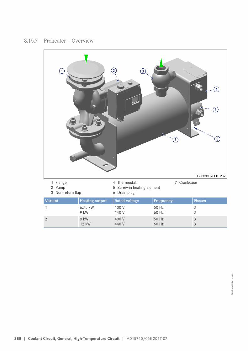
8.15.7 Preheater – Overview
1 Flange2 Pump3 Non-return flap
4 Thermostat5 Screw-in heating element6 Drain plug
7 Crankcase
Variant Heating output Rated voltage Frequency Phases1 6.75 kW
9 kW400 V440 V
50 Hz60 Hz
33
2 9 kW12 kW
400 V440 V
50 Hz60 Hz
33
288 | Coolant Circuit, General, High-Temperature Circuit | M015710/06E 2017-07
TIM
-ID: 0
0000
7433
3 - 0
01

8.15.8 Preheater – Overhaul
PreconditionsEngine is stopped and starting disabled.
DANGERElectric voltage supply for operation.Danger of burns and fatal electric shock!• Make certain that the power supply to the product is switched off before starting work. Secure
against unintentional switching on!
WARNINGHot components/surfaces.Risk of burns!• Allow the engine to cool down to below 50 °C before beginning work.• Wear suitable protective equipment/thermal gloves.• Avoid unprotected contact with hot surfaces.
WARNINGCoolant is hot and under pressure.Risk of injury and scalding!• Let the engine cool down.• Wear protective clothing, gloves, and goggles / safety mask.
Preparatory steps1. Switch off preheater.2. Disconnect power supply to preheater.3. Allow heating elements to cool down.4. Provide a suitable container to catch the coolant.5. Close shutoff valves in the supply and return line to/from preheater.6. Drain coolant through drain plug opening into a clean vessel.
Checking preheater (after 1 month)1. Check tightness at screws, bolts, nuts and electrical connections.2. Check that flanges are properly closed and seals/gaskets are not leaky.3. Regularly check coolant level inside the preheater to avoid heating element operation in a dry condition.
M015710/06E 2017-07 | Coolant Circuit, General, High-Temperature Circuit | 289
TIM
-ID: 0
0000
7207
8 - 0
02

Overhauling preheater (once ayear, minimum)
1. Clean and flush housing (2).2. Check hoses for cracks and other damage.
Replace as necessary.3. Check wiring for damage and overheating.4. Tighten screws, nuts and all electrical con-
nections.5. Release screws (3) on protective caps of the
heating elements (4) and remove protectivecaps.
6. Check cables on heating elements for dam-age and overheating.
7. Remove heating elements (4).8. Clean heating elements (4) and check for de-
posit formation form coolant residues, re-place element(s) if necessary.
9. Check ground connections and groundingsystem.
10. Check electrical operation of heating ele-ments (→ Page 291).
11. Install heating elements (4).12. Mount protective cap of heating element and
tighten screws (3).13. Connect heating elements (4) to power sup-
ply.
Note: Replace defective control thermostats orthermostats which are older than 3 years.The manufacturing date can be found on thenameplate of the thermostat.
14. Check the control thermostat (5) annually.15. Remove control thermostat (5) and take off
gasket.16. Clean seat for control thermostat (5) on
housing.17. Insert new gasket and install new control
thermostat (5).18. Remove pump (1) from volute and check for
residues in impeller and lines.19. Insert pump (1) in volute.
Final steps1. Connect preheater to power supply.2. Connect hose lines and open shutoff valves in the supply and return line.3. Switch on preheater.4. Check preheater for leakage and correct operation (→ Page 292).5. Check coolant level (→ Page 278).
Note: Every maintenance activity must be recorded and stored safely.6. Have the electrical parameters (ohmic resistance, continuity) checked by qualified personnel.
290 | Coolant Circuit, General, High-Temperature Circuit | M015710/06E 2017-07
TIM
-ID: 0
0000
7207
8 - 0
02

8.15.9 Electrical operation of heating elements – Check
DANGERElectrical voltage at exposed terminals and components.Risk of serious injury - danger to life!• Work must be carried out by trained, qualified and approved according to the regional regulations
personnel only!• Ensure that no other persons have access to exposed terminals and/or components!• Close terminal boxes and/or components immediately after completion of work!• Act with extreme caution!
Checking electrical operation of heating elements1. Check the electrical operation of the screw-in heating elements on the copper terminal in the housing.2. Check the electrical conductivity between the phases of each individual output stage.
Result: The ohmic value must be balanced.3. For the insulation check, apply 500 V direct voltage between the phases and the grounding.
Result: The insulating resistance should not be more than 10 MΩ.4. For the dielectric strength test, apply a 2000 V alternating voltage for 1 minute between the phases and the
grounding.5. If not all tests are positive:
1. Open protective cover of screw-in heating elements and check the integrity of the electrical connections.2. Disconnect the feed cables to the screw-in heating elements.3. Carry out tests in accordance with (→ Step 1) and (→ Step 2) between the feed cables to check the integ-
rity.4. Carry out tests in accordance with (→ Step 1) and (→ Step 2) on the individual heating elements within
the protective cover.5. Disconnect defective heating elements and replace them.6. Assemble all disconnected parts again and visually check gaskets for leaks.
M015710/06E 2017-07 | Coolant Circuit, General, High-Temperature Circuit | 291
TIM
-ID: 0
0000
7432
7 - 0
01

8.15.10 Preheater – Function and leak-tightness check
PreconditionsPreheater is switched on.
WARNINGCoolant is hot and highly pressurized.Risk of injury! Risk of scalding!• Allow engine to cool down.• Wear protective clothing, protective gloves, and safety glasses / facial protection.
Checking operationNote: The coolant temperature must correlate to the control range of the thermostat when the preheater is ready
for operation.1. Check coolant preheating temperature.2. Set the thermostat accordingly if the temperatures are not in the control range.
Checking for leaks1. Check leak-tightness at coolant inlet and outlet.2. Tighten any leaking unions.
292 | Coolant Circuit, General, High-Temperature Circuit | M015710/06E 2017-07
TIM
-ID: 0
0000
4888
2 - 0
01

8.15.11 Valve cover – Replacement
PreconditionsEngine is stopped and starting disabled.
Special tools, Material, Spare partsDesignation / Use Part No. Qty.
Valve cover (→ Spare Parts Catalog) 1
WARNINGCoolant is hot and under pressure.Risk of injury and scalding!• Let the engine cool down.• Wear protective clothing, gloves, and goggles / safety mask.
Preparatory stepsu Switch off preheater.
Replacing valve coverNote: Schematic diagram. Design may deviate.
1. Turn valve cover (1) on coolant expansiontank counterclockwise until the first stop andrelease pressure.
2. Continue to turn valve cover counterclock-wise and remove.
3. Remove chain with screw (4) and washer (3).4. Draw off separated corrosion inhibitor oil in
expansion tank via filler neck (2).5. Fit new valve cover and close it.6. Install chain.
M015710/06E 2017-07 | Coolant Circuit, General, High-Temperature Circuit | 293
TIM
-ID: 0
0000
6549
5 - 0
04

8.16 Low-Temperature Circuit
8.16.1 Charge-air coolant – Level check
PreconditionsEngine is stopped and starting disabled.
MTU Fluids and Lubricants Specifications (A001061/..) are available.
WARNINGCoolant is hot and under pressure.Risk of injury and scalding!• Let the engine cool down.• Wear protective clothing, gloves, and goggles / safety mask.
Checking charge-air coolant level at filler neck:1. Turn cap on coolant expansion tank counterclockwise to the first stop and allow pressure to escape.2. Continue to turn cap counterclockwise and remove.
Note: Charge-air coolant must be visible at markerplate.
3. Check charge-air coolant level.4. Top up charge-air coolant as necessary
(→ Page 298).5. Check that cap is in serviceable condition.6. Clean sealing surfaces as necessary.7. Fit cap and close tight.
Checking charge-air coolant level by means of level sensor:Note: Coolant level is automatically monitored by engine control system.
1. Switch on engine control system and check readings on the display.2. Top up charge-air coolant as necessary (→ Page 298).
294 | Low-Temperature Circuit | M015710/06E 2017-07
TIM
-ID: 0
0000
0004
2 - 0
08

8.16.2 Charge-air coolant – Change
Special tools, Material, Spare partsDesignation / Use Part No. Qty.
Coolant
Charge-air coolant – Change1. Drain charge-air coolant (→ Page 296).2. Fill with charge-air coolant (→ Page 298).
M015710/06E 2017-07 | Low-Temperature Circuit | 295
TIM
-ID: 0
0000
0004
1 - 0
11

8.16.3 Charge-air coolant – Draining
PreconditionsEngine is stopped and starting disabled.
Special tools, Material, Spare partsDesignation / Use Part No. Qty.
Sealing ring (→ Spare Parts Catalog)
WARNINGCoolant is hot and under pressure.Risk of injury and scalding!• Let the engine cool down.• Wear protective clothing, gloves, and goggles / safety mask.
Charge-air coolant – Draining1. Provide a suitable container to catch the
coolant.2. Turn breather valve on coolant expansion
tank counterclockwise to the first stop andallow pressure to escape.
3. Continue to turn breather valve counterclock-wise and remove.
4. Draw off separated corrosion inhibitor oil inexpansion tank through the filler neck.
5. Open drain valves or drain plugs and drainengine coolant at the following drain points:• at LT coolant pump• at the LT thermostat housing.
6. Drain remaining charge-air coolant at inter-cooler (arrow).
296 | Low-Temperature Circuit | M015710/06E 2017-07
TIM
-ID: 0
0000
0702
2 - 0
05

7. Tighten drain valve on LT coolant pump to specified torque using a torque wrench.
Name Size Type Lubricant Value/Standard
Spindle 11A/F Tightening torque 12 Nm
8. Screw drain plug with new sealing rings into LT thermostat housing.9. Position breather valve on filler neck and close.
M015710/06E 2017-07 | Low-Temperature Circuit | 297
TIM
-ID: 0
0000
0702
2 - 0
05

8.16.4 Charge-air coolant – Filling
PreconditionsEngine is stopped and starting disabled.
MTU Fluids and Lubricants Specifications (A001061/..) are available.
Special tools, Material, Spare partsDesignation / Use Part No. Qty.
Coolant
WARNINGCoolant is hot and under pressure.Risk of injury and scalding!• Let the engine cool down.• Wear protective clothing, gloves, and goggles / safety mask.
NOTICECold coolant in hot engine can cause thermal stress.Possible formation of cracks in the engine!• Fill / top up coolant only into cold engine.
Preparatory steps1. Turn valve cover on coolant expansion tank
counterclockwise to the first stop and allowpressure to escape.
2. Continue to turn valve cover counterclock-wise and remove.
298 | Low-Temperature Circuit | M015710/06E 2017-07
TIM
-ID: 0
0000
0094
0 - 0
09

Filling with coolant using apump
1. Connect appropriate pump with hose to drainvalve (1).
2. Loosen vent line union at distributor piece(arrow).
3. Open drain valve and pump coolant into en-gine at 0.5 bar minimum.
4. Tighten union (arrow) if coolant leaks out atloose union.
5. Fill expansion tank up to overflow edge.6. Close drain valve.7. Check serviceable condition of valve cover
and clean sealing faces as necessary.8. Position valve cover on filler neck and close.9. Start engine (→ Page 149).
10. After 10 seconds of running the engine with-out load, stop the engine (→ Page 154).
11. Turn valve cover on coolant expansion tankcounterclockwise to the first stop and allowpressure to escape.
12. Continue to turn valve cover counterclock-wise and remove.
13. Check coolant level (→ Page 294) and top upcoolant as necessary:
a) Top up coolant via expansion tank untilcoolant level at top edge of filler neck re-mains constant.
b) Position valve cover on filler neck andclose.
14. Repeat the steps from "Start engine"(→ Step 9) until coolant no longer needs to betopped up.
15. Remove pump and hose.
M015710/06E 2017-07 | Low-Temperature Circuit | 299
TIM
-ID: 0
0000
0094
0 - 0
09

Alternatively: Filling with cool-ant via filler neck
1. Loosen vent line union at distributor piece(arrow).
2. Top up coolant in expansion tank via fillerneck until coolant level at top edge of fillerneck remains constant.
3. Tighten union (arrow) if coolant leaks out atloose union.
4. Check serviceable condition of valve cover oncoolant expansion tank, clean sealing facesas necessary.
5. Fit valve cover and close it.6. Start engine (→ Page 149).7. After 10 seconds of running the engine with-
out load, stop the engine (→ Page 154).8. Turn valve cover on coolant expansion tank
counterclockwise to the first stop and allowpressure to escape.
9. Turn valve cover counterclockwise and re-move.
10. Check coolant level (→ Page 294) and top upwith coolant via filler neck as necessary:
a) Top up coolant in expansion tank via fillerneck until coolant level at top edge of fill-er neck remains constant.
b) Fit valve cover and close it.11. Repeat the steps from "Start engine"
(→ Step 6) until coolant no longer needs to betopped up.
Final steps1. Start the engine and run it without load for some minutes.2. Check coolant level (→ Page 294) and top up coolant as necessary.
300 | Low-Temperature Circuit | M015710/06E 2017-07
TIM
-ID: 0
0000
0094
0 - 0
09

8.16.5 Charge-air coolant pump – Relief bore check
DANGERComponents are moving or rotating.Risk of crushing, danger of parts of the body being caught or pulled in!• Operate the engine at low load only. Keep clear of the danger zone of the engine.
WARNINGHigh level of engine noise when the engine is running.Risk of damage to hearing!• Wear ear protectors.
Charge-air coolant pump – Re-lief bore check
1. Check relief bore for oil and coolant dis-charge.
2. Stop engine (→ Page 154) and disable enginestart, observe general safety instructions formaintenance and repair.
3. Clean the relief bore with a wire if it is conta-minated.• Permissible coolant discharge: up to 10
drops per hour.• Permissible oil discharge: up to 5 drops
per hour.4. If discharge exceeds the specified limits:
Contact Service.
M015710/06E 2017-07 | Low-Temperature Circuit | 301
TIM
-ID: 0
0000
0096
4 - 0
08

8.17 Belt Drive
8.17.1 Drive belt – Condition check
PreconditionsEngine is stopped and starting disabled.
Protective cover is removed.
Drive belt – Condition check
Item Findings MeasureDrive belt A Singular cracks NoneDrive belt B Cracks on entire circumference Replace (→ Page 304)Drive belt C ChunkingDrive belt Belt is oily, shows signs of over-
heating
302 | Belt Drive | M015710/06E 2017-07
TIM
-ID: 0
0000
0092
0 - 0
12

8.18 Battery-Charging Generator
8.18.1 Battery-charging generator – Drive belt tension adjustment
PreconditionsEngine is stopped and starting disabled.
Special tools, Material, Spare partsDesignation / Use Part No. Qty.
Torque wrench, 60–320 Nm F30452768 1Ratchet adapter F30027341 1Torque wrench, 10–60 Nm F30452769 1Ratchet adapter F30027340 1
WARNINGBelt tensioner spring is pretensioned.Risk of hands being crushed!• Lock belt tensioner in position.• Only use specified tools and devices.
Adjusting belt tension1. Slacken screws (1) and (2) by half a turn.
Result: Belt tensioner moves against the drive beltand tensions it.
2. Tighten screw (2) to specified torque using a torque wrench.
Name Size Type Lubricant Value/Standard
Screw M10 Tightening torque 60 Nm +5 Nm
3. Tighten screw (1) with a torque wrench.
M015710/06E 2017-07 | Battery-Charging Generator | 303
TIM
-ID: 0
0000
7147
4 - 0
02

8.18.2 Battery-charging generator drive – Drive belt replacement
PreconditionsEngine is stopped and starting disabled.
Special tools, Material, Spare partsDesignation / Use Part No. Qty.
Torque wrench, 60–320 Nm F30452768 1Ratchet bit F30027341 1Torque wrench, 10–60 Nm F30452769 1Ratchet bit F30027340 1Drive belt (→ Spare Parts Catalog)
WARNINGBelt tensioner spring is pretensioned.Risk of hands being crushed!• Lock belt tensioner in position.• Only use specified tools and devices.
Battery-charging generator drive – Drive belt replacement1. Remove protective cover.
2. Loosen screws (2) and (3) by half a turn.3. Mount socket or box wrench on screw (1)
and press belt tensioner in direction of arrowas far as the stop.
4. Tighten screw (3).5. Remove the used drive belt.6. Fit new drive belt.7. Loosen screw (3) by half a turn.
Result: Belt tensioner moves against the drive beltand tensions it.
8. Tighten screw (3) with torque wrench to specified tightening torque.
Name Size Type Lubricant Value/Standard
Screw M10 Tightening torque 60 Nm +5 Nm
9. Tighten screw (2).10. Install protective cover.11. Readjust drive belt tension after 30 minutes and after 8 hours engine runtime (→ Page 303).
304 | Battery-Charging Generator | M015710/06E 2017-07
TIM
-ID: 0
0000
2297
0 - 0
07

8.19 Engine Mounting / Support
8.19.1 Engine mounting – Check
Engine mounting – CheckItem Findings ActionVisually inspect resilient mounts. • Damage
• Brittleness• Deformation• Crack formation• Swelling
Replace (contact Service).
M015710/06E 2017-07 | Engine Mounting / Support | 305
TIM
-ID: 0
0000
1537
0 - 0
05

8.20 Wiring (General) for Engine/Gearbox/Unit
8.20.1 Engine cabling – Check
PreconditionsEngine is stopped and starting disabled.
Special tools, Material, Spare partsDesignation / Use Part No. Qty.
Solvent (isopropyl alcohol) X00058037 1
Engine cabling – Check1. Check securing screws of cable clamps on engine and tighten loose screw connections.2. Ensure that cables are securely seated in clamps and cannot move freely.3. Check if all cable clips are closed and intact.4. Replace faulty cable clips.5. Check cable clamps for secure fit, tighten loose clamps.6. Replace faulty cable clamps.7. Visually inspect the following electrical components for damage:
• Connector housings• Contacts• Plug connectors• Cables and terminals• Plug-in contacts
Result: If cable conductors are damaged, contact Service.
Note: Close connectors that are not plugged in with the protective cap supplied.8. Use isopropyl alcohol to clean dirty connector housings, plug connectors and contacts.9. Ensure that all connecting plugs of the sensors are correctly engaged.
306 | Wiring (General) for Engine/Gearbox/Unit | M015710/06E 2017-07
TIM
-ID: 0
0000
0002
9 - 0
25

8.21 Accessories for (Electronic) Engine Governor / Control System
8.21.1 Engine governor and connector – Cleaning
PreconditionsEngine is stopped and starting disabled.
Special tools, Material, Spare partsDesignation / Use Part No. Qty.
Solvent (isopropyl alcohol) X00058037 1
NOTICEInsertion of unsuitable test probe, e.g. test prod.The contacts in the plug connection can be bent!• Carry out check of plug connection only with test connectors.
Engine governor and connector – Cleaning1. Use isopropyl alcohol to remove coarse dirt from housing surface.2. Use isopropyl alcohol to remove dirt from the connector and cable surfaces.3. Check legibility of cable labels. Clean or replace illegible labels.
Heavily contaminated connectors on engine governor – CleaningNote: Close connectors that are not plugged in with the protective cap supplied.
1. Release latches of connectors and withdraw connectors.2. Clean connector housings, connector socket housings and all contacts with isopropyl alcohol.3. When connectors, sockets and all contacts are dry: Fit connectors and latch them.
M015710/06E 2017-07 | Accessories for (Electronic) Engine Governor / Control System | 307
TIM
-ID: 0
0000
0004
7 - 0
14

8.21.2 Engine governor plug connections – Check
PreconditionsEngine stopped and starting disabled.
Electronic engine management system is de-energized.
NOTICEInsertion of unsuitable test probe, e.g. test prod.The contacts in the plug connection can be bent!• Carry out check of plug connection only with test connectors.
Checking plug connections at engine governor1. Check all plug connections for secure seating.2. Lock loose connectors.3. Check dust cap on ECU and EXU connectors for damage and correct seating.
308 | Accessories for (Electronic) Engine Governor / Control System | M015710/06E 2017-07
TIM
-ID: 0
0000
0004
8 - 0
09

8.21.3 Engine governor ECU 7 – Removal and installation
PreconditionsEngine is stopped and starting disabled.
Engine electronics is powered off.
NOTICEWrong engine governor installed.Engine damage!• When reassembling an engine, make sure that the governor with the data record for the given engine
is installed.
Removing engine governor fromengine
1. Note or mark assignment of cables andplugs.
2. Remove all screws (3).3. Undo clips (2) on connectors.4. Remove all male connectors.5. Remove screws (1).6. Take off engine governor.
Installing engine governor on engine1. Install in reverse order. Ensure correct assignment of plugs and sockets.2. Check resilient mount before installing.
Result: If resilient mount is porous or defective then replace it.
M015710/06E 2017-07 | Accessories for (Electronic) Engine Governor / Control System | 309
TIM
-ID: 0
0000
0004
9 - 0
09

9 Appendix A
9.1 AbbreviationsAbbre-viation
Meaning Explanation
A/D Analog/Digital converter Converter: converts sensor voltages into digital val-ues
ADEC Advanced Diesel Engine Controller Engine management systemAFRS Air Filter Restriction SensorAGR Abgasrückführung Exhaust Gas RecirculationAL AlarmANSI American National Standards Institute Association of American standardization organiza-
tionsATL Abgasturbolader/Abgasturboaufladung Exhaust turbocharger/exhaust turbochargingATS Air Temperature SensorBR Baureihe SeriesBV Betriebsstoffvorschrift Fluids and Lubricants Specifications, MTU Publica-
tion No. A01061/..CAN Controller Area Network Data bus system, bus standardCDC Calibration Drift Compensation Drift correction setting with DiaSys in engine gover-
norCEL Check Engine Lamp 1st function: Warning lamp (rectify fault as soon as
possible)2nd function: Read out fault codes
CKT CircuitCLS Coolant Level Sensor Monitors coolant levelCM Current Measurement Current measured valueCPS Coolant Pressure Sensor Monitors coolant pressureCR Common RailCTS Coolant Temperature Sensor Monitors coolant temperatureDDEC Detroit Diesel Electronic Controls Engine control system made by Detroit DieselDDL Diagnostic Data Link Diagnostic linesDDR Diagnostic Data Reader Diagnostic unitDia-Sys®
Electronic dialog system
DIN Deutsches Institut für Normung e. V. German national standards institute. At the sametime identifier of German standards (DIN = “Deut-sche Industrie-Norm”)
DL Default Lost Alarm: Default CAN bus failureDMC Data Matrix CodeDOC Diesel Oxidation Catalyst Oxidation catalyst upstream of the diesel particulate
filterDPF Diesel Particulate FilterDT Diagnostic Tool Diagnostic unitECM Electronic Control Module Electronic control unit of the DDEC system
310 | Appendix A | M015710/06E 2017-07
TIM
-ID: 0
0000
0085
8 - 0
15

Abbre-viation
Meaning Explanation
ECU Engine Control Unit Engine governorEDM Engine Data Module Memory module for engine dataEE-PROM
Electrically Erasable Programmable ReadOnly Memory
Electrically Erasable Programmable Read Only Mem-ory
EFPA Electronic Foot Pedal Assembly Electronic accelerator pedalEGR Exhaust Gas RecirculationEIL Engine Ident LabelEIM-ID Emission Identification NumberEMU Engine Monitoring UnitESCM Extreme Site Condition Management Power reduction for operation in extreme conditionsESD Single accumulator pressureETK Ersatzteilkatalog Spare Parts CatalogEUI Electronic Unit Injector Electronic injection nozzle unitFO Frequency OutputFPS Fuel Pressure Sensor Monitors fuel pressureFRS Fuel - Differential Pressure SensorFTS Fuel Temperature Sensor Monitors fuel temperatureFWCP Fire Water Control Panel Control cabinetGND GroundHP High PressureHI High Alarm: Measured value exceeds 1st maximum limitHIHI High High Alarm: Measured value exceeds 2nd maximum limitHT High TemperatureIDM Interface Data Module Memory module for interface dataIIG Initial injector equalization Initial input of injector code in Engine Control Unit
with DiaSys inINJ InjectorISO International Organization for Standardiza-
tionInternational umbrella organization for all nationalstandardization institutes
KGS Kupplungsgegenseite Engine free end in accordance with DIN ISO 1204KS Kupplungsseite Engine driving end in accordance with DIN ISO 1204L1 Limit 1 Limit value, limit 1L2 Limit 2 Limit value, limit 2LED Light Emitting DiodeLLK Ladeluftkühlung Charge-air coolingLO Low Alarm: Measured value lower than 1st minimum limit
valueLOLO Low Low Alarm: Measured value lower than 2nd minimum lim-
it valueLSG Limit Speed Governor Maximum-speed governorLSU Lambda Sonde Universal Universal Lambda probeLT Low TemperatureMCR Maximum Continuous Rating Torque limitation curve
M015710/06E 2017-07 | Appendix A | 311
TIM
-ID: 0
0000
0085
8 - 0
15

Abbre-viation
Meaning Explanation
N/A Not ApplicableLP Low PressureNN Normal Null Reference surface for heights above sea levelNT Niedertemperatur Low temperatureOEM Original Equipment ManufacturerOI Optimized IdleOLS Oil Level Sensor Monitors oil levelOPS Oil Pressure Sensor Monitors oil pressureOTS Oil Temperature Sensor Monitors oil temperatureOT Oberer Totpunkt Top Dead CenterPAN Panel Control panelPIM Peripheral Interface ModulePWM Pulse Width Modulation Modulated signalP-xyz Pressure-xyz Pressure measuring point xyzRL Redundancy Lost Alarm: Redundant CAN bus failureSAE Society of Automotive Engineers U.S. standardization organizationSD Sensor Defect Alarm: Sensor failureSEL Stop Engine Lamp 1st function: Warning lamp (stop engine and rectify
fault)2nd function: Read out fault codes
SID System IdentifierSRS Synchronous Reference Sensor TDC cylinder 1SS Safety System / Security Shutdown Safety system alarmTBS Turbocharger Boost Sensor Monitors charge-air pressureTCI Turbo Compressor InletTCO Turbo Compressor OutletTD Transmitter Deviation Alarm: Sensor comparison faultTPS Throttle Position SensorTRS Timing Reference SensorT-xyz Temperature-xyz Temperature measuring point xyzU_PDU Voltage Power Driver Unit Distribution voltage for solenoid valve output stagesUDV Pressure relief valveUT Unterer Totpunkt Bottom Dead CenterVNT Variable Nozzle TurbineVSG Variable-Speed GovernorVSS Vehicle Speed SensorWZK Werkzeugkatalog Tool CatalogZKP Zuordnung - Kategorie - Parameter Assignment - Category - Parameter. A number allo-
cated to a parameter describing its function and as-signment
312 | Appendix A | M015710/06E 2017-07
TIM
-ID: 0
0000
0085
8 - 0
15

9.2 MTU Contact/Service PartnersThe worldwide network of the sales organization with subsidiaries, sales offices, representatives and custom-er service centers ensure fast and direct support on site and ensure the high availability of our products.
Local SupportExperienced and qualified specialists place their knowledge and expertise at your disposal.
For locally available support, go to the MTU Internet site: http://www.mtu-online.com
24h HotlineWith our 24h hotline and high flexibility, we're your contact around the clock: during each operating phase,preventive maintenance and corrective operations in case of a malfunction, for information on changes inconditions of use and for supplying spare parts.
Your contact person in our Customer Assistance Center:
E-mail: [email protected]
Tel.: +49 7541 9077777
Fax.: +49 7541 9077778
Asia/Pacific: +65 6100 2688
North and Latin America: +1 248 560 8000
Spare Parts ServiceFast, simple and correct identification of spare parts for your drive system or vehicle fleet. The right sparepart at the right time at the right place.
With this aim in mind, we can call on a globally networked spares logistics system, a central warehouse atheadquarters and on-site stores at our subsidiary companies, agencies and service workshops.
Your contact at Headquarters:
E-mail: [email protected]
Tel.: +49 7541 9077777
Fax.: +49 7541 9077778
M015710/06E 2017-07 | Appendix A | 313
TIM
-ID: 0
0000
0087
3 - 0
16

10 Appendix B
10.1 Special ToolsAngular screw driver
Part No.: F30002815Qty.:Used in:
1 8.4.3 Valve clearance – Check and adjustment(→ Page 231)
Barring gear
Part No.: F6555766Qty.:Used in:
1 8.1.1 Engine – Barring manually (→ Page 213)
Barring tool
Part No.: F6555766Qty.:Used in:
1 8.2.1 Cylinder liner – Endoscopic examination(→ Page 217)
314 | Appendix B | M015710/06E 2017-07
DCL-
ID: 0
0000
0750
0 - 0
06

Crossbeam
Part No.: T80091826Qty.:Used in:
1 2.1 Transportation (→ Page 18)
Crossbeam
Part No.: T80092360Qty.:Used in:
1 2.1 Transportation (→ Page 18)
Depth gage, 200 mm
Part No.: Y20000918Qty.:Used in:
1 8.4.1 Valve protrusion – Measurement (→ Page 226)
Endoscope
Part No.: Y20097353Qty.:Used in:
1 8.2.1 Cylinder liner – Endoscopic examination(→ Page 217)
M015710/06E 2017-07 | Special Tools | 315
DCL-
ID: 0
0000
0750
0 - 0
06

Feeler gage
Part No.: Y20098771Qty.:Used in:
1 8.4.3 Valve clearance – Check and adjustment(→ Page 231)
Filter wrench
Part No.: F30379104Qty.:Used in:
1 8.8.1 Fuel filter – Replacement (→ Page 246)
Qty.:Used in:
8.14.1 Engine oil filter – Replacement (→ Page 273)
Fuel suction device
Part No.: F30378207Qty.:Used in:
1 8.5.1 HP fuel pump – Filling with engine oil (→ Page 236)
High-pressure cleaner
Part No.:Qty.:Used in:
1 5.12 Plant – Cleaning (→ Page 158)
316 | Special Tools | M015710/06E 2017-07
DCL-
ID: 0
0000
0750
0 - 0
06

Installation/removal device
Part No.: F6789889Qty.:Used in:
1 8.6.2 Injector – Removal and installation (→ Page 239)
Measuring jig 1
Part No.: Y4350009Qty.:Used in:
1 8.4.1 Valve protrusion – Measurement (→ Page 226)
Measuring jig 2, optional
Part No.: Y4350010Qty.:Used in:
1 8.4.1 Valve protrusion – Measurement (→ Page 226)
Milling cutter
Part No.: F30452739Qty.:Used in:
1 8.6.2 Injector – Removal and installation (→ Page 239)
M015710/06E 2017-07 | Special Tools | 317
DCL-
ID: 0
0000
0750
0 - 0
06

MTU test kit
Part No.: F6798833Qty.:Used in:
1 8.13.3 Engine oil – Sample extraction and analysis(→ Page 270)
MTU test kit
Part No.: 5605892099/00Qty.:Used in:
1 8.15.6 Engine coolant – Sample extraction and analysis(→ Page 286)
Ratchet adapter
Part No.: F30027340Qty.:Used in:
1 8.3.1 Crankcase breather – Oil separator element re-placement (→ Page 221)
Qty.:Used in:
1 8.8.6 Fuel prefilter (non-switchable) – Filter element re-placement (→ Page 254)
Qty.:Used in:
1 8.8.7 Fuel prefilter (switchable) – Filter element replace-ment (→ Page 256)
Qty.:Used in:
1 8.18.1 Battery-charging generator – Drive belt tension ad-justment (→ Page 303)
Ratchet adapter
Part No.: F30027341Qty.:Used in:
1 8.13.1 Engine oil – Change (→ Page 267)
Qty.:Used in:
1 8.18.1 Battery-charging generator – Drive belt tension ad-justment (→ Page 303)
318 | Special Tools | M015710/06E 2017-07
DCL-
ID: 0
0000
0750
0 - 0
06
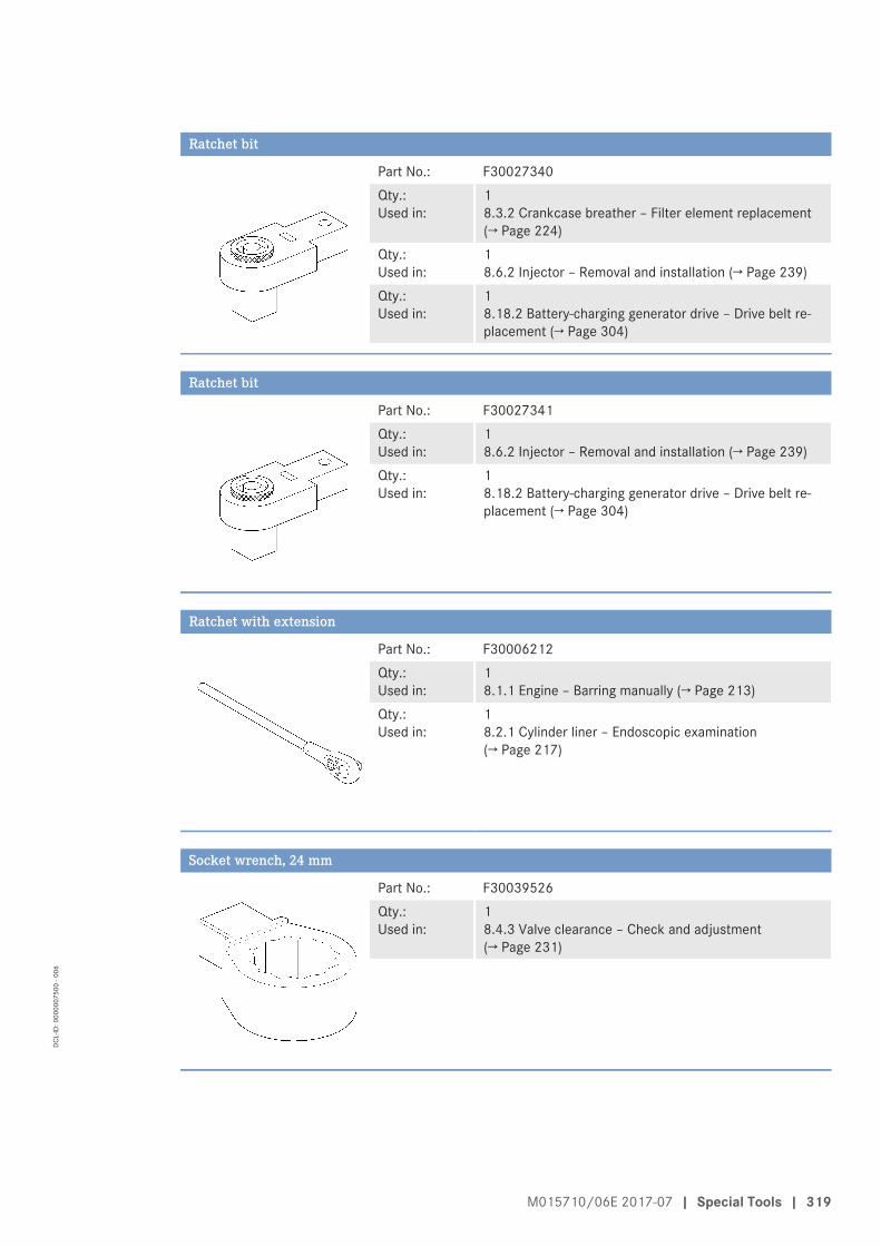
Ratchet bit
Part No.: F30027340Qty.:Used in:
1 8.3.2 Crankcase breather – Filter element replacement(→ Page 224)
Qty.:Used in:
1 8.6.2 Injector – Removal and installation (→ Page 239)
Qty.:Used in:
1 8.18.2 Battery-charging generator drive – Drive belt re-placement (→ Page 304)
Ratchet bit
Part No.: F30027341Qty.:Used in:
1 8.6.2 Injector – Removal and installation (→ Page 239)
Qty.:Used in:
1 8.18.2 Battery-charging generator drive – Drive belt re-placement (→ Page 304)
Ratchet with extension
Part No.: F30006212Qty.:Used in:
1 8.1.1 Engine – Barring manually (→ Page 213)
Qty.:Used in:
1 8.2.1 Cylinder liner – Endoscopic examination(→ Page 217)
Socket wrench, 24 mm
Part No.: F30039526Qty.:Used in:
1 8.4.3 Valve clearance – Check and adjustment(→ Page 231)
M015710/06E 2017-07 | Special Tools | 319
DCL-
ID: 0
0000
0750
0 - 0
06

Torque screwdriver, 1–5 Nm
Part No.: F30452774Qty.:Used in:
1 8.6.2 Injector – Removal and installation (→ Page 239)
Qty.:Used in:
1 8.10.3 Air filter – Removal and installation (→ Page 264)
Torque wrench, 10–60 Nm
Part No.: F30452769Qty.:Used in:
1 2.3 Crankshaft transport locking device (→ Page 20)
Qty.:Used in:
1 8.5.1 HP fuel pump – Filling with engine oil (→ Page 236)
Qty.:Used in:
1 8.6.2 Injector – Removal and installation (→ Page 239)
Qty.:Used in:
1 8.14.3 Centrifugal oil filter – Cleaning and filter-sleeve re-placement (→ Page 276)
Qty.:Used in:
1 8.18.1 Battery-charging generator – Drive belt tension ad-justment (→ Page 303)
Qty.:Used in:
1 8.18.2 Battery-charging generator drive – Drive belt re-placement (→ Page 304)
Torque wrench, 4–20 Nm
Part No.: F30044239Qty.:Used in:
1 8.3.1 Crankcase breather – Oil separator element re-placement (→ Page 221)
Qty.:Used in:
1 8.3.2 Crankcase breather – Filter element replacement(→ Page 224)
Qty.:Used in:
1 8.14.3 Centrifugal oil filter – Cleaning and filter-sleeve re-placement (→ Page 276)
320 | Special Tools | M015710/06E 2017-07
DCL-
ID: 0
0000
0750
0 - 0
06

Torque wrench, 60–320 Nm
Part No.: F30452768Qty.:Used in:
1 2.3 Crankshaft transport locking device (→ Page 20)
Qty.:Used in:
1 8.4.3 Valve clearance – Check and adjustment(→ Page 231)
Qty.:Used in:
1 8.6.2 Injector – Removal and installation (→ Page 239)
Qty.:Used in:
1 8.13.1 Engine oil – Change (→ Page 267)
Qty.:Used in:
1 8.18.1 Battery-charging generator – Drive belt tension ad-justment (→ Page 303)
Qty.:Used in:
1 8.18.2 Battery-charging generator drive – Drive belt re-placement (→ Page 304)
Torque wrench, 6–50 Nm
Part No.: F30027336Qty.:Used in:
1 8.8.6 Fuel prefilter (non-switchable) – Filter element re-placement (→ Page 254)
Qty.:Used in:
1 8.8.7 Fuel prefilter (switchable) – Filter element replace-ment (→ Page 256)
Valve setting gauge
Part No.: Y4349603Qty.:Used in:
1 8.4.3 Valve clearance – Check and adjustment(→ Page 231)
M015710/06E 2017-07 | Special Tools | 321
DCL-
ID: 0
0000
0750
0 - 0
06

10.2 IndexA
Abbreviations 310Actuators – Overview 25ADEC (ECU 7) – Fault messages 164After stopping the engine – Engine remains ready for operation 156– Putting the engine out of operation 157Air filter – Check 263– Installation 264– Removal 264– Replacement 262Air starter – Manual operation 266
B
Battery-charging generator – Drive belt replacement 304– Drive belt tension adjustment 303
C
Cabling – Check
– On engine 306Centrifugal oil filter – Cleaning 276Charge-air coolant – Change 295– Check
– Level at filler neck 294– Level via level sensor 294
– Draining 296– Filling 298Charge-air coolant pump – Relief bore check 301Connector – Cleaning 307Contact persons 313Coolant – Change 280, 295– Filling 283Crankcase breather – Filter element replacement 224– Oil separator element replacement 221Crankshaft – Transport locking device
– Installation/removal 20Cylinder – Designation 23Cylinder head cover – Installation 235– Removal 235
Cylinder liner – Endoscopic examination 217– Instructions and comments on endoscopic and visual
examination 219
D
Drive belt – Condition check 302
E
ECU 7 – Installation 309– Removal 309Emergency start – Override mode 151Emission label – Check 153Engine – Barring
– Manually 213– Emergency start (override mode) 151– Emergency stop 155– Main dimensions 146– Starting in manual mode (test run) 149– Stopping in manual mode (test run) 154– Test run 216– Turning
– On starting system 215Engine cabling – Check 306Engine coolant – Analysis
– Sample 286– Change 280– Check
– Level at external cooler 278– Level at filler neck 278– Level via level sensor 278
– Draining 281– Extraction
– Sample 286– Filling 283Engine coolant pump – Relief bore check 285Engine driving end – Definition 23Engine free end – Definition 23Engine governor – Cleaning 307– Plug connections
– Check 308Engine governor ECU 7 – Installation 309– Removal 309
322 | Index | M015710/06E 2017-07
DCL-
ID: 0
0000
0750
0 - 0
06

Engine mounting – Check 305Engine oil – Centrifugal oil filter
– Cleaning 276– Change 267– Filter sleeve
– Replacement 276– Sample extraction and analysis 270Engine oil filter – Replacement 273Engine oil level – Check 269Engine sides – Designation 23Engine – Overview 24
F
Fault messages – Engine governor ADEC (ECU 7) 164Filter sleeve – Replacement 276Final compression pressure 144Firing order 145Fuel filter – Replacement 246Fuel prefilter – Contamination indicator check
– Switchable 253– Draining
– Non-switchable 248– Switchable 250
– Filter element replacement – Non-switchable 254– Switchable 256
– Pressure ratios 247– Venting 259Fuel system – Venting 245
H
Hotline 313HP pump – Filling with engine oil 236
I
Injector – Installation 239– Removal 239– Replacement 238Intercooler – Checking condensate drain for coolant leakage 261– Checking condensate drain for obstructions 261
L
Lifting requirements 19
M
Main dimensions 146
Maintenance task reference table [QL1] 159MTU contact persons 313
O
Oil indicator filter – Check 274– Cleaning 274Oil priming pump – Visual check 272Oil separator – Replacement 221Operational checks 152
P
Plant – Cleaning 158Preheater – Overhaul 289– Electrical operation of heating elements check 291– Function and leak-tightness
– check 292– Overview 288Product data 12V4000G23 – Continuous operation 3B
– China Nonroad mobile Machinery Stage III 49– NEA Singapore for ORDE 49– Optimized exhaust gas emissions (TA-Luft) 41– Optimized fuel consumption 33
– Continuous operation 3G – China Nonroad mobile Machinery Stage III 118– NEA Singapore for ORDE 118– Optimized exhaust gas emissions (TA-Luft) 110– Optimized fuel consumption 102
– Standby operation 3D – China Nonroad mobile Machinery Stage III 66– NEA Singapore for ORDE 66– Optimized fuel consumption 53
– Standby operation 3E – China Nonroad mobile Machinery Stage III 78– NEA Singapore for ORDE 78– Optimized exhaust gas emissions (TA-Luft) 74– Optimized fuel consumption 70
– Standby power operation 3F – China Nonroad mobile Machinery Stage III 98– NEA Singapore for ORDE 98– Optimized exhaust gas emissions (TA-Luft) 90– Optimized fuel consumption 82
– Standby power operation 3H – China Nonroad mobile Machinery Stage III 140– NEA Singapore for ORDE 140– Optimized exhaust gas emissions (TA-Luft) 131– Optimized fuel consumption 122
Product data 12V4000G23R – Continuous operation 3B
– China Nonroad mobile Machinery Stage III 49– NEA Singapore for ORDE 49– Optimized exhaust gas emissions (TA-Luft) 41– Optimized fuel consumption 33
M015710/06E 2017-07 | Index | 323
DCL-
ID: 0
0000
0750
0 - 0
06

Product data 12V4000G43 – Continuous operation 3A
– Optimized fuel consumption 28– Continuous operation 3B
– EPA Nonroad T2 Comp (40CFR89) 45– EPA Stationary EMERG T2 (40CFR60) 45– Optimized fuel consumption 33
– Continuous operation 3G – EPA Nonroad T2 Comp (40CFR89) 114– EPA Stationary EMERG T2 (40CFR60) 114– Optimized fuel consumption 102
– Standby operation 3D – EPA Nonroad T2 Comp (40CFR89) 61– EPA Stationary EMERG T2 (40CFR60) 61– Optimized fuel consumption 53
– Standby power operation 3F – EPA Nonroad T2 Comp (40CFR89) 94– EPA Stationary EMERG T2 (40CFR60) 94– Optimized fuel consumption 82
– Standby power operation 3H – EPA Nonroad T2 Comp (40CFR89) 135– EPA Stationary EMERG T2 (40CFR60) 135– Optimized fuel consumption 122
Product data 12V4000G63 – Continuous operation 3A
– Optimized fuel consumption 28– Continuous operation 3B
– NEA Singapore for ORDE 49– Optimized exhaust gas emissions (TA-Luft) 41– Optimized fuel consumption 33
– Continuous operation 3G – NEA Singapore for ORDE 118– Optimized exhaust gas emissions (TA-Luft) 110– Optimized fuel consumption 102
– Standby operation 3D – NEA Singapore for ORDE 66– Optimized fuel consumption 53
– Standby operation 3E – NEA Singapore for ORDE 78– Optimized exhaust gas emissions (TA-Luft) 74– Optimized fuel consumption 70
– Standby power operation 3F – NEA Singapore for ORDE 98– Optimized exhaust gas emissions (TA-Luft) 90– Optimized fuel consumption 82
– Standby power operation 3H – NEA Singapore for ORDE 140– Optimized exhaust gas emissions (TA-Luft) 131– Optimized fuel consumption 122
Product data 12V4000G83 – Continuous operation 3A
– Optimized fuel consumption 28– Continuous operation 3B
– EPA Nonroad T2 Comp (40CFR89) 45– EPA Stationary EMERG T2 (40CFR60) 45– Optimized fuel consumption 33
– Continuous operation 3G – EPA Nonroad T2 Comp (40CFR89) 114– EPA Stationary EMERG T2 (40CFR60) 114– Optimized fuel consumption 102
– Standby operation 3D – EPA Nonroad T2 Comp (40CFR89) 61– EPA Stationary EMERG T2 (40CFR60) 61– Optimized fuel consumption 53
– Standby power operation 3F – EPA Nonroad T2 Comp (40CFR89) 94– EPA Stationary EMERG T2 (40CFR60) 94– Optimized fuel consumption 82
– Standby power operation 3H – EPA Nonroad T2 Comp (40CFR89) 135– EPA Stationary EMERG T2 (40CFR60) 135– Optimized fuel consumption 122
Product data 16V4000G23 – Continuous operation 3B
– China Nonroad mobile Machinery Stage III 49– NEA Singapore for ORDE 49– Optimized exhaust gas emissions (TA-Luft) 41– Optimized fuel consumption 37
– Continuous operation 3G – China Nonroad mobile Machinery Stage III 118– NEA Singapore for ORDE 118– Optimized exhaust gas emissions (TA-Luft) 110– Optimized fuel consumption 106
– Standby operation 3D – China Nonroad mobile Machinery Stage III 66– NEA Singapore for ORDE 66– Optimized fuel consumption 57
– Standby operation 3E – China Nonroad mobile Machinery Stage III 78– NEA Singapore for ORDE 78– Optimized exhaust gas emissions (TA-Luft) 74– Optimized fuel consumption 70
– Standby power operation 3F – China Nonroad mobile Machinery Stage III 98– NEA Singapore for ORDE 98– Optimized exhaust gas emissions (TA-Luft) 90– Optimized fuel consumption 86
– Standby power operation 3H – China Nonroad mobile Machinery Stage III 140– NEA Singapore for ORDE 140– Optimized exhaust gas emissions (TA-Luft) 131– Optimized fuel consumption 126
324 | Index | M015710/06E 2017-07
DCL-
ID: 0
0000
0750
0 - 0
06

Product data 16V4000G43 – Continuous operation 3A
– Optimized fuel consumption 28– Continuous operation 3B
– EPA Nonroad T2 Comp (40CFR89) 45– EPA Stationary EMERG T2 (40CFR60) 45– Optimized fuel consumption 37
– Continuous operation 3G – EPA Nonroad T2 Comp (40CFR89) 114– EPA Stationary EMERG T2 (40CFR60) 114– Optimized fuel consumption 106
– Standby operation 3D – EPA Nonroad T2 Comp (40CFR89) 61– EPA Stationary EMERG T2 (40CFR60) 61– Optimized fuel consumption 57
– Standby power operation 3F – EPA Nonroad T2 Comp (40CFR89) 94– EPA Stationary EMERG T2 (40CFR60) 94– Optimized fuel consumption 86
– Standby power operation 3H – EPA Nonroad T2 Comp (40CFR89) 135– EPA Stationary EMERG T2 (40CFR60) 135– Optimized fuel consumption 126
Product data 16V4000G63 – Continuous operation 3A
– Optimized fuel consumption 28– Continuous operation 3B
– China Nonroad mobile Machinery Stage III 49– NEA Singapore for ORDE 49– Optimized exhaust gas emissions (TA-Luft) 41– Optimized fuel consumption 37
– Continuous operation 3G – China Nonroad mobile Machinery Stage III 118– NEA Singapore for ORDE 118– Optimized exhaust gas emissions (TA-Luft) 110– Optimized fuel consumption 106
– Standby operation 3D – China Nonroad mobile Machinery Stage III 66– NEA Singapore for ORDE 66– Optimized fuel consumption 57
– Standby operation 3E – China Nonroad mobile Machinery Stage III 78– NEA Singapore for ORDE 78– Optimized exhaust gas emissions (TA-Luft) 74– Optimized fuel consumption 70
– Standby power operation 3F – China Nonroad mobile Machinery Stage III 98– NEA Singapore for ORDE 98– Optimized exhaust gas emissions (TA-Luft) 90– Optimized fuel consumption 86
– Standby power operation 3H – China Nonroad mobile Machinery Stage III 140– NEA Singapore for ORDE 140– Optimized exhaust gas emissions (TA-Luft) 131– Optimized fuel consumption 126
Product data 16V4000G83 – Continuous operation 3A
– Optimized fuel consumption 28– Continuous operation 3B
– EPA Nonroad T2 Comp (40CFR89) 45– EPA Stationary EMERG T2 (40CFR60) 45– Optimized fuel consumption 37
– Continuous operation 3G – EPA Nonroad T2 Comp (40CFR89) 114– EPA Stationary EMERG T2 (40CFR60) 114– Optimized fuel consumption 106
– Standby operation 3D – EPA Nonroad T2 Comp (40CFR89) 61– EPA Stationary EMERG T2 (40CFR60) 61– Optimized fuel consumption 57
– Standby power operation 3F – EPA Nonroad T2 Comp (40CFR89) 94– EPA Stationary EMERG T2 (40CFR60) 94– Optimized fuel consumption 86
– Standby power operation 3H – EPA Nonroad T2 Comp (40CFR89) 135– EPA Stationary EMERG T2 (40CFR60) 135– Optimized fuel consumption 126
Product data 16V4000G83L – Standby operation 3D
– EPA Nonroad T2 Comp (40CFR89) 61– EPA Stationary EMERG T2 (40CFR60) 61– Optimized fuel consumption 57
– Standby power operation 3H – EPA Nonroad T2 Comp (40CFR89) 135– EPA Stationary EMERG T2 (40CFR60) 135– Optimized fuel consumption 126
Pump – Engine coolant
– Relief bore check 285Putting the engine-generator set into operation after ex-
tended out-of-service-periods (>3 months) 147Putting the engine-generator set into operation after
scheduled out-of-service-period 148
S
Safety regulations – Assembly work 11– Environmental protection 15– Fire prevention 15– Fluids and lubricants 15– Important provisions 6, 7– Indirect materials 15– Initial start-up 9– Maintenance work 11– Operation 9– Organizational requirements 8– Personnel requirements 8– Repair work 11Safety requirements – Warning notices, standards 17Safety system – Override 150
M015710/06E 2017-07 | Index | 325
DCL-
ID: 0
0000
0750
0 - 0
06

Sensors – Overview 25Service indicator – Signal ring position check 265Service partners 313Spare parts service 313Starting system – Turning
– Engine 215Starting valve – Manual operation 266
T
Transport locking device – Crankshaft
– Installation/removal 20Transportation – Description 18– Lifting requirements 19Troubleshooting 161Turning – Engine
– On starting system 215
V
Valve clearance – Adjustment 231– Check 231Valve cover – Replacement 293Valve gear – Lubrication 230Valve protrusion – Measurement 226
W
Warning notices, standards 17
326 | Index | M015710/06E 2017-07
DCL-
ID: 0
0000
0750
0 - 0
06