Feeding Study with Bt Corn (MON810: Ajeeb YG) on Rats: Biochemical Analysis and Liver Histopathology
Upload
khangminh22Category
view
0download
0
IS 2878:2004
(m yg!im )
Indian Standard
FIRE EXTINGUISHER, CARBON DIOXIDE TYPE( PORTABLE AND TROLLEY MOUNTED) —
SPECIFICATION
(’Third Revision)
ICS 13.220.10
0 BIS 2004
BUREAU OF INDIAN STANDARDS
MANAK BHAVAN, 9 BAHADUR SHAH ZAFAR MARG
NEW DELHI 110002
{
August 2004 Price Group 8
LIC
EN
SED
TO
ESSA
R ST
EE
L L
IMIT
ED
, HA
ZIR
A
FOR
INT
ER
NA
L U
SE A
T T
HIS L
OC
AT
ION
ON
LY
, SUPPL
IED
BY
BO
OK
SUPPL
Y B
UR
EA
U.
Fire Fighting Sectional C-ommittee, CED 22
FOREWORD
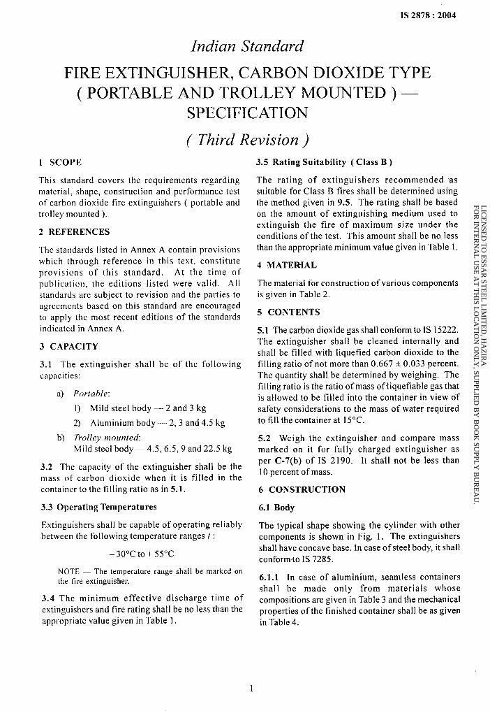
This Indian Standard ( Third Revision ) was adopted by the Bureau of Indian Standards, after the draftfinalized by the Fire Fighting Sectional Committee had been approved by the Civil Engineering DivisionCouncil.
One of important types of fire extinguishers used for fine extinguishment is the carbon dioxide type which issuitable for fire fighting in oils, petroleum products and gaseous substances under pressure ( Classes B and Cfires ) and also for fires involving electrical equipment. This standard was first pubtished in 1964 and revisedin 1976 and 1986. This revision is being prepared so as to include squeeze grip valve. and aluminium body offire extinguishers besides updating the requirements in respect of the materials, ptmformance and to bring it in linewith international practices specially as a replacement to HaIon 1211 and high effectiveness weight ratio.
The cylinders used for manufacturing of COZ extinguishers shall be approved by Chief Controller of Explosives.
For the purpose of deciding whether a particular requirement of this standard is complied with, the finalvalue, observed or calculated, expressing the result of a test or analysis, shall be rounded off in accordance withIS 2:1960 ‘Rules for rounding off numerical values ( revised)’. The number of significant places retained in therounded off value should be the same as that of the specified value in this standard.
LIC
EN
SED
TO
ESSA
R ST
EE
L L
IMIT
ED
, HA
ZIR
A
FOR
INT
ER
NA
L U
SE A
T T
HIS L
OC
AT
ION
ON
LY
, SUPPL
IED
BY
BO
OK
SUPPL
Y B
UR
EA
U.
1S 2878:2004
Indian Standard
FIRE EXTINGUISHER, CARBON DIOXIDE TYPE( PORTABLE AND TROLLEY MOUNTED) –
SPECIFICATION
( Third Revision)
1 SC=OPE
This standard covers the requirements regardingmaterial, shape, construction and performance test
of carbon dioxide fire extinguishers ( portable andtrolley mounted ).
2 REFERENCES
The standards listed in Annex A contain provisionswhich through reference in this text, constitute
provisions of this standard. At the time of
publication, the editions listed were valid. Allstandards are subject to revision and the parties toagreements based on this standard are encouragedto apply the most recent editions of the standardsindicated in Annex A.
3 CAPACITY
3.1 The extinguisher shall be of the followingcapacities:
a) Por~able:
1) Mild steel body — 2 and 3 kg
2) Aluminium body— 2,3 and 4.5 kg
b) Trolley mountedMild steel body—4.5, 6.5,9 and22.5 kg
3.2 The capacity of the extinguisher shall be themass of carbon dioxide when it is filled in thecontainer to the filling ratio as in 5.1.
3.3 Operating Temperatures
Extinguishers shall be capable of operating reliablybetween the following temperature ranges t :
–30°cto+550c
NOTE — The temperature range shall be marked onthe fire extinguisher.
3.4 The minimum effective discharge time ofextinguishers and fire rating shall be no less than theappropriate value given in Table 1.
3.5 Rating Suitability ( Class B )
The rating of extinguishers recommended as
suitable for Class B fires shall be determined usingthe method given in 9.5. The rating shall be based
on the amount of extinguishing medium used toextinguish the fire of maximum size under theconditions of the test. This amount shall be no less
than the appropriate minimum value given in Table 1.
4 MATER-IAL
The material for construction of various componentsis given in Table 2.
5 CONTENTS
5.1 The carbon dioxide gas shatl conform to IS 15222.The extinguisher shall be cleaned internally and
shall be filled with liquefied carbon dioxide to thefilling ratio of not more than 0.667* 0.033 percent.The quantity shall be determined by weighing. The
filling ratio is the ratio of mass of liquefiable gas thatis allowed to be filled into the container in view of
safety considerations to the mass of water required
to fill the container at 15“C.
5.2 Weigh the extinguisher and compare massmarked on it for fully charged extinguisher as
per C-7(b) of IS 2190. It shall not be less than10 percent of mass.
6 CONSTRUCTION
6.1 Body
The typical shape showing the cylinder with other
components is shown in Fig. 1. The extinguishersshall have concave base. In case of steel body, it shall
conform to IS 7285.
6.1.1 In case of aluminium, seamless containers
shall be made only from materials whosecompositions are given in Table 3 and the mechanicalproperties of the finished container shall be as givenin Table 4.
LIC
EN
SED
TO
ESSA
R ST
EE
L L
IMIT
ED
, HA
ZIR
A
FOR
INT
ER
NA
L U
SE A
T T
HIS L
OC
AT
ION
ON
LY
, SUPPL
IED
BY
BO
OK
SUPPL
Y B
UR
EA
U.
1S 2878:2004
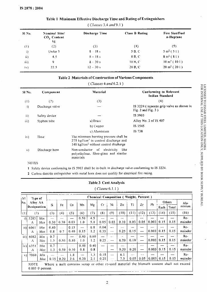
Table 1 Minimum Effective Discharge Time and Rating of Extinguishers
( Clauses 3.4 and 9.1 )
S1 No. Nominal Size/ Discharge Time Class B Rating Fire Size/FuelCOz CoRtent rs-Heptane
kg
(1) (2) (3) (4) (5)
i) [Jnder 3 8–18s 5B, C 5m2 (51)
ii) 4.5 8-18s 8B, C 8m2 (81)
iii) 9 8–30s IOB, C 10m2 (101)
iv) 22.5 12–30s 20 B, C 20m2 (201)
Table 2 Materials of Construction of Various Components
( Clauses 4 and6.2.l )
S1 No. Component
(1) (2)
i) Discharge valve
ii) Safety device
iii) Syphon tube
iv) [Hose
v) Discharge horn
Material
(3)
—
—
a) Brass
b) Copper
c) Aluminium
The minimum bursting pressure shall be275 kgf/cm~ in control discharge and140 kgf/cmz without control discharge
Non-conductor of electricity likepolyethylene, fibre-glass and similarmaterials
Conforming to RelevantIndian Standard
(4)
IS 3224 ( squeeze grip valve as shown inFig. 2 and Fig. 3 )
Is 5903
Alloy No. 2 of IS 407
IS 1545
IS 738
NOTES
1 Safety device conforming to IS 5903 shall be in-built in discharge valve conforming to IS 3224.
2 Carbon dioxide extinguisher with metal horn does not qualify for electrical fire rating.
Table 3 Cast Analysis
( Clause 6.1.1 )
SI Type of Chemical Composition ( Weight, Percent )
No. Alloy AA OthersSi Fe Cu Mn Mg Cr “Ni Zn Ti Zr Pb Ahs-
Designation Each Total minium,— ..- ..—
(1) (2) 73) (4) (5) (6) (7) (8) (9) (10) (11) (12) (13) (14) (15) (16)
i) 5283 A4in — — — 0.50 4,5 — — — — — — — — Re-A Max 0.30 0.30 0.03 1.0 5.1 0.05 0.03 0,10 0.03 0.05 0.003 0.15 0.15 mainder
ii) 6061 A4in 0.40 — 0.15 — 0.8 0.04 — — — — — — — Re-A Max 0.8 0.7 0.40 0.15 1.2 0.35 — 0.25 0.15 — 0.003 0.15 0.15 mainder
iii) 6082 Min 0.7 — — 0.40 0.60 — — — — — — — — Re-A VOX 1.3 0,50 0.10 1.0 1.2 0.25 — 0.20 0.10 — 0.003 0.15 0.15 mainder
iv ) 6351 A!in %.7 — — 0.40 0.40 — — — — — — — — Re-A A4clx 1.3 0.50 0.10 0.8 0.8 — — 0.20 0.20 — 0.003 0.15 0.15 mainder
v) 7060 Min — — 1.8 — 1.3 0.15 — 6,1 — — — — — Re-Mcrx 0.15 0.20 2.6 0.20 2. I 0.25 — 7.5 0,05 0.05 0.003 0.15 0.15 mainder
I NOTE — Where a melt contains scrap or other re-used material the bismuth content shall not exceed0.003 0 percent. I
2
LIC
EN
SED
TO
ESSA
R ST
EE
L L
IMIT
ED
, HA
ZIR
A
FOR
INT
ER
NA
L U
SE A
T T
HIS L
OC
AT
ION
ON
LY
, SUPPL
IED
BY
BO
OK
SUPPL
Y B
UR
EA
U.

1S 2878:2004
IvHANDLE
DISCHARGEVALVE \ /
HOSE RESTINGBRACKET7 II Ah
I l-!-r
‘0s’4FC’L’N1 11 19 1 n d 1 b
HOSE RESTBRACKE
BOTTO
+-
WHEEL
CLAMP
TROLLEYJ
FIG. 1 GENERALFEATURESOFCARBONI) IOXIDFTYPEFIREEXTINCiUISH~R,TROLLEYMOUNTED
Table 4 Mechanical Properties
( Clauses 6.1.1 and6.2.2.3 )
S1 No. Mechanical Properties
(1) (2)
i) Tensile strength ( T )
ii) Specified mioimum 0,2 percent proof stress ( Y )
iii) Elongation percent. on 5.65~
iv) Bend test former radios
v) Hardness equivalent to:Brinell orRockwell B
Requirements
(3)
325 N/mm2, Min
280 N/mm2, Min
12. Min
3 (, maximum ( t, is actualthickness of the specimen )
90. Min45. Min
3
LIC
EN
SED
TO
ESSA
R ST
EE
L L
IMIT
ED
, HA
ZIR
A
FOR
INT
ER
NA
L U
SE A
T T
HIS L
OC
AT
ION
ON
LY
, SUPPL
IED
BY
BO
OK
SUPPL
Y B
UR
EA
U.
IS 2878:2004
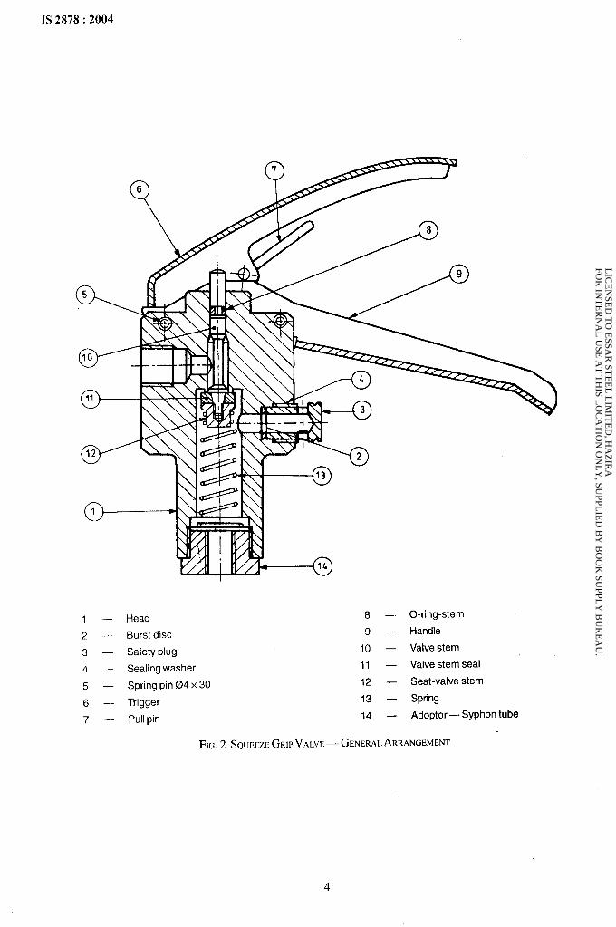
1 — Head 8 — O-ring-stem
2 — Burst disc 9 — Handle
3— Safety plug 10 — Valve stem
4 Sealing washer 11 — Valve stem seal
5 — Spring pin 04 x 30 12 — Seat-valve stem
6 — Trigger 13 — Spring
7 — Pull pin 14 — Adoptor — Syphon tube
FIG.2 SQUEIZEGRIPVALVE— GENERALARRANGE!WNT
4
LIC
EN
SED
TO
ESSA
R ST
EE
L L
IMIT
ED
, HA
ZIR
A
FOR
INT
ER
NA
L U
SE A
T T
HIS L
OC
AT
ION
ON
LY
, SUPPL
IED
BY
BO
OK
SUPPL
Y B
UR
EA
U.
IS 2878:2004
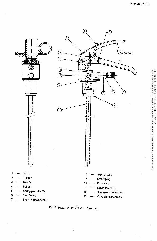
1 — Head
2 — Trigger
3 — Handle
4— Pullpin
5— Spring pin 04x 30
6 — Seal O-ring
7 — Syphontube adopter
8 — Syphon tube
9 — Safety plug
10 — Burst disc
11 — Sealing washer
12 — Spring—compression
13 — Valve stemassembiy
FIG.3 SQU~EZEGRIPVALV~— ASS~MWY
5
LIC
EN
SED
TO
ESSA
R ST
EE
L L
IMIT
ED
, HA
ZIR
A
FOR
INT
ER
NA
L U
SE A
T T
HIS L
OC
AT
ION
ON
LY
, SUPPL
IED
BY
BO
OK
SUPPL
Y B
UR
EA
U.
IS 2878:2004
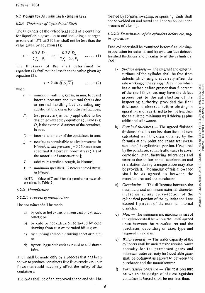
6.2 Design for Aluminium Extinguishers
6.2.1 Thickness ?f Cylindrical Shell
The thickness of the cylindrical shell of a containerfor liquefiable gases, up to and including a chargedpressure at 15°C at 210 bar, shall not be iessthan thevalue given by equation (1):
0.3 P,D, 0.3 P,DOf= or
7fe– Pl 7&–o.4Pl... ... ...(1)
The thickness of the shell determined byequation (1) shall not be less than the value given byequation (2).
t = 2.484( D,/T) ... ... ... (2)
where
t=
PI =
f), =
.~ =
T=
Y=
minimum wall thickness, in mm, to resistinternal pressure and external forces dueto normal handling but excluding anyadditional thickness for other influences;
test pressure ( in bar ) applicable to the
design governed by equations (1) and (2);DOis the external diameter of the container,
in mm;
internai diameter of the container, in mm;
maximum permissible equivalent stress, inN/nlm2, at test pressure [ = 0.75 x minimumspecified 0.2 percent proof stress ( Y) ofthe material of construction];
minimum tensile strength, in N/mmz;
minimum specified 0.2 percent proof stress,in N/mmz.
NOTE — Values ot’7’and Yfor the permissible materialsare given in Table 2.
6.2.2 Manufactui-e
.6.2.2.1 Process of manufacture
The container shall be made:
a)
b)
c)
d)
by cold or hot extrusion from castor extrudedbillets; or
by cold or hot extrusion followed by cold
drawing from cast or extruded billets; or
by cupping and cold drawing sheet or plate;or
by necking at both ends extruded or cold drawntube.
They shall be made only by a process that has been
shown to produce containers free from cracks or other
flaws that could adversely affect the safety of the
containers.
The ends shall be of an approved shape and shall be
formed by forging, swaging, or spinning. Ends shallnot be welded on and metal shall not be added in theprocess of closing.
6.2.2.2 Examination of the cylinders before closing-
in operation
Each cylinder shall be examined before final closing-in operation for external and internal surface defects,finished thickness and circularity of the cylindricalshell.
6
a)
b)
c)
d)
e)
f)
Surface defects — The internal and externalsurfaces of the cylinder shall be free fromdefects which might adversely affect thesafe working of the cylinder. A cylinder whichhas a surface defect greater than 5 percent
of the shell thickness may have the defectground out to the satisfaction of theinspecting authority, provided the finalthickness is checked before closing-inoperation and is certified to be not less thanthe calculated minimum wall thickness plus
additional allowance.
Finished thickness — The agreed finished
thickness shall be not less than the minimumcalculated wall thickness obtained by Iheformula at any point and at any transverse
section of the cylindrical portion. If requiredby the purchaser, suitable allowance to covercorrosion, manufacturing tolerances andstresses due to horizontal acceleration andretardation during transportation may also
be provided. The amount of this allowanceshall be as agreed to between themanufacturer and the purchaser.
Circularity — The difference between the
maximum and minimum external diametermeasured at any cross-section of thecylindrical portion of the cylinder shall notexceed 1 percent of the nominal internal
diameter.
Mass — The minimum and maximum mass ofthe cylinder shall be within the limits agreedupon between the manufacturer and the
purchaser, depending on size, type andrequired thickness.
Water capacity — The water capacity of thecylinders shall be such that the nominal water
capacity for the permanent gases andminimum water capacity for liquefiable gases
shall be obtained as agreed to between the
purchaser and the manufacturer.
Permissible pressure — The test pressure
on which the design of the extinguisher
container is based shall be not less than:
LIC
EN
SED
TO
ESSA
R ST
EE
L L
IMIT
ED
, HA
ZIR
A
FOR
INT
ER
NA
L U
SE A
T T
HIS L
OC
AT
ION
ON
LY
, SUPPL
IED
BY
BO
OK
SUPPL
Y B
UR
EA
U.
IS 2878:2004
1/0.85 x the pressure developed by the gas
at the reference temperature ( for liquefiablegases).
6.2.2.3 Heat treatment
Each container shall be heat treated at a temperaturewithin the range 5 15°C to 545°C and water quenchedand then artificially aged at a temperature selectedwithin the range 150°C to 200°C.
Minimum values of mechanical properties required inthe finished container after heat treatment and at roomtemperature shall be as given in Table 4.
The operations involving heat treatment shall be carriedout carefully in furnaces equipped to controltemperatures accurately, and the containers shall bemaintained at the stipulated temperatures for the length
of time necessary to ensure that all parts have reachedthe required temperature and all necessary metallurgical
changes have been effected.
6.3 Discharge Valve or Operating Head
The valve shall be provided and it shall be squeezegrip type or wheel type.
6.4 Discharge Fittings
6.4.1 The discharge tube shall be provided to 2 ands kg capacity extinguishers fitted to discharge valve
by swivel joints.
6.4.2 The hose of not less than 10 mm internal diametershall be provided for4.5, 6.5, 9 and 22.5 kg capacity
fire extinguishers. The length of the hose shall be
not less than 1 m for 4.5 and 6.5 kg capacity fire
extinguisher, 2 m for 9 kg, and 5 m for 22.5 kg capacityfire extinguishers.
6.4.3 A discharge horn with a suitable handle shallbe provided ( see Fig. 1 ).
6.5 Trolley
The details of trolley are given in Fig. 1. The
dimensions of trolley shall be 132 mm x 28 mm x20 mm for sizes up to -9 kg and for higher sizes
300 mm x 50 mm x25 mm.
7 ANTI-CORROSIVE TREATMENT
The external surface of.the body shall be completely
coated with epoxy powder of minimum 0.050 mm
thickness. The thickness of the coating shall bemeasured as per the procedure given in IS 3203.
8 PAINTING
8.1 Each extinguisher shall be painted fire red or post
office red conforming to shade No. 536 or 537 of IS 5.
8.2 A picture showing operation of the extinguisher
in the correct manner shall be provided on the body
of the extinguishers.
8.3 The extinguisher shall be marked with theletters B and C indicating their suitability forrespective classes of tires as laid down in IS 2190.The letters B and C shall be of2.5 cm size printed inwhite colour centrally contained in a square of4 cmsize and a circle of 2 cm radius respectively and shallbe coloured black. For 2 kg capacity, size of squareshall be 2 cm and a circle of 1 cm radius and size ofletter 1.5 cm.
8.4 The paint shall conform to IS 2932.
9 PERFORMANCE REQUIREMENTS
9.1 Discharge Duration
The design and construction of the extinguisher
shall be such that when operated at an angle ofnot more than 45°C from thevertical at a temperature
of27 * 2°C, it shall expel not less than 95 percent ofthe contents in the form of a continuous dischargewithin the following period from the time ofoperating the valve. The body shall be weighed
30 min after the discharge period and shall be wipedand dried before checking the contents. Theminimum effective discharge time of extinguishersshall not be less than the appropriate value givenin Table 1.
NOTE — Extinguisher should be conditioned for I hbefore testing.
9.2 Intermittent Operation
An extinguisher shall be capable of being operated
intermittently without freeze up of the valve seat
and causing any leak when conditioned at 27 + 2°C.The valve shall be opened for 3 s and closed for 10sand the cycle shall be repeated and shall dischargeat least 95 percent of the contents. ‘
9.3 Leakage Test
The extinguisher without its attachment shall be
filled with C02 gas to the specified filling ratioand dipped in water for 2 min and then check that no
bubbles come out or soap solution test for leakagebe carried out.
9.4 Inspection and Tests for Aluminium Cylinders
9.4.1 Inspection and test requirements foraluminium cylinders used in the extinguishers aregiven in Annex A, Annex B, Annex C and Annex D.
9.5 Class B Test Fire
9.5.1 Construction
Class B test fires utilize a range of welded-sheet-
7
LIC
EN
SED
TO
ESSA
R ST
EE
L L
IMIT
ED
, HA
ZIR
A
FOR
INT
ER
NA
L U
SE A
T T
HIS L
OC
AT
ION
ON
LY
, SUPPL
IED
BY
BO
OK
SUPPL
Y B
UR
EA
U.

IS 2878:2004
steel cylindrical trays ( dimensions givenin ‘rable 6 ). The sides are vertical. The bases ofthe trays are set horizontal and level with thesurrounding ground.
NOTE — Reinforcement of the base of the larger testtlretraysw,ill benecessary to minimize distortion, 10such cases it will be necessary to ensure that theunderside of the trays are not exposed to the atmosphere.
Details of Class Btestfires aregivenin Table5. Eachtest fire is designated by a number followed by theletter B.
9.5.2 Fuel
Use an aliphatic hydrocarbon having an initialboiling point of no less than 88°C and a final boiling
point of not more than 105”C. Most suitable anduniversally used fuel is rr-heptane.
NOTE — Typical fuels meeting this requirement are rr-beptane and certain solvent fractions sometimes referredto as commercial heptane.
9.5.3 Procedure
9.5.3.1 Add the appropriate volume of water andrr-heptane specified in Table 5. Add additionalwater to compensate for distortion of the base so that
all points are covered, subject to a maximum liquiddepth of 50 mm and a minimum heptane depth of
15 mm at any point.
9.5.3.2 Ignite the ftlel
9.5.3.3 Permit the fuel to burn freely for a minimum
of 10 s before operating the extinguisher.
9.5.3.4 Operate the extinguisher and apply theextinguishing medium to the test fire.
NOTES
1 Tbe extinguisher maybe discharged continuously orin intermittent bursts at the discretion of the operator.The operator may move round the fire in order to obtainthe best results. Operator should use proper tire protectivesuits, helmet and gloves.
2 For reasons of safety the operator shall not reachover the edge of the tray, and at no time shall the operatorreach onto or into the tray.
9.S.4 Low-Temperature Extinguishment Test
An extinguisher, charged with its rated capacity of
extinguishing agent and expellant gas, andconditioned at the minimum storage temperaturefor 18 h, shall extinguish a Class B test fire two
classification sizes smaller than the rating of theextinguisher given in Table 5.
9.5 Special Requirements
The extinguisher ‘horn shall be constructed towithstand crushing when 25 kg is applied to its
extremity for 5 min immediately after havingcompletely discharged the extinguisher throughthe -horn.
Subject the horn to the following test:
a) Condition the horn at 55°C for 18 h;
b) Attach the horn to a fully chargedextinguisher;
c) Discharge the extinguisher with the valve fully
open;
d) Subject the horn to a static load of 25 kgusing a circular contact surface of 50 mm
diameter for 5 min applied at the end of thehorn; and
Table 5 Dimensions of Class B Test Fires
(C/auses 9.5.1 ,9.5.3.1, 9.5.4 arrdB-5 )
St No. Classification Minimum Volume of Dimensions of Test Fire TrayDischarge of IJiquidlJ .- .
Dian~eter2) internal Minimal ApproximateExtinguishers i mm Depth2j, mm Thickness Surface of Fire
(1) (2) (3) (4) (5) (6) (7) (8)
i) !3B3) . 8 570+ 10 150+5 2.0 0.25
ii) 13B3) — 13 720+ 10 150+5 2.0 0.41
iii) 21B 8 21 920+ 10 150+5 2.0 0.66
iv) 34B 8 34 1 170+ 10 150+5 2.5 1.07
NOTE — Each test fire is designated by a number in a series in which each term is equal to the sum of the two precedingterms ( this series is equivalent to geometric progression having a common ratio of about 1.62 ). Test fires larger thanthose given may be constructed following the rules of this geometric progression, The additional tires 70 B/1 13B/l 83 Brepresent the product of the preceding term and ~
-———.I) I/3 water and 2/3 heptane.
‘) Measured at rim.J) This fire size is for a low-temperature tire teSt OnlY.
8
LIC
EN
SED
TO
ESSA
R ST
EE
L L
IMIT
ED
, HA
ZIR
A
FOR
INT
ER
NA
L U
SE A
T T
HIS L
OC
AT
ION
ON
LY
, SUPPL
IED
BY
BO
OK
SUPPL
Y B
UR
EA
U.
e) Check that the horn does not show anyevidence of cracking or breakage.
10 MARKING
10.1 Every extinguisher shall be clearly and
permanently marked in accordance with therequirements laid down in 10.2 and 10.2.1.
10.2 The following information shall be marked on
the extinguisher:
a)
b)
c)
d)
e)
t-l
Manufacturer’s name or trade-mark;
Method of operation in prominent letters;
The words ‘CARBON D1OX1DE TYPE’ inprominent letters;
Capacity;
Year of manufactur~ of extinguisher and dateof refilling; and
Source, year of manufacture of the cylinderand its test pressure.
10.2.1 The following information to facilitate fillingor recharging shall also be marked on the head ofextinguisher or on the neck of the cylinder:
a) Empty weight of extinguisher ( to include
1S No,
5:1994
407:1981
738:1994
1“545:1994
2190:1992
2932:1993
b)
1S 2878:2004
operating head, internal discharge tubeand carrying handle but not any hose ordischarge horn assembly ), shown as EW;and
Filled weight of extinguisher ( to include
operating head, internal discharge tube,carrying hand and gas-filled contentsbut not any hose or discharge horn
assembly ), shown as FW.
10.3 BIS Certification Markkng
The extinguisher may also be marked with the Standard
Mark.
The use of the Standard Mark is governed by the
provisions of the Bureau of Indian Standards Act,1986 and the Rules and Regulations madethereunder. The details of conditions under which
a licence for the use of the Standard Mark may begranted to manufacturers or producers may beobtained from the Bureau of Indian Standards.
11 SAMPLING AND CRITERIA FORCONFORMITY
The details of sampling and criteria for conformity is
given in Annex E.
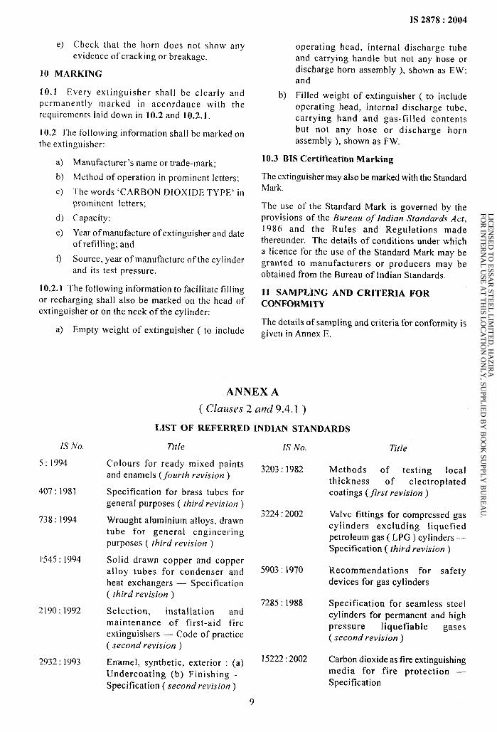
ANNEX A
( clauses 2 and 9.4.1 )
LIST OF REFERRED INDIAN STANDARDS
Title
Colours for ready mixed paintsand enamels (fourth revision )
Specification for brass tubes forgeneral purposes ( third revision )
Wrcwght aluminium alloys, drawntube for general engineering
purposes ( third revision )
Solid drawn copper xnd copperalloy tubes for condenser andheat exchangers — Specification( [bird revision)
Selection, installation and
maintmance .of first-aid fire
extinguishers — Code of practice
( second revision)
Enamel, synthetic, exterior : (a)
Undercoating (b) Finishing —
Specification ( second revision)
Is No.
3203:1982
3224:2002
5903:1970
7285:1988
15222:2002
9
Title
Methods of testing local
thickness of electroplated
coatings (first revision )
Valve fittings for compressed gas
cylinders excluding liquefiedpetrolemti gas ( LPG ) cyl inders —Specification ( third revision)
Recommendations for safety
devices for gas cylinders
Specification for seamless steelcylinders for permanent and highpressure liquefiable gases
( second revision)
Carbon dioxide as.fire extinguishingmedia for fire protection —
Specification
LIC
EN
SED
TO
ESSA
R ST
EE
L L
IMIT
ED
, HA
ZIR
A
FOR
INT
ER
NA
L U
SE A
T T
HIS L
OC
AT
ION
ON
LY
, SUPPL
IED
BY
BO
OK
SUPPL
Y B
UR
EA
U.
IS 2878:2004
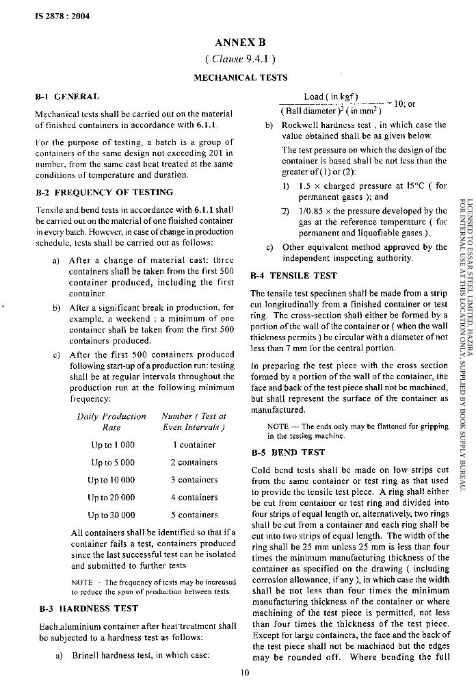
ANNEX B
( clause 9.4.1 )
MECHANICAL TESTS
B-1 GENERAL
Mechanical tests shall be carried out on the materialof finished containers in accordance with 6.1.1.
For the purpose of testing, a batch is a group ofcontainers of the same design not exceeding 2(I 1 innumber, from the same cast heat treated at the sameconditions of temperature and duration.
B-2 FREQUENCY OF TESTING
Tensile and bend tests in accordance with 6.1.1 shall
be carried out on the material of one finished containerin every batch. However, in case of change in productionschedule, tests shall be carried out as follows:
a) After a change of material cast: threecontainers shall be taken from the first 500
container produced, including the firstcontainer.
.- b) After a significant break in production, forexample, a weekend : a minimum of onecontainer shall be taken from the first 500containers produced.
c) After the first 500 containers producedfollowing start-up of a production run: testingshall be at regular intervals throughout theproduction run at the following minimumfrequency:
Daily Production Number ( Test at
Rate Even Intervals )
up to 1000 1 container
upto5000 2 containers
Up”to 10000 3 containers
upto20000 4 containers
upto30000 5 containers
All containers shall be identified so that if acontainer fails a test, containers producedsince the last successful test can be isolatedand submitted to further tests
NOTE — The frequency of tests maybe increasedto reduce the span of production between tests.
B-3 HARDNESS TEST
Eachaluminium container after heat treatment shall
be subjected to a hardness test as follows:
a) Brinell hardness test, in which case:
b)
c)
Load (in kgf )= 17);or
( Ball diameter )Z( in mm2 )
Rockwell hardness test , in which case thevalue obtained shall be as given below.
The test pressure on which the design of thecontainer is based shall be not less than thegreater of(1) or (2):
1) 1.5 x charged pressure at 15°C ( for
permanent gases ); and
2) 1/0.85 x the pressure developed by the
gas at the reference temperature ( forpermanent and liquefiable gases ).
Other equivalent method approved by theindependent inspecting authority.
B-4 TENSILE TEST
The tensile test spe~imen shall be made from a stripcut longitudinally from a finished container or testring. The cross-section shall either be formed by a
portion of the wall of the container or ( when the wallthickness permits ) be circular with a diameter of notless than 7 mm for the central portion.
In preparing the test piece with the cross sectionformed by a portion of the wall of the container, the
face and back of the test piece shall not be machined,but shall represent the surface of the container asmanufactured.
NOTE — The ends only may be flattened for grippingin the testing machine.
B-5 BEND TEST
Cold bend tests shall be made on low strips cutfrom the same container or test ring as that usedto provide the tensile test piece. A ring shall either
be cut from container or test ring and divided intofour strip-s of equal length or, alternatively, two rings
shall be cut from a container smd each ring shall be
cut into two strips of equal length. The width of thering shall be 25 mm unless 25 mm is less than four
times the minimum manufacturing thickness of thecontainer as specified on the drawing ( includingcorrosion allowance, if any), in which case the widthshall be not less than four times the minimum
manufacturing thickness of the container or where
machining of the test piece is permitted, not less
than four times the thickness of the test piece.-Except for large containers, the face and the back of
the test piece shall not be machined but the edges
may be rounded off. Where bending the full
10
LIC
EN
SED
TO
ESSA
R ST
EE
L L
IMIT
ED
, HA
ZIR
A
FOR
INT
ER
NA
L U
SE A
T T
HIS L
OC
AT
ION
ON
LY
, SUPPL
IED
BY
BO
OK
SUPPL
Y B
UR
EA
U.
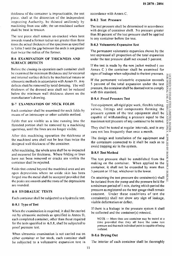
1S 2878:2004
thiclmess of thecontaincr is impracticable, the test
piece, shall at the discretion of the independentinspecting Authority, be thinned uniformly bymachining from one side; the un-machined surfaceshall be bent in tension.
The test piece shall remain un-cracked when bentinwards round a former radius not greater than threetimes the actual thickness of the specimen as specifiedin Table 5 until the gap between the ends is not greater
than twice the radius of the former.
B-6 EXAMINATION OF THICKNESS ANDSURFACE DEFECTS
Before the closing-in operation each contairwr shallbe examined for minimum thickness and fortxternaland internal surface defects by mechanical means orultrasonic methods in accordance with Annex D. Any
defects shall be removed by local dressing. The wall
-thickness of the dressed area shall not be reducedbelow the minimum wall thickness shown on themanut%cturn-’s drawing.
B-7 EXAMINATION OF NECK FOLDS
Each container shall be examined for neck folds bymeans of an introscope or other suitable method.
Folds that are visible as a line running into the
threaded portion shall be removed by a machiningoperation, until the lines are no longer visible.
After this machining operation the thickness at
the machined area shall not be less than twice the
designed wall thicknexs of the container.
After machining, the whole area shall be re-inspected
and measured for thickness. Where folding or lineshave not been removed or cracks are visible thecontainer shall be rejected.
Folds that extend beyond the machined area and are
open depressions where no oxide skin has beenforged into the metal shall be accepted provided thatthe peaks are smooth and the roots of the depressions
are rounded.
B-8 HY-DRAULIC TESTS
Each container shall be subjected to a hydraulic test.
B-8.1 Type of Test
When the examination is required, it shall be carried
out by ultrasonic methods as specified in Annex D,
each completed container, other than those requiredfor the tests specified in 6.1.1, shall be subjected to
proof pressure test.
When ultrasonic examination is not carried out on
either container or bar stock, each container shall
be subjected to a volumetric expansion test in
accordance with Annex C.
B-8.2 Test Pressure
The test pressure shall be determined in accordancewith design of container shell. No pressure greaterthan 80 percent of the-test pressure shall be appliedto any container before the test.
B-8.3 Volumetric Expansion Test
The permanent volumetric expansion shown by thetest expressed all proportion of the total expansionunder the test pressure shall not exceed 5 percent.
If the test is made by the non jacket method ( see
Annex C ) the container shall be examined forsigns of leakage when subjected to the test pressure.
If the permanent volumetric expansion exceeds5 percent of the total expansion under the test
pressure, the container shall be deemed not to complywith this standard.
B-8.4 Proof Pressure Test
Testequipment; all rigid pipe work, flexible tubing,valves, fittings and components forming thepressure system of the test equipment shall be
capable of withstanding a pressure equal to themaximum test pressure of any container to be tested.
They shall be tested at regular intervals, and in anycase not less frequently than once a month.
The design and installation of the equipment and
the containers connected to it shall be such as to
avoid trapping air in the system.
B-8.5 Test Method
The test pressure shall be established from the
making on the container. When applied to thecontainer, it shall not be exceeded by more than3 percent or 10 bar, whichever is the lower.
On attaining the test pressure the container(s) shall
be isolated from the pump and the pressure held fora minimum period of 1 rein, during which period the
pressure as registered on the test gauge shall remainconstant. Under these conditions of test thecontainer(s) shall not show any sign of leakage,visible deformation or defect.
If there is .a leakage in the pressure system it shallbe COIlected and the container(s) retested.
NOTE — More than one container may be tested at atime provided that they all have the same testpressure and that each individual point is capable of beingisolated.
B=8.6 Drying Out
The interior of each container shall be Thoroughly
LIC
EN
SED
TO
ESSA
R ST
EE
L L
IMIT
ED
, HA
ZIR
A
FOR
INT
ER
NA
L U
SE A
T T
HIS L
OC
AT
ION
ON
LY
, SUPPL
IED
BY
BO
OK
SUPPL
Y B
UR
EA
U.
IS 2878:2004
dried by a suitable method immediately afterhydraulic testing. Containers shall not be heatedabove 150°C.
B-8.7 Re-heat Treatment
Containers shall be solution treated not more thanonce.
NOTES
1 Where itcan reestablished fromtheh eattreatmentfurnace records that the artificial ageing treatment hasnot been adequate, additional time at the ageing treatmenttemperatures permissible.
2 Where itcanbe estabfislled thatsolution heattreatmel]twas at fault resolution treatment and artificial ageingof the container are permissible.
B-9 CHECKING OF WATER CAPACITY
The water capacity of each container shall be checkedand recorded. This shall be done “by weighing, byfilling the container with a calibrated volume of liquidor by other means approved by the IndependentInspection Authority.
b<)
If after the permitted number of retests and re-heattreatments the mechanical requirements have notbeen complied with, the containers in the batch shallbe rendered unserviceable for holding gas under
pressure, by one of the following methods:
a)
b)
Container shall -be crushed by mechanicalmeans.
An irregular hole shall be made in the topdome of the container, equivalent in area to
approximately 10 percent of the area of the
top dome; or, in the case of thin walledcontainers, the containers shall be pierced
in at least three places. Drilling a hole orholes in a container shall not be considered
as satisfying the requirement of this clause.
B-10 TESTING OF PROTOTYPE CONTAINERS
B-10.1 New Design
For the purpose of this clause a container shall be
considered a new design compared with an existingapproved design, when:
a)
b)
c)
d)
e)
o
it is manufactured in a different factory; or
it is manufactured by a different process; or
the base profile and the base thickness havechanged relative to the container diameterand calculated minimum wall thickness; or
the length of the container has increasedby more than 50 percent ( containers withan L/D ratio less than 3 shall not be used asreferenced containers for any new design
with an L/D ratio greater than 3 ); or
the diameter has changed by more than5 percent; or
a change in hydraulic test pressure requiresa change in design wall th-ickness.
Where a container is to”be used for a lower pressureduty than that for which design approval has beengiven, it shall not be deemed a new design.
The nominal hoop stress corresponding to the pressureat which destruction occurs shall be calculated fromthe formula:
2ofb t’pb =
(Do-t’)L
where
& = nominal hoop stress, in N/mmz, at whichdestruction occurs;
P~ = internal pressure, in bar, at which
destruction occurs;
DO = external diameter, in mm, of the container;
and
t’ = actual-minimum wall thickness, in mm, for
the container being tested.
The value of fb shall be not less than 0.95 of theminimum specified tensile strength of the material of
the container.
LIC
EN
SED
TO
ESSA
R ST
EE
L L
IMIT
ED
, HA
ZIR
A
FOR
INT
ER
NA
L U
SE A
T T
HIS L
OC
AT
ION
ON
LY
, SUPPL
IED
BY
BO
OK
SUPPL
Y B
UR
EA
U.
IS 2878:2004
ANNEX C
( Clauses 9.4.1, B-8.1 and B-8.3 )
VOLUMETRIC EXPANSION TESTING OF SEAMLESS CONTAINERS
C-1 GENERAL
This Annex gives details of two methods of determiningthe volumetric expansion of seamless aluminium alloygas containers:
a) Water jacket method ( preferred method );and
b) Non-water jacket method.
The water jacket volumetric expansion test may becarried out on equipment with a Ievelling burette witha fixed burette.
C-2 TEST EQUIPMENT
NOTE –- The requirements specified in B-2.1to B-2.7 are general to both methods of test,
C-2.1 Hydraulic test pressure pipelines shall be
capable of withstanding pressures equal to the
maximum test pressure of container that maybe tested.
C-2.2 Glass burettes shall be of sufficient length
to receive water equivalent to the full volumetricexpansion of the container and capable of being read
to an accuracy of 1 percent or 0.1.
C-2.3 Pressure gauges shall be tested at regularintervals and in any case not less frequently than
once a month.
C-2.4 A suitable device shall be employed toensure that the test pressure of.the container is not
exceeded by more than 3 percent or 10 bar which-everis the lower.
C-2.5 Pipe work shall utilize long bends in preferenceto elbow fittings and pressure pipes shall be as short
as possible. Flexible tubing shall be capable ofwithstanding equal to the maximum test pressure of
any container that may be tested and have sufficientwall thickness to prevent kinking.
C-2.6 All joints shall be leak-tight.
C-2.7 Care shall be taken to avoid trapping air in thestem.
C-3 WATER .JACKET VOLUMETRIC
EXPANSION TEST
C-3.1 Principle
This method of test necessitates enclosing thewater filled container in a jacket also filled with water.
The total volumetric expansion of the container is
measured by the amount of water displaced from thejacket when the container has been pressurized. Thepermanent volumetric expansion of the container ismeasured by the amount of water that continues tobe displaced from the jacket when the pressure hasbeen released.
C-3.2 Apparatus
The water jacket shall be fitted with a safety devicecapable of releasing the energy from any containerthat may burst at the test pressure.
An air bleed valve shall be fitted to the highest pointof the jacket.
C-3.3 Procedure
C-3.3.1 General
Two methods of performing this test are describedin C-3.3.2 and C-3.3.3. Other methods are acceptable
provided that they are capable of measuring the total
and, if any, the permanent volumetric expansion ofthe container.
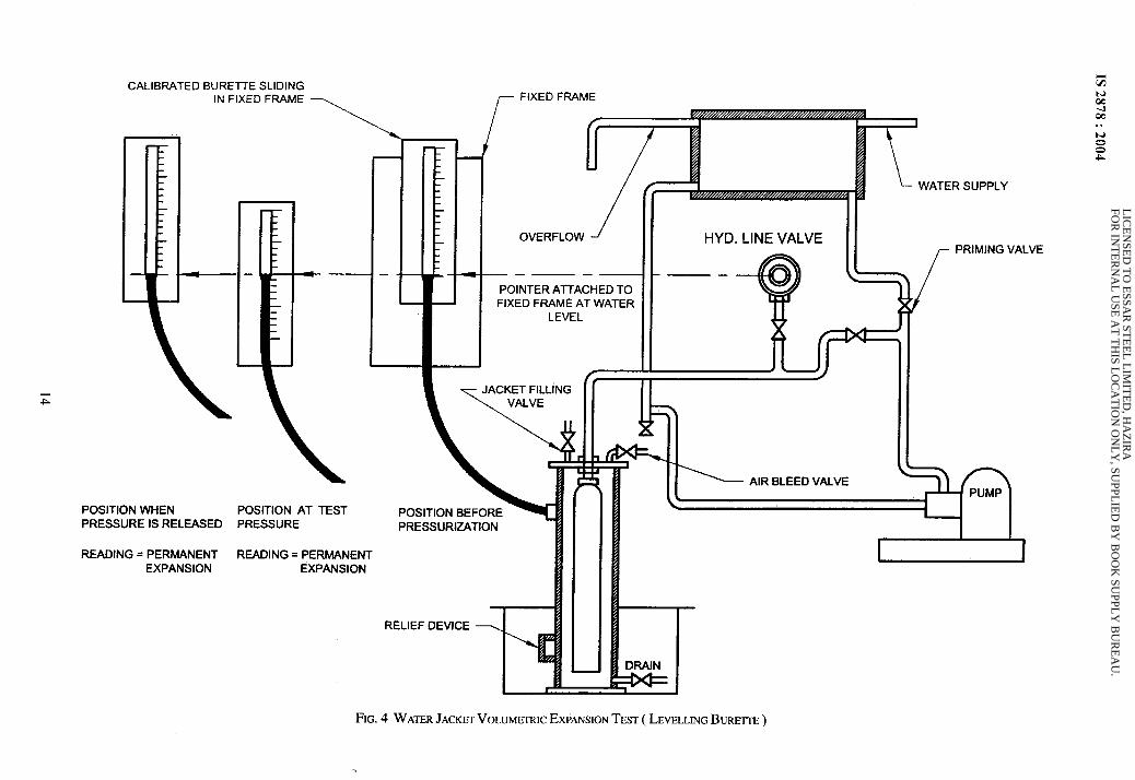
C-3.3.2 Water .Jacket Volumetric Expansion Test
( Levelling Burette Method)
A typical example of the equipment required is
shown in Fig. 4. The following procedure shall becarried out:
a)
b)
c)
d)
e)
Fill the container with water and attach the
water jacket cover to it,
Seal the container in the jacket and attachthe pressure line to the container.
Fill the jacket with water, allowing air to
bleed off through the air bleed valve. Close
the air bleed valve when water issues freelyfrom it.
Adjust the zero level on the burette to the
datum mark on the burette support stand.Adjust the height of the water to theburette zero level by manipulation of the jacketfilling valve and the drain valve.
Raise the pressure in the container to two-thirds of the test pressure. Close the hydraulicpressure supply valve and check that the
burette reading remains constant.
NOTE — A rising water level indicates a leakingjoint between container and jacket, A falling waterlevel indicates a Ieakingjoint between water jacketand atmosphere.
13
LIC
EN
SED
TO
ESSA
R ST
EE
L L
IMIT
ED
, HA
ZIR
A
FOR
INT
ER
NA
L U
SE A
T T
HIS L
OC
AT
ION
ON
LY
, SUPPL
IED
BY
BO
OK
SUPPL
Y B
UR
EA
U.
IS2378:2004
IL
Wii
fxz3–m
I
t“’’’’’’’’’’’’’’’”II
LwiUJ
K
r
14
LIC
EN
SED
TO
ESSA
R ST
EE
L L
IMIT
ED
, HA
ZIR
A
FOR
INT
ER
NA
L U
SE A
T T
HIS L
OC
AT
ION
ON
LY
, SUPPL
IED
BY
BO
OK
SUPPL
Y B
UR
EA
U.

Q
g)
h)
j)
k)
Open the hydraulic pressure line valve andcontinue the pressurization of the containeruntil the test pressure is reached. Close thehydraulic pressure line valve.
Lower the burette until the water level is atthe datum mark on the burette support stand.Take the reading of the water level in theburette. This reading is the total expansionand shall be recorded on the test certificate.
Open the hydraulic pressure line drain valveto release pressure from the container. Raisethe burette until the water level is again atthe datum line on the burette support stand.
Check that the pressure is at zero and thatthe water level is constant.
Read the water level in the burette. Thisreading is the permanent expansion, if
any, and shall be recorded on the testcertificate.
Check that the permanent expansion doesnot exceed 5 percent of the total expansionas determined by the following:
Permanent expansion x 100Percent
Tcrtal expansion
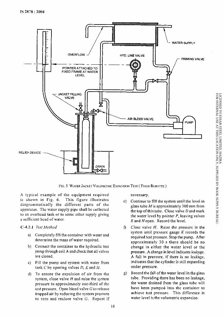
C-3.3.3 Water Jacket Volumetric Expansion Test
( Fixed Burette Method)
A typical example of the equipment required isshown in Fig. 5. The following procedure shall becarried out :
a) Fi 11the container with water and attach the
water jacket cover to it.
b) Seal the container in the jacket and attachthe pressure line to the container.
c) Fill the jacket with water, allowing air to
bleed off through the air bleed valve. Closethe air bleed valve when water issues freelyfrom it.
d) Adjust the water level to the zero mark onthe burette.
e) Raise the pressure in the container totwo-thirds of the test pressure. Close thehydraulic pressure supply valve and
check that the burette reading remains
constant.
NOTE — A rising water level indicates a leakingjoint between. container and jacket. A falling waterlevel indicates a leaking joint between water jacketand atmosphere.
f) Open the hydraulic pressure line valve andcontinue the pressurization of the container
until the test pressure is reached. Close the
hydraulic pressure line valve.
g)
h)
j)
k)
IS 2878:2004
Read the water level in the burette. Thisreading is the total expansion and shall berecorded on the test certificate.
Open the hydraulic pressure Iine drain valveto release pressure ti-om the container. Checkthat the pressure is at zero and that the waterlevel is constant.
Read the water level in the burette. Thisreading is the permanent expansion, ifany, and shall be recorded on the testcertificate.
Check that the permanent expansion does notexceed 5 percent of the total expansion asdetermined by the following:
Permanent expansion x 100Percent
Total expansion
C-4 NON-WATER JACKET VOLUMETRICEXPANSION TEST
C-4.1 Principle
This method consists of measuring the amount ofwater passed into the container under proof
pressure and on release of this pressure, measuringthe water returned to the manometer. It is necessary
to allow the compressibility of water and the volumeof the container under test to obtain true volumetricexpansion. No fall in pressure under this test is
permitted.
C-4.2 Apparatus
The equipment shall be arranged such that all air
can be removed. The glass tube reservoir shall bccalibrated in millimeters and be accurate to 1 percent
of reading. It shall be so arranged that accuratereadings can be determined of the volume of waterrequired to pressurize the filled container and ofthe volume expelled from the container whendepressurized. In the case of large containers, it maybe necessary to augment the glass tube with metaltubes arranged in a manifold.
If a single-acting hydraqlic pump is used, care shall
be taken to ensure that the piston is in tile ‘back’
position when water levels are noted.
The water used shall be free of air. Any leakage from
the system or the presence of free air will result infalse readings.
Every care shall be taken to maintain steady
temperature conditions and sufficient time shallbe allowed to permit the apparatus, the container
and the water to attain a uniform constant
temperature.
15
LIC
EN
SED
TO
ESSA
R ST
EE
L L
IMIT
ED
, HA
ZIR
A
FOR
INT
ER
NA
L U
SE A
T T
HIS L
OC
AT
ION
ON
LY
, SUPPL
IED
BY
BO
OK
SUPPL
Y B
UR
EA
U.
1S 2878:2004
REI
—.
.IEF
OVERFLOW ~
———. —POINTER AITACHED TOFIXED FRAME AT WATER
LEVEL
lA/. ”e-r c,, , ,.,0
WATER SUPPLY
r I I\
[
PRIMING VALVE
——
I la DRAIN 1
FIG. 5 WATERJACKETVOLUMETRICEXPANSIONTEST( FIXEDBURETTE)
A typical example of the equipment requiredis shown in Fig, 6. This figure illustratesdiagrammatically the different parts of theapparatus. The water supply pipe shall be collectedto an overhead tank or to some other supply giving
a sufficient head of water.
C-4.2.1
a)
b)
c)
d)
Test Method
Completely fill the container with water and
determine the mass of water required.
Connect the container to the hydraulic test
pump through coil A and check that all valvesare closed.
Fi 11the pump and system with water fromtank C by opening valves D, E and H.
To ensure the expulsion of air from the
system, close valve H and raise the system
pressure to approximately one-third of the
test pressure. Open bleed valve G to release
trapped air by reducing the system pressure
to zero and reclose vaIve G. Repeat if
e)
f)
d
necessary.
Continue to fill the system smtil the level inglass tube A4is approximately 300 mm from
the top of this tube. Close valve D and markthe water level by pointer P, leaving valves
E and Hopen. Record the level.
Close valve H. Raise the pressure in thesystem until pressure gauge K records the
required test pressure. Stop the pump. Afterapproximately 30 s there should be no
change in either the water level or thepressure. A change in level indicates Iea$age.
A fall in pressure, if there is no leakage,indicates that the cylinder is still expanding
under pressure.
Record the fall of the water level in the glasstube. Providing there has been no leakage,
the water drained from the glass tube will
have been pumped into the container to
achieve test pressure. This difference inwater level is the volumetric expansion.
16
LIC
EN
SED
TO
ESSA
R ST
EE
L L
IMIT
ED
, HA
ZIR
A
FOR
INT
ER
NA
L U
SE A
T T
HIS L
OC
AT
ION
ON
LY
, SUPPL
IED
BY
BO
OK
SUPPL
Y B
UR
EA
U.

1S 2878:2004
m ‘w.:IIH ill m lbLG.L1
FIG. 6 NONWATERJACKETVOLUMETRICEXPANSIONTEST
h) Open valve H slowly to release the pressure
in the container and allow the water releasedto return to the glass tube. The water levelshould return to the original level should be
marked by pointer P. If the water level returnsto a point below pointer P, this difference inlevel will denote the amount of permanentvolumetric expansion in the container,neglecting the effect of the compressibility
of the water obtained from the calculationgiven in C-4.4.
j) Before disconnecting the container from thetest rig, close valve E. This will leave the
pump and system full of water for the nexttest. Action as per C-4.2 .l(d) shall, however,be repeated at each subsequent test.
k) If permanent volumetric expansion has
occurred, record the temperature of the waterin container.
C-4.3 Test Results
C-4.3.1 The tests determine the volume of waterrequired to pressurize the filled container to testpressure.
C-4.3.2 The total mass and temperature of thewater in the container are known and compressibility
to be calculated by the change in the volume of thewater in the container. The volume of the waterexpelled from the container when depressurized isknown. Thus total volumetric expansion ( TE ) and
permanent volumetric expansion ( FE ) can bedetermined.
C-4.3.3 The permanent volumetric expansion shallnot exceed 5 percent of the total volumetric expansion.
C-4.4 The compressibility of water is calculated fromthe following formula:
C=mP[K–0.68P
1051
where
c.
m=
p.
K=
volume of water forced into the container
due to compressibility of water, in ml;
mass of water in the container at testpressure, in kg;
test pressure, in bar; and
factor for individual temperatures as givenin Table 6.
17
LIC
EN
SED
TO
ESSA
R ST
EE
L L
IMIT
ED
, HA
ZIR
A
FOR
INT
ER
NA
L U
SE A
T T
HIS L
OC
AT
ION
ON
LY
, SUPPL
IED
BY
BO
OK
SUPPL
Y B
UR
EA
U.

1S 2878:2004
Table6 KFactors forthe Compressibility of Water
( Clauses 9.5.1 amz-’C-4.4 )
S1 No.
(1)
i)
ii)
iii)
iv)
v)
vi)
vii)
viii)
ix)
x)
xi)
xii)
xiii)
xiv)
xv)
xvi)
xvii)
xviii)
xix)
xx)
xxi)
“c
(2)
6
7
8
9
10
11
12
13
14
15
16
17
18
19
20
21
22
23
24
25
26
K
(3)
0.049 15
0.04886
0.04860
0.04834
0,048 12
0.04792
0.04775
0.04759
0.04742
0.04725
0.047 10
0.04695
0.04680
0.04668
0.04654
0.04643
0.04633
0.04623
0.046 13
0.04604
0.04594
18
LIC
EN
SED
TO
ESSA
R ST
EE
L L
IMIT
ED
, HA
ZIR
A
FOR
INT
ER
NA
L U
SE A
T T
HIS L
OC
AT
ION
ON
LY
, SUPPL
IED
BY
BO
OK
SUPPL
Y B
UR
EA
U.
IS 2878:2004
ANNEX D
( Clauses 9.4.1, B-6 ami B-8.l )
ULTRASONIC THICKNESS MEASUREMENT
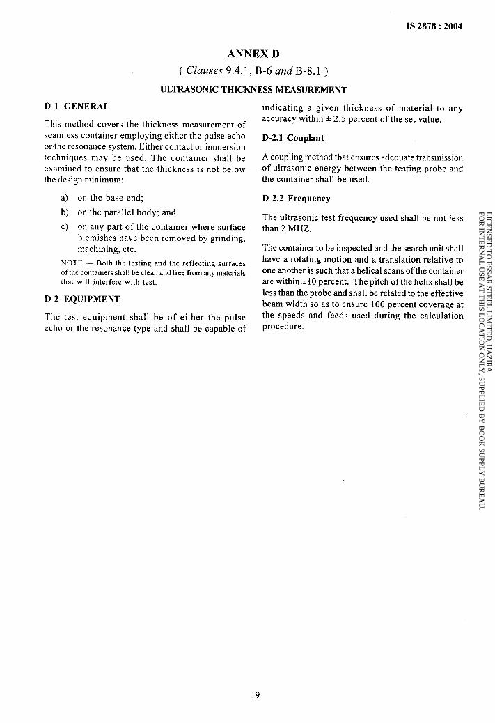
D-1 GENERAL
This method covers the thickness measurement of
seamless container employing either the pulse echoor the resonance system. Either contact or immersiontechniques may be used. The container shall beexamined to ensure that the thickness is not belowthe design minimum:
a) on the base end;
b) on the parallel body; and
c) on any part of the container where surfaceblemishes have been removed by grinding,
machining, etc.
NOTE — Both the testing and the reflecting surfacesof the containers shall be clean and free from any materialsthat will interfere with test.
D-2 EQUIPMENT
The test equipment shall be of either the pulse
echo or the resonance type and shall be capable of
indicating a given thickness of material to anyaccuracy within + 2.5 percent of the set value.
D-2.1 Couplant
A coupling method that ensures adequate transmission
of ultrasonic energy between the testing probe andthe container shall be used.
D-2.2 Frequency
The ultrasonic test frequency used shall be not lessthan 2 MHZ.
The container to be inspected and the search unit shallhave a rotating motion and a translation relative to
one another is such that a helical scans of the containerare within +10 percent. The pitch of the helix shall be
less than the probe and shall be related to the effective
beam width so as to ensure 100 percent coverage atthe speeds and feeds used during the calculationprocedure.
19
LIC
EN
SED
TO
ESSA
R ST
EE
L L
IMIT
ED
, HA
ZIR
A
FOR
INT
ER
NA
L U
SE A
T T
HIS L
OC
AT
ION
ON
LY
, SUPPL
IED
BY
BO
OK
SUPPL
Y B
UR
EA
U.
IS 2878:2004
ANNEX E
( Clause 11 )
SAMPLING AND CRITERIA FOR CONFORMITY
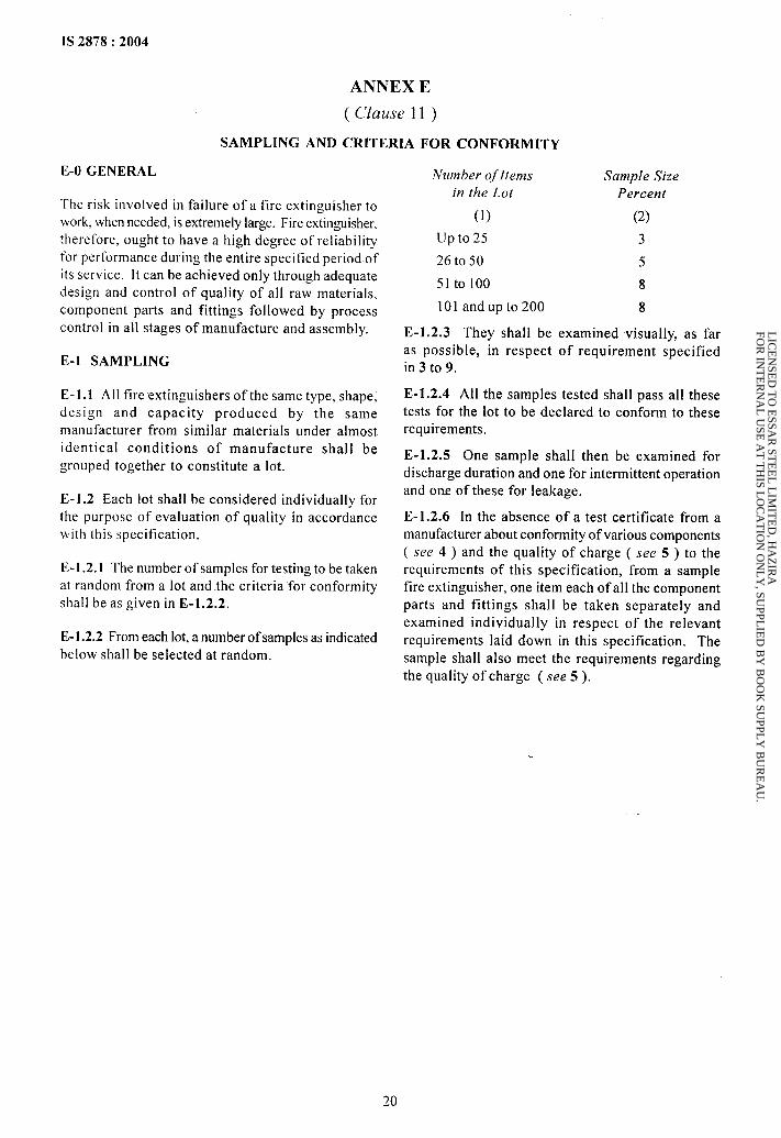
E-O GENERAL
The risk involved in failure of a fire extinguisher towork, when needed, is extremely large. Fire extinguisher,therefore, ought to have a high degree of reliabilityfor performance during the entire specified period ofits service. It can be achieved only through adequate
design and control of quality of all raw materials,component parts and fittings followed by process
control in all stages of manufacture and assembly.
E-1 SAMPLING
E-1.1 All fire extinguishers of the same type, shape,design and capacity produced by the same
manufacturer from similar materials under almostidentical conditions of manufacture shall be
grouped together to constitute a lot.
E-1.2 Each lot shall be considered individually forthe purpose of evaluation of quality in accordancewith this specification.
E-1.2.1 The number of samples for testing to be takenat random from a lot and the criteria for conformity
shall be as given in E-1.2.2.
E-1 .2.2 From each lot, a number of samples as indicated
below shall be selected at random.
Number ofItems
in the Lot
(1)
Up to 25
26 to 50
51 to 100
101 and up to 20.0
E-1.2.3 They shall beas possible, in respectin 3 to 9.
Sample SizePercent
(2)
3
5
8
8
examined visually, as farof requirement specified
E-1.2.4 All the samples tested shall pass all thesetests for the lot to be declared to conform to theserequirements.
E-1.2.5 One sample shall then be examined fordischarge duration and one for intermittent operationand one of these for leakage.
E-1.2.6 In the absence of a test certificate from amanufacturer about conformity of various components
( see 4 ) and the quality of charge ( see 5 ) to therequirements of this specification, from a samplefire extinguisher, one item each of all the component
parts and fittings shall be taken separately andexamined individually in respect of the relevantrequirements laid down in this specification. The
sample shall also meet the requirements regardingthe quality of charge ( see 5 ).
20
LIC
EN
SED
TO
ESSA
R ST
EE
L L
IMIT
ED
, HA
ZIR
A
FOR
INT
ER
NA
L U
SE A
T T
HIS L
OC
AT
ION
ON
LY
, SUPPL
IED
BY
BO
OK
SUPPL
Y B
UR
EA
U.
Bureau of Indian Standards ,.
BIS is a statutory institution established under the Bureau of Zndian Standards Act, 1986 to promoteharmonious.development of the activities of standardization, marking and quality certification of goods andattending to connected matters in the country.
Copyright
BIS has the copyright of all its publications. No part of these publications may be reproduced in any formwithout thepriorpermission in writing of BIS. This does not preclude the free use, in the course of implementing
the standard, of necessary details, such as symbols and sizes, type or grade designations. Enquiries relatingto copyright be addressed to the Director (Publications), BIS.
Review of Indian Standards
Amendments are issued to standards as the need arises on the basis of comments. Standards are also reviewedperiodically; a standard along with amendments is reaffirmed when such review indicates that no changes areneeded; if the review indicates that changes are needed, it is taken up for revision. Users of Indian Standardsshould ascertain that they are in possession of the latest amendments or edition by referring to the latest issueof ‘BIS Catalogue’ and ‘Standards : Monthly Additions’.
This Indian Standard has been developed from Doc : No. CED22(7185 ).
Amendments Issued Since Publication
Amend No. Date of Issue Text Affected
BUREAU OF INDIAN STANDARDS
Headquarters:
Manak Bhavan, 9 Bahadur Shah Zafar Marg, New Delhi 110002Telephones: 23230131,23233375,2323 9402 Website: www.bis.arg. in
Regional Offices : Telephones
Central :
Eastern :
Northern:
Southern:
Western :
Manak Bhavan, 9 Bahadur Shah Zafar Marg
{
23237617
NEW DELHI 110002 23233841
1/14 C. I. T. Scheme VII M,V. I. P. Road, Kankurgachi
{
23378499,2337856”1
KOLKATA-700 054 23378626,23379120
SCO 335-336, Sector 34-A, CHANDIGARH 160022
{
26038432609285
C. 1.T. Campus, IV Cross Road, CHENNAI 600113
{
22541216,2254144222542519,22542315
Manakalaya, E.9 MIDC, Marol, Andheri (East) ~ 28329295,28327858MUMBAI 400093 ~ 28327891,28327892
Branches : AHMEDABAD. BANGALORE. BHOPAL. BHUBANESHWAR. COIMBATORE.FARIDABAD. GHAZIABAD. GUWAHATI. HYDERABAD. JAIPUR. KANPUR.LUCKNOW. NAGPUR. NALAGARH. PATNA. PUNE. RAJKOT. THIRUVANANTHAPURAM.VISAKHAPATNAM.
Printed at New India Printing Press, Khurja, India
LIC
EN
SED
TO
ESSA
R ST
EE
L L
IMIT
ED
, HA
ZIR
A
FOR
INT
ER
NA
L U
SE A
T T
HIS L
OC
AT
ION
ON
LY
, SUPPL
IED
BY
BO
OK
SUPPL
Y B
UR
EA
U.

AMENDMENT NO. 1 APRIL 2005TO
IS 2878:2004 FIRE EXTINGUISHER, CARBONDIOXIDE TYPE (PORTABLE AND TROLLEY
MOUNTED) — SPECIFICATION
( Third Revision)
( Foreword) — Insert the following new clause after third para:
‘A scheme for labelling environment friendly products known as ECO Mark hasbeen introduced at the instance of the Ministry of Environment and Forests(MEF), Government of India. The ECO Mark would be administered by theBureau of Indian Standards (BIS) under the BIS Act, 1986 as per the ResolutionNo. 71 dated 21 February 1991 and No. 425 dated 28 October 1992 published inthe Gazette of the Government of India. For a product to be eligible for mat+cingwith ECO logo, it shall also carry the 1S1 Mark of BLS besides meeting additionaloptional environment friendly requirements. For the purpose, the Standard Markof BIS would be a single mark being a combination of the 1S1Mark and the ECOlogo. Requirements to be satisfied for a product to qualify for the BIS StandardMark for 13C0 friendliness being included in the relevant published standardsthrough an amendment. These requirements are optional; manufacturing unitsare free to opt for the 1S1 Mark alone also.
The amendment is based on the Gazette Notification No. 160 dated 1 April 1999for Fire Extinguishers as environment friendly products published in the Gazetteof Government of India.’
( Page 7, clause 8.1) — Substitute ‘538’ for ‘537’.
( Page 7, clause 9.4.1, line 3 ) — Delete ‘Annex A’.
( Page 7, claus; 9.5 ) — Renumber clause ‘9.5’ as ‘9.6’.
( Page 7, clause 9.5 ) — Insert the following new clauses after 9.5 andrenumber the subsequent clauses:
’10 OPTIONAL REQUIREMENTS FOR ECO MARK
10.1 General Requirements
10.1.1 Any fire extinguisher having BIS Standard Mark qualifies forconsideration of ECO Mark.
. ,.-
,.
---1
‘s
1Price Group 2
,.
LIC
EN
SED
TO
ESSA
R ST
EE
L L
IMIT
ED
, HA
ZIR
A
FOR
INT
ER
NA
L U
SE A
T T
HIS L
OC
AT
ION
ON
LY
, SUPPL
IED
BY
BO
OK
SUPPL
Y B
UR
EA
U.

I‘,
IAmend No. 1 to IS 2878:2004
110.1.2 The products manufacturer must produce the consent clearance as perprovision of the Water (Preventiorr and Control of Pollution) Act, 1974, Water(Prevention and Control of Pollution) Cess Act, 1977 and Air (Prevention andControl of Pollution) Act, 1981 respectively, along with authorization if requiredunder Environment (Protection) Act, 1986 and the Rules made thereunder to theBureau of Indian Standards while applying for ECO Mark.
10.1.3 The products may display in brief the criteria based on which the producthas been awarded ECO Mark. ,
10.1.4 The product may carry along with instructions for proper use so as to [maximize product performance with statutory warning, if any, minimize waste Iand method of safe disposal. I
I10.1.5 The material used for product packaging (excluding refills) shall berecyclable, reusable or biodegradable. ~
10.1.6 The product must display a list of critical ingredients in descending orderof quantity present in percent by weight. The list of such critical ingredientsshall be identified by the Bureau of Indian Standards.
10.2 Specific Requirements i
10.2.1 The fire extinguisher shall not contain any Ozone Depleting Substance 1
(ODS) relevant to fire extinguishers industry as identified under the MontrealProtocol (see Annex F). I
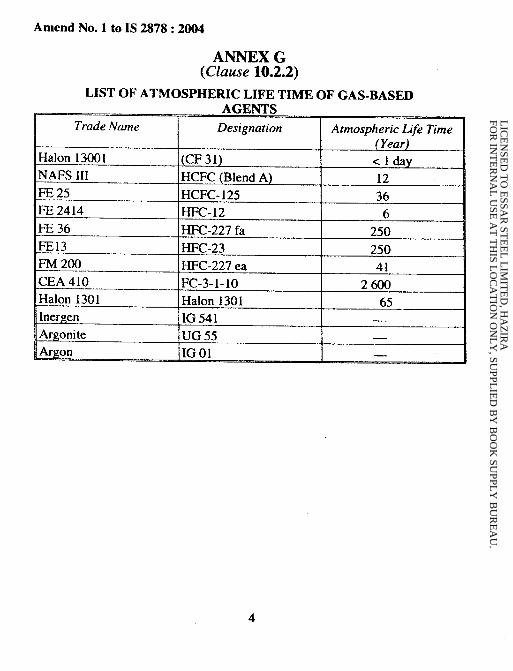
10.2.2 Gas based extinguishing media once discharged in the atmosphere shouldnot have atmospheric 1ife time of more than a year (see Annex G).
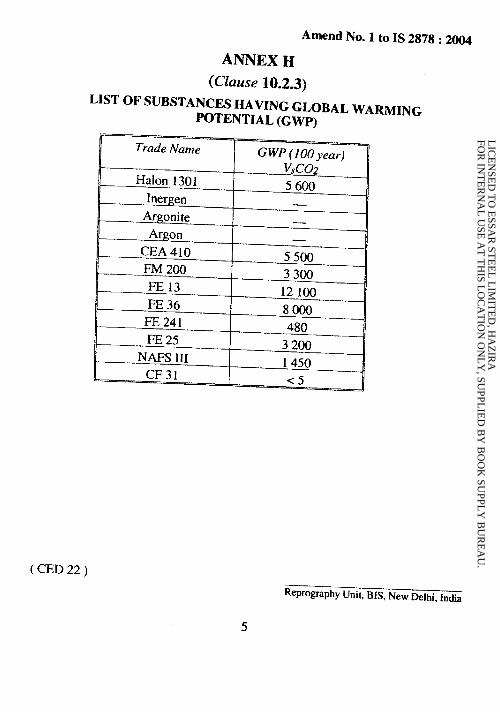
10.2.3 Chemical used should not have global warming potential (see Annex H).
10.2.4 The metallic body and other metal parts of the fire extinguishers shall befree of lead or lead alloys.
10.2.5 The coating used for the metallic part shall not be formulated withmercury and mercury compounds or be tinted with pigments of lead, cadmium,chromium VI and their oxides. Excluded are natural impurities entailed by theproduction process Up to the amount 0.1 percent by weight which are containedin the raw material.
NOTE — CO? extinguishersmy be permitted till suitable subsututes are available.
‘i,%,%...
1..2
,-. .
—.
LIC
EN
SED
TO
ESSA
R ST
EE
L L
IMIT
ED
, HA
ZIR
A
FOR
INT
ER
NA
L U
SE A
T T
HIS L
OC
AT
ION
ON
LY
, SUPPL
IED
BY
BO
OK
SUPPL
Y B
UR
EA
U.
kwmMw.J’#mlwlw!... .m. -~ -—m ..-. ——
-,. *. 7, ...
Amend No. 1 to IS 2878:2004
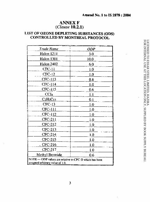
ANNEX F(Clause 10.2.1)
LIST OF OZONE DEPLETING SUBSTANCES (ODS)CONTROLLED BY MONTREAL PROTOCOL
Trade Name \ ODP
Halon 1211 3.0
Halon 1301 Ii 10.0Halon 2402 6.0
CFC- 11 1.0
CFC-12 1.0
CFC-113 0.8CFC-114 1.0
CFC-115 0.6CC14 1.1
c2H3cl3 0.1CFC-13 1.0
CFC-111 1.0
CFC- 112 1.0
CFC-211
1=
1.0 _ {CFC-212 1.0
CFC-213 1.0.—.CFC-214— 1.0
CFC-215 1.0
.CFC-216 j 1.0CFC-217 1.0
M~j Bromide ] 0.6NOTE — ODP values are relative to CFC-11which has heenassigned arbltrarr
3
LIC
EN
SED
TO
ESSA
R ST
EE
L L
IMIT
ED
, HA
ZIR
A
FOR
INT
ER
NA
L U
SE A
T T
HIS L
OC
AT
ION
ON
LY
, SUPPL
IED
BY
BO
OK
SUPPL
Y B
UR
EA
U.
,
Amend No. 1 to IS 2878:2004
ANNEX G(Clause 10.2.2)
LIST OF ATMOSPHERIC LIFE TIME OF GAS-BASEDA C.ZWTC.. WUL ..”
Trade Name Designation Atmospheric fife Time
(Year)HaIon 13001 (CF 31) <1 dayNAFS III HCFC (Blend A) 12FE 25 HCFC- 125 36@ 2414 HFC-12 6FE 36 HFC-227 fa 250FE13 HFC-23 250FM 200 HFC-227 ea 41CEA 410 FC-3-1-1O 2600HaIon 1301 HaIon 1301 65Inergen IG541 —
Argonite UG 55 —A–—- ----
... ..-
~~ {%.,.,.
LIC
EN
SED
TO
ESSA
R ST
EE
L L
IMIT
ED
, HA
ZIR
A
FOR
INT
ER
NA
L U
SE A
T T
HIS L
OC
AT
ION
ON
LY
, SUPPL
IED
BY
BO
OK
SUPPL
Y B
UR
EA
U.
~....
Amend No. 1 to IS 2878:2004
ANNEx H
(clause 10.2.3)LIST OF SUBSTANCES HAVING GLOBAL WARMING
POTENTIAL (GWP)
( CED 22 )
Reprography Unit, BIS, New Delhi, India
5
?
,...
{
,’
,-.
LIC
EN
SED
TO
ESSA
R ST
EE
L L
IMIT
ED
, HA
ZIR
A
FOR
INT
ER
NA
L U
SE A
T T
HIS L
OC
AT
ION
ON
LY
, SUPPL
IED
BY
BO
OK
SUPPL
Y B
UR
EA
U.
.,,
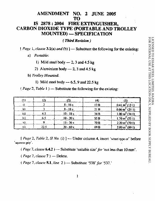
AMENDMENT NO. 2 JUNE 2005
IS 2878:2004 FI&OEXTINGUISHER,CARBON DIOXIDE TYPE (PORTABLE AND TROLLEY
MOUNTED) — SPECIFICATION
( Third Reviswn )
[ Page 1, clause 3.l(a) and (b)] — Substitute the following for the existing:
a) Portable:
1) Mild steel body — 2,3 and 4.5 kg
2) Aluminium body — 2,3 and 4.5 kg
b) Trolley Mounted
1) Mild steel body — 6.5,9 and 22.5 kg
( Page 2, Table 1 ) — Substitute the following for the existing:
K
(1) (2) (3) (4) (5) –
i) 2 8-16s 13 B 0.41 m2(13 1)
ii) 3 8-18s 21 B 0.66 m2(21 1).m) 4.5 10-!8s 34 B 1.00m2(34 1)
__.LQ_ 6.5 10-20s 55 B I .70 m2 (55 1)
v) 9 15-36s 70 B 2.20 m2(701)1 vi) 22.5 20-60s 89 B 2.80 m2(891 )d
[ Page 2, Table 2, S1 No. (i)] — Under column 4, insert ‘wheel type or’ before‘squeezegrip’.
( Page 7, clause 6.4.2) — Substitute ‘suitable size’~or ‘not less than 10 mm’.
( Page 7, clause 7 ) — Delete.
( Page 7, clause 8.1, lirte 2 ) — Substitute ‘538*for ‘537.’
1
LIC
EN
SED
TO
ESSA
R ST
EE
L L
IMIT
ED
, HA
ZIR
A
FOR
INT
ER
NA
L U
SE A
T T
HIS L
OC
AT
ION
ON
LY
, SUPPL
IED
BY
BO
OK
SUPPL
Y B
UR
EA
U.

.+..
Amend No.2 to IS 2878:2004
( f’age 7, clause 9.1, Note ) — Shift the existing note under clause 9.1between clause headings 9 and 9.1.
( Page 7, clause 9.5.1, lines 3 and It)) — Substitute ‘Table I‘ for ‘Table 6’and ‘Table 5’.
( Page 8, clause 9.5.3.1, line 2 ) — Substitute ‘Table 1‘for ‘Table 5’.
( Page 8, clause 9.5.4, last line) — Substitute ‘Table 1‘for ‘Table 5’.
( Page 8, Table 5 ) — Delete.
( Page 8, clause 9.5) — Substitute ‘9.6 for ‘9.5’.
. ..-
{
( CED 22 )
L
Reprography Unit, 91S, New Delhi, India
LIC
EN
SED
TO
ESSA
R ST
EE
L L
IMIT
ED
, HA
ZIR
A
FOR
INT
ER
NA
L U
SE A
T T
HIS L
OC
AT
ION
ON
LY
, SUPPL
IED
BY
BO
OK
SUPPL
Y B
UR
EA
U.

AMENDMENT NO. 3 SEPTEMBER 2006TO
IS 2878:2004 EXTINGUISHER, CARBONDIOXIDE TYPE (PORTABLE AND
TROLLEY MOUNTED) — SPECIFICATION
.
( Third Rewkion )
[Page 9, clause 10 (see also Amendment No. 1)] — Substitute‘ADDITIONAL’~or ‘OPTIONAL’.
(CED 22)
Reprography Unit, BIS, New Delhi, India
LIC
EN
SED
TO
ESSA
R ST
EE
L L
IMIT
ED
, HA
ZIR
A
FOR
INT
ER
NA
L U
SE A
T T
HIS L
OC
AT
ION
ON
LY
, SUPPL
IED
BY
BO
OK
SUPPL
Y B
UR
EA
U.
Copyright © 2022 FDOKUMEN