LUDLUM MODEL 3 SURVEY METER - BLM ePlanning
423
LUDLUM MODEL 3 SURVEY METER April 2016 Serial Number 294605 and Succeeding Serial Numbers
-
Upload
khangminh22 -
Category
Documents
-
view
0 -
download
0
Transcript of LUDLUM MODEL 3 SURVEY METER - BLM ePlanning

LUDLUM MODEL 3 SURVEY METER
April 2016
Serial Number 294605 and Succeeding
Serial Numbers

LUDLUM MODEL 3 SURVEY METER
April 2016
Serial Number 294605 and Succeeding
Serial Numbers

STATEMENT OF WARRANTY Ludlum Measurements, Inc. warrants the products covered in this manual to be free of defects due to workmanship, material, and design for a period of twelve months from the date of delivery. The calibration of a product is warranted to be within its specified accuracy limits at the time of shipment. In the event of instrument failure, notify Ludlum Measurements to determine if repair, recalibration, or replacement is required. This warranty excludes the replacement of photomultiplier tubes, G-M and proportional tubes, and scintillation crystals which are broken due to excessive physical abuse or used for purposes other than intended. There are no warranties, express or implied, including without limitation any implied warranty of merchantability or fitness, which extend beyond the description of the face there of. If the product does not perform as warranted herein, purchaser’s sole remedy shall be repair or replacement, at the option of Ludlum Measurements. In no event will Ludlum Measurements be liable for damages, lost revenue, lost wages, or any other incidental or consequential damages, arising from the purchase, use, or inability to use product.
RETURN OF GOODS TO MANUFACTURER If equipment needs to be returned to Ludlum Measurements, Inc. for repair or calibration, please send to the address below. All shipments should include documentation containing return shipping address, customer name, telephone number, description of service requested, and all other necessary information. Your cooperation will expedite the return of your equipment. LUDLUM MEASUREMENTS, INC. ATTN: REPAIR DEPARTMENT 501 OAK STREET SWEETWATER, TX 79556
800-622-0828 325-235-5494 FAX 325-235-4672


Ludlum Measurements, Inc. April 2016
Table of Contents Introduction 1
Getting Started 2 Unpacking and Repacking 2-1
Battery Installation 2-1
Connecting a Detector to the Instrument 2-2
Battery Test 2-2
Instrument Test 2-2
Reading the Meter Face Dial 2-3
Operational Check 2-6
Specifications 3
Identification of Controls and Functions 4
Safety Considerations 5 Environmental Conditions for Normal Use 5-1
Warning Markings and Symbols 5-1
Cleaning and Maintenance Precautions 5-2
Calibration and Maintenance 6 Calibration 6-1
Exposure Rate Calibration 6-2
CPM Calibration 6-3
Establishing an Operating Point 6-4
Maintenance 6-5
Recalibration 6-5
Batteries 6-6
Troubleshooting 7 Troubleshooting Electronics which utilize a
GM Detector or Scintillator 7-1
Troubleshooting GM Detectors 7-3
Troubleshooting Scintillators 7-4

Model 3 Technical Manual
Ludlum Measurements, Inc. April 2016
Technical Theory of Operation 8 Low-Voltage Supply 8-1
High-Voltage Supply 8-1
Detector Input 8-1
Amplifier 8-1
Discriminator 8-2
Audio 8-2
Scale Ranging 8-2
Meter Drive 8-2
Meter Reset 8-2
Fast/Slow Time Constant 8-2
Recycling 9
Parts List 10 Model 3 Survey Meter 10-1
Main Board, Drawing 464 × 204 10-1
Wiring Diagram, Drawing 464 × 212 10-3
Drawings and Diagrams 11

Model 3 Technical Manual Section 1
Ludlum Measurements, Inc. Page 1-1 April 2016
Introduction
he Model 3 is a portable radiation survey instrument with four linear ranges used with exposure rate or cpm (counts per minute) meter dials, or a combination of both exposure rate and count rate (referred to as “combo”) meter face dials. The instrument features a
regulated high-voltage power supply, unimorph speaker with audio ON-OFF capability, fast-slow meter response, meter reset button, and a six-position switch for selecting battery check or scale multiples of ×0.1, ×1, ×10 and ×100. Each range multiplier has its own calibration potentiometer. The unit body and meter housing are made of cast aluminum and the can is 0.23 cm (0.090 in.) thick aluminum.
The audio provides a brief “click” for every radiation event detected. It also provides a steady tone to warn the user of a low battery condition. This low battery warning overrides the position of the AUD ON-OFF switch.
Any Geiger-Mueller (GM) detector offered by Ludlum Measurements will operate with this unit as well as any scintillation type detector. The instrument is typically set at 900 volts for GM tube operation. For special requirements of GM or scintillation detectors, the instrument high voltage may be adjusted from 400 to 1500 volts.
The unit is operated with two ˝D˝ cell batteries for operation from -20 to 50 °C (-4 to 122°F). For instrument operation below 0 °C (32 °F), either very fresh alkaline or rechargeable NiCd batteries should be used.
Section
1 T

Model 3 Technical Manual Section 2
Ludlum Measurements, Inc. Page 2-1 April 2016
Getting Started Unpacking and Repacking Remove the calibration certificate and place it in a secure location. Remove the instrument and accessories (batteries, cable, etc.) and ensure that all of the items listed on the packing list are in the carton. Check individual item serial numbers and ensure calibration certificates match. The Model 3 serial number is located on the front panel below the battery compartment. Most Ludlum Measurements, Inc. detectors have a label on the base or body of the detector for model and serial number identification.
Important! If multiple shipments are received, ensure that the detectors and instruments are not interchanged. Each instrument is calibrated to specific detector(s), and therefore not interchangeable.
To return an instrument for repair or calibration, provide sufficient packing material to prevent damage during shipment. Also provide appropriate warning labels to ensure careful handling. Include detector(s) and related cable(s) for calibration
Every returned instrument must be accompanied by and Instrument Return Form, which can be downloaded from the Ludlum website at www.ludlums.com. Find the form by clicking on the “Support” tab and selecting “Repair and Calibration from the drop-down menu. Then choose the appropriate Repair and Calibration division where you will find a link to the form.
Battery Installation Ensure the Model 3 range selector switch is in the OFF position. Open the battery lid by pushing down and turning the quarter-turn thumbscrew
Section
2

Model 3 Technical Manual Section 2
Ludlum Measurements, Inc. Page 2-2 April 2016
counterclockwise a quarter of a turn. Install two ˝D˝ size batteries in the compartment.
Note the (+) and (-) marks inside the battery door. Match the battery polarity to these marks. Close the battery box lid, push down and turn the quarter-turn thumb screw clockwise a quarter of a turn.
Note: The center post of a “D” size battery is positive.
Connecting a Detector to the Instrument
Caution! The detector operating voltage is supplied to the detector via the detector input connector. A mild electric shock may occur if you make contact with the center pin of the input connector. Switch the Model 3 range selector switch to the OFF position before connecting or disconnecting the cable or detector.
Connect one end of a detector cable to the detector by firmly pushing the connectors together while twisting clockwise a quarter of a turn. Repeat the process in the same manner with the other end of the cable and the instrument.
Battery Test Check the batteries daily or prior to use, whichever is less frequent, to assure proper operation of the instrument. Move the range multiplier switch to the BAT position. Ensure that the meter needle deflects to the battery check portion on the meter scale. If the meter does not respond, check to see if the batteries have been correctly installed. Replace the batteries if necessary.
Instrument Test After checking the batteries, turn the instrument range switch to the X100 position. Place the AUD ON-OFF switch in the ON position. Expose the detector to a check source. The instrument speaker should emit “clicks” relative to the rate of counts detected. The ˝AUD ON/OFF˝ switch will silence the audible clicks if in the OFF position. In order to preserve battery life, it is recommended to keep the AUD ON/OFF switch in the OFF position

Model 3 Technical Manual Section 2
Ludlum Measurements, Inc. Page 2-3 April 2016
The detector cable can be a source of problems. Test the detector cable by bending or flexing either end of the cable and checking for an increase of counts detected. Replace the cable if increases in the rate of counts are detected.
Check the meter reset function by depressing the RESET pushbutton switch and ensuring the meter needle drops to 0.
Once this procedure has been completed, the instrument is ready for use.
Reading the Meter Face Dial Reading the meter face is very important for consistent measurements. There are, in general, three types of meter faces:
1) count rate (typically cpm [counts per minute])
2) exposure rate (typically mR/hr)
3) combo (typically cpm and mR/hr.)
The following examples are intended to help the user interpret the correct reading.
The normal procedure is to turn the range selector switch to the highest range and if no readings are seen on the meter, turn the selector switch down to the lower scales until a reading is seen. The ranges on the instrument selector switch are multipliers for the meter reading. A typical single scale (one arc) meter face with a cpm (counts per minute) dial is shown below.
The count rate scale reads 0-5K COUNTS/MINUTE (kcpm or 1000’s of counts per minute) and has BAT TEST on the dial.
If the needle is pointing as indicated below and the instrument range selection switch is on the ×0.1 scale multiple, then the reading is 3.5 kcpm (multiplied by) ×0.1 = 350 cpm.

Model 3 Technical Manual Section 2
Ludlum Measurements, Inc. Page 2-4 April 2016
The same needle indications on successive ranges would be: ×1 = 3.5 kcpm (or 3500 cpm) ×10 = 35 kcpm (or 35,000 cpm) ×100 = 350 kcpm (or 350,000 cpm) A typical dual scale (two arcs) meter face is shown below. The top scale reads 0-2 mR/hr. The bottom scale also reads 0-2 mR/hr and is for ×100 only scale. The ×100 ONLY scale will work correctly when the multiplier switch is in the ×100 range. The meter face also has a BAT TEST position on the dial.
If the needle is pointing as indicated below and the range selection switch is on the ×0.1 scale, then the reading is 0.1 mR/hr.
The same needle indications on successive ranges would be: ×1 = 1.0 mR/hr (or 1000 µR/hr) ×10 = 10 mR/hr (or 10,000 µR/hr) ×100 = 70 mR/hr (or 70,000 µR/hr)

Model 3 Technical Manual Section 2
Ludlum Measurements, Inc. Page 2-5 April 2016
The dial shown below has three arcs: a counts per minute scale (cpm), a linear mR/hr scale, and a non-linear mR/hr scale for the ×100 range only. The meter face also has a BAT TEST position.
The top cpm scale is valid for the ×0.1, ×1, ×10, and the ×100 ranges. The linear (middle) mR/hr scale is valid for the ×0.1, ×1, and ×10 ranges. The non-linear mR/hr scale is valid for the ×100 range only. This meter face is commonly referred to as a “combo” meter face since it has both count rate (cpm) and exposure rate (mR/hr) arcs. Simpler meter faces may only have a count rate or an exposure rate arc(s) like the previous meter faces shown.
A “combo” meter face is specifically designed for a particular detector. In the example above, the 1.0 mR/hr mark on the middle arc lines up with 3.3 kcpm on the upper arc. The meter face in this example works with a detector that receives 3.3 kcpm per mR/hr (the Ludlum Model 44-9 pancake detector.)
In the following picture, the needle is on the first tick mark past the 4 kcpm mark. Therefore, if the instrument selector switch is on the ×0.1 range, the reading is 4.2 kcpm (multiplied by) × 0.1 = 420 cpm.

Model 3 Technical Manual Section 2
Ludlum Measurements, Inc. Page 2-6 April 2016
The same needle indications on successive ranges would be: ×1 = 4.2 kcpm (or 4200 cpm) ×10 = 42 kcpm (or 42,000 cpm) ×100 = 420 kcpm (or 420,000 cpm) If you use the mR/hr scales, then the readings would be: ×0.1 = 0.13 mR/hr ×1 = 1.3 mR/hr ×10 = 13 mR/hr ×100 = 180 mR/hr* *This reading is using the bottom (non-linear) scale. Many different dials are available, but each can be used as described above.
Operational Check To assure proper operation of the instrument and detectors(s) between calibrations, an instrument operational check including battery test and instrument test (as described on pages 2-2 and 2-3) should be performed at least daily or prior to use, whichever is less frequent. A reference reading (or readings) with a check source should be obtained with the detector(s) in a constant and reproducible manner at the time of calibration or at the time the instrument is received in the field. If at any time the instrument fails to read within 20% of the reference reading when using the same check source, it should be sent to a calibration facility for recalibration and/or repair. If desired, multiple readings may be taken at different distances and/or with different sources so that other ranges or scales are checked.

Model 3 Technical Manual Section 3
Ludlum Measurements, Inc. Page 3-1 April 2016
Specifications 0
High Voltage: adjustable from 400 to 1500 Vdc
Threshold: fixed at -35 mV ± 10 mV
Response: toggle switch for fast (4 seconds) or slow (22 seconds) from 10% to 90% of final reading
Range: typically 0-200 mR/hr, or 0-500,000 cpm
Linearity: reading within 10% of true value with detector connected
Meter: 6.4 cm (2.5 in.) arc, 1 mA analog type
Meter Dial: 0-2 mR/hr, or 0-5 kcpm, BAT TEST (others available)
Multipliers: ×0.1, ×1, ×10, ×100
Calibration Controls: individual potentiometers for each range; accessible from front of instrument (protective cover provided)
End-of-Battery Life Warning: At 2.1 Vdc, the meter needle will drop to the edge of the BAT TEST or BAT OK area when the meter selector switch is moved to the BAT position. At 2.0 Vdc, a steady audible tone will be emitted to warn the user of the low battery condition.
Battery Dependence: less than 3% change in readings to battery failure indication
Reset: pushbutton to zero the meter
Audio: built-in unimorph speaker with ON-OFF switch (greater than 60 dB at 2 feet)
Connector: series ˝C˝ (other available)
Cable: one-meter (39-inch) with ˝C˝ connector (others available)
Power: two ˝D˝ cell batteries housed in a sealed externally accessible compartment
Battery Life: typically greater than 2000 hours with alkaline batteries and with the AUD ON-OFF switch in the OFF position
Section
3

Model 3 Technical Manual Section 3
Ludlum Measurements, Inc. Page 3-2 April 2016
Size: 16.5 x 8.9 x 21.6 cm (6.5 x 3.5 x 8.5 in.) (H x W x L), including handle
Weight: 1.6 kg (3.5 lb), including batteries
Construction: cast and drawn aluminum with beige powder coat

Model 3 Technical Manual Section 4
Ludlum Measurements, Inc. Page 4-1 April 2016
Identification of Controls and Functions
See the Model 3 FRONT PANEL drawing at the beginning of this manual to reference the following controls:
Meter: 6.4 cm (2.5 in.) arc, 1 mA analog type with pivot-and-jewel suspension. Typical meter dials are 0-2 mR/hr, 0-20 µSv/h, 0-5 kcpm or combination of exposure rates (0-2 mR/hr or 0-20 µSv/h) and cpm and BAT
TEST.
Connector: Used to connect the detector to the instrument. Series ˝C˝ is typically used, but “BNC,” “MHV,” “UHF,” or others, can be used as well.
Range Selector Switch: A six-position switch marked OFF, BAT, ×100, ×10, ×1, ×0.1. Turning the range selector switch from OFF to BAT provides the operator with a battery check of the instrument. A BAT check scale on the meter provides a visual means of checking the battery-charge status. Moving the range selector switch to one of the range multiplier positions (×100, ×10, ×1, ×0.1) provides the operator with an overall range of 0 to 500,000 cpm. Multiply the scale reading by the multiplier to determine the actual scale reading.
Calibration Controls: Recessed potentiometers that are used to calibrate the individual range selections and allow for high-voltage adjustment from 400 to 1500 volts. A protective cover is provided to prevent tampering.
Battery Compartment: Sealed compartment to house two ˝D˝ cell batteries.
RESET Button: When depressed, this switch provides a rapid means to drive the meter to 0.
AUD ON-OFF Switch: In the ON position, operates the unimorph speaker, located on the left side of the instrument. The frequency of the clicks is relative to the rate of the incoming pulses. The higher the rate,
Section
4

Model 3 Technical Manual Section 4
Ludlum Measurements, Inc. Page 4-2 April 2016
the higher the audio frequency. The audio should be turned OFF when not required, in order to reduce battery drain.
Note: A low-battery condition results in a steady audio tone, regardless of the position of the AUD ON-OFF switch.
F-S Toggle Switch: Provides meter response. Selecting the fast, ˝F˝ position of the toggle switch provides 90% of full-scale meter deflection in four seconds. In the slow, ˝S˝ position, 90% of full-scale meter deflection takes 22 seconds. In ˝F˝ position, there is fast response and large meter deviation. The ˝S˝ position should be used for slow response and damped, meter deviation.
Note: The slow response position is normally used when the instrument is displaying low numbers that require a more stable meter movement. The fast response position is used at high rate levels.

Model 3 Technical Manual Section 5
Ludlum Measurements, Inc. Page 5-1 April 2016
Safety Considerations Environmental Conditions for Normal Use Indoor or outdoor use
No maximum altitude
Temperature range of -20 to 50 °C (-4 to 122 °F). May be certified for operation from -40 to 65 °C (-40 to 150 °F).
Maximum relative humidity of less then 95% (non-condensing)
Pollution Degree 3 (as defined by IEC 664). (Occurs when conductive pollution or dry nonconductive pollution becomes conductive due to condensation. This is typical of industrial or construction sites.)
Water resistance is achieved by the use of rubber seals on all front-panel switches and gaskets on the battery lid, meter bezel, and between the instrument can and front panel.
Warning Markings and Symbols
Caution! The operator or responsible body is cautioned that the protection provided by the equipment may be impaired if the equipment is used in a manner not specified by Ludlum Measurements, Inc.
Caution! Verify the instrument voltage input rating before connecting to a power converter. If the wrong power converter is used, the instrument and/or power converter could be damaged.
Section
5

Model 3 Technical Manual Section 5
Ludlum Measurements, Inc. Page 5-2 April 2016
The Model 3 Survey Meter is marked with the following symbols:
CAUTION, RISK OF ELECTRIC SHOCK (per ISO 3864, No. B.3.6) – designates a terminal (connector) that allows connection to a voltage exceeding 1 kV. Contact with the subject connector while the instrument is on or shortly after turning off may result in electric shock. This symbol appears on the front panel.
CAUTION (per ISO 3864, No. B.3.1) – designates hazardous live voltage and risk of electric shock. During normal use, internal components are hazardous live. This instrument must be isolated or disconnected from the hazardous live voltage before accessing the internal components. This symbol appears on the front panel. Note the following precautions:
Warning! The operator is strongly cautioned to take the following precautions to avoid contact with internal hazardous live parts that are accessible using a tool: 1. Turn the instrument power OFF and remove the batteries. 2. Allow the instrument to sit for one minute before accessing internal components.
The “crossed-out wheelie bin” symbol notifies the consumer that the product is not to be mixed with unsorted municipal waste when discarding; each material must be separated. The symbol is placed on the battery compartment lid. See section 9, “Recycling.” for further information.
The “CE” mark is used to identify this instrument as being acceptable for use within the European Union.
Cleaning and Maintenance Precautions The Model 3 may be cleaned externally with a damp cloth, using only water as the wetting agent. Do not immerse the instrument in any liquid. Observe the following precautions when cleaning or performing maintenance on the instrument:
1. Turn the instrument OFF and remove the batteries.
2. Allow the instrument to sit for one minute before cleaning the exterior or accessing any internal components for maintenance.

Model 3 Technical Manual Section 6
Ludlum Measurements, Inc. Page 6-1 April 2016
Calibration and Maintenance Calibration Calibration controls are located on the front of the instrument under the calibration cover. The controls may be adjusted with a 0.32 cm (one-eighth inch) blade screwdriver.
Note: Local procedures may supersede the following.
The instrument may be calibrated using Exposure Rate Calibration or CPM Calibration. Both methods are described below. Unless otherwise specified, the instrument is calibrated to exposure rate at the factory.
Note: Measure high voltage with a Model 500 pulser or a high-impedance voltmeter with a high-meg probe. If one of these instruments is not available, use a voltmeter with a minimum of 1000 megаohm input resistance.
Calibration shall include response evaluations and adjustment for two points of each scale of the instrument. The points should be separated by at least 40% of the full-scale value and should be represented by points of approximately equal distance from the mid-point of the scale. For example, 25% and 75%, or 20% and 80% could be used.
Section
6

Model 3 Technical Manual Section 6
Ludlum Measurements, Inc. Page 6-2 April 2016
Exposure Rate Calibration
Connect the input of the instrument to a negative pulse generator, such as a Ludlum Model 500 Pulser.
Caution! The instrument input operates at a high potential. Connect the pulse generator through a 0.01 µF, 3000-volt capacitor, unless the pulse generator is already protected.
Adjust the HV control for the proper operation voltage of the detector to be used. Disconnect the pulser, and connect the detector to the instrument.
Turn the range selector switch to the ×100 position. Expose the detector to a calibrated gamma field, which corresponds to approximately 80% of full-scale meter deflection. Adjust the ×100 calibration control for the proper reading.
Reposition the detector so the field corresponds to approximately 20% of full-scale meter deflection. Confirm that the meter reading is within 10% of the field.
Repeat this process for the ×10, ×1, and ×0.1 ranges.
If your gamma exposure range cannot calibrate two positions on each scale, the pulser may be used to “electronically calibrate” the remaining points. Reconnect the pulser to the instrument and determine the count rate conversion at a previous range calibration point. Then use that conversion rate to calibrate other points or scales.
If, for example, you can exposure rate calibrate the 400 µR/hr point, first use the pulser to get the count rate equivalent to the calibrated 400 µR/hr point. Then switch the pulser multiplier switch to the next lower setting, and adjust the appropriate calibration control on the Model 3 for the meter to read 40 µR/hr.

Model 3 Technical Manual Section 6
Ludlum Measurements, Inc. Page 6-3 April 2016
CPM Calibration
Connect the input of the instrument to a negative pulse generator, such as a Ludlum Model 500 Pulser.
Caution! The instrument input operates at a high potential. Connect the pulse generator through a 0.01 µF, 3000-volt capacitor, unless the pulse generator is already protected.
Adjust the HV control for the proper operating voltage of the detector to be used. Adjust the pulser negative pulse frequency to provide a better meter deflection of approximately 80% of full scale on the ×100 range. Adjust the ×100 calibration control for the proper reading.
Check the 20% scale indication of the Model 3 by reducing the pulser count rate by a factor of 4. The Model 3 should read within 10% of the actual pulse rate. Decrease the pulse rate of the Model 500 by one decade and turn the Model 3 range selector to the next lower range. Repeat the above procedure for the remaining lower ranges.
Note: In the event that any reading is not within 10% of the true value on any scale after any of the above calibration methods is performed, a reading within 20% of true value shall be acceptable. It is acceptable if a calibration graph or chart is provided with the instrument. Instruments that cannot meet these criteria are defective and require repair.
Model 3 Technical Manual Section 6
Ludlum Measurements, Inc. Page 6-4 April 2016
Establishing an Operating Point
The operating point for the instrument and detector is established by setting the instrument high voltage (HV). The proper selection of this point is the key to instrument performance. Efficiency, background sensitivity, and noise are fixed by the physical makeup of the given detector and rarely vary from unit to unit. However, the selection of the operating point makes a marked difference in the apparent contribution of these three sources of count.
In setting the operating point, the final result of the adjustment is to establish the system gain so that the desirable signal pulses (including background) are above the discrimination level, and the unwanted pulses from noise are below the discrimination level. and are therefore, not counted. The system gain is controlled by adjusting the high voltage.
Note: Measure the high voltage with a Ludlum Model 500 Pulser. If the pulser does not have a high-voltage readout, use a high-impedance voltmeter with at least 1000 megohm input resistance to measure the high voltage.
GM Detectors: In the special case of GM detectors, a minimum voltage must be applied to establish the Geiger-Mueller characteristic. The output pulse height of the G-M detector is not proportional to the energy of the detected radiation. Most GM detectors operate at 900 volts, although some miniature detectors operate at 400-500 volts. Refer to the detector operating manual for specific recommendations. If a recommended setting is unavailable, plot an HV-versus-count-rate curve to produce a plateau graph similar to the one displayed below. Adjust the HV for 25-50 volts above the knee or start of the plateau. For mixed detector use, the high voltage may be tallied for both, as long as the GM detector is operated within the recommended voltage range.
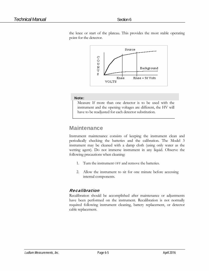
Scintillators: Scintillation type detectors have a wide gain spectrum, typically 1000:1 at a single operating point. An operating voltage versus count rate curve (plateau) must be established to determine the proper operating voltage. The operating voltage is typically set above the knee of the plateau. Plot the HV-versus-background and source count to produce a plateau graph similar to the one in the figure below. Adjust the HV to 25-50 volts above
Technical Manual Section 6
Ludlum Measurements, Inc. Page 6-5 April 2016
the knee or start of the plateau. This provides the most stable operating point for the detector.
Note: Measure If more than one detector is to be used with the instrument and the opening voltages are different, the HV will have to be readjusted for each detector substitution.
Maintenance Instrument maintenance consists of keeping the instrument clean and periodically checking the batteries and the calibration. The Model 3 instrument may be cleaned with a damp cloth (using only water as the wetting agent). Do not immerse instrument in any liquid. Observe the following precautions when cleaning:
1. Turn the instrument OFF and remove the batteries.
2. Allow the instrument to sit for one minute before accessing internal components.
Recalibration Recalibration should be accomplished after maintenance or adjustments have been performed on the instrument. Recalibration is not normally required following instrument cleaning, battery replacement, or detector cable replacement.

Technical Manual Section 6
Ludlum Measurements, Inc. Page 6-6 April 2016
Note: Ludlum Measurements, Inc. recommends recalibration at intervals no greater than one year. Check the appropriate regulations to determine required recalibration intervals.
Ludlum Measurements offers a full-service repair and calibration department. We not only repair and calibrate our own instruments, but most other manufacturer’s instruments as well. Calibration procedures are available upon request for customers who choose to calibrate their own instruments.
Batteries The batteries should be removed any time the instrument is placed into storage. Battery leakage may cause corrosion on the battery contacts, which must be scraped off and/or washed using a paste solution made from baking soda and water. Use a spanner wrench to unscrew the battery contact insulators, exposing the internal contacts and battery springs. Removal of the handle will facilitate access to these contacts.
Note: Never store the instrument over 30 days without removing the batteries. Although this instrument will operate at a very high ambient temperatures, battery seal failure may occur at temperatures as low as 37.8 ˚C (100 ˚F).

Model 3 Technical Manual Section 7
Ludlum Measurements, Inc. Page 7-1 April 2016
Troubleshooting
ccasionally you may encounter problems with your LMI instrument or detector that may be repaired or resolved in the field, saving turnaround time and expense in returning the instrument to us for repair. Toward that end, LMI electronics
technicians offer the following tips for troubleshooting the most common problems. Where several steps are given, perform them in order until the problem is corrected. Keep in mind that with this instrument, the most common problems encountered are: (1) detector cables, (2) sticky meters, and (3) battery contacts.
Note that the first troubleshooting tip is for determining whether the problem is with the electronics or with the detector. A Ludlum Model 500 Pulser is invaluable at this point, because of its ability to simultaneously check high voltage, input sensitivity or threshold, and the electronics for proper counting.
We hope these tips will prove to be helpful. As always, please call if you encounter difficulty in resolving a problem or if you have any questions.
Troubleshooting Electronics that utilize a GM Detector or Scintillator
SYMPTOM
no power (or meter does not reach BAT
TEST or BAT OK mark)
POSSIBLE SOLUTION
1. Check batteries and replace if weak. 2. Check polarity (See marks inside
batter lid). Are the batteries installed backwards?
Section
7 O

Model 3 Technical Manual Section 7
Ludlum Measurements, Inc. Page 7-2 April 2016
SYMPTOM no power (or meter does not reach BAT
TEST or BAT OK mark) (continued) nonlinear readings meter goes full scale or “pegs out”
POSSIBLE SOLUTION 3. Check battery contacts. Clean them
with rough sandpaper or use an engraver to clean the tips.
4. Remove the can and check for loose
or broken wires.
1. Check the high voltage (HV) using a
Ludlum Model 500 Pulser (or equivalent). If a multimeter is used to check the HV, ensure that one with high impedance is used, as a standard multimeter could be damaged in this process.
2. Check for noise in the detector cable
by disconnecting the detector, placing the instrument on the lowest range setting, and wiggling the cable while observing the meter face for significant changes in readings.
3. Check for “sticky” meter movement.
Does the reading change when you tap the meter? Does the meter needle “stick” at any spot?
4. Check the “meter zero.” Turn the
power OFF. The meter should come to rest on 0.
1. Replace the detector cable to
determine whether or not the cable has failed, causing excessive noise.
2. Check the HV, and if possible, the
input threshold for proper setting.

Model 3 Technical Manual Section 7
Ludlum Measurements, Inc. Page 7-3 April 2016
SYMPTOM meter goes full scale or “pegs out” (continued)
no response to radiation no audio
POSSIBLE SOLUTION
3. Remove the can and check for loose or broken wires.
4. Ensure that the instrument’s “can”
is properly attached. When attached properly, the speaker will be located on the left side of the instrument. If the can is on backwards, interfer-ence between the speaker and the input preamplifier may cause noise.
1. Substitute a “known good” detector and/or cable.
2. Has the correct operating voltage
been set? Refer to the calibration certificate or detector instruction manual for correct operating voltage. If the instrument uses multiple detectors, confirm that the high voltage is matched to the current detector being used.
1. Ensure that the AUD ON-OFF switch
is in the ON position. 2. Remove the instrument housing and
check the connection between the circuit board and the speaker. Plug in the 2-pin connector if necessary.
Troubleshooting GM Detectors 1. If the tube has a thin mica window, check for window breakage.
If damage is evident, the tube must be replaced.
2. Check the HV. For most GM tubes, the voltage is normally 900 Vdc, or 460-550 Vdc for “peanut” tubes (Ludlum Model 133 series).

Model 3 Technical Manual Section 7
Ludlum Measurements, Inc. Page 7-4 April 2016
3. If the input sensitivity is too low, the user could see some double-pulsing (where the instrument “counts” a single pulse from the detector multiple times).
4. Wires to the tube may be broken, or the crimped connector could have a loose wire.
Troubleshooting Scintillators 1. Alpha or alpha/beta scintillators are prone to light leaks. They
can be tested for this problem in a dark room or with a bright light. If a light leak is determined, changing the Mylar window assembly will usually fix the problem.
Note: When replacing the window, make sure to use a window made with the same thickness Mylar and the same number of layers as the original window.
2. Verify that the HV and input sensitivity are correct. Alpha and gamma scintillators typically operate from 10-35 mV. High voltage varies with the photomultiplier tubes (PMT) from as low as 600 Vdc, to as high as 1400 Vdc.
3. On a gamma scintillator, visually inspect the crystal for breakage or humidity leakage. Water inside the crystal will turn it yellow and gradually degrade performance.
4. Check the PMT to see if the photocathode still exists. If the end of the PMT is clear (not brownish), this indicates a loss of vacuum, which will render the PMT useless.

Model 3 Technical Manual Section 8
Ludlum Measurements, Inc. Page 8-1 April 2016
Technical Theory of Operation
Low-Voltage Supply Battery voltage is coupled to U11 and associated components (a switching regulator) to provide 5 volts at pin 8 to power all logic circuits. A voltage divider (R27 and R32) located at pin 1 of U11 sets the end-of-battery–life squeal at 2.0 Vdc. Components R12 and C30 provide filtering to create +5 VA used by the amplifier and discriminator circuits.
High-Voltage Supply High voltage is developed by pulses from switching the regulator U13 to transformer T1. High voltage is multiplied by the ladder network of diodes CR3 through CR7 and capacitors C18 through C27. High voltage is coupled back through R39 to pin 8 of U13. High-voltage output is set by front-panel potentiometer R42, which sets the voltage feedback of 1.31 Vdc to pin 8 of U13. R38 and C28 provide filtering.
Detector Input Detector pulses are coupled from the detector through C6 to amplifier input pin 2 of U4. CR1 protects U4 from input shorts. R37 couples the detector to the high-voltage supply.
Amplifier A self-biased amplifier provides gain in proportion to R15 divided by R14, with some gain loss due to feedback capacitor C4. A transistor (pin 3 of U4) provides amplification. U6 is configured as a constant current source to pin 3 of U4. The output self-biases to 2 Vbe (approximately 1.4 volts) at the emitter of Q1. This provides just enough bias current through pin 3 of U4 to conduct all of the current from the current source. Positive pulses from the emitter of Q1 are coupled to the discriminator.
Section
8
Model 3 Technical Manual Section 8
Ludlum Measurements, Inc. Page 8-2 April 2016
Discriminator Comparator U8 provides discrimination. The discriminator is set by a voltage divider (R21 and R23), coupled to pin 3 of U8. As the amplified pulses at pin 4 of U8 increase above the discriminator voltage, 5-volt negative pulses are produced at pin 1 of U8. These pulses are coupled to pin 5 of U9 for meter drive and pin 12 of U9 for audio.
Audio Discriminator pulses are coupled to univibrator pin 12 of U9. The front-panel audio ON-OFF selector controls the reset at pin 13 of U9. When ON, pulses from pin 10 of U9 turn on oscillator U12, which drives the housing-mounted unimorph speaker. Speaker tone is set by R31 and C14. Tone duration is controlled by R22 and C7.
Scale Ranging Detector pulses from the discriminator are coupled to univibrator pin 5 of U9. For each scale, the pulse width of pin 6 of U9 is changed by a factor of 10 with the actual pulse width being controlled by the front-panel switch, the analog switches U1 and U2, and the related potentiometers. This arrangement allows the same current to be delivered to C9 by 1 count on the ×0.1 range as 1000 counts on the ×100 range.
Meter Drive Pulses from pin 6 of U9 charge capacitor C9. A constant current driver (opamp U10 and transistor Q2) delivers proportional current to the meter. For battery test (BAT TEST), the meter is directly coupled by the analog switch U3 to the batteries through resistor R8.
Meter Reset Ratemeter reset is initiated by changing the voltage differential at C9 to 0 when the RESET button is depressed.
Fast/Slow Time Constant For the slow time constant, C17 is switched from the output of the meter drive to parallel C9.

Model 3 Technical Manual Section 9
Ludlum Measurements, Inc. Page 9-1 April 2016
Recycling
udlum Measurements, Inc. supports the recycling of the electronic products it produces for the purpose of protecting the environment and to comply with all regional, national, and international agencies that promote economically and environmentally sustainable
recycling systems. To this end, Ludlum Measurements, Inc. strives to supply the consumer of its goods with information regarding reuse and recycling of the many different types of materials used in its products. With many different agencies – public and private – involved in this pursuit, it becomes evident that a myriad of methods can be used in the process of recycling. Therefore, Ludlum Measurements, Inc. does not suggest one particular method over another, but simply desires to inform its consumers of the range of recyclable materials present in its products, so that the user will have flexibility in following all local and federal laws.
The following types of recyclable materials are present in Ludlum Measurements, Inc. electronic products, and should be recycled separately. The list is not all-inclusive, nor does it suggest that all materials are present in each piece of equipment:
Batteries Glass Aluminum and Stainless Steel
Circuit Boards Plastics Liquid Crystal Display (LCD)
Ludlum Measurements, Inc. products that have been placed on the market after August 13, 2005 have been labeled with a symbol recognized internationally as the “crossed-out wheelie bin.” This notifies the consumer that the product is not to be mixed with unsorted municipal waste when discarding; each material must be separated. The symbol will be placed near the AC receptacle, except for portable equipment where it will be placed on the battery lid.
The symbol appears as such:
Section
9 L

Model 3 Technical Manual Section 10
Ludlum Measurements, Inc. Page 10-1 April 2016
Parts List Reference Description Part Number UNIT Completely Assembled Model 3 Survey Meter 48-1605 BOARD Completely Assembled Main Circuit Board 5464-204
C1 47pF, 100V 04-5660 C2 0.1F, 35V 04-5755 C3 0.0047F, 100V 04-5669 C4 10pF, 100V 04-5673 C5 0.01F, 50V 04-5664 C6 100pF, 3KV 04-5735 C7 0.022F, 50V 04-5667 C8 1F, 16V 04-5701 C9 10F, 25V 04-5655 C10 100pF, 100V 04-5661 C11 68F, 10V 04-5654 C12 10F, 25V 04-5728 C14 470pF, 100V 04-5668 C15 220pF, 100V 04-5674 C16 68F, 10V 04-5654 C17 47F, 10V 04-5666 C18-C27 0.01F, 500V 04-5696 C28 0.001F, 2KV 04-5703 or 100pF, 3KV 04-5735 C29 10F, 25V 04-5655 C30-C31 1F, 16V 04-5701 C32 470pF, 100V 04-5668
Section
10 Model 3 Survey Meter
Main Board, Drawing 464 × 204
CAPACITORS

Model 3 Technical Manual Section 10
Ludlum Measurements, Inc. Page 10-2 April 2016
Reference Description Part Number
Q1 MMBT3904LT1 05-5841 Q2 MMBT4403LT1 05-5842
U1-U3 MAX4542ESA 06-6453 U4-U5 CMXT3904 05-5888 U6 CMXT3906 05-5890 U7 MAX4541ESA 06-6452 U8 MAX985EUK-T 06-6459 U9 CD74HC4538M 06-6297 U10 LMC7111BIM5X 06-6410 U11 LT1304CS8-5 06-6434 U12 MIC1557BM5 06-6457 U13 LT1304CS8 06-6394
CR1 CMPD2005S 07-6468 CR2 RECTIFIER CMSH1-40M 07-6411 CR3-CR7 CMPD2005S 07-6468 CR9 RECTIFIER CMSH1-40M 07-6411
SW1 D5G0206S-9802 08-6761 SW2 TP11LTCQE 08-6770 SW3-SW4 7101SDCQE 08-6781 R33 250K, 64W254, ×100 09-6819 R34 250K, 64W254, ×10 09-6819 R35 500K, 64W504, ×1 09-6850 R36 250K, 64W254, ×0.1 09-6819 R42 1.2M, 3296W, HV 09-6814
R1-R5 200K, 1/8W, 1% 12-7992 R6 8.25K, 1/8W, 1% 12-7838 R7 10K, 1/8W, 1% 12-7839 R8 2.37K, 1/8W, 1% 12-7861 R9-R11 10K, 1/8W, 1% 12-7839 R12 200 Ohm, 1/8W, 1% 12-7846 R13 10K, 1/8W, 1% 12-7839 R14 4.75K, 1/8W, 1% 12-7858
TRANSISTORS
INTEGRATED CIRCUITS
DIODES
SWITCHES
POTENTIOMETERS / TRIMMERS
RESISTORS
Model 3 Technical Manual Section 10
Ludlum Measurements, Inc. Page 10-3 April 2016
Reference Description Part Number R15 200K, 1/8W, 1% 12-7992 R16 10K, 1/8W, 1% 12-7839 R17 1K, 1/8W, 1% 12-7832 R18 4.75K, 1/8W, 1% 12-7858 R19 2K, 1/8W, 1% 12-7926 R20-R21 100K, 1/8W, 1% 12-7834 R22 1M, 1/8W, 1% 12-7844 R23 2.49K, 1/8W, 1% 12-7999 R24 14.7K, 1/8W, 1% 12-7068 R25 200K, 1/4W, 1% 12-7992 R26 100K, 1/4W, 1% 12-7834 R27 68.1K, 1/8W, 1% 12-7881 R28 100K, 1/8W, 1% 12-7834 R29 1K, 1/8W, 1% 12-7832 R30 100K, 1/8W, 1% 12-7834 R31 475K, 1/8W, 1% 12-7859 R32 100K, 1/8W, 1% 12-7834 R37 100K, 1/8W, 1% 12-7834 R38 2.2M, 1/8W, 1% 12-7002 R39 500M, 3KV, 2% 12-7031 R40 402K, 1/8W, 1% 12-7888 R44 1K, 1/4W, 1% 12-7832
P1 640456-5 - MTA100 13-8057 P2 640456-6 - MTA100 (installed as required) 13-8095 P3 640456-2 - MTA100 13-8073 L1 22 µH 21-9808 T1 31032R 21-9925 J1 MTA100×5, MAIN BOARD 5464-204 13-8140 J2 OPTIONAL (M3 overload) MTA100×6, 5464-204 13-8171 J3 MTA100×2, MAIN BOARD 5464-204 13-8178
CONNECTORS
INDUCTOR
TRANSFORMER
Wiring Diagram, Drawing 464 × 212
CONNECTORS

Model 3 Technical Manual Section 10
Ludlum Measurements, Inc. Page 10-4 April 2016
Reference Description Part Number DS1 UNIMORPH TEC3526-PU 21-9251 B1-B2 ˝D˝ DURACELL BATTERY 21-9313 * PORTABLE BATTERY NEGATIVE CONTACT ASSEMBLY 2001-065 * PORTABLE BATTERY POSITIVE CONTACT ASSEMBLY 2001-066 * MODEL 3 CASTING 7464-219 * MODEL 3 MAIN HOUSING 8464-035 * PORTABLE CAN ASSEMBLY (MTA) 4363-441 * PORTABLE KNOB 08-6613 M1 METER ASSEMBLY METER BEZEL W/GLASS W/O SCREWS 4363-188 * METER MOVEMENT (1 mA) 15-8030 * PORTABLE METER FACE 7363-136 * HARNESS-PORT CAN WIRES 8363-462 * PORTABLE BATTERY LID WITH STAINLESS CNTCT 2009-036 * PORTABLE LATCH KIT W/O BATTERY LID 4363-349 * PORTABLE HANDLE(GRIP) W/SCREWS 4363-139 * PORTHANDLE FOR CLIP W/SCREWS 4363-203 * REPLACEMENT CABLE (STD 1 meter [39 in.]) 40-1004 * CLIP (44-3 TYPE) W/SCREWS 4002-026-01 * CLIP (44-6 TYPE) W/SCREWS 4010-007-01 * LABEL-M3 CALIBRATION 2310602 * LABEL-M3 BATTERY LID 2310601 * LABEL-M3 FACEPLATE 2310603
AUDIO
BATTERIES
MISCELLANEOUS

Model 3 Technical Manual Section 11
Ludlum Measurements, Inc. Page 11-1 April 2016
Drawings and Diagrams
MAIN CIRCUIT BOARD, Drawing 464 × 204 (3 sheets)
MAIN CIRCUIT BOARD LAYOUT, Drawing 464 × 205 (2 sheets)
CHASSIS WIRING DIAGRAM, Drawing 464 × 212
Section
11


LUDLUM MODEL 19 MICRO R METER
February 2012 Serial Number 207422 and Succeeding
Serial Numbers

LUDLUM MODEL 19 MICRO R METER
February 2012 Serial Number 207422 and Succeeding
Serial Numbers

STATEMENT OF WARRANTY Ludlum Measurements, Inc. warrants the products covered in this manual to be free of defects due to workmanship, material, and design for a period of twelve months from the date of delivery. The calibration of a product is warranted to be within its specified accuracy limits at the time of shipment. In the event of instrument failure, notify Ludlum Measurements to determine if repair, recalibration, or replacement is required. This warranty excludes the replacement of photomultiplier tubes, G-M and proportional tubes, and scintillation crystals which are broken due to excessive physical abuse or used for purposes other than intended. There are no warranties, express or implied, including without limitation any implied warranty of merchantability or fitness, which extend beyond the description of the face there of. If the product does not perform as warranted herein, purchaser’s sole remedy shall be repair or replacement, at the option of Ludlum Measurements. In no event will Ludlum Measurements be liable for damages, lost revenue, lost wages, or any other incidental or consequential damages, arising from the purchase, use, or inability to use product.
RETURN OF GOODS TO MANUFACTURER If equipment needs to be returned to Ludlum Measurements, Inc. for repair or calibration, please send to the address below. All shipments should include documentation containing return shipping address, customer name, telephone number, description of service requested, and all other necessary information. Your cooperation will expedite the return of your equipment. LUDLUM MEASUREMENTS, INC. ATTN: REPAIR DEPARTMENT 501 OAK STREET SWEETWATER, TX 79556
800-622-0828 325-235-5494 FAX 325-235-4672


Ludlum Measurements, Inc. February 2012
Table of Contents Introduction 1
Getting Started 2 Unpacking and Repacking 2-1
Battery Installation 2-1
Operational Check 2-2
Maintenance 2-3
Recalibration 2-3
Batteries 2-3
Specifications 3
Identification of Controls and Functions 4
Safety Considerations 5 Environmental Conditions for Normal Use 5-1
Warning Markings and Symbols 5-1
Cleaning and Maintenance Precautions 5-2
Troubleshooting 6 Troubleshooting Electronics which utilize a Scintillation Detector 6-1
Technical Theory of Operation 7 Detector 7-1
Input 7-1
Amplifier 7-1
Discriminator 7-1
Audio 7-2
Scale Ranging 7-2
Digital Analog Converter 7-2
Meter Drive 7-2
Fast/Slow Time Constant 7-2
Low Voltage Supply 7-2
High Voltage Test 7-2
High Voltage Supply 7-3

Model 19 MICRO R METER Technical Manual
Ludlum Measurements, Inc. February 2012
Recycling 8
Parts List 9 Model 19 Micro R Meter 9-1
Main Board, Drawing 367 × 166 9-1
Wiring Diagram, Drawing 367 × 174 9-4
Drawings and Diagrams 10

Model 19 MICRO R METER Technical Manual Section 1
Ludlum Measurements, Inc. Page 1-1 February 2012
Introduction
he Ludlum Model 19 Micro R Meter utilizes an internally-mounted 2.5 x 2.5 cm (1 × 1 in.) NaI(T1) scintillator for optimum performance in locating and measuring low-level (near background) gamma radiation.
The unit features a push-button, lighted meter and was designed to be moisture and dust resistant. The meter is housed in a rugged aluminum bezel with waterproof seals. All controls, including a calibration potentiometer for each range, are located on the front panel. Front-panel switches are rubber-booted to seal out moisture and dust. A high-voltage (HV) test control is provided to allow rapid plateau testing of the detector.
Five range divisions are provided in the 0-5000 micro R/hr spectrum. The meter face is made up of two scales, 0-50 and 0-25, plus battery test. The 0-50 scale corresponds to the 50, 500 and 5000 positions on the range selector switch. The 0-25 scale corresponds to the 25 and 250 positions on the range selector switch.
The instrument is capable of using either standard "D" cell flashlight batteries or nickel-cadmium rechargeable batteries. However, the Model 19 does not include circuitry for recharging the batteries. The two "D" cell batteries are located in an isolated compartment, easily accessible from the front panel.
The Model 19 NaI scintillator is energy sensitive. An energy response curve is included in section 10 of this manual for further reference.
Section
1 T

Model 19 MICRO R METER Technical Manual Section 2
Ludlum Measurements, Inc. Page 2-1 February 2012
Getting Started
Unpacking and Repacking Remove the calibration certificate and place it in a secure location. Remove the instrument and accessories (batteries, cable, etc.) and ensure that all of the items listed on the packing list are in the carton. Check individual item serial numbers and ensure calibration certificates match. The Model 19 serial number is located on the front panel below the battery compartment. Most Ludlum Measurements, Inc. detectors have a label on the base or body of the detector for model and serial number identification.
Important!
If multiple shipments are received, ensure that the detectors and instruments are not interchanged. Each instrument is calibrated to specific detectors, and therefore, not interchangeable.
To return an instrument for repair or calibration, provide sufficient packing material to prevent damage during shipment. Also provide appropriate warning labels to ensure careful handling. Include detector(s) and related cable(s) for calibration. Include brief information as to the reason for return, as well as return shipping instructions:
- Return shipping address - Customer name or contact - Telephone number - Description of service requested and all other necessary
information
Battery Installation Ensure the Model 19 power switch is in the “OFF” position. Open the battery lid by pushing down and turning the quarter-turn thumbscrew counterclockwise a quarter of a turn. Install two "D" size batteries in the compartment.
Section
2

Model 19 MICRO R METER Technical Manual Section 2
Ludlum Measurements, Inc. Page 2-2 February 2012
Note the (+) and (-) marks inside the battery door. Match the battery polarity to these marks. Close the battery box lid, push down and turn the quarter-turn thumb screw clockwise a quarter of a turn.
Note:
Center post of a flashlight battery is positive. The batteries are placed in the battery compartment in opposite directions.
Operational Check Turn the range selector switch to the “25” position. Depress the “BAT” pushbutton switch and ensure that the meter needle falls within the “BAT OK” marks. Check for a proper background reading. A typical reading would be: 5-15 uR/hr
Turn the range selector switch to the “5000” position. Expose the instrument to a check source and verify that the instrument indicates within 20% of the check source reading obtained during the last calibration.
Switch the “AUD ON/OFF” switch to the “ON” position and confirm that the external unimorph speaker produces an audible click for each event detected. The “AUD ON/OFF” switch will silence the audible clicks if in the “OFF” position. It is recommended that the “AUD ON/OFF” switch be kept in the “OFF” position when not needed in order to preserve battery life.
Turn the range selector switch to the “250” position and increase the source activity for a meter reading of 10-100 uR/hr. While observing the meter fluctuations, select between the fast and slow response time (F/S) positions to observe variations in the display. The "S" position should respond approximately five times slower than the “F” position.
Note:
The slow response position is normally used when the instrument is displaying low numbers, which require a more stable meter movement. The fast response position is used at high rate levels.
Check the meter reset function by depressing RESET and ensuring the meter needle drops to “0.”

Model 19 MICRO R METER Technical Manual Section 2
Ludlum Measurements, Inc. Page 2-3 February 2012
Depress the “LAMP” pushbutton switch. Ensure that the meter face illuminates when the switch is depressed. Proceed to use the instrument.
Maintenance Instrument maintenance consists of keeping the instrument clean and periodically checking the batteries and the calibration. The Model 19 instrument may be cleaned with a damp cloth (using only water as the wetting agent). Do not immerse instrument in any liquid. Observe the following precautions when cleaning:
1. Turn the instrument off and remove the batteries.
2. Allow the instrument to sit for one minute before accessing internal components.
Recalibration Recalibration should be accomplished after any maintenance or adjustment of any kind has been performed on the instrument. Battery replacements are not considered maintenance and do not normally require instrument recalibration.
Note:
Ludlum Measurements, Inc. recommends recalibration at intervals no greater than one year. Check the appropriate regulations to determine required recalibration intervals.
Ludlum Measurements offers a full-service repair and calibration department. We not only repair and calibrate our own instruments but most other manufacturers’ instruments. Calibration procedures are available upon request for customers who choose to calibrate their own instruments.
Batteries The batteries should be removed any time the instrument is placed into storage. Battery leakage may cause corrosion on the battery contacts, which must be scraped off and/or washed using a paste solution made from baking soda and water. Use a spanner wrench to unscrew the battery contact

Model 19 MICRO R METER Technical Manual Section 2
Ludlum Measurements, Inc. Page 2-4 February 2012
insulators, exposing the internal contacts and battery springs. Removal of the handle will facilitate access to these contacts.
Note:
Never store the instrument over 30 days without removing the batteries. Although this instrument will operate at very high ambient temperatures, battery seal failure may occur at temperatures as low as 37 °C (100 °F).

Model 19 MICRO R METER Technical Manual Section 3
Ludlum Measurements, Inc. Page 3-1 February 2012
Specifications 0
Linearity: reading within 10% of true value
High Voltage: variable from 400 to 1500 Vdc; electronically regulated to within 1%
Battery Dependence: instrument calibration change less than 3% within the meter battery check limits
Power: two standard alkaline "D" cell batteries, secured in an isolated compartment
Battery Life: expected lifetime of approximately 2000 hours with the “AUD ON/OFF” switch in the OFF position
Audio Output: built-in unimorph speaker and “ON/OFF” switch provided on the front panel
Counting Ranges: two-scale meter face presenting 0-50 µR/hr with full scale range positions of 5000, 500 and 50; and 0-25 µR/hr with full scale range positions of 250 and 25.
Meter: 1 mA, 6.4 cm (2.5 in.) scale, pivot-and-jewel suspension
Detector: photomultiplier coupled to a 2.5 x 2.5 (1 × 1 in.) NaI(Tl) crystal, mounted inside the instrument housing
Construction: cast-and-drawn aluminum with beige powder-coat finish and printed membrane front panel
Size: 15.2 x 8.9 x 21.6 cm (6.0 x 3.5 x 8.5 in.), not including instrument handle
Weight: 2.04 kg (4.5 lb), including batteries
Section
3

Model 19 MICRO R METER Technical Manual Section 4
Ludlum Measurements, Inc. Page 4-1 February 2012
Identification of Controls and Functions
Range Selector Switch: a six-position switch marked OFF, 5000, 500, 250, 50, and 25. Moving the range selector switch to one of the range positions (5000, 500, 250, 50, 25) provides the operator with an overall range of 0-5000 µR/hr. Note that the range positions 5000, 500 and 50 are screened in black and correspond to the meter scale screened in black. The range positions 250 and 25 are screened in red and correspond to the meter scale screened in red.
AUD ON-OFF Toggle Switch: In the ON position, the switch operates the unimorph speaker, located on the left side of the instrument. The frequency of the clicks is relative to the rate of the incoming pulses. The higher the rate is, the higher the audio frequency. The audio should be turned OFF when not required in order to reduce battery drain.
F-S Toggle Switch: provides meter response. Selecting the fast, "F," position of the toggle switch provides 90% of full-scale meter deflection in four seconds. In the slow, "S," position, 90% of full-scale meter deflection takes 22 seconds. In "F" position, there is fast response and large meter deviation. The "S" position should be used for slow response and damped, meter deviation.
BAT Pushbutton Switch: when depressed, this switch indicates the battery charge status on the meter. The range selector switch must be out of the OFF position.
RES Pushbutton Switch: When depressed, this switch provides a rapid means to drive the meter to zero.
LAMP Pushbutton Switch: When depressed, this switch lights the meter face.
HV Pushbutton Switch: When depressed, the meter reads the detector high voltage. Each meter division is equivalent to 100 V.
Section
4

Model 19 MICRO R METER Technical Manual Section 4
Ludlum Measurements, Inc. Page 4-2 February 2012
HV Adjustment: provides a means to vary the high voltage from 400 to 1500 V.
Range Calibration Adjustments: recessed potentiometers located under the calibration cover on the right side of the front panel. These adjustment controls allow individual calibration for each range multiplier.

Model 19 MICRO R METER Technical Manual Section 5
Ludlum Measurements, Inc. Page 5-1 February 2012
Safety Considerations
Environmental Conditions for Normal Use Indoor or outdoor use
No maximum altitude
Temperature range of -20 to 50 °C (-4 to 122 °F)
Maximum relative humidity of less than 95% (non-condensing)
Pollution Degree 3 (as defined by IEC 664) (Occurs when conductive pollution or dry nonconductive pollution becomes conductive due to condensation. This is typical of industrial or construction sites.)
Warning Markings and Symbols
Caution!
The operator or responsible body is cautioned that the protection provided by the equipment may be impaired if the equipment is used in a manner not specified by Ludlum Measurements, Inc.
The Model 19 Micro R Meter is marked with the following symbols:
CAUTION (per ISO 3864, No. B.3.1) – designates hazardous live voltage and risk of electric shock. During normal use, internal components are hazardous live. This instrument must be isolated or disconnected from the hazardous live voltage before accessing the internal components. This symbol appears on the front panel. Note the following precautions:
Section
5

Model 19 MICRO R METER Technical Manual Section 5
Ludlum Measurements, Inc. Page 5-2 February 2012
Warning!
The operator is strongly cautioned to take the following precautions to avoid contact with internal hazardous live parts that are accessible using a tool:
1. Turn the instrument power OFF and remove the batteries. 2. Allow the instrument to sit for one minute before accessing
internal components.
The “crossed-out wheelie bin” symbol notifies the consumer that the product is not to be mixed with unsorted municipal waste when discarding; each material must be separated. The symbol is placed on the battery compartment lid. See section 8, “Recycling,” for further information.
The “CE” mark is used to identify this instrument as being acceptable for use within the European Union.
Cleaning and Maintenance Precautions The Model 19 may be cleaned externally with a damp cloth, using only water as the wetting agent. Do not immerse the instrument in any liquid. Observe the following precautions when cleaning or performing maintenance on the instrument:
1. Turn the instrument OFF and remove the batteries.
2. Allow the instrument to sit for one minute before cleaning the exterior or accessing any internal components for maintenance.

Model 19 MICRO R METER Technical Manual Section 6
Ludlum Measurements, Inc. Page 6-1 February 2012
Troubleshooting
ccasionally, you may encounter problems with your LMI instrument or detector that may be repaired or resolved in the field, saving turn-around time and expense in returning the instrument to us for repair. Toward that end, LMI electronics
technicians offer the following tips for troubleshooting the most common problems. Where several steps are given, perform them in order until the problem is corrected. Keep in mind that with this instrument, the most common problems encountered are: (1) sticky meters; and (2) battery contacts.
Note that the first troubleshooting tip is for determining whether the problem is with the electronics or with the detector. A Ludlum Model 500 Pulser is invaluable at this point, because of its ability to simultaneously check high voltage, input sensitivity or threshold, and the electronics for proper counting.
We hope these tips will prove to be helpful. As always, please call if you encounter difficulty in resolving a problem or if you have any questions.
Troubleshooting Electronics which utilize a Scintillation Detector
SYMPTOM
No power (or meter does not reach BAT TEST or BAT OK mark)
POSSIBLE SOLUTION
1. Check batteries and replace if weak. 2. Check polarity (see marks inside
batter lid). Are the batteries installed backwards?
Section
6 O

Model 19 MICRO R METER Technical Manual Section 6
Ludlum Measurements, Inc. Page 6-2 February 2012
SYMPTOM No power (or meter does not reach BAT TEST or BAT OK mark) (continued) Nonlinear Readings Meter goes full-scale or “pegs out”
POSSIBLE SOLUTION 3. Check battery contacts. Clean them
with rough sandpaper or use an engraver to clean the tips.
4. Check for loose or broken wires,
especially between the main board and the calibration board.
1. Check the high voltage (HV) by
pressing the HV TEST button. If a multimeter is used to check the HV, ensure that one with high impedance is used, as a standard multimeter could be damaged in this process.
2. Check for “sticky” meter movement.
Does the reading change when you tap the meter? Does the meter needle “stick” at any spot?
3. Check the “meter zero.” Turn the
power OFF. The meter should come to rest on “0.”
1. Check the HV and, if possible, the
input threshold for proper setting.
2. Check for loose wires, especially between the main board and the calibration board.

Model 19 MICRO R METER Technical Manual Section 7
Ludlum Measurements, Inc. Page 7-1 February 2012
Technical Theory of Operation
Detector The detector consists of a crystal of sodium iodide with Thallium activation (NaI Tl) that gives off light pulses when penetrated by radiation photons.
The light pulses are converted to electrical pulses by the photo cathode of the photomultiplier tube. The photomultiplier includes a nine-stage electron amplifier. This amplifier utilizes an electrostatic field for each stage, adding up to a required 500 to 1500 V supply.
Input Detector pulses are coupled from the detector through C6 to the amplifier. CR1 protects the amplifier from input shorts. R37 couples the detector to the high-voltage supply.
Amplifier A self-biased amplifier provides gain in proportion to R15 and C4 divided by R14. Transistor (pin 3 of U4) provides amplification. U6 is configured as a current mirror to provide a load for pin 3 of U4. The output self biases to 2 Vbe (approximately 1.4 volts) at emitter of Q1. This provides just enough bias current through pin 3 of U4 to conduct all of the current from the current mirror.
Positive pulses at R16 are coupled to the discriminator through C5.
Discriminator Comparator U8 provides discrimination. The discriminator is set by the voltage divider, R21 and R23, coupled to pin 3 of U8. U8 output pulses are coupled to pin 5 of U9A for meter drive and pin 12 of U9B for audio.
Section
7
Model 19 MICRO R METER Technical Manual Section 7
Ludlum Measurements, Inc. Page 7-2 February 2012
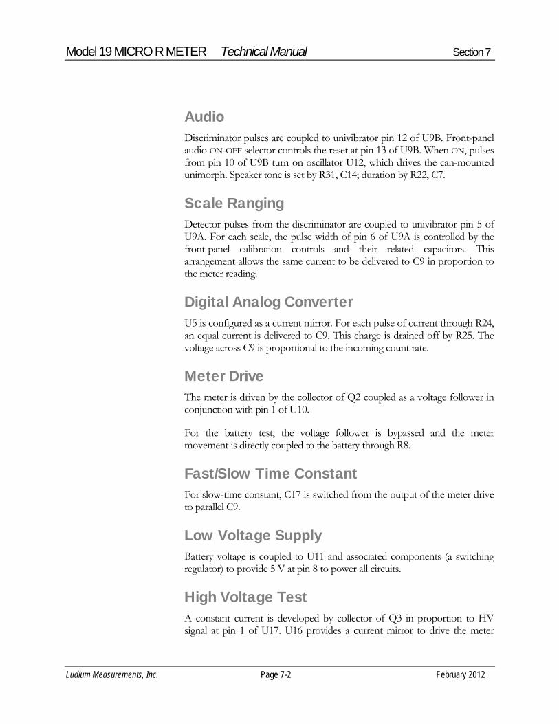
Audio Discriminator pulses are coupled to univibrator pin 12 of U9B. Front-panel audio ON-OFF selector controls the reset at pin 13 of U9B. When ON, pulses from pin 10 of U9B turn on oscillator U12, which drives the can-mounted unimorph. Speaker tone is set by R31, C14; duration by R22, C7.
Scale Ranging Detector pulses from the discriminator are coupled to univibrator pin 5 of U9A. For each scale, the pulse width of pin 6 of U9A is controlled by the front-panel calibration controls and their related capacitors. This arrangement allows the same current to be delivered to C9 in proportion to the meter reading.
Digital Analog Converter U5 is configured as a current mirror. For each pulse of current through R24, an equal current is delivered to C9. This charge is drained off by R25. The voltage across C9 is proportional to the incoming count rate.
Meter Drive The meter is driven by the collector of Q2 coupled as a voltage follower in conjunction with pin 1 of U10.
For the battery test, the voltage follower is bypassed and the meter movement is directly coupled to the battery through R8.
Fast/Slow Time Constant For slow-time constant, C17 is switched from the output of the meter drive to parallel C9.
Low Voltage Supply Battery voltage is coupled to U11 and associated components (a switching regulator) to provide 5 V at pin 8 to power all circuits.
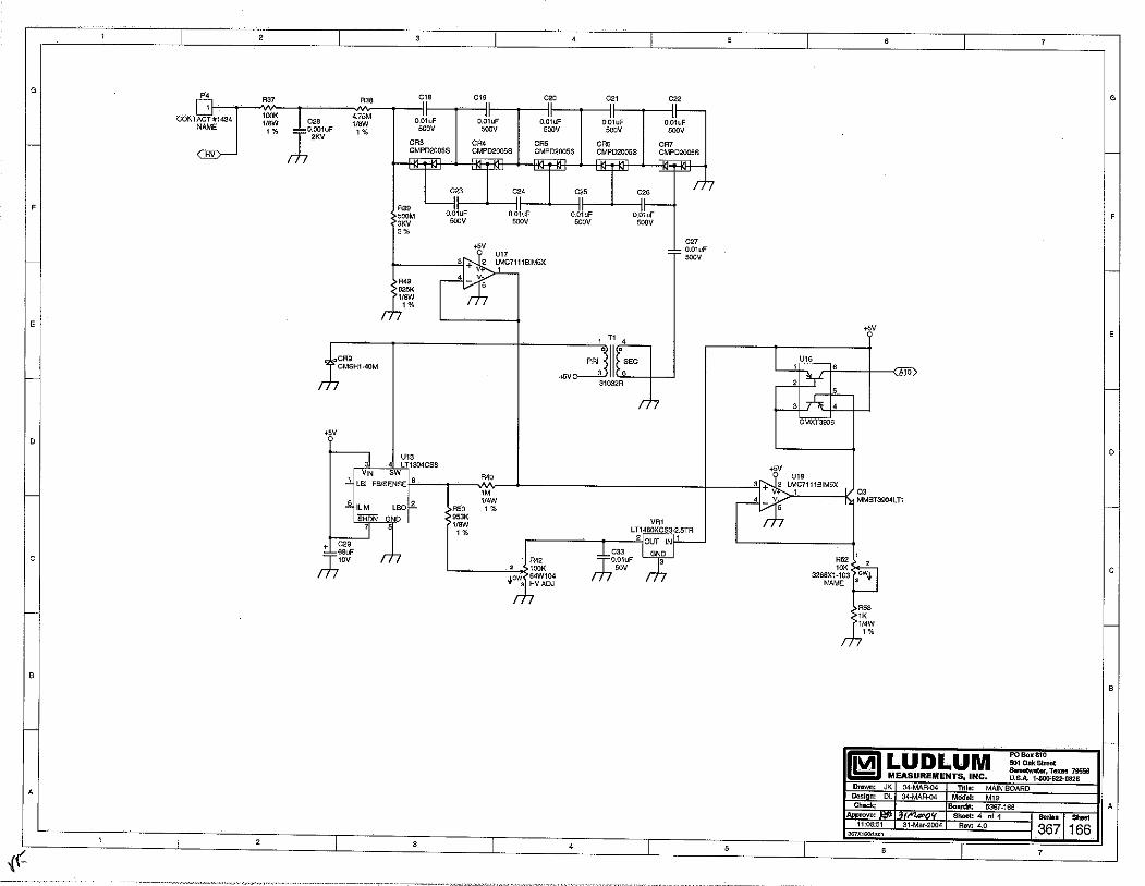
High Voltage Test A constant current is developed by collector of Q3 in proportion to HV signal at pin 1 of U17. U16 provides a current mirror to drive the meter

Model 19 MICRO R METER Technical Manual Section 7
Ludlum Measurements, Inc. Page 7-3 February 2012
through analog switch logic circuit U15, U14, and U3.
High Voltage Supply High voltage is developed by switching regulator U13 and T1. Voltage multiplier CR3 thru CR7, and associated components, develop the detector voltage. Voltage feedback is provided by R39 thru U17 to feed back pin 8 of U13 for voltage regulation. Pin 1 of U17 is proportional to the high voltage, and its output is also utilized to measure the high voltage. High voltage is adjusted by varying the feedback current with R42.

Model 19 MICRO R METER Technical Manual Section 8
Ludlum Measurements, Inc. Page 8-1 February 2012
Recycling
udlum Measurements, Inc. supports the recycling of the electronics products it produces for the purpose of protecting the environment and to comply with all regional, national, and international agencies that promote economically and environmentally sustainable
recycling systems. To this end, Ludlum Measurements, Inc. strives to supply the consumer of its goods with information regarding reuse and recycling of the many different types of materials used in its products. With many different agencies – public and private – involved in this pursuit, it becomes evident that a myriad of methods can be used in the process of recycling. Therefore, Ludlum Measurements, Inc. does not suggest one particular method over another, but simply desires to inform its consumers of the range of recyclable materials present in its products, so that the user will have flexibility in following all local and federal laws.
The following types of recyclable materials are present in Ludlum Measurements, Inc. electronics products, and should be recycled separately. The list is not all-inclusive, nor does it suggest that all materials are present in each piece of equipment:
Batteries Glass Aluminum and Stainless Steel
Circuit Boards Plastics Liquid Crystal Display (LCD)
Ludlum Measurements, Inc. products, which have been placed on the market after August 13, 2005, have been labeled with a symbol recognized internationally as the “crossed-out wheelie bin.” This notifies the consumer that the product is not to be mixed with unsorted municipal waste when discarding; each material must be separated. The symbol will be placed near the AC receptacle, except for portable equipment where it will be placed on the battery lid.
The symbol appears as such:
Section
8 L

Model 19 MICRO R METER Technical Manual Section 9
Ludlum Measurements, Inc. Page 9-1 February 2012
Parts List Reference Description
Part Number
UNIT Completely Assembled Model 19 Micro R Meter 48-1615 BOARD Completely Assembled Circuit Board 5367-166
C1 47pF, 100V 04-5660 C2 0.0022µF, 50V 04-5676 C3 0.001µF, 100V 04-5659 C4 10pF, 100V 04-5673 C5 0.01µF, 50V 04-5664 C6 100pF, 3KV 04-5735 C7 0.022µF, 50V 04-5667 C8 1µF, 16V 04-5701 C9 10µF, 25V 04-5655 C10 100pF, 100V 04-5661 C11 68µF, 10V 04-5654 C12 10µF, 25V 04-5728 C14 470pF, 100V 04-5668 C17 47µF, 10V 04-5666 C18-C27 0.01µF, 500V 04-5696 C28 0.001µF, 2KV 04-5703 C29 68µF, 10V 04-5654 C30-C31 1µF, 16V 04-5701 C32 270pF, 100V 04-5679 C33 0.01µF, 50V 04-5664
Section
9 Model 19 Micro R Meter
Main Board, Drawing 367 × 166
CAPACITORS

Model 19 MICRO R METER Technical Manual Section 9
Ludlum Measurements, Inc. Page 9-2 February 2012
Reference Description
Part Number
Q1 MMBT3904LT1 05-5841 Q2 MMBT4403LT1 05-5842 Q3 MMBT3904LT1 05-5841
VR1 LT1460KCS3-2.5TR 05-5867
U1-U3 MAX4542ESA 06-6453 U4-U5 CMXT3904 05-5888 U6 CMXT3906 05-5890 U7 MAX4541ESA 06-6452 U8 MAX985EUK-T 06-6459 U9 CD74HC4538M 06-6297 U10 LMC7111BIM5X 06-6410 U11 LT1304CS8-5 06-6434 U12 MIC1557BM5 06-6457 U13 LT1304CS8 06-6394 U14-U15 MAX4542ESA 06-6453 U16 CMXT3906 05-5890 U17-C18 LMC7111BIM5X 06-6410
CR1 CMPD2005S 07-6468 CR2 CMSH1-40M 07-6411 CR3-CR7 CMPD2005S 07-6468 CR9 CMSH1-40M 07-6411
SW1 RANGE SELECTOR 08-6761 SW2 H.V. PUSHBUTTON 08-6770 SW3 F-S TOGGLE 08-6781 SW4 AUD ON-OFF TOGGLE 08-6781 SW5 RES PUSHBUTTON 08-6770 SW6 LAMP PUSHBUTTON 08-6770 SW7 BAT PUSHBUTTON 08-6770 R33 1M, 64W105 NAME 09-6814 R34 1M, 64W105 X10 09-6814 R35 1M, 64W105 X1 09-6814 R36 1M, 64W105 X0.1 09-6814 R41 100K, 64W104 X100 09-6813
TRANSISTORS
VOLTAGE REGULATOR
INTEGRATED CIRCUITS
DIODES
SWITCHES
POTENTIOMETERS / TRIMMERS

Model 19 MICRO R METER Technical Manual Section 9
Ludlum Measurements, Inc. Page 9-3 February 2012
Reference Description
Part Number
R42 100K, 64W104 HV ADJ 09-6813 R52 10K, 3266X1-103 NAME 09-6822
R1-R5 200K, 1/8W, 1% 12-7992 R6 8.25K, 1/8W, 1% 12-7838 R7 10K, 1/8W, 1% 12-7839 R8 2.37K, 1/8W, 1% 12-7861 R9-R11 10K, 1/8W, 1% 12-7839 R12 200 Ohm, 1/8W, 1% 12-7846 R13 10K, 1/8W, 1% 12-7839 R14 4.75K, 1/8W, 1% 12-7858 R15 200K, 1/8W, 1% 12-7992 R16 10K, 1/8W, 1% 12-7839 R17 1K, 1/8W, 1% 12-7832 R18 4.75K, 1/8W, 1% 12-7858 R19 2K, 1/8W, 1% 12-7926 R20-R21 100K, 1/4W, 1% 12-7834 R22 1M, 1/8W, 1% 12-7844 R23 2.49K, 1/8W, 1% 12-7999 R24 14.7K, 1/8W, 1% 12-7068 R25 200K, 1/4W, 1% 12-7992 R26 100K, 1/4W, 1% 12-7834 R27 68.1K, 1/8W, 1% 12-7881 R28 100K, 1/8W, 1% 12-7834 R29 1K, 1/8W, 1% 12-7832 R30 100K, 1/8W, 1% 12-7834 R31 475K, 1/8W, 1% 12-7859 R32 100K, 1/8W, 1% 12-7834 R37 100K, 1/8W, 1% 12-7834 R38 4.75M, 1/8W, 1% 12-7995 R39 500M, 3KV, 2% 12-7031 R40 1M, 1/4W, 1% 12-7844 R44 1K, 1/4W, 1% 12-7832 R45 8.25K, 1/8W, 1% 12-7838 R46-R48 200K, 1/4W, 1% 12-7992 R49 825K, 1/8W, 1% 12-7005 R50 953K, 1/8W, 1% 12-7950 R53 1K, 1/4W, 1% 12-7832
P1 CONN-640456-4 MTA100x4 NAME 13-8088
RESISTORS
CONNECTORS

Model 19 MICRO R METER Technical Manual Section 9
Ludlum Measurements, Inc. Page 9-4 February 2012
Reference Description P2 CONN-640456-3
Part Number
MTA100x3 NAME 13-8081 P3 CONN-640456-2 MTA100x2 NAME 13-8073 P4 CONTACT #1434 NAME 18-9124
L1 22µH, CD43-220 21-9808
T1 31032R 21-9925
DS1 Model 19 LAMP BOARD 5367-113 5367-113 DS2 UNIMORPH TEC-3526-PU 21-9251
P1 MTA100x4 MAIN BOARD 5367-166 13-8170 P2 MTA 100x3 MAIN BOARD 5367-166 13-8135 P3 MTA 100x2 MAIN BOARD 5367-166 13-8178
B1-B2 DURACELL "D" 21-9313
* MODEL 19 INTERNAL DETECTOR 47-3426 * TUBE/XTAL ASSY 2004-061 M1 MODEL 19 METER ASSY 987010-001 1mA 4367-024 * MODEL 19 METERFACE (202-016) 7367-023 * METER BEZEL W/ GLASS W/ SCREWS 4363-352-00 * METER MOVEMENT (1mA) 15-8030 * Model 19 BATTERY BOX LID W/CNTCT 2363-191 * DEEP PORTABLE CAN ASSY 4363-615 * MODEL 19 CASTING 7367-171 * MODEL 19 MAIN HARNESS 8367-170
INDUCTOR
TRANSFORMER
Wiring Diagram, Drawing 367 × 174
AUDIO
CONNECTOR
BATTERY
MISCELLANEOUS

Model 19 MICRO R METER Technical Manual Section 9
Ludlum Measurements, Inc. Page 9-5 February 2012
Reference Description
Part Number
* PORTABLE KNOB 08-6613 * SWITCH SEAL (P/B) 08-6611 * UNIMORPH W/WIRES, O'RING 40-0034 * CAL COVER W/SCREWS 4363-200 * HANDLE- PORTABLE (GRIP) 7363-139

Model 19 MICRO R METER Technical Manual Section 10
Ludlum Measurements, Inc. Page 10-1 February 2012
Drawings
Model Board Circuit, Drawing 367 × 166 (4 sheets)
Model Board Component Layouts, Drawings 367 × 167 (2 sheets)
Wiring Diagram, Drawing 367 × 174
Energy Response for Ludlum Model 19
Section
10


LUDLUM MODEL 177 ALARM RATEMETER
March 2013
Serial Number 276475 and Succeeding
Serial Numbers

LUDLUM MODEL 177 ALARM RATEMETER
March 2013
Serial Number 276475 and Succeeding
Serial Numbers
LUDLUM MEASUREMENTS, INC. 501 OAK STREET, P.O. BOX 810 SWEETWATER, TEXAS 79556 325-235-5494, FAX: 325-235-4672

STATEMENT OF WARRANTY Ludlum Measurements, Inc. warrants the products covered in this manual to be free of defects due to workmanship, material, and design for a period of twelve months from the date of delivery. The calibration of a product is warranted to be within its specified accuracy limits at the time of shipment. In the event of instrument failure, notify Ludlum Measurements to determine if repair, recalibration, or replacement is required. This warranty excludes the replacement of photomultiplier tubes, G-M and proportional tubes, and scintillation crystals which are broken due to excessive physical abuse or used for purposes other than intended. There are no warranties, express or implied, including without limitation any implied warranty of merchantability or fitness, which extend beyond the description of the face there of. If the product does not perform as warranted herein, purchaser’s sole remedy shall be repair or replacement, at the option of Ludlum Measurements. In no event will Ludlum Measurements be liable for damages, lost revenue, lost wages, or any other incidental or consequential damages, arising from the purchase, use, or inability to use product.
RETURN OF GOODS TO MANUFACTURER If equipment needs to be returned to Ludlum Measurements, Inc. for repair or calibration, please send to the address below. All shipments should include documentation containing return shipping address, customer name, telephone number, description of service requested, and all other necessary information. Your cooperation will expedite the return of your equipment. LUDLUM MEASUREMENTS, INC. ATTN: REPAIR DEPARTMENT 501 OAK STREET SWEETWATER, TX 79556
800-622-0828 325-235-5494 FAX 325-235-4672


Ludlum Measurements, Inc. March 2013
Table of Contents Introduction 1
Getting Started 2 Preparing the Instrument for Use 2-1
Operating the Instrument 2-1
Specifications 3
Description of Controls and Functions 4 Front Panel 4-1
Back Panel 4-2
CAL Control 4-3
Internal Controls (Overhaul Only) 4-4
Safety Considerations 5 Environmental Conditions for Normal Use 5-1
Cleaning Instructions and Precautions 5-1
Warning Markings and Symbols 5-2
Calibration and Maintenance 6 Calibration 6-1
Establishing an Operating Point 6-2
Maintenance 6-3
Troubleshooting 7 Troubleshooting Electronics that utilize a GM or Scintillation Detector 7-1
Troubleshooting GM Detectors 7-2
Troubleshooting Scintillators 7-3
Technical Theory of Operation 8 Amplifier 8-1
Discriminator 8-1
Digital Analog Conversion 8-1
Time Constant 8-2

Model 177 Technical Manual
Ludlum Measurements, Inc. March 2013
Alarm 8-2
Reset 8-2
Audio 8-2
High Voltage (HV) 8-3
Low Voltage 8-3
Battery Charge 8-3
High Voltage Test 8-3
Alarm Set Voltage 8-3
Battery Test Voltage 8-4
Recycling 9
Parts List 10 Model 177 Alarm Ratemeter 10-1
Main Board, Drawing 347 × 496 10-1
Calibration Board, Drawing 347 × 132 10-4
Wiring Diagram, Drawing 347 × 492 10-5
Drawings and Diagrams 11

Model 177 Technical Manual Section 1
Ludlum Measurements, Inc. Page 1-1 March 2013
Introduction
he Ludlum Model 177 Alarm Ratemeter may be used with GM (Geiger-Mueller) or scintillation detectors for contamination monitoring, surveying and area monitoring. The unit provides four ranges (in decades) of the analog meter, enabling measurement from 0
to 500,000 counts per minute (CPM) on the standard meter dial; others are available. Detector high voltage is adjustable from 400 to 1500 volts.
The unit incorporates an adjustable alarm set point. The alarm setting may be checked by depressing the front-panel TEST switch. Audible and visual enunciators are triggered when the meter reading rises above the alarm set point. Accessory outputs include: Unbuffered Output, Supply Voltage, Negative Pulse Output, Recorder, and Alarm Sink for Remote Relay. The unit may be operated from an internal rechargeable battery or by external 9 Vdc wall transformer.
Section
1 T

Model 177 Technical Manual Section 2
Ludlum Measurements, Inc. Page 2-1 March 2013
Getting Started
he Ludlum Model 177 Alarm Ratemeter is designed for use with GM (Geiger Mueller) or scintillation detectors, which operate from 400 to 1500 V. Typical applications include contamination monitoring, surveying, and area monitoring.
Preparing the Instrument for Use Turn the power switch to the ON position. Depress the BAT TEST button. Check that the meter reads above the BAT TEST indication. If the battery does not check, the instrument will operate on 9 Vdc wall transformer only. The battery may be trickle charged from 9 Vdc wall transformer.
Select the operating voltage. This voltage is set by the manufacturer for the detector shipped with the instrument and recorded on the Certificate of Calibration. For other detector/instrument setups, consult the detector manual or manufacturer. Then adjust the HV potentiometer accordingly.
Note:
Most GM detectors will operate at 900 volts. However, some smaller GM tubes operate at lower voltages.
Operating the Instrument Connect a detector to the instrument. Obtain a meter reading from a check source or calibrated source, if available. Remove the source.
Set the instrument to the appropriate range with the RANGE selector switch.
If the alarm point is not already set, press the ALARM TEST switch and adjust ALARM SET for the desired alarm point.
Section
2 T
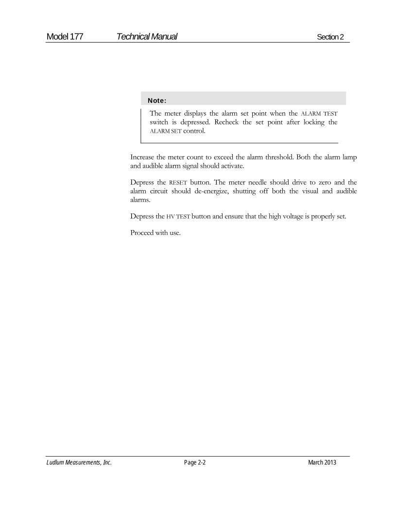
Model 177 Technical Manual Section 2
Ludlum Measurements, Inc. Page 2-2 March 2013
Note:
The meter displays the alarm set point when the ALARM TEST switch is depressed. Recheck the set point after locking the ALARM SET control.
Increase the meter count to exceed the alarm threshold. Both the alarm lamp and audible alarm signal should activate.
Depress the RESET button. The meter needle should drive to zero and the alarm circuit should de-energize, shutting off both the visual and audible alarms.
Depress the HV TEST button and ensure that the high voltage is properly set.
Proceed with use.

Model 177 Technical Manual Section 3
Ludlum Measurements, Inc. Page 3-1 March 2013
Specifications 0
Power: 95-250 Vac wall transformer and 6 volt gell-cell (sealed lead-acid) battery; typical battery life of approximately 50 hours in a non-alarming condition with a fully charged battery.
Fuse: internal resettable
Response Time: toggle switch control selects FAST (2.2 seconds) or SLOW (22 seconds) response, for 90% of full-scale reading
Linearity: within 5% of full scale; typically ±2% of full scale reading when measured with an electronic pulse generator
Battery Dependence: Meter readings vary less than 3% within battery check limits.
High Voltage: variable from 400 to 1500 V
Input Sensitivity: adjustable from -10 through -100 mV
Connector: Series "C"
Audio: unimorph speaker with volume control located on the front panel
Meter: 1 mA, size 6.4 x 6.4 cm (2.5 x 2.5 in.), DC movement
Meter Scale: 0-500 CPM; 0-1.5 kV; BAT TEST
Ranges: four ranges of X1 through X1K
Recorder Output: adjustable from 0 to 1.25 V at 1 mA
Alarm Output: current sink to 200 mA DC, open circuit voltage not to exceed 50 Vdc
Unbuffered Output: may be used to externally add to or subtract from the meter reading
Section
3

Model 177 Technical Manual Section 3
Ludlum Measurements, Inc. Page 3-2 March 2013
Alarm Range: adjustable from 0 through 150% of full scale
Alarm Output: visual indicator (lamp), audible tone and remote current sink
Alarm Control: factory set to latching, non-latching alarm available through the removal of main board resistor R116
Finish: powder coat paint
Size: 12.7 x 20.3 x 15.2 cm (5 x 8 x 6 in.) (H x W x D), excluding handle
Weight: 1.9 kg (4.2 lb) with battery

Model 177 Technical Manual Section 4
Ludlum Measurements, Inc. Page 4-1 March 2013
Description of Controls and Functions Front Panel Power ON-OFF Switch: provides 9 Vdc through a wall transformer to the instrument and trickle-charges the standby battery. In case of line power failure, the battery automatically comes on-line to power the instrument. The battery will provide up to 50 hours of operation.
Note:
To recharge the battery, the ON-OFF switch must be in the ON position.
Power-on Lamp: a red lamp that comes on when power is supplied to the instrument.
VOLUME Control: varies the volume of the audio output through the unimorph speaker. This control has minimal effect on the audio when the alarm is activated.
Audio Speaker: a unimorph speaker, located behind the front panel.
ALARM Lamp: a red lamp that comes on when the alarm threshold has been exceeded. The lamp will remain on (unless the alarm is configured to “non-latching”) until the reset button is depressed, driving the meter needle below the alarm threshold.
RANGE Selector Switch: a four-position switch providing range multipliers of X1K, X100, X10, and X1. With a scale (meter face) of 0-500 CPM, the full range of the instrument is 0 to 500,000 CPM .
Ratemeter: a four-decade linear meter with ranges of 0-500, 0-5000, 0-50,000, 0-500,000 CPM. Other meter faces are available depending on the application. Readout is on a 6.4 cm (2.5 in.) scale panel meter. A separate scale is provided for battery check and high voltage readout.
Section
4

Model 177 Technical Manual Section 4
Ludlum Measurements, Inc. Page 4-2 March 2013
Connector: Series "C" connector (Series BNC and MHV connectors are also available). The connector is provided on the front of the instrument for connection to a detector.
RESET Button: This button, when depressed, provides a rapid means of driving the meter needle to zero.
FAST-SLOW RESPONSE Toggle Switch: When in the FAST position, this switch provides 90% of full-scale meter deflection in 2.2 seconds. With this switch in the SLOW position, 90% of full-scale meter deflection takes 22 seconds. If quick needle response and maximum deviation are desired, the FAST position should be used. For slow response and damped meter movement, the SLOW position should be used.
BAT TEST Button: When this button is depressed, the meter displays the battery status. A sufficiently charged battery is indicated when the meter needle is on or within the BAT TEST range.
HV TEST Button: When this button is depressed, the meter displays the detector high voltage.
ALARM TEST Button: When this button is depressed, the meter displays the alarm calibration set point.
ALARM SET: used to adjust the alarm calibration set point. Note the locking knob below the control.
Back Panel 9 VDC INPUT: Input for external 9 Vdc.
Data: a 9-pin type “D” data plug with connections as follows:
PIN 1: Battery terminal. This is a direct connection and does not go through the front panel ON-OFF switch. Use to parallel the battery.
PIN 2: Unregulated supply from approximately 6 volts, battery only at 8.7 volts with wall transformer plugged in. Limit current drain to 50 milliamperes.

Model 177 Technical Manual Section 4
Ludlum Measurements, Inc. Page 4-3 March 2013
PIN 3: instrument common (ground).
PIN 4: alarm sink. The open collector of a 2N7002L. Limits sink current to 200 milliamperes with open circuit voltage limited to a range of 0 to +50 volts. Unit conducts when in alarm.
PIN 5: Pulse out. A negative pulse connected to the discriminator output through a 0.001 µF capacitor, typically -4.0 volts.
PIN 6: Unbuffered output ties directly to the meter drive circuit. (R124/C122). Approximately 1.3 volts at full scale. Using an external constant current sink will allow background subtract. At full scale, draws out approximately 3.3 microamperes to zero the meter.
PIN 7: Recorder output, adjustable from 0 to 1.0 volts at 1 milliamperes.
PIN 8 and PIN 9: Spares
CAL Control Remove the calibration (cal) cover plate to access the following calibration potentiometers:
DISCR: Discrimination Control. For pancake-type GM detectors (i.e. Model 44-9), adjust DISCR for 80 ±10 millivolts. All other GM detectors and scintillators should be set to 35 ±10 millivolts. If a lower operating voltage for a scintillator is desired, adjust the discriminator to 10 2 millivolts. This control has an adjustable range of 10 to 100 millivolts. A Ludlum Model 500 Pulser may be used to determine the discrimination level.
Calibration Controls: X1K through X1 calibration controls used to calibrate ranges.
HV ADJ: used to set detector operating voltage.
RCDR: used to calibrate the recorder output.

Model 177 Technical Manual Section 4
Ludlum Measurements, Inc. Page 4-4 March 2013
Internal Controls (Overhaul Only) The following controls are located internally, on the main circuit board:
BAT C: used to adjust charge voltage to 6.825 volts.
BAT T: used to adjust meter test voltage reading to 5.97 volts at the BAT
OK line.
HV T: used to adjust the high-voltage test reading to correspond with the actual high-voltage output.

Model 177 Technical Manual Section 5
Ludlum Measurements, Inc. Page 5-1 March 2013
Safety Considerations
Environmental Conditions for Normal Use Indoor use only
No maximum altitude
Temperature range of -20 to 50 °C (-4 to 122 °F)
Maximum relative humidity of less then 95% (non-condensing)
Wall transformer supply voltage range of 95-250 Vac, 50/60 Hz single phase (less than 100 mA)
Maximum transient voltage of 1500 Vac
Installation Category II (Overvoltage Category as defined by IEC 1010-1)
Pollution Degree 2 (as defined by IEC 664) (Normally only nonconductive pollution occurs. Temporary conductivity caused by condensation is to be expected.)
Cleaning Instructions and Precautions The Model 177 Alarm Ratemeter may be cleaned externally with a damp cloth, using only water as the wetting agent. Do not immerse the instrument in any liquid. Observe the following precautions when cleaning:
1. Turn the instrument OFF and disconnect the instrument power cord.
2. Allow the instrument to sit for one minute before cleaning.
Section
5

Model 177 Technical Manual Section 5
Ludlum Measurements, Inc. Page 5-2 March 2013
Warning Markings and Symbols
Caution!
The operator or responsible body is cautioned that the protection provided by the equipment may be impaired if the equipment is used in a manner not specified by Ludlum Measurements, Inc.
The Model 177 Alarm Ratemeter is marked with the following symbols:
CAUTION (per ISO 3864, No. B.3.1) – designates hazardous live voltage and risk of electric shock. During normal use, internal components are hazardous live. This instrument must be isolated or disconnected from the hazardous live voltage before accessing the internal components. This symbol appears on the front panel. Note the following precautions:
Warning!
The operator is strongly cautioned to take the following precautions to avoid contact with internal hazardous live parts that are accessible using a tool:
1. Turn the instrument power OFF and disconnect the power cord.
2. Allow the instrument to sit for one minute before accessing internal components.

Model 177 Technical Manual Section 5
Ludlum Measurements, Inc. Page 5-3 March 2013
CAUTION, RISK OF ELECTRIC SHOCK (per ISO 3864, No. B.3.6) – designates a terminal (connector) that allows connection to a voltage exceeding 1 kV. Contact with the subject connector while the instrument is on or shortly after turning off may result in electric shock. This symbol appears on the front panel.
The “crossed-out wheelie bin” symbol notifies the consumer that the product is not to be mixed with unsorted municipal waste when discarding; each material must be separated. The symbol is placed on the back panel. See section 9, “Recycling,” for further information.
The “CE” mark is used to identify this instrument as being acceptable for use within the European Union.

Model 177 Technical Manual Section 6
Ludlum Measurements, Inc. Page 6-1 March 2013
Calibration and Maintenance Calibration
Note:
Local procedures may supersede the following.
Connect the instrument to a Ludlum Model 500 Pulser (Pulse Generator) or equivalent.
The ratemeter may be calibrated by adjusting the calibration controls labeled 1, 10, 100, and 1K. Starting with the 1000 range, apply 400,000 CPM from the pulser. Adjust the 1K calibration control for a meter reading of 400. Drop the pulse rate to 100,000 CPM and ensure a meter reading of 100 ±10.
Repeat this procedure for the lower scales with scaled pulse rates.
For pancake-type GM detectors (i.e. Model 44-9), adjust DISCR for 80 ±10 millivolts. All other GM detectors and scintillators should be set to 35 ±10 millivolts. To lower the scintillation detector operating voltage, decrease the input sensitivity to 10 ±2 millivolts. Adjustment is made by setting the pulse generator amplitude to the desired pulse height. Adjust DISCR until the meter reaches 75% of the generated incoming count rate.
Connect the Model 177 to an external voltmeter. Adjust the rear panel HV control for a reading of 1000 Vdc on the voltmeter. Depress HV TEST. On the main board, adjust HV for a meter reading of 1.0 kV. Using the rear-panel HV control, vary the high-voltage output from 500 to 1500 Vdc and ensure that the high-voltage meter reads within 10% of the Model 177 meter reading.
Adjust RCDR (recorder output) for 1 volt output (equivalent to full scale).
Adjust ALARM SET to the desired set point.
Section
6

Model 177 Technical Manual Section 6
Ludlum Measurements, Inc. Page 6-2 March 2013
Establishing an Operating Point The operating point for the instrument and detectors is established by setting the detector voltage and instrument sensitivity (HV and DIS). The proper selection of this point is the key to instrument performance.
Efficiency, background sensitivity, and noise are fixed by the physical makeup of the given detector and rarely vary from unit to unit. However, the selection of the operating point makes a significant difference in the contribution of these three sources of count.
The purpose of setting the operating point is to establish the system gain so that the desirable signal pulses (including background) are above the discrimination level, and the unwanted pulses from noise are below the discrimination level. The pulses above the discrimination level are counted by the instrument, while those below are not.
The total system gain is controlled by adjusting the instrument gain or the high voltage. Voltage affects the output of the detector. Amplifier gain is controlled by the DIS (discriminator) control.
In special cases of GM detectors, a minimum voltage must be applied to establish the Geiger-Mueller characteristic. Further changes in gain will not affect this type of detector.
The operating point for each detector is set at a compromise point between sensitivity, stability, and background contribution. These operating points are best for general monitoring. In application, these arbitrarily selected points may not be a better operating point. The following guidelines are presented:
GM Detectors: The output pulse height of the GM detector is not proportional to the energy of the detected radiation. Adjusting DIS will have minimal effect on the observed count rate unless the setting is so low that the instrument double pulses.
For most GM detectors, set DIS for 30-40 millivolts and adjust HV to the GM tube recommended high voltage. Most GM detectors operate at 900 volts; however, some miniature detectors operate at 400-600 volts. If a recommended setting is unavailable, run a plateau of HV setting vs. count rate. Then set the high voltage on the low side of “center.”

Model 177 Technical Manual Section 6
Ludlum Measurements, Inc. Page 6-3 March 2013
Scintillators: Set DIS for 10 millivolts. Carefully increase HV until the instrument plateaus on the background count. This provides the most stable operating point for the detector.
Maintenance Instrument maintenance consists of keeping the instrument clean and periodically checking the battery and calibration.
An instrument operational check should be performed prior to each use by exposing the detector to a known source and confirming the proper reading on each scale.
Recalibration should be accomplished after any maintenance or adjustment has been performed on the instrument. Ludlum Measurements recommends recalibration at intervals no greater than one year. Local regulations may have precedence over this recommendation.
To maintain the life of the battery, it is recommended that the instrument be constantly connected to external power with the power switch in the ON position, even when the instrument is not in use. This will keep the internal battery fully charged.
When the instrument is used without external power, adequate charge time must be allowed for the internal battery to recharge. If possible, leave the instrument on with line power applied overnight and weekends. At a minimum, allow one hour of charge time for each hour of use. If the battery is inadvertently allowed to fully discharge, and is left in that state, constant charging for 500 hours (3 weeks) may be required for battery recovery.
Note:
The ON-OFF switch must be in the ON position to charge the batteries. If the unit is out of service for extended periods of time, charge the battery every six months.
It is recommended that the internal GEL-CELL battery be replaced every four years.

Model 177 Technical Manual Section 7
Ludlum Measurements, Inc. Page 7-1 March 2013
Troubleshooting
ccasionally, you may encounter problems with your LMI instrument or detector that may be repaired or resolved in the field, saving turn-around time and expense in returning the instrument to us for repair. Toward that end, LMI electronics
technicians offer the following tips for troubleshooting the most common problems. Where several steps are given, perform them in order until the problem is corrected. Keep in mind that with this instrument, the most common problems encountered are detector cables and sticky meters.
Note that the first troubleshooting tip is for determining whether the problem is with the electronics or with the detector. A Ludlum Model 500 Pulser is invaluable at this point because of its ability to simultaneously check high voltage, input sensitivity or threshold, and the electronics for proper counting.
We hope these tips will prove to be helpful. As always, please call if you encounter difficulty in resolving a problem or if you have any questions.
Troubleshooting Electronics that utilize a GM or Scintillation Detector
SYMPTOM
No power (or meter does not reach BAT
TEST or BAT OK mark)
POSSIBLE SOLUTION
1. Check battery and charge if necessary. 2. Check for loose or broken wires,
especially between the main board and the calibration board.
Section
7 O

Model 177 Technical Manual Section 7
Ludlum Measurements, Inc. Page 7-2 March 2013
SYMPTOM
Non-linear Readings
POSSIBLE SOLUTION 1. Check the high voltage (HV) by
pressing the HV TEST button. If a Multimeter is used to check the HV, ensure that one with high impedance is used; as a standard multimeter could be damaged in this process.
2. Check for noise in the detector cable
by disconnecting the detector and placing the instrument on the lowest range setting. Wiggle the cable and observe the reading for significant changes.
3. Check for “sticky” meter movement.
Does the reading change when you tap the meter? Does the meter needle “stick” at any spot?
4. Check the “meter zero.” Turn the
power OFF. The meter should come to rest on “0.”
Meter goes full-scale or “pegs out”
1. Replace the detector cable to see if it
has failed, causing excess noise. 2. Check the HV and, if possible, the
input threshold for proper setting.
3. Check for loose wires, especially between the main board and the calibration board.
Troubleshooting GM Detectors
1. If the tube has a thin mica window, check for window breakage. If damage is evident, the tube must be replaced.

Model 177 Technical Manual Section 7
Ludlum Measurements, Inc. Page 7-3 March 2013
2. Check the HV. For most GM tubes, the voltage is normally 900 Vdc, or 460-550 Vdc for “peanut” tubes (Ludlum Model 133 series).
3. If the input sensitivity is too low, the user could see some double-pulsing. See Page 4-3, “DISCR” for further information on sensitivity/discrimination control.
4. Wires to the tube may be broken or the crimped connector could have a loose wire.
Troubleshooting Scintillators 1. Alpha or alpha/beta scintillators are prone to light leaks. They
can be tested for this problem in a dark room or with a bright light. If a light leak is determined, changing the aluminized polyester window assembly will usually fix the problem.
Note:
When replacing the window, make sure to use a window made with the same thickness of aluminized polyester and the same number of layers as the original window.
2. Verify that the HV and input sensitivity are correct. Alpha and gamma scintillators typically operate from 10-35 mV. High voltage varies with photomultiplier tubes (PMT), from as low as 600 Vdc to as high as 1400 Vdc.
3. On a gamma scintillator, visually inspect the crystal for breakage or humidity leakage. Water inside the crystal will turn it yellow and gradually degrade performance.
4. Check the PMT to see if the photocathode still exists. If the end of the PMT is clear (not brownish), this indicates a loss of vacuum, which will render the PMT useless.

Model 177 Technical Manual Section 8
Ludlum Measurements, Inc. Page 8-1 March 2013
Technical Theory of Operation Amplifier Negative detector pulses are coupled through C124 to emitter follower Pin U121. R127 protects the input from inadvertent high-voltage shorts. R129 couples the detector to the high-voltage supply.
Negative pulses from emitter, Pin 2 of U121, are coupled through C121 to amplifier Pin 5 through Pin 7 of U121. This amplifier is self-biased and provides gain in proportion to R029 divided by R0210. Transistor (pins 4, 5, 6, U121) provides amplification. Pins 12 and 15 of U121 are coupled as a current mirror to provide a load for Pin 6 of U121. The output self-biases to 2 Vbe (approximately 1.4 volts) at Pin 7 of U121. This provides just enough bias current through Pin 6 of U121 to conduct all of the current from the current mirror.
Positive pulses from Pin 7 of U121 are coupled to the discriminator.
Discriminator Comparator U021 provides discrimination. The discriminator is set by the DIS (Discriminator) control located on the rear panel, coupled to Pin 5 of U021. Negative pulses (approximately 5 volts) at Pin 7 of U021 are coupled to Pin 5 of U011 for meter drive and Pin 11 of U011 for audio.
Digital Analog Conversion Pin 7 of U021 is connected to the dual univibrator, U011. For each low pulse for Pin 7 of U021, Pin 6 of U011 goes high. The pulse of Pin 6 of U011 is typically 5.0 volts for 6 milliseconds on X1 to 6 microseconds on X1K. This pulse is connected to the constant current drive U012. The pulse width control (R3-C2 on calibration board) is utilized for calibration adjustment. Controls R4 through R6 allow calibration on other scales.
For each positive pulse connected to Pin 8 of U012, a constant current pulse is sourced at Pin 15 of U012. This current pulse charges C122, which is
Section
8

Model 177 Technical Manual Section 8
Ludlum Measurements, Inc. Page 8-2 March 2013
discharged by R124. The average voltage on C122 is coupled through HV, BAT, and ALARM TEST switch to voltage-follower Pin 5 of U311. Pin 7 of U311 drives the meter and recorder output.
Time Constant The meter time constant is determined by R124 and C122. For a slower time constant, C122 is paralleled by C101. When C101 is not used, it is connected to Pin 7 of U311 (voltage follower), maintaining the same voltage level as C122. This allows C101 to be switched in or out of the circuit without transients.
Alarm An alarm is provided by U021, Pins 1, 2, and 3. The alarm set control biases the op-amp U021 for a low output. When the meter signal at Pin 3 exceeds the bias of Pin 2, the output at Pin 1 goes high. Q102 and Q103 saturate, allowing supply voltage to be coupled to:
Lamp voltage through R004.
Audio oscillator U16 through CR112.
R116 couples back to base of Q102, locking up the Alarm On.
Through CR113 to audio transformer T211, allowing full voltage for full volume.
Through R111 to saturating current sink Q101 for external use.
Reset Reset is provided by coupling a voltage to the base of transistors U012 pins 1, 2, 3, and 4, 5, 6. Both transistors saturate. One discharges C122, causing the meter to zero. Pin 3 U012 turns Q102 off, allowing the alarm to reset.
Audio A high on Pin 4 U111 turns the oscillator on, saturating Q111 with each positive swing of the oscillator. T211 couples the pulses to the unimorph. Audio volume is controlled by voltage, applied to Pin 2 of T211. This is either 4.3 volts from the alarm circuit or 0 to 4.3 volts from external volume control through emitter follower Q104.

Model 177 Technical Manual Section 8
Ludlum Measurements, Inc. Page 8-3 March 2013
For counting, audio pulse width is set by R113/C111 of U011 with one pulse per count. For an alarm condition, Pin 4 U111 is held high through CR112 until alarm is reset. Alarm audio tone is controlled by R117 and C112.
High Voltage (HV) The high-voltage power supply is a blocking oscillator utilizing Q401-T411 and quadrupler CR123, CR421, CR422, and through CR423. The HV output is controlled by conduction to ground through Q302. With Q302 saturated, the HV output is maximum.
The op amp, U311 Pins 1, 2, 3, is used as a comparator to compare the voltage reference at Pin 3 to the feedback voltage at Pin 2 through R322 for voltage control and regulation. High voltage is adjusted by HV control R311 changing bias on Pin 2 U311. With the HV control wiper at ground, high-voltage output is maximum.
Low Voltage Low voltage is supplied by internal battery B1 (wiring diagram, 347 × 126) or external power T1. Unregulated power at C125 is coupled to voltage regulator VR211 and battery charger U201-Q301.
Regulated low voltage is supplied to the balance of the circuit through VR131 at 5.0 volts and U301 at 1.2 volts.
Battery Charge Battery charge is provided by voltage regulator U201 and power transistor Q301. R402 limits charge current for discharged battery. A negative voltage coefficient of -0.0063 volts per degree F is provided by ratio of R013/R201. R013 sets output voltage to 6.825 volts.
High Voltage Test High voltage test is supplied by R001 through HV TEST switch, BAT TEST switch, ALARM TEST, Pin 5 of U311, and then the meter. The HV readout is calibrated by R001.
Alarm Set Voltage Alarm set voltage is coupled from ALARM SET control through the ALARM
TEST switch, voltage follower Pin 5 of U311, and to the meter.

Model 177 Technical Manual Section 8
Ludlum Measurements, Inc. Page 8-4 March 2013
Battery Test Voltage Battery test voltage is controlled by R002 through BAT TEST switch, ALARM
TEST switch, then voltage follower Pin 5 of U311 to the meter.

Model 177 Technical Manual Section 9
Ludlum Measurements, Inc. Page 9-1 March 2013
Recycling
udlum Measurements, Inc. supports the recycling of the electronics products it produces for the purpose of protecting the environment and to comply with all regional, national, and international agencies that promote economically and environmentally sustainable
recycling systems. To this end, Ludlum Measurements, Inc. strives to supply the consumer of its goods with information regarding reuse and recycling of the many different types of materials used in its products. With many different agencies – public and private – involved in this pursuit, it becomes evident that a myriad of methods can be used in the process of recycling. Therefore, Ludlum Measurements, Inc. does not suggest one particular method over another, but simply desires to inform its consumers of the range of recyclable materials present in its products, so that the user will have flexibility in following all local and federal laws.
The following types of recyclable materials are present in Ludlum Measurements, Inc. electronics products, and should be recycled separately. The list is not all-inclusive, nor does it suggest that all materials are present in each piece of equipment:
Batteries Glass Aluminum and Stainless Steel
Circuit Boards Plastics Liquid Crystal Display (LCD)
Ludlum Measurements, Inc. products that have been placed on the market after August 13, 2005 have been labeled with a symbol recognized internationally as the “crossed-out wheelie bin,” which notifies the consumer that the product is not to be mixed with unsorted municipal waste when discarding. Each material must be separated. The symbol will be placed on the back panel, except for portable equipment where it will be placed on the battery lid.
The symbol appears as such:
Section
9 L

Model 177 Technical Manual Section 10
Ludlum Measurements, Inc. Page 10-1 March 2013
Parts List Reference Description Part Number UNIT Completely Assembled Model 177 Alarm Ratemeter 48-1632
BOARD Completely Assembled Circuit Board 5347-496
C001 10µF, 20V, 04-5655 C011 47PF, 100V 04-5660 C012 68µF, 6.3V 04-5654 C021 0.1µF, 50V 04-5663 C022 0.001µF, 100V 04-5659 C023-C024 0.1µF, 50V 04-5663 C025 10PF, 100V 04-5673 C101 22µF, 10V 04-5672 C111 0.022µF, 50V 04-5667 C112 470PF, 100V 04-5668 C121 0.001µF, 100V 04-5659 C122 2.2µF, 20V 04-5671 C123 1µF, 35V 04-5656 C124 100PF, 3KV 04-5532 C125 3300µF, 35V 04-5675 C211 47µF, 10V 04-5666 C221 0.0056µF, 3KV 04-5522 C301-C302 47µF, 10V 04-5666 C311-C312 0.01µF, 50V 04-5664 C321 100PF, 3KV 04-5532 C322 0.0056µF, 3KV 04-5522 C323 0.0047µF, 3KV 04-5547
Section
10 Model 177 Alarm Ratemeter
Main Board, Drawing 347 × 496
CAPACITORS

Model 177 Technical Manual Section 10
Ludlum Measurements, Inc. Page 10-2 March 2013
Reference Description Part Number C401-C402 1µF, 35V 04-5656 C403 0.1µF, 50V 04-5663 C411 47µF, 10V 04-5666 C421-C423 0.0047UF, 3KV 04-5547 Q101 2N7002L 05-5840 Q102 MMBT3904T 05-5841 Q103 MJD210 05-5843 Q104 MMBT3904T 05-5841 Q111 MMBT3904T 05-5841 Q301 MJD200 05-5844 Q302 MMBT3904T 05-5841 Q401 MJD210 05-5843 VR211 LM2931AT 5.0 05-5813 U011 CD74HC4538M 06-6297 U012 CA3096M 06-6288 U021 TLC372ID 06-6290 U111 ICM7555CBA 06-6300 U121 CA3096M 06-6288 U201 ICL7663SCBA 06-6302 U301 LM285M-1.2 05-5845 U311 TLC27M7ID 06-6292 CR111-CR114 MMBD914L 07-6353 CR201-CR202 CXSH-4 07-6358 CR321 1N4007 07-6274 CR401 MMBD914L 07-6353 CR421-CR423 1N4007 07-6274 R314 250 07-6366 R001 1M, HV TEST 09-6906 R002 50K, BAT T 09-6920 R013 50K, BAT C 09-6920
TRANSISTORS
VOLTAGE REGULATOR
INTEGRATED CIRCUITS
DIODES
THERMISTOR
POTENTIOMETERS / TRIMMERS

Model 177 Technical Manual Section 10
Ludlum Measurements, Inc. Page 10-3 March 2013
Reference Description Part Number R003 475K, 1%, 125mW 12-7859 R004 150 ohm, 1%, 125mW 12-7062 R011 4.75K, 1%, 125mW 12-7858 R012 82.5K, 1%, 125mW 12-7849 R014-R015 100K, 1%, 125mW 12 7834 R016 100, 1%, 125mW 12-7840 R021-R022 10.0K, 1%, 125mW 12-7839 R023 100K, 1%, 125mW 12-7834 R024 1.00K, 1%, 125mW 12-7832 R025 10.0K, 1%, 125mW 12-7839 R026-R027 100K, 1%, 125mW 12-7834 R028 10.0K, 1%, 125mW 12-7839 R029 221K, 1%, 125mW 12-7845 R0210 5.62K, 1%, 125mW 12-7871 R101 1.00K, 1%, 125mW 12-7832 R102 10.0K, 1%, 125mW 12-7839 R103 100, 1%, 125mW 12-7840 R111 1.00K, 1%, 125mW 12-7832 R112 100K, 1%, 125mW 12-7834 R113 1.00M, 1%, 125mW 12-7844 R114 SAT, TYPICALLY 35.7K,
1%, 125mW 12-7911 R115 100 OHM, 1% 12-7840 R116 56.2K, 1%, 125mW 12-7873 R117 1.00M, 1%, 125mW 12-7844 R118 3.32K, 1%, 125mW 12-7870 R121 3.92K, 1%, 125mW 12-7875 R122 10.0K, 1%, 125mW 12-7839 R123 100, 1%, 125mW 12-7840 R124 392K, 1%, 125mW 12-7841 R125 47.5K, 1%, 125mW 12-7872 R126 100K, 1%, 125mW 12-7834 R127 10.0K, 1%, 125mW 12-7839 R128 221K, 1%, 125mW 12-7845 R129 1M 10-7028 R201 165K, 1%, 125mW 12-7877 R202 1.00K, 1%, 125mW 12-7832 R203 2.2, 5%, 125mW 12-7932 R221 1M 10-7028 R301 10.0K, 1%, 125mW 12-7839
RESISTORS

Model 177 Technical Manual Section 10
Ludlum Measurements, Inc. Page 10-4 March 2013
Reference Description Part Number R302 1.00K, 1%, 125mW 12-7832 R303 2.21K, 1%, 125mW 12-7835 R311 750K, 1%, 125mW 12-7882 R312 301, 1%, 125mW 12-7863 R313 475 ohm, 1%, 125mW 12-7851 R315 22.1K, 1%, 125mW 12-7843 R316 1.00M, 1%, 125mW 12-7844 R321-R322 1G 12-7686 R323 1M 10-7028 R401 200, 1%, 125mW 12-7846 R402 15, 1W 12-7738 T211 4275-083 4275-083 T411 40-0902, 9=GND, 10=GND 40-0902 P1 CONN-640445-3 MTA156 13-8125 P2 CONN-1-640456-2 MTA100 13-8061 P3 CONN-1-640456-0 MTA100 13-8066 10 EA. CLOVERLEAF RECEPT. 011-6809-000-599 18-8771 BOARD Completely Assembled Calibration Board 5347-189 C1 0.0047µF, 100V 04-5570 C2 0.047µF, 100V 04-5565 R1 10K, RECORDER 09-6787 R2 100K, HV 09-6813 R3 1M, X1 09-6814 R4 1M, X10 09-6814 R5 2M, X100 09-6834 R6 250K, X1000 09-6819 R7 10K, DISCRIMIINATOR 09-6787
TRANSFORMERS
MISCELLANEOUS
Calibration Board, Drawing 347 × 132
CAPACITORS
POTENTIOMETERS

Model 177 Technical Manual Section 10
Ludlum Measurements, Inc. Page 10-5 March 2013
Reference Description Part Number R9 680, 1/3W 12-7885 RN1 10K 12-7720 P6 CONN 1-640457-1 MTA100 13 8397 S1 46206-LR SLIDE 08-6523 S2 PA-1002 08-6543 S3 7101-SYZ-QE 08-6511 S4 HV (#923 SWITCHCRAFT) 08-6518 S5 BAT (#923 SWITCHCRAFT) 08-6518 S6 ALARM (#923 SWITCHCRAFT) 08-6518 S7 RESET (30 1 PB GRAYHILL) 08-6517 R1 10K, VOLUME 09-6753 R2 100K, ALARM SET 09-6795 J1 MAIN BOARD 5347-496,
3 PIN SIP (CONN 640428-3 MTA 156) 13-8124
J2 MAIN BOARD 5347-496, 12 PIN SIP (CONN 1-640441-2) 13-8431
J3 MAIN BOARD 5347-496, 10 PIN SIP (CONN 1-640441-0MTA 100) 13-8197
J4 CONNECT BOARD 5347-489 13-7801 5 PIN SIP (CONN-3-640428-5 MTA 156)
J5 CONNECTOR BOARD 5347-489 13-8096 2 PIN SIP (CONN3-643193-2 MTA-156)
J6 CALIBRATION BOARD 13-8161 5347-189, 11 PIN SIP (CONN 1-640441-1 MTA 100)
J7 FLYING LEAD TO MAIN 13-7751 BOARD 5347-293
(RECPT-UG706)
RESISTOR
RESISTOR NETWORK
MISCELLANEOUS
Wiring Diagram, Drawing 347 × 492 SWITCHES
POTENTIOMETERS
CONNECTORS
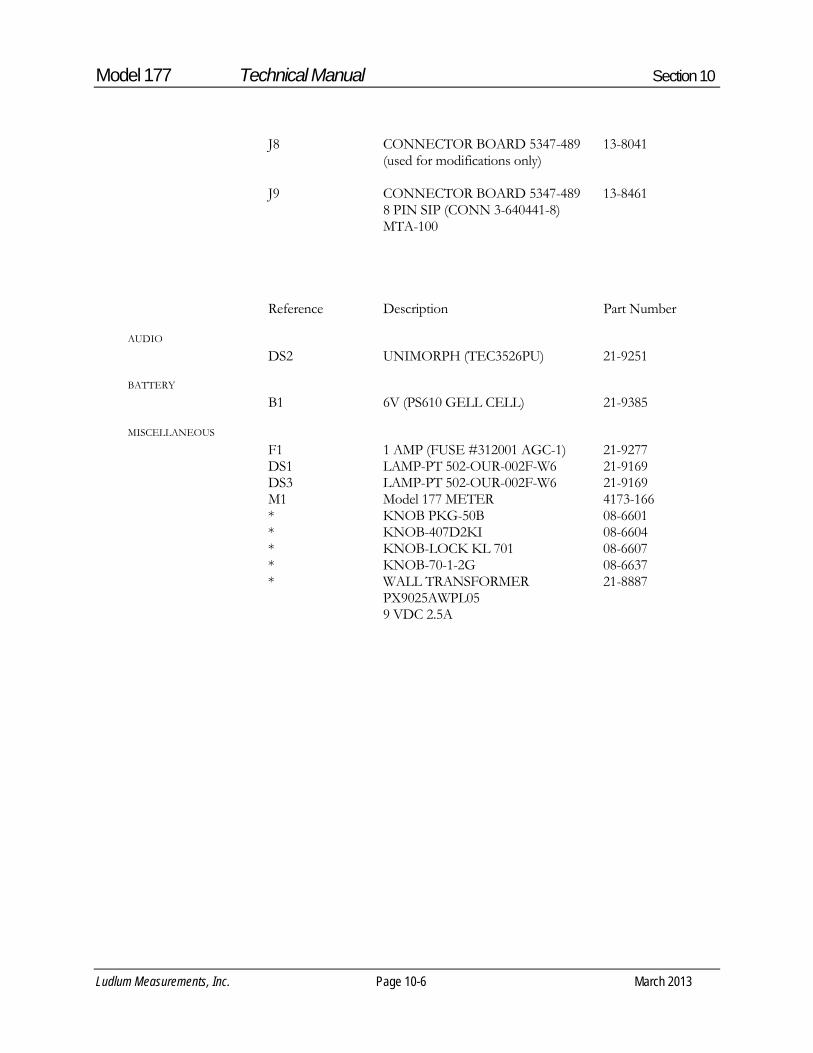
Model 177 Technical Manual Section 10
Ludlum Measurements, Inc. Page 10-6 March 2013
J8 CONNECTOR BOARD 5347-489 13-8041 (used for modifications only) J9 CONNECTOR BOARD 5347-489 13-8461 8 PIN SIP (CONN 3-640441-8) MTA-100 Reference Description Part Number DS2 UNIMORPH (TEC3526PU) 21-9251 B1 6V (PS610 GELL CELL) 21-9385 F1 1 AMP (FUSE #312001 AGC-1) 21-9277 DS1 LAMP-PT 502-OUR-002F-W6 21-9169 DS3 LAMP-PT 502-OUR-002F-W6 21-9169 M1 Model 177 METER 4173-166 * KNOB PKG-50B 08-6601 * KNOB-407D2KI 08-6604 * KNOB-LOCK KL 701 08-6607 * KNOB-70-1-2G 08-6637 * WALL TRANSFORMER 21-8887 PX9025AWPL05 9 VDC 2.5A
AUDIO
BATTERY
MISCELLANEOUS

Model 177 Technical Manual Section 11
Ludlum Measurements, Inc. Page 11-1 March 2013
Drawings
MAIN BOARD FOR HOYT 1mA/1K MOVEMENT, Drawing 347 × 496
MAIN BOARD (HOYT 1mA/1K) Component Layout, Drawing 347 × 497
CALIBRATION BOARD, Drawing 347 × 132
CALIBRATION BOARD Component Layout, Drawing 347 × 133
CONNECTOR BOARD, Drawing 347 x 489
CONNECTOR BOARD Component Layout, Drawing 347 x 490
WIRING DIAGRAM FOR HOYT 1mA/1K MOVEMENT, Drawing 347 × 492
Section
11


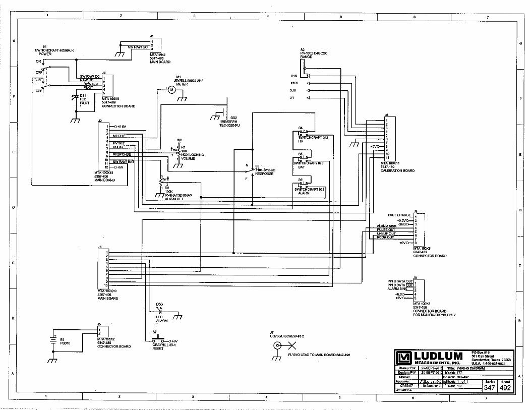

LUDLUM MODEL 2221 PORTABLE SCALER RATEMETER
Revised March 2016
Serial Number 161568 and Succeeding Serial Numbers

LUDLUM MODEL 2221 PORTABLE SCALER RATEMETER
Revised March 2016
Serial Number 161568 and Succeeding Serial Numbers

STATEMENT OF WARRANTY Ludlum Measurements, Inc. warrants the products covered in this manual to be free of defects due to workmanship, material, and design for a period of twelve months from the date of delivery. The calibration of a product is warranted to be within its specified accuracy limits at the time of shipment. In the event of instrument failure, notify Ludlum Measurements to determine if repair, recalibration, or replacement is required. This warranty excludes the replacement of photomultiplier tubes, G-M and proportional tubes, and scintillation crystals which are broken due to excessive physical abuse or used for purposes other than intended. There are no warranties, express or implied, including without limitation any implied warranty of merchantability or fitness, which extend beyond the description of the face there of. If the product does not perform as warranted herein, purchaser’s sole remedy shall be repair or replacement, at the option of Ludlum Measurements. In no event will Ludlum Measurements be liable for damages, lost revenue, lost wages, or any other incidental or consequential damages, arising from the purchase, use, or inability to use product.
RETURN OF GOODS TO MANUFACTURER If equipment needs to be returned to Ludlum Measurements, Inc. for repair or calibration, please send to the address below. All shipments should include documentation containing return shipping address, customer name, telephone number, description of service requested, and all other necessary information. Your cooperation will expedite the return of your equipment. LUDLUM MEASUREMENTS, INC. ATTN: REPAIR DEPARTMENT 501 OAK STREET SWEETWATER, TX 79556
800-622-0828 325-235-5494 FAX 325-235-4672


Model 2221 Portable Scaler Ratemeter March 2016
page i
TABLE OF CONTENTS 1. GENERAL .................................................................................................................................1 2. SPECIFICATIONS ....................................................................................................................1 3. DESCRIPTION OF CONTROLS AND FUNCTIONS ............................................................2 4. OPERATING PROCEDURES ..................................................................................................4
4.1 Initial Preparation ................................................................................................................4 4.2 Operating Point ....................................................................................................................4 4.3 Limitation of Controls .........................................................................................................4
5. DETERMINING INSTRUMENT PLATEAU AND SELECTING OPERATING POINT ....5 6. WINDOW OPERATION AND ENERGY CALIBRATION PROCEDURES .........................5 7. OVERLOAD DETECTION CALIBRATION ..........................................................................6 8. CALIBRATION ........................................................................................................................6
8.1 Ratemeter Calibration ..........................................................................................................6 8.2 TEST Pushbutton/Display Calibration ................................................................................7 8.3 High Voltage Calibration .....................................................................................................7 8.4 Threshold/Gain Calibration .................................................................................................7
9. OVERHAUL PROCEDURE .....................................................................................................8
9.1 Amplifier/Power Supply Board ...........................................................................................8 9.2 Processor Board Checkout ...................................................................................................9 9.3 Functional/Chassis Checkout .............................................................................................11
10. PARTS LIST ............................................................................................................................14
Amplifier/Power Supply Board, Drawing 261 X 56 .........................................................14 Processor Board, Drawing 261 X 91 .................................................................................15 Calibration Board, Drawing 261 X 59 ...............................................................................16 LCD Display Board, Drawing 261 X 58 ...........................................................................16 Backplane Board, Drawing 261 X 60 ................................................................................17 Chassis Wiring Diagram, Drawing 261 X 61 ....................................................................17 RS-232 Port Kit, Board Drawing 261 X 179 .....................................................................17
11. RS-232 PORT ADDITION ......................................................................................................18
12. DRAWINGS AND DIAGRAMS ............................................................................................19

Model 2221 Portable Scaler Ratemeter March 2016
page 1
1. GENERAL The Ludlum Model 2221 Portable Scaler Ratemeter is a self-contained counting instrument designed for operation with scintillation, proportional, or GM detectors. Power is derived from four “D” cell batteries. The unit is complete with a voltage-sensitive preamplifier, linear amplifier, electronic timer, detector high-voltage power supply, and detector overload detection circuitry.
A single channel analyzer is also featured in this unit for use in gamma spectrum analysis. The analyzer may be switched on or off, allowing gross or window counting. The unit has a combination four-decade linear and log ratemeter and a six-digit LCD readout for the scaler and digital ratemeter. Potentiometers are supplied for threshold, window, and high-voltage controls.
2. SPECIFICATIONS
HIGH VOLTAGE: 400 to 2400 volts with digital readout
CALIBRATION STABILITY: less
than 3% variance to battery endpoint
SENSITIVITY: voltage sensitive and adjustable from 1.5 mV to 100 mV; typically factory calibrated to 10 mV = 100 on the THR display
INPUT IMPEDANCE: 22k ohm
READOUT: six-digit liquid crystal
display, 1.3 cm (0.5 in.) characters with backlight selection
METER: 6.4 cm (2.5 in.) scale, 1 mA,
pivot and jewel suspension
SCALES/RANGE: four-decade log ratemeter ranging from 50 to 500 kcpm; four decade linear ratemeter, 0-500 CPM meter dial with range multipliers of X1K, X100, X10, X1 producing an overall range of 0-500 kcpm
OPERATING TEMPERATURE:
-20 to 50 °C (-4 to -122 °F)
LINEARITY: 10% of the true value for the analog and digital ratemeter;
2% of the true value for the digital Scaler, HV, THR, and WIN digital voltmeter readings; 4% of the true value for the BAT voltmeter reading
RESPONSE: two positions. Fast
response = 4 1 second. Slow response = 22 2 second. All response times are measured from 10-90% of final reading.
CALIBRATION CONTROLS:
recessed screwdriver adjustments with calibration cover
AUDIO: built-in unimorph speaker
with click-per-event and switch selectable divide-by 1, 10, and 100
CONNECTOR: Series "C"
BATTERY COMPLEMENT: four
each "D" cell batteries
BATTERY LIFE: approximately 250 hours

Model 2221 Portable Scaler Ratemeter March 2016
page 2
POSITION COUNT TIME IN MINUTES
0.1 0.1 0.2 0.2 0.5 0.5 1 1 2 2 5 5 10 10 CONT COUNTER COUNTS UNTIL HOLD IS PRESSED
SIZE: 22.9 x 10.9 x 25.4 cm (9 x 4.3 x 10 in.) (H x W x L), including handle
WEIGHT: 2.5 kg (5.5 lb), including
batteries
FINISH: polyurethane enamel with
silk-screened nomenclature
3. DESCRIPTION OF CONTROLS AND FUNCTIONS
POWER: two-position ON-OFF switch
DETECTOR: Series "C" connector for detector
Input Impedance: 22k
Ballast Resistor: 1M
RATEMETER:
F-S RESP Switch: two-position switch
for selecting ratemeter response. F position 4 1 second; S position 22 2 seconds.
ZERO: when pressed, resets the
ratemeter
RANGE SELECTOR: Five-position switch labeled LOG, X1K, X100, X10, X1 used to select the analog ratemeter range. The LOG position selects the upper meter scale to provide a four decade logarithmic reading from 50-500k CPM. The X1, X10, X100, and X1K range multipliers used with the lower 0-500 CPM meter scale, providing an overall measuring range from 0-500k CPM. Multiply the meter reading by the respective range position.
DIGITAL CONTROL:
COUNT Pushbutton: When pressed,
resets and starts the counter. While the counter is counting, two sets of colons are displayed.
HOLD Pushbutton: When pressed,
stops the counter and leaves the count in the display.
SCALER/DIG RATE Toggle Switch:
Two-position toggle switch for selecting scaler or digital ratemeter
SCALER Position: The display shows the counter contents.
DIG. RATE Position: The display shows the ratemeter count rate. Note: The scaler and digital ratemeter are active even when not selected. This allows the user to start a timed count, switch to the digital ratemeter, and then switch back to scaler without having to restart the counter.
MINUTES Selector Switch: Eight-position switch used for selecting the count times for the scaler:

Model 2221 Portable Scaler Ratemeter March 2016
page 3
CALIBRATION CONTROLS:
WIN: 20-turn potentiometer used to adjust window width when the window toggle switch, WIN, is in the "IN" position
THR: 20-turn potentiometer used to adjust the threshold
HV: 20-turn potentiometer used to
adjust detector voltage
O.L.: 20-turn potentiometer used to adjust detector overload current
TEST:
BAT Pushbutton Switch: When
pressed, displays the battery voltage in the digital display.
HV Pushbutton Switch: When
pressed, displays the detector high voltage in the digital display.
THR Pushbutton Switch: When
pressed, displays the threshold setting in the digital display.
WIN Pushbutton Switch: When
pressed, displays the window setting in the digital display.
LAMP Toggle Switch: Two-position
switch to turn on the display lights.
WIN Toggle Switch: Two-position switch for switching the window IN or OUT.
IN position: The SCA (Single Channel Analyzer) is set up as a window counter. Detector pulses to be counted must be above the threshold but below the window.
OUT position: The SCA is set up as a gross counter. All detector pulses above the threshold are counted.
AUDIO:
VOL Control: One-turn potentiometer used to adjust the volume of the speaker or headset.
AUDIO DIVIDE:
1 Position: provides 1 click per event 10 Position: provides 1 click per 10
events 100 Position: provides 1 click per 100
events
1/8 inch HEAD PHONE JACK: used for headset. When headset is plugged in, the unimorph speaker on the can is disabled.
LIQUID CRYSTAL DISPLAY: 16.5
cm (6.5 in.) high digits, displaying counter contents or digital count rate
STATUS INDICATORS:
Counter Overflow: When in SCALER mode, the left digit alternates between the correct digit and an “H.”
Detector Overload: The display flashes all dashes. (“------“).
Battery: When the battery voltage is 4.4 volts or less, all decimal points are turned on. This indicates that the batteries should be changed immediately.
Scaler Counting: The two colons are turned on when MINUTES selector switch is in CONT position.

Model 2221 Portable Scaler Ratemeter March 2016
page 4
4. OPERATING PROCEDURES
4.1 Initial Preparation Unscrew battery door latch.
Install 4 "D" size batteries in the battery
holder. The correct position of the batteries is indicated on the bottom of the battery door.
Switch the POWER ON/OFF switch to
the ON position. A random number will first be observed in the display, then 8.8:8.8:8.8. The third displayed number will be the program version. (At the time of this printing, program version is #261010.)
Press COUNT pushbutton. The display
should zero. Two sets of colons should appear on the display.
Press HOLD pushbutton. The colons
should disappear.
Switch LAMP toggle switch to the ON position. LCD display backlighting and two lamps at the bottom of the analog meter should be illuminated.
NOTE: If the Lamp switch is left in the ON position for extended periods of time, battery life will decrease rapidly.
Check TEST pushbutton functions for
proper operation.
4.2 Operating Point
Instrument and detector operating point is established by setting the probe voltage (HV) and instrument sensitivity (THR). For a given detector system, efficiency, background and noise are fixed by the physical makeup of the detector and rarely vary from unit to unit. However, the selection of the operating point makes a
marked difference in the apparent contribution of these three sources of count. In the singular case of the GM detector, a minimum operating voltage is required to establish the GM operating region. (At lower voltages, the detector operates as a very insensitive proportional counter.) This detector is not capable of energy dis-crimination (pulse-height discrimination). The threshold (THR) is typically adjusted to 550, with a THR reading of 100 = 10 mV input pulse for GM detectors. For gain sensitive detectors (proportional or scintillation), the most straightforward method of selecting the operating point is to develop a graph, relating count rate to system gain. This relationship is commonly referred to as a plateau or instrument plateau curve. System gain may be changed by adjusting detector high voltage or THR control. The threshold is typically adjusted for 100 = 10 mV for scintillation detectors and 50 (5mV equivalent) on the THR readout for proportional detectors.
4.3 Limitation of Controls
HV Control provides a linear adjustment of the detector voltage supply. The range is approximately 400 to 2400 volts. Changing the detector voltage will cause the detector gain to change. It should be remembered that a linear change in voltage will cause an exponential change in detector gain. THR Control sets the basic pulse discrimination point of the scaler. WIN Control is calibrated with the THR control so that the reading of the WIN control is equivalent to the reading of the THR control. As an example, 100 on the THR is equal to 100 on the WIN.

Model 2221 Portable Scaler Ratemeter March 2016
page 5
5. DETERMINING INSTRUMENT PLATEAU AND SELECTING OPERATING POINT Set WIN ON/OFF to OFF. Set MINUTES switch to 0.1 minutes. Set THR control at 100. With detector shielded from source, turn up
high-voltage control and take a plot of HV versus background count rate until the detector maximum voltage rating is reached. (Maximum voltage on most scintillation detectors is 1500-1600 Vdc; maximum voltage on proportional detectors is reached at the continuous discharge point. Return HV control to minimum.
Expose the detector to a source and again make a plot of voltage versus count.
Plot both sets of data and select the
operating point to correspond with maximum source count and minimum background count. Avoid areas of very fast count rate changes with small changes in detector voltage. The optimum operating point for low-background detectors is just above the inflection point (or break-over point or knee) of the plateau curve. If background count is irrelevant, shift operating point to the plateau center for greater stability.
6. WINDOW OPERATION AND ENERGY CALIBRATION PROCEDURES The following procedure calibrates threshold directly in keV: Place RATEMETER multiplier switch to
LOG position. Unscrew and remove CAL cover. Press HV pushbutton. The HV should read
out on the display directly in volts. While depressing the HV pushbutton, turn HV potentiometer maximum counterclockwise. The HV should be less than 50 volts.
Depress the THR pushbutton. Turn the
THR potentiometer clockwise until 652 displays.
With WIN IN/OUT switch IN, depress the
WIN pushbutton. Turn the WIN potentiometer until 20 appears on the display.
Switch WIN IN/OUT to OUT.
Connect the probe and expose to a 137Cs source (a source of approximately 10Ci placed 3-4 inches away is recommended).
Increase HV. (If HV potentiometer is at
minimum, it will take approximately three turns before any change is indicated.) While increasing the HV, observe the log scale of the ratemeter. Increase HV until ratemeter indication occurs.
Switch WIN IN/OUT switch to IN. Turn the HV control until maximum
reading occurs on the log scale. Increase HV until reading starts to drop off, then decrease the HV for maximum reading.
Turn RATEMETER selector switch to the
X1K position. Press ZERO pushbutton and release. If
meter does not read, switch to a lower range until a reading occurs.

Model 2221 Portable Scaler Ratemeter March 2016
page 6
Carefully adjust HV potentiometer until maximum reading is achieved on the range scale. The instrument is now peaked for 137Cs on both the LOG and Linear scales.
NOTE: When the THR control is adjusted, the effective window width remains constant. As an example, if the THR is set at 612, and the WIN at 100, a 662 keV peak 612 + (100
divided by 2) will be centered in the window. Then the threshold point is equivalent to 612 keV with a 100 keV window and calibrated for 100 keV per turn. If the threshold is reduced to 250, the threshold is equivalent to 250 keV, but the window (100) is still equal to 100 keV. Proportionally, this represents a broader window.
7. OVERLOAD DETECTION CALIBRATION Detector count saturation is detected in this
instrument and is indicated by the LCD display by flashing all dashes and the analog ratemeter deflecting full scale. The count saturation or "overload" point is calibrated by the O.L. front-panel control.
Adjust the O.L. control to fully clockwise
position. Connect detector and set HV for correct
detector operating voltage. Expose detector to radiation field and while
observing ratemeter, increase field intensity until a decrease in count rate is noticed. For alpha scintillators, the detector photomultiplier tube (PMT) should be exposed to a small light leak through the probe face to establish the detector saturation point.
With the detector in the count saturation field, adjust the O.L. control counterclockwise until the overload alarm point is reached (flashing dashes in LCD display).
Position detector in a lower field intensity
just below the saturation point and confirm overload is defeated.
Example: Ludlum Model 44-9 GM pancake
detector saturates at approximately 500 mR/hr (5 mSv/h).
Full-scale instrument analog meter reading
= 200 mR/hr (2 mSv/h). Set the Model 2221 to overload at 500 mR/hr (5 mSv/h) field, then position detector in a 300 mR/hr (3 mSv/h) field and confirm that overload alarm is defeated. The O.L. control will have to be "fine adjusted" to perform the above procedure.
8. CALIBRATION Refer to schematic and component layout for the following calibration: 8.1 Ratemeter Calibration Connect frequency counter to pin 18 of U22
(80C51FA) on processor board, #5261-073. Confirm crystal frequency is 6 MHz 0.1% (6006-5994 kHz).
Set THR control to 100 and Window
IN/OUT switch to the OUT position. Connect Ludlum Model 500 Pulser or
equivalent and adjust count rate for 40,000 CPM.

Model 2221 Portable Scaler Ratemeter March 2016
page 7
Switch Ratemeter Multiplier switch to the X100 position and the Response switch to “F.”
Adjust pulse amplitude above threshold
until a steady count rate is observed on ratemeter.
Adjust R40 Meter Cal (labeled MCAL) on
Processor board, for 40,000 CPM on meter. Switch SCALER/DIG RATE switch to the
SCALER position. Confirm counter time operation by taking
0.1 minute count. Colons should be observed during count cycle.
8.2 TEST Pushbutton/Display Calibration Adjust THR control to fully clockwise
position. Connect positive voltmeter lead to pin 7 of
U3 (TLC27M7IP) on the amplifier/power supply board. Connect negative lead to ground near U3.
Press the THR test pushbutton and adjust
R171 Volt Cal (labeled "V"), so that the front-panel display reading corresponds to the voltmeter reading at pin 7 of U3.
8.3 High Voltage Calibration Connect HV meter (1000 Megohm input
impedance or greater) to the junction of R32 (4.7 Meg) and R33 (1 Meg) on the amplifier/power supply board.
While pressing the HV Test pushbutton,
adjust the HV front-panel control until the display reads 1500.
Adjust R175 HV Cal on amplifier/power
supply board for 1500 5 volts on external HV meter.
Confirm HV will adjust from 400 to 2400-2500 volts. Ensure HV displayed reading tracks within 2% of HV output.
8.4 Threshold/Gain Calibration Set pulser pulse amplitude to 10 mV. With THR set at 100, fine adjust R174 gain
control (on Power Supply board) until ratemeter reads 30,000 CPM with 40,000 CPM from pulser.
Adjust THR control for readings of 200,
300, 400, and 500 to ensure the pulser input is 20, 30, 40, and 50 mV respectively. Use the 3/4 CPM input setting to discriminate turn on points as in procedure above.
Adjust THR control back to 100. Switch Window IN/OUT switch to the IN
position. Adjust WIN control for 100, 200, 300, 400, and 500 to confirm 20, 30, 40, and 50 mV window cut-off points.
Set WIN back to 100 and OUT position. Check the rest of the front-panel functions
for proper operation.

Model 2221 Portable Scaler Ratemeter March 2016
page 8
9. OVERHAUL PROCEDURE The checkout below can be performed with boards in instrument. An extender board (LMI part # 5261-098) is available if better access to board components is necessary: 9.1 Amplifier/Power Supply Board Connect low-voltage power supply, capable
of supplying 4.0-5.0 Vdc to the Model 2221 and plug in amplifier/power supply board (component side to back of instrument).
Adjust the WIN, THR, and O.L. front-panel
controls to maximum clockwise position. Turn HV control to maximum counterclockwise position. Switch the lamp switch to the OFF position. Window IN/ OUT switch to the OUT position.
Adjust input voltage for approximately +4
Vdc and turn instrument to the ON position. Battery current should be approximately 30 mA or less.
Confirm pin 8 of U7 (CA3290A) is equal to
or greater than +6.4 Vdc. Increase supply voltage to approximately
+5 Vdc and pin 8 of U7 should increase to +9 1 Vdc.
Check for +5 0.15 Vdc at pin 8 of any of
the TLC27M7IP circuits (such as U3 or U4).
Check for -6.5 0.5 Vdc at pin 4 of any of
the same TLC27M7IP circuits. Connect subminax wire from detector input
to amplifier/power supply board. Connect HV meter to detector input and
adjust front-panel HV control to fully clockwise position.
Adjust the HV front panel control to the fully clockwise position. Then adjust R175 HV CAL for approximately 2400-2450 Vdc. Decrease front-panel HV control to the fully counterclockwise position and confirm that HV output is 50 volts or less. Then set HV for approximately 1000 Vdc.
Connect voltmeter to pin 1 of U3
(TLC27M7IP). With HV output set at approximately 1000
volts, adjust R176 Current Cal (labeled "O") for approximately 0.1 Vdc at pin 1 of U3.
Connect Overrange Simulator (needs to
have a 1000 meg resistor) to detector input and confirm pin 1 of U3 increases to approximately 0.15 0.01 Vdc.
Connect voltmeter to pin 1 of U2 (LM358)
and with the over-range simulator connected, adjust O.L. control on the front panel counterclockwise until the voltmeter reads approximately +0.5 Vdc. Disconnect simulator and confirm pin 1 of U2 goes above +3 volts.
Turn O.L. control to its maximum
clockwise position. Connect positive voltmeter lead to pin 7 of
U3 (TLC27M7IP) and connect negative lead to ground close to U3.
Press the WIN test pushbutton and confirm
pin 7 of U3 is approximately 2.7 to 3.8 volts.
Press THR test and confirm pin 7 is 1.23
0.02 Vdc. Press BAT test pushbutton and confirm pin
7 is approximately 0.5 with supply voltage at +5 Vdc.

Model 2221 Portable Scaler Ratemeter March 2016
page 9
With the HV still set at 1000 Vdc, pin 7 of
U3 should be approximately 1 0.1 Vdc while pressing the HV test pushbutton.
Connect oscilloscope to pin 3 of U5
(LM331) and adjust R171 Volt Cal (labeled "V") for approximately 2 kHz (0.5 millisecond period) with the HV pushbutton pressed.
Connect voltmeter to pin 7 of U3, and while
pressing the THR test pushbutton, adjust THR control for approximately +0.1 Vdc.
Switch the Window IN/OUT switch to the
IN position. While pressing the WIN test pushbutton, adjust the WIN control for approximately +0.1 Vdc at pin 7 of U3 also. Then switch the Window to the OUT position.
Connect oscilloscope to pin 2 of U8
(CA3096). Connect pulser and set pulse amplitude for
approximately 10 millivolts. Set CPM to 40,000.
Adjust R174 Gain (labeled "G") to
maximum clockwise position and confirm positive pulses at pin 2 of U8 are ap-proximately 1 0.1 volt in amplitude.
Connect oscilloscope to pin 10 of U105
(CD4098). Adjust R174 Gain until pulses just start to
appear at pin 10 of U105. Then adjust pulser amplitude until pulses are clearly visible.
Adjust R173 T Pulse (labeled "T") for a 2.5
microsecond positive pulse width at pin 10 of U105.
Connect oscilloscope to pin 7 of U105 and
adjust R172 Width (labeled "W") for a 3 microsecond negative pulse width.
Switch the Window IN/OUT switch to the
IN position and verify that the pulses are present at pin 7 of U105 from 10 to 20 mV input pulse amplitude and off approximately above 20 mV.
Switch Window IN/OUT switch to the
OUT position and verify the pulses appear above the window limit as in the above step.
Battery current should be less than 30 mA
with +5 Vdc supply input. 9.2 Processor Board Checkout The procedure below is to be used without
the Amplifier/Power Supply board. If the Amplifier/Power Supply board is used, delete the steps containing the signal generator use. Use the pulser for the standard count rate inputs. Window, Threshold, HV, and Bat Test will display the control setting.
Plug in amplifier/power supply simulator
board and connect signal generator to jumper wires (black= probe ground).
Plug in processor board with component
side toward back of instrument. Connect display ribbon cable.
Set signal generator to square wave
function. Range = 10k and all other switches to the OUT
position. Adjust the Frequency Symmetry,
Amplitude and D.C. Offset controls to achieve a 5 volt negative pulse with a pulse width of approximately 50 microseconds and a period of approximately 1.2 milliseconds.

Model 2221 Portable Scaler Ratemeter March 2016
page 10
With supply voltage set at +5 0.15 Vdc, turn instrument ON and observe display = 8.8:8.8:8.8 for approximately 2 seconds, then 261010 indicating the program number.
Connect frequency counter to pin 18 of U22
(80C51FA) and confirm crystal frequency is 6 MHz 0.1% (6006-5994 kHz).
Switch the Scaler/Dig. Rate Switch to the
Dig. Rate position. Counts should start accumulating every 2
seconds until approximately 50,000 CPM is observed. (The symmetry control can be fine adjusted until 50,000 CPM is achieved.) At this displayed count rate, the low BAT Test indication should be observed, indicated by 5 decimal points across the bottom of the display.
Press BAT Test and display should be 4.1
0.2. Press HV and WINDOW = 410 20.
Threshold pushbutton has no effect without amplifier/power supply plugged in.
Switch ratemeter response time to F. Switch Ratemeter multiplier to X100. Adjust R40 Meter Cal (labeled MCAL)
until ratemeter matches displayed accumulated count (approximately 50,000 CPM).
Change the multiplier range on the signal
generator to correspond to each decade on the rate multiplier to confirm range switch operation.
Connect voltmeter to recorder output and
confirm R41 RCDR CAL (labeled RCAL) will adjust from 0 to approximately 3.7 Vdc, with full-scale CPM on display and ratemeter. Then set for 1 Vdc to equal full-scale meter deflection.
Connect oscilloscope to pin 9 of U10
(ICM7556) and decade sweep generator down to the 1k range.
Switch the Audio Divide switch between
the 1, 10, and 100 positions to confirm audio frequency divides or multiplies by 10 between each position.
Connect headset or turn on unimorph and
confirm volume control operation. With full-scale meter deflection (500),
check F/S response time (90% full scale) for 4.5 0.5 seconds and 22 2 seconds respectively.
Check Count, Hold, and Zero pushbutton
functions. Switch Scaler/Dig. Rate switch to the
Scaler position and check the 0.1, 0.2, and 2 minute time multipliers for correct time operation.
With +5 volts supply input, battery current
should be less than approximately 15 mA, with full-scale meter deflection.

Model 2221 Portable Scaler Ratemeter March 2016
page 11
COUNT TIME PROCESSOR BOARDPOSITION CINCH CONNECTOR PIN 8 30 31 0.1 0 0 0 0.2 0 0 1 0.5 1 0 0 1 1 0 1 2 0 1 0 5 0 1 1 10 1 1 0 CONT 1 1 1
9.3 Functional/Chassis Checkout This procedure requires a checked-out
amplifier/power supply board and processor board.
Connect one lead of an ohmmeter to chassis
ground.
Connect other lead of ohmmeter to the processor board cinch connector pins below to check count time switch operation. Boards are not plugged in yet.
1= open 0= shorted
Connect external power supply and set
input voltage for approximately +5 Vdc. Turn Lamp switch to the OFF position,
THR, and O.L. controls to maximum clockwise position, and HV to maximum counterclockwise position.
Plug in processor and amplifier/power
supply boards and related cable connec-tions.
Turn instrument ON. Current draw should
be less than 45 mA.
Confirm display reads 8.8:8.8:8.8 for
approximately 2 seconds, then 261010 indicating the program version.
Connect positive voltmeter lead to pin 7 of
U3 (TLC27M7IP) on the amplifier/power supply board. Connect negative lead to ground near U3.
With the THR control full clockwise, press
the THR test pushbutton and adjust R171 Volt Cal (labeled "V"), so that the front-panel display reading corresponds to the voltmeter reading at pin 7 of U3.
Connect HV meter (2500 Megohm input
impedance or greater) to the junction of R32 (4.7 Meg) and R33 (1 Meg) on power supply board.
While pressing the HV Test pushbutton,
adjust HV control until the display reads 1500. R176 Current Cal may have to be adjusted counterclockwise to defeat the Overrange function.
Adjust R175 HV Cal on amplifier/power
supply board for 1500 5 on external HV meter.
Confirm HV will adjust from 400 to 2400
volts. Ensure HV displayed reading tracks within 2% of HV output.
Adjust HV for approximately 1000 volts. Adjust R176 Current Cal (labeled "0") for
approximately 0.1 volt at pin 1 of U3 (TLC27M7IP) on amplifier/power supply board.
Connect over-range simulator (1000
megohm) to the detector input. Adjust the O.L. control counterclockwise
until hyphens start flashing across the display every other count interval.

Model 2221 Portable Scaler Ratemeter March 2016
page 12
Disconnect over-range simulator and confirm overrange function is defeated. Then adjust to fully clockwise position.
Set THR control to 100 and Window
IN/OUT switch to the OUT position. Connect pulser and adjust count rate for
40,000 CPM. Switch ratemeter multiplier switch to the
X100 position and the response switch to “F.”
Adjust pulse amplitude above threshold
until a steady count rate is observed on ratemeter.
Adjust R40 Meter Cal (labeled MCAL) on
processor board, for 400 CPM on meter. Adjust pulser for 10,000 CPM and check
meter for 10% linearity of reading. Adjust pulser and rate multiplier switch to confirm linear readings on all ranges.
Switch SCALER/DIG. RATE switch to the
SCALER position. Confirm count time switch operation by
taking a 0.1 minute and 0.5 minute count. Colons should be observed during count cycle.
Check HOLD and ZERO pushbutton
functions. Switch SCALER/DIG. RATE switch to the
DIG. RATE position and confirm update count display operation approximately every two seconds.
Connect unimorph and headset to the audio
outputs and confirm audio divide and volume control functions. NOTE: Unimorph should shut off when headset is connected.
With the THR control adjusted for 100, adjust R174 Gain (labeled G) for 1.5 millivolt input sensitivity. Ensure instrument functions at low input sensitivity without noise.
Instrument may have to be placed in can to permit noise-free operation.
Set pulser pulse amplitude to 10 mV. With THR still set at 100, fine adjust R174
gain control until ratemeter reads 30,000 CPM with 40,000 CPM from pulser.
Adjust THR control for readings of 200,
300, 400, and 500 to ensure the pulser input is 20, 30, 40, and 50 mV respectively. Use the 3/4 CPM input setting to discriminate turn-on points as in procedure above.
Adjust THR control back to 100. Switch Window IN/OUT switch to the IN
position. Adjust WIN control for 100, 200, 300, 400, and 500 to confirm 20, 30, 40, and 50 mV window cut-off points.
Set WIN back to 100 and OUT position for
instrument shipment. Input a full-scale ratemeter count rate (500
CPM) and connect voltmeter to the recorder output. Adjust R41 (labeled RCAL) on processor board for 1 volt.
Check F/S ratemeter response time for 4.5
0.5 and 22 2 seconds at 90% of full scale. Decrease input supply voltage until periods
are observed at bottom of display. Press BAT Test pushbutton and confirm low BAT Test is 4.4 0.1 Vdc. Adjust supply voltage back to 5 volts and confirm BAT test and actual supply input is 5 ±0.05 Vdc.
Switch SCALER/DIG. RATE switch to the
SCALER position, Count Time multiplier to CONT., then press count pushbutton and start with low enough count rate to observe

Model 2221 Portable Scaler Ratemeter March 2016
page 13
each digital number count sequence from least significant digit to most significant digit (MSD). Decade pulser count rate to speed up digit segment display check.
Increase count rate enough to overflow
counter. An "H" should be observed in the MSD flashing every count interval.
Turn Lamp switch to the ON position and confirm two lamps in the display and two lamps below the meter are illuminated.
Current draw with lamps on should be 210
20 mA. Turn lamp OFF, and current should be
approximately 40 5 mA.

Model 2221 Portable Scaler Ratemeter March 2016
page 14
10. PARTS LIST Ref. No. Description Part No. Model 2221 Portable Scaler Ratemeter UNIT Completely Assembled Model 2221 Portable Scaler Ratemeter 48-2065
Amplifier/Power Supply Board, Drawing 261 X 56 BOARD Assembled Board 5261-072
CAPACITORS
C107 1F, 35V, DT 04-5575 C108 2.2F, 25V, DT 04-5559 C109 4.7F, 10V, DT 04-5578 C110 4.7F, 10V, DT 04-5578 C111 100F, 10V, DT 04-5576 C112 4.7F, 10V, DT 04-5578 C114 10pF, 100V, C 04-5573 C115 0.1F, 100V, C 04-5521 C116 0.1F, 100V, C 04-5521 C117 0.1F, 100V, C 04-5521 C118 0.1F, 100V, C 04-5521 C120 0.0022F, 100V, P 04-5580 C121 0.001F, 100V, C 04-5519 C122 0.1F, 100V, C 04-5521 C123 100pF, 100V, C 04-5527 C124 0.1F, 100V, C 04-5521 C125 0.01F, 100V, C 04-5523 C126 47pF, 100V, C 04-5533 C127 0.1F, 100V, C 04-5521 C128 47pF, 100V, C 04-5533 C129 100pF, 100V, C 04-5527 C130 10pF, 100V, C 04-5573 C131 0.1F, 100V, C 04-5521 C132 10pF, 100V, C 04-5573 C133 0.0015F, 3kV, C 04-5518 C135 0.0015F, 3kV, C 04-5518 C136 0.0015F, 3kV, C 04-5518 C137 100pF, 3kV, C 04-5532 C138 100pF, 3kV, C 04-5532 C139 0.0056F, 3kV, C 04-5522 C140 0.0056F, 3kV, C 04-5522 C141 0.0056F, 3kV, C 04-5522 C145 1F, 35V, DT 04-5575 C146 100F, 10V, DT 04-5576 C147 100F, 10V, DT 04-5576 C148 10F, 20V, DT 04-5592 Ref. No. Description Part No.
C154 0.0015F, 3kV, C 04-5518 C164 0.1F, 100V, C 04-5521 C165 0.1F, 100V, C 04-5521
TRANSISTORS
Q142 2N3904 05-5755 Q143 MPSU51 05-5765
INTEGRATED CIRCUITS
U1 TLC27M7 06-6248 U2 LM358 06-6024 U3 TLC27M7 06-6248 U4 TLC27M7 06-6248 U5 LM331 06-6156 U6 LM2578 06-6223 U7 CA3290AE 06-6140 U8 CA3096 06-6023 U9 CA3096 06-6023 U105 CD4098 06-6066 U106 CA3096 06-6023 U144 CD4052 06-6141
DIODES
CR10 IN5819 07-6306 CR12 MR-250-2 07-6266 CR13 MR-250-2 07-6266 CR14 MR-250-2 07-6266 CR15 MR-250-2 07-6266 CR16 1N4148 07-6272 CR17 1N4148 07-6272 CR18 1N4148 07-6272 CR19 1N4148 07-6272 CR20 1N4148 07-6272 CR21 1N4148 07-6272 CR22 1N4148 07-6272 CR24 1N5819 07-6306 CR25 1N5819 07-6306 CR151 MR-250-2 07-6266 CR177 1N5252 07-6265
RESISTORS
R32 4.7M 10-7030 R33 1M 10-7028 R34 1M 10-7028 R35 1G 12-7686 R36 1G 12-7686 R37 0.1 OHM, 1% 12-7647 Ref. No. Description Part No.

Model 2221 Portable Scaler Ratemeter March 2016
page 15
R38 10k 12-7748 R39 1M, 1% 12-7609 R40 10k 12-7748 R41 10k 12-7748 R42 10k 12-7748 R43 10k 12-7748 R44 47k 12-7758 R45 4.7k 12-7755 R46 10k 12-7748 R47 10k 12-7748 R48 10k 12-7748 R49 1k 12-7750 R50 220 OHM 12-7753 R51 220 OHM 12-7753 R52 470k 12-7757 R53 47k 12-7758 R54 1k 12-7750 R55 10k 12-7748 R56 4.7k 12-7755 R57 10k 12-7748 R58 10k 12-7748 R59 10k 12-7748 R60 1k 12-7750 R61 178k, 1% 12-7769 R62 4.7k 12-7755 R63 100k 12-7747 R64 10k 12-7748 R65 10k, 1% 12-7764 R66 220 OHM 12-7753 R68 10k 12-7748 R69 1.5k 12-7773 R70 100k, 1% 12-7747 R71 200k 12-7752 R72 200k 12-7752 R73 100k 12-7747 R74 100k 12-7747 R78 22k 12-7754 R79 10k 12-7748 R80 10k 12-7748 R81 100k 12-7557 R82 200k 12-7752 R83 22k 12-7754 R84 10k 12-7748 R85 1M 12-7609 R86 4.42k 12-7760 R87 47 OHM 12-7756 R88 100k, 1% 12-7747 R89 17.8k 12-7759 R90 10k,1% 12-7764 R91 1M, 1% 12-7609 R92 1M, 1% 12-7609 R93 40.2k, 1% 12-7761 R94 100 OHM 12-7746 R95 10k 12-7748 Ref. No. Description Part No. R96 1M, 1% 12-7609
R97 10M 12-7749 R98 1M 12-7751 R99 470k 12-7757 R100 470k 12-7757 R101 100k 12-7747 R102 1M, 1% 12-7609 R171 10k TRIMMER 09-6822 R172 100k TRIMMER 09-6823 R173 100k TRIMMER 09-6823 R174 10k TRIMMER 09-6822 R175 1M TRIMMER 09-6828 R176 1M TRIMMER 09-6828
TRANSFORMERS
T103 M2300 HVPS 4275-037 T104 M2221 LVPS 4275-094
MISCELLANEOUS
9 EA. CLOVERLEAF RECEPTACLES 011-6809-00 18-8771 3 EA. SPACERS 18-8933 * TRANSISTOR SPACER 18-8992 * AMPLIFIER SHIELD 7261-100
Processor Board, Drawing 261 X 91 BOARD Assembled Board 5261-136
CAPACITORS C1 47pF, 100V, C 04-5533 C2 0.047F, 100V, C 04-5565 C3 0.001F, 100V, C 04-5519 C4 27pF, 100V, C 04-5614 C5 27pF, 100V, C 04-5614 C6 22F, 15V, DT 04-5579 C7 10F, 20V, DT 04-5592 C8 100F, 10V, DT 04-5576 C9 100F, 10V, DT 04-5576
TRANSISTOR Q36 2N3904 05-5755
INTEGRATED CIRCUITS U10 ICM7556 06-6244 U11 CD74HCO8 06-6222 U13 CD4054 06-6245 U14 CD4056 06-6095 U15 CD4056 06-6095 U16 CD4056 06-6095 Ref. No. Description Part No. U17 CD4056 06-6095

Model 2221 Portable Scaler Ratemeter March 2016
page 16
U18 CD4056 06-6095 U19 CD4056 06-6095 U20 CD74HC573 06-6093 U21 87C257 06-6278 U22 80C51FA 06-6236 U25 RDD104 06-6060 U26 LM358 06-6024 U43 CD74HC238 06-6246 DIODE CR45 1N4148 07-6272
RESISTORS R27 3.3k 10-7013 R28 220k 10-7066 R29 130k 10-7067 R30 470k 10-7026 R31 220k 10-7066 R32 1.2k 10-7058 R33 5.6k 10-7042 R40 1M TRIMMER 09-6828 R41 1M TRIMMER 09-6828 RESISTOR NETWORKS R34-R35 NETWORK-22k SIP 10 PIN 12-7566
TRANSFORMER
T37 Model 300-9 4275-074
CRYSTAL Y39 6.000 MHZ 01-5209
CONNECTOR P3/1-50 RIBBON-1-102159-0 13-7834
MISCELLANEOUS * 28P SOCKET 06-6096 7 EA. SPACER-816-045 16P 18-8990 * SPACER-470-015 18-8991 2 EA. RIBBON-102312-2 LATCH 13-7805
Ref. No. Description Part No.
Calibration Board, Drawing 261 X 59
BOARD Assembled Board 5261-075
VOLTAGE REFERENCES
U1 LM385Z-1.2 05-5808 U2 LM385Z-1.2 05-5808 U3 LM385Z-1.2 05-5808
RESISTORS R4 22k 12-7754 R10 22k 12-7754 R11 100k TRIMMER 09-6813 R12 100k TRIMMER 09-6813 R13 100k TRIMMER 09-6813 R14 100k TRIMMER 09-6813
CONNECTOR P6/1-7 640457-7 MTA100 13-8183
LCD Display Board, Drawing 261 X 58 BOARD Assembled Board 5261-074
INTEGRATED CIRCUIT U7 3918 07-6252
RESISTORS R4 22 OHM 10-7072 R14 22 OHM 10-7072
CONNECTORS
P4 RIBBON-RD67 50BRN EDGE 50P 13-7816 P5 640456-2 MTA100 13-8073
MISCELLANEOUS
DS10-DS13 BULB-#6833 22-9613
Ref. No. Description Part No.
Backplane Board, Drawing 261 X 60

Model 2221 Portable Scaler Ratemeter March 2016
page 17
BOARD Assembled Backplane Board 5261-076
DIODE CR6 1N5819 07-6306
CONNECTORS J1-J2 EZA22DRSN 13-8181 P7 640456-7 MTA100 13-8115 P8 1-640456-4 MTA100 13-8141 P9 640456-5 MTA100 13-8057 P10 640456-2 MTA100 13-8073 P11 1-640456-4 MTA100 13-8141
Chassis Wiring Diagram, Drawing 261 X 61
AUDIO DS1 UNIMORPH 60690 21-9251
CONNECTORS J1 CONN-640456-2 MTA100 13-8073 J2 UG706/U SERIES C 13-7751 J5 PHONE JACK TINI #42A 21-9333 J6-J7 (ON CAL HARNESS) 8261-088 J8 (ON MAIN HARNESS) 8261-087 J9 (ON BATTERY HARNESS) 8261-089 J10 NOT USED J11 (ON MAIN HARNESS) 8261-087
SWITCHES S1-S7 30-1-PB GRAYHILL 08-6517 S8-S12 7101-SYZ-QE TOGGLE 08-6511 SW1 513381 08-6656 SW2 513381 08-6656 SW3 MTA-206PA 08-6657 BATTERY B1-B4 1.5 VOLT "D" DURACELL 21-9313
RESISTORS R1 10k NON-LOCKING 09-6753
MISCELLANEOUS M1 Model 2221 METER ASSY. 4261-091 Ref. No. Description Part No. RS-232 Port Kit (optional) 4261-148
RS-232 Board, Drawing 261 X 179 BOARD Assembled RS-232 Board 5261-179
CAPACITORS C1 4.7F, 20V, SMT 04-5653 C2 10F, 20V, SMT 04-5655 C3 4.7F, 20V, SMT 04-5653 C4 10F, 20V, SMT 04-5655 C5-C6 68F, 10V, SMT 04-5654 INTEGRATED CIRCUITS U001 IC-MAX220CSE, SMT 06-6329

Model 2221 Portable Scaler Ratemeter March 2016
page 18
11. RS-232 Port Addition (LMI Part No. 4261-148)
The Model 2221 RS-232 port addition allows the Model 2221 data to be read as output to a computer or serial printer, by dumping either the ratemeter or scaler reading as desired. The desired reading is selected with a toggle switch located in the digital control section of the front panel, labeled with two positions: SCALER and DIG. RATE. The port addition kit (LMI Part No. 4261-148) includes the internal board and a cable that will connect directly to a 9-pin PC port.
The scaler reading dumps when the scaler has completed a count. The ratemeter is dumped every two seconds in one of three formats, depending on the firmware installed. The three available formats are 1 count per 2 seconds, 2 counts per 60 seconds (cpm), or 3 counts per second (cps). Data output is always in a six-digit format with a letter prefix, corresponding to the following:
Ratemeter: “R”
Scaler: According to the table below
Letter Prefix
Time of Count (min)
Time of Count (sec)
Format 1 or 2
Format 3 (cps
version)
A 0.1 1
B 0.2 2
C 0.5 5
D 1.0 10
E 2.0 30
F 5.0 60
G 10.0 120 A carriage return and then a line-feed character follows the sixth digit.
The communication protocol is 9600 baud, no parity, 1 stop bit, and 8 data bits. The RS-232
port is for output only with no handshaking available.
The Model 2221 will dump the data, no matter what, even if the attached computer or printer is not read. The cable provided is a coaxial cable, providing TXD and GND to a 9-pin D connector, ready to plug into a standard PC serial port.
Windows Hyper Terminal may be used to display and/or log the readings.
The Model 2221 processor board utilizes an EPROM with one of the following firmware numbers, depending on the desired rate:
Rate Dump as counts per 2 seconds – #261-06-N03.
Rate Dump as counts per 60 seconds – #261-07-N02.
Rate Dump as counts per second with meterface 202-930 – #261-02-N02.
__________________________________
261-06-N03 RS-232 output rate dump as counts per 2 seconds.
261-07-N02 RS-232 output rate dump as counts per 60 seconds.
261-02-N02 RS-232 output rate dump as counts per second (cps) with special meterface 202-930 (0-10 kcps).
261-02-N04 NEW RS-232 output every second, 0-10 kcps meterface 202-930, 1,2,5,10,30,60,120 sec scaler.
261-02-N07 NEW RS-232 output every second, original meterface, cpm RS-232 output.

Model 2221 Portable Scaler Ratemeter March 2016
page 19
12. DRAWINGS AND DIAGRAMS Amplifier/Power Supply Board Schematic, Drawing 261 x 56 Amplifier/Power Supply Board Component Layout, Drawing 261 x 205 Processor Board Schematic, Drawing 261 x 91 Processor Board Component Layout, Drawing 261 x 103 Calibration Board Schematic, Drawing 261 x 59 Calibration Board Component Layout, Drawing 261 x 59A LED Display Board Schematic, Drawing 261 x 58 LED Display Board Component Layout, Drawing 261 x 209 (2 sheets) Backplane Board Schematic, Drawing 261 x 60 Backplane Board Component Layout, Drawing BS261076 RS-232 Board Schematic, Drawing 261 x 179 RS-232 Board Component Layout, Drawing 261 x 180 Wiring Diagram, Drawing 261 x 61


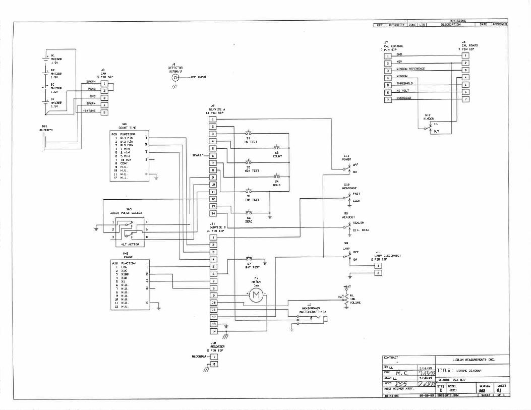

LUDLUM MODEL 2224-1 SCALER / RATEMETER
January 2012 Serial Number 125559 and Succeeding
Serial Numbers

LUDLUM MODEL 2224-1 SCALER / RATEMETER
January 2012 Serial Number 125559 and Succeeding
Serial Numbers

STATEMENT OF WARRANTY Ludlum Measurements, Inc. warrants the products covered in this manual to be free of defects due to workmanship, material, and design for a period of twelve months from the date of delivery. The calibration of a product is warranted to be within its specified accuracy limits at the time of shipment. In the event of instrument failure, notify Ludlum Measurements to determine if repair, recalibration, or replacement is required. This warranty excludes the replacement of photomultiplier tubes, G-M and proportional tubes, and scintillation crystals which are broken due to excessive physical abuse or used for purposes other than intended. There are no warranties, express or implied, including without limitation any implied warranty of merchantability or fitness, which extend beyond the description of the face there of. If the product does not perform as warranted herein, purchaser’s sole remedy shall be repair or replacement, at the option of Ludlum Measurements. In no event will Ludlum Measurements be liable for damages, lost revenue, lost wages, or any other incidental or consequential damages, arising from the purchase, use, or inability to use product.
RETURN OF GOODS TO MANUFACTURER If equipment needs to be returned to Ludlum Measurements, Inc. for repair or calibration, please send to the address below. All shipments should include documentation containing return shipping address, customer name, telephone number, description of service requested, and all other necessary information. Your cooperation will expedite the return of your equipment. LUDLUM MEASUREMENTS, INC. ATTN: REPAIR DEPARTMENT 501 OAK STREET SWEETWATER, TX 79556
800-622-0828 325-235-5494 FAX 325-235-4672


Ludlum Measurements, Inc. January 2012
Table of Contents Introduction 1
Getting Started 2 Unpacking and Repacking 2-1
Internal Switches 2-1
Battery Installation 2-2
Connecting a Detector to the Instrument 2-2
Battery Test 2-2
Operating the Instrument 2-3
Principle of Operation 2-3
Specifications 3
Description of Controls and Functions 4 Operator Controls 4-1
Internal Controls 4-2
Safety Considerations 5 Environmental Conditions for Normal Use 5-1
Cleaning Instructions and Precautions 5-1
Warning Markings and Symbols 5-2
Calibration and Maintenance 6 Calibration 6-1
Establishing an Operating Point 6-1
Meter Calibration 6-2
Detector Overload Calibration 6-4
Maintenance 6-5
Recalibration 6-5
Batteries 6-5
Technical Principle of Operation 7

MODEL 2224-1 Technical Manual
Ludlum Measurements, Inc. January 2012
Troubleshooting 8
Recycling 9
Parts List 10 Model 2224-1 Scaler / Ratemeter 10-1
Amplifier / Power Supply Board, Drawing 390 × 104 10-1
Processor Board, Drawing 390 × 107 10-4
Calibration Board, Drawing 390 × 112 10-4
Display Board, Drawing 390 × 127 10-5
Interconnect Board, Drawing 390 × 124 10-5
Wiring Diagram, Drawing 390 × 110 10-5
Drawings and Diagrams 11

MODEL 2224-1 Technical Manual Section 1
Ludlum Measurements, Inc. Page 1-1 January 2012
Introduction
he Model 2224-1 is a portable microprocessor based radiation survey instrument used to measure and discriminate low-level alpha/beta radiation when used with an alpha/beta scintillation or proportional detector.
The data is displayed by an analog ratemeter and a six-digit liquid crystal display (LCD) counter. The ratemeter dial indicates 0-500 CPM with four linear range multipliers of ×1, ×10, ×100, and ×1000, producing an overall range of 0-500 kCPM. The LCD is used to display the counts accumulated during the preset count time. Four count times are available for selection through a front-panel switch. These count times are: 0.5, 1, 2 and, 5 minutes. The counter is reset and started by pressing the count button located in the end of the carrying handle.
The ratemeter and LCD can display alpha only, beta only, or alpha and beta by selecting the corresponding toggle switch selection. Audible click-per-event tones can also be selected to discriminate beta (low pitch tone) from alpha (high pitch tone) via the side-mounted speaker. Beta threshold, window, and alpha threshold are adjustable to optimize alpha/beta efficiency and count separation.
A regulated high-voltage power supply adjustable from 400 to 2000 volts with detector overload detection is utilized to operate a wide range of scintillation detectors. Other operating features of the instrument include programmable audio divide-by (beta channel only), a two-position switch (internal) for selecting the audio discrimination mode, audio headphone jack, adjustable volume, battery test pushbutton, high-voltage display pushbutton, and a ratemeter reset pushbutton.
The unit body is made of cast aluminum with a drawn aluminum can. The unit is operated with two ˝D˝ cell flashlight batteries for operation from -10 oC to approximately 50 oC (14 to 122 °F). For operation to -10 oC (14 °F), either very fresh alkaline or rechargeable NiCd batteries may be used.
Section
1 T

MODEL 2224-1 Technical Manual Section 2
Ludlum Measurements, Inc. Page 2-1 January 2012
Getting Started
Unpacking and Repacking Remove the calibration certificate and place it in a secure location. Remove the instrument and accessories (batteries, cable, etc.) and ensure that all of the items listed on the packing list are in the carton. Check individual item serial numbers and ensure calibration certificates match. The Model 2224-1 serial number is located on the front panel below the battery compartment. Most Ludlum Measurements, Inc. detectors have a label on the base or body of the detector for model and serial number identification.
Important!
If multiple shipments are received, ensure that the detectors and instruments are not interchanged. Each instrument is calibrated to specific detectors, and is therefore not interchangeable.
To return an instrument for repair or calibration, provide sufficient packing material to prevent damage during shipment. Also provide appropriate warning labels to ensure careful handling. Include detector(s) and related cable(s) for calibration. Include brief information as to the reason for return, as well as return shipping instructions:
- Return shipping address - Customer name or contact - Telephone number - Description of service requested and all other necessary
information
Internal Switches Release the can latches and remove the cover from the instrument, taking care not to damage the speaker wires. Using a ball-point pen, set the
Section
2

MODEL 2224-1 Technical Manual Section 2
Ludlum Measurements, Inc. Page 2-2 January 2012
switches for the desired AUDIO division and TONE as described on Page 4-3. Replace the cover and fasten the latches.
Battery Installation Ensure that the range selector switch is in the ˝OFF˝ position. Open the battery lid by pushing down and turning the quarter-turn thumbscrew counterclockwise one-fourth of a turn. Install two ˝D˝ size batteries in the compartment.
Note the (+) and (-) marks inside the battery door. Match the battery polarity to these marks. Close the battery box lid, then push down and turn the quarter-turn thumb screw clockwise one-fourth of a turn.
Note:
The center post of a flashlight battery is positive. The batteries are placed in the battery compartment in opposite directions.
Connecting a Detector to the Instrument
Caution!
The detector operating voltage (HV) is supplied to the detector via the detector input connector. A mild electric shock may occur if you make contact with the center pin of the input connector. Switch the Model 2224-1 to the ˝OFF˝ position before connecting or disconnecting the cable or detector.
Connect one end of a detector cable to the detector by firmly pushing the connectors together while twisting clockwise one-fourth of a turn. Repeat the process in the same manner with the other end of the cable and the instrument.
Battery Test The batteries should be checked each time the instrument is turned on. Move the range selector switch to the BAT position. Verify that the overload (OL) LED on the front panel turns on briefly. The LCD should go through an initialization sequence displaying ˝88:8.8:8.8,˝ then the current sample number, and finally ˝0.˝ Ensure that the meter needle deflects to the battery check portion on the meter scale. If the meter does not respond, check to

MODEL 2224-1 Technical Manual Section 2
Ludlum Measurements, Inc. Page 2-3 January 2012
see if the batteries have been correctly installed. Replace the batteries if necessary.
Operating the Instrument Connect a detector to the instrument if you have not already done so. Obtain a meter reading from a check source or calibrated source, if available. Verify that the reading falls within the expected range. Remove the source.
If a radiation source is available, increase the meter count to exceed the counting capability of the instrument, signified by the illumination of OL LED and full-scale needle deflection.
Depress the RESET pushbutton. The meter needle should drive to zero, and the alarm circuit should de-energize, shutting off the visual alarm.
Select the desire count channel display (α/α+β/β) and count cycle duration (MIN) and proceed with use.
Principle of Operation The Model 2224-1 is to be used in combination with alpha/beta scintillation or proportional detectors. The instrument uses pulse heights discrimination to distinguish between alpha and beta pulses from the radiation detector.
The detected alpha count is displayed by selecting the α position on the three-position α, α + β, and β toggle switch. The sum of the alpha and beta counts are displayed in the α + β position, and beta counts are displayed in the β position. Multiply the CPM reading on the analog ratemeter by the range multiplier position. When using the LCD and count cycle selector switch (MIN), the counts are accumulated in each of the three channels during the count cycle. The alpha, alpha + beta, and beta counts can be displayed by selecting the appropriate α, α + β, β channel. The count cycle is started by depressing the pushbutton switch located in the end of the carrying handle.
The RESET pushbutton switch resets the meter pointer to zero. The detector operating voltage is displayed on the meter dial, 0-2 kV (kilovolts), by depressing the HV switch. The OL (overload) lamp, located in the lower right-hand corner of the meter dial, is to indicate that the detector is saturated either by a puncture in the detector face on a scintillation detector or an exposure to a radiation field above the counting capability of the instrument. The analog meter will deflect full-scale when the OL lamp is illuminated.
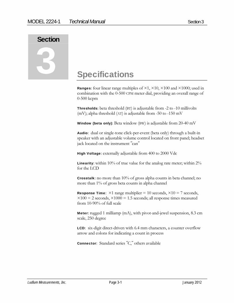
MODEL 2224-1 Technical Manual Section 3
Ludlum Measurements, Inc. Page 3-1 January 2012
Specifications 0
Ranges: four linear range multiples of ×1, ×10, ×100 and ×1000; used in combination with the 0-500 CPM meter dial, providing an overall range of 0-500 kcpm
Thresholds: beta threshold (BT) is adjustable from -2 to -10 millivolts (mV); alpha threshold (AT) is adjustable from -50 to -150 mV
Window (beta only): Beta window (BW) is adjustable from 20-40 mV
Audio: dual or single-tone click-per-event (beta only) through a built-in speaker with an adjustable volume control located on front panel; headset jack located on the instrument ˝can˝
High Voltage: externally adjustable from 400 to 2000 Vdc
Linearity: within 10% of true value for the analog rate meter; within 2% for the LCD
Crosstalk: no more than 10% of gross alpha counts in beta channel; no more than 1% of gross beta counts in alpha channel
Response Time: ×1 range multiplier = 10 seconds, ×10 = 7 seconds, ×100 = 2 seconds, ×1000 = 1.5 seconds; all response times measured from 10-90% of full scale
Meter: rugged 1 milliamp (mA), with pivot-and-jewel suspension, 8.3 cm scale, 250 degree
LCD: six-digit direct-driven with 6.4 mm characters, a counter overflow arrow and colons for indicating a count in process
Connector: Standard series ˝C,˝ others available
Section
3
MODEL 2224-1 Technical Manual Section 3
Ludlum Measurements, Inc. Page 3-2 January 2012
Power: two standard ˝D˝ cell batteries
Battery Dependence: instrument calibration change less than 3% to battery endpoint
Battery Life: exceeds 350 hours with a fresh set of alkaline ˝D˝ cell batteries
Temperature Range: -20 to 50 °C (-4 to 122 °F)
Finish: drawn-and-cast aluminum, with beige powder coating
Size: 16.5 x 8.9 x 21.6 cm (6.5 x 3.5 x 8.5 in.) (H x W x L)
Weight: 1.6 kg (3.5 lb), including batteries

MODEL 2224-1 Technical Manual Section 4
Ludlum Measurements, Inc. Page 4-1 January 2012
Description of Controls and Functions
Operator Controls OFF/BAT/X1000/X100/X10/X1 Switch (or Range Selector Switch): a six-position rotary switch to select the analog meter range multipliers and check the battery status. When switched to the BAT position, the meter pointer should deflect above the left vertical mark on the BAT OK or BAT TEST line. Moving the range selector switch to one of the range multiplier positions (×1, ×10, ×100, ×1000) provides the operator with an overall range of 0-500 kcpm. Multiply the scale reading by the multiplier to determining the actual reading.
During the initial turn-on, the meter is driven full-scale for about two seconds and then returns to zero. The LCD will then show “888888,” display the processor program version, and then “0.”
Liquid Crystal Display (LCD): six-digit display that shows the scaler count for the selected channel. The display also indicates when a count is in progress by displaying two colons. The colons are turned off when the count is completed. If the counter exceeds 999999, an arrow in the upper left corner of the display turns on to indicate the overflow, and the counter rolls over to zero and continues counting.
VOL: Turning this control clockwise will increase the speaker volume, and counterclockwise will decrease the volume.
Note:
The volume should be turned down, when not required, to reduce battery drain.
α / α+β / β Switch: a three-position toggle switch used to select the sum of both alpha and beta count channels (α+β), alpha count only (α), or beta count only (β) for display. This switch affects both the ratemeter and the counter. The separate ratemeter and counter channels are active
Section
4
MODEL 2224-1 Technical Manual Section 4
Ludlum Measurements, Inc. Page 4-2 January 2012
regardless of the switch position and will continue to function when the channel is not selected for display. This allows the operator to view each channel separately or together by simply selecting the appropriate switch position.
Headphone Jack: 1/8 inch headphone jack for connection of external headphones. Connecting the headphones results in the disconnection of the external unimorph speaker from the audio circuitry. Use 1/8 inch mating plug (LMI part # 21-9653).
RESET/HV: a dual-position momentary toggle switch, which provides readout of the detector high voltage when the HV position is selected and provides a rapid means of driving the analog meter to zero when the RES position is selected. Use the 0-2 kV meter scale for high-voltage readings.
Count Pushbutton (located in the carrying handle): When depressed, the counter is reset to zero, and the timer is started. Colons on the display indicate a count cycle is in progress.
Remove the CAL cover to access the following:
HV Adjustment: provides a means to vary the high voltage from 400 to 2000 volts.
Internal Controls Remove the instrument cover (can) to access the following dipswitches on S301:
Dipswitch1 & 2 (Audio-divide select): a two-pole DIP switch used to select the audio divide ratios of 1, 10, 100, and 1000.
Note:
The AUDIO divide function only affects the lower frequency beta tones. The higher frequency alpha clicks per events will be unaffected by the divide-by selection.

MODEL 2224-1 Technical Manual Section 4
Ludlum Measurements, Inc. Page 4-3 January 2012
The ratio is selected from the following table. (O is open and C is closed)
SWITCH DIVIDE BY 1 2 RATIO C C 1 O C 10 C O 100 O O 1000
Dipswitch 3 & 4 (SPARE): Not used Dipswitch 5 (TONE): a one-pole DIP switch used to select tone discrimination between alpha and beta count channels. When in DUAL mode (C position), alpha and beta pulse tones will be audible in all selector switch positions (i.e. if in the α only position and β is detected, the β tones will be heard in addition to the α tones and visa versa).
When the SNGL tone position (O position) is selected, both alpha and beta pulse tones can be heard in the α+β selection, but alpha pulses cannot be heard in the beta only channel selection and beta pulse tones will not be heard in the alpha only channel selection.
Dipswitch 6 (SPARE): Not used
The following controls are utilized during calibration only and should only be adjusted by a qualified calibrator.
MTR: a multi-turn potentiometer used to calibrate the meter to the CPM reading.
AT: a multi-turn potentiometer used to vary the alpha pulse threshold from approximately -40 to -700 mV.
BW: a multi-turn potentiometer used to vary the beta pulse upper window limit from the beta threshold to the alpha threshold setting and anywhere in between those two parameters. The beta window can be disabled by adjusting the BW control to the maximum clockwise position, allowing the upper beta threshold limit to equal the alpha threshold.
BT: a multi-turn potentiometer used to vary the beta pulse threshold from approximately -2 to -15 millivolts.

MODEL 2224-1 Technical Manual Section 4
Ludlum Measurements, Inc. Page 4-4 January 2012
OL: a multi-turn potentiometer that provides a means to vary the detector current overload set point.
LIM: a multi-turn potentiometer used to set the maximum HV limit to 2000 Vdc.
HV: a multi-turn potentiometer used to adjust the high-voltage test reading to correspond with the actual high-voltage output. HV must be selected on the RES/HV toggle switch during adjustment.
LB: a multi-turn potentiometer used to adjust the minimum battery voltage level, corresponding to the low-battery indication on the meter dial. The range selector switch must be in the BAT position during adjustment.

MODEL 2224-1 Technical Manual Section 5
Ludlum Measurements, Inc. Page 5-1 January 2012
Safety Considerations
Environmental Conditions for Normal Use Indoor use only
No maximum altitude
Temperature range of -20 to 50 °C (-4 to 122 °F)
Maximum relative humidity of less then 95% (non-condensing)
Pollution Degree 3 (as defined by IEC 664) (Occurs when conductive pollution or dry nonconductive pollution becomes conductive due to condensation. This is typical of industrial or construction sites.)
Cleaning Instructions and Precautions The Model 2224-1 Scaler/Ratemeter may be cleaned externally with a damp cloth, using only water as the wetting agent. Do not immerse the instrument in any liquid. Observe the following precautions when cleaning:
1. Turn the instrument range selector switch to the OFF position and remove the batteries.
2. Allow the instrument to sit for one minute before cleaning.
Section
5

MODEL 2224-1 Technical Manual Section 5
Ludlum Measurements, Inc. Page 5-2 January 2012
Warning Markings and Symbols
Caution!
The operator or responsible body is cautioned that the protection provided by the equipment may be impaired if the equipment is used in a manner not specified by Ludlum Measurements, Inc.
The Model 2224-1 Scaler / Ratemeter is marked with the following symbols:
CAUTION (per ISO 3864, No. B.3.1) – designates hazardous live voltage and risk of electric shock. During normal use, internal components are hazardous live. This instrument must be isolated or disconnected from the hazardous live voltage before accessing the internal components. This symbol appears on the front panel. Note the following precautions:
Warning!
The operator is strongly cautioned to take the following precautions to avoid contact with internal hazardous live parts that are accessible using a tool:
1. Turn the instrument power OFF and remove the batteries
2. Allow the instrument to sit for one minute before accessing internal components.
CAUTION, RISK OF ELECTRIC SHOCK (per ISO 3864, No. B.3.6) – designates a terminal (connector) that allows connection to a voltage exceeding 1 kV. Contact with the subject connector while the instrument is on or shortly after turning off may result in electric shock. This symbol appears on the front panel.
The “crossed-out wheelie bin” symbol notifies the consumer that the product is not to be mixed with unsorted municipal waste when discarding; each material must be separated. This symbol is placed on the battery lid. See section 9, “Recycling,” for further information.
The “CE” mark is used to identify this instrument as being acceptable for use within the European Union. This symbol is located on the battery lid.

MODEL 2224-1 Technical Manual Section 6
Ludlum Measurements, Inc. Page 6-1 January 2012
Calibration and Maintenance
Calibration
Note:
Local procedures may supersede the following.
ESTABLISHING AN OPERATING POINT
The detector operating parameters are established by adjusting the detector operating voltage (HV), alpha threshold, and beta window to find an optimum efficiency for the alpha/beta scintillator or proportional detector.
The threshold and window parameters can be adjusted to optimize alpha/beta count discrimination, count efficiency, and minimize "cross talk" between channels. Refer to the specific detector Operation Manual or calibration certificate for the suggested threshold and window settings. Once the thresholds and window settings are established, an operating voltage versus count rate plot should be performed for both alpha and beta count channels with alpha and beta particle emission sources.
The following procedure is an example of determining the operating voltage for an alpha/beta scintillation or proportional detector:
1. Connect a Ludlum Model 500 Pulser or equivalent to the
Model 2224-1.
2. Switch the Model 2224-1 channel selector to the β position. Adjust the beta threshold (BT) for 3.5 mV and the window (BW) for 30 mV. The pulser counts should be detected on the Model 2224-1 ratemeter above 3.5 ±1 mV and should shut off above 30 mV.
Section
6

MODEL 2224-1 Technical Manual Section 6
Ludlum Measurements, Inc. Page 6-2 January 2012
3. Switch the channel selector switch to the α position. Adjust the pulser for a 120 mV pulse output and vary the AT control until counts are detected on the ratemeter.
4. Depress the HV switch and adjust the HV potentiometer for 0.4 to 0.5 kV on the 0-2.0 kV scale. Connect the scintillator and switch to the β only position. Place an alpha source on the detector face.
5. Slowly increase the HV potentiometer to observe an increase, then decrease, and increase again in count as the HV is increased. Decrease the HV until the ratemeter is in the "dip" of the observed count rate versus HV plot just performed. Depress the HV switch and note the HV setting.
6. Plot a HV versus count rate plateau in 25-volt increments, 50 volts each side of the HV reading found in the above step (ie, HV setting for count "dip" in the above step = 675 volts, start the plot at 625 volts and increase in 25-volt steps until 725 volts is reached). Plot alpha source, beta source, and background counts for both the α and β channel positions.
7. Find the optimum operating voltage from the plot, which gives the greatest alpha and beta source efficiency while maintaining no greater than the maximum acceptable level of "cross talk" between channels.
8. Select the desired count channel display, and proceed with use.
METER CALIBRATION
A Ludlum Model 500 Pulser or equivalent is required. If the pulser does not have a high-voltage readout, use a high-impedance voltmeter with at least 1000 Megohm input resistance to measure the detector voltage.
1. Ensure that the meter movement has proper mechanical zero. The adjustment is on the front of the meter bezel. It must be adjusted to zero with the range selector switch in the OFF position.
2. Connect the Model 500 Pulser to the Model 2224-1 with the appropriate cable. Rotate the Model 2224-1 range selector switch to the ×100 position. Select the α+β channel position.

MODEL 2224-1 Technical Manual Section 6
Ludlum Measurements, Inc. Page 6-3 January 2012
3. Adjust the pulser for 40,000 cpm and adjust the pulse amplitude to twice the beta threshold level (ie; beta threshold = 3.5 mV, adjust pulser to 7-10 mV).
4. Remove the instrument cover and adjust the MTR potentiometer until the meter reads 400 cpm. Adjust the pulser to 10,000 cpm and ensure ratemeter reads 100 ±10%. Decade the pulser and Model 2224-1 range multiplier switch to check meter linearity on the ×1000, ×10, and ×1 positions. Linearity should be within 10% of each reading.
5. Set the LCD count time for one minute. Adjust the pulser count rate to 40 kcpm. Depress the count button, and when the count cycle is complete, confirm that LCD reads within 2% of the incoming count rate.
6. Adjust the BT, BW, and AT controls for the appropriate set points as described in the previous subsection, “Establishing an Operating Point.”
7. Connect high-impedance, high-voltage meter (may use the Model 500 Pulser if equipped with a HV meter), and adjust the HV control for a reading of 1000 Vdc on the voltmeter.
8. Depress the HV pushbutton and adjust the HV potentiometer located on the main circuit board for a reading of 1.0 kV on the meter dial. Adjust the HV output from 500 to 1500 Vdc and confirm that the Model 2224-1 HV meter corresponds to the external voltmeter within 10% of each reading.
9. Remove the batteries from the battery compartment and connect a DC power supply to the two screw terminals located at the rear of the battery compartment. The positive power supply lead should connect to the terminal with the red wire and the negative lead to the terminal with the black wire.
10. Adjust the power supply for 2.2 Vdc and switch the Model 2224-1 to the α+β position. Depress the BAT pushbutton and adjust the LB potentiometer to align the meter needle with the low-battery mark on the meter dial (vertical line to the left of BAT OK).

MODEL 2224-1 Technical Manual Section 6
Ludlum Measurements, Inc. Page 6-4 January 2012
11. Replace the Model 2224-1 cover (can) and proceed with use.
Note:
DETECTOR OVERLOAD CALIBRATION
The detector operating voltage (HV) must be determined and set before the OL (overload) adjustment is performed. If the detector operating voltage is re-adjusted, the overload adjustment must be re-adjusted.
1. Adjust the OL control to the maximum counterclock-
wise position.
Note:
Detector saturation is when the meter response no longer increases with increasing radiation field intensity.
2. For alpha/beta scintillators, expose the detector photomultiplier tube (PMT) to a small light leak by loosening the detector window. Some scintillation detectors incorporate a screw in the detector body, which when removed, will simulate a detector face puncture or light leak. The meter should start to decrease toward zero as light saturates the scintillation material.
3. Expose just enough light to where the meter starts to decrease. Adjust the OL control until the overload LED just begins to flicker on the meter dial. The ratemeter should deflect above full meter scale at this point.
4. Re-seal the detector window and expose the detector to a radiation source that will drive the meter near full scale. Confirm that the LED does not turn on and the meter remains on-scale.

MODEL 2224-1 Technical Manual Section 6
Ludlum Measurements, Inc. Page 6-5 January 2012
Maintenance Instrument maintenance consists of keeping the instrument clean and periodically checking the batteries and the calibration. The Model 2224-1 instrument may be cleaned with a damp cloth (using only water as the wetting agent). Do not immerse instrument in any liquid. Observe the following precautions when cleaning:
1. Turn the instrument OFF and remove the batteries. 2. Allow the instrument to sit for one minute before accessing
internal components.
RECALIBRATION
Recalibration should be accomplished after maintenance or adjustments have been performed on the instrument. Recalibration is not normally required following instrument cleaning, battery replacement, or cable replacement.
Note:
Ludlum Measurements, Inc. recommends recalibration at intervals no greater than one year. Check the appropriate regulations to determine required recalibration intervals.
Ludlum Measurements offers a full-service repair and calibration department. We not only repair and calibrate our own instruments, but most other manufacturers’ instruments as well. Calibration procedures are available upon request for customers who choose to calibrate their own instruments.
BATTERIES
The batteries should be removed any time the instrument is placed into storage. Battery leakage may cause corrosion on the battery contacts, which must be scraped off and/or washed using a paste solution made from baking soda and water. Use a spanner wrench to unscrew the battery contact insulators, exposing the internal contacts and battery springs. Removal of the handle will facilitate access to these contacts.

MODEL 2224-1 Technical Manual Section 6
Ludlum Measurements, Inc. Page 6-6 January 2012
Note:
Never store the instrument over 30 days without removing the batteries. Although this instrument will operate at very high ambient temperatures, battery seal failure may occur at temperatures as low as 37 °C (100 °F).

MODEL 2224-1 Technical Manual Section 7
Ludlum Measurements, Inc. Page 7-1 January 2012
Technical Principle of Operation
Refer to the Amplifier/Power Supply Board Schematic, Drawing 390 × 104, for the following:
Detector Input/ Amplifier Negative-going detector pulses are coupled from the detector through C021 to amplifier U021. R023 and CR021 protects the input of U021 from inadvertent shorts. Self-biased amplifier U021 provides gain in proportion to R021 divided by R022. Transistor pins 4, 5, and 6 of U021 provides amplification. Pins 12 and 15 of U021 are coupled as a constant current source to pin 6 of U021. The output self-biases to 2 Vbe (approximately 1.4 volts) at pin 7 of U021. This provides just enough bias current through pin 6 of U021 to conduct all of the current for the constant current source. Positive pulses from pin 7 of U021 are coupled to the discriminators through R011 and C011.
Alpha/Beta Discriminator Positive pulses from amplifier U021 are coupled to comparator U012, pin 6, for alpha discrimination and pins 6 and 2 of U011 for beta discrimination. R103, alpha threshold, provides the reference voltage for alpha comparator U012. R106, beta threshold (defined as the lower threshold limit of the beta counting window), provides the reference voltage for beta threshold comparator pins 1, 2, and 3 of U011. R102, beta window (defined as the upper threshold limit of the beta counting window), provides the reference voltage for the beta window comparator pins 5, 6, and 7 of U011.
Alpha/Beta Discriminator Logic Circuit Alpha pulses from U012 are coupled to univibrator U111. Pulses at pin 6 of U111 are inverted by Q111 for connection to reset (R) pins 3 and 13 of U101. Pin 9 of U111 provides the pulses to be counted by the microprocessor (μP). Pulses from pin 9 of U111 are connected to pin 3 of
Section
7

MODEL 2224-1 Technical Manual Section 7
Ludlum Measurements, Inc. Page 7-2 January 2012
U111 to provide a time delay for the μP clock cycle to complete before the next alpha pulse can be recognized by the μP.
Beta pulses from pin 1 of U011 are coupled to univibrator U101. Pulses are coupled to the μP from pin 7 of U101 as long as pins 3 and 13 of U011 remain high (+5 V). When an alpha and/or a beta window pulse is present, the reset (pins 3 and 13 of U101) function is enabled and 7 of U101 remains high. Pin 7 of μP is connected to pin 13 of U101 to provide a time delay for the μP clock cycle to complete before the next beta pulse can be recognized by the μP.
Low Voltage Supply Battery voltage is coupled to switching regulator U201 and associated components to provide +5 V to power op-amps and logic circuitry. The charge pump (cp) output, C202, CR211, CR212, and C201 form a voltage doubler circuit to provide +9 V for U201 amplifier supply. U001 and related components provide +2.5 V reference HV SET and alpha/beta discriminator controls. R201, LO BAT, is adjusted so that the meter pointer is aligned with the left vertical mark on the BAT OK or BAT TEST line with 2.2-volt battery input.
High Voltage Supply High voltage is developed blocking oscillator Q421, T321, C412, and rectified by voltage multiplier CR221-CR224, C221-C223, C211, and C114. High voltage increases as current through Q421 increases, with maximum output voltage with Q421 saturated.
High voltage is coupled back through R123 to op-amp pin 2 of U311. Resistor network R211-214 completes the HV division circuit to ground. R214 provides HV limit at 2.0 kV when the HV SET control on the calibration board is at maximum. The regulated HV output is controlled by HV potentiometer, located under the CAL cover on the front panel. This control provides the reference for comparator pin 3, U311. During stable operation, the voltage at pin 2 of U311 will equal the voltage at pin 3 of U311. Pin 1 of U311 will cause conduction of Q312 to increase or decrease until the HV finds a level of stability. R115, HV TEST, calibrates the analog meter to the HV output when HV is selected on the RES/HV momentary toggle switch.

MODEL 2224-1 Technical Manual Section 7
Ludlum Measurements, Inc. Page 7-3 January 2012
Detector Overload A voltage drop is developed across R121 and sensed by comparator U012 as detector current increases. When the voltage at pin 3 of U012 goes below pin 2, pin 1 goes low, illuminating the OL LED and driving the meter to full scale. R211, Overload, provides adjustment for the overload set point.
Meter Drive Pulses are coupled from the μP board (refer to μP theory of operation) to the gate of Q302. Q302 inverts the pulses, and R403 and C401 provides integration. Integrated meter drive voltage is coupled from P1-13 via the battery (BAT) and HV test switch to pin 5 of U311. The meter is driven by the emitter of Q111, coupled as a voltage follower in conjunction with pin 6 and 7 of U311. R406, Meter Cal, is adjusted to calibrate the ratemeter reading corresponding to the incoming count rate. R407 and R408 provide temperature compensation for changes in the meter resistance due to temperature variations.
Refer to Processor Board Schematic, Drawing 390 × 107 for the following:
Power supply Battery voltage is coupled to switching regulator U321 and associated components to provide +5 V to power the μP and display drivers U211, U212. R101, C101, Q101, and Q201 form a delay switch, which allows U321 to stabilize before the load current is connected to the +5 V supply.
Microproccessor (μP) U311, Intel N87C51FA, controls all of the data, control inputs, and display information. The clock frequency is crystal controlled by Y211 and related components at 6.144 MHz. The μP incorporates internal memory (ROM), storing the program information. C311 resets the μP at power-up to initiate the start of the program routine. During the program loop, the μP looks at all of the input switches for initiation or status changes and responds accordingly.
The μP uses pulse-width modulation to control the analog ratemeter. The analog output, RATE (P3-3), is divided into 255 increments in a 166 μs

MODEL 2224-1 Technical Manual Section 7
Ludlum Measurements, Inc. Page 7-4 January 2012
period. At full meter deflection, the low pulse period, leading edge to leading edge, will be 166 μs, 500 cpm = 130 μs, 400 cpm = 104 μs, 200 cpm = 52 μs, 100 cpm = 26 μs, and 0 = no pulse or +5 V. The pulses are inverted by Q302 on the amplifier/power Supply board and then integrated by R403, C401.
LCD Drive U211 and U212 make up the liquid crystal display drive circuitry. The display information is sent from the μP to U211 and 212 via BUS0-3 and ADD0-1 data lines. When the SELECT line is brought low by the μP, the data is transferred and latched into the drivers until the SELECT line is brought low again. The corresponding digits and segments are illuminated corresponding to the stored count information from the μP.
Audio Alpha and/or beta audio pulse frequency is generated by the μP and coupled to Q202. Q202 then inverts the pulses and drives the low side of the audio transformer T201. Front-panel VOL control provides the bias voltage to the top of T210. Secondary winding of T201 is coupled to unimorph speaker via front-panel audio jack.

MODEL 2224-1 Technical Manual Section 8
Ludlum Measurements, Inc. Page 8-1 January 2012
Troubleshooting
ccasionally you may encounter problems with your LMI instrument or detector that may be repaired or resolved in the field, saving turn-around time and expense in returning the instrument to us for repair. Toward that end, LMI electronics
technicians offer the following tips for troubleshooting the most common problems. Where several steps are given, perform them in order until the problem is corrected. Keep in mind that the most common problems encountered with this particular instrument are: (1) detector cables, (2) sticky meters, (3) battery contacts.
Note that the first troubleshooting tip is for determining whether the problem is with the electronics or with the detector. A Ludlum Model 500 Pulser can be invaluable at this point because of its ability to simultaneously check high voltage, input sensitivity or threshold, and the electronics for proper counting.
We hope these tips will prove to be helpful. As always, please call if you encounter difficulty in resolving a problem, or if you have any questions.
Troubleshooting Electronics that utilize Proportional and Scintillator Type Detectors
SYMPTOM
No power (or meter does not reach BAT TEST or BAT OK mark)
POSSIBLE SOLUTION
1. Check batteries and replace if weak. 2. Check polarity (see marks inside
battery lid). Are the batteries installed backwards?
Section
8 O

MODEL 2224-1 Technical Manual Section 8
Ludlum Measurements, Inc. Page 8-2 January 2012
SYMPTOM No power (or meter does not reach BAT TEST or BAT OK mark) (continued) Non-linear Readings Meter goes full-scale or “pegs out”
POSSIBLE SOLUTION 3. Check battery contacts. Clean them
with rough sandpaper or use an engraver to clean the tips.
4. Check for loose or broken wires,
especially between the main board and the calibration board.
1. Check the high voltage (HV) by using
a Ludlum Model 500 Pulser (or equivalent). If a multimeter is used to check the HV, ensure that one with high impedance is used, as a standard multimeter could be damaged in this process.
2. Check for noise in the detector cable
by disconnecting the detector, placing the instrument on the lowest range setting, and wiggling the cable while observing the meter face for significant changes in readings.
3. Check for “sticky” meter movement.
Does the reading change when you tap the meter? Does the meter needle “stick” at any spot?
4. Check the “meter zero.” Turn the
power OFF. The meter should come to rest on “0.”
1. Replace the detector cable to
determine whether or not the cable has failed, causing excessive noise.
2. Check the HV and, if possible, the
input threshold for proper setting.

MODEL 2224-1 Technical Manual Section 8
Ludlum Measurements, Inc. Page 8-3 January 2012
SYMPTOM Meter goes full-scale or “pegs out” (continued) No Response to Radiation
No Audio
POSSIBLE SOLUTION
3. Open the instrument “can” and check for loose wires.
4. Ensure that the instrument’s “can”
is properly attached. When attached properly, the speaker will be located on the left side of the instrument. If the can is on backwards, interfer-ence between the speaker and the input preamplifier may cause noise.
1. Substitute a “known good” detector
and/or cable. 2. Has the correct operating voltage
been set? Refer to the calibration certificate or detector instruction manual for correct operating voltage. If the instrument uses multiple detectors, confirm that the high voltage is matched to the current detector being used.
1. Ensure that the VOL (volume) knob
is turned up. 2. Remove the instrument housing and
check the connection between the circuit board and the speaker. Plug in the two-pin connector if necessary.

MODEL 2224-1 Technical Manual Section 9
Ludlum Measurements, Inc. Page 9-1 January 2012
Recycling
udlum Measurements, Inc. supports the recycling of the electronics products it produces for the purpose of protecting the environment and to comply with all regional, national, and international agencies that promote economically and environmentally sustainable
recycling systems. To this end, Ludlum Measurements, Inc. strives to supply the consumer of its goods with information regarding reuse and recycling of the many different types of materials used in its products. With many different agencies – public and private – involved in this pursuit, it becomes evident that a myriad of methods can be used in the process of recycling. Therefore, Ludlum Measurements, Inc. does not suggest one particular method over another, but simply desires to inform its consumers of the range of recyclable materials present in its products, so that the user will have flexibility in following all local and federal laws.
The following types of recyclable materials are present in Ludlum Measurements, Inc. electronics products, and should be recycled separately. The list is not all-inclusive, nor does it suggest that all materials are present in each piece of equipment:
Batteries Glass Aluminum and Stainless Steel
Circuit Boards Plastics Liquid Crystal Display (LCD)
Ludlum Measurements, Inc. products that have been placed on the market after August 13, 2005 have been labeled with a symbol recognized internationally as the “crossed-out wheelie bin,” which notifies the consumer that the product is not to be mixed with unsorted municipal waste when discarding. Each material must be separated. The symbol will be placed near the AC receptacle, except for portable equipment where it will be placed on the battery lid.
The symbol appears as such:
Section
9 L

MODEL 2224-1 Technical Manual Section 10
Ludlum Measurements, Inc. Page 10-1 January 2012
Parts List Reference Description
Part Number
UNIT Completely Assembled Model 2224-1 Scaler / Ratemeter 48-2679 BOARD Completely Assembled
Amplifier/Power Supply Board 5390-099 C001 100PF, 100V 04-5661 C002 47PF, 100V 04-5560 C011-C012 0.1µF, 50V 04-5663 C013 0.01µF, 50V 04-5664 C014-C016 0.001µF, 100V 04-5659 C015 0.1µF, 50V 04-5663 C017 10µF, 20V 04-5655 C021 10PF, 100V 04-5673 C022 100PF, 3KV 04-5532 C101-C102 47PF, 100V 04-5560 C111-C113 47PF, 100V 04-5560 C114 0.0047µF, 3KV 04-5547 C121-C122 0.0047µF, 3KV 04-5547 C201-C202 10µF, 20V 04-5655 C203 330PF, 100V 04-5657 C211 0.0047µF, 3KV 04-5547 C212 68µF, 6.3V 04-5654 C213 1µF, 35V 04-5656 C214 0.01µF, 50V 04-5664 C221-C223 0.0047µF, 3KV 04-5547 C301 68µF, 6.3V 04-5654 C311 0.01µF, 50V 04-5664 C401 0.1µF, 50V 04-5663 C411 0.1µF, 50V 04-5663 C412 1µF, 35V 04-5656 C421 68µF, 6.3V 04-5654
Section
10 Model 2224-1 Scaler / Ratemeter
Amplifier/Power Supply Board, Drawing 390 × 104
CAPACITORS

MODEL 2224-1 Technical Manual Section 10
Ludlum Measurements, Inc. Page 10-2 January 2012
Reference Description
Part Number
Q111 2N7002L 05-5840 Q301 MMBT4403LT 05-5842 Q302 2N7002L 05-5840 Q311-C312 MMBT3904T 05-5841 Q421 MJD210 05-5843 U001 LM285M-2.5 06-6291 U011-U012 TLC372ID 06-6290 U021 CA3096M 06-6288 U101 CD74HC4538M 06-6297 U111 CD74HC4538M 06-6297 U201 MAX631AESA 06-6285 U301 CD74HC4066M 06-6323 U311 TLC27M7ID 06-6292 CR021 MMBD7000LT1 07-6355 CR111-CR112 MMBD914L 07-6353 CR211-CR212 BAT54 07-6354 CR221-CR225 GI250-2 07-6266 CR411 MMBD914L 07-6353
R407 03006-165.9-55G100 07-6366 R102 10K, BETA THRESH 09-6921 R104 1M, BETA WIN 09-6906 R115 1M, (HV) HV READOUT 09-6906 R201 1M, ALPHA THRESH 09-6906 R202 200K, LO BAT (LB) 09-6908 R211 1M, OVERLOAD 09-6906 R214 1M, HV LIMIT 09-6906 R406 5K, METER CAL (MTR) 09-6907 R001 22.1K, 1%, 125mW 12-7843 R002 249K, 1%, 125mW 12-7862 R003 22.1K, 1%, 125mW 12-7843 R004 1.0K, 1%, 125mW 12-7832 R011 100, 1%, 125mW 12-7840 R012 22.1K, 1%, 125mW 12-7843 R013 33.2K, 1%, 125mW 12-7842 R014 10.0K, 1%, 125mW 12-7839 R015 22.1K, 1%, 125mW 12-7843 R016 10.0K, 1%, 125mW 12-7839
TRANSISTORS
INTEGRATED CIRCUITS
DIODES
THERMISTOR
POTENTIOMETERS
RESISTORS

MODEL 2224-1 Technical Manual Section 10
Ludlum Measurements, Inc. Page 10-3 January 2012
Reference Description
Part Number
R021 392K, 1%, 125mW 12-7841 R022-R023 10.0K, 1%, 125mW 12-7839 R024 33.2K, 1%, 125mW 12-7842 R025 22.1K, 1%, 125mW 12-7843 R026 1M 10-7028 R101 100K, 1%, 125mW 12-7834 R103 4.75K, 1%, 125mW 12-7858 R105 22.1K, 1%, 125mW 12-7843 R106 100K, 1%, 125mW 12-7834 R107 5.11K, 1%, 125mW 12-7909 R108 274K, 1%, 125mW 12-7963 R111 100, 1%, 125mW 12-7840 R112 1G 12-7686 R113-R114 100K, 1%, 125mW 12-7834 R116 249K, 1%, 125mW 12-7862 R121 4.7M, 125mW 10-7030 R122 1M 10-7028 R123 1G 12-7686 R212-R213 1M, 1%, 125mW 12-7844 R215 1M, 1%, 125mW 12-7844 R301 2.21K, 1%, 125mW 12-7835 R302-R303 22.1K, 1%, 125mW 12-7843 R311 10.0K, 1%, 125mW 12-7839 R312 22.1K, 1%, 125mW 12-7843 R313 2.21K, 1%, 125mW 12-7835 R314 10.0K, 1%, 125mW 12-7839 R401 200, 1%, 125mW 12-7846 R402 221K, 1%, 125mW 12-7845 R403 7.5K, 1%, 125mW 12-7847 R404 1K, 1%, 125mW 12-7832 R405 1M, 1%, 125mW 12-7844 R408 301, 1%, 125mW 12-7863 R411 200, 1%, 125mW 12-7846 R412 10.0K, 1%, 125mW 12-7839
L301 220µH 21-9678 T321 L8050 40-0902 P1 CONN-1-640456-5, MTA100 13-8355 P2 CONN-640456-3, MTA100 13-8081 * RECEPTACLE (8 ea) Cloverleaf 011-6809 18-8771
INDUCTORS
TRANSFORMERS
MISCELLANEOUS

MODEL 2224-1 Technical Manual Section 10
Ludlum Measurements, Inc. Page 10-4 January 2012
Reference Description BOARD Completely Assembled
Part Number
Processor Board 5390-100 Y211 6.144 MHZ 01-5262
C101 0.15µF, 50V 04-5665 C201 47µF, 10V 04-5666 C211-C212 27PF, 100V 04-5658 C221 68µF, 6.3V 04-5654 C311-312 10µF, 20V 04-5655 C321 330PF, 100V 04-5657 C322 68µF, 6.3V 04-5654 Q101 2N7002L 05-5840 Q201 MMBT4403L 05-5842 Q202 2N7002L 05-5840 Q311 MMBT4403L 05-5842 U211-U212 ICM7211AMIQH 06-6294 U311 N87C51FA 06-6303 U321 MAX631AESA 06-6285 S301 90HBW06S 08-6710 R101 1M, 1%, 125mW 12-7844 R102 10K, 1%, 125mW 12-7839 R211 2.21K, 1%, 125mW 12-7835 R221 150K, 1%, 125mW 12-7833 R222 100K, 1%, 125mW 12-7834 R301-R306 22.1K, 1%, 125mW 12-7843 RN401 220K 12-7831
L311 150µH 21-9677 T201 AUDIO 4275-083 P3 CONN-1-640456-6, MTA100 13-8134 P4 CONN-640456-2, MTA100 13-8073 P6 CONN-640456-3, MTA100 13-8081 * SOCKET-44P 06-6293 BOARD Completely Assembled Calibration Board 5390-104
Processor Board, Drawing 390 × 107
CRYSTAL
CAPACITORS
TRANSISTORS
INTEGRATED CIRCUITS
SWITCHES
RESISTORS
RESISTOR NETWORK
INDUCTOR
TRANSFORMER
MISCELLANEOUS
Calibration Board, Drawing 390 × 112

MODEL 2224-1 Technical Manual Section 10
Ludlum Measurements, Inc. Page 10-5 January 2012
Reference Description
Part Number
DS1 HLMP4700, OVERLOAD 07-6356 * LED-SPACER 457-570 07-6357 R3 250K, HV SET 09-6819 P7 CONN-640456-5 MTA100 13-8057 BOARD Completely Assembled Display Board 5390-118 DSP1 LCD 7728-365-481 07-6351 J6 CONN-52 POS CP50 13-8410 BOARD Completely Assembled Interconnect Board 5390-117 J5 CONN-52 POS CP50 13-8410 S1 PA-600-210 08-6501 S2 55D36-01-2-AJN 08-6514 S3 MPS-103F 08-6699 S4 PHONE JACK TINI #42A 21-9333 S5 7103SYZQE TOGGLE 08-6720 S6 7103SYZQE TOGGLE 08-6720 R1 10K NON-LOCKING VOLUME 09-6753 J1 CONN-1-640442-5 MTA100 13-8383 J2 CONN-640442-3 MTA100 13-8135 J3 CONN-1-640442-6 MTA100 13-8187 J4 CONN-640442-2 MTA100 13-8178 J7 CONN-640442-5 MTA100 13-8140 J8 Series "C" UG706/U 13-7751 J9 CONN-640442-3 MTA100 13-8135 J10 1/8 inch PHONE JACK 18-9080 DS1 UNIMORPH 21-9251 B1-B2 "D" Duracell Battery 21-9313
M1 METER ASSY 4390-136 * HANDLE ASSY 4408-178
LED
POTENTIOMETER
MISCELLANEOUS
Display Board, Drawing 390 x 127
DISPLAY
CONNECTOR
Interconnect Board, Drawing 390 x 124
CONNECTOR
Wiring Diagram, Drawing 390 × 110
SWITCHES
POTENTIOMETER
CONNECTORS
AUDIO
BATTERY
MISCELLANEOUS

MODEL 2224-1 Technical Manual Section 11
Ludlum Measurements, Inc. Page 11-1 January 2012
Drawings and Diagrams
AMPLIFIER / POWER SUPPLY BOARD, Drawing 390 × 104
AMPLIFIER / POWER SUPPLY LAYOUT, Drawing 390 × 105
PROCESSOR BOARD, Drawing 390 × 107
PROCESSOR BOARD, LAYOUT, Drawing 390 × 108
CALIBRATION BOARD, Drawing 390 × 112
CALIBRATION BOARD LAYOUT, Drawing 390 × 113 (2 sheets)
DISPLAY BOARD, Drawing 390 × 127
DISPLAY BOARD COMPONENT LAYOUT, Drawing 390 × 128 (2 sheets)
INTERCONNECT BOARD, Drawing 390 × 124
INTERCONNECT BOARD LAYOUT, Drawing 390 × 125
WIRING DIAGRAM, Drawing 390 × 110
Section
11

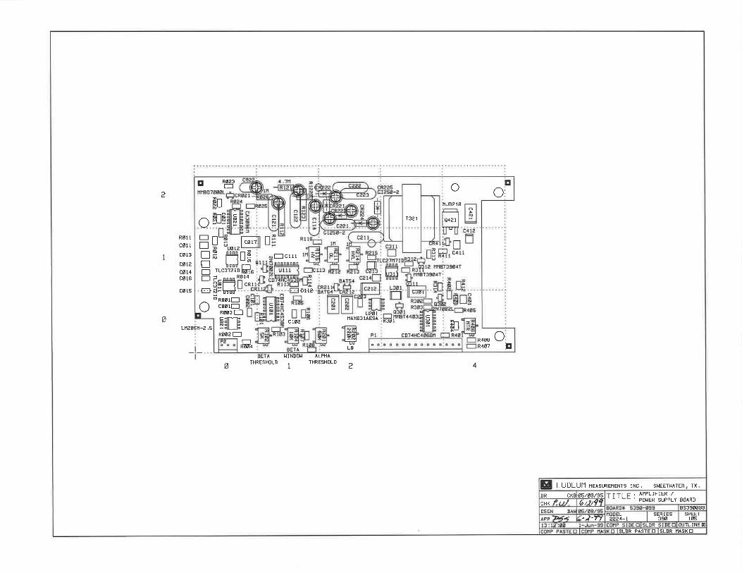


LUDLUM MODEL 2350-1 DATA LOGGER
February 2017
Serial No. 126167 and Succeeding
Serial Numbers
CPU Firmware 37122N32
I/O Firmware 37123N05

LUDLUM MODEL 2350-1 DATA LOGGER
February 2017
Serial No. 126167 and Succeeding
Serial Numbers
CPU Firmware 37122N32
I/O Firmware 37123N05

STATEMENT OF WARRANTY Ludlum Measurements, Inc. warrants the products covered in this manual to be free of defects due to workmanship, material, and design for a period of twelve months from the date of delivery. The calibration of a product is warranted to be within its specified accuracy limits at the time of shipment. In the event of instrument failure, notify Ludlum Measurements to determine if repair, recalibration, or replacement is required. This warranty excludes the replacement of photomultiplier tubes, G-M and proportional tubes, and scintillation crystals which are broken due to excessive physical abuse or used for purposes other than intended. There are no warranties, express or implied, including without limitation any implied warranty of merchantability or fitness, which extend beyond the description of the face there of. If the product does not perform as warranted herein, purchaser’s sole remedy shall be repair or replacement, at the option of Ludlum Measurements. In no event will Ludlum Measurements be liable for damages, lost revenue, lost wages, or any other incidental or consequential damages, arising from the purchase, use, or inability to use product.
RETURN OF GOODS TO MANUFACTURER If equipment needs to be returned to Ludlum Measurements, Inc. for repair or calibration, please send to the address below. All shipments should include documentation containing return shipping address, customer name, telephone number, description of service requested, and all other necessary information. Your cooperation will expedite the return of your equipment. LUDLUM MEASUREMENTS, INC. ATTN: REPAIR DEPARTMENT 501 OAK STREET SWEETWATER, TX 79556
800-622-0828 325-235-5494 FAX 325-235-4672


Table of Contents 1. INTRODUCTION .................................................................................................................................... 1
2. UNPACKING AND REPACKING .......................................................................................................... 2
3. SPECIFICATIONS ................................................................................................................................... 3
4. DESCRIPTION OF CONTROLS AND FUNCTIONS ........................................................................... 6 MAIN DISPLAY ........................................................................................................................................... 7 PARAMETER DISPLAY ................................................................................................................................ 8 DETECTOR DISPLAY ................................................................................................................................. 10 ALARM DISPLAY ...................................................................................................................................... 11 LOGGED DATA DISPLAY .......................................................................................................................... 11 LOGGED DATA LOCATION DISPLAY ........................................................................................................ 12 RECYCLE DATA DISPLAY ......................................................................................................................... 13 RECYCLE SETUP DISPLAY ........................................................................................................................ 15 MAXIMUM VALUES DISPLAY ................................................................................................................... 15 ERROR MESSAGE DISPLAY ...................................................................................................................... 16 COMMAND VERIFICATION DISPLAY ........................................................................................................ 17 OPTIONAL KEYPAD CONTROL ................................................................................................................. 18
5. SAFETY CONSIDERATIONS AND WARNING MARKINGS .......................................................... 19
ENVIRONTMENTAL CONDITIONS FOR NORMAL USE ............................................................................... 19 CLEANING INSTRUCTIONS AND PRECAUTIONS ........................................................................................ 19 WARNING MARKINGS AND SYMBOLS ...................................................................................................... 20
6. OPERATING PROCEDURES ............................................................................................................... 21
INITIAL PROCEDURES ............................................................................................................................... 21
BATTERY INSTALLATION ............................................................................................................................ 21 COMPUTER CONTROL SETUP ...................................................................................................................... 22 OPTIONAL KEYPAD SETUP .......................................................................................................................... 22 DETERMINING INSTRUMENT PLATEAU ....................................................................................................... 23
SETTING OPERATING PARAMETERS .......................................................................................................... 24
OPERATION COMMANDS .................................................................................................................. 31
7. SAMPLE APPLICATIONS ................................................................................................................... 41
RECYCLE MODE APPLICATIONS ............................................................................................................... 41 MAXIMUM VALUE WITH LOGGING PUSHBUTTON ................................................................................... 42
8. RECYCLING .......................................................................................................................................... 44

Model 2350-1 Data Logger
Ludlum Measurements, Inc. Page 1 February 2017
Introduction
The Model 2350-1 Data Logger is a portable microprocessor-based counting instrument designed for use with Geiger-Mueller (GM), proportional, and/or scintillation detectors for measurement of alpha, beta, gamma, and/or neutron radiation. Radiation data is presented in four ways:
1. Auto-ranging digital ratemeter
2. Timed counter (scaler)
3. Integrated dose counter
4. Five-decade logarithmic bar graph
All readouts operate from a single input, and each display can be enabled or disabled if desired.
Up to 16 different sets of detector parameters can be stored, allowing for quick changing of detectors or operating parameters. Detector readings can be stored in the 1000 data point memory with identifiers for the date, time, sample number, detector number, and the type of count that was logged. There are also eight different location code identifiers, which include seven five-character alphanumeric codes and a five-digit location coordinate. Other features include individual alarms for each readout, click-per-event audio with audio divide and volume control, voltage sensitive amplifier, single channel analyzer, adjustable detector high voltage, adjustable window and threshold, detector overload sensing circuitry, adjustable dead time compensation, calibration constant, and response time.
Controlling the Model 2350-1 can be done by connection to a PC, optional keypad, and/or optional bar code reader. The Model 2350-1 also has built-in calibration sub-routines for calculating the calibration constant and dead time of detectors.
The instrument readout is an 8-line by 15-character alphanumeric liquid crystal display (LCD). A display backlight can be turned on or off by a toggle switch on the front panel of the instrument. Batteries are externally accessible from the back of the instrument housing for quick and easy replacement when necessary.
Section
1

Model 2350-1 Data Logger
Ludlum Measurements, Inc. Page 2 February 2017
Unpacking and Repacking
Remove the calibration certificate and place it in a secure location. Remove the instrument and accessories (batteries, cable, etc.) and ensure that all of the items listed on the packing list are in the carton. If more than one instrument (Model 2350-1 and detector(s)) is in a carton, refer to the calibration certificate(s) for the serial number (S/N) match. The Model 2350-1 S/N is located on the front-panel below the acknowledgeable button. Most LMI detectors have a label on the base or body of the detector for the Model and S/N identification.
To return the instrument for repair or calibration, provide sufficient packing material to prevent damage during shipment and appropriate warning labels to ensure careful handling.
Every returned instrument must be accompanied by an Instrument Return Form, which can be downloaded from the Ludlum website at www.ludlums.com. Find the form by clicking the “Support” tab and selecting “Repair and Calibration” from the drop-down menu. Then choose the appropriate Repair and Calibration division where you will find a link to the form.
Section
2

Model 2350-1 Data Logger
Ludlum Measurements, Inc. Page 3 February 2017
Specifications
Compatible Detectors: GM, proportional, scintillation Connector: Series C (others available on request) Display: 8-line LCD display with 15 characters per line Backlight: a two-position toggle switch to activate backlight Scaler: six-digit display Timer: used in conjunction with scaler. Count time can be set from 1 to 65,535 seconds in one-second intervals. Ratemeter: digital ratemeter, corrected for dead time and calibration constant Trend Indicator: five-decade logarithmic bar graph Linearity: reading within 10% of true value with detector connected Scale: can display rem/hr, Sv/h, R/hr, cpm, cps, dpm, dps, rad(r), Gray (G), C/kg, Ci/cm2, or Bq/cm2 Integrated Dose: counter provided to give total accumulated dose for up to 45 days (will display in the same units as the ratemeter) Audio: built-in unimorph speaker with volume control (greater than 60 dB at 0.61 m 2 ft, full volume) Audio Divide: operator selected divisions of 1, 10, or 100 events per click Alarm: separate alarms for digital ratemeter, scaler, and integrated dose can be set at any point (audible and visual indicators) ACK/Scroll: pushbutton to silence audio after alarm has been indicated and/or scrolled through the various displays
Section
3

Model 2350-1 Data Logger
Ludlum Measurements, Inc. Page 4 February 2017
Data Logger: capable of logging up to 1000 individual data points with following identifiers for each point: eight location codes, time of day, month, day, and year, detector number, count rate/scaler count/integrated dose, count time, logging mode, sample number Detector Parameters: capable of storing the following parameters for 16 different detectors: model number, serial number, calibration constant, dead time correction, high voltage, threshold, window, display range multiplier, display time base, display units, overload current, ratemeter alarm setting, scaler alarm setting, scaler count time, integrated dose alarm setting RS-232 Port: a full duplex communication port that allows for instrument setup by optional keypad or PC, also allows for data to be transferred to a PC file Bar Code Reader (optional): allows for setup of instrument by computer generated bar codes High Voltage: adjustable from 400 to 2500 volts Threshold: adjustable from -100 to -1000 mV Window: adjustable from 0 to 1000 above threshold Gain: adjustable from 2 to 350 mV at threshold setting of 100 Dead Time: adjustable to compensate for dead time of detector and electronics Response: Fixed response is adjustable from 1 to 127 seconds in one-second intervals. Variable response will vary according to the number of counts present. FAST is typically 4 to 25 seconds, and SLOW is typically 4 to 60 seconds from 10% to 90% of final reading. Power: four each D cell batteries (housed in sealed compartment that is accessible from back of instrument) Battery Life: greater than 75 hours (low-battery condition is automatically indicated) Battery Dependence: less than 3% change in readings to battery end point Construction: cast-and-drawn aluminum with beige polyurethane enamel paint Temperature Range: 0 to 50 °C (32 to 122 °F)

Model 2350-1 Data Logger
Ludlum Measurements, Inc. Page 5 February 2017
Size: 14.2 x 11 x 22 cm (5.6 x 4.3 x 8.8 in.) (H x W x L) without handle, 20.9 cm (8.2 in.) (H) with handle Weight: 2.4 kg (5.2 lb), including batteries

Model 2350-1 Data Logger
Ludlum Measurements, Inc. Page 6 February 2017
Description of Controls and Functions
Section
4

Model 2350-1 Data Logger
Ludlum Measurements, Inc. Page 7 February 2017
A. WAND: a plug that is used to connect an optional bar code reader want to the instrument
B. SERIAL I/O: a 15-pin RS-232 connector that is used to connect the instrument to the optional keypad to a computer
C. DISPLAY: an 8-line, 15-character alphanumeric liquid crystal display (LCD)
D. CONNECTOR: used to connect the detector to the instrument, typically Series C, but can be BNC, MHV, UHF, or others
E. POWER SWITCH: a two-position switch used to turn the instrument on and off
F. BACKILGHT: a two-position toggle switch that is used to turn the display backlight on and off
G. AUDIO DIVIDE: a three-position toggle switch that is used to adjust the audio divide between 1, 10, or 100 events per click
H. VOLUME: a one-turn potentiometer used to adjust the volume of the audio
I. ACK/SCROLL: a pushbutton that is used to silence the audible alarm indicator and scroll through the various displays
Main Display (SVD0)
A. INTEGRATED DOSE INDICATOR: provides total integrated dose readout. In an alarm condition, the alarm indicator (ALM) displays in place of the DOS indicator and alternates at one-second intervals.
B. INTEGRATED DOSE TIMER: provides a readout in minutes of an integrated dose
C. CLOCK: displays the current time of day in 24-hours format
D. LOCATION CODES 1 & 2: identifies the five-character alphanumeric location code settings 1 & 2
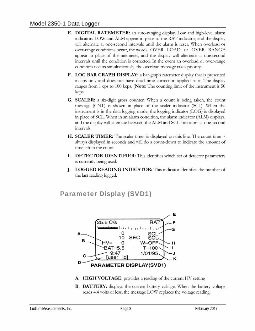
Model 2350-1 Data Logger
Ludlum Measurements, Inc. Page 8 February 2017
E. DIGITAL RATEMETER: an auto-ranging display. Low and high-level alarm indicators LOW and ALM appear in place of the RAT indicator, and the display will alternate at one-second intervals until the alarm is reset. When overload or over-range conditions occur, the words OVER LOAD or OVER RANGE appear in place of the ratemeter, and the display will alternate at one-second intervals until the condition is corrected. In the event an overload or over-range condition occurs simultaneously, the overload message takes priority.
F. LOG BAR GRAPH DISPLAY: a bar-graph ratemeter display that is presented in cps only and does not have dead time correction applied to it. The display ranges from 1 cps to 100 kcps. (Note: The counting limit of the instrument is 50 kcps.
G. SCALER: a six-digit gross counter. When a count is being taken, the count message (CNT) is shown in place of the scaler indicator (SCL). When the instrument is in the data logging mode, the logging indicator (LOG) is displayed in place of SCL. When in an alarm condition, the alarm indicator (ALM) displays, and the display will alternate between the ALM and SCL indicators at one-second intervals.
H. SCALER TIMER: The scaler timer is displayed on this line. The count time is always displayed in seconds and will do a count-down to indicate the amount of time left in the count.
I. DETECTOR IDENTIFIER: This identifies which set of detector parameters is currently being used.
J. LOGGED READING INDICATOR: This indicator identifies the number of the last reading logged.
Parameter Display (SVD1)
A. HIGH VOLTAGE: provides a reading of the current HV setting
B. BATTERY: displays the current battery voltage. When the battery voltage reads 4.4 volts or less, the message LOW replaces the voltage reading.

Model 2350-1 Data Logger
Ludlum Measurements, Inc. Page 9 February 2017
C. CLOCK: displays the current time of day in 24-hour format. If the battery voltage reads 4.4 volts or less, the message LO BAT alternates with the time at one-second intervals.
D. USER ID: a 15-character alphanumeric display to allow for individual operator ID codes
E. DIGITAL RATEMETER: an auto-ranging display. Low and high-level alarm indicators LOW and ALM appear in place of the RAT indicator, and the display will alternate at one-second intervals until the alarm is reset. When overload or over-range conditions occur, the words OVER LOAD or OVER RANGE appear in place of the ratemeter, and the display will alternate at one-second intervals until the condition is corrected. In the event an overload and over-range condition occurs simultaneously, the overload messages takes priority.
F. LOG BAR GRAPH DISPLAY: a bar graph ratemeter display that is presented in cps only and does not have dead time correction applied to it. The display ranges from 1 cps to 100 kcps. Note: The counting limit of the instrument is 50 kcps.
G. SCALER: a six-digit gross counter. When a count is being taken, the count message (CNT) is shown in place of the scaler indicator (SCL). When the instrument is in the data logging mode, the logging indicator (LOG) is displayed in place of the SCL. When in an alarm condition, the alarm indicator (ALM) displays, and the display will alternate between the ALM and SCL indicators at one-second intervals.
H. SCALER TIMER: The scaler timer is displayed on this line. The count time is always displayed in seconds and will do a count-down to indicate the amount of time left in the count.
I. WINDOW: This identifies the window setting of the chosen detector. The display reads OFF when the window is not activated.
J. THRESHOLD: This display indicates the threshold setting of the chosen detector.
K. DATE: displays the current date

Model 2350-1 Data Logger
Ludlum Measurements, Inc. Page 10 February 2017
Detector Display (SVD2)
A. MODEL: used to identify the model number of the detector being used (44-2, 44-3, etc.)
B. DISPLAY UNITS: identifies the current display units used by the detector (R, Sv, counts, etc.)
C. HIGH VOLTAGE: provides a reading of the current HV setting
D. SCALER COUNT TIME: displays the scaler count time in seconds for the detector
E. CALIBRATION CONSTANT: indicates the current dead time compensation factor that is being used for the detector
F. DEAD TIME: indicates the current dead time compensation factor that is being used for the detector
G. DETECTOR: identifies which detector parameters are being displayed
H. SERIAL NUMBER: used to identify the serial number of the detector being used
I. MULTIPLIER CODE: identifies the current range multiplier being used. (The display multiplier can be auto-ranging, read in micro, milli, kilo, etc.)
J. TIME BASE: indicates the current time base being used (seconds, minutes, or hours)
K. WINDOW: This identifies the window setting of the detector. The display reads OFF when the window is not activated.
L. THRESHOLD: This display indicates the threshold setting of the detector.

Model 2350-1 Data Logger
Ludlum Measurements, Inc. Page 11 February 2017
Alarm Display (SVD3)
A. DETECTOR: identifies which detector alarm settings are being
displayed
B. RATEMETER LOW ALARM: indicates the ratemeter alarm setting
C. RATEMETER LOW ALARM: indicates the low alarm setting for the ratemeter. This alarm is used to identify a possible detector failure. When the counts from the detector drop below the alarm set point, the alarm is activated.
D. SCALER ALARM: indicates the scaler alarm setting
E. INTEGRATED DOSE ALARM: indicates the alarm setting for the integrated dose counter
F. OVERLOAD: indicates the current overload current setting. When disabled, the word OFF appears.
Logged Data Display (SVD4)

Model 2350-1 Data Logger
Ludlum Measurements, Inc. Page 12 February 2017
A. DATA SOURCE: identifies the source of the logged data (i.e. ratemeter, scaler, or integrated dose)
B. CLOCK: displays the current time of day in 24-hour format. If the battery voltage reads 4.4 volts or less, the message LO BAT alternates with the time at one-second intervals.
C. LOCATION CODES 7 & 8: identifies the preset Location Code 7 and Location Coordinate 8
D. SAMPLE NUMBER: identifies the sample number you are viewing
E. LOCATION CODE 1 & 2: identifies the five-character alphanumeric Location Codes 1 & 2 (These are the same codes that appear on the normal display.)
F. DETECTOR NUMBER: identifies the detector used in the logged sample
G. LOGGED COUNT: displays the actual count taken in exponential format. When ratemeter count or integrated dose count is taken, the exposure rate will display. If a scaler count is taken, the count time will display.
H. DATE: This identifier indicates the current date.
Logged Data Location Display (SVD8)
This display provides the user with the eight different identifiers for each location. L1-L7 are strings of five alphanumeric characters, and L8 is a five-digit location coordinate.
A. L1: a five-character alphanumeric location identifier

Model 2350-1 Data Logger
Ludlum Measurements, Inc. Page 13 February 2017
B. L2: a five-character alphanumeric location identifier
C. L3: a five-character alphanumeric location identifier
D. L4: a five-character alphanumeric location identifier
E. L5: a five-character alphanumeric location identifier
F. L6: a five-character alphanumeric location identifier
G. L7: a five-character alphanumeric location identifier
H. L8: a five-digit location coordinate that can have a value from 0 to 65535 (The location coordinate can be set to automatically change by a set increment when data is logged.)
Recycle Data Display (SVD5)
A. CYCLE COUNTER: indicates the number of cycles that will be run, the number of cycles in process, and the number of recycles remaining
B. CYCLE DELAY: indicates the time delay between each cycle
C. CLOCK: displays the current time of day in 24-hour format
D. LOCATION CODES 1 & 2: identifies the five-character alphanumeric Location Code Settings 1 & 2
E. DIGITAL RATEMETER: an auto-ranging display. Low and high-level alarm indicators LOW and ALM appear in place of the RAT indicator, and the display will alternate at one-second intervals until the alarm is reset. When overload or over-range conditions occur, the words OVER LOAD or OVER RANGE appear in place of the ratemeter, and the display will alternate at one-second intervals until

Model 2350-1 Data Logger
Ludlum Measurements, Inc. Page 14 February 2017
the condition is corrected. In the event an overload and over-range condition occurs simultaneously, the overload message takes priority.
F. LOG BAR GRAPH DISPLAY: a bar graph ratemeter display that is presented in cps only and does not have dead time correction applied to it. The display ranges from 1 cps to 100 kcps. (Note: The counting limit of the instrument is 50 kcps.)
G. SCALER: a six-digit gross counter. When a count is being taken, the count message (CNT) is shown in place of the scaler indicator (SCL). When the instrument is in the data logging mode, the logging indicator (ALM) displays and the display will alternate between the ALM and SCL indicators at one-second intervals.
H. SCALER TIMER: The scaler timer is displayed on this line. The count time is always displayed in seconds and will do a count-down to indicate the amount of time left in the count.
I. DETECTOR IDENTIFIER: This identifies which set of detector parameters is currently being used.
J. LOGGED READING INDICATOR: This indicator identifies the number of the last reading logged.
K. RECYCLE DISABLE: indicates that Recycle Mode has been disabled. (Message replaces the Recycle Mode parameters.)

Model 2350-1 Data Logger
Ludlum Measurements, Inc. Page 15 February 2017
Recycle Setup Display (SVD6)
A. IDENTIFIER: indicates that this is the Recycle Setup display
B. RECYCLE SETUP: displays the parameters for Cycles 1-6. When enabled, the cycle number, detector number, delay time between recycles, and logging mode (i.e. ratemeter, scaler, or integrated dose) are displayed.
C. RECYCLE COUNT: indicates the number of recycles that will run once initiated
Maximum Values Display (SVD7)
A. SCALER: displays the maximum scaler count logged and the count time used
B. CLOCK: displays the current time of day in 24-hour format
C. LOCATION CODES 1 & 2: identifies the five-character alphanumeric Location Code Settings 1 & 2

Model 2350-1 Data Logger
Ludlum Measurements, Inc. Page 16 February 2017
D. DIGITAL RATEMETER: an auto-ranging display. Low and high-level alarm indicators LOW and ALM appear in place of the RAT indicator, and the display will alternate at one-second intervals until the alarm is reset. When overload or over-range conditions occur, the words OVER LOAD or OVER RANGE appear in place of the ratemeter, and the display will alternate at one-second intervals until the condition is corrected. In the event an overload and over-range condition occurs simultaneously, the overload message takes priority.
E. LOG BAR GRAPH DISPLAY: a bar graph ratemeter display that is presented in cps only and does not have dead time correction applied to it. The display ranges from 1 cps to 100 kcps. (Note: The counting limit of the instrument is 50 kcps.)
F. DISPLAY IDENTIFIER: displays the words MAXIMUM VALUES when the maximum values latching mode is off. When activated, the words LATCHING VALUES display.
G. RATEMETER: displays the maximum ratemeter reading logged
H. DETECTOR IDENTIFIER: this identifies which set of detector parameters is currently being used
I. LOGGED READING INDICATOR: This indicator identifies the number of the last reading logged.
Error Message Display
The error message display is activated when one of the following errors occur:
1. Mathematical bit shift overflow
2. Multiply overflow

Model 2350-1 Data Logger
Ludlum Measurements, Inc. Page 17 February 2017
3. Divide by zero
4. Dead time multiplied by recorded rate > 1
5. Dead time corrected count has exceeded 3 bytes
6. Accumulator overflow when adding new count
7. Accumulator overflow when correcting for new time constant
8. Counts per second larger than 4 bytes
Note: This screen cannot be called up. It appears alternately with whichever screen is currently active until the error is corrected.
Command Verification Display
These commands require the instrument to save parameters to memory or change or delete data required verification. The following commands require command verification when executed:
SAA
SAC
SCA
SKD
SP
SSC
SSR

Model 2350-1 Data Logger
Ludlum Measurements, Inc. Page 18 February 2017
Optional Keypad Control
A. DISPLAY: 4-line by 20-character LCD display
B. FUNCTION KEYS: programmable multi-task function keys
C. KEYPAD: 40-key complete alphanumeric, soft-touch keypad

Model 2350-1 Data Logger
Ludlum Measurements, Inc. Page 19 February 2017
Safety Considerations and Warning Markings
Environmental Conditions for Normal Use Indoor and outdoor use
No maximum altitude
Temperature range of 0 to 50 °C (32 to 122 °F)
Maximum relative humidity of less than 95% (non-condensing)
Mains supply voltage range 95-250 Vac
Maximum transient voltage of 1500 Vac
Installation Category (Overvoltage Category) II (as defined by IEC 1010-1)
Pollution Degree 3 (as defined by IEC 644) (Conductive pollution or dry nonconductive pollution that becomes conductive due to condensation to be found in industrial environments or construction sites – harsh environments.)
Cleaning Instructions and Precautions The Model 2350-1 may be cleaned externally with a damp cloth, using only water as the wetting agent. Do not immerse the instrument in any liquid. Observe the following precautions when cleaning:
1. Turn the instrument OFF.
2. Allow the instrument to sit for one minute before cleaning.
Section
5

Model 2350-1 Data Logger
Ludlum Measurements, Inc. Page 20 February 2017
Warning Markings and Symbols
Caution!
The operator or responsible body is cautioned that the protection provided by the equipment may be impaired if the equipment is used in a manner not specified by Ludlum Measurements, Inc.
Warning!
The operator is strongly cautioned to take the following precautions to avoid contact with internal hazardous live parts that are accessible using a tool: 1. Turn the instrument power OFF and disconnect the power cord. 2. Allow the instrument to sit for one minute before accessing internal components.
The “crossed-out wheelie bin” symbol notifies the consumer that the product is not to be mixed with unsorted municipal waste when discarding; each material must be separated. See section 9, “Recycling,” for further information. Also

Model 2350-1 Data Logger
Ludlum Measurements, Inc. Page 21 February 2017
Operating Procedures
Initial Instrument Setup
Battery Installation
Ensure that the power switch is in the OFF position. Open the battery lid by turning the thumb screw counter-clockwise one quarter of a turn.
Note: The battery compartment is accessible from the back side of the instrument housing.
Install four D cell batteries in the compartment, making sure to align (+) and (-) marks on the battery door with the markings on the batteries.
Note: Center post of the battery is positive (+).
Close the battery door and latch it by turning the thumbscrew one quarter of a turn clockwise until it latches firmly. Turn the power switch on. The instrument will perform an LCD check, causing the display to go black, then it will initiate a memory check. Once this has been completed, the instrument will momentarily display the current battery voltage and then the last screen that was active when the instrument was turned off. Once this process is complete, turn the instrument off and connect it to the optional keypad and/or bar code reader, or connect it directly to a computer. When batteries need to be replaced, ensure that the instrument is turned off and batteries are replaced as quickly as possible. The parameter memory is protected by a back-up power supply for approximately 15 minutes before data is lost.
Note:
The following three sections go through the process of setting up the instrument with the keypad, computer, and/or bar code reader.
Section
6

Model 2350-1 Data Logger
Ludlum Measurements, Inc. Page 22 February 2017
Computer Control Setup The Model 2350-1 is provided with a basic software package that allows the user to control eh instrument by a computer. The software has a demonstration program, a terminal emulator to allow for command entry, and a program to format logged data so that it may be downloaded into a spreadsheet program.
Once the software is loaded onto the computer, the following procedures will prepare you to control the Model 2350-1 by your computer.
Connect the computer interface cable to an available serial port on your computer.
Connect the other end to the Model 2350-1 Data Logger.
Refer to the software user’s manual for instruction on starting the software and follow the instructions in the program.
Note:
The terminal emulator software utilizes the same commands as the optional terminal, which are entered the same way.
Optional Keypad Setup Note: When keypads are purchased with instruments, the following procedures are done at initial setup and calibration. If the keypad is connected to the instrument and the batteries go dead, it is possible that the keypad will have to be re-initialized. New keypads that are purchased after the instrument will also need to be initialized. To initialize the keypad: 1. Connect the keypad to the Model 2350-1. 2. Turn the Model 2350-1 ON. 3. Press the CNTRL, SHIFT, and F1 keys simultaneously to activate the
keypad parameter display. The following screen will appear on the keypad display. BAUD = 9600 F1-CHANGE PARAMETER F2-NEXT F3-PREVIOUS F4-QUIT F5-SAVE
4. Press the F2 button to scroll through the parameters until you find one that needs to be changed.

Model 2350-1 Data Logger
Ludlum Measurements, Inc. Page 23 February 2017
5. Press the F1 button to scroll through the parameter settings until the correct setting appears.
6. Repeat the process until all parameters are correctly set as listed below. 7. When all parameters have been set, press the F5 button to store the new
parameters in the terminal memory. Note: Terminal memory is non-volatile and will hold the parameters even when the keypad is disconnected from the instrument and has no power supply
8. The keypad will beep three times and prompt you with the question, “ARE YOU SURE?” If you want to save the parameters as you have selected, press F1, and the parameters will be saved and the keypad will return to normal operating mode. If not, press F5 and the terminal will return to normal operating mode without saving the changes. The keypad parameters should be set as follows for proper operation with the Model 2350-1 Data Logger: BAUD = 9600 DATA BITS = 8 PARITY = IGNORE REPEAT = FAST ENABLE KEY CLICK DISABLE KNP FUNCTION ENABLE CURSOR ENABLE CURSOR BLINK DISABLE XON/XOFF ENABLE HANDSHAKE ENABLE ECHO ESCAPE MODE = ANSI CR/LF MODE = NEWLINE DISABLE TEST SHIFT LOCK DISABLE SCROLL ON 80 VIEWING ANGLE MAX ENABLE BREAK CMND BACKLIGHT TIMED Once the parameters are set as listed above, the instrument is ready for operation, and the user can proceed to Section 7 for setting up the instrument for specific applications.
Determining Instrument Plateau The bar code reader utilizes the 3 of 9 code format. This code consists of a start character, command characters, termination character, check sum character, and a stop character. As an example, the symbols and code to activate the normal display would be as follows:

Model 2350-1 Data Logger
Ludlum Measurements, Inc. Page 24 February 2017
In this example, the “*” is the start and stop character. “SVD0” is the command being executed. “$” is the command to execute the carriage return and lien feed, and the “P” is the check sum character that is used to ensure that the data being sent is correct.
The following instructions will explain how to install the bar code reader wand and begin operation:
1. Connect the wand to the instrument by aligning the pins of the connector, pressing down firmly, and twisting approximately a quarter of a turn clockwise until the connector latches.
2. Turn the instrument on.
3. Hold the wand at about a 10 to 20-degree angle from vertical with the tip touching the surface approximately one-fourth of an inch from the left side of the bar code to be read.
4. Scan the bar cod rapidly with a uniform speed.
When the instrument recognizes the code, it will give a short beep. For first-time users, it can sometimes be difficult to get good scans. For the most part when a user has trouble getting the reader to work, the scanning speed is too slow.
Bar code reading can make routine procedures simple to do. In some cases, though, the bar codes will need to be protected from surrounding elements by a laminated covering. Below are a few things to keep in mind when laminating or covering bar codes to protect them.
1. Make sure the laminate extends at least one-fourth of an inch from the ends of the bar code.
2. When scanning a laminated code, make sure not to scan past the edge of the laminate, as the reader may try to identify the edge as part of the code.
3. Extended outside applications may require an ultraviolet (UV) resistant laminate to protect the label from fading.
Setting Operating Parameters The following section provides examples for setting the various parameters of the instrument. For clarification purposes, these examples all start by activating a display where the various parameters can be viewed. System programming allows for the operator to set individual parameters at any time and any display. The displays are simply used as a method of confirmation that the parameters are set correctly. In addition to the various displays, all parameter settings can be individually displayed on a computer screen or keypad by initiating the read commands. To initiate a read

Model 2350-1 Data Logger
Ludlum Measurements, Inc. Page 25 February 2017
command, enter an R and then the command that you want to read, and the current setting will be displayed.
Example: To read the current high-voltage setting:
KEYSTROKES RESPONSE
RH – ENTER The current setting will be displaying on either the computer screen or keypad display.
Setting the Time of Day
KEYSTROKES RESPONSE
SVD0 – ENTER The instrument will display the main display.
ST9:25 – ENTER Sets the instrument clock to 9:25 AM.
Setting the Date
KEYSTROKES RESPONSE
SVD1 – ENTER The instrument will display the parameter display.
SD01/01/95 – ENTER Sets the date to January 1, 1995.
Setting the Location Code
KEYSTROKES RESPONSE
SVD8 – ENTER The instrument will display the logged data location display.
L1BLDG1 – ENTER Sets Location Code 1 to Building 1.
L2ROOM2 – ENTER Sets Location Code 2 to Room 2.
L8123 – ENTER Sets the location coordinate to Position 123.

Model 2350-1 Data Logger
Ludlum Measurements, Inc. Page 26 February 2017
The data location code is an eight-part identifier that allows the user to set up seven different five-character alphanumeric codes and one five-digit coordinate for each piece of logged data. The above example could be expanded to have five other location identifiers of up to five characters, if desired to pinpoint the location of a reading.
Setting the User ID
KEYSTROKES RESPONSE
SVD1 – ENTER The instrument will display the parameter display.
IJOHN DOE – ENTER Sets John Doe as the user ID.
Detector Setup
The following example will set up a Model 44-2 gamma scintillator with a serial number PR 123456 as detector #00. The detector will display in cpm, high voltage will be 800 volts, the threshold setting will be 100, and the window will be off. The scaler count time will be 6 seconds, the calibration constant will be 1, and the dead time will be set at 18 microseconds.
KEYSTROKES RESPONSE
SVD2 – ENTER The Model 2350-1 displays the detector parameter screen.
Note: The Model 2350-1 will display the detector parameters that are currently being used by the instrument (i.e. DET 00-15). If there are no parameters stored in memory, the display will show the default values of DET 00.
DO – ENTER The instrument will display the parameters for detector 00.
M44-2 – ENTER The numbers 44-2 will display after MODEL on line 2 of the display.

Model 2350-1 Data Logger
Ludlum Measurements, Inc. Page 27 February 2017
NPR123456 – ENTER The numbers PR123456 will display after serial number on line 3 of the display.
SU7 – ENTER Sets the display units to counts. The display will read U=7.
SM0 – ENTER Sets the multimeter to auto-ranging. The display will read M=0.
SB1 – ENTER Sets the display time base to minutes. The display will read TB=1.
H800 – ENTER Sets the detector high voltage to 800 volts. The display will read HV=800.
WOFF – ENTER Turns the window off. The display will read W=OFF.
F6 – ENTER Sets the scaler count time to 6 seconds. The display will read CT=6.
T100 – ENTER Sets the threshold to 100. The display will read T=100.
SC1 – ENTER Sets the calibration constant to 1. The display will read CC=1.000000e+00.
SL1.8E-5 – ENTER Sets the dead time to 18 µs. The display will read DT=1.799999e.05.
SP0 – ENTER Saves the above parameters as detector 00.
Note: A verification screen will appear when this command is done. To execute the command, answer “Y ENTER.” If you do not want to save the parameters as DET 00, press “N ENTER” to cancel the command.
Note: When setting the dead time, the actual setting may be slightly different than the one entered, due to rounding parameters used by the instrument.

Model 2350-1 Data Logger
Ludlum Measurements, Inc. Page 28 February 2017
Alarm Setup
There can be a total of 16 different sets of alarm parameters. One for each set of detector parameters:
KEYSTROKES RESPONSE
SVD3 – ENTER The instrument will display the alarm parameters for the detector that is currently being used.
D0 – ENTER The instrument will display the alarm parameters for detector 00.
J1.0E+4 – ENTER Sets the ratemeter alarm at 10,000 cpm. The display will read RAT 1.00000e+04.
SVC1.0E+4 – ENTER Sets the low ratemeter alarm at 10,000 counts. The display will read 1.00000e+06.
K1.0E+6 – ENTER Sets the integrated dose alarm at 1,000,000 counts. The display will read 1.0000e+6.
P1.0E+6 – ENTER Sets the integrated dose alarm at 1,000,000 counts. The display will read 1.0000e+6.
O200 – ENTER Sets the detector overload alarm at 20 microamperes. The display will read OVERLOAD=200.
OON – ENTER Turns the overload alarm on.
SP0 – ENTER Saves the above alarm parameters to detector 00. (Please see the note on the previous page about the verification requirement of this command.)

Model 2350-1 Data Logger
Ludlum Measurements, Inc. Page 29 February 2017
Recycle Data Setup
The recycle mode can be set up with one count per cycle and be able to log a maximum of 1000 samples, or up to six different counts per cycle with approximately 166 cycles per count.
KEYSTROKES RESPONSE
SVD6 – ENTER The instrument will display the Recycle Setup Display.
SR2 – ENTER Enables the first two sets of count parameters on the recycle display.
Note: Cycle #1 cannot be disabled and will always show. When using the SR command, any number between 1 and 6 can be used to activate that number of counts.
SY25 – ENTER Sets the number of recycles. The bottom line of the display should read # RECYCLES 25
SQ1 1 10 1 – ENTER Sets count one of the cycle to use DET 01, with a 10-second delay between counts, and logs a scaler count. Line one of the display will read 1 DET 01 10 Q1
SQ2 2 25 1 – ENTER Sets count two of the cycle to use DET 02, with a 25-second delay between counts, and logs a scaler count. Line two of the display will read 2 DET 02 25 Q1
Note: The delay time between the counts comes before the count is taken. In the above example when the count is started the 10-second delay in count 1 will occur before the count is taken. After count 1 is complete, then there will be a 25-second delay before count 2 is taken.

Model 2350-1 Data Logger
Ludlum Measurements, Inc. Page 30 February 2017
Setting Response Time
KEYSTROKES RESPONSE
G1 – ENTER Sets the response time to the fast mode.
Note: The “1” after the “G” is the code for fast response time. It can also be set for slow response – 0, or fixed respond time – 2.
When setting the fixed response time, the following procedures may be followed:
KEYSTROKES RESPONSE
G1 – ENTER Sets the response time to the fast mode.
SXG30 – ENTER Sets the time constant to 30 seconds.
Note: The time constant can be set at any point from 1 and 127 seconds.
Setting the Security Code
The security code is used only when changing the access levels, or restarting the access level and security code to their default values. To change the security code, you must be in Access Level 1.
KEYSTROKES RESPONSE
SAC1234 – ENTER Sets the security code to 1234.
SAA1234 – ENTER Sets the security code and access level to their default settings. (SC = 0; AL = 1)
Note: The 1234 is an example of the current security code.

Model 2350-1 Data Logger
Ludlum Measurements, Inc. Page 31 February 2017
Setting Access Levels
The Model 2350-1 has eight different access levels for control of the instrument. Level 1 allows for total control of the instrument, while Level 8 allows the user to control data logging functions only. The following example will set the access level to 3, which provides the user with some control of the instrument and access to all of the read commands.
KEYSTROKES RESPONSE
SAL3 0 – ENTER The command access level is changed to Level 3.
Note: The “0” is the default security code. This can be changed by the user at any time. A space must be between the access level number and the security code for the command to be properly read.
To ensure that the access level has been properly changed, the following procedure may be followed to read the current access level.
KEYSTROKES RESPONSE
RCA – ENTER Displays the current access level of the instrument on the computer or keypad display.
Operation Commands There are 113 different commands that can be used to control the various applications of the Model 2350-1 Data Logger.
A more detailed description of the commands is available in the command reference manual. What follows is an alphabetized list of all of the commands with a brief description of each and their adjustable parameters.

Model 2350-1 Data Logger
Ludlum Measurements, Inc. Page 32 February 2017
Command Description Parameters
C Starts a scaler count
D(0-15) Recalls a stored detector setup
Any number between 0 and 15
E Stops a scaler count
F(1-65535) Sets the scaler count time
Any number between 1 and 65535 seconds
G(0-2) Sets the ratemeter response time
0 = slow 1 = fast 2 = fixed
H(0-2500) Sets the detector high voltage
Any number between 0 and 2500 volts
I(a) Sets the user ID code Up to 15 alphnumeric characters
J(10-30 to 1030) Sets the ratemeter alarm Can be set at any point from 10-30 to 1030
K(1-4294967295) Sets the scaler alarm Can be set at any point from 1 and 4294967296
L(a) Sets the location code Up to 10 alphanumeric characters
M(a) Sets the detector model number
Up to 9 alphanumeric characters
N(a) Sets the detector serial number
Up to 9 alphanumeric characters
O(0-400) Sets the overload alarm Can be set at any point from 0 to 400
P(10-30 to 1030) Sets the integrated dose alarm
Can be set at any point from 10-30 and 1030
Q(0-2) Logs a count 0 = ratemeter 1 = scaler 2 = integrated dose
RBV Reads the battery voltage Will read from 0 and 6.2

Model 2350-1 Data Logger
Ludlum Measurements, Inc. Page 33 February 2017
RCA Reads the current access level
Displays a value from 1 to 8
RCB Reads the bar graph count
Displays a value from 0 to 1e30
RCD Reads the ID elapsed time
Displays a value from 0 to 64768
RCI Reads the ID count Displays a value from 10-30 to 1030
RCR Reads the ratemeter Displays a value from 10-30 to 1030
RCS Reads the ratemeter Displays a value from 10-30 to 1030
RCT Reads the time remaining in scaler count
Displays a value from 0 to 65535
RD Reads the detector setup in use
Will display a number from 0 to 15
REC Reads all detector setups (binary format)
RED Reads the current detector setup
REF Reads all detector setups
REL Reads the logged memory with L1 & L2 codes
REM Reads the logged memory (formatted)
REN Reads the Model 2350-1 serial number
Displays a value from 0 to 999999
REO Reads the logged data with all location codes and two-second time stamp
REP Reads the logged data with all location codes

Model 2350-1 Data Logger
Ludlum Measurements, Inc. Page 34 February 2017
REQ Reads the logged memory in binary format
RES Reads the logged memory with L1 & L2 codes
RET Reads the logged memory (formatted)
RF Reads the scaler count time
Displays a value from 0 to 65535
RG Reads the ratemeter response time
0 = slow 1 = fast 2 = fixed
RH Reads the detector high voltage
Displays a value from 0 to 2500 volts
RI Reads the user ID code
RID Reads the user ID counter status
0 = off 1 = on
RIO Reads the I/O firmware number
RJ Reads the ratemeter alarm setting
Displays a value from 10e-30 to 1030
RK Reads the scaler alarm setting
Displays a value from 0 to 4294967295 counts
RL Reads the current location code number
RM Reads the detector model number
RN Reads the detector serial number
RNI Reads the location increment
Displays a number from 0 to 2500
RO Reads the overload alarm setting
Displays values x, y x = setting (0-400) y = on/off status (0/1)

Model 2350-1 Data Logger
Ludlum Measurements, Inc. Page 35 February 2017
RP Reads the ID counter alarm setting
Displays a value from 10e-30 to 10e30
RR Reads the raw counts from the detector
Displays a value from 0 to 50000 cps
RSB Reads the time base of the ratemeter
0 = seconds 1 = minutes 2 = hours
RSC Reads the calibration constant
Displays a value from 10-
30 to 1030
RSD Reads the date
RSE Reads which counters are currently displayed
0 = All counters off 1 = Ratemeter 2 = Scaler 3 = Ratemeter and scaler 4 = Integrated dose (ID) 5 = Ratemeter and ID 6 = Scaler and ID 7 = All counters on
RSL Reads the dead time setting
Displays a value from 10-12 to 1
RSM Reads the ratemeter multiplier
0 = Auto range 1 = micro 2 = milli 3 = None 4 = Kilo 5 = Mega 6 = Giga 7 = Tera
RSN Reads the CP firmware number
RSP Reads the pushbutton logging operation
0 = Log ratemeter 1 = Log scaler 2 = Log integrated dose
RSQ(1-6) Reads the current cycle count
Displays values x, y, z x = detector number y = delay in seconds z = logging mode (0-2) 0 = ratemeter 1 = scaler 2 = ID counter

Model 2350-1 Data Logger
Ludlum Measurements, Inc. Page 36 February 2017
RSR Reads the number of sub-cycles per recycle
Displays a number from 1 to 6
RSS Reads the instrument alarm status
RST Reads the 24-hour format
RSU Reads the ratemeter display units
0 = (r)ad 1 = (G)ray 2 = rem 3 = Sv 4 = R 5 = C/kg 6 = D 7 = C 8 = Ci/cm2
9 = Bq/cm2
RSY Reads the number of recycles
Displays a number from 0 to 1000
RT Reads the detector threshold setting
Displays a number from 0 to 1000
RVC Reads the low ratemeter alarm setting
Displays a value from 10-30 to 1030
RVM Reads the maximum values latching mode
0 = Off 1 = On
RVR Reads the maximum ratemeter value
Displays a value from 10-30 to 1030
RVS Reads the maximum scaler value
Displays a value from 10-30 to 1030
RW Reads the detector window setting
Displays a value from 0 to 1000
RXG Reads the ratemeter response time
If the response time is set on fast or slow, the display reads “VARIABLE.” If the response time is fixed, the display will show a number from 1 to 127 seconds.

Model 2350-1 Data Logger
Ludlum Measurements, Inc. Page 37 February 2017
SAA Sets the access level and security codes to default values
This command requires entry of the current security code
SAC Sets the security code Any number from 0 to 65535
SAD(x y f) Sets up and starts the auto dump
X = ON/OFF (1, 0) Y = 1-10 1 = Ratemeter 2 = Scaler 3 = Ratemeter and scaler 4 = Integrated dose (ID) 5 = Ratemeter and ID 6 = Scaler and ID 7 = Ratemeter, Scaler and ID 8 = Raw cps 9 = Ratemeter and raw cps 10 = Timed scaler F = 1 to 65535 seconds
SAL(x y) Sets the access level x = 0-3 y = security code
SB(0-2) Sets the ratemeter time base
0 = Seconds 1 = Minutes 2 = Hours
SC(a) Sets the calibration constant
a = 10-30 to 1030
SD Sets the date mm/dd/yy format
SE(1-7) Sets the counter display 0 = All counters off 1 = Ratemeter 2 = Scaler 3 = Ratemeter and scaler 4 = Integrated dose (ID) 5 = Ratemeter and ID 6 = Scaler and ID 7 = All counters on
SHR(0-1) Starts the HV ramp routine
0 = Data dump off 1 = Data dump on
SID(0-1) Turns integrated dose counter on/off
0 = off 1 = on
SIZ Resets ID counter

Model 2350-1 Data Logger
Ludlum Measurements, Inc. Page 38 February 2017
SKB Starts CC and DT routines with background subtract
SKD Resets current detector parameters to defaults
SL Sets detector dead time Any number from 10-12
to 10 = off SM(0-7) Sets the ratemeter
multiplier 0 = Auto range 1 = micro 2 = milli 3 = none 4 = Kilo 5 = Mega 6 = Giga 7 = Tera
SNE(x) Sets the instrument serial number
Any number from 0 to 999999
SNI(0-2500) Sets the L8 location code auto incremental value
Any number from 0 to 2500
SP(0-15) Saves a detector setup Detector setup 0-15
SQ(w x y z) Sets up a set of cycle parameters
w = cycle number (1-6) x = detector no. (0-15) y = delay in seconds z = logging mode (0-2) 0 = ratemeter 1 = scaler 2 = integrated dose
SR(1-6) Sets the number of recycles per cycle
Any number from 1 to 6
SSB Starts single point calibration routine with background subtract
SSC Clears the logged memory
SSD Starts the dead time routine with background subtract
SSE Stops the recycle mode

Model 2350-1 Data Logger
Ludlum Measurements, Inc. Page 39 February 2017
SSF Starts the recycle mode
SSG Restarts a stopped recycle mode
SSK Starts calibration constant and dead time routines
SSP(0-2) Sets logging pushbutton operation
0 = logs ratemeter 1 = logs scaler 2 = logs integrated dose
SSQ Logs a count based on SSP setup
SSR Resets all memory to default values
SSS Starts a single point calibration routine
ST Sets the time in 24-hour format
SU(0-9) Sets the ratemeter and integrated dose display units
0 = (r)ad 1 = (G)ray 2 = rem 3 = Sv 4 = R 5 = C/kg 6 = (d)isintegrations
SVC(f) Sets the low ratemeter alarm
Any number from 10-30
to 1030
SVD(0-7) Sets the instrument display screen
0 = Main 1 = Parameters 2 = Detectors 3 = Alarms 4 = Logged data 5 = Recycle data 6 = Recycle setup 7 = Maximum values
SVL(0-999) Selects the logged data sample to view
Any number from 0 to 999
SVM(0-6) Sets and/or clears maximum values latching mode and
0 = Latching mode off 1 = Latching mode on 2 = zeros ratemax & scalmax

Model 2350-1 Data Logger
Ludlum Measurements, Inc. Page 40 February 2017
displays 3 = zeros ratemax
4 = zeros scalermax
5 = zeros scalmax & scalmax
6 = zeros ratemax & scalmax
& scal SXG(0-127) Sets the fixed response Any number from 0 to
127 seconds SY(0-999) Sets number of recycles Any number from 0 to
999 T(0-1000) Sets the threshold Any number from 0 to
1000 W(0-1000) Sets the window Any number from 0 to
1000 X Resets the alarm
Y Silences audible alarm
Z Zeros the ratemeter

Model 2350-1 Data Logger
Ludlum Measurements, Inc. Page 41 February 2017
Sample Applications
Recycle Mode Applications The recycle mode in the Model 2350-1 is ideal for applications that require repetitive counting processes over a grid layout, as in site decommissioning or other related activities. The following example will demonstrate how to set up and use the recycle mode to take an alpha survey of a site using a Ludlum Model 43-90 100 cm2 alpha scintillator. The grid is the floor of a 3 x 3 m (10 x 10 ft) room.
KEYSTROKES RESPONSE
SVD2 – ENTER Sets the display to the detector display.
You can scroll through the detector setups using the D(x) command with (x) = a number from 0 to 15. If you do not have a detector configuration already set up for the Model 43-90, then find a blank setup (i.e. all parameters set to default settings), and set the detector up according to the instructions on page 27 of this manual. Once the detector is set up, save it to the active memory and proceed with the following procedures.
KEYSTROKES RESPONSE
SSC – ENTER Clears all logged memory registers.
SVD6 – ENTER Displays the Recycle Setup Display.
SR1 – ENTER Activates the first count sub-routine. Note: The first routine is always active. The SR1 command does, however, ensure that only one count sub-routine is active.
SQ1 0 15 1 – ENTER Sets the count sub-routine parameters so that it uses “0” for the count with a 15- second delay between counts, and it will log a scaler reading.
Section
7

Model 2350-1 Data Logger
Ludlum Measurements, Inc. Page 42 February 2017
KEYSTROKES RESPONSE
SY10 – ENTER Sets the number of recycles to 10.
SVD5 – ENTER Displays the Recycle Data Display.
SSF – ENTER Activates the recycle routine. The routine will start with a 15-second time- out to allow the user to position the detector. It will then take a 10-second scaler count and log it to the data logging memory. It will then do another 15-second time-out to allow the user to re-position the detector and prepare for the next count.
The command SSE will stop a recycle routine in progress, and the command SSG will restart a routine from the point it was stopped at.
A recycle routine can have up to six different count sub-routines performed in a cycle. When more than one count sub-routine is performed, the logging memory is divided by the number of sub-routines done.
Example: A recycle mode is set up with four different count sub-routines. The maximum number of cycles that can be logged is (1000 / 4 = 2500).
Maximum Value with Logging Pushbutton The maximum value latching feature is useful when surveying an object, and the user is only interested in the highest reading from the object. The instrument can be set up with the optional pushbutton logging control in the handle and the optional bar code reader for clearing the maximum value readings between each count. The following description sets up the optional pushbutton and assumes that the user is going to use a Model 44-10 5.1 x 5.1 cm (2 x 2 in.) NaI detector, which is set up as Detector #4.
KEYSTROKES RESPONSE
SVD2 – ENTER Displays the Detector Display.
D4 – ENTER Places Detector #4 parameters into active memory.
SSP0 – ENTER Sets up the optional pushbutton so that it will log a ratemeter reading when pressed.
SVD7 – ENTER Displays the Maximum Value Display.
SVM3 – ENTER Clears the maximum ratemeter reading.
Model 2350-1 Data Logger
Ludlum Measurements, Inc. Page 43 February 2017
SVM1 – ENTER Activates the latching maximum values option.
After the above commands are completed, turn the instrument off, disconnect the keypad or computer from the instrument, and connect the optional pushbutton to the serial port and the bar code reader to its connector. Turn the instrument on and connect the detector. You are now ready to survey. After each survey, the bar code reader can be used to issue a command to clear the maximum ratemeter reading.

Model 2350-1 Data Logger
Ludlum Measurements, Inc. Page 44 August 2016
Recycling
Ludlum Measurements, Inc. supports the recycling of the electronics products it produces for the purpose of protecting the environment and to comply with all regional, national, and international agencies that promote economically and environmentally sustainable recycling systems. To this end, Ludlum Measurements, Inc. strives to supply the consumer of its goods with information regarding reuse and recycling of the many different types of materials used in its products. With many different agencies – public and private – involved in this pursuit, it becomes evident that a myriad of methods can be used in the process of recycling. Therefore, Ludlum Measurements, Inc. does not suggest one particular method over another, but simply desires to inform its consumers of the range of recyclable materials present in its products, so that the user will have flexibility in following all local and federal laws. The following types of recyclable materials are present in Ludlum Measurements, Inc. electronics products, and should be recycled separately. The list is not all-inclusive. Nor does it suggest that all materials are present in each piece of equipment:
Batteries
Glass
Aluminum and Stainless Steel
Circuit Boards
Plastics
Liquid Crystal Display (LCD)
Ludlum Measurements, Inc. products, which have been placed on the market after August 13, 2005, have been labeled with a symbol recognized internationally as the “crossed-out wheelie bin.” This notifies the consumer that the product is not to be mixed with unsorted municipal waste when discarding; each material must be separated. The symbol will be placed near the AC receptacle, except for portable equipment where it will be placed on the battery lid.
Section
8

6dT`ce 6]W
Af^a
Z_decfTeZ`_ ^R_fR]
» H2C?:?8
E9:D >2?F2= >FDE 36 42C67F==J C625 3J 2== :?5:G:5F2=DH9@ 92G6 @C H:== 92G6 E96 C6DA@?D:3:=:EJ 7@C FD:?8 @CD6CG:4:?8 E96 AC@5F4E =Z\V R_j aZVTV `W T`^a]Vi VbfZa^V_eeYZd ac`UfTe hZ]] aVcW`c^ Rd UVdZX_VU `_]j ZW Ze Zd fdVU R_UdVcgZTVU Z_ RTT`cUR_TV hZeY eYV ^R_fWRTefcVc¶d Z_decfTeZ`_d@E96CH:D6 :E 4@F=5 72:= E@ A6C7@C> 2D 56D:8?65 2?5A6CD@?D H9@ C6=J @? E9:D AC@5F4E 7@C E96:C D276EJ 4@F=5DFDE2:? D6G6C6 A6CD@?2= :?;FCJ @C 562E9
EYV hRccR_eZVd ^RUV Sj >Z_V DRWVej 2aa]ZR_TVd 4`^aR_j hZeYcVdaVTe e` eYV ac`UfTe RcV g`ZUVU ZW eYV ac`UfTe Zd _`e fdVUR_UdVcgZTVU Z_RTT`cUR_TVhZeY eYV Z_decfTeZ`_d Z_ eYZd^R_fR]A]VRdV ac`eVTe j`fcdV]W R_U `eYVcd Sj W`]]`hZ_X eYV^ HVV_T`fcRXV `fc Tfde`^Vcd e` hcZeV `c TR]] cVXRcUZ_X eYZdVbfZa^V_e acZ`c e` fdV `c W`c R_jRUUZeZ`_R] Z_W`c^ReZ`_ cV]ReZgVe` fdV `c cVaRZcd
8] cWT DB c^ R^]cPRc h^da ]TPaTbc bc^RZX]V [^RPcX^] SXP[ c^[[UaTT '<B0!!!!C^ R^]cPRc <B0 8]cTa]PcX^]P[ SXP[ '%&!&&&&
<X]T BPUTch 0__[XP]RTb 2^\_P]h ((& 0[[ AXVWcb ATbTaeTS
<P]dUPRcdaTS Qh<8=4 B054CH 0??;80=24B 2><?0=H?> 1^g #!& ?XccbQdaVW ?T]]bh[eP]XP $!"
; ATe # ' "$#(

» H 2 C ? : ? 8 D
3^ ]^c RWPaVT cWT QPccTah _PRZ X] PaTPb cWPc \PhR^]cPX] P U[P\\PQ[T \XgcdaT ^U R^\QdbcXQ[T VPbTbeP_^ab ^a Sdbc P]S PXa* ^cWTafXbT P] Tg_[^bX^]\Ph ^RRda QTRPdbT P b^daRT ^U XV]XcX^] TgXbcbSdaX]V RWPaVX]V
! 3^ ]^c ^_TaPcT cWT _d\_ X] ^ghVT]T]aXRWTSPc\^b_WTaTb \^aT cWP] ! ^ghVT] R^]cPX]X]VR^\QdbcXQ[T VPbTb eP_^ab ^a ^cWTa \PcTaXP[b5XaT ^a Tg_[^bX^] RP] aTbd[c Ua^\ ^_TaPcX]V X]cWTbT Pc\^b_WTaTb
" >_TaPcT cWT _d\_fXcW<B0_] #(&&! QPccTah _PRZ^][h 3^ ] c dbT cWTa QPccTaXTb ^a _^fTa b^daRTb
# FWT] dbX]V cWT _d\_ X] P WPiPaS^db PaTP fXcW aTb_TRcc^ UXaT ^a Tg_[^bX^] Pb b_TRXUXTS X] cWT =PcX^]P[4[TRcaXR 2^ST =420acXR[T $ 7PiPaS^db2[PbbXUXTS ;^RPcX^]b cWT _d\_\dbc QT [PQT[TSbcPcX]V cWPc Xc \TTcb cWT STbXV] RaXcTaXP ^U cWT b_TRXUXR2[Pbb 3XeXbX^] P]S6a^d_ DbTab\dbc ^_TaPcT cWT_d\_ X] PRR^aSP]RTfXcW cWT X]bcadRcX^]b U a cWPc2[Pbb 3XeXbX^] P]S 6a^d_ 0 R^_h ^U cWT=42 2^STRP] QT ^QcPX]TS Ua^\ cWT =PcX^]P[ 5XaT ?a^cTRcX^]0bb^RXPcX^] 1PccTah\PaRW ?PaZ @dX]Rh<0!!%(
$ DbT ^][h VT]dX]T <B0 aT_[PRT\T]c _Pacb fWT]_TaU^a\X]V \PX]cT]P]RT _a^RTSdaTb STbRaXQTS X]cWXb \P]dP[* UPX[daT c^ S^ b^ \Ph bTaX^db[h X\_PXacWT 4B2>AC 4;5 ?d\_ _TaU^a\P]RT AT_PXa ^aP[cTaPcX^] QTh^]S cWT bR^_T ^U cWTbT \PX]cT]P]RTX]bcadRcX^]b ^a Qh P]h^]T ^cWTa cWP] PdcW^aXiTS<B0 bTaeXRT _Tab^]]T[ R^d[S RPdbT cWT _a^SdRc c^UPX[ c^ _TaU^a\ Pb STbXV]TS P]S _Tab^]b fW^ aT[h^] cWXb _a^SdRc U^a cWTXa bPUTch R^d[S bdbcPX]bTeTaT _Tab^]P[ X]Ydah ^a STPcW
508;DA4 C> 2><?;H F8C7 C74 01>E4 F0A=8=6B 20= A4BD;C 8=
B4A8>DB ?4AB>=0; 8=9DAH >A 340C7

» 4 2 F E : @ ? D
3^ ]^c dbT cWT _d\_ fXcW ^aVP]XR U[dXSb X] P]X\_X]VTa fXcW^dc P] PQb^aQTa caP_* ^cWTafXbT cWT_d\_ fX[[ QT SP\PVTS
! DbT ^][h P] <B0 >\TVP Ω) 2WPaVTa c^ RWPaVTcWT _d\_
" 8U PUcTa cW^a^dVW[h aTPSX]V cWXb \P]dP[ h^d PaTd]RTacPX] ^U cWT X]bcP[[PcX^] ^_TaPcX^] ^a\PX]cT]P]RT _a^RTSdaTb RP[[ '<B0!!!!U^a PbbXbcP]RT

ERS]V `W 4`_eV_ed
BTRcX^] 6T]TaP[ 8]U^a\PcX^]
8]ca^SdRcX^]
>_TaPcX]V B_TRXUXRPcX^]b !
BTRcX^] !CWT^ah ^U >_TaPcX^] !
8]ca^SdRcX^] !
5d]RcX^]P[ 3TbRaX_cX^] ^U >_TaPcX^] !
5XVdaT ! 5[^f5TTSQPRZ 2^]ca^[ BhbcT\ !!
;43 8]SXRPc^a >_TaPcX^] !"
BTRcX^] ">_TaPcX^] "
2WPaVX]V cWT 1PccTah ?PRZ "
» F0A=8=6 "
» 20DC8>= "
>_TaPcX]V CX\T "
?Tab^]P[0aTP BP\_[X]V "!
5XVdaT " Ch_XRP[ >_TaPcX]V CX\T 6aP_W "!
>_TaPcX]V cWT ?d\_ ""
BTRcX^] #A^dcX]T <PX]cT]P]RT #
?TaX^SXR <PX]cT]P]RT #
2WTRZX]V cWT 8][Tc 5X[cTa #
5XVdaT # 2WTRZX]V cWT 8][Tc 5X[cTa #
5X[cTa AT_[PRT\T]c #!
5aXc AT_[PRT\T]c #!
1PccTah ?PRZ AT_[PRT\T]c #!
5XVdaT #! AT_[PRX]V cWT 1PccTah ?PRZ #"
C>2
BTRcX^] $4;5 BT]b^a 2P[XQaPcX^] $
BTRcX^] %4;5 BT]b^a 2P[XQaPcX^]U^a ?d\_b dbTS X] cWT DB 6^eTa]\T]c <X]T BPUTch P]S7TP[cW 0S\X]XbcaPcX^] <B70 2^P[ <X]T 3dbc BP\_[X]V?a^VaP\ %
BTRcX^] &AT_PXab P]S AT_[PRT\T]c ?Pacb &
Ca^dQ[TbW^^cX]V &
» F0A=8=6 &
2^aaTRcXeT <PX]cT]P]RT &
CPQ[T & Ca^dQ[TbW^^cX]V 6dXST[X]Tb &!
D]_[dVVX]V cWT 4[TRcaXRP[ 2^]]TRc^ab &"
ATPccPRWX]V cWT 4[TRcaXRP[ 2^]]TRc^ab &"
?d\_ 3aXeT 0bbT\Q[h >dc[Tc 3P\_T]Ta ^a?aTbbdaT BT]b^a AT_[PRT\T]c &#
?aX]cTS 2XaRdXc 2^]ca^[ 1^PaS AT_[PRT\T]c &#
>QcPX]X]V AT_[PRT\T]c ?Pacb &$
5XVdaT & AT_[PRT\T]c ?Pacb &%
CPQ[T &! AT_[PRT\T]c ?Pacb ;Xbc &&
5XVdaT &! AT_[PRT\T]c ?Pacb R^]c &'
C>2!

DVTeZ`_ "
8V_VcR] :_W`c^ReZ`_
: _ e c ` U f T e Z ` _
CWT 4B2>AC 4;5 ?d\_ X]ca^SdRTb P c^cP[[h ]Tf _PcT]cTSR^]RT_c ^U U[^f R^]ca^[ P]S U[^f aTPS^dc DB ?PcT]c $!($&(CWT WTPac ^U cWXb ]Tf bhbcT\ Xb cWT T[TRca^]XR [P\X]Pa U[^fbT]b^a CWT 4;5 bT]b^a R^\QX]Tb P [P\X]Pa U[^f T[T\T]c P]S PSXUUTaT]cXP[ _aTbbdaT bT]b^a c^ \TPbdaT bP\_[T e^[d\T U[^f aPcTCWXb \TPbdaT ^U U[^f aPcT Xb ]^c PUUTRcTS Qh RWP]VTb X] bP\_[T[^PSX]V ^a cWT ^cWTa UPRc^ab cWPc PUUTRc a^cP\TcTach_T X]SXRPc^abdbTS X] ^cWTa _d\_b CWT 4;5 bT]b^a _a^eXSTb P] T[TRca^]XRbXV]P[ fWXRW Xb [X]TPa[h aT[PcTS c^ U[^f aPcT CWXb bXV]P[ Xb dbTSX] cWT _d\_ R^]ca^[ RXaRdXc c^ \PX]cPX] cWT RW^bT] U[^f aPcTR^]bcP]c c^ fXcWX] !$ P]S Xb dbTS X] cWT aTPS^dc RXaRdXc c^P[[^f cWT SXVXcP[ SXb_[Ph ^U cWT PRcdP[ U[^f aPcT c^ fXcWX] [XcTab _Ta \X]dcT ;?<
CWT 4B2>AC 4;5 bT]b^a P]S R^]ca^[ RXaRdXcah PaT eTah bcPQ[TQ^cW X] bc^aPVT P]S dbT C^VTcWTa cWTh U^a\ P bTR^]SPahbcP]SPaS c^ \PX]cPX] cWT RP[XQaPcX^] PRRdaPRh U^a Pc [TPbc !W^dab ^U _d\_ dbPVT 0 QdX[cX] ^_TaPcX]V cX\T c^cP[XiTa WT[_baT\X]S cWT dbTa ^U cWT c^cP[ ^_TaPcX]V W^dab bX]RT cWT [PbcRP[XQaPcX^] RWTRZ fPb _TaU^a\TS PVPX]bc P _aX\Pah U[^fbcP]SPaS CWXb c^cP[XiTa Pdc^\PcXRP[[h aTbTcb c^ fWT] PRP[XQaPcX^] Xb _TaU^a\TS 8U cWT _d\_ Xb dbTS X] cWT R^P[ \X]TSdbc bP\_[X]V _a^VaP\ cWTbT RP[XQaPcX^] RWTRZb bW^d[S QTS^]T PUcTa TPRW ! W^dab ^U dbT 8U cWT _d\_ Xb dbTS U^a>B70 R^\_[XP]RT bP\_[X]V cWT aTRP[XQaPcX^] bW^d[S QT_TaU^a\TS \^]cW[h
BTRcX^] 6T]TaP[ 8]U^a\PcX^]
4B2>AC 4;5 ?d\_ 8]bcadRcX^] <P]dP[

>_TaPcX]V B_TRXUXRPcX^]b
4;42CA820; 270A02C4A8BC82B
?>F4A BD??;H #'e^[c QPccTah _PRZ ^U U^da ]XRZT[RPS\Xd\ RT[[b
10CC4AH ?02:
20?028CH ' P\_TaT W^da
10CC4AH ?02:
A4270A64 C8<4 # % W^dab ^eTa]XVWc fXcW aTR^\\T]STS RWPaVTab
270A68=6
C4<?4A0CDA4
^c^ "
^2 $
^c^ '%
^5
CH?820; 10CC4AH
?02: ;854" ^a \^aT RWPaVX]V RhR[Tb
>?4A0C8=6 0=3 ?7HB820; 270A02C4A8BC82B
5;>F 2>=CA>;
E^[d\TcaXR U[^f aPcT Xb R^]ca^[[TS Pc cWT bTc_^X]c fXcWPdc^\PcXR R^\_T]bPcX^] U^a QPccTah e^[cPVT P[cXcdSTcT\_TaPcdaT P]S bP\_[T [^PS RWP]VTb
>?4A0C8=6 A0=64
$ C> " ;?<
$ c^ " X]RWTb fPcTa [^PS d_ c^ ;?<*d_ c^ " X]RWTb ^U fPcTa [^PS d_ c^ ! ;?<*d_ c^ ! X]RWTb ^U fPcTa [^PS d_ c^ !$ ;?<* P]Sd_ c^ X]RWTb ^U fPcTa [^PS d_ c^ " ;?<
5;>F 1;>2:064
34C42C8>=
FWT] U[^f Xb Q[^RZTS cWT 5;>F 50D;C ;43 X]SXRPc^a [XVWcbP]S bcPhb [XVWcTS d]cX[ cWT RPdbT ^U U[^f Q[^RZPVT XbaT\^eTS 8U Q[^RZTS U^a [^]VTa cWP] $ \X]dcTb cWT _d\_bWdcb S^f] ?d\_b cWPc PaT ^aSTaTS U^a R^P[ \X]T SdbcbP\_[X]V PaT UPRc^ah_a^VaP\\TS c^ ]^c bWdc S^f]
5;>F A403>DC
;X`dXS RahbcP[ SXVXcP[ SXb_[Ph fXcW ;?< aTb^[dcX^] Ua^\$ c^ " ;?<
0RRdaPRh !$ Ua^\ c^ " ;?< ^c^ #$
^2
$ Ua^\ c^ " ;?< !^c^
^2 P]S #$
^c^ %$
^2
$ Ua^\ $ c^ ( ;?< ^c^ #$
^2
BTRcX^] 6T]TaP[ 8]U^a\PcX^]
! 4B2>AC 4;5 ?d\_ 8]bcadRcX^] <P]dP[

>_TaPcX]V B_TRXUXRPcX^]b
4;0?B43 C8<4
A403>DC
@dPaci R^]ca^[[TS cX\Ta aTPSb ^dc c^ ((( \X]dcTb X] \X]dcT bcT_b 7^[Sb [Pbc aTPSX]V PUcTa TXcWTa U[^f UPd[c ^a[^f QPccTah bWdcS^f] P]S fWT] _d\_ Xb >55 ^a X]7>;3 \^ST* aTbTcb c^ iTa^ Pdc^\PcXRP[[h fWT] _d\_ Xbcda]TS >= CX\Ta S^Tb ]^c R^d]c cX\T fWT] 5;>F 50D;C;43 Xb [XVWcTS
B2743D;43
20;81A0C8>=
CWT _d\_ WPb P] ^_TaPcX]V W^dab c^cP[XiTa c^ WT[_ aT\X]SdbTa ^U cWT ]TTS U^a _TaX^SXR RP[XQaPcX^] RWTRZb
>?4A0C8=6 C8<4
EPaXTb fXcW U[^f aPcT bP\_[X]V STeXRT [^PSX]V P]ScT\_TaPcdaT <X]X\d\ TXVWcW^da ^_TaPcX^] Pc !$ ;?< fXcW!X]RW fPcTa [^PS BTT 586DA4 "
;>F 10CC4AH
5D=2C8>=
CWT _d\_ bWdcb S^f] P]S [XVWcb cWT ;>F 10CC ;43 fWT]QPccTah e^[cPVT Sa^_b QT[^f # e^[cb
C4<?4A0CDA4
2><?4=B0C8>=
^ c^ #$^2 "!
^c^ "
^5 !$ PRRdaPRh
!^c^
^2 P]S #$
^c^ %$
^2
#^c^ #(
^5 P]S !
^c^ #'
^5 $ PRRdaPRh
0;C8CD34
2><?4=B0C8>=1T[^f bTP[TeT[ c^ Pc [TPbc Uc
38<4=B8>=B
! X]RWTb STT_ g # X]RWTb WXVW g "&' X]RWTb fXST$ RT]cX\TcTab STT_ g " RT]cX\TcTab WXVW g ('RT]cX\TcTab fXST
F4867C ( ^i $$ VaP\b
20B4
2PbT _[PbcXR Xb T[TRcaXRP[[h R^]SdRcXeT c^ aTSdRT aPSX^ UaT`dT]RhX]cTaUTaT]RT* P] ^_cX^]P[ [TPcWTa RPbT Xb PePX[PQ[T U^a _d\__a^cTRcX^] SdaX]V a^dVW dbPVT bdRW Pb d]STaVa^d]S \X]X]V ^aR^]bcadRcX^] P]S ST\^[XcX^] f^aZ PaTPb
B4A80; =D<14A
834=C85820C8>=
;^RPcTS ^] cWT bXST ^U cWT RPbT d]STa cWT QPccTah _PRZX]R[dST ]d\QTa X] R^aaTb_^]ST]RT fXcW <B0
BTRcX^] 6T]TaP[ 8]U^a\PcX^]
4B2>AC 4;5 ?d\_ 8]bcadRcX^] <P]dP[ "

DVTeZ`_ #EYV`cj `W @aVcReZ`_
: _ e c ` U f T e Z ` _
CWXb bTRcX^] STbRaXQTb cWT ^_TaPcX^] ^U cWT bP\_[T U[^f R^]ca^[P]S aTPS^dc RXaRdXcah ^U cWT 4B2>AC 4;5 ?d\_
5d]RcX^]P[ 3TbRaX_cX^] ^U >_TaPcX^]
CWT 4B2>AC 4;5 ?d\_ R^]cPX]b P aTRWPaVTPQ[T QPccTah _PRZ P\^c^aSaXeT] _d\_ cWT 4;5 bT]b^a P]S cWT T[TRca^]XR RXaRdXc c^R^]ca^[ P]S SXb_[Ph cWT U[^f aPcT
CWT QPccTah _PRZ R^]bXbcb ^U U^da ]XRZT[RPS\Xd\ RT[[b CWT RT[[bPaT R^]]TRcTS X] bTaXTb fXcW P RdaaT]c [X\XcX]V aTbXbc^a c^ P[[^fdbT X] WPiPaS^db Pc\^b_WTaTb bTT FPa]X]Vb CWT _PRZ P[b^WPb P ?C2 aTbXbc^a fWXRW Ud]RcX^]b Pb P bT[UaTbTccX]V RXaRdXcQaTPZTa c^ _aTeT]c SP\PVT c^ cWT _PRZ XU cWT ^dc_dc cTa\X]P[bPaT PRRXST]cP[[h bW^acTS
CWT \^c^aSaXeT] _d\_ R^]bXbcb ^U P] X][Tc _d[bPcX^] SP\_T]TaP SXP_WaPV\ _d\_ P]S bX[XR^]T adQQTa X][Tc P]S TgWPdbceP[eTb CWT SXP_WaPV\ Xb SaXeT] Qh cWT \^c^a c^ \PZT ^]T_d\_ bca^ZT fXcW TPRW aTe^[dcX^] CWT _d[bPcX^] SP\_T]Ta PRcbPb P] T[PbcXR bc^aPVT RWP\QTa c^ b\^^cW cWT X]SXeXSdP[ _d\__d[bTb c^ \X]X\XiT cWTXa TUUTRc ^] cWT bP\_[X]V STeXRTbR^]]TRcTS c^ cWT _d\_ X][Tc
CWT 4;5 bT]b^a R^]bXbcb ^U P [P\X]Pa U[^f T[T\T]c P]S P_aTbbdaT bT]b^a 0[[ ^U cWT PXa U[^f cWa^dVW cWT _d\_ _PbbTbUa^\ cWT TgWPdbc _^ac ^U cWT _d\_ P]S cWa^dVW cWT [P\X]PaU[^f T[T\T]c CWT T[T\T]c Xb P W^[[^f Rh[X]STa ^U _^a^dbbcPX][Tbb bcTT[ CWT PXa U[^fX]V cWa^dVW cWT ]Paa^f _PbbPVTb X]cWT Rh[X]STa _a^SdRTb P] PXa _aTbbdaT SXUUTaT]RT QTcfTT] cWT^dcTa P]S X]]Ta fP[[b ^U cWT Rh[X]STa CWXb SXUUTaT]RT Xb
BTRcX^] ! CWT^ah ^U >_TaPcX^]
4B2>AC 4;5 ?d\_ 8]bcadRcX^] <P]dP[ !

\^]Xc^aTS Qh R^]]TRcX^]b c^ cWT WXVW P]S [^f _aTbbdaT cP_b ^U PbT]bXcXeT SXUUTaT]cXP[ _aTbbdaT bT]b^a CWT T[TRcaXRP[ bXV]P[ Ua^\cWT bT]b^a Xb P [X]TPa e^[cPVT fWXRW Xb SXaTRc[h aT[PcTS c^ cWT PXaU[^f cWa^dVW cWT [P\X]Pa T[T\T]c CWXb bXV]P[ Xb R^\_PaTS c^cWT U[^f bTc _^X]c X] cWT T[TRca^]XR RXaRdXc P]S Xb dbTS c^ R^]ca^[cWT U[^f Pc cWT bTc _^X]c 0]h STeXPcX^] X] U[^f aPcT Xb bT]bTS
5XVdaT ! 5[^f5TTSQPRZ 2^]ca^[ BhbcT\
BTRcX^] ! CWT^ah ^U >_TaPcX^]
!! 4B2>AC 4;5 ?d\_ 8]bcadRcX^] <P]dP[
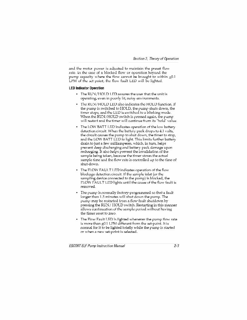
P]S cWT \^c^a _^fTa Xb PSYdbcTS c^ \PX]cPX] cWT _aTbTc U[^faPcT 8] cWT RPbT ^U P Q[^RZTS U[^f ^a ^_TaPcX^] QTh^]S cWT_d\_ RP_PRXch fWTaT cWT U[^f RP]]^c QT Qa^dVWc c^ fXcWX] ;?< ^U cWT bTc _^X]c cWT U[^f UPd[c ;43 fX[[ QT [XVWcTS
;43 8]SXRPc^a >_TaPcX^]
• CWT AD=7>;3 ;43 PbbdaTb cWT dbTa cWPc cWT d]Xc Xb^_TaPcX]V TeT] X] _^^a[h [Xc ]^Xbh T]eXa^]\T]cb
• CWT AD=7>;3 ;43 P[b^ X]SXRPcTb cWT 7>;3 Ud]RcX^] 8UcWT _d\_ Xb bfXcRWTS c^ 7>;3 cWT _d\_ bWdcb S^f] cWTcX\Ta bc^_b P]S cWT ;43 Xb bfXcRWTS c^ P Q[X]ZX]V \^STFWT] cWT AD=7>;3 bfXcRW Xb _aTbbTS PVPX] cWT _d\_fX[[ aTbcPac P]S cWT cX\Ta fX[[ R^]cX]dT Ua^\ Xcb W^[S eP[dT
• CWT ;>F 10CC ;43 X]SXRPcTb ^_TaPcX^] ^U cWT [^f QPccTahSTcTRcX^] RXaRdXc FWT] cWT QPccTah _PRZ Sa^_b c^ # e^[cbcWT RXaRdXc RPdbTb cWT _d\_ c^ bWdc S^f] cWT cX\Ta c^ bc^_P]S cWT ;>F 10CC ;43 c^ [XVWc CWXb [X\Xcb UdacWTa QPccTahSaPX] c^ Ydbc P UTf \X[[XP\_TaTb fWXRW X] cda] WT[_b_aTeT]c STT_ SXbRWPaVX]V P]S QPccTah _PRZ SP\PVT d_^]aTRWPaVX]V 8c P[b^ WT[_b _aTeT]c cWT X]eP[XSPcX^] ^U cWTbP\_[T QTX]V cPZT] QTRPdbT cWT cX\Ta bc^aTb cWT PRcdP[bP\_[T cX\T P]S cWT U[^f aPcT Xb R^]ca^[[TS d_ c^ cWT cX\T ^UbWdcS^f]
• CWT 5;>F 50D;C ;43 X]SXRPcTb ^_TaPcX^] ^U cWT U[^fQ[^RZPVT STcTRcX^] RXaRdXc 8U cWT bP\_[T X][Tc ^a cWTbP\_[X]V STeXRT R^]]TRcTS c^ cWT _d\_ Xb Q[^RZTS cWT5;>F 50D;C ;43 [XVWcb d]cX[ cWT RPdbT ^U cWT U[^f UPd[c XbaT\^eTS
• CWT _d\_ Xb ]^a\P[[h UPRc^ah_a^VaP\\TS b^ cWPc P UPd[c[^]VTa cWP] $ \X]dcTb fX[[ bWdc S^f] cWT _d\_ CWT_d\_ \Ph QT aTbcPacTS Ua^\ P U[^f UPd[c bWdcS^f] Qh_aTbbX]V cWT AD= 7>;3 bfXcRW ATbcPacX]V X] cWXb \P]]TaP[[^fb R^]cX]dPcX^] ^U cWT bP\_[T _TaX^S fXcW^dc WPeX]VcWT cX\Ta aTbTc c^ iTa^
• CWT 5[^f 5Pd[c ;43 Xb [XVWcTS fWT]TeTa cWT _d\_ U[^f aPcTXb \^aT cWP] ;?< SXUUTaT]c Ua^\ cWT bTc_^X]c 8c Xb]^a\P[ U^a Xc c^ QT [XVWcTS QaXTU[h fWX[T cWT _d\_ Xb bcPacTS^a fWT] P ]Tf bTc_^X]c Xb bT[TRcTS
BTRcX^] ! CWT^ah ^U >_TaPcX^]
4B2>AC 4;5 ?d\_ 8]bcadRcX^] <P]dP[ !"

DVTeZ`_ $@aVcReZ`_
4 Y R c X Z _ X e Y V 3 R e e V c j A R T \
DbT P]h >\TVP RWPaVTa U^a TgP\_[T) ?= #(#& % #($(%$'$!$ ^a ' &$( U^a RWPaVX]V cWT QPccTah _PRZ AT\^eT cWT_a^cTRcXeT adQQTa _[dV P]S RWPaVT cWT QPccTah _PRZ U^a # c^ %W^dab =^cT cWPc RWPaVX]V U^a [^]VTa _TaX^Sb fX[[ ]^c aTSdRTQPccTah [XUT _a^eXSTS cWT RWPaVX]V Xb _TaU^a\TS Pc a^^\cT\_TaPcdaT CWT QPccTah _PRZ RP] QT RWPaVTS fXcW cWT _PRZaT\^eTS Ua^\ cWT _d\_ 0[fPhb aT_[PRT cWT adQQTa _[dV PUcTaRWPaVX]V P]S QTU^aT dbX]V cWT _d\_ c^ _aTeT]c fPcTa T]cahX]c^ cWT YPRZ
» H 2 C ? : ?83^ ] c RWPaVT cWT QPccTah _PRZ X] PaTPb cWPc \Ph R^]cPX] P U[P\\PQ[T\XgcdaT U R^\QdbcXQ[T VPbTb eP_^ab a Sdbc P]S PXa* ^cWTafXbT P]Tg_[ bX^] \Ph ^RRda QTRPdbT P b^daRT ^U XV]XcX^] TgXbcb SdaX]V RWPaVX]V
» 4 2 F E : @ ?DbT ^][h P] <B0 >\TVP Ω RWPaVTa Ua \ <B0 c^ RWPaVT cWT _d\_
@ a V c R e Z _ X E Z ^V
CWT \PgX\d\ Tg_TRcTS ^_TaPcX]V cX\T U^a P _d\_ fXcW P Ud[[hRWPaVTS QPccTah _PRZ ST_T]Sb ^])
CWT bT[TRcTS U[^f aPcT
! CWT ePRdd\ [^PS X\_^bTS Qh cWT bP\_[X]V STeXRT
" CWT cT\_TaPcdaT
# CWT PVT ^U cWT QPccTah _PRZ
BTRcX^] " >_TaPcX^]
4B2>AC 4;5 ?d\_ 8]bcadRcX^] <P]dP[ "

BTT 586DA4 " U^a P__a^gX\PcT ^_TaPcX]V cX\Tb CWT bWPSTSPaTP bW^fb ^_TaPcX]V [^PSb P]S U[^f aPcTb fXcWX] cWT _d\_b_TRXUXRPcX^]b CWT TgP\_[T bW^f] fXcW SPbWTS [X]Tb Xb U^a P_d\_ bTc U^a ! ;?< fXcW P bP\_[X]V [^PS ^U $* cWT Tg_TRcTS\PgX\d\ ^_TaPcX]V cX\T f^d[S QT $ W^dab CWXb UXVdaT XbQPbTS ^] a^^\ cT\_TaPcdaT ^_TaPcX^] fXcW P ]Tf _PRZ 0c STVaTTb 2T]cXVaPST cWT ^_TaPcX]V cX\T fX[[ QT aTSdRTS Qh ! Pc !^2 0UcTa bTeTaP[ Wd]SaTS RWPaVTSXbRWPaVT RhR[TbcWT _PRZ RP_PRXch \Ph QT aTSdRTS Qh !
A V c d ` _ R ] 2 c V R D R ^a ] Z _ X
CWT 4B2>AC 4;5 ?d\_ Xb STbXV]TS U^a TXcWTa _Tab^]P[ ^a PaTPbP\_[X]V ^U P\QXT]c PXa 8c Pdc^\PcXRP[[h _a^eXSTb P R^]bcP]ce^[d\TcaXR U[^f aPcT ^U cWT bP\_[T PXa cWa^dVW cWT bP\_[X]VSTeXRT UX[cTa SXbR X\_X]VTa ^a PQb^aQT]c cdQT c^ \TPbdaT cWTR^]RT]caPcX^] ^U PXaQ^a]T \Xbcb Sdbcb _PacXRd[PcTb VPbTb P]SeP_^ab X] cWT f^aZ_[PRT
5XVdaT " Ch_XRP[ >_TaPcX]V CX\T 6aP_W
BTRcX^] " >_TaPcX^]
"! 4B2>AC 4;5 ?d\_ 8]bcadRcX^] <P]dP[

@ a V c R e Z _ X e Y V A f ^a
2WPaVT cWT QPccTah _PRZ U^a % W^dab dbX]V cWT <B0>\TVPΩ 2WPaVTa
• ATPS cWT F0A=8=6 ^] cWT QPccTah _PRZ
! 2^]]TRc cWT STbXaTS bP\_[X]V STeXRT c^ cWT X][Tc UXccX]V
" ?aTbb >=>55 Qdcc^] d]cX[ cWT AD=7>;3 ;43 [XVWcb
• CWT 5[^f 5Pd[c P]S ;^f 1Pc ;43b fX[[ cWT] [XVWc3daX]V cWT cX\T cWTbT ;43b PaT QTX]V [XVWcTS P]d\QTa Ua^\ c^ ((( fX[[ QT SXb_[PhTS CWXb Xb cWTc^cP[ ^U cWT _d\_´b ^_TaPcX]V W^dab bX]RT Xcb[Pbc RP[XQaPcX^]
• FWT] P[[ cWaTT ;43b PaT [XVWcTS cWT SXb_[Ph RWP]VTbc^ ''' ;?<<8=B c^ bW^f P[[ bTV\T]cb PaT Ud]RcX^]P[
• CWT _d\_fX[[ cWT] QTVX] ^_TaPcX^] CWT ;>F10C;43 fX[[ QT SPaZ XU cWT QPccTah e^[cPVT Xb PQ^eT # e^[cb CWT 5[^f 5Pd[c ;43 fX[[ QT SPaZ fWT] cWT U[^faPcT Xb fXcWX] ;?< ^U cWT bTc_^X]c
# DbT cWT ↑P]S ↓ bfXcRW Qdcc^]b c^ PSYdbc cWT U[^f bTc_^X]c XUP ]Tf U[^f aPcT Xb STbXaTS FWT] TXcWTa Qdcc^] Xb _aTbbTS)
• AD=7>;3 ;43 fX[[ QT SPaZ
• 3Xb_[Ph fX[[ bW^f cWT U[^f bTc_^X]c QTX]V bcT__TS d_^a bcT__TS S^f] c^ cWT ]Tf bTc_^X]c
$ CWT AD=7>;3 Qdcc^] \Ph QT _aTbbTS c^ X]cTaad_cbP\_[X]V fXcW^dc RPdbX]V cWT cX\Ta c^ aTbTc c^ iTa^
% ?aTbb cWT >=>55 Qdcc^] Pc cWT T]S ^U bP\_[X]V
• C^cP[ bP\_[T \X]dcTb fX[[ QT ^] cWT SXb_[Ph P]S fX[[aT\PX] d]cX[ cWT _d\_ Xb cda]TS >= PVPX]
& 2WTRZ RP[XQaPcX^] \^]cW[h TeTah ! W^dab ^U dbT U^a R^P[\X]T Sdbc bP\_[X]V
' >_TaPcT cWT _d\_fXcW P bP\_[X]V STeXRT R^]]TRcTS c^ cWTX][Tc >_TaPcX^] fXcW^dc P bP\_[Ta PccPRWTS fX[[ aTSdRTcWT [XUT ^U cWT _d\_ X][Tc UX[cTa >_TaPcX^] Pc eTah [^f U[^faPcTb \Ph QT d]bcPQ[T fXcW^dc P] PccPRWTS bP\_[X]VSTeXRT bdRW Pb P RWPaR^P[ cdQT
BTRcX^] " >_TaPcX^]
4B2>AC 4;5 ?d\_ 8]bcadRcX^] <P]dP[ ""

DVTeZ`_ %
C`feZ_V >RZ_eV_R_TV
A V c Z ` U Z T >R Z _ e V _ R _ T V
2WTRZX]V cWT 8][Tc 5X[cTa
CWT _d\_ X][Tc R^]cPX]b Sdbc P]S fPcTa UX[cTab c^ _a^cTRc cWT_d\_ Ua^\ _PacXR[Tb P]S fPcTa X] cWT bP\_[T PXa 586DA4 # 8U cWT UX[cTab QTR^\T R[^VVTS cWT bP\_[T U[^f \Ph QT Q[^RZTS^a P] TgcaP [^PS _[PRTS ^] cWT _d\_* cWTaTU^aT RWTRZ cWTUX[cTab aTVd[Pa[h
5XVdaT # 2WTRZX]V cWT 8][Tc 5X[cTa
BTRcX^] # A^dcX]T <PX]cT]P]RT
4B2>AC 4;5 ?d\_ 8]bcadRcX^] <P]dP[ #

CWT UaT`dT]Rh ^U cWT RWTRZb bW^d[S ST_T]S ^] cWT P\^d]c ^U_d\_ dbPVT P]S cWT R^]RT]caPcX^] ^U _PacXR[Tb P[[^fTS c^ T]cTacWT _d\_ DbdP[[h ^][h cWT Sdbc UX[cTa ]TTSb c^ QT aT_[PRTS CWTCTU[^] fPcTa UX[cTa bW^d[S aPaT[h ]TTS c^ QT aT_[PRTS CWT fPcTaUX[cTa Xb eTah UaPVX[T P]S \dbc QT WP]S[TS fXcW RPaT 4eT] P cX]h_X] W^[T fX[[ STbca^h Xcb Ud]RcX^] CWT UX[cTa UaXc bW^d[S ]TeTa]TTS c^ QT aT_[PRTS XU cWT ^cWTa UX[cTab PaT \PX]cPX]TS
5X[cTa AT_[PRT\T]c
AT\^eT cWT U^da bRaTfb W^[SX]V cWT UX[cTa R^eTa P]S >aX]V
! AT_[PRT cWT UX[cTa fXcW P ]Tf ^]T
" ATPbbT\Q[T cWT >aX]V P]S R^eTa
5aXc AT_[PRT\T]c
BcPQ cWT UaXc RT]cTa fXcW P b\P[[ bRaTfSaXeTa P]S [XUc Xc ^dc
! ?aTbb X] P ]Tf UaXc
" ATPbbT\Q[T cWT CTU[^] P]S Sdbc UX[cTab >aX]V P]S R^eTa
3 R e e V c j A R T \ C V a ] R T V ^V _ e
586DA4 #! X[[dbcaPcTb cWT QPccTah _PRZ
AT\^eT cWT cf^ bRaTfb bTRdaX]V cWT QPccTah _PRZ c^ cWT RPbT
! BT_PaPcT cWT _PRZ Ua^\ cWT RPbT
" <PZT bdaT cWPc cWT >aX]V Xb X] _[PRT ^] cWT aT_[PRT\T]c_PRZ CWT] b[XST cWT _PRZ X]c^ cWT _d\_ RPbT fWX[T_aTbbX]V cWT RPbT Ua^]c P]S QPRZ c^ \PZT bdaT cWT RPbTTSVTb V^ X]bXST cWT TSVTb ^U cWT _PRZ
# 8]bTac cWT cf^ bRaTfb P]S cXVWcT]
BTRcX^] # A^dcX]T <PX]cT]P]RT
#! 4B2>AC 4;5 ?d\_ 8]bcadRcX^] <P]dP[
CTU[^] Xb P caPST\PaZ ^U cWT Sd ?^]c 2^\_P]h

5XVdaT #! AT_[PRX]V cWT 1PccTah ?PRZ
BTRcX^] # A^dcX]T <PX]cT]P]RT
4B2>AC 4;5 ?d\_ 8]bcadRcX^] <P]dP[ #"

DVTeZ`_ &
6=7 DV_d`c 4R]ZScReZ`_
2WTRZ _d\_ X][Tc UX[cTa U^a Sdbc* aT_[PRT XU WTPeX[h [^PSTS
! Cda] >= cWT _d\_ P]S P[[^f Xc c^ aTPRW Xcb U[^f aPcT bTccX]V
" 8U cWT _d\_ Xb ]^c bTc U^a !$ ;?< bTc Xc c^ !$
# 0[[^f cWT _d\_ c^ ^_TaPcT U^a c^ $ \X]dcTb Pc !$ ;?<C^ RWTRZ U^a [TPZb cT\_^aPaX[h Q[^RZ cWT _d\_ X][Tc* !;?< ^a [Tbb bW^d[S QT SXb_[PhTS 8U ]^c RWTRZ cWT X][TcUX[cTa R^eTa P]S ^aX]V U^a R^aaTRc PbbT\Q[h
$ ;TPeT cWT _d\_ bTc U^a !$ ;?< P]S cda] >55 cWT _d\_
% 2^]]TRc P _aX\Pah RP[XQaPcX^] bcP]SPaS c^ cWT _d\_
& Cda] >= cWT _d\_* Pb cWT _d\_ V^Tb cWa^dVW Xcb bT[URWTRZbT`dT]RT _aTbb P]S W^[S cWT >=>55 P]S AD=7>;3bfXcRWTb bX\d[cP]T^db[h d]cX[ cWT SXb_[Ph aTPSb 20;8\\TSXPcT[h aT[TPbT Q^cW Qdcc^]b
=>C4) 5PX[daT c^ aT[TPbT Q cW Qdcc^]bfX[[ cda]>55 cWT _d\_
• CWT SXb_[Ph fX[[ bW^f 20; P]S P R^d]cS^f]bT`dT]RT ^U ]d\QTab Ua^\ ( cWa^dVW * cWTaTPUcTa XcfX[[ P[cTa]PcT[h SXb_[Ph 20; P]S !$ ;?<
' >_TaPcT cWT RP[XQaPcX^] bcP]SPaS P]S ^QcPX] Pc [TPbc bXgaTPSX]Vb fWXRW PaT eTah R[^bT c^ ^]T P]^cWTa
( DbT cWT↑P]S↓ bfXcRW Qdcc^]b c^ bcT_ cWT_d\_SXb_[Phd_^aS^f]d]cX[ Xc PVaTTb TgPRc[hfXcW cWT PeTaPVT U cWT bXg aTPSX]Vb
Cda] >55 cWT _d\_* cWT 4;5 bT]b^a Xb ]^f RP[XQaPcTSAT_TPc \^]cW[h ^a TeTah ! W^dab ^U dbT
FWT] h^d ]Tgc cda] >= cWT _d\_ cWT ^_TaPcX]V W^dab fX[[QT aTbTc c^ P]SQTSXb_[PhTSSdaX]V cWT [XVWcX]V ^U cWT5;>F 50D;C P]S ;>F 10C ;43b
BTRcX^] $ 4;5 BT]b^a 2P[XQaPcX^]
4B2>AC 4;5 ?d\_ 8]bcadRcX^] <P]dP[ $

CWT 18>B 3ah2P[ bW^d[S QT dbTS c^ RP[XQaPcT ^a RWTRZ cWTU[^f aPcT ^U P] <B0 4bR^ac 4;5 _d\_ ^][h XU P] Xb^[PcX]VU[^f aTbcaXRc^a TV P UX[cTa ^a P] ^aXUXRT bdRW Pb ?= %"!%#%_a^eXSX]V Pc [TPbc F2 Xb _[PRTS X] [X]T QTcfTT] cWT _d\_P]S cWT RP[XQaPc^a 5PX[daT c^ dbT bdRW P] Xb^[PcX^] cTRW]X`dTRP] RPdbT P RP[XQaPcX^] X]PRRdaPRh ^] cWT ^aSTa ^U ! P]S Xb]^c aTR^\\T]STS
BTRcX^] $ 4;5 BT]b^a 2P[XQaPcX^]
$! 4B2>AC 4;5 ?d\_ 8]bcadRcX^] <P]dP[

DVTeZ`_ '6=7 DV_d`c 4R]ZScReZ`_W`c Af^ad fdVU Z_ eYV FD8`gVc_^V_e >Z_V DRWVej R_U 9VR]eY2U^Z_ZdecReZ`_ >D92 4`R] >Z_V5fde DR^a]Z_X Ac`XcR^
2WTRZ _d\_ X][Tc UX[cTa U^a Sdbc* aT_[PRT XU WTPeX[h [^PSTS
! Cda] >= cWT _d\_ P]S P[[^f Xc c^ aTPRW Xcb U[^f aPcT bTccX]V
" 8U cWT _d\_ Xb ]^c bTc U^a ! ;?< bTc Xc c^ !
# 0[[^f cWT _d\_ c^ ^_TaPcT U^a c^ $ \X]dcTb Pc ! ;?<C^ RWTRZ U^a [TPZb cT\_^aPaX[h Q[^RZ cWT _d\_ X][Tc* !;?< ^a [Tbb bW^d[S QT SXb_[PhTS 8U ]^c RWTRZ cWT X][TcUX[cTa R^eTa P]S ^aX]V U^a R^aaTRc PbbT\Q[h
$ ;TPeT cWT _d\_ bTc U^a ! ;?< P]S cda] >55 cWT _d\_
% 2^]]TRc P _aX\Pah RP[XQaPcX^] bcP]SPaS c^ cWT _d\_
& Cda] >= cWT _d\_* Pb cWT _d\_ V^Tb cWa^dVW Xcb bT[URWTRZbT`dT]RT _aTbb P]S W^[S cWT >=>55 P]S AD=7>;3bfXcRWTb bX\d[cP]T^db[h d]cX[ cWT SXb_[Ph aTPSb 20;8\\TSXPcT[h aT[TPbT Q^cW Qdcc^]b
=>C4) 5PX[daT c^ aT[TPbT Q cW Qdcc^]bfX[[ cda]>55 cWT _d\_
• CWT SXb_[Ph fX[[ bW^f 20; P]S P R^d]cS^f]bT`dT]RT ^U ]d\QTab Ua^\ ( cWa^dVW * cWTaTPUcTa XcfX[[ P[cTa]PcT[h SXb_[Ph 20; P]S ! ;?<
' >_TaPcT cWT RP[XQaPcX^] bcP]SPaS P]S ^QcPX] Pc [TPbc bXgaTPSX]Vb fWXRW PaT eTah R[^bT c^ ^]T P]^cWTa
BTRcX^] % 4;5 BT]b^a 2P[XQaPcX^] U^a ?d\_b dbTS X]<B70 2^P[ <X]T 3dbc BP\_[X]V ?a^VaP\
4B2>AC 4;5 ?d\_ 8]bcadRcX^] <P]dP[ %
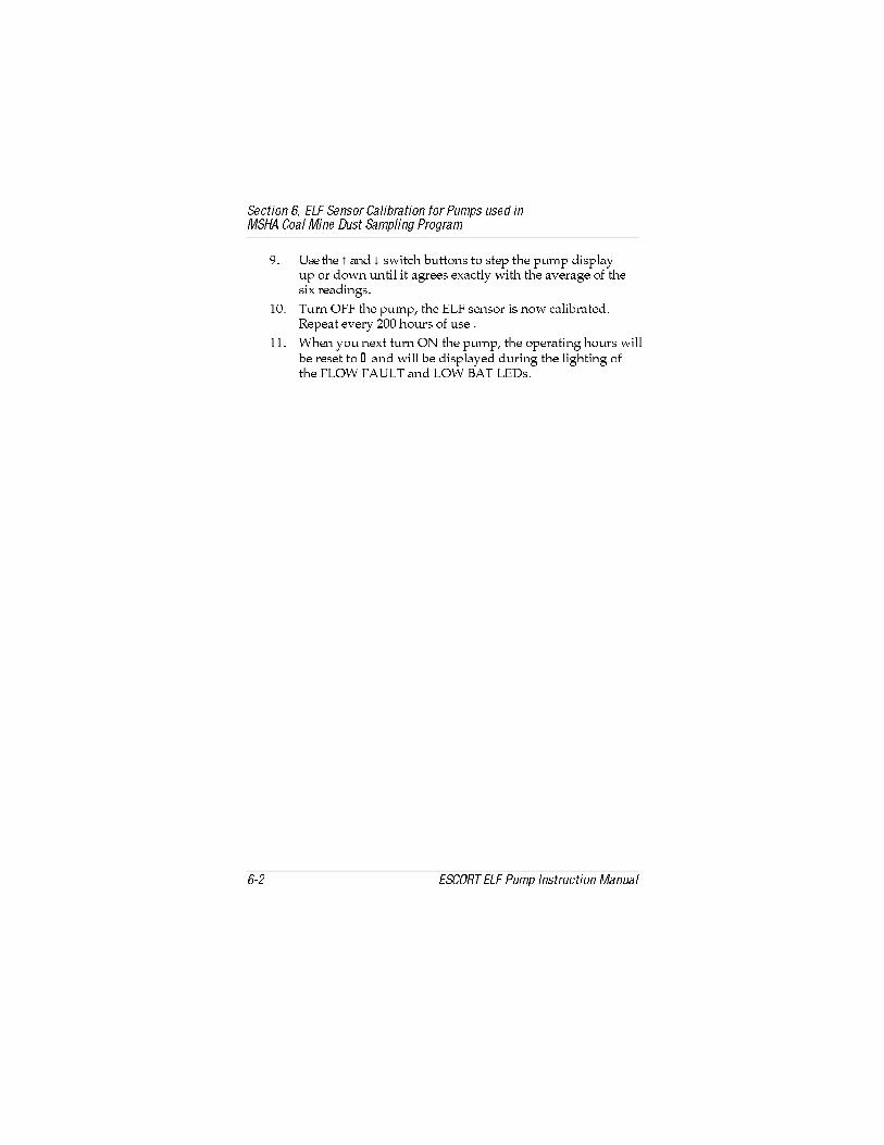
( DbT cWT↑P]S↓ bfXcRW Qdcc^]b c^ bcT_ cWT _d\_ SXb_[Phd_ ^a S^f] d]cX[ Xc PVaTTb TgPRc[h fXcW cWT PeTaPVT ^U cWTbXg aTPSX]Vb
Cda] >55 cWT _d\_* cWT 4;5 bT]b^a Xb ]^f RP[XQaPcTSAT_TPc TeTah ! W^dab ^U dbT
FWT] h^d ]Tgc cda] >= cWT _d\_ cWT ^_TaPcX]V W^dab fX[[QT aTbTc c^ P]S fX[[ QT SXb_[PhTS SdaX]V cWT [XVWcX]V ^UcWT 5;>F 50D;C P]S ;>F 10C ;43b
BTRcX^] % 4;5 BT]b^a 2P[XQaPcX^] U^a ?d\_b dbTS X]<B70 2^P[ <X]T 3dbc BP\_[X]V ?a^VaP\
%! 4B2>AC 4;5 ?d\_ 8]bcadRcX^] <P]dP[

DVTeZ`_ (CVaRZcd R_U CVa]RTV^V_e ARced
E c ` f S ] V d Y ` ` e Z _ X
C01;4 & Ca^dQ[TbW^^cX]V 6dXST[X]Tb [Xbcb cWT bh\_c^\b ^UcWT \^bc R^\\^] _a^Q[T\b* Xc P[b^ [Xbcb cWTXa _a^QPQ[T RPdbTbP]S cWT PRcX^] aT`dXaTS c^ R^aaTRc TPRW _a^Q[T\ DbT cWTVdXST[X]Tb XU h^d RP]]^c RP[XQaPcT cWT 4B2>AC 4;5 ?d\_ ^a XUcWT _d\_ S^Tb ]^c ^_TaPcT _a^_Ta[h 8U h^d RP]]^c aTb^[eT P_a^Q[T\ Qh dbX]V cWT VdXST[X]Tb RP[[ '<B0!!!! c^ [^RPcT P[^RP[ <B0 AT_PXa 2T]cTa
» H 2 C ? : ?8DbT ^][h VT]dX]T <B0 aT_[PRT\T]c _Pacb fWT] _TaU^a\X]V cWT\PX]cT]P]RT _a^RTSdaTb STbRaXQTS X] cWXb \P]dP[ 5PX[daT c^ S^ b^\Ph bTaX^db[h X\_PXa X]bcad\T]c _TaU^a\P]RT AT_PXa ^a P[cTaPcX^]QTh^]S cWT bR^_T ^U cWTbT \PX]cT]P]RT X]bcadRcX^]b ^a Qh P]h^]T^cWTa cWP] P] <B0caPX]TS bTaeXRT _Tab^] R^d[S RPdbT cWT _a^SdRcc^ UPX[ c^ _TaU^a\ Pb STbXV]TS P]S _Tab^]b fW^ aT[h ^] cWXb _a^SdRcU^a cWTXa bPUTch R^d[S bdbcPX] bTeTaT _Tab^]P[ X]Ydah ^a STPcW
4 ` c c V T e Z g V >R Z _ e V _ R _ T V
FWT] P] X]^_TaPcXeT _Pac Xb [^RPcTS Qh dbX]V C01;4 & Ca^dQ[TbW^^cX]V 6dXST[X]Tb aT_[PRT Xc PRR^aSX]V c^ ^]T ^U cWTaT_[PRT\T]c _a^RTSdaTb [PcTa X] cWXb bTRcX^] 0[b^ aTUTa c^>QcPX]X]V AT_[PRT\T]c ?Pacb [PcTa X] cWXb bTRcX^] U^aX]U^a\PcX^] ^] W^f c^ ^aSTa cWT ]TRTbbPah _Pac Ua^\ <B0
BTRcX^] & AT_PXab P]S AT_[PRT\T]c ?Pac
4B2>AC 4;5 ?d\_ 8]bcadRcX^] <P]dP[ ?PVT &

CPQ[T & Ca^dQ[TbW^^cX]V 6dXST[X]Tb
BH<?C>< ?A>101;4 20DB4 2>AA42C8E4 02C8>=
>=7>;3 ;43X]SXRPc^a cda]b >55_aT\PcdaT[h* 5;>F50D;C ;43 8]SXRPc a\Ph QT >= a >55P]S ;>F 10CC ;43Xb cda]TS >=
8][Tc UX[cTa R[^VVTS ^aQ[^RZTS fXcW fPcTa
AT_[PRT UX[cTa PRR^aSX]V c^2WTRZX]V cWT 8][Tc 5X[cTa
! 1PccTah _PRZ XbSTVaPSTS
! 8]bcP[[ ]Tf _PRZ ^] _d\_Qh _TaU^a\X]V _a^RTSdaTSTbRaXQTS d]STa 1PccTah?PRZ AT_[PRT\T]c
" >_TaPcX^] QTh^]SU[^f P]S [^PS [X\Xcb
" ATSdRT U[^f ^a aT_[PRTbP\_[Ta fXcW [^fTa[^PS STeXRT
>=7>;3 ;43 P]S5;>F 50D;C ;43X]SXRPc^ab cda]TS>= P]S _d\_ fX[[]^c ad] ^a XU Xc S^Tbad] ]^ U[^f XbSXb_[PhTS ^] aTPS^dc
?d\_ \^c a R^]]TRc^aX\_a^_Ta[h _[dVVTS X]c^?2 Q^PaS
2WTRZ R^]]TRc^a
! ?aTbbdaT bT]b aR^]]TRc^a UPd[c
! 2WTRZ R^]]TRc^a ETaXUh UXeT_X]b PaT _[dVVTS X]
" ?d\_ \^c^aX]^_TaPcXeT
" AT_[PRT _d\_ P]S \^c aSaXeT PbbT\Q[h PRR^aSX]V c^_a^RTSdaT d]STaAT_[PRX]V cWT ?d\_ P]S3aXeT 0bbT\Q[h
# ?aTbbdaT bT]b^a ^a?2 Q^PaS X]^_TaPcXeT
# AT_[PRT bT]b^a ^a ?2 Q^PaS
FWT] X][Tc XbQ[^RZTS cWT U[^fX]SXRPcX^] Xb ]^c! [_\ ^a [Tbb
BP\_[T U[^f [TPZb 2WTRZ U^a [TPZX]V cdQT
R^]]TRcX^] ^a >aX]V bTP[ PccWT X][Tc UX[cTa R^eTa
;43 X]SXRPc^a ^]RWPaVTa S^Tb ] c cda]>= fWT] _[dV ^][X]TR^aS Xb X]bTacTS X] $ E02 ^dc[Tc P]S_[dV ^] RWPaVX]V R^aSXb X]bTacTS X] YPRZ ^]QPccTah _PRZ
?^fTa b^daRTX]PRcXeT
2WTRZ P]S R^aaTRcRPdbT ^U _^fTa [^bb
! 2WPaVTa UPX[daT ! AT_[PRT RWPaVTa
" 1PccTah _PRZ UPX[daT
" AT_[PRT QPccTah _PRZQh _TaU^a\X]V _a^RTSdaTd]STa AT_[PRX]V cWT1PccTah ?PRZ
3TbXaTS U[^f aPcTRP]]^c QT ^QcPX]TSd]STa WTPehbP\_[X]V STeXRT[^PSb fXcWX] aTVX\T^U 586DA4 "
8][Tc UX[cTa _PacXP[[hR[^VVTS
AT_[PRT UX[cTa PRR^aSX]V c^X]bcadRcX^]b d]STa2WTRZX]V cWT 8][Tc 5X[cTa
! ;TPZ TgXbcb X]bP\_[T U[^f bhbcT\
! 2WTRZ U^a [TPZX]V cdQTR^]]TRcX^] ^a >aX]V Pc cWTX][Tc UX[cTa R^eTa
BTRcX^] & AT_PXab P]S AT_[PRT\T]c ?Pac
?PVT &! 4B2>AC 4;5 ?d\_ 8]bcadRcX^] <P]dP[

D]_[dVVX]V cWT 4[TRcaXRP[ 2^]]TRc^ab
BTaeXRT _a^RTSdaTb fWXRW aT`dXaT ^_T]X]V cWT 4;5 _d\_ RPbTaT`dXaT cWT d]_[dVVX]V ^U cf^ T[TRcaXRP[ R^]]TRc^ab)
?d[[ ^] cWT \^c^a T[TRcaXRP[ R^]]TRc^a c^ aT\^eT cWT \^c^afXaTb Ua^\ cWT _aX]cTS RXaRdXc Q^PaS
! ?d[[ ^] cWT $_X] aXQQ^] RPQ[T c^ aT\^eT cWT R^]]TRc^a Ua^\cWT 4;5 bT]b^a
ATPccPRWX]V cWT 4[TRcaXRP[ 2^]]TRc^ab
FWT] aTPccPRWX]V cWT \^c^a R^]]TRc^a \PZT bdaT cWTP]Vd[Pa aP\_ Pc cWT T]S UPRTb c^fPaSb cWT [PcRW _a^YTRcX]VUa^\ cWT _aX]cTS RXaRdXc Q^PaS b^RZTc
=>C4) CWT _d\_ fX[[ ^_TaPcT fXcW cWT R^]]TRc^a X]bcP[[TScWT ^cWTa fPh Qdc cWT PQ^eT \TcW^S XbT]R^daPVTS QTRPdbT cWT aP\_ P]S [PcRW WT[_ZTT_ cWT R^]]TRc^a PccPRWTS Pb cWT _d\_ XbZ]^RZTS Pa^d]S SdaX]V dbT
! FWT] aTPccPRWX]V cWT R^]]TRc^a c^ cWT 4;5 bT]b^a \PZTbdaT _X]b cWa^dVW $ PaT bcaPXVWc P]S X] [X]T
=>C4) 8U cWTbT _X]b PaT QT]c dbT ]TTS[T]^bT _[XTab c^bcaPXVWcT] P]S P[XV] cWT\ ?X] % Xb X]cT]cX^]P[[hRdc ^UU QTRPdbT Xc Xb ]^c dbTS X] cWT 4;5 _d\_
" ?d[[ cWT RPQ[T b^ cWPc cWT T]S ^U cWT R^]]TRc^a Xb PQ^dc &'PQ^eT cWT _aX]cTS RXaRdXc Q^PaS
# 7^[S cWT _d\_ UPRT X] cWT aXVWc WP]S P]S _^bXcX^] h^dacWd\Q P]S U^aTUX]VTa Pa^d]S cWT c^_ [TUc WP]S R^a]Ta ^UcWT _d\_ UPRT
$ 7^[S cWT R^]]TRc^a fXcW cWTbT cf^ UX]VTab P]S W^[S cWT_d\_ RPbT fXcW cWT [TUc WP]S
% ?^bXcX^] cWT R^]]TRc^a b^ cWPc P] T]S _X] Xb Ydbc X]bXST cWTUd]]T[ ^_T]X]V ^U cWT R^aaTb_^]SX]V _X] b^RZTc
& 6aPSdP[[h cX[c cWT R^]]TRc^a c^ VTc cWT ]Tgc _X] Ydbc X]bXST Xcbb^RZTc P]S aT_TPc cWXb _a^RTbb d]cX[ P[[ UXeT _X]b PaT YdbcX]bXST cWTXa R^aaTb_^]SX]V b^RZTcb
' B[^f[h _aTbb cWT R^]]TRc^a ^]c^ cWT _X]b d]cX[ cWThQ^cc^\ ^dc
BTRcX^] & AT_PXab P]S AT_[PRT\T]c ?Pac
4B2>AC 4;5 ?d\_ 8]bcadRcX^] <P]dP[ ?PVT &"

( 8]b_TRc cWT R^]]TRc^a Pc cWT c^_ P]S Q^cc^\ c^ \PZT bdaT P[[_X]b PaT R^aaTRc[h X]bTacTS
?d\_ 3aXeT 0bbT\Q[h>dc[Tc 3P\_T]Ta ^a ?aTbbdaT BT]b^a AT_[PRT\T]c
AT\^eT cf^ bRaTfb bTRdaX]V cWT QPccTah _PRZ c^ cWT RPbT
! AT\^eT cWT QPccTah _PRZ
" AT\^eT cWT cf^ bRaTfb bTRdaX]V cWT _d\_ RPbT
# ?d[[ cWT $_X] aXQQ^] R^]]TRc^a Ua^\ cWT _aTbbdaT bT]b^a
$ ?d[[ cWT \^c^a T[TRcaXRP[ R^]]TRc^a Ua^\ cWT ?2 Q^PaS
% AT\^eT cWT cf^ bRaTfb bTRdaX]V cWT _d\_\^d]cX]V R^[[Pac^ cWT QPRZ ^U cWT RPbT
& ;XUc ^dc cWT _d\_ P]S SaXeT fWX[T aT\^eX]V cWT X][TcSP\_T]Ta R^]]TRcX^] Ua^\ cWT UXccX]V
=>C4) 0 Sa^_ ^U b^P_ b^[dcX^] B=>>? f^aZTS X] PccWT T]S ^U cWT adQQTa cdQT \PZTb aT\^eP[ TPbXTaP]S fX[[ _aTeT]c cTPaX]V cWT adQQTa cdQT
' AT\^eT cWT cf^ bRaTfb bTRdaX]V cWT _aTbbdaT bT]b^a
( AT\^eT cWT _aTbbdaT bT]b^a P]S QT RPaTUd[ ]^c c^ Sa^_ XcTeT] c^ cWT cPQ[T c^_
AT\^eT cWT ^dc[Tc SP\_T]Ta XU Xc Xb c^ QT aT_[PRTS
8]bcP[[ cWT aT_[PRT\T]c _d\_ P]S SaXeT ^dc[Tc SP\_T]Ta ^a_aTbbdaT bT]b^a Qh aTeTabX]V cWXb _a^RTSdaT
=>C4) FTccX]V cWT T]S ^U cWT ^dc[Tc SP\_T]Ta fX[[ \PZTb[XSX]V Xc ^eTa cWT bT]b^a Q^Sh TPbXTa <PZT bdaTQ^cW RdUUb PaT R^\_[TcT[h X] cWT Va^^eTb
=>C4) CXVWcT] cWT d__Ta \^c^a R^[[Pa bRaTf QTU^aTcXVWcT]X]V cWT [^fTa bRaTffWT] X]bcP[[X]V cWT]Tf _d\_ P]S SaXeT
?aX]cTS 2XaRdXc 2^]ca^[ 1^PaS AT_[PRT\T]c
AT\^eT cWT cf^ bRaTfb bTRdaX]V cWT QPccTah _PRZ
! AT\^eT cWT QPccTah _PRZ
B=>>? Xb P caPST\PaZ ^U =d_a^ 2^\_P]h
BTRcX^] & AT_PXab P]S AT_[PRT\T]c ?Pac
?PVT &# 4B2>AC 4;5 ?d\_ 8]bcadRcX^] <P]dP[

" AT\^eT cWT cf^ bRaTfb bTRdaX]V cWT _d\_ RPbT
# ?d[[ cWT R^]]TRc^a Ua^\ cWT _aTbbdaT bT]b^a
$ ?d[[ cWT\^c^a T[TRcaXRP[ R^]]TRc^a Ua^\ cWT _aX]cTS RXaRdXc Q^PaS
& AT\^eT P]S bPeT cWT cWaTT bRaTfb cf^ fPbWTab P]S b_PRTabTRdaX]V cWT ?2 Q^PaS c^ cWT _d\_ UPRT
' 8]bcP[[ cWT aT_[PRT\T]c _aX]cTS RXaRdXc Q^PaS Qh aTeTabX]VcWXb _a^RTSdaT
=>C4) 1T bdaT cWT QPccTah R^]]TRc^a Xb \^d]cTS fXcW cWTQ[PRZ fXaT c^fPaSb cWT c^_ ^U cWT RPbT
@ S e R Z _ Z _ X C V a ] R T V ^V _ e A R c e d
CWT 4B2>AC 4;5 ?d\_ _Pacb P]S _Pac ]d\QTab PaT [XbcTS X]C01;4 &! C^ ^QcPX] _Pacb bTaeXRT ^a X]U^a\PcX^] X] cWT DBRP[[ '<B0!!!! c^ UX]S cWT ]TPaTbc Rdbc^\Ta bTaeXRT RT]cTaC^ aTPRW <B0 8]cTa]PcX^]P[ RP[[ # !(%&"
BTRcX^] & AT_PXab P]S AT_[PRT\T]c ?Pac
4B2>AC 4;5 ?d\_ 8]bcadRcX^] <P]dP[ ?PVT &$

5XVdaT & AT_[PRT\T]c ?Pacb
BTRcX^] & AT_PXab P]S AT_[PRT\T]c ?Pac
?PVT &% 4B2>AC 4;5 ?d\_ 8]bcadRcX^] <P]dP[
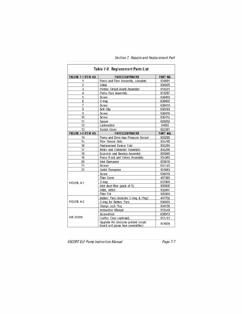
CPQ[T &! AT_[PRT\T]c ?Pacb ;Xbc
586DA4 & 8C4< => ?0AC2><?>=4=C ?0AC =>
?d\_ P]S 5[^f 0bbT\Q[h R^\_[TcT '#%%
! 2^[[Pa '!$
" ?aX]cTS 2XaRdXc1^PaS 0bbT\Q[h ' "$$
# ?d\_ 5PRT 0bbT\Q[h ' "!(&
$ BRaTf %"%#("
% >aX]V %"%%!
& BRaTf %"%# #
' 1T[c 2[X_ %"%!("
( BRaTf %"%# %
BRaTf %"%# $
B_PRTa %!''$!
! ;^RZfPbWTa %#($
" BfXcRW 2^eTa '!"'
586DA4 &! 8C4< => ?0AC2><?>=4=C ?0AC =>
# ?d\_ P]S 3aXeT [Tbb ?aTbbdaT BT]b^a '$!'$
$ 5[^f BT]b^a >][h '$!'%
% AT_[PRT\T]c BT]b^a >][h '$!'#
& <^c^a P]S 2^]]TRc^a 0bbT\Q[h '$!(%
' 4RRT]caXR P]S 1TPaX]V 0bbT\Q[h '$#%
( ?d\_ 1[^RZ P]S EP[eTb 0bbT\Q[h '$"%
! 8][Tc 3P\_T]Ta '"' %
! BRaTfb %"& #
!! >dc[Tc 3P\_T]Ta '#%%"
586DA4 #
BRaTf %"%# '
5X[cTa 2^eTa #(&"("
>aX]V %"&(
8][Tc Sdbc UX[cTa _PRZ ^U $ ''("$
5X[cTa CTU[^] '!'(&
5X[cTa 5aXc '""
586DA4 #!1PccTah ?PRZ X]R[dSTb >aX]V ?[dV #(&&!
>aX]V U^a 1PccTah ?PRZ %"%%"
2WPaVT 9PRZ ?[dV '# $'
]^c bW^f]
8]bcadRcX^] <P]dP[ ' "$#(
BRaTfSaXeTa %"%( "
;TPcWTa 2PbT ^_cX^]P[ ' &#
D_VaPST :Xc X]R[dSTb _aX]cTS RXaRdXcQ^PaS P]S _d\_ UPRT PbbT\Q[XTb
' #!(
BTRcX^] & AT_PXab P]S AT_[PRT\T]c ?Pac
4B2>AC 4;5 ?d\_ 8]bcadRcX^] <P]dP[ ?PVT &&

5XVdaT &! AT_[PRT\T]c ?Pacb R^]c
CPQ[T &! AT_[PRT\T]c ?Pacb ;Xbc R^]c
?0AC2><?>=4=C ?0AC =>
:Xc ?d\_ <PX]cT]P]RT ?Pacb
'!(!!
1T[c 2[X_b
5X[cTa 2^eTa
BRaTfb UX[cTa R^eTa
>AX]Vb QPccTah _PRZ
BRaTfb QT[c R[X_
BRaTfb RPbT
?^[hTcWh[T]T 3XbRb
>AX]Vb UX[cTa R^eTa
8][Tc 5X[cTab
BTRcX^] & AT_PXab P]S AT_[PRT\T]c ?Pac
?PVT &' 4B2>AC 4;5 ?d\_ 8]bcadRcX^] <P]dP[

Protean Instrument Corporation
ASC-950 Dual Phosphor
Revision 1.3

Protean Instrument Corporation 2
ASC-950
Contents About This Manual ........................................................................................................................................ 8
Installation Overview .................................................................................................................................... 9
Unpacking Instructions ............................................................................................................................. 9
Unpacking the Mobile Cart Crate ............................................................................................................. 9
Preliminary Preparations ........................................................................................................................ 10
Visual Inspection ..................................................................................................................................... 10
Preliminary Procedures ........................................................................................................................... 11
Printer Testing ......................................................................................................................................... 12
Manually Count a Test Source ................................................................................................................ 16
Print and Save Factory Plateau ............................................................................................................... 18
Setting the Calendar/ Clock .................................................................................................................... 19
Installations Without Attached Printer ................................................................................................... 19
Install the Stacks ..................................................................................................................................... 19
Load Carriers and Test the Sample Changer ........................................................................................... 20
Read the Manual ..................................................................................................................................... 21
ASC‐950 Overview ....................................................................................................................................... 22
Menu Driven Operation .......................................................................................................................... 22
Pass Code Protection .............................................................................................................................. 22
Count Function ........................................................................................................................................ 22
Calibration Function ................................................................................................................................ 22
Control Charts ......................................................................................................................................... 22
Program Function ................................................................................................................................... 23
Counting Parameters .............................................................................................................................. 23
Background Parameters .......................................................................................................................... 23
Efficiency Parameters ............................................................................................................................. 23
Battery Backup ........................................................................................................................................ 23
Printer ..................................................................................................................................................... 24
Computer Connectivity ........................................................................................................................... 24
International Power Entry ....................................................................................................................... 24

Protean Instrument Corporation 3
ASC-950
Limited Warranty .................................................................................................................................... 24
Sample Loading ....................................................................................................................................... 25
The Five Types of Plates .......................................................................................................................... 25
Sample Carrier Plates .............................................................................................................................. 26
End Plates ................................................................................................................................................ 26
Skip Plates ............................................................................................................................................... 26
Routine Plates ......................................................................................................................................... 26
QC Plates ................................................................................................................................................. 26
Prepare Changer ..................................................................................................................................... 27
Selecting Sample Carriers ....................................................................................................................... 27
The ASC‐950 Console .............................................................................................................................. 28
The Rear Panel ........................................................................................................................................ 28
Getting Started ............................................................................................................................................ 29
Count a Sample ....................................................................................................................................... 29
Step 1 Define ........................................................................................................................................... 29
Define Counting Routines ....................................................................................................................... 30
Routine Definition Page 1 ....................................................................................................................... 31
Routine Definition Page 2 ....................................................................................................................... 32
Routine Definition Page 3 ...................................................................................................................... 32
Routine Definition Page 6 ....................................................................................................................... 33
Step 2 Calibrate ....................................................................................................................................... 34
Step 3 Single Sample Count .................................................................................................................... 36
Step 3 Batch Count .................................................................................................................................. 38
Review ..................................................................................................................................................... 40
Batch Input .................................................................................................................................................. 41
Edit Batch Input ....................................................................................................................................... 42
Import Batch ........................................................................................................................................... 43
Setup Menu ................................................................................................................................................. 44
Screen Utilities ........................................................................................................................................ 44
Calibrating the Touch Screen .................................................................................................................. 44

Protean Instrument Corporation 4
ASC-950
Backlight Brightness ................................................................................................................................ 45
Beep Volume ........................................................................................................................................... 45
Program Menu ............................................................................................................................................ 46
Import Settings........................................................................................................................................ 46
Instrument Parameters ........................................................................................................................... 47
Auto Count Options ................................................................................................................................ 48
Query Options ......................................................................................................................................... 48
Auto Start Options .................................................................................................................................. 49
Cycle Recount .......................................................................................................................................... 49
Cycle Delay .............................................................................................................................................. 49
Printer ..................................................................................................................................................... 49
High Voltage Control ............................................................................................................................... 50
Set Calendar/Clock .................................................................................................................................. 50
Setup Pass Codes .................................................................................................................................... 51
Set Instrument ID .................................................................................................................................... 52
Define Counting Routines ....................................................................................................................... 52
Count Routine Definition Page 1 ............................................................................................................. 53
Naming the Count Routine ..................................................................................................................... 53
Preset Time ............................................................................................................................................. 53
Minimum Count Time ............................................................................................................................. 54
Repeats ................................................................................................................................................... 54
Preset Counts .......................................................................................................................................... 54
Specifying the Counting Mode ................................................................................................................ 55
Alpha Only ........................................................................................................................................... 55
Alpha and Beta .................................................................................................................................... 55
Results Storage........................................................................................................................................ 55
1 Page per Sample................................................................................................................................... 55
Automatic Print ....................................................................................................................................... 55
Completing Count Routine Definition Page 1 ......................................................................................... 55
Count Routine Definition Page 2 ............................................................................................................. 56

Protean Instrument Corporation 5
ASC-950
Count Routine Definition Page 3 ............................................................................................................. 61
Count Routine Definition Page 4 ............................................................................................................. 62
Count Routine Definition Page 5 ............................................................................................................. 63
Count Routine Definition Page 6 ............................................................................................................. 64
Calibration Menu ........................................................................................................................................ 66
Plateau Determination ............................................................................................................................ 67
Acquiring a Plateau ................................................................................................................................. 68
Viewing a Plateau .................................................................................................................................... 69
Manual Background/Efficiency Entry...................................................................................................... 70
Radon Efficiency Factors ......................................................................................................................... 72
Import Control Chart Limits .................................................................................................................... 73
Print All Calibration Info .......................................................................................................................... 73
Control Charts ............................................................................................................................................. 74
Manually Acquiring Control Checks ........................................................................................................ 75
Acquiring Control Checks ........................................................................................................................ 76
Data Menu .................................................................................................................................................. 77
View Count Routine Data ........................................................................................................................ 78
Routine Data View .................................................................................................................................. 79
Display Option ......................................................................................................................................... 80
Full Record View ..................................................................................................................................... 80
Page Selection ......................................................................................................................................... 81
Delete Count Routine Data ..................................................................................................................... 82
View Control Check Data ........................................................................................................................ 83
Background Control Chart....................................................................................................................... 83
Alpha Control Chart ................................................................................................................................ 85
Beta Control Chart .................................................................................................................................. 87
Export Data ............................................................................................................................................. 89
Diagnostics Menu ........................................................................................................................................ 91
Trending .................................................................................................................................................. 92
Acquiring Trending Data ......................................................................................................................... 94

Protean Instrument Corporation 6
ASC-950
Printing Trending Data ............................................................................................................................ 96
Manual Count ......................................................................................................................................... 97
The Data Display ..................................................................................................................................... 98
Printer Test .............................................................................................................................................. 99
Guarding Against Obsolescence ............................................................................................................... 100
Plateau Data CSV File Format ................................................................................................................... 101
Alpha Control Chart Checks Data CSV File Format ................................................................................... 102
Beta Control Chart Checks Data CSV File Format ..................................................................................... 103
Background Control Chart Checks Data CSV File Format.......................................................................... 104
Sample Data CSV File Format .................................................................................................................... 105
Trend Data CSV File Format ...................................................................................................................... 106
Radon Subtraction .................................................................................................................................... 109
Determination of Radon Efficiency Factors .......................................................................................... 110
Routine Counting with Radon Subtraction ........................................................................................... 110
External Control ........................................................................................................................................ 111
Service Guide Introduction ....................................................................................................................... 112
The Power Supply Subsystem ............................................................................................................... 112
The Linear Electronics Subsystem ......................................................................................................... 112
The CPU Subsystem .............................................................................................................................. 113
General Instructions .............................................................................................................................. 113
Stack Installation ................................................................................................................................... 113
Stack Removal ....................................................................................................................................... 113
Cover Removal ...................................................................................................................................... 113
Cover Installation .................................................................................................................................. 114
Removing the Sample Detector ............................................................................................................ 114
Installing the Sample Detector .............................................................................................................. 114
Power Entry ........................................................................................................................................... 114
Line Voltage Selection ........................................................................................................................... 114
Checking the Low Voltage Power Supply (LVPS) ................................................................................... 115
Removing Low Voltage Power Supply .................................................................................................. 115

Protean Instrument Corporation 7
ASC-950
Installing Low Voltage Power Supply .................................................................................................... 115
Operating Environment ........................................................................................................................ 116
General Electrical Failures ..................................................................................................................... 116
Blows Main Fuses .................................................................................................................................. 116
Failure to Initialize on Power‐up ........................................................................................................... 117
Intermittent Lockup .............................................................................................................................. 117
Beta Background is High? ..................................................................................................................... 117
Sample Counts are zero? ...................................................................................................................... 118
Performance Changes – Background .................................................................................................... 118
Contamination ...................................................................................................................................... 118
Electronic Noise .................................................................................................................................... 118
Performance Changes – Efficiency ........................................................................................................ 118
Geometry .............................................................................................................................................. 119
Plateau Settings .................................................................................................................................... 119
Variable Definitions and Equations ........................................................................................................... 120
Concepts of Alpha / Beta Counting ........................................................................................................... 125
The Alpha / Beta Counter ..................................................................................................................... 125
Dual Phosphor Detectors ...................................................................................................................... 125
Count Time Requirements .................................................................................................................... 125
Low Background Material Selection ..................................................................................................... 126
Background Stability ............................................................................................................................. 126
Absolute Counting Efficiency ................................................................................................................ 126
Intrinsic Detector Efficiency .................................................................................................................. 126
Counting Geometry and Efficiency ....................................................................................................... 127
Sample Self‐Absorption and Counting Efficiency .................................................................................. 128
Calibrated Conversion Factors .............................................................................................................. 129
The Control Chart .................................................................................................................................. 129
ASC‐950 OPTIONS .................................................................................................................................... 130
ASC‐950 SPARES & ACCESSORIES .............................................................................................................. 130
LIMITED WARRANTY ................................................................................................................................. 131
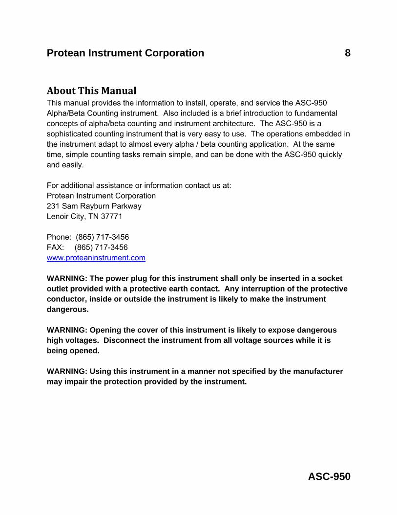
Protean Instrument Corporation 8
ASC-950
About This Manual This manual provides the information to install, operate, and service the ASC-950 Alpha/Beta Counting instrument. Also included is a brief introduction to fundamental concepts of alpha/beta counting and instrument architecture. The ASC-950 is a sophisticated counting instrument that is very easy to use. The operations embedded in the instrument adapt to almost every alpha / beta counting application. At the same time, simple counting tasks remain simple, and can be done with the ASC-950 quickly and easily. For additional assistance or information contact us at: Protean Instrument Corporation 231 Sam Rayburn Parkway Lenoir City, TN 37771 Phone: (865) 717-3456 FAX: (865) 717-3456 www.proteaninstrument.com WARNING: The power plug for this instrument shall only be inserted in a socket outlet provided with a protective earth contact. Any interruption of the protective conductor, inside or outside the instrument is likely to make the instrument dangerous. WARNING: Opening the cover of this instrument is likely to expose dangerous high voltages. Disconnect the instrument from all voltage sources while it is being opened. WARNING: Using this instrument in a manner not specified by the manufacturer may impair the protection provided by the instrument.

Protean Instrument Corporation 9
Installation ASC-950
Installation Overview This section is intended to provide guidelines for unpacking and installing your ASC-950 Alpha/Beta Counting instrument. The installation procedures will introduce many of the diagnostic tools provided by the instrument. The intention is to get all hardware connected and verified before embarking on the setup and calibration of the instrument.
Unpacking Instructions
The standard instrument is shipped in one wooden crate. A second wooden crate will contain the mobile cart option if it was ordered. Optional printers, computers, etc, are shipped in separate boxes.
The following instructions are a guide to unpacking the instrument.
Unpacking the Mobile Cart Crate o Identify crate 2 containing the mobile cart and remove the top and one side. If
there is no crate 2 ignore this section. o Remove the cart and tilt to an upright position. o Place the vinyl mat on top of the cart.
WARNING
If you did not purchase the mobile cart and plan to place the instrument on a table or lab bench take notice. The ASC-950 weighs approximately 130 lbs. Make sure your table will SAFELY support this weight.

Protean Instrument Corporation 10
Installation ASC-950
Unpacking the ASC-950 Crate
o Identify crate 1 and remove the 4 lag screws on each corner. o With a person at each end, lift the A-frame top straight up being careful not to
scratch the cabinet cover. o Tag the lift rods as front and rear respectively according to the way they are
packed in the crate. o Remove the clamps securing the lift rods and set the rods aside. o Remove the turnbuckles securing the instrument to the bottom of the crate. o Identify and set aside the following contents:
o Instruction Manual o Power Cord o Sample Carriers and Control Plates o Sample Carrier Inserts (planchet holders)
o Remove the accessories box from the crate. o The sample stacks are packed underneath the accessories box. Remove and
set aside with the other accessories. o Inspect and report any observed damage inside the instrument.
Removing the ASC-950 from the Crate
Simultaneously raise both ends of the lift rod such that the locks engage the cabinet.
If you do not have the wheeled cart option, and the instrument is to be moved to another area find a sturdy cart or dolly. Do not expect to carry the instrument for any distance.
Preliminary Preparations Before applying power and pressing buttons, there are a few preliminary details to consider. The instructions that follow assume that the instrument is positioned in its permanent location in preparation for usage. Allow about six inches in the rear of the instrument for access for peripheral cables.
Visual Inspection Visually inspect the instrument for any obvious damage. If everything looks in order proceed with the following tests. The procedures that follow are not intended to cover detailed calibration and counting operations. The intention is to verify everything is operable before starting the detailed setup and calibration procedures.

Protean Instrument Corporation 11
Installation ASC-950
WARNING: If your main power is not USA standard 120 VAC 60Hz, check the power configuration and fusing before proceeding. Refer to the section titled Service Guide Introduction.
Preliminary Procedures
• Attach the power cord to the IEC power entry module on the bottom left of the rear of the instrument. Plug the power cord into the power mains and switch on the power. The power switch is also located in the power entry module above the cord.
The display should then show the Top Menu screen seen below.

Protean Instrument Corporation 12
Installation ASC-950
Printer Testing The ASC-950 prints alphanumeric and graphic information. Graphic commands are kept to a minimum for compatibility purposes. The graphic control commands are compatible with printers that support 9P ESC/P or PCL5 printer command language. We do not maintain detailed instructions for all printer models and brands. The printer connection is a standard USB interface.
• Connect the printer USB cable to the back of the ASC-950 USB port. • Select the correct print driver.
The goal is to test the printer in order to do so the correct printer driver must be selected.
• Press the Setup button on the Top Menu screen. The Setup Menu will be displayed as seen below.
• Press the Program button. The Program Menu will be displayed as seen below.

Protean Instrument Corporation 13
Installation ASC-950
• Press the Edit Instrument Parameters button to display the menu seen below.
• Press the Printer button to display the Printer Option Menu below.

Protean Instrument Corporation 14
Installation ASC-950
• If connecting a line printer toggle the button to show 9P ESC/P otherwise choose PCL5 for a printer using the PCL5 printer command language. Press OK to accept the changes.
• Press EXIT until the Top Menu is displayed.

Protean Instrument Corporation 15
Installation ASC-950
• Press the Diagnostics button on the Top Menu.
• Press the Printer Test button. The printer should begin to print out a test page similar to the one shown below. If the printed test page appears normal then continue to the next phase of the installation. If the test page does not print correctly verify that the correct print driver is selected and that the printer cable connections are secure.
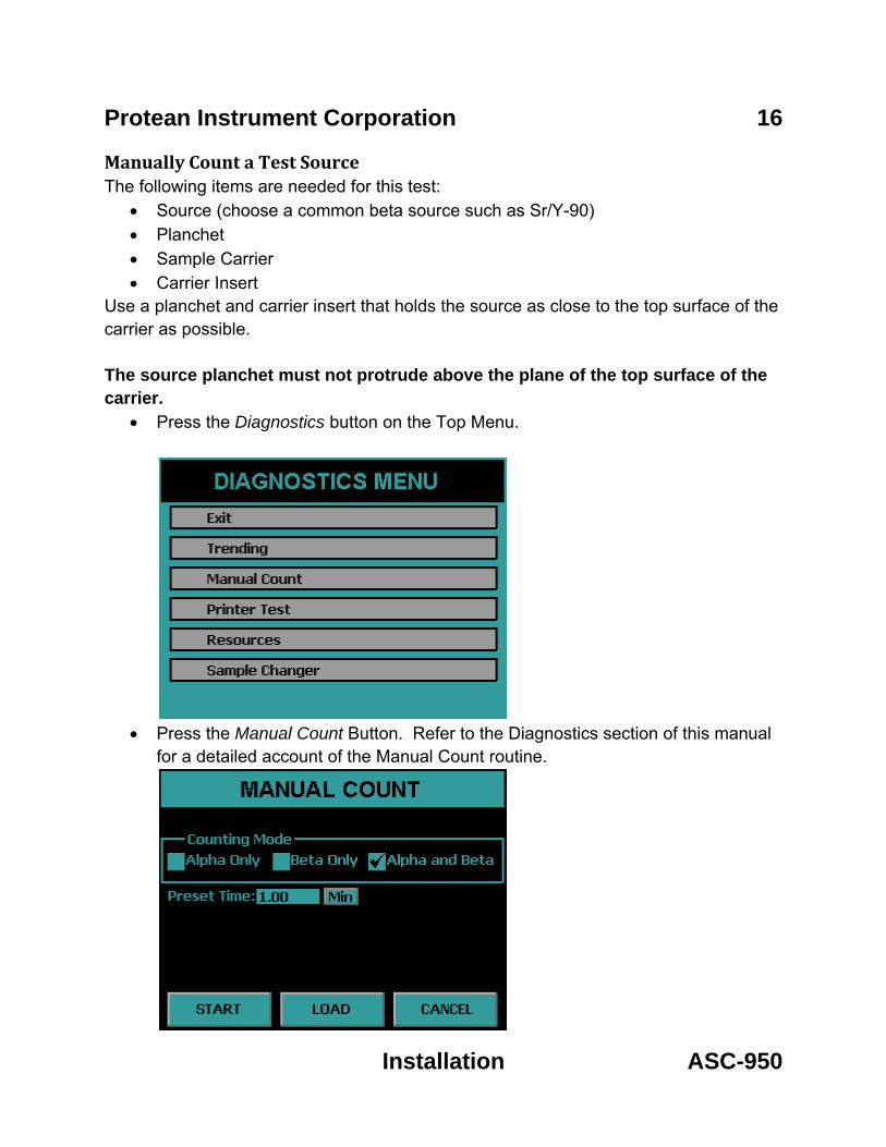
Protean Instrument Corporation 16
Installation ASC-950
Manually Count a Test Source The following items are needed for this test:
• Source (choose a common beta source such as Sr/Y-90) • Planchet • Sample Carrier • Carrier Insert
Use a planchet and carrier insert that holds the source as close to the top surface of the carrier as possible. The source planchet must not protrude above the plane of the top surface of the carrier.
• Press the Diagnostics button on the Top Menu.
• Press the Manual Count Button. Refer to the Diagnostics section of this manual
for a detailed account of the Manual Count routine.

Protean Instrument Corporation 17
Installation ASC-950
• Select Alpha and Beta counting mode and Preset Time of 1 min. • Press LOAD and the sample changer will pull out the sample arm so that a
sample can be placed on the arm. • Place the sample on the arm with the label facing the user. • Press START and the arm will pull in and the beta counts will begin to
accumulate.
When the preset time expires, accumulation will terminate and the display will remain static until you press the EXIT key. The Manual Count utility does not provide a printed output.
Try other test sources if they are available. Typical isotopes used to calibrate and test these instruments are Am-241, Th-230, Po-210, C-14, Tc-99, Cs-137 and Co-60. The first three listed are primarily alpha emitters. Most alpha emitters also decay with some percentage of betas and x-rays which will show in the beta channel of the display.
Put a clean blank planchet into the magazine and count for 10 minutes. Typical results for a 10 minute count at elevations of sea level to 1000 ft are: Alpha: 0.10 cpm
Beta: 52 cpm
It is normal for these counts to increase 25%-30% at elevations above 5000ft.
Use the manual count routine several times until you become familiar with the procedure.

Protean Instrument Corporation 18
Installation ASC-950
Print and Save Factory Plateau A detector plateau curve is generated on each ASC-950 during factory tests using Sr/Y-90 beta source. Alpha only and Alpha and Beta operating voltages have been selected from this plateau and all performance tests completed. The plateau data is retained in battery backed memory and available for your inspection. It is recommended that you print the plateau graph and data and maintain this document for future reference. Proceed as follows:
• From the Top Menu press the Setup button.
• Press the Calibration button.
• Press Plateau Determination • Press the PRINT button to print the plateau.
The plateau data which was collected at the factory should be resident in the instrument. The printed report should be saved for future reference. The Calibration section of this manual provides the details for producing your own plateau data.

Protean Instrument Corporation 19
Installation ASC-950
The plateau can be viewed on the console screen by pressing the VIEW button. From the Plateau Data View screen the alpha and beta operating points can be adjusted. Do Not Adjust these operating points at this time. Read through the Calibration section before making any adjustments.
Setting the Calendar/ Clock
If the calendar/clock information displayed on the Top Menu is incorrect you should now correct it.
• Press the Setup button from the Top Menu. • Press the Program button. • Press Set Calendar / Clock button.
Installations Without Attached Printer
If the ASC-950 is to be used without an attached printer in this case the plateau report specified in previous tests cannot be printed. In such installations save the plateau to the USB flash drive and copy the PLATEAU.CSV file from the USB flash drive to a safe location. Refer to the Export Data section.
Install the Stacks o Locate the left stack. Hold the stack with the brace structure pointed away from
you. If the longer of the two vertical sample guides is to your left, you are holding the left stack.
o Hold the stack over the left side of the sample changer with the brace structure pointing to the back of the instrument. Align the slots on the stack with the receptacles on the changer and slide it straight down and into place.
o Locate the lower retaining pin on the stack. This pin has a Teflon block attached. Grasp the block and pull the pin from the magazine.
o Locate the hole on the bridge beneath the right vertical guide of the magazine. The block attached to the pin has a retaining ball on one surface. With this surface pointed down, slide the pin completely in the hole.
o Repeat these steps to install the right stack.

Protean Instrument Corporation 20
Installation ASC-950
Load Carriers and Test the Sample Changer Now that the stacks are in place the user can fully test the sample changer. First locate the plastic plates shipped with the instrument. Locate the two white plates and the two plates marked as Skip. When loading plates onto the sample changer, orientate them such that you can read the ID label normally as it faces the user. Refer to the Sample Loading section of this manual for further information on the different types of plates.
o Place the two skip plates into the right stack. o Place one of the white plates on top of the two skip plates that are already in the
right stack. o Load as many of the Carrier plates in the left stack as you wish (at least ten). o Place the second white plate on top of the Carrier plates in the left stack.
Now the sample changer is ready for test.
From the Top Menu press the Diagnostics Button.
Press the Sample Changer button from the Diagnostics Menu.

Protean Instrument Corporation 21
Installation ASC-950
Press the AUTO ALIGN button to line up the changer. Press the ADVANCE, REVERSE, IN and OUT buttons and observe the changer status.
Read the Manual
The installation of the ASC-950 is now complete. The user should now have some feel for how to interact with the instrument. Only a few of the many and powerful functions have been used. The next task is to define the count routines from the dozens of options. Then determine calibration factors for each of the counting routines that are defined. Then finally samples will be ready to be counted.

Protean Instrument Corporation 22
Overview ASC-950
ASC950 Overview The ASC-950 has many unique features described in detail in subsequent sections of this manual. This section is provided to give you an overview of some of these features.
Menu Driven Operation The ASC-950 can be operated in a stand-alone mode or from a computer. In the stand-alone mode operation menus are displayed on a touch screen LCD display.
Pass Code Protection Pass code protection prevents unauthorized entry into the three main operating functions of the ASC-950:
• Count • Calibrate • Program
Pass code protection can be turned off as well. If enabled, up to five unique pass codes can be entered.
Count Function Routine Sample counting begins by pressing the Single Sample Count or Batch Count button from the Top Menu.
Calibration Function Calibration of the ASC-950 consists of setting the detector operating voltages and determining efficiency and background values for the count routines. In most cases control charts are also used to monitor instrument stability. Each counting routine uses separate background and efficiency calibration data. When a sample is counted, calibration data for the selected counting routine is used for calculating sample activity.
Control Charts Once calibration parameters are established, control checks are used to insure that the instrument is stable and the calibration is still valid. The ASC-950 maintains three control charts. The control chart data may also be the designated source for backgrounds and efficiency values.

Protean Instrument Corporation 23
Overview ASC-950
Program Function All operations of the instrument are initially defined using the program function through the Program button under the Setup Menu. This includes assignments of pass codes as well as defining the specifics of the counting routines and calibration methods. The ASC-950 allows up to twelve counting routines to be defined. The routines can be named for easy and meaningful identification. Count routine definitions include routine name, report model, presets, counting mode, counting cycles, background mode, efficiency mode, report units, routine data storage options, printing options, and report models.
Counting Parameters Each count routine has parameters that include the preset conditions and the count mode. The preset conditions include maximum time, minimum time, alpha counts and beta counts. Count mode is either alpha and beta or alpha-only. In the alpha and beta mode the alpha and beta counts are separated by a pulse height discriminator in a single preset time interval. In the alpha-only mode, the sample detector is operated at the alpha plateau voltage where the detector is insensitive to betas.
Background Parameters Background values can be selected using a calibration sample or manually entered. The preset time for a background count is specified as it may be different from the routine sample count time.
Efficiency Parameters Efficiency values can be entered from a calibration sample or manually entered.
Battery Backup The ASC-950 has a memory backup battery for the 24-hour clock/calendar, operating parameters, calibration files and sample data. The battery is a long life lithium type that has lasted in excess of eight years in the field. The low power consumption of the ASC-950 makes it an excellent candidate for a UPS (un-interruptible power supply).

Protean Instrument Corporation 24
Overview ASC-950
Printer Two printers are supported, a line printer with 9P ESC/P printer control language and a laser page printer with PCL5 control language. Host only based printers are not supported.
Computer Connectivity The rear panel of the ASC-950 contains a RS-232 port for connecting to external or remote computers. A software option is available from Protean Instrument Corporation to allow full control of the system from a PC. Simple data transfer is available to copy saved data resident on the instrument to a USB flash drive in CSV (comma separated value) format. The CSV output formats are described in detail in this manual.
International Power Entry The rear panel power entry module supports a universal IEC line cord attachment. The power entry module can be converted for operation at either 110VAC or 220VAC 50/60Hz.
Limited Warranty A twelve month limited warranty covers the ASC-950 with the exception of consumable items and accessories not manufactured by Protean Instrument Corp. In the latter case, the original manufacturer’s warranty will prevail. A maintenance program (both on-site and return-to-factory) is available and is highly recommended

Protean Instrument Corporation 25
Overview ASC-950
Sample Loading Throughout this manual many references are made to loading and unloading samples. Let’s begin with an orientation of key areas of the sample changer. As you face the front of the instrument there are five key areas.
• The left stack or magazine is the send stack. • The left bridge is between the slide and the left stack. The bar code reader is
mounted to this bridge and internally it contains a sensor for detecting an End plate.
• The slide is the center of the sample changer. • The right bridge is between the slide and the right stack. Internally it contains an
End plate sensor. • The right stack or magazine is a receive stack for samples as they are
processed.
The Five Types of Plates There are five types of plates supplied with each instrument. These plates look similar but are coded differently and are treated differently by the instrument. Each plate has a bar code label on its top and an identification label on the front edge. The plates are keyed such that there is only one way to load them in the stacks. The plates are molded using a conductive plastic to minimize static charge.
Locate and examine the sample carriers provided with your instrument. There should be either 50 (or 100 if this option was ordered) sample carriers with appropriate labels attached to the outside edge. Each of these carriers also has a bar code label on top through which the instrument identifies this specific carrier. Blank labels and custom bar codes are available if needed. The identification labels on the outside edge may also be replaced as needed.
There are also four other types of plates supplied with each instrument besides the sample carriers. These four types are called Routine plates, QC plates, Skip plates, and End plates.

Protean Instrument Corporation 26
Overview ASC-950
The following is a description of the various plates and their usage.
Sample Carrier Plates The sample carrier plates are designed to accept planchets up to 2 inches in diameter and up to 5/16 inches deep. Snap-in inserts are available in three depts. To match the dimensions of the planchets to be used. Standard depths are 1/8, 1/4, and 5/16 inches. Planchets and/or their contents should never be allowed to protrude above the top surface of the sample holder or a sample changer jam or ruptured window will occur. The depth of the planchet should be matched closely to the depth of the sample holder to minimize performance loss.
End Plates End plats designate the beginning and the end of a stack of samples. Two of these plates are included with each instrument. They are unique because of the reflective surface on the back edge of the plate. Sensors in the bridges detect these reflective surfaces. Detection of an End plate by the right bridge sensor indicates the start of a stack of samples or a restacked position. Detection of an End plate by the left bridge sensor indicates the end of a stack of samples.
Skip Plates Skip plates are used to fill the void between the left bridge and the slide so that samples can be removed from the stack.
Routine Plates The ASC-950 provides 12 unique counting routines. Define and use as many of these routines as needed. A routine tells the instrument how to count and report results for a batch of samples. Routine plates are used to tell the instrument which routine a batch of samples belongs to.
QC Plates Control charts track instrument performance on a day by day basis by counting control standards and comparing the results with historical results. The QC plates are a combination sample (control standard) and routine plate. Whenever they are encountered, the instrument knows which standard is carried and which control chart to update. There are three QC plates initially labeled “QC1” through “QC3”.

Protean Instrument Corporation 27
Overview ASC-950
Prepare Changer First place two Skip plates and then an End plate on the right stack. Next place a Routine plate and then Sample Carrier plates and finally place an End plate on the left stack. Press the Diagnostics button from the Top Menu and then press the Sample Changer button. Press the Reverse button until the Receive stack indicates Empty.
Selecting Sample Carriers Sample carriers are available in 1/8 inch, 1/4 inch, and 5/16 inch depths to accommodate planchets of the same depths. In general, the shallowest planchet and carrier should be used to achieve the highest counting efficiency. Since radiation from the sample follows the inverse square law, a very small change in distance from the detector has a very large effect on the intensity of the radiation seen by the detector. The limiting factor for close sample spacing is the thickness and uneven nature of the sample itself. Smear or swipe samples are often very “wavy”. Although the sample media is very thin, ripples in the media can make the vertical dimension of the sample quite large. The ultra-thin window on the detector can be torn easily from contact with the sample.

Protean Instrument Corporation 28
Overview ASC-950
The ASC950 Console The ASC-950 is controlled through a LCD touch screen display. Detailed descriptions of the screen menus are provided later in this manual.
The Rear Panel The rear panel contains AC power, USB printer interface, and a RS-485 connector. ASC-950 with the DP detector does not have a gas connector. The empty connector slot is reserved for future options. The power entry module on the right size of the rear panel contains the power on/off switch. Power supply fuses are located behind the removable plastic panel. Input power range can also be changed from the power connector.
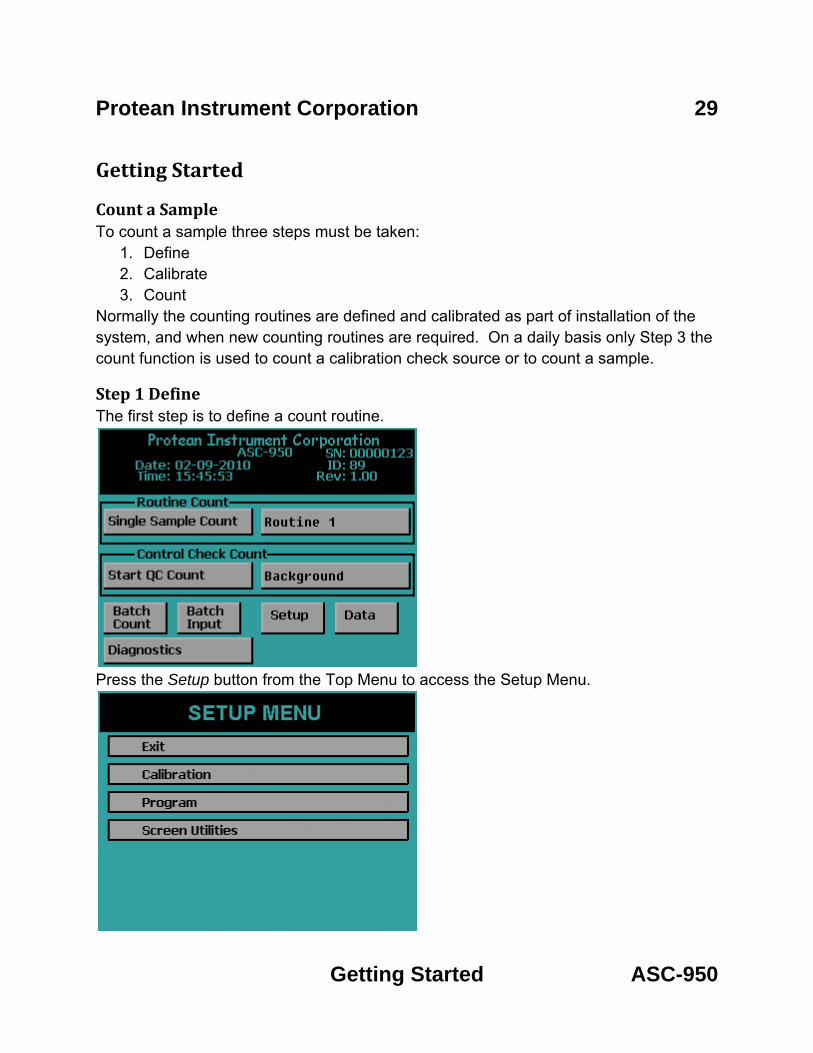
Protean Instrument Corporation 29
Getting Started ASC-950
Getting Started
Count a Sample To count a sample three steps must be taken:
1. Define 2. Calibrate 3. Count
Normally the counting routines are defined and calibrated as part of installation of the system, and when new counting routines are required. On a daily basis only Step 3 the count function is used to count a calibration check source or to count a sample.
Step 1 Define The first step is to define a count routine.
Press the Setup button from the Top Menu to access the Setup Menu.

Protean Instrument Corporation 30
Getting Started ASC-950
Press the Program button from the Setup Menu.
Define Counting Routines
When you press Define Counting Routines the next screen lists twelve routines to edit. Press the Routine 1 button to edit this routine.

Protean Instrument Corporation 31
Getting Started ASC-950
Routine Definition Page 1
Set the following parameters: Preset Time: 1 min Min Count Time: 0 min Repeats: 0 Counting Mode: Alpha and Beta Alpha Preset Counts: 0 Beta Preset Counts: 0 Results Storage: Internal 1 Page Per Sample: No Automatic Print: No Now press the NEXT button to go to the next routine definition page.

Protean Instrument Corporation 32
Getting Started ASC-950
Routine Definition Page 2
Select the Standard Report Model. Press the NEXT button to go to the next routine definition page.
Routine Definition Page 3
Set the following parameters: Input Units: None Activity: dpm Per: None Format: Normal Press NEXT button to go to the next routine definition page. Note during this setup pages four and five are skipped.

Protean Instrument Corporation 33
Getting Started ASC-950
Routine Definition Page 6
Set the following parameters: Background From: Local Manual Entry Efficiency From: Local Manual Entry Press the DONE button to complete the routine definition. Step 1 Define is now complete

Protean Instrument Corporation 34
Getting Started ASC-950
Step 2 Calibrate Now press EXIT until the Setup Menu is displayed.
Press the Calibration button on the Setup Menu.
Press the Manual Background/Efficiency Entry button from the Calibration Menu.

Protean Instrument Corporation 35
Getting Started ASC-950
Press the Routine 1 button to enter the calibration factors for Routine 1.
Enter the following calibration factors: Alpha Background: 0.10 cpm Beta Background :45.00 cpm Count Time: 10.00 min Alpha Efficiency: 0.20 Beta Efficiency: 0.45 Now press the EXIT button. Step 2 Calibration is now complete.

Protean Instrument Corporation 36
Getting Started ASC-950
Step 3 Single Sample Count Press the EXIT button until the Top Menu is displayed. The next step is to start a count with the routine that was defined and calibrated.
On the Top Menu confirm Routine 1 is selected and displayed. If Routine 1 is not selected then press the button to the right of the Single Sample Count button to display the Select Count Routine menu.
Press the Routine 1 button. The menu will revert back to the Top Menu. Confirm the Routine 1 count routine is selected. Press the Single Sample Count button from the Top Menu.

Protean Instrument Corporation 37
Getting Started ASC-950
The sample changer will now pull the slide out so that the user may insert a sample carrier. The next screen to appear is the data entry screen. This routine only requires or allows for a Sample ID. To change the Sample ID press the Sample ID field. Type the new Sample ID and press Enter.
Now press the CONTINUE button to insert the sample carrier and begin a sample count. The acquisition screen appears and displays the Sample ID and Routine Name. The first column lists the cpm. The second column provides the Activity shown in units defined in the count routine. In this case the report units are in dpm. The elapsed and remaining time as well as the current bias voltage is also displayed. Pressing the EXIT button before the count is finished aborts the count.

Protean Instrument Corporation 38
Getting Started ASC-950
Step 3 Batch Count Like the Step 3 Single Sample Count we will perform the sample count but instead utilize the sample changer. Press the EXIT button until the Top Menu is displayed.
Verify that the sample changer is in the restacked position (Receive Stack is empty). Now place the Routine 1 plate onto the bottom of the left stack. Next place a Sample Carrier 1 onto the left stack. Now place the End plate onto the left stack.
Press the Batch Input button.
Press the Routine 1 button to select the batch file for Routine 1.

Protean Instrument Corporation 39
Getting Started ASC-950
The Edit Batch Input screen will appear.
On this screen are three columns of Carrier #, Sample ID, Input. Since we are using Carrier 1 observe the assigned Sample ID for Carrier 1. If the user wishes to change the ID first make sure it is selected. A input is selected when it is highlighted in white. To select an input press the + and – buttons or simply press the input to select it. With the input selected press the ID button to edit the Sample ID. Enter the new ID and press the Enter button. Refer to the Batch Input Section of the manual for further information regarding editing batch files. Now press the EXIT button to display the Top Menu.
Now press the Batch Count button to start a stack directed count. The sample changer will begin to exercise and the barcode reader will scan the barcodes of the carriers. Once the Routine plate is scanned by the barcode reader the Routine 1 parameters are loaded. Next the Carrier 1 is scanned and the Sample ID from the batch file is loaded. Once the Carrier 1 is located under the detector the count will begin just like in the case of the Single Sample Count. Once the count is finished the sample changer will restack all of the carriers.

Protean Instrument Corporation 40
Getting Started ASC-950
Review The three most important functions in a counting instrument have just been performed, define a counting routine, calibrate a counting routine, and use a counting routine. With slight variations, the same three steps are taken for every sample counted. Normally the counting routines are defined and calibrated once or as required. The calibration step is performed on a periodic basis or when the calibration checks indicate it is needed. Calibration should always be checked after any maintenance on the detector, detector window, or detector amplifier. The next section covers all of the menus and a detailed discussion of all of the options that are available to the user

Protean Instrument Corporation 41
Program ASC-950
Batch Input
To access the Batch Input press the Batch Input button from the Top Menu. The Batch Input is where the Sample ID and Input are associated with a Carrier number for a Batch Count.
After pressing the Batch Input button the user is given the option of selecting a routine batch. There are twelve batch files that are available for editing each with 200 inputs.

Protean Instrument Corporation 42
Program ASC-950
Edit Batch Input After pressing one of the Routine batch files the following screen appears where the batch file may be viewed and edited.
PREV – Press this button to go to a previous page of inputs.
NEXT – Press this button to go to the next page of inputs.
PAGE – Press this button to go to a particular page of inputs.
Erase All – Press this button to erase a batch file and set to the default.
ID – Press this button to change the selected Sample ID.
Input – Press this button to change the selected Input.
+ - Press this button to select the next input.
- - Press this button to select the previous input.

Protean Instrument Corporation 43
Program ASC-950
Import Batch Pressing the IMPORT button from the Select Routine Batch screen gives the user the option to import a batch file that was created using the Companion Software. The batch files are saved onto a USB flash drive and then inserted into the USB port on the front of the instrument.
The user then selects a batch from the IMPORT SELECTED BATCH screen and presses the IMPORT button. The import will begin and once finished press the EXIT button to return to the Top Menu. The user can now view the imported batch file by pressing the Batch Input button from the Top Menu and selecting the appropriate Routine.

Protean Instrument Corporation 44
Program ASC-950
Setup Menu To access the Setup Menu press Setup from the Top Menu. Under the Setup Menu you have the Calibration button where the calibration functions are accessed. The Program button is where you program the count routines and instrument parameters. The Screen Utilities is where you define the beep volume, backlight brightness and calibrate the touch screen.
Screen Utilities To access the Screen Utilities Menu press the Screen Utilities button on the Setup Menu.
Calibrating the Touch Screen Sometimes it may be necessary to calibrate the touch screen when it becomes apparent that the area of the screen touched does not activate a button. To calibrate the touch screen press the Touch Calibrate button and follow the on screen instructions. If the Touch Calibrate button is accidentally pressed, wait for the built-in timeout to activate after five seconds and abort the operation.

Protean Instrument Corporation 45
Program ASC-950
Backlight Brightness Depending on the lighting of the room you may want to change the brightness of the display. To activate the Backlight Brightness Menu, press the Backlight Brightness button on the Screen Utilities Menu.
Press a location on the slider and the backlight brightness is updated. Press EXIT to save the changes
Beep Volume The sound volume of the system can be adjusted through the Beep Volume menu. To activate the Beep Volume menu press the Beep Volume button on the Screen Utilities menu.
Press a location on the slider and the instrument will beep with the current volume setting. Press EXIT to save the changes

Protean Instrument Corporation 46
Program ASC-950
Program Menu To access the Program Menu, select the Program button on the Setup Menu. The Program Menu is where the count routines and instrument parameters are defined. The settings can also be imported from a USB flash drive through the Program Menu.
Import Settings Instead of entering count routine settings and instrument parameters through the instrument menus the ASC-950 offers the option of importing these settings from a USB flash drive. This USB flash drive has a CONFIG.XML file located in a folder named with the serial number coordinating with the instrument to be updated. Select the Import Settings button on the Program Menu. Insert the USB flash drive and press IMPORT. See the companion software manual for information on how to create the CONFIG.XML file.

Protean Instrument Corporation 47
Program ASC-950
The next screen will display Finished to indicate that the settings have been imported successfully.
Instrument Parameters
The Edit Instrument Parameters Menu is accessed by pressing the Edit Instrument Parameters button from the Program Menu.

Protean Instrument Corporation 48
Program ASC-950
Auto Count Options Activate the Auto Count Options Menu by pressing the Auto Count Options button. The Auto Count Options are only valid for a Batch Count. They are not used for a Single Sample Count.
Query Options There are two query options available, Query when memory is full and when a QC Check fails.
If Query when memory is full is selected Yes then when Routine data exceeds 200 records then the stack directed count is stopped and the user is notified and has the option of continue and delete the oldest record or abort the count.
If Query when memory is full is selected No then when Routine data exceeds 200 records then the oldest record for this routine is automatically deleted and the count continues.
If Query when QC Check fails is selected Yes then when a QC Check is above 2 standard deviations then a recount is performed and if the check fails the second time the user is notified and has the option to continue or abort the count.
If Query when QC Check fails is selected No then when a QC Check is above 2 standard deviations then a recount is performed and if the check fails the count continues anyway.

Protean Instrument Corporation 49
Program ASC-950
Auto Start Options The Auto Start Options gives the user the capability to start a Batch count at a defined date and time. The Auto Start must be enabled by selecting Yes for Enable Auto Start and then the instrument must be on the Top Menu when the Auto Start Time and Date has been reached for the Batch count to begin.
To disable the Auto Start select No for Enable Auto Start.
To set the Auto Start Date and Time press each field. Note the time is in 24 hour format.
Cycle Recount The Cycle Recount tells the instrument the number of times to count a batch of samples. A Cycle Recount of 0 indicates only count a batch of samples once. A Cycle Recount of 1 indicates counting a batch of samples twice. To change the Cycle Recount press the field and enter a number and press Enter.
Cycle Delay The Cycle Delay tells the instrument the delay in minutes between a Cycle Recount.
Printer Activate the Printer Option Menu by pressing the Printer button. Press the button to select the printer driver. PCL5 is the driver for a printer with PCL5 command support. 9P ESC/P is the driver for a printer with 9P ESC/P command support. Press OK to save the setting.

Protean Instrument Corporation 50
Program ASC-950
High Voltage Control Activate the High Voltage Control Menu by selecting the High Voltage Control button on the Edit Instrument Parameters Menu. Press the button to enable and disable the High Voltage Control. When the High Voltage Control is enabled the voltage to the detector is 0V when not actively counting. When the High Voltage Control is disabled the voltage is still applied to the detector even when not counting. Press OK to save the setting.
Set Calendar/Clock Activate the Set Calendar/Clock Menu by selecting Set Calendar/Clock from the Edit Instrument Parameters Menu. Press each field to set the time and date. Press OK to save the settings.

Protean Instrument Corporation 51
Program ASC-950
Setup Pass Codes Activate the Setup Pass Codes by selecting Setup Pass Codes from the Edit Instrument Parameters Menu. Press the button to enable and disable pass code protection. Press USERS to access the User Information menu and setup User Name, Pass Code, and Permission Level. Press OK to save settings.
Press the Name field to change the user name. Press the Code field to change the pass code. Press the Level button to select the permission levels. Four permission levels can be selected:
• Super – This user is granted access to all features of the instrument. • Calib – This user is granted access to the Calibration Menu but not the Program
Menu. • Oper – This user cannot access the Calibration Menu or the Program Menu. • Void – This user is disabled and cannot log in.

Protean Instrument Corporation 52
Program ASC-950
Set Instrument ID Press the Set Instrument ID button from the Edit Instrument Parameters Menu to set the Instrument ID. Press the Instrument Name field to change the Instrument Name. Press the ID Number field to change the ID Number. Press OK to save the settings.
Define Counting Routines Press the Define Counting Routines button from the Program Menu. When you press Define Counting Routines the next screen lists twelve routines to edit. Press the routine button which you would like to edit.

Protean Instrument Corporation 53
Program ASC-950
Count Routine Definition Page 1
Naming the Count Routine The name which will appear in the menus for the Count, Data, and Calibration functions should be defined. This name will identify to the operator the type of samples to be counted using the defined routine. The name will also appear in the printed report.
Preset Time The preset time specifies one of several conditions which can terminate an acquisition. This field defines the maximum amount of time for sample analysis. For most applications, this will be the only preset condition that is used. Therefore this time equates to the amount of time each sample is analyzed. The length of time is usually selected to meet a desired sensitivity or minimum detectable activity requirement. How much time is needed should be determined by the worse case efficiency and background values. The preset time is set by pressing the Preset Time field and entering the time. The minimum preset time must be greater than 0.01 minute.

Protean Instrument Corporation 54
Program ASC-950
Minimum Count Time The minimum count time should be used only if the user desires to specify preset conditions other than just preset time such as count presets. Otherwise a minimum count time of zero is acceptable. The minimum count time is related to the preset conditions. The preset time is only one condition that may be specified to terminate an acquisition. For instance, a preset time of one minute could be specified along with a count preset of 10,000 counts. This would cause an acquisition to terminate when either 10,000 counts are accumulated or when the elapsed time reaches one minute – whichever comes first. The Minimum Count Time field allows the user to specify a minimum time to analyze the sample, even if the preset conditions have been met. For instance, assume a minimum count time of one-half minute was specified along with the previous preset conditions. In this example, all samples would be analyzed for a minimum of one-half minute. After the minimum time has elapsed, the system will monitor the number of accumulated counts. Once 10,000 counts are accumulated, the acquisition will be terminated. However, if the elapsed time reaches one minute, then the acquisition will be terminated regardless of the number of counts accumulated. The Minimum Count Time is set by pressing the Minimum Count Time field and entering the time. A Minimum Count Time of zero disables this feature.
Repeats It is sometimes desirable to count a sample for a series of short intervals rather than for a single long interval. This method allows determination of decay times or possible interference from a nuclide with a short half life. The ASC-950 provides for a sample to be recounted up to 99 times. The Repeats is set by pressing the Repeats field and entering the value. A repeat value of 0 disables this feature.
Preset Counts Preset Alpha and Preset Beta Counts can be entered which will terminate the acquisition if the entered value is reached. If a minimum count time is entered then the Preset Count values are not evaluated until after the minimum count time has elapsed.

Protean Instrument Corporation 55
Program ASC-950
Specifying the Counting Mode The ASC-950 provides two different methods of alpha/beta activity determination, Alpha Only and Alpha and Beta. These methods dictate how the instrument determines whether a detected event was the result of an alpha particle or a beta particle entering the sample detector. Alpha Only – In the Alpha Only mode the voltage on the detector is lowered to the point where only an alpha particle possesses adequate ionizing energy to produce a detectable pulse. No beta information will appear on the resulting report. Alpha and Beta – This mode operates the detector at the beta operating voltage where both alpha and beta events can be detected. These events are characterized as either alpha or beta depending on the pulse height of the associated event. The resulting report will show both alpha and beta count information.
Results Storage This field allows you to choose where the count routine data is stored. If Internal is selected the count routine data is stored in internal memory only. If external is selected, the count routine data is stored both in internal memory and directly to the USB flash drive. There is a limit of 200 records for each routine if storing to internal memory. If external is selected, the count routine data is stored in internal memory and directly to the USB flash drive.
1 Page per Sample This option is only valid when using the PCL5 driver (page printer). When you select Yes only one record per page is printed. Otherwise the page is not printed until the page is full. When using a line printer (9P ESC/P driver) this option is ignored. To enable or disable the 1 Page per Sample toggle the Yes/No button.
Automatic Print This field controls whether or not data is automatically printed after each acquisition. To enable or disable the automatic printing toggle the Yes/No button.
Completing Count Routine Definition Page 1 Once all settings are properly adjusted, press the NEXT button to proceed to the Second Count Routine Definition Page. If no further settings are required press the DONE button.

Protean Instrument Corporation 56
Program ASC-950
Count Routine Definition Page 2 The second Routine Definition page allows you to select the report model to use with the count routine. The report model selection will define the appearance of the final printed report and the calculations to be performed after a sample is counted. The available choices are described below.
Standard Report – This report shows the calibration factors along with the Sample ID, Alpha and Beta cpm, and Activity in the report units specified in the routine definition. Standard Report (High Alpha-Only Recount) – This report is the same as the Standard Report except that an alpha limit must be specified. If that limit is reached then a recount in Alpha-Only Counting Mode is performed. Standard Report (Radon Subtraction) – This report is the same as the Standard Report except that Activity contributed by Radon is subtracted. Flag Concentration – This report is the same as the Standard Report except that alpha and beta warning limits can be set and indicated on the report. Flag Concentration (High Alpha-Only Recount) – This report is the same as the Flag Concentration except that an alpha limit must be specified. If that limit is reached then a recount in Alpha-Only Counting Mode is performed. Flag Concentration (Radon Subtraction) – This report is the same as the Flag Concentration except that Activity contributed by Radon is subtracted. Note: Report Models Standard Report (Radon Subtraction) and Flag Concentration (Radon Subtraction) require the counting mode to be Alpha and Beta.

Protean Instrument Corporation 57
Program ASC-950
Standard Report
An example of a Standard Report can be seen below.

Protean Instrument Corporation 58
Program ASC-950
Flag Concentration
An example of a Flag Concentration report can be seen below.

Protean Instrument Corporation 59
Program ASC-950
Standard Report (High Alpha-Only Recount)
An example of a Standard Report (High Alpha-Only Recount) can be seen below.

Protean Instrument Corporation 60
Program ASC-950
Flag Concentration (High Alpha-Only Recount)
An example of a Flag Concentration (High Alpha-Only Recount) can be seen below.

Protean Instrument Corporation 61
Program ASC-950
Count Routine Definition Page 3
Count routine definition page 3 allows for the selection of units for the reported results.
Input Units Select the units for the volume of your sample or area or select None if you do not have an input. Report Units Select the units for which you want to display the Activity. Format Toggle the button from Normal to Scientific Notation for the Activity Format.

Protean Instrument Corporation 62
Program ASC-950
Count Routine Definition Page 4 This page is not displayed if you have input units of None. This page allows for the setting of a default input.
Default Input This field is the default input volume or area depending on the input units from the previous page. This is useful if you are not using batches and your input volume or area is the same for each sample. Therefore, the user will not have to type in the input for each count. If the user is using batches and a input in the batch file is 0 then this Default Input is used.

Protean Instrument Corporation 63
Program ASC-950
Count Routine Definition Page 5 This page will appear only for the following report Models:
• Standard Report (High Alpha-Only Recount) • Flag Concentration • Flag Concentration (High Alpha-Only Recount) • Flag Concentration (Radon Subtraction)
This page allows for the ability to set action limits for the alpha only recount and flag concentration reports.
Action Limits In environments where many samples are counted within a single shift, it may not be possible to closely examine the analysis results for every single sample. The ASC-950 can provide a warning on the printed report for samples with excessively high activities. The alpha action levels may also be used to automatically mark samples for recounting. The ASC-950 provides separate limits for the alpha and beta channels while in the “Alpha and Beta” counting mode. If the counting mode is “Alpha Only” only the alpha action limits are used and the beta action limits are ignored. The action limits are entered in scientific notation.

Protean Instrument Corporation 64
Program ASC-950
Count Routine Definition Page 6
Count Routine Definition page 6 provides the ability to set the source for the background and efficiency values.
Background From There are two choices to choose from, Local Manual Entry and External Entry. Local Manual Entry – As its name implies, manual entry relies upon the calibration technician to determine and enter the background values. These values may be obtained through the use of the ASC-950’s Trending function, or by counting a background reference sample. External Entry – This option is programmed through the USB key. There are three possible options for the selection which are described below.
• Manual Entry – Background values are imported from the USB key.
• Last Control Chart Check – This method requires that a control chart be in use for tracking backgrounds. The appropriate values are extracted from the last entry in the control chart. Many users believe that this method gives the most accurate picture of the “current” background count rate because it uses the latest available data. However unless the control check is performed for a long period of time (typically 100 minutes or greater), the precision of the background count rate obtained by this method may not be acceptable.

Protean Instrument Corporation 65
Program ASC-950
• Control Limits Mean – Background values are determined by calculating the
mean of all control limit data points. The error in this rate is determined by considering all of the limits data points to be a single acquisition. For example, if the limits data contains forty points at 60 minutes each, the effective count time will be 2400 minutes. This method provides the highest possible precision.
Efficiency From There are two choices to choose from, Local Manual Entry and External Entry. Local Manual Entry -- As its name implies, manual entry relies upon the calibration technician to determine and enter the efficiency values. External Entry – This option is programmed through the USB key. There are three possible options for the selection which are described below.
• Manual Entry – Efficiency values are imported from the USB key.
• Last Control Chart Check – This method requires that control charts for alpha and beta be in use for tracking efficiency. The appropriate values are extracted from the last entry in each control chart. Even though this method is not highly recommended for obtaining background calibrations, it is very useful for obtaining efficiency values. Counting efficiency tends to vary slightly with barometric pressure, temperature, and humidity. This method for obtaining calibration data will provide the most up-to-date efficiency values available.
• Control Limits Mean—Efficiency values are determined by calculating the mean of all control limit data points.

Protean Instrument Corporation 66
Calibration ASC-950
Calibration Menu The Calibration Menu is accessed by pressing the Calibration button from the Setup Menu. The Calibration Menu is where a plateau can be generated to set operating voltages. Background and efficiency values are entered from the Calibration Menu. Control chart limits are set from this menu as well.

Protean Instrument Corporation 67
Calibration ASC-950
Plateau Determination The Plateau Determination screen is accessed from the Calibration Menu. This screen allows the user to acquire, view, and print the plateau.
Plateau Name – This field allows the user to provide a name for the acquired plateau.
Preset Time – This field allows the amount of time for each acquisition to be specified.
VIEW – This button allows the current plateau to be examined on the display. The counting operating bias is also set from the plateau view.
PRINT – This button prints the current plateau.
LOAD – This button moves the Slide in and out so that the user can place the sample on the Slide.
ACQUIRE – This button causes a plateau to be generated using the current plateau parameters.
CANCEL – This button exits the Plateau Determination screen and goes back to the Calibration Menu.

Protean Instrument Corporation 68
Calibration ASC-950
Acquiring a Plateau The plateau is acquired by specifying a Plateau Name and Preset Time. Once the desired sample is loaded, the ACQUIRE button is used to start the plateau data collection.
The Plateau Acquisition screen is shown below. The first column shows the gross and guard counts. The second column shows the gross and guard cpm. The elapsed and remaining times are updated as well as the current operating voltage. A progress bar is provided to display the status of the current step. The current step number and remaining step total are displayed below the status bar. Pressing EXIT before the acquisition is complete aborts the plateau acquisition.

Protean Instrument Corporation 69
Calibration ASC-950
Viewing a Plateau Pressing VIEW on the Plateau Determination screen displays the screen below.
The ASC-950 will automatically generate a plateau curve. Two cursors are displayed. The blue cursor is the alpha-only operating bias. The green cursor is the alpha and beta operating bias. The % slope per 100 volts is displayed for the active cursor. Note the first two points and last two points for the slope are not displayed because the slope is calculated using a five point smoothing technique for accurate slope determination. Two points before and two points after the cursor position are used in the slope calculation. To toggle the active cursor press the button beside “Cursor.” The + and – buttons allow fine cursor control. Pressing the vertical blue bars causes the cursor to snap to that line. The slope and counts are displayed for the current cursor position. The current alpha-only operating bias is displayed beside “Alpha Volts” and the alpha and beta operating bias is displayed beside “Beta Volts.”
To select the alpha-only voltage, toggle the cursor to Alpha and then move the cursor to the voltage the user wishes to set the alpha-only bias setting. It is recommended to set the alpha-only bias to 705. To set the alpha and beta operating point, toggle the cursor to Beta and then observe the slope. Protean Instrument Corporation recommends that the first point below 5% slope be used for the alpha and beta operating voltage. Pressing the EXIT button saves the operating bias settings and returns to the Plateau Determination screen.
When using the plateau function it is critically important to use a point source. Using a distributed source will cause a degraded plateau curve to be generated, leading to a bias set point that is far from optimum. Protean Instrument Corporation encourages users to become familiar with ANSI Standard 42.25-1997 “Calibration and Usage of Alpha/Beta Proportional Counters.”

Protean Instrument Corporation 70
Calibration ASC-950
Manual Background/Efficiency Entry Pressing the Manual Background/Efficiency Entry button from the Calibration Menu displays the following screen.
Press the button corresponding to the routine that you wish to add background and efficiency values. Note that efficiency values are entered as factors and not as percentages. Press EXIT to return to the Calibration Menu. Pressing a routine button displays the following screen.

Protean Instrument Corporation 71
Calibration ASC-950
Pressing the Alpha Efficiency field or Beta Efficiency field displays the following screen. From this screen the user can either enter the efficiency factor and press the Enter button or acquire the efficiency by pressing the Acquire Eff. button.
Pressing the Acquire Eff. button displays the following screen.
Select the Count Mode, Preset Time, Source DPM, Halflife, and Calibration Date of the source. Press the LOAD button to insert the source and press the START button to acquire the efficiency. Once the count finishes press the Exit button and the efficiency factor that was acquired will now be entered.
Press EXIT to save the changes and return to the routine selection screen.

Protean Instrument Corporation 72
Calibration ASC-950
Radon Efficiency Factors Pressing the Radon Calibration Factors button from the Calibration Menu displays the following screen.
Press the button corresponding to the routine you wish to edit radon factor values. Press EXIT to return to the Calibration Menu.
Press EXIT to return to the routine selection screen.

Protean Instrument Corporation 73
Calibration ASC-950
Import Control Chart Limits Pressing the Import Control Chart Limits button from the Calibration Menu displays the following screen.
Insert a USB flash drive into the front USB port and then press the IMPORT button. The control chart limits which are set on the USB flash drive from the companion software will be imported. The imported limits can be viewed from the Data Menu.
Note only the limits for the control chart are set with the Import Control Chart Limits function. The user must use the Import Settings under the Program Menu if the user wishes to change control chart settings other than the limits.
Press the EXIT button to return to the Calibration Menu.
Print All Calibration Info Pressing the Print All Calibration Info button prints the current plateau and calibration information for each routine.

Protean Instrument Corporation 74
Calibration ASC-950
Control Charts Three control charts can be used with the ASC-950, one chart for tracking alpha and beta background and two charts for tracking alpha and beta efficiency. The specifics of the control chart are defined in the companion software. Control chart limits are established through the companion software and are sent to the USB flash drive. Control chart limits are then imported through the calibration function. Finally, control checks are performed by loading the check source and starting the count from the Top Menu. The implementation of a control chart requires that limits be established before routine checks are made. The control limits are established by randomly counting the appropriate standard over a period of several days using the control check acquisition routine. The ASC-950 stores a maximum of forty check measurements for each control chart. It is recommended that no fewer than ten limit points be acquired before beginning routine control checks. If more than forty check points are acquired, the oldest point is discarded to make room for the next point. Once at least ten checks are acquired then the limits may be sent to the companion software by going to the DATA MENU and then selecting Export Data. Select QC Checks and press EXPORT. The checks data is now on the USB flash drive ready to upload to the companion software to establish the Control Chart Limits. The companion software then sends Control Limits back to the USB flash drive. The next step is to import the limits that are on the USB flash drive using the Calibration function. The mean and associated standard deviations established by the control chart limits now become the bench mark by which future performance (the control checks) are judged. The control checks will be plotted on the same scale as the limits data. The two sigma lines around the mean will be considered warning levels. The three sigma lines will be considered control limits. If the instrument is performing in a stable manner, the control checks should follow a statistically predictable distribution about the control limits mean. It should not be expected that the instrument will continue counting forever in a perfectly stable and predictable manner. Aging of detectors and electronics contribute to performance changes. Control charts should be reestablished at least on an annual basis. Any time components such as detectors or electronics are replaced, adjusted or serviced, the control charts should be reinitialized.

Protean Instrument Corporation 75
Calibration ASC-950
Manually Acquiring Control Checks
From the Top Menu press the button beside Start QC Count to select the control chart. The screen below will be displayed.
Select the control chart to count by pressing the appropriate button. The control chart that was selected will now appear on the Top Menu.
Protean Instrument Corporation 76
Calibration ASC-950
Press the Start QC Count button from the Top Menu and the following screen will appear.
Press the appropriate button for the number of repeats. Pressing the button 0 only one control check count will be performed. Pressing the button 1 two control check counts will be performed. Pressing EXIT returns to the Top Menu.
Acquiring Control Checks The control checks may also be acquired using the automatic sample changer. Place the appropriate QC plate on the sample changer and press the Batch Count button from the Top Menu to acquire the control checks. The sample carrier labeled QC 1 selects the background control chart routine. The sample carrier labeled QC 2 selects the alpha control chart routine. The sample carrier labeled QC 3 selects the beta control chart routine.
Protean Instrument Corporation 77
Data ASC-950
Data Menu
The Data Menu provides a means of examining, editing, printing and exporting data collected. This data is divided into two main categories, count routine data and control check data. Control check points that were acquired in error may also be deleted using the Data Menu.

Protean Instrument Corporation 78
Data ASC-950
View Count Routine Data Pressing the View Count Routine Data button from the Data Menu displays the following screen. The data is organized under each count routine. For instance pressing Routine 1 displays all of the data that was acquired using count routine 1.

Protean Instrument Corporation 79
Data ASC-950
Routine Data View
After selecting a count routine the following screen is displayed.
The Routine Name is displayed at the top. The + and – buttons are used to select records. A record can also be selected by simply touching it. The currently selected record is highlighted in white. The PREV and NEXT buttons move to the previous and next page of data. The display option buttons at the top of the four columns can be pressed to change the information displayed in that column. See the Display Option section below for further explanation. When the Select button is pressed the current highlighted record is displayed in a full record view. See the Full Record View section below for further explanation. The PAGE button goes to the PAGE SELECTION screen. See the Page Selection section below for further explanation.

Protean Instrument Corporation 80
Data ASC-950
Display Option The following screen is displayed when pressing one of the four display option buttons on the routine data view screen. Press one of the buttons and the column on the routine data view is updated to reflect the new heading.
Full Record View The following screen is displayed when pressing the Select button on the Routine Data View screen. Pressing the PRINT button prints the displayed record on a single page.

Protean Instrument Corporation 81
Data ASC-950
Page Selection The following screen is displayed when pressing the PAGE button on the routine data view screen. Pressing the PRINT button prints all data records for this routine. Twenty page buttons each with the record range for that page on the button. Simply press the button coresponding to the record range desired. This feature prevents multiple presses of the PREV and NEXT buttons to go from the beginning to the end of the record set.

Protean Instrument Corporation 82
Data ASC-950
Delete Count Routine Data The following screen appears if you press Delete Count Routine Data on the Data Menu screen. To delete the routine data press the routine buttons to select the desired count routines. The buttons will turn red. To unselect, press the button again and the button will turn back to grey. Once you have selected which routine data to delete, press the DELETE SELECTED button and all of the count routine data for the selected routines will be removed. The screen below shows Routine 2 and Routine 4 data ready to be deleted.

Protean Instrument Corporation 83
Data ASC-950
View Control Check Data
Background Control Chart The background control chart settings are defined using the companion software. However once you have imported the settings through the Program function then the current settings can be viewed. To view the background control chart settings from the Top Menu press Data. The next screen will be the Data Menu. Press View Control Check Data.
Now select a control chart to view. The names of the control charts are defined by the companion software. However the top button will always be the background control chart. The middle button will always be the alpha control chart. The bottom button will always be the beta control chart. Now press the top button (Background) to view the background control chart.

Protean Instrument Corporation 84
Data ASC-950
The top left button allows you to toggle between viewing the alpha and beta background. The + and – buttons allow fine control of the cursor to look at various points. The vertical green bar is your cursor. Pressing the vertical blue bars causes the cursor to snap to that line if there are points at that location otherwise the button presses are ignored. This feature eliminates the need for multiple + and – button presses to get to the beginning or end of the data set. Below the + and – buttons are data for the current cursor position. Pressing the DELETE button deletes the point at the cursor location.
Pressing the SETTINGS button allows viewing of the control chart settings.
The first line is the control chart name. The second line is the counting mode used during acquisition. The third line is the amount of time for each acquisition. The date range is the date of the first limit point to the date of the last limit point that is used in the Alpha and Beta Mean and Standard Deviation values which are shown on the last four lines.

Protean Instrument Corporation 85
Data ASC-950
Alpha Control Chart To view the alpha control chart settings from the Top Menu press Data. The next screen will be the Data Menu. Press View Control Check Data.
Now select a control chart to view. The names of the control charts are defined by the companion software. However the top button will always be the background control chart. The middle button will always be the alpha control chart. The bottom button will always be the beta control chart. Now press the middle button (Alpha) to view the alpha control chart.

Protean Instrument Corporation 86
Data ASC-950
The top left button allows you to toggle between viewing the alpha cpm and efficiency. The + and – buttons allow fine control of the cursor (the vertical green bar) to look at various points. Pressing the vertical blue bars causes the cursor to snap to that line if there are points at that location, otherwise the button presses are ignored. This feature eliminates the need for multiple + and – button presses to get to the beginning or end of the data set. Below the + and – buttons are data for the current cursor position. Pressing the DELETE button deletes the point at the cursor location.
Pressing the SETTINGS button allows viewing of the control chart settings.
The first line is the control chart name. The second line is the counting mode used during acquisition. The third line is the amount of time for each acquisition. The date range is the date of the first limit point to the date of the last limit point that is used in the Alpha Mean and Standard Deviation values which are shown on the next four lines. The last three lines show the check source information.

Protean Instrument Corporation 87
Data ASC-950
Beta Control Chart To view the beta control chart settings from the Top Menu press Data. The next screen will be the Data Menu. Press View Control Check Data.
Now select a control chart to view. The names of the control charts are defined by the companion software. However the top button will always be the background control chart. The middle button will always be the alpha control chart. The bottom button will be the beta control chart. Now press the bottom button (Beta) to view the beta control chart.

Protean Instrument Corporation 88
Data ASC-950
The top left button allows you to toggle between viewing the beta cpm and efficiency. The + and – buttons allow fine control of the cursor (vertical green bar) to look at various points. Pressing the vertical blue bars causes the cursor to snap to that line if there are points at that location, otherwise the button presses are ignored. This feature eliminates the need for multiple + and – button presses to get to the beginning or end of the data set. Below the + and – buttons are data for the current cursor position. Pressing the DELETE button deletes the point at the cursor location.
Pressing the SETTINGS button allows viewing of the control chart settings.
The first line is the control chart name. The second line is the counting mode used during acquisition. The third line is the amount of time for each acquisition. The date range is the date of the first limit point to the date of the last limit point that is used in the Beta Mean and Standard Deviation values which are shown on the next four lines. The last three lines show the check source information.

Protean Instrument Corporation 89
Data ASC-950
Export Data The following screen appears if you press Export Data from the Data Menu. To export data to the USB flash drive insert a USB flash drive into the front USB port and press the blue box beside the data you wish to export. Selected data will have a check in the box. To deselect press the box again and the check will be removed. Press the EXPORT button to begin the export of the selected data.

Protean Instrument Corporation 90
Diagnostics ASC-950
Once data export begins the serial number directory is checked to verify that the selected data for export does not overwrite previous data. As displayed on the screen below, a warning message showing the Alpha Control Check data already exists on the USB flash drive. If you wish to overwrite the data press OVERWRITE and the Alpha Control Check data that was on the USB flash drive is overwritten. If you wish to keep the Alpha Control Check data press EXIT, and remove the USB flash drive and copy the data to another source or insert a new USB flash drive. It is recommended to delete any previous exported data under the serial number directory on the USB flash drive before exporting new data so that you avoid the data overwrite warning.
When the data export is successfully completed, “Finished!” will be displayed, as seen on the screen below.
Protean Instrument Corporation 91
Diagnostics ASC-950
Diagnostics Menu The Diagnostics Menu is reached by pressing Diagnostics from the Top Menu. The Diagnostics Menu provides access to a group of diagnostic routines for basic data collection and peripheral testing.
Trending – allows sequential counting of a sample or standard to verify proper performance of the electronics and/or detector. A graphical presentation of the sequentially collected data plotted about the mean permits short term trends to be conveniently identified. Manual Count – provides a no frills accumulation routine useful for adjustment of amplifier gains and discriminator levels. Printer Test – used to verify compatibility of printers with the graphics commands utilized when printing. Resources – displays the available count record storage for each routine. Sample Changer – Used to adjust the alignment of the barcode reader, clearing a sample carrier jam, and verifying the operation of the sample changer and associated sensors.

Protean Instrument Corporation 92
Diagnostics ASC-950
Trending There are occasions when it is desirable to collect a series of counts on a standard or background blank. If erratic counting is suspected, or some short term drifting trend needs checking, the Trending routine provides a convenient multiple count testing format. Trending provides the collection of data, calculation of mean and standard deviation, calculation of chi-squared values, and generation of reports in graphic and text formats.

Protean Instrument Corporation 93
Diagnostics ASC-950
The Trending Screen The Data Trending routine is accessed from the Diagnostics Menu. This routine displays the screen below which allows the user to acquire, view, and print the trending data.
Counting Mode – Select between “Alpha Only”, “Beta Only”, and “Alpha and Beta” by pressing the blue box to select which counting mode new trending data may be acquired. Preset Time – This field allows the amount of time for each acquisition to be specified for new trending data. Repeats – This field specifies the number of times to analyze a sample when new trending data is acquired. VIEW – This button allows current trending data to be examined on the display. PRINT – This button prints current trending data. LOAD – This button moves the Slide in and out so that the user can place the sample on the Slide. ACQUIRE – This button causes the sample to be analyzed using the current trending parameters. CANCEL – This button exits the trending routine and goes back to the Diagnostic Menu.

Protean Instrument Corporation 94
Diagnostics ASC-950
Acquiring Trending Data Trending data is acquired by using the Counting Mode, Preset Time , and Repeats fields to specify how the new trending data is to be acquired. Once the desired sample is loaded, the ACQUIRE button is used to start the trending data collection. The detector bias will be applied and a short delay will occur while the bias voltage stabilizes. Finally, the analysis will commence and the display described below will be shown. The trending acquisition screen is shown below. The first column shows the raw counts for Alpha, Beta, Guard, and Pseudo-Coincidence. The second column shows the raw cpm for Alpha, Beta, Guard and Pseudo-Coincidence. The elapsed and remaining times are updated as well as the current operating voltage. A progress bar is provided so that a quick glance of the screen is all that is required to view the progress of the current step. Below the progress bar, the current step and remaining number of steps are displayed. A VIEW button is provided to view the trend graph during the acquisition, however at least one point must have been acquired before viewing the graph. Otherwise the button press is ignored. The trend graph is not updated during an acquisition so the user must press EXIT while on the trend graph screen to view the current count progress. Pressing EXIT on the trending acquisition screen before the acquisition is complete aborts the trend acquisition.

Protean Instrument Corporation 95
Diagnostics ASC-950
The screen below indicates that all five trend steps have been completed and that the acquisition is complete. It is now safe to press EXIT without aborting the trend acquisition.
Pressing VIEW will display the trending graph screen seen below. The top left button allows the user to toggle between Alpha, Beta, Guard, and PCE data. The button that is adjacent to the top left button allows the user to view the data in units of counts or CPM. The – and + buttons allows fine cursor (vertical green bar)control. Pressing the vertical blue bars causes the cursor to snap to that line. The mean, standard deviation and Chi-Square values are calculated and displayed. The counts, CPM, Date, Time and whether the point is within two and three standard deviations are indicated at the cursor location. Forty points are displayed on each screen. Use the PREV and NEXT buttons to go to the previous forty points or next forty points.
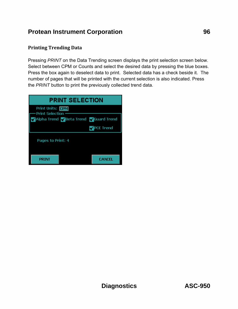
Protean Instrument Corporation 96
Diagnostics ASC-950
Printing Trending Data Pressing PRINT on the Data Trending screen displays the print selection screen below. Select between CPM or Counts and select the desired data by pressing the blue boxes. Press the box again to deselect data to print. Selected data has a check beside it. The number of pages that will be printed with the current selection is also indicated. Press the PRINT button to print the previously collected trend data.

Protean Instrument Corporation 97
Diagnostics ASC-950
Manual Count
A no frills count routine is provided for quick checks. This routine is useful if adjustments are necessary for discriminators. There is no report generated from the Manual Count routine other than the data displayed on the screen. The Manual Count Screen This routine displays a screen which allows the user to set count parameters. Selections are made by pressing the blue boxes. The screen contains the following controls: Counting Mode – Select the counting mode which new data may be acquired by pressing the blue box beside the desired mode. Preset Time – This field allows the amount of time for each acquisition to be specified for new data. START – This button causes the sample to be analyzed using the specified counting parameters. LOAD – This button moves the Slide in and out so that the user can place the sample on the Slide. CANCEL – This button exits the Manual Count routine and goes back to the Diagnostics Menu.

Protean Instrument Corporation 98
Diagnostics ASC-950
The Data Display Once the Start button is selected the detector bias voltage is then applied. A short delay will occur in waiting for the bias to stabilize. Once the bias supply is stable, counting will commence. Count data is displayed during and after data acquisition on a screen similar to the one shown below.
When making certain hardware adjustments, it is desirable to see the results of these adjustments immediately. This feedback enables “tweaking” the adjustment until the desired results are obtained. This requires clearing the display so that the adjustment effects can be viewed. Pressing the CLEAR button will clear the counters and reset the elapsed clock Pressing EXIT during the acquisition will abort the count.

Protean Instrument Corporation 99
Diagnostics ASC-950
Printer Test
The Printer Test routine sends out five lines of alphanumeric data and one line of graphics to insure compatibility between the instrument and the printer. This is also helpful when setting up printers which have their own configuration switches. The test page will appear slightly different depending if it was printed with a line printer or laser printer. Below are examples of what the test page should look like for each printer type. Epson 9P/ESC P
HP PCL5

Protean Instrument Corporation 100
Export Format ASC-950
Guarding Against Obsolescence Computer technology and software is probably the most rapidly changing industry on the planet. Whatever you are using today will be obsolete in a few months. Our task is to integrate an instrument designed to last a decade into an environment which changes daily and guard against obsolescence. There are few lasting standards to aid in this quest, especially in software. If you wonder why we have invested so much effort in the stand-alone features of the ASC-950, this should be a clue. The methods and procedures built into the ASC-950 are not likely to change during its useful life. In five years, however, you will probably be on your third or fourth computer and several generations of software upgrades. While you struggle through the new spread sheet help files to learn new syntax, macro languages, etc.; you have the comfort of knowing that you will not have to spend weeks rewriting operating procedures for your old alpha/beta counter. You also have the comfort of knowing that once you master your new tools, you can use them to create spectacular reports from the same old data imported from the same old alpha/beta counter. We rely on three elements to provide this guard against obsolescence. The first is our commitment to keep the structure of the ASC-950 data records upwards compatible. The second is a reliance on the computer industry to include a USB port on all new computers. The third element expects that every new spread sheet package, data base manager, etc., will be able to read and parse comma separated field text record structure. These are very safe bets and the foundation for our computer connectivity philosophy. In the following pages we will describe the details of the data saved on the USB flash drive.

Protean Instrument Corporation 101
Export Format ASC-950
Plateau Data CSV File Format PLATEAU.CSV Record 1 Header 1
Field Name 1 DESCRIPTOR 2 ID_NAME 3 ID_NUMBER 4 OPERATOR 5 PLATEAU_TITLE 6 PLATEAU_DATE 7 COUNT_TIME 8 COUNT_TIME_UNITS
PLATEAU.CSV Record 2 Data Values
Field Field Value Description 1 ASC-950 Detector Plateau Data Fixed Test 2 Instrument ID Name QET 18 Characters 3 Instrument ID Number Integer Value 4 Operator Name QET 18 Characters 6 Plateau Generation Date (mm/dd/yyyy) 7 Count Time Non-integer 8 Count Time Units min/sec
PLATEAU.CSV Record 3 Header 2
Field Name Description 1 VOLTS Detector Voltage integer value 2 COUNTS Integer Value 3 SLOPE Non-integer
PLATEAU.CSV Record 4 – 43 Data Values

Protean Instrument Corporation 102
Export Format ASC-950
Alpha Control Chart Checks Data CSV File Format ACHECK.CSV Record 1 Header 1
Field Name 1 DESCRIPTOR 2 ID_NAME 3 ID_NUMBER 4 CHART_TITLE
ACHECK.CSV Record 2 Data Values
Field Field Value Description 1 ASC-950 Alpha Control Checks Fixed Test 2 Instrument ID Name QET 18 Characters Max 3 Instrument ID Number Integer Value 4 Chart Title QET 18 Characters Max
ACHECK.CSV Record 3 Header 2
Field Name Description 1 POINT Sequence Number (1 – 40) Integer 2 ALPHA_COUNTS Integer Value 3 BETA_COUNTS Non-integer 4 DATE Date (mm/dd/yyyy) 5 TIME Time (hh:mm:ss) 24 Hour Time Format
ACHECK.CSV Record 3 + n Data Values

Protean Instrument Corporation 103
Export Format ASC-950
Beta Control Chart Checks Data CSV File Format BCHECK.CSV Record 1 Header 1
Field Name 1 DESCRIPTOR 2 ID_NAME 3 ID_NUMBER 4 CHART_TITLE
BCHECK.CSV Record 2 Data Values
Field Field Value Description 1 ASC-950 Beta Control Checks Fixed Test 2 Instrument ID Name QET 18 Characters 3 Instrument ID Number Integer Value 4 Chart Title QET 18 Characters
BCHECK.CSV Record 3 Header 2
Field Name Description 1 POINT Sequence Number (1 – 40) Integer 2 ALPHA_COUNTS Integer value 3 BETA_COUNTS Non-integer 4 DATE Date (mm/dd/yyyy) 5 TIME Time (hh:mm:ss) 24 Hour Time Format
BCHECK.CSV Record 3 + n Data Values

Protean Instrument Corporation 104
Export Format ASC-950
Background Control Chart Checks Data CSV File Format BKGCHECK.CSV Record 1 Header 1
Field Name 1 DESCRIPTOR 2 ID_NAME 3 ID_NUMBER 4 CHART_TITLE
BKGCHECK.CSV Record 2 Data Values
Field Field Value Description 1 ASC-950 Background Control Checks Fixed Test 2 Instrument ID Name QET 18 Characters 3 Instrument ID Number Integer Value 4 Chart Title QET 18 Characters
BKGCHECK.CSV Record 3 Header 2
Field Name Description 1 POINT Sequence Number (1 – 40) Integer 2 ALPHA_COUN Integer value 3 BETA_COUNT Non-integer 4 DATE Date (mm/dd/yyyy) 5 TIME Time (hh:mm:ss) 24 Hour Time Format
BKGCHECK.CSV Record 3 + n Data Values

Protean Instrument Corporation 105
Export Format ASC-950
Sample Data CSV File Format RXDATA.CSV Record 1 Header 1
Field Name 1 DESCRIPTOR 2 ID_NAME 3 ID_NUMBER
RXDATA.CSV Record 2 Data Values
Field Field Value Description 1 ASC-950 RXDATA Fixed Test 2 Instrument ID Name QET 18 Characters 3 Instrument ID Number QET 18 Characters
RXDATA.CSV Record 3 Header 2
Field Name Description 1 SEQUENCE_NUMBER Sequence Number Integer 2 ROUTINE_NAME QET 18 characters 3 SAMPLEID QET 18 characters 4 START_TIME mm/dd/yyyy hh:mm 5 COUNT_TIME Non-integer 6 ALPHA_CPM Non-integer 7 BETA_CPM Non-integer 8 GUARD_CPM Non-integer 9 PCE_CPM Non-integer 10 ALPHA_BKG_CPM Non-integer 11 BETA_BKG_CPM Non-integer 12 ALPHA_EFF Non-integer 13 BETA_EFF Non-integer 14 BKG_TIME Non-integer 15 INPUT Non-integer 16 INPUT_UNITS Text 17 ALPHA_RECOUNT Integer
RXDATA.CSV Record 3 + n Data Values

Protean Instrument Corporation 106
Export Format ASC-950
Trend Data CSV File Format TREND.CSV Record 1 Header
Field Name 1 DESCRIPTOR 2 ID_NAME 3 ID_NUMBER 4 COUNT_MODE 5 COUNT_VOLTAGE 6 COUNT_TIME 7 COUNT_TIME_UNITS 8 REPEATS 9 MEAN_CTS_ALPHA 10 MEAN_CPM_ALPHA 11 SIGMA_CTS_ALPHA 12 SIGMA_CPM_ALPHA 13 CHI-SQUARED_ALPHA 14 MEAN_CTS_BETA 15 MEAN_CPM_BETA 16 SIGMA_CTS_BETA 17 SIGMA_CPM_BETA 18 CHI_SQUARED_BETA 19 MEAN_CTS_GUARD 20 MEAN_CPM_GUARD 21 SIGMA_CTS_GUARD 22 SIGMA_CPM_GUARD 23 CHI_SQUARED_GUARD24 MEAN_CTS_PCE 25 MEAN_CPM_PCE 26 SIGMA_CTS_PCE 27 SIGMA_CPM_PCE 28 CHI_SQUARED_PCE

Protean Instrument Corporation 107
Export Format ASC-950
TREND.CSV Record 2 Data Values
Field Field Value Description 1 ASC-950 Trend Data Fixed Text 2 ID Name QET 18 Characters Max 3 ID Number Integer 4 Count Mode Text 5 Count Voltage Integer 6 Count Time Non-integer 7 Count Time Units Text 8 Repeats Integer 9 Mean Alpha Counts Non-integer 10 Mean Alpha CPM Non-integer 11 Sigma Alpha Counts Non-integer 12 Sigma Alpha CPM Non-integer 13 Chi-Square Alpha Non-integer 14 Mean Beta Counts Non-integer 15 Mean Beta CPM Non-integer 16 Sigma Beta Counts Non-integer 17 Sigma Beta CPM Non-integer 18 Chi-Square Beta Non-integer 19 Mean Guard Counts Non-integer 20 Mean Guard CPM Non-integer 21 Sigma Guard Counts Non-integer 22 Sigma Guard CPM Non-integer 23 Chi-Square Guard Non-integer 24 Mean PCE Counts Non-integer 25 Mean PCE CPM Non-integer 26 Sigma PCE Counts Non-integer 27 Sigma PCE CPM Non-integer 28 Chi-Square PCE Non-integer

Protean Instrument Corporation 108
Export Format ASC-950
TREND.CSV Record 3 Header
Field Name Description 1 POINT Sequence Number Integer 2 ALPHA_COUNTS Integer 3 ALPHA_CPM Non-integer 4 BETA_COUNTS Integer 5 BETA_CPM Non-integer 6 GUARD_COUNTS Integer 7 GUARD_CPM Non-integer 8 PCE_COUNTS Integer 9 PCE_CPM Non-integer 10 TREND_DATE mm/dd/yyyy 11 TREND_TIME hh:mm:ss 24 Hour Format 12 ALPHA_RESULT Text (OK, >2S, >3S) 13 BETA_RESULT Text (OK, >2S, >3S) 14 GUARD_RESULT Text(OK, >2S, >3S) 15 PCE_RESULT Text (OK, >2S, >3S)
TREND.CSV Record 3 + n Data Values

Protean Instrument Corporation 109
Radon Subtraction ASC-950
Radon Subtraction The ASC-950 utilizes a Pseudo-Coincidence method to compensate for Radon progeny interference when the report model (Standard Report (Radon Subtraction) or Flag Concentration (Radon Subtraction)) are selected in the count routine definition. This method is based upon a unique feature of the radon and thoron decay schemes. The probability is >99% that a 214Po atom created from the beta decay of a 214Bi atom will decay by emitting an alpha particle within 7 half-lives. Protean’s implementation attempts to optimize the time window in which 95% of the emissions occur. This helps to maximize coincidence detection efficiency yet create a minimum number of chance or random coincident events (Rcc) as predicted by the following equation.
6 10
Rα = Alpha cpm Rβ = Beta cpm Tµs = pseudo-coincidence time window in µs To summarize, the pseudo-coincidence method uses the beta detector to open a time gate within which any detected alpha event is surmised to have originated from radon. With a proper calibration of alphas and betas per pseudo-coincidence events (PCE), the gross alpha counts and gross beta counts may be corrected to compensate for the elevating effects of the radon interference. The alpha and beta radon contribution is the rate determined from the number of pseudo-coincidence events (PCE) as shown in the following equations.
The αεPCE and βεPCE radon efficiency factors convert the number of coincidence events into the equivalent number of counts. The determination of these factors is described below.

Protean Instrument Corporation 110
Radon Subtraction ASC-950
Determination of Radon Efficiency Factors
The user should use the provided radon source to prepare a radon standard. Without delay insert the prepared source and use the diagnostic trending routine to count the source in Alpha and Beta counting mode with a Preset Time of 1 min and repeats of 120. Export the trend data to a spread sheet and graph Net Alpha per PCE as well as Net Beta per PCE omitting the first 30 data points
8.01 10
8.01 10
Rα = Alpha cpm Rβ = Beta cpm PCE = PCE cpm The two resulting graphs should be almost linear. Now average the 90 Net Alpha per PCE and Net Beta per PCE points to use as the alpha radon efficiency factor ( ) and beta radon efficiency factor ( ) respectively. For more information on this technique see Application Note – AN0409-1.
Routine Counting with Radon Subtraction When performing a routine count utilizing one of the radon subtraction report models then it is necessary to wait at least 30 minutes before counting so that the influence of 218Po and its 3 minute half-life does not interfere with the pseudo-coincidence method for radon subtraction.

Protean Instrument Corporation 111
External Control ASC-950
External Control In order for the instrument to connect to a Protean Instrument Corporation application for external control the display should be on the Top Menu. External control is disabled when not on the Top Menu so that any active routine counting cannot be interrupted by an outside application.
When the instrument is controlled with a Protean Instrument Corporation application the following screen is displayed.
If the count is halted for any reason such as voltage bias stabilization or the sample changer is busy this information is displayed in the box below the progress bar as in the screen below.

Protean Instrument Corporation 112
Service ASC-950
Service Guide Introduction The ASC-950 is designed to be serviced by modular replacement. Isolating faults to a specific module requires a basic understanding of the functions of each module or assembly inside the instrument.
The instrument subsystems fall into one of four categories. These are the power supply, the detector subsystem, the linear electronics, and the CPU or central processing unit.
The Power Supply Subsystem The power circuitry consists of power entry module and a low voltage power supply (LVPS). The power entry module contains the line fuses, selects the main AC voltage requirements, and a transient suppressor. The LVPS provides +-12VDC and +5VDC for the instrument.
DC power is routed from the LVPS to the CPU card. Since the presence of proper power is fundamental in all electrical and electronic trouble shooting, test points are provided. Keyed connectors simplify the removal and replacement of the LVPS should it become necessary.
The Linear Electronics Subsystem The detector must have high voltage in order to detect radiation. The source of the high voltage is the HV-20-D module. Radiation passing through the detector ultimately produces a small electrical charge. This charge is converted to a voltage pulse and is amplified and filtered (shaped) by the APA-10-D-DP Preamp/Amplifiers.
The bipolar shaped pulses from the APA-10-D-DP sample channel can be categorized as either alpha or beta radiation due to the pulse height. The HV-20-D provides an interface to the CPU for which the HV-20-D voltage output is controlled.

Protean Instrument Corporation 113
Service ASC-950
The CPU Subsystem All functions of the ASC-950 are controlled by a central processing unit (CPU). The CPU is a single board computer with an extensive program retained in read only memory. Transient data is collected in static random access memory backed by a lithium battery. Sample data, calibration data and setup information are stored in unique file structures and are continually checked for integrity.
The CPU card interfaces to the linear electronics through the APA-10-D-DP. Two other interfaces are provided on the CPU. These are the USB interface and touch screen interface.
General Instructions These instructions pertain to routine operations such as cover and detector removal, and recommended maintenance supplies. Subsequent maintenance instructions assume familiarity with these general instructions.
Stack Installation • Locate the left stack. The left stack is identified by having unequal length sample
guides. • Hold the stack with the brace structure pointing to the back of the instrument.
Align the slots on the stack with the receptacles on the sample changer and slide it straight down and into place.
• Locate the retaining pin. This pin has a black Teflon block attached. Locate the hole on the right vertical guide of the stack. The black block attached to the pin has a retaining ball on one surface. With this surface pointed down, slide the pin completely in the hole.
• Repeat these steps to install the right stack.
Stack Removal • Remove all sample carriers from the stacks. • Locate the lower retaining pin on the stack. This pin has a black Teflon block
attached. Grasp the block and pull the pin from the stack. • Grasp the stack and slide it up and off of the sample changer assembly.
Cover Removal Remove the left and right stacks. See Stack Removal for detailed instructions. Gently pull the cover up and off of the chassis.

Protean Instrument Corporation 114
Service ASC-950
Cover Installation To replace the cover, slide the cover over the chassis. Replace the left and right stacks. Set Stack Installation for detailed instructions.
CAUTION
Do not attempt any detector maintenance without first disconnecting the sample detector coax cable from the sample amplifier (APA-10-D-DP) PREAMP IN connector. This removes DANGEROUS HIGH VOLTAGE from the detector.
Removing the Sample Detector The sample detector is mounted on the upper platform of the sample changer assembly. The ultra thin window is very fragile. Do not touch. Disconnect the coax cable located at the top of the detector. Remove the four screws and slowly lift the detector.
Installing the Sample Detector Line up the holes on the detector housing with the four mounting holes and tighten the four screws. Connect the coax cable located at the top of the detector.
Power Entry The ASC-950 is equipped with a power entry module located on the rear of the instrument. This module includes an on/off switch (1 – ON; 0 – OFF) and a fuse cartridge. The fuse cartridge is removable for fuse replacement and line voltage selection. To remove, detach the line cord, place a small flat blade screwdriver in the slot on top of the cartridge, and slide the cartridge forward by turning the screwdriver.
The system is factory set to either ~120 VAC or ~ 240 VAC operation. The fuse cartridge’s insertion orientation selects Input Line Voltage of 120 VAC or 240 VAC. Fuse size ratings are:
120 VAC 0.75 A (SB)
230 VAC 0.4 A (T)
Line Voltage Selection To select the line voltage, insert the cartridge so that the printed white arrow below the appropriate line voltage selection is pointing down towards the black arrow in the lower right hand corner of the module housing

Protean Instrument Corporation 115
Service ASC-950
Checking the Low Voltage Power Supply (LVPS) The Low Voltage Power Supply or LVPS provides +12VDC, -12VDC and +5VDC for the instruments subassemblies. The LVPS is modular and can be replaced if necessary. It includes test points which can be used to check for proper voltages.
To access the LVPS, first remove the front instrument cover. The test points are labeled and color coded. Use a Digital Volt Meter (DVM) or VOLT-OHM meter (VOM) to check voltage levels as necessary. If an oscilloscope is available, also check the LVPS test points for any excessive ripple.
DC Volts Test Point Color Voltage Limit
+ 12V RED ± 0.1
-12 BLACK ±0.1
+5 GREEN 5.0 to 5.2
GROUND WHITE N/A
Removing Low Voltage Power Supply • Disconnect the line cord from the instrument. • Disconnect the two keyed connectors from the power supply. • Remove the two mounting screws. • Lift the LVPS from the instrument.
Installing Low Voltage Power Supply • Align the LVPS with the mounting holes. • Install the two mounting screws. • Connect the two keyed connectors. • Connect the line cord and check the voltage levels.

Protean Instrument Corporation 116
Service ASC-950
Operating Environment The ASC-950 is operable within 10-40 degrees C, and 20-90% humidity (non-condensing). The ASC-950 is classed as: Over-Voltage Category II, and Pollution Category II.
General Electrical Failures Certain circumstances may result in a totally nonfunctional instrument. We will refer to these types of faults as general failures. The following cases describe preliminary checks which should be performed.
Blows Main Fuses The presence of at least partial power inside the instrument is indicated if the backlight on the display is illuminated. If not, switch the power off and check the line fuses and main voltage selection. If the fuses are blown, insure that the fuse ratings correctly match the power entry voltage selection. Next check your power receptacle for correct wiring and grounding. Replace the fuses and once again apply power. If the instrument blows the replacement fuses and all else is correct, contact the factory for assistance.

Protean Instrument Corporation 117
Service ASC-950
Failure to Initialize on Powerup If the sign-on screen does not appear or if it does appear but the clock does not update, a more permanent problem is indicated. You should first check the levels of the Low Voltage Power Supply as described earlier.
A component failure in any one of the linear electronic modules can trigger an overload protection circuit in the LVPS. This results in a low voltage condition. With the instrument turned off, remove the keyed power connectors from the APA-10 and HV-20 modules. Apply power to the instrument. If the boot-up sequence is normal, try to isolate the faulty module. To do this, turn off the instrument and reconnect the module power connectors one-at-a-time, reapply power and observe for normal boot-up sequence. If there is a permanent component failure, the user should isolate the faulty module in this manner.
If the +5VDC test point indicates low voltage and the previous procedure fails to isolate the problem, the failure may be either the LVPS or the CPU. Disconnect the CPU power connector and observe the +5VDC test point as you cycle power. The instrument will not boot-up however you may identify the overload this way.
Once the user has performed the preceding trouble shooting tasks, consult the factory for replacement modules as required or for additional assistance.
Intermittent Lockup The ASC-950 contains an embedded controller (the CPU). Static potentials, line voltage variations, faulty line power grounding, or noise from inductive loads on the power distribution network may cause infrequent Lockup conditions. The intermittent nature of these faults is usually difficult or impossible to totally eliminate. The usual indication of such a condition is a lack of response from the touch screen. To recover control, turn off the power for approximately 15-30 seconds. This delay allows the internal dc power supply to completely discharge. Restart the unit by turning on the power. The instrument will go through the normal initialization routine (boot-up). Observe that the main clock indicates correct time and is updating.
Beta Background is High? If the beta background increases by a few cpm, the problem is probably due to some type of contamination or a bad APA-10-D-DP module.

Protean Instrument Corporation 118
Service ASC-950
Sample Counts are zero? A quick way to verify the sample channel is to place a source underneath the detector and observe the LED on the APA-10-D-DP module. If it is not flashing then this indicates a non functioning APA-10-D-DP module. To eliminate the possibility of the source of the problem as the detector, thump the coaxial cable between the detector and the PREAMP-IN. Microphonics will produce a burst of pulses which should trigger the LED on the APA-10-D-DP.
Performance Changes – Background Increases in background can occur gradually due to exposure from contaminated samples or environmental sources. An abrupt change can also be a sign of contamination, electronic failures, or a light leak in the detector.
Contamination Background counts may increase abruptly or gradually over a long term due to contamination. In either case, it will be necessary to decontaminate the instrument. The following items may be source and should be cleaned:
• Sample Carriers – Use the recommended liquid detergent and dry thoroughly. • Sample Drawer – Clean with methanol. • Detector – Replace the window.
Electronic Noise An increase in background counts can be caused by a noisy high voltage supply, preamplifier, main amplifier, or cables. As a simple test check these components, Disconnect the sample detector from the sample amplifier by removing the coax cable from the PREAMP-IN connector of the APA-10-D-DP. Run a trending background check. The counts due to electronic noise are typically less than 0.1 cpm.
Performance Changes – Efficiency Changes in efficiency may be caused by an inadvertent change in counting geometry or detector changes. A continually increasing or decreasing trend in a beta control chart requires investigation.

Protean Instrument Corporation 119
Service ASC-950
Geometry For alpha and low energy beta radiation the efficiency may decrease by 10% to 15% using 5/16 planchet as compared to a 1/8” planchet. Verify the calibration sources are counted geometrically the same as the reference used to establish the instrument efficiency.
Plateau Settings Insure that the proper sample detector voltage is selected for both “Alpha Only” and “Alpha and Beta” counting modes. The “Alpha and Beta” operating point is typically set 30 volts above the knee of the beta plateau curve. The knee is defined as the point at which the slope first drops to 5% per 100 volts. The “Alpha Only” operating point is set well below the foot of the beta curve. The foot is defined as the point at which beta counts are first detected. The recommended “Alpha Only” voltage is 705 volts.
Verification of the detector plateau curve may be necessary to identify any performance changes due to electronic drift or detector degradation.

Protean Instrument Corporation 120
Calculations ASC-950
Variable Definitions and Equations
Variable Definition
A_CTS Gross Alpha Counts
A_CTS_SD Gross Alpha Counts Standard Deviation
A_CPM Gross Alpha Counts per Minute
A_CPM_SD Gross Alpha Counts per Minute Standard Deviation
A_BG Alpha Background Counts
A_BG_CPM Alpha Background Counts per Minute
A_BG_CPM_SD Alpha Background Counts per Minute Standard Deviation
A_NET_CPM Net Alpha Counts per Minute
A_NET_CPM_SD Net Alpha Counts per Minute
A_EFF Alpha Efficiency Percent
A_EFF_SD Alpha Efficiency Percent Standard Deviation
A_DPM Net Alpha Disintegrations per Minute
A_DPM_SD Alpha Disintegrations per Minute Standard Deviation
A_LLD_DPM Alpha Lower Limits of Detection in DPM
BG_TIME Background Counting Time Minutes
CNT_TIME Sample Counting Time Minutes
B_CTS Gross Beta Counts
B_CTS_SD Gross Beta Counts Standard Deviation
B_CPM Gross Beta Counts per Minute
B_CPM_SD Gross Beta Counts per Minute Standard Deviation
B_BG Beta Background Counts
B_BG_CPM Beta Background Counts per Minute
B_BG_CPM_SD Beta Background Counts per Minute Standard Deviation
B_NET_CPM Net Beta Counts per Minute
B_NET_CPM_SD Net Beta Counts per Minute Standard Deviation

Protean Instrument Corporation 121
Calculations ASC-950
Variable Definition
B_EFF_SD Beta Efficiency Percent Standard Deviation
B_EFF Beta Efficiency Percent
B_DPM Net Beta Disintegrations per Minute
B_DPM_SD Beta Disintegrations per Minute Standard Deviation
B_LLD_DPM Beta Lower Limits of Detection in DPM
A_PCE_EFF Alpha PCE Efficiency Factor
B_PCE_EFF Beta PCE Efficiency Factor
RCC Chance Coincident Events
R_A_RADON Total Alpha Radon Contribution
R_B_RADON Total Beta Radon Contribution
PCE Pseudo-coincidence Events
_ _ _
_ _ _ _ _
Radon compensated in bold.
_ _
_ _ _ _ __
_ _ _ _ _ – _ _
_ _
2.71_ 3.29 _ _
_ 1 __
_ /100
_ _ _ 100
_

Protean Instrument Corporation 122
Calculations ASC-950
_ _ __ _ _
_ __ _
_
_ _ _ _ _ _ _ _
_ _ _
_
_ _ _
_ _ _ _ _ _ _ _
_ _ _
_ _ _ – _ _
Radon compensated in bold.
_ _ _ _ __
_ _ _ – _ _ – _ _
_ __
_ _ _ _
_
_ _ _
_
_
_ _
_ _ _ 100
_
_ _
2.71_ 3.29 _ _
_ 1 __
_ /100

Protean Instrument Corporation 123
Calculations ASC-950
Activity Reports
The ASC-950 provides an extensive selection of report units from which to select. Selections are made using the Define Counting Routines under the Program Menu.
Activity Volume Area pCi l cm2
µCi ml 100 cm2
Bq m3 DPM ft3
Variable Definition
A_ACT Alpha Activity expressed in units of activity per volume or area.
B_ACT Beta Activity expressed in units of activity per volume or area. DF Decay Factor calculated using the half-life for the specific routine. The
decay factor is calculated from the midpoint of the count time to the date and time of the sample collection.
VOL Sample Volume expressed in defined output units. VOL_IN Input Sample Volume as entered by the operator
CF Input Volume Conversion Factor. The value depends on the input units and the output units selected.
ACF DPM to activity units conversion factor. Value depends on the units specified in the Define Counting Routine.
2 ½
½ _
Note: Decay time is calculated in seconds from the entered collection date/time to the midpoint of the count. Half-life is from the count routine definition.

Protean Instrument Corporation 124
Calculations ASC-950
_
Input Volume Conversion Factors
Output Vol Units Input Vol Units CF ml ml 1.00 ml l 1.00 x 10³
ml m3 1.00 x 10⁶
ml ft3 2.83 x 10⁴
l ml 1.00 x 10⁻³
l l 1.00 l m3 1.00 x 10³
l ft3 2.83 x 101
m3 ml 1.00 x 10⁻⁶
m3 l 1.00 x 10⁻³
m3 m3 1.00 m3 ft3 2.83 x 10⁻²
ft3 ml 3.53 x 10⁻⁵
ft3 l 3.53 x 10⁻²
ft3 m3 3.53 x 101
ft3 ft3 1.00
Activity Conversion Factors
Activity Units ACF DPM per units pCi 2.22 µCi 2.22 x 10⁶
Bq 6.00 x 101
__
_ _ _
_ _
_ _ _

Protean Instrument Corporation 125
Concepts ASC-950
Concepts of Alpha / Beta Counting
The Alpha / Beta Counter The evolution of alpha/beta counting instruments has been driven by application requirements and advances in computer technology. The first counters (often referred to as scalers) were simple to use and simple in scope. In fact, referring to them as counters is a clue as to how little was expected of them. The operator inserted a sample underneath a detector, started a timer, and recorded the accumulated counts at the termination of the preset period. Reporting a result in counts per minute, however, is of little benefit. Calculations must be performed on the raw data in order to produce a meaningful report. These calculations convert the raw counts from counts per minute (CPM) into disintegration’s per minute (dpm) and finally into units of activity per sample such as pCi/l. As is the practice in all analytical measurements, propagated uncertainties should also be calculated and reported.
Dual Phosphor Detectors Dual phosphor or dual scintillator detectors are made by coupling two scintillating materials to a photo-multiplier tube. These detectors are sometimes referred to as a “phoswich” (for phosphor sandwich). This type of detector is used primarily because it does not need a supply of counting gas. Without a high pressure gas supply the detector and counting system can be moved and located more easily. There is also no safety hazard from the P-10 gas bottle. A common phoswich detector for many years was a layer of cesium fluoride (CsF) bonded to sodium iodide (NaI) crystal. The combination was optically coupled to a photo-multiplier tube (PMT). The ASC-950 contains a custom designed detector with a zinc sulfide layer bonded to a plastic scintillator. The combination is optically coupled to a PMT. The outermost layer detects alpha particles, and the inner layer detects beta particles.
In general, and compared to a gas flow detector, the DP (phoswich) detector offers equivalent alpha efficiency, and slightly lower beta efficiency. Background performance is somewhat similar, but is very much dependant on the environment.
Count Time Requirements The counting time required to meet specific measurement sensitivity is dependent upon the absolute counting efficiency, the inherent background of the instrument, and the representative volume or mass of the sample. Measurement sensitivities are often referred to as Lower Limits of Detection (LLD) or Minimum Detectable Activity (MDA) and their respective equations were developed using statistical decision theory techniques.

Protean Instrument Corporation 126
Concepts ASC-950
Low Background Material Selection Construction material used in the ASC-9509 is carefully selected for low inherent activity. The sample media used should also be selected carefully , if the lowest background performance is desired. Stainless steel planchets are preferable to aluminum for this reason.
Background Stability Now that most of the sources and remedies for background have been discussed, it is appropriate to mention a few pitfalls. Backgrounds are due to random decay and therefore are subject to statistical fluctuations. Backgrounds are due to random decay and therefore are subject to statistical fluctuations. When background values are determined, they are mean values gathered from several tests. The lower the background becomes, the more difficult (time consuming) it is to determine the true mean of the background value. Often the background fluctuations due to random decay is confused as instrument instability.
A source of background instability is often attributed to the environment of the counting room. A measurable amount of background can originate with radioactivity carried by the ambient air in the counting room. This appears in the form of trace amounts of radioactive gases or dust particles which settle on samples or the counting instrument. Radon (Rn-222 and Rn-220) are short-lived radioactive gases which originate as daughter products in the decay chains of the uranium and thorium present in soil and laboratory construction materials. Their concentration in the atmosphere can vary significantly depending on the time of day and meteorological conditions. Radioactive dust can be largely eliminated through effective filtration (activated charcoal) of the air supply to the counting room.
Absolute Counting Efficiency The absolute counting efficiency, usually expressed as a percentage, represents the ratio of the measured count rate and the actual count rate (total disintegrations per minute) emitted by the sample. The absolute counting efficiency is influenced by the intrinsic detector efficiency, counting geometry effects, and sample self absorption. Absolute counting efficiency is very much energy dependent. This dependence is due primarily to the absorption characteristics of the radiation and the design of the detector.
Intrinsic Detector Efficiency The intrinsic efficiency of a detector is the probability that any ionizing radiation which enters the sensitive volume will result in a count.

Protean Instrument Corporation 127
Concepts ASC-950
Counting Geometry and Efficiency Since geometry places such a vital role in counting efficiency, it is important to match the geometries of the calibration source to that of the unknown samples. One aspect of the counting geometry is the distance between the sample and the active volume of the detector.
Alpha and beta particles emitted at small angles from thin samples placed in deep planchets will lose energy in interaction with the planchet walls. This loss of energy decreases the likelihood of detection since the lower ionization trail produced can recombine before multiplication occurs.
Energy absorption will occur in the air molecules between the sample and the window. It is best to position the sample as close as practical to the top of the sample carrier. This is especially important if alphas and low energy betas (<0.3 MeV) are to be counted efficiently. Air absorption will reduce the relative efficiency of C-14 by about 22% with a 4 mm spacing. The choice of planchet depth is often influenced by the practicalities of sample preparation. Once a depth is selected, do not change unless you intend to recalibrate against the new geometry.

Protean Instrument Corporation 128
Concepts ASC-950
Sample SelfAbsorption and Counting Efficiency
The effect energy absorption has on counting efficiency is apparent from the discussion on counting geometry. Absorption also occurs within the sample itself. An alpha particle ejected by a decaying nuclide surrounded by a mass of inert molecules will not escape the mass without losing some energy through collisions. The greater the mass, the higher the probability of energy loss.
Counting Efficiency Reduction due to Sample Density
In most (if not all) applications the sample weight cannot be closely controlled. For this reason, a table of absolute counting efficiency values versus sample density is often determined using appropriately prepared standards.

Protean Instrument Corporation 129
Concepts ASC-950
Calibrated Conversion Factors In order to report accumulated counts in terms of activity, several conversion factors must be determined and applied. Determination of these conversion factors constitutes the instrument calibration.
Once determined, conversion factors must be revalidated on a routine basis to insure instrument stability. This is accomplished (usually daily) by collecting counts from a standard and comparing the results to those obtained during the calibration. If these results repeat within statistical expectations, the instrument is stable and the calibration conversion factors are valid.
The Control Chart Revalidation procedures are called control checks. Control checks are usually plotted on a chart representing a control mean and the standard deviations of the control mean. This chart is referred to as a control chart. Several control charts are usually maintained (e.g., one for an alpha standard, one for a beta standard, and one for background).

Protean Instrument Corporation 130
Parts ASC-950
ASC950 OPTIONS Line Printer 9P ESC/P with USB Port Interface Laser Printer HP PCL5 with USB Port Interface
ASC950 SPARES & ACCESSORIES APA-10 Amplifier / Preamplifier HV-20 High Voltage Power Supply, 2kV 110-0013 Power Supply, +5V, ±12V 120-0008 80µg/cm2 Window 140-0278-1/4 Sample Holder ¼” Depth Stainless Steel 140-0278-1/8 Sample Holder 1/8” Depth Stainless Steel 140-0278-5/16 Sample Holder 5/16” Depth Stainless Steel 700-0007 Planchet 2”x1/8” Stainless Steel Flat 700-0008 Planchet 2”x1/4” Stainless Steel Flat 700-0009 Planchet 2”x5/16” Stainless Steel Flat
Protean Instrument Corporation 231 Sam Rayburn Parkway Lenoir City, TN 37771 Phone/ Fax: (865)717-3456

Protean Instrument Corporation 131
Warranty ASC-950
LIMITED WARRANTY Protean Instrument warrants that the products or components manufactured by it shall be free from defects in material or workmanship for a period of one year from the date of delivery to purchaser. If such product or component is determined to be defective by Protean Instrument, its sole warranty obligation shall be limited to either replacing or repairing such defective product or component or allowing credit therefore, at Protean Instrument's option. Such warranty is further conditioned upon the purchaser's giving prompt notice of any such defect and satisfactory proof thereof to Protean Instrument's customer service manager. Thereafter upon Protean Instrument's approval, the purchaser shall return such defective product or component to Protean Instrument's factory at Lenoir City, Tennessee, all transportation charges prepaid. Protean Instrument shall be responsible only for transportation charges incurred in returning such product or component to purchaser. All customs, brokerage and duty charges shall be at the expense of the purchaser. Damage in transit due to inadequate packaging will be repaired at purchaser's expense. Any repairs or replacements by the purchaser without Protean Instrument's approval, any willful abuse or any evidence that the product or component was not properly used and maintained, would automatically void this warranty. Protean Instrument makes no warranty whatsoever in respect to products or components not manufactured by it but instead the applicable warranties, if any, of the respective manufacturers thereof shall apply. Likewise fuses, batteries and other consumable items are specifically excluded from this warranty. THIS LIMITED WARRANTY IS IN LIEU OF ALL OTHER WARRANTIES, EXPRESS OR IMPLIED, STATUTORY OR OTHERWISE, INCLUDING WARRANTY OF MERCHANTABILITY AND FITNESS.


![HC[Final]-BLM and Paul Kruger, Gauteng.pdf](https://static.fdokumen.com/doc/165x107/63236790be5419ea700e96f1/hcfinal-blm-and-paul-kruger-gautengpdf.jpg)