Low Cycle Fatigue of SiCp Reinforced AA2009 Composites
10
Low cycle fatigue of SiCp reinforced AA2009 composites M.J. Luk a , F.A. Mirza a , D.L. Chen a,⇑ , D.R. Ni b , B.L. Xiao b , Z.Y. Ma b,⇑ a Department of Mechanical and Industrial Engineering, Ryerson University, 350 Victoria Street, Toronto, Ontario M5B 2K3, Canada b Shenyang National Laboratory for Materials Science, Institute of Metal Research, Chinese Academy of Sciences, 72 Wenhua Road, Shenyang 110016, China article info Article history: Received 19 June 2014 Accepted 25 October 2014 Available online 4 November 2014 Keywords: Metal-matrix composites Low cycle fatigue Cyclic deformation Strain ratio Mean stress abstract Strain-controlled low cycle fatigue (LCF) characteristics of an extruded Al–Cu–Mg aluminum alloy rein- forced with SiC particles (SiCp/AA2009 composite) in the T4 and T6 heat treatment conditions were investigated. In comparison with the T6 condition with Al 2 CuMg precipitates, the composite in the T4 condition had a higher ductility and equivalent ultimate tensile strength despite a lower yield strength, leading to a higher strain hardening exponent and hardening capacity. Unlike the extruded magnesium alloys, the SiCp/AA2009 composite exhibited symmetrical hysteresis loops in tension and compression due to the dislocation slip-dominated deformation in the aluminum matrix. Cyclic hardening occurred at higher strain amplitudes with a more pronounced hardening in the T4 condition, and cyclic stabiliza- tion remained at lower strain amplitudes (0.1–0.3%). Fatigue life in both conditions was equivalent, which can be well described by the Coffin–Manson law and Basquin’s equation. Strain ratio significantly affected cyclic deformation characteristics of the composites in both conditions, with a large amount of plastic deformation observed in the tensile phase of the first cycle of hysteresis loops at zero or positive strain ratios. A mean stress relaxation was observed. Fatigue crack was observed to initiate from the spec- imen surface and crack propagation was characterized predominantly by particle cracking along with de- bonding. Ó 2014 Elsevier Ltd. All rights reserved. 1. Introduction Due to the tremendous environmental concerns and rising glo- bal energy demand in recent years, lightweighting of vehicles is being deemed as a prime design tool for improving the fuel econ- omy and reducing anthropogenic environment-damaging, climate- changing, costly and human death-causing 1 emissions [1–5]. It has also been reported that the fuel efficiency of passenger vehicles can be improved by 6–8% for each 10% reduction in weight [6–9]. This has drawn a considerable interest in the application of lightweight metals and alloys in the automotive and aerospace industry [10]. Metal-matrix composites (MMCs) are one of the attractive light- weight materials since they can offer significant weight reduction and improve fuel efficiency due to their excellent combination of physical and mechanical properties, such as low density, high tensile strength, enhanced stiffness, superior wear and creep properties, as well as improved fatigue resistance compared with their counterpart monolithic alloys [11–17]. MMCs, such as aluminum matrix compos- ites (AMCs) reinforced with ceramic particles, often silicon carbide (SiCp), have found a lot of applications in the automotive industry for the production of pistons, cylinder liners, cam shafts, connecting rods, main bearings, brake rotors and calipers, and in the aerospace industry for the production of structural components [18]. AMCs can be reinforced with continuous fiber or discontinuous particles or whiskers. Compared with the long fiber reinforced AMCs, particle- reinforced AMCs are rapidly developed because of their lower costs, isotropic properties, and desirable deformability [19,20]. The struc- tural application of the AMCs involves inevitably fatigue and cyclic deformation characteristics due to the fact that structural compo- nents experience dynamic loading, which results in the occurrence of fatigue failure [14,15,21–26]. Hence, an understanding of fatigue and cyclic deformation behavior of AMCs is critical for the design, durability evaluation and life prediction of engineering components. Studies have been conducted to understand the influence of par- ticulate reinforcements on high cycle fatigue (HCF) behavior [27,28] and tensile fracture behavior [12,29] of AMCs. Several studies also http://dx.doi.org/10.1016/j.matdes.2014.10.070 0261-3069/Ó 2014 Elsevier Ltd. All rights reserved. ⇑ Corresponding authors. Tel.: +1 (416) 979 5000x6487; fax: +1 (416) 979 5265 (D.L. Chen). Tel./fax: +86 24 83978908 (Z.Y. Ma). E-mail addresses: [email protected] (D.L. Chen), [email protected] (Z.Y. Ma). 1 According to Science News entitled ‘‘Air pollution kills 7 million people a year’’ on March 25, 2014 at http://news.sciencemag.org/signal-noise/2014/03/air-pollution- kills-7-million-people-year: ‘‘Air pollution is not just harming Earth; it is hurting us, too. Startling new numbers released by the World Health Organization today reveal that one in eight deaths are a result of exposure to air pollution. The data reveal a strong link between the tiny particles that we breathe into our lungs and the illnesses they can lead to, including stroke, heart attack, lung cancer, and chronic obstructive pulmonary disease.’’ Materials and Design 66 (2015) 274–283 Contents lists available at ScienceDirect Materials and Design journal homepage: www.elsevier.com/locate/matdes
Transcript of Low Cycle Fatigue of SiCp Reinforced AA2009 Composites

Materials and Design 66 (2015) 274–283
Contents lists available at ScienceDirect
Materials and Design
journal homepage: www.elsevier .com/locate /matdes
Low cycle fatigue of SiCp reinforced AA2009 composites
http://dx.doi.org/10.1016/j.matdes.2014.10.0700261-3069/� 2014 Elsevier Ltd. All rights reserved.
⇑ Corresponding authors. Tel.: +1 (416) 979 5000x6487; fax: +1 (416) 979 5265(D.L. Chen). Tel./fax: +86 24 83978908 (Z.Y. Ma).
E-mail addresses: [email protected] (D.L. Chen), [email protected] (Z.Y. Ma).1 According to Science News entitled ‘‘Air pollution kills 7 million people a year’’ on
March 25, 2014 at http://news.sciencemag.org/signal-noise/2014/03/air-pollution-kills-7-million-people-year: ‘‘Air pollution is not just harming Earth; it is hurting us,too. Startling new numbers released by the World Health Organization today revealthat one in eight deaths are a result of exposure to air pollution. The data reveal astrong link between the tiny particles that we breathe into our lungs and the illnessesthey can lead to, including stroke, heart attack, lung cancer, and chronic obstructivepulmonary disease.’’
M.J. Luk a, F.A. Mirza a, D.L. Chen a,⇑, D.R. Ni b, B.L. Xiao b, Z.Y. Ma b,⇑a Department of Mechanical and Industrial Engineering, Ryerson University, 350 Victoria Street, Toronto, Ontario M5B 2K3, Canadab Shenyang National Laboratory for Materials Science, Institute of Metal Research, Chinese Academy of Sciences, 72 Wenhua Road, Shenyang 110016, China
a r t i c l e i n f o
Article history:Received 19 June 2014Accepted 25 October 2014Available online 4 November 2014
Keywords:Metal-matrix compositesLow cycle fatigueCyclic deformationStrain ratioMean stress
a b s t r a c t
Strain-controlled low cycle fatigue (LCF) characteristics of an extruded Al–Cu–Mg aluminum alloy rein-forced with SiC particles (SiCp/AA2009 composite) in the T4 and T6 heat treatment conditions wereinvestigated. In comparison with the T6 condition with Al2CuMg precipitates, the composite in the T4condition had a higher ductility and equivalent ultimate tensile strength despite a lower yield strength,leading to a higher strain hardening exponent and hardening capacity. Unlike the extruded magnesiumalloys, the SiCp/AA2009 composite exhibited symmetrical hysteresis loops in tension and compressiondue to the dislocation slip-dominated deformation in the aluminum matrix. Cyclic hardening occurredat higher strain amplitudes with a more pronounced hardening in the T4 condition, and cyclic stabiliza-tion remained at lower strain amplitudes (0.1–0.3%). Fatigue life in both conditions was equivalent,which can be well described by the Coffin–Manson law and Basquin’s equation. Strain ratio significantlyaffected cyclic deformation characteristics of the composites in both conditions, with a large amount ofplastic deformation observed in the tensile phase of the first cycle of hysteresis loops at zero or positivestrain ratios. A mean stress relaxation was observed. Fatigue crack was observed to initiate from the spec-imen surface and crack propagation was characterized predominantly by particle cracking along with de-bonding.
� 2014 Elsevier Ltd. All rights reserved.
1. Introduction
Due to the tremendous environmental concerns and rising glo-bal energy demand in recent years, lightweighting of vehicles isbeing deemed as a prime design tool for improving the fuel econ-omy and reducing anthropogenic environment-damaging, climate-changing, costly and human death-causing1 emissions [1–5]. It hasalso been reported that the fuel efficiency of passenger vehicles canbe improved by 6–8% for each 10% reduction in weight [6–9]. Thishas drawn a considerable interest in the application of lightweightmetals and alloys in the automotive and aerospace industry [10].Metal-matrix composites (MMCs) are one of the attractive light-weight materials since they can offer significant weight reduction
and improve fuel efficiency due to their excellent combination ofphysical and mechanical properties, such as low density, high tensilestrength, enhanced stiffness, superior wear and creep properties, aswell as improved fatigue resistance compared with their counterpartmonolithic alloys [11–17]. MMCs, such as aluminum matrix compos-ites (AMCs) reinforced with ceramic particles, often silicon carbide(SiCp), have found a lot of applications in the automotive industryfor the production of pistons, cylinder liners, cam shafts, connectingrods, main bearings, brake rotors and calipers, and in the aerospaceindustry for the production of structural components [18]. AMCs canbe reinforced with continuous fiber or discontinuous particles orwhiskers. Compared with the long fiber reinforced AMCs, particle-reinforced AMCs are rapidly developed because of their lower costs,isotropic properties, and desirable deformability [19,20]. The struc-tural application of the AMCs involves inevitably fatigue and cyclicdeformation characteristics due to the fact that structural compo-nents experience dynamic loading, which results in the occurrenceof fatigue failure [14,15,21–26]. Hence, an understanding of fatigueand cyclic deformation behavior of AMCs is critical for the design,durability evaluation and life prediction of engineering components.
Studies have been conducted to understand the influence of par-ticulate reinforcements on high cycle fatigue (HCF) behavior [27,28]and tensile fracture behavior [12,29] of AMCs. Several studies also
(a)
(b)
20 µm
T
ST
L
20 µm
T
ST
L
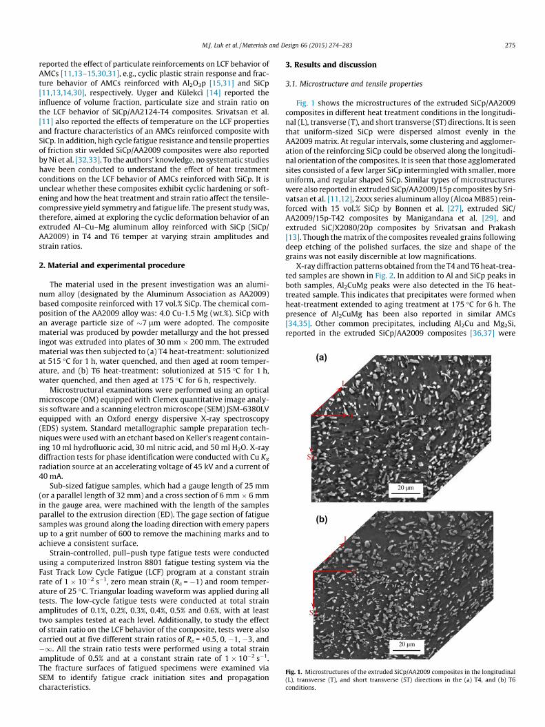
Fig. 1. Microstructures of the extruded SiCp/AA2009 composites in the longitudinal(L), transverse (T), and short transverse (ST) directions in the (a) T4, and (b) T6conditions.
M.J. Luk et al. / Materials and Design 66 (2015) 274–283 275
reported the effect of particulate reinforcements on LCF behavior ofAMCs [11,13–15,30,31], e.g., cyclic plastic strain response and frac-ture behavior of AMCs reinforced with Al2O3p [15,31] and SiCp[11,13,14,30], respectively. Uyger and Külekcì [14] reported theinfluence of volume fraction, particulate size and strain ratio onthe LCF behavior of SiCp/AA2124-T4 composites. Srivatsan et al.[11] also reported the effects of temperature on the LCF propertiesand fracture characteristics of an AMCs reinforced composite withSiCp. In addition, high cycle fatigue resistance and tensile propertiesof friction stir welded SiCp/AA2009 composites were also reportedby Ni et al. [32,33]. To the authors’ knowledge, no systematic studieshave been conducted to understand the effect of heat treatmentconditions on the LCF behavior of AMCs reinforced with SiCp. It isunclear whether these composites exhibit cyclic hardening or soft-ening and how the heat treatment and strain ratio affect the tensile-compressive yield symmetry and fatigue life. The present study was,therefore, aimed at exploring the cyclic deformation behavior of anextruded Al–Cu–Mg aluminum alloy reinforced with SiCp (SiCp/AA2009) in T4 and T6 temper at varying strain amplitudes andstrain ratios.
2. Material and experimental procedure
The material used in the present investigation was an alumi-num alloy (designated by the Aluminum Association as AA2009)based composite reinforced with 17 vol.% SiCp. The chemical com-position of the AA2009 alloy was: 4.0 Cu-1.5 Mg (wt.%). SiCp withan average particle size of �7 lm were adopted. The compositematerial was produced by powder metallurgy and the hot pressedingot was extruded into plates of 30 mm � 200 mm. The extrudedmaterial was then subjected to (a) T4 heat-treatment: solutionizedat 515 �C for 1 h, water quenched, and then aged at room temper-ature, and (b) T6 heat-treatment: solutionized at 515 �C for 1 h,water quenched, and then aged at 175 �C for 6 h, respectively.
Microstructural examinations were performed using an opticalmicroscope (OM) equipped with Clemex quantitative image analy-sis software and a scanning electron microscope (SEM) JSM-6380LVequipped with an Oxford energy dispersive X-ray spectroscopy(EDS) system. Standard metallographic sample preparation tech-niques were used with an etchant based on Keller’s reagent contain-ing 10 ml hydrofluoric acid, 30 ml nitric acid, and 50 ml H2O. X-raydiffraction tests for phase identification were conducted with Cu Karadiation source at an accelerating voltage of 45 kV and a current of40 mA.
Sub-sized fatigue samples, which had a gauge length of 25 mm(or a parallel length of 32 mm) and a cross section of 6 mm � 6 mmin the gauge area, were machined with the length of the samplesparallel to the extrusion direction (ED). The gage section of fatiguesamples was ground along the loading direction with emery papersup to a grit number of 600 to remove the machining marks and toachieve a consistent surface.
Strain-controlled, pull–push type fatigue tests were conductedusing a computerized Instron 8801 fatigue testing system via theFast Track Low Cycle Fatigue (LCF) program at a constant strainrate of 1 � 10�2 s�1, zero mean strain (Re = �1) and room temper-ature of 25 �C. Triangular loading waveform was applied during alltests. The low-cycle fatigue tests were conducted at total strainamplitudes of 0.1%, 0.2%, 0.3%, 0.4%, 0.5% and 0.6%, with at leasttwo samples tested at each level. Additionally, to study the effectof strain ratio on the LCF behavior of the composite, tests were alsocarried out at five different strain ratios of Re = +0.5, 0, �1, �3, and�1. All the strain ratio tests were performed using a total strainamplitude of 0.5% and at a constant strain rate of 1 � 10�2 s�1.The fracture surfaces of fatigued specimens were examined viaSEM to identify fatigue crack initiation sites and propagationcharacteristics.
3. Results and discussion
3.1. Microstructure and tensile properties
Fig. 1 shows the microstructures of the extruded SiCp/AA2009composites in different heat treatment conditions in the longitudi-nal (L), transverse (T), and short transverse (ST) directions. It is seenthat uniform-sized SiCp were dispersed almost evenly in theAA2009 matrix. At regular intervals, some clustering and agglomer-ation of the reinforcing SiCp could be observed along the longitudi-nal orientation of the composites. It is seen that those agglomeratedsites consisted of a few larger SiCp intermingled with smaller, moreuniform, and regular shaped SiCp. Similar types of microstructureswere also reported in extruded SiCp/AA2009/15p composites by Sri-vatsan et al. [11,12], 2xxx series aluminum alloy (Alcoa MB85) rein-forced with 15 vol.% SiCp by Bonnen et al. [27], extruded SiC/AA2009/15p-T42 composites by Manigandana et al. [29], andextruded SiC/X2080/20p composites by Srivatsan and Prakash[13]. Though the matrix of the composites revealed grains followingdeep etching of the polished surfaces, the size and shape of thegrains was not easily discernible at low magnifications.
X-ray diffraction patterns obtained from the T4 and T6 heat-trea-ted samples are shown in Fig. 2. In addition to Al and SiCp peaks inboth samples, Al2CuMg peaks were also detected in the T6 heat-treated sample. This indicates that precipitates were formed whenheat-treatment extended to aging treatment at 175 �C for 6 h. Thepresence of Al2CuMg has been also reported in similar AMCs[34,35]. Other common precipitates, including Al2Cu and Mg2Si,reported in the extruded SiCp/AA2009 composites [36,37] were

0
4
8
12
16
20
20 30 40 50 60 70 80
Inte
nsity
, Cou
nts
×100
0
Diffraction angle 2θ,°
AlSiCAl2CuMg
As-extruded-T4
As-extruded-T6
Fig. 2. X-ray diffraction patterns of heat-treated SiCp/AA2009 composites.
276 M.J. Luk et al. / Materials and Design 66 (2015) 274–283
not seen in the XRD patterns of the present composites. Similar find-ings have been reported for T6 heat-treated SiCp/AA2009 compos-ites by Rodrigo et al. [38], where it was noted that the lack ofthese precipitates was indicative of a good solution treatment ofthe composite materials.
Fig. 3 shows the typical tensile stress–strain curves of the com-posites determined at a strain rate of 1 � 10�3 s�1. The correspond-ing tensile properties, i.e., the mean values based on duplicatetests, are listed in Table 1. Despite only a slight increase in theultimate tensile strength (UTS), the T6 samples exhibited a signif-icantly higher yield strength (YS) than the T4 samples, i.e.,�421 MPa vs. �358 MPa, due to the presence of Al2CuMg precipi-tates caused by age hardening. The slight increase in the UTS of theT6 sample was due to the fact that it did not reach its full capacityprior to failure with a ductility of 3%, in comparison with 4.4% inthe T4 condition (Table 1). The obtained tensile properties werebasically in agreement with those reported for extruded SiCp/AA2009 composites [11,12,29]. Young’s modulus for current com-posites was obtained to be about 121 GPa. Using the rule of mix-tures [39], the Young’s modulus of the present composites couldbe estimated to be about 118 GPa, where the following values wereused: Em = 70 GPa (aluminum matrix) [39], Ep = 350 GPa (SiCp)[39], Vm = 0.83, and Vp = 0.17 (17 vol.% SiCp in the current compos-ites). The estimated and measured values of Young’s modulus inthe current composites were in fairly good agreement. These
0
100
200
300
400
500
600
0 1 2 3 4 5
Engi
neer
ing
stre
ss, M
Pa
Engineering strain, %
As-extruded+T4
As-extruded+T6
Fig. 3. Tensile stress–strain curves of the extruded SiCp/AA2009 composites indifferent heat-treatment conditions tested at a strain rate of 1 � 10�3 s�1.
values also approximately concurred with the reported results,e.g., about 100 GPa for SiCp/AA2009 composites (15 vol.% SiCp) inthe T42 condition [11,12]. The strain hardening exponent (n) eval-uated according to the Hollomon equation [40] and hardeningcapacity (Hc) according to the equation proposed by Afrin et al.[41] are listed in Table 1. It is seen that both strain hardening expo-nent and hardening capacity became lower in the T6 state. Thiswas due to the fact that the initially hardened material had a lowerdislocation storage capacity. In the present T6 samples, this wasmainly due to the precipitation of Al2CuMg particles (Fig. 2). How-ever, the strain hardening exponents obtained for the present com-posites in both T4 (n = 0.21) and T6 (n = 0.16) conditions werehigher than that (n = 0.124) of the T42 heat-treated AA2009 alloyreinforced with 15 vol.% SiCp reported by Srivatsan et al. [12]. Sim-ilarly, the present heat-treated composites also showed signifi-cantly higher n values, as compared with the X2080 matrix alloyreinforced with 16 lm SiCp particles [13].
3.2. Cyclic deformation response
Fig. 4 shows typical stress–strain hysteresis loops of the firstand mid-life cycles at a given strain amplitude of 0.6% and strainratio of Re = �1 for the composites in different heat-treated condi-tions. It is seen from Fig. 4 that both the composites exhibitednearly symmetrical hysteresis loops at both the outset and mid-life, representing an isotropic response. This was in sharp contrastwith the cyclic deformation characteristics in the rare-earth freeextruded magnesium alloys due to the occurrence of twinning inthe compressive phase caused by the presence of strong basal tex-tures [21–23]. Such symmetrical tension–compression behaviorwas a result of dislocation slip-dominated deformation since thematrix material (aluminum) has face-centered cubic (fcc) crystalstructure, rather than twinning often occurring in the hexagonalclose-packed (hcp) metals during deformation. Similar symmetri-cal behavior was reported in other fcc metals (e.g., Cu, Ni) [28],SiCp/2124 [14], and Al2O3p/6061 [15].
Fig. 5 shows the evolution of stress amplitudes with respect tothe number of cycles over a range of total strain amplitudes on asemi-log scale for the composites in different heat-treated condi-tions. As the total strain amplitude increased, the stress amplitudeincreased and the fatigue life of the material decreased in both theT4 and T6 heat-treated composites. For the T4 heat-treated com-posites (Fig. 5(a)), a pronounced cyclic hardening effect wasobserved at strain amplitudes of 0.4% and higher, whereas thecomposites remained cyclically stable at lower strain amplitudes(0.1–0.3%). However, for the T6 heat-treated composites(Fig. 5(b)), while the cyclic hardening tendency was remained thesame, it was weaker. The variation of cyclic stress amplitude withfatigue cycling is mainly dependent on the composite microstruc-ture and the cyclic strain amplitude applied [13]. The cyclic hard-ening behavior during fully reversed cyclic straining at higherstrain amplitudes (Fig. 5) could be attributed to competing andsynergistic effects of stress (load) transfer between the soft andductile AA2009 matrix and the hard and brittle ceramic particle(SiCp) reinforcement [42,43], the presence of a pre-existing dislo-cation density in the alloy matrix caused by the presence of theSiCp [44–46], Al2CuMg precipitates in the matrix (Fig. 2) and initialprecipitate-dislocation interactions, the thermo-residual stress dis-tribution in the composite and the related plastic strains intro-duced near the reinforcement particles due to mismatch in thecoefficients of thermal expansion (CTE) between the soft matrixand hard SiCp particle reinforcement [47,48].
In the low cycle fatigue tests, plastic strain amplitude was con-sidered as a physical quantity that resulted in several damagingprocesses and influenced the internal microstructure, which wasclosely related to the strain resistance and eventually the fatigue

Table 1Tensile properties of the extruded SiCp/AA2009 composites in the T4 and T6 conditions.
Specimen Yield strength (ry), MPa Ultimate tensile strength (rUTS), MPa Elongation, % Strain hardening exponent (n) Hardening capacity (Hc)a
As-extruded + T4 358 556 4.4 0.21 0.55As-extruded + T6 421 559 3.0 0.16 0.33
a According to Afrin et al. [41] the hardening capacity Hc was defined as Hc ¼ rUTS�ry
ry¼ rUTS
ry� 1.
-600
-400
-200
0
200
400
600
-1 -0.5 0 0.5 1
Stre
ss, M
Pa
Strain, %
First cycle
As-extruded+T4As-extruded+T6
-600
-400
-200
0
200
400
600
-1 -0.5 0 0.5 1
Stre
ss, M
Pa
Strain, %
Mid-life cycle
As-extruded+T4As-extruded+T6
(a)
(b)
Fig. 4. Typical stress–strain hysteresis loops of the extruded SiCp/AA2009 com-posites at a given total strain amplitude of 0.6% and strain ratio of Re = �1, (a) firstcycle, and (b) mid-life cycle.
0
100
200
300
400
500
600
1E+0 1E+2 1E+4 1E+6
Stre
ss a
mpl
itude
, MPa
Number of cycles, N
As-extruded+T4 0.6%0.5%0.4%0.3%0.2%0.1%
0
100
200
300
400
500
600
1E+0 1E+2 1E+4 1E+6
Stre
ss a
mpl
itude
, MPa
Number of cycles, N
As-extruded+T6 0.6%0.5%0.4%0.3%0.2%0.1%
(a)
(b)
Fig. 5. Stress amplitude vs. the number of cycles for different strain amplitudestested at a strain ratio of Re = �1 in the SiCp/AA2009 composites in the (a) T4, and(b) T6 conditions.
M.J. Luk et al. / Materials and Design 66 (2015) 274–283 277
life [21,45,47]. The variation of the plastic strain amplitude (Dep/2)during cyclic deformation is shown in Fig. 6 at different strainamplitudes for the composites in different heat-treated conditions.A decrease in the plastic strain amplitude at higher strain ampli-tudes (Fig. 6) corresponded well to an increase in the stress ampli-tude (Fig. 5) in both composites. As with the stress amplitude, theplastic strain amplitude remained cyclically stable at lower strainamplitudes. The cyclic hardening at higher strain amplitudes, asindicated by the decrease in the plastic strain amplitude, wasstronger in the T4 state than in the T6 state. This was closelyrelated to the higher monotonic strain hardening exponent andhardening capacity (Hc) in the T4 condition (Table 1). Furthermore,while the initial cyclic deformation characteristics were similar(i.e., cyclic hardening occurred) in both heat-treated conditions,both the cyclic stress amplitudes and plastic strain amplitudes ata given total strain amplitude were different, except at lower strainamplitudes of 0.1–0.3%. For example, at a total strain amplitude of0.5% the stress amplitude was �369 MPa in the T4 state, and�415 MPa in the T6 state (Fig. 5). The difference in the stressamplitude also increased with increasing strain amplitude applied.
3.3. Fatigue life and fatigue parameters
The total strain amplitudes (Det/2) as a function of the fatiguelife (i.e., the number of cycles to failure, Nf) is plotted in Fig. 7, incomparison with the data reported in the literature for various Alcomposites [13–15,30,31]. As seen from Fig. 7, the present compos-ites in both heat-treated conditions had more or less the same fati-gue lives. It is also seen that the present SiCp/AA2009 compositeswere stronger than several existing Al composites and comparableto even those materials reinforced with ultra-fine particles. Specif-ically, the fatigue life of the present composites was significantlyhigher at all strain amplitudes than that of a similar as-cast SiCpreinforced A356 composite [30], SiCp reinforced Al–Cu–Mg–Zr(X2080) composite [13], AA2009 composite reinforced with20 vol.% SiCp [31], and (Al2O3 + TiB2)/Al composite [31]. Similarimprovements in the fatigue life was also observed for spray-atom-ized SiCp reinforced AA2009 composites [30] and Al–Cu–Mg–Mn(2124) composite reinforced with sub-micron scale SiCp [14].However, aluminum alloys reinforced with ultra-fine SiCp (i.e.,with an average particle size of 0.7 lm) were found to have slightly

-0.05
0
0.05
0.1
0.15
0.2
0.25
0.3
1E+0 1E+1 1E+2 1E+3 1E+4 1E+5
Plas
tic s
trai
n am
plitu
de, %
Number of cycles, N
As-extruded+T4 0.6%0.5%0.4%0.3%0.2%0.1%
-0.05
0
0.05
0.1
0.15
0.2
0.25
0.3
1E+0 1E+1 1E+2 1E+3 1E+4 1E+5
Plas
tic s
trai
n am
plitu
de, %
Number of cycles, N
As-extruded+T6 0.6%0.5%0.4%0.3%0.2%0.1%
(a)
(b)
Fig. 6. Plastic strain amplitude vs. the number of cycles for different strainamplitudes tested at a strain ratio of Re = �1 in the SiCp/AA2009 composites in the(a) T4, and (b) T6 conditions.
0.0
0.1
0.2
0.3
0.4
0.5
0.6
0.7
0.8
0.9
1E+1 1E+3 1E+5 1E+7
Δt/2
, %
Number of cycles to failure, Nf
SiC/AA2009-as-extruded+T4SiC/AA2009-as-extruded+T6SiCp/X2080/15p [13]SiCp/X2080/20p [13]SiCp/2124/17p [14]SiCp/2124/25p [14]Al2O3/6061/10p [15]Al2O3/6061/20p [15]As-cast SiCp/A356/20p [30]Extruded SiCp/AA356/20p [30]SiCp/Al/20p [31]Al2O3+TiB2/Al [31]
ε
Fig. 7. Total strain amplitude versus the number of cycles to failure of the extrudedSiCp/AA2009 composites, in comparison with the data reported in the literature forvarious Al composites.
Log(∆εt/2) = -0.16Log(2Nf) - 1.84R² = 0.98
Log(∆εp/2) = -0.94Log(2Nf)- 0.61R² = 0.95
Log(∆εe/2) = -0.13Log(2Nf) - 2.00R² = 0.93
-6
-5
-4
-3
-2
-1
1 2 3 4 5 6
Log
((Δε/
2)
Log (2Νf)
As-extruded+T4 TotalPlasticElastic
Log(∆εt/2) = -0.15Log(2Nf) - 1.89R² = 0.96
Log(∆εp/2) = -0.83Log(2Nf) - 0.89R² = 0.91
Log(∆εe/2) = -0.11Log(2Nf) - 2.06R² = 0.91
-6
-5
-4
-3
-2
-1
1 2 3 4 5 6
Log
(Δε/
2)
Log (2Νf)
As-extruded+T6 Total
Plastic
Elastic
(b)
(a)
Fig. 8. Cyclic total, plastic, and elastic strain amplitude-fatigue life response of theSiCp/AA2009 composites in the (a) T4, and (b) T6 conditions.
278 M.J. Luk et al. / Materials and Design 66 (2015) 274–283
longer fatigue life than the present SiCp/AA2009 composites[14,15]. This was due to the fact that ultra-fine particles couldrestrict the movement of dislocations most effectively. Theimproved fatigue resistance of the present SiCp/AA2009 compos-ites indicated that the volume fraction of 17% and choice ofreinforcement (i.e., 7 lm SiCp) resulted in optimal interfacialmatrix-particle bonding.
Based on the Basquin equation and Coffin–Manson relation, thetotal strain amplitude could be expressed as two components of elas-tic strain amplitude and plastic strain amplitude [23–25,49–51], i.e.,
Det
2¼ Dee
2þ Dep
2¼
r0f 2Nf� �b
Eþ e0f ð2Nf Þc; ð1Þ
where E is the Young’s modulus, Nf is the fatigue life or number ofcycles to failure, r0f is the fatigue strength coefficient, b is the fatiguestrength exponent, e0f is the fatigue ductility coefficient, and c is thefatigue ductility exponent. In addition, cyclic deformation behavioris normally considered to be predominantly dependent on the por-tion of the plastic strain amplitude and independent of the elasticstrain amplitude, which could be expressed by the following equa-tion [23],
Dr2¼ K 0
Dep
2
� �n0
; ð2Þ
where Dr2 is the mid-life stress amplitude, Dep
2 is the mid-life plasticstrain amplitude, n0 is the cyclic strain-hardening exponent and K0
is the cyclic strength coefficient. Fig. 8 presents the total, elasticand plastic strain amplitudes as a function of the number of rever-sals to failure (2Nf) for the extruded SiCp reinforced AA2009 matrixcomposites in different heat-treated conditions, where the values ofthe strain amplitudes were taken from the mid-life cycles. The fati-gue life parameters in both extruded composites evaluated on thebasis of Eqs. (1) and (2) are summarized in Table 2. It is seen fromFig. 8 that the Basquin and Coffin–Manson relations are obeyedfairly well, and the obtained fatigue parameters were in agreement

Table 2Low cycle fatigue parameters obtained for the extruded SiCp/AA2009 composites inthe T4 and T6 conditions.
Low cycle fatigue parameter As-extruded + T4 As-extruded + T6
Cyclic strain hardening exponent, n0 0.13 0.14Cyclic strength coefficient, K0 , MPa 1139 1181Fatigue strength coefficient, r0 f, MPa 1010 899Fatigue strength exponent, b �0.13 �0.11Fatigue ductility coefficient, e0 f 0.25 0.13Fatigue ductility exponent, c �0.95 �0.83
0
100
200
300
400
500
600
0 0.2 0.4 0.6 0.8
ΔΔσ
/2 a
t mid
-life
, MPa
Δε t/2 at mid-life, %
As-extruded+T4
Monotonic stress-strain curveCyclic stress-strain curve
0
100
200
300
400
500
600
0 0.2 0.4 0.6 0.8
Δσ/2
at m
id-li
fe, M
Pa
Δε t/2 at mid-life, %
As-extruded+T6
Monotonic stress-strain curveCyclic stress-strain curve
(a)
(b)
Fig. 9. Cyclic stress–strain curves for SiCp/AA2009 composites in the (a) T4, and (b)T6 conditions, where the corresponding monotonic stress–strain curves are plottedfor comparison.
-600
-400
-200
0
200
400
600
-1.5 -1 -0.5 0 0.5 1 1.5 2 2.5
Stre
ss, M
Pa
Strain, %
As-extruded+T4-First cycle
-600
-400
-200
0
200
400
600
-1.5 -1 -0.5 0 0.5 1 1.5 2 2.5
Stre
ss, M
Pa
Strain, %
As-extruded+T4-Mid-life cycle
Rε=0.5
Rε= -∞
Rε=0
Rε=-1
Rε=-3
Rε=0.5Rε=0
Rε=-1
Rε=-3
Rε= -∞
(a)
(b)
Fig. 10. Typical stress–strain hysteresis loops of different cycles for different strainratios at a given total strain amplitude of 0.5% of SiCp/AA2009 composites in the T4state, (a) first cycle, and (b) mid-life cycle.
M.J. Luk et al. / Materials and Design 66 (2015) 274–283 279
with the data of other Al composites reported in the literature[11,13,15], except for the cyclic strength coefficient (K0) whichwas higher than the reported data. Fig. 9 shows the monotonicand cyclic stress–strain curves of the T4 and T6 heat-treated sam-ples. The steeper slope of the cyclic stress–strain curves in both con-ditions demonstrated a more pronounced hardening effect in theextruded AA2009 composite in the cyclic loading than the mono-tonic tensile loading, especially in the T4 condition. This hardeningbehavior could be attributed to the interactions of dislocations dur-ing deformation in the plastic domain [11]. More specifically, dislo-cation multiplication during deformation increased the dislocationdensity in the matrix and subsequently increased the interactionsamong dislocations, as well as interactions between dislocationsand the SiCp particles [11]. The situation shown in Fig. 9 wherethe cyclic stress–strain curve is positioned above the monotonicstress–strain curve indeed reflects cyclic hardening behavior of amaterial, as noted in [49]. This corresponded well to the change
in the cyclic stress amplitude and plastic strain amplitude (Figs. 5and 6). It is also well known that materials with a high monotonicstrain hardening exponent (n > 0.15) undergo cyclic hardening;those with a low monotonic strain hardening exponent (n < 0.15)experience cyclic softening. As seen from Table 1, the present com-posites had a monotonic strain hardening exponent of 0.21 in the T4condition and 0.16 in the T6 condition. It follows that cyclic harden-ing occurred in both conditions, with T4 condition exhibiting ahigher extent of cyclic hardening than T6 condition, as seen fromFigs. 5, 6 and 9.
3.4. Effect of strain ratio on LCF
Figs. 10 and 11 show typical stress–strain hysteresis loops of the(a) first and (b) mid-life cycles at different strain ratios, Re, and at agiven strain amplitude of 0.5% in the T4 and T6 heat-treated SiCp/AA2009 composites, respectively. It is seen from Figs. 10 and 11(a)that at all strain ratios in both conditions, the initial tensile phaseof the first cycle was synchronized and followed essentially thesame path, which suggested the occurrence of Masing-like behav-ior, representing a special cyclic stress–strain response in somematerials as reported by Chirst and Mughrabi [52]. It was alsoreported that Masing behavior appeared due to the lack of signifi-cant microstructural changes during the fatigue tests performedfor different strain ratios [53,54]. With increasing strain ratio from�1 (negative infinity) to 0.5, the maximum/peak tensile stress rmax
increased from nearly zero to about 480 MPa (Fig. 10(a)) and toabout 530 MPa (Fig. 11(a)) in the T4 and T6 heat-treated SiCp/AA2009 composites, respectively, and the plastic deformation in

-600
-400
-200
0
200
400
600
-1.5 -1 -0.5 0 0.5 1 1.5 2 2.5
Stre
ss, M
Pa
Strain, %
As-extruded+T6-First cycle
-600
-400
-200
0
200
400
600
-1.5 -1 -0.5 0 0.5 1 1.5 2 2.5
Stre
ss, M
Pa
Strain, %
As-extruded+T6-Mid-life cycle
Rε=0.5
Rε= -∞Rε=0
Rε=-1
Rε=-3
Rε=0.5Rε=0
Rε=-1
Rε=-3
Rε= -∞
(b)
(a)
Fig. 11. Typical stress–strain hysteresis loops of different cycles for different strainratios at a given total strain amplitude of 0.5% of SiCp/AA2009 composites in the T6state, (a) first cycle, and (b) mid-life cycle.
(a)
(b)
As-extruded+T4
As-extruded+T6
Fig. 12. Number of cycles to failure vs. strain ratio of SiCp/AA2009 composites inthe (a) T4 and (b) T6 conditions at a given total strain amplitude of 0.5% and strainrate of 1 � 10�2 s�1.
280 M.J. Luk et al. / Materials and Design 66 (2015) 274–283
the tensile phase became much more remarkable in both conditions(Figs. 10 and 11(a)). To be more specific, a large amount of plasticdeformation appeared in the tensile phase for zero or positive strainratio (i.e., Re = 0 and 0.5). This was attributed to the high positivemean strain values, which forced the occurrence of a large amountof plastic deformation in the tensile and compressive phase of thefirst cycles. The significantly larger shifts of the hysteresis loopsfrom Re = 0 to Re = 0.5 were also due to the influence of strain limits.As the strain ratio was reduced from 0.5 to �1, the peak compres-sive stress rmin decreased from about�290 MPa to about�420 MPa(Fig. 10(a)) and from about �200 MPa to about �520 MPa(Fig. 11(a)) in the T4 and T6 heat-treated samples, respectively.Tests performed at Re = 0.5 and Re = 0 did not reach the compressiveyielding point of the present composites due to the high positivelower strain limits (i.e., emin = 1% for Re = 0.5 and emin = 0 forRe = 0). It is seen from Figs. 10 and 11(b) that the mid-life cyclesshifted towards the zero-stress line due to the occurrence of meanstress relaxation to a certain extent. While the Re = �1 test gaveessentially symmetrical hysteresis loops, the tests at other strainratios apparently gave rise to slight asymmetrical hysteresis loopswith respect to the zero-stress line (Figs. 10 and 11(b)). However,these results differed from those in the extruded magnesium alloys,in which twinning–detwinning activities resulted in asymmetrichysteresis loops reported in [21–23].
Fig. 12 shows the fatigue life (i.e., the number of cycles to failure,Nf) as a function of strain ratio in the T4 and T6 heat-treated sam-ples. It is seen that in both cases, the fatigue life appeared to be high-est at Re = �1, while it decreased as the strain ratio deviated bothpositively and negatively from Re = �1. This suggests that the
strength of the material is optimized when uniform tensile andcompressive stresses are applied (i.e., with a mean stress of zeroat Re = �1). The mean stress of the T4 and T6 heat-treated samplesas a function of normalized cycle ratio (N/Nf), where Nf is the fatiguelife (the number of cycles to failure), is shown in Fig. 13. As the nor-malized cycle ratio N/Nf increased, the mean stress decreased forRe > �1 and increased for Re < �1. That is, the mean stress tendedto become closer to zero. Quasi-stabilization of these curvesoccurred after�10–20% of the fatigue life. Accordingly, the strengthof the material may be related to how effectively the sample wasable to approach a zero mean stress. This phenomenon is oftenreferred to as the mean stress relaxation. It is clear that the meanstress relaxation occurred more drastically at the outset of cyclicdeformation within the initial cycles of the fatigue life, beyondwhich (especially beyond the mid-life) it became increasingly stabi-lized. The mean stress at Re = �1 remained fairly stable at nearlyzero. The absolute value of the maximum mean stress was�100 MPa and �200 MPa for the T4 and T6 heat-treated samples,respectively. This was associated with the higher strength of thecomposites in the T6 condition. Similar findings have been reportedfor 2124 Al-alloy T4 composites reinforced with SiCp particles [14].
3.5. Fractography
Fig. 14 shows an overall view of the fracture surfaces at a lowermagnification in the T4 and T6 conditions tested at a total strainamplitude of 0.2%. The propagation area can be classified into threemajor regions based on the slightly different colors; (i) the areanear the crack initiation site, (ii) the intermediate propagationarea, and (iii) the final fast fracture region. Fatigue crack initiation

-200
-100
0
100
200
0 0.2 0.4 0.6 0.8 1
Mea
n st
ress
, MPa
N/Nf
As-extruded+T4
Rε=0.5Rε=0Rε=-1Rε=-3Rε=-∞
-300
-200
-100
0
100
200
0 0.2 0.4 0.6 0.8 1
Mea
n st
ress
, MPa
N/Nf
As-extruded+T6
Rε=0.5Rε=0Rε=-1Rε=-3Rε=-∞
(a)
(b)
Fig. 13. Mean stress vs. a normalized cycle ratio (N/Nf) of SiCp/AA2009 compositesin the (a) T4 and (b) T6 conditions at different strain ratios at a total strainamplitudes of 0.5%.
M.J. Luk et al. / Materials and Design 66 (2015) 274–283 281
was observed to occur from the specimen surface. This could bebetter seen from Fig. 15, where the crack growth near the initiationsite appeared to occur primarily through the matrix, with no evi-dence of particle/matrix interfacial cracking or particle cracking.Figs. 16 and 17 show the intermediate propagation region testedat a total strain amplitude of 0.2% for the T4 and T6 heat-treatedspecimens, respectively, at a higher magnification. The compositesin both T4 and T6 conditions exhibited a similar fractograph. Thelocation and orientation of fractured SiCp particles could be clearly
Fig. 14. SEM images of overall fracture surfaces of SiCp/AA2009 composites in t
identified from the SEM back-scattered electron images (Figs. 16and 17(b)), while the topography of the fracture surface could beobserved from the SEM secondary electron images (Figs. 16 and17(a)). SiCp cracking, indicated by the arrows in Figs. 16 and 17,was the predominant failure mechanism observed, indicating astrong interfacial bonding between SiCp and the AA2009 matrix,in spite of the occurrence of particle de-cohesion as well. Similarfracture characteristics were also reported for similar SiCp/AA2009 composites [11,12].
4. Conclusions
Strain-controlled low cycle fatigue tests were conducted onextruded SiCp/AA2009 composites in different heat treatment con-ditions of T4 and T6 at varying strain amplitudes and strain ratios.The following conclusions can be drawn from this investigation:
(1) Microstructural observations of the SiCp/AA2009 compos-ites revealed even-sized SiCp uniformly dispersed through-out the AA2009 matrix, with little agglomerated sitesobserved. After T6 heat treatment, Al2CuMg precipitatesappeared.
(2) In comparison with the T6 condition, while the SiCp/AA2009composite in the T4 condition exhibited a lower yieldstrength, it had a higher ductility and equivalent ultimatetensile strength. This gave rise to a higher strain hardeningexponent and hardening capacity in the T4 condition.
(3) The SiCp/AA2009 composites exhibited basically symmetricalhysteresis loops in tension and compression, representing anisotropic response in the composites. This was due to the dis-location slip-dominated deformation in face-centered cubic(fcc) aluminum matrix, rather than twinning in the hcpmetals.
(4) Cyclic hardening was observed at strain amplitudes of 0.4%and higher in both T4 and T6 conditions, with a more pro-nounced hardening in the T4 condition. The hardeningbehavior was mainly attributed to the interactions of dislo-cations in the plastic domain and the resistance of SiCp dur-ing cyclic deformation. Cyclic stabilization occurred at lowerstrain amplitudes (0.1–0.3%).
(5) The fatigue life of the SiCp/AA2009 composites in both T4and T6 conditions was equivalent within the experimentalscatter, which can be well described by the Coffin–Mansonlaw and Basquin’s equation.
(6) Strain ratio significantly affected the cyclic deformationcharacteristics of the composites in both T4 and T6 condi-tions. A large amount of plastic deformation occurred in
he (a) T4 and (b) T6 conditions fatigued at a total strain amplitude of 0.2%.

Fig. 15. SEM micrographs of the fracture surfaces near fatigue crack initiation site of SiCp/AA2009 composites in the (a) T4 and (b) T6 conditions fatigued at a total strainamplitude of 0.2%.
Fig. 16. (a) SEM secondary electron and (b) back-scattered electron micrographs of the fatigue crack propagation region of the T4 heat-treated specimen fatigued at a totalstrain amplitude of 0.2%.
Fig. 17. (a) SEM secondary electron and (b) back-scattered electron micrographs of the fatigue crack propagation region of the T6 heat-treated specimen fatigued at a totalstrain amplitude of 0.2%.
282 M.J. Luk et al. / Materials and Design 66 (2015) 274–283
the tensile phase of the first cycle of hysteresis loops at zeroor positive strain ratio (i.e., Re = 0 and 0.5), which was relatedto the high positive mean strain values.
(7) Fatigue crack initiation was observed to occur from the spec-imen surface. SiCp particle cracking was the predominantfailure mechanism observed, indicating a strong interfacialbonding between SiCp and the AA2009 matrix. Additionally,some particle de-cohesion was also observed in the interme-diate propagation area.
Acknowledgements
The authors would like to thank the Natural Sciences and Engi-neering Research Council of Canada (NSERC) for providing financialsupport. Z.Y. Ma would like to give thanks to National BasicResearch Program of China for the financial support (Grant No.2012CB619600). D.L. Chen is also grateful for the financialsupport by the Premier’s Research Excellence Award (PREA),NSERC-Discovery Accelerator Supplement (DAS) Award, Canada

M.J. Luk et al. / Materials and Design 66 (2015) 274–283 283
Foundation for Innovation (CFI), and Ryerson Research Chair (RRC)program. The authors would also like to thank Messrs. A. Machin,Q. Li, J. Amankrah and R. Churaman for easy access to thelaboratory facilities of Ryerson University and their assistance inthe experiments.
References
[1] McNutt M. Climate change impacts. Science 2013;341:435.[2] Pollock TM. Weight loss with magnesium alloys. Science 2010;328:986–7.[3] Revesz RL, Howard PH, Arrow K, Goulder LH, Kopp RE, Livermore MA, et al.
Global warming: improve economic models of climate change. Nature2014;508:173–5.
[4] Murray J, King D. Oil’s tipping point has passed. Nature2012;481(7382):433–5.
[5] Myers SS, Zanobetti A, Kloog I, Huybers P, Leakey ADB, Bloom AJ, et al.Increasing CO2 threatens human nutrition. Nature 2014;510:139–42.
[6] Mirza FA, Chen DL, Li DJ, Zeng XQ. Effect of strain ratio on cyclic deformationbehavior of a rare-earth containing extruded magnesium alloy. Mater Sci Eng A2013;588:250–9.
[7] Tahreen N, Chen DL, Nouri M, Li DY. Effects of aluminum content and strainrate on strain hardening behavior of cast magnesium alloys duringcompression. Mater Sci Eng A 2014;594:235–45.
[8] Macwan A, Patel VK, Jiang XQ, Li C, Bhole SD, Chen DL. Ultrasonic spot weldingof Al/Mg/Al tri-layered clad sheets. Mater Des 2014;62:344–51.
[9] Sarker D, Friedman J, Chen DL. Influence of pre-deformation and subsequentannealing on strain hardening and anisotropy of AM30 magnesium alloy. JAlloys Compd 2014;611:341–50.
[10] Patel HA, Chen DL, Bhole SD, Sadayappan K. Low cycle fatigue behavior of asemi-solid processed AM60B magnesium alloy. Mater Des 2013;49:456–64.
[11] Srivatsan TS, Al-Hajri M, Vasudevan VK. Cyclic plastic strain response andfracture behavior of 2009 aluminum alloy metal-matrix composite. Int JFatigue 2005;27:357–71.
[12] Srivatsan TS, Al-Hajri M, Vasudevan VK, Smith C, Petraroli M. The tensileresponse and fracture behavior of 2009 aluminum alloy metal matrixcomposite. Mater Sci Eng A 2003;346:91–100.
[13] Srivatsan TS, Prakash A. Effect of particulate silicon carbide on cyclic strainresistance and fracture behavior of X2080 aluminum alloy metal matrixcomposites. Eng Fract Mech 1994;49(5):751–72.
[14] Uygur I, Külekcı̄ MK. Low cycle fatigue properties of 2124/SiCp Al-alloycomposites. Turkish J Eng Env Sci 2002;26:265–74.
[15] Gasem ZM, Ali SS. Low-cycle fatigue behavior of powder metallurgy 6061aluminum alloy reinforced with submicron-scale Al2O3 particles. Mater SciEng A 2013;562:109–17.
[16] Akbarpour MR, Salahi E, Alikhani Hesari F, Kim HS, Simchi A. Effect ofnanoparticle content on the microstructural and mechanical properties ofnano-SiC dispersed bulk ultrafine-grained Cu matrix composites. Mater Des2013;52:881–7.
[17] Asif Iqbal AKM, Arai Y, Araki W. Effect of hybrid reinforcement on crackinitiation and early propagation mechanisms in cast metal matrix compositesduring low cycle fatigue. Mater Des 2013;45:241–52.
[18] Macke A, Schultz BF, Rohatgi PK, Gupta N. Metal matrix composites forautomotive applications. In: Elmarakbi A, editor. Advanced compositematerials for automotive applications: structural integrity andcrashworthiness. Chichester, UK: John Wiley & Sons Ltd; 2013.
[19] Ibrahim IA, Mohamed FA, Lavernia EJ. Particulate reinforced metal matrixcomposites - a review. J Mater Sci 1991;26(5):1137–56.
[20] Tjong SC, Ma ZY. Microstructural and mechanical characteristics of in situmetal matrix composites. Mater Sci Eng R 2000;29:49–113.
[21] Begum S, Chen DL, Xu S, Luo AA. Low cycle fatigue properties of an extrudedAZ31 magnesium alloy. Int J Fatigue 2009;31:726–35.
[22] Begum S, Chen DL, Xu S, Luo AA. Strain-controlled low-cycle fatigue propertiesof a newly developed extruded magnesium alloy. Metall Mater Trans A2008;39:3014–26.
[23] Lin XZ, Chen DL. Strain controlled cyclic deformation behavior of an extrudedmagnesium alloy. Mater Sci Eng A 2008;496:106–13.
[24] Mirza FA, Chen DL. In: Zhang S, Zhao DL, editors. Aerospace MaterialsHandbook. New York: CRC Press, Taylor & Francis; 2013.
[25] Patel HA, Chen DL, Bhole SD, Sadayappan K. Cyclic deformation and twinningin a semi-solid processed AZ91D magnesium alloy. Mater Sci Eng A2010;528:208–19.
[26] Anand D, Chen DL, Bhole SD, Andreychuk P, Boudreau G. Fatigue behavior oftailor (laser) welded blanks for automotive applications. Mater Sci Eng A2006;420(1–2):199–207.
[27] Bonnen JJ, Allison JE, Jones JW. Fatigue Behavior of a 2xxx Series AluminumAlloy Reinforced with 15 Vol Pct SiCp. Metall Trans A 1991;22A:1007–19.
[28] Suresh S. Fatigue of materials. second ed. Cambridge: Cambridge UniversityPress; 1998.
[29] Manigandana K, Srivatsan TS, Quick T. Influence of silicon carbide particulateson tensile fracture behavior of an aluminum alloy. Mater Sci Eng A2012;534:711–5.
[30] Srivatsan TS, Lavernia EJ. Effects of microstructure on the strain-controlledfatigue failure behavior of an aluminum-alloy/ceramic-particle composite.Comp Sci Technol 1993;49:303–13.
[31] Tjong SC, Wang GS, Mai YW. Low-cycle fatigue behavior of Al-basedcomposites containing in situ TiB2, Al2O3 and Al3Ti reinforcements. Mater SciEng A 2003;358:99–106.
[32] Ni DR, Chen DL, Xiao BL, Wang D, Ma ZY. Residual stresses and high cyclefatigue properties of friction stir welded SiCp/AA2009 composites. Int J Fatigue2013;55:64–73.
[33] Ni DR, Chen DL, Wang D, Xiao BL, Ma ZY. Tensile properties and strain-hardening behaviour of friction stir welded SiCp/AA2009 composite joints.Mater Sci Eng A 2014;608:1–10.
[34] Styles MJ, Hutchinson CR, Chen Y, Deschamps A, Bastow TJ. The coexistence oftwo S (Al2CuMg) phases in Al–Cu–Mg alloys. Acta Mater 2012;60:6940–51.
[35] Schueller RD, Sachdev AK, Wawner FE. Identification of a cubic precipitateobserved in an Al–4.3Cu–2Mg SiC cast composite. Scr Metall Mater1992;27:617–22.
[36] Ni DR, Chen DL, Wang D, Xiao BL, Ma ZY. Influence of microstructuralevolution on tensile properties of friction stir welded joint of rolled SiCp/AA2009-T351 sheet. Mater Des 2013;51:199–205.
[37] Feng AH, Xiao BL, Ma ZY. Effect of microstructural evolution on mechanicalproperties of friction stir welded AA2009/SiCp composite. Comp Sci Technol2008;68:2141–8.
[38] Rodrigo P, Poza P, Utrilla MV, Ureña A. Identification of r and X phases inAA2009/SiC composites. J Alloys Compd 2009;482:187–95.
[39] Callister WD, Rethwisch DG. Materials science and engineering: anintroduction. 9th ed. New York: John Wiley & Sons, Inc.; 2014. p. 637–9.
[40] Hollomon JH. Tensile deformation. Trans AIME 1945;162:268–90.[41] Afrin N, Chen DL, Cao X, Jahazi M. Strain hardening behavior of a friction stir
welded magnesium alloy. Scr Mater 2007;57(11):1004–7.[42] Cho K, Gurland J. Law and mixtures applied to the plastics deformation of two-
phase alloys of coarse microstructures. Metall Trans 1988;19A(8):2027–40.[43] Nardone VC, Prewo KM. On the strength of discontinuous silicon carbide
reinforced aluminum composites. Scr Metal 1986;20(1):43–8.[44] Arsenault RJ, Wang L, Feng CR. Strengthening of composites due to
microstructural changes in the matrix. Acta Metall Mater 1991;39(1):47–57.[45] Zhang Q, Chen DL. A model for predicting the particle size dependence of the
low cycle fatigue life in discontinuously reinforced MMCs. Scr Mater2004;51(9):863–7.
[46] Zhang Z, Chen DL. Consideration of Orowan strengthening effect inparticulate-reinforced metal matrix nanocomposites: a model for predictingtheir yield strength. Scr Mater 2006;54(7):1321–6.
[47] Zhang Q, Chen DL. A model for low cycle fatigue life prediction ofdiscontinuously reinforced MMCs. Int J Fatigue 2005;27(4):417–27.
[48] Zhang Z, Chen DL. Contribution of Orowan strengthening effect in particulate-reinforced metal matrix nanocomposites. Mater Sci Eng A 2008;483–484:148–52.
[49] Dieter GE. Mechanical Metallurgy, McGraw-Hill Series. New York: McGraw-Hill; 1986.
[50] Chowdhury SH, Chen DL, Bhole SD, Powidajko E, Weckman DC, Zhou Y. Fiberlaser welded AZ31 magnesium alloy: the effect of welding speed onmicrostructure and mechanical properties. Metall Mater Trans A2012;43:2133–47.
[51] Mirza FA, Chen DL, Li DJ, Zeng XQ. Low cycle fatigue of a rare-earth containingextruded magnesium alloy. Mater Sci Eng A 2013;575:65–73.
[52] Christ HJ, Mughrabi H. Cyclic stress–strain response and microstructure undervariable amplitude loading. Fatigue Fract Eng Mater Struct 1996;19(2/3):335–48.
[53] Jameel MA, Peralta P, Laird C. Masing behavior in copper single crystalsfatigued under load Control. Mater Sci Eng A 2001;297:48–53.
[54] Niendorf T, Maier HJ, Canadinc D, Karaman I. On the cyclic stability and fatigueperformance of ultrafine-grained interstitial-free steel under mean stress. KeyEng Mater 2008;378–379:39–52.