Constituent damage mechanisms in metal matrix composites under fatigue loading, and their effects on...
16
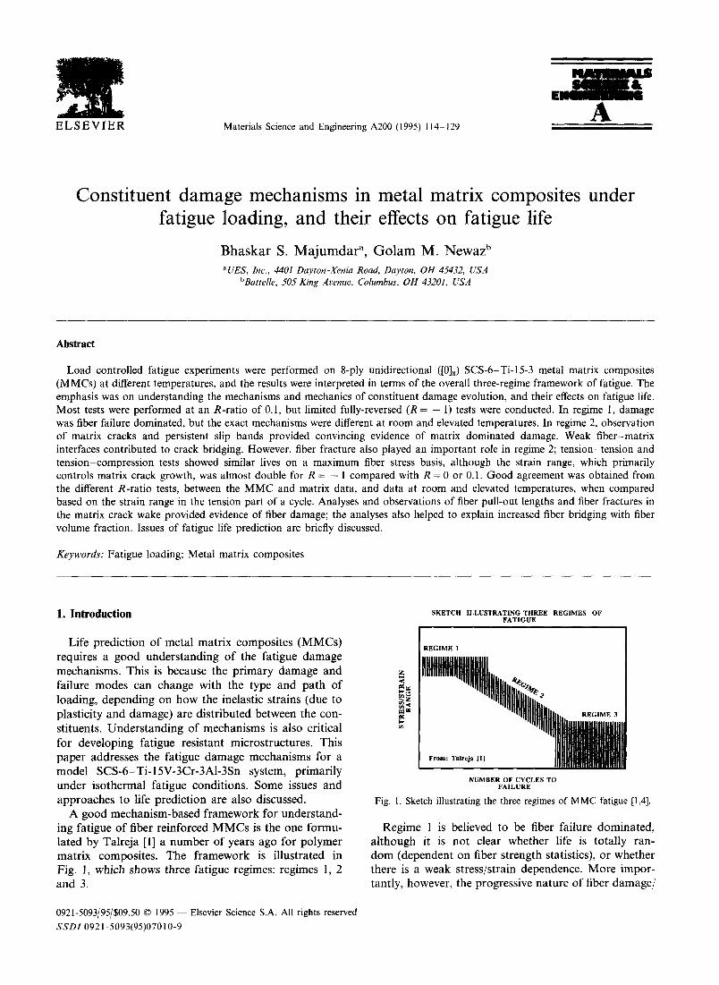
! ELSEVIER Materials Science and Engineering A200 (1995) 114 129 A Constituent damage mechanisms in metal matrix composites fatigue loading, and their effects on fatigue life Bhaskar S. Majumdar ~, Golam M. Newaz b aUES, Inc., 4401 Dayton-Xenia Road, Dayton, OH 45432, USA bBattelle, 505 King Avenue, Columbus, OH 43201, USA under Abstract Load controlled fatigue experiments were performed on 8-ply unidirectional ([0]8) SCS-6-Ti-15-3 metal matrix composites (MMCs) at different temperatures, and the results were interpreted in terms of the overall three-regime framework of fatigue. The emphasis was on understanding the mechanisms and mechanics of constituent damage evolution, and their effects on fatigue life. Most tests were performed at an R-ratio of 0.1, but limited fully-reversed (R = - 1) tests were conducted. In regime 1, damage was fiber failure dominated, but the exact mechanisms were different at room and elevated temperatures. In regime 2, observation of matrix cracks and persistent slip bands provided convincing evidence of matrix dominated damage. Weak fiber-matrix interfaces contributed to crack bridging. However, fiber fracture also played an important role in regime 2; tension-tension and tension-compression tests showed similar lives on a maximum fiber stress basis, although the strain range, which primarily controls matrix crack growth, was almost double for R = - 1 compared with R = 0 or 0.1. Good agreement was obtained from the different R-ratio tests, between the MMC and matrix data, and data at room and elevated temperatures, when compared based on the strain range in the tension part of a cycle. Analyses and observations of fiber pull-out lengths and fiber fractures in the matrix crack wake provided evidence of fiber damage; the analyses also helped to explain increased fiber bridging with fiber volume fraction. Issues of fatigue life prediction are briefly discussed. Keywords: Fatigue loading; Metal matrix composites I. Introduction Life prediction of metal matrix composites (MMCs) requires a good understanding of the fatigue damage mechanisms. This is because the primary damage and failure modes can change with the type and path of loading, depending on how the inelastic strains (due to plasticity and damage) are distributed between the con- stituents. Understanding of mechanisms is also critical for developing fatigue resistant microstructures. This paper addresses the fatigue damage mechanisms for a model SCS-6-Ti-15V-3Cr-3AI-3Sn system, primarily under isothermal fatigue conditions. Some issues and approaches to life prediction are also discussed. A good mechanism-based framework for understand- ing fatigue of fiber reinforced MMCs is the one formu- lated by Talreja [1] a number of years ago for polymer matrix composites. The framework is illustrated in Fig. l, which shows three fatigue regimes: regimes 1, 2 and 3. 0921-5093/95/$09.50 © 1995 -- Elsevier Science S.A. All rights reserved SSD1 0921-5093(95)07010-9 SKETCH ILLUSTRATING THREE REGIMES OF FATIGUE REGIME 1 I gl N REGIME 3 From: Talreja [1] NUMBER OF CYCLES TO FAILURE Fig. 1. Sketch illustrating the three regimes of MMC fatigue [1,4]. Regime 1 is believed to be fiber failure dominated, although it is not clear whether life is totally ran- dom (dependent on fiber strength statistics), or whether there is a weak stress/strain dependence. More impor- tantly, however, the progressive nature of fiber damage/
-
Upload
independent -
Category
Documents
-
view
0 -
download
0
Transcript of Constituent damage mechanisms in metal matrix composites under fatigue loading, and their effects on...
! E L S E V I E R Materials Science and Engineering A200 (1995) 114 129
A
Constituent damage mechanisms in metal matrix composites fatigue loading, and their effects on fatigue life
Bhaskar S. Majumdar ~, Golam M. Newaz b aUES, Inc., 4401 Dayton-Xenia Road, Dayton, OH 45432, USA
bBattelle, 505 King Avenue, Columbus, OH 43201, USA
under
Abstract
Load controlled fatigue experiments were performed on 8-ply unidirectional ([0]8) SCS-6-Ti-15-3 metal matrix composites (MMCs) at different temperatures, and the results were interpreted in terms of the overall three-regime framework of fatigue. The emphasis was on understanding the mechanisms and mechanics of constituent damage evolution, and their effects on fatigue life. Most tests were performed at an R-ratio of 0.1, but limited fully-reversed (R = - 1) tests were conducted. In regime 1, damage was fiber failure dominated, but the exact mechanisms were different at room and elevated temperatures. In regime 2, observation of matrix cracks and persistent slip bands provided convincing evidence of matrix dominated damage. Weak fiber-matrix interfaces contributed to crack bridging. However, fiber fracture also played an important role in regime 2; tension-tension and tension-compression tests showed similar lives on a maximum fiber stress basis, although the strain range, which primarily controls matrix crack growth, was almost double for R = - 1 compared with R = 0 or 0.1. Good agreement was obtained from the different R-ratio tests, between the MMC and matrix data, and data at room and elevated temperatures, when compared based on the strain range in the tension part of a cycle. Analyses and observations of fiber pull-out lengths and fiber fractures in the matrix crack wake provided evidence of fiber damage; the analyses also helped to explain increased fiber bridging with fiber volume fraction. Issues of fatigue life prediction are briefly discussed.
Keywords: Fatigue loading; Metal matrix composites
I. Introduction
Life prediction of metal matrix composites (MMCs) requires a good understanding of the fatigue damage mechanisms. This is because the pr imary damage and failure modes can change with the type and path of loading, depending on how the inelastic strains (due to plasticity and damage) are distributed between the con- stituents. Understanding of mechanisms is also critical for developing fatigue resistant microstructures. This paper addresses the fatigue damage mechanisms for a model SCS-6-Ti-15V-3Cr-3AI-3Sn system, primarily under isothermal fatigue conditions. Some issues and approaches to life prediction are also discussed.
A good mechanism-based framework for understand- ing fatigue of fiber reinforced MMCs is the one formu- lated by Talreja [1] a number of years ago for polymer matrix composites. The framework is illustrated in Fig. l, which shows three fatigue regimes: regimes 1, 2 and 3.
0921-5093/95/$09.50 © 1995 - - Elsevier Science S.A. All rights reserved SSD1 0921-5093(95)07010-9
S K E T C H ILLUSTRATING THREE REGIMES OF F A T I G U E
REGIME 1
I gl N
REGIME 3
From: Talreja [1]
NUMBER OF CYCLES TO FAILURE
Fig. 1. Sketch illustrating the three regimes of MMC fatigue [1,4].
Regime 1 is believed to be fiber failure dominated, although it is not clear whether life is totally ran- dom (dependent on fiber strength statistics), or whether there is a weak stress/strain dependence. More impor- tantly, however, the progressive nature of fiber damage/

B.S. Majumdar, G.M. Newaz / Materials Science and Engineering A200 (1995) 114 129 115
failure mechanisms at the high stress/strain ranges needs to be understood, both to predict fatigue life, as well as to assess retained MMC strength in the presence of such defects. The fiber-dominated issue is also important under in-phase thermomechanical fatigue (TMF) condi- tions, where fiber fractures initiate and accumulate extremely early in life and produce strain ratchetting well above isothermal fatigue conditions [2,3].
Regime 2 has similar characteristics to monolithic metals, in that there is a powerlaw type of relationship between the strain/stress range and fatigue life. A num- ber of studies [4-9] have shown that this regime in MMCs is matrix damage dominated. On a strain range basis, the SCS-6-Ti-15-3 system performed worse than the matrix at strain ranges of 0.5% and higher. However, what was lacking was a detailed understanding of the matrix crack initiation and propagation process, such as whether classical fatigue mechanisms like persistent slip bands (PSBs) operate in the matrix of MMCs, or what roles reaction zone (rz) cracks played in the matrix cracking process; such rz-cracks, which formed during loading, were found to play an important role in nucle- ating premature plasticity under monotonic loading conditions [10-13]. Some of these issues are briefly addressed in this paper, and a more detailed description of the damage sequence is available in Refs. [14-16]. In Ref. [8], a life prediction approach using the 0 ° fiber stress range was suggested, based on data obtained from different laminate configurations. While there is insuffi- cient evidence to suggest that SiC fibers fail in fatigue, there is the possibility of fiber damage caused by rubbing (fretting) with the surrounding matrix, and by environ- ment. We shall return to this subject later in this paper.
An additional aspect of most of the past work, except for Refs. [17,18], was that experiments were performed primarily in load control at R-ratios of 0 or 0.1. This prevented adequate assessment of the mechanisms and mechanics of fatigue crack growth and fiber fracture. Some initial results under fully reversed load conditions (R = - 1), possible ways of rationalizing lives at differ- ent R-ratios, and interpretation of MMC life based on matrix data, are discussed in this paper.
Finally, in regime 3, MMC life is crack initiation or equivalently threshold fatigue crack growth controlled. In Ref. [14] it was shown that MMCs with higher fiber volume fractions, accompanied with smaller grain size, improved the near endurance behavior. However, suffi- cient understanding still appears to be lacking in this regime of fatigue, and it is also outside the scope of this paper.
2. Experiments
Isothermal fatigue experiments were performed on 8-ply unidirectional [018 SiC (SCS6)-Ti-15-3 MMCs
with 15, 35, and 41 vol.% fibers; we shall designate these MMCs as MMC-15, MMC-35, and MMC-41 respectively. The different fiber volume fractions helped in better understanding of the mechanics of damage evolution. Dog-boned shaped specimens with a width of 8.9 mm in the gage section, and a shoulder radius of 356 mm [14,15] were machined from unidirectional panels. Special care was taken in specimen preparation, including rounding the specimen corners and polishing the faces and edges, to minimize premature crack nucle- ation from machining flaws. Load controlled fatigue experiments were performed both at room temperature (RT) and at 538 °C at a frequency of 1 Hz and an R-ratio of 0.1. In addition, load controlled tension compression tests at an R-ratio of - 1 were performed on a MMC-35 material at 427 °C. Buckling guides were employed in the reversed loading tests to prevent buck- ling. Stress-strain measurements in compression yielded an elastic modulus that lay within _+ 3% of that measured in tension tests without buckling guides [16,26], pointing to little if any bending strains for the specimens that ranged in thickness from 1.55 mm to 2.92 mm for MMC-41 and MMC-15 respectively.
All elevated temperature tests were performed in a chamber that was initially evacuated between 10- 4 and 10 - 6 Torr, then backfilled with high purity argon at approximately 1 lbf in - 2 gage pressure. The purpose of the inert environment was to address primarily the MMC constituent issues, rather than the more complex problem associated with oxidation. The strain range in these stress controlled experiments remained constant for better than 85% of life in all tests. This also allowed fatigue life data to be interpreted in terms of strain ranges.
3. Results
A characteristic feature of all fatigue tests was that the hysteresis loops had very narrow widths, implying an almost elastic response for the matrix. For both room and elevated temperature tests, the specimen stiff- ness remained constant for a major fraction of the test. However, there was one difference, in that at R = 0 or 0.1, the MMC continually ratchetted (i.e. an increase of minimum and maximum strain with cycling) at elevated temperatures, driven by the viscoplastic response of the matrix. Ratchetting was negligible in the R = - 1 tests at 427 °C.
Figs. 2(a) and 2(b) illustrate how the different strain parameters evolved as a function of the number of cycles at RT and 538 °C respectively, for specimens with similar lives at an R-ratio of 0.1. Note the absence and presence of ratchetting in Figs. 2(a) and 2(b) respectively. Although metallography following inter- rupted tests revealed that matrix cracks initiated any-

116 B.S. Majumdar , G.M. N e w a z / Mater ia ls Science and Eng&eer&g A 2 0 0 (1995) 1 1 4 - 1 2 9
E/Einilial; Ein i t i a l=134GPa _ "~ AAA A ~ k ' " -& - - A ' A .
0.8 Strain Range = 0.45% NFailu,~=27437 Cycles ~;~
0.6 Max.Strain
~" 0 . 4 ~ooo Str'/u-nR~in~e .... ¢----o- --o-- o<>-~ .~
• ~ - :~xx×-Mea°-Sgai.~ . . . . . x - x - - x - - _ _ ~ > ~ _ > ~ x ' , " i: [ o 0.2
Min. Strain ~ o o o . . . . . . . . o . . . . . o - - o - - o . . . . o o o - ~
0 5 1 0 1 5 2 0 2 5 3 0
( 0 ) Cycle No. (in Thousands)
1 ' ' '''"'I ' ' ''""I ' ' "''"'I ' ' '''"'I ' ' '''"'l
Strain Range - 0.38%
NFailur e = 29,097 0.8
0.6 Max. Strain ~ Mean Strain
'~ . Strain Range 0 .4 . . . . . . . . . . . . . . . . . .
0.2
0 , , .,,,,,I , , ,,.*,d ........ l l i ...... l , i ,,1,
1 10 100 1000 104 105
( b ) Cycle No.
Fig. 2. Evolution of different strain parameters for an MMC-15 specimen tested at an R-ratio of 0.1: (a) R T at a stress range of 615 MPa, and (b) at 538 °C.
where between 30 and 50% of life, their effect on strain range and specimen stiffness was negligible until about 85% of life. At high strain ranges, the drop in stiffness towards the end of life was significantly less than in Fig. 2.
At 538 °C, the hysteresis loops after the first cycle shrank down to almost zero width, indicating the fiber- dominated global response of the MMC. The strain range settled down to a constant value, typically within three cycles, and remained so for better than 95% of life (see Fig. 2(b)). However, at R = 0.1, there was continu- ous increase in the mean strain. A consequence of matrix ratchetting is that fiber strains can become suffi- cient to cause statistical fiber cracking, with the net effect being an extended transition region between regimes 1 and 2, compared to that at RT.
Fig. 3 is a plot of the stress range versus specimen life for the MMC specimens and the Ti-15-3 matrix at RT. The plot includes data from this investigation, as well as those generated on the same system in references [5-7,9]. Fig. 3 shows that for each MMC fiber volume fraction, there was an approximate power law relation- ship between the stress range and specimen life, for lives greater than about 2000 cycles. However, there were life differences between each set of data, with MMC-41 and
MMC-35 showing a distinct advantage over MMC-15. It is this stress advantage that has guided the need to incorporate fibers into a metal matrix, and which will be a likely driving force behind developing fiber rein- forced MMCs in the future, given the temperature limitations of monolithic alloys.
In the low life domain (less than 2000 cycles) at RT, life was extremely sensitive to the applied stress level. The extent of ratchetting was found to be typi- cally less than 0.05% strain [14], and that too in the last 5-10% of life, reflecting the fact that viscoplastic effects are negligible at RT, and that possible fiber failures occur only near the end of life. At the same time, it is important to note that the MMC survived many cycles before failure in this regime, implying that some damage process must have occurred during this period, but which did not manifest itself through changes in measured strains.
An additional point to note with reference to Fig. 3, is that if experiments had been performed on only one volume fraction MMC, then stress range may have appeared attractive as a characterizing parameter for predicting fatigue life, given the relatively narrow scat- ter band for a particular MMC fiber volume fraction. In contrast, different life responses for different MMC fiber volume fractions illustrate that applied stress range is not a fundamental material parameter that controls life.
Fig. 4 shows the RT life data for the same specimens as in Fig. 3, but on a strain range basis. The strain range versus life plot in Fig. 4 shows that the data for different MMC fiber volume fractions fall within a relatively narrow band, particularly for strain ranges below approximately 0.6%, suggesting strain range as a more fundamental parameter that controls life. Fig. 3 shows that the data for the matrix material also agreed reasonably well with that for the MMCs, for strain ranges below approximately 0.5%. From a deformation
2000
1 0 0 0
. . . . . ' " I ' ' ' . . . . . I . . . . . . " | ' ' ' ' ' ' " I I [ I I i I l l
Lines are not best fit lines, but are drawn A ~1 • ~ to illustrate approximate trends.
15%, Cunr.at 41%
41. Ti 15-3 l ~ ' _ Cum~ Dm ~ u ~ -o 1 .~%, N~ ~ (C, ayda, C,=bl,) ~ ~ 15%
• A 35'~'~q),NASALr.i~(~~ord) \_ 35% $M, NASA Lewis (G1~b,Gaydn,L*~a,Half0rd) ~ Matrix
O Ti I f~3 M{lix Vii). N~A l.¢wi~ (C~bb,C~ydI,lJ~c~d) ~
100 104 106 Cycles
Fig. 3. Fatigue life of SCS-6-Ti-15-3 at RT, plotted on a stress range basis. SM and W D refer to s t r ong -med ium and weak-duct i le matrix conditions respectively in Ref. [5].
B.S. Majumdar, G.M. Newaz / Materials Science and Engineering A200 (1995) 114 129 117
. . . . . . . . I ' ' ' ' ' ' " 1 ' ' " ' ' ' " 1 " " ' ' ' ' " 1 . . . . . ' " O
~ o o
@ A4~o o t l i
0 [3#
• 15 % Current 0 [] • • 41% Ctarent
• "fi 15-3 Mal~, Cta'fent (R-sms=0A)
0 15% NASA Lewis(Gay~Gel~)
[] 41% NASA Lev,~ (GaydtGebb)
A 35% WD NASA L e ~ s ( C ~ I ~ C . ~ 35% SM NASA Lewis (Gebb,Gayda.lagh.Halfo~
O Ti 15-3 b ~ i x WI) NASA Lew~ (R.slnin~, CJbb et ~ )
100 1000 10 4 10 s 106 107 Cycles
Fig. 4. Fat igue life o f S C S - 6 - T i - 1 5 - 3 at RT, plotted on a strain range
basis.
mechanism perspective, a possible implication is that MMC fatigue life is matrix life controlled; it is well established that fatigue life of metals are strain range controlled (through inelastic deformation). However, matrix cracks generally initiated at rz-cracks which formed in the brittle reaction layers on loading, sug- gesting that those regions likely experienced the largest amount of reversed plasticity.
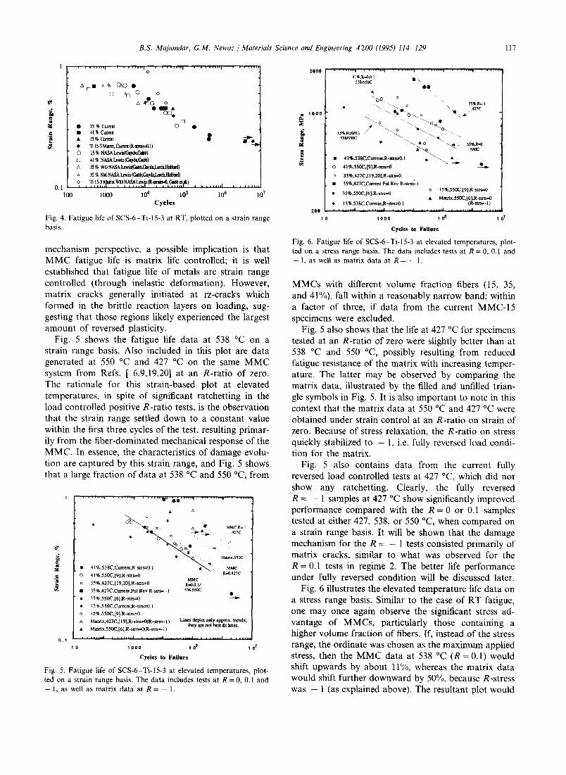
Fig. 5 shows the fatigue life data at 538 °C on a strain range basis. Also included in this plot are data generated at 550 °C and 427 °C on the same MMC system from Refs. [ 6,9,19,20] at an R-ratio of zero. The rationale for this strain-based plot at elevated temperatures, in spite of significant ratchetting in the load controlled positive R-ratio tests, is the observation that the strain range settled down to a constant value within the first three cycles of the test, resulting primar- ily from the fiber-dominated mechanical response of the MMC. In essence, the characteristics of damage evolu- tion are captured by this strain range, and Fig. 5 shows that a large fraction of data at 538 °C and 550 °C, from
. . . . . . . . , . . . . . . . . r . . . . . . . l e #.il .. . . . . ' . . . . . . . . ' . . . . . . . .
~ ~ { ~ _ __ i ~ MMC.R=- I m "~ • 427c
• ~ ' . . Matnx,550C
• 41%.538C,Current,R-strs=0. I MMC
O 41%.550C,[9],R-strs=O R=0,427C MMC
".~ n 35%.427C,[ 19,20],R-strs=0 R=O,0.1/
• 35%,427C,Currcnt,Ful R e v R - s t r s = -1 538,550C
m 35%,550C,[61,R-strs=0
*, 15%,538C,Current ,R-sus=0.1
o 15%,550C,[9],R-strs=0
A Matrix,427C,[ 19],R-stm=O(R-strs=- I ) L i n e s d e p i c t o n l y a p p r o x , t r e n d s ; t h e y a t e n o t b e s t f i t f i n e s .
• Matrix,550C,[6],R-stm=O(R-strs=- I )
. . . . . . . . i . . . . . . . . i . . . . . . . . i . . . . . . . . | , , , , , , , 4 . . . . . . . 0 . 1
1 0 1 0 0 0 1 0 s 1 0 7
Cycles to Failure
Fig. 5. Fatigue life o f SCS-6 T i -15-3 at e levated temperatures , plot-
ted on a strain range basis. Th e data includes tests at R = 0, 0.1 and
- 1, as well as matr ix data at R = - 1.
2 0 0 0 . . . . . . . . i . . . . . . . . i . . . . . . . . I . . . . . . . . ~ . . . . . . . . ; . . . . . . . . 41%,R=0,0.1 • \,
538/550C m-m
b Q = \ \ 35%.R=- I
m "-.. " - . c ' \ 427c 10o0 -. .... ""-, °.m " "e'b--.. o i \ ~,,.-
:~ ...... o. ........ -..~.~ t
15%,R~ .1 53gl550C " ~ . " ' - . q " '"~-~.
4, ""... • 0 "''-...,~ . 35%.R.-~] • "---~.., "- 5~
• 41%,538C,Cun'ent, R*str-.--0. I . ""~.. •
O 41%,550C,[9],R-sus=O ~" ~
o 35%.427C,[ 19.20],R-strs=0
u 35%,427C,Current Ful Rev R-$tr~-I o 15 %.S50C,[9],R-strs=0
m 35%,550C.[6],R-strs=0 • Matfix.550C,[6],R-stm=0
• 15 %,538C.Current,R-strs--'O. l (R-strs=-l)
2 0 0 . . . . . . . . ' . . . . . . . . ' . . . . . . . . ' . . . . . . . . ' . . . . . . . . ' ' , , " "
1 0 1 0 0 0 1 0 5 1 0 7
C y c l e s t o F a i l u r e
Fig. 6. Fatigue life o f SCS-6 T i -15-3 at e levated temperatures , plot-
ted on a stress range basis. The data includes tests at R = 0, 0.1 and
- 1, as well as matr ix data at R = - 1.
MMCs with different volume fraction fibers (15, 35, and 41%), fall within a reasonably narrow band; within a factor of three, if data from the current MMC-15 specimens were excluded.
Fig. 5 also shows that the life at 427 °C for specimens tested at an R-ratio of zero were slightly better than at 538 °C and 550 °C, possibly resulting from reduced fatigue resistance of the matrix with increasing temper- ature. The latter may be observed by comparing the matrix data, illustrated by the filled and unfilled trian- gle symbols in Fig. 5. It is also important to note in this context that the matrix data at 550 °C and 427 °C were obtained under strain control at an R-ratio on strain of zero. Because of stress relaxation, the R-ratio on stress quickly stabilized to - 1, i.e. fully reversed load condi- tion for the matrix.
Fig. 5 also contains data from the current fully reversed load controlled tests at 427 °C, which did not show any ratchetting. Clearly, the fully reversed R = - 1 samples at 427 °C show significantly improved performance compared with the R = 0 or 0.1 samples tested at either 427, 538, or 550 °C, when compared on a strain range basis. It will be shown that the damage mechanism for the R = - 1 tests consisted primarily of matrix cracks, similar to what was observed for the R = 0.1 tests in regime 2. The better life performance under fully reversed condition will be discussed later.
Fig. 6 illustrates the elevated temperature life data on a stress range basis. Similar to the case of RT fatigue, one may once again observe the significant stress ad- vantage of MMCs, particularly those containing a higher volume fraction of fibers. If, instead of the stress range, the ordinate was chosen as the maximum applied stress, then the MMC data at 538 °C ( R = 0.1) would shift upwards by about 11%, whereas the matrix data would shift further downward by 50%, because R-stress was -- 1 (as explained above). The resultant plot would

118 B.S. Majumdar, G.M. Newaz / Materials Science and Engineering A200 (1995) 114-129
then show that the MMC clearly outperforms the ma- trix material on a maximum stress basis. Considering the results in Figs. 5 and 6 together, the strongest benefit of MMCs, compared with the matrix, is in those fatigue applications which require a high mean stress to be borne by the material, taking advantage of the load carrying capability of the high modulus fibers.
The dislocation structure in fatigued MMCs was inhomogeneous. In certain regions, channel type dislo- cation structures were observed, as illustrated in Fig. 7 for a specimen fatigued at a strain range of 0.45% at RT. This type of structure is characteristic of PSBs in b.c.c, metals, and confirms that classical fatigue mecha- nisms do operate in the MMCs. Such PSBs, together with similar lives of MMC and matrix at RT at strain ranges below 0.5% provide convincing evidence of ma- trix damage controlled life at such strain ranges. How- ever, there must also exist an important role of the fiber, since MMC failure is ultimately precipitated by fiber failure.
Multiple matrix cracks were observed in specimens cycled at RT, but they were relatively few and count- able. Typical spacings were of the order of 2 ram, although there were some near specimen corners that were closer, presumably due to greater fiber and reac- tion zone damage at such locations during specimen machining. Most often the matrix cracks had their origin at rz-cracks and Mo-ribbon cracks, both well embedded in the MMC; these rz- and Mo-cracks were not pre-existing, but formed during loading, as shown in Ref. [10]. The embedded crack initiation sites were confirmed by polishing the faces and edges to different depths, as well as from the fracture surface (multiple embedded initiation sites observed around fibers). Ma- trix cracks also had their origin in fiber cracks at
Fig. 7. Channel type dislocation structure in the matrix of an MMC- 15 specimen cycled at a strain range of 0.45% at RT. This type of structure is characteristic of persistent slip bands in b.c.c, metals.
specimen corners and edges. However, even here the matrix cracks started from rz-cracks immediately adja- cent to surface-cracked fibers (damaged by machining); i.e. if the reaction zone did not crack next to a ma- chined fiber, then a matrix crack most often did not initiate there. One likely reason is the excellent bond between the reaction zone and the matrix, so that a crack in the reaction zone could easily propagate into the matrix with cyclic loading. Conversely, the weak fiber-matrix interface strength, coupled with significant reduction of residual clamping stress at the surface, could prevent a fiber-crack at the surface from propa- gating into the matrix. At elevated temperatures, fa- tigue cracks emanating from such surface related defects were larger and more frequent compared with internal reaction zone initiation sites, possibly because of some degrading influence of the environment; i.e. surface related sites appeared to play a more dominant role in matrix cracking at elevated temperature com- pared with RT.
Fig. 8(a) illustrates the fracture surface of an MMC- 15 specimen fatigued at a strain range of 0.45% at RT. The regions marked I indicate radial cracks emanating from around the fiber. Fig. 8(b) is a slightly higher magnification micrograph and shows evidence of a feathery crystallographic type of fracture in the fatigue crack growth (fcg) region. This crystallographic mor- phology was in agreement with observation on the side surfaces which showed matrix cracks following slip bands; this /C-alloy was found to favor planar slip [10,21] because of the presence of extremely fine co phase. Only in a few areas could classical fatigue stria- tions be observed in the MMC specimens at RT. In contrast, the matrix-only specimens showed a greater incidence of striations and relatively less incidence of the flat and crystallographic type of appearance ob- served on the fracture surface of the MMC specimens. One possible reason for this difference is that bridging fibers in the crack wake prevent closure of the crack during unloading, and thus act to reduce marking on the fracture surface in the MMC specimens.
Another notable observation with regard to Fig. 8(b) is the extremely small pull-out of the fiber in the fcg region; compare the pull-outs in the fcg and fast frac- ture regions in Fig. 8(b). Polishing of side surfaces also confirmed this characteristic. This behavior was true both for RT and elevated temperature tests, with pull- out lengths mostly ranging between 0.25 and 1.5 fiber diameters. The small pull-out occurred in spite of the fact that polishing of the specimen faces to the fiber level showed extended lengths of debonds (typically 2 to 5 fiber diameters long) on either side of the fatigue- crack plane. The small pull-outs in the fatigue crack growth region are indicative of fiber damage, possibly by to-and-fro rubbing with the surrounding reaction zone and the matrix, or from environmental reactions.

B.S. Majumdar, G.M. Newaz / Mater&& Science and Engineering A200 (1995) 114 129 119
(a)
(b)
Fig. 8. Fracture surface of an MMC-15 specimen cycled to failure at 0.45% strain range at RT. (a) Overall view showing radial cracks emanating (marked 1) from around fibers. (b) At the transition between fatigue crack growth (fcg) region (lower part) and fast fracture (f0 region. Note the feathery crystallographic character and the extremely small fiber pull-out length in the fcg region, compared with ductile dimple failure and large pull-out in ff region.
In the fast fracture region, there was extensive fiber pull-out, and the matrix failure morphology was of a ductile dimple type.
A major damage mechanism observed in the fatigued specimens was f iber-matrix debonding. Fig. 9 shows a matrix crack propagating from the left to right in the MMC specimen cycled at 0.45% strain range at RT. There are two important observations to point out here. One is that there was significant debonding on either side of the crack plane. Such interfacial debonds prevent fiber failures ahead of an advancing matrix crack; i.e. the debonds allow for a bridged crack and are beneficial. The second point to note with respect to Fig. 9 is the debond that had occurred on the left side of the right-most fiber. This latter debond probably
occurred because of the tensile stress parallel to the crack plane caused by the matrix crack to its left, and shear (parallel to the fibers) caused by plasticity of the matrix ahead of the main crack. The extent of this type of debonding was not always as extensive, although in most cases rz-cracks were observed around the fiber immediately ahead of the main crack. Those rz-cracks often gave rise to individual matrix cracks around the fiber ahead of the main crack, which then linked back- wards with the main crack [14,23]. In other words, crack propagation in MMCs is not a one-directional phenomenon, in contrast to what is assumed in most crack propagation models.
The extent of fiber bridging in the crack wake ap- peared to depend on the volume fraction of fibers, similar to what was observed in fatigue crack growth experiments [22] on this same system. MMC-15 speci- mens, cycled at strain ranges between 0.4 and 0.5% at R = 0 . 1 , typically showed two to three intact fibers immediately behind the various crack tips (in the wake), when polished to the first ply level; further behind in the wake, the fibers had failed. For MMC-41, cycled at similar strain ranges, the number of intact fibers in the crack wake was larger, typically six to eight. This difference is probably related to the fact that, for the same far-field strain, matrix cracking leads to significantly more load being transferred to the fibers of lower fibre volume fraction MMC than higher fiber volume fraction MMC, thus causing those fibers to fail earlier. The observed number of intact fibers in the wake also increased with lower strain ranges. Thus, an MMC-15 specimen, cycled at 0.3% strain range, showed five to eight intact fibers in the crack wake, the implication being that fiber failure in the bridged zone is, as anticipated, dictated by the imposed maximum stress or strain.
Figs. 10(a), 10(b), and 10(c) are optical micrographs of replicas taken at the maximum load for an MMC-15 specimen cycled at a strain range of 0.3% at RT; the specimen life was 194000 cycles. The face of the speci- men was polished down to the first level of fibers before testing, which did damage the fibers and caused some of them to fail prematurely (within 1000 cycles). The micrographs in Fig. 10 illustrate the progression of damage, with the terms sb, cr, and db implying slip bands, crack, and debond respectively. At 5000 cycles, a prematurely cracked fiber had given rise to an rz- crack, which then initiated a slip band in the matrix, in a manner similar to that observed under monotonic deformation [10,11]. A debond between the two outer layers of the SiC fibers may also be observed in Fig. 10(a), consistent with an anticipated debonding phe- nomenon. With continued cycling, more slip bands accumulated, and at 20000 cycles (Fig. 10(b)), a mode I crack had initiated in the matrix in the plastically deformed region. This type of cyclic plasticity induced

120 B.S. Majumdar, G.M. Newaz Materials Science and Engineering A200 (1995) 114-129
Fig. 9. Matrix crack growth and accompanying fiber matrix debonds on either side of the crack plane in an MMC-15 specimen, cycled at RT.
matrix crack initiation was the dominant mechanism at both room and high temperatures, with the rz-crack playing the role of facilitating slip band formation. The crack initiation in the matrix was followed by matrix crack propagation. Fig. 10(c) shows the situation at 52000 cycles. Both the cracks touching the right-most fiber had initiated before the main matrix crack had progressed all the way, and only one of those new cracks then joined up with the main crack.
At high strain ranges at RT, matrix cracks were not observed. Rather, there was overload failure involving fiber fractures. Since ratchetting did not occur at RT, a mechanism is needed to explain why fiber failures oc- curred after a limited number of cycles. The deformed microstructure provided useful insight into a probable cause. One important damage mode was fiber-matrix debonding in the absence of matrix cracks; see Fig. 1 l(a). There was axial cracking of the outer layers of the SCS-6 fibers, and the debonds switched locations from the inner to the outer carbon layer on either side of that crack. In Refs. [14,23], a mechanism was pro- posed for the debonding phenomenon. The presence of debonds point to local fiber-matrix slippage in shear, and cyclic deformation can produce rubbing induced damage of fibers, causing them to fail after a certain number of cycles, ultimately leading to failure of the MMC. A possible damage sequence is reproduced from Ref. [14] in Fig. 1 l(b).
At high temperature and intermediate strain ranges, matrix cracking again was the dominant mechanism; fracture surfaces showed a number of matrix fatigue cracks. Fractography once again revealed extremely small pull-out lengths. In the case of MMC-15, the number of intact fibers in the crack wake, for those
matrix cracks away from the fracture surface, was even smaller than at RT, possibly because ratchetting of this MMC caused fiber stresses to be significantly elevated and cause their failure. Correspondingly, MMC-35 and MMC-41 showed bridging that was similar to that at RT; in all likelihood this was because ratchetting was smaller, and any oxidative damage of the fiber at elevated temperature was probably comparable with the high clamping stress induced rubbing-type fiber damage at RT. It may be worth noting here that interface work [24,25] on this MMC system has shown high friction stress (100-150 MPa) in the as-fabricated MMC at RT, coupled with significant damage of the interface during fiber push-out.
The fully reversed tests showed a very interesting cracking morphology. Fig. 12 illustrates the extensive amount of matrix cracks for a specimen cycled at a stress range of 1500 MPa (maximum stress of 750 MPa) at R = - 1 and 427 °C. The crack density is much larger than observed for the same strain range under R = 0.1, for any of the MMCs studied at either RT or elevated temperature. The compressive part of the cycle may have been instrumental in nucleating additional cracks (compared with the tension-tension case), since past observations [16,26] on this MMC system under monotonic loading revealed extensive reaction zone damage and fiber-matrix debonding in compression; microbuckling may have also occurred. Another inter- esting feature in the R = - 1 samples, was that in spite of the extensive matrix cracking, the number of fiber cracks in the crack wake was extremely few. One im- portant reason is that matrix ratchetting in these sam- ples was negligible, so that fiber stresses in the crack wake did not become high enough to cause fiber failure.

B.S. Majumdar, G.M. Newaz / Materials Science and Engineering A200 (1995) 114-129 121
The elongated precipitates in Fig. 12 are believed to be ~ particles that precipitated in situ during the test at 427 °C. The favored sites for their nucleation in this metastable fl-alloy are imperfections, such as grain boundaries or dislocations. Thus, the increased number of particles immediately adjacent to the fatigue crack surfaces likely reflect higher dislocation densities, gener- ated during the crack propagation process, being
present there. We have yet to evaluate the extent of the precipitate zone on either side of the crack plane to get an estimate of the local plastic deformation field, and hence the local K field during crack propagation.
At high strain ranges and at elevated temperatures, matrix cracking was small, if observed at all. Also, the type of debonding damage that was observed in regime 1 at RT was largely absent. For an MMC-15 specimen that failed in 760 cycles at a maximum stress of 700 MPa, there was an extremely large density of fiber cracks without any matrix crack; the fracture surface showed a tensile type of overload failure. Fig. 13 shows the fiber cracking morphology for an MMC-41 speci- men, which failed in 3895 cycles at a stress range of 1030 MPa (measured strain range of 0.58"/0) at 538 °C, cycled at a slow rate of 0.01 Hz. The illustrated region is at least 10 mm from the fracture surface, which showed a region of matrix fatigue crack growth. The maximum fiber stress in this specimen is estimated to lie between 2400 and 2600 MPa, suggesting that periodic fiber fractures without matrix cracks can occur at these stresses under isothermal fatigue.
Refs. [2,3] contain additional information on periodic fiber fractures under TMF loads as well as under isothermal fatigue at high stress ranges. In particular, for specimens cycled between 300 and 538 °C under in-phase TMF conditions, periodic fiber fractures occur at applied stresses as low as 300 MPa for an MMC-41 material. In contrast, interrupted experiments appeared to indicate no significant fiber strength degradation due to TMF cycling. Fiber fractures often appeared to progress along bands, as illustrated in Fig. 14, and such specimens usually had very low lives. The occurrence of such banding may be related to the difficulty of global load sharing [28] when a particular fiber breaks under in-phase TMF, although microstructural inhomogenei- ties may also play some role. The propensity for greater fiber cracking under in-phase TMF, coupled with accu- mulation of stress concentration arising from banding, as well as less recoverable viscoplastic deformation during unloading, lead to a runaway ratchetting and fiber cracking response. The net effect is a significantly shorter life under in-phase TMF compared with isothermal fatigue [2,3] in the fiber dominated regime of fatigue.
Fig. 10. Replicas of a specimen tested at a strain range of 0.3% at RT. The replicas illustrate progression of plasticity and damage in the matrix during fatigue. Kilo-cycle numbers are indicated at the top right of the micrographs.
4. Discussion
The fatigue experiments illustrate that it is indeed convenient to understand MMC fatigue in terms of Talreja's three-regime mechanism-based concept of fatigue.
In regime 1, although fatigue life was dominated by failure of fibers without any significant matrix crack, there were differences in the way fibers failed at RT and

122 B.S. Majumdar, G.M. Newaz / Materials Science and Engineering A200 (1995) 114-129
]1
_
Outer layers of SCS6 fiber
(a)
2
slip ~ ~ - bands ) | | I J III
\ \ )11 II ( \\,, "N II
Mo-weave crack e
(b)
/ Fi~rM~Clm~u I~ading
Fig. II. (a) Isolated debond damage around a fiber, when an MMC-41 specimen was cycled at a strain range of 0.69% at RT. Note how the debond switched location. Debonds were long, but there were no matrix cracks in this specimen. (b) Sketch illustrating the damage mechanism in regime 1 at RT.
at elevated temperatures. At RT, there was significant debonding without matrix cracks. This can lead to damage of fibers with cycling through a rubbing mech- anism (Fig. 11 (b)), and may explain why the specimens failed after a certain number of cycles, rather than in the first cycle. In related fatigue crack growth experi- ments [24], where applied stresses were typical of regime 2 of fatigue, fibers removed from crack-bridged regions do show appreciable loss of fiber strength, likely be- cause of rubbing in the slipped/debonded regions. How- ever, fiber testing after fatigue loading is needed to confirm the above fiber damage scenario in regime 1 at RT. At elevated temperatures, however, isolated debonding was insignificant, and fiber fracture was dominated by overload failure through creep type de- formation of the matrix under R = 0 and R = 0.1 condi- tions. Interrupted in-phase TMF tests indicate [2,3] that fiber failures occur progressively, whereby initially some fibers (presumably lower strength ones) fail and lead to further matrix viscoplastic deformation and stress con- centration in neighboring fibers, and hence to failure of
additional fibers. The mechanics of this progressive fracture event in fatigue is not available to allow a direct comparison between the predicted and experi- mental ratchetting response.
The mechanisms of fatigue damage at RT and ele- vated temperature were similar in regime 2. Transmis- sion electron microscope (TEM) structures and replica experiments confirmed that matrix crack initiation in regime 2 occurred through cyclic plastic deformation of the matrix, with rz-cracks being the primary matrix crack initiation sites; the damage progression is sketched in Fig. 15. Our observations point to a matrix dominated behavior, as suggested in Talreja's model, but fiber fractures are also important in this regime, as discussed later. Interrupted tests showed crack initia- tion could occur anywhere between 30 and 50% of life, depending on the surface preparation, environment, and strain ranges. In contrast, mechanical measure- ments showed that the effect of these cracks on MMC stiffness in regime 2 was negligible up to about 85% of life, and even then the effects were small at elevated

B.S. Majumdar, G.M. Newaz / Materials Science and Engineering A200 (1995) 114 129 123
Fig. 12. Matrix cracking morphology for an MMC-35 specimen cycled under a fully reversed stress of _+750 MPa at 427 °C. Specimen has been etched, and note the high density of matrix cracks.
temperatures [14]. This is because the MMC response is dominated by the high modulus fibers; also, the bridging fibers keep on carrying their far-field stresses,together with an additional amount from fric- tional sliding, all along the matrix crack wake, as discussed in the bridging models of Refs. [28,29]. These crack bridging modes are different from those in Refs. [30,31], wherein the bridging stress, and hence the fiber stress, approaches zero in the immediate wake of the crack tip because of zero relative displacements; this leads to some difficulty in explaining how the far-field stress in that fiber reduces to zero at the crack tip.
From a life prediction viewpoint, it is desirable to correlate MMC life with the lives of the constituents. The experiments at RT showed good agreement be- tween MMC and matrix lives for strain ranges of 0.5% and below, when compared on a strain range basis. At
Fig. 13. Periodic fiber fracture in an MMC-41 specimen that failed in 3895 cycles at a stress range of 103 1030 MPa at 538 °C.
I
Fig. 14. Banded type fiber fracture morphology, in the absence of matrix cracking, for an MMC-41 specimen, cycled under in-phase TMF between 300 °C and 538 °C, at a stress range of 114 1114 MPa for 30 cycles.
high temperature in regime 2, the fatigue life of the tension-tension cycled MMC was lower than the matrix when compared on a strain range basis (Fig. 5). One reason is that Mo-weaves acted to initiate cracks earlier in the MMC; however, the cracks were bridged in the MMC, so that the early initiation could be tempered by a longer period of crack growth. A more likely explana- tion is that the matrix data were obtained under fully reversed load, whereas the MMC specimens were stress cycled at an R-ratio of 0.1. Since crack propagation can consume a significant fraction of life in regime 2, com- parisons on the basis of a matrix stress intensity factor range (AK) may provide useful insights, assuming that the crack remains sufficiently small so as not to alter the specimen stiffness significantly. According to the bridg- ing models in Refs. [28,29], the far-field stress in the matrix (which behaves primarily elastically within a hysteresis loop), and not the far-field stresses in the bridged fibers, primarily determine the local matrix K and AK. Thus, it is indeed valid to compare life of the MMC and the matrix on a strain range basis rather than on a stress range basis; on a strain range basis the bridging in MMCs should produce longer lives than in the matrix only (neat) specimens. The reason that the results are just the opposite is that under fully reversed load in matrix only specimens, the matrix crack can only be open for slightly more than half the cycle; i.e. the effective AK is only about half the applied AK. However, at an R-ratio of 0.1, the matrix crack tip in the MMC experiences almost the full AK, based on the imposed strain range on the MMC. According to this scenario, if the matrix strain range in the neat specimens is reduced by half, it can be deduced from Fig. 5 that indeed there is good agreement between the tension-- tension cycled MMC and the reverse-cycled matrix.

124 B.S. Majumdar, G.M. Newaz / Materials Science and Engineering A200 (1995) 114 129
zone ~ x
Fiber
! I
~: db
I I
Fig. 15. Damage progression in regime 2 of fatigue. Under tension tension loading at elevated temperatures, there is the additional effect of strain ratchetting, which decreases substantially after the matrix is forced into a tension compression loading situation (see text).
A similar explanation can be offered for the observed longer life of MMC-35 at R = -- 1 compared with the other elevated temperature tests at R = 0 and 0.1, when compared on a strain range basis (Fig. 5). There are two main points here. First, tension-compression may not be nearly as damaging to the matrix as tension- tension tests for the same strain range; the compression part of the cycle may only have a small effect on growth of the matrix crack, based on crack closure consider- ations. In fact, hysteresis loops do sometimes show slightly lower modulus in the tension part than the compression part of the cycle. Second, if final MMC failure is preceded by large scale breakage of fibers in the crack wake, then the tension part of the cycle, and in particular the maximum stress, would be more criti- cal in determining the probability of fiber fracture, and hence MMC failure. From such reasoning, the com- pression part of the cycle at R = - 1 could be consid- ered to have a relatively small effect, but the tension part of the strain range would have a dominant effect on life. Fig. 16 presents such a plot; the tension part of the strain range is plotted versus life, and it illustrates that data from different R-ratio tests, as well as data from different volume fraction fibers appear to collapse within a fairly narrow band, at least in regime 2. It is also worth noting that with this characterizing parame- ter, the RT and elevated temperature data, all appear to
fall within the band, in spite of different matrix crack growth characteristics at the two temperatures.
It is important to point out that one could collapse data at different R-ratios using some parameter that incorporates mean stress effects, and there are a number of such parameters available in the monolithic alloys literature. The emphasis here is not so much to collapse the data, but rather to assess what mechanisms are governing MMC fracture. Thus, a strain range in the tension part of the cycle represents the fact that there
C
.=-
..=
0.1
o~ oo o 0 ~0 0
• "o o
Open circle: RT,41%,R---'0/0.1 Open diamond: RT,15%,R=0/0.1 Solid circle: Elevated Temp.,41%,R=0/0.1 Solid diamond: Elevated Temp., 15%,R=0/0.1 Square w/cross: Elev. Temp., 35%, R=0 Solid square: 427 C, 35%, R= - I Solid Triangle: Matrix, 550 C, R-strain=0 (R-strs=- I)
. . . . . . . . i . . . . . . . . e . . . . . . . . e . . . . . . . . e
0 1 0 0 0 1 0 s
C y c l e s to F a i l u r e
o i
o o
. . . . . . . . e .
1 0 7
Fig. 16. Life data plotted on the basis of the strain range in the tension part of a cycle.

B.S. Majumdar, G.M. Newaz / Materials Science and Engineering A200 (1995) 114-129 125
4 5 0 0
4 0 0 0
3 5 0 0
3 0 0 0
2 5 0 0
2 0 0 0
• ~ 1 5 0 0
1 0 0 0
. . . . . . . . I . . . . . . . . i . . . . . . . . i . . . . . . . . i . . . . . . .
Open circle: 41%,RT,R--0/0.1 Open diamond: 15%,RT,R----0/0.1 Solid circle: 41%,Elevated temp., R=0/0.1 Solid diamond: 15%, Elevated Temp., R=0/0.1
t Solid square: 35%, 427C, R= -I
o~.. o o
o o • ~ o
o
o
5 0 0 ' . . . . . . . ~ . . . . . . . . ~ . . . . . . . . ~ . . . . . . . . ~ . . . . . .
1 O 0 1 0 0 0 1 04 1 0 s I 0 e 1 07
Cycles to Failure
Fig. 17. Life data plotted on the basis of maximum fiber stress in a cycle (using Eq. (1)).
has to be cyclic loading (a range) to initiate and grow matrix cracks. Such growth occurs only when the crack is open, and the growth is governed by the far-field strain range (possibly weakly dependent on the fiber volume fraction, from compliance considerations); ulti- mate failure is governed by fiber failure in the wake, which is strongly dependent on the maximum tension stress in a cycle, rather than the compression part of the cycle.
Further assessment of the role of fiber fracture on MMC life can be obtained by evaluating how life is dependent on the maximum fiber stress in a cycle. For elevated temperature tests with an extremely viscoplas- tic matrix, concentric cylinder model (CCM) analysis shows [6] that after some cycling the matrix undergoes fully reversed tension-compression deformation, even though the MMC may be undergoing tension-tension loading. Utilizing this steady state characteristic, and considering the nearly linear nature of the hysteresis loops, one can use elastic isostrain considerations to derive the following relation between the maximum fiber stress and the maximum applied stress in a cycle
a 1 O',max = . . . . I P (1 -- p ) E I 1 flpEc J (1)
where alma x is the maximum fiber stress in a cycle, ~ . . . . is the maximum applied stress in a cycle, p is the fiber volume fraction, and Em and Ec are matrix and com- posite moduli respectively. The parameter fl is 2 for tension-tension loading at different R-ratios, but is 1 for fully reversed tension-compression loading. Eq. (1) neglects any residual stress. Using Eq. (1), we obtain Fig. 17, which is a plot of the maximum fiber stress in a cycle versus the specimen life. The reasonably good agreement between the R = 0/0.1 data and R = - 1 data for MMC-35 and MMC-41 at elevated tempera- tures, once again points to the important role of the maximum fiber stress in precipitating fiber fracture in
the matrix crack wake (in regime 2), and the ensuing MMC failure. In Fig. 17, we have neglected the thermal residual stress at RT, mainly because the residual stress is anticipated to be dissipated in the matrix crack wake region.
It is important to point out that Fig. 17 should not be interpreted as being a fiber damage kinetics plot, whereby one may assume that fiber strengths are re- duced to the levels indicated by the data points after the corresponding number of cycles. Neither is it implied that the maximum fiber stress by itself controls life, since fiber failure in regime 2 would not have occurred if a matrix crack was not allowed to initiate. Rather, the maximum fiber stress has to be interpreted in the context of the observed sequence of mechanisms; in regime 2, the stress has to be considered in the context of fiber failures in the matrix crack wake. We would also like to point out that Fig. 17 indicates, incorrectly, that MMC-15 outperforms MMC-41. A reason for the apparent better showing of MMC-15 is that when the volume fraction of fibers is very low, then the matrix may not be forced into a tension-compression situa- tion, an assumption used in deriving Fig. 17; i.e. the maximum fiber stress in MMC-15 was probably less than that calculated based on fully reversed deforma- tion of the matrix.
In the context of the above apparently important role of fiber failure in fatigue, even in regime 2, it is impor- tant to probe whether there is fiber damage, and under what conditions fiber fractures initiate in the wake of the matrix crack. Such constituent damage information is important for life prediction purposes. Some prelimi- nary understanding on these issues is provided in the remaining part of this discussion.
The first analysis is with regard to the average fiber pull-out length in the fatigue crack growth region. Pull-out lengths provide useful information, but this has generally been neglected in past fatigue studies. According to Curtin [32], the average pull-out length Lp is given by
(Lp) = 0.25f(m)Jo (2)
where f(m) is a function of the Weibull modulus m of fibers, and is plotted in Ref. [32]. The Weibull distribu- tion for fiber fractures is given by
P = 1 - e x p [ - (L/Lo)(~/~ro)"] (3)
where P is the probability of failure at a length L and a stress ~r, and O-o is the reference stress corresponding to 63.2% failure probability at gage length Lo. Fibers extracted from the as-processed MMC-41 material, and tested [3] using a gage length of 20 mm, gave m and ao of 5.5 and 4200 respectively, for Lo = 20 mm. From Ref. [32], f(m) is obtained as approximately 1.1. In Eq. (2), Jc is given by

126 B.S. Majumdar, G.M. Newaz / Materials Science and Engineering A200 (1995) 114 129
{C~orL~o/,. ~,./(m + 1) C~c=\ ~-v ,] (4)
where r is the fiber radius, r is the interface friction stress, and the factor 2 has been introduced in the denominator to account for reversed deformation.
Using these equations and available data, we obtain Table 1, where some of the variables are treated para- metrically. A friction stress of 50 MPa is assumed, based on numbers reported in the MMC fatigue litera- ture, realizing that 50 MPa may be on the high side.
The first row in Table 1 illustrates that if the fibers were not damaged, then the average pull-out length should have been of the order of 15 fiber radius. In contrast, observed pull-out lengths ranged between 1 and 3 fiber radius. A possible explanation for the lower pull-out length is fiber damage in the matrix crack wake, through a rubbing mechanism at RT and through a combination of rubbing and environmental damage at elevated temperatures. Kantzos et al. [24] measured the strength of fibers extracted from fatigue- crack regions (at RT) in SiC-Ti-15-3 specimens, and showed average fiber strengths of around 2600 MPa, compared with an average strength of 3600-4200 MPa in the as-fabricated material. Row 2 in Table 1 uses this information, equating the average strength to 50% fail- ure probability, keeping the same Weibull modulus, and hence a ~r o of 2780 MPa for Lo= 20mm. The predicted average pull-out length is then approximately 10 fiber radius, which is still much larger than observed.
The problem with row 2 in Table 1 is that it assumes that the strength of 2780 MPa was obtained with a gage length Lo of 20 mm, where the entire fiber had the same statistical damage distribution. In reality, only the debonded region experiences any significant damage, so that in effect the tension tests on damaged fibers really were performed with a gage length equal to twice the debonded zone. This size was of the order of 0.7 mm on either side of the matrix crack. Row 3 shows that this correction is able to provide improved agreement with observed measurements. Additional corrections, in terms of changed Weibull modulus, may provide fur- ther improvements, including some adjustments of Eq. 2. The main point, however, is that fiber pull-out distributions do point to fiber damage in the crack wake, indicating that fiber strength degradation statis- tics must constitute any realistic modeling of life predic- tion using a fatigue crack growth approach.
Table 1 Calculated average pull-out length in the fatigue crack growth region
% (MPa) m L o (mm) r (MPa) (Lp)/r
4200 5.5 20 50 15 2780 5.5 20 50 I0 2780 5.5 1.4 50 7
4! ~:',, _
I
IJt = ~f +
Fig. 18. Sketch illustrating stress in the bridged fibers in the crack wake.
While bending may play some role in precipitating fiber failures at the crack plane at apparent lower far-field tensile stresses, the effect is anticipated to be small for the specimen geometry under consideration. Finite element analyses in Ref. [33] showed that the maximum bending stress occurred in the fiber just behind the crack tip; less bending was found further in the wake. In contrast, our experimental observations indicate that fiber failures do not occur right behind the crack tip, but that they occur after some extent of bridging. In other words, bending effects cannot explain the low pull-out lengths.
The second evidence of fiber damage is obtained by noting the number of intact fibers in the crack wake. Fig. 18 provides a sketch of fiber stress distribution in the crack wake. The stresses in the fibers in the crack wake increase with distance behind the crack tip, reach- ing a plateau value, equal to the applied stress divided by the fiber volume fraction, for a sufficiently long crack (steady state). Rather than dwell on details of the stress in each fiber at different distances from the crack tip, we shall, for simplicity, assume that the stress distribution is identical for all fibers in the wake, realiz- ing that this procedure can be in error when the crack length is small. At higher temperatures the errors are anticipated to be less because less stress is being carried by the matrix, thereby producing less variation in fiber stress in the crack wake at different distances from the crack tip. Also, analysis of crack growth rates and crack opening profiles of bridged cracks in SCS6-Ti- 24A1-11Nb MMC [34] suggests that the fiber stress may be reasonably constant over a significant fraction of intact fibers in the crack wake.
Referring to Fig. 18, the probability of failure of one fiber out of a total of N fibers in the wake is
[ f°>z o,q P = l - e x p - N (5)
B.S. Majumdar, G.M. Newaz / Materials Science and Engineering A200 (1995) 114-129 127
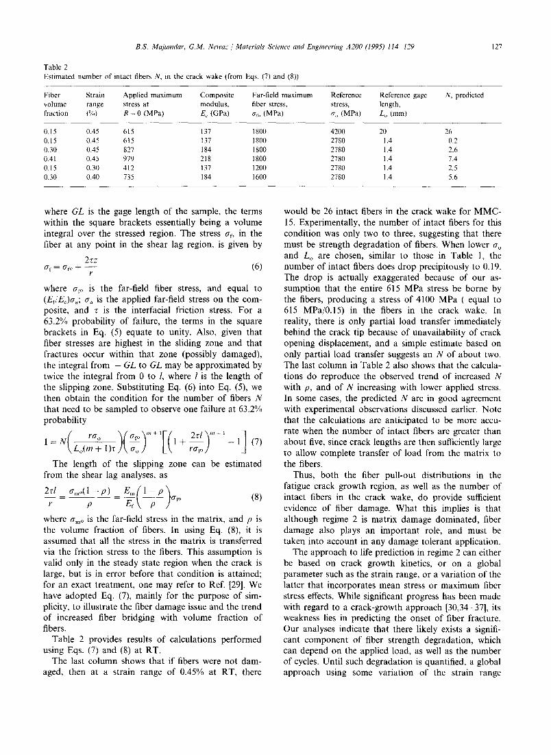
Table 2 Estimated number of intact fibers N, in the crack wake (from Eqs. (7) and (8))
Fiber Strain Applied maximum Composite Far-field maximum Reference Reference gage volume range stress at modulus, fiber stress, stress, length, fraction (%) R = 0 (MPa) E~ (GPa) ~rf, (MPa) n o (MPa) Lo (ram)
N, predicted
0.15 0.45 615 137 1800 4200 20 0.15 0.45 615 137 1800 2780 1.4 0.30 0.45 827 184 1800 2780 1.4 0.41 0.45 979 218 1800 2780 1.4 0.15 0.30 412 137 1200 2780 1.4 0.30 0.40 735 184 1600 2780 1.4
26 0.2 2.6 7.4 2.5 5.6
where G L is the gage length of the sample, the terms within the square brackets essentially being a volume integral over the stressed region. The stress ~rf, in the fiber at any point in the shear lag region, is given by
2zz a t - = afo + - - (6)
F
where ~r~> is the far-field fiber stress, and equal to (Ef/Ec)tTa; O" a is the applied far-field stress on the com- posite, and r is the interfacial friction stress. For a 63.2% probability of failure, the terms in the square brackets in Eq. (5) equate to unity. Also, given that fiber stresses are highest in the sliding zone and that fractures occur within that zone (possibly damaged), the integral from - G L to G L may be approximated by twice the integral from 0 to l, where l is the length of the slipping zone. Substituting Eq. (6) into Eq. (5), we then obtain the condition for the number of fibers N that need to be sampled to observe one failure at 63.2% probability
1 = N Lo(m + l ) r 1 + r•fo - 1 (7)
The length of the slipping zone can be estimated from the shear lag analyses, as
2r/ O'mO(1 -- p ) Em(~_p_ ) r - p - E,- a , , (8)
where amo is the far-field stress in the matrix, and p is the volume fraction of fibers. In using Eq. (8), it is assumed that all the stress in the matrix is transferred via the friction stress to the fibers. This assumption is valid only in the steady state region when the crack is large, but is in error before that condition is attained; for an exact treatment, one may refer to Ref. [29]. We have adopted Eq. (7), mainly for the purpose of sim- plicity, to illustrate the fiber damage issue and the trend of increased fiber bridging with volume fraction of fibers.
Table 2 provides results of calculations performed using Eqs. (7) and (8) at RT.
The last column shows that if fibers were not dam- aged, then at a strain range of 0.45% at RT, there
would be 26 intact fibers in the crack wake for MMC- 15. Experimentally, the number of intact fibers for this condition was only two to three, suggesting that there must be strength degradation of fibers. When lower O'o and Lo are chosen, similar to those in Table 1, the number of intact fibers does drop precipitously to 0.19. The drop is actually exaggerated because of our as- sumption that the entire 615 MPa stress be borne by the fibers, producing a stress of 4100 MPa (equal to 615 MPa/0.15) in the fibers in the crack wake. In reality, there is only partial load transfer immediately behind the crack tip because of unavailability of crack opening displacement, and a simple estimate based on only partial load transfer suggests an N of about two. The last column in Table 2 also shows that the calcula- tions do reproduce the observed trend of increased N with p, and of N increasing with lower applied stress. In some cases, the predicted N are in good agreement with experimental observations discussed earlier. Note that the calculations are anticipated to be more accu- rate when the number of intact fibers are greater than about five, since crack lengths are then sufficiently large to allow complete transfer of load from the matrix to the fibers.
Thus, both the fiber pull-out distributions in the fatigue crack growth region, as well as the number of intact fibers in the crack wake, do provide sufficient evidence of fiber damage. What this implies is that although regime 2 is matrix damage dominated, fiber damage also plays an important role, and must be taken into account in any damage tolerant application.
The approach to life prediction in regime 2 can either be based on crack growth kinetics, or on a global parameter such as the strain range, or a variation of the latter that incorporates mean stress or maximum fiber stress effects. While significant progress has been made with regard to a crack-growth approach [30,34-37], its weakness lies in predicting the onset of fiber fracture. Our analyses indicate that there likely exists a signifi- cant component of fiber strength degradation, which can depend on the applied load, as well as the number of cycles. Until such degradation is quantified, a global approach using some variation of the strain range

128 B.S. Majumdar, G.M. Newaz / Materials Seience and Engineering A200 (1995) 114-129
concept would appear preferable for predicting fatigue life. As already indicated, a strain range approach has the advantage that it incorporates aspects of matrix crack growth, as well as fiber fracture, both of which combine to produce MMC failure, and show up in the life diagrams described in this paper. A global parame- ter, such as a modified version of the strain range, or a combined stress and damage based approach [38], would also appear appropriate in regime 1, where creep effects and subsequent overload fracture of fibers domi- nate to produce MMC failure.
5. Summary and conclusions
The following summarizes our current understanding on fatigue of uniaxial fiber reinforced MMCs.
(1) Talreja's model does provide a good mechanism- based framework for interpreting MMC fatigue.
(2) Regime 1 is fiber failure dominated, but the exact mechanisms are different at RT and elevated tempera- tures.
(3) Persistent slip band observations and matrix cracking provide confirmatory evidence that a large fraction of fatigue life in regime 2 is controlled by matrix fatigue characteristics. However, fiber fracture also plays an important role, as discussed below.
(4) Reaction zone cracks are important crack initiat- ing sites. Essentially, slip bands initiate more easily at reaction zone crack sites, and repeated cycling leads to matrix cracks through classical metal fatigue mecha- nisms.
(5) Experiments on MMCs with different fiber vol- ume fraction show that strain range is a better parame- ter for characterizing fatigue life than the stress range.
(6) On a strain range basis, tension-compression life is much greater than tension-tension life, although the density of matrix cracks is larger under tension com- pression. The difference in life, however, is small when the two sets of data are compared based on the maxi- mum stress in the fiber, suggesting the important role of fiber fracture in controlling fatigue life.
(7) Good agreement is obtained between various data sets when data are plotted based on the strain range in the tension part of a cycle. This parameter has the advantage of incorporating a strain range for ma- trix damage, since metal fatigue is primarily strain range controlled, and it also emphasizes the role of tensile strain, which governs crack closure effects as well as the onset of fiber fracture. The parameter also provides good agreement between MMC data at posi- tive R-ratio, and the matrix data obtained under fully reversed load.
(8) Pull-out lengths in the fatigue crack growth re- gions, and observations of only limited crack bridging, provide convincing evidence of fiber damage in the
crack wake. An approximate probabilistic method of determining when fibers start failing is also provided, and it does reproduce the observed trend of increasing fiber bridging with increased fiber volume fraction, for specimens cycled at the same strain range. Future analyses will concentrate on using more accurate esti- mates of fiber stress in the bridged region.
Acknowledgments
The tension-tension fatigue work was supported by the NASA Lewis Research Center under the HITEMP program, while the tension-compression work was sup- ported by the Air Force Office of Scientific Research. We sincerely thank Dr. Bradley A. Lerch and Dr. J. Rod Ellis of NASA Lewis for many useful discussions and suggestions throughout the program, and Dr. Wal- ter Jones of AFOSR for his encouragement of compres- sion and reversed deformation studies.
References
[1] R. Talreja, Fatigue of. Composite Materials, Technomic Publish- ing Co., Lancaster, PA, 1987.
[2] B.S. Majumdar and G.M. Newaz, Inelastic deformation of MMCs: Thermomechanical fatigue, Proc. HITEMP'93 Conf, NASA Rep. No. 19117, 1993, pp. 36.1-36.12.
[3] B.S. Majumdar and G.M. Newaz, Damage mechanisms under in-phase TMF for a SiC Ti-15-3 system, Proc. HITEMP'94 Conf., NASA Rep. No. 10146, 1994, pp. 41.1-41.3.
[4] P.A. Bartolotta and P.K. Brindley, High temperature fatigue behavior of a SiC-Ti-24AI-11Nb composite, NASA Tech. Memo. No. 103157, 1990.
[5] T.P. Gabb, J. Gayda, B.A. Lerch and G.R. Halford, The effect of matrix mechanical properties on [0]8 unidirectional SiC-Ti composite fatigue resistance, Ser. Metall., 25 (1991) 2879-2884.
[6] J. Gayda, T.P. Gabb and A.D. Freed, The isothermal fatigue behavior of a unidirectional SiC-Ti composite and the Ti alloy matrix, in P.K. Liaw and M.N. Gungor (eds.), Fundamental Relationships between Microstructure and Mechanical Properties of Metal Matrix Composites, The Metallurgical Society, 1990, pp. 497-514.
[7] T.P. Gabb, J. Gayda and R. Mackay, Isothermal and non- isothermal fatigue behavior of a metal matrix composite, J. Compos. Mater., 24 (1990) 667-686.
[8] W.S. Johnson, S.J. Lubowinski and A.L. Highsmith, Mechanical characterization of unnotched SCS6 Ti-15-3 metal matrix com- posites at room temperature, in J.M. Kennedy, H.H. Moeller and W.S. Johnson (eds.), Thermal and Mechanical Behavior of. Metal Matrix and Ceramic Matrix Composites, ASTM STP 1080, 1990, pp. 193-218.
[9] J. Gayda and T.P. Gabb, The effect of fiber content on the fatigue life of SCS6-Ti-15-3 composite, Proc. 3rd NASA HITEMP Conf., 1992, NASA Rep. No. 10104, 1992, pp. 51.1 51.15.
[10] B.S. Majumdar and G.M. Newaz, Inelastic deformation of metal matrix composites: plasticity and damage mechanisms", Philos. Mag., 66 (2) (1992) pp. 187-212.
[11] B.S. Majumdar and G.M. Newaz, Inelastic deformation of metal matrix composites: Part l l--plasticity and damage at high tem- perature, NASA Contractor Rep. No. 189096, 1992.

B.S. Majumdar, G.M. Newaz / Materials Science and Engineering A200 (1995) 114-129 129
[12] B,A. Lerch and J. Saltsman, Tensile deformation damage in SiC reinforced Ti-15V-3Cr-3AI-3Sn, NASA Tech. Memo., 1991, (NASA Lewis Research Center).
[13] B.S. Majumdar, G.M. Newaz and J.R. Ellis, Evolution of plas- ticity and damage in metal matrix composites, Metall. Trans. A, 24 (1993) 1597 1610.
[14] B.S. Majumdar and G.M. Newaz, Isothermal fatigue mecha- nisms in Ti-based metal matrix composites, NASA Contractor Rep. No. 191181, 1993, (NASA Lewis Research Center).
[15] B.S. Majumdar and B.A. Lerch, Fatigue mechanisms in a Ti- based fiber reinforced MMC and approaches to life prediction, in P.R. Smith and W. Revelos (eds.), Titanium Metal Matrix Composites--ll, Proc. Air Force Workshop on Titanium Matrix Composites, La Jolla, November 1993, Air Force Tech. Rep. No. WL-TR-93-4105, pp. 409 426.
[16] B.S. Majumdar and G.M. Newaz, Inelastic deformation of metal matrix composites: compression and fatigue, Proe. 3rd NASA HITEMP Conf., 1992, NASA Rep. No. 10104, pp. 49.1-- 49.17.
[17] B.A. Lerch, M.J. Verrilli and G.R. Halford, Fully reversed fatigue of a MMC, Proc. Am. Soc. Jor Composites, Eighth Tech. Conf., Technomic Publication Company, Pennsylvania-17604, 1993, pp. 388-396.
[18] E.A. Boyum and S. Mall, Fatigue behavior of a cross-ply titanium matrix composite under tension-tension and tension- compression cycling, this issue.
[19] J. Gayda and T.P. Gabb, Isothermal fatigue behavior of a [90]8 SiC-Ti-15-3 composite at 426 °C, NASA Technical Memo. No. 103686, January 1991.
[20] B.A. Lerch, Fatigue behavior of SiC Ti-15-3 laminates, NASA Conf. Publication No. 10051, HITEMP Rev. 1990, pp. 35.1-35.8.
[21] B.S. Majumdar, G.M. Newaz, F.W. Brust and J.R. Ellis, Defor- mation mechanisms in a Ti-alloy-SiC metal matrix composite, in F.H. Froes (ed.), Proc. Vllth Worm Conf. on 7~tanium, San Diego, June 1992, 1993, pp. 2609-2616.
[22] S. Covey, A study of fiber volume fraction effects in notched unidirectional SCS-6-Ti-15V-3Cr-3AI-3Sn composite, Ph.D. Thesis, University of Cincinnati; also NASA Contract Rep. No. NASA CR 191165, 1993.
[23] B.S. Majumdar and G,M. Newaz, Mechanisms of fatigue dam- age and failure of a SCS-6 Ti-15-3 composite, in R.B. Bhagat, S.G. Fishman and R.J. Arsenault (eds.), Mechanisms and Me- chanics of Composites Fracture, Proc. A SM 1993 Materials Con- gress, ASM International, 1993, pp. 77-90.
[24] P. Kantzos, J. Eldridge, D.A, Koss and L.J. Ghosn, The effect of fatigue loading on the interfacial shear properties of SCS-6-Ti- based MMCs, MRS Symp. Proc., 273 (1992) pp. 325 330.
[25] B.S. Majumdar and U. Santosh, Interface measurements using push-out tests in MMCs: Mechanisms and a fracture mechanics analyses, submitted to Scr. Metall.
[26] G.M. Newaz and B.S, Majumdar, Inelastic deformation mecha- nisms in SCS-6 Ti-15-3 MMC lamina under compression, NASA Rep. No. NASA-CR-191170, 1993, (NASA Lewis Re- search Center).
[27] M.Y. He, A.G. Evans and W.A. Curtin, The ultimate tensile strength of metal and ceramic matrix composites, Acta Metall., 41 (3) (1993) 871 878.
[28] B.S. Majumdar, G.M. Newaz and A.R. Rosenfield, Yielding behavior of ceramic-matrix composites, in K. Salama et al. (eds.), Advances in Fracture Research, Proc. 7th Int. Con[~ on Fracture, 1989, pp. 2805-2814.
[29] S. Danchaivijit and D.K. Shetty, Matrix cracking in ceramic matrix composites, J. Am. Cer. Soc., 76 10 (1993) 2497-2504.
[30] R.M. McMeeking and A.G. Evans, Matrix fatigue cracking in fiber composites, Mech. Mater., 9 (1990) 217 226.
[31] D.B. Marshall, B.N. Cox and A.G. Evans, The mechanics of matrix cracking in brittle matrix composites, Acta Metall., 33 (1985) pp. 2013-2021.
[32] W.A. Curtin, Theory of mechanical properties of ceramic matrix composites, J. Am. Cer. Soc., 74 (1991) 2837.
[33] W.L. Morris, M.S. Dadakh, M.R. James, M.R. Mitchell and S.A. Schroeder, Micromechanics of fatigue crack growth in Ti-Aluminide composites, in P.R. Smith, S.J. Balsone and T. Nicholas (eds.), Titanium Aluminide Composites, Air Force Rep. WL-TR-91-4020, 1991, pp. 511-521.
[34] R. John, S.G. Kaldon and N.E. Ashbaugh, Applicability of fiber bridging models to describe crack growth in unidirectional tita- nium matrix composites, in P.R. Smith and W.C. Revelos (eds.), Titanium Metal Matrix Composites II, Proe. TMC Workshop, La Jolla, Air Force Rep. No. WL-TR-93-4105, 1993, pp. 270-290.
[35] J.R. Jira and J.M. Larsen, Crack bridging behavior in unidirec- tional SCS-6-Ti-24AI-11Nb composite, in J.P. Bailon and J.I. Dickson (eds.), Fatigue 93, Vol.II, Engineering Materials Advi- sory Services Ltd, West Midlands, UK, 1993, pp. 1085-1090.
[36] F.W. Zok, Z.Z. Du and S.J. Connell, On the development of fatigue failure maps for titanium matrix composites, this issue.
[37] L.J. Ghosn, P. Kantzos and J. Telesman, Modeling of crack bridging in a unidirectional metal matrix composite, lnt. J. Fraet., 54 (1992) 345- 357.
[38] T. Nicholas, S. Russ, N. Schehl and A. Cheney, Frequency and stress-ratio effects on fatigue of unidirectional SCS-6-Ti-24AI- l lNb, in J.P. Bailon and J.I. Dickson (eds.), Fatigue 93, Vol.ll, Engineering Materials Advisory Services Ltd, West Midlands, UK, 1993, pp. 995-1000.