Lossy Mode Resonance Generation With Indium-Tin-Oxide-Coated Optical Fibers for Sensing Applications
7
JOURNAL OF LIGHTWAVE TECHNOLOGY, VOL. 28, NO. 1, JANUARY 1, 2010 111 Lossy Mode Resonance Generation With Indium-Tin-Oxide-Coated Optical Fibers for Sensing Applications Ignacio Del Villar, Carlos R. Zamarreño, Miguel Hernaez, Francisco J. Arregui, Member, IEEE, and Ignacio R. Matias, Senior Member, IEEE Abstract—Surface plasmon resonances and lossy mode reso- nances (LMRs) can be generated with indium tin oxide (ITO) coated optical fibers. Both phenomena are analyzed and com- pared. LMRs present important advantages: they do not require a specific polarization of light, it is possible to generate multiple attenuation bands in the transmission spectrum, and the sen- sitivity of the device to external parameters can be tuned. The key parameter is the thickness of the ITO coating. The study is supported with both theoretical and experimental results. The main purposes are sensing and generation of multiple-wavelength filters. Index Terms—Indium tin oxide (ITO), optical fiber filters, op- tical fiber sensor, optical resonance, thin films. I. INTRODUCTION D URING the last decades, much research has been done in the field of semiconductor and metal-clad optical waveg- uides [1]–[6]. In both cases, the clad introduces losses to the propagation of light in the optical waveguide [2]. Depending on the properties of the cladding or thin film, three main cases can be distinguished [3]. The first case occurs when the real part of the thin film permittivity is negative and higher in magnitude than both its own imaginary part and the permittivity of the material surrounding the thin film (i.e., the optical waveguide and the surrounding medium in contact with the thin film). In this case, coupling occurs between light propagating through the waveguide and a surface plasmon, which is called surface plasmon polariton [3], or surface plasmon resonance (SPR) [4]–[6]. The second case occurs when the real part of the thin film permittivity is positive and higher in magnitude than both its own imaginary part and the material surrounding the thin film. Some authors consider these modes as long-range guided modes [3], whereas others call them lossy modes [2], [7]. Since lossy modes are a specific type of guided modes, we will use henceforward the name “lossy modes.” The third case occurs Manuscript received September 02, 2009; revised October 23, 2009. First published November 24, 2009; current version published December 23, 2009. This work was supported in part by the Spanish Ministry of Education and Sci- ence under Grant FEDER TEC2006-12170 and Grant TEC2007-67987-C02-02/ MIC. The authors are with the Electrical and Electronic Engineering De- partment, Public University of Navarra, 31006 Pamplona, Spain (e-mail: [email protected]). Digital Object Identifier 10.1109/JLT.2009.2036580 when the real part of the thin film permittivity is close to zero, while the imaginary part is large [3]. This case, known as long-range surface exciton polariton, falls beyond the scope of this study and will no longer be studied. Hence, the study will be focused on the first two cases mentioned. Some theoretical studies have been devoted to light propaga- tion through semiconductor-cladded waveguides [1], [8]. The characteristics of these materials are adequate for generation of lossy modes. Moreover, for specific thickness values, attenua- tion maxima of the light propagating through the optical wave- guide are obtained [1]. This is due to a coupling between a wave- guide mode and a particular lossy mode of the semiconductor thin film, which depends on two conditions: there is a consider- able overlap between the mode fields and the phase-matching condition (i.e., the equality of real parts of propagation con- stants) is sufficiently satisfied [2]. Since the phenomenon occurs when the lossy mode is near cutoff, it is stated in [1] that there are cutoff thickness values that lead to attenuation maxima. In other works, similar conclusions are extracted after a thorough analysis of the modes. As the thickness of the thin film on the waveguide is increased, some modes guided in the optical wave- guide become guided in the thin film, which causes a modal re- distribution or modal conversion [8], [9]. Previous studies have been focused on the variation of thick- ness. However, if the thin film thickness is fixed, a resonance will be visible in the electromagnetic spectrum for those inci- dent wavelength values where there is a mode near cutoff in the overlay. This is of great interest because one of the basic ways of using waveguides as sensors is by analysis of resonance wave- length shift. Hence, the phenomenon studied in this paper is the generation of resonances in the electromagnetic spectrum based on near cutoff lossy modes. The right term should be near cutoff lossy mode resonance (NCLMR). However, for the sake of sim- plicity, the term LMR will be used, which indeed is similar to that mentioned in [7]. During the last few years, hundreds of publications have been devoted to the SPR, whereas the number of publications devoted to lossy modes is quite low [1]–[3], [7]. Moreover, the utiliza- tion of LMR for sensing purposes has not been used before this study. The main reason is that the selection of the thin-film ma- terial is critical. Among the materials whose characteristics meet the criteria for the generation of LMR, indium tin oxide (ITO) is chosen for this study. There are various reasons for selecting ITO. First, it belongs to transparent conductive oxides (TCOs), which have made a breakthrough in many scientific areas during 0733-8724/$26.00 © 2009 IEEE
-
Upload
independent -
Category
Documents
-
view
2 -
download
0
Transcript of Lossy Mode Resonance Generation With Indium-Tin-Oxide-Coated Optical Fibers for Sensing Applications
JOURNAL OF LIGHTWAVE TECHNOLOGY, VOL. 28, NO. 1, JANUARY 1, 2010 111
Lossy Mode Resonance GenerationWith Indium-Tin-Oxide-Coated Optical
Fibers for Sensing ApplicationsIgnacio Del Villar, Carlos R. Zamarreño, Miguel Hernaez, Francisco J. Arregui, Member, IEEE, and
Ignacio R. Matias, Senior Member, IEEE
Abstract—Surface plasmon resonances and lossy mode reso-nances (LMRs) can be generated with indium tin oxide (ITO)coated optical fibers. Both phenomena are analyzed and com-pared. LMRs present important advantages: they do not requirea specific polarization of light, it is possible to generate multipleattenuation bands in the transmission spectrum, and the sen-sitivity of the device to external parameters can be tuned. Thekey parameter is the thickness of the ITO coating. The study issupported with both theoretical and experimental results. Themain purposes are sensing and generation of multiple-wavelengthfilters.
Index Terms—Indium tin oxide (ITO), optical fiber filters, op-tical fiber sensor, optical resonance, thin films.
I. INTRODUCTION
D URING the last decades, much research has been done inthe field of semiconductor and metal-clad optical waveg-
uides [1]–[6]. In both cases, the clad introduces losses to thepropagation of light in the optical waveguide [2]. Depending onthe properties of the cladding or thin film, three main cases canbe distinguished [3]. The first case occurs when the real part ofthe thin film permittivity is negative and higher in magnitudethan both its own imaginary part and the permittivity of thematerial surrounding the thin film (i.e., the optical waveguideand the surrounding medium in contact with the thin film). Inthis case, coupling occurs between light propagating throughthe waveguide and a surface plasmon, which is called surfaceplasmon polariton [3], or surface plasmon resonance (SPR)[4]–[6]. The second case occurs when the real part of the thinfilm permittivity is positive and higher in magnitude than bothits own imaginary part and the material surrounding the thinfilm. Some authors consider these modes as long-range guidedmodes [3], whereas others call them lossy modes [2], [7]. Sincelossy modes are a specific type of guided modes, we will usehenceforward the name “lossy modes.” The third case occurs
Manuscript received September 02, 2009; revised October 23, 2009. Firstpublished November 24, 2009; current version published December 23, 2009.This work was supported in part by the Spanish Ministry of Education and Sci-ence under Grant FEDER TEC2006-12170 and Grant TEC2007-67987-C02-02/MIC.
The authors are with the Electrical and Electronic Engineering De-partment, Public University of Navarra, 31006 Pamplona, Spain (e-mail:[email protected]).
Digital Object Identifier 10.1109/JLT.2009.2036580
when the real part of the thin film permittivity is close to zero,while the imaginary part is large [3]. This case, known aslong-range surface exciton polariton, falls beyond the scope ofthis study and will no longer be studied. Hence, the study willbe focused on the first two cases mentioned.
Some theoretical studies have been devoted to light propaga-tion through semiconductor-cladded waveguides [1], [8]. Thecharacteristics of these materials are adequate for generation oflossy modes. Moreover, for specific thickness values, attenua-tion maxima of the light propagating through the optical wave-guide are obtained [1]. This is due to a coupling between a wave-guide mode and a particular lossy mode of the semiconductorthin film, which depends on two conditions: there is a consider-able overlap between the mode fields and the phase-matchingcondition (i.e., the equality of real parts of propagation con-stants) is sufficiently satisfied [2]. Since the phenomenon occurswhen the lossy mode is near cutoff, it is stated in [1] that thereare cutoff thickness values that lead to attenuation maxima. Inother works, similar conclusions are extracted after a thoroughanalysis of the modes. As the thickness of the thin film on thewaveguide is increased, some modes guided in the optical wave-guide become guided in the thin film, which causes a modal re-distribution or modal conversion [8], [9].
Previous studies have been focused on the variation of thick-ness. However, if the thin film thickness is fixed, a resonancewill be visible in the electromagnetic spectrum for those inci-dent wavelength values where there is a mode near cutoff in theoverlay. This is of great interest because one of the basic ways ofusing waveguides as sensors is by analysis of resonance wave-length shift. Hence, the phenomenon studied in this paper is thegeneration of resonances in the electromagnetic spectrum basedon near cutoff lossy modes. The right term should be near cutofflossy mode resonance (NCLMR). However, for the sake of sim-plicity, the term LMR will be used, which indeed is similar tothat mentioned in [7].
During the last few years, hundreds of publications have beendevoted to the SPR, whereas the number of publications devotedto lossy modes is quite low [1]–[3], [7]. Moreover, the utiliza-tion of LMR for sensing purposes has not been used before thisstudy. The main reason is that the selection of the thin-film ma-terial is critical. Among the materials whose characteristics meetthe criteria for the generation of LMR, indium tin oxide (ITO)is chosen for this study. There are various reasons for selectingITO. First, it belongs to transparent conductive oxides (TCOs),which have made a breakthrough in many scientific areas during
0733-8724/$26.00 © 2009 IEEE
112 JOURNAL OF LIGHTWAVE TECHNOLOGY, VOL. 28, NO. 1, JANUARY 1, 2010
the last decades: the fabrication of heat shields, liquid crystaldisplays, flat panel displays, plasma displays, touch panels, elec-tronic ink, organic LEDs, solar cells, antistatic coatings, or evenelectromagnetic interference shields [10], [11]. This success isdue to the good qualities that these materials present (electro-chemical stability and high transmittance in the visible spectralrange), if compared with other well-known conductive materialssuch as gold or silver. More specifically, ITO has been also usedin many different sensing applications, such as the fabricationof conductimetric or optical sensors [12]–[16], by exploiting thecombination of conductive and transparency/reflectivity proper-ties in the visible/IR regions, respectively. In fact, it is this dualbehavior what makes ITO an adequate candidate for the gener-ation of LMR. In the region of high reflectance, the imaginarypart of the ITO refractive index is of the order of metals. Con-sequently, this region is adequate for SPR generation. However,for the low-reflectance region, the imaginary part is lower andpermits the LMR generation.
Another important question is the selection of the substrate.Among optical waveguides, the fine characteristics of opticalfiber are well known: lightweight, capability of multiplexing,and immunity against electrical discharge [17], [18]. In viewof these properties, optical fiber is considered as an advanta-geous substrate for the deposition of ITO sensing films. The firstapproach to ITO-coated optical fiber was done in [19]. How-ever, the LMR phenomenon was not detected, which is vitalfor exploiting the sensing capability of ITO-coated optical fibersensors.
In this study, the typical transmission configuration of metal-coated optical fiber sensors is used [4]. ITO is deposited ontothe uncladded core of an optical fiber. The result is the cre-ation of an LMR with a high sensitivity in the wavelength rangewhere there is a low reflectance. The characteristics of this novelfiber-optic-based device and its ability to detect changes in thesurrounding refractive index (SRI) are presented theoreticallyand experimentally for the first time in the literature. The sen-sitivity of these devices is located in the range of SPR sensors,which have been extensively used as refractometers during thelast years [4], [20], [21].
One of the main differences with SPR is that LMR can beobserved for both TE and TM polarized light [3], which is alsodemonstrated in this work. Moreover, if the ITO thickness isincreased, several LMR can be obtained in the transmissionspectrum.
It is well known that, depending on the parameters used forthe fabrication of ITO, its characteristics can differ in a greatmanner [22]–[25]. Consequently, depending on the characteris-tics of ITO, the resonance wavelength can be tuned, which is an-other advantage of the utilization of ITO. In other words, the res-onance can be located in the visible or the IR region, dependingon ITO properties. Moreover, for a specific ITO parameteriza-tion, it is also possible to tune the LMR simply by changing theITO thin film thickness. This value also determines the sensi-tivity of the device.
II. THEORY
There are various models both for the dispersion curve of ITOand the analysis of the propagation of light through a metal-
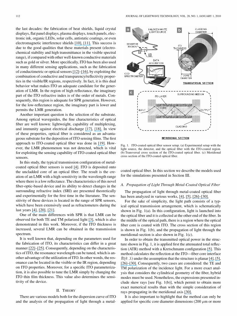
Fig. 1. ITO-coated optical fiber sensor setup. (a) Experimental setup with thelight source, the detector, and the optical fiber with the ITO-coated region.(b) Transversal cross section of the ITO-coated optical fiber. (c) Meridionalcross section of the ITO-coated optical fiber.
coated optical fiber. In this section we describe the models usedfor the simulations presented in Section III.
A. Propagation of Light Through Metal-Coated Optical Fiber
The propagation of light through metal-coated optical fiberhas been analyzed in various works, [4], [5], [26]–[30].
For the sake of simplicity, the light path consists of a typ-ical optical transmission arrangement, which is schematicallyshown in Fig. 1(a). In this configuration, light is launched intothe optical fiber and it is collected at the other end of the fiber. Inthe middle of the optical path, there is a region where the opticalfiber core is coated with ITO. The cross section of this regionis shown in Fig. 1(b), and the propagation of light through themeridional-section is also shown in Fig. 1(c).
In order to obtain the transmitted optical power in the struc-ture shown in Fig. 1, it is applied first the attenuated total reflec-tion (ATR) method with a Kretschmann configuration [5]. Thismethod calculates the reflection at the ITO—fiber core interface
under the assumption that the structure is planar [4], [5],[26]–[30]. Consequently, two cases are considered: the TE andTM polarization of the incidence light. For a more exact anal-ysis that considers the cylindrical geometry of the fiber, hybridmodes must be used. Nonetheless, the expressions presented in-clude skew rays [see Fig. 1(b)], which permit to obtain moreexact numerical results than with the simple consideration ofrays propagating in the meridional axis [30].
It is also important to highlight that the method can only beapplied for specific core diameter dimensions (200 m or more
DEL VILLAR et al.: LOSSY MODE RESONANCE GENERATION 113
according to [30]), which is the case for the optical fiber understudy in Section III.
Depending on the length of the metal-coated region and theincidence angle, the number of reflections N at the ITO—fibercore interface is obtained as follows:
(1)
where is the length of the of the metal-coated region, is thediameter of the optical fiber core, the angle between the rayand the normal to the core-metal interface [the projection of thisangle in the meridional axis is shown in Fig. 1(b)], and is theskewness angle [see Fig. 1(c)].
The final step is to calculate the transmitted power. Accordingto [27], depending on the sensor’s application, the propagationof light can be analyzed considering remote sensing or nonre-mote sensing. Since the dimension of the fiber used in our ex-periments is short, it will be considered the nonremote case. Themain issue now is to select an adequate equivalent of the lightsource in the following expression used to calculate thetransmitted power [30]:
(2)
where is the critical angle, which is expressed as follows:
(3)
with and being the cladding and the core index,respectively.
Following the same idea of [29], if we assume that the sourceis a white light source, this will be expressed as the propagatingmode density. Since the model is 2-D, following the expressionsof [31], the modal density can be easily calculated as follows:
(4)
where is the quotient between and the incidence wave-length, and is the angle shown in Fig. 1(c).
It is interesting to remark that expression (4) coincides withthe expression of a Lambertian source, which is typically usedin the description of LED sources [26] (the white light sourcecan be considered as a combination of LED sources).
The final step is to replace in expression (2) with thevalue of expression (4). It is also important to highlight thatsince the light introduced in the optical fiber is unpolarized,
can be replaced in expression (2) with the fol-lowing expression, which considers the reflected light as a com-bination of the reflected power in TE and TM mode polariza-tions [26]:
(5)
B. ITO Layer
Depending on the technique used for the deposition of ITO onoptical fiber or any other substrate, the properties of the metallicfilm may differ in a great manner [25], [32]–[34]. The most
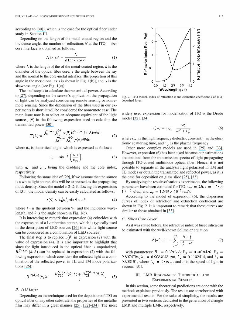
Fig. 2. ITO model. Index of refraction n and extinction coefficient k of ITO-deposited layer.
widely used expression for modelization of ITO is the Drudemodel [32], [34]
(6)
where is the high frequency dielectric constant, is the elec-tronic scattering time, and is the plasma frequency.
Other more complex models are used in [25] and [33].However, expression (6) has been used because our estimationsare obtained from the transmission spectra of light propagatingthrough ITO-coated multimode optical fiber. Hence, it is notpossible to separate in the analysis light polarized in TM andTE modes or obtain the transmitted and reflected power, as it isthe case for deposition on glass slide [25], [33].
By analyzing the results of various experiments, the followingparameters have been estimated for ITO:
s/rad, and rad/s.According to the model of expression (6), the dispersion
curves of index of refraction and extinction coefficient areshown in Fig. 2. It is important to remark that these curves aresimilar to those obtained in [33].
C. Silica Core Layer
As it was stated before, the refractive index of fused silica canbe estimated with the well-known Sellmeier equation
(7)
with parameters:m, , and
, where and is the speed of light invacuum [31].
III. LMR RESONANCES: THEORETICAL AND
EXPERIMENTAL RESULTS
In this section, some theoretical predictions are done with themethods explained previously. The results are corroborated withexperimental results. For the sake of simplicity, the results arepresented in two sections dedicated to the generation of a singleLMR and multiple LMR, respectively.
114 JOURNAL OF LIGHTWAVE TECHNOLOGY, VOL. 28, NO. 1, JANUARY 1, 2010
A. Single LMR Generation
Fig. 1 shows the experimental setup, which basically con-sists of a halogen white light source (DH2000, Avantes, Inc.)that launches light into the optical fiber, the optical fiber (FTsilica/TEQS, Thorlabs, Inc. 200/225 m of core/cladding di-ameter) with a sensitive region where ITO has been deposited[see Fig. 1(b)–(c)] and the detector (NIR512, Oceanoptics, Inc.).Sol–gel dip-coating deposition process was selected because itwas considered as an effective and simple method for the fab-rication of ITO coatings onto nonplanar substrates as opticalfibers. Additionally, this technique had been proven as a suitablemethod for the fabrication of ITO coating with good conductiveand optical properties in several works before.
The optical fibers were cleaved and pretreated by chemicallyremoving with acetone a 10 cm portion of the plastic cladding.These fibers were sonicated in ultrapure water and boiled inacetone. Then they were used as substrates in a dip-coating de-position process in order to fabricate the ITO outer layer aroundthe fiber core, as described by R. Ota [33]. The immersionand pulling-out speed was 4 cm/s. The fabrication process wasstopped at 10 and 20 dips in order to obtain ITO thicknesses of115 and 220 nm respectively. After the deposition process, aportion of the ITO-coated optical fibers of length L was cleavedand spliced to optical fiber patch cords at both ends.
The parameters of the optical fiber used both for the exper-iments and simulations of light transmitted through the setupare: 200/225 m of core/cladding diameter in the optical fiber,length of the ITO-coated region of 4 cm, numerical aperture ofthe optical fiber 46 , and it is assumed that the core is madeof fused silica. Hence, the Sellmeier equation is used [36]. Theperformance of the sensor as a refractometer was tested by ob-taining the transmission response of the devices for several sur-rounding media refractive indexes: 1.321, 1.339, 1.358, 1.378,1.400, 1.422, and 1.436, which were obtained from differentwater/glycerin concentration solutions from 0% to 85%, respec-tively [37]–[39].
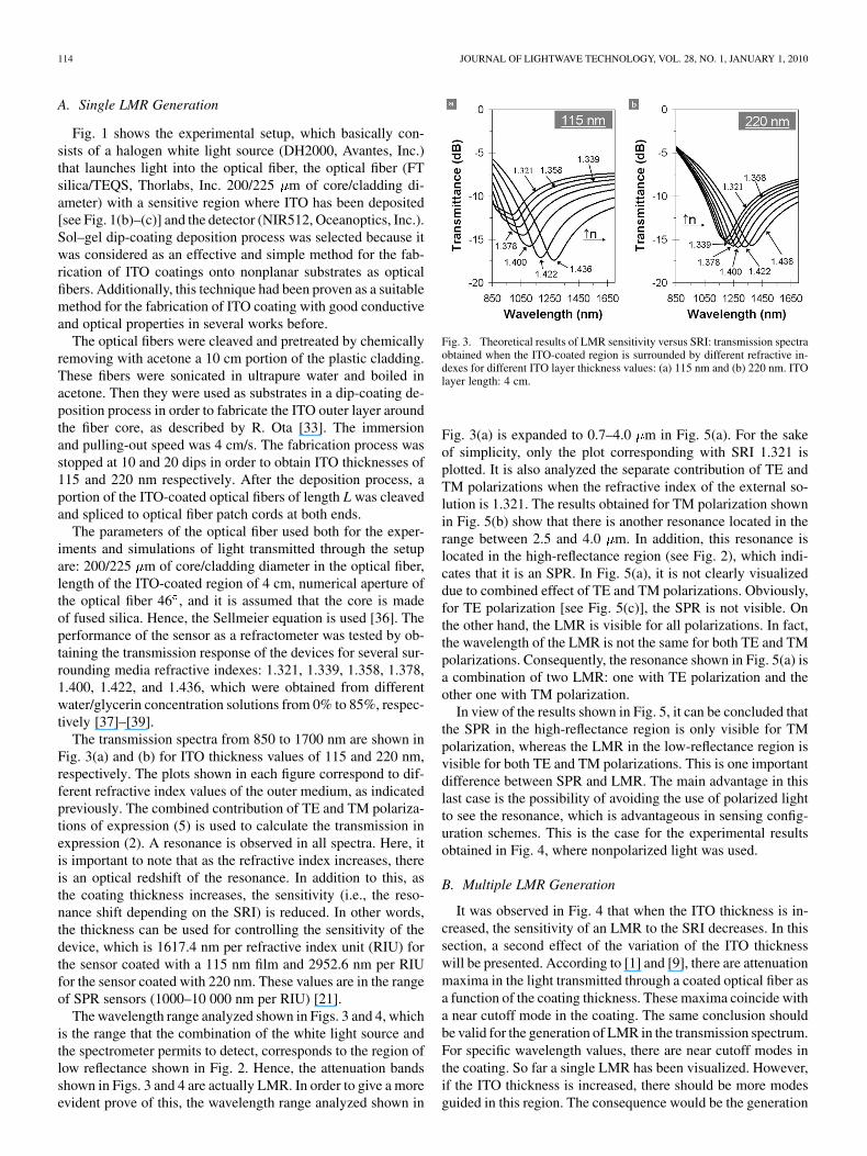
The transmission spectra from 850 to 1700 nm are shown inFig. 3(a) and (b) for ITO thickness values of 115 and 220 nm,respectively. The plots shown in each figure correspond to dif-ferent refractive index values of the outer medium, as indicatedpreviously. The combined contribution of TE and TM polariza-tions of expression (5) is used to calculate the transmission inexpression (2). A resonance is observed in all spectra. Here, itis important to note that as the refractive index increases, thereis an optical redshift of the resonance. In addition to this, asthe coating thickness increases, the sensitivity (i.e., the reso-nance shift depending on the SRI) is reduced. In other words,the thickness can be used for controlling the sensitivity of thedevice, which is 1617.4 nm per refractive index unit (RIU) forthe sensor coated with a 115 nm film and 2952.6 nm per RIUfor the sensor coated with 220 nm. These values are in the rangeof SPR sensors (1000–10 000 nm per RIU) [21].
The wavelength range analyzed shown in Figs. 3 and 4, whichis the range that the combination of the white light source andthe spectrometer permits to detect, corresponds to the region oflow reflectance shown in Fig. 2. Hence, the attenuation bandsshown in Figs. 3 and 4 are actually LMR. In order to give a moreevident prove of this, the wavelength range analyzed shown in
Fig. 3. Theoretical results of LMR sensitivity versus SRI: transmission spectraobtained when the ITO-coated region is surrounded by different refractive in-dexes for different ITO layer thickness values: (a) 115 nm and (b) 220 nm. ITOlayer length: 4 cm.
Fig. 3(a) is expanded to 0.7–4.0 m in Fig. 5(a). For the sakeof simplicity, only the plot corresponding with SRI 1.321 isplotted. It is also analyzed the separate contribution of TE andTM polarizations when the refractive index of the external so-lution is 1.321. The results obtained for TM polarization shownin Fig. 5(b) show that there is another resonance located in therange between 2.5 and 4.0 m. In addition, this resonance islocated in the high-reflectance region (see Fig. 2), which indi-cates that it is an SPR. In Fig. 5(a), it is not clearly visualizeddue to combined effect of TE and TM polarizations. Obviously,for TE polarization [see Fig. 5(c)], the SPR is not visible. Onthe other hand, the LMR is visible for all polarizations. In fact,the wavelength of the LMR is not the same for both TE and TMpolarizations. Consequently, the resonance shown in Fig. 5(a) isa combination of two LMR: one with TE polarization and theother one with TM polarization.
In view of the results shown in Fig. 5, it can be concluded thatthe SPR in the high-reflectance region is only visible for TMpolarization, whereas the LMR in the low-reflectance region isvisible for both TE and TM polarizations. This is one importantdifference between SPR and LMR. The main advantage in thislast case is the possibility of avoiding the use of polarized lightto see the resonance, which is advantageous in sensing config-uration schemes. This is the case for the experimental resultsobtained in Fig. 4, where nonpolarized light was used.
B. Multiple LMR Generation
It was observed in Fig. 4 that when the ITO thickness is in-creased, the sensitivity of an LMR to the SRI decreases. In thissection, a second effect of the variation of the ITO thicknesswill be presented. According to [1] and [9], there are attenuationmaxima in the light transmitted through a coated optical fiber asa function of the coating thickness. These maxima coincide witha near cutoff mode in the coating. The same conclusion shouldbe valid for the generation of LMR in the transmission spectrum.For specific wavelength values, there are near cutoff modes inthe coating. So far a single LMR has been visualized. However,if the ITO thickness is increased, there should be more modesguided in this region. The consequence would be the generation
DEL VILLAR et al.: LOSSY MODE RESONANCE GENERATION 115
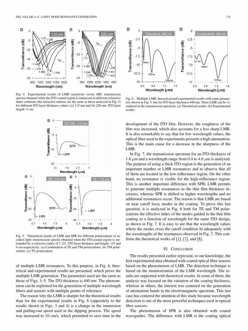
Fig. 4. Experimental results of LMR sensitivity versus SRI: transmissionspectra obtained when the ITO-coated region is immersed in different refractiveindex solutions (the refractive indexes are the same as those analyzed in Fig. 3)for different ITO layer thickness values: (a) 115 nm and (b) 220 nm. ITO layerlength: 4 cm.
Fig. 5. Theoretical results of LMR and SPR for different polarizations of in-cident light: transmission spectra obtained when the ITO-coated region is sur-rounded by a refractive index of 1.321. ITO layer thickness and length: 115 and4 cm respectively. (a) Combination of TE and TM polarizations. (b) TM polar-ization. (c) TE polarization.
of multiple LMR resonances. To this purpose, in Fig. 6, theo-retical and experimental results are presented, which prove themultiple LMR generation. The parameters used are the same asthose of Figs. 3–5. The ITO thickness is 440 nm. The phenom-enon can be exploited for the generation of multiple wavelengthfilters and sensors with multiple points of reference.
The reason why the LMR is sharper for the theoretical resultsthan for the experimental results in Fig. 6 (oppositely to theresults shown in Figs. 3 and 4) is a change in the immersionand pulling-out speed used in the dipping process. The speedwas increased to 10 cm/s, which permitted to save time in the
Fig. 6. Multiple LMR: theoretical and experimental results with same parame-ters shown in Fig. 5, but for ITO layer thickness 440 nm. Three LMR can be vi-sualized in the transmission spectrum. (a) Theoretical results. (b) Experimentalresults.
development of the ITO film. However, the roughness of thefilm was increased, which also accounts for a less sharp LMR.It is also remarkable to say that for low wavelength values, theoptical fiber used in the experiments presents a high attenuation.This is the main cause for a decrease in the sharpness of theLMR.
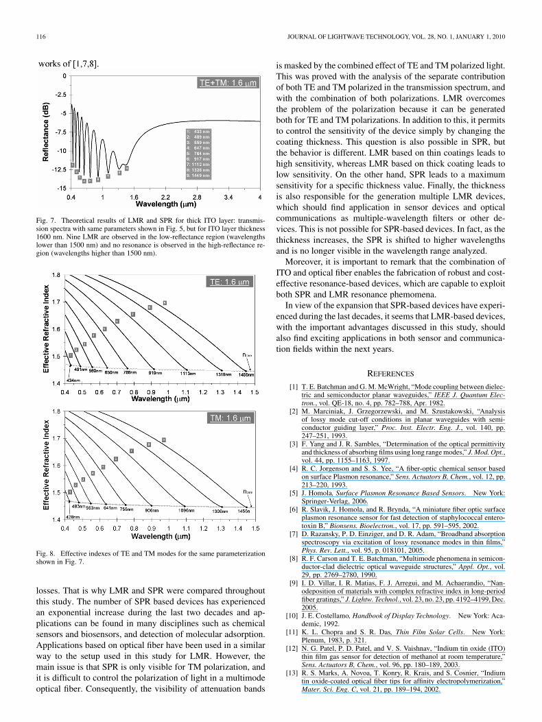
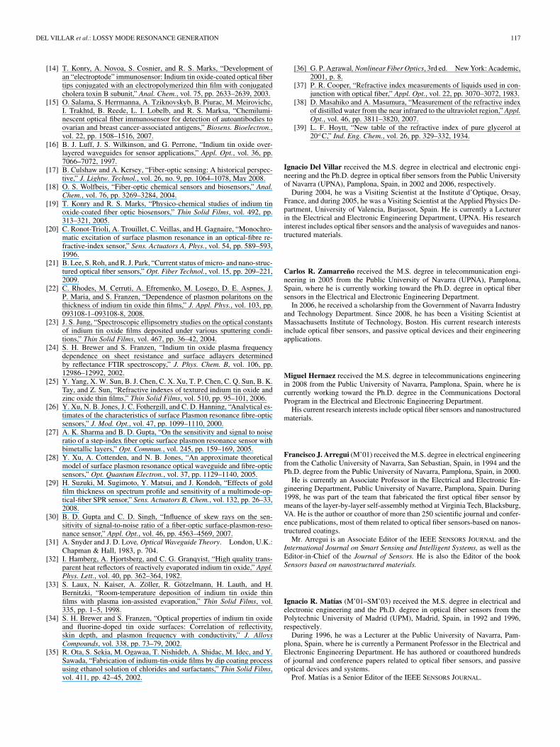
In Fig. 7, the transmission spectrum for an ITO thickness of1.6 m and a wavelength range from 0.4 to 4.0 m is analyzed.The purpose of using a thick ITO region is the generation of animportant number or LMR resonances and to observe that allof them are located in the low-reflectance region. On the otherhand, no resonance is visible for the high-reflectance region.This is another important difference with SPR; LMR permitsto generate multiple resonances as the thin film thickness in-creases, whereas SPR is shifted to higher wavelengths and noadditional resonances occur. The reason is that LMR are basedon near cutoff lossy modes in the coating. To prove this lastquestion, it is analyzed in Fig. 8 both for TE and TM polar-izations the effective index of the modes guided in the thin filmcoating as a function of wavelength for the same ITO design,as shown in Fig. 7. It is easy to see that the wavelength valueswhere the modes cross the cutoff condition fit adequately withthe wavelengths of the resonances observed in Fig. 7. This con-firms the theoretical works of [1], [7], and [8].
IV. CONCLUSION
The results presented earlier represent, to our knowledge, thefirst experimental data obtained with coated optical fiber sensorsbased on the phenomenon of LMR. The detection technique isbased on the monitorization of the LMR wavelength. The re-sults are supported with theoretical results. In some of them, theanalysis was focused on the variation of the coating thickness,whereas in others, the interest was centered on the generationof attenuation bands in the electromagnetic spectrum. This lastcase has centered the attention of this study because wavelengthdetection is one of the most powerful techniques used in opticalfiber sensors.
The phenomenon of SPR is also obtained with coatedwaveguides. The difference with LMR is the coating optical
116 JOURNAL OF LIGHTWAVE TECHNOLOGY, VOL. 28, NO. 1, JANUARY 1, 2010
Fig. 7. Theoretical results of LMR and SPR for thick ITO layer: transmis-sion spectra with same parameters shown in Fig. 5, but for ITO layer thickness1600 nm. Nine LMR are observed in the low-reflectance region (wavelengthslower than 1500 nm) and no resonance is observed in the high-reflectance re-gion (wavelengths higher than 1500 nm).
Fig. 8. Effective indexes of TE and TM modes for the same parameterizationshown in Fig. 7.
losses. That is why LMR and SPR were compared throughoutthis study. The number of SPR based devices has experiencedan exponential increase during the last two decades and ap-plications can be found in many disciplines such as chemicalsensors and biosensors, and detection of molecular adsorption.Applications based on optical fiber have been used in a similarway to the setup used in this study for LMR. However, themain issue is that SPR is only visible for TM polarization, andit is difficult to control the polarization of light in a multimodeoptical fiber. Consequently, the visibility of attenuation bands
is masked by the combined effect of TE and TM polarized light.This was proved with the analysis of the separate contributionof both TE and TM polarized in the transmission spectrum, andwith the combination of both polarizations. LMR overcomesthe problem of the polarization because it can be generatedboth for TE and TM polarizations. In addition to this, it permitsto control the sensitivity of the device simply by changing thecoating thickness. This question is also possible in SPR, butthe behavior is different. LMR based on thin coatings leads tohigh sensitivity, whereas LMR based on thick coating leads tolow sensitivity. On the other hand, SPR leads to a maximumsensitivity for a specific thickness value. Finally, the thicknessis also responsible for the generation multiple LMR devices,which should find application in sensor devices and opticalcommunications as multiple-wavelength filters or other de-vices. This is not possible for SPR-based devices. In fact, as thethickness increases, the SPR is shifted to higher wavelengthsand is no longer visible in the wavelength range analyzed.
Moreover, it is important to remark that the combination ofITO and optical fiber enables the fabrication of robust and cost-effective resonance-based devices, which are capable to exploitboth SPR and LMR resonance phemomena.
In view of the expansion that SPR-based devices have experi-enced during the last decades, it seems that LMR-based devices,with the important advantages discussed in this study, shouldalso find exciting applications in both sensor and communica-tion fields within the next years.
REFERENCES
[1] T. E. Batchman and G. M. McWright, “Mode coupling between dielec-tric and semiconductor planar waveguides,” IEEE J. Quantum Elec-tron., vol. QE-18, no. 4, pp. 782–788, Apr. 1982.
[2] M. Marciniak, J. Grzegorzewski, and M. Szustakowski, “Analysisof lossy mode cut-off conditions in planar waveguides with semi-conductor guiding layer,” Proc. Inst. Electr. Eng. J., vol. 140, pp.247–251, 1993.
[3] F. Yang and J. R. Sambles, “Determination of the optical permittivityand thickness of absorbing films using long range modes,” J. Mod. Opt.,vol. 44, pp. 1155–1163, 1997.
[4] R. C. Jorgenson and S. S. Yee, “A fiber-optic chemical sensor basedon surface Plasmon resonance,” Sens. Actuators B, Chem., vol. 12, pp.213–220, 1993.
[5] J. Homola, Surface Plasmon Resonance Based Sensors. New York:Springer-Verlag, 2006.
[6] R. Slavik, J. Homola, and R. Brynda, “A miniature fiber optic surfaceplasmon resonance sensor for fast detection of staphylococcal entero-toxin B,” Bionsens. Bioelectron., vol. 17, pp. 591–595, 2002.
[7] D. Razansky, P. D. Einziger, and D. R. Adam, “Broadband absorptionspectroscopy via excitation of lossy resonance modes in thin films,”Phys. Rev. Lett., vol. 95, p. 018101, 2005.
[8] R. F. Carson and T. E. Batchman, “Multimode phenomena in semicon-ductor-clad dielectric optical waveguide structures,” Appl. Opt., vol.29, pp. 2769–2780, 1990.
[9] I. D. Villar, I. R. Matias, F. J. Arregui, and M. Achaerandio, “Nan-odeposition of materials with complex refractive index in long-periodfiber gratings,” J. Lightw. Technol., vol. 23, no. 23, pp. 4192–4199, Dec.2005.
[10] J. E. Costellamo, Handbook of Display Technology. New York: Aca-demic, 1992.
[11] K. L. Chopra and S. R. Das, Thin Film Solar Cells. New York:Plenum, 1983, p. 321.
[12] N. G. Patel, P. D. Patel, and V. S. Vaishnav, “Indium tin oxide (ITO)thin film gas sensor for detection of methanol at room temperature,”Sens. Actuators B, Chem., vol. 96, pp. 180–189, 2003.
[13] R. S. Marks, A. Novoa, T. Konry, R. Krais, and S. Cosnier, “Indiumtin oxide-coated optical fiber tips for affinity electropolymerization,”Mater. Sci. Eng. C, vol. 21, pp. 189–194, 2002.
DEL VILLAR et al.: LOSSY MODE RESONANCE GENERATION 117
[14] T. Konry, A. Novoa, S. Cosnier, and R. S. Marks, “Development ofan “electroptode” immunosensor: Indium tin oxide-coated optical fibertips conjugated with an electropolymerized thin film with conjugatedcholera toxin B subunit,” Anal. Chem., vol. 75, pp. 2633–2639, 2003.
[15] O. Salama, S. Herrmanna, A. Tziknovskyb, B. Piurac, M. Meirovichc,I. Trakhtd, B. Reede, L. I. Lobelb, and R. S. Marksa, “Chemilumi-nescent optical fiber immunosensor for detection of autoantibodies toovarian and breast cancer-associated antigens,” Biosens. Bioelectron.,vol. 22, pp. 1508–1516, 2007.
[16] B. J. Luff, J. S. Wilkinson, and G. Perrone, “Indium tin oxide over-layered waveguides for sensor applications,” Appl. Opt., vol. 36, pp.7066–7072, 1997.
[17] B. Culshaw and A. Kersey, “Fiber-optic sensing: A historical perspec-tive,” J. Lightw. Technol., vol. 26, no. 9, pp. 1064–1078, May 2008.
[18] O. S. Wolfbeis, “Fiber-optic chemical sensors and biosensors,” Anal.Chem., vol. 76, pp. 3269–3284, 2004.
[19] T. Konry and R. S. Marks, “Physico-chemical studies of indium tinoxide-coated fiber optic biosensors,” Thin Solid Films, vol. 492, pp.313–321, 2005.
[20] C. Ronot-Trioli, A. Trouillet, C. Veillas, and H. Gagnaire, “Monochro-matic excitation of surface plasmon resonance in an optical-fibre re-fractive-index sensor,” Sens. Actuators A, Phys., vol. 54, pp. 589–593,1996.
[21] B. Lee, S. Roh, and R. J. Park, “Current status of micro- and nano-struc-tured optical fiber sensors,” Opt. Fiber Technol., vol. 15, pp. 209–221,2009.
[22] C. Rhodes, M. Cerruti, A. Efremenko, M. Losego, D. E. Aspnes, J.P. Maria, and S. Franzen, “Dependence of plasmon polaritons on thethickness of indium tin oxide thin films,” J. Appl. Phys., vol. 103, pp.093108-1–093108-8, 2008.
[23] J. S. Jung, “Spectroscopic ellipsometry studies on the optical constantsof indium tin oxide films deposited under various sputtering condi-tions,” Thin Solid Films, vol. 467, pp. 36–42, 2004.
[24] S. H. Brewer and S. Franzen, “Indium tin oxide plasma frequencydependence on sheet resistance and surface adlayers determinedby reflectance FTIR spectroscopy,” J. Phys. Chem. B, vol. 106, pp.12986–12992, 2002.
[25] Y. Yang, X. W. Sun, B. J. Chen, C. X. Xu, T. P. Chen, C. Q. Sun, B. K.Tay, and Z. Sun, “Refractive indexes of textured indium tin oxide andzinc oxide thin films,” Thin Solid Films, vol. 510, pp. 95–101, 2006.
[26] Y. Xu, N. B. Jones, J. C. Fothergill, and C. D. Hanning, “Analytical es-timates of the characteristics of surface Plasmon resonance fibre-opticsensors,” J. Mod. Opt., vol. 47, pp. 1099–1110, 2000.
[27] A. K. Sharma and B. D. Gupta, “On the sensitivity and signal to noiseratio of a step-index fiber optic surface plasmon resonance sensor withbimetallic layers,” Opt. Commun., vol. 245, pp. 159–169, 2005.
[28] Y. Xu, A. Cottenden, and N. B. Jones, “An approximate theoreticalmodel of surface plasmon resonance optical waveguide and fibre-opticsensors,” Opt. Quantum Electron., vol. 37, pp. 1129–1140, 2005.
[29] H. Suzuki, M. Sugimoto, Y. Matsui, and J. Kondoh, “Effects of goldfilm thickness on spectrum profile and sensitivity of a multimode-op-tical-fiber SPR sensor,” Sens. Actuators B, Chem., vol. 132, pp. 26–33,2008.
[30] B. D. Gupta and C. D. Singh, “Influence of skew rays on the sen-sitivity of signal-to-noise ratio of a fiber-optic surface-plasmon-reso-nance sensor,” Appl. Opt., vol. 46, pp. 4563–4569, 2007.
[31] A. Snyder and J. D. Love, Optical Waveguide Theory. London, U.K.:Chapman & Hall, 1983, p. 704.
[32] I. Hamberg, A. Hjortsberg, and C. G. Granqvist, “High quality trans-parent heat reflectors of reactively evaporated indium tin oxide,” Appl.Phys. Lett., vol. 40, pp. 362–364, 1982.
[33] S. Laux, N. Kaiser, A. Zöller, R. Götzelmann, H. Lauth, and H.Bernitzki, “Room-temperature deposition of indium tin oxide thinfilms with plasma ion-assisted evaporation,” Thin Solid Films, vol.335, pp. 1–5, 1998.
[34] S. H. Brewer and S. Franzen, “Optical properties of indium tin oxideand fluorine-doped tin oxide surfaces: Correlation of reflectivity,skin depth, and plasmon frequency with conductivity,” J. AlloysCompounds, vol. 338, pp. 73–79, 2002.
[35] R. Ota, S. Sekia, M. Ogawaa, T. Nishideb, A. Shidac, M. Idec, and Y.Sawada, “Fabrication of indium-tin-oxide films by dip coating processusing ethanol solution of chlorides and surfactants,” Thin Solid Films,vol. 411, pp. 42–45, 2002.
[36] G. P. Agrawal, Nonlinear Fiber Optics, 3rd ed. New York: Academic,2001, p. 8.
[37] P. R. Cooper, “Refractive index measurements of liquids used in con-junction with optical fiber,” Appl. Opt., vol. 22, pp. 3070–3072, 1983.
[38] D. Masahiko and A. Masumura, “Measurement of the refractive indexof distilled water from the near infrared to the ultraviolet region,” Appl.Opt., vol. 46, pp. 3811–3820, 2007.
[39] L. F. Hoytt, “New table of the refractive index of pure glycerol at20 C,” Ind. Eng. Chem., vol. 26, pp. 329–332, 1934.
Ignacio Del Villar received the M.S. degree in electrical and electronic engi-neering and the Ph.D. degree in optical fiber sensors from the Public Universityof Navarra (UPNA), Pamplona, Spain, in 2002 and 2006, respectively.
During 2004, he was a Visiting Scientist at the Institute d’Optique, Orsay,France, and during 2005, he was a Visiting Scientist at the Applied Physics De-partment, University of Valencia, Burjassot, Spain. He is currently a Lecturerin the Electrical and Electronic Engineering Department, UPNA. His researchinterest includes optical fiber sensors and the analysis of waveguides and nanos-tructured materials.
Carlos R. Zamarreño received the M.S. degree in telecommunication engi-neering in 2005 from the Public University of Navarra (UPNA), Pamplona,Spain, where he is currently working toward the Ph.D. degree in optical fibersensors in the Electrical and Electronic Engineering Department.
In 2006, he received a scholarship from the Government of Navarra Industryand Technology Department. Since 2008, he has been a Visiting Scientist atMassachusetts Institute of Technology, Boston. His current research interestsinclude optical fiber sensors, and passive optical devices and their engineeringapplications.
Miguel Hernaez received the M.S. degree in telecommunications engineeringin 2008 from the Public University of Navarra, Pamplona, Spain, where he iscurrently working toward the Ph.D. degree in the Communications DoctoralProgram in the Electrical and Electronic Engineering Department.
His current research interests include optical fiber sensors and nanostructuredmaterials.
Francisco J. Arregui (M’01) received the M.S. degree in electrical engineeringfrom the Catholic University of Navarra, San Sebastian, Spain, in 1994 and thePh.D. degree from the Public University of Navarra, Pamplona, Spain, in 2000.
He is currently an Associate Professor in the Electrical and Electronic En-gineering Department, Public University of Navarre, Pamplona, Spain. During1998, he was part of the team that fabricated the first optical fiber sensor bymeans of the layer-by-layer self-assembly method at Virginia Tech, Blacksburg,VA. He is the author or coauthor of more than 250 scientific journal and confer-ence publications, most of them related to optical fiber sensors-based on nanos-tructured coatings.
Mr. Arregui is an Associate Editor of the IEEE SENSORS JOURNAL and theInternational Journal on Smart Sensing and Intelligent Systems, as well as theEditor-in-Chief of the Journal of Sensors. He is also the Editor of the bookSensors based on nanostructured materials.
Ignacio R. Matías (M’01–SM’03) received the M.S. degree in electrical andelectronic engineering and the Ph.D. degree in optical fiber sensors from thePolytechnic University of Madrid (UPM), Madrid, Spain, in 1992 and 1996,respectively.
During 1996, he was a Lecturer at the Public University of Navarra, Pam-plona, Spain, where he is currently a Permanent Professor in the Electrical andElectronic Engineering Department. He has authored or coauthored hundredsof journal and conference papers related to optical fiber sensors, and passiveoptical devices and systems.
Prof. Matías is a Senior Editor of the IEEE SENSORS JOURNAL.