Long-Term Alternate Water Feasibility Study
276
SUBMITTED TO: Alaska Department of Administration, Division of Risk Management P.O. Box 110218 Juneau, Alaska 9981 BY: Shannon & Wilson, Inc. 2355 Hill Road Fairbanks, AK 99709 (907) 479-0600 www.shannonwilson.com REPORT Long-Term Alternate Water Feasibility Study DILLINGHAM, ALASKA October 2020 Shannon & Wilson No: 102786-003
-
Upload
khangminh22 -
Category
Documents
-
view
3 -
download
0
Transcript of Long-Term Alternate Water Feasibility Study

SUBMITTED TO: Alaska Department of Administration, Division of Risk Management P.O. Box 110218 Juneau, Alaska 9981
BY: Shannon & Wilson, Inc. 2355 Hill Road Fairbanks, AK 99709
(907) 479-0600www.shannonwilson.com
REPORT
Long-Term Alternate Water Feasibility Study DILLINGHAM, ALASKA
October 2020 Shannon & Wilson No: 102786-003

Long-Term Alternate Water Feasibility Study Report
102786-003 October 2020
PAGE INTENTIONALLY LEFT BLANK FOR DOUBLE-SIDED PRINTING

Long-Term Alternate Water Feasibility StudyReport
October 2020102786-003i
Submitted To: Alaska Department of Administration, Division of Risk Management P.O. Box 110218 Juneau, Alaska 9981
Subject: REPORT, LONG-TERM ALTERNATE WATER FEASIBILITY STUDY,DILLINGHAM, ALASKA
The effort summarized herein was conducted on behalf of the Alaska Department of Administration, Division of Risk Management (DRM), in accordance with Shannon & Wilson, Inc.’s approved scope of services dated October 15, 2019. This document has been revised in response to comments received from the Alaska Department of Transportation & Public Facilities (DOT&PF) and DRM.
Shannon & Wilson appreciates the opportunity to be of service to you on this project. If you have questions concerning this report, or we may be of further service, please contact us.
Sincerely,
SHANNON & WILSON, INC.
Marcy Nadel Geologist Role: Project Manager
Christopher Darrah, C.P.G., CPESC Vice President Role: Contract Manager
hristophehehhhhhhhhhhhhhhhhhhehhhhhhhhhhhhhhhhhhhhhhhhhhhhhhhhhhhhhhhhhhhhhh r Darrah, C P G , CPESC

Long-Term Alternate Water Feasibility Study Report
102786-003 October 2020 ii
CONT
ENTS
CONTENTS
1 Introduction ................................................................................................................................ 1
1.1 Drinking Water Action Levels ........................................................................................ 1
1.2 Background ....................................................................................................................... 1
1.3 Purpose .............................................................................................................................. 2
1.4 Use of Report .................................................................................................................... 2
2 Feasibility of Long-Term Water Options ................................................................................ 3
2.1 Water Storage Tanks and Deliveries ............................................................................. 4
2.2 Municipal Water System Expansion ............................................................................. 5
2.3 Individual Point-of-Entry Water Treatment Systems ................................................. 7
2.4 Small-Scale Distribution Systems .................................................................................. 8
2.4.1 Existing, Untreated Source ................................................................................. 9
2.4.1.1 Dillingham Courthouse ......................................................................... 9
2.4.1.2 Salmon Roe Apartments ...................................................................... 10
2.4.1.3 DOT&PF Shop Well ............................................................................. 11
2.4.1.4 Advantages and Disadvantages ......................................................... 12
2.4.2 Existing, Treated Source ................................................................................... 12
2.4.2.1 Holy Rosary Church ............................................................................ 12
2.4.2.2 Well ID 191710 ...................................................................................... 13
2.4.2.3 Advantages and Disadvantages ......................................................... 14
2.4.3 Drilled Well ........................................................................................................ 14
2.4.4 Distribution Center ........................................................................................... 15
3 Local Preferences ...................................................................................................................... 15
4 Option Summary ...................................................................................................................... 16
5 Discussion ................................................................................................................................. 20
Exhibits Exhibit 1-1: Impacted Properties ........................................................................................................2 Exhibit 2-1: Summary of Potential Water Delivery Contractors ...................................................4 Exhibit 2-2: Summary of Small-Scale Distribution Systems...........................................................8 Exhibit 4-1: Cost Summary by Option ............................................................................................18 Exhibit 4-2: Cost Summary by Area ................................................................................................19

Long-Term Alternate Water Feasibility Study Report
102786-003 October 2020 iii
CONT
ENTS
Figures Figure 1: Highest Reported Water Supply Well Analytical Results
Appendices Appendix A: HDR Report Appendix B: Barr Report and Supporting Information Appendix C: Storage Tank Supporting Information Important Information

Long-Term Alternate Water Feasibility Study Report
102786-003 October 2020 iv
ACRO
NYMS
ACRONYMS
Barr Barr Engineering Co. Choggiung Choggiung, Ltd. Village Corporation CDL Commercial Driver's License DEC Alaska Department of Environmental Conservation DOT&PF Alaska Department of Transportation and Public Facilities DRM Alaska Department of Administration's Division of Risk Management EPA U.S. Environmental Protection Agency GAC granular activated carbon gpm gallons per minute HDR HDR Engineering, Inc. LDRC Laboratory Data Review Checklist LHA Lifetime Health Advisory ng/L nanograms per liter O&M operations and maintenance PFAS per- and polyfluoroalkyl substance PFHpA perfluoroheptanoic acid PFHxS perflurohexanesulfonic acid PFOA perfluorooctanoic acid PFOS perfluorooctanesulfonic acid PFNA perfluorononanoic acid POET Point-of-Entry Water Treatment PWS public water system SGS SGS North America, Inc. TestAmerica Eurofins TestAmerica Laboratories, Sacramento QA quality assurance

Long-Term Alternate Water Feasibility Study Report
102786-003 October 2020 1
1 INTRODUCTION Shannon & Wilson, Inc. is pleased to submit this Long-Term Alternate Water Feasibility Study Report (Report) summarizing potential water sources for water supply wells impacted by per- and polyfluoroalkyl substances (PFAS) in Dillingham, Alaska. These locations are shown in Figure 1, Highest Reported Water Supply Well Analytical Results. The Dillingham Airport is an active, Alaska Department of Environmental Conservation (DEC) listed contaminated site (File Number 2540.38.023, Hazard ID 26971).
1.1 Drinking Water Action Levels
The current DEC action level for drinking water samples aligns with the U.S. Environmental Protection Agency (EPA) lifetime health advisory (LHA) level of 70 nanograms per liter (ng/L) for the sum of two PFAS compounds, perfluorooctanesulfonic acid (PFOS) and perfluorooctanoic acid (PFOA). The former DEC action level was 70 ng/L for the sum of five PFAS compounds: PFOS, PFOA, perfluoroheptanoic acid (PFHpA), perflurohexanesulfonic acid (PFHxS), and perfluorononanoic acid (PFNA). PFAS concentrations are compared to the applicable action level at the time each sample was collected (Figure 1).
1.2 Background
On behalf of the DRM and Alaska Department of Transportation and Public Facilities (DOT&PF), Shannon & Wilson conducted a water supply well search on and downgradient of Dillingham Airport property beginning in February 2019. To date, Shannon & Wilson has sampled 97 water supply wells, the majority of which are drinking-water wells. The water supply well search and initial sampling effort occurred primarily in February and June 2019. Resampling of select wells occurred in November 2019, February 2020, and September 2020, and is ongoing.
Seven wells are considered impacted by PFAS due to PFAS results above the applicable action level, five are off and two are on Dillingham Airport property (Figure 1). These seven wells serve 11 structures and represent a range of property types including single-family houses, an apartment building, a church serving as a community water source, a restaurant, and other commercial businesses. Many of these occupants are receiving interim bottled water deliveries. Exhibit 1-1, Impacted Properties, describes these properties.

Long-Term Alternate Water Feasibility Study Report
102786-003 October 2020 2
Exhibit 1-1: Impacted Properties
1.3 Purpose
The purpose of this Report is to summarize each long-term alternate water option, including estimated capital and operations and maintenance (O&M) costs, and advantages and disadvantages of the alternate water options. This information is meant to assist the DRM and DOT&PF in selecting a long-term water source for PFAS-impacted water supply wells in Dillingham. The preferred alternative may include a combination of these options.
Shannon & Wilson understands the DRM is responsible for alternate water planning for the five impacted off-airport properties, while DOT&PF is responsible for the two impacted on-airport properties. This feasibility study assumes O&M costs will be addressed by a one-time settlement to the property owner, system operator, or other entity. The settlements towards long-term costs included in this Report are based on conversations with the DRM. Shannon & Wilson assumes the DOT&PF will provide the same settlement as DRM.
1.4 Use of Report
This Report was prepared for the exclusive use of the DRM, DOT&PF, and their representatives for the purpose of long-term alternate water planning for impacted wells on and off Dillingham Airport property. This work presents Shannon & Wilson’s professional judgment and is based on information obtained from individuals in Dillingham, Shannon & Wilson’s contractors, and analytical sampling.
Area Well ID Property Type Description
Airport Tenants 191300 Commercial Hangar
191320 Commercial Grant Aviation Terminal and Twin Dragon Restaurant
Airport Spur Road 191700 Residential House, 1 occupant
191710 Residential rental Apartment, 5 units with 4 to 10 occupants
191710 Residential rental House, 2 occupants
191710 Residential rental House, 1 occupant
191710 Commercial rental Office
191720 Residential rental House, 1 occupant
191050 Church Holy Rosary Church and Rectory, outdoor spigot serves as community water source
Kanakanak Road / Windmill Hill
200150 Residential House, up to 15 occupants

Long-Term Alternate Water Feasibility Study Report
102786-003 October 2020 3
This Report should not be used for other purposes without Shannon & Wilson’s approval or if any of the following occurs:
Project details change, or new information becomes available such that Report findingsmay be affected.
Conditions change due to natural forces or human activity at, under, or adjacent to theproject site.
Assumptions stated in this Report have changed.
If ownership or land use of the site and/or impacted properties has changed.
More than one year has passed since the date of this report.
Regulations, laws, or cleanup levels change.
If the site’s regulatory status has changed.
If any of these occur, Shannon & Wilson should be retained to review the applicability of this Report. This Report should not be used for other purposes without Shannon & Wilson’s review. If a service is not specifically indicated in this report, do not assume it was performed.
2 FEASIBILITY OF LONG-TERM WATER OPTIONS Shannon & Wilson has prepared the following summary of four different options for providing long-term alternate water to PFAS-impacted properties in Dillingham, Alaska. These options included:
1. Water Storage Tanks and Deliveries (Section 2.1)
2. Municipal Water System Expansion (Section 2.2)
3. Individual Point-of-Entry Water Treatment (POET) Systems (Section 2.3)
4. Small-Scale Distribution Systems (Section 2.4)
HDR Engineering, Inc. (HDR) investigated the feasibility of municipal water system expansion and small-scale distribution systems. HDR's report is included in Appendix A. Barr Engineering Co. (Barr) prepared preliminary POET system designs, their report is included in Appendix B.
In November 2019, Shannon & Wilson field staff conducted site visits at impacted properties for planning purposes. This information was recorded on PFAS Impacted Well Site Assessment Forms, copies of which are include within Barr's report (Appendix B, Attachment 1). These forms were provided to HDR and Barr.

Long-Term Alternate Water Feasibility Study Report
102786-003 October 2020 4
2.1 Water Storage Tanks and Deliveries
This option would provide water storage tanks to the impacted properties, which would be filled by periodic deliveries of municipal water. Water storage tanks are not a common water source in Dillingham, and currently there is no water delivery infrastructure. This option would involve construction of potable water tanks at each impacted property, purchase of a potable water trailer, and identifying a contractor to deliver water over the long term.
Appendix C, Water Storage Tank Supporting Information, includes specifications for fabricating two different insulated potable water tank trailers: a 2,000-gallon trailer to be towed by a 1-ton pickup truck and a 5,000-gallon tandem axle trailer to be towed by a semi-truck requiring a Commercial Driver's License (CDL). The trailer would be equipped with a pump and hose and has an anticipated 20 to 25 year lifespan considering rural Alaska wear-and-tear. Shannon & Wilson has identified several potential water delivery contractors, summarized in Exhibit 2-1 below. This is not a comprehensive list of potential water delivery contractors in Dillingham. Shannon & Wilson assumes DOT&PF and DRM will select a contractor by issuing a Request for Information (RFI) and/or Request for Proposal (RFP) to comply with state bidding requirements. After a contractor is identified, the trailer specifications would be modified for compatibility (gas vs. diesel, chassis and towing, heat trace for outdoor storage, etc.).
Exhibit 2-1: Summary of Potential Water Delivery Contractors
Contractor Type Staff Capacity Equipment
Aleutian Industries, LLC. / M&K Enterprises
Business Driver and alternate available year-round, both hold CDLs
1-ton pickup and tandem axlesemi-tractor
Curyung Tribal Council Government 6 year-round staff members, no CDL drivers
3/4-ton pickup, would need to purchase a larger vehicle
JJC Contractors Business 2 or 3 drivers hold CDLs and may be available year-round, >6 drivers available in summer
Multiple 3/4-ton pickups and tandem axle semi-tractor
Lawrence Chounaird Individual Driver and alternate available year-round, neither holds CDL
1/2-ton and 3/4-ton pickup
The City of Dillingham had operated a potable water delivery truck in the past, but their truck is no longer operational. Following a February 2020 meeting with the City Manager, Public Works Director, and Public Works staff, the City began preparing a cost estimate to purchase a truck and use City staff to deliver water. However, the City of Dillingham is facing a significant budget shortfall related to COVID-19 and has indicated they are unable

Long-Term Alternate Water Feasibility Study Report
102786-003 October 2020 5
2.2 Municipal Water System Expansion
This option involves extending the existing City of Dillingham municipal water system to serve the impacted properties. The City of Dillingham municipal water system currently provides water to 215 structures in downtown Dillingham, approximately two miles east of most PFAS-impacted wells. HDR developed preliminary water main routing to extend the municipal water system and estimated probable project costs (Appendix A). The preliminary design includes two possible routes for an 8-inch water main extension along Kanakanak Road. HDR’s April 2020 report describes a main routed under the runway to connect Airport Spur Road to Kanakanak Road (Appendix A, Figure 2). HDR’s July 2020
to provide deliveries for the foreseeable future. Choggiung, Ltd. Village Corporation (Choggiung) has also indicated they not interested in supplying water deliveries.
Icicle Seafoods operates a potable water delivery truck during the salmon season, from approximately June to August. They use the truck to transfer water purchased from the City to their processing plant and employee lodging facility outside of town. The 1978 Walker semi-truck trailer is equipped with an approximately 6,500-gallon potable water tank. The Icicle Seafoods truck is used for six to eight hours each night. The company has declined to rent the delivery truck for year-round use, citing logistical challenges associated with sharing the vehicle each summer.
The ballpark capital cost for water storage tank and water trailer purchase, freight, design, and installation is approximately $820,000. This estimate assumes the water delivery contractor would supply their own vehicle/s and includes a 35 percent contingency. Shannon & Wilson assumes the tanks will be buried to help prevent freezing and UV degradation, tank capacity will range from 1,500 to 5,000 gallons. This assumes the Holy Rosary Church holding tank will be not be sized to supply water to the public. If this alternate water option is selected, storage tank size would be optimized during the design phase. This option has the second-lowest installation cost of the options reviewed. Please note, costs associated with water delivery and O&M could not be calculated without selection of the water delivery contractor. DEC has indicated the water delivery contractor would not need to be classified as a public water system (PWS) operator, therefore this estimate does not include preparing DEC Drinking Water Program submittals.
The primary advantage of water storage tanks is the limited and relatively simple construction needed to implement this option. A secondary advantage is it can be upscaled should the PFAS groundwater plume spread or regulatory standards change. The main disadvantage is that the selected water delivery contractor may not be able to continue this service long term.

Long-Term Alternate Water Feasibility Study Report
102786-003 October 2020 6
supplement to their report describes a main routed around the airport along Kanakanak Road (Appendix A, Figure 8). The summary tables and report text discuss the longer water main route (Exhibits 4-1 and 4-2).
City of Dillingham staff and at least one City Council member are encouraging selection of this option. The City of Dillingham water system is regulated by the DEC Drinking Water Program as a community public water system serving resident, transient, and non-transient populations (PWS ID No. AK2260197). Shannon & Wilson assumes the City of Dillingham would be administratively, physically, and financially responsible for regulatory compliance and O&M costs.
The estimated capital cost to expand the City of Dillingham water system is approximately $23 million, including design, easements and right-of-way planning, and construction. This Class 4, order-of-magnitude cost estimate assumes a single, dead-end water main is adequate for this project. Over one-half of the total cost is for water main installation and asphalt road reconstruction. HDR’s report assumes a 10-foot burial depth, the same as other water lines in Dillingham. Trenching below 4 feet significantly increases the anticipated cost because trench stability control is required (sloping trench sides, trench box, etc.) for safety. Should hydraulic analysis determine a looped main is required, the cost would be considerably higher. This cost estimate also assumes connection to the municipal water system will not require mechanical or electrical upgrades to the impacted properties. The cost estimate assumes a settlement of $3,000 per property, regardless of the number of structures served. If possible, the settlement will be paid by DRM or DOT&PM to the City of Dillingham as a credit towards each property owner’s account.
The main advantage of a municipal water expansion is reliability. This is the only option that involves use of an established long-term water source, and where the source is managed by a known entity with a proven track record. Should the PFAS groundwater plume spread or regulatory standards change, additional service line connections could be added. Furthermore, this option allows for non-PFAS-impacted property owners along Kanakanak Road to connect at their own expense. The primary disadvantage is the high overall cost, and high cost per impacted property, compared to the other options presented in this Report. Federal infrastructure grant and loan programs may be available as supplemental funding sources and should be investigated for their applicability to this option.
Please note, in March 2019 Shannon & Wilson collected pre- and post-treatment water samples at the City of Dillingham water plant. PFHxS was detected at an estimated concentration of 1.1 ng/L in the pre-treatment sample. PFOS, PFOA, and the three other reported PFAS were not detected in either sample.

Long-Term Alternate Water Feasibility Study Report
102786-003 October 2020 7
2.3 Individual Point-of-Entry Water Treatment Systems
This option involves designing, installing, and maintaining individual POET systems for each impacted water supply well to reduce PFAS concentrations below applicable regulatory standards. Barr has developed preliminary treatment recommendations for six of the seven impacted locations (Appendix B). Well ID 191720 on Airport Spur Road is excluded because the owner initially declined to provide access for a site assessment. The assessment for this property was conducted in September 2020. Barr recommends POET systems consisting of the following elements, depending on the property:
iron and manganese greensand filtration with continuous hypochlorite injection,
particulate filtration,
granular activated carbon (GAC) filtration, and
UV disinfection.
Estimated capital costs for individual POET systems range from $30,000 for a business or single-family home to $135,000 for a system supplying up to four structures. The low-end estimate assumes two of the properties will be supplied with non-potable water, and outbuilding construction will be required. Metals pre-treatment and particulate filtration are necessary to treat PFAS to below applicable action levels. Barr’s estimated annual O&M costs range from $15,000 to $30,000. Cost limitations for these class 5 cost estimates are described in Barr’s report (Appendix B). Please note, a Class 5 cost estimate is less defined than a Class 4 estimate.
The two primary advantages of POET systems are their comparatively low cost, and that they are a standalone solution for properties located far from existing water-supply infrastructure. This option has the least expensive capital cost, equal to less than 5 percent of the anticipated municipal water expansion installation cost and two-thirds of the anticipated water storage tank installation cost. Depending on the settlement value selected, POET systems could have the least expensive total cost.
A major disadvantage is POET systems require ongoing maintenance, which is logistically challenging in rural communities. DRM, DOT&PF, or a local trust would be responsible for managing O&M of POET systems. Shannon & Wilson does not recommend leaving maintenance to home or business owners with impacted water supply wells. For comparison purposes the option summary tables include 5 years of O&M costs (Exhibits 4-1 and 4-2). Furthermore, if regulatory standards become more stringent, the POET systems may need to be supplemented or redesigned.
Long-Term Alternate Water Feasibility Study Report
102786-003 October 2020 8
To implement this option, Shannon & Wilson would collect pre-installation water samples from Well IDs 191300 and 191700 to confirm treatment design assumptions, and work with property owners to determine the POET location and necessary piping modifications. The project team would prepare access and maintenance agreements for each property, construct POET outbuildings, and modify existing DEC Drinking Water Program permits for PWSs.
The Holy Rosary Church (PWS ID No. 2263018) is considered a non-transient non-community PWS serving approximately 530 people. Grant Aviation (PWS ID No. 2262733) is considered a non-community PWS because it rents the second story of the terminal to the Twin Dragon Restaurant. DEC will require submittal of POET design drawings, breakthrough calculations, analytical results, material specifications, an O&M plan, and other information for these two properties prior to their use. The DEC Drinking Water Program consults the Contaminated Sites and Wastewater Divisions as part of their permitting process. DEC Contaminated Sites has indicated it may not approve discharge of untreated backwash water into private septic systems and/or the City of Dillingham sewer system, as they have for other projects. Backwash is required for GAC-based POET. If they do not approve discharge, additional costs would be incurred for disposal of backwash water or treatment system design modifications (i.e., additional treatment for backwash water or recirculation).
2.4 Small-Scale Distribution Systems
This option involves constructing one or more small-scale water distribution systems that supply alternate water to properties with PFAS-impacted wells using water from either an existing well or a new source. In Dillingham it is common for multiple properties to share a single well. Shannon & Wilson examined seven potential water sources as summarized in Exhibit 2-2, below, and further defined in this section. Preliminary piping route maps are included in Appendix A.
Exhibit 2-2: Summary of Small-Scale Distribution Systems
Option Water Source (Well ID) Water Source Owner Locations Served
Existing, Untreated Source
Choggiung, Ltd. Village Corporation
Airport Spur Road
Well ID 200150
DOT&PF Airport Tenants
Existing, Treated Source
Holy Rosary Church (191050) Archdiocese of Anchorage Airport Spur Road
Well ID 191710 Private individual Well ID 191720 and 191700
New Source Drilled Well N/A Airport Tenants, Airport Spur Road Distribution Center N/A
Salmon Roe Apartments (200340)
Dillingham Courthouse (191040)
DOT&PF Shop Well (191210)

Long-Term Alternate Water Feasibility Study Report
102786-003 October 2020 9
2.4.1 Existing, Untreated Source
The following three small-scale distribution systems originate from existing wells not impacted by PFAS. These locations would not require PFAS treatment (i.e. a POET system).
2.4.1.1 Dillingham Courthouse
The Dillingham Courthouse is considered a transient non-community PWS serving approximately 220 people (PWS ID No. 2263071). This small-scale distribution system option would involve extending the Courthouse PWS to supply the Holy Rosary Church and Rectory, an apartment building, an office, and four houses (Appendix A, Figure 4). Choggiung, the owner of the Courthouse well, has asked that expansion of their system only be pursued if other alternate water options are exhausted. Their primary concern is disruption of their current water use.
The Courthouse well is 62 feet deep, 6 inches in diameter, and screened from 56.5 to 59.5 feet. The well driller reports an estimated production of 50 gallons per minute (gpm), the pump reportedly draws at 40 gpm and is set at 59 feet. HDR recommends conducting a flow test to determine if the well has sufficient recovery to expand distribution. A February 2019 water sample collected from the Courthouse well was submitted for six PFAS; none were detected (Well ID 191040). Although regular PFAS water sampling is recommended, this study assumes water treatment will not be required. Available groundwater information indicated there are no PFAS-impacted wells greater than 50 feet deep within a half-mile of this well. However, Shannon & Wilson is unable to predict the likelihood of PFAS concentrations in the Courthouse well increasing due to the higher groundwater draw needed to implement this option.
The estimated capital cost for expansion of the Courthouse system is $1.9 million, including distribution system design, easements, well rehabilitation, and construction. HDR’s cost estimate assumes fire suppression is not required, allowing for the installation of a 2-inch water main. The estimated annual O&M cost is $2,500 per year, including electrical, employee, and water testing costs. Shannon & Wilson assumes Choggiung would manage the system, and DRM would provide a one-time $5,000 settlement to cover O&M costs. This fee is applied to each untreated, small-scale distribution system.
For this option to be implemented, the project team would need to apply to re-classify the Dillingham Courthouse PWS as a community system. DEC will require submittal of drawings and specifications, peak demand and service pressure calculations, and other pertinent information. Choggiung would also need to select a staff member to become a certified operator. It is unknown if redeveloping the existing well and/or installing a new pump would provide adequate capacity and pressure to the system's end point

Long-Term Alternate Water Feasibility Study Report
102786-003 October 2020 10
approximately one-half mile away. Additionally, the project team would need to approach Choggiung and nearby property owners to obtain permission for piping rights-of-way.
2.4.1.2 Salmon Roe Apartments
The well at Salmon Roe Apartments, formerly Bingaman Apartments, is considered a resident community PWS serving several hundred people (PWS ID No. 2261460). The PWS currently serves five seasonally-occupied apartment buildings, a church, and four single-family homes. This option would extend piping from the existing distribution system to serve one additional home, Well ID 200150 (Appendix A, Figure 2). Choggiung is also the owner of this PWS and has not granted permission to expand the system.
In 2019, Choggiung installed a corrosion control system to mitigate lead and copper leaching. The Salmon Roe Apartments well is reportedly 32 feet deep, 4 inches in diameter, and produces water at 12 gpm. The corrosion control system is designed for a maximum treatment rate of 8 gpm.
Shannon & Wilson does not recommend this option without additional information because the Salmon Roe Apartments well has a maximum combined PFOS and PFOA concentrations greater than 10 percent of the applicable action level. Five PFAS were detected in a February 2019 water sample from the Salmon Roe Apartments Well ID 200340: PFOS at 7.2 ng/L, PFOA at an estimated 1.6 ng/L, PFHxS at 12 ng/L, and two other PFAS at lower concentrations. These sample results were consistent with the DEC water sample collected in December 2018.
The Salmon Roe Apartments well has a similar depth to nearby Well ID 200150 based on occupant-reported information. Well ID 200150 is considered impacted, with PFOS detected at a concentration nearly 10 times higher than the Salmon Roe well in samples collected between February and June 2019. As of summer 2020, the Salmon Roe Apartments well has been included in quarterly water supply well monitoring. Although Shannon & Wilson is unable to predict the likelihood of PFAS concentrations in Well ID 200340 increasing above the action level, if the Salmon Roe well draws from the same water source as nearby Well ID 200150 it is likely to increase.
The estimated capital cost for this option is $415,000. Estimated annual O&M costs are $2,500 per year, including the same items described in Section 2.4.1.1, above. Choggiung is a relatively new owner of this property and does not have a metering system in place to charge tenants for their water use. In addition to their caution over disrupting current tenant water use, they are concerned water metering would add cost and administrative burden during a time when their revenue streams are uncertain.

Long-Term Alternate Water Feasibility Study Report
102786-003 October 2020 11
For this option to be implemented, the PWS permit would need to be updated to include additional distribution, but the permit type would not change. As part of DEC's October 2019 interim approval to operate Choggiung's new corrosion control system, the drinking water program requested record drawings for the existing system and other information. To Shannon & Wilson’s knowledge, these engineering drawings have not been provided. It is possible the absence of information pertaining to the existing system could delay approval of system expansion.
2.4.1.3 DOT&PF Shop Well
The main DOT&PF Shop well (Well ID 191210) currently supplies two structures, the DOT&PF Aircraft Rescue and Firefighting building and nearby Federal Aviation Administration building. This alternate water option would supply two additional nearby structures including a hangar, terminal, and the Twin Dragon Restaurant (Appendix A, Figure 7).
The DOT&PF Shop well is 350 feet deep, 6 inches in diameter, produces at approximately 5 gpm, and is softened prior to use. DOT&PF staff, airport tenants, and local drillers note groundwater within the airport lease area often has a high mineral content and sulfur odor. PFOS was detected at 5.0 ng/L in a February 2019 water sample from this well. The sample was analyzed for six PFAS compounds; the other five were not detected. DOT&PF staff report the second, shallower DOT&PF well used for filling fire trucks has higher iron concentrations than the main DOT&PF Shop well. Available well search information indicates the next-deepest groundwater well within a half-mile is 100 feet deep. Shannon & Wilson assumes, but cannot confirm, that the DOT&PF Shop well is hydrologically connected to other water-supply wells in the Airport lease area. Without further information on PFAS concentrations at this depth, it is not possible to predict the likelihood of concentrations in DOT&PF Shop well increasing due to the higher groundwater draw needed to provide water to additional buildings.
The estimated capital cost for this system is $625,000 and estimated annual O&M costs are $2,500 per year. For this option to be implemented, the project team would need to obtain a PWS permit for the DOT&PF Shop well. DEC Drinking Water permitting is required because the well would supply the Twin Dragon Restaurant (PWS ID No. 2262733). Plan review is more extensive for a new system than an existing one. Depending on the PWS classification, DEC may require a DOT&PF employee to become a certified operator. Similar to the Dillingham Courthouse, it is unclear if this well has the capacity to supply an expanded system.

Long-Term Alternate Water Feasibility Study Report
102786-003 October 2020 12
2.4.1.4 Advantages and Disadvantages
The advantages of untreated, small-scale distribution systems are logistical convenience and cost. The Salmon Roe Apartments (PWS ID No. 2261460) and DOT&PF Shop Well systems already supply multiple nearby structures with water from a single well. These options involve infrastructure modifications similar to those already in place, which may require less specialized materials and labor than the other alternate water options. The estimated total cost is less than 20 percent that of municipal water expansion. Assuming the Dillingham Courthouse and DOT&PF Shop wells have sufficient capacity, these options could be further expanded to supply additional properties.
Shannon & Wilson assumes the property owner would physically, administratively, and financially manage the system. However, both Choggiung and DOT&PF have indicated they would prefer a different option is selected. For this option to be feasible, the property owners would need to assume responsibility for system management including payment of water bills, ongoing water testing, and routine maintenance. A second disadvantage of these untreated systems is uncertainty in future PFAS concentrations in the source wells, or the potential for concentrations to change when groundwater draw is increased.
2.4.2 Existing, Treated Source
The following two small-scale distribution systems would require PFAS treatment (i.e. a POET system) of the source water. Distribution design and other considerations are included in Appendix A, while preliminary POET design information is included in Appendix B.
2.4.2.1 Holy Rosary Church
The Holy Rosary Church is considered a non-transient non-community PWS serving approximately 530 people (PWS ID No. 2263018). The well currently supplies the Church and Rectory buildings. Until the discovery of PFAS, an outdoor spigot served as a community water source for homes and businesses without water or whose water was unpalatable due to a high mineral content. This option includes installation of a POET system in the Rectory building and an extension of this treated water to supply a nearby apartment building, office, and four single-family houses (Appendix A, Figure 5). Appendix B refers to this POET system as Combined System 1.
The Holy Rosary Church well is an estimated 45 feet deep and is currently untreated. The well diameter, production rate, and other details are unknown. It was drilled over 50 years ago and a driller’s well log is not available. It is unknown if this well has sufficient capacity to supply adequate pressure at the system end point. HDR recommends conducting a flow
Long-Term Alternate Water Feasibility Study Report
102786-003 October 2020 13
test and/or rehabilitating the well to meet peak demand requirements. Barr further recommends reviewing pressure head loss and hydraulic residence time.
The estimated total capital cost for this option is approximately $1.3 million. HDR's order-of-magnitude cost estimate for expanding distribution to nearby structures is approximately $1.2 million and includes system design, well rehabilitation, easements, and construction. If well redevelopment or a new pump are not required, the cost will be lower (Appendix A). Barr's estimated POET system capital cost is $135,000. This study assumes an outbuilding is required to accommodate the larger system. The anticipated capital cost for this option is lower than expanding the untreated Courthouse system; however, Barr’s estimated annual O&M cost is approximately $30,000.
For this option to be implemented, the project team would need to apply for modification of the system's PWS permit. DEC will require supplying the items listed in both Sections 2.3 for POET systems and 2.4.1.1 for small-scale distribution. Barr assumes the treatment backwash water can be discharged to the Church and Rectory's septic system without treatment. Shannon & Wilson recommends evaluating the septic system capacity to determine if it can accommodate backwash from the larger, combined POET system. Additionally, as noted in Section 2.3, the DEC Contaminated Sites program may not approve the discharge of untreated backwash water.
2.4.2.2 Well ID 191710
Of the impacted properties, Well ID 191710 is currently one of the highest water users. The well supplies four structures: an apartment building, an office, and two houses. Appendix B refers to it as Combined System 2. This option includes installation of a POET system and extension of the treated water to supply two additional, nearby homes (Appendix A, Figure 6).
The estimated total capital cost for this option is approximate $745,000. HDR's order-of-magnitude capital cost for expanding distribution is approximately $605,000 of the overall cost and Barr's estimated POET system is approximately $140,000. Shannon & Wilson assumes an outbuilding is required to accommodate the larger system. The estimated costs for this option POET are similar to Barr's proposed POET costs for Well ID 191710 without the two additional properties. Annual O&M costs are estimated at approximately $30,000.
The Well ID 191710 system is not currently a PWS and DEC's Drinking Water Program has indicated the expansion described above would not trigger PWS classification. The well is reportedly 70 feet deep and water is softened prior to use. The production rate is unknown, but water is supplied by a submersible 220-volt pump set at approximately 60 feet. Barr

Long-Term Alternate Water Feasibility Study Report
102786-003 October 2020 14
recommends conducting a flow test and reviewing pressure head loss and hydraulic residence time for this option. The requirements for an existing, operational system may be less stringent than obtaining a DEC Drinking Water Program PWS permit. Shannon & Wilson also recommends reviewing septic system capacity, but note the current configuration is likely larger than the Church and Rectory's system. The project team would need to work with the property owner to determine the POET outbuilding location, necessary piping modifications, and system management details.
2.4.2.3 Advantages and Disadvantages
The primary advantage of treated, small-scale distribution systems compared to individual POET systems is lower maintenance costs and less maintenance liability. The estimated O&M cost for the Holy Rosary Church system described above (Section 2.4.2.1) is less than half the combined O&M cost for individual systems. However, the anticipated capital cost is higher than individual POET systems. Additionally, the estimated total cost is approximately 15 percent that of municipal water expansion.
The disadvantages of this option include ongoing maintenance, inability to expand easily, and potential system management challenges. Should additional properties become impacted, the distribution system could be expanded relatively easily but the POET system would need to be reevaluated.
2.4.3 Drilled Well
Shannon & Wilson reviewed the possibility of constructing a small-scale distribution system supplied by a new water source. This option is not recommended by HDR given the lack of hydrologic information in the vicinity of the Dillingham Airport. If selected, this option would delay implementation of a long-term solution until after the first phase of site characterization, assuming characterization is conclusive. Shannon & Wilson does not recommend drilling a new water-supply well unless a location and depth can be selected that is upgradient or cross-gradient from PFAS source areas and samples report PFAS concentrations less than 10 percent of action levels. This study assumes the well would be drilled on Airport property, west of the runway and within one-half mile of the airport lease area.
This option would serve the Airport Spur Road and airport tenants only. The seventh impacted well, located off Kanakanak Road on Windmill Hill, is excluded due to its distance from the other impacted properties. The ballpark capital cost is $7.7 million. This study assumes distribution system design, easements, well rehabilitation, and construction will cost three times that of the Dillingham Courthouse system. If the well can be located closer to the impacted properties, this would be an overestimate. Shannon & Wilson further

Long-Term Alternate Water Feasibility Study Report
102786-003 October 2020 15
assumes the well would be no more than 100 feet deep, the location will be accessible by road, a 2-inch water main is sufficient, and water treatment would not be required. This cost estimate does not include environmental permitting, including but not limited to obtaining a wetland fill permit. Extending this water main to Kanakanak Road or a required increase in the water main diameter would increase the cost.
Depth, screen length and size, pump specifications, and other factors can be controlled when installing a new well and assist in providing adequate capacity for impacted properties. A second advantage of this option is the cost compared to expanding the City of Dillingham water system. The primary disadvantage of this option is uncertainty in future PFAS concentrations in the water-supply well. The source well would need to be located in an area unimpacted by the PFAS groundwater plume, currently and in the future. Shannon & Wilson is unable to predict the likelihood of PFAS concentrations increasing in a newly drilled well over time without aquifer testing information from PFAS site characterization activities.
For this option to be implemented, the project team would need to select a system manager. DOT&PF has indicated they are not interested in operating a PWS, however, it is unlikely another entity would be interested. It is possible the City of Dillingham could serve this role. The project team would need to obtain a PWS permit for the system. DEC’s plan review would include engineering drawings, material specifications, peak demand and service pressure calculations, and other information, as requested.
2.4.4 Distribution Center
The City of Dillingham proposed trucking treated municipal water from their downtown water plant to a distribution center on airport property, then piping this water to the impacted properties. The distribution center would include a large holding tank or aboveground standpipe.
This option was considered as an alternative to drilling a new well. However, it is no longer considered feasible due to City of Dillingham's budget and staffing projections. This option is not included in Exhibits 4-1 and 4-2.
3 LOCAL PREFERENCES In conversations with residents during Shannon & Wilson’s November 2019 site visits, we noted owners and occupants of impacted properties have varied preferences for long-term alternate water sources. This diverse group includes business and homes, owners and renters, long-term community members and newcomers. Their water use and current water

Long-Term Alternate Water Feasibility Study Report
102786-003 October 2020 16
system upkeep and maintenance costs also vary widely, depending on the quality of their water. The owner of Well ID 191300, who do not use their water for drinking or cooking, initially expressed reluctance at replacing their well with an alternative source. The owners of Well IDs 191050 and 200150 expressed a preference for POET systems because they are concerned other options will not allow them to maintain their water usage.
Shannon & Wilson noted many impacted-property owners consider the State of Alaska to be responsible for providing alternate water in perpetuity. Some residents may not find the settlement value agreeable and may choose to negotiate their claims with DRM.
Numerous residents expressed disappointment over the loss of the community water spigot at the church. The Church is their preferred location for filling potable water containers, compared to filling containers at the downtown Dillingham Senior Center, due to convenience and reported water quality. Some community members report the City of Dillingham water can taste or smell of chlorine, however City staff note the water quality has improved considerably in the last few years.
During the summer fishing season many Dillingham residents are out of communication for long periods of time. This may make alternate water planning and/or construction challenging.
4 OPTION SUMMARY The following exhibits compare order-of-magnitude costs, advantages, and disadvantages of the four long-term alternate water options. Exhibit 4-1 summarizes each option individually, while Exhibit 4-2 summarizes them by area. Water holding tanks and expansion of the municipal water system are excluded from Exhibit 4-2 because Shannon & Wilson assumes these options would only be selected if they can be enacted for all impacted properties. Drilling a new well to supply a small-scale distribution system would serve only the Airport Spur Road and airport lease areas. This option is also excluded from Exhibit 4-2.
HDR, Barr, and Shannon & Wilson cost estimates included herein vary in precision but are considered approximate, order-of-magnitude values. Once an option or combination of options is selected, the anticipated costs can be refined. These estimates should not be used by contractors to prepare bids. The project team does not have control over the cost of labor, materials, equipment, or work furnished by others; the contractor’s actual or proposed construction methods or pricing; competitive bidding; or market conditions. Shannon & Wilson cannot guarantee that proposals, bids, or actual cost will be similar to the enclosed estimates. Shannon & Wilson is not a construction cost estimator or contractor. These

Long-Term Alternate Water Feasibility Study Report
102786-003 October 2020 17
opinions of probable cost should not be considered equivalent to the nature and extent of services a construction cost estimator or contractor would provide.

Long-Term Alternate Water Feasibility Study Report
102786-003 October 2020 18
Exhibit 4-1: Cost Summary by Option
Option Capital Cost
Settlement Towards Long-Term Costs Total Cost Advantages Disadvantages
Holding Tanks and Deliveries $820,000 Unknown Unknown Simple construction, easily upscaled
Lack of water delivery infrastructure
Municipal Water System Expansion $23,005,000 $20,000 1 $23,025,000 Reliability, easily upscaled Most expensive option
Individual POET Systems $460,000 $640,000 2 $1,100,000 Standalone solution for properties far from infrastructure, least expensive feasible option
Requires ongoing maintenance, redesign if regulatory standards change
Small-Scale Distribution Systems
Exiting, Untreated Source 3 $2,920,000 $15,000 $2,935,000 Logistical convenience, somewhat easily upscaled
Owner permission not granted, potential for PFAS concentrations in source wells to increase
Existing, Treated Source 4 $2,340,000 $150,000 2 $2,490,000 Less ongoing maintenance than individual POET systems
Requires ongoing maintenance, not easily upscaled
Drilled Well 5 $7,680,000 $5,000 $7,685,000 Easily upscaled Potential for PFAS concentrations in source well to increase
NOTES:
Costs are considered approximate, rounded to the nearest $5,000. Settlement of $3,000 per property, regardless of the property type or number of structures served. The City of Dillingham charges both metered and non-metered water rates by property type (i.e., single-family, multifamily, commercial). Assumes settlement equal to 5 years of O&M costs for comparison purposes only. The settlement value has not been determined. Includes combined costs of small-scale Dillingham Courthouse, Salmon Roe Apartment, and DOT&PF Shop systems. Includes combined costs of small-scale Holy Rosary Church, Salmon Roe Apartments, and DOT&PF Shop systems. Salmon Roe Apartments and DOT&PF Shop systems are untreated, there are no treated options for these areas. Small-scale distribution system supplied by a drilled well would serve only the Airport Spur Road and airport lease areas.

Long-Term Alternate Water Feasibility Study Report
102786-003 October 2020 19
Exhibit 4-2: Cost Summary by Area
Area Option Capital Cost
Settlement Towards Long-Term Costs Total Cost Advantages Disadvantages
Airport Tenants
Individual POET Systems $105,000 $165,000 $270,000 Standalone solution for properties far from infrastructure, least expensive feasible option
Requires ongoing maintenance, redesign if regulatory standards change
Small-Scale Distribution from DOT&PF Shop Well
$625,000 $5,000 $630,000 Logistical convenience, somewhat easily upscaled
Potential for PFAS concentrations in source wells to increase
Airport Spur Road
Individual POET Systems $200,000 $285,000 $485,000 Standalone solution for properties far from infrastructure, least expensive feasible option
Requires ongoing maintenance, redesign if regulatory standards change
Small-Scale Distribution from Dillingham Courthouse
$1,880,000 $5,000 $1,885,000 Logistical convenience, somewhat easily upscaled
Owner permission not granted, potential for PFAS concentrations in source wells to increase
Small-Scale Distribution from Holy Rosary Church
$1,305,000 $140,000 $1,445,000 Less ongoing maintenance than individual POET systems
Requires ongoing maintenance, not easily upscaled
Individual POET for Holy Rosary Church and Small-Scale Distribution from Property 191710
$785,000 $210,000 $995,000 Less ongoing maintenance than individual POET systems
Requires ongoing maintenance, not easily upscaled
Windmill Hill / Kanakanak Road
Individual POET System $45,000 $70,000 $115,000 Standalone solution for properties far from infrastructure, least expensive feasible option
Requires ongoing maintenance, redesign if regulatory standards change
Small-Scale Distribution from Salmon Roe Apartments
$415,000 $5,000 $420,000 Logistical convenience, somewhat easily upscaled
Owner permission not granted, potential for PFAS concentrations in source wells to increase
NOTES: Costs are considered approximate, rounded to the nearest $5,000.
Long-Term Alternate Water Feasibility Study Report
102786-003 October 2020 20
5 DISCUSSION Shannon & Wilson reviewed numerous options for providing long-term alternate water to PFAS-impacted properties near the Dillingham Airport and was unable to identify a single preferred option.
DRM and DOT&PF have expressed a preference for water storage tanks and deliveries (Section 2.1) with a reliable, long-term water delivery contractor. Municipal water system expansion (Section 2.2) has a considerably higher anticipated cost than the other options. Individual POET systems (Section 2.3) and small-scale distribution supplied by a treated water source (Section 2.4.2) require ongoing maintenance to remain effective. Small-scale distribution supplied by an existing, untreated water source (Section 2.4.1) or drilled well (Section 2.4.3) have the potential for PFAS concentrations in source wells to increase, and owner permission has not been granted.
Following your review of this feasibility study, Shannon & Wilson will schedule a follow up meeting to select a preferred option or combination of options.
Shannon & Wilson’s assessment is based on:
Shannon & Wilson’s understanding of the project and information provided by theDOT&PF, DRM, HDR, Barr, City of Dillingham, impacted property owners andoccupants, and other contacts in Dillingham.
Site conditions Shannon & Wilson observed during visits to impacted properties as theyexisted in November 2019 and February 2020. These observations are specific to thelocations and dates these visits occurred and may not be applicable to all areas of thesite.
The results of testing performed on water samples Shannon & Wilson collected from thewater supply wells on, near, and downgradient from the Dillingham Airport.
Shannon & Wilson’s previous experience at and near the Dillingham Airport.
Publicly available literature reviewed for this Report.
The limitations of Shannon & Wilson’s approved scope, schedule, and budget describedin the October 15, 2019 scope of services.
Shannon & Wilson has prepared the enclosed document “Important Information about Your Environmental Report” to help you and others understand the use and limitations of this report. Regulatory agencies may reach different conclusions than Shannon & Wilson.

!(
!(!(
!(")
")
")
")")
")
")
") ")
")")
")
")
")
")
")
")
")")
")
")
")
")")
")
")
")
")")
")")
")
")
")
")")
")
")
")
")")
")
")
")
")")
")
")
")
")
")
")
")
")")
")
")
")
")
")
")")
")
")
")
")
")")
")
")
")")
")
")
")
")
")
")
")
")
")
")")
")
")
")")
")
")
")
")
")
")
Dillingham AirportDillingham, Alaska
HIGHEST REPORTED WATER SUPPLY WELL ANALYTICAL RESULTS
102786
N
LEGEND
Figure 1
KANAKANAK RD
KANAKANAK RD
Service Layer Credits: Source: Esri, DigitalGlobe, GeoEye,Earthstar Geographics, CNES/Airbus DS, USDA, USGS,
AeroGRID, IGN, and the GIS User Community
DILL
ING
HAM
AIR
PORT
WOOD RIVER RD
PresumedGroundwaterFlow Direction
EMPEROR WAY
")Sum of PFOS + PFOA ≤ 17nanograms per liter (ng/L)
") 18 to 69 ng/L
")≥ 70 ng/L (over EPAadvisory)
!(
Property consideredaffected before April 2019,compared to former DECaction level*
Airport Boundary
0 0.25 0.5
Miles
*Sum o f PFOS, PFOA, PFHxS, PFHpA, and PFNA
October 2020

Long-Term Alternate Water Feasibility Study Report
102786-003 October 2020 A-i
APPE
NDIX
A: H
DR R
EPOR
T Appendix A: HDR Report
Appendix A
HDR, Inc. Alternative Water Supply Study

hdrinc.com 2525 C Street, Suite 500, Anchorage, AK 99503-2633 (907) 644-2000
1
Memo Date: April 28, 2020
Project: Dillingham PFAS Contamination - Alternative Water Supply Study
To: Marcy Nadel, Shannon & Wilson, Inc.
From: Anson Moxness, PE, Wescott Bott, PE, HDR
Subject: Dillingham PFAS Contamination - Alternative Water Supply Study
HDR was contracted by Shannon & Wilson, Inc. (S&W) to examine the feasibility of alternative
means to provide reliable and regulatory-compliant drinking water to properties served by wells
that have been found to have per- and polyfluoroalkyl substance (PFAS) levels exceeding the
US Enviornmental Protection Agency (EPA) lifetime health advisory (LHA) or former State of
Alaska Department of Environmental Conservation (DEC) action level. This memorandum
provides the analysis, potential advantages, disadvantages, challenges, and opinions of
probable project cost of these alternatives. Referenced figures are attached at the end of the
report.
Background Information The following section provides general background information on the properties where water
wells have been found to have PFAS levels above the applicable action level at the time of
sampling, regulatory criteria and planning criteria, and methods used in the evaluation of
alternative drinking water sources.
The current DEC action level and EPA LHA level are both 70 ppt for the sum of two PFAS
compounds, perfluorooctane sulfonate (PFOS) and perfluorooctanoic acid (PFOA). The former
DEC action level was 70 ppt for the sum of five PFAS compounds: PFOS, PFOA,
perfluoroheptanoic acid (PFHpA), perflurohexanesulfonic acid (PFHxS), and perfluorononanoic
acid (PFNA). Wells considered affected are compared to the action level at the time the sample
was collected. The wells discussed in this report were all initially sampled at the time when the
former DEC action level was in effect.
Study Areas Based on the maps and GIS information provided by S&W of the wells tested for PFAS levels,
the tested properties were separated into three areas. Figure 1 shows the project area map with
these areas noted.
• Windmill Hill
o One well serving a large group housing building
• Airport Spur
o Four wells serving six homes and cabins, one apartment building, a small office,
the Holy Rosary Church and rectory, and a community water spigot
• Airport

hdrinc.com 2525 C Street, Suite 500, Anchorage, AK 99503-2633 (907) 644-2000
2
o Two wells serving the Bay Air Inc. hangar, Grant Aviation terminal, and an airport
restaurant
Well logs for some of the wells in the area were found in the State of Alaska’s Well Log Tracking
System (WELTS); additional well logs were obtained from property owners. Not all well logs for
area wells were available and some wells in the WELTS system did not have adequate location
data. An examination of the available well logs showed no distinct correlation between the
measured PFAS levels and well parameters such as total well depth, casing depth, and static
water level. As there is no reliable technique to determine the location of the PFAS
contamination in the groundwater without sampling the specific location, there is no guarantee
that drilling a new well would provide uncontaminated water.
Water Demand Water demand for the properties being evaluated has been developed based on estimates
provided by property owners and EPA guidelines for water use. In general, there is significant
variation of water demand between individuals and institutions. Without water meter records it is
difficult to estimate exact water demand. The water demands presented in Table 1 are an
estimate of summer period water use in each area when use may be highest. Actual water use
may differ from the provided data. A summary of building types and their estimated water use is
attached in Appendix A.
Table 1: Estimated per capita daily water use.
Use Type Daily Water Demand (gal per capita/day, gpcd)
Single Family Home 100 Apartment 75 Office 15 Restaurant 8*
*per customer
Windmill Hill
The property on Windmill Hill is a large single family home with up to 15 residents. While
technically this is a single family residence, for the purposes of this analysis, residents in this
group housing are considered to use a similar amount of water as an apartment resident. The
estimated summer water demand for this property is 1,125 gallons per day based on 15
residents.
Airport Spur
The properties in the Airport Spur include 6 privately owned cabins or single family homes, a
business office, a 5-unit apartment building, the Holy Rosary Church and rectory, and a
community water supply spigot located on the church property. While not all cabins, homes, and
apartments are occupied at all times, for the purposes of developing water demand estimates it
is assumed that there are 13 cabin/house/rectory residents and 10 apartment residents. The
church estimates that during the summer, the water demand for the community water supply
spigot can be up to 400 gallons per day. The total estimated summer water demand for the
Airport Spur properties is 2,095 gallons per day.

hdrinc.com 2525 C Street, Suite 500, Anchorage, AK 99503-2633 (907) 644-2000
3
Airport
The properties at the airport include a hanger with approximately 2 employees, a terminal with
approximately 9 employees, and a restaurant with up to 20 customers per day. The estimated
summer water demand for the Airport properties is 325 gallons per day.
The properties at Windmill Hill, Airport Spur, and at the Airport are estimated to require a
combined 3,950 gallons per day of water during the summer months.
Existing Municipal Water System Properties in the City of Dillingham town site surrounding the harbor have water service
provided by the City utility. Figure 1 shows the extent of the water system and the 3 areas
discussed in this memorandum. GIS mapping data of the parcel lines, roads, and water system
mains and other components were provided by the City of Dillingham Planning Department and
their GIS contractor, Alaska Map Company on Nov 13, 2019. Water well PFAS sampling data
was provided by S&W.
Opinions of Probable Project Cost The City of Dillingham Planning Department provided bid results from a recent water system
upgrade and road construction projects to aid the development of these opinions. Opinions of
probable project cost (OPCC) are based on these bids, quotes from well drillers with experience
in Dillingham, recent water master plan documentation, and bid tabs from the Municipality of
Anchorage, factored to account for remote Alaska construction. The OPCCs provided below are
conceptual rough order of magnitude values that would generally be considered Class 4 level of
accuracy under AACE guidelines (AACE 18R-97). As such the OPCCs below include a 35
percent contingency cost on the construction subtotal to account for the current limited level of
design. This contingency factor is based on HDR’s professional judgment and is within the
guidance provided by AACE 18R-97 for a Class 4 estimate.

hdrinc.com 2525 C Street, Suite 500, Anchorage, AK 99503-2633 (907) 644-2000
4
Alternatives Analysis This memorandum examines two alternatives to address the stated project objective. These
alternatives are
1. Municipal Water System Extension
2. Small-Scale Water Distribution Systems
There are other possible solutions not examined by this report. These include alternatives such
as point-of-entry and point-of-source treatment, or water delivery service and onsite storage.
These alternatives were not included for analysis in the scope of this contract, but are
referenced for potential use in combination with the two presented alternatives.
Alternative 1: Municipal Water System Extension This alternative would extend the existing municipal water distribution system from the City of
Dillingham town site to serve the properties. Approximately 11,100 linear feet of 8-inch water
main and approximately 1,150 linear feet of water service lines would be required to connect
municipal water service to the properties. The water main would be routed under the Dillingham
Airport runway. Existing wells would be abandoned and water service lines would connect with
existing private water service piping near the location of the wells and from there, water would
flow to the buildings.
It is assumed that this municipal water system extension alternative would include fire protection
capability, because the rest of Dillingham’s municipal water system includes fire protection.
However, after discussions with the State Fire Marshal’s office and after review of the pertinent
fire codes and City of Dillingham municipal code, it is HDR’s understanding that the decision on
whether or not to include fire protection capability in the design is up to the local authority having
jurisdiction, in this case the City of Dillingham. The assumption of including fire protection adds
costs due to the need for larger pipes and the need for fire hydrants.
The International Fire Code section 507.2 and Appendix C give guidance for spacing of fire
hydrants depending on fire prevention needs. Specific placement of hydrants and the number
required would need to be confirmed by the City Fire Chief during design. Twelve fire hydrants
are included in the opinion of probable project cost. A map of the proposed alignment of the
water system extension is provided in Figure 2.
Advantages
The community water wells serving the City of Dillingham water system are located a
considerable distance from the presumed source of PFAS (the airport). Therefore, city water
provided from these community wells should provide clean water to the properties under
consideration in this study. Customers served by the City of Dillingham water system would
benefit from the reliability and safety of a managed, treated, and regulated public water system.
While the initial construction of the water main and service lines would only provide water
service to the buildings shown on Figure 1, this alternative would allow for possible future
expansion to serve other properties. Should properties with moderate levels of PFAS continue

hdrinc.com 2525 C Street, Suite 500, Anchorage, AK 99503-2633 (907) 644-2000
5
to see increasing levels of PFAS, this alternative would allow the future construction of
additional service connections to provide city water.
The extension of the water system will traverse the heavily developed Windmill Hill area. There
is an opportunity to add connections to additional properties. Approximately 100 properties
would be within close proximity of the conceptual water main and could be added to the water
system. An 8-inch water main is sufficiently sized to provide water service to the adjacent
properties. These properties include six zoned apartment parcels, several commercial
properties, and at least 85 residential properties. With a current City of Dillingham residential fee
of $57.79 per month for water service and higher fees for commercial and apartment users,
there is up to $7,000 of potential monthly revenue should all users connect to water service.
While many property owners may elect to continue using well water, some may choose to
connect to the water system.
Installation of the water main and associated fire hydrants will allow improved fire service to
these areas. This alternative would increase the fire protection for many residents of Dillingham,
could decrease homeowners’ insurance premiums for residents, and boost firefighting capacity
at the airport. A hydraulic analysis of the entire Dillingham water system would be necessary to
accurately estimate the available fire flow to the residential areas and increase in firefighting
capacity at the airport.
Disadvantages
This alternative has a large initial capital cost compared to other alternatives. The cost per
connection is high if service is only provided to properties with tested PFAS levels above 70 ppt.
Annual operations and maintenance costs of this alternative would be relatively low. Fire
hydrants and valves would need to be routinely inspected and tested, but very little other
maintenance would be necessary.
The construction of this alternative may have a large impact on the community. The installation
of the water main beneath the airport runway may require that the runway be shut down during
construction. Directional drilling may be possible to mitigate these impacts, but would drive up
construction cost to mobilize the specialized equipment. The Dillingham Airport serves as a hub
for the local area and receives, on average, 139 operations per day based on 2018 FAA airport
records. Disruption to the airport should be avoided as there is only one runway and closure of
the runway would result in closure of the airport. During design, it would be necessary to
carefully evaluate design alternatives and construction timing to minimize airport impacts.
Extension of the water main would place additional water demand on the city water system. The
2015 City of Dillingham Water Master Plan prepared by Michael L Foster & Associates (Master
Plan) indicates that there is 290,000 gallons per day (gpd) of water production capacity. One
water supply well can produce up to 218,000 gpd and another can produce 72,000 gpd. The
maximum observed daily demand as stated in the Master Plan was 200,000 gpd. The Master
Plan states that on the highest demand days, contractors were requested to not fill water trucks
to reduce total system demand. While the additional 3,950 gallons per day of demand would
keep the total system demand under the total system supply, addition of a significant number of
other properties would require additional water supply, treatment, and storage capacity.
hdrinc.com 2525 C Street, Suite 500, Anchorage, AK 99503-2633 (907) 644-2000
6
Additional water supply wells and a treated water storage tank are noted as
recommended projects in the Master Plan.
The Master Plan notes some water quality issues and proposes looping projects to improve this.
The long length of larger diameter pipe in this alternative would result in high water age at end
points of the system. High water age can result in water quality issues. Several methods to
decrease water age include line flushing and water distribution pipe looping. These water age
mitigation methods were not considered in the development of the opinion of probable project
cost below. However, water quality and potential high water age should be considered during
project design.
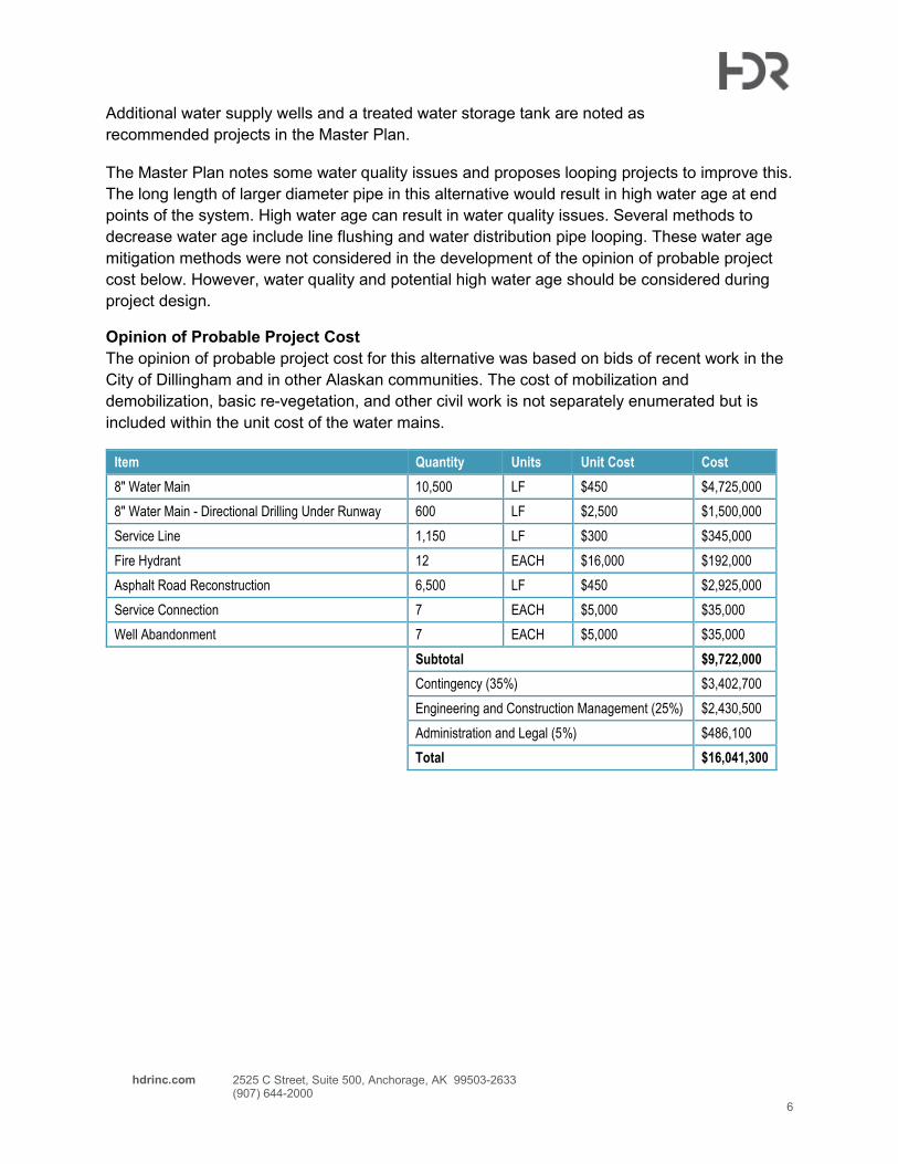
Opinion of Probable Project Cost
The opinion of probable project cost for this alternative was based on bids of recent work in the
City of Dillingham and in other Alaskan communities. The cost of mobilization and
demobilization, basic re-vegetation, and other civil work is not separately enumerated but is
included within the unit cost of the water mains.
Item Quantity Units Unit Cost Cost
8" Water Main 10,500 LF $450 $4,725,000 8" Water Main - Directional Drilling Under Runway 600 LF $2,500 $1,500,000 Service Line 1,150 LF $300 $345,000 Fire Hydrant 12 EACH $16,000 $192,000 Asphalt Road Reconstruction 6,500 LF $450 $2,925,000 Service Connection 7 EACH $5,000 $35,000 Well Abandonment 7 EACH $5,000 $35,000
Subtotal $9,722,000
Contingency (35%) $3,402,700 Engineering and Construction Management (25%) $2,430,500 Administration and Legal (5%) $486,100 Total $16,041,300

hdrinc.com 2525 C Street, Suite 500, Anchorage, AK 99503-2633 (907) 644-2000
7
Alternative 2: Small-Scale Water Distribution System This alternative would connect multiple buildings in close proximity to share an uncontaminated
or treated water well. As each area of buildings has a unique layout and unique challenges,
each area will be examined separately.
Alternative 2 was developed assuming the installation of 2-inch service connection lines for
water distribution rather than the 8-inch water mains required for Alternative 1. The larger water
mains are only necessary to transmit fire flows over long distances. As it would not be
necessary to install fire hydrants in these smaller water distribution systems, the larger water
mains are not necessary.
Area Summaries
Below, each area is summarized and proposed small-scale distribution system described.
WINDMILL HILL
On Windmill Hill, one well has a PFAS level above the EPA advisory level of 70 ppt. The
Salmon Roe Apartments located 500 ft to the east of the property is served by an existing
transient community Public Water System (ID AK261460). The public water system is managed
by the Choggiung Limited village corporation. In order to create a small scale distribution
system from this well, approximately 600 ft of water supply pipe would need to be installed.
Installation of the water pipe would occur over several private properties and will require
easements. A map of a proposed alignment can be seen in Figure 3.
AIRPORT SPUR
In the Airport Spur area there are four wells with PFAS levels above the EPA advisory level. The
nearest non-privately owned, uncontaminated well is at the Courthouse. The Courthouse well
has an existing transient non-community Public Water System (ID AK2263071) and is managed
by the Choggiung Limited village corporation, the land is owned by the City of Dillingham. This
alternative would involve likely rehabilitating the existing well and installing a new pump. In order
to create a small-scale distribution system utilizing this well, approximately 2,900 linear feet of
water supply pipe would need to be installed. Installation of the water pipe would occur either
within the road easement or on the Church property. An easement would have to be obtained
on the Church property for the water supply pipe. A map of a proposed alignment can be seen
in Figure 4.
Another option for this area would be to implement a PFAS treatment system at the church well
to serve a small scale distribution system serving the church, community water spigot, and the
three properties along Airport Spur Road. A new well or utilization of the existing well is possible
for this option. In order to create this system, approximately 1,700 linear feet of water supply
pipe would need to be installed. Installation of the water supply pipe would occur within the road
right of way and require obtaining approval from the owner of the right of way. An opinion of
probable project cost for this alignment is included but is not complete as the costs for a PFAS
treatment system of this size is unknown at this time and an owner and manager of the system
has not been identified. The water system at the church has an existing Non-Transient Non-
community public water system (ID AK2263018) managed by the Holy Rosary Church.
Consultation with DEC during design and construction is advised to ensure that construction

hdrinc.com 2525 C Street, Suite 500, Anchorage, AK 99503-2633 (907) 644-2000
8
and management complies with regulations. A map of a proposed alignment can be seen in
Figure 5.
A final option for this area would be to implement a PFAS treatment system at one of the wells
at a property along Airport Spur road, which could supply other nearby properties. A new well
or utilization of one the existing wells is possible for this option. A proposed alignment can be
seen in Figure 6. This alignment would require 750 linear feet of water supply pipe. The
alignment would require PFAS treatment at one of the properties along Airport Spur Road.
Installation of the water supply pipe would occur within the road right of way and require
obtaining approval from the owner of the right of way. An opinion of probably project cost for
this alignment is included, but is not complete as the costs of PFAS treatment system is not
included and an owner and manager of the system has not been identified. This water system
may be small enough to not be regulated by Alaska Department of Environmental Conservation
(DEC) regulations for community water systems, though consultation with DEC is advised to
ensure that construction and management complies with regulations
AIRPORT
The Airport area contains two wells with PFAS levels above the EPA advisory level. These wells
provide water to a hangar, airport terminal, and an airport restaurant. The Alaska Department of
Transportation (DOT) owns an unaffected well near the property. A small-scale distribution
system consisting of approximately 825 linear feet of water supply pipe could serve this area as
the two properties could connect to the existing DOT well. As the well is already publically
owned, this could simplify operating a small-scale distribution system. Easements or right-of-
ways would still need to be obtained for any pipes in roads. An owner and manager of the
system has not been identified.
Due to the number of restaurant patrons served in addition to the airport workers, this water
system would likely be classified as a transient non-community water system. This designation
necessitates a public water system review and approval from the Alaska DEC as well as regular
water quality testing. A map of a proposed alignment can be seen in Figure 7.
Potential Challenges to Development
There are several potential overarching challenges with developing small-scale distribution
systems in the affected areas. The following sections briefly discuss each of these challenges.
SYSTEM MANAGEMENT
Depending on the size and number of residents served, small-scale water distribution systems
could be categorized as “community”, “transient non-community”, or “non-transient” water
systems per Alaska DEC guidelines (18 AAC 80). Water systems which provide water to at least
25 people or 15 residences for over 60 days per year will have a state classification. In addition
to water supply regulations, a legal framework would need to be developed in order to direct the
responsibilities of ownership and maintenance of the water supply and water distribution
network. Options include, but are not limited to, a private co-operative agreement, a private
utility wholly owned by the landowner where the well is located, or a city-managed utility.
Whether private water supply pipes can be located within public right-of-ways must also be

hdrinc.com 2525 C Street, Suite 500, Anchorage, AK 99503-2633 (907) 644-2000
9
addressed prior to construction. These legal and logistical issues are outside of the scope of
this technical memorandum.
WELL SELECTION
A challenge with using walls is identifying one free of PFAS contamination. While several wells
around the study area properties have tested below PFAS detection or action levels, many of
these are privately owned wells. Beyond the utility management aspects discussed above,
permission to use a privately owned well, originally designed for a single home, as a source of
water for other properties must be negotiated. In this analysis, it is assumed that either a new
well can be drilled, or the use of a commercially or publically owned well is available. In the case
of alternatives that would involve drilling a new well, there is no guarantee that it will be free of
PFAS contamination. There is no discernible pattern of PFAS contamination with regard to well
construction, depth, or casing, and no exhaustive groundwater modelling has been performed.
Therefore, it is impossible to predict if a new well will be free of PFAS contamination.
EXISTING WELL DEVELOPMENT
The limited information from well logs make it difficult to determine the yield of many wells in the
area. A well flow test must be performed in order to determine if the existing well has sufficient
supply and recovery rate for the additional buildings that would be connected. The installation of
a new, higher capacity well pump may be necessary if the well recovery rate is sufficient but the
existing well pump is inadequate to provide the necessary flow or pressure to the system.
Additionally, the increase in flow from a single well could draw a larger plume of contaminated
groundwater, which could result in increased PFAS levels in that well. Without additional
groundwater or contaminant modelling, there is no definitive way of determining the extent of
possible future contamination issues.
Opinions of Probable Project Cost
The following tables present opinions of probable project cost for the proposed alignments in
each affected area. These opinions assume that no new wells will need to be drilled. The cost of
a new well installation would vary depending on the depth of wells. Including the well pump and
well pump installation, the average cost of a new well drilled would be approximately $25,000.
This cost would be added to the subtotal of any alternative opinion of probable project cost.
Well rehabilitation and new well pump installation was assumed to be equal to new well
development. The final cost could be lower if the existing well is found to be adequate and only
a limited amount of rehabilitation work is necessary.
Opinions below do not enumerate costs such as mobilization and demobilization which can be
quite high in rural areas. Instead, these costs are included within the unit cost of the water
distribution lines assuming that multiple small-scale distribution systems are installed within one
construction season. Costs such as re-seeding and re-vegetation are including within the unit
cost of water distribution lines. However if extensive site work is necessary, extra costs would
be incurred.
WINDMILL HILL
This opinion of probable project cost includes water distribution system utilizing the well at the
Salmon Roe Apartments to serve the property on Windmill Hill, see Figure 3. As the proposed
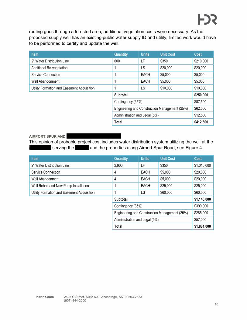
hdrinc.com 2525 C Street, Suite 500, Anchorage, AK 99503-2633 (907) 644-2000
10
routing goes through a forested area, additional vegetation costs were necessary. As the
proposed supply well has an existing public water supply ID and utility, limited work would have
to be performed to certify and update the well.
Item Quantity Units Unit Cost Cost
2" Water Distribution Line 600 LF $350 $210,000 Additional Re-vegetation 1 LS $20,000 $20,000 Service Connection 1 EACH $5,000 $5,000 Well Abandonment 1 EACH $5,000 $5,000 Utility Formation and Easement Acquisition 1 LS $10,000 $10,000
Subtotal $250,000
Contingency (35%) $87,500 Engineering and Construction Management (25%) $62,500 Administration and Legal (5%) $12,500 Total $412,500
AIRPORT SPUR AND CHURCH FROM COURTHOUSE
This opinion of probable project cost includes water distribution system utilizing the well at the
courthouse serving the church and the properties along Airport Spur Road, see Figure 4.
Item Quantity Units Unit Cost Cost
2" Water Distribution Line 2,900 LF $350 $1,015,000 Service Connection 4 EACH $5,000 $20,000 Well Abandonment 4 EACH $5,000 $20,000 Well Rehab and New Pump Installation 1 EACH $25,000 $25,000 Utility Formation and Easement Acquisition 1 LS $60,000 $60,000
Subtotal $1,140,000
Contingency (35%) $399,000 Engineering and Construction Management (25%) $285,000 Administration and Legal (5%) $57,000 Total $1,881,000
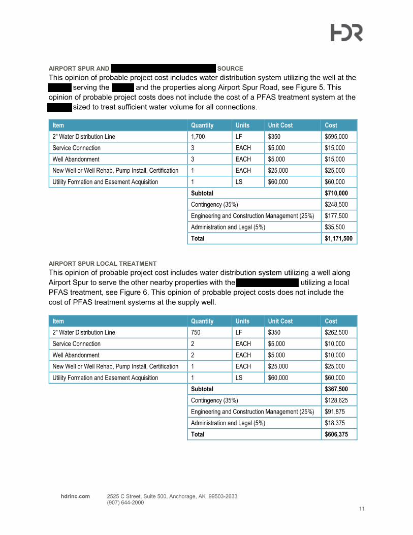
hdrinc.com 2525 C Street, Suite 500, Anchorage, AK 99503-2633 (907) 644-2000
11
AIRPORT SPUR AND CHURCH FROM TREATED CHURCH SOURCE
This opinion of probable project cost includes water distribution system utilizing the well at the
church serving the church and the properties along Airport Spur Road, see Figure 5. This
opinion of probable project costs does not include the cost of a PFAS treatment system at the
church sized to treat sufficient water volume for all connections.
Item Quantity Units Unit Cost Cost
2" Water Distribution Line 1,700 LF $350 $595,000 Service Connection 3 EACH $5,000 $15,000 Well Abandonment 3 EACH $5,000 $15,000 New Well or Well Rehab, Pump Install, Certification 1 EACH $25,000 $25,000 Utility Formation and Easement Acquisition 1 LS $60,000 $60,000
Subtotal $710,000
Contingency (35%) $248,500 Engineering and Construction Management (25%) $177,500 Administration and Legal (5%) $35,500 Total $1,171,500
AIRPORT SPUR LOCAL TREATMENT
This opinion of probable project cost includes water distribution system utilizing a well along
Airport Spur to serve the other nearby properties with the church and rectory utilizing a local
PFAS treatment, see Figure 6. This opinion of probable project costs does not include the
cost of PFAS treatment systems at the supply well.
Item Quantity Units Unit Cost Cost
2" Water Distribution Line 750 LF $350 $262,500 Service Connection 2 EACH $5,000 $10,000 Well Abandonment 2 EACH $5,000 $10,000 New Well or Well Rehab, Pump Install, Certification 1 EACH $25,000 $25,000 Utility Formation and Easement Acquisition 1 LS $60,000 $60,000
Subtotal $367,500
Contingency (35%) $128,625 Engineering and Construction Management (25%) $91,875 Administration and Legal (5%) $18,375 Total $606,375

hdrinc.com 2525 C Street, Suite 500, Anchorage, AK 99503-2633 (907) 644-2000
12
AIRPORT
This opinion of probable project cost includes a water distribution system utilizing a well owned
by Alaska DOT, see Figure 7. A certification process will be necessary to convert the private
well into a public water system.
Item Quantity Units Unit Cost Cost
2" Water Distribution Line 825 LF $350 $288,750 Service Connection 2 EACH $5,000 $10,000 Well Abandonment 2 EACH $5,000 $10,000 New Well or Well Rehab, Pump Install, Certification 1 EACH $40,000 $40,000 Utility Formation and Easement Acquisition 1 LS $30,000 $30,000
Subtotal $378,750
Contingency (35%) $132,563 Engineering and Construction Management (25%) $94,688 Administration and Legal (5%) $18,938 Total $624,938
Opinion of Probable Operations and Maintenance Costs
In order to fully capture the estimated costs of the small-scale water distribution system,
operations and maintenance (O&M) costs were estimated. Items included in the rough opinion
of probable O&M cost are: additional pump electrical costs, part-time employees for
administrative, testing, and maintenance work, water testing costs, and other costs for items
such as repairs, insurance, and general overhead. The Opinion of Probable O&M costs apply to
each small scale distribution system and do not include additional costs for operating any
proposed PFAS treatment system.
PUMP ELECTRICAL COSTS
Electricity costs approximately $0.44/kWh for residential and small commercial customers
according to Nushtel Cooperative publications. While pump selection and anticipated water flow
would affect the total power demand by the well supply pump, an estimate of $100 per month
was calculated for the area with the highest water demand (Airport Spur).
EMPLOYEE COSTS
In order to manage billing, utility payment, utility management, perform required water quality
testing, and make any repairs or maintenance necessary to the systems, a part-time employee
is necessary. It was estimated this work would average one 8-hour work day per week.
Including a multiplier for overhead and benefit costs, at a wage of $25/hour, the employee would
cost approximately $1,600 per month.
WATER TESTING
All registered water supply systems are required to go through regular water testing. Monthly
tests for coliform are generally required along with lead and copper testing and other tests at
longer intervals. In addition, regular PFAS testing is recommended to monitor the levels of
contamination in the supply wells. These costs were estimated to be $400 per month.

hdrinc.com 2525 C Street, Suite 500, Anchorage, AK 99503-2633 (907) 644-2000
13
OVERHEAD
Other overhead costs such as parts for repairs and maintenance, and insurance were bundled
and estimated at $400 per month.
Item Cost
Pump Electrical Costs $100
Administration/Maintenance (assume 0.2 FTE @ $25/hr) $1,600
Testing (DEC Required & PFAS) $400
Other Overhead Costs (Insurance, Repairs, etc) $400
Total $2,500

West Main St
KennyW
renRd
Kanakanak
Rd
West D St
Wood River Rd
Airport Rd
Wes
t2n
dAv e
AirportRd
AleknagikLake Rd
Source: Esri, DigitalGlobe, GeoEye, Earthstar Geographics, CNES/Airbus DS, USDA, USGS,AeroGRID, IGN, and the GIS User Community
PROJECT AREA MAP
LEGENDTested Well PFAS Concentration*
0 - 69 ppt70 + ppt
City of Dillingham Water SystemExisting Water System
FIGURE 1
DILLINGHAM AIRPORT ALTERNATIVE WATER
*Sum of PFOS, PFOA, PFHxS, PFHpA, and PFNA
Windmill Hill Area
AirportArea
Airport SpurArea
0 0.25 0.5MILES

Kenny Wr en
Rd
Woo
d Rive
r Rd
Kanakan
ak Rd
West Main St
Airport Rd West D St
Source: Esri, DigitalGlobe, GeoEye, Earthstar Geographics, CNES/Airbus DS, USDA, USGS,AeroGRID, IGN, and the GIS User Community
MUNICIPAL WATER SYSTEM EXTENSION
LEGENDTested Well PFAS Concentration*
0 - 69 ppt70 + ppt (to be abandoned)Buildings served by 70+ ppt wells
Water System MainsNew Water Distribution MainNew Service LineExisting Water SystemExisting Private Service Lines
FIGURE 2
DILLINGHAM AIRPORT ALTERNATIVE WATER
(CLIENT LOGO)
*Sum of PFOS, PFOA, PFHxS, PFHpA, and PFNA
0 0.25 0.5MILES
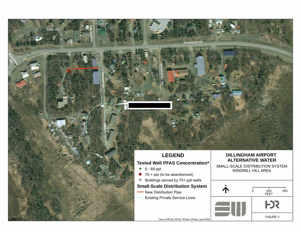
Kanakanak Rd
Wood River
Rd
Gaut
hier W
ay
Fairview Dr
Birch Ln
Cedar Cir
Fairview Rd
Sunny Dr
Windm il l Hi l lRd
Source: Esri, DigitalGlobe, GeoEye, Earthstar Geographics, CNES/Airbus DS, USDA, USGS,AeroGRID, IGN, and the GIS User Community
SMALL-SCALE DISTRIBUTION SYSTEMWINDMILL HILL AREA
LEGENDTested Well PFAS Concentration*
0 - 69 ppt70 + ppt (to be abandonned)Buildings served by 70+ ppt wells
Small-Scale Distribution SystemNew Distribution PipeExisting Private Service Lines
FIGURE 3
DILLINGHAM AIRPORT ALTERNATIVE WATER
(CLIENT LOGO)
*Sum of PFOS, PFOA, PFHxS, PFHpA, and PFNA
0 250 500FEET
Salmon Roe Apartments

Airport Rd
Kanakanak Rd
South Emperor Way
Airport Rd
West Airport Rd
Airport Spur Rd
Thre
eSi
sters
Road
Source: Esri, DigitalGlobe, GeoEye, Earthstar Geographics, CNES/Airbus DS, USDA, USGS,AeroGRID, IGN, and the GIS User Community
LEGENDTested Well PFAS Concentration*
0 - 69 ppt70 + ppt (to be abandonned)Buildings served by 70+ ppt wells
Small-Scale Distribution SystemNew Distribution PipeExisting Private Service Lines
FIGURE 4
DILLINGHAM AIRPORT ALTERNATIVE WATER
(CLIENT LOGO)
*Sum of PFOS, PFOA, PFHxS, PFHpA, and PFNA
0 500 1,000FEET
SMALL-SCALE DISTRIBUTION SYSTEMAIRPORT SPUR AREA
COURTHOUSE SUPPLY

Kanakanak Rd
Airport Spur Rd
Kanakan
ak Rd
Airport Rd
West
Airport Rd
Airport Rd
Thre
eSi
sters
Roa d
South Emperor Way
Source: Esri, DigitalGlobe, GeoEye, Earthstar Geographics, CNES/Airbus DS, USDA, USGS,AeroGRID, IGN, and the GIS User Community
SMALL-SCALE DISTRIBUTION SYSTEMAIRPORT SPUR AREACHURCH TREATMENT
LEGENDTested Well PFAS Concentration*
0 - 69 ppt70 + ppt (to be abandonned)Buildings served by 70+ ppt well
Small-Scale Distribution SystemNew Distribution PipeExisting Private Service LinesPFAS Treatment System at Well
FIGURE 5
DILLINGHAM AIRPORT ALTERNATIVE WATER
(CLIENT LOGO)
*Sum of PFOS, PFOA, PFHxS, PFHpA, and PFNA
0 250 500FEET
PFAS Treatment at Church Well

Airport Spur Rd
Source: Esri, DigitalGlobe, GeoEye, Earthstar Geographics, CNES/Airbus DS, USDA, USGS,AeroGRID, IGN, and the GIS User Community
SMALL-SCALE DISTRIBUTION SYSTEMAIRPORT SPUR AREALOCAL TREATMENT
LEGENDTested Well PFAS Concentration*
0 - 69 ppt70 + ppt (to be abandonned)Buildings served by 70+ ppt well
Small-Scale Distribution SystemNew Distribution PipeExisting Private Service LinesPFAS Treatment System at Well
FIGURE 6
DILLINGHAM AIRPORT ALTERNATIVE WATER
(CLIENT LOGO)
*Sum of PFOS, PFOA, PFHxS, PFHpA, and PFNA
0 150 300FEET
PFAS Treatment at Well

West
Airpo
rt
Airpo
rt
West Airport
Source: Esri, DigitalGlobe, GeoEye, Earthstar Geographics, CNES/Airbus DS, USDA, USGS,AeroGRID, IGN, and the GIS User Community
LEGENDTested Well PFAS Concentration*
0 - 69 ppt70 + ppt (to be abandonned)Buildings served by 70+ppt wells
Small-Scale Distribution SystemNew Distribution Pipe
FIGURE 7
DILLINGHAM AIRPORT ALTERNATIVE WATER
(CLIENT LOGO)
*Sum of PFOS, PFOA, PFHxS, PFHpA, and PFNA
0 250 500FEET
SMALL-SCALE DISTRIBUTION SYSTEMAIRPORT AREA

Appendix A Water Demand Calculations
Development Area Sample ID Address Description People gpcd Gal/day
(gpd)
Total
(gpd)
Airport 325
191300 720 Airport Rd Hangar 2 15 30
191320 750 Airport Rd Airport Terminal 9 15 135
750 Airport Rd Restaurant 20 8 160
Airport Spur 2,095
191700 2531 Airport Spur Rd House 2 100 200
191710 2546 Airport Spur Rd Apartment 10 75 750
191710 2550 Airport Spur Rd House 2 100 200
191710 2570 Airport Spur Rd House 2 100 200
191710 2570 Airport Spur Rd Office 3 15 45
191720 2565 Airport Spur Rd Cabin 2 100 200
191050 509 Airport Rd Rectory 1 100 100
191050 509 Airport Rd Community Spigot 1 400 400
Windmill Hill 1,125
200150 1629 Kanakanak Rd Group Housing 15 75 1,125
Total (gpd) 3,545

hdrinc.com 2525 C Street, Suite 500, Anchorage, AK 99503-2633 (907) 644-2000
1
Memo Date: July 24, 2020
Project: Supplement to Dillingham PFAS Contamination - Alternative Water Supply Study
To: Marcy Nadel, Shannon & Wilson, Inc.
From: Anson Moxness, PE, Wescott Bott, PE, HDR
Subject: Municipal Water Expansions Pipe Routes
During development of the alternative of extending the City of Dillingham municipal water system to serve the affected properties, both pipe routing under the Dillingham Airport runway and around the runway were considered. Only the route under the airport was included in the initial report. Below is a brief comparison of the two pipe routes. Figure 8 shows the pipe route around the airport.
Route Around the AirportThis route uses traditional trenching techniques to construct a 16,500 pipe following Kanakanak Road around the airport from the existing municipal water system and terminates at the airport. Traditional trenching techniques have been used in prior water line construction in Dillingham. However, the additional length of pipe and asphalt road needing reconstruction adds significant cost to the project compared to the routing under the airport. Additionally, this alternative may impede traffic trying to access homes and business east of the airport during construction.
Below is the opinion of probable project cost of routing the pipe around the airport:
Item Quantity Units Unit Cost Cost
8" Water Main 16,500 LF $450 $7,425,000
Service Line 1,150 LF $300 $345,000 Fire Hydrant 18 EACH $16,000 $288,000Asphalt Road Reconstruction 13,000 LF $450 $5,850,000Service Connection 7 EACH $5,000 $35,000 Well Abandonment 7 EACH $5,000 $35,000
Subtotal $13,943,000
Contingency (35%) $4,880,050Engineering and Construction Management (25%) $3,485,750Administration and Legal (5%) $697,150Total $23,005,950

hdrinc.com 2525 C Street, Suite 500, Anchorage, AK 99503-2633 (907) 644-2000
2
Route Under the AirportThis route utilizes the trenchless technology of horizontal directional drilling under the runway, which shortens the overall pipe length needed to serve affected properties and limits the impact to traffic along Kanakanak Road during construction. This method has been used under other active airports in the past and the Air Force has issued a technical letter giving guidance for using trenchless technology under Air Force pavements. Use of HDPE pipe reduces the risk of pipe breaks due to corrosion which would limit the long term effects to the runway pavement. To our knowledge, this technology has not been used in Dillingham for prior water line construction. Due to the lower pipe length, the project cost would likely be significantly lower than the alternative of routing around the airport.

Kanakanak
Rd
Airport Rd
AirportRd
AleknagikLake Rd
Woo
dRive
rRd
Source: Esri, DigitalGlobe, GeoEye, Earthstar Geographics, CNES/Airbus DS, USDA, USGS,AeroGRID, IGN, and the GIS User Community
MUNICIPAL WATER SYSTEM EXTENSIONAROUND AIRPORT
LEGENDTested Well PFAS Concentration*
0 - 69 ppt70 + ppt (to be abandoned)Buildings served by 70+ ppt wells
Water System MainsMainNew Service LineExisting Water SystemExisting Private Service Lines
DILLINGHAM AIRPORT ALTERNATIVE WATER
(CLIENT LOGO)
*Sum of PFOS, PFOA, PFHxS, PFHpA, and PFNA
0 0.25 0.5MILES
FIGURE 8

Long-Term Alternate Water Feasibility Study Report
102786-003 October 2020 B-i
APPE
NDIX
B: B
ARR
REPO
RT A
ND S
UPPO
RTIN
G IN
FORM
ATIO
N Appendix B: Barr Report and Supporting Information
Appendix B
Barr Engineering Co. Feasibility Report and Supporting Information CONTENTS
B.1 Analytical Sampling........................................................................................................... ii
Enclosures
Barr Engineering Co. Dillingham Airport PFAS Point-of-Entry Treatment FeasibilityReport
SGS North America, Inc. (SGS) Lab Report 1199948 and Laboratory Data ReviewChecklist (LDRC)
Eurofins TestAmerica Laboratories, Sacramento (TestAmerica) Lab Report 320-56436and LDRC
Residential Well Sampling Logs

Long-Term Alternate Water Feasibility Study Report
102786-003 October 2020 B-ii
APPE
NDIX
B: B
ARR
REPO
RT A
ND S
UPPO
RTIN
G IN
FORM
ATIO
N
B.1 ANALYTICAL SAMPLING
On November 14 and 15, 2020, Shannon & Wilson, Inc. field staff collected groundwater samples from four impacted water supply wells (Well IDs 191050, 191320, 191710, and 200150) to inform Barr’s treatment recommendations. Copies of completed Residential Well Sampling Logs are enclosed. The analytical water samples were submitted for determination of total suspended solids, metals, petroleum compounds, pH, organic carbon, and PFAS by SGS North America, Inc. and Eurofins TestAmerica. SGS North America, Inc. subcontracted determination of arsenite, arsenate, dimethylarsinic acid (DMA), and monomethylarsonic acid (MMA) to Brooks Applied Labs. An analytical results summary table is included within Barr’s report.
Shannon & Wilson reviewed the analytical results for laboratory quality control samples and conducted a quality assurance (QA) assessment for this project. These QA review procedures allowed Shannon & Wilson to document the accuracy and precision of the analytical data, as well as check the analyses were sufficiently sensitive to detect analytes at levels below regulatory standards. The results are presented in the appended SGS North America, Inc. report 1199948, Eurofins TestAmerica report 320-56436, and associated DEC Laboratory Data Review Checklists (LDRCs).
Shannon & Wilson considers the samples collected for this project to be representative of site conditions at the locations and times they were obtained. Based on this QA review, no samples were rejected as unusable due to quality control failures. In general, the quality of the analytical data for this project does not appear to have been compromised by analytical irregularities and is adequate for the purposes of this assessment.

Long-Term Alternate Water Feasibility Study Report
102786-003 October 2020
APPE
NDIX
B: B
ARR
REPO
RT A
ND S
UPPO
RTIN
G IN
FORM
ATIO
N
BARR’S POINT-OF-ENTRY TREATMENT FEASIBILITY REPORT

Barr Engineering Co. 4300 MarketPointe Drive, Suite 200, Minneapolis, MN 55435 952.832.2600 www.barr.com
Technical Memorandum
To: Scott Jordan, Alaska Department of Administration (DOA) From: Andy McCabe, Katie Wolohan, Bryan Oakley and Brian Angerman, Barr Engineering Co.
(Barr) Subject: Dillingham Airport PFAS Point-of-Entry Treatment Feasibility Report Date: April 23, 2020 Project: Shannon & Wilson, Inc., Dillingham Feasibility Report c: Kristen Freiburger, Shannon & Wilson, Inc.
1.0 Background Shannon & Wilson, Inc. (S&W) began collecting per- and polyfluoroalkyl substances (PFAS) samples from private wells near and downgradient of the Dillingham Airport in February 2019. Prior to the first mobilization, the Alaska Department of Environmental Conservation (DEC) had sampled nine wells and encountered a public water source that exceeded the former DEC action level for drinking water. S&W’s initial well search and sampling effort occurred in February and March 2019. The well search area was expanded in response to detections of PFAS east of the Dillingham Airport in June 2019. To date, nearly 100 private wells have been sampled between February 26 and November 16, 2019.
On April 9, 2019, the DEC action level for drinking water was aligned with the U.S. Environmental Protection Agency (EPA) lifetime health advisory (LHA) level of 70 parts per trillion (ppt) for the sum of two PFAS compounds, perfluorooctane sulfonate (PFOS) and perfluorooctanoic acid (PFOA). Prior to April 2019, the DEC action level was 70 ppt for the sum of five PFAS compounds: PFOS, PFOA, perfluoroheptanoic acid (PFHpA), perflurohexanesulfonic acid (PFHxS), and perfluorononanoic acid (PFNA). Wells considered affected are compared to the action level at the time the sample was collected. Seven of the private wells sampled in Dillingham are impacted by PFAS. Those who use their wells for drinking or cooking are currently receiving interim bottled water deliveries.
S&W partnered with Barr Engineering Co. (Barr) to evaluate feasibility of point-of-entry treatment (POET) systems for PFAS at the impacted properties. This memorandum includes recommendations for PFAS water treatment along with related pre- and post-treatment for water treatment systems that will be installed at the impacted properties if water treatment is selected. Table 1 summarizes the properties addressed in this memorandum. Each property has one well. Note property 191720 (cabins on Airport Spur Road) has been excluded from this report because the property owner declined to provide access for a site assessment in February 2020.

To: Scott Jordan, Alaska Department of Administration (DOA) From: Andy McCabe, Katie Wolohan, Bryan Oakley and Brian Angerman, Barr Engineering Co. (Barr)Subject: Dillingham Airport PFAS Point-of-Entry Treatment Feasibility Report Date: April 23, 2020 Page: 2
P:\Mpls\02 AK\08\02081001 Shannon & Wilson Gustavus Resp\WorkFiles\Dillingham temporary\Feasibility Report\Dillingham - PFAS Water Treatment Action Plan.docx
Table 1 Summary of properties addressed in this memorandum
Property ID number
Property Description Address
191050 Church, rectory, and community water spigot
509 Airport Rd
191300 Hangar ADA-09029 Block 500, Lot 5B 720 Airport Rd
191320 Airport terminal and restaurant ADA-09024 Block 500, Lot 7B, 750 Airport Rd
191700 House 2531 Airport Spur Rd
191710 Apartment Building, two houses (House A and B), and office
Multiple addresses on Airport Spur Road
200150 Group housing 1629 Kanakanak Rd
2.0 Site Assessment Summary – Dillingham, AK On November 14 and 15, 2019, a representative from S&W visited the properties listed in Table 1 to collect details on current water use, available space, and, if present, existing treatment systems. Water samples were also collected to assess the water quality at the site to inform potential pretreatment. Daily water use estimates based on the site visits are summarized in Table 2. The complete site visit reports for the water supplies at these properties are provided in Attachment 1.
Water pressure-related concerns were noted at property 191300 (commercial hangar), specifically when severe iron fouling is observed. No water pressure-related concerns were noted at any of the other properties. The pressure recorded at the bladder tanks were all greater than 100 pounds per square inch (PSI). Concerns related to water odors and staining were noted at properties 191300, 191320, 191700, 191710, and 200150.

To: Scott Jordan, Alaska Department of Administration (DOA) From: Andy McCabe, Katie Wolohan, Bryan Oakley and Brian Angerman, Barr Engineering Co. (Barr)Subject: Dillingham Airport PFAS Point-of-Entry Treatment Feasibility Report Date: April 23, 2020 Page: 3
P:\Mpls\02 AK\08\02081001 Shannon & Wilson Gustavus Resp\WorkFiles\Dillingham temporary\Feasibility Report\Dillingham - PFAS Water Treatment Action Plan.docx
Table 2 Summary of site occupancy and estimate daily water use
Property ID Number
Property Description(1) Number of
People(2) Est. Daily Water Use
(gpd)(3)
191050
Rectory, outdoor spigot serves as community water source
1 person, plus outdoor community use
400-500
Church <10 people 191300 Hangar 2 people 30
191320
Airport terminal (ground floor)
Approximately 9 people
135
Restaurant (second floor) 20 people assumed for treatment design purposes
160
191700 House 1 person 200
(non-potable use only)
191710
House A 2 people 200 Apartment Building, 5 units
4 to 8 people (10 max)
750
House B 1 to 2 people 200 Office 3 people 45
200150 Group housing, fish processing
1 person in winter; 15 people in summer
1,125
(1) Separate buildings or multi-residential buildings at each property are shown in separate rows.(2) Assume year-round residency or occupancy unless noted.(3) Gallons per day, from HDR Dillingham PFAS Contamination - Alternative Water Supply Study (April 2020).
3.0 Design Basis 3.1 Treatment Requirements The minimum treatment requirements for the water treatment systems include:
• <70 nanograms per liter (ng/L) PFOS and PFOA (EPA LHA and DEC action level as of April 2019)
In addition to the treatment requirements, treatment goals for the water treatment systems include:
• <10 micrograms per liter (µg/L) arsenic (National Primary Drinking Water Regulation [NPDWR]Maximum Contaminant Level [MCL])
• <70 ng/L sum of five PFAS: PFOA, PFOS, PFHpA, PFNA, and PFHxS (DEC action level prior toApril 2019)

To: Scott Jordan, Alaska Department of Administration (DOA) From: Andy McCabe, Katie Wolohan, Bryan Oakley and Brian Angerman, Barr Engineering Co. (Barr) Subject: Dillingham Airport PFAS Point-of-Entry Treatment Feasibility Report Date: April 23, 2020 Page: 4
P:\Mpls\02 AK\08\02081001 Shannon & Wilson Gustavus Resp\WorkFiles\Dillingham temporary\Feasibility Report\Dillingham - PFAS Water Treatment Action Plan.docx
Secondary treatment goals for the water treatment systems include:
• <300 µg/L iron (National Secondary Drinking Water Regulation [NSDWR] Secondary Maximum Contaminant Level [SMCL] and protective of the PFAS water treatment process to prevent iron fouling)
• <50 µg/L manganese (NSDWR SMCL and protective of the PFAS water treatment process to prevent manganese fouling)
3.2 Water Quality Water quality results are summarized in Attachment 2. General water chemistry at four of the properties are summarized in Table 3. General water chemistry data for properties 191300 and 191700 were not available at the time this feasibility report was prepared. Based on the November 2019 sampling results, of the four properties with data, none exceed the primary arsenic treatment target, and arsenic treatment will not be necessary.
Iron and manganese pretreatment is not required to meet secondary treatment targets at properties 191050 or 200150. Iron and manganese concentrations are relatively high at properties 191320 and 191710 and will require pretreatment to meet secondary treatment targets and targets that are protective of the PFAS water treatment processes.
While general water chemistry data were not available for properties 191300 and 191700, concentration ranges for iron and arsenic species were assumed at these two properties to facilitate preliminary treatment system design and cost estimating. Based on the data available for arsenic species, it is assumed that concentrations at properties 191300 and 191700 are similarly below the primary arsenic treatment target. For purposes of this feasibility report, arsenic treatment is not considered. However, samples should be collected to verify this assumption. If arsenic exceeds 10 µg/L at properties 191300 and 191700, arsenic treatment will be required.
Based on proximity of property 191300 to property 191320, it is assumed that the iron concentration at property 191300 will exceed the secondary treatment target. Likewise, based on the proximity of property 191700 to property 191710, it is assumed that the iron concentration at property 191700 will exceed the secondary iron treatment target. These assumptions are consistent with water quality observations during S&W site visits. For purposes of this feasibility report, both properties 191300 and 191700 are assumed to exceed 10,000 µg/L iron, thus requiring iron pretreatment.

To: Scott Jordan, Alaska Department of Administration (DOA) From: Andy McCabe, Katie Wolohan, Bryan Oakley and Brian Angerman, Barr Engineering Co. (Barr) Subject: Dillingham Airport PFAS Point-of-Entry Treatment Feasibility Report Date: April 23, 2020 Page: 5
P:\Mpls\02 AK\08\02081001 Shannon & Wilson Gustavus Resp\WorkFiles\Dillingham temporary\Feasibility Report\Dillingham - PFAS Water Treatment Action Plan.docx
Table 3 Summary of general water chemistry
Parameter Units Property ID Number
191050 191300 191320 191700 191710 200150
pH pH units 6.6 na 6.4 na 6.5 6.6
Conductivity µmhos/cm 87.0 na 315 na 257 262
Hardness, as CaCO3 mg/L 31.7 na 115 na 87.9 64.3
Iron µg/L 123 J Assumed Fe + Mn
>10,000(1)
46,000 Assumed Fe + Mn
>10,000(1)
36,800 <125
Manganese µg/L 1.79 1,420 1,340 7.40
Arsenite (III) µg/L <0.0400 assumed Arsenite + Arsenate
<10(1)
1.9 assumed Arsenite + Arsenate
<10(1)
3.6 <0.0400
Arsenate (V) µg/L 0.0590 J 0.461 0.993 <0.0400
na - not available. J - Estimated concentration, detected greater than the method detection limit (MDL) and less than the reporting limit (RL). Flag applied by the laboratory. (1) Approximate concentration ranges were assumed to facilitate preliminary treatment system design and cost estimating.
PFAS data for each property are summarized in Table 4. The PFAS sample results shown were collected during four sampling events between December 2018 and November 2019. Where multiple sample results are available, concentration ranges are provided. Detailed PFAS sample results are provided in Attachment 2.
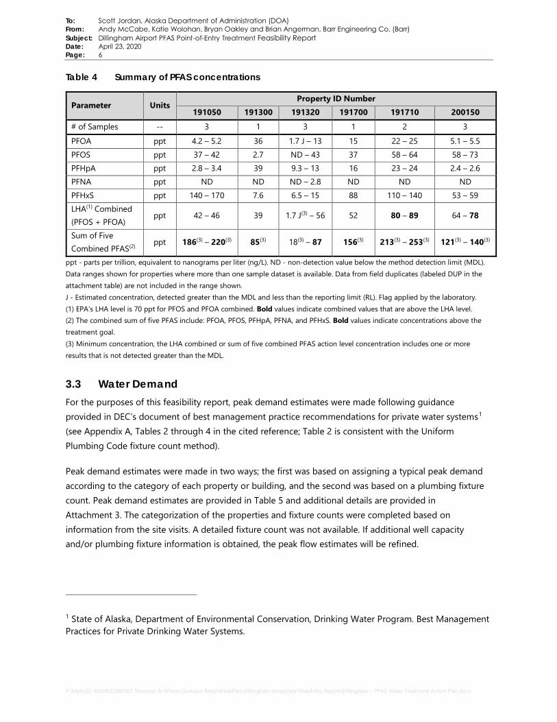
To: Scott Jordan, Alaska Department of Administration (DOA) From: Andy McCabe, Katie Wolohan, Bryan Oakley and Brian Angerman, Barr Engineering Co. (Barr)Subject: Dillingham Airport PFAS Point-of-Entry Treatment Feasibility Report Date: April 23, 2020 Page: 6
P:\Mpls\02 AK\08\02081001 Shannon & Wilson Gustavus Resp\WorkFiles\Dillingham temporary\Feasibility Report\Dillingham - PFAS Water Treatment Action Plan.docx
Table 4 Summary of PFAS concentrations
Parameter Units Property ID Number
191050 191300 191320 191700 191710 200150
# of Samples -- 3 1 3 1 2 3
PFOA ppt 4.2 – 5.2 36 1.7 J – 13 15 22 – 25 5.1 – 5.5 PFOS ppt 37 – 42 2.7 ND – 43 37 58 – 64 58 – 73 PFHpA ppt 2.8 – 3.4 39 9.3 – 13 16 23 – 24 2.4 – 2.6 PFNA ppt ND ND ND – 2.8 ND ND ND PFHxS ppt 140 – 170 7.6 6.5 – 15 88 110 – 140 53 – 59 LHA(1) Combined (PFOS + PFOA)
ppt 42 – 46 39 1.7 J(3) – 56 52 80 – 89 64 – 78
Sum of Five Combined PFAS(2) ppt 186(3) – 220(3) 85(3) 18(3) – 87 156(3) 213(3) – 253(3) 121(3) – 140(3)
ppt - parts per trillion, equivalent to nanograms per liter (ng/L). ND - non-detection value below the method detection limit (MDL). Data ranges shown for properties where more than one sample dataset is available. Data from field duplicates (labeled DUP in the attachment table) are not included in the range shown. J - Estimated concentration, detected greater than the MDL and less than the reporting limit (RL). Flag applied by the laboratory. (1) EPA’s LHA level is 70 ppt for PFOS and PFOA combined. Bold values indicate combined values that are above the LHA level.(2) The combined sum of five PFAS include: PFOA, PFOS, PFHpA, PFNA, and PFHxS. Bold values indicate concentrations above thetreatment goal.(3) Minimum concentration, the LHA combined or sum of five combined PFAS action level concentration includes one or moreresults that is not detected greater than the MDL.
3.3 Water Demand For the purposes of this feasibility report, peak demand estimates were made following guidance provided in DEC’s document of best management practice recommendations for private water systems1 (see Appendix A, Tables 2 through 4 in the cited reference; Table 2 is consistent with the Uniform Plumbing Code fixture count method).
Peak demand estimates were made in two ways; the first was based on assigning a typical peak demand according to the category of each property or building, and the second was based on a plumbing fixture count. Peak demand estimates are provided in Table 5 and additional details are provided in Attachment 3. The categorization of the properties and fixture counts were completed based on information from the site visits. A detailed fixture count was not available. If additional well capacity and/or plumbing fixture information is obtained, the peak flow estimates will be refined.
1 State of Alaska, Department of Environmental Conservation, Drinking Water Program. Best Management Practices for Private Drinking Water Systems.

To: Scott Jordan, Alaska Department of Administration (DOA) From: Andy McCabe, Katie Wolohan, Bryan Oakley and Brian Angerman, Barr Engineering Co. (Barr) Subject: Dillingham Airport PFAS Point-of-Entry Treatment Feasibility Report Date: April 23, 2020 Page: 7
P:\Mpls\02 AK\08\02081001 Shannon & Wilson Gustavus Resp\WorkFiles\Dillingham temporary\Feasibility Report\Dillingham - PFAS Water Treatment Action Plan.docx
Table 5 Summary of peak water demand estimates for individual properties
Property ID Number
Categorical Peak Demand Estimate (gpm)
Fixture Count Peak Demand Estimate (gpm)
Design Flow Rate (gpm)
191050 11 21 16 191300 1 7 8 191320 25 25 24 191700 8 10 8 191710 32 39 32 200150 14 23 16
The estimates made using the fixture count method are all higher than those made based on assigning property categories, except for property 191300 (commercial hangar) which has both a low expected number of water users and low count of plumbing fixtures. It is expected that plumbing fixtures were overcounted, thus the peak demands based on fixture counts provide upper-level estimates. At this stage of design, to estimate capital and operating expenses, it is assumed that peak flows based on property category are more accurate than those based on fixture counts. Peak demand estimates may change at a later stage of design. Design flow rates were selected based on the nearest 8 gpm increment, which is constrained by the size and target empty bed contact time (EBCT) of the granular activated carbon (GAC) vessels for typical residential PFAS treatment.
Additionally, two alternative treatment scenarios were considered using combined systems. Under these two scenarios, one treatment system would service multiple properties using 2-inch service connection lines. Note that these two combined treatment systems are exclusive of each other. If a combined treatment system is selected, only one, not both, would be installed. As previously noted, property 191720 (cabins on Airport Spur Road) was excluded from this report because the property owner declined site access, thus it was excluded from the combined system evaluation.
Combined System 1: System would be sited at property 191050 and be sized to also provide water to properties 191710 and 191700.
Combined System 2: System would be sited at property 191710 and be sized to also provide water for property 191700.
Peak demand estimates for the combined treatment systems are summarized in Table 6. The peak demand estimates included in Table 6 are slightly less than estimates taken as the sums of the peak demands included in Table 5. This occurs because as the number of residences served increases, the peaking factor decreases.

To: Scott Jordan, Alaska Department of Administration (DOA) From: Andy McCabe, Katie Wolohan, Bryan Oakley and Brian Angerman, Barr Engineering Co. (Barr) Subject: Dillingham Airport PFAS Point-of-Entry Treatment Feasibility Report Date: April 23, 2020 Page: 8
P:\Mpls\02 AK\08\02081001 Shannon & Wilson Gustavus Resp\WorkFiles\Dillingham temporary\Feasibility Report\Dillingham - PFAS Water Treatment Action Plan.docx
Table 6 Summary of peak water demand estimates for combined systems
Combined System Scenarios
Categorical Peak Demand Estimate (gpm)
Fixture Count Peak Demand Estimate (gpm)
Design Flow Rate (gpm)
Combined System 1 191050, 191700, 191710
45 45 48
Combined System 2 191700, 191710
37 41 40
Additional Design Considerations for Combined Systems
In evaluating the feasibility of these two combined scenarios, it will be necessary to review the well capacities, pressure head loss through the service lines, and the average hydraulic residence time of the distribution system.
• The well capacities at the sited property should be reviewed to verify the well and well pump are appropriately sized to supply the total peak demand of all properties served. If the pump capacity is not known, a pumping test will be required to verify well capacity.
• The pressure head loss of the service connection lines should be reviewed to verify all properties will have adequate water pressure.
o For Combined System 1, it is estimated that approximately 1,700 feet of service connection lines will be required. Assuming the longest length of the connection line is 1,400 feet (between properties 191050 and 191710) and 2-inch HDPE is used, the pressure drop at peak flow in the distribution system (assumed to be 40 gpm) is estimated to be 22 pounds per square inch (psi). Thus, to provide a minimum water pressure of 35 psi at 191700, the water pressure to the treatment system must be 75-95 psi depending on how fouled the filters and treatment units are. This may require more frequent replacement of filtration units to maintain adequate pressure at the remote properties.
o For Combined System 2, approximately 500 feet of connecting service lines are needed and a flow of 8 gpm, the pressure head loss is estimated to be less than 1 psi.
• The average hydraulic residence time in the service lines should be reviewed to verify the water will not become stagnant during periods of low use.
o For Combined System 1, assuming a total daily flow of 1,395 gallons per day (gpd) for properties 191700 and 191710 and 1,700 feet of service line, the average hydraulic residence time will be less than 5 hours.

To: Scott Jordan, Alaska Department of Administration (DOA) From: Andy McCabe, Katie Wolohan, Bryan Oakley and Brian Angerman, Barr Engineering Co. (Barr)Subject: Dillingham Airport PFAS Point-of-Entry Treatment Feasibility Report Date: April 23, 2020 Page: 9
P:\Mpls\02 AK\08\02081001 Shannon & Wilson Gustavus Resp\WorkFiles\Dillingham temporary\Feasibility Report\Dillingham - PFAS Water Treatment Action Plan.docx
o For Combined System 2, assuming a total daily flow of 200 gpd for property 191700 and500 feet of service line, the hydraulic residence time will be 9 hours.
In addition, disinfection requirements will need to be evaluated for the combined systems. If either of the combined systems are categorized as Public Water Systems (PWS) by the State, certain disinfection requirements may need to be met as outlined in 18 Alaska Administrative Code Chapter 80. There are three categories of PWS and designations are made based on the expected number of people served:
• Community Water Systemo expects to serve, year round, at least 25 individuals; oro expects to serve, year round, at least 15 residential service connections
• Non-Transient Non Community Water System (NTNCWS)o regularly serves the same 25 or more individuals for at least 6 months of the year
• Transient Non Community Water System (TNCWS)o is not a CWS or NTNCWS, ando regularly serves at least 25 individuals each day for at least 60 days of the year
Based on the number of people served at each property as provided in HDR’s Dillingham PFAS Contamination – Alternative Water Supply Study2, Combined System 1 is expected to serve a maximum of 21 people and Combined System 2 is expected to serve a maximum of 19 people. While presently, neither system is expected to serve 25 people, the state may evaluate the combined systems based on the number of people that could be served.
If either of the combined systems are categorized as a PWS, disinfection requirements will need to be met. Disinfection options could include chlorination to achieve a target residual concentration or installation of ultraviolet (UV) disinfection units at the points of use.
3.4 Available Space and System Siting Responses from the site visit surveys indicated that the property owners preferred the water treatment systems to be located indoors using existing space. Depending on space constraints, the water treatment systems may need to be constructed inside an insulated Conex box or similar outbuilding. Existing infrastructure, including piping and appurtenances, will need to be evaluated prior to selection of a treatment system location. A general arrangement CAD drawing will be prepared to evaluate space and equipment clearances once treatment system sizing and process flow has been finalized.
2 HDR. Dillingham PFAS Contamination – Alternative Water Supply Study Memorandum, April 2020.

To: Scott Jordan, Alaska Department of Administration (DOA) From: Andy McCabe, Katie Wolohan, Bryan Oakley and Brian Angerman, Barr Engineering Co. (Barr) Subject: Dillingham Airport PFAS Point-of-Entry Treatment Feasibility Report Date: April 23, 2020 Page: 10
P:\Mpls\02 AK\08\02081001 Shannon & Wilson Gustavus Resp\WorkFiles\Dillingham temporary\Feasibility Report\Dillingham - PFAS Water Treatment Action Plan.docx
Space availability for the water treatment systems at each property are summarized below in Table 7 based on information gathered during the site visits. Space availability and system locations will be confirmed once designs have been finalized.
In estimating the available space at a given property, it is assumed that existing water softeners will be replaced, unused water treatment equipment will be removed, existing bladder pressure tanks will remain, and appliances (e.g., water heaters and washing machines) will remain. It is assumed that each PFAS treatment vessel requires approximately 4 square feet. The total space for the vessels is doubled to allow for working areas, process piping, and valves in the treatment space requirements. Other treatment equipment (e.g., particulate filters and UV units) can be wall mounted, and do not require significant floor space. Existing space configuration, access, and other limitations may affect the actual space required for treatment systems.
Table 7 Treatment system space requirements
Property ID Number Approximate Space Available Approximate Treatment System
Requirements 191050 40 square feet (sq ft) near the existing pressure
tank 32 sq ft
191300 5-10 sq ft near existing pressure tank 24 sq ft 191320 10 sq ft near existing pressure tank 72 sq ft 191700 5-10 sq ft near existing pressure tank
(requires removal of existing treatment system) 24 sq ft
191710
House A - no space available Apartment Building - 60 sq ft in garage and 15 sq ft in utility room House B and Office - 40 sq ft
Option 1 - 96 sq ft Option 2:
• 8 gpm system - 24 sq ft • 32 gpm system - 96 sq ft
200150 16 sq ft in laundry room 32 sq ft Combined System 1 191050, 191700, 191710
System sited at 191050 96 sq ft
Combined System 2 191700, 191710
System sited at 191710 120 sq ft
Based on the high level review of treatment system sizing and space availability, property 191050 and the 8 gpm system associated with Option 2 at property 191710 appear to have sufficient, existing indoor space for a treatment system. As mentioned, space constraints will be further evaluated at a later stage of design using CAD general arrangements.
Because there are multiple buildings on property 191710, two designs have been considered. Currently, water is distributed directly to the Apartment Building and to the Office from the well. From the Apartment Building, water is directed to House A. From the Office, water is directed to House B. Refer to

To: Scott Jordan, Alaska Department of Administration (DOA) From: Andy McCabe, Katie Wolohan, Bryan Oakley and Brian Angerman, Barr Engineering Co. (Barr) Subject: Dillingham Airport PFAS Point-of-Entry Treatment Feasibility Report Date: April 23, 2020 Page: 11
P:\Mpls\02 AK\08\02081001 Shannon & Wilson Gustavus Resp\WorkFiles\Dillingham temporary\Feasibility Report\Dillingham - PFAS Water Treatment Action Plan.docx
Figure 1 for the approximate location of the distribution piping. One design includes a single treatment system located in an outbuilding near the groundwater well (Option 1). The second design includes two separate systems, one located in the Apartment Building which would also serve House A, and one located in the Office which would also serve House B (Option 2).
Figure 1 Approximate location of distribution piping at property 191710
Peak flow demand estimates used to size the individual treatment systems for these two options are summarized in Table 8.
Table 8 Peak flow demand estimates for treatment system siting options for 191710
Treatment System Siting Options for
191710 Description
Categorical Peak Demand
Estimate (gpm)
Fixture Count Peak Demand
Estimate (gpm)
Design Flow Rate (gpm)
Option 1 System sited in an outbuilding and serves all buildings
32 39 32
Option 2
System sited in the Apartment Building and also serves House A
25 35 32
System sited in the Office and also serves House B 7 10 8

To: Scott Jordan, Alaska Department of Administration (DOA) From: Andy McCabe, Katie Wolohan, Bryan Oakley and Brian Angerman, Barr Engineering Co. (Barr)Subject: Dillingham Airport PFAS Point-of-Entry Treatment Feasibility Report Date: April 23, 2020 Page: 12
P:\Mpls\02 AK\08\02081001 Shannon & Wilson Gustavus Resp\WorkFiles\Dillingham temporary\Feasibility Report\Dillingham - PFAS Water Treatment Action Plan.docx
An alternative to Option 1 would be to have a single treatment system located in the Apartment Building which would not require an outbuilding near the well. However, this alternative would likely include substantial plumbing costs to revise the existing water distribution piping to each of the buildings. The current distribution consists of:
• 1-inch copper piping connecting the well to the Apartment Building and the well to the Office.• ¾-inch copper piping connecting House A to the Apartment Building and likewise House B to the
Office.
The maximum flow through ¾-inch copper piping will be 12 to 15 gpm, so there should be adequate capacity to furnish water from the Apartment Building to House A and from the Office to House B. The maximum flow through 1-inch copper piping will be 21 to 26 gpm. It’s likely that there would not be significantly reduced flow or pressure with Option 2 because the distribution would be unchanged. After confirming well capacity, it may be feasible to remove one of the treatment trains for this option and reduce the design flow to 24 gpm. Option 1 would likely require upsizing the copper piping from the well to the Apartment Building from 1-inch to 1.25-inch to supply the additional water demand from the Office and House B. An outbuilding would continue to use the existing distribution piping. By putting the system in the Apartment Building, the cost of the outbuilding would be saved, but part of that savings would be offset by additional plumbing costs.
4.0 Process design 4.1 Unit Process Descriptions The treatment systems installed at these properties will be on-demand, point-of-entry treatment (POET) systems. Water will be pumped through iron and manganese pretreatment (if necessary), particulate filtration, granular activated carbon (GAC) vessels in a lead/lag configuration, and UV disinfection. The water treatment system will include flow meters and flow restrictors as necessary. A diverter line post-GAC will also be included to allow forward flow during low-flow periods. General process flow diagrams for the proposed water treatment systems are included in Attachment 4.
Due to uncertainty associated with performance and to ensure adequate pretreatment for PFAS removal, existing water softening systems at properties 191320 and 191710 will be removed and replaced with iron filters. Properties 191050 and 200150 do not currently have water softening systems and iron filtration is not necessary based on the November 2019 sample results. Iron staining was noted at property 200150 during the site visit; however, as such, water softening may be desired for aesthetic reasons. This estimate does not include a water softener or metals filtration at this property.
4.1.1 Pretreatment – Iron Removal and Particulate Filtration
GAC is susceptible to iron and manganese fouling causing less effective PFAS treatment when concentrations are greater than approximately 1,000 µg/L (1.0 mg/L) total. At elevated concentrations,

To: Scott Jordan, Alaska Department of Administration (DOA) From: Andy McCabe, Katie Wolohan, Bryan Oakley and Brian Angerman, Barr Engineering Co. (Barr) Subject: Dillingham Airport PFAS Point-of-Entry Treatment Feasibility Report Date: April 23, 2020 Page: 13
P:\Mpls\02 AK\08\02081001 Shannon & Wilson Gustavus Resp\WorkFiles\Dillingham temporary\Feasibility Report\Dillingham - PFAS Water Treatment Action Plan.docx
precipitate formation can cause physical blockage of GAC adsorption sites. Pretreatment should be considered when concentrations are greater than the SMCLs. Due to the high background iron and manganese concentrations at properties 191320 and 191710, pretreatment is necessary and will be designed to meet the SMCLs. While general chemistry is not available for properties 191300 and 191700, for purposes of this feasibility report, it is assumed that these two properties also exceed the SMCLs.
At concentrations lower than approximately 10,000 µg/L (10 mg/L) total iron and manganese, ion exchange water softening is commonly used in Alaska for iron and manganese removal. However, because concentrations of iron exceed 10,000 µg/L at properties 191320 and 191710, continuous injection greensand iron filters with hypochlorite is recommended instead of water softening systems. Because of the proximity of property 191300 to 191320 and property 191700 to 191710, it is assumed that both 191300 and 191700 exceed 10,000 µg/L. Thus, continuous injection greensand is also recommended for these two properties. The backwash from these systems will include PFAS at concentrations similar to the influent. DEC has previously allowed regeneration flows to be discharged without PFAS treatment if they support operation of a PFAS removal system. Iron filters will produce less backwash flow than similarly sized softeners; however, the existing septic systems should be evaluated for capacity to treat the backwash flow and solids load. Properties 191300 and 191320 are connected to the municipal sewer system.
Particulate filtration is recommended following iron and manganese pretreatment to remove large particles that could impact the downstream GAC vessels. Particulates can cause physical blockage of GAC adsorption sites and fill pore space in the GAC vessels that could cause an increase in vessel pressure and impact PFAS removal effectiveness. Ten-micron filtration or smaller is recommended. Particulate filtration is also recommended in treatment systems that do not have iron and manganese filters, to remove organic debris, dirt, and sand from the groundwater. Particulate filtration will consist of bag or cartridge filtration, depending on space constraints. Each filter housing will include a pressure gauge for pressure monitoring to inform filter change-out.
4.1.2 PFAS Treatment
The recommended technology for PFAS water treatment is GAC media adsorption. This is considered one of the best available technologies for PFAS water treatment and is the most mature of the PFAS water treatment technologies. PFAS adsorbs to GAC when an adequate EBCT is provided. EBCT is a measure of the approximate time water is in contact with the GAC media inside an individual vessel.
PFAS treatment will consist of lead and lag GAC vessels with approximately 2 cubic feet of media in each vessel. An EBCT of 2 minutes for the lead vessel will be targeted, a total 4 minutes EBCT between the lead and lag vessels at a flow rate of 8 gpm. This EBCT has successfully demonstrated PFAS removal in POET systems and is approved by regulators at other residential and commercial applications in multiple states,

To: Scott Jordan, Alaska Department of Administration (DOA) From: Andy McCabe, Katie Wolohan, Bryan Oakley and Brian Angerman, Barr Engineering Co. (Barr)Subject: Dillingham Airport PFAS Point-of-Entry Treatment Feasibility Report Date: April 23, 2020 Page: 14
P:\Mpls\02 AK\08\02081001 Shannon & Wilson Gustavus Resp\WorkFiles\Dillingham temporary\Feasibility Report\Dillingham - PFAS Water Treatment Action Plan.docx
including New York, Vermont, and Alaska3,4. While a 4-minute EBCT across each lead/lag vessel system (train) is maintained at up to the flow-restricted 8 gpm per train, the typical operational flow rate will be less than the flow-restricted amount resulting in longer EBCT.
12x40 reagglomerated, bituminous coal-based GAC is typically used in PFAS water treatment and is recommended for this application for use in both the lead and the lag vessel of each train. GAC that is NSF certified (or equivalent) for drinking water use will be used. Due to the remote nature of the site, using the same size and type of GAC vessel at all applicable properties will make operations and maintenance more efficient.
Spent GAC requires offsite disposal by a regulated waste-disposal company. This service will be provided by the selected water treatment maintenance contractor under an operation and maintenance contract.
4.1.3 Post-treatment – UV Disinfection
UV disinfection is recommended as the final, post-PFAS-treatment step in order to inactivate any bacteria in the treated water prior to distribution and use. UV disinfection is only required if the water is intended for potable use. UV disinfection will consist of either a single reactor or multiple reactors that contain UV bulbs. As treated water passes over and is exposed to the UV light, bacteria and viruses are inactivated.
4.2 Instrumentation and Controls Instrumentation and controls for the water treatment systems consist of the following:
• Pressure gauges – one per well, one per particulate filtration housing, one per GAC vessel• Treated effluent flow meter – displays instantaneous flow, records totalized flow• Treated effluent flow restrictors – one per train
Greensand filters will be programmed to backwash periodically to remove solids. During low-flow periods, water will be automatically pumped through GAC filters to prevent water stagnation. Based on owner-provided information, it is assumed that all treatment systems will operate year-round, except for property 200150. Because property 200150 has high occupancy during summer months and low occupancy during the winter, it is recommended that one of the two GAC trains and one of the two UV reactors are taken offline during the winter.
3 Example POET Operation, Maintenance and Monitoring (OM&M) for installations in Bennington, Vermont, approved by State of Vermont Department of Environmental Conservation: https://anrweb.vt.gov/PubDocs/DEC/PFOA/Corrective%20Action%20Plan%20OUB/Final-CAP-OUB-2018-0509.pdf 4 Shannon & Wilson, Inc. and Barr Engineering Co. Gustavus Inn PFAS Water Treatment Action Plan. Submitted to Alaska Department of Environmental Conservation, February 2019.
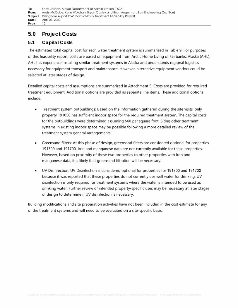
To: Scott Jordan, Alaska Department of Administration (DOA) From: Andy McCabe, Katie Wolohan, Bryan Oakley and Brian Angerman, Barr Engineering Co. (Barr) Subject: Dillingham Airport PFAS Point-of-Entry Treatment Feasibility Report Date: April 23, 2020 Page: 15
P:\Mpls\02 AK\08\02081001 Shannon & Wilson Gustavus Resp\WorkFiles\Dillingham temporary\Feasibility Report\Dillingham - PFAS Water Treatment Action Plan.docx
5.0 Project Costs 5.1 Capital Costs The estimated total capital cost for each water treatment system is summarized in Table 9. For purposes of this feasibility report, costs are based on equipment from Arctic Home Living of Fairbanks, Alaska (AHL). AHL has experience installing similar treatment systems in Alaska and understands regional logistics necessary for equipment transport and maintenance. However, alternative equipment vendors could be selected at later stages of design.
Detailed capital costs and assumptions are summarized in Attachment 5. Costs are provided for required treatment equipment. Additional options are provided as separate line items. These additional options include:
• Treatment system outbuildings: Based on the information gathered during the site visits, only property 191050 has sufficient indoor space for the required treatment system. The capital costs for the outbuildings were determined assuming $60 per square foot. Siting other treatment systems in existing indoor space may be possible following a more detailed review of the treatment system general arrangements.
• Greensand filters: At this phase of design, greensand filters are considered optional for properties 191300 and 191700. Iron and manganese data are not currently available for these properties. However, based on proximity of these two properties to other properties with iron and manganese data, it is likely that greensand filtration will be necessary.
• UV Disinfection: UV Disinfection is considered optional for properties for 191300 and 191700 because it was reported that these properties do not currently use well water for drinking. UV disinfection is only required for treatment systems where the water is intended to be used as drinking water. Further review of intended property-specific uses may be necessary at later stages of design to determine if UV disinfection is necessary.
Building modifications and site preparation activities have not been included in the cost estimate for any of the treatment systems and will need to be evaluated on a site-specific basis.

To: Scott Jordan, Alaska Department of Administration (DOA) From: Andy McCabe, Katie Wolohan, Bryan Oakley and Brian Angerman, Barr Engineering Co. (Barr) Subject: Dillingham Airport PFAS Point-of-Entry Treatment Feasibility Report Date: April 23, 2020 Page: 16
P:\Mpls\02 AK\08\02081001 Shannon & Wilson Gustavus Resp\WorkFiles\Dillingham temporary\Feasibility Report\Dillingham - PFAS Water Treatment Action Plan.docx
Table 9 Total capital cost estimates for individual treatment systems
Property ID Number
Required Treatment
System Cost
Estimated Costs for Additional Options Treatment System Cost
with Additional Options(1)
Outbuilding Greensand Filter
UV Disinfection
191050 $40,800 -- -- -- -- 191300 $20,900 $1,500 $3,600 $900 $27,800 191320 $74,300 $4,400 -- -- $79,400 191700 $20,900 $1,500 $3,600 $900 $27,800 191710 – Option 1 $100,800 $5,800 -- -- $107,500 191710 – Option 2 $126,400 $5,800 -- -- $133,100 200150 $40,800 $2,000 -- -- $43,100
ENRCCI = 11496 Jan 2020 This is a Class 5 cost estimate with a +50/-30% uncertainty as applicable for projects at less than 2% of full project definition per AACE International 17R-97. (1) Includes a 15% contingency of subtotal capital costs for the additional options.
Capital cost estimates for the combined treatment system scenarios are summarized in Table 10. Note that these estimates do not include capital expenses associated with the service connection lines that will be required to connect each property. That being said, differences in estimated total project costs between the combined systems and the individual systems as shown likely represent maximum cost differences. For the combined systems to be economically viable, the capital costs of the service connection lines likely need to be below these differences. The estimated cost difference between combined system 1 and individual systems for properties 19050, 191700, and 191710 (Option 2) is $68,200, and the estimated difference between combined system 2 and individual systems for properties 191700 and 191710 (Option 2) is $22,000. If additional combined systems are evaluated in the future, scenarios that could eliminate iron/manganese pretreatment should be emphasized because it is expected that these scenarios will have the greatest cost benefit.
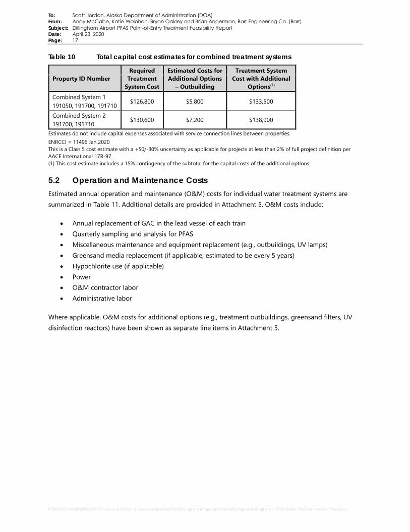
To: Scott Jordan, Alaska Department of Administration (DOA) From: Andy McCabe, Katie Wolohan, Bryan Oakley and Brian Angerman, Barr Engineering Co. (Barr)Subject: Dillingham Airport PFAS Point-of-Entry Treatment Feasibility Report Date: April 23, 2020 Page: 17
P:\Mpls\02 AK\08\02081001 Shannon & Wilson Gustavus Resp\WorkFiles\Dillingham temporary\Feasibility Report\Dillingham - PFAS Water Treatment Action Plan.docx
Table 10 Total capital cost estimates for combined treatment systems
Property ID Number Required
Treatment System Cost
Estimated Costs for Additional Options
– Outbuilding
Treatment System Cost with Additional
Options(1) Combined System 1 191050, 191700, 191710
$126,800 $5,800 $133,500
Combined System 2 191700, 191710
$130,600 $7,200 $138,900
Estimates do not include capital expenses associated with service connection lines between properties. ENRCCI = 11496 Jan 2020 This is a Class 5 cost estimate with a +50/-30% uncertainty as applicable for projects at less than 2% of full project definition per AACE International 17R-97. (1) This cost estimate includes a 15% contingency of the subtotal for the capital costs of the additional options.
5.2 Operation and Maintenance Costs Estimated annual operation and maintenance (O&M) costs for individual water treatment systems are summarized in Table 11. Additional details are provided in Attachment 5. O&M costs include:
• Annual replacement of GAC in the lead vessel of each train• Quarterly sampling and analysis for PFAS• Miscellaneous maintenance and equipment replacement (e.g., outbuildings, UV lamps)• Greensand media replacement (if applicable; estimated to be every 5 years)• Hypochlorite use (if applicable)• Power• O&M contractor labor• Administrative labor
Where applicable, O&M costs for additional options (e.g., treatment outbuildings, greensand filters, UV disinfection reactors) have been shown as separate line items in Attachment 5.

To: Scott Jordan, Alaska Department of Administration (DOA) From: Andy McCabe, Katie Wolohan, Bryan Oakley and Brian Angerman, Barr Engineering Co. (Barr)Subject: Dillingham Airport PFAS Point-of-Entry Treatment Feasibility Report Date: April 23, 2020 Page: 18
P:\Mpls\02 AK\08\02081001 Shannon & Wilson Gustavus Resp\WorkFiles\Dillingham temporary\Feasibility Report\Dillingham - PFAS Water Treatment Action Plan.docx
Table 11 Annual O&M costs for individual treatment systems
Property ID Number
Est. Annual Maintenance Cost for Required Equipment
Est. Annual Maintenance Cost with
Additional Options(1)
191050 $13,800 -- 191300 $10,500 $12,700191320 $20,000 $20,300 191700 $10,500 $12,700 191710 – Option 1 $23,500 $23,800 191710 – Option 2 $30,200 $30,500 200150 $13,800 $14,000
ENRCCI = 11496 Jan 2020 O&M costs are based on a Class 5 capital cost estimate with a +50/-30% uncertainty as applicable for projects at less than 2% of full project definition per AACE International 17R-97. O&M Costs are also expected to have a +50/-30% uncertainty. (1) In addition to annual maintenance costs for additional options, this cost estimate includes a 15% contingency of the subtotal forthe capital costs of the additional options.
O&M costs associated in combined treatment systems are summarized in Table 12. Note, these estimates do not include operation and maintenance expenses associated with the connection service lines between properties which are deemed to be low.
Table 12 Annual O&M costs for combined treatment systems
Property ID Number Est. Annual
Maintenance Cost for Required Equipment
Est. Annual Maintenance Cost with Additional Options(1)
Combined System 1 191050, 191700, 191710 $27,300 $27,600
Combined System 2 191700, 191710 $27,300 $27,700
ENRCCI = 11496 Jan 2020 O&M costs are based on a Class 5 capital cost estimate with a +50/-30% uncertainty as applicable for projects at less than 2% of full project definition per AACE International 17R-97. O&M Costs are also expected to have a +50/-30% uncertainty. (1) In addition to annual maintenance costs for additional options, this cost estimate includes a 15% contingency of the subtotal forthe capital costs of the additional options.
The following could result in an increase in O&M costs:
• Additional water treatment equipment• Additional parameters for sampling and analysis• More frequent sampling requirements• Higher PFAS loading to the system• Faster PFAS breakthrough• Higher water usage• Higher iron loading

To: Scott Jordan, Alaska Department of Administration (DOA) From: Andy McCabe, Katie Wolohan, Bryan Oakley and Brian Angerman, Barr Engineering Co. (Barr) Subject: Dillingham Airport PFAS Point-of-Entry Treatment Feasibility Report Date: April 23, 2020 Page: 19
P:\Mpls\02 AK\08\02081001 Shannon & Wilson Gustavus Resp\WorkFiles\Dillingham temporary\Feasibility Report\Dillingham - PFAS Water Treatment Action Plan.docx
6.0 Project Implementation 6.1 Equipment Lead Times and Schedule Based on quotes from AHL, equipment lead times for shipment to Dillingham from Anchorage are expected to be 60 to 90 days from order submittal.
6.2 Permitting and Permissions Properties 191050 and 191320 operate drinking water supplies that are currently permitted by DEC. Installation and operation of the water treatment system will comply with applicable building codes. Permitting needs associated with the installation of a water treatment system for drinking water supply will be evaluated by S&W.
Any access agreements required for operations and maintenance and routine monitoring will be obtained by S&W ahead of water treatment system start-up.
6.3 Process Safety Overview A process safety overview with property owners, managers, and/or residents will be completed after installation and before start-up of the water treatment systems. The objective of the process safety overview is for personnel involved in system use, operation, and monitoring to understand safety considerations associated with the water treatment equipment and associated chemicals. If any additional safety concerns are identified during the process safety overview, these will be addressed and mitigated prior to system start-up.
6.4 Pre-start-up Activities and Treatment Verification The complete treatment system will be disinfected by the vendor after assembly and prior to delivery. All system components will be flushed with a chlorine solution, except the treatment media itself and the interior of some equipment once filled with media (iron filter, if applicable; GAC vessels, etc.).
During installation of the PFAS water treatment system, the well pump will be shut down for a short duration (anticipated to last less than 8 hours) while the new treatment system equipment is installed. Tap water for drinking water use or otherwise will not be available during this time.
GAC vessels will be filled with water from the onsite wells after system delivery and before installation, and a 24-hour GAC soak will start in order to hydrate the carbon and loosen fines. Following installation, the system will be backwashed at the design flow rate (8 gpm) for 15 minutes to remove fines. A 30-minute flush at the design flow rate will follow the soak in order to remove air and remaining fines from the GAC vessels after installation of the system. Flush water will be directed to an exterior drainage area and not to the septic system or municipal sewer. This procedure is subject to change based on vendor recommendations.

To: Scott Jordan, Alaska Department of Administration (DOA) From: Andy McCabe, Katie Wolohan, Bryan Oakley and Brian Angerman, Barr Engineering Co. (Barr) Subject: Dillingham Airport PFAS Point-of-Entry Treatment Feasibility Report Date: April 23, 2020 Page: 20
P:\Mpls\02 AK\08\02081001 Shannon & Wilson Gustavus Resp\WorkFiles\Dillingham temporary\Feasibility Report\Dillingham - PFAS Water Treatment Action Plan.docx
Treated water samples will be collected for PFAS analytical evaluation after the 30-minute flush, before continuous operation and treated water distribution for drinking water purposes. A minimum of one confirmatory sample will be collected to demonstrate treatment system effectiveness. The treatment system can be used for non-drinking water uses until sample results are received confirming treatment goals are being achieved.
The water treatment maintenance contractor and the property owner will receive training by the water treatment system vendor within one week of treatment system pre-start-up activities and treatment verification, prior to continuous operation of the system.
6.5 System Start-up and Continuous Operation After pre-start-up sample results are received and reviewed, if all treatment requirements outlined in Section 3.1 are met, continuous operation and monitoring will start. If the water treatment system was intentionally shut down after pre-start-up activities for more than 24-hours, treated water will be diverted to an exterior drainage area for approximately 30 minutes following start-up to adequately flush the system.
6.6 Operation, Monitoring, and Maintenance An Owner’s Manual with equipment information and troubleshooting guidance will be provided to the property owners prior to start-up of the water treatment system. The Owner’s Manual will include directions to only use drinking water from taps that supply water treated through the system for PFAS removal.
Additionally, an O&M Manual will be prepared and provided to the selected water treatment maintenance contractor. The O&M Manual will cover start-up testing, routine monitoring (including sample collection), particulate filter replacement, GAC vessel change-out, and UV lamp cleaning and replacement.
Initially, quarterly monitoring of the water treatment system is recommended, which includes flow tracking, differential pressure monitoring, and analytical sampling locations. Monitoring will verify the system’s efficacy and determine when the GAC vessels need to be replaced. Once a lead-vessel breakthrough curve has been established, the frequency of analytical sampling may be reduced.
Depending on solids loading, the particulate filters may require more frequent replacement than on a quarterly basis. This replacement can be done by property owners when the pressure drop across the filter exceeds the set-point discussed during training.
If applicable, the water treatment maintenance contractor will be responsible for maintaining the chlorine dosing system for the greensand filters. Depending rate of use, homeowners may also be responsible for refilling the hypochlorite feed tank. Greensand media replacement is expected to be infrequent, likely requiring replacement every 5 to 8 years.

To: Scott Jordan, Alaska Department of Administration (DOA) From: Andy McCabe, Katie Wolohan, Bryan Oakley and Brian Angerman, Barr Engineering Co. (Barr)Subject: Dillingham Airport PFAS Point-of-Entry Treatment Feasibility Report Date: April 23, 2020 Page: 21
P:\Mpls\02 AK\08\02081001 Shannon & Wilson Gustavus Resp\WorkFiles\Dillingham temporary\Feasibility Report\Dillingham - PFAS Water Treatment Action Plan.docx
The frequency of GAC replacement will depend on water usage, PFAS loading, and the final operational set-points (e.g., differential pressure recommendations for particulate filters). If quarterly monitoring results indicate that the sum of five PFAS: PFOS, PFOA, PFHxS, PFNA, and PFHpA is >35 ng/L at the midpoint sample point (after the lead GAC vessels but prior to the lag GAC vessels), GAC vessel change-out will occur. GAC replacement will be scheduled to occur after quarterly monitoring results for the installed system have been received, but before the next quarterly sampling event. For this feasibility report, one GAC vessel replacement is assumed per year per train. However, GAC media may need to be replaced more frequently than on a yearly basis because short-chain PFAS, such as PFHxS and PFHpA, are present in the wells and may break through more quickly than long-chain PFAS, such as PFOA and PFOS.
Routine GAC vessel change-out will be conducted as follows:
• Remove the lead GAC vessel;• Disconnect the lag GAC vessel and install in the lead position; and• Install a replacement GAC vessel in the lag position.
The UV lamp will be replaced as indicated by the manufacturer’s recommendation and anticipated to be on a 12-month basis. Cleaning of the UV quartz sleeve is dependent on water hardness. Cleaning should be conducted based on the manufacturer’s recommendation, but at least on an annual basis.
6.7 Residuals Management Water treatment residuals include the following:
• Iron and manganese greensand filter backwash (or water softener regeneration solution, ifapplicable)
• Spent particulate filters• Spent GAC• Spent UV disinfection lamps
This report assumes filter backwash can be discharged to the existing onsite septic system or municipal sewer. This will need to be confirmed with DEC.
Spent particulate filters should be collected for disposal in a waste container that will be emptied when the selected water treatment system maintenance contractor services the GAC vessels. The frequency of filter replacement will depend on the amount of sediment produced in the water supply well.
The selected water treatment maintenance contractor will facilitate spent GAC change-out. It is assumed that each property will have one vessel on standby for each train in the event that routine PFAS monitoring results indicates change-out is required. The selected vendor will collect individual vessels for servicing, which includes transport of vessels to and from the servicing location, removal of spent GAC

To: Scott Jordan, Alaska Department of Administration (DOA) From: Andy McCabe, Katie Wolohan, Bryan Oakley and Brian Angerman, Barr Engineering Co. (Barr) Subject: Dillingham Airport PFAS Point-of-Entry Treatment Feasibility Report Date: April 23, 2020 Page: 22
P:\Mpls\02 AK\08\02081001 Shannon & Wilson Gustavus Resp\WorkFiles\Dillingham temporary\Feasibility Report\Dillingham - PFAS Water Treatment Action Plan.docx
from the vessels, rinsing and decontamination of empty vessels, and refilling virgin GAC into the vessels. The selected vendor will transport spent GAC along with the particulate filters to the nearest appropriate disposal facility that will accept PFAS-impacted GAC/materials.
Spent UV lamps will be handled per the manufacturers recommendations and will be managed by the selected water treatment maintenance contractor.

Attachments
Attachment 1 – Site Visit Reports
Attachment 2 – Water Quality Tables
Attachment 3 – Peak Water Demand Estimates
Attachment 4 – Process Flow Diagrams
Attachment 5 – Capital and O&M Cost Details

Attachment 1 – Site Visit Reports

Long-Term Alternate Water Feasibility Study Report
102786-003 October 2020
Site visit field notes contain personal information. This content has been removed for confidentiality.

Attachment 2 – Water Quality Tables

Perluoro-butane sulfonic acid
(PFBS)
Perfluoro-heptanoic acid
(PFHpA)
Perfluoro-nonanoic acid
(PFNA)
Perfluoro-hexane sulfonic acid
(PFHxS)
Perfluoro-octane sulfonate (PFOS)
LHA Combined (PFOS + PFOA)
2,000 70† 70†
Sample Date Well Category ppt ppt ppt ppt ppt ppt12/17/2018 1 51 3.3 <1.8 140 37 42 12/17/2018 1 54 3.3 <1.7 130 36 41 2/26/2019 1 57 3.4 <2.0 170 42 46 2/26/2019 1 54 3.2 <2.0 160 42 46 2/27/2019
21.9 J I 39 <2.0 7.6 2.7 39
12/17/20181
11 9.7 <1.8 7.0 <1.8 1.9 ‡
2/26/20191
10 J* 13 2.8 15 43 56
2/26/20191
14 J* 13 2.9 15 38 50
2/28/2019 2 34 16 <2.0 88 37 52 2/27/2019 1 48 24 <2.0 140 64 89
191720 2/28/2019 2 47 22 <2.0 140 58 802/28/2019 1 7.9 2.4 <2.0 53 60 65 6/11/2019 1 7.6 2.6 <2.0 59 73 78 6/11/2019 1 7.5 2.9 <2.0 61 72 78
ppt parts per trillion, equivalent to nanograms per literLHA U.S. Environmental Protection Agency Lifetime Health Advisory
† LHA level is 70 ppt for PFOS and PFOA combined. Bold Concentration exceeds action level.DUP Field-duplicate sample
< Analyte not detected; listed as less than the reporting limit (RL) unless otherwise flagged due to quality-control (QC) failures.J Estimated concentration, detected greater than the method detection limit (MDL) and less than the RL. Flag applied by the laboratory.‡ Minimum concentration, the Combined concentration includes one or more result that is not detected greater than the MDL.
2565 Airport Spur Rd 22
300150 (DUP) 1629 Kanakanak Rd. 5.5
200150 1629 Kanakanak Rd 5.1 200150 1629 Kanakanak Rd 5.3
191700 2531 Airport Spur Rd 15 191710 Multiple, Airport Spur Rd 25
291320 (DUP) ADA-09024Block 500, Lot 7B750 Airport Rd
12
191320ADA-09024Block 500, Lot 7B750 Airport Rd
13
191320 (DIL-10)ADA-09024Block 500, Lot 7B750 Airport Rd
1.9
291050 (DUP)509 Airport Rd 3.8
191300ADA-09029 Block 500, Lot 5B720 Airport Rd
36
191050 509 Airport Rd 4.2 191050 (DIL-06) (DUP) 509 Airport Rd 4.8
Sample Name Address ppt191050 (DIL-05) 509 Airport Rd 5.2
Attachment 2 - Dillingham Airport - Summary of Affected Property Private Well PFAS Analytical Results from December 2018 through June 2019
AnalytePerfluoro-
octanoic acid (PFOA)
Action Level

SHANNON & WILSON, INC.
191050 191320 191710 200150
1 1 1 1Units 11/15/19 11/14/19 11/15/19 11/15/19
ppt 4.3 1.7 J 22 5.5 ppt 40 <1.9 58 58 ppt 50 12 34 6.9 ppt 2.8 9.3 23 2.4 ppt <1.9 <1.9 <1.8 <1.8 ppt 140 6.5 110 56 ppt <1.9 <1.9 <1.8 <1.8 ppt <19 <19 <18 <18 ppt <1.9 <1.9 <1.8 <1.8 ppt <1.9 <1.9 <1.8 <1.8 ppt <1.9 <1.9 <1.8 <1.8 ppt <3.8 <3.8 <3.7 <3.7 ppt <1.9 <1.9 <1.8 <1.8 ppt <19 <19 <18 <18 ppt <1.9 <1.9 <1.8 <1.8 ppt 37 59 110 16 ppt <1.9 <1.9 <1.8 <1.8 ppt <1.9 <1.9 <1.8 <1.8 ppt 8.4 23 21 1.5 Jppt <1.9 <1.9 <1.8 <1.8 ppt <1.9 <1.9 <1.8 <1.8 ppt <1.9 0.87 J 0.78 J 1.1 Jppt 11 70 71 4.0 ppt <19 <19 40 <18 ppt <19 <19 <18 <18 ppt <19 <19 <18 <18ppt <1.9 <1.9 <1.8 <1.8ppt <1.9 <1.9 <1.8 <1.8ppt <1.9 <1.9 <1.8 <1.8ppt <3.8 <3.8 <3.7 <3.7ppt <2.0 <2.0 <1.9 <1.9
AK101 mg/L <0.0500 <0.0500 <0.0500 <0.0500 AK102 mg/L <0.705 B* <0.916 B* <0.566 B* <0.566 B*AK103 mg/L <0.537 B* <0.586 B* <0.236 <0.236
µg/L <0.250 <0.250 <0.250 <0.250 µg/L <0.500 <0.500 <0.500 <0.500 µg/L <0.500 <0.500 <0.500 <0.500 µg/L <1.00 <1.00 <1.00 <1.00 µg/L <0.500 <0.500 <0.500 <0.500 µg/L <1.50 <1.50 <1.50 <1.50
EPA 1664B mg/L 1.91 J 1.58 J 1.53 J 1.62 J SM 5310B mg/L 0.597 J 11.3 1.99 0.847 J SM21 2540C mg/L 65.0 237 175 148 SM21 2540D mg/L <0.500 74.4 35.6 <0.500 SM21 4500-H B pH units 6.6 6.4 6.5 6.6SM21 2340B mg/L 31.7 115 87.9 64.3 SM21 2510B umhos/cm 87.0 315 257 262 SM21 4500-N D mg/L <0.500 2.09 0.608J <0.500 SM21 4500NO3-F mg/L <0.200 B* <0.200 B* <0.200 B* 1.80 SM23 4500S D mg/L <0.0500 0.0800 J <0.0500 <0.0500
mg/L 3.92 15.9 8.57 38.2 mg/L 0.126 J 0.182 J 0.163 J 0.0970 J mg/L 1.36 3.44 1.58 7.14 µg/L 8,620 30,400 21,600 18,000µg/L <1.00 1.94 J <1.00 <1.00 µg/L 123 J 46,000 36,800 <125 µg/L 2,470 9,450 8250 4,710µg/L 1.79 1,420 1,340 7.40 µg/L 527 1,480 2,830 1,120µg/L 4,600 6,920 9,190 24,200µg/L <0.0400 1.9 3.6 <0.0400µg/L 0.0590 J 0.461 0.993 <0.0400µg/L <0.0500 <0.0500 <0.0500 <0.0500µg/L <0.0900 <0.0900 <0.0900 <0.0900
ppt parts per trillion, equivalent to nanograms per literµg/L micrograms per liter
umhos/cm micromhos per centimetermg/L milligram per liter
† Environmental Protection Agency (EPA) Lifetime Health Advisory (LHA) level is 70 ppt for PFOS and PFOA combined. < Analyte not detected; listed as less than the reporting limit (RL) unless otherwise flagged due to quality-control (QC) failures.
Bold Concentration exceeds LHA level.DUP Field-duplicate sample
J Estimated concentration, detected greater than the method detection limit (MDL) and less than the RL. Flag applied by the laboratory.B* Result is considered not detected due to quality control failures. Flag applied by Shannon & Wilson, Inc. (*)‡ Minimum concentration, the LHA Combined oconcentration includes one or more result that is not detected greater than the MDL.
EPA 537
Diesel Range OrganicsResidual Range Organics
Nitrogen Kjeldahl
SW8021B
BenzeneEthylbenzene
P & M -XyleneToluene
4,8- Dioxa-3H-perfluorononanoic acid (ADONA) N-methylperfluorooctanesulfonamidoacetic acid (NMeFOSAA)11-Chloroeicosafluoro-3-oxaundecane-1-sulfonic acidPerfluoro-tridecanoic acid (PFTriA)Perfluoro-tetradecanoic acid (PFTeA)Hexafluoropropylene oxide dimer acid (HFPO-DA)Perfluorodecanoic acid (PFDA)
Sodium
EP200.8
SOP BAL - 4100
As(III) ArseniteAS(V) ArsenateDimethylarsinic acid (DMAs)
CalciumChromiumIron
ManganesePotassium
EPA 300.0ChlorideFluorideSulfate
Analytical Method
Oil & Grease, TotalTotal Organic CarbonTotal Dissolved SolidsTotal Suspended SolidspH
o-Xylene
Hardness as CaCO3Conductivity
Total Xylenes
Nitrate + NitriteSulfide
Attachment 2 - November 2019 Dillingham Point-of-Entry Water Treatment Design Analytical Results
Perfluoropentanoic acid (PFPeA)6:2 FTS8:2 FTS
Perfluorobutanoic acid (PFBA)Perfluorodecanesulfonic acid (PFDS)Perfluorododecanoic acid (PFDoA)Perfluorooctane Sulfonamide (FOSA)
Perfluoro-dodecanoic acid (PFDoA)
N-ehtylperfluorooctanesulfonamidoacetic acid (NEtFOSAA)
Perluoro-butane sulfonic acid (PFBS)Perfluoro-heptanoic acid (PFHpA)Perfluoro-nonanoic acid (PFNA)Perfluoro-hexane sulfonic acid (PFHxS)
9-Chlorohexadecafluoro-3-oxanonane-1-sulfonic acidPerfluorohexanoic acid (PFHxA)Perfluoroundecanoic acid (PFUnA)
HFPO-DA (GenX)
Monomethylarsonic acid (MMAs)
Perfluoro-n-hexadecanoic acid (PFHxDA)
ADONA
4:2 FTS10:2 FTSPerfluorononanesulfonic acid (PFNS)
Magnesium
Gasoline Range Organics
Well CategoryAnalyte
Perfluoro-octanoic acid (PFOA)Perfluoro-octane sulfonate (PFOS)
December 2019 Page 1 of 1 102786-003
Sample Name

Attachment 3 – Peak Water Demand Estimates

Attachment 3 Peak Demand Estimates
Sample ID Number Description(1) Number of
People(2)
Categorical Method Fixture Count Method
Area Category
Peak Flow Estimate per use
or building (gpm)
Total Peak Demand Estimate
per property (gpm)
Approx. Fixture Count (fixture
units)
Peak Flow Estimate per use
or building (gpm)
Total Peak Demand Estimate
per property (gpm)
191050
Rectory and community water spigot
1 person, plus outdoor community use
Residential, 0-5 Residences Served (8 gpm per residence)
8
11 32.5 N/A 21
Church <10 people Other Establishment (0.3 gpm per person)
3
191300 Hangar 2 people Industrial (0.5 gpm per employee) 1 1 6.5 6.5 7
191320
Airport Terminal (ground floor)
Approximately 9 people
Industrial (0.5 gpm per employee) 4.5
25 42 N/A 25
Restaurant (second floor)
20 people assumed for treatment design purposes
Restaurant (1 gpm per seat) 20
191700 House 1 person (2 people max)
Residential, 0-5 Residences Served (8 gpm per residence)
8 8 11.5 11.5 10
191710
House A (white/gray single-story) 2 people
Residential, 6-10 Residences Served (5 gpm per residence)
5
32
17 13
39
Apartment Building, 5 units
4 to 8 people (10 max) 20 51.5 29
House B (green single-story) 1 to 2 people 5 7 7
Office (brown single-story) 3 people Office Building (0.4
gpm per 100 SF) 2.4 5 6
200150 Group housing, fish processing
1 person in winter; 15 people in summer
Residential, 0-5 Residences Served (8 gpm per residence)
8 (assume 6 gpm additional during
winter) 14 35 N/A 23
(1) Separate buildings or multi-residential buildings at each property are shown in separate rows.(2) Assume year-round residency or occupancy unless noted.N/A = not available or not applicable.

Attachment 4 – Process Flow Diagrams

REVISION DESCRIPTIONDATEAPP.BYNO. CHK. TO/FORRELEASED
DATE RELEASED Approved
Designed
Drawn
Checked
Date
Scale
DWG. No.
BARR PROJECT No.
CLIENT PROJECT No.
REV. No.Minneapolis, MinnesotaPh: 1-800-632-2277
Corporate Headquarters:
DATE LICENSE #
SIGNATURE
I HEREBY CERTIFY THAT THIS PLAN, SPECIFICATION, ORREPORT WAS PREPARED BY ME OR UNDER MY DIRECT
SUPERVISION AND THAT I AM A DULY LICENSEDPROFESSIONAL ENGINEER UNDER THE LAWS OF THE
STATE OF MINNESOTA.
BARR ENGINEERING CO.Project Office:
PRINTED NAME
AS SHOWN
SHANNON & WILSONFAIRBANKS AK
DILLINGHAM FEASIBILITY REPORTDILLINGHAM, ALASKA
INDIVIDUAL SYSTEMS FOR PROPERTIES 191050 AND 20015016 GPM EACH NO IRON PRETREATMENT
02081001.03
EXH 1. .
JANUARY 24, 2020REVISED MARCH 16, 2020
DRAFT
.
CAD
D U
SER
: Jos
eph
A. M
ilash
ius
FILE
: P:\M
PLS\
02 A
K\08
\020
8100
1 SH
ANN
ON
& W
ILSO
N G
UST
AVU
S R
ESP\
WO
RKF
ILES
\DIL
LIN
GH
AM T
EMPO
RAR
Y\FE
ASIB
ILIT
Y R
EPO
RT\
ATTA
CH
MEN
TS\D
WG
DR
AWIN
GS\
1910
50_2
0015
0.D
WG
PLO
T SC
ALE:
1:2
PLO
T D
ATE:
4/1
0/20
20 2
:13
PM
BAR
M:\A
utoC
AD 2
011\
Auto
CAD
201
1 Su
ppor
t\enu
\Tem
plat
e\Ba
rr_20
11_T
empl
ate.
dwt
Plot
at 1
10/
05/2
010
14:
03:5
0..
CLIENTBIDCONSTRUCTION
-----------------------------------
A B C 0 1 2 3
Suite 2004300 MARKETPOINTE DRIVE
Fax: (952) 832-2601www.barr.com
Ph: 1-800-632-2277MINNEAPOLIS, MN 55435
.
1-
PFAS WATER TREATMENT SYSTEM PROCESS FLOW DIAGRAM
PFAS TREATMENT 12X40 REAGGLOMERATED GAC VESSELS2 PARALLEL TRAINS OF LEAD/LAG VESSELS 8 GPM MAX EACH
UV DISINFECTION2 PARALLEL UNITS 8 GPM MAX EACH
TREATED WATER FORUSE AND CONSUMPTION
WELL PUMP
10 MICRON PARTICULATEFILTRATION
1 FILTER, 20 GPM MAX
8 GPM FLOW RESTRICTOR(ONE PER TRAIN)
TOTALIZING FLOW METER(ONE PER TRAIN)
FORWARD FLOW DIVERSION LINEFOR PERIODS OF LOW FLOW

REVISION DESCRIPTIONDATEAPP.BYNO. CHK. TO/FORRELEASED
DATE RELEASED Approved
Designed
Drawn
Checked
Date
Scale
DWG. No.
BARR PROJECT No.
CLIENT PROJECT No.
REV. No.Minneapolis, MinnesotaPh: 1-800-632-2277
Corporate Headquarters:
DATE LICENSE #
SIGNATURE
I HEREBY CERTIFY THAT THIS PLAN, SPECIFICATION, ORREPORT WAS PREPARED BY ME OR UNDER MY DIRECT
SUPERVISION AND THAT I AM A DULY LICENSEDPROFESSIONAL ENGINEER UNDER THE LAWS OF THE
STATE OF MINNESOTA.
BARR ENGINEERING CO.Project Office:
PRINTED NAME
AS SHOWN
SHANNON & WILSONFAIRBANKS AK
DILLINGHAM FEASIBILITY REPORTDILLINGHAM, ALASKA
INDIVIDUAL SYSTEMS FOR PROPERTIES 191300 AND 1917008 GPM EACH IRON PRETREATMENT SHOWN
02081001.03
EXH 2. .
MARCH 16, 2020DRAFT
.
CAD
D U
SER
: Jos
eph
A. M
ilash
ius
FILE
: P:\M
PLS\
02 A
K\08
\020
8100
1 SH
ANN
ON
& W
ILSO
N G
UST
AVU
S R
ESP\
WO
RKF
ILES
\DIL
LIN
GH
AM T
EMPO
RAR
Y\FE
ASIB
ILIT
Y R
EPO
RT\
ATTA
CH
MEN
TS\D
WG
DR
AWIN
GS\
1913
00_1
9170
0.D
WG
PLO
T SC
ALE:
1:2
PLO
T D
ATE:
4/1
0/20
20 2
:13
PM
BAR
M:\A
utoC
AD 2
011\
Auto
CAD
201
1 Su
ppor
t\enu
\Tem
plat
e\Ba
rr_20
11_T
empl
ate.
dwt
Plot
at 1
10/
05/2
010
14:
03:5
0..
CLIENTBIDCONSTRUCTION
-----------------------------------
A B C 0 1 2 3
Suite 2004300 MARKETPOINTE DRIVE
Fax: (952) 832-2601www.barr.com
Ph: 1-800-632-2277MINNEAPOLIS, MN 55435
.
1-
PFAS WATER TREATMENT SYSTEM PROCESS FLOW DIAGRAM
TREATED WATER FORUSE (NOT DRINKING)
WELL PUMP
10 MICRON PARTICULATEFILTRATION
1 FILTER, 20 GPM MAX
8 GPM FLOW RESTRICTOR
TOTALIZING FLOW METER
FORWARD FLOW DIVERSION LINEFOR PERIODS OF LOW FLOW
PFAS TREATMENT 12X40 REAGGLOMERATED GAC VESSELS1 TRAIN OF LEAD/LAG VESSELS 8 GPM MAX
IRON/MANGANESE GREENSAND FILTERWITH CONTINUOUS HYPOCHLORITE INJECTION
1 PARALLEL VESSEL WITH HYPOCHLORITE FEED TANK 8 GPM MAX
NO UV TREATMENT SHOWN.PROPERTIES DO NOT REQUIREWATER FOR DRINKING.
IRON/MANGANESE TREATMENT SHOWN VIA GREENSAND.IRON/MANGANESE DATA ARE NEEDED TO CONFIRMTREATMENT REQUIREMENTS. IF IRON RANGES FROM 1TO 10 MG/L ION EXCHANGE IS RECOMMENDED, IF IRONEXCEEDS 10 MG/L GREENSAND FILTRATION ISRECOMMENDED.

REVISION DESCRIPTIONDATEAPP.BYNO. CHK. TO/FORRELEASED
DATE RELEASED Approved
Designed
Drawn
Checked
Date
Scale
DWG. No.
BARR PROJECT No.
CLIENT PROJECT No.
REV. No.Minneapolis, MinnesotaPh: 1-800-632-2277
Corporate Headquarters:
DATE LICENSE #
SIGNATURE
I HEREBY CERTIFY THAT THIS PLAN, SPECIFICATION, ORREPORT WAS PREPARED BY ME OR UNDER MY DIRECT
SUPERVISION AND THAT I AM A DULY LICENSEDPROFESSIONAL ENGINEER UNDER THE LAWS OF THE
STATE OF MINNESOTA.
BARR ENGINEERING CO.Project Office:
PRINTED NAME
AS SHOWN
SHANNON & WILSONFAIRBANKS AK
DILLINGHAM FEASIBILITY REPORTDILLINGHAM, ALASKA
INDIVIDUAL TREATMENT SYSTEM FOR PROPERTY 19132024 GPM SYSTEM WITH IRON PRETREATMENT
02081001.03
EXH 2. .
January 24, 2020Revised March 16, 2020
DRAFT
.
CAD
D U
SER
: Jos
eph
A. M
ilash
ius
FILE
: P:\M
PLS\
02 A
K\08
\020
8100
1 SH
ANN
ON
& W
ILSO
N G
UST
AVU
S R
ESP\
WO
RKF
ILES
\DIL
LIN
GH
AM T
EMPO
RAR
Y\FE
ASIB
ILIT
Y R
EPO
RT\
ATTA
CH
MEN
TS\D
WG
DR
AWIN
GS\
1913
20.D
WG
PLO
T SC
ALE:
1:2
PLO
T D
ATE:
4/1
0/20
20 2
:14
PM
BAR
M:\A
utoC
AD 2
011\
Auto
CAD
201
1 Su
ppor
t\enu
\Tem
plat
e\Ba
rr_20
11_T
empl
ate.
dwt
Plot
at 1
10/
05/2
010
14:
03:5
0..
CLIENTBIDCONSTRUCTION
-----------------------------------
A B C 0 1 2 3
Suite 2004300 MARKETPOINTE DRIVE
Fax: (952) 832-2601www.barr.com
Ph: 1-800-632-2277MINNEAPOLIS, MN 55435
.
1-
PFAS WATER TREATMENT SYSTEM PROCESS FLOW DIAGRAM
WELL PUMP
10 MICRON PARTICULATEFILTRATION
2 PARALLEL FILTERS, 20 GPM MAX EACH
PFAS TREATMENT 12X40 REAGGLOMERATED GAC VESSELS3 PARALLEL TRAINS OF LEAD/LAG VESSELS 8 GPM MAX EACH
IRON/MANGANESE GREENSAND FILTERSWITH CONTINUOUS HYPOCHLORITE INJECTION
3 PARALLEL VESSELS WITH HYPOCHLORITE FEED TANK 8 GPM MAX EACH
8 GPM FLOW RESTRICTOR(ONE PER TRAIN)
TOTALIZING FLOW METER(ONE PER TRAIN) FORWARD FLOW DIVERSION LINE
FOR PERIODS OF LOW FLOW
UV DISINFECTION3 PARALLEL UNITS 8 GPM MAX EACH
8 GPM FLOW RESTRICTOR(ONE PER TRAIN)
TREATED WATER FORUSE AND CONSUMPTION

REVISION DESCRIPTIONDATEAPP.BYNO. CHK. TO/FORRELEASED
DATE RELEASED Approved
Designed
Drawn
Checked
Date
Scale
DWG. No.
BARR PROJECT No.
CLIENT PROJECT No.
REV. No.Minneapolis, MinnesotaPh: 1-800-632-2277
Corporate Headquarters:
DATE LICENSE #
SIGNATURE
I HEREBY CERTIFY THAT THIS PLAN, SPECIFICATION, ORREPORT WAS PREPARED BY ME OR UNDER MY DIRECT
SUPERVISION AND THAT I AM A DULY LICENSEDPROFESSIONAL ENGINEER UNDER THE LAWS OF THE
STATE OF MINNESOTA.
BARR ENGINEERING CO.Project Office:
PRINTED NAME
AS SHOWN
SHANNON & WILSONFAIRBANKS AK
DILLINGHAM FEASIBILITY REPORTDILLINGHAM, ALASKA
INDIVIDUAL TREATMENT SYSTEM FOR PROPERTY 191710OPTION 1 - SINGLE SYSTEM 32 GPM WITH IRON PRETREATMENT
02081001.03
EXH 4. .
January 24, 2020Revised March 16, 2020
DRAFT
.
CAD
D U
SER
: Jos
eph
A. M
ilash
ius
FILE
: P:\M
PLS\
02 A
K\08
\020
8100
1 SH
ANN
ON
& W
ILSO
N G
UST
AVU
S R
ESP\
WO
RKF
ILES
\DIL
LIN
GH
AM T
EMPO
RAR
Y\FE
ASIB
ILIT
Y R
EPO
RT\
ATTA
CH
MEN
TS\D
WG
DR
AWIN
GS\
1917
10_O
PTIO
N1.
DW
G P
LOT
SCAL
E: 1
:2 P
LOT
DAT
E: 4
/10/
2020
2:3
5 PM
BAR
M:\A
utoC
AD 2
011\
Auto
CAD
201
1 Su
ppor
t\enu
\Tem
plat
e\Ba
rr_20
11_T
empl
ate.
dwt
Plot
at 1
10/
05/2
010
14:
03:5
0..
CLIENTBIDCONSTRUCTION
-----------------------------------
A B C 0 1 2 3
Suite 2004300 MARKETPOINTE DRIVE
Fax: (952) 832-2601www.barr.com
Ph: 1-800-632-2277MINNEAPOLIS, MN 55435
.
1-
PFAS WATER TREATMENT SYSTEM PROCESS FLOW DIAGRAM
WELL PUMP
10 MICRON PARTICULATEFILTRATION
2 PARALLEL FILTERS, 20 GPM MAX EACH
PFAS TREATMENT 12X40 REAGGLOMERATED GAC VESSELS4 PARALLEL TRAINS OF LEAD/LAG VESSELS 8 GPM MAX EACH
IRON/MANGANESE GREENSAND FILTERSWITH CONTINUOUS HYPOCHLORITE INJECTION
4 PARALLEL VESSELS WITH HYPOCHLORITE FEED TANK 8 GPM MAX EACH
8 GPM FLOW RESTRICTOR(ONE PER TRAIN)
TOTALIZING FLOW METER(ONE PER TRAIN)
FORWARD FLOW DIVERSION LINEFOR PERIODS OF LOW FLOW
UV DISINFECTION1 UNIT 30 GPM MAX
8 GPM FLOW RESTRICTOR(ONE PER TRAIN)
TREATED WATER FORUSE AND CONSUMPTION

REVISION DESCRIPTIONDATEAPP.BYNO. CHK. TO/FORRELEASED
DATE RELEASED Approved
Designed
Drawn
Checked
Date
Scale
DWG. No.
BARR PROJECT No.
CLIENT PROJECT No.
REV. No.Minneapolis, MinnesotaPh: 1-800-632-2277
Corporate Headquarters:
DATE LICENSE #
SIGNATURE
I HEREBY CERTIFY THAT THIS PLAN, SPECIFICATION, ORREPORT WAS PREPARED BY ME OR UNDER MY DIRECT
SUPERVISION AND THAT I AM A DULY LICENSEDPROFESSIONAL ENGINEER UNDER THE LAWS OF THE
STATE OF MINNESOTA.
BARR ENGINEERING CO.Project Office:
PRINTED NAME
AS SHOWN
SHANNON & WILSONFAIRBANKS AK
DILLINGHAM FEASIBILITY REPORTDILLINGHAM, ALASKA
INDIVIDUAL TREATMENT SYSTEM FOR PROPERTY 191710OPTION 2 - TWO SYSTEMS 8 AND 32 GPM WITH IRON PRETREATMENT
02081001.03
EXH 5. .
January 24, 2020Revised March 16, 2020 Revised April 9, 2020
DRAFT
.
CAD
D U
SER
: Jos
eph
A. M
ilash
ius
FILE
: P:\M
PLS\
02 A
K\08
\020
8100
1 SH
ANN
ON
& W
ILSO
N G
UST
AVU
S R
ESP\
WO
RKF
ILES
\DIL
LIN
GH
AM T
EMPO
RAR
Y\FE
ASIB
ILIT
Y R
EPO
RT\
ATTA
CH
MEN
TS\D
WG
DR
AWIN
GS\
1917
10_O
PTIO
N2.
DW
G P
LOT
SCAL
E: 1
:2 P
LOT
DAT
E: 4
/10/
2020
2:3
6 PM
BAR
M:\A
utoC
AD 2
011\
Auto
CAD
201
1 Su
ppor
t\enu
\Tem
plat
e\Ba
rr_20
11_T
empl
ate.
dwt
Plot
at 1
10/
05/2
010
14:
03:5
0..
CLIENTBIDCONSTRUCTION
-----------------------------------
A B C 0 1 2 3
Suite 2004300 MARKETPOINTE DRIVE
Fax: (952) 832-2601www.barr.com
Ph: 1-800-632-2277MINNEAPOLIS, MN 55435
.
2-
PFAS WATER TREATMENT SYSTEM PROCESS FLOW DIAGRAM
WELL PUMP
10 MICRON PARTICULATEFILTRATION
2 PARALLEL FILTERS, 20 GPM MAX EACH
PFAS TREATMENT 12X40 REAGGLOMERATED GAC VESSELS4 PARALLEL TRAINS OF LEAD/LAG VESSELS 8 GPM MAX EACH
IRON/MANGANESE GREENSAND FILTERSWITH CONTINUOUS HYPOCHLORITE INJECTION
4 PARALLEL VESSELS WITH HYPOCHLORITE FEED TANK 8 GPM MAX EACH
8 GPM FLOW RESTRICTOR(ONE PER TRAIN)
TOTALIZING FLOW METER(ONE PER TRAIN) FORWARD FLOW DIVERSION LINE
FOR PERIODS OF LOW FLOW
UV DISINFECTION1 UNIT 30 GPM MAX
8 GPM FLOW RESTRICTOR(ONE PER TRAIN)
TREATED WATER FORUSE AND CONSUMPTION
IRON/MANGANESE GREENSAND FILTERSWITH CONTINUOUS HYPOCHLORITE INJECTION
1 VESSEL WITH HYPOCHLORITE FEED TANK 8 GPM MAX EACH
PFAS TREATMENT 12X40 REAGGLOMERATED GAC VESSELS1 TRAINS OF LEAD/LAG VESSELS 8 GPM MAX
UV DISINFECTION1 UNIT 8 GPM MAX
TREATED WATER FORUSE AND CONSUMPTION
FORWARD FLOW DIVERSION LINEFOR PERIODS OF LOW FLOW
8 GPM FLOW RESTRICTOR
TOTALIZING FLOW METER
10 MICRON PARTICULATEFILTRATION
1 FILTERS, 20 GPM MAX EACH
WELL PUMP
TREATMENT SYSTEM SITED IN THEOFFICE AND ALSO SERVES HOUSE B
TREATMENT SYSTEM SITED IN THE APARTMENTBUILDING AND ALSO SERVES HOUSE A
1-
PFAS WATER TREATMENT SYSTEM PROCESS FLOW DIAGRAM

REVISION DESCRIPTIONDATEAPP.BYNO. CHK. TO/FORRELEASED
DATE RELEASED Approved
Designed
Drawn
Checked
Date
Scale
DWG. No.
BARR PROJECT No.
CLIENT PROJECT No.
REV. No.Minneapolis, MinnesotaPh: 1-800-632-2277
Corporate Headquarters:
DATE LICENSE #
SIGNATURE
I HEREBY CERTIFY THAT THIS PLAN, SPECIFICATION, ORREPORT WAS PREPARED BY ME OR UNDER MY DIRECT
SUPERVISION AND THAT I AM A DULY LICENSEDPROFESSIONAL ENGINEER UNDER THE LAWS OF THE
STATE OF MINNESOTA.
BARR ENGINEERING CO.Project Office:
PRINTED NAME
AS SHOWN
SHANNON & WILSONFAIRBANKS AK
DILLINGHAM FEASIBILITY REPORTDILLINGHAM, ALASKA
COMBINED TREATMENT SYSTEM 1 PROPERTIES 191050, 191700, AND 191710SYSTEM SITED AT PROPERTY 191050 48 GPM SYSTEM NO IRON PRETREATMENT
02081001.03
EXH 6. .
March 16, 2020DRAFT
.
CAD
D U
SER
: Jos
eph
A. M
ilash
ius
FILE
: P:\M
PLS\
02 A
K\08
\020
8100
1 SH
ANN
ON
& W
ILSO
N G
UST
AVU
S R
ESP\
WO
RKF
ILES
\DIL
LIN
GH
AM T
EMPO
RAR
Y\FE
ASIB
ILIT
Y R
EPO
RT\
ATTA
CH
MEN
TS\D
WG
DR
AWIN
GS\
CO
MBI
NED
_SYS
TEM
_1.D
WG
PLO
T SC
ALE:
1:2
PLO
T D
ATE:
4/1
0/20
20 2
:51
PM
BAR
M:\A
utoC
AD 2
011\
Auto
CAD
201
1 Su
ppor
t\enu
\Tem
plat
e\Ba
rr_20
11_T
empl
ate.
dwt
Plot
at 1
10/
05/2
010
14:
03:5
0..
CLIENTBIDCONSTRUCTION
-----------------------------------
A B C 0 1 2 3
Suite 2004300 MARKETPOINTE DRIVE
Fax: (952) 832-2601www.barr.com
Ph: 1-800-632-2277MINNEAPOLIS, MN 55435
.
1-
PFAS WATER TREATMENT SYSTEM PROCESS FLOW DIAGRAM
WELL PUMP
10 MICRON PARTICULATEFILTRATION
3 PARALLEL FILTERS, 20 GPM MAX EACH
PFAS TREATMENT 12X40 REAGGLOMERATED GAC VESSELS7 PARALLEL TRAINS OF LEAD/LAG VESSELS 8 GPM MAX EACH
8 GPM FLOW RESTRICTOR(ONE PER TRAIN)
TOTALIZING FLOW METER(ONE PER TRAIN)
FORWARD FLOW DIVERSION LINEFOR PERIODS OF LOW FLOW
UV DISINFECTION2 PARALLEL UNITS 30 GPM MAX
TREATED WATER FORUSE AND CONSUMPTION

REVISION DESCRIPTIONDATEAPP.BYNO. CHK. TO/FORRELEASED
DATE RELEASED Approved
Designed
Drawn
Checked
Date
Scale
DWG. No.
BARR PROJECT No.
CLIENT PROJECT No.
REV. No.Minneapolis, MinnesotaPh: 1-800-632-2277
Corporate Headquarters:
DATE LICENSE #
SIGNATURE
I HEREBY CERTIFY THAT THIS PLAN, SPECIFICATION, ORREPORT WAS PREPARED BY ME OR UNDER MY DIRECT
SUPERVISION AND THAT I AM A DULY LICENSEDPROFESSIONAL ENGINEER UNDER THE LAWS OF THE
STATE OF MINNESOTA.
BARR ENGINEERING CO.Project Office:
PRINTED NAME
AS SHOWN
SHANNON & WILSONFAIRBANKS AK
DILLINGHAM FEASIBILITY REPORTDILLINGHAM, ALASKA
COMBINED TREATMENT SYSTEM 2 PROPERTIES 191700 AND 191710SYSTEM SITED AT PROPERTY 191710 40 GPM SYSTEM WITH IRON PRETREATMENT
02081001.03
EXH 6. .
March 16, 2020DRAFT
.
CAD
D U
SER
: Jos
eph
A. M
ilash
ius
FILE
: P:\M
PLS\
02 A
K\08
\020
8100
1 SH
ANN
ON
& W
ILSO
N G
UST
AVU
S R
ESP\
WO
RKF
ILES
\DIL
LIN
GH
AM T
EMPO
RAR
Y\FE
ASIB
ILIT
Y R
EPO
RT\
ATTA
CH
MEN
TS\D
WG
DR
AWIN
GS\
CO
MBI
NED
_SYS
TEM
_2.D
WG
PLO
T SC
ALE:
1:2
PLO
T D
ATE:
4/1
0/20
20 3
:03
PM
BAR
M:\A
utoC
AD 2
011\
Auto
CAD
201
1 Su
ppor
t\enu
\Tem
plat
e\Ba
rr_20
11_T
empl
ate.
dwt
Plot
at 1
10/
05/2
010
14:
03:5
0..
CLIENTBIDCONSTRUCTION
-----------------------------------
A B C 0 1 2 3
Suite 2004300 MARKETPOINTE DRIVE
Fax: (952) 832-2601www.barr.com
Ph: 1-800-632-2277MINNEAPOLIS, MN 55435
.
1-
PFAS WATER TREATMENT SYSTEM PROCESS FLOW DIAGRAM
WELL PUMP
10 MICRON PARTICULATEFILTRATION
2 PARALLEL FILTERS, 20 GPM MAX EACH
PFAS TREATMENT 12X40 REAGGLOMERATED GAC VESSELS5 PARALLEL TRAINS OF LEAD/LAG VESSELS 8 GPM MAX EACH
8 GPM FLOW RESTRICTOR(ONE PER TRAIN)
TOTALIZING FLOW METER(ONE PER TRAIN)
FORWARD FLOW DIVERSION LINEFOR PERIODS OF LOW FLOW
UV DISINFECTION2 PARALLEL UNITS 30 GPM MAX
TREATED WATER FORUSE AND CONSUMPTION
IRON/MANGANESE GREENSAND FILTERSWITH CONTINUOUS HYPOCHLORITE INJECTION
5 PARALLEL VESSELS WITH HYPOCHLORITE FEED TANK 8 GPM MAX EACH
8 GPM FLOW RESTRICTOR(ONE PER TRAIN)

Attachment 5 – Capital and O&M Cost Details

Dillingham PFAS TreatmentFeasibility Report
Capital Cost Estimates April 23, 2020
Property: 191050Peak Demand: 16 gpm
Item Item Description Unit Quantity Unit Cost Item Cost Notes1 20 gpm 10 micron 20x4.5 Sediment Filter (housing, filter, bracket) Ea 1 225$ 300$ 2 8 gpm GAC vessels (2.5 cu ft per vessel) Ea 6 1,025$ 6,200$ Includes 1 spare per train3 GAC Media (12x40 bituminous coal-based carbon, NSF certified) cu ft 15 188$ 2,900$ 4 8 gpm UV Disinfection Unit Ea 2 813$ 1,700$ 5 8 gpm flow restrictor Ea 2 150$ 300$ 6 Totalizing flow meter Ea 2 750$ 1,500$ 7 Sample Taps Ea 4 83$ 400$
Installation hour 56 150$ 8,400$ Hourly quote from AHL; 28 hours per 8 gpm systemPlumbing, piping, fittings, valves Ea 2 2,400$ 4,800$ Quote from AHL per systemFreight Ea 2 1,500$ 3,000$ $1,500 per 8 gpm systemEquipment Subtotal 29,500$ Contingency 4,500$ Construction Subtotal 34,000$ Engineering, Legal, Administrative 6,800$
40,800$
All item costs are rounded up to the nearest $100.ENRCCI = 11496 Jan 2020This is a Class 5 cost estimate with a +50/-30% uncertainty as applicable for projects at less than 2% of full project definition per AACE International 17R-97.
Property: 191300Peak Demand: 8 gpm
Item Item Description Unit Quantity Unit Cost Item Cost Notes1 20 gpm 10 micron 20x4.5 Sediment Filter (housing, filter, bracket) Ea 1 225$ 300$ 2 8 gpm GAC vessels (2.5 cu ft per vessel) Ea 3 1,025$ 3,100$ Includes 1 spare per train3 GAC Media (12x40 bituminous coal-based carbon, NSF certified) cu ft 7.5 188$ 1,500$ 4 8 gpm flow restrictor Ea 2 150$ 300$ 5 Totalizing flow meter Ea 2 750$ 1,500$ 6 Sample Taps Ea 3 83$ 300$
Installation hour 28 150$ 4,200$ Hourly quote from AHL; 28 hours per 8 gpm systemPlumbing, piping, fittings, valves Ea 1 2,400$ 2,400$ Quote from AHL per systemFreight Ea 1 1,500$ 1,500$ $1,500 per 8 gpm systemEquipment Subtotal 15,100$ Contingency 2,300$ Construction Subtotal 17,400$ Engineering, Legal, Administrative 3,500$
20,900$
All item costs are rounded up to the nearest $100.ENRCCI = 11496 Jan 2020This is a Class 5 cost estimate with a +50/-30% uncertainty as applicable for projects at less than 2% of full project definition per AACE International 17R-97.
Additional OptionsItem Item Description Unit Quantity Unit Cost Item Cost Notes
1 Treatment building sq ft 24 60$ 1,500$ Inclusion to be assessed after reviewing space constraints and preparing general arrangements.2 8 gpm Iron Greensand Filter (5 cu ft per vessel) Ea 1 3,025$ 3,100$ Inclusion to be assessed after collecting additional analytical information.3 Hypochlorite tank and pump Ea 1 487$ 500$ 4 8 gpm UV Disinfection Unit Ea 1 813$ 900$ Inclusion to be assessed after reviewing property-specific uses.
Additional Options Subtotal 6,000$ Contingency 900$ Additional Options Construction Subtotal 6,900$
27,800$
All item costs are rounded up to the nearest $100.ENRCCI = 11496 Jan 2020This is a Class 5 cost estimate with a +50/-30% uncertainty as applicable for projects at less than 2% of full project definition per AACE International 17R-97.
Property: 191320Peak Demand: 24 gpm
Item Item Description Unit Quantity Unit Cost Item Cost Notes1 8 gpm Iron Greensand Filter (5 cu ft per vessel) Ea 3 3,025$ 9,100$ 2 Hypochlorite tank and pump Ea 1 487$ 500$ 3 20 gpm 10 micron 20x4.5 Sediment Filter (housing, filter, bracket) Ea 2 225$ 500$ 4 8 gpm GAC vessel (14x47, 2.5 cu ft per vessel) Ea 9 1,025$ 9,300$ Includes 1 spare per train5 GAC Media (12x40 bituminous coal-based carbon, NSF certified) cu ft 23 188$ 4,300$ 6 8 gpm UV Disinfection Unit Ea 3 813$ 2,500$ 7 8 gpm flow restrictor Ea 3 150$ 500$ 8 Totalizing flow meter Ea 3 750$ 2,300$ 9 Sample Taps Ea 6 83$ 500$
Installation hour 84 150$ 12,600$ Hourly quote from AHL; 28 hours per 8 gpm systemPlumbing, piping, fittings, valves Ea 3 2,400$ 7,200$ Quote from AHL per systemFreight Ea 3 1,500$ 4,500$ $1,500 per 8 gpm systemEquipment Subtotal 53,800$ Contingency 8,100$ Construction Subtotal 61,900$ Engineering, Legal, Administrative 12,400$
74,300$
All item costs are rounded up to the nearest $100.ENRCCI = 11496 Jan 2020This is a Class 5 cost estimate with a +50/-30% uncertainty as applicable for projects at less than 2% of full project definition per AACE International 17R-97.
Additional OptionsItem Item Description Unit Quantity Unit Cost Item Cost Notes
1 Treatment building sq ft 72 60$ 4,400$ Inclusion to be assessed after reviewing space constraints and preparing general arrangements.Additional Options Subtotal 4,400$ Contingency 700$ Additional Options Construction Subtotal 5,100$
79,400$
All item costs are rounded up to the nearest $100.ENRCCI = 11496 Jan 2020This is a Class 5 cost estimate with a +50/-30% uncertainty as applicable for projects at less than 2% of full project definition per AACE International 17R-97.
15% of subtotal
20% of construction costs
15% of subtotal
20% of construction costs
Estimated Required Treatment System Cost
Estimated Treatment System Cost w/ Additional Options
15% of subtotal
20% of construction costs
Estimated Required Treatment System Cost
15% of subtotal
15% of subtotal
Estimated Treatment System Cost w/ Additional Options
Estimated Required Treatment System Cost

Dillingham PFAS TreatmentFeasibility Report
Capital Cost Estimates April 23, 2020
Property: 191700Peak Demand: 8 gpm
Item Item Description Unit Quantity Unit Cost Item Cost Notes1 20 gpm 10 micron 20x4.5 Sediment Filter (housing, filter, bracket) Ea 1 225$ 300$ 2 8 gpm GAC vessels (2.5 cu ft per vessel) Ea 3 1,025$ 3,100$ Includes 1 spare per train3 GAC Media (12x40 bituminous coal-based carbon, NSF certified) cu ft 7.5 188$ 1,500$ 4 8 gpm flow restrictor Ea 2 150$ 300$ 5 Totalizing flow meter Ea 2 750$ 1,500$ 6 Sample Taps Ea 3 83$ 300$
Installation hour 28 150$ 4,200$ Hourly quote from AHL; 28 hours per 8 gpm systemPlumbing, piping, fittings, valves Ea 1 2,400$ 2,400$ Quote from AHL per systemFreight Ea 1 1,500$ 1,500$ $1,500 per 8 gpm systemEquipment Subtotal 15,100$ Contingency 2,300$ Construction Subtotal 17,400$ Engineering, Legal, Administrative 3,500$
20,900$
All item costs are rounded up to the nearest $100.ENRCCI = 11496 Jan 2020This is a Class 5 cost estimate with a +50/-30% uncertainty as applicable for projects at less than 2% of full project definition per AACE International 17R-97.
Additional OptionsItem Item Description Unit Quantity Unit Cost Item Cost Notes
1 Treatment building sq ft 24 60$ 1,500$ Inclusion to be assessed after reviewing space constraints and preparing general arrangements.2 8 gpm Iron Greensand Filter (5 cu ft per vessel) Ea 1 3,025$ 3,100$ Inclusion to be assessed after collecting additional analytical information.3 Hypochlorite tank and pump Ea 1 487$ 500$ 4 8 gpm UV Disinfection Unit Ea 1 813$ 900$ Inclusion to be assessed after reviewing property-specific uses.
Additional Options Subtotal 6,000$ Contingency 900$ Additional Options Construction Subtotal 6,900$
27,800$
All item costs are rounded up to the nearest $100.ENRCCI = 11496 Jan 2020This is a Class 5 cost estimate with a +50/-30% uncertainty as applicable for projects at less than 2% of full project definition per AACE International 17R-97.
Property: 191710 - Option 1 - Single SystemPeak Demand: 32 gpmItem Item Description Unit Quantity Unit Cost Item Cost Notes
1 8 gpm Iron Greensand Filter (5 cu ft per vessel) Ea 4 3,025$ 12,100$ 2 Hypochlorite tank and pump Ea 1 487$ 500$ 3 20 gpm 10 micron 20x4.5 Sediment Filter (housing, filter, bracket) Ea 2 225$ 500$ 4 8 gpm GAC vessel (14x47, 2.5 cu ft per vessel) Ea 12 1,025$ 12,300$ Includes 1 spare per train5 GAC Media (12x40 bituminous coal-based carbon, NSF certified) cu ft 30 188$ 5,700$ 6 30 gpm UV Disinfection Unit Ea 1 4,700$ 4,700$ 7 8 gpm flow restrictor Ea 8 150$ 1,200$ 8 Totalizing flow meter Ea 4 750$ 3,000$ 9 Sample Taps Ea 7 83$ 600$
Installation hour 112 150$ 16,800$ Hourly quote from AHL; 28 hours per 8 gpm systemPlumbing, piping, fittings, valves Ea 4 2,400$ 9,600$ Quote from AHL per systemFreight Ea 4 1,500$ 6,000$ $1,500 per 8 gpm systemEquipment Subtotal 73,000$ Contingency 11,000$ Construction Subtotal 84,000$ Engineering, Legal, Administrative 16,800$
100,800$
All item costs are rounded up to the nearest $100.ENRCCI = 11496 Jan 2020This is a Class 5 cost estimate with a +50/-30% uncertainty as applicable for projects at less than 2% of full project definition per AACE International 17R-97.
Additional OptionsItem Item Description Unit Quantity Unit Cost Item Cost Notes
1 Treatment building sq ft 96 60$ 5,800$ Inclusion to be assessed after reviewing space constraints and preparing general arrangements.Additional Options Subtotal 5,800$ Contingency 900$ Additional Options Construction Subtotal 6,700$
107,500$
All item costs are rounded up to the nearest $100.ENRCCI = 11496 Jan 2020This is a Class 5 cost estimate with a +50/-30% uncertainty as applicable for projects at less than 2% of full project definition per AACE International 17R-97.
Property: 191710 - Option 2 - Two separate systemsPeak Demand: One 8 gpm systems and one 32 gpm systemItem Item Description Unit Quantity Unit Cost Item Cost Notes
1 8 gpm Iron Greensand Filter (5 cu ft per vessel) Ea 5 3,025$ 15,200$ 2 Hypochlorite tank and pump Ea 2 487$ 1,000$ 3 20 gpm 10 micron 20x4.5 Sediment Filter (housing, filter, bracket) Ea 3 225$ 700$ 4 8 gpm GAC vessel (14x47, 2.5 cu ft per vessel) Ea 15 1,025$ 15,400$ Includes 1 spare per train5 GAC Media (12x40 bituminous coal-based carbon, NSF certified) cu ft 38 188$ 7,100$ 6 30 gpm UV Disinfection Unit Ea 1 4,700$ 4,700$ 7 8 gpm UV Disinfection Unit Ea 1 813$ 900$ 8 8 gpm flow restrictor Ea 9 150$ 1,400$ 9 Totalizing flow meter Ea 5 750$ 3,800$ 10 Sample Taps Ea 9 83$ 800$
Installation hour 140 150$ 21,000$ Hourly quote from AHL; 28 hours per 8 gpm systemPlumbing, piping, fittings, valves Ea 5 2,400$ 12,000$ Quote from AHL per systemFreight Ea 5 1,500$ 7,500$ $1,500 per 8 gpm systemEquipment Subtotal 91,500$ Contingency 13,800$ Construction Subtotal 105,300$ Engineering, Legal, Administrative 21,100$
126,400$
All item costs are rounded up to the nearest $100.ENRCCI = 11496 Jan 2020This is a Class 5 cost estimate with a +50/-30% uncertainty as applicable for projects at less than 2% of full project definition per AACE International 17R-97.
Additional OptionsItem Item Description Unit Quantity Unit Cost Item Cost Notes
1 Treatment building sq ft 96 60$ 5,800$ Inclusion to be assessed after reviewing space constraints and preparing general arrangements; Outbuilding sized for the 32 gpm system. The 8 gpm system is assumed to be sited in the Office.
Additional Options Subtotal 5,800$ Contingency 900$ Additional Options Construction Subtotal 6,700$
133,100$
All item costs are rounded up to the nearest $100.ENRCCI = 11496 Jan 2020This is a Class 5 cost estimate with a +50/-30% uncertainty as applicable for projects at less than 2% of full project definition per AACE International 17R-97.
15% of subtotal
Estimated Treatment System Cost w/ Additional Options
15% of subtotal
20% of construction costs
15% of subtotal
Estimated Treatment System Cost w/ Additional Options
Estimated Required Treatment System Cost
15% of subtotal
Estimated Required Treatment System Cost
15% of subtotal
20% of construction costs
Estimated Treatment System Cost w/ Additional Options
Estimated Required Treatment System Cost
15% of subtotal
20% of construction costs

Dillingham PFAS TreatmentFeasibility Report
Capital Cost Estimates April 23, 2020
Property: 200150Peak Demand: 16 gpmItem Item Description Unit Quantity Unit Cost Item Cost Notes
1 20 gpm 10 micron 20x4.5 Sediment Filter (housing, filter, bracket) Ea 1 225$ 300$ 2 8 gpm GAC vessel (14x47, 2.5 cu ft per vessel) Ea 6 1,025$ 6,200$ Includes 1 spare per train3 GAC Media (12x40 bituminous coal-based carbon, NSF certified) cu ft 15 188$ 2,900$ 4 8 gpm UV Disinfection Unit Ea 2 813$ 1,700$ 5 8 gpm flow restrictor Ea 2 150$ 300$ 6 Totalizing flow meter Ea 2 750$ 1,500$ 7 Sample Taps Ea 4 83$ 400$
Installation hour 56 150$ 8,400$ Hourly quote from AHL; 28 hours per 8 gpm systemPlumbing, piping, fittings, valves Ea 2 2,400$ 4,800$ Quote from AHL per systemFreight Ea 2 1,500$ 3,000$ $1,500 per 8 gpm systemEquipment Subtotal 29,500$ Contingency 4,500$ Construction Subtotal 34,000$ Engineering, Legal, Administrative 6,800$
40,800$
All item costs are rounded up to the nearest $100.ENRCCI = 11496 Jan 2020This is a Class 5 cost estimate with a +50/-30% uncertainty as applicable for projects at less than 2% of full project definition per AACE International 17R-97.
Additional OptionsItem Item Description Unit Quantity Unit Cost Item Cost Notes
1 Treatment building sq ft 32 60$ 2,000$ Inclusion to be assessed after reviewing space constraints and preparing general arrangements.Additional Options Subtotal 2,000$ Contingency 300$ Additional Options Construction Subtotal 2,300$
43,100$
All item costs are rounded up to the nearest $100.ENRCCI = 11496 Jan 2020This is a Class 5 cost estimate with a +50/-30% uncertainty as applicable for projects at less than 2% of full project definition per AACE International 17R-97.
Property: Combined System 1 (191050, 191700, 191710)Peak Demand: 48 gpmItem Item Description Unit Quantity Unit Cost Item Cost Notes
1 20 gpm 10 micron 20x4.5 Sediment Filter (housing, filter, bracket) Ea 3 225$ 700$ 2 8 gpm GAC vessel (14x47, 2.5 cu ft per vessel) Ea 18 1,025$ 18,500$ Includes 1 spare per train3 GAC Media (12x40 bituminous coal-based carbon, NSF certified) cu ft 45 188$ 8,500$ 4 30 gpm UV Disinfection Unit Ea 2 4,700$ 9,400$ Assumes centralized UV disinfection5 8 gpm flow restrictor Ea 6 150$ 900$ 6 Totalizing flow meter Ea 6 750$ 4,500$ 7 Sample Taps Ea 8 83$ 700$
Installation hour 168 150$ 25,200$ Hourly quote from AHL; 28 hours per 8 gpm systemPlumbing, piping, fittings, valves Ea 6 2,400$ 14,400$ Quote from AHL per systemFreight Ea 6 1,500$ 9,000$ $1,500 per 8 gpm systemEquipment Subtotal 91,800$ Contingency 13,800$ Construction Subtotal 105,600$ Engineering, Legal, Administrative 21,200$
126,800$
All item costs are rounded up to the nearest $100.ENRCCI = 11496 Jan 2020This is a Class 5 cost estimate with a +50/-30% uncertainty as applicable for projects at less than 2% of full project definition per AACE International 17R-97.
Additional OptionsItem Item Description Unit Quantity Unit Cost Item Cost Notes
1 Treatment building sq ft 96 60$ 5,800$ Inclusion to be assessed after reviewing space constraints and preparing general arrangements.Additional Options Subtotal 5,800$ Contingency 900$ Additional Options Construction Subtotal 6,700$
133,500$
All item costs are rounded up to the nearest $100.ENRCCI = 11496 Jan 2020This is a Class 5 cost estimate with a +50/-30% uncertainty as applicable for projects at less than 2% of full project definition per AACE International 17R-97.
Note: This cost estimate does not include capital expenses associated with service connection lines between properties.
Property: Combined System 2 (191700, 191710)Peak Demand: 40 gpmItem Item Description Unit Quantity Unit Cost Item Cost Notes
1 8 gpm Iron Greensand Filter (5 cu ft per vessel) Ea 5 3,025$ 15,200$ 2 Hypochlorite tank and pump Ea 1 487$ 500$ 3 20 gpm 10 micron 20x4.5 Sediment Filter (housing, filter, bracket) Ea 2 225$ 500$ 4 8 gpm GAC vessel (14x47, 2.5 cu ft per vessel) Ea 15 1,025$ 15,400$ Includes 1 spare per train5 GAC Media (12x40 bituminous coal-based carbon, NSF certified) cu ft 37.5 188$ 7,100$ 6 30 gpm UV Disinfection Unit Ea 2 4,700$ 9,400$ Assumes centralized UV disinfection7 8 gpm flow restrictor Ea 10 150$ 1,500$ 8 Totalizing flow meter Ea 5 750$ 3,800$ 9 Sample Taps Ea 8 83$ 700$
Installation hour 140 150$ 21,000$ Hourly quote from AHL; 28 hours per 8 gpm systemPlumbing, piping, fittings, valves Ea 5 2,400$ 12,000$ Quote from AHL per systemFreight Ea 5 1,500$ 7,500$ $1,500 per 8 gpm systemEquipment Subtotal 94,600$ Contingency 14,200$ Construction Subtotal 108,800$ Engineering, Legal, Administrative 21,800$
Estimated Required Treatment System Cost 130,600$
All item costs are rounded up to the nearest $100.ENRCCI = 11496 Jan 2020This is a Class 5 cost estimate with a +50/-30% uncertainty as applicable for projects at less than 2% of full project definition per AACE International 17R-97.
Additional OptionsItem Item Description Unit Quantity Unit Cost Item Cost Notes
1 Treatment building sq ft 120 60$ 7,200$ Inclusion to be assessed after reviewing space constraints and preparing general arrangements.Additional Options Subtotal 7,200$ Contingency 1,100$ Additional Options Construction Subtotal 8,300$
138,900$
All item costs are rounded up to the nearest $100.ENRCCI = 11496 Jan 2020This is a Class 5 cost estimate with a +50/-30% uncertainty as applicable for projects at less than 2% of full project definition per AACE International 17R-97.
Note: This cost estimate does not include capital expenses associated with service connection lines between properties.
15% of subtotal
Estimated Treatment System Cost w/ Additional Options
15% of subtotal
Estimated Treatment System Cost w/ Additional Options
15% of subtotal
20% of construction costs
Estimated Required Treatment System Cost
15% of subtotal
Estimated Treatment System Cost w/ Additional Options
15% of subtotal
20% of construction costs
Estimated Required Treatment System Cost
15% of subtotal
20% of construction costs

Dillingham PFAS TreatmentFeasibility Report
Operation and Maintenance Cost Estimates April 23, 2020
Property: 191050Peak Demand: 16 gpm
Item Item Description Unit Quantity Unit Cost Item Cost Notes1 GAC Replacement (per vessel) Ea 2 1,000$ 2,000$ Assume annual replacement of lead vessels2 Analysis Ea 16 300$ 4,800$ Quarterly sampling; Influent, Effluent, between lead/lag vessels3 Sampling hour 24 90$ 2,200$ Assume 4 hrs of travel per property for quarterly sampling plus 2 hrs for sample collection4 Equipment Maintenance and Replacement -- -- -- 900$ 3% of the equipment subtotal, including Freight5 Power kW-hr 500 0.44$ 300$ 6 Labor hour 8 75$ 600$
Subtotal 10,800$ Contingency 1,700$ Annual Maintenance Cost Total 12,500$ Administrative 1,300$
13,800$
All item costs are rounded up to the nearest $100.O&M costs are based on a Class 5 capital cost estimate with a +50/-30% uncertainty as applicable for projects at less than 2% of full project definition per AACE International 17R-97. O&M Costs are also expected to have a +50/-30% uncertainty.
Property: 191300Peak Demand: 8 gpm
Item Item Description Unit Quantity Unit Cost Item Cost Notes1 GAC Replacement (per vessel) Ea 1 1,000$ 1,000$ Assume annual replacement of lead vessels2 Analysis Ea 12 300$ 3,600$ Quarterly sampling; Influent, Effluent, between lead/lag vessels3 Sampling hour 24 90$ 2,200$ Assume 4 hrs of travel per property for quarterly sampling plus 2 hrs for sample collection4 Equipment Maintenance and Replacement -- -- -- 500$ 3% of the equipment subtotal, including Freight5 Power kW-hr 500 0.44$ 300$ 6 Labor hour 8 75$ 600$
Subtotal 8,200$ Contingency 1,300$ Annual Maintenance Cost Total 9,500$ Administrative 1,000$
10,500$
All item costs are rounded up to the nearest $100.O&M costs are based on a Class 5 capital cost estimate with a +50/-30% uncertainty as applicable for projects at less than 2% of full project definition per AACE International 17R-97. O&M Costs are also expected to have a +50/-30% uncertainty.
Additional OptionsItem Item Description Unit Quantity Unit Cost Item Cost Notes
1 Hypochlorite Use LS 1 1,500$ 1,500$ Budgetary quote from AHL for NSF certified hypochlorite2 Greensand Media Replacement Ea 1 120$ 200$ $600 per 5 years for media replacement3 Equipment Maintenance and Replacement -- -- -- 200$ 3% of the additional items subtotal
Additional Options Subtotal 1,900$ Contingency 300$ Additional Options Construction Subtotal 2,200$
12,700$
All item costs are rounded up to the nearest $100.O&M costs are based on a Class 5 capital cost estimate with a +50/-30% uncertainty as applicable for projects at less than 2% of full project definition per AACE International 17R-97. O&M Costs are also expected to have a +50/-30% uncertainty.
Property: 191320Peak Demand: 24 gpm
Item Item Description Unit Quantity Unit Cost Item Cost Notes1 GAC Replacement (per vessel) Ea 3 1,000$ 3,000$ Assume annual replacement of lead vessels2 Analysis Ea 20 300$ 6,000$ Quarterly sampling; Influent, Effluent, between lead/lag vessels3 Sampling hour 24 90$ 2,200$ Assume 4 hrs of travel per property for quarterly sampling plus 2 hrs for sample collection4 Equipment Maintenance and Replacement -- -- -- 1,700$ 3% of the equipment subtotal, including Freight5 Greensand Media Replacement Ea 3 120$ 400$ $600 per 5 years for media replacement6 Hypochlorite Use LS 1 1,500$ 1,500$ Budgetary quote from AHL for NSF certified hypochlorite7 Power kW-hr 500 0.44$ 300$ 8 Labor hour 8 75$ 600$
Subtotal 15,700$ Contingency 2,400$ Annual Maintenance Cost Total 18,100$ Administrative 1,900$
20,000$
All item costs are rounded up to the nearest $100.O&M costs are based on a Class 5 capital cost estimate with a +50/-30% uncertainty as applicable for projects at less than 2% of full project definition per AACE International 17R-97. O&M Costs are also expected to have a +50/-30% uncertainty.
Additional OptionsItem Item Description Unit Quantity Unit Cost Item Cost Notes
1 Equipment Maintenance and Replacement -- -- -- 200$ 3% of the additional items subtotalAdditional Options Subtotal 200$ Contingency 100$ Additional Options Construction Subtotal 300$
20,300$
All item costs are rounded up to the nearest $100.O&M costs are based on a Class 5 capital cost estimate with a +50/-30% uncertainty as applicable for projects at less than 2% of full project definition per AACE International 17R-97. O&M Costs are also expected to have a +50/-30% uncertainty.
15% of subtotal
Estimated Treatment System Cost w/ Additional Options
15% of subtotal
Estimated Treatment System Cost w/ Additional Options
15% of subtotal
10% of annual maintenance cost
15% of subtotal
10% of annual maintenance cost
15% of subtotal
10% of annual maintenance cost
Estimated Annual Cost Total
Estimated Annual Cost Total
Estimated Annual Cost Total

Dillingham PFAS TreatmentFeasibility Report
Operation and Maintenance Cost Estimates April 23, 2020
Property: 191700Peak Demand: 8 gpm
Item Item Description Unit Quantity Unit Cost Item Cost Notes1 GAC Replacement (per vessel) Ea 1 1,000$ 1,000$ Assume annual replacement of lead vessels2 Analysis Ea 12 300$ 3,600$ Quarterly sampling; Influent, Effluent, between lead/lag vessels3 Sampling hour 24 90$ 2,200$ Assume 4 hrs of travel per property for quarterly sampling plus 2 hrs for sample collection4 Equipment Maintenance and Replacement -- -- -- 500$ 3% of the equipment subtotal, including Freight5 Power kW-hr 500 0.44$ 300$ 6 Labor hour 8 75$ 600$
Subtotal 8,200$ Contingency 1,300$ Annual Maintenance Cost Total 9,500$ Administrative 1,000$
10,500$
All item costs are rounded up to the nearest $100.O&M costs are based on a Class 5 capital cost estimate with a +50/-30% uncertainty as applicable for projects at less than 2% of full project definition per AACE International 17R-97. O&M Costs are also expected to have a +50/-30% uncertainty.
Additional OptionsItem Item Description Unit Quantity Unit Cost Item Cost Notes
1 Hypochlorite Use LS 1 1,500$ 1,500$ Budgetary quote from AHL for NSF certified hypochlorite2 Greensand Media Replacement Ea 1 120$ 200$ $600 per 5 years for media replacement3 Equipment Maintenance and Replacement -- -- -- 200$ 3% of the additional items subtotal
Additional Options Subtotal 1,900$ Contingency 300$ Additional Options Construction Subtotal 2,200$
12,700$
All item costs are rounded up to the nearest $100.O&M costs are based on a Class 5 capital cost estimate with a +50/-30% uncertainty as applicable for projects at less than 2% of full project definition per AACE International 17R-97. O&M Costs are also expected to have a +50/-30% uncertainty.
Property: 191710 - Option 1 - Single SystemPeak Demand: 32 gpm
Item Item Description Unit Quantity Unit Cost Item Cost Notes1 GAC Replacement (per vessel) Ea 4 1,000$ 4,000$ Assume annual replacement of lead vessels2 Analysis Ea 24 300$ 7,200$ Quarterly sampling; Influent, Effluent, between lead/lag vessels3 Sampling hour 24 90$ 2,200$ Assume 4 hrs of travel per property for quarterly sampling plus 2 hrs for sample collection4 Equipment Maintenance and Replacement -- -- -- 2,200$ 3% of the equipment subtotal, including Freight5 Greensand Media Replacement Ea 4 120$ 500$ $600 per 5 years for media replacement6 Hypochlorite Use LS 1 1,500$ 1,500$ Budgetary quote from AHL for NSF certified hypochlorite7 Power kW-hr 500 0.44$ 300$ 8 Labor hour 8 75$ 600$
Subtotal 18,500$ Contingency 2,800$ Annual Maintenance Cost Total 21,300$ Administrative 2,200$
23,500$
All item costs are rounded up to the nearest $100.O&M costs are based on a Class 5 capital cost estimate with a +50/-30% uncertainty as applicable for projects at less than 2% of full project definition per AACE International 17R-97. O&M Costs are also expected to have a +50/-30% uncertainty.
Additional OptionsItem Item Description Unit Quantity Unit Cost Item Cost Notes
1 Equipment Maintenance and Replacement -- -- -- 200$ 3% of the additional items subtotalAdditional Options Subtotal 200$ Contingency 100$ Additional Options Construction Subtotal 300$
23,800$
All item costs are rounded up to the nearest $100.O&M costs are based on a Class 5 capital cost estimate with a +50/-30% uncertainty as applicable for projects at less than 2% of full project definition per AACE International 17R-97. O&M Costs are also expected to have a +50/-30% uncertainty.
Property: 191710 - Option 2 - Two separate systemsPeak Demand: One 8 gpm system and one 32 gpm system
Item Item Description Unit Quantity Unit Cost Item Cost Notes1 GAC Replacement (per vessel) Ea 5 1,000$ 5,000$ Assume annual replacement of lead vessels2 Analysis Ea 36 300$ 10,800$ Quarterly sampling; Influent, Effluent, between lead/lag vessels3 Sampling hour 24 90$ 2,200$ Assume 4 hrs of travel per property for quarterly sampling plus 2 hrs for sample collection4 Equipment Maintenance and Replacement -- -- -- 2,800$ 3% of the equipment subtotal, including Freight5 Greensand Media Replacement Ea 5 120$ 600$ $600 per 5 years for media replacement6 Hypochlorite Use LS 1 1,500$ 1,500$ Budgetary quote from AHL for NSF certified hypochlorite7 Power kW-hr 500 0.44$ 300$ 8 Labor hour 8 75$ 600$
Subtotal 23,800$ Contingency 3,600$ Annual Maintenance Cost Total 27,400$ Administrative 2,800$
30,200$
All item costs are rounded up to the nearest $100.O&M costs are based on a Class 5 capital cost estimate with a +50/-30% uncertainty as applicable for projects at less than 2% of full project definition per AACE International 17R-97. O&M Costs are also expected to have a +50/-30% uncertainty.
Additional OptionsItem Item Description Unit Quantity Unit Cost Item Cost Notes
1 Equipment Maintenance and Replacement -- -- -- 200$ 3% of the additional items subtotalAdditional Options Subtotal 200$ Contingency 100$ Additional Options Construction Subtotal 300$
30,500$
All item costs are rounded up to the nearest $100.O&M costs are based on a Class 5 capital cost estimate with a +50/-30% uncertainty as applicable for projects at less than 2% of full project definition per AACE International 17R-97. O&M Costs are also expected to have a +50/-30% uncertainty.
15% of subtotal
Estimated Annual Cost w/ Additional Options
15% of subtotal
Estimated Annual Cost w/ Additional Options
15% of subtotal
10% of annual maintenance cost
Estimated Annual Cost Total
Estimated Annual Cost Total
15% of subtotal
Estimated Treatment System Cost w/ Additional Options
10% of annual maintenance cost
15% of subtotal
15% of subtotal
10% of annual maintenance cost
Estimated Annual Cost Total

Dillingham PFAS TreatmentFeasibility Report
Operation and Maintenance Cost Estimates April 23, 2020
Property: 200150Peak Demand: 16 gpm
Item Item Description Unit Quantity Unit Cost Item Cost Notes1 GAC Replacement (per vessel) Ea 2 1,000$ 2,000$ Assume annual replacement of lead vessels2 Analysis Ea 16 300$ 4,800$ Quarterly sampling; Influent, Effluent, between lead/lag vessels3 Sampling hour 24 90$ 2,200$ Assume 4 hrs of travel per property for quarterly sampling plus 2 hrs for sample collection4 Equipment Maintenance and Replacement -- -- -- 900$ 3% of the equipment subtotal, including Freight5 Power kW-hr 500 0.44$ 220$ 6 Labor hour 8 75$ 600$
Subtotal 10,800$ Contingency 1,700$ Annual Maintenance Cost Total 12,500$ Administrative 1,300$
13,800$
All item costs are rounded up to the nearest $100.O&M costs are based on a Class 5 capital cost estimate with a +50/-30% uncertainty as applicable for projects at less than 2% of full project definition per AACE International 17R-97. O&M Costs are also expected to have a +50/-30% uncertainty.
Additional OptionsItem Item Description Unit Quantity Unit Cost Item Cost Notes
1 Equipment Maintenance and Replacement -- -- -- 100$ 3% of the additional items subtotalAdditional Options Subtotal 100$ Contingency 100$ Additional Options Construction Subtotal 200$
14,000$
All item costs are rounded up to the nearest $100.O&M costs are based on a Class 5 capital cost estimate with a +50/-30% uncertainty as applicable for projects at less than 2% of full project definition per AACE International 17R-97. O&M Costs are also expected to have a +50/-30% uncertainty.
Property: Combined System 1 (191050, 191700, 191710)Peak Demand: 48 gpm
Item Item Description Unit Quantity Unit Cost Item Cost Notes1 GAC Replacement (per vessel) Ea 6 1,000$ 6,000$ Assume annual replacement of lead vessels2 Analysis Ea 32 300$ 9,600$ Quarterly sampling; Influent, Effluent, between lead/lag vessels3 Sampling hour 24 90$ 2,200$ Assume 4 hrs of travel per property for quarterly sampling plus 2 hrs for sample collection4 Equipment Maintenance and Replacement -- -- -- 2,800$ 3% of the equipment subtotal, including Freight5 Power kW-hr 500 0.44$ 300$ 6 Labor hour 8 75$ 600$
Subtotal 21,500$ Contingency 3,300$ Annual Maintenance Cost Total 24,800$ Administrative 2,500$
27,300$
All item costs are rounded up to the nearest $100.O&M costs are based on a Class 5 capital cost estimate with a +50/-30% uncertainty as applicable for projects at less than 2% of full project definition per AACE International 17R-97. O&M Costs are also expected to have a +50/-30% uncertainty.
Additional OptionsItem Item Description Unit Quantity Unit Cost Item Cost Notes
1 Equipment Maintenance and Replacement -- -- -- 200$ 3% of the additional items subtotalAdditional Options Subtotal 200$ Contingency 100$ Additional Options Construction Subtotal 300$
27,600$
All item costs are rounded up to the nearest $100.O&M costs are based on a Class 5 capital cost estimate with a +50/-30% uncertainty as applicable for projects at less than 2% of full project definition per AACE International 17R-97. O&M Costs are also expected to have a +50/-30% uncertainty.
Note: This cost estimate does not include operation and maintenance expenses associated with the connection service lines.
Property: Combined System 2 (191700, 191710)Peak Demand: 40 gpm
Item Item Description Unit Quantity Unit Cost Item Cost Notes1 GAC Replacement (per vessel) Ea 5 1,000$ 5,000$ Assume annual replacement of lead vessels2 Analysis Ea 28 300$ 8,400$ Quarterly sampling; Influent, Effluent, between lead/lag vessels3 Sampling hour 24 90$ 2,200$ Assume 4 hrs of travel per property for quarterly sampling plus 2 hrs for sample collection4 Equipment Maintenance and Replacement -- -- -- 2,900$ 3% of the equipment subtotal, including Freight5 Greensand Media Replacement Ea 5 120$ 600$ $600 per 5 years for media replacement6 Hypochlorite Use LS 1 1,500$ 1,500$ Budgetary quote from AHL for NSF certified hypochlorite7 Power kW-hr 500 0.44$ 300$ 8 Labor hour 8 75$ 600$
Subtotal 21,500$ Contingency 3,300$ Annual Maintenance Cost Total 24,800$ Administrative 2,500$
27,300$
All item costs are rounded up to the nearest $100.O&M costs are based on a Class 5 capital cost estimate with a +50/-30% uncertainty as applicable for projects at less than 2% of full project definition per AACE International 17R-97. O&M Costs are also expected to have a +50/-30% uncertainty.
Additional OptionsItem Item Description Unit Quantity Unit Cost Item Cost Notes
1 Equipment Maintenance and Replacement -- -- -- 300$ 3% of the additional items subtotalAdditional Options Subtotal 300$ Contingency 100$ Additional Options Construction Subtotal 400$
27,700$
All item costs are rounded up to the nearest $100.O&M costs are based on a Class 5 capital cost estimate with a +50/-30% uncertainty as applicable for projects at less than 2% of full project definition per AACE International 17R-97. O&M Costs are also expected to have a +50/-30% uncertainty.
Note: This cost estimate does not include operation and maintenance expenses associated with the connection service lines.
15% of subtotal
Estimated Treatment System Cost w/ Additional Options
15% of subtotal
Estimated Treatment System Cost w/ Additional Options
Estimated Annual Cost w/ Additional Options
15% of subtotal
Estimated Annual Cost Total
Estimated Annual Cost Total
15% of subtotal
10% of annual maintenance cost
10% of annual maintenance cost
15% of subtotal
15% of subtotal
10% of annual maintenance cost
Estimated Annual Cost Total

Long-Term Alternate Water Feasibility Study Report
102786-003 October 2020
APPE
NDIX
B: B
ARR
REPO
RT A
ND S
UPPO
RTIN
G IN
FORM
ATIO
N
SGS LAB REPORT 1199948 AND LDRC

Report Number: 1199948
Client Project: 102786-003 DLG Alt. Water
Laboratory Report of Analysis
Dear Mary Nadel,
Enclosed are the results of the analytical services performed under the referenced project for the received
samples and associated QC as applicable. The samples are certified to meet the requirements of the National
Environmental Laboratory Accreditation Conference Standards. Copies of this report and supporting data will be
retained in our files for a period of ten years in the event they are required for future reference. All results are
intended to be used in their entirety and SGS is not responsible for use of less than the complete report. Any
samples submitted to our laboratory will be retained for a maximum of fourteen (14) days from the date of this
report unless other archiving requirements were included in the quote.
If there are any questions about the report or services performed during this project, please call Jennifer at (907)
562-2343. We will be happy to answer any questions or concerns which you may have.
Thank you for using SGS North America Inc. for your analytical services. We look forward to working with you
again on any additional analytical needs.
Sincerely,
SGS North America Inc.
__________________________________________________________________
Jennifer Dawkins Date
Project [email protected]
To: Shannon & Wilson-Fairbanks
2355 Hill Rd
Fairbanks, AK 99707
(907)479-0600
Print Date: 12/12/2019 8:11:56AM
Member of SGS Group
SGS North America Inc. 200 West Potter Drive, Anchorage, AK 99518
t 907.562.2343 f 907.561.5301 www.us.sgs.com
Results via Engage
Page 1 of 98

Shannon & Wilson-Fairbanks
1199948
102786-003 DLG Alt. Water
SGS Client:
SGS Project:
Project Name/Site:
Case Narrative
Refer to sample receipt form for information on sample condition.
1199948001 PS191050Arsenic Speciation was analyzed by Brooks Applied of Bothell, WA.
1544387 MBXXX/42616]AK102 - DRO is detect in the MB greater than one half the LOQ, but less than the LOQ.
1544666 MBWTI/5312]2510B - Conductivity - Conducitivity of the MB was detected above the LOQ. Associated samples are greaterthan 10X the MB conductivity.
* QC comments may be associated with the field samples found in this report. When applicable, comments will beapplied to the associated field samples.
SGS North America Inc.200 West Potter Drive, Anchorage, AK 99518
Member of SGS Groupt 907.562.2343 f 907.561.5301 www.us.sgs.com
Page 2 of 98

Laboratory Qualifiers
Enclosed are the analytical results associated with the above work order. The results apply to the samples as received.
All results are intended to be used in their entirety and SGS is not responsible for use of less than the complete report.
This document is issued by the Company under its General Conditions of Service accessible at
<http://www.sgs.com/en/Terms-and-Conditions.aspx>. Attention is drawn to the limitation of liability,
indenmification and jurisdiction issues defined therein.
Any holder of this document is advised that information contained hereon reflects the Company's findings at the time of
its intervention only and within the limits of Client's instructions, if any. The Company's sole responsibility is to its Client
and this document does not exonerate parties to a transaction from exercising all their rights and obligations under the
transaction documents. Any unauthorized alteration, forgery or falsification of the context or appearance of this
document is unlawful and offenders may be prosecuted to the fullest extent of the law.
SGS maintains a formal Quality Assurance/Quality Control (QA/QC) program. A copy of our Quality Assurance Plan
(QAP), which outlines this program, is available at your request. The laboratory certification numbers are AK00971
(DW Chemistry & Microbiology) & 17-021 (CS) for ADEC and 2944.01 for DOD ELAP/ISO17025 (RCRA methods:
1020B, 1311, 3010A, 3050B, 3520C, 3550C, 5030B, 5035A, 6020A, 7470A, 7471B, 8015C, 8021B, 8082A, 8260C,
8270D, 8270D-SIM, 9040C, 9045D, 9056A, 9060A, AK101 and AK102/103). SGS is only certified for the analytes
listed on our Drinking Water Certification (DW methods: 200.8, 2130B, 2320B, 2510B, 300.0, 4500-CN-C,E, 4500-H-B,
4500-NO3-F, 4500-P-E and 524.2) and only those analytes will be reported to the State of Alaska for compliance.
Except as specifically noted, all statements and data in this report are in conformance to the provisions set forth by the
SGS QAP and, when applicable, other regulatory authorities.
The following descriptors or qualifiers may be found in your report:
* The analyte has exceeded allowable regulatory or control limits.
! Surrogate out of control limits.
B Indicates the analyte is found in a blank associated with the sample.
CCV/CVA/CVB Continuing Calibration Verification
CCCV/CVC/CVCA/CVCB Closing Continuing Calibration Verification
CL Control Limit
DF Analytical Dilution Factor
DL Detection Limit (i.e., maximum method detection limit)
E The analyte result is above the calibrated range.
GT Greater Than
IB Instrument Blank
ICV Initial Calibration Verification
J The quantitation is an estimation.
LCS(D) Laboratory Control Spike (Duplicate)
LLQC/LLIQC Low Level Quantitation Check
LOD Limit of Detection (i.e., 1/2 of the LOQ)
LOQ Limit of Quantitation (i.e., reporting or practical quantitation limit)
LT Less Than
MB Method Blank
MS(D) Matrix Spike (Duplicate)
ND Indicates the analyte is not detected.
RPD Relative Percent Difference
U Indicates the analyte was analyzed for but not detected.
Note: Sample summaries which include a result for "Total Solids" have already been adjusted for moisture content.
All DRO/RRO analyses are integrated per SOP.
Print Date: 12/12/2019 8:11:59AM
Member of SGS Group
SGS North America Inc. 200 West Potter Drive, Anchorage, AK 99518
t 907.562.2343 f 907.561.5301 www.us.sgs.com
Page 3 of 98

Sample Summary
Client Sample ID Lab Sample ID Collected Received Matrix
191050 1199948001 11/15/2019 11/20/2019 Water (Surface, Eff., Ground)
191320 1199948002 11/14/2019 11/20/2019 Water (Surface, Eff., Ground)
200150 1199948003 11/15/2019 11/20/2019 Water (Surface, Eff., Ground)
191710 1199948004 11/15/2019 11/20/2019 Water (Surface, Eff., Ground)
Trip Blank 1199948005 11/14/2019 11/20/2019 Water (Surface, Eff., Ground)
Method DescriptionMethod
AK101/8021 Combo.AK101
AK101/8021 Combo.SW8021B
Conductivity SM2510BSM21 2510B
DRO/RRO Low Volume WaterAK102
DRO/RRO Low Volume WaterAK103
Hardness as CaCO3 by ICP-MSSM21 2340B
Ion Chromatographic Analysis (W)EPA 300.0
Metals in Water by 200.8 ICP-MSEP200.8
Nitrate/Nitrite Flow injection Pres.SM21 4500NO3-F
Oil & Grease HEM by EPA 1664EPA 1664B
pH AnalysisSM21 4500-H B
Sulfide by ColorimetricSM23 4500S D
TKN by Phenate (W)SM21 4500-N D
Total Dissolved Solids SM18 2540CSM21 2540C
Total Organic CarbonSM 5310B
Total Suspended Solids SM20 2540DSM21 2540D
Print Date: 12/12/2019 8:12:01AM
Member of SGS Group
SGS North America Inc.200 West Potter Drive, Anchorage, AK 99518
t 907.562.2343 f 907.561.5301 www.us.sgs.com
Page 4 of 98

Detectable Results Summary
Client Sample ID: 191050
Lab Sample ID: 1199948001 UnitsParameter Result
Calcium ug/L8620Metals by ICP/MS
Hardness as CaCO3 ug/L31700
Iron ug/L123J
Magnesium ug/L2470
Manganese ug/L1.79
Potassium ug/L527
Sodium ug/L4600
Diesel Range Organics mg/L0.705Semivolatile Organic Fuels
Residual Range Organics mg/L0.537
Chloride ug/L3920Waters Department
Conductivity umhos/cm87.0
Fluoride ug/L126J
Oil & Grease HEM ug/L1910J
pH pH units6.6
Sulfate ug/L1360
Total Dissolved Solids ug/L65000
Total Nitrate/Nitrite-N ug/L118J
Total Organic Carbon ug/L597J
Client Sample ID: 191320
Lab Sample ID: 1199948002 UnitsParameter Result
Calcium ug/L30400Metals by ICP/MS
Chromium ug/L1.94J
Hardness as CaCO3 ug/L115000
Iron ug/L46000
Magnesium ug/L9450
Manganese ug/L1420
Potassium ug/L1480
Sodium ug/L6920
Diesel Range Organics mg/L0.916Semivolatile Organic Fuels
Residual Range Organics mg/L0.586
Chloride ug/L15900Waters Department
Conductivity umhos/cm315
Fluoride ug/L182J
Oil & Grease HEM ug/L1580J
pH pH units6.4
Sulfate ug/L3440
Sulfide ug/L80.0J
Total Dissolved Solids ug/L237000
Total Kjeldahl Nitrogen ug/L2090
Total Nitrate/Nitrite-N ug/L71.8J
Total Organic Carbon ug/L11300
Total Suspended Solids ug/L74400
Print Date: 12/12/2019 8:12:03AM
Member of SGS Group
SGS North America Inc. 200 West Potter Drive, Anchorage, AK 99518
t 907.562.2343 f 907.561.5301 www.us.sgs.com
Page 5 of 98

Detectable Results Summary
Client Sample ID: 200150
Lab Sample ID: 1199948003 UnitsParameter Result
Calcium ug/L18000Metals by ICP/MS
Hardness as CaCO3 ug/L64300
Magnesium ug/L4710
Manganese ug/L7.40
Potassium ug/L1120
Sodium ug/L24200
Diesel Range Organics mg/L0.212JSemivolatile Organic Fuels
Chloride ug/L38200Waters Department
Conductivity umhos/cm262
Fluoride ug/L97.0J
Oil & Grease HEM ug/L1620J
pH pH units6.6
Sulfate ug/L7140
Total Dissolved Solids ug/L148000
Total Nitrate/Nitrite-N ug/L1800
Total Organic Carbon ug/L847J
Client Sample ID: 191710
Lab Sample ID: 1199948004 UnitsParameter Result
Calcium ug/L21600Metals by ICP/MS
Hardness as CaCO3 ug/L87900
Iron ug/L36800
Magnesium ug/L8250
Manganese ug/L1340
Potassium ug/L2830
Sodium ug/L9190
Diesel Range Organics mg/L0.253JSemivolatile Organic Fuels
Chloride ug/L8570Waters Department
Conductivity umhos/cm257
Fluoride ug/L163J
Oil & Grease HEM ug/L1530J
pH pH units6.5
Sulfate ug/L1580
Total Dissolved Solids ug/L175000
Total Kjeldahl Nitrogen ug/L608J
Total Nitrate/Nitrite-N ug/L58.6J
Total Organic Carbon ug/L1990
Total Suspended Solids ug/L35600
Print Date: 12/12/2019 8:12:03AM
Member of SGS Group
SGS North America Inc. 200 West Potter Drive, Anchorage, AK 99518
t 907.562.2343 f 907.561.5301 www.us.sgs.com
Page 6 of 98

Client Sample ID: 191050
Client Project ID: 102786-003 DLG Alt. Water
Lab Sample ID: 1199948001
Lab Project ID: 1199948
Collection Date: 11/15/19 09:05
Received Date: 11/20/19 09:16
Matrix: Water (Surface, Eff., Ground)
Solids (%):
Results by Metals by ICP/MS
Results of 191050
Location:
Date AnalyzedParameter DFUnitsResult LOQ/CL DLAllowable
LimitsQual
Calcium 8620 ug/L 1500 150 12/05/19 17:14
Chromium 1.00 ug/L 12.00 0.800 12/05/19 17:14U
Iron 123 ug/L 1250 78.0 12/05/19 17:14J
Magnesium 2470 ug/L 150.0 15.0 12/05/19 17:14
Manganese 1.79 ug/L 11.00 0.350 12/05/19 17:14
Potassium 527 ug/L 1500 150 12/05/19 17:14
Sodium 4600 ug/L 1500 150 12/05/19 17:14
Batch Information
Prep Batch: MXX33025
Prep Method: E200.2
Prep Date/Time: 12/02/19 09:48
Prep Initial Wt./Vol.: 20 mL
Prep Extract Vol: 50 mL
Analytical Batch: MMS10696
Analytical Method: EP200.8
Analyst: ACF
Analytical Date/Time: 12/05/19 17:14
Container ID: 1199948001-B
Date AnalyzedParameter DFUnitsResult LOQ/CL DLAllowable
LimitsQual
Hardness as CaCO3 31700 ug/L 15000 5000 12/05/19 17:14
Batch Information
Prep Batch: MXX33025
Prep Method: E200.2
Prep Date/Time: 12/02/19 09:48
Prep Initial Wt./Vol.: 20 mL
Prep Extract Vol: 50 mL
Analytical Batch: MMS10696
Analytical Method: SM21 2340B
Analyst: ACF
Analytical Date/Time: 12/05/19 17:14
Container ID: 1199948001-B
Print Date: 12/12/2019 8:12:05AM
Member of SGS Group
SGS North America Inc.200 West Potter Drive Anchorage, AK 95518
t 907.562.2343 f 907.561.5301 www.us.sgs.com
J flagging is activated
Page 7 of 98
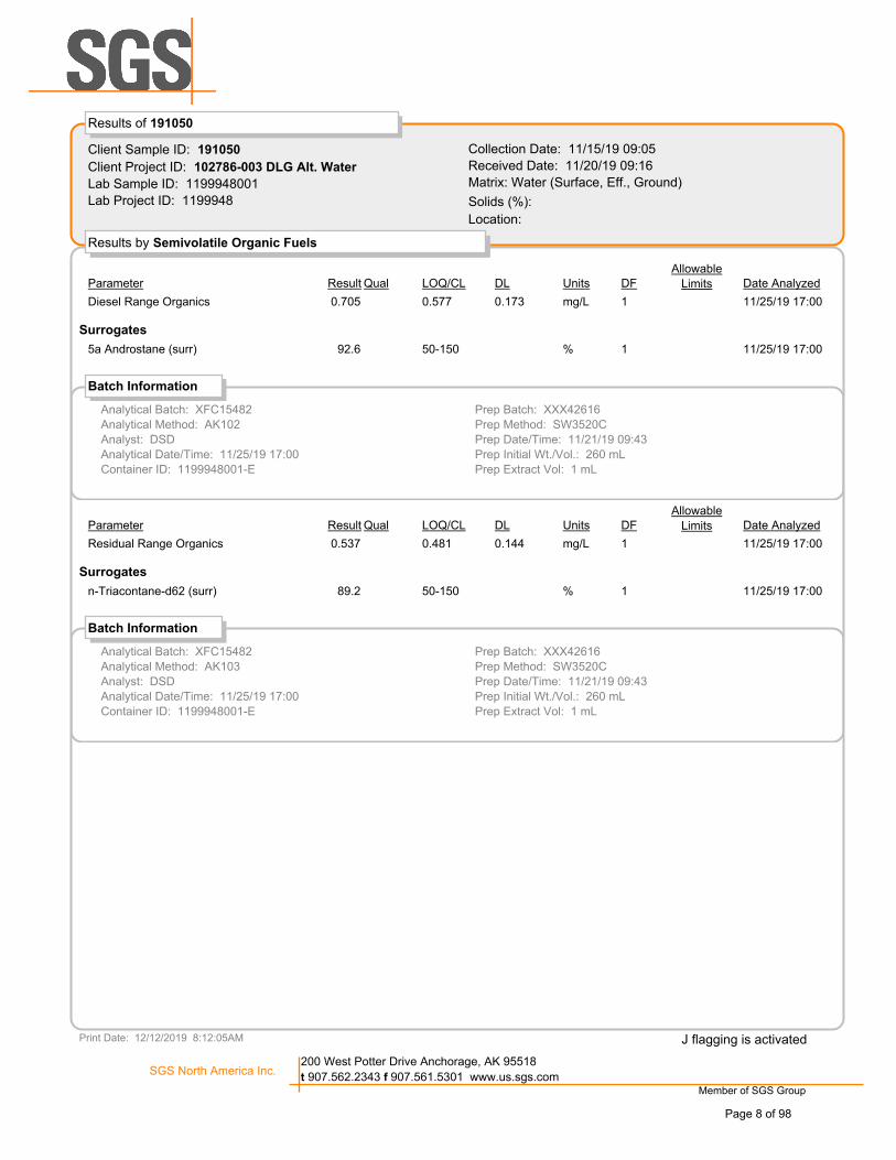
Client Sample ID: 191050
Client Project ID: 102786-003 DLG Alt. Water
Lab Sample ID: 1199948001
Lab Project ID: 1199948
Collection Date: 11/15/19 09:05
Received Date: 11/20/19 09:16
Matrix: Water (Surface, Eff., Ground)
Solids (%):
Results by Semivolatile Organic Fuels
Results of 191050
Location:
Date AnalyzedParameter DFUnitsResult LOQ/CL DLAllowable
LimitsQual
Diesel Range Organics 0.705 mg/L 10.577 0.173 11/25/19 17:00
Surrogates
5a Androstane (surr) 92.6 % 150-150 11/25/19 17:00
Batch Information
Prep Batch: XXX42616
Prep Method: SW3520C
Prep Date/Time: 11/21/19 09:43
Prep Initial Wt./Vol.: 260 mL
Prep Extract Vol: 1 mL
Analytical Batch: XFC15482
Analytical Method: AK102
Analyst: DSD
Analytical Date/Time: 11/25/19 17:00
Container ID: 1199948001-E
Date AnalyzedParameter DFUnitsResult LOQ/CL DLAllowable
LimitsQual
Residual Range Organics 0.537 mg/L 10.481 0.144 11/25/19 17:00
Surrogates
n-Triacontane-d62 (surr) 89.2 % 150-150 11/25/19 17:00
Batch Information
Prep Batch: XXX42616
Prep Method: SW3520C
Prep Date/Time: 11/21/19 09:43
Prep Initial Wt./Vol.: 260 mL
Prep Extract Vol: 1 mL
Analytical Batch: XFC15482
Analytical Method: AK103
Analyst: DSD
Analytical Date/Time: 11/25/19 17:00
Container ID: 1199948001-E
Print Date: 12/12/2019 8:12:05AM
Member of SGS Group
SGS North America Inc.200 West Potter Drive Anchorage, AK 95518
t 907.562.2343 f 907.561.5301 www.us.sgs.com
J flagging is activated
Page 8 of 98

Client Sample ID: 191050
Client Project ID: 102786-003 DLG Alt. Water
Lab Sample ID: 1199948001
Lab Project ID: 1199948
Collection Date: 11/15/19 09:05
Received Date: 11/20/19 09:16
Matrix: Water (Surface, Eff., Ground)
Solids (%):
Results by Volatile Fuels
Results of 191050
Location:
Date AnalyzedParameter DFUnitsResult LOQ/CL DLAllowable
LimitsQual
Gasoline Range Organics 0.0500 mg/L 10.100 0.0310 11/26/19 12:52U
Surrogates
4-Bromofluorobenzene (surr) 85.7 % 150-150 11/26/19 12:52
Batch Information
Prep Batch: VXX35282
Prep Method: SW5030B
Prep Date/Time: 11/26/19 08:00
Prep Initial Wt./Vol.: 5 mL
Prep Extract Vol: 5 mL
Analytical Batch: VFC15049
Analytical Method: AK101
Analyst: ST
Analytical Date/Time: 11/26/19 12:52
Container ID: 1199948001-H
Date AnalyzedParameter DFUnitsResult LOQ/CL DLAllowable
LimitsQual
Benzene 0.250 ug/L 10.500 0.150 11/26/19 12:52U
Ethylbenzene 0.500 ug/L 11.00 0.310 11/26/19 12:52U
o-Xylene 0.500 ug/L 11.00 0.310 11/26/19 12:52U
P & M -Xylene 1.00 ug/L 12.00 0.620 11/26/19 12:52U
Toluene 0.500 ug/L 11.00 0.310 11/26/19 12:52U
Xylenes (total) 1.50 ug/L 13.00 0.930 11/26/19 12:52U
Surrogates
1,4-Difluorobenzene (surr) 93.4 % 177-115 11/26/19 12:52
Batch Information
Prep Batch: VXX35282
Prep Method: SW5030B
Prep Date/Time: 11/26/19 08:00
Prep Initial Wt./Vol.: 5 mL
Prep Extract Vol: 5 mL
Analytical Batch: VFC15049
Analytical Method: SW8021B
Analyst: ST
Analytical Date/Time: 11/26/19 12:52
Container ID: 1199948001-H
Print Date: 12/12/2019 8:12:05AM
Member of SGS Group
SGS North America Inc.200 West Potter Drive Anchorage, AK 95518
t 907.562.2343 f 907.561.5301 www.us.sgs.com
J flagging is activated
Page 9 of 98

Client Sample ID: 191050
Client Project ID: 102786-003 DLG Alt. Water
Lab Sample ID: 1199948001
Lab Project ID: 1199948
Collection Date: 11/15/19 09:05
Received Date: 11/20/19 09:16
Matrix: Water (Surface, Eff., Ground)
Solids (%):
Results by Waters Department
Results of 191050
Location:
Date AnalyzedParameter DFUnitsResult LOQ/CL DLAllowable
LimitsQual
Oil & Grease HEM 1910 ug/L 14260 1060 11/26/19 08:38J
Batch Information
Analytical Batch: THOG1311
Analytical Method: EPA 1664B
Analyst: EWW
Analytical Date/Time: 11/26/19 08:38
Container ID: 1199948001-J
Date AnalyzedParameter DFUnitsResult LOQ/CL DLAllowable
LimitsQual
Chloride 3920 ug/L 1200 50.0 12/09/19 19:03
Fluoride 126 ug/L 1200 50.0 12/09/19 19:03J
Sulfate 1360 ug/L 1200 50.0 12/09/19 19:03
Batch Information
Prep Batch: WXX13139
Prep Method: METHOD
Prep Date/Time: 12/09/19 10:45
Prep Initial Wt./Vol.: 10 mL
Prep Extract Vol: 10 mL
Analytical Batch: WIC6002
Analytical Method: EPA 300.0
Analyst: DMM
Analytical Date/Time: 12/09/19 19:03
Container ID: 1199948001-M
Date AnalyzedParameter DFUnitsResult LOQ/CL DLAllowable
LimitsQual
Total Organic Carbon 597 ug/L 11000 400 12/03/19 16:06J
Batch Information
Analytical Batch: WTC2974
Analytical Method: SM 5310B
Analyst: BMZ
Analytical Date/Time: 12/03/19 16:06
Container ID: 1199948001-A
Date AnalyzedParameter DFUnitsResult LOQ/CL DLAllowable
LimitsQual
Conductivity 87.0 umhos/cm 11.00 0.477 11/21/19 14:15
Print Date: 12/12/2019 8:12:05AM
Member of SGS Group
SGS North America Inc.200 West Potter Drive Anchorage, AK 95518
t 907.562.2343 f 907.561.5301 www.us.sgs.com
J flagging is activated
Page 10 of 98

Client Sample ID: 191050
Client Project ID: 102786-003 DLG Alt. Water
Lab Sample ID: 1199948001
Lab Project ID: 1199948
Collection Date: 11/15/19 09:05
Received Date: 11/20/19 09:16
Matrix: Water (Surface, Eff., Ground)
Solids (%):
Results by Waters Department
Results of 191050
Location:
Batch Information
Analytical Batch: WTI5312
Analytical Method: SM21 2510B
Analyst: EWW
Analytical Date/Time: 11/21/19 14:15
Container ID: 1199948001-M
Date AnalyzedParameter DFUnitsResult LOQ/CL DLAllowable
LimitsQual
Total Dissolved Solids 65000 ug/L 110000 3100 11/20/19 17:49
Batch Information
Analytical Batch: STS6557
Analytical Method: SM21 2540C
Analyst: DMM
Analytical Date/Time: 11/20/19 17:49
Container ID: 1199948001-M
Date AnalyzedParameter DFUnitsResult LOQ/CL DLAllowable
LimitsQual
Total Suspended Solids 500 ug/L 11000 310 11/20/19 15:11U
Batch Information
Analytical Batch: STS6556
Analytical Method: SM21 2540D
Analyst: EWW
Analytical Date/Time: 11/20/19 15:11
Container ID: 1199948001-D
Date AnalyzedParameter DFUnitsResult LOQ/CL DLAllowable
LimitsQual
pH 6.6 pH units 10.100 0.100 11/21/19 14:15
Batch Information
Analytical Batch: WTI5311
Analytical Method: SM21 4500-H B
Analyst: EWW
Analytical Date/Time: 11/21/19 14:15
Container ID: 1199948001-M
Date AnalyzedParameter DFUnitsResult LOQ/CL DLAllowable
LimitsQual
Print Date: 12/12/2019 8:12:05AM
Member of SGS Group
SGS North America Inc.200 West Potter Drive Anchorage, AK 95518
t 907.562.2343 f 907.561.5301 www.us.sgs.com
J flagging is activated
Page 11 of 98

Client Sample ID: 191050
Client Project ID: 102786-003 DLG Alt. Water
Lab Sample ID: 1199948001
Lab Project ID: 1199948
Collection Date: 11/15/19 09:05
Received Date: 11/20/19 09:16
Matrix: Water (Surface, Eff., Ground)
Solids (%):
Results by Waters Department
Results of 191050
Location:
Date AnalyzedParameter DFUnitsResult LOQ/CL DLAllowable
LimitsQual
Total Kjeldahl Nitrogen 500 ug/L 11000 310 12/04/19 17:30U
Batch Information
Prep Batch: WXX13134
Prep Method: METHOD
Prep Date/Time: 12/04/19 10:52
Prep Initial Wt./Vol.: 25 mL
Prep Extract Vol: 25 mL
Analytical Batch: WDA4697
Analytical Method: SM21 4500-N D
Analyst: DMM
Analytical Date/Time: 12/04/19 17:30
Container ID: 1199948001-C
Date AnalyzedParameter DFUnitsResult LOQ/CL DLAllowable
LimitsQual
Total Nitrate/Nitrite-N 118 ug/L 2200 50.0 12/02/19 13:53J
Batch Information
Analytical Batch: WFI2848
Analytical Method: SM21 4500NO3-F
Analyst: EWW
Analytical Date/Time: 12/02/19 13:53
Container ID: 1199948001-C
Date AnalyzedParameter DFUnitsResult LOQ/CL DLAllowable
LimitsQual
Sulfide 50.0 ug/L 1100 31.0 11/21/19 12:25U
Batch Information
Analytical Batch: WAT11457
Analytical Method: SM23 4500S D
Analyst: EWW
Analytical Date/Time: 11/21/19 12:25
Container ID: 1199948001-L
Print Date: 12/12/2019 8:12:05AM
Member of SGS Group
SGS North America Inc.200 West Potter Drive Anchorage, AK 95518
t 907.562.2343 f 907.561.5301 www.us.sgs.com
J flagging is activated
Page 12 of 98

Client Sample ID: 191320
Client Project ID: 102786-003 DLG Alt. Water
Lab Sample ID: 1199948002
Lab Project ID: 1199948
Collection Date: 11/14/19 17:45
Received Date: 11/20/19 09:16
Matrix: Water (Surface, Eff., Ground)
Solids (%):
Results by Metals by ICP/MS
Results of 191320
Location:
Date AnalyzedParameter DFUnitsResult LOQ/CL DLAllowable
LimitsQual
Calcium 30400 ug/L 1500 150 12/05/19 17:17
Chromium 1.94 ug/L 12.00 0.800 12/05/19 17:17J
Iron 46000 ug/L 1250 78.0 12/05/19 17:17
Magnesium 9450 ug/L 150.0 15.0 12/05/19 17:17
Manganese 1420 ug/L 11.00 0.350 12/05/19 17:17
Potassium 1480 ug/L 1500 150 12/05/19 17:17
Sodium 6920 ug/L 1500 150 12/05/19 17:17
Batch Information
Prep Batch: MXX33025
Prep Method: E200.2
Prep Date/Time: 12/02/19 09:48
Prep Initial Wt./Vol.: 20 mL
Prep Extract Vol: 50 mL
Analytical Batch: MMS10696
Analytical Method: EP200.8
Analyst: ACF
Analytical Date/Time: 12/05/19 17:17
Container ID: 1199948002-B
Date AnalyzedParameter DFUnitsResult LOQ/CL DLAllowable
LimitsQual
Hardness as CaCO3 115000 ug/L 15000 5000 12/05/19 17:17
Batch Information
Prep Batch: MXX33025
Prep Method: E200.2
Prep Date/Time: 12/02/19 09:48
Prep Initial Wt./Vol.: 20 mL
Prep Extract Vol: 50 mL
Analytical Batch: MMS10696
Analytical Method: SM21 2340B
Analyst: ACF
Analytical Date/Time: 12/05/19 17:17
Container ID: 1199948002-B
Print Date: 12/12/2019 8:12:05AM
Member of SGS Group
SGS North America Inc.200 West Potter Drive Anchorage, AK 95518
t 907.562.2343 f 907.561.5301 www.us.sgs.com
J flagging is activated
Page 13 of 98

Client Sample ID: 191320
Client Project ID: 102786-003 DLG Alt. Water
Lab Sample ID: 1199948002
Lab Project ID: 1199948
Collection Date: 11/14/19 17:45
Received Date: 11/20/19 09:16
Matrix: Water (Surface, Eff., Ground)
Solids (%):
Results by Semivolatile Organic Fuels
Results of 191320
Location:
Date AnalyzedParameter DFUnitsResult LOQ/CL DLAllowable
LimitsQual
Diesel Range Organics 0.916 mg/L 10.682 0.205 11/25/19 17:10
Surrogates
5a Androstane (surr) 94 % 150-150 11/25/19 17:10
Batch Information
Prep Batch: XXX42616
Prep Method: SW3520C
Prep Date/Time: 11/21/19 09:43
Prep Initial Wt./Vol.: 220 mL
Prep Extract Vol: 1 mL
Analytical Batch: XFC15482
Analytical Method: AK102
Analyst: DSD
Analytical Date/Time: 11/25/19 17:10
Container ID: 1199948002-E
Date AnalyzedParameter DFUnitsResult LOQ/CL DLAllowable
LimitsQual
Residual Range Organics 0.586 mg/L 10.568 0.170 11/25/19 17:10
Surrogates
n-Triacontane-d62 (surr) 93.4 % 150-150 11/25/19 17:10
Batch Information
Prep Batch: XXX42616
Prep Method: SW3520C
Prep Date/Time: 11/21/19 09:43
Prep Initial Wt./Vol.: 220 mL
Prep Extract Vol: 1 mL
Analytical Batch: XFC15482
Analytical Method: AK103
Analyst: DSD
Analytical Date/Time: 11/25/19 17:10
Container ID: 1199948002-E
Print Date: 12/12/2019 8:12:05AM
Member of SGS Group
SGS North America Inc.200 West Potter Drive Anchorage, AK 95518
t 907.562.2343 f 907.561.5301 www.us.sgs.com
J flagging is activated
Page 14 of 98

Client Sample ID: 191320
Client Project ID: 102786-003 DLG Alt. Water
Lab Sample ID: 1199948002
Lab Project ID: 1199948
Collection Date: 11/14/19 17:45
Received Date: 11/20/19 09:16
Matrix: Water (Surface, Eff., Ground)
Solids (%):
Results by Volatile Fuels
Results of 191320
Location:
Date AnalyzedParameter DFUnitsResult LOQ/CL DLAllowable
LimitsQual
Gasoline Range Organics 0.0500 mg/L 10.100 0.0310 11/26/19 13:10U
Surrogates
4-Bromofluorobenzene (surr) 84.4 % 150-150 11/26/19 13:10
Batch Information
Prep Batch: VXX35282
Prep Method: SW5030B
Prep Date/Time: 11/26/19 08:00
Prep Initial Wt./Vol.: 5 mL
Prep Extract Vol: 5 mL
Analytical Batch: VFC15049
Analytical Method: AK101
Analyst: ST
Analytical Date/Time: 11/26/19 13:10
Container ID: 1199948002-H
Date AnalyzedParameter DFUnitsResult LOQ/CL DLAllowable
LimitsQual
Benzene 0.250 ug/L 10.500 0.150 11/26/19 13:10U
Ethylbenzene 0.500 ug/L 11.00 0.310 11/26/19 13:10U
o-Xylene 0.500 ug/L 11.00 0.310 11/26/19 13:10U
P & M -Xylene 1.00 ug/L 12.00 0.620 11/26/19 13:10U
Toluene 0.500 ug/L 11.00 0.310 11/26/19 13:10U
Xylenes (total) 1.50 ug/L 13.00 0.930 11/26/19 13:10U
Surrogates
1,4-Difluorobenzene (surr) 92.8 % 177-115 11/26/19 13:10
Batch Information
Prep Batch: VXX35282
Prep Method: SW5030B
Prep Date/Time: 11/26/19 08:00
Prep Initial Wt./Vol.: 5 mL
Prep Extract Vol: 5 mL
Analytical Batch: VFC15049
Analytical Method: SW8021B
Analyst: ST
Analytical Date/Time: 11/26/19 13:10
Container ID: 1199948002-H
Print Date: 12/12/2019 8:12:05AM
Member of SGS Group
SGS North America Inc.200 West Potter Drive Anchorage, AK 95518
t 907.562.2343 f 907.561.5301 www.us.sgs.com
J flagging is activated
Page 15 of 98

Client Sample ID: 191320
Client Project ID: 102786-003 DLG Alt. Water
Lab Sample ID: 1199948002
Lab Project ID: 1199948
Collection Date: 11/14/19 17:45
Received Date: 11/20/19 09:16
Matrix: Water (Surface, Eff., Ground)
Solids (%):
Results by Waters Department
Results of 191320
Location:
Date AnalyzedParameter DFUnitsResult LOQ/CL DLAllowable
LimitsQual
Oil & Grease HEM 1580 ug/L 14210 1050 11/26/19 08:38J
Batch Information
Analytical Batch: THOG1311
Analytical Method: EPA 1664B
Analyst: EWW
Analytical Date/Time: 11/26/19 08:38
Container ID: 1199948002-J
Date AnalyzedParameter DFUnitsResult LOQ/CL DLAllowable
LimitsQual
Chloride 15900 ug/L 1200 50.0 12/09/19 19:41
Fluoride 182 ug/L 1200 50.0 12/09/19 19:41J
Sulfate 3440 ug/L 1200 50.0 12/09/19 19:41
Batch Information
Prep Batch: WXX13139
Prep Method: METHOD
Prep Date/Time: 12/09/19 10:45
Prep Initial Wt./Vol.: 10 mL
Prep Extract Vol: 10 mL
Analytical Batch: WIC6002
Analytical Method: EPA 300.0
Analyst: DMM
Analytical Date/Time: 12/09/19 19:41
Container ID: 1199948002-M
Date AnalyzedParameter DFUnitsResult LOQ/CL DLAllowable
LimitsQual
Total Organic Carbon 11300 ug/L 11000 400 12/03/19 16:25
Batch Information
Analytical Batch: WTC2974
Analytical Method: SM 5310B
Analyst: BMZ
Analytical Date/Time: 12/03/19 16:25
Container ID: 1199948002-A
Date AnalyzedParameter DFUnitsResult LOQ/CL DLAllowable
LimitsQual
Conductivity 315 umhos/cm 11.00 0.477 11/21/19 14:22
Print Date: 12/12/2019 8:12:05AM
Member of SGS Group
SGS North America Inc.200 West Potter Drive Anchorage, AK 95518
t 907.562.2343 f 907.561.5301 www.us.sgs.com
J flagging is activated
Page 16 of 98

Client Sample ID: 191320
Client Project ID: 102786-003 DLG Alt. Water
Lab Sample ID: 1199948002
Lab Project ID: 1199948
Collection Date: 11/14/19 17:45
Received Date: 11/20/19 09:16
Matrix: Water (Surface, Eff., Ground)
Solids (%):
Results by Waters Department
Results of 191320
Location:
Batch Information
Analytical Batch: WTI5312
Analytical Method: SM21 2510B
Analyst: EWW
Analytical Date/Time: 11/21/19 14:22
Container ID: 1199948002-M
Date AnalyzedParameter DFUnitsResult LOQ/CL DLAllowable
LimitsQual
Total Dissolved Solids 237000 ug/L 110000 3100 11/20/19 17:49
Batch Information
Analytical Batch: STS6557
Analytical Method: SM21 2540C
Analyst: DMM
Analytical Date/Time: 11/20/19 17:49
Container ID: 1199948002-M
Date AnalyzedParameter DFUnitsResult LOQ/CL DLAllowable
LimitsQual
Total Suspended Solids 74400 ug/L 14000 1240 11/20/19 15:11
Batch Information
Analytical Batch: STS6556
Analytical Method: SM21 2540D
Analyst: EWW
Analytical Date/Time: 11/20/19 15:11
Container ID: 1199948002-D
Date AnalyzedParameter DFUnitsResult LOQ/CL DLAllowable
LimitsQual
pH 6.4 pH units 10.100 0.100 11/21/19 14:22
Batch Information
Analytical Batch: WTI5311
Analytical Method: SM21 4500-H B
Analyst: EWW
Analytical Date/Time: 11/21/19 14:22
Container ID: 1199948002-M
Date AnalyzedParameter DFUnitsResult LOQ/CL DLAllowable
LimitsQual
Print Date: 12/12/2019 8:12:05AM
Member of SGS Group
SGS North America Inc.200 West Potter Drive Anchorage, AK 95518
t 907.562.2343 f 907.561.5301 www.us.sgs.com
J flagging is activated
Page 17 of 98

Client Sample ID: 191320
Client Project ID: 102786-003 DLG Alt. Water
Lab Sample ID: 1199948002
Lab Project ID: 1199948
Collection Date: 11/14/19 17:45
Received Date: 11/20/19 09:16
Matrix: Water (Surface, Eff., Ground)
Solids (%):
Results by Waters Department
Results of 191320
Location:
Date AnalyzedParameter DFUnitsResult LOQ/CL DLAllowable
LimitsQual
Total Kjeldahl Nitrogen 2090 ug/L 11000 310 12/04/19 17:32
Batch Information
Prep Batch: WXX13134
Prep Method: METHOD
Prep Date/Time: 12/04/19 10:52
Prep Initial Wt./Vol.: 25 mL
Prep Extract Vol: 25 mL
Analytical Batch: WDA4697
Analytical Method: SM21 4500-N D
Analyst: DMM
Analytical Date/Time: 12/04/19 17:32
Container ID: 1199948002-C
Date AnalyzedParameter DFUnitsResult LOQ/CL DLAllowable
LimitsQual
Total Nitrate/Nitrite-N 71.8 ug/L 2200 50.0 12/02/19 13:54J
Batch Information
Analytical Batch: WFI2848
Analytical Method: SM21 4500NO3-F
Analyst: EWW
Analytical Date/Time: 12/02/19 13:54
Container ID: 1199948002-C
Date AnalyzedParameter DFUnitsResult LOQ/CL DLAllowable
LimitsQual
Sulfide 80.0 ug/L 1100 31.0 11/21/19 12:25J
Batch Information
Analytical Batch: WAT11457
Analytical Method: SM23 4500S D
Analyst: EWW
Analytical Date/Time: 11/21/19 12:25
Container ID: 1199948002-L
Print Date: 12/12/2019 8:12:05AM
Member of SGS Group
SGS North America Inc.200 West Potter Drive Anchorage, AK 95518
t 907.562.2343 f 907.561.5301 www.us.sgs.com
J flagging is activated
Page 18 of 98

Client Sample ID: 200150
Client Project ID: 102786-003 DLG Alt. Water
Lab Sample ID: 1199948003
Lab Project ID: 1199948
Collection Date: 11/15/19 11:50
Received Date: 11/20/19 09:16
Matrix: Water (Surface, Eff., Ground)
Solids (%):
Results by Metals by ICP/MS
Results of 200150
Location:
Date AnalyzedParameter DFUnitsResult LOQ/CL DLAllowable
LimitsQual
Calcium 18000 ug/L 1500 150 12/05/19 17:20
Chromium 1.00 ug/L 12.00 0.800 12/05/19 17:20U
Iron 125 ug/L 1250 78.0 12/05/19 17:20U
Magnesium 4710 ug/L 150.0 15.0 12/05/19 17:20
Manganese 7.40 ug/L 11.00 0.350 12/05/19 17:20
Potassium 1120 ug/L 1500 150 12/05/19 17:20
Sodium 24200 ug/L 1500 150 12/05/19 17:20
Batch Information
Prep Batch: MXX33025
Prep Method: E200.2
Prep Date/Time: 12/02/19 09:48
Prep Initial Wt./Vol.: 20 mL
Prep Extract Vol: 50 mL
Analytical Batch: MMS10696
Analytical Method: EP200.8
Analyst: ACF
Analytical Date/Time: 12/05/19 17:20
Container ID: 1199948003-B
Date AnalyzedParameter DFUnitsResult LOQ/CL DLAllowable
LimitsQual
Hardness as CaCO3 64300 ug/L 15000 5000 12/05/19 17:20
Batch Information
Prep Batch: MXX33025
Prep Method: E200.2
Prep Date/Time: 12/02/19 09:48
Prep Initial Wt./Vol.: 20 mL
Prep Extract Vol: 50 mL
Analytical Batch: MMS10696
Analytical Method: SM21 2340B
Analyst: ACF
Analytical Date/Time: 12/05/19 17:20
Container ID: 1199948003-B
Print Date: 12/12/2019 8:12:05AM
Member of SGS Group
SGS North America Inc.200 West Potter Drive Anchorage, AK 95518
t 907.562.2343 f 907.561.5301 www.us.sgs.com
J flagging is activated
Page 19 of 98

Client Sample ID: 200150
Client Project ID: 102786-003 DLG Alt. Water
Lab Sample ID: 1199948003
Lab Project ID: 1199948
Collection Date: 11/15/19 11:50
Received Date: 11/20/19 09:16
Matrix: Water (Surface, Eff., Ground)
Solids (%):
Results by Semivolatile Organic Fuels
Results of 200150
Location:
Date AnalyzedParameter DFUnitsResult LOQ/CL DLAllowable
LimitsQual
Diesel Range Organics 0.212 mg/L 10.566 0.170 11/25/19 17:20J
Surrogates
5a Androstane (surr) 82.9 % 150-150 11/25/19 17:20
Batch Information
Prep Batch: XXX42616
Prep Method: SW3520C
Prep Date/Time: 11/21/19 09:43
Prep Initial Wt./Vol.: 265 mL
Prep Extract Vol: 1 mL
Analytical Batch: XFC15482
Analytical Method: AK102
Analyst: DSD
Analytical Date/Time: 11/25/19 17:20
Container ID: 1199948003-E
Date AnalyzedParameter DFUnitsResult LOQ/CL DLAllowable
LimitsQual
Residual Range Organics 0.236 mg/L 10.472 0.142 11/25/19 17:20U
Surrogates
n-Triacontane-d62 (surr) 79.9 % 150-150 11/25/19 17:20
Batch Information
Prep Batch: XXX42616
Prep Method: SW3520C
Prep Date/Time: 11/21/19 09:43
Prep Initial Wt./Vol.: 265 mL
Prep Extract Vol: 1 mL
Analytical Batch: XFC15482
Analytical Method: AK103
Analyst: DSD
Analytical Date/Time: 11/25/19 17:20
Container ID: 1199948003-E
Print Date: 12/12/2019 8:12:05AM
Member of SGS Group
SGS North America Inc.200 West Potter Drive Anchorage, AK 95518
t 907.562.2343 f 907.561.5301 www.us.sgs.com
J flagging is activated
Page 20 of 98

Client Sample ID: 200150
Client Project ID: 102786-003 DLG Alt. Water
Lab Sample ID: 1199948003
Lab Project ID: 1199948
Collection Date: 11/15/19 11:50
Received Date: 11/20/19 09:16
Matrix: Water (Surface, Eff., Ground)
Solids (%):
Results by Volatile Fuels
Results of 200150
Location:
Date AnalyzedParameter DFUnitsResult LOQ/CL DLAllowable
LimitsQual
Gasoline Range Organics 0.0500 mg/L 10.100 0.0310 11/26/19 13:27U
Surrogates
4-Bromofluorobenzene (surr) 83.4 % 150-150 11/26/19 13:27
Batch Information
Prep Batch: VXX35282
Prep Method: SW5030B
Prep Date/Time: 11/26/19 08:00
Prep Initial Wt./Vol.: 5 mL
Prep Extract Vol: 5 mL
Analytical Batch: VFC15049
Analytical Method: AK101
Analyst: ST
Analytical Date/Time: 11/26/19 13:27
Container ID: 1199948003-H
Date AnalyzedParameter DFUnitsResult LOQ/CL DLAllowable
LimitsQual
Benzene 0.250 ug/L 10.500 0.150 11/26/19 13:27U
Ethylbenzene 0.500 ug/L 11.00 0.310 11/26/19 13:27U
o-Xylene 0.500 ug/L 11.00 0.310 11/26/19 13:27U
P & M -Xylene 1.00 ug/L 12.00 0.620 11/26/19 13:27U
Toluene 0.500 ug/L 11.00 0.310 11/26/19 13:27U
Xylenes (total) 1.50 ug/L 13.00 0.930 11/26/19 13:27U
Surrogates
1,4-Difluorobenzene (surr) 93.4 % 177-115 11/26/19 13:27
Batch Information
Prep Batch: VXX35282
Prep Method: SW5030B
Prep Date/Time: 11/26/19 08:00
Prep Initial Wt./Vol.: 5 mL
Prep Extract Vol: 5 mL
Analytical Batch: VFC15049
Analytical Method: SW8021B
Analyst: ST
Analytical Date/Time: 11/26/19 13:27
Container ID: 1199948003-H
Print Date: 12/12/2019 8:12:05AM
Member of SGS Group
SGS North America Inc.200 West Potter Drive Anchorage, AK 95518
t 907.562.2343 f 907.561.5301 www.us.sgs.com
J flagging is activated
Page 21 of 98

Client Sample ID: 200150
Client Project ID: 102786-003 DLG Alt. Water
Lab Sample ID: 1199948003
Lab Project ID: 1199948
Collection Date: 11/15/19 11:50
Received Date: 11/20/19 09:16
Matrix: Water (Surface, Eff., Ground)
Solids (%):
Results by Waters Department
Results of 200150
Location:
Date AnalyzedParameter DFUnitsResult LOQ/CL DLAllowable
LimitsQual
Oil & Grease HEM 1620 ug/L 14040 1010 11/26/19 08:38J
Batch Information
Analytical Batch: THOG1311
Analytical Method: EPA 1664B
Analyst: EWW
Analytical Date/Time: 11/26/19 08:38
Container ID: 1199948003-J
Date AnalyzedParameter DFUnitsResult LOQ/CL DLAllowable
LimitsQual
Chloride 38200 ug/L 102000 500 12/10/19 07:48
Fluoride 97.0 ug/L 1200 50.0 12/09/19 20:00J
Sulfate 7140 ug/L 1200 50.0 12/09/19 20:00
Batch Information
Prep Batch: WXX13139
Prep Method: METHOD
Prep Date/Time: 12/09/19 10:45
Prep Initial Wt./Vol.: 10 mL
Prep Extract Vol: 10 mL
Analytical Batch: WIC6002
Analytical Method: EPA 300.0
Analyst: DMM
Analytical Date/Time: 12/10/19 07:48
Container ID: 1199948003-M
Prep Batch: WXX13139
Prep Method: METHOD
Prep Date/Time: 12/09/19 10:45
Prep Initial Wt./Vol.: 10 mL
Prep Extract Vol: 10 mL
Analytical Batch: WIC6002
Analytical Method: EPA 300.0
Analyst: DMM
Analytical Date/Time: 12/09/19 20:00
Container ID: 1199948003-M
Date AnalyzedParameter DFUnitsResult LOQ/CL DLAllowable
LimitsQual
Total Organic Carbon 847 ug/L 11000 400 12/03/19 16:39J
Batch Information
Analytical Batch: WTC2974
Analytical Method: SM 5310B
Analyst: BMZ
Analytical Date/Time: 12/03/19 16:39
Container ID: 1199948003-A
Date AnalyzedParameter DFUnitsResult LOQ/CL DLAllowable
LimitsQual
Print Date: 12/12/2019 8:12:05AM
Member of SGS Group
SGS North America Inc.200 West Potter Drive Anchorage, AK 95518
t 907.562.2343 f 907.561.5301 www.us.sgs.com
J flagging is activated
Page 22 of 98

Client Sample ID: 200150
Client Project ID: 102786-003 DLG Alt. Water
Lab Sample ID: 1199948003
Lab Project ID: 1199948
Collection Date: 11/15/19 11:50
Received Date: 11/20/19 09:16
Matrix: Water (Surface, Eff., Ground)
Solids (%):
Results by Waters Department
Results of 200150
Location:
Date AnalyzedParameter DFUnitsResult LOQ/CL DLAllowable
LimitsQual
Conductivity 262 umhos/cm 11.00 0.477 11/21/19 14:29
Batch Information
Analytical Batch: WTI5312
Analytical Method: SM21 2510B
Analyst: EWW
Analytical Date/Time: 11/21/19 14:29
Container ID: 1199948003-M
Date AnalyzedParameter DFUnitsResult LOQ/CL DLAllowable
LimitsQual
Total Dissolved Solids 148000 ug/L 110000 3100 11/20/19 17:49
Batch Information
Analytical Batch: STS6557
Analytical Method: SM21 2540C
Analyst: DMM
Analytical Date/Time: 11/20/19 17:49
Container ID: 1199948003-M
Date AnalyzedParameter DFUnitsResult LOQ/CL DLAllowable
LimitsQual
Total Suspended Solids 500 ug/L 11000 310 11/20/19 15:11U
Batch Information
Analytical Batch: STS6556
Analytical Method: SM21 2540D
Analyst: EWW
Analytical Date/Time: 11/20/19 15:11
Container ID: 1199948003-D
Date AnalyzedParameter DFUnitsResult LOQ/CL DLAllowable
LimitsQual
pH 6.6 pH units 10.100 0.100 11/21/19 14:29
Print Date: 12/12/2019 8:12:05AM
Member of SGS Group
SGS North America Inc.200 West Potter Drive Anchorage, AK 95518
t 907.562.2343 f 907.561.5301 www.us.sgs.com
J flagging is activated
Page 23 of 98

Client Sample ID: 200150
Client Project ID: 102786-003 DLG Alt. Water
Lab Sample ID: 1199948003
Lab Project ID: 1199948
Collection Date: 11/15/19 11:50
Received Date: 11/20/19 09:16
Matrix: Water (Surface, Eff., Ground)
Solids (%):
Results by Waters Department
Results of 200150
Location:
Batch Information
Analytical Batch: WTI5311
Analytical Method: SM21 4500-H B
Analyst: EWW
Analytical Date/Time: 11/21/19 14:29
Container ID: 1199948003-M
Date AnalyzedParameter DFUnitsResult LOQ/CL DLAllowable
LimitsQual
Total Kjeldahl Nitrogen 500 ug/L 11000 310 12/04/19 17:33U
Batch Information
Prep Batch: WXX13134
Prep Method: METHOD
Prep Date/Time: 12/04/19 10:52
Prep Initial Wt./Vol.: 25 mL
Prep Extract Vol: 25 mL
Analytical Batch: WDA4697
Analytical Method: SM21 4500-N D
Analyst: DMM
Analytical Date/Time: 12/04/19 17:33
Container ID: 1199948003-C
Date AnalyzedParameter DFUnitsResult LOQ/CL DLAllowable
LimitsQual
Total Nitrate/Nitrite-N 1800 ug/L 2200 50.0 12/02/19 13:56
Batch Information
Analytical Batch: WFI2848
Analytical Method: SM21 4500NO3-F
Analyst: EWW
Analytical Date/Time: 12/02/19 13:56
Container ID: 1199948003-C
Date AnalyzedParameter DFUnitsResult LOQ/CL DLAllowable
LimitsQual
Sulfide 50.0 ug/L 1100 31.0 11/21/19 12:25U
Batch Information
Analytical Batch: WAT11457
Analytical Method: SM23 4500S D
Analyst: EWW
Analytical Date/Time: 11/21/19 12:25
Container ID: 1199948003-L
Print Date: 12/12/2019 8:12:05AM
Member of SGS Group
SGS North America Inc.200 West Potter Drive Anchorage, AK 95518
t 907.562.2343 f 907.561.5301 www.us.sgs.com
J flagging is activated
Page 24 of 98

Client Sample ID: 191710
Client Project ID: 102786-003 DLG Alt. Water
Lab Sample ID: 1199948004
Lab Project ID: 1199948
Collection Date: 11/15/19 16:51
Received Date: 11/20/19 09:16
Matrix: Water (Surface, Eff., Ground)
Solids (%):
Results by Metals by ICP/MS
Results of 191710
Location:
Date AnalyzedParameter DFUnitsResult LOQ/CL DLAllowable
LimitsQual
Calcium 21600 ug/L 1500 150 12/05/19 17:26
Chromium 1.00 ug/L 12.00 0.800 12/05/19 17:26U
Iron 36800 ug/L 1250 78.0 12/05/19 17:26
Magnesium 8250 ug/L 150.0 15.0 12/05/19 17:26
Manganese 1340 ug/L 11.00 0.350 12/05/19 17:26
Potassium 2830 ug/L 1500 150 12/05/19 17:26
Sodium 9190 ug/L 1500 150 12/05/19 17:26
Batch Information
Prep Batch: MXX33025
Prep Method: E200.2
Prep Date/Time: 12/02/19 09:48
Prep Initial Wt./Vol.: 20 mL
Prep Extract Vol: 50 mL
Analytical Batch: MMS10696
Analytical Method: EP200.8
Analyst: ACF
Analytical Date/Time: 12/05/19 17:26
Container ID: 1199948004-B
Date AnalyzedParameter DFUnitsResult LOQ/CL DLAllowable
LimitsQual
Hardness as CaCO3 87900 ug/L 15000 5000 12/05/19 17:26
Batch Information
Prep Batch: MXX33025
Prep Method: E200.2
Prep Date/Time: 12/02/19 09:48
Prep Initial Wt./Vol.: 20 mL
Prep Extract Vol: 50 mL
Analytical Batch: MMS10696
Analytical Method: SM21 2340B
Analyst: ACF
Analytical Date/Time: 12/05/19 17:26
Container ID: 1199948004-B
Print Date: 12/12/2019 8:12:05AM
Member of SGS Group
SGS North America Inc.200 West Potter Drive Anchorage, AK 95518
t 907.562.2343 f 907.561.5301 www.us.sgs.com
J flagging is activated
Page 25 of 98

Client Sample ID: 191710
Client Project ID: 102786-003 DLG Alt. Water
Lab Sample ID: 1199948004
Lab Project ID: 1199948
Collection Date: 11/15/19 16:51
Received Date: 11/20/19 09:16
Matrix: Water (Surface, Eff., Ground)
Solids (%):
Results by Semivolatile Organic Fuels
Results of 191710
Location:
Date AnalyzedParameter DFUnitsResult LOQ/CL DLAllowable
LimitsQual
Diesel Range Organics 0.253 mg/L 10.566 0.170 11/25/19 17:30J
Surrogates
5a Androstane (surr) 86.6 % 150-150 11/25/19 17:30
Batch Information
Prep Batch: XXX42616
Prep Method: SW3520C
Prep Date/Time: 11/21/19 09:43
Prep Initial Wt./Vol.: 265 mL
Prep Extract Vol: 1 mL
Analytical Batch: XFC15482
Analytical Method: AK102
Analyst: DSD
Analytical Date/Time: 11/25/19 17:30
Container ID: 1199948004-E
Date AnalyzedParameter DFUnitsResult LOQ/CL DLAllowable
LimitsQual
Residual Range Organics 0.236 mg/L 10.472 0.142 11/25/19 17:30U
Surrogates
n-Triacontane-d62 (surr) 83.1 % 150-150 11/25/19 17:30
Batch Information
Prep Batch: XXX42616
Prep Method: SW3520C
Prep Date/Time: 11/21/19 09:43
Prep Initial Wt./Vol.: 265 mL
Prep Extract Vol: 1 mL
Analytical Batch: XFC15482
Analytical Method: AK103
Analyst: DSD
Analytical Date/Time: 11/25/19 17:30
Container ID: 1199948004-E
Print Date: 12/12/2019 8:12:05AM
Member of SGS Group
SGS North America Inc.200 West Potter Drive Anchorage, AK 95518
t 907.562.2343 f 907.561.5301 www.us.sgs.com
J flagging is activated
Page 26 of 98

Client Sample ID: 191710
Client Project ID: 102786-003 DLG Alt. Water
Lab Sample ID: 1199948004
Lab Project ID: 1199948
Collection Date: 11/15/19 16:51
Received Date: 11/20/19 09:16
Matrix: Water (Surface, Eff., Ground)
Solids (%):
Results by Volatile Fuels
Results of 191710
Location:
Date AnalyzedParameter DFUnitsResult LOQ/CL DLAllowable
LimitsQual
Gasoline Range Organics 0.0500 mg/L 10.100 0.0310 11/26/19 13:44U
Surrogates
4-Bromofluorobenzene (surr) 87.4 % 150-150 11/26/19 13:44
Batch Information
Prep Batch: VXX35282
Prep Method: SW5030B
Prep Date/Time: 11/26/19 08:00
Prep Initial Wt./Vol.: 5 mL
Prep Extract Vol: 5 mL
Analytical Batch: VFC15049
Analytical Method: AK101
Analyst: ST
Analytical Date/Time: 11/26/19 13:44
Container ID: 1199948004-H
Date AnalyzedParameter DFUnitsResult LOQ/CL DLAllowable
LimitsQual
Benzene 0.250 ug/L 10.500 0.150 11/26/19 13:44U
Ethylbenzene 0.500 ug/L 11.00 0.310 11/26/19 13:44U
o-Xylene 0.500 ug/L 11.00 0.310 11/26/19 13:44U
P & M -Xylene 1.00 ug/L 12.00 0.620 11/26/19 13:44U
Toluene 0.500 ug/L 11.00 0.310 11/26/19 13:44U
Xylenes (total) 1.50 ug/L 13.00 0.930 11/26/19 13:44U
Surrogates
1,4-Difluorobenzene (surr) 93.1 % 177-115 11/26/19 13:44
Batch Information
Prep Batch: VXX35282
Prep Method: SW5030B
Prep Date/Time: 11/26/19 08:00
Prep Initial Wt./Vol.: 5 mL
Prep Extract Vol: 5 mL
Analytical Batch: VFC15049
Analytical Method: SW8021B
Analyst: ST
Analytical Date/Time: 11/26/19 13:44
Container ID: 1199948004-H
Print Date: 12/12/2019 8:12:05AM
Member of SGS Group
SGS North America Inc.200 West Potter Drive Anchorage, AK 95518
t 907.562.2343 f 907.561.5301 www.us.sgs.com
J flagging is activated
Page 27 of 98

Client Sample ID: 191710
Client Project ID: 102786-003 DLG Alt. Water
Lab Sample ID: 1199948004
Lab Project ID: 1199948
Collection Date: 11/15/19 16:51
Received Date: 11/20/19 09:16
Matrix: Water (Surface, Eff., Ground)
Solids (%):
Results by Waters Department
Results of 191710
Location:
Date AnalyzedParameter DFUnitsResult LOQ/CL DLAllowable
LimitsQual
Oil & Grease HEM 1530 ug/L 14080 1020 11/26/19 08:38J
Batch Information
Analytical Batch: THOG1311
Analytical Method: EPA 1664B
Analyst: EWW
Analytical Date/Time: 11/26/19 08:38
Container ID: 1199948004-J
Date AnalyzedParameter DFUnitsResult LOQ/CL DLAllowable
LimitsQual
Chloride 8570 ug/L 1200 50.0 12/09/19 20:19
Fluoride 163 ug/L 1200 50.0 12/09/19 20:19J
Sulfate 1580 ug/L 1200 50.0 12/09/19 20:19
Batch Information
Prep Batch: WXX13139
Prep Method: METHOD
Prep Date/Time: 12/09/19 10:45
Prep Initial Wt./Vol.: 10 mL
Prep Extract Vol: 10 mL
Analytical Batch: WIC6002
Analytical Method: EPA 300.0
Analyst: DMM
Analytical Date/Time: 12/09/19 20:19
Container ID: 1199948004-M
Date AnalyzedParameter DFUnitsResult LOQ/CL DLAllowable
LimitsQual
Total Organic Carbon 1990 ug/L 11000 400 12/03/19 16:55
Batch Information
Analytical Batch: WTC2974
Analytical Method: SM 5310B
Analyst: BMZ
Analytical Date/Time: 12/03/19 16:55
Container ID: 1199948004-A
Date AnalyzedParameter DFUnitsResult LOQ/CL DLAllowable
LimitsQual
Conductivity 257 umhos/cm 11.00 0.477 11/21/19 14:36
Print Date: 12/12/2019 8:12:05AM
Member of SGS Group
SGS North America Inc.200 West Potter Drive Anchorage, AK 95518
t 907.562.2343 f 907.561.5301 www.us.sgs.com
J flagging is activated
Page 28 of 98

Client Sample ID: 191710
Client Project ID: 102786-003 DLG Alt. Water
Lab Sample ID: 1199948004
Lab Project ID: 1199948
Collection Date: 11/15/19 16:51
Received Date: 11/20/19 09:16
Matrix: Water (Surface, Eff., Ground)
Solids (%):
Results by Waters Department
Results of 191710
Location:
Batch Information
Analytical Batch: WTI5312
Analytical Method: SM21 2510B
Analyst: EWW
Analytical Date/Time: 11/21/19 14:36
Container ID: 1199948004-M
Date AnalyzedParameter DFUnitsResult LOQ/CL DLAllowable
LimitsQual
Total Dissolved Solids 175000 ug/L 110000 3100 11/20/19 17:49
Batch Information
Analytical Batch: STS6557
Analytical Method: SM21 2540C
Analyst: DMM
Analytical Date/Time: 11/20/19 17:49
Container ID: 1199948004-M
Date AnalyzedParameter DFUnitsResult LOQ/CL DLAllowable
LimitsQual
Total Suspended Solids 35600 ug/L 12000 620 11/20/19 15:11
Batch Information
Analytical Batch: STS6556
Analytical Method: SM21 2540D
Analyst: EWW
Analytical Date/Time: 11/20/19 15:11
Container ID: 1199948004-D
Date AnalyzedParameter DFUnitsResult LOQ/CL DLAllowable
LimitsQual
pH 6.5 pH units 10.100 0.100 11/21/19 14:36
Batch Information
Analytical Batch: WTI5311
Analytical Method: SM21 4500-H B
Analyst: EWW
Analytical Date/Time: 11/21/19 14:36
Container ID: 1199948004-M
Date AnalyzedParameter DFUnitsResult LOQ/CL DLAllowable
LimitsQual
Print Date: 12/12/2019 8:12:05AM
Member of SGS Group
SGS North America Inc.200 West Potter Drive Anchorage, AK 95518
t 907.562.2343 f 907.561.5301 www.us.sgs.com
J flagging is activated
Page 29 of 98

Client Sample ID: 191710
Client Project ID: 102786-003 DLG Alt. Water
Lab Sample ID: 1199948004
Lab Project ID: 1199948
Collection Date: 11/15/19 16:51
Received Date: 11/20/19 09:16
Matrix: Water (Surface, Eff., Ground)
Solids (%):
Results by Waters Department
Results of 191710
Location:
Date AnalyzedParameter DFUnitsResult LOQ/CL DLAllowable
LimitsQual
Total Kjeldahl Nitrogen 608 ug/L 11000 310 12/04/19 17:34J
Batch Information
Prep Batch: WXX13134
Prep Method: METHOD
Prep Date/Time: 12/04/19 10:52
Prep Initial Wt./Vol.: 25 mL
Prep Extract Vol: 25 mL
Analytical Batch: WDA4697
Analytical Method: SM21 4500-N D
Analyst: DMM
Analytical Date/Time: 12/04/19 17:34
Container ID: 1199948004-C
Date AnalyzedParameter DFUnitsResult LOQ/CL DLAllowable
LimitsQual
Total Nitrate/Nitrite-N 58.6 ug/L 2200 50.0 12/02/19 13:58J
Batch Information
Analytical Batch: WFI2848
Analytical Method: SM21 4500NO3-F
Analyst: EWW
Analytical Date/Time: 12/02/19 13:58
Container ID: 1199948004-C
Date AnalyzedParameter DFUnitsResult LOQ/CL DLAllowable
LimitsQual
Sulfide 50.0 ug/L 1100 31.0 11/21/19 12:25U
Batch Information
Analytical Batch: WAT11457
Analytical Method: SM23 4500S D
Analyst: EWW
Analytical Date/Time: 11/21/19 12:25
Container ID: 1199948004-L
Print Date: 12/12/2019 8:12:05AM
Member of SGS Group
SGS North America Inc.200 West Potter Drive Anchorage, AK 95518
t 907.562.2343 f 907.561.5301 www.us.sgs.com
J flagging is activated
Page 30 of 98

Client Sample ID: Trip Blank
Client Project ID: 102786-003 DLG Alt. Water
Lab Sample ID: 1199948005
Lab Project ID: 1199948
Collection Date: 11/14/19 17:45
Received Date: 11/20/19 09:16
Matrix: Water (Surface, Eff., Ground)
Solids (%):
Results by Volatile Fuels
Results of Trip Blank
Location:
Date AnalyzedParameter DFUnitsResult LOQ/CL DLAllowable
LimitsQual
Gasoline Range Organics 0.0500 mg/L 10.100 0.0310 11/26/19 12:35U
Surrogates
4-Bromofluorobenzene (surr) 82.7 % 150-150 11/26/19 12:35
Batch Information
Prep Batch: VXX35282
Prep Method: SW5030B
Prep Date/Time: 11/26/19 08:00
Prep Initial Wt./Vol.: 5 mL
Prep Extract Vol: 5 mL
Analytical Batch: VFC15049
Analytical Method: AK101
Analyst: ST
Analytical Date/Time: 11/26/19 12:35
Container ID: 1199948005-B
Date AnalyzedParameter DFUnitsResult LOQ/CL DLAllowable
LimitsQual
Benzene 0.250 ug/L 10.500 0.150 11/26/19 12:35U
Ethylbenzene 0.500 ug/L 11.00 0.310 11/26/19 12:35U
o-Xylene 0.500 ug/L 11.00 0.310 11/26/19 12:35U
P & M -Xylene 1.00 ug/L 12.00 0.620 11/26/19 12:35U
Toluene 0.500 ug/L 11.00 0.310 11/26/19 12:35U
Xylenes (total) 1.50 ug/L 13.00 0.930 11/26/19 12:35U
Surrogates
1,4-Difluorobenzene (surr) 93.5 % 177-115 11/26/19 12:35
Batch Information
Prep Batch: VXX35282
Prep Method: SW5030B
Prep Date/Time: 11/26/19 08:00
Prep Initial Wt./Vol.: 5 mL
Prep Extract Vol: 5 mL
Analytical Batch: VFC15049
Analytical Method: SW8021B
Analyst: ST
Analytical Date/Time: 11/26/19 12:35
Container ID: 1199948005-B
Print Date: 12/12/2019 8:12:05AM
Member of SGS Group
SGS North America Inc.200 West Potter Drive Anchorage, AK 95518
t 907.562.2343 f 907.561.5301 www.us.sgs.com
J flagging is activated
Page 31 of 98

Blank ID: MB for HBN 1802652 [MXX/33025]
Blank Lab ID: 1545306
QC for Samples:
1199948001, 1199948002, 1199948003, 1199948004
Matrix: Water (Surface, Eff., Ground)
Results by EP200.8
DL UnitsLOQ/CLResultsParameter
Method Blank
Calcium 500 ug/L150250U
Chromium 2.00 ug/L0.8001.00U
Iron 250 ug/L78.0125U
Magnesium 50.0 ug/L15.025.0U
Manganese 1.00 ug/L0.3500.500U
Potassium 500 ug/L150250U
Sodium 500 ug/L150250U
Batch Information
Analytical Batch: MMS10696
Analytical Method: EP200.8
Instrument: Perkin Elmer NexIon P5
Analyst: ACF
Analytical Date/Time: 12/5/2019 5:48:48PM
Prep Batch: MXX33025
Prep Method: E200.2
Prep Date/Time: 12/2/2019 9:48:19AM
Prep Initial Wt./Vol.: 20 mL
Prep Extract Vol: 50 mL
Print Date: 12/12/2019 8:12:10AM
Member of SGS Group
SGS North America Inc.200 West Potter Drive Anchorage, AK 95518
t 907.562.2343 f 907.561.5301 www.us.sgs.com
Page 32 of 98

Blank Spike ID: LCS for HBN 1199948 [MXX33025]
Blank Spike Lab ID: 1545307
Date Analyzed: 12/05/2019 16:17
Results by EP200.8
Blank Spike Summary
Matrix: Water (Surface, Eff., Ground)
Parameter Spike Rec (%) CL
Blank Spike (ug/L)
QC for Samples: 1199948001, 1199948002, 1199948003, 1199948004
Result
Calcium 10000 100 ( 85-115 )9990
Chromium 400 104 ( 85-115 )417
Iron 5000 105 ( 85-115 )5240
Magnesium 10000 108 ( 85-115 )10800
Manganese 500 102 ( 85-115 )509
Potassium 10000 107 ( 85-115 )10700
Sodium 10000 107 ( 85-115 )10700
Batch Information
Analytical Batch: MMS10696
Analytical Method: EP200.8
Instrument: Perkin Elmer NexIon P5
Analyst: ACF
Prep Batch: MXX33025
Prep Method: E200.2
Prep Date/Time: 12/02/2019 09:48
Spike Init Wt./Vol.: 10000 ug/L Extract Vol: 50 mL
Dupe Init Wt./Vol.: Extract Vol:
Print Date: 12/12/2019 8:12:14AM
Member of SGS Group
SGS North America Inc.200 West Potter Drive Anchorage, AK 95518
t 907.562.2343 f 907.561.5301 www.us.sgs.com
Page 33 of 98

Original Sample ID: 1545310
MS Sample ID: 1545311 MS
MSD Sample ID:
Analysis Date: 12/05/2019 16:20
Analysis Date: 12/05/2019 16:23
Analysis Date:
Matrix: Water (Surface, Eff., Ground)
Results by EP200.8
Matrix Spike (ug/L) Spike Duplicate (ug/L)
QC for Samples:
Parameter SpikeSample Rec (%) Spike Rec (%) CL RPD (%)
1199948001, 1199948002, 1199948003, 1199948004
Matrix Spike Summary
RPD CLResult Result
Calcium 10000250U 97 70-1309720
Chromium 4000.857J 107 70-130429
Iron 5000125U 109 70-1305470
Magnesium 10000285 106 70-13010900
Manganese 5003.16 105 70-130528
Potassium 10000380J 103 70-13010700
Sodium 10000193000 0 70-130*250U
Batch Information
Prep Batch: MXX33025
Prep Method: DW Digest for Metals on ICP-MS
Prep Date/Time: 12/2/2019 9:48:19AM
Prep Initial Wt./Vol.: 20.00mL
Prep Extract Vol: 50.00mL
Analytical Batch: MMS10696
Analytical Method: EP200.8
Instrument: Perkin Elmer NexIon P5
Analyst: ACF
Analytical Date/Time: 12/5/2019 4:23:47PM
Print Date: 12/12/2019 8:12:16AM
Member of SGS Group
SGS North America Inc.200 West Potter Drive Anchorage, AK 95518
t 907.562.2343 f 907.561.5301 www.us.sgs.com
Page 34 of 98

Blank ID: MB for HBN 1802386 [STS/6556]
Blank Lab ID: 1544292
QC for Samples:
1199948001, 1199948002, 1199948003, 1199948004
Matrix: Water (Surface, Eff., Ground)
Results by SM21 2540D
DL UnitsLOQ/CLResultsParameter
Method Blank
Total Suspended Solids 1000 ug/L310500U
Batch Information
Analytical Batch: STS6556
Analytical Method: SM21 2540D
Instrument:
Analyst: EWW
Analytical Date/Time: 11/20/2019 3:11:54PM
Print Date: 12/12/2019 8:12:23AM
Member of SGS Group
SGS North America Inc.200 West Potter Drive Anchorage, AK 95518
t 907.562.2343 f 907.561.5301 www.us.sgs.com
Page 35 of 98

Original Sample ID: 1199948002
Duplicate Sample ID: 1544295
Analysis Date: 11/20/2019 15:11
Matrix: Water (Surface, Eff., Ground)
Results by SM21 2540D
Duplicate Sample Summary
QC for Samples:
RPD (%)DuplicateOriginalNAME Units RPD CL
1199948001, 1199948002, 1199948003, 1199948004
3.207680074400Total Suspended Solids ug/L (< 5 )
Analytical Batch: STS6556
Analytical Method: SM21 2540D
Instrument:
Analyst: EWW
Batch Information
Print Date: 12/12/2019 8:12:24AM
Member of SGS Group
SGS North America Inc.200 West Potter Drive Anchorage, AK 95518
t 907.562.2343 f 907.561.5301 www.us.sgs.com
Page 36 of 98

Original Sample ID: 1199948004
Duplicate Sample ID: 1544296
Analysis Date: 11/20/2019 15:11
Matrix: Water (Surface, Eff., Ground)
Results by SM21 2540D
Duplicate Sample Summary
QC for Samples:
RPD (%)DuplicateOriginalNAME Units RPD CL
1199948003, 1199948004
0.003560035600Total Suspended Solids ug/L (< 5 )
Analytical Batch: STS6556
Analytical Method: SM21 2540D
Instrument:
Analyst: EWW
Batch Information
Print Date: 12/12/2019 8:12:24AM
Member of SGS Group
SGS North America Inc.200 West Potter Drive Anchorage, AK 95518
t 907.562.2343 f 907.561.5301 www.us.sgs.com
Page 37 of 98
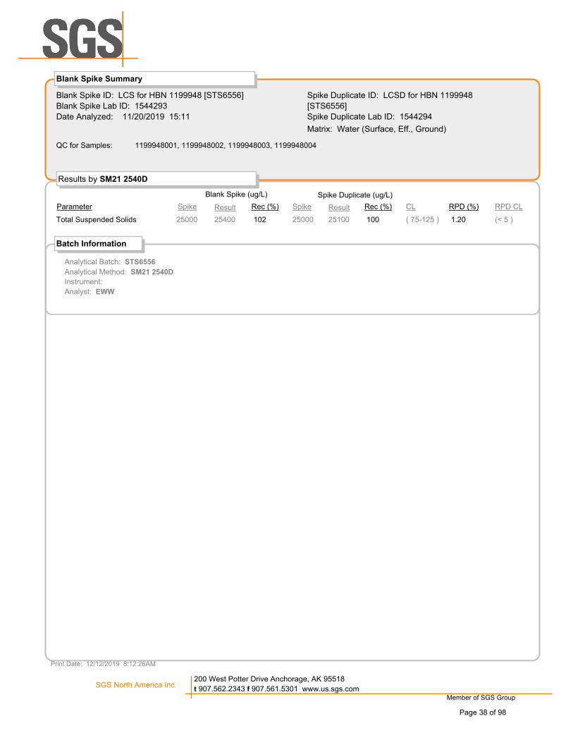
Blank Spike ID: LCS for HBN 1199948 [STS6556]
Blank Spike Lab ID: 1544293
Date Analyzed: 11/20/2019 15:11
Spike Duplicate ID: LCSD for HBN 1199948
[STS6556]
Spike Duplicate Lab ID: 1544294
Results by SM21 2540D
Blank Spike Summary
Matrix: Water (Surface, Eff., Ground)
Parameter Spike Rec (%) Spike Rec (%) RPD (%)CL
Blank Spike (ug/L)
RPD CL
Spike Duplicate (ug/L)
QC for Samples: 1199948001, 1199948002, 1199948003, 1199948004
Result Result
Total Suspended Solids 25000 102 25000 100 ( 75-125 ) (< 5 ) 1.2025400 25100
Batch Information
Analytical Batch: STS6556
Analytical Method: SM21 2540D
Instrument:
Analyst: EWW
Print Date: 12/12/2019 8:12:26AM
Member of SGS Group
SGS North America Inc.200 West Potter Drive Anchorage, AK 95518
t 907.562.2343 f 907.561.5301 www.us.sgs.com
Page 38 of 98

Blank ID: MB for HBN 1802403 [STS/6557]
Blank Lab ID: 1544358
QC for Samples:
1199948001, 1199948002, 1199948003, 1199948004
Matrix: Water (Surface, Eff., Ground)
Results by SM21 2540C
DL UnitsLOQ/CLResultsParameter
Method Blank
Total Dissolved Solids 10000 ug/L31005000U
Batch Information
Analytical Batch: STS6557
Analytical Method: SM21 2540C
Instrument:
Analyst: DMM
Analytical Date/Time: 11/20/2019 5:49:01PM
Print Date: 12/12/2019 8:12:30AM
Member of SGS Group
SGS North America Inc.200 West Potter Drive Anchorage, AK 95518
t 907.562.2343 f 907.561.5301 www.us.sgs.com
Page 39 of 98
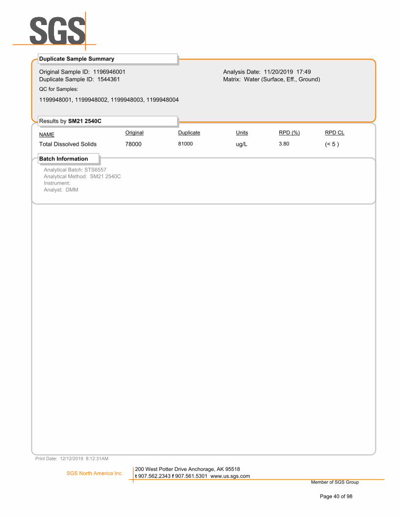
Original Sample ID: 1196946001
Duplicate Sample ID: 1544361
Analysis Date: 11/20/2019 17:49
Matrix: Water (Surface, Eff., Ground)
Results by SM21 2540C
Duplicate Sample Summary
QC for Samples:
RPD (%)DuplicateOriginalNAME Units RPD CL
1199948001, 1199948002, 1199948003, 1199948004
3.808100078000Total Dissolved Solids ug/L (< 5 )
Analytical Batch: STS6557
Analytical Method: SM21 2540C
Instrument:
Analyst: DMM
Batch Information
Print Date: 12/12/2019 8:12:31AM
Member of SGS Group
SGS North America Inc.200 West Potter Drive Anchorage, AK 95518
t 907.562.2343 f 907.561.5301 www.us.sgs.com
Page 40 of 98

Blank Spike ID: LCS for HBN 1199948 [STS6557]
Blank Spike Lab ID: 1544359
Date Analyzed: 11/20/2019 17:49
Spike Duplicate ID: LCSD for HBN 1199948
[STS6557]
Spike Duplicate Lab ID: 1544360
Results by SM21 2540C
Blank Spike Summary
Matrix: Water (Surface, Eff., Ground)
Parameter Spike Rec (%) Spike Rec (%) RPD (%)CL
Blank Spike (ug/L)
RPD CL
Spike Duplicate (ug/L)
QC for Samples: 1199948001, 1199948002, 1199948003, 1199948004
Result Result
Total Dissolved Solids 333000 86 333000 87 ( 75-125 ) (< 5 ) 1.40287000 291000
Batch Information
Analytical Batch: STS6557
Analytical Method: SM21 2540C
Instrument:
Analyst: DMM
Print Date: 12/12/2019 8:12:33AM
Member of SGS Group
SGS North America Inc.200 West Potter Drive Anchorage, AK 95518
t 907.562.2343 f 907.561.5301 www.us.sgs.com
Page 41 of 98

Blank ID: MB for HBN 1802553 [THOG/1311]
Blank Lab ID: 1544908
QC for Samples:
1199948001, 1199948002, 1199948003, 1199948004
Matrix: Water (Surface, Eff., Ground)
Results by EPA 1664B
DL UnitsLOQ/CLResultsParameter
Method Blank
Oil & Grease HEM 4000 ug/L10002000U
Batch Information
Analytical Batch: THOG1311
Analytical Method: EPA 1664B
Instrument:
Analyst: EWW
Analytical Date/Time: 11/26/2019 8:38:12AM
Print Date: 12/12/2019 8:12:35AM
Member of SGS Group
SGS North America Inc.200 West Potter Drive Anchorage, AK 95518
t 907.562.2343 f 907.561.5301 www.us.sgs.com
Page 42 of 98

Blank Spike ID: LCS for HBN 1199948 [THOG1311]
Blank Spike Lab ID: 1544909
Date Analyzed: 11/26/2019 08:38
Spike Duplicate ID: LCSD for HBN 1199948
[THOG1311]
Spike Duplicate Lab ID: 1544910
Results by EPA 1664B
Blank Spike Summary
Matrix: Water (Surface, Eff., Ground)
Parameter Spike Rec (%) Spike Rec (%) RPD (%)CL
Blank Spike (ug/L)
RPD CL
Spike Duplicate (ug/L)
QC for Samples: 1199948001, 1199948002, 1199948003, 1199948004
Result Result
Oil & Grease HEM 40000 81 40000 80 ( 78-114 ) (< 18 ) 1.6032500 32000
Batch Information
Analytical Batch: THOG1311
Analytical Method: EPA 1664B
Instrument:
Analyst: EWW
Print Date: 12/12/2019 8:12:38AM
Member of SGS Group
SGS North America Inc.200 West Potter Drive Anchorage, AK 95518
t 907.562.2343 f 907.561.5301 www.us.sgs.com
Page 43 of 98

Original Sample ID: 1544911
MS Sample ID: 1544964 MS
MSD Sample ID:
Analysis Date: 11/26/2019 8:38
Analysis Date: 11/26/2019 8:38
Analysis Date:
Matrix: Water (Surface, Eff., Ground)
Results by EPA 1664B
Matrix Spike (ug/L) Spike Duplicate (ug/L)
QC for Samples:
Parameter SpikeSample Rec (%) Spike Rec (%) CL RPD (%)
1199948001, 1199948002, 1199948003, 1199948004
Matrix Spike Summary
RPD CLResult Result
Oil & Grease HEM 449007640 84 78-11445200
Batch Information
Analytical Batch: THOG1311
Analytical Method: EPA 1664B
Instrument:
Analyst: EWW
Analytical Date/Time: 11/26/2019 8:38:12AM
Print Date: 12/12/2019 8:12:39AM
Member of SGS Group
SGS North America Inc.200 West Potter Drive Anchorage, AK 95518
t 907.562.2343 f 907.561.5301 www.us.sgs.com
Page 44 of 98

Blank ID: MB for HBN 1802620 [VXX/35282]
Blank Lab ID: 1545165
QC for Samples:
1199948001, 1199948002, 1199948003, 1199948004, 1199948005
Matrix: Water (Surface, Eff., Ground)
Results by AK101
DL UnitsLOQ/CLResultsParameter
Method Blank
Gasoline Range Organics 0.100 mg/L0.03100.0500U
Surrogates
4-Bromofluorobenzene (surr) 50-150 %82.4
Batch Information
Analytical Batch: VFC15049
Analytical Method: AK101
Instrument: Agilent 7890 PID/FID
Analyst: ST
Analytical Date/Time: 11/26/2019 10:51:00AM
Prep Batch: VXX35282
Prep Method: SW5030B
Prep Date/Time: 11/26/2019 8:00:00AM
Prep Initial Wt./Vol.: 5 mL
Prep Extract Vol: 5 mL
Print Date: 12/12/2019 8:12:41AM
Member of SGS Group
SGS North America Inc.200 West Potter Drive Anchorage, AK 95518
t 907.562.2343 f 907.561.5301 www.us.sgs.com
Page 45 of 98

Blank Spike ID: LCS for HBN 1199948 [VXX35282]
Blank Spike Lab ID: 1545168
Date Analyzed: 11/26/2019 11:43
Spike Duplicate ID: LCSD for HBN 1199948
[VXX35282]
Spike Duplicate Lab ID: 1545169
Results by AK101
Blank Spike Summary
Matrix: Water (Surface, Eff., Ground)
Parameter Spike Rec (%) Spike Rec (%) RPD (%)CL
Blank Spike (mg/L)
RPD CL
Spike Duplicate (mg/L)
QC for Samples: 1199948001, 1199948002, 1199948003, 1199948004, 1199948005
Result Result
Gasoline Range Organics 1.00 100 1.00 104 ( 60-120 ) (< 20 ) 3.301.00 1.04
Surrogates
4-Bromofluorobenzene (surr) 0.0500 94 0.0500 99 ( 50-150 ) 4.9094.3 99.1
Batch Information
Analytical Batch: VFC15049
Analytical Method: AK101
Instrument: Agilent 7890 PID/FID
Analyst: ST
Prep Batch: VXX35282
Prep Method: SW5030B
Prep Date/Time: 11/26/2019 08:00
Spike Init Wt./Vol.: 1.00 mg/L Extract Vol: 5 mL
Dupe Init Wt./Vol.: 1.00 mg/L Extract Vol: 5 mL
Print Date: 12/12/2019 8:12:44AM
Member of SGS Group
SGS North America Inc.200 West Potter Drive Anchorage, AK 95518
t 907.562.2343 f 907.561.5301 www.us.sgs.com
Page 46 of 98

Blank ID: MB for HBN 1802620 [VXX/35282]
Blank Lab ID: 1545165
QC for Samples:
1199948001, 1199948002, 1199948003, 1199948004, 1199948005
Matrix: Water (Surface, Eff., Ground)
Results by SW8021B
DL UnitsLOQ/CLResultsParameter
Method Blank
Benzene 0.500 ug/L0.1500.250U
Ethylbenzene 1.00 ug/L0.3100.500U
o-Xylene 1.00 ug/L0.3100.500U
P & M -Xylene 2.00 ug/L0.6201.00U
Toluene 1.00 ug/L0.3100.500U
Xylenes (total) 3.00 ug/L0.9301.50U
Surrogates
1,4-Difluorobenzene (surr) 77-115 %93.4
Batch Information
Analytical Batch: VFC15049
Analytical Method: SW8021B
Instrument: Agilent 7890 PID/FID
Analyst: ST
Analytical Date/Time: 11/26/2019 10:51:00AM
Prep Batch: VXX35282
Prep Method: SW5030B
Prep Date/Time: 11/26/2019 8:00:00AM
Prep Initial Wt./Vol.: 5 mL
Prep Extract Vol: 5 mL
Print Date: 12/12/2019 8:12:46AM
Member of SGS Group
SGS North America Inc.200 West Potter Drive Anchorage, AK 95518
t 907.562.2343 f 907.561.5301 www.us.sgs.com
Page 47 of 98

Blank Spike ID: LCS for HBN 1199948 [VXX35282]
Blank Spike Lab ID: 1545166
Date Analyzed: 11/26/2019 11:25
Spike Duplicate ID: LCSD for HBN 1199948
[VXX35282]
Spike Duplicate Lab ID: 1545167
Results by SW8021B
Blank Spike Summary
Matrix: Water (Surface, Eff., Ground)
Parameter Spike Rec (%) Spike Rec (%) RPD (%)CL
Blank Spike (ug/L)
RPD CL
Spike Duplicate (ug/L)
QC for Samples: 1199948001, 1199948002, 1199948003, 1199948004, 1199948005
Result Result
Benzene 100 101 100 102 ( 80-120 ) (< 20 ) 0.35101 102
Ethylbenzene 100 101 100 102 ( 75-125 ) (< 20 ) 0.55101 102
o-Xylene 100 100 100 100 ( 80-120 ) (< 20 ) 0.6499.5 100
P & M -Xylene 200 101 200 101 ( 75-130 ) (< 20 ) 0.15202 203
Toluene 100 100 100 102 ( 75-120 ) (< 20 ) 1.70100 102
Xylenes (total) 300 101 300 101 ( 79-121 ) (< 20 ) 0.31302 303
Surrogates
1,4-Difluorobenzene (surr) 50 100 50 102 ( 77-115 ) 2.10100 102
Batch Information
Analytical Batch: VFC15049
Analytical Method: SW8021B
Instrument: Agilent 7890 PID/FID
Analyst: ST
Prep Batch: VXX35282
Prep Method: SW5030B
Prep Date/Time: 11/26/2019 08:00
Spike Init Wt./Vol.: 100 ug/L Extract Vol: 5 mL
Dupe Init Wt./Vol.: 100 ug/L Extract Vol: 5 mL
Print Date: 12/12/2019 8:12:48AM
Member of SGS Group
SGS North America Inc.200 West Potter Drive Anchorage, AK 95518
t 907.562.2343 f 907.561.5301 www.us.sgs.com
Page 48 of 98

Blank ID: MB for HBN 1802465 [WAT/11457]
Blank Lab ID: 1544602
QC for Samples:
1199948001, 1199948002, 1199948003, 1199948004
Matrix: Drinking Water
Results by SM23 4500S D
DL UnitsLOQ/CLResultsParameter
Method Blank
Sulfide 100 ug/L31.050.0U
Batch Information
Analytical Batch: WAT11457
Analytical Method: SM23 4500S D
Instrument:
Analyst: EWW
Analytical Date/Time: 11/21/2019 12:25:00PM
Print Date: 12/12/2019 8:12:51AM
Member of SGS Group
SGS North America Inc.200 West Potter Drive Anchorage, AK 95518
t 907.562.2343 f 907.561.5301 www.us.sgs.com
Page 49 of 98

Blank Spike ID: LCS for HBN 1199948 [WAT11457]
Blank Spike Lab ID: 1544603
Date Analyzed: 11/21/2019 12:25
Results by SM23 4500S D
Blank Spike Summary
Matrix: Drinking Water
Parameter Spike Rec (%) CL
Blank Spike (ug/L)
QC for Samples: 1199948001, 1199948002, 1199948003, 1199948004
Result
Sulfide 499 108 ( 75-125 )540
Batch Information
Analytical Batch: WAT11457
Analytical Method: SM23 4500S D
Instrument:
Analyst: EWW
Print Date: 12/12/2019 8:12:53AM
Member of SGS Group
SGS North America Inc.200 West Potter Drive Anchorage, AK 95518
t 907.562.2343 f 907.561.5301 www.us.sgs.com
Page 50 of 98

Original Sample ID: 1199948001
MS Sample ID: 1544604 MS
MSD Sample ID: 1544605 MSD
Analysis Date: 11/21/2019 12:25
Analysis Date: 11/21/2019 12:25
Analysis Date: 11/21/2019 12:25
Matrix: Water (Surface, Eff., Ground)
Results by SM23 4500S D
Matrix Spike (ug/L) Spike Duplicate (ug/L)
QC for Samples:
Parameter SpikeSample Rec (%) Spike Rec (%) CL RPD (%)
1199948001, 1199948002, 1199948003, 1199948004
Matrix Spike Summary
RPD CLResult Result
Sulfide 49950.0U 114 499 116 75-125 1.70 (< 25 )570 580
Batch Information
Analytical Batch: WAT11457
Analytical Method: SM23 4500S D
Instrument:
Analyst: EWW
Analytical Date/Time: 11/21/2019 12:25:00PM
Print Date: 12/12/2019 8:12:55AM
Member of SGS Group
SGS North America Inc.200 West Potter Drive Anchorage, AK 95518
t 907.562.2343 f 907.561.5301 www.us.sgs.com
Page 51 of 98
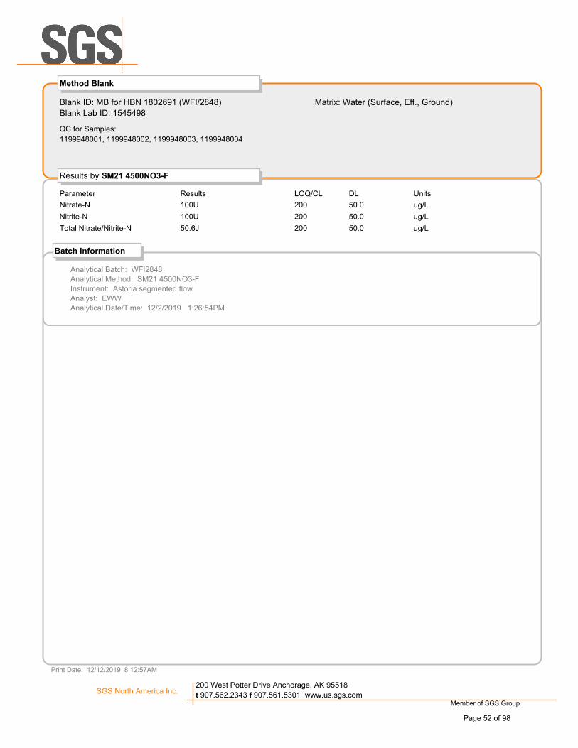
Blank ID: MB for HBN 1802691 (WFI/2848)
Blank Lab ID: 1545498
QC for Samples:
1199948001, 1199948002, 1199948003, 1199948004
Matrix: Water (Surface, Eff., Ground)
Results by SM21 4500NO3-F
DL UnitsLOQ/CLResultsParameter
Method Blank
Nitrate-N 200 ug/L50.0100U
Nitrite-N 200 ug/L50.0100U
Total Nitrate/Nitrite-N 200 ug/L50.050.6J
Batch Information
Analytical Batch: WFI2848
Analytical Method: SM21 4500NO3-F
Instrument: Astoria segmented flow
Analyst: EWW
Analytical Date/Time: 12/2/2019 1:26:54PM
Print Date: 12/12/2019 8:12:57AM
Member of SGS Group
SGS North America Inc.200 West Potter Drive Anchorage, AK 95518
t 907.562.2343 f 907.561.5301 www.us.sgs.com
Page 52 of 98

Blank ID: MB for HBN 1802691 (WFI/2848)
Blank Lab ID: 1545500
QC for Samples:
1199948001, 1199948002, 1199948003, 1199948004
Matrix: Water (Surface, Eff., Ground)
Results by SM21 4500NO3-F
DL UnitsLOQ/CLResultsParameter
Method Blank
Nitrate-N 200 ug/L50.0100U
Nitrite-N 200 ug/L50.0100U
Total Nitrate/Nitrite-N 200 ug/L50.0100U
Batch Information
Analytical Batch: WFI2848
Analytical Method: SM21 4500NO3-F
Instrument: Astoria segmented flow
Analyst: EWW
Analytical Date/Time: 12/2/2019 2:12:24PM
Print Date: 12/12/2019 8:12:57AM
Member of SGS Group
SGS North America Inc.200 West Potter Drive Anchorage, AK 95518
t 907.562.2343 f 907.561.5301 www.us.sgs.com
Page 53 of 98

Blank ID: MB for HBN 1802691 (WFI/2848)
Blank Lab ID: 1545502
QC for Samples:
Matrix: Water (Surface, Eff., Ground)
Results by SM21 4500NO3-F
DL UnitsLOQ/CLResultsParameter
Method Blank
Nitrate-N 200 ug/L50.0100U
Nitrite-N 200 ug/L50.0100U
Total Nitrate/Nitrite-N 200 ug/L50.052.2J
Batch Information
Analytical Batch: WFI2848
Analytical Method: SM21 4500NO3-F
Instrument: Astoria segmented flow
Analyst: EWW
Analytical Date/Time: 12/2/2019 2:57:53PM
Print Date: 12/12/2019 8:12:57AM
Member of SGS Group
SGS North America Inc.200 West Potter Drive Anchorage, AK 95518
t 907.562.2343 f 907.561.5301 www.us.sgs.com
Page 54 of 98

Blank Spike ID: LCS for HBN 1199948 [WFI2848]
Blank Spike Lab ID: 1545497
Date Analyzed: 12/02/2019 13:25
Results by SM21 4500NO3-F
Blank Spike Summary
Matrix: Water (Surface, Eff., Ground)
Parameter Spike Rec (%) CL
Blank Spike (ug/L)
QC for Samples: 1199948001, 1199948002, 1199948003, 1199948004
Result
Nitrate-N 2500 100 ( 70-130 )2490
Nitrite-N 2500 101 ( 90-110 )2510
Total Nitrate/Nitrite-N 5000 100 ( 90-110 )5000
Batch Information
Analytical Batch: WFI2848
Analytical Method: SM21 4500NO3-F
Instrument: Astoria segmented flow
Analyst: EWW
Print Date: 12/12/2019 8:13:00AM
Member of SGS Group
SGS North America Inc.200 West Potter Drive Anchorage, AK 95518
t 907.562.2343 f 907.561.5301 www.us.sgs.com
Page 55 of 98

Blank Spike ID: LCS for HBN 1199948 [WFI2848]
Blank Spike Lab ID: 1545499
Date Analyzed: 12/02/2019 14:10
Results by SM21 4500NO3-F
Blank Spike Summary
Matrix: Water (Surface, Eff., Ground)
Parameter Spike Rec (%) CL
Blank Spike (ug/L)
QC for Samples: 1199948001, 1199948002, 1199948003, 1199948004
Result
Nitrate-N 2500 96 ( 70-130 )2400
Nitrite-N 2500 99 ( 90-110 )2460
Total Nitrate/Nitrite-N 5000 97 ( 90-110 )4860
Batch Information
Analytical Batch: WFI2848
Analytical Method: SM21 4500NO3-F
Instrument: Astoria segmented flow
Analyst: EWW
Print Date: 12/12/2019 8:13:00AM
Member of SGS Group
SGS North America Inc.200 West Potter Drive Anchorage, AK 95518
t 907.562.2343 f 907.561.5301 www.us.sgs.com
Page 56 of 98

Blank Spike ID: LCS for HBN 1199948 [WFI2848]
Blank Spike Lab ID: 1545501
Date Analyzed: 12/02/2019 14:56
Results by SM21 4500NO3-F
Blank Spike Summary
Matrix: Water (Surface, Eff., Ground)
Parameter Spike Rec (%) CL
Blank Spike (ug/L)
QC for Samples:
Result
Nitrate-N 2500 89 ( 70-130 )2230
Nitrite-N 2500 98 ( 90-110 )2450
Total Nitrate/Nitrite-N 5000 94 ( 90-110 )4680
Batch Information
Analytical Batch: WFI2848
Analytical Method: SM21 4500NO3-F
Instrument: Astoria segmented flow
Analyst: EWW
Print Date: 12/12/2019 8:13:00AM
Member of SGS Group
SGS North America Inc.200 West Potter Drive Anchorage, AK 95518
t 907.562.2343 f 907.561.5301 www.us.sgs.com
Page 57 of 98
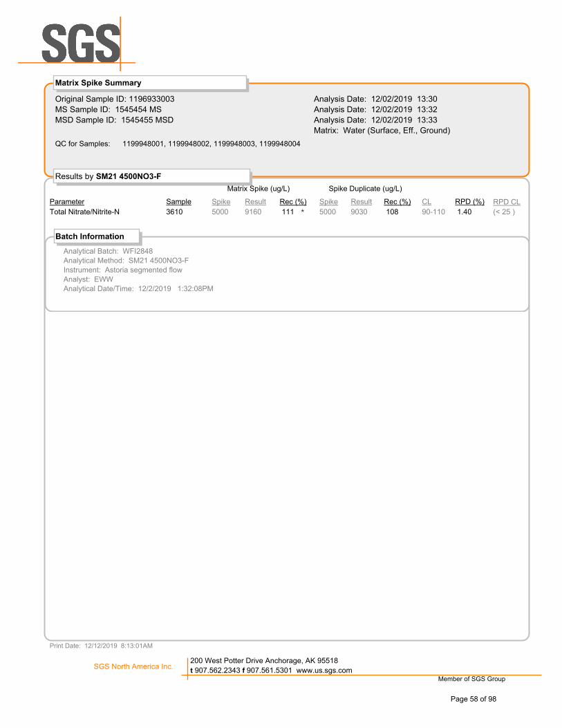
Original Sample ID: 1196933003
MS Sample ID: 1545454 MS
MSD Sample ID: 1545455 MSD
Analysis Date: 12/02/2019 13:30
Analysis Date: 12/02/2019 13:32
Analysis Date: 12/02/2019 13:33
Matrix: Water (Surface, Eff., Ground)
Results by SM21 4500NO3-F
Matrix Spike (ug/L) Spike Duplicate (ug/L)
QC for Samples:
Parameter SpikeSample Rec (%) Spike Rec (%) CL RPD (%)
1199948001, 1199948002, 1199948003, 1199948004
Matrix Spike Summary
RPD CLResult Result
Total Nitrate/Nitrite-N 50003610 111 5000 108 90-110 1.40 (< 25 )*9160 9030
Batch Information
Analytical Batch: WFI2848
Analytical Method: SM21 4500NO3-F
Instrument: Astoria segmented flow
Analyst: EWW
Analytical Date/Time: 12/2/2019 1:32:08PM
Print Date: 12/12/2019 8:13:01AM
Member of SGS Group
SGS North America Inc.200 West Potter Drive Anchorage, AK 95518
t 907.562.2343 f 907.561.5301 www.us.sgs.com
Page 58 of 98

Original Sample ID: 1196958001
MS Sample ID: 1545456 MS
MSD Sample ID: 1545457 MSD
Analysis Date: 12/02/2019 14:15
Analysis Date: 12/02/2019 14:17
Analysis Date: 12/02/2019 14:19
Matrix: Drinking Water
Results by SM21 4500NO3-F
Matrix Spike (ug/L) Spike Duplicate (ug/L)
QC for Samples:
Parameter SpikeSample Rec (%) Spike Rec (%) CL RPD (%)
1199948001, 1199948002, 1199948003, 1199948004
Matrix Spike Summary
RPD CLResult Result
Total Nitrate/Nitrite-N 5000200U 117 5000 118 90-110 0.68 (< 25 )* *5850 5890
Batch Information
Analytical Batch: WFI2848
Analytical Method: SM21 4500NO3-F
Instrument: Astoria segmented flow
Analyst: EWW
Analytical Date/Time: 12/2/2019 2:17:39PM
Print Date: 12/12/2019 8:13:01AM
Member of SGS Group
SGS North America Inc.200 West Potter Drive Anchorage, AK 95518
t 907.562.2343 f 907.561.5301 www.us.sgs.com
Page 59 of 98

Original Sample ID: 1197002001
MS Sample ID: 1545458 MS
MSD Sample ID: 1545459 MSD
Analysis Date: 12/02/2019 13:19
Analysis Date: 12/02/2019 13:21
Analysis Date: 12/02/2019 13:23
Matrix: Drinking Water
Results by SM21 4500NO3-F
Matrix Spike (ug/L) Spike Duplicate (ug/L)
QC for Samples:
Parameter SpikeSample Rec (%) Spike Rec (%) CL RPD (%)
Matrix Spike Summary
RPD CLResult Result
Total Nitrate/Nitrite-N 200009490 103 20000 99 90-110 2.50 (< 25 )30100 29300
Batch Information
Analytical Batch: WFI2848
Analytical Method: SM21 4500NO3-F
Instrument: Astoria segmented flow
Analyst: EWW
Analytical Date/Time: 12/2/2019 1:21:39PM
Print Date: 12/12/2019 8:13:01AM
Member of SGS Group
SGS North America Inc.200 West Potter Drive Anchorage, AK 95518
t 907.562.2343 f 907.561.5301 www.us.sgs.com
Page 60 of 98

Blank ID: MB for HBN 1802754 [WTC/2974]
Blank Lab ID: 1545700
QC for Samples:
1199948001, 1199948002, 1199948003, 1199948004
Matrix: Water (Surface, Eff., Ground)
Results by SM 5310B
DL UnitsLOQ/CLResultsParameter
Method Blank
Total Organic Carbon 1000 ug/L400500U
Batch Information
Analytical Batch: WTC2974
Analytical Method: SM 5310B
Instrument: TOC Analyzer
Analyst: BMZ
Analytical Date/Time: 12/3/2019 11:44:56AM
Print Date: 12/12/2019 8:13:03AM
Member of SGS Group
SGS North America Inc.200 West Potter Drive Anchorage, AK 95518
t 907.562.2343 f 907.561.5301 www.us.sgs.com
Page 61 of 98

Blank Spike ID: LCS for HBN 1199948 [WTC2974]
Blank Spike Lab ID: 1545698
Date Analyzed: 12/03/2019 11:29
Results by SM 5310B
Blank Spike Summary
Matrix: Water (Surface, Eff., Ground)
Parameter Spike Rec (%) CL
Blank Spike (ug/L)
QC for Samples: 1199948001, 1199948002, 1199948003, 1199948004
Result
Total Organic Carbon 75000 106 ( 80-120 )79400
Batch Information
Analytical Batch: WTC2974
Analytical Method: SM 5310B
Instrument: TOC Analyzer
Analyst: BMZ
Print Date: 12/12/2019 8:13:06AM
Member of SGS Group
SGS North America Inc.200 West Potter Drive Anchorage, AK 95518
t 907.562.2343 f 907.561.5301 www.us.sgs.com
Page 62 of 98

Original Sample ID: 1196939001
MS Sample ID: 1545706 MS
MSD Sample ID: 1545707 MSD
Analysis Date: 12/03/2019 12:15
Analysis Date: 12/03/2019 12:31
Analysis Date: 12/03/2019 12:46
Matrix: Drinking Water
Results by SM 5310B
Matrix Spike (ug/L) Spike Duplicate (ug/L)
QC for Samples:
Parameter SpikeSample Rec (%) Spike Rec (%) CL RPD (%)
1199948001, 1199948002, 1199948003, 1199948004
Matrix Spike Summary
RPD CLResult Result
Total Organic Carbon 100001000U 94 10000 107 75-125 13.50 (< 25 )9370 10700
Batch Information
Analytical Batch: WTC2974
Analytical Method: SM 5310B
Instrument: TOC Analyzer
Analyst: BMZ
Analytical Date/Time: 12/3/2019 12:31:30PM
Print Date: 12/12/2019 8:13:07AM
Member of SGS Group
SGS North America Inc.200 West Potter Drive Anchorage, AK 95518
t 907.562.2343 f 907.561.5301 www.us.sgs.com
Page 63 of 98

Original Sample ID: 1196838001
Duplicate Sample ID: 1544659
Analysis Date: 11/21/2019 12:29
Matrix: Drinking Water
Results by SM21 4500-H B
Duplicate Sample Summary
QC for Samples:
RPD (%)DuplicateOriginalNAME Units RPD CL
1199948001, 1199948002, 1199948003, 1199948004
1.307.707.6pH pH units (< 5 )
Analytical Batch: WTI5311
Analytical Method: SM21 4500-H B
Instrument: Titration
Analyst: EWW
Batch Information
Print Date: 12/12/2019 8:13:09AM
Member of SGS Group
SGS North America Inc.200 West Potter Drive Anchorage, AK 95518
t 907.562.2343 f 907.561.5301 www.us.sgs.com
Page 64 of 98

Original Sample ID: 1196924002
Duplicate Sample ID: 1544660
Analysis Date: 11/21/2019 13:51
Matrix: Water (Surface, Eff., Ground)
Results by SM21 4500-H B
Duplicate Sample Summary
QC for Samples:
RPD (%)DuplicateOriginalNAME Units RPD CL
1199948001, 1199948002, 1199948003, 1199948004
1.406.907.0pH pH units (< 5 )
Analytical Batch: WTI5311
Analytical Method: SM21 4500-H B
Instrument: Titration
Analyst: EWW
Batch Information
Print Date: 12/12/2019 8:13:09AM
Member of SGS Group
SGS North America Inc.200 West Potter Drive Anchorage, AK 95518
t 907.562.2343 f 907.561.5301 www.us.sgs.com
Page 65 of 98

Original Sample ID: 1544662
Duplicate Sample ID: 1544663
Analysis Date: 11/21/2019 17:26
Matrix: Water (Surface, Eff., Ground)
Results by SM21 4500-H B
Duplicate Sample Summary
QC for Samples:
RPD (%)DuplicateOriginalNAME Units RPD CL
1199948001, 1199948002, 1199948003, 1199948004
0.009.109.1pH pH units (< 5 )
Analytical Batch: WTI5311
Analytical Method: SM21 4500-H B
Instrument: Titration
Analyst: EWW
Batch Information
Print Date: 12/12/2019 8:13:09AM
Member of SGS Group
SGS North America Inc.200 West Potter Drive Anchorage, AK 95518
t 907.562.2343 f 907.561.5301 www.us.sgs.com
Page 66 of 98

Blank Spike ID: LCS for HBN 1199948 [WTI5311]
Blank Spike Lab ID: 1544656
Date Analyzed: 11/21/2019 11:00
Results by SM21 4500-H B
Blank Spike Summary
Matrix: Water (Surface, Eff., Ground)
Parameter Spike Rec (%) CL
Blank Spike (pH units)
QC for Samples: 1199948001, 1199948002, 1199948003, 1199948004
Result
pH 6.99 100 ( 99-101 )7.00
Batch Information
Analytical Batch: WTI5311
Analytical Method: SM21 4500-H B
Instrument: Titration
Analyst: EWW
Print Date: 12/12/2019 8:13:11AM
Member of SGS Group
SGS North America Inc.200 West Potter Drive Anchorage, AK 95518
t 907.562.2343 f 907.561.5301 www.us.sgs.com
Page 67 of 98

Blank Spike ID: LCS for HBN 1199948 [WTI5311]
Blank Spike Lab ID: 1544661
Date Analyzed: 11/21/2019 14:57
Results by SM21 4500-H B
Blank Spike Summary
Matrix: Water (Surface, Eff., Ground)
Parameter Spike Rec (%) CL
Blank Spike (pH units)
QC for Samples: 1199948001, 1199948002, 1199948003, 1199948004
Result
pH 6.99 100 ( 99-101 )6.97
Batch Information
Analytical Batch: WTI5311
Analytical Method: SM21 4500-H B
Instrument: Titration
Analyst: EWW
Print Date: 12/12/2019 8:13:11AM
Member of SGS Group
SGS North America Inc.200 West Potter Drive Anchorage, AK 95518
t 907.562.2343 f 907.561.5301 www.us.sgs.com
Page 68 of 98

Blank ID: MB for HBN 1802483 [WTI/5312]
Blank Lab ID: 1544666
QC for Samples:
1199948001, 1199948002, 1199948003, 1199948004
Matrix: Water (Surface, Eff., Ground)
Results by SM21 2510B
DL UnitsLOQ/CLResultsParameter
Method Blank
Conductivity 1.00 umhos/cm0.4771.10*
Batch Information
Analytical Batch: WTI5312
Analytical Method: SM21 2510B
Instrument: Titration
Analyst: EWW
Analytical Date/Time: 11/21/2019 11:47:28AM
Print Date: 12/12/2019 8:13:14AM
Member of SGS Group
SGS North America Inc.200 West Potter Drive Anchorage, AK 95518
t 907.562.2343 f 907.561.5301 www.us.sgs.com
Page 69 of 98

Original Sample ID: 1196838001
Duplicate Sample ID: 1544667
Analysis Date: 11/21/2019 12:29
Matrix: Drinking Water
Results by SM21 2510B
Duplicate Sample Summary
QC for Samples:
RPD (%)DuplicateOriginalNAME Units RPD CL
1199948001, 1199948002, 1199948003, 1199948004
0.15337336Conductivity umhos/cm (< 20 )
Analytical Batch: WTI5312
Analytical Method: SM21 2510B
Instrument: Titration
Analyst: EWW
Batch Information
Print Date: 12/12/2019 8:13:15AM
Member of SGS Group
SGS North America Inc.200 West Potter Drive Anchorage, AK 95518
t 907.562.2343 f 907.561.5301 www.us.sgs.com
Page 70 of 98

Blank Spike ID: LCS for HBN 1199948 [WTI5312]
Blank Spike Lab ID: 1544664
Date Analyzed: 11/21/2019 10:01
Results by SM21 2510B
Blank Spike Summary
Matrix: Water (Surface, Eff., Ground)
Parameter Spike Rec (%) CL
Blank Spike (umhos/cm)
QC for Samples: 1199948001, 1199948002, 1199948003, 1199948004
Result
Conductivity 10.3 106 ( 90-110 )10.9
Batch Information
Analytical Batch: WTI5312
Analytical Method: SM21 2510B
Instrument: Titration
Analyst: EWW
Print Date: 12/12/2019 8:13:17AM
Member of SGS Group
SGS North America Inc.200 West Potter Drive Anchorage, AK 95518
t 907.562.2343 f 907.561.5301 www.us.sgs.com
Page 71 of 98

Blank ID: MB for HBN 1802833 [WXX/13134]
Blank Lab ID: 1545950
QC for Samples:
1199948001, 1199948002, 1199948003, 1199948004
Matrix: Water (Surface, Eff., Ground)
Results by SM21 4500-N D
DL UnitsLOQ/CLResultsParameter
Method Blank
Total Kjeldahl Nitrogen 1000 ug/L310500U
Batch Information
Analytical Batch: WDA4697
Analytical Method: SM21 4500-N D
Instrument: Discrete Analyzer 2
Analyst: DMM
Analytical Date/Time: 12/4/2019 5:07:26PM
Prep Batch: WXX13134
Prep Method: METHOD
Prep Date/Time: 12/4/2019 10:52:00AM
Prep Initial Wt./Vol.: 25 mL
Prep Extract Vol: 25 mL
Print Date: 12/12/2019 8:13:19AM
Member of SGS Group
SGS North America Inc.200 West Potter Drive Anchorage, AK 95518
t 907.562.2343 f 907.561.5301 www.us.sgs.com
Page 72 of 98

Blank Spike ID: LCS for HBN 1199948 [WXX13134]
Blank Spike Lab ID: 1545951
Date Analyzed: 12/04/2019 17:08
Spike Duplicate ID: LCSD for HBN 1199948
[WXX13134]
Spike Duplicate Lab ID: 1545952
Results by SM21 4500-N D
Blank Spike Summary
Matrix: Water (Surface, Eff., Ground)
Parameter Spike Rec (%) Spike Rec (%) RPD (%)CL
Blank Spike (ug/L)
RPD CL
Spike Duplicate (ug/L)
QC for Samples: 1199948001, 1199948002, 1199948003, 1199948004
Result Result
Total Kjeldahl Nitrogen 4000 93 4000 98 ( 75-125 ) (< 25 ) 4.403730 3900
Batch Information
Analytical Batch: WDA4697
Analytical Method: SM21 4500-N D
Instrument: Discrete Analyzer 2
Analyst: DMM
Prep Batch: WXX13134
Prep Method: METHOD
Prep Date/Time: 12/04/2019 10:52
Spike Init Wt./Vol.: 4000 ug/L Extract Vol: 25 mL
Dupe Init Wt./Vol.: 4000 ug/L Extract Vol: 25 mL
Print Date: 12/12/2019 8:13:21AM
Member of SGS Group
SGS North America Inc.200 West Potter Drive Anchorage, AK 95518
t 907.562.2343 f 907.561.5301 www.us.sgs.com
Page 73 of 98

Original Sample ID: 1198801012
MS Sample ID: 1545948 MS
MSD Sample ID: 1545949 MSD
Analysis Date: 12/04/2019 17:11
Analysis Date: 12/04/2019 17:15
Analysis Date: 12/04/2019 17:16
Matrix: Water (Surface, Eff., Ground)
Results by SM21 4500-N D
Matrix Spike (ug/L) Spike Duplicate (ug/L)
QC for Samples:
Parameter SpikeSample Rec (%) Spike Rec (%) CL RPD (%)
1199948001, 1199948002, 1199948003, 1199948004
Matrix Spike Summary
RPD CLResult Result
Total Kjeldahl Nitrogen 40001000U 92 4000 99 75-125 7.30 (< 25 )3670 3940
Batch Information
Prep Batch: WXX13134
Prep Method: Distillation TKN by Phenate (W)
Prep Date/Time: 12/4/2019 10:52:00AM
Prep Initial Wt./Vol.: 25.00mL
Prep Extract Vol: 25.00mL
Analytical Batch: WDA4697
Analytical Method: SM21 4500-N D
Instrument: Discrete Analyzer 2
Analyst: DMM
Analytical Date/Time: 12/4/2019 5:15:13PM
Print Date: 12/12/2019 8:13:23AM
Member of SGS Group
SGS North America Inc.200 West Potter Drive Anchorage, AK 95518
t 907.562.2343 f 907.561.5301 www.us.sgs.com
Page 74 of 98

Blank ID: MB for HBN 1802910 [WXX/13139]
Blank Lab ID: 1546353
QC for Samples:
1199948001, 1199948002, 1199948003, 1199948004
Matrix: Water (Surface, Eff., Ground)
Results by EPA 300.0
DL UnitsLOQ/CLResultsParameter
Method Blank
Chloride 200 ug/L50.0100U
Fluoride 200 ug/L50.0100U
Sulfate 200 ug/L50.0100U
Batch Information
Analytical Batch: WIC6002
Analytical Method: EPA 300.0
Instrument: 930 Metrohm compact IC flex
Analyst: DMM
Analytical Date/Time: 12/9/2019 6:04:17PM
Prep Batch: WXX13139
Prep Method: METHOD
Prep Date/Time: 12/9/2019 10:45:00AM
Prep Initial Wt./Vol.: 10 mL
Prep Extract Vol: 10 mL
Print Date: 12/12/2019 8:13:25AM
Member of SGS Group
SGS North America Inc.200 West Potter Drive Anchorage, AK 95518
t 907.562.2343 f 907.561.5301 www.us.sgs.com
Page 75 of 98

Blank Spike ID: LCS for HBN 1199948 [WXX13139]
Blank Spike Lab ID: 1546354
Date Analyzed: 12/09/2019 18:25
Results by EPA 300.0
Blank Spike Summary
Matrix: Water (Surface, Eff., Ground)
Parameter Spike Rec (%) CL
Blank Spike (ug/L)
QC for Samples: 1199948001, 1199948002, 1199948003, 1199948004
Result
Chloride 5000 108 ( 90-110 )5390
Fluoride 5000 100 ( 90-110 )5010
Sulfate 5000 105 ( 90-110 )5260
Batch Information
Analytical Batch: WIC6002
Analytical Method: EPA 300.0
Instrument: 930 Metrohm compact IC flex
Analyst: DMM
Prep Batch: WXX13139
Prep Method: METHOD
Prep Date/Time: 12/09/2019 10:45
Spike Init Wt./Vol.: 5000 ug/L Extract Vol: 10 mL
Dupe Init Wt./Vol.: Extract Vol:
Print Date: 12/12/2019 8:13:28AM
Member of SGS Group
SGS North America Inc.200 West Potter Drive Anchorage, AK 95518
t 907.562.2343 f 907.561.5301 www.us.sgs.com
Page 76 of 98

Original Sample ID: 1546357
MS Sample ID: 1546358 MS
MSD Sample ID:
Analysis Date: 12/09/2019 19:03
Analysis Date: 12/09/2019 19:22
Analysis Date:
Matrix: Water (Surface, Eff., Ground)
Results by EPA 300.0
Matrix Spike (ug/L) Spike Duplicate (ug/L)
QC for Samples:
Parameter SpikeSample Rec (%) Spike Rec (%) CL RPD (%)
1199948001, 1199948002, 1199948003, 1199948004
Matrix Spike Summary
RPD CLResult Result
Chloride 50003920 99 90-1108860
Fluoride 5000126J 99 90-1105050
Sulfate 50001360 99 90-1106310
Batch Information
Prep Batch: WXX13139
Prep Method: EPA 300.0 Extraction Waters/Liquids
Prep Date/Time: 12/9/2019 10:45:00AM
Prep Initial Wt./Vol.: 10.00mL
Prep Extract Vol: 10.00mL
Analytical Batch: WIC6002
Analytical Method: EPA 300.0
Instrument: 930 Metrohm compact IC flex
Analyst: DMM
Analytical Date/Time: 12/9/2019 7:22:05PM
Print Date: 12/12/2019 8:13:29AM
Member of SGS Group
SGS North America Inc.200 West Potter Drive Anchorage, AK 95518
t 907.562.2343 f 907.561.5301 www.us.sgs.com
Page 77 of 98

Original Sample ID: 1546356
MS Sample ID: 1546359 MS
MSD Sample ID:
Analysis Date: 12/09/2019 23:48
Analysis Date: 12/10/2019 0:06
Analysis Date:
Matrix: Water (Surface, Eff., Ground)
Results by EPA 300.0
Matrix Spike (ug/L) Spike Duplicate (ug/L)
QC for Samples:
Parameter SpikeSample Rec (%) Spike Rec (%) CL RPD (%)
1199948001, 1199948002, 1199948003, 1199948004
Matrix Spike Summary
RPD CLResult Result
Chloride 500015400 81 90-110*19400
Fluoride 500094.0J 95 90-1104820
Sulfate 50004820 92 90-1109410
Batch Information
Prep Batch: WXX13139
Prep Method: EPA 300.0 Extraction Waters/Liquids
Prep Date/Time: 12/9/2019 10:45:00AM
Prep Initial Wt./Vol.: 10.00mL
Prep Extract Vol: 10.00mL
Analytical Batch: WIC6002
Analytical Method: EPA 300.0
Instrument: 930 Metrohm compact IC flex
Analyst: DMM
Analytical Date/Time: 12/10/2019 12:06:59AM
Print Date: 12/12/2019 8:13:29AM
Member of SGS Group
SGS North America Inc.200 West Potter Drive Anchorage, AK 95518
t 907.562.2343 f 907.561.5301 www.us.sgs.com
Page 78 of 98
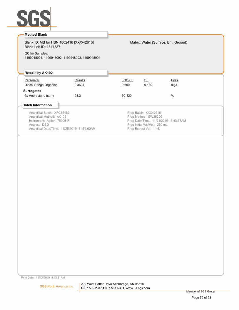
Blank ID: MB for HBN 1802416 [XXX/42616]
Blank Lab ID: 1544387
QC for Samples:
1199948001, 1199948002, 1199948003, 1199948004
Matrix: Water (Surface, Eff., Ground)
Results by AK102
DL UnitsLOQ/CLResultsParameter
Method Blank
Diesel Range Organics 0.600 mg/L0.1800.360J
Surrogates
5a Androstane (surr) 60-120 %93.3
Batch Information
Analytical Batch: XFC15482
Analytical Method: AK102
Instrument: Agilent 7890B F
Analyst: DSD
Analytical Date/Time: 11/25/2019 11:52:00AM
Prep Batch: XXX42616
Prep Method: SW3520C
Prep Date/Time: 11/21/2019 9:43:37AM
Prep Initial Wt./Vol.: 250 mL
Prep Extract Vol: 1 mL
Print Date: 12/12/2019 8:13:31AM
Member of SGS Group
SGS North America Inc.200 West Potter Drive Anchorage, AK 95518
t 907.562.2343 f 907.561.5301 www.us.sgs.com
Page 79 of 98

Blank Spike ID: LCS for HBN 1199948 [XXX42616]
Blank Spike Lab ID: 1544388
Date Analyzed: 11/25/2019 12:11
Spike Duplicate ID: LCSD for HBN 1199948
[XXX42616]
Spike Duplicate Lab ID: 1544389
Results by AK102
Blank Spike Summary
Matrix: Water (Surface, Eff., Ground)
Parameter Spike Rec (%) Spike Rec (%) RPD (%)CL
Blank Spike (mg/L)
RPD CL
Spike Duplicate (mg/L)
QC for Samples: 1199948001, 1199948002, 1199948003, 1199948004
Result Result
Diesel Range Organics 20 93 20 93 ( 75-125 ) (< 20 ) 0.3218.6 18.5
Surrogates
5a Androstane (surr) 0.4 99 0.4 100 ( 60-120 ) 0.9198.7 99.6
Batch Information
Analytical Batch: XFC15482
Analytical Method: AK102
Instrument: Agilent 7890B F
Analyst: DSD
Prep Batch: XXX42616
Prep Method: SW3520C
Prep Date/Time: 11/21/2019 09:43
Spike Init Wt./Vol.: 20 mg/L Extract Vol: 1 mL
Dupe Init Wt./Vol.: 20 mg/L Extract Vol: 1 mL
Print Date: 12/12/2019 8:13:34AM
Member of SGS Group
SGS North America Inc.200 West Potter Drive Anchorage, AK 95518
t 907.562.2343 f 907.561.5301 www.us.sgs.com
Page 80 of 98

Blank ID: MB for HBN 1802416 [XXX/42616]
Blank Lab ID: 1544387
QC for Samples:
1199948001, 1199948002, 1199948003, 1199948004
Matrix: Water (Surface, Eff., Ground)
Results by AK103
DL UnitsLOQ/CLResultsParameter
Method Blank
Residual Range Organics 0.500 mg/L0.1500.162J
Surrogates
n-Triacontane-d62 (surr) 60-120 %90
Batch Information
Analytical Batch: XFC15482
Analytical Method: AK103
Instrument: Agilent 7890B F
Analyst: DSD
Analytical Date/Time: 11/25/2019 11:52:00AM
Prep Batch: XXX42616
Prep Method: SW3520C
Prep Date/Time: 11/21/2019 9:43:37AM
Prep Initial Wt./Vol.: 250 mL
Prep Extract Vol: 1 mL
Print Date: 12/12/2019 8:13:37AM
Member of SGS Group
SGS North America Inc.200 West Potter Drive Anchorage, AK 95518
t 907.562.2343 f 907.561.5301 www.us.sgs.com
Page 81 of 98

Blank Spike ID: LCS for HBN 1199948 [XXX42616]
Blank Spike Lab ID: 1544388
Date Analyzed: 11/25/2019 12:11
Spike Duplicate ID: LCSD for HBN 1199948
[XXX42616]
Spike Duplicate Lab ID: 1544389
Results by AK103
Blank Spike Summary
Matrix: Water (Surface, Eff., Ground)
Parameter Spike Rec (%) Spike Rec (%) RPD (%)CL
Blank Spike (mg/L)
RPD CL
Spike Duplicate (mg/L)
QC for Samples: 1199948001, 1199948002, 1199948003, 1199948004
Result Result
Residual Range Organics 20 88 20 89 ( 60-120 ) (< 20 ) 0.7417.6 17.7
Surrogates
n-Triacontane-d62 (surr) 0.4 83 0.4 88 ( 60-120 ) 5.9083.1 88.1
Batch Information
Analytical Batch: XFC15482
Analytical Method: AK103
Instrument: Agilent 7890B F
Analyst: DSD
Prep Batch: XXX42616
Prep Method: SW3520C
Prep Date/Time: 11/21/2019 09:43
Spike Init Wt./Vol.: 20 mg/L Extract Vol: 1 mL
Dupe Init Wt./Vol.: 20 mg/L Extract Vol: 1 mL
Print Date: 12/12/2019 8:13:39AM
Member of SGS Group
SGS North America Inc.200 West Potter Drive Anchorage, AK 95518
t 907.562.2343 f 907.561.5301 www.us.sgs.com
Page 82 of 98

Page 83 of 98

Page 84 of 98

e-Sample Receipt Form
If samples received without a temperature blank, the "cooler temperature" will be documented instead & "COOLER TEMP" will be noted to the right. "ambient" or "chilled" will
be noted if neither is available.
Holding Time / Documentation / Sample Condition Requirements
°C
Yes
2
@
If <0°C, were sample containers ice free?
N/A
***Note: If sample information on containers differs from COC, SGS will default to COC information.
Yes
Were samples received within holding time?
*If >6°C, were samples collected <8 hours ago?
Were proper containers (type/mass/volume/preservative***)used?
Additional notes (if applicable):
Note to Client: Any "No", answer above indicates non-compliance with standard procedures and may impact data quality.
Do samples match COC** (i.e.,sample IDs,dates/times collected)?
YesWere Trip Blanks (i.e., VOAs, LL-Hg) in cooler with samples?Were all water VOA vials free of headspace (i.e., bubbles ≤ 6mm)?
Yes
Yes
Note: Refer to form F-083 "Sample Guide" for specific holding times.
Volatile / LL-Hg Requirements
Were all soil VOAs field extracted with MeOH+BFB? N/A
Yes
Were analytical requests clear? (i.e., method is specified for analyses with multiple option for analysis (Ex: BTEX, Metals)
N/A
Therm. ID:
Yes
**Note: If times differ <1hr, record details & login per COC.
Cooler ID:
Cooler ID:
D45Therm. ID:
°CTherm. ID:
Cooler ID:
Note: Identify containers received at non-compliant temperature . Use form FS-0029 if more space is needed.
**Exemption permitted if chilled & collected <8 hours ago, or for samples where chilling is not required1 @
N/A
1F, 1B
Exceptions Noted below
4.3
Were Custody Seals intact? Note # & location
Cooler ID:
YesChain of Custody / Temperature Requirements
Temperature blank compliant* (i.e., 0-6 °C after CF)?
@
***Exemption permitted for metals (e.g,200.8/6020A).
D62
Therm. ID:
°C
@Yes Therm. ID:
Cooler ID:
DOD: Were samples received in COC corresponding coolers?
@
Yes °CN/A
°C
1.8
SGS Workorder #: 1199948 1199948Exemption permitted if sampler hand carries/delivers.N/A
Yes
Condition (Yes, No, N/A)Review Criteria
COC accompanied samples?
F102b_SRFpm_20190325Page 85 of 98

e-Sample Receipt Form FBK
Additional notes (if applicable):
Note to Client: Any "No", answer above indicates non-compliance with standard procedures and may impact data quality.
Earliest Sulfide, TDS, TSS break hold 11/21Were all soil VOAs field extracted with MeOH+BFB? N/A
For Rush/Short Hold Time, was RUSH/Short HT email sent? Yes
N/C
**Note: If times differ <1hr, record details & login per COC.***Note: If sample information on containers differs from COC, SGS will default to COC information.
Were analytical requests clear? (i.e., method is specified for analyses with multiple option for analysis (Ex: BTEX, Metals)
Yes
Yes
Chain of Custody / Temperature Requirements
2
N/A
Temperature blank compliant* (i.e., 0-6 °C after CF)? °C°C
SGS Workorder #: 1199948 1199948
Exemption permitted if sampler hand carries/delivers.Yes
DOD: Were samples received in COC corresponding coolers?
Were Custody Seals intact? Note # & location
Review Criteria Exceptions Noted belowCondition (Yes, No, N/A)
COC accompanied samples? Yes
**Exemption permitted if chilled & collected <8 hours ago, or for samples where chilling is not required
N/A
Cooler ID: Therm. ID:
Therm. ID:
°C
1 @Cooler ID: Therm. ID: D64
°C
Yes
Therm. ID:
Note: Identify containers received at non-compliant temperature . Use form FS-0029 if more space is needed.
5.35.6
If <0°C, were sample containers ice free?
@
@
Cooler ID:
If samples received without a temperature blank, the "cooler temperature" will be documented instead & "COOLER TEMP" will be noted to the right. "ambient" or "chilled" will
be noted if neither is available.
Were all water VOA vials free of headspace (i.e., bubbles ≤ 6mm)? N/C
Yes @ D65
*If >6°C, were samples collected <8 hours ago?
Holding Time / Documentation / Sample Condition Requirements
Cooler ID:
Note: Refer to form F-083 "Sample Guide" for specific holding times.
SGS Profile # 350732 350732
Do samples match COC** (i.e.,sample IDs,dates/times collected)?
Yes
Were samples in good condition (no leaks/cracks/breakage)?
Were Trip Blanks (i.e., VOAs, LL-Hg) in cooler with samples?
F10_SRFforTransfer_Digital_20190703Page 86 of 98

SGS logo new.gif
Sample Containers and Preservatives
Container Id Preservative Container
Condition
Container Id Container
Condition
Preservative
1199948001-A HCL to pH < 2 OK
1199948001-B HNO3 to pH < 2 OK
1199948001-C H2SO4 to pH < 2 OK
1199948001-D No Preservative Required OK
1199948001-E HCL to pH < 2 OK
1199948001-F HCL to pH < 2 OK
1199948001-G HCL to pH < 2 OK
1199948001-H HCL to pH < 2 OK
1199948001-I HCL to pH < 2 OK
1199948001-J HCL to pH < 2 OK
1199948001-K HCL to pH < 2 OK
1199948001-L NaOH to pH > 10 OK
1199948001-M No Preservative Required OK
1199948001-N No Preservative Required OK
1199948002-A HCL to pH < 2 OK
1199948002-B HNO3 to pH < 2 OK
1199948002-C H2SO4 to pH < 2 OK
1199948002-D No Preservative Required OK
1199948002-E HCL to pH < 2 OK
1199948002-F HCL to pH < 2 OK
1199948002-G HCL to pH < 2 OK
1199948002-H HCL to pH < 2 OK
1199948002-I HCL to pH < 2 OK
1199948002-J HCL to pH < 2 OK
1199948002-K HCL to pH < 2 OK
1199948002-L NaOH to pH > 10 OK
1199948002-M No Preservative Required OK
1199948002-N No Preservative Required OK
1199948003-A HCL to pH < 2 OK
1199948003-B HNO3 to pH < 2 OK
1199948003-C H2SO4 to pH < 2 OK
1199948003-D No Preservative Required OK
1199948003-E HCL to pH < 2 OK
1199948003-F HCL to pH < 2 OK
1199948003-G HCL to pH < 2 OK
1199948003-H HCL to pH < 2 OK
1199948003-I HCL to pH < 2 OK
1199948003-J HCL to pH < 2 OK
1199948003-K HCL to pH < 2 OK
1199948003-L NaOH to pH > 10 OK
1199948003-M No Preservative Required OK
1199948003-N No Preservative Required OK
1199948004-A HCL to pH < 2 OK
1199948004-B HNO3 to pH < 2 OK
1199948004-C H2SO4 to pH < 2 OK
1199948004-D No Preservative Required OK
1199948004-E HCL to pH < 2 OK
1199948004-F HCL to pH < 2 OK
1199948004-G HCL to pH < 2 OK
1199948004-H HCL to pH < 2 OK
1199948004-I HCL to pH < 2 OK
1199948004-J HCL to pH < 2 OK
1199948004-K HCL to pH < 2 OK
1199948004-L NaOH to pH > 10 OK
1199948004-M No Preservative Required OK
1199948004-N No Preservative Required OK
1199948005-A HCL to pH < 2 OK
1199948005-B HCL to pH < 2 OK
1199948005-C HCL to pH < 2 OK
11/20/2019Page 87 of 98
Container Id Preservative Container
Condition
Container Id Container
Condition
Preservative
Container Condition Glossary
Containers for bacteriological, low level mercury and VOA vials are not opened prior to analysis and will be
assigned condition code OK unless evidence indicates than an inappropriate container was submitted.
OK - The container was received at an acceptable pH for the analysis requested.
BU - The container was received with headspace greater than 6mm.
DM - The container was received damaged.
FR - The container was received frozen and not usable for Bacteria or BOD analyses.
IC - The container provided for microbiology analysis was not a laboratory-supplied, pre-sterilized
container and therefore was not suitable for analysis.
NC- The container provided was not preserved or was under-preserved. The method does not allow for
additional preservative added after collection.
PA - The container was received outside of the acceptable pH for the analysis requested. Preservative was
added upon receipt and the container is now at the correct pH. See the Sample Receipt Form for details
on the amount and lot # of the preservative added.
PH - The container was received outside of the acceptable pH for the analysis requested. Preservative was
added upon receipt, but was insufficient to bring the container to the correct pH for the analysis
requested. See the Sample Receipt Form for details on the amount and lot # of the preservative added.
QN - Insufficient sample quantity provided.
11/20/2019Page 88 of 98

December 11, 2019
SGS Environmental ATTN: Julie Shumway 200 West Potter Drive Anchorage AK 99518 [email protected]
RE: Project SGS-AN1803 Client Project ID: 1199948
Dear Julie Shumway, On November 26, 2019, Brooks Applied Labs (BAL) received four (4) water samples in a sealed cooler. The samples were logged-in for dissolved arsenite [(As(III)], arsenate [As(V)], monomethylarsonic acid [MMAs], and dimethylarsinic acid [DMAs]. The samples were filtered in the field by the client. All samples were received, prepared, analyzed, and stored according to BAL SOPs and EPA methodology. Arsenic speciation was preformed using ion chromatography inductively coupled plasma collision reaction cell mass spectrometry (IC-ICP-CRC-MS). Arsenic species are chromatographically separated on an ion exchange column and then quantified using inductively coupled plasma collision reaction cell mass spectrometry (ICP-CRC-MS) If the native sample result and/or the DUP result is not detected (ND) above the MDL, then the associated RPD is not calculated (N/C). All data was reported without qualification (aside from concentration qualifiers) and all associated quality control sample results met the acceptance criteria. BAL, an accredited laboratory, certifies that the reported results of all analyses for which BAL is NELAP accredited meet all NELAP requirements. For more information please see the Report Information page in your report. It should be noted that all Brooks Applied Labs, LLC methods, standard operating procedures, inventions, ideas, processes, improvements, designs and techniques included or referred to therein, must be considered and treated as Proprietary Information, protected by the Washington State Trade Secret Act, RCW 19.108 et seq., and other laws. All Proprietary Information, written or implied, will not be distributed, copied, or altered in any fashion without prior written consent from Brooks Applied Labs, LLC. All Proprietary Information (including originals, copies, summaries or other reproductions thereof) shall remain the property of Brooks Applied Labs, LLC at all times and must be returned upon demand. Furthermore, products presented in this document may be protected by Federal Patent laws and infringement will be subject to prosecution in accordance with Title 35 US Code 271.
Sincerely,
Amanda Royal Senior Project Manager [email protected]
BAL Report 1948020
Page 1 of 10
Page 89 of 98

Project ID: SGS-AN1803PM: Amanda Royal
Client PM: Julie Shumway Client Project: 1199948
Definition of Data Qualifiers(Effective 9/23/09)
Laboratory AccreditationBAL is accredited by the National Environmental Laboratory Accreditation Program (NELAP) through the State of FloridaDepartment of Health, Bureau of Laboratories (E87982) and is certified to perform many environmental analyses. BAL is also certified by many other states to perform environmental analyses. For a current list of ouraccreditations/certifications, please visit our website at <http://www.brooksapplied.com/resources/certificates-permits/>. Results reported relate only to the samples listed in the report.
Report Information
BLKBAL
BSCAL
CCV
DDUP
ICV
MSDNDNR
PSREC
RPDSCVSOP
method blank Brooks Applied Labs
blank spikecalibration standard
continuing calibration verification
dissolved fractionduplicate
initial calibration verification
matrix spike duplicatenon-detectnon-reportable
post preparation spikepercent recoveryrelative percent differencesecondary calibration verificationstandard operating procedure
MDLMRL
MS
method detection limitmethod reporting limit
matrix spike
SRMT
COC
reference materialtotal fraction
chain of custody record
Common Abbreviations
These qualifiers are based on those previously utilized by Brooks Applied Labs, those found in the EPA SOW ILM 03.0, Exhibit B, Section III, pg. B-18, and the USEPA Contract Laboratory Program National Functional Guidelines for Inorganic Superfund Data Review ; USEPA ; January 2010. These supersede all previous qualifiers ever employed by BAL.
E An estimated value due to the presence of interferences. A full explanation is presented in the narrative.H Holding time and/or preservation requirements not met. Please see narrative for explanation.
J-1 Estimated value. A full explanation is presented in the narrative.M Duplicate precision (RPD) was not within acceptance criteria. Please see narrative for explanation.N Spike recovery was not within acceptance criteria. Please see narrative for explanation.R Rejected, unusable value. A full explanation is presented in the narrative.U Result is ≤ the MDL or client requested reporting limit (CRRL). Result reported as the MDL or CRRL.X Result is not BLK-corrected and is within 10x the absolute value of the highest detectable BLK in the batch.
Result is estimated.
Field Quality Control SamplesPlease be notified that certain EPA methods require the collection of field quality control samples of an appropriate typeand frequency; failure to do so is considered a deviation from some methods and for compliance purposes should only bedone with the approval of regulatory authorities. Please see the specific EPA methods for details regarding required fieldquality control samples.
IBL instrument blank
continuing calibration blankCCBnot calculatedN/C
TR total recoverable fraction
as receivedAR
Detected by the instrument, the result is > the MDL but ≤ the MRL. Result is reported and considered an estimate.J
18804 North Creek Parkway, Suite 100, Bothell, WA 98011 · P(206) 632-6206 · F(206) 632-6017 · [email protected] · www.brooksapplied.com
BAL Report 1948020
Page 2 of 10
Page 90 of 98

Project ID: SGS-AN1803PM: Amanda Royal
Client PM: Julie Shumway Client Project: 1199948
Sample Information
Report Matrix Type ReceivedSampledSample Lab ID1948020-01191050 11/15/2019 11/26/2019Water Sample1948020-02191320 11/14/2019 11/26/2019Water Sample1948020-03200150 11/15/2019 11/26/2019Water Sample1948020-04191710 11/15/2019 11/26/2019Water Sample
Batch Summary
Analyte Prepared Analyzed SequenceBatchLab Matrix MethodB19348412/03/2019 12/04/2019 1901574As(III) Water SOP BAL-4100B19348412/03/2019 12/04/2019 1901574As(V) Water SOP BAL-4100B19348412/03/2019 12/04/2019 1901574DMAs Water SOP BAL-4100B19348412/03/2019 12/04/2019 1901574MMAs Water SOP BAL-4100
18804 North Creek Parkway, Suite 100, Bothell, WA 98011 · P(206) 632-6206 · F(206) 632-6017 · [email protected] · www.brooksapplied.com
BAL Report 1948020
Page 3 of 10
Page 91 of 98

Project ID: SGS-AN1803PM: Amanda Royal
Client PM: Julie Shumway Client Project: 1199948
Sample Results
Sample Sequence Result MDL MRL Unit BatchQualifierAnalyte BasisReport Matrix
191050≤ 0.040D 1901574B193484Water 0.2000.0401948020-01 As(III) µg/LU
0.059D 1901574B193484Water 0.2000.0401948020-01 As(V) µg/LJ≤ 0.050D 1901574B193484Water 0.2100.0501948020-01 DMAs µg/LU≤ 0.090D 1901574B193484Water 0.2300.0901948020-01 MMAs µg/LU
1913201.90D 1901574B193484Water 0.2000.0401948020-02 As(III) µg/L
0.461D 1901574B193484Water 0.2000.0401948020-02 As(V) µg/L≤ 0.050D 1901574B193484Water 0.2100.0501948020-02 DMAs µg/LU≤ 0.090D 1901574B193484Water 0.2300.0901948020-02 MMAs µg/LU
200150≤ 0.040D 1901574B193484Water 0.2000.0401948020-03 As(III) µg/LU≤ 0.040D 1901574B193484Water 0.2000.0401948020-03 As(V) µg/LU≤ 0.050D 1901574B193484Water 0.2100.0501948020-03 DMAs µg/LU≤ 0.090D 1901574B193484Water 0.2300.0901948020-03 MMAs µg/LU
1917103.60D 1901574B193484Water 0.2000.0401948020-04 As(III) µg/L
0.993D 1901574B193484Water 0.2000.0401948020-04 As(V) µg/L≤ 0.050D 1901574B193484Water 0.2100.0501948020-04 DMAs µg/LU≤ 0.090D 1901574B193484Water 0.2300.0901948020-04 MMAs µg/LU
18804 North Creek Parkway, Suite 100, Bothell, WA 98011 · P(206) 632-6206 · F(206) 632-6017 · [email protected] · www.brooksapplied.com
BAL Report 1948020
Page 4 of 10
Page 92 of 98

Project ID: SGS-AN1803PM: Amanda Royal
Client PM: Julie Shumway Client Project: 1199948
Accuracy & Precision Summary
Batch: B193484
Analyte Result UnitsNative Spike REC & Limits RPD & Limits
Method: SOP BAL-4100Lab Matrix: Water
SampleBlank Spike, (1936017)B193484-BS1
5.000 97%µg/L 75-125As(III) 4.8315.000 99%µg/L 75-125As(V) 4.9255.210 98%µg/L 75-125DMAs 5.115
Blank Spike, (1911013)B193484-BS24.870 104%µg/L 75-125MMAs 5.068
Duplicate, (1948020-04)B193484-DUP3µg/L 3%As(III) 3.6973.604 25µg/L 0.4%As(V) 0.9900.993 25µg/L N/CDMAs NDND 25µg/L N/CMMAs NDND 25
Matrix Spike, (1948020-04)B193484-MS310.45 98%µg/L 75-125As(III) 13.813.6049.710 99%µg/L 75-125As(V) 10.620.99310.20 99%µg/L 75-125DMAs 10.10ND10.00 99%µg/L 75-125MMAs 9.864ND
Matrix Spike Duplicate, (1948020-04)B193484-MSD310.45 100%µg/L 75-125 2%As(III) 14.093.604 259.710 101%µg/L 75-125 1%As(V) 10.760.993 2510.20 99%µg/L 75-125 0.3%DMAs 10.12ND 2510.00 100%µg/L 75-125 1%MMAs 9.987ND 25
18804 North Creek Parkway, Suite 100, Bothell, WA 98011 · P(206) 632-6206 · F(206) 632-6017 · [email protected] · www.brooksapplied.com
BAL Report 1948020
Page 5 of 10
Page 93 of 98

Project ID: SGS-AN1803PM: Amanda Royal
Client PM: Julie Shumway Client Project: 1199948
Method Blanks & Reporting Limits
Batch: B193484
Method: SOP BAL-4100Matrix: Water
Analyte: As(III)Result UnitsSample
B193484-BLK1 µg/L0.00B193484-BLK2 µg/L0.00B193484-BLK3 µg/L0.00B193484-BLK4 µg/L0.00
MDL: 0.004Average: 0.000Limit: 0.020 MRL: 0.020
Analyte: As(V)Result UnitsSample
B193484-BLK1 µg/L0.001B193484-BLK2 µg/L0.001B193484-BLK3 µg/L0.001B193484-BLK4 µg/L0.0008
MDL: 0.004Average: 0.001Limit: 0.020 MRL: 0.020
Analyte: DMAsResult UnitsSample
B193484-BLK1 µg/L0.00B193484-BLK2 µg/L0.00B193484-BLK3 µg/L0.00B193484-BLK4 µg/L0.00
MDL: 0.005Average: 0.000Limit: 0.021 MRL: 0.021
18804 North Creek Parkway, Suite 100, Bothell, WA 98011 · P(206) 632-6206 · F(206) 632-6017 · [email protected] · www.brooksapplied.com
BAL Report 1948020
Page 6 of 10
Page 94 of 98
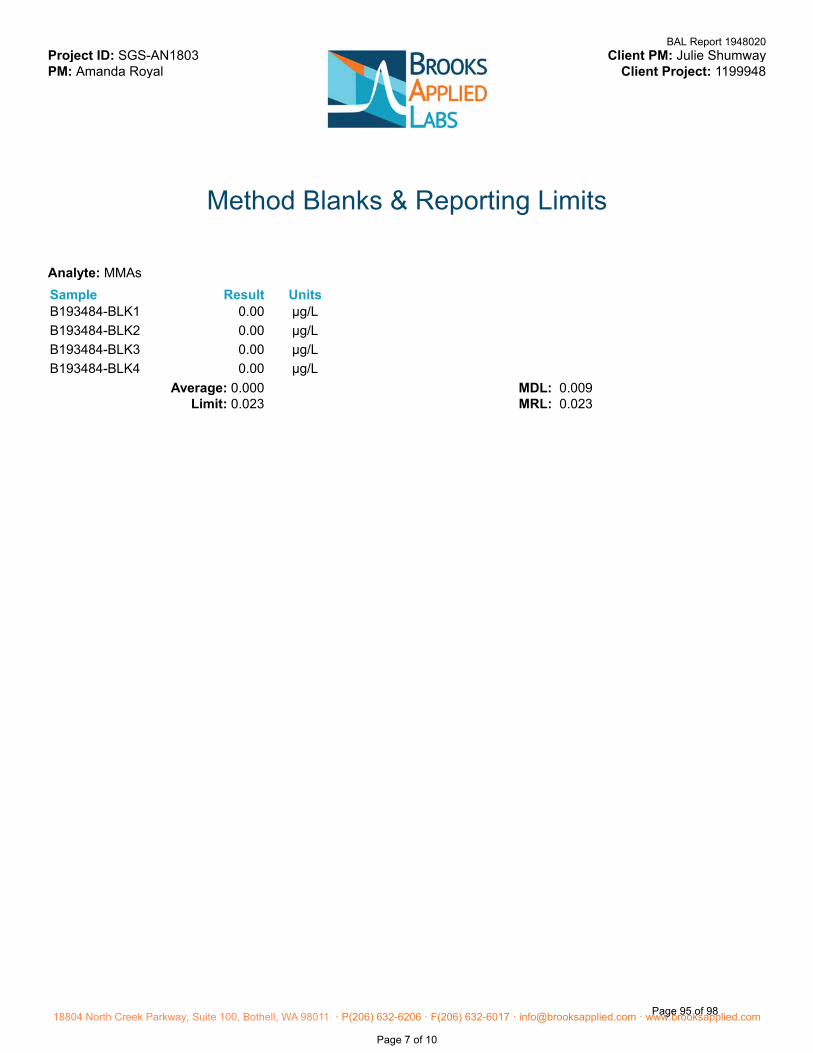
Project ID: SGS-AN1803PM: Amanda Royal
Client PM: Julie Shumway Client Project: 1199948
Method Blanks & Reporting Limits
Analyte: MMAsResult UnitsSample
B193484-BLK1 µg/L0.00B193484-BLK2 µg/L0.00B193484-BLK3 µg/L0.00B193484-BLK4 µg/L0.00
MDL: 0.009Average: 0.000Limit: 0.023 MRL: 0.023
18804 North Creek Parkway, Suite 100, Bothell, WA 98011 · P(206) 632-6206 · F(206) 632-6017 · [email protected] · www.brooksapplied.com
BAL Report 1948020
Page 7 of 10
Page 95 of 98

Project ID: SGS-AN1803PM: Amanda Royal
Client PM: Julie Shumway Client Project: 1199948
Sample Containers
Lab ID: 1948020-01 Report Matrix: WaterSample Type: Sample Received: 11/26/2019Sample: 191050
Collected: 11/15/2019
Ship. Cont.pHP-LotPreservationLotSizeContainerDesA Bottle HDPE As-SP 125mL 19-0120 none n/a 4 Styrofoam
Cooler - 1948020
Lab ID: 1948020-02 Report Matrix: WaterSample Type: Sample Received: 11/26/2019Sample: 191320
Collected: 11/14/2019
Ship. Cont.pHP-LotPreservationLotSizeContainerDesA Bottle HDPE As-SP 125mL 19-0120 none n/a 4 Styrofoam
Cooler - 1948020
Lab ID: 1948020-03 Report Matrix: WaterSample Type: Sample Received: 11/26/2019Sample: 200150
Collected: 11/15/2019
Ship. Cont.pHP-LotPreservationLotSizeContainerDesA Bottle HDPE As-SP 125mL 19-0120 none n/a 4 Styrofoam
Cooler - 1948020
Lab ID: 1948020-04 Report Matrix: WaterSample Type: Sample Received: 11/26/2019Sample: 191710
Collected: 11/15/2019
Ship. Cont.pHP-LotPreservationLotSizeContainerDesA Bottle HDPE As-SP 125mL 19-0120 none n/a 4 Styrofoam
Cooler - 1948020
Shipping Containers
Styrofoam Cooler - 1948020
Tracking No: 1ZA8619W0166292256 via UPS
Temperature: 5.5 °CCoolant Type: Blue Ice
Comments: IR # 19
Description: Styrofoam CoolerDamaged in transit? NoReturned to client? No
Custody seals present? YesCustody seals intact? Yes
COC present? Yes
Received: November 26, 2019 10:07
18804 North Creek Parkway, Suite 100, Bothell, WA 98011 · P(206) 632-6206 · F(206) 632-6017 · [email protected] · www.brooksapplied.com
BAL Report 1948020
Page 8 of 10
Page 96 of 98

BAL Report 1948020
Page 9 of 10
Page 97 of 98

BAL Report 1948020
Page 10 of 10
Page 98 of 98

November 2019 Page 1
Laboratory Data Review Checklist
Completed By:
Brittany Blood
Title:
Environmental Professional I
Date:
12/17/2019
Consultant Firm:
Shannon and Wilson, Inc.
Laboratory Name:
SGS North America, Inc.
Laboratory Report Number:
1199948
Laboratory Report Date:
12/12/2019
CS Site Name:
ADOT&PF Dillingham Airport Sitewide PFAS
ADEC File Number:
2540.38.023
Hazard Identification Number:
26971

1199948
Laboratory Report Date:
12/12/2019
CS Site Name:
ADOT&PF Dillingham Airport Sitewide PFAS
November 2019 Page 2
Note: Any N/A or No box checked must have an explanation in the comments box.
1. Laboratory
a. Did an ADEC CS approved laboratory receive and perform all of the submitted sample analyses?
Yes☒ No☐ N/A☐ Comments:
TOC, Metals 200.8 + hardness, nitrogen, TSS, DRO, RRO, GRO, BTEX8021, Sulfide, Cl, F, pH,
TDS, conductivity, and sulfide analyses were all performed by the SGS laboratory in Anchorage, AK.
The laboratory is certified by the ADEC CSP for these requested analyses.
Speciated arsenic analysis was subcontracted to Brooks Applied Labs of Bothell Washington.
b. If the samples were transferred to another “network” laboratory or sub-contracted to an alternate
laboratory, was the laboratory performing the analyses ADEC CS approved?
Yes☐ No☒ N/A☐ Comments:
Samples were transferred to Brooks Applied Labs for the analysis of speciated arsenic. Brooks Applied
Labs is not an ADEC CSP approved lab for the requested analysis.
2. Chain of Custody (CoC)
a. CoC information completed, signed, and dated (including released/received by)?
Yes☒ No☐ N/A☐ Comments:
b. Correct analyses requested?
Yes☒ No☐ N/A☐ Comments:
3. Laboratory Sample Receipt Documentation
a. Sample/cooler temperature documented and within range at receipt (0° to 6° C)?
Yes☒ No☐ N/A☐ Comments:
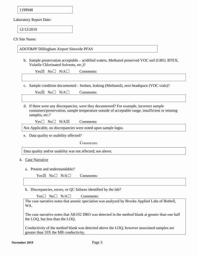
1199948
Laboratory Report Date:
12/12/2019
CS Site Name:
ADOT&PF Dillingham Airport Sitewide PFAS
November 2019 Page 3
b. Sample preservation acceptable – acidified waters, Methanol preserved VOC soil (GRO, BTEX,
Volatile Chlorinated Solvents, etc.)?
Yes☒ No☐ N/A☐ Comments:
c. Sample condition documented – broken, leaking (Methanol), zero headspace (VOC vials)?
Yes☒ No☐ N/A☐ Comments:
d. If there were any discrepancies, were they documented? For example, incorrect sample
containers/preservation, sample temperature outside of acceptable range, insufficient or missing
samples, etc.?
Yes☐ No☐ N/A☒ Comments:
Not Applicable, no discrepancies were noted upon sample login.
e. Data quality or usability affected?
Comments:
Data quality and/or usability was not affected; see above.
4. Case Narrative
a. Present and understandable?
Yes☒ No☐ N/A☐ Comments:
b. Discrepancies, errors, or QC failures identified by the lab?
Yes☐ No☐ N/A☐ Comments:
The case narrative notes that arsenic speciation was analyzed by Brooks Applied Labs of Bothell,
WA.
The case narrative notes that AK102 DRO was detected in the method blank at greater than one half
the LOQ, but less than the LOQ.
Conductivity of the method blank was detected above the LOQ, however associated samples are
greater than 10X the MB conductivity.

1199948
Laboratory Report Date:
12/12/2019
CS Site Name:
ADOT&PF Dillingham Airport Sitewide PFAS
November 2019 Page 4
c. Were all corrective actions documented?
Yes☐ No☐ N/A☒ Comments:
Corrective action not required.
d. What is the effect on data quality/usability according to the case narrative?
Comments:
Case narrative does not specify an effect on data quality, it only discusses discrepancies. Any notable
data quality issues mentioned in the case narrative are discussed above in 4b or elsewhere within this
ADEC checklist.
5. Samples Results
a. Correct analyses performed/reported as requested on COC?
Yes☒ No☐ N/A☐ Comments:
b. All applicable holding times met?
Yes☒ No☐ N/A☐ Comments:
c. All soils reported on a dry weight basis?
Yes☐ No☐ N/A☒ Comments:
All samples submitted within this work order were water samples.
d. Are the reported LOQs less than the Cleanup Level or the minimum required detection level for
the project?
Yes☒ No☐ N/A☐ Comments:
e. Data quality or usability affected?
Data quality and/or usability were not affected.

1199948
Laboratory Report Date:
12/12/2019
CS Site Name:
ADOT&PF Dillingham Airport Sitewide PFAS
November 2019 Page 5
6. QC Samples
a. Method Blank
i. One method blank reported per matrix, analysis and 20 samples?
Yes☒ No☐ N/A☐ Comments:
ii. All method blank results less than limit of quantitation (LOQ) or project specified objectives?
Yes☐ No☒ N/A☐ Comments:
No method blank results were above the LOQ, however, DRO, RRO, conductivity, total
nitrate/nitrite-N, and arsenic (V) were detected in method blank samples below the LOQ.
Arsenic (V) and conductivity concentrations in associated samples were greater than ten times the
detection in the method blank. No data qualification required.
DRO, RRO, and total nitrate/nitrite-N were detected within five times the concentrations detected in
the method blank samples in the following associated project samples:
DRO - 191050, 191320, 200150, and 191710
RRO – 191050 and 191320
Total nitrate/nitrite – N – 191050, 191320, 191710.
These analytes in the noted samples have been flagged B* and are considered non-detect as a result of
potential laboratory cross contamination.
iii. If above LOQ or project specified objectives, what samples are affected?
Comments:
See above.
iv. Do the affected sample(s) have data flags? If so, are the data flags clearly defined?
Yes☒ No☐ N/A☐ Comments:
See above.
v. Data quality or usability affected?
Comments:
Data quality and/or usability were not affected; see above.

1199948
Laboratory Report Date:
12/12/2019
CS Site Name:
ADOT&PF Dillingham Airport Sitewide PFAS
November 2019 Page 6
b. Laboratory Control Sample/Duplicate (LCS/LCSD)
i. Organics – One LCS/LCSD reported per matrix, analysis and 20 samples? (LCS/LCSD
required per AK methods, LCS required per SW846)
Yes☒ No☐ N/A☐ Comments:
An LCS/LCSD was submitted for methods AK101, AK102, AK103, SW8021B, and EPA 1664B.
ii. Metals/Inorganics – one LCS and one sample duplicate reported per matrix, analysis and 20
samples?
Yes☒ No☐ N/A☐ Comments:
An LCS sample was submitted for methods SM23 4500S D, SM21 4500- H B, SM21 2510B, SM21
4500NO3-F, SM 5310B, EPA 300.0, EPA 200.8, and speciated arsenic.
An LCS/ LCSD was submitted for methods SM21 2540C, SM21 2540D, and SM21 4500-N D.
iii. Accuracy – All percent recoveries (%R) reported and within method or laboratory limits and
project specified objectives, if applicable? (AK Petroleum methods: AK101 60%-120%,
AK102 75%-125%, AK103 60%-120%; all other analyses see the laboratory QC pages)
Yes☒ No☐ N/A☐ Comments:
iv. Precision – All relative percent differences (RPD) reported and less than method or laboratory
limits and project specified objectives, if applicable? RPD reported from LCS/LCSD, and or
sample/sample duplicate. (AK Petroleum methods 20%; all other analyses see the laboratory
QC pages)
Yes☒ No☐ N/A☐ Comments:
All relative percent differences were reported and less than method or laboratory limits for samples
reported with both and LCS and LCSD.
v. If %R or RPD is outside of acceptable limits, what samples are affected?
Comments:
Not applicable, see above.
vi. Do the affected sample(s) have data flags? If so, are the data flags clearly defined?
Yes☐ No☐ N/A☒ Comments:
No samples required data qualification.

1199948
Laboratory Report Date:
12/12/2019
CS Site Name:
ADOT&PF Dillingham Airport Sitewide PFAS
November 2019 Page 7
vii. Data quality or usability affected? (Use comment box to explain.)
Comments:
Data quality and/or usability were not affected; see above.
c. Matrix Spike/Matrix Spike Duplicate (MS/MSD)
Note: Leave blank if not required for project
i. Organics – One MS/MSD reported per matrix, analysis and 20 samples?
Yes☒ No☐ N/A☐ Comments:
An MS/MSD was submitted for analytical methods SM 5310B, and an MS was submitted for EPA
1664B.
ii. Metals/Inorganics – one MS and one MSD reported per matrix, analysis and 20 samples?
Yes☒ No☐ N/A☐ Comments:
An MS/MSD was submitted for analytical methods SM21 4500NO3-F, SM21 4500-N D, SM23
4500-S D, and speciated arsenic. An MS was submitted for EPA 200.8 and EPA 300.0.
iii. Accuracy – All percent recoveries (%R) reported and within method or laboratory limits and
project specified objectives, if applicable? (AK Petroleum methods: AK101 60%-120%,
AK102 75%-125%, AK103 60%-120%; all other analyses see the laboratory QC pages)
Yes☐ No☒ N/A☐ Comments:
The MS and/or MSD recoveries for total nitrate/nitrite, chloride, and sodium were outside of QC
criteria. However, the MS/MSD samples used were not project sample. No qualification of data is
required.
iv. Precision – All relative percent differences (RPD) reported and less than method or laboratory
limits and project specified objectives, if applicable? RPD reported from MS/MSD, and or
sample/sample duplicate. (AK Petroleum methods 20%; all other analyses see the laboratory
QC pages)
Yes☒ No☐ N/A☐ Comments:
v. If %R or RPD is outside of acceptable limits, what samples are affected?
Comments:
Not applicable, see above.

1199948
Laboratory Report Date:
12/12/2019
CS Site Name:
ADOT&PF Dillingham Airport Sitewide PFAS
November 2019 Page 8
vi. Do the affected sample(s) have data flags? If so, are the data flags clearly defined?
Yes☐ No☐ N/A☒ Comments:
See above.
vii. Data quality or usability affected? (Use comment box to explain.)
Comments:
Data quality and/or usability were not affected; see above.
d. Surrogates – Organics Only or Isotope Dilution Analytes (IDA) – Isotope Dilution Methods Only
i. Are surrogate/IDA recoveries reported for organic analyses – field, QC and laboratory
samples?
Yes☒ No☐ N/A☐ Comments:
ii. Accuracy – All percent recoveries (%R) reported and within method or laboratory limits and
project specified objectives, if applicable? (AK Petroleum methods 50-150 %R; all other
analyses see the laboratory report pages)
Yes☒ No☐ N/A☐ Comments:
iii. Do the sample results with failed surrogate/IDA recoveries have data flags? If so, are the data
flags clearly defined?
Yes☐ No☐ N/A☒ Comments:
See above.
iv. Data quality or usability affected?
Comments:
Data quality and/or usability were not affected; see above.
e. Trip Blanks
i. One trip blank reported per matrix, analysis and for each cooler containing volatile samples?
(If not, enter explanation below.)
Yes☒ No☐ N/A☐ Comments:
A trip blank was submitted for analytical methods AK101 and SW8021B.
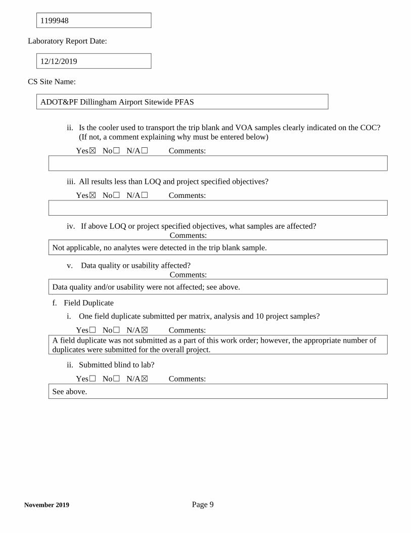
1199948
Laboratory Report Date:
12/12/2019
CS Site Name:
ADOT&PF Dillingham Airport Sitewide PFAS
November 2019 Page 9
ii. Is the cooler used to transport the trip blank and VOA samples clearly indicated on the COC?
(If not, a comment explaining why must be entered below)
Yes☒ No☐ N/A☐ Comments:
iii. All results less than LOQ and project specified objectives?
Yes☒ No☐ N/A☐ Comments:
iv. If above LOQ or project specified objectives, what samples are affected?
Comments:
Not applicable, no analytes were detected in the trip blank sample.
v. Data quality or usability affected?
Comments:
Data quality and/or usability were not affected; see above. S
f. Field Duplicate
i. One field duplicate submitted per matrix, analysis and 10 project samples?
Yes☐ No☐ N/A☒ Comments:
A field duplicate was not submitted as a part of this work order; however, the appropriate number of
duplicates were submitted for the overall project.
ii. Submitted blind to lab?
Yes☐ No☐ N/A☒ Comments:
See above.
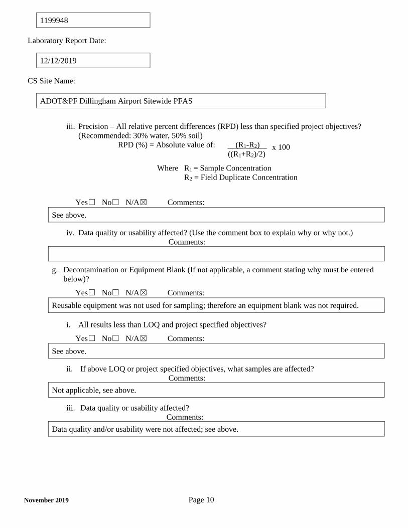
1199948
Laboratory Report Date:
12/12/2019
CS Site Name:
ADOT&PF Dillingham Airport Sitewide PFAS
November 2019 Page 10
iii. Precision – All relative percent differences (RPD) less than specified project objectives?
(Recommended: 30% water, 50% soil)
RPD (%) = Absolute value of: (R1-R2)
((R1+R2)/2)
Where R1 = Sample Concentration
R2 = Field Duplicate Concentration
Yes☐ No☐ N/A☒ Comments:
See above.
iv. Data quality or usability affected? (Use the comment box to explain why or why not.)
Comments:
g. Decontamination or Equipment Blank (If not applicable, a comment stating why must be entered
below)?
Yes☐ No☐ N/A☒ Comments:
Reusable equipment was not used for sampling; therefore an equipment blank was not required.
i. All results less than LOQ and project specified objectives?
Yes☐ No☐ N/A☒ Comments:
See above.
ii. If above LOQ or project specified objectives, what samples are affected?
Comments:
Not applicable, see above.
iii. Data quality or usability affected?
Comments:
Data quality and/or usability were not affected; see above.
x 100

1199948
Laboratory Report Date:
12/12/2019
CS Site Name:
ADOT&PF Dillingham Airport Sitewide PFAS
November 2019 Page 11
7. Other Data Flags/Qualifiers (ACOE, AFCEE, Lab Specific, etc.)
a. Defined and appropriate?
Yes☐ No☐ N/A☒ Comments:

Long-Term Alternate Water Feasibility Study Report
102786-003 October 2020
APPE
NDIX
B: B
ARR
REPO
RT A
ND S
UPPO
RTIN
G IN
FORM
ATIO
N
TESTAMERICA LAB REPORT 320-56436 AND LDRC

ANALYTICAL REPORTEurofins TestAmerica, Sacramento880 Riverside ParkwayWest Sacramento, CA 95605Tel: (916)373-5600
Laboratory Job ID: 320-56436-1Client Project/Site: DLG Alt. Water
For:Shannon & Wilson, Inc2355 Hill Rd.Fairbanks, Alaska 99709-5244
Attn: Marcy Nadel
Authorized for release by:12/9/2019 2:15:32 PM
David Alltucker, Project Manager I(916)[email protected]
The test results in this report meet all 2003 NELAC and 2009 TNI requirements for accreditedparameters, exceptions are noted in this report. This report may not be reproduced except in full,and with written approval from the laboratory. For questions please contact the Project Managerat the e-mail address or telephone number listed on this page.
This report has been electronically signed and authorized by the signatory. Electronic signature isintended to be the legally binding equivalent of a traditionally handwritten signature.
Results relate only to the items tested and the sample(s) as received by the laboratory.
1
2
3
4
5
6
7
8
9
10
11
12
13
14
15

Table of Contents
Client: Shannon & Wilson, IncProject/Site: DLG Alt. Water
Laboratory Job ID: 320-56436-1
Page 2 of 28Eurofins TestAmerica, Sacramento
12/9/2019
Cover Page . . . . . . . . . . . . . . . . . . . . . . . . . . . . . . . . . . . . . . . . . . . . . . 1
Table of Contents . . . . . . . . . . . . . . . . . . . . . . . . . . . . . . . . . . . . . . . . . 2
Definitions/Glossary . . . . . . . . . . . . . . . . . . . . . . . . . . . . . . . . . . . . . . . 3
Case Narrative . . . . . . . . . . . . . . . . . . . . . . . . . . . . . . . . . . . . . . . . . . . 4
Detection Summary . . . . . . . . . . . . . . . . . . . . . . . . . . . . . . . . . . . . . . . . 5
Client Sample Results . . . . . . . . . . . . . . . . . . . . . . . . . . . . . . . . . . . . . . 7
Isotope Dilution Summary . . . . . . . . . . . . . . . . . . . . . . . . . . . . . . . . . . . 15
QC Sample Results . . . . . . . . . . . . . . . . . . . . . . . . . . . . . . . . . . . . . . . . 16
QC Association Summary . . . . . . . . . . . . . . . . . . . . . . . . . . . . . . . . . . . 21
Lab Chronicle . . . . . . . . . . . . . . . . . . . . . . . . . . . . . . . . . . . . . . . . . . . . 22
Certification Summary . . . . . . . . . . . . . . . . . . . . . . . . . . . . . . . . . . . . . . 23
Method Summary . . . . . . . . . . . . . . . . . . . . . . . . . . . . . . . . . . . . . . . . . 24
Sample Summary . . . . . . . . . . . . . . . . . . . . . . . . . . . . . . . . . . . . . . . . . 25
Chain of Custody . . . . . . . . . . . . . . . . . . . . . . . . . . . . . . . . . . . . . . . . . . 26
Receipt Checklists . . . . . . . . . . . . . . . . . . . . . . . . . . . . . . . . . . . . . . . . . 28
1
2
3
4
5
6
7
8
9
10
11
12
13
14
15

Definitions/GlossaryJob ID: 320-56436-1Client: Shannon & Wilson, Inc
Project/Site: DLG Alt. Water
Qualifiers
LCMSQualifier Description
* Isotope Dilution analyte is outside acceptance limits.
Qualifier
B Compound was found in the blank and sample.
J Result is less than the RL but greater than or equal to the MDL and the concentration is an approximate value.
GlossaryThese commonly used abbreviations may or may not be present in this report.
¤ Listed under the "D" column to designate that the result is reported on a dry weight basis
Abbreviation
%R Percent Recovery
CFL Contains Free Liquid
CNF Contains No Free Liquid
DER Duplicate Error Ratio (normalized absolute difference)
Dil Fac Dilution Factor
DL Detection Limit (DoD/DOE)
DL, RA, RE, IN Indicates a Dilution, Re-analysis, Re-extraction, or additional Initial metals/anion analysis of the sample
DLC Decision Level Concentration (Radiochemistry)
EDL Estimated Detection Limit (Dioxin)
LOD Limit of Detection (DoD/DOE)
LOQ Limit of Quantitation (DoD/DOE)
MDA Minimum Detectable Activity (Radiochemistry)
MDC Minimum Detectable Concentration (Radiochemistry)
MDL Method Detection Limit
ML Minimum Level (Dioxin)
NC Not Calculated
ND Not Detected at the reporting limit (or MDL or EDL if shown)
PQL Practical Quantitation Limit
QC Quality Control
RER Relative Error Ratio (Radiochemistry)
RL Reporting Limit or Requested Limit (Radiochemistry)
RPD Relative Percent Difference, a measure of the relative difference between two points
TEF Toxicity Equivalent Factor (Dioxin)
TEQ Toxicity Equivalent Quotient (Dioxin)
Eurofins TestAmerica, Sacramento
Page 3 of 28 12/9/2019
1
2
3
4
5
6
7
8
9
10
11
12
13
14
15

Case NarrativeClient: Shannon & Wilson, Inc Job ID: 320-56436-1Project/Site: DLG Alt. Water
Job ID: 320-56436-1
Laboratory: Eurofins TestAmerica, Sacramento
Narrative
Job Narrative
320-56436-1
Receipt
The samples were received on 11/20/2019 10:10 AM; the samples arrived in good condition, properly preserved and, where required, on
ice. The temperature of the cooler at receipt was 0.5º C.
LCMS Method 537 (modified): Due to a shortage in the marketplace for 13C3-PFBS, the target analyte PFBS and/or Perfluoropentanesulfonic
acid (PFPeS) could not be quantitated against 13C3-PFBS (its labeled variant) as listed in the SOP. PFBS and Perfluoropentanesulfonic acid (PFPeS) was quantitated versus 18O2-PFHxS instead.
Method 537 (modified): Several Isotope Dilution Analyte (IDA) recoveries are above the method recommended limit for the following
samples: 200150 (320-56436-1) and 191320 (320-56436-3). Quantitation by isotope dilution generally precludes any adverse effect on data quality due to elevated IDA recoveries.
Method 537 (modified): Isotope Dilution Analyte (IDA) recovery is above the method recommended limit for M2-4:2 FTS in following sample: 191050 (320-56436-4). Quantitation by isotope dilution generally precludes any adverse effect on data quality due to elevated IDA
recoveries.
No additional analytical or quality issues were noted, other than those described above or in the Definitions/Glossary page.
Organic Prep Method 3535: Insufficient sample volume was available to perform a matrix spike/matrix spike duplicate (MS/MSD) associated with preparation batch 320-341272.
Method 3535: The following samples were preserved with Trizma: 200150 (320-56436-1), 191710 (320-56436-2), 191320 (320-56436-3)
and 191050 (320-56436-4). Thus, the MB, LCS and LCSD also contain Trizma.
Method 3535: the following samples contain a thin layer of orange sediment at the bottom of the bottle prior to extraction: 191710 (320-56436-2) and 191320 (320-56436-3)
Method 3535: During the solid phase extraction process, the following samples have non-settable particulates which clogged the
extraction columns: 191710 (320-56436-2) and 191320 (320-56436-3).
Method 3535: The following sample is yellow after extraction: 191320 (320-56436-3).
No additional analytical or quality issues were noted, other than those described above or in the Definitions/Glossary page.
Eurofins TestAmerica, SacramentoPage 4 of 28 12/9/2019
1
2
3
4
5
6
7
8
9
10
11
12
13
14
15

Detection SummaryJob ID: 320-56436-1Client: Shannon & Wilson, Inc
Project/Site: DLG Alt. Water
Client Sample ID: 200150 Lab Sample ID: 320-56436-1
Perfluorobutanoic acid (PFBA)
RL
1.8 ng/L
MDL
0.32
Analyte Result Qualifier Unit Dil Fac D Method Prep Type
Total/NA1J1.5 537 (modified)
Perfluoropentanoic acid (PFPeA) 1.8 ng/L0.45 Total/NA14.0 537 (modified)
Perfluorohexanoic acid (PFHxA) 1.8 ng/L0.54 Total/NA116 537 (modified)
Perfluoroheptanoic acid (PFHpA) 1.8 ng/L0.23 Total/NA12.4 537 (modified)
Perfluorooctanoic acid (PFOA) 1.8 ng/L0.79 Total/NA15.5 537 (modified)
Perfluorobutanesulfonic acid (PFBS) 1.8 ng/L0.18 Total/NA16.9 537 (modified)
Perfluoropentanesulfonic acid
(PFPeS)
1.8 ng/L0.28 Total/NA114 537 (modified)
Perfluorohexanesulfonic acid (PFHxS) 1.8 ng/L0.16 Total/NA156 B 537 (modified)
Perfluoroheptanesulfonic Acid
(PFHpS)
1.8 ng/L0.18 Total/NA11.2 J 537 (modified)
Perfluorooctanesulfonic acid (PFOS) 1.8 ng/L0.50 Total/NA158 537 (modified)
Perfluorooctanesulfonamide (FOSA) 1.8 ng/L0.32 Total/NA11.1 J 537 (modified)
Client Sample ID: 191710 Lab Sample ID: 320-56436-2
Perfluorobutanoic acid (PFBA)
RL
1.8 ng/L
MDL
0.32
Analyte Result Qualifier Unit Dil Fac D Method Prep Type
Total/NA121 537 (modified)
Perfluoropentanoic acid (PFPeA) 1.8 ng/L0.45 Total/NA171 537 (modified)
Perfluorohexanoic acid (PFHxA) 1.8 ng/L0.54 Total/NA1110 537 (modified)
Perfluoroheptanoic acid (PFHpA) 1.8 ng/L0.23 Total/NA123 537 (modified)
Perfluorooctanoic acid (PFOA) 1.8 ng/L0.78 Total/NA122 537 (modified)
Perfluorobutanesulfonic acid (PFBS) 1.8 ng/L0.18 Total/NA134 537 (modified)
Perfluoropentanesulfonic acid
(PFPeS)
1.8 ng/L0.28 Total/NA134 537 (modified)
Perfluorohexanesulfonic acid (PFHxS) 1.8 ng/L0.16 Total/NA1110 B 537 (modified)
Perfluoroheptanesulfonic Acid
(PFHpS)
1.8 ng/L0.18 Total/NA12.9 537 (modified)
Perfluorooctanesulfonic acid (PFOS) 1.8 ng/L0.50 Total/NA158 537 (modified)
Perfluorooctanesulfonamide (FOSA) 1.8 ng/L0.32 Total/NA10.78 J 537 (modified)
6:2 FTS 18 ng/L1.8 Total/NA140 537 (modified)
Client Sample ID: 191320 Lab Sample ID: 320-56436-3
Perfluorobutanoic acid (PFBA)
RL
1.9 ng/L
MDL
0.33
Analyte Result Qualifier Unit Dil Fac D Method Prep Type
Total/NA123 537 (modified)
Perfluoropentanoic acid (PFPeA) 1.9 ng/L0.46 Total/NA170 537 (modified)
Perfluorohexanoic acid (PFHxA) 1.9 ng/L0.54 Total/NA159 537 (modified)
Perfluoroheptanoic acid (PFHpA) 1.9 ng/L0.23 Total/NA19.3 537 (modified)
Perfluorooctanoic acid (PFOA) 1.9 ng/L0.80 Total/NA11.7 J 537 (modified)
Perfluorobutanesulfonic acid (PFBS) 1.9 ng/L0.19 Total/NA112 537 (modified)
Perfluoropentanesulfonic acid
(PFPeS)
1.9 ng/L0.28 Total/NA14.3 537 (modified)
Perfluorohexanesulfonic acid (PFHxS) 1.9 ng/L0.16 Total/NA16.5 B 537 (modified)
Perfluorooctanesulfonamide (FOSA) 1.9 ng/L0.33 Total/NA10.87 J 537 (modified)
Client Sample ID: 191050 Lab Sample ID: 320-56436-4
Perfluorobutanoic acid (PFBA)
RL
1.9 ng/L
MDL
0.33
Analyte Result Qualifier Unit Dil Fac D Method Prep Type
Total/NA18.4 537 (modified)
Perfluoropentanoic acid (PFPeA) 1.9 ng/L0.46 Total/NA111 537 (modified)
Perfluorohexanoic acid (PFHxA) 1.9 ng/L0.55 Total/NA137 537 (modified)
Perfluoroheptanoic acid (PFHpA) 1.9 ng/L0.24 Total/NA12.8 537 (modified)
Perfluorooctanoic acid (PFOA) 1.9 ng/L0.80 Total/NA14.3 537 (modified)
Eurofins TestAmerica, Sacramento
This Detection Summary does not include radiochemical test results.
Page 5 of 28 12/9/2019
1
2
3
4
5
6
7
8
9
10
11
12
13
14
15

Detection SummaryJob ID: 320-56436-1Client: Shannon & Wilson, Inc
Project/Site: DLG Alt. Water
Client Sample ID: 191050 (Continued) Lab Sample ID: 320-56436-4
Perfluorobutanesulfonic acid (PFBS)
RL
1.9 ng/L
MDL
0.19
Analyte Result Qualifier Unit Dil Fac D Method Prep Type
Total/NA150 537 (modified)
Perfluoropentanesulfonic acid
(PFPeS)
1.9 ng/L0.28 Total/NA150 537 (modified)
Perfluorohexanesulfonic acid (PFHxS) 1.9 ng/L0.16 Total/NA1140 B 537 (modified)
Perfluoroheptanesulfonic Acid
(PFHpS)
1.9 ng/L0.18 Total/NA13.3 537 (modified)
Perfluorooctanesulfonic acid (PFOS) 1.9 ng/L0.51 Total/NA140 537 (modified)
Eurofins TestAmerica, Sacramento
This Detection Summary does not include radiochemical test results.
Page 6 of 28 12/9/2019
1
2
3
4
5
6
7
8
9
10
11
12
13
14
15

Client Sample ResultsJob ID: 320-56436-1Client: Shannon & Wilson, Inc
Project/Site: DLG Alt. Water
Lab Sample ID: 320-56436-1Client Sample ID: 200150Matrix: WaterDate Collected: 11/15/19 11:50
Date Received: 11/20/19 10:10
Method: 537 (modified) - Fluorinated Alkyl SubstancesRL MDL
Perfluorobutanoic acid (PFBA) 1.5 J 1.8 0.32 ng/L 11/25/19 06:35 12/02/19 23:58 1
Analyte Dil FacAnalyzedPreparedUnit DResult Qualifier
1.8 0.45 ng/L 11/25/19 06:35 12/02/19 23:58 1Perfluoropentanoic acid (PFPeA) 4.0
1.8 0.54 ng/L 11/25/19 06:35 12/02/19 23:58 1Perfluorohexanoic acid (PFHxA) 16
1.8 0.23 ng/L 11/25/19 06:35 12/02/19 23:58 1Perfluoroheptanoic acid (PFHpA) 2.4
1.8 0.79 ng/L 11/25/19 06:35 12/02/19 23:58 1Perfluorooctanoic acid (PFOA) 5.5
1.8 0.25 ng/L 11/25/19 06:35 12/02/19 23:58 1Perfluorononanoic acid (PFNA) ND
1.8 0.29 ng/L 11/25/19 06:35 12/02/19 23:58 1Perfluorodecanoic acid (PFDA) ND
1.8 1.0 ng/L 11/25/19 06:35 12/02/19 23:58 1Perfluoroundecanoic acid (PFUnA) ND
1.8 0.51 ng/L 11/25/19 06:35 12/02/19 23:58 1Perfluorododecanoic acid (PFDoA) ND
1.8 1.2 ng/L 11/25/19 06:35 12/02/19 23:58 1Perfluorotridecanoic acid (PFTriA) ND
1.8 0.27 ng/L 11/25/19 06:35 12/02/19 23:58 1Perfluorotetradecanoic acid (PFTeA) ND
1.8 0.82 ng/L 11/25/19 06:35 12/02/19 23:58 1Perfluoro-n-hexadecanoic acid
(PFHxDA)
ND
1.8 0.18 ng/L 11/25/19 06:35 12/02/19 23:58 1Perfluorobutanesulfonic acid (PFBS)
6.9
1.8 0.28 ng/L 11/25/19 06:35 12/02/19 23:58 1Perfluoropentanesulfonic acid (PFPeS)
14
1.8 0.16 ng/L 11/25/19 06:35 12/02/19 23:58 1Perfluorohexanesulfonic acid (PFHxS)
56 B
1.8 0.18 ng/L 11/25/19 06:35 12/02/19 23:58 1Perfluoroheptanesulfonic Acid (PFHpS)
1.2 J
1.8 0.50 ng/L 11/25/19 06:35 12/02/19 23:58 1Perfluorooctanesulfonic acid (PFOS)
58
1.8 0.15 ng/L 11/25/19 06:35 12/02/19 23:58 1Perfluorononanesulfonic acid (PFNS) ND
1.8 0.30 ng/L 11/25/19 06:35 12/02/19 23:58 1Perfluorodecanesulfonic acid (PFDS) ND
1.8 0.32 ng/L 11/25/19 06:35 12/02/19 23:58 1Perfluorooctanesulfonamide (FOSA)
1.1 J
18 1.8 ng/L 11/25/19 06:35 12/02/19 23:58 1N-ethylperfluorooctanesulfonamidoac
etic acid (NEtFOSAA)
ND
18 2.9 ng/L 11/25/19 06:35 12/02/19 23:58 1N-methylperfluorooctanesulfonamidoa
cetic acid (NMeFOSAA)
ND
18 4.8 ng/L 11/25/19 06:35 12/02/19 23:58 14:2 FTS ND
18 1.8 ng/L 11/25/19 06:35 12/02/19 23:58 16:2 FTS ND
18 1.8 ng/L 11/25/19 06:35 12/02/19 23:58 18:2 FTS ND
1.8 0.18 ng/L 11/25/19 06:35 12/02/19 23:58 110:2 FTS ND
1.8 0.17 ng/L 11/25/19 06:35 12/02/19 23:58 14,8-Dioxa-3H-perfluorononanoic acid
(ADONA)
ND
3.7 1.4 ng/L 11/25/19 06:35 12/02/19 23:58 1HFPO-DA (GenX) ND
1.9 0.18 ng/L 11/25/19 06:35 12/02/19 23:58 1ADONA ND
1.8 0.22 ng/L 11/25/19 06:35 12/02/19 23:58 19-Chlorohexadecafluoro-3-oxanonan
e-1-sulfonic acid
ND
1.8 0.30 ng/L 11/25/19 06:35 12/02/19 23:58 111-Chloroeicosafluoro-3-oxaundecan
e-1-sulfonic acid
ND
13C4 PFBA 74 25 - 150 11/25/19 06:35 12/02/19 23:58 1
Isotope Dilution Dil FacAnalyzedPreparedQualifier Limits%Recovery
13C5 PFPeA 95 11/25/19 06:35 12/02/19 23:58 125 - 150
13C2 PFHxA 91 11/25/19 06:35 12/02/19 23:58 125 - 150
13C4 PFHpA 97 11/25/19 06:35 12/02/19 23:58 125 - 150
13C4 PFOA 104 11/25/19 06:35 12/02/19 23:58 125 - 150
13C5 PFNA 103 11/25/19 06:35 12/02/19 23:58 125 - 150
13C2 PFDA 101 11/25/19 06:35 12/02/19 23:58 125 - 150
13C2 PFUnA 96 11/25/19 06:35 12/02/19 23:58 125 - 150
Eurofins TestAmerica, Sacramento
Page 7 of 28 12/9/2019
1
2
3
4
5
6
7
8
9
10
11
12
13
14
15

Client Sample ResultsJob ID: 320-56436-1Client: Shannon & Wilson, Inc
Project/Site: DLG Alt. Water
Lab Sample ID: 320-56436-1Client Sample ID: 200150Matrix: WaterDate Collected: 11/15/19 11:50
Date Received: 11/20/19 10:10
Method: 537 (modified) - Fluorinated Alkyl Substances (Continued)
13C2 PFDoA 98 25 - 150 11/25/19 06:35 12/02/19 23:58 1
Isotope Dilution Dil FacAnalyzedPreparedQualifier Limits%Recovery
13C2 PFTeDA 89 11/25/19 06:35 12/02/19 23:58 125 - 150
18O2 PFHxS 113 11/25/19 06:35 12/02/19 23:58 125 - 150
13C4 PFOS 103 11/25/19 06:35 12/02/19 23:58 125 - 150
13C8 FOSA 90 11/25/19 06:35 12/02/19 23:58 125 - 150
M2-6:2 FTS 170 * 11/25/19 06:35 12/02/19 23:58 125 - 150
M2-8:2 FTS 153 * 11/25/19 06:35 12/02/19 23:58 125 - 150
d5-NEtFOSAA 123 11/25/19 06:35 12/02/19 23:58 125 - 150
d3-NMeFOSAA 116 11/25/19 06:35 12/02/19 23:58 125 - 150
M2-4:2 FTS 170 * 11/25/19 06:35 12/02/19 23:58 125 - 150
13C2 PFHxDA 56 11/25/19 06:35 12/02/19 23:58 125 - 150
13C3 HFPO-DA 74 11/25/19 06:35 12/02/19 23:58 125 - 150
Eurofins TestAmerica, Sacramento
Page 8 of 28 12/9/2019
1
2
3
4
5
6
7
8
9
10
11
12
13
14
15

Client Sample ResultsJob ID: 320-56436-1Client: Shannon & Wilson, Inc
Project/Site: DLG Alt. Water
Lab Sample ID: 320-56436-2Client Sample ID: 191710Matrix: WaterDate Collected: 11/15/19 16:51
Date Received: 11/20/19 10:10
Method: 537 (modified) - Fluorinated Alkyl SubstancesRL MDL
Perfluorobutanoic acid (PFBA) 21 1.8 0.32 ng/L 11/25/19 06:35 12/03/19 00:14 1
Analyte Dil FacAnalyzedPreparedUnit DResult Qualifier
1.8 0.45 ng/L 11/25/19 06:35 12/03/19 00:14 1Perfluoropentanoic acid (PFPeA) 71
1.8 0.54 ng/L 11/25/19 06:35 12/03/19 00:14 1Perfluorohexanoic acid (PFHxA) 110
1.8 0.23 ng/L 11/25/19 06:35 12/03/19 00:14 1Perfluoroheptanoic acid (PFHpA) 23
1.8 0.78 ng/L 11/25/19 06:35 12/03/19 00:14 1Perfluorooctanoic acid (PFOA) 22
1.8 0.25 ng/L 11/25/19 06:35 12/03/19 00:14 1Perfluorononanoic acid (PFNA) ND
1.8 0.29 ng/L 11/25/19 06:35 12/03/19 00:14 1Perfluorodecanoic acid (PFDA) ND
1.8 1.0 ng/L 11/25/19 06:35 12/03/19 00:14 1Perfluoroundecanoic acid (PFUnA) ND
1.8 0.51 ng/L 11/25/19 06:35 12/03/19 00:14 1Perfluorododecanoic acid (PFDoA) ND
1.8 1.2 ng/L 11/25/19 06:35 12/03/19 00:14 1Perfluorotridecanoic acid (PFTriA) ND
1.8 0.27 ng/L 11/25/19 06:35 12/03/19 00:14 1Perfluorotetradecanoic acid (PFTeA) ND
1.8 0.82 ng/L 11/25/19 06:35 12/03/19 00:14 1Perfluoro-n-hexadecanoic acid
(PFHxDA)
ND
1.8 0.18 ng/L 11/25/19 06:35 12/03/19 00:14 1Perfluorobutanesulfonic acid (PFBS)
34
1.8 0.28 ng/L 11/25/19 06:35 12/03/19 00:14 1Perfluoropentanesulfonic acid (PFPeS)
34
1.8 0.16 ng/L 11/25/19 06:35 12/03/19 00:14 1Perfluorohexanesulfonic acid (PFHxS)
110 B
1.8 0.18 ng/L 11/25/19 06:35 12/03/19 00:14 1Perfluoroheptanesulfonic Acid (PFHpS)
2.9
1.8 0.50 ng/L 11/25/19 06:35 12/03/19 00:14 1Perfluorooctanesulfonic acid (PFOS)
58
1.8 0.15 ng/L 11/25/19 06:35 12/03/19 00:14 1Perfluorononanesulfonic acid (PFNS) ND
1.8 0.30 ng/L 11/25/19 06:35 12/03/19 00:14 1Perfluorodecanesulfonic acid (PFDS) ND
1.8 0.32 ng/L 11/25/19 06:35 12/03/19 00:14 1Perfluorooctanesulfonamide (FOSA)
0.78 J
18 1.8 ng/L 11/25/19 06:35 12/03/19 00:14 1N-ethylperfluorooctanesulfonamidoac
etic acid (NEtFOSAA)
ND
18 2.9 ng/L 11/25/19 06:35 12/03/19 00:14 1N-methylperfluorooctanesulfonamidoa
cetic acid (NMeFOSAA)
ND
18 4.8 ng/L 11/25/19 06:35 12/03/19 00:14 14:2 FTS ND
18 1.8 ng/L 11/25/19 06:35 12/03/19 00:14 16:2 FTS 40
18 1.8 ng/L 11/25/19 06:35 12/03/19 00:14 18:2 FTS ND
1.8 0.18 ng/L 11/25/19 06:35 12/03/19 00:14 110:2 FTS ND
1.8 0.17 ng/L 11/25/19 06:35 12/03/19 00:14 14,8-Dioxa-3H-perfluorononanoic acid
(ADONA)
ND
3.7 1.4 ng/L 11/25/19 06:35 12/03/19 00:14 1HFPO-DA (GenX) ND
1.9 0.18 ng/L 11/25/19 06:35 12/03/19 00:14 1ADONA ND
1.8 0.22 ng/L 11/25/19 06:35 12/03/19 00:14 19-Chlorohexadecafluoro-3-oxanonan
e-1-sulfonic acid
ND
1.8 0.30 ng/L 11/25/19 06:35 12/03/19 00:14 111-Chloroeicosafluoro-3-oxaundecan
e-1-sulfonic acid
ND
13C4 PFBA 62 25 - 150 11/25/19 06:35 12/03/19 00:14 1
Isotope Dilution Dil FacAnalyzedPreparedQualifier Limits%Recovery
13C5 PFPeA 77 11/25/19 06:35 12/03/19 00:14 125 - 150
13C2 PFHxA 70 11/25/19 06:35 12/03/19 00:14 125 - 150
13C4 PFHpA 74 11/25/19 06:35 12/03/19 00:14 125 - 150
13C4 PFOA 79 11/25/19 06:35 12/03/19 00:14 125 - 150
13C5 PFNA 79 11/25/19 06:35 12/03/19 00:14 125 - 150
13C2 PFDA 76 11/25/19 06:35 12/03/19 00:14 125 - 150
13C2 PFUnA 71 11/25/19 06:35 12/03/19 00:14 125 - 150
Eurofins TestAmerica, Sacramento
Page 9 of 28 12/9/2019
1
2
3
4
5
6
7
8
9
10
11
12
13
14
15

Client Sample ResultsJob ID: 320-56436-1Client: Shannon & Wilson, Inc
Project/Site: DLG Alt. Water
Lab Sample ID: 320-56436-2Client Sample ID: 191710Matrix: WaterDate Collected: 11/15/19 16:51
Date Received: 11/20/19 10:10
Method: 537 (modified) - Fluorinated Alkyl Substances (Continued)
13C2 PFDoA 70 25 - 150 11/25/19 06:35 12/03/19 00:14 1
Isotope Dilution Dil FacAnalyzedPreparedQualifier Limits%Recovery
13C2 PFTeDA 63 11/25/19 06:35 12/03/19 00:14 125 - 150
18O2 PFHxS 91 11/25/19 06:35 12/03/19 00:14 125 - 150
13C4 PFOS 81 11/25/19 06:35 12/03/19 00:14 125 - 150
13C8 FOSA 71 11/25/19 06:35 12/03/19 00:14 125 - 150
M2-6:2 FTS 120 11/25/19 06:35 12/03/19 00:14 125 - 150
M2-8:2 FTS 101 11/25/19 06:35 12/03/19 00:14 125 - 150
d5-NEtFOSAA 81 11/25/19 06:35 12/03/19 00:14 125 - 150
d3-NMeFOSAA 83 11/25/19 06:35 12/03/19 00:14 125 - 150
M2-4:2 FTS 127 11/25/19 06:35 12/03/19 00:14 125 - 150
13C2 PFHxDA 59 11/25/19 06:35 12/03/19 00:14 125 - 150
13C3 HFPO-DA 51 11/25/19 06:35 12/03/19 00:14 125 - 150
Eurofins TestAmerica, Sacramento
Page 10 of 28 12/9/2019
1
2
3
4
5
6
7
8
9
10
11
12
13
14
15

Client Sample ResultsJob ID: 320-56436-1Client: Shannon & Wilson, Inc
Project/Site: DLG Alt. Water
Lab Sample ID: 320-56436-3Client Sample ID: 191320Matrix: WaterDate Collected: 11/14/19 17:45
Date Received: 11/20/19 10:10
Method: 537 (modified) - Fluorinated Alkyl SubstancesRL MDL
Perfluorobutanoic acid (PFBA) 23 1.9 0.33 ng/L 11/25/19 06:35 12/03/19 00:22 1
Analyte Dil FacAnalyzedPreparedUnit DResult Qualifier
1.9 0.46 ng/L 11/25/19 06:35 12/03/19 00:22 1Perfluoropentanoic acid (PFPeA) 70
1.9 0.54 ng/L 11/25/19 06:35 12/03/19 00:22 1Perfluorohexanoic acid (PFHxA) 59
1.9 0.23 ng/L 11/25/19 06:35 12/03/19 00:22 1Perfluoroheptanoic acid (PFHpA) 9.3
1.9 0.80 ng/L 11/25/19 06:35 12/03/19 00:22 1Perfluorooctanoic acid (PFOA) 1.7 J
1.9 0.25 ng/L 11/25/19 06:35 12/03/19 00:22 1Perfluorononanoic acid (PFNA) ND
1.9 0.29 ng/L 11/25/19 06:35 12/03/19 00:22 1Perfluorodecanoic acid (PFDA) ND
1.9 1.0 ng/L 11/25/19 06:35 12/03/19 00:22 1Perfluoroundecanoic acid (PFUnA) ND
1.9 0.52 ng/L 11/25/19 06:35 12/03/19 00:22 1Perfluorododecanoic acid (PFDoA) ND
1.9 1.2 ng/L 11/25/19 06:35 12/03/19 00:22 1Perfluorotridecanoic acid (PFTriA) ND
1.9 0.27 ng/L 11/25/19 06:35 12/03/19 00:22 1Perfluorotetradecanoic acid (PFTeA) ND
1.9 0.84 ng/L 11/25/19 06:35 12/03/19 00:22 1Perfluoro-n-hexadecanoic acid
(PFHxDA)
ND
1.9 0.19 ng/L 11/25/19 06:35 12/03/19 00:22 1Perfluorobutanesulfonic acid (PFBS)
12
1.9 0.28 ng/L 11/25/19 06:35 12/03/19 00:22 1Perfluoropentanesulfonic acid (PFPeS)
4.3
1.9 0.16 ng/L 11/25/19 06:35 12/03/19 00:22 1Perfluorohexanesulfonic acid (PFHxS)
6.5 B
1.9 0.18 ng/L 11/25/19 06:35 12/03/19 00:22 1Perfluoroheptanesulfonic Acid
(PFHpS)
ND
1.9 0.51 ng/L 11/25/19 06:35 12/03/19 00:22 1Perfluorooctanesulfonic acid (PFOS) ND
1.9 0.15 ng/L 11/25/19 06:35 12/03/19 00:22 1Perfluorononanesulfonic acid (PFNS) ND
1.9 0.30 ng/L 11/25/19 06:35 12/03/19 00:22 1Perfluorodecanesulfonic acid (PFDS) ND
1.9 0.33 ng/L 11/25/19 06:35 12/03/19 00:22 1Perfluorooctanesulfonamide (FOSA)
0.87 J
19 1.8 ng/L 11/25/19 06:35 12/03/19 00:22 1N-ethylperfluorooctanesulfonamidoac
etic acid (NEtFOSAA)
ND
19 2.9 ng/L 11/25/19 06:35 12/03/19 00:22 1N-methylperfluorooctanesulfonamidoa
cetic acid (NMeFOSAA)
ND
19 4.9 ng/L 11/25/19 06:35 12/03/19 00:22 14:2 FTS ND
19 1.9 ng/L 11/25/19 06:35 12/03/19 00:22 16:2 FTS ND
19 1.9 ng/L 11/25/19 06:35 12/03/19 00:22 18:2 FTS ND
1.9 0.18 ng/L 11/25/19 06:35 12/03/19 00:22 110:2 FTS ND
1.9 0.17 ng/L 11/25/19 06:35 12/03/19 00:22 14,8-Dioxa-3H-perfluorononanoic acid
(ADONA)
ND
3.8 1.4 ng/L 11/25/19 06:35 12/03/19 00:22 1HFPO-DA (GenX) ND
2.0 0.18 ng/L 11/25/19 06:35 12/03/19 00:22 1ADONA ND
1.9 0.23 ng/L 11/25/19 06:35 12/03/19 00:22 19-Chlorohexadecafluoro-3-oxanonan
e-1-sulfonic acid
ND
1.9 0.30 ng/L 11/25/19 06:35 12/03/19 00:22 111-Chloroeicosafluoro-3-oxaundecan
e-1-sulfonic acid
ND
13C4 PFBA 47 25 - 150 11/25/19 06:35 12/03/19 00:22 1
Isotope Dilution Dil FacAnalyzedPreparedQualifier Limits%Recovery
13C5 PFPeA 77 11/25/19 06:35 12/03/19 00:22 125 - 150
13C2 PFHxA 71 11/25/19 06:35 12/03/19 00:22 125 - 150
13C4 PFHpA 83 11/25/19 06:35 12/03/19 00:22 125 - 150
13C4 PFOA 93 11/25/19 06:35 12/03/19 00:22 125 - 150
13C5 PFNA 89 11/25/19 06:35 12/03/19 00:22 125 - 150
13C2 PFDA 96 11/25/19 06:35 12/03/19 00:22 125 - 150
13C2 PFUnA 86 11/25/19 06:35 12/03/19 00:22 125 - 150
13C2 PFDoA 93 11/25/19 06:35 12/03/19 00:22 125 - 150
Eurofins TestAmerica, Sacramento
Page 11 of 28 12/9/2019
1
2
3
4
5
6
7
8
9
10
11
12
13
14
15

Client Sample ResultsJob ID: 320-56436-1Client: Shannon & Wilson, Inc
Project/Site: DLG Alt. Water
Lab Sample ID: 320-56436-3Client Sample ID: 191320Matrix: WaterDate Collected: 11/14/19 17:45
Date Received: 11/20/19 10:10
Method: 537 (modified) - Fluorinated Alkyl Substances (Continued)
13C2 PFTeDA 74 25 - 150 11/25/19 06:35 12/03/19 00:22 1
Isotope Dilution Dil FacAnalyzedPreparedQualifier Limits%Recovery
18O2 PFHxS 103 11/25/19 06:35 12/03/19 00:22 125 - 150
13C4 PFOS 96 11/25/19 06:35 12/03/19 00:22 125 - 150
13C8 FOSA 85 11/25/19 06:35 12/03/19 00:22 125 - 150
M2-6:2 FTS 228 * 11/25/19 06:35 12/03/19 00:22 125 - 150
M2-8:2 FTS 178 * 11/25/19 06:35 12/03/19 00:22 125 - 150
d5-NEtFOSAA 105 11/25/19 06:35 12/03/19 00:22 125 - 150
d3-NMeFOSAA 106 11/25/19 06:35 12/03/19 00:22 125 - 150
M2-4:2 FTS 198 * 11/25/19 06:35 12/03/19 00:22 125 - 150
13C2 PFHxDA 42 11/25/19 06:35 12/03/19 00:22 125 - 150
13C3 HFPO-DA 43 11/25/19 06:35 12/03/19 00:22 125 - 150
Eurofins TestAmerica, Sacramento
Page 12 of 28 12/9/2019
1
2
3
4
5
6
7
8
9
10
11
12
13
14
15

Client Sample ResultsJob ID: 320-56436-1Client: Shannon & Wilson, Inc
Project/Site: DLG Alt. Water
Lab Sample ID: 320-56436-4Client Sample ID: 191050Matrix: WaterDate Collected: 11/15/19 09:05
Date Received: 11/20/19 10:10
Method: 537 (modified) - Fluorinated Alkyl SubstancesRL MDL
Perfluorobutanoic acid (PFBA) 8.4 1.9 0.33 ng/L 11/25/19 06:35 12/03/19 00:30 1
Analyte Dil FacAnalyzedPreparedUnit DResult Qualifier
1.9 0.46 ng/L 11/25/19 06:35 12/03/19 00:30 1Perfluoropentanoic acid (PFPeA) 11
1.9 0.55 ng/L 11/25/19 06:35 12/03/19 00:30 1Perfluorohexanoic acid (PFHxA) 37
1.9 0.24 ng/L 11/25/19 06:35 12/03/19 00:30 1Perfluoroheptanoic acid (PFHpA) 2.8
1.9 0.80 ng/L 11/25/19 06:35 12/03/19 00:30 1Perfluorooctanoic acid (PFOA) 4.3
1.9 0.26 ng/L 11/25/19 06:35 12/03/19 00:30 1Perfluorononanoic acid (PFNA) ND
1.9 0.29 ng/L 11/25/19 06:35 12/03/19 00:30 1Perfluorodecanoic acid (PFDA) ND
1.9 1.0 ng/L 11/25/19 06:35 12/03/19 00:30 1Perfluoroundecanoic acid (PFUnA) ND
1.9 0.52 ng/L 11/25/19 06:35 12/03/19 00:30 1Perfluorododecanoic acid (PFDoA) ND
1.9 1.2 ng/L 11/25/19 06:35 12/03/19 00:30 1Perfluorotridecanoic acid (PFTriA) ND
1.9 0.27 ng/L 11/25/19 06:35 12/03/19 00:30 1Perfluorotetradecanoic acid (PFTeA) ND
1.9 0.84 ng/L 11/25/19 06:35 12/03/19 00:30 1Perfluoro-n-hexadecanoic acid
(PFHxDA)
ND
1.9 0.19 ng/L 11/25/19 06:35 12/03/19 00:30 1Perfluorobutanesulfonic acid (PFBS)
50
1.9 0.28 ng/L 11/25/19 06:35 12/03/19 00:30 1Perfluoropentanesulfonic acid (PFPeS)
50
1.9 0.16 ng/L 11/25/19 06:35 12/03/19 00:30 1Perfluorohexanesulfonic acid (PFHxS)
140 B
1.9 0.18 ng/L 11/25/19 06:35 12/03/19 00:30 1Perfluoroheptanesulfonic Acid (PFHpS)
3.3
1.9 0.51 ng/L 11/25/19 06:35 12/03/19 00:30 1Perfluorooctanesulfonic acid (PFOS)
40
1.9 0.15 ng/L 11/25/19 06:35 12/03/19 00:30 1Perfluorononanesulfonic acid (PFNS) ND
1.9 0.30 ng/L 11/25/19 06:35 12/03/19 00:30 1Perfluorodecanesulfonic acid (PFDS) ND
1.9 0.33 ng/L 11/25/19 06:35 12/03/19 00:30 1Perfluorooctanesulfonamide (FOSA) ND
19 1.8 ng/L 11/25/19 06:35 12/03/19 00:30 1N-ethylperfluorooctanesulfonamidoac
etic acid (NEtFOSAA)
ND
19 2.9 ng/L 11/25/19 06:35 12/03/19 00:30 1N-methylperfluorooctanesulfonamidoa
cetic acid (NMeFOSAA)
ND
19 4.9 ng/L 11/25/19 06:35 12/03/19 00:30 14:2 FTS ND
19 1.9 ng/L 11/25/19 06:35 12/03/19 00:30 16:2 FTS ND
19 1.9 ng/L 11/25/19 06:35 12/03/19 00:30 18:2 FTS ND
1.9 0.18 ng/L 11/25/19 06:35 12/03/19 00:30 110:2 FTS ND
1.9 0.17 ng/L 11/25/19 06:35 12/03/19 00:30 14,8-Dioxa-3H-perfluorononanoic acid
(ADONA)
ND
3.8 1.4 ng/L 11/25/19 06:35 12/03/19 00:30 1HFPO-DA (GenX) ND
2.0 0.18 ng/L 11/25/19 06:35 12/03/19 00:30 1ADONA ND
1.9 0.23 ng/L 11/25/19 06:35 12/03/19 00:30 19-Chlorohexadecafluoro-3-oxanonan
e-1-sulfonic acid
ND
1.9 0.30 ng/L 11/25/19 06:35 12/03/19 00:30 111-Chloroeicosafluoro-3-oxaundecan
e-1-sulfonic acid
ND
13C4 PFBA 84 25 - 150 11/25/19 06:35 12/03/19 00:30 1
Isotope Dilution Dil FacAnalyzedPreparedQualifier Limits%Recovery
13C5 PFPeA 97 11/25/19 06:35 12/03/19 00:30 125 - 150
13C2 PFHxA 91 11/25/19 06:35 12/03/19 00:30 125 - 150
13C4 PFHpA 96 11/25/19 06:35 12/03/19 00:30 125 - 150
13C4 PFOA 99 11/25/19 06:35 12/03/19 00:30 125 - 150
13C5 PFNA 93 11/25/19 06:35 12/03/19 00:30 125 - 150
13C2 PFDA 95 11/25/19 06:35 12/03/19 00:30 125 - 150
13C2 PFUnA 94 11/25/19 06:35 12/03/19 00:30 125 - 150
13C2 PFDoA 89 11/25/19 06:35 12/03/19 00:30 125 - 150
Eurofins TestAmerica, Sacramento
Page 13 of 28 12/9/2019
1
2
3
4
5
6
7
8
9
10
11
12
13
14
15

Client Sample ResultsJob ID: 320-56436-1Client: Shannon & Wilson, Inc
Project/Site: DLG Alt. Water
Lab Sample ID: 320-56436-4Client Sample ID: 191050Matrix: WaterDate Collected: 11/15/19 09:05
Date Received: 11/20/19 10:10
Method: 537 (modified) - Fluorinated Alkyl Substances (Continued)
13C2 PFTeDA 91 25 - 150 11/25/19 06:35 12/03/19 00:30 1
Isotope Dilution Dil FacAnalyzedPreparedQualifier Limits%Recovery
18O2 PFHxS 112 11/25/19 06:35 12/03/19 00:30 125 - 150
13C4 PFOS 99 11/25/19 06:35 12/03/19 00:30 125 - 150
13C8 FOSA 90 11/25/19 06:35 12/03/19 00:30 125 - 150
M2-6:2 FTS 147 11/25/19 06:35 12/03/19 00:30 125 - 150
M2-8:2 FTS 126 11/25/19 06:35 12/03/19 00:30 125 - 150
d5-NEtFOSAA 112 11/25/19 06:35 12/03/19 00:30 125 - 150
d3-NMeFOSAA 106 11/25/19 06:35 12/03/19 00:30 125 - 150
M2-4:2 FTS 151 * 11/25/19 06:35 12/03/19 00:30 125 - 150
13C2 PFHxDA 48 11/25/19 06:35 12/03/19 00:30 125 - 150
13C3 HFPO-DA 57 11/25/19 06:35 12/03/19 00:30 125 - 150
Eurofins TestAmerica, Sacramento
Page 14 of 28 12/9/2019
1
2
3
4
5
6
7
8
9
10
11
12
13
14
15

Isotope Dilution SummaryJob ID: 320-56436-1Client: Shannon & Wilson, Inc
Project/Site: DLG Alt. Water
Method: 537 (modified) - Fluorinated Alkyl SubstancesPrep Type: Total/NAMatrix: Water
Lab Sample ID Client Sample ID (25-150) (25-150) (25-150) (25-150) (25-150) (25-150) (25-150) (25-150)
PFBA PFPeA PFHxA PFHpA PFOA PFNA PFDA PFUnA
74 95 91 97 104 103 101 96320-56436-1
Percent Isotope Dilution Recovery (Acceptance Limits)
200150
62 77 70 7974 79 76 71320-56436-2 191710
47 77 71 9383 89 96 86320-56436-3 191320
84 97 91 9996 93 95 94320-56436-4 191050
101 106 99 104109 107 106 94LCS 320-341272/2-A Lab Control Sample
91 97 89 9896 97 95 90LCSD 320-341272/3-A Lab Control Sample Dup
98 103 97 99104 105 104 96MB 320-341272/1-A Method Blank
Lab Sample ID Client Sample ID (25-150) (25-150) (25-150) (25-150) (25-150) (25-150) (25-150) (25-150)
PFDoA PFTDA PFHxS PFOS PFOSA M262FTS M282FTSd5-NEtFOSAA
98 89 113 103 90 170 * 153 * 123320-56436-1
Percent Isotope Dilution Recovery (Acceptance Limits)
200150
70 63 91 7181 120 101 81320-56436-2 191710
93 74 103 8596 228 * 178 * 105320-56436-3 191320
89 91 112 9099 147 126 112320-56436-4 191050
99 99 119 97108 139 145 123LCS 320-341272/2-A Lab Control Sample
91 88 107 8499 134 136 111LCSD 320-341272/3-A Lab Control Sample Dup
98 91 115 94104 144 132 122MB 320-341272/1-A Method Blank
Lab Sample ID Client Sample ID (25-150) (25-150) (25-150) (25-150)
d3-NMeFOSAAM242FTS PFHxDA HFPODA
116 170 * 56 74320-56436-1
Percent Isotope Dilution Recovery (Acceptance Limits)
200150
83 127 59 51320-56436-2 191710
106 198 * 42 43320-56436-3 191320
106 151 * 48 57320-56436-4 191050
114 140 57 71LCS 320-341272/2-A Lab Control Sample
113 128 65 88LCSD 320-341272/3-A Lab Control Sample Dup
115 125 71 76MB 320-341272/1-A Method Blank
Surrogate Legend
PFBA = 13C4 PFBA
PFPeA = 13C5 PFPeA
PFHxA = 13C2 PFHxA
PFHpA = 13C4 PFHpA
PFOA = 13C4 PFOA
PFNA = 13C5 PFNA
PFDA = 13C2 PFDA
PFUnA = 13C2 PFUnA
PFDoA = 13C2 PFDoA
PFTDA = 13C2 PFTeDA
PFHxS = 18O2 PFHxS
PFOS = 13C4 PFOS
PFOSA = 13C8 FOSA
M262FTS = M2-6:2 FTS
M282FTS = M2-8:2 FTS
d5-NEtFOSAA = d5-NEtFOSAA
d3-NMeFOSAA = d3-NMeFOSAA
M242FTS = M2-4:2 FTS
PFHxDA = 13C2 PFHxDA
HFPODA = 13C3 HFPO-DA
Eurofins TestAmerica, Sacramento
Page 15 of 28 12/9/2019
1
2
3
4
5
6
7
8
9
10
11
12
13
14
15

QC Sample ResultsJob ID: 320-56436-1Client: Shannon & Wilson, Inc
Project/Site: DLG Alt. Water
Method: 537 (modified) - Fluorinated Alkyl Substances
Client Sample ID: Method BlankLab Sample ID: MB 320-341272/1-AMatrix: Water Prep Type: Total/NAAnalysis Batch: 342729 Prep Batch: 341272
RL MDL
Perfluorobutanoic acid (PFBA) ND 2.0 0.35 ng/L 11/25/19 06:35 12/02/19 22:45 1
MB MB
Analyte Dil FacAnalyzedPreparedDUnitResult Qualifier
ND 0.492.0 ng/L 11/25/19 06:35 12/02/19 22:45 1Perfluoropentanoic acid (PFPeA)
ND 0.582.0 ng/L 11/25/19 06:35 12/02/19 22:45 1Perfluorohexanoic acid (PFHxA)
ND 0.252.0 ng/L 11/25/19 06:35 12/02/19 22:45 1Perfluoroheptanoic acid (PFHpA)
ND 0.852.0 ng/L 11/25/19 06:35 12/02/19 22:45 1Perfluorooctanoic acid (PFOA)
ND 0.272.0 ng/L 11/25/19 06:35 12/02/19 22:45 1Perfluorononanoic acid (PFNA)
ND 0.312.0 ng/L 11/25/19 06:35 12/02/19 22:45 1Perfluorodecanoic acid (PFDA)
ND 1.12.0 ng/L 11/25/19 06:35 12/02/19 22:45 1Perfluoroundecanoic acid (PFUnA)
ND 0.552.0 ng/L 11/25/19 06:35 12/02/19 22:45 1Perfluorododecanoic acid (PFDoA)
ND 1.32.0 ng/L 11/25/19 06:35 12/02/19 22:45 1Perfluorotridecanoic acid (PFTriA)
ND 0.292.0 ng/L 11/25/19 06:35 12/02/19 22:45 1Perfluorotetradecanoic acid (PFTeA)
ND 0.892.0 ng/L 11/25/19 06:35 12/02/19 22:45 1Perfluoro-n-hexadecanoic acid
(PFHxDA)ND 0.202.0 ng/L 11/25/19 06:35 12/02/19 22:45 1Perfluorobutanesulfonic acid (PFBS)
ND 0.302.0 ng/L 11/25/19 06:35 12/02/19 22:45 1Perfluoropentanesulfonic acid
(PFPeS)0.313 J 0.172.0 ng/L 11/25/19 06:35 12/02/19 22:45 1Perfluorohexanesulfonic acid (PFHxS)
ND 0.192.0 ng/L 11/25/19 06:35 12/02/19 22:45 1Perfluoroheptanesulfonic Acid
(PFHpS)ND 0.542.0 ng/L 11/25/19 06:35 12/02/19 22:45 1Perfluorooctanesulfonic acid (PFOS)
ND 0.162.0 ng/L 11/25/19 06:35 12/02/19 22:45 1Perfluorononanesulfonic acid (PFNS)
ND 0.322.0 ng/L 11/25/19 06:35 12/02/19 22:45 1Perfluorodecanesulfonic acid (PFDS)
ND 0.352.0 ng/L 11/25/19 06:35 12/02/19 22:45 1Perfluorooctanesulfonamide (FOSA)
ND 1.920 ng/L 11/25/19 06:35 12/02/19 22:45 1N-ethylperfluorooctanesulfonamidoac
etic acid (NEtFOSAA)ND 3.120 ng/L 11/25/19 06:35 12/02/19 22:45 1N-methylperfluorooctanesulfonamidoa
cetic acid (NMeFOSAA)ND 5.220 ng/L 11/25/19 06:35 12/02/19 22:45 14:2 FTS
ND 2.020 ng/L 11/25/19 06:35 12/02/19 22:45 16:2 FTS
ND 2.020 ng/L 11/25/19 06:35 12/02/19 22:45 18:2 FTS
ND 0.192.0 ng/L 11/25/19 06:35 12/02/19 22:45 110:2 FTS
ND 0.182.0 ng/L 11/25/19 06:35 12/02/19 22:45 14,8-Dioxa-3H-perfluorononanoic acid
(ADONA)ND 1.54.0 ng/L 11/25/19 06:35 12/02/19 22:45 1HFPO-DA (GenX)
ND 0.192.1 ng/L 11/25/19 06:35 12/02/19 22:45 1ADONA
ND 0.242.0 ng/L 11/25/19 06:35 12/02/19 22:45 19-Chlorohexadecafluoro-3-oxanonan
e-1-sulfonic acidND 0.322.0 ng/L 11/25/19 06:35 12/02/19 22:45 111-Chloroeicosafluoro-3-oxaundecan
e-1-sulfonic acid
13C4 PFBA 98 25 - 150 12/02/19 22:45 1
MB MB
Isotope Dilution
11/25/19 06:35
Dil FacPrepared AnalyzedQualifier Limits%Recovery
103 11/25/19 06:35 12/02/19 22:45 113C5 PFPeA 25 - 150
97 11/25/19 06:35 12/02/19 22:45 113C2 PFHxA 25 - 150
104 11/25/19 06:35 12/02/19 22:45 113C4 PFHpA 25 - 150
99 11/25/19 06:35 12/02/19 22:45 113C4 PFOA 25 - 150
105 11/25/19 06:35 12/02/19 22:45 113C5 PFNA 25 - 150
104 11/25/19 06:35 12/02/19 22:45 113C2 PFDA 25 - 150
96 11/25/19 06:35 12/02/19 22:45 113C2 PFUnA 25 - 150
98 11/25/19 06:35 12/02/19 22:45 113C2 PFDoA 25 - 150
Eurofins TestAmerica, Sacramento
Page 16 of 28 12/9/2019
1
2
3
4
5
6
7
8
9
10
11
12
13
14
15

QC Sample ResultsJob ID: 320-56436-1Client: Shannon & Wilson, Inc
Project/Site: DLG Alt. Water
Method: 537 (modified) - Fluorinated Alkyl Substances (Continued)
Client Sample ID: Method BlankLab Sample ID: MB 320-341272/1-AMatrix: Water Prep Type: Total/NAAnalysis Batch: 342729 Prep Batch: 341272
13C2 PFTeDA 91 25 - 150 12/02/19 22:45 1
MB MB
Isotope Dilution
11/25/19 06:35
Dil FacPrepared AnalyzedQualifier Limits%Recovery
115 11/25/19 06:35 12/02/19 22:45 118O2 PFHxS 25 - 150
104 11/25/19 06:35 12/02/19 22:45 113C4 PFOS 25 - 150
94 11/25/19 06:35 12/02/19 22:45 113C8 FOSA 25 - 150
144 11/25/19 06:35 12/02/19 22:45 1M2-6:2 FTS 25 - 150
132 11/25/19 06:35 12/02/19 22:45 1M2-8:2 FTS 25 - 150
122 11/25/19 06:35 12/02/19 22:45 1d5-NEtFOSAA 25 - 150
115 11/25/19 06:35 12/02/19 22:45 1d3-NMeFOSAA 25 - 150
125 11/25/19 06:35 12/02/19 22:45 1M2-4:2 FTS 25 - 150
71 11/25/19 06:35 12/02/19 22:45 113C2 PFHxDA 25 - 150
76 11/25/19 06:35 12/02/19 22:45 113C3 HFPO-DA 25 - 150
Client Sample ID: Lab Control SampleLab Sample ID: LCS 320-341272/2-AMatrix: Water Prep Type: Total/NAAnalysis Batch: 342729 Prep Batch: 341272
Perfluorobutanoic acid (PFBA) 40.0 41.5 ng/L 104 76 - 136
Analyte
LCS LCS
DUnitResult Qualifier %Rec
Spike
Added
%Rec.
Limits
Perfluoropentanoic acid (PFPeA) 40.0 36.9 ng/L 92 71 - 131
Perfluorohexanoic acid (PFHxA) 40.0 38.9 ng/L 97 73 - 133
Perfluoroheptanoic acid (PFHpA) 40.0 36.8 ng/L 92 72 - 132
Perfluorooctanoic acid (PFOA) 40.0 38.8 ng/L 97 70 - 130
Perfluorononanoic acid (PFNA) 40.0 40.4 ng/L 101 75 - 135
Perfluorodecanoic acid (PFDA) 40.0 39.2 ng/L 98 76 - 136
Perfluoroundecanoic acid
(PFUnA)
40.0 40.1 ng/L 100 68 - 128
Perfluorododecanoic acid
(PFDoA)
40.0 40.3 ng/L 101 71 - 131
Perfluorotridecanoic acid
(PFTriA)
40.0 40.5 ng/L 101 71 - 131
Perfluorotetradecanoic acid
(PFTeA)
40.0 35.6 ng/L 89 70 - 130
Perfluoro-n-hexadecanoic acid
(PFHxDA)
40.0 43.5 ng/L 109 76 - 136
Perfluorobutanesulfonic acid
(PFBS)
35.4 32.1 ng/L 91 67 - 127
Perfluoropentanesulfonic acid
(PFPeS)
37.5 33.1 ng/L 88 66 - 126
Perfluorohexanesulfonic acid
(PFHxS)
36.4 31.1 ng/L 85 59 - 119
Perfluoroheptanesulfonic Acid
(PFHpS)
38.1 37.9 ng/L 100 76 - 136
Perfluorooctanesulfonic acid
(PFOS)
37.1 35.7 ng/L 96 70 - 130
Perfluorononanesulfonic acid
(PFNS)
38.4 39.6 ng/L 103 75 - 135
Perfluorodecanesulfonic acid
(PFDS)
38.6 38.9 ng/L 101 71 - 131
Perfluorooctanesulfonamide
(FOSA)
40.0 40.2 ng/L 101 73 - 133
N-ethylperfluorooctanesulfonami
doacetic acid (NEtFOSAA)
40.0 40.1 ng/L 100 76 - 136
Eurofins TestAmerica, Sacramento
Page 17 of 28 12/9/2019
1
2
3
4
5
6
7
8
9
10
11
12
13
14
15

QC Sample ResultsJob ID: 320-56436-1Client: Shannon & Wilson, Inc
Project/Site: DLG Alt. Water
Method: 537 (modified) - Fluorinated Alkyl Substances (Continued)
Client Sample ID: Lab Control SampleLab Sample ID: LCS 320-341272/2-AMatrix: Water Prep Type: Total/NAAnalysis Batch: 342729 Prep Batch: 341272
N-methylperfluorooctanesulfona
midoacetic acid (NMeFOSAA)
40.0 43.2 ng/L 108 76 - 136
Analyte
LCS LCS
DUnitResult Qualifier %Rec
Spike
Added
%Rec.
Limits
4:2 FTS 37.4 43.9 ng/L 117 79 - 139
6:2 FTS 37.9 40.4 ng/L 107 59 - 175
8:2 FTS 38.3 38.1 ng/L 100 75 - 135
10:2 FTS 38.6 37.8 ng/L 98 64 - 142
4,8-Dioxa-3H-perfluorononanoic
acid (ADONA)
37.7 38.5 ng/L 102 79 - 139
HFPO-DA (GenX) 40.0 52.8 ng/L 132 51 - 173
ADONA 39.5 40.3 ng/L 102 79 - 139
9-Chlorohexadecafluoro-3-oxan
onane-1-sulfonic acid
37.3 35.4 ng/L 95 75 - 135
11-Chloroeicosafluoro-3-oxaund
ecane-1-sulfonic acid
37.7 30.4 ng/L 81 54 - 114
13C4 PFBA 25 - 150
Isotope Dilution
101
LCS LCS
Qualifier Limits%Recovery
10613C5 PFPeA 25 - 150
9913C2 PFHxA 25 - 150
10913C4 PFHpA 25 - 150
10413C4 PFOA 25 - 150
10713C5 PFNA 25 - 150
10613C2 PFDA 25 - 150
9413C2 PFUnA 25 - 150
9913C2 PFDoA 25 - 150
9913C2 PFTeDA 25 - 150
11918O2 PFHxS 25 - 150
10813C4 PFOS 25 - 150
9713C8 FOSA 25 - 150
139M2-6:2 FTS 25 - 150
145M2-8:2 FTS 25 - 150
123d5-NEtFOSAA 25 - 150
114d3-NMeFOSAA 25 - 150
140M2-4:2 FTS 25 - 150
5713C2 PFHxDA 25 - 150
7113C3 HFPO-DA 25 - 150
Client Sample ID: Lab Control Sample DupLab Sample ID: LCSD 320-341272/3-AMatrix: Water Prep Type: Total/NAAnalysis Batch: 342729 Prep Batch: 341272
Perfluorobutanoic acid (PFBA) 40.0 42.6 ng/L 106 76 - 136 3 30
Analyte
LCSD LCSD
DUnitResult Qualifier %Rec
Spike
Added
%Rec.
Limits LimitRPD
RPD
Perfluoropentanoic acid (PFPeA) 40.0 36.7 ng/L 92 71 - 131 1 30
Perfluorohexanoic acid (PFHxA) 40.0 38.7 ng/L 97 73 - 133 0 30
Perfluoroheptanoic acid (PFHpA) 40.0 40.1 ng/L 100 72 - 132 9 30
Perfluorooctanoic acid (PFOA) 40.0 37.5 ng/L 94 70 - 130 3 30
Perfluorononanoic acid (PFNA) 40.0 41.6 ng/L 104 75 - 135 3 30
Perfluorodecanoic acid (PFDA) 40.0 42.6 ng/L 107 76 - 136 8 30
Eurofins TestAmerica, Sacramento
Page 18 of 28 12/9/2019
1
2
3
4
5
6
7
8
9
10
11
12
13
14
15

QC Sample ResultsJob ID: 320-56436-1Client: Shannon & Wilson, Inc
Project/Site: DLG Alt. Water
Method: 537 (modified) - Fluorinated Alkyl Substances (Continued)
Client Sample ID: Lab Control Sample DupLab Sample ID: LCSD 320-341272/3-AMatrix: Water Prep Type: Total/NAAnalysis Batch: 342729 Prep Batch: 341272
Perfluoroundecanoic acid
(PFUnA)
40.0 38.2 ng/L 96 68 - 128 5 30
Analyte
LCSD LCSD
DUnitResult Qualifier %Rec
Spike
Added
%Rec.
Limits LimitRPD
RPD
Perfluorododecanoic acid
(PFDoA)
40.0 42.1 ng/L 105 71 - 131 4 30
Perfluorotridecanoic acid
(PFTriA)
40.0 41.0 ng/L 102 71 - 131 1 30
Perfluorotetradecanoic acid
(PFTeA)
40.0 34.4 ng/L 86 70 - 130 4 30
Perfluoro-n-hexadecanoic acid
(PFHxDA)
40.0 40.3 ng/L 101 76 - 136 8 30
Perfluorobutanesulfonic acid
(PFBS)
35.4 33.8 ng/L 96 67 - 127 5 30
Perfluoropentanesulfonic acid
(PFPeS)
37.5 35.9 ng/L 96 66 - 126 8 30
Perfluorohexanesulfonic acid
(PFHxS)
36.4 31.3 ng/L 86 59 - 119 1 30
Perfluoroheptanesulfonic Acid
(PFHpS)
38.1 37.8 ng/L 99 76 - 136 0 30
Perfluorooctanesulfonic acid
(PFOS)
37.1 37.0 ng/L 100 70 - 130 4 30
Perfluorononanesulfonic acid
(PFNS)
38.4 38.7 ng/L 101 75 - 135 2 30
Perfluorodecanesulfonic acid
(PFDS)
38.6 37.5 ng/L 97 71 - 131 3 30
Perfluorooctanesulfonamide
(FOSA)
40.0 41.0 ng/L 103 73 - 133 2 30
N-ethylperfluorooctanesulfonami
doacetic acid (NEtFOSAA)
40.0 42.1 ng/L 105 76 - 136 5 30
N-methylperfluorooctanesulfona
midoacetic acid (NMeFOSAA)
40.0 38.6 ng/L 96 76 - 136 11 30
4:2 FTS 37.4 44.1 ng/L 118 79 - 139 1 30
6:2 FTS 37.9 39.0 ng/L 103 59 - 175 4 30
8:2 FTS 38.3 38.1 ng/L 99 75 - 135 0 30
10:2 FTS 38.6 36.8 ng/L 95 64 - 142 3 30
4,8-Dioxa-3H-perfluorononanoic
acid (ADONA)
37.7 39.1 ng/L 104 79 - 139 2 30
HFPO-DA (GenX) 40.0 43.1 ng/L 108 51 - 173 20 30
ADONA 39.5 41.0 ng/L 104 79 - 139 2 30
9-Chlorohexadecafluoro-3-oxan
onane-1-sulfonic acid
37.3 37.3 ng/L 100 75 - 135 5 30
11-Chloroeicosafluoro-3-oxaund
ecane-1-sulfonic acid
37.7 31.5 ng/L 84 54 - 114 3 30
13C4 PFBA 25 - 150
Isotope Dilution
91
LCSD LCSD
Qualifier Limits%Recovery
9713C5 PFPeA 25 - 150
8913C2 PFHxA 25 - 150
9613C4 PFHpA 25 - 150
9813C4 PFOA 25 - 150
9713C5 PFNA 25 - 150
9513C2 PFDA 25 - 150
9013C2 PFUnA 25 - 150
9113C2 PFDoA 25 - 150
Eurofins TestAmerica, Sacramento
Page 19 of 28 12/9/2019
1
2
3
4
5
6
7
8
9
10
11
12
13
14
15
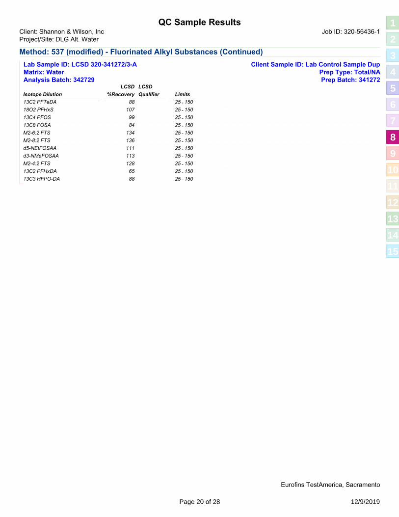
QC Sample ResultsJob ID: 320-56436-1Client: Shannon & Wilson, Inc
Project/Site: DLG Alt. Water
Method: 537 (modified) - Fluorinated Alkyl Substances (Continued)
Client Sample ID: Lab Control Sample DupLab Sample ID: LCSD 320-341272/3-AMatrix: Water Prep Type: Total/NAAnalysis Batch: 342729 Prep Batch: 341272
13C2 PFTeDA 25 - 150
Isotope Dilution
88
LCSD LCSD
Qualifier Limits%Recovery
10718O2 PFHxS 25 - 150
9913C4 PFOS 25 - 150
8413C8 FOSA 25 - 150
134M2-6:2 FTS 25 - 150
136M2-8:2 FTS 25 - 150
111d5-NEtFOSAA 25 - 150
113d3-NMeFOSAA 25 - 150
128M2-4:2 FTS 25 - 150
6513C2 PFHxDA 25 - 150
8813C3 HFPO-DA 25 - 150
Eurofins TestAmerica, Sacramento
Page 20 of 28 12/9/2019
1
2
3
4
5
6
7
8
9
10
11
12
13
14
15

QC Association SummaryJob ID: 320-56436-1Client: Shannon & Wilson, Inc
Project/Site: DLG Alt. Water
LCMS
Prep Batch: 341272
Lab Sample ID Client Sample ID Prep Type Matrix Method Prep Batch
Water 3535320-56436-1 200150 Total/NA
Water 3535320-56436-2 191710 Total/NA
Water 3535320-56436-3 191320 Total/NA
Water 3535320-56436-4 191050 Total/NA
Water 3535MB 320-341272/1-A Method Blank Total/NA
Water 3535LCS 320-341272/2-A Lab Control Sample Total/NA
Water 3535LCSD 320-341272/3-A Lab Control Sample Dup Total/NA
Analysis Batch: 342729
Lab Sample ID Client Sample ID Prep Type Matrix Method Prep Batch
Water 537 (modified) 341272320-56436-1 200150 Total/NA
Water 537 (modified) 341272320-56436-2 191710 Total/NA
Water 537 (modified) 341272320-56436-3 191320 Total/NA
Water 537 (modified) 341272320-56436-4 191050 Total/NA
Water 537 (modified) 341272MB 320-341272/1-A Method Blank Total/NA
Water 537 (modified) 341272LCS 320-341272/2-A Lab Control Sample Total/NA
Water 537 (modified) 341272LCSD 320-341272/3-A Lab Control Sample Dup Total/NA
Eurofins TestAmerica, Sacramento
Page 21 of 28 12/9/2019
1
2
3
4
5
6
7
8
9
10
11
12
13
14
15
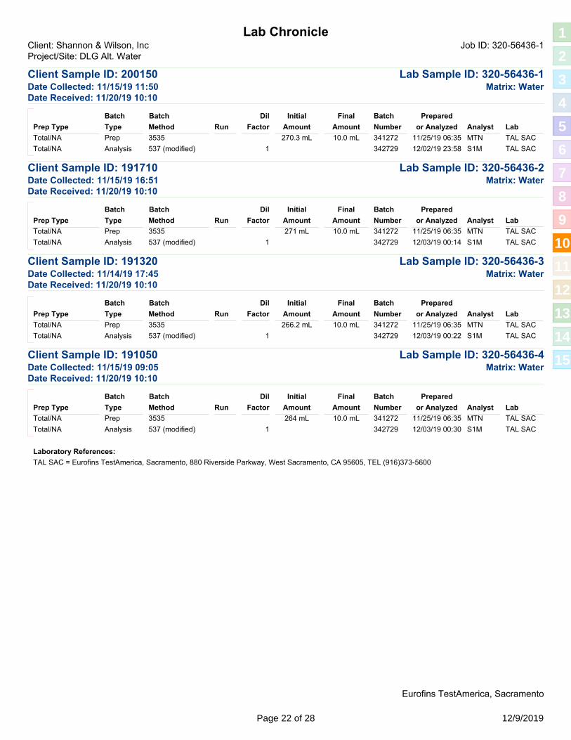
Lab ChronicleClient: Shannon & Wilson, Inc Job ID: 320-56436-1Project/Site: DLG Alt. Water
Client Sample ID: 200150 Lab Sample ID: 320-56436-1Matrix: WaterDate Collected: 11/15/19 11:50
Date Received: 11/20/19 10:10
Prep 3535 MTN11/25/19 06:35 TAL SAC341272
Type
Batch
Method
Batch
Prep Type LabAnalystRun
Prepared
or Analyzed
Initial
Amount Amount
Final Batch
NumberFactor
Dil
Total/NA 270.3 mL 10.0 mL
Analysis 537 (modified) 1 342729 12/02/19 23:58 S1M TAL SACTotal/NA
Client Sample ID: 191710 Lab Sample ID: 320-56436-2Matrix: WaterDate Collected: 11/15/19 16:51
Date Received: 11/20/19 10:10
Prep 3535 MTN11/25/19 06:35 TAL SAC341272
Type
Batch
Method
Batch
Prep Type LabAnalystRun
Prepared
or Analyzed
Initial
Amount Amount
Final Batch
NumberFactor
Dil
Total/NA 271 mL 10.0 mL
Analysis 537 (modified) 1 342729 12/03/19 00:14 S1M TAL SACTotal/NA
Client Sample ID: 191320 Lab Sample ID: 320-56436-3Matrix: WaterDate Collected: 11/14/19 17:45
Date Received: 11/20/19 10:10
Prep 3535 MTN11/25/19 06:35 TAL SAC341272
Type
Batch
Method
Batch
Prep Type LabAnalystRun
Prepared
or Analyzed
Initial
Amount Amount
Final Batch
NumberFactor
Dil
Total/NA 266.2 mL 10.0 mL
Analysis 537 (modified) 1 342729 12/03/19 00:22 S1M TAL SACTotal/NA
Client Sample ID: 191050 Lab Sample ID: 320-56436-4Matrix: WaterDate Collected: 11/15/19 09:05
Date Received: 11/20/19 10:10
Prep 3535 MTN11/25/19 06:35 TAL SAC341272
Type
Batch
Method
Batch
Prep Type LabAnalystRun
Prepared
or Analyzed
Initial
Amount Amount
Final Batch
NumberFactor
Dil
Total/NA 264 mL 10.0 mL
Analysis 537 (modified) 1 342729 12/03/19 00:30 S1M TAL SACTotal/NA
Laboratory References:
TAL SAC = Eurofins TestAmerica, Sacramento, 880 Riverside Parkway, West Sacramento, CA 95605, TEL (916)373-5600
Eurofins TestAmerica, Sacramento
Page 22 of 28 12/9/2019
1
2
3
4
5
6
7
8
9
10
11
12
13
14
15

Accreditation/Certification SummaryClient: Shannon & Wilson, Inc Job ID: 320-56436-1Project/Site: DLG Alt. Water
Laboratory: Eurofins TestAmerica, SacramentoAll accreditations/certifications held by this laboratory are listed. Not all accreditations/certifications are applicable to this report.
Authority Program Identification Number Expiration Date
Alaska (UST) 17-020State 01-20-21
ANAB Dept. of Defense ELAP L2468 01-20-21
ANAB Dept. of Energy L2468.01 01-20-21
ANAB ISO/IEC 17025 L2468 01-20-21
Arizona State AZ0708 08-11-20
Arkansas DEQ State 19-042-0 06-17-20
California State 2897 01-31-20
Colorado State CA0004 08-31-20
Connecticut State PH-0691 06-30-21
Florida NELAP E87570 06-30-20
Georgia State 4040 01-29-20
Hawaii State <cert No.> 01-29-20
Illinois NELAP 200060 03-17-20
Kansas NELAP E-10375 10-31-20 *
Louisiana NELAP 01944 06-30-20
Maine State 2018009 04-14-20
Michigan State 9947 01-29-20
Michigan State Program 9947 01-31-20
Nevada State CA000442020-1 07-31-20
New Hampshire NELAP 2997 04-18-20
New Jersey NELAP CA005 06-30-20
New York NELAP 11666 04-01-20
Oregon NELAP 4040 01-29-20
Pennsylvania NELAP 68-01272 03-31-20
Texas NELAP T104704399-19-13 05-31-20
US Fish & Wildlife US Federal Programs 58448 07-31-20
USDA US Federal Programs P330-18-00239 07-31-21
Utah NELAP CA000442019-01 02-29-20
Vermont State VT-4040 04-16-20
Virginia NELAP 460278 03-14-20
Washington State C581 05-05-20
West Virginia (DW) State 9930C 12-31-19
Wyoming State Program 8TMS-L 01-28-19 *
Eurofins TestAmerica, Sacramento
* Accreditation/Certification renewal pending - accreditation/certification considered valid.
Page 23 of 28 12/9/2019
1
2
3
4
5
6
7
8
9
10
11
12
13
14
15

Method SummaryJob ID: 320-56436-1Client: Shannon & Wilson, Inc
Project/Site: DLG Alt. Water
Method Method Description LaboratoryProtocol
EPA537 (modified) Fluorinated Alkyl Substances TAL SAC
SW8463535 Solid-Phase Extraction (SPE) TAL SAC
Protocol References:
EPA = US Environmental Protection Agency
SW846 = "Test Methods For Evaluating Solid Waste, Physical/Chemical Methods", Third Edition, November 1986 And Its Updates.
Laboratory References:
TAL SAC = Eurofins TestAmerica, Sacramento, 880 Riverside Parkway, West Sacramento, CA 95605, TEL (916)373-5600
Eurofins TestAmerica, Sacramento
Page 24 of 28 12/9/2019
1
2
3
4
5
6
7
8
9
10
11
12
13
14
15

Sample SummaryJob ID: 320-56436-1Client: Shannon & Wilson, Inc
Project/Site: DLG Alt. Water
Lab Sample ID Client Sample ID ReceivedCollectedMatrix Asset ID
320-56436-1 200150 Water 11/15/19 11:50 11/20/19 10:10
320-56436-2 191710 Water 11/15/19 16:51 11/20/19 10:10
320-56436-3 191320 Water 11/14/19 17:45 11/20/19 10:10
320-56436-4 191050 Water 11/15/19 09:05 11/20/19 10:10
Eurofins TestAmerica, Sacramento
Page 25 of 28 12/9/2019
1
2
3
4
5
6
7
8
9
10
11
12
13
14
15

Page 26 of 28 12/9/2019
1
2
3
4
5
6
7
8
9
10
11
12
13
14
15

Page 27 of 28 12/9/2019
1
2
3
4
5
6
7
8
9
10
11
12
13
14
15

Login Sample Receipt Checklist
Client: Shannon & Wilson, Inc Job Number: 320-56436-1
Login Number: 56436
Question Answer Comment
Creator: Her, David A
List Source: Eurofins TestAmerica, Sacramento
List Number: 1
TrueRadioactivity wasn't checked or is </= background as measured by a survey meter.
TrueThe cooler's custody seal, if present, is intact. Seal present with no number.
N/ASample custody seals, if present, are intact.
TrueThe cooler or samples do not appear to have been compromised or tampered with.
TrueSamples were received on ice.
TrueCooler Temperature is acceptable.
TrueCooler Temperature is recorded.
TrueCOC is present.
TrueCOC is filled out in ink and legible.
TrueCOC is filled out with all pertinent information.
TrueIs the Field Sampler's name present on COC?
TrueThere are no discrepancies between the containers received and the COC.
TrueSamples are received within Holding Time (excluding tests with immediate HTs)
TrueSample containers have legible labels.
TrueContainers are not broken or leaking.
TrueSample collection date/times are provided.
TrueAppropriate sample containers are used.
TrueSample bottles are completely filled.
N/ASample Preservation Verified.
TrueThere is sufficient vol. for all requested analyses, incl. any requested MS/MSDs
TrueContainers requiring zero headspace have no headspace or bubble is <6mm (1/4").
TrueMultiphasic samples are not present.
TrueSamples do not require splitting or compositing.
N/AResidual Chlorine Checked.
Eurofins TestAmerica, SacramentoPage 28 of 28 12/9/2019
1
2
3
4
5
6
7
8
9
10
11
12
13
14
15

November 2019 Page 1
Laboratory Data Review Checklist
Completed By:
Brittany Blood
Title:
Environmental Professional I
Date:
12/11/2019
Consultant Firm:
Shannon and Wilson, Inc.
Laboratory Name:
TestAmerica Laboratories, Inc.
Laboratory Report Number:
320-56436-1
Laboratory Report Date:
12/9/2019
CS Site Name:
ADOT&PF Dillingham Airport Sitewide PFAS
ADEC File Number:
2540.38.023
Hazard Identification Number:
26971

320-56436-1
Laboratory Report Date:
12/9/2019
CS Site Name:
ADOT&PF Dillingham Airport Sitewide PFAS
November 2019 Page 2
Note: Any N/A or No box checked must have an explanation in the comments box.
1. Laboratory
a. Did an ADEC CS approved laboratory receive and perform all of the submitted sample analyses?
Yes☒ No☐ N/A☐ Comments: The ADEC certified the Eurofins TestAmerica Laboratories West Sacramento, CA location for the analysis of perfluorooctanesulfonic acid (PFOS) and perfluorooctanoic acid (PFOA) on February 6, 2018. These compounds were included in the ADEC’s Contaminated Sites Laboratory Approval 17-020. b. If the samples were transferred to another “network” laboratory or sub-contracted to an alternate
laboratory, was the laboratory performing the analyses ADEC CS approved?
Yes☐ No☐ N/A☒ Comments: Analyses were performed by Eurofins TestAmerica Laboratories, Inc. in West Sacramento, CA.
2. Chain of Custody (CoC)
a. CoC information completed, signed, and dated (including released/received by)?
Yes☒ No☐ N/A☐ Comments:
b. Correct analyses requested?
Yes☒ No☐ N/A☐ Comments:
3. Laboratory Sample Receipt Documentation
a. Sample/cooler temperature documented and within range at receipt (0° to 6° C)?
Yes☒ No☐ N/A☐ Comments:
b. Sample preservation acceptable – acidified waters, Methanol preserved VOC soil (GRO, BTEX, Volatile Chlorinated Solvents, etc.)?
Yes☒ No☐ N/A☐ Comments:

320-56436-1
Laboratory Report Date:
12/9/2019
CS Site Name:
ADOT&PF Dillingham Airport Sitewide PFAS
November 2019 Page 3
c. Sample condition documented – broken, leaking (Methanol), zero headspace (VOC vials)?
Yes☒ No☐ N/A☐ Comments:
d. If there were any discrepancies, were they documented? For example, incorrect sample containers/preservation, sample temperature outside of acceptable range, insufficient or missing samples, etc.?
Yes☐ No☐ N/A☒ Comments: No discrepancies were noted by the laboratory.
e. Data quality or usability affected?
Comments:
Data quality and/or usability were not affected; see above.
4. Case Narrative
a. Present and understandable?
Yes☒ No☐ N/A☐ Comments:

320-56436-1
Laboratory Report Date:
12/9/2019
CS Site Name:
ADOT&PF Dillingham Airport Sitewide PFAS
November 2019 Page 4
b. Discrepancies, errors, or QC failures identified by the lab?
Yes☒ No☐ N/A☐ Comments: Due to a shortage in the marketplace for 13C3-PFBS, the target analyte PFBS and/or Perfluoropentanesulfonic acid (PFPeS) could not be quantitated against 13C3-PFBS (its labeled variant) as listed in the SOP. PFBS and Perfluoropentanesulfonic acid (PFPeS) was quantitated versus 18O2-PFHxS instead. Several Isotope Dilution Analyte (IDA) recoveries are above the method recommended limit for the following samples: 200150, 191320, and 191050. Quantitation by isotope dilution generally precludes any adverse effect on data quality due to elevated IDA recoveries. Insufficient sample volume was available to perform a matrix spike/matrix spike duplicate (MS/MSD) associated with preparation batch 320-341272. The following samples were preserved with Trizma: 200150, 191710, 191320, and 191050. Thus, the MB, LCS and LCSD also contain Trizma. The following samples contain a thin layer of orange sediment at the bottom of the bottle prior to extraction: 191710 and 191320. During the solid phase extraction process, the following samples have non-settable particulates which clogged the extraction columns: 191710 and 191320. Sample 191320 was yellow after extraction.
c. Were all corrective actions documented?
Yes☒ No☐ N/A☐ Comments: See above.
d. What is the effect on data quality/usability according to the case narrative?
Comments:
The case narrative does not note an affect on data quality and/or usability.

320-56436-1
Laboratory Report Date:
12/9/2019
CS Site Name:
ADOT&PF Dillingham Airport Sitewide PFAS
November 2019 Page 5
5. Samples Results
a. Correct analyses performed/reported as requested on COC?
Yes☒ No☐ N/A☐ Comments:
b. All applicable holding times met?
Yes☒ No☐ N/A☐ Comments:
c. All soils reported on a dry weight basis?
Yes☐ No☐ N/A☒ Comments: All samples in this work order are water samples.
d. Are the reported LOQs less than the Cleanup Level or the minimum required detection level for the project?
Yes☒ No☐ N/A☐ Comments:
e. Data quality or usability affected?
Data quality and/or usability were not affected; see above.
6. QC Samples
a. Method Blank i. One method blank reported per matrix, analysis and 20 samples?
Yes☒ No☐ N/A☐ Comments:
ii. All method blank results less than limit of quantitation (LOQ) or project specified objectives?
Yes☒ No☐ N/A☐ Comments: All method blank results were less than the LOQ, however, PFHxS was detected in the method blank sample below the LOQ.

320-56436-1
Laboratory Report Date:
12/9/2019
CS Site Name:
ADOT&PF Dillingham Airport Sitewide PFAS
November 2019 Page 6
iii. If above LOQ or project specified objectives, what samples are affected? Comments:
No samples were affected, as associated samples were greater than 10 times the concentration detected in the method blank sample.
iv. Do the affected sample(s) have data flags? If so, are the data flags clearly defined?
Yes☐ No☐ N/A☒ Comments: No project samples were affected, see above.
v. Data quality or usability affected? Comments:
No data quality or usability was affected
b. Laboratory Control Sample/Duplicate (LCS/LCSD) i. Organics – One LCS/LCSD reported per matrix, analysis and 20 samples? (LCS/LCSD
required per AK methods, LCS required per SW846)
Yes☒ No☐ N/A☐ Comments:
ii. Metals/Inorganics – one LCS and one sample duplicate reported per matrix, analysis and 20 samples?
Yes☐ No☐ N/A☒ Comments: Metals and inorganics were not analyzed as a part of this work order.
iii. Accuracy – All percent recoveries (%R) reported and within method or laboratory limits and project specified objectives, if applicable? (AK Petroleum methods: AK101 60%-120%, AK102 75%-125%, AK103 60%-120%; all other analyses see the laboratory QC pages)
Yes☒ No☐ N/A☐ Comments:

320-56436-1
Laboratory Report Date:
12/9/2019
CS Site Name:
ADOT&PF Dillingham Airport Sitewide PFAS
November 2019 Page 7
iv. Precision – All relative percent differences (RPD) reported and less than method or laboratory limits and project specified objectives, if applicable? RPD reported from LCS/LCSD, and or sample/sample duplicate. (AK Petroleum methods 20%; all other analyses see the laboratory QC pages)
Yes☒ No☐ N/A☐ Comments:
v. If %R or RPD is outside of acceptable limits, what samples are affected? Comments:
Not applicable, all %Rs and RPDs were within acceptable limits.
vi. Do the affected sample(s) have data flags? If so, are the data flags clearly defined?
Yes☐ No☐ N/A☒ Comments: See above.
vii. Data quality or usability affected? (Use comment box to explain.) Comments:
Data quality and/or usability was not affected; see above.
c. Matrix Spike/Matrix Spike Duplicate (MS/MSD)
Note: Leave blank if not required for project i. Organics – One MS/MSD reported per matrix, analysis and 20 samples?
Yes☐ No☒ N/A☐ Comments: There was insufficient sample volume to perform a MS/MSD associated with the samples in this work order.
ii. Metals/Inorganics – one MS and one MSD reported per matrix, analysis and 20 samples?
Yes☐ No☐ N/A☒ Comments: Metals and inorganics were not analyzed as a part of this work order.

320-56436-1
Laboratory Report Date:
12/9/2019
CS Site Name:
ADOT&PF Dillingham Airport Sitewide PFAS
November 2019 Page 8
iii. Accuracy – All percent recoveries (%R) reported and within method or laboratory limits and project specified objectives, if applicable? (AK Petroleum methods: AK101 60%-120%, AK102 75%-125%, AK103 60%-120%; all other analyses see the laboratory QC pages)
Yes☐ No☐ N/A☒ Comments: There was insufficient sample volume to perform a MS/MSD associated with the samples in this work order.
iv. Precision – All relative percent differences (RPD) reported and less than method or laboratory limits and project specified objectives, if applicable? RPD reported from MS/MSD, and or sample/sample duplicate. (AK Petroleum methods 20%; all other analyses see the laboratory QC pages)
Yes☐ No☐ N/A☒ Comments: There was insufficient sample volume to perform a MS/MSD associated with the samples in this work order.
v. If %R or RPD is outside of acceptable limits, what samples are affected? Comments:
Not applicable, there was insufficient sample volume to perform a MS/MSD associated with the samples in this work order.
vi. Do the affected sample(s) have data flags? If so, are the data flags clearly defined?
Yes☐ No☐ N/A☒ Comments: See above.
vii. Data quality or usability affected? (Use comment box to explain.) Comments:
Data quality and/or usability were not affected.
d. Surrogates – Organics Only or Isotope Dilution Analytes (IDA) – Isotope Dilution Methods Only i. Are surrogate/IDA recoveries reported for organic analyses – field, QC and laboratory
samples?
Yes☒ No☐ N/A☐ Comments:

320-56436-1
Laboratory Report Date:
12/9/2019
CS Site Name:
ADOT&PF Dillingham Airport Sitewide PFAS
November 2019 Page 9
ii. Accuracy – All percent recoveries (%R) reported and within method or laboratory limits and project specified objectives, if applicable? (AK Petroleum methods 50-150 %R; all other analyses see the laboratory report pages)
Yes☐ No☒ N/A☐ Comments: Recovery of IDAs M2-4:2FTS, M2-6:2FTS, and M2-8:2FTS in samples 200150 and 191320 were reported above laboratory limits. Recovery of IDA M2-4:2FTS in sample 191050 was above the QC limits.
iii. Do the sample results with failed surrogate/IDA recoveries have data flags? If so, are the data flags clearly defined?
Yes☐ No☐ N/A☒ Comments: The sample results with failed IDA recoveries were not qualified as all analytes with IDA failures were not detected within the samples.
iv. Data quality or usability affected? Comments:
Data quality and/or usability was not affected.
e. Trip Blanks i. One trip blank reported per matrix, analysis and for each cooler containing volatile samples?
(If not, enter explanation below.)
Yes☐ No☐ N/A☒ Comments: A trip blank is not required for the analysis of PFAS as PFAS is not a volatile compound.
ii. Is the cooler used to transport the trip blank and VOA samples clearly indicated on the COC? (If not, a comment explaining why must be entered below)
Yes☐ No☐ N/A☒ Comments: A trip blank is not required.
iii. All results less than LOQ and project specified objectives?
Yes☐ No☐ N/A☒ Comments: See above.
iv. If above LOQ or project specified objectives, what samples are affected? Comments:
Not applicable, see above.

320-56436-1
Laboratory Report Date:
12/9/2019
CS Site Name:
ADOT&PF Dillingham Airport Sitewide PFAS
November 2019 Page 10
v. Data quality or usability affected? Comments:
Data quality and/or usability were not affected.
f. Field Duplicate i. One field duplicate submitted per matrix, analysis and 10 project samples?
Yes☐ No☐ N/A☒ Comments: A field duplicate was not submitted as a part of this work order, however, the appropriate number of duplicate samples were submitted for the overall project.
ii. Submitted blind to lab?
Yes☐ No☐ N/A☒ Comments: See above.
iii. Precision – All relative percent differences (RPD) less than specified project objectives? (Recommended: 30% water, 50% soil)
RPD (%) = Absolute value of: (R1-R2)
((R1+R2)/2)
Where R1 = Sample Concentration R2 = Field Duplicate Concentration
Yes☐ No☐ N/A☒ Comments: See above.
iv. Data quality or usability affected? (Use the comment box to explain why or why not.) Comments:
Data quality and/or usability were not affected; see above.
g. Decontamination or Equipment Blank (If not applicable, a comment stating why must be entered below)?
Yes☐ No☐ N/A☒ Comments: Reusable equipment was not used to collect samples on this work order.
x 100

320-56436-1
Laboratory Report Date:
12/9/2019
CS Site Name:
ADOT&PF Dillingham Airport Sitewide PFAS
November 2019 Page 11
i. All results less than LOQ and project specified objectives?
Yes☐ No☐ N/A☒ Comments: See above.
ii. If above LOQ or project specified objectives, what samples are affected? Comments:
Not applicable, see above.
iii. Data quality or usability affected? Comments:
Data quality and/or usability were not affected; see above.
7. Other Data Flags/Qualifiers (ACOE, AFCEE, Lab Specific, etc.)
a. Defined and appropriate?
Yes☐ No☐ N/A☒ Comments:

Long-Term Alternate Water Feasibility Study Report
102786-003 October 2020
APPE
NDIX
B: B
ARR
REPO
RT A
ND S
UPPO
RTIN
G IN
FORM
ATIO
N
RESIDENTIAL WELL SAMPLING LOG

Long-Term Alternate Water Feasibility Study Report
102786-003 October 2020
Water supply well field notes contain personal information. This content has been removed for confidentiality.

Long-Term Alternate Water Feasibility Study Report
102786-003 October 2020 C-i
APPE
NDIX
C: W
ATER
STO
RAGE
TAN
K SU
PPOR
TING
INFO
RMAT
ION
Appendix C
Water Storage Tank Supporting Information
CONTENTS
Enclosures
West-Mark 2,000-gallon and 5,000-gallon trailer specifications and quote
Greer Tanks polyethylene tank brochure
Alaska Marine Lines shipping quote
C.1 Cost Estimates.......................................................................................................... ii

Long-Term Alternate Water Feasibility Study Report
102786-003 October 2020 C-ii-6
APPE
NDIX
C: W
ATER
STO
RAGE
TAN
K SU
PPOR
TING
INFO
RMAT
ION
C.1 COST ESTIMATES
This appendix contains supporting information used to prepare the ballpark capital cost estimate for water storage tanks. Enclosed please find cost estimates from several contractors.
Exhibit C.1-1: Impacted Properties
Item Units Unit Cost Total Cost
1,500-gallon tank and freight 17 tanks $6,324 $107,508
Materials (pump, piping, fittings, insulation, etc.) at single-tank locations 7 locations $5,500 $38,500
Materials at multiple-tank locations 3 locations $8,250 $24,750
Installation at single-tank locations 7 locations $9,000 $63,000
Installation at multiple-tank locations 3 locations $13,500 $40,500
Plane flights, lodging for out-of-town plumber - - $3,691
Well abandonment 7 wells $5,000 $35,000
Engineering and design, includes site visits 10 locations $20,000 $200,000
Potable water trailer, 5,000-gallon - - $94,900
Subtotal $607,849
Contingency (35%) $212,747
Total $820,596

Long-Term Alternate Water Feasibility Study Report
102786-003 October 2020
APPE
NDIX
C: W
ATER
STO
RAGE
TAN
K SU
PPOR
TING
INFO
RMAT
ION
WEST-MARK 2,000 GALLON AND 5,000 GALLON TRAILER SPECIFICATIONS AND QUOTE

SALESMAN: Scott Vincent
Quote for:
DILLINGHAM, ALASKA
75561-00S3 10/01/20 1
P.O.BOX 100 PHONE: (209) 537-4747 CERES, CA 95307 TOLL FREE: (800) 692-5844 www.west-mark.com FAX: (209) 537-1753
GENERAL The following equipment shall be a new West-Mark tandem-axle water trailer.
OVERAL DIEMENSION REQUIREMENTS: Length: 25 feet (prox.) measured from rear of trailer to lunette eye Width: Maximum 8 feet
Unit shall be capable of transporting a minimum of 2,000 gallons of water over improved roads at sustained speeds of 55 MPH and off-road at sustained speeds of 15 MPH.
PRODUCT: Potable water. PRODUCT WEIGHT: 8.35 lbs./gallon. TANK OPERATING TEMPERATURE: 125° F maximum INTENDED AREA OF OPERATION: State of Alaska. INTENDED USE: Highway and Unimproved roads.
TANK/ MANHOLES/ VENTING • Barrel, 2,000 Gallons T-304 stainless steel 10GA oval, straight.• Head(s), stainless steel 10GA, dished and flanged.• Baffle(s), one (1) 10GA stainless steel, dished and flanged.• Tank mounted directly to trailer decking.• Wings, Bolsters, and Sidefillers, Stainless Steel.• Weld Finish, interior to be W-2 with all longitudinal seams to be W-3. Exterior weld finish to be W-0.• Manhole(s), one (1) 20", T-304 stainless steel with a single lug, EPDM gasket and provisions for a padlock; located top
of tank at front.• Venting, one (1) with anti-splash deflector, synthetic filter media, w/ mesh screen.• Insulation, Polystyrene foam sheets, fiberglass at heads, ring tape at all rings.• Jacketing, belly wrapped stainless steel with lapped seams. Jacket heads to be 20 Gauge stainless steel, lock seamed
to jacket.• Sight Gauge(s), one (1) acrylic liquid level gauge sight tube assembly with shutoff valve and drain cock at bottom. Red
ball installed inside tube. Gauge to be located at rear head.• Tank Cleanout, one (1) 1-1/2" drain shall be located at the bottom of the tank, near the rear. Outlet shall have a cam-lock
adapter with tethered cap.
LIGHTS AND WIRING • Trailer Lighting, L.E.D. lighting to meet all D.O.T. requirements w/ rear license plate lamp.• Reflectors, per D.O.T.• Conspicuity Striping, per D.O.T.• Electrical Plug, 7-way male RV type.• Cabinet Dome Light(s), two (2) L.E.D. with switch.

SALESMAN: Scott Vincent
Quote for:
DILLINGHAM, ALASKA
75561-00S3 10/01/20 2
PLUMBING • Cabinet(s), one (1) stainless steel non- insulated double door with stainless steel hardware and lockable latch located at
rear.• Pump and Engine Assembly, one (1) stainless steel pump with diesel engine. Engine to have cold weather start package
Installed.• Meter installed in cabinet for “resale” of water.• Hose reel installed in cabinet with 1” x 50’ of potable water hose with ball valve at end.• Fuel Tank, to be remotely mounted in an easy access location for tank fill.• Battery, in plastic enclosure• Flow Diagram, flow chart with valving instructions for various pumping functions.
UNDERCARRIAGE • Trailer, 26,000 LB GVWR tandem-axle trailer• Frame, heavy-duty channel style• Tow Bar, ridged and extend to minimize the threat of early jackknifing at any turning angle.• Platform, one (1) 2' X 4' (minimum) platform with kick plate, slip resistant floor, and safety railing shall be installed at the
front of the tank for access to manhole. Slip resistant steps with safety railing installed for access to platform.• Grab Handle, one (1) to assist when accessing rear platform.• Decking, carbon steel diamond plate.• Jack, one (1) heavy-duty landing gear assembly located a minimum of 50" from Lunette eye.• Axles, two (2) 12,000 lb. 3” round with electric brakes.• Springs, four (4) each multi-leaf• Wheel(s), nine (9) steel• Tire(s), nine (9) commercial grade radial.• Brake System, electric brakes for a tandem axle trailer.• Break-Away Kit, An electric brake, kit consisting of a break-away switch, trickle charger, and a battery• Bumper, carbon steel end cap.• Hitch, one (1) Lunette eye with multi-height adjustability.• Safety Chain, two (2) with hook.• Cabinet, one (1) powder coated with lift-up door on tongue of trailer.• Tire Carrier, installed on tongue of trailer.• Ten (10) lengths of 2” x 10’ of potable water hose with stainless steel fittings installed in the hose trays.
OPTIONAL ITEMS • Tie Down Points, aid in the securing of the unit when transporting.• Two (2) stainless steel hose trays installed to carry the potable water hose.
MISC. • Severe Service Undercoating (SSU) applied to the frame package.• Heat trace package installed to cover plumbing package. Connects for wiring to be at front of frailer• Paint, all carbon steel fabricated parts.• Paint Preparation, all steel chassis components shall be properly prepared prior to painting (Example: shot blast, sand
blast, hot power washed with chemical, and/or any other method accepted in the industry) to ensure the surfaces arelightly etched and all contaminants/rust/oils are removed prior to the application of paint.
• Operator Training Guide in each manual containing detailed operating instructions of all functions with photos.• Operation and maintenance manual(s) in paper format and on CD-ROM complete with:
- Operator & maintenance manual- Calibration chart (if applicable)- Equipment parts list- Misc. vendor literature / manuals

SALESMAN: Scott Vincent
Quote for:
DILLINGHAM, ALASKA
75561-00S3 10/01/20 3
Any and all Brand Name parts mentioned in specifications above are subject to substitution of an equal part that is of a different brand. Other substitutions may also be made if said substitution does not affect the intended function of the vehicle’s mission and is equivalent or an upgrade as determined by West-Mark. All specified dimensions are nominal and may vary slightly.
Tank and all fabricated parts warranty good for one (1) year.

Salesman: Scott Vincent
Quote for DILLINGHAM, ALASKA
201061-00S4 10/01/20 Page 1 of 6
P.O.BOX 100 PHONE: (209) 537-4747 CERES, CA 95307 TOLL FREE: (800) 692-5844 www.west-mark.com FAX: (209) 537-1753
GENERAL
The following equipment shall be a new West-Mark tandem axle semi trailer.
OVERALL LENGTH: Approximately 32’. PRODUCT: Non-potable water. PRODUCT WEIGHT: 8.35 lbs./gallon. VESSEL CODE: Non-Spec. OPERATING PRESSURE: Atmosphere. VACUUM RATING: None (0 in./Hg). TANK OPERATING TEMPERATURE: One hundred twenty-five degrees Fahrenheit (125° F) maximum. INTENDED AREA OF OPERATION: State of Alaska. INTENDED USE: Gravel roads.
PASSIVATION: None. (Available as option upon request and may be recommended for the product specified herein)
TRACTOR
TRACTOR: Customer supplied.
(Note: weights are based on tractor full of fuel and with driver.)
A=____ D=____ G=____ B=____ E=____ C=____ F=____
Salesman: Scott Vincent
Quote for DILLINGHAM, ALASKA
201061-00S4 10/01/20 Page 2 of 6
(Customer to supply chassis info. at time of order.)
If information is not supplied at time of order, West-Mark will use its standard typical setup. Any information supplied after engineering package has been released to production, that requires set-up changes, will be done at additional charge to customer.
TANK / MANHOLES / VENTING
BARREL: 5000 Gallons round, straight barrel, with slope to rear. The barrel shall be made from 12 gauge T-304 stainless steel, 2B finish material.
Capacity does not include head outage.
HEADS: Two (2) each stainless steel, T-304 2B, 12 gauge, West-Mark air-dished and flanged. HEAD FINISH: No polishing on interior or exterior of heads.
HEAD FINISH: No polishing on interior or exterior of heads. BAFFLES: None. (Available as option upon request) RINGS: Stainless steel channel sections, fully welded to shell.
WINGS AND BOLSTERS: Shall be made of stainless steel.
SIDE FILLERS: Stainless steel with coupler plate adjustment rails.
WELD FINISH: INTERIOR: Weld finish to be W-2 inside. All Longitudinal seams to be W-3. EXTERIOR: Weld finish to be W-2 outside.
MANHOLE: One (1) each, 20", T-316 stainless steel with a single lug, EPDM gasket and a hinge stop for keeping the lid off the shell when open. Located:__________ Hinged:_______________
CLEANOUT(S): None. (Available as option upon request)
VENTING: One (1) Each NAFCO 2" filter (or equal) with stainless steel element, installed over a RUNO pagoda with a stainless steel sleeve, on a 3" stainless steel Camlock and cap. Located in top of tank, forward of manhole.
INSULATION: 2” Styrene insulation installed with fiberglass at heads. Ring tape installed on all rings.
JACKET: Stainless steel jacket (belly wrapped) installed with lock seamed stainless steel jacket heads
HEAT: Heat trace package installed to cover plumbing package. Connection for package located at front of trailer.

Salesman: Scott Vincent
Quote for DILLINGHAM, ALASKA
201061-00S4 10/01/20 Page 3 of 6
C.I.P.:None. (Available as option upon request)
LIQUID LEVEL GAUGE: None. (Available as option upon request)
LADDERS / WALKWAYS / SPILLDAMS
SPILLDAM: One (1) Each non-insulated, stainless steel box style, with drain hoses each side.
LADDER: One (1) aluminum tubular, multi-purpose ladder assembly, with West-Mark heavy duty slip resistant steps located at curbside of unit. Step will be between 18” and 22” from the ground. No grab rails installed (available as option upon request).
SPILLDAM WALKWAY: 12" Wide aluminum non-slip platform walkway, full length of spilldam; located between ladder and spilldam.
LIGHTS AND WIRING
ELECTRICAL SYSTEM: System shall be 12-volt, 7-way, and vapor proof. All lamps to be L.E.D. type and locations shall meet all D.O.T. requirements.
STOP/ TAIL/ TURN: Four (4) each model 44 type in 2-hole, stainless steel boxes; 2 red each side. CENTER ID: One (1) each Truck-Lite model 15 stainless steel I.D. shall be mounted at rear per D.O.T. MID TURN/ MARKER: One (1) each amber model 60 oval turn/ marker light shall be mounted @ center of unit (approx.) each side if required by D.O.T. FRONT MARKERS: One (1) each amber model 30 light shall be mounted to the front corner of the trailer at 45° on each side of unit. REAR MARKERS: One (1) each red model 30 marker lamp located at end of each light box.
SECURITY RINGS / MOUNT COVERS: None. (Available as option upon request)
REFLECTORS: To be mounted per D.O.T. specifications.
CONSPICUITY STRIPING: To be installed at sides and rear per D.O.T. specifications.
FRONT RECEPTICAL: Truck-Lite 7-way nosebox (model #50806) with 15 amp circuit breakers and front access to cable hookup, mounted on a stainless steel bracket between glad hands.
PLUMBING
REAR OUTLET: 3" Stainless steel split pipe out rear head.

Salesman: Scott Vincent
Quote for DILLINGHAM, ALASKA
201061-00S4 10/01/20 Page 4 of 6
OUTLET PLUMBING: Plumb from sump to a 3” butterfly valve with stainless steel disc and stem and lever lock handle.
Plumbing to end in 3" stainless steel male camlock adapter and lockable brass cap with chain.
APRON: Stainless steel splash pan to be installed under valve at rear of trailer.
TOP FILL: None. (Available as option upon request)
PUMP PACKAGE: One (1) Each Thomsen # 8 stainless steel 3" x 2" pump with 11hp diesel engine with electric start. Install meter (for resale) and hose reel (1” x 50’) for potable water service.
UNDERCARRIAGE
APRON: Stainless steel splash pan to be installed under valve at rear of trailer.
KICK PLATE: To be installed at front of unit and to be of stainless steel construction.
KING PIN PLATE: Adjustable upper coupler, mild steel. 48" Ride height, unless noted otherwise in tractor spec's above. King Pin to be located: _______________
WEAR PAD: None. (Available as option upon request)
LANDING GEAR FRAME: Frame to be stainless steel construction.
LANDING LEG SUPPORTS: Stainless steel pipe style from legs up to crossmember and to rear of subframe with lower leg supports for aluminum landing legs.
LANDING GEAR: JOST Aluminum square leg, 2-speed, steel sand shoes, 55,000 lb. lift capacity. Crank located on curbside.
REAR SUBFRAME: Stainless steel construction for a tandem axle suspension.
SUSPENSION: Two (2) HENDRICKSON TURNER INTRAAX AANT 23K air ride integration system 17" ride height, weld-on wing style hangers, front shock absorbers

Salesman: Scott Vincent
Quote for DILLINGHAM, ALASKA
201061-00S4 10/01/20 Page 5 of 6
AXLES: Two (2) 23K, 5-3/4" round 71-1/2" track 10 stud on 11.25" centers ConMet Preset aluminum hubs with HUB piloted mounting HP spindles (same inner and outer bearings) Chevron Delo semi fluid grease
BRAKES: 16-1/2" X 7", 28 spline S-Cam, balanced fused drums16.5" x 7" HXS Abex 3030-197 non-asbestos brake liningHendrickson’s standard chambers and automatic slacksTone rings for ABS system.
DUST SHIELDS: None. (Available as option upon request)
WHEELS: OUTER: Four (4) Each Alcoa 22.5 x 8.25 Aluminum machine finish, 10-hole, 11-1/4" bolt circle, hub piloted. INNER: Four (4) Each Alcoa 22.5 x 8.25 Aluminum machine finish, 10-hole, 11-1/4" bolt circle, hub piloted.
TIRES: Eight (8) Each 295/75R 22.5 CONTINENTAL HT3.
HEIGHT CONTROL (SUSPENSION SPECIFIC): One (1) Each height control valve.
DUMP VALVE: Manual dump valve to be installed.
TIRE INFLATION SYSTEM: One (1) each Hendrickson Turner TIREMAAX PRO tire inflation system. System provides constant pressure with active inflation, deflation and equalization. Control box located at front of rear subframe.
BUMPER: Stainless steel non-code, 3" x 2" x 66" long. (If underidement bumper is required, this item may be eliminated.)
BRAKE SYSTEM: To be built to D.O.T. specifications, WABCO 4S/2M ABS with ROLL STABILITY system and Aluminum air tank(s). ABS malfunction/ operation light located on front fender bracket of roadside rear fender, facing forward, per D.O.T.
HOSE TRAYS: Two (2) Stainless steel hose trays installed to support 100’ of food grade hose. Trays to include cover to protect hoses.
HOSE: Ten (10) lengths of 2” x 10’ potable water hose with stainless steel fittings (potable service). Hose to be stored in the hose trays.
Salesman: Scott Vincent
Quote for DILLINGHAM, ALASKA
201061-00S4 10/01/20 Page 6 of 6
FRONT FENDERS: Aluminum contour, ribs down. Stainless steel fender pipe mounting Mudflaps at rear of front fenders to be WHITE, poly, anti-spray type.
REAR FENDERS: Aluminum contour, ribs down. Stainless steel fender pipe mounting Mudflaps at rear of unit to be WHITE, poly, anti-spray type. Mudflap mounting to meet SAEJ682 standard.
MISC. ITEMS
TRANSPORT SECURITY SYSTEM: Lugs for padlock/seal tab security system at all openings.
CERTIFICATE HOLDER: Betts PS-1 (#820012) document holder with spring. Mounted on landing leg subframe (roadside).
PAINT: None. (Available as option upon request)
DECALS: The following decals shall be installed on each side of Water Tank:
4" Decals to read: "POTABLE WATER".
MANUALS: One (1) each operation and maintenance manual(s) on CD-ROM shall be supplied and shipped with unit; complete with the following:
• Operator & maintenance manual• Calibration chart (if applicable)• Equipment parts list• Misc. vendor literature / manuals
CALIBRATION: Theoretical, in 1/4" increments, complete with charts.
CERTIFIED TANK WASH: None. West-Mark does not supply a certified wash to unit before initial customer use.
WARRANTY: Unit shall be guaranteed to be free from defects in material and workmanship, while under normal use and service by the original purchaser, for a period of ONE (1) year from the date unit is delivered.

FC-02-03 Rev. 9-25-15
NO:
P.O. BOX 100 PHONE: (209) 537-4747
QUOTATION: ☒
CERES, CA 95307 TOLL FREE: (800) 692-5844 ORDER ☐www.west-mark.com FAX: (209) 692-5844
TO: SHANNON & WILSON ATTN: MARCY & AMBER
DATE: 10-01-20
F.O.B. TERMS: EST SHIPPING DATE
TACOMA, WA 20% DEP, NET ON COMP TBD
QTY DESCRIPTION PRICE AMOUNT 1 2021 WEST-MARK 2,000 GALLON,
STAINILESS STEEL TANDEM AXLE SEMI PER ATTACHED SPECIFICATIONS.
$91,500.00
1 2021 WEST-MARK 5,000 GALLON, STAINLESS STEEL TANDEM AXLE SEMI PER ATTACHED SPECIFICATIONS.
FET IS NOT INCLUDED (IF APPLICABLE) BUDGET PRICING ONLY.
$94,900.00
TOTAL: Due to continued volatility of raw materials and vendor supplied parts, all units are subject to price increases. Prices include 12% FET (if applicable). Local fees and sales taxes are not included. Customer agrees to authorize credit
verification.
SALESMAN: Scott Vincent ACCEPTED BY:
APPROVED BY: Scott Vincent DATE ACCEPTED:

FC-02-03 Rev. 9-25-15
GENERAL TERMS AND CONDITIONS OF SALE
1. ACCEPTANCE AND FULFILLMENT OF ORDERS All orders are subject to acceptance in writing by Seller at its home office, and no local agent or employee is authorized to contractually bind Seller. The acceptance and fulfillment of orders and agreements by Seller are contingent upon and subject to accidents, breakdowns, strikes, sabotage,riots, insurrection, war, delays, interruptions in or failure of sources to supply materials and equipment, labor transportation, acts of God, or other cause and conditions, whether of like or different nature, affecting Seller, and to orders, contracts, priorities, directives, requisitions or assumed and Seller shall not be liable for loss, damage, delay or failure of delivery resulting from such causes.2. PRICE Because of the relatively long delivery time and the resultant uncertainties in Seller’s costs, Seller and Buyer after that the price to be paid by Buyer for the equipmentdescribed on the front side hereof (hereinafter referred to as the “Equipment”) shall be that contained in or delivered from the Seller’s price list in effect 30 days prior to delivery of the Equipment. If there is no such price list then covering the Equipment, the price may be adjusted for cost increases experienced by Seller, which may increase the totalprice from that stated on the front hereof. The price is also subject to adjustment by Seller for any change made by Buyer and approved by Seller in any of the specifications or other terms of this contract.3. TAXES, FEES AND CHARGES The price is F.O.B. Seller’s plant and includes federal excise tax, but does not include any other manufacturers, sales, use or other excisetaxes, charges or duties, and the amount of any thereof which Seller is required to pay or collect will be invoiced to Buyer. Buyer shall pay all such taxes, charges and duties arising by reason of this contract and all other taxes, charges and duties of whatever nature assessed upon the Equipment. The amount, if any, shown on the front of this contract for freight shall also be adjusted to reflect any change in freight rates. Buyer shall also pay any collection fees and reasonable attorney’s fees incurred by Seller in collecting payment of the purchase price and another amounts for which Buyer is liable under the terms and conditions hereof.4. PAYMENT Payment terms are as specified on the front hereof.5. DELIVERY The delivery date specified on the front hereof is approximate and Seller may ship or deliver Equipment before or after the specified date.6. SHIPMENT; RISK OF LOSS; TITLE Unless otherwise specified by Buyer, Seller shall place the Equipment in the possession of such a carrier of Seller’s choice and makesuch a contract for its transportation as may be reasonable, having regard for the nature of the Equipment and good commercial standards. Buyer shall bear all expenses paidor incurred by Seller in delivering the Equipment. Risk of loss of the Equipment shall pass to Buyer at the time it is tendered for shipment. Title to the Equipment shall remainwith Seller until payment is received by Seller.7. WARRANTY, DISCLAIMERS AND LIMITATION OF LIABILITY (A) Seller warrants the Equipment manufactured by it to be free from defects in material and workmanshipunder normal use and service and to be in compliance with the pertinent provisions of the ASME Boiler and Pressure Vessel Code, if applicable. For a period of six months fromdate of delivery (12) months in the case of an inner tank only), Seller shall correct by repair or replacement any defect in material or workmanship in any part of a productmanufactured by it subject to the following conditions: (a) Written notice of any such claimed defect must be given to Seller during the warranty period; (b) Seller shall have theright to inspect the claimed defective Equipment at such time and place as it reasonably requests; (c) The Equipment must be delivered for repair within 15 days after Seller notifies Buyer of the repair procedure, but shall not be returned before such notification is given; (d) Unauthorized repairs shall void this warranty; (e) This warranty does notapply to parts requiring replacement because of natural wear and tear, or to products, accessories, parts or attachments which were not manufactured by Seller…Seller receiveswarranties on certain components purchased by it and its obligation with respect to such components shall be limited to the extent of the warranties, if any, given and honoredby its suppliers; (f) This warranty shall not apply if parts and/or labor are required due to accident, abuse or improper or neglected maintenance, and applies only to the original purchaser from Seller; (g) When alterations are made or parts or attachments are installed by Buyer or for him by others, this warranty shall be void and Seller shall not beresponsible for such alterations or installations, or for the operation of the Equipment thereafter; (h) This warranty shall be void when tanks are subjected to weight loads or pressures, or are used to contain, or are cleaned with, materials having corrosive temperature or other characteristics for which the tank was not designed; (i) Seller shall not be obligated to furnish “loaners” or any compensation for rented, loaned or borrowed equipment while repair is being made under this warranty; (j) All repairs under this warranty shall be made at Seller’s plant in Ceres, California, or at such other place designated by Seller, and Buyer must bear the risk and expense of transporting the Equipment to Seller’s plant or such other designated place. (B) The description of the front hereof does not create any warranty, express or implied. Seller may substitute without notice any comparable component in the Equipment, and Equipment with such substituted components shall be considered in conformance with Seller’s obligations under this contract.(C) THE FOREGOING WARRANTY IS IN LIEU OF ANY OTHER WARRANTIES, EXPRESS OR IMPLIED, INCLUDING, WITHOUT LIMITATION, ANY IMPLIED WARANTY OR MERCHANTIBILITY OR FITNESS FOR A PARTICULAR PURPOSE, AND IS IN LIEU OF ANY AND ALL OTHER OBLIGATIONS OR LIABILITY ON SELLER’S PART. Under no circumstances will Seller be liable for any incidental or consequent damages, or for any other loss, damage or expense of any kind, including, but not limited to,personal injury, labor costs or loss of profits, arising in connection with this contract or with the use of or inability to use the Equipment sold hereunder. Seller’s maximum liability shall not exceed, and Buyer’s remedy is limited to, correction, by repair or replacement, of defects to which the foregoing warranty applies.8. PATENT INDEMNITY (A) In the event the Equipment furnished hereunder is claimed to infringe any United States patent issued at the time of delivery, Seller agrees, at its option; (1) to procure for Buyer the right to use the Equipment, or (2) to modify or replace the Equipment so as to avoid infringement, or (3) to accept redelivery of the Equipmentand reimburse Buyer for the purchase price and any reasonable transportation expenses incurred by Buyer. Should any litigation be instituted against Buyer based on a claim that the Equipment in the condition received from Seller infringes any such United States patent, Seller will undertake the defense thereof on Buyer’s behalf and pay any damages and costs awarded therein against Buyer, provided Seller is given written notice and is furnished with copies of all demands, process and pleadings; and provided Buyer cooperates fully in giving Seller authority, information and assistance at Seller’s expense for such defense, as well as control over the defense and any negotiations with regard to settlement. (B) THE FOREGOING REPRESENTS SELLER’S ENTIRE AND EXCLUSIVE OBLIGATION WITH RESPECT TO ANY CHARGE OR PATENTINFRINGEMENT AND IS IN LIEU OF ANY STATUTORY WARRANTY RELATING TO INFRINGEMENT. SELLER SHALL HAVE NO RESPONSIBILITY INSOFAR AS THE EQUIPMENT IS MODIFIED BY BUYER OR IS MADE OR MODIFIED BY SELLER IN ACCORDANCE WITH BUYER’S ORDER, AND BUYER SHALL WHOLLY INDEMNIFY SELLER FOR ALL DAMAGES, COSTS OR EXPENSES,INCLUDING ATTORNEYS FEES, PAID OR INCURRED BY SELLER IN CONNECTION WITH ANY CLAIM OF INFRINGEMENT OF A PATENT, COPYRIGHT ORTRADEMARK, TRADE SECRET OR OTHER PROPRIETARY RIGHT, WHICH ARISES OUT OF SELLER’S COMPLIANCE WITH BUYER’S SPECIFICATIONS OR ANY MODIFICATION BY BUYER. SELLER SHALL ALSO HVE NO RESPONSIBILITY WITH REGARD TO ANY SETTLEMENT, ADMISSION OR PROMISE MADE BY BUYER WITHOUT SELLER’S PRIOR WRITTEN CONSENT, NOR SHALL SELLER BE LIABLE FOR ANY INDIRECT, SPECIAL OR CONSEQUENTIAL DAMAGES OF ANY NATUREWHATSOEVER, INCLUDING LOSS PROFITS CLAIMED TO HAVE BEEN SUSTAINED BY BUYER OR ANY USER OF THE EQUIPMENT ARISING OUT OF ANY CLAIM ORINFRINGEMENT. (C) Seller may be entitled to indemnity from certain of its suppliers, and the rights and options vested in Seller shall extend to such suppliers and may beexercised by them.9. TRADEMARKS Buyer warrants that any trademark Buyer requests Seller to affix to the Equipment is owned or authorized for use by Buyer.10. CANCELLATION, MODIFICATION, SUSPENSION Cancellation, modification, suspension or delay in shipment of Buyer’s order will not be accepted on terms which willnot fully indemnify and reimburse Seller against loss; such indemnity to include recovery of all direct costs incurred, normal indirect and overhead charges, and a normal profit.No change proposed by Buyer in any specifications, terms or conditions shall be valid or binding upon Seller unless approved in writing by Seller’s chief executive officer or general sales manager.11. CONTRARY TERMS; ENTIRE AGREEMENT Buyer’s order is accepted only on the terms and conditions herein, and the provisions of any purchase order or other writinginconsistent are herewith rejected and shall not constitute a part of the contract of sale. If any of the terms and conditions hereof are not acceptable to Buyer, Seller must benotified promptly. This writing is intended by the parties to be a final expression of their agreement and is intended also as a complete and exclusive statement of the terms andconditions thereof.12. NOTICE Any notice shall be considered given when deposited in the United States mail, postage prepaid, addressed to the other arty at the addresses given herein.13. WAIVER No claim or right arising out of a breach of this agreement can be discharged in whole or part by a waiver or renunciation of the claim or right unless the waiver orrenunciation is supported by consideration and is in writing signed by the aggrieved party.14. SETOFF Seller may set off any amount due from Buyer hereunder against any amount, which may be due to Buyer whether or not under this agreement.15. ASSIGNMENT Buyer shall not assign its rights under this agreement or any interest therein without Seller’s prior written consent.16. CONTROLLING LAW This transaction shall be governed by, and this agreement shall be construed and enforced in accordance with the internal laws of the State ofCalifornia. If any provision, clause or part, or the application thereof under certain circumstances is held invalid, the remainder of this agreement or the application of suchprovision, clause or part under other circumstances shall not be affected thereby.17. SECURITY INTEREST If financing is involved or under other circumstances if Seller so chooses, Buyer agrees to execute such further documents as Seller requests toreflect Buyer’s obligation to pay the deferred portion of the price and perfect a security interest in the Equipment and/or other collateral as security for payment thereof. TheEquipment shall at all times be considered personal property and shall not be deemed a fixture or a part of or an appurtenance to building, real estate or vehicle, even though attached thereto. Damage to or loss or destruction of the Equipment shall not release Buyer from its payment obligation.18. TRADE-IN If a trade-in is involved, Buyer shall be responsible for maintaining the equipment to be traded in the same condition as when inspected by Seller in determiningthe trade-in allowance. The trade-in allowance shall be adjusted, or eliminated, for any subsequent change in condition of the equipment to be traded.

Long-Term Alternate Water Feasibility Study Report
102786-003 October 2020
APPE
NDIX
C: W
ATER
STO
RAGE
TAN
K SU
PPOR
TING
INFO
RMAT
ION
GREER TANKS POLETHYLENE TANK BROCHURE

www.greertank.com2921 W Int'l Airport Rd, Anchorage, AK 99502
Polyethylene Products
ATV Trailer$1,316
Made in Alaska by Alaskans for Alaskans
Top width 40-1/2”Bottom width 31”Top length 65 1/2”Bottom length 55”Height 22”Total length 94”Total weight 180 lbsTire size 22x11-8Rating per tire 247 lbsLid can hold 50 lbs and should be included in the 247 lbs rating per tire.
Inside wheel width 24”Outside wheel width 43”Not to be used as a fl oatation device such as a boat or raft. Water resistant but not water proof.
Pricing Current As Of 4/01/20 *Prices Subject to Change*
907-243-2455800-770-8265

Underground Water Tanks
Septic Tanks
Aboveground Water Tanks Rectangular
Aboveground Water Tanks Vertical Cylindrical
Pickup Bed Water Tank
1 1/2” Bulkhead Fitting & 8” Manway w/ vent
105 gallon tank has 1 1/2” Bulkhead Fitting & 4” Manway150 & 200 gallon tanks have 1 1/2” Bulkhead Fitting & 8” Manway
Capacity Length Width Height Weight Price
105 24" 24" 48" 44 lbs $366
150 48" 36" 26" 60 lbs $382
200 48" 40" 30" 72 lbs $415
Capacity Diameter Height Weight Price
325 62" 34" 84 lbs $547
1 1/2” Bulkhead Fitting & 16” Manway w/ vent2500 has 2" Bulkhead Fitting & 16" Manway w/ vent
Capacity Diameter Height Weight Price
200 31"
300
500
500
1000
1550
2500
36"
62"
48"
63"
87"
95"
67" 58 lbs $427
77" 80 lbs $520
45" 120 lbs $750
78" 125 lbs $780
79" 180 lbs $1,540
65" 235 lbs $1,910
89" 400 lbs $2,420
Water Wagon
1 1/2” & 2” Bulkhead Fittings & 4” Manway w/ vent
Capacity Length Width Height Weight Price
200 48" 36"
300 52" 48"
400 68" 48"
450 84" 48"
85 lbs30" $496
30" 110 lbs $623
30" 135 lbs $709
10' Maximum Burial Depth
Capacity Length Width Height Weight Price
1000 102" 78"
1250 102" 78"
1500 102" 78"
59" 480 lbs $1,734
68" 540 lbs $2,234
77" 580 lbs $2,699
10' Maximum Burial Depth
Capacity Length Width Height Weight Price
1000 102" 78"
1250 102" 78"
1500 102" 78"
59" 510 lbs $2,107
68" 590 lbs $2,341
77" 670 lbs $2,784 1000
30" 160 lbs $835
34” 400 lbs $2170125” 64”

Long-Term Alternate Water Feasibility Study Report
102786-003 October 2020
APPE
NDIX
C: W
ATER
STO
RAGE
TAN
K SU
PPOR
TING
INFO
RMAT
ION
ALASKA MARINE LINES SHIPPING QUOTE

Requested by: Phone: Origin: Destination:Marcy Nadel (907) 458-3150 Anchorage, AK Dillingham, AK
Company: Fax/Email: Ship date: Bid Date:Shannon & Wilson, Inc [email protected]
Address: Prepared by: Preparer phone: Preparer email:2355 Hill Road Courtney Atkinson 206-892-2641 [email protected]
City, state, zip: Description:Fairbanks, AK Water Tanks
Ship date:
Origin: Anchorage, AK POL: ANCHORAGE POD: DILLINGHAM Destination: Dillingham, AK Dock to Dock
Qty Item No. Pkg. Type Description Length Width Height Weight Min Qty Rated As Rate Basis Estimate Ttl. Weight
1 1690-000 EACH LCL - Water Tanks (1,500 gallon capacity) 7' 11'' 7' 11'' 7' 5'' 400 1 464.83 $7.42 CFT $3,449.04 400
1 1690-000 EACH LCL - Water Tanks (2,500 gallon capacity) 8' 6'' 6' 6'' 6' 5'' 580 1 354.52 $5.29 CFT $1,875.41 580
1 1690-000 EACH LCL - Water Tanks (5,025 gallon capacity) 17' 7'' 8' 6'' 6' 1'' 1,900 1 909.20 $4.85 CFT $4,409.62 1,900
Fuel Surcharge: Rates are subject to Carrier's applicable fuel surcharge in effect at the time of shipment.
SFT: 267.38 / CFT: 1728.55 SUBTOTAL: $9,734.07 2,880
SFT: 267.38 / CFT: 1728.55 TOTAL ESTIMATE: $9,734.07 2,880
Carrier's liability shall be limited as outlined in Alaska Marine Lines's STB AKMR RULES TARIFF 100 (available online at www.lynden.com); cargo valued at $75,000 or greater will be assessed an additional charge of 2% of the total value as declared on the bill of lading.
CREDIT: Until you have been approved for credit with Alaska Marine Lines, you will be required to pay your freight charges in full before release of your cargo at the destination port.
For the hub ports of Dutch Harbor, Naknek, Dillingham, Bethel, Nome, and Kotzebue, Alaska Marine Lines' equipment must be made available at the dock by 30 calendar days (including weekends and holidays) following initial delivery or prior to our next barge arrival. Alaska Marine Lines equipment destined for Western Alaska villages must be made available at the traditional barge landing by 45 days (including weekends and holidays) following initial delivery. If the equipment is not available, the Bill-to Party will be responsible for demurrage charges of $6.00 per day for 20' equipment and $9.00 per day for 40' equipment which will accrue until the equipment is picked up by the Carrier on the next subsequent arrival.
Rates herein are valid for 30 days from the date shown above.
Cargo is transported on open deck barge. Shipper is responsible to sufficiently pack or prepare goods to withstand the normal rigors of barge transportation. Please visit our website for packaging instructions, available at http://www.lynden.com/aml/tools/tariffs-and-forms.html.
FOR SHIPMENTS FROM ANCHORAGE TO WESTERN ALASKA: Please deliver cargo to 660 Western Drive, Anchorage, AK 99501. Toll-Free: 1-800-426-3113
All services are subject to the standard terms and conditions of our Surface Transportation Board tariff (available at http://www.lynden.com/terms-conditions.html) and the bill of lading published therein. Any bill of lading or other shipping document issued shall not be effective to the extent it conflicts with our terms and conditions. By shipping with Alaska Marine Lines, you are acknowledging acceptance of our terms and conditions.
Please make a Booking with Customer Service and reference quote number to ensure proper rating.
Estimate is based on current rates. Actual freight charges shall be subject to increases and surcharges in effect at the time of shipment.
Quote W200424058-01Page 1 of 2Date: 04/24/2020

Rates and charges stated herein are estimates based on the shipment specifications provided, including, but not limited to, cargo description, dimensions, and weight, as well as requested origin and destination points, and shall not be construed as a tariff. Freight charges shall be assessed based on the actual weight, dimensions and services provided as verified when cargo is received.Consolidation charges are applied as a flat charge per 20' container ($285.00) or 20' platform ($415.00), which includes consolidation and physical transfer of the cargo from Shipper’s vehicle, plus an additional per bill of lading charge of $21 for non-hazardous cargo or $62 for hazardous cargo; charges are not subject to fuel surcharge.
Carrier’s liability under the Extended Liability program shall be subject to a maximum limitation of $75,000 per Package (as that term is defined in section 2 of Carrier’s bill of lading) or, for Goods not deemed a Package, $75,000 for all Goods identified on any single bill of lading issued by Carrier. The charge for any excess valuation declaration shall be two percent (2%) of the value so declared and inserted in the bill of lading.
Mailing Address:PO Box 24348
Seattle, WA 98124-4348Toll Free: 800-326-8346
Quote W200424058-01Page 2 of 2Date: 04/24/2020

Long-Term Alternate Water Feasibility Study Report
102786-003 October 2020 II-i
IMPO
RTAN
T IN
FORM
ATIO
N Important Information
Important Information About Your Environmental Report

Long-Term Alternate Water Feasibility Study Report
102786-003 October 2020 II-1
IMPO
RTAN
T IN
FORM
ATIO
N CONSULTING SERVICES ARE PERFORMED FOR SPECIFIC PURPOSES AND FOR SPECIFIC CLIENTS. Consultants prepare reports to meet the specific needs of specific individuals. A report prepared for a civil engineer may not be adequate for a construction contractor or even another civil engineer. Unless indicated otherwise, your consultant prepared your report expressly for you and expressly for the purposes you indicated. No one other than you should apply this report for its intended purpose without first conferring with the consultant. No party should apply this report for any purpose other than that originally contemplated without first conferring with the consultant.
THE CONSULTANT’S REPORT IS BASED ON PROJECT-SPECIFIC FACTORS. A geotechnical/environmental report is based on a subsurface exploration plan designed to consider a unique set of project-specific factors. Depending on the project, these may include the general nature of the structure and property involved; its size and configuration; its historical use and practice; the location of the structure on the site and its orientation; other improvements such as access roads, parking lots, and underground utilities; and the additional risk created by scope of service limitations imposed by the client. To help avoid costly problems, ask the consultant to evaluate how any factors that change subsequent to the date of the report may affect the recommendations. Unless your consultant indicates otherwise, your report should not be used (1) when the nature of the proposed project is changed (for example, if an office building will be erected instead of a parking garage, or if a refrigerated warehouse will be built instead of an unrefrigerated one, or chemicals are discovered on or near the site); (2) when the size, elevation, or configuration of the proposed project is altered; (3) when the location or orientation of the proposed project is modified; (4) when there is a change of ownership; or (5) for application to an adjacent site. Consultants cannot accept responsibility for problems that may occur if they are not consulted after factors that were considered in the development of the report have changed.
SUBSURFACE CONDITIONS CAN CHANGE.
Subsurface conditions may be affected as a result of natural processes or human activity. Because a geotechnical/environmental report is based on conditions that existed at the time of subsurface exploration, construction decisions should not be based on a report whose adequacy may have been affected by time. Ask the consultant to advise if additional tests are desirable before construction starts; for example, groundwater conditions commonly vary seasonally.
Construction operations at or adjacent to the site and natural events such as floods, earthquakes, or groundwater fluctuations may also affect subsurface conditions and, thus, the continuing adequacy of a geotechnical/environmental report. The consultant should be kept apprised of any such events and should be consulted to determine if additional tests are necessary.
MOST RECOMMENDATIONS ARE PROFESSIONAL JUDGMENTS. Site exploration and testing identifies actual surface and subsurface conditions only at those points where samples are taken. The data were extrapolated by your consultant, who then applied judgment to render an opinion about overall subsurface conditions. The actual interface between materials may be far more gradual or abrupt than your report indicates. Actual conditions in areas

Long-Term Alternate Water Feasibility Study Report
102786-003 October 2020 II-2
IMPO
RTAN
T IN
FORM
ATIO
N not sampled may differ from those predicted in your report. While nothing can be done to prevent such situations, you and your consultant can work together to help reduce their impacts. Retaining your consultant to observe subsurface construction operations can be particularly beneficial in this respect.
A REPORT’S CONCLUSIONS ARE PRELIMINARY. The conclusions contained in your consultant’s report are preliminary, because they must be based on the assumption that conditions revealed through selective exploratory sampling are indicative of actual conditions throughout a site. Actual subsurface conditions can be discerned only during earthwork; therefore, you should retain your consultant to observe actual conditions and to provide conclusions. Only the consultant who prepared the report is fully familiar with the background information needed to determine whether or not the report’s recommendations based on those conclusions are valid and whether or not the contractor is abiding by applicable recommendations. The consultant who developed your report cannot assume responsibility or liability for the adequacy of the report’s recommendations if another party is retained to observe construction.
THE CONSULTANT’S REPORT IS SUBJECT TO MISINTERPRETATION. Costly problems can occur when other design professionals develop their plans based on misinterpretation of a geotechnical/environmental report. To help avoid these problems, the consultant should be retained to work with other project design professionals to explain relevant geotechnical, geological, hydrogeological, and environmental findings, and to review the adequacy of their plans and specifications relative to these issues.
BORING LOGS AND/OR MONITORING WELL DATA SHOULD NOT BE SEPARATED FROM THE REPORT. Final boring logs developed by the consultant are based upon interpretation of field logs (assembled by site personnel), field test results, and laboratory and/or office evaluation of field samples and data. Only final boring logs and data are customarily included in geotechnical/environmental reports. These final logs should not, under any circumstances, be redrawn for inclusion in architectural or other design drawings, because drafters may commit errors or omissions in the transfer process.
To reduce the likelihood of boring log or monitoring well misinterpretation, contractors should be given ready access to the complete geotechnical engineering/environmental report prepared or authorized for their use. If access is provided only to the report prepared for you, you should advise contractors of the report’s limitations, assuming that a contractor was not one of the specific persons for whom the report was prepared, and that developing construction cost estimates was not one of the specific purposes for which it was prepared. While a contractor may gain important knowledge from a report prepared for another party, the contractor should discuss the report with your consultant and perform the additional or alternative work believed necessary to obtain the data specifically appropriate for construction cost estimating purposes. Some clients hold the mistaken impression that simply disclaiming responsibility for the accuracy of subsurface information always insulates them from attendant liability. Providing the best available information to contractors helps prevent costly construction problems and the adversarial attitudes that aggravate them to a disproportionate scale.

Long-Term Alternate Water Feasibility Study Report
102786-003 October 2020 II-3
IMPO
RTAN
T IN
FORM
ATIO
N
READ RESPONSIBILITY CLAUSES CLOSELY. Because geotechnical/environmental engineering is based extensively on judgment and opinion, it is far less exact than other design disciplines. This situation has resulted in wholly unwarranted claims being lodged against consultants. To help prevent this problem, consultants have developed a number of clauses for use in their contracts, reports, and other documents. These responsibility clauses are not exculpatory clauses designed to transfer the consultant’s liabilities to other parties; rather, they are definitive clauses that identify where the consultant’s responsibilities begin and end. Their use helps all parties involved recognize their individual responsibilities and take appropriate action. Some of these definitive clauses are likely to appear in your report, and you are encouraged to read them closely. Your consultant will be pleased to give full and frank answers to your questions.
The preceding paragraphs are based on information provided by the ASFE/Association of Engineering Firms Practicing in the Geosciences, Silver Spring, Maryland