3D-CGIN: A 3 Disjoint Paths CGIN with Alternate Source
12
A. Abraham et al. (Eds.): ACC 2011, Part IV, CCIS 193, pp. 25–36, 2011. © Springer-Verlag Berlin Heidelberg 2011 3D-CGIN: A 3 Disjoint Paths CGIN with Alternate Source Meenal A. Borkar 1 and Nitin 2 1 Department of Computer Sciecnce and Engineering, Amrapali Institute of Technology and Sciences, Shiksha Nagar, Haldwani-263139, Uttarakhand, India [email protected] 2 College of Information Science and Technology, The Peter Kiewit Institute, University of Nebraska at Omaha, Nebraksa-68182-0116, United States of America [email protected] Abstract. The performance of multiprocessor systems is greatly dependent on interconnections and their fault tolerance ability. Handling faults becomes very important to ensure steady and robust working. This paper introduces, a new CGIN with at least 3 disjoint paths. It uses an alternate source at the initial stage, due to which at least 3 disjoint paths can be ensured. The network provides multiple paths between any source and destination pair. The alternate source guarantees delivery of packets to the intended destination, even if two switches or links fail. The alternate source proves quite helpful in case of any fault at initial stage, or the source is busy. In such cases, the packets can be retransmitted through the alternate source to avoid delayed delivery or starvation, which was not being used in original CGIN. This network also provides the dynamic re-routing to tolerate faults. The paper further presents two very simple routing strategies – first for routing in fault free environment and second for routing in faulty environment. Keywords: Gamma Interconnection Network, CGIN, disjoint paths, fault tolerance, Distance tag routing, Destination tag routing, re-routing. 1 Introduction In a multiprocessor system, many processors and memory modules are tightly coupled together with an interconnection network. A properly designed interconnection network certainly improves the performance of such multiprocessor system. Multistage Interconnection Networks (MIN) are highly suitable for communication among tightly coupled nodes. For ensuring high reliability in complex systems, fault tolerance is an important issue. The Gamma Interconnection Network (GIN) is a class of MIN is popularly used in many multiprocessor systems. In a gamma interconnection network, there are multiple paths between any source and destination pair except when source and destination are same. To overcome this
Transcript of 3D-CGIN: A 3 Disjoint Paths CGIN with Alternate Source
A. Abraham et al. (Eds.): ACC 2011, Part IV, CCIS 193, pp. 25–36, 2011. © Springer-Verlag Berlin Heidelberg 2011
3D-CGIN: A 3 Disjoint Paths CGIN with Alternate Source
Meenal A. Borkar1 and Nitin2
1 Department of Computer Sciecnce and Engineering,
Amrapali Institute of Technology and Sciences, Shiksha Nagar, Haldwani-263139, Uttarakhand, India [email protected]
2 College of Information Science and Technology,
The Peter Kiewit Institute, University of Nebraska at Omaha, Nebraksa-68182-0116, United States of America
Abstract. The performance of multiprocessor systems is greatly dependent on interconnections and their fault tolerance ability. Handling faults becomes very important to ensure steady and robust working. This paper introduces, a new CGIN with at least 3 disjoint paths. It uses an alternate source at the initial stage, due to which at least 3 disjoint paths can be ensured. The network provides multiple paths between any source and destination pair. The alternate source guarantees delivery of packets to the intended destination, even if two switches or links fail. The alternate source proves quite helpful in case of any fault at initial stage, or the source is busy. In such cases, the packets can be retransmitted through the alternate source to avoid delayed delivery or starvation, which was not being used in original CGIN. This network also provides the dynamic re-routing to tolerate faults. The paper further presents two very simple routing strategies – first for routing in fault free environment and second for routing in faulty environment.
Keywords: Gamma Interconnection Network, CGIN, disjoint paths, fault tolerance, Distance tag routing, Destination tag routing, re-routing.
1 Introduction
In a multiprocessor system, many processors and memory modules are tightly coupled together with an interconnection network. A properly designed interconnection network certainly improves the performance of such multiprocessor system. Multistage Interconnection Networks (MIN) are highly suitable for communication among tightly coupled nodes. For ensuring high reliability in complex systems, fault tolerance is an important issue. The Gamma Interconnection Network (GIN) is a class of MIN is popularly used in many multiprocessor systems.
In a gamma interconnection network, there are multiple paths between any source and destination pair except when source and destination are same. To overcome this
26 M.A. Borkar and Nitin
drawback, many new techniques have been introduced. These techniques have also improved the fault tolerance capability of the GIN. These networks are – Extra Stage Gamma Network, Monogamma Network, B-network, REGIN, CGIN, Balanced-GIN, PCGIN, FCGIN and 3DGIN. These network architectures use additional stages, backward links & alteration in connecting patterns to tolerate the faults. These networks also suggest the techniques to route packets towards destination in case of any occurrence of a fault(s).
In this paper, we propose a new network, namely 3D-CGIN – a 3 Disjoint CGIN with alternate source. This network is capable of tolerating two switch or link faults, by providing alternate source. Its hardware complexity is approximately equal to PCGIN. We further propose a simple routing algorithm for packet delivery. This paper is organized as follows – Section 2 covers Background and Motivation for this architecture. Section 3 introduces 3D-CGIN and its Topology, Section 4 focuses on routing in fault free environment and re-routing techniques to tolerate faults. Section 5 provides comparison of 3D-CGIN with other networks. Concluding remarks are in section six, followed by acknowledgments and references.
2 Background and Motivation
2.1 The Gamma Interconnection Network (GIN)
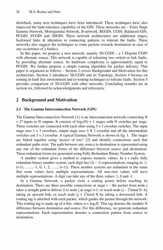
The Gamma Interconnection Network [1] is an interconnection network connecting N = 2n inputs to N outputs. It consists of log2(N) + 1 stages with N switches per stage. These switches are connected with each other using 3 x 3 crossbar switches. The input stage uses 1 x 3 crossbars, output stage uses 3 X 1 crossbar and all the intermediate switches use 3 x 3 crossbar. A typical Gamma Network is shown in fig. 1. The stages are linked together using “power of two” [2] and identify connections such that redundant paths exist. The path between any source to destination is represented using any one of the redundant forms of the difference between source and destination. These redundant forms are generated using Fully Redundant Binary Number System.
A number system gives a method to express numeric values. In a r radix fully redundant binary number system, each digit has (2r – 1) representations, ranging in {-(r-1), …..., -1, 0, 1, 2, ….., (r-1)}. These number systems are redundant in the sense that some values have multiple representations. All non-zero values will have multiple representations. A digit can take any of the three values: 1, 0 and -1.
In a Gamma Network, a packet visits n routing points before reaching its destination. There are three possible connections at stage i – the packet from node j takes a straight path to deliver it to node j at stage i+1; or reach node (j – 2i)mod N by taking an upward link; or reach node (j + 2i)mod N by taking a downward link. A routing tag is attached with each packet, which guides the packet through the network. This routing tag is made up of n bits, where n = log2N. This tag denotes the modulo N difference between destination and source. For this difference, we generate redundant representations. Each representation denotes a connection pattern from source to destination.
3D-CGIN: A 3 Disjoint Paths CGIN with Alternate Source 27
In this network, at any switching element three different packets can arrive at the same time. At stage i any node j can receive input packet from following three nodes: j, (j - 2i+1 ) and (j + 2i+1 ). These three packets will have 0, 1 and -1 at the ith digit in the routing tag. This network provides multiple paths between any source and destination pair using the redundant number representation. However, it provides unique path when source is same as destination.
Fig. 1. The Gamma Interconnection Network
2.2 Cyclic Gamma Interconnection Network (CGIN)
In n-stage Gamma Network, the connection pattern can be represented as 20, 21, 22, …..., 2n-1 . In CGIN [8] the connection patterns were altered by repeating any stage at initial and end connections. This alteration provided multiple disjoint paths, guaranteeing one arbitrary fault tolerance. It also guaranteed multiple paths between any pair of source and destination. The resulting network depicted cyclic nature.
A CGINγn is a CGIN with n stages and the connecting patterns between first two
stages and last two stages being 2γ where 0≤ γ ≤ (n-2). So, the connecting patterns between stages can be ordered as
2γ, 2γ+1, 2γ+2, …., 2n-3, 2n-2, 20, 21, 22, …...2γ-1, 2γ
28 M.A. Borkar and Nitin
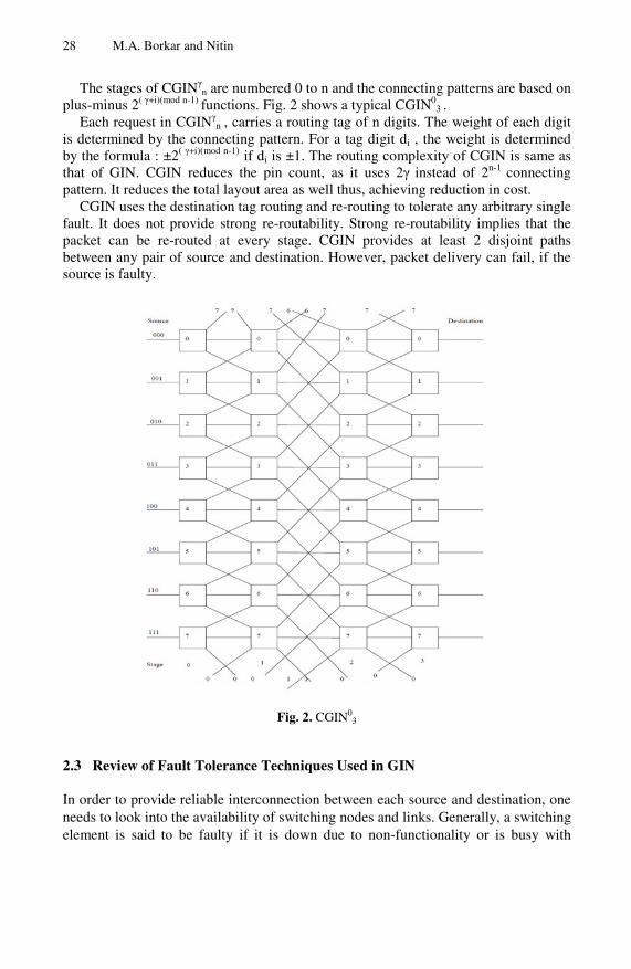
The stages of CGINγn are numbered 0 to n and the connecting patterns are based on
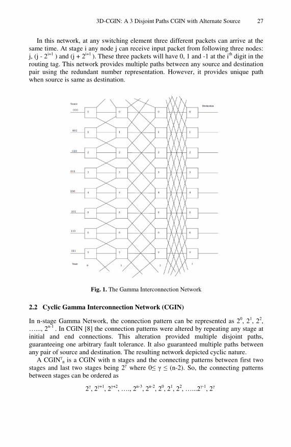
plus-minus 2( γ+i)(mod n-1) functions. Fig. 2 shows a typical CGIN03 .
Each request in CGINγn , carries a routing tag of n digits. The weight of each digit
is determined by the connecting pattern. For a tag digit di , the weight is determined by the formula : ±2( γ+i)(mod n-1) if di is ±1. The routing complexity of CGIN is same as that of GIN. CGIN reduces the pin count, as it uses 2γ instead of 2n-1 connecting pattern. It reduces the total layout area as well thus, achieving reduction in cost.
CGIN uses the destination tag routing and re-routing to tolerate any arbitrary single fault. It does not provide strong re-routability. Strong re-routability implies that the packet can be re-routed at every stage. CGIN provides at least 2 disjoint paths between any pair of source and destination. However, packet delivery can fail, if the source is faulty.
Fig. 2. CGIN03
2.3 Review of Fault Tolerance Techniques Used in GIN
In order to provide reliable interconnection between each source and destination, one needs to look into the availability of switching nodes and links. Generally, a switching element is said to be faulty if it is down due to non-functionality or is busy with
3D-CGIN: A 3 Disjoint Paths CGIN with Alternate Source 29
transfer of packets. There are two possible faults in the Gamma Network, either a SE i.e. switching element is faulty or a link connecting two SEs is faulty. When a SE is faulty, then either the Source or the SE at previous stage should take a decision about retransmission of packet or re-routing the packet through some intermediate SE. In case of a link failure, the node connected with it should be able to choose an alternate path to the destination. In the following section we discuss various techniques used to tolerate these faults.
Fault Tolerance Techniques. We try to focus on the major attempts made to tolerate the faults and improve the performance as well as terminal reliability of the Gamma Network. The majority of the work is done by providing additional hardware or altering the connection patterns.
Adding Extra Stage. Adding extra stage to the Gamma Network eliminates following two problems: first, the unique path between a source and destination when S = D and second, the number of paths for even tag value are less than the number of paths for odd tag values. To provide multiple paths for S = D, an extra stage is added to the Gamma Network. The connection pattern for this extra stage can be any stage of gamma network. The routing tag is again made up of three possible values 1, 0 and -1. By using an additional bit for the extra stage one can generate the multiple paths from source to destination. The routing tags are generated in similar manner as that of the Gamma Network. The routing algorithm is a simple extension of routing in Gamma Network. The Extra Stage Gamma Network [3] uses this concept to provide multiple paths; those could be followed to handle the faults.
Providing Back Links. In any multiprocessor system, the memory requests from processing elements are generated randomly, hence the path or memory conflicts are inevitable. By increasing switch sizes the path conflicts may be reduced, but memory conflicts are still unavoidable. Providing extra buffer space will certainly reduce the memory conflicts, but the implementations become very costly. Therefore, some networks use Backward Links to provide multiple paths, to cater with path / memory conflicts. The B-network [4] is the network using this particular fault tolerant technique. In this technique, the requests blocked due to path / memory conflict, are simply send back one stage and from there a new path is selected for the packet. In this approach, the packet may follow any number of back links, and then may get forwarded to destination. Following are certain features observed with back links – 1) The backward links act as implicit buffers, 2) The backward links at the very last stage can handle the memory contention, which cannot be done by crossbars.
Providing the Extra Link. Some network architectures use an additional link that may connect to some additional SE in next stage. The Balanced Gamma Network [5] uses this approach. It uses the distance tag routing. Two more modified GINs, namely, PCGIN [6] and FCGIN [6], make use of additional links at 0th stage. In PCGIN, all the nodes are connected to each other, forming a chain from 0 to N. Using this layout it ensures at least 2 disjoint paths between any source to destination pair. It uses backtracking to tolerate faults. On the other side, FCGIN, uses a fully chained approach at each stage to avoid backtracking. Due to chaining at every stage, it provides distributed control and dynamic rerouting, hence a better fault tolerance is provided. These networks are 1 - fault tolerant.
30 M.A. Borkar and Nitin
Changing the Interconnection Patterns. Due to ±2i interconnection patterns, GIN provides multiple paths for many sources to destination pairs. However, for certain Source and Destination it provides unique paths, which prove risky if a node fails. Then for certain pairs the communication becomes impossible. One can provide multiple disjoint paths for all source to destination pairs by altering the interconnections between any stage i and i+1. The Reliable Gamma Network (RGIN) [7], uses the altered interconnection patterns to provide multiple paths and disjoint paths. Another network, called Mono gamma Network [8] also uses the altered interconnections to provide multiple paths between any source to destination pair, but they are not disjoint in nature. In Cyclic Gamma Interconnection Network (CGIN), any interconnection pattern between any two stages can be repeated to provide multiple disjoint paths without increasing the hardware cost. As it uses, the repetition of connection pattern the pin count reduces. Balance modified GIN [9], reverses the connection patterns for upper links as compared with GIN, while keeping the connection patterns intact for lower and straight links. This approach balances the distances between any communicating pair.
By Combining the Switching elements. 3DGIN [10] is a network which combines the switches to provide 3 disjoint paths. Here, the switches at initial stage are combined together. It ensures without one lookahead, less hardware cost, 3 Disjoint paths and two faults tolerance.
We propose a new network, which is an alteration in CGIN, with an alternate link at stage 0. This network provides 3 disjoint paths in CGIN, with use of the alternate link.
3 3D-CGIN: A 3 Disjoint Paths CGIN
3.1 Network Architecture of 3D-CGIN
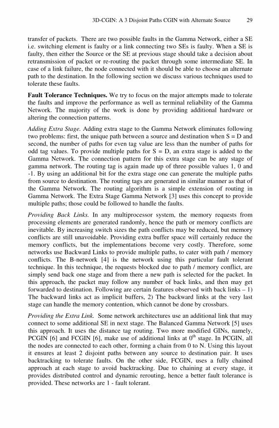
3D-CGIN is a cyclic Gamma Network, connecting N = 2n inputs to N outputs. It consists of log2N + 1 stages with N switching elements per stage. The number of input nodes in 3D-CGIN are divided in two parts, and an alternate link is used connecting the respective input nodes to each other. It means that the first node in first part is connected with first node in second part with alternate link and so on. The 0th stage switches are 2 X 3 crossbars, 1st and 2nd stage switches are 3 X 3 crossbars, output stage switches are 3 X 1 crossbars. The connecting patterns between different stages are done as per CGIN concept. The connections between stage 0 - 1 & 2 - 3 are done as per 20 patterns whereas the 21 pattern is used for connection between 1 – 2. Fig. 3 shows the topology of 3D-CGIN for N = 8.
In 3D-CGIN, a packet visits n switches before reaching the destination. The stages are numbered 0 to n, from left to right. The connecting pattern between stages is given by plus-minus 2(γ+i)mod (n-1) functions. The jth switch at stage i, 0 ≤ i ≤ n, is connected with three switches at stage i+1 using three functions:
fstraight (j) = j fup (j) = j - 2(γ+i)mod (n-1) mod N
fdown (j) = j + 2(γ+i)mod (n-1) mod N
3D-CGIN: A 3 Disjoint Paths CGIN with Alternate Source 31
The function fstraight defines the switch to be visited if a straight link is chosen. The functions fup and fdown denote the switches visited if we choose up and down links respectively. Each request in 3D-CGIN also carries a routing tag of n digits. Each digit in tag can take any of the following three values: 0, 1 and -1. We can use both the distance tag routing and destination tag routing methods to route a packet to its intended destination. By distance we mean Distance = D – S (Mod N), where D is the destination and S is the source. Following formula is used, to generate the all possible routing tags representing the distance between source and destination:
RTDistance = δij 20 ± δi
j 21 ± δij 20 . (1)
The alternate source / link at stage 0 is used in following cases : 1) The source S is faulty / non operational, 2) Source S is busy with packets and the current request needs urgent processing, 3) the buffer of source S is full, due to which the request is required to wait. The routing algorithm should make a decision about it. Whenever the packet is transferred to alternate source the routing needs one extra hop processing.
Fig. 3. Topology of 3D-CGIN with N = 8
32 M.A. Borkar and Nitin
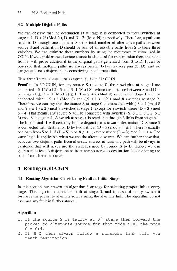
3.2 Multiple Disjoint Paths
We can observe that the destination D at stage n is connected to three switches at stage n-1; D + 2γ (Mod N), D and D - 2γ (Mod N) respectively. Therefore, a path can reach to D through one of them. So, the total number of alternative paths between source S and destination D should be sum of all possible paths from S to these three switches. We can estimate these numbers by using the recurrence relation used in CGIN. If we consider the alternate source is also used for transmission then, the paths from it will prove additional to the original paths generated from S to D. It can be observed that, multiple paths are always present between every pair (S, D), and we can get at least 3 disjoint paths considering the alternate link.
Theorem: There exist at least 3 disjoint paths in 3D-CGIN.
Proof : In 3D-CGIN, for any source S at stage 0, three switches at stage 1 are connected : S-1(Mod 8), S and S+1 (Mod 8), where the distance between S and D is in range -1 ≤ D – S (Mod 8) ≤ 1. The S ± i (Mod 8) switches at stage 1 will be connected with S ± i (Mod 8) and ((S ± i ) ± 2 ) mod 8 switches at stage 2. Therefore, we can say that the source S at stage 0 is connected with ( S ± 1 )mod 8 and (( S ± 1 ) ± 2 ) mod 8 switches at stage 2, except for a switch where (D – S ) mod 8 = 4. That means, any source S will be connected with switches (S, S ± 1, S ± 2, S ± 3) mod 8 at stage n-1. A switch at stage n is reachable through 3 links from stage n-1. The links 1 and -1 will certainly lead to disjoint paths towards destination D. Source S is connected with destination D by two paths if (D – S) mod 8 = ± 1. There is exactly one path from S to D if (D – S) mod 8 ≠ ± 1, except where (D – S) mod 8 = ± 4. The same logic is applicable when we use the alternate source. We can further show that, between two disjoint paths from alternate source, at least one path will be always in existence that will never use the switches used by source S to D. Hence, we can guarantee at least 3 disjoint paths from any source S to destination D considering the paths from alternate source.
4 Routing in 3D-CGIN
4.1 Routing Algorithm Considering Fault at Initial Stage
In this section, we present an algorithm / strategy for selecting proper link at every stage. This algorithm considers fault at stage 0, and in case of faulty switch it forwards the packet to alternate source using the alternate link. The algorithm do not assumes any fault in further stages.
Algorithm 1. If the source S is faulty at 0th stage then forward the
packet to alternate source for that node i.e. the node S = S+4.
2. If S=D then always follow a straight link till you reach destination.
3D-CGIN: A 3 Disjoint Paths CGIN with Alternate Source 33
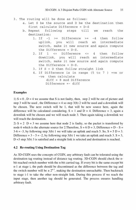
3. The routing will be done as follows: a. Let S be the source and D be the destination then
first calculate Difference = D–S b. Repeat following steps till we reach the
destination: 1. If -1 >= Difference >= -4 then follow
uplink, you will reach an intermediate switch, make it new source and again compute the Difference = D-S.
2. If 1 <= Difference <= 4 then follow downlink, you will reach an intermediate switch, make it new source and again compute the Difference = D-S.
3. If S = D then follow straight link 4. If Difference is in range (5 to 7 ) +ve or
-ve then calculate diff = 8 mod Difference
Difference =- diff
Examples
1) S = 0 , D = 4 we assume that S is not faulty, then, step 2 will be out of picture and step 3 will be used , the Difference = 4 so step 3(b) 2 will be used and a downlink will be chosen. The next switch will be 1, that will be new source here, again the difference will be calculated considering, S = 1 and D = 4. Difference = 3, again a downlink will be chosen and we will reach node 3. Then again taking a downlink we will reach the destination.
2) S = 2 D = 3 we assume here that node 2 is faulty, so the packet is transferred by node 6 which is the alternate source for 2.Therefore, S = 6 D = 3, Difference = D – S = 3-6 = -3, by following step 3(b) 1 we will take an uplink and reach 5. So, S = 5 D = 3. Difference = 3 – 5 = -2, by following step 3(b) 1 we take an uplink and reach 3. S = 3, D =3 step 3(b) 3 is satisfied and a straight link is selected and destination is reached.
4.2 Re-routing Using Destination Tag
As 3D-CGIN uses the concepts of CGIN, any arbitrary fault can be tolerated using the destination tag routing instead of distance tag routing. 3D-CGIN should check the n-bit reached switch number with the n-bit carried tag. If every bit is the same except bit n-1 at stage i, the path should be discontinued as the difference between the tag and the switch number will be ± 2n-1, making the destination unreachable. Then backtrack to stage i-1 to take the other non-straight link. During this process if we reach the input stage, then another tag should be generated. The process ensures handling arbitrary fault.
34 M.A. Borkar and Nitin
5 Comparison of 3DCGIN with Other Interconnection Networks
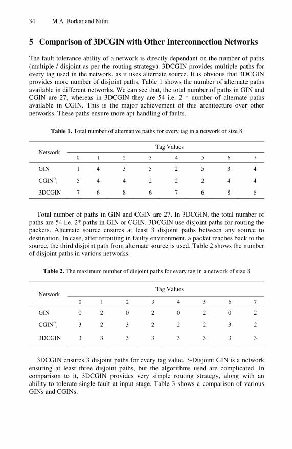
The fault tolerance ability of a network is directly dependant on the number of paths (multiple / disjoint as per the routing strategy). 3DCGIN provides multiple paths for every tag used in the network, as it uses alternate source. It is obvious that 3DCGIN provides more number of disjoint paths. Table 1 shows the number of alternate paths available in different networks. We can see that, the total number of paths in GIN and CGIN are 27, whereas in 3DCGIN they are 54 i.e. 2 * number of alternate paths available in CGIN. This is the major achievement of this architecture over other networks. These paths ensure more apt handling of faults.
Table 1. Total number of alternative paths for every tag in a network of size 8
Network Tag Values
0 1 2 3 4 5 6 7
GIN 1 4 3 5 2 5 3 4
CGIN03 5 4 4 2 2 2 4 4
3DCGIN 7 6 8 6 7 6 8 6
Total number of paths in GIN and CGIN are 27. In 3DCGIN, the total number of
paths are 54 i.e. 2* paths in GIN or CGIN. 3DCGIN use disjoint paths for routing the packets. Alternate source ensures at least 3 disjoint paths between any source to destination. In case, after rerouting in faulty environment, a packet reaches back to the source, the third disjoint path from alternate source is used. Table 2 shows the number of disjoint paths in various networks.
Table 2. The maximum number of disjoint paths for every tag in a network of size 8
Network Tag Values
0 1 2 3 4 5 6 7
GIN 0 2 0 2 0 2 0 2
CGIN03 3 2 3 2 2 2 3 2
3DCGIN 3 3 3 3 3 3 3 3
3DCGIN ensures 3 disjoint paths for every tag value. 3-Disjoint GIN is a network
ensuring at least three disjoint paths, but the algorithms used are complicated. In comparison to it, 3DCGIN provides very simple routing strategy, along with an ability to tolerate single fault at input stage. Table 3 shows a comparison of various GINs and CGINs.
3D-CGIN: A 3 Disjoint Paths CGIN with Alternate Source 35
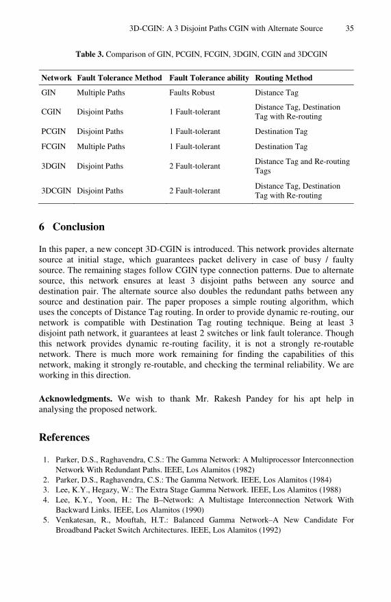
Table 3. Comparison of GIN, PCGIN, FCGIN, 3DGIN, CGIN and 3DCGIN
Network Fault Tolerance Method Fault Tolerance ability Routing Method
GIN Multiple Paths Faults Robust Distance Tag
CGIN Disjoint Paths 1 Fault-tolerant Distance Tag, Destination Tag with Re-routing
PCGIN Disjoint Paths 1 Fault-tolerant Destination Tag
FCGIN Multiple Paths 1 Fault-tolerant Destination Tag
3DGIN Disjoint Paths 2 Fault-tolerant Distance Tag and Re-routing Tags
3DCGIN Disjoint Paths 2 Fault-tolerant Distance Tag, Destination Tag with Re-routing
6 Conclusion
In this paper, a new concept 3D-CGIN is introduced. This network provides alternate source at initial stage, which guarantees packet delivery in case of busy / faulty source. The remaining stages follow CGIN type connection patterns. Due to alternate source, this network ensures at least 3 disjoint paths between any source and destination pair. The alternate source also doubles the redundant paths between any source and destination pair. The paper proposes a simple routing algorithm, which uses the concepts of Distance Tag routing. In order to provide dynamic re-routing, our network is compatible with Destination Tag routing technique. Being at least 3 disjoint path network, it guarantees at least 2 switches or link fault tolerance. Though this network provides dynamic re-routing facility, it is not a strongly re-routable network. There is much more work remaining for finding the capabilities of this network, making it strongly re-routable, and checking the terminal reliability. We are working in this direction.
Acknowledgments. We wish to thank Mr. Rakesh Pandey for his apt help in analysing the proposed network.
References
1. Parker, D.S., Raghavendra, C.S.: The Gamma Network: A Multiprocessor Interconnection Network With Redundant Paths. IEEE, Los Alamitos (1982)
2. Parker, D.S., Raghavendra, C.S.: The Gamma Network. IEEE, Los Alamitos (1984) 3. Lee, K.Y., Hegazy, W.: The Extra Stage Gamma Network. IEEE, Los Alamitos (1988) 4. Lee, K.Y., Yoon, H.: The B–Network: A Multistage Interconnection Network With
Backward Links. IEEE, Los Alamitos (1990) 5. Venkatesan, R., Mouftah, H.T.: Balanced Gamma Network–A New Candidate For
Broadband Packet Switch Architectures. IEEE, Los Alamitos (1992)
36 M.A. Borkar and Nitin
6. Chen, C.W., Lu, N.P., Chen, T.F., Chung, C.P.: Fault Tolerant Gamma Interconnection Networks By Chaining. IEEE Proceedings (2000)
7. Tzeng, N.F., Chuang, P.J., Wu, C.H.: Creating Disjoint Paths In Gamma Interconnection Networks. IEEE, Los Alamitos (1993)
8. Chuang, P.J.: CGIN: A Modified Gamma Interconnection Network with Multiple Disjoint Paths. IEEE, Los Alamitos (1994)
9. Chuang, P.J.: Creating a Highly Reliable Modified Gamma Interconnection Network Using a Balance Approach. IEEE Proceedings (1998)
10. Chen, C.W., Lu, N.P., Chung, C.P.: 3–Disjoint Gamma Interconnection Network. The Journal of Systems and Software (2003)